
Philips Technical Review - World Radio History
390
VOL. 1 No. 1 JANUARY 1936 Philips Technical Review DEALING WITH TECHNICAL PROBLEMS RELATING TO THE PRODUCTS, PROCESSES AND INVESTIGATIONS OF N.V. PHILIPS' GLOEILAMPENFABRIEKEN EDITED BY THE RESEARCH LABORATORY OF N.V. PHILIPS' GLOEILAMPENFABRIEKEN, EINDHOVEN, HOLLAND INTRODUCTION With the appearance of the first issue of this new periodical, the policy and aims should be outlined which will be pursued in these pages. The Philips Research Laboratories are .continually receiving an everincreasing number of enquiries and reqUests from many quarters for more detailed data "and particulars of- the extensive range of Philips pro- ducts, and especially for information as to their specific characteristics and practical applications. A large proportion of ihese enquiries comes from the engineering world and it is hoped by means of this periodical to establish permanent contact with these circles. . This journal will deal with the following items: a) Technical descriptions of new Philips products, and reports on investigations relating thereto, b) Information concerning the applications of these products, and c) Technical articles of a more general nature on various questions relating to the above, which may be of interest to the reader. An endeavour will be made to present the sa- ject matter of the articles as simply as possible. Mathematical treatment will be resorted to neither more nor less than is necessary. Facts which can be concisely stated by mathematical for- mulae will in addition be explained. in simple language, which will make it possible for those who do not wish to follow the mathematics to gather the gist of the article from the text alone. Additional clarity will further be strived for by the free use of diagrams and graphs. In this way every unnecessary show of learnedness will be avoided, but on the other hand care will be taken that this simplicity of expression does not lead to superficiality and indefiniteness when dealing with really complicated subjects._ Each contribution to this periodical will be, as far as possible, complete in itself. Owing to the wide range of products manufactured by Philips every, article cannot be expected to command the same measure of interest from every reader. Nevertheless, it may be expected that many readers wil find matter of interest also in those contributions which do not concern their own immediate activities. This periodical therefore will be not merely a journal embracing the activities of the Philips organisation nor a technical journal on popular lines, but a source of information of value and interest to the whole engineering profession. Our hope is that this publication will prove of practical interest and use to many, and in consequence merit a wide circle of readers. G. HOLST.
-
Upload
khangminh22 -
Category
Documents
-
view
1 -
download
0
Transcript of Philips Technical Review - World Radio History

VOL. 1 No. 1 JANUARY 1936
Philips Technical ReviewDEALING WITH TECHNICAL PROBLEMS
RELATING TO THE PRODUCTS, PROCESSES AND INVESTIGATIONS OFN.V. PHILIPS' GLOEILAMPENFABRIEKEN
EDITED BY THE RESEARCH LABORATORY OF N.V. PHILIPS' GLOEILAMPENFABRIEKEN, EINDHOVEN, HOLLAND
INTRODUCTION
With the appearance of the first issue of this newperiodical, the policy and aims should be outlinedwhich will be pursued in these pages. The PhilipsResearch Laboratories are .continually receivingan everincreasing number of enquiries and reqUestsfrom many quarters for more detailed data "andparticulars of- the extensive range of Philips pro-ducts, and especially for information as to theirspecific characteristics and practical applications.A large proportion of ihese enquiries comes fromthe engineering world and it is hoped by means ofthis periodical to establish permanent contactwith these circles. .
This journal will deal with the following items:
a) Technical descriptions of new Philips products,and reports on investigations relating thereto,
b) Information concerning the applications ofthese products, and
c) Technical articles of a more general natureon various questions relating to the above,which may be of interest to the reader.
An endeavour will be made to present the sa-ject matter of the articles as simply as possible.Mathematical treatment will be resorted to neithermore nor less than is necessary. Facts whichcan be concisely stated by mathematical for-mulae will in addition be explained. in simple
language, which will make it possible for thosewho do not wish to follow the mathematics togather the gist of the article from the text alone.Additional clarity will further be strived for bythe free use of diagrams and graphs. In this wayevery unnecessary show of learnedness will beavoided, but on the other hand care will be takenthat this simplicity of expression does not leadto superficiality and indefiniteness when dealingwith really complicated subjects._
Each contribution to this periodical will be,as far as possible, complete in itself. Owing to thewide range of products manufactured by Philipsevery, article cannot be expected to command thesame measure of interest from every reader.Nevertheless, it may be expected that manyreaders wil find matter of interest also in thosecontributions which do not concern their ownimmediate activities.
This periodical therefore will be not merelya journal embracing the activities of the Philipsorganisation nor a technical journal on popularlines, but a source of information of value andinterest to the whole engineering profession. Ourhope is that this publication will prove of practicalinterest and use to many, and in consequencemerit a wide circle of readers.
G. HOLST.

2 PHILIPS TECHNICAL REVIEW VOL: lf No. 1
-
COMPARISON BETWEEN DISCHARGE PHENOMENA IN SODIUM AND-.
MERCURY VAPOUR LAMPS
Summary. The visible radiations of sodium and mercury vapour lamps are generatedby entirely different processes. Sodium is excited by the impact of electrically, accelerated .electrons against atoms in the normal state. In high-pressure mercury vapour lampsthe radiation is produced by the, temperature of the mercury vapour.'
Introduction
The technical features of sodium and mercuryvapour lamps as regards the state of the metalvapourg have developed along very different lines,which in many respects have been tending inopposite directions. Thus it has been found that ingeneral the efficiency of light production in sodiumvapour was the higher, the -lower the vapourpressure, the current density and the luminousintensity, while that of the mercury vapour lampin the range investigated increased with thesefactors. Table I brings out the marked differencebetween these two types of gas -discharge lampsin thei; present stages of development. This tablecompares certain essential data = of the metalvapours of a commercial sodium lamp with anexperimental type of mercury vapour dischargetube of very high efficiency.
Table I. Characteristics of the mcial 4apoliF of a sodiuintube lamp of 100 watts (Pliilora type SO 100) and of a super -high -pressure mercury, bunp bf1400 watts (experimental type).
Hg,
ll'essure in atmos. 10s,
200
Current density in amp/sq.cm. 0.4 280
Cross-section in sq.cm. 1.43 0.0075
Luminous intensity in candles/sq.cm. 10-20 180000
Vapour temperature in deg.0 280 8600
Light output in lumens/watt 68 78
' The sodium lamp is surrounded by a doublewalled vacuum flask which diminishes heat con-
. auction; the mercury vapour discharge, howeyer,is Cooled by running water.
The completedivergence in the behavicuir' of
sodium vapour and mercury vapour cannot bereadily reconciled with the assumption that theprocesses responsible ..for the emission of lightfrom these two classes of, laMps are analogous.CloserCloser examination does in fact show that, inspite of a fundamental similarity in the mechanismof the _two forMS of discharge, there is yet an es-
,
sential difference between yhefprocesses generatingthe visible radiation. Those prosesses which furnishthe useful light in the mercury lamp represent, onthe other hand, undesirable losses in the case ofthe sodium lamp, and vice' versa. The explanationof this must be. sought,in :the, different. structureof the sodium ,and mercury atoms,; and makes itnecessary for us to consider the :fundamental prin-ciples of atomic physics regarding the emissionof light from atoms.
Luminous Radiation due to Atomic Processes
In discussing this problem the principles willhe followed enunciated in the atomic theory' ofB o h r. The sodium atom consists of a positively -charged nucletis about which 11 electrons' revolve.A 'measure "of the forces linking the electrons tothe atom -is the energy which -must be expendedto reinove an election froni the rest of the atom.With both the sodium and mercury atoms it hasbeen foUndinubh'eaSier to remove the first'Clectronfrom the atomic system than subSequeili electrons,WhOse -separation requires the exienditure of 'amuch larger amount of energy: Ionisation may beproduced, for instance, by bombarding the atom'with electrons which have been sufficiently acCe-lerated by an electric field that they are able toimpart the requisite energy for ionisation teoneof the atomic electrons. If an electron with Chargee has passed through a.' voltage drop of V voltsand 'stored the energy:
e V (1)
5

JANUARY 1936 SODIUM 'AND MERCURf VAPOUR LAMPS
A
acquired m this.process, it will l'e termed an electron,of V volts.
- To be able to ionize sodium an electron must haveacquired at least 5.12 yolts, while in order to ionizemercury 10.38 volts are required. If electrons witha lower energy collide with the atoms, they willproVe'too weak to break up the. atoms into positiveions and electrons.-
The atoms, -ore,-however, _able to absorbb-certainamounts ' of energy . Which' -are- smaller than. theionisation energy, but any energy Values irrespectiveof magnitude cannot be, absorbed; the energyabsorbed must be in specific quanta.
The consequences will be discussed somewhat,in detail for sodium -atoms bombarded withelectrons of steadily increasing velocities. Aslong as au eleetrdn has. Tossed only through aVoltOge range idnch is "sinaller than 2.1:- volts,collision is perfectly elastic since the sodium cannotabsorb such small energy quanta. But as soon as theelectron has passechthichigh i*Voitage drop of 2.1volts, it is'able to imparfthe eOrresponding 'energyquantum of 2:1' e <to the %ton:v.'', By absorbing this.Amount of energy s the atom passes into a socalledexcited state, from which it is usually able to returnvery rapidly to its initial normal state' (d.g: after-the elapse of -about. 10'. sec:). During -this -processit radiates light. of a perfebtly definite wave -length
or frequenCy' v," as' expressed by Plane k'sequation:
hes =`hv = - . . . (2)
where c is the velocity of light and h the constantof Planck (h = 6.55.10-27 ergsec).
Equation, (2) not only applies to the transitionfrom the first excited state to the norrnarstate,but -in fact to every transition from one specificenergy level to another during which the energyliberated is radiated as light. E is here the differencein energy between the two. states. In the particularcase where sodium is excited by_ electrons of atleast 2.1 volts; a yellow light is radiated. Analysingthis radiation with the spectroscope, two lines arefound, with wave -lengths of 5890 and 5896 A res-pectively. These lines correspond to transitionsfrom two states whose energies differ by such a
small margin that in practice it is not possible toobtain the lower excited state alone. The wave-lengths agree with -equations (2) and (1), fromwhich we obtain the following relationship betweenthe wave -length of the luminous radiation in Aand the potential difference passed through:
he: 6.55.10-273.10m108 = 300.108
e V/3 0 0 4.7710-10 V
12340Angstrom.
V
:With mercury eleetrons of 4.86 volts are similarlyfound capable of generniing the 4tra-violet mercury
,.line with a wave -length= of 2537 A.;
4,1
V
10
9
8
7
: 6
5
4
3
2
1
8,8
667I
4,86
°?I 4//I 0/I /
I1 /
/I /
V/...5.12 V
4,3
/5061
-=10,381<,
7- 8,8
Hg/SOSO
Fig. 1.' Energy levels of Sodimii and Mercury. The thickness -of the lines denotes the visibility of the transition phenomena;invisible (ultraviolet and infrared) transitions are shown asbroken lines. Vi is the ionisation voltage. With sodium,visible light is produced mainly by resonance lines (5890and 5896 A); higher transitions give infrared radiation.With mercury, visible radiation is produced by higher tran-sitions (mainly 5461 and 5791 A); the resonance lines (1850and 2537 A) are Ultraviolet.

r
4 PHILIPS TECHNICAL. REVIEW VOL. 1, No. 1
A
If in the case of sodium the velocity of the bom-barding electrons is increased, various other linesof the sodium spectrum appear successively. Thusat 3.2 volts two infrared lines in the neighbourhoodof 11400 A are obtained, corresponding to a tran- sition from the 3.2 volt level to the 2.1 volt level,and from 3.5 volts onward there" appear the lines8183 arid 8195 A. In:this way the 'whole of thesodium spectrum ,is gradtially"pr Uctuced, until at'5.12 volts the sodium -.is, ionized. Similarly with,mercury, at 6.67 volts there appears in the extremeultraviolet a line with a wavelength of 1850 A.From 7.7 volts onwards one 4et's 'the wellknowngreen, blue and violet lines' of mercury with wave-lengths of 5461, 4358 and 4047 A, while in theneighbourhood of 9 volts the yellow mercury line5791 Aappears, as well as a large number of lineswhich are on the threshold between the visible violetand the ultraviolet.
The energy levels of sodium and mercury may berepresented as shown in fig. 1. Along the verticalaxis the minimum voltage is plotted Which the elec7tron must pass through in order to be able to bring theatom into the corresponding state. The individuallevels between which a transition accompaniedby radiation may occur are joined by lines, whosethickness corresponds roughly to the intensity ofthe visible light obtained. 'These diagrams clearlyshow that not all possible transitions are obtainedwith noticeable intensity, thus e.g. there are nocombinations between the energy levels in one andthe same column. In fact, whether reciprocal com-binations are possible or not with the emission ofradiation has determined this distribution of thedifferent energy levels Over a mimber of columns.This question cannot be discussed in detail withinthe 'scope Of this article'.
The diagram Shows that the common yellowsodium lines which make up the larger part of thevisible light emitted by sodium lamps are radiatedon the transition of the sodium atom from thelowest excited state to its normal state. The ana-logous process with mercury gives an invisibleultraviolet line and must therefore be regarded ,asundesirable. On the other hand, the visible mercurylines in the green and yellow 'are due to transitionsbetween higher levels, which in the case of sodiummostly produce infrared lines. To this is due thefundamental difference in the behaviour of thesodium and mercury vapour lamps.
Energy can be imparted to an atom not merelyby bombarding it with high-speed electrons, butalso by causing the atom to absorb radiation orraising the gas to a high temperature. In these
processes also it is found that the atom can absorbenergy only in definite pianta. If the temperatureis. not too high, practically all the atoms arc in thenormal state and they then absorb only such lightquanta, ..as are radiated on return to the normalstate. The smallest light quantum which can beabsorbed is that corresponding to a transitionfrom the normal state to the nearest excited state.A spectral line radiated on return to the normalstate is termed a resonance line. '.
The resonance lines play an important part, asthey are strongly absorbed by the gas itself. Ifthe -pressure of the metal vapour is not extremelysmall, the intensity of the resonance radiation isconsiderably weakened by self-absorption. Self-absorption is not intrinsically a loss in luminosity,as the absorbed energy is usually emitted againin the' form of a light quantum of the same wavelength. But it may happen that an atom beforeradiating the absorbed light quantum is excitedto a higher degree by collision with an electron(cumulative excitation) or transfers its energy toan electron and thus returns to the normal statewithout emitting radiation (collision of the secondkind).
It is obvious that the weakening of the resonanceradiation in gaseous discharges isdetermined not onlyby the intensity of self-absorption,' but also by therelative occurrence of the secondary processesreferred to. Self-absorption increases with thepressure, while the secondary processes increasewith the current density.
Conclusions bearing on the Design of Soditun andMercury Vapour Lamps
The above considerations show that to obtaina high output of visible radiation from sodiumvapour and mercury vapour lamps entirely dif-ferent methods must be adopted. To obtain a highyield of light rays with sodium, it is essential forthe resonance radiation to predominate and tran-sitions between higherenergy levels to be suppressedas far as possible. On the other hand in the mercuryvapour lamp the discharge must be such that themaximum radiation is obtained by transitionsbetween high energy levels.
As already indicated in the previous section,resonance lines are easily and considerably wea-kened by 'self:absorption. This weakening is un-desired in the sodium lamp, but highly desirablein the case of the mercury lamps. As this weakeningdue to self-absorption increases with the gaspressure and' the current density, it appears that

JANUARY 1936 SODIUM AND MERCURY VAPOUR LAMPS
to obtain the best results, sodium lamps shouldhave a low vapour pressure and be run on a lowcurrent density, and mercury lamps have a veryhigh vapour pressure as well as a very high currentdensity.
How far the adoption of these principles wouldresult in an increase in the light output of sodiumand mercury lamps will be discussed in a laterpaper. Certain results will, however, be brieflyreferred to here owing to their general interest,although they do not completely bear out theconsiderations above. It has been found that inthe sodium lamp radiation is produced as a resultof excitation by electronic collision. On the otherhand, when passing a discharge through mercuryvapour at a high pressure, the conditions of ex-citation and ionization are determined by thetemperature of the vapour, in other words thevapour atoms behave as if they were containedin a closed vessel at a constant tempera-ture. In spite of the input of energy by thecurrent and the output of energy by radiation,a thermal equilibrium is roughly established. Thisis due to the fact that owing to the high con-centration of the mercury atoms the energy storedin the gaseous column as heat is much greater thanthe energy input and output during a specifictime interval sufficient for thermal equilibriumto be established.
In the case of sodium, nearly the whole of theenergy of the electrons is converted to resonanceradiation, when the current density is extremelylow and the vapour pressure has a suitable value.In practice this limiting case is not approached,because inter alia part of the energy must be con-verted to heat in order to maintain the walls atsuch a temperature that the vapour pressureof sodium has a satisfactory value. The energylost by thermal radiation increases with the areaof the radiating surface. Therefore a specific luminousflux should not be radiated through an excessivearea. The luminous density and hence also thecurrent density must therefore not be too low.
The spectral distribution of energy in the ra-diation of high pressure mercury vapour presentsa very complex problem. With rising vapourpressure, the relative concentration of mercurymolecules Hg2 also increases. These molecules givea spectrum, composed of wide bands instead ofsharply defined lines. As a result the line spectrumwill gradually become covered by a continuousbackground, the transition becoming the more
marked as the vapour pressure rises. Fig. 2 showsthe spectra obtained with a super -high-pressuremercury vapour lamp at different vapour pressures.
P = 120 at
80 at
50 at
20 at
1 at
< 0.1 at
P1,151
1 1 1 1 1 1
2378 2537 2653 2804 2967 3132 A
Fig. 2. Spectrum of a mercury vapour discharge, cooled witha stream of water, at different vapour pressures P. Withrising vapour pressure, the spectrum lines will progressivelybe covered by emission and absorption bands. (Internaldiameter of tube 2 mm, current intensity approx. 1.3 A).
The most striking difference in these spectra is thesteady intensification of the continuous back-ground beginning at the resonance line 2537 Aand spreading mainly in the direction of the longerwavelengths. With the increase in vapour pressurean absorption band progressively covers a greaterpart of the spectrum owing to self-absorption ofthe resonance radiation. The appearence of thebands may be regarded as the first stage of thetransition of radiation into a state of thermalequilibrium, where the spectral distribution ofintensity is no longer determined by the charac-teristics of the individual atoms but merely byPlane k's law of black body radiation. Since ablack body at the temperature of the radiating zonein the discharge emits comparatively more red radia-tion and less ultraviolet radiation than a mercury-vapour lamp, it may be concluded already from ther-modynamical considerations that with rising vapourpressure the center of gravity of the intensitydistribution becomes shifted towards longer wave-lengths. This effect is indeed clearly brought outin fig. 2. The wide absorption bands produced bya broadening of the resonance lines weaken theultraviolet radiation of the mercury vapour to adegree which increases with the rise in vapourpressure, while the continuous background whichincreases in intensity with the pressure stretchesfar into the red and infrared region of the spec-trum.
Compiled by G. HELLER.

PHILIPS TECHNICAL' REVIEW VOL. 1, No.
A MODERN HIGH -VOLTAGE EQUIPMENT
Summary The equipment described furnishes peak voltages up to 1000 kV, and a D.C.voltage of 700 kV, a current of 4 miLliamps being derived. Compactness and simplicityof control are its features. The installation is composed of two symmetrical units. Oneunit comprises four stages, each consisting of a condenser and valve; each structuralelement is subject to a quarter only of the total voltage. Owing to their special design,the valves are able to cope with a 200 kV backfiring voltage. The oxide cathodes areheated by means of a high -frequency generator.
Introduction
The problem of generating D.C.. voltages up toseveral hundreds of kilovolts has been stimulatedin a high degree by the development of atomicphysics, which has acquired considerable propor-tions during the last few years. For, experimentson the disintegration of atoms a very large numberof high -voltage equipments complying more orless with the special requirements have been desig-ned and constructed. But most,of.these. equipmentstake up a great deal of <room.and demcind-muchof the experimenter's attention,:which, therefore,has to be necessarily divided between the actualexperiments in hand and the apparatus supplying
V4
CIE
V3
V211
C2
/5046
Fig. 1. Principle of the Greinacher 'circuit. If transformerT supplies an A.C. voltage of amplitude E, point c is at a con-stant voltage 2 E and point e at a constant voltage 4 E with'respect to earth. The circuit can be expanded as required.
the requisite high voltage. An installation which,while not relieving the experimenter from everysuch duty, yet does simplify supervision to a markeddegree, has been developed in the X-ray laboratoryof the Philips Works 1). This equipment, which
1) A short description of the equipment - which has sincebeen much improved - has been published by A. B o u- wers ("Modern X-ray Development", British Journalof Radiology 7, 21, 1934).
. .
supplies a direct current of 4 mA at 700 kV andpeak voltages up to 1000 kV, takes up very littlespace and is remarkable for the simplicity of itsconstruction and operation.
The theoretical lay -out of this installationis based upon a circuit, first described byGreinacher. Cockcroft (Cambridge), andB o u w e r s (Eindhoven), working independentlyalmost simultaneously thought. of applying thisprinciple for generating very high voltages.
.
Principle of circuit
The fundamental diagram is shown in fig.1.The secondary winding T of a high-tension trans-former furnishes an A.C. voltage of amplitude E.Point a is earthed and is thus always at zero po-
15042
Fig.' 2. Voltage -time curves for various points of the circuitin fig. 1. Across each valve the voltage fluctuates betweenzero and 2 E; for adjacent valves the phase -displacementis half a cycle.
tential. (This fact is not essential, but it is statedto facilitate a clear understanding of the circuit).Point a1 has a voltage with respect to, earth, whichis represented by the voltage -time sine curve a1in fig. 2. How will the voltage at point b varywith time?
In the absence of valve V1, the upper plate ofcondenser C1 would alternately assume a 'positiveand negative charge, whose maximum value would

JANUARY 1936 MODERN HIGH -VOLTAGE EQUIPMENT 7
correspond to the peak value E of the transformer(it amounts to E times the capacity of C1). As,however, valve V1 permits the current to flow incircuit a al b b1 a in one direction only (viz. to theleft) 2), the positive charge once accumulated onthe upper condenser plate will be maintained, asthe deficiency of electrons cannot be made up viaV1. Condenser C1 is thus charged to the peak voltageE, and the potential at b consequently remains
E in excess of that at al (or -E, if the valve isreversed). The potential at b which with respectto earth is identical to the voltage across valve V1can obviously be represented by curve b: it oscillatesbetween zero and 2E.
The same reasoning may be followed for ascer-taining the fluctuation of the potential at point cof the adjacent circuit. The voltage across valve V1which oscillates between zero and 2E, here per-forms the function of the A.C. voltage suppliedby the transformer; owing to the action of valveV2, condenser C2 is charged to the highest voltageoccurring at V1, viz. 2E. Point c, therefore, has aconstant potential 2E with respect to b1 (= earth)(cf. line c, fig. 2).
Between points c and b, i.e. across valve V2,a voltage occurs which can readily be found asthe difference of the potentials at these points,that is, the difference between the ordinates ofcurves c and b (cf. the shaded area V2.) It is seenthat the valve -voltage V2 oscillates between zeroand 2E (which was also the case with valve V1),this voltage being displaced by half a cycle withrespect to that of V1. Starting with V2 and pro-ceeding by the same method, it is similarly foundthat at point d the voltage fluctuates between 2Eand 4E; and also, that point e acquires a constantvoltage 4E (cf. curves d and c in fig. 2).
If, for instance, the original A.C. voltage E is100 kV, a D.C. voltage 4E = 400 kV is obtainedat c; by means of a second unit devised on thesame lines but having valves operating in theopposite direction, a voltage of -400 kV can beobtained. Between the terminals of the two systemsa total voltage 8E = 800 kV will therefore obtain.From fig. 2 it will be evident that in the unitdescribed, voltages still higher than 4E occur:between points e and a1, the voltage fluctuatesbetween 3E and 5E. By earthing point al insteadof a, a peak voltage as high as 5E per unit may beobtained, so that two units in combination areable to supply a peak voltage of 10E.
2) In the symbol for the valves used in fig. 1, the arrowdenotes the cathode ; the arrow consequently indicatesthe direction of the flow of electrons.
The main advantage of this circuit is that a 11condensers and valves are subjected to a fractionof the voltage only (viz. 2E, and even E only in C1).This has enabled the dimensions of all componentsto be kept within reasonable limits. Moreover, eachunit is composed of identical stages, so that stillhigher voltages can be attained by increasing thenumber of stages per unit.
15097
Fig. 3. Complete equipment consisting of two units. Themetal globes B enclose the connecting points to eliminatecorona phenomena. Between the globes the condensers Cwhich form the vertical structural elements are visible; thevalves V are fitted in the sloping interconnections. Thetransformer is at the rear, the transmitter H for high -frequencyheating is in the front.
Description of equipment
Fig. 3 shows a photograph of the completeequipment, comprising two units of four stages each.At .both sides of each unit the condensers C(papercondensers of about 0.01 li.F) can be seen mountedvertically; the valves V are contained in the slopingconnecting members. The connecting points b,
c, d and e are surrounded by globe -shaped metalshields B to decrease corona phenomena. Theore-tically, a maximum D.C. voltage of 800 kV is ob-tained between the terminals if the amplitude ofthe transformer voltage amounts to E = 100 kV.(When the system is loaded this voltage will be some-what lower because the condensers cannot maintaintheir peak voltages. Also, a ripple amountingto a small percentage will occur in that case). Bya slight modification of the circuit, it is possible,as already mentioned, to obtain a voltage fluc-tuating between 600 and 1000 kV.
It has already been pointed out that this typeof installation is not by any means bulky, the

8 PHILIPS TECHNICAL REVIEW VOL. 1, No. 1
equipment shown in fig. 3 occupying a floor areaof only 1.5 x 3 m and being only 2 m high. It can,therefore, be accommodated in a comparativelysmall room.
The valves
Among the various components constitutingthe equipment, the valves designed by Mulder 3)(Eindhoven) call for special mention. They con-tain mercury vapour at saturation pressure (ap-proximately 2.10-3 mm at 15° C) and are provided
Fig. 4A. Two -stage unit. Starting at instant to a current istaken from c.
toi t/5047
Fig. 4B. The variation of potential at points b and c issimilar to that in fig. 2, but the potential of c slowly decreasesfrom the instant to. At t1, the potential difference across thevalves (between points b and c) attains the value of theignition voltage Eo; ignition is effected, the potential at cincreases up to t2. During the short interval t2-t, the wholecharge. of condenser C2 lost during the long interval ti-tohas to be made up. The charging current must therefore assumehigh momentary values during this short interval.
with oxide cathodes. It is true that, comparedwith high -vacuum valves, gasfilled tubes havethe disadvantage of a high ignition voltage (about7 kV). Moreover, their operation sets a limit tothe ambient temperature, such that in view ofthe mercury -pressure required, the permissibletemperature range is restricted to between about15° and 40° C. On the other hand, they offer theadVantages of a very low voltage drop (50 volts);their main feature, however, is that they enableoxide cathodes to be used which require verylittle heating and thus facilitate the application of"high -frequency heating", described below (thepower required for heating tungsten cathodes isabout ten times greater).
3) cf. J. G. W. 3,1*u 1 d e r, Dissertation, Delft 1934.
Notwithstanding the fact that the high-tensionequipment has to supply a current of a few mil-liataps only, the cathodes must be designed foran emission current of about 100 milliamps, forthe instantaneous values of the charging currentsin the valves are many times greater than thecurrent to be ultimately supplied. This point willbe considered in some detail, as it is of paramountimportance to the efficient functioning of theinstallation.
When the equipment has to supply current,the functioning of the installation is explainedon the same lines as outlined above, except thatthe potentials of the condensers are somewhatreduced as a discharge occurs. The state of affairsis shown in fig. 4B, for an installation of only twostages, up to c (fig. 4A), and assuming that at acertain instant to the current is drawn from point c.The potential at c, which was initially 2E, nowslowly drops as condenser C2 is discharged. At acertain instant the potential at b, which, as pre-viously stated, fluctuates between zero and 2E,will be' in. excess of the decreased potential at c;when the excess voltage reaches the value E0 ofthe ignition voltage - at the instant t1 - thevalve is started up and the condenser C2 becomesrecharged. The potential at b, however, remainsonly a short time at the peak around 2E; it de-creases again, whilst the potential at c increases.Shortly after, at the instant t2, the potential dif-ference at the valve becomes zero and the chargingcurrent is interrupted. From this point, the cycleis repeated. In order to prevent the condenservoltage from decreasing regularly at intervals, itis necessary to restore to the condenser in the shortperiod to-t1 that charge which has been lostduring the long period ti-to by the dischargecurrent. As the charge is represented by theintegral of the current over the time, it isclear that owing to the short duration of thecharging current its magnitude must be corres-pondingly greater; it should exceed the dischargecurrent by the ratio between the time intervalstf-to and t2t14).
The oscillogram of the current of condenser C2,shown in fig. 5, clearly shows how the condenseris discharged with a small current and how thecharge is restored in a few peaks.
Moreover, the importance of using valves witha 1 o w ignition voltage will now be evident. If the
4) If the potential at c is decreasing more quickly, point t1is shifted to the left and the ratio of the tune intervalsbecothes more favourable, but the potential "ripple" at cis then very large.

JANUARY 1936 MODERN HIGH -VOLTAGE EQUIPMENT 9
ignition voltage is high, it may happen that, at thefirst "crossing" of the potential at b and c (point t1in fig. 4B), no ignition of the valve at all takesplace, so that the condenser is still further dis-
Fig. 5. Oscillogram of current in condenser C2 (of fig. 4A),showing the small discharge current (below the zero -line)and the peaks of the charging current (above the zero -line,about 10 times as large).
charged, until recharging occurs at the next"crossing", or even later! In this case the timeinterval for restoring the charge has become stillmore unfavourable.
The valves used are provided with oxide ca-thodes consuming about 8 watts, which is amplefor obtaining the necessary emission current.
As the cathode is at a potential of several 100 kV,the heating power supply presents a problem initself. Cock c r oft made use of small storagebatteries, which were placed directly on the con-densers. This seems to be a simple solution, butthe regular charging and supervision of the batteriesnecessary are serious drawbacks and prove veryinconvenient. In the case of the equipment des-cribed here, the cathodes have for some timebeen heated by small generators, a method alsoemployed by C o c k c r oft. The generators weremounted on the condensers and were driven inpairs by a motor on the floor through a commoninsulating pertinax shaft. This solution is fairlysatisfactory, but has the drawback that operationis not noiseless.
The high -frequency heating
The heating problem was later solved in a moreelegant way by the application of high -frequencyheating, a method suggested by K u n t k e (Eind-hoven). The circuit at present used is shown dia-grammatically in fig. 6 (only one of the two unitsis shown).
The condensers C1 -C4 act as insulators for theD.C. voltage produced, but allow a high -frequencyalternating current to pass freely. Between thepoints a and b1 (a is at zero potential) an alter-nating voltage is applied with a frequency of7.5.105 c/s (corresponding to a wavelength of 400metres) and derived from a small 150 -watt trans-mitter H. This A.C. voltage now delivers current
to the high-tension circuit without affecting thehigh tension and without being affected thereby.This implies, however, that the circuit must besuitably dimensioned to carry both kinds of
C3
Clof
/5045
Fig. 6. Circuit diagram of a single unit, with supplementaryhigh -frequency heating. Through the high-tension circuitthere also flows a 750 kc current of 0.7 amp; by means ofspecially -designed air -core transformers (at b, c, d and aboveC,), the requisite value of 3.5 amp for heating the cathodesis obtained. The functions of the supplementary components(capacities, inductances and resistances) are explained inthe text.
current; the condensers for instance must bedesigned in such a way that, apart from the re-quired capacity and disruptive strength, theyinvolve only small high -frequency losses. Not-withstanding the special design, the high -frequencylosses in the condensers are still comparativelyhigh. Therefore it was desirable to restrict thehigh -frequency current intensity to 0.7 amp. Toobtain the 3.5 amp current required for heatingthe cathodes, small air -core trnasformers of a5 : 1 ratio have therefore to be included in thecircuit (cf. fig. 6). The necessary power of 8 wattsis arrived at by constructing the air -core trans-formers with a tight coupling and low leakage;the secondary voltage is derived from taps on thecoil, as in an auto -transformer. All cathodes arethus heated in a series circuit.
Some details of the diagram shown in fig. 6may be referred to. The resistances W of 20000ohms, connected in series with the valves, wereoriginally designed to limit the initial current atthe moment of ignition; now they also serve toprevent the valves from providing a shunt for thehigh -frequency current. For the high -frequencycurrent the capacity C' shorts the transformer,

10 PHILIPS TECHNICAL REVIEW VOL. 1, No. 1
while capacity C" bridges the last valve. The self-inductance L is used to tune the circuit to reso-nance and, therefore, to reduce the impedanceof the high -frequency circuit to the minimumpossible. The choke coil L' prevents the high -frequency circuit from passing over to the loadingcircuit.
The design of the valves is such that the dis-charge path between cathode and anode is sub-divided by a number of short metal tubes. Thevalves are glass tubes about 50 cm long and 3 cmin diameter; the cathode -anode distance d is about30 cm and is sub -divided by means of 60 tubes insuch a way that the distance c between the smalltubes amounts to about 0.5 cm (cf. fig. 7).
The function of the tubes, which may be regardedas intermediate electrodes, is to increase the back-firing voltage; this is briefly -explained as follows:The break -down voltage depends on the vapourpressure and the, distance between the electrodes.When the distance between the electrodes isdecreased, with a fixed vapour pressure, a regionis ultimately reached in which the break -downvoltage increases with decreasing elec-trode -distance 5). Roughly speaking, this conditionprevails when the mean free path of the electrons
5) Cf. e.g. J. J. Thomson and G. P. Thomson, Con-duction of electricity through gases, Cambridge 1933,Vol. 2, p. 475 ff.
in the vapour is of the same order of magnitudeas the distance between the electrodes. Then,owing to the deficiency of the number of collisions,the electrons do not produce a sufficient quantityof ions to cause a discharge. Now the mean freepath of the. electrons in mercury vapour at a
17-YYYti'7d /5044
Fig. 7. Construction of valve: the distanced = 30 cm betweencathode K and anode A is subdivided by 6 tubes each separ-ated by a distance c = 0.5 cm to increase the backfiring vol-tage. The bridging condensers produce uniform distributionof the total voltage along the tube.
pressure of about 2.10-3 mm is of the order of a fewcentimetres and is therefore comparable to thedistance between the small tubes. The latter areinterconnected by condensers; this affords a linearpotential distribution along the discharge -path,which is necessary during the period during whichthe tube has to stand the full voltage (2E). Thedielectrics of these condensers are constructed asrings of high-tension Philite and fitted round thevalve -tube, and thus give the valves the strikingappearance shown in fig. 3.
Compiled by S. GRADSTEIN.

JANUARY:1936 11
RELAY VALVES AS TIMING DEVICES IN SEAM -WELDING PRACTICE
By D. M. DUINKER.
Summary. The usual method of bonding two pieces of metal by spot-welding is to passa very high -ampere alternating current through them. Practical experience in recentyears has shown that to obtain a reliable bond it is essential to limit the time the currentis passing to a few hundredths of a second, i.e. to a small number of periods at a 50 -cyclefrequency. In welding long seams the parts to be bonded are passed between roller -typeelectrodes at a constant speed, a series of welding -spots being produced bypassing a currentimpuls of the above mentioned duration through the electrodes at uniform intervals.A timing device designed for this purpose must therefore allow the current to pass for acertain number of cycles x, then arrest the current for a further number of cycles y andrepeat this sequence (x+y) continually. Mechanical timing devices are not suitablefor this purpose owing to the extremely short period of time involved (of the order of0,02 second) and the powerful current used (usually several 100 amps). The employmentof a relay valve controlled by a relaxation oscillation offers considerable advantagesas it operates with perfect synchronism and can be readily and instantaneously regulatedwithin wide limits. The design and operation of a timing device of this type are describedbelow.
In addition to arc welding, two pieces of metalcan also be bonded electrically by resistance weldingin which a powerful current is passed through themetal. In this process the greatest resistance tothe flow of current is encountered at the gap be-iween the two surfaces, the heat generated at thispoint causing the metals to fuse together to givethe desired bond. Usually the current is suppliedto the two pieces of metal by means of more orless tapered electrodes, the weld covering an areawith a diameter of only a few millimetres. Hencethe term "spot-welding". To produce long seams,a series of welding -spots are required, to obtainwhich the electrodes are made in the form of rollersthat are brought in contact with the metal surfacesto be bonded. The metal is then passed between therollers at a speed determined by the distancerequired between the welding -spots, which inturn depends on the reqUired mechanical strengthand impermeability to liquids of gases. The presentpaper deals essentially with this method of seam -welding.
The heat generated at a welding -spot is deter-mined by the strength of the current pasied andits duration of flow. Investigations during recentyears have shown that it is important for the cur-rent to be sufficiently powerful to allow it to passthrough the metal for only an e x t r em e l yshort period of time, in order that theheat generated is restricted to the spot where itis required. The heating of the surrounding mate-rial, which is avoided by this means, is not onlyof no practical value but may also have a mostdeleterious effect on the quality of the weld, sinceit may cause oxidation and other undesirablechemical and physical changes.
The method of interrupting the flow of the weldingcurrent p e r i o di c ally signifies an importantadvance in this method of welding, as comparedwith a non -periodic interruption. In the first placeit has led to a marked speeding up of welding, andsecondly it has enabled such metals as stainless steelsand aluminium alloys to be welded satisfactorily.In some cases it may be necessary to restrict thepassage of the current to a few hundredths of asecond, in other words to a few cycles of the alter-nating current, and it is evident that to give asatisfactory uniform weld a circuit breaker capableof performing this duty must operate in p efeetr-synchronism with the mains supplyand permit of such accurate adjustment that theintervals between the opening and closing of theassociated circuit can be maintained absolutelyconstant; With the short times of current flowinvolved here, a difference of half a periode (0,01second) either way is already sufficient to producea marked alteration in the amount of heat pro-duced. Furthermore, as the primary current ofthe transformer is several 100 amps (the secon-dary current being 1000 to 10000 amps at 3 to10 volts), it is apparent that a mechanical deviceis quite impracticable, especially as it' would beexposed to the most severe wear.
A more satisfactory and more efficient methodfor the synchronous opening and closing of thecircuit is obtained by means of r e 1 a y v al v e s.These are gas -filled hot -cathode rectifiers withcontrol grid; the ignition voltage of such valvescan be adjusted by means of the grid voltage,as shown by fig. 1, the characteristic for Philipsrelay valve DCG 5/30: It will be noticed that atpositive grid voltages exceeding 12 volts the

12 PHILIPS: TECHNICAL:REVIEW . VOL. 1, No. 1
ignition voltage is low (<100 volts), whereas in thecase for instance of -2 volts grid voltage thevalve ignites only at 11000 volts - anode voltage.
These relay valves render it possible, by meansof certain circuits (see below) to close the current
-4 0 4 8 12 16V/5057
Fig. 1. Characteristic of Philips Relay Valve type DCG 5/30:Ignition voltage as a function of grid voltage.
Principal data: Max. peak inverse voltage 12000 voltsMax. anode current peak value, 25 ampsMax. anode current mean value, 6 amps
for any desirable number of cycles (x = 1, 2, 3, ...)and to open it for any other number of cycles(y = 1, 2, 3, ...), and this sequence x+y to berepeated periodically. The values of x and y canbe varied independently of each other withinwide limits. The principal advantages of a timingdevice of this type are:1. Absence of all moving and revolving parts,
no wear or noise;2. Perfect synchronism with the main's supply;3. Ready and instantaneous regulation of time
intervals x- and y;4. The value of x can be reduced to a single cycle
(0,02 second);
1r -
L
5. Uniformity in operation in any setting whenonce made.
Fig. 2 shows the various circuits making up thetiming device, and which consist essentially ofthe three following:
A. The oscillating circuit;B. The time -delay circuit;C. The interrupter circuit;
these circuits are also shown separately andslightly .simplified in figs. 3, 7 and 5.
The primary circuit of the welding transformer(T1, fig. 3) includes the primary winding of atransformer (T2), whose secondary winding isconnected to the cathode and anode of a relayvalve (M1). Transformer T3 serves for heating the -cathode of valve M1. When the potential differencebetween the grid and the cathode of M1 reachessuch a value that the valve passes current, trans-former T2 is shorted 1), practically the whole ofthe mains voltage is applied across the terminalsof T1 and welding takes place. The grid of M1 isnow given a negative potential sufficiently largeto prevent ignition of the valve: the secondirycircuit of T2 remains open, and only the weakmagnetising current flows through the primarycircuit; the welding current is then practically zero.A grid potential of -Vg volts (e.g. derived from abattery) is sufficient to prevent ignition of thevalve. What potential difference must be appliedto the grid between the points 1 and 2 (fig. 3)so that the primary current can flow for a singlecycle (x=1) and be cut off for y cycles (y beingintegral)? It follows from the above that this isobtained by imparting to the grid a positive po-tential impulse every (1+y) cycles, at the instantthe anode becomes positive with respect to thecathode. We therefore require a potential of the
1) This applies only for one direction of the secondary cur-rent, but for the primary current this has practicallythe same effect as a complete short-circuit (cf. e.g. P.Lenz, Archly fur .Elektrotechnik 27, 497, 1933).
r2,
"krxso.ce
Fig. 2. Circuit diagram of timingdevice for seam welding.T1 = Welding transformer.A = Oscillating circuit (see fig. 5).B = Time -delay circuit (see fig. 7).C = Interrupter circuit (see fig. 3).

JANUARY 1936 RELAY VALVES IN SEAM -WELDING 13
form shown in fig. 4, i.e. an alternating voltagewith a fundamental frequency 1/(1+y) times themains frequency. Such demultiplic a t io nof the frequency may be conveniently ob-tained by means of relaxation oscillations 2),which brings us to the oscillating circuit shownin fig. 5.
A small relay valve (M2) of low output is con-nected in parallel with the condenser C1, which
/5062
Fig. 3. Interrupter circuit (cf. "C" in fig. 2).TL = Welding transformer.T2 = Series -transformer.T, = Filament heating transformer.Ml = Main relay valve.
Grid (1) is negative with respect to cathode (2): the anodecurrent of the valve is blocked and only no-load current flowsthrough the primary circuit of T2. Grid (1) is given a potentialcausing ignition of the valve: transformer T2 is shorted andpractically the whole of the mains voltage is applied acrossthe welding transformer Ty
is slowly charged from a source of direct currentthrough a high resistance R1 after the circuit isclosed by the. switch; the anode voltage, which isequal to the condenser voltage, therefore increases.As the potential of C1 increases, there is a decreaseof the voltage drop at R1, which drop serves asnegative grid voltage for valve M2; after a certaintime the valve ignites, the condenser is rapidlydischarged through the valve and the small resis-tance.r. This cycle then starts all over again: A freerelaxation oscillation of this type has a frequencyproportional to 1/ItiCi, although it can be veryreadily synchronised with a higher or lower har-monic of any other frequency introduced into thesystem. This is illustrated in fig. 6: anode and con-denser voltage with respect to the cathode K showan exponential trend (A, C1). The trend of thecritical grid voltage (dotted line g) has been de-duced from this by means of the characteristic, i.ethe grid voltage required for ignition at the anode
2) Cf. e.g. B. van der Po 1, Phil. mag. 2, 978, 1926,and B. van der Pol and J. van der Mark,Frequency Demultiplication, Nature 120, 363, 1927.
voltage in question. Actually the grid voltage Gconsists of the voltage -drop across R1 (VRi) withthe superimposed A.C. voltage Vs. Ignition takesplace the moment the actual grid voltage exceedsthe critical one, i.e. at the point of intersection ofthe curves G and g. As this point of intersectionwill always be situated near the peak of Vs, onlysuch conditions will occur at which an i n t e g r alnumber (1, 2, 3 ...) of cycles of the frequency of
/505/
Fig. 4. Required voltage waveform between terminals 1 and2 (fig. 3) in order to obtain welding -spots during a singlecycle at intervals of y cycles.
the synchronising voltage elapses between two suc-cessive -ignitions. The tfrequency of the free relaxa-tion oscillation will therefore adapt itself to thatof the adjacent lower harmonic . (1/1, 1/2, 1/3 ...)of the imposed mains -frequency. It is, for instance,sufficient to apply to the grid circuit a low -voltage50 -cycle alternating current (fig. 5) "in order to
15063.
Fig. 5. Oscillating circuit (simplified) (Cf. "A" in fig. 2).C1 = Variable condenser.R1 = Charging resistance.r = Discharging resistance.M2 = Relay valve.T, = Transformer to furnish a potential of mains
frequency at the grid of M2.Valve M2 is ignited with a frequency which is a sub -harmonicof the mains frequency. The degree of frequency demultipli-cation is determined by the product C,R1. Circuit C311, permitsthe phase displacement to be varied between the relaxationoscillation obtained and the mains.
limit the possible frequencies of the relaxation.oscillations to 50, 25, 162/s, 12'/2 and 10 cycles, etc.If to the capacity of C1 values are given at which

14 PHILIPS TECHNICAL REVIEW VOL. 1, No. 1
the free relaxation frequency would be in the neigh-bourhood of these fractions of the mains frequency,a current impulse will flow through the resistancer (fig. 5) every 2, 3, 4 or more periods of the mainssupply. The potential at r, combined with the
I& aaMIF
T3T
Fig. 6. Diagram of a free relaxationwith a lower harmonic (in this casevoltage.
oscillation synchronised1/3) of an imposed A.C.
battery voltage -Vg, then fluctuates as shown infig. 4. The condenser C3 and resistance R3 (fig. 5)permit the phase displacement between the mainsvoltage and the grid potential of M2 to be adjustedin such a way that M2 is ignited exactly at theinstant the anode of M1 becomes positive. The phasedisplacement requires adjustment only once andremains constant.
By connecting terminals 1 and 2 in fig. 5 withterminals 1 and 2 in fig. 3, an arrangement isobtained which allows current to be passed throughthe associated circuit for one single cycle at inter-vals of 2, 3, 4 or more cycles. For some purposesthis duration of current flow may be too short,and one would like to be able to prolong it asrequired to 2, 3, 4 or more periods, retaining at
/5052
Fig. 7. Time -delay circuit (simplified) (cf. "B" in fig. 2).This circuit which is made up of a variable condenser C2, aresistance R2 and a valve V2, serves for prolonging the intervalduring which welding current is flowing.
the same time a suitable interval with no current -flowing. This can be readily achieved by insertinga t i m e -d el a y c i r c u i t between the circuits
C and A in figs. 3 and 5, which will prolong as re-quired the time the positive impulse is appliedto the grid of M1. A circuit of this type is shownin fig. 7; it has a condenser C2 in parallel with theresistance r (fig. 5) which is charged the instant
Fig. 8. Front view of apparatus.On the left is the knob for con-trolling the "on + off" cycle(x+y) which is variable be-tween 1 and 75 periods of the50 -cycle current, and on theright the knob for controllingthe "on" interval (x); in themiddle at the top is a pilotlamp, and below the switchfor the auxiliary circuits.
f.1035
the valve M2 becomes ignited and is dischargedslowly through the high resistance R2 (a rapiddischarge of C2 through r is prevented by the valveV2). By increasing the capacity of C2 (or the resis-
0036
Fig. 9. Interior view of apparatus. Below, the series -trans-former (T2), on the left at the top the condensers and a stepswitch. The valves are on the right hand side behind the par-tition.
tance R2) the interval during which the grid ofM1 remains positive with respect to the cathodecan be increased as required, this interval corres-

JANUARY 1936 RELAY VALVES IN SEAM -WELDING 15
AA A AAA AAAAV VIVIFY VV
ponding to the number of cycles x the welding -currentflows. The apparatus thus has two control knobs
0 by means of which the capacities of C1 and C2can be varied: With C2 x is adjusted and with C1the whole sequence x+y.
Returning to the complete diagram (fig. 2),1 which incorporates the individual circuits shown
in figs. 3, 5 and 7, it is seen that the batteries inthe latter have been replaced by rectifiers (valvesV1 and V3) which are provided with condensers
1 3 for smoothing the rectified voltage. The apparatusis protected against the high tension of the trans-former T2 on the one hand by earthing the cathodeof M1, and on the other hand by the fuse F and the
2 the rare gas cartridge G (fig. 2). In the event ofa short-circuit between the grid and anode ofvalve MI, the cartridge G ignites and blows outthe fuse F, thus disconnecting the valve from the
x y rest of the circuit.An apparatus of the type described here is shown
2 22 in figs. 8 and 9. The controls referred to aboveare mounted on the front panel. Transformer T2is accommodated in the lower part of the housing,and the relay valves M1 and the auxiliary circuitsin the top part. A number of oscillograms of the
10 2 primary current obtained with this apparatus arereproduced in fig. .10; it is seen that there is per-fect periodicity iri the opening and closing of thecircuit in synchronism with the mains supply.
16 32These curves also show that a wide variety ofsettings can be obtained with this apparatus.
The above description brings out the manypractical advantages of a relay -valve timing cir-cuit as compared with mechanical devices.
62 .1.
Fig. 10. Oscillograms of the primary current: Circuit closedfor x cycles, and opened for y cycles.

16 PHILIPS TECHNICAL REVIEW VOL. 1, No. 1
AN EXPERIMENTAL TELEVISION TRANSMITTER AND RECEIVER
By J. VAN DER MARK.
Summary. On the occasion of the erection of a television transmitter at the PhilipsLaboratory, some of the main principles of modern television are discussed. The circuitand components of a modern television transmitter and receiver are described with specialreference to the Philips experimental unit.
Principle of Television
The human eye is a very complex and sensitiveorgan, whose optical mechanism functions brieflyas follows: The crystalline lens of the eye produces.an image of the field of view on the retina whichis made up of a very large number of minutelightsensitive cells. Each of these cells throughits own nerve filament communicates to the brainthe stimulus it receives from the amount of lightfalling on it, and from the sum -total of the stimulireceived by it the brain builds up the 'image seenby the eye.
, In the human eye Nature has provided us withthe basic principles of television fully worked out;also in televising the area of the picture to betransmitted is resolved into a large number ofsmall elements or cells (fig. 1). Each of theseelements is given a number and the light valueof each element is :telegraphed to the receiver insequential order. Exactly as at the transmitter,the picture surface at the receiver is also resolvedinto elements which are numbered in the sameway, and each element is given the light valuetelegraphed for. its particular number. In this way
2 3 4 5 6 7 8 9 10
11 12
2 3 4 5 6 7 8 9 ro11 12
/sassFig. 1. Principle of television. The surface of the picture tobe televised is resolved into a number of small elements whichare numbered in succession. The brightress of each individualelement is telegraphed. At the receive,- where the picturesurface is subdivided into similar elemeLts each element isgiven the brightness transmitted for its respective number,so that- the received picture exactly reproch.ces the original.
the picture reproduced at the receiver is the sameas that transmitted by the sender.
In the eye every element of the picture in thetransmitter (cell of retina) has.its own conductor(Optic nerve filament) to the receiver (brain),
and the light values of all elements are telegraphedsimultaneously. In television this simultaneity natur-ally cannot be effected, as only one conductor (a" singlecarrier wave) is available for all picture elements,so that the separate light values must be tele-graphed in succession. In consequence televisiontechnique is rather complex, as may be exemplifiedby a simple calculation. To obtain a picture ofsatisfactory quality, the area of a picture mea-suring 4 x 4.8 in. must be resolved into about40000 elements. In televising moving pictures, itis necessary, as in cinematography, to send a suf-ficient number of pictures per second, at least 25,in order to produce a connective image on spec-tator's eye. Thus, only 1/25th of a second is avail-able for the transmission of each picture, in otherwords each second the light values of 25 x 40000 =1,000,000 elements of the picture must be tele-graphed 1).
Conversion of a Picture into a Modulated RadioWave. Resolution of the Picture into Elements orCells
Both at the transmitter and receiver the pictureis resolved into a series of elements or cells by"scanning" it with a beam of electrons furnishedby a cathode ray tube. The scanning spot at whichthe electronic beam strikes the surface of thepicture describes a path on this surface of thetype shown in fig. 2: This path is made up of aseries of nearly horizontal lines packed closetogether, the beam passing over these lines in
1) This is aptly brought out by the following example: Forsome years facsimile and picture telegraphy has enabledpictures to be transmitted by telegraphy, the trans-mission of a single picture taking from 10 to 20 secondsor even 'longer. In the Melbourne Air Race in October,1934, a film was made of the arrival of the winners atMelbourne and was transmitted to London. This shortfilm, which was on exhibition at London cinemas on thesame day already, took a 3/4 minute to project, while thetime of transmission from Australia was about 6 hours.In television the same transmission must he completedin a 3/4 minute.

JANUARY 1936 TELEVISION TRANSMITTER AND RECEIVER 17
succession. When the beam reaches the end ofone line, it jumps to the beginning of the next -line,scans it in exactly the same way and so on overthe whole picture, until it arrives at the end of thelast line. Then it flies back to the beginning of the
75054
Fig. 2. The numbering in fig. 1 is replaced by "scanning"the picture in a definite sequence. The path of the scanningspot shown here determines the order in which the variouselements are telegraphed.
first line and goes thrOugh the same sequence ofoperations again. During scanning, the scanningbeam measures the brightness of each elementof the picture as described in the next section.The beam is guided along its scanning path by twovoltages which deflect the beam to varying degreessimultaneously, each voltage fluctuating witha saw -tooth voltage -time diagram as shown in -fig. 3. The slow voltage controls the scanningmotion in the vertical direction with a frequencyequal to the number of pictures per second, whilethe fast voltage controls the motion in the horizon-tal direction with a frequency equal to the productof the number of pictures per second and the numberof lines in the picture.
In order to reassemble the picture at the receiverfrom the elements in the same manner, as it wasresolved at the transmitter, the electron beamin the cathode ray tube of the receiver must atevery moment' occupy exactly the same positionrelative to the picture as the electron beam of thetransmitter, i.e. the scanning sequence in thereceiver and transmitter must be completely syn-chronised. This is realised by means of two distincttypes of synchronising signals which are radiatedfrom the transmitter at the end of every line andeach picture respectively. We shall return to thispoint later.
The modulation of the light value when, scanninga horizontal line may be regarded as equivalentto a resolution into a definite number of elements.If the picture is a square and has the same sharpnessboth horizontally and vertically, the number ofthese elements must be equal to the number of
lines N in the whole picture. Usually rectangularpictures with sides in a ratio of 6:5 are televised2).The total number of elements in the picture is then1.2 N2. The number of picture elements to betransmitted per second, which determines the max -
t/504.0
Fig. 3. Composition of the two motions of the scanning beam.A deflecting voltage with a saw -tooth time diagram controlsmotion along each line (left), while a similar voltage (right)N times slower (N being the number of lines in the picture)controls the beam motion in such a way that it does notincessantly scan the same line but passes along the N linesin succession and then flies back to its starting point again.
imum modulating frequency of the radio waverequired for televising the pi9ture, is then 30 N2with a picture frequency of 25. In this' way veryhigh frequencies are soon reached. Since an alter-nating current of p cycles per second already cor-responds to 2p alternations per second of lightand dark, the required modulating frequency canbe halved, so that with 180 lines the maximummodulating frequency is 500,000 cycles and with450 lines 3,000,000 cycles.
As already stated, television signals are trans-mitted in .the same way as microphone signals inbroadcasting by modulation of a carrier wavewhose frequency must be considerably higher thanthe modulating frequency. For televising it istherefore necessary to use a carrier wave in theultra short-wave range between 7 and 5 metres.
This very short wave, however, has a particulardrawback. Contrary :to broadcasting waves . ofseveral *100 m in length these waves do not propa,gate along the curved surface of the earth. Theycan therefore only be received within a' radiuswhich barely exceeds the distance at which thetransmitting aerial is still in sight of the receivingaerial 3). To make this area as large as possible, the
2) This is the usual size ratio of sound -film pictures.3)' Recently these waves have been detected for short inter-
vals also at greater distances, but reception has been sopatchy that satisfactory transmission to points beyondthe visible horizon is quite impracticable.

18 PHILIPS TECHNICAL REVIEW VOL. 1, No. 1
aerial must be suspended from very high masts.In the case of the transmitter at Eindhoven, theprimary aim has not been to obtain a range ofreception as large as possible; the aerial has there-fore only been made about 150 ft. high and is fixedto a small mast on the roof of one of the worksbuildings. The Eindhoven transmitter operates on awave -length of about 7 m and has a maximumoutput of about 40.0 watts; it has been designedfor a maximum modulating frequency of about3,000,000 cycles and can therefore televise picturesof the finest screen yet attained.
Conversion of Light Values into Voltages withthe Iconoscope
How are the light values, registered by theelectron beam on scanning the picture elements,converted into a modulating voltage? the ap-paratus here used for this purpose, is the iconoscopewhich was developed by Z w or y k i n. It herefulfils the same function as the human eye in theseeing mechanism.
This apparatus (fig. 4) consists of a cathoderay Aube, which, in addition to the usual hotcathode, the anode and the deflector system in part K,.also has a photo -electric plate P prepared in aspecial manner mounted in place of the usualfluorescent screen. The picture to be televisedis projected on to this plate by means of an ordi-nary photographic lens. The whole arrangement,comprising the iconoscope with the attached op-tical system for projecting the picture on the plateP, may be termed a "television camera". Plate P,which may be regarded as the retina in the eyeof the transmitter, is made of very thin non -con-ducting material (cf. fig. 4), which has a unifor-mily-distributed mosaic of -separate cells in theform of drops of metal on the illuminated side.These cells are insulated from each other and havephotoelectric surfaces. The number of these cellsis so great that several fall within the area coveredby the scanning beam. On the back the insulatedplate P is covered with a continuous conductinglayer, which with the metal cells on the uppersurface forms a corresponding number of minutecondensers from which current can be taken atthe outside.
As soon as the scanning spot strikes a cell, thelatter acquires a negative charge from the beamup to a certain maximum value; this means thatthe associated condenser gets a definite potential.The beam now moves onward and only returnsto this cell again after having scanned the wholepicture. In the meantime, the photo -electric cell
emits photoelectrons under the action of the in-cident light and thus looses a part of its charge,this diminution being proportional to the lightvalue of the picture at the' respective point. When
/SOSO
Fig. 4. The iconoscope. In a cathode ray tube which containsthe usual components in part K (hot cathode, anode and de-flection systems), the fluorescent screen is replaced by aphoto -electric plate P (the "retina") prepared in a special way,on to which the picture to be televised is projected.
the scanning spot again reaches the cell, the latter'sdepleted stock of elections is immediately replenish-ed until the same maximum charge is restoredas it possessed at the outset. At the instant thisoccurs, a charging current proportional to thebrightness of the picture at this particular pointflows from the outside to the condenser. A poten-tial is hence produced at the' resistance R (fig. 4)in the external circuit of the iconoscope which ateach instant is proportional to the light value ofthe various picture elements in the sequence theyare scanned. This potential is now amplified andserves for modulating the radiated carrier wave.
The great advantage of the iconoscope as com-pared with other systems, such as for ,instanceNip k o w's disc, is its high sensitivity: while inother cases the brightness of each picture elementmust be measured in the extremely short period thescanning spot is in contact with the element, inthe iconoscope the light' at each such point can actas a stimulus during the far longer period betweensuccessive scanning moments and the effect producedis stored as an electric charge in the individual con-densers. Only by means of this enormous gain insensitivity is it at all possible to televise ordinarydaylight scenes without spotlights, etc.
Films are transmitted by a somewhat differentprocess, as here a sufficient interval must beprovided to allow for the motion of the film. Toenable the television camera designed for out -doorscenes to be used without alteration also for films,the film is only illuminated during the period ofthe synchronising impulse at the end of each picture
A`i

JANUARY 1936 TELEVISION TRANSMITTER AND RECEIVER 19
.ALM. AUL
4500 Osc.Per/sec
1500
500
125
25
L
HAN
1111L.Jifir
A
Osc./S059
Fig. 5. Circuit diagram of television transmitter (simplified). In the top left handcorner is the oscillator which generates the line impulses of 25 x 180 = 4500 cycles(with 450 lines in the picture this value would be 25 x 450 = 11250 cycles). In thestages immediately below, this frequency is demultiplied until the picture frequencyof 25 per second is reached. From these two types of impulses the line and picturesynchronising signals (ritctangular voltage wave -form) are generated in circuitsL and B respectively. These have firstly to synchronise the two relaxation voltageunitq which control the movement of the iconoscope scanning beam, and secondlythey are amplified in As and used for modulating the carrier wave generated by theoscillator in the bottom right hand corner. The voltage fluctuations furnished by theiconoscope are amplified in the video -frequency amplifier Av and also modulatedon the carrier wave. A is the last amplifier for the modulated carrier wave.
Scanning cycle. As the film also can be illuminatedwith a greater light intensity, according to require-ments, the short period of illumination is not adraWback. For the same reason, however, the ico-noscope offers no pronounced advantage in thiscase.
The Transmitter. Synchronising Signals
We shall now briefly review the circuit andcomponents of the television transmitter. In thefirst place the voltages for the synchronous controlof the scanning beams must be generated. ,
- An oscillator (in the left hand top corner of thediagram in fig. 5) generates relaxation oscillationsof line -frequency, i.e. 25 N (thus with N = 180,a frequency of 4500 cycles). This frequency isdemultiplied in successive stages until the picturefrequency of about 25 cycles is obtained. Frequencydemultiplication is very simple with relaxationoscillations 4).
The line and picture impulses 5) generated do notyet possess the voltage wave -form required for thesynchronising signals, but these signals can be
4)
5)
The properties of relaxation oscillations, particularlyfor frequency demultiplication, have for some years beenthe subject of close investigation in this laboratory. Cf.e.g.B. van der Po 1, Phil. Mag. 2, 978, 1926, and B. v a nder Pol and J. van de r' Mark, Nature 120, 363,1927.In televising films, the frequencies of the line and pictureimpulses generated must also be in a fixed ratio to thefrequency of the local mains supply, as in film projectiona mains -fed synchronous motor is usually employed. Thepicture synchronising signal (period of illumination) mustalways coincide with the moment the film is stationary.This supplementary synchronising with the mains willnot be further discussed here.
obtained quite simply from them, exactly as -they"have to be modulated on the radiated carrier wave:These signals are right-angled voltage impulsesof specific duration. The duration of the signalfor each line is about 5 per cent of the time requiredfor scanning a line; the synchronising signal foreach picture is equal to the: scanning time ofseveral lines. As a result a width of several linesis lost at the bottom of the picture; but even ifhence say only 170 lines are contained in thevisible picture instead of 180, we must still takeN = 180 when calculating the line frequency.
Control of Scanning Beam
Each of the two synchronising signals controlsone of the relaxation voltage units, which togetherprovide the components for controlling the motionof the scanning beam as already shown in fig. 3.Each voltage unit consists essentially of a condenserwhich is charged by a constant current (thus givinga potential which increases linearly with the time),and a discharge tube which is ignited by the corres-ponding synchronising signal so that the condenseris discharged (the potential rapidly drops to zero).The potential generated is applied to the deflectingsystem of the cathode ray tube and causes thescanning beam to move to and fro in the mannerrequired.
While with Nip k o w's disc, the number of linesin the picture is invariable, as it is equal to thenumber of perforations in the disc, it is com-paratively simple with the iconoscope to adapta transmitter for televising different numbers of

20 PHILIPS TECHNICAL REVIEW VOL. 1, No. 1
lines per picture. To do this it is only necessary.to alter the velocity of the component motionsof the scanning beam by adjusting the relaxationvoltage units and the synchronising signals. It isproposed to modify the transmitter, which is nowunder test, on these lines at some later date andto carry out experiments with the various systemsof transmission.
In the iconoscope the photo -electric plate (thepicture surface) is at an angle to the scanning beam,so that the picture can be projected vertically on it(see fig. 4). This requires certain additional cor-rections in the relaxation voltages generated inorder to scan properly the picture with the electronbeam.
Amplification of the Modulated Voltage
The small voltage fluctuations furnished by theiconoscope must be amplified before they can bemodulated on the radiated carrier wave. The"video -frequency" amplifier provided for this pur-pose (Av in fig. 5) has to perform a far more diffi-cult task here than the "audio -frequency." -am-plifier commonly used for sound reproduction inbroadcasting. For while in television the voltagewave -form at the receiver must be exactly similar-to that. at the transmitter, in broadcasting if weregard- the modulating voltage as resolved into allits component frequencies (its F ourier spectrum)the various frequencies are permitted to reach theloudspeaker with a larger or a smaller phase dis-placement: in music we are unable to detect dif-ferences in phase. In television, however, a phasedisplacement of the component frequencies wouldcompletely destroy the original voltage wave -formand fluff the picture received. It follows thereforethat the transit times of each frequency throughthe amplifier must be equal within certain limits.The frequencies in question here cover a spreadfrom a few cycles to more than 3000000 cycles,as already calculated above. Again in this respectthere is a radical difference 'to ordinary radio am-plifiers,' as in broadcasting the highest modulatingfrequencies do not exceed 5000 cycles.
By using various special.circuits it has been pos-sible to construct amplifiers which satisfy theabove requirements for televising 25 pictures persecond and 450 lines per picture. The voltagesamplified in this way, together with the synchron-ising signals amplified separately by As in fig. 5,are now used for modulating the carrier wave. Theradiated signal is of the form shown in the righthand top corner of fig. 5, where 1 corresponds to aline in the picture.
In addition to the components already mentionedthe transmitter is also equipped with a number ofauxiliary units, such as oscillographs to controlthe relaxation voltages, and for further control ofthe modulated voltages a receiver in which .theradiated picture is reassembled. Sound is radiatedby a separate apparatus on an adjoining wavelength, which facilitates tuning of the receiver.Reference to these points must be dispensed withhere.
The receiver
In the receiver (circuit shown in fig. 6) a picturehas to be reassembled from the incoming signals.This is done in a cathode ray tube B of which amodified form has already been met with in thetelevision camera. The tube in the receiver is, how-ever, of the standard form as employed in cathoderay oscillographs, i.e. with a fluorescent screen Fon which the electron beam inscribes the imagein the' usual way. This beam is again controlledby two relaxatiOn vOltage units in the same wayas in the transmitter,: so that the.light spot on thescreen desCribes a path as shown in fig. 2. At thesame time the intensity of fluorescence is varied.by modulating the intensity of the scanning beam
/5053
Fig. 6. Circuit diagram for television receiver. The televisionsignals received and rectified at the receiver E are amplifiedin the video -frequency amplifier Av and applied to thecontrol grid of the cathode ray tube B, after the synchronisingsignals have' een filtered out in As by means of their particularamplitude. In the two filter circuits Z the (short) line and the(long) picture synchronising signals are 'separated from eachother and passed to the respective relaxation voltage unitswhich control the motion of the scanning beam. The pictureis produced on the fluorescent screen F.
by means of a control grid which functions inexactly the same way as the grid in a radio valve.The incoming picture signals are applied to thecontrol grid, so that the brightness of the fluorescentspot fluctuates with the variations in light valueregistered on the original picture by the scanningbeam of the transmitter. In this way the samepicture as transmitted is reproduced on the fluores-cent screen 6).
The received signals are amplified by a video -
6) 'The cathode ray tube will shortly be the subject of furtherseparate articles in this journal.

--1
JANUARY 1936 TELEVISION TRANSMITTER AND RECEIVER 21
frequency amplifier (AO similar to that used inthe transmitter. They also include the synchron-ising signals which here have to maintain the dis-placements of the scanning beams of the receiverand transmitter in perfect synchronism. Thesesignals have been modulated on the carrier wavein a certain manner, so that they can be separatedfrom the picture modulation by an amplifier (As)responding to specific amplitudes only. Exactlyas in the transmitter, the saw -tooth motion of thereceiver scanning beam (fig. 3) is obtained bymeans of oscillating circuits, which generate therequisite type of relaxation oscillaians having afrequency which in unconstrained vibration isalready close to the required frequency and which
is corrected to obtain the right rhythm by thesynchronising signals which come in at regularintervals. By using two filter circuits (Z), of whichone responds to only short potential impulses andthe other to only long impulses, the (short) line -synchronising signals can be separated from the(long) picture -synchronising signals and passedseparately to the corresponding relaxation voltageunits.
Receivers constructed on these principles wereevolved some time ago in this laboratory and haveoperated with complete satisfaction. Fig. 7 repro-duces two photographs of televised pictures (180lines) which show the quality of reproductionalready here attained.
Fig. 7. Two television pictures (180 lines) produced with the new television plant at this laboratory.
a) An out -door scene (without artificial lighting). b) A studio -portrait.

22 PHILIPS TECHNICAL REVIEW VOL. 1, No. 1
THE LOUDSPEAKER AND SOUND -AMPLIFYING INSTALLATION ON THE T.S.S."NORMAND IE"
Fig. 1. Watertight loudspeakers on the fore -deck.
With the steady perfection in the efficiency ofmicrophones, amplifiers and loudspeakers inrecent years, sound -amplifying installations havecome more and more into favour for the transmissionof speech and music and their amplified repro-duction without loss of naturalness.
Installations of this type have recently also beencarried out in ships. For the TSS. "Normandie",Philips has evolved and constructed a very com-prehensive loudspeaker and sound -amplifying in-stallation, a description of which Will give someidea of what has already been achieved in thisdirection.
Seventy-four loudspeakers are distributedthroughout the vessel. These are of watertightconstruction where necessary (fig. 1), beingprotected against sea -water and rain by the add-ition of weatherboards which in no way affectthe radiation of sound.
In the passenger saloons the loudspeakers areinstalled as inconspicuously as possible; in factin the 1st Class saloon it is almost impossible todetect that the gilt rosette over the escutcheonat the entrance hides a loudspeaker horn (fig. 2).In the 1st Class smoking saloon, the loudspeakersare fixed behind a lamp over the upright wallfittings (fig. 3); in the winter garden the loud-speaker is recessed in the wall under the clock(fig. 4), while in the dining room the speakers are
hidden from sight in the ceiling panels. At allpoints where "acoustic reaction" is likely to causeinterference (i.e. the sound radiated from a loud-speaker can again be picked up by the transmittingmicrophone) when broadcasting speeches andaddresses, etc., the particular loudspeakers likelyto cause trouble can be switched off.
The loudspeaker installation on the TSS. "Nor-mandie" is designed for the following purposes:
Transmission of musical programmes by theship's orchestra.
Transmission of gramophone records, e.g. organmusic for religious services in the chapel.
Transmission of speeches and news.Transmission of radio programmes.Transmission of religious services in the chapel
tu other parts of the ship.Transmission of orders from the bridge to the
passenger decks in the event of accident ordanger.
For the transmission of music and speech,microphones are installed in the chapel, the 1stClass dining saloon, the large 1st Class saloon, thetheatre, in the grill room and on the bridge. Thebridge microphone has precedence over all othermicrophones, the captain being always in a positionto address every one of the 2000 passengers fromthe bridge. Oral communications regarding landingarrangements, explanations of delays, notices of

JANUARY 1936 SOUND -AMPLIFYING INSTALLATION NORMANDIE 23
festivities, etc., can now be transmitted to allpassengers from the bridge much quicker than bythe method employed hitherto of posting up noticesat various points in the vessel. Loudspeakers arealso provided on the boat deck, so that ordersand instructions can similarly he issued duringboat drill.
Should the space available in the chapel beinsufficient to accomodate the whole of the con-gregation, arrangements can be made for theTourist Class passengers to remain in their saloonand receive the service through the medium ofthe loudspeakers installed there. These speakersare connected to the microphone in the chapelthrough one of the amplifiers.
The theatre which has 400 seats is not largeenough to accommodate all the First Class pass-engers, but with the aid of the loudspeaker
Fig. 2. 1st Class saloon, with loudspeakerentrance.
built in over the
installation it is possible to transmit theatricalproductions, musical recitals and other stageproductions to all those passengers unprovidedwith seats.
The ship's orchestra plays alternatively in thedining room and in the grill room, both of whichare provided with microphones; the grill room canmoreover be converted for dancing. For the
reproduction and transmission of gramophonerecords, a playing desk with two turntables in acardan suspension is provided so that the recordsremain perfectly horizontal also during the rollingof the vessel.
To ensure maximum reliability and continuity
Fig. 3. 1st Class smoking saloon, with loudspeakers builtin over the entrance.
in the functioning of the whole equipment, allessential components, such as the amplifiers andthe 3 -kw D.C.-A.C. converters, have been dupl-icated. In addition to the two principal amplifiers,each of 350 watts output (the output can bereduced to 175 watts by cutting out two of thefour last -stage valves), two smaller amplifiers,each of 20 watts, are also provided.
The 74 loudspeakers of 6, 10 and 20 watts arerated for 680 watts at full load. As a rule theloudspeakers will not be run all at the same timeor all at their maximum power (the volume of eachloudspeaker can be adjusted independently); areduced amplifier output, e.g. 350 watts 175
watts or 350 watts, will then prove sufficient tofeed all speakers in operation. One of the 20 -wattamplifiers is sufficient for transmitting a servicein the chapel to one of the Tourist Class or ThirdClass saloons. By means of a switchboard in theamplifier room (see fig. 5), the 40 loudspeakercircuits terminating at the board can be connectedto the 4 amplifiers (fig. 5, b, d and e) in variousways as required.
A simplified circuit diagram of the installationon the TSS. "Normandie" is shown in fig. 6.
All amplifiers have a maximum output voltage of100 volts at normal full load. The cone coils of theelectrodynamic loudspeakers must be built for amuch lower voltage, and these are thereforeprovided with transformers to enable them to beconnected to the standard 100 -volts supply.

24 PHILIPS TECHNICAL REVIEW VOL. 1, No. 1
Owing to the comparatively high voltageand hence the low current intensity in the circuits,the voltage losses remain within reasonable limitsin spite of the great length of the many conductorsrequired on this large vessel. A still higher voltage
Fig. 4. Wintergarden with loudspeaker built in under theclock.
has not been chosen on account of the risk of acci-dents and because the capacity of the extensive cablesystem might then adversely affect the quality ofreproduction.
When connecting one or more loudspeakersto an amplifier, it is necessary to take as a basisthe principle that the rated consumption of theloudspeakers is equal to the rated output of theamplifier; furthermore, the total impedance ofall loudspeakers must be such that they canactually take the output of the amplifier. To arriveat this adaptation, a number of tappings on thesecondary winding of the output transformer maybe useful. As commercial types of loudspeakershave very different impedance values, it may bevery difficult or even impossible in some circum-stances to obtain the required total impedanceby merely connecting the loudspeakers in seriesor parallel. Frequently a number of loudspeakersare connected in series in order to avoid excessivecurrent intensities and voltage losses. In power
current practice complicated circuits of this typehave long been abandoned, and it is now thepractice to provide a constant voltage supplyto which only apparatus rated for this specificsupply voltage are connected in parallel.
This method has also been adopted by Philipsfor sound -amplifying installations. The amplifiersat complete modulation (i.e. at the highest possiblevoltage of the signal to be amplified) and on fullload furnish an output of 100 volts. As alreadypointed out above, the loudspeakers are providedwith transformers with ratios of transformationsuch that on connection to a 100 -volt input thepower absorbed is equal to that rated power forwhich the loudspeakers are built.
Thus it is unnecessary to sum the reciprocalvalues of the loudspeaker impedances, whichconstitute the load, in order to obtain the totalimpedance determining the correct adaptation.The problem of correct adaptation is now easier todeal with. For if the total rated consumption ofthe loudspeakers, which individually may havevery different consumption ratings, is made equalto the rated output of the amplifier, one isassured that the amplifier will really give thisoutput.
If the rated output of the amplifier is slightlyexceeded by the rated consumption of the loud-speakers, this will not cause any appreciable
a)b)
c)d)
Fig. 5. Amplifier room.
SwitchboardTwo 20-W amplifiers with impedance matching boxesbelowSwitchboard for the loudspeaker circuitsand e) Two 350 W amplifiers.
for the microphone circuits
reduction in the output of the amplifier. Heavyoverloading of the amplifier is however undesirable,since inter alia the voltage drop resulting there-from is frequently accompanied by an increase

JANUARY 1936 SOUND -AMPLIFYING INSTALLATION NORMANDIE 25
in the current intensity, which in the long run maye.g. damage the end -stage valves. On the other hand,there is no objection to a subnormal load, as long
V
140
120
100
80
60
40
20
0 22 IL ad0 50 100 150 200 250 300 350 400 450 W (WI)
15/4.5.
Fig. 7. Voltage curves of the amplifier as a function ofthe rated power consumption of the connected loudspeakers.The line A -B is for the 350-W amplifier at, full output, andA -C for the same amplifier when set for supply of half thepower.
220V_
_a 827=
as the voltage does not rise too much that theloudspeakers become overloaded.
In installations of this type where a fluctuatingload has to be dealt with, the output voltage mustriot be too closely dependent on the load. Thisrequirement is met by the Philips 350 -watt am-plifier, as may be seen from fig. 7 where the voltageis plotted against the power consumption 'of theconnected loudspeakers. On no-load the voltagedoes not exceed 123 volts, which can do no harmto the Philips loudspeakers. In practice it is veryunlikely that o n e loudspe.aker only will be con-nected to the 350 -watt amplifier; besides, the over-load of the loudspeaker implied in this case' willbe audible only, rit the loudest 'passages of themusic. '
The permissible maximum load on the amplifieris shown in fig.1 by the points B and C respectively.
220V
L,
L2g
L3
L4
L5
L6
g
g
g
L7o
Gil I
L8ca
L9o
L10 L40
A 350W
1001/
A 350
100V
o "4 20Wf001/
A 20W
100V
Compiled by N. A. HALBERTSMA.
M,
°
BA
M7
BA:
fOOV 100V
Fig. 6. Simplified circuit diagram of the sound -amplifying installation.A Amplifiers C ConvertorsBA Impedance matching boxes G. TurntablesB Microphone batteries L Loudspeaker or loudspeakergroup
i M5
TS F
/5142.
M MicrophonesV Voltmeters
-.is'.

26 PHILIPS TECHNICAL REVIEW VOL. 1, No. 1
HOW DOES A WELDING ELECTRODE FUSE ?
By J. SACK.
If an arc -welder is asked what he thinks of twoparticular welding electrodes, he will usuallyanswer that one welds better than the other. Theease' or difficulty of welding is closely associatedwith the conditions of fusion at the end of theelectrode. In this article it is not intended to give
'a complete explanation of the conditions of fusion,of an electrode, since many aspects of the problemare still obscure and form the subject of currentresearch. Reference here will be limited to a fewof the more common methods of investigation nowbeing employed for studying this problem.
The fusion of a welding electrode cannot befollowed in detail with unprotected eyesmerely screened against glare by coloured . glasses;in fact the formation of drops of metal is onlyjust distinguishable with electrodes which meltslowly and form large drops. The drops are seento grow, and at the moment of coming into con-tact with the molten metal in the pool, theybecome detached from the electrode and mergeinto the pool. The currents of gas. and vapour atthe arc and their dizzling light are very troublesomewhen observation -s are made with the naked eye.
Observation is,' fa"cilitated ,by projecting anenlarged, image of -the arc on to ,a pr ojectionscr ee n, a method'used by C r e 'e d 3'7-'1) in hisinvestigations on the influence of the electromagn-etic forces on drop formation. It has been foundthat by a considerable reduction in the weldingcurrent; the rate of- "drop -formation can be decr-eased so much that the process can be followed onthe screen. On the other hand, the fusion proce'ssat these 'low current intensities " of, say, 5 amps,differs fundamentally from that obtained at normalcuirenI§, e.gc 150 amps. In the former case thedrops detach themselves from the electrode in thesame .way as -water drips from a tap, while in thelatter case the drops disappear very suddenlywith a more or less loud click. This observationwas made in investigations 'with bare electrodes.
_The registration .of welding conditions on aphotographic f i 1 m, and in particular., by meanof a s 1 o w -m o t i o n cine-cainera, has constituteda marked advance in these investigations. If anordinary type of film is used, the interesting part
1) F. Creedy, R. 0. Lerch, P. W. Seal, E. P. Sordon:Forces of electric origin in the iron arc. (Abstract A.I.E.E.Paper Nr. 32-41). Electrical Engineering 51, 49, 1932.
of the process, i.e. the formation and separationof the metal drops is completely masked by thearc. The Chicago Steel and Wire Co 2) has there-fore made use of a special infrared sensitive filmand a filter only permitting the passage of infra-red (thermal) radiation: These rays are mainlyemanating from the glowing metal and theincandescent gases and are able to penetratethrough the cloud of vapour surrounding the arc.Pictures were taken at the rate of 60 exposuresper second, which on projecting at the rate of20 pictures per second gave a threefold slowing -down of the actual process. This method for thefirst time revealed photographically the transferof material during welding and was applied to alltypes of bare and coated electrodes. In particularthe influence of the chemical composition and thephysical properties of the core and coating wasstudied. .
A short time later H i 1 p e r t 3) in Germanyalso made film records of the welding arc. Hisapparatus constructed by 'T h u n took 800 picturesper second and thus gave a 40 -fold expansion ofthe actual time of welding. Precautions to cut outthe intense glare were, however, omitted, with theresult that the light rays from the arc stronglypredominated and the drop -transfer could hardlybe followed. Nevertheless these records have beenuseful. They showed that even with a 40 -foldretardation, the arc still moved to and fro veryquickly: -The number of pictures per second wastherefore further increased to a maximum of 4000,and the arc and the ambient region no longerregistered by Means of the intrinsic light but as asilhouette obtained with a more powerful sourceof light. With these modifications the transfer ofmaterial with bare electrodes was studied. Inaddition to photographic registration, the weldingcurrent, the welding voltage and as a time standard.an A.C. voltage of 50 cycles were also recorded bymeans of an oscillograph. In films made at therate of about 1600. to 2400 pictures per second,corresponding to a slowing down of 80 to 120times, two types of drop transfer were observed,viz.;
2) Cf. K. B u n g: Der Werkstoffiibergang im elektrischenSchweisslichtbogen. Zeitschrift des V.D.I. 72, 750, 1928.
3) A. Hilper t: Werkstoffubergang im Schweisslicht-bogen. Zeitschrift des V.D.I. 73, 798, 1929.

JANUARY 1936 HOW DOES A WELDING ELECTRODE FUSE? 27
280
279
278
277
276
1. a thread -shaped transfer, which may be com-pared to a narrow stream of metal being pouredfrom the molten end of the electrode on to thepiece of work, and2. a mushroom -shaped transfer where a verythick drop of irregular shape moves to and froand seems to be reluctant to combine with thepiece of work.
The French investigator L. B u 11 4), also tookcinematograph pictures of silhouettes of thewelding arc. Using heavily -coated electrodes andtaking 60 to 80 pictures per second, he observedthe rapid transfer of spherical drops without anyshort-circuit occurring, such as was usuallyobserved with bare and thinly -coated electrodes.These pictures were taken with solar rays, a
heliostat being employed to direct a powerful rayof sunlight on to the object being photographed.
From these methods of direct observation ofthe welding process, we shall turn to the indirectmethods which have been devised for the samepurpose. First of all the method mentioned aboveof registrating the welding current and voltage as
4) Cf. M. L e b r u n: La soudure dectrique a l'arc et sesapplications (1931), p. 39-44.
201
200
199
198
191
a function of the time by means of the oscillographshould be considered. A short-circuit on drop -transfer is indicated in the oscillogram as a voltagedrop to nearly zero and an increase of the currentto the short-circuit value. We are primarily int-erested in the instant the short-circuit occurs andhow long this condition lasts. This informationis not only of value as regards the behaviour of theelectrodes, but principally as an indication of theefficiency of the welding aggregate as a whole. Tothis end oscillograms have been employed todetermine the intensity of the current -impulsesand the speed of adaptation of the welding setto variations of arc length.
As already mentioned the oscillograms showthat in general two periods have to be distinguishedviz.,
1. the arc -period B, during which the arc burns, and
2. the short -circuit -period K.
If the total time of the drop -period is T, (i.e. T =B K), it will be interesting to know the ratioB : T or K : T, either as a fuction of the time or asan average over a certain lapse of time. A circuitwhere a meter indicates and registers the ratio
177
176
175
171
173
Film exposures recorded by the X-ray cine-camera (cf. p. 29)The pictures must always be read from bottom to top.
Fig. 1. Drop -transfer. The drop is completely enclosed bycoating material.Fig. 2. The melting point of the metal core and the softeningrange of the coating must be adapted to each other so thaton fusion a sleeve is formed (see fig. 10).
Fig. 3. After contracting (picture 173) an elongated drop(picture 174) is formed which moves to and fro (picture 175)and is eventually transferred to the piece of work (picture 176).Fig. 4. A metal drop is thrown back to the welding electrode.
271
270
269
268
267

28 PHILIPS TECHNICAL REVIEW VOL. 1, No. 1
94
93
92
91
90
106
105
104
103
102
Fig. 5. Gas bubble in the coating (picture 90); 0,02 secondlater the gas bubble has burst (picture 91). In pictures 92and 93, the material of the coating appears to "neck" thecoating drop.Fig. 6. A coated drop becomes detached from the weldingelectrode: during its descent the drop explodes (picture 104).
B: T was used by Flamm 5), and afterwards byBela R o nay 6), who called his apparatus an"arcronograph". It was found that with heavily-
coated electrodes the ratio B: T was nearly equalto unity, in other words that the drops duringtransfer produce no short-circuit (K : T = 0). Thisresult confirms the film records obtained by B u 11.
Finally, reference must also be made to thosemethods of investigation which cannot be calledeither direct or indirect methods. We shall groupthese under the general head of model ex-periment s, as a model is made of that partof the welding process which it is desired to studyin greater detail.
A typical example of this class is given by theexperiments of Flamm 7), who studied the for-mation and transfer of drops and the capillaryforces accompanying these processes by using oilas a medium. From his observations he drew
6)
7)
P. Fl am m: Messmethoden and Messungen bei derelektrischen Lichtbogenschweissung.Die Elektroschweissung 3, 50, 1932.Bela Rona y: Evolution of the Arcronograpb. J.Amer. Soc. Nay. Eng. 46, 285, 1934.P. F 1 a m m: Die elektrische Lichtbogenschweissung alsKapillarvorgang. Die Schmelzschweissung 9, 105 and 162,1930.
Fig. i. 121/2 pictures per second. Over the whole surface ofthe sleeve the coating fuses into droplets. Core and coatingare difficult to distinguish.Fig. 8. 121/2 pictures per second. Thinly -coated electrode.The drop falls and causes a short-circuit. The bulk of themolten metal flows into the welding seam.
various conclusions regarding the transfer ofmaterial during welding.
The investigations of Doan and his collabor-ators 8) also come under this head: they consistedin welding on a continuously -moving band so thatsuccessive drops were collected separately. Thesame applies to the experiments already describedat the beginning of this article 1), where the period
Fig. 9. X-ray cine-camera fur taking 50 pictures per second,with cover removed.
8) Gilbert E. Doan and J. Murray Weed:Metaldisposition in electric arc welding. Electrical Engineering51, 852, 1932.

JANU' 111936 HOW DOES A WELDING ELECTRODE FUSE? 29
of drop-fcnrmation was extended by employingvery small currents, and the experiments ofRona y.9) in . which the electrode 'was fusedagainst a carbon Base.
A method has recently been developed at ,thePhilips Laboratory 9) to make radiographic 'film
Fig. 10. Diagrammatic, sketch of drop transfer from thewelding electrode to the workpiece (cross-sectional view):1 core, 2 coating of the welding electrode, 3 sleeve; 4 dropenclosed by coating material, 5 piece of work, 6 head, 7 pool.
°) J. S a c k: The Iron and Steel Institute. Symposium on thewelding of iron and steel, London 1935, Vol. 2, p. 553.
pictures of the transfer of material. The weldingprocess is recorded with X-rays on a special X -ray -sensitive film; if the X-ray tube is run on a suitablevoltage it is found that the core and coating of theelectrode can.- loe readily distinguished on theradiograph, the method thus" being of specialvalue with coated electrodes. But also for bareelectrodes the method presents advantages, as -thegas and vapour clouds surrounding the arc can becompletely penetrated by the X-rays and arehence not reproduced -on the film. This enhancesthe clearness of reproduction.
The. first pictures were made <with an ordinaryamateur tine -camera which was reconstructedfor X-ray exposures. With this <unit 121/2 picturesper second could be taken on. an X -ray -sensitivefilm. Subsequent pictures were made with, an X-ray tine -camera: (fig. 9) speciallY deSigded forthis purpose and with which 50 pictures per second(slow-motion film) could be' obtained. Fig. '10 -give5 a schematical representation of the drop -transfer; the reproductions.fig. 1-8 shown'abOveare parts of the film and show various stagesduring the drop -,transfer.
PRACTICAL APPLICATIONS OF X-RAYS FOR THE EXAMINATION OFMATERIALS 1)
By W. G. BURGERS.
Introduction
The successful application of X-rays to 'thetechnical examination of materials does not byany means require a fundamental theoreticalknowledge of the laws of crystallography andphysics, such as is essential for an exhaustivescientific investigation. X-ray methods have there-fore become, very useful aids for testing materialsand enable valuable results to be obtained alsoin cases where other means of examination do
1) In this section we propose to discuss applications ofthe socalled interference method only, in which diffractionof the X-rays takes place at the atoms of the radiographedmaterial. No consideration will be given to the absorptionmethod by which structural flaws and other internalabnormalities of a material can be deduced from dif-ferences in the absorption of the rays.
not succeed. In the modern laboratory, in res-earches concerned with the structure of matter,an apparatus for taking X-ray diffraction patternsis nowadays as indispensable as the microscope.
It is obvious that satisfactory results cannot beexpected without suitable apparatuS, which com-prise a high-tension generator, an X-ray tube andan X-ray camera. During recent years, X-raydiffraction apparatus have been evolved whichare no more difficult to manipulate' than theordinary microscope. The adjoining picture ( fig. 1)shows the apparatus employed in the Philipslaboratory for registering diffraction patterns. Thebase Of this apparatus has a diameter of 10,in.,the overall height being 2.5 ft. It is run directlyoff the alternating -current mains.

30 PHILIPS TECHNICAL REVIEW VOL. 1, No. 1
The use of this apparatus is quite simple in themajority of its applications. The actual camerais merely a cylindrical box on the inside wall ofwhich the photographic film is secured by springs(in fig. 1 a camera is seen on either side of theX-ray tube); a diagrammatic sketch of the arrang-
Fig. 1. Apparatus for taking X-ray diffraction patterns.
ement is shown in fig. 2. In the middle of thecamera top is the specimen holder which can berotated about its axis and at the end of whichthe specimen P is secured. The material to beexamined should be pulverised if possible and alittle of the powder (a few tenths of a gram suffice,the small quantity required being in fact one ofthe main advantages of the X-ray method) placedin a thin -walled glass capillary with a diameter ofabout 1 mm. The X-rays pass through a smallmetal tube B (diaphragm) inserted in the cylinderwall of the camera and impinge on the preparedspecimen, where they are dispersed and producea series of characteristic interference lines on thefilm F.
If the material cannot or must not be pulverised,a different arrangement is used. Thus if the test -pieces are of larger size, they can be secured to thebase of the camera with wax so that the X-raysjust graze them. Other models of camera with aflat film can also be employed.
With the aid of this handy and portable appar-atus it is quite simple to extend the applicationof X-ray analysis from the laboratory to thework -shop. It is, however, not generally recognisedthat in practice many cases occur which are
particularly suitable for the successful applicationof this method of analysis, as for instance wheredefinite information is sought on specific pointswithout extensive and complicated investigation.Information of this character can frequently beobtained with surprising simplicity and greataccuracy from X-ray diagrams. The diffractionpatterns do not require careful measurement norhave complicated theories to be applied; simpleinspection is enough, provided a certain amountof experience has been acquired. It is evident thata series of diagrams for a number of commonlyoccurring materials is very useful for comparisonpurposes and as a guide in this work.
That up to the present the X-ray diffractionmethod is applied to practical problems in alimited number of cases only, is probably due tothe fact that, on the one hand radiologists havenot come in contact with these problems, and,on the other hand investigators employed in thepractical testing of materials have not yet fullyrealised the potentialities of X-rays in their work.Only as a result of a more intense exchange ofviews and experience will X-ray diffraction methodsand apparatus acquire the general application inindustrial practice which their practical utilitymerits.
To contribute to the wider adoption of thismethod is the purpose of this section, in whichwe propose to publish periodically examples of
/5048
Fig. 2. Camera for obtaining X-ray diffraction patterns. Thearrow denotes the entrant direction of the rays emitted bythe X-ray tube. D is a diaphragm for producing a narrowpencil of rays, P is the specimen attached to the rotatableholder, F the strip of film clamped to the inner wall. Thecamera has an aperture at 0 for the emergence of those X-rayswhich are not diffracted, in order to prevent disturbinginterferences. For the same purpose a hole is cut in the filmat this point.
applications and results achieved in this laboratory.We shall intentionally limit ourselves to the dis-cussion of problems and cases in which mereinspection of the diffraction patterns is sufficient

JANUARY 1936 APPLICATIONS OF X-RAYS FOR EXAMINATION OF MATERIALS 31
to give the desired result. Problems, whether of apractical nature or not, which necessitate a morefundamental examination will not be embracedin this section.
The examples 2) to follow will demonstrate themanifold applications of X-ray analysis in practice.
1. Comparison of Porcelains
To determine whetherwas identical with anpatterns were obtained
a new porcelain mixtureexisting one, diffractionfor different specimens.
Fig. 3a reproduces the pattern obtained withthe new mixture before firing and fig. 3b the same
45067
Fig. 3. Comparison of porcelain mixtures.a) New mixture before firingb) New mixture after firingc) Existing porcelain mixture
mixture after firing; fig. 3c shows the patternobtained with an existing porcelain. The distancesbetween the lines in fig. 3b differ from thosein fig. 3a, thus indicating that a structural changehas taken place during firing, while on the otherhand the exact agreement between the lines infigs. 3b and 3c shows that the fired product isidentical with that already known.
2. Identification of Surface Film on Steel Balls
Steel balls which had been in rolling contactwith brass bushes gradually acquired a dark surfacefilm, which evidently was extremely thin andadhered tenaciously to the steel surface.
2) The majority of these investigations were carried outin collaboration with M. F. M. Jacob s.
It was required to establish the nature of thisfilm without in any way treating the balls eitherchemically or mechanically. The X-ray patternsfor a new steel ball (a) and two balls (b and c)which had been in use for increasing times arereproduced in fig. 4; the photographs were obtainedby means of radiations just grazing the sphericalsurface 3).
While the pattern for an unused ball containsonly lines due to a -iron (fig. 4a), another group
15068
Fig. 4. Identification of a surface film on steel balls.a) New steel ball before useb) and c) Steel ball after increasing periods of serviced) Copper
of lines is seen to become gradually more andmore apparent as the period of service increases(fig. 4b and c). Simple comparison with a diagramobtained for copper (fig. 4d) shows that the ballsare covered with a thin film of copper.
It may also be concluded from the constantdistance between the iron lines in all three diagrams,a to c, that the copper film on the balls has notpenetrated into the steel with the formation of asolid solution, as otherwise the iron lines wouldreveal a displacement.
3) The different appearance of fig. 4 and fig. 3 is due tothe fact that a different method of registration was used.The essential characteristic is the relative position of 'thelines.

32 PHILIPS TECHNICAL REVIEW VOL. 1, No." 1
ABSTRACTS OF RECENT SCIENTIFIC PUBLICATIONS OFTHE N.V. PHILIPS' 'GLOEILAMPENFABRIEKEN
This section will he devoted to a monthly review of the latest scientific papers publishedby the N.V. Philips' Cloeilampenfabrieken. Reprints of the majority of these papers canbe obtained on applic.ation to the Administration of the Research Laboratory, Kastanje-laan, Eindhoven, Holland. Those papers Of which only a limited number of reprints areavailable are marked with an asterisk (*).
No. 1030: E. J. W. V e r w e y, Ionenadsorptonand Anstausch (Kolloid-Zeitschrift72, 187-192, August 1935).
Adsorption phenomena in electrolyies may bereduced to three fundamental proCesses:a. The adsorption of ions which deterinine the
potential of the double layer;b. The interchange of oppositely -charged mobile
ions in the double layer ("counterions");c. True adsorption of an electrolyte.
It is shown on the basis of ion interchange inthe finystal lattice observed by Kolthoffthat these processes are frequently inter -relatedin a complex manner. The mechanism of "adsorpt-ion indicators" is also discussed in shine detail.The author shows in conclusion` that' there is asystematic error in precipitation titrations' wherethe equivalence point is taken as the end point.The practical utility 'oethe-s;- titration methodsis however not adverselyaffe8tedbY this.
No. 1031: M. Strut t, Anode benddetection (Proc. Institute of RadioEkgincers 23,.945-957;,Angust 1935.)
:., 4The anode direct current 'is as a 'function, of the
'grid potential expressed as a series which enablesthe characteristics of cprtany modern commercialvalves to be accurately represented by no morethan three terms. Theprincipal-advantage of thisform, of expressiqA is that the rectification gradientand the distortion effects can be calculated exactlyfrom the static valire characteristics. Certain generalconclusions are also drawn' regarding the rectific-ation of various incoming waves. Results of meas-urement and cnIenin7tion are.ln. ye` iy,0?d.,agreement.
No. 1032*: ;van der Po 1, Oplossing vanpotentianlveigelijking 'en. golfverge-inking in, n,' n+1, n+2..:.' dimensies(Handelingen van het- XXV Ned.Nat.- en Geneesk. Congres, 1935).
The fact that a small rotation of a potentialor wave function gives rise-to another potential
or wave function can be employed to derivefunctions for an n-1-1 dimensional space fromfunctions in n dimensions. Simple derivation andextension of the general solution according toWhittaker.
No. 1033*: C. G. A. von Linder n, Mag-netrons (Handelingen van het XXVNed. Nat.- en Geneesk.. Congres,1935).
With rotating field oscillations described byNo rdlohne and Posthumus, the high -frequency radiation energy generated is considerablygreater than with the two earlier known types ofoscillations of the magnetrons valve. With a wavelength of 100 cin both theory and experimentgive an efficiency of 65 percent:
No. 1034*: H. Br uinin g, Secundaire elec-tronenemissie (Handelingen van hetXXV Ned. Nat.- en Geneesk. Congres,1935)."
The .depths from which secondary electrons areemitted from metal surfaces. are 'investigated andit is found that these electrons are not derived fromthe upper atomic layer but from those at a greater
depth. Electrons which graze a smooth metalsurface cause the emission 'of more secondaryelectrons from this surface than obtained on verticalincidence, as the secondary elec rons emitted havefreer access to the surface.
No. 1035*: W. de Groot, Aard en meting vanstraling (Handelingen van het .XXVNed. Nat.- en Geneesk. Congres,1935).
This paper, which was read at a joint meeting ofphysicists and medical men, deals mainly withthe nature and properties of electromagneticradiations throughout the whole known range
of wavelengths. At the end, of the paper referenceis also made. to the latest work on corpuscularradiationi.

VOL. 1 No. 2 FEBRUARY 1936
Philips Technical ReviewDEALING WITH TECHNICAL PROBLEMS
RELATING TO THE PRODUCTS, PROCESSES AND INVESTIGATIONS OFN.V. PHILIPS' GLOEILAMPENFABRIEKEN
EDITED BY THE RESEARCH LABORATORY OF N.V. PHILIPS' GLOEILAMPENFABRIEKEN, EINDHOVEN, HOLLAND
THE PRODUCTION OF SHARP FLUORESCENT SPOTS IN CATHODE RAY TUBES
Summary. The problem of producing sharply -defined light spots on a fluorescent screenwith the aid of a beam of electrons is studied in this article, use being made as far aspracticable of the analogy between light -rays and the cathode rays.
Introduction
During recent years, the cathode ray (or Braun)tube which was originally only employed forphysical experiments has been adapted to permitof its use for various technical purposes. Theearliest use of the cathode ray tube was in thecathode-ray oscillograph in which the motion ofa sharp spot of light on a fluorescent screen wasstudied. The television apparatus, which has alreadybeen described in the first number of this Review 1),is one of the latest applications of the cathode raytube. In this apparatus the image is produced onthe fluorescent screen by causing a spot of light(or scanning beam), whose intensity is subject torapid fluctuations, to travel at great speed over thewhole picture -surface. A third important applicationof the cathode ray tube is the electron microscope.in which the cathode ray throws an enlarged imageof the hot cathode surface on the fluorescent screen.Fig. 1 reproduces a series of photographs of thecrystal structure of a cathode surface, which wereobtained by Dr. W. G. Burgers with the aid ofan electron microscope.
In the various applications of the cathode raytube, the specific requirements were such as tonecessitate a closer investigation and improvementsof various details. It appears desirable, therefore.
'1 Philips techn. Rev, 1, 16, 1936.
in this introductory article to review the principlesgoverning the construction and method of operationof the cathode ray tube.
/5286
Fig.. 1. Series of pictures of a cathode surface produced bycathode rays (magnification 15 times).

34 PHILIPS TECHNICAL REVIEW VOL. 1,i NO. 2
Fig. 2 shows the ' construction of a gasfilledcathode ray. tube of very simple design. The hotcathode K is surrounded by the cylinder C, whichis given a negative bias of such magnitude that
- /5264
Fig. 2. Diagrammatic sketch of Ei gas -filled cathode ray tube.K = cathode. F = leading -in wires. C = Wehnelt cylinder.A = anode. P1 and P2 = deflecting plates. S = screen.
owing to attraction by the gas ions the electronsemitted from the cathode are focussed as 'far aspossible to a single point (fig. 3). If a potential
.111,11.1
----- ---
refractive index n, the velocity of light is c/n,where c is the speed of light in vacuo. F erm a ts 'principle may be expressed mathematically asfollows:
f dt =-- as = n ds = minimum (1)C
,
In order to describe the path of a beam ofelectrons, we must start from the fundamentallaws of point mechanics. These laws may besummarised in the principle of minimum action,aceording to which the space -integral of theproduct of the mass in and the velocity v (mv =impulse p) between any two points of the spacetraversed is smaller for the actual path taken thanfor any other conceivable path terminating at thesame two points with the same- velocities. It ispresupposed here that the velocity of the body atevery point in its path is as great as required bythe energy theorem. We thus obtain the followingcondition for a minimum:
15263 p ds = m J v ds = minimum . . (2)
Fig. 3. Image of the cathode obtained with the aid of theWehnelt cylinder C. Owing to the electric field of C and theattraction Of the gas ions the electrons emitted by the'Cathode.are concentrated on a point of the a,cis forming an imageof the cathode.
difference is applied to the pair of plates P1 and P2,
the beam of electrons ig deflected.' OWing to thesmall rout -time of the electrons from the cathodeto the screen, the beam of electrons can respondto electrical oscillations much more quickly thanmechanical oscillographs. Only at frequencies higherthan 108 per sec (i.e..at a wavelength of less than
-:3m) in high vacuum tubes the cathode, ray does nolonger follow the impressed ,oscillations. ,
Electron Lenses .
.Although the 'cylinder C (fig. 2) -is quite effectivefor focussing the beam of electrons in gasfilledtubes, sharply defined cathode images can indeedonly be obtained with the aid of more complexelectrical arrangements. This is the Only successfulmethod in high -vacuum" tubes. To visualise clearlythe methodof operation of -such additional electricfields, we will" discuss the electriCal system byanalogy with optical systems. We therefore alsospeak of electron lenses, etc..
The path of light -rays in geometrical optics isgoverned 'by F erm a t's principle, according towhicn the path of these rays between two pointsis such that' the time for passing from one pointto the other is a minimum. In a medium with' a
Comparing equations (1) and (2), it is seen thatthe velocity v of the electrons in electronic opticsplays exactly. the same, part as the refractive index7Z in geometrical optics. If, with the aid of metallattices, lenticular areas in cathode ray tubes(fig. 4) are raised by a constant amount of potentialabove the surrounding space, the 'electrons will.
/527/
Fig. 4. Electronic lens of wire lattice. K = cathode. B =image. The wire lattices are electrical double layers. At thesmall distance between them the electrons are much acceler-ated or retarded; outside and inside the electron lens theirvelocity is a constant.
travel within such areas at greater velocities thanoutside them. The velocity within the electron lensis determined by the potential difference theelectrons passed through:
1e V -2 m v2 = const.
V being the potential and e, in 2) and v respectivelythe charge, the mass and the velocity of the electron.
The lenticular area thus acts on the electrons inan analogous way to an ordinary optical lens.'
2) e = 4,77.1040 e. s. m = 9.10'28 gr. _

FEBRUARY 1936 SHARP -FLUORESCENT .SPOTS IN CATHODE RAY TUBES - 35
The, practical production of lenses by means ofwire lattices has, however, certain disadvantagesas the electrons are scattered at the lattice wires.
' -Immersion Systems for Electrons
Of an efficient cathode' ray tube it is not onlyrequired that the image of the cathode on thefluorescent screen shall be as small as pogsible, butalso that the optical system and the screen, shallbe sufficiently far apart (fig. 2). This large inter-vening distance is necessary so that the fairly smallangular deflections, which the pair of plates P1 andP2 impart to the beam of electrons, are renderedvisible on the screen on a magnified scale. On thefluorescent screen we thus obtain an image 0' ofsmall area as well as a beam of small angleOn the other hand, to obtain a sufficient intensityit- is necessaryto make the area of the cathode 0as well as the angle of emission .S2 of the electronbeam as large as possible.
According to a theorem in geometrical optics, theproduct of the area 0, the angle Q of the beam andthe square of the refractive index n2 is the samefor both image and object, thus:
n'2 = 0 f2 n2 . (3)
A corresponding formula also applies. in electronicoptics, except that the refractive index n is replacedby the velocity v of the electrons. The requirementsto be met by the cathode ray tube set forth in theprevious section can obviously only be satisfied ifthe electrons striking the screen have a much
4.527O
Fig. 5. Electrostatic field, of an immersion system for electrons.It can be deduced from the shape of the lines of force thatthe electrons' moving from left to right are accelerated; sothey pass through the aperture of the anode at a high velocity.
greater velocity than those leaving the cathode.In 'optics, systems in which the object and imageare embedded in media with different refractiveindices are termed immersion systems. The samenomenclature may be applied in electronic opticsto systems in which the velocities of the electrons
at the cathode and at the screen are not the same.For light rays the refractive indices vary only
between 1 and 2; with cathode rays, hoWever,any desired ratio between the velocities corres-ponding to the refractive indices, can be obtainedby accelerating the electrons sufficiently. In thisway both the angle of the beam and the image ofthe cathode can be made as small as desired.The beam of electrons is focussed* by means.of electric fields with a rotational symmetryinstead of by wire lattices. An example of this isshown ink 5. The foeussing action of such electricfields can be readily deduced from the configurationof the lines of force. Fig. 6 shows the arrangement
/5265
Fig. 6., Arrangement of an ele.ctronic lens in the Philips3951/3952 cathode ray tube. Lines of force:equipotential surfaces: - . - . -; path of electrons: -
of the electronic lenses in the Philips 3951/3952cathode ray tubes. The Wehnelt cylinder is providedwith a metal plate which has a small aperture justin front of the hot cathode. Owing to the negatiVebias of the Wehnelt cylinder, the beam of electronson admission into the first anode cylinder is ahead);subject to preliminary focussing. The electric fieldbetween the two anode cylinders ensures accurateconcentration of the electron bedm.
Magnetic Electron Lenses
Besides electrical ssteins,-m4gnetie systems suchas a homogeneons magnetic field with, the samedirection as -the electron beani, can also be employedfor focussing the cathode ray. for the action of sucha magnetic field there is no optical analogy. If aslightly divergent beam of electrons travels in thelongitudinal direction of a magnetic field, theelectrons are deflected by Lorentz forces which arePerpendicular to the direction of motion of theelectrons and to the magnetic field. Under theaction of these Lorentz forces, the electrons describeelongated spiral paths whose axes are in thedirection of the magnetic field. As these spiral paths(fig. 7) all have the same pitch, the electron beamis concentrated to a single focus.
We shall analyse this process in greater detail.Take an electron with a velocity v which makesa small angle a with the direction of the magneticfield, so that the radial component of the velocityis v sin a, while the axial component is almostequal to v. The projection -of the path of the electron

36 ' PHILIPS TECHNICAL REVIE'Cir . VOL. 1, No.: 2
on a surface perpendicular to the axis of "themagnetic field is then a circle of radius r:- Thecentripetal force
m ve sine a
required to produce this motion is provided by themagnetic field H, which is therefore equal to
(e I c) v sina (c is the velocity of light). Thisgives the radius of the circle as:
c m vr = sin 0 . (4)
The radii of the circles are therefore proportionalto the velocities of the electrons v and inverselyproportional to the magnetic field strength H.
At a given field -strength, all circular paths willbe described in the same time, viz:
2 7-cr1
v sinaM
-=-7 TeeH (5)
During this time ' of motion the electrons willtraverse the same distance s in an axial direction:
mcvs = v = z 71 eH. (6)
The. spiral' paths thus all have the same pitch(fig. 7).'With Magnetic &Cussing very 'good results are
.
15.27J
Fig. 7. Spiral paths described by electrons in a homogeneousmagnetic field. The cylindrical surfaces enclosing these spiralpaths are shownsolid for the sake of elucidation. The axisof the system is the'common generator of all cylinders.
obtained. It is also used in the electron microscopewith which the photographs of fig. 1 were made.
Distortion of the image .
As a rule light -rays of different colours arerefracted to different degrees at 'the surfacesbounding two media, so that two rays of light ofdifferent colours coming from the same point areusually not focussed in exact coincidence, and so-called 'chromatic aberration is obtained. Thecorresponding distortion in electronic optics isobtained :with non -homogeneous -beams, a bemilbeing defined as non -homogeneous when theconstituent electrons haVe different velocities andare therefore deflected to different degrees in the
electric field. The electrons being emitted by thecathode with various velocities, the electron beamis always non -homogeneous. The difference betweenthe velocities of the electrons can, however, be keptwithin sufficiently narrow limits by accelerating theelectrons already close to the cathode to such adegree that their velocity is large compared withdifferent emission velocities.
If in geometrical optics the apertures throughwhich the ray passes are not made too small, thenthe rays emitted from one point in the axis willbe combined at different points according as theytravel close to the axis or make a large angle withit. Distortion of the image due to this factor istermed spherical aberration. The correspondinganalogy in electronic optics" is the aberration ofhomogeneons beams of"electrons with a finite angleof emission, bUt in practice such distortion is smallas the apertures employed are not very large.
If a plane perpendicular to the axis appears asa curved surface in the image, we have what iscalled Curvilinear' distortion, which is of littletrouble in electronic optics as we are dealing withbeams of great depth of definition (cf. the sectionof space -charge phenomena, fig. 10) in which thesurface of the image does not occupy a strictlydefined position.- A beam of light -rays which does not travelparallel to the axis of the lens Will as a rule notbe concentrated at a focus, blit along two focallines perpendicular to each other and perpendicularto the axis of the lens at different distances fromthe lens. This form of distortion is termed theastigmatism of inclined beams. In opticalsystems not accurately centred, astigmaticdistortion of beams parallel to the axisalso occurs. 'In electronic optics this phenomenonmay be very troublesome, for the beam of electronshere gives rise to two lines perpendicular to each other,which are thrown on the screen at different poten-tials. To obtain sharply -defined images astigma-tic distortion must therefore be kept as small aspossible. It has been found that the deviations fromrotational symmetry and the error in centring thecathode and the Wehnelt' cylinder must not exceed0.01 mm. In other parts of the optical system thedimensions in question are greater, so that thegeometrical and centring errors may also be some-what greater (about: 0.1 mm). Furthermore, non -homogeneities of the surface of the Cathode mayalso cause deviations .in, the rotational, symmetryof the beam of electrons, resulting in the productionof so-called cathodic.astigmatism. Fortunately thisdistortion usually disappears in course of time as

FEBRUARY, 1936 SHARP FLUORESCENT SPOTS IN CATHODE RAY TUBES 37
the surface of the cathode beconies sufficiently..homogeneous after a few hours' heating. -
When using magnetic for which there isno analogy -in geometrical optics, distortion of theimage is also obtained, but for whose elucidation
C /526.5
Fig. 8. Rotational distortion projected on a surface perpen-dicular to the axis. 0 is the axis, a is a line cutting the axisperpendicularly; b is its rotated image according to equation 6;4 is the figure produced by rotational distortion.
no optical analogy can be of any assistance. Inthe case of rays which only deviate slightly fromthe direction of the axis, we obtain in a homogeneousmagnetic field H a specific rotation of eH/cmv perunit of length in the direction of the axis. If theelectrons are also accelerated during their passagethroUgh the magnetic coil, their total rotation inthe magnetic field is the integral of this specificrotation along the path of the electron. Non-
._homogeneous magnetic fields also enable well-defined images to he obtained, whereby the imageis not only rotated but also magnified or reduced.If the rays make a larger angle with the axis,their rotation may differ from that of the raystravelling almost parallel to the axis, and for thisreason straight lines perpendicular to the axis arefrequently shown in the image as curved. In thiscase we speak of rotational distortion (fig. 8).
Deflection Systems
The deflecting fields naturally possess no rotationalsymmetry but usually an enantiomorphic symmetry,and thus behave as cylindrical lenses in geometricaloptics. Care must be taken that the astigmatismcaused by them is as small as possible, for if forinstance one of the deflecting plates is connectedto the anode and an alternating voltage appliedonly to the other, the astigmatism at the samepotential difference between the plates will be muchgreater than when the two plates are connectedup symmetrically with respect to the anode.
If the electrons are deflected to a marked extent,they will approach the edges of the, deflecting plateswhere the field is very non -homogeneous. Deflection
will then no longer be proportional to the deflectingpotential difference.. To avoid this source of error,the ends of the deflecting plates are splayed out-wards (fig. 9) so that the electrons on leaving thedeflecting system can travel along equipotentialsurfaces for as great a distance as possible.
/5267
Fig. 9. A deflecting system in which the electrons on emissionare almost parallel to the equipotential lines:
Space -Charge Phenomena
The mutual rewilsion of the electrons has nocorresponding analogy in geometrical optics andthe distortion of the cathode ray -resulting fromthis action must therefore 'be discussed independ-ently. The fluorescent spot owing to the space -charge, becomes greater than it should do accordingto, geometrical optics. If in a 2000 -volt oscillographthe maximum diameter of the spot is. stipulatedas 1 mm the greatest permissible current intensityis then 0.1 milliamp. In modern cathode ray tubesfor television purposes this current value is reachedalthough only at higher voltages. Perhaps thecurrent strength of the cathode ray could befurther increased by using systems with a greateraperture and in which the current density remainedsufficiently low up to the neighbourhood: of thescreen.
With a cathode ray the position 'of the imageobtained is not by any means fixed as precisely aswith light -rays, for the beam of electrons in theneighbourhood of its maximum constriction haspractically a constant cross-section over a fairlyconsiderable distance (fig. 10). A cathode ray hastherefore a much greater depth of definition, sothat curvilinear distortion (see section on distortionof the image) is of no moment.
/5266
Fig. 10. Production of an image: (a) by light -rays, (b), by abeam of cathode rays. With light -rays the outlines of thebeam are straight lines, with cathode rays they are curvedby mutual repulsion of the electrons. Therefore these electronbeams possess apinmdmitely their minimum cliimeter alonga large distance. ,

38 PHILIPS TECHNICAL REVIEW VOL. 1, No. 2
The thickness of the graphed line in an oscillo-gram obtained with a cathode ray tube .is alsodetermined by the graphing speed. This phenomenonis termed the "charging spread" and is due toirregularities in the charging of the screen causedby the greater or lower velocity of the scanningcathode ray. Charging produces an electrostaticfield in front of the screen which scatters theelectron beam. '
The electric charge of the cathode ray, in additionto the troublesome effects mentioned above,' hasfortunately also an advantageous action.- The so-called gas concentration which can be obtained ingas -filled tubes, results from the ionisation of thegaseous atoms by the high-speed electrons. In thisway the passage of the cathode ray produces atrack of positive ions, which; as they are far lessmobile than the electrons generated at the sametime, remain in their original positions, whilethe electrons diffuse into the surrounding space.In the path traversed a space -charge field- is thusprOduce4 which not only counteracts the mutualrepulsion of the electrons but is also even capable'of focussing the beam -of electrons. In gas -filledtubes sufficiently small spots can be obtainedwithout special electric fields.
For the gas concentration gas 'pressures of 10'to 10' mm are required. Neon, argon or mercuryvapour are among the gases used for filling thetubes. Cathode ray tubes of this type give satis-factory spots already with a few hundred volts.A .disadvantage of the gas filling is the danger ofcausing deterioration of the cathode by bombard-inent with positive ions. To prevent this actionthe anode is so constructed that it isolates thecathode space as far as possible from the deflectionspace where the majority of the ions are produced.
The focussing action of the space -charge fieldis closely determined by the radiation intensity.On varying the intensity the equilibrium betweenthe electrons, ions and gaseous atoms in theneighbourhood of the ray is naturally also altered.For television purposes, in which the intensity ofthe ray varies considerably, it is not a simplematter to obtain satisfactory results with gasconcentration. For this reason also, high -vacuumtubes are used for television which are run onseveral kilovolts, so that owing to the much greatervelocity of the electrons their mutual repulsion isnot given time to spread out the beam.
Compiled by G. P. ITTMANN.

FEBRUARY 1936 39
RELAXATION OSCILLATIONS
Summary. The characteristics of relaxation oscillations are a fixed amplitude (and notan amplitude determined by the initial conditions, as in the case of harmonic vibrations)and a period determined by a relaxation time (i.e. the time -delay of the formation of anequilibrium). This class of oscillations is widely distributed and is met with in the mostvaried branches of science and technology.'They fulfil a special function in the maintenance
of harmonic vibrations, a motion with which the engineer is much more closely acquainted.A very useful property of relaxation oscillations from the practical standpoint is the easewith which they can be synchronised. Between the two limiting cases of perfect relaxationoscillations and perfect harmonic motion there are transitional forms which can beproduced experimentally as well as derived from a differential equation. .
Introduction
In the case of many natural phenomena, progressin our knowledge of them and their subsequenttechnical application do not date from the time oftheir discovery but from the time they were givena distinguishing name. The acquisition of a specificname is an indication that the phenomenon inquestion, although it may have been known alreadyfor centuries, has become a focus of interest andthat the research worker commencing to study andinvestigate it in greater detail, now requires somemeans of readily identifying it.
Relaxation oscillations were given this name 1)in 1926 when a number of investigators, among whichare also those in the Philips Laboratory, began toshow a deeper interest in this type of phenomenon.It was. soon realized that very many periodicprocesses in the most divergent branches of sciencecould be interpreted as relaxation oscillations. Thenewly -christened type of oscillation was also fOundto be a useful tool to the engineer, which he hadunknowingly already been .employing for a longtime. In the first issue of this Review specialapplications of these oscillations have already beendescribed in two different articles (J. van derM ark, An Experimental Television Transmitter andReceiver, p. 16; D. M. D u in k er, Relay Valves asTiming Devices in Seam Welding, p. 11).
1) By B. van der Pol in the Tijdschr. v. h. Nederl. RadioGenootsch. 3, 25, 1926, (cf. also Phil. Mag. 2, 978, 1926).About the same time, E. Friedlander, Arch. f. Elektro-technik 17, 1, 1926, termed these oscillations "Kipp-schwingungen", which name has been adopted in Germany.
The mechanism `and most important propertiesof those systems which are subject to relaxationoscillations will be discussed here.
A Special Relaxation Oscillation as Example
To demonstrate without preamble the particularclass of processes which enter into considerationhere, we shall start with the discussion of an examplewhich has indeed been known for a long time, viz.the intermittent discharge of a glow discharge tubehaving a condenser connected in parallel.
The circuit of this system is shown'in fig.1.13 is adischarge tube of any type, which has a specific ignit-ion voltage V1 and a specific extinction voltage V2.
15248
Fig. 1. A system which can perform relaxation oscillations:The condenser C is charged from battery E through thesuitably -rated resistance R. The discharge tube B has initiallyan infinitely high resistance. However, as soon as the potentialof the condenser exceeds >the ignition voltage of B, the tubebecomes ignited, i.e. its resistance drops abruptly to a lowvalue r. The condenser discharges itself rapidly through thislow resistance until its potential has dropped to the extinctionvoltage of B, whereupon 'the resistance of the tube againbecomes infinite and the same cycle recommences.

40 . PHILIPS TECHNICAL REVIEW VOL. 1.. No. 2
The tube commences to conduct current assoon as the potential across its terminals exceedsV1. The condenser C, which is charged from abattery E .through*the high resistance R, is dis-charged through the low resistance r of the tube Bas soon as it has reached the potential V1. Thepotential of the condenser on discharge throughthe low, resistance r drops rapidly to the extinctionvoltage V2, at which the tube alloWs no furthercurrent to pass and the discharge again ceases.The condenser is then recharged and its potentialagain rises from V2 to, V1 when the same cycle isrepeated. The potential V of the condenser thusfluctuates as shown in fig. 2.
It is seen that the oscillation obtained is verydifferent from an ordinary sinusoidal one. In the
V
Vt
V2
/.524.9
Fig. 2. Variation of . the potential V of the condenser in thecircuit in fig. L V1 is the ignition voltage, 11.2 the extinctionvoltage. The curve represents a relaxation oscillation.
curve in fig. 2, as in other forms' of relaxationoscillations (see fig. 7c), characteristic features arethe steep discontinuities which occur at the endof each period corresponding to the sudden dis-'Charge. The length of the- period is therefore mainlydetermined by the time required for charging thecondenser (front the potential V2 to ,Vii.); thisinterval of time is determined by the resistance Rand the capacity C. An interval of time of this kind,which quite generally represents the 'dela'y withwhich an -equilibrium is arrived at (in the presentcase the equilibrium between the potential of thecondenser and the batter)., voltage) is termed arelaxation time. In the class of oscillations whichare discussed here, the vibration period is alwaysdetermined by a relaxation time, hence theterm "relaxation oscillations" proposed by.van der Pol.
Apart from this rather superficial differencebetween relaxation oscillations and the well:knownharmonic (sinusoidal) motion, - there are otherreasons -which justify relaxation oscillations beingregarded and investigated as independent phenom-ena. It might be advanced against this that arelaxation oscilation' similar to every other periodicphenomenon can be formally conipOunded fromvarious harmonic motions by Means of a F o u r i er
series. But in contradistinction to a harmonicmotion, the most characteristic property of arelaxation oscillation. is, indeed, n o t the p eri o-dicity of the process. In our example we saw howa typical a p e r i o d i c process, viz, the charging ofa condenser, can be continually repeated, linked upby interposed intervals of discharging of the conden-ser. The rhythm in which these sequential operationstake place is determined by the rate of supplyfrom the energy source E through the resistance R;by disconnecting the source E we can interruptthe charging process at any desirable moment andthen again continue it from the same point at anysubsequent time. This system of oscillation there-fore exhibits no preference for any characteristicfrequency, which latter can be readily influencedby extraneous factors. On the other hand, theamplitude of the relaxation oscillation is fixed;the reversal from charging to discharge of thecondenser and inversely always takes place at theignition voltage or at the extinction voltage of thedischarge tube, the system continually. fluctuatesbetween these two voltages.
Application of Relaxation Oscillations for Maintain-ing Harmonic Oscillations
Let us now consider the conversion of energywhich takes place with a relaxation oscillation andwith a harmonic oscillation respectively. In theexample of a relaxation oscillation discussed above,we had an energy accumulator (the condenser) towhich energy was supplied from a- constant source(the battery). The system also contained' a unit(the discharge tube) which at a certain high "ten-sion" of the energy accumulator suddenly commencesto dissipate energy (converting it to heat) untilthe potential of the accumulator has dropped toa specific low value: the dissipation of energy then.ceases and the same cycle commences afresh. Thenet result is, therefore, that the system absorbsand dissipates a definite quantity of energy froma constant energy source, and this process can becontinued indefinitely.
In a system of harmonic vibrations, we alwayshave two energy accumulators, e.g. a mass m inwhich kinetic energy can be accumulated and aspiral spring c in which potential energy can bestored (fig. 3a), or a condenser C for electricalenergy and a self-induction L for magnetic energy(fig. 3b). During the motion energy is transformed
.periodically from the .one form to the other. Adissipation of energy, which occurs in all practicalcases (friction, electrical resistance), results iii the

FEBRUARY 1936 RELAXATION OSCILLATIONS 41
gradual decay of the oscillation. Hence to obtaina sinusoidal vibration lasting a long time, we mustmake up the energy lost. But here the strikingfact must be considered that from .a source of
/5150
Fig. 3. Examples of systems carrying out harmonic vibrations.a) Mechanical system consisting of a mass in attached to' a
. spring with a retracting ,force c. . .
h) Electrical system comprising a condenser C and a self-induction L connected in series.
.
constant 'energy we cannot directly apply energyto a system ,of harmonic oscillations in order tomaintain the vibratory motion. This may be readilyseen with the aid of the differential equation forharmonic motion, e.g. in the mechanical system(fig. 3a):
dx dxm
dt2+ a + cx = 0 . . (1)
where x is the deviation of the system from itsposition of rest (i.e. the amplitude) and the threeterms give in the order shOwn the inertia (accu-mulator m or L), the friction (dissipation of energy)and the retracting force (accumulator c or C),which at every instant of time are in dynamicequilibrium. If for the moment we neglect damping,the solution of (1) is a sine function (fig. 4) whosefrequency is fixed, but whose phase and amplitude.
Fig. 4. Undamped harmonic oscillation (sine function). Theperiod T = 2 r I co is determined by the magnitude of thecomponents of the system. The phase tp and the amplitude Aarc arbitrary (i.e. only determined by the initial conditionsof the differential equation (1)).
can have any values, being only governed by theinitial conditions (the magnitudes of x and.dxIdtat time t = 0). If a constant external force K isapplied to the system, equation (1) becomes:
2xm
dt2 +a dtx' cx = K . . (la)
The. energy imparted to the system by this means.is determined by the integral of the force over thepath traversed:
Work done= 1. K dx = K dx
But if we substitute for x the sine function express-ing the oscillation to be maintained, the integralis equal to zero, over each complete period of thesine 2).. In,order that the value of the integral shallnot become zero, i.e. energy is actually suppliedto the system, we must apply, a force which isnot constant but is an arbitrary function of thetime, provided only ;that this function containsa component synchronising 'with x (e.g. to bedetermined by Fourier analysis), i.e. a sinusoidalfunction similar to x. In the majority of cases thesources of energy available furnish constant forces:for instance, gravity, wind pressure or a currentof water, the E.M.F. of a battery; etc. In orderto introduce the requisite sinusoidal componenthere, we must intercept the constant time functionof the force at regular intervals, so that the influxof energy is alternately free and blocked. But thisis just what relaxation oscillations are able to do.We can therefore place between the constantenergy. source and the damped system of harmonicvibrations a system of relaxation oscillations inorder to supply the requisite energy in, fractions asrequired.
.This principle is indeed actually employed, inpractice. The simplest example of maintainedharmonic oscillations which suggests itself is themechanism of ,,a clock. Being constrained to ,adefinite frequency, harmonic oscillations are idealfor time measurement; thus, a pendulum (in a wallclock) or a balance wheel (in a watch).,or a piezo7electric quartz lamina (in some modern astronomicalclocks) is allowed to oscillate and the time measuredby counting the numberof oscillations. To maintainthese, oscillations, so that as a result of dampingthey do not rapidly decay and cease altogether,we provide a source of constant energy, e.g. thewound' spring in a watch. Through the lever ,A
2) For the constant force merely causes a displacement ofthe position of rest about which the system oscillates;this follows from the differential equation (1a) which onmaking the substitution =-- x - K/c can be written as:
.d
-W + TIT cx' =
This is_ again the same equation as (1), except that theposition of rest is now x = 0, i.e. x = Kfr, instead ofx = 0.

42 PHILIPS TECHNICAL REVIEW ' VOL. 1, No. 2
(anchor) of the escapement (fig. 5) the balance wheel0 is given a fresh impulse at the end of each half -period of its oscillation by the driving spring un-coiling' a very little way, i. e. a small part of its
Fig. 5. Escapement of a watch. The harmonic vibrations ofthe balance wheel 0 are maintained by a periodic supplyof energy through' the anchor A which performs a relaxationoscillation. In detail this process is as follows: As soon asthe balance wheel during oscillation approaches its middleposition (maximum velocity), the pin p coming from abovestrikes against the fork of the anchor A, which up to thismoment rested against the upper pin s. The anchor is turnedslightly, and its upper claw slides along the tooth of theescapement wheel R against which it rested; when the toothhas been released (this instant is shown in the figure), thescape wheel turns through the space of one tooth, under thetension of the driving spring, in the direction of the arrow(being again immediately engaged by the lower claw of theanchor) and now accelerates the motion of the anchor bymeans of the lifting "surface" at the top of the tooth in sucha way that the anchor tilts into its opposite terminal position(the lower stop s), its fork at the same time giving a pushto the pin p of the balance wheel in the direction of its oscillation.Hence, in this moment energy is imparted to the harmonicsystem by the spring. The anchor remains in its lower terminalposition until the balance, after passing through half a swing,again initiates the same operations in the opposite direction.
.potential energy is transmitted as twist to the gearmechanism and the anchor. The lever A of theescapement performs a typical movement of therelaxation oscillation type; it moves 'to and frobetween two fixed terminal positions to the rightand left (stops s), the reversal in direction in thiscase being produced itself through the couplingwith the harmonic oscillation 3).
A further example is a tuning fork whose harmonicoscillations are maintained by a similar mechanismas used in the electric bell:'this is also a relaxationoscillation (the energy accumulator charged anddischarged being here the magnet coil) 4).
3) That the, escapement through the scapement wheel R atthe same time sets in operation a counting mechanismwhich enables us. to read the time on the dial, is -of noimportance for our considerations. 'By the way, the"relaxation system" (anchor) could not in this caseperform independent oscillations without being coupledto the 'harmonic system.
4) For musical purposes, N i au d et has constructed aclock in which a tuning fork with a frequency of 64 cyclesacting as regulator is driven by an escapement (the
The sound in an organ pipe is also produced ina similar way: the column of air in the pipe performsa harmonic oscillation, which is created and main-tained by a current of air blown over a tongue.Air eddies are produced behind the tongue whichgrow to a certain size, then become unstable andrelease the tongue. This is repeated periodicallyand is another example of a relaxation oscillationwhich maintains a harmonic oscillation.
The Synchronising of Relaxation Oscillations
In the above we have seen the important practicaldifference in behaviour between systems of har-monic and relaxation oscillations with respect to aconstant force. We shall now see how these twosystems would react to a periodic, e.g. sinus-oidal, external -force.
Under the action of an external periodic force,a harmonic system becomes subject to what arecalled forced vibrations, -with a frequency equalto that of the external force, but with an amplitudewhich is very small if there is a great differencebetween the forced and natural frequencies; if,however, the,forced vibration frequency approachesthe value of the natural frequency, the amplitudeof the system becomes large, i.e. "resonance" isobtained.
A system of relaxation oscillations does notexhibit a 'similar resonance phenomenon. Theamplitude is here fixed by the difference betweenthe "potentials" of the energy accumulator atwhich a reversal of the controlling unit (in ourfirst example the discharge tube) takes place. Theexternal force, however, determines the momentreversal takes place: without appreciably alteringthe amplitude of the relaxation oscillations itinfluences its frequency within certain limits.
This is very aptly shown in frequency demultipli-catibn 5). In the system, in fig. 1 a periodic voltagee sin wt (fig. 6) is applied in series with the .dis-charge tube. We then find that the time betweentwo ignitions, i.e. a period of relaxation oscillation,favours an integral multiple n (n' = 1, '2, 3, ...)of the periods of the applied voltage: the frequencyof the relaxation oscillation becomes synchronisedwith the' n-th part (1/n = 1/1, 1/2, 1/3, ...) of theapplied frequency, viz, that fraction whose value
icapement wheel here makes a complete revolution persecond). If this clock loses a second per day, the frequencyof the tuning fork is only 63.99926 cycles, as may be readilycalculated. With this instrument extremely accuratemeasurement of pitch is possible by the method of beats.
5) B. van der Pol and J. van der Mark, Nature 120,363, 1927.

,'....t ;. -.....
'.6 I 'k. /-x_ FEBRUARY /
':-// I /'is- nearest te/ the frequency of the "free" (un-./eonstr4ine4)' relaxation oscillation. If in fig. 6 the"freer' frequency is gradually altered by varyingthe ,,apacity of the condenser, the frequency of the" forced" vibrations initially remains unchanged,
'1525.5
Fig. 6. The same system of relaxation oscillations as shownin fig. 1 (intermittent glow discharge), but here with theaddition of a periodic voltage a sin cot which affects thetimes of ignition and extinction.
i.e. in step with the fraction of the extraneousfrequency with which it has been synchronised;as the deviation becomes greater the frequencyjumps to the next fraction- to which the "free"relaxation frequency has now approached moreclosely. In this way van der Pol and Van derMark, (loc. cit.) have succeeded in synchronisingrelaxation oscillations with 1/200 of the frequencyof an applied oscillation.
Further Examples and Technical Applications ofRelaxation Oscillations
We have seen above that in the case of harmonicoscillations a special mechanism is required for the.periodic addition of . fresh energy. Relaxationoscillations do not, require a similar provision.Hence nature and technology provide us with manyexamples of systems of relaxation oscillations whichcontinue indefinitely in vibration without any,special demand being made on the energy sourcefor the maintenance of, the motion. In additionno harmonic oscillation is required to controlreversal as, for instance, in the case of the clock.We have already met with a typical example inthe swelling and self -generating air eddies in acontinuous current of air when discussing the organpipe; the same process is also responsible for themusical sounds of the Aeolian harp and the hummingof telegraph wires in the wind. The period of thenote produced (pitch) is determined by the durationof growth of an eddy to the unstable size, i.e: by
RELAXATION OSCILLATIONS 43
the velocity of the wind and the diameter of thewire, but does not depend on the length and tensionof the wires (as with the harmonic vibration ofstrings, in for example the violin and piano). Manyother well-known sounds are also due to relaxationvibrations; the grating of, a knife on a plate, thefluttering of a flag, the hammering or singing of a,water pipe, etc.
In the biological world, there are probably also(many phenomena which can be interpreted casrelaxation oscillations, e.g. the beat of the heart.In this periodic process the fact that the heart"beats" already enables us to deduce that it doesnot perform a sinusoidal vibration but a relaxationoscillation. Actually in the heart three systems ofrelaxation oscillations are coupled in a specificmanner. Van der Pol and van .der Mark 6) bycoupling in a similar way three electrical systemsof: relaxation vibrations have succeeded in repro-ducing in a most striking manner electrocardiogramsas obtained with healthy and diseased hearts.
The opening and closing of blossoms is alsofrequently a relaxation oscillation which the plantscontinue to carry out with a definite periodicitywhen they are removed from all external.influenccs(such as light, heat, etc.) and which can then besynchronised with new light stimuli.
In electro-technology, relaxation oscillations haveperhaps been investigated most exhaustively of allbranches of science. Apart from the example ofthe intermittent glow discharge 'and the electricbell, there is the We hn el t interrupter, further thecombination'of a series -wound dynamo which feeds
.
a motor with independent field -excitation, ,thedynamo commutating periodically; furthermore'there is the multi -vibrator of Abraham andBloch, as well as' other circuits with electrontubes with specific characteristics.
Particularly the last-named electrical relaxationoscillations are widely employed in technology (cf.for instance the above -mentioned descriptions alrea-dy Published in.the first issue of this Review). Otherapplications deserving of mention are the use ofbi-metal switches for luminous advertising signsand other purposes (the relaxation period is here*the time required for heating), the motion ofwindscreen wipers on motor cars which are drivenpneumatically by a type of escapement, and finallythe automatic flushing of water closets by cisternswhich periodically are filled slowly and then rapidlydischarged by means of a syphon.
6) B. van der Pol and J. van der Mark, Phil. Mag. 6c763, 1928.,

44 PHILIPS TECHNICAL REVIEW
./1
1, No. 2
Mathematical Representation of Relaxation Oscil-lations
In a previous section we have used the differentialequation (1) of lirmonic moiion. The questionarises whether we can also represent relaxationoscillations mathematically, i.e. deduce their prop-
' erties from the solutions' of certain differentialequationg.
Consider again our, first example of the inter-mittent glow discharge in fig. 1. During the chargingof the condenser C from the battery with potentialE through the resistance R, the discharge tube hasan infinitely high resistance; the condition ofequilibrium between the voltages gives us thefollowing differential equation for the condensercurrent in at this point:
Rii -f dt = E .
. C. (2a)
The solution of this equation is-
E Trc"e
-FM: the condenser potential V = E - in R we thusget:
V = E (1 - - R)This, represents the first portion of the 'curve shownin fig. 2: V increases with a velocity which is-deterrhined by the 'relaxation time" RC in the
3,
21,
1,1
-2,i-3,
3,
2,
71,
-3
exponential function. But as soon as V 'ecomesgreater than the ignition voltage V1 of till.% tube,its resistance jumps from infinity to the value r.From this instant onwards the discharge eurc ent-of the condenser i2 in the opposite directiondefined by the following differential equation.(neglecting the small term r/R with respect tounity):
rdi
2I
20 . . . (2b)
which gives for the potential of the condenser
V = V e rc
We have now arrived at the next portion of thecurve in fig. 2, the one with a negative slope, until theextinction potential V2 is reached; the velocitywith which this point is reached is again determinedby a relaxation period, which is here rC. The totalduration of the process, which is continuallyrepeated, is the sum of the two components ofwhich each one is proportional to a relaxationperiod 7).
7) It is readily foiind that the charging period is
T1= RC InE V].
. and the discharging period
-r2 = r C In2
The whole period is T + T2.
E - V2
1
I -
i
i_ _______ _,_
Ir, in 211 ..-...., In en sn NI 7n an on 100 110 120 130 140 150 16
I- i
,.
_ --t)
in 7n er1 sn sn 90 so 90 100 110 120 130 140 150 ft
?-E-=-10----.
1----,,
rsTr-----))
) --:1-1..-----"--7n
in al an 40 50 60 70 so 9n 100 110 120 130 140 150 fe
'.Fig. 7. Graphically found solutions of the differential equation (3) for three differentvalues of the parameter E.a) For E<< I the solution is a gradually -developing sinusoidal vibration with a terminal
amplitude of 2.b) For 8 = 1 we get a distinctly distOrtecl, vibration, which more rapidly reaches the
terminal amplitude. .c) Fore >1 the solution brings out the typical properties of a relaxation oscillation.
A to and fro movement between two terminal positions is shown, neither such, positionsnor the zero position being stable themselves. On closer analysis it is found that theperiod is proportional to a magnitude physically equivalent to a relaxation period.
1528/
a)
b)

'EBRUARY 1936 RELAXATION OSCILLATIONS . 45
Corresponding to the two entirely differentprocesses of which it is made up, the relaxationoscillation is here represented by two differentialequations (2a and 2b) which have alternate appli-cation.
B. van der Pol has succeeded in deducingmathematically from a single differential equationthe behaviour of the multi -vibrator and Othersystems, which perform relaxation oscillations 'andwere referred to above under technical applications.This equation after certain simplifying transforma-tions can always be written in the form:
d2x dxte - 6 -X j x = O. (3)
Compared to differential equation (1) for harmonicvibrations, equation (3) differs in respect to thenon-linear "damping" term containing the coeffi-cient I.% The solution of (3) (which. is obtained bya graphical method) proves to be closely dependenton the magnitude of e (cf. figs. 7a, b and c). Ife << 1, e.g. e = 0.1 (fig. 7a) we obtain an almostsinusoidal vibration- with a gradually increasingamplitude. At'e = 1 (fig. 7b) the sine functionhas become distinctly distorted and the finalamiditude-rsattained much quicker. Ate > > 1,e.g. e, = 10 (fig. 7c), a vibration is obtained whoseessential .properties agree with those of what wehave defined as a "relaxation oscillation" in fig. 2. Wehave an amplitude determined by two fixed terminalpositions (independent of the energy consumption),as well as the typical discontinuities (the attainmentof instability); also the period (numerically ap-
proximately equal to e) dan be shown to be determi-. ned by a magnitude which is essentially a relaxation
period. The symmetrical form of the function Withrespect to the abscissa (fig. 7c) is only due to :thesimple form of the damping term; if we add to it anasymmetrical term so that the damping termbecomes
dxe (1 - fix -- x-) at
the solution also becomes asymmetric, resemblingstill more fig. 2. '
This far-reaching concordance between thebehaviour of the general type of relaxation oscil-lation discussed above and the properties of thesolution of equation (3) for e >> 1 makes it notunjustifiable to regard equation (3),as the mathema-tical expression of the phenomenon- of the "relax-ation oscillation". From it the essential character-istics of systems of relaxation oscillations can bededuced and predicted, although care must betaken that conclusions of further import are notdrawn. For those cases for which the differentialequation (3) has been deduced physically' (multi -vibrator, etc.) it has been observed that a continuoustransition to sinusoidal vibrations is possible; andthese transition forms have actually been realisedexperimentally in the cases in question. From theequation (3), however, no direct Conclusions canbe drawn regarding the behaviour of, for instance,the intermittent glow discharge with respect tothese transition forms.
Compiled by S. GRADSTEIN.

46 PHILIPS TECHNICAL REVIEW VOL. 1, No. 2
OPTICAL MODEL EXPERIMENTS FOR STUDYING THE ACOUSTICSOF THEATRES
By R. VERMEULEN and J. DE BOER.
Summary. In the auditoriums of theatres where one of the primary considerations is the,perfect audibility and intelligibility of the spoken word, a short period of reverberationis essential; this, however, should not cause too great a reduction in the "useful soundintensity". The distribution of loudness is examined in this paper with the aid of opticalmodel experiments, in which the source of sound is replaced by a small lamp and thewalls of the theatre simulated in a three-dimensional model by walls with a suitablecoefficient of reflection. This method'was applied on the occasion of the rebuilding of theassembly hall in Philips "Ontspanningsgebouw" (Philips Theatre).
To gain an idea of the acoustics of a hall ortheatre during a concert or a theatrical productionrequires no special knowledge or auxiliary means.On the contrary, the opinions of the uninitiatedaudience witnessing the- show here..act as..a yard-
' stipk: If the audience is not satisfied, it is thebusiness -of -the' expert to -establish :the ,cause ofsuch dissatisfaction. But he must. also be in ,aposition to determine the potential. acoustic charac-teristics of a hall, even, before it is built, - merely,from a study of the plans. In both cases he mustwake use of measurements and. experience withexisting halls -and from these deduce with the aidof calculations and designs the information required.In addition,. the, behaviour of the sound waves inthe structure in question can also be determinedby means of asmall scale model of the hall: A newmethod will be described here for carrying outsuch experiments with:,models, which has beenapplied in the Philips Laboratory, inter alia, toassist in the reconstruction of the assembly hall in
'"Ontspanningsgebouw" (Theatre) at Eind-hoven.
Acoustic Properties of a Hall
The acoustic characteristics of a hall or theatreaie almost completely determined by the reflectionof the sound waves at the walls. The sound whichbecomes audible to the audience can be resolvedinto various components, viz:1) The direct sound, i.e: the sound waves reaching
the audience without reflection at one of thewalls or other surface;The "useful", sound, which in . addition to thedirect sound also includes every sound wavestriking the ear within 1/15 'of a second after the
arrival of the direct sound. Useful sound hasbeen so named because it has been found thatall these contributed,sounds aid in making thespoken word audible and intelligible, and inpractice cannot be distinguished from thedirect sound.
3) Reverberation, which includes all sound per-. sisting after the emission from the sound Source
has ceased. Reverberation thus embraces the"useful" sound Sand all contributed 'soundwaves which- reach the ear after 1/15 of asecond;
4) For the sake of completion echoes will also beincluded here. An echo comprises a reflectedsound wave:whieh, owing to the peculiar shape
. .
of a part of the reflecting walls, predominatesabove the reverberation and can be distin-guished, separately because of its high intensity.
-The reverberation period is defined as the timetaken by the intensity, of sound in a sound -filledspace to .decay to a millionth part of its initialintensity Tafter emission from .the sound sourcehas ceased. In the case of musical productions ithas been found that there is an optimum value ofthe' reverberation period at which the music isheard to the best effect. For the spoken word,specific reverberation periods also give optimumresults, signifying that at these values maximumintelligibility is obtained. That an optimum isactually obtained here is due to the fact that theuseful sound constitutes a part of the reverberation,So that with too short a reverberation period theuseful sound intensity becomes too weak; if, on theother .hand, the reverberation period becomes toolong the successive syllables overlap and .theintelligibility again deteriorates.

FEBRUARY ACOUSTICS OF THEATRES 47
In/ he ideal theatre the whole sound radiatedfroFii the source would reach the audience as usefulscYund. Except for the case where the speaker standsin a suitable spot and is surrounded by a soundreflector, this acoustic ideal cannot be even approx-imately realised. A certain quantity of sound willalways be "wasted", reaching the audience onlyafter many reflections, i.e. after a long delay, andin the form of reverberation will only have anadverse effect on intelligibility. Even if for aparticular theatre the useful sound intensity hasbeen found to be sufficiently large, it is still necessaryto keep the reverberation period within reasonablelimits by the provision of sound -absorbing materials.
Optical Model Experiments
The hall of Philips Theatre was primarilyintended for theatrical performances for whichit was essential to obtain a sufficient intensity
of useful sound. On reconstruction of the auditoriumit appeared desirable to obtain an insight into themagnitude and distribution of the useful soundintensity in the old theatre and in the new onefor which plans had been drawn up. For this purposemodel experiments were carried out in which thesource of sound was replaced by a light -source andthe resulting light intensity determined directly fordifferent parts of the auditorium.
The model of the hall is made of sheet aluminium(see figs. la and b), and a small lamp is used asa "sound -source" which can be placed in differentpositions. About 50 per cent of the light -raysimpinging on the aluminium walls is reflected sothat after three reflections the intensity of a light -
ray is already reduced to about 10 per cent of itsinitial value and thus will no longer contributemuch to the total intensity. The luminous intensityat each point in the model is, therefore, determinedby the interaction of only a few reflected rays,
Fig. 1. Models for examining the "useful" intensity of sound in a hall. The source of soundis represented by a small lamp, shown at the bottom of the photograph. The walls ofthe model are made of aluminium which reflects about 50 per cent of the light -rays fallingon it, so that, in accordance with the definition of the "useful" intensity, a ray afteronly a few reflections can just contribute to the illumination of the opal glass representingthe audience. (In the pictures this glass has been removed in order to show the interior;in the upper half of fig. lb, however, the opal glass representing the seating on the balconyis visible. Sound -absorbing surfaces in the hall are blackened in the model, e.g. the right-hand wall in fig. lb. The brightness of the opal glass (see figs. 4, 8 and 11) representsthe distribution of the useful intensity of sound.a) Model of hall of Philips "Ontspanningsgebouw" (Theatre) before reconstruction.b) Model of the same hall after reconstruction on the plans of Prof. Witzmann, Vienna.

i.e. the resultant luminous intensity is actually ameasure of the useful sound intensity. In themodel the area occupied by the" audience wasrepresented by' an oppl glass plate with 'a low'reflecting power 1). The brightness of this platewhich may be observed and. photographed fromthe outside; gives a picture of the distribution ofsound intensity over its area.
How far is our assumption that an analogyexists between sound and light waves justified?We all know from, experience that sound wavesper se exhibit an entirely different behaviour tolight wave's. Light . is propagated rectilinearly,undergoes simple reflection and casts deep shadows. sponding to a wave -length of 30 cm. For theseFrom a superficial glance, none of these properties important, speech frequencies the light model can,appears to be shared by sound waves. SOund
travels round corners, does not throw deep shadowsand on the whole does not appear to obey the lawsof simple' reflection to any extent (except in thecase of echoes)_ but always seems to undergoscattered reflection-. This, difference in behavio-uris due to the difference in wave -length; visible
PHILIPS TECHNICAL REVIEW L. 1, No. 2
reflection - at fairly rough-finished -walls. cantherefore assume that sound in an auditoriu isreflected in the sameway as the light -rays in Or models. It is true this no longer applies to lom7;,,frequency sounds, -as a hall usually contains manysurfaces which are not very large in comparisonto these (long) wave -lengths. But the intelligibilityof the spoken word depends M a large measure onjust the higher socalled characteristic 'frequencies(thus whispered words in which the 1(w tones inparticular are absent can be heard almost equally'as well as loudly -spoken words). These frequenCiesare in the neighbourhood of 1,000 cycles, corre-
therefore, be definitely employed.
Application of the Method
Firstly a model was built of the hall beforereconstruction ( figs. la, 2 and 3). The length ofthe hall was 34 in, its width 16 m and the greatest
light is made up. of (ether) waves with a wave,- - height 9 'in. At an earlier period the rear wall hadlength from 0.4 to" 0.76 (4. while audible soundconsists of atmospheric waves with a wave -lengthfrom 6 cm to 6 m, i.e. 100,000 to 10 million timeslonger.' Waves which strike an obstruction willbehave similarly if the dimensions of the obstructionare the .same relative to the wave -length. Thussound waves are reflected at surfaces in exactlythe same way as light waves, if the dimensions ofthe "surface are large as compared with the wave-length, although surface inequalities which justRemit a true reflection of sound waves may befar greater for these waves than for light waved.It is, therefore, necessary to use a perfectly smoothsurface for light, while sound can still exhibit true
1) The coefficient of absorption of the audience is taken as0.90 to 0.95.
been completely covered with Akusti-celotex tosuppress echoes. The floor sloped a little upwards.The roof was supported by framework trusses andwas of stepped construction with the verticalsections of glass,' which were closed by rollershutters during performances. The trusses werecompletely covered by a panelling and thus formedtransverse walls 1.8 m high.
On- making a closer examination of the distri-bution of brightneSs .on the opal glass of the model '
(fig. 4), a feature which strikes one immediately isthe abundance of light close to the stage, represent-ing the direct sound. Perhaps more striking still isthe fact that ,this intensity diminishes so rapidlyto the rear, much more rapidly in fact than shouldfollow 'from the quadratic diminution in intensity-with distance for a point source of light., The
i
'$280
'Fig. 2. Longitudinal and transverse sections through the hall of the Theatre beforereconstruction. The hall was very low compared to its length. Note the transversepartitions in the roof which are formed by the roof trusses.

FEBRUARY 1936 ACOUSTICS OF THEATRES 49
Fig. 3. Auditorium of the "Ontspanningsgeboulk (Theatre) before reconstruction.
reflection at the ceiling, however, which is shownas a trapezoidal area of light in the foreground,has a very high intensity, much greater than thatof the direct sound, although the distance fromthe source of sound along the reflected ray is muchgreater and in reflection a certain amount ofabsorption has taken place.
1,5.322
Fig. 4. Photograph of the opal glass in the model of the oldhall (fig. la). The stage is on the right-hand side. The rapiddiminution in illumination intensity towards the left maybe noted: at the rear of the hall the useful sound intensitywas far too small. The bright trapezoidal spot near the stageis due to reflection at the forepart of the ceiling (see text)which was not screened by the transverse roof trusses.
And yet this phenomenon is easy to account for.The brightness of the opal glass is determined bythe quantity of light falling on unit area. Thesource radiates light with an equal intensity inall directions, so that the intensity of illuminationis determined by the solid angle which the unitof surface subtends at the source. As the heightof the source above the audience is not very greatand the floor slopes only slightly, this solid anglediminishes very rapidly towards the back (fig. 5).
P/5278
Fig. 5. Effect of reflection at the ceiling. In the normal caseof a slightly sloping floor (auditorium P) the solid anglesubtended by the audience at the sound source T decreasesrapidly towards the rear of the hall. On the other hand, thesolid angle subtended by the audience at the mirror imageof the sound source above the ceiling D diminishes much moreslowly: Reflection at the ceiling contributes more to the soundintensity than the direct sound waves.

TO PHILIPS TECHNICAL REVIEW VOL. 1, No. 2
Fig. 6. Longitudinal and transverse sections of the hall in the Theatre after recon-struction on the plans of Prof. Witzmann. The auditorium has been made shorterand higher (cf. fig. 2), and a balcony has been added, the seating accomodation beingpractically the same as in the old hall.
On the other hand, the solid angle which the unitof surface (in the auditorium) subtends at themirror image of the source above the ceiling ismuch greater in spite of the greater distance theseare apart. It is thus clear that the audience receivesfar more energy fr fleeted ray than fromthe direct ray 2).
2) It may be argued against this that the sound receiver inthe auditorium (the head of a person in the audience)is vertical and the solid angle it subtends at .the stagemust not be compared with a surface of the same arealocated on the sloping floor. It could thus be deducedthat the sound intensity received by reflection at theceiling could in no case be greater than the direct sound.
/3274
The roof trusses prevent the sound reaching theback parts of the hall by reflection at the ceiling,so that in that area only the weak direct sound isreceived. The rear wall of the hall reflects the sound,
This explanation would, however, not be correct: the seatingand the audience, particularly in the projection perpendic-ular to the direction of the direct sound, in their partshave measurements of the order of magnitude of thesound wave -lengths and thus act as a single absorbingsurface; or, expressed in other words, the seats or the headsof the audience screen off the sound by their diffractioneffect, although one can see optically across the elementsof this diffraction "grating". Cf. B eke sy, Z. f. techn.Phys. 14, 6, 1933, and Brilloui n, Rev. acoust. 4, 113,1935.
Fig. 7. Auditorium of the Theatre after reconstruction, as seen from the balcony.

FEBRUARY 1936 ACOUSTICS OF THEATRES 51
not towards the audience, but also towards theceiling, or rather to the roof trusses, so that thissound is also lost and only becomes audible aftera large number of reflections as reverberation. Itwas, therefore, correct in this case to make therear wall sound -absorbing.
This model shows in a most convincing mannerthat in general the largest part of the audiblesound comes from the roof, provided the latter isof suitable design. Further confirmation of this isthe fact that in open-air theatres the spoken wordis much less audible. To remedy this drawback,the benches are arranged on a steep slope oramphitheatre, and it is clear that as a resultthereof the available solid angle through whichsound is received is considerably increased.
The second model made was of the same hallreconstructed on the plans of Prof. Wit z mannof Vienna (figs. lb, 6 and 7). The whole roof hasbeen raised and a ceiling fixed under the trusses.The hall has also been made shorter and a balconyadded, which runs further back than the lower partof the hall. The new dimensions are: Width 16 m,height 11 m, length 22 m, and length with balcony28 m. The seating accomodation has been leftpractically unchanged. The improved distributionof sound was immediately revealed by the newmodel (fig. 8). The forepart of the auditoriumagain receives a large percentage of direct sound,
tiny
Fig. 8. Photograph of the opal glass in the model of the newhall (fig. lb). The stage is again on the right-hand side. Thedistribution of illumination (useful sound intensity) is muchmore uniform than in fig. 4. The rear part of the hall underthe balcony is still fairly dark (see text and fig. 11).
and from the middle of the hall reflection at theceiling comes into play and transmits a satisfactoryintensity of sound to the balcony also. The spaceunder the balcony naturally receives no part of thisreflected sound and is therefore shown in the model
as much darker. How this drawback has beenremedied is outlined below.
The side walls are panelled and hence absorbsound to some extent. The model and experimentsin a "ripple tank" 3) (fig. 9) had already demon-strated that the sound falling on the walls of the
/.5324
Fig. 9. Registration of waves in a ripple tank model of thecross-section of the new hall. By this means the effect ofreflection at the side walls was investigated. It is seen thatthe waves are in the main reflected to and fro between thewalls, so that they do not contribute much to the usefulsound intensity but only increase reverberation.
auditorium did not have much opportunity toreach the audience as useful sound. After repeatedreflection between the walls the bulk of this soundcontributes to reverberation. The side -walls thusappeared to be the most suitable places for fixingthe panelling, which was necessary to reduce thereverberation period to the desired value (for thispurpose a certain degree of absorption at the wallsis necessary).
In this way the requirement has been met asfar as practicable that the sound shall reach theaudience either directly or after one or two reflections(with the largest possible solid angle) and then beabsorbed. All other sound has to be absorbed tosuch an extent that the hall does not possess toosmall a reverberation period. The hall can thereforealso be used for concerts for which a greaterblending of sound is required, i.e. the sound -wavesalso after several reflections must reach the audiencewith sufficient intensity.
It must still be outlined how the audibility underthe balcony was improved. After the optical modelshad shown that the intensity there was too small,the area in question was examined in greater detail
3) In these experiments a reduced section of the hall is filledwith water and the propagation of small artificial waterwaves is studied.

PHILIPS TECHNICAL REVIEW VOL. 1, No. 2
- _L. _- -
/5271
Fig. 10a. Path of a sound wave entering the space underthe balcony B and reflected at the vertical rear wall. Thewave is so to speak folded back by reflection at the undersideof the balcony and again leaves this space without reachingthe audience P.
in the ripple tank. It was then found that the rearwall reflected an intense wave to the underside ofthe balcony, but which impinged against the latterat such a small angle of incidence that it was notreflected to the seats under the balcony (fig. 10a).The wave was as it were folded up and left thespace as a concentrated packet of waves, passingjust under the edge of the balcony. This difficultywas very easily remedied: If the rear wall is givena slight slope forward the sound waves are reflecteddirectly to the audience in this part of the hall(fig. 10b). Naturally in doing this care must betaken that only the back rows are reached by thewave so that not too long an interval intervenesbetween the arrival of the direct sound and thatof the sound reflected at the wall (echo). In themodel the effect of the sloping rear wall was clearlydemonstrated (fig. 11).
Already during the inaugural performances inthe new hall on October 11, 12, and 13, 1935,audibility was found to be very good in all parts
B
/5276
Fig. 10b. The same wave as shown in fig. 10a, but with awall sloping slightly forward in place of the vertical wall.The entering wave is now immediately reflected to the audience.
of the auditorium; later performances confirmedthat at all points of the hall, also under the balcony,the words spoken on the stage were now clearlyintelligible and no effort in listening was requiredwhatsoever.
/CD
Fig. 11. Photograph of the opa glass in the model, as infig. 8, but now with the rear wall under the balcony slopingslightly forward. The space under the balcony now alsoreceives a satisfactory intensity of sound.

FEBRUARY '1936 53
A HIGH -FREQUENCY FURNACE WITH VALVE GENERATOR
Summary. An induction furnace employed in the foundry of Philips works especially for
melting charges of scrap is described. Alternating current of high frequency is requitedas a poWer supply for the furnace and is generated with the aid of a transmitting valvewhich has a useful output of 250 kW.
To be of service to other finishing branches ofits works, Philips have for some years been operatingtheir own melting shop and foundry, 'which forexample produces a chrome -iron alloy that can befused with glass to give a vacuum -tight joint andin view of this property is employed in a largenumber of apparatus. 'One of the commonestfunctions of the melting shop is to melt compara-tively small quantities of material under conditionsguaranteeing a prescribed analysis within narrowlimits 'of composition. In this work great difficultyis usually experienced with alloying constituentswhich' hum in air,' such as the carbon in ferro-alloys, or are very volatile, such as zinc andcadmium in copper alloys. The electric arcfurnace, which was originally used for all :meltingoperations, did not conform with the increasinglysevere requirements in this " direction, since amarked volatilisation of the volatile constituentswas found to occur at the electrodes whOse temper-ature was about 4000 deg C. It thus becamenecessary to build a new inciting furnace, whichhad .to meet the following requirements:
1) The furnace must take a charge of 50 kg ofiron, and also enable scrap and other wastematerials to be utilised;
2) The melting charge must be kept free fromall impurities; any contact with combustiongases or electrodes was therefore undesirable.
3) To reduce the volatilisation of volatile con-stituents, temperatures above the castingtemperature must be avoided as far as possible..For the same reason the melting time mustnot exceed 15 minutes.
To meet these requirements, the method of eddy -current heating was adopted, i.e. the heating ofthe melting charge by electrical eddy currents whichare produced in the charge itself by alter-nating magnetic fields.
In this process the melting charge does not infact 'come in contact with either combustion gasesor electrodes. In addition, the fusing metal consti-tutes the hottest part of the furnace so that 110temperatures higher than the melting temperatureoccur.
The first attempts at utilising eddy currentheating for practical purposes were made sonic30 years ago (Soc. Schneider, Creuz ot andO. Z an de r, 1905). Fundamental- theoretical inves-tigations of the induction furnace were carried out'by Northrup'); Ribeaud Wever andFischer 3), Burch and Da.vis.4), Strutt 5)and others. Details about ,the general behaviourof an induction furnace will lie' given below inconnection with the _description of the Philipsmelting plant. It, has been found that the efficiencyof inductive heating in general increases with thefrequency. The smaller the pieces making up thecharge, the higher are the frequencies requked.If pieces of ,metal a few centimetres in diameterare to ,be melted with .a satisfactory efficiency,frequencies from 5000 to 10000 cycles are found -to be necessary. .
A voltage of this high frequency cannot he readilyand easily produced with ordinary generators. Atransmitting valve was therefore employed, viz,Philips TA 20/250 valve which on correct adaptationcan furnish a useful. output of 250 kW (V6f12,
14000 volts, Iii = 18 amps). This output isgreater :than that required for melting the chargein 15 minutes.
2)
2)
2)
1)
Northrup, J. Frank!. Inst. 20, 240, 1926.
M. G. Rib e au d, La technique moderne, 19, No. 8-9, 1929.
F. Wever and W. Fischer, Inst. f. Fisenforsch. 8, 149,1926.
C. K. Burch and N. R. D a vis,'Arch. f. El. 20, 211, 1928.
M. J. 0. Strutt, Ann. d. Phys. 82, 605, 1927; Arch. f.El. 19, 424, 1928.

54 PHILIPS TECHNICAL REVIEW VOL. 1, No. 2
Description of the Induction Furnace
The melting throughput of the plant was requiredto be 200 kg of steel per hour, for which about250 kW are drawn from the mains supply. Thefurnace plant can take a load of 300 kW so thatit has an ample rating. The capacity of the meltingcrucible is 12.5 litres (diameter 20 cm and height40 cm) which when half charged represent 50 kgof steel. If material is added during the meltingprocess, the total charge can be increased to 100 kg.As the time taken for the settling and removal ofthe slag and for casting is roughly the same as thatrequired for melting alone, two furnaces have beeninstalled which are connected alternately with thesame electrical supply. The latter is therefore inconstant service.
The furnaces are so small and easy to manipulatethat no casting ladles are required. The chargesare poured directly into the moulds placed belowthe furnaces. In this way operations are continuousand regular, while with larger furnace charges thecasting metal, after requiring a longer period formelting, must be distributed through one or moreintermediate ladles to the various moulds and infact with great speed, as otherwise the melt is toohot at the start or too cold at the end of casting.
Fig. 1. Induction furnace.trunnions A and B whichvice. During heating thecasting in B.
On thesupportfurnace
B A
right-hand wall are thethe furnace during ser-rests in A and during
Figs. 1 and 2 show the furnace installed readyfor use and with the side walls removed. The baseand cover plates of the furnace are made ofinsulating material and are joined together with
brass angles. These plates support the fireproofcrucible which is surrounded by an induction coil,being insulated from the latter by an earthenwarejacket and a layer of asbestos. The self-inductionof the coil is 0.125 millihenry; it is of single -layand consists of 20 windings of rectangular coppertube, 12.5 by 25 mm, through which cooling wateris passed during service. The diameter and heightare each 40 cm. In the construction of the furnace,mutual insulation of the metal parts was provided.
Fig. 2. Induction furnace with side walls removed.
in order to avoid any short circuits in whichpowerful eddy currents could be formed. Owingto these precautions the brass units only becomehand -warm. Iron which offers a much greaterresistance to eddy currents would become red-hotunder the same conditions.
Fig. 3 is a general view of the furnace platformand shows the suspension of the furnace duringthe heating period (left) and during casting (right).During the heating period the furnace is supportedby two axle bolts (one of which is visible in fig. 1)which are located just above the centre of gravity,thus enabling the furnace to be easily turned. Whenpouring the charge, the furnace is turned by thetension of a wire rope. The mouth then moves ina circle forwards and downwards until two otheraxle bolts, fixed in line with the axis through themouth, drop into the corresponding bearings.

FEBRUARY 1936 HIGH -FREQUENCY FURNACE WITH VAINEIGENERATOR 55
Fig. 3. General view of the melting plant. Behind the furnace is the switchboard for the elec-trical plant which heats the two furnaces alternatively. The door marked "Hoogspanning"is the entrance to the transformer room.
This position has been reached by the right-handfurnace in fig. 3. With continued tension on therope, the furnace turns about its mouth so thatthe stream of poured metal remains in one positionand it is unnecessary to move the mould duringcasting.
The Electrical Plant
Fig. 4 shows the general lay -out of the electricalplant. The latter is made up of a high -frequencygenerator, an air -core transformer which reduces thevoltage from 12500 voltseff to 5000 voltseff, andthe condenser C, which takes up the wattless currentof the furnace coil. The self-induction of the furnaceis represented by L and the non -reactive resistanceby R. This non -reactive resistance is made up ofthe eddy current losses in the charge, the ohmiclosses in the coil and the dielectric losses in thecondenser. As the oscillating circuit of the valvegenerator is formed by the furnace coil L and thecondenser C themselves, it always operates withthe natural frequency of the L -C -circuit. At thisfrequency the impedance at the poles of the
generator is a true non -reactive resistance, thusavoiding an unnecessary loading with reactivecurrents. The resistance is determined by the type
P1 Si
S2 /525/
Fig. 4. Electrical lay -out of the melting plant.
and temperature of the charge, but can also bealtered by varying the capacity C 6).
This method is employed to maintain the loadingresistance of the generator practically constantduring the heating of the crucible.
6) This naturally also alters the frequency of the alternatingvoltage applied to the furnace coil.

56 PHILIPS TECHNICAL. REVIEW VOL. 1, No. 2
Owing to the variability of the loading resistance,the transmitting valve constitutes a markedadvance over the mechanical generator. To derivethe full output from a current generator the loadingresistance must have a definite value. With amechanical generator, howeVer, the loading resist-ance cannot be varied in the manner describedabove because the frequency is generally fixed. Itwould therefore be necessary to alter the capacityC and the self-induction L simultaneously in sucha way that the natural frequency
f 24TTC
of the oscillating circuit maintains exactly the samevalue as the frequency of the mechanical generator.
Fig. 3 shows the switchboard of the transmitting -valve plant located at the rear of the platform.The door marked "Hoogspanning" is the entranceto the transformer room which also accomodatesa large battery of condensers. Fig. 5 shows a viewof this room as seen from the door, while fig. 6shows half of the condenser battery. This batteryis made up of 72 separate condensers, each of
Fig. 5. Transformer of high -frequency furnace. Primarywinding (outside) 12500 volts; secondary winding 5000 volts.Part of the battery of condensers may be seen on the righthand wall of the transformer room.
0.083 [IF, which can be interconnected in fourdifferent ways. In the four positions of the switchdrum, the following capacities are obtained:
0.75 p.,F, 1.5 (J,F, 4.5 i.F and 6 11F.
Fig. 6. Half of the battery of condensers. The 72 condenser,each of 0.083 !/F, are arranged in 8 series.
The phase difference of the condensers is given bytg h = 0.007. In consequence of the high voltageand frequency of the current the dielectric lossesare quite considerable. The dielectric losses N ofa condenser are given by:
2 C ,2N - 04-: v tgL-
tgeff
Substituting the respective numerical values: Veff =5000 volts, C = 6 1.LF and L = 0.09 millihenry,one obtains as a maximum value of the losses
N= 45 kW.Table I collates the principal data relating to
t he high -frequency furnace.
Table I. Operating data, relating to the high -frequency furnace.
Frequency of alternatingCapacity of condenser C current
0.75 !./F1.5 !IF
4.56.0 t./F
16300 to 18600 cycles11600 to 12800 cycles6700 to 7400 cycles5800 to 6400 cycles
Self-induction of coil: 0.09 to 0.125 millihenry (depending onthe charge).
Voltage applied to furnace coil: . . 5000 voltsikApparent power Max. 6400 kVAEffective power Max. 200 kWUseful power in charge: Max. 130 kW

RtiVAteir 1936 HIGH -FREQUENCY FURNACE VALVE GtNtRATOli 57
I
The required rate of heating is readily attainedwith the furnace. With a loss of 30 per cent as aresult of thermal conduction and radiation, about18 kW-hrs. are required for melting 50 kg of iron.As under the most favourable conditions of E:laTp)
about 130 kW are furnished to the charge,thel time required for melting is found to be 8.3minutes. The actual time taken is of courselonger, but even with the most difficult charge inthe crucible only 10 to 15 minutes' are -required.
In the case of meta4 with a higher conductivitythan iron; the proportion of the total power suppliedwhich is abgorbed by the charge is naturally smaller.Nevertheless aluminium, silver and copper can alsobe melted in this high -frequency furnace. At fiistglance this appears surprising, since for instance acharge of copper shavings can in no case be heatedto. a higher temperature than the copper inductioncoil itself, if the diameter of the shavings is not grea-ter than that of the copper tube of which the coil is`made. Thig shows quite clearly that water coolingis imperative. Cooling keeps the resistance of theinduction coil low, while the resistance of thecharge rises as a result of heating to about 4 timesits initial value. .
Discussion of the Method of Operation of the High -Frequency Furnace
,Omitting all consiaeration of the processes inthe high -frequency furnace itself, we can regard itas a loading impedance with an inductance L anda -resistance R. For the plant in question we thusobtained the diagram shown in fig. 4. At theresonance frequency, the secondary terminals S1and S2, of the transformer are loaded with a non -reactive resistance W, which in the case of asufficiently small damping resistance R 7) of theoscillating circuit, is given approximately by:
L=
As already pointed out, the commutable capacity Cis so adjusted that the resistance W approaches asclose as possible to a specific optinnim value Ws.In this case Ws is 127 ohms. The resistance acrossthe primary terminals of the trUnsformer is thenWP = Ws times squared transformation ratio =127 x 6.25 = 720 ohms.'
It is thus equal to the internal resistance ofthe transmitting valve.
7) "Small damping" signifies R2C c 1.
A somewhat closer insight into the process ofheat evolution in the furnace is obtained byregarding the furnace coil as the primary windingof a transformer whose secondary winding con-stitutes the path of the current in the charge. Thisis shown in the diagram in fig. 7 where the indices 1
/5254
Fig. 7. Substitution diagram for high -frequency furnace:1.1. and R1 are the self-induction and resistance of the furnacecoil. L2 and R2 are the self-induction and resistance of thecharge. The mutual induction is represented by M.
relate to the furnace coil and the indices 2 to thecurrent path through the charge.
Owing to the mutual inductance M the resistanceof the charge is imparted to the primary coil. Inorder to obtain a satisfactory efficiency, this resist-ance RK which is coupled to the input side mustbe as large as possible e::tompaied with tlie inputresistance R1. The power input is
(Ai +N = IL.
and the efficiency -
=RK
If w is the frequency of the alternUting currentexpressed in circular measure, one obtams by asimple calculation.
RK (02 L22 + R22
Equation' (1) is derived from the transformer equations:
R2 M2 (02(1)
+ w + /2 i M.-- Ul
M + (i + R2) =
which express the relationship between the primary voltageU1 and the primary and secondary currents 11 and 12. Elimi-nating 12 from these equations, one obtains:
, - . ,
=U1 [ + jw1,1 + R2 ' 2 M2 iwL2 (02 M22 r 2 LI 2+ 2 j 2 _I_ p
(0 I 221
The third and fourth terms in this expression give the additionalresistance RK and a corresponding (negative) additionalinductance.

58. PHILIPS TECHNICAL REVIEW VOL. 1, No. 2_
The variation of RK with respect to w is shownin fig. 8. This' diagram shows (RK/R2). (L22/M2)plotted against (wL2/R2).
It is seen from the curve that RK at first risesquickly .with the frequency, eventually to becomeasymptotic to the limiting value: RK R2 M2/L22.
0,5 1,0 1,5 2,0 2,5 3,0
/5257
Fig. 8. Coupling resistance RK plotted against the frequency.When co L2/R2 = 3, RK assumes 90 per cent of its asymptoticlimiting value.
As already stated, a high coupling resistance isrequired in order to obtain a satisfactory efficiency.The frequency must therefore be made so high thatthe limiting value is almost obtained. On the otherhand, it is desirable to keep the frequency as lowas po'ssible since at a given output the lossesexterior to the furnace as a rule inciease with thefrequency. We shall therefore stipulate a couplingresistance of only 90 per cent of the limiting value,which 'according to the graph (8) corresponds tothe condition that: .
coL2
R2> 3
/5258
Fig. 9. Intensity of eddy currents produced in a metal cylinderby a homogeneous magnetic field in the direction of the axis.The arrows indicate the direction of the eddy currents.
A further increase in the frequency (in radians)would result in very little improvement of theefficiency.
The substitution of a self-induction L2 and a resist-ance R2 for the electrical properties of the chargeasks for a .further comment. The distribution of
the eddy currents in the charge depends on thefrequency of the magnetic field, and as 'a resultL2 and R2 also vary with the frequency.
In order to visualise the distribution of the eddycurrents, consider firstly the limiting cases at verylow and very high frequencies. Consider a cylinderwhose axis is parallel to the magnetic field (fig. 9).It is well known that the induction currents are insuch directions that within the metal they weaken themagnetic field. If the frequency is sufficiently low,the induced voltages and currents are, however, sosmall that the weakening of the field can beneglected. In this case the distribution of currentshown in fig. 9 is obtained. The current density iszero along the axis and increases in proportion tothe radius.
The higher the frequency, the greater will be theweakening of the magnetic field in the interior of thecylinder. At the same time the eddy currents, inthe interior also become weaker and with risingfrequency we get in succession the current dis:tribu-tion curves II, III and IV shown in fig. 10. Inthe limiting case of a very high frequency the
/5259
Fig. 10. Intensity of the eddy currents produced in a cylinderat different frequencies. Owing to the natural magnetic fieldof the eddy currents, the total field is not homogeneous,but greater at the walls than in the interior. With risingfrequency the current distribution is altered from I (see alsofig. 9) to JI, III and IV.
current flows merely through a thin layer at thesurface.
We shall reserve the opportunity of returningto these interesting phenomena 'in greater detailin a subsequent `'}gsue of this periodical. Closerinvestigation shovidAliat the' condition aiL2IR2>:3in 'every case leads to such a high frequency thatthe displacement of the magnetic field from theinterior of the pieces making up the charge alreadybecomes very pronounced. The current flowsthrough a layer at the surface, whime thicknessat a given frequency is only' slightly dependenton the sizes of the pieces. In. -this case the fraction

FEBRUARY J936 HIGH -FREQUENCY FURNACE WITH VALVE GENERATOR 59
of the self-induction value L2 due' to a single piece(e.g. of spherical shape) will increase with thevolume, while the resistance R2 will be practicallyindependent of the size of the piece. As a resultthe ratio L2/R2 will increase with the size modulus.The smaller the pieces making up the charge, thehigher therefore will be the frequency required inorder' to make coL2/R2 sufficiently large.
With the frequencies of 6000 to 7000 cycles usedhere, the condition coL2/R2 > 3 is still met withpieces a few centimetres' in size. In general thepolicy will be not to use the frequencies higherthan are absolutely necessary, as the generationof high -frequency alternating currents withsatisfactory efficiency becomes progreskvely moredifficult as the frequency is raised (e.g. owing tothe increase in the dielectric losses).
Convection Currents in the Melt
A particularly valuable characteristic of theinduction furnace is the production of convectioncurrents in the melt by the action of electro-magnetic forces, which promote a rapid and uniformintermixing of the 'alloying constituents. Themagnetic field acts on the conduCtor of eddycurrents with a(ir-avitationaPorce directed inwards(the eddy currents are in a direction opposite tothe current through the coil). The pressure, in thefluid mass therefore increases towards the centre.Fig. -11 shows diagrammatically the distribution ofpressure in the melting crucible, which curve canalso be regarded as a contour of theliree surfa-c'eAs near the surface of the melt the magnetic field.is not homogeneous, the pressure. "caused by themagnetic forces will vary with the height. This
leads to the formation of convection currents, whichare marked qualitatively in fig. 11. With eddy cur-rents of a given intensity, the presgure causing the
/52C0
Fig. 11. Convection currents in the molten metal. Above:first curve, current distribution i; second curve: pressure P,produced by magnetic forces.
convection currents is proportional to the magneticfield. In a practical sense this signifies that convec-tion decreases with rising frequency, for the greaterthe frequency, the weaker are the magnetic fieldsrequired to. generate the requisite eddy .currents.
Compiled by G. HELLER.

PHILIPS TECHNICAL REVIEW VOL. 1, No. 2
PRACTICAL APPLICATIONS OF X-RAYS FOR THEEXAMINATION OF MATERIALS
II.
By W. G. BURGERS.
Two examples are given here of the examinationof materials by means of X-rays in which the differ-ence in the properties of the preparations examinedis not chie to a difference in chemical composition,but to a difference in texture, i.e. in the arrange-ment of the crystals of which the substances arebuilt up.
The "scattering" of X-rays by crystals may bevisualised as a reflection of the rays at the planeswhich are formed by the atoms in the crystal;from this it may be deduced that a substancein which the crystallites do not assume a preferredorientation gives rise to lines in the X-ray patternwhich are uniformly black throughout their wholelength. If, on the other hand, the crystallites havea certain preferred orientation (as is always foundfor instance in worked metals and also in manynatural substances), the rays are reflected morestrongly in certain directions than in others, andhence the blackening of the X-ray lines variesalong their length.
In the limiting case where the rays impinge ononly one crystal, this effect may be so pronouncedthat the lines are resolved into discrete points.whose arrangement then corresponds to that of theplanes in the crystal lattice, i.e. to the symmetryof the crystal (L a u e -photograph).
3. Quality Tests on Soapstone before Firing 1).
Soapstone is a soft material which can be workedto exact dimensions. After suitable shaping it canbe converted by firing (heating to about 1200 deg. C,during which about 6 per cent of water is givenoff) into a compact, hard and heat -resisting stone.During firing it frequently happens that certainplaces swell and as a result cracks appear whichmake the product useless. It is desirable to beable to detect and reject these pieces before firing,and as it appeared probable that the cracking wasassociated in some way with certain structuralcharacteristics, examination by means of X-rayswas indicated as offering a possible solution.
1-) W. G. Burgers and J. Hoek stra, Polytech. Weekblad29, 443, 1935.
Fig. la shows a radiograph of that part of theraw material which did not swell on subsequentfiring, while fig. lb is a similar exposure of anotherpart where swelling actually took place later.
15204 F$285
a) b)
Fig. 1. Radiographs of steatite before tiring:a) of a place which did not swell on subsequent firing, andh) of a place which later swelled on firing.
An examination of these exposures reveals thesame system of interference rings 2) in both. Butthere is a fundamental difference in that theintensity distribution is uniform round the peripheryof the rings in exposure la, but varying in lb, wherecertain intensity maxima appear round the circum-ference. This enables us to conclude that while thereis no essential difference in composition at swellingand non -swelling places (identical systems of ringsare obtained) there is yet a difference in texture: theplaces swelling on subsequent firing reveal that thecrystallites favour a pronounced directional con-figuration (fibro-crystalline structure). Thus with-out entering into an analysis why this differencein structure causes a swelling during firing, wehave evolved a method for testing the qualityof soapstone before the firing process.
4. Differentiation between Natural and CulturedPearls
A natural pearl is built up of concentric layersof calcium carbonate (mother-of-pearl) which have
2) That here complete circles appear, while in the reproductionsincluded in the first article (cf. this Review 1, 29, 1936)the lines consisted only of circular arcs, is due to themethod of registration. If it is only required to determinethe relative positions of the rings, it is sufficient to usea narrow strip of film cut along a diameter of the circles.

FEBRUARY 1936 X-RAYS FOR EXAMINATION OF MATERIALS 61
been deposited by the oyster round any availablenucleus (e.g. a grain of sand). Each layer consistsof crystallites with a sixfold symmetry, the axis ofeach crystallite being perpendicular to the layer.This structure is shown schematically in fig. 2a.
A "cultured" (or Japanese) pearl is obtained by
a) b)Fig. 2. Diagrammatic representation of the structure of anatural and a cultured pearl.a) The natural pearl is made up of con c en t r i c layers of
mother-of-pearl (crystallites of calcium carbonate).h) The cultured pearl consists of a nucleus of plane layers
of mother-of-pearl, on the outside of which several thinconcentric layers have become secreted.
inserting in the oyster a bead of mother-of-pearlcut from an oyster shell. This shell is built up ofplane layers of mother-of-pearl with the sixfoldaxis of symmetry of the individual crystallitesagain arranged perpendicular to the layer. Thenucleus of a cultured pearl therefore has a structureas shown schematically by the horizontally shadedsection in fig. 2b. Round this "nucleus" the oysterdeposits several thin concentric layers so that inexternal appearance the finished cultured pearlcannot be distinguished from a natural pearl.
If now a narrow beam of X-rays is brought toimpinge on a natural pearl in any direction, therays will always be perpendicular to the layers,i.e. parallel to the axis of the hexagonal crystalsof calcium carbonate. On the other hand with acultured pearl, the rays will as a rule not coincidewith the direction of the crystal axis 3) (the externalconcentric layers are so thin that compared to thepearl as a whole their effect can be neglected).
From the connection between the symmetry of
") Such coincidence would only be obtained if the X-raysaccidentally impinged on the pearl in a vertical directionin the figure. A second exposure made after slightly turningthe pearl would, however, soon bring this to light.
the crystals and the X-ray pattern (which is pro-duced by reflection of the rays at the crystal latticeplanes) referred to at the beginning, it follows thatthe patterns obtained with a natural pearl mustalways exhibit an arrangement of dots with asixfold symmetry, which latter cannot be obtainedwith a cultured pearl. Figs. 3a and 3b confirm thisconclusion, and show that it is indeed possible to
1.5283
a)1.092
b)Fig. 3. a) The diffraction pattern of a natural pearl always
exhibits a sixfold symmetry.b) A cultured pearl gives another type of pattern.
distinguish between natural and cultured pearls bymeans of X-rays 4).
This method, together with other (e.g. optical)methods, is employed in practice by jewellers. Forthis purpose a special apparatus has been deve-loped, which is shown in fig. 4.
big. 4. The Philip. pearl -testing apparatus. On the right handis the "Metalix" X-ray tube mounted horizontally on fourlegs. On the tube the camera is fixed containing the supportfor the pearls to be examined. At the rear on the left is thehigh-tension transformer, in front of it the switch.
4) The principle of this method has been indicated byJ. Galihourg and F. Ryziger. Revue d'Optique 6, 97.1927.


62 PHILIPS TECHNICAL REVIEW VOL. 1, No. 2
SHORT NOTICES
Dosage control in X-ray Labbratories 'and Works
X-rays can exercise a healing action on diseasedtissues as well as cause serious injury to healthytissues: In both cases a specific "dosage" of raysis necessary before the respective effects are pro-duced. Originally the dosage of X-rays was indeeddefined on the basis. of their biological action, anexposure to the radiation being taken as a unitdose, viz, 1 HED, when it just sufficed to producean erythema (sunburn) on the human skin. Todaythis biological definition of dosage has been replacedby a physical one which is niore accurately repro-duCible and which is based on ,the ionisation actionof the' X-rays (air being rendered an electricalconductor). This physical unit is the "Röntgen"(abbreviated "r"), and is equivalent to 1/600 HED.
Where a person working with X-rays is exposedto accidental (stray) radiation, it has been laiddown that the dosage of exposure must not exceed0.2 r per day. Experience has shown that when aperson is exposed to this maximum radiation evenover a long period no ill effects need be feared. Inmodern X-ray tubes, such as the Philips "Metalix"tube, care has been taken that outside the useful beamof rays the dosage is always below .lhis limitingor tolerable dose. There is thus no danger what-soever outside the actual X-ray beam in the useof 'all permanent X-ray installations designed forspecific purposes, such as diagnosis, therapy or theradiographic examination of materials. But inlaboratories and in works making X-ray apparatusfairly frequent exposure of the research worker orthe workman to the action of the rays cannot beavoided. Naturally in these cases one must not waituntil the exposed person begins to show the symp-toms of harmful exposure to the rays before providingsome form of special protection: it is essential totest continually whether those working in suchexposed positions are being exposed to a dailydoiage below the tolerable maximum of 0.2 r or not.
In the Philips X-ray laboratory and works, thisis done by providing each person with a small
cassette containing an X-ray film, which is alwayscarried in the pocket. Every week this film isdeveloped and the intensity of blackening measuredphotometrically, from which is calculated the X-raydosage which has fallen on the film and to whichtherefore the person carrying the film has beenexposed. The blackening of the film is not fullydetermined by the dosage, but is also dependenton the hardness (wave -length) of the X-rays; thiscan be taken into consideration in a simple way.
In many occupations it is natural that not thewhole body of the exposed person receives the samedosage. Thus, in the case of a physician whofrequently must place his hands in the useful beamof X-rays, these will be exposed to the action of therays far more than any other part of the, body. In thiscase a small film is carried on the hand or whereverthe greatest exposure to the rays may be expected.
Brightness greater than on the sun
Brightnesses greater than those on the sun wererecently produced in the Philips Laboratory byfurther increasing the wattage Of the water-cooledsuper-high-pressnre mercury vapour lamp describedby B ol (De Ingenieur 50, E 91, 1935). Theoreticalconsiderations of El enb a as indicated that byreducing the diameter the brightness would beincreased, and a lamp was theiefore constructedwith an internal diameter of 1 mm and an externaldiameter of 31/2 mm, which with electrodes 10 mmapart and an 805 -volt alternating current took aload of 1400 watts. The luminous intensity with thisload was 11,000 candle -power and the pressureabout 200 a.tmos. Along the axis of the dischargethe brightness was 1,160,000' candle -power per sq.in.; this was measured by passing a photo -electriccell with a small slit parallel to the axis of the.discharge tube across an enlarged image of the lamp.
Seen from the earth, the brightness at the surfaceof the sun is only 1,065,000 candle -power per sq. in.(according to the International Critical Tables).

FEBRUARY 1936 63
ABSTRACTS OF' RECENT SCIENTIFIC PUBLICATIONS . OF THEN.V. PHILIPS' GLOEILAMPENFABRIEKEN
No. 1036: Balth.vanderPol,Interactionof radio waves, II (T. Ned. RadioGenootsch. 7, 93-97, Sept. 1935).
This report contains the conclusions drawnfrom 1823 observations of the interference producedin the modulation of radio waves reflected by theHeaviside layer. These observations whichwere made by 30 radio workers in different partsof the world relate primarily to the interferencewith reception of a numb r of European radiostations caused by a Morse signal specially radiatedfor this purpose 'by the Luxemburg transmitter.It is found that the effects produced by a stationwith a long wave -length on transmitters 'of longand medium wave -lengths are of the same orderof magnitude. The effect has a monotonic decrementas the distance increases. between the interfeiingstation and a point midway between the stationsearched for and the observer. If this distanceexceeds -600 km, interference is practically negli-gible. The observations 'made show that interferenceis due to the non-linear conductivity of the iono-sphere, and also give a closer in-ight into the mannerradio waves are reflected at the ionosphere. -
No. 1037: J. A. M. van Liemp t, Die Be-rechnung der Auflockerungswarmeder Metalle aus Rekristallisations-daien (Z. Phys. 96;.534-541, Sept.1935).
A formula is derived for _calculating the energyrequired for dhintegra'ing the crystal lattice ofmetal -3 from recrystallisation data. This energyexpressed in cals. per gram-atom is approximately4.6 times the socalled recrystallisation constant;more roughly still, this energy is proportional tothe melting poin., the factor of proportionalitybeing 32 cals. per degree. This relationship is inclose agreement with observation. In conclusionthe author discusses Langmui r's and his owndiffusion formulae, referring inter alia to varioussti.1 obscure diffusion phenomena.
*) A sufficient number of reprints for purposes of distributionis not available of those publications marked with anasterisk (*). Reprints of other publications may be obtainedon application from Philips Laboratory, Eindhoven,Holland.
No. 1038*): J. G. C. Stegwee: Het harden vansnelstaal met hoog ' kobaltgehalte(Metaalbewerking 2, 341-343, Sept.1935).
A practical method for hardening a high-speedtool steel containing 18 per cent tungsten and 15to 18 per cent cobalt is described. It was found,inter alia, that in tools which have been hardenedin oil from -temperatures above 1300 deg. C, fractureimmediately took place as a result of hardeningcracks. This was avoided by hardening in com-pressed air. In order to obtain adequate hardening,it is essential to anneal twice at 620 to 630 deg. Cfor 15 to> 30 minutes each time. A single annealingfor a longer period is not sufficient.
No. 1039: E: J. W. Verwey: The structure ofthe electrolytical oxide layer" on aluminium (Z. Kristallogr. A 91,317-320, Sept. 1935).
. A structure is proposed for cubic y' -A1203
obtained by electrolytic oxidation of aluminium.The elementary cell according to this structurecontains 4 negative 0 ions -in a space -centredconfiguration. Of the positive A13+ ions 22/3 arepresent in each elementary cell, i.e. they .aredistributed statistically over all the spaces betweenthe 02- ions, and in such a way that 70 per centof the A134- ions have the. co-ordination number6 with respect to oxygen and 30 per cent the co-ordination number' 4. The modifications y' -A1203and y -A1203 represent intermediate cases betweenthe amorphous state and that with a completeatomic arrangement.
No. 1040: E. J. W. Verwey: Incomplete atomicarrangement in crystals (J. chem.Phys. 3, 592-593, Sept. 1935).
With respect to their positive ions, y-Fe203,y-A1203and y' -A1203, which is produced on electrolyticoxidation of Al, possess a structure which canonly be, defined statistically. The two modifications -of y and y' have indeed the same oxygen lattice,although they differ in the incompleteness of thearrangement of the negative ions. These structuresrepresent transition stages between the amorphousstate and the complete atomic arrangement.

64:. PHILIPS TECHNICAL REVIEW VOL. 1, No. 2
No. 1041: J. A. M. van Liempt: De wet voorovereenstemmende toestanden 'vanroosterherstel (Chem. Wbl. '32,
546-550, Sept. 1935).
If a piece of metal which has. been, worked orshaped is heated to a sufficiently high temperaturefor some time, a "recovery" of' its 'hake takesplace. 'On heating foi: different periods (t secs.) todifferent temperatures (T deg. abs.) "correspondingstates" of lattice recovery are obtained, if T (13.5+ log t) is a constant. This formula is in satis-factory agreement, for instance in the case of brassand pure copper, with practical experience.
No. 1042: P. G. Gath: Het gedrag van metaal-draadlampen bij het branden opwisselstroom (Ingenieur 50, E 101-104,Aug. 1935).
The temperature of the metal filament fluctuateswhen electric lamps are run from an alternatingcurrent supply. These fluctuations are calculatedin this paper and represented. in a diagram. Inaddition it is stated for a certain mean temperaturehow many times the vaporisation, the luminousintensity and thermal emission of electrons fromthe filament is greater with alternating currentthan .the corresponding, values for direct current.
No. 1043: K. F. Niess en: Erweiterung einerfriiheren Formel fur die Erdabsorption
- ,in der drahtlosen Telegraphic (Ann.Physik 24, 31-48, Sept. 1935).
The author calculates the absorption by theearth of radiated wireless waves for various typesof surface strata (sea water,. fresh water, wet anddry_ soil) and for various dipole levels above thesurface of the ground, the 'latter within certainlimits: It is shown that the wave -lengths may also
assume values in which the densities of the displace:went and conduction currents in the earth are inany arbitrary ratio. '
No. 1044: J. Sack: A new method for theinvestigation of the ;transfer ofmaterial through the welding arc(Symposium on the welding of ironand steel, organised by the Iron andSteel Institute; London, May 1935,vol. 2,. 553-559).
The drop transfer from the welding electrode to,the work -piece is registered by means of the slow-motion camera. For this purpose the weldingprOcess is illuminated with X-rays. Compared toexposures with ordinary light, these rays offer theadvantage that the formation of metal dropswithin the coating of the electrode can be recorded.In addition, the definition of the pictures is notadversely affected by the clouds of gas and vapoursurrounding the welding arc. (See the short articleon this subject in No. 1 of this Review, p. 26).
No. 1045: J. A. M. van Liempt and J. A. deVriend: Eine einfache Methode zurBestimmung der Farbtemperatur vonBlitzlichtern (Z.. wiss. Photogr. 34,237-240, Oct. 1935).
The colour -scale temperature of flashlights can-not be determined by the ordinary spectro-photo-metric method, as their duration is too short. Itis therefore necessary to employ exposures ofL a go ri o's colour scale on panchromatic plates,obtained with both flashlights and different light -sources of known, colour -scale temperature. Acolour -scale, temperature of approx. 4000 deg. abs.is found for magnesium, aluminium and alloys ofthese two metals burning in oxygen.

VOL. 1 . No.:.3 1 MARCH 1936
Philips Technical ReviewDEALING WITH TECHNICAL PROBLEMS fl
RELATING TO THE PRODUCTS, PROCESSES AND INVESTIGATIONS OFN.V. PHILIPS' GLOEILAMPENFABRIEICEN
EDITED' BY THE RESEARCH LABORATORY OF N.V. PHILIPS'NGLOEILAMPENFABRIEKEN, EINDHOVEN, HOLLAND
. a w.
A NEW METAL RECTIFYING VALVE WITH ,MER(URY CATHODE .
By J. G. W. MULDER.%
Summary. The new type of rectifying valve with mercury cathode described in this articlehas a cathode chamber which is made of metal and is water-cooled. Owing to the use ofchrome -steel the pump which has hitherto been necessary with metal rectifier chambershas been dispensed with. The valve is of the single-phase type, whereby its construction hasbeen much simplified and at the same time its dimensions considerably reduced. The .
new type of rectifier is designed for medium and high powers corresp9nding to currentintensities of about 50 to several hundred amps per unit.
Introduction
For the rectification of high powers, rectifyingvalves with a mercury cathode 1) are pa- rticularlysuitable, owing inter alia to their ability to with-stand overloading. The development of theserectifying valves has resulted in the productionof two main types, the glass valve and the metalvalve.
Where high powers have to be rectified the maindifficulty in the design of rectifying valves, as inmany other branches of electrical technology,has been the dissipation of the heat generated.This problem is dealt with by introducing a systemof artificial cooling, a current of water being themost efficient. Water cooling is most suitablycarried out with a metal valve body and has ledto the construction of mercury cathode rectifierswith iron jackets for currents above 1000 amps,which are equipped with a water-cooling 'systemand a high -vacuum pump. The latter was essential
1) This term appears to us more suitable than that in commonuse hitherto, viz, "mercury rectifying valve", as thermionicrectifying valves nowadays also frequently contain anatmosphere of mercury vapour.
in this class of rectifier, as hydrogen ions presentin the water diffuse through the iron walls. Butthe need for high-vacimm pumps in order to em-ploy water cooling had many disabilities, sincethe presence of the pump, in spite of the .use of.automatic regulating devices, called for more carefulsupervision of these rectifiers than was required-with sealed rectifier ,valves.
For this and other reasons metal rectifier valveswere not constructed for currents below 1000 amps.In the glass valves which were used for theseratings, the dimensions had to be very large in orderto provide for the necessary dissipation of the heatgenerated. But there is naturally an upper limitin dimensions to which glass bulbs can be manufac-tured. So that if with the maximum practicaldimensions the valve was still unable to dissipateall the heat generated, it became imperative toadopt more intensive air cooling.
At the Philips Works a new type of metalsingle-phase rectifying valve .with mercury cathodehas now been evolved which, like glass valves,is used in a sealed condition. In this valvewhich is intended for a power range at

66 PHILIPS TECHNICAL REVIEW Vol. 1, No. 3
present catered for by glass mercury -cathoderectifying valves (and even for still higher powers)the same advantages are offered as by the irontypes rated for high powers, while the pumpnecessary in the latter has been dispended within the new rectifiers. This, new type of rectifyingvalve is described in the present paper 2).
Construction of the New Type of Valve
A diagrammatic section through the valve isshown in fig. I. The cathode is a pool of mercury
15450
Fig. 1. Section through new type of mercury -cathode rec-tifying valve (schematic). The cathode K is a pool of mercuryin a chrome -steel chdmber, and the anode A a, graphite block.The chrome -steel chamber and the glass anode insulator 1form a hermetic seal. The chamber is cooled with waterwhich flows in at W1 and flows out at W2. An auxiliary anodea with a magnetising coil m provides ignition.
K contained in a chrome -steel chamber. The latteris cooled by a current of water which circulatesbetween the wall of the valve and a metal coolerwhich is screwed on to the outside for this purpose.The use of chrome -steel enables the valve to besealed without raising any difficulties regardingthe maintenance of a vacuum, since no hydrogendiffuses through chrome -steel into the valve aswas known in this laboratory from the experiencewith water-cooled transmitting valves. The generaldesign is, however, here the exact, reverse to thatadopted with transmitting valves, for in the latterthe chamber acts as the anode, while here it isthe cathode. The chamber is pressed from a singlepiece of sheet metal.
A partition has been fitted inside the cooler toavoid water remaining at rest in "dead" ends.The chamber is as a result uniformly and effectivelycooled, and the greater part of the discharge takesplace in this highly -cooled metal system.
The glass anode insulator I forms a hermeticseal with the edge of the cathode chamber. The
.2) In the design and testing of the new valve, .valuableassistance was 'rendered by Mr. L e m s.
head of the cathode insulator'with the two cylindersmounted on it is pressed in one piece. The twowelded joints are produced by machine.
The anode A is a graphite block. The valve isstarted in the usual way by an auxiliary anode a,which can. be moved 1113 and doWn.through a shortdistance. At the beginning an auxiliary directcurrent :which has been rectified independentlyflows through .the auxiliary anode and a mag-netising coil m connected in series with it, whichthen draws the auxiliary anode out of the mercury.The arc generated- in this 'way ignites the actualdischarge.
The temperature of the anode insulator I mustbe kept below a specific maximum in order toavoid damage, while on the other, hand it must notfall below a certain minimum in order to preventmercury condensing on the inner wall during therunning of the valve. All mercury, which is volatil-ised from the cathode spot must become depositedon the metal walls before it can reach the anode;if there is mercury on the anode back -firing mayOccur.
The. design of valve shown in fig. 1 is suitablefor low voltages. For higher voltages specialcooling and de -ionisation walls must be introducedin the usual :way in the discharge path .of thevalve. One or.more of these walls maybe suitablyinsulated and then act "as a control grid. In theirplace, however, the auxiliary anode a can also bereplaced by an ignition unit permitting the ignitiontime to be displaced, as required, with respect tothe phase of the anode voltage.
The complete valve mounted in its cooler isshown in fig. 2.
Single-phase or Polyphase Valves
Hitherto rectifying valves with mercury cathodeshave always been of polyphase construction, i.e.with an anode for each phase of the polyphasealternating current and a single common cathodefor all phases. There are various reasons for thisiolicy. In the first place 'the polyphase mercury -cathode rectifying valve is more stable in service,as the anodes assist each other when starting up.The generation and maintenance of the cathodespot is indeed the weakness in all designs of thistype of rectifier 3). Secondly, in a polyphase valve
3) Thermionic rectifiers are certainly more convenient inthis connection, where the heated cathode is alwaysready for emitting electrons. Directly -heated or indirectly -heated hot -cathodes for emission currents of severalhundred amps are indeed feasible, but introduce a num-ber of practical difficulties.

MARCH 1936 METAL RECTIFYING VALVE WITH MERCURY CATHODE 67
a single common auxiliary ignition -system can beused for starting up in all phases. This systemconsists of an ignition anode and two auxiliary
Fig. 2. Construction of the single-phase metal rectifyingvalve shown diagrammatically in fig. 2.
anodes for which an auxiliary current of severalamps is independently rectified and smoothed.There is still another important reason for buildingmercury -cathode rectifying valves always on thepolyphase principle. Each valve must, even if itwere built on single-phase lines, be provided witha spacious condensing chamber for the purpose ofcondensing so much of the mercury volatilised thatthe pressure in front of the anodes remains low. Ina polyphase design this domed chamber, which atany rate must be provided, is employed far moreefficiently.
In the new type of valve this chamber has be-come superfluous owing to the vigorous coolingaction of the metal walls. For this reason a single-phase design is more practical 4) in the present
4) Actually only the single-phase design has made it possibleto do away with the condensation chamber; in a six -phasevalve of small volume constructed on corresponding linesto the type described here (with mercury cathode in achrome -steel chamber) it would not have been so easyto localise the discharge within the cooled metal portionof the valve.
case. It offers important advantages which morethan completely outweigh the above -mentioneddrawback that adequate provision for satisfactoryignition must be made for each valve individually.General construction is thus considerably sim-plified, and permits complete mechanical manufac-ture, so that six single-phase metal valves arebetter productions than a single glass valve ratedfor a sixfold current. The dimensions can be keptsmall, since in the negative phase no anode isaffected by the ionisation produced by the currentflowing to one of the other anodes. (This pheno-menon would again occasion large dimensions inthe case of polyphase valves, so that the advan-tages due to watercooling would not be entirelyutilised. See also footnote 4)). Erection and transportare extremely simple with the single-phase metalvalves. In service it is, moreover, important thatwhen using single-phase valves a spare for onlya fraction of the total power of the plant need beprovided. In addition, the liability to defects whichusually occur only at leading -through points andwelded joints is still lower with the simple single-phase valves than with one corresponding poly-phase valve. Finally, if a valve fails the rectifyingplant does not cease operating as a whole sincethe remaining valves continue to run.
Characteristics of the New Type of Valve
The valve shown in fig. 2 is rated for a mediumcurrent of 75 amps and a peak current of 500amps. Like other mercury -cathode rectifyingvalves this valve can without trouble carry heavyoverloads for short periods. The only damagewhich overloads could do would be to producetoo high a temperature rise, which, however,requires a certain time. The valve can sustain a50 per cent overload for 5 minutes and a 100 percent overload for 30 seconds. The quantity ofcooling water required is comparatively low, as onfull load only about 1150 watts are converted toheat in the valve. Each valve requires about1 litre of water per minute, the temperature ofthe water rising by 16 deg. C.
The ignition voltage has been reduced to lessthan 22 volts by the auxiliary current of 2.5 ampsalready referred to and which flows through a(fig. 1). Auxiliary ignition must be furnishedseparately for each valve in view of the single-phase design adopted. It has, however, been foundpossible to avoid using three auxiliary anodes ineach valve (one for ignition and two for main-taining the cathode spot). A single anode a per-forms both functions since it is fed with direct

68 PHILIPS TECHNICAL REVIEW ' Vol. 1, No. 3
current. The direct current is . furnished for allphases (valves) in common from.. a specially -provided rectifier rated for a low voltage and lowpower. This auxiliary rectifier operates through athermionic valve.
The voltage -drop depends on the currentintensity and the temperature, and varies between10.5 and about 18 volts, with an average of 15 volts.In the case of new valves, or where the cathodespot is not sufficiently stable, it may be slightlyhigher (up to 25 volts). Fig. 3 shows the variationof the voltage -drop in relation to the load.
The back -firing voltage in the case of thevalve shown in fig. 2 is about 500 volts. The valve
V8 Volt13
12
11
10
9
8
0 20 90afmp'ere.,
,/$4.51
Fig. 3. The voltage -drop Va plotted, as a function of the load/ for the new rectifying valve, measured with direct current.
operates with 100 per cent reliability up to 250volts.
The efficiency depends on the rectified power.The total losses in the valve at full load are 1150watts, including the consumption for auxiliaryignition. The efficiency at 220 volts and 75 ampsis therefore 93 per cent and at 120 volts and 75amps 88 per cent.
Regarding the 1 if e of these valves no numericaldata can yet be furnished, as up to the present nota single one of the valves (which have been undertest for more than a year) has failed. The lifetherefore amounts in any case to Many thousandsof hours.
Use of the Valve in a Rectifying Unit.
Fig. 4 gives the circuit lay -out and fig. 5 a photo-graph of a 58 -kilowatt (450 amps, 130 volts)rectifying unit erected in one of the poWer stationsof the Philips Works. The direct current, circuitsof the factory shops are designed for this voltageand, are fed at different points from the powerstations.
Hitherto rotary converters have been used forthis purpose and owing to the impulsive loads(e.g. for feeding lathes, etc.) each of these had
RW
m2 82 m34 B3 m'i Bf' 1115
W1
J
1
t14/2
B61 B,
V
Fig. 4. Circuit connections of a rectifying unit rated for 130 volts and 450 amps. This unitis equipped with six sealed mercury -cathode metal rectifying valves Bi to 136. Bn is aspare valve. Each valve is ignited by means of its own auxiliary anode and a magnetisingcoil (m1 to m5). The auxiliary anodes are fed from a common and independent thermionicrectifier G. For water cooling, the valves are divided into two groups, of three valveseach. Each group has a water -actuated relay RW which switches off the unit on anyinterruption of the water supply. (In this diagram only one water -actuated relay is shownand the water pipes are only indicated at the inlet of the first and the outlet of the sixthvalve).
15461

MARCH 1936 METAL RECTIFYING VALVE WITH MERCURY CATHODE 69
to be liberally rated. Thus under normal conditionsthey are run at loads considerably below theirratings and hence with a low efficiency. Therectifiers described here are much better suited forthis purpose. Their efficiency remains satisfactoryeven with loads far below their ratings, and im-pulsive loads can be handled without inconvenience.
Brief reference must be made to some ofthe principal features of the rectifying unit. Thewater cooling systems of the six valves are dividedinto two groups, each of three valves connected inseries, so that the water consumption of the wholeunit is not greater than that required for two of
the valves. A water -actuated relay RW has beenintroduced into the water supply (fig. 4) whichcuts off the whole unit if the circulation is inter-rupted for any reason.
The auxiliary ignition is fed from a rectifier G,whose power consumption is the product of theD.C. voltage of 30 volts and the sum of the auxil-iary currents. The auxiliary currents for all sixauxiliary anodes are smoothed separately. Eachauxiliary current draws its own auxiliary anode aout of the mercury by means of the magnetisingcoils m m2, etc. If the arc in any valve breaks thevalve is thus re -ignited automatically.
ig. 5. Photograph of the unit shown in fig. 4. The middle valve of the seven shown is thespare valve which is not connected in the operating circuit. On the extreme righthandside the two water -actuated relays for the two cooling circuits are shown. On the leftis the thermionic rectifier for the auxiliary direct current (ignition). A back -firing relay,which is not included in fig. 4, is to be seen fixed above each valve.

70 PHILIPS TECHNICAL REVIEW Vol. 1, No. 3
COMPARISON BETWEEN DISCHARGE PHENOMENA IN. SODIUM ANDMERCURY VAPOUR LAMPS
II.
Summary. An analysis of certain fundamental phenomena in the mechanism of dischargesthrough gases gives important conclusions regarding the properties of sodium and mercuryvapour lamps. Use is made in this article of the characteristics of excitation and ionisationof sodium and mercury discussed in a previous issue of this Review 1). Discussion is herelimited to the middle portion of a long discharge column.
Conduction of Electricity through Gases
In its simplest form a gaseous discharge takesplace in a vessel with two electrodes C1 and C2 (fig. 1)which are fused through the walls and connectedto a source of current through a resistance R, necess-ary for limiting the current flowing. The currentfrom C1 to C2 is conveyed by ions and electrons.The electrons travel towards the positive pole (COwhere they are absorbed, while the ions travel tothe negative pole (C2) and combine with the elec-trons emitted from this electrode to form neutralatoms. Thus at both plates the carriers of thecharge are destroyed, while other carriers are lostthrough recombination at the walls of the vesselor in the gas space.
1[1 + 1535eFig. 1. Circuit diagraM of a gas -discharge.
To maintain a continuous flow of electricitythrough gases it is necessary that under suitableconditions the gas of itself attains a state such thatthe generation of ions (ionisation) exactly balancesthe rate of recombination. If ionisation is greaterthan the rate of recombination, the strength of thecurrent will increase. As a result the voltage -dropat the resistance R will rise and the voltage acrossthe poles C1 and C2 will drop. In response to thesechanges ionisation will also in general decreaseand the discharge tends towards a stationary state.
1) Philips techn. Rev. 1, 2, 1936.
But the external resistance R is an essential sinequa non for the attainment of this equilibrium.
In the middle portion of a long column, to whichfor the sake of simplicity the present discussionwill be limited, the stationary state is, determinedby the equilibrium between the ionisation in thegas space and the recombination of ions and electronsat the walls. The emission of light, which as regardspractical applications is of main interest to us,depends on other phenomena which were describedin part I of this paper and which are of secondaryimportance in the mechanism of electrical con-duction.
.The obscurity in which the mechanism of gaseousdischarges is shrouded is mainly due to the vastmultiplicity of the types of particles present evenin a simple atomic gas (i. e. a gas in which theatoms have not combined to form molecules). Inaddition to atoms in the fundamental state,electrons, atoms in different states of excitation andlight quanta of different frequencies also occur.The state of equilibrium referred to above isdetermined by the mutual interaction of all thesevarious particles.
An insight into the complex phenomena rulingis best obtained by a consideration of the limitingcases:
1. Low current -density,low vapour -pressure.
2. High current -density,high vapour -pressure.
As shoW'n in the first part of this article alreadypublished the limiting case 1 is represented by thesodium vapour lamp, the limiting case 2 by themercury vapour lamp. The point. of view adoptedhere is therefore particularly suitable for ananalysis of the discharge characteristics in thesetwo types of lamp.

MARCH 1936 SODIUM AND MERCURY VAPOUR LAMPS 71
Low pressure discharge. Motion of Ions andElectrons
In the column of gas discharges, electrons and ionsoccur with the same space -charge density, but owingto their greater mobility, the electrons carrypractically the whole of the current. The energyimparted to them per cub.cm, viz: Energy percm3 = Current density x longitudinal field -
strength (gradient) is transmitted by variousprocesses to the atoms in the gas or to the wallsof the containing vessel and is finally radiatedin the form of light and heat.
The smallness of the kinetic energy transmittedfrom the electrons to the atoms, which is relatedto the large difference in the masses m and M ofthe electrons and atoms respectively has a veryimportant bearing on the motion of the electrons.The maximum energy E imparted to an atom atrest by a single elastic collision is:
E = -4m(1)
where a is the energy of the electron. Accordingto equation (1) at most 1/10,000th part of theenergy of the electron is given up on a single elasticcollision in the case of sodium vapour, and at most1/100,000th part in the case of mercury vapour.On the other hand by ionisation or excitation, theelectron can impart its whole kinetic energy to anatom. Appreciable transmission of energy to thegas atoms therefore is only initiated when the elec-trons have derived sufficient energy from the electiicfield to produce atomic excitation. A state is there-fore established in which the mean kinetic energyof the electrons is comparable with the energy ofexcitation, whilst the mean energy of the atomsdoes not assume a greater value than that corres-ponding- to the temperature of the vapour. Thetemperature of the sodium vapour at the wall -ofthe tube is approximately 280° C: In the axis ofthe discharge column the temperature is about50 degree higher. The mean kinetic energy of thefree electrons is of the order of 2 electron -volts 2).Such a high mean energy would only be acquiredby the atoms at a temperature of 15000 °K. Thisfact is sometimes stated by saying that the tem;perature of electrons" is 15000 °K. Table I giveselectron temperatures such as are met with insodium lamps at different vapour pressures.
Equation (1) is derived from the equations ofenergy and momentum. The maximum energy is
2) The unit electron -volt (eV) is the energy which an electronmust expend in order to overcome a voltage drop of1 volt. 1 eV = 1.59 10-19 watt -sec.
transmitted from an electron to an atom on centralcollision (fig. 2). Denoting the velocity of atomand electron before collision as V and v and aftercollision as V' and v' respectively and assuming.
V
Fig. 2.
11.0
0
the atom to be at rest before the impact (V = 0)the following equations are obtained:Conservation of energy:
m2
v2 =' 2
v'2 Vi2' 2
Conseiiiation of momentum:my = mv' MV'
Eliminating v' one obtains:2 7n vV' - M -m
which on substituting the kinetic energies:
E = -M 17/2
=_ v22
leads to the result:4 mME= (m+n)2
or approximately
E = 47n- EThe assumption that the atoms are at rest beforecollision is justified by the very marked differencein the mean kinetic energies of atoms and electrons.Owing to their higher velocity more electrons thanions impinge on the wall of the discharge tube,which thus become negatively charged. As a resultsubsequent electrons are repelled and ions 'attracted,so that the ionic current at the wall becomes justas great as the electronic current. The wall, however,always remains negatively charged. The path des-cribed by the ions is shown diagrammatically infig. 3. It is seen that ions which are produced in thedischarge soon terminate at the walls after traver-sing a short path. There they recombine withelectrons of the wall charge to form neutral atomsand give up the ionisation energy liberated to thewalls in the form of heat.

72 - PHILIPS TECHNICAL REVIEW Vol. 1, No. 3
Excitation and Ionisation Processes dependent onPressure and Current Density
In very rarefied gases and with small current -densities the frequency of excitation and ionisationreactions is proportional to the product of the con-centrations of electrons and atoms in the fundam-
/5246
Fig. 3. Path of the ions J in a discharge through gases.
ental state. The number of excited atoms is'thenrelativelY small and has no influence on the reac-tions taking place. The probability of excitation isclosely governed by the velocities of the freeelectrons and by the properties of the individualatoms. In general excitation of the resonancestate is particularly favoured. Thus, Krefft,Reger and Rompe 3) found that in sodiumvapour at a pressure of 0.005 mm and a currentdensity of 0.05 A per sq.cm 95 percent of theenergy of the electrons is utilised for excitationand emission of resonance light.
In the sodium lamp somewhat higher pressuresand current densities are in general used than inthe experiments of Krefft, Reger and Rompe,whereby owing to the intervention of secondaryprocesses, the excitation processes become extra-ordinarily complex.
However, in a qualitative sense, it can be readilyconceived that the intensity of the resonance lightwill become diminished as compared with the in-tensity of the higher transitions and that theconcentration of the ions will increase to a greaterdegree than the concentration of the excited atoms.Responsible for this transformation are self-absorption, collisions of the second kind andcumulative excitation.
Self-absorption and Secondary Processes
Light quanta of the resonance line becomeabsorbed, after traversing a short path S, by anatom in the fundamental state, resulting in thelatter's excitation to the resonance state, and arere -emitted in no particular direction by the excited
atom. These quanta thus describe a very long wan-dering path if the density of the. gas is not toosmall, which with a tube of radius R is made up of
Z = (R/S)2absorptions and re -emissions before a particularquantum of light escapes from the tube. As thenumber of absorptions Z increases, there is a
greater probability that one of the atoms will beexcited from the resonance state to a higher energylevel by electron impact (cumulative excitation)or inversely transfer its energy to the collidingelectron thus returning to the fundamental statewithout emission (collision of the second kind).Both these processes produce a weakening of theresonance radiation. The calculation of Z is renderedvery difficult by the heterogeneity of the radiation,which latter does not possess a single well-definedwave -length, but an intensity distribution coveringsome hundredths of an Angstrom unit and givinga spectral line of finite width. The wings are subjectto much less absorption than the core. The cal-culation of the free path S thus stipulates a knovi-ledge of the shape of the spectral line, which inturn undergoes marked alteration owing to self-absorption. (See fig. 4). These processes have beeninvestigated theoretically by d e Gr o o t 4) andKenty 5). Under average operating conditions,
/7.10"
/7.10"
/7-119'z
. /7-f0"
I I I
-4 -3 -2 -1 0 1 2 3 4 10Zin/5360
Fig. 4. Spectral distribution of resonance radiation at variousconcentrations of the sodium vapour. The curves are calcul-ated for a layer thickness of 2 cm. n is the number of atomsper cub. cm. (Reproduced from W. de Gr o o t, Physica12, 289, 1932). '
the value of Z for sodium lamps is estimated to beof the order of 1000 to 10000. Self-absorptionreduces the concentration of the atoms in thefundamental state and intensifies excitation tohigher levels including the ionized state. At a givenvelocity distribution for the electrons, the secon.-
3) H. Krefft, M. Reger en R. -Rompe, Z. f. techn. 4) W. de Groot, Physica 12, 289, 1932; 13, 41, 1933.Phys. 14, 242, 1933. M. J. Druyvesteyn, Phys. Z. 33, 5) Carl Kenty, Phys. Rev. 40, 633, 1932; 41, 390, 1932;822, 1932. 42, 823, 1932.

MARCH 1936 SODIUM AND MERCURY VAPOUR LAMPS
dary processes thus produce ,an augmentation ofionization greater than in proportion to the con-centration of the electrons and the atoms. This hasan important bearing on the interpretation of thecharacteristics of discharges in gas tubes.
Effect of Pressure and Current Density on theVoltage Gradient
At a constant pressure the recombination ofions and' electrons occurring at the walls is propor-tional to the current density. As no excess of ionscan be produced, the same also applies to ionisation.With a constant velocity distribution of the elec-trons, however, as shown in the preceedingchapter, ionisation would increase more than therelative increase in current density. Hence, inview of the stability of the discharge referred toat the outset, it may be expected that as a resultof a drop in the voltage gradient the velocities ofthe electrons will diminish and the ionisationwill be restored to the correct measure. Thedecrease of the gradient with rising current densityis known as the negative resistance of the discharge.For stability to be obtained it is necessary for theexternal resistance to be sufficiently great to makethe total resistance positive. Also if the currentstrength is constant and the pressure increased,the mean kinetic energy of electrons will falland thus compensate the increasing influence ofcumulative processes. Table I gives details of mea-surements taken of sodium tubes by Dr u y v e-st eyn and W arm oltz 6) which confirm thisinterpretation.
Table I
Vapourpressure Current Gradient Energy of electrons
,mm Ampere Volt per cm Volt. Temp. °K
2.10-3
8.10-3
0.2
1.0
0.2
1.0
0.432
0.398
1.082
0.668
4,00
2.48 '
3.80
1.24
30900
' 19200
29400
9600
The table gives data of the . voltage gradientsand the temperature of the electrons at two vapourpressures (2.10-3 mm and 8.10-3 mm), which cor-respond to wall temperatures of 255 and 287 deg. C.On increasing the current from 0.2 A to 1 A, thevoltage gradient and the energy of the electronsdecrease for both vapour pressures. Furthermore,
6) M. J: Druyvesteyn and N. Warmoltz, Phys. Z. 33,822, 1932; Phil. Mag. 17, 1, 1934.
the energy of the electrons also decreases at con-stant current density and increase in the vapourpressure, so that the "electron temperature" TTand the temperature of the vapour Tg converge.
Transition to the high-pressure Discharge
'The variation in the electron temperature atconstant current density and rising vapour pres-sures has been studied over a wider range withdischarges through mercury vapour than withdischarges through sodium vapour. With mercuryvapour also, To and Tg approach each other asthe pressure rises. As shown in fig. 5, these twotemperatures are practically equal at pressuresabove 30 mm. At these vapour pressures a thermalequilibrium between the electrons and atoms hasbeen attained. The thermal equilibrium is a 'char-acteristic feature of the high-pressure discharge.
105
TOO
Kfi
103
Te
Tg
1.9210 Kid to-i
'7
10 102p(mm) 103 104
15174
Fig. 5. Electron temperature Te and vapour temperature Tgat constant current strength and different vapour pressures.(Diagrammatic.) Reproduced from W. El enb a as, Ingenieur50, E 83, 1935.
High-pressure Discharge
Whilst the transition processes between: thelimiting cases are very complex, the high-pressuredischarge itself can. be described more easily.
At thermal equilibrium the degrees of excitationand ionisation can be deduced from statisticalconsiderations without any knowledge of theatomic mechanism. For the density zia (per cub.cm)of the excited atoms, the Boltzmann equationapplies:
Ea '
kTna/no = e (2)
where nr, is the density of the atoms in the fun-damental state Ea the excitation energy, k the mole-cular gas constant of Boltzmann 7).
7) The molecular gas constant -1z is related to the molargas constant R by the formula: R = Ii.N where N is thenumber of molecules per gram -molecule. (N =. 6.06 1023,li = 1.37 10-46 erg per degiee;)

74' PHILIPS TECHNICAL REVIEW Vol. 1, No. 3
The density of excited atoms determines theintensity of radiation in the corresponding wave-lengths.
Ionisation may be regarded as dissociation ofthe gaseous atoms into ions and electrons. Thedegree of ionisation a can be calculated from theequilibrium condition between ions and electronsand neutral atoms by. means of the law of massaction. The .dissociation equilibria are thus givenby the equation:
a2 no- -/-a = C (T) . (3)
where -C is a function of the temperature containingthe energy 6 of ionisation in the B o It z m a nn.factor exp (- e1/kT). Saha 8), calculating thevalue of the constant C for ionisation equilibriain ideal gases, found:
Ei
C(8 m kT) 312 7T-
2 h3
whereby h = 6.55.10-27 ergsec (Cf. Nr. 1, p. 3 ofthis journal). Introducing the concentration ni ofexcited atoms: ni = a no, one computes fromequation (3) with the numerical values of m, k and h:
nitno- ni
. -16 312 -0,98.10 T e CM -3 . (4)
This, expression determines the concentration ofions as a function of the temperature.
Mechanism of Discharge at Thermal Equilibrium.
At thermal equilibrium the conditions of dis-charge are completely described by the temperatureT in the cylindrical discharge tube as a functionof the radius r. Knowing the temperature distri-bution, one can compute as a function of the radius:
1) The concentration ni of thermal ionised atomsand thus the current density, given by
= ni (fli G
where G means the gradient, /3 and #a the mobilitiesof ions and electrons.
2) The concentration no of thermal excited atomsand thus the intensity of radiation in the differentwavelengths..
3)' The power jG, supplied per cub.cm and thus,after subtraction of the radiation power, the heatdevelopment Q per cub.cm and sec. .
The temperature 'distribution is given by thelaws of thermal conduction. The heat flow is
8) M. N. Saha, Phil. Mag. 40, 472, 1920; Z. f. Phys. 6, 40,1921.
.proportional to the_ temperature -gradient and fora cylindrical surface of radius r is:
q = 2n rdT a (5)
where a means the coefficient of thermal conduc-tion and is a function of the temperature.From equation (5) it is simple to derive adifferential equation for the temperature distri-bution. Consider a cylindrical volume element witha thickness dr. The difference dq between theheat influx and heat efflux is equal to the amountof heat generated in the element of volume persecond. This is 2 n r dr. Q (r), where Q(r) is theamount of heat developed per cub. cm per sec.Thus:
e
dd
= = 2 n r Q(r)
or substituting for q from equation (5):
cW 2 "d dT 1
=2 r Q(r) (6)
As shown above, the heat development 'Q canbe calculated as a function of the temperature:Substituting this function in equation (6), oneobtains a differential equation for the temperaturewhich contains no arbitrary coefficient. Thisequation was analysed 'by Elenb a as 9) for dis-charges through high-pressure mercury vapourand for a particular case (vapour pressure P =1 atmos., power input N = 40 watts per cm of thedischarge column) gives the temperature 'distri-bution shown in fig.6. The temperature at themiddle 'of the discharge path is above 6000 deg:
T(*10
5000
1000
0 0,5R R
/.52 ZS
Fig. 6. Temperature in a mercury vapour discharge (in deg.abs.) as a function of the distance r from the axis of thedischarge tube. Vapour pressure 1 atmos., power input40 watts per cm, diameter of tube 2cm. Reproduced fromW. Elenbaas, Ingenieur 50, E83, 1935.
8) W. Elenbaas, Physica 1, 673, 1934.

MARCH 1936 SODIUM AND MERCURY VAPOUR LAMPS 75
abs. Concordance between the calculated currentdensity and the measured values was satisfactory.The differential equation can, however, not bestrictly correct as the transfer of energy by radiationas compared with thermal conduction' has beenneglected.
Contraction of the Column
The constriction of the path of the discharge isthe visible indication of the transition from themechanism of electronic collision to the thermalform of discharge. This phenomenon is readilyexplained from the temperature distribution shown
. in fig. 5. At the hottest part, i.e. along the centre,
00%
75
50
25
0R
100%
75
50
25
0R
125R - 0 051? R
/5255
0,51? 0 '0,5R R
15256
Fig. 7. a) Calculated current strength.b) Measured intensity of the yellow lines at 5770/90 A
as . a function of the distance ,r from the axis of the tube fora mercury -vapour discharge at a pressure P -= 1 atmos anda power N = 40 Watt per cm. (Relative units). '
ionisation and hence the current density has thegreatest value. Fig. 7 shows as a function of theradius:
a) The current density (theoretical)b) The intensity of the yellow mercury lines
(experimental measurement).
Curves a) and ,b) show qualitatively the sametrend, Mit curve b) is wider. This is chiefly due tothe fact that in the external zones of the dischargewhere, in consequence of the lower temperature,practically no more ionisation takes place, thereis still a slight emission of light, owing to absorptionand re -emission of light quanta emanating from thehot internal zone. This phenomenon is -treatedmore in detail in part I of the article. (See thisperiodical, page 4, Januari 1936).
Conclusions to Parts I and II
The visible light of the sodium lamp chieflycomes from resonance radiation. Radiation corres-ponding to higher transitions is generally infra -red.On the other hand the visible light from the mercuryvapour lamp is due to transitions between higherlevels; the resonance lines are ultra-violjt.
Resonance light is principally radiated at lowcurrent densities and gas pressures.Excitationthen takes place owing to electron impact uponatoms being in the fundamental state. Transitionsbetween higher excited leVels are favoured at highcurrent strengths and pressures. Resonance lightis then weakened by self-absorption and collisionsof the second kind; the excitation of higher statesis promoted by cumulative processes.
By such considerations one is led to run sodiumlamps from which a marked resonance radiation isdesirable with the lowest possible current densitiesand pressures. A limit is here set by the fact thatthe heat' evolved must give a sufficiently highoperating temperature (280 deg. C) with suitabletypes of insulation. On the other hand, mercuryvapour lamps give the highest efficiency at veryhigh current strengths and pressures, and ' aretherefore designed in the form of high-pressuredischarges. The, limits 'are here set by the pressuresand temperatures which can be maintained technic-ally.
At the practical limits sodium vapCnr andmercury vapour radiate their characteristic lum-inous rays with approximately the same efficiency.
Compiled by G. HELLER:

76 PHILIPS TECHNICAL REVIEW Vol. 1, No. 3
DEMONSTRATION MODEL ILLUSTRATING SUPERHETERODYNE RECEPTION
Introduction
At the World Exhibition held in Brussels lastyear, a demonstration model was exhibited whichillustrated in the most elementary manner themethod of operation of modern radio receivers.It is of course generally known that in radiotransmission a carrier wave of high frequency isemployed and the much lower audio -frequenciesare transmitted as a modulation of the amplitudeof this carrier wave., The function of the recti-fying stage in the receiver is to separate theselow audio -frequencies from the high frequency ofthe carrier wave. Perhaps less well known is thesequence of operations which actually take placein a superheterodyne receiver in which an "oscil-lator", a "converter valve" and an "intermediatefrequency" are used. The main object of the demon-stration model described in the present article istherefore to illustrate the principles underlyingsuperheterodyne reception.
The Superheterodyne Principle
In -superheterodyne receivers, not only is theincoming high -frequency carrier wave appropri-ately dealt with, but provision is also made for thesimultaneous generation of an additional oscillationby means of an oscillator, the frequency of thislocal oscillation differing by a specific number ofcycles per second from the frequency of the carrierwave. The function of the converter valve is toreduce inodulation to a new carrier wave of lowerfrequency. This is done by producing a periodicfluctuation in the amplification of the incomingwave in synchronism with the self -generatedauxiliary oscillation of the oscillator. The alternatingcurrent /a in the anode circuit of the convertervalve is gil;en by -the product of the gradient S ofits characteristic and 'the amplitude 17g of the alter-
' nating current component of the grid potential,thus:
S Vg - (I)
The gradient S is now varied' with the angularfrequency. 'aih of the auxiliary oscillation, while thegrid potential Vg varies with the angidai frequencycoi of the incoming Carrier wave-. For the' sake ofconvenience we shall 'express the conditions Oh-taining simply as sine' functions:
S --= q coswht
Vs = /3 coscoit
(2)
(3)
In the expression for the anode. current we thenhave the term:
a /9 coswht coswit
which can be resolved into two terms containingthe sum and the difference respectively of thefrequency of the carrier wave and of the auxiliaryoscillation, thus:
a /3-2 cos ((oh+ cod t cos (wh- cod t?...(4)
The differential frequency ((oh - coe), which isalso termed the intermediate frequency, is thenfiltered out in the receiver. The differential -frequencycircuits are very accurately tuned to an intermediatefrequency -band at .125 kilo -cycles, which from nowon acts in the receiver as the new carrier wave ofthe audio -frequency modulation. For if /3 in equation(3) is not constant, but varies with the audio -frequencies to be transmitted, then according toequation (4) the amplitude of Ia also will fluctuatewith the same frequency. After suitable amplifi-cation, the intermediate -frequency carrier waveis separated in the usual way in the rectifyingsection Of the receiver from the low -frequencymodulation, which it is required to render audiblein the loudspeaker.
The chief advantage of superheterodyne receptionas compared with direct amplification and elimin-ation of the high -frequency carrier wave is thatthe tuning of the intermediate -frequency circuitsby the .reception of stations operating with verydifferent high -frequency carrier waves can alwaysbe very accurately maintained at the individualintermediate -frequency bands. Particularly thedesire to. make receiving apparatus capable ofreceiving, in addition to ordinary radio waves,also very short wave lengths, has been responsiblefor the adoption of the. superheterodyne principlein radio reception.
The Octode
To generate the auxiliary oscillation and tomodulate it, on 'the incoming oscillation a specialconverter valve, the octode, is 'used' in Philipssuperheterodyne receivers. This valve may beregarded as a triode and a pentode, connected inseries, in which the triode serves for the generation'of the auxiliary oscillation, while the pentodefurther handles the alternating current generatedin the triode.

MARCH 1936 SUPERHETERODYNE RECEPTION 77
In the diagrammatic sketch in fig. 1 the gridsare marked from 1 to 6. The indirectly -heatedcathode together with the control grid 1 and theauxiliary anode 2 constitute the triode. The control
L5 L4
C3 4
20W p3834
Fig. 1. Circuit diagram of the octode. The circuit LiCi. istuned to the auxiliary oscillation, 1,3C3 to the incomingsignals, L5C5 and L4C4 to the intermediate frequency.
= Control grid 2 = Auxiliary anode3 = Screen -grid 4 = Control grid5 = Screen -grid 6 = Intercepter grid
grid 1 is connected to the oscillating circuit L1C1which is tuned to the auxiliary frequency. L2 isa reaction coil connected to the auxiliary anode 2,while a third grid serves for screening the triodeagainst the pentode. In the latter, 4 is the controlgrid, 5 the screen -grid and 6 the interceptor gridconnected to the cathode, which prevents thesecondary electrons emitted from the various gridsand the anode from contributing to the anodecurrent. The control grid 4 is in circuit with thetuned aerial circuit L3C3.
The potential applied to grid 1 varies in syn-chronism with the auxiliary frequency. As a resultthe electrons emitted from the cathode can onlyintermittently pass through the control grid 1. Anelectron stream is therefore obtained in the pentode
whose intensity varies with the auxiliary frequency.The amplification factor in the pentode of the con-verter valve will thus also vary periodically withthe auxiliary frequency according to equation (2).The incoming oscillation, which has to be amplified,is applied to the control grid 4 of the pentode.This grid will therefore allow a more or less freepassage to the electron stream in synchronism withthe frequency of the incoming carrier wave, sinceits potential varies according to equation (3). Inthe anode circuit, resultant currents will thereforebe obtained with either the additive or differentialfrequency of the auxiliary oscillation and the carrierwave, as expressed by equation (4). The connectedcircuits of the receiver, L5C5 and L4C4, are accuratelytuned to the differential frequency, which is filteredout here and then passed to the rectifying stageas described above.
Mechanical representation with the aid of sandfigures
Electrical oscillations are usually representeddiagrammatically by means of a sinusoidal orsimilar type of wavy line. It appeared thereforethat these oscillations, which are usually drawnwith chalk on a blackboard, could be usefullyreproduced mechanically for general exhibition bymeans of a sand figure on a slowly -moving belt.This would enable a practical demonstration of theprinciples of reception and the properties and usesof the carrier wave. In the demonstration modelwhich was evolved for this purpose, the utilisationof the actual carrier wave is also demonstrated bymeans of a number of cathode ray tubes, whichproduce a visible trace of the electrical oscillationson their fluorescent screens.
Fig. 2. Front view of model demonstrating superheterodyne reception, as shown at theBrussels 1935 World Exhibition.

78 PHILIPS TECHNICAL REVIEW Vol. 1, No. 3
Fig. 3. Sand figures demonstrating the anode current of the octode.
In fig. 2 the apparatus is shown which wasexhibited on the Philips stand at Brussels. Thegraphing of the various oscillations occurring inradio receivers in the form of sand figures is per-formed on a moving belt which moves in a horizontaldirection from right to left. The belt is only justvisible in this picture, but is more clearly shown infig. 3. The feed tubes for the sand and the pendulumsfitted with funnels which swing to and fro fromback to front and thus produce the sand figures,can be picked out in fig. 1. Fig. 4 is a diagrammaticsketch of the arrangement. The conveyer beltsrunning from right to left are shown dotted infig. 4b (I, II, ...). Above them are the funnel -shaped and tubular sand distributors (1, 2, ...).Fig. 4a depicts the sand figures as they are producedon the horizontal moving belts.
The carrier waves of the incoming oscillations isshown in fig. 4a by curve A; the sand distributor 1swings to and fro, while at the same time the belt Imoves from right to left so that a sinusoidal orwavy line is traced. The modulation of the carrierwave has not been taken into consideration hereas even with a very high musical note of for instance5000 cycles, modulated on a 200 -metre (1500 -kilo-cycle) carrier wave, no less than 300 carrier -waveperiods are required to reproduce a single modulationperiod. The variation in amplitude after only a few
periods would therefore be too small on the beltto be distinctly visible. The curve B depicts thelocal oscillation which is generated by the octodein the receiver. It is traced on the belt by funnel 2.
The superposition of the carrier wave and thelocal oscillation is represented by means of the sandfigures in the following way. The two sand figuresA and B drop into a mixing box at the end of themoving belt I and are then transferred to funnel 3by means of an elevator, this funnel then tracingthe striking figures C on the second belt. Thesefigures symbolise the current in the anode circuitof the octode. The C figures are traced in thefollowing manner:
Pendulum 3 always swings in phase with pen-dulum 1 which traces curve A (incoming carrierwave), but its flow of sand is not continuous, beingregulated by means of a flap which opens and closesin phase with the motion of pendulum 2. Thisintermittent release of sand gives a trace of theelectron stream in the triode in phase with theauxiliary oscillation. The magnitude of the anodecurrent varies in synchronism with the incomingcarrier wave, which in the demonstration model issimulated by phase equality in the motions ofpendulum 3. If the ends of the sand figures C arevisualised as connected by an envelope, a curveis obtained which slowly fluctuates up and down

MARCH 1936 SUPERHETERODYNE RECEPTION 79
M L K 6 J H II 16, 'i 0 . ____,I
il'Ati
) ,(vvvv_v:,,, .
I 5_11
4IF- 1]
a
Fig. 4a. The belts moving from right to left on which thesand figures are traced.
A' = Incoming sign'alB = Auxiliary oscillationC = Anode current of the octodeD = Intermediate -frequency oscillation . 2 .
E = Variable magnitude of incoming signalsF = AmplificationG = Loudspeaker current, practically constant
E, F, G represent the automatic volume control.H, J, K, L and M represent the methode of operation of themains-fedd component of the receiver.
Fig. 4b. Diagrammatic front view of the demonstration model.I to V are the belts moving from right to left, on which thependulums 1 to 6 trace the sand figures. N to W are the
and represents the oscillation of the intermediatefrequency. This behaviour can be observed in fig. 3.
In the intermediate -frequency circuits, the inter-mediate -frequency oscillation is filtered out fromthe current impulses leaving the converter valve.It then acts as a new carrier wave for audio -frequency modulation, which is what is requiredas it constitutes the sound emitted from the loud-speaker. As in this representation by means ofsand figures modulation of the high -frequencycarrier wave (pendulum I) has not been takeninto account the converter valve of the demon-stration model furnishes only an unmodulatedintermediate frequency for the carrier wave. Inview of the absence of modulation, rectificationof the radio signals also has not been consideredin the present model.
In the demonstration model, the_ sand figures onreaching the end of belt II are allowed to slidedown a short inclined plane, which causes a moreuniform distribution of the sand .particles beforethe lower moving belt III, is reached. This beltmoves at a slower speed so that the sand particlesfalling on it produce a closed wavy curve D with
p5463
. . -fluorescent screens of the cathode ray .oscillograph's on whichthe following voltages and current; aredepicted.
-
N = Incoming signals from the aerial.P = Auxiliary oscillation gen4ated by the. octode.0 = Variation of the anode current of the octode:R = Voltage at the intermediate -frequency transformer. :{S = Low -frequency voltagg at the loudspeaker poles.T = Portion of the signal voltage in first circuit of the
receiver.U = Amplication factor to which the receiver is automatic-
ally controlled.V = Portion of the voltage at the loudspeaker terminals.W = Variation of the rectified voltage.
Fig. 4c. Side view of model.
a shorter wave -length' (see fig: 4a). This curve,represents the filtered oscillation, of intermediate;frequency as a function of a slower time para-meter; thus for the sake of clearness the time axisof the sine curves, which, are of principal interesthere, has been slightly compressed on belt /./1.,
Representation of other factors in reception
The radio receiver also incorporates a self-regulating fading eliminator or automatic volumecontrol whose operation is based on the followingprinciple. The fluctuation in the unidirectionalvoltage, which occurs on a variation in the amplitudeof the intermediate -frequency carrier wave behindthe rectifying stage, is led back to the precedingvalves, whereby these valves receive a greater orsmaller negative grid bias. As the incoming signalsfade this bias is reduced and the amplification isincreased. The method of volume control is re-presented by the sand figures E, F and G (fig. 4a).E represents the variable intensity of the incomingcarrier wave, F the amplification which is main-tained automatically in the receiver, and G thevoltage fed to the loudspeaker and which is practi-
er;
1'

PHILIPS TECHNICAL REVIEW Vol. 1, No. 3
" ZICHTBAAR GELUID "
Fig. 5. Representation of automatic volume control and rectification of mains supply.
tally unaffected by the fading effect. These sandfigures are traced by means of three funnels withflattened extremities from which the sand runs out(see the right half of fig. 5). The first two funnelscan be turned about their longitudinal axis, butare coupled together in such a way that theirrelative positions differ by a fixed angle of 90 0.If the first funnel traces a very thin line (corres-ponding to a very weak incoming signal) thesecond funnel traces a line of maximum breadth(corresponding to maximum amplification). Thethird funnel traces a curve of practically constantbreadth. Only when the line traced by the firstfunnel becomes very thin (very extreme fading) isthe third funnel turned a little, so that its tracealso becomes somewhat narrower.
Finally, on the last belt ( Vin fig. 4b) the operationof the two-way rectifier is represented, whichfurnishes the anode voltage required for thereceiving valves. A pendulum 5 traces sine curveswhich represent the transformer voltage, where His one half and J the other half of the wave. Therectifying valve allows current to flow through itin one direction only. An arrangement has thereforebeen employed here which dispenses with H andretains only J. Two-way rectification may beregarded as the combination of two separaterectifiers which operate alternately, so that eachof the half -waves is rectified. To represent this a
second pendulum 6 is allowed to trace a sine curvein phase opposition to the first pendulum funnel,and which traces the voltage of the other half ofthe transformer. After two-way rectification apulsating rectified current is produced which isrepresented. in sand figure K. The first condenserof the smoothing circuit reduces the non -uniformityof the rectified current. This is simulated in thesand figures by means of a small revolving brushwhich sweeps the sand towards the middle, so thatfigure L is produced. Further smoothing makes thecurrent completely uniform and steady; thus asecond brush removes the slight remaining wavinessand traces figure M (see on the left of fig. 5).
The sand dropping off the ends of the belt iscollected and is returned to the storage box bymeans of an elevator which is not visible to thepublic; at the same time it is dried to prevent thesand particles adhering to the belts.
Demonstration with Cathode Ray Tubes
In addition to this highly slowed down represen-tation of the processus occurring in the superhete-rodyne receiver, the various electrical phenomenahave also been rendered visible by a series of ninecathode ray tubes whose fluorescent screens areshown in fig. 2. The alternating voltages at ninedifferent points of the receiver are magnified byamplifiers to such values that their fluctuation can

MARCH 1936 SUPERHETERODYNE RECEPTION 81
be demonstrated with the aid of the cathode raytubes. Each amplifier has its own rectifier so thatno disturbing coupling actions can be produced.
The amplified voltages are applied to thedeflection plates of the cathode ray oscillographswhich deflect the electron beam in a verticaldirection. By means of a horizontal time -basedeflection 1) of suitable frequency the alternatingcurrent figures are traced on the fluorescent screens.The period of the time -base can be adjusted asrequired, but it must be a whole multiple of thealternating voltage represented.
In fig. 4b the screens of the tubes are indicatedby the letters N to W. The suffixes indicate thenature of the trace on each screen. By applyingmore or less quickly varying saw -tooth voltages,sinusoidal figures were obtained on the screenwhich showed more or fewer oscillations as indicatedin fig. 4.
hi place of the saw -tooth voltage variation ofthe time -base a sinusoidal voltage of mains frequencycan also be applied to the horizontal deflectingsystem or to both systems. In the first case theso-called Lissajous curves are obtained and in thesecond case ellipses, which may be seen on thescreens in figs. 2 and 3.
Fig. 4c shows a section through the electricalportion of the demonstration model, which consistsof a radio receiver with 53 auxiliary units. Thispart (see fig. 6) is enclosed in a metal chamberwhich effectively screens off the action of surround -
1) For the time -base deflection the saw -tooth variation ofa special type of relaxation oscillations is employed. Forfurther details see: Philips techn. Rev. 1, 16, 1936.
ing disturbing fields. (A tramway line with heavytraffic passed directly under the Philips stand atthe exhibition.) As the sand figures require a con-
Fig. 6. Rear view of model.
of space and the cathode raytubes must also not be placed too close to eachother, the whole model is 7.5 metres long and isthus probably the largest radio receiver in theworld. The demonstration model was constructedin the Research Laboratory on designs ofR. P. Wirix.
Compiled by H. J. J. BOUMAN.

82 PHILIPS TECHNICAL REVIEW Vol. 1, No. 3
- ABSOLUTE SOUND -PRESSURE MEASUREMENTS
By J. DE BOER.
Summary. The paper discusses two methods for the measurement of sound pressures,by both of which a microphone is calibrated. The difference of the results is within thelimits of discrimination of the ear.
Introduction
To determine the sensitivity of a loudspeaker ora microphone it is necessary to measure twomagnitudes of different quality, an electricalmagnitude (e.g. the current passing through thecoil of the loudspeaker or the voltage at the outputterminals of the microphone) and an acousticmagnitude (e.g. the `soinid output 'of' the loud-'speaker or the sound pressure at the location ofthe microphone). The first two sections of thisarticle describe two methods for measuring soundpressures. In the first Raleigh's disc is used andin the second the condenser microphone. In the con-cluding section details are given of the results ofa calibration carried out by these two methods.
Raleigh's Disc
Raleigh's disc is a thin circular plate suspendedfrom a torsion wire (fig. I). If a disc of this typehangs vertically in a uniform or periodic stream ofgas or fluid, it will sustain a torque which will tendto turn its surface in a direction perpendicular tothe direction of flow. The magnitude of this torqueM is determined by the mean velocity v of thevibrating air particles. If M is known then thevelocity and hence also the sound pressure can becalculated. Rayleigh was the first to investigatethese phenomena. Konig I) has calculated thetorque M on the basis of the following assumptions:
a) An incompressible fluid,b) uniform rate of flow, andc) total absence of friction and viscosity.
He Obtained the expression:
4M =3
a3 v2 sin 2 19' - (1)
where e is the density of the fluid, v the velocityof flow, 19' the angle between the vertical to the disc
and the direction of flow, and a the radius of thedisc.
Fig. 1. R a yl eig h' s disc. The atmospheric vibrations inthe field of sound exercise a torque on the disc such that itsaxis A tends to turn into the direction of propagation v, ofthe sound. The torque hai its greatest value when the anglee between A and vo is 45 deg.
With the aid of the streamline diagram reproduced qualit-atively in fig: 2, an idea may be gained of the action of theflowing medium on the disc. With a current flowing in ahorizontal direction without eddies, the following relation-ship connects the pressure p and velocity v:
Pressure energy + kinetic energy .= constant.Applying the theorem to 1 cm3 of the fluid gives B e r -n o ulli's equation:
P2
V2 = constant.
The highest excess pressure pm is obtained at the conden-sation points PI and P2 in fig. 1, where the velocity of flowis zero. The peak values of the pressure on the back and frontof the disc are obviously displaced with respect to each otherand produce a torque which tends to turn the disc perpen-dicular to the direction of flow. If the pressure distributionon, the front and rear of the disc is in each case replacedby the resultant K, one obtains fig. 3. It is clear that
the pressure p is proportional to 1/2 a 002,
the force K is proportional to 1/2 v02 z a2,
The torque M is proportional to 1/2 a vo2 z a2 a.
This result is in agreement with equation (1).Furthermore it is obvious from -conditions ofsymmetry that the torque must disappe-ar if theangle between the disc and -the direction of flow

MARCH 1936 ABSOLUTE SOUND -PRESSURE MEASUREMENTS 83
is either zero or 90 deg. This is expressed by theterm sin 2 ?9' in equation (1).
For the purpose of K s calculation it is notabsolutely essential to assume that the flow isuniform. Equation (1) also applies to periodically -
variable conditions of flow provided the wave-length is sufficiently great compared with thedimensions of the disc. The mean value of thetorque is therefore:
_4 e a3 v2 sin2I9 (2)3
...where v2 is the mean square of the velocity. Mrepresents the torque produced by a sound field 1).As owing to its inertia R a 1 e i g h's disc cannotrespond to acoustic vibrations, the average torquealone is of practical interest. From equation (2)one gets:
3 Mv = 114a3 Q sin 219, (3)
By carrying out a measurement of M, v can becalculated from this equation, i.e. the square root
15446
Fig. 2. Streamlines around an infinitely long strip arrangedperpendicular to the plane of the paper. The diagram alsoapplies qualitatively for the conditions of flow round a circulardisc. The hydrodynamical pressure is greatest at the conden-sation points P1 and P2.
Fig. 3. Hydrodynamical forces. The resultants K of the com-ponent pressures on the rear and front sides of the disc aredisplaced with respect to each other (corresponding to thepositions of the condensation points) and produce a torque.The arm on which this torque acts is proportional to theradius a of the disc; the force K is proportional to the surfacearea gr a2 of the disc.
1) The medium of the sound -waves does not correspond withthe assumption of an incompressible frictionless fluid asmade by K onig in his calculations. Nevertheless, asKing") has shown, Konig's result as summarised inequation (1) also applies to sound -waves.
of the mean square velocity of the vibration. Therelationship between v and the corresponding soundpressure p depends on the type of sound wavesunder consideration.
With plane waves, this relationship is expressedby p = ecv, where c is the velocity of sound. If cis measured in cm per sec, we get for air at 1 atmo-spere pressure and a temperature of 20 deg. Cnumerically: .
p = 42,6 V bar (see footnote 2)) (4)
In the case of spherical waves emitted from apoint source of sound, the relationship between thesound pressure and the velocity of the vibratingparticles is by no means so simple. For a soundwith a frequency v and a wave number k (i.e.k wave -lengths per unit of length) the laws rulingp and v take the form:
p = A sin 2 yr (vt ,- kr)
v = AQC [sin 2 7r (vt - kr) -cos 2 n(vt2 kr
These expressions indicate that equation (4) isapplicable also to spherical waves with an accuracyof 1 0/00, if the distance r from the source of soundis at least 3.5 wavelengths ,of the sound underconsideration (e.g. 120 cm with 1000 cycles).
Deviations from Konig's theory occur, whenthe length of the sound waves becomes copparablewith the diameter of the' disc. If the disc has adiameter of 1 cm, the correction required at 10,000cycles is in the neighbourhood of 10 per cent.
Measurement of the Torque
The torque M given by equation (2) will turnthe disc through 'an angle a, which will have sucha magnitude that the elastic strain of the torsionwire will balance the torque (M = D a). Theangular deflection a of the reflecting disc is deter-mined by the reflected beam method, which consistsin viewing through a telescope the image of a scalereflected by the disc (see fig. 4). The directingtorque D is obtained from the time of oscillationT` of the disc when swinging freely and from itsknown moment of inertia Q, thus:
4 n2 Q 2 QD = 4 n; M = a (5)
Substituting Min equation (3), we get the averagevelocity:
= TailQa;31620.- 51'4i/ a3Qsicr: 2
2) 1 bltr ='1 dyile/Sq.cm. = 0.75 10-3 mm Hg.'
(6)

84 PHILIPS TECHNICAL REVIEW Vol. 1, No. 3
Equation (6) expresses the velocity v of the soundvibrations as a function of the angular deflection' aof Raleigh's disc. All other terms in the equationare known.
It suggests itself that these measurements couldbe suitably carried out in the open air where noreflected sound would be a source of disturbance.This, however, has proved impossible as Raleigh'sdisc responds, not only to audio -frequency soundwaves, but also to slowly -variable air currents whichalways occur with measurements in the open andseriously disturb measurements, due to the longoscillation time of the disc. For this reason the discwas suspended in a room surrounded by wallshaving a high sound -absorption factor (fig. 4). Thewall opposite the sound -source was left open as it
/5444
Fig. 4. Room with sound -absorbing walls suitable for mea-surements with Rayleigh's disc.
1. Wall covering2. Rayleigh's disc3. Loudspeaker4. Telescope5. Scale.
is the sound -wave reflected from this wall whichconstitutes the most serious source of error. Thehigher the frequency, the lower is the interferencedue to reflected waves, since the absorption coeffi-cient of the walls increases with the frequency andsince, moreover, if a loudspeaker is the source ofsound, the beam of sound becomes increasinglydirectional with rising frequency.
The Condenser Mikrophone
The responsive element of the condenser micro-phone is a diaphragm conducting electricity 1 (e.g.of aluminium 20 .t in thickness), 'stretched .directlyin front of an electrode 2. This diaphragm vibratesunder the action of the sound -waves in exact res-
ponse to the fluctuations "in pressure. The capacityof the condenser composed of the electrodes 1 and 2is thus subject to a periodic fluctuation. As thecondenser is charged, the fluctuations in capacity
Fig. 5. Diagrammatic sketch of a condenser microphone.1 = Diaphragm2 = Contra -electrodeR = Resistance leakE0 = Battery.
The varying sound -pressure acting on the' diaphragm 1produces changes in the capacity C. As a result the voltageof the condenser fluctuates, since the charge cannot flow withsufficient speed from or to the condenser via the resistance R.
become converted into fluctuations in voltage,which are measured by means of an amplifyingvoltmeter. The circuit of the condenser microphoneand its connection with the first valve of the volt-meter is shown in fig. 5.
If w is the angular frequency of the sound, thedistance between the electrodes 1 and 2 can beexpressed by:
d = do - di sin cot
where do is the mean value of the distance betweenthe plates and d1 is the amplitude of oscillation.The capacity C of the condenser is also subject toperiodic variation:
CSurface of plates = 0
4 n. gap 4 n (do-di sin co t)
At a sufficiently low frequency, a quantity ofelectricity would flow either to or from the condenserthrough the resistance R such that the E.M.F. ofthe condenser would remain constant, viz, equalto the battery voltage 4. At sufficiently highfrequencies (time of oscillation small as comparedwith the relaxation time RC of the condenser 3))the charge q of the condenser may, however, beregarded as invariable (q = 0E014 n do). The E.M.F..of the condenser then becomes:
Uc = = 4n (do - d1 sin cot)
3) The 'period of discharge of a condenser C through aresistance R is given by the product R C (cf. the articledealing with relaxation oscillations, this journal 1, 44,1936).

MARCH 1936 ABSOLUTE SOUND -PRESSURE MEASUREMENTS 85
The potential difference U R across the terminalsof R is:
U11 = Eo -Uc = 407'
q di sin a)
-E0 dod'
sin a) t
As stated, above, equation (7) applies when1
(7)
RC >> -a) or RC co >> 1.
In order to draw conclusions regarding the soundpressure from the amplified alternating voltage, theelastic characteristics of the diaphragm must beknown and in addition all other magnitudes in theelectrical amplifier. The very tedious work of deter-mining the numerical value of each factor can,however, be dispensed with, since the wholesystem can be calibrated by applying a knownpressure, generated electrically. This pressure isgenerated by means of an electrode placed in frontof the diaphragm. Applying tdthe fronting electrodethe sum of a D.C. voltage and an A.C. voltage ofaudio -frequency, the diaphragm will be attractedby alternating forces which can be easily calculated.
The tension on the plate of a condenser is:E2p =8:r
where E is the electrical field -strength. In the case in question(fig. 6) E = E1 E2 sin w t and hence
rp = 8-, {E12 + 2 E1 E2 Sinwl + 1/2 E22 (t-COs 2,0] (8)
The pressure expression contains a constant term, a termwhich varies with the angular frequency u and a termvarying with 2 co. It is therefore not purely harmonic, butalso includes a second overtone. This latter can, however, beneglected if the amplitude E2 of the A.C. voltage is sufficientlysmall with respect to Ei. If El is zero, only the overtone isobtained; i.e. a purely harmonic oscillation of (limbic thefrequency.
The fronting electrode (fig. 6) is designed as alatticed bar. If a solid plate were used an enclosedair -space would be produced between 1 and 3, andas a result the diaphragm would acquire an additi-'onall stiffness during calibration which would beabsent in ordinary sound -pressure measurements.As the above calculation of the sound pressureapplies to a flat electrode, equation (8) is notstrictly correct, and there should be included acorrection factor independent of the frequency Ill).
In measurements with the condenser microphonetwo further corrections must still be taken intoaccount, for the microphone measures the sound -pressure at the location of the diaphragm, whileactually information is required of the pressure atthe same point in the absence of the microphone.For two reasons the pressure is not the same inthe absence and presence of the microphone:
a) Owing to .refraction of the sound -waves aroundthe microphone, a phenomenon which increases thesound pressure. The smaller the wave -length of thesound, the greater will be this correction. If the
3 iMMN.Irk WAV.'
\rigrtatoammum-w&
E2 sin cat
Fl
1544 2
Fig. 6. Section through a condenser microphone with electrodeplaced in front of it.
1 = Diaphragm2 = Contra -electrode --3 = Fronting electrode.
By means of a D.0 voltage (E1) and an A.C. voltage (E2sin col), connected in series to the fronting electrode, a pressureof known magnitude and frequency is applied to the dia-phragmn. Bij this means the whole system can be calibrated.
sound -waves are small compared with the dianieterof the diaphragm, the sound -pressure will be doubled.The requisite correction can be calculated if thedesign and dimensions of the microphone areknown IV).
b) Owing to the shape of the housing. The micro-phone is designed in such a way that the diaphragm
5
4
3
2
1000 1500 X00 3000 40a3 5000 6030 7000 8000 10003ser-1
/5460
Fig. 7. Correction factors for the condenser microphone.- Lower curve: Correction for resonance of the extension,
mean curve: Refraction correction,upper curve: Total correction.
With sound -frequencies of 10,000 cycles the pressure on ,thediaphragm is nearly 3 times as great as the pressure at thecorresponding point in space in the absence of the microphoneAt frequencies below 1000 cycles no corrections need be made.

86 PHILIPS TECHNICAL REVIEW Vol. 1, No. 3
constitutes the rear of a short cylindrical extensiontube. The pressure on the diaphragm is not exactlyequal to the pressure on the front surface of theextension. Ballantine and West have calculatedthe ratio of the two pressuresv). In fig. 7 in additionto the correction for refraction, computed for amicrophone of 25 mm diameter, the correction dueto the resonance of the extension tube is also shownas a function of the frequency for an extension3 mm long, and a diaphragm 18 mm in diameter.The upper curve in this figure represents theaggregate correction taking into consideration thesetwo factors.
Measurements with the Condenser Microphone
As already pointed out, the voltage of the micro-phone is amplified. The amplifier must not beplaced too close to the microphone as otherwise itwill interfere with the field of sound. On the otherhand the leads from the microphone to the amplifiermust not be too long, since otherwise the capacityof the leads.becomes too high. - -
The method is particularly suitable for use in theopen air. The effect of uniform air currents can beneglected, and although sudden air impulses doaffect the deflection, these can be readily detected,since the voltmeter operates with practically no lag.
Comparison of the Two Methods
A Raleigh disc was suspended in front of aloudspeaker at a distance of 1 m. The loudspeakercurrent was adjusted for different frequencies suchthat the disc indicated a sound -pressure of 1 bar.A condenser microphone was then substituted forthe Raleigh disc and the voltage at the outputterminals of the microphone amplifier was measuredwith exactly the same frequencies and currentintensities through the loudspeaker coil. Thecalibration curve 'for the microphone obtained inthis way was compared with electrostatic calibrationresults, allowing for the corrections discussed above. The result obtained is shown in fig. 8. The degree of concordance between the two
methods is entirely satisfactory. Throughout thewhole frequency -range up to 8000 cycles the resultsdiffer by less. than 7 per cent (i.e. by less than 0.6
db 4)). At very low frequencies the Rayleighdisc is perhaps slightly less reliable, for the effect
0-60
50
40
4o30
o
20
O
0
4
.
15._
10
x
*WI 4snn xrI7 Innn enm can xtrn nim ronn sin
/S-g5S,
Fig. 8. Calibration of a condenser microphone. Sensitivityof the microphone in millivolts per bar plotted as a functionof the frequency.
X Calibration by means of the fronting electrodeQ Calibration by means of R ayleig h's disc.
of the reflected waves is difficult to eliminate inthese circumstances. On the other hand, at thehighest frequencies less credence must be put onthe indications of the condenser microphone, asthe corrections for refraction are then very large(e.g. at 8000 cycles almost 'equal to a factor 3).The maximum difference of 7 per cent between thetwo methods is below that which can be detectedby the human ear. The degree of accuracy thusconforms with all practical requirements.
I)II)
III)
LITE RATUUR
W. Koni g, Wied. Ann. 43, 43, 1891.L. v. King, Proc. Roy Soc. A. 153, 17, 1935.S. B a 11 ant in e, Journ. Ac. Soc.Am. 3, 352,1932.
Iv) S. B all a n t i n e, Journ. Ac. Soc. Am. 3,319, 1932.
v) S. Ballantine, Proc. I.R.E. 18, 1206,1930.W. West, Proc.. Inst. Electr. Eng. 5, 145,
.1930.
4) The difference 1 I of two sound -intensities correspondingto the sound -pressures P1 and 132, is. defined by AI = -
20 login Pi/P2 decibel. The ear cannot discriminate diffe-rences below 1 decibel, i.e. of 12 per cent of the sound -pressure.

MARCH 1936 87
HIGH -FREQUENCY OSCILLATIONS IN SODIUM LAMPS
By L. BLOK.
Summary. In addition to the high -frequency oscillations occurring on ignition with alldischarge tubes fed with alternating current, permanent high -frequency oscillations canalso be present in the discharge in sodium lamps, and in certain circumstances, if nosuitable precautions are taken, these can interfere with radio reception. The investigationof these oscillations in direct -current lamps has resulted in the recognition of two typesof oscillations, A and B, which differ from each other in their external characteristics andin their response to several factors. Type A oscillations are apparently due to oscillationsof positive ions, and type B to oscillations of electrons. With current designs of lightingequipment, in which each lamp is fed via its own auto -transformer (with secondarywinding split into two parts symmetrically connected to the lamp), the oscillations nor-mally do not react on the mains supply. In special cases where interference with radioreception may occur, a small and simple interference suppressor will be found adequateto remove all interference.
Introduction
It is well known that in discharges through gaseshigh -frequency oscillations may occur, which byradiation or transmission along conductors maycause interference with radio receiving apparatusin the neighbourhood. The propagation of theseoscillations to the mains supply is nowadays inthe case of sodium lamps avoided very simply by asuitable design and circuit for the supply transformer.In order to find out what precautious would besuitable for avoiding interferences, it was desirableto obtain a closer insight into the production andnature of these oscillations.
A distinction must here be drawn between high -frequency oscillations generated during the burningof the lamp and those generated during ignition.The latter type is a well-known cause of radiointerference; it may occur with practically allA.C.-fed discharge tubes, such as the neon tubesused in luminous signs, rectifying valves, etc.,which are started up and extinguished again twicein each period. In many cases this kind of inter-ference is absent altogether; when it occurs, however,it is similar to the interference caused by sparkingat switches and electric motors. An analysis of thistype of oscillation offers no new information andwill therefore not be discussed here, the more sosince these oscillations are rendered harmless byinterference suppressors at the same time as theoscillation of the gas discharge per se.
In the case of interference from direct -currentdischarges it is evident that only the permanenthigh -frequency oscillations can be responsible, forignition only takes place once here, viz, on switchingon. That the permanent oscillations may in certaincircumstances interfere with radio reception was
seen on adopting sodium lamps (which- wereoriginally of the D.C. type) for street lighting.This gave the impetus to a closer investigation "ofthe problem, the results of which are briefly' out-lined in this article 1). -
Measurement of the High -Frequency Oscillations
At the outset 'an arrangement was evolved formeasuring the high -frequency oscillations._ Theapparatus used for outdoor measurements consistedof a transportable receiver with aerial, the high -frequency oscillation being reproduced in the loud-speaker as a radio interference, while at the sametime the rectified voltage was measured with an
C
Fig. L Measuring apparatus for investigating high -frequencyoscillations in sodium lamps. The lamp N is fed:with directcurrent. Two chokes L prevent the transmission of the'high-frequency oscillations to the network, and two condensers Cshut off the unidirectional voltage from the actual measuringapparatus. 1 is a high -frequency amplifier, behind which thecathode-ray tube B is connected. In 2 the high -frequencyoscillations are rectified and in the amplifying voltmeter Vconnected after it the high -frequency voltage is measured.3 is a low -frequency amplifier which renders the oscillationsaudible in the loudspeaker as radio interference.
1) Although, in the meantime, the Philips Works have forvarious reasons changed over to the production of sodiumlamps for alternating current, the observations made ondirect -current lamps are still of interest.

88 PHILIPS TECHNICAL REVIEW Vol. 1, No. 3
amplifying voltmeter. In measurements in thelaboratory the high -frequency voltage was inaddition rendered visible by means of a cathode-raytube. For this purpose, however, the high -frequencyoscillation was tapped directly from the lamp. Theexperimental apparatus used is shown in fig. 1.
By means of a band-pass filter in the high -frequency amplifier, various wave -bands from 200to 2000 m could be adjusted for determining thefrequency range of the oscillations. The fluorescentspot on the screen of the cathode-ray tube wasexpanded to a luminous line of adjustable length(time axis), by means of a "saw -tooth" deflectionvoltage 2). The (amplified) high -frequency voltagebroadened this line to a band (fig. 2) whose widthwas a direct measure of the amplitude of thisvoltage. In subsequent measurements with A.C.lamps the time -deflection frequency was synchron-ised with the frequency of the A.C. mains supplyor with a fraction of this frequency; in this wayinformation was also obtained of the distributionof the oscillations throughout the period of theA.C. supply.
/5519
Fig. 2. Fluctuation of the high -frequency voltage of an alter-nating current sodium lamp ("Philora" type SO 100) during asingle period of the mains alternating current. The fluorescentspot on the screen of the cathode-ray tube is elongated toa (horizontal) luminous line, the time -axis, by a "saw -tooth"voltage. The high -frequency voltage deflects the electron beamin a direction perpendicular to the time axis, and the luminousline of the fluorescent screen is broadened to the band photo-graphed here. The width of the band is a measure of theamplitude of the high -frequency voltage. The time -deflectionfrequency is synchronised with the frequency of the A.C. mainssupply. If conditions are exactly the same in each period,a stationary image is obtained. Exposure time of this picturewas about 10 periods (approximately 1/5 sec).
The majority of the measurements made werecarried out with sodium lamps of the low -voltagearc type. These lamps were fed with 24 voltsunidirectional current (the voltage drop was approx-imately 14 volts). The arc intensity i b was 5 to 12amps, the cathode was heated by an alternatingcurrent if of about 10 amps.
2) See e.g. Philips teehn. Rev. 1, 19, 1936.
Two Types of Oscillation
The oscillations obtained with different lampswere never of exactly the same type. Yet it wassoon established that two essentially different typesof oscillation A and B were present, providingcriteria by which almost all lamps could be classifiedaccording to their behaviour.
Type A oscillations contain components withfrequencies from about 1.5.106 to 0.5.106 cyclescorresponding to wave -lengths A of 200 to 600 m.The components are found to be at certain fairlywell-defined wave -lengths in this range. In manycases the frequency difference between severalsuccessive components was constant, and thesemay therefore be regarded as harmonics of anoscillation of much lower frequency (i.e. equal tothe frequency difference in question, with A up to30,000 m), whose existence was proved indirectlyin this manner. Type A oscillation is modulatedto a marked degree with the frequency of theheating current (50 cycles).
Type B oscillations are also situated in therange of wavelengths from 200 to 600 m, butcover a more continuous frequency band. Theyare much weaker than A and cannot thereforebe detected by the oscillograph; they are modu-lated to a lesser degree or not at all. The strikingobservation was made that in suppressing radiointerference due to the B type of oscillation (butnot of the A type) by means of a condenser con-nected in parallel (see below), the length of theconnecting leads played an important part. It maybe concluded from this that the B oscillationsalso contain an ultra -short wave component.
More striking still than the difference in thecharacteristics of these types of oscillations is theirdifference in response to conditions under whichthe lamp is run. The determining factors here arethe arc intensity ib and the intensity of the heatingcurrent if; ib determines the concentration of theions in the discharge and ij the emission of electronsfrom the cathode 3). If a lamp generates type Aoscillations, oscillation increases as i6 is raisedand/or if is reduced. If on the other hand the lampis subject to B oscillations, its behaviour is theexact converse: oscillation increases as 1, is reducedand/or if is increased. In very many lamps a trans-ition from type A to type B could in fact beobtained by altering ib and if. In a lamp with A
3) Actually the emission of electrons is also determined by itas the ions may pull out extra electrons from the cathodeand also may heat the cathode by their bombardment.On a variation of i6, there is thus a change in the concen-tration of the ions as well as in the emission of electrons.

MARCH 1936 HIGH -FREQUENCY OSCILLATIONS IN SODIUM LAMPS 89 ,
oscillations, by reducing ib and raising if, the ampli-tude of the high -frequency voltage (read on theamplifying voltmeter) was progressively reduced,and eventually disappeared altogether at certainvalues. of ib and if; on a further alteration of ib and ifin the same sense, type B oscillations then madetheir appearance with a gradually increasingamplitude. In principle this could provide a meansfor eliminating a possible radio interference, viz,by suitable regulation of the arc and heating currentsof. the lamps. In practice, however, this method ofSuppression is not suitable. Even, if the workingconditions of the lamp were not already fixed byother considerations, and the transition from typeA to type B could be effected in a 11 lamps viaan intermediate state devoid of oscillation (whichis definitely not the case), a single regulation ofeach lamp would not in fact suffice, since theoscillatory behaviour of the lamps varies consider-ably with increasing age. Moreover, the oscillationscan be rendered harmless by much simpler means,as is shown below.
As already pointed out, type A oscillations arepromoted by an increase in the ion concentrationand reduced emission of electrons, while type Boscillations are promoted by just the opposite, viz,an increase in emission and a reduced ion concen-tration. These facts suggest that in the case oftype A oscillations the oscillations of positive ionsin the discharge play a part, while with type B onthe other hand the oscillations of electrons are thegoverning factor. Oscillations of ions and electronsin gases have in fact been known for some time.The frequencies which have been deduced theoretic --ally for the oscillations of ions are also of the sameorder of magnitude as 'those found here. -The oscil-lation of electrons may perhaps be regarded as -aB a r kh aus en- Kurz oscillation 4) in which thepositive space -charge cloud hovering behind thecathode fall assumes the role of the positive grid 5).
Suppression of Oscillations
Investigation of the high -frequency oscillationsobtained with various street -lighting systems con-firmed the results of laboratory work. In particularit was found that an overhead feeder system ,witha number of sodium lamps connected in seriesselected from the wide frequency -band of the lamps'oscillations the particular frequency to which it was"tuned". Along the feeder stationary waves are
4) These arc oscillations of very high frequency Q. = 10 to100 cm) which may occur in a radio valve if the grid isgiven a high positive voltage with respect to the anode.
5) See F. M. Penning, 'Physica 6, 241, 1926.
produced, whose nodes and antinodes may be readilylocated by moving the transportable measuringequipment along the feeder. Hence from the pointof view of the feeder promoting interference, alighting system fed through a buried cable is moresuitable than an overhead feeder owing to thesmaller amount of radiation due. to the cable.With the latter an ordinary interference filter mayprove sufficient to prevent the propagation of thehigh -frequency oscillations to other sections of thesupply.
At the Present day, however, it is more commonpractice to connect the lamps 'in parallel than inseries. In these systems interference is suppressedin the following way. Each lamp is connected inparallel to the supply via 'its own auto -transformer(fig. 3). For both lamP terminals a portion of thesecondary winding of the transformer acts as achoke, which prevents the propagation of the high -frequency oscillations. All interferences are avoidedby this arrangement, provided the transformer isplaced directly next to the lamp. Where this is notpossible, for instance in cases where the lamp andtransformer are separated by a section of theoverhead feeder (acting, as an aerial), each lampmust be supplemented by its own suppression units.This is done in the usual way,by the addition ofcondensers and self-induction coils: -
For direct -current lamps, a small condenser ofabout 2, 1./.F rating is in. general, sufficient for sup-pressing the high -frequency oscillationg. To as-certain whether a' lamp is oscillating or not, asimple method was available here. The voltage -dropacross the lamp is measured, the, condenser beingparalleled during measurement. If high -frequency
Fig. 3. Current method of interconnection of lamps for sup-pressing high -frequency oscillations. Each lamp N is connectedin parallel to the mains with its own auto -transformer T, insuch ,a way that a portion of the secondary winding opf thetransformer acts on the two poles of the lamp as a high -frequency choke, thus preventing the propagation of the high -frequency oscillations to the network...The magnetic character-istics of the transformer, which for th'e sake of simplicity havenot been shown here, are in, fact of essential importance inthe high-frequenCy choke -action.
`lc

90 PHILIPS TECHNICAL REVIEW Vol. 1, No. 3
oscillations of type A are being generated thisvoltage -drop will increase a little at the instantthe condenser is connected up, i.e. at the momentthe oscillations cease. As a result of these oscillationsthe requisite number of ions is apparently alreadygenerated at a somewhat lower average voltage.If the high -frequency voltage fluctuations dis-appear owing to the elimination of the oscillation,a higher (now constant) working voltage must beattained to reproduce the same number of ions.Type B oscillations cannot be detected by meansof this effect. But experience has shown that direct -current lamps, which at the moment give type Boscillations or do not oscillate at all, steadily passover to type A oscillation with increasing age 6).
In the case of alternating -current lamps it is notpermissible to connect a condenser of the ratingindicated in parallel with the lamp, as the impulsesin the discharge resulting therefrom would increaseflickering; moreover, the working life of the tubeswould be reduced owing to the high instantaneousvalues of the current densities. In these lamps,therefore, in order to render the external effect ofthe high -frequency alternating voltage E harmless,a self-inductance L of about 4 millihenries and acondenser C of approximately 0.01 1.LF rating are
0-/5408
Fig. 4. Suppression of interference in alternating -currentlamps by means of a self-induction coil L connected in seriesand a condenser C connected in parallel. The suppression factoris n'2LC.
provided in the manner shown in fig. 4. With thechosen values of L and C we have coL> >/ /coC, so
6) This is probably connected with the gradual reductionin emission of the cathodes (corresponding to a reductionin if).
that the high -frequency current in the LC circuitis approximately i = E I a.)1, and the interferencevoltage reacting on the rest of the system (beingequal to the potential of the condenser) is e =E/cu2LC. The interference -suppression factor ob-tained in this way is therefore Efe = w2 LC (forthe smallest frequencies coming into question E/eis approximately equal to 30).
Fig. 5 reproduces a photograph of the inter -
/5517
Fig. 5. Photograph of the small interference -suppression unit.The three wires are connected up in the manner shown in fig. 3.
ference-suppression unit in which the condenserand the self-induction coil are combined; it can beconnected without preliminary alterations to anylamp where suppression is considered desirable.Fig. 6 shows a lighting fitting with the suppressorunit incorporated.
Fig. 6. Lighting unit with interference -suppression unit (left)incorporated.

MARCH 1936 91
CONTROL OF THE BEAM INTENSITY IN CATHODE RAY TUBES
.
Summary. A survey is given of the principal methods which have been devised for thecontrol of the current intensity in cathode ray tubes. Characteristics of the Philips cathoderay tubes 3951/3952 are discussed.
Introduction
In the preceding issue of this Reviews) the produc-tion of high --definition fluorescent "SpOts in cathoderay tubes was discussed, but the brightness of thelight -spot bn the fluorescent screen was not thendealt with in detail. In general. it is 'unnecessaryto regulate the intensity of the beam in cathoderay oscillographs, but where these oscillographsare used for television reception, fluctuation' in thebrightness of the picture spots due to variationsin the beam intensity has a considerable bearingon the definition of the picture 2). For sound -filmsa procedure (Li gn. ose-Br eusing) is elaboratedin which a cathode ray tube is used where theelectron beam is not deflected but only varied inintensity. The fluorescent spot on the screen isphotographed on the film and its varying bright-ness is used in this manner for registration of ;thesound. In the present article the principal methodsfor controlling the beam intensity will be discussedin some detail.
The brilliancy of the bright spot on the screenis determined by the current density of the elec-trons which produce the spot, and by theirvelocity. When it is required to alter the intrinsicbrilliance of the spot,' but without in any wayaffecting its size and position on the screen, itis sufficient to change the velocity of the electronsby varying the accelerating field (voltage modu-lation) while keeping the Current intensity constant.In television receivers it is imperative that a changein intensity does' not produce any alteration what-soever in the size of the picture spot or its positionon the screen. As this condition is extremely diffi-cult to be satisfied by voltage modulation, theusual method employed in cathode ray tubes fortelevision reception is to vary the current intensityof the electron beam, but to leave unchanged thevoltages for accelerating and deflecting the beam
1) Philips techn. Rev. 1, 33, 1936.2) See J. van der Mark, Philips techn. Rev.,. 1, 16,
1936. In addition to intensity control, velocity regulationis also employed for television purposes and consists inpassing an electron beam of constant intensity over thevarious parts of the picture at a high speed varying withthe latter's brightness. Space does not permit this methodto be discussed in detail in this article.
(so-called current or intensity modulation). Theintrinsic brilliance of the fluorescent spot is pro-portional to the current intensity within the rangeof current densities employed in television reveivers.
The deflection response of the electron beam is notaffected by intensity modulation. The spontaneousconcentration of the beam in gasfilled tubes dueto the space -charge of the positive ions is, however,dependent on the ,current intensity. As alreadyindicated in the previous issue 3), gasfilled cathoderay tubes have only a limited application fortelevision purposes for this very reason.
Current or Intensity Modulation
Since the intensity of the electron beam _mustfrequently be altered very rapidly, it is not possibleto vary the current intensity by regulating theheating current of the cathode. The emissiontemperature, and hence also 'the emission current, istoo slowly built-up for this method to be of use.Mechanical control of the current (e.g. by meansof an adjustable screen) would also possess toogreat an inertia (in television apparatus modulationfrequencies of the order of 106 cycles are met with).
There are nevertheless available two fundament-ally different methods of electrical current mod-ulation which operate with a sufficiently lowinertia.
1. A variable part of the electron beam is'passedthrough a screen, by imparting to the beam infront of the screen a small variable deflection.
2. A variable portion of the electrons emittedis forced back to the cathode by applying a variableopposing field in the immediate neighbourhood ofthe cathode.
Current Modulation with Screen
The electron beam is pre -concentrated by meansof a Wehnelt cylinder. As long as no potentialis applied to the plates P and P' almost all theelectrons pass through the small aperture in thecentre of the anode A. The shape of the beamwhere P and P' have a positive bias with respect
3) Philips techn. Rev. 1, 38, 1936.

92 PHILIPS -TECHNICAL REVIEW Vol. 1, No. 3
to the anode is shown in .fig. 1. A portion of thebeam which increases as the voltage is raised iscut off by the edge of the screen. The deflectionsof the electron beam produced by the plates P and
A
I
/545e
Fig. 1. Current modulation by deflection of the ray, usingthe electrode P. The electrode P' compensates the deflectionso that the light -spot is not displaced on the screen.
P' balance each other, so that the spot is notappreciably displaced on altering the intensity.
Instead of unilateral screening of the electronbeam by the edge of the aperture, the ray can alsobe symmetrically screened off on all sides. Anarrangement for doing this is illustrated in fig. 2.By applying an alternating potential between the
A
C
El 1-0-
_ Hi 11 /5457
Fig. 2. Current modulation by modulation of the concentratingaction of the Wehnelt cylinder.
cathode and the cylinder C, the focussing actionof the cylinder can be varied in such a way thata variable fraction of the electron beam passesthrough the aperture in the screen. This arrange-ment has the disadvantage that the definitionof the spot is influenced by modulation,, since thedistance of the cathode image varies with thepotential applied to C, but can be avoided bythrowing on the fluorescent screen not an imageof the cathode but an image of the screen apertureat A.
Where the cathode beam is focussed by electro-magnetic means, current modulation can beemployed to similar purpose. The gradient of thehelical paths described by the electrons 4) is approx-
.
4) Philips techn. Rev. 1, 36, 1936.
imately equal to the distance between the cathodeand anode and for control purposes is altered insynchronism with modulation. The cathode imagethus- alters its distance from the screen apertureso that a variable portion of the beam passesthrough the aperture.
Current Modulation by means of the Space Charge
If the cylinder C (fig. 2) has a negative biaSwith respect to the cathode, a very powerfulnegative space charge is produced in the cathodespace. Since the majority of the electrical linesof force pass between the anode and the highly -negative cylinder and practically no lines of forcepenetrate the interior of the cathode space, it isvery difficult for the electrons to leave the cathode.On altering the potential of the cylinder, thecurrent intensity is altered without a screen beingrequired at all. The Wchnelt cylinder, whichwas originally used for the purpose of promotingspontaneous focussing in gasfilled tubes, hereserves an altogether different purpose, and whenused as such it will be referred to below as thecontrol cylinder.
According to the magnitude of the negative biasof the control cylinder, more or less electrons willbe able to leave their storage chamber, the cathodespace. If the temperature of the cathode is suffi-ciently high to cause the continuous emission ofexcess electrons, it will not affect the intensityof the cathode ray, which is determined solelyby the voltages of the control cylinder and theanode.
The storage chamber of the electrons can beregarded as a condenser of specific capacity. In otherwords, the charge accumulated in it, and hencealso the charge density, is proportional to thepotential V applied to it. The intensity of thecurrent flowing out of the storage chamber isproportional to the product of the charge densityand the velocity of the electrons. As the chargedensity increases in proportion to the potential,and the velocity is proportional to the square rootof the potential, the current intensity as long as itis determined by the space charge alone is propor-tional to V312. The current -voltage curves of cathoderay, tubes reproduced in fig. 5 show in fact thatthe current increases according to the 3/2 powerof the control voltage.
The control cylinder of high -vacuum cathode-raytubes serves the same purpose as the control gridin wireless valves. The control electrode is a cy-linder closed at the front; which surrounds thecathode. The front wall is situated very close in

MARCH 1936 BEAM INTENSITY IN CATHODE RAY TUBES 93
front of the emitting surface of the cathode andhas a small aperture at the centre. The currentintensity of the cathode ray is determined notonly by the control voltage, but also by the surfacearea of that part of the cathode' participating inemission. In fig. 3 the variation of the electricfield between the cathode and the control electrodeis represented diagrammatically. The greater theopposing voltage of the control electrode, thesmaller will be the effective area of the cathode,which in fig. 3 is hounded by the points a and b.At the highest permissible currents of about 10011Athe diameter of the emitting surface is about0.5 mm. With a diameter of 0.1 mm the electroncurrent is only 1 p.A.
15456
Fig. 3. Current modulation by means of a control electrode Gplaced very close to the surface of the Cathode, K. Diagram-matic sketch of the field with a cold cathode.
Only that portion of the emitting surface of the cathodebetween a and b participates in generating the cathodeas here the field applied at the cathode accelerates the elec-trons. Beyond the boundary points a and b the electrons areretarded by the external field and driven back to the cathode.The greater the negative potential applied to the controlcylinder, the smaller becomes the distance between a and b.Finally a and() will coincide along the central line so that theportion of the cathode surface contributing to emission willbecome zero.
The arrangement of the electrodes in a Philipscathode ray tube designed for television purposesis shown in fig. 4. In addition to the negative controlelectrode G1, these tubes are also provided witha positive screen -grid G2, which screens off thefields of the electronic lenses A1 and A2 againstthe variable field of the control electrode. In thearrangement illustrated here potentials of about10 volts are sufficient to control the electron beamintensity over a wide range. These small modulationpotentials have practically no influence on the pathsof the electrons, so that the definition of thefluorescent spot remains unaltered. The highsensitivity of this arrangement is due to its very
compact construction from small components. Aconstruction of this type requires a very, homo-geneous cathode material and an exact centring ofthe individual components.
G2
AlA2
I - I
7.
Fig. 4. Circuit diagram of a Philips cathode ray tube fortelevision purposes.G, = Control electrode. C2 = Screen grid. Al and A2 areanodes which serve for both the acceleration of the electronsand electron -optical focussing. " . "
15455
Current -Voltage Curves of Intensity, Modulation
In order to gain some idea of what can be achievedby current modulation; it is necessary to know foreach, anode potential V. how the current Ia varieswith the potential Vg of the control electrode. Inthis direction the arrangement corresponds com-pletely to a radio, valve equipped with a controlgrid. Accordingly the slope of the curve in which/a is plotted against 'VI may be taken as thegradient S of the charaCteristic.
As indicated above, the anode current may beregarded as a function of a control potential Vapplied to the supply chamber, which is principallydetermined by the potential Vg of the controlcylinder, although the anode potential also hasa subsidiary influence, thus:
Vg Vn . . (I)
and ./. = f ( V) f ( Vg - . . (2)
The amplification factor g indicates to howmuch larger extent the potential Vg of the controlcylinder determines the anode current than theanode potential V. does. Equation (2) brings outthe fact that the ratio g of the effects producedby the potentials of the control electrode and theanode is independent of V. and Vg. This equationis useful if the characteristics In = f (Vg)produced at different potentials V. can be broughtto coincide by displacement in the direction of theV -axis. The ratio of the difference 4 V. of theanode potentials of the two curves to the displi-
. cement z1 Vg is then the amplication factor g.

94 PHILIPS TECHNICAL REVIEW Vol. 1, No. 3
The characteristics of Philips 3951 and 3952high -vacuum cathode-ray tubes for potentials of1000 and 2000 volts at the anode A2 (anode Alis at a potential of 200 and 400 volts respectively)are shown in fig. 5. It is observed that the curveshave 'an almost uniform displacement of about
15454
Fig. 5. Current -voltage curves for the Philips 3951 and 3952cathode-ray tubes for anode potentials of 1000 and 2000 volts.
10 volts in the direction of the Viaxis. The ampli-fication factor of the tubes is thus g = AKILIgV= 1000/10 = 100. With an anode potential of1000 volts, the anode current can be regulatedbetween 0 and 150 1.L.o by altering the potentialof the control cylinder between -25 volts andzero. With, an anode potential of 2000 volts, theanode current can be regulated betW6en zero.'andalmost 304A2. The: thodu4tion, potential in thiscase must,be,varied between' -35 volts and zero.The heating current is about 1 amp: The capacityOf the control, cylinder with respect to the otherelectrodes. is
Voltage Modulation
As stated at the outset, the intrinsic brillianceof the spot can also be controlled when keepingthe current intensity constant, viz, by modulatingthe voltage of the fluorescent screen. A greatdisadvantage of voltage modulation is that thefaster electrons are less influenced by the deflectingsystem than the slower ones. This may be avoidedby stretching a large wire gauze directly in frontof the screen and imparting to it a fixed potentialdifference as against the other electrodes, whilethe control voltage is applied between the wiregauze and the fluorescent screen (fig. 6). If thefield of the screen has only a slight through -pull
15453
Fig. 6. Voltage modulation with a wire gauze placed in frontof the pick-up screen.
across the wire gauze, the deflection of the electronsis independent of the velocity with which theyarrive at the pick-up screen.
However, every type of voltage modulationlias the inhereni disadvantage that, in order toobtain a sufficiently high control of the luminousintensity, control potentials, of seirerl thousandvolts are required, while with current modulationpotentials of the order of 10, volts are adequate.
Compiled by G. P. ITTMANN.

MARCH 1936 95
PRACTICAL APPLICATIONS OF X-RAYS FOR THE EXAMINATIONOF MATERIALS
III.
By W. G. BURGERS.
The following example of X-ray analysis is of thesame type as the two applications, Nos. 3 and 4,described in the previous part (II) of this section.Here again the preparations investigated differonly in texture, i.e. in the arrangement of thecrystallites, and not in their chemical composition.
5. Texture of Electrolytically -Deposited NickelCoatings
Electrolytically -deposited metal coatings maydiffer in many properties such as lustre, hardness,internal stresses, etc., according to the conditionsof deposition employed, e.g. the composition of theplating bath, the current density, etc.
X-ray examination shows that in certain casesan alteration in the conditions of electrolysis mayresult in an alteration of the texture of the depositedcoatings. Moreover, one and the same coating maybe built up of zones with a different texture1).
Fig. 1 reproduces an X-ray photograph of a
Fig. 1. Fig. 2 a)
nickel coating, 15 p, in thickness and having ametallic lustre, which was deposited on a copperrod in an industrial nickel plating bath. From thefairly uniform blackening on the whole circum-ference of the interference rings it may be deducedthat the crystallites in the nickel coating arehaphazardly positioned.
Fig. 2a is a photograph of a much thicker coating(150 p.) which has a matt surface. This picturereveals very marked intensity maxima round theperiphery of the rings. The crystallites must there-fore, at least in the outer zone of the nickel coating,possess a perfectly well-defined orientation. Figs.2b -d are photographs of the same coating afteretching to various depths. It is seen that theblackening of the rings becomes more and moreuniform: in fig. 2d nearly the same picture is obtainedas shown in fig. 1. The layer deposited first thushad no well-defined texture at all, the textureonly having been developed as the coating wasbuilt up.
b) c)
Fig. 1. X-ray photograph of an electrolytically -deposited nickel coating, 15 11 in thickness,possessing a metallic lustre.Fig. 2. Zonal structure of an electrolytically -deposited nickel coating, 150 t.s. in thickness,with a matt surface.a) The surface.b)-d) After etching to depths of 100, 130 and 140 tr.These photographs have 'been obtained by radiation grazing the nickel surface 2). Infig. 2d the nickel coating is so thin that the interference lines of the substratum ofcopper also commence to become visible.
13611
d)
1) W. G. Burg e r s and W. Elenbaa s, Naturwiss. 21, 2) Cf. fig. 4 in this section, part I, Philips Techn. Rev. 1,465, 1933. 31, 1936.

90 PHILIPS TECHNICAL REVIEW Vol: 1, No. 3
ABSTRACTS OF RECENT SCIENTIFIC PUBLICATIONS OF THEN.V. PHILIPS' GOEILAMPENFABRIEKEN
No. 1046: P. J. B o um a : Verblinding (Polytechn.Wb1. 29, 625-629, Oct. 1935).
A distinction is drawn between direct and indirectglare according as the rays producing glare do ordo not fall on those parts of the retina whosereduction in sensitivity is observed. Furthermorea distinction is also made between simultaneousand successive glare. The former is a reductionin sensitivity during exposure to glare, and thelatter that persisting some time after exposure.In this paper the effect of glare on the contrastsensitivity is investigated in relation to the position,dimensions, brightness and colour of the light -source. In general the results of the measurementsmade agree with those of Holladay; some smalldiscrepancies appearing are discussed. A comparison.is made between the glare effect With uniocular '-and binocular vision, and the question is studied
. how exposure to glare of one eye reacts on thecontrast sensitivity of the other eye. Finally theauthor describes further measurements of thevelocity with which the contrast, sensitivity isrestored, and measurements of the time duringwhich white, sodium and mercury -vapour lightcontinue to produce after -images on the yellowspot of the retina. (We shall revert to this subjectin a subsequent issue of this Review).
No. 1047: W. Uyterho even and C. Verburg:Effets de la variation periodique dela concentration des atomes neutresde la vapeur dans une lampe a courantalternatif au sodium (C. R. Acad. Sci.,Paris, 201, 647-649, Oct. 1935).
For a 50 -cycle alternating -current" sodium lamp,oscillograms are obtained of the current, voltageand intensity of the yellow sodium light. The currentvaries almost "sinusoidally, while the fluctuationsof voltage and luminous intensity are on the otherhand much more irregular. This is ascribed to thevariable degree of ionisation of the sodium and thefinite time separating ionisation, recombination atthe walls and vaporisation. Actually the phasedisplacement between the current and the intensitymaxima increases at higher frequencies. At a con-stant temperature the distortion of the voltageand intensity curves become still more marked ifthe current density is increased. The distortion isreduced if, at constant current, the temperature,
and hence also the pressure of the sodium vapour,are raised. The intensity distribution in the sodiumlines was found to be dependent on the time tosome extent, as was to be expected from the periodicvariation in concentration of the neutral sodiumatoms.
No. 1048*: J. L. Sno ek: Apparaat ter demon-stratie van het ontstaan van ferro-magnetische hysteresis (Faraday 5,141-144, May 1935).
B ecker's theory of ferromagnetic hysteresis isillustrated by means of .a* mechanical model. Arevolving arrow, which represents the direction ofmagnetisation, is positively connected to a tubeellipsoidally bent to give a total enclosure whichis partly filled with mercury. The equilibriumpositions of this tube represent the states withminimum magnetic energy. If in a magneticmaterial the preferred direction of magnetisationis everywhere the same and if an external magneticfield is applied perpendicular to this preferreddirection, no hysteresis losses occur. Magnetisationis reversible, which can also be shown by themechanical model.
No. 1049: W. G. Burgers and J. J. A. Ploosvan Amst el: Cinematographic recordof the a .-(.1.>y iron transition as seenby the electron -microscope (Nature,136, 721, Nov. 1935).
By careful volatilisation of barium and strontium'oxides, the authors lMve succeeded in increasingthe emission of electrons from an iron lamella tosuch an extent that emission was already sufficientat the transition temperature of about 900 deg. Cto permit the recrystallisation process to be followedwith the electron -microscope. On raising the temper-ature slowly above the transition point, it is possibleto obtain complete recrystallisation in 5 to 10 mins.During this period an exposure of the electronicimage was made every 4 secs. In this way a micro-film has been. obtained which shows distinctly thegrowth of the a -crystals in the y -phase and theinverse.
*) A sufficient cumber of reprints for purposes of distributionis not available of those publications marked with anasterisk (*). Reprints of other publications may onapplication be obtained from Philips Laboratory, Kastanjc-laan, Eindhoven, Holland.

VOL. 1 No. 4 APRIL' 1936
Philips Technical ReviewDEALING WITH TECHNICAL PROBLEMS
RELATING TO THE PRODUCTS, PROCESSES AND INVESTIGATIONS OFN.V. PHILIPS' GLOEILAMPENFABRIEKEN
EDITED BY THE RESEARCH LABORATORY OF N.V. PHILIPS' GLOEILAMPENFABRIEKEN, EINDHOVEN, HOLLAND
THE DEVELOPMENT OF THE COILED -COIL LAMP
By W. GEISS.
Summary. The coiledcoil filament, while emitting the same luminous energy, transmitsless heat to the surrounding gas envelope than the single -coil filament. As a resultcoiled coils give a marked increase in 'efficiency, especially'with lamps of low rating.
One of the primary aims of the electric lamp'industry is to produce sources of light which willconvert electrical energy into useful light with themaximum efficiency. In the pursuit of this goal twodifferent methods of approach have been followedduring, the last ten years. On the one hand entirelynew sources of light, have been evolved, such asgaseous discharge lamps, in reference to whichseveral articles have already appeared in thisReview. On the other hand, systematic investiga-tions have been carried out into all possible means'for improving the efficiency of existing types ofelectric lamp. In this direction also, considerableprogress has been made, for instance by the pro-duction of the coiled -coil lamp, which was placedon the market about two years ago. Some detailsof the investigations which led' to the 'design andmanufacture of this -'`new lamp are described below.
The efficiency of an electric incandegcent lampincreases with the temperature of its filament, butthis gain is obtained at the cost of the life of thelamp since the rate of volatilisation of the filamentalso increases considerably with the temperature.In endeavouring to obtain a high efficiency it is
of primary importance to keep the rate of volatili-sation as low -as possible, or, what conies to thesame thing; to obtain the highest temperature fora given rate of volatilisation. This end may beattained in two ways:
1) By the discovery of a substance whichvolatilises very slowly, and
2) By the introduction of a gasThe original material used for lamp filaments
was carbon (carbonised bamboo fibre), which waslater replaced by graphite. A further increase intemperature was made possible by the adoptionof metals with high fusion points, viz, osmium,tantalum and tungsten. Developments in thisdirection have now provisionally terminated .withthe general use of ttmgsten, but it is not impossiblethat certain metallic oxides and nitrides volatilisestill more slowly than tungsten, although up tothe present no success has attended the attemptsto produce sufficiently homogeneous filamentsfrom these substances. Tungsten thus remainswithout dispute the best material for lamp fila-ments.
The most -important properties of tungsten fila-

98 PHILIPS 'TECHNICAL REVIEW VOL. I; No.' 4
ments are collated in Table I. If a life of 1000hours is required, an efficiency of about 10 lumensper watt may be obtained with a filament 0.01 mmthick. With a filament 0.1 mm in thickness anefficiency of about 13 lumens per watt can beobtained under equivalent conditions. These valuesapply to straight filaments in vacuo,
Table I. Life of an incandescent straight -wire tungstenfilament as a function of the temperature. The mean life isrelated to the rate of volatilisation by the experimental factthat during the normal mean life 10 per cent of the massof the filament volatilises. (Taken from C. Zwikke r,,Physica 5, 252, 1925.)
Absolutetempera-
cure.
Effi-ciency
Rate ofvolatilization
Life of afilament
0.01 mm indiameter
Life of afilament
0.01 mm indiameter
°Kgr/cm2lumens!-watt
sec. hours hours
2000 2.93 15.540-15 1.04.10' 1.04408
2200 5.71 22.4.10-1' 7.20.104 7.20.105
2400 9.77 13.8.10-11 1.17403 1.17.104
2600 14.8 41.7.10-10 38.6 386
2800 ' 20.9 83.3.10-9 1.9 19.
3000 27.8 10.5-10--7 0.15 1.5
filament to the left of the vertical line. A tungstenatom on volatilising will in, the. first place movetowards the right. After a few collisions with thegas molecules the atom will have lost its initialenergy, and it will then depend on fortuitouscircumstances whether the atom will now turnback in its path or continue to travel away fromthe filament. Half the atoms will do the one thingand the other half the reverse. In consequence offurther collisions with gas molecules this alter-native will repeat, when the tungsten atom hastravelled a certain path. It is seen from fig. 1 that'only a small fraction of the atoms reach the oppositewall. In the case illustrated with two plane wallsat a distance of five of these paths apart, the rateof volatilisation will be reduced to a fifth. Fig. 2gives a diagram of the reduction of volatilisationwhich is obtained with a tungsten filament 75 /2in diameter. It is seen that the rate of volatilisationdecreases to a few per cent of its original valueby a filling of argon or nitrogen at 50 ,to 100 cmpressure.
100
The effect of a gas filling on the rate of volat-ilisation may be discussed from fig. 1. Consider the 80
is 0,0625
%.4 0,1093
8456 0,1405
15738
Fig. 1. Diagrammatic representation of the diffusion ofatoms through a gas. In consequence of collisions with thegas molecules the atoms emitted' from the plate at the leftare able, after a certain path, to choose a direction eitherto the right or to the left. With the plates at a distance offiye of these paths apart, only a fifth of the atoms emittedreaches the right-hand plate.
15741
Fig. 2. Rate of volatilisation of incandescent tungsten, fil-aments in atmospheres of nitrogen and argon respectively,plotted against the gas pressure. -
Unfortunately a gas filling also introduces adisadvantage, for the thermal conduction and con-vection of the gas causes additional losses whichin the case of thin straight filaments may in factbe greater than the gain obtained by the increasein temperature. Thick filaments in this respectgive much more satisfactory values than thin ones.
,,,Experience has shown that the loss of heat due tothe presence of the gas increases but little with
increase in filament diameter, while -radiation isproportional to the diameter. In other words, at a

APRIL '1936 DEVELOPMENT OF COILED -COIL LAMP 99
given radiation output the losses due to thermalconduction increase almost proportionally to thelength of the filament. Langmui r, who was thefirst to call attention to -this remarkable phenom-enon, advanced the following explanation. Con-vection currents are set up in the hot gas surround-ing ;the filament. The latter is itself, however,Surrounded by a film of gas, which remains atrest since its viscosity owing to its high tempera-ture is very high (cf. fig. 3). The thickness ofthe stationary film is determined by convectioncurrents along the outer Wall of -the. cylinder. andis only slightly dependent on the diameter andtemperature of the very much thinner filament.
Fig. 3. The incandescent filament is surrounded by astationary film several millimetres in diameter. Outside thislayer the convection currents in., the gas ensure uniformtemperature distribution. The heat dissipated is, however,restricted by the thermal conductivity of the layer ofstationary gas.
f
The energy losses are due to thermal conductionthrough the film of stationary gas and with aconstant thickness of the layer they are proportion-al to the length of the filament.
In former years investigations have been 'pro-ceeding at this laboratory with respect to thethermal; conduction of incandescent filaments, andthese ,investigations have shown very clearly theaction of the stationary layer. Two similar incan-descent tungsten. filaments were suspended side byside in an atmosphere of argon at 60 cm pressure,*using a holder by means of which the distancebetween the wires could be altered at will. CurvesS and.. C- in fig. 4 show the heat losses due toradiation and conduction as a function of thedistance betWeen the filaments, the temperaturebeing constant. While radiation is practicallyconstant, the conduction factor diminishes veryconsiderably as soon as the stationary films of thetwo filaments overlap. At a very small distance
apart, conduction (curve C) is only half the initialvalue, while the radiation loss (curve S) has barelyaltered. The two filaments are then surroundedby a common layer of stationary gas so that theeffective.length of the filament is reduced to half.
The heat losses through conduction are particu-larly. important in the case 'of small lamps. The
.
10C
S
10 11mm
15742Fig. 4. Heat losses from two incandescent filaments as afunction of their distance apart.
S By radiation.C By conduction and convection of the gas filling.
The heat transfer to the gas is'considerably diminished whenthe filaments are brought so close together that the statio-nary layers overlap. On The other hand radiation is practicallyindependent of the distance between the filaments.
lower the rating of the lamp the thinner are thetungsten filaments, and hence the smaller theradiation emitted per unit of length as comparedwith the heat losses.
An important advance was made in the designof small lamps, by the introduction dl,rlie coiled-
coil filament. If a long thin filament-is:wound inthe form of a spiral or coil, its totairheat lossesare of the same, order as for a filament with thesame length and cross-section as the coil. In thisway the effective overall length of the filament canbe considerably reduced, the reduction -becomingthe greater the greater the diameter of the coil.
The diameter of the coil cannot, however, beindefinitely increased, for with increasing diameterthe resistance to deformation of the coil diminishesto such an extent that there is a danger of shortcircuits occurring between the turns when exposedto unavoidable shocks and vibrations. Neverthelessit has been possible 'to reduce the effective lengthof the coil still further by winding the coil itselfround a core and thus arriving at a coiled -coilarrangement.
The first attempts to use coiled. coils werealready carried out about 20 years ago, but.thesefailed owing to the inadequate processes formanufacturing the coiled -coil filament. The in-candescent elements made at that time possessedthe undesirable property of expanding duringservice so that the- coil of an old lamp showed amarked sag.
8
6
4
2
Do2 3 4 5 6 7

RIO PHILIPS TECHNICAL REVIEW VOL. 1, No. 4
Extensive research on tungsten wires and fil-aments which were worked cold and hot by variousprocesses, showed that the sag f of the filamentscould be expressed as a function of the time t, asfollows:
f = a, ± a, Lb (1)
The initial sag a, is produced when the filamentis firstly raised to its incandescent temperatureand is largely independent of the pre-treatmentof the coil. By suitable pre-treatment it is, however,possible to reduce the value of the exponent bvery considerably. Finally the initial sag a, can bewidely reduced, by submitting the finished coil toprolonged heat treatment at a high temperatureso that it assumes a suitable crystal structure. Toprevent expansion of the filament already duringthis heat treatment it has been found necessaryto use for the core a material with a high meltingpoint. The primary and secondary coils are woundon molybdenum cores, which after heat treatmentare removed from the coils by chemical means.Fig. 5 showing the filaments of a modern lampand of an old one (both after about 1000 hours'burning) indicates the progress which has beenmade in the course of the last few years in stif-fening the coils. This improvement is also shown
Fig. 5. A lamp with non -sagging coiled -coil and anotherwith a sagging single coil, both after about 1000 hours'burning. It is clear that nowadays no conclusion can bedrawn from the sag as regards the age of the lamp.
quantitatively in fig. 6. These illustrations showclearly that it is now no longer possible to estimatethe age of a lamp from the sag of the filament,even in lamps with single coils which have alsoshared in the advances made in filament -finishingprocesses.
A mixture of argon and nitrogen has been usedfor filling coiled -coil lamps as was employed
for single -coil lamps also. As both the heatlosses and the rate of volatilisation diminish withincreasing atomic weight of the filling gas, anexamination of the properties. of the heavier rare
a b
/5739
Fig. 6. The depth of sag f is related to the hours of burningby the equation: f = a, + a2 t b. The figure shows the sag:A after 1 hour, B after 500 hours.
a) Sagging filament: h) Non -sagging filament:a, = 0.08 a, = 0.00
a, = 0.08 a2 = 0.08
b = 0.150 b = 0.005
gases suggested itself. This work has only beenmade possible in recent years after technicalmethods had been evolved for isolating kryptonand xenon in such quantity and of such purity asto permit comprehensive experiments on a tech-
nical scale 1).A marked diminution in the factors investigated
was actually found with these gases, the rate ofvolatilisation in krypton being only half that inargon under the practical conditions in questionhere. The heat losses were also much lower, as maybe seen from the example quoted in Table II.
Table II. Heat losses due to gas Filling.
GasPer cent
Heat losses
Argon filling 100
Krypton filling 68
Xenon filling 53
In spite of these advantages, the substitution ofan expensive krypton filling for argon does not atthe present time appear practicable. Whether suchsubstitution may be possible in the future dependson what progress is made in the isolation of therare gases.
A further novelty of the coiled -coil lamp is thateach lamp is supplied with its own self-containedfuse. This has been done because the break -sparkproduced when the lamp blows may strike anelectric arc between the electrodes. The internalfuse then blows and thus protects the mains fuses.
1) Krypton and xenon are constituents of the atmosphere.1 cub.m of air contains about 10 cm) of krypton and1 ccm of xenon.

APRIL 1936 DEVELOPMENT OF COILED -COIL LAMP 101
., The semi -frosting frequently used: hitherto hasbeen replaced by internal frosting in the coiled -coillamp, since it has been, possible to reduce theabsorption of light with the latter to below thatwith semi -frosting; the light loss is now only 0.5to 1 per cent as compared with 2 per cent forsemi -frosting. Moreover, from the point of view ofilluminating engineering semi -frosting is incorrect,since it acts as a reflector so that 60 per cent ofthe light is reflected upwards and only 40 per cent
so° In°
0° 10°
600 150°. 1400
;200 30° 400.
130°
0
is thrown downwards. In the diagram of flux disf.tribution (fig. 7) the difference between these twomethods of frosting in clearly shown.
100
80
60
40
20no°
100°
000
80° Fig. 8.
60°
5744
Fig. 7.. Diagram of light distribution for a internally -frostedlamp (continous line) and a semi -frosted lamp (brokenline). The semi-frostitig acts as a reflector, which reflectsupwards part of the light radiated downwards.
200 900 600 800 1000 h
5740
Diminution in the efficiency, of a lamp with -use.A Single -coil lamp:B Coiled-cOil lamp..
In conclusion, it may be stated that the sub-stitution of the coiled -coil for the single -coil hasresulted in a saving in power of. 7 to 10 watts, theinitial luminous flux of the two types being thesame. Considering the .;whole Pe" of the lamp,a - better ' illumination lg.:, also obtained, for,:, :asshown in fig. 8, the decline in luminoUs, efficiencywith the age, of the laMp is much less with thecoiled -coil than with the single -coil filament:

102 PHILIPS TECHNICAL REVIEW - VOL.- 1, No. 4 -
CHARACTERISTICS OF THE EYE WITH SPECIAL REFERENCETO ROAD LIGHTING
By P. J. BOUMA.
Summary. Following a brief discussion on the way in which objects- are seen onartificially -illuminated highways, the circumstaUces in which the eye is likely to failare studied. The efficient or imperfect functioning of the eye is determined mainlyby the visual acuity, the contrast sensibility, the richness of contrast and the speedof vision. The interconnection of these phenomena is discussed in reference to thefollowing characteristics of the eye: Accommodation,diameter of pupil, chromatic andspherical aberration, astigmatism, adaptation, glare and the P u r k i n j e phenomenon.
When the question is asked: "What constitutesreally good road lighting?" the extreme com-plexity,ofthe problem entailed must be adequatelyrealised. The solution of this problem can only bearrived at by the closest collaboration betweenthe most divergent branches of science, _whileconsiderable practical experience is also imperative.It must be borne in mind that particularly in theinterests of safety on the road the conditions oflighting must be such as to afford distinct v i s i o n.Apart from a host of technical and physical fac-tors (such as the distribution of brightness, thephysical composition of light, etc.), the conditionsof vision are in large measure determined by theintrinsic characteristics of the human e y e itself.A detailed study of these characteristics is henceindispensable in dealing with the' problem of
road lighting..The eye is one of the most remarkable organs
with which Nature has endowed us; remarkable forthe' many divergent functions which it can fulfil,for its enormous sensibility, and finally for thewide variety of conditions under which it operatesas an efficient instrument.
On. the other hand, in studying the propertiesof the eye with reference to road lighting, we shallfrequently have to' consider the defects and short-comings of this remarkable organ, since to ensuresafety of the highway it is essential to know whenand 'Under what conditions the eye is likely to failin the discharge of its duty; for this failure is thecause of many accidents which could be avoidedby better lighting.
To determine which characteristics of the eyeare the most important in this connection, we mustfirst establish exactly in what way objects are seenon highroads. We p erceive an object in thestreet because it stands out from its background,i.e. because usually'its brightness differs from thatof the background. (Differences in colour may alsoplay a part, although usually only a subsidiaryone, in creating this contrast.) When we haveperceived, the object, we must also r e c o g n i s eit; i.e. distinguish its from and distance. It is alsoof the greatest importance that this recognitiontake place rapidl y; sometimes an object onlyremains a short time in a position suitable for itsrecognition and frequently rapid recognition isnecessary in order to take timely measures to
.prevent an accident.From the above it follows that the principal
causes for the failure of the eye to perform itsdue functions may be classified in three groups:1) The impossibility of perceiving very weak
contrasts: when the contrast is very small, theobject will not he perceived at all.
2) The image of the object impressed on theretina is not sufficiently well defined: theobject is not recognised.
3) The eye functions too sluggishly: the objectis not perceived' or recognised quickly enough.
The second cause is the simplest to discuss, andin this respect there is a considerable similaritybetween ;the eye and a photographic camera.Exactly as the camera; lens throws an image of an

APRIL 1936 CHARACTERISTICS OF, THE EYE AND ROAD LIGHTING 103
object on the photographic plate, so does the lensof the eye impress an image of the object viewedon the retina. The focal length of the lens of theeye can be altered" by the contraction of certainmuscles. This alteration is termed accOmmo-datio ii, and it enables us to form sharply -definedimages of objects at very different distances fromthe eye on the retina successively. Acconunodationcan be obtained consciously and voluntarily;usually it is, however, created involuntarily by forceof habit., Furthermore, the eye is also equippedwith a variable diaphragm by means of whichthe, effective diameter of the lens - and hence thequantity of light falling on the eye as well as thequality of the image - can be varied. This ad-justment of the diameter of the pupiltakes place quite involuntarily and is a reflexaction caused by external influences.
The lens of the eye is subject to the same opti-cal defects in the production of images as ordinarylenses. Those defects which only cause a distortionof the image are usually not disturbing in the caseof the eye, for in spite of this distortion the brainis capable of visualising the correct shape' andform of the actual object. The clearest Proof ofthis is the fact that the inverted image on theretina presents no diffibulties, and that it is possibleby the use of an optical system which turns theimage through a right angle (i.e. turns it on to its'side) to see "normally" again after a time. On theother hand, those defects of the eye may prove verytroublesome which cause rays emanating from a
point of the object not to meet at the same pointon the retina. The principal defects of this type,which all adversely affect the "definition" or"sharpness" of the image on the retina and hencealso the visual acuity are:
1) Lack of accomodation, which may be due totwo causes:
a. Because the object is situated at a distanceto which the eye cannot be sharply focussed,the normal eye can be sharply focussed todistances between about 12 to 15 cm andinfinity; with short-sighted and long-sighted eyes this range is smaller.
b. Because the object emits light of differentwavelengths and the focal length of the eyelens depends on the wavelength (see, fig. 1).Fig. 1 shows for example that an eye whichis sharply focussed for a wavelength of
5550 A possesses a myopia (short-sightedness) of 3.5 diopter at 4000 A. anda hypermetropia (long-sightedness) of 1.8
55
50
45
40
diopter at 7000 A'). This phenomenon -chromatic aberration - can onlybe avoided by using monochromatic light.
A
4000 5000 Am 6000 7000
15843 .
Fig. 1. Refractive power in diopter D of the normal oremmetropic eye at rest a sa function of the wavelenghtAt the wavelenght a .= 5550 (maximum of the visibilitycurve of the eye), the refractive power of the normal eyeis approx. 1)= 48. As may be seen from the graph the eyeis myopic with reference to blue light and hypermetropicwith reference to red light.
2) The phenomenon that monochromatic raysemanating from a point are not focussed at apoint. This defect - spherical ab err a-t i o n- which is shared by every normal eye,can be avoided by a stronger curtaining of theeye lens (either by involuntary contraction of
the pupil of the eye or by placing an artificialpupil in front of the eye).
3) Astigmatism: The rays emanating froma point and travelling in a horizontal planehave another focUs than those rays lying in 'avertical plane. This asymmetry of the eye is ofcommon occurrence,' frequently in conjunctionwith myopia and hypermetropia; it is depend-ent on the wavelength (fig. 2).
These three defects all affect the visual acuityand hence render the recognition of objects at agreat distance more difficult.
_ To investigate in further detail thefirst-mentionedcause of 'defective vision (the impossibility ofperceiving. small differences in brightness), wemust regard the eye as a measuring in st r
e n t capable of 'measuring brightness values. Insuch an instrument the first point to consider isthe magnitude of the measuring range, in otherwords the range of brightness over which the eyeis still a serviceable instrUment. This range is muchgreater with the eye than with most physical
1) The number of diopter (D) of a lens is the reciprocalof the focal length in:metres. For the normal eye in apdsition of rest Dn is approximately 48.

104 PHILIPS TECHNICAL REVIEW VOL. 1, No. 4
measuring instruments, for the eye can functionwell at brightness levels differing by a factor of
6,5 A
0,4
0,3
0,2
0,1
0 A
4000 5000 6000 7000 A
15842
Fig. 2. Astigmatism A of a myopic eye in diopter (i.e. 1(1,-1112, where fi and f, are the focal lengths for light beamsin the horizontal and vertical planes respectively) for themyopic eye of the author at different wavelengths X.
108 or 101°. In a technical instrument, for instancean ammeter, the measuring range can be increasedby attaching shunts, and for a specific range of themagnitude under measurement the sensitivity ofthe instrument is then adapted to the values to bemeasured. The sensibility of the' eye can be simi-larly altered by 'a process here termed adapt a-t i o n, viz, by making two different adjustments,which both take place involuntarily when the eyeis exposed for a time to a certain brightness level:1) By altering the diameter of ,the pupil, the
laitei becoming smaller the greater the bright-ness 2) of the field of view (fig.- 3); thisalteration does not take place instantaneously,and actually occupies a time interval of theorder of 1 second.
2) By. changes in the properties of the retinawith the illumination intensity; if for instancethe eye is first exposed to a high and then toa low brightness, the retinal sensitivity willincrease for these low intensities after a time.The change is very slow; for while the eyeadapts itself to a high intensity in a fewminutes, adaptation -to 'very low brightness
-levels may sometimes take several hours.It requires no detailed explanation to show that
the speed and degree of adaptation has an impor-
2) Brightness values are always expressed in candles persq.m.' (1 candle per sq.m. is equal to 10' stilb =0.292 foot candle). To visualise the order of Magnitudeof this brightness unit, it should be noted that ii surfacewhich is illuminated with 1 lux (0.093 foot candle) andby which the whole of the incident light is perfectlydiffusedly reflected has a brightness of 1/7r candles persq. m. The concept of brightness cannot be discussed indetail in this article, but will be dealt with comprehen-
- sively in a subsequent article.
tant bearing on road -lighting problems, 'particu-larly where' considerable fluctuations 'in the inn-mination falling on the eye may take place, forthe capacity of the eye depends in a large measureon its state of adaptation.
In addition 'to the measuring range of a meas-uring instrument we are also interested in itssensibility, whiCh is determined by the smalleststill just detectable difference in the magnitudeunder measurement. The tendency is frequentlytherefore to make the sensibility throughout thewhole measuring range roughly the same, i.e. todesign the instrument on such lines that thepercentage changes just detectable are the samethroughout the range.
In the case of the eye this requirement is ful-filled over a wide range. of brightness values, andincluding practically all brightness values coveredby daylight; at very low' and very high intensitiesthe sensibility of the eye diminishes. If a brightnessof H H.can still just be distinguished froma brightness H, the ratio Mal is termed thecontrast sensibility (see fig. 4). It isnearly constant over a wide range of brightnessvalues eber-Fechner law). In road light-ing, on the other hand, we are always concerned
mm8
6
5
4
3
d
0X1-5
20-4 v-3 v-2 .1 .10 v2kim2
1584/
Fig. 3. Diameter of pupil d as a function of the adaptationbrightness H; with increasing brightness the pupil contractsfrom 8 to 2% mm (R e e v e s). The unit of brightness isthe candle per sq.m. = 10" stab = 0.092 foot candle.
with a range 'in which a reduction in brightnessresults in a diminution in the contrast sensibility.As the perception of an object depends on thecontrast between it and its background, it is evidentthat the contrast sensibility is here an importantfactor. Fig. 4 shows for instance that with a

APRIL 1936 . CHARACTERISTICS OF THE EYE AND ROAD LIGHTING " 105
brightness of 0.3 candle per sq. in. (. 0.028 candleper sq. ft.) on the surface of the highway an objectwhose brightness differs by less than 4 per cent
80
60
40
20
10
8
6
2
1
IRDAGLICHT
--A
WE6VERLICHTIO
.
H
so so V so-' so to' 103 104 105 k/m2
/.563.5
Fig. 4. The contrast sensibility HIGH for white light asa function of the brightness H is practically constant indaylight (W eber-Fechne r), but varies strongly withthe brightness in the case of road lighting (K o n i g).
from that of the highway, i.e. HIAH > 25, cannotbe perceived even under the most favourableconditions.
A third cause for the defective functioning ofthe eye may lie in its sluggish operation. This rateof operation - the speed of vision - dependsinter alia on the following factors:
1) The time of exposure or illuminatiOn whichis necessary to produce a satisfactory imageon the retina.
2) The time required for the construction of animage on the retina. (Construction of theimage may in certain circumstances persisteven after exposure.)
3) The time elapsing before the image is impres-sed on the brain.
The first time -element depends on the sensibilityof the eye, the second on a chemical reaction timeand the third on a psychical reaction time. Thecomplexity of this mechanism is thus obvious. Ingeneral it may be assumed that the speed of visionincreases with brightness (see fig. 5).
If the road -lighting system is so devised that innormal circumstances the visual acuity, the contrastsensibility and the speed of vision suffice fordistinct vision, these magnitudes may still dropbelow their critical values as a result of one partof the retina (n o t necessarily that 'part on which
the image is impressed) being exposed to a muchgreater brightness than the rest of the retina.Glare is then experienced. Both during thepresence in the field of vision of a light sourcecausing glare and after the disappearance of suchsource, the visual acuity, the contrast sensibility
see
25
20
15
10
5
002 3 4 5k/ma
15840
Fig. 5. Speed of vision V (reciprocal : of the time ofillumination of a specific object which is required just toperceive it) as a function of the brightnesg H (W eige 1).
and the speed of vision are reduced. Frequen-tlyglare may be regarded as the pro.ductio'n of anunsatisfactory state of adaption.
Finally; a factor must be referred to which - inparticular with loW brightness valued, - has amarked effect on the measurement and inter-pretatiou of brightnesses, viz, the fact that individ-ual parts of the retina have intirely differentstructures. The retina contains two types of ele-ments sensitive `to light stimuli, the cones and therods. In the centre of the retina is d nearlycircular yellow spot (macula lutea) with a diam-eter of approximately 2 mm. Outside this yellowspot the retina is composed almost exclusively ofrods. In the yellow spot the number of rods persq. mm. diminishes progressively from the edges tothe centre, while the number of cones rapidlyincreases. At the centre of the yellow spot (foveacentralis, diameter about 0.25 mm) no rods occurat all, whilst the cones are packed closely together.The cones and rods behave very differently in thefollowing respects:
1) The rods give us an impression where allobjects have the same colour (a 'bluish grey),while the cones are able to perceive colourdifferences.
2) At very. low brightness levels only the rodsregister a sensation, and at high intensitiespractically only the cone's; in the interveningtransition range both types of elements func-

- 106 PHILIPS TECHNICAL REVIEW VOL. 1, No. 4
tion. The ,brightness values obtained withroad -lighting systems are generally situatedin the upper part of this transition range.
3) The sensibility of the rods to light -raysdepends on the wavelength in an altogetherdifferent way to that of the cones (see fig. 6).
These differenCes result in a group of phenomenawhich' are included under the name of the P u r -k i n j e _phenomenon and may play an importantpart on comparing lights of different colours.
In particular, these phenomena affect thebrightness ratios of the various parts of the fieldof vision, i.e. the richness of contrast.This richness of contrast is also an importantmagnitude with regard to the perception of objects.Also when the contrast is already considerablygreater than the value required in view of thecontrast sensibility, an object is perceived with stillgreater certainty and more quickly the morepronounced the contrasts are, i.e. the greather therichness of contrast.
0,
0,
a
I
i
f ,
B A
2
4000 5000 6000 . 7000A.-15839
Fig. 6. Visibility curves of the eye (relative reciprocalvalues of the energy required to obtain a uniform "impres-sion of brightness" as a function of the wavelength X):A). For the cones (valid for brightnesses exceeding 3
candles per sq.m. = 0.28 candle per sq. ft.).B) For the rods (Valid for brightnesses in the neighbour.
hood of the absolute threshold value of the eye).
In a series of further articles we shall enter ingreater detail into the concepts mentioned here.,

APRIL .1936 PHILIPS -MILLER SYSTEM OF SOUND RECORDING 107
THE PHILIPS -MILLER SYSTEM OF SOUND RECORDING
By R. VERMKULEN.
Contents. On the ordinary disc sound is recorded and reproduced mechanical 1y;in the photographic method of sound 'recording, both recording and reproduction.'are carried out by optical means. Mechanical reproduction on the one blindand optical recording on the other hand possess certain inherent disadvantages. ThePhilips -Miller system of sound -recording, whose principles are discussed in this article,
,avoids these disadvantages, in that the sound -track is recorded on the film bymechanical means and is then o p c ally reproduced.
The art of recording music and speech with highfidelity - it is impossible to conceive of modernlife existing without it - has been employed ina host of .direction's. It is the medium for bringingmusic into the homes of all, it has proved usefulin the teaching of languages, it is employed forproducing etlinagraphical and cultural documentsand records, in ordinary office work (in the formof the dictaphone), and on a more maguificientscale for pioducing sound -films and for broad-casting purposes. Particulary the latter two fieldsof application have made very specific demands,not always easy to fulfil, on the methods employedfor recording sound.
In the oldest forth of sound -recording apparatus,the E d i s on phonograph, the recorded sound-track was inscribed on a wax cylinder. Where nocopies of the sound -track are required and thequality of the sound does not have to satisfy specialrequirements, as for instance in the dictaphone,this earliest method of recording is still employedto the preSent day. In later methods a magnetisablesteel wire, a wax disc, or a strip of film or paperchart were, or are still being, used for recordinga sound -track.
For reproducing music in the home, the classicalmethod of sound -recording continues to be em-ployed, viz, the gramophone disc. It is evidenttherefore that in making the first sotmd-films thegramophone disc ,was also selected to carry therecorded sound. Certain difficulties were, howeVer,soon found to be inherent in sound -tracks on discs,as for instance the difficulty of synchronising the
sound after "cutting" and "splicing" the film, andthe frequent changing of the discs which wasnecessary owing to their short playing time, etc.For this and other reasons another method ofrecording sound was adopted in sound -film work,viz, the production of a sound -track on the filmstrip itself. The Sound -track was inscribed byoptical means, the blackening produced by anarrow beam of light on the photographic surfacebeing made to vary in synchronism with the soundvibrations either in 'dimensions (variable width)or in intensity (variable density) (see figs. 5 and 6).Various inconveniences inherent in this method,such as the time lost for developing the film, aweakening of the higher notes, etc., were tempora-rily tolerated or complicated means were evolvedfor remedying them.
In the Philips Laboratory a new method forrecording sound has been evolved in the last fewyears, which is based on a principle proposed byJ. A. Mille r.. A description of this Philips -Millersystem, which;has now reached a high stage ofperfection, is giveti below. In this article it isproposed to describe in the main the principleemployed and to compare this new method withthose in use hitherto. The technical develOpmentof the basic, principle of the Philips -Miller systemintroduced a number of special problems, thesolution of which ;will be discussed in a series ofarticles in this Review.
1) "Splicing" is the operation of joining together a numberof pieces of film in the required order to produce thefinal sound film or news reel.

108 PHILIPS TECHNICAL REVIEW VOL. 1, No. 4
Basic Principle of the Philips -Miller Method
In the Philips -Miller method as in the photo-graphic sound -film processes a sound -track isrecorded on a strip of film. However, this is notdone by op tic al means as hitherto but bym e c h a n i c al means. The film material, the"Philimil" tape, consists of a celluloid base, whichin place of the usual photographic emulsion iscoated with an ordinary translucent layer of gela-tine about 60 p. in thickness, on which a very thinopaque surface layer about 3 p, in thickness isaffixed. Perpendicular to the tape, a cutter orstylus shaped like an obtuse wedge as shown infig. 1 moves in synchronism with the sound vibra-tions to be recorded. This cutter removes a shavingfrom the gelatine layer which is displaced belowit at a uniform speed.
111111111111111111111111111MNOW "ANA& ,,,,,,C
/5849
Fig. 1. Section through the wedge-shaped cutter S and the"Philimil" tape. The latter consists of a celluloid base C,a transparent layer of gelatine G and a very thin opaquecoating D. The cutter shaves a groove from the tape whichis moved under the cutter. The coating D thus beingremoved along this groove, a transparent track on anopaque background is obtained. By making the cutter inthe form of an obtuse wedge, small elevations anddepressions i h of the cutter produce marked changes inwidth. 2AI; of the inscribed track; with a semi -apicalangle of the wedge a the "magnification" is 2 tan a. Inpractice a is made 87 deg, hence 2 tan a = about 40.
If the cutter remains stationary, it cuts a grooveof uniform width 2b in the film below it. Alongthis groove the thin top coating (and a part ofthe gelatine layer) is removed, so that a transparenttrace is obtained on an opaque background. If thecutter is now brought deeper into the film by adistance d h, the groove cut will become wider
by a small amount 24b (cf. fig. 2) and if a ishalf the apical angle of the wedge (fig. 1) therelationship
2 db dh 2 tan awill apply. At a = 90 deg, tan a will be infinity;it is thus seen that if a is nearly 90 deg aslight displacement d h of the cutter will producea marked alteration 24 b in the width of therecorded trace. With 87 deg, the angle of thewedge used in practise, the "magnification" obtain-ed will be 2dbi dh 2 tan 87 deg, i.e. about 40.
Now if the cutter moves up and down in syn-chronism with the sound vibrations to be recorded(perpendicular to the tape), a transparent trackon an opaque background will be produced onthe moving tape whose width will vary in syn-chronism with the sound vibrations (fig. 3). To
Fig. 3. The cutter S moves up and down in synchronismwith the sound vibrations to be recorded (perpendicular tothe plane of the tape). D, G and C represent the same as infig. 1. A transparent sound -track on an opaque backgroundis produced on the "Philimil" tape which moves under thecutter in the direction T.
obtain a maximum width of trace of 2b = 2 mm,as commonly used in sound -film recording prac-tice, the displacement of the cutter need onlyhave a double amplitude d h of 2000/40 = 50 p,.The principal characteristic of the whole methodis this small magnitude required for the cutteramplitude.
The recorded sound is reproduced by the usualmethod employed in optical sound -film technology.The film carrying the sound -track is movedbetween a photo -electric cell and a small, brightly
ma'"Nag'-/ AWre
/5849
Fig. 2. The width of the track inscribed in the tape for three different positions of the cutter.

APRIL 1936 PHILIPS -MILLER SYSTEM OF SOUND RECORDING 109
illuminated slit (transversal to the direction ofmotion of the film). The intensity of the lightfalling on the photo -electric cell thus varies withthe variable width of the sound -track, and theresulting current fluctuations in the photo -electriccell are amplified and passed to a loudspeaker.
The Philips -Miller system is thus a combinationof a mechanical recording method with anoptical method of reproduction. This uniqueassociation offers distinct advantages over themethods hitherto in use, as will be evident fromthe discussion below.
Mechanical Sound Recording and Reproductionon Discs
Sound is recorded on the gramophone disc bymechanical means: an oscillating cutter(scribing stylus) cuts an undulating groove in awax disc (fig. 4). Reproduction is also performedmechanically, the gramophone needle
/58S4
F lg. 4. Undulating grooves of a gramophone disc. Viewfrom above and in section.
(reproducing stylus) being made to follow theundulation of the groove. The disc is manifoldedwith the aid of a mould produced by electro-deposition. This process is very suitable for pro-ducing large numbers of a record and will there-fore not be easily superseded by any other process.Yet it possesses certain general disadvantages inin addition to those already referred to and whichare particularly undesirable for sound -film work,viz, the short playing time of a disc and thedifficulty of excising part of the sound -track. As aresult of mechanical playing back the disc assubject to considerable wear; even if the needleis changed each time the disc is played, the quality
of reproduction is still noticeably reduced alreadyafter playing the disc 20 times. Moreover, theresistance to motion produced by the needle onthe revolution of the disc depends on the intensityof modulation in the sound -groove, so that in aloud passage (particularly of pianoforte music)the disc may be retarded, with the production ofthe well-known undesirable booming effect 2).
Above all the method of reproduction' introducesan unavoidable falling -off in the higher notes. Thewear and resistance to motion of the disc are dueto the needle on travelling through the groovesustaining considerable accelerations, i.e. greatforces, at all highly curved points. In fact Withtoo great a curvature in the groove, the needle mayeven stick or break down the walls of the .groove:It follows, therefore, that. the curvature of thegroove must not exceed a certain value- (as maybe readily seen, the radius of curvature must notbecome smaller than the width of the groove):The groove has an undulating form expressed blthe equation A sin <0 x, where A is the -amplitude)and w the frequency of the recorded sound; themaximum curvature and hence also the, force isthen proportional to 0)2A. It would, therefore, ifA were constant, assume high values at the highfrequencies.,,On prescribing that the forces mustfor the hikh' frequencies remain the same as forthe low ones, provision must be made in sound -recording such that the (fully -modulated) ampli-tude A diminishes in proportion to 471/64. Thiswould, however, result in such small- amplitudesat the higher frequencies, that they, would becomeindistinguishable from the ever-presept smallsurface inequalities ; of the material, with the,
result that the higher notes would be subinergedin the ground noise (surface nee) of the discitself. Moreover, for the lo?Ner"notes .1.- the ampli-tudes obtained would be too great, so ..that thedistance between ithe groovbs would have to bemade very large, and the dLcs thus'become mostcumbersome (or the playing time beehme undesi-rably short). In practice, tkierefore;R:i recordingmethod is adopted in which, at full modulation,an amplitude is recorded --proportional to /10)
(instead of to 40') 3). Such a fre'quency character-... ".
iStie is in' fact also very suitable for' electro-' s1
2) During recording the load on the driving motornaturally also varies according . to the intensity ofmodulation. This fluctuation ityloadcan be convenientlytaken up here by a fly -wheel. The addition of amassive. fly -wheel to a gramoph,one4nr the home would,however, not be a very satisfactory solution.
3) At the lowest frequencies, the amplitudes are evenmade independent of the frequency.

110 PHILIPS TECHNICAL REVIEW VOL. 1, No. 4
magnetic reproduction. The needle is connectedwith an armature or a coil which moves in amagnetic field. The voltage produced by displace-ment of the armature, which latter for instancemay be represented by A sin (0 t, is proportionalto the velocity co A cos 0, t of this displacement, i.e.proportional to the product w A of the frequencyand the amplitude. Since according to the abovemethod of recording the inscribed amplitude Aof the groove is proportional to Po), to A remainsconstant, so that we obtain directly the requiredconstant (frequency -independent) output voltagewhich is passed to the valve amplifier. However,with this frequency characteristic (A proportionalto instead of to .11(08), the amplitudes of thelower notes and the curvature of the groove forthe higher notes would still become too great, sothat at both ends of the frequency range theamplitudes must be reduced (see footnote 3). Thisloss can be compensated at the lower frequenciesby selecting a suitable characteristic for the valveamplifier, but at the higher frequencies such com-
Fig. 5 Fig. 6
/5855
Fig. 5. Sound -film strip with variable -density sound -track.The sound -track is produced by illuminating the filmthrough a slit situated transverse to the direction of motionof the film, the intensity of illumination (or thewidth of the slit) being varied by the sound vibrations.
Fig. 6. Sound -film- strip with variable -width sound -track.This sound -track is produced by varying the length ofthe illuminated slit in synchronism with the sound vibra-tions, see fig. 7.
pensation would at the same time result in a moremarked ground noise.
All these disadvantages; wear, retardation of thedisc, and degeneration of the high frequencies, areas we see only due to mechanical reproduc-tion and not to mechanical registration.
Optical Sound Recording and Reproduction fromSound -Film Tracks
Optical registration of the sound -track on a filmstrip represented a marked advance in sound -filmtechnology. The playing time was now made muchlonger, being the same as for the picture itself.Synchronising vision and sound, and film cuttingand splicing were also much simplified. Wearresulting from (optical) reproduction no longeroccurred, nor a fluctuating load placed on themotor which pulls the film through the repro-duction machine. Optical reproduction thusoffered a very satisfactory solution of the problem.Also manifolding is very simple since as manycopies as required can be obtained by photo-graphic means.
Certain drawbacks of the optical method are, how-ever, inherent in the method of recording thesound track. The film is exposed by an illuminatedslit of varying intensity (variable -density record,fig. 5) or of varying length (variable -width record,figs. 6 and 7). The illuminated slit always has adefinite width, e.g. 25 With a film speed of
liPiiii %
ii i 1
III
11/11 %
IIII
i 1 $t 11
+ II111II1 '\\"
,.1111111 -*- 11111 Al'--...-- I\'I\
Fig. 7. Arrangement for the photographic recording of avariable -width sound -track. From the light emitted from theconstant light source L a beam is passing through thediaphragm D. The mirror S mounted on a sensitive oscillo-graph throws the beam of light on to the slit Sp, underwhich the film .F is moved (perpendicular to the plane ofthe paper). When the mirror S commences to swing underthe action of the sound to be recorded, the sharply -focussedbeam of light oscillates to and fro over the slit Sp andproduces a blackened band of varying width on the film(see fig. 6). The path of the rays is shown for threedifferent positions of the mirror.
50 cm per sec = 20000 25 /2 per sec, each partof the film is therefore in front of the slit for aperiod of 1/20000 sec. With a vibration of 5000-

APRIL 1936 PHILIPS -MILLER SYSTEM OF SOUND RECORDING 111
cycle frequency, the brightness of the slit with avariable -density record or the length of the slitwith a variable -width record varies quite consider-ably already in this period of time, so that themodulation recorded on the film decreases inintensity in favour of an increasing uniformblackening over the whole width (or, with thevariable -width method: part of the width) of thefilm.
The finite width of the slit thus results in acertain degeneration in reproduction of the highnotes 4). The same effect is also produced by theunavoidable grain and halation due to dispersionand reflexion of light (cf. fig. 8) in the photo-graphic material; the grains and the lack ofdefinition at the edges of the sound -track producea murmur on reproduction, which again affectsespecially the high notes.
In fact the use of photographic material is notvery satisfactory. After the sound has been recordedit is necessary to wait until the film has beendeveloped, which frequently results in much in-convenience owing to loss of time (it is usuallynecessary to wait until the next day). It is truedeveloping can be accelerated but speed is onlyobtained at the expense of quality. The blackeningproduced on the film must depend in a definiteway on the exposure in order to obtain undistortedreproduction 5), and to satisfy this requirement it
/5656
Fig. 8. Microphotograph of a variable -width record of a1000 -cycle note. Owing to the grain and dispersion of lightin the emulsion the track is not wholly sharp. Magnificationapprox. 50 times.
4) This effect of course is also obtained in the (optical)method of reproduction, but if it only occurs duringreproduction it is not yet so troublesome as when itoccurs t w i c e, viz, during both recording and repro-duction.This condition is also due to the finite width of theslit. With an infinitely narrow slit, the law of blackeningcan have any arbitrary from in the variable -widthmethod where the length of the illuminated slit isvaried, but not so with a finite slit, owing to the halfshadows produced at the edges (in variable -densityrecording where the intensity of blackening is varied,still more severe requirements must be met as regardsaccurate maintenance of the prescribed relationshipbetween blackening and the incident amount of light).
5)
is essential to exercise considerable care indeveloping.
We thus see that in the optical method thedisadvantages (loss of time and also deteriorationof the high frequencies) are due mainly to opticalrecording on the photographic material, andnot to the method of optical repro ductio n.
Mechanical Sound Recording on a Tape
In the Philips -Miller method the disadvantagesof mechanical reproduction as well as those ofphotographic recording are avoided, since repro-duction is effected by optical means and registra-tion on the film by mechanical means. Alreadybefore Mille r, various other methods had beenevolved to the same end, but all proved unsuccess-ful as the mechanical recording of sound on thefilm had to face insuperable obstacles. Some detailsof these difficulties will be discussed here.
In optical reproduction of the sound -track, thefluctuations in light, i.e. the modulation of thetrack width on the "Philimil" tape are converteddirectly into voltage fluctuations. In contrast to themethod of reproduction with discs where, in agree-ment with the insertion of the electromagneticsystem, the recorded amplitude was made todiminish with increasing frequency, in the opticalmethod of reproduction the recorded amplitude ismade independent of the frequency, in orderto obtain an output voltage independent of fre-quency. Fig. 9 shows in a striking manner the
Fig. 9. Records of exactly the same sound vibrations usingtwo different amplitude -frequency relationships. For opticalreproduction (film) the amplitude must be independent ofthe frequency with a given intensity of sound (continuoussound curve F). For mechanical reproduction (disc), theamplitude must be inversely proportional to the frequency(dotted sound curve G) . It is seen that in the first case(continuous sound curve) the higher frequencies are muchmore pronounced in the sound -track.
difference in sound -recording with both these typesof amplitude -frequency relationship. One and thesame sound vibration has been recorded on the

112 PHILIPS TECHNICAL REVIEW VOL.' 1, No. 4
basis of each frequency relationship. It is seenthat on the film (amplitude for optical repro-duction being independent' of the frequency) thehigh frequencies are much more distinctly recordedthan on the disc (where the amplitude diminisheswith the frequency), and are hence also situatedhigher above the interference level. The normalwidth of the sound -track on the sound -film is2 mm. The sound -recording machine must there-fore record an amplitude of 1 mm.
How must a system be designed for mechanicallyrecording sound? Let the, stylus or cutter beattached to a spring -controlled armature, whichfor instance' may be driven electromagnetically bythe amplified microphone currents. The mechanismcan be visualised as a mechanical oscillator of massm (armature with cutter), a directional force c(spring control) and a certain damping constant r.If the system is set in motion by a force k sin 0) t,it will oscillate with an amplitude:
k
V (c -m 0))2 (r 0))2
This equation can be reduced to the form:A
kic
1
V - (040)92+ 82 (4,00)2
( 1)
(la)
where co, V c/.m is 2,7 times the natural fre-quency of the undamped system and 8 rj\/mcis the only parameter contained in this expression.Fig. 10 shows A/(k/c) plotted against w/wo forvarious values 8 of the parameter. If the dampingis not too high (8 < 1), resonance is obtained inthe neighbOurhood of 1, i.e. when thedriving frequency 0) is close to the natural fre-quency wo., The curves show that it is essential toremain below the resonance.frequency if an ampli-tude sufficiently independent of the frequency isto be realised, or alternatively, since the frequencyrange of sound registration is fixed (up to approx.8000 cycles) the driving system (sound recorder)must be so dimensioned that its natural frequenicy(Do = Vein/ lies within the range of thehighestfrequencies to be recorded. For 'this purpose it isevident that the controlling force, c must be madelarge and the mass -m small. - The diminutionpossible in the mass of the armature is, however,limited by the dimensions which it must have inorder to obtain the requisite driving force toovercome the resistance of the tape and inertiaof the cutter. We are therefore constrained to makethe directional force (of the spring) c of thesystem very large, but this in its turn results in theamplitude A, with which the system responds toone and the same force k, becoming .undesirably
small; this follows from equation (1). This draw-back cannot be remedied, either, by increasing karbitrarily, since this will lead to an increase inthe stress on the material and soon exceed thepermissible limiting load.
A
4%1'8
I,6
1,4
1,2
1,0
48
0,6
40
0,2
'- --,0ar-1
ef- Ior- G
of- "ri
,r
er= 8
-15
r L 4- 4 1 4 9 2 3 5 10 20 3t
"675Fig. 10. Resonance curves of an' oscillating system (springcontrolling force c, mass m, damping r) set in motion by aforce k sin cot. The frequency 'ratio 4w, (6)0 .= 2 timesnatural frequency) is plotted along the abscissa (which forconvenience' sake is divided logarithmically), and the ratioof the amplitudes Al(k1c) (A = amplitude with which thesystem responds 'to 'excitation) along the ordinate. Theresonance curve if plotted in these dimensionless variablesis completely determined by the similarly dimensionlessparameter X = r1V.c. In working out the dimensions ofthe sound recorder the .f o r m of the resonance curve isthe primary factor; 8 ought to be made equal to aboutunity. In addition A/k should.be as large as possible.(Reproduced from B. D. H. Tellege n, Arch. Elektro-techn. 22, 62, 129.) '; .
.
The conclusion must therefore be drawn that ahigh natural frequency and a' considerable ampli-tude independent of the frequency cannot berealised simultaneously 6). Miller provides away out of the difficulty: By giving the cutter theshape of an obtuie wedge (fig. 1) the sound -trackis recorded with a large amplitude (= half -widthof track = 1 mm at complete modulation), whilethe amplitude of the mechanical oscillating systemserving as sound recorder need only be compara-tively small, viz, a maximum of 25 A. These valuescan just be attained by most careful construction.In a following article the whole problem involvedhere will be discussed in 'greater detail. Fig. 11gives the frequency characteristic of the soundrecorder which has been attained at present.
6) In the mechanical .recording of sound on discs, condi-tions are much simpler in this respect as only at thelower frequencies is a pronounced amplitude required,but with the high frequencies a lower amplitude isneeded; this kind of frequency characteristic is readilyto be obtained from the ordinary form of resonancecurves, see. fig. 10.

APRIL 01936 PHILIPS -MILLER °SYSTEM OF "SOUND RECORDING 113
dB20
10
10
-20
- 3025
sec -1
100 200 400 600 -fopo '2000 - 4090 6000 .,10000ti
Fig. 11. Characteristic of the sound recorder (continuous curve)' -,as at presentconstructed. The sound frequencies in cycles are plotted legarithinicialy' along "theabscissa and the amplitude differences in decibels along ihe (A differenceof in decibels between two amplitudes A, and A2 (A, > A0) signifies'that the squaresof the amplitudes Al2 and 1102 are in a ratio of 100.1m : 1). It is seen tliat"the amplitudebetween 20 and 6000 cycles is practically independent of the frequency. The dotted line gives the characteristic of the whole recording and. reproducing apparatus; bysuitably designing the amplifier the characteristic is still further improved withrespect to the continuous line; the differences in the range between 20 and 8000cycles do not now exceed 2 decibels, which is hardly to be heard. Reproduction is.thus free from (linear) distortion.
The high magnification with the wedge-shapedcutter called for the solution of a number ofpractical problems. The slightest change in thedistance between the cutter and the tape, as aresult for instance of a slight eccentricity of theroller carrying the tape or the presence of a
particle of dust between the roller and tape, ora slight variation in the thickness of the tape, isable to cause immediately an audible distortionof the sound -track. The recording apparatus musttherefore be constructed with the greatest precision,while in the manufacture of the tape every caremust be taken to obtain maximum uniformity andpurity of the material. This latter precaution isalso necessary in order to prevent the very heavily-stregsed cutter ,becoming damaged by particles of
' dust or traces of impuritiefi in the gelatine layer.It is also most essential to have an absolutely
uniform motion Of the tape. The resistance applied.
by the tape to the cutter, however, varies' with thewidth of track from 0 to 2 kg, this. rendering theuniform motion very difficult to be obtained. Thefluctuation in load cannot be taken up by theperforation taken over from the picture film andby the driving sprOcket wheel, without producingundesirable vibrations in the tape motion. A newdriving method has brought the remedy here.
The recorded tape can. be copied photograph-ically in the same way 'as 'an ordinary variable -density or variable:width..sound-film, but- as the
15344
sound -track possesses a modulation not only in itswidth but also in its density, it acts on a beam'of light passing through it as if it' were a prism.The 'fluctuations in the light resulting herefromdo not cause interference, .and in 'any 'case can berendered innocuous by simple means.
Characteristics and Applications of ,theMiller System
The sound -track on the "Philimil" tape has thesame desirable characteristics as the ordinary film:A longer playing time (30 tot 60 minutes), thepossibility of cutting and splicing, and the pro-duction of copies photographically. In addition alldisadvantages of the photographic material havebeen avoided. All operations with the film stripcan now be carried out in daylight. The sound-track is more sharply recorded since no granulationand dispersion.of light in the photographic emul-sion occur here, see fig. 12. Moreover, owing to thealmost complete absence. granulation in thematerial the ground 'noise has been considerably .reduced. High frequencies are recorded with morefidelity; the cutter can be made so sharp that itdoes not alter the frequency characteristics, as wasthe case in the optical method of recording by thewidth of the light -slit.
The most important and most striking advantageoffered by this method 'is that the sound -track

114 PHILIPS TECHNICAL REVIEW VOL. 1, No. 4
can be reproduced immediately the recordingprocess has been completed (e.g. after 115 of asecond). This property is of the greatest impor-
Fig. 12. Microphotograph of the sound -track of a 1000 -cycle note on the "Philimil" tape, with the same magnifi-cation as in fig. 8. The coating is devoid of all grains andthe edges of the sound -track are sharply defined. The groundnoise is therefore much reduced.
tance and value when recording sound -films. Theproducer has now no longer to wait for thedevelopment of the light-sensitive film in order to
decide whether the sound record conforms withhis requirements. After each scene has beenrecorded he can listen in to the playback of thesound -track immediately and decide on the spotof the sound -track for documentary and otherrepeated.
For broadcasting purposes also, the immediatereproducibility of the sound -track is of the greatestutility. The exchange of programmes betweenstations, the postponement of the transmission ofcurrent items of news (races, speeches, etc.) to amore suitable time of the day, the production ofradio plays, all these are much facilitated by thePhilips -Miller system, while the tonal qualityexceeds that obtainable with the wax disc. Thehigh fidelity of reproduction also offers a methodof copying sound -records which in certain circum-stances may be very convenient, viz, by makinga new record of the reproduced sound track on asecond "Philimil" tape. This "mechanical" copyingcan be carried out at the same time as repro-duction, so that a direct duplicate can be obtainedof the sound -track for documentary and otherpurposes.
THE V.R. 18 TRANSMITTING AND RECEIVING EQUIPMENT
By C. ROMEYN.
Introduction
With the progressing development of commer-cial flying, the need for some means of intercom-munication between an aircraft in flight and theairport very soon became apparent, and the firstpassenger and commercial airplanes, although stillvery small, were already equipped with wirelessapparatus. With the steady and radical improve-ments in technical methods and apparatus duringthe last ten years both flying and wirelesstechnology have made rapid strides. The impor-tance of wireless intercommunication during flighthas progressively increased and at the present dayit is impossible to conceive of a passenger orcommercial aircraft being without wireless
apparatus. Reports of weather conditions alongthe aircraft route, landing instructions, direction-
finding signals, etc., have become indispensableto the pilot.
It is the task of the wireless industry to providesuitable apparatus capable of meeting the specialrequirements for use in modern aircraft. That anaircraft radio equipment in many respects mustdiffer fundamentally from a permanent andstationary ground equipment is obvious. In thepresent article the V. R. 18 aircraft transmitting -receiving equipment designed by Philips isdescribed. This equipment has been speciallyevolved to meet the various requirements for useaboard aircraft, yet in its design attention has,moreover, been given to certain specialised needs


APRIL 1936 AIRCRAFT RADIO EQUIPMENT V. R. 18 115
considering the application of this equipment forthe Douglas air liners operating on the Nether-lands East Indies route of the K.L.M. air services.
General Characteristics of a Wireless Equipmentfor Aircraft Use
The V.R. 18 equipment (see fig. 1) consists inthe main of the transmitter, receiver, aerial andrequisite sources of power, as well as a series ofauxiliary components such as the control box, theaerial lead -through, etc. In both electrical andmechanical characteristics, all components have tobe designed to meet special requirements. Thus allparts must be as light as possible and take up theminimum of space without constituting an obstruc-tion. Furthermore, the equipment must be installedin such a way that it is not exposed to seriousvibration or hard jolts. To permit the interior tobe tested readily and quickly, easy dismantling ofboth the transmitter and the receiver is moreoverdesirable.
Fig. 1. Complete wireless equipment V.R. 18 for aircraft.(In the Douglas machines the various components aremounted in different places.) Z = Transmitter. 0 =Receiver. B = Control box. ZO = Converter furnishinganode voltage of transmitter. 00 = Converter furnishinganode voltage of receiver. S = Switch for changing overfrom trailing aerial to fixed aerial.
Intercommunication between aircraft and air-port is nowadays performed almost exclusively by
t el e g r a p hi c means. In this connection it isinteresting to review briefly the historical develop-ment of the methods employed. During the earlyyears of flying intercommunication with aircraftwas carried out solely by means of the t ele-p h o n e. This instrument alone could be used atthat time, since the pilot who had to operate thewireless apparatus already had both hands fullyoccupied in controlling the flight of the machineand it was thus impossible for him to work a Morsekey. The disadvantages of using telephony became,however, steadily more apparent. In the first place,to cover the same range a telephone transmitterhas to have a greater power than a telegraph trans-mitter; .yet the most serious drawback of telephonyis that it requires a wider frequency band, since,owing to modulation, an additional side band istransmitted at both sides of the carrier -wave fre-quency. In view of the increasing number of trans-mitting stations, which were concentrated in acomparatively small geographical area, the fewfrequency bands available were soon taken up. Theonly practical means for avoiding intensive mutualinterference of stations was to adopt the tele-graphic method of intercommunication. Thismade it necessary to provide a wireless operatorfor each aircraft in addition to the pilot. Thisaddition to the crew would, however, have becomenecessary for other reasons, even without changingover from the telephone to the Morse key. Thegreater demands made on the pilot by the morecomplex problems associated with navigation(flying at night and through fog) were alreadymaking the care of the telephone an onerousadditional responsibility, while on the other handwireless intercommunication for the self -samereason, viz, the much -increased number of reportsrequired for safe navigation, itself demanded closerattention. Moreover, it had become practicable tocarry a special operator, as larger aircraft werebeing built in which more room was provided inthe pilot's cabin.
Intercommunication between aircraft and air-ports is thus at the present time almost exclusivelybased on t e l e g r a p h y. By international agree-ment the wave -lengths of 600, 944, 918 and 932 mhave been allocated for wireless aircraft trans-mitters, of which the 600-m wave -length is onlyallowed for transoceanic flights.
The TransmitterThe transmitter of the V.R. 18 equipment is
constructed for continuous -wave and tonic -traintelegraphy. In the former a high -frequency oscill-

116 PHILIPS TECHNICAL REVIEW VOL. 1, No. 4
anon is radiated at intervals corresponding to theMorse signals. These oscillations are generated bya control stage S (see fig. 2) containing an oscill-ating valve (called the control valve) and a tuning -circuit. The oscillations generated are amplifiedby an amplifying stage V comprising two valvesconnected in parallel. In the anode circuit of thisstage the amplified energy is fed to the transmit-ting aerial A. This method of wiring ensures a veryconstant frequency, as aerial reaction on theoscillator (control stage) is very small. Forfrequency adjustment the tuning-curcuit of thecontrol stage is provided with a variable conden-ser, which by a snap action can be fixed in fourstandard positions. These four settings corespondto the above -mentioned standard internationalwave -lengths, but can be altered to conform toany subsequent alteration in the agreed wave-lengths.
-Va +Va
Fig. 2. Simplified circuit diagram of the transmitter V.Z. 18.S is the control stage, which generates the desired frequency,V the amplifying stage containing two valves in parallel,A the aerial circuit with aerial reaction, tuning variometerand ammeter. The voltage -drop at the resistance in parallelwith the Morse key Sl is applied as negative grid bias Vgto all valves and inhibits transmission. By means of theMorse key this resistance is shorted and, as a result, thetransmitter enabled to transmit in synchronism with theMorse signals.
A high negative bias V is applied to thegrids of the control and amplifying valves, whichinhibits the oscillation. During transmission thisnegative bias is removed in synchronism with theMorse signals (see fig. 2).
By means of a rotary interrupter, which is inseries with the Morse key, the radiated high -frequency oscillation can, moreover, be interrupted1000 times per second. This method of trans-mission, tonic -train telegraphy, is used for makingthe connection with some station. Owing to thegreater width of the frequency band as a resultof modulation with the 1000 -cycle frequency,
tuning is rendered more simple. But as soon as theconnection has been set up, the wireless operatorchanges over to continuous -wave telegraphy, sincethe latter causes less interference owing to theabsence of side bands.
The Douglas air liners on the East Indies routeof the K.L.M. have to cross regions in Asia whereairports are few and far between. In order to keepin communication with at least one airpost a power-ful transmitter is required, and for this reasonthe power output of the V.R. 18 equipment inthe aerial circuit has been rated at 75 watts. Therange when using a trailing aerial (see below)is then at least 600 km for continuous -wave tele-graphy and 300 km for tonic -train telegraphy. Incertain circumstances the range may be consider-ably greater and on several occasions this equip-ment has been able to transmit over distancesexceeding 6000 km. During flights in the Europeanzone, where a large number of well-equipped air-ports are situated close to each other, a fairly smalltransmitting power is, on the other hand, sufficientfor efficient intercommunication, provided atmos-pheric disturbances are not too serious. In fact, atransmitter with an excessive power output is
undesirable for this zone, since it may interferewith the wireless signals being transmitted simul-taneously from an airport to other aircraft inflight. The transmitting power of the equipmentcan therefore be regulated, the aerial power beingreducible to either a half or a quarter by increas-ing the negative bias of the amplifying valves.
The interior of the transmitter, with the chassispulled out, is shown in fig. 3.
Fig. 3. V.Z. 18 transmitter with clus;d6 drawn out and frontwall removed. The housing and chassis are made of dur-alumin.

APRIL 1936 AIRCRAFT RADIO EQUIPMENT V. R. 18 117
The Receiver
L
Fig. 4. Simplified circuit diagram of receiver V.O. 18. The circuit shown is thatof a, five -valve superheterodyne receiver, where A is the first tuning circuit, H thehigh -frequency amplifying stage, 0 the modulating and oscillating valve, Osc theoscillating circuit, which is tuned to an oscillation with a frequency differing byan almost constant amount (differential or intermediate frequency) from the tuningfrequency of A and H. The three variable condensers of these three stages aremounted on a common shaft. F1 is the first and F2 the second intermediate -frequencyband filter; by means of a variable coupling the band width passing through thesefilters can be varied. The intermediate -frequency amplifying stage M is situatedbetween the two filters. The intermediate -frequency alternating voltages are- appliedto the diode D; which also contains in the same glass -body the three -electrode valveof the low -frequency amplifying stage L. Z is the beat oscillator which generates anoscillation differing from the intermediate frequency by a specific (variable) frequency(usually 1000 cycles). The oscillation of the beat oscillator is also applied to D,so that at the exit of the rectifying stage an oscillation with the differential frequency(1000 cycles) is to be heard. E is the terminal stage with the output transformer.
The oscillating circuit I is tuned to the intermediate frequency and hence short-circuits any (disturbing) carrier wave emanating from a long -wave transmitter with dfrequency equal. to the intermediate frequency. By means of the switch S- the automaticvolume control. reacting on all preceding valves H, 0 and M, can be switched on(left position) or replaced by manual control (right position). To generate the rectified
' output voltage for the automatic volume control a special detector d is provided.This is necessary because the diode D, being coupled to the beat oscillator Z, alreadyfurnishes- an output voltage when no signal at all is received at the receiver, and wouldthus in this case already reduce the sensitivity of the receiver.
When crossing those areas -of Asia sparselyprovided with airports an aircraft must, needs beequipped with a very sensitive receiver. The super-heterodyne method, adopted 'in the V.R. 18 equip -
15610
frequency. If this frequency together with theintermediate -frequency signals is passed to therectifying stage, the Morse signals become audibleon the differential frequency between the two.The frequency of the beat. oscillator can be regulated, so that the pitch of the Morse signals can
ment is particularly . suitable for obtaining the % be adjusted as required. This simplifies the separa-
high sensitivity required. A lay -Out of the circuit tiori of stations operating on wave -lengths closeemployed (simplified) is shown in fig. 4. An octode together. ,The receiver is rated for wave -lengths(0) serves as a converter valve. It is preceded by a - between 520 and 1300 m.high -frequency amplifying stage (H). The interr The . apparatus, on a wave -length of 600 m,mediate frequency generated in the converter valve'.' furnishes a power output of 10 milliwatts with ais again amplified (in M), then rectified (in D) ..0.75 It-volt amplitude of the incoming signal 1).. .
and amplified once more in the - low -frequency This is' roughly the maximum sensitivity whichstage (L). A small beat oscillator (Z) is provided - can be attained at present.
,to render the - continuous -wave signals audible, :- The sensitility.of :the receiver can be regulated(since no addible frequencies per se are obtained by hand, or an automatic volume control (see Sfrom these signals after the, rectifying stage). This in 'fig. 4) may be put into action with the aid ofoscillator generates oscillations with a frequency -
1) Measured in accordance with the usual definition ofwhich differs only slightly from the intermediate sensitivity.

118 PHILIPS TECHNICAL REVIEW VOL. 1, No. 4
which the receiver adjusts itself continuously to afairly constant output power and the volume canthen be adjusted by hand to the required value.Volume control is particularly useful whenapproaching radio beacons, as without it thevolume has to be continually readjusted.
A further requirement which has to be met inthe receiving apparatus is the possession of a highselectivity. This feature is necessary to set up areliable channel of communication in areas whereair traffic is heavy, and is also of great value forflying in the tropics in order to reduce the effectsof atmospheric interference. The circuit of thesuperheterodyne receiver permits a very highselectivity to be obtained in a very simple manner,for the intermediate frequency is constant so thata large number of invariable oscillating circuitscan be tuned to it (see F, and F2 in fig. 4). Insome cases, however, a high selectivity is undesir-able, particularly during wireless telephone recep-tion (by cutting off the side bands, speech becomesdistorted or even unintelligible) and particularlywhen picking up stations; in this case the wirelessoperator listens whether he is being called by anyairport and must therefore listen as it were to allstations at the same time. To permit this to bedone the selectivity of the apparatus is variable;the band width can be adjusted to 3.8, 5.5 and 7.5kilocycles. The smallest band width is used forreceiving continuous -wave telegraph transmitters,the medium width for telephony and tonic -traintelegraphy, and the largest for picking up stations.
A photograph of the receiver with the chassispulled out is reproduced in fig. 5.
Fig. 5. V.O. 18 receiver with chassis pulled out.housing and chassis are made of duralumin.
The
The Aerials
The Douglas air liners are equipped with atrailing aerial, i.e. a wire 60 m long which isloaded with a weight at the lower end and canbe paid out during flight through a lead -throughin the body of the aircraft. The paying -out andwinding -in of the aerial is performed by a winch.An electrical counterpoise is provided by the metalfuselage of the aircraft.
In many cases a trailing aerial cannot be used.The time required to fly from one airport toanother at a small distance, e.g. from Schiphol toWaalhaven, is only a few minutes at the highspeeds attained by the Douglas machines. Thistime is not sufficient for paying out the aerial.Nevertheless, unbroken radio communication isnecessary, for the aircraft must receive its landinginstructions from the airport during flights.Moreover, it is desirable when landing to take inthe aerial in good time and yet remain in com-munication with the airpost up to the last minute.For this purpose each machine is equipped withan additional aerial which is fixed permanentlyabove the body. This is also naturally the onlymeans whereby landing can be controlled fromradio -beacons.
The Douglas air liners must be capable of flyingin all weathers. Should they fly through stormclouds, a long trailing aerial will increase thedanger of being struck by lightning. The aerialis therefore taken in and transmission and recep-tion must then be maintained with the aid of thefixed aerial. To keep in communication with theairport, which in this case may be at a greaterdistance, and in spite of the lower radiation ofthe fixed aerial, which has only one quarter of the"effective height" of the trailing aerial, every carehas been taken that the maximum possible portionof the available energy is radiated. In view of this,not only the trailing aerial but also the fixed aerialhas, therefore, been carefully adapted to theamplifying stage, by introducing a special aerial -loading inductance and aerial coupling. A singlemanual movement of the switch provided is allthat is required to change over from the trailingaerial to the fixed aerial.
Power Supply
Perhaps the nature of the power supply bestbrings out how far improvements in aircraft designhave had a fundamental influence on the designof the aircraft wireless equipment. In the past anoutboard generator was used with an auto-regulat-

APRIL 1936 AIRCRAFT RADIO EQUIPMENT V. R. 18 119
ing air -screw (the anode voltage and the filamentvoltage had to be kept constant; in other words,the speed of the air -screw had to be independentof the "wind" velocity over a wide range, i.e. ofthe flying speed). As the flying speed was in-creased, which was achieved mainly by giving alland even the smallest components of the aircrafta stream -line design, the use of an outboard gener-ator was no longer permissible in view of itshigh air resistance.
To act as a source of power for the wholeequipment, the 12 -volt starting battery is now usedwith the V.R. 18 set. The filaments are fed directlyfrom the battery. The anode voltages for thetransmitting and receiving valves are furnishedby two converters which are driven from thebattery. The anode voltage of the receiving valvesmust be properly smoothed and any interferenceeliminated. Formerly the necessary supply wastherefore furnished by a dry battery; the converternow used for this purpose is of special design witha very low interference from the commutatorbrushes and in which all causes of interferencehave been most carefully eliminated by means ofcondensers and chokes.
The converter for the transmitting valvesfurnishes a uni-directional voltage of 500 volts at300 milliamps and the converter for the receivingvalves 200 volts at 40 milliamps. The startingbattery is recharged during flight by a dynamo,which is driven from the aero-engines. Comparedwith the outboard generator, the battery offers theadditional advantage that the machine can forsome time continue to send out wireless messagesfrom the ground, for instance after a forcedlanding.
Installation of Equipment
The transmitter with the associated converter isaccommodated in a corner of the luggage cabin.It is suspended by shock -absorbing cables and isthus adequately protected against jolts and vibra-tion. The receiver is set up on spring rubber
supports in front of the operator's seat (fig. 6),together with the control box, on which arearranged, among other items, the Morse keys,various switches and the aerial ammeter. For nightflying, dial illumination is provided, being capableof regulation and so placed that it does not inter-fere with the pilot's field of vision. The componentsof the transmitter and receiver are mounted onspecial chassis, which can be taken out separately.Like the boxes and the converter housings, thesechassis are made of duralumin or aluminium inorder to keep the weight as low as possible. Thewhole equipment (transmitter, receiver, two con-verters, winch and aerial lead -through, control box,switches, cable and telephone) weighs about 92 lbs.
Fig. 6. Installation of the receiver (above) and the controlbox (below) in front of the wireless operator in the pilot'scabin of a Douglas air liner.

120 PHILIPS TECHNICAL REVIEW VOL. 1, No. 4
THE PHOTOMETRY OF METAL VAPOUR LAMPS
Summary. Following a discussion of the principles of photometry with regard tocoloured light sources, an arrangement is described by means of which the luminousflux of gaseous discharge laiims are, measured in this laboratory. Some resultsobtained in the photometric investigation of sodium and mercury vapour lamps withthis apparatus are discussed in detail. The fundamental difficulties in the photometryof light -sources whose spectral intensity distribution does not correspond to thatobtained with the standard, appear to be partiularly pronounced in measurements onthe mercury vapour lamp. In conclusion, investigations are discussed which are beingmade in order to overcome the difficulties of heterochromatic photometry.
Introduction
As gaseous discharge lam-lamps and in particularmetal vapour lamps , have become more widelyemployed, the photometric investigation of colourdlight sources (heterochromatic photometry) be-came an,:urgent technical problem. An account 'is given below as to hoir the luminous flux ofcoloured light sources is measured in thie,;:labora-
--4 -,..itory, together' with. some specal results obtained,
ih measurements Oil sodium, antl mercury vapour, . .
lamps. .. , ;. , .,
Befo.re.'entering',into. details these measure--. inenteVsome principlesheterlchr'omatie
" lintOrnetry,i discussed. -
Every pliotontexriOneasniement is based on the. ,. t" -
-, comparison of brightn ess,alnes...Tlie particular.-: - . -a, $
encOuntered..inphotometric'measure.'-4; v4? "i _4)
merits -tort Coleured.lig.ht,sources .are due, to thefad ,:tliat,the equality:. of; briihtnestil ,of two surfacesof ;different ,c6lour- is :determinect--,by
, ,giysiologicalmeans andtherefor:e.catinpf:riaturally be ,reduced' to a pure physical.. basis. Such determination'
.
depends entirely on the'. characteristice of the,.7human eye.- Particularly with very great difference
;ittleOlOur is it difficult to decide whether two sur-- dade's",'A' and.'B are equally. bright. Various 'criteriaof eipiivarent'- brightness are feasible and are in-
' deed em iiiiiractigias-maybe gathered from.the folloWitig. ' "
Direct Comparison, -of Bri-ghtness(Eq.u:ality- of -Brightness Method)
Two light sources of different colour illuminatethe two comparison 'fields of a photometer, viz,fieldsA 'and B. The positions of the light sourcesare so adjusted that the observer "sees" both fieldsilluminated equally bright. The criterion employedhere yields definite result only if the differencein colour is sufficiently small. -
Step byI;y step MethodIf -the difference in 'colour is so marked that a
direct comparison is difficult, it is advantageous
to introduce a series of intermediate stages, viz,the auxiliary fields A A, ... An, which respectiveto their neighbours show such slight changes incolour that a direct comparison of brightness ispossible between A and A,, between A, and- A2,and so on, up to between An and B. '
Application of the Flicker Photo-meter In the flicker photometer, two illuminated sur-
faces whose brightness values have to be comparedwith each other, are projected into the field ofvision alternately with a specified frequency. Ata low frequency the field of vision appears toflicker in intensity as well as in colour. Beyond acertain frequency the colours merge into a com-posite colour, while with unequal intensities ofthe two surfaces a flicker in the brightness persists.At the lowest frequency at which the colour flickerhas just disappeared, there exists a sharply definedadjustments of intensities at which the brightnessflicker ceases also. The disappearance of brightnessflicker may be considered to be a criterion fOrequality of brightness of the two surfaces.
It is important, that, under the specific experi-mental conditions laid down by Ives 1), thejudgments regarding equality of brightness con-forms to the following laws:
1) If brightness h, is equal to brightness h, andh, is equal to h3, then h, h, (transitive law).
2) If h, = h, and h, = h4, then h, h,h, (additive law). h, is thesensation due to the sum of radiations yieldingthe sensations h, and h, respectively.
1) H. E. I v e s, Phil. Mag. 24, 149, 352 and 853, 1912.The angle of vision of the photometer field mustbe about 2 deg., corresponding roughly to the yellowspot of the retina. This point will be discussed againlater on. Furthermore, the brightness must be at least1 candle 'per sq. foot (at lower brightness values thePurk in j e phenomenon is obtained owing to a dis-placement of the spectral distribution of ocular sensitiv-ity). On the other hand it must not be too high, inorder to avoid glare.

APRIL 1936 PHOTOMETRY OF METAL VAPOUR LAMPS 121
The transitive law is an inherent need, if it- isdesired to characterize a certain brightness by asingle numerical value. But it is the additive lawwhich offers a fundamentally simple method ror`a photometry, which is objective,- i.e. independentof the eye of the observer.
Ocular Sensitivity Curves and Physical Definitionof Brightness
The eye responds most sensitively to rays witha wave -length of approx. 5550 A, so that of allradiations which produce an equal sensation ofbrightness a monochromatic (green) radiation of5550 A has the least energy. The ratio of theenergy E5560 of this radiation to the energy of anequally bright radiation with a wave -length A isa measure of the relative ocular sensitiVity orluminosity factor V for the wave length A:
E5550V (X) =
Various investigators have determined the spec-tral distribution of relative ocular sensitivity for alarge number of observers 2). An average of theseresults has been accepted as the internationalocular sensitivity curve 3).
By utilizing the additive law and the inter-national ocular 'sensitivity curve an objectivemeasure H can be introduced to represent thebrightness of a radiation with arbitrary spectraldistribution. The brightness of a radiation com-posed of light of different wave lengths Xi, AQ ...can by the additive law be put proportional to thesum of the products of the luminosity factors
V(X,) ... and the 'corresponding radiationenergies E (Xi), E(A2) ... In practical units thedefinition of brightness so obtained is expressedas follows: .
H = 621 IV (An) En lumens per sq. footand solid angle unit.
Here E is expressed in watts per sq. foot andsolid angle unit (1 lunien per sq. foot and solidangle unit is equal to 1 candle per sq. foot).
In general the intensity is continually distributedthroughout the spectrum, then the sum:must bereplaced by the integral:
H = 621fV(X) E(A) dA ,candles per sq. foot (1)
2) K. S. Gibson and E. P. T. Tyndall, Bur. Stand.Scient. Pipers, Nr. 475, p. 131, 1923.
3) Proc. International Commission of Illumination, 6thMeeting, Gtheva, July 1925, pp.- 67 and 232. Cf. alsoD. J u d d, J. O. S. A. 21, 267, 1931.
Measurement of Brightness
'For brightness measurements an observer shouldbe required whose sensitivity curve coincidesreasonably with the international curve. Experiencehas shown, however, that this condition is practi-cally never fulfilled. A simple method has thereforebeen sought for selecting a small group of observerswhose average results are of sufficient reliability.To do this it is absolutely essential to be able todetermine in some way the difference between thesensitivity curve of an observer and the inter-national sensitivity curve. The method proposedby Ives and Kingsbury 4) for this purposeconsists in determining the transmission factor of ayellow and a blue solution (aqueous solutions ofpotassium bichromate and copper sulphate ofspecified concentrations in vessels with an internaldiameter of exactly 1 cm) for the light from acarbon filament lamp of specific temperature. Thesolution filters are so selected that theirtransmissionfactors are equal as measured with reference to the"international eye". The "yellow-hlUe ratio"
transmission of yellow filterR
Y" transmission of blite filter
for an observer is then considered to be a measurefor the deviation of his ocular sensitivity curve fromthe' international 'curve. If the observers are sochosen that the average value of. allratios" is unity, then, according to I v e s, .,evenwith a comparatively small number of Observer'sthe, average value of the results obtained will bein satisfactory accord with the values which wouldbe obtained- on the basis of the internationalluminosity curve. It must, however, be borne inmind ,that this method, which, up to the presenthas only been employed in photometric measure-ments on incandescent filament lamps in whichthe differences in colour are small, 'cannot beapplied without reservation to metal -vapour lamps.
Description of the Photometric Apparatus
The apparatus 5), which has been used for someyears in this laboratory; has been designed speci-fically for the measurement of the luminous fluxof direct -current and alternating -current gaseousdischarge lamps. An integrating sphere is used inthis apparatus which has been previously cali-brated with a lamp giving a known flux. The
4) H. E. Ives and E. P. Kingsbury, Trans. Illt Eng.Soc. 9, 795, 1914; 10, 195, 1915.
5) P. Cl au sin g, Physica, 2, 731, 1935.

122 PHILIPS TECHNICAL REVIEW VOL. 1, No. 4
arrangement of the apparatus is shown in fig. 1,the inscriptions below indicating some details ofthe design. The use of the flicker photometer forMeasurements with the sphere did not appeardesirable at the outset, as in measurements with
k
If
F
V
1
tii
(5850
Fig. 2. Photometric arrangement for determining thetransmission factor of the filter 1.
Q = Standard lamp,H = Auxiliary lamp for photometricf = Filter,F = Flicker photometer.
alternating -current lamps difficulties werepated as a result of interferences between thealternating -current and the flicker frequency. Forthis reason the equality of brightnes method wasadopted and the chromatic difference kept -as low as
possible by equalising the colour of the comparisonsurface to that of the gaseous discharge by meansof a filter 6). The flicker photometer . cannot,hOwever, be dispensed with when using thisarrangement, but serves for determining the trans-mission factor of the filter. Determination of theluininous flux of a gaseous discharge lamp thusrequires three separate measurements; of which Iand II need in principle only be carried out oncefor each type of lamp; these three are:
Calibration of the filter,Calibration of the integrating sphere with alamp of known luminous flux, andMeasurement of the luminous flux of a
gaseous discharge lamp with the sphere bythe filter method.
comparison, Calibration of FilterUsing a flicker photometer F (scheme 2), the
antici-
Similar methods have also been employed by otherlaboratories, cf. e.g. G. T. Wine h, E. H. Palmer s,C. P. Machin, B. P. Duddin g, G.E.C.Journal 5,No. 3, August 1934. II. Buckle y, Ill. Eng. 27, 118and 148, 1934.
Fig. 1. Design of integrating sphere. The inner surface of the sphere is painted witha neutral grey colour, i.e. a colour whose coefficient of reflection is approximatelyindependent of the wave length. Q = Standard lamp, V = Measured field of the,sphere, E = Opaque, white screen, M = Opal glass, B = Band lamp fOr photometriccomparison, P = Photometer cube, S, = Lens for obtaining an image of V on thefocal point of S2, S3 =. Lens for obtaining an image of M on the focal point of S2,1 and 2 = Filter boxes, f = Filter. The measurement of luminous flux by means ofthe integrating sphere is based on the fact that the illumination of every part of thesurface which is screened against direct rays of the lamp (such as the measuringsurface V here) is proportional to the total luminous flux. The illumination of V isdetermined by photometric comparison with the illumination of the opal glass M.

APRIL '1936 - PHOTOMETRY OF METAL VAPOUR LAMPS -423
horizontal candle power of an. incandescent lamp.Q with a known luminous flux'L is measured on aphotometer bench, the lamp being later used forcalibrating the integrating, sphere. ,This measure-ment is carried out twice, viz, with and without
P
/5851
Fig. 3. Sketch of apparatus for calibrating the integratingsphere. The filter f is so placed that both the radiationsfrom Q and B have to pass through. the filter.
the filter f in the path of the light from Q. Thetransmission factor of the filter is calculated fromthe 'adjustments //and lo obtained, thus:
1,
Calibration of the IntegratingSphere
The standard' lamp Q is submitted to photo-metric peasurement with the integrating sphere asshown in fig, 3. The distance a between the opalglass window M and the comparison lamp B isdetermined at which the surfaces of the Lumme r -B r odhun photometer head, both viewed throughthe filter f, appear equally bright. (The compari-son. lainp B is- a tungsten band-lamp.)
Fig.- 4. Sketch of apparatus for measuring' luminous flux.The filter f is so placed that only the light from- B isfiltered.
Measurement of Luminous Flux'ofGaseous Discharge LampsThe gaseous discharge lamp G is set up in thearrangement shown in, fig. 4 and compared photo-metrically with the comparison lamp B. The filterf is in a position different from that duringcalibration; it is so placed that the light from theintegrating sphere does not pass through the filter.If the adjustment of equality of brightness yieldsa distance b between M and V the luMinous fluxof the gaseous discharge lamp is given by:
a2L .-LD = L lumens.G b2 Ti
Filters
Filters of coloured gelatine are used, viz, Wrattenfilters: The best combinations found for Varioustypes of light are shown in Table 1.
Table I. Best. combinations of Wratten filters for adapting'the radiations of a tungsten band lamp to various typesof light.
Type of ,LightPrincipal
wave lengthsin A
Combinations ofWratten filters
Nos. :
Sodium light 5890 and 5896 23 A + 57
Mercury light 5461, 5770,5790, 4358 38 + 51
Green mercury line 5461 62
Yellow mercury line 5770 and 5790 61 + 22
Table I also gives the filters used for measuringthe luminous flux of individual Mercury linesaloite. In this case the mercury light must naturallyalso be filtered. The arrangement shown in fig. 3(rather than that shown in fig. 4) must thereforebe used in these measurements. The absorptionof the yellow or green mercury line by the filteris determined in a separate measurement, using aphoto -electric cell 7).
Results
The adaptation of the filtered radiation of thecomparison lamp to the colour and spectraldistribution of the sodium vapour lamp is in gener-al very satisfactory. Photometric measurements ofmercury vapour lamps are, however, more difficult,mainly because the colour of the light, emittedfrom ,these lamps varied considerably during therapid teclmical progress which has been made in
7) The determination of the absorption coefficients withthe photO:electric cell is of course only permissiblewhen the radiation undergoes no change in spectraldistribution as a result of absorPlion..,This condition isfulfilled for instance on filtering monochromatic light.

124 PHILIPS TECHNICAL REVIEW, . VOL. 1, No. 4
these lamps in the course of the last fein, years.In addition the avalable filters for adapting thespectral distribution. of 'the comparison lamp tothat of the mercury lamp are not so suitable asthat for the sodium lamp.
To test the reliability of measurements, theluminous flux of the yellow and green lines wasseparately determined for a number of mercurylamps in addition to the total flux. The sum of thevalues obtained for yellow and green radiationshould agree to within a small percentage with thetotal fluic, as the blue radiation contributes' verylittle to the total light. Table II gives some resultswhich appear quite satisfactory.
Table II. Luminous flux (lumens) of green and yellowlines separately and total flux of mercury lan ps.
Lamp Greenline
Yellowline
Green +yellow Total Difference
per cent
1) 9085 10350 19435 20600 -5.62) 3530 3456 6986 7187 -2.83) 2075 2190 4265 . 4320 -1.34) 5285 - ' 5640 10925 11030 -1.05) 3195 3214 6409 6575 -2.56) 7948 9209 17157 12800 -3.67) 3300 3310 6610 6850 -3.58) 5010 5275 10590 10590 -2.59) 6610 . 6610 13220 13800 -4.3
More protracted measurements and a change inthe group of observers have, however, shown thatphotometric measurements were not always repro-ducible . owing to ..the inadequate chromaticadaption., Table III shows that measurementsmade by the two observers R and K, which werein satisfactory agreement in February, were subjectto a marked deviation in August. The secondcolumn gives the results obtained by the sameobservers when using a flicker photometer insteadof the equality of brightness method. In this caseTable III. Luininous flux (lumens) of mercury lamps,measured by two observers in February and August.
Lamp Date Observer Filtermethod
Difference%
Flickermethod
Differ -ence%
. -
R 7940 7000I February , 1.0 1.7
K 7860 6860
R 9140 8290II August 8.4 1.2
K 8370 8190
The results obtained by the two observers using the filtermethod are in very good agreement in February, but differconsiderably in August. Moreover, except for observer Kin August, there is a marked difference between the resultsobtained by the filter method and with the flicker photo-meter.
there is no abrupt difference, in the results ob-tained by the different observers. From this itmay be concluded that the sudden anomaly is notdue to a change in the properties of one obierv'ers'eye.
Investigations are being prosecuted in threedirections with the goal of improving the repro-ducibility of the measurements.
Reduction of the Photometer Field
As Iv es (cf. footnote 1)) has shown, the resultsobtained with the flicker photometer are onlyreliable when the angle of vision does not exceed2 deg. With direct comparison also a systematicdifference is observed between the results obtainedwith angles of vision of 6 deg. and 2 deg. respect-ively. As to be expected, -on reducing this anglethe difference between the equality of brightnessmethod and the flicker photometer diminishes.Table IV gives the results of measurements carried
Table IV. Luminous flux (lumens) of three mercury lamps,measured by the flicker method and the equality of bright-ness method with angles of vision of 2 deg. and 6 deg.
Lamp Observer
Flickermethod
Anglefield
2 deg.
of8)6 deg.
%agediffer-ence
Equalitybrightnessmethod
Angle2 deg.
of
of fieldI 6 deg.
%agediffer -ence
V 6875 6745 +1.9 7140 7850 +9.9A R 6955 7000 +0.6 7475 7940. +6.2
K 6925 6860 -0.9 7440 7860 +5.6
V 8245 8245 0.0 '8635 9385 +8.7B R 8550 8280 -3.1 8965 9615 +7.2.
K 8300 8220 -1.0 8830 9320 +5.5
V 8195 8175 -2.4 8675 9485 +9.3C R 8475 8375 -1.2 9130 9595 +5.1
K 8290 8320 +0.4 8940 9440 +5.6
On using the equality of brightness i method, it was foundthat a decrease of the field of vision from 6 deg. to 2 deg.causes a considerable reduction in the observed values ofluminous flux (particularly with observer V). With theflicker photometer the influence of the angle of vision isless marked. The difference between the results obtainedwith the flicker photometer and the equality of brightnessmethod is certainly reduced by diminishing the angle of thephotometer field, but is not entirely eliminated.
out all on the same lamp with angles of vision of6 deg. arid 2 deg., and with an equality of brightnessphotometer and a flicker photometer respectively.
8) The flicker photometer with 6 deg. angle of vision(B echstein type) has a divided field; the inner fieldof 2 deg. flickers in opposition to the outer field. Theobservation that (contrary to the statement of ' I v e s)the results obtained with the 2 deg. and 6 deg. fields arepractically the same is perhaps due to the fact that theeye of the observer is fixed on the inner field only.

APRIL 1936 PHOTOMETRY OF METAL VAPOUR LAMPS 125
Application of the Flicker Photometer also toA.C. Lamps
In spite of interferences between the brightnessfluctuations of A.C. lamps and the flicker frequency,the measurements with .the flicker photometerwere found reproducible beyond all expectations(see Table V). Since,, however, as indicated inTable III, three of the four measurements usingthe equality of brightness method yielded higherbrightness values for the mercury lamp than the
Table V. Reproducibility of measurements on alternating.current lamps with the flicker photometer.
. Date ofmeasure-
ment
Sodium' Lamp70 watts
SodiumLamp
50 watts
MercuryLamp
500 watts
MercuryLamp
400 watts
lumens lumens lumens lumens .11.10.35 - - 23400 15580
15.10.35 - - 23400 15600.4.11.35 3400 2020 - . 15650
16.11.35 - 2080 - -30.11.35 3450 2110 23670 15940
4.1.36 - -... 23510 - 14.1.36 3410 2015 15690
24.1.36. - . - 15020
_26.2:36 - 23300 -The values for the luminous flux of one and the same lampobtained on: different days agree within the limits of theaccuracy of measurement, which is a few per cent.
- flicker photometer, the question arose as to whethersystematic errors occurred in measurements onA.C. lamps wheii using the flicker photometer. Thispoint was investigated by means of a light -sourceflickering with a 100 -cycle frequency, which wasproduced by rotating a sector disc in front of adirect -current lamp. It was found that between the
photometrically measured transmission factor ofthe sector disc and the value calculated from thedimensions, non-systematic errors not exceeding4 per cent occurred, so that in this respect there isno serious objection to the use of the flickerphotometer.
Physical Measurement of the Luminous Flux
The luminous flux is defined on a physical basisby equation (1), indicating that it is fundamentallypossible. to determine the value of this magnitudeby purely physical means. For this purpose a light-sensitive apparatus is required which reacts toradiation of the wave length proportional toE (A) V (A) (e.g. electrically). Furthermore, thereactions to raditions of different wave -lenghtsmust be additive. The construction of such anapparatus using a photo -electrical cell and filtershas been described in detail by K o n i g 9). Thepractical application of this objective methodis undoubtedly highly desirable . because withevery sub j e -c t i v e method it is very difficultto determine in how far results ogiained by alimited number of observers conform to the resultsbased of international luminosity curve. There are,however, certain technical difficulties, since severerequirements have to be met as regards the ab-solute constancy of the properties of the, photo-electric cell and the filters. It mayl, rhowever, beexpected that these difficulties will be overcomeenabling the physical measurement to be regardedas the most suitable method of the future.
Compiled by G..HELLEI,t.
9) H. K o n i g, Helvetica Physica Acta 4, 427 and 433, 1934.

126 PHILIPS TECHNICAL REVIEW VOL. 1, No. 4
A very sensitive spring balance
It has been known since ancient times that forcesand in particular weights, can be measured by theelongation they produce in a spiral spring. Springbalances based on this principle offer variousadvantages, such as extreme simplicity of construc-tion, the possibility of taking continuous readings,etc. Moreover, by making the spiral spring of verythin quartz wire (quartz being very suitable onaccount of its small elastic after-effect and itschemical inertness) it is possible to obtain very highsensitivities, as a result of which these spiral springscan be employed for numerous purposes and par-ticularly for micro -investigations 1). Spring balancesof the type described below are used technically, forinstance, in gas analysis, for checking the liberationof gas from metals in high -vacuum tubes. They mayfuthermore serve for testing the amount ofmoisture absorbed by textiles and paper, fortesting the spread of lubricants, and in general formeasuring very small forces or weights.
For the study of gases one frequently makes useof the adsorption phenomenon whereby the gas
1) See for instance J. W. Ma c B a in and A. M. B a k r,J. Am. chem. Soc. 48, 690, 1926.
adheres to the surf ace of a suitable solid sub-stance. When this adsorptive substance is suspend-ed from the quartz spring in a space into whichthe gas is introduced, the increase of weight ofthe adsorbing medium resulting from the adsorptionof a certain quantity of gas causes an elongationof the coil which can be read accurately to within0.01 mm by means of a cathetometer.
The sensitivity of a spring balance of this type,i.e. the elongation per unit weight suspended fromit (cm per mg) increases with the thinness of thequartz wire, the width of the spiral and the numberof turns it possesses. With a thickness of wire of70,u, a spiral of 2.5 cm diameter and 10 turns, asensitivity of 1 cm per mg (and over) has beenobtained here. The minimum elongation of 0.01 mmmeasurable with the cathetometer thus correspondsto a weight of 111000 mg.
In order to be able to utilise this high sensitiv-ity, however, care must be taken that the initialload on the quartz coil (i.e. the total weight sus-pended from the coil) is made very small. Insimilar apparatus used elsewhere the initial loadranged from 500 to 1000 mg, so that a coil witha sensitivity 1 cm per mg would become extendedby from 5 to 10 metres as a result of this load!For this reason a new method has been elaboratedin which a few milligrams (this small amountbeing sufficient) of the adsorbing medium isdeposited by volatilisation on a mica foil 5 p, inthickness and 4 X 6 = 24 sq. cm in area. De-posited layers of this type have an active surfacewhich is many times (e.g. 50 times) larger thanthe geometrical surface. The mica foil with thedeposited surface -layer is suspended from thequartz coil (see fig.), and as it weighs only about25 mg the initial elongation is 25 cm.
One particular problem in making the balanceis the manner of preparing the quartz coils. Thisoperation is performed automatically on a coilingmachine in which a quartz cylinder is used as acore. If wires are used whose thickness does notvary by more than 5%, very uniform coils freefrom stresses can be obtained by this method. Thequartz wires are prepared by a special process andtheir thickness is checked with the microscope.
C. J. Dippel.

APRIL 1936 127
ABSTRACTS OF RECENT SCIENTIFIC PUBLICATIONS OF THEN.V. PHILIPS' GLOEILAMPENFABRIEKEN1)
No. 1050: J. H. de Boer and C. F. Veene-rn a n s:. Adsorption of alkali metalson metal surfaces. VI - The selectivephotO-electric effect (Physica 2,915-922, Nov. 1935).
Alkali atoms are primarily adsorbed at metalsurfaces in the form of ions. From a coveringfraction upwards, atoms are adsorbed and thesetake up positions immediately adjoining an ion.At covering fractions > e, atoms are also adsorbedwhich are not linked directly to an ion but to otheralkali atoms. The authors in this pakr investigatethe adsorption of sodiuni by tungsten: With lalYcovering fractions, ordinary photo -electric emissionof the tungsten takes place which'is intensified bythe electrical double -layer formed by the sodiumions. At higher covering fractions ( > O.) selectivephoto -electric emission of the adsorbed ions forms anappreciable part of the photo -current. Those atomswhich are bound next to the ions (e.< <O m)emit electrons only at comparatively short wave-lengths in the ultra -violet. But as soon as 0 > 0ma., selective photo -electric effect occurs at higherwave -lengths. This is due to the adsorbed atomswhich- are -located near other atoms and are lessloosely linked in Such positions, but on transitionto ions by photo -ionisation become more firmlybound than id the neighbourhood of another ion.At the end of the paper a summary is given ofparts I tot VI.
l'homme et des animaux 20, 477-480,Oct. 1935):
The anti-rachitic dose of a vitamin D preparationof R eerin k and van Wyk determined bythe author before the introduction of standardpreparations, appeared very small to Y a n H a r r e -
v e 1 d compared with the activity of the samepreparation in international units estimated sub-sequently by the author. The latter now explainsthis difference as being due to a diminution 'of,sensitivity of his 'strain of experinientai animals;this diminution was concluded from: a .long seriesof control calibrations with international' standardpreparations.
No. 1053: E. J. W. V er wey and M. G.v anB r u g g e n: Structure of solid solu-tions of FO03 in Mn304 (Z. Kris-tallogr. 92, 136-138, "Oct. 1935).
,
By means of X-rays the authors have, investigatedthe crystal structure of,aseries of solid solutionsof Fe303 in MP304;lt was found that the tetrago-nal structure of Mn304 (fiausmaniiite) with increas-ing Fe303 content grachtilally passes ,over, into thecubic spinel structure. The- axial ratio, which is1.16 with M304, assumes a value of 1.0 with anatomic ratio of Mn: Fe = 3 so that from thiscomposition onwards the structure can no longerbe distinguished from one 'with cubic symmetry.
No. 1051: J. A. M.`van Liempt: Die Damp f- No. 1054:drucke der Metalle and ihre Ver-dampfungsgeschwindigkit im Va-kuum (Rec. Tray. chim. Pays -Bas 54;847-852, Nov. 1935).
For regular crystals formulae are deduced ex-pressing ,the rate of vaporisation in vacuo as a
function of the temperature, for the vapour press-ure as a function of the temperature, and for theheat of vaporisation at the temperature of vapo-risation. The rates of vaporisation and vapourpresiures for different metals are in satisfactoryaffreement with the values calculated from theseformulae.
No.1052: J. van Nieker k: Changes in the :sensitivity of rachitic rats for vitaminD (Arch. neerl. de physiologie de
J. M. v, an Lie p t and:, J.,A.de yri en d: Die' Schmelzzeit vdnSehmelisiehertingen II' (Z. Phys.'. 98,133-140; 'Nov: 195).
By means, of a figh-vachums cathode-ray oscil-lograph, the times, of fusion of 'a number of fusiblecut-outs were -determined at different short-circuitcurrent values, ,which -were up to 20 times thelimiting current ratings :of the:fuses. In the caseof 2-25 amp fuses, it "was, found in, accordance withprevious investigations that the product of thetime of melting and the sghare of the appliedshort-circuit current was fairly constant for eachtype of fuse. The constant is in satisfactoryagreement with the values calculated theoreti-
1) Reprints of these papers may be obtained on application'from Philips Laboratory, Kastanjelaan, Eindhoven, Hol-land.

128 PHILIPS TECHNICAL REVIEW
cally. Finally 6 -amp fuses were loaded with thelimiting current of 6 amps for half au 'hour andin this pre -heated state the short-circuit currentwas applied. The time of fusion was then found tobe reduced to half the initial value.
No. 1055: E. J. W. V erwey: Electrolytic e'en;duction of a solid insulator at highfields. The formation of the anodicoxide film on aluminium (Physica 2,1059-1063, Dec. 1935).
To account for the formation of the crystallineoxide film during the electrolytic oxidation ofaluminium, the author suggests the followingmechanism: Under the action of the powerfulfield, Al ions are drown into the initially formedsurface oxide film composed of close -packed oxygenions, wherein, electrolytic conduction then takesplace. As the author has already shown the productobtained is y' -A1203, a cubic face -centred oxygen -ionlattice in which the A13+ ions are distributed statisti-cally, viz, 70. per cent at the octahedral positionsand 39 per cent at the tetrahedral positions. Theunoccupied positions then serve as "intermediate 'lattice positions" in the sense of F r e n k e l'stheory of electrolytic conduction in a solid. Theelectrical conductivity calculated is of the sameorder of magnitude as the measured values.
No. 1056: W. G. Burgers and J. L. Snoek:Lattice distortion and coercive forcein single crystals of nickel -iron -alumi-nium (Physica 2, 1064-1074, Dec.1935).
The phenomenon of hardening as a result of thetendency for the precipitation of molecules fromthe super -saturated solid solution is investigatedby X-rays and magnetically on single crystals ofNi-Fe-Al alloys, obtained by unilateral cooling.The y -phase which should be precipitated, does notoccur under normal conditions of hardening but onlyon heating to above 1000 deg. C. During hardeningcharacteristic changes in the X-ray diffraction linesof the a -phase are observed. The authors assumethat in the original crystal lattice nuclei of varyingcomposition are formed which possess a differentlattice distance and hence produce stresses in theirenvironment. On' increasing or enlarging these
nuclei, the coercivity increases to a maximum,after which it diminishes again. This may be ex-plained either by a plastic deformation of thestressed material which in this way regains itsstructure or by the assumption that the precipita-tion of the y -phase does actually take place, theunstressed lattice then being re-established duringtransformation.
No.1057 : E. J. W. V e r we y: Eenige vlakken-gecentreerde roosters met onvollediggerangschikte kationen (Chem. Wbl.32, 721-726, Dec. 1935).
The structure of many crystal lattices is deter-mined by the anions which are considerably greaterthan the cations. In the case of the crystals underconsideration here the anions form a regularface -centred lattice; on the other hand the cationsare distributed statistically over the available tetra-hedral and octahedral positions. The various typesof these "intermediate structures" differ in. thedegree of random arrangement of the cations owingto their thermal mobility, or in the presence orabsence of unoccupied positions in the statisticaldistribution (cf. also Nos. 1039 and 1040).
No. 1058: A. Bonwer s: - Die Leisttmgsfragebei Rontgenaufnahmen (Rontgen-praxis 7, 779-780, Nov. 1935).
In this paper the commonly -held opinion isopposed that in order to improve the definition' ofthe X-ray pictures the power of X-ray tubes mustbe raised. This raise at the present could only beachieved by enlarging the radiating focus wherebythe geometrical lack of definition U9 of the radio-graph would increase. Though the lack of definitioncaused by the motion of the object, U , woulddiminish (the increased power enabling a shortertime of exposure), the definition would not bemuch improved; since the optimum definition ina radiograph is always obtained when Ub U
From these considerations the author concludesthat by shortening the time of exposure the defini-tion, of the picture will only be increased, whenthis shortening is possible (owing to more sensitivephotographic material) with a reduced powerof the X-ray tube.
S.

VOL.. 1 No. 5. MAY 1936
Ph.iIips Technical ReviewDEALING WITH TECHNICAL PROBLEMS
RELATING TO THE PRODUCTS, PROCESSES AND INVESTIGATIONS OF
N.V. PHILIPS' GLOEILAMPENFABRIEKEN
EDITED BY THE RESEARCH LABORATORY OF N.V. PHILIPS' GLOEILAMPENFABRIEKEN, EINDHOVEN, HOLLAND
40.)23- 000.THE MERCURY VAPOUR LAMP HP 300
Contents. Electrical discharges through mercury vapour at high vapour pressures con-stitute light -sources with a high luminous efficiency coupled with small overall dimensions.The new mercury vapour lamp "Philora" HP 300, which is designed for connection toalternating current mains, has roughly the same size and shape as an incandescent lampof the same rating (75 watts) but gives three times the luminous flux. The present articlediscusses the electrical and illumination characteristics of this lamp, with special referenceto the importance and the function of the current -limiting unit (series or leak transformer)and the spectral composition of the emitted radiation.
Introduction
In the history of the technical application ofelectricity for illumination purposes various periodsof development can be distinguished. Neglectingconsideration of the arc lamps, the first period maybe regarded , as starting from the time E di s o ndemonstrated his -first carbon -filament lamps andlasting to the beginning of the present century,during which these carbon filament lamps com-pletely held the field. About 1900 there appearedthe first Nernst lamps and a variety of metal -filament lamps, first merely as negligible competitors,but later gaining such ground that by about 1912they had practically ousted the carbon -filamentlamp. And today when the field has been heldalmost exclusively by the tungsten -filament lampfor .a period of nearly 25 years, gas -discharge, lanipsare steadily encroaching on its preserves. Invariety of important directions sodium and mercurylamps have already been adopted on a large scalefor practical piirposes, principally for street androad lighting and for illuminating shunting -yardsand workshops.
In the -new "Philora" lamp HP 300 Philips haveadded a small mercury -vapour lamp, which possessesan exceptionally high efficiency, the output of lightbeing about three times that of a tungsten lampof the same rating. In the long run, will this lampbe capable of displacing the tungsten lamp in thesame way as the latter has completely supersededthe carbon -filament lamp ?
No, this cannot be anticipated, since the tungstenlamp possesses certain desirable characteristics
which are lacking in the new lamp. Thus the. .tungsten lamp burns at its full brilliancy the
moment it is switched on, whilst in the new lampseveral minutes must elapse before- this state isreached. Moreover, the colour of the mercury lightdiffers from that which one has become accustomedto with the incandescent lamp.
But what may be expected from the new lamp ?,Wherever the level of illumination is low, a markedincrease in this level can be obtained with a lampof this type for a small extra current consumption.By mixing the mercury light with that of theincandescent lamp a very pleasing tone coupled witha high luminous efficiency is obtained. Thus iftungsten lamps of 200 watts are supplemented bya 75 -watt mercury - lamp,- the luminous, flux ispractically doubled, and all colours appear verynearly the same as in ordinary daylight. Thismixed light thus offers advantages as comparedwith the light obtained from each source separately.
Although the carbon -filament lamp during theearly years of lighting by electricity made- a veryimportant contribution to the development of thisbranch of electrical engineering, it yet remainedto the much more efficient tungsten lamp topopularise the use of electric lighting to a degreewhich a decade previously no one would havedared to prophecy. In less than 50 years the annualconsumption of incandescent lamps has grown tomore than a thousand million, accounting for theconsumption of about -25 109 kWh of electricityper annum. Electric lighting has introduced elec-tricity. into practically every household.

130 PHILIPS TECHNICAL REVIEW Vol. 1, No.
We are now again on the threshold of an im-portant advance in the increased efficiency ofelectric lighting. In view of the fact that the levelof illumination in practically all applications ofelectric lighting still is kept very low for economicreasons, it appears that the new lamp will also openup a number of new avenues of application forelectric illumination which have hitherto not beenaccessible to it.
Characteristics of the New Mercury Lamp
Fig. 1 shows the mercury vapour lamp in itsnatural size. The discharge tube is of quartz, withthe liquid mercury contained in the small cupuleswhich surround the electrodes. During operationthe pressure of the mercury vapour rises to 20 atmosThe external dimensions of the glass bulb aresimilar to those of an incandescent lamp of the samerating. The principal electrical and illuminationdata for this lamp are collected in table I.
TABLE I. Characteristics of the mercury lamp HP 300 instationary operation.
Voltage -drop across the lamp . .
Current intensityConsumption of lampLosses in connected transformer
5450 G/86Power factorLuminous fluxNet yield of lightDiameter of discharge tube .Distance between electrodesMean luminous densityLuminous density along axis
230 volts0 4 amp75 watts
15 watts0.553000 lumens33 lumens per wattab. 4 mm18 mm420 candles/sq. cmab. 1150 candles/sq. cm
The lamp is designed for running from an alter-nating -current mains supply. As with all other gas -discharge lamps, the new mercury vapour lampalso may not be connected directly to the mains,but must be connected in series with a resistance,condenser or a self-induction coil, in order to limitthe current. The use of resistances is naturallyavoided as far as possible in order to guard againstsupplementary power -losses. A strikingly simplesolution of this problem is offered by the use of atransformer with a high leakage which servesboth as a voltage source and as an inductiveseries resistance. The leak transformer (type No.5450 G/86) provided for the new lamp is so ratedthat on the secondary side an inductive resistanceof suitable magnitude is obtained and on con-necting to a 220 -volt mains supply the open -circuitvoltage of 410 volts(eff.) for starting up andrunning the lamp is furnished.
To obtain a closer insight into the operation ofthis current -limiting unit, oscillograms were regis-
7 0
Fig. 1. Mercury pour lamp "Philora" HP 300 rated for75 watts and 3000 lumens in natural size.
tered of the voltage drop UE across the dischargeand UL across the unit in question, as well asof the total voltage U and the current intensityI (fig. 2). These curves show that the total tensionis practically of sinusoidal form. On the otherhand the voltage -drop UE at the discharge whenrepresented as a function of the time is roughlyof rectangular form. The magnitude of the voltage-
drop is thus almost independent of the currentintensity, and we will call it the running voltageED. The direction of the voltage -drop, however,suddenly reverses when the direction of the currentis reserved. The instant after reversal the voltage-
drop rises to a higher value ED, which we willterm the re -ignition voltage, as this voltage isnecessary to re -ignite the lamp when it becomesextinguished each time after reversing the current.The voltage UL at the series transformer is equal

MAY 1936 THE MERCURY VAPOUR LAMP HP 300 131
to the difference between U and UE. It is thereforenot sinusoidal but, as shown in the figure, has a
UL-
U-
I-
U,-
16160
Fig. 2. Oscillograms of mercury vapour lamp HP 300 undernormal running conditions. UE = discharge voltage; UL =voltage at series unit; U = total voltage; I = current intensity.
fairly complex form. As the series transformer hasan inductive resistance, the following relationshipholds between the current intensity I and thevoltage UL:
UL =dI
L dt.
This expression indicates in accordance with fig. 2that the current attains its highest value when thevoltage UL changes sign. Only when this hasoccurred does the current commence to drop.It is thus found that the current lags behind thefeed voltage U, which was to be expected owingto the inductive character of the series transformer,although the currents in question here are notsinusoidal. When the current intensity becomesequal to zero, the voltage -source is already furnish-ing an appreciable reverse voltage. The magnitude ofthe re -ignition voltage ED now determines whetherthis reverse voltage is sufficient to re -ignite thelamp immediately in the opposite direction afterit has been extinguished. This is definitely possibleif the ignition voltage is sufficiently low, as in thecase shown in fig. 2. But under certain working
conditions the lamp remains dead for a finiteperiod, the so-called dark pause, before the currentchanges direction and before the tension has againreached such a value that re -ignition of the dischargetakes place. Fig. 3 shows the calculated fluctuationof the voltages and the current intensity assuminga sinusoidal total voltage, a rectilinear voltage -dropat the lamp and a purely inductive resistance atthe series transformer. The agreement with theoscillograms is very satisfactory.
/60 31
Fig. 3. Calculated current and voltages of the gas dischargeand the series unit assuming simplified characteristics forthe lamp. The concordance with the oscillograms is verysatisfactory.
Shortness of the dark pause is not only advantage-ous from considerations of better illumination (lessflickering) but also enables the lamp to be run withthe minimum feed voltages. The re -ignition voltageED is indeed not constant but increases during thedark pause, and as a result the running of a lampwith a resistance in series requires higher peakvoltages than when using chokes in series.
Heating -up and Stability
The voltage -drop EB and the power output W ofthe mercury -vapour discharge both increase withthe vapour pressure. If W is represented as a func-tion of EB, nearly a straight line as shown in fig. 4is obtained for the HP 300 mercury lamp. Thecurves N1, N2 and N3 give the inputs of the lampfed through the series unit, also as a functionof the voltage drop, for an opencircuit voltage U

132 PHILIPS TECHNICAL REVIEW Vol. 1, No. 5
of 410 volts and various settings of the leaktransformer. Expressed as a function of the voltage -drop the power input has a maximum value.This may 'be readily understood, for at EB = 0the voltage -drop disappears and at EB = '580the current 'disappears. Actually the curve alreadybreaks off at EB = 350 volts, as the re -ignitionvoltage then exceeds the maximum open circuitvoltage (580 V).
220
200
1
14
1
10
8
6
2
All11IumA
migmr0 40' 80 120 160 200 240 280 320 360 V
/6027
Fig. 4. The power output W of the mercury lamp HP 300 plottedas a function .of the voltage -drop EB under normal coolingconditions. The curves Ni, N2 and N3 show the inputs of thelamp with a total voltage of 410 voltseff and various .settingsof tke19klyansformer. The_points Pi and P2 correspond tostableworking states of the lamp. If the energy input islthatcorresponding to the top curve N3 no stable working point isobtained. The lampthe re -ignition voltage rises above the maximum voltageapplied to the lamp.
On switching on the cold lamp, the input powerN is initially greater than the total output iv.As a result the lamp heats up, whereupon its voltage -drop EB, and hence also the power output Waccording to fig. 4 increases. The input powerexpressed as a function of EB is represented bythe curve N2 for a, load slightly higher than normal.In this case the heating -up stage terminates atEB = 250 volts in the stationary working stateP2, in which the energy input N2 and the radi-ation emitted W are equal.
Consider now the heating -stage curve N3 whichwas obtained with a lamp running on a heavy over-load. The output in this case too follows the curve
W. As the input of energy is always in excess, thetemperature as well as the re -ignition voltage risesuntil (at EB = 350 volts) the maximum feed voltageis insufficient to ignite -the lamp. The dischargeis then extinguished, the temperature drops, thelamp is, re -ignited after the elapse of a short intervaland so on.
When the lamp is running on a subnormal load(heating -stage curve Ni) no abnormal behaviouris observed. The difference between the heat inputNi and the output W is, however, very small asshown in the diagram, so that the time taken toreach the stationary state on reducing the powerinput increases very considerably. Moreover, owingto the small angle between the curves Ni and Wthe position of the working point Pi (stationarystate) is very susceptible to slight displacementof these curves, i.e. small changes in the workingconditions.
Under certain operating conditions (intensecooling and subnormal, load), it may even happenthat a lamp will not become heated to the normalworking state. Such a case is shown in fig. 5. Thestationary working point is P with a voltage EB,
E0/6024 ,
Fig. 5. The same as,..fig..4,_but _w llyith abnormahigh,cooling'- and `insufficient input (diagrammatic). The stable
working point P is not attained, as the input N and the outputW are already in equilibrium at the point Po.
becomes heated and goes out as soon as
but this working level is not attained. Duringheating, the lamp does not get beyond the firstpoint of intersection P. of the curves N and W,so that at the very low running voltage E.it remains at the stage corresponding to a low-pressure discharge: To get it into a proper workingcondition, the vapour pressure must be raised bysuitable means, e.g. by external heating, to sucha level that the running voltage rises above thesecond point of intersection P' of the curves Wand N. In this' case the input energy will againexceed the output energy, so that the lamp willcontinue to heat itself and tend to attain its stableend state.
It can thus be generally concluded that thenormal load of the lamp is a fixed within certain

MAY 1936 THE MERCURY VAPOUR' LAMP HP 300 133
limits. .With .a. subnormal load the. temperaturerises too slowly, whilst with a very heavy overloadno stable working point is obtained. The meanheating curve is obtained when using the leaktransformer 5450 G/86 for an output of 75 wattsin the end state. The curves in fig. 6 show theheating process as a function of the time. ,
160
140
120
100
80
60
40
20
0
N
L
2 3 4 5 6 7 8 9 10min
/6020
Fig. 6. Current intensity 1, power N and luminous flux Lof the mercury lamp HP 300 expressed in percentages oftheir end values and plotted as a function of the time afterswitching on. After the elapse of about 5 minutes the lampgives about 90 per cent of its total luminous flux.
Illumination Characteristics
The luminous flux of the new mercury vapourlamp on a normal load is 3000 lumens. As thecurrent -limiting unit itself absorbs about 15 watts,the light yield is 33 lumens per watt 9. The spatialdistribution of the light emitted by a lamp sus-pended vertically and with an opal globe is shownin fig. 7. A detailed discussion of the spectrum ofthe mercury -vapour discharge has already beenpublished in a previous issue of Philips techn: Rev.(1, 5, 1936), where it was indicated that thedistribution of spectral intensity was determined bythe vapour pressure of the mercury. In generalit may be assumed that the higher the vapourpressure the richer will be the spectrum in long -wave (red and infra -red) radiation, and hence thestronger will the ultra -violet lines be absorbed bythe vapour. In addition the lines are broadened toan increasing extent and a continuous backgroundappears between the lines especially in the visibleregion. Fig. 8 shows the intensity distribution ofthe new mercury -vapour lamp . in the visiblespectrum. The figures at the peaks of the curvesindicate the percentage contribution of the corres-
1) With the same power, the efficiency of an incandescentlamp is approximately 13 lumens/watt.
ponding lines to the total luminous flux. As couldbe expected, this lamp already has a definite con-tinuous background as well as an appreciableproportion of red light. Nevertheless the spectraldistribution still deviates very considerably fromthat of daylight and the light given by incandescentlamps.
230°
' 240°
250°
260°
270°
280°
290°
300°
310°
220° 210° 200° 190° 180° 170° 160° 150° 140°
320° 330° 340° 350° 360° 10° 20° . 30° ' 40
130°
120°
110°
100°
90°
0
70°
0
50°
/6028
Fig. 7. Spatial distribution of the luminous flux of the newmercury lamp with opal globe.
To obtain a convenient survey of the spectraldistribution the scale of wave -lengths has beensubdivided in table II into four ranges; these
0.7
CI4
55
25
4000 4500 5000 5500 6000 6500 A
/6029
Fig. 8. Intensity distiibution of the radiation of the newmercury lamp in the visible spectrum. The, figures at thepeaks of the intensity curve represent the percentage contri-bution of the respective spectral lines to the total luminousflux.
ranges being of such extent that they contributeequal proportions of luminous flux in the case of aspectrum of constant intensity in the wave -lengthscale (so-called equal energy spectrum). As indicatedby table II, solar radiation is distributed almostuniformly over the different ranges selected. The

134 PHILIPS TECHNICAL REVIEW Vol. 1, No. 5
TABLE H. Distribution of luminous flux of various light -sources over four spectral ranges of visible light expressed
as a percentage of the total light output.
Mer-Mixed light.
G and H denoteEqual cury the luminous
Range ofwave -lengths
energy Sun
In_
cand.vapourlamp
fluxl
of the incand.amp and the
A.
spec-ene
trumlamp Hp
300mercury vapour
lamp resp.
GiH = 111 Gill = ill
0 10°/o
oh oh oh0/0
4000-5300 25 26 14 8 10 12
5300-5580 25 26 22 58 40 34
5580-5880 25 25 28 31 30 29
5880-7000 25 23 36 3 20 25
incandescent lamp contains a higher proportion oflong -wave radiation and a less proportion of short-wave. The mercury -vapour discharge is made upmainly of yellow and green light. The blue lines,owing to their very short wave -length (4358 A and4047 A), contribute only very little to the totalluminous flux. Although long -wave radiation (A =above 5880 A) is indeed present as a continuousbackground it is by no means sufficient to producea natural impression.
Control of the Spectral Composition of the Light
Experiments have shown that the impressiongiven by coloured surfaces on illumination withmercury vapour lamps can be considerably im-proved by the admixture of red radiation. Thismay be done in various ways, e.g. the use of red -fluorescing reflectors or the addition of light fromincandescent lamps, which as we have seen has anexcess of red radiation as compared with daylight.In order to give a numerical instance of the degreeof adaptation, two cases of mixed illumination areincluded in Table II. Favourable adaptation 'appears to be obtained when about 2/3 of the lightis furnished by incandescent lamps and 1/3 by themercury vapour lamp. In this case the propor-tions of yellow and red radiation compare favour-ably with those of sunlight, although there is anexcess of green and a corresponding lack of blueradiation. Perfect adaptation to the spectralintensity distribution of sunlight can naturally notbe achieved and is possibly not desirable 'at all.It is indeed, quite probable that the eye requiresa different distribution of spectral intensity withartificial light than with daylight owing to thenecessarily lower brightness. The best mixture ofglowlamplight and mercury vapour light cantherefore only be determined by experiment.
Compiled by G. HELLER.

MAY 1936 135
THE SOUND RECORDER OF THE PHILIPS -MILLER SYSTEM
by A. TH. VAN URK.
_ Summary. In this article the connection between the resonance frequency and the attainableamplitude is discussed for various constructions. It is shown that the attainable am-plitudes are very small in all cases (of the order of 0.1 mm) and only by a marked mag-nification of the amplitude by means of the special shape of the cutter can a sound trackof normal width (1,8 mm) be recorded. The magnetic driving system finally evolvedand its operating characteristics are discussed in detail.
In the previous issue of this Review the basicprinciple of the Philips -Miller system of soundrecording was described and a comparison madewith those methods in use hitherto 1). Attentionwas called to certain difficulties which had to beovercome at the outset in developing the newmethod. In particular it was indicated that theconstruction of the apparatus for recording soundby mechanical means, i.e. the sound recorder,constituted the nucleus of the method.
The fundamental principle of the method is as follows.Under a stylus or cutter S a tape is displaced which is composedof a celluloid base C covered with a simple transparent layerof gelatine G which is itself coated with a very thin opaquecoating D (fig. I). The cutter is a wide -angled wedge asshown in fig. 1. On its displacement in response to the soundvibrations, this cutter moves in a direction perpendicularto the tape and cuts a strip of varying width out of the topcoating of the film, thus giving a transparent sound -trackon an opaque background. The sound -track, producedmechanically in this way is used for sound reproduction byoptical means.
/6039
Fig. 1. Principle of the Philips -Miller system. S = Wedge-shaped cutter. C = Celluloid base. G = Transparent gelatinesurface. D = Opaque coating of "Philimil" strip on whichthe sound -track is produced.
It was pointed out earlier that by combiningmechanical recording with optical reproduc-
1) R. V ermeul en: The Philips -Miller System of SoundRecording, Philips techn. Rev. 1, 107, 1936.
tion a number of important advantages are obtained.The method had, however, one difficulty, viz,that in order to produce an equivalent soundamplitude, the amplitude to be recorded must bemuch greater at high frequencies than in 'oldersystems of mechanical recording (gramophonediscs). The mechanical vihra'iing system, composedof the driving system of the cutter, must have avery high resonance frequency in order to obtainan amplitude independent of the frequency in thefrequency range embracing musical sounds 2).
This condition cannot be Combined with a largeamplitude 3). By the wedgeshaped form with theobtuse angle of about 174° of the cutter adopted byMiller and the magnification of 40 obtainedthereby, it has been possible to work with' a cutteramplitude of 25 .t. Yet even this apparentlyminute amplitude is just at the practical limit - atthe high resonance frequency in question 4).
Amplitude and Natural Frequency, of the SoundRecorder
If the sound recorder is designed with a highnatural* frequency the vibrating system becomescomparatively insensitive; it responds only withsmall amplitudes and powerful driving forces mustbe provided in order to obtain an adequateamplitude. The actual increase in these forces ishowever limited by the permissible stresses which
2) Philips techn. Rev. 1, 107-114, 1936. See here equation(1) and fig. 10 on p. 112.
3) The maximum amplitude of the sound track has beenstandardised to F8 mm. (Here and elsewhere in thecomputations 2 mm are adopted for the reason of sim-plicity).
4) For comparison it may be mentioned that the diaphragmof a powerful loudspeaker oscillates with an amplitudeof some tenths of a p. at the highest frequencies.

136 PHILIPS TECHNICAL REVIEW Vol. 1, No. 5
can be applied to the material. It is important tonote that this limit is independent of the dimensionsof the sound recorder and is determined solely bythe mechanical proPerties of the material. Thismay readily be seen from a simple example, asshown below:
Consider the case of a rod of circular sectionwhich is firmly secured at one end (fig. 2). The
16040
Fig. 2. Bar of circular section clamped at one end to form asimple mechanical oscillating system. Length of bar 1, sectionaldiameter d, flexure f.
minimum natural frequency n of the transversevibrations is:
n = 0.140 d c/12, (1)
where d and l are the dimensions of the rod as shownin fig. 2 and c is the velocity of sound through thematerial of the rod. On the other hand the am-plitude f of the end of the rod with an oscillationcorresponding to the lowest natural frequency is:
122 / amax
Ewhere E is the modulus of elasticity and crmax themaximum stress in .the rod. Multiplying these twoequations together, we get
nf = 0,0935 an. c/E . . . . (3)
The dimensions of the rod land d are now no longercontained in this expression. The sane result couldalso be deduced ror_oiher types of vibrating systems.If we substitute in (3) the values for iron c = 5.105cm. per sec and E = 2.106 kg per sq cm, and put1= 25 t and cr.= 1300 kg per sq. cm (i.e. approx.the maximum stress), we get
n = 12000 cycles/secWe thus see that the limiting natural frequencycalculated in this way is still sufficiently .abovethe audio -frequencies.
Driving System
For a given natural frequency of the recorder,the attainable amplitude is limited not only bythe proportionality limit of the material, but alsoby the forces available for driving the mechan-ical vibrating system. There are in the main twotypes of drive which can be employed, viz, the
(2)
electrodynamic and the electromagnetic. In theelectrodynamic drive a coil through which a fluc-tuating current I (in amperes) flows is situatedin a constant magnetic field H (see fig. 3). A force0.1II1.1- then acts on the coil, where l is the length
/6042Fig. 3. Electrodynamic drive. Coil Sp, through which themicrophone currents pass, moves between the pole -pieces Pin the permanent magnetic field generated by the magnets ZN.The coil is represented as held in position by a flat spring D.The cutter must be attached at S, motion being in the directionof the double arrow.
of wire on the coil: If furthermore its mass is mand it is so fixed that the resonance frequency isco/2r, the amplitude of the coil will be:
0.1 Ha - U(4)
m CO2
IntrOducing the cross-sectional area q and thedensity e of the coil wire, as well as the currentdensity i, we can substitute I = iq and m = lqe 5),and thus obtain for the amplitude of the coil theexpression:
a = 0./ H 1.2 (5)
Again all dimensions of the system are absent inthe result. To obtain a great amplitude at thegiven resonance frequency col27r, H and i mustbe made large and e made small. In practice themaximum values which can be obtained are: afield strength H of 15000 gauss, a maximumcurrent density i of 10 A per sq.mm and aminimum density e of 3 gr. per cub. cm. (alumn-nium). With the very low resonance frequency of3500 cycles (a) = 2 7C 3500) one computes from (5)that the attainable amplitude is a = 10 .t, whichis insufficient for a full modulation of the soundtrack. Further progress cannot be made in thisdirection as a limit is set by the properties of thematerial.
5) The small mass of the body of the coil has been neglectedhere.

MAY 1936 SOUND RECORDER OF PHILIPS -MILLER SYSTEM 137
For this reason the electromagnetic drivingsystem has been preferred, as shown diagram-matically in fig. 4. Contrary to an electromagneticsystem the attainable amplitude with the elec-
I
Sp
0
IP
//0045
Fig. 4. Electromagnetic drive. The armature A which isenergised by the coil Sp (microphone current I) moves inthe air gap I. between the pole -pieces P. The cutter is attachedat S and moves in the direction of the double arrow.
tromagnetic system is determined by the dimensionsof the system. The amplitude is found to be:
a - k H° 11 H2
e(6)
where Z1H is the alternating field in the armature Aand Ho the field in the air gap L due to the per-manent magnet P; k is ' a factor of the dimensionof a reciprocal length and is inversely proportionalto the dimensions of the system. By reducing thesize of the recorder its amplitude can be increased,although there is an upper limit to.this increase due,inter alia, to the fact that the air gap L mustremain appreciably larger than the amplitude a ofthe vibrating armature. At a resonance frequencyof approx. 5000 cycles, an amplitude of about 3011was cut with the driving system shown in fig. 5.
Description of the Sound 'Recorder
The interior of the sound recorder is showndiagrammatically in fig. 6. Fig. 7 shows thearmature component separately. The armature isconnected with the two clamping plates P1 by. apair of short bridge stays T which provide a torsionaxis. In designing the sound recorder, the firstrequirement to be met was that air gap (L in fig. 4),in which the armature moves, must be made largecompared with the armature amplitude, as otherwisethe dispacement of the armature would not be pro-portional to the force. On the other hand the air gapmust be kept small in order that the magneticresistance of the magnetic circuit does notbecome too large. The air gap is only 0.12 mm,
accurate adjustment to this value being obtainedin the following way. The armature is made inone piece with the clamping plates P1 and thetorsion stays, and is ground quite flat. Similarly
' \
/6044
Fig. 5. Diagrammatic sketch of the sound recorder. To reg-ulate the depth of the track in the film; the sound recordercan be turned about the axis E by means of the adjustablestop D. The part enclosed in the dotted circle is reproducedon an enlarged scale in fig. 6.
the upper pole -piece together with the top partof the brass frame R in which it is countersunk,and the lower pole -piece with the lower section ofthe frame are also ground flat on the front surfaces.When clamping the armature thin spacing sheetsZb (figs. 6), exactly 0.12 mm in thickness, are
R
Sp
A
P1
Zb
PS
R
Fig. 6. View of the interior of the driving system, showingthe pole -pieces P (Z = south pole, N = north pole) counter-sunk in the brass frame R, between which the armature Aoscillates. The energising coils Sp enclose the armature Awhich is clamped between the upper and lower halves of theframe by means of the clamping plates PI, the spacingplates Zb serving for accurately adjusting the required airgap between A and P. To a lug on the armature A is attachedthe cutter S which engraves the sound -track in the film Fwhen the latter moves in the direction of the arrow.
inserted between the end surfaces of the' frameand the clamping plates Pl. This arrangementgives the required dimension for the air gapbetween the pole -Pieces and the armature. The

138 PHILIPS TECHNICAL REVIEW Vol. 1, No. 5
marked torsional rigidity of the short stays withwhich the armature is secured in position, providesthe necessary powerful controlling force and hencethe high resonance frequency of the armature
referred to above.vibrations frequentlyA
00000o
P1
0
Fl
0Pl
/6041
Fig. 7. The flat armature component consists of the armatureproper A, the links T providing a torsion axis, and the clamp-ing plates Pl. The armature is provided with a lug N forattaching the cutter and a vane Fl for providing additionaldamping, see page 141.
To obtain the high field -strengths H. and AHwhich are required here (equation (6)), provisionmust be made for a low magnetic resistance in theiron circuit, in addition to a small air gap.The pole -pieces have therefore been given a largesection and are made of a nickel -iron alloy, a
material with a high permeability and a highmagnetic saturation. The electrical conductivityof this material is small so that eddy currentand hysteresis losses are slight. In view of thelimited mechanical strength of this alloy it was,however, not suitable for the armature. This ismade of a silicon -iron (4 percent Si) having prac-tically the same magnetic and electrical propertiesas the nickel -iron alloy; it is, however, very muchharder and more brittle. The brittleness is herenot a disturbing factor as the armature unitrequires only very simple machining and finishing.In fig. 8 the sound recorder is depicted, mountedon the desk of the recording machine.
Frequency Characteristics of the Sound Recorder
Determination of the frequency characteristicof the sound recorder in the no-load condition,i.e. without the cutter making a trace on the film,gives a resonance curve of the type shown in thefamily of resonance curves in fig. 10 on page 112of the previous issue of this Review, which relateto a simple mechanical vibrating system.' Thischaracteristic is reproduced in fig. 9, curve A.
Fig. 8. The sound recorder mounted on the desk of the recording machine. By meansof the micrometer screw Q which displaces a stop (not visible here, see D in fig. 5)the whole recording unit can be turned about the pin E for adjusting the depth oftracing of the cutter.

MAY 1936 SOUND RECORDER OF PHILIPS -MILLER SYSTEM 139
On graphing the corresponding characteristic forthe sound recorder on load 6), i.e. during the ;trac-ing of the sound -track, the shape and the absoluteheight of the resonance curve are found to bealtered (fig. 9, curve B). The flattening of theresonance peak is due to the damping actionexercised by the film on the vibratuon of thearmature. At the same time there is also a lateraldisplacement in the position of the resonancemaximum which is due to the fact that the filmnot only applies a damping force (which onlyabsorbs energy) to the cutter, but as already men -
dB8
6
0
-2
4
8
25 40 60 100
A
sec4000 6000 10000
/6/70
Fig. 9. Frequency characteristics of the sound recorder:A in the no load condition with the cutter oscillating freely,the resonance point is here about 3500 cycles; B duringnormal running with the cutter engraving a sound -track,where, owing to the additinal directional force due to thefilm, the resonance point has been displaced to about 5000cycles and the sensitivity of the system, i.e. the amplitudeat an equivalent energising current has dropped by about3 dB (3 decibels corresponding to a factor 10" =. 2); thedamping due to the film has here caused a marked flatteningof the resonance peak. The deviations from the horizontalstill present in curve B are eventually largely compensatedby choosing a suitable characteristic for the amplifier. Thedotted curve C shows the frequency characteristic "of thewhole apparatus used for sound recording and reproduction.
200 400 600 1000 2000
tioned also has an elastic force which increases thedirectional force of the whole vibrating system.As a result there is an increase in the resonancefrequency. In addition the sensitivity of thesystem is reduced, which tends to lower the positionof the whole curve. By appropriately dimensioningthe clamping arrangements of the armature, thepotential increase in the resonance frequencyhas already been taken into consideration; whenrunning freely the resonance frequency is. at about
6) In measurements made to obtain these characteristics aconstant current with a continuously increased frequencyis passed through the energising coil of the sound recorderand the cutter allowed to trace the corresponding track.Measurement of the amplitudes of this sound -track bymeans of a microscope gives the characteristic directly(amplitude as a function of the frequency). The soundrecorder thus traces its own characteristic on the film.
3500 cycles/sec, being increased . during normaloperation by the directional force caused by thefilm to about 5000 cycles (cf. curves A and B infig. 9). The drop in the characteristic curve in therange between 100 and 1000 cycles/sec is due tothe iron losses which increase with the frequency..
Possible Causes of Distortion
In the reproduction of music the principal aimis to reproduce the mixture of component soundvibrations without any distortion. To' achieve thisthe intensity ratio of all component notes must bemaintained, in other words the frequency charac-teristic for the whole apparatus must be as closelyhorizontal as possible. Slight deviations from . thehorizontal are not very disturbing, and only ap-preciable differences actually become apparent asvariations in timbre. Moreover, such deviationsof the frequency characteristic from the horizontalwhich occur in one part of the apparatus, e. g.in the sound recorder as in curve B of fig. 9, canbe readily compensated in other parts of the appa-ratus, e.g. in the valve amplifier. Thus the brokencurve C in fig. 9 which represents the frequencycharacteristic of the whole sound -recording and.reproducing apparatus is almost horizontal.
In addition to variation in` timbre, a furthertype of distortibn is that -aue to"the formation ofnew notes with frequencieywhich were not origin-ally present in the incomih''sound vibrations. Thisform of distortion makeg its appearance when theoutput amplitude (for each individual frequency)is not absolutely pr op ortion61 to' the inputamplitude; it is therefore termed "non-linear
. -distortion". ' .
Thus, in the case of the sound recorder, therecorded amplitude 'A must be proportional to theintensity of the energising current, / in the armaturecoil, i.e. A = f (I) must be a linear function. If this,is not the case, and if the function contains for in-stance a quadratic term, on substituting for I avibration .l sin co t we get f(I) containing an extraterm sine oo t, i.e. a term cos 2 co t 7). Hence A con-tains in addition to the initial' frequency co also a .
second harmonic 2 co. If the deviation of functionf (I) from linearity is still more marked, a wholeseries of harmonics of ea c h individual note in
. the frequency mixture of the incoming musicalvibrations can occur: If, furthermore, we substitutefor I the sum of several sinusoidal vibrations (whichcorresponds to the case occurring in practice), e.g.// sin colt + 12 sin cot t, A will contain, among
7) Since sing a = 1/2 (I - cos 2 a).

140 PHILIPS TECHNICAL REVIEW Vol. 1, No. 5
others, also a term of frequency (col-co2) and an-other of frequency (co./ -I-- (.02). In addition to theharmonics (overtones) already referred to, sum-mation and differential tones are thus also obtained.These contribute a sound which stands, in view ofharmonics, entirely apart from the original musicto be recorded and hence may considerably harmthe music when reproduced.
A "non-linear" distortion is thus more disturbingto the ear than a distortion due to the frequencycharacteristic not being quite horizontal (variationin timbre alone, see above). Moreover, it is prac-tically impossible to compensate a non-linearamplitude characteristic of one component of thetransmission circuit in one of the succeeding com-ponents, such as can be done with a non -horizontalfrequency curve. It is essential, therefore, thatevery trace of non -linearity is as far as possibleeliminated in each component separately.
Various causes might be thought of in the Philips -Miller sound recorder, for a deviation from thelinear relationship between the recorded amplitudeand the energising current: In the main, threepoints require consideration. Firstly, such deviation
may be caused by the magnetic conditions. Inorder to make the .amplitude a of the armatureproportional to the energising current I, thealternating field ZJH generated by / in the air gapmust, as follows from equation' (6), be proportionalto I. But the connection between the intensityof this alternating field in the air, gap and theenergising current is determined by the wholemagnetic circuit, which is composed of the air gapand the iron components. In a magnetic circuitthrough air alone the required proportionalitywould always be maintained, as air has a constant 'permeability or, in other words, a constant magneticresistance to the passage of the magnetic flux.In iron, however, this magnetic resistance is wellknown not to be constant; it depends on thefield strength, so that in a magnetic circuit throughiron alone the connection between the alternatingfield and the energising current will deviate moreor less from linearity according to which part ofthe magnetisation curve is under consideration.
. As the magnetic resistance of the circuit as a wholeis arrived at by compounding the "linear" resist-ance in the air gap and the "non-linear" resistancein the iron, it is evident that the required linearitycan be approached by making the magnetic resist-ance of the iron component small compared with theresistance in the air gag. This is achieved by select-ing a type of iron with a high alternating -currentpermeability 8) and by making the iron component
of ample cross-section, particularly the pole -pieces.To ensure high permeability through the iron it isnaturally necessary to work sufficiently below thesaturation range on the magnetisation curve, i.e.with field strengths at which the permeability isstill very large.
A second possible cause of non-linear distortionis that the various parts of the mechanical vibratingsystem subject to torsion and transverse bendingmay, during vibration, become deformed beyondthe limit of proportionality. As this is most liableto occur at sharp corners and edges where thestresses may attain high peak values, all edgesand corners (particularly on the torsion axis andclamping units of the armature) have been carefully,rounded off. Experimental tests by loading thearmature with weights (up to 2 kg) and measuringwith the microscope the bending produced, haveshown that Hooke's law is satisfied within reason-able limits up to the highest forces which mayoccur in practice.
Finally, non-linear distortion may also be pro-duced by the "damping due to the film not beinglinear, i.e. the resistance applied by the film is notstrictly proportional to the velocity of the cutter 9).,There were indeed certain indications that a slightdistortion during recording was actually due tothis cause, since it was found on recording a vibra-tion with a frequency of a half or a third of theresonance frequency that a suggestion of the latterwas also present in the recorded track. Thus, upto a point the second and third harmonics of theoscillations to be recorded were also generated inthe sound recorder (as already pointed out, thisis in' fact the nature of a non-linear, distortion).To eliminate this undesirable effect of non-lineardamping due .to the film, the vibrating system wasgiven an additional (linear) damping, so thatthe damping due to the film constituted only afraction of the total damping, and its non -linearityno longer had a disturbing effect. The extra damp-ing was applied by providing the armature witha type of vane (Fl) on the side opposite to the lug,this vane during oscillation of the armature movingin a plastic medium (R). The arrangement of thevane and the damping medium in the chamberformed by the pole -pieces and the magnet blockis shown in fig. 10; to increase the adhesion between
8) In the case of the nickel -iron alloy chosen,µ is > 600when the induction in the iron (pole -pieces), which isnumerically roughly equal to the field strength in the airgap, (dispersion not being taken into account), is about10000.
0) E. g. it might also depend on the depth of the track.

MAY 1936 SOUND RECORDER OF PHILIPS -MILLER SYSTEM 141
the damping medium and the vane the latter isgiven a number of perforations. -
Fig. 11 shows the relationship between thecurrent intensity I in milliamperes (at a frequencyof 200 cycles) in the armature coil (1200 turns)and the amplitude a in millimetres, which thesound recorder traces at different current intensitieson the "PhiEmil" strip.
/6046
Fig. 10. Application of additional damping force to reduce theeffect of a non-linear damping due to the resistance producedby the film. To the armature a vane Fl (see also fig. 7) isattached moving in a demping medium R which has beenspecially evolved for this purpose and with which the chamberformed by the pole -pieces and the magnet is filled.
It is seen that by adopting the various measuresdescribed, viz, reducing the share of the iron in thetotal resistance of the magnetic circuit, avoidingpeak stresses in components exposed to torsion,and reducing the effect of non-linear damping dueto the film, true linear recording of the soundwaves is obtained.
A
mm
2,0
1,5
1,0
0,5
05 10 15 20 25 I mA
/6073
Fig. 11. Relationship between the amplitude A (in mm)traced by the sound recorder and the current intensity I(in milliamps) through the energising coil at a frequencyof 200 cycles/sec. This line is nearly a straight line, thus,the required proportionality is satisfactorily fulfilled.

142 PHILIPS TECHNICAL REVIEW Vol. 1, No. 5
The constant k is as yet still quite
THE DEFINITIONS OF BRIGHTNESS AND APPARENT BRIGHTNESS ANDTHEIR IMPORTANCE* IN ROAD LIGHTING AND PHOTOMETRY
By P. J. BOUMA.
Summary. In illumination technology brightness is defined as the magnitudeH = C f E(A) V (A) clA, where C is a constant, E(A) the relative spectral distributionand V(2.) the international standard visibility curve. In the investigation of variousproblems in physiological optics and particularly prOblems relating to road lightingit has, however, been found necessary to introduce another quantity, the so-called apparentbrightness h, which is more closely related to the sensation of brightness which the eyeexperiences. The apparent brightness h is defined as follows: If two surfaces appear tothe eye to be "equally bright" we assume that they have the same h value. At highbrightness levels (daylight) the two quantities are identical, but at low brightnesses(at the level of road lighting and lower) there are considerable differences between them.The significance of these differences in photometry, physiology and road lighting arebriefly discussed.
. In dealing with problems of road lighting, theconcepts of brightness and apparent brightness areof paramount importance. It is therefore necessaryto define these two quantities as accurately aspossible, particularly as. considerable misappre-hension and contradiction in the literature relatingto this subject exist due to the, insufficientdifferentiation between these two terms.
What does direct experience teach us ? If in thefirst place we limit ourselves to light of a specificspectral composition (i.e. of a specific colour), theeye can establish whether two surfaces whichradiate this light are equally bright; if this is notthe case we can state which of the two surfacesis the brighter. Direct observation c a nn o t giveus more information, and in particular the eye. isunable to assign by mere inspection a quantitativeratio to two unequal sensations of brightness.We cannot say: "This surface is, six times brighterthan that one", although we can state: "This surfaceis brighter than that one". Experience furtherinforms us that a particular surface is the brighterthe more energy, it emits of the type of light inquestion.
From this it follows that we can represent the"brightness" numerically, without contradicting ourdirect experience of the sensation of brightness, bya magnitude H which is proportional to the energyE which the surface radiates per second from eachunit of surface and in each unit of solid angle,thus:
H = k E. (1)
arbitrary 1).
The matter becomes much more complicatedwhen we have to compare the luminosities of twosurfaces which radiate light of different spectralcomposition (different colour).
From measurements on the optical bench it canreadily be established that the eye can determinewithout difficulty which of two surfaces withconsiderable differences in brightness is the brighter;if the photometer is adjusted in such a way thatthe difference in brightness is very small, comparisonis rendered very difficult by the difference in colour.But after a little practice it is possible to adjustsufficiently accurately two surfaces with differentcolours to equivalent brightness values. Now whatare the results on making such "heterochromatic"adjustments to obtain an equivalent brightness ?
Restricting ourselves in the first place to thespectral colours and determining for the variouswavelengths A the energies E(A) which are requiredto obtain the same sensation of brightness, we findthat the minimum amount of energy required forthis purpose is for the yellowish green (5550 A),whilst considerably more energy is required at thetwo ends of the spectrum. In other words the eyeresponds most sensitively to yellowish -green light;it is least sensitive to red, blue and Violet, and isquite unresponsive to wavelengths outside therange between 3100 'and 7600 A. A good measure1) Theoretically we could have equally well selected other
definitions for the brightness, e.g. H = le log E. Suchdefinitions are frequently found in physiological andopthalmological literature. The advantages of the definitionadopted by us (which is that in general technical use)are purely of a practical nature as the calculations aremuch simplified by it.

MAY 1936 BRIGHTNESS, APPARENT BRIGHTNESS AND ROAD LIGHTING 143
for ocular sensitivity or visibility can he assumedto be the ratio 1/E( 2), i.e. the reciprocal of the energywhich must be utilised to obtain a specific sensationof brightness. Generally these magnitudes are.multiplied by such a constant as will .make themaximum value of the sensitivity of the eyeexactly equal to unity. Fig. I shows the ocularsensitivity V(2) obtained in this way, plotted asa function of A. (Cf.-curve A in fig. 6, Philips techn.Rev. 1, 1060936.)
to
o vat
0,2
70002
/6000
Fig. 1. The standard visibility or sensitivity curve of the eye.V(A) is, except for a constant factor, the reciprocal of theenergy required at different wavelengths to produce anequal brightness.
The curve has now been determined for a specific.sensation of brightness. If we repeat these meas-urements for other brightness levels a strikingfact emerges, viz., that over a wide range of bright-ness values (which inter alia includes the wholerange. of daylight) the same curve is alwaysobtained, in. other words the visibility ratio ofthe eye is constant for various wavelenghts overa wide range of brightness. .The visibility curveobtained for this range - which we shall term thestandard visibility curve - has been deter-mined with great accuracy by Gibson, Tyndalland others and has been taken as the internationalstandard.
On this standard curve V (A) the definition for"brightness" is based on the following: .
For a spectral colour of wavelength- 20 theluminosity is
H = C V(20) E(20) . . . . (2a)
for composite colours made up of a number ofspectral colours (line spectra, e.g. of gaseousdischarge lamps):
H = C V(A* ) E(2k) . . . (2b)
and for continuous spectra (sunlight, incandescentlamps):
H = C f V(A) E(A) dA . . . (2c)
E(A) dA the energy which is radiated in the rangeof wavelengths A --> A + dA, and C is a universalconstant whose magnitude depends only on thechoice of unit for the brightness and for the energy. .
The most common brightness units are the candleper sq. metre, the candle per sq. cm (stilb), apostilb,milli -lambert and the candle per sq. ft., which areinter -regulated as shown in the following table:
Table I
candlesper sq.metre
candlesper sq.
cm
apo-stilb
milli.
lambertcandles
persq. ft.
1 candle persq. metre =
1 candle persq. cm =
1 apostilb =
1 milli-lambert =
1 candle perft.sq. ft. =
1
104
1
107,
10-4
1
1 --77 10_4
10-3
n
n.104
10
or
10
n.103
1/10
1
0.0929
929
0.0296
0.296
1
or
1.07676;10
If H is expressed in candles per sq. cm and E inwatts per sq. cm per unit solid angle, 'C becomes621 (this figure is termed the mech anic alequivalent of light, and represents the -bright-ness of a surface which from each sq. cm of surfaceand in each unit 'of solid angle radiates in thedirection of the eye 1 watt of monochromatic lightwith the wavelength of maximum visibility).
Now experiments have shown that in the rangeof brightnesses in which the standard visibilitycurve applies, the definitions of brightness (2) arein no wise in contradiction with our subjectivesensation of brightness; i. e. two surfaces to whichon the basis of (2) we ascribe the same brightnessimpress the eye as being "equally bright" 2). Inwhat -way is the "range of brightness" frequentlymentioned above limited ? And what deviationsoccur outside this range ?
In an upward direction the range is limited bythe range where the brightnesses are so great thattheir glaring effect prevents the eye from makinga comparison of brightness vahies. -
Of more importance to us is the lower limit ofthe range as it lies in the neighbourhood of thebrightnesses obtained with road lighting systems.It is indeed found that at brightnesses below approx.3 candles per sq. metre visibility curves are obtainedof a different type to that shown in fig. 1; the
Here E(4) is the energy of wavelength Ak which 2) This general statement embraces various characteristicsis radiated per second from unit surface and in . of the eye as regards the comparison and addition of
brightnesses, an aspect which we cannot enter into atunit solid angle in the direction of the eye, the present juncture.

144 PHILIPS TECHNICAL REVIEW Vol. 1, No. 5
visibility curve becomes displaced at diminishingbrightnesses towards the blue, at first slowly, thenmore rapidly. The principal part of the displace-ment takes place in the brightness range between0.3 and 10-3 candles per sq. metre. At still lowerbrightnesses a further slight displacement occurs,and finally the curve assumes a constant shapeagain at about 3.10' candles per sq. metre (fig. 2)3).The maximum becomes displaced from 5550 A to
Fig. 2. Various visibility curves:A. for high brightness levels (standard curve),B. for extremely low brightnesses.For intermediate brightness levels (road lighting) an inter -
.mediate curve applies.
5050 A. If we remember how a visibility curve isobtained experimentally, we see that this displace-ment of the curve signifies that the ratio of theenergies which must be utilised.by different coloursin order toobtain a visual sensation of equivalentbrightness is dependent on the brightness level(thus, for instance, - the same amount of energyis required for the wavelengths 5300 and 5800 fora specific high brightness, whilst for an extremelylow brightness twelve times more energy is requiredfor the second wavelength than for the first).
This extremely important fact, which is termedthe Purkinj e effect, can be expressed in variousother ways, e.g.:. Two surfaces emitting light of different coloursand appearing to be equally bright do not retainthis appearance of equivalence when both energiesare divided by the same factor, or:
If two surfaces have the same numerical valuefor the brightness according to definition (2), theyneed not always produce the same brightnessimpression, and hence:
The interpretation of brightness according todefinition (2) no longer coincides, outside the rangeof validity 'of the standard visibility curve, withthe concept of brightness deduced from everydayexperience.
It thus follows that to avoid a loose inter-
pretation we must adopt two different concepts,viz., brightness and apparent brightness.
Brightness H is defined - for every range ofbrightness - as the numerical value given bydefinition (2). This definition has already beenadopted as the international standard. Our firstrequirement as regards the apparent brightnessh is that two surfaces which produce the sensationof equivalent brightness must also have the samevalue of h. It follows from this that the plottingof the visibility curve by the method describedabove constitutes in all cases a measurement ofenergies, which must be radiated at differentwavelengths in order to create the same apparentbrightness. .
This "definition of equality" (which answers thequestion: When have two surfaces the sameapparent brightness,?) is already adequate in itselffor dealing with a large number of problems. Inother cases it will be, however, of great advantageif we can also assign a definite numerical valueto the apparent brightness, i.e. obtain a "quan-titative definition" answering the question: Howgreat is the apparent brightness of this surface ?Exactly as when assigning numerical values tothe brightness (see footnote 1)) there is a certainlatitude in choosing this "quantitative definition".We select the following definition:
The apparent brightness of a surface whichradiates light of any arbitrary colour has assignedto it the same numerical value as the brightnessof a surface which emits monochromatic light ofwavelength 5350 A 4) which gives the same bright-ness -impression as the surface under investigation(Konig, Bouma).
We can express this complete concept of apparentbrightness also in somewhat different terms, viz.,as follows:
For monochromatic light of 5350 A the brightnessand the apparent brightness have according todefinition the same numerical value. The valuesfor light of different colours are determined bythe rule: Two surfaces have the same apparentbrightness if they appear to the eye to be "equallybright".
Expressed in this way it is seen immediatelythat in the range above 3 candles per sq. metretwo surfaces which have the same brightness alsohave the same apparent brightness, and that henceabove 3 candles per sq. metre the brightness andthe apparent brightness completely coincide. Thevery marked difference which can occur in these two
3) These curves have also already been published in Philips .4) This wavelength of 5350 A has been chosen to facilitatetechn. Rev. 1, 106, 1936. correlation with K ni g 's measurements.

MAY 1936 BRIGHTNESS, APPARENT BRIGHTNESS AND ROAD LIGHTING , 145
factors at low brightness levels is shown by fig. 3,where the lines of equal apparent brightness hare plotted graphically with the wavelength A alongthe abcissa and the brightness H along the ordinate.It is seen for example that to obtain -the sameapparent brightness h = 3.10-4 candles per sq.metre a luminous density is required for red light(6500 A) about 140 times greater than for bluelight (4500 A).
10 ,
10-
Kr4
h=102
tH
--)-4000 4400 4800 5200 5600 6000 6400 6800 A
I6002
Fig. 3. The relationship between brightness (H) and apparentbrightness (h) for monochromatic light: in an H -A diagramthe lines of constant apparent brightness are drawn; thecurvature of these lines indicates the occurrence of thePurkinj e effect. Both H and h are given in candles per sq.metre. The line h = 3.10-6 candles per sq. metre representsapproximately the absolute threshold value.
hr..10
h.1
h=v4
h.10-2
h=/0-3
h=10-4
h.!?h=3.10'6
The physiological cause of the Purkinj e effectis very probably to be sought in the functioningof the two different light-sensitive elements of theeye, the cones and rods (cf. also the article in Philipstechn. Rev. 1, 102, 1936). Above 3 candles persq. metre vision is due practically solely to thecones which give us the standard visibility curve(A in fig. 2); beloW about 3.10-5 candles per sq.metre only the rods are functioning and thesegive the visibility curve B in fig. 2. At intermediatebrightness levels there is a combined functioningof both elements, cones and rods, to produce vision,and the visibility curve obtained for this range istherefore situated between curves A and B infig. 2. As the rods and cones are irregularly dis-
tributed over the retina, it is evident that for theaccurate definition of apparent brightness it is infact also necessary to state the size and shape ofthe field of vision, and for this purpose we choosetwo semicircles in contact with each other withan angular diameter of at least 6 deg. (a smallerdiameter would partially exclude the rods, whilstan increase in the diameter would not affect theresults of measurement).
We cannot conclude this discussion withoutindicating the practical value of the concepts ofbrightness and apparent brightness in certainbranches of science and engineering.1. Photometry. The principal purpose of photom-etry is the measurement of brightnesses and thecalculation of other technical light magnitudes(candle power, luminous flux, etc.) from themeasured brightnesses. The methods of measure-ments 5) employed are divided into two groups:
a) Those methods in which the eye is used asa measuring instrument, as in the flicker photom-eter. True brightnesses are only obtained bythese methods when the values are above 3 candlesper sq. metre. At lower brightness levels values arefound which in general agree with neither thebrightness nor the apparent brightness.
b) Those methods in which the eye is not useddirectly for measuring purposes, e.g. in adaptinga photo -electric cell to the standard visibility curve.Accurate brightness values are obtained with thesemethods also below 3 candles per sq. metre.2. Physiology, the description of thecharacteristics of the eye. Many. .physiologicalproperties (contrast sensibility, diameter of pupil,state of adaptation, etc.) are determined principallyby the apparent brightness and not by thebrightness. Thus if we plot the contrast sensibilityas a function of the brightness we get very differentcurves for various colours; but if we plot theapparent brightness along the abcissa the curvesagree fairly closely. We thus see that here, byintroducing the notion of apparent brightness, weobtain a more comprehensive survey of.the resultsof measurements and means for simplifying thelaws regarding the behaviour of the eye.3. Road lighting. In this connection 'the twoconcepts discussed are of importance in variousdirections. The brightness levels obtained withroad lighting systems are of the order of 0.06to 1.5 candles per sq. metre i.e. they are in a rangein which the Purkinj e displacement becomesappreciable. As an example showing how the
5) Cf. Philips techn. Rev. 1, 120, 1936.

146 PHILIPS TECHNICAL REVIEW Vol. 1, No. 5
quality of road, lighting can be affected by thisfactor, we can compare sodium light and whitelight (from an ordinary incandescent lamp). Theresult of the Purkinj e effect is as follows:
If two roads are illuminated with the same andsufficiently high brightness, one with sodium lightand the other with white light, it is found thatvision is better on the road illuminated withsodium light. Now if the levels of. illuminationof the two roads are reduced by the same factor,vision deteriorates much more quickly in the roadilluminated with sodium light than in that illumi-nated with white light. The reason for this is thatalthough the brightnesses in the two roads remainthe same, the apparent brightness of the "sodiumroad" diminishes more rapidly than that of the"white road". We conclude from this that theillumination in the sodium road is only betterwhen the brightness remains above a certain lowerlimit (about 3 candles per sq. metre).
This same phenomenon of "more rapid darkening"of the sodium road causes dark objects in the sodiumroad to stand out more clearly from the brightbackground than is the case in the white road,in other words the appearance of greater richnessof contrast with the sodium light is also 'explainedby the Pu'rkinj e effect and the difference betweenapparent brightness and brightness connected withit. We shall discuss this phenomenon in greaterdetail in a later article.
BIBLIOGRAPHY
Konig, Ann. Physik 45, 604, 1892 (Visibilitycurves at different brightness levels).
Nutting, Bur. Stand. Bull. 7, 235, 1911, (con-tains, inter alia, the fully -evaluated measure-ments made by Konig).
Teichmuller, E. T. Z. 38, 296 and 308,1917 (herefor the first time the need is emphasised for twodifferent concepts of brightness in street lightingproblems).
Bertling, Licht und Lampe 23,82, 130, 207 and 227, 1934;24, 77, 1935.
Bertling, Das Licht 4, 98, 1934.
Reeb and Richter, Das Licht 4,59 and 100, 1934.
Reeb, Licht und Lampe 24, 50,1935.
Dziobek,' Das Licht 5, 9, 1935.
B oum a, Licht und Lampe 24, 217,1935.
Gibson and Tyndall, Bur. Stand. Bull. 19,131, 1923. (The determination of the standardvisibility curve; the figures of Gib son andTyndall are to be found in a large number ofphysical, photometric and illumination works).
(These articlescontain adetailed
discussionof the
concepts ofbrightness
andapparent
brightness.)

MAY 1936 147
"AN OSCILLOGRAPH APPARATUS
Summary. A cathode-ray oscillograph which has been constructed by Philips, is described,by means of which the fluctuations of voltages from 5 millivolts upwards can be studiedin a frequency range from 10 to 500000 cycles.
IntroductionAn electrical oscillograph can be usefully employed
for rendering visible the fluctuations of a specificvoltage. As already indicated in previous issuesof this Review 1) the cathode-ray oscillograph hasnow been developed to a useful technical apparatus.In this article, a description is given of an oscillo-graph (type G.M. 3150) evolved by Philips.
This oscillograph contains an amplifier by meansof which the voltage under investigation is raisedto the value required for feeding to the deflectorplates V of the cathode-ray tube (fig. 1). Theapparatus also incorporates a time -deflection (or
/6036
Fig. 1. Diagram of cathode-ray tube. K = cathode; F =filament; G = control electrode; Al and A2 = first and secondanode; H and V = pairs of plates which can impart horizontaland vertical deflections respectively to the cathode ray.
relaxation voltage) unit, which furnishes the saw -tooth voltage 2) for the plates H for periodicallydeflecting the cathode ray in a horizontal direction.In place of the saw -tooth voltage, a voltage froman external source can also be applied to the platesH. The saw -tooth voltage can be synchronised withthe signal transmitted by the amplifier or with asignal transmitted from any external source oralso with the alternating current mains supply.Two anode rectifiers are also incorporated in theapparatus for furnishing the direct voltages forthe cathode-ray tube, for the amplifier and for therelaxation voltage (time -deflection) unit. With thisoscillograph, time diagrams can be produced, withpractically no distortion, of voltages from 5 milli-volts upwards and with frequencies from 10 to500000 cycles.
Feed Circuit for the Cathode -Ray Tube
Fig. 1 shows the, circuit connections of thecathode-ray tube (type No. 3957) which is employed
1) Philips techn. Rev. 1, 33 and 91, 1936.2) Cf. Philips techn. Rev. 1, 16, 1936. ,
in the oscillograph. The various direct voltages,which must be applied to the control electrode andthe anodes, are furnished by a rectifying valve L2(fig. 2) with smoothing condenser -C, and can betapped with the required magnitudes from aresistance (R,, R4). The circuit (fig. 2) is so
arranged that the second anode A2 is- earthed andthe indirectly -heated cathode K has..a negativebias of about 12000 volts compared with the secondanode. The potential of the control electrode G,which is slightly lower than that of the cathode K,and the potential applied to the first anode Alcan be regulated. .By altering the tapping on -R4
S5
Fig. 2. Simplified feed circuit of cathode -ray -tube. By meansof R4 and R1 the brightness and sharpness respectively ofthe fluorescent spot can be varied.
/6037
the intensity of the electron beam which the controlelectrode G allows to pass is altered, whilst bymeans of Rj, the definition of the fluorescent spotcan be adjusted. In addition to the usual deflectingvoltages an adjustable bias is also applied to thepairs of plates H and V, by means of which thespot can be adjusted to the centre of the fluorescentscreen. The front panel of the oscillograph housing(figs. 3a and 3b) contains inter alia the knobs R1and R4 by means of which the definition and thebrightness respectively of the spot can be altered.Knob R4 also operates the switch S5 with whichthe primary winding of the feed transformer isswitched on and off, i.e. the whole apparatus isconnected up to or disconnected from the supply.
Time Deflection
The electrical voltage, whose time diagram is tobe reproduced on the fluorescent screen, is appliedto the plates V (fig. 1) which deflect the cathoderay in a vertical direction. To achieve this a voltagemust' at the same time be applied to the plates Hwhich deflect th6 cathode ray in a horizontal

148 PHILIPS TECHNICAL REVIEW Vol. 1, No. 5
direction; this voltage must vary linearly with thetime and, after the elapse of an integral numberof periods of the voltage under investigation, mustreturn rapidly to its original value, and then again
Fig. 3a. General view of the oscillograph unit.
R4
34.56
S2
a 6 O
Rf
Fig. 3b. Front view of oscillograph unit.R1 controls the sharpness of the fluorescent spot.R, controls the width of the time diagram.R3 controls the intensity of the synchronising signal.R4 controls the brightness of the fluorescent spot.R5 controls the frequency of the saw -tooth voltage.R, controls the amplification of the voltage under investi-
gation.S1 serves for rough regulation of the frequency of the saw -
tooth voltage.S2 determines what voltage is applied to the deflector plates H.S3 determines which method of amplification is used.
changes over the amplification.connects up the feed transformer.
S4S5
increase linearly with the time in exactly the sameway. This so-called "saw -tooth voltage" for theplates H is furnished by the relaxation voltage(or time -deflection) unit.
The main details of the circuit in the relaxationvoltage unit are shown in fig. 4. An anode rectifierfurnishes a direct voltage of about 400 volts acrossthe terminals A and B of the relaxation voltageunit. Across the terminals C and D a saw -tooth
voltage as far as possible of rectilinear form isrequired. To do this the potential at the condenserVF must increase linearly with the time. Thiscannot be done by charging the condenser VFthrough a resistance, since owing to the increasein voltage at the condenser the charging currentwould drop during charging. One characteristicof a pentode, however, is that the anode currentis practically independent of the anode voltageover a wide range. This property is employed inthe relaxation voltage unit. At the beginning of aperiod the condenser VF is uncharged, whilst theanode voltage is applied to VG. No voltage is thenapplied to the pentode L7, so that it passes nocurrent, although pentodes L8 and L9 do so. Thecondenser VF is charged with a constant currentintensity through L8. The voltage VF across theterminals B and D thus increases linearly withthe time (fig. 5) and this is the voltage which isapplied to valve L7. When this voltage has increasedto a certain value an anode current will also flowthrough L7, but at the same time the screen gridS of this valve will be carrying a current whichcan flow away through r1. As a result a voltage -dropoccurs at r1 which causes a diminution of the voltageat the two plates of the condenser VG chargedto the anode voltage. The potential at the negativeplate of VG thus drops below the voltage of thecommon negative conductor AC. A current willthen flow through r3 which will discharge the con-denser VG, whilst the control grid of the pentodeL9 will acquire a negative potential (V9 in fig. 5).The ratings of the apparatus have been so chosenthat this voltage -drop at the control grid of L9is large enough to reduce the passage of currentthrough L9 to practically zero (19 in fig. 5). Theanode of L9 and hence the control grid of thepentode L7 are thus reduced to nearly the samevoltage as the anode of L7. This pentode is thusrendered a very good conductor and the condenserVF will become rapidly discharged through it(L7 in fig. 5). Hence as soon as the condenser VFcommences to become discharged through L7, thecircuit provided with the pentode L9 will ensurethat this discharge takes place very rapidly, afterwhich the whole process recommences from thebeginning.
The voltage of the anode of L9 is passed throughterminal D to one of the deflector plates H of thecathode-ray tube. It has the requisite saw -toothcharacteristic for this purpose as it is the differencebetween the direct voltage at the terminals A andB and the voltage VF in fig. 5. The other plate Hreceives a specific adjustable potential difference

MAY 1936 OSCILLOGRAPH 149
Fig. 4. Circuit details of the time -base unit. A constant direct voltage of about 400 voltsis applied across terminals AB and a synchronising signal to terminal I. The saw -tooth
' voltage for the deflector plates H is taken from terminals CD. L7 is a pentode AL4Pentodes AF7 are used for L8 and 4.
with respect to terminal C such that the fluorescentspot travels to and fro over the required area ofthe screen. If the screen -grid voltage for L9 istapped at various points of R2, the anode current/9 of L, will assume different values, whereby thescreen grid of L7 will receive different voltages.This will also alter the voltage at which the con-denser VF becomes discharged through L7. UsingR2, regulation is :thus obtained of the voltagefluctuations at D and hence of the Magnitudeof the horizontal deflections of the cathode ray inthe cathode-ray tube. Knob R2 in fig. 3 serves for
r v
t
t
/6035
Fig. 5. Time diagrams of voltage at condenser VF, of theanode current 17 of pentode L7, of the voltage V9 at the controlgrid of L9 and of the anode current 19 of the pentode L9.
adjusting the width of the time diagram on thescreen. The time taken for the condenser VF tobecome once charged depends on its capacity.The frequency of the relaxation voltage is thereforeeasy to adjust in this unit by merely insertingcondensers of different capacity for VF.' This isdone by means of switch Si. which has six differentsettings, as shown in fig. 3b. Naturally in this wayonly rough regulation of the frequency of the saw -tooth voltage can be obtained, and must be followedby fine regulation which is carried out by tappingfrom different points of resistance R5 the voltagefor the screen grid of L$ by means of which thecharging current of the condenser VF is regulated.
To ensure that at different frequencies ,of thesaw -tooth voltage the ratio between the chargingand the discharging periods remains practicallyConstant, Sr alters not only the capacity of VFbut also alters' that of VG at the same time. Inthis way the lability of the circuit by means ofwhich the condenser VF can be discharged at sucha rapid rate (17 in fig. 5), is maintained even afteraltering the capacity of VF. In this circuit thefunction of the pentode L9 is therefore to makethe resistance of the pentode L7, which is in parallelwith the condenser VF, suddenly very small, sothat condenser VF becomes very rapidly dischargedthrough the pentode L7 which practically shortsthe condenser. The instant this sudden dischargetakes place is very easily affected 3) in this circuitby small changes which may for instance occur
3) Cf. D. M. Duinker, Philips techn. Rev. 1, 14, 1936:

150 PHILIPS TECHNICAL REVIEW Vol. 1, No. 5
in the voltage at certain points of the circuit.We can regulate the moment at 'which the dischargecurrent 17 commences toflow by applying a voltageover terminal J (fig. 4) to the control grid of L9,which makes V, sufficiently negative either slightlyearlier or later 3) so that the anode current ./, isreduced practically to zero (fig. 5). The voltage
' applied to J, which is drawn from the amplifieror the mains or an external supply provided forthis purpose, thus determines the correct instantat which the condenser F becomes very rapidlydischarged; it thus serves as a so-called synchron-ising signal, in other words it ensures that thesaw -tooth voltage is always synchronised witheither the magnitude under investigation, or thealternating -current mains or a periodic currentapplied from an external source. The requiredintensity of the synchronising signal is regulatedby means of R3.
Fig. 6 shows how, with the aid of switch S2,different potentials can be applied to the deflector
KfoDo
K3
16034
Fig. 6. Diagram of the six different combinations between thedeflection settings of the cathode ray and the synchronisingsettings which can be obtained with the switch S2. J is theterminal over which the synchronising signal is passed tothe time -base unit, and II- is the plate which imparts ahorizontal deflection to the cathode ray. To terminals I), Nand M are applied respectively the saw -tooth voltage, avoltage in phase with the a.c. mains and a synchronisingsignal from the amplifier. Through terminals Kl and K, adeflection voltage or a synchronising signal from an externalsource can be passed in or out.
plates H and various synchronising 'signals can beapplied to the terminal J (cf. fig. 4).Position 1: Saw -tooth voltage (D) applied to the
deflecting plate .(H); synchronising signal (J)taken from the amplifier (M). This is the normalsetting.
Position 2: Saw -tooth voltage (D) applied to thedeflecting plate (H); external synchronising signal(J) applied over terminal K3. This setting is usedto synchronise with a specific frequency, when'for instance the signal under investigation consistsof a combination of different vibrations.
Position 3: External deflecting voltage (H) appliedthrough terminal K1; synchronising signal fromthe amplifier (M) passed outwards over terminalK3. By this means a different relaxation voltageunit to that incorporated in the apparatus canbe pit in circuit.
Position 4: External deflecting voltage (H) appliedover terminal K1; synchronising signal (J) cutout to prevent this signal causing distortion.
Position 5: Saw -tooth voltage (D) applied todeflector plate (H); synchronising signal (J) takenfrom the alternating current supply (N), thussynchronising with 50 cycles.
Position 6: External deflecting voltage (H) appliedthrough terminal K1; synchronising signal fromthe a.c. mains (N) passed outwards over terminalK3. This setting differs from setting 5 only in thatthe built-in time -base unit is replaced by another.
Amplifier
Fig. 7 shows a simplified diagram of the variouscircuits by which the signal to be plotted by theoscillograph is applied to the plates V of thecathode-ray tube; these plates have to produce avertical deflection of the electron beam. The sameanode rectifier which feeds the time -base unit alsofurnishes the amplifier with a direct voltage ofabout 400 volts across the terminals A and B, ofwhich A is earthed. The signal under investigationis applied across the terminals K, and K7, of whichthe latter is earthed. If switch S3 is moved intoposition 1, a signal for feeding to the amplifiercan be taken from the resistance R6 . When a currentflows through R6, which causes pronounced dis-tortion of the signal voltage under examination,the signal must be applied across K6 and K7 sothat it reaches the control grid of the pentode L2directly through the condenser C1. The regulatingknob of R6 (cf. fig. 3) is then turned to' the left,whereupon S4 is switched off and R6 no longercarries current either. Normally the 'voltage tappedfrom R6 passes to the control grid of L2 throughC1. The screen grid has a specific potential differencewith respect to the cathode, whilst the collectinggrid is directly connected to it.
The alternating voltage generated at resistancer4 by the anode current of L2 is now an amplificationof the signal and at position 1 of S3 is applied tothe control' grid of pentode L3 through the con-denser C2. If the original signal is powerful enoughit can also be applied directly to C2 by movingS3 into position 2, the first amplifying stage withthe valve L2 being cut out. At settings I and 2

MAY. 1936 OSCILLOGRAPH 151
of S3 the anode of L3 is connected through con-denser C4 to terminal M, from which the voltageis tapped for one of the plates V of the cathode-raytube which deflect the cathode ray in a verticaldirection. Furthermore, at positions 1 and 3 ofswitch S2 (cf. fig. 6) the synchronising signal Jfor the time -base unit (cf. fig. 4) is also drawnfrom M. To ensure that the potentials applied tothe pair of plates H are symmetrical, the pentodes
directly to the deflector plates V of the cathode-raytube by cutting out the amplifier altogether byputting switch 'S3 into position 3. The maximumintensity of the signals which can be applied byUsing the amplifier across K5 and K7 is 45 volts,when a power of 0.2 watt is converted in theresistance R6. If only the valves L3 and L4 areused for amplification, a standard image 6 cm in.size is obtained with a voltage of 0.5 volt across
Fig. 7. Simplified circuit of the amplifier for the signal under investigation. A directvoltage of about 400 volts is applied across terminals A and B. The incoming signalis applied across K5 and K7 (or K6 and K,). By means of switch S, different typesof amplification can be selected. The. amplified or unamplified signal is then appliedthrough terminals M and 0 to the plates V which impart a vertical deflection to thecathode ray (cf. fig. 1). For L2 a pentode AF7 is used and for L3 and Ed pentodes AL4.
L3 and L4 are connected in such a way that theanode of L4 gives through condenser C6 a voltageform at the terminal 0 which is similar to thatat terminal M but has an opposite sign. The ratioof the resistances r7 and r8 is -so chosen that theanode alternating voltages of L3 and L4 have thesame absolute value. The voltage at terminal 0is then applied to the other pair of deflectingplates V.
If the signal to be represented by the oscillographpossesses a sufficient intensity, it can also be applied
the terminals; when using the whole amplifier thesame size of image may be obtained with signalsof only 0.05 volt. As a 6 -cm image is quite adequate,voltages from 5 millivolts upwards may be in-vestigated. Care must be taken that at.the deflectorplates, both at V and at H, no voltages exceeding90 volts are applied. The apparatus is suitablefor frequencies from 10 to 500000 cycles; at thehighest frequency the amplification ratio has notyet dropped 10 per cent.
Compiled by G. P. ITTMANN.

152 PHILIPS TECHNICAL REVIEW Vol. 1, No. 5
OPTICAL TELEPHONY
By J. W. L. KOHLER
Summary. In the apparatus for optical telephony described in this article, a modulatedray of light is generated by feeding an incandescent lamp simultaneously with a directcurrent and with an alternating current from a microphone amplifier. The characteristicsof this lamp are discussed. The range of transmission of this method is limited by the noiseinterference produced at the receiving apparatus. The means for suppressing this inter-ference as far as possible are outlined. The apparatus described has a transmission rangeof 4.5 km when using white light and of 3 km with red light.
Introduction
The term optical telephony has been applied tothe method of telephonic intercommunication bymeans of light rays, and is thus an extension ofthe principle of the ordinary signalling lamp bymeans of which telegraphic signals are transmitted.In the latter method an incandescent lamp fittedwith .a reflector is provided as a transmitter ateach of the two .points of intercommunication andby means - of these a parallel beam of light istransmitted to the opposite receiving point. Eachlamp is connected in circuit with a Morse keyand, with the aid of the two beams of light employed,Morse signals can be transmitted and thus a channelof intercommunication established.
This system of telegraphic intercommunicationoccasions a considerable loss of time which in manycases has proved a serious obstacle to its use. Thisdifficulty has been avoided in optical telephony,where the intensity, of a beam of light is also variedperiodically, not by Morse signals but by the speechfrequencies which are used for intensity modulation.Reception is therefore not possible with the nakedeye as with Morse signals, but requires the use ofa photo -sensitive cell with an amplifier and tele-phone.
The complete equipment for optical telephonycomprises the following components (see fig. 1).At the transmitting station there are provided alamp L which is fed with direct current and islocated at the focus of the reflector R, as well asa microphone M and an amplifier Vz which amplifiesthe microphone current for modulating the beamof light. With this arrangement an, image of theincandescent lamp filament is obtained at a greatdistance. The size b of this image is determinedby the distance a between transmitter and receiver,
the focal length f of the, mirror and the size v ofthe filament, according to the expression:
=. v . a
If, for instance, a = 1 km, v =- 0.1 mm and f =75 mm, then b = 130 cm. If this image is thrownon a parabolic reflector R' a portion of the image
/6054
Fig. 1. Diagramniatic sketch of intercommunication by opticaltelephony. R. and R' are the transmitting and receivingmirrors. L is the incandescent lamp. The lamp is modulatedby the microphone IV/ and the transmitter amplifier V. Atthe focus of the receiving mirror the photo -electric cell F issituatedwhich converts the light fluctuations into alternatingcurrents: after amplification by the receiving amplifiei Vothese alternating currents become audible in the telephone T.
can be directed on to the photo -electric cell Fsituated at the focus. The receiving end is alsoequipped with a photo -electric amplifier Vo anda telephone T.
Transmitter
Simple consideration of the various methods bywhich the intensity of a beam of light can bemodulated with speech frequencies indicates that /several of these methods cannot be employed inthe present case, since with them the position of the

MAY 1936 OPTICAL TELEPHONY 153
image varies. Thus, for example (see fig. 2) animage of the lamp filament can be obtained bymeans of a supplementary lens L1 and the imageperiodically covered with a screen S which is
L2 /6055
Fig. '2. Modulation of light with a screen. V is the source oflight of which the lens L, produces the image B,. This image issituated at the focus of the lens L,. which throws an' image B,to infinity. At the position of B, the screen S is placed whichis moved up and down by the electromagnetic system. In thisway the, image B2 is covered to varying degrees.
controlled by an electro-magnetic system M. Thetotal flux of the beam will then certainly vary,but at the receiving mirror, 'where an image ofthe filament is reproduced, it is not the intensityof the image that will vary but merely the sizeof the image; part of the .image will in fact becovered. This method can thus only be employedwhere the image is small compared with the receivingapparatus, while in practice the very reverse isactually the case. It is therefore essential forthe image to be maintained -as a wholeat the receiving station, but to have afluctuating intensity. This may be achieved invarious ways, viz:1. The beam of light is screened off by a screen
placed in the immediate vicinity of the lens.2. The beam of light is passed through a medium
with a variable transmissibility.3. The temperature of the incandescent filament
is varied.The first method requires only brief consideration.
Since the transmitting, mirror always has a fairlylarge diameter (e.g. about 20 cm), it is evidentthat the diaphragm or screen must be of the samesize. But it is very difficult to vary the size of adiaphragm of these dimensions with a frequencyof 2000 cycles per second.
An example of the second method is the Kerrcell (fig. 3). This cell is a condenser K with a liquiddielectric which has the property of being double -refracting in an electric field. The two light com-ponents, whose electric fields vibrate parallel andperpendicular to the field, are propagated withdifferent velocities in the double -refracting medium.This phenomenon is utilised in the following wayfor modulating the light radiated. The light fromthe incandescent lamp becomes Polarised linearlyby the nicol N1, which is so arranged that it only
allows light to pass through whose plane of vibrationmakes an angle of 45° with the direction of theelectric field in the plane perpendicular to thedirection of propagation. This direction is indicated
NI T 16056
Fig. 3. Light modulation with the Kerr cell. The light fromthe light -source V is rendered parallel by the lens L. Thebeam of light then passes through the nicol N, liy which itis linearly polarised (the arrow marked, below denotes thedirection of polarisation in the plane perpendicular to thedirection of propagation). When the, light has then passedthrough the double refracting medium of the Kerr cell, thephases of the vertical and horizontal components are displacedwith respect to each other. The second nicol N2 is crossed withrespect to the first. If no potential is applied to the plates ofthe Kerr cell, the two transmitted components will justbalance each other beyond N2. Owing to the displacementin phase sustained by the components in the double refractingmedium light will, however, pass through N2.
by the arrow in the plane sketched beloW the figure.In the electric field of the Kerr cell K the equalvertical and horizontal field components of this,vibration are propagated at different velocities. Thetwo components then pass through the nicol N2,which is so arranged :that it- only allows light topass whose electric field vibrates in a directionperpendicular to the direction of transmission of1V1. Of the light waves with electric vectors.vibratingin vertical and horizontal planes which issue fromthe Kerr cell, only those components pass throughthe second nicol which vibrate in the plane oftransmission of N2. This is also shown by arrowsin fig. 3. If no potential difference is applied tothe condenser of the Kerr cell, then, as' mayreadily be seen from the figure, 'these two equaland opposite components just balance each other.In these circumstances, as is well known, no lightpasses through the crossed nicols N1 and N2. Butif a potential is applied to the Kerr cell, thenthe two components which pass through N2 suffera phase displacement owing to the difference intheir velocities of propagation in the double -refracting medium. They are in this case no longerequal and opposite at every instant and thus- donot balance each other, so that light passes throughwith the same periodicity as the frequency of thepotential applied to the Kerr cell. - An advantageof this method is the complete absence of inertia,although on the other hand the nicols and the restof the system absorb a considerable amount oflight and thus make the method uneconomical.

154 PHILIPS TECHNICAL REVIEW Vol. 1, No. 5
A third method which starts with an incandescentlamp fed with direct current, has been- evolvedat the Philips Laboratory. This direct current hassuperposed on it the alternating current furnishedby the microphone amplifier (fig. 4), so that thetemperature of the hot filament varies with the
Fig. 4. Modulation of the incandescent lamp. The lamp N2is fed from the battery B. This circuit contains the secondarywinding of the output transformer T of the transmittingamplifier. L1 is the power valve of the amplifier, viz, PhilipsKDD 1 valve.
frequency of the alternating current. To visualisethis, consider the energy fed to the filament bythe direct and alternating currents. If a is theamplitude of the direct current, b that of thealternating, current (peak value), r the resistanceof the filament regarded as independent of thetemperature, w the frequency of the alternatingcurrent and w the power input, we have:w = r .(a + b sin cot)2 = r a2 (1 + m sin cot)2 . (1)
where b/a ='m is the degree of modulation. Wethus get:w = r (a2 + 2 ab sin 1I2b2 --- 1/2 b2 cos 2wt) =
m2 m2= r a2 (1 + 2 m sin cot + - cos 2wt) . . (2)
This expression contains a constant part and avariable' part. The first term of the alternatingenergy, which is the determining factor, is 2ra2msin cot, and this has the same frequency as thealternating current; the second term has doublethis frequency.' Naturally this second term isundesirable. On complete modulation, i.e. m = I,its energy is 1/4 of that of the fundamental wave.The potential difference at the photo -electric cellis proportional to the light energy and so in thiscase has a distortion of- 25 per cent.
The result desired is that the intensity of thelight shall vary with the fundamental' frequency.Since small temperature fluctuations at the filamentcause variations in the luminous intensity whichto a first approximation are proportional to thetemperature fluctuations, the temperature mustfluctuate with the fundamental frequency. With adefinite rate of a.c. input per second the magni-tude of these temperature fluctuations is determinedmainly by the thermal capacity of the filamentand by the frequency.
.
which fluctuates sinusoidally with the time t. Theenergy input (E dt) per element of time dt isdissipated partly by radiation (W dt), whilst theremainder (C dt) is imparted to the filament,
, whose thermal capacity is C, to produce a tempera-ture rise dT:
E dt - Wdt = C dT . . . .(4)The energy W dissipated per unit of time can beapproximately represented by:
W = Wo + a (T - To) . . . (5)
where Wo is the mean energy dissipation in unittime. Hence the energy input (E) per unit of timerequired at each instant is given by:
E Wo ± a A sin cot ± C A ai cos cot . (6)
If the frequency w is sufficiently high, the lastterm in equation (6) will have the largest value,so that the expression for the input energy requiredE-Wo may be approximated as .follows:
E-Wo = C A co cOs cot . .
Simple calculation shows how the energy inputshould be regulated in order to obtain a temperature
T = To + A sin cot . . . . (3)
(7)
The following conclusions may be drawn from thisexpression:1. -If a specific a.c. power is fed to a given filament
in each second, the product A co is determined.The amplitude A of the temperature fluctu-ations will then be inversely proportional tothe frequency a).
2. But if we have filaments of different diametersand employ a constant frequency, the constantenergy which must be supplied to the filaments'to maintain them at a specific temperaturewill be proportional to the diameter d of thefilament. This energy is . radiated by' thesurface of the filament, and will therefore beproportional to the surface area, and henceproportional to the filament diameter. Now ifthe input energy is made to vary with a definitemodulation coefficient, then the a.c. poweraccording to equation (2) will be proportionalto the constant energy component and hencealso proportional' to the diameter of thefilament. We thus find that in equation (7)the a.c. power E Wo is proportional to thediameter d of the filament, whilst the thermalcapacity C of the filament is naturally pro-portional to its volume, i. e. to d2. It thus followsthat the amplitude A of the temperaturefluctuations is inversely proportional to thediameter d of the filament.

MAY 1936 OPTICAL TELEPHONY 155
Measurements have confirmed this conclusion,at least for frequencies at not too low a level.But the amplitude of the temperature variationsis very small in the case of a lamp with a filamentburning in vacuo.
In this respect gas -filled lamps are more suit-able than vacuum lamps for the following reasons.Equation (6) also applies to gas -filled lamps, but,Wo and a are then much greater in- value. If thefrequency is made sufficiently high, equation (6)can again be reduced to the form of expressionin (7). The presence of the gas -filling has thereforenot altered the relationship between temperaturevariation and the a.c. power input. The amplitudeof the temperature fluctuations is thus independentof the gas filling when the a.c. input, filamentdiameter and frequency are constant. But, owingto the much greater thermal conductivity of -thegas, a much greater stationary power is nowrequired to maintain the filament at a definitetemperature than in the absence of the filling.At the same degree of modulation m, the possiblealternating power is thereby also increased in thesame ratio, and in accordance with equation (7)also the amplitude of the temperature variations.For example, the temperature fluctuations of thefilament are three times greater with a nitrogenfilling,- and even ten times greater with hydrogen,than in vacuo.
A high temperature is desirable because thevariation produced in the amount of light radiatedby a specific temperature' change is greater at ahigher mean temperature. But there is a limit inthis direction as the life of the lamp becomesrapidly shortened with increase in the temperature.
Receiver
The arrangements at the receiving terminal followdirectly from the above* considerations. The photo-electric cell converts the intensity fluctuations ofthe light into alternating currents which are amplifiedand passed to the telephone (fig. 5). But the intensity-of the beam of light decreases with the square ofthe distance, and still more so as a result of absorp-tion and. dispersion in the atmosphere. Thus, inorder to obtain a sufficient intensity at the telephonea high amplification must be employed, whichdetermines the practicable range of transmissionwith this apparatus. It is well known that theamplification cannot be infinitely increased, as noiseinterference in the amplifier becomes heavilyintensified at the same time. The sources of thesenoises may be classified into three groups asfollows:
1. The first amplifying valve; .
2. The coupling resistance coupling the photo-electric cell with the amplifier, and
3. The photo -electric cell itself.
Fig. 5. Connection of photo -electric cell with receiving amplifier.The battery B furnishes the voltage for the photo -electriccell F. The alternating currents, which are produced byvariable illumination of the cell, generate an alternatingvoltage at the resistance RF. This voltage is passed throughthe condenser C and the resistance RK to the grid of the inputvalve L of the amplifier.
Space, does not permit of a detailed discussionof the interference due to the amplifier, althougha few of the more important points may be dealtwith.
Noises due to the Amplifying Valves
These interfering noises are ,due to the 'electriccurrent, here the anode current, not being a con-tinuous current, but a stream of electrons whichare detached from the cathode in a haphazardfashion. These small current fluctuations producea noise in the telephone. There is thus a naturallimit set to reception, for if the amplitude of thevariation in anode current produced by the signalis smaller than the current variation due to theinherent noises the signal will no longer be detectable.The only remedy here is to use a valve which givesa minimum of noise and to adjust it as accuratelyas possible.
Noises due to the Grid -Circuit Resistances
Owing to the Brownian movement of the elec-trons in the resistance slight voltage fluctuations areproduced in it which cannot be eliminated in anyway. But the various ratings can be so adjustedthat interference is reduced to a minimum. Theamplitude of the noise voltage at the resistance isproportional to the root of the resistance rating.At a specific illumination the photo -electric cellgives a definite current. The",voltage-drop producedat. the coupling resistance, by. this current is pro-portional .to the resistance. Hence if we doublethis resistance, the signal voltage at this unit willalso be doubled, whilst the noise voltage will be1/2 times greater. We have thus reduced the ratio

156 PHILIPS TECHNICAL REVIEW Vol. 1, No. 5
of signal voltage to noise voltage by la Althougha. greater resistance increases the noise, a highercoupling resistance is nevertheless of advantagehere. On the other hand this resistance must notbe made too large, owing to the input capacityof the valves connected in parallel to it, the capacitiesof the photo -electric cell and the leads which forhigh frequencies short the resistance.
Noises in the Photo -electric Cell
This noise is .due to the same radical cause as thenoise produced in the amplifying valves. In additionto the beam of light directed on to the photo-electric cell, the latter is also exposed to daylight,Which generates a direct -current component in thephoto -electric current. This component, similar tothe anode current, is also subject to fluctuationsowing to electronic conditions, such variationsbeing responsible for the noises. In addition theillumination itself can also fluctuate and constitutea new source of disturbance. The only remedy hereis to screen off daylight as far as possible. At thefocus of the receiving mirror an image of thetransmitting limp and its surroundings is produced.If a screen is therefore set up with the same sizeas the image produced by the receiving mirrorfrom the transmitting mirror, daylight will practi-cally' be completely cut off (fig. 6). But this is onlythe case with 'an ideal mirror. With ordinary
L
Fig. 6. Screening off daylight. At the focus of the receivingmirror R the image B of the incandescent lamp is producedwhich is set up at the focus of the mirror Z. Daylight rays (D)from the vicinity of the transmitting lamp are focussed at thepoints d. The screen S prevents access of these rays to thephoto -electric cell F.
mirrors with a short focus parallel beams of lightare not focussed. to a mathematical point but toa spot about 1 mm in diameter. If we thereforemake the aperture of the diaphragm or screen lessthan 1 mm, more daylight will be cut out but atthe same time also a part of the useful light fromthe transmitter, so that no advantage will be gained.A much better method is to increase the focal length,whilst lenses can be used to advantage instead ofmirrors. With ordinary lenses the focus is still 1 mmin size, although now, owing to the greater focal
length, the image of the transmitting mirror is alsolarger, so that only a smaller part of the surround-ings is visible through the diaphragm aperture of1 mm.
In this way very good results have been achievedwith a lens of 40 cm focal length. It is evidentthat with the smaller diaphragm aperture it ismore difficult to direct the receiver on to thetransmitter, yet with the dimensions selected thisdiffiCulty has remained within reasonable limits.
There is also a general method which may beemployed for suppressing interfering. noises. Thesenoises cover a frequency band, and the aggregatenoise voltage increases with the square root of thewidth of the frequency band in question. If provisionis made that the amplifier does not amplify thosefrequencies which are not absolutely essential fortelephonic communication, the noise may beconsiderably reduced. The receiver has thereforebeen designed on such lines that frequencies above2500 cycles are not amplified.
General Remarks
It has already been indicated that owing to thethermal capacity of the hot filament the amplitudeof the luminous fluctuations decreases considerablywith rising frequency. To ensure intelligible inter-communication it is naturally necessary for thefrequency characteristics from the microphone tothe telephone to be as near horizontal as possiblefor speech frequencies between 300 and 2500 cycles.For this reason a suitable correction must be made.The most practicable method for doing this appearsto be to give the transmitter a characteristic whichrises with the frequency, for if this means is employedin the receiving amplifier, interfering noise wouldbecome intensified. As long as the current throughthe lamp is only weakly modulated, no difficultiesare encountered in this direction. With a constant input power for all frequencies at the transmittingamplifier the degree of modulation_ of the currentthrough the lamp will,- however, be greater for thehigher frequencies than for the lower ones; thiswill not constitute a disadvantage as long as thedegree of modulation. for the higher frequenciesdoes not attain 100 per cent. Upon further increasein the input voltage the current at the highestfrequencies will at a given instant be fully modulated,so that amplification may not be further increased.But the current is then by no means fully modulatedin the lower frequencies, so that the transmitter isapparently being run at a very low efficiency. Inpractice, however, entirely different conditionsprevail since the human voice contains a far lower

MAY 1936 OPTICAL TELEPIIONY 157
proportion of the higher frequencies than of thelower ones. When speaking into the microphonethe current through the incandescent lamp is almostequally modulated by the different frequencies,provided the transmitting amplifier is given sucha characteristic that, with an input signal havingan intensity independent of frequency, the amplitudeof the temperature fluctuations is similarly in-dependent of frequency.
Since an apparatus for optical telephony must bereadily portable, it . is desirable for all amplifiersto be fed with current from anode batteries. Theoutput power of the amplifier is therefore limited.Now with a specific modulation the a.c. energyabsorbed by the lamp is proportional to the direct -current energy. The latter must therefore be keptlow, which may be arrived at by making thefilament short. From these considerations a lamphas been evolved which requires a 3 -watt direct -current supply in order to burn at the correcttemperature. At full modulation 11/2 watts istherefore sufficient. This energy can be controlledby the Philips KDD 1 valve, a double triode,the lamps of which are used in the neighbourhoodof the zero of the characteristic (B -,connection).This arrangement has the advantage that the anodebattery does not have to furnish a current in theabsence of modulation. The use of a small filamentis furthermore useful since it gives a very narrowbeam of light; the dispersion with a focal length of75 mm is only about 11/2 per cent of the range of
.transmission.
Practical Results.
The efficiency . and reliability of intercommuni-cation depend inter alia on the wave -length of thelight used, since the photo -electric cell has a differentsensitivity for different wave -lengths, whilst more-
over atmospheric absorption may also vary .fordifferent wave -lengths. Standard caesium photo-electric cells have a maximum sensitivity in the
-infra-red region of the spectrum, but also respondto visible light. Red light- is less dispersed by airthan violet light; nevertheless the intensity stilldecreases considerably if, in place of white light,dark red or even infra -red light is used by intro-ducing a filter. The range of transmission is thenreduced by at least 30 per cent.
With the apparatus built in the laboratory,satisfactory inter -communication was maintainedover a distance of 4.5 km with white light and over3 km with red light. The transmitting and receivingmirrors were each 130, mm in diameter. It shouldbe mentioned in this connection that the rangeof transmission is proportional to the diameter ofeach of the reflectors. The data given here applyfor good visibility, but it is quite possible to maintainintercommunication over a medium distance alsothrough fog when once established, although toset up the required channel of communication is
.very difficult under these circumstances.Compared with other methods of intercommuni-
cation, optical -telephony has the disadvantages ofbeing dependent on atmospheric conditions and ofoffering only a restricted range of transmission.On the other hand it has certain advantages; thus,compared with signalling lamps, messages can betransmitted with much greater speed, which appliesin fact as regards all methods of telegraphic trans-mission. In regard to short-wave spark telegraphythere' is, moreover, the added advantage of secrecy.Owing to the extremely, small dispersion, of theray it is impossible to detect the position of thetransmitter during the day, even when using whitelight; " messages therefore cannot be tapped. Forthe same reasons intercommunication is also proofagainst malicious interference.

158 PHILIPS TECHNICAL REVIEW Vol. 1, No. 5
PRACTICAL APPLICATIONS OF X-RAYS FOR THE EXAMINATIONOF MATERIALS
Iv.
By W. G. BURGERS.
Perhaps the most fruitful application of X-raysfor practical purposes is in those cases where thepresence of certain compounds has to be establishedin a mixture or a chemical reaction product, ora chemical product has to be identified. Everycrystalline body possesses its own characteristiccrystal structure and hence gives a specific X-raypattern. A given mixture can therefore in mostinstances be analysed directly by comparing itsX-ray photograph with the patterns obtained forthose compounds whose presence is suspected inthe product under examination. Naturally, for theapplication of this method it is essential to haveat hand a series of standard X-ray photographsrelating to the comparison substances in question.These radiographic standards can usually beobtained without difficulty.
To enable the detection of an impurity or admix-ture in a given substance by means of X-rays, theimpurity must generally be present in at least acertain percentage in order that the diffraction pat-tern given by it can be recognised besides that ofthe principal constituent. In this respect the X-raymethod is subject to a certain limitation 1) ascompared with chemical analysis. Nevertheless,chemical analysis is only able to identify the natureof the atoms (or the ions) present, whilst the X-raymethod directly indicates the compounds present;thus, by means of X-rays it is possible to distinguishfor instance between a mixture of NaC1 KBrand another containing KC1 NaBr (see exampleNo. 7). It is evident that the two methods ofanalysis supplement each other to a marked degree,since they afford information on different matters.
In view of the multiplicity of these special applica-tions of the radiographic examination of structure(i.e. for identification), practical examples of thiskind will frequently be encountered.
1) In the case where mixed crystals or solid solutions areformed by which the crystal lattice is altered, the presenceof admixtures can often be indirectly detected even inmuch smaller quantities.
6. Diagnosis of Renal Calculus
For the successful treatment of patients sufferingfrom renal calculus it is, inter alia, essential toknow whether the calculi consist of oxalate orphosphate. In general this can be easily establishedby chemical means. But in many cases (where thecalculi are small) it may be desirable not tosacrifice any part of the stone for chemical analysis,and just in these instances a radiograph will proveof great value. Fig. la shows an X-ray diffractionpattern which was obtained from a small quantityof a powdered calculus, whilst fig. lb reproducesan X-ray diffraction pattern of calcium oxalate.From the identity of the arrangement of the variouslines in the two radiographs it may be concludedthat the calculus under examination was composedlargely of calcium oxalate.
15616
Fig. 1. Diagnosis of renal calculus.a) Powder of a renal calculusb) Calcium oxalate
7. Detection of Compounds in a Mixture
By pounding the powdered substances in amortar, mixtures were produced of (a) NaC1K Br, and (b) KC1 NaBr, equivalent molecularquantities being taken of each substance.
Figs. 2a and b reproduce the radiographs of thetwo mixtures side by side, and the differencebetween them, may be clearly seen. From figs. 3a -c

MAY 1936 X-RAYS FOR THE EXAMINATION OF MATERIALS 159
15613
Fig. 2. Mixture of chemical compounds.a) NaC1 KBrb) KC1 NaBr
15014
Fig. 3. Identification of compounds in the mixture in 11g. 2a.a) NaC1b) NaC1 KBr (= fig. 2a)c) KBr
15613
and 4a -c, which reproduce not only the radiographsof the mixtures but also those of the constituents,the composition of the mixtures may be deduced.
Ordinary chemical analysis would have shownthe same atomic (or ionic) composition for bothmixtures (2) and would thus have given no inform-ation as to which metal was present as chlorideand which as bromide.
8. Identification of Aluminium Oxide
Aluminium oxide is employed in the manufactureof incandescent lamps. There are various modifi-cations of it, including the corundum modification,which occurs in natural crystals. This modificationis formed for instance by heating aluminiumhydroxide to a very high temperature, in theneighbourhood of 1200 deg. C. For the technicalproduct used in manufacture it was essential toknow whether this corundum modification wasactually present, as otherwise heating to a veryhigh temperature might have caused a conversionundesirable for various reasons. This point is verydifficult to establish by chemical means, but acomparison of radiographs of the powder, whichthe works had submitted for examination (fig. 5a),and of pulverised natural corundum (fig. 5b) showed
15612
Fig. 5. Identification of a modification of aluminium oxide ascorundum.a) Aluminium oxide (initially of unknown modification)b) Pulverised natural corundum
that both substances bad the same arrangement oflines. It follows from this that at least 90 per centof the aluminium oxide is present as the corundummodification. From the presence of individual dotson the lines in fig. 5a (see the second article in thissection, in No. 2 of this Review, p. 60) it may befurthermore concluded that the crystals of alu-minium oxide in the technical product are at leastin part greater than 10 u..
Fig. 4. Identification of compounds in the mixture in fig. 2b. 2) The above example is not of a practical nature, but hasa) KC1 been included here merely to bring out the fundamentalb) KC1 NaBr (= fig. 2b) difference between the potentialities of X-ray and chemicalc) NaBr analysis.

160 PHILIPS TECHNICAL REVIEW Vol. 1, No. 5
ABSTRACTS OF RECENT SCIENTIFIC PUBLICATIONS OF THEN.V. PHILIPS' GLOEILAMPENFABRIEKEN
No. 1059: M. J. 0. Strutt and A. van derZiel: Messungen der charakteristi-schen Eigenschaften von Hochfre-quenz-Empfangsrohren (Elektr.Nachr.-Techn. 12, 347-354, Nov.1935).
For a variety of commercial and other high -frequency penthode valves the authors have meas-ured the input and output impedances, the slopeand the reaction of the anode on the grid in theshort-wave range. In this range the damping atthe input and output is inversely proportional tothe square of the frequencies. Up to a frequencyof approximately 60 megacycles, the slope is stillroughly equal to its statical value. The reactionof the anode on the grid can be repre'sented by acapacity which with long waves roughly agreeswith its static value. On shortening the wavelengththe reaction diminishes and many in fact change itssign. At very high frequencies its absolute valueincreases in proportion to the square of the fre-quency. It appears that the pentodes (type AF 3)investigated are quite suitable for high -frequencyamplification up to wavelengths op .7m as usedfor television' purposes.
.
No. 1060: 0 J. van Niekerk: Evaluation of,
the relative toxic effects of large dosesof Calciferol and the crystalline anti-rachitic preparation substance L
4.- (Arch. neer'. de physiologie del'homme et de's animaux 20, 559-561,
. Dec. 1935).
It was 'found that 'the ratio of the toxic tothe antirachitic dose with Reer ink and v a nW ij k's preparition is almost the same as withCalciferol. For the smallest toxic dose 'the author"has obtained, roughly the same value as otherinvestigators.
No. 1061*): J. Dr uyveste y n: Der positive' Ionenstrom zur Gluhkathode einer
Gasentladung (Phys. Z. Sowjetunion.8, 579-581, 'Nov. 1935).
investigators, have measured the positive.ionic current in discharges through gases with a
Various
*) A sufficient number of reprints for purposes of distribu-tion is not available of those articles marked with anasterisk (5). Reprints of other papers may be obtainedon application from Philips Laboratory, Kastanjelaan,Eindhoven, Holland.
cold probe -electrode. They have also determined theelectronic emission of the heated probe -electrode,which is raised e.g. to a potential about 7 voltslower than the surrounding plasma. If it was thenfound that the discharge was not affected by elec-tronic radiation at a certain distance from thecathode, some investigators assumed that the ioniccurrent flowing towards a heated cathode was thesame as that to a cold one. The author points outthat this assumtion is untenable and from meas-urements made by Gv osdov er concludes that theionic current flowing to a heater electrode isroughly double that flowing to a cold one. For theratio between the electronic. and ionic currentsusing a hot cathode the author obtains the value200, which is in better accord with the plasmatheory of Langmuir than the value of 400which G -v osdover deduces himself from his mea-surements.
No. 1062: K. F. Niessen: A contribution tothe symbolic calculus (Phil. Mag. 20,977-997, Suppl. Nov. 1935).
New methods are given for deriving from afunction and its operational transformation certain.new functions which are inter -related as "original"and "operational image". For certain "images" ofsimple form this method enables the original tobe deduced. The new operational relationshipsfinally give new mathematical relationships.
No. 1063: J. M. A. van Liempt: Eine Be-ziehung zwischen Umwan.dlungs-warme and Umwandlungspunkt beienantiotropen Modifikationen (Rec.Tray. chim. Pays -Bas 54, 934-936,Dec. 1935).
On the basis of the equality of the sublimationvelocities of two enantiotropic modifications at thetransition temperature, a formula is deduced forthe relationship between the heat of transformationand the transition temperature. This formula wastested for tin and suphur. Sufficient data regardingthe specific heats of these elements as ,a functionof the temperature are, however, lacking and pre-clude a thorough test of the formulae derived.It appears, however, that values of the correctorder of magnitude are obtained on calculationof the above relationship.

VOL. 1 No. 6 JUNE 1936
Philips Technical ReviewDEALING WITH TECHNICAL PROBLEMS
RELATING TO THE PRODUCTS, PROCESSES AND INVESTIGATIONS OF
N.V. PHILIPS' GLOEILAMPENFABRIEKEN
EDITED BY THE RESEARCH LABORATORY OF N.V. PHILIPS' GLOEILAMPENFABRIEKEN, EINDHOVEN, HOLLAND
A CONTROLLABLE RECTIFIER UNIT FOR 20 000 VOLTS/18 AMPERES
By .1. G. W. MULDER and H. L. VAN DER HORST.
Summary. The use of relay valves enables the construction of highly -efficient controllablerectifier units. In this article a controllable rectifier unit for 20 000 volts / 18 amperesis described for feeding the transmitting valve of a high -frequency furnace with valvegenerator.
IntroductionGas -filled rectifying valves are particularly suit-
able for rectifying high powers. They differ fromthe high -vacuum valves, which have been givenpreference in the past, by their much lower internalresistance and correspondingly higher efficiency.At the same time the whole unit is of simple con-struction, since the cooling arrangements whichbecome very cumbersome with high -vacuum valves
for high tensions (dissipation) can be dispensedwith.
The relay valves represent an important advancein the design of gas rectifiers. These are gas -filledrectifying valves which, in addition to the cathodeand anode, also have a control grid with the aidof which the ignition voltage of the valve can beregulated within wide limits with a very smallpower consumption (low grid voltages and small
Fig. 1. General view of the 20 -kilovolt, 18 -ampere rectifier unit. On the right is oneof the two high-tension transformers furnishing the anode voltage. On the left are therectifying valves, which are screened by metal walls against electric fields. The anodesare shown above. Below are the heating current transformers (left coils) and the gridvoltage transformers (right coils).

162 PHILIPS TECHNICAL REVIEW Vol. 1, No. 6
grid currents).. By .means of these, relay valves thecontinuous voltage furnished by the' unit can be
. ,
controlled and regulated in a very simple manner,without the need for opening or clo.sing any con-tacts what§oever in the high-iens.ion
A description "is given below of a rectifying unitequipped with relay valves (fig. 1), which feeds thetransmitting valve 'of a high -frequency furnacewith valve generator already described in thisReview 1). On its full load, of 20 amps this unitfurnishes a D.C.iotential of 20 000 volts, whichcan, ,however, be adjusted to any desirable lowervalue merely by turning a phase regulator..
Lay -out of the Rectifying Unit
The lay -out of the rectifying unit is showndiagrammatically in fig. 2. It is seen, that the plantis . made up of two similar components, eachof which furnishes half the voltage and canalso be'used separately. Each unit is connectedto a transformer (Ti, T2) and contains six rectifyingvalve'8,. Which provide six -phase rectification on acircuit de'sCribed by' Gra.etz,, the current in, each
,phase pas'sing'. through a pair of. valves connectedin series. . .
'.The transfornier primaries areConnectecl in delta(380 volts) and the secondarie's in a star circuit,7400' volts .against the neutral. ..Thes-C, circuitsare' both of exactly identical design,' although thesecondaries carry different voltages against earth.This offers, the advantage, that only one trans-former of half the capacity of the whole unit issufficient as a spare.
The pulsating direct current charges the 2p.Fcondenser C, which at the same time is dischargedthrough the transmitting valve Z connected inparallel. The anode current of the transmittingvalve must also pass through the 400 -millihenrychoke coil L2, which protects the rectifier againstthe high -frequency alternating voltage of approx-imately 7000 cycles generated at the transmittingvalve. The large choke coil L1 (1 henry) serves forsmoothing the current which charges condenser Cand hence also the D.C. potential applied to thetransmitting valve. The resistance R = 50 ohms,which is in series with L1, limits the anode currentin the event of any transient irregularities at thetransmitting valve.
The rectifying valves B1 - B12 can each furnisha mean D.C. of .6 amps, so that ;the whole unitcan carry a load of 18 amps. These valves areshown only diagrammatically in the circuit diagramby arrows. The detailed drawings of, the valves
1) Philips techn. Rev. 1, 53, 1936.
B3 and B6 show the,indirect heating of the cathodeby means of a separate filament transformer foreach valve, as well as the supply of an alternatingvoltage to the ,control grid through the transfor-mers t3, t6 and the phase -shifters F1, F2.
These phase -shifters used, consist of a stator and arotor, which are adjusted and secured by means ofa worm transmission. The rotating field generatedby the stator intersects the rotor windings earlier
r-
L.5"1
189
-t40-00L,
II
13
RLC1_1
L2
1
812.
Fig. 2. Electrical lay -out of the rectifying unit. The unitconsists of two 10 -kilovolt, 18 -ampere components, which areconnected in series. The rectifying valves 131 to B12 (type DCG5/30) serve as relay valves. The grid voltage is taken fromthe phase -shifters Fl and F2 through the transformers t1 to/12. (In the circuit diagram only t3 and 16 are sho'wn, since theremaining valves are indicated only diagrammatically). Thechoke coil Li and the condenser C serve for smoothing theD.C. potential furnished. The choke coil L2 protects therectifying unit against high -frequency oscillations from thetransmitting valve.
or later, according to the position of the rotor with -reference to the stator. By altering the positionof the rotor, the phase displacement of the rotor -
voltage against the stator voltage can thus bealtered. *
The voltage systems of, the stator and rotorare both three-phase. The grids of the rectifyingvalves are connected to the rotor in. such a waythat the grid voltage of all the, Valves has the samephase displacement against the corresponding anodevoltage.
ti

JUNE 1936 CONTROLLABLE RECTIFIER UNIT 163
The action of the phase of grid voltage inregulating the voltage of the rectifier is discussedin detail in the section dealing with this matter.
Construction of the Rectifying Valves
The rectifying valves used are Philips relay valvestype DCG 5/30 with hot cathode and with mercuryvapour as a gas filling, whose main electricalcharacteristics have already been described in aseparate article in this Review 2). The valve, whichis shown in figs. 3 and 4, is made up of two glassbulbs b1 and b2, which are fused to the muchnarrower chrome -iron ring r. The top bulb b2contains the anode a, and the lower bulb b1 the
at
r
t
b2
16724
Fig. 3. Relay valve type DCG 5/30 with mercury vapourdischarge. a is the graphite anode, I the indirectly -heatedcathode, and r the control grid subdivided by partitions,with the funnel -shaped extension t. The upper half of thebulb b1, is covered on the inner side with a conductive coatingwhich is connected to the control grid. The liquid mercuryis in the neck h at the bottom.
2) Relay valves as timing devices in seam -welding practice,D. M. Duinker, Philips techn. Rev. 1, 11, 1936. Sincethe publication of this article the construction of the DCG5/30 valves has been slightly altered. The inside wall ofthe bulb enclosing the cathode has been coated with aconductive layer, which is connected to the control grid.Owing to this change the characteristic (ignition voltageplotted as a function of the grid voltage) is no longeridentical with that shown in fig. 1 of the article citedabove. The grid voltage required for ignition in themodified valve is approximately 18 volts and is practicallyindependent of the anode voltage.
Fig. 4. Photograph of the DCG 5/30 rectifying valve. Thewarm air rising from the lower bulb is taken up by the micaplate above the anode, in this way heating the upper bulband preventing condensation of the mercury vapour.
indirectly -heated hot cathode k. The lower bulbterminates in a cylindrical neck h containing liquidmercury, the temperature of which is only slightlyabove the ambient temperature. The vapourpressure of the mercury in the cold state is a fewthousandths of a millimetre. The ring r serves asa control grid, its voltage differing from that ofthe cathode by not more than a few hundredvolts. In addition the presence of this ring increasesthe back -firing voltage of the valve. For this purposea funnel -shaped extension t is provided, which isshaped to conform with the conical anode a. Thedistance between the funnel and the anode isroughly the same at all points, the optimum distanceto obtain a high back -firing voltage being fairlycritical, for in the negative phase practically thewhole reverse voltage is applied across the funneland the anode. If this distance is too large, back-firing may occur since the electrons in the gas -space are given every opportunity to ionise, whilstwith too small a distance the field strength and

164 PHILIPS TECHNICALIREVIEW Vol. 1, No. 6
hence the danger of auto -electronic emission fromthe anode are considerably enhanced.
The temperature of the ring is determinedmainly by the radiation of heat from the hotcathode and by ,the anode current. To avoid exces-sive heating, when the valve is running on fullload, the width of the ring has had to be madelarger, than appeared desirable, to make sure ofsuppressing back -firing between the anode andcathode. It was therefore found advantageous tosubdivide the aperture of the ring as shown infig. 3, 'so that in place of an open ring there arethree parallel, narrow tubes.
Electrical Characteristics
The permissible mean working current of therelay valve DCG 5/30 is 6 amps. The voltage -dropat the discharge is about 16 volts and is practicallyindependent of the current intensity. The ignitionvoltage is not appreciably greater with a sufficientlyhigh potential at the control ring. If, on the otherhand, the grid 'voltage is reduced below 18 volts,the ignition voltage will rise abruptly to morethan 10 000 volts, so that with the availabletransformer voltage ignition is no longer obtained.
wt
4
When, however, ignition has once taken place thedischarge cannot be extinguished by merelyreducing the control voltage. The discharge isonly extinguished, when the alternating voltageat the anode passes through zero.
Voltage Regulation
The phase displacement of the grid voltage Vgof the relay valve with respect to the anode voltageva determines the moment of ignition in each.positive phase of K. and hence the average valueof the output voltage of the cycle. This is due tothe fact that, as already stated, ignition is onlyobtained when the grid voltage exceeds a certaincritical value' va (of about 18 volts).
Fig. 5 shows the action of the phase -shifterin the case of one single valve va is the anodevoltage, Vg the alternating grid voltage, V, thecritical grid voltage, and a the phase -lag of thegrid voltage against the anode voltage. In case(1) Vs and va are in- phase. The discharge isobtained when V, exceeds the critical value (cot = (p).To fix satisfactorily the moment of ignition, alsowith small fluctuations of V,, the alternating gridvoltage should )be several times greater than the
ofill11111111111ilh 6.d
\111111'
kik
6
wt
Wt
Fig. 5. Ignition sequence of a relay valve. with the alternating anode voltage V. and thealternating grid voltage Vg. Ve is the critical grid voltage. a is the phase lag of thegrid voltage with respect to the anode voltage.1) al = 0 Current passes almost during the whole positive phase from wt =
onwards.2) 02 = 7t/3 Current passes from wt = n/3 + 99 onwards.3) a3 = 22/3 Current passes from wt = 243 ± 9.) onwards.4) 04 = z , Grid voltage in opposing phase. No current passes.5) a5 = 4243 Current passes throughout the positive phase.6) a6 = 543
3
1,5723

JUNE 1936 CONTROLLABLE RECTIFIER, UNIT 165
critical voltage (e.g. 100 volts). The current passesduring the greater part of the positive phase ofthe anode voltage, as indicated by the shading.`As the phase retardation increases (a3 = n/3,a3 = 2'r/3) the portion of the period during ivhichcurrent passes is reduced. If Vg and Va are in counterphase (a4 = n) no current at all flows. If the. phaseretardation is further increased, then at a = q
the current suddenly commences to pass with itsmaximum value; it continues to flow during thewhole positive half of the cycle of the anode voltage,although the grid voltage has in the meantimedropped below the critical value and even becomezero. When ionisation has once taken place, the gridis inactive. In fig. 6 the average D.C. potential vofurnished by a single valve is plotted as a functionof the phase retardation a. The points 1 to 6 cor-respond to the cases represented in fig. 5.
/6722
Fig. 6. Average D.C. potential V. plotted as a function ofthe angle of lag a between the alternating grid voltage andthe _alternating anode voltage. Points I to 6 correspond tothe special cases of fig. 5.
Safety Precautions in the Rectifying UnitThe operation of the fairly extensive plant of
highltension transformers, rectifying valves, trans-mitting valve, high -frequency oscillating circuitsand melting furnaces has been considerably simpli-fied by the adoption of suitable safety precautionsand the provision of automatic auxiliary equipment.In addition these protect the transformers, therectifying valves and the transmitting valve againstoverloads, which might result, when the switchesare operated in the wrong order.
The .protection of the high-tension transformersagainst overloads is afforded by the adjustablemaximum -current relays (r1-r4, fig. 2), which areinserted in two of the three primary conductors.If one of the maximum -current relays operates themain switch is tripPed.
The rectifying valves must be protected againstanode, voltage, being applied before the cathodehaving reached operating temperature. For thispurpose a slow -acting relay is provided, which isconnected in parallel with the heating transformers.The main switch can only be closed after this relayhas been under tension for 6 minutes. In coldsituations it is advisable to extend this time from10 to 15 minutes. Although after 6 - minutes' thecathode has been sufficiently heated, the vapourpressure of the mercury is still very low. With toolow a vapour pressure the arc voltage is too high,and as this might adversely affect the_ cathode,it is desirable to wait before switching on theanode voltage until the whole bulb, as well as themercury in the neck at the bottom, has becomesufficiently heated to raise the vapour pressure' ofthe mercury to the required value.
The transmitting valve is protected against over-heating by means of a so-called "Water lock"which prevents the heating current or the anodecurrent from being applied, if. the flow of coolingwater is not adequate. Moreover, the heating currentcan only be switched on, when the regulatingdevice is adjusted to the minimum voltage. Theanode is protected in a similar way. The anodevoltage can only be switched on, when the phase -shifter for voltage control is at its minimumsetting. Regulating the output voltage to its maxi-mum value by turning the phase -shifter takes onlya few seconds. The anode is also protected againstoverloads, which might occur if the anode voltageis applied before the valve can oscillate. This is,for instance, the case when the electrical connec-tion with the furnace is broken, which takes placeautomatically when the furnace is tilted from itsvertical position for casting operations.

166 PHILIPS TECHNICAL REVIEW Vol. 1, No. 6
THE PERCEPTION OF BRIGHTNESS CONTRASTS IN ROAD LIGHTING
By P. J. BOUMA.
Summary. The two essential factors in the perception of brightness contrasts are:1) Contrast sensibility, which determines the smallest still perceptible con-
trasts and depends on the brightness; at equivalent apparent brightnesses it is piac-tically the same for all colours.
2) Richness of contrast (the relative intensity of stronger contrasts). It is shown,that the marked differences existing between the various types of light are relatedto the Purkinj e phenomenon, which accounts, inter alia, for the marked richness ofcontrast with sodium light at the brightness levels commonly obtained in road lighting.
`After introducing a measure R for the richness of contrast, the lines of equal R areplotted in a brightness -wavelength diagram (fig. 5).
The perception of an object on the highway isalways fundamentally the perception of c o n -t r as t: The object is seen, because it has a bright-ness, different from that of the road surface againstwhich it stands out. In addition to this contrastin brightness, colour contrast may also play apart, the object and the background having dif-ferent colours. This factor is, however, of secondaryimportance for the following two reasons:1) Because most objects (just as the road surface
itself) usually possess very unsaturated (notvery pronounced) colours on illumination withnon -monochromatic light;
2) Because the low brightnesses, possessed bymost dark objects standing out dark againstthe road surface, cause the colours to appearpaler still (in addition to the photopic(or cone) vision which differentiates betweencolours, the non -chromatic scotopic (or rod)vision already plays a part).
-In the present article, we shall consider onlybrightness contrasts and must therefore discussthe conditions under which the eye can still perceivea brightness contrast and when it is liable to failin fulfilling this function. , This failure may bedue to two different 'causes:1) Because the existing contrast is_ too small, i.e.
the two brightness values differ by so little,- that even with keen and prolonged focussingthe eye is imable, to perceive the object inquestion; in this case the contrast sen-sibility of the eye is obviously not greatenough to observe the object;
2) Because the contrast, although much greaterthan the minimum value required for percep-tion of the object by keen and prolongedfocussing, is still so low that the object escapesobservation altogether or is not perceived
in time, because the perception requires acertain time, a fairly accurate focussing anda certain measure of concentration. In thiscase we say that the richness of contrastis insufficient for satisfactory and quick per-ception.
In this first case, we are thus dealing with aminimum contrast, which the eye can still justperceive under favourable conditions, whilst inthe second case we are concerned with the moreor less pronounced occurrence of stronger contrasts.
Both cases have an important bearing on roadlighting and we shall therefore discuss them inturn. _
The' contrast sensibility at a specificbrightness H is defined as followg: If a brightnessH .Z1H can still be just differentiated from H,the ratio HIAH is termed the contrast sensibility(K). This contrast sensibility is determined by alarge number of factors, of which the principalare the following:1) The brightness H.2) The colour of the light.3) Size and shape of the two fields under com-
parison.4) Use of an artificial or natural pupil (viewing
through a small diaphragm placed before theeye or with the naked eye).
5) Individual differences.6) Method of measurement.7)' Disturbing factors, such as incorrect adapta-
tion, presence of dazzling sources of light in thefield of view, after -images, etc.
In the case of 3) above, we assume, that thefields are taken so large that prctically the wholeretina is adapted to the brightness H; where useis made of an artificial pupil 4) specific mentionis made in every case. Regarding the method of

JUNE 1936 BRIGHTNESS CONTRASTS IN ROAD LIGHTING 167
measurement 6), the following should be noted:The usual 'Measurement made is the determinationof what additional brightness A H must be impressedon a part of the field of view, in order to make thisportion appear just a little brighter than thesurrounding areas, which have a brightness H(direct method). In some cases the mean error inphotometric adjustment is taken as a measure ofthe contrast sensibility (indirect method). Theresults obtained with these two methods maydiffer considerably; we always employ the directmethod ourselves.
It is assumed, that the disturbing factOrs enumer-ated under 7) (which may be referred to by thegeneral term of "glare") do not occur and thereforedo not require consideration.
Fig. 1 based on measurements made by
100 -
50
30
20
5
. 3
103 10 K!1 10 102 103 104 K/M 2/5.354
Fig. 1. Contrast sensibility HIL11-1 plotted as a function of thebrightness H in candles per sq. m, for monochromatic lightof different wavelengths 2 (K o n i g).
K onig indicates the general variation of contrastsensibility with the brightness and its relation tothe colour of the light. In this figure log(HILIH)is plotted as a function of log H for monochromaticlight of different wavelengths. H is expressed incandles per sq. m; an artificial pupil of 1 sq. mmwas used in these measurements. The followingcharacteristics are deducible from the curve:1) There' is an area, where H/LIH varies , only
slightly with the brightness (only in this rangedoes the Web er -F e chn er law apply).
2) Both at lower and at very high brightnessvalues the contrast sensibility diminishes.
3) The curves are made up of two parts, whichmeet at an angle. This is probably due to thefact, that below this' point the rods have thegreater contrast sensibility and hence aremainly responsible for vision, whilst above thispoint the cones are mainly operative.
4) At high brightness values the contrast sell-' sibility K is independent of the colour, whilst
at low brightnesses a much greater brightnessof red rays than of blue rays is required, inorder to obtain the same K.
A greater brightness of red light than of bluelight 1) is also necessary for obtaining an equivalentapparent -brightness in this range (P ur kinj ephenomenon), and so it appears interesting toexamine, what trend the curves would have if Kwere plotted as a function not of the brightness H
100
50
30
20
10
5
3
2
h
0-5 104 v-3 102 v1 to 102 . 103 104 K/M2/6335
Fig. 2. Richness of contrast H ILI H plotted as a function ofthe apparent brightness h in candles per sq. pa; this curveapplies within close approximation to all types of light. '
but of the apparent brightness h. This is done infig. '2. (In this figure the conversion has also beenmade from the artificial to the natural eye -pupil,so' that fig. 2 relates to the perceptions obtainedwith the eye proper). All curves in fig. 1 are nowreduced- to a single curve, of which individualmeasurements in no case differ by more than 20per cent, i.e. the contrast sensibility at a specificapparent brightness is practically independent ofthe colour of the light. The causes of sjmall devia-tions which might occur will be discussed in moredetail below.
A large number of recent measurements with
1) Regarding the definition of brightness H and apparentbrightness h and the quantitative connection between thesetwo magfiitudes cf. Philips techn. Rev. 1, 144, 1936.

168 PHILIPS TECHNICAL REVIEW,
Vol. 1, No. 6
very different types of light (monochromatic light,incandescent lamp light, mercury vapour light, etc.)
' on correct conversion 1) are also in very satisfactoryaccord with fig. 2.
From the above the following conclusions of apractical nature may be deduced:1) Since in road lighting we are always dealing
with a range of illumination in which K isstill _closely dependent on h, every increasein the level of apparent brightness will permitan increase of K and hence an improvedperception of low -contrasting objects.
2) As long as the apparent brightness of the roadsurface does not drop below 0.3 candle persq.m, practically the same h and hence almostthe same K is obtained for lights of diffCrentcolours with .. the same H, i.e. there are nomarked differences in contrast sensibility atequivalent values of.Fifor different coloured rays.
In considering the second point, the richne ssof contrast, we have to compare much greatercontrasts than the above, and we must considerthe question:
If the same road is illuminated in successionwith two different types of light having equalintensities, can the contrasts in the one casebe still more pronounced than in the other?
It is found, that this is indeed the case and as anexample, illumination with sodium light and withwhite incandescent lamp light may be considered.In the first case we see dark objects stand outblacker from the road surface than with the secondtype of illumination. How can this be explainedfrom the characteristics of the eye ? The mostobvious explanation would be, that the coefficientsof reflection of dark objects on the highway aremuch lower with sodium light than with whitelight; - at equivalent intensities of illuminationobjects would thus have a much lower brightnessin sodium light. Extensive measurements of thecoefficients of reflection, with different types oflight, have however shown that such differencesdo not in fact exist. We must therefore assumethat the brig htn e s s of dark objects is aboutthe same in both cases; yet we see them darkerwith sodium lighting, i.e. the apparent bright-ness is in this case smaller. This interpretationsuggets im4mediitely a relationship with the P u r-k in j e phenomenon 2).
2) The contrasts may here also be influenced by anothereffect, though one of secondary importance only, viz, thefact, that blue light is dispersed in the eye to a slightlygreater degree than other light -rays. This may resultin small dark objects being veiled by dispersed light, whenilluminated with white light; with sodium light this effectis much less pronounced.
For a more precise investigation we must knowthe relationship between the brightness H, theapparent brightness h and the wavelength A formonochromatic light (see fig. 3 based on measure-
K/m2
102 h 102
I0
5
2
0.5
0,210-f
to -2
10 3
0-4
to -5
rob
Hg i iW Na -
, I
I II
117\
1 I
!h A' h=101
P.
h.10-2
/7=10
h 10-4
h.10-5
--A4000 4400 4800 5200 5600 6000 6400 6800 I
16356
Fig. 3. Relationship between brightness (H) and apparentbrightness (7) for incandescent lamp light (W - -mercury light (H9 - - -) and monochromatic light, interalia sodium light (N(7-).
ments by Konig and showing the lines of equiv-alent apparent brightness h drawn. in an H -diagram).
From the measurements of K o n i g, there canalso be deduced the apparent brightness h corre-sponding to every brightness H for a comp o sitetype of light, e.g. incandescent lamp light, whichmay be assumed to have a black body temperatureof 2700 deg.K. Each pair of values of h and Hdetermines a point in the diagram shown in fig.3(that a brightness of 0.13 candle per sq. m of whitelight corresponds to an apparent brightness of0.10 candle per sq. m gives for instance the .pointP). By connecting all points determined in thisway by a curve, a line(- - -) is obtained indicat-ing the behaviour of white light (W). The second
3) The wavelength A determined by this point signifies in aphysical sense that white light behaves, as regards theratio 17/H, in exactly the same manner as monochromaticlight of this wavelength A.

JUNE 1936 BRIGHTNESS CONTRASTS IN ROAD LIGHTING 169
line (- - -) showing the corresponding conditionsfor mercury light (Hg) was obtained in the same way.In general. a composite source of light is indicatedin our diagram by a curved line and a monochromaticlight by a vertical line.
To expl'ain from the diagram the better contrastsobtained with sodium light consider the followingsimple experiment (fig. 4). Two semicircular spotsof light are projected on a sheet of white paper,
Fig. 4. Demonstration of the greater richness of contrast withsodium light:
AB white light A'B' ' sodium lightAA' white paper BB' black cloth.
If A' is as bright as A then B' appears much darker than B.
the left half (AB) of white light and the right hal,(A'B') of sodium light. The intensities of illumina-tion are so adjusted, that the two apparent bright-nesses are the same, e.g. 0.3 candle per sq. m -Now place on the lower half (BB;) a piece of blackcloth, whose coefficient of reflection is for example20 times smaller than that of the paper. A remark-able result is then observed, viz, that whilst Aand A' appear equally bright, the quadrant B'appears much darker than the quadrant B, in otherwords the "sodium contrast" A'B' is much more'pronounced than the "white contrast" AB.
This phenomenon can be diiectly explained fromfig. 3, in which the four points are indicated showingthe conditions in the quadrants ABA' B' . The twopoints A and A,' both lie on the curve h = 0.3candle per sq. m, and correspond to brightnessesH = 0.390 and 0.474 candle per sq. m respectively.The points B and B' should have a brightness20 times smaller, viz, H = 0.0195 and 0.0237respectively (the vertical distance between A and Bon a logarithmic scale is thus equal to that betweenA' and B' in the diagram). It is seen that anapparent brightness h = 0.0138 corresponds to thepoint B and a value h = 0.0036 to the point B'.It is actually found that the apparent brightness
of the quadrant 'B' is much lower than that of B.In exactly the same way the better contrast
obtained on sodium -lighted roads can also beexplained. The two road surfaces then correspondto the quadrants A and.,4', and the dark objects toquadrants B and B'; the object B' stands outmuch more strongly from road A' than object Bfrom road A.
Since this phenomenon is fundamentally dueto the displacement of the visibility curve of theeye, it follows that it will only occur when at leastone of the two brightnesses is situated in the rangein which such displacement takes place.- Thiseffect thus disappears at both high and very lowbrightnesses. In road lighting we are in a veryfavourable range, for the brightness of the roadis of the order of 0.3 candle per sq. m and is thusnear the top of the displacement range, whilst thatof the object is usually much lower in the transitionregion. Between these two brightnesses there isan appreciable P u r k in j e displacement, which in-tensifies the contrasts when using sodium light.
A still closer insight into these conditions isobtained by introducing a measure for therichness of contrast, and for this purpose we haveagain drawn the function connecting H, h andin fig.5. How can we obtain a physiologically correctmeasure for the contrast between, say the points Pand Q, which both represent a definite brightness.with light of 5350 A? Neither the difference inenergy nor the energy ratio (the length PQ in fig. 5)is a measure of the contrast which can claim physio-logical accuracy; the best measure for the contrastbetween P and Q is the number of steps of justperceptible difference in apparent brightness be-tween P and Q. Thus, on the line 2 =- 5350 A wemust locate the points, which are -separated by onestep (in the figure each tenth *point is marked),and assume that through all these points thecurves of equivalent apparent brightness havebeen drawn 4). Each curve is given a number n(numbering commencing from It = 0 for the ab-solute threshold value); these numbers have beeninserted on the left-hand side of the curves.
We thus establish the' fact, that the c ontrastbetween two points of the diagram applying to thesame type of light is ni-n2, when the, curve withnumber ni passes through one point and the curvewith number a2 through the other point.
The contrast between P and Q in fig. 5 is thus 20,that between h = 0.878 and h = 0.0239 is 80 forevery type of light, and those between A and B
4) These curves thus belong to the family of curves shownin fig. 3.

170 PHILIPS TECHNICAL REVIEW Vol. 1, No. 6
320
280
a5 100
0,1
10
and between A' and B' in fig. 3 are 55 and 67respectively. The definition is
10
in ' agreement with
64,7 K/1n2
31,7
240 14,9 htO n R.IP° _ _
1200 - - 6,47_
..______. 0(1 -5 - - -,1 160 ---St 1 .........._IW'---- ___.----- g58 I .
120:1 ---7.'" -- - - -- 0,878. L.-41.160- 0,223
1 /80 I /
60
30
20
10-4 10
106
10
R001,00
R.0,90
I
\
R.1,00 :
-B.- A
9,25.10-3
277103
2,9.10-4
2,5.10
4000 4400 4800 5200 5600 6000 6400 680016.351
, -
Fig. 5. H-1 diagram with lines of equivalent apparent bright-ness h (--) and lines of equal richness of contrast R (- . -).For sodium light the maximum value of R (1.33) is at H = 0.3
candle per sq. m, whilst for white light R is everywhere equalto unity.
the requirement: Two contrasts PQ and P'Q' areequal, when P and P' and also Q and Q' each have the same apparent brightness.
The richness of contrast R of a specific type oflight with a given apparent brightness h0 is definedas the quotient of the contrast obtained by reducingthe brightness by a factor 5,, and the contrast withwhite light between the apparent brightness h0and the apparent brightness obtained when againthe brightness is reduced five times. (The factor5 is a common ratio of brightness on highways).
Thus, fOr every point in the diagram we can deter -Mine in this way the richness of contrast R andplot the curves for equivalent R, as has been donein fig. 5. The following is noted: '
1) For very low and high brightnesses, therichness 'of contrast is practically equal tounity, i.e. it is the same for all colours as forwhite.
2) The 'maximum richness of contrast is 'obtainedat the greatest wavelengths (red) at apparentbrightnesses of 0.3 to 0.6 candle per sq. m.
3) The riclMess of contrast is lowest at the short
wavelengths (blue) for an apparent brightnessof approximately 0.3 candle per' sq. m.
4) For sodium light the richness of contrastassumes its greatest value at a brightness ofabout 0.3 candle per sq. m., i.e. just at thosebrightness values, which occur most 'frequentlyon road surfaces.
The richness of contrast for white light is accord-ing to definition always equal to unity; the richnessof contrast for mercury light is nearly the samesince the mercury curve (Hg) and the curve forwhite light (W) in fig. 3 differ very little from eachother. Actually in practice the use of mercurylight does not improve the contrast obtained. Toomuch importance must not be attached to themarked richness of contrast in the extreme red, be-cause the reduced sensitivity of the eye in thisrange of wavelengths makes the use of this kindof light of little use in practice. .
. In conclusion, .it may be noted, that it is reason-able to expect that at a specific apparent brightnessa greater richness of contrast is accompanied by asomewhat greater contrast sensibility. This phe-nomenon has indeed been observed on comparingsodium light and white light: In the region of thePurkinj e displacement the contrast sensibilityis slightly higher for sodium .light, than for whitelight, at equivalent apparent brightnesses. Atequivalent brightnesses no marked differences areobservable.
BIBLIOGRAPHY.
Contrast Sensibility:
Konig, Brodhun, Sitz Ak. Berl. 1888, p. 917(Gesammelte Abhandl. p. 115) . (Contrast sen-sibility at different brightnesses and wavelengths).
Nutting, Bur. Stand. Bull. 3, 59, 1907; 5, 261,1908: (Contains, inter alia, the evaluated meas-'urements of K oni g).
Stiles, Crawford, Proc. Roy. Soc. B 113, 496,1933; 116, 55, 1934; Nature 132, 759, 1933.(Contrast -sensibility measurements under verydivergent conditions).
Blanchard, Phys. Rev. 11, 81, 1918. (Measure-ments of K 8 n i g, supplemented by the author'sown measurements).
Houston, Phil. Mag. 12, 538, 1931. (Comparisonof direct and indirect methods of measurement).
Cobb, Trans. Ill. Eng. Soc. 8, 292, 1913; 11, 372,1916. (Effect of brightness of the surroundingarea).

JUNE 1936 BRIGHTNESS CONTRASTS IN ROAD LIGHTING 171
Klein, Licht und Lampe 23, 168, 1934; Das Licht4, 81, 1934. (Comparison between white light andsodium light).
Hecht, Nat. Acad. Sc. Proc. 20, 644, 1934. (Inter-pretation on the basis of photochemical reactions).
Weigel, Das Licht 5, 211, 1935. (Comparisonbetween the light from incandescent lamps,sodium and mercury lamps).
Introduction
Boum a, Ingenieur 49, A 290, 1934.. (Comparison, between white light and sodium light; relationshipwith the richness of contrast).
Richness of Contrast:
B o u rn a, Ingenieur 49, A 290, 1934; Licht undLampe 24, 217, 1935. (Relationship between therichness of contrast and the Pur kinj e phe-nomenon).
SOME CHARACTERISTICS OF RECEIVING VALVES INSHORT-WAVE RECEPTION
By C. J. BAKKER.
Summary. Phenomena are discussed which relate a) to the space -charge of electrons inthe spaces between the electrodes of a receiving valve, and b) to the finite time of transitof the electrons between the different electrodes. On the input side of the yalve a) causesdetuning and, b) a damping in the input circuit. These effects must be considered particularlywith short waves.
A new method of amplification is described, which is based on the induced charge producedby the electrons on an "anode" with negative bias. With short waves this new methodis under certain circumstances superior to the standard method of amplification using a"positive" anode. -
At the present time there is a pronouncedtendency to include short waves in the range ofwave lengths used for broadcasting. In the followingthe term short waves is used for all waves witha wave length under, 15 m, and in this connectionit may be recalled, that waves of approximately7 m and even shorter are now being employedfor television purposes.
In this article a number of the most importantcharacteristics of these short waves are discussed,which must be taken into consideration whenusing the receiving valves in the short-wave range.
The present discussion will be restricted in themain to three -electrode valves or triodes, but caneasily be extended to tubes with more electrodes. Theoperation of a valve of this type is governed bythe laws connecting the alternating currents inthe input circuit i5 and the output circuit iswith the voltages e5 and ea on the input and outputsides. The input circuit is defined here as thecircuit connected to the cathode and the controlgrid, whilst the output circuit is connected to the
cathode and the anode. If the alternating voltage es'and ea are sufficiently small, then the 'relationshipbetween the voltages and the currents is linear, i.e.equations of the following form apply:
ia = A eg Beai = C e .6
A, B, C and D in these equations are determinedby the chiracteristics of the receiving valve andby the d,c. voltages applied to the anode and thegrid.
The coefficient A is the slope or characteristicof the valve, and is a measure of the ,degree to whichthe anode current is is controlled by the gridpotential ,es.
.
B indicates, which alternating current passes tothe anode as a result of an alternating anodevoltage ea. 1 /B_ is termed the output impedanceof the valve.
The coefficient C determines the alternatingcurrent, which flows between the cathode and thegrid when the latter is fed with alternating voltage./ /C is ;termed the 'input impedance. If the bias ofthe grid is negative, no direct current can pass from

JUNE 1936 BRIGHTNESS CONTRASTS IN ROAD LIGHTING 171
Klein, Licht und Lampe 23, 168, 1934; Das Licht4, 81, 1934. (Comparison between white light andsodium light).
Hecht, Nat. Acad. Sc. Proc. 20, 644, 1934. (Inter-pretation on the basis of photochemical reactions).
Weigel, Das Licht 5, 211, 1935. (Comparisonbetween the light from incandescent lamps,sodium and mercury lamps).
Introduction
Boum a, Ingenieur 49, A 290, 1934.. (Comparison, between white light and sodium light; relationshipwith the richness of contrast).
Richness of Contrast:
B o u rn a, Ingenieur 49, A 290, 1934; Licht undLampe 24, 217, 1935. (Relationship between therichness of contrast and the Purkinj e phe-nomenon).
SOME CHARACTERISTICS OF RECEIVING VALVES INSHORT-WAVE RECEPTION
By C. J. BAKKER.
Summary. Phenomena are discussed which relate a) to the space -charge of electrons inthe spaces between the electrodes of a receiving valve, and b) to the finite time of transitof the electrons between the different electrodes. On the input side of the salve a) causesdetuning and, b) a damping in the input circuit. These effects must be considered particularlywith short waves.
A new method of amplification is described, which is based on the induced charge producedby the electrons on an "anode" with negative bias. With short waves this new methodis under certain circumstances superior to the standard method of amplification using a"positive" anode. -
At the present time there is a pronouncedtendency to include short waves in the range ofwave lengths used for broadcasting. In the followingthe term short waves is used for all waves witha wave length under, 15 m, and in this connectionit may be recalled, that waves of approximately7 m and even shorter are now' being employedfor television purposes.
In this article a number of the most importantcharacteristics of these short waves are discussed,which must be taken into consideration whenusing the receiving valves in the short-wave range.
The present discussion will be restricted in themain to three -electrode valves or triodes, but caneasily be extended to tubes with more electrodes. Theoperation of a valve of this type is governed bythe laws connecting the alternating currents inthe input circuit i5 and the output circuit iswith the voltages e5 and ea on the input and outputsides. The input circuit is defined here as thecircuit connected to the cathode and the controlgrid, whilst the output circuit is connected to the
cathode and the anode. If the alternating voltage e5'and ea are sufficiently small, then the 'relationshipbetween the voltages and the currents is linear, i.e.equations of the following form apply:
ia = A eg Beai = C e .6
A, B, C and D in these equations are determinedby the chiracteristics of the receiving valve andby the d,c. voltages applied to the anode and thegrid.
The coefficient A is the slope or characteristicof the valve, and is a measure of the ,degree to whichthe anode current is is controlled by the gridpotential es. .
B indicates, which alternating current passes tothe anode as a result of an alternating anodevoltage ea. 1 /B_ is termed the output impedanceof the valve.
The coefficient C determines the alternatingcurrent, which flows between the cathode and thegrid when the latter is fed with alternating voltage.1/C is ;termed the input impedance. If the bias ofthe grid is negative, no direct current can pass from

172- PHILIPS TECHNICAL REVIEW , Vol. 1, No. 6
the cathode -to the grid. The passage of alternatingcurrent is, however, not zero, since the input voltageeg generates a capacity current between the gridand the cathode. We shall see later, that in spiteof a negative bias and particularly "at high fre-quencies a resistance term also appears in, theexpression for the input impedance in addition toa capacity term:
The coefficient D gives the "reaction", i.e. theaction of the anode potential on the grid current.
The current in a receiving valve' is conveyed byelectrons, which. are emitted from the hot cathode.This signifies that electrons are always presentin the space between the cathode, grid and anode,and that their density is the greater the larger the'number emitted from the cathode per second andthe slower the speed at which they move. Theeffects associated with these electrons existingin the vacuous space (space -charge) and havinga finite velocity of translation are of paramountimportance, when dealing with ultra -short wavesand form the subject of this article.
An important' property of the space -charge isits influence on the mutual capacity of the electrodesbetween which the charge is generated. Thesecapacity variations and their effects are discussedin detail in the section: Variations in Tuning,and 'in the, first part of the theoretical section.
Those phenomena are also dealt with, which aredue to the fact, that the electrons in the valverequire a short yet finite time -interval to passfrom one electrode to another. This signifies,inter alia, that the phase of the anode current willbe behind that of the control voltage, the angle oflag increasing with the frequency of the alternatingcontrol voltage. The results of these effects arediscussed in the section: Damping Effects, andin the second 'part of the theoretical section.
. The influence of both the space -charge and thetime of transit of the electrons will be discussedmainly in reference to the input side of the receivingvalve. Our investigations will therefore relateexclusively to the coefficient C. It is useful to notethat both these effects are more marked here thanon the output side. Between the cathode and thecontrol grid the electrons have very much lowervelocities than between the other electrodes, owingto the low acceleration voltage (the bias of thecontrol grid is negative). In consequence the space -charge is of greatest density in this area and forthe same reason the time 'of transit from thecathode to the first control 'grid is large comparedWith the time of transit between the other electrodes.
Finally, in 'the section: Induction Effect we
shall consider an induction effect produced' by thespace -charge, which has an important result insix -electrode mixing valves and also in octodes.On this 'induction effect is based an entirely newmethod of amplification applicable to ultra -shortwaves and which will be dealt with in the lastsection.
Variations in Tuning
As the simplest example consider the circuit ofa triode given in fig. 1. The following discussion
0/6362
Fig. 1. The input circuit consisting of a self-induction and acondenser is connected with the grid of the triode. The inter -electrode capacity Ceti is raised by the space -charge betweenG and K. As Cgs, is in parallel with the external capacity,the space -charge affects the tuning of the input circuit. Theresistance Rgk which bridges the capacity Cgs, is producedas a result of the finite time of transit of the electrons betweenK and G. Rgt causes a damping of the input circuit which isproportional to the square of the frequency.
can, however, be applied pari passu to multi -gridamplifying valves. The electrode condensers Cgs. andCga are in parallel With the condenser of theconnected oscillating circuit and hence reduce' thenatural frequency of the latter. Since the capacityCgk is governed by the space -charge between thecathode and grid which fluctuates with the anodecurrent its effect on the tuning is not constant,and on theoretical analysis it is found, that thisspace -charge raises the capacity Cgk. The increase Cgk of the capacity is greatest, when the currentis determined by the so-called space -charge equi-librium, i.e. when the filament emits an excess ofelectrons, so that part of the electrons are forcedback to the cathode owing to repulsion sustainedfrom electrons in the intervening space. In thiscase ZI C. is independent of the current intensity.In all other working conditions of the valve Cgk
is smaller.

.1 UNE 1936 RECEIVING. VALVES IN SHORT-WAVE RECEPTIONI
173
Variations in tuning are particularly, marked inreceivers equipped with automatic volume control,since the latter is so designed that as the aerialsignals become more powerful the amplificationof the control valves is reduced by increasing thenegative bias of the control grid. The control valve
has a control grid with a wire winding of variableslope. On raising the negative bias the current isfirst suppressed at those points of the cathodemost closely covered by the winding, which resultsin a shortening of the emitting cathode and hencein a reduction of the supplementary space -chargecapacity, thus producing an alteration in the tuning.The capacity variations .(1 Cgk in question are of theorder of 1 (.y.F in valves of normal dimensions.They are naturally the greater the smaller thecapacity C of the oscillating circuit. In generalthe capacities used are the smaller the higher thefrequency to be picked up. The effect .of capacityfluctuations is therefore particularly marked inshort-wave reception.
The capacity fluctuations in the receiving valvebecome the more apparent, the greater the sharpnessof timing of the oscillating circuit, which is detunedby the change in capacity.
Consider the circuit shown in fig. 1. To obtainthe maximum alternating voltage eg at the terminalsPI and P2 (i.e. between the grid and the cathode)for a given current intensity' I of the generatorthe impedance R of the oscillating circuit mustbe as high as possible 1). The impedance and thesharpness of tuning of an oscillating circuit are,however, closely related to each other, viz, by theequation:
R= 1
2nvZ1C
where v is the natural frequency of the oscillatingcircuit and LI C that alteration in capacity in thetuned oscillating circuit which reduces the potentialdifference between P, and P2 to 70 per cent (moreaccurately 1/1/2) of its maximum value. With wavelengths exceeding 20 m an impedance R = 20 000ohms can be readily obtained. Taking this imped-ance value in a concrete example, and requiringa flatness in tuning A C 1 ty.F (the deviationmust be at least this value in order that capacityfluctuations shall not cause detuning), one obtainsan upper limit for the frequency:
v < 1 = 8.106sec'2nRLIC
1) The -impedance is defined experimentally by the quotientR = eg/I of the tuned circuit.
which corresponds to the wave length:
A > 38 metres:
Thus, in the example considered here, the effectof capacity fluctuations is felt in reception of wavelengths below 40 m.
'Damping effects
The finite time of transit of 'the electrons fromthe cathode to the control grid, as discussed inmore detail in the theoretical section, causes adamping in one of the oscillating circuits connectedto these two electrodes. It is found, that when thevoltage of the generator G is kept constant, theeffective power taken from it is greater with thevalve in 'circuit than when the valve is cut- out.(This valve_can be cut out, for instance, by makingthe negative grid bias Vg so high that no anodecurrent passes.) This damping is equivalent elec-trically to a resistance Rgo which bridges thecapacity Cgk. Contrary to the capacity fluctuations
Cgk which are independent of the frequency,Rgk is inversely proportional- to the square of thefrequency. Table I gives a selection of experimental
Table I. Input capacity and input damping of the AF 7receiving valve at different wave lengths.
Input capacity - Input damping
). Cia = 0 Cia = 3 mA Ria Ri: m 3 mA Rgk
m p.i.t.F n4F MI) MI) MI)
. .
200 6.5 8.0 5 3 8
40 6.5 ' 8.0 3 0.28 0.3120 6.5 8.0 1.5 0.074 0.07810 6.5 8.0 0.6' 0.0185 0.019
4 6.5 8.0 0.1 0.0029 0.003
The effect of the space -charge on the input capacity is in-dependent of the wave length (LI Co = 1.5 1.1.VE7). On theother hand the input damping is inversely proportional tothe square of the wave length owing to the time of transitof the electrons (I/Rgk = 11Ria 3 mA - 11Ria _ 0).-
data for the high -frequency pentode AF 7. ,Fig. 2shows logarithmically the measured values of Rgi,for various frequencies w ,(in radians); these pointslie on a straight line with a gradient of -2 in accordwith theoretical requirements. The damping, whichincreases ,with the frequency, causes a markedreduction ,in the attainable ' amplification withultra -short waves. In the theoretical appendix itis shown, that the period of oscillation of the shortestwaves which can be amplified must be 1.4 timesgreater, than the time of transit of the electronsbetween the cathode and the grid. For the valve

174 PHILIPS TE,FIINICAL REVIEW Vol. 1, No. 6
AF 7 calculation85 cm.
gives a shortest wave
A120 80 40 20 12 8 4 miri I I I I
103107 08
length of An immediate method for controlling ultra -shortwaves is therefore to reduce the external dimen-sions of the valves. Fig. 3 shows the evolutionof high -frequency amplifying valves for short-wave
A reception. The two valves on the left are used inmodern sets for normal wave ranges, whilst thesmallest type on the right can still be used at awave -length of 50 cm. The input capacity Cgkhas been reduced from about 6 1/11F to 2.5 tiv.F.The cathode -grid distance has been reduced from0.4 mm to 0.1 mm and the times of transit of theelectrons from the cathode to the control grid havebeen reduced from 2.10-9 sec to 0.540-9 sec.
(i)/0"SeCi
/6.561
Fig. 2. The resistance 128k, produced as a result of the finitetime of transit of the electrons between the cathode and grid,is plotted along the ordinate, and the logarithm of the frequencyin circular measure along the abscissa. The values measuredwith the high -frequency pentode AF7 lie on a straight linewith a slope of -2. This is in agreement with theory, whichstates that Ro must be inversely proportional to w2.
Both the capacities of the electrodes and thetimes of transit of the electrons are proportionalto the dimensions of the valve with a specificarrangement of electrodes and given voltages.
Fig. 3. The picture depicts the evolution of the high -frequencyamplifying valves (pentodes) for short-wave reception. Thesecond valve on the left (AF7) is used in modern radio receivers.The smallest pentode on the right, which is a little more than1 cm high can still be used at a wave length of 50 cm.
Induction Effects
In multi -grid valves it may occur, that the voltageat one pair of electrodes (e.g. across grid andcathode) affects the space -charge between two otherelectrodes. A circuit in which this effect is producedis shown in fig. 4. The grids I and 3 have a small
016.. 7 6 0
Fig. 4. Part of the electrons which pass through grid 2 areturned back from grid 3 so that between grids 2 and 3 a largespace -charge is produced, which varies with the frequencyof the alternating voltage at grid t furnished by the generatorG. The varying space -charge between grids 2 and 3 inducesa variable charge on grid 3 so that an alternating currentpasses through the circuit connected-to grid 3. Owing to the"inductive forces" of the electrons, alternating voltages withthe generator frequency are produced in the circuit of grid 3.According to the phase of these voltages the slope is eitherincreased or reduced.
negative bias, and the anode a still higher potential.Owing to the retardation of the electrons by grid 2a rather high space -charge density will be presentbetween grid 2 and 3. This charge will fluctuatein phase with the alternating tension of grid 1provided by generator G. The fluctuation in space -charge will induce a fluctuating charge on grid 3,so that an alternating current will pass in the outercircuit between the grid 3 and the cathode. If this cir-cuit contains impedance the potential of grid 3 willfluctuate in synchronism with the generator voltage.

JUNE 1936 RECEIVING VALVES IN SHORT-WAVE RECEPTION 175
11
4
The characteristics of the impedance between thegrid to the cathode will thus determine the phase*relationship between the two voltages. If thevoltages are in phase, induction will intensify theeffect of the grid potential on the anode currentand increase the slope. If, however, the potentialat grid 3 is in phase opposite to the anode current,induction will reduce the effect of the grid voltageon the anode current, i.e. the slope. Which of thesetwo results will obtain, depends on the naturalfrequency of the L -C -circuit. If the free oscillationv of the circuit has a higher natural frequencythan 'the oscillation vo produced by the generator G,the slope will be increased. If on the other handv < r0the slope will be reduced. The effect of theinduction on the slope is clearly apparent withoctodes, when used as mixing valves in heterodynereceivers.
A New Amplifying Method,
ks, shown already in the previous section, the'induction forces of the space -charge can result inan increase of the amplificlkipn factor of a valveif a suitable circuit is used. An 'arrangement willbe described below, which for short waves is justas efficient as the standard amplificationin some cases even better, and in which amplificationis due entirely to induction. Consider the tetrodein fig. 5. The "screen grid"' 2 has a high positive
-o -17 4,-- /6359
Fig. 5. The anode has a slight negative bias, so that the electronswhich pass through the grid 2 are turned back directly infront of the anode and return to this grid. The density of thespace -charge between grid 2 and the anode varies inrhythm with the alternating voltage at grid 1 furnished by,the, gnerato . Tihis fluctuation in space -charge induces akictuatingA ge on the "anode", so that an alternating fretmency. range In which damping is considerable.current -flows inilthe anode circuit. 'An, alternating voltage is
JNAI
Part of the electrons emitted from the cathodepasses through the meshes in the screen grid, isrepelled by the anode and finally ends at the screengrid itself. The density of electrons is' very greatat the point where they 'reverse direction. Thenegative charge' between the screen grid and theanode induces a positive inductive charge Q onthe anode. If the control grid is given a smallalternating voltage with a frequency in radiansof co, the space -charge density in front of theanode will be altered and hence also the, inductivecharge Q. The anode current is in = dQ Idt. Fromthis it follows, that the anode current has thefollowing characteristics:
a) its frequency in radians is co;b) its amplitude is proportional to co;c) with a pure ohmic resistance R in the anode
circuit it is in phase quadrature with thepotential at the control grid.
The ratio of the voltage fluctuations at theresistance R to the corresponding voltage fluctu-ations at the control grid. can as usual be taken
; as the amplification. By suitably rating the resist-'ance R a higher amplification factor can be obtainedfor short waves by this method, than by the usualmethod using a high positive anode potential. Theamplification does not, however, rise with increasingfrequency in this wave range, but falls, since, owingto the finit6 time of transit of the electrons betweenthe screen grid and the anode, damping effects areproduced on the anode side which, like the inputdamping, increase with the square of the fre-quency.
Upon closer examination of the induction processit is found, that the new method of 'amplificationoffers advantages only at frequencies at which thetime of transit of the 'electrons already causesappreciable "damping. The slope S of inductionamplification is:
-SCOT . (1)
thus prothicedinihe anode circuit, which may be several timesgreater, than 't11:4.lternatng voltage at 'grid 1. With shortwaves this circuit,.^tith anode gives 'af.greateramplification thAOANorrrial circuit ttith a "ppsitive",-aMIQ1
bias, e.g. 100 volts, whilst control, gridanode A have a small negative ''bias.
To interpre-tzwion (1) it must be:remembered
4,s,:as represented liy the product of the current ispassing thVoitgh. the meshes of the screen grid and'It1/4hIPe''time Of transit r (up to near the anode and
-. .7
back to the screen grid). .
i.4that thdertt inagnitirde a the induced chargee or
where s is the natural slope, ,w the frequency ,inradians and 'r then -time of :transit of the electronsfrom the'screen aid up to near the anode and back.S will be of the same order of magnitude as the staticslopes if arc is of. theordek of unity, i.e. in the same
t

176 PHILIPS TECHNICAL REVIEW Vol. 1, No. 6
Q V. in .-r=Vr.segsincot.The induction current to the anode is therefore:
-dQ = 13 s cot' es cos cot =nJl cos cotdt
and hence the slope of induction -amplification:
S.= IZ11 = s COTeg
in agreement 'with equation (1) if for # the numericalvalue 2/3 is inserted as deduced by more detailedanalysis 2).
In experimental work on the new method ofamplification a 40 -fold amplification was obtainedwith a 50-m wave and a 10 -fold with a 5-m wave.In the standard amplification circuit the corre-sponding factors were 75 and 7. The new methodis thus superior at a wave -length of 5 m.
In conclusion it should be mentioned, that goodresults have been obtained in the construction ofa complete radio receiver with three -stage high -frequency amplification and operating on the newmethod. In interconnecting the various amplifyingstages it was found particularly advantageous thatthe anode and control grid have the same directvoltages. The anode of the preceding valve cantherefore be connected directly with the grid ofthe next valve, 'without the aid of a coupling unitconsisting of a condenser and grid -leak as is usuallynecessary.
Some Theoretical Considerations
Detailing. Consider the simple case of a three -element valvewith flat electrodes (fig. 6) whose surface area is large comparedwith the space between the electrodes. The broken lines indicatethe potential distribution obtained in the absence of space -charge in the,valve (i.e. with a cold cathode). The space -charge
/6769
Fig. 6. The broken lines indicate the potential distributionwithout a space -charge in the valve (i.e. with a cold cathode).The continuous lines show the potential distribution withthe space -charge. At the cathode the tangent to the potentialcurve is horizontal so, that at the cathode the field strengthis zero.
2) C. J. Bakker and G. de Vries, Physica 1, 1045, 1934.
affects the potential field mainly between the cathode andgrid. If the electrode potentials are kept constant and the
tanode current is increased by heating the filament up to thelimiting value of the space -charge equilibrium, the potentialdistribution represented by the continuous lines is obtained.In the absence of a space -charge the capacity of the gridrelative to the cathode is:
where a is the distance between the grid and cathode and fthe area of the surface.
The variation in capacity due to the space -charge can bereadily calculated if the alteration in the field strength atthe location of the grid is known. Langmuir has given thefollowing equation for the potential distribution as affectedby the space -charge:
, 413
V = (1- (2)
Vs- is here the effective potential at the surface of the controlgrid, termed the control voltage or potential. This potentialis determined primarily by the potential Vg of the grid wires,the anode voltage Va having a much less effect. To a satiq-factory approximation we may put:
V, = V + - VaD
where i /g is a small number, g is termed the amplificationfactor. If the anode voltage is constant, as is assumed below,the alternating control voltage is equal to the alternatinggrid voltage. The field strength at the grid is, according toequation (2):
rJE
,d x a x= a
4 Vx 4 Vs= --.3 a. a 3 a
The charge per unit surface of the grid is Q = (E/47r)f, wheref is the area of the grid; with the aid of the relationship:
charge = capacity x voltage (Q = C Vs)we get the capacity:
C= - f3 47sa
whilst in the absence of the space -charge:
Cez =.4 7r a
would be obtained. The capacity thus increases by a thirdof its value.
With a grid and cathode of cylindrical form a similarcalculation gives the relative variations in capacity tlegkjegk,which are determined by the ratio rg/rk of the radii of thegrid and cathode and in general are greater than with flatelectrodes. In fig. 7 the relative increase in capacity has beenplotted as a function of rg/rk.
ticgcsk .5
40
4,0
2,0
- 1,
0tar" Pgirk VC19°
07/9
Fig. 7. In a cylindrical valve the variation LI Cgk in the inter -electrode capacity Co due to the space -charge is a functionof the ratio rg/rk of the radii of the grid and cathode. Thefigure shows the shape of this function.
10

JUNE 1936 RECEIVING VALVES IN SHORT-WAVE RECEPTION ' 177
Input impedance. To calculate the input damping, fiatelectrodes are again considered. The alternating grid voltagein the circuit in fig. 1 is es sin CO t. The capacity current to thegrid at low frequencies, at which the time of transit is shortcompared with the period of oscillation, is:
I = capacity x differential quotient of the voltagewith respect to time
4I =
3- Cgk es CO cos w t (3)
At high frequencies, owing to the finite time of transit of theelectrons, the current phase will lag considerably behind thevalue given by equation (3); the lag is proportional to thetime of transit w and the frequency w in radians. If the propor-tionality factor is a, we have:
I= 43
co Cg eg [cos (u1t -a w r)]
or since even with ultra -short waves a w c < 1:
4= Tjt oCskeg [cos w t a co'r sin col (4)
Accurate calculation 3) gives a = 0.075. From equation (4)it is seen that the current receives a component which is inphase with the voltage. Energy is thus dissipated; which isthe direct cause of the damping of the associated oscillatingcircuit.
The damping expressed in equation (4) corresponds to abridging of the grid -cathode capacity by a conductor:
1
a C co2 -rRgk 3 gk
If in place Of Csk we introduce the usually better knownslope s of the valve, according to the equation:
Cgk.
we get:
(5)
I2= -as co2r2 = -20 s co2r2 (6)
3Sk
Equation (5) follows from the known law of the space -chargecurrent:
is = cons!. Vs3/2
The slope is:,t ; 3 is
s 7dV= 2- Tra
3) C. J. Bakker and G. de Vries, Physica 2, 683, 1935.
(7)
' The anode current is is equal to the space -charge Q between thegrid and cathode, divided by the time of transit (ia = Q/z).In the case of the space -charge equilibrium under considerationhere the field strength at the cathode is equal to zero 4).As a result no inductive charge is generated on the cathode.The inductive charge on the grid is then equal to the space -charge Q between the cathode and grid with the sign changed.If for Q we insert the product of the grid voltage Vg andthe grid -cathode capacity 4/3 Csk we get:
Vsis = 4/3 C
and thus equation (7) becomes5 4 Cgks = - - -2 3 T
hence
CgA, =s
2T in accord with equation (5).
From equation (6) it may be deduced, that an input signalwhose period of oscillation is shorter than the time of transitof the electrons can no longer be amplified; this signifies thatit is then no longer possible to obtain an alternating voltagein the anode circuit greater than the alternating grid voltageeg. The alternating anode voltage ea is equal to the productof the anode alternating current is and the resistance R. inthe anode circuit. This resistance is, however, limited if thealternating voltage generated at it is passed to the grid ofthe succeeding valve. For, as alreadyindicated, grid and cathode'are bridged by a resistance Rgk which decreases with rising,frequency. If we assume that this resistance determines the''anode resistance, we get:
ea=iaRe, 7 s eg Rgh
and hence the amplification obtained with the valve is:
The last part of equation (8) is really, only another way of writing equation' (6). .
If we insert the time of oscillation T = 2 3r/w,' we get:2
(8)ea 20f= = s Rgk = .2es
f 0.5 (2--)
To obtain amplification (f > i) the time of oscillation Tof the incoming wave must be greater than 1.4 T.
With the high -frequency pentode AF 7, z is for example2.10-9 sec. Hence the limit of amplification is T = 2.8.10-9sec, corresponding to a wave length ). = 85 'cm.
4) It is assumed here that the electroni are emitted from thecathode with zero velocity.

PHILIPS TECHNICAL REVIEW Vol. 1, No. 6
HEAVY -CURRENT CONDENSERS
Summary. A short survey is given of the reasons responsible for the extensive use of heavy -current condensers as phase -shifters. This is followed by a discussion of the internalconstruction, the electrical characteristics and the testing, the life and finally the externaldesign of these condensers. Further applications (other than for power factor improvement)are also briefly referred to.
Introduction
Extensive use has been made of heavy -currentcondensers as phase -shifters which are generallyemployed for this purpose for reactive powersup to approximately 1000 kVA. During recentyears these condensers have also supersededrotary phase -shifters for still higher powers. Theprincipal reasons responsible for these develop-ments are:a) The almost complete absence of loss in these
condensers.b) Their simple and economical divisibility which
enables their distribution throughout a wholenetwork. In so far as other practical consider-ations permit, the reactive power can begenerated close to the point of consumptionand thus relieve both lines and transformersof reactive currents. The following advantagesaccrue: Reduction in transmission losses, im-provement in voltage regulation and, in newplants and systems, marked economies ininstallation costs for the line network.
c) A battery of condensers can be economicallyexpanded to any desired proportions, so thatthe capacity of the plant can be adapted tothe current demand without incurring un-necessary installation costs and losses.
d) As the condensers contain no moving parts,no special attendance is required.
About ten years ago the general adoption of heavycurrent condensers was limited by their life inservice not always being satisfactory. Moreover,at that time experience was lacking regarding theinterconnection of large batteries of condensersand the means for avoiding resonance effects.Since these difficulties have now been overcome,the use of rotary phase -shifters appears to bejustified only in cases, where they have a secondduty to perform, viz, where large synchronousmotors are used simultaneously for driving machin-ery and for generating reactive power.
Internal Construction
Heavy -current condensers are built up of reelsmade on reeling machines from aluminium foilwith several intermediate layers of thin' paper(fig. 1). These reels are rated for a capacity of
Fig. 1. Condenser reeling machine.
0.5 to 2.5 [IF and for voltages from 220 to 900 volts.At a 50 -cycle frequency their reactive power is30 to 100 VA. For higher capacities the individualreels required are connected in parallel, and forhigher voltages they are series -connected in groups.In the case of low -voltage condensers the reels inparallel are connected to the bus -bar by thin silverwire which also acts as a fuse. These reels are fixedin a frame and then evacuated in an impregnatingtank; after being impregnated with oil they arefinally placed in a casing which is hermeticallysealed (figs. 3 and 4).
The dielectric composed of oil -impregnated papersheets determines the efficiency and reliabilityof the condenser. As the capacity of a condenseris inversely proportional to the thickness of thedielectric, it is desirable to use the thinnest possibledielectric in order to save both cost and weight.At the present time a rating of 0.5 to 1 kVA hasbeen obtained per cub. dm (at 50 cycles). A reduction

HEAVY -CURRENT CONDENSERS 179
in dielectric losses has gone hand in hand with anincrease in the permissible voltage loading of thedielectric. These improvements and advances havebeen responsible for the rapid development of thecondensers during the last decade. Condenser paperof satisfactory uniform texture can now be madewith a thickness of only. 711, and with very lowdielectric losses, which do not increase with tem-perature rise in the range of heating experiencedwith these condensers. At a working temperatureof 50 to 60 deg. C. the losses of the finished dielectricare a minimum. The dielectric, which is usuallyonly a few hundredths of a millimetre thick, is,built up of several layers of this thin paper, so thatthe unavoidable slight defects of the single layerscannot cause trouble. Rag paper is in most casesmore suitable than cellulose paper, since it can bemade thinner and with lower losses. For impreg-nation highly refined mineral oils are used, whosechemical and electrical properties 'have to complywith severe standards.
In the manufacture of these condensers evacua-tion and impregnation are the two most importantoperations. Before evacuation the paper contains5 to 8 per cent moisture, and 20 to 40 per cent thetotal volume is occupied by air. The extent to whichmoisture and occluded air can be removed, thecorrect handling of the material dining manufac-ture and the retention of the initial conditionsduring service are the main .factors determiningthe losses, efficiency and life of the condenser.Water and air are removed from the oil byatomising it on spraying into the evacuated im-pregnating tank. By using flat reels and makingthem of the most suitable dimensions, adversemechanical stresses in the condenser reels areavoided and the dielectric can be compressed to astandard size, thus ensuring uniform impregnation.The reels are made fairly small in order to ensureadequate removal of air and moisture from theinterior. The subdivision of the condenser intosmall elements also permits simple and reliablecontrol of every stage in manufacture.
The surface area of the dielectric is alreadyof the order of 1000 sq. m with a 50 kVA condenser.Such a large surface of the thin dielectric canonly be obtained with satisfactory precision byextremely careful supervision of the raw materialsused and of every step in the manufacturing pro-cesses. The paper is tested before use for tenacity,folding coefficient, elongation, freedom from acid,dielectric losses and conductive places. The acidvalue, insulation resistance, disruptive voltage andviscosity of the oil are also continually tested.
Electrical Characteristics and Testing
An effective pressure of.10 to 20 kilovolts can beapplied per mm of the dielectric without endan-gering the efficiency and life of the condenser. Ifthe condenser is used mainly for direct current, as forinstance in voltage smoothing in rectifier units,an effective pressure up to 80 kilovolts per mm may'be applied, according to the ripple of the voltageand the duration of loading. The disruptive voltagefound in D.C. tests is as high as 240 kilovolts permm. With a 50 -cycle alternating current appliedfor 1 minute, the disruptive voltage is roughly120 kilovolts per mm. If the A.C. test voltage isapplied for longer .periods the disruptive voltagefirst diminishes rapidly, then more slowly, andafter a time attains practically a constant valuein the neighbourhood of 40 kilovoltseff per mm.'The test specified in current standards in which2 to 3 times the working voltage is applied for theperiod of a minute does not therefore give an: ade-quate insight into the behaviour of the coKenserduring continuous service,and it is onlyOuit'ablefor bringing out thei: More serious defect ; ; It± is,however, not advisable, to "increase the tesiz.y.oltage,as there is then the danger that the of thecondenser will be impaired. A closer insight intothe operating characteristics of, the condenser isgained by measuring.; what is termed to ;phasedisplacement 6 1) .1 !.
Fig. 2 shows the' connection between t.Cti;;.0 andthe voltage per mm thickness of the dielectric.In addition to the absolute value' of tan 6' at theworking voltage it is particularly important to
to
3
2
00 10 20 30 90 kVeff/nunI63
x10-3
Fig. 2. Tangent of the phase displacement (tan (5) as a functionof the voltage per mm at 50 cycles.
1) If the current taken from the condenser differed by exactly90 deg. in phase from the voltage, the condenser wouldoperate without loss. In condensers the dielectric lossesare only very small as compared with their reactive power.They cause a small deviation from 90 deg. in the phaselag between current and voltage, such deviation beingrepresented' by the phase difference S. The tangent ofthis angle (tan d) is therefore the quotient of the wattlosses of the condenser and its reactive power.

180 PHILIPS TECHNICAL REVIEW Vol. 1, No. 6
know its variation as the voltage rises. The curvegiven here was obtained in measurements, in whichthe voltage was gradually increased at the rateof 5 kilovolts per mm per hour. It is seen that atthe outset tan 6 remains constant up to a certainapplied pressure. It then begins to increase slowly,probably owing to the ionisation of the dielectric.Later tan 6 increases very rapidly and indicatesthe imminence of rupture. In current production astandard value of 0.002 is obtained for tan (5, i.e.the losses total only 2 per 1000 of the reactive powerof the condenser, which is at most 1/20 of theoperating losses with rotating phase -shifter. Frompractical considerations, it would indeed not be adisadvantage for the losses to have been a littlehigher; the smallness of the losses and particularlytheir constancy over a wide voltage range are,however, reliable criteria showing the efficiencyof the condenser 2).
Life
At international technical congresses the lifeof power current condensers was stated in 1927to be only 3 years, but by 1933 their accreditedlife has already increased to 30 years. The first -mentioned figure applied to condensers with asolid impregnation, which are no longer adaptedfor heavy -current purposes. Although the latterfigure cannot be borne out by experience forobvious reasons, it is nevertheless based on reason-able evidence. The last and determining stage inthe advances made has been due to research oncertain chemical -changes in the impregnation oilduring long service, such changes being firstobserved on cables and later also in the interiorof condenser reels. These changes probably takeplace owing to the traces of residual oxygen in thedielectric and their ionisation in powerful electricfields. Accompanied by the evolution of gas theoil is then converted to higher molecular com-pounds of a wax -like nature. The voltage at whichthis transformation takes place has therefore beentermed the "gas voltage". By, inter alia, morecomplete evacuation at the outset and by employingan oil less liable to undergo such transformation,it is possible to raise the gas voltage far above theworking voltage range and thus eliminate thedirect causes of aging. This has been confirmed by
2) The standardisation of a dielectric by measurement ofits dielectric losses was first adopted in Holland in 1925in the regulations laid down for tests on high-tensioncables, on the basis of investigations by C. F. Pr o o s:Eenige beschouwingen omtrent dielectrische verliezenvan hoogspanningskabels (v. Kampen, Amsterdam 1921).Similar testing regulations appear applicable to condensersalso.
accelerated aging tests with voltages higher thanthe normal working, level.
External Construction
A high condenser capacity can be accommodatedeither in a single enclosure or built up of a numberof separate small elements. The second methodresults in a higher efficiency and has therefore beenfavoured by Philips. Large batteries of condensersare built up from units rated from 10 to 60 kVA, 'either of single-phase or three-phase design. Thismethod of battery assembly. offers moreover thefollowing advantages:
The large cooling surface relative to the volumeobtained in smaller units, coupled with the lowlosses, results in a temperature rise of only about5 deg. C. The thermal expansion is therefore small,enabling hermetically -sealed enclosures to be usedwhich completely exclude access of moisture andair during service. The rise in temperature is,moreover, so slight that the phase difference anddisruptive strength remain practically constant.The time during which the impregnated reelsare in contact with the air before hermetic enclo-sure in the condenser chamber has been reducedto a harmless minimum. In practice the sub-division of a battery of condensers into any numberof groups to meet specific requirements or an,alteration of the grouping to satisfy a., new distri-bution of the load involves no difficulty whatsoever.In the most common cases where the mains voltageis altered, the condensers can be adapted to thenew voltage quite readily by modifying the arrange-ment of the circuits (delta, star and series cir-cuits). Erection of the condensers on site is quitesimple and does not require a crane, whilst theycan also be readily adapted to the available space.
A battery of condensers for low -voltage circuitscomposed of six units each of 10 kVA, which is setup in a simple iron frame, is shown in fig. 3. Thecondenser chamber of each unit is a welded sheet -iron structure with pressed -in strengthening ribs.The cover of the chamber has two connectingterminals of moulded insulating material and anearthing terminal. In the interior of the chamberthere is ,a discharge -resistance, which lowerst hecharge of the condenser to 1/10 of its workingvoltage within 30 secs. after disconnection. Tinnedcopper strips connect the units in a delta circuit.The earthing terminals of the units. are screwedto 'the frame, which is itself earthed.
High-tension condensers for phase -shifting andfor mains voltages up to 30,000 volts are made ascylindrical units (fig. 4). The leading -out insulator

JUNE 1936 HEAVY -CURRENT CONDENSERS 181
of each unit constitutes one electrical pole, and theiron casing the second pole. The top frame of the
Fig. 3. Low -voltage condensor-battery 60 kVA for phase -shifting.
iron rack, to which the units are suspended, connectsthe chambers in a star circuit and constitutes theirneutral. In assemblies with insulated neutral pointthe rack is supported on insulators.
Fig. 4. High -voltage condensor-batteryshifting.
360 kVA for phase -
The production of phase -shifting condensers formains voltages over 30 000 volts by series inter-connection of the reels appears to present no dif-ficulty, but at the present time there is no demandfor such assemblies. High-tension condensers are,however, employed for other purposes, of whicha few examples will be given here.
Further Applications
After it was demonstrated, that condenserscould be built to satisfy all requirements imposedfor use in heavy -current circuits their employmentmade rapid strides. In addition to their use forpower factor improvement, these condensers havealso been employed in heavy -current equipmentsfor the following purposes:
a) Starting of single-phase asynchronous motors.b) Voltage smoothing in rectifier equipment.c) Over -voltage protection (protection against
surges produced by electric shadow, leakageand storms.
d) In oscillating circuits of high -frequency fur-naces.
e) Coupling of high-tension lines with high -frequency telephone circuits.
f) For the protection of radio receivers againstinterference from consumers connected to thepower mains.
Brief reference to various types of heavy -currentcondensers used for the above purposes may proveinteresting.
For coupling high-tension lines with high -frequencytelephone, tele-metering and remote -control cir-cuits, the condensers are incorporated in porcelaininsulators. The insulator shown in fig. 5 containsa capacity of 0.001 tF at a working voltage of150 kV, which corresponds to a reactive power of7 kVA. Condensers for over -voltage protection areof similar design.
For X-ray apparatus and impulsive voltageapparatus, the reels are accommodated in rings ofinsulating material, each rated for 0.05 11F at 50 kV.Any high voltages can be obtained by mountingthe requisite number of rings one above the other.
Fig. 6 shows a 400 -kV X-ray equipment with thecondenser rings in the pillars standing against thewall. From the same rings an impulsive voltagegenerator for 2 millions of volts, has been builtwhich will be described in a later issue of thisjournal. The same type of condensers is used in thehigh -voltage equipment described in this Review1, 6, 1936 (s. fig. 3).

182 PHILIPS TECHNICAL REVIEW Vol. 1, No. 6
A further type of heavy -current condenser oper- of condensers, shown in that article, was rated forating in the oscillatory circuit of a high -frequency 6000 kVA at 7000 cycles and 5000 volts. It is
Fig. 5. Condenser for connecting high -frequency telephone -sets with high voltage conductors.
induction furnace has also already been describedin a previous issue of this Review 3). The battery
3) Philips techn. Rev. 1, 56, 1936.
Fig. 6. A 400 kV X-ray equipment.
made up of 72 units, each of 83 kVA, which havebeen provided with cooling ribs to dissipate theheat generated by the specific powers and losseswhich increase with the frequency.
Compiled by H. EHRNREICH.
Rectification: On page 157, in the May issue of this Review (article"Optical Telephony") the dispersion of the beam of light is estimatedto 112 per cent. This value must be replaced by 1 1/2 per mille.

JUNE 1936 183
A SPEED-INCREMENT TEST AS A SHORT -TIME TESTING METHOD FOR, ESTIMATING THE MACHINABILITY OF STEELS
Summary. Cutting tests on lathes, in which the cutting speed increases proportionallyto the time (speed -increment tests), are suitable for estimating the machinability of differentkinds of steel and the wearing properties of lathe tools made of high-speed steel. It isfound, that the results obtained in cutting tests with a constant cutting speed (Taylortests) can be deduced from the results of tests in which the face of a disk is turned withradial feed, beginning at the centre.
Introduction: -
The materials required by' the N.V. Philips'Gloeilampenfabrieken for its products and theirmanufacture are supplied according to stricttesting standards. The 'supervision of all materialsreceived is in the hands of the material -testingdepartment, which is itself a section of the material -investigating department of the research laboratory.This investigation department deyelops the speci-fications on which the testing procedure is basedand is also engaged in research work on variousproblems, such as the choice of material, theworking out of the best methods of treatment andthe elimination of practical difficulties in manu-facturing processes. We propose to describe suchmaterial investigations from time to time in thisReview and will commence with a description ofan investigation directed towards an improvementof certain testing methods as well as towards thechoice of materials and their optimum treatment.
The consumer is always faced with, serious diffi-culties in the testing of metals as soon as specificinformation is required of their machinability.These difficulties lie mainly in the considerableamount of time, and comparatively high expensedue to extensive machinability tests. As a resultusers endeavour to obtain a guarantee for satis-factory machinability by stipulating specific re-quirements for certain other properties, e.g. inrespect of hardness and chemical composition.It has, however, been amply demonstrated thatthis policy does not give the desired result. There-fore it is unquestionably one of the most importantproblems of the metal -industry to develop somekind of short -time test for machinability, whichcan form the basis of practical testing procedure.Restricting ourselves in the following to themachinability of steel in turning round bars in alathe, a good impression is obtained by measuringat different cutting speeds the time during whicha standardized tool holds (i.e. the time until thetool breaks down through wear and chipping),
when making a cut of definite dimensions. Thereliability of the results obtained in practice withthese Taylor tests (as they are called) will be thegreater the more closely the conditions of test agreewith_ those met with in actual practice. Thissignifies, inter alia, that the duration of the_ testsmust be of the order of at least 30 or 60 minutes.However, the unavoidable large diversity in theresults of such tests._ renders it necessary, thateach test be repeated several times in order toobtain a reliable mean value.
This tedious and wasteful method has naturallygiven rise to a desire for a short -time testingmethod. Such a method is that, in which the cuttingspeed is progressively increased 1). Fundamentallythis method consists in increasing the cutting speedat such a rate, that in spite of a low initial speedthe tool becomes blunted very quickly (usuallyafter no more than a few minutes): Tests based onthis principle can be carried out in two differentways. Firstly, in turning a round bar the angularspeed of the lathe can be gradually increased, thesize of the chip automatically remaining unaltered.Secondly, keeping the angular speed of the latheconstant, the face of a short thick bar or a disccan be cut, beginning at the centre towards theoutside (see fig. 3). In this case the cutting speedincreases -proportionally to the distance of the toolfrom the axis of the disc. In this paper we willmainly deal with this second method, which willbe referred to below as the "disk -test" 2).
1) Cf. Werkstoff-Handbuch Stahl and Eisen, E 41, Dusseldorf,1927. ,
') Compared with the first -mentioned method the disk -testoffers the advantage, that it can be applied on any lathewithout a special arrangement (such as a D.C. motor withregulator) for gradually increasing the speed of the lathe.However, a disadvantage is that the disk -test generallyrequires materials with a larger diameter, than is necessaryin other tests, which not only limits the application ofthe method but also introduces a certain degree of uncer-tainty owing to the unavoidable difference between thinand thick material and a more or less marked irregular-ity over the cross-section of the thick material.

184 PHILIPS TECHNICAL REVIEW Vol. 1, No. 6
Where machinability tests have been 'referred toabove, it has always, been assumed that the turningtools were all identical. Only the bars to be cutwere considered to be made from different materials.
Conversely, the cutting qualities of various high-speed steels can be compared 'with each other bycarrying out Taylor -tests and/or disk -tests on onedefinite kind of steel with tools of a standard model.Moreover,a comparison can also be made betweenlathe tools from one and the same high-speed steelwhich has been submitted to different heat treat-ments. Systematic experiments on these lines wereperformed in this Laboratory by W. F. Brandsm a3),and aimed primarily at establishing the best processfor hardening and tempering modern high-speedsteels. These steels in fact require an exceptionalheat -treatment to endow them with optimumcutting -properties. -
' Other series of experiments have been performedto demonstrate that the disk -test is very suitableas a short life -test for determining the optimumtool angles and for obtaining a criterion of themachinability 4).
Principle of the Taylor test -The arrangement used in the Taylor tests is
shown diagramatically in fig. 1.
Fig. 1. Normal Taylor test. A cylindrical layer is cut fromthe bar, which revolves at constant angular speed. Thus thecutting speed u is constant -throughout the test and a definitetool -life T (i.e. the time elapsing before the tool completelybreaks down) is found for every value of u.
3) W. F. Brandsma, Metaalbewerking 2, 541, 1936.'') J. R. J. van Dongen and J. G. C. Stegwee, Metaal-
bewerking 3, 1 and 49, 1936.
F. W. Taylor 5) was the first who called attentionto the simple formula:
T =-* (C )n (1)V
which represents to a fair degree of approximationthe relation between the tool -life T and the linearcutting speed v, when throughout a series of testsall other factors, such as the material being cut,the material and angles of the tool, the dimensionsof the chip, the lubrication, etc., are kept the sameand only the cutting speed is varied. C and rt areconstants, which _depend only on the factors men-tioned. If the 'cutting speed is expressed in metersper minute and the tool -life in minutes, then Cvaries, according to circumstances, between 10 and500 and n between roughly 6 and 20. The straightline by which equation (1) is represented in adouble logarithmic diagram facilitates the determi-nation of -the speeds v7, (e.g. v30 and v60) correspond-ing to definite values of the tool -life (e.g. T = 30and 60 min) from a small number of tests madewith several suitable cutting speeds.
Fig. 2 shows a double logarithmic v -T -diagram forone of the kinds of steel, which haVe been examined.
We have assumed, that the speed v30, i.e. the
60
9030
20
Turin
1086
43
2
1
70 80 90, 100 110 120 130 190 150 160-90- V M/Min /6718
Fig. 2. Results of Taylor tests with a particular kind ofsteel. The tool -lives T have been determined for differentcutting speeds I, and are plotted in a double -logarithmicdiagram. In agreement with Taylor's equation (1) thesepoints lie on a straight line from which the values of theconstants C and n for the particular steel can be deduced.
cutting speed corresponding to a tool -life of 30minutes (other conditions being equal) has agreater practical significance than v60. This ismore readily understood, when it is remembered
5) Taylor, "On the art of cutting metals" 1907. A consid-erable amount of data and an extensive bibliography aregiven in E. Brodner, Zerspanung and Werkstoff",Berlin, 1934.

JUNE 1936 SHORT -TIME TESTING FOR THE MA CHINABILITY 185
that on the whole the lathes in workshops do not al-low the cutting speed to be varied continously. Gener-ally that speed will be used, which is as close as possi-ble to v30 and is smaller than v30. If one keeps v equalto or smaller than v30 and it is assumed that thelathe -speeds, which can be successively adjustedare roughly in a ratio of 1 : It the time betweentwo grindings (e.g. for 72 = 8) will occasionallyturn out to be (0)8 x 30 min = 8 hours; themean time being about 2 hours.
As a tool is blunted, its face becomes graduallygrooved and scored by the chip travelling acrossit. At the start this wear of the tool has very littleeffect on the power consumption of the lathe andon the state of the worked surface, but duringthe last stage of blunting, when a more or less widebright -polished zone appears on the bar being cut,the temperature and hence the wear of the edgeand the power consumption increase more and morerapidly until the cutting edge becomes so hot, thatthe tool breaks down. The bright -polished zone
6) As a matter of fact from 'equation (1) we get Ti/T2 =(U2/Vi)11' Hence a ratio vi/v2 = /r27 for two cuttingspeeds gives Tz /T2 = (jg) for the ratio of the corresponding
tool -lives (e.g. (1/2 )" = 16 for o = 8).
results from the blunt tool . rubbing harder andharder against the surface. The last stage duringwhich the cutting action of the tool is no longer.normal is always of such short duration, that itscan safely be neglected in determining the life ofthe tool.
Principle of the disk -test
In a disk -test, a disk of the material being testedis clamped to the lathe chuck and a hole is boredat the centre. The tool to be used in the test isnow fixed at centre level, started at the surfaceof the central hole and fed towards the peripheryof the disk, the lathe operating at constant angularspeed. Fig. 3 shows the principle of the arrangenkent..
Fundamentally in disk -tests the tool is subject tosimilar changes in face -lathe work as in Taylo r -tests, except that owing to the steady increase ofthe linear cutting speed these changes take placemore and more rapidly. The result is, that the laststage of blunting, now limited to a much shorterperiod, becomes apparent by no more than a brightedge at the end of the worked surface. Again thecutting edge becomes hot and breaks down:
During the test the lathe runs at a constantangular speed of N , r.p.m. The diameter D. of
Fig. 3. Normal disk -test. The disk which revolves at a constant speed, is cut from thecentre outwards. The, cutting speed v now increases during the test up to a definitevalue vm at which the tool completely breaks down.

186 PHILIPS TECHNICAL REVIEW Vol. 1, No. 6
the disk, at which theiailure of the tool has occurredis measured in mm. The maximum obtained cutting
,speed vm expressed in meters per minute, ,corres-ponding to Dm, is given by the expression
vN D,
(2)in /000
In accordance with formula (1) the tool will,with a smaller N, not break down at the same Dmas at first, for over the same cutting length thespeed has been lower during the whole time. Asa result the tool cuts on further to a larger D..On the other hand, with the smaller N only asmaller vm will be obtained on account of the longer
cutting length. Fig. 4 shows the relationship foundexperimentally between v. and N for the samesteel as considered in fig. 2.
2
20Vm
mlmin
115
10
5
0
Dth.100mm
// // 1/ //
/ / /
-
/ /// //1/// /
///
////1/ //
.
II/1 /1/
//// /////
///
i///
0 200 400 600 800 '1000
N min -t mq47
Fig. 4. Ha disk -testis repeated with a lower number of revolu-tions N, a lower maximum cutting speed vm is found, which,however, then corresponds to a greater cutting length (and agreater Dm). The curve shows the relation found experimentallybetween N and fin; for the same steel as in fig. 2. By keepingD. constant the formula (2) between N and vm is representedby a straight line. A series of these straight lines for differentvalues of D. are also plotted in this figure; they allow thosevalues of vm to be found, which correspond to definite valuesof D., e.g. to D. = 100 mm.
The simplest method would of course be, tokeep N the same in all tests, in which case thevalues of vm would be directly comparable witheach other. If, however, the investigation includesa widely different range of steels, this methodcannot be adopted, at any rate if 'very large diskdiameters are to be avoided in testing the bettermachinable steels. Van Dongen and Stegwee 4),
taking this difficulty into consideration, havemeasured for each of these different steels vm asa function of N, and by interpolation found thosevalues of vm for each steel at which Dm have definitevalues. This enables a comparison on the basis ofequal Dm, which seems as justified as a comparisonwith a constant lathe speed, moreover, in practicewe have the advantage that equal values of Dmenable a fixed size of disk to be used.
According to equation (2), the interpolationreferred to is made by drawing in,the N-vm diagramthe lines corresponding to the given values of Dmand by determining their intersections with theN -v. curve. In fig. 4 this interpolation has beenmade for five values of Dm and special attentionis called in this diagram to the line for Dm= 100 mm,
mpoo)the cutting speed v. for this Dm beingtaken as the characteristic value of vm for thematerial being tested.
Relation between Taylor tests and speed -incrementtests
We have assumed above, that under comparableconditions of cutting, the progress of the wear ofa cutting tool in disk -tests and in Taylor testsis analogous. However, this does not hold goodin all respects. Thus, a comparison of blunt -toolswith each other reveals the fact, that in Taylortests of long duration the top surfaces of the tools,are excavated by the chip, whilst in the shortdisk -tests (and also in very short Taylor tests)there is no time for this to occur. To this excavationcorresponds a change in the amount of frictionalwork and in the energy of deformation of the chipand in consequence the heating of the tool isaltered. It is reasonable to assume, however, thatthe differences in the frictional and machiningwork in the two methods of test are small comparedwith the total energy applied to the tool. Although,on closer examination of the blunted edge, differ-ences may also be found in other respects, onemay ask whether the results of the two methodsare in any way related. This is indeed found tobe the case.
The equation of Taylor already referred to, forthe tests named after him:
1)(
gives the relationship between the cutting speed vwhich remains constant during a test and the timeT which elapses before the tool breaks down. Wecan write equation (1) also in the following form:
T.v"= Cn (la)

JUNE 1936 SHORT -TIME TESTING FOR THE MACHINABILITY 187
Assuming, that the reduction in the cuttingcapacity of a tool in all the Taylor tests (withdifferent cutting speeds) is given by the samefunction of the time expressed in the time T asunit, one can derive the following equation forcutting tests with variable speeds:
Tm
f [v(t)]n dt = Cn . . . (3)
Here the speed v(t) can still be an arbitrary functionof the time, whilst Tm is the time, in which the toolcompletely breaks down. This fortianla, which forv = constant is reduced to T a yl o r's expression(1), shows that in every, cutting test, no matterhow the speed is varied, there is a relationshipbetween the generalised tool -life Tm and the con-stants C and n of Taylor's equation.
Of course the nature of this relation willdepend on the procedure of the test, i.e. on thevariation of the cutting speed v with the time.In. order to be able to apply (3), we must knowthe function v(t). For disk -tests this function canbe readily deduced. If N is the (constant) angularlathe -speed, a the radial feed and D0 the diameterof the hole in the disk (the cutting speed at thestart of the experiment thus being v0 N D0),then the cutting speed v(t) at time t will be givenby the expression
v(t) = 7i N (Do ± 2a Nt) = v0 + 2 n N2 at,if it is remembered that the diameter of the cutincreases by 2a after each revolution. Substitutingin equation (3), we get:
Tm
Cn = f (v0 + 2 7r N2at)n dt =°
2 yr (n ± 1) N2 av,, being the maximum speed found in the disk -test. We now get the following expression for therequired relation between the Taylor tests andthe disk tests:
v,nn +1 - von +1 = 2 n + 1) a N2 Cn . (4)By substituting the values- v,,1 and vm2 for twodisk -tests carried out with different lathe speedsNi and NZ we -get two equations of the form of (4),from which C and n can be' readily calculated.Thus, for T = 30, v30 can be directly calculatedby inserting these values in (1).
If n is already known, the normal -cutting speedv7, corresponding to the tool -life T can be deducedfrom a single test on a disk, for by eliminating Cfrom (4) and (1) and neglecting Von + 1 againstvmn + I 7)
7) With n = 6, the smallest value occurring in practice, theerror due to this neglect is still less than 1 per cent, ifthe diameter D. of the hole in the plate is less than D./2.
1 n /=_- (Vmn. + 1- V0 ),
Vm=vm
n
2 7-c (n + 1)'N2 a TTo' obtain the simplest expression, we substitutev,n = 7 c N Dm (equation (2)) under the radiCalsign. If further the cutting speed is expressed inmeters per minute, the feed a in mm per revolution,the diameter Din -in mm, the lathe speed Nin r.p.m.and the time. T in mins, so we finally get:
V30 = Vm 7Dm
60 (n 1) N a2.
(5)
By this expression the normal cutting speed v30for a tool -life of 30 min can be calculated fromthe value's of vim and Dm obtained in a single disk -test.
Equation (5) has been very satisfactorily con-firmed by actual tests. For a number of, steelssubmitted to Taylor tests and. to disk -tests, v30was determined in the Taylor tests by inter-polation in the v -T diagrams and in the disk -testsby the use of equation (5). The 'measured andcalculated values of v30 are plotted in fig. 5. Each
150
-u
T.)
a50
100
0 50 100 150
/6349
v30 measured
Fig. 5. Relation between the measured and calculated valuesof u30. Each point shown corresponds to a particular steel.The measured value of v30 is derived from a 1.77T diagramsuch as in fig. 2 and is thus the result of a series of Taylortests; the calculate -d value of um has been deduced fromequation (5) with values of U. and D. found in a disk -test.As the diagram shows, the agreement between these two setsof values is very _satisfactory.
point marked corresponds to a particular kind ofsteel. If the assumptions made were rigorouslyvalid, all points should lie on the, drawn 45 -degreeline.
In view of the low degree of reproducibilityinherent in cutting tests of this type, it is evidentthat the deviations found are rather small. Thescattering of the points about the 45 -degree line is,moreover, such as to indicate accidental deviations,so that on the whole the results may be consideredsatisfactory.(To be continued.) Compiled by P. CLAUSING.
41.

188 PHILIPS TECHNICAL REVIEW Vol. 1, No. 6
PRACTICAL APPLICATIONS OF X-RAYS FOR THE EXAMINATIONOF MATERIALS
V.
By W. G. BURGERS.
As already indicated in the previous article inthis series, the possibility of detecting by radio-graphic means the presence of specific chemicalcompounds in a mixture or a chemical reactionproduct leads to numerous applications of theX-ray method for investigation. Some more ex-amples of these applications (identifications) aregiven in the present issue.
9. Metallic Deposition in the Formation of MetallicCarbides 1)
Metallic carbides, i.e. the compounds composedof carbon and metals, such as titanium, zirconium,tantalum, etc., are characterised by a high meltingpoint, which in certain cases, e.g. tantalum carbide.is even higher than that for tungsten. In conse-quence the formation and properties of thesecompounds have been closely investigated in thelight of their potential use for incandescent bodies.
One method of preparing these carbides consistsin strongly heating a carbon filament in the vapourof a volatile compound of the metal in question(usually a halogen compound), with or without anadmixture of hydrogen. The formation of the carbidemay then be represented by an equation of thetype:
(M = metal, X = halogen), the halogen liberatedeither being evacuated or combining with thehydrogen.
The carbide filaments obtained, which have ametallic appearance, are difficult to analyse bychemical means, as they are highly resistive toall reagents. Owing to their simple crystal structurethey can, however, be quite conveniently identifiedby radiographic means. Fig. la shows an X-ray pho-tograph of zirconium carbide ZrC. The discontinuouscharacter of the lines indicates, that the wire iscomposed of comparatively large crystals (> 10(cf. the introduction to section 11 in this Review 1,60, 1936).
In certain cases (depending on the temperatureat which the above reaction takes place) wires are
obtained, having a colour differing from the normalcolour. An X-ray photograph of a wire of thistype is shown in fig. lb, which in addition to theZrC lines found in fig. la also contains a numberof lines coinciding with those in fig. l c. This latter
15998
Fig. 1. Metallic deposition in the formation of metallic carbides.a) Zirconium carbide,b) "Zirconium carbide" wire obtained by heating a carbon
filament in an atmosphere of zirconium halide,c) Metallic zirconium.
photograph was obtained with a wire of metalliczirconium. Thus it is shown that, in fig. lb, inaddition to the formation of carbide a depositionof metal has also taken place. A similar resultwas also observed in the case of tantalum carbide,where moreover it was found that two differentcarbides could be formed, viz, TaC and Ta2C, eachhaving a different crystal structure.
10. Detection of Thorium Oxide and Metallic Thoriumin Tungsten Wire 2)
Various properties of drawn tungsten wires,such as crystal growth, recrystallisation ability,electronic emission, etc., depend on the presenceof certain admixtures of which one of the commonestis thorium. Tungsten containing thorium is obtained
') W. G. Burgers and J. C. M. Basart, Z. anorg. allg. Chem. 2) W. G. Burgers and J. A. M. van Li e mp t, Z. anorg. allg.216, 209, 1934. Chem. 193, 144, 1930.

JUNE 1936 X-RAYS FOR THE EXAMINATION OF MATERIALS 189
by adding thorium nitrate or hydroxide to the tung- selves reduced during the reduction of the tungstensten oxide which is to be reduced. For electronic emis- oxide, but are converted to oxides and are thus
a
b
Fig. 2. Thorium oxide and metallic thorium in tungsten wire.a) Thorium oxide (Th02),b) Mixture of thorium oxide and metallic thorium,c) Metallic thorium.
M996
sion it is of paramount importance, whether the thori- present in the wire as such before heating or onurn occurs in the metallic state (Th) or as oxide (Th02) 2:heating to a comparatively low temperature.in the reduced tungsten which is made into wire.'72:According to the current theory partial reduction
15997
Fig. 3. Thorium oxide in tungsten wire before heating.a) Pure tungsten (drawn wire).b) Tungsten + 3 per cent thorium oxide (drawn wire),c) Thorium oxide (= left part of fig. 2a).
The dotted lines between figs. b and c indicate diffractionlines, which were too weak in photograph b to be sufficientlyclear for reproduction by printing.
It is generally assumed, that the thorium compoundsmentioned (nitrate and hydroxide) are not them -
M999
Fig. 4. Electrolytic deposition of /3- with a -tungsten.a) a -tungsten (= fig. 3a),b) Electrolytic product from a ternary melt of tungstates,c) fl -tungsten obtained from a phosphate melt.
of the thorium oxide to metallic thorium is assumedto occur only on raising the wires to a high tempera-ture (about 3000 deg. C); the metallic thorium thus

190 PHILIPS TECHNICAL REVIEW Vol. 1, No. 6 "
formed may then produce an enhanced electronicemission according to Langmuir.
It is difficult to determine definitely by chemicalmeans, in how far these conclusions are justified.Though it is possible, to dissolve away the 'metallictungsten with special solvents which attack neithermetallic thorium nor thorium oxide (a mixtureof concentric hydrofluoric, acid and nitric acid) 3),leaving a white residue in the case of an unheatedwire and a grey residue in the case of a stronglyheated wire, the quantity of these residues is usuallytoo small for accurate quantitative . chemicalanalysis, (normally a total of 3/4 per cent of thoriumoxide is contained in tungsten wire). This quantityis, however, amply sufficient for X-ray analysis.It is. found, that a radiograph for the white residueis identical with that for Th02, while that. for thegrey residue contains, in addition to the Th02 lines,other lines corresponding to those of metallicthorium. A. comparison of the photographs repro-duced in figs. 2a, ,b and c shows clearly, how thesedifferences can be determined, and thus demon-strates quite definitely, that the unheated tungstenwire contains the added thorium as oxide whilstthe strongly -heated wire contains metallic thorium.
Even without chemical treatment, the X-raymethod can be employed to detect directly thepresence of thorium oxide in tungsten wires beforeheating, provided the tungsten used initiallycontained an extra large amount of the admixedthorium compound, to give for instance a Th02content of 3 per cent. Fig. 3b is a radiographobtained with such a wire, together with a com-parison photograph for pure tungsten (a) and forthorium oxide (c). A comparison of these photo -
3) J. A. M. van Liempt, Rec. Tray. chim. Pays -Bas 45, 512,1926.
graphs shows, that, the wire radiograph contains,in addition to the very intensive (strongly over-exposed) lines of tungsten itself (cf. with a), alsoa few weaker lines, which coincide with the Th02lines in c.
11. Electrolytic Deposition of 13- with a -Tungsten 4)
Metallic tungsten can be deposited by the elec-trolysis of fused alkaline tungstates 5). By meansof X-rays it can be shown, that when the temperatureof the melt is kept below 700 deg. C in additionto- the normal a -tungsten another modification,fl -tungsten, is deposited. According to the discov-erers of this phenomenon, this only occurs, whentungstate phosphate melts are used.
It was important to demonstrate, that /3 -tungstenwas also fornied in the absence of phosphoric acid,provided only the temperature of the melt was keptbelow the upper limit Mentioned above:
This is indeed shown to be the case by theradiographs reproduced in fig. 4. Fig. 4b relates toan electrolytic product obtained at 500 deg. C froma ternary melt of potassium, sodium and lithiumtungstates; a is the photograph for pure a -tungstenand c the radiograph 7) of /3 -tungsten obtained froma phosphate melt. A comparison of b with a and cshows that the metal obtained from the phosphate-
free melt contained both modifications; a study ofc moreover shows, that conversely the fl -tungstenobtained from the phosphate also contains a certain.amount of a -tungsten.
4) W. G. Burgers and J. A. M. van Liempt, Rec. Tray.chim. Pays -Bas 50, 1050, 1931.
5) J. A. M. van Liempt, Z. Elektrochem. 31, 249, 1925.6) H. Hartmann, F. Ebert and 0. Bretschneider.
Z. anorg. allg. Chem. 198, 116, 1931.') This radiograph was made by Dr. H. Hartmann.
ABSTRACTS OF RECENT SCIENTIFIC PUBLICATIONS OF THEN.V. PHILIPS' GLOEILAMPENFABRIEKEN*)
No. 1064 J. H. de Boer and J. D. Fast: DieDiffusion von Wasserdainpf durch.Kupfer (Rec. Tray. chim. Pays -Bas54, 970-974, Dec. 1935).
At temperatures of approximately 800 deg. C.steam diffuses very easily through copper. Hydrogendiffuses much quicker through this metal, whilst
nitrogen does not diffuse through it at all. Withrespect to fern:I-chrome, nitrogen and steam exhibitopposite behaviours: Steam does not diffuse throughferro-chrome, while nitrogen diffuses very readily.*) A sufficient number of reprints for purposes of distribution
is not available of those articles marked with an asterik (*).Reprints of other papers may be obtained on applicationfrom Philips Laboratory, Kastanjelaan, Eindhoven,Holland.

JUNE 1936 ABSTRACTS OF RECENT SCIENTIFIC PUBLICATIONS 191
No. 1064A: J. .11. de Boer: Verandering van deionisatie-energie van een alkali-atoomdoor binding (Ned. T. Natuurk. 2,273-288, Dec. 1935).
A simple description is given, showing how thebinding energy of an electron to an ion decreasesunder the influence of an external electric field.This concept is then expanded, to describe thereduction in the ionisation energy of an alkaliatom which is adsorbed at the surface. Potentialcurves for the adsorptiou of caesium in variousstates to a salt surface are given. Various phenomenaare discussed in their relation to adsorption.
No. 1065: G. Heller: Dynamical similarity lawsof the mercury high-pressure discharge(Physica 6, 389-394, Dec. 1935).
According to Elenb a as the properties of electricdischarges through mercury vapour at a high pres-sure are determined by the quantity of mercuryvapour (m) and the energy consumption (L) percm of the tube length. It is investigated, how mand L must be altered simultaneously in order toobtain corresponding states. Thermal equilibriumis. assumed in this analysis. Self-absorption andthe effect of differences in the temperature of the,walls , are not considered. Experiments show, thatthe laws derived are applicable in practice.
No. 1066: M. Ziegler: Shot effect of secondaryemission. I. (Physica 3,1-11, Jan. 1936).
The author assumes, that the impact of a primaryelectron on a metal surface and the emission of the71 secondary electrons, which are liberated by suchimpact, take place practically simultaneously,so that the primary and the n secondary electronstogether give a single current impulse. As notallprimary electrons liberate the same number ofsecondary electrons, the secondary electron currentis not made up of equal impulses. It can howeverbe resolVed into components composed of equalimpulses. Since the primary collisions are in-dependent of each other, it is possible by meansof the theory of the shot effect, to calculate thequadratic variations of secondary electron currents.The author has carried out this calculation for atriode, in which the grid and anode are positiveand secondary electrons can be emitted. It is found,that there must be a certain relationship betweenthe quadratic fluctuations of the anode currentand those of the grid current. This relationship isconfirmed by accurate measurements indicatingthe correctness of the assumption, on which thecalculation was based.
No. 1067: W. Elenbaas: Dynamische Charak-teristiken des Quecksilberbogens (Phy-sica 3, 12-30, 'Jan. 1936).
Alternating ,currents with frequencies from 50 to1400 cycles were superimposed on the D.C. througha discharge tube containing mercury vapour at apressure of 1/6 to 100 atmos. On raising the" fre-quency from 60 to 14000 cycles the phase anglebetween the voltage and current diminished from150 deg. to 25 deg. The ratio of A.C. toconductivities first increased and then diminishedagain, and at very high frequencies probablyapproaches unity. For a frequency of 50 cyclesthe curve for the emitted luminous radiation wasmeasured by taking .an oscillogram of the amplifiedcurrent of° a potassium photo -electric cell; themodulation of the luminous intensity at thisfrequency is greater than that of the current orthe energy consumed. On the assumption of atemperature equilibrium and Boltzmann'sdistribution the radiation curve was calculatedfrom the current and voltage curve using Saha'sformula. The calculated modulation is then aboutdouble the value measured; this is probably dueto neglecting the absorption which is greater atmaximum luminous intensity than at minimum.By striking an energy balance for the dischargeand applying S oho's ionisation theory the charac-teristics for the discharge can be deduced whenonly the shape of the current curve is given. Therelationship between temperature and' phase foundin this way is in very good accord with the valuescalculated by the first -mentioned method. Thecalculated voltage curve is in satisfactory coin-cidence with the results of measurement.
No. 1068: J. A. M. van Liempt: Die Ver-dampfungsgeschwindigkeit der Metalle
in einer Gasatmosphare (Rec. Tray.chim. Pays -Bas 55, 1-6, Jan. 1936).
In continuation of paper No. 1051,. where thevolatilisation of a metal surface in vacuo was studied,this paper is devoted to a discussion of the influenceof the gas molecules in the surrounding atmosphereon the volatilisation of a metal filament. The -number of atoms, which at a specific, temperatureleave the surface of an incandescent filament isindependent of the surrounding gaseous atmosphere.Owing to the collisions with gas atoms a part ofthe metal atoms may, however, drop back to thesurface of the filament, as a., result of which therate of volatilisation in a gaseous , atmosphere ofpressure is reduced in a definite ratio as comparedwith the ratio in vacuo. The author obtains an

192 PHILIPS TECHNICAL REVIEW Vol. 1, No. 6
expression for this ratio, which at the limit p = 0tends to unity. The formula of S op hu.s Weberaccording to which this ratio is inversely proportionalto the square root of the gas pressure does notsatisfy this limiting condition and cannot thereforehave a strict validity. For pressures which are nottoo low the two formulae agree fairly well witheach other as well as with the experimental results.At higher pressures deviations are observed whichare probably due to the fact, that the free pathof the atoms then has an order of magnitudecomparable to the irregularities in the surface ofthe filament.
No. 1069: M. J. Druyvesteyn: Calculation ofTowns end's a for Ne (Physica 3,65-74, Febr. 1936).
For electrons which diffuse through a rare gasunder the action of a homogeneous electric fieldthe stationary distribution of velocity is calculatedfrom a consideration of elastic collisions, excitationand ionisation. It is assumed in this calculationthat the probabilities of excitation and ionisationare linear functions of the energy of the electron.A number of physical properties can be calculatedfrom the velocity distribution. For ratios betweenthe electric field strength and the pressure between5 and 30 volts per cm and per mm gas pressure,the ionisation coefficient a of Towns end was cal-culated and found to be in good agreement withexperimental measurements. The energy loss dueto elastic collision can in this case be neglectedwithout affecting the result.
No. 1070: J. L. Sno ek: Magnetic powder experi-ments on rolled nickel -iron. I. (Physica3, 118-124, Febr. 1936).
The so-called Bitter striae were registered forrolled .nickel -iron in a more or less pronouncedanisotropic state. The striae always run parallelto the direction of easiest magnetisation. Withhighly anisotropic material the system of lines isless clear than with a low anisotropy; it can infact only be clearly seen when the lines of forceissue perpendicularly. According to the author thisis probably due to the fact that in a highly aniso-tropic sheet the internal stresses are weaker. Re-heated material shows no striae. With coarse -crystalline sheets striae are found which correspondto those observed by Bitter and Akulov withstress -relieved single crystals. .Intersecting systeinsof lines are found and sometimes also a secondsystem parallel to the first, but with a much greaterperiod.
No. 1071: J. H. de Boer: The influence of Vander Waals' forces and primary bondson binding energy, strength and orien-tation, with special reference to someartificial resins (Trans. Faraday Soc. 32,10-37, Jan. 1936).
This paper commences with a discussion of themutual orientation of the molecules under theinfluence of Van der'W a als' forces. The tendencyof the atoms to be in contact with as many otheratoms as possible generally predominates over theanisotropy with respect to polarisability. Neglectingthe repulsive forces, satisfactory results are obtainedfor the energy in the equilibrium state by meansof the approximation formulae of London or ofKirkwood and Slater. As is well known, a muchgreater tensile strength is calculated for a theoreticalcrystal than that found by actual measurement ofordinary crystals. If the Van der W a als ' forces aretaken into consideration in such calculations thenthe tensile strength of the crystals would be foundhigher still. By assuming a mosaic structure of thetype suggested by Zwicky much lower tensilestrengths are obtained, but these are still muchhigher than the measured values. According toSmekal the low tensile strengths are due tostructural defects in the crystal lattice. Thesesuggestions made with regard to salt crystals areapplied by the author to artificial resins of thephenol -formaldehyde and m -cresol -formaldehydetypes. For the theoretical structure the tensilestrength is found to be about 4000 kg per sq. mm,whilst in a mosaic structure with Van der Waals'forCes this value would be reduced to 35 kg persq. mm, which, is however, still much higher thanthe measured value of 7.8 kg per sq. mm for thetensile strength of phenol -formaldehyde. This mayprobably be dile to inhomogeneities of the substance.With a theoretical structure, values for the tensilestrength can indeed be obtained in this way whichare of the correct order of magnitude. Young'smodulus for artificial resin does not depend on -Van der Waals' forces (cf. No. 1072 byR. Houwink). The potential curve of the linkagebetween two benzene molecules was also investi-gated on the basis of the mutual forces acting
' between the individual CH groups. Regarding theorientation of the benzene rings in a substance,such as polystyrene, it was found that the benzenering assumes a preferential position 'with its planevertical to the direction of the aliphatic carbonchain of this substance. The negative doublerefraction caused by flow in the' case of polystyreneis thus explained.

VOL. 1 No. 7 JULY 1936
Philips Technical -ReviewDEALING WITH TECHNICAL PROBLEMS
. RELATING TO THE PRODUCTS, PROCESSES AND INVESTIGATIONS OFN.V. PHILIPS' GLOEILAMPENFABRIEKEN
EDITED BY THE RESEARCH LABORATORY OF N V. PHILIPS' GLOEILAMPENFABRIEKEN, EINDHOVEN, HOLLAND
IRRADIATION OF PLANTS WITH NEON LIGHT
By J. W. M. ROODENBURG and G. ZECHER:. .
Summary. Owing to the want of light the growth and development of plants duringthe winter becomes considerably arrested. This check may be' completely or partlycounterbalanced by irradiating the plants with artificial light. Owing to its favourablespectral distribution neon light is particularly suitable for this purpose. The technicaldevelopment of neon light sources for plant irradiation and the irradiation conditionslaid down by Roodenburg on the basis of extensive experimental work now permitthe commercial grower and the amateur horticulturist to promote'the growth of theirplants by irradiation.
After decades of abortive experiments in theNetherlands and elsewhere on the artificial irradi-ation of plants, an appreciable measure of successhas recently been achieved in this direction. Thatlight is one of the principal factors in the growthof plants has been realised fOr many years, andthe idea has long been entertained of attemptingto influence the growth and development of plantsby irradiation with artificial light. But only withthe technical development of the requisite sourcesof light has a fundamental investigation of thisproblem been made possible and enabled the marketgrower and amateur horticulturist to employirradiation methods on a practical scale.
Composition of light for the irradiation of plants
The life and growth of plants are intimatelyconnected with certain chemical processes. One of.the chief of these is the assimilation of carbondioxide, in the course of which the plants absorbcarbon dioxide from the air and the carbohydratesfrom the water of which plants are principallybuilt up. Carbon dioxide assimilation takes placeonly when a light stimulus is provided, the lightbeing absorbed by the green colouring matter ofthe leaves, ,viz, chlorophyll. If the light availablefor the plant drops below a specific level, e.g.during the short days of winter,' growth is practi-cally static, even though all other conditions fortheir growth are adequately met, as for instance'by placing in heated and moist greenhouses andby the addition of. suitable fertilisers.
By augmenting the natural with anauxiliary source of illumination, it has now beenpossible to promote the growth of plants evenduring the darkest winter months.
Carbon dioxide assimilation is most active inred light, which is absorbed to a high degree bychlorophyll. Hence, in providing auxiliary irradiationfor plants, it is essential to utilise' n'soirree of lightcontaining a sufficient concentration of red, rays.At an early date it was therefore proposed toemploy neon light for this purpose 1). Fig. I showsthe spectrum of a neon light source and theassimilation curve, the latter indicating theamount of carbohydrate formed on irradiationwith an equivalent light energy of each wave-length. Neon has the most intense lines just inthat region in which the effect of light on carbondioxide assimilation is greatest. _The same figurealso gives the- spectrum for an ordinary glowlamp.The greater part of the radiation from the glowlampconsists of infra -red (invisible) rays and" only 8 percent of its radiation is situated in the visiblespectrum, whilst about 20 per cent of the total energyradiated from the neon tube lies in this region.But since glowlamp light is much easier to generateand to manipulate than neon light, experimentshave also been carried out on the irradiation ofplants with glowlamp light. In the first place it isnecessary to produce an adequate intensity of red
1) G. Hostermann: Experiments with neon light. BerichtGilrtnerlehranstalt Dahlem, 1916-17, p. 76.

/94 PHILIPS TECHNICAL REVIEW Vol. 1, Nb. 7
light. This can be readily obtained with high -powerglowlamps, although at the same time an imnieasur-
12000 10000 8000 6000 .
100
90
80
20
60
50
40
30
20
10
40002/6587
Infrared I Red I -Orange...
Fig. 1. Assimilation curve, of plants, giving the relativeamount of carbonhydrate formed on irradiation with a specificlight energy at each wave length. The spectra for a neon lightsource and an ordinary glowlamp are also included. Thestrongest neon lines are situated exactly in that ,region ofthe spectrum of principal importance to assimilation, whilstmaximum radiation from the glowlamp is obtained at muchhigher wave lengths, viz; in the infra -red.
ably greater amount of energy is also radiated inthe undesirable region of the spectrum.
Inve"stigations made by Roodenb er g 2) gavea fresh insight into this problem in so far as theydemonstrated that excess infra -red rays were notonly superfluous but even deleterious to the plants.Nearly all investigators have found with glowlamplight that, although the growth of .the leaves waspromoted in the' irradiated plants, the generalquality . of 'the plants suffered, as' the stemsand stalks grew too 'leggy". This "legginess" isdue to the -high percentage of infra -red heat raysgiven out by glowlamps 3).
2) J. W. M. Ro o denbukg:Kunstlichtcultuur, October, 1930and December; 1932. Meded. LandboimhoogeschoolWageningen, vol.-34, No..8 and vol. 36, No. 2.,(Publishedby R. Veenman, Wageningen.) . '
3) In some cases it is Mainly a question of rapid growth, asin the germination of seeds and bulb 'culture, etc. Nocarbohydrates need be formed in these instances, theirformation taking place at the cost of reserve bodieswhich have been accumulated in the bulb. With theseplants, growth may be -equally well promoted merely byincreasing the temperature; "light" is of no specific valuehere.
As we have already seen, neon light also containsinfra -red radiation, although there is here not thesame disproportion between the infra -red and thered rays as found with the glowlamp. Moreover,, thedistribution of the radiated energy over the variousparts of the infra -red region is here quite different,as is shown in fig. 2. The "infra -red" has here beendivided up into three almost arbitrary ranges, viz,from a wave length of 0.8 to 1.3 from 1.3 to 3 v.,and above 3 E.L. The "visible" wave lengths extend
1,3 08 - 0,4 e 00 3,0 13 0,8 OA
/66'75
(a) (b)
Fig. 2. Infra -red radiation in neon light (a) and in glowlamplight (b). The infra -red range is divided into three fairlyarbitrary parts. The ratio of visible to infra -red radiationis much less favourable with the glowlamp than with theneon tube. At the same time radiation between 0.8 and 3 v.,which probably is mainly responsible for the unwanted"legginess" of plants, is almost completely absent in theneon light, whilst it constitutes the greater part of radiationfrom the glowlamp.
from 0.4 to 0.8. Neon light radiates an adequateamount of energy in the first (visible) range,almost none at all in the second and third rangesand a very large proportion in the last range(above 3 p.). A glowlamp, on the other hand, whichin the visible spectrum gives the same amount ofradiation energy as the neon tube, radiates lightrays principally in the two ranges of 0.8 to 1.3and up to 3 Ft. It is, moreover, probable, althoughnot yet confirmed by experiments, that the infra-red radiation, in the range from 0.8 to 3 .E.F. causesmore "legginess" in plants than the very long waveradiation 3 (./.. For the latter radiation is alreadyradiated to a considerable extent by the heatingarrangements provided in greenhouses and livingrooms. '
The points outlined above have been confirmed bya large number of experiments on a wide variety ofplants, in which the neon light was found exception-ally suitable for plant irradiation: In figs. 3 to 6a few of the results arrived at in -these experiments are reproduced. The general observation may bemade that apart from more rapid growth largerleaves ,are also formed, which owing to the greater'amount of chlorophyll formed are coloured a dark

JULY 1936 IRRADIATION OF PLANTS 195
green 4), the stems are thicker, the roots are stronger,and frequently the formation of fruit and bloomsis also much promoted.
Dosage of irradiation
Similar to the procedure dictated in irradiationtreatment for medical purposes, the application ofthe correct dosage is also a most important factorin the irradiation of plants if successful resultsare to be obtained. The correct dosage can alsobe established by actual experiments, and isdetermined by two factors: The radiation intensityto be used and the time during which the plantsare exposed to irradiation. Important experimentaldata have already been collected regarding thisquestion, particularly by the A g r i cult u r alCollege at Wageningen. It is evident that inthese experiments the "efficiency" of irradiationhas also had to be given consideration in view ofthe practical adoption of the method by marketgrowers: The costs of irradiation must be in reason-able proportion to the extra return which well -
developed plants will fetch.As regards the requisite intensity of irradiation,
the experiments have shown that with the majorityof plants very good results can be obtained withan illumination intensity of 500 topurposes of comparison it may be stated that themean illumination on a December day at about3 o'clock in the afternoon is roughly 3000 lux andduring the evening on a sufficiently illuminateddesk about 200 lux.
Turning to the irradiation times, it is possibleto regulate the "light diet" of the plants in a varietyof ways. Consideration must be given to the stageof growth at which the plants are irradiated,4) This result is frequently observed after only a few
nights' irradiation.
furthermore for how many weeks or monthsirradiation is to be applied and how many hourseach night. In general an irradiation period of 8 hoursnightly is recommended, e.g. from 10 p.m. to6 a.m. It does not lie within the scope of thisarticle to set forth full instructions for irradiatingplants, such as have been worked out on the basisof the research carried out at Wageningen referredto above, particularly as the instructions varyaccording to the genus of the plants.
The irradiation of Star of Bethlehem (Campanula iso-phylla) may, however, serve as an example. This plant, whichis slipped and potted in spring and is disbudded as muchas possible during the summer, is usually transferred to theforcing house about the first of September. About the middleof November irradiation with neon light is commenced (ata forcing house temperature of 15 °C.). During the firstfew weeks little result is to be seen, although the irradiatedplants very soon acquire a fine dark -green colour. DuringDecember the growth of the plants is rapid and large leavesand stout stems are formed. At the end of January, whenthe plants have borne a host of buds, irradiation can beterminated. Irradiation is therefore only applied during thebudding period. As early as the beginning of February thefirst buds will open on the irradiated plants (see the photo-graph in fig. 3).
Plant irradiation equipment. Neon tubes
At the time neon lights were introduced for theirradiation of plants, they had already been employedfor several years for luminous advertisements. Theneon light sources used for these purposes consistedof a long glass tube, into the ends of which two ironelectrodes were fused, and containing a neon fillingat a pressure of approx. 10 mm. They were runon high tension (e.g. 3000 volts) and emitted acomparatively small luminous flux per metre oftube length (160 lumens per m). The use of hightension in damp forcing houses for the irradiationof plants met with serious objection as well asthe low brightness of the high-tension tubes. Toobtain the requisite illumination of at least 500 lux
Fig. 3. Star of Bethlehem (Campanula isophylla). Picture taken on February 5, 1934.Left: Irradiated with neon light, 600 lux, each night from 10 p.m. to 6 a.m. fromNovember 2, 1933, to January 25, 1934. Right: plants non -irradiated.

196 PHILIPS TECHNICAL REVIEW Vol. 1, No. 7
1 sq. m of radiation surface.The illumination intensity could only be increased
at that time by raising the current intensity, butwith the then normal pressure (10 mm) of the neonfilling this had a very adverse effect on the efficiencyand the life of the tubes. A satisfactory efficiencycould only be achieved with a pressure of 1 mm andbelow, or by increasing the current densityin the tubes ten times. This lower pressure, however,led to a pronounced disintegration of the ironelectrodes due to ionic bombardment resulting fromthe high voltage drop at the cathode in this range(approx. 300 volts); the life of a low-pressure neontube was thus reduced to a few hours. Ameliorationwas afforded by the use of hot cathodes, whichowing to their electronic emission reduced thecathode fall to a few volts and enabled the tubesto be run on low-tension. Modern gas -discharge
Fig. 4. Strawberry, var. "Deutsch EN ern." Potted in the open, July 19, 1935; trans-ferred to forcing house October 2.a) Picture taken on December 7, 1935. Left: Irradiated with neon light, approx. 450 lux,
nightly 10 p.m. to 6 a.m. Right: Non -irradiated plants.b) Picture taken February 28, 1936 (towards the end of the crop). Left: Irradiated as
at (a). Right: Non -irradiated plants.
a tube already about 5 m long was required for lamps for highway lighting are also constructedon this principle. Compact high -power units arethus obtained, operating with currents of a fewamperes instead of for instance 25 milliamps in thecase of high-tension tubes. A selection of early and
Table I. Dimensions and Data of a High-tension Neon Tube(H) and Three Low -Tension Neon Tubes (Type Nos. 4307,4309, 4311).
TubeOverall
diameter
mm
Lengthof lightcolumn
m
Tubecurrent
amps
Con-Gross lightLights yieldout puttion lumens
per wattwatts
H 13-14 2 0.025 36 320 9
4307 380 40-43 1.5 3.0 500 8751) 17.5*)
4309 220 45-48 1 4.5 450 6300 14
4311 220 16-18 0.35 0.95 90 1200 14
*) The light yield of the neon column after substracting thelosses in the input unit and at the electrodes is in thiscase 26.5 lumens per watt.

JULY 1936 IRRADIATION OF PLANTS
Fig. 5. Gloxinia, var. Kaiser Friedrich. Bulbs planted Nov. 11, 1932. Picture takenon April 3, 1933, i.e. one month after end of irradiation period. Left: Irradiated with neonlight, approx. 8001ux, 8 hrs. nightly, until the end of February. Right: Non -irradiated plants.
40. I` 416 -te- Noe. lope - ". Aelb
t74,414,10% 40:16 In '2', At, 40". 401t,
415- 46
it: 41% SO 4o,1111.411,1"..41)wmilllotke* 40 to -4Malt ES 41' :14
alfta. ~Ito011104,11 fitt 41116411%* 4,4V. .4111 ,01;4110 .7.0%. qt. fellik
lb"4116 0%11 61°' ° 40 I,
-a stilt, a %el .4;4141C410,ZIP
Fig. 6. Begonia gracilis luminosa. Sown November 3, 1934.a) Picture taken on January 2, 1935. Left: Irradiated with neon light, approx. 600 lux,
10 p.m. to 6 a.m. nightly, from November 21. Right: Non -irradiated plants.b) Picture taken on April 6, 1935, the same plants as shown in (a). Left: Irradiated till
February 15, 1935. Right: Non -irradiated plants.The second picture, which was taken seven weeks after the end of irradiation, showsvery clearly the after-effects of irradiation.

198 PHILIPS TECHNICAL REVIEW Vol. 1, No. 7
modern types of tube are shown in fig. 7. A summaryof the dimensions, applications and light outputs ofthese tubes is given in Table I.
tension impulse which is obtained at the terminalsof the series -connected choke on shorting the neontube is utilised for this purpose. After the first
iY
Fig. 7. Some early high-tension neon tubes (a) and various modern low-tension neontubes (b to (I). The electrical and illumination characteristics of these tubes are collatedin Table I. Tube (b) emits practically 30 times as much light as (a) with approximatelydouble the light yield; the small tube (I) gives almost four times the light obtained from (a).
The hot cathode is that component of the tubewhich ultimately determines the life of the tube,since the emitting substance (barium -strontiumoxide) on the heated coil is steadily consumed.During the burning of the lamp the cathode sufferspractically no disintegration at all and the lightoutput of the tube remains uniform. Only after2000 running hours does the consumption of theradiating substance become noticeable, the voltage -drop at the cathode increases, the cathode com-mences to be atomised, and in its neighbourhooda black deposit forms on the glass wall 5), whichadsorbs gas, as a result of which the cathodevoltage -drop increases considerably until it be-comes impossible to run the tube off the mainsvoltage and the tube must be replaced. The longlife of 2000 running hours of the tube is due, interalia, to the fact that in front of each cathode aplate is located (see fig. 7) which in the positivephase of the alternating voltage serves as anodeand in this way protects the heated coil from exces-sive heating during the anode phase.
Circuit details and construction of plant irradiators
The neon tubes with hot cathodes are connecteddirectly to 220 or 380 volts mains supply througha series -connected choke coil. In contrast to high-tension tubes special provision must be made herefor starting up the tube, since the running voltageis too low to initiate the first electric dischargethrough the low-pressure neon gas. The extra -
5) The black deposit is always restricted to the neighbourhoodof the cathodes; the whole tube is never covered with ablack deposit.
discharge has taken place adequate residual ioni-sation is retained in the tube for re -ignition to beregularly obtained with a 50 -cycle A.C. on reversingthe polarity, even with a voltage which is too lowfor initiating the first discharge.
The circuit details of the large plant irradiators(types 4308, 4310 with tubes 4307, 4309) whichhave been designed for market growers, are shownin fig. 8. T is the heating transformer for the
S R
Fig. 8. Circuit details of the plant irradiator 4308 and 4310.The tube L is connected to the A.C. mains through a series -connected choking coil S. A bimetallic slow -acting relay R andB control signition. The cathodes K are heated through theirown heating transformer T.
heated coils K which are run on 2 volts and 18 amps.S is the series choke coil. The heating coil R andthe bimetallic strip B constitute a slow -acting relay,which connects up the initially -shorted tube L onlyafter the coils K have become sufficiently heated.The tube is thus started up automatically by theslow -acting relay. If the first attempt at startingup fails owing to the phase of the supply beingtemporarily unfavourable at the instant the relayoperates, the starting procedure is immediatelyrepeated. The condenser C connected in parallelwith the tube facilitates re -ignition, thus reducing

JUJAr 1936 IRRADIATION OF PLANTS 199
the mains voltage required and at the same timesuppressing radio interference.
For small-scale operations and to meet therequirements of amateur horticulturists for con-servatories and indoor use, a lower -power irradiator(rated for 90 watts) has been designed of whichcircuit details are given in fig. 9. By omitting theautomatic starting device the circuit has beenmuch simplified, whilst it has also been foundpossible to dispense with a heating current forthe cathodes. When the cathodes have been onceraised to the requisite temperature at the beginningof the discharge, they are kept suitably hot bythe discharge itself. By introducing a special circuitthe series choke coil is used as a heating transformerfor heating the cathodes at the start of the discharge:After connecting the irradiator to the mains the
I
S
r\., 0-/65.90
Fig. 9. Circuit diagram of the small plant irradiator 4312.By dispensing with the automatic ignition device the circuithas been much simplified; the choke coil also acts as a heatingtransformer.
two -pole switch S is pushed in, so that the chokenow acts as an auto -transformer and the hotcathodes heat up. After releasing the switch thetube fires and the original circuit is re-established.
The light -yield of this small tube is 14 lumensper watt (taking into consideration all losses); ithas a life of 1000 running hours.
Installation of irradiation 'units
The neon tubes are mounted in reflectors, whichconsiderably increase the efficiency of irradiation.These reflectors are flat and fairly small, so as notto take up too much space in the usually low forcingand greenhouses and particularly so that they donot cast a wide shadow during the day. The liveends of the tube are protected in the reflectors.The large irradiation units 4308 and 4310 (seefig. 10) are connected up through cables to a water-
tight cast-iron box containing the transformer,choking coil and relay. In the case of the smallirradiator 4312 the input unit (choke, condenser
Fig. 10. The large plant irradiator 4310 installed for use.The input unit (T, B, R, C and S in fig. 8) is enclosed in thewatertight cast-iron box on the right, to which the tubesmounted in the reflector are connected by a cable.
and switch) is incorporated with the tube in theradiator, thus making a very simple arrangementwhich can be directly connected to a 220 -voltA.C. mains plug (fig. 11). With this unit an areaof 10 sq. ft. can be adequately irradiated from adistance of 20 to 24 in.; the larger irradiator 4308is sufficient for irradiating an area of about 100sq. ft. The large units are suspended above theplants at a height of 3 to 5 ft. When suspendinga series of irradiators in a forcing house a spaceequal to the length of the irradiator is usuallyleft between consecutive units, this arrangementpermitting an efficient and comparatively uniformirradiation of the plants.
Fig. 11. The small plant irradiator 4312. The input unit ishere incorporated with the tube in the reflector, thus givinga very simple arrangement.

200 PHILIPS TECHNICAL REVIEW Vol. 1, No. 7
THE DISK TEST AS A RAPID METHOD FOR ESTIMATING THEMACHINABILITY OF STEEL
(Continued from p. 187)
In the first part of this paper the general procedureadopted in the Taylor test and the disk test wasdiscussed and the relation between these twomethods of test analysed. In the present sectionthe experiments carried out here and the resultsarrived at are reviewed.
General Experimental Details
- Materials Used. To facilitate a discussion ofthe test made, full details of all types of steel usedin these investigations aire given in Table I.
Cooling agents. In accordance with the experi-mental work carried out by other investigators nocooling agents or lubricants were used in the presentwork. Although the absence of :a cooling agentconsiderably reduces the cutting efficiency of cuttingtools, the advantage gained is that the experfmentsare more closely reproducible.
Shapes 'of Cutting Tools Used. In hisexperiments Br an dsma employed tools withstraight sides, and in later work adopted knife-edge cutters.of the type already illustrated in figs. 1and 3. The shape of these tools is shown moreclearly in figs. 6 and 7. In fig. 6 the sizes of allangles are given. It is seen from the last but onecolumn in Table I that the cutting angle was nottaken the same for all steels; in fact the mostsuitable angle for each particular steel was selected.The only difference between the cutting tools usedin the disk tests (see figs. 3 and 7) and those used
in the Taylor tests (sec fig. 1) was, that in theformer the back of the tool was ground down sothat the cutting edge alone was in contact with thetest disk. The cutting properties of the steels areprobably very little influenced by this modification.
2-2'
/6586
Fig. 6. Cutting tool (cutter angle 90 deg.) with horizontal edge. a = Cutting angle. 13 = Principal angle of clearance.
Secondary cutter angle. rp = Secondary angle of clear-ance. b = Blunting width. (I = Depth of cut. a = Widthof cut. The various cutting angles used for the differenttypes of steel are given in Table I. With all steels, a, 13 and (pwere each equal to 30° and b was 0.5 mm.
Table I. Survey of all the steels investigated..
Approx. percentage composition of components other .
. . 4C.)
,-. S7122 ct,
F
a g.
,V,,,,. ,
21,1 20, Type State in which used
4-,
(:,,-.
CD
Tu., co c)'-': 4 cs
,-. k 0-)(-I
C4
41 0CI
c..)7:(r) R.0 cn
,g g u .--4 >,"8
aE-i
,-4---
PAo
- .
Carbon Steel. I 0.0.8 <0.5 0.08 0.15 - - <0.8 - - - - Forged 25° 116Carbon Steel II 0.15 <0.35 <0.04 <0.04 - - <0.4 - - - - "Normalised" ' 25° 121Carbon Steel III 0.45 <0.35 <0.03 <0.03 - - <0.8 - - - - "Normalised" 20° 174Chromium steel 0.12 <0.35 <0.03 <0.03 - 0.4 <0.4 - - - - Soft annealed 25° 107Nickel -chromium steel I 0.14 <0.35 <0.03 <0.03 - 0.75 <0.5 ' - 3.5 - - Soft annealed 20° 175Nickel -chromium steel II 0.30 <0.35 <0.03 <0.03 - 1.0 0.6 --- 3.5 0.4 - Heat -refined 15° 311Nickel -chromium steel III 0.35 <0.35 <0.03 <0.03 - 1.2 <0.6 - 4.5 - - Soft -annealed 15° 263Tool steel I 1.1 0.3 <0.03 <0.03 - 1.0 1.0 - - - 1.0 Soft -annealed 15° 216Tool steel II 2.2 0.6 <0.03 <0.03 - 1.2 0.25 - - - - Soft -annealed . 15° 241
Cobalt high-speed steel 0.7 <0.35 1.5 5 <0.25 16 - 20 Hardened and twice annealedVanadium high-speed steel 1.2 3.5 5 - - 0.7 15 Hardened as delivered

JULY 1936 SHORT TIME TESTING FOR THE MACHINABILITY 201
Lathes Used. The first disk tests were carriedout on a lathe with a maximum speed of 600 r.p.m.
Fig. 7. View of lathe as used for carrying out a disk test.
and driven by a 4 h.p. motor. Subsequently thesetests were carried out on the same lathe as usedfor the Taylor tests. This lathe had a maximumspeed of 1500 r.p.m. and was driven by a variable -
speed 7.5 h.p. D.C. motor. The cutting speed waskept as constant as possible during the tests withthe aid of a tachometer.
Disk Test for Examining the Heat Treatment ofHigh -Speed Steels
The high -cobalt high-speed steel shown in Table Iwas used in these tests, and tools ground from squarebars of 12 -mm side. After annealing, the tools werereheated once or twice. Very important factors inheat treatment are the annealing temperature, therate of cooling and the number of times re -heatingis applied.
In investigating the influence of these factors,all cutters were tested on disks of a very homo-geneous and pure plain carbon steel which, apartfrom a somewhat higher manganese content, wassimilar to carbon steel II shown in Table I. Thewidth of cut was 0.125 mm and the depth of cut1.0 mm in all cases.Effect of the Annealing Temperature. Inthose experiments designed to establish the influenceof the annealing temperature, all tools were reheatedtwice. This characteristic twofold reheating withintermediate cooling is particularly recommendedfor high -cobalt high-speed steels in order to obtaina high hardness value (cf. Table II).
The results obtained in disk tests carried outon two cutting tools to estimate the effect of the
8) W. F. Br a ndsm a, Metaalbewerking 2, 541, 1936.
Table H. Maximum cutting speed in disk test (cm in m permin) in relation to the annealing temperature of the cuttingtool in deg. C.
Annealingtemperature
1280
1300
1320
v, cm afterre -grinding
220 217211 221
224227
223223
Average valueof cm
217
224
225225
1340 244241
243234 232
258246 247
annealing temperature are given in Table II, whichshows, firstly, that the tests are satisfactorilyreproducible and, secondly, that the maximumcutting speed vm is the greater the higher thetemperature of annealing.Influence of the Number of Re-Heatings.The results of tests performed to examine thisquestion are collated in Table III, which also givesthe corresponding "Rockwell hardness on theC -scale" in column H. It should be noted thattwofold annealing results in an improvement onlyat the higher annealing temperatures, whilst on theother hand a third annealing process has a markedadverse effect on the cutting properties of the steels.
It may be quite definitely concluded from thetable that the hardness is in many cases anunreliable measure of the cutting properties of asteel. On twofold annealing a greater hardnesscorresponds to better cutting properties as measuredin the disk test, in other words a greater hardnessis equivalent to a higher cutting speed v.. Oncomparing the steels which have been annealedtwice and three times, it should follow from thehardness values that treble annealing would bemore advantageous, although disk tests show thatthe cutting properties of the steel are then lesssatisfactory than after a single annealing process.
Effect of the Rate of Cooling in Annealing.In the case of high -cobalt high-speed steels very
Table HI. Rockwell hardness on scale C (H), and maximumcutting speed in the disk test ("m in m per min) in relationto the annealing temperature in deg. C on reheating 1 to3 times.
=iti5 vcl,
E
After noreheating
Afterreheating
once
Afterreheating
twice
Afterreheating
three timesH H cm H v H 1,m m.., -
1280 60 63.5 211 62.5 209 62.5 1821300 55.5 61 221 64 217 63 1851320 52.5 60.5 214 65 220 63.5 1901340 51 59.5 218 66 241 65.5 230

202 PHILIPS TECHNICAL REVIEW Vol. 1, No. 7
rapid cooling is not desirable in view of the riskof hardness cracks appearing and of the prematurecrumbling of. the cutting edge on the lathe. Theeffect of cooling was studied by cooling in compressedair, ilower, cooling in the fairly quiescent hot airof a furnace and still slower cooling in a very highly -insulating kieselguhr. As it was intended to detectparticularly any brittleness developing, a groove13 mm wide was cut radially in the disk in such amanner, that the cutting was interrupted once duringeach revolution. The results of these experimentsare given in Table IV, where it is shown that the
Table IV. Rockwell hardness on scale C (Ii), and maximumcutting 'speed in the disk test (vm in m per min) in relationto the annealing temperature in deg. C. and the rate of coolingduring annealing.
to.1 '45 a)
c* l''t,
Cooling in Rate ofcooling
- vn,
afterre-
grind-.ing
Aver -
valueof m
1300 Compressed air Fairly slow 63.5 *) 214 214Furnace Slow 64 199 200 200Kieselguhr Very slow 60.5 185 185 185
1320 Compressed air Fairly slow 64.5 223 ' 237 230Furnace Slow 63.5 220 207 213Kieselguhr Very slow 62 196 199 197
1340 Furnace Slow . 164 226 220 223Kieselguhr Very slow 163.5 217 157 187
*) Gradually became useless.
cutting ability increases with the rate 'of coolingand that it is barely affected by periodic interrup-tion. Whether the brittleness can be evaluated in
this way, therefore appears very doubtful, althoughsome information on this point was furnished bya number of works tests and a metallographicexamination of the structure. On the basis of theseexperiments and the results of the disk tests de -
60
9030
20
scribed above, the optimum heat treatment requiredfor 'the steels was established.
Disk Test for Testing and Classifying Steels accordingto their Machinability
To determine whether the results obtained indisk tests are in concordance with those found bythe Taylor test, a large number of experimentswere carried out with the first nine steels enumeratedin Table I. In these tests those cutting tools wereused which had been found best suited for both the Taylor and disk tests, i.e. the exact instantat which the edge crumbled could be readilyobserved in each case, this not being always thecase with other forms of cutting tools. All steelsused in the investigation described below weremade from high-speed vanadium steel (deliveredhardened) given in Table I.
In, both the Taylor and the disk tests the depthof cut d sand the width of cut a were 1.00 and 0.26mm respectively. With each of the steels studied,the -material for both the Taylor and the disktests was taken from the same bar; only with toolsteel II was this not possible as the available bardiameter for .carrying out the disk test was toosmall. But disks of sufficiently large diameter wereavailable. The diameter Do of the hole in the discwas again 50 mm in all tests.
In all Taylor tests, always the same three cuttingtools were used in a continuous series of measurementsfor plotting the complete v- T curve with all typesof steel 10), so that the final results given below
0) J. R. J. van Dongen and J. G. C. Stegwee, Metaal-bewerking 3, 1 and 49, 1936. Special attention is calledto the second part of this paper, which gives a compre-hensive summary of all quantitative measurements.
'10) In other words, after plotting one point of the v -T curvethe worn cutting tool was reground before plotting thenext point, and after the whole v -T curve had been plottedthe same prdcess was' repeated with each of the other twotools.
1 1 1\.
.
nickel-chromium steel III -4
carbon steel I chromium steel\toolsteel I
carbon steely
I .
1 .
carbon steel Ill nckei_enrnminn \ \ ksteel I k \toolsteel ff nickel -chromium steel 0
,
Ik N11kvilI16.
2
60
30
20
l08
6
4
3
2
1
20 30 . 40 50 60 70 80 90 100 200
V on/n;in)
Fig. 8: Results of Taylor tests with various types of steel. For each steel the durabilitypCriods T for several different cutting speeds v were determined and plotted in a double -logarithmic diagram.
/6837

JULY 1936 SHORT TIME TESTING FOR THE MACHINABILITY 203
may be regarded as the averages of three completesets of tests. Three different tools were similarlyused in the disk tests and with each tool the N-v,curves for all the steels were plotted. Here againthe final result given is a mean of three completeseries of tests.
The results obtained in the Taylor tests areshown graphically in fig. 8 and those in the disktests in fig. 9. The principal values derived fromthe two graphs being a comparison betWeen thetwo tests are collated -in Table V.
In addition, the cutting speed v30 corresponding
Table V. Results of Taylor and; disk tests (um in m permin) in relation to the cutting speed.
MaterialTaylor tests Disk
testsN C*) ) 0 060
um(100)
Chromium steel 8 178 178 115 105 282Carbon steel I 10 152 152 107 109 243Carbon steel II 7 135 135 87 7 225Nickel -chromium steel I 6 122 122 68 61 167Carbon steel III 11 79 79 57 54 112Nickel -chromium steel III 8 57 57 37 34 83Nickel -chromium steel II 11 48 48 35 33 64Tool steel I 12 45 45 34 32 62Tool steel II 11.5 29 29 22 20.5 33.5
The values of C and vi are in agreement, although thedimensions of these magnitudes are different.
300
250
Amax
2.00
150
ee s4, 4, yi.f
e eI///
///
/chroMium
steel
steel! -ff/
//
/ //
//
carbon
carbon steel
// // /
///nickel -chromium steel I.
///
///..e. I /
/// carbon steel 111
-
,/ -
/// /nickel
/ -nickel
toolsteel
-chromium
-chromium
1
steel!!!
steel II1itoolsteel
%
///r-
ll
50
400 600 800°
sN (omw/mi7)1000 1200
/6836
Fig. 9. Results of disk tests with various types of steel. Foreach steel the cutting speed um at the instant of collaps6of the tool was determined for different lathe -speeds.
to a durability of 30 min was calculated from theresults of the disk tests, using equation (5). In this
150
0 so 100 150
/6399
030 measuredFig. 5. Calculated values of 1)30 plotted against measured.values.
calculation n was obtained directly from theresults of Taylor tests, since the fathe speed Nin the disk tests was altered by too small an amountfor each type of steel to allow n to be calculatedtherefrom with sufficient accuracy. The values ofv30 calculated from equation (5) are collated inTable VI and fig. 5 together with those of v30 (see
Table VI. Survey of values of 030 as measured in Taylortests and as calculated from disk tests (both in m per min).
Material 030 measured inTaylor tests
030 calculatedfrom disk tests
Chromium -steel 115 116Carbon steel I 107 115Carbon steel II 87 79Nickel -chromium steel I 68 59Carbon steel II 57 60.5Nickel -chromium steel III 37 40Nickel -chromium steel II 35 37Tool steel I 34- 38Tool steel II 22 21
also table V) read from fig. 8. The agreement isseen to be very satisfactory. The greatest differencebetween the calculated and the measured valuesis 13 per cent, the average difference being only7 per cent, which is not very serious when it isremembered that in Taylor tests the values ofv30 cannot be determined with an accuracy' greaterthan about 5 per cent.
As regards the possible routine testing of struc-tural steels for their workability and machinability,it must be remembered that in the present articleOnly the turning of small -sectional chips has beendiscussed "and no reference has been made to roughturning, boring, planing, milling and grinding, etc.In practice it is essential to study these methodsOf working too. Since for round bars turning is themost common and most important operation, it

204. PHILIPS TECHNICAL REVIEW Vol. 1, No. 7
should be possible to obtain satisfactory data ofthe machinability of various materials with thedisk test by employing widely -different sections
of chips.
CHROMIUM STEEL
CARBON STEEL I
CARBON STEEL II
NICKEL -CHROMIUM STEEL!
CARBON STEELN
NICKEL -CHROMIUM STEEL III
NICKEL -CHROMIUM STEEL II
TOOL STEEL I
TOOLSTEEL 11
moo-. BRINELL HARDNESS10/3000/30
10 200
tao1111111111111111=
0 Igo
curacy and over a wider range. That an investi-gation over these lines is worth while is evident froma consideration of the advantages which the disktest offers over the Taylor test. It is sufficient to
(n/min) MEASURE6 (TAYLOR TEST)
1==(mlmin)
-..1130 CALCULATED (DISK TEST)29.0 300 0 50 Igo
IN=
111111111111211111l,
fra Mom. /68/8
Fig. 10. Various criteria of machinability compared for a number of different steels: TheBrinell hardness (10/3000/30), the maximum speed cm measured in the disk test, the
value,of o30 calculated from the disk test, and the value of "30 measured in the Taylortest. It is seen that the two latter are in very good agreement. The Taylor test givesdecidedly the most direct measure of the machinability. The results of the disk test, eitherrecalculated or not, i.e. u30(cal.) or um, lead to the same conclusion. On the other handthe Brinell hardness would lead to an entirely wrong conclusion.
Yet, before the disk test can be adapted to aroutine test, much additional research has still tobe carried out and in particular the relationbetween the Taylor test and the disk test shouldbe investigated experimentOly with greater ac -
u) These figures give in order the diameter of the ball in mm,the pressure in kg and the time in seconds employed, in,measuring the hardness with the Brinnell apparatus.
indicate but a few here and to emphasize the markedpotential importance of the disk test. for routinedaily tests: practically every lathe can be readilyadapted for carrying out the disk test; there isalso less danger of the cutting tool crumblingowing to slag inclusions; the duration of a test is
short and moreover little material is required.Compiled by P. CLAUSING.

J ULY 1936 205
AUTOMATIC STARTING RESISTANCES("STARTO" TUBES)
By- P. C: VAN DER WILLIGEN.
Summary: The starting impulse obtained with many electrical consumers can be reducedor suppressed altogether by series connection of- a resistance with a negativetemperature coefficient (high resistance when cold and low resistance when hot). Thisprinciple has been eniployed_ in the "Starto" starting tubes. The construction andcharacteristics of these tubes are described in this article, and their application to typical.cases, such as for starting motors, for the gradual switching -on of lighting circuits, andfor delayed circuit closing, etc., are discussed by reference to concrete examples.
Introduction
On switching on large electrical machinery heavycurrent impulses are frequently obtained, which aredue to the fact that the working current absorbedby a motor is not limited by the resistance of thearmature windings, but by the reverse voltageinduced in the rotor. At the instant the motor isswitched on, no counter -voltage is produced if therotor does not immediately start to move; in thiscase the current may become several times greaterthan the normal working current. It thus usuallybecomes necessary to protect the armature windingsagainst overheating when starting.
A starting rheostat is generally connected inseries to the windings to prevent this overheating,this resistance being gradually reduced either byhand or automatically as the speed of the motorincreases to its normal value during the startingperiod. At the outset the resistance must have ahigh value which gradually drops to a low endvalue. This type of resistance variation is foundin semi -conductors (metalloids, metallic compounds,etc.) whose electrical resistance has a negativetemperature coefficient, in other words the electricalresistance decreases as the temperature rises. Whena'semi-conductor of this type is connected in serieswith the consumer, the starting current is limited -by its resistance when cold. During starting, thetemperature of the resistance is raised by thepassage of current and the resistance value thusgradually drops to a much lower final value.
The starting tubes which Philips are marketingunder the name of "Rarto" tubes have beenevolved on this principle; they can be used in allcases where it is desirable to procure a gradualincrease in the current.
Before passing to a detailed description of theconstruction and characteristics of these, startingtubes it should be pointed out that these tubesare the exact opposites of the hydrogen -filled iron -filament resistors which are used as regulators.
In the latter, technical use is Made of the pro-nounced positive temperatUre coefficient of theresistance of the iron; with a change in the voltageapplied to the resistor the current passing mayremain constant in certain circumstances 1), cf.fig. 1, curve A. On the other hand the operation
Amp
5
3
2
1
0
,A
5 10 15 ,20 V
16598
Fig. 1. Current -voltage "characteristics: A - Iron filamentresistor (Philips 1913). B - Starting tube ("Starto", 2-A type).The resistance of the first has a positive temperaturecoefficient and that of the second a negative coefficient.Each point on the curves corresponds to a condition ofequilibrium.
of the starting resistances depends on the markednegative temperature coefficient of the resistance(a specific semi -conductor), and in the current -voltage characteristic there is a range in whichthe voltage -drop across the terminals of *the tuberemains practically constant, when the current isaltered 2), cf. curve B in fig. 1. The two character-istics A and B are seen to be perpendiculareach other. As we shall see below, this property isnot employed in the starting tubes during starting, .
1) For if the current E/R tends to increase as aresult of an increased voltage E, the temperature riseoccurring at the same time causes an increase in theresistance R, so that E/R remains practically constant,at least over a certain part of the characteristic.
2) For , if the voltage -drop IR tends to increase owingto a greater current I, the resistance R is reduced as aresult of the temperature rise occurring at the same time,so that IR remains practically constant, at least over acertain part of the characteristic.

206 PHILIPS TECHNICAL REVIEW Vol. 1, No. 7
the operation of these tubes being in fact based ontheir inertia due to their marked thermal capacity.
Construction 3) and characteristics
In "Starto" tubes, the semi -conductor used isa mixture of silicon and a ceramic binder. Theresistance of silicon itself does not possess a pro-nounced negative temperature coefficient, but on"diluting" with a suitable binder this coefficientis considerably increased to give a very markeddifference between the resistance when cold andwhen hot. A favorable circumstance is the fact,that these considerable differences appear withthe addition of a small quantity of ceramicmaterial (for instance 25 per cent).
The resistance material is used in the form ofa rod enclosed in a glass tube filled with argon.
Fig. 2. "Starto" starting tubes for small currents. 1 -amp.3 -amp and 6 -amp types (the tubes shown here are all intendedfor 220 volts; tubes for 125 and 380 volts are also made).
3) Assistance in the construction of the tubes described herewas given by Messrs. Ploos van Amstel andDe Schrevel.
A C
The argon filling is required because the silicon ofthe rod reacts with oxygen and nitrogen.
To ensure that the characteristics of the startingresistance remain unchanged during service, theresistance material must not become too hot, i.e. itmust not exceed a specific maximum in the end stagereached after starting up the current. Figs. 2 and 3illustrate "Starto" tubes designed for differentmaximum permissible currents from 1 to 100 amps.On full load the rod is raised to red heat and itstemperature is then in the neighbourhood of800 deg. C. With an overload there is the risk ofaltering the characteristics of the rod, which mayeven melt.
Characteristic Curves
The lower half of fig. 4 gives the current -resistancecharacteristic for starting tubes designed for 220volts and 1.3 amp (fig. 2) and the upper half the
6 -Arp 7
tooto60
.10
20
10
90 An. 100
/619/7
Fig. 4. Current -resistance characteristics of 220 volt startingtubes shown in fig -s 2 and 3. The ordinate (resistance in ohms)has been divided logarithmically in view of the large differencebetween the resistance when cold and when hot. Each curveis drawn lip to the point of the maximum permissible workingcurrent for each tithe.
D
Fig. 3. "Starto" starting tubes for higher currents: A (17 amps), B (25 amps), C (35 amps),D (55 amps) and E (100 amps).

JULY 1936 AUTOMATIC STARTING RESISTANCES 207
. -
corresponding curve for tubes designed for 220volts and 17, 25, 35, 55 and 100 amps (fig. 3),denoted by the letters A to E..In both diagramsthe ordinates have been divided logarithmicallyin view of the marked difference between theresistances when cold and when hot. Each curvehas been drawn up to the point corresponding tothe maximum permissible working current. !rubesA to E are manufactured for circuit voltages of125, 220 and 380 volts; the only difference betweenan A 125 and an A 220 tube is in the length ofthe resistance material.
It follows from fig: 4 that the final resistance willbe the smaller, the greater the current for whichthe starting tube is designed. Table I gives thesefinal resistances for tubes A 220 to E 220.
Table I.
T eyp'Max. current
in ampsResistancein ohms
Voltarreabsorbedin volts
A 220 17 1.2 20B 220 25 0.7 18C 220 35 0.5 171) 220 70 0.2 15E 220 100 0.15 14
As may be seen, the voltage consumption in alltypes of tubes is about 12 volts, i.e. 5 per cent ofthe mains voltage. In the 125 -volt tubes the averageconsumption is 8 per cent, and in the 380 -volt tubesapproximately 4 per cent 4).
The resistances when cold are in the neighbour-hood of 100 ohins with type A 220 and of 15 ohmswith type E 220; these values have been chosensuch that the -current on applying the full mainsvoltage is roughly 1/8 of the maximum permissiblecurrent through the tube. By taking a suitablecomposition of resistance material the resistancewhen cold R, can, however be altered within widelimits. Thus, a 3 -amp tube can. be made with afinarresistance of 4 ohms and with Rh = 200 ohms,and also a tube for the same current rating with afinal resistance of 5 ohms and with R1 = 2000 ohms5).
From the current -resistance characteristic thecurrent -voltage characteristic can readily be de -
4) In addition to the mains voltage Rk and the maximumpermissible current, the resistance when cold is also markedon the glass bulb of the starting tube, e.g. 220 volts,100 ohms/17 amps.
5) A rod of a semi -conductor served here as an incandescentbody. As long as the rod absorbed little current, heatingwas furnished, immediately after switching on, by a -resistance wire which is automatically cut out as soonas the rod becomes hot enough to conduct sufficientcurrent to heat itself.
duced, being of the' type given in . fig. 1 for °the3 -amp starting tube (curve B). The resistancevaries almost in the inverse ratio of the currentintensity over a very wide range of current values,so that in this range, as already indicated at theoutset, the voltage consumed by the tube remainspractically constant. With lower currents it isfairly difficult to trace the exact path of the curve;this is, however, of little importance since the pointsof this curve in fact relate only to equilibriumconditions. In practice an equilibrium is onlyreached when the current attains its final value,whilst during the starting period the resistance lagsconsiderably behind the current owing to its markedinertia. As a result the voltage applied to the startingtube during starting (i.e. at low and increasingcurrent intensities) is high and then drops to thefinal value of 10 volts as given in the characteristiccurve.
Starting Time
The duration of the starting period, i.e. the timeelapsing from the moment the switch is closeduntil the current reaches its maximum value, is.determined by the time taken for an equilibriumto be reached between the heat supplied and theheat dissipated. The heat input is governed by themains voltage, the resistance of the starting tubewhen cold Rh and the magnitude of the resistancein series with the starting' ttibe. The heat dissipateddepends on the shape and size of the tube. A con-sideration of the construction of the tube indicatesthat the starting time increases, the greater theresistance RI, when cold (small heat input) andthe greater the mass and surface area of the startingresistance (slow temperature increase owing togreater thermal capacity and rapid dissipation ofheat resulting from a larger surface). With a'particular starting tube a variety of starting timescan be obtained, depending on the mains voltageand the value of the resistance in series. Witha specific low mains voltage (or a sufficiently highseries resistance) the energy input of the startingtube can be made so small that an equilibriumbetween the heat input and the heat dissipatedis already attained with a temperature .increaseof 30 to 40 deg. No starting is then obtained andthe current retains its small initial value. Properstarting can still be achieved in this case by heatingthe starting resistance from an external source, e.g.with a resistance wire wound round the startingrod and connected iri parallel with it (see alsobelow, fig. 9). If the tube has been once heatedup, then the current intensity and hence also the

208 PHILIPS TECHNICAL REVIEW Vol. 1, No. 7
heat input of the tube is so much higher that, ata certain temperature at which the tube is at redheat, a second equilibrium between heat input andthe excessive dissipation of heat is reached.
In nearly all applications of the starting tubes,the resistance of the series -connected consumer doesnot remain constant but steadily increases. Whenselecting a starting tube for a particular purpose,this point must also be considered in addition tothose already referred to.
Cooling Teriod
The iron -filament resistor, which we have indi-cated as the opposite of the starting tube, is em-ployed as a regulator in order to obtain a con-stant current in spite of a fluctuating voltage.The horizontal part of curve A in fig. 1 is thereforeemployed. A certain inertia in the resistor due tothe time required for the temperature to changeis, however, undesirable. The starting tube, whenemployed to suppress a current impulse on startingup, behaves in an exactly opposite manner. Theuse of this tube depends on the fact that the in-crease in temperature occupies a certain finiteperiod of time; owing to the large mass of theresistance material the tube has a fairly highthermal capacity and hence exhibits a certain
Oh
1
8
6
4
2
)
1A
3A
IlIii 6A17A (A)
25A
35A
(8)
(C)
li 70A (D)
100A (E)
0 20 40 60 80 100 120 140 min/6
Fig. 5. Cooling curves for different types, of starting tubes.The resistance in ohms is plotted as a function of the timein minutes when the tube is switched off at time 0. An arrowon each curve indicates when the corresponding tube hasagain reached 2/3 of its resistance when cold, It is observedthat the cooling time increases with the size of the startingtube.
inertia. On the other hand, the inertia' necessitatesa certain period of cooling after the tube has beenswitched off, before it is ready to work properly onthe next starting up. In most cases it is desirablefor the resistance to again reach 2/3 of its valuewhen cold 6). Fig. 5 gives the cooling curves forthe various types of tube illustrated in figs. 2 and 3.The cooling time is indicated in each case by asmall arrow. It is seen that the cooling period isthe longer the greater the starting tube.
That the "Starto" starting tubes operate at ahigh temperature is an advantage as regards rapidcooling. For at red heat radiation contributesappreciably more to rapid cooling, whilst in a lowertemperature range cooling is due largely to con-vection and thus takes place much more slowly.
Applications of Starting Tubes
The use of starting resistances for reducing orpreventing current impulses when switching onmotors, lighting circuits, transformers, condensers,etc., offers several important advantages as com-pared with ordinary sliding resistances or switches.These starting resistances are fully -automatic inoperation and contain no moving parts or slidingcontacts which can seize. A feature of starting tubesis therefore their long life; type 3-A retains itsinitial characteristics when continuously loaded formore than 10 000 hours and when used 100 000times to start a 1.3-h.p. motor. The saving in weightand space with starting tubes is also considerable;the 3-A tubes weighs only 15 gr, and the maximumoverall dimensions are 2.5 x 6 cm; the corre-sponding data for the 100-A type are 700 gr and9 x 25 cm.
In many cases where a consumer has hithertobeen switched straight across the line because theexpense of an intermediate starter was not war-ranted, a starting tube can now be used toadvantage. Slow starting is also an advantagewith impithes having a low absolute value, since forinstance less maintenance is required by the motorcommutators and current impulses in the mainsas well the blowing of fuses are also avoided.
Starting of Motors
The resistance rod in each tube can only carrya limited amount of power without overheating,so that for each tube a maximum current ratingis prescribed for continuous duty. But if the initialresistance of the current consumer is very' muchsmaller than its final resistance, as is the case for
2) On starting motors, in most cases a smaller increase issufficient.

JULY 1936 AUTOMATIC STARTING RESISTANCES 209
instance with large motors, the heat generated in thestarting tube will be too great if the latter has beenselected on the basis of the maximum permissiblecurrent intensity marked on it; the heating up ofthe tube is then no longer uniform and local over-heating may occur. To prevent this it is safest toselect for a motor of specific current rating astarting tube rated for approximately double th emaximum current 7).
Example: A 3 h.p., 125 volts D.C. shunt-wou.nd motorabsorbs 12 amps on a 30 per cent load. A starting tube B 125(i.e. with 25 amps maximum current) is suitable for startingthis motor on no load; the impulse on starting is found tobe 19 amps 8). When the motor has started and the startingtube is hot, the current may be increased in continuousduty to 25 amps above this level and for short periods evenup to 50 per cent above. This temporary permissible overloadof 50 per cent when hot applies in fact to all tubes.
It is evident that a fully -automatic seriesresistance cannot be used where speed controlmust also be provided for (as with certain D.C.motors). In other cases a consumer has to beswitched on again' immediately after being cutoff. The difficulty of the higher starting impulsethen occurring, can be met by shorting the startingtube after starting. The tube is then usually giVensufficient time to cool, apart from the fact thatthe watt losses of the tube are eliminated. Shortingcan be effected either by means of an ordinary switch
Amp7
0,2 0,4 0,6 0,8 1,0 1,2 1.4 1,6 t8 2,0 sec/6591.
Fig. 6. Oscillogram of current on switching on a single-phaseA.C. commutator motor, 220 volts, with a current consumptionof 1.3 amps. A:. straight across line, the starting impulsebeing 500 per cent of the working current. B: with "Starto"starting tube, 3 -amp type, which reduced the starting impulseto 130 per cent of the normal working current. C with thesame starting tube, switching on immediately after the motorhas stopped (i.e. 7 sec. after switching off, thus representingthe most unfavourable case), the impulse being 340 per centof the normal current.
7) Thus the starting tube A (maximum permissible currentin continuous duty 17 amps) can be used for starting asmall motor which on full load takes 9 amps, and for alarger motor which on no-load takes 9 amps.
8) The resistance when hot of the tube B 125 is about 0.9 ohm.If in place of the starting tube an ordinary resistancewire of 0.9 ohm is connected in series with the rotor thestarting impulse will be 60 amps, i.e. three times greater.
or automatically by an electromagnetic relay. Withthe smaller starting tubes the watt consumptionis frequently so small that itdoes not pay to shortthe tube to save the losses sustained.
The example shown in fig. 6 indicates the magni-tude of the starting impulses, which must bereckoned with on immediately reclosing a circuit.
Slow Switching -On of Lighting Circuits
The starting impulses on closing Blowlamp cir-cuits can be suppressed with the starting tube inthe same way as these tubes can be used withmotors. In many cases it is desirable for the lampsto light up gradually, e.g. in cinemas, theatres,etc. The starting tube can also perform this duty,and where a comparatively long lighting-up periodis necessary a tube can be selected with a maximumpermissible current rating equal to double theworking current of the lighting circuit (or evenhigher), in the same way ' as with large motors.
Exciiipby. Six glowlamps with a total consumption of900 watts arc connected to the 220 -volts mains. The normalcurrent is therefore 4 amps. If the lamps arc to burn veryweakly immediately after switching on, the initial currentmust be approximately half the normal, i.e. 2 amps. Theresistance on switching on must therefore be 110 ohms.The six lamps in parallel have an initial resistance of approx.12 ohms, so that the resistance when cold of the starting tuberequired must be approx. 100 ohms. These requirements arcmet by the A 220 tube, which also has a suitable maximumpermissible current rating. The current -time diagram in Jig. 7indicates that the current increases from 50 to 90 per centof its final value in .15 sec, a period giving every comfort.to the eye.
Amp
4
3
2
10 20 30 90 50 60 sec/6597
Fig. 7. Increase of current in a lighting circuit with 'a series -connected A 220 starting tube. The tube has been so selected(resistance when cold), that the initial current, 2 amps,is 50 per cent of the working current. After 15 sec. the currenthas attained 90 per cent of its final value. This gradual lighting-up of the lamps is soothing to the eyes.
Delayed and Graduated Starting
As demonstrated particularly by the last exampleabove, these starting tubes can also take the placeof bimetallic switches for the delayed closing ofelectric circuits, e.g. anode circuits in rectifiers,amplifiers, relays, etc. The required time delay canbe provided, by suitable choice of the resistancewhen cold of the starting tube, and a current -time

210 PHILIPS TECHNICAL REVIEW Vol. 1, No. 7
curve of the type shown in fig. 8 can be readily ' resistance. In this way a great variety of currentsobtained. and time delays can be obtained.
60 70 sec16596
Fig. 8. Current increase with a starting tube serving as a"delay switch". This application of these tubes is chieflysuitable for switching on main feeder circuits by means ofan electromagnetic relay: The auxiliary current through therelay is allowed to increase slowly by means of the starting tubeconnected in front of it, and only at point a i.e. afterafull minute, does it reach the necessary intensity to attractthe clectro-magnet. This offers the advantage that smalltypes of starting tubes can still be used for heavy, mainscurrent (short cooling period).
If a specific starting current is needed, whichafter a definite number of minutes shall be increased.,say fourfold, a starting tube of special design canbe selected in which a resistance wire is connectedin parallel to the starting resistance (fig. 9). Thetime delay in this case is determined by the resist-ance when cold of the starting rod and the heatfurnished by the current flowing through the iarallel
1
16595
Fig. 9. Special type of starting tube for graduated starting.The glass bulb of the tube contains, in addition to the startingrod 1, also a resistance wire 2 which is connected in parallelto the rod. By this means a specific initial current is obtainedat the consumer 3. The resistance when cold of rod 1 is sohigh that the rod cannot heat up of its own accord. The rodis gradually heated by the heat generated in coil 2; after aspecific period; however, it heats up rapidly, so that the currentin 3 increases to its final value.
The above considerations and examples willbe sufficient to indicate that the new starting tubespossess characteristics which make them eminentlysuitable for many applications in electrical tech-nology.

JULY 1936 211
. THE SOUND -RECORDING CUTTER IN THE PHILIPS -MILLER SYSTEM .
By A. CRAMWINCKEL.
Summary. From a consideration of the requirements which the cutter used for soundrecording in the Philips -Miller system has to fulfil, some dimensions are deducedfor the cutter and, a suitable material for it is mentioned. A brief description is also givenof investigations on the durability of the cutter for sound -track recording on the"Philimil" strip.
The principles underlying the Philips -Millermethod of sound recording and in particular theconstruction and characteristics of the sound -recording system have been discussed in detailin two previous articles in this Reviews 2). Sound isrecorded by mechanical means by a vibratingwedge-shaped cutter S (fig. I), cutting a trans-
I5e411
Fig. 1. The wedge-shaped cutter and the "Philimil" stripused for sound recording in the Philips -Miller system. The"Magnification" obtained in the recording of the sound trackis 2 LibMit = 2 san a ;
parent sound -modulated groove in a "Philimil." filmstrip. This strip is built up of a celluloid base C(similar to a photographic film), on which are laida transparent layer of gelatin G (about 60 II thick)and a very thin opaque coating D (about 3 1.1.
thick). A transparent track on an opaque back-ground is produced by the removal of the opaqueCoating along the groove made by the cutter.
The cutter being shaped like a blunt wedge,small cutter amplitudes d h are converted tomagnified variations in the width 2 4 b of theengraved track. It is just this magnification whichhas enabled the advantages of mechanical regis-tration of - the vibrations of 'a linear -amplitudesystem 1) to be utilised.
In this article an outline will be given of theinvestigations which have been carried outregarding the shape of the cutting unit and of the
1) R. Vermeulen, Philips techn. Rev. 1, 107, 1936.2) A. Th. v. I.Trk, Philips techn. Rev. 1, 135, 1936.
results which have been obtained in this direction.The cutter has to meet the following requirements:1) It must magnify the vibrations of the reed of
the sound recorder 40 times 3) and registerthem on the film without distortion; even up.to the highest audio -frequencies with themaximum amplitudes which may occur in thevibrations to be registered.
2) It must be so stable that during recording nowear takes place thatis likely to have an adverseeffect on the quality of the sound reproduced.
The first requirement determines the dimensionsof the cutter. Fig. 1 shows that the amplitude2z1b of the modulated sound track is:
Zl'h2 tan, a
The required magnification 2 d b / d h = 40 gives.the apical angle of the cutter a = 174 deg; thesides of the wedge therefore make an angle ofonly 3 deg. with the surface of the strip. The smallvalue of this angle naturally considerably enhancesthe 'reqiiirements which determine undistortedreproduction, as 'regards the smoothness of thecutting edges,' the flatness of the strip and theaccuracy of4 the attachment of the cutter.4)
The_ angle /3 of the cutter (see fig. 2) may varywithin certain `limits. It must not, however, be toolarge, ,as the maximum gradient (p which the cuttercan inscribe on penetration is limited by the rearslope R of the cutter, being determined by therelation 92 ± /3 = 90 deg. The maximum amplitudeWhich can be registered is proportional to thelength of the inscribed wave, and hence for a givenvelocity of the strip it is inversely proportional
3) As already stated in this Review 2), the vibrations of thereed in a sound recorder of the type constructed here,amount to only a few hundredths of a mm. To obtaina modulated sound track with a width of 1.8 mm, highmagnification is therefore indispensable.
1) To avoid distortion of the track, the plane of intersectionof the cutter with the film must be exactly perpendicularto the direction of motion of the strip. A slight lateraldisplacement of the cutter axis, such that the two cuttingedges make different angles with the plane of the film,is, however, not deleterious. The sound track becomesunsymmetrical as a result thereof, but no distortionoccurs on reproduction.

212 PHILIPS TECHNICAL REVIEW Vol. 1, N. 7
to the frequency. Fig. 3 shows this relation 'forvarious cutter angle's. Each sloping line gives the
/6595
Fig. 2., Limitation of the cutter amplitude;Left rp ± < 90 deg,' possible.Right 93 + > 90 deg, inipossible.
The maximum slope cp which the cutter call inscribe onpenetrating the strip; is determined by the condition thatrp+fJ= 90 deg.
maximum width of sound- track for a specificcutter angle. Thus, with the cutter angle of 55 deg.employed in actual practice a sound with a 4000 -cycle frequency can be inscribed with a maximumtrack width of only 1 mm (instead of 2 mm wideas would be obtained with the full amplitude ofthe cutter of 25 The curve also included in thisfigure represents the maximum amplitudes of thevarious frequencies occurring in music and speech.
This curve was derived by Fletcher frommeasurements by Sivian, Dunn and White 5 ) .
5) L. I. Sivian, H. K. Dunn, and S. D. White, J. acoust.Soc. Amer., 2, 330, 1931. .
H. Fletcher, Bell, Syst. techn. J. 10, 349, 1931..
mm
2,0
:1,0
,
0,1
The maximum occurring at 300 cycles would heregive the maximum amplitude of 2 mm. It is seen thatat ti = 55 deg. the amplitude only becomes limitedby the rear of the cutter above 8000 cycles. Buteven at 15000 cycles the limitation in registrationis only 3 decibels 6), so that it does not appearuseful to make the cutter angle smaller still(especially as the stability and durability of thecutter increase with its apical angle).
The second requirement for maximum durabilityand stability of the cutter called for ;the selectionof -a suitable material; since, as we have' seen, thecutter angles , are :already fixed: In this: directionit was first necessary to elucidate the exact causesresponsible for the wear of the cutter.
It was found that by increasing the purity ofthe gelatin the life ,of the cutter could be con-siderably lengthened. It thus appeared that thecutting work done on' the gelatin was not itselfresponsible for the wear, but :that the' impurities,such as dust. -particles,. etc., which.were sporadic-ally embedded in' the gelatin .were the -primarycause.
Owing to the great. hardness of these particlesthe cutter must be made of a very hard material,whilst the extreme local concentration of stressesdue to these particles also called for maximumhomogeneity. The toughness of the cutter material
0) Corresponding to a factor 1.4. in the amplitude, whichat these high sounds cannot be detected by the car.
25 40 60 80 100 200 400 600 1000 2000 9000 6000 10000 15000.16J.52
Fig. 3. Graphical representation of the limitation of the cutter amplitude a, plottedagainst the frequency v. For each of a number of cutter angles /3 a sloping line is drawn,Which indicates directly the maximum width of the sound track in mm that can beobtained at each frequency. The drawn curve indicates the actual amplitudes (widths ofsound track) of all frequencies occurring in normal music and speech. Where a slopingline cuts the curve, the actual, limitation of the amplitude begins at the correspondingcutter angle.

JULY 1936 SOUND RECORDING IN THE PHILIPS -MILLER SYSTEM 213
appears to be only of secondary importance. Varioustypes of steel with Vickers -hardness values 7)between 800 and 900 were not found hard enoughat the outset; this may in fact be gathered fromthe micrograph of the sound track obtained witha worn steel cutter shown in fig. 4. On the otherhand various sintered substances, such as thecarbides of the heavy metals, which had a much
16566
Fig. 4. Micro -photograph of a sound track obtained with anexperimental cutter made of an alloy steel, after havingrecorded a path equivalent to a sound track on 400 or 500 mof "Philimil" strip. The cutting edge has become very jaggedand has acquired a large number of notches (indicated bythe thin continuous lines and the rough edge of the soundtrack due to the retention of the coating at certain points).The frequency of the sound registered was 150 cycles.Magnification x 18.
greater hardness (Vickers values between 1300 to1800) were found to be too inhomogeneous (cf.the etched section in fig. 5). The material finallyselected, viz, sapphire in single -crystal form, in-corporated the two requisite properties: Being ofsingle -crystalline structure, it is naturally completelyhomogeneous (cf. the Laue diagram in fig. 6obtained with X-rays; an etched section similarto that in fig. 5 would have been useless here, asit would not have revealed any structural details);moreover, its Vickers hardness value is approx.1850. On Mohs's scale of hardness sapphire has ahardness 9 as compared with diamond, the hard-est substance known, which has a hardness of10 on this scale. Between these two there is forinstance silicon carbide with a Vickers hardness
7) In measuring the hardness with the Vickers apparatus,a diamond point in the shape of a square pyramid withan apical angle of 118 deg. is forced into the materialwith a given force. Compared with other methods formeasuring hardness, the Vickers method offers theadvantage that it can be used equally well for the softestand hardest materials and gives fairly accurate results.For research purposes the Vickers hardness scale istherefore always used in this Laboratory.
valuetried
of about 2100 8). This material was alsoas a cutter and, although it was found
Fig. 5. Etched section through a sintered material, magnifi-cation x 100. The individual particles can be clearly pickedout; these are composed of a very hard metallic carbide andheld together by a soft tough binding medium. The materialis evidently very inhomogeneous.
quite suitable, it is difficult to obtain it in theform of large crystals. The same also applies tozirconium oxide, boron carbide (Vickers hard-ness about 2600; this material has very nearlythe same hardness as diamond 8), and other car-bides, such as the metallic carbides alreadyreferred to, which would probably also be quite
/6365
Fig. 6. X-ray diagram of a sapphire single crystal (Lau ediagram). The complete homogeneity of the single crystal isindicated by the sharpness and, on suitable orientation tothe crystal axes, by the symmetrical distribution of theX-ray diffraction spots (cf. also this Review, 1 60, 1936).
8) A Vickers hardness value cannot be very well given fordiamond, which in fact follows from the definition givenin footnote 7). It would in any case be greater than 2600.

214 PHILIPS TECHNICAL REVIEW Vol. 1, No. 7
suitable materials if they could be obtained insufficiently large single crystals. Natural andsynthetic sapphire reveal no appreciable differencein quality. Also the orientation of the cutting
/6.364
Fig. 7a. A perfect sound track recorded by a sapphire cutteron first use.
edges of the cutter with respect to the crystalaxes does not call for special consideration withsapphire, in contradistinction to the other crystalstested, such as spinel, corundum and silicon carbide.Micro -photographs of a sound track obtained witha sapphire cutter, on first use and after recordinga length of track corresponding to 500 m of"Philimil" strip, are shown in fig. 7. It is seenthat comparatively few notches have been producedin the cutter edge, these not being detectable
M365
Fig. 7b. Sound track obtained with the same sapphire cutterafter performing the same amount of recording as the cuttershown in fig. 4. The present cutter shows much less wearthan the steel cutter in fig. 2; the edge has not become jaggedand only a few notches are visible (indicated by the continuouslines and jagged edges of the sound track). Frequency andmagnification are the same as in fig. 4.
acoustically; there is, moreover, no question of anypronounced jaggedness of the edges (such as maybe seen on the steel cutter in fig. 4) 9). As thestandard length of a roll of "Philimil" strip is300 m, the durability of the cutter is equal torecording the maximum sound track which canbe obtained on a single film, and the general ruleapplies that the cutter requires changing after eachroll of film.
The ease with which the cutter can he fixed inthe sound recorder and changed for a new onemay be gathered from fig. 8.
Fig. 8. Attachment of cutter to the armature extension ofthe sound recorder. When inserting, the cutter is pressedagainst the machined contact surfaces in the direction ofthe two arrows and is screwed tight by means of a smallspanner (strongly magnificated).
In designing the clamping arrangement, theprinciple followed was that the cutter and theend of the recorder reed must be as light aspossible in order that the recorder shall not be un-necessarily burdened with a high inertia whenregistering high frequencies.
9) Although the micro -photograph applies to the low frequencyof 150 cycles it is nevertheless applicable to averageworking conditions, for during recording the sound generatortraversed all frequency values. A point corresponding toa lower frequency was photographed solely for the sakeof clarity. It was found, moreover, that the wear of thecutter depended to no appreciable extent on either thefrequency or the amplitude.

JULY 1936 215
VISUAL ACUITY AND SPEED OF VISION IN ROAD LIGHTING
By P. J. BOUMA.
Summary. The relationship is investigated between the visual acuity on the one hand 'and the brightness levels of the object and the backgro6nd, the type' of illu urination(monochromatic and other types of light), the distance of the observer from the ohjeci andmonocular or binocular vision on the other hand. With -technical sources ollight, the visualacuity is considerably greater with sodium and mercury light than with ordinary glowlamp and neon light. The speed of vision is investigated for various types of light: a) For -stationary objects mercury and sodium lamps are better than glow lamps and neon light,b) for moving objects the descending sequence is sodium light, glowlamps, mercurylight.
In observing objects on artificially -illuminatedhigh -ways the first requirement is to p er c eivethe presence of the object. .This perception isrendered poSsible by the existence of a contrastbetween, the object and the road surface; contrastsensibility and contrast richness are determiningfactors here.
When an object has been once perceived it is thennecessary to recognise -it, i.e. to observe its exactform and to estimate its distance. This recognitionis governed directly by another property of the eye,viz, its visual acuity, which" is defined as theability to differentiate between the form of certainobjects which are viewed with a small angle ofVision, -Or the ability to distinguish as separateentities objects situated close together (e.g. twodots or a number of parallel lines).
In addition to visual acuity, the speed ofvision is also an important factor in visual recog-nition; rapid recognition of an object on a highwayis of the greatest importance.
As a numerical measure of visual acuity wecould, for instance, take the angle of vision atwhich two parallel lines are still just' perceptibleas separate entities. But since it is preferable toallot to the greatest visual acuity the highestnumerical value, the visual, acuity is usuallyexpressed as the reciprocal of this angle (idminutes).Another method of measurement would be to givethe distance at which a circle and a square :witha diameter of 1 cm could still just be differentiated.These measures are inter -related as follows:
1 minute -1 corresponds to 690 cm.The visual acuity is determined, inter alia, by thefollowing factors:A) Physical Factors
1) The brightness of the object perceived.2) The brightness of the background.3) The physical composition ,of the light.4) The distance at which the object is per-
ceived.
B) Characteristics of the Eye5) Myopia (shortsightedness) oratyperme tro-
pia (longsightedness). .
.6). Astigmatisni: '7) Chromatic and spherical aberration:8) Size of the photo -sensitive elements of the
retina.C) Methods of Measurement
9) Choice of object. -
10) Monocular or binOcular vision.11) Disturbing secondary influences. Glare.
Certain of these factors. require only _very briefreference. We shall consider only a "normal" oremmetropic eye; for monochromatic light from thecentre of the visible speetnim this eye will exhibitneither myopia, hypermettopia nor astigmatism.We shall not discuss the 'question of glare eitherbut shall assume that any similar disturbing influ-ences are entirely absent. All other factors will bedealt with -in some detail:
The -relation' between visual acuity and the twocontrasting brightnesses can... be, ,fepresentcd indiffetent ways. To read off, directly 'visualacuity. for two given brightness levels.; the bestmethod is, to employ 'a diagram with the bright-ness levels H1 (background) and 112 (object) plottedas aliScissa and ordinate and to insert the- lines ofconstant .visual acuity G. This has_ been dOiie infig. 1 for sodium light; the objects viewed hereconsisted a.:series of circles and ',squares, andthe distanee* at which the square with a length ofside of 1- Cm would still just, be:,distinguishe.d-Wastaken As 'a. measure 'of G.' The resulfi aiiply- toordinary conditions of road lighting, where thebrightness of the object is smaller than that ofthe background (H2 < H1). The following pointsmay be deduced, inter alia, from the diagram:1) An increase in H2 results in a diminution of
the contrast and hence a decrease of G.2) An increase in H., results in an increase in the
contrast 'and hence an increase in G.

216 PHILIPS TECHNICAL REVIEW Vol. 1, No. 7
The increase does not, however, exceed a certainlimit, which in the present case is about 860 cm(1.25 minute-'). This limit is reached when theimage on the retina of the feature to bedifferentiated becomes the same size as thephoto -sensitive elements. Under ordinary roadlighting conditions, e.g. H1 = 0.3, H2 = 0.06candles per sq. m, where G = 530, we areusually far below this limit.
3) Increasing H1 and H2 in the same ratio, infig. 1, proceeding in a direction parallel to theline G = 0 (for instance by increasing theintensity X illumination),*results in an increasein G; thus, if we double II1 and H2 in theexample cited above, G will already increase to600; here again the limit G = 860.
k/fn2100
50
20
10
5
2
'1
0,5
Q2
0,1
0,05
//\,ekl-\
\4I/if
H
1
il ,t.82_,,,k
\0rk . 1alr Mr
2Q 0,5 2 5 10q05 q1 100 m2
16585.
Fig. 1. Visual acuity G as a function of the brightness (incandles per sq. m) of the background (H1) and of the object(112) with sodium light (B o um a).
50
To compare the visual acuity with different typesof light, a diagram such as that shown in fig. 2 *willbe found more useful and suitable. In this diagramthe visual acuity G is plotted as a function of thebrightness H for the following types of light:1 mercury light; 2 sodium light; 3 neon light;4 neon light (only the red lines); 5 white light(glow lamps), -and 6 the blue, mercury line, takingin every case a fixed ratio .of H1 to H2 (here 1 : 12,i.e. for a bright object on a dark background).The curves for the green and the yellow mercurylines almost coincide with those for the total mercurylight. It is seen from the diagram that the visualacuity with mercury light and with sodium lightis considerably greater than that with white light.A correct idea of the magnitude of the differencebetween sodium light and white light is afforded
by the ratio of the brightness levels required withwhite light and with sodium light in older to obtain
9
80
70
\
.5
76A
-142 jMc nt 119 ns _ f 9 c in 9nk
506
.20
s.
m2
/656'4
Fig. 2. Visual acuity G as a function of the brightness 112(in candles per sq. m) of the object (brightness of backgroundH1 = 1/12 142) for: I mercury light; 2 sodium light; 5 neonlight; 4 red neon light; 5 glowlamp light; 6 blue mercuryline; ou as 6 after correction for myopia (B oum a).
an equivalent visual acuity G in both cases. Thisfactor f is on the average 2.5 for the range undermeasurement, in other words the same visualacuity G is obtained when the brightness withwhite light is 2.5 times greater than that withsodium light. The main reason for this differenceis the chromatic aberration of the eye, whichadversely affects the definition of the image onthe retina in the case of white light, an effect whichis absent with the almost -monochromatic sodiumlight. Closer investigation shows that all mono-chromatic colours (with the exception of theshortest wave lengths, viz, blue and violet) givea greater visual acuity than white light. Thisdifference also can be expressed by a correspondingfactor f. In fig. 3, f is plotted as a function of thewave length A for monochromatic light: Curve 1is based on the average of measurements made
5
2
q5
2
112 4500 5500 6000 6500A/658,3
Fig. 3. Ratio f of tli'e brightness levels of white and mono-chromatic light required to obtain the same visual acuity(various investigators): I for line grating as object; 2 forother objects.
20

JULY 1936 ACUITY AND VISION IN ROAD LIGIITING 217
by Ives and Luckiesh, and curve 2 on the aver-age of measurements made by Arndt, Bouma,Korff-Petersen and Ogata (in all cases atapprox. 1 candle per sq. m). That these curvesdo not coincide, is due to the fact that differentobjects were employed in the two series of experi-ments; the first -named investigators used a gratingof parallel lines, and the latter more symmetricalobjects, such as letters, L an d olt rings, circles andsquares. The difference is particularly pronouncedin the case of sodium light (5890 A): f = 4.5 forthe line grating and 2.4 for the other objects. Forpractical purposes curve 2 is the more important,and according to this curve the greatest visualacuity is obtained at 5600 A (not far from thepoint where the visibility factor of the eye is alsoa maximum), whilst the acuity for red rays ispractically the same as for white light, but thatfor blue light- is much lower. The fact thatmercury light gives such a high visual acuity, isalso accounted for by fig. 3: the intense green andyellow Mercury lines (5461, 5770 and 5790 A) areboth in very favourable positions,' and since theyare still close 'together they do not create anymarked interference; the blue line (4358 A) alsocauses little trouble owing to its very low intensity.
The low visual acuity with blue light is partlydue to the fact that the eye is myopic for this
short wave length. That the main cause is, however,of different origin is indicated by curve 611 in fig. 2where a correction for myopia has been made. Theimprovement is seen to be only slight.
Of the various factors referred to at the outsetwe have not dealt with two of these in detail,viz, monocular and binocular vision and the effectof the distance of the object.
Regarding the first factor, it has been found(Blondel; Ferree, etc.) that binocular visiongivesa better visual acuity than monocular vision, pro-vided both eyes are identical (either naturally orafter suitable correction); where the eyes are notequivalent, visual acuity in binocular vision isdetermined by the eye with the best accomodation;closing the other eye then has no effect.
In conclusion the effect of distance should bediscussed. It seems reasonable to assume that forthe normal eye the visual acuity (which is ultimatelydetermined by the angle of vision) is independentof the distance; in Other word, if a square of 1 cmcan still just be distinguished at a distance of 6 m,it might be expected that a square of 2 cm wouldstill just be distinguishable at a distance of 12 m.This has, however, been found not to be quite thecase. Measurements by Freeman, Luckiesh,
Bouma and Mouton indicate that for distancesless than 2 m the visual acuity G increases withthe distance d, that for d between 2 and 7 m, G ispractically independent of the distance, and forgreater distances gradually diminishes with thedistance. Fig. 4 shows this relation graphically; the
1,00
0,50
020
0,10-d
30 50 100 2W 300 500 1000 2000 3000cm/6582
Fig. 4. Visual acuity G as a function of the distance d (various -
investigators).
cause of this phenonienon is still unknown. Thediagram applies to. the normal eye; a myopic eyewould for instance exhibit a much greater decreaseof G at greater distances.
In the above discussion an important factor hasbeen left entirely out of consideration, viz, th etime, a factor which in reality plays an importantpart on the road. In all the measurements referredto, the eye has been given an opportunity toobserve the stationary object for an unlimitedperiod. These experiments may be extended in twodirections:1) The eye is allowed to observe the object for
only a short time.2) The object is caused to move in the field of
vision.Restricting ourselves first to the first -named case,
it is interesting to know the time i during whichan object must remain in the field of vision inorder to make recognition possible: This timeinterval depends on the nature and size of the object,on the distance separating it' from the observer,and on the brightness levels of the object arid thebackground. If we alter only' the intensity ofillumination (such that the two brightness levelsare altered in the same ratio) it will be found 'thatbelow a certain brightness Ho of the object thelatter will no longer be distinguishable at all; this
'limit Ho may be deduced from the measurementsof visual acuity. At brightness levels which areonly slightly above Ho, a becomes very large andthe magnitude 1/r; which is frequently termed thespeed of vision, approaches zero. Fig. 5 givesan example of the variation of this factor 1/r beingplotted as a function of the brightness H of theobject (a number of circles and squares of 1 cm

218 PHILIPS TECHNICAL REVIEW Vol. 1, No. 7
. diameter were viewed from a distance of 2 m). Theratio of the brightness levels -of the object and thebackground was here .12 : 1; the short exposuretimes were obtained by means of a Compur shutter.Curve 1 applies to sodium light and curve 2 toglowlamp light. The following points may be noted:
see-,10
7
5
3
r
I
I
00" '
,
"PIPPIN2
.
H
40.S 007 Of 0.2 03 05 07 1 . 2 3 5 7 10
f0
3
m2
IesisFig. 5. Speed of vision 1/w (w is the time for which thestationary object must be illuminated in order to beperceived) as a function of the brightness H (in candlesper sq. m) of the object (Bouma): I sodium light; 2 glow -lamp light.
1) The curves do indeed approach zero for thevalues Ho = 0.032 and Ho = 0.060 which wecan also obtain from fig. 2 for G = 200.
2) The speed of vision is always greater for sodiumlight than for white light, or expressed other-wise: To obtain the same 1/r values a higherbrightness level is required with white lightthan with sodium light. If we represent theratio of the required brightness levels againby f (exactly as in the measurements of visualacuity), we see that at low brightness levels fis roughly equal to 2, whilst at high brightnesslevels - (above the brightness level of roadlighting) f is about` 1.2. '-
3) At high brightness levels 1/r becomes pro-portional to II, i.e. whether an object is per-ceived depends solely on the magnitude r H.and hence on the total quantity of light fallingon the eye. Over these short time intervalsthe eye integrates the brightness within theperiod of exposure (exactly as does a photo-graphic plate).
It was found for various monochromatic andtechnical sources of light that the values of foccurring at the speed of vision are in agreementwith those from measurements of the visual acuity(Arndt). In particular the speed of vision is,thusalso greater with sodium and mercury light thanwith glowlaMp light; this applies' especially to
objects which are viewed under a small angle ofvision (Luckies h).
The conditions are somewhat different if at thesame time the object is moved (thus simultaneouslyextending the visual acuity experiments in the twodirections indicated). Investigations on these lineswere carried out, inter alia, by Weigel, whodetermined the time t during which a movingobject must be visible in order to. be recognised.The velocity of the object was in all -cases suchthat during the time in which the object wasvisible the same distance was always traversed.Fig. 6 shows some of the results obtained, wherefor various types of light (l'sodium light, 2 glowlamplight, 3 mercury light) 1/r1 is plotted as a functionof the brightness of the background (the brightnessof the object was always 2.2 times greater). As inthe measurements made by Arndt and Bouma,sodium light is again also seen to give much betterresults than glowlamp light. Compared with theprevious measurements there are, however, twoimportant differences:
3 r
' 4
16
kAn 2/658/
Fig. 6. Speed of vision 1/w' (t is the dine during which amoving object must be illuminated in order to be perceived)as a function of the brightness H (in candles per sq. in)of the background (Weigel).I sodium light; 2 glowlamp light; 3 mercury light.
I
1) The magnitude r' rapidly reaches a saturationvalue of about 1/25 of a second, whilst r measuredfor stationary objects may be reduced withhigh brightness levels to 1/200 (Bouma, Cobb)and even to 1/500 of a second (F err ee, R a n d).
2) For moving objects, the speed of vision withmercury light is in fact smaller than withglowlamp light (Weigel), whilst it is muchgreater with stationary objects (A r n dt).
These differences can to some extent be accounted.for. At very short exposure times Weigel employed

JULY 1936 ACUITY AND VISION IN ROAD LIGHTING 219
very high velocities for the object, so that the eyewas no longer able to follow the movements ofthe object. Even at the highest brightness levelssuch short times of percePtion are therefore nolonger able to give satisfactory vision, hence thesaturation value. That the chromatic relationshipof x' may differ from that of r is evident whenit is remembered that here entirely differentproperties of the eye are called into operation,particularly the speed at which the image disappearsfrom the retina. If we assume that this speed issmaller with blue light than with other kinds oflight, it is clear that sodium light under theseconditions is considerably superior to both mercurylight and glowlamp light.
It may be advanced against the above discussionthat on the highway we are not only interestedin the time during which an object must be visibleto us, but also particularly in the time elapsingbetween the, first appearance of the object and theinstant at which an impression has been conveyedto the brain, and the object is actually recognisedfor what it is. This interval obviously also embracesa psychological reaction time, viz, the time elapsingbetween the formation of the complete image onthe retina of the eye and the instant at which ithas been registered on the brain and the latterreacts to it. Although it appears plausible that thisreaction time will be the same for different typesof light, it is nevertheless important to investigatewhether, in this respect also, sodium light offers anyadvantages over ordinary glowlamp light.
Information of the total time taken by the wholeoperation of a registration on the brain is givenby the results of experiments on the speed of reading.Fig. 7 shows the speed of reading in letters persecond for various brightness levels of the page and
30
20
15
10
5
L
00,02 O05 01 Q2 Q5 1 2 5 10 20 50 10015477
/65 eQ
Fig. 7. Speed of reading E., (in letters per second) as a functionof the brightness H (in candles per sq. in) of the page (B o um a):I sodium light; 2 glowlamp light.
for both white light and sodium light. It is seen,that also in this repect sodium light is superiorto white light, and for f we again get, as was to be
expected, approximately the same value as wasdetermined for visual acuity and speed of vision(f"'2).
Unlike fig. 5, fig. 7 naturally reveals a saturationvalue determined by the speed at which our ,mindis able to "digest" the matter, this saturationvalue is the same for both types of light.
BIBLIOGRAPHY
Arndt, Das Licht, 3, 213, 231, 1933. (Visual acuityand speed of .vision for various types of light.) .
Blond el, Rev, Opt., 13, 247, 1934. (Monocularand binocular vision.)
B o um a, Ingenieur, 49, A 31 and 243, 1934. (Visualacuity and speed of vision for various types oflight; dependence on the two brightness levelsand on the distance; comparison between different '
.test objects; speed of reading.)Cobb, Trans. Ill. Eng. Soc., 19, 150, 1924. (Speed
of vision with white light.)Cobb and Moss; Trans. Ill. Eng.. Soc., 23, 496,
1928. (Visual acuity with white light.)Ferree and Rand, Trans. Ill. Eng. Soc., 22, 79,
1927. (Speed of vision with white light.)Freeman, J. Opt. Soc. Am., 22, 285, 402 and 729,
1932; 26, 271, 1936 (Visual acuity as a functionof the distance.)
Ives, Phil: Mag., 24, 845, 1912. (Visual acuity withmonochromatic light.)
Korff-Petersen.and Ogata, Licht and Lampe,15, 41, 1926. (Visual acuity and speed of visionwith different types of light.)
Kruyswijk and Zwikker, Physica, 1, 225, 1934.(Visual acuity with sodium light and white light;monocular and binocular vision.)
Luckiesh, Taylor and Sinden. J. Franklin Inst.,192, 757, 1921. (Speed of reading.)
Luckiesh and Moss, J. Opt. Soc. Am., 10, 275,1925; J: Franklin Inst., 215, 401, 1933. (Visualacuity with!' different types of light.)
Luckiesh and Moss, J. Optic. Soc. Am., 23, 25,1933. (Visual acuity as a function of the distance.)
Luckiesh, J. Opt. Soc. Am., 24, 6, 1930 (Speedof vision with sodium and white light.)
Mouton, Recherches sur les proprietes physiques'et les- effets physiologiques d'une lumiere coloree;Paris, 1935. (Visual acuity and speed of readingwith yellow light; effect of distance.)
Weigel, Das Licht, 5, 211, 1935. (Visual acuityand speed of vision with different types of light.)

220 PHILIPS TECHNICAL REVIEW Vol. 1, No. 7
PRACTICAL APPLICATIONS OF X-RAYS FOR THE EXAMINATIONOF MATERIALS
By W. G. BURGERS.
Up to the present we have discussed in thissection only X-ray photographs of pure compoundshaving a specific chemical composition and in whichthe various elements are present in fixed quantitativeproportions. Where mixtures of such compoundswere considered, as in the two previous articles,the compounds were present as independentphysical entities. But substances are known which
The conception is that, for instance, in the caseof BaCO3 and SrCO3 the barium and strontiumatoms, which occupy very definite positions in thecrystal lattices of the homogeneous compounds, arearbitrarily distributed over these positions in themixed crystal.
Owing to the difference between the interatomicdistances in isomorphous crystals referred to above,
Fig. 1. X-ray photographs of copper -nickel alloys of different compositions.
are composed of several elements or compoundsin varying proportions, although one phase ispresent. In these cases we speak of solid solutionsor mixed crystals, and in the case of metals fre-quently of alloys.
Mixed crystals are frequently formed by elementsor compounds having identical crystal lattices inwhich only the interatomic distances may havedifferent values. Examples of these "isomorphous"crystal structures are found in many metals aswell as in compounds of corresponding composition,e.g. barium and strontium carbonate, BaCO3 andSrCO3. Hence these elements or compounds areoften "miscible" with each other in all proportions.
0/0 Cu 0/0 Ni
100
,U 30
50 50
30 70
0 100
/6c1C,`
it must be expected - and this is actually found tobe the case - that the interatomic distances ina mixed crystal (in which only a "mean" inter-atomic distance can be assumed owing to thedifferent atoms alternating with each other) havevalues between those for the two components. Closerinvestigation has shown that the interatomic dis-tances in a series of mixed crystals vary in generalin proportion to the composition.
The occurrence of isomorphism and the formationof mixed crystals are readily brought into evidenceby X-ray photographs, for since in isomorphouscrystals the same arrangement of atoms is found,with only a difference in their distances, they give
16.

JULY 1936 X-RAYS FOR THE EXAMINATION OF MATERIALS
X-ray photographs in which the interference ringsoccupy the same relative positions but have differentdiameters. These diameters are in fact determinedby the angles of dispersion of the incident X-raybeam produced at the atomic lattice, the anglesvarying with the interatomic distances.
Thus, if we compare the X-ray photographsobtained with a series of isomorphous crystallinebodies, the corresponding rings are found to bedisplaced with respect to each other.
Fig. 1 a -e shows a series of photographs for mixedcrystals, which were obtained with copper -nickelalloys containing 0, 30, 50, 70 and 100 per centnickel respectively. The progressive increase in thediameter of the corresponding interference ringsis brought out very clearly here.
The presence of an alloy or a solid solution cantherefore be assumed when the X-ray photographof the substance under examination is comparableto those obtained with the isomorphous substancesconcerned, but differs from the latter in the sizeof the interference rings. From the magnitude ofthis difference, bearing in mind the above -mentionedconsideration, it is possible to deduce the approx-imate composition of the solid solution.
f
16810
3/, Ba 0 3/0 Sr 0
100 0
69 31
43 57
20 80
0 100
Ni
Fig. 2. Formation of mixed crystals between BaO and SrO.Fig. e contains some lines which, on comparison with 'thenickel diagram f, are seen to be due to the nickel tube whichcarries the oxide layer.
A number of examples are given below in whichthe occurrence of mixed crystals or solid solutionswas of interest.
12. Mixed crystal formation in oxide cathodes
The "oxide layer" of oxide cathodes consistsprincipally of barium oxide and strontium oxide,these oxides being formed by decomposition
/6809
Fig. 3. Formation of mixed crystals between BaCO, andSrCO3 on simultaneous precipitation from a solution of thenitrates.a) BaCO3; b) BaSr(CO3)2; c) SrCO3.
carbonates. The latter aresprayed on the cathode (e.g. a short nickel tube)in the form of a paste and during preparation aredecomposed by strongly heating in vacuo. At thehigh temperature of formation applied the oxidesform mixed crystals as a result of diffusion 1). Thiscan be proved by X-ray methods as demonstratedby fig. 2 a -e. This figure reproduces a series of X-rayphotographs of oxide preparations obtained bystrongly heating carbonate mixtures containingdifferent proportions of BaCO3 and SrCO3. It wasfound that the formation of mixed crystals influencedthe emissivity of the cathode 2).
Radiographic examination of a number of cathodesfrom standard valves showed, however, that mixed -
crystal formation was not always complete. In somecases the photographs indicated that the separateoxides were still present 3), probably owing to thefact that in the preparation of the cathodes theduration of heating and the temperature were notthe same in all cases, the time being too short insome for complete formation of mixed crystals.
1) W. G. Burgers, Z. Phys. 80, 352, 1933.2) M. Benjamin and H. P. Rooksby, Phil. Mag. 15, 810,
1933.
3) W. G. Burgers, loc. cit. The diagrams showed no linesdue to metallic barium, the proportion of barium in themixed crystals being far too small.

222 PHILIPS TECHNICAL REVIEW Vol. 1, No. 7
If, however, on spraying the cathode a mixedcrystal of the carbonate is present at the outset,it may be expected that the solid solution of oxideswill be formed directly by decomposition of thismixed crystal and as a result the interdiffusion ofthe oxides is eliminated. A carbonate mixtureprecipitated from a solution containing both Baand Sr ions, e.g. a mixture of their nitrates, appearssuitable for this purpose; as shown' by the X-rayphotograph in fig. 3, such a solution does indeedgive a mixed crystal of BaCO3 and SrCO3.
13. Nickel -iron alloy
The next example is of the same class as the onejust discussed. X-ray photographs confirmed theconclusion drawn from microscopic examination,that mixed crystals are formed on precipitatinga mixture of nickel oxalate and iron oxalate from
a 'solution' of nickel chloride and iron chloride.The oxide obtained on heating the precipitate giveson reduction a nickel -iron powder composed of asolid solution of iron and nickel. In this way,therefore, a nickel -iron alloy is directly obtained.
14. Fluorescent Preparations for Luminescent Tubesand Fluorescent Screens ,
Zinc sulphide containing a varying proportion ofcadmium sulphide is in common use as a fluorescentpreparation, the colour of the latter being determinedby the relative proportions of the two substances.These substances are isomorphous and form mixedcrystals in all proportions. By comparing X-rayphotographs of these preparations with standarddiagrams of the separate sulphides, the approximatecomposition of the preparations can be readilydetermined (to within several per cent).

JULY 1936 223
ABSTRACTS OF RECENT SCIENTIFIC PUBLICATIONS OF THEN.V. PHILIPS' GLOEILAMPENFABRIEKEN
No. 1072: R. Houwink: The strength and mod-ulus of elasticity of some amorphousmaterials, -related to their internalstructure (Trans. Faraday Soc. ,32,133-141, Jan. 1936).
A general discussion is given of the tensilestrength and the modulus of elasticity of matteron the basis of the cohesive forces of matter. Theprincipal theories regarding the internal structureof asphalts, resins and glass are briefly outlined.The elastic properties particularly of hardeningresins are studied. For a phenol -formaldehyde -resin,a modulus of elasticity of 1050 kg per sq. mmand a tensile strength of 7.8 kg per sq. mm werefound at 195 deg. C. This tensile strength is only1/550th of the theoretical value (cf. No. 1071 byJ. H. de Boer). An explanation is offered byassuming the occurrence of irregularities ("Locker-stellen") in the structure of the macro -moleculesof the resin. Causes responsible for the presence ofthese "Lockerstellen" are enumerated and discussed,both for resins and for other amorphous substances,e.g. glass. For the modulus of elasticity the measuredvalue is 1/10th of the theoretical value. That thisdifference is so many times smaller than in thecase of the tensile strength is probably due to thepart which the secondary bonds (resulting fromVan der Wa ale forces) play in addition to theprimary bonds in the macro -molecules of the resin.
No. 1073: R. H o u win k : High elasticity of three -dimensionally polymerised amorphousmaterials in relation to their internalstructure (Trans. Faraday Soc. 32,131-143, Jan. 1936).
In this paper the relationship is given betweenthe maximum elastic energy which can be storedin a substance and the energy content of the bonds.In particular the elastic properties of hardeningresins are discussed. A high possible elastic de-formation (up to 240 per cent) is found at a definitedegree of polymerisation of the resin (B state) ata temperature of 120 deg. C. The relationshipbetween these' elastic properties and the formationof insoluble, elastic three-dimensional networks isgiven. A similar behaviour may be observed withasphalt and glass, but it is not so pronounced aswith the resins. With these former substancesthe highest possible elastic deformation is onlyof the order of 20 per cent. It is shown that a
highest possible elatic deformation of this ordermay generally occur with amorphous substances ifthe viscosity is of the order of 1011 to 1013 poises(1 poise = 1 dyne cm -2 sec). Calculations aregiven to explain the changes which occur inYoung's modulus, in the tensile strength and inthe yield point when matter is transformed froma Compact to an open reticulated structure. Fromthe bonding energy which is stored in the intra-molecular bonds in asphalt, glass and resins, theauthor, attempts to give a rough explanation forthe high possible elastic deformation of thesematerials.
No. 1074: W. Elenbaas: tier die mit denwassergekuhlten Quecksilber-Super-Hochdruckrohren erreichbare Leucht-dichte (Z. techn. Phys., 17, 61-62, Febr.,1936).
It is shown in this article that in ultra -highpressure mercury vapour discharge tubes equippedwith water cooling' the brightness hitherto attainedcan be further increased by reducing the internaland external diameters of the tubes. In the firstplace the powei input and the pressure are keptconstant; the brightness increases slightly less thanwould be proportional to 1/R (R = radius). Byreducing the internal diameter to 1 mm and withan input of 1400 watts per cm length of the tube(805 volts and 2.1 amp) brightness values of180 000 candles per sq. cm have been obtained.
No. 1075: M. J. 0. Strutt: Diode frequencychangers, (Wirel. Eng., 13, 73-80,Febr. 1936).
In this article the most important properties ofdiode frequency changers are set forth theoreticallyand experimentally. The conversion gain is g =RI(R R1), where R is the tuned impedance onthe primary side of the intermediate frequencytransformer and Ri the effective internal resistanceof the diode for the inc9ming signal. If oscillatorvoltages of over 4 volts are used and a properbias applied to the diode, the value of Ri may be.about 0.1 megohm. Owing to the low input imped-ance, it is preferable to use the diode in sets witha high -frequency valve before it. In this case thenoise due to shot effect is negligible; whistlingnoises are sufficiently low if the input signalamplitude on the diode is only a few millivolts,

224 PHILIPS TECHNICAL REVIEW Vol. 1, No. 7
while at the same time distortion effects are negli-gible. Compared to the' octode, the diode circuitfor frequency changing generally offers the advan-tage that it is more suitable for short waves.Contrary to other mixers, higher harmonics of theoscillator frequency for frequency changing can alsobe used with this diode circuit without loss of gain,as may be sometimes advisable for short waves.
No. 1076*: W. F. Brandsm a: Het onderzoek vande beitelpunt (Metaalbewerking, 2,541-545, Fehr. 1936).
This article describes the application of the so-called facing -lathe test by means of which thequality of a cutting tool edge can be determined.In these tests the distance from the shaft is measuredat which the tool loses its edge when a disk rotatingat a uniform angular velocity is turned by thetool from the centre towards the periphery. A fullerabstract of this paper will be omitted here as thissubject is dealt with' in detail in a separate series'of articles appearing in this journal (Philips techn.Rev., 1, 183 and 200, 1936).
- No. 1077: Balth. van der Pol: On oscillations(Norsk Rikskringkastings Vorelesninger,Oslo, 1936, pp. 243-275).
This ,paper presents a general mathematicalreview of the principal properties of oscillationswhich are of interest in different branches of scienceand technology. In addition to standard functionsrepresented by a sinusoidal time diagram, 'specialattention is' also directed to functions with a rec-tangular time diagram, for which, analogous toordinary sine functions, an orthogonal system offunctions, can also, :be derived, thus permitting anordinary sine function to be expanded on the basisofihe§e fin:Cations:After discussing those oscillationswhiCh :can be ,,represented by linear differentialeqUations; the. anthor passes to a consideration ofnori4inear phenomena. The reltionship betweenharmonic and so-called relakation oscillations isanalysed:. The" paper concludes with a discussion'of various types of relaxation oscillations of frequent'oecnirence 'in' natnre and technology, such as thebeat,of the heart; the multivibrator of Abraham
5) A sufficient'number of reprints for pttrposei of distributionis not available of those publications, marked with anasterisk *). Reprints- of other publications May on appli-caticebe cibfained fro-m,Philips laboratory, Kastanjelaan,Eindhoven,. Holland.
and Bloch and the so-called "sleeping actions" .Ofplants. -
(A translation of these papers appeared in Ned.T. v. Natuurk., 3, pp. 65-85 and 97-108, 1936).
No. 1078: J. L. Sno ek: On the "PermalloyProblem" (Nature, 137, 493, 1936).
According to Lichtenberger the exceptionallyhigh permeability of Permalloy may be ascribedto the fact that three particular points in theiron -nickel system are situated close together; at71 per cent the crystal anisotropy vanishes; at82 per cent the absolute value of magnetostrictionpasses through a minimum, and at 85.5 per centthe anistropy of magnetostriction also vanishes.Various recent researches carried out by the authorand other investigators lead the former to concludethat Lichtenberger's hypothesis is valid. Onslow cooling in the absence of a magnetic fieldmagnetostriction is able to disturb the magneticorientation, resulting in a lower permeability. Ifon the other hand slow cooling takes place in thepresence of a magnetic field, the disturbance dueto magnetostriction is eliminated in the directionof this field and the action of crystal anisotropybecomes much more pronounced.
No. 1079: K. F. Nieseen: Erdabsorption beivertikalen Dipolantennen in grosserHobe fiber ebener Erde (Ann. Physik,25, 673-687, Apr., 1936).
For the case where the quotient of the heitgh hof a vertical dipole -aerial above the ground andthe radiated wave length satisfies a certain inequal-ity, the author deduces a formula for that fraction Tof the total energy radiated from the aerial whichis absorbed by the earth. This absorbed portion isdetermined by the absolute value n and the argu-ment of 'the complex .refractive index and henceby the dielectric constant and by the conductivityof the soil. Simple formulae are given for the prac-tical case where 1/n3 can be neglected comparedwith unity. The absorbed portion T at a finite heighth of the dipole aerial is greater than T (so) for aninfinite height. This additional absorption due toplacing the aerial at height 'h may be expressed asa function of h/2. From this expression it followsthat it is of advantage to locate the dipole aerialat ,a height which is equal to an odd multiple ofthe quarter wave length, whilst practically no furthergain accrues .when the aerial is located at a heightof more than four wave -lengths above the ground.

No: 8 AUGUST 1936
Philips Technical ReviewDEALING WITH TECHNICAL PROBLEMS
RELATING TO .THE PRODUCTS, PROCESSES AND INVESTIGATIONS OFN.V. PHILIPS' GLOEILAMPENFABRIEKEN
EDITED BY THE RESEARCH LABORATORY' OF N.V. PHILIPS' GLOEILAMPENFABRIEKEN, EINDHOVEN, HOLLAND
THE PROBLEM OF GLARE IN HIGHWAY LIGHTING
By P. J. BOUMA.
Summary. After a short discussion of the concept of glare or dazzle and a survey of thevarious types of glare (direct, indirect, simultaneous and successive glare) as well as ofthe effects of glare (reduction in the visual faculties= of the eye, fatigue, diversion of at-tention), the influence of glare on contrast sensitivity is analysed in some detail. Anapproximate formula given by Ho 11 aday is dealt with. Consideration is then given inturn to the effect of successive glare (after-effects), the feeling of discomfort and dif-ferences between observations by different observers (on the basis of investigations with100 observers). A number of practical conclusions are then drawn.
One of the most important and at the same timeone of the most difficult .problems encountered inthe study of highway lighting is that relating toglare or dazzle. The difficulties to be overcomeare very varied in character. In the first placethere appears to be no agreement as to whatactually constitutes glare, whilst it is also difficultto determine what type of glare plays the principalpart. No criterion for measuring the intensity ofglare exists and there is perhaps no other branchof physiological optics, in which the personalequation enters more deeply than in this problemOf glare or dazzle.
What do we understand by glare*?
The various phenomena which are includedunder the generic term of "glare" may be classifiedunder two heads:1) The reduction in all visual functions of the eye
which results when a portion of the retina isstimulated by i brightness which is, far abovethe average brightness level 'at which normal
. vision and perception operate.2) The feeling of discomfort (with the simultaneous
diversion of attention and various fatigueeffects) which an object of such exceptionalbrightness creates.
. -Frequently both phenomena occur simultane-
ously and in many cases it is thus essential to
distinguish clearly between these two groups:The visual faculty of the eye can in fact alreadybe appreciably reduced before the second groupof phenomena exercise any influence. .
A characteristic difference between these twogroups is to be found in the fact that the ocularfaculties of the human eye can be measured andexpressed numerically in many different ways, whilsta similar evalution as regards discomfort phenom-ena is ' much more difficult and is often quiteimpossible.
That portion of the retina on 'which the dazzlinglight impinges, may be the same -as that which weemploy for visual perception. We, then speak ofdirect glare. (This occurs; foi-intarice,When wemake an attempt to determine .the 'form, of a light -.source and also when we' look directly, at a lightsource and then try to distinguish an -object withthe same mean retinal area). A still more commoncase is when_ the exposed area of the retina doesnot coincide, - with the area utilised for percep,-,tion, (e.g. when our perception of -nbject on ahighway is disturbed" by -insufficiently-screened...stationary sources of glare, or by the ,headlights ofan approaching motor car). In this case we speak ofin dir ect glare: the visual a,cuity of a portion ofthe retina is reduced because n fhTr part ofthe retina is over -stimulated 1).
') This diminution may be partly attributed also' to thedispersion of the glare light in the various parts of the eye.
t

226 PHILIPS TECHNICAL REVIEW, Vol. 1, No. 8
As is already apparent from the examples given above, the functioning of the eye can be affectedduring the presence of a dazzling source as well as -
s ub s e qu ently after its removal' from the field'of vision. In the first case we have s imult a n e -o us glare and in the second successive glare("after-effects"). In the investigation of the latterphenomenon the time is naturally an' importantfactor.
Criteria-for Measuring Simultaneous' Glare
To investigate the,_ dazling effects of differentsources of light under different conditions, we mustevaluate the effect produced numerically. For thispurpose a' measurement is usually made of 'how'far a specific property of the eye is adverselyaffected by the presence of a source of glare. Thuswe can measure the reduction in contrast sen-sitivity,, in visual acuity, and in the speed of per-ception, etc., for all of which the following generalconsiderations apply:1) The dazzling effect will be the greater, the
higher the intensity of illumination E whichthe source of glare produces at the'eye.
2) The dazzling effect will be the greater, thesmaller the angle of vision a between the objectperceived and the glare source.
3) A given source of glare will have 'the greatereffect, the lower the brightness values at whichobjects are. to be perceived.
4) The differences between different types of lightare very small.
Exhaustive measurements have been carried outregarding the effect of glare on contrastsensitivity; these measurements will now bediscussed in some detail.
Contrast sensitivity in the absence of a sourceof glare is defined as:
K'4 HH
where AH is the difference in brightness which'can still be just distinguished against 'a backgroundbrightness of H 2). Glare causes a reduction in thecontrast sensitivity by a fraction P times its originalvalue, thus:
K' = P K = H: 1:1)P
In other words, in the presence Of a source of glarethe difference in brightness just perceptible to theeye is AH/P.
.2) See also Philips techn. Rev., 1, 166, 1936 (fig. 4).'
..The diminution in contrast sensitivity due toglare can also be expressed as the so-called "equiv-alent veiling brightness" H' instead of by themagnitude P. The 'equivalent veiling brightnessis defined -by H o 11 a day as' follows:
The difference in brightness still just perceptiblewould be similarly raised from AH to AHIP if inplace of the source of glare an additional brightnessH' were introduced into the whole field of view. ForH' Holladay gaVe the follOwing approximateformula:
Er'= C-am (1)
where H', E and a represent the same as above andC, n and m are constants, which Holladay foundhad the following values: C ,= 9.2 (when H' isexpressed in candles per sq. m, E in lux and a in de-grees); 71, = 1 and m = 2.
Hence the veiling brightness is proportional tothe amount of light emitted from the glare sourceand is inversely proportional to the square of theangle of vision between* the object and the sourceof glare. We skall discuss the application of thisformula for a specific case. We must take as abasis the relationship existing between the mag-nitudes All and H - in the absence of dazzlinglight -sources - and which is shown in fig. I for
Q2
0,1
0,05
0,03
0,02--
Kefr '
0,01
0,005
0.003
0,002
0,001
0.0005
0,0003
0.0002
0,00010,0010,002 0,005 0,01 0,02 005 41 0,2 Q3 Q.5 2 3 5 10 y,
'/69/5 -
Fig. 1. Difference in brightness 4H which is still just detectible,plotted as a function of the brightness i-I of the background,both expressed in candles per sq.m. The figure is applicable forwhite light. The ratio of abscissal to ordinal values gives thecontrast sentitivity.
white light. It is seen from this figure that, forinstance, with a brightness H = 0.3 candle persq. m, a brightness difference of 0.013 candleper sq.m is still just perceptible (contrast sen-sitivity K = '23). Now assume that a source ofglare is introduced which has an intensity of 810candles in the direction of vision and is 2 m to theside of the object to be perceived. The distance

AUGUST 1936 GLARE IN HIGHWAY LIGHTING 227
between the eye and the source of glare is assumedto be 30 m, so that the intensity of ilhiminationat the eye (due to the source of glare) is E =0.9 lux and a = 3.82 ° This case is describedin the report. of the. Illumination Committee ofthe Royal Dutch Automobile Club and of -the Na-tional Dutch Cycling Association, (1925) as "justembarrassing glare". From (1) we get:
H' = 0.568 candles per ,sq.
Fig. 1 gives, for a brightness H H' = 0.868candles per sq.m, a value of Z1H of 0.03' candleper sq.m, so that the contrast sensitivity K' is0.3/0.03 = 10 and has hence dropped to half. -
It should be emphasised that Holladay'sformula only gives the order of magnitude of theglare. Various investigators have found that it. issubject to a number of deviations:a) The value of in varies from 1.5 (S t ile s) to
4 (Rep. Roy. Dutch Auto. Club), whilst we havefound that m is closely dependent on the angleof view a; for a between 2, and 15 ° an averagevalue of m = 2 was found.
b) A source of glare situated above the object beingviewed, has less effect than a glare source placedbeside or below the object (W ei g el, Boum a);this phenomenon is not taken into considerationin equation (1).
c) The values given by H o 11 a d ay indicate thatn is also dependent on a; as the angle of viewincreases n diminishes; between 2.5 and 5 °n has a mean value of 90. We found a valueof 0.89 for n when a = 3.5 °, so that theproportionality to E is not strict.
d) In equation (1) the brightness HB of the glaresource and the angle 6 at which it is viewedare included only in the general term E whichis proportional to HBO. The law which assumesthat the effect of the glare source, with equiva-lent E, is independent of the particular valuesof HB and a only holds good for sufficiently smallsources of glare, i.e: where (5,(50. The limits for60 given by different investigators are: 3 °
(Bordoni), 1° (Stiles), 0.5° (Nat. DutchC y c 1. Ass o c. A.N.W.B.). We have found thatthe law still gives satisfactory values at 6 = 0.6 °
e) According to our measurements H' was in-dependent of H, as well as of E and a.
These deviations indicate,. that the "equivalentbrightness" cannot be regarded as a brightnessvalue, which actually falls on the retina owing tolight dispersion, in the eye, but merely as a fic-
titious magnitude which facilitates the correlationof practical results. Measuzements based' on thereduction in visiial acuity, speed of perception, etc.,'as a criterion lead to analogous results, but thesecannot be,so easily collated by introducing a veilingbrightness.
The effect of the colour of the glare sourceis very slight in all cases. On comparing glowlamp andsodium light -many investigators have, for instance,arrived at the same values apart from unavoid-able experimental tolerances, whilst others haveobserved a slight advantage in favour of sodiumlight. In investigations carried 'out in these labor-atories, in which .100 observers participated, aslight advantage in favour of sodium `light wasalso found. The permissible intensity of the sodiumglare source was on the average 1.086 times greaterthan that of a white glare source. The probableerror in this value was 30/0. In the case of 610/oof the observers the sodium glare source gave a lesserreduction in K than a white glare source ofequivalent intensity, whilst 39 '5/0 found the opposite.
Successive' Glare
The following must be considered as criteria forthe degree of successive glare:a) The time during which, an after -image of the
glare source persists.b) The time, following the removal of the glar'e
source until the eye again adapts itself to itsnormal visual capacity.
Few comprehensive measurements have as yetbeen Carried out on this aspect of the problem,although certain tentative conclusions may alreadybe drawn from the measurements which have beenmade. Thus it has been found that in general therays of shortest wave length (blue, violet) arethe most trying in successive glare. In this respect,for instance, sodium light offers considerable ad-vantages over glowlamp and mercury -vapour light.It was also observed that light sources with khighluminous intensity and of small dimensions producemore intense successive dazzle than light sourcesof the same degree of brightness but of greatersurface area.
Discomfort due to Glare
The feeling of discomfort and disturbance, etc:,caused by a,source of glare is difficult to expressnumerically. Attempts have been made to adjusttwo sources of light to have the "same discomfortvalues" (H arriso n), but without conspicuoussuccess.

228 PHILIPS TECHNICAL"REVIEW 1,. No. '847,
Measurements of fatigue based on the gradualreduction in the visual capacity of the eye in thepresence of a source of glare persisting for a longtime (e.g. a reduction in the speed of reading)have not led to any noteworthy results. Measure-ments . carried out by Mouton indicate that inthis particular case there is practically no differencebetween, white glowlamp light and the light ob-tained when all wave lengths below 5000 A (blue-green, blue, violet) are cut out ("Selectiva" light).
Since no reliable measurements have been madein this direction, an estimate of this factor must bebased on general practical expeiience. The followingconclusions appear tc be justified:1) Exactly as in the case 'of successive glare, a
light source of high brightness 4nd smalldimensions here again produces more discom-fort than an equally bright source of fight witha larger surface of radiation.
2) In generalthe blue rays are mainly responsiblefor the discomfort produced. Hence yellowlight (both monochroMatic light' given by thesodium lamp and "Selectiva" light) results inless discomfort than white light.
The Personal Equation
In all the measurements described relating toglare, differences due to the personal equation of theobservers are extremely marked. The extent ofthese differences will be shown by an outline of theresults of measurements obtained in this laboratorywith 100 collaborators.
. '
For. a given set of conditions (backgroundbrightness H = 0.3' candle per sq.m, illuminationfalling on the eye from the glare source E = 2.1lux, angular distance between ;the object and the .
glare source 3.1 0) each observer had to deter-mine the contrast sensitivity without the glaresource, with a sodium glare source and with awhite glare source, the latter of equivalent bright-ness. The, average deviation of the, result of anobserver from the mean values was about 40 percent; some deviations were as much as 300 per cent.In spite of this lack of agreement the followinggeneral conclusions could be drawn:
1) The 32 persons wearing. speCtacles exhibiteda lower average contrast sensitivity than theOther observers (1.2 times) even in the absenceof.a glare source. They also experienced gieaterdiscomfort from the glare source, so that
, their contrast sensitivity with -this sourcewas much lower (1.4 to 1.5 times) than 'thatfound by the other observers.
2) The ratio of the above factors P for sodium andwhite light glare was on an average: NaP : Ptchite
1.059 (probable error approx. 0.022). Theslight advantage in favour of sodium light is duemainly to the results obtained by the observerswearing' spectacles Iwith an average of 1.128),whilst the obserVers wearing no spectacles foundpractically no difference (on, an average 1.024).
3) The contrast sensitivity, both in the absenceand presence of the dazzle source, was lowerwith older persons than with the youngerobservers. The "reduction between -18 and 50years 'of age was L48 without a glare source,1.57 with a sodium source, and 1.69, with awhite -light glare source. An example of thisreduction with a sodium source of 'dazzle isshown in fig. 2. Each point represents the mean
20 30 40 50
i0916
Fig. 2. The contrast sensitivity WAN with glare due to sndiumlight as a function of the age of the observer (in years). Thehorizontal arrows represent the age group over which anaverage was taken, and the vertical arrows give the probableerror. This curve was drawn on, the basis of results obtainedwith 100 observers.
value of a definite group of observers. Thehorizontal arrows through these points indicatethe particular age group, over which the meanvalue was obtained; the vertical arrows'indicatethe magnitude of the probable error.
4) The observers were also asked whether theyfound the sodium light. or the white light morediscomforting. 250/0 expressed no opinion, whilstof the remainder. 66°/0 suggested the sodiumlight was the more trying and 340/0 the whitelight. The ratio 'Pm, : P,10 referred to abovehad a mean value of 1.092 for the first group,'and a mean: value of 0.947 for the second group.It was also found that there is some connectionbetween the greater"comfort afforded by onetype of light on the one hand and betterperception on the other hand, although itfrequently happened that one light source gave

AUGUST 1936. GLARE ITT HIGHWAY LIGHTING 229
,greater comfort whilst the other gave a greaterease of perception.
The experiments' just described indicate,- that measurements based on ,a Small number
of observers can only be employed with thegreatest reserve for arriving at any conclusions.
Practical Conclusions from the Above Considerations
In every respect it is desirable for the eye to beexposed for as short a time as possible to a perma-;nent source of 'glare which passes through its fieldof view. Precautions must therefore be -takenthat the light source does not radiate light, over asmall angle only "(e.g. less than 15 ° against thehorizon). .
In view bf successive- -glare and the discomfortproduced it is desirable to give light sources lowbrightness values (i.e. large surfaces of radiation).In this respect an unscreened sodium light offersmarked advantages over mercury light.
For the same two reasons it is advantageousto use light sources emitting few or no blue rays("Selectiva" light for motor -car and cycle lamps,sodium light for stationary lamps)..
By raising the brightness level of the highway.surface, either by increasing the intensity of il-lumination or by improving the coefficient of re-flection of the highway surface, the dazzle causedby various light sources can usually be reduced.
Glare due to, other light sources on the highway ismany times more powerful than that due to in-sufficiently screened stationary light sources, butthe latter cause more discomfort than mightappear on first consideration,, mainly owing totheir repetitive occurrence. The ideal solution istherefore to illuminate the highway principallyby stationary light sources" and to screen these
sources in a proper way, so that, they do not' have 'a 'small angle of radiation against the horizon."
References,
Weigel, Licht and Lampe,' 18, 955 and 10541929. (Discussion of various`types of glare). ,
Harrison, Trans. Ill. Eng. Soc., 15,, 34 1920.. (Direct comparison of the discomfort produced
by two sources of glare).
H o 11 a day, J. Opt., Soc. Am., 12, 271, 1926;,14, 1, 1927. (Dealing, inter alia, with the ap-proximate formula discussed above).
S t i 1 e s, Ill. Eng., 22, 195 and 304, 1929. (Holla-day's approximate formula with in = 1.5).
Rapport permanente verlichtings-commissie van deK. N. A. C. 'en de A. N. W. B., 1925. (Visibilitymeasurements under conditions of glare; pro:posals for official regulations).
Luckiesh,Holladay,Taylor,J.Opt.Soc.Am.,11, 311,'1925. (The effect on contrast sensitivityis practically, independent of the colour).
B o u m a, Polytechn.- Wkbl, 29, 625, 1935.,(Deviations from Holladay's formula; durationof after -images; time of recovery after exposureto glare; monocular or -binocular vision).
-
Bor do ni,Int. Comm. :Ill. Proc.;', 349, 1924. (Inthe case of glare sources subtending an' angleless than 3 ° the total luminous intensity isalone the determining factor).
M out on, Recherches sur les proprietes physiques et les effets physiologiques d'une lumiere coloiee(Paris, 1935), pp. 83-89. (Readaptation times;fatigue with yellow and white light).

2311 PHILIPS TECHNICAL REVIEW Vol. 1, No. 8
THE NEW SODIUM LIGHTING SCHEME OF THE PURLEY WAY, CROYDON
Some time ago the extended sodium lighting 1 footcandle under the lamps and 0.7 footcandlesscheme on Purley Way Croydon was put in the mid -span points on a stretch of road fourinto operation. 235 "P hil or a" -S0-150 W. -lamps miles long.in Wardle Units provide an illumination of

tbe photo -electric cell has -its maximum sensitivity.With the 'standard types -of photo=electric cells ihisrange of maximum sensitivity 'is situated in' theinfra -red of the spectrum. 'In addition the coveringlayer must absorb the light rays used for photographic printing of the inscribed positive, and also,be as thin as possible.The search for a suitable strip ,has thus a twofoldpurpose:1) The production of a recording layer in which a
sound track.sharply defined at the edges can becut without meeting an excessive resistance; and
2) The coating, of this recording layer -withcovering surface meeting the requirements set;forth above.
Requirements regarding Blackening and .Transpar-ency of a. Transversal Sound Track
A number of requiremCnts which the sound `striphas to meet can be specified immediately.
It is naturally desired to obtain an adequatevolume of sound froth the sound track with a givenamplification. The volume range is governed on the
1) See Philips teclui. Rev. 1, 107, 135 and 211, 1936.
AUGUST 1936
THE RECORDING STRIP IN THE PHILIPS -MILLER SYSTEM
iiy;:c. J. DIA),PE I, .
-:- ' . ,.- .,,..0, . r .. ' -.,.',, `' "
Sunimary. A sii'ecial registration strip has had, to. be evolved for the Philips -Miller system,:.of sound recording, whose - Ilaracteristics are, aiscuised in the present article.' jhe stripis composed of a gelatine layer at least 50,'eji thick, the actual recording layer; which is t-;
. . ..
., . :
d'eposited'on a celluloid base. The recording,layer"cOrries a black coveringcolloidal '''''-. t . .
..:,,.mercury -sulphide, which is only 3 u. thick. and entirely 'fee ftOm grain::,Ry chemical,.,-; treatment or'the gelatin And the addition oP sPedial substances, it has been possible:* '' obtain a'tronsparent modulated sound track with sharp boundaties. BotIvoatingq'hie *
:made with a high degree of,.uniformity and within narrow thickness tolefUnces. ;CK ."-';,-f..
Introduction
As already indicated,in previous .articles 1), the"Philimil" strip, -on i'irlfich the sound track -i's iracedby a mechanical sound recorder in thePhilips-Milleisystem has' to' meet 'certain specific requirements.
A recording strip of - this' type z.consigis' of two
one hailsd by the ground noise; as the softest soundsmust -'still be above the ,interference level, and onthe o.ther,_ hand,..by , the :difference .;in'of liglit,betweeitiFthe transparent and'lllack portionsof the sound track. given width of ,the'stationary track this differenee*fact determines-'coatings laid down on a celluloid base, wiz, the the Maximum variation; in- theiltensity, falling on the.}photb-electric cell.: If THrecording lay et, which must be at .least 50 .:11,"
:the transmissibility :-for the' bright portion ofthick in view of 'the modulation width required is
11.
'
231
. .
the -§. trip and ,T'i that of khe :black
covering layer. The latter .must be completelyportion 1,' thenand the' form of cutter 'used, and the very thin . -.
-t*.t.:with a 100010 niodulatiOli.':t47.,maximu-m.:,
nearly opaque to thOse light rays fdr which' of light falling On the photo=electric ell, aiidlence-also 'Ile photO-electrie c:urreqten.lea-atedisisProperti-
T u
0,2
' 0,4
0,6
48
1,00 0,2 04 0,6 08 tO 1,2 ! 4 1,6 1,9 20
't/69/3S
Fig. 1. The logarithmic relation betWeen transparency (T)and blackening (S = log/0 1/T) of.;the covering layer. 'Thephoto-eldctric current is proportiOnal to the transmitted light,whilst for a given substance the blackening is proportionalto the thickness of the covering 'layer. It is seen from thediagram that above S = 1.4 the transparency (and hencethe photo -electric current through' the cell), diminishes onlyslightly, so that as regards maximum volume on reproduction,it isniot necessary to make the covering layer thickerthan isrequisite for this intensity of blackening. With lesser blackeningintensities the transparency diminishes much more rapidly.To bring the difference between the transparelkies of theclear and black sound tracks (TH-Tz) as close as possiblefo the maximum value of unity it is therefore primarilynecessary to make TH as great as possible.
2) The transparency is r = I1/10 where I0 is the intensity. of the incident light and I/ the:intensity of the transmitted
light.

232 PHILIPS TECHNICAL REVIEW Vol. 1, No. 8
onal to TH, and the smallest amount of incidentlight proportional to Tz, so that the amplitudeof luminous intensity is proportional to ( TH - Ti).The maximum value of (TM - Tz) is unity, i.e.when the covering layer is completely opaque( Tz = 0) and the transparent layer has nilabsorption ( TH = 1).
How thick must the covering layer be so thatTH -Tz is sufficiently close to unity ? In fig. 1the transparency is plotted logarithmically againstthe "blackening" S, the latter being defined inphotography as S = login 1 / T where T is thetransparency.
Hence at T = 1, S = 0T = 0, S= ooT = 0.1, S = 1, and so on.
The blackening is proportional to the thickness ofthe black covering layer. If two layers with ablackening of S = 1 are laid one over the other,we get S = 2 (transparency = 0.01). Fig. 1 thusgives directly the required thickness of the coveringlayer. Little is to be gained by making the blacken-ing of the covering layer greater than S = 1.4(T = 0.04) as measured with infra -red rays whichare used for the reproduction, since above S = 1.4
is no longer much reduced, inother words by making the covering layer thickerthe volume is not appreciably increased. For if acovering layer with S -- 4 ( T = 0.0001) were used,which would no longer be transparent, the maximum
volume would only be increased by 0.36 decibel,but to this end the covering layer should be threetimes thicker than with S = 1.4 3).
Summarising, we thus see that in order toreproduce a high volume sweep with a constantamplification it is essential for:1) the blackening of the covering layer to be at
least 1.4; a higher value offers little practicaladvantage.
2) the transparency of the bright portion toas great as possible; (a slight fog of sayS = 0.06, would already reduce the lighttransmission from 1 to 0.87, i.e. by 13 per cent);
3) all causes liable to augment background noisesto be avoided; the definition of the edges ofthe inscribed sound track must therefore bevery sharp and the track itself must be asuniform as possible.
The Recording Layer
be used
be
3) For if TH is put equal to differenceTH-Tz is 1 : (1 - 0.04) = 1.042, and the increase involume is equal to the square of this value, viz, 1.086.The number of decibels is obtained by multiplying thecommon logarithm of this value (0.035) by 10. If the prac-tical value of TH= 0.93 is taken, we get 0.38 decibel.
Fig. 2. The micro -photograph on the left (magnification x 60) shows a partially mattsound track in a clear gelatin layer. It is clearly seen how the matt portion stronglydisperses the light and that the boundary between the matt and the bright areas is notsharp. The photograph on the right shows a matt sound track of 200 x magnification.
A wide variety of materials may formaking the recording layer. A choice was madeof gelatin, since investigations had indicated thatthis material offered better prospects of successful

AUGUST 1936 RECORDING IN THE PHILIPS -MILLER SYSTEM 233
results than, for instance, nitro- and acetyl -cellulosecoatings. In addition gelatin is comparatively cheapand the technology of producing multi -coatedproducts has been thoroughly mastered in photo-graphicfilm factories.
The sound track traced has to meet the followingrequirements:
1) The track traced must be well-defined andtransparent:
2) The edges of the sound track must be smoothand straight.
;
" 3) The removed shaving must peel off easily; itmust not adhere to the cutter and must notcrumble.
4) The wear on the cutter must be reduced to aminimum.
Special attention has been given to the firstrequirement, viz., the transparency of the soundtrack. In many materials only a matt track can beinscribed, which has an appearance under themicroscope as shown in fig. 2. The surface of thistype of trace is wholly or partially- rough, whichnaturally results in dispersion of the light rays andhence in reduced transmissibility, and if the matt-effect extends to the edges this also leads to a wantof definition at the track boundaries, which inturn is responsible for groUnd noise.
To ensure that the sound track is adequately_transparent the gelatin must be subjected tospecific chemical treatment, viz, partial decompo-sition.
Gelatin is a product of an albuminous nature andis made from animal albumens found in the connec-tive tissues (muscles, tendons and corium) and inbones. The albumen occurs in these in the form ofcomplex molecular ' chains with a more or lessregular configuration in space. By treatment ,withbases the albuminous bodies are caused to -swell,i.e. water is absorbed. If they are then heated(thermolysis) the weak bonds are broken and smallermolecular complexes of colloidal dimensions, areproduced. The resultant product is a colloidalgelatin solution made up principally "of. albumenmolecules, except that the complex molecules havebecome so reduced in size that they form a colloidalsolution in water. The configuration of the albumenchains is also much reduced as a result of thistreatment.
The product so obtained, with which everyone isacquainted as household gelatin and as the principalconstituent of glue, was found to be a suitable rawmaterial for making the recording layer. The gelatinmanufacturer, however, does not always supply a
uniform product, since neither the final decompo-sition product he aims at producing, nor the rawmaterial he uses, has to meet very specific require-ments. This perhaps accounts for the fact, that oneproduct exhibits better sound -registration charac-teristics than another. To obtain the desiredcharacteristics and to ensure a supply of, gelatinof. uniform quality the decomposition process iscontinued a stage further under controlled con-ditions, during which the albumen molecules arethemselves also attacked: The chains becomeshorter and the viscosity of the aqueous solutionsdrops considerably. If this process were continuedindefinitely a molecular, solution of amino acids(the well-known end products obtained on the totaldecomposition of albumens) would result, fromwhich a coating could no longer, be prepared. Theprocess has therefore, to be continued under well-defined conditions as regards hydrogen -ion con-centration, temperature, density, etc., but only toa specific limit .as measured, by the viscosity.
What is achieved by this ?In the first place the differences between various
gelatin deliveries are more or less eliminated andat the same time ,the resistance of the recordinglayer to the motion of the cutter is reduced. Themost important point for the sound track tracedin thus treated gelatin is to be perfectly transparent.Supplementary decompoSition has, moreover, the
great advantage that. any foreign bodies presentadhere less tenaciously to the recording layer andthat filtration of the gelatin "mass before coatingis easier owing to the lower viscosity.
To prevent gelatin treated in this way ,fromgiving a brittle recording layer a water-soluble oilis added to the gelatin solution. The" addition ofthis oil makes the dried recording layer very muchmore pliable and soft, so that the presence of theoil permits decomposition to be carried much further,than would Otherwise be possible. On a correctchoice of the hydrogen -ion concentration, in the finalcoating product a little free Oleic acid is retainedin the dried recording layer' and acts as a lubricantfor.,the cutter, this being an advantage owing tothe friction 'of the removed chip along 'the fritont ofthe cutter.
In this way decomposition and the addition ofan oil furnish a recording strip giving a transparentsound track, a satisfactory continuous shaving andvery good definition at the edges; moreover, anyparticles in the gelatin can be readily removed byfiltering, and all impurities introduced later have' amuch less serious effect than with undecomposedgelatin.

234 PHILIPS TECHNICAL REVIEW Vol. 1, No. 8
The Covering Layer
As is well: known, 4) a trace registered photo-graphically is not sharply defined owing to thegrain of the coating. In photographic films granu-lation has been a hitherto unavoidable consequenceof the processing required to arrive. at a high lightsensitivity. As the "Philimil" strip' 'does not needto be light-sensitive, the covering layer can bemade entirely free from grain. Recent investi-gations have shown this to be desirable, since agranular edge on the sound track causes a by nomeans negligible increase -in background noise.
It is obvious that the application of the coveringlayer must not in any way affect the characteristicsof the recording layer. If, for instance, an exposedand grain -free silver -halide gelatin emulsion weredeposited on the recording layer 'and subsequentlydeveloped as free from grain a's possible, the finishedproduct would have to be passed through developingand fixing= baths which have a specific alkalinityand at the same time produce a more or lesshardening effect. Even if develoioing,7 fixing andwashing could be carried out under closely repro-
..
ducible conditions, there is still, the, difficulty thatthe ;treatment required by the" covering layerwould adversely affect the' cutting properties. Itwas - therefore found necessary to apply thecovering layer to the recording layer in such a waythat no finishing 'operations were required; moreover,this also makes it technically easier to meet thevery severe requirements as regards freedom fromimpurities and foreign substances.
As a.` rule the material for the black, coveringlayei is prepared separately and spread on therecording surface in the form of a black solutionmixed with gelatin. It is obvious from the aboveconsiderations that the covering power of theblack substance must be very high, in other wordsthe requisite blackening of at least 1.4 must beattainable with very thin layers. Many dyes which,when mixed with gelatin or adsorbed in it, givea satisfactory blackening in thick layers, cannotbe used owing to their lack of covering .power.It must be remembered in this connection thatat the edges of the sound track the ,thickness ofthe covering layer decreases to zero owing to thewedge-shaped, form of the cutter. The greater thecovering power, the smaller will be the area atthe wedge having a blackening of less than 1.4.
The covering layer of the `13hilimil" strip consistsof a black Mercury sulphide 'sol 'which is easilyprepared by chemical means and which, similar
4) See Philips tcchn. Rev. 1, 107, 1936.
to other metallic sulphide sols and metal sols,possesses a high covering power. (A sol is definedas a colloidal solution containing no grains visibleunder the microscope).
With a colloidal mercury -sulphide solution 1 mgper sq. cm already gives a blackening in the infra-red of 2.5 to 5, 'according to the method ofpreparation. It is seen from fig. 3 that the blackening
S f8
6
5
4
3
2
10000 cavA/59;4 ,
" .Fig. 3. Light absorption by the covering layer of a "Philimil",strip. The covering layer of this strip was- 2.4 N. thick. Ii isseen, that the- blackening IN vith the light used for prjntiiig,(approx. 4000 A) is three to four times greater than withthe light used for reproduction (approx. 8000 A), in otherwords the "covering power"' of this coating is three to fourtimes greater with the printing light.
in the visible part of the spectrum and particularlyin the ultra -violet is much greater still. This featureis of great advantage in the photographic printingof the "Philimil" positive.
The thickness of the covering layer is 3 12,
although it is technically possible to obtain therequisite blackening with' much thinner layers.To guard against mechanical damage a lesser thick-ness is, however not used.
No granulation can be observed even under themicroscope in the mercury -sulphide covering layer,if it is carefully prepared. On comparing underthe microscope a high frequency registered by thePhilips -Miller process with the same frequencyregistered photographically, the greater definitionof the former will be apparent at once (see fig. 4).This is due to the fact that the absence of grainin the "Philimil" strip firstly ensures high defini-tion at the edges of the track and,secondly makes itimpossible for the apices to be masked by lightdispersion at the grains. The latter point constitutesa reduction in amplitude and, in photographicregistration, always results in losses in the high -frequency range. Fortunately, in the Philips -Miller

AUGUST 1936 RECORDING IN THE PHILIPS -MILLER SYSTEM 235
/6942
Fig. 4. a) Edge of an unmodulated Philips -Miller sound track,magnification x 100. The absence of granulationis clearly visible also in the transparent partremoved by the cutter wedge.
/6944'
r) Micro -photograph with same magnification x 100)of a sound track obtained by the Philips -Millerprocess (positive) for a frequency of 5000 cycles.
mechanical -registration system there is no limitationin this direction.
Finishing
The manufacture of the "Philimil" strip on thebasis of the experimental results indicated abovewas, however, at the outset still fraught withvarious difficulties, which have in the meantimebeen overcome.
Attention must first be called to the veryimportant requirement that the finished productmust cause the minimum amount of wear of thecutter. Wear of the cutter is principally due tothe impact of the instrument during registrationagainst inhomogeneities in the gelatin layer. By thespecial method of pre-treatment of the recordinglayer cutter wear has been reduced as far aspossible; nevertheless any impurities or foreignbodies present may still cause damage to thecutter edge. Every care must therefore be takento avoid all impurities and to keep the materialsas clean and free from dust as is practicable in eachfinishing stage.
/6945
b) For comparison with fig. 4a: a micro -record of astationary track on an experimental film of goodquality (photographic process).
/6945
d) The same as obtained on the experimental film(photographic positive).
Foreign bodies must naturally be avoided bothduring the preparation of the coating material andduring the coating process itself. Thorough strainingthrough various filter units is repeated many times,after which the now thoroughly clean material hasto be spread on a large surface of celluloid. Thisis done by passing the celluloid base over a rollerto bring it in contact with the solutions, a certainportion being taken up by the strip. A greater orsmaller part of the gelatin layer or of the coveringlayer sol adheres to the base and is caused to flowover it, the amount depending on the temperatureand rate of travel of the base and the viscosityof the solution. After drying, the celluloid is coatedwith a black layer U., p. thick. It is evident thatboth the coating and the drying processes musttake place in a perfectly dust -free atmosphere.Also in all subsequent operations, such as cuttingto the requisite width of say- 7 or 17.5 mm, andperforation, no precaution must be omitted toprevent dust from being deposited on the film.After manufacture the product is scrupulouslytested for potential cutter wear.

236 PHILIPS TECHNICAL REVIEW Vol. 1, No. 8
Uniformity in Thickness
A further source of error in sound registrationand reproduction is introduced by variations inthickness of the ."Philimil" strip,: for the soundrecording system with cutter are stationary andthe registration strip is stretched taut on a recordingdrum. A gradual reduction in thickriess of say atotal of 25 Ft would reduce the width of a stationarytrack from 1 mm down to zero. Variations in. thick-ness over the whole length of a strip, 300 m long,must therefore be kept within narrow limits of afew 'The finishing processes are so devised,that the total variation in thickness cannotexceed about 6 IL and over short lengths notmore than 4.5 whilst the thickness of the
recording layer is not below a certain minimum.Uniformity in the thickness of the covering layer,
i.e. in the blackening, is largely dependent on thecase with which the covering layer sol can be spreadon the recording layer. By adding various substances,which, inter alia, reduce the surface tension of thesol, the spreading -power can be favourably in-fluenced. The covering layer is made extremelyuniform by suitable adaptation of the two layersto one another.
The above considerations indicate that theproduct in question here is one which has to meetvery severe requirements. By systematic researchit has been found possible to satisfy these desiderata in every respect.
AN IMPULSE -VOLTAGE GENERATOR FOR TWO MILLION VOLTS
By A. KUNTKE.
Summary. The method of operation and the construction of an impulse voltage generatorrated for 2 000 000 volts with symmetrical voltage distribution against earth is described.By suitable construction the dimensions of the equipment have been made extremely small.
A few months ago an impulse -voltage generatorwith an output of 2 x 1000 kilovolts against earthand 2000 kilovolts across the poles :was constructedat the Philips X -Ray Laboratory. The method ofoperation and construction of this generator aredescribed in the present article.
As is well known, impulse -voltage generators arein common use in electrical engineering, e.g. fortesting insulators and leading -through units, sinceimpulse voltages afford a ready means of simulatingartificially the effects of over -voltages created inhigh-tension networks as a result of atmosphericdisturbances and switching operations.
Short -period voltage impulses are usually pro-duced by imparting a heavy charge to a condenserand then passing the charge to a resistance througha suitable switch -a flash -over spark gap beingused in practice for this purpose. The voltageapplied to the resistance, thus abruptly increasesfrom zero to the potential of the condenser at the
instant the flash -over occurs; it then falls again asthe condenser discharges through the resistance.
This simple case is illustrated in fig. 1. If the
/69/7
Fig. 1. Diagrammatic sketch of an impulse voltage circuit.The object P under test (with capacity .Cp) is connected tothe condenser C through a series resistance Rd and the sparkgap V. The condenser is charged through RL and at the flash-over at V is discharged through RE. A voltage impulse isthus applied to the object P under test.
condenser C is slowly charged from an undefinedD.C. source through the resistance RL a spark -overwill occur at the sphere gap V when the breakdownvoltage is reached.Thus, by choosing a suitable rating for the resistance

236 PHILIPS TECHNICAL REVIEW Vol. 1, No. 8
Uniformity in Thickness
A further source of error in sound registrationand reproduction is introduced by variations inthickness of the ."Philimil" strip,: for the soundrecording system with cutter are stationary andthe registration strip is stretched taut on a recordingdrum. A gradual reduction in thickn'ess of say atotal of 25 IL would reduce the width of a stationarytrack from 1 mm down to zero. Varia.tions in thick-ness over the whole length of a strip, 300 m long,must therefore be kept within narrow limits of afew 'The finishing processes are so devised,that the total variation in thickness cannotexceed about 6 v.. and over short lengths notmore than 4.5 whilst the thickness of the
recording layer is not below a certain minimum.Uniformity in the thickness of the covering layer,
i.e. in the blackening, is largely dependent on thecase with which the covering layer sol can be spreadon the recording layer. By adding various substances,which, inter alia, reduce the surface tension of thesol, the spreading -power can be favourably in-fluenced. The covering layer is made extremelyuniform by suitable adaptation of the two layersto one another.
The above considerations indicate that theproduct in question here is one which has to meetvery severe requirements. By systematic researchit has been found possible to satisfy these desiderata in every respect.
AN IMPULSE -VOLTAGE GENERATOR FOR TWO MILLION VOLTS
By A. KUNTKE.
Summary. The method of operation and the construction of an impulse voltage generatorrated for 2 000 000 volts with symmetrical voltage distribution against earth is described.By suitable construction the dimensions of the equipment have been made extremely small.
A few months ago an impulse -voltage generatorwith an output of 2 x 1000 kilovolts against earthand 2000 kilovolts across the poles :was constructedat the Philips X -Ray Laboratory. The method ofoperation and construction of this generator aredescribed in the present article.
As is well known, impulse -voltage generators arein common use in electrical engineering, e.g. fortesting insulators and leading -through units, sinceimpulse voltages afford a ready means of simulatingartificially the effects of over -voltages created inhigh-tension networks as a result of atmosphericdisturbances and switching operations.
Short -period voltage impulses are usually pro-duced by imparting a heavy charge to a condenserand then passing the charg6 to a resistance througha suitable switch -a flash -over spark gap beingused in practice for this purpose. The voltageapplied to the resistance, thus abruptly increasesfrom zero to the potential of the condenser at the
instant the flash -over occurs; it then falls again asthe condenser , discharges through the resistance.
This simple case is illustrated in fig. 1. If the
/69/7
Fig. 1. Diagrammatic sketch of an impulse voltage circuit.The object P under test (with capacity .Cp) is connected tothe condenser C through a series resistance Rd and the sparkgap V. The condenser is charged through RL and at the flash-over at V is discharged through RE. A voltage impulse isthus applied to the object P under test.
condenser C is slowly charged from an undefinedD.C. source through the resistance RL a spark -overwill occur at the sphere gap V when the breakdownvoltage is reached.Thus, by choosing a suitable rating for the resistance
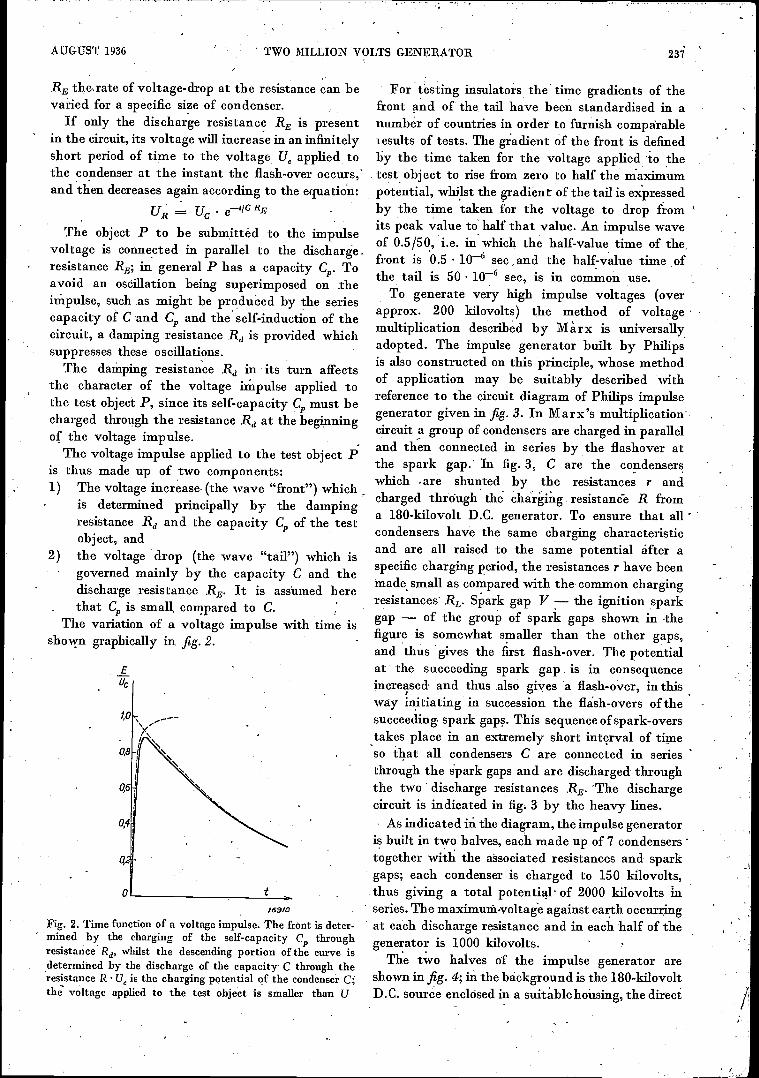
AUGUST 1936 TWO MILLION VOLTS GENERATOR
RE the,rate of voltage -drop at the resistance can bevaried for a specific size of condenser.
If only the discharge resistance RE is presentin the circuit, its voltage will increase in an infinitelyshort period of time to the voltage Ue applied tothe condenser at the instant the flash -over occurs,'and then decreases again according to the equation:
uR uc etIC RE
The object P to be submitted to the impulsevoltage is connected in parallel to the discharge.resistance RE; in general P has a capacity G,. Toavoid an oscillation being superimposed on theimpulse, such as might be produced by the seriescapacity of C and Cr and the self-induction of thecircuit, a damping resistance Rd is provided whichsuppresses these oscillations.
The damping resistance Rd in its turn affectsthe character of the voltage impulse applied tothe test object P, since its self -capacity C, must becharged through the resistance Rd at the beginningof the voltage impulse.
The voltage impulse applied to the test object Pis thus made up of two components:1) The voltage increase (the wave "front") which
is determined principally by the dampingresistance Rd and the capacity Cp of the testobject, and
2) the voltage drop (the wave "tail") which isgoverned mainly by the capacity C and thedischarge resistance RE. It is assumed herethat Cp is small compared to C.
The variation of a voltage impulse with time isshown graphically in fig. 2.
EUc
1,0
0,8
0,6
0,4
/59/0
Fig. 2. Time function of a voltage impulse. The front is deter-mined by the charging of the self -capacity Cp throughresistance Rd, whilst the descending portion of the curve isdetermined by the discharge of the capacity C through theresistance R U is the charging potential of the condenser Cthe voltage applied to the test object is smaller than U
237
For testing insulators the' time gradients of thefront and of the tail have been standardised in anumber of countries in order to furnish comparableresults of tests. The gadient of the front is definedby the time taken for the voltage applied `to thetest object to rise from zero to half the maximumpotential, whilst the gradient of the tail is expressedby the time taken for the voltage to drop fromits peak value to half that value. An impulse waveof 0.5/50, i.e. in which the half -value time of the,front is 0.5 10-6 sec and the half -value time ofthe tail is 50 10-6 sec, is in common use.
To generate very high impulse voltages (overapprox. 200 kilovolts) the method of voltagemultiplication described by Marx is universallyadopted. The impulse generator built by Philipsis also constructed on this principle, whose methodof application may be suitably described withreference to the circuit diagram of Philips impulsegenerator given in fig. 3. In Marx's multiplicationcircuit a group of condensers are charged in paralleland then connected in series by the flashover atthe spark gap. In fig. 3, C are the condenserswhich are shunted by the resistances r andcharged through the charging resistance R froma 180 -kilovolt D.C. generator. To ensure that allcondensers have the same charging characteristicand are all raised to the same potential after aspecific charging period, the resistances r have beenmade small as compared with the common chargingresistances' RL. Spark gap V the ignition sparkgap - of the group of spark gaps shown in thefigure is somewhat smaller than the other gaps,and thus gives the first flash -over. The potentialat the succeeding spark gap is in consequenceincreased and thus also gives a flash -over, in thisway initiating in succession the flash-overs of thesucceeding spark gaps. This sequence of spark-overstakes place in an extremely short interval of timeso that all condensers C are connected in seriesthrough the spark gaps and are discharged throughthe two discharge resistances RE. The dischargecircuit is indicated in fig. 3 by the heavy lines.
As indicated in the diagram, the impulse generatoris built in two halves, each made up of 7 condenserstogether with the associated resistances and sparkgaps; each condenser is charged to 150 kilovolts,thus giving a total potential. of 2000 kilovolts inseries. The maximumvoltage against earth occurringat each discharge resistance and in each half of thegenerator is 1000 kilovolts.
The two halves of the impulse generator areshown in fig. 4; in the background is the 180 -kilovoltD.C. source enclosed in a suitable housing, the direct

238 PHILIPS TECHNICAL REVIEW , Vol. 1, No. 8
Fig. 3. Circuit -diagram of the 2000 kilovolt impulse -voltage generator. All condensers Care charged from the 180 -kilovolt D.C. source through the resistances. RL and r. At theinstant of flash -over at the spark gap V the potential at the other spark gaps is raised,so that a flash -over is obtained at these also. The circuit, then set up, is shown by theheavy line in the diagram; it is seen that all condensers C are diieharged in series through
*the two discharge resistances 'RE. By adopting a construction in two halves and earthingthe centre of the resistances RE, the potential is symmetrical with respect to earth. Thevoltage applied to the test object P, is measured ,by means of the spark gap F.
voltage being furnished by high-tension rectifyingvalves. At floor level between the two pillars arethe spark gaps and on the front of each pillar isthe discharge resistance in the form of a wireresistance oil -immersed in a glass tube. The sparkgaps with 10 cm spheres and the liquid resistances
.actmg as charging resistances are also shown.The small overall height of.the equipment is due'
to the compact design of the condensers. By makingthe outer walls of exceptionally ' strong insulatingmaterial it has been possible to employ the con-densers as supporting members, for the rest of theequipment. The constructional details are the same
as adopted in certain of our X-ray apparatus 1).A new feature as regards impulse voltage generatorsis the large metal electrode at the top, which hasbeen found to serve a useful purpose in preventingflash-overs between the top constructional membersat the instant the voltage impulse is applied. Ifthis electrode is absent, premature discharges toearth occur at the high-tension metal units duringthe application of the voltage impulse, which incertain circumstances may induce the flash -over at apartial potential level, e.g. at the top condenser. The
1) See Philips techn. Rev., 1, 6 and 178, 1936.

AUGUST 1936 TWO MILLION VOLTS GENERATOR 239
field intensities are reduced by the screen electrodeto such an extent that these flash-overs are avoided.
The technical data of the equipment are givenbelow:
The 2 x 7 condensers are rated for 0.01 1/F perunit. At 150 kilovolts per condenser an impulsevoltage of 2000 kilovolts is obtained. The impulseenergy is then approx. 1.5 kilowatts per sec. Thedischarge resistance (oil -immersed metal resistance)is rated for 2 x 70 000 ohms, this giving a half -period value of the wave tail of 70 10-6 sec.
To retain the general simplicity in design of theequipment, means for the common regulation of theintermediate spark gaps have been dispensed with;the spark gaps must be adjusted individually,although if required a common control for thegaps can be provided without appreciable modifi-cation in design.
The overall height of the pillars is 3 m, each pillarhaving a base area of 0.8 1.3 m. Compared withthe performance of the equipment these dimensionsare extremely small.
Fig. 4. Construction of the 2000 -kilovolt impulse -voltage generator. At the rear is theenclosed 180 -kilovolt D.C. source; between the two pillars is the ignition spark gap V.The discharge resistances RE are located on the fronts of the pillars, the condensers beingconstructional members of the two pillars. The upper screen electrodes, which preventpartial flash-overs, are also shown. The sphere gap for measuring the total voltage andthe connected test object are not shown in the picture.

240 PHILIPS TECHNICAL REVIEW
ELECTRICAL FILTERS I
Vacation Course, held at Delft, April 1936.
By BALTH. VAN DER POL and TH. J. WEIJERS.
Summary. In this series of articles (originally forming a vacation course) the theoreticaland practical constructional principles relating to electrical filters are discussed. Thegeneral characteristics of networks compounded of an arbitrary choice of impedancesprovide a starting point; various equivalent networks for any arbitrary filter are alsodealt with. The properties of the simplest types of filter units in common use are deducedand then applied to high-pass, low-pass and band-pass filters. It is shown how, fromthese filter units, a compound filter can be built up to meet specific.requirements. Finally,circuit -closing phenomena with low-pass and high-pass filters are discus.4ed. In this firstarticle an introduction is given to the general char.acteristics of linear networks and filters.
Introduction
Electrical filters are networks with a number ofexternal terminals whose branches are composedof impedanees of which all or some are dependenton the frequency. The most common form of filterhas two primary and two Secondary terminals.A network with four external terminals is calleda four -pole or quadripole; if there are two primaryand two secondary terminals the network is termeda di -dipole. As the impedances are dependent' onthe frequency, the ratio of the secondary currentto the primary current is also dependent on thefrequency. The general purpose of filters is to permit,the free passage with minimum attenuation offrequencies within one or more specific frequencyranges, the frequencies in 'all other ranges beingattenuated. The transmitted frequency range istermed the transmission band and the latter theattenuation band.
The filters in most common use are the following:a) Low-pass filters, which permit those fre-
quencies to pdss with minimum attenuationwhich are below a specific limiting value andattenuate all frequencies above this limit. -
b)High-pass filters, which permit frequenciesto pass with minimum attenuation which areabove a specific' limiting frequency and atte-nuate all frequencies below this limit.
c) Band-pass filters, which permit only fre-quencies to pass with minimum attenuation_which are situated within specific. frequencylimits and suppress ,all frequencies beyond theselimits. .
Between the transmission and attenuation bandsthere is always a transition range; in fact it isfundamentally impossible to obtain a discontinuous(sharply -defined) limit between these two 'bands
Vol. 1,' No. 8
if all frequencies pass through the filter with thesame velocity, such that tIA phase lag is pro-portional to the frequency. For it can be shownmathematically that such a filter would cause asignal to arrive before it has been transmitted,which is naturally impossible.
Electrical filters , find their principal use intelegraphy and telephony as well as in cableand wireless circuits and in television.
The fundamental principles on which the theoryand construction of filters are based, were developedby Lagrange (1736-1813), Heaviside (1893),Campbell and K. W. Wagner (both in 1915)and in subsequent years by Zobel, Carson,Le Corbeiller, Brillouin, David, Cauer, Bode,Kiipfmiiller and others.
The theory of filters may be divided into twosections:Filters with .a sinusoidal e.m.f.;' andFilters operating under the action of an impulseor an abruptly -applied and subsequently -constantvoltage (transient phenomena).
1) Filters with sinusoidal e.m.f.The theory of these filters can be developed in a
variety of ways. In their niost recent analysis thetheory of matrices and groups, as well as complexfunctions, occupies a prominent position. If con-sideration is restricted to the practical design offilters, the application of elementary mathematicalanalysis already permits substantial progress tobe made. The hyperbolic sine and hyperbolic cosinefunctions. are extensively employed, being defined'as follows:
1Binh T =--3
cosh T =
sin j T = 112 (eT 6-.T);
cos j T = 1/2 (eT -T).

AUGUST 1936 , ELECTRICAL FILTERS 241
, and analogous to: cos2T sin2T = 1 we also have:
cosh2T - sinh2T = 1.
2) Behaviour of filters under impulses(transient phenomena).
The study of this subject requires the applicationof the higher branches of ,mathematics, althoughwith the aid of the operational calculus of Heavisidewe can' in many cases reduce the requisite calcu-lations to an elementary form.
Division of Lectures .The subjects to be dealt with have been spread
over 'four lectures as follows:Lecture I (van der Poly: Introduction into the
general characteiistics of linear networks andfilters;
Lectures II & III (Weijers): Application offundamental principles to the practical treatmentof special filters with sinusoidal e.m.f.;
Lecture IV (van der Poly: Switching operationswith low-pass and high-pass filters.
INTRODUCTION INTO THE GENERAL CHARACTERISTICS OF LINEAR NETWORKS AND FILTERS.
Consideration will be restricted to networks whichare:1) Linear, i.e. the components (resistances, self -
inductances, capacitances and mutual induct-ances) are independent of the current orvoltage;
2) Passive, i.e. having no internal source ofenergy;
3) Containing only positive components, exceptmutual inductances, which can also be negative;
4) Invariable, i.e. the characteristics of thecomponents do not vary with time;
5) Free from gyroscopic terms, thus conformingto the reciprocal theorem described below. Thiscondition is always fulfilled under the con-ditions 1-4, if the elements of the filtor arenot coupled with a mechanical system or ifthis coupling is purely electrically.
These networks conform to three fundamentalprinciples:
1) Principle of SuperpositionIf in a circuit an e.m.f. E1 (t) applied to the
branch A produces a current .11(t) in' anotherbranch B, and a subsequent e.m.f. E2(t) in Aproduces a current I2(t) in B, then according tothe principle of superposition, if the sum of theelectromotive forces E1(t) E2 (t) is applied in A,the current obtained in B will be the sum of thecurrent .1 1(t) .12(t), or in othei words; if two forcesact at the same time, the result is the sum of theresults obtained if either of the two forces actalone. '
2) Reciprocity TheoremThe reciprocity theorem states that if an e.m.f.
Ek(t) applied to the k-th branch produces a currentof iki(t) in the l-th branch, then if subsequentlythe same e.m.f. Ek(t) is applied to the l-th branch,the same current /ki(t) as previously obtained in thel-th branch will be obtained in the k-th branch.
3) Conservation of FrequencyThe principle of the conservation of frequency
states that if a sinusoidal e.m.f. with a frequency Vois applied to any branch circuit of the system, thenall other voltages and currents in the system willhave the same frequency vo.
Simplification of Networks
In networks with the above characteristics anode with, n converging branches can always beconverted into a complete n -sided polygon for aspecific frequency, without the Voltages and currentsin any of the other branches being altered. By. a"complete" n-gon is implied that in addition tothe n sides all diagonals are also present. A completen-gon thus has a total of 1/2 n (n - 1) branches.
By a single application of this transformationthe number of nodes in the network is reduced byone; so that by repeated transformation it is possibleto eliminate all the nodes from a network with the.exception of the external terminals. We shalldiscuss here only networks with four externalterminals, so that the network can be reducedto a complete quadrilateral (see fig. 1) made upof 1/2 4 (4 - 1). = 6 elements. The most
Fig. 1. Six impedances forming a complete quadrilateral andto which any arbitrary quadripole can be reduced.

2:12 PHILIPS' TECHNICAL REVIESV Vol. 1, No. B
1I 1>
' ---12-12 3-016
--`,1
CC fa '
. II = rye .1- S12
a 8 -fipl
1 .3 1 3
4°'IMAGE IMPEDANCE" -I
I .;3
Zao
---' ' P riP--,- Ea VAZka ±1---t_,Zbk 4
F.BTh
AZb
I 4 2 4
Zak AL, /=AlZoo Zto k 4
GCIt= I6 +AI2
It = Ilia + 612 .
a5-137=1
.
c A =\/e; I
V zee FEL Ci =1. Z. cosh 7
Zb
p=\11,,zbsinh T
^inh T
13=Zak Zbk\iar
/
in71-y203 Zbo -
6,-.Vri ' 1
" 11, 21)
S=V5Za
co TZao T --L4.--
Zo
Z.1% -12n-----34 Zap. SS,-
/37-ak= T....L
raZbk = 07
7.00= Za coth T
zak=Za tanhr
Zbo,Zb coth T
Zbk=Zb taaar
Zakr.-21----11;01__Li:324a0
r_o_it
St2,2!_=
3
-4r1.43__Ztk
t,,,,, (=kJ
IMAGE IMPEDANCE"3 Za ,\I Ag.
v 7 6
,, Zb=cVi
cosh T ,V.<6
.
Za=Zakr;i:kciZas_..--7a Zb-_,__Zb
4
12-...F 1 e -T
Zb =1Z17-bOilic
tanh AT..
ITERATIVE
1
Kb
IMPEDANCE3
.
Ka -4 -1-01-5 Ka=7000-40)+1/211(Zao-Zbof +4 Zao Zbk kt=3(2(20-ZbirothT+1/211(Za-Z4)2 03(172 T +4 ZaZba -V(.1+5)2T
,c1'
Kb,06(+5P-4 #6 -al Ich=5*ba-Zegta(Zoo-Zbo)2+4 Zap Zbk
cosh r ÷
Kb_-.Y20,-Za)cothT+Y4fa-Zbf coth2T ci-42,a zb
1.1cosh r= v2Arig. +\17a)cashT ,
' t zb V Za/
r-(,-(32d- -
.
cosh r= c_c_t.. 2
2 4
-l_i = e -rIt -2Zak-2-Zbk)
_E-yy-1-
-
f'.V(Rtitut)(Atjac)
__R.+ .1,0Lju.,C
RtituL= arc cosh cc
Ay wC qi arc cosh cc
.
Pt/ tt,L= Z 7
Ai-juic= TT
.
R v., L=V1,)T( arc tanhaA tjtoC,..1 arc tankR
vZ3Zk
z IRi t_A_1V
_lAi:1,X
22 Zy= V '
23....- .614.-
Z3= ±r
Zi- Zacos T-z'Z1,2012- 41/PT:a i-FFC
nhh T
22.40-17/7; ;TV 1-17 1i.4 z2- 4 cosh T -1Zii;sinh r
23, zeV07-e0 ii -Z -Fr:
z,_ /Za Zb-- stnh 7
.1 3
P g1=a=.1
p2= flcx-t
8. /3.
Zak.
pi= Zo sink T
111113= o Zk1-- .
bo Zo
8= . Zbk
cosh T_V'217
p2=Zb stnh T .
t;
.
'1112--1L111-17:Zi.
za, 4, .
coshT_pczo
8= VicTib sink Tp3_ Oak ZbkA, Zo ,
1t 3
1='' a4/ .
52" d5
5/'40-FTV
Zk52- 1717-Zr
r
,L..z toi v 7:
72=Z troth 4:..-,---110-100-
2 52
4., n*
/69

7-"--"7-17-
AUGUST 1936 ELECTRICAL FILTERS 243
..ITERATIVE IMPEDANCE "1
3 R+JuiLI 21 Z2 '
1 3P3
1.1
i 3
-2 &. 4 -( ' (PwC ..
23 PIfp' I
z_VR+JcvL
2 4
b _..-r.r, . .
A-FituC 2. 4. 2. 4
.2 4
Iri.V(R+,,u4m+Juic)
Kaer+ Kb e -r c<=6=coshr'
/3= z stnh r,
tr ,..... +soh rf
.za =1 + --1-., ....3
'
. P-z,z2+:223+2,z,
,
a=l+ -al;. a
fl= P3,
r= 112.5.,L2,-P
of (5_ 52+51kb -f Kb
= 2 Ka Kb sinh r _
_
- 5,
2 gt 52Ka+Kb
2 sinhr '
. 41.= J_
li - 1 +
13 -525,2
Ka+ Kb
4, er+ Ka cf.'
v 11 Pa
a=1+
r -52-51 .a+ Kb .PI
Kb er+Kb e -ro .n.Zap =40=2 coth rt
Zak=.20..-Z tank r,
:
Zoo= 21+23.
Zak- Z122+423+2321
Zoo.,., fl Ntt3) Zoo =434'2(5+5J
Zak=Zbk--. 25,53
4 2sinh rj2Ka_fp k2hr
'
Ri-q+Pi
Zal. P15-Kb cr+Ka e'r
Kb er+Ka er,-Z2 +23
zoo= z2_,z3
Z1 22+2223i-2321zbk-
1+13
zbo_fi OOPS) 511-2
.
2 sinhr
j 2 Ka sinh rR+P2-03
Zbk-= 3-3-, 61-6" Ka er+ Kb er 2,1-23 .
72a- 2p -2
' -- - -
T ..= r' .
.
...., 18,INKCer+Kb e -rig' .., za_VZI+23) 04+423+2320 'Za= P4
P 3 (P2+P3)
Za = 26=Ar
tank : __A
Kb er÷Ka e- 1 . . . . Z2+23 .
. g+ 13)0+1+13)
',-1V(141,\111.6 er+Ka e -r zb4(22+23)(2t 221-2aZa+ZaZt) 7p=/3 P+
Kb er+ Kb e -r 21+23 (13+130+1311)
hT=V7Piit case!' ii,,,e coshr= 1 V(21+23)(22+23)z
cosh r -V11+31AL211-P0G1, ,,,,k
- ' Ifi,Ka= = 2
rr't
If3=N21-22)+1/2\1( Z1+4)2+423 (21+22) Ifc,_ 13(P -)+\/ fa2 (3+13)2+4 11136 (6+6) Kb. Kb= 1r;, 3;
. 'banh _vT,2 - 52
2 (1+11+13)
Ifp=1/2(7rzi)-14q4+22)21-423(4+23)
cosh r= 1 + ka
Hp= /3N-V+VP32(7 +/3)2+ 4 q 13(9+i2 (R+q+13)
.coShr = 1-4213 6,1-1.+ i) .
,2 23
-julL=K r
.
tjwc= rT{
Rticol.2V-garctanhp52
,11-jaC= a tont,
It+j u. i L=612 +2 ;23 arc cosh(1+.ft)
.
A+jwC-cosh (1+ !L)
R +.1 ca L =11\11-_--- arc croh(t4-1)26 +1 p,
A i-juiC=IVEL-7-F8 arc cosh I i÷a)cosh(I+I)421-22,2, Z3 Ti 6 Pi
,,E5, 52 G
Ka -Kb e -r Z1 .Z2 =2 tanh -5L
23= Z
..,
21 - P1P3
,.
21 .22 =5,
-
2 3=(5 -s2)
1 + e -r.
.
Kb -Ka 4-r
1 ? +13 +13
22- lab---1 + e -r -
..
_ Ka+Kb
R+13+1323= fl P2
2sinh I". slab ri,
11+F.1+13
_ Ka Kb( I +e-r) P, .=1 = 2 coth _5.
,
p3=2 sin!, r,
Pi- 2722+2223+2321
- %
-*
. ,
6 =6= 52 -
25, 52P32
!Kb -Ha e -r
Ha IV) +e -r)
22 ,
44+44+4;k, -Kb e -r
\2 Ka/fond, r
.p2
2,
p3_ Z1 Z2tZ2Z3-1.234
Kai -Kb 23' '525t
..
= K tank r2
th- 4:.
5,= Z ianh 4
. = 2 oath .r.2...
5,= z,
S= Z, +2 Z3
ii.--,---- 211 t13
PI .
1694 8

244. PHILIPS TECHNICAL REVIEW Vol. 1, No.' 8
general quadripole is ,thus determined by sixelements.
The quadripoles such as are represented byfilters are, however, of a special type. We are hereonly interested in the voltages between the primarypoles 1 and 2 on the one hand and between thesecondary poles 3 and 4 on the other. Outside ofthe filter there is no electrical connection betweenthe pair of terminals 1 '2 and the pair 3 and4 (fig. 2).
Fig. 2. Di -dipole, a special forth of quadripole, which is definedby only- three impedances, where the four external terminals
2, 3 and 4 are divided into two primaries / and 2 and twosecondaries 3 and 4. Externally to the di -dipole there is noelectrical connection between the primary terminals on theone hand and the secondary terminals on the other.
It may be shown that, owing to these restrictions,applied to the general quadripole and which reducethe latter to a di -dipole, 'only three impedancesare required for defining the characteristics ofthe network.
Various Ways of Defining a Filter by Three Para-meters
The three impedances which are sufficient fordefining a filter can be regarded as distributedin a quadripole in various ways, the differentconfigurations being mutually transformable with-out the external characteristics of the filter beingaltered in any way. If the 'filter is symmetrical,i.e. if the external currents and voltages remainunaltered, when the primary terminals are made thesecondary terminals and the secondary the primary,two impedances will be sufficient for defining thefilter. In the large table on pp. 242 and 243 thethree determinant impedances (for symmetrical'filters, two impedances) are represented in various,ways, together with the conversion formulae fortransformation from one system of variables toanother. In Place of three determinant impedancesthree other mutually independent parameters canalso be used, or also four parameters with one inter-relation.
In the table each filter is defined in succession by:a) the four coefficients of its analytical expression:
V1=aV2-I-/9I2Il = yV2 612
in which the four coefficients a, /3, y and 6are connected by the expression:
a 6 -t3 y = 1b) the prim-ary input impedance Z. with the
secondary terminals open -circuited, the primaryinput .impedance Zak with the secondary ter-minals short circuited, the secondary inputimpedance Zbo with the primary terminalsopen circuited and the secondary input imped-ance Zbk with iimary ectless'; wherethese four4trerminals short-cfreuiteorare inter-related as follows:
Zak/Za. = ZbItiZbo ;
c) the primary image impedance Za, the secondaryimage impedance Zb and the propagation -constant T, being defined as follows: If thesecondary side is terminated in an externalimpedance Z5', then the impedance betweenthe primary terminals is Za;. if the primaryside is terminated in an external impedanceZ01, leaving the secondary terminals open -circuited, then the impedance between thesecondary terminals is Zb. If the values of Z'and Zb' are so chosen that Z = Z' and Zb = Zb' 'then Z and Zb are termed the primary andsecondary image impedances. The propagationconstant is then defined as:
d)
/2 14. _Te
'Zr,the primary iterative impedance K, the second-ary iterative impedance Kb and the propa-gation constant I, being defined .as follows:On shorting the secondary side with an imped-ance Ka the filter when seen from, the primaryside, similarly has the impedance Ka; onshorting the primary side through an impedanceKb, the filter similarly has an impedance Kbas seen from the secondary side. These imped-ances Ka and Kb are termed the primaryand secondary iterative impedances; thepropagation constant P is then defined as:
= e1.1
(this propagation constant is only equal, tothe propagation constant referred to under cin the case of a symmetrical filter);

AUGUST 1936 ELECTRICAL FILTERS 245
e) cable defined by its impedance R jwL ,andits parallel admittance A + jcoC ;
f) a network in the form of a T -with the threeimpedances Z2 and Z3;a network in the form of a TT with the threeimpedances P P, and P3;
h) a symmetrical -lattice network with the twoimpedances Ci and C2; each occurring twice(this circuit corresponds to an ordinary bridgecircuit, fig. 3).
g)
'692/
Fig. 3. Two methods of representing the same di -dipole;a symmetrical lattice network and a bridge circuit.
It should be noted that definitions e) and h)apply only to a symmetrical filter; the other
definitions are based on an unsymmetrical filter; butbecome simplified when applied to a symmetricalfilter. Thus for a symmetrical filter a =- (5; Zak = Zbh;4,0 = Zba; Za= Zb;Ka = Kb; Z, = Z2; .131-= P2.
As already indicated, any arbitrary filter can beregarded as compounded in any one of the waysa), b),,c), d), e), f), g) and h), where e) and h) applyto symmetrical filters only, and in place of afilter, it is thus possible to substitute that networkwhich will be the simplest for the particular caseunder consideration. In principle all networks givenare equivalent and the table enables each methodof representation to be transformed to any other.On transformation to another frequency inde-pendent calculation should in general be carriedout, as. 'impedancps are usually obtained whosefi equency dependence cannot be realised in practice.
The general characteristics found are employedin the soluticin of practical problems relating tothe construction of high-pass, low-pass or band-'pass filters to meet specific requirements, a subjectto be discussed in subsequent lectures. ,

246 PHILIPS TECHNICAL REVIEW Vol. 1, No. 8
THE COMMUNAL AERIAL
By. J. VAN SLOOTEN.
Summary. This article describes the electrical construction and method of operationof the aerial -signal amplifier t'Antennaphil". With this apparatus it is possible, to supplyaerial signals to a large number of receiving sets in a block of flats by using a single aerialonly. Aerial -signal amplification also eliminates interference in reception.
Introduction
In large towns and cities the provision of a goodaerial is usually fraught with serious difficulties,particularly in houses divided up into self-containedflats. As a rule it is not an easy matter to erectOn one and the same roof a large number of separ-ate aerials which would satisfy the requirementsof all listeners. There is als'o the additional difficultythat in some places radio reception is practicallyimpossible owing to interference from electricmotors and other apparatus.
To *surmount these difficulties a communal aerialsystem was evolved some years ago in theseLabOratories and marketed under the name - ofthe "Antennaphil". Briefly, this system operatesin the following manner: An aerial of suitabledimensions and quality is erected at a point whereinterference is limited, e.g. 20 ft. above the roof.Through a specially -screened lead-in, which is madeas short as. possible, the aerial is connected to aso-called aerial -signal amplifier from which theincoming, signals are transmitted to a number ofreceiving sets through -a screened distributingcircuit (lead -covered cable). As a rule up to 50 setscan be connected to an aerial fitted with this formof amplifier. The arrangement can also be employedquite satisfactorily with a smaller number of setswhere reception sufficiently free from interferencecan only be obtained at a distance of severalhundred to a thousand yards. These Laboratorieshave had an aerial of this type in use for severalyears in order to ensure reception free from allinterference. The aerial and the aerial -signalamplifier are located about 200 yards from thelaboratory on a building estate, and the supplycable for the amplifier and the high -frequencydistribution cable from the amplifier are laidunderground.
The amplifier consists essentially of:
a) an electrical filter unit,
b) a number of amplifying valves (high -frequencypentodes) and
c) two output transformers for matching thevalves to the distribution cable.
In addition to the characteristics of the amplifier,those of the high -frequency distributing cable arealso important, and as these closely determine theoperation and design of the amplifier a brief dis-cussion of the cable characteristics will not be outof place here.
The High -Frequency Distributing Cable
For the present purpose the best type of cableto use is a coaxial or concentric high -frequencycable, a diagrammatic Section of which is shown
Fig. 1. Section through a high -frequency cable. a - Radiusof core, 6 and c "- internal and external radius of sheath.'For a specific value of 6/a the attenuation of the cable isa minimum. With a copper core and a lead sheath 6/0 mustfor instance be 5.2.
in fig. 1. The diameter of the core is 2a and theinternal diameter of the sheath 2b, the external 2c.
*or

AUGUST 1936 ' COMMUNAL' AERIAL 247
The intervening space is usually filled with a dielec-tric (paper or rubber), but may also have a partialair space. This insulating medium can be charac-terised by two constants, the dielectric constant'sand the phase difference (5. The tangent of thephase difference is given by the ratio of the effectivecurrent to the capacity current (per unit of length)and with air as dielectric is nearly unity. In cableswith a good quality paper or rubber insulation (5 is.0.01 to 0.025. Over the range of radio wave lengths(5 is practically independent of the frequency. InAddition to the sectional linear dimens.ions of thecable, this phase difference also determines theattenuation sustained by the oscillations duringtheir passage through the cable.
The principal factor governing the practicalefficiency of the cable is the so-called char a ct eris ti cimpedance. A remarkable property of a homo-geneous cable is that its impedance measured atthe input terminals tends towards a specific limitingresistance (the characteristic impedance) when thecable is made infinitely long. If the frequency ismade sufficiently high, this resistance is practicallyindependent of the frequency.
It follows from this property, of an infinitelylong cable that the input impedance of a finitecable will also become equal to the characteristicimpedance if the 'resistance of the load at theoutput terminals is equal to the characteristicimpedance; for in this way the same effect isproduced as is obtained by prolonging the, cablewith an infinite length of equivalent cable. Underthese circumstances no reflection therefore occurs atthe ends and a true progressive wave is produced.This is the result desired, since the reflected wavetravelling in the opposite direction may interferewith the advancing wave and thus generate nodesand antinodes in the voltage, which would provevery disturbing. With this type of disturbance aninadequate signal voltage would be obtained inany receiver connected to a nodal point of thecable. It is apparent from the above considerationsthat the cable must be a straight -through conductorwithout any taps or branches.
When designing the distributing system the firstpoint to be considered is the choice of the optimumcharacteristics of the cable. The characteristicimpedance should be fairly low, e.g. 60 ohms,for the cable is also loaded with the input impedancesof the connected receivers. Hence, by using a cablewith a high characteristic impedance the voltagedistribution through the cable would be subjectto serious interference. Another consideration alsoindicates the need for a low characteristic impedance.
The question must be raised as , to what must bethe core thickness in a cable with a given thicknessof lead sheathing (as determined, for instance, bycost considerations) in order to obtain ,the lowest'possible drop in amplitude per unit length of thecable.
With a lead sheath and a copper core we getfor the ratio of b to a (see fig. 1):
b- = 5.2a (1)
and for this ratio the characteristic impedance issimilarly of the order of 60 ohms 1), independently
, of the absolute value of the diameter.Having determined the value of this ratio, we
can also calculate the lowest absolute values forthese diameters. The attenuation losses in the cablecan be resolved into the copper losses in theinsulation, which are determined, by the ohmicresistances of the core and the sheath, taking intoconsideration the skin effect and the. dielectriclosses in the insulation, which are proportional tothe phase difference already referred to. The latterdamping effect is determined solely by the insulatingmaterial and is independent of a and b.
Analysis of the copper losses gives equation (1);these losses can also be-. reduced as required byincreasing the cross-section of the' cable, but thisis naturally of use only as long as the dielectriclosses do not predominate 2).
A practical example is, for instance, the followingcable" in which the attenuation due to the copperlosses is equal to that due to the dielectric losses ata wave length of 200.m.
2a 2.5 mm, 2b = 13 mm, e= 2.5;= 0.02, Z = 63 ohms.
With a wave length of 200 m this cable producedan overall attenuation of 1 neper, i.e. a trans-mission loss factor of 2.72 per km. With higher
1) The exact formula is:
I,
I,
1/e2(la)
I elwhere 92 and ei are the specific res'stances of the materialsof the sheath and the core. The relationship between thecharacteristic impedance Z, the values a, b and thedielectric constant E of the insulating material. is:
Z = 60 bIn - Ohm_
(2)
If e.g. we put e = 2.5 and take -b from equation (1),we get Z = 63 ohms.
2) For further details and the derivation of equation (la)see Radio-Nieuws, 17, 77, 1934.

248 PHILIPS TECHNICAL REVIEW Vol. 1, No. 8
Fig. 2. General view of the aerial distributing system. a - aerial, b - lead in, c - aerial- _signal amplifier, d - high -frequency distributing cable, e - branch boxes, f - lead,fl - receiving set, h - terminating resistance. .
wave lengths the attenuation diminishes, whilstwith shorter wave lengths it increases; in the lattercase dielectric losses also predominate.
Actually this cable is more than adequate forthe purpose intended. For a receiving system wherethe cable is ,not more than 200 to 300 yards longa much thinner cable could also be employed withstill satisfactory results, and it is then also possibleto use one of the many low -capacity cables, whichin general have a characteristic impedance of 100to 150 ohms, for the screened aerial lead-in.
Fig. 2 gives a general view ,of the receivingsystem, where a is the aerial, b the aerial, lead-infor which a screened low -capacity should be usedfor preference, c is the aerial -signal amplifier, andd the high -frequency 'distributing cable: Thephantom aerials for eliminating the effect of tliecable on the tuning of the. receiver and whichconsist of a 200 p.I.A.F condenser and a 30 -ohm
,
resistance connected in series are accommodated inthe branch boxes e inserted in the cable. Toconnect a branch box to 'a receiver g a flexiblescreened cable f with a low capacity not exceeding40 tA.I.A.F per metre and not more than 3 to 4 yardslong should be used. The earthing terminal of thereceiver is connected directly to the cable sheath'and is not separately earthed. A box with a terminalresistance h is located at the end of the cable,through which the sheath is earthed.
'
The Aerial -Signal Amplifier
A simplified circuit diagram of an aerial -signalamplifier is given in fig. 3. The aerial voltages are
/6906
passed to the grid of an amplifying valve (preferablya tetrode or pentode), the anode of this valve beingconnected to the cable impedance Z through anoutput transformer T. As the valve has a highinternal resistance and the impedance of the cableis low, it is necessary to step down n times through T.
'n:
/6907
Fig. 3. Simplified circuit of an aerial -signal amplifier. Thealternating voltages generated at the resistance R are amplifiedand passed to the distributing cable,Z through a transformer T,which serves for matching the characteristic impedance of thecable to the valve.
Closer investigation indicates, however, that asimple amplifier of this type is unsuitable for trans-mitting 4 wide frequency sweep. The principalreason for this is the limitation sustained in thefrequency as a result of the adverse capacityconnected through the -primary winding. Thisundesirable capacity is principally made up ofthe capacities of the valve and leads and the self -capacity' of the winding.
The explanatory circuit in fig. 4 shows how the voltage E./is produced through the primary winding of the transformer.The valve has been replaced by the current source VeS(S = slope, Vg = grid alternating voltage); Cl representsthe total undesirable capacity, Li is the self-induction ofthe primary winding and o2Z the secondary load resistance

AUGUST 1936 COMMUNAL AERIAL
transformed on to the primary side. The secondary outputvoltage is a times smaller than El.
n2Z
/6905
Fig. 4. Explanatory circuit for the circuit shown in fig. 3.Li - primary self-induction of the output transformer T,C1 - adverse capacity. The current source s Vg takes theplace of the amplified aerial voltage and the impedancen2Z is in place of the transformed load resistance. At verylow frequencies the alternating current is removed throughLi and at very high frequencies through C1. A maximumamplification is obtained at w2 L1 C1 = 1.
It may be seen from fig. 4 that in the absence of C1 and witha sufficiently high self-induction L1 the primary impedanceis determined by n2Z, and would require a high ratio oftransformation n. This also applies when C1 is present andis of sufficiently low rating, or when the circuit L - C1 isin resonance with the incoming wave. But if C1 becomes sogreat that its impedance determines the voltage E1, thehighest cable voltage is obtained with a low ratio of trans-formation n. Thus, C1 determines the ratio which must beemployed and with a higher wave length will be greater than
a
b
d
e
with a short one, as the impedance of C1 increases with thewave length.
The following conclusions may therefore be drawn:
1) The adverse influence of the undesirable capac-ity increases as the wave length is reduced.
2) The smaller the wave range to be amplified,the better can use be made of a resonancebetween the primary capacity C1 and the self-induction L1 for eliminating the adverse effectof C1.
3) It is therefore advantageous not to amplifythe whole wave range through a single amplifierand output transformer but to divide it upand amplify the components separately inparallel amplifying stages, whose output volt-ages can again be combined. In practice thewave range is divided into two components:the broadcasting range with wave lengths from200 to 2000 m and the short-wave range from20 to 55 m.
Fig. 5 gives a view and fig. 6 circuit details ofthe aerial -signal amplifier. On the right are twovalves III and IV in parallel for amplifying thebroadcast wave range, and further to the left twovalves I and II for amplifying the short-wave
e e
Fig. 5. View of the amplifier, open, showing the rectifying valve for the feed circuit (a),the mains connection (b), the mains switch (c), the change -over panel (f) for adjustmentto various mains voltages, the amplifying valves (e), the two output transformers (f and g)and the connections for the aerial and the distributing cable (h and i).
fh
/6902

250 PHILIPS TECHNICAL REVIEW Vol. 1, N.o. 8
-CIRf
(gS2
'ULMR2
C3
S3 C5.
Fig. 6. Circuit cable of the aerial -signal amplifier. The valves I and II amplify the shortwaves and valves III and ly" the broadcast waves. The circuit components C1, C2, C3,Si, S2, S3, RI, R2, R3, constitute the filters for the two wave -length ranges. C8 preventsthe winding of the short, -wave transformer from shorting the broadcast -wave transformer3).
range. The secondary windings of the two outputtransformers are connected to the inpUt terminalsof the cable. The condenser C8 is necessary here toprevent the secondary winding 'of the transformerfor the short-wave range froM shorting the windingof the broadcast -range transformer with which itis in parallel. -
On the left of fig. 6 there are a number of con-densers, coils and resistances, which are insertedbetween the aerial and the grid of the amplifyingvalves. The main purpose of these units is to allowonly those frequencies to iass to the valve gridswhich are to be amplified, for owing to the curvedcharacteristic of the valve (anode current plottedagainst grid volts) it is possible for disturbingoscillations to be generated in the valve with fre-quencies which are the sum or difference of thefrequencies passed to the grid. The risk of thisinterference materialising is considerably reduced if
' unnecessary frequencies are prevented from reachingthe valve grids.
The units inserted between the aerial and the grids constitutea filter system which may be regarded as a combination ofthe simple filters shown in figs: 7 and 8. The 'filter in fig. 7allows low frequencies to pass, and that in fig. 8 high fre-.quencies. The limiting frequency is given in both cases by0)02 L C = I (co = 2.7rf, where f is the frequency). The resist-ances R serve for suppressing the peaks in the neighbourhoodof a frequency of coo. In both figures I is the transmission
3) The latest design also contains two filter circuits, which:suppress interference from any powerful local transmittingstations. To simplify the circuit diagram these have notbeen included here.
/6908
curve with a low resistance R, and 11 the transmission curvefor a high resistance.
The various circuit components in fig. 6 serve the followingpurposes: C2 and S2 prevent wave lengths exceeding 55 in fromreaching the grids of valves I and II. The input capacityof these valve's is in parallel to S2, so that resistance R2 isrequired to suppress any disturbing resonance.
Si and the input capacity of valves 111 and / V prevent.wave lengths of less than 200 m being impressed on the gridsof these valves. Finally, C3 and S3 prevent wave lengths of`over 2000 m reaching the grids of valves 111 and / V.
RI and R3 are damping resistances which are so ratedthat the resonance peak is not entirely suppressed with wavelengths between 200 and 2000 in.
0-f 000\--9.11111.11RP-1--°
' f00
CO
'6909
Fig. 7. A filter which suppresses frequencies above a limitingfrequency of too/2r (low-pass filter).

AUGUST J.936 COMMUNAL AERIAL 251
In fig. 9 the aerial voltage fuinished by theamplifier to a load of a resistance of 50 ohms is
100
0-11-TilliogL
o 4 0
6.10/69/0
Fig. 8. A filter which suppresses frequencies below 'a certainlimiting frequency w0/27r (high-pass filter). The limitingfrequency is deterinined by co02liC = I. Figs. 7 and 8 alsoshow the transmission curves for the two filters: 1 for a lowresistance R and II for a high resistance .R.
plotted against the wave length. The graph showsthe subdivision into a short wave range and abroadcast wave range, which are obtained withresonance peaks partially smoothed by resistances.The resonance peaks 2 and 5, are due to filters ofthe type shown in fig. 8; peak 3 is due to' a filterof the type shown in fig. 7, whilst peaks. 1 and 4correspond to resonance frequencies of the outputtransformers for the short-wave and broadcast -waveranges.
96miimmilm =illiminillMilligIIIMMIIIIIMINIMIIIII
IIIMININIMMIIIIIIII MN IIIIIIIIIIMIIIIIIIINIM
IMINOMINIIIIIMIII MINI MOM11111111111MINIMUM MIMIIIMISIMINIMINIIIIMIIIIIMIli
it
l!tIMIMIIIIMMMIIMEM
NEMIIIMIIIIIIIIIIMINgar.
1111
.i
,11 iI
0 eon y , m
1691/
Fig. 9. Aerial voltage at a resistance of 50 ohms plotted againstthe wavelength. The peaks 2 and 3 are due to the high-passfilter and 3 to a low-pass filtei; I and 4 are the resonancefrequencies of the output transformers.

252 PHILIPS TECHNICAL REVIEW Vol. 1, No. 8
SHORT NOTICES
Sodium lighting of tennis courts
The problem of lighting tennis courts is of specialinterest as two requirements in particular have tobe satisfied which, although also of importance inall illumination problems, yet have a special signi-ficance in this case; these are complete freedom fromglare and high speed of discrimination. Both theserequirements are exceptionally well fulfilled by alighting system employing sodium lamps. As regardsthe danger of glare, experience has shown that thepresence of a source of light in the field of visionis less disturbing with sodium lamps than withother light -sources of an equivalent total candlepower. This fact is obviously due to the com-paratively low luminous density of sodium lamps,although no satisfactory agreement has yet beenobtained in the various attempts to arrive atquantitative determination of the disturbing effectof the glare produced with different types of light.With reference to the second factor, viz, high speedof discrimination, Arndt, Bouma, and Luckieshand Moss established almost simultaneously that- as was recently confirmed by Weigel -the speed of discriminating objects is greaterwith sodium light than with other types of light.The speed of discrimination is defined as the timeduring which an observer must view an objectin order to be able to recognise a specific detailof it with more than fifty per cent certainty. A
Fig. 1. Lighting fixtures of tennis courts with sodium lampsilluminated.
similar task has to be performed by tennis players,who must be able to detect the exact location ofthe ball during its rapid flight.
Modern sodium lamps thus give a very satis-factory solution to the problem of illuminatingtennis courts. As the glare factor is small, the lampscan be given a wide angle of radiation, and as aresult uniform illumination is obtained even whenthe lamps are suspended at a low level, a lowmounting height being desirable in order to obtainintensive illumination at a minimum of cost.
The illumination of tennis courts is particularlyimportant in regions with a tropical climate wherethe heat renders play during the day impossible,and where during the evening, when the atmosphereis cooler, darkness sets in very quickly. Three open-air tennis courts in the Netherlands East Indieswere recently equipped with sodium lamps, viz,one at Banjermasin and two at Sourabaya. Goodresults have been obtained in this case with anarrangement of eight sodium lamps ("Philora" SO,150 watts) in two rows on both sides of the courts.These lamps are situated 20 ft. above the ground.Since little experience is as yet available of thisspecial lighting problem it is possible that a stillbetter arrangement of the lamps may yet beevolved (e.g. more lamps placed closer together).Fig. 1 shows the suspension of the lamps and fig. 2an illuminated tennis court.
Fig. 2. Tennis court with sodium illumination.

AUGUST 1936 253
PRACTICAL APPLICATIONS OF X-RAYS FOR THE EXAMINATION OFMATERIALS VII
By W. G. BURGERS.
The X-ray photographs, obtained with mixedcrystals (solid solutions), which were described inthe previous article in this series, can frequentlybe utilised for the "indirect" detection by radio-graphic means of an admixture in a specific com-pound. In many cases the principal constituent isable, to take up an impurity in "solid solution",in other words the admixed body is not presentas a separate phase, but forms a mixed crystal orsolid solution with the chief substance present. Thisbehaviour is observed, not only with substanceshaving a similar crystal structure, i.e. with theformation of isomorphous crystals, but also withbodies which crystallize in entirely different systemsand even when one of the components is a gas. Themixed crystal then assumes the crystalline formof the predominating component.
As was indicated in the previous article (VI),this phenomenon becomes apparent in X-rayanalysis by a displacement of the interference linesfor the principal component, such displacementbeing exhibited by a greater or lesser angle ofdeviation of the dispersed X-rays from the directionof the incident beam, according as the crystal latticeof the principal component is either "expanded"or "contracted" by the admixture. Although theimpurity is not necessarily detected by this meansand cannot therefore be identified, it is yet possibleto establish that the principal product is not entirelypure, which in many cases is already of greatimportance. The two following examples illustratethese points.
Examination of the radiographs of the series of copper -nickel mixed crystals reproduced in fig. 1 of the previousarticle will show that the inner lines have suffered muchgreater mutual displacement than the outer lines. Thisstriking effect is due to the method used in making thephotographs. The "sensitivity" of the angle of diffractionto a change in the interatomic distances is in fact greatestfor those lines produced by rays, which are deflected to thegreatest extent from the direction of the incident radiation.These lines are situated at the two ends of the film in a"normal" exposure, where the film is so fixed in the camera,that the undeflected X-ray, on leaving the camera, passesthrough a hole in the middle of the film (cf. fig. ia; see alsofig. 2 of article I in this series, Philips techn. Rev. 1, 29 1936).Better results are obtained when the film is placed in thecamera in the manner described by van Ark el 1), so that
1) A. E. van Ark el, Z. Kristallogr. 67, 235, 1928.
the X-ray passes through a hole in the film, not on leavingbut on entering the camera (see Jig. A): With such a
Fig. la. Normal position of film. The "sensitive" lines(2 e slightly smaller than 180 deg.) are situatedat the ends of the film.
b. "Reversed" film. The "sensitive" lines are at themiddle, giving the advantage, that the measurementof the distances of the sensitive lines is less affectedby shrinkage of the film during drying.
reversed" film the sensitive" lines are situated at the middle,which has the advantage, that the accuracy in measuring theinteratomic distances for the sensitive lines is less affectedby the shrinking of the film during drying.
/6899
Fig. 2. "Reversed" X-ray photographs of isomorphouscrystalline preparations.
a) Thorium oxide, ThO,b) Metallic thorium, Th.
Corresponding lines on both diagrams are connected witheach other. It is clearly shown that the inner lines haveundergone much greater mutual displacement than theouter lines.
clearly the marked difference in displacement between theinner and outer lines. The top exposure was obtained withthorium oxide Th02, and the lower one with metallic thoriumthese two bodies being "isomorphous", as regards the mutualarrangement of the thorium atoms, except that the distancebetween the Th atoms is much greater in the oxide than inthe metal.
15. Excessive Tantalum Content of TantalumCarbide 2)
It was stated in example 9 (article V, Philipstechn. Rev. 1, 188, 1936) that in the preparationof carbides of highly refractory metals theisolation of the metal itself sometimes takes place.
2) W. G. Burgers and J. C. M. B a sart, Z. anorg. allg.Chem., 216, 223, 1924.

254 PHILIPS TECHNICAL REVIEW Vol. 1, No. 8
The radiographs of certain filaments of zirconium be converted to carbide and the latter thus obtainedcarbide thus contain, in addition to lines due tothe carbide itself, also those due to metalliczirconium (loc. cit. fig. 1). In these cases the metalhas at least partially become separated in the freestate as an independent phase alongside the carbide.
In making filaments of tantalum carbide thesame phenomenon has been sometimes observed,whilst other wires were obtained which gave apattern of only the carbide lines. These wires, whichappeared identical on examination with the nalu'deye (having a light to golden yellow metallic lustre),could, however, be distinguished when stronglyheated in vacuo, a behaviour which was naturallycarefully observed in view of their possible useas incandescent filaments for lamps: Even atcomparatively low temperatures (about 2000 °C.)the variation in resistance was found to differfrom wire to wire and the bulbs became coveredwith a metallic mirror which differed in thicknessfrom case to case. It was concluded from ("reversed")radiographs of the wires that the diameter of theinner interference line was different for each wire,corresponding to alterations in the interatomicdistance of about 1 per cent. Two exposures illustrat-ing this are shown in figs. 3a and b 3). It appeared
a
/6900
Fig. 3. X-ray photographs of:a) Pure tantalum carbide, Ta Cb) Tantalum carbide containing excess of tantalum in solid
solution.The inner ("sensitive") interference ring has a much smallerdiameter in fig. b) than in fig. a).
very probable that the wires had absorbed in solidsolution different amounts of metallic tantalum inexcess, an assumption which was subsequentlyconfirmed for several wires by chemical (com-bustion) analysis, which gave a molecular com-position corresponding to Ta : C = 6 : 5. By heatingin methane the metallic tantalum in excess could
3) The exposures again show clearly the greater "sensitivity"of the inner lines with respect to the lines further out.
in the pure state. The diameter of the inner inter-ference ring for pure TaC was determined and haspermitted X-ray analysis to be adopted as a routinetesting method in the preparation of this carbide.
16. Hydrogen in Tantalum
Metallic tantalum can be deposited on a strongly -heated core wire 4) by thermal decomposition oftantalum pentachloride, Ta Cl this method closelyresembling the isolation of tungsten from W C16as first achieved by van Arkel 5). The ductilityof the product was found to be by far the bestwhen the Ta Cl, used had first been sublimed invacuo (such treatment making it, moreover, farmore active).
It appeared feasible that this improvement wasdue to the expulsion of absorbed gases from theTa Cl5 during sublimation: If theses gases were stillpresent on the isolation of the tantalum, they couldbe absorbed by the metal and for instance forma solid solution, thus resulting in a reduction inductility.
This assumption was confirmed by X-ray analysis,for small differences in interatomic distances werefound for tantalum wires prepared by differentmeans, a result which could again be deduced fromthe difference in diameter of the inner interferencering (registered on a "reversed" film). Two exposuresso obtained are reproduced in figs. 4a and b, the
a
b
/690
Fig. 4. X-ray photographs of tantalum prepared from tantalumchloride by thermal decomposition a) with and b) withouthydrogen. The greater diameter of the inner interference ringin fig. b) is due to the presence of hydrogen in the metal, whichis thus made less ductile.
former relating to metal deposited from pure Ta C15and the latter to metal obtained by decompo-sition of the chloride in a hydrogen atmosphere.The difference between the diameters of the innerinterference rings (a doublet) is 2 mm, which herecorresponds to a difference in the lattice constantsof approx. 0.2 per cent, the tantalum lattice havingbeen slightly expanded by the absorption of
hydrogen.
4) W. G. Burgers and J. C. M. Basart, Z. anorg. allg.Chem., 216, 223, 1924.
5) A. E. van Arkel, Physica, 3, 76, 1923.

AUGUST 1936
ABSTRACTS OF RECENT SCIENTIFIC PUBLICATIONS OF THEN.V. PHILIPS' GLOEILAMPENFABRIEKEN *)
NO. 1080: A. Bouwers: RontgenapParaten. (In-genieur, 51, E 27-30, March, 1936).
In this paper the author, with the aid of examples,traces how X-ray technology has succeeded inevolving, from the X-ray tube used in experimentalphysics, a perfectly safe electrotechnical equipmentwith a priori calculated characteristics. The authordiscusses the problem of insulating high-tensionequipment, with special. reference to a simplifiedmethod for calculating and providing insulationon high-tension equipment capable of withstandinga uniform stress at a specific field strength, theproduction of high outputs for short periods, andthe generation of very high tensions of the orderof several million volts. A series of demonstrationswere given, including 'a small complete X-rayequipment weighing only 31/2 kg and high-tensiongenerators for a million volts direct voltage andimpulse voltages of 2 million volts.
No. 1081: R. Vermeul en: Geluidsfilm-apparaten(Ingenieur, 51, E 30-34, March, 1936).
In the Philips -Miller method, sound films areproduced .by mechanical means in the same wayas gramophone records, whilst the sound track isreproduced by optical means similar to the methodemployed with the photographically -registeredsound film. . ,
As.a series of articles on this subject is appearingin this journal (Philips tech. Rev., 1, 107, 135, 211and 231, 1936), a fuller abstract of this paper willnot be given here.
. .
No. 1:082: T J. van der Mark: Een experimenteele' televisiezender en -ontvanger (Ingenieur,51, E 37-40, March, 1936).
This paper is almost identical with a paper o1the same title contributed by the author to thefirst number of this journal (cf. Philips_ techn. Rev.,1, 161936).
No. 1083: M. J. Druyvesteyn: Electron emis-sion of the cathode of an arc (Nature,137, 580, Apr. 1936). '
In carbon and tungsten arcs electron emissionis in general due to the high temperature of the
*) A sufficient number of reprints for purposes of distributionis not available of those articles marked with an asterik (*).Reprints of other papers may be obtained on applicationfrom Philips'. Laboratory, Kastanjelaan, = Eindhoven,Holland.
255
cathode. In the case of the mercury arc it is assumedthat electron emission of the cold cathode is dueto the powerful electric field produced in front ofthe cathode by those positive ions which traveltowards this electrode. In addition the authorassumes also a third mechanism for electron emis-sion from the 'cathode. According to this hypothesisthe cathode is coated, at least partially, with a thinlayer of an insulating substance. The positive ionswhich accumulate on this layer can generate sucha powerful field that the metal emits electronsthrough .the insulating layer. These electronstraverse at great speed the space chargé of thepositive ions, thus having little opportunity torecombine with them. The greater part of thecathode drop is obtained at the insulating layer.
No.' 1084: J. A. M. van Liempt: Die Dampf-drucke des Caesiums (Rec. Tray. chim.Pays -Bas; 55, 157-160; March, 1936).
On the basis of previous investigations (cf.Abstract No. 1051) the author deduces a forniulaexpressing the vapour pressure of caesium as afunction of the temperature, which is valid for'temperatUres, betWeen- 300 and' 1000` deg;:.IC. Themost probable sublimatioeuryi is ziven fortemperatures between 270 and 300 deg.' K:
No. 1085i :J. L. ,5no ek:. Sur. une 'expe-rience de magnetostriction(PIiysiea, 3,20.5-206, Apr.; 1936).
The reversible torslop. Phenomenwhitli'acCOrd-ing.to Perrier are' exhibited by a. nickel wire' afterspecial pre-treatnicnt when temperature changesare-
produced in the neighbourhood of the' :Curiepoint, are no longer observed when the wire hasbeen corroded by hydrogen chloride or whenoxidation during pre-treatment is prevented.According to the author these phenomena mustbe regarded as due to the oxide layer and not to reversible changes in texture as assumed byPerrier.
No. 1086: W. Elenb a a s: Der Einfluss des Ziind-gases auf die Quecksilber-Hochdruck-entladung (Physica, 3, 219-236, Apr.,1936).
By measuring the reduction in radiation theauthor has determined the additional loss in energyper cm of tube length in a high-pressure discharge

256 PHILIPS TECHNICAL REVIEW' Vol. 1, No. 8
through mercury vapour due to the addition ofrare gases. This increased loss was found to bepractically independent of the energy input percm of tube length, and could be calculated fromthe increase in thermal 'conductivity. On theassumption, that in pure mercury the heat dissi-pated per cm of tube length is 10 watts, themeasurements could be described with the aid ofa formula due to En s k o g'for the thermal conduc-tivity of a gas mixture. In a previous paper (Physica,2, 757, 1935) the author arrived at an energy lossof 9 watts per cm from the relationship between thevoltage gradient and the energy input. If theadditional losses due to th_e rare gases introducedare also taken into consideration, the influence ofthe rare gases on, the gradient can be calculatedby a theoretical method given previously. -
No. 1087: J. R. J. van Dongen and J. G. C.St egwee: De beteekenis van de schijf-proef als verkorte standtijdproef (Me-taalbewerking, 3, 1-6 and 49-56, March
' and Apr., 1936).
As a number of articles dealing with this subjecthave already appeared in this Review (Phil. techn.Rev., 1, 183 and 200, 1936) a full abstract of thispaper is superfluous. '
No. 1088: K. P osthumus: Richtantennes metidentiek riehtingsdiagram, maar onge-lijke stroomverdeeling (aequivalenterantennes). (T. Ned... Rad. Genoot., 7,115-139, Apr., 1936).
The author points out that the directionaldistribution of an aerial made up of a numberof similar components situated in a straight lineat" uniform intervals and having an arbitrarycurrent distribution, can in general also be obtainedwith several other forms of aerial and a differentcurrent distribution. In the aggregate there are 2n4equivalent aerials from n components. It is shownhow these equivalent aerials can be deduced fromthe data for an arbitrary aerial. In conclusion theauthor points out that the more common aerialsin use have no equivalent aerial.
No. 1089: J. H. de Boer, W. G. Burgers andJ. D. Fast : The transition of hexag-onal a -titanium into regular /3 -titan-ium at a high temperature (Proc. kon.Akad. Wet. Amsterdam, 39, 515-519,Apr., 1936).
In isolating zirconium by thermal decomposition'of ZrJ4 the metal is -deposited in a form with regularsymmetry (fl -modification), whilst at ordinary tein-
perature it is obtained with hexagonal symmetry(a -modification). Titanium is isomorphous withzirconium and at high temperatures is depositedtogether with zirconium in the form of mixedcrystals. It thus appeared that titanium alsoWould pass over into a regular /3 -modification athigh temperatures; this was in fact found to bethe case from both resistance curves and X-rayphotographs. The transition temperature was 882deg. C and thus differs little from that for zirconium(862 deg. C): Also, as with zirconium, (see AbstractNo. 1095) a well-defined transition temperature isonly found when the metal contains no oxygen ornitrogen.
No. 1090: J. A. M. van Liempt .and J. A.' deVrien d: Das Flimmern von Gliih-lampen bei Wechselstrom (Z. Phys.,100, 263-266, Apr., 1936).
The flickering of various types of electric lampswhen run on a low -frequency alternating currentsupply was investigated with the aid of a cathoderay tube and a caesium photo -electric cell. At anequivalent wattage spiral filament vacuum lampsshowed the least flickering, being followed bystraight -filament vacuum lamps and gas -filledcoiled -coil lamps; the greatest comparative flicker-ing was obtained with gasfilled single -coil lamps.
No. 1091: B alt h. van der P ol: Trillingen (Ned.T. Natuurk., 3, 65-84 and 97-108, Apr.,1936).
A translation of the paper read in English,abstracted under No. 1077.
No. 1092: H. Ziegler : Shot effect of secondaryemission. II. (Physica, 3, 307-316, May,1936):
The coefficient of secondary emission and thevariation in secondary current are governed bythe energy of the primary electrons and by thenature of the electrode bombarded. In continuationof a previous paper (cf. Abstract No. 1066) theauthor examines the multiple electronic chargescomposing the current impulse. The quotient ofthe coefficient of secondary emission and of thecoefficient of secondary current fluctuations is ameasure of the proportion of effective primaryelectrons and of the quality of the amplificationdue to secondary emission in respect of fluctuationsin operating conditions. These phenomena arestudied for a nickel plate with an activated bariumand strontium surface in relationship to the velocityof the primary electrons.

VOL. 1 No. 9 SEPTEMBER 1936
Philips Technical ReviewDEALING WITH TECHNICAL PROBLEMS
RELATING TO THE PRODUCTS, PROCESSES AND INVESTIGATIONS OFN.V. PHILIPS' GLOEILAMPENFABRIEKEN
EDITED BY THE RESEARCH LABORATORY OF N.V. PHILIPS' GLOEILAMPENFABRIEKEN, EINDHOVEN, HOLLAND
PROPERTIES AND APPLICATIONS OF ARTIFICIAL RESIN PRODUCTS
By R. HOUWINK.
Summary. The chemical nature of artificial resins is briefly outlined with the principleson which their manufacture is based. As artificial resins are per se electrical insulatingmaterials, this property is compared with that for other insulators; the differences between"Philite" and other insulators are also referred to. Various applications of "Philite" resinsare then enumerated and discussed, followed by reference to products with special pro-perties designed to meet the specific requirements of the consumer.
Introduction
The progressive development and expansion ofthe electrical industry has led to an increasingdemand for cheaper and better raw materials.
demand has not by any means been metis shown by the call for materials with low dielectriclosses (low values of tan 6), which during recentyears has become very heavy in view of develop-ments in short-wave technology. The demand is notmerely for an insulating material per se, for thematerial required has also to meet a host of otherrequirements. For example a material, such asmica, which has an exceptional suitability formaking certain articles is yet frequently founduseless in mass production as soon as it becomesa question of making units of complicated shapeby an inexpensive process and which have to bewithin close dimensional tolerances. It may benoted that these requirements present insulatingtechnology with entirely new problems, especiallyas the consumer is not merely concerned with theinsulating properties and the mechanical strength,but frequently makes a point of specifying apleasing appearance, which can only be obtainedby very complex and highly perfected finishingprocesses.
In this article we will show that one of the chiefreasons why "Philite", an artificial resin, whichcan be readily shaped by hot pressing, has foundextensive applications is mainly because itcan satisfy a host of practical require-ments at one and the sametime. Fig. 1 shows
a selection of "Philite" products, and brings out thewide variety of objects into which this materialcan be moulded and for which it can be utilised.
11101110-014,6gzti.
Fig. 1. Various "Philite" products for technical uses.
Basis of Manufacture of Artificial Resin
Even twenty years ago resinified products ob,tained by chemical reaction were disposed of asuseless waste. At the present time the exactreverse is the case, and in a large number of in-dustrial laboratories systematic search is pro-ceeding for still further artificial resins. Of thegreat variety of artificial resins which have beenevolved in recent years, consideration will be

258 ' PHILIPS TECHNICAL REVIEW Vol. 1, No.. 9
limited ,here to the phenol -formaldehyde resins,since these form important constituents of varioustypes of Philite materials. It would lead too farto discuss in detail the chemistry of these resins,although an attempt will be made with the aidof fig. 2 to explain the fundamental principles onwhich the formation of such a resin is based. If
OH'
CH2 0 -->
OH
HOH2C-
OH
OH
artificial resin filling every corner of the matrixor mould. If the body is kept at this high temper-ature for a few minutes longer the hardeningprocess already referred to takes place, with theresult that the mass hardens in the mouldand can therefore be removed from the warmmould without the latter having to be cooled.
- CH2- -CHr-OH
-7- CH2-
CH2
- CH2- - CH2-
OH
OH
CH2
OH
OH
- CH2-
CH2OH
OH
OH
Fig. 2. Foimation of phenol -formaldehyde resin. This method of representation is purelydiagrammatic. The benzene nuclei must be regarded as arranged specially and linkedto one another in some sort of haphazard arrangement, without giving a "pattern"as indicated in this figure.
phenol and formaldehyde are caused to interactat a high temperature, then as shown in fig. 2, themolecules of these bodies combine to form a reactionproduct which in the figure is denoted by the word"resin". It is seen that by condensation a very largemolecule is produced, and the assumption is justi-fied that a pressed product of artificial resin (apartfrom fillers, which for various reasons must beadded) consists of a single large molecule. Thisgradual growth to a so-called macro -moleculeis the basis of manufacture of "Philite" materials.If we remember that the initial materials are fluid(or at least solids with low melting points) andthe final product is a hard mass resembling ebonitein appearance, it is evident that in the course of thefinishing process considerable changes must havetaken' place. In practice it may be observed thatthe transition to the solid finished product takesplace very gradually. At first the phenol andformaldehyde form a resin -like viscous fluid, whichon further, heating gradually hardens to a consis-tency comparable to that of asphalt, finally beingconverted into a very hard and infusible endproduct. The essential factor here is the formationof an asphaltic intermediate product, for in thisstage the mass can be readily liquified in heatedmatrices (150 °C.) under hydraulic pressure, the
The moulding process in the case of artificialresins is thus fundamentally different from thatemployed with' metals, such as cast iron, which ismolten and then poured'into a cold mouldin which it is allowed to cool. The raw materialfor "Philite" is introduced into a hot mould inwhich it hardens as a result of chemical reactionspecifically promoted by the application of a hightemperature.
To make this important characteristic still moreclear, compare the moulding process employedwith that which must be used for producing mouldedarticles from a substance, such as asphalt.
Asphalt can 'also be liquified by placing into a hotmould and applying a pressure, although thereis here no chemical reaction which results in ,ahardening process taking place. Hence to removethe shaped asphaltic article . from the mould,the latter must be cooled and again reheated beforepressing of the succeeding article can commence.With artificial resin this is naturally unnecessary,thus considerably accelerating the process of manu-facture. But, as in most cases this advantage is notobtained without overcoming certain difficulties,since to obtain a satisfactory shape very highpressures are required of the order of 300 kg/sq cm.The matrices thus have to sustain very high stresses

SEPTEMBER 1936 ARTIFICIAL 'RESIN PRODUCTS 259
and for this reason are usually fairly expensiVe.Fig: 3 shows the variations in certain properties
of the artificial resin with time during the pressingprocess. It is seen -that the tensile strength, as wellas the stability to heat, increases considerably.This is readily accounted for by a further glance atthe reaction product showh in fig. 2 and when it isremembered that the various chemical bonds inthis molecule have a high energy value (100 to200 kilo-cals per gr. equivalent). The significanceof this is that a considerable amount of energyhas to be absorbed either in the form of mechanicalor thermal energy to split these bOnds again,
- thus accounting for the mechanical and thermalstability.
' kgcm -2400-
T
300
200
100
T
-1150
w
J75
4 12 20 28 min / 7/5.5
Fig. 3. Increase in the, tensile strength T and the stabilityto heat'W of an artificial resin with increasing duration ofpressing.
In this brief' survey we have limited ourselvesmerely to the artificial resin constituent and havemade no mention of the fillers in "Philite",since a discussion of these latter does not enterinto the scope of the present article. In this con-nection it may, however, be mentioned that thesefillers have a marked effect on both the electricaland the mechanical properties of the finishedmaterial, such that by a rational combination ofvarious types of artificial resins and differentfillers a very varied range of products can beobtained. This is indeed one of the reasons why"Philite", as already indicated, can frequentlybe very easily adapted to meet specific require-ments.
Comparison with other Insulating Materials
It has already. been pointed out that "Philite"is able to satisfy simultaneously a number ofdifferent requirements and just for this reasonit is frequently better than other insulating ma-terials. To obtain a closer insight into this com-parison the principal requirements generally deter-mining the choice of an insulating material havebeen collated in Table I. This summary is, ofcourse, not complete since in the first place acomparison is limited to merely some of the prin-cipal properties. Other `properties> entering intoquestion will be indicated later, as well as theposition of "Philite" .in respect of these.
The most important property of interest ininsulating materials, the disruptive strength, hasin the case' of Philite S the not too high value ofapprox. 8 kV per mm. For ordinary low -voltageapplications this disruptive strength is 'howeverquite adequate, the difference as compared withthe higher values given for the three other materialsbeing of no special moment. In fact where'for high -
Table I. Comparison of the Properties of Different Insulating Materials
Tensilestrength
Impactvalue
Stable up totemperatures of Disrup-
tivestrength
Specificgravity
Toleran-ces
Ease ofsurface
treatment-
Longperiods
Shortperiods
in kgcm -2
in kgcm -2'.°C °Cin kVmm -1 r cm3'g / Vo
"Philite" moulding material (Type S) 350 7 140 160 8* 1.35 0.2 . Good
"Philite" sheet material (Philitax) 750 30 140 150 25 1.35 -- Good
Porcelain 300 about1000 about1000 30 2.5 1 - Bad
Cellulose * derivatives (Philite A) 300 50 ' 50 50 50 10 1.3-1.6 Very good
Ebonite 400 10 60 60 10 1.1-1.7 Very good
*) Other types of "Philite" have a higher disruptive strength, up to 30 kV/min.

260 PHILIPS TECHNICAL REVIEW Vol. 1, No. 9
tension purposes, a greater value is desirable thiscan also be met as shown in Table II.
With the aid of Table I let us compare the otherprincipal properties of other insulating materialswith those of "Philite" S. Consider first themechanical strength as expressed by thetensile strength and the impact value; it is seen thatporcelain has a very low impact value of 2 kgcmper sqcm, the wellknown fragility of porcelainmaking it in fact quite unsuitable for many pur-poses. Again as regards stability to heat it isobserved that just those bodies, such as cellulosederivatives and ebonite, which have quite satis-factory mechanical values, give low values for thisproperty, mainly because the maximum tem-perature they can sustain is below 100 °C., a
temperature level which is of very great importancein technology. In this respect porcelain naturallyoffers a quite unmistakable advantage, whichorganic bodies, such as the artificial resins, canperhaps never hope to equal. This range of hightemperatures will, it appears, therefore remainthe preserve of the inorganic substances; but theapplications at which such a high temperaturelevel is not required are so numerous that a verywide field still remains for the organic insulators.And just in these applications the various kindsof "Philite" can prove of inestimable value, sincee.g. specific temperature requirements in thetropics can be very readily met, even if an extraalthough not excessive amount of heat is evolvedin the electrical apparatus itself.
As regards the dimensional toleranceswhich can be obtained in the products, a factorfrequently of paramount importance, it is wellknown that in mass production the choice of amaterial is often determined by the toleranceswithin which a moulded product can be made.This is another reason why very often porcelainis rejected in favour of "Philite" S with its fivefoldsmaller tolerance of approx. 1 per cent., particularlyas porcelain, as indicated in the last column, isvery difficult to work, so that any deviations indimensions are difficult to correct.
On the whole the principal advantages of"Philite" over porcelain are its greater impactstrength and its greater accuracy in workmanship.Other advantages are its low specific gravity, itspleasing appearance and the wide range of coloursin which it can be made. "Philite" is of the samecolour throughout and is not merely covered witha thin varnish which can be readily damaged.
For outdoor use and under conditions in whichtemperatures exceeding 150 °C. may occur, pro-
celain is naturally to be preferred to "Philite".Comparing "Philite" S with cellulose derivatives
and ebonite, the very low stability to heat of thetwo latter is the chief reason for serious objectionbeing frequently raised against their use. It is thusseen that each of the insulating materials listedpossesses at least one important property whichdoes not compare with that of "Philite" S.
In addition to its suitability for making allstandard moulded products, "Philite" can alsobe employed for making special compound productsin which metal or other parts are pressed into thematerial. Fig. 4 shows a radiograph of a moulding
Fig. 4. Radiograph of a moulded product made of "Philite"into which metal parts have been pressed (shown white in thepicture).
where the metal component has been completelyembedded in the "Philite". Fig. 5 shows diagram-matically how such a metal part, here a threadednut M, is pressed into the "Philite". The nut isplaced on the pin P of the opened matrix 0, which isthen filled with the powdered raw material (Ph)(Fig. 5b). During pressing the mass does not fillall the cavities in the matrix but also flows roundthe metal parts (fig. 5c). Fig. 5d shows how the

SEPTEMBER, 1936 ARTIFICIAL RESIN PRODUCTS 261
"Philite" (Ph) after hardening in the matrix hascompletely surrounded the brass nut M, holdingit firmly. Here again it is possible to work to narrowtoleranCes, for the position of the brass nut isdetermined entirely by the pin P, which is attached
a
above, the latter being regarded as 'a standard ofcomparison.
It is evident that in view of the wide varietyof demands which technology makes as regardsan insulating material it is practically impossible
Ph P M Ph
Fig. 5. Manufacturing process for pressing in a brass nut M into "Philite" Ph whichis moulded by pressing in a lower matrix 0 and an upper matrix B.
a) Matrix open. -
b) Inserting the brass nut M and filling with raw mixture.c) Closing the matrix.d) Finished product with embedded nut.
to a solid part 0 of the matrix: This method of.em-bedding metal parts is much.simpler than the pro-cess employed in which holes are first drilled inthe moulded article and the metal part" thensecured by putty or. screwed in.
Special Kinds of "Philite'.'
In the following; brief reference will be made toseveral variaties of "Philite", each of which differsin some particular or othr from "Philite" S referred
M171.57
to find a single substance' which will satisfy everysingle requirement. For -this reason a large range' `Xof special types of "Philite"-have been evolved andare employed for various4roducts. Table II givesa survey of a selecticin'of these varieties and alsoincludes, to facilitate comparison, the corresponding ,,
properties of the staiadid "Philite" S. For the -;k4other kinds of "Philite", figures' are only given ,iot:fwhere the relevant properties differ appreciablyfrom those of "Philite" S.
Tabel II. SqUe of the Principal Properties of Special "Philite" Products *)
- .
Tensilestrength
s - ,Impactvalue
.Stable.up totemperatures
. of '(long period)
-
. Disruptivecapacity,
Tan 6 in 10-4at 200 m(L5 106
cycles)Other characteristics
in kg cm -2 in kg cra cm -2 in °C. in kV mm -1
- . . .
"Philite" S 350 7 140 8 500 , See Table I."Philite" I - - 180 1 tot 5 - For high temperatures.High-tension "Philite" . . . - - 30 High tension material for
indoor situations.High -frequency "Philite" P
.
- - 60 20 2 tot 5 20 000 per matrix andper week; not stable toheat.
High -frequency "Philite" 160(in various kinds)
.
.
Between 200and 300, ac-cording to
kind
- 180 . 30 55 General high -frequencyuse.
,
Flaked "Philite" - 10-15 - about 1 - High impact strength."Transphilite" - - - Transparent.Acidproof "Philite" . . . .
-
- - - -. Inter Olin, unattacked bystrong HC1, 30 per centsulphuric acid and HF.
*) For the sake of simplicity only those values are given for each material which differ considerably from the correspondingvalues for "Philite" S: On application the exact values for the properties of each specific material be gladly supplied.

262 PHILIPS TECHNICAL REVIEW Vol. 1, No. 9
The first requirement specified by users ofartificial resins is their ability to withstandhigh temperatures. It is obvious that inthe case of an organic body, such as an artificialresin, the same high stability cannot be attainedas with, for instance, porcelain. Nevertheless asatisfactory stability to prolonged heating up to180 °C. can be attained as indicated for "Philite I"in Table II, and which is quite satisfactory for alarge number of technical applications.
The very frequent demand for a material witha very high electrical disruptive value is met byHigh -Tension Philite which has a disruptivestrength of 30 kV per mm, a value roughly the sameas that for porcelain. Although the use of thismaterial is limited to indoor locations, it yet offersmany advantages over porcelain in view of itshigh mechanical stability and the low dimensionaltolerances to which it can be worked, as well asthe ease with which metal parts can be pressedinto it, so much so that it has already found veryextensive use.
Two types of high -frequency "Philite" have beenevolved to meet the increased demand for materialswith low dielectric losses. High -frequency Philite Pwith a value of tan a = 2 to 5 10-4 offers excep-tional advantages in this respect, and enables valuesto be obtained which are nearly equal to the bestother materials in this class, such as mica andquartz, but which are not susceptible to moulding.On the other hand, this material has the dis-advantage that its stability to heating is low, viz.,about 60 ° C. To overcome this difficulty High -Frequency Philite 160 was evolved which can beproduced with different tensile values, and similarlyto "Philite I" can withstand heating to a temperatureof 180 °C. Although this advantage has been gainedto a certain extent at the expense of the phasedifference, yet tan 6 = 55 104 as compared with"Philite S" (tan 6 = 500 10-4) is so low that Philite160 still has many practical applications.
The mechanical strength will naturally al-ways remain an important consideration, especiallyas "Philite" has in recent years become extensivelyemployed in directions other than those for whichit was originally intended, viz., as an insulatingmaterial, and in these supplementary applicationsproperties entirely foreign to good insulation havebeen required. The impact value of 10 to 15 kg -cmper sq cm of "Flaked Philite" closely approachesthat of various kinds of wood, and componentsmade of this material thus possess very highmechanical values. Whilst the insulation propertieshave become slightly reduced, the final product
is still an insulating material with exceptionalimpact strength.
"Transphilite" is a material which is made witha variety of transparent colours and is used forcertain lighting fittings.
A special "Philite" product which must be men-tioned is the acid -proof variety of "Philite" whichhas been evolved for use in chemical works, beingpractically unattacked by various concentratedacids. It is interesting to note that contrary toglass this product is not attacked by hydrofluoricacid, and in view of this property it is frequentlyemployed in place of glass.
Flat sheets of "Philite"
Up to the present reference has been limited toartificial resins which could be moulded to anydesirable shape. In addition there is a series ofartificial resins which are only suitable for manu-facturing fl at sheets which can be easily cutwith the saw. Sheet "Philite" is supplied in variouskinds, distinguished for exceptional mechanicalproperties, in this respect being comparable towood.
"P hilit a x", whose principal properties areenumerated in Table I, is one of the best materialsfor making insulating sheets. In small thicknesses(e.g. 1.5 mm) it can be easily cold stamped, aswell as hot stamped up .to a thickness of 7 mm.In this way simple mass -production articles canbe produced from it as shown in fig. 6, and similar
Fig. 6. Sfamping of articles from "Philitax" sheet material.
to stamped metal plates and sheets. It is not onlyextensively used in the construction of switch-boards, but also for interior components in a largerange of electrical apparatus since owing to theease with which it can be worked it combinescheapness with desirable mechanical and electricalproperties, without requiring expensive matrices.

SEPTEMBER 1936 ARTIFICIAL RESIN PRODUCTS 263
"P hil it ex t" meets the need for a very highimpact value, which in the case of this materialis 50 kg cm cm -2. Electrically, this material is not
Fig. 7. Silent gears made of "Philitext".
quite comparable to "Philitax" whose electricalcharacteristics are high; it has become widelyadopted since it is suitable for manufacturingbearings which can be water lubricated, as well
as for making silent gear wheels, a selection ofwhich is illustrated in fig. 7. In these directionsin particular "Philitext" offers a number of stillfurther potentialities. It should be mentioned inthis connection that the friction of bearing materialsmade with artificial resin as a base is roughlycomparable to that of good bearing metals (co-efficient of friction 0.1). In addition artificialresins have the advantage of being unattacked byacids and alkalies, permitting lubrication withwater and offering a long life.
This brief outline of the characteristics andproperties of the "Philite" range of artificial resinswill suffice to indicate to what extent the variedrequirements of consumers can be met. Techno-logical advances, however, continue to be madeand it may be confidently expected that in thecourse of the next few years further additionswill be made to the comprehensive list of existing"Philite" products and which will in their turnmeet other specific requirements.

264 PHILIPS TECHNICAL REVIEW Vol. 1, No. 9
IMPROVEMENTS IN RADIO RECEIVERS
By C. J. VAN LOON.
Summary. Two important improvements in radio receivers, viz., touch tuning and loW-frequency counter -coupling, are discussed in detail.
In touch tuning sharp tuning is indicated by the turning of the tuning knob suddenlybecoming tiffer; in the circuit employed a braking magnet which brakes the tuning -knobshaft is magnetised on sharp tuning. This device has been supplemented by an arrangementwhich by mechanical means keeps the set perfectly silent as long as no station has beensharply tuned in.
With low -free Uency counter -coupling the distortion occurring in low -frequency ampli-fication is reduced to a small fraction of its value in the absence of counter -coupling,the frequency relationship of amplification being favourably influenced at the same time.
Introduction
The most important characteristics of radioreceivers are unquestionably their purity of repro-duction, their selectivity and their sensitivity. Inthe course of the technical development of receivingsets the quality of reproduction has been improvedin various directions, thus the acoustic reproductionof the loudspeaker, which during the first fewyears of broadcasting was limited to a comparativelynarrow range of audio -frequencies, has steadilybeen improved upon such that a range of forinstance 40 to 10 000 cycles/sec. can now be re-produced with satisfactofy uniformity. Further-more, the technical design and construction ofthe 'various 'amplifying stages in a receiver and theoutputs of the amplifying and output valves havebeen raised, to a high stage of development, theseadvances being naturally also to the markedadvantage of purity of reproduction.
Controllable Band Width
Similar far-reaching improvements have alsobeen achieved in regard to the selectivity of sets,such refinement having become indispensable underpresent-day conditions of broadcasting with power=ful transmitters utilising frequencies which areextremely to those employed by weak stations.On the other hand, however, a very high selectivitycannot be coupled with the requisite purity ofreproduction. A small resonance curve as shownin fig. la results in the side bands of the incomingsignal being daniped; so that high modulationfrequencies are far too weak and reproductionsounds heavy or ."fiat". An improvement is ob-tained by making the. resonance curve less sharp(see fig. lb); When as large as possible a portionof the side bands is transmitted nndamped. Furtherinvestigations in this direction' have led to theso-called "controllable band width" which is used
to an increasing extent insuperheterodyne receivers.By adjustment of the coupling between the cir-cuits in the intermediate frequency section, the
10
-0,6
0,4
0,2
-10 -8 -6 -4 -2 +10/7/40
Fig. 1. Resonance curves, with intensity plotted as a functionof the detuning in kilocycles.a) Small resonance curve; the higher modulation frequencies
are reproduced much too weakly.b) Smoother resonance curve: a greater part of the side bands '
is transmitted undamped and the selectivity is lower. 'c) Example of a resonance curve as obtained with controllable
band width on adjustmant to "wide".
0 +2 +4 +6 +8
resonance curve can be made narrower (as shownin fig. lb) or wider (as in fig. lc) just as required.A wide transmission band is employed where a highselectivity is not required, since the transmittertuned in is powerful or there is no interference fromadjoining stations; the high audio -frequencies arethen not weakened so that reproduction is of anexceptionally high quality. Where a high selec-tivity is required under the conditions ruling, anarrower transmission band is chosen, which

SEPTEMBER 1936 IMPROVEMENTS IN RADIO RECEIVERS 265
however unavoidably leads to a loss of the highnotes.
Automatic Volume Control
An improvement which has been incorporatedin a large number of radio -receiving sets forseveral years is the automatic control of volume,consisting in producing an automatic decrease inthe amplification of a set as the signal at thedetector becomes more powerful. The markeddifferences between the input signal voltages(a, medium -strength signal, for instance, gives0.1 millivolt in the aerial, and the signal from apowerful local station, 500 millivolts) are reducedconsiderably in the set itself by the automaticvolume control.
The pronounced advantages 'of automatic volumecontrol both as regards fluctuations in the strengthof the station tuned in (fading effects) and whenlistening in to number of stations of differentcutputs in succession, are too well known to requiredetailed discussion. Such control, however, introd-uces a number of difficulties; for instance it is moredifficult with an A.V.C. to determine sharp tuningof a station. In receiving sets without automaticvolume control sharp tuning presents no difficulty,for tuning by ear is merely continued until amaximum volume of reception is obtained. On theother hand; accurate, audio -tuning is much moredifficult in those sets equipped with automaticvolume control and also having a resonancecurve with a flat peak; on slight detuning of theset there is no detectible difference in volumesince automatic control compensates for anyreduction.
It thus becomes necessary to employ as a cri-terion of correct tuning a maximum volume of thelow notes or a minimum of distortion. This methodof tuning requires, however, considerable skillwith the result a set of this type is frequentlyflat tuned, thus affecting the purity of reproductionowing to the absence of the low notes and theoccurrence of distortion.
"Touch" Tuning
It is not surprising, therefore, that means havesought to eliminate these difficulties and whichwould indicate in a simple manner when sharptuning was realised. One method evolved for thispurpose was that of "visual" tuning in whicha maximum or minimum deflection of a pointerwas obtained when tuning was sharp. Circuitswere also evolved with which, as in early receivingsets, a fairly definite maximum volume was ob-
tained when sharp,. timing was attained so thattuning was again an audible process. In this labor-atory an entirely new method of tuning has how-ever been developed, viz., a method of "touch"tuning, which considerably facilitates accurateadjustment. Sharp tuning is. here indicated by 'asudden braking of the tuning knob, being achievedby means of a circuit in which as sharp tuning isapproached there is a sudden increase in currentwhich is utilised to hold the tuning shaft by meansof a magnet. An arrangement can also be quiteeasily incorporated with this circuit which by mech-anical means keeps the receiver completely silentuntil it has been sharply tuned to the station(socalled "silent" tuning); as soon as the brakingmagnet is energised a contact is closed at the sametime which connects up the loudspeaker system.In this Way "touch" tuning is combined with"silent" tuning.
We shall discuss the operation of the "touch"tuning circuit with, the aid of a number of diagrams.Assume that the receiving set which has to beequipped with the "touch" tuning system is aheterodyne receiver of the type shown diagram-matically in fig. 2.
When the set is sharply tuned the high -frequencyportion is, adjusted to the frequency of the in-coming signal and at the same time the oscillatortuned to a frequency such that the differentialfrequency generated in the mixer valve is exactlyequal 'to the intermediate frequency fo to whichthe intermediate -frequency portion is tuned.On a slight departure from the sharp -tuningposition by giving the tuning knob a little turn,the oscillator becomes detuned. The differentialfrequency has thus been altered and no longercoincides with the intermediate frequency. The cir-cuits in the high -frequency portion are, also detuned,so that in consequence there is a slight change in theamplitude of the signal passed to the mixer valve.If detuning is not excessive, then owing to theoperation of the automatic volume control it maybe expected that to a first approximation a signalwhose frequency varies while the amplitude remainssubstantially the same will be obtained at the out-put of the intermediate -frequency amplifier, i.e.at P; on sharp tuning the frequency. is exactly.equal to the intermediate frequency fo.
The circuit shown in fig. 3 is now connected toP through a small condenser C1. This arrangementconsists of a circuit (L C r) which is tuned to theintermediate frequency fo. The oscillating alter-nating voltage in this circuit is rectified by .thediode D,' so that a direct voltage is obtained at

266 PHILIPS TECHNICAL REVIEW Vol. 1, No.' 9
H.F. Mixer valve
Oscillator
I.F.
Tuning -knob
Detector L.F. Loudspeaker
Fig. 2. Circuit of a super -heterodyne receiver. The intermediate -frequency signal fortouch tuning is tapped from the point P.
the resistance R, which is by-passed by thecondenser C2. R is also connected in series with'a direct -current source VB whose negative pole
Fig. 3. Equivalent ,circuit for "touch" tuning. On sharptuning of the set a voltage is obtained at P (see also fig. 2)which is passed through C1 to the oscillating circuit LCrtuned to the intermediate frequency; on sharp tuning thevoltage in this circuit is greater than VB so that the diode Dwith which the threshold voltage VB is connected in seriesacts as a rectifier and furnishes a direct voltage at the resist-ance R which serves for operating a braking arrangement.As detuning becomes greater the voltage in circuit LCrbecome smaller, so that from a certain degree of detuningVB prevents rectification and the brake no longer operates.
is connected to the anode, so that in the absenceof alternating voltage in the circuit the anode ofthe diode is negative with respect to the cathode.It should be' noted that a rectified' current onlycommences to flow when . the amplitude 'of thealternating voltage is greater than the thresholdvoltage VB.
When the receiver is sharply tuned pole P, as
17141
we have seen, will have a voltage with the frequencyfo. The voltage resulting therefrom in the oscillatingcircuit will have an amplitude Vo. On slight de -tuning the amplitude of the voltage in P willremain practically unchanged. If the' frequencyis altered to A + d f (or A - d f) the circuitvoltage will then drop to:
vo
J
(4nLlf) 2r IL
If Vo > VB the diode will pass current at tuningand a direct voltage will be produced at R. Ondetuning this current ceases to flow as soon as A freaches a limiting value Alum as expressed by theequation:
-vo1
1/14- rntifung)r IL
=VB . (1).
Thus by a suitable choice of the thresholdvoltage VB it is possible to determine in whatfrequency range on both sides of the resonancefrequency fo rectification will occur and a directvoltage be obtained at resistance R. This directvoltage can, for instance, be utilised for modulatingan amplifying valve such that a magnet insertedin the anode circuit of this valve will brake thetuning -knob shaft.
By this method "touch" timing of stations of aspecific strength becomes possible. But if a stationis chosen with e.g. a much greater strength, thevoltage in P, in spite of automatic volume control,can be as much as several times greater than in the

SEPTEMBER 1936 IMPROVEMENTS IN RADIO RECEIVERS' 267
case just considered. As a result the frequencysweep over which "touch" tuning is effective willalso increase. Consider the example of a circuitin which r/L = 6280 sec' and VB/Vo = 0.86. -Fromequation (1) we get Alum = 300 cycles/sec. If for a
powerful station Vo is, say, twice as powerful,VB/Vo will be 0.43 and hence AA. will be 1050cycles/sec. The range over which touch tuningoperates thus varies fairly considerably for trans-mitters of different strengths, so much that thetuning knob. in the case of the powerful stationsbecomes already' braked at an excessive distancefrom the sharp -tuning position.
This difficulty may be overcome in the followingway. It follozws from equation (1) that for a givenvalue of r/L the term A flin, will also have a definitevalue, provided the ratio of VB to Vo is unchanged.This would be the case if in the circuit shown infig. 3 the threshold voltage VB were not constant butincreased in proportion to Vo: Fig. 4 shows howthis is achieved and represents two circuits, I and II,which are both tuned to the intermediate frequency,as well as two rectifying diodes. C3 is a smallcondenser. . .
C3
/7/4.5
Fig. 4. Improvement of the circuit shown in fig. 3. The voltageof circuit I is rectified by the diode D1. A part of the directvoltage obtained serves as the threshold voltage VB for thesecond rectifying circuit (circuit II, diode D2, resistance R).By means of this circuit the diode D2 always rectifies in thesame frequency range on both sides of the sharp tuningposition, almost independently of the signal strength in P.
The diode D1 rectifies the voltage in circuit I,part of the rectified voltage constituting the thres-hold voltage VB for the rectifying circuit of D2.This circuit ensures that the rectifying action of thediode D2 always commences at the same degreeof detuning Alum irrespective of the signal strengthin P, whereby a diiect voltage is obtained at theresistance R which through an amplifying valveenergises the braking magnet. ' ,
In the practical design of this arrangement asshown in fig. 5 circuit I is not connected directly
to P in the intermediate -frequency section, butielinke.d up through an amplifying valve L. Valve Lis modulated by the rectified voltage at R; in thesharp tunning range the voltage at R makes the
0
I
Relais /7144
Fig. 5. Practical design of a circuit for touch tuning. Circuit I(cf. also fig. 4) is not connected directly to the intermediatefrequency portion at P but through an amplifying valve L.The direct voltage obtained at R onsharp tuning is passedto the grid of L and reduces the anode current in this valve; as a result the relay trips and the brake comes into operation.
grid of L more negative so that the relay insertedin the anode circuit of L. trips and thus closes acontact in a circuit which energises the brakingmagnet. If the relay simultaneously closes a secondcontact, for instance for switching on the loudspeak-er, a "Went" tuning system is arrived at in a verysimple way.
Fig. 6 gives a view of the braking system wherean iron disc is attached to the tuning -knob shaftopposite to the braking magnet. This disc is securedon the shaft by a spring and cannot be turned aboutthe, shaft but only displaced along it, so that it isattracted towards the braking magnet when thelatter is energised
Counter -coupling
Brief reference has already been made aboveto the fact that developments in radio valves,and in particular in output valves, have alsoincluded an improved purity in reproduction.The immediate means for reducing the distortionsin reproduction has appeared to be the introductionof high -output last -stage valves. At the sametime a circuit was evolved in this laboratory, whichhas been employed in a variety of receiving setsand which may be termed that of low -frequencycounter -coupling. With this circuit the distor-tion occurring in the low -frequency part of areceiver is reduced to 'a very small fraction of itsinitial value, while at the same time the frequencycharacteristics of reproduction are also favourablyinfluenced.
If an alternating voltage Vg is applied to the grid

268 PHILIPS TECHNICAL REVIEW Vol. 1, No. 9
of an output valve, an amplified alternatingvoltage V. will occur at the load resistance, in theanode circuit. A part n V. of this output voltage
Fig. 6. Brake. An iron disc is fixed on the tuning -knob shaftopposite to the braking magnet. The disc is attached to theshaft by means of a specially -shaped spring and is therereforeconstrained to move along the shaft only, so that it is drawntowards the brake magnet when the latter is energised.
can be fed back to the input circuit. If this fed -back voltage is in phase opposition to the inputvoltage V, we can speak of counter -coupling (oropposed coupling). The amplification is reducedby this counter -coupling, as well as the distortionin almost the same ratio.
1:I
Vj
/7/47
Fig. 7. Circuit of a counter -coupled output valve. A partn V. of the anode alternating current V4, which is generatedby the grid alternating current V5, is fed back to the gridin phase opposition to the input voltage Vi.
The circuit of a counter -coupled output valve isshown in fig. 7; the load is not inserted directlyin the anode circuit but is connected up throughan ideal transformer with a 1 : 1 ratio in orderto be independent of the direct voltage of the anode
battery. If the amplification of the valve is m,we have V4 = m Vg. As furthermore V = V, -n V.we thus get V. = m m n Va, or:
Va-m V. ,1 m n
so that the amplication has been reduced by afactor (1 m n) by counter -coupling. If n is madeso great that m n >> 1 then V. will approachthe value Vi/n. Thus as the counter -couplingincreases the amplification becomes pregressivelymore independant of m, i.e. of the characteristicsof the valve, so that the distortion also becomessteadily smaller owing to the non -linearity of thevalve characteristics.
For a closer investigation, express the non -linearitybetween V. and Vg as follows:
V. a Vg + /3 Vg2 y Vg3 (2)
The alternating voltage V5 is equal to Vg., cos cot, whichsubstituted in equation (2) gives:
Va = a Vg,,, cos cot P Vgm2 C 0 S2" ± Y V gm3 C 0 S 3(01
To a first approximations) this expression may be written asfollows:
FtV. = 1/2 # Vgm2 + a Vg,,, coswt + 1/2 P V8.,2 cos 2 CO1
+ 1/4 y V8.3 cos 3 wt.
We thus have terms containing 2w and 3w, i.e. distortionsdue to the second and third harmonics respectively.
If we denote the amplitudes of the first, second and third -over -tones of V. by V.1, V42 and V43, we then get:
V.1 = a Vgm, V42 = 1/2 # V57n2 and V43 = 114 y Vgm3
With counter -coupling we get for the relationship betweenVi and V5:
Vg = Vi -n V. (3)
Equations (2) and (3) together express the relationshipbetween V. and V. Let us write V4 also as a power series ofVi; to do this we must first "invert" equation (2), thus getting:
2
a1 /3 #z-
Vg = Va V42 +2
a5
a y V.3 + 123
Substituting from equation (3) we find:
/3 2 /32- a y.3 + .VVi= n
a a3 a5
After "inversion" this equation becomes: '
a /3 y(1 + a n) -2 fl2nV = V. ± V2+ V13 .
a 1 -Fan ' (1 +.03 ' (1 + «03which neglecting the small terms as usual may be written asfollows:
Vi /1 [ Vi 2 y ( Vi \ 3
V = a + +l -1-an 1 -i-anki +an) i +ank I +an)
We have thus obtained the non-linear relationship betweenV. and Vi with counter -coupling.
In the same way as adopted above we get for the am-plitudes of the first, second and third harmonics the followingexpressions:
1) We neglect 3/4 y V8.,2 against a

SEPTEMBER 1936 IMPROVEMENTS IN RADIO RECEIVERS 269
Vim
+ a n
Vim \v-11,2 I ± a 11 + an
Viv - 1/,1a3 -Fan +an)
We thus see that to obtain 'the same output voltageVaiwhen introducing counter -coupling an input voltage
(1 + a n) Vgm is required,' so that the amplification isreduced (1 + a n) times; at the same time Vat and V.3 arereduced in the same ratio.
3
This is shown graphically in fig. 8 where for theAL 4 output valve with an anode load of 7000 ohm'sthe distortion with and without counter -couplingis plotted as a function of the energy passed to theanode load; the factor (1 a n), which denotesthe degree of counter -coupling 'was here takenas approximately = 4.
1 i AL4Va . 250V192" 250V
.. 36 mARa .700012
t
r
1 /---""
?
11
0 05 1,5 2 25 30 3,5 4,0 W
17/48
Fig. 8. Distortion in the AL 4 output valve with an anoderesistance of 7000 ohms plotted as a function of the power
developed in the anode resistance, without counter -coupling(curve 1) and with fourfold counter -coupling (curve II).
In the above discussion we have in every caseassumed an anode resistance independent of thefrequency. Actually the load. is provided by aloudspeaker whose impedance varies fairly con-siderably with the frequency. At the resonancepoint, which is usually situated between 50 and100 cycles/sec. the impedance is a maximum.
Above this point it' is practically constant over aspecific range, increasing again at still higherfrequencies. It is evident that. this variation inimpedance will affect the fluctuations in loudspeakercurrent or the loudspeaker voltage as the frequencyvaries and hence also the purity of reproduction.Counter-coujiling thus 'offers - a means wherebyan arbitrary choice of the frequency characteristiccan be made. If fol. instance for all frequencies thesame fraction of the voltage va at the load is takenas the counter -coupled voltage, which will corres-pond to a fixed fraction n, the voltage va will, varyprogressively less with the frequency as the counter -
coupling increases; eventually va = Vi/n; i.e. quiteindependent of the frequency. If, on the other hand,more powerful reproduction is desirable over aspecific frequency range, for instance in the higher,notes, the 'counter -coupling can be so adjustedthat it is smaller for the range in question than forother frequencies.
Fig. 9. Circuit for a counter -coupled amplifier in which thevoltage is not fed back to the grid circuit of the output valvebut to the grid circuit of the preceding amplifying valve.
Fig. 9 shows a further circuit in which the counter -
coupling is not applied to the grid circuit of theoutput valve but to the grid circuit of the precedingamplifying valve.' This offers, inter alia, the ad-vantage that not only is the distortion in the outputvalve reduced but also the distortion in the wholeof the two -stage low -frequency amplifier.

270 PHILIPS TECHNICAL REVIEW Vol. 1, No. 9
ELECTRICAL FILTERS II
Vacation course, held at Delft, April 1936.
By BALTH. v. d. - POL and TH. J. WEIJERS.
PRACTICAL CALCULATION OF FILTERS WITH SINUSOIDAL E.M.F.
Summary. In this article the characteristics of filter sections are systematically discussedby the method of Campbell and Zobel 1), in which the filters are defined by theirimage impedances Z. and Zb and the propagation constant T. Some simple fundamental
types (T -sections, /7 -sections and half -sections). are analysed in detail. From the character-istics of the filter sections the characteristics of compound filters can be directly derived,the filter sections of the latter being closed by their image impedances. Particularlyuseful for obtaining a systematic survey of the subject is a study of filters composed of
non -dissipative impedances (inductances and capacities). In these cases there are sharply -defined transmission and attenuation bands in the frequency range. In the sections dealingwith the mr-transformation and the ma -transformation, a method is outlined for derivingfrom T -or /7 -sections a series of new filters having the same image impedances and trans-mission and attenuation bands, but a different propagation constant, the latter beingdefined by equations (25) and (31). If this transformation is applied to the asymmetricalhalf -sections only one of the image impedances remains unchanged, the other beingaltered as determined by equations (24) and (30). '
Magnitudes, defining the filters
As indicated in the first article 2) the character-istics ,of a filter can be expressed in terms of threeparameters. In the following 1) we shall select for
Ahese three parameters the primary image imped-ance Z., the secondary image impedance Zb andthe propagation constant T. The calculation ofthese magnitudes for a given filter is based onanother system of variables whose values can bereadily determined, viz., the primary and secondaryopen -circuit and short-circuit impedances Z.0, Zak,Zba and Zbb, which, being 'impedances of simplenetworks can be easily calculated. After determiningthese Magnitudes we can calculate from them Za,Zb and T using the formulae in the table on pp. 242and 243 of the previous issue of this Review:
Za = 1/ Zan Zak ;
Zb = 11Zba Zbk ;
tanh T = 1/ ZkI Z.
As Zak/Z.. Z /Zb., in equation (3) this quantityhas been abbreviated for the sake of simplicity toZkiZo. Equation (3) can also be written in thefollowing form:
(1)
(2)
1)
2)
- (3)
Campbell, Bell Syst. techn. J. vol. 1, No. 2, 1922.Zobel, Bell Syst. techn. J., vol. 2, No. 1, 1923.Cf. Philips techn. Rev., 1, 240, 1936. For the followingsee the large table line 3, colurim.3.
1 --2T+Zk
(4)
In general 21 and Z., and hence also T, are complex.If we put:
T = a -F j /3we get:
-I2 II/ -Z. -Te -1/- e .Z
Zb Zb(5)
It is thus seen that a determines the attenuationand /3 the phase difference between Ii and 12.
Filter sections The design of a filter to meet specific requirements
usually consists of a stepwise process of compoundinga certain- number of filter sections. We shalllimit disoussion below to the symmetrical T -section,the symmetrical /1 -section and the half -section.As already indicated two impedances are all thatare required for a symmetrical filter to define thecharacteristics of the filter. To construct a filtersection we therefore start from two impedancesZ1 and Z2 (fig. 1 a) which are termed "full branches"and from these build up the sections enumeratedin the manner shown in fig. lb, c, d and e. If twohalf -sections are suitably connected in series, weget a symmetrical T -section or a symmetricalI1 -section (fig. 2). A half -section can therefore 'beregarded as half a T -section or as half a 11 -section.

SEPTEMBER 1936 ELECTRICAL FILTERS$
271
Zf
a
Z2
'/2Z1 '/aZi
. d.
Fig. 1. Filter sections made up of the "full branches" Z1 and Z2,"a) Full branches,b) Symmetrical T -section,c) Symmetrical H -section,d) Half -section,e) Half -section.
1/2Z1 Yazi
a b
Fig. 2. a) T -section composed 'of two half -sections,b) 11 -section composed of two half -sections.
Compound Filters
A compound filter is obtained by .connectingindividual filter sections in series. The imageimpedance and the propagation constant of thiscompound filter may be determined from thecorresponding .value of the separate sections'.
As already pointed out the primary imageimpedance Z. is the impedance across the primaryterminals I and 2 when the secondary terminals'3 and 4 are closed with the secondary imageimpedance Zb (fig. 3).
Z$ Vat 3
Fig. 3. Filter section, secondary closed with the correspondingimage impedance.
It is immaterial how the impedance Z5 is. produced;it can, for instance, even consist of a filter with aprimary image impedance Zb, whose secondary isclosed by its own secondary image impedance Z.. Inthe diagram (fig. 4) this second filter is equal to the
. VW, 1/227 3 12 V2Z
2 4
312Z1
/7372
Fig. 4. Filter section, secondary closed with a closed filtersection.
1/2zi
/7/60
e /7/59
given filter, so that Z. = Zb = Z,; this is naturallynot imperative, for the only condition which mustbe met is that the interconnect0,image impedancesmust be equal and the output of the secondfilter must be terminated with the correspondingimage impedance. ' _
In this way filter chains can 'be compounded' of.any number of sections, the primary image imped-ance 'Z. of the whole 'filter remaining equal tothe primary image impedance ,of th6 first section.Hence the secondary image impedance, of thewhole filter is equal to the secondary imageimpedance of the last section. If the image imped-ance of the, -sections are different, the imageimpedance of the -compound filter will not beequal to that of the terminal sections and willin general be an. irregular, fluctuating function ofthe frequency. This gives the undesirable resultthat 12111 also will vary irregularly, with the fre-quency. Thus in the practical design of filters itis usually to make the two image impedances at'the junctions of two sections. equal to each other.This is assumed to be so in every case in thefollowing analysis.
The propagation constant T of the compoundfilter is calculated from the propagation constantsT1, T2, T3 ... Tn of the individual sections. We haveseen above (5) that /2/// = . e-T. Itfollows from fig. 4 that the secondary current /2of the first section is the primary current of thesecond section. Similarly the secondary current /3of the second section is equal to the primary currentof the third section, and so on. For a compoundfilter made of n sections we have therefore:

.272 PHILIPS TECHNICAL REVIEW Vol. 1, No. 9
/2 viaZb
e 7 T1
13 _1/Zb= e12 Z.
T2;
± / / Zn Ta
In = Zn + 1
The continued product of these equations is:
In+1 11 Z - (T + T2'+ (6)Z. +
The propagation constant of the compound filteris hence equal to the sum of the propagationconstants of the individual sections.
The relationship between the primary and thesecondary currents of the filter is deduced fromthe assumption that on the secondary side thefilter is closed with its image impedance. In practicethis is however never the case at all frequencies,so that 12/11 is found to be a non -uniform ,functionof the frequency in the transmitting bands; thedeviations from uniform variation will be thegreater the greater the secondary terminatingresistance deviates from the secondary imageimpedance. An endeavour must therefore be madeto match these two impedances as closely aspossible in the transmission bands. As we havealready seen, the image impedances of compoundfilter sections are equal to those of the terminalsections. In the following chapter it will be shownthat the image impedance in the transmission bandis' a pure real resistance, which however varieswith the frequency. We shall later discuss severalspecial forms of terminal sections, in which theimage impedance throughout the greater part ofthe transmission band is practically, independentof the frequency. If a terminal section of thischaracter is closed by a suitable constant resistance,a very close approximation to the above ideal case
Is obtained. The very tedious, accurate calculationof 12/11 will not be dealt with in this series of lectures.
We shall study a large number of different classes,of filter sections of which a few will have the sameimage impedances but different propagation con-stants which vary with the frequency. Filter sectionswill also be included with Propagation constantsof the same function of the frequency but with'different image impedances. To construct a filterwith a propagation constant meeting specific.requirements, a number of known types of filtersections are linked up, their choice being such
that the sum of the propagation constants of theindividual sections gives the requisite frequencyfunction. Furthermore from the sections with thesame propagation constant those types are selected ,that give the same image impedances at all junctionsof the sections.
Filters composed of non -dissipative reactances.
Optimum energy conditions are -required in thetransmission band. If the filter contains resistancesenergy will be lost so that as a rule a filterwill be built up from reactances, self -inductances,capacities and mutual inductances having theminimum possible dissipation. True non -dissipativereactances cannot be realised, but the loss can bereduced to a minimum. We shall therefore firstconsider some characteristics of ideal filters com-posed of non dissipative reactances.
For these filters the open -circuit and short-circuitimpedances Zoo, Zak, Zbo and Zbk are imaginary(for certain specific frequencies zero or infinite),as they are impedances of networks composedexclusively of imaginary impedances. Zk/Zn as aquotient of two imaginary quantities is howeverreal.
If in a certain frequency band 4./Zn is negative.then it follows from equations (1) *to (5) that Z.and Zb are real and T is imaginary, i.e. a = C.A real impedance in a passive network is nevernegative, so that Z. and Zb are here positiveand real. It thus follows from (5) that:
1/21 /Z.1T1 V 4.
Hence 11212 Zb = 11112 Zn, i.e. the apparent powerinput on the primary side of the filter is alsoavailable at the secondary. The filter thus causes noattenuation; this frequency band is thus a trans-mission band. The propagation constant is hereT = j 9 signifying that the phase angle betweenI/ and /2 is 13. If in a particular case Z. = Zb then112 =. 122; the amplitudes of the primary andsecondary currents are then equal.
If in a particular frequency.b and Zh/Zn is positive,then we have pari passu that Z. and Zb areimaginary and T .a j /3 = complex, wherea > 0 and 9 is a multiple of 7r14, We then have1.22 Z b < 112 Zn; the apparent power output on thesecondary side of the filter is thus smaller than theinput of the primary side. The filter thus has anattenuating effect, so that this frequency.F band istherefore an attenuating band.
It is found from the above that for a filter

SEPTEMBER 1936 ELECTRICAL :FILTERS ' 273
composed of non -dissipative reactances the imageimpedances in the transmitting bands are real andin the attenuating bands imaginary; they . aretherefore never complex.
The frequency at which a transmission bandpasses over into an attenuating band is termed thelimiting frequency; Zk/Zo here changes from anegative to a positive value and is therefore zeroor infinite.
Special. importance attaches to the 'frequenciesat which Zk/Z0 = + 1. For from equation ,(4) itfollows that for these frequencies e-7 = 0, so that 'from equation (5) 12 = 0, i.e. the filter allows nocurrent to pass with these frequencies, which aretermed frequencies with infinite attenuation.It is also evident that the attenuation is infiniteat Zk/Z = 1, i.e. when Zk = Z.. Zak = Zaosignifies that shorting or opening the secondaryterminals does not affect the impedance betweenthe primary terminals and hence does not alter the*current distribution in the filter. With the secondaryterminals open just as little voltage is present aswhen these terminals are shorted. If an externalimpedance is connected across these terminals, nocurrent will pass through . it. But zero secondarycurrent signifies an infinite attenuation.
These considerations naturally apply only approx-imately to non -ideal filters in which the coils and' condensers always have a finite resistance. Thetransmitting and attenuating bands, the limitingfrequencies and the frequencies with infiniteattenuation are then defined as above, at the sametime neglecting the resistances; In the transmittingbands there is a certain attenuation present; for"frequencies with infinite attenuation" the attenu-ation is then not infinite but has a maximum.In determining the image impedances the resistancesin the filter coils and condensers can as a ,r-ulebe neglected ,without introducing any error.
Image Impedances and Propagation Constants ofFilter Sections after fig. I.
The following tl;tre,,, parameters are taken asdefining a filter: the image impedances Zo and Zb andthe propagation constant T. The filter sections infig. 1 are however determined by the impedancesZ1 and Z2. We shall express the open -circuit andshort-circuit impedances in terms of Z1 and Z2and then with the aid of equations (1) to (4)Obtain the image impedanCes Zo and Zb and thepropagation constant T.
If we form a T -section from two half -sections(fig. 2a) then at the junction of the half -sectionsthe condition is satisfied that equal image
impedances close each other: each of the two half -sections is the image of the other. If a /7 -sectionis constituted from twn half -sections (fig. 2b) thiscondition is similarly met. It thus follows that theimage impedances of the T -section are the same asthe image impedances of the half -section on theleft of fig. ld and that the image impedances ofthe II -section are the same as the image impedancesof the half -section on the right hand side of fig. ld.Thus in fig. lb to e there are only two differentimage impedances, which for the sake of claritywe shall no longer refer to as Zo and Zb but as ZTand .Z7i, as indicated in fig. 1. The image impedancesand the propagation constant are most easilycalculated for the half -section from, the open -circuit and short-circuit impedances Zo and Zk.For the left-hand side of the half -section afterfig. ld we have:,
Zo = 1/2 Zi + 2 Z2
Zk - 112 Zi ;
zT= itzozk =1/zi z2zi
+4 Z2
(7)
(8)
(9)
For the right hand side of the half -section accordingto fig. ld (left hand side of fig. le) we have:
Zo - 2 Z2 ;
2 Z1 Z2Zk
4 Z2'
liZa ZkII AZ2
zivi +4z2.
(10).
For both sides of the half -section we ihrerefore get:
Zk 1
Zo i +4 Z2Zi
The propagation constant T of thethen 'satisfies the equation:
e-2T 1/-7. +A -VA
V 1 + 4 Z2+ 4Z'which is obtained by substituting equation (13)in equation
For. a whole section, which whethex of the T -orthe /7 -type may be regarded as series combination.of two half -sections; the propagation constant fromequation (6) is double as great as for the half -section:thus for both the T -section and the 11 -section wehave:
(13)
half -section
. . (14)'

274 PHILIPS TECHNICAL'REVIEW Vol. 1, No. 9
1 +4 2 1/4%C-T ; (15)
1/ 1 +41+ 1/L2We ;thus 'see that the magnitudes which define our
filter sections 3) viz., ZT, Z3 and T can be expressedin terms of Z1 Z2 and Z114 Z2. Since T dependsmerely on Z1 /4 Z2, we will not calculate T but onlyZ114 Z2 and read T from a graph giving its valueas a function of Z114 Z2. The method of graphicalrepresentation will be discussed in the next article.
As shown at the outset, in the case of filterscomposed of non -dissipative reactances Zh/Zo isnegative and real in the transmission band.Expressed in terms of Z1 and Z2 this condition maybe written according to equation, (13) as follows:
-1 < Z,<0 (16)
' 4 Z,It follows herefrom that for the limiting fre-quencies one ,of the two relationships:
Z, 0(17)
4 Z2 {-1
is satisfied. Z1/4 Z2 = 0, when Z1 = 0 and Z2 0,or when Z, oo and Z2 = 00; Z114 Z2 = - 1,when Z1 = -4Z2.
For frequencies with infinite attenuationthe condition applies: `Z;/Z. = -4- 1, from whichthrough equation (13) we get:
Z,
4 Z2co (18)
i.e. Z, = co and Z2 Do, or Z., 0, Z2 = 0.This may in fact be directly inferred, for ifZ1. = co, the branch will allow no current topass and the secondary current is therefore zero;if Z2. = 0, the voltage between the, two ends ofthe branch will be zero and behind this branch, i.e.also between the secondary terminals, no currentwill flow. The cases where ,Z, and Z2 are bothzero or infinite require closer analysis.
m -Transformations
!In the T- and ,//-sections as shown in fig. lb and cwe have studied sections which have the s am epropagation constant but different image imped-ances. We shall now analyse a method by which
3) There is a duality between T -sections and /7 -sections.If in 77 -sections the 'admittance 1/Z is introduced as avariable in place of the impedances Z,. formulae areobtained for equations (10) to (12) which are almost identi-cal with equations (7) to (9) for T -sections. In this way it ispossible to apply the results of calculation for T -sectionsto 77 -sections and vice versa. Equations (21) to (25) forthe "m T -transformation" and equations (27) to (31) forthe "t,, -transformation" are examples of this.
from a given filter section which may be regardedas the fundamental type and whose characteristicsare denoted. by an accent, other sections can bederived which have the same image impedance,but different propagation constants. It has beenshown above (p. 272) that the image impedancesin the transmitting band are real and in the attenuat-ing band imaginary. It follows from the fact thatthe derived filters have the same image impedancesas the fundamental filter that both types also havethe same transmitting and attenuating bands.
it) m7,- Transformation: We shall first analyse howfrom the half -section in fig. ld another half -sectioncan be derived, which on the left has the 'sameimage impedance ZT = ZT'. If in the expressionZT = Zo Zk we multiply the short-circuit imped-ance Zk with a positive real number m and dividethe open -circuit impedance Zo by the same valuem, ZT will remain unchanged. For the originalhalf section Zk' = 1/2 and for the transformedsection we therefore have:
Zk = 112M ; (19)
thus for the original section Zo' = 1 + 2 Z2'and for the transformed section:
Z. 2 Z2'Zo - (20)
2m
The question now arises as to the composition ofthe filter .section conforming ,with this conditions.If Z1 and Z2 are the impedances of the full branchesof the transformed section, then it follows fromequations (7), (8), (19) and (20), that:
= m Z,' ; (21)
1 -m 1"Z2 = ±- Z2' (22)
With these values for Z1 and Z2 for a full section,a T -section, a II -section and a half -section can beformed (fig. 5).
As the image impedance Zr of the T -section(fig. 5b) is .the same as the primary image imped-ance ZT of the half -section (fig. 5d), the imageimpedances ZT of the T -section (fig. 5b) and Z1.'of the fundamental type (fig. lb) are equal, sothat we have:
ZT = Zr', (23)
independent of the choice of the parameter m.From equations (12) and (14) we get however thatin the transformed half -section Z, and T differfrom z,' and T'. For these sections we then getfrom equations (12), (19), (20), (21) and (22) onputting 1 - m2 = 1 /a2 :

SEPTEMBER 1936 ELECTRICAL FILTERS 275
a) Full branches 1)) T -section,
rnZi
c) 11 -section d) Half -section
,Fig: 5. mT-Transformation. The image impedances ZT of the T -section (b) are equal tothe primary image impedance ZT of the half -section (d, left) and are also equal tothe image impedance ZT' of the fundamental type (fig. lb). The image impedances Zrrof the //-section (c) are equal to the secondary image impedance of the half -section(d, right), which is however not equal to the image impedance Zi of the fundamentaltype (fig. lc). The propagation' constant T of the T-section.(b) and the H -section (c)are equal but not equal to the propagation constant T' of the fundamental types(figs. lb and c).
1 Z.1'Z7, = Z ( 1 +
a2 4 Z2 t) ;
m2
4 Z2= 4 Z2' I Z11. (25)
1 + a2 4 Z2' Zl = the parOel combination of m Z1' and
If therefore T -sections of the fundamental typeand the transformed type are connected ill series,equal image impedances will always be obtainedat the junctions. This does not however apply toII -sections.
It follows from equation (22) that an mT-trans-formation is only rational when:
0 m / (26)
If m = 0 the filter disappears; for m = 1 we arriveback at the fundamental type.
-Since by this transformation of the fundamentaltype ZT does not change, this method is termedthat of mT-transformation.
b) ma -transformation. ma -transformations are seen from equations (25) and (31) that at the same
/7/63
defined as those - in which 4 remains constant.A method analogous to that employed in the mT-transformation can also be used in the ma -trans-formation:
1Z2 = -Z2 ;
Zol = Zni
ZrZT
=
Zz m2
4mZ2';1-m2(27)
(28)
4m 71 2m 71 2ffi___ 711-m2 2 1-7P7 `-2 ,1-7724-2
a) Full bradches
a2 4 Z2'
Here again condition (26) must be satisfied. It is
(29)
(30)
(31)4 Z2 4 Z2' 11+-Z1'
4m zl177-n2 2
c) Er -section
-21-2" Z12
d) Half -section
Fig. 6. m, -Transformation. The image impedances Z., of the H -section (c) are equal tothe secondary image impedance Z. of the half -section (d, right) and also equal tothe image impedance Zi of the fundamental type (fig. 1c). The image impedances Z./.of the T -section (b) are equal to the primary image impedance ZT of the half -section(d, left), but are not equal to the image impedance ZT' of the fundamental type(fig. lb). The propagation constants T of the T -section (b) and of the II -section (c) areequal to each other, and are also equal to the propagation constant for T- and H -sectionsin mr-transformation (fig. 5, b and c), but are to the propagation constant T' ofthe fundamental types (figs lb and c).
/7/G4

276 PHILIPS TECHNICAL REVIEW Vol. 1, No. 9
value of m, 21/4 Z2 and hence the propagationconstant T is the same for both transformations.Fig. 6 shows how front these transformed branchesbf, a T -section, a Thseetion and a half -section canbe produced. If H -sections of the fundamental andtransformed types are connected in series, the same
z z
w
I
to
z
z
z
Lo o
d
W
c-"" l[rn0-3 <10-qT0-3
image impedances will always be obtained at thejunctions. This does not however apply to T -sections.
It is evident that, tor instance, after applyingthe mrtransformation the transformed section canagain be regarded as a new fundamental type andan m1/4 transformation applied to it and vice versa.
/7/58
Fig. 7. Reactances composed of 1, 2, 3 or 4 elements.
Reactance Diagrams..
A general characteristic of networkscomposed of not -resistive' reactances is amonotonic increase in the impedance withrising freqUency, apart from discontinuoustransitions front j 00 to -- j 00. Asan example fig. 7 gives the reactances,which will be u§ed later as filter branches,the reactance being plotted as a functionof the frequency. In the case of reactanceshaving 'more than two elements, severalequivalent circuits can be obtained (figs.7e to h).
These reactance diagrams offer a simplemeans for deriving at least qualitatively,the most important characteristics of thepropagation Constant of a specific filtersection.
In the next article it will be shownhow these reactance diagrams are utilisedin the analysis of the various simpletypes of sections for low-pass, high-passand band-pass filters.

SEPTEMBER 1936- 277
A NEW APPARATUS FOR TESTING THE FASTNESS -TO -LIGHT OF MATERIALS
By J. F. H. CUSTERS.
Summary. A testing device is described, which allows to investigate the fastness -to -lightof materials by means of a short time exposure.
Introduction
The colour of no substance is absolutely fastto light, and experience teaches that sunlightaffects every' material to a more or less extent,causing a permanent photochemical change in thecolour and frequently also some change in thefibrous structure. The changes produced differ frommaterial to material, both as regards intensity andnature. Some materials become lighter in colour,others darker, while again others acquire a colourtotally different to their original colour. An instruc-tive example of decoloration was 'observed by theauthor in a tobacconist's window display, where adark chocolate -brown packing had been convertedto a greenish colour. On prolonged illuminationthe chocolate -brown paper became graduallychanged to a very stable bright grass green.
How can the stability of a substance againstthe action of light be tested and how can thefastness -to -light be standardised? Where infor-mation of the fastness of a colour or material underthe action of sunlight and daylight is. required,a suitable 'method of determining this appears tobe the exposure of a sample of the material tosunlight to observe if after a time an appreciablechange in colour is obtained. To arrive at standardsOf fastness -to -light it is further necessary to knowthe variation in intensity of the *radiation fallingon the 'sample of material during its period ofexposure, since the intensity of illumination is notconstant. In addition to changes in the altitude ofthe sun (diurnal and annual motion of the' sun),there are also changes in intensity due to theVery pronounced fluctuations in the meteorologicalconditions of the earth's atmosphere. In the courseof -an investigation the cloud- conditions are liableto vary very considerably; but even without thischange the intensity also varies owing to the stateof humidity of the ,atmosphere. The . spectralcomposition of solar radiation is itself subject tofluctuation, thus during the winter sunlight con-
tains much less short-wave ultra -violet rays thansummer sunlight, and finally the composition ofdirect sunlight differs appreciably from that ofindirect daylight, where again the cloud conditionsplay an important part. These flucttfations can be
taken into account by recording with a suitableinstrument (photo -electric cell or thermopile) thesolar intensity during the ekposure of the sampleand expressing the quantity of light found in thisway in terms of a standard unit, for instance theamount of light which falls on unit surface of the
'sample in unit time on a bright cloudless summerday. It is, however, then tacitly assumed that therelative spectral energy distribution of the lightfalling on the material remains constant. On thebasis of a method of test worked out on theselines, fastness -to -light standards could be evolvedby defining various fastness -to -light classes, eachcorresponding to a specific number of the arbitrarystandard units of light quantity.
This method of investigation is, however, very'cumbersome and tedious, especially when carryingout fastness -to -light tests during the -winter months.It is evident that simpler means must be evolved,and to some extent this need has been met. Themethods arrived at are of two types. On the onehand, endeavours have been made to avoid theinconvenience already referred to, by startingwith a series of type colouri'each of which representsa specific fastness -to -light class; the sample underinvestigation is then compared with this 'Standardseries. On the ,other hand, an artificial source oflight has been evolved as a substitute for naturalsunlight, which has usually a constant intensityand with which the given sample is illuminatedeither with or without simultaneous 'exposure ofstandard type colours. The principal requirementwhich this artificial light source has to meet isthat the light emitted must have exactly the samerelative spectral energy distribution as sunlight.It is sufficient merely to 'point out that a low-pressure mercury lamp, which is frequently employedfor this purpose, is actually quite unsuitable, for itemits a line spectrum containing only a few lines,while the ultra -violet' spectral lines radiated havetoo great an intensity.
With the artificial sources of light employedhitherto, it was a common difficulty that to obtainan appreciable change in colour in the sample
$irradiation had to be continued for a very long

278 PHILIPS TECHNICAL REVIEW Vol. 1, No. .9
period. In the case of the new apparatus describedbelow this difficulty was overcome by concentratingthe light from a special type of glowlamp in sucha way that the sample, whose fastness -to -light wasunder test, could be irradiated with 50 times theintensity of sunlight. At the same time the spectralcomposition of the light is modified by a suitablefilter so that it is closely' comparable to that ofsunlight.
Principle of Operation of Apparatus
The concentration of the irradiation on the sampleunder test is based on the property of an ellipsoidof rotation that every beam of light radiating fromone focus is reflected at the surface of the ellipsoidalong a line passing through the other focus. Thisproperty is utilised in the apparatus described hereby placing a nearly punctiform source of light atone focus of the ellipsoid and the sample undertest at the other focus.
Fig. 1 shows the energy distribution E (A) of thelight from the glowlamp as a function of the wave
EQJ
t1,5
1,0
0,5
' 03000
b
5000 - 7000
a
9000 . 11000 A
Fig. 1. Spectral energy .distributiona) Glowlamp light.b) Solar light.
length in A .(curve a). The light source is a 750 -wattgas -filled tungsten filament lamp, burning at atemperatur9 of 3100 deg. K. at which it emitsa total Juutinous flux of 20 000 lumens and hasa life of approximately 100 hours. For purposesof comparison the energy distribution in sunlightis also given (curve. b).
- It is seen that the two curves, of energy distri-bution differ considerably.' By means of suitablefilters they can however be made comparable.
17/54
curves:
The transmission factor of an ideal filter for thispurpose would at every wave length be proportionalto the ratio of E (A) for the sun and the glowlamp.In the present case, there is the additional im-portant requirement to be met that the filter itselfmust be perfectly stable to the action of light,.so that very few materials can be 'used as filters.An aqueous solution of copper -sulphate of a certainconcentration satisfies these two essential require-ments very well, as may be seen from the following.Fig. 2 shows the spectral transmission curve of aquartz vessel filled with a filter liquid of this type.
100%
0
50%
03000 7000 A
/7/55
Fig. 2. Spectral transmission curves for a copper sulphatefilter. Together with curve a in fig. 1 this curve shows thatthe filter absorbs a considerable portion of glowlamp light;
4000 5000 6000_ a
This filter is placed near the focus so that theradiation incident on the sample passes throughthe filter and is thus partially absorbed. Theabsorbed portion is quite considerable, as may begathered from a comparison of fig. 1 (curve a)and fig. 2, since all radiation emitted from theglowlamp with a wave length above approx. 7000 A- and this is more than 85 per cent of the totalenergy radiated - is absorbed by the filter andconverted to heat. As a result there is a markedtemperature rise in the filter vessel, which mustbe avoided in some way or other, e.g. by 'filteringout the long -wave energy before the light reachesthe filter vessel. A column of water of suitablethickness is very useful for this purpose, as shownby fig. 3 which gives the spectral transmissioncurves for water columns 1 cm and 27 cm thick.
02000 4000 6000
Fig. 3.27 cm
Spectralthick.
/7/56
transmission curves for water coluMns 1 and

SEPTEMBER 1936 APPARATUS FOR TESTING THE FASTNESS -TO -LIGHT 279
The second curve applies to the method employedhere, for in the practical design adopted for theapparatus the whole ellipsoid is filled- with purewater. The dimensions of the ellipsoid are so chosenthat the path traversed by the light rays fromfocus to focus via the surface of the ellipsoid is27 cm. It may be seen from the figure. that purewater is transparent for all rays from 3000 to 7000 A,while above 9000 A all the incident rays are absorbed.The light energy absorbed by the water is indeedso great that special provision has to be made fordissipating the heat evolved; details of the methodadopted are given below. Fig. 4 shows the energydistribution in the plain glowlamp light (1), in the
1,5
1,0
0,5
03000
3
34
2
5000 , 7000
1
9000 11000A /7157
A
Fig. 4. Distribution of spectral energy in glowlamp light:i) In plain lamp,3) After the light has been passed through 27 cm of water,
and3) After it has also been passed through the second filter,4) Energy distribution in sunlight (for comparison with
curve 3).
light after passing through the colunin of water (2),and after being passed through the second (coppersulphate solution) filter (3), as well as that in thesunlight which reaches the earth (4). It is Seen thatthere is very good agreement betWeen the relativespectral energy distributions in sunlight and thelight issuing from the apparatus under discussion.The deviation is greatest at wave -lengths aboveapproximately 6000 A. In this wave -length rangethe photochemical effect of the light is howeverso small that this difference may be neglected.It has been shown by investigations made by R einl)that the photochemical changes observed in materialsare due principally to the visible radiation with very
1) H. Rein, Z. angew. Chem. 47, 157, 1934.
high energy. By comparative illumination experi-ments of objects through quartz glass (complete ex-posure to solar radiation) and through window glass(elimination of wave range below approx. 3250 A)Rein showed that contrary to common opinionthe short ultra -violet of sunlight contributes onlyvery little to the action of sunlight on all kindsof coloured materials. It depends entirely on theabsorption spectrum of the material under inves-tigation which range of wave -lengths causes themost marked decoloration. White and yellowpigments (e.g. white or undyed textiles or dyes,white paper, films, etc.) which absorb ultra -violetlight exclusively and whose absorption usuallyincreases with diminishing wave length, exhibitvery marked differences on illumination throughquartz glass and window glass. It is thereforedesirable for the artificial light source to cont-ain wave -lengths down, to 3000 A. Colouredmaterials not only absorb in the ultra -violet, butalso a , considerable proportion of _waves in thevisible part of the spectrum, and since the sunis richest in just these rays the photochemicalaction of sunlight is particularly due to this rangeof wave lengths.
Construction. of Apparatus
The general construction of the apparatus evolvedis shown in fig. 5. Owing to the difficulties encount-ered in the construction of a complete ellipsoid, only 'the upper half of the ellipsoid has been employedand fitted at the top with a neck. The lower sideconsists of a conical jacket which at the bottom isclosed by a quartz plate K. On the interior the ellips-oid is bright chromium -plated. The coefficient ofreflection of chromium for vertically incident lightvaries in the wave -length range in question here -(from 3000 to 7500 A) from 62 to 71 per cent.Since the greater part of the light from the glowlarnpstrikes the surface at a fairly flat angle, the averagecoefficient of reflection is in fact much greater.The ellipsoid and the cone are filled withwater up to the edge of the neck. The incandescentfilament of the lamp is situated at the focus B',this lamp being made from a specific kind of glassto 'prevent the immersed part of the bulb from cracking. The liquid filter vessel is located at Cand is also immersed in the water filling theellipsoid, for in spite of preliminary filteringthrough water so much, heat is still generated in Cthat if the vessel were placed in air it would crack.'In the arrangement adopted here, the heat developedin C is absorbed by the water. To provide additionalmeans for the dissipation of the heat, the ellipsoid

280 PHILIPS TECHNICAL REVIEW Vol. 1, No. 9
has been fitted with a cooling jacket N connectedto a water tap at c; d is the outlet for the coolingwater. The sample of material irradiated is located
/7151
Fig. 5. Construction of the fastness -to -light meter. B' is theincandescent filament of the lamp situated at one focus ofthe ellipsoid. The glowlamp is always accurately positionedat the focus B' as it is secured to the holder H by a positioningflange. C is the copper sulphate filter. The sample under testis placed at the other focus B" and is fixed to a turntableholder; it can be cooled by the electric blower B.
at the focus B" which is slightly below K. Thesample is clamped to a metal holder under a circulardiaphragm 15 mm in diameter (for which springsV' and V" have been provided), so that one partis exposed to radiation and the other part is
screened. In spite of the extensive measures takento absorb the long -wave energy in the two lightfilters supplementary cooling of the sampling hasbeen found necessary in some cases. This is indeednot surprising when it is remembered that theeffective intensity of illumination of the sampleis about 50 times the intensity of sunlight. A con-siderable proportion of the light falling on thesample is converted to heat and to dissipate thisheat energy cooling water is circulated through thecentre of the sample holder and flows out throughb, entering the cooling jacket N at c. In this wayan excessive temperature rise at the sample iseffectively avoided, provided that the material
itself is a good conductor of heat (or is sufficientlythin) and a heat conducting path is establishedwith the metal holder. If this cannot be achieved,as with woollen or rough materials which are ableto accumulate warm air between the fibres, coolingfrom above is essential, and is provided by a rapidcurrent of air directed by the electric blower Bagainst the surface of the material.
In regard to the fixing of the light source itshould be mentioned that the glowlamp is fittedwith a so-called positioning flange with which thelamp is secured in the holder H in an invariableposition; the holder H rests against the head S andis secured with the clip L.The incandescent filamentof the lamp is thus always brought exactly intothe focus of the ellipsoid. A mains -fed transformeris employed for feeding the lamp and motor andis accomodated in the foot of the apparatus. Thecurrent consumption of the lamp is indicated onthe ammeter M and can be regulated by means oftwo switches. A general view of the whole apparatusis shown in fig. 6, while fig. 7 shows the rotaryplate holder for the sample of material under test.
Although tungsten, which volatilises during therunning of the lamp, rapidly blackens the lamp
Fig. 6. General view of fastness -to -light meter. The total heightof the apparatus is approx. 85 cm.

SEPTEMBER 1936 APPARATUS FOR TESTING THE FASTNESS -TO -LIGHT 281
Fig. 7. View of the lower side of the meter showing the turn-table holder for the sample under test and the fan with blowerhood for cooling the sample when necessary.
bulb the surface round the incandescent filamentremains perfectly clear in view of the special designof the lamp adopted. The luminous flux of theapparatus is thus maintained constant throughoutthe life of the lamp.
Results of Investigations with the New Apparatus
Apart from extensive experiments carried outto determine the comparative illumination inten-sities of the apparatus and the sun, a series ofcomparative tests were also made with a varietyof samples of material. Thus 30 kinds of offsetprinted colours of different shades and degrees offastness -to -light were irradiated, every colourshowing the same degree and type of fading after30 minutes exposure in the apparatus as obtainedwith exposure to sunlight for a period of eight sunnydays in September. The yellowing of various kindsof white paper was found to be exactly the samein this apparatus as on irradiation by sunlight; thenormal colour of newsprint was altered after twohours illumination to a yellowish brown. Colouredsamples of paper with a low fastness -to -lightexhibited a marked fading already after three
minutes irradiation, while after 30 minutes theyhad been completely bleached.
Samples of textile materials were also tested.An apt example is the series of standard bluesalready referred to, which under the fastness -to -light meter became decoloured in the same wayand in the same order as when exposed to solarradiation. This series contained eight examples,numbered from I to VIII, the fastness -to -lightcoefficient increasing from I to VIII. No. I exhibiteda distinct decoloration already after three minutesexposure in the meter, and No. V a just detectiblechange after an hour's exposure. If a textile materialshows no distinct decoloration, after one hour'sexposure it appears to be adequately fast to light.
Owing to the variety of practical requirementswhich have to be met, the time of exposure tolight which a sample must be able to sustainwithout decoloration varies according to thenature of the sample. In the case of textiles itis reasonable to prescribe a minimum period ofexposure of at least an hour, for printed colours(black and other colours) on paper at least halfan hour, and for varnished colours at least twohours before a change in colour takes place.
With certain textiles a striking behaviour wasobserved. On exposure to irradiation they becamedarker and during a subsequent period of non -irradiation they regained their original coloursalmost completely, only a slight residual changebeing detectible. Owing to the weak intensity ofsunlight this behaviour is barely or not at allvisible under normal conditions (many lithopones),since the material has an opportunity to recover.Actually after suitable solar irradiation the residualeffect alone is observed. In general, only materialswith a pronounced fastness -to -light exhibited thisreversible behaviour in tests with the apparatus.In practice the same standards can be retained hereas adopted for materials showing a normalbehaviour; after irradiation a short period mustbe allowed to elapse to see whether the darkeningin colour disappears or not.
In conclusion, reference must be made to thepossibility of using the apparatus described forformulating fastness -to -light standards. To stand-ardise this property in terms of solar exposurehours has very little practical value. Since theapparatus described here permits a constantintensity of irradiation to be maintained, andaccording to experience produces the same fadingas the sun, it offers a standard illumination foruse in fastness -to -light tests.

282 PHILIPS TECHNICAL REVIEW Vol. 1, No. 9
FESTIVE ILLUMINATION OF THE NETHERLANDS CRUISER ,,DE RUYTER"
For visits in foreign harbours this new cruiser has beenequipped with an installation by means of which the entirevessel can be brightly illuminated, without having to dependupon search -lights on the shore. The grey hull is lightedby 24 incandescent lamps of 500 watts in enamelled reflectors,which are hung outboard from suspension poles 20 ft. long.
The fire -control tower, which is about 65 ft. high, is illuminatedby six 750 -watt lamps in mirrored reflectors. The gun -turrets,the boats and other accessories are lighted separately. Alto-gether, 30 kilowatts have been installed for this festiveillumination.

SEPTEMBER 1936
..- -, -
283
THE PERCEPTION OF COLOUR
By, P. J..BOUMA.
Summary." The principles of colour- vision are di§Cussed 'in 'this article, consideration:Of the problem being limitedto its qualitative aspects. An investigation. is made of theconditions determining the production of a:colour sensation.. Following considerationof the effect of the nature of the incident light and the characteristics of the objectluminated, the properties of the_eye are discussed. It is shown that all colour sensationsor impres§ions.can perepre'senpd graphically in a plane. The effects of very low brightriesslevels and of.simultaneous and successive contragt are then considered, and finally 'briefreference is 'made to the -theory of colour vision. -* .
"When1 look out of the :window; see that thegrass is green".
We all agree with this statement,:'but as a rule -we do not realise the vast complexity of phenomenawhich lead t us to draw : this' apparently simpleconclusion. ' , . .
The sun illuminates, the-
grass with light 'Con-taining practically all wave -lengths of the visiblespectrum in' definite proportions., Ofthe incidentlight the grass reflects a, -certain portion, but'not the _same' proportion of, each of the variouswave -lengths is reflected. A portion of the reflectedlight = whose spectral composition is thus differentfrom that of the incident 'sunlight - impingeson the eye, penetrates into it and after refractionin the lens and liquids of the eye throws an imageon the retina. The formation of this image producescertain stimuli in the optic nerves; these stimuliare transmitted- to the brain and there becomeregistered by; our conciousness; the impressionwhich we finally receive we describe briefly by thestatement: "I ,see` the grass is green".
This step by 'step analysis of the process ofvision also teaches 'us the conditions determiningthe production of a specific colour, sensation.
Effect 'of the Nature of the Incident Light
The nature of the light falling on the grass candiffer in two particulars, viz., "
1) In character (spectral composition).2) In quantity (intensity of illumination)'.
To visualise the effect which the spectral com-position of the: incident light has on the coloursof illuminated; objects,. let us consider a few im-portant practical examples:a) If sunlight is replaced by nearly monochromatic
sodium light, then all objects are almostexclusively illuminated with wave lengths of5890 and 5896 A.. Whatever may be thepropeities 'of reflection of the objects, they can.never reflect any light other than rays of these
particular - wave -lengths 1). .The-; net,., resPlt = isthat the same type of light impinges on the eyefrom -every. object: We'see all 'objects as yellow,and only the "dark7? objects, which ,reflectonlya small amount of light, -appear -a r brOwnish.'Yellow. It 'cannot be 'expected' that in these
. circumstances the grass'..will still appear green:b) In light from a mercury" vapour- lamp our
surroundings aIready, have a . "Much' cloierresemblance ,to theiriapPearance in -the "world
" of daylight"; nevertheless it observed- that:various objects: exhibit', an unnatural,abnormal, colour. This, is mainly due to"the fact
-,that the red rays are',.,:.ab,-ent in mercury`,' lightand all blue rays have beenp concentrated to asin g Le wave length.1;(4358 A). Since 'the in-cident light ha's a different spectral compositionto daylight, this will also be the case with thereflected light, with 'the net result that the'Col-onrs appear different to us. '
c) Also when we use the light from Ordinary' electric glowlamps our surroundings will againappear different to what we see in daylight.That the difference in this- case is, less strikingis partly due to- the fact -that we have becoMemore accustomed- to this type of light,. andpartly because the light from a -glowlampwith its continuous spectrum differs much legsfroin 'sunlight than, for instance; sodium' andmercury light. Very striking are, howeirer-, thedifferences when,'we view.the same surionntlingsin 'quick succession in, daylight and glowlamp`light, or when a sheet of paper:Is illuminatedhalf with daylight and half ,- with glowlariip
-light (for, instance when the ,paper is' held: in
1) We must here make an exception of the so-calledfluorescent substances, i.e. chemical' substances whichtransform incident light into light of different (longer)wave length. Thus rhodamine converts yellow sodiumlight into red light and is therefore employed in practicefor making traffic signals (boards) appear red on sodiumillumination.
A\

284 PHILIPS TECHNICAL REVIEW Vol. 1, No. 9
front of a gap in the curtains in a room from- - which daylight is excluded, 'and the two halves
are separated by another. ,sheet of paper fixedperpendicUlar to them). In this case the, halfsheet illuminated with daylight will appearslightly .bluish and the 'other half a pale orangeyellow 2).
These examples show clearly that colour is not aproperty of the objects themselves but a resultof the combination of the source of light, the objectviewed and the eye.
If the spectral composition of the light is leftunchanged, we can vary the amount of the in-cident light (intensity of illumination) and hencealso the quantity of the reflected light (brightnessof the object) within wide limits, without observinga marked alteration in the nature of the cohnirsensations produced by the objects viewed: Grasswill appear green both on a bright sunny dayand in dull weather. Only when the objects havevery low brightness values (e.g.. in a moonlightlandscape) will the brightness bave an. appreciableeffect on the nature of the colour. We shall returnlater to a discussion of this point in greater detail.
,
Effect of the Characteristics of the Object
Theyellow flower 'which grows among the grassreceives exactly the same sunlight, but reflectsdifferent pioportions of the various -Wavelengthsthan those reflected by the grass. As a result the lightfrom the flower which impinges on the eye has adifferent 'spectral composition to the light comingfrom the grass. Owing to the specific characteristicsof the eye we perceive this difference in compositionas a difference in colour: the flower appears yellow,and the grass appears green. The part played by the object in Producing a
colour sensation consists therefore exclusivelyin the fact that it reflects a specific portion R(A)from light of a particular wavelength A. If 'E (A) isthe Spectral composition of the incident light, then'the spectral composition of the reflected' light isR (A) E (A).
If R is the same for all wave lengths, the reflectedlight will have the same spectral composition asthe incident light and will also produce the samecolour sensation (provided R is not too small).Viewed in "daylight such an object will appearwhite (or grey if R is small), and it is usual therefore-to'speak in this scase of a "white object", althoughthe same object viewed in 'sodium light will na-turally 'appear to be yellow. . .
2) The difference is emphasised 'here by simultaneouscontrast, which is referred to in greater detail below.
If R is not the same value for all Wave lengths,the reflected light will have a different compositionto the incident light. In daylight such an objectwill then usually not appear to Jae white, and in thiscase we generally ascribe a specific colour to theobject, although with another kind of incidentlight it will as a rule produce a different colour.sensation (in certain circumstances even appearingto be white).
The "Normal" Mixing Characteristics of the Eye
The "Visna). organ" 3) acts simultaneously asa receiver, transformer and reproducer for coloursand thus constitutes the most complex link in thechain 'of generating a colour sensation.
We shall first summarise briefly the' variousproblems entailed here.1) How does the eye operate as a mixer for rays of
different wavelength, i.e. what colour sensationsdo the various spectral mixtures produce whichcan impinge on the ,eye?
2) How do these characteristics change with verysmall brightness values ?
3) How is the eye's ability to discriminate coloursaffected by the simultaneous presence of ob-jects of different colour in the field of vision?
4) Are the 'characteristics of the eye, affected bylight sensations to which it is exposed justpreviously to viewing a particular object? "
5) What individual variations occur in ,the "colourcharacteristics" of the eye?
To obtain an insight into the first problem,consider the four other influences as absent, i.e.an object with a brightness above a certain limit(about 3 candles per sq. m) is viewed with anon tired normal eye, no objects of anothercolour being present in the field of vision. For theseconditions let us determine the various colour -sensations corresponding to different spectral com-positions of the light incident on the eye 4).
Each specific spectral distribution produces adefinite colour sensation in the eye. Is the conversealso true? Can we deduce the spectral compositionof the light from the nature of the colour sensationobtained? This question must be answered in thenegative. A specific colour sensation- can be pro-duced by entirely different spectral compositiOns.
3) "Visual organ" is defined as the combination of the eyeproper, the optic nerve and that part of the brain whichassists. 1n creating a colour impression. The term "eye"is usually also defined in this broad sense, for ,of manyphenomena in vision we are unable to determine in whichpart of the organ, they actually take place.
4) Consideration is omitted here'of whether the light whichimpinges on the eye is derived directly from the lightsource or is first reflected by an object.

SEPTEMBER 1936 PERCEPTION OF COLOUR . 285
The well-known phenomenon of complementarycolours should be recalled: A combination of twospectral . colours (e.g. blue 4800 1 and yellow5800 A) can produce exactly the same colour im-
pression as the continuous solar spectrum.In the same way as we have here simulated the'
colour of sunlight by ,mixing two colours of thespectrum, it has been found possible by suitablymixing three spectral colour's (e.g. red 7000 A,green 5200 A and blue 4800 A) to obtain practicallyall compound colours'6):
An -interesting survey of these mixtures is affo"rdedby a. graph in which every 'colour sensation is in-dicated by a specific point on the plane of the paper.In fig. 1 the three primary colours of the spectrummentioned above are indicated by the points 1,2 and 3. To represent other colour sensations in the
2
/7149 '
Fig. 1 - Mixing of colours from three' primary colours:1) Red 7000 A; 2) green 5200 A; 3) blue 4800 A. W representswhite; A, B, C, D are orange, yellow, yellowish -green andbluish -green respectively; the line 1-3 embraces the shadesof .purple. G represents the spectral blue-green, which mustbe mixed with white (W) in order to give the blue-green D.E is produced by mixing W and 2.
diagram the mixture' of two colours be re-presented by the points in the line joining the twopoints for these colours. We thus get the line 1-2for all colour sensations which can be 'simulated bya suitable mixture of 1 and 2. The position of themixture on the line is determined by the ratio
5) The type mixture referred to here must not in any waybe confused with the mixing of dyes which follows entirelydifferent laws. The two methods of mixing are fundamentallydifferent: In the first case one type of light is mixed withanother, both being allowed to fall on the eye simul-taneously 'or with the aid of a sector disk being throwninto the field of vision in rapid sucession, whilst in thesecond case each of the two dyes absorbs a specific pro-portion of the incident light. The results achieved bythese two forms of mixing are also quite different: Ifyellow and blue are mixed by the sector method they will,give, as complementary colours, white or grey on a correctchoice of the ratio. But if a blue dye is mixed with ayellow dye, the former will absorb red and yellow rays andthe latter the blue rays of solar light, so that a g r e ericolour is left.
in which we must mix the two .components; thegreater the percentage of- colour 1 required thecloser will be the point to 1 which represents thiscolour 6). To determine the position of a particularcolour, e.g. white, we must first assume a mixtureof the requisite amounts of 1 and 2. This mixtureis represented by the point B.' White is now pro-duced by a suitable mixing of B and 3 (B is thusa complementary colour to 3). The point W istherefore on the line B-3, its position on this linebeing determined by the ratio of B and 3 in themixture. In this way every colour sensation whichcan be produced by a mixing of the three primarycolours can be represented by a point within thetriangle 1-2-3. What are now the relative positionsof the various colours in this triangle?
'The mixtures of 1 and 2 are: orange (A), yellow(B) and yellowish , green (C). Along the line 2-3the various shades of bluish -green (e.g. D) aresituated, while along the line 1-3 are the different.shades .of purple. From the method of representingthe colour mixtures adopted here it follows, thattwo colours ,are complementary ,when the pointW lies on the line joining them. The pair of colours'B-3 is an example of this. Furthermore we see thatthe colour sensation E can' be simulated by mixingspectral green, (2) with white (W); this mixtureproduces a sensation of. an "unsaturated" (pale,bleached, dull) green. The closer this pintmoved towards 2 the deeper will be the colour,finally reaching its maximum saturation at 2.
If the .point F is moved along the line W D. aprogressive intensification in the bluish -green colouris similarly observed, but contrary to the previousexample the maximum saturation is not yetreached at D. For among the spectral coloursthere is still a deeper bluish -green, which mustbe mixed with a certain amount of white (bleached)in order.to give the point D. Thus in, our methodof representing mixed colours we must representthis spectral bluish-green_by .a point G on the. lineW -D p r (id u c e d: The point p must be situated,between TV and G.
Similar considerations. apply to all spectralcolours, and these are all (with the exception of1, 2 and 3) represented by points outs i,d e. thetriangle 1-2-3.
In .fig. 2 the same triangle 1-2-3 has again beendrawn but with the spectral colours included.The numbers relate to the wave lengths. If we alsodraw the line 1-V, connecting the two ends of the6) Quantitative scales can .be always so chosen . that the
method of representation never results in contradictions.The quantitative side of the problem will be discussedin a later article.

286 PHILIPS TECHNICAL REVIEW Vol. 1; No. 9
spectrum with each other, we again find by ourmethod - of representing colour.- mixtures that allcolour sensations can be represented by pointssituated within the figure enclosed by the curveof spectral colours and the line 1 V. (For all coloursensations are produced by mixing spectral colourSand these mixtures are all situated within the figurereferred to).
/7/50 .
Fig. 2. The same graphical representation, as in fig. 1; the curverepresents the spectral colours and is enclosed in a triangleABC, in order to enable the colours to be expressed numerically.H represents glowlamp light and N sodium light.
The wave -length of , the .spectral colour G istermed the predominant wave -length of thecoJour sensation F. If F can be simulated by mixinga- luminous flux Li of white light with a beam L2of the spectral. light G, the ratio L2/(Li +Li) istermed,the colorometrie purity of the colour F. Forwhite this ratio is thus equal to zero; it increases
' progressively along -the line W -G and reaches itsmaximum value at the spectral curve (i.e. -1).The strongest saturated purples are situated alongthe line 1-V:.
To expreis the various colour sensations numeri-cally, an isosceles triangle ABC (fig. 2) is drawnwhich completely encloses the spectral curve, andthe position of the point which produces a specificcolour sensation, is than expressed. by .the ratioof the distances of the point from the three sidesof ABC. In this way every colour sensation isexpressed by the ratio. of three .numbers.
Effect of Brightness on the Mixing Properties ofthe Eye '
As already indicated, the "standard" - mixingc6yacieristics of the eye discussed above are validonly above a certain brightness level ' (approx.0.3 candles per sqft.). Below this limit the rods
come into action in addition to the cones 7). Theresulting effect on' colour vision can be describedin broad outline as follows: When vision is restrictedto the rods' exclusively (extremely low bright-nesses), no colour differences aze apparent andeverything= appears to be grey. If the brightnessis in that range in which both cones androds operate, we may expect to see a compositecolour formed froni the colour apparent on usingthe cones (e.g. F in fig. 2) and the grey colourseen with the rods. Applying this rule of mixturesand starting with a colour F and gradually reducingthe brightness (retaining the same spectral distri-bution) we shall eventually arrive at a colour sen-sation corresponding to a point between Wand F.In other words: In the transmission range from"cone" vision to "rod" vision colours becomesteadily paler, finally all passing over into thegrey of "rod" vision at very low brightness levels.This phenomenon is in fact observed when duskfalls. The rate at which the colours become palerdepends on the choice of colour. The 'brightnessratio between individual colours also changes whendusk falls 8)..
Simultaneous Contrast
Up to the present we have made the assumptionthat the colour -under investigation is the onlyone in the field of vision. If a second colour appealsalongside the first colour, the remarkable phenom-enon is observed that the first colour appears tohave undergone a change as compared with when itwas present alone. The difference between the twocolours becomes intensified by their appearancesimultaneously (simultaneous contrast). With theaid of fig. 2 we can in fact state in advance in which
direction the chromatic displacement will approxi-mately occur: The two points in the colour trianglesum to move further apart and will repel eachother equally. This behaviour explains the resultobtained in the experiment -described above inwhich white daylight (W) was compayed withyellow glowlamp light (H); as a result 'of simul-taneous contrast the points move further awayfrom each other; the daylight appears bluish andthe artificial light has a definite orange -yellow.The well-known phenomenon that when sodiumlight (Na) and glowlamp light (H) are presentsimultaneously the latter appears bluish can alsobe explained on these lines 9).
7) Regarding the functions of the rods and cones, sge Philipstechn. Rev. 1, 105, 1936."
8) On this point, seePhilips techn. Rev. 1, 142, 1934.9) The effect is here very marked owing to the high saturation
of the' sodium light.

SEPTEMBER 1936 PERCEPTION OF COLOUR 287
The colour sensation is also affected in quiteanother way by the surrounding conditions. Thereader will have noticed that in discussing the colourtriangle no mention was made of grey and b r ow n.As already pointed out the impression of "grey"is obtained when the object being viewed. emits -the same type of light as a "white" object, althoughhaving at the same time a low- coefficient ofreflection. Grey is thus really the same as white,in the sense that. a white object in, general- has abrightness higher than that of its surroundings anda grey, object a lower brightness: As a result ofsimultaneous contrast,the surroundings make whiteappear grey. If a white. paper and a grey paperare separately illuminated in dark surroundings,the grey e.g. receiving about five times morelight, it is quite readily possible to make thetwo sheets appear to have exactly the same colour.
In the same way as grey may be produced fromwhite by simultaneous contrast, brown may beobtained from yellow, orange or red. This. can alsobe demonstrated by a similar experiment. To a,lesser extent the same phenomenon occurs withgreen, and at low coefficients of reflection the so-called olive green is produced.
Finally, it should be pointed out that siniul-taneous contrast in the same way as it intensifiescolour differences also emphasises differences inbrightness: A small white spot in a large blackfield appears much brighter than, the same whitein a large white field.
Successive Contrast
By successive contrast we understand the effectof a prior illumination of the eye on the subsequentdifferentiation of colour. These phenomena areof a similar type to simultaneous contrast: When theeye has become accustomed for some time to asodium light a white light will again appear to bebluish.
If the intensity of prior illumination were verypowerful (we have for instance looked directlyat a lamp for a time), this phenomenon will resultin the appearance of an after -image; For a briefperiod an image of the object, previously viewedwill persist, sometimes 'dark and sometimes brightagainst the background and frequently with quitedifferent colours than possessed by the originalobject. Such after -images are very disturbing tovision and play an important part in glare problems.
Theory of Colour Vision
Only brief reference will be made to this subject;as it is beyond the prescribed.scope of this Review.
Moreover, as yet very little definite informationhas been gathered of the mechanism of colourvision.
. The study of the phenomena of colour vision hasled to the enunciation of two different sets of'theories, which subsequently have become expandedin a variety of directions.)
The first, due originally tq Young andHelmholt z, assumes that three sensations cantake place in the eye; the first sensation is excitedto the greatest .extent by red light, the secondby green light and the third by blue light. Onthe basis of this, assumption- the mixing lawsestablished experimentally are readily explained:each colour provides a stimulus for the threefundamental sensations in a specific, ratio, and itcan thus be actually expressed by the ratio ofthese magnitudes. With this theory we canmoreover, readily account for the occurrence ofdifferent types of colour blindness on the simpleassumption that in these one or other of the threefundamental sensations is absent.
The other theories, due , initially to Her in g,assume three sensations each of which can take ,
place in two directions: A blue -yellow sensation,a -red -green sensation and a black -white sensation;blue light displaces the -first sensation in the onedirection and yellow light displaCes it in the oppositedirection, etc.- A theory on . these lines gives us abetter insight into the sensations 'experienced withsimultaneous and successive contrast, after -imagesand fatigue phenomena, etc., but does not givesuch a natural and simple explanation of therepresentation of colours .in a colour triangle as isoffered by the Helmholtz theory:". It has hitherto not been possible to .demonstrate
anatomically that three kinds of nervous elementsexist in the retina or that- three kinds of chemicalphenomena take place there.
In conclusion a few words may be added regardingbinocular colour mixing.r If the two eyes areexposed to light of different colours,' a mixed colouris obtained with most persons, the' same mixingrules applying in general to this sensation as toordinary mixing. With other pergons such a mixturecannot be obtained and as a rule these Will seeonly one of the two original colours. From theexistence of binocular mixing it may be concludedthat the -mixing processes - at least the combi-nation of the primary colours ,to ,give a simplecolour sensation - do not take place on the retinaor the optic nerve,but at- some, deeper point, pos-sibly not before the brain is reached. .

288 PHILIPS TECHNICAL REVIEW Vol. 1, No. 9
ABSTRACTS OF RECENT SCIENTIFIC PUBLICATIONS OF THEN.V. PHILIPS' GLOEILAMPENFABRIEKEN
No. 1093: A.E. van Arkel, E. J. W. Verweyand M. G. van B e n: Ferrites I(Rec. Tray. chim. Pays - Bas, 55,331-339, May, 1936).
Radiographs were made of mixtures of oxidesof bivalent metals (MO) with ferric oxide (Fe203)in different proportions, which had been stronglyheated from 1200 °C up to 1300 °C. for severalhours. The radiographs indicated that mixturescontaining a high percentage of Fe203 have com-parable structures. At high temperatures (up to1300°C.) the ferrite phase (with spinel structure)stretches far towards the Fe203 side. At lowertemperatures (800 ° to 1000 °C) this area is con-siderably contracted. From a crystallographicstandpoint, solid solutions in which the iron contentis greater 'than corresponding to the ratio MO:Fe203 = 1 : 1 may be regarded as "differentialphases" as defined by Hit gg. Compounds with acomposition 2 MO. 3 Fe203 as assumed by Hil-p ert do not exist.
No. 1094: E. J. W. Verwey, A. E. van Arkeland M. G. v an B r u g g e n: FerritesII (Rec. -Tray. chim.. Pays -Bas, 55,340-347, May, 1936).
At high temperatures (up to 1400 CC) the pro-portions in which ferrites are miscible with metallicoxides are investigated. Hausmannite (Mn304)
dissolves considerable quantities of Fe203 (at1300 ° up to' Mn304 : Fe203 = 1 : 6), whereby itstetragonal lattice gradually passes over into thecubic lattice of ferrite. Solid solutions of Mg 0with Mg Fe204 and of Ni 0 with Ni Fe204, whichare formed at high temperatures, segregate slowlyat about 1000 °C. The elementary cell for ferriteis almost exactly double as great as that for theoxides. Segregation can therefore be investigatedby X-ray methods only on the basis of calculatedand observed intensities of the diffraction lines.Magnetic measurements reveal the segregation farmore accurately . than X-ray measurements, andthe latter much better than observations with themicroscope.
With a ratio of Cu 0: Fe203 = 3 : 1 a new com-pound is formed in copper. ferrite.
No. 1095: J. H. de Boer and J. D. Fast:The a -j5 transition in zirconium in the
presence of hydrogen (Rec. Trac. chim.-Pays-Bas, 55, 350-356, May, 1936).
. Both a and 13 zirconium absorb hydrogen. Thesolubility decreases in both modifications withrising temperature. Hydrogen is absorbed when azirconium is converted into ia zirconium at risingtemperature and in a hydrogen atmosphere. Oncooling /3 .zirconium passes over into the a modi-fication and at the same time liberates hydrogen.The transition of a zirconium into the /3 modifi-cation appears to be responsible for the very rapidabsorption of hydrogen observed by Cl a u s in gand Lu d wi g when a zirconium wire is allowedto cool.
No. 1096: A. G. Boer, E. H. Reerink, A.v. W ij k and J. v. Ni ek er k: A na-turally occurring chicken provitamin-D(Proc. Roy. Soc. Amst., 39, 622-632May, 1936). .
This paper describes the preparation and pro-perties of provitamin-D which is a constituent ofcholesterol. The probable structural formula de-duced from various data is confirmed by differentreactions and proved by comparison with puresynthetic 7-dehydrocholesterol with which the newprovitamin D is identical. By irradiation a vitaminD is obtained whose anti-rachitic action on chickensis comparable with vitamin D from.cod-liver oil.
No. 1097: W. Uyterhoeven and C. Verburg:Temperature des electrons (Ta) dansune &charge en colonise positive dansun melange Ne-Na (C.R. Acad. Sci.,Paris, 202, 1498-1500, May, 1936).
In a previous paper (see Abstract No. 1047)the authors have indicated that the addition of alittle sodium vapour to neon causes the voltagedrop in the positive column to increase conside,rably. In the present paper- probe measurementsin a column of Ne-Na are described. The tem-perature of the electrons (To) and the concen-tration of the ions (np) are determined as a functionof the temperature of the wall of the tube, i.e. asa function of the Na concentration. The electrontemperature attains a maximum of approx. 23 000 °K.with one atom of sodium to 10 000 atoms ofneon; in the case of pure neon -and other conditionsbeing equal the temperature is 19 500 °K.

VOL. 1 No. 10 OCTOBER 1936
Philips Technical.ReviewDEALING WITH TECHNICAL PROBLEMS
RELATING TO THE PRODUCTS, PROCESSES AND INVESTIGATIONS OFN.V. PHILIPS' GLOEILAIVIPENFABRIEKEN
EDITED BY THE RESEARCH LABORATORY OF N V. PHILIPS' GLOEILAMPENFABRIEKEN, EINDHOVEN, HOLLAND
THE "PHOTOFLUX"A LIGHT -SOURCE FOR FLASHLIGHT PHOTOGRAPHY
by J. A. M. VAN LIEMPT and J. A. DE VRIEND.
Summary. The "Photoflux" is' a light -source suitable for flashlight photography. It consistsof a bulb containing oxygen in which a long wire of a combustible alloy is'ignited electrically.This article deals with the method employed for measuring the quantity of light emittedand the luminous intensity as -a function of the time.
Introduction ,
The art of photography is now one' hundredyears old and is almost as old as are attempts todevise means of artificial illumination enablingphotographs to be taken when natural sunlightis either lacking or too weak. At the present timetwo types of artificial light sources are employedin photography:1) Light -sources for studio lighting by means of
which a large number of photographs can betaken in rapid succession.
2) 'Light -sources which can be used once onlyand which furnish a very powerful light fora brief period oftime, this characteristic beingimplied in their ordinary name of "flashlights".
A light -source of the latter type is exceptionallysuitable for taking snapshots and must satisfy,inter alia, the following requirements:a) It must generate an intense light which must
however not be embarrassing to the subjectbeing photographed.
b) It must operate without even the least complexor heavy current source.
c) It must not introduce any fire hazard or otherundesirable condition, such as smoke or odour.
d) It must always be ready for- use, also duringrainy and stormy weather.
e) It must be compact in design and light in weight.
It is, comprehensible therefore why flashlight ,powder, which only satisfies requirements b) and e)and not by any means requirements c) and d), hasbeen rapidly replaced during recent years by flashbulbs in which the "whole process of the rapidlight -generation by combustion takes place in atotally -enclosed glass bulb. This ' class of lightgenerator includes the "PhotofluX" in which theduration of the flashlight is only about 1/40 of asecond, thus being considerably below the reflex ,
time of the eye of approx. 1/10 sec. The use ofthis source thus eliminates that screwing -up of theeyes in flashlight photographs, which has .been acommon fault of these photographs :in the .past.
Description
The "Photoflux" (fig. 1) consists of a glass bulb55 or 10 mm in diameter filled with oxygen andenclosing a wire of an aluminium alloy containing
approx. 8 Per cent Magnesium. This wire is only0.035 mm thick and is in the form of a crimpledmass, so that it is distributed 'as uniforMily aspossible over the whole interior of the bulb. Thevolume occupied by the whole wire is not greaterthan that of a hailstone. After careful 'evacuation'the bulb is filled with pure dry oxygen 'at apressure. In the middle of the bulb and thus com-pletely surrounded by the crumpled wire is a 'smallincandescent filament carrying a weak charge ofpriming paste. If the filament is brought to incan-

290 PHILIPS TECHNICAL REVIEW Vol. 1, No. 10
descence, e.g. by connecting the lamp to aflashlamp battery, the priming is ignited. Ignitionis transmitted to the wire which burns very rapidly
Fig. 1. The "Photoflux" flashbulb.
radiated light is utilised to good purpose and thelight is intensified four to five times in the requireddirection. The simple Photoflux millboard re-flector makes a very good reflector, where a moreefficient and hence more expensive unit is notessential. The "Photoflux" is fitted with either aminiature cap, similar to that on flashlamp bulbs,or with standard screw and bayonet caps as onordinary incandescent lamps. The Photoflux" withincandescent lamp cap can be used with either a4 -volt battery or a lighting mains supply. For thelatter case a rapid -acting fusible element is incor-porated in the lamp to protect the house fuses.The actinic energy of the light from the Photo -
flux" is given in the following table, which appliesto the smallest Type I now on sale.
Illumination Table for Photoflux" Type I when using alamp with reflector
17344 Distance (in metres) from the light source to the objectbeing photographed for different apertures.
in the oxygen atmosphere. Since the length andthickness of the wire are the same in all lamps andthe quantity of light evolved is proportional to theweight of the wire, there is every guarantee thatall lamps of the same type will give the same in-tensity of light.
Should inleakage develop in the lamp afterleaving the works, for instance through a crackin the bulb, the latter will fill with air through thecrack owing to the low pressure of the containedoxygen. A lamp of this type with a thin -walledbulb and a much higher gas pressure than theinitial oxygen filling would prove dangerous onignition, since the bulb cannot withstand the suddenincrease in pressure generated on combustion. Toavoid this hazard a deep -blue spot of a cobaltsalt is provided in the bulb which turns a lightrose colour by absorption of moisture when airleaks into the lamp. The salt used is so sensitive thatthe humidity of the air even on the driest andcoldest days is sufficient to produce a change incolour. Lamps with a bright rose instead of ablue indicator spot are therefore defective andmust not be used owing to the liability of shatteringthe bulb.
Since the combustion responsible for the gener-ation of light takes place in a sealed bulb, the"Photoflux" operates with complete reliability inall weathers. The fire hazard has been com-pletely eliminated and the combustion -productsformed remain in the bulb.
The "Photoflux" is preferably used with a re-flector so that the greater part of the spherically-
Ne ative ApertureMaterial 3.5 4.5 6.3 11 12.5 18 21 32
Normalorthochromatic 8 6.5 4.5 2.6 2.3 1.6 - -
Rapidorthochromatic 12 9 7 3.7 3.2 2.2 1.9 -
Normalpanchromatic 14 11 8 4.5 4 2.8 2.4 1.6
Rapidpanchromatic 20 16 11 6.5 6 4 3.4 2.2
Quantity of Light and Light Yield
The photographic value of a flashlight is ex-pressed essentially by the quantity of light (luminousflux multiplied by the time). It may be measuredwith a photo -electric cell in conjunction witha spherical integrating photometer and an elec-trostatic voltmeter. In our measurements we useda type 3510 photo -electric cell (a vacuum cellwith potassium cathode) whose characteristic isgiven in fig. 2. This figure shows that the photo-
kA/lm
4
100 150 1CX1 250V/740
Fig. 2. Characteristic of the Philips type 3510 photo -electriccell.

OCTOBER 1936 "PHOTOFLUX" 291
of the anode voltage as long as the, latter does notdrop below 50 volts, a feature which is very con-venient for the present measurements. The coloursensitivity of the cell is roughly the same as thatof an orthochromatic plate, the 'red limit beingapproximately at 7500 A.
To measure the light output the following ar-rangement was used (fig. 3). The "Photoflux" 2 wassuspended in an Ulbricht sphere, and the photo-electric cell 6 connected to the electrostatic volt-meter 7. -The -condenser which is incorporated inthe design of this voltmeter is initially charged to300 volts by a Wimshurst machine. As soonas light falls on the cell, the condenser is dischargedby the photo -electric current and since the currentis independent of the anode voltage (above 50 volts),the quantity of light generated is proportionalto the voltage difference measured on the elec-trostatic voltmeter before and after discharge,provided the lowest voltage is not under 50 volts.The capacity of the condenser referred to is matchedto the quantity of light expected by connectingone or more other condensers in parallel.
Fig. 3. Arrangement for photometric examination of theflashbulbs. 1 Ulbricht sphere; 2 "Photoflux"; 3 screen;4 opal glass plate protected by the screen 3 against directradiation from the "Photoflux"; 5 diaphragm; 6 photo -electriccell; 7 electrostatic voltmeter.
After the photometer has been calibrated withan incandescent lamp, whose luminous flux has it-self been calibrated and which is switched on fora definite period, the light output of the flash -bulbcan be calculated in lumens per sec. Thus for ,the"Photoflux type" I -a:value of 25 000 lumen secswas obtained and for type II 50.000 lumen secs.Since the dUration of the flash is about 1/40of a second, the light output of 25 000 lumen secsor 1 000 000 lumens in 1/40 of a sec correspondsto the light emitted in the same time by 1000 lampsof 100 Dekalumen.
The heat of combustion of the alloy wire Wasmeasured in a calorimetric bomb and was foundto be 28.9 watts -secs per mg. Since the "Photoflux"
electric current in the cell is practically independent type I contains 27 mg of alloy wire, the lightoutput is:
25000=-'
27 28.932 lumens per watt
This corresponds to the light output of a black,body' at a temperature of 3100 °K.
Luminous Intensity as 'a Function of the Time-
In addition to the total, light -output of the flash-bulb the variation Of the light output as a functionof the time is also of interest. The measuringapparatus used 'consists essentially of a photo-electric cell 'and a cathode ray tube. The photo-electric current generated by the light from the"Photoflux" produces a voltage drop at a non -inductive resistance of tO 000 ohms. The terminalsof this resistance are connected to the deflectingplates which deflect the cathode ray perpendicularlyto its direction; the second pair of deflecting platesis not employed and is earthed.
In fig. 4 the arrangement of the apparatus usedis shown diagrammatically. At the top is the high-
,
vacuum cathode ray tube. (1), and on the right the
II I. 360 V -II
'1.111111P
17415
Fig. 4. Apparatus for measuring the light intensity asafunction of the time. 1 cathode ray tube; 2 Type 3512photo -electric cell.
mains connection for furnishing the heating cur-rent for indirectly heating the cathode and, througha series of potentiometer tappings, the D.C. volt-ages for the grid and the two anodes. At the bottomleft is the photo -electric cell (2) whose anodevoltage is furnished by a 360 -volt battery. The cellwith battery is bridged by a 50 000 -ohm resistanceand connected in parallel.with two series -connectedresistance leaks of 10 megohms, whose junctionis connected to the deflection -plates and theearthed anode of the cathode ray tube. In thearrangement shown a vacuum cell with caesiumcathode, type 3512, was used, since no amplifier

292 PHILIPS TECHNICAL REVIEW Vol. 1, No. 10
is employed here and a high sensitivity is thereforeessential. The photo -electric cell is encloied in ametal housing mounted on the Ulbricht sphere.Between the' sphere and cell an adjustablediaphragm is fixed. When the flashlight isburnt in the spherical photometer, a beam oflight falls on the photo -electric cell which is reducedto a suitable intensity by the diaphragm. Thevoltage drop at the 50 000 -ohm coupling resistanceis then used to control the cathode ray.
The vertical deflection of the cathode ray pro-duced in this way is registered by means of anoscillograph camera with extra high -power opticalsystem. The photographic plate is displacedhorizontally in the camera by means of a releasedspring. On unlatching the locking pawl, whichreleases the' stretched spring in the camera, aswitch is released at the same time which switcheson the "Photoflux", so that the cathode ray isdeflected the moment the camera plate startsmoving. A small neon lamp fed from a 50 -cycleA.C. mains supply is also photographed to providea time base, a black mark being produced on theplate at intervals of 0.01 sec. The oscillogram
m
0,5
5 sec x10-217416
Fig. 5. Light -intensity -time curve of the "Photoflux". x isthe speed of the flash.
obtained can, if necessary, be enlarged four to fivetimes with an enlarger and can be converted toabsolute units since the total quantity of lightin lumens per second is known. The variation inlight intensity of the type I bulb as a functionof time is shown in fig. 5.
Lag on Ignition
In addition to the light intensity -time curve
the socalled lag on ignition is also an importantcharacteristic, i.e. the time elapsing between themoment' the lamp is switched on and the instantthe "Photoflux" ' commences to radiate light.To measure this lag the arrangement just describedhas been slightly amplified. Philips E 499 radio
17417
0
Fig. 6. Diagram of arrangement for measuring the lag inignition of the "Photoflux".
valve is connected in parallel with the photo-electric cell (fig. 6), the valve being fed from e.g.a 240 -volt battery. On operating the cameraswitch 0 a relay K is energised which connectsthe ."Photoflux" to a 4 -volt accumulator throughtwo contacts (which are here connected in parallelin order to ensure good circuit -closing contact).A 2 -ohm resistance is .connected in series withthe accumulator to adapt the arrangement to theworking conditions obtaining when using a pocket -
lamp battery.On switching on the "Photoflux" the accumulator
is inserted, at the same time and through the samecontact, between the cathode and the grid of theE 499 valve, so that the grid bias of the valve isincreased by 4 volts as compared with that pre-viously adjusted at the potentiometer through thefilament voltage of the E 499 valve, whereby theanode current of the valve is suppressed. This anodecurrent preiriously flowed through the 50 000 -ohmcoupling resistance and caused a deflection in thecathode ray tube which disappeared on switchingon the "Photoflux". When light commences to beradiated from the "Photoflux" the cathode rayis again deflected. The time elapsing betWeen thesetwo deflections is the required lag on ignition.In addition to the lag the oscillogram also includesthe whole of the light intensity -time curve.
An oscillogram of this type is reproduced in fig. 7,which includes not only the light -time diagram,as shown in fig. 5, but also the actual lag on ig-nition. The lag in the "Photoflux" is about 0.035 sec;

OCTOBER 1936 "PHOTOFLUX" 293
it varies very little from bulb to bulb and isalso not appreciably affected by the resistance inthe circuit, i.e. ignition is obtained just as rapidly
/7343
Fig. 7. Oscillogram of the lag in ignition of the "Photoflux"and the variation of light intensity with time.
with a new as with a partially -exhausted pocket-
lamp battery.The absolute value of the lag is of less moment
than the fact that it is practically constant, animportant characteristic when using the "Photoflux"in conjunction with synchronised shutter releases.The latter are small units mounted on the camerafor synchronising the shutter with the flash -bulb.The simplest arrangement of this type consistsof an electric switch which is operated at the sametime as the shutter cable release. With a singlemanual operation the shutter is first opened anda very short time later the flash -bulb is switchedon (for the sake of convenience the bulb is mountedin a holder on the camera), 0.035 sec later lightis emitted and lasts for only about 0.05 sec, whenthe shutter is automatically reclosed. To ensuresatisfactory exposure the shutter in this arran-gement must remain open for about 1/10 of asecond.
In a more refined arrangement the flash -bulbcan, for instance, be switched on first and immedi-ately after the shutter released, so that its openingcoincides with the emission of light. To obtainwell-defined exposures and to avoid any inter-ference from artificial light sources and windowsin the field of view, the shutter speed can bereduced to 1/100 to 1/500 of a second withoutdisadvantage. The only precaution necessary hereis that the shutter is open during the short timethe maximum quantity of light is emitted fromthe flash -bulb. It is evident that in both cases, andparticularly in the latter, the lag on ignition ofthe flash -bulb must be very constant if light emis-sion is to be obtained exactly at the momentrequired.
Practical Speed of the Flash
It will be apparent that the time during whichthe light is strong enough to act on the photo-graphic plate is smaller than the base of the light-
time curve diagrams in figs. 5 and 7. The spursat the two ends of the light -time curve are ofnegligible importance since the sensitivity of theplate drops considerably below a certain intensitythreshold.
To determine the actual speed of the flashwe can compare exposures of a moving objectobtained with the flash -bulb with similar exposuresmade with a uniform illumination and using anideal, previously calibrated, instantaneous shutter,and estimating at which exposure time photographsof equal definition are obtained.
This has been done by photographing with the"Photoflux" a rotating black disc on which severalhexagonal white and grey stars with black lettersare arranged at different distances from the centre.The requisite distance of the "Photoflux" fromthe disk was determined from an illuminationformula 1), so that the correct blackening of thenegative was realised. The exposures obtainedwere compared with those of the disk rotatingat the same velocity when illuminated by a light -source giving a uniform luminous flux and withpreviously calibrated shutter speeds of 1 /10, 1/25,1/35, 1/50 and 1/100 of a second 2). In this waythe practical speed of the flash was found to be1/35 to 1 /50 of a sec, which is in agreement withfig. 5, if it is assumed that the spurs on both sidesof the light -time curve produce no latent blackeningof the plate up to light intensities of 20 to 30 percent of the maximum value. For these comparativeexposures a shutter should be used in which theinertia of the blades is very small. With shorterexposure times (below 1/25 sec) a diaphragm can beused with advantage, in order that the illuminateddiagram of the shutter is a rectangle.
Colour of the Light
The spectrum of the light emitted by the "Photo -
flux" was recorded with a H i 1 g e r spectrographType E 3 with quartz prism on Ilford SpecialRapid panchromatic plates. The negative wasprinted through a grey wedge using the method ofVisser 3) so that the length of the spectral lines
1) J. A. M. van Liempt, Rec. Tray. chim. Pays -Bas, 53,471, 1934.
2) For information on the calibration of instaneous shuttersusing the cathode ray tube see:, J. A. M. van Liemptand J. A. de Vriend, Z. Phys., 95, 198, 1935.
3) S. H. R. Visser, Physica, 1, 497, 1934.

294 PHILIPS TECHNICAL REVIEW Vol. 1, No. 10
on the print increases with their intensity. Theresult obtained is indicated in fig. 8. The spectrumis seen to be continuous and reaches from about3500 A into the infra -red. A more intense band anda stronger line occur at 5200 A (Mg) and 5900 A(Na).
Furthermore, the chromatic reproduction ondifferent plates was measured with the Agfagraded colour table 4). We found the followingvalues:
Plate 5) Red Yellow Green Blue
Blue -sensitive plate 30 15 30 160
Isochromatic plate 30 30 30 160
Orthochromatic plate 30 20 30 180
Panchromatic plate I 180 80 30 100
Panchromatic plate II 70 60 50 120
Panchromatic plate III 90 50 40 120
For comparison, the results are given below ofmeasurements on the same plates using daylightwith a clear sky and facing the north. As maybe seen the reproduction of colours with "Photo -flux" illumination is better than with daylight.
The colour -scale temperature of the light fromthe "Photoflux" was determined by comparing
4) H. Arens and J. Eggert, Z. wiss. Phot., 29, 239, 1930.5) The panchromatic plates I, II and III were obtained from
three of the principal makers.
"401 11111
4-- VFig. 8. Spectrum of the "Photoflux".
--->17342
the photographic reproduction of colour withother light sources of known colour -scale tem-perature. The colour diagram of von L a go ri 06)
Plate 5) Red Yellow Green Blue
Blue -sensitive plate 30 10 25 180
Isochromatic plate 30 20 30 180
Orthochromatic plate 30 15 30 180
Panchromatic plate I 90 40 30 180
Panchromatic plate II 60 40 40 140
Panchromatic plate III 60 30 30 160
was obtained for these light sources and for the"Photoflux" on different panchromatic plates.It was found that the colour -scale temperature ofthe "Photoflux" is slightly higher than that of thecarbon filament lamp, viz., about 4000 deg. abs. 7).
6) A. von Lagorio, Phot. Ind., 23, 629, 1930.7) J. A. M. van Liempt and J. A. de Vriend, Z. wiss.
Phot., 34, 237, 1935.

OCTOBER 1936 295
RECTIFIERS FOR TELEPHONE EXCHANGES
Summary: For telephone installations a D.C. supply is required with very constant voltageand low internal resistance. K rectifier is described which satisfactorily meets theserequirements, being designed for feeding small telephone Installations without the aidof a battery.
Charging of Telephone Batteries
Batteries are employed in telephone exchangesall over the world for furnishing the currentrequirements of microphones and relays. Initiallyit was usual to equip these exchanges with a doubleset of batteries, each set being employed alternately.se that the idle batteries could be recharged whilethe other set was in service. During recent yearscharging arrangements have been constructed bymeans of which the batteries can be charged duringservice, thus making spare battery sets superfluous.For this socalled "buffer operation" .in telephoneexchanges the rectifier is a very suitable supplyunit since it has no moving parts, requires no at-tendance, operates quite noiselessly and alio 'has asatisfactory efficiency. Moreover, the rectifier canbe set up close to the battery, thus considerablyshortening the connecting cables.
The batteries can be charged by either of twomethods:a) By means of a rectifier which is set in operation
automatically as soon as the charge has droppedbelow a specific minimum, and, which againdisconnects itself when the battery has beenfully charged;
b) By means of a socalled "buffer rectifier" whichis in continuous operation.
With the buffer rectifier the charging current isso adjusted that the rectifier just makes up theaverage discharge current. The battery can thenbe made much cheaper as its capacity has to bemerely sufficient to maintain the service on atemporary failure of the mains supply or whenduring peak traffic periods a greater amount ofcurrent is consumed than can be supplied from therectifier.
A Rectifier as a Battery Substitute
By using the buffer rectifier, the battery can infact be dispensed with altogether and the rectifiedalternating current smoothed by a filter. Theproblem whether this method offers advantagesin certain cases has long been the subject ofinvestigation.
A feature in favour of batteries is that a disturb-ance in the mains supply does not interfere with
the telephone service itself. But a battery is notalways necessary. In most private telephone in-stallations a breakdown in the supply is not to beanticipated, since a failure in the power supplyoccurs only rarely and is then only of short duration.Moreover, a large telephone installation,, such as iscommonly used in large buildings and warehouses,can be connected to two different sections of themains supply where a failure cannot take placein both together.
When using a rectifier for a direct supply of atelephone network the direct voltage must as faras possible be independent of the load; a filter must also be provided as otherwise the ripple of thecurrent furnished by the rectifier will produce anaudible hum in the telepliOne circuits.
A valve rectifier is described below whichoperates without a battery`and which is suitablefor feeding small telephone exchanges, e.g. housetelephone installations in warehouses and factories.'
Fig. 1 gives the general circuit diagram. Theprincipal components of the 'rectifier are the rec-
Fig. 1: Diagrammatic circuit of the telephone rectifier. Theprincipal components are the rectifying valves and the filtercomposed of C1, C2, L1 and L2. When one valve is running,the other valve cannot start as its starting voltage is higherthan the running voltage of the other valve. The idle valvehowever starts to operate automatically as soon as the othervalve ceases to function.
tifying valves B1, B2 and the filter which is madeup of the choke coils L1, L2 and the condensersC1, C2. Of the various types of rectifying valveavailable the gasfilled valve offers the advantageof having a voltage loss independent of the load,so -that a compensating arrangement can be dis-pensed with. Gasfilled' rectifying valves with oxidecathodes are particularly suitable for the presentpurpose.

296 PHILIPS TECHNICAL REVIEW Vol. 1, No. 10
This valve has moreoier a very long life. Fig. 2shows the efficiency of the two-phase 10 -amp rec-
100
90
80
70
60
50
400
100V
50V
1 2 3 4 5. 6° 7 8 .9 104
17348
Fig. 2. Efficiency of the gas filled rectifying valves Type 1788for voltages of 50 and 100 volts plotted as a function of thecurrent intensity.
tifying valve type 1788 plotted as a function of thecurrent for direct voltage outpirts of 100 volts(maximum) and 50 volts. At 50 volts the efficien-cies 'at 5 and 10 amps current are 76 and 79 per centrespectively. At 100 volts the efficiencies are 86and 89 per cent respectively.
The filter
A two-phase rectified alternating voltage of50 volts, 50 cycles, has inter alia an A.C. componentof 100 cycles and approx. 25 volts eff., which mustbe suppressed sufficiently so that no humming isaudible in the telephones 1).
The filter consists in its simplest form of a chokecoil through which the charging current passesand a condenser in parallel with the output ter-minals of the rectifier. As necessary a series of thesestages are connected in series (see e.g. fig. 1). Thefilter circuit employed for a rectifier used fordirectly feeding a telephone network must havean extremely small D.C. resistance in order tokeep the output voltage constant and independentof the load.
The degree: of smoothing is determined to afirst approximation by the product of self-inductionL of the choke coil and the capacity ,C of the con-denser. Within certain limits L can be made smalland C very large or vice versa 2). To avoid cross -talking the A.C. resistance of the source of supply
1) At 100' cycles this, limit is located at approx. 0.2 volt.Cf. for further information J. G. W. Mulder and D. M.Duinker, Over het afvlaksysteem bij het laden vantelefoonbatterijen gedurende het bedrijf. De Ingenieur 46,E 27, 1931.
2) Cf. D. M. Duinker, Discussion on "Some considerationsin the design of hot cathode mercury -vapour rectifiercircuits", J. Inst. el. Eng., 76, 421, 1935.
must be low. The self-induction values aretherefore made as low as possible and the capacityC2 very large. Electrolytic condensers are partic-ularly suitable for this purpose as they enablehigh capacities to be coupled with compact di-mensions and with a low weight.
The voltage furnished by the rectifier is prac-tically constant over a wide- current range, butincreases with a very low load up to the peak valueof the rectified alternating voltage, while the normalrunning voltage E0 is much smaller. To avoidthe voltage fluctuations which may result therefroma resistance r is connected in parallel with thecondenser C1, this resistance shown in fig. 2 permitsa minimum load to be applied. The value of r is so.chosen that the voltage of the rectifier on no loadhas dropped to E0.
In many telephone installations the feed circuitsfor the microphones and relays can be kept separate.Since the direct current for the relays does not haveto be smoothed to the same degree as the micro-phone current, while the 'direct voltage in the mi-crophone -circuit .need not be kept as rigidly con-stant as in the relay circuits, the filter at therectifier can with advantage be split up. Fig. 3gives the general circuit details for an arrangement
17346
Fig. 3. Circuit diagram of a telephone rectifier with separateterminals for the microphones (M) and the relays (R). The voltage at terminals R is more constant but less well smoothedthan that at terminals M.
of this type. The relays are connected to the ter-minals R and the microphones to the terminals M.
The last portion of the filter composed of L2and C2 here also acts as an interference -suppressionfilter eliminating the crackling noises emanatingfrom the relays, in addition to smoothing the directcurrent. In a rectifier designed on the lines. of thecircuit in fig. 1 these disturbances are suppressedby the condenser C2 which for this Purpose musttherefore have a much greater capacity.
Reliability in Operation
As may be seen from the circuits in figs. 1 and 3two rectifying valves connected in parallel are em-ployed. The starting voltage of gas -filled 'valves

OCTOBER 1936 RECTIFIERS FOR TELEPHONE EXCHANGES 297
differs slightly from valve to valve, but is alwaysgreater than the arc voltage so that of two valvesin parallel the one with the lower starting voltagewill come into operation first and at the same timeprevent the starting of the other valve. In thisway one valve acts as a reserve and takes overautomatically immediately the other valve fails. Thetemperature of the filament in these valves isonly about 950 °C., and is thus so low that vaporis-ation is of no account so that the spare valveremains in excellent condition. The current con-sumption of the hot cathode in the 10 -amp valvein only 20 watts, so that also in this directionthere is no objection against a second filamentbeing continuously in circuit. A double pole anodeswitch is incorporated in the rectifier for eachvalve, such that immediately the working valveis switched of the other valve is switched on. Inthis way it is possible to test each valve without
Fig. 4. View of aD.C. The unit isIt is suitable forsupply and canbetween 190 and
telephone rectifier for 50 volts and 7 ampswired as shown in the diagram in fig. 3.connection to a single-phase A.C. mains
be adjusted for various supply voltages260 volts (50 cycles).
breaking the continuity of supply. A defectivevalve can be replaced without any interruptionin service.
Electrical Construction
The apparatus shown in fig. 4 is suitable forconnection to a single-phase A.C. mains supplyand can be adjusted for various supply voltages.It is constructed for a voltage of 50 volts with amaximum current of 7 amps. The efficiency isshown graphically in fig. 5. The voltage rippleoccurring at the output terminals is less than0.1 volt at 100 cycles, and with this rippling nohum is audible.
°A V70 70
760 60
50
40
30
20
10
00 1 2 3
I
4 5
250
90
30
20
V
06 7A
/7347
Fig. 5. 1 Efficiency of the rectifier shown in fig. 4, plottedas a function of the current intensity. 2 Direct voltageoutput plotted as a function of the current intensity. As thecurrent increases up to full load the voltage gradually dropswith about 8 per cent. To correct for small voltage fluctuationsthe transformer primary is provided with three tappings,which correspond to the three curves in the figure.
Rectifiers of this type for furnishing a directsupply to telephone installations and for bufferoperation are now supplied for outputs up toseveral kilowatts.
Compiled by H. J. J. BOUMAN.

298 PHILIPS TECHNICAL REVIEW `Vol. 1, No. 10
Introduction
ELECTRICAL FILTERS IIIVacation course, held at Delft, April, 1936.
By BALTH. VAN DER POL and TH. J. WEIJERS.LOW-PASS FILTER SECTIONS.
Summary. In this article the eharacteristids of non -dissipative low-pass filter sectionsare analysed by the method described in the previous issue of Philips Technical Review.A short discussion follows of the effect of the losses and the design of compound filters,whose input and output impedances are practically equivalent to pure resistancesindependent of the frequency. In conclusion a diagrammatic summary is given of the'data and formulae for the design of low-pass filter sections. The appendix contains asummary of the formulae which were deduced in the article: Electric.al Filters II.
The general characteristics of T -sections,H -sections and half -sections which were deduced inthe previous article will now be applied for derivingthe simplest forms of low-pass, high-pass and band-pass filter elements and their characteristics. In eachcase we shall take a simple form of filter elementas the fundamental type and from this derive theother type with the aid of m -transformations. Weshall see later how from the sections available a.compound filter can be built up to satisfy specificrequirements.
Low -Pass Filter Sections
The function, of a low-pass filter consists intransmitting all frequencies below a certain limitingfrequency with the minimum degree of attenuationand to damp all frequencies above vl in a givenratio. We shall, in the first instance consider idealfilter sections composed of pure reactances. Weshall see Uter what effect the real resistances offilter elements can exercise.
a) Fundamental Form. As a basic form we shall,take the simplest form of low-pass filter section.We shall again denote all magnitudes relatingto the fundamental form with an accent. The com-plete sections Z1' and Z2' are made up of a self-inductance L1' and a capacity C2' respectively, thus:
1) Philips techn. R. 1, 272, 1936.
Z1' = jco.L1 ;
1Z2' - . , .
JO) C2
A T -section, a H-dection and a half -section canbe fofmed from these elements in the usual way.As shOwn in the previous article (p. 274) thetransmission bands of these sections coincide andare determined by - 1 < Z114 Z2 < 0; Z1 and 4 Z2are in this region of opposite sign, while Z1 and-4 Z2 are of the same sign. Moreover 1Z11 < 14 Z21.If now in one graph Z1 and -4 Z2 are plotted asa bandof the frequency, the transmissionis characterised by the fact that Z1 lies betweenthe abscissa and - 4 Z2. For the filter sectionconsidered fig. .8 represents this diagram of react-ances. From this we see that Z1' lies between theabscissae and - 4 Z2' for all frequencies betweenv = 0 and v = v./. The transmission band thusreaches from v . = 0 to v = v1. The attenuationband reaches from v = v1 to 00. The limitingfrequencies are therefore v = 0 and v = v1. Forthe sake of simplicity we shall express the frequencywith the limiting value v1 as unity and thus put:
-= X (33)vl
The limiting frequencies are therefore givenby x = 0 and x = 1. According to equation (17)we have for a limiting frequency:
a) Z1 = 0, Z2 0 orb) Z2 = oo, Z1 oo orc) Z1 =-4Z2.
(32)
L; 1/2L/
' Z.
1/2L/
T'
L>
Zr
1/2L1i
0
-4Z2o-f 0000 `-0
!znV2C
z41/x2.
.
0 Ji %1
complete branches T -section 17 -section half section , reactance -diagramFig. 8. Low-pass filter section. Basic form: L1' = v1; C2' = I /Rr
/7366

OCTOBER 1936 ELECTRICAL 'FILTERS 299
For x = 0 (v = 0) a) and b) are satisfied, for x = 1(v = v1) condition c) is satisfied. According - toequation (18) we have for frequencies wit hinfinite attenuation:
a) Z1 = 00, Z2 oob) Z2 = 0, Zi O.
These conditions are satisfied when x = oo (v = Do).In the previous article we have seen that the
characteristics of filter sections are determined byZ1Z2 and Z1/4 Z2. For the sections in fig. 8 thesemagnitudes are expressed in the filter elementsL1' and C2':
LI''A' Z2' = -
C2'
or'
114(02 C21
4Z'2 .
Z1' Z2' = L1' /C2' is real, positive and indepvidentof the frequency. We can therefore write:
Z2' = = R2 . . . (36)C'2
We shall soon see the physical meaning of thisresistance R.
For the limiting frequency x = 1 we haveZ1'14 Z2' = -1, so that:
114w/2 L.z' C2' = 1 (37)
From equations (36) and (37) 'we get L1' and C2'expressed in terms of R and v:
=VI VI
1C2' =R vi.
Substitution of (33) and '(38) in (32) gives:Zi--=j2Rx ;
'R
Z2 =j 2 x
0,
Zr' RR =237
0,
a
0,
0,
0,
0,
0 Of
i
)
i
i
f
?
(3i)
. (35)
08 09 1,0X /7362
Fig. 9. 4712 = (2/4' plotted as a functiinof the frequencyx = v/v1 in the transmission range for the basic type of alow-pass filter.
(38)
(39)
02 0,3 oil 0,5 0,6 0,7
Z1' 2x (40)4Z2'
The image impedances now follow from (9)and (12)
Z71 = R I11 - x2 ; . . (41)
R(42)Z,' -
The physical meaning of the resistance R is thusthe image impedance (both Z7.' and Z') of this
. filter section for x = 0 (v = 0). Fig. 9 gives:Zgr' R
for these filter sections as a function of the fre-quency x (= v/vi) in the transmission band. Inthe attenuation band x > 1 and Zr' and Z;,'are therefore imaginary according to (41) and (42),thus conforming with the general conclusionspreviously reached. The value of the image imped-
* antes in the attenuation range is in most cases ofno practical use.
db20
. 18
96
14
12
10
8
6
4
002 04 06 08 1,0 1,2 1,4 1,6
/7360
Fig. 10. Attenuation equivalent a (real part of the propagation'constant T) in decibels as a function of Z1/4 Z2 for T- andH- sections.
Z1/4 Z2 = U j V ; Ian = V IU
The attenuation equivalent a is determinedby means of fig. 10 in which a for the whole section

300 PHILIPS TECHNICAL.REVIEW Vol. 1, No. 10
(whether of the T -form or the H -form) is representedas a function of IZ,/4 Z2I, for which x2 may besubstituted according to equation (40): For thehalf section a is half as great. a is expressed indecibels, i.e.- 20 time's the value found fOr thereal part of the exponent when e-T is written asa power of 10, as is almost universally the practiceat the present day. We must here take the curvewith the parimeter 99 = 180 deg. (Further referencewill be made later to the significance of thisparameter and the other curves in these illustra-tions). We see from the figure that the loss in thetransmission band (x < 1, or IZ114 Z21 > 1) is zeroand in the attenuation band (x > 1, 1Z1/4 Z21 > 1)
3,2
3,0A 2,8
2,6
2,9
2,2
2,0
1,8
1,6
1,9
1,2
1,0
0,8
0,6
0,9
0,2
0
(1)175°(p,170°
cp=90°
P. 0°0,2 09 06 08 1,0 1,2 1,9 1,6
4Z217359
Fig. 11. Phase constant /3 (imaginary part of the propagationconstant T) as a function of 1Z1/4 Z21 for T- and /7 -sections.
it' increases from zero to oo as the frequency rises.The phase constant /3 is obtained from fig. 11,
where 'again the curve with -Ole parameter(19 = 180 deg. is the operative one. It is seen
that /3 in the transmission band increases from0 to n as the frequency rises and is constantin the attenuation band.
b) mT-Transformation. Applying equations (21)and (22) to the section in fig. 8 as the basictype, we get the complete sections, the T -section,the H -section, the half -section and the reactancediagram, given in fig. 12. We thus have:
Z1= ;
1 - m2 1
4mi.e.
1= m L1' ;
I -m2L2 =
4 m
C2 = M C2' ;
Zi=j 2 Rm.x=mZ1' ;1 - m2 R
Z2=j 2 R .x+ j2mxx2 (.7 ne)
= Z2'
(L1'. and C2' are the elements of a fundamentaltype whose values are obtained from equation (38).
For the three magnitudes ZT, Z., and Z1/4 Z2which determine the characteristics of the filtersection, we get from equations (23), (24) and (25)if we again put 1 771.2 1 la2
ZT = ZT' - X2 ; (45)
x2
. (43)
/
Zn
x2\ a21 - R
Z.1
- x2 '
1
1
a2
. . (46)
(47)
We have already found that the transmissionband, -the attenuation band and the Limitingfrequencies are the same for the transformed typeas for the fundamental type. The frequency with
-.
Li fhL
41
1/2Li
.
L f
zr '
1/2( f.
-4Z20'0000`-0R.
, L2E 4' 4/.2L2 242 4r 2L
ZIT
r.2 ...C.. ..- 6
r2C2 hc2T T
V2C2 _.o 0 0 0 0 0I
complete branChes T -section IT -section
Fig. 12. Low-pass filter section. mT-transformation:
half -section1 ,n2
= rrtrq' ; L2 = L1' ; C2 = mC2.
reactancediagram /7364

OCTOBER 1936 ELECTRICAL FILTERS 301
infinite attenuation, the :resonancefrequency of Z2, since for this frequency Z2 = 0and Z, 0. For x = oo, both Z, and Z2 are 00.To obtain the attenuation for this frequency, weput x = oo in equation (47) and obtain:
1. 412=a2 !1__m2
which only becomes -o for m = 1, i.e. forthe basic type. In the transformed types theattenuation for x = oo (v = oo) is thus finite.The frequency with infinite attenuation v. isobtained by pitting Z2 0 in equation (44);i.e.x-1a = (48)
'V/ - 77/2
We haVe seen before that m lies between 0 and 1.It follows herefrom that xm lies between 1 and 00.By a suitable choice of m infinite attenuation canthus be obtained for any arbitrary frequency inthe attenuation band.
zr,RR Z
0 , ice_pAsi=d4 RI
PP____Ar, ii....III a5
. kallkill*4
c
04 06 08
/7361
Fig. 13. .ZT/R = 12/Zoplotted as a function of Z1/4 Z2 fornon -dissipative filters. The image impedances ZT for them,, -transformation and ZZ for the mT-transformation inthe transmission range are derived from this figure for alltypes of filter sections.
The' attenuation equivalent a and thephase constant 13 are again determined for eachgiven frequency from figs. 10 and 11 by means of
equation (47). For x < a' (i.e. ,x < x.) we findfrom equation (47) that Z1/4 Z2 is negative andin the figures we take the curves' with theparameter co = 180 deg; for x >. a (i.e. x > x.)Z114 Z2 is positive and here we take' the curvewith the parameter q) =.0 deg.
The ,image impedances ZT ZT' and zn in -the.passing band can be found in fig. 13,. where ZT/Rand RI Z are plotted as a function of:.
. x24 Z ' :
In the mT-transformation ZT/R -= ZT /R ig in-dicated by the curve with the parameter m = 1:0,for all different values of m to be used in thistransformation, while R Za is to be found fromthe, curve with the value of m used as parameter.c) ma -Transformation. Applying the' equations(27) to (31) to the basic filter in fig. 8, we getthe complete sections, the T -section, the H -section,the half -section and the reactance diagram shownin fig. 14. We .thus get:
. ;
1 - M2C2' ; . (49)Cl = 4m
C2= m C21.- .
2RmxZi = = Z 'x2 (.i m2) 1 /
R Z2'- -2 j m x in
;
1 11 .1 - x2ZT= ZT'
X2- R ' x2 ;
1 --T /a
Z2
RZyr =,Zgr`
1/1 - x2Z1' .
4 Z2 a21
-00
;
(50)7
. (52)
= a - 1
yi -m2
(53)
(54)
Li,
1/2L/ 1 L1 L V2L, . ZZi
.
11-°01
C2
,
T.'Z2C1
-
.
2C1
C2 _,.41_ Z711 ZT
2Cy
1/2.C2
.
Z1T0
-4Z2. Cs
L ,,/2C2 Y2C2
,
_AO"s J 9
..
1
_
complete branches T -section H -section half -section reactancediagram1 _ m2
... Fig. 14. Low-pass filter section. m, -transformation: L1 = rnE,1' ; CI =4 m C2'3 C2 = MC2'.
/7365

302 PHILIPS TECHNICAL REVIEW Vol. 1, No. 10
Obviously Z114 Z2 and hence xe, a and /3 for thesame value of m are the same for the m -trans-formation as for the mr-transformation.
It follows from equations (46) and (51) thatZT/R for the m,, -transformation is equal to .R/Znfor the mT-transformation. ZT and Z are nowalso found from fig. 13. RIZ, = RIZ is nowrepresented independent of m by the curve withthe parameter m = 1.0, while ZT/R is given bythe curve with the value of m used as parameter.
d) Effect of Losses in the Filter Components. Upto the present it has been assumed that the corn- pOnents of the filters are non -dissipative. But thecoils and condensers always have a certain resistance.To determine the effect of this resistance we regardthe losses in the Coils as a series resistance rL andthat in the condensers as a parallel resistance Rc,writing:
L 1= = dc
co LdL' Rc CWe also assume that dL is' the same for all coilsin the filter and dc is the same for all condensersin the filter. Hence in the equations for the non- .dissipative filterwe must substitute for j co L andj co C the expressions:
rL + -= froL( co1/ j r)= jcOL (1- j clL) ;
1 1 .
-+ jcoC ja)C 11R
J Rcco = w C (1 7i tic)c
We then get for the fundamental form:
' j 2 R x (1 -j ;
Z2' = j 2 x (1 -j dc)
- x2 (1 -j dL) (1 -j dc)4 Z2'
As already indicated above, the effect of the lossesin the filter components on the imag'6, impedancescan as a rule be neglected. The image impedancesare therefore always calculated without, consider-ation of the losses.
It follows from equation (57) that Z1/4 Z2' isnow complex, we must therefore put:
Zl = U' + j V' ; . (58)4
V'-= tg yo' (59)
M a rule dL and do are small (0.005 to 0.05). Inmany cases when using high-grade condensers docan in fact be neglected altogether. To a very
(55)
(56)
. (57)
close degree of approximation we can thereforewrite:
4Z2' - [1-j (dL + dc)] ; (60)
= - 1e2
-11, = X2 (di, ± dc);tg 92' = - (cli, + dc)
. . (61)
. . (62)
For the transformed types we can similarly deduceZ114 Z2 from the results for the non -dissipative case,by. "substituting x2 (1 -j (1 -j dc) for x2. Wethen get:
zi4 Z2
2 7a -a2
x2 (1 -j4) (1 - jdc)We now also put Z114 Z2= U j V, tan q) = V/ U.in figs. 10 and 11 a and # are plotted as a functionof IZ114 Z21 with g) as parameter.
In the transmission band the effect of the lossesis most marked in the neighbourhood of the upperlimiting frequency, where the' attenuation may befairly high owing to the losses, as may be seenfrom fig. 10. In the attenuation band the effectof the losses is greatest at the "frequency withinfinite attenuation", resulting in the attenuationactually remaining finite. For xe, x = a .we getfrom equation (63) to a sufficiently close degreeof approximation:
Zl a2 - 14 Z2= dc '
Z1 a2 - 1. (65)
4 Z2 c1.1, dc
95, = 90° (66)
(63)
. . (64)
e) Compouiid Filters. It was shown in the previousarticle how a filter can be compOunded from anumber of individual sections. By connecting inseries various sections of the types discussed havingdifferent values of m (also with m .=. 1, i.e. thefundamental type), the attenuation in the attenu--ation band can be made to satisfy specific require-ments. At the points of interconnection of thesections equivalent image , impedances must becontiguous; if the only sections employed arewholly T sections after mT-transformation or II cellsafter m7, -transformation, this requirement will bemet. Also by .inserting a half -section of thebasic form T -sections can be transformed intoH -sections. It is also essential for the image imped-ances of the whole filter, i.e. the image impedancesof the terminal sections,to be as closely equivalentas possible in the transmission band to the resist-

OCTOBER 1936 ELECTRICAL FILTERS 303
ances Ri and R2 connected across the externalterminals of the filter. It is assumed' that these
/7558Fig. 15. Filter whose primary and secondary are terminatedby the resistances RI and R2 kind a generator of voltage V.'The ratio of the transformer Tr is )72-7-21. If R1 = R2 thetransformer can be dispensed with.
external resistances R1 and ,R2 are real and equalto each other. Ti they are not real, complicationsoccur, to which further reference must be dispensedwith here. If they are different they can be made,equivalent to each other by inserting a transformer(fig. 15). It follows from fig. 13 that for m = 0.6the impedances ZT for the ma transformation and'Zn for the mrtransformation are practicallyindependent of the frequency over nearly the wholeof the transmission band.. This interesting propertycan be employed to advantage for providing afilter with suitable terminals sections. A -filter builtup of T sections whether of the fundamental formor after mrtransformation is terminated on bothsides with a half -section after mrtransformationwith an image -impedance Z' at the terminatingside and m = 0.6; a filter made up of ff-sectionsis terminated with half -sections after %trans-formation with an image -impedance Zn at theterminating side and m = 0.6. Fig.16 gives anexample of each of these two cases. At the inter-connection of the sections equivalent image impe-
a
dances are everywhere contiguous in the filter,and the image impedances of the whole filter arepractically constant over nearly the whole of thetransmission band. The' values of the filter com-ponents are calculated from the equations discussed,Where for R the value of the. (equal) externalresistances is taken.
By employing the multiple'm-transformationreferred to on p. 276 terminals sections can beobtained whose image impedances are still moreclosely constant in the transmission band. Butvery complex circuits are then obtained whichinmost cases can be dispensed with.
f) Diagrammatic Survey of the Filter Sections dis-cussed. '(Fig. 17). The composition and most im-portant characteristics of the filter sections dis=cussed are given diagrammatically in fig. 17.Column 1 refers to the basic form, column 2to the mrtransformation, column 3 to the mn-transformation. In the first row the completesections are given; the second row contains thevalues of the components of these completesections expressed in R, and in. How a T -section,a If -section and a half -section can be made upfrom these complete sections is shoWn in figs. 8,12 and 14. The subsequent rows gives the quali-tative values of ZT, Z,`, a and /3 as a function ofthe frequency. In each picture the frequency xis represented as the abcissa such that x = oofalls in each case at the end of the axis. By adoptinga similar diagrammatic method the value oo onthe ordinate also has a finite location, except for 9which is plotted linearly. In these four series thefilter sections are regarded as non -dissipative. Howthe sketches are affected by the losses in the filter
TTT17558
Fig. 16. Low-pass filter composed of a section of the fundamental type, a section afterm -transformation with an arbitrary value of in, and two terminal half -sections afterm -transformation with m = 0.6, giving an image impedance for the whole filter whichis practically constant in the transmission band. a the individual section of T form;b these sections combined to form a filter, c the individual sections of H form; d thesesections combined to form a filter. The filters'l and d are equivalent.
A

304 , PHILIPS TECHNICAL REVIEW Vol. 1, No. 10
components may beanalysis_ given abovethe next row Z.714 Z2
case (d = 0) as forBy means of these
deduced by means of the calculated for each frequency and the values offor. each particular case. In a and 13 then obtained from figs. 10 and 11. Theis given both for the ideal last row of the table then gives the definitiOnsthe practical case (d 0). of the magnitudes employed.equations Z1I4 Z2 can be
LOW PASS F/L TER SECT/ONS
TYPE NUMBER f . 2 - 3
FULL BRANCHES
0-WAA1\-°Zi
Z2
0-f'
BASIC TYPE mr
0-(
-TRANSFORMATION mr-TRANSFORMATION
iL
i ' ,
U0 V-0L.
,(..2
000N-0L7
L21
' VALUES
OF THE
ELEMENTS
.
Li. RL7 ..me7
L2. 1.--1112 L'14m4C2 . In q
L1 = TO c, irle ci
7r Vi
CZ'1
m
C2 = f C2RINI
. .
14rR
.
// 141-R0i, Zr.
,/*
or,0/ Afi ,
,
I NZr. Z7Z2 firk
0 i co f o0 0 1 x,, 00
ITC Inf.)7( R 1-1,177c. (.49 Zr -R1- a2
R
0
I\1
0.Viii
R 1\ ,/I
oo
1411 R---Al\ ..]I
- N
V1+441i 1 c..0
Z4=
1 x.. c20
1-42Z7r R -__=
0 1 00
Z7r.IR _Vf-x
,___R (.24)V 1-,c
ATTENUATION
FOR ELEMENT
WITHOUT LOSSES
* '
co
a
o
cc
0
o.
0 A1 001 )6 0 1 00
PHASE CONSTANT/i
FOR ELEMENTS
WITHOUT LOSSES ,
/3
'Tr
0
13
ir
0
fifr
0
..
.Al. All -All1 ic1 00 1 00
Zt4Z2
WITHOUTLOSSESd .0
-x2a2- 1-Tr-1- 72
WITHLOSSES
... d f 0-,;(20 -jd4 (1-jda)
..32-1 .
fa2
X20-idL)(1-.14)
DEFINITIONS
x.= m2=+'
fr. Q- 2a1)7
a
I _ I
1
d...I.=
dc =
riad.
1... I -m2 R,. c.fC
20347
Fig. 17. Data and formulae for the construction of low-pass filter sections.

OCTOBER 1936 ELECTRICAL FILTERS
Appendix. Formulae in the article: "Electrical Filters II".
Meaning of symbols: 1/Zi Z2
Zi= 140 Z7c.
Input side. 4z2
4,0 Open -circuit impedanceZak Short-circuit impedance40 Open -circuit impedance
Output side. Zk 1
Y=
4 ZZbk Short-circuit impedance (13)
.Za, Zb Image impedances. 0 2
T Propagation constant. Zi
a Attenuition equivalent.For half -section:13 Phase constant.
/,, Primary current of the nth section = secondarycurrent in (n - /)th 'section.
1/1 Zi I. Zi4 Z I 4 Z
ZT, Zn Image impedances of the T. and H -sections e- 2T --respectively. iti z1 -1/ ZiZ1, Z2 Complete sections. 4 Z2 f 4 Z2Z11. Z2' Complete sections of basic form.
.
m Parameter of "m -transformation". For T -section and /I -section:...
305
(12)
Formulae:
za = VZoa Zak (1)
Zb = 114 Zbk (2)
tanh T =114Zo
e-2T1 -
za
Zae- T = Za
. e- a -Zb
(3).
e-1/1 + 1 1,/
Z
T 4 Z2 4 Z2
17 4Z; +1/
Valid for transmitting band:
Zi7- 1 < 4 Z2 < °
Boundaries at passing bands:
Z1 -S 0(4' 4Z2 ?-1
Condition for infinite attenuation:
Zi(5) 4 Z2
mT-transformation:
(14)
(15)
(16)
(17)-
v (18)
In + y za e(Tr+ T2 + Tn) (6) . zk 1127.71 (19)2'.
7Zo = 1/22 2 Z2+ 2 Z2 .(7) Zo = 2111; +7n
(20)
zk = 1/2 Z7 (8) .= m (21)
ZT =1/Z0 Zk = 1/Z./ Z2l// 4Z.z12 / - m2 /(9) Z2 = -I- Z2' (22)
4m m
Zo = 2 Z2 (10) Zr Z7`' (23)
2 Z1 Z24 -± 4 Z2
(11) Z - Z' 1 (24)2 4 Z4a 2

306 PHILIPS TECHNICAL REVIEW Vol. 1, No. 10
Zi Zif m2
4Z2 4 Z2' 1 Z1'1 +
.2 4 Z2'
(25)
0 < m < / (26)
m7rtransformation:
Zi= parallelconnection of mZ/' and4m-m2 Z2' (27)
1
1Z2 = - Z2' ;
= ;
.Z"T'1
1 +a2 4 Z2'
Zi Zi'4 Z2 4 Z2' 1 Z1'
1 -a2 4 Z2'
1 Z1'
A SURVEILLANCE SYSTEM USING INFRA -RED RAYS
By A. L. TIMMER and A. H. VAN ASSUM.
Summary. Description of a surveillance system with infra red alternating light intensity,which works over a distance of 425 metres. In addition to the light source a foto-electriccell and a two valves amplifier is used.
Introduction
At the present time it is becoming increasinglythe practice to entrust the protection andsurveillance of rooms containing valuable objectsno longer to human attendants, but to automaticalarm systems which become actuated immediatelyan unauthorised person enters the protection area.The advantage of an arrangement of this type isthat surveillance is continuous and that if requiredthe competent public authorities, such as the police,can be directly warned of any intrusion, etc. Theclose surveillance offered by these systems is
particularly useful and desirable, for instance, onstrong rooms of banks, valuable collections inmuseums, shop premises, etc.
A reliable and efficiently alarm system mustsatisfy the following requirements:1) . It must not be capable of being easily rendered
inoperative.2) It must give an alarm on any interference with
its normal state of preparedness (e.g. a failure'of the current supply).
3) It must not be recognised as an alarm system.4) It must not be subject to interference or put
out of action by normal activities and operationsin the vicinity.
Various mechanical protective arrangements,such as door contacts or step contacts, are naturallyquite practicable, but important advantages are 'offered by a method using invisible rays which on
(28)
(29)
(30)
(31)
being intercepted .in any way release an alarmsystem. Fundamentally the method depends onthe operation of a photo -electric cell, whichfurnishes a current as long as infra -red radiationfalls on it. After amplification this very weak currentcan be used for controlling an alarm system.
In the simplest form of such a system the photo-electric current is used directly for energising arelay. The current generated is however only of
the order of a few micro -amperes, as may be gatheredfrom the following example. If a glowlamp of say25 candles is used as a light source, the totalluminous flux radiated will be 'about 250 lumens.When a photo -electric cell with a window openingof e.g. 20 sq. cm is placed about 1 m from the lamp,the light falling on the cell will be:
20250 0.04 lumen.
4n1002A vacuum' cell is employed which for white lighthas a sensitivity of approx. 25 micro -amps per lumenso that a current of about 1 micro -amp is generated.This extremely weak current can be intensified byinserting a lens between the light source and thephoto -electric cell (fig. 1). If for this purpose a lensof 25 cm focal length and 10 cm diameter is usedand the distance between the cell and the lightsource is made only so great that the image ofthe incandescent coil still falls completely withinthe cell window, then the whole of the lightcollected by the lens will fall on the cell.

306 PHILIPS TECHNICAL REVIEW Vol. 1, No. 10
Zi Z1' m2
4Z2 4 Z2' 1 Z1'1 +
.2 4 Z2'
(25)
0 < m < 1 (26)
m7rtransformation:
Zi= parallelconnection of mZi' and4m- in2
Z2' (27)1
1Z2 - Z2' ;
= ;
ZT-1
1 +a24 Z2'
Z1 Z1' M2
4 Z2 4 Z2' 1 Z1'1 -
.2 4 Z2'
1 Z1'
A SURVEILLANCE SYSTEM USING INFRA -RED RAYS
By A. L. TIMMER and A. H. VAN ASSUM.
Summary. Description of a surveillance system with infra red alternating light intensity,which works over a distance of 425 metres. In addition to the light source a foto-electriccell and a two valves amplifier is used. '
Introduction
At the present time it is becoming increasinglythe practice to entrust the protection andsurveillance of rooms containing valuable objectsno longer to human attendants, but to automaticalarm systems which become actuated immediatelyan unauthorised person enters the protection area.The advantage of an arrangement of this type isthat surveillance is continuous and that if requiredthe competent public authorities, such as the police,can be directly warned of any intrusion, etc. Theclose surveillance offered by these systems is
particularly useful and desirable, for instance, onstrong rooms of banks, valuable collections inmuseums, shop premises, etc.
A reliable and efficiently alarm system mustsatisfy the following requirements:1) . It must not be capable of being easily rendered
inoperative.2) It must give an alarm on any interference with
its normal state of preparedness (e.g. a failure'of the current supply).
3) It must not be recognised as an alarm system.4) It must not be subject to interference or put
out of action by normal activities and operationsin the vicinity.
Various mechanical protective arrangements,such as door contacts or step contacts, are naturallyquite practicable, but important advantages are 'offered by a method using invisible rays which on
(28)
(29)
(30)
(31)
being intercepted .in any way release an alarmsystem. Fundamentally the method depends onthe operation of a photo -electric cell, whichfurnishes a current as long as infra -red radiationfalls on it. After amplification this very weak currentcan be used for controlling an alarm system.
In the simplest form of such a system the photo-electric current is used directly for energising arelay. The current generated is however only of
the order of a few micro -amperes, as may be gatheredfrom the following example. If a glowlamp of say25 candles is used as a light source, the totalluminous flux radiated will be*about 250 lumens.When a photo -electric cell with a window openingof e.g. 20 sq. cm is placed about 1 m from the lamp,the light falling on the cell will be:
20250 0.04 lumen.
4n1002A vacuum' cell is employed which for white lighthas a sensitivity of approx. 25 micro -amps per lumenso that a current of about 1 micro -amp is generated.This extremely weak current can be intensified byinserting a lens between the light source and thephoto -electric cell (fig. 1). If for this purpose a lensof 25 cm focal length and 10 cm diameter is usedand the distance between the cell and the lightsource is made only so great that the image ofthe incandescent coil still falls completely withinthe cell window, then the whole of the lightcollected by the lens will fall on the cell.

OCTOBER 1906 SURVEILLANCE SYSTEM USING INFRA -RED RAYS 307
The coil covers roughly a square of 2 mm side, generated is 350 microamps, which is still too small.while the cell window is a circle of 5 cm diameter. We are employing visible light in this example,The filament must then be placed 26 cm in front which therefore does not satisfy condition 3) above.
/7549
Fig. 1. The image of the incandescent filament of a glowlamp I; is produced in such away that it exactly fills the aperture of a photo -electric cell C. In the lower half of thefigure V is the size of the incandescent coil, v its distance from the lens, f the focal lengthof, the lens, b the distance of the cell from the lens, and B the size of the image V on the cell.
of the lens, and the image is produced 460 cmbehind the lens, so that a space of 4 m wide can bereadily kept under surveillance. .
Although the lens throws a much greater portionof the spherically -radiated light on the photo-electric cell than would be incident thereon withouta lens, even with this arrangement only 2.32 lumensof the 250 lumens radiated will reach the cell, theabsorption losses in the lens being still left out ofaccount. The photo -current is then 58 micro-amperes. It is not a simple matter to constructa relay responding ti this small current, whilemoreover the space of 41/2 m wide controlled is notparticularly large. If in place of a vacuum cella gasfilled cell is used which is six times as sensitive,but also critical in adjustment, the electric current
L
A
1111-111+ /7350
Fig. 2. If no light falls on the cell C a current flows throughthe relay A which attracts the armature. If C is illuminated,the current i generated as a result of this illumination producesa voltage drop at R. The control grid of the valve L becomesnegative, and the anode current through A is reduced sothat the armature is released.
Since the photo -electric cell under consideration ishowever fairly sensitive to infra -red rays, the lightbeam can be rendered invisible by passing it througha glass plate which allows only the infra -red raysto pass through (infra -red filter). This adaptationreduces the photo -current to about, a third. Inorder to be able to operate a relay it has thus beenfound necessary to amplify the photo -current.
The Amplifier
A simple circuit for amplifying the photo -electriccurrent is shown in fig. 2.
The current generated in the photo -electric cell Cby illumination is passed through a resistance R,which is connected to the grid and cathode of theamplifying valve L, so that the voltage of the gridis negative with respect to the cathode. The methOdof operation is then as follolfg: No current passesthrough the resistance R when no illumination fallson the cell. The grid of the valve L is then at thesame potential as the cathode, and a definite anodecurrent. is circulating which maintains the attrac-tion of the armature of the relay A. When the cellis illuminated the grid becomes negative, and ,as aresult the anode current diminishes, thus releasingthe relay armature. In this position the whole systemis therefore in the "safe" setting. If the beam oflight is interrupted, the current through the relayrises, the armature is attracted and an "alarm"arrangement can be operated.

308 PHILIPS TECHNICAL REVIEW Vol. 1, No. 10
This method of operation obviously does notsatisfy the second condition enumerated above.Any failure or interference in the amplifier remainsundetected, since the relay current is then zeroand the armature is hence not attracted. Thisshortcoming can however be readily overcome by
1
- 1735/
A
Fig. 3. If no light falls on C a very weak current flows throughA which causes no other component to operate. If C is illumi-nated then, contrary to fig. 2, the grid of L becomes morepositive, since here the current from C flows through Rin the opposite direction; the current through A increasesand may cause the attraction of the armature.
using the circuit shown in fig. 3, where the grid ofthe amplifying valve L has a negative grid bias,so that a small feed current flows through the relayA which does not actuate the latter. Since the photo-electric cell is connected in the opposite way tothat shown in fig. 2, the plioto-current through theresistance R generated on illumination will reducethe negative grid bias, so that the anode Currentrises and the relay operates. If the system is in
increased by using a more powerful source of light,but this introduces the need for greater amplifica-tion; one valve is not sufficient for this purposeand several have to be used.
The fundamental circuit of the apparatus evolvedin this Laboratory is reproduced in fig. 4. It willbe seen that a condenser has been inserted betweenthe photo -electric cell and the grid of the firstamplifying valve. This has been done for thefollowing reason: The circuits in figs. 2 and 3 arefundamentally those for D.C. amplifiers. It is,
however, difficult without complicated precautionsto obtain a D.C. amplifier with more than one stage,while on the other hand the construction of amulti -stage amplifier for A.C. is very simple.Fig. 4 is thus a circuit for an A.C. amplifier, sothat it is necessary to furnish the cell with A.C. also.
Two methods can be used for generating alter-nating current:
1) Alternating voltage can be passed to the anodeof the cell.
2) The cell can be illuminated with an inter-mittent or fluctuating light.
The second method is naturally the moreadvantageous. The apparatus no longer respondsto a continuous beam of light, so that one cannotwalk through the beam and direct a beam froma pocket lamp on to the cell as a substitute for thescreened light. For this reason the second methodwas selected.
Fig. 4. The intermittent illumination system. Light of fluctuating intensity falls .
on the photo -electric cell C; inter alia, an alternating voltage is thus generated across R.This voltage is amplified by L and is then applied -to L2, whereupon the current throughthe relay A increases, as shown in fig. 6.
the ,"safe" setting, then contrary to the circuit infig...2 current flows through the relay such .thatthe armature remains attracted. Any interferenceof whatever nature will then release the alarmsystem. The width of the area protected 'can be
The fluctuating light is generated in the followingway: A steel spring is substituted for. the armaturein a magnetised coil (such as that from a loud-speaker) which is energised by alternating current.A small disk is attached to the spring. at its free

OCTOBER 1936 SURVEILLANCE SYSTEM USING INFRA -RED RAYS
end. On connecting the coil to the A.C. mainssupply -the disk will vibrate with a frequency of50 times per second (fig. 5). This arrangement is
175,55
Fig. 5. Oscillating spring for generating the intermittent beam.50 -cycle alternating current is passed through the coil S,so that the spring is set in vibration with the aid of the horse-shoe magnet with poles N and Z.
set up in the beam between the glowlamp and thelens in such a way that the disk, when. at' rest,just bisects' the beam of light falling on the lens.In this way the beam can be entirely cut off orgiven a free passage by a minimum"- deflection ofthe spring. One might be inclined to employresonance phenomena, i.e. make the naturalfrequency of the spring equal to the A.C. frequency,in order to obtain a large deflection with a smallpower. This method cannot however be usedsatisfactorily since then a small variation infrequency will immediately result in a marked
-diminition of the deflection. The natural frequencymust exceed the frequency superposed on it, as,otherwise the spring would vibrate about a node.
In this way the photo -electric cell receives an'intermittent beam of light so that on a voltage,drop in R an alternating voltage is obtained atthe grid of the first amplifying valve. After amplifi-cation this voltage is impressed on the grid of thesecond valve, which acts as an anode, rectifier andwhose anode current therefore increases withincreasing (alternating) voltage at the grid. Thegrid of L2 has a negative bias of such- a valuethat a very weak anode current flows (fig. 6). Ifalternating voltage is now applied to the grid theanode current as shown in the figure will becomepulsating; the pulsations are not however registeredif measured by a moving coil instrument which ata sufficiently high frequency of pulsation. indicates
309
the mean current. This anode current is employedfor actuating the alarm relay.
The currents at which the relay attracts or releases
1.2
/73.54
Fig. 6. In the absence of alternating voltage at the grid theamplifying valve operates at the point P of the characteristic(current intensity i1). If an alternating voltage is applied tothe grid a pulsating anode current with an average valueof i2 is obtained.
the armature are determined by the dimensions.From the characteristic of, the rectifier,,,i.e. fromthe variation of the anode current as a functiOnof the grid alternathig voltage, the voltage requiredat the grid can be found so that the relay attractsits armature. The rest current which flows when noalternating voltage is present, i.e. when the lightbeam is cut off, must therefore be a little smallertlian the current at which the armature is released(see fig. 7).
ea ebeR
17355
Fig. 7. Characteristic of the rectifier, i.e. anode current ofthe rectifier (which therefore flows through the relay -A)as a function of the alternating voltage at the resistance Rof fig. 4. At the current ib the relay armature is attracted;at is it is released.

310 PHILIPS TECHNICAL REVIEW Vol. 1, No. 10
Sensitivity of the system
The sensitivity of the system is mainly determinedby the current sensitivity of the relay, which inits turn is governed inter alia by the windings onthe relay core. The power of a relay is determinedsolely by, the product of the current intensity andthe 'number of turns, so that up to a point thesensitivity of the relay can be raised by increasingthe number of turns and reducing the diameterof the wire. Since the photo -electric cell mustgenerate such a current that the amplifier canfurnish the difference between the currents atwhich the relay armature is attracted and released,it is evident that these currents will preferably bemade small since the ratio between them is constant.
It has been found possible to wind a relay havinga ."response current" of 0.6 mA and a "releasecurrent" of 0.2 mA. To obtain this current differencea grid alternating voltage of 0.015 volt is requiredat the first amplifying valve. The photo -electriccell must therefore furnish 0.015 p.A (throughan impedance of 1 megohm). This is the effectivevalue, the peak value is YE times greater. The lighthowever fluctuates from zero to a maximum, andthe curve of the intermittent light must be comparedwith the "zero line" A: as shown in fig. 8. Thisindicates that the peak vahie of the current whichthe cell must furnish is:
2 0.015 = 0.042 [LA.When using a gasfilled photo -electric ,cell whosesensitivity for white light is approx. 150 t.LA perlumen, the 0.042 t.t.A. required would need anintensity of 0.00028 lumen of white light. Withinfra -red rays the sensitivity is however three timessmaller, so that then 0.00084 lumen (expressedas white light) must impinge on the photo -electriccell.
Distance of Surveillance,
To calculate the length of beam correspondingto an intensity of 0.00084 lumen at the cell window,
it must be remembered that over this great distancethe whole of the light emerging from the lens nolonger falls on the photo -electric cell; the size ofthe image of the lamp coil is on the other hand amultiple of the cell window (fig. 9). In this case'the amount of incident light is inversely proportionalto the square full distance of the light source.Since the focal length f, the size V of the lampcoil and the quantity of light L falling on the lensare fixed, and also the amount of light 1 requiredfor illuminating the cell cannot be improved in theparticular construction adopted, the length of thebeam b between the lens and the cell can only beincreased by enlarging the surface A2 of the cell.The photo -electric cell must receive a minimum of
A2 A2 fLl=- L
B2 b2 v2
which gives for ,the permissible distance of thephoto -electric cell:
b = 1/ A2 L1
The magnitude A2, the operative area of the cell,can in fact be further increased. For if the cell isplaced at the focus of a parabolic mirror, theeffective surface of the cell will be equal to that ofthe mirror.
The above -mentioned magnitudes have the fol-lowing values in our apparatus:
f = 25 cm,V = 0.2 cm,A2 = 200 sq cm,L = 2.32 lm (see above),.1 = 0.00084.1m
so that for infra -red light the distance of surveillancecan be:
b =0.2 /200 2.32 = 93000 cm25 0.00168
/7356
Fig. 8. Fluctuation of the intermittent beam as a function of the time. The average valueis represented by the line A and is a.. The curve may be regarded as made up of twocomponents, viz., a D.C. component with the value au, and an A.C. component with theamplitude au,.

OCTOBER 1936 SURVEILLANCE SYSTEM USING INFRA -RED RAYS 311
In practice the attainable length of beam issmaller since absorption losses must also be takenin consideration. A more comprehensive system ofsurveillance with rays will in fact require a largernumber of mirrors; e.g. for reflecting the beam oflight to and fro. The lens and the parabolic mirrorreferred to above also absorb light. If five planemirrors are used and each optical unit absorbs 20
be given. The apparatus will also give an 'alarmwhen a failure or defect develops in one of thecomponents; yet, according to the point of view,this can also be regarded as an advantage.
The 'principal advantage of the system is thefact that the beam of light is itself a fluctuatingmagnitude. A second and less important advantageis that, owing to the provision of the parabolic
Fig. 9. Layout of a surveillance system in which the window A of the photo -electric cellis considerably smaller than the image B of the lamp coil.
per cent of the light incident on it, then thequantity of light L must be multiplied by a factor(0.8)7 = 0.21.The maximum path of surveillance is then:
b' = 93000 10.21 2,', 42500 cm.The apparatus could therefore be used for sur-veillance over a distance of 425 m.
Advantages and Disadvantages
One disadvantage of all systems run fromalternating current mains is, that any failure inthe supply immediately causes a false alarm to
Mirror which concentrates' all incident rays at its focus, a screen with a small hole can be placed atthis level at the focus itself. Extraneous light raysimpinging at an angle, emanating from the general.illumination or from passing light sources andconcentrated next to the actual focus, do not.thenreach the photo -electric cell which is thereforescreened against these rays. This renders inter-ference with the apparatus by means of a, lightsource with the same characteristics extremelydifficult, since the direction of incidence of the rayshas also to be very accurately adjusted.
0 /

312 PHILIPS TECHNICAL REVIEW Vol. 1, No. 10
THE ELECTRON MICROSCOPE AS AN AID IN METALLOGRAPHIC RESEARCH
By W. G. BURGERS and J. J. A. PLOOS VAN AMSTEL.
Summary. The crystalline structure of a metallic surface heated to a high temperaturecan be registered by employing thermo-electronic emission of the metal utilising anelectron beam. For this purpose in a cathode ray tube of suitable construction the electronsemitted from the metal surface must be focussed on a fluorescent screen in the tubeby means of electrical or magnetic fields.
This article describes a suitable tube for this purpose and also discusses the activationprocess which must be applied to the metal under investigation, in order to raise itselectron emissivity to such a level that a "visible" fluorescence is obtained. In conclusionit is shown that the emission and etched diagrams are in substantial agreement.
Investigation of Crystalline Structure by Etching
To bring out the crystalline structure of a metallicsurface, the usual method adopted in metallographyis to polish the surface of the test specimen underexamination and then to etch the surface with asuitable chemical reagent. Owing to their aniso-tropic structure the crystallites are not uniformilyattacked by the etching medium, and certainatomic surfaces are thus subjected to a moreintense action than others, such that the crystal-lites acquire a tiered or stepped surface. Thisresult is shown in fig. 1, which illustrates diagram -
/73.34
Fig. 1. ) Reflection of incident light from an etched metalsurface (diagrammatic). This illustration shows a sectionperpendicular to the surface of the etched specimen. Thethick lines indicate the boundaries of the various crystallites,and the thin lines the position of the atomic lattice in eachcrystallite.) This illustration is taken from: G. Sachs, Z. Metallk., 17,
299, 1925.
matically a section drawn perpendicularly throughthe etched surface (the depth of the step is of theorder of several microns). Since the orientationof the crystal lattice is quite abrupt on passingfrom one crystallite to another, the same willalso apply to the direction of the steps. If thereforea beam of light is directed against the surfaceat a specific angle of incidence, the rays will bereflected in different directions by the differentcrystallites such that when viewed from a certaindirection the crystallites will appear with unequalbrightnesses. This phenomenon is shown clearlyin fig. 2 for an aluminium plate which is composedof comparatively large crystals and which has beenetched with hydrofluoric acid and aqua regia.
It is obvious that etching at room temperaturecan only reveal the crystalline structure existingat that temperature, and that to investigate the
1733.5
Fig. 2. Etched aluminium sheet composed of large crystals(half natural size).
structure obtaining at higher temperatures thespecimen must be etched in the hot state. Althoughthis can indeed be done 1) the requisite procedureis cumbersome and difficult.
Investigation of the Crystalline Structure with anElectron Beam
As already indicated in a previous issue of thisReview 2) the crystalline structure of a metallicsurface at high temperatures can also be investigatedby means of a beam of electrons.
The practicability of such socalled electron -optical representation depends on the following twofundamental principals:a) The emission of electrons of metals at a hottemperature is determined by the composition ofthe metallic phase and for a specific compositionby the surface of the crystal lattice through whichthe electrons emerge. This latter factor appliesparticularly following activation (see section below).b) If in a vacuum tube an electron -emitting cathodeof suitable form is used, then by employing suitableelectrical and magnetic fields it is possible to
1) Thus e.g. in an investigation by A. E. van Arkel andP. Koets (Z. Phys., 41, 701, 1927) Iron was etchedwith chlorine gas at a temperature above 900 ° C.
2) G. P. I ttmann, Philips techn. Rev. 1, 33, 1936.

OCTOBER 1936 ELECTRON MICROSCOPE -IN METALLOGRAPHIC RESEARCH 313
concentrate all electrons emitted from a specificpoint of the cathode on to a given point of a screensituated at a given distance away. The luminouspattern obtained on the fluorescent coating of thisscreen will then correspond point for point to thedistribution of intensity over the emitting cathodesurface. As may be gathered from the previousarticle in this Review, a magnification or reductionof the image of the structure can be realisedaccording to requirements. Magnification is em-ployed in the "electron microscope" in order toobtain a maximum size of image on the cathodesurface. If this surface forms part of the specimenunder examination, then in view of the differencesin emissivity ...referred to above the different
/77
fJ
to the experimental method adcipted, while, thesecond article will deal in detail with the applicationof the method to a specific example.
Experimental Procedure
The experimental problems entailed fall into twogroups:1) Construction of the cathode-ray tube, and2) Preparation of the metallic surface to be used
as cathode.
Construction of ,the Cathode Ray Tube
The design and construction of the cathode-raytube depend on the magnification required. Withthe comparatively low linear magnification of 15
a
Fig. 3. Cathode ray tube with magnetic focusing for the investigation of metallic surfaces.a Cylindrical glass tube (length approx. 45 'cm, diameter approx. 6 cm). b Plane glassplate. c Ground connection securing the cathode. d Cathode, made of a rolled strip ofthe metal under investigation. e Brass cap in front of cathode. f Anode, a wide brasicylinder. g Fluorescent screen. h Anode pole. k Connection for vacuum pump. 1 Tungstencoil for depositing the activating coating on the cathode. m Ground)connection. p Magnetcoil enclosed in mild steel sheath (internal diameter approx. 8 cm, external diameterapprox. 20 cm, height approx. 6 cm).
crystallites will be distinguishable from each otherby differences in brightness on the, fluorescent,screen. The emission diagram obtained in this wayclosely resembles that obtained by etching thesurface.
, The first study of metallographic problems by theelectron -optical method outlined above was carriedout by Briiche and his collaborators during in-vestigations in the Research Institute ,of theA. E. G. 3) Investigations in similar lines 4) havealso been carried out in this Laboratory. Someresults of this work will be described in two articlesto show what has been achieved in this direction.In this, the first article; discussion will be devoted
3) See in particular the work by E. Briiche and O. Scherz er,Geometrische Elektronenoptik (Julius Springer, Berlin,1934). Some new work at this laboratory will be referredto in the course of this and subsequent articles.W. G. Burgers and J. J. A. Ploos van Amstel,Nature, 136, 721, 1935.
/7.536
to 25 employed in this Laboratory, the mostpracticable method was to focus the electrons bymeans of -a magnetic field. A numbei of investi-gators 3) have published constructional data fortubes of this type, and the tube employed by us,shown diagranimatically in fig. 3, was designed onthe basis of these data. It consists of a glasscylinder a about 45 cm long and, 6 cm wide, whichis closed at one end by a flat glass plater b. Atthe other end there is a ground connection for the'union with a tube- holder c in which the metaltestpiece d to be used as cathode is fixed; thespecimen is adjustably mounted on two nickelpoles. One of the nickel poles carries abrass cap ewith an aperture at the centre. A brass cylinder flocated ,in the glass cylinder a serves as anode.
5) M. Knoll, F. G. Houtermans and W. Schulze, -
Z. Phys., 78, 340, 1932.'J. Pohl, Z. techn. Phys., 15, 579, 1934.

314 PHILIPS TECHNICAL REVIEW Vol. 1, No. 10
At the end of the brass cylinder is the fluorescentscreen g, usually coated with blue -fluorescingcalcium tungstate (for making photographic ex-posures). The connection to the anode is passed outat h. The tube k connects up with a vacuum pump.By means of a tungsten coil / in a small tube holderany suitable substance, such as barium carbonate(if necessary produced by decomposition), can bedeposited on the cathode to activate the latter.By means of the ground joint m the coil can beturned through a right angle after the materialhas been deposited, so that it no longer lies betweenthe cathode and the fluorescent screen (as shownin the figure). Finally, p is a coil acting as a"magnetic lens" and which except for a slot severalmillimetres wide, is completely covered with mildsteel to a depth of about 5 mm, as described byRuska and Knoll. Fig. 4 gives a general view of
/73.37
Fig. 4. View of experimental apparatus; the cathode ray tube,viewing window and enclosed magnet coil can be easilypicked out.
the whole apparatus, the cathode ray tube and the"magnetic lens" being easily picked out. With atube of this type diagrams subject to very littledistortion can be readily obtained. Naturally toensure good diagrams at a given anode voltage(with respect to the cathode which is earthed inthis arrangement) the current through the magnetcoil must be of such a value that the rays can besharply focussed on the fluorescent screen. Theoptimum current intensity through the magnetcoil and the optimum anode voltage depend onthe emissivity of the cathode and also on therelative positions (cf. fig. 3) of the surface of thecathode d, the brass cap e, the magnet coil p, the
6) E. Ruska and M. Knoll, Z. techn. Phys., 12, 448, 1931.In this way the magnetic field is concentrated mainlyin a plane perpendicular to the axis of the cathode raytube, permitting the ampere -turns required to obtain agiven "refractive action" to be reduced. Cf. also M. Knolland E. Ruska, Z. Phys., 78, 318, 1932.
brass anode f, and the fluorescent screen g. Thevoltages employed in our apparatus were of theorder of 3000 to 6000 volts when about 1 Acurrent was passed through the magnet coil (2000
ampere -turns).To obtain a sharply -defined image the voltage
and the current intensity must be maintainedsufficiently constant. The constant voltage wassupplied from a suitably -rated anode voltage unit 7)and the constant current derived from an accum-mulator. Naturally the cathode ray tube as a wholehad also to be adequately protected againstvibration, etc.
Preparation of the Metallic Surface to be used asCathode
Shape of the cathodeIt was found that a plane cathode located
perpendicular to the axis of the tube gave an imageof satisfactory definition on the fluorescent screen.We employed the metal under examination in theform of a rolled strip about 2.5 mm wide and 0.1 mmthick, the shape of which is shown in fig. 3d. Onlythe front position (a small square of about 2.5 mmside) served as the actual cathode surface for whicha diagram was obtained. This surface was polished 8)and set up perpendicular to the axis of the tubeimmediately behind the aperture approx. 5 mmwide, in the brass cap e.
Activation of the CathodeFrequently the emission of electrons from metals
at temperatures at which e.g. a transformation is
to be observed, is far too small to give fluorescentimages of sufficient intensity for visual observationor photographic registration. It then becomesnecessary to "activate" the surface of the metal,i.e. to raise its emissivity. Such activation can berealised by coating the surface with a layer ofelectro-positive atoms, as of barium, strontium orcaesium.
As a result of such activation the aggregateemissivity of the metal is very considerablyincreased. But apart from this effect, an intensifiedcontrast in the emission pattern can frequently
7) The anode voltage unit employed by us gives a maximumoutput of 20 watts. The energy taken from it is howevermuch smaller, since the anode current is normally less than0.1 mA.
8) Inequalities of the surface (as a result of deep etching),which affect the potential distribution in the immediateneighbourhood of the cathode, render the focusing actionof the electrical and magnetic fields difficult and shouldbe avoided.
9) Compare J. H. de Boer, Electron emission and adsorptionphenomena (Cambridge 1935).

OCTOBER 1936 ELECTRON MICROSCOPE IN METALLOGRAPHIC RESEARCH
also be obtained, since the different planes in thecrystal lattice adsorb varying amounts of electro-positive atoms so that the differences in theiremissivities are intensified.
Activation may be performed in several ways,e.g. by coating the metal surface with an aqueoussolution of barium azide or, with the aid of thetungsten coil 1 in fig. 3 which is suitably coatedwith barium or strontium carbonate, by depositingon the metal surface metallic barium or strontiumor the oxides of these metals and then submittingthe specimen to a specific, frequently complex,heat treatment, usually consisting of stronglyheating the metal surface to different temperatures,with or without the simultaneous applications ofthe anode voltages.
The choice of activator depends inter cilia on the temperatureat which observations of the crystal structure are to be made.If this temperature is comparatively high, an activating atomiclayer should be sought which does not volatilise too readilyfrom the surface of the cathode. For observations at lowtemperatures activation with the most powerful electro-positive atoms is necessary, thus Schenk 10) has obtainedgood results with caesium already at 400 ° C. The emission ofelectrons from a metal can also be induced by photo -electricmeans by irradiating the surface with ultra -violet light. Usingthis method, diagrams of the crystalline structure can alreadybe produced at room temperature 11).
The series of photographs shown in fig. 5 indicatethe changes visible during the activation process.These photographs relate to an iron strip activatedwith strontium carbonate and represent variousstages of the activation process 12).
Immediately after vaporisation a more or lessuniform emission is observed (a) at a comparativelylow temperature (approx. 800 to 900 ° C.), suchemission revealing no crystalline structure. Thetemperature is then raised, e.g. to 1010 ° C., where-upon the emission slowly decays (b -c), until even-tually13) it disappears altogether(d). The temperatureof the cathode is then again reduced, as a resultof which emission recommences (e-i) and spreadsvisibly over the surface.
The emission now obtained reveals the crystallinestructure of the cathode surface. Fig. 6 enables acomparison of an electron -optical image (a) withthe photograph of the etched cathode (b) takenimmediately after. It is seen that the emission and
10) E. Schenk, Z. Phys., 98, 753, 1935.11) J. Pohl, Z. techn. Phys., 15, 579, 1934.
H. M a hl and J. Pohl, ibid, 16, 219, 1935.12) For this purpose a standard film camera was set up in
front of the glass plate 6 with which exposures were madewith exposure times of 1 to 2 seconds.
13) A temporary increase in emission may occur here. Fordetails of these characteristics in the activation processreference should be made to a paper to be published inPhysica.
etched diagrams are practically identical. The smalldifferences observed are due to the fact that theemission diagram corresponds to the uppermostsurface of the iron strip, while the etched diagramrelates to a surface situated at a greater depth.
6
8
17338
1.
Fig. 5. Appearance and disappearance of the crystal-structurediagram on activating an iron strip with strontium carbonate.a After depositing the activator on the cathode, in the first
instance forming a comparatively thick coating ofstrontium or strontium carbonate.
6 to d On heating to a high temperature the activatingcoating disappears and the emission becomes reduced.
d to I The temperature is lowered and an image of thecrystalline structure is obtained.
I to m On again raising the temperature this image alsodisappears.

316 PHILIPS TECHNICAL REVIEW Vol. 1, No. 10
The process of activation described above mayperhaps be explained on the following lines. Afterdepositing the activating coating, the iron strip
a
17330
Fig. 6. Crystalline structure diagram of iron on magnification20 times: Agreement between a the emission diagram (at880 ° C) and b the etching diagram (at 20 ° C).
is in the first place covered with a comparativelythick coating of strontium or strontium oxide, and
the emission obtained originates from this coating.As the temperature is subsequently raised, thiscoating disappears from the surface of the metal,part being removed by volatilisation and part bydiffusion inwards. The emission therefore becomes
reduced to that of the iron itself, i.e. it disappearsalmost wholly since the emission of iron at 1100 ° C
is very small. If the temperature is now reduced thevolatilisation of the strontium from the surface ofthe iron diminishes to a greater extent than theback -diffusion of the strontium out of the iron.When the temperature has been sufficiently reduced,
diffusion will predominate over volatilisation so thatthe metal coating required for activation is able
to form on the surface. On again raising thetemperature this coating also volatilises and theemission again falls, as may be seen from the
photographs k -m in fig. 5 14).
Revealing the Crystalline Boundaries
In the emission diagrams reproduced in figs. 5
and 6 the emission is seen to differ for different
crystallites. With different methods of activationdiagrams are obtained in which as in fig. 7a only
14) According to the above experiment the activation processdescribed here bears a close analogy to observations madein the activation of tungsten containing thorium oxide,cf. E. Briiche and H. M a hl, Z. techn. Phys., 16, 623,1935.
the boundaries of the crystallites are well defined.A diagram of this type is obtained particularly onheating cathodes which are still covered with such
a
/7340
Fig. 7. Emission diagram a (at 1100° C) and etched diagram bat room temperature of nickel iron: In the emission diagramthe boundaries of the crystallites can be clearly picked out,while the socalled "twinning boundaries" marked in theetched diagrams by arrows are barely visible.
a thick coating of activating material that thecoating itself emits electrons and not the metalbeneath it. Since at the boundaries of the crystallitesany admixtures in the metal are frequently accu-mulated, it is possible that the activating coatingabove these boundaries is present in a different
state, i.e. reacts chemically or volatilises morerapidly, than over the crystallites themselves, andthat as a result a different emission is obtained 15).
Fig. 7a was obtained with nickel iron at a tem-perature of approx. 700 ° C., and fig. 7b with acathode etched with hydrochloric acid and picricacid. In addition to a number of irregular boundarylines, the etched diagram also includes severalwhich are quite straight (marked with arrows).These are the socalled boundaries, i.e. they separatetwo crystal lattice areas mutually orientated intwin positions. These boundaries are thus entirelydifferent from ordinary crystal boundaries, where,
as already indicated, e.g. admixtures or impuritiesmay be accumulated. It should be noted that thedifference in character of these two types ofboundary lines is clearly brought out in the electron -optical diagram. While the ordinary crystal bound-aries appear very dark, the twinning boundaries canbe barely distinguished.14) A generally valid explanation of this phenomenon has
not yet been advanced as far as we are aware. Cf. e.g.E. Briiche, Z. Phys., 98, 77, 1935.
Correction. In the article on the Development of the Coiled -Coil Lamp" Philips techn. Rev. I, 97,
1936 the following corrections to printer's errors should be noted:1. (Table p. 98): The figures in the last column relate to a wire 0.1 mm in diameter ( and
not to one of 0.01 mm).2. (Footnote p. 100) : 1 m3 of air contains approximately 1 cm3 of krypton and 0.1 cm3
of xenon (instead of 10 and 1 cm3 respectively).3. (Fig. 8, p. 101): In the caption A and B have been interchanged; the caption should
read: A for a coiled -coil lamp, B for a single-coil lamp. Hence the diminution in effi-
ciency is lower in the case of the coiled -coil lamp.

7 77-7 '77-77 '77-7
VOL. 1 No: 11 NOVEMBER 1986
Technical ReviewDEALING WITH TECHNICAL PROBLEMS .
RELAUNG TO THE PRODUCTS, PROCESSES AND INVESTIGATIONS OF.,NiV. PHILIPS'- GLOEILAMPENF-ABRIEkEN.' 4,7-7e ,
.
EDITED BY THE RESEARCH LABORATORY OF N.V. PHILIPS' Gi0i1LAMPENFABRIEICEN,:Elliii lioViN,I(OLLAND:v. .skat.
ELECTRON -OPTICAL OBSERVATIONS ON THE TRANSITION OF ALPHA TOGAMMA IRON
By W. G. BURGERS and J. J. A. PLOOS VAN AMSTEL
Summary. To investigate the process of transformation or recrystallisation in a metalby the standard etching method used in metallography, etching must ,in general beperformed during the transformation itself. In most instances this introduces Considerabledifficulty, particularly at high transformation temperatures. In such cases the electron-optidal method of exhibiting the crystal structure of a metal at a high temperature can.prove of great service. The present article describes how this procedure may be appliedto the investigation of the transformation of iron from the y to the n phase which occurs,at about 900,0 C.'
In, the previous issue 1) of this Review it wasshown how the, crystalline 'structure of a heatedmetal 'surface could be rendered visible by electron -optical means in the cathode ray tube. This methodconsists in focusing the electrons *emitted fromthe metal acting as a cathode, on to a fluorescentscreen in the tube by applying suitable electricaland magnetic fields to the electron beam. A fluores-cent image is produced on the screen whose bright-ness corresponds point for point to the emittingcathode 'surface and which can moreover be enlaigedto give a much magnified image of this surface.Since the individual. crystals of which the cathodeis composed in general emit electrons to a varyingdegree owing to differences in composition andaxial orientation, fluorescent areas of varyingintensity are produced on the screen. The screenthus reveals a pattern very similar to an etchedfigure, a feature very aptly shown in fig. 6 of theprevious paper.
This method of rendering visible the crystallinestructure of a metal specimen at a high temperaturecan prove particularly instructive where the metalundergoes a transformation on heating and it is
1) Philips techn. Rev., 1, 312, 1936.
desirable to investigate the stable phase above thetransition point. By the etching process commonlyused in metallography and briefly outlined in theprevious article, this can only be done by etchingat room temperature when the phase in questioncan be supercooled by reducing the temperatureof the heated testpiece at a sufficient velocity("quenching"). But frequently retention of thisphase is impossible even on the most rapid cooling.In order to investigate in such case the phaseexisting at a high temperature the testpiece mustbe etched at this temperature.
That the etched figure then obtained remains stable inspite of the transformation occurring during cooling is demon-stratedpy the following. As already explained in the previousarticle the surface of the crystallites becomes "stepped" asa result of etching. These steps are of "microscopic size",i.e. they are composed of a large number of atoms, and theirdirection conforms with specific surfaces of the crystal lattice.An etched surface of this type is again reproduced in Jig, 1
with the crystals shown by continuous lines. Assume that thecrystals owing to a transformation during cooling have beenaltered to the state as shown by the broken lines. In general -
these changes are not directly observable, for as the alterationsin structure in many cases take place atom for atom, the newcrystals completely occupy the same" space as previouslytaken up by the original crystals, except for deviations ofatomic dimensions (approx. 10-8 cm) at the surface. These

318 PHILIPS TECHNICAL REVIEW Vol. 1, No. 11
changes are however much too small to alter the visible shapeof the steps, so that no difference is detected in the etchedfigure2). Only on further etching does the old surface disappearand in place of it there appears a surface formed by the newly -constituted crystals.
'ownFig. 1. Structural changes in a metal during recrystallisation(diagrammatic representation after van Ark el and K o et s).The figure shows a section drawn perpendicular to the surfaceof the test specimen. The continuous lines indicate the bound-aries of the crystals originally present, at which a step -shapedsurface is exposed by etching. The crystals produced bytransformation and indicated by broken lines completely fillthe space occupied by the previous phase, except for differencesof atomic dimensions (of a magnitude of 10-8 cm). Only afterrenewed etching is the old step -shaped surface displaced byone corresponding to the new crystals formed, so that thelatter becomes apparent.
In many cases the etching of surfaces at a hightemperature is a difficult matter, particularly wherenot only the phase formed by a specific transfor-mation, but also the development of such trans-formation itself is to be studied.
The intrinsic suitability of the electron -opticalmethod for investigating a transformation takingplace at a high temperature is shown by the studydescribed below of the transformation of the alphamodification of iron stable at temperatures belowabout 900 ° C into the gamma modification 3) stableabove this temperature.
2) There are however exceptions. So the growth of martensiteneedles can immediately be observed without etching.This transformation was cinematographically recorded byH. J. Wiester. Z. Metallk., 24, 276, 1932.
3) As is well known the iron atoms in both modificationsform a cubic lattice, with the sole difference that in thecase of a iron the centres of the cubic cells are occupiedin addition to the corners (space -centred structure), whilein y iron the cubic surfaces are occupied in additionto the corners (face -centred structure). That the modifi-cation stable above 900 ° C is denoted by y and not by/3 is associated with the fact that magnetic a iron stableat room temperature becomes non-magnetic at about760 ° C (Curie point) and this non-magnetic phase,which has the same crystal structure as the magneticphase, is already designated as f3 iron. It would in factbe more logical to term the transformation at 900 ° Cthe /3 -transformation.
Briiche and Knecht 4) were the first to studythis transformation by electron -optical means. Intheir experiments the iron was activated to sucha degree by a thin coating of barium volatilisedon an oxide cathode that at a temperature ofabout 1000 ° C a well-defined fluorescent imageof the crystalline structure, embracing all crystalsof the gamma modification stable above 900 ° C,was produced which moreover could be readilyphotographed. At the transition point itself andparticularly at still lower temperatures, the emissionwas however too weak, in spite of activation, togive the fluorescent pattern, if adequate adaptationin a darkened room were not provided. Photographicregistration of the variation in structure at thetransformation point was thus not possible 5).
In our experiments the iron, which was used inthe form of a rolled strip several mm wide and0.1 mm thick, was electrically heated, and activatedby a volatilised coating of Sr (or Sr0) depositedfrom a tungsten coil coated with SrCO3. By suitableheat treatment it was found possible to obtain suchpowerful and sustained emission that both aboveand below the transformation point well-definedpatterns of the structure were obtained; these didnot exhibit any appreciable reduction in intensity
b20016
Fig. 2. Electron -optical images of crystal structure (magnifi-cation approx. 15) of a heated iron strip whose temperatureis a) a little above, b) a little below, and c) again above thetransformation temperature of the two modifications. Thefigures thus show: a) y crystals, b) a crystals, and c) againy crystals. Figures a and c are seen to be quite different.
during a period of 10 minutes and could be success-fully photographed with a standard film camera(through the glass plate b in fig. 3, loc. cit.) employingan exposure time of about 2 secs.
The mechanism of activation on these lines has
4) E. Briiche and W. Knecht, Z. techn. Phys., 15, 461,1934; 16, 95, 1935.
5) These investigations could however quite definitely con-clude from the alteration in the crystal pattern, if any,whether the transformation point was passed or not onreducing the temperature, by making all observations at1000 ° C. and reducing the cathode temperature for ashort time between successive observations to a temper-ature in the neighbourhood of the transformation point.

NOVEMBER 1936 THE TRANSITION OF ALPHA TO GAMMA IRON 319
already been described in detail in the previousarticle on the basis of a series of photographicrecords. The photographs reproduced in fig. 5 ofthat article relate to iron. In fig. 2 of the presentarticle three crystal -structure patterns obtained bythe same method are reproduced. These wereobtained with the same strip and at temperaturesjust above, just below and also directly at thetransformation point. The patterns thus show in15 -fold magnification: a) y crystals, b) a crystals,and c) again y crystals. From a metallographicstandpoint the fact is interesting that the twoy structures are different: The first transformationfrom the y into the a phase was probably verycomplete and left no y nuclei, which on subsequenttransformation could have caused the re -generationof the original crystals.
The progress of transformation itself can alsobe very well followed by varying the electric currentpassing through the iron when the latter is heatedin the neighbourhood of the transformation point.The occurrence of a temperature gradient in thestrip (as a result of the marked cooling at theclamped ends) causes a displacement along thesurface of the strip of the line of separation betweenthe crystalline states above and below the trans-formation temperature. In consequence trans-formation is seen to proceed from one side of thefluorescent screen to the other. By very slowlyaltering the current the duration of transformationcould be extended to a period of 5 minutes, thuspermitting the whole process to be filmed usingan exposure time of 2 secs per picture as indicatedabove.
The observation of the transition of the y phase stableabove the transformation temperature into the a phase stablebelow this temperature was particularly successful. Since theends of the strip are always at room temperature, a crystalsare always present in the colder part of the strip; these serveas nuclei and ensure a uniform development of the trans-formation process. Conditions are however different on inversetransformation: At the beginning of the experiment y crystalsare then absent and it may occur that transformation is onlyinitiated when some point or other is superheated to a fewdegrees. When this has once occurred the nuclei generatedthen frequently commence to grow suddenly and very rapidly(owing to the high temperature) and it is no longer possibleto register the development of growth photographically usingthe comparatively long exposure time of 2 secs per picture.
In figs. 3 and 4 two series of photographs takenfrom a film are reproduced which bring out wellthe transition of y crystals into a crystals. Apoint to be noted is how the nuclei of the a phaseformed on the left develop into more or less elongated
crystals filling the whole strip. The rate of growthof these crystals has thus kept pace with the velocityof transformation, so that practically no othernuclei are formed. The photographs, which arein fact enlargements of standard film pictures, showthe crystal structure with a magnification of approk.20 (fig. 3) and approx. 35 (fig. 4). The photographsin fig. 3 were made at the beginning of the investiga-tion, i.e. before sufficient attention has been givento setting up the cathode ray tube on a vibrationlessbase, which thus accounts for their somewhatblurred appearance. This defect has in the meantimebeen eliminated. Fig. 4 with a still higher magnifi-cation demonstrates extremely well the suitabilityof the electron -optical, method for investigatingthe transformation processes. Further investigation 1
of this method of analysis will show how far theprocedure can prove of general application.
a
b
c
d
20017
e
h
Fig. 3. Electron -optical representation of the transformationof y crystals a) stable above 900 ° C into a crystals 6)stable below 900 ° C on slowly lowering the temperatureof the strip. The new crystals grow from left to right, asindicated by the white line of separation.

PHILIPS TECHNICAL REVIEW Vol. 1, No. 11
a
Fig. 4. As fig. 3. The line of separation between the growing a and the disappearing ycrystals is not shown here, since it can be quite clearly picked out.
2001e
e
9

NOVEMBER 1936 ,321
-TELEVISION
hy.J. VAN PER 11/4.RK.
Summary. The television transmitter in the Philips Laboratory -which has already beendescribed in the first number of this review') has now been adapted for transmittingwith a wide variety of line frequencies using sequefitial'am1 interlaced' scanning systems.Thege extensions are clisCussOd; as well as a number of circuit details which N4re not referred to in the first " ". ' '
In r a previous article 1) in this Review thetelevision -transmitter in this Laboratory hasalready been described in; brnad outline. In thepresent article' details are given of a --number ofpoints on which further information.- has. beengathered during experience with the experimentaltransmitter. .
It should, be ,pointed ,mit at the outset -that thetransmitter in its present form, .as indeed alreadyindicated the.-previons,, article, is .suitable fortransmitting 'purposes employing a wide_ choice ofscanning -lines per -picture: Before passing to acloser consideration of -this point we shall againbriefly describe the scanning process employed.
The earlier description . related to a unit fortransmitting 25 pictures per second and 180 linesper picture. These pictures' -were on 'the, wholequite' -satisfactory, but -suffered -.from. a ,very un-desirable . defect, viz., the bright parts. in thefield of vision :Vvere -subject to flicker.- This flickeringproduced an unsteady visual impression whichmade. it very fatiguing to view the pictures forany length of time. The reason for this was thatwhen an adequate, brightness of the. field of viewwas2Obfaineirj the: picture' -.frequency of 25 persecond was' insufficient to -,produce a perfectlysteady iMpression. This ffickering could be avoidedby transmitting at a higher picture frequency,e.g. 50 pictures per second, at which no fluctuationsin the brightness impression occur 2), but thiswould mean doubling the maximum modulationfrequency to retain the same picture definition:a very undesirable alteration. -
Flickering can, hoWever, be suppressed' withoutaltering- the maximum modulation frequency,viz.; by adopting a suitable artifice.- For if with anodd number of scanning lines per piCture, e.g.405,- at a -picture freqUency. of 25 per:second, thepictnie-_ frequency is -doubled, i.e. to ,50, then
1) Philips techn. Rev., 1, 16, 1936.2) For reasons given later on in this article, thereis in practice
only a choice between 25 and 50 pictures per secondwhen using a mains frequency of 50 cycles.
4.
202.5 scanning lines per picture will be obtained,i.e. not an integral number of lines. The scanningof the picture then commences -.alternately in theleft-hand top corner'and:in the "middle of- the topedge of the picture.- Fig. 1' shows thatin bringing the_lines,of.the.!`even" ,pictures exactly
j-----,s:-.. ..'-____
. -
t_
-
-
- . . : 20006.
Fig. -1: ,'Interlaced and idqu scaiOng 'Of al -Picture of7 lines. 13oth-Sfaterui employ _the:iaine-sas7-tOoth ,movementin scanning the lines (LI and III); in interlaced scanning thesaw -tooth movement -of the line's acidss-thd franc has doublethe frequency as in, sequential sCanning,;(1b: and, III)). Thenet result is that by both systems the whole suitac,e of theframe- is scanned in -the same time; with sequential` scanning(right) _the lines, are scanned in dire4 successionwhile ininterlaced scanning (left) first all odd lines ,and then all even.lines are scanned.- ' '
midway -between the lines of the:!`odd7 pictures.Although the whole picture surface is written :in1/25 of a second, i.e. in the same time as fortherly,directly 'contignons lines in the ,picturp are nowreproduced - alternately at intervalS of -.:1/50 of asecond. Since a, televised picture -must.-be :.viewedfrom .such :a distance that :.the. individual' lines
. .cannot lie seen SeparatelY4in the sanie.war,as theimpression. of -a' screen -block -must be viewed fromsuch a- distanCe that the screen' dots' seenindividually); no- flickering will be = observable.This effect is sliqwn in fig. .1 for apictiire With only7 lines:' -
The maximum modulation freqUenci 'in thissystem of scanning, palled int e r l e a v e dScanning, interlacing' or line jumpscanning, remains unchanged; for the number of
4

322 PHILIPS TECHNICAL REVIEW Vol. 1, No. 11
picture elements transmitted per second is notincreased.
The transmitting equipment at the presentmoment is suitable for the use of the followingscanning systems:
Picturefrequencyper second
Scanninglines perpicture
Scanningsystem Picture
1) 50 90 Sequential Non -flicker2) 50 1203) 50 1804) 25 180 I> Flickering5) 25 2406) 25 360 I/7) 25 3758) 25 4059) 2 x 25 187'/a Interlaced Non -flicker
10) 2 X 25 202V2
A number of examples is reproduced in fig. 2.The oscillator, the frequency demultiplicator
and the various saw -tooth generators are adjustedby switches to the various requisite frequencies,so that by switching over a number of knobsa change can be made instantaneously from onesystem of scanning to the other.
In the diagrammatic sketch in fig. 3, a number ofadditional components not included in the previouslayout (page 19 of this Review) are shown on theleft next to the oscillator and the frequency demulti-plication stages. The need for these . auxiliaries isshown by the following considerations. The tele-vision receiver, and in fact also the transmitter,must be fed from the mains. The direct voltagesemployed, which are generated by rectification,will always indicate their origin by the presence ofripples, if no costly additional apparatus is includedto avoid this effect, these ripples are apparent in theimages by one or more slightly dark bands and aslight displacement of the lines. As long as thebands are stationary with respect to the frame,this effect can be tolerated, but the bands con-stitute a serious disturbance as soon as they com-mence to wander across the picture. Stationarybands are only obtained by synchronising thepicture frequency with the A.C. mains supply.If interlaced scanning is used for transmission,synchronising becomes still more imperative, sinceadjoining lines are not scanned in direct succession,so that without synchronising the lines of the oddand the even pictures will move with respect toeach other, the definition of the picture naturallysuffering in conseqeunce. If scanning is synchro-nised with the A.C., the two frames used withinterlaced scanning follow each other at intervalsof 1/50 of a sec., as indicated in the table, i.e. withthe same periodicity as the mains supply, with the
result that the adjoining lines are distorted to thesame extent by the voltage ripple. It is al3o essentialto synchronise the picture frequency with themains also when transmitting films in which theprojector is driven by a synchronous motor.
a)
20013
b)
20019
Fig. 2c) 405
Pictures obtained with:lines
a) 90 lines, b)
c)
20014
180 lines,

NOVEMBER 1936 TELEVISION 323
,R
2F910 251405-25
270-25
90 25
30 25
1025
2 25 25
AUL
LJ
r
I
I vi-E----E-E-4E-NI
-4-117
A
C
--j
Mod
Osc
20007
Fig. 3. Diagrammatic layont of -the transmitter. In the oscillator 2 F the top left, im-,pulses are ,generated with' a frequency 2f (f is the line frequency, being equal to the
, product of the picture frequency n per second and the number of lines N per picture).In the stage's 'depicted below this frequency is deinultiplied until a 50 -cycle frequency isobtained. In this way the picture frequency n (25 or 50 cycles) is arrived at 'on the onehand, and on the other hand (going to the left -in the diagram) the oscillator, whichfurnishes a voltage with a 'rectangular time diagram, is controlled. This voltage, togetherwith an equal mains -controlled voltage is passed to a component marked R;.. the latterfurnishes' a direct- voltage which is a measure of the phase difference between the two'alteinating yOlfaies. This direct voltage serves as the control voltage for the oscillator 2 Fwhich in this -way Is stabilised as decribed in the text. The impulses furnished: ky F'andnare' converted in L and B to synchronising signals with rectangular voltage chatVcteiistics.
,These signals are milted and. -amplified in the amplifier As; they. also serve f2ttpperatingihe two saw -tooth generators for controlling the electron beam in the icomyscope, andare finally passed to the complex C which furnishes the compensating signals: From' the. .
amplifier A's the synchronising signals are inter'dia, passed to the control electrode ofthe iconoscope in order to suppress the electron beam during each flyback:Four different compensating signals are given in the diagram (although' actually more areused), viz., the saw-toothvoltages with line and picture frequencies, and sinusoidal volt-ages with the same frequencies: These voltages, each of which can be regulated, aremixed tri the amplifier Ac. The picture signals of the iconoscope are first amplified in theamplifier A1. As shown diagrammatically these signals increase, for instance, from leftto right, while they should have a horizontal mean value throughout: By mixing a suitablecompensating signal- from Ac in .the amplifier 'A2, this horizontal level may be obtained.The end of she gynchionising signal is however then distorted. To eliminate this, distortion -
. , .the distorted end is cut out in Ai, by limiting the amplitude, whereupon a synchronisingsignal is added in A4 in order to obtain the correct amplitude for the synchronising signal.The signal is then passed to the transmitter.
The-- frequency of *the oscillator, whia; controlsscanning, must .therefOre be , of such a value thatthe picture frequency which - is' derived -fromit by 'a series 'of dentultiplications maintainedin synchiOnism With the inains."This is: done -in thefollowing way: The:oscillator:is designed on-. such
that= its -frequeney can be regulated Withinspecific lithitsi by altering - a - direct ,voltage. Thelatter is furnished by a circuit in which- a' 50:cyclealternating voltage derived from the mains isbalanced against another 50 -cycle alternating
voltage generated by frequency demultiplication.This circuit is so designed that the direct voltageobtained is a measure of the phase differencebetween' these' two voltages. As soon as the picturefrequency deviates slightly from the mains fre-quency, this phase difference will be altered andhence also the direct voltage. This change in thedirect voltage now reacts on the oscillator frequencyin 'such a way that the initial change is compen-sated. In this way the line and picture impulsesare maintained in a strict proportionality by demul-

324 PHILIPS TECHNICAL REVIEW Vol. 1, No. 11
tiplication in frequency and phase, and the latterare always synchronised with the mains supplyand in a definite adjustable phase relationshipwith it.
The circuit diagram in fig. 3 also includes anumber of other alterations whose purpose will alsobe described in some detail. It has already beenindicated in the previous article that the iconoscopefurnishesinstant is
a voltage whose magnitude at everya measure of the illumination incident
on that part of the light-sensitive plate beingscanned at that moment. In addition to thissignal, the iconoscope can also generate a further,and undesirable, signal owing to a small part ofthe electrons emitted from the signal plate return-ing to it and impinging at points different fromtheir initial points of emission. There thus resultsa charge transport from one part of the signalplate to other parts, such transport becomingapparent in the final picture as blurred bright anddark patches. The definition of the picture doesnot suffer in consequence, but the average bright-ness over certain areas deviates from the correctvalue. Since this phenomenon makes itself appar-ent as large blurred spots, it is possible to eliminateit by means of an auxiliary signal.
If, for instance, a picture is obtained at the re-ceiver which is too bright on the left and too darkon the right, this condition can be improved bysuperposing in the transmitter a compensating signalin the form of a saw -tooth voltage with the linefrequency on the voltage furnished by the iconos-cope (the line frequency is entailed here since thelines are scanned from left to right). In this waythe average brightness is reduced on the left andincreased on the right, so that with a suitablechoice of voltage the correct value is obtainedover the whole frame. The result is checked witha monitor receiver.
To permit this method of compensation to beused in all cases, various compensating voltagesare available, such as e.g. saw -tooth voltages ofpicture and line frequency and alternating voltagesof various frequencies, which are derived from thesynchronising impulses. As Fourier componentsthe synchronising impulses contain a large numberof harmonics of the picture and line frequencies.All- these voltages can be continuously and con-trollably mixed or modulated with respect toeach other, both in magnitude and direction, andimpressed on the picture. Naturally the com-pensating signals must be subsequently regulatedby hand, the result being checked on a monitorreproduction tube. It should also be noted that
by the addition of the compensating signals thesynchronising signals become distorted, as shownin fig. 3 in the diagrams drawn above A2and A4. As this is not permissible if efficient
Fig. 4. Iconoscope camera.
operation of the receiver is to be ensured, thedistorted part of the synchronising signals is
eliminated in a special amplifier A3 by limitingthe amplitude, and after a new synchronisingsignal has been superposed in A4 the total signalis then passed to the actual transmitter.
A small temporary transmitting room has beenequipped in which the television camera was setup; the camera is as mobile as an ordinary filmcamera and is connected by cables with the feed -voltage supplies and the control board. The iconos-cope was electrically controlled from this controlboard. By means of a mirror the cameraman isable to check directly the definition of the opticalimage on the iconoscope screen. Since the focallength of the lens is fairly large (21 cm) owing tothe size of the iconoscope, the depth of contrastis very small with the diaphragm fully open (f/2.9),

NOVEMBER 1936 TELEVISION 325
Fig. 5. Filmprojector and iconoscope
so that focusing requires very great care. In thisrespect, the conditions are less satisfactory thanwhen filming.
Regarding the sensitivity, it has been foundthat as a rule outdoor scenes which can be suitablyfilmed can also be satisfactory picked up with theiconoscope.
For direct -transmission from the transmittingroom Philips water-cooled high-pressure mercurylamp was used as a light source. The generallighting was provided by a combination of threeof these lamps, which owing to their compactdimensions could be placed close together; whenfed from three-phase alternating -current mainsthis group gave a practically constant light output.(In television the light source must not be subjectto fluctuation, as the various parts of the object
are reproduced in succession and light fluctuationsare liable to appear as dark and bright strips.) Theaggregate output of the group of three lampsreferred to is 7.5 kilowatts.
Small mercury lamps were used as auxiliarylighting to illuminate areas in shadow.
This method of illumination represents an im-portant advance, mainly because of the smallamount of heat radiated. With incandescent lampsand arc lamps the radiation of heat is frequentlyintolerable to the speakers or artists being televised,while the mercury lamps radiate only very littleheat. This is a very important point in television,since here the persons must usually face the camerafor longer periods than when being filmed, wherethe individual scenes usually do not exceed morethan a few minutes in duration.

Y_! PHILIPS TECHNICAL REVIEW Vol. 1, No. 11
Fig. 6. Control board.

NOVEMBER 1936 327
ELECTRICAL .FILTERS .IV.:
Vacation Conise, held at Delft, --April 1936, ;
By BALTH. VAN 'DER POL and TH. J. WEIJERS.
ilIGH-PASS AND. BAND-PASS 'FILTER SECTIONS :
Summary, The method described in the previous article for investigating low-pass filter. -
sections (basic types and m -transformations) are applied in this article to high-pass andband pass filters. Furthermore, in the section on "double in -transformation" an extension'of the m-transforniation is given, which can be applied to band-pass filters and, inter
.can also give rise to sections Hof a particularlysimple construction. All data obtained inthis way for the design of low-pasi, high-pass and band-pass filter sections are collatedin Tables II and III. In conclu"Sion, the.design of a low-pass filter whichhas to meet speeifiC.,requirements is discussed by' way of example.
'
Basic Types and m -TransformationsIn the previous articles it was shown how ,the
image impedances, the propagation constant andthe transmission and attenuation bands forT -sections, H -sections and half -sections could berepresented as functi'ons of the impedances Z1 And Z2of the "complete branches".
Thus the transmission band is expressed by the condition that Z114 Z2 must lie between 1 and 0.
For the low-pass filter sections discussed in theprevious article this condition was found to besatisfied for frequencies below a certain limitingfrequency This condition may also be derivedfrom the reactance diagrams of the fundamentaltypes shown in fig. 18. The transmission bandcommences at the frequency 0 with Z1' :10 and-4 Z2' = j oo.Z1'j CO Li' increases with thefrequency, -4 Z2' = j 4 I co C2' diminishes withincreasing frequency; the point of intersection ofthe two curves determines the limiting frequency
These considerations also show the values whichthe impedances and Z2' must liave in order toobtain a high-pass or a .and -pass filter. For high-pass filter; sections (fig. 18b) the transmission bandreaches from :the frequency v1: to oo, and forband-paisfilter rsectionS'rfrItim vl to :v2. In the caseof all tithe 'baSio lypeS,,,there is a frequency vo
'for .which = 00'.,
low-passfilter sections this frequencyis 0 and; for high-pass
_
filter sections 09; .while for the band-passfilter sections it is -finite an, lies between vi and v2.
The figure shows diagrAaniatically the variationof the reactances Z1' "arid'`- 4 Z2'-, as a functionof the frequency for the three basic types. The cir-cuits .of the complete branches giving theae functionsare shown at the side. In the case of the high-passfilter section Z1' is a capacity C1', and Z2' a self-inductance L 2' . With the band-pass filter sectionZ1' is a self-inductance L1' with a condenser C1'in Series, and Z2' is a self -,inductance L2' with a
eof 6-0 ,,t,. -4Z;
Z;-
0;
°-1I-°0
'
2,
, vL' ci
crts-v-11-0/
C
-44
,
4
V.
2I f, L'2
0i , 2
S ,-4Z2
4=jcul.',+1-,,,icut.,,
4-4w1.;
I' l
o ' ti, ,/.
z;=.thc.Z;=
-444-7,Z;=jcve2
/
-2- C71jc7.7 jco4+
Jun.2
20093a) b) c)
Fig. 18. Reactance diagrams. Reactances-Ziand -4 Z 2' for filters of the basic type asa function of the frequency v. a) Low-pass filter, b) High-pass filter, c) Band-pass filter.A filter has a passband when -4 Z 2' lies between Z1' and the axis. The transmissionbands are indicated on the axis by a thicker stroke. On the left of each diagram, it isindicated how the reactances can be made up from self -inductances and condensers andhow they can be represented analytically as a function of the angular frequency.

328 PHILIPS TECHNICAL REVIEW Vol. 1, No. 11
condenser C2' in. parallel, "where Li" C1' = L2' C2'so 'that the impedance Z2' becomes infinite at thesame frequency vo at which the impedance Z1'disappears 1).
db20
18
16
14
12
10
0,2' 04 "06 08 1,0 1,2 1,4 1,6
1*1'7360
Fig. 19. Attenuation constant a (real component of 'thepropagation constant T) in decibels expressed as a functionof 1Z//4 Z21 for T -sections and H sections.
In the previous article (see e.g. p. 305, equation 9,12, 15, 23, 24, 25, 29, 30 and 31) it was shownthat the image impedances and the propagationconstant could be expressed for all sections (basictypes and m -transformations) in terms of Z1' Z2'
and Z1'14 Z2'. Now for the low-pass, high-pass andband-pass filter sections of the basic type Z1' Z2'has a real, positive value independent of the fre-quency, which in conformity with equation (36)in the previous article is 'denoted by R2. If nowZ1114 Z2' expressed 'as a function of the frequencyis known for an arbitr'ary filter section or thebasic type, then from the equations enumeratedabove the image impedances and the propagationconstant can similarly be obtained as functions of
1) If these frequencies are different, then Z174 Z2' will
change its sign between vi and v2, and will therefore notlie wholly between 0 and - 1. Between the frequenciesat which Z1' and Z 2' become zero and infinity respectively,there is an attenuation band, which interrupts' the trans-mission band.
dB40
a36
32
28
24
20
16
12
12 14 16
I c( (cie) aft 0 cqd B)14 Z21
12-/-- I.5. 42
11L-14 Z2
20 37,9 50 45,8 200 58,1.
' 25 39,8 60 47,3 300 61,6
30 41,3 70 . 48,8 400 645 .
35 42,7 80 50,0 500 66,0
40 43,8 90 51,0 1000 72,1
45 44,8 100 51,9 2000 742
4 Z2
20059
Fig. 20. Attenuation constant a in decibels for high valuesof 1Z114 Z21. For 1Z1/4 Z21 < 1.6 fig. 19 is used. The tableunder the figure is a continuation of the graph for IZ1/4Z21> 16.In the latter case the effect of co on a can be neglected inpractice.
the frequency (hence also the transmission bandsand the frequencies with infinite attenuation) forboth the bas'ic type and those types obtained afterm -transformation. . .
The results obtained by this method have beencollated in Table I. In addition the requisite datafor laying out filters are also given in Tables IIand III, on similar lines as already deduced forlow-pass filter sections in the previous article(p. 304) 2).
2) These two tables are inserted in this issue of Philips techn.Rev. as separate sheets. The broken lines in the diagrams
. of the image impedances are. intended to show that theimage impedance is imaginary in the correspondingfrequency band, being positive or negative accordingas the absolute value, increases or decreases respectivelywith rising frequency.

NOVEMBER 1936 ELECTRICAL FILTERS 329
All expressions in Table I, with the. exceptionof the third line, apply for non -dissipative filtersections (d = 0). In the previous article (p. 302)a -brief discussion was given on the effect of thelosses -in low-pass filter, sections. The same remarksalso apply to high-pass and band-pass filter sections.
The physical interpretation of the resistance11 = Z2' was in the case of low-pass filtersections the image impedance' (both ZT and- 4)at the frequency v = 0, and this was in fact truefor both the basic type and the results -of m -trans-formation. With high-pass filter, sections R is theimage impedance at the frequency v = oo,, andfor band-pass filter sections that at the frequencyv = vo, the resonance frequency of the two branchesZi and Z2. This frequency vo is the mean proportionbetween the two limiting frequencies v1 and v2 andalso at the same time the mean proportion of thetwo frequencies with infinite attenuation and
One of these frequencies with infinite attenuationcan be chosen arbitrarily, and then determines theother frequency with infinite attenuation which liesin the other attenuation band, as well as theparameter m. In the following section (doublem-transforination) we will however encounter band-pass filter sections, in which the two frequencieswith infinite attenuation can be arbitrarily chosenindependent of each other:
As in the case of the loW-pass filter sections, soalso with the high-pass and band-pass filter sections,ZT in the m, -transformation and 4 in themT-transformation are comparatively constantthroughout the transmission band, -if m is madeabout 0.6 (see fig.,13 in the previous article). Thusas a rule, here also, half -sections with m equal toapprox. 0.6 can be chosen as terminal half -sectionsin a compound filter.
When Z114 Z2 has been determined for one filtersection, then figs. 19, 20 and 21 can be employedto deiive the attenuation constant a and the phaseconstant 13 by the method discussed in the previousarticle for low-pass filter sections.
How a T -section, a /I. -section and a half -sectionare derived from the full branches given, in thetables and how, a compound filter can be built upfrom these sections require no further ehicidationhere, in view of the full analysis alreadiigiven forlow-pass filters.
Double m -Transformations of Band -Pass FilterSections
In addition to the m -transformations alreadydiscussed, other transformations can also be
A
.44
2,8
2,6
2,9
g2
40
1,6
1,9
t21,0
08.
0,6
0,41ago
1Il3,0 .1750alip
IIPipAv.
.1500..All111111
111.1111- 1200
illIIMMplammill
IWANTEITM1111111rim ermaini.-r= 0° IN
PO401"-
.06 08 1,0 1,2 1,4. 1,6
4421-117.5.59
Fig. 21. Phase constant /3 (imaginary component of -thepropagation constant T).as a function of 1Z1/4 Z21 for T= and
performed with band-pasS filters, which similarlypermit other types, rof filter 'sections" to be' derivedfrom the basic type; in which the limiting frequenciesand one of the image impedances remain the same,while the other image impedance and the propaga-tion constant T are different. In certain cases thesetransformations give sections of simpler construc-tion, which are frequently employed for buildingup compound filters.
For the basic type we have found:
On
1Z1' = j co LI +
,j,co
mr-transformation we ;get:
m
mj C/'
and Z2 is defined such that Zr = y Z Z21/.1 + Z114 Z2remains the same as for the bask' type. But if wemultiply L1' by a positive, real number m1 and divideC1' by another positive, real number m2, we thenget
ZI= j co L1' j+ "2
co CI'
If we now seek for a corresponding impedance Z2,such that ZT = ZT', then these values of Z1 and Z2represent the full brancheS of another filter section,whose ZT is the same for all frequencies as that ofthe basic type. This signifies that the limiting

330 PHILIPS TECHNICAL REVIEW Vol. 1, -No. 11
.
Tabel I
Lowpass filter sections I Highpass,filter sections B andp as s filter sections
Basic type
Z1' Z2' = R2Li'C2'
1,2'
Ci'
itlii' L2'. VC,i C21
Zi'
Without lossesd = 0 - x2 - 1 IX2
. (x -1 IX)2
'(x2 - x1)2
With loss.P.d 0._. x2 (1 -j di,) (1-j dc) - -- 1
1 dc.
2
4 Z ' (x2 = X1)2 1- j CIL,
.1dL)
x2 (1_i dL)(1-j-dc) x (1-J x (1-J dc)Transmission band-1 < Z174 Z2 < 0 0 < x.< 1 1 < x < 00 xi < x < x2
Infinite1Z//4
attenuationZ2'1 = oo
x = 0° x = 0 xi. = 0 ; x2co = C"°Z/=T' 1141/
11--X2
zi'I Zli Z2'1/1+
R -1/ 1 - x2 Ry 1 - y24 Z2
R R RI/ Zi' Z2'
1/1+ Z1'142.21, 11.1 - , 1/ r - 11x2 ' -?m -transformations (a = 1/1/1 - m2)
Zi ' Zi' m2 a2 - 1 -
a2 - 1.
a2 - 1
4 A.,2 41., L,2' 1 Zi'1
a21
a21- -2.y
1 - a2 X2+a24 Z2.-
Transmission band As basic type As' basic type As basic type
Infinite attenuationZi' 14 Z2' = - a2
x. = a -
1xe, = xzoa
31.0 = a- x1. = a (x2 -
Xi. X2. = 1x1)
mrtransfoTmation
ZT = ZT' RI / .1 - x2 RI / 1 -1 IX2 R1/1 - y2.
Z zni (.7 +12
aZ1' 1--2X2
aR .'a1-1- 1- .
Ra x
R4 2 11-x2 11.1 - 1 IX2 1 y2
mn-transformation
Z'
. 1 -
= RillRTI 1 - 11x2
'
- y2
T T - 1 z,'l'+-4Z2i
X2
1 - a2 .
1
1
Rill ,21 -.L2
aai a2 x2
Z7r = Z'R .1?
1/1-x2 1/1 - 11x2 1/1 - y2.
- 4L
- Definitions '... . .
Vx = - ;i'..z .
,
2 .2 n vi :=-- '
VX = ..VI
2 a vi ='
.
;. .
1-; --
XLX2 = 1
vx = -- ;
; x2-x1=21/
2
2' CI';
Li C2'1
7C Vo =4
' . -II Li' C2' . ,. 2 1/L2',C1'. vo 11L1' 1/2' C1' C2'
,

NOVEMBER' 1936 ELECTRICAL FILTERS 331
frequencies are also. unchanged; for on exceedingthe limiting frequencies, the image impedancescharige from a real to an imaginary value andvice versa. Calculation shows that this impedanceZ2 is of the form shown in fig. 22; in this figurethe values of the components are also given. It.can also be substituted by the equivalent circuitshown in Table II; Band-pass filter sections .14.Usually the latter circuit will be given preference,since the values of the self -inductances and thecondensers are then as a rule neither too large nortoo small, as might frequently happen with thecircuit shown in fig. 22. Yet to derive still furtherfilter sections we will for the sake of simplicityemploy the circuit shown in fig. 22. ,
The impedance Z2 can only be realised whenm1 and m2 satisfy the 'following conditions:
0 < < 1 ;0 < ril2 < 1 ;x2/m1>x1 17Z2 X2
The sections obtained by "double m-trarisforma-don" are composed of the same L's and C's as the
Li CI
000
20221
Fig. 22. Full branches of a band pass filter obtained by doublem -transformation from the basic type. L1', L2, C2' are thevalues of the components for the basic type, and xi and x2are the limiting frequencies (see Table II, column
LI= mil.;
= -42 Ci
1_2= le L.;
C2= C ;
772b L2fb
(x2- x,)(x2- X02
band-pass filter sections .4 obtained by simplem-transformatiOn, although x = 1 is now no longervalid 'for the resonance - frequencies of the twobranches and the two frequencies with infiniteattenuation xia and x2. are no longer inter -relatedby the equation. x1, x2. = 1. By a suitable valueof mi and m2, x1, and x2., can be arbitrazily chosenindependent of each other, provided a frequenCywith infinite attenuation is located in each attenu-ation band.
A double m -transformation may be performed onexactly the same lines on the basic type in such amanner that remains equal to Z7,' of the basictype.
In Table II: Band-pass filter sections, II, thecircuits for the full branches after double mT and
double m, transformations are given, as well asthe values of the Components. L2' and C2'are the values of the- elements of the basic type(see column If the limiting frequencies x1 and x2,the frequencies with infinite attenuation xim and x2.,and the image impedance R for the frequency x = 1are given, as is usually the case in practice, the valuesof the componentscan be calculated. The propaga-tion constant T = a -pip for these sections ismost easily calculated by adding the propagationconstants of two simpler types of section, whichhave still to be analysed, as indicated in Table II.The qualitative 'variation of a and /3 as a functionof the frequency is similar to that found with thesingle m -transformation.
Special Cases of Double m -Transformation. SimplerSections.
For certain values of mi and m2 the sectionsassume a simpler form; these special cases Are .summarised in' Table III.
The following special cases are differentiated inthe double. mr-trarisformation.
mi -= m2 T 1formation.
The twofold in -transformationpasses over into single m-trans-
The filter section cor-responds to type ' III
m1 = mz = 1 The fundamental type is obtained I1
..
m1 1, m2 = 1In fig. 22, C2 becomes infinity, anda filter section is obtained aequi-valent with type '
.
V1
m1 = 1, M2' 1
In fig. 22, C2 becomes zero, anda filter section is obtained aequi-valent with type V2
mi X2-= -m2. xi
In fig. 22, b becomes zero, fromwhich follows: L3 = 0, C3 = 00,and a filter section is obtained oftype /V1
mi xi=MT x2 .
Similarly b = 0, L3 = 0 andC3 = 00; and a filter section isobtained of type . . . /V2
Xmi = 1, m2 = -Ix2
In fig. 22, L3 = 0, C3 -= 00, E.,2 = 0,and a filter section is obtained oftype '
.
///1r
Xim2 = 1, MI = -
x2
In fig. 22 L3 = 0, C3 = 00,C2 = ao, and a filter section isobtained of type ' 11/2
The same eight special cases occur under the sameconditions in the double m1 transformation, forwhich the relevant formulae and the data are alsogiven in Table III. Sections after MT-trrmsforma-

332 PHILIPS TECHNICAL REVIEW Vol. 1, No. 11
\\,
tion are only used in the T form and those afterma -transformation only in the 11 form, as otherwiseit is not possible to connect up separate sectionsof a compound filter with equal., image imped-ances side by side. No formulae are given in thefigures for those image impedances having no directbearing on such compounding, but only qualitativecurves, whose irregular shape in the transmissionband is already sufficient indication of theirunsuitability and of the need for avoiding them.
For the sections of types II and V the propagationconstant T= a + i fi is best determined not bycalculating Z114 Z2, but by addition of the valuesof a and j9 for two simpler sections, which are givenin the Table II and III for each section of typeII or V. The propagation constants of the simplersections are calculated by substituting in theindicated formulae those values of x10, and x2mwhich are employed for the sections of type IIor, V under consideration. Thus for type II thesections IV1 and IV2 are indicated, and in orderto determine a for these filter sections Z114 Z2 isfirst calculated for the .ry, section with that valueof x2. as employed in II, then deriving the cor-responding attenuation coefficient a from fig. 19or 20. This is follOwed by the calculation of Z314 Z2for section IV2 with the same value of as givenfor the type II section, again reading the cor-responding value of a from fig. 19 or 20, and finallyadding the two attenuation values of a so obtained.The imaginary term j9 of the propagation constantis derived in exactly the same way with the aidof fig. 21.
If a thorough grasp has been obtained of thetheory of electrical filter's outlined in this seriesof articles, the data given in Tables II and IIIand in figs. 19, 20 and 21 will be found sufficientfor evolving any filter to meet specific requirementsincluded among the usual types employed in prac-tice. This may be suitably demonstrated by a specificexample.,
Example.
It is required to design a low-pass filter to meetthe following requirements: The filter is to be usedin the anode circuit of a triode with an internalresistance of 10 000 ohms. With a constant alter-nating voltage applied to the grid of the triode, thesecondary voltage ofthe filter must not vary morethan 1 decibel from a specific mean value forfrequencies below 900 cycles/sec (the voltage musttherefore be maintained between 0.89 and 1.12 percent of this mean value), and for frequencies above
-1100 cycles /sec it must be less than 1/500 of this mean
value. The attenuation must therefore be at least54 decibels. The losses in the coils, which it isproposed to use, at frequencies above 1000 cycles/sec, and those of the condensers throughout thewhole frequency sweep have such values thatr L = R co C = 0.02. It is further assumedthat the losses in the coils below 1000 cycles/sec areexclusively due to a D.C. resistance, and are thusindependent of the frequency. Then for v > 1000cycles/sec, dL = dc = 0.02; for v < 1000 cycles/sec,dL = 0:02 1000/v.
No conditions are laid down for the frequencyband between 900 and 1100 cycles/sec; this istherefore the transition range between the trans-mission and the attenuation bands. The limitingfrequency v1 is taken in the middle of this band,so that v1 = 1000 cycles/sec.
Firstly, the type and number of the filter sectionsrequired are determined; this is followed by thedetermination of the ratings of the filter com-ponents. In the transmission band required (v = 0to 900 cycles., i.e. x < 0.9), the attenuation mustbe adequately constant. To satisfy this condition
dB90
a
180
70
60
50
90
30
20
10
0500 1000 1250 2002-
5
3
4
5000411
2006/
10000
Fig. 23. Attenuation constant a of a low-pass filter composedof four sections, plotted as a function of the frequency.1. Attenuation of a section with x.: = 1.1.2. Attenuation of both terminal half -sections with in = 0.6
(x. = 1.25), which together may be regarded as a singlesection.
3. Attenuation of a section with x. = 2.0.4. Attenuation of a half -section of the basic type.5. 'Total attenuation.

PHILIPS TECHNICAL REVIEW Vol. 1, No. 11
BAND PASS FILTER SECTIONS I BAND PASS FILTER SECTIONS IILOW PASS FILTER SECTIONS HIGH PASS FILTER SECTIONS
TYPE NUMBER f 2 3 1 2 3 I, 1, 13 II, li. 2
FULL BRANCHES BASIC TYPE mr -TRANSFORMATION
L, .
mir- TRANSFORMATION
L,
BASIC TYPE mr - TRANSFORMATION mg -TRANSFORMATION
L,
BASIC TYPE mr -TRANSFORMATION mit -TRANSFORMATION
Li'106%
1-11-1-11-C,
L2
C2
L3C3
DOUBLE mr-TRANSFORMATION
L, C,
o-rzym---11-.
DOUBLE mo-TRANSFORMATION
L2
0_12416 \f 000
-IC,
L7
o-rowif-0 ot(5-0-6-AF00-,006-0,-0
L2
..s.C2
0-AAMAILO
.Z2
()--f 0 n 0 \-0
.I.
Tc; L2
0..-6-0-o0-.
C,
.
i C2
T
0-ii--0e
CI,I-- C2
LCo
C22r_emC.7
L; .
L2
2
: :72 L3
VALUES
OF THE
L,' = RtrJ,
C2'
L, « m L;
L 2 = 1=62 1 -;4m
C2 = M C2'
C' C1'C, .. ifi-
4m ,C2 =Cr1-m
L2'L2 = ---117
CI'C, « -a-7
4mL, « 7:-.1-77, L2
L2'L2 = --M
L; = R L, = m I.; 4m IL, = Tip L2
C, = `Iiin7772+Xf.,2.)C2'
L2 = -i% r..*2 L;
C2 = 17427V X2.2.,)C2.
L3 = -1-11-7 L1
C,= m C2'
L, = 177, L,'
f r 'C, .. -. ,..)M2
L2 = a L;
C2 = 1 C;b
L3 = C L;
C3 = -I- C,'d
L, = i L;Cr = a C;
L2 = ÷ L;
C2 = CC2'
La = ni L;
C2 ... m,Cj
7114 (X2- Xi)
c, Lez:&_ C, = C;L, .. m L;
1_,72 ,C, = -Tin- C2
C2 = M C.
.. 47rV, R4irVoRL; .. 44,
=
L' = AL2---a-ri R
,1
L2 = 47-1711-712 e+X1.2.)L;4rr Vo
C2'1 c, = thx. CI
ELEMENTS
= ini,,R=
rr vo (x2 -.91t 7441k,
L3 = 14-177220+ X2.2.)L;
4m I c 'C, = 1-M2 1+ Xt! '
k
IZ...._TI R 141 ...,'/IZTI R /:\
/ \I \
1271
0
%
R 1271
0
.....\ R ,IZT
o
I I\/ 1/ I . \
,
R 127ImIT
o
\ /,t I\ ,
17 1r-rl R
o
/\ /\ /IZT1 It / I \
01 :1 1 ; X
/ , 1i 1
IZTI
o
i\ /
/t iZr = V Zi Z2 :PAZ
-0
,./0
Zr =
X, 1 X2 P7
R Il-.72 (= Z;)Zr
0 114..X1 1. X2 X2.7.
R
0
Z;
x, 1 x2 ...
= R VI -71 Zr
0 X, 1 112 .4.
= R VT:72 (=Z,f)Zr
0 X.. 1 mo
F-tyR-2(1-0 1 - ,0 1 x.. - 0 1 -
ZT
0 1
= RiIT-7121-x7( Zr)
0 1 ....
ZT = R III ---r- (= 211,2 /'R VT -7 RZ; = R 1.%r--..2=
1-0/W= .--:73-v
1-arZT = 1-4 Z; = 11,,1,-,y
IZ7r17? ----ill\I
IZ7411--)1\
o0
1 \ /1 V
1 141R
0
---11:\ .1
I \I '
Orli
0
//1*"----R..., I
...- 1
... 1
1
IZIri
0
\ ji% / :
R.\ / I
1Z1f1L
0
ili1/4*--- R
."// 11
.....
IZI/IR
o
[ AA\ j1 \/ 1 I
/ : ! \
lZfrlR
o
\ A j /1\ ri il 1
% , i ii ,VI . IV
IZ TrlR
o,/I i\/ . 1\/ I ' `! .1%
1ZtrI i
0
AA' . JZir 1-22-
I
%%.= 1----fZ 0 1
2,r=
0 x, 1 112 aR
0
Zit=
x, I X2 P
,41 (= 20Z7;
0 x, 1 X2 pa
= Zff
0 * x, I X2 X2..aa
1-1;-R2,r
0 1 ....
(=2,-.1)1-,-77
0 1 ... 0 1 «,
ZIT=
0 x. 1 '
R 1 a457** '
1 x. ....At?
Zir= R ___,F__
+" 4Z2
Zy;
0 1 ro
= --g--
77."7 eZr;-)21r..1.1,472-(= AO ZIT = irx I I I - lirV77. -..A.-,2 (117y V77:17 -y2-
ATTENUATION
CO NSTANT aa
0
a
0
Ai «a
0
Ai , .....
a
0
01 I
I
1
I
d 1
1
0 xr 1 ...
aa0i
«
°L0ia
0i Ai a
01i Ai0 X; x, 1 X2 x2_...0. Xi.. X1 I A., K2....0 X4,..%) I k X2......
.
0 x, 1 X2 Pa 0 x_ x, I X2 X2..,001 x. .... 0 f ,... 0 xr 1 ... ,
1
0 1FOR ELEMENTS
WITHOUT LOSSES
0 1 -
PHASE CONSTANT A /37T
0 -AI1 ....
00 r I ....
Or,
I
0 r 1 .... rrx, A 'Mr
0 Ix, X
tr
0 , x,
tr/ 3 o x x,
tr
0 , x,
0
-rr r13
n'0
4 MirFOR ELEMENTS
0 All X2 X2,1 X2 x2......-
I 2...
_CV, X2 ... X2 X,2,.
0 Alf x.. ..1 X.* OW
wirmour LOSSES0 1
Z,
WITHOUTLOSSESd=0
- X2 a 2- 1 ,32-12
T = ot+jA IS THE SUM OF THE T's OF TYPES li, and 112WITH THE SAME VALUES x2_ and x,_ RESPECTIVELY
..y2 -. 1- -7Y1 -a1 2e(2-if-1- -7 - X2
4Z2 WITHLOSSES
d *0- x2 (1-jd,)(1-jdr)
rt_
BY Lick ric 11-41.1 1 721 y2 REPLACE --, .
. (x2 -x) I-jtIL L k ' v x t -'dc1- a x 1-jc4)(1-jdr)x2(1-jr00-idc)
DEFINITIONS
x = -;,, .n72 . 1_ ; dc = Ficr`
11
V m2 = 1- -12- di. = _a_x = -7,-
4' ' I 1dc =
A
7'02 = Vi 712 = 11.112... X,.... = -1-j-= X, X2 = Xt. X2...= 1 m2 . 1 - b
.. V2..., X2,..- X, r14 = -rL
va, . V, V, x, x2 = 1 hi.,, a . iiinix4-S.m, - -4°--2-
L Ix = xi7Vo
4..,*..# l'o'::-;-2-27); 't7:,,,i,2)x -1-'
VO - vo X2- X, L".f
V, x re / dr =
X, = IL.:::
fX - 7 - )72-1- i_m 2 , .. 2 s
e.' c = 'x2 = -R76 - 12)X, = -177, Y =
a2.x2 -x, I _m2 Ra..IC
1
x2. wv2 .
y « .1 (1X2- X,xr = T = a a2 =' 1-m2 dc = Rco.)C
.
= a2 =xr. = 7,- -a-1:7-n-2 Rc taC
.
X,.. = t g =11(x,2-x,2)(xi -xr2) a = 1±771?- x4- 8.I -m22 ii, 1r 42_ 1
12-. h LKI-x' = 77 - x2 xd xi x22 4h x,r? V xt... Ile 9Table II. Data for the designs of low-pass, high-pass and band-pass filters.

01 T
so,

NOVEMBER 1936 ELECTRICAL FILTERS
BAND PASS FILTER SECTIONS DI BAND PASS FILTER S5CTIONS 1V BAND PASS FILTER SECTIONS 1
TYPE NUMBER H , 11 I 2 M. 3 1114 ET , JEF 2 H.7 Er., I 7 , 72 11", 74
FULL BRANCHES
Z,
mr -TRANSFORMATION
L, C, L, C,
IN. -TRANSFORMATION
L , C,
mT -TRANSFORMATION
Li C, Li C,
mg -TRANSFORMATION
Li L t
m T - TRANSFORMATION
Li C, Li Cr
ofLi
-4-60
Cy
mil-- TRANSFORMATION
-1F°
3 C
Li
Cy
L2 \
3 C3
(3-f COP--II-0
2 L3
C3
0--/ 000 \-11-0
CrTTT L
C2
0-1\AAAA.0
Z2
o-reff\--11Fo
--- i C2
0-'060 \-1Fo
,L2
0--f 0000 -.3-- -L C2
0-1 ili-c'
2 C2
o -f 060 \IF°
iL2C2
o -f 000 AFO
7C2
L,C,
L2 C2
CI
L2 C2
?.-7 L;4 mp t
L, = in, 1_,'
CI = CI '
L2 = P4
L3 LI.
Li = Li'
Cy = L Cy'M29L2 = SI- Ly'
4g , iC2 =
h ,4g1, L2iL, = L2
R x,2 R R x, .X2C,
Li = m, Li
1 '
L, mi LiLIL, 0. -411-m221 _ m 2 ,
..- =21-mi1-17.42
= T
C, = lienliC2' '
C2 .. P C21
L3 0. L2'
CT = MI C?'
I -M22
C, . 3- C.;
L2 Iv .1- L;cl
L3 = -L L;M2.
CT = C2' '
VALUES
L, = 7.7.-07d,_,..d.L1 L, =77Vo (X2 -0
Li =77-Vo kr +x2)
=47r 4) R C = C
' 711-2 1
I 2
C, = -L C,'MT1_ m 2
L2 L
C, = --L C24m,
L = i- L;Cy = C.
4m, 2
L2 = -/- L;X2 -X, X 2- Xy ,., , (X2-Xy)R X2-Xy)R , ,
L2L2 = 4m,' LI = ---1- (
4M I2
M1 M2OF THE
C =' 47-1707-1-c, R Cy = L.$
4;7110 RL2 = 4rri)2 x,2
= = L24rri1,,CT =4m2 9
cy C = 4m, c.,. C2 = m, C2' C2 = My C;I -M2
2 77.n0. .1.77124h
C3 = 2-7 Cy'P
Gi1 _,,,22
CT = 1- CI'9
ELEMENTS 1 (xi +x2) R 1- ,i2Xx2272.:Xx5 1/X12 -X 2 X22 W
C2 = n-1,0(x,+x2)RL_' 47r Vr7
C2 - C.;77.02-xdR
CT ..7rJ0(x2-x,1R
V
m2 = X12M1
m, - V XT2 -x,7-2
m2 = X22MI
m,11X2.12-
X2...- Xy2
M2 = X,2 m,V X22-41
M1 = X22 mi
, ,
12,1R \ / IZT1'I?
/// 1Z,1 i II /
IZrli\ /I\I
\ 1 \IZTI
R.\ ,
IZ riR
/ IZTI,
141/ I I I%
1Z rillity\ ji , , i \
IZ 11R
0
//I
% ,
IZrIR
0
//\\\/
1
IZTI
0
IA' \\I , %
IZTIR
0
k1 I\I ' /
1
27. =11117; 11---1+4*i
\\
/DV/
,I /
0\ I \' I I 0 0
% I0
. I / 1 %
' I 0i I i I \
I , I
0 .x, 1 X2 X.2 oa 0 x, xi 1 X, oo0
Zr =
Xy 1 X2 ...
RVI-72 (Zif)
0
ZT =
x, I XT oo
R VI -Y7 ("Zi!)
00
Zr =
x, I x2 ==
R%11y2(= Zr)
00
Z7.
x, I x2 00
= RVT-y-f(CZT)
0 Xy I x2 00 0 x, f X2 00 0
Zr
X, I X2 00
. R11177y2 ( Zr')
0
Zr =R
X; 1 X2 co
(=Z,)
0 Xy I X2 XT,..... 0 Xy..Xy I X2 00
IZ,T1 1\ /1\ j\ t
IZTri [, /1 Zr[IR
//I1
1 1 ii
IZni/. %
// i I
IZTrl [ /\ /1\ I t /IZ/rI h 1 I 71 IZTrI
R[ /I I \ ij 1 1
ValR[ /V ij 1 \ IZ/4
,Y. I
AQ1 1/ I I` 1
/ 1 :1%12 I t I V
IZ I
7 .1?,.,\,,I.,
V\ i\ / , I \x,, ,,..
V I 1 I
IZ I
ir R
0
[ VI \// : I\ d,, ,.1 , ,
1.60
,i ,/ki,: 1\i , ,Z' Z2zn.._zi \ , , 1
/ \,, ,. ,, , 1%, % j I / I I % , ,/ I I
0 ,., 0 0,, 0,,. 0 ,,v 0, V " , I 1 V " i I i
0
Zr
Xy 1 X2 00 0
Zir =
Xi I X2 oo
Z;)0 Xy I XT XT.,.... 0 X4....Xy 1 X2 00
VI 4 4'4 0 x, 1 x2 00 0 A'y I XT 00 . 0 Xy I X2 00 0 A'y I X2 ..')
0 Xy I X2 X2,..00 0 Xy...Xy I X2 oo 0 xi I X2 00
R
0 Xy I Xp co
' r= ..ry, (-Zy; ) 7472(=Zit = 7/17,- (= Zrif ) Zyr = q ..*i (s Zyr Zz = 7 (= Zir) ZTI = VT:Rp (= Z IT)
ATTENUATION
CONSTANT a
o0
a0o
a."oc
""a
o0
cc0. A
00
a
0iii Aia . "I'
d0, . 110 A''''
a0i I "I'
0̀AL
A"''
all0 Ix, I X1 XT..= 0 Xy...X1 1 X2 ooA's I X2 X2.,... 0 Xy., Xy I X2 00FOR ELEMENTS
WITHOUT LOSSES
0o A., I ,y, c,...
0o A., 1 A., 00
00 X, I 2 00
00 Xy I XT oo 0 x, 1 X2 X2...00 0 Xt. Xl I X? 00 0 Xy I XT X2..po 0 Xy..,Xy 1 X2 00
7r rr rr rr-.
ir rr/3 XI A rr
13
o xi
rrx, IA
ir/3 ox, x
.
PHASE CONSTANT fl rr rr.
x, 1 X2
rrRo _4M /3 x, 1 X2 Po Al x, , x, /3° _,Ai 13
0, Xr XI I X2 ow
o Inr X2 X2.. ..._
1 X2 ....o
_Illr X2 X2, W
_1 XT .y.
FOR ELEMENTS
WITHOUT LOSSES
o
-I Xi I X2
0
- -'
I Xy 1 X2 000
-7rXi I X2 X.?.. ...
oox-7r-
0 XI 1 X2 X2 w_ Ir
WITHOUT W._ 2
17342 -X2 4- -/ (x22- x,..2)(x2- x,2) 062- X, 2 2- X22) (X22 -1(22)(X2 -X12) (X12- X1.2.) (X2 - X22) T = d+ jI3
0_72 en .117,
IS THE SUM OF THEWITH THE, SAME
I PI, en N2I
T's OF TYPES LISTEDVALUES x,_ and x2_
1112 en .1L7; 1
BELOW
III, en AF2
ZiLOSSES
d =0 x22 - xt2 4--x2 - x,2 x/ -xt2 x22 - xt2 (x22- x72)(x2,.2,- x2) x,2-tf xi ae x2) , (x22-x12)(x2..2 -x2) (x12-x22A_2- x2)
4Z2 WITHLOSSESd #0
x2 REPLACE BY x2 (1-idc)(1-..idc) x REPLACE BY x2 (1-j90(1 -.NO
J1 x-4_ 0, ' x- 1 PLd,. -J, 1 - mt2 2
Jo = Vt il2 g =1(x,2 .- X72)&22 XtZ) P = xiKt..= 4 -,, /-.22 I
DEFINITIONS
Joe= 1,7 112 Xy = 7.0-. Y ' .I dl d =2-'iL c..1L
J2x =-J xa = - X; XT = 1 dc =1
Jo Jo Rc L/C
..--= _.X._1'0' . 1?1 02 Xy 0 ITs, x,., y'' x2- xi &I L
t I,x = x2 =112Vx '2' Xy X2= 1 do=g
W Igo2.* Jo Rc crC
x - - q =- Jo ..2,..=
'0 h zil (4 -6612- 19 4 x7!
x -x, = 7; 7 mi ' 72.1. hY= x,- x,6X2 . - M2 . X,1+ gJo
x, x2',
--- --
Table III. Data for the design of special band-pass filters.

.t

NOVEMBER 1936 ELECTRICAL FILTERS
the supplementary attenuation produced at thetwo terminals of the filter by the deviation of theimage impedances from the terminating resistancesmust be small. As already indicated on p. 302, thismay, be achieved by 'terminating the filter at bothends with half -sections obtained by m -transforma-tion, where m = 0.6. The image impedances ofthe whole filter, which are equal to the imageimpedances of the terminating sections, are thennearly constant for x < 0.9, and to a first approx.;imation the supplementary attenuation just referredto can be neglected. Since this conforms with themost common practical case, the calculation ofthe supplementary attenuation will be omittedhere in order to simplify the analysis. The two half -sections together give the same attenuation as awhole section. If the attenuation of this section iscalculated for a number of frequencies, theattenuation curve 2 in fit. 23 is obtained. The"frequency with infinite attenuation" (for which,as already shown in a previous article, the attenuationwith a dissipative filter is not really infinite but hasa maximum value) is x. = a = 1 /f1 - m2 = 1.25.For frequencies in the neighbourhood of the fre-quency with infinite attenuation (x = 1.25) andclose to the limiting frequency (but x > 1), thevalue of Z114 Z2 including into consideration thelosses may be obtained from the expression:
4Z2
2 1a -1
x2 (1 - jdi,) (1 - jc/c)
0.5625
.a2
11.5625
x2 (1 -j 0.04)
(At x < 1 we must insert a higher value for 4,viz., 0.02/x.) For the remaining frequencies (in thepresent case for x > 1.5) the effect of the lossesin the filter components can be neglected and thefollowing simplified equation found applicable to asufficient degree ,of approximation:
Zl a2 - 1 0.5625
4 Z2 a2 1.5625- x2 1
As an example, we calculate the attenuationconstant of the section under consideration forx = 1.2:
Zl 0.5625=4 Z2
11.5625
1.44 (1 0.04)
- - 5.31 j 2.76.
From this it 'follows:
Z,1
4 Z2=- V5.312 + 2.762 = 5.98 ;
' 2.76tg (i) = - 0.520;
5.31
9.9 = 152 ° 3()' .
From fig. 20 we then get for this frequency: a = 28decibels.
We must now investigate which forms of sectionscan be inserted between these two half -sections inorder to satisfy the requirements as regards attenua-tion. The lowest frequency for which a givenattenuation is stipulated is x = 1.1, which is fairlyclose to the limiting frequency. To obtain adequateattenuation at this frequency a section withx. = a = 1.1 must be used, since sections withhigher values of a give too low an attenuation soclose to the limiting frequency. Exactly as for theterminal sections with a = 1.25 (m = 0.6), theattenuation curve is de4uced for this section (fig. 23;curve 1). It is found that lipth sections togethergive an attenuation of only 41' decibels at x = 1.1,which is thus not enough. Apart, from the con-sideration of other points, further sections musttherefore be added, which for x = 1.1 all addsomething to the attenuation.. We must thenexamine whether the attenuation of the completefilter is adequate at x = 1.1.
It follows from curves I and 2 that the attenuationis still too low at x > 1.5. We therefore add a sectionwith x = a = 2. The choice of this value of x,is to some arbitrary, but with some experience inthe construction of filters a reasonable closeapproximation to the correct value of x. can bereadily made. For this section we again calculatethe attenuation curve (fig. 23, curve 3). On plottingthe attenuation .curve for the three sections con-nected in series, which is equivalent to the sumof the attenuations of the separate sections, it isobserved that the attenuation above x > 2 piogress-ively diminishes with increasing frequency. Toobtain adequate attenuation for x > 3, still anothersection must hence be added which will give a highattenuation particularly at high frequencies, e.g.a section of the basic type. The attenuation of ahalf -section of the basic type, i.e. half the attenua-tion of a whole section, is found to be alreadysufficient. The attenuation of this half -section isshown in curve 4 in fig. 23, while curve 5 givesthe attenuation of the whole filter.
It now remains to be seen whether all conditionslaid down at the outset have been fully met. In

T.
334 PHILIPS TECHNICAL REVIEW Vol. 1, No. 11
the prescribed transmission band (0 < x < 0.9)the attenuation is between 1 and 3 decibels. Theaverage is 2 decibels, and the attenuation doesnot vary from this by more than 1 decibel. Therequirements as regards the transmission bandhave thus been met. In the required attenuation
0,955H
17000 NIS
955Opti F
a=t25
1,325H
slightly greater and is then adequate. Above x > 2the attenuation is indeed reduced, but this is ofno moment since the attenuation in this frequencyband is even then more than enough. The valueseventually arrived at in this analysis correspondto a filter with x. = a = 1.8 for this section.
2,645H
a4f a.1,8
1,591H
a - co
0,955H
1,700H
9550 ttillTo
a.1,2520057
Fig. 24. Filter sections for a low-pass filter with a limiting frequency of 1000 cycles/sec.This filter satisfies the requirements set out on p. 336, if the coils and condensers havethe ratings as stated there.
band (x > 1.1) the attenuation has to be 2 + 54 =56 decibels. We see that for x = 1.1 the attenuationis, only 54 decibels; nevertheless this condition isadequately met for higher frequencies. 'In themajority of practical cases this difference of only2 decibels is quite permissible (being moreover ina very narrow frequency range). In our case,however, there are several ways available forincreasing the attenuation for x = 1.1. For instance,another filter section can be. added, although:thisway out 'of the difficulty is rathei expensive; alsoat the same time attenuation in the whole attenua-tion range becomes much greater than is necessary,and the filter becomes unnecessarily bulky andcostly. A usually simpler solution consists in usinga self-inductance of somewhat better quality, i.e.with a slightly lower value for cl, = L in thesection with a =' 1.1. As a result the attenuationfor xe, = = 1.1 is made much greater. But in thepresent case a still simpler solution can be adopted.For the section with x,, = a = 2 the value 2 wasselected rather arbitrarily. If a is made 1.9 or 1.8,the attenuation of this section at x = 1.1 becomes
' - 895511 " 025 H 2,645 H
0 0 0 0 \- -f OT -r 0 0 0 0 x- 2,546H
0 0 0
- I II1700H
17000111F ' 158001111 2950 lief
T1,". 6175140" 198551.ituf- : 12914011ff
- -. 9950NLFT
20058
Fig. 25. Low-pass filtei composed of the filter sections givenin fig. 24. ' .."
Finally, it must be 'decided whether the varioussections are to be used in the T or the H form.As regards attenuation these two forms are identical,only in the one case more coils are required and inthe other more condensers. In general:the circuitwith the smaller number of coils is the less costly,so that if at all possible the H type will be preferredhere. Since, inter alia, a half -section of the fun-damental type occurs, in which there is a spontane-ous transition from 11 sections to T sections, theone terminal half section will correspond to themT-transformation and the other to the n1/4 -trans-formation. We thus arrive at the sequence ofsections shown in ,fig. 24. The numerical valuesindicated there for the components are calculatedby the formulae in Table II by inserting R = 10 000ohms, and v1 = 1000 cycles/sec. If the individualsections are interconnected and the condensers inparallel are replaced by a single condenser equivalentto the sum of the two, and the self -inductancesin series are also replaced by a single unit equivalentto the pair, then the filter shown in fig. 25 is obtained,which on the secondary side must be terminatedby a resistance of 10 000 ohms.
The accuracy with which the self -inductancesand condensers are calculated and calibratedmust as a rule by so high that the ratings of thefinished filter components do not differ more than1 per cent from the theoretical values. Only forfilters which have, to satisfy particularly severerequirements 'is a higher degree of accuracynecessary.

NOVEMBER 1936 335
SYSTEMATIC X-RAY EXAMINATION . FOR THE DETECTION OF PULMONARYTUBERCULOSIS
By J. G. A. VAN WEEL.
Summary. A description is given of the application of X-ray screening as adopted by themedical welfare section of N.V. Philips for the detection of pulmonary tuberculosis.Examinations are made on all new entrants to the Works, the whole of the permanentstaff, school -children and the families 'of patients suffering from pulmonary tuberculosis.
Introduction
The applications of X-rays in medical practicehave steadily gained in importance during the lastfew decades, their progressive utilisation being 'dueto the simultaneous developrnent of theory andpractice in two outstanding directions. Firstly,there has been the marked technological advancemade in the construction of apparatus having amuch greater range of application and affordingboth the patient and the radiologist better pro-tection against the injurious action of .the rays 1)than hitherto.' The other development is the recog-nition of the fact that in certain circumstancesdiagnosis cannot be based solely on the findingsof ordinary clinical examination, and radiologicalexamination is necessary to supplement clinicaldiagnosis. The omission 'to avail oneself of theadvantages of a radiological examination is in manyinstances due to a lack of appreciation of itspotentialities and value.
The aim of the radiological methods as an aidin diagnosis is to render visible the internal organsof the human body, either by radiography or byscreening. Such examination can be based on eithera natural contrast, (e.g. in pulmonary diagnosis)or on an artificial contrast as produced for thestomach, intestines and kidneys when using bariumor other substance which has a marked absorptionfor X-rays.
A very important field of X-ray diagnosis liesin the examination of the thoracic cavity. Owingto the 'contained air the lungs produce a naturalcontrast with respect to surrounding organs, suchas the heart and vascular system, and it is justthis characteristic which can be used to advantagein the investigation of one of the most common1) It should be noted in this connection that modern X-ray
tubes, such as the Metalix, have been so thoroughlyscreened that no radiation is obtained outside the actualX-ray beam. It must not, however, be concluded from thisthat the radiologist is exposed to no danger at all providedhe remains outside the beam, for although the primarybeam has been adequately cut off the patient dispersesrays which as a rule are of such intensity that in mostcases additional precautions must be taken.
diseases of the thoracic cavity, viz., pulmonarytuberculosis.
It may be recalled that X-ray examination wasoriginally employed to obtain a cloler insight intothe cprocesses developing in the tubercular lung.At' the present time it is also used for the activedetection of tuberculosis. Pulmonary tuberculosisfrequently develops without the patient at theoutset complaining of any symptoms, and thesecases of.`.`unsuspected',' tuberculosis can only bedetected by systematic X-ray examination.
It would lead us too far to discuss fully all theadvantages and disadvantages of the two methodsemployed for this . purpose, viz.; screening andradiography, and only the more important charac-teristics will be referred to.
The high cost of making radicigiaphs is still the.principal obstacle in the way of -the general appli-cation of radiography for these - investigations.Screening owing to. its simple procedure and lowcost is however eminently suitable for this purpose.One drawback of this method is that certaintubercular foci may escape detection. It would ofcourse be far better if both methods could beapplied simultaneously in all cases, but .the highcost of radiography precludes this. The marked,technical advances made have opened up a largefield of application for screening, and large groupsof persons can now be examined by screening almostat any place (offices, factories, schools, barracks,etc.), mainly owing to the construction of 'simpleand portable screening equipment.
In a large industrial undertaking with a largestaff, the active detection of tuberculosis amongthe employees enables early treatment to be givento those infected. Healthy persons, moreover,benefit by the reduced danger of infection whenestablished cases of active tuberculosis are locatedin their early stages and given timely treatment.
A. brief description is given here of the systematicX-ray examinations for the diagnosis of tuber-culosis which axe carried out in connection withthe staff of the Philips Works at Eindhoven.

336 PHILIPS TECHNICAL REVIEW Vol. 1, No. 11
Procedure and Results
To combat resolutely the spread of pulmonarytuberculosis it is essential that every singleindividual is submitted to a proper examination;since tuberculosis is an infectious disease its originmust be sought among all persons (family, depend-ents, colleagues, apprentices, etc.) which have comein contact with an infected case. A more or lessisolated group of individuals in fact offers anexcellent opportunity for the intensive fighting oftuberculosis.
At the beginning of 1932 the medical and welfareservices of N. V. Philips' Gloeilampenfabriekencommenced the systematic screening of all applicantsfor employment, and proposed the gradual extensionduring subsequent years of this examination to ;thewhole staff of employees. The school children inthe Philips schools had also to be included in thissystematic investigation, followed by the familiesof patients.
The various groups submitted to periodical X-rayexamination were:
A) New employees.
B) Existing staff.
C) The schoolchildren.
D) Employees' families.
A) New Employees. In addition to the ordinarymedical examination, all new employees (abovethe age of 14 years) were submitted to screening.On the detection of any pathological abnormalitythis examination was supplemented by an examin-ation of the blood, radiography, etc. Unsuitable andrejected applicants were reported to their owndoctors or to the competent medical institution.
The results of this examination are given in'Table I2).
Table I. Incidence of Tuberculosis -among New Employees.
Active
Open LatentDoubtful
active
FemalesMales
0.1 0/03.8 0/0
10 0/0
4 2/0
7 0/0
12
Total 2.7 0/o 6 0/ 10%
B) Existing Staff. In general all employees onengagement are subMitted to a medical examin-ation; subsequently to April, 1932, this examinationwas also supplemented by screening. It was, how-ever, found that persons who originally exhibited
2) Compiled by J. G. A. van WeeL Thesis, Utrecht, 1935.
no foci on X-ray examination later developed adiseased condition of the lungs, thus indicating theextreme importance of periodical X-ray examination:It thus becomes necessary to examine all membersof the existing staff by screening at regular intervalsof, say, one to two years.
Persons showing pathological abnormalities inthese routine examinations are submitted to closerexamination; viz., general medical examination,blood tests and if necessary sputum tests, tuberculinreaction, and radiography. The examination showswhether the patient requires treatment (surgical,rest, hospital or sanatorium treatment) or merelyobservation (repeated blood tests and, radio-logical examination) under favourable conditionsof employment.
The family doctor is sent reports of theseexamination; a summary of the results achieved isgiven in Table II.
Table II. Incidence of Tuberculosis among Existing Staff
Active
Open LatentDoubtful
active
Females . . .
Males0.9 °A1.4 Vo
4.2 0/03 ova
9 0/14 0/0
Total 1.27 °Jo 3 °A 13 Vo
Non -tubercular changes in the thoracic cavity,i.e. of the heart , vascular system, etc., were foundto total 4 per cent in all cases examined in groupsA) and B).
Table III shows the results obtained by system-atic screening of all new applicants for employment;employees (approx. 10 000) engaged before April 1,1932, were not screened during their initial ex-amination, but all applicants subsequently engaged(approx. 5 000) were submitted to radiologicalexamination.
Table III. Reduction in the number of tuberculosis casesamong permanent staff since the introduction of radiologicalexamination on April 1, 1932.
TotalExamined
BeforeApril 1, 1932
AfterApril 1, 1932
ActiveOpenLalent14
32
13
29
- 1
3
Doubtful Active 142 127 - . 15
Total , 188 169 19.
C) Schoolchildren.' Originally all children in Philips -schools were screened once a year, but for practical

NOVEMBER 1936 X-RAYS FOR THE DETECTION OF PULMONARY TUBERCULOSIS 337
reasons this periodical examination has now beenlimited ,to. those children which give_ a positivereaction in the tuberculin test (Moro ointment).This reduces the number of children coming upfor examination to about 1/6 to 1/7 of the total.
Results of these examinations were as follows:Qf 1246 children' of the Philips schools who werescreened 1.2 per cent had active and 2.7 per centdoubtfully active symptoms. The former class thusrequired treatment and the latter careful obser-vation.D) Examination of Families. For the effectivesuppression of tuberculosis it is absolutely imper-ative to examine in addition to .the patients allthose persons coming in daily contact with them,either in their own homes or at works (apprentices,etc.), viz., the socalled "contacts".
For the periodical examination of these contactsthe medical department of N.V. Philips has organised.a consultative section for tuberculosis suffererswhich works in collaboration with the local medicalinstitution at Eindhoven.
The functions of the Philips consultative sectioninclude the examination of the following groups:1.) Persons who report of their own accord com-
plaining of symptoms, or who require examin-ation as a precautionary measure (marriage)or those suspecting infection (open tuber-culosis in the neighbourhood).
2.) Persons sent by their own physician owing tothe detection of a lung disease.
3.) Persons sent by other employers to ensure thatthey are not suffering from an infectious lungdisease (e.g. domestic employees)..
4.) Contacts with all cases of active (open andlatent tuberculosis) and with doubtfully activecases enumerated under A, B, C and D 1),2) and 3).
The importance and necessity for treating orkeeping under observation all contacts with tuber-cular patients is indicated by the fact that amongcontacts with patients suffering from active tuber-culosis (open and latent) six times as many infec-tions of all kinds were found than among the restof the community, while among contacts withdoubtfully active cases there were twice as manyinfected cases.
The ratio of the number of cases established bythe active . diagnosis of tuberculosis (systematicradiological examination of all members of thestaff and their contacts) to the number of passivecases (sent by the patient's family physician orpatient reporting of his own accord) is shown by
the proportion of cases passing through the consult-ative section which have been detected by eachof the two methods. The relevant dita are givenin Table IV, which Andicate's that nearly three-
.
quarters of all cases were detected as a result ofdirect examination.
Table IV. Distribution of cases according to method of detection
. .
. Direct Indirect ' -
Active Op en 50 0/0 50.0/otuberculosis Latent 70 '3/0' 30 Vo
Doubtfully active 77 0/0 23 0/0
Total 73 0/0 27 0/0
The great value of submitting large groups ofpersons to systematic radiological examination isshown by Table V, where the cases detected byradioscopy are compared with the number of casesdiagnosed by family physicians and by the ex-amination of contacts.
Table V. Value of Group Radioscopy for the detection oftuberculosis.
Active Opentuberculosis Latent
Doubtfully activetuberculosis
ScreeningFamily physiciansand examination
contacts
36 0/0 64 Va27 PA . 76 Vo
62 6/0 38 Vs
It,may be concluded from this table that withoutroutine screening of large groups.. of persons morethan a third of the infections cases (open cases)would have remained undetected. Moreover, routinescreening on these. comprehensive lines reveals thegreater part of the doubtfully active cases; this isparticularly important since it is just these caseswhich provide the later active and open cases of
Table VI. Decrease in number of days of sick leave as a resultof anti -tuberculosis measures.
Year Average number of days ofsick leave 3)
1932
1933
1934
1935
1.38
1.24
1:21
0.80
3) Calculated per head and per annum with a maximum of375 days of sick leave per head (including Sundays).

338 . PHILIPS TECHNICAL REVIEW Vol. 1, No. 11
infection. By the periodical 'supervision of thesecases the formation of unknown foci of infectioncan thus be, to a large extent, prevented.
It is interesting to note that during theperiodical repetition .of radiological examinationsover a large mass of people the :number, of newcases detected gradually diminishes since all old
cases are already' known and the families where'the greatest danger of infection and spread of thedisease obtains are kept' under constant super-vision' by the consultative officials. -
In conclusion Table VI gives data ,covering theperiod 1932' to 1935 which show the reductionin the average number of days of sick leave.
THE pinups TWIN CURRENT WELDING UNIT
By H. A. W. KLINKHAMER.
Summary. A description of a unit for arc welding with direct current and alternatingcurrent is given. The transformer which feeds the rectifier during D.C. welding is usedas a welding transformer during A.C. welding.
Introduction
Since. some 5 years ago Philips first employedtheir hot -cathode valves in direct -current weldingunits .the welding rectifier has continued tojustify its place in welding practice. In thesefive years the wealth of practical experiencegathered both in our own work and in otherworks has enhanced the reputation of this newunit, and 'a wide field of application has beendeveloped in which the welding rectifier has shownitself as particularly apt and efficient.These applications include:A) The welding of thin sheets from 0.02 to 0.1
inch thick, for which alternating currentis not very suitable; thicker sheets also can bewelded with. direct current more quickly,easier and better than with alternating currentespecially if the direct current is furnishedby a welding rectifier.
B) Difficult welding work, such as vertical andoverhead seams; direct current is the muchmore preferable for this purpose than alter-nating, current.
C)"s The welding of special metals, such as rustlesssteels, aluminium, and bronze. Aluminiumcannot in fact be welded at all with alternatingcurrent.
For the welding jobs included under A) directcurrent of approx. ' 10 to- 80 A is required;for B) and. C) current intensities of up to 140 Aare frequently needed and welding rods up to 0.15inch in thickness used.
The applications of the welding rectifier arehowever not by any means limited to the above
jobs for it can be used to advantage in all -caseswhere a welding transformer is suitable. Accordingto a large number of practical users work with thewelding rectifier is more convenient and agreeable,and' hence over long periods much more rapid.This is however to some extent purely a matter ofindividual taste, while the nature of the weldingjob also is a determining factor.
The welding rectifier competes with the weldingtransformer and the rotary converter. In theabove enumeration under A), B) and C) of thespecific fields of application of the welding rec-tifier, we had a comparison with the welding trans-former particularly in mind. The jobs referred tocan as a rule also be performed with direct currentfurnished by a rotary converter, but compared with
,
the latter, the 'welding rectifier offers the im-portant advantages. of lower 'first cost and lowerweight.
The speed with which a welding unit adaptsits voltage to the rapidly fluctuating' voltage ofthe arc is a point of paramount importance..Withoutentering into thii question in great detail it maybe recalled that,during welding there is a continuoussequence .of striking -and- re -striking of. the '-arc.
. To strike -die arc the point of the welding rod isbiought info - brief- contact with 'the, workpiece,Which canses a powerful current to be built up,and is then removed from the surface again whenthe arc is struck. The length of the arc and hencealso the minimum voltage for maintaining the arc

NOVEMBER 1936 TWIN CURRENT WELDING UNIT 339
increase rapidly during this operation. There isnow a race between the minimum arc voltage andthe voltage output of the unit. If the voltage ofthe latter lags behind the arc breaks down and mustbe struck afresh. But with every collapse of the arcthere is the danger of a weak spot being producedin the welded seam, so that it is absolutely essentialto keep the voltage output of the supply unitcontinuously matched to the arc voltage.
It is just in this respect that the welding rectifiershows to better advantage than .the welding con-verter. The unidirectional voltage furnished bythe welding converter is in fact proportional tothe field about the poles of the welding dynamo.This field cannot alter its magnitude abruptly,since any alteration in the field produces currentsin the exciter winding and in certain circumstancesalso in the solid poles and yoke, which counteracta change in field. In the welding rectifier no similarlag is naturally found since no exciter winding isused.
There are various types of welding dynamo inwhich this lag is to a large extent eliminated byadopting a suitable circuit and appropriate lamina-tion of the yoke and poles. But by these modi-fications in construction the cost of the converteris increased, although it can nevertheless neverbe made entirely comparable in efficiency with thewelding rectifier.
The rapidity with which the voltage of the weld-ing rectifier recovers after a short-circuit maybe gathered from the oscillogram in fig. 1, whichshows the variation in voltage when in a type 1306Philips welding rectifier, the short-circuit currentin the highest setting of the regulator is inter-rupted by a high-speed switch. It is seen that thetime required for completely re-establishing theopen -circuit voltage is less than 0.002 sec. An
2002/Fig. 1. Voltage oscillogram for Philips welding rectifier,type 1306, when suddenly interrupting the short-circuitcurrent with a high-speed switch.
accurate time scale is here provided by the wavesof the voltage oscillogram, and since four -phaserectification is employed each wave correspondsto 0.005 sec.
V' V
AA200
20020
Fig. 2. Voltage and current oscillograms for the same operationas in fig. 1 but registered at a slower film speed.
Fig. 2 reproduces a second oscillogram of thesame operation, except that here the speed of thefilm, i.e. the time scale, is about five times smaller.The top curve represents the welding voltage, andthe lower curve the welding current.
Philips Twin -Current Welding Unit
The special applications of the welding rectifierenumerated under A), B) and C) include only workwhich can be performed with comparatively lowcurrents. At higher currents the welding rectifierfrequently does not show to such good advantageas the welding transformer, and usually one ofthe latter type can be used quite satisfactorily.
Now a welding rectifier includes, in addition tothe valves, also a transformer which is less ef-ficiently loaded than as in normal circumstances.It thus seemed reasonable to adapt this trans-former also for welding with high -intensity alter-nating current, especially as this would permit aconsiderable increase in the application of theequipment without entailing much extra cost.
These considerations led to the developmentof the twin -current welding unit, which canbe used as a welding rectifier for lower currentsand as a welding transformer for higher currents.
Circuit Layout of the Twin -Current Welding Unit
The unit is run off a three-phase mains supply.It is equipped with a switch, in one extremeposition of which the unit operates as a weldingrectifier and in the other extreme position as awelding transformer, while in the middle position

340 PHILIPS TECHNICAL REVIEW, Vol. 1, No. 11-.
ti
the output terminals are dead and all circuitsare disconnected from the supply.
The unit contains two single-phase leakagetransformers, whose leakage resistances can besimultaneously altered by adjusting a magneticleakage regulator. This permits continuous vari-ation of the welding current between wide limits.
If the switch is moved into the D.C. weldingposition,. the primaries of the transformers areinterconnected to a T -circuit, and they transformthe three-phase mains current into low -voltagefour -phase current which is then rectified by thetherniionic valves.
In the A.C. position of the switch one pole ofthe three-phase mains supply is off circuit. Thetwo single-phase transformers are then intercon-nected in parallel across the two other poles;the four secondary coils, which in the rectifiercircuit constitute the aims of the four -phasestar connection, are then interconnected in paralleland each carries one fourth of the welding current.
Fig. 3 shows a simplified circuit fore the D.C.position of the switch. The points U, . V and Ware connected to the phases of the three-phasenetwork. and H is connected to K. The windingsare dimensioned to give the vector diagram shown
T1
T2
V
0
20009
Fig. -3. General circuit layout for D.C. welding with thePhilips twin -current welding unit.
in fig. 5a, and the K-R section of the windingremains dead. The secondary windings form asymmetrical four -phase star connection, whoseneutral point is connected to the negative outputterminal. The positive output terminal is connectedto the centre of the heating windings, which sur-round the primary coils and whose voltage is there-fore independent of the load.
On changing over to A.C. welding, the simplifiedcircuit shown in fig. 4 is obtained.. The pointsH and K of the primary winding are now no longerinterconnected; but U and R are linked to eachother, as well as W and V, and these terminalsare connected to the delta voltage of the three-phase mains supply, so that the fields of the twotransformers are in phase with each other andno longer have a displacement of 90 deg. as in theprevious case (see fig. 5b). The left hand terminati-ons of the four secondary windings are connectedwith one output terminal, and the right hand ter-minations with the other terminal. In this positionof the change -over switch the. D.C. windings areopen -circuited, so that no D.C. power is unneces-sarily wasted during welding with A.C. As indicatedin the circuit diagram, the secondary windings
UO
0 Al
-A/V\WAP- AAP-
BIO
TI
0
0
00
B2
nAMAAAAr 'AAAAAM/- -AA/. vWT2
0 0V
20024
Fig. 4. General circuit layout for A.C. welding with thePhilips twin -current welding unit.

NOVEMBER 1936 TWIN CURRENT WELDING UNIT 341
in this circuit "have been lengthened by severalsupplementary windings, such - that the 'open -circuit voltage is raised to the value required for
V.
b
0-0
20025
Fig. 5. a) Diagram of connections of primary windings whenusing the welding unit as a welding rectifier.b) Diagram of circuits when using the welding unit as asingle-phase transformer.
A.C. welding. These supplementary windings arewound above the primary coil, thus making theleakage resistance just equal, to the value at whichthe unit furnishes alternating current at 300 Ain the extreme outer position of the leakageregulator. This maximum value of 300 A wasselected out of consideration of the practical needof obtaining efficient welding with sheathed. weldingrods 0.3 inch thick.
The primary winding is also .provided with anumber of taps not shown in the diagram, thesepermitting the unit to be connected to three-
phases supplieS of other. voltages, e.g. 220 and380 'volts or 190 And 220 volts. Changing overfrom one voltage to the other is done by read-.,justing four small clips on a terminal board locatedunder the cover.
Construction of the Transformers and the Regulator.
The use of . leakage transformers in heavy -current technology introduces a number of dif-ficulties which are the greater the larger the trails-former used. If, for instance, an ordinary leakagetransformer rated for several 10 kVA is enclosedin an iron housing, the powerful leakage fieldsurrounding the transformer will' induce eddycurrents in the magnetic material of the housing,framework and constructional elements, theseeddy currents being the direct cause of losges,overheating and humming of the iron structure.It therefore becomes necessary to make the frame-work and housing from expensive non-magneticmaterial, a method which has been adopted 'byvarious constructors of welding transformers usingbrass for the framework and wood for the housing.
A different method was adopted in the twin-
current welding unit. Instead of making thetransformers of the core -type as commonlyadopted for units of this rating, the shell -typeconstruction was favoured, although a little morematerial is perhaps entailed In this design of trans-former. With this design the leakage field does notindeed constitute .a source of disturbance, as maybe seen from figs. 6 and 7.
Fig. 6 is a diagrammatic sketch of a leakagetransformer of the core type, while fig. 7 showsthe same transformer of the shell type. Betweenthe primary coil I and the secondary coil II is themagnetic shunt C, which in the' core -type unitis of one piece and in the shell -type is in twopieces. To alter the leakage resistance it is sufficientto insert the shunt to a greater or less depth in theaperture, so that regulation is obtained by dis-placement perpendicular to the plane of the paper.
When the transformer is on load, then neglectingthe magnetising current the ampere -turns on theprimary coil are equal to those on the secondary.The two coils thus give the_ same magnetic fieldintensity; the direction of this intensity at aparticular moment is shown by arrows in thefigure. rn fig. 6 this produces a positile magneticpotential in the whole of the upper yoke B and anegative magnetic potential in the lower yoke, A.'The magnetic field strength at any surroundingpoint, e.g. at the point P, which is compoundedof a component from each A and B, is readily seento be of the same order of magnitude as the com-ponents themselves.
In fig. 7, however, the part B of the middle limbbetween the coils is separated from the surround-ings by the shell A which may be regarded as a

.342 PHILIPS TECHNICAL REVIEW Vol. 1, No. 11
,2'
I C H
A
Fig. 6. Leakage transformer, core type.
-.20026
magnetic short-circuiting ring. In this way thewhole 'of the surroundings are completely screenedfrom magnetic effects Which may emanate fromthe transformer: -
This does not, 'however, entirely apply to pointsoutside the plane_ of thepaper; nevertheless it isdefinite that the leakage field in:. the &sign shownin fig. 7 is concentrated to a greater extent towardsthe interior of the transfOr-mer thin. in the designshown in fig. 6. The difficiilties. with the core -typetransformer mentioned above are not experiencedwith the shell -type, so that the frame and housingof the latter can without any apprehension be madeof iron.
- Nevertheless the core -type transformer with itspowerful external- leakage field could not be usedhere for an entirely different reason: In an experi-ment using two core transformers in the circuitshown* in fig. 3 it was found that On load onerectifying valve carried almost double the currentpassing through the other valve, although the open -circuit voltages and the short-circuit currents werethe same. The valves had exchanged their functionswhen the phase sequence of the mains supply wasreversed. Although the currents could be balanced
_ by increasing. the 'distance between the trans-formers, this way out of the difficulty was naturallyout of the question in a welding 'unit.
The cause of this behaviour is to be sought in the- mutual influence of the transformers produced
by their leakage fields, as a result of which trans-former T1 generates a supplementary voltage
jkI1 in the secondary winding of T2 and T2 asupplementary voltage -= jk/2 in the secondarywinding of T. Here. k is a coefficient of mutual'induction. -If each transformer has a leakageresistance jx and carries of load of -resistance R,
1pA
-C -
411.
A ------a
Fig. 7. Leakage transformer, shell type.
20027
and V1 and V2 are the open -circuit voltages, thenthe equations for the two circuits are found to be:
V1 = jxI1 RI1 jkl2V2 = jXI2 RI2
If the first equation is multiplied by j andis thensubtracted from the second equation, then sinceV2 =-: j V1 we get:
12 R jx-k= jR jx
'i.e. /2 j// for k 0, in other 'words we get anasymmetrical three-phase load when the trans-formers influence each other through their leakagefields. On short circuit (R = 0), although the cur-rents are equal, the- phase difference is yet notequal to 90 deg. With the shell -type transformer kwas found to be so small that the valve currentswere practically' equal, - also when the unit, was onload.
If the secondary circuits are not kept separateas in the above example, but are coupled togetheron the D.C. side of the valves, this factor can betaken into consideration by assuming that onetransformer carries a load R1 arid the other aload R2, where R1I1 = R2112. Calculation is thennot so simple but gives the same qualitative result.
The 'shell type of transformer also offers ad-vantages as regards the construction of the regulat-ing device. To make a movable magnetic shunt isnever' a simple_ matter,, since powerful magneticforces- have to be taken into consideration. Thuswith an air gap with an induction B, the forceacting' on the contiguous iron surfaces 'is B2125000gr per sq. cm, i.e. approx. 600 kg per sq. dm withan induction of With' a mains fre-quency of 50 cycles this force fluctuates 100 times.per second between zero, and its maximum value.

NOVEMBER 1936 TWIN CURRENT WELDING UNIT 343
Owing to the elastic response of the structure aloud hum is then very quickly produced, part-icularly where the whole structure does not con-stitute a rigid unit, and the magnetic shunt hasto be made to slide along the guide bars.
Although in the design shown in figs. 6 and 7the magnetic forces which act on the shunt regulatorhave indeed been compensated theoretically, yethigh unbalanced magnetic forces immediatelymake their appearance in service owing to smalldiscrepancies in erection, such as a slight twistof the regulator about its axis perpendicular to theplane of the paper.
The whole construction has therefore to be madeextremely rigid. Heavy guide bars must be usedwhose supports in their turn must be very rigidlyconnected to the transformer.
In order not to make the unit excessively costly,another method was adopted which althoughsuitable for the shell type was not applicable tothe core type of transformer: it consisted of clamp-ing the shunt cores after adjustment firmlyagainst the middle core. During service they thenform a rigid aggregate with the middle core, sothat the magnetic forces acting between the shuntcores and the middle core produce no displacementand hence also no hum is heard.
To illustrate this the section a-a in fig. 7 is
b
B =A
A-
1-22:
B A
L2
Fig. 8. Leakage transformer with locking -type regulator(section through a-a in fig. 7).
shown in fig. 8. The middle cores are denoted by B,the outer cores by A, and the hatching indicatesthe direction of the laminations. The two shuntcores L1 are made up of sheets packed on a brassrod with the same thickness, and so combined toform a rigid bar. The two shunts L2 are constructedon similar lines. To adjust the welding currentthese bars are displaced longitudinally and thenclamped against the middle core by a bolt whoseaxis is indicated by bb in the figure.
The Twin -Current Welding Units, Types 1306 and1307
Two types of welding units have been built todate on the principles outlined above, viz., 1306(fig. 9) for high outputs and 1307 (fig. 10) for low
Fig. 9. Twin -current welding unit, type 1306. The leverchange -over switch serves for changing over from alternatingto direct current. The current intensity is regulated by meansof the upper handwheel; the magnetic shunt cores are clampedagainst the middle core by menas of the side handwheel.
outputs. The welding current can be regulatedbetween the following limits:
Type 13 06: Direct current 25-140 A.Alternating current 60-300 A.
Type 13 07: Direct current 10- 80 A.b Alternating current 30-175 A.
The D.C. range of type 1306 is suitable for theduties enumerated under A) above, viz., on sheetsof 0.04 inch thick upwards, also for the workgiven under B and C using welding rods up to0.15 inch thick. With alternating current weldingrods up to 0.25 inch thick can be employed withthis unit.
In type 1307 the D.C. range will permit weldingon sheets from 0.02 inch thick upwards, as well
20028 as the use of welding rods up to 0.1 inch thick.With alternating current welding rods up to 0.15to 0.2 inch thick can be used with this unit.

344 PHILIPS TECHNICAL REVIEW Vol. 1, No. 11
Type 1306
The type 1306 welding unit is shown in fig. 9.It is of rainproof design and mounted on two wheelswith solid rubber tyres; fan cooling is provided.The housing is in the form of a cylindrical windtunnel in which the two transformers are mountedone behind the other and behind the two type
Fig. 10. Twin -current unit, Type 1307. The side lever servesfor adjusting the current, while changing over from alter-nating to direct current is performed by means of the switch Bon the cover. The clamping arrangement is operated by meansof the crank A.
1069 valves; the latter are fixed side by side in alight frame held in a spring suspension. Then fol-lows the fan which forces out the hot air throughlouvres on the pusher bar side. On the side of thehousing is a semi -cylindrical cover under whichthe change -over switch is situated, whose top,middle and bottom positions correspond to alter-nating current, "off", and direct current.
The handwheel on the top side serves for ad-justing the welding current; through a verticalshaft and gearwheel and rod it controls the mag-netic shunts which can be displaced in the axialdirection of the cylindrical housing. A pointer isattached to the handwheel to indicate the weldingcurrent on a scale.
The handwheel at the side of the housing operates
the clamping arrangement; on a complete revolutionthe shunt cores are clamped tight against the middlecore.
V
70
GO
50
40
30
20
10
0
NEM
Ill
MM.
1306
I
50 100 150 200 ' 250 300 350 A
20010
Fig. 11. Current -voltage characteristics of the twin -currentwelding unit, Type 1306.I on adjustment to highest alternating current,II lowestIII 91 highest directIV ,, lowest V!
kW
12
10
8
6
4
2
cos
1,2
1,0
0,8
0,6
0,4
Q2
13061=L
cos1
0 40 80 120 140 A
20011
Fig. 12. Curves for the efficiency, power factor and powerconsumption of the twin -current welding unit, type 1306,used as welding rectifier for an arc voltage of 25 volts.

NOVEMBER 1936 TWIN CURRENT' WELDING UNIT 345
To inspect the interior. the carrying ring isscrewed off, the handwheel-'detached, the clipsat the side opened and the upper part of the housingwhich is hinged to the lower half is tilted upwards.
Fig. 11 shows the static volt-ampere charac-teristics of the unit in the two extreme positions
k
1.
1
cos
1306
Nst.
q1
--
1
cos"
?.
40 80
12
1,0
0,8
0,6
0,4
0,2
120 160 200 290 280 A -
20012
Fig. 13. Curves for the efficiency, power factor and powerconsumption of the twin -current welding Unit, type 1306,used as welding transformer with an arc voltage varying from25 to 30 volts along the broken line in fig. 11. Where a reduc-tion hi mains current consumption is desired, the powerfactor can be improved with the aid of a condenser.
of the regulator; curves I and II are those. for ,theA.C. circuit and curves III and IV those for theD.C. circuit. Fig. 12 gives few D.C. curves andfig. 13 the corresponding'curves for A.C.
Where it is desirable to reduce the power eon=sumption from the mains, the power factor Can beimproved by means of a condenser.
Type 1307
A° view of the type 1307 welding unit is shown in fig; 10. This type is splaShproof and cawhe car-ried short distances by means of the handleg. It isnot provided With fan but is designe-d for. naturalair. cooling. -The- construction of .the tranSfOrmersand the regulator is exactly the same as in the 1306type, except thU't the `shillt regUlater is not con-trolled -by mean's of a gearwheel but:by two forkedlevers. These leVeri are pivoted' on the level ofthe base where, they ;are attached to a hOrizontalshaft. The'Shaft . can be turned from the outsidethrOUgh about .50' deg. by means _a a lever; whichis show -U in the figure at the front of Lthe unit.' Thecrank A cover of the4 mnit actuates theelamp-ing arrangeme4t and .the crank B operates thechangeover, switch. -The two Valves of type- 1054are mounted -above the transformers.
The characteristics and.the curves for efficiencyand power factor are very.'smular to -those for type1306. ;.
a ,

346 PHILIPS TECHNICAL REVIEW Vol: 1, No. 11
ABSTRACTS OF RECENT SCIENTIFIC PUBLICATIONS OF THEN.V. PHILIPS GLOEILAMPENFABRIEKEN
No. 1098: H. van d er. Tuuk: Moderne Ront-gentechniek (Ned. T. Natuurk. 3, 129to 140, May, 1936).
This paper surveys the principal stages in thedevelopMent of X-ray technology during recentdecades. The requirements are set out which X -'raytubes for diagnosis and .therapy have to fulfil..
No. 1099: F. M. Penning De beweging vanelectronen in een homogeen electrischen homogeen magnetisch veld (Ned.T. Natuurk. 3, 141 to 154, May, 1936).
The author discusses the equations of motion ofan electron under the action of a homogeneouselectrical and a homogeneous magnetic field. Iftwo long plates parallel to each other are employedas cathode and anode, then at a minimum angle 99between the magnetic field and these plates partof the electron§ deflected by the magnetic fieldwill not return to the cathode. For a number ofspecial cases this angle qo is calculated from themagnetic field strength, the electrical field strength -and 'the components of the velocity of emergence.The results are applied to gas discharges at a verylow pressure in a magnetic field.
No. 1100: J. -L. Sno e k: Action of an alter-nating magnetic field on disks madeof magnetic steel (Physica, 3, 361 to370, June, 1936).
The author has observed that small disks ofmagnetic -steel 'rotated in an alternating magneticfield situated parallel to the plane of the platesare subject to an accelerating moment even if theinitial velocities are extremely small, until finallytheir revolution synchronises with the 50 -cyclealternating field. This lability phenomenon is due
- to ferro-magnetic hysteresis and only occurs whenamplitude, of the magnetic field strength is of thesame order of magnitude as the coercivity. Theequations deduced are confirmed quantitatively.The lability also continues to occur at 500 cycles.
No. 1101: B a It h. van der Po 1: On potentialand wave functions in n dimensions(Physica 3, 385 to 392, June, 1936).
Analogous to the derivation of the wave equationin n dimensions from one in n 1 dimensions,by making the latter independent of one of the
dimensions concerned ("methode de descente" ofHadamar d), the same 'solutions can also be ar-,rived at by means of problems in n -1 dimensions("methode de montee"). This gives a simple methodfor deriving the classical Whittaker potentialand wave functions in .three dimensions in ageneralised form and at the same time constitutesan extension of these functions to n dimensions.The integral expressions so derived also cover theHankel functions and spherical, functions of thesecond degree.: '
No. 1102: Balth._ v an. der P ol: A generaliza-tion of Maxwell's definition of solidharmonics to waves in n dimensions(Physica 3, 393-397, June, 1936).
A solution of the potential equatton in threedimensions derived by Maxwell with the aid ofspherical functions is generalised for n dimensionsand -also for the wave equation, by the derivation -of analogous solutions containing B es s el and-Ge g enb au e r functions.
No. 1103: J. F. H.Custers and J. H. de Boer:- Die -Lichtabsorption des absorbierten-
Paranitrophenols (Physica 3, 407 to -417, June, 1936).
As already demonstrated for the adsorption ofparanitrophenol by CaF2, adsorption at, a BaF2surface also takes place in two different layers.The molecules of the lower layer are linked elec- .
trostatically with their OH dipoles to the fluorineions of the surface. They have an absorption spectrumwhich compared to that of pure paranitrophenolis displaced considerably towards the red, thedisplacement, being greater with BaF2 than withCaF2. The molecules of the upper layer are linkedto the molecules of the lower layer by Van derW a als's adsorption forces. The absorptionspectrum has also undergone slight modificationand shows a displacement towards the red, whichdiminishes as the concentration at the surface rises:
No. 1104: J. L. Snoe k: Magnetic and electrical. properties of the binary systems
MO.Fe203 (Physica, 3, 463 to 483,June, 1936).
The magnetic and electrical properties of the--binary systems MO. F e203 - composed of ferric

NOVEMBER 1936 ABSTRACTS-SCIENTIFICPUBLICATIONS4.
347
oxide with ferous, manganese, cupric, nickel ofmagnesium oxide are investigated. In additionto the two existant methods- for distinguishing ahomogeneous phase from a two-phase system athird Method is also employed in which the demag-netising factor is derived from the socalled idealcurve: in this way it is- possible to detect quiteeasily the presence of extremely small admixturesof a second nonmagnetic component. If a's a resultof the energy differences being too small segregatia:takes place very slowly, this method is of markedvalue' (nickel and magnesium ferrite). Close to theCuriepoint (manganese ferrite) the deductions tobe drawn from the measurements made are notconclusive, so that the method cannot be usedin these cases. The results obtained coincide withthose 'deduced from radiographs.
No. 1105: W. El enb a as: Vbergang der lamin-aren in turbulente Konvektions-Stro-mmig im Ifochdruckentladungsrohr(Physica 3, .484 to 490, June, 1936).
If the presiure of the diameter of a high-pressuremercury discharge exceeds a certain value, the dis-charge becomes unstable. It is observed that convec-tion flow which is initially streaMline then becomesturbulent. With diameters exceeding 10 mm, theamount of mercury per cm of tube length at whichinstability occurs, expressed as a function of thecross-section, conforms with the laws of similitudefor turbulence. The Reynolds 's number calcu-lated herefrom is of the order of 1000, whichindicates that the phenomenon is in fact caused byturbulent convection flow.
No: 1106:- A. A. Kruithof and F. M. Penning:Determination.' of the Townsendionisation 'coefficient a for pure Argon(Physica 3, 515 to 533, June, 1936).
For determining the T o wns en d ionisationcoefficient a new apparatus has. been evolvedwhich ca:n. be evacuated at a high temperatureand on which exterior to the tube an arrangementhas been- fitted for displacing the cathode. Theionisation coefficient a of pure argon was deter-mined for values of the quotient of the electrical,field strength in volts per cm and the gas pressurein mm of mercury (reduced to 0 C°) between 5 and400 volts per cm per mm. For Small values of thisquotient the values obtained were about 500 timessmaller than staked by Ayr e
No. 1107: F. M. Penning: Verzogerungen beider Ziindung von gasgefiillten Photo-
Zellen. ina Dunkeln (Physica 3, 563 to.!,568, June, 1936).
In certain gasfilled photo -electric cells, spon-taneous discharge_ in the dark only takes placewith a specific lag depending on the voltage em-ployed. Very weak illumination reduces thisdelay considerably. Owing to' the thermal emissionof. the cathode a current flows through the cellalready at Voltages which are under the starting-
.voltage. This current has a specific discontinuouscharacteristic which may be ascribed to the windifivof the cell acting as a third electrode with a powerfulsecondary emission. If the previous dischirge isgiven due consideration, it is found that the dura-tion of the lag diminishes with increasing tempera-ture of the photo -electric cell.'
No. 1108: E. J. W. Verwey and J. H. de Boer:.Molecular energy of alkali halides.
(Rec. Tray. chim. Pays -Bas 55, 431to 442, June, 1936).
The lattice energies of the alkali halides and the. -
dissociation energies of the halide molecules- into. ..ions are recalculated, the _values of Mayer and..Helmholtz ,being corrected by the subsequentmore accurate estimation of the Van der Waal sand London forces given by Mayer. The elec--tron affinities are then foUnd to be: F- 92.2;', C1-,83.0; Br- 77.2, and I- 69.9 kg. cals. The dissociation-
energies of the molecules .which are deduced` fromlattice and sublimation energies are compared withvarious values deduced from molecular models(Preis, Born and Heisenberg). In place of the.'law of powers the exponential law is employed forthe repulsion in calculating the dissociation energy,consideration also being given to the polarisationenergy. If the six immediately surrounding ionsare alone taken into consideration calculation ismuch simplified and very little difference is foundin the results. In the case of molecules with nucleardistances smaller than 2A considerable deviations'are found frOm the exponential law of repulsion.The calculated proportions of the polarisationenergy in the linkage' are as expected several kgcalstoo high, assuming homogeneous fields and constant'polarisability.
No. 1109: J. H. de Boer and E. J. W. Verwey:Energy and structure of the moleculesof the alkaline earth oxides. (Rec.
chim. Pays -Bas 55, 443 to 450,June, 1936).
With the aid of Born and Mayer's exponen-tial law of repulsion, . the' lattice energies of the

oxides' Be0,-MgO, ,Ca0Yand BaO have been recal-culated. The electron affinity of 'oXygen (0=0-)was thus found to be -7173 ...kgcals,per gramatorrt.As for the alkali halide,s_ she, molecular energieswere also calculated for these oxides. The valuesobtained for ionic molecules are considerablyless. than r those calculated from the lattice andsublimation energies, 'which indicates that thehomopolar linkage has a marked effect' on the com-bination energy. It follows from . other consider-ations that the oxides of the alkaline earths al-though they undoubtedly form ionic latticeshave a predominating homopolar valency in theVapour state and then form atomic molecules.
No. 1110: J. H. de Boer, P. Clausing andJ. D. Fast: The a /3 transition irithmechanically -treated and with un-treated zirconium (Rec. Tray. chim.Pays -Bas, 55, 450 to 458, June, 1936).
In 1926 Zwikker observed a transition stagewith zirconium 'Wires - between temperatures of 1100 and 1400 C; later inVe§tigations ' showedthat there was a sharp transition ',temperature.In the present paper it is shc4n that the ill-definedcharacter ,of the a - 16. transition in the parkerinvestigations was due to the heating of thematerial in different stages of working: The transi-tion temperature was 865 ± 10 ° C. The totalradiation of j9 zirconium is proportional to T1.7.
.No. 1111: J. H. de Boer and' J. D. Fast: The
influence of oxygen and nitrogen onthe a - /3 transition of zirconium (Rec.Tray. chim. Pays -Bas, 55, 459 to 467,1936).
In zirconium two' or more atoms per cent ofoxygen and nitrogen can be homogeneously' ab-
..sorbed. The transition from hexagonal a zirconiumtO the regular /3 modification does not then, however,take place at a well-defined transition temperatureof 865 ±,10 ° C., bUt throughout a wide transitionrange. The transition.' commences at 10 atoms percent' of oxygen, at a temperature of 910 ° C. andis not yet completed at 1550 ° C. A low -oxygen13 -phase in this range always in equilibrium witha high -oxygen a -phase. The resistance of a specific
. test -bar was found to be free from hysteresis' phenomena and to depend 'only on the temperature.If the zirconium' absorbs oxygen and `nittogen atthe same time, the resistance 'as ' a functinn -ofthe temperature exhibits definite hysteresis phen-omena. The resistance 'curves are practicallyunaffected by the addition of
Mt : PHILIPS TECRNICA REVIEW Vol. 1, No. -11'
NO. 1112: . J. -7.A. M. van Liempt: Die ,DamPf-.... . driicke des Bariums (Rec. Trav: chit.
. - Pays -Bas, 55, 468 to 470, June 1936).
From 'the careful vapoui-pressure measurementscarried out by Rudber g and Lamp ert On bariumbetween 500 and 750 ° C., the author has calculatedthe sublimation pressure and the sublimation'.velocity as a function of the temperature, usingthe formulae previously derived by him in anotherpaper (No. 1051). Employing a forMula also froma previous paper (No. 1068), the velocity of vapor-isation in an inactive gas can now also be calculated.
No. 1113: E. J. W. Verwey and J. H. de Boer:Cation arrangement in 'a few oxideswith crystal structures of the spineltype (Rec. Tray. chim. Pays -Bas, 55,531 to 540, June, 1936).
On the basis of the differences in character ofthe cations and in their arrangement- over thecrystal lattice, it is possible to account for thegood conductivity for electrOns possessed by Fe304and the absence' of such conductivity in Co304 andMn304. From . radiographic Measurements 'it isconcluded that Fe304' consists of divalent andtrivalent ions and Co304 and Mn304 of divalentand tetravalent ions. The lattice of Fe304 is anabnorzhal spinel type in which probably all Fe++together with half the Fe+++ are distributedstatistically over mutually -equivalent crystallo-graphic lattice points. Co304 and Mn304 have anormal spinel lattice: Co Co2H0 and Mniv1VIn21104.The Mn203 prepared as described by Dubois isy-Mn203. Its face -centred tetragonal cell may be'regarded as a deformed elemetary cell of y-Fe2O3type. Contrary to Mn304 it contains only trivalentcations, iimilar to y-Fe203.
No. 1114: E. J. W. Verwey: De electrolytischedubb.ellaag van kolloiden, in het bijzon-derVon AgI, metalen en kool y (Chem.Wbl., 33, 414 to 420, June, 196).
In this report of a paper read, several fundamentalproblems in the theory, of the electrical double layerare discussed, viz:, those relating to the structureof the inner and outer surfaces of the double layer,their production, and the --part played therein by,'differences in the contact potentials in the boundarylayer. The examples discussed include the negativelycharged dialysed AgI sol, the electro-kineticbehaviour of rare metals in water, and the behaviour-of positive and negative carbon suspensions.
A

VOL. .1 No.. 12 DECEMBER 1936
Philips Tecnnical ReviewDEALING WITH TECHNICAL PROBLEMS
RELATING TO THE PRODUCTS, PROCESSES AND INVESTIGATIONS OFN.V. PHILIPS' GLOEILAMPENFABRIEKEN
EDITED BY THE RESEARCH LABORATORY OF N.V. PHILIPS' GLOEILAMPENFABRIEKEN, EINDHOVEN,.HOLLAND
HOW CAN ONE JUDGE THE EFFICIENCY OF ROAD LIGHTING ?
By G. HOLST and P. J. BOUMA.
Summary. To determine the efficiency of road lighting equipment neither a knowledgeof the illumination intensity nor information of the brightness distribution on the highwayis sufficient in itself. It is necessary to carry out in addition visibility measurementsdirectly on the highway in question. Following a discussion of the fundamental principleswhich a visibility meter has to satisfy, a simple type of instrument is described. Theresults of measurements for different existing lighting equipments are given and discussed.
Introduction
In a number of previous articles ]) we havediscussed various characteristics of the eye whichthrow light on the mechanism of perception ofobjects on a highway and indicate the factorswhich affect the ability of perception either favour-ably or adversely. In addition, these data bringout the general principles governing the design oflighting equipment:
Our knowledge of the mechanism of vision hasby no means advanced to such a stage that fromthe characteristics .of the eye we can withoutfurther ado evolve the ideal method of illuminationfor a particular case. In the first place, we frequentlydo not know to what extent the various factorsentailed, such as the visual acuity, contrast sensi-tivity, etc., contribute to visual perception, andmoreover in every system of road lighting thereare various associated factors (such as the bright-ness conditions of the surroundings, alterations inthe reflecting powers of the road, as a result ofwear and moisture), whose effect on the ability ofperception it is diffic'ult to estimate.
Both to extend our practical knowledge as wellas to permit expression of the intrinsic value ofa specific lighting system in practice, it is thereforeextremely desirable to be able to make a reliableevaluation of the efficiency of a lighting equipmentalready in service and if at all possible to expressits characteristics numerically:
It must be clearly emphasised that to do thismeasurements made on the highway itself areabsolutely indispensable, for only by performing
1) Philips techn. Rev. 1, 102, 142, 166, 215, 225, 1936.
such a survey can all factors which determineperception on the highway be included in theresults of measurement. Measurements made onreduced scale models of an equipment or a studyof photographs and films of the illuminated high-way are usually quite inadequate for this purpose.
Measurement of the' Intensity of Illumination
What measurements must be conducted on thehighway in order to arrive at useful and reliablevalues expressing the quality or efficiency of thelighting equipment?
4..
In the past, illumination surveys were frequentlylimited to a measurement of the horizontal andvertical illumination, i.e. to a measurement of theamount of light, incident on different areas of theroad surface and on different vertical surfaces. Itis evident that such illumination measurementsreally give no information as to how well the eyecan perceive objects. What interests us is by nomeans the quantity of light falling on various roadareas or on the objects on the highway which wehave to perceive, but rather the quantity oflight which the different parts of the road and theobjects radiate in the direction of our eyes anilwhich is utilised for visual perception. In, otherwords: It is less a question of the intensity' ofillumination of the highway as of the brightness.If two different roads are equipped with the, sametype of lamps, the results obtained can yet differconsiderably, if one road surface has entirelydifferent properties of reflection than the other(e.g. is darker or has a -greater specular reflection);although the intensities of illumination are thesame, the distribution of brightness is different.

350' PHILIPS TECHNICAL
Measurement of Brightness
We can thus judge the quality of the illuminationmuch better by measuring the brightness valuesinstead of the intensity of illumination on thehighway.
A practical difficulty is encountered in that therequisite measurements are very tedious. For whilethe intensity of illumination at a specific pointon the road can be obtained by a single measure-ment, the brightness of the same area of surfaceis different in different directions, i.e. it dependson the location of the observer. To make a completesurvey of the brightness conditions it thereforebecomes necessary not only to move our measuringinstrument in succession to all parts of the roadsurface, but the observer himself has also to takeup various positions.
A serious disadvantage of a more fundamentalcharacter is that a determination of the brightnessdistribution over the roadway does not yet givethe necessary answer to the question as to howwell we can see on the highway. There are severalreasons for this.
In the first place, perception is not determinedexclusively by the brightness values of the road-way and of the objects located on it, but may alsodepend e.g. on the presence, of sources of glare:Brightness measurements alone therefore do notafford an adequate basis fOr judging the lighting.,At the same time they provide certain data in anot -readily usuable form, for it is difficult, if notimpossible, to deduce from the distribution ofbrightness the efficiency of vision on the highway.It is indeed possible to determine from brightnessmeasurements, for instance, whether the highwayhas any bright and dark spots or not, but it is noteasy to estimate the effect of this irregularity onthe facility of perception.
Measurement of Visual Performances
It is seen that nothing else remains but to conductexperiments on the highway of the visibility of theobjects on it.
If a number of different objects are placed atdifferent points on a. highway and it is estimatedat wht distance they are still perceptible orrecognisable a true idea is obtained of the visibilityof such objects on the highway, although themeasurements themselves are very cumbersome,tedious and frequently dangerous. It is:'thereforeimportant to investigate whether, these experimentscan be facilitated by means of an optical instrument.
In designing such an instrument, the fundamental
REVIEW
requirement must not be lost sight of that in obser-vations with it the eye must function under exactlythe same conditions as when perceptionis performedwith the naked eye. If there is any divergence fromthis equivalence, we still measure the performancesof the eye, yet it will be functioning under con-ditions which do not occur in practice.
Practically every measurement of visual perform-ance is based on determining a "threshold value",i.e. a determination of the conditions under whichthe eye can still just perceive a particular object. Thefirst question which arises is therefore: How canwe create the conditions 'required for determiningthe requisite threshold value ?
The most direct way appears to be to reducethe brightness of the whole field of vision - e.g.by placing light -absorbing glasses in front of theeyes - to such a value that a test object on the
`highway becomes invisible, and to take themagnitude of this brightness reduction as ameasure of the visibility of the object in question.An instrument 2) extensively used in America.functions on this principle, but it is apparent thatthis Method does .,not . satisfy, ,the fundamentalrequirement stated above, for in using the instru-ment the eye is functioning under conditions - inthis case at brightness values which neveroccur in practice on the highway concerned. Thisdivergence can -in' many cases readily result in,an entirely false evaluation of the quality of thelighting system. The greatest danger of this is
incurred when the method is employed to comparethe illumination values produced by different tyi)esof light sources. As has already been discussed indetail 3), the brightness level is a factor ofmakingpara-mount importance in such comparisons:A system of lighting which proves efficient at thebrightness levels occurring on the highway mayprove less favOurable than another methOd oflighting at low brightness values. The " effect ofglare on perception in general also does not remainthe same if the brightness of the highway surfaceand of the source of glare are reduced by the,same factor.
A better method for determining the threshold.
values is offered -by making the test object variableor by selecting the still just visible test objectout of a group of these objects. Since setting up agroup of test objectsnn a'roadway is a very cumber-some and time -wasting proceduie, an apparatus hasbeen devised in which a lens throwg an image of
2) The."vistbilify meter" of Luckiesh431, 1935).
(J. Frank. Inst., 220,
3) Philips techn. Rev. 1, 166, 1936.

rr*---47-;7----- 17;7 -
DECEMBER 1936 THE EFFICIENCY OF ROAD LIGHTING'
BFig. 1. "Philips Visibility Meter". A objective and C lens-, with which the spots Fwith progressively increasing transmission coefficients are observed against the road
.the road on to a plane in front of the eyepiece,and in which the test -objects are also located.
surface as background. '
Construction of the "Philips Visibility Meter"
Fig. 1 shows the construction of an apparatus'designed by us on this principle. The objective Aprojects an image of the highway surface on theplane B -B, in which a glass disc D pivoted aboutthe axis E -E is mounted. On the disc thereare 50 small numbered circular spots F with diffe-rent transmission coefficients which have beenprepared by photographic means. These spots areviewed together with the image of the roadwaythrough the lens C. Directing the instrumenttowards the area of road under investigation andturning the disc D, the spot which is still justperceptible against the highway as background canbe determined.
In the practical design of this apparatus thefundamental requirement stated was to a largeintent satisfied, viz., that the eye when using theinstrument should function under exactly the sameconditions as in normal vision. The following pointsare important in this respect:1) On a highway objects nearly always appeal' '
dark against the background of the surface;the same contrast is found with the test objects.
To avoid sources, of glare, which affect, per-ception to a marked extent, from being
20/20
screened off during observation, the field ofvision has been made very large. That thisreduces the definition at the edges of 'the imageis, of secondary importance. c '
3) , The angles of vision ketween different. objeictsin the field of view,' for instance between anobject being perceived and a source of glare,must not be altered by the instrument. Thishas been achieved by adopting the same focal "
length for A and C, as a result of which thewhole optical system has a magnification of 1 : 1.
4) The angUlar dimensions of the test ' objects,must be of the same order of magnitude asthe, obstructions present on the roadway. Inthe apparatus described the spots subtend 'anangle of about' 35', which is equivalent tothe angle subtended by a pedestrian seen ata distance of about 150 yards. :
5) The contrasts between the test object and thebackground milk be comparable to thoseactually occurring on a highway.
Fig. 2 illustrates the calibration of one of theglass plates used. Along the abscissa the numbersof-thespots N are plotted, and along this ordinatethe contrast K 4) which .the spot 'exhibits against
4) The contrast between two brightness values is defined as:K ._ Maximum brightness - minimum brightness
.maximum brightness
A, spot with the transmission coefficient i thus p'roducesa contrast of K = 1 - p. ,

352 PHILIPS TECHNICAL REVIEW ' VOL- 1, No. 12
the road surface as background. The contrasts lie)aetween 80 per cent (an object with a reflectingpower one fifth of that of the road) and 2 per cent(a contrast just still perceptible under the mostfavourable conditions).
Results of MeasUrements
The values measured naturally differ for differentareas of the road surface (irregularity in brightnessdistribution, variable effect of glare, etc.). If wedetermine the highest and the lowest values fora particular highway, we. shall in fact already
obtain a fairly reliable picture of the efficiency ofthe lighting, at any rate a better idea than wouldbe got by a complete survey of the illuminationintensities or the brightness distribution.
Table I gives the results of some measurementscarried out on existing lighting. systems.
Table I
Place Type ofLighting
-o0 I.,
Just perceptiblecontrast
t..! o o.,..,-. p.p..
g.,- ,xmost
favourable
most unfavour
ableAverage
1 Eindhoven Sodium','3 0.07 0.20 0.142° Cheltenham ,s 2.5 0.15
3 Vught ' 17 3 0.104 Croydon 5) ;, 4.3 0.15
.5 '
,Vught
.
Blended light.6) 6.3 0.186 London Mercury 10.5 0.347 Cheltenham ,, 9.5 0.39 '
8 Eindhoven Glow lamps 5 0.19 0.31 0.259 22 32 0.34 0.47 0.40
10 Eindhoven Gas lamps 0.39 0.70 0.5411 London , 0.28
4a Croydon Sodium 4.3With glare
source .
The following points are of interest in connectionwith these measurements:
The, results 1 - 4 obtained on different highwaysilluminated by sodium are in, surprisingly goodagreement, while those obtained for the threeroadways lighted with mercury (5 - 7) . differconsiderably from each other, the reason. for which,is,immedcately apparent; In the lighting system atVught provision is made by using socalled con:centrated reflectors so that the lamps radiate no
5) See photograph on'p. 312 in the October issue of Philips. techn. Rev.6) We call. blended' light a mixture of mercury light and
glow lamps.
0,80
0,70
0,60
0,50
0,40
0,30
0,20
0,10
K
, ,N
20 24 26 30 38 46
2012/Fig. 2. The contrast K of the spots numbered from 1 to 46against their background.
light at an angle close to the horizontal, whilesuch concentration is not employed in the othersystems (distributing or dispersive reflectors). Themarked difference between 5, 6 and 7 is thereforemainly due to glare resulting from the pronouncedradiation of light, in an almost horizontal direction.
Examples 8 and 9 relate to the best and theworst of a numbei of lighted roadways equippedWith ordinary electric lamps in the vicinity ofEinftoven, while examples 10 -and 11 refer to aninefficient and a satisfactory gas lighting equipmentrespectively.
xample 4a applies to the same equipment as 4,but measurements were made at a moment whena motor vehicle with headlights on appeared in
the field of vision at a distance of approx. 200 yards.It is seen that glare has had a pronounced advers'e
.
effect on visibility.The best visibility values are obviously obtained
with sodium and mercury lighting systeMs (1 - 5)if the sources are screened from direct exposureto the eye; it should be noted how this result hasbeen achieved with a low current consumption inkilowatts per kilometer.
The general observation should be noted thatthe illumination. is inadequate for fast traffic whencontrasts. of approx. 25 per, cent can no longer beperceived over greater parts of the road surface.The requirements as regards fast traffic are there-
' fore only fully met by lighting equipments 1 - 5.(where' example 4a demonstrates how necessary itbecomes to traverse such well -lighted roadways withscreened headlights), while the best 'glow lampand gas lighting systems (8 and 11) lie just atthe boundary.
4' 8 12' 16

DECEMBER 1936 353
THE USE OF LOADING COILS ,IN TELEPHONY
By W. SIX.r
Summary. The ,attention effects and distortions obtained in a telephone cable can beappreciably reduced by the insertion of induction' coils (termed Pup in or loading coils)in the line at regular intervals. In this article it is shown on the basis of the theory ofcoil -loaded conductors that the iron cores of the loading coils have to possess thefollowinkcharacteristics: High permeability, low hysteresis, and high stability. By a combinedrolling and heat -treatment process it has been po'ssible to produce nickel -iron strip whichadequately satisfies these requirements.
In telephone circuits the sound waves are con-verted by the microphone into electric waveswhich are transmitted by conductors and thenre -converted into sound waves by the telephonereceiver.
The sound waves generated by the human, voiceare composed of vibrations of various frequencieswith extremely divergent amplitudes. Satisfactorytransmission is only realised when the sound wavesgenerated by. the telephone receiver contain thedifferent frequencies in the same mutual ratiosof intensity as the 'sound waves picked up by themicrophone. On the other hand, the ear is 'fairlyinsensitive to alterations in the phase of , theindividual vibrations. In a telephone circuit con-sisting of microphone, conductor and receiver,each' of these three components affects transmissionin some way or other. In the present article atten-tion will be limited to the conductors alone. For-tunately the human ear is capable' of detecting.the originating sound; even in' a highly -distortedsound complex. On a marked change in the ratiosof the amplitudes, the tone is however altered;thus the voice sounds drummy when high -frequencyvibrations have a lower amplitude than low -frequency vibrations. Yet if the higher frequenciesbecome too attenuated, there will eventuallyremain only a heavy hum and speech will becomequite unintelligible.
As will be shown in greater detail later, the, at-tenuation of the line or conductor causes a reductionin the amplitude of a sinusoidal electric vibration -traversing the line. The attenuation increases withthe frequency. Moreover, the velocity of propagationis smaller for higher frequencies than for lower'frequencies, with the net result that in the trans-mission of compound vibrations along the line thecomposition of these vibrations will vary with theattenuation and the alteration in phase. Thisphenomenon proved a serious obstacle in the earlydays of telephony to the setting Up of efficienttelephone channels.
t
In addition to its electrical resistance, a telephoneline, whether in the form- of a buried cable or anoverhead line, also possesses capacity, self-inductionand- leakance. A 'conductor of this type can besimulated by a network with series impedances
' composed -of resistance and self-induction and withparallel reactances composed of cap'acity andleakance.
In fig. I the substitution scheme of a unit length
, di+ di(3( 0 0 0 CO \-41KITIP-0
L
V
4
a0
20366
Fig. 1. Substitution diagram for a,unit length of a Cable.a) Effect of resistance and self=induction on the voltages
in the cable.b) Effect of leakance and capacity on the currents.
of cable is shown diagrammatically. From a studyof this diagram the following differential equations,which 'state, how the current i and the vol-tage v vary with the longitudinal co-ordinate 1 -ofthe cable, can be. derived: .
av at:- Ral
av= Gv.+at at'where R is the resistance, L the self-induction, C
'.the capacity' and ^G the leakance.per km of cable.To solve these ' equations . the voltages and cur-
rents assumed to be sinusoidal are expressed ascomplex functions' of the time:
=Lei '
v = V ei .
We can then write the above differential equationsas follows:

354 PHILIPS TECHNICAL REVIEW Vol. 1., No. 12
-a V = (R + j co L) .1al
--= (G + j co C) Val
. . (2)
These equations are satisfied by:
V= v0 e- T1'
I = Io e -T1 ,
where /0 and V0 are the current and voltage at theinput of the line and:
T = ll (R + j co L) (G + j co C) = a ± j 13 (3)
T is termed the propagation constant and is com-pounded of a real component a, the attenuationconstant, and an imaginary component j19,
the phase constant. Voltage and current alongthe line are expressed by the following:
v= V e'"` = V, e-(°+.119)le j''
v = V, C-a 1 ej' ('-'174"))
i = I e- I e10) -fi 11W)o
. (4)
It follows from this form of expression that thevolt age and the current 'are propagated along theline in the form of attenuated or damped travellingwaves. The attenuation is determined by a. Thevelocity of propagation is:
If the real parts on both sides of equationare equated to each other, as well as the imaginaryparts, we get:
(3)
1/1/2(R2±w2L2)
(62+a).20±1/2 (RG__(0.2
1/1/21/(R2+a)2L2)(G2+w2C2)-1/2
(RG.co2Lc).
Lack of knowledge of the theory of propagationof electric vibrations along conductors, which hasbeen briefly outlined above, was responsible forthe initial failure to. arrive at reliable and efficienttelephone channels. It was indeed rapidly realisedthat the attenuation increased with the resistanceand the capacity, although at the same time itwas generally assumed that the principal require-
' ment, was to keep the self-induction of the line aslow as possible.
In 1887 Heaviside developed the theory ofpropagation of electrical vibrations along conduc-tors, and at the same time showed that the com-paratively complex formulae for the propagation
constant became much simplified in the special caseof LG = RC. Then a = 1/I/G and /3 = col/LC.The velocity of propagation S in this case becomes:
s= =13 C
In a conductor satisfying this condition both the,attenuation and the velocity of propagation arethus independent of the frequency, in other wordsa vibration compounded of a variety of frequenciescan also be transmitted along the line without anydistortion whatsoever being created. Although thetrain of waves is damped here also, yet the formof the train remains unchanged. The line is thensaid to be distortionless or non -distorting.
Since 'in normal types of cable RC is alwaysconsiderably greater than LG, the question ariseshow the condition LG = RC can, be satisfied.It is possible, firstly, to make R or C smaller, andindeed it is known that the attenuation in low -capacity overhead lines is ' considerably smallerthan that of cables and that also by increasingthe cross-section of the conductor, i.e. by reducingthe resistance, the attenuation can be diminished.But all possibilities in this direction have alreadybeen exhausted within commercial limits.
SeCondly, it would appear possible to arrive atdistortionless lines by increasing G or L. IncreasingG does indeed result in making the attenuationthe same for all frequencies, but also produces anincrease, while by increasing L the attenuationcan be reduced.
It was not 'till 1899 that Prof. M. I. Pup ingave a practical solution of the problem of providingtelephone lines possessing a low distortion. Heproposed the insertion Of choke coils in the linesat regular intervals for the purpose of increasingthe self-induction of the line. Pup in demonstratedthat the expressions for the propagation constantof cables with a -Uniformly distributed self-induc-tion are . still valid when the self -inductions areconcentrated at regular intervals, provided thedistances of the coils are small compared withthe wave -length. He calculated that the ratio ofthe attenuation of a line with concentratedsAf-inductions to the attenuation of an equivalentline with uniformly distributed self -inductions wasas 1/12 Ns : sin 112 13 when fi's is the phase displace-ment of the wave betWeen two consecutive coils.For small values of /3s, i.e. where, the distancebetween two coils is small compared with the wavelength, a is roughly equal to a'. If 1/2 Ns is muchgreater than sin 112 133, then also a will be much

DECEMBER 1936 LOADING COILS IN TELEPHONY, - 355
greater than a'. It is therefore necessary to makethe distance between consecutive coils such that alsoat the highest frequency to be transmitted a suffi-cient number of coils per wavelength are present.
The first cables equipped with Pupin or loadingcoils were laid at the beginning of. this century.These coils were composed of an annular core madeof 'thin steel wire which was surrounded by atoroidal winding of copper wire. The. toroidalform was intentionally selected to keep the external.fields of the coil as small as possible, in order toprevent the coils, of which large numbers wereaccommodated in large iron tanks, from influencingeach other.
Since `that time the laboratories of the varioustelephone manufacturers have been studying ingreat detail the core material for these coils. Theresult of .this work has been not only a markedreduction in the dimensions of the coils, but alsoa considerable improvement in their characteristics.
Copper and Iron Losses
We shall first study the principal characteristicswhich must be possessed by loading coils.
The copper and iron losses in loading coilsnaturally increase the attenuation of the line andit is therefore desirable to keep them small ascompared with the natural resistance of the line.The copper losses may be traced back to the ohmicresistance of the winding, which can be kept smallby choosing a material for the core with the maxi-mum ' permeability. These losses can, however,alWays be reduced by increasing the dimensionsof the coil.
The iron losses can be differentiated under threeheads: the eddy -current losses, the hysteresis lossesand the losses due to magnetic viscosity.
The eddy -current losses are due to the productionof eddy currents in the core; they are proportionalto the square of the frequency and to Be, if Borepresents the amplitude of induction in the core.As is well known these losses can be reduced bysubdividing the core; this subdivision is continueduntil the losses at the maximum frequency to betransmitted can be' neglected as compared withthe losses due to- the ohmic resistance.
The hysteresis , losses are proportional to thefrequency and, for small current amplitudes, alsoproportional to B03 1). The eddy -current andhysteresis losses can be expressed in the formof a loss resistance, multiplied by the square ofthe current intensity. If we put the induction Boproportional to the amplitude of the current,
it is found that the resistance representing theeddy -current loss is independent of the current,while the hysteresis -loss resistance increases inproportion to the amplitude of the current.' As shown in another connection 2), a resistancedependent on the current results in non-lineardistortion, so from this point of view it is importantto make the hysteresis -loss resistance as small aspossible. For this reason the induction Bo must notbe made too high.
Since Bo is proportional to they_permeabilityof the material, the hysteresis and eddy -currentlosses limit the permissible permeability. This is incontradiction with the requirements stated aboveas regards the copper losses, so that a compromisemust be achieved.
We have also referred to the losses due to mag-netic viscosity. As already indicated the eddy -cur-rent loss resistance is proportional to the squareof the frequency, while the hysteresis -loss resistanceis proportional to the first power of the frequenciesand the current. Investigation of the iron losses atdifferent frequencies and currents and resultingextrapolation for zero frequency and zero current 'demonstrates however that there "i'S'*still another '
loss resistance. Jordan 3) - has termed thisphenomenon the magnetic after effect of viscosity;it is independent of the current and proportionalto the frequency. It is however small comparedwith the other losses and can therefore be neglectedin. this analysis.
Stability
When 'the first loading coils had been. in use for" a few years it was discovered that the self-induction
of many coils had undergone a considerable change.The cause of this was found to be due to an alterationin the permeability of the core material by mag-netisation with direct current. This magnetisationwas the result of abnormally high currents oc-casionally induced in the telephone lines by lightningor the power conductors of electric railways, etc.The change in self-induction on magnetisation
1) On weak magnetisation with alternating current, thefollowing type of relationship is found between theinduction B and the field strength H: B=µ H± v (H3-H02)#where Ho is the amplitude of the field strength and thealgebraical sign is negative or positive according as thefield strength decreases or increases.' The loss in energyper period is given by the surface F of this curve and isfound to be:
8 v ' 3F = S- 1,3 - B0
2) Philips techn. Rev. 1, 140, 1936 (in the article dealingwith the sound recorder of the Philips -Miller system).
3) H. Jordan, E.N.T. 1, 7, 1924.

356 PHILIPS TECHNICAL REVIEW Vol. 1, No. 12
by passing a direct current of 1 A through the linewas taken henceforth as a measure for the stability.In the first loading coils this change might amountto as much as 30 per cent, while in modern loadingcoils the stability has been raised to less than1 per cent.
As already stated the cores in the first loadingcoils were made of thin steel wire. A marked im-provement was made in 1916 by the introductionof the compound core.
These cores were made of iron powder whichhad been compressed under a high pressure withan insulating material. By using powdered ironthe path of the lines of force through the core issubdivided; this subdivision thus acts similarlyto an air gap, except that in the compound coresthis gap is spread uniformly over the wholelength of the lines of force, whereby symmetry isretained and the stray field remains small.
1500
1000
500
0
A
B
0 50 100 150 200Oersted
209/8
Fig. 2. Magnetisation curves of nickel -iron strip for loadingcoils.
A) Magnetic field perpendicular to the direction of rolling.B) Magnetic field parallel to the direction of rolling.
Owing to the air gap the induction at constantfield strength is reduced. If A in fig. 2 representsthe magnetisation curve of the original material,the curve for the compound core is found to be
less steep, roughly as shown by B. This secondcurve has a much greater stability and smallerhysteresis losses.
Since that time progressive improvements havebeen made on the material used for coil cores.Better characteristics were sought in differentdirections, e.g. by modifying the shape of the metalparticles and in the choice of insulating medium.Efforts were also made to obtain directionalorientation of the metal particles by applying amagnetic field to them during the pressing process;but the principal work was directed towards theuse of metallic alloys with a high initial permeabilityand low hysteresis losses. The best known alloysemployed for this purpose are the nickel -ironalloys, such as Permalloy which was evolved inAmerica.
Some details are given below of a material formaking the cores of loading -coils, which was produceda few years ago in the laboratories of the PhilipsWorks. The development of this material wasbased on the fact that the remanence must besmall and B must be proportional to H. Themagnetising curve had therefore to be of the formshown for the powder material Permalloy (see curveB in fig. 2).
It was well known that certain nickel -iron alloyswhich had a very high remanence in the normalannealed state exhibited a lower remanence anda suitable hysteresis curve in the hard -rolledcondition. A hard -rolled alloy of this type wouldtherefore prove a suitable material for making coresif its necessary properties could be still furtherenhanced.
To investigate whether this could be done coreswere made of a nickel -iron alloy which was rolleddown to a strip of 60 microns, then insulated withvarnish and finally wounded up to a coil core (seefig. 3). To enable the material to be rolled easily it wasreheated several times during the rolling process.
It became immediately apparent in the first ex -
Fig. 3. Loading coil. a) Ready for fitting. b) Cross-section. c) Coil core.

DECEMBER' 1936 ' LOADING COILS IN TELEPHONY 357
periments made that cores manufactured by thisprocess exhibited marked differences as regardshysteresis losses. These losses were .five timesgreater with several coils as with others. The highhysteresis losses were always accompanied by ahigh remanence.
After tracking down the causes of these dif-ferences, the following Manufacturing process wasevolved, which furnishes a material with very lowhysteresis losses and a satisfactory stability. Anickel -iron strip was rolled down to approx. 0.1 mmand recrystallisation then induced by' reheating;the strip was then rolled down to 60 microns andagain annealed at a temperature of approx. 400 °Cduring which stage no recrystallisation takes 'place.
Each of the four stages of this process has itsown specific importance. During first rolling thenickel -iron undergoes marked deformation in thedirection of rolling, as a result of which a verycharacteristic structure is obtained on subsequentrecrystallisation: The axes of the crystals, withvery low deviation, lie parallel to the length,breadth and depth of the strip.
This pronounced crystal structure causes theappearance of stresses in the material during thesubsequent rolling process (reduction from 0.1 mmto 60 microns), the material also becomingmagnetically anisotropic. The magnetisation curvesof the rolled strip obtained on magnetisation in thedirection of rolling and perpendicular to it areobserved to be essentially different. The are givenby the curves B and A respectively in fig. 2. We havethus obtained a material which on magnetistionin the direction of rolling has very low hys-teresis losses.
The fourth stage in manufacture, annealling,is merely carried out for the purpose of reducingthe internal stresses, as a result of which thepermeability rises without the low hysteresis value
in the longitudinal direction increasing too much.The effect of this annealing process is shown
clearly in fig. 4:giving ;the curves for the permea-
p.
50
4
3
2
)
)
4L
ii
.,
q
I
inn 2nn .fin Ann cm Konn 7/
ALL
5%
2
20220
Fig. 4. Permeability II, hysteresis value q and stability Z1L/Las a function of the temperature after last re -heating. It isseen that the hysteresis has its lowest initial value up to400 °C. At this temperature the permeability has alreadyconsiderably increased, while the stability has reached anoptimum at this value.
bility tk, the hysteresis value q 4) and the stabilityZ1L/L; as a function of the temperature of annealing.
For the type of coil shown in fig. 3 the followingpractical values were obtained.
Permeability 1.). = 80Hysteresis value q = = 7
..Stability ZILIL = 0.5 per cent.The volume of the core was 23 cm3 and that
of the coil 60 cm3.
4) The hysteresis value q = WIT gives a figure for thehysteresis losses of the coil which is independent of thenumber of turns and is only determined by the dimensionsand the material of the core. Here h is the hysteresisfactor, i.e. the increase in the hysteresis loss, resistanceper henry and mA at 800 cycles/sec.

358 PHILIPS TECHNICAL REVIEW
TELESCOPE MIRRORS
By H. J. MEERKAMP VAN EMBDEN.
Summary. The degree of precision to which the surface of mirrors must conform to thetrue shape for use in large reflecting telescopes is exceptionally high. Deviations fromthe' true shape occur owing to sag and bending under its own weight and also owingto small temperature changes at the upper and lower surfaces of the glass disc. A processis described here in which the thick disc of glass normally employed is replaced by achromium -iron casting, one surface of which is coated with a thin glass layer on whichthe reflecting surface is ground.
The history of astronomy and particularly ofastrophysics is very closely related to the evolutionof the instruments used for observations in thesesubjects. Before the invention of the refractingtelescope only the paths of the planets could beobserved and described; a deeper delving into thestructure of the universe could not be essayed.The first refracting telescopes were made about1580 by Giambettista della Porta in Italy andby Zacharias Jansen (1608) in Holland. TheDutch telescope, which was originally invented asan instrument for use in warfare and offered toPrince Maurits for this purpose, very soonbecame widely known and was also sold in Paris,Galilei in Padua thus obtaining information ofits existence. He realised the importance of theinvention and himself built a telescope on the samelines. From this time dates a rapid expansionof knowledge of the structure of universe: Thediscovery of the satellites of Jupiter, the "mountainsof the moon", the starry clusters of the Milky.Way,and spots of the sun, etc. By the applications ofspectrum analysis and photography in the nine-teenth century a more profound knowledge of thesephenomena was gained.
Together with the refracting telescope, thereflecting telescope was also undergoing develop-ment. Newton (1640 - 1720) gaVe the first impetusto its evolution by his discovery that a mirror,contrary to a lens, does not posSess chromaticaberration.
In the histories of the refracting and reflectingtelescopes we are confronted with an example ofthe keenest mutual competition in which eachinstrument in its turn occupied the position offavour and preference. During recent years thereflecting telescope has come more and more tothe fore, after a telescope with a mirror of 100".diameter was put into commission in 1918 at' theMount Wilson Observatory. At the present timean instrument is under construction with a mirrorhaving a diameter of '200". It should be notedfor purposes of comparison that the largest telescope,
Vol. 1, No. 12
that at the Yerkes Observatory, is equippedwith a lens of 40" diameter, so that for thelargest instruments the reflecting telescope holdsunchallenged priority.. Yet both instruments have their own specificfields of application. The refracting telescope isemployed in general for visual observations andfor astronomical purposes, while the reflectingtelescope, particularly those of large dimensions,is the ideal instrument for the observation ofobjects having a low luminosity ,as well as forspectrographic and photographic work. The imageobtained with the refracting telescope is 'still sharpat some distance from the optical axis and in thisrespect gives better representation than the reflect-ing telescope; the latter is however a better condenserof the feeble light emitted from very distant objects.Moreover, reflecting telescopes are frequentlyfavoured by amateurs since they are easier to makethan refracting telescopes giving the same bright-ness of image.
To eliminate chromatic aberration the objectiveof a telescope must be composed of at least twolenses, which entails, grinding and mutually centeringfour surfaces on each objective, 'as against only onesurface in a reflecting telescope where chromaticaberration is absent. Furthermore, in the. objectiveof a refracting telescope part of the incident lightis reflected at the surface and absorbed by the glass;this absorption is most pronounced with, short wave-lengths to which photographic plates are mostsensitive. The efficiency of the reflecting telescopeis therefore the more satisfactory, especially as inthe most modern types the surface is coated withaluminium instead of silvered, mainly because analuminium coating gives a satisfactory reflectionof that part of the spectrum required for photo-graphic purposes. Reflection at the silvered surfaceof a telescope mirror is much reduced if the. silversurface tarnishes by exposure to air, so that itmust be renovated at regular intervals by replating.
The most important component of the reflectingtelescope, the mirror, was originally made of metal.

DECEMBER 1936 , TELESCOPE MIRRORS 359
Socalled "mirror metal", an alloy of 68.3 per centcopper and 31'7 per cent tin, has been knownfor many years and has proved extremely efficient.One disadvantage was, however, its brittleness andits difficulty to work, making the manufacture oflarge units impossible: By altering the compositionit was indeed found possible to cast larger objects,but only at the expense of the surface, which aftera short time lost its polish and no longer gave agood reflection. Owing to the extreme accuracyrequired of the surface, renovation cannot beresorted to and a metal mirror once- having, lostits reflecting surface cannot be reconditioned..
Nevertheless mirror metal was the only materialavailable to the famous English builders of tele-scopes, Herschel,,Lord Rosse and Lassell inthe 19th centuEy when constructing their largetelescopes - up to a diameter of 72" - withwhich they made a large number of importantdiscoveries.
It was not until 1857 that Foucault describeda new method of preparing a, reflecting surface. Hemade a glass disc with the requisite shape of surfaceand by chemical means coated this surface with avery thin layer of silver. If the surface becomesdull by contact with the air, the silver was merelydissolved off and a new silver coating was depositedon it, without the shape of the surface being inthe least way altered. This method was very success-ful and is still in general use. In recent years,however, Dr. Strong of Pasadena has evolved aprocess in which the silver coating is replaced byaluminium, which is deposited on the glass in a highvacuum by volatilisation. On exposure to air thealuminium becomes coated with an extremely thinfilm of oxide, but is subsequently not furtherattacked by the atmosphere.
If we examine the causes which limit the observa-tion of extremely distant objects in the universewhen using large telescope mirrors, we find thatthese causes fall naturally into two groups: Onegroup is independent of the instrument used, andthe other group is inherent in the instrument.
In the first group we have the lack of homogeneityof the atmosphere and the occurrence of disturbinglight, and in the second group inaccuracies in thesurface of the mirror and abnormalities due tostresses in the materials used and created in shapingthem.
Difficulties Independent of the Instrument
The observation of objects beyond the earth'satmospheric mantle is rendered difficult becausethe air through which the emitted light reaches
the observer is not at rest but in constant motion.If the air were homogeneous, this motion 'wouldhave no effect; but owing to difference's in temper-ature and humidity this is by no means the case,and the irregular refraction of the light rays duringtheir passage to the instrument frequently preventsreliable observations being made.
In addition there are other disturbances due tothe atmosphere surrounding the earth not beingwholly transparent, but being permeated with dustand fog particles in suspension. Their presence notonly causes diffuse dispersion of part of the emittedlight, but has the same effect also on light fromother sources, so that a star cannot be seen againsta perfectly dark background but only against abackground which itself appears to have a certainbrightness. The greater the surface of the telescopemirror, the more light from the star under observa-tion will be collected at the focus and the greaterwill be the contrast against the background.
To restrict the effect of this diffuse -dispersedlight, it has been decided to erect the 200"telescope now in course. of construction in Americanot on Mount Wilson. alongside the existing 100"teleScope, which is the, largest one. in use at thepresent time, but on Mount Palomas (3300 m) ata distance of 150 km. The reason for this is that thevalleys surrounding Mount Wilson have. becomedensely populated during recent years and it hasbecome essential to loppte the new observatory atsome more distant''spot.
Difficulties Inherent in the Instrument
While the difficulties described above are beyondthe control of the instrument builder, he mustnevertheless give the most careful consideration tothe following points since they have a paramountbearing on the efficiency and utility of the instru-ment. We will therefore discuss these difficult pointsin order.
The correct theoretical shape for the surface ofthe mirror is a paraboloid and every deviation fromthis ideal shape results in a reduction in the qualityof the image. The first question which thereforearises is: How far scan the actual shape of thesurface deviate from the ideal theoretical shape,in other words what tolerance is permissible inthe preparation of the surface? The best knownrule for this is that given by Lord Rayleigh,according to which the maximum deviation at anypoint must not exceed 1/8 of the wavelength ofvisible light or approx. 0.07 v.. It is thus evidentto what high degree of accuracy the surface mustbe worked, since in machining metals a precision

360 PHILIPS TECHNICAL REVIEW Vol. 1, No. 12
to within several microns already calls for the mostexceptional accuracy on the part of the machinesused. That the difficulties in making large mirrorsbecome rapidly greater with the size is also appa-rent, for it is a very different matter to work tothis precision with a surface of 28 "2 (a mirror of6" diameter) than with a mirror of 30000 "2 surface,i.e. of 200" diameter.
Although this requirement per se is alreadydifficult enough to fulfil, it is rendered still moreonerous by the fact that a telescope mirror is nota perfectly rigid body, since when the instrumentis turned in different directions elastic deformationis set up within it while changes in shape are alsoproduced by temperature gradients. As a resultof these deviations a telescope may become quiteuseless.
Hitherto telescope mirrors have been made ofglass, with the lower surface flat and the uppersurface ground convex and then silvered. If a plateof this type is supported at three points in the usualway and is then turned out of its horizontal positionin following the path of a star a deformation mustinevitably occur. In a horizontal position the mirrorbends. at the centre under its own weight, whilewhen exactly vertical the force of gravity createsa quite different type of deformation. In the caseof a massive disc the deformation in the verticalposition can be neglected, but this cannot be donewhen the plate is horizontal and has a diameterexceeding about 8 "...
Consider two' mirrors made of the same material,then 'according to' investigations by Couder 1)the sag of the mirror is proportional to R4/h2, whereR is the radius and It the thickness of the mirror.It is thus possible to keep the deformation smallby making the thickness large as compared withthe diameter; but difficulties are then encounteredin manufacture as well as in erection which limitthe advantages to be gained by this means.
With two mirrors of the same dimensions, butof different materials, the sag at the centre wasfound to be proportional to d/E, where d is thedensity and E the modulus of elasticity. Thus if'we compare glass and bronze,' two materials whichare commonly used for making mirrors, it is foundthat E is the same for both materials;viz. approx.7.105 kg per sq cm, while the density of bronze is8 and that of glass 21/2, so that in this case glasswould be much more suitable than bronze.
In the large telescopes in use at various observa-tories, the mirror is usually given extra support
1) A detailed investigation of this point is described byA. Couder in Bull. Astron. VII, 1931.
at different points by means of a co'inplicatedsystem of levers with counterweights, thus elimi-nating the effect of the dead weight of the mirror.If these mirrors are raised towards the vertical,the opposing pressure applied by the counterweightsdiminishes.
We shall now turn to another factor which affectsthe deformation, viz., the variable temperaturedistribution over the mirror. Already during themanufacture of the mirror this effect becomesapparent, since the grinding media cause theevolution of heat on the worked surface, whilethe lower side of the mirror remains at a lowertemperature. As a result the upper surface expandsrelative to the lower one, resulting in a deviationfrom the correct curvature, so that further grindingor measurement must be postponed until thetemperature has again become uniform. Theopposite state of affairs rules during the employ-ment of the mirror: The surface directed towardsthe heavens becomes cooled during night observa-tions, while the lower surface protected by acushion of still air between 'the back of the mirrorand the mount is subject to less cooling. Thistemperature difference again results in a changein shape, unless provision for a temperatureequilibrium is made by thermal conduction ofthe glass and by radiation. Coud er also investigatedthis phenomenon and found that with equivalentdimensions the deformation occurring is proportionalto a d c/k, where:a is the coefficient of linear expansion,d the density,c the specific heat, andk the thermal conductivity.
To reduce these deformation effects Pyrex glasshas been used in place of ordinary glass, the formerhaving a lower coefficient of expansion and agreater thermal conductivity.
Coefficient of expansion= Relative elongation
per °C
Thermalconductivity
cal cm -1 sec -1
Pyrex glass
Ordinary glass
340-6910-6
0.012
0.005
With metal mirrors a considerable improvementcould be achieved in this respect, since theconductivity of metals is approx. 100 timesgreater than that of glass.
A third cause of deformation is that temperaturedifferences can occur not only between the upperand lower sides of the mirror but also between the

DECEMBER 1936 TELESCOPE MIRRORS 361
Fig. 1. Rear side of the 12" mirror. The casting by whichthe mirror is later secured in the telescope can be clearlyseen. During surface working which is done by hand a woodring is attached to the casting to provide a grip.
rim and the centre. As a result of this the zoneat the rim may become so highly deformed thatthe sole remedy possible is to place a diaphragmin front of the mirror, which naturally reducesits useful reflecting surface. In this respect againa metal mirror would be less sensitive.
Mirrors in the past have been made exclusivelyin the form of massive discs, except the 200 "mirror of Pyrex glass now in course of manufacture,which is made up of a plate ribbed on the lowerside. A ribbed construction of this type offers variousadvantages, but could not be hitherto employedowing to the great difficulty of casting complicatedshapes of glass.
Fig. 2. Casting for a 12" concave mirror (focal length80"). On affixing the glass, part has run over the edge.Shaping is done by polishing two glass discs one againstthe other, using a suitable lubricant (carborundum, alundumor rouge).
The casting of metals is much simpler, althoughby using metals the important disadvantage alreadyreferred to remains, viz., that the surface of themirror is difficult to work and rapidly deteriorates.
A way to overcome the difficulty has been investi-gated at this Laboratory for some time past; thenew method of manufacture evolved is based ona combination of the desirable properties of glassand metal, viz., the use of a metal mirror whichon the upper side is coated with a very thin skinof glass on which the mirror surface is ground.
The metal used is a special chromium -iron alloywhose coefficient of expansion is the same as thatof glass and to which the glass can very tenaciously
Fig. 3. Rear side of the 35" mirror. The supporting frame-work provides the necessary stiffening for the thin uppersurface on which the glass is fused.
adhere. This alloy has found extensive use invacuum -tight metal -to -glass unions, which forman important component in the larger types ofrectifying valve, in transmitting valves and X-raytubes.
The manufacture of castings from chromium -ironis not much more difficult than from steel and ismuch simpler than from glass.
Any shape can be cast and the strengtheningribs can be made as thin and as high as required forobtaining the requisite strength, at the same timerealising a low weight. Eyes and lugs can also bereadily cast on, which can be later machined andthreaded to facilitate the fixing of the mirror inits support.

362 PHILIPS TECHNICAL REVIEW Vol. 1, No. 12
Fig. 4. Chromium -ironthe front with glass toglass is later groundsurface is silvered.
casting of 35" diameter, covered ona thickness of 10 mm (shaded). Thecompletely smooth, after which the
The casting is readily relieved of internal stressesby reheating, while for the same end glass mirrorsmust usually be allowed to cool for several monthsunder the most carefully controlled conditions.
The chromium -iron casting is first machined onthe rear side and turned flat in a lathe so that themirror will later lie quite flat when mounted inthe polishing machine. The workpiece is thenreversed and the top surface which is later coveredwith glass is then machined. In this operation thesurface is roughly shaped to conform with the finalsurface contour of the mirror.
This is followed by the application of the glass
coating. A glass plate is laid on the casting and theassembly then heated in a furnace to above thesoftening point of the glass. The glass melts andforms a bond with the metal surface below it; thefused glass must not be allowed to get too fluidso that with a concave mirror the whole of theglass collects at the centre. If this operation iscorrectly performed the glass coating forms a layerof uniform thickness over the whole surface andcan therefore be maintained very thin. Little hasthen to be removed in the subsequent machiningprocess, although the principal advantage is thatthe thin glass layer can be cooled very rapidlywithout the production of internal stresses. Coolingtakes as many hours as months were required inthe past. It is also possible to sort out the glassplates at the outset and reject all those with anysuspicion of air bubbles, inclusions or other defects.
In this way the advantages of metal and glasscan be combined, viz., the easy machinability,good conductivity and ease in fixing of metal andthe excellent surface and every facility for silveringor aluminium coating offered by glass.
A concave mirror 12" in diameter (figs. 1 and 2)manufactured by this process was placed at thedisposal of a number of amateur astronomers atEindhoven, who are now grinding it down to givea focal length of 80". This mirror will be used ina telescope being built for its reception.
A plane mirror with a diameter of 36 "(figs. 3 and 4) was supplied to the CalifornianInstitute of Technology. It is now being groundand is to be used as a mirror in a coelostat, i.e.an instrument which at a plane mirror rotated byclockwork reflects the light emitted from a star orother heavenly body so that the measuring instru-ments used can be kept stationary.
When using such coelostats for solar observations,a glass mirror introduces considerable difficultiesowing to the marked differences in temperaturewhich occur during the measuring period, whilemetal mirrors have the disadvantage that thesurface gradually deteriorates and the power ofreflection becomes considerably reduced.
The advantages of the new process thus becomestrikingly apparent in this application.

DECEMBER 1936 363
ELECTRICAL FILTERS V
Vacation course, held at Delft, April, "1936,
By BALTH. VAN DER POL and TH. J. WEIJERS.
Summary. In this article the transient phenomena in non -dissipative low-pass filtersare analysed. With the aid of Heaviside's operational calculus the cut -in current ofthe n-th section of an infinitely long filter composed of a number of equivalent sectionsof basic type is calculated. By repeated subdivision of the filter sections thecontinuous cable is obtained at the limit with uniformly -distributed inductance andcapacity. On passing to the limit, it is found that the impressed impulse is propagatedwithout distortion and at a specific velocity through a non -dissipative cable. It is indickedin the last section how the transient phenomena, in high-pass filters can be deducedfrom those derived for low-pass filters.
In the previous articles of this series the behaviourof filters when sinusoidal e.m.f. is. impressed onthem was investigated. From- the results obtainedthe behaviour of the filter on the application of anon -sinusoidal but still periodically -varying voltagecould also be deduced. This voltage can be expandedas a' Fourier series, each term of which can bedealt with independently and the results thenadded by the principle of superposition (p. 242).
Conditions are, however, different where thevoltage is not a periodic function, and in this caseit is not possible to expand it as a Fourier series.An example of a non -periodic voltage sequence isthe phenomenon obtained when closing a circuit;in this case transient phenomena are encountered.
These phenomena will be analysed in detail below.The simplest case is the sudden impression of adirect voltage which will be assumed,' for thesake of simplicity, to be unity, and to remainconstant after the circuit is closed, on a filtercarrying .neither current nor voltage. Fig. 1 givesthis voltage as a function' of the time: For t < 0,V= 0 and for t > 0, V= 1.
I0
20160
Fig. 1. The Heaviside unit function.
This function will be termed the unit function,in accordance with Heaviside, and will berepresented by the symbol [1]. In this articlewe shall limit discussion to low and high-pass filtersof fundamental form when this unit voltage -timefunction is impressed on them.
We shall employ the operational or symboliccalculus, which is based on the following principle:
If i(t) is an arbitrary function of the time, a functionwith another variable p can be obtained by meansof the following expression (C ars on's integral):
The symbolic form of equation
cc.
pf e-Pt i(t) t = f (p)
(t) f (p) (2)
For each given function At), f(p) is defined by (I)and vice versa. f(p) is termed the operationalrepresentation of i(t). If i(t) represents a currentand if at time t = 0 the current and all timederivatives are equal to zero, then it follOWs that:
-dti P f (p) ;
d2
dt2 L (I) P2 f (p)
dn(t) Pm f (P)
(3)
Differentiation with respect to t therefore corre-sponds to a multiplication by p (and not by j w,as in the complex method). Similarly integrationcorresponds to a multiplication by 1/p. We getby calculation with the aid of equation (1):
i (t) dt -1 (p) (4)
We thus obtain a transformation from the knowncomplex method to the operational calculus, if j wis replaced by p.

364 PHILIPS TECHNICAL REVIEW Vol. 1, No. 12
The operational representationfunction [1], which is now underis according to equation (1):
0,
[1] p f e-Pt [1] dt = p e-Pg I dt = I ,
0 0
of the unitconsideration,
(5)A potential impressed at the time t = 0 whichsubsequently remains constant is thus representedin the operational calulues by a constant which isequal to the absolute value of this potential.
Low -Pass Filter of Basic Type on the Applicationof the Heaviside Unit Function
Consider a low-pass filter composed of an infinitenumber of T -sections of basic type (fig. 2),or what is the same thing as regards the currentsand voltages in the filter, of a finite number ofsections which are terminated by the image imped-ance.
10 .
1/2L
TC20161
Fig. 2. Low-pass filter composed 'of --an infinite number ofT sections of basic type.
-We shall discuss this filter in the first place asagain having a sinusoidal e.m.f. impressed on it,using the complex method of representation Eoei "`.We shall here make use of the formulae for low-passfilters which were derived earlier 1) and which arecollected together in a comprehensive table onp. 305 of this Review. For the image impedanceZT, i.e. here the impedance between the primaryterminals, we have:
(02
Z = R171 - x2 =1/L 1 -2 (6)
co/
and the propagation constant r of a single sectionis given by the expression:
./T1T2 - jx (VI co)-.7 -
(02
e-T =- X2 ± X wi w.
Equations (6) and (7) give Z and T as functionsof the angular frequency. col is the angular fre-quency at the boundary of the transmission band.The secondary current of the n-th section is in,
i.e. the primary current of the n-th section (= thesecondary current of the (n - 1)th section) is Li.
2
1) Philips techn. Rev. 1, 298, 1936.
.(7)
The primary current of the first section is thusio. If now the voltage between the primary terminalsof the filter is E0 we have:
Foci'ZT,
e-nTLn =TZ
2 (1/11lE0 ei w2 0\2n
11_1/ CO O.) CO
C I CO1
What does in become if no sinusoidal voltage isimpressed across the primary terminals of the filter,but a unit potential function [1] ? We obtain theoperational representation of this current in(t)* bysubstituting in equation (10) p for j co and 1 for.Eo ei wt, thus:
in (t)1
(9)
Eoei'
L/
p2(1/1 ±
/ 2COI
(10)
2 2nP)
.2(.01 CO
In order to determine to which time function thisoperational expression (11) corresponds, i.e. howthe current in the n-th branch depends on thetime, expression (11) is substituted in the integral.equation (1). We have therefore to solve the integralequation:
c"? 12 2n
p P` i(t)dt-YL
(I/1 + --Pco/ co/
1/1-1- P22coi (12)
and to answer the question: What function in (t) onintegration gives this result ?
The operational representation of a large numberof functions is known; the right hand side ofequation (11) belongs to the group of knownexpressions:cult
7)2
I j2n (x) dx -:= 1 (1/I + - - . (13)WI W2
0 12-2-2
COI
It thus follows from (11) and (13):wit
r2in(t)=
1/LJn(x) dx, (14)
where ',J2n(x) is the Bess el function of the 2n-thorder with the argument x.
Equation (14) thus gives the current obtainingbehind the n-th section of a low-pass filter composedof T -sections of basic type, if at the inputof the filter at time t = 0 a direct voltage of unit

DECEMBER 1936 ELECTRICAL FILTERS 365
'value is suddenly applied, and the filter before t = 0carried neither current nor voltage.
Fig. 3 shows the current in the self-induction ofthe fourth section, i.e.
(t) =
wit
L-C f J8 (x) dx
0
as a function of col t. It is seen that the current in(t)remains very small up to time t = 2 n1(01; it thencommences to be built up and finally fluctuatesabout i/L, with gradually diminishing amplitude.This is the analogue of the finite time of transmissionof a signal as found in the case of cables. In ourcase the current has passed through n sections inthe time t = 2 nIcoi, so that per second n/t =,112 colsections are traversed. The velocity of propagationis therefore .1/2. (0/. = i/fIC sections per second.
A
1,2
1,0
0,8
0,6
0,4
0,2.
.0.4 40 Wit
1 20/62
Fig. 3. The current in the self-induction of the fourth sectionof a low-pass filter composed of an infinite number of sectionsof basic type (or a finite number of sections -terminatedby the image impedance), when unit potential [1] is impressedat the input of the filter at t = 0. This current is representedby
8 12 16 20 24 28 32 36
colt
t4 = rT, f (x) dx,
0
where co, is the limiting frequency of the filter. The brokenline indicates the current at the same point when the filteris transformed into a continuous cable by infinite subdivisionof the filter sections.
Transition from a Low -Pass Filter to a ContinuousCable
The filter discussed in the previous section con-sisted of a group of equivalent -T -sections connectedin series. If each T -section is replaced by a series -
connected group of other T -sections, with self -inductions and capacities an m-th part of theoriginal filter, the total self-induction and totalcapacity will both remain unchanged. Since,
furthermore, the limiting frequency of the filtercol = 2/)/LC is determined by the self-inductionand the capacity per section, it will be multipliedby m on subdivision of the section. If this demulti-plication is continued ad infinitum, we get the con-tinuous cable at the limit m -> co viz., a uniformlydistributed self-induction in series and uniformly -
distributed capacity in parallel throughout the cable.As m has been taken to infinity, the limiting fre-quency of the cable will be infinite. A cable devoidof resistance (i.e., non -dissipative) will transmitall frequencies without attenuation. The impedanceof the cable is the limiting value of
i.e.
2
ZT =1
I - -CO1
ZT =
The behaviour of the cable on the application ofthe unit function [1] can be derived from thebehaviour of the filter already investigated andfrom which we have derived the cable as thelimiting case.
Consider the point A which in the original filterwas located at the end of the n-th section, andassume that the current at that point is i A(t). Ifeach section is subdivided into in sections, thenfor each new section the self-induction will be L/mand the capacity C/m, so that the limiting frequencyof the filter is no longer 2/1/LC, but:
WI =2m
(15)
The current. at the point A now follows fromequation (11):
(11 P2 LC pll 17CYmn
L\4m22 , 2m
(16)p4LC
If subdivision of the sections is continued to -infinity, i.e. m = oo, the filter passes over into thecontinuous cable. The total 'self-induction betweenthe input of the filter and the point A remains n L,and the total capacity n C. If 1 is the length of thecable between the input and the point A, the self-induction per unit of length is L = nL/l and thecapacity per unit of length C = n C//. For thesake of abbreviation in'sert = e and we get:
-LC = L C = . . (17).

366 PHILIPS TECHNICAL REVIEW Vol. ,1, No. 12
Substitution in equation (16) then gives:
i,1(t)
(11 Az
C4m2n2c2 2mnc
P1
L P 212I1 +4m2n2c2
If m in this expression is taken to infinity, we getthe limiting case of the continuous cable, thus:
(18)
P212 pl )2mn
limiA(t)*
I C Ill -I- 47712_"2 _2 2mndV
1272
i+ 4m2n2c2
lim 11 C plm -> oo 1 (1 2mnci
e
-pile (19)
Since the impedance of the cable at every point is,r , ta,, the operational representation of the voltageat the point A is:
eA (t) ePl/e (20)
This is, the operational representation of theunit function [1], which however does not operateat t = 0, but at t = //c, as demonstrated in fig. 4.
°L
2mn
f
20163
Fig. 4. Current through a continuous cable at a distance 1,when the potential at the input is represented by the H e a v-iside unit function.
J
Thus the unit potential [1], which was impressedon the cable at the input end, arrives at the point Afree from distortion as a unit potential after theelapse of the time t = 11c. Hence on the transitionfrom a low-pass filter to a continuous cable adistortionless propagation is obtained with a timeof transmission of //c, in accordance with theelementary theory of electric cables. Propagation
. has in fact become free from distortion becausethe limiting frequency in the transmission bandhas been displaced to infinity. For a non -dissipativecable located in an area without dielectric lossesand with a dielectric constant e = 1 the self-induction. and capacity assume such values thatthe velocity of propagation c is equal to the velocity
of light. If 6 > 1, c will be smaller than the velocityof light.
Transient Phenomena with High -Pass Filters ofFundamental Form
Hitherto we have limited discussion to tran-sient phenomena with low-pass filters; the resultsobtained can be applied to high-pass filters withthe aid of a mathematical transformation by whichthe transient phenomena in a second networkcan be calcUlated when those in the first networkare known. A necessary condition before this canbe done is that the second network must be afrequency -reciprocal of the first network, i.e. itmust possess self -inductions at those points wherethe first network has capacities, and capacities atthose points where self -inductions are located inthe first network, while the resistances in the twonetworks must be the same. The values of C*, L*and R* of the second network must be related tothe L, C and R values of the first network accord-ing to the following expressions:
1
col C*
1
- o.)/ L
= col Ccol L*
R* = R ,where col is an arbitrary angular frequencyin radians.If col is taken equal to the limiting frequency ofthe low-pass filter, the latter will pass on applyingthe above -mentioned mathematical transformationinto a high-pass filter with the same limitingfrequency and it becomes possible to deduce fromexpressions derived on highly generalised assump-tions 2) the transient phenomena in high-passfilters in a closed form, directly from the knownexpressions for low-pass filters as demonstratedabove. .
Since the high -frequency components of thevoltage impulse applied to the first section in thiscase allow current to flow instantaneously throughall seile.s.-connected capacities, the retardationfound with... low-pass filters is absent here,and the currents ,in all circuits exhibit a discontinu-ous front, which, to some extent complicates mathe-matical representation. We shall not consider thispoint in greater detail.
2) Balth. van der Pol, Physica 1, 521, 1934.

DECEMBER 1936 367
GAS -FILLED TRIODES
By H. G. BOUMEESTER and M. J. DRUYVESTEYN.
Summary. In this article a description is given of a gas -filled triode, which contains inaddition to a cathode, a grid and an anode a cat hano d e. The manner in which itworks and the possibilities of i is application are dealt with.
To obtain a specific amplification with the smallest only a low velocity and thus remove from the spacenumber of amplifying valves, valves must be used charge a much greater number of electrons, soin which a definite variation in the grid voltage that the anode current increases considerably. It
is just this slow displacement of the positive ions(a result of their great mass) which is responsiblefor the reduced gradient at higher frequencies.
Some time ago 2) a valve filled with mercuryvapour was described which could be used as triodeand which did not possess the above -mentioneddisadvantages of the gas -filled triode; in this valvea greater slope was moreover achieved in a some-what different manner. The general appearance ofthe valve may be gathered from fig. 1, while fig. 2shows a section through the Philips type of thisvalve. K is an indirectly -heated cathode. At adistance of 10 mm from the cathode is a rectangulargrid (K A) made of gauze. It is seen from thelongitudinal section that the upper and lower sidesof the grid are covered by mica plates m. Immediatelybehind the first gauze there is a second gauze at
Fig. 1. The gas -filled triode.
produces the greatest possible change in the anodecurrent. In receiving valves of normal ratings theratio between these two variations, the socalledslope or gradient, is rarely greater than 10 milliampsper volt. Yet if triodes of standard ratings arefilled with a small quantity of gas 1) a slope of30 milliamps per volt and even more can be realised.In spite of this desirable result there are, however,two important objections against the use of a valveof this type, viz., its marked noise and the factthat the steep slope is maintained only at lowfrequencies; at higher frequencies (roughly above106 cycles) the slope drops to a much lower value.The relationship between the slope and the fre-quency is evident when it is remembered that theoccurrence of a high slope when using a gas fillingis due to ionisation by electrons in the vicinityof the anode; the resultant positive ions possess
1) Gas -filled valves were used already 20 years ago.
Erzi
A
- -KA
28mm
20/22
Fig. 2. Section through the gas -filled triode. K cathode;KA cathanode; G grid; A anode and m mica plates for limitingthe discharge.
2) J. R. Nelson and J. D. le Van, Q.S.T. June 1935,p. 23.

368 PHILIPS TECHNICAL REVIEW Vol. 1, No. 12
a distance of 1 to 1.5 mm, and directly behind thelatter a plate bent at right angles :which serves asthe anode. The valve bulb contains a drop of mercuryso that an atmosphere of mercury vapour is presentbetween the electrodes. The valve functions on thefollowing lines: Between the cathode and the firstgauze an arc discharge is produced for which thisgauze acts as anode. In the arc a large number ofpositive ions are formed which dilute the spacecharge of electrons, so that the running voltage ofthe arc (i.e. the voltage between cathode and anode)is low, for' example 10 volts. Electrons pass throughthis gauze -like electrode and are attracted to theplate by the second gauze. The plate thus performsthe same function as the anode in a vacuum valve,while the second gauze is fully comparable to thegrid of a vacuum valve. The first gauze may becompared on the one hand to the cathode of avacuum valve, and since on the other hand itconstitutes the anode of the arc discharge it istermed the "cathanode".
. 20123
Fig. 3: Circuit for plotting the characteristics. V. anode voltage,Vka voltage at the cathanode, Vs grid potential, is grid 'current,ika cathanode current, is anode current and R resistance forstabilising the arc discharge.
To measure the characteristics of this valve thecircuit shown in fig. 3 is employed. The .arc current,which is e.g. 500 mA,' is furnished by a 24 -voltbattery through a resistance R. The grid and anodevoltages are varied by means of potentiometersand the usual characteristics then plotted. The arccurrent flowing to the cathode is not altered duringthis measurement, but only that part of this currentwhich flows from either the'cathanode or the anode.Figs. 4 and 5 reproduce a number of characteristicsin which the anode current is is plotted as afunction of the anode volts V. and the' grid'voltage Vg respectively. In the example illustratedin the graphs the slope was 27 mA per volt,and the internal resistance 1900 ohms, so that theamplification factor was 51.'It is seen that the slopeincreases with the arc current, while the amplificationfactor meanwhile changes very little.
The properties of this valve may be explainedby regarding the cathanode as a cathode,, theaction of the valve then being identical to that
of a vacuum, triode'). Sincecathode is very large and theto the cathode, the steep slope
/a(mA)
200
100
the surface of thegrid is located closeis readily accounted
lka.500mAVg
Vg -1.1V
Vg.0 V
Vg.1-11,
Vg= 2V
Va(V)
100 20020/24
Fig. 4. Characteristics of the anode current is as a functionof the anode volts V. for different values of the grid potentialV5' The cathanode current ik.- is here 500 mA.
for. The number of 'positive ions formed betweenthe grid and the anode is 'small and is not a measureof the slope. As on varying the grid voltage theanode current is also altered but not the arc current,while at the same time the number of positiveions formed between the cathode and the cathanoderemains constant, it would be expected that theslope is not related to the frequency, provided thelatter does not assume such high values that thetime of transit of the electrons has to be taken intoconsideration. In fict this valve may be quitereadily used as an oscillator at a wavelength of,for example, 200 m. The other disadvantage ofgas -filled valves mentioned at the outset, viz., thepronounced noise, is also absent in this valve.
3) A fundamental difference between this virtual cathodeand the normal oxide cathode of a vacuum valve is thatthe mean velocity of emission of the electrons in thesecond case is only about 0.1 volt as against severalvolts with the cathanode. It is desirable for the velocityof emission of the electrons at the cathanode to be aslow as possible, since the slope increases as the velocityof emission diminishes. This velocity can be reduced byraising the gas pressure as well as by increasing the arccurrent; the form of the discharge space can also be mademore efficient than shown in fig. 2. If, for instance, theanode is enclosed by two grids and the discharge isproduced in the outer space where also the cathode mustbe situated, the discharge space is enlarged and thevelocity of the electrons at the cathanode is reduced.

DECEMBER 1936 GAS -FILLED TRIODES 369
On comparing this valve with vacuum valves itis found that in spite of the absence the dis-
advantages referred, to above its general application
la(mA)
20042=500 mA
Va.140 V
Va=100 V
3.60 V
100
0V (V)
.-6 ' -4 -2 0 +2 +4/n/25
Fig. 5: Characteristics of the anode current is as a function,of the grid volts Vg for different values of the anode voltageVa. The cathanode current ika is here 500 mA.
is 'nevertheless restricted by several propertieswhich it differs from those of the vacuum valves.The principal divergent properties are:1). The cathanode current introduces an additional
complication, especially as it is fairly high; e.g.500 -mA, and must be kept constant to a highdegree.
2) The grid currents are high, being for' instanceseveral mA 4).
3) The grid -anode capacity is high, since thedistance between the electrodes is small, this
in
4) While with a negative grid bias (with reference to thecathode) a' current of positive ions flows to the grid'which hardly varies with the grid potential, a current ofelectrons which will vary 'with the grid potential willflow to the grid when the bias is positive.
small interval .being indeed necessary in orderto limit the ionisation: By introducing a screengrid between these electrodes the capacity canhowever be considerably reduced. -
4) As the pressure of the mercury is .governed bythe temperature, the characteristics usually
' vary with fluctuations in the room temperatureor when the valve is cooled .by a current ofair 5).
5) The Vg characteristic has a fairly pronouncedcurvature..
Since these properties are .on -the whole inherentin the valve described, they restrict considerablythe possible use of the valve. It is evident thatthese properties will prove more undesirable insome applications than in others.
110v
Fig. 6. Circuit for a gas -filled triode used as oscillator in aone -valve transmitter for operating, on an anode ,voltage of110 V. The cathanode current is furnished by a 24 -voltbattery.
This valve can be used with marked satisfactionas an oscillator in one -valve transmitters, thepronounced slope permitting the operation of atransmitter of the - type shown in fig. 6 from a110 -volts supply. The anode consumption is here12 watts, the cathanode current 400 milliamps, andthe high -frequency energy 6 watts 'at a wave -lengthof 670 m.
5) This difficulty could be overcome by using an unsaturatedmercury vapour instead of saturated one, or by fillingthe valve with a rare gas at a low pressure. In the latter case the slope is,' however, smaller than when usingmercury vapour.

370 PHILIPS TECHNICAL REVIEW Vol. 1, No. 12
THE DAMPING OF MECHANICAL VIBRATIONS
By A. CRAMWINCKEL, C. J. DIPPEL and G. HELLER.
Summary'. Two factors: friction and the decay of the restoring stresses determine theproperties of damping agents. In the present article an investigation is made as tohow the damping properties depend on the frequency taking into consideration theabove two factors. Two groups of damping agents can be distinguished which exhibitfundamentally different behaviours towards vibrations. In the first group, the dampingdepends mainly on the decay of the restoring stress, and in the second it is due mainlyto internal friction. A damping agent of the second group is described, which is suitable fordamping the resonances of vibrating mechanical systems.
In the construction of vibrating mechanicalsystems (for instance for acoustic purposes) it isfrequently necessary to damp the undesirablenatural vibrations without excessively reducing thesensitivity of the system. In many cases suitabledamping can be obtained with air or, where a morepowerful action is required, with oil or other fluid.But in many apparatus these forms of damping arenot desirable or cannot be realised in practice; itbecomes necessary to employ solid damping agents.
Since the damping of vibrations plays an im-portant part in modern engineering, some of themore important aspects of damping agents will bediscussed below. We shall first discuss the principalcauses producing the damping of vibrations, takingas an example a rectilinear vibration of a pointmass under the action of elastic and damping forces.This will be followed by the analysis of a specifictechnical problem.
Friction and Decay of Restoring Forces as DampingCauses
Two causes of damping will be considered below 1).The first, friction, is a general phenomenon wellknown in mechanics. It can be represented by aforce which, contrary to elastic forces, alWays actsin a direction opposite to that of the motionaffected and at the same time increases with thevelocity. In the simplest case (liquid friction) thisforce is proportional to the velocity:
Force of friction
where x is the distance traversed and a is thecoefficient of friction.
There is also a second factor causing the damping
-ay.-a d x(1)
d t
of vibrations. If a material, such as ebonite, is
1) A detailed discussion of these questions is to be foundin J. M. Burgers, -Ned. T. Natuurk. 1, 209, 1934;First Report on Viscosity and Plasticity, Proc. Roy. Ac.Sc.' A'dam, Physics I., Vol. XV, No. 3.
allowed to remain for a long time in an elasticallydeformed state, it will be found that on beingreleased it does not return either at all or Whollyto its initial state of equilibrium. The reason forthis is that the forces of restitution do not correspondto perfect elasticity, but gradually decay with thelapse of time owing to molecular rearrangements.If with such a material the external forces impressedon it are kept constant, the material will begin toflow in such a way that a reduction of the elasticforces results. If the time of decay r is intrOducpd 2),we have the differential law:
dtdK==cdx-K- (2)
This law states that the force of restitution witha sufficiently rapid vibration is proportional to theelongation (K = - c x). If the system is arrestedafter deflection a decay of the forces will, however,take place with a lapse of time according to thelaw:
It may be readily seen that this phenomenon alsoresults in a damping of the vibrations. If, forinstance, we represent the velocity v by an electriccurrent i and the force K by a voltage V, then the
conditions of damping resulting for a point massare analogous to the damping of an oscillatingcircuit 'by a resistance r in series and a secondresistance R in parallel to the condenser (see fig. l).It is thus evident that this electrical problemsatisfies exactly the same differential equations asthe mechanical model, if the 'circuit elements areso chosen that:
2) The Assumption of a time of decay independent of therestoring forces, as in the case of our model, signifies thatthe material already begins to flow at the lowest appliedforce. In practice, with .flow phenomena .one is mostlydealing with materials which only commence to flowappreciably above a specific force, the socalled yield point.

DECEMBER 1936 THE DAMPING OF MECHANICALIVIBRATIONS 371
C = 1/c= m
r = aR C -=
It is well known that both the series resistance rand the shunt resistance R produce a damping of
2 03 6 7
Fig. 1.. Substitution circuit for a mechanical vibration withfriction and decay of restoring forces. In place of the coefficientof frictibn a we have the resistance r, and in place of, thetime of decay ,x of the forces of restitution the time of dischargeRC of the condenser.
the oscillations. Thus in ,our mechanical model adamping is similarly produced, both as a result
' of friction and of the decay of the, restoringforces.
Behaviour of Damping Agents with respect to ForcedVibrations
The behaviour of damping agents has a muchgreater practical importance with respect to forcedvibrations - the arresting of vibrating mechanicalsystems - than with, regard to free vibrations. Thenecessary calculations can be readily carried out byintroducing, in' addition to the internal forces,which are the same as those for free vibrations,also an external force k sin co t.
The following expression is obtained for theabsolute value of the amplitude A of vibration:
A= k (1/arr)2
c {1 co )12+ _coo a \22
C° 0 WO -11
(3)
where coo is the natural frequency of the freely -vibrating system. Thisequation gives the "numericalamplitude" A/k/c as a function of the "numericalfrequency" co/coo , the "numerical friction" a' = cooa/c, and "the numerical time of decay" 2' = (.00 t.
Discussion of the relation 3
In fig. 2 the numerical .amplitude is plotted . asa function of the numerical frequency for a specificcase (r' = 20, a' = 0.45). The frequency scaleco/coo has been divided into four regions 'whichwill be discussed separately.
I) Decay Region -
At low frequencies the amplitude -becomes verygreat owing to the decay of the restoring forces.If the frequency is so low that co/coo is small ascompared with unity, we get from equ'ation (3) forthe numerical amplitude:
A-=k/c . cot
(4)
It is therefore determined by the time of delay r,and for this reason this region will be termed thedecay region.
LT) Static Region
In the region between approx. 1/20 coo and 1/2 coothe amplitude differs but little from the value:
A = k/c . . . (5)This is Hooke's' law, which applies to the staticloading of a material with elastic constant c witha force k This region can therefore be termed thestatic region.
///) Friction Region ,z
At resonance (co = coo) 'the amplitude in theabsence of friction would increase 'without limit.Friction limits the 'amplitude in such a way thatthe maximum, numerical amplitude is inverselyproportional to the numerical friction:
A c, 1
A
2
2.
1,
= =k/c woo a'
.
71
9i
1
1
5.
. i i
a
1
1
I
1
-
7
\ 1
1
-
.
51 g x I
%
A
1.
AI
V 20 31V301A0 % Vs V3 Yz 1 2 3 5
(6)
°Apo.
2 0 0 0 8
Fig. 2. Amplitude of a vibrating system as a function of thefrequency when under the action of a 'constant energisingforce. Atveryvery low frequencies, the amplitude becomes
the amplitude at the resonance frequency becomes infinite.
.
.00,...,4.
great owing to flow phenomena (decay of the restoring forces),while for the rest the usual curve for damped oscillationsis obtained. The curve applies for war = 20, coo a/c = 0.45.I decay region; II static region; III friction region; IV massregion. The broken line shows the amplitude, in regions I andIII, in the absence of friction and decay. In the latter case

372 PHILIPS TECHNICAL REVIEW . Vol. 1, No. 12
IV) Mass Region., , ..At very high frequenCies > coo, the amplitude
of the vibration beCOines independent of the friction;the 'time of deCay and the' hardness of the spring.FOr this limiting case we get:
' k wo2 - k
c co mw
in other words a diminution inversely proportional to the mass and square of the frequency.
Equations ,(4) to (7) indicate that in each ofthe four frequency regions one of the four constants
c, a and m determines the amplitude. Theseresults are collated in table I.
Table I
Region Characteristicconstant
I) Decay regionII) Static region
III)' Friction regionIV) Mass region m
.
, is seen that the amplitude is determined m tworegions (.1. and Iii) by the damping constants r and a;
: Il?efrequency range of ,these regions is proportionalto air and the first region, that of decay, thedecay of the restoring forces at a given amplitudeof the forced vibrations leads to a reduction of theforces. In the third ,region (friction) the frictionwith given- forces inducing vibration, causes areduction of the amplitudes. .
A separate problem is the relationship betweenthe dam''ping constants on the one hand and theviscosity and decay of the damping agent on theother. This relationship cannot be immediatelydeduced, for it is governed by the method thevibrations are transmitted, particularly e.g. whether
-trafisv,ersal or, longitudinal vibrations are set upin the damping medium.. model for the puretransversal 'transmission of vibrations has beeninvestigated theoretically. and experimentally byMadelung and El iigg.e 3).
Specific ,Applications
The above analysis indicates the existence of -fundamentally different' types of damping agents.The first type (flow -type damping agents) yields toslow displacements and- is elastic with regard to
3) E. Madelung and S. FlUgge, Ann. Physik, 22, 209,'1935.'
high frequencies. These damping agents are partic-ularly. 'suitable for preventing the occurrence ofelastic stresses on gradual deformation, e.g. ,in
Joundations. A typical example of this class ofmaterial is asphalt. Under .a brisk blow from ahammer, which generates mainly.. high frequenciesthis material exhibits a true elasticity, ,b:ut,,under a sustained pressure it commences to flow. The
.second group of agents (frictional damping agents), is elastic when subjected to slow. ,displacements;
the natural vibrations . are, however, damped byinternal friction. These agents are extremelysuitable for damping instruments used for recordingvibra,tions, particularly when the modulus ofelasticity of the damping material is suffic'ientlysmall. Rubber is a typical frictional dampingmedium provided the impressed force is not toogreat, but also has a comparatively high modulusof - elasticity, so that its use in vibrating systemsconsiderably increases the rigidity in addition tothe damping force.
A damping medium without this disadvantage hasbeen employed in the sound recorder of the Philips'Miller system. In this case the material has tobe run into the damping chamber as a fluid andmust then rapidly set, before it has a chance toflow into the air gaps of, the magnetic system. Theseconsiderations, together with the need for a, lowmodulus of elasticity, led to experiments beingconducted with gelatinised systems, of which gelatinand agar -agar solutions, are typical examples: Com-pared to fluid damping agents, a solid dampingmedium offers, the advantage that the point ofapplication of the damping force can be chosenarbitrarily and made of limited dimensions, and thatthe damping material can be applied directly whererequired in every, case.
Mixtures of gelatin and water are unsuitable, asthey rapidly dry out and also shrink considerably,so that on drying the material becomes detachedfrom the walls. Both disadvantages can be over-come by the addition of glycerine. But a considerableamount of glycerine has to be added, which in itsturn reduces the damping force too much. By addingwater-soluble oils, the desired combination of a highdamping and low rigidity .was indeed realised, butat.thesame time the durability of the mixture wasunsatisfactory, for in course of time. shrinkageoccurred and the rigidity increased.- The addition of sugar was found satisfactoryfrom every point of view. The damping was in-creased, the rigidity remained small, and all shrink-age disappeared, while the adhesion of the materialwas excellent.

DECEMBER 1936 THE DAMPING OF MECHANICAL. VIBRATIONS 373,
1
The damping properties of this material, may beimproved by a suitable thermal Areatment. 'It is
' remarkable that this implies a diniinuation of the viscosity -of the mass in the liquid phase. Thereforethe damping properties of definite gelatinisingsysteins cannot be deduced as a rule from the
'Properties of 'the system above - the - gelatinisingtemperature in the molten state.
The total damping of the sound recorder wasroughly doubled by using this damping medium,while the sensitivity was reduced by only about5: per Cent.
By varying the composition,. the physicalproperties of the material, such as melting point,
damping, rigidity, could to some extent.be modified.The addition of agar -agar in place of gelatin, forinstance,_, raises the melting point:
It should be, mentioned that tin's daMpi,ngcompound can also be employed for other dampingduties, such as occur in wax -disc cutters and loud-speakers. One of the authors has used the dampingagent described here with complete satisfaction forfilling bicycle tyres, which thus acquired markeddamping properties and no longer required pumpingup. Since the compound does not flow, the cyclecan be left to stand for a long time without thetyres. going flat.
PRACTICAL' APPLICATIONS OF X-RAYS TOR THE EXAMINATION OFMATERIALS VIII
By W. G. BURGERS.
In article No. VII of this' 'series it was shownthat the ekpansioli" contraction) of a' crystallattiee is exhibited in X-ray analysis by a displace-ment of the interference lines towards ,a smaller(or larger) angle of deflection -with reference tothe direction of incidence. This phenomenon can beemployed as the basis for a method for revealingthe elastic strains in a materialby means of X,rays 1).These strains produce elastic deformations resultingin a slight change in the interatomic distances whichalteration- can- be' -brought out by radiography.According to the' nature of strain distribution inthe material or workpiece this can happen indifferent ways. In general' the strains vary inilifeetion and magnitude from area to area. If theareas of nearly constant strain are greater thanthe cross-section' of the X-ray beam (i.e. greaterthan about 1 sq mm) then the'41istortion' of thelattice is the same ;throughout the 'whole of theirradiated area: The X-ray lines are then displacedeither inwards or outwards according -to' the hicalstrain. Strains of this type, which may be termed"macro -strains" May for instance occur in theneighbourhood of welded 'seams or in VOrkpiecesunder an external load or stress,; such 'as axles,levers, etc. Elastic strains may, however, vary overmuch smaller areas such that in a single square
-1) In certain circumstances it can also be measured, cf.A. E. van Arkel and W. G. Burgeis, "Inwendigespanningen in metalen", Polytechn. Wbl. 28, 513, 1934.
millimetre every possible state of strain can. befOund. Such micro -strains occur for instance in cold -worked (e.g: rolled) Metals, even when these are not'subject to external load: 'In such a case the:inter-atomic distance's in the irradiated area are' slightlygreater at one point and%Slightly smaller at anotherpoint:' The X-ray 'lines are then displaced "bothinwards and outwards, so that the lines .becdrneindistinct, while their distance apart is to a firstapproximation the same as in the absence of anystrain 2).
Frequently the mechanical state of a .workpiecewill include both'macro and micro -strains, a con-dition which is revealed in the radiograph by thepresence of lines which compared with the radio-graph' for the unstrained material'` are displacedas 'well as 'broadened out.
To obtain the X-ray strain diagram for a work -piece the'arrangement 'shOWn diagrammatically infig.'/ may be used With. satisfactory results;' hereonly those' rays reflected in a direction almostopposite to that of the incident 4.?eam areregistered on the film. This arrangement is favorablein view of the low value of the -possible defoimation.The maximum strains are indeedto a certain extentlimited by the yield point .(in certain circumstances
2) This has , been demonstrated by W. P. Davey, andA.' E. van Arkel:W. P. Davey, Gen. Electr. Rev. 28, 586; 1925;A. E. van 'Ark el, Physica 5, 208, 1925.
A

'374 PHILIPS TECHNICAL REVIEW
by the ultimate strength) of the material, i.e. bythe strain at 'which permanent set (or failure) isobtained, On exceeding the yield point the inter-atOmic distances undergo on the average no further
z '. 1, 4.
t 14
Vol. 1,' No. 12
whieh was irradiated in 'a direction perpendieularto its surface Wusing the arrangement representedin fig. 1. Fig. 2b reproduces the radiograph of thesame: strip after it has 'been elastically flexed, as
4 . by the hatched-alineWin fig. 1, (the,;{
fleikinlet*een two points .4.1!cmz4nitt'Iteing:SerVeralmiih.'ntri!)?.,,As a result ..of .,'fleadon the convex side..,of the strip hasjbeceme'elastieally expanded' parallel
fP.x.C,to'Ane surface, -,and owing to transverse contractint,it lasibeoine-elastically constricted (perpendiculartertge surface. z
The reduction in the interatomic distance idthe..,
A s latter dtteetion causes a di!placentent'O?the sensitiveX,rdy &nes inwards (see .in: particular the inner
/7258:: `'.- interference ring). If the band is flexed in the oppositedirection (hatched line W" in fig. 1) so that the
Fig. 1. Diagrammatic arrangement of X-ray tube, film and X-ray beam strikes the concave side, there is aspecimen for the X-ray investigation of internal strains. displacement of the lines in the opposite directionR = X-ray tube. D = Diaphragm. (fig. 2c). Thus from an examination of the displace -F -F = Photographic film (with a hole at the centre through
which the diaphragm D projects). ;. ment of the lines, the character of the strains inIli = Surface of workpiece or material under investigation
(for the meaning of W' and W" see example 17).
change over small arras of for instance 10*00 atoms,since the lattice tILtn. gives and' the atoms slideover each other. This critical strain; particularlywith metals, is less than per cent of the modulusof elastieity, in' general being actually ' muchsmaller fraction. The fluctuations 'in interatomic'distances resulting from elastic strain will thereforebe at the most:R.:this :nrder).OfiWIgnitude.,' so that
,only the Most sensitive lines on a radiograph willbecome measurably displaced, i.e. those lines which
,on a specific changeinteratoinic distance sustainthe maximum displacement. As already indicatedin the previous article (Philips techn. Rev. 1, 253,
. 1936: fig. lb) these are 'the inner lines of a socalled"reversed" radiograph, i.e. a radiograph in whichthe film is so placed that the incident X-ray beampasses through a hole in the centre of the film.This method is employed in the arrangement shownin fig. 1.
As ,X-thys are strongly absorbed by metals, strainconditions :can only be registered and investigatedby the X-ray method which are' located in the outersuperficial layer (e.g.. within a thickness of 20 v.)of the sample or workpiece under examination.
A number of simple applications of the X-raymethod to the investigation of strain conditionsare discussed. below.
17. Detection of "Macro -strains" in an elastically -flexed Metal Strip
Fig. 2a shows the "most sensitive" interferencelines in a radiograph of a rolled nickel -iron strip
the surface (and in certain circumstances also theirmagnitude, cf. the article in the Polytechn. Wbl.quoted) can be approximately determined. In theexample under discussion here the line displacementcan be equated against the strain produced byflexion, thus providing the basis of a method fordetermining the macro --strains at any point of aworkpieCe (e.g. in a welded seam); to do this itis merely necessary to compare the radiographobtained with the arrangement shown in fig. 1 forthe stresseearea',:with the .corresponding exposureobtained-fo'r'" unstressed «4rea.
-
18. Effect of Heat Treatment on the "Micro -strains"in a Steel Ring
The radiograph! shown figs. 3a and b wereobtained with two steel* rings of which one hadbeen reheated to 600 ° C for half an hour. Thedefinition of the sensitive interference lines (adoublet) is very different in the two exposures:in fig. 3a the linese'indistinct and in fig. 3b theyare quite clearly separated. It may thus be concludedthat the latter radiograph applies to the reheatedring: As a result of reheating the elastic "micro -strains" in this ring have disappeared, being retainedin the non -heated ring (produced probably as aresult of previous working) where they are indicatedby the lack of definition in the interference lines.
19. Difference in Micro -strains between the SurfaceLayer and Core of a drawn Tungsten Wire
Fig. 4a reproduces :the "most sensitive" X-raylines of a radiograph prepared from a cold -drawn .
-.

DECEMBER 1936 X-RAYS FOR THE EXAMINATION OF MATERIALS
b aFig. 2. Radiographs, of a nickel -iron strip irradiated perpendic-ularly to the surface.a Band flat ( W in fig. 1).b Band flexed, outer surface irradiated ( W' in fig. 1).c Band flexed, inner surface irradiated (W" in fig. 1).
fine -crystalline tungsten wire 500 tt in thickness,while fig. 4b gives the corresponding lines fora radiograph of the same wire after etching offthe skin to a depth of about 15 The linesin fig. 4a lack definition, while those in fig. 4b aresharply defined (this is particularly shown by thefact that the pictures consist of two doublets whose
a
b
/7/66
Fig. 3. Effect of heat treatment on the "micro -strains" in asteel ring.a Non -reheated ring.b Ring after reheating to 600 ° C for about half an hour.
17165
separation is very different in figs. a and b). Itmay be concluded from these 1.1....iographs that theouter layer of a drawn tungsten wire, i.e. the layerwhich has come in direct contact with the drawingdisc, has bene subjected to variable deformationfrom point to point 3).
/7/84
Fig. 4. Difference between the "micro -strains" in the outerlayer and core of a drawn tungsten wire.a Surface of unetched wire 500 p. thick.b Surface after etching off a layer 15 µ thick.
3) As will be shown later, X-ray lines which lack definitioncan also be produced by the pressure of extremely smallcrystallites. This factor is probably of no moment in thepresent case, since the lack of definition in the lines canbe eliminated in the radiograph of the unetched wire byreheating the wire to a temperature at which crystallinegrowth (recrystallisation) is still almost completely absent,although such atomic displacement occurs that the dis-tortions of the crystal lattice and hence also the "micro -strains" are reduced.

376 PHILIPS TECHNICAL REVIEW Vol. 1, No. 12
ABSTRACTS OF RECENT SCIENTIFIC PUBLICATIONS OF THEN.V. PHILIPS GLOEILAMPENFABRIEKEN
No. 1114a: J. W. Ro o denbur g: Aardbeien onderneonlicht (Tuinderij, 16, No. 25, June,1936).
Practical data are given of the lesults achievedin strawberry culture with new/ irradiation (cf.also Philips techn. Rev. 1, 193, 1936).
No. 1115: J. A. de Vriendi Eine Methode zurMessung der ziiindverzogerung vonBlitzlampen (Z'. wiss. Photogr., 35,.129 to 131, Aufe, 1936).
A method is described measuring the lag onignition of flashlight lampl using a cathode-rayoscillograph (cf. also Philip techn. Rev. 1, 289,
1936).
P. G. Cath and 0. L. v. Steenis:Der Ausdehnungskohffizient von Bariumand Kaizium and Allotropic (Z. techn.Phys., 17, 239 to 241, July, 1936).
If liquid barium is cooled in a quartz tube of onlymedium thickness, the tube is found to fracturefrequently. This behaviour indicate a change inmodification of the barium in this temperaturerange. Between 0 and 300 °C. the lineltr coefficientof expansion Was observed, to be closely dependenton the thermal pre-treatment, and was 170 to210 10'. After heating for two hours at 400 °C,the coefficient of expansion was approx. 182-10'.On heating to above 390 °C a considerable reductionin volume takes place which indicates a changein -modification at this temperature.. For calciuma coefficient of expansion of approx. 220.10-7 wasfound below 300 °C, no transition temperaturewas observed with this element.
No. 1117:. N. Warmoltz: A second sheath nearthe cathode of an arc discharge(Nature 138, 36, July, 1936).
Between the Langmuir electrical double layerat the cathode and the light of the plasma of thearc a new, sharply defined layer has been discovered,which for various rare gases and mercury vapouris described in this short communication.
No. 1118: A. Bouwers and J. H. van der Tuuk: A new X-ray tube for 700 kV and some
measurements of penetrating radiation
Np., 1116:
(Brit. J. Radiol. 9, 431 to 441, July,1936).
A description is given of a new sealed X-raytube for voltages up to 700 kV. Two tubes for400 kV are separately evacuated, then connectedin series and joined while maintaining the vacuum.Some details are also given on the new high-tensionequipment for 2.5 million volts at 3 milliamps(cf. Philips techn. Rev. 1, 236, 1936). In conclusionthe results of measurement are given for theabsorption of X-rays, generated with voltagesfrom 400 to 600 kV, by copper, tin, tungsten, leadand uranium filters.
No. 1119: W. G. Burgers and J. M. Jacobs:Crystal structure of titanium (Z.Kristallogr. A 94, 299 to 300, July,1936).
/3 titanium which is stable -above approx. 900 ° C.has a, cubic body -centred lattice with twcratomsper elementary cell. At a temperature just abovethe transition point, the length of the edge of theelementary cell is 3.32 A.
No. 1120: W. G. Bur ger s: Electron -diffractionphotograph of a random arrangementof "cross -grating" crystallites (Z.Kristallogr. A 94, 301 to. 305,' July,1935).
The occurrance of an electron diffraction imagewith asymmetrical intensity distribution in theinterference rings is correlated with the diffractionpattern, obtained by the method of M. yon Lauewith monochromatic waves on a random arrange-ment of two-dimensional lattices (cros_s-gratinglattices).
No. 1121: C. J. -Bakker and C. J. Boers: Onthe influence of the non -linearity ofthe characteristics on the frequencyof dynatron and triode oscillators(Physica 3, 649 to 665, July, 1936).
Formulae are given for the amplitude andfrequency of dynatron and triode oscillators withnon-linear characteristics, in a form suitable :forexperimental verification. The results of experimentsare found to be in very good agreement with thevalues obtained from the theoretical formulae.