Digital Unwrapping of the Mummy of King Amenhotep I (1525 ...

Quiroga et al. Vol. 22, No. 3 /March 2005/J. Opt. Soc. Am. A 439
Estimation of the orientation term of thegeneral quadrature transform
from a single n-dimensional fringe pattern
J. Antonio Quiroga
Departamento de Optica, Facultad de Ciencias Fısicas, Universidad Complutense, Ciudad Universitaria s/n,28040 Madrid, Spain
Manuel Servin
Centro de Investigaciones en Optica AC, P.O. Box 1-948, Leon 37150, Guanajuato, Mexico
J. Luis Marroquin
Centro de Investigacion en Matematicas, P.O. Box 402, Guanajuato 37000, Guanajuato, Mexico
Daniel Crespo
Departamento de Optica, Facultad de Ciencias Fısicas, Universidad Complutense, Ciudad Universitaria s/n,28040 Madrid, Spain
Received June 4, 2004; revised manuscript received August 26, 2004; accepted September 21, 2004
The spatial orientation of the fringe has been demonstrated to be a key point in the reliable phase demodula-tion from a single n-dimensional fringe pattern regardless of the frequency spectrum of the signal. The re-cently introduced general n-dimensional quadrature transform (GQT) makes explicit the importance of thefringe orientation in the demodulation process. The GQT is a quadrature operator that transforms cos f into2sin f—where f is the modulating phase—and it is composed of two terms: an orientation factor directlyrelated to the fringe’s spatial orientation and an isotropic n-dimensional generalization of the one-dimensionalHilbert transform. We present a method for the determination of the orientation factor in a generaln-dimensional case and its application to the demodulation of a single fringe pattern by the GQT. We havetested the algorithm with simulated as well as real photoelastic fringe patterns with good results. © 2005Optical Society of America
OCIS codes: 100.0100, 100.2650, 100.6890, 120.5050.
1. INTRODUCTIONThe irradiance distribution of a fringe pattern can be rep-resented in a first approximation as an n-dimensionalphase-modulated signal given by
I~r! 5 b~r! 1 m~r!cos f~r!, (1)
where I is the irradiance, b is the background, m is themodulation, f is the modulating phase, and r5 (x1 ,...,xn) denotes an n-dimensional position vector[for example, in a temporal experiment in which a seriesof images are obtained, n 5 3 and r 5 r(x, y, t), with tas the time and x, y as the spatial coordinates]. Usually,in this model the modulating phase is associated with thephysical magnitude to be measured, and the backgroundand the modulation are associated with environmentalconditions, such as the illumination setup or object reflec-tance or both.
Phase demodulation from a single fringe pattern is animportant task in areas such as the study of fast tran-sient phenomena, where only one fringe pattern can beacquired (two-dimensional case), or a temporal set can be
1084-7529/2005/030439-06$15.00 ©
captured but with unknown phase temporal behavior[three-dimensional (3D) case]. In the general case offringe patterns with closed fringes, it is not possible to ob-tain good results with ordinary algorithms such as theFourier transform or spatial phase-sampling methods.1
To solve this problem, researchers have developed severalmethods.2–5
Recently two quadrature methods have appeared,based on the isotropic generalization of the one-dimensional Hilbert transform for the phase demodula-tion from a single fringe pattern,4,5 in which the impor-tance of the fringe orientation is made explicit, appearingas a term of the quadrature operator.
The aim of any n-dimensional quadrature operatorQn$ • % is to transform a given single fringe pattern intoits quadrature image. If we assume that the backgroundis spatially smooth, we can remove it by using a high-passfilter. If we denote by IHP the high-pass-filteredbackground-suppressed version of the irradiance signalgiven by Eq. (1), then IHP(r) 5 m(r)cos f(r) andQn$IHP(r)% 5 2m(r)sin f(r). With this quadrature sig-
2005 Optical Society of America

440 J. Opt. Soc. Am. A/Vol. 22, No. 3 /March 2005 Quiroga et al.
nal, one can easily determine the modulo 2p wrappedphase, W$f(r)%, over the whole region of interest by asimple arctangent calculation.
The general quadrature transform (GQT) presented inRef. 5 is a quadrature operator given by
Qn$IHP~r!% 5¹f~r!
u¹f~r!u•
¹IHP~r!
u¹f~r!u5 nf~r! •
¹IHP~r!
u¹f~r!u.
(2)
From Eq. (2) it is possible to see that the GQT is com-posed of two terms. The second term is an isotropicn-dimensional generalization of the one-dimensional Hil-bert transform, Hn$IHP% 5 ¹IHP /u¹f u. The first term ofEq. (2), nf(r) 5 ¹f(r)/u¹f(r)u, is a unit vector normal tothe corresponding isophasics, which points in the direc-tion of the ¹f(r)-denominated fringe orientation term.In n dimensions it is worthwhile to express nf as a func-tion of its direction cosines:
nf~r! 5¹f~r!
u¹f~r!u5 (
k51
n
ck~2p!ek , (3)
where ek , k 5 1...n, is an orthonormal base in the directspace and ck
(2p) are the direction cosines given by
ck~2p! 5 cos ak
~2p! 5]f/]xk
u¹f~r!u5
vk
u¹f~r!u, (4)
where ak(2p) , k 5 1...n, are the angles between the kth co-
ordinate axis and ¹f(r) and vk can be interpreted as thelocal spatial frequencies of the fringe pattern. The su-perscript (2p) is used because in two dimensions ak
(2p) cor-responds to the modulo 2p fringe’s orientation angle.6
In consequence, to demodulate a single n-dimensionalfringe pattern by the GQT, it is necessary to computeHn$IHP% and the orientation term nf(r). The estimationof Hn$IHP% as a linear operator regardless of the dimen-sion of the problem is shown in Ref. 5. However, the com-putation of the orientation term has been demonstratedonly up to two dimensions.6 In effect, in two dimensionsthere is a clear correlation between a1
(2p) and a2(2p) , given
by a1(2p) 2 a2
(2p) 5 p/2, that easily allows their correctcomputation from the irradiance gradient. However, fordimensions higher than two, this correlation is not so ob-vious; this is a key point of the GQT method because with-out the possibility of the orientation term computationthe generalization represented by the GQT is not pos-sible. In Section 2 we will show how the orientation termcan be computed in a general n-dimensional case from asingle fringe pattern given by Eq. (1), making possible theapplication of the GQT demodulation method to ann-dimensional case.
2. n-DIMENSIONAL ORIENTATION TERMCOMPUTATIONIn the case of fringe patterns, as the phase is wrapped bythe observation process, it is not possible to find a linearsystem to calculate the field nf for an image with closedfringes. To obtain the orientation term, we have access
only to the fringe pattern’s irradiance and its gradient,from which it is possible to compute a new set of directioncosines given by
ck 5]I/]xk
u¹I~r!u. (5)
If the modulation m(r) and the background b(r) are spa-tially smooth, we can approximate ¹I ' 2m sin f¹f, andEq. (5) becomes
ck 52 sin f
usin f u
]f/]xk
u¹f u
5 2sgn~sin f !]f/]xk
u¹f u5 2sgn~sin f !ck
~2p! . (6)
Therefore if we compute the orientation term from the ir-radiance gradient instead of the phase gradient, we ob-tain
nf~r! 5¹I
u¹Iu5 (
k51
n
ckek 5 2sgn~sin f !nf~r!. (7)
If the modulation and background were not spatiallysmooth, the approximation ¹I ' 2m sin f¹f will nothold, and Eq. (6) will not describe the problem correctly.In this case, the main consequence is that the orientationterm given by Eq. (7) will not have the correct magnitudeand will not point in the correct direction.7 This is usu-ally the case in experimental techniques as holographicinterferometry, photoelasticity, and shadow moire. Inthis case the use of a normalization technique (back-ground suppression and modulation equalization) is rec-ommended. For the examples presented in this paper wehave used an isotropic n-dimensional normalization.8
This method is based on the use of the so-called quasi-quadrature operator. As is demonstrated in Ref. 8, from
Fig. 1. Noisy fringe pattern with additive phase noise with animage size of 100 3 100 pixels.
Quiroga et al. Vol. 22, No. 3 /March 2005/J. Opt. Soc. Am. A 441
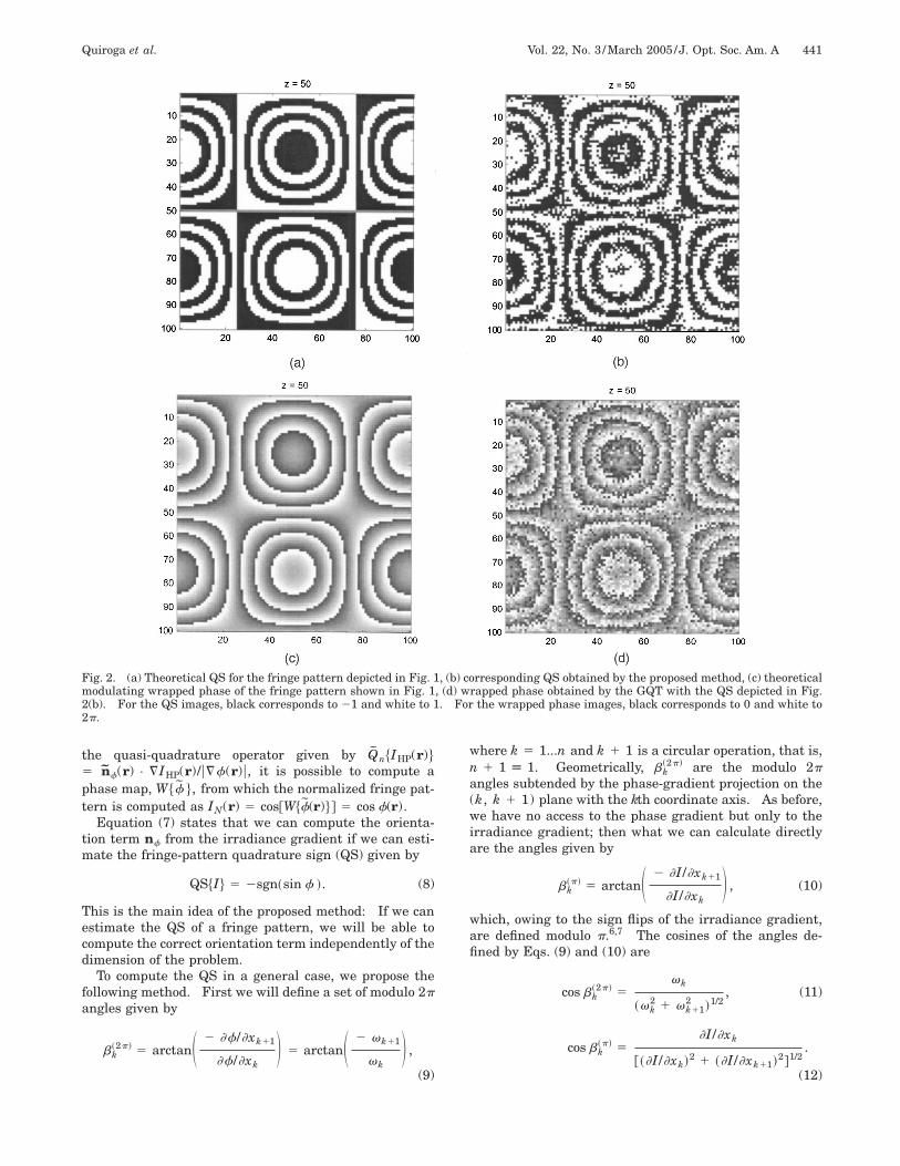
Fig. 2. (a) Theoretical QS for the fringe pattern depicted in Fig. 1, (b) corresponding QS obtained by the proposed method, (c) theoreticalmodulating wrapped phase of the fringe pattern shown in Fig. 1, (d) wrapped phase obtained by the GQT with the QS depicted in Fig.2(b). For the QS images, black corresponds to 21 and white to 1. For the wrapped phase images, black corresponds to 0 and white to2p.
the quasi-quadrature operator given by Qn$IHP(r)%5 nf(r) • ¹IHP(r)/u¹f(r)u, it is possible to compute aphase map, W$f %, from which the normalized fringe pat-tern is computed as IN(r) 5 cos@W$f(r)%# 5 cos f(r).
Equation (7) states that we can compute the orienta-tion term nf from the irradiance gradient if we can esti-mate the fringe-pattern quadrature sign (QS) given by
QS$I% 5 2sgn~sin f !. (8)
This is the main idea of the proposed method: If we canestimate the QS of a fringe pattern, we will be able tocompute the correct orientation term independently of thedimension of the problem.
To compute the QS in a general case, we propose thefollowing method. First we will define a set of modulo 2pangles given by
bk~2p! 5 arctanS 2 ]f/]xk11
]f/]xkD 5 arctanS 2 vk11
vkD ,
(9)
where k 5 1...n and k 1 1 is a circular operation, that is,n 1 1 [ 1. Geometrically, bk
(2p) are the modulo 2pangles subtended by the phase-gradient projection on the(k, k 1 1) plane with the kth coordinate axis. As before,we have no access to the phase gradient but only to theirradiance gradient; then what we can calculate directlyare the angles given by
bk~p! 5 arctanS 2 ]I/]xk11
]I/]xkD , (10)
which, owing to the sign flips of the irradiance gradient,are defined modulo p.6,7 The cosines of the angles de-fined by Eqs. (9) and (10) are
cos bk~2p! 5
vk
~vk2 1 vk11
2 !1/2, (11)
cos bk~p! 5
]I/]xk
@~]I/]xk!2 1 ~]I/]xk11!2#1/2.
(12)
442 J. Opt. Soc. Am. A/Vol. 22, No. 3 /March 2005 Quiroga et al.
If the modulation and the background are smooth func-tions, the irradiance gradient can be approximated by¹I ' 2m sin f¹f, and therefore these cosines are relatedby
cos bk~p! 5 2sign@sin f #cos bk
~2p! 5 QS$I%cos bk~2p! .
(13)
Finally, Eq. (13) indicates that if we are able to calculatecos bk
(2p) we can compute the QS in the generaln-dimensional case from the direct measurement cos bk
(p)
as
QS$I% 5 sgn~cos bk~p!!sgn~cos bk
~2p!!
5 sgn~]I/]xk!sgn~cos bk~2p!!, (14)
where we have used the properties of the signum functionand the fact that, from Eq. (12), sign(cos bk
(p))5 sign(]I/]xk).
The bk(p) fields are, by definition, noisy and piecewise
discontinuous in the case of real fringe patterns withclosed fringes; however, it is possible to reliably compute
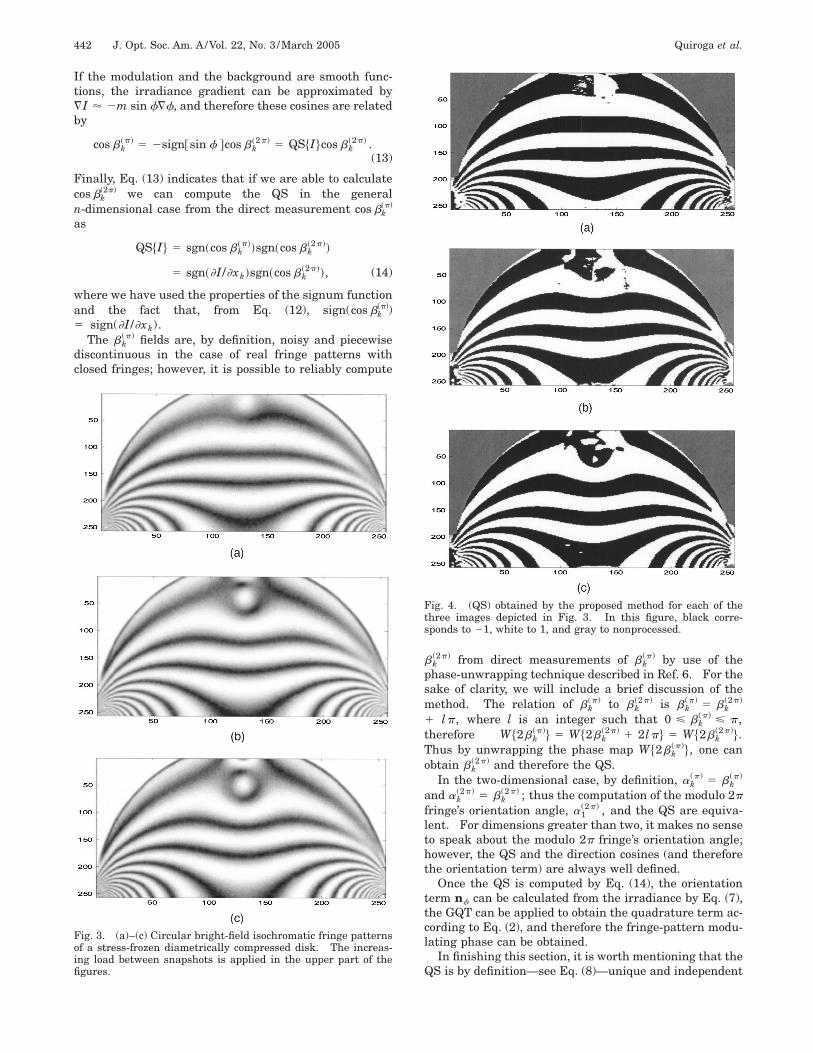
Fig. 3. (a)–(c) Circular bright-field isochromatic fringe patternsof a stress-frozen diametrically compressed disk. The increas-ing load between snapshots is applied in the upper part of thefigures.
bk(2p) from direct measurements of bk
(p) by use of thephase-unwrapping technique described in Ref. 6. For thesake of clarity, we will include a brief discussion of themethod. The relation of bk
(p) to bk(2p) is bk
(p) 5 bk(2p)
1 lp, where l is an integer such that 0 < bk(p) < p,
therefore W$2bk(p)% 5 W$2bk
(2p) 1 2lp% 5 W$2bk(2p)%.
Thus by unwrapping the phase map W$2bk(p)%, one can
obtain bk(2p) and therefore the QS.
In the two-dimensional case, by definition, ak(p) 5 bk
(p)
and ak(2p) 5 bk
(2p) ; thus the computation of the modulo 2pfringe’s orientation angle, a1
(2p) , and the QS are equiva-lent. For dimensions greater than two, it makes no senseto speak about the modulo 2p fringe’s orientation angle;however, the QS and the direction cosines (and thereforethe orientation term) are always well defined.
Once the QS is computed by Eq. (14), the orientationterm nf can be calculated from the irradiance by Eq. (7),the GQT can be applied to obtain the quadrature term ac-cording to Eq. (2), and therefore the fringe-pattern modu-lating phase can be obtained.
In finishing this section, it is worth mentioning that theQS is by definition—see Eq. (8)—unique and independent
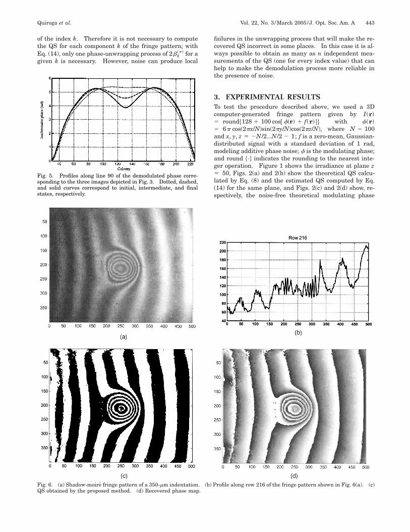
Fig. 4. (QS) obtained by the proposed method for each of thethree images depicted in Fig. 3. In this figure, black corre-sponds to 21, white to 1, and gray to nonprocessed.
Quiroga et al. Vol. 22, No. 3 /March 2005/J. Opt. Soc. Am. A 443
of the index k. Therefore it is not necessary to computethe QS for each component k of the fringe pattern; withEq. (14), only one phase-unwrapping process of 2bk
(p) for agiven k is necessary. However, noise can produce local
Fig. 5. Profiles along line 90 of the demodulated phase corre-sponding to the three images depicted in Fig. 3. Dotted, dashed,and solid curves correspond to initial, intermediate, and finalstates, respectively.
failures in the unwrapping process that will make the re-covered QS incorrect in some places. In this case it is al-ways possible to obtain as many as n independent mea-surements of the QS (one for every index value) that canhelp to make the demodulation process more reliable inthe presence of noise.
3. EXPERIMENTAL RESULTSTo test the procedure described above, we used a 3Dcomputer-generated fringe pattern given by I(r)5 round$128 1 100 cos@ f(r) 1 f(r)#% with f(r)5 6p cos(2px/N)sin(2py/N)cos(2pz/N), where N 5 100and x, y, z 5 2N/2...N/2 2 1; f is a zero-mean, Gaussian-distributed signal with a standard deviation of 1 rad,modeling additive phase noise; f is the modulating phase;and round $•% indicates the rounding to the nearest inte-ger operation. Figure 1 shows the irradiance at plane z5 50, Figs. 2(a) and 2(b) show the theoretical QS calcu-lated by Eq. (8) and the estimated QS computed by Eq.(14) for the same plane, and Figs. 2(c) and 2(d) show, re-spectively, the noise-free theoretical modulating phase
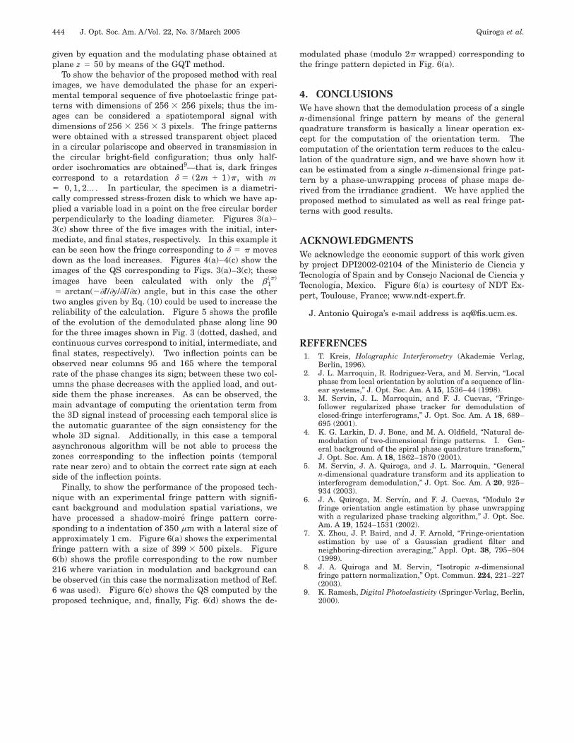
Fig. 6. (a) Shadow-moire fringe pattern of a 350-mm indentation. (b) Profile along row 216 of the fringe pattern shown in Fig. 6(a). (c)QS obtained by the proposed method. (d) Recovered phase map.
444 J. Opt. Soc. Am. A/Vol. 22, No. 3 /March 2005 Quiroga et al.
given by equation and the modulating phase obtained atplane z 5 50 by means of the GQT method.
To show the behavior of the proposed method with realimages, we have demodulated the phase for an experi-mental temporal sequence of five photoelastic fringe pat-terns with dimensions of 256 3 256 pixels; thus the im-ages can be considered a spatiotemporal signal withdimensions of 256 3 256 3 3 pixels. The fringe patternswere obtained with a stressed transparent object placedin a circular polariscope and observed in transmission inthe circular bright-field configuration; thus only half-order isochromatics are obtained9—that is, dark fringescorrespond to a retardation d 5 (2m 1 1)p, with m5 0, 1, 2... . In particular, the specimen is a diametri-cally compressed stress-frozen disk to which we have ap-plied a variable load in a point on the free circular borderperpendicularly to the loading diameter. Figures 3(a)–3(c) show three of the five images with the initial, inter-mediate, and final states, respectively. In this example itcan be seen how the fringe corresponding to d 5 p movesdown as the load increases. Figures 4(a)–4(c) show theimages of the QS corresponding to Figs. 3(a)–3(c); theseimages have been calculated with only the b1
(p)
5 arctan(2]I/]y/]I/]x) angle, but in this case the othertwo angles given by Eq. (10) could be used to increase thereliability of the calculation. Figure 5 shows the profileof the evolution of the demodulated phase along line 90for the three images shown in Fig. 3 (dotted, dashed, andcontinuous curves correspond to initial, intermediate, andfinal states, respectively). Two inflection points can beobserved near columns 95 and 165 where the temporalrate of the phase changes its sign; between these two col-umns the phase decreases with the applied load, and out-side them the phase increases. As can be observed, themain advantage of computing the orientation term fromthe 3D signal instead of processing each temporal slice isthe automatic guarantee of the sign consistency for thewhole 3D signal. Additionally, in this case a temporalasynchronous algorithm will be not able to process thezones corresponding to the inflection points (temporalrate near zero) and to obtain the correct rate sign at eachside of the inflection points.
Finally, to show the performance of the proposed tech-nique with an experimental fringe pattern with signifi-cant background and modulation spatial variations, wehave processed a shadow-moire fringe pattern corre-sponding to a indentation of 350 mm with a lateral size ofapproximately 1 cm. Figure 6(a) shows the experimentalfringe pattern with a size of 399 3 500 pixels. Figure6(b) shows the profile corresponding to the row number216 where variation in modulation and background canbe observed (in this case the normalization method of Ref.6 was used). Figure 6(c) shows the QS computed by theproposed technique, and, finally, Fig. 6(d) shows the de-
modulated phase (modulo 2p wrapped) corresponding tothe fringe pattern depicted in Fig. 6(a).
4. CONCLUSIONSWe have shown that the demodulation process of a singlen-dimensional fringe pattern by means of the generalquadrature transform is basically a linear operation ex-cept for the computation of the orientation term. Thecomputation of the orientation term reduces to the calcu-lation of the quadrature sign, and we have shown how itcan be estimated from a single n-dimensional fringe pat-tern by a phase-unwrapping process of phase maps de-rived from the irradiance gradient. We have applied theproposed method to simulated as well as real fringe pat-terns with good results.
ACKNOWLEDGMENTSWe acknowledge the economic support of this work givenby project DPI2002-02104 of the Ministerio de Ciencia yTecnologıa of Spain and by Consejo Nacional de Ciencia yTecnologıa, Mexico. Figure 6(a) is courtesy of NDT Ex-pert, Toulouse, France; www.ndt-expert.fr.
J. Antonio Quiroga’s e-mail address is [email protected].
REFERENCES1. T. Kreis, Holographic Interferometry (Akademie Verlag,
Berlin, 1996).2. J. L. Marroquin, R. Rodriguez-Vera, and M. Servin, ‘‘Local
phase from local orientation by solution of a sequence of lin-ear systems,’’ J. Opt. Soc. Am. A 15, 1536–44 (1998).
3. M. Servin, J. L. Marroquin, and F. J. Cuevas, ‘‘Fringe-follower regularized phase tracker for demodulation ofclosed-fringe interferograms,’’ J. Opt. Soc. Am. A 18, 689–695 (2001).
4. K. G. Larkin, D. J. Bone, and M. A. Oldfield, ‘‘Natural de-modulation of two-dimensional fringe patterns. I. Gen-eral background of the spiral phase quadrature transform,’’J. Opt. Soc. Am. A 18, 1862–1870 (2001).
5. M. Servin, J. A. Quiroga, and J. L. Marroquin, ‘‘Generaln-dimensional quadrature transform and its application tointerferogram demodulation,’’ J. Opt. Soc. Am. A 20, 925–934 (2003).
6. J. A. Quiroga, M. Servın, and F. J. Cuevas, ‘‘Modulo 2pfringe orientation angle estimation by phase unwrappingwith a regularized phase tracking algorithm,’’ J. Opt. Soc.Am. A 19, 1524–1531 (2002).
7. X. Zhou, J. P. Baird, and J. F. Arnold, ‘‘Fringe-orientationestimation by use of a Gaussian gradient filter andneighboring-direction averaging,’’ Appl. Opt. 38, 795–804(1999).
8. J. A. Quiroga and M. Servin, ‘‘Isotropic n-dimensionalfringe pattern normalization,’’ Opt. Commun. 224, 221–227(2003).
9. K. Ramesh, Digital Photoelasticity (Springer-Verlag, Berlin,2000).
Copyright © 2022 FDOKUMEN