SN 1988Z: spectro-photometric catalogue and energy estimates
Upload
independentCategory
view
7download
0
CER
N-A
T-20
08-0
2605
/12/
2008
EUROPEAN ORGANIZATION FOR NUCLEAR RESEARCHLaboratory for Particle Physics
PHASE TRANSFORMATIONS DURING THE REACTION HEAT TREATMENTOF INTERNAL TIN Nb3Sn STRANDS WITH HIGH Sn CONTENT
C. Scheuerlein1, M. Di Michiel2, G. Arnau1, F. Buta3
1 CERN, Accelerator Technology Department, Geneva, Switzerland2 European Synchrotron Radiation Facility (ESRF), Grenoble, France3 University of Geneva, Group of Applied Physics (GAP), Geneva, Switzerland
CERN/AT 2008-26
Published in IEEE Transactions on Applied Superconductivity
Departmental Report
CERNAccelerator Technology DepartmentCH - 1211 Geneva 23Switzerland
The phase transformations that occur during the reaction heat treatment of Nb3Sn superconductorsdepend on the overall elemental composition of the strand sub-elements. In the case of modern high Jc
strands with a relatively low Cu content, liquid phases are present during large temperature intervalsand phases that can be detrimental for the microstructural and microchemical homogeneity of the fullyreacted strand are formed. We report synchrotron x-ray diffraction measurements during in-situreaction heat treatment of a state-of-the-art high Jc Nb3Sn Internal Tin (IT) strand. In this strand Cu3Snis formed upon Cu6Sn5 decomposition at 415 °C, a Sn-rich ternary Cu-Nb-Sn phase is detected in theapproximate temperature interval 345-575 °C and NbSn2 is present in the temperature interval545-630 °C. The formation of voids in the strand sub-elements has been monitored by synchrotronmicro-tomography during in-situ reaction heat treatment.
27 November 2008

2
1 Introduction
Modern Nb3Sn strands of the Internal Tin (IT) design can achieve very high critical
current densities and are therefore considered for building high field accelerator magnets
for application in high energy physics. Presently the Nb3Sn strands with the highest
critical current densities are fabricated by the Restacked Rod Process (RRP®) by Oxford
Instruments, Superconducting Technology (OI-ST), USA [1].
The brittle superconducting A15 phase in Nb3Sn superconducting strands is produced
from the ductile precursor elements Nb and Sn during a reaction heat treatment (HT).
During this HT the precursor elements interdiffuse with the Cu in the sub-element
bundle, forming various intermetallic phases and finally the superconducting Nb3Sn.
Since the phase transformations that occur prior to Nb3Sn nucleation and growth can
degrade the microstructural and microchemical homogeneity of the fully reacted strand, it
is necessary to understand how the strand design and the overall elemental composition
of its sub-elements influence these transformations.
For IT Nb3Sn strands with a Cu to Sn at.% ratio of approximately 10 and 2.4, the phase
transformations prior to the Nb3Sn nucleation and growth have been reported in [2] and
[3], respectively. In these studies phase analysis has been performed by Energy
Dispersive X-ray Spectroscopy (EDS) in the Scanning Electron Microscope (SEM) on
metallographic cross sections of ex-situ heat treated strand samples. X-ray Diffraction
(XRD) is an alternative tool for phase analysis. Previously we have reported XRD results
acquired during in-situ strand reaction heat treatments of a Nb3Sn IT strand with a
relatively high Cu to Sn at.% ratio of about 8 [4] and of a state-of-the-art Powder-in-Tube
(PIT) strand with much lower Cu content [5].

3
In the case of IT strands with a high Cu to Sn at.% ratio within the sub-elements the pure
Sn initially present in the strand is successively transformed into Cu-Sn intermetallics
with increasingly high Cu content (Cu6Sn5, Cu3Sn, Cu41Sn11, Cu5.6Sn). After the Nb3Sn
formation the Sn concentration in the matrix is reduced below its solubility limit in Cu. In
more recent high Jc Nb3Sn strands the Cu concentration within the strand sub-elements
has been strongly reduced. At least one Cu-Nb-Sn ternary phase is formed during the
lower temperature HT when the Nb filaments are partly dissolved in the strand matrix
[3].
In the present article we describe the phase transformations occurring during the reaction
HT of a state-of-the-art Nb3Sn strand of the RRP® design, based on XRD results that
have been obtained at the European Synchrotron Radiation Facility (ESRF) High-Energy
Scattering Beamline ID15B during in-situ reaction HT. The XRD results are
complemented by EDS measurements on metallographic cross sections of ex-situ heat
treated strand samples. The influence of the different phase transformations on the void
growth has been studied by synchrotron tomography during an in-situ HT. The total
strand volume change after full reaction has been determined by strand length and
diameter measurements before and after the reaction HT.
2 Experimental
2.1 The sample
The sample studied is a Nb3Sn RRP® strand fabricated by OI-ST (billet #7419). The
strand with a nominal diameter of 0.8 mm contains 54 Nb-Ta alloy filament bundles,
each surrounded by distributed diffusion barriers. The strand has an effective filament
diameter of about 80 μm and it can reach 12 T, 4.2 K non-Cu critical current density

4
values close to 3000 A mm-2, at the same time maintaining a high purity Cu stabiliser
with a RRR of well above 200 [6]. More details about the OI-ST RRP® strands can be
found in reference [1].
2.2 In-situ synchrotron x-ray diffraction and micro-tomography
Diffraction measurements were carried out at the ID15B high energy beamline of the
ESRF in transmission geometry, using a 89.1 keV monochromatic x-ray beam. Debye-
Scherrer diffraction pattern were acquired with a MAR345 image-plate detector.
During the in-situ HT with a temperature ramp rate of 100 °C h-1 and three short
isothermal holding steps, diffractograms were acquired every 5 minutes. In-situ heating
was performed in a dedicated x-ray transparent furnace built at ID15 that enables an
accurate sample temperature control during the diffraction experiments. For the
temperature measurement a thermocouple was directly attached to the strand sample. The
estimated accuracy of the temperature measurement is better than ±5 °C.
Absorption micro-tomography was performed at ID15A using a high energy filtered
white x-ray beam. The tomography set-up is described in detail in [7]. The ramp rate
during the tomography measurements was again 100 °C h-1, but without any isothermal
holding steps.
A typical reaction HT for the RRP® strand recommended by OI-ST is increasing the HT
temperature with 25 °C h-1 to 210 °C, holding 100 h at 210 °C, ramping with 50 °C h-1 to
400 °C, holding 50 h at 400 °C and then ramp with 50 °C h-1 to the final reaction
temperature. Since the synchrotron beam time cost for such a standard HT lasting about
one week would be prohibitive, the HT schedule used in the present study has been
5
changed such that it can be performed within about 14 h. Therefore, the temperature
intervals during which the different phases are detected during the in-situ diffraction
measurements may differ somewhat from the temperatures at which the phases are
formed during the reaction HT of a magnet coil.
2.3 Scanning Electron Microscopy (SEM) and Energy Dispersive X-ray Spectroscopy (EDS)
Cross-sections of ex-situ heat treated strand samples where observed with a SEM Leo
430 using a 20 keV electron beam and a solid state diode detector for recording
backscattered-electron (BSE) images. The compositional contrast, with regions of
increasing atomic number appearing increasingly brighter, given by the BSE images
allowed the identification of the constituents of the strand microstructure to a resolution
better than 0.1 µm.
An EDS system Oxford Isis 300 with a Si(Li) detector coupled to the SEM was used in
the standardless mode for the quantitative elemental analysis. For the constituents of
small size in the order of the micrometer, particularly large cases were targeted to
overcome the relatively poor lateral resolution of the EDS point analyses, at least one
order of magnitude worse than BSE imaging.
3 Results
3.1 In-situ synchrotron diffraction
During the in-situ HT with a ramp rate of 100 °C h-1 and isothermal heating for 2 h at
390 °C, 2 h at 482 °C and 2.75 h at 659 °C, a total of 170 diffractograms were acquired.
For phase analysis the 2-D diffraction patterns have been integrated into 1-D patterns and
a colour intensity diagram of all is shown in Figure 1. Before the onset of Nb3Sn

6
formation, four phases (apart from Cu and Nb) could be identified, notably (β-) Sn,
Cu6Sn5, Cu3Sn and NbSn2. A fifth phase was detected but could not be identified by
comparison with published reference patterns. Since the diffraction pattern of this
unidentified phase is detected in the same temperature interval during which a
Cu-Nb-Sn ternary phase is detected by EDS in ex-situ heat treated samples, we assume
that these diffraction peaks are characteristic for the previously reported Cu-Nb-Sn phase
[3,1 and 5].
Some faint diffraction peaks that appear upon NbSn2 dissolution at about 620 °C may
indicate the formation of a small amount of Nb6Sn5 at this temperature, but because these
peaks are relatively weak and partly overlap with prominent peaks of other phases,
Nb6Sn5 could not be unambiguously identified. However, it can be concluded that if
Nb6Sn5 is formed during the reaction HT of the RRP® strand, its amount is much smaller
than the amount of Nb6Sn5 that is formed in a Nb3Sn PIT strand, which has been studied
previously by synchrotron diffraction under similar experimental conditions [5]. In the
PIT strand Nb6Sn5 could be identified easily and it was even possible to obtain the semi-
quantitative evolution of Nb6Sn5 during the HT.

7
Figure 1: Variation of the diffraction patterns of the OI-ST Nb3Sn RRP® strand during
in-situ HT cycle with ramp rate 100 °C h-1 and additional isothermal plateaus 2 h-390
°C, 2 h-482 °C and 2.75 h-659 °C. Diffractograms have been acquired every 5 minutes,
i.e. the temperature resolution of the experiment is 8 °C. The diffraction peaks labelled
with a star are tentatively assigned to a Cu-Nb-Sn ternary phase.
The phase growth results are summarised in Figure 2. At first pure Sn is transformed into
Cu6Sn5. When heating with a ramp rate of 100 °C h-1, this transformation occurs mainly
above 232 °C in the presence of liquid Sn. Cu6Sn5 decomposes entirely at 415 °C. At the
same temperature Cu3Sn appears and the presumed Cu-Nb-Sn ternary phase grows
markedly. The growth of the presumed Cu-Nb-Sn ternary phase coincides with a slight
decrease of the Nb (211) peak area, which indicates that part of Nb is incorporated into a

8
Cu-Nb-Sn ternary phase. The vanishing of the Cu-Nb-Sn phase at about 560 °C coincides
with the growth of NbSn2 and at about 620 °C the Nb3Sn (200) peak starts to grow.
Figure 2: Relative variation of the diffraction peak areas of all Sn containing phases
detected in the OI-ST RRP® strand as a function of the reaction HT temperature and
duration. The Sn(101), Cu6Sn5(202), NbSn2(220), Nb3Sn(200) and Cu3Sn peak with d-
spacing d=3.23 Å have been chosen for peak area measurements. An un-identified phase,
for which the evolution of the diffraction peak area (peak with d-spacing~2.78 Å) is also
plotted, is presumably a ternary Cu-Nb-Sn phase. Peak areas have been scaled in order
to fit into the plot and to facilitate comparison.
3.2 Metallographic examination of ex-situ heat treated samples
In order to study the effect of longer heat treatments and to examine the spatial
distribution of the phases detected by XRD within the RRP® strand, metallographic cross
sections of ex-situ heat treated strand samples have been analysed in the Scanning
Electron Microscope (SEM) by Energy Dispersive x-ray Spectroscopy (EDS) and by
9
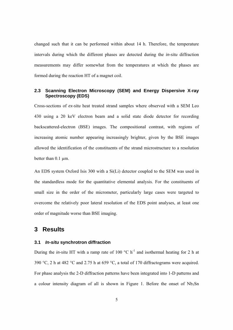
optical microscopy. The individual ex-situ heat treatments of 10 h-340 °C, 10 h-410 °C,
10 h-540 °C and 10 h-590 °C have been achieved under vacuum, each with a ramp rate of
60°C h-1. A 10 h duration of the isothermal HT has been chosen in order to limit a
possible influence of the ramp rate on the results. Backscatter Electron (BSE) images of
the respective cross sections are shown in Figure 3. The phases that have been identified
by EDS are labelled in the images.
Figure 3: OI-ST RRP® strand cross sections after 10 h-340 °C, 10 h-410 °C, 10 h-540 °C
and 10 h-590 °C HT (ramp rate 60 °C h-1). After the 340 °C HT the Sn core has been
10
transformed into Cu6Sn5 and some pure Sn remains close to the filaments (bright region
in the BE images). During the 410 °C HT part of the Cu6Sn5 is transformed into Cu3Sn
and a Cu-Nb-Sn ternary phase that contains roughly 69 at.% Sn. After the 540 °C HT Sn
is in the form of Cu3Sn, Cu-Nb-Sn and NbSn2 and during the 590 °C HT Sn is present in
the form of Cu3Sn and some Nb6Sn5, which is detected around the filaments closest to the
Sn source. NbSn2 was not detected after the 590 °C HT.
After the 340 °C HT the Sn inside the diffusion barriers has been partly transformed into
Cu6Sn5. The presence of pure Sn (bright areas in the BSE-SEM image) indicates that
after 10 h heating at 340 °C the Sn transformation into Cu-Sn intermetallics is not
complete and that there remains some liquid Sn in the strand at the end of this HT step.
During the 10 h-410 °C HT part of the Cu6Sn5 in the Sn cores is transformed into Cu3Sn
(lower Z and therefore darker regions in the BE images) and into a Cu-Nb-Sn ternary
phase that contains roughly 69 at.% Sn. After the ex-situ 10 h-540 °C HT the Cu inside
the diffusion barrier is mainly present in the form of Cu3Sn and partly in the Cu-Nb-Sn
ternary phase. The Nb filaments closest to the Sn reservoirs have been transformed into
NbSn2. After the ex-situ 10 h-590 °C HT Sn is mainly present in the form of Cu3Sn, and
some Nb6Sn5 in the filament region closest to the Sn source.
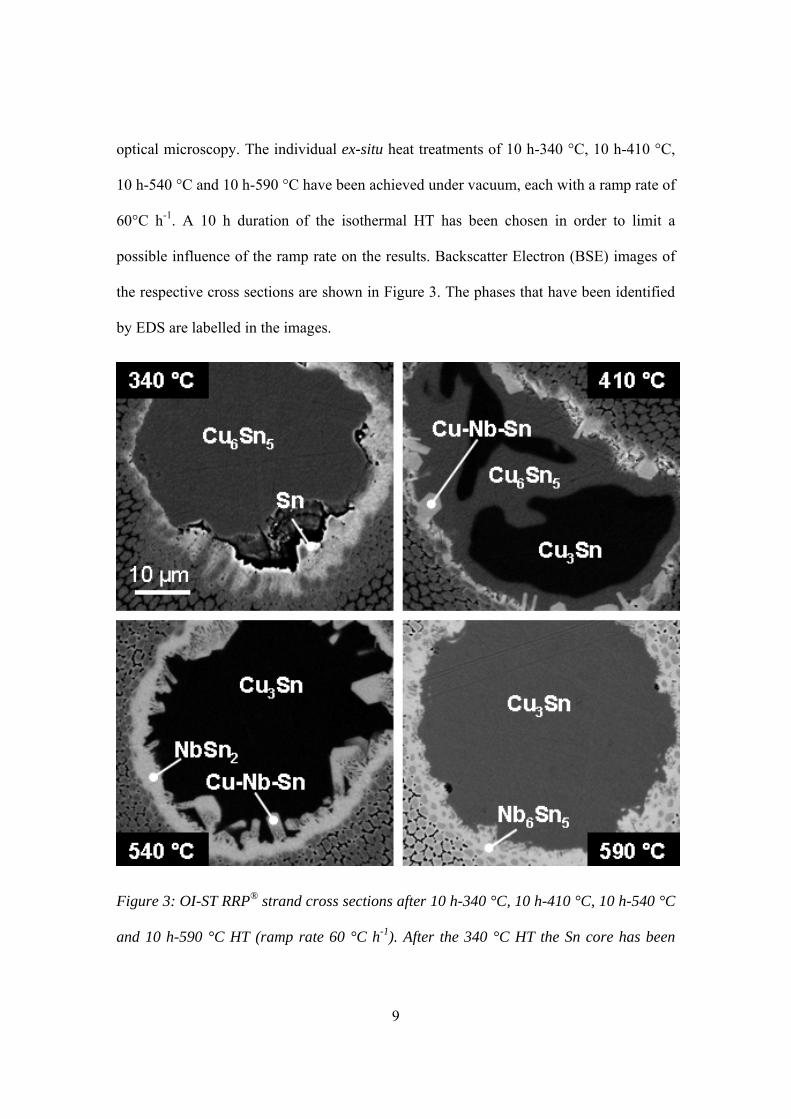
In Figure 4 a secondary electron image of a RRP® fracture sample after 17 h-695 °C HT
is shown. The initially separated filaments within the non-reacted sub element have
coalesced to a single filament that exhibits a homogenous fine grain Nb3Sn
microstructure, as it is typical for high critical current density Nb3Sn conductors [8]. Only
a small ring closest to the Sn core is composed of coarse grains, presumably the strand
region that has been converted into Nb6Sn5 prior to Nb3Sn formation.
11
Figure 4: Secondary electron image of OI-ST-RRP® fracture sample after 17 h-695 °C
HT. A thin coarse grain region is present at the filament region closest to the Sn source.
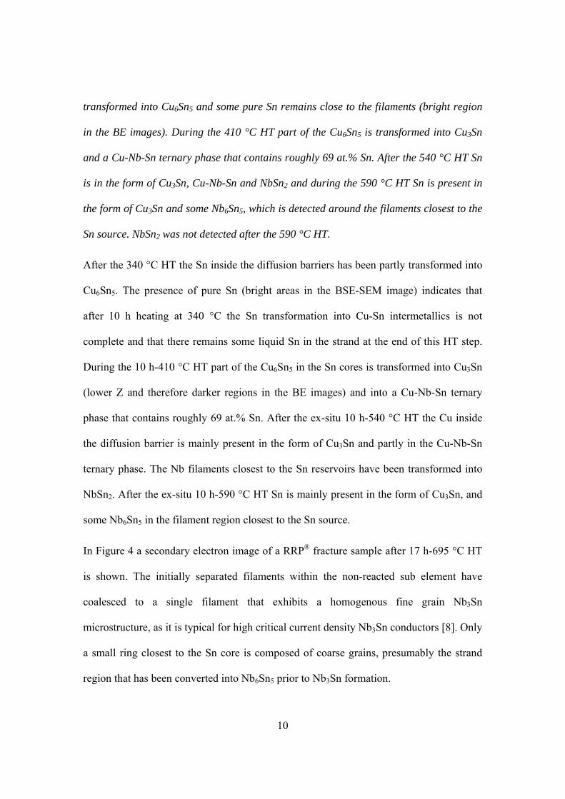
The influence of a 220 °C isothermal holding step on the Cu3Sn growth during
subsequent 400 °C HT has been examined by comparing optical micrographs obtained
after 400 °C HT, either with or without prior 314 h-220 °C holding step. As can be seen
in Figure 5, after both heat treatments most Sn is still present as Cu6Sn5.
Figure 5: OI-ST-RRP® strand cross section after 40 h-400 °C HT (left) and 314 h-220
°C+50 h-400 °C (right). After both heat treatments Sn is mainly present in the form of
Cu6Sn5 (bright grey) with some Cu3Sn (dark grey). The Cu-Nb-Sn ternary phase that is

12
also formed can not be seen in the low resolution optical micrographs. The black regions
in the true color images are voids.
3.3 Void formation and strand volume change during the reaction HT
The formation of voids during the reaction HT of the OI-ST RRP® strand has been
monitored by high energy synchrotron micro-tomography. The strand cross sections of a
non reacted RRP® strand and the same strand after ex-situ 17 h-695 °C HT are presented
in Figure 6.
Figure 6: OI-ST RRP® strand cross section before HT (left) and after 17 h-695 °C HT
(right), obtained by synchrotron micro-tomography. The total void cross section is 0.027
mm2, which corresponds with 5.0 % of the total strand cross section.
In Table 1 the strand diameter, length and pore volume before and after full reaction HT
of the RRP® strand are summarised. As has been shown previously for other Nb3Sn
strands [9,10], the length of the free standing straight RRP® strand contracts slightly
during a full reaction HT. This contraction is caused by the Nb filament relaxation during
the Cu annealing HT, prior to the Nb3Sn formation. The main strand volume increase is
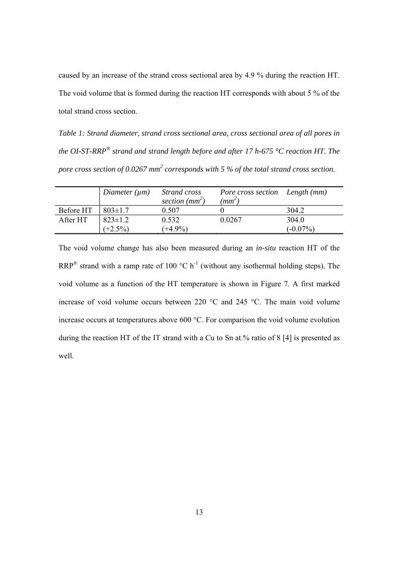
13
caused by an increase of the strand cross sectional area by 4.9 % during the reaction HT.
The void volume that is formed during the reaction HT corresponds with about 5 % of the
total strand cross section.
Table 1: Strand diameter, strand cross sectional area, cross sectional area of all pores in
the OI-ST-RRP® strand and strand length before and after 17 h-675 °C reaction HT. The
pore cross section of 0.0267 mm2 corresponds with 5 % of the total strand cross section.
Diameter (µm) Strand cross section (mm2)
Pore cross section (mm2)
Length (mm)
Before HT 803±1.7 0.507 0 304.2 After HT 823±1.2
(+2.5%) 0.532 (+4.9%)
0.0267
304.0 (-0.07%)
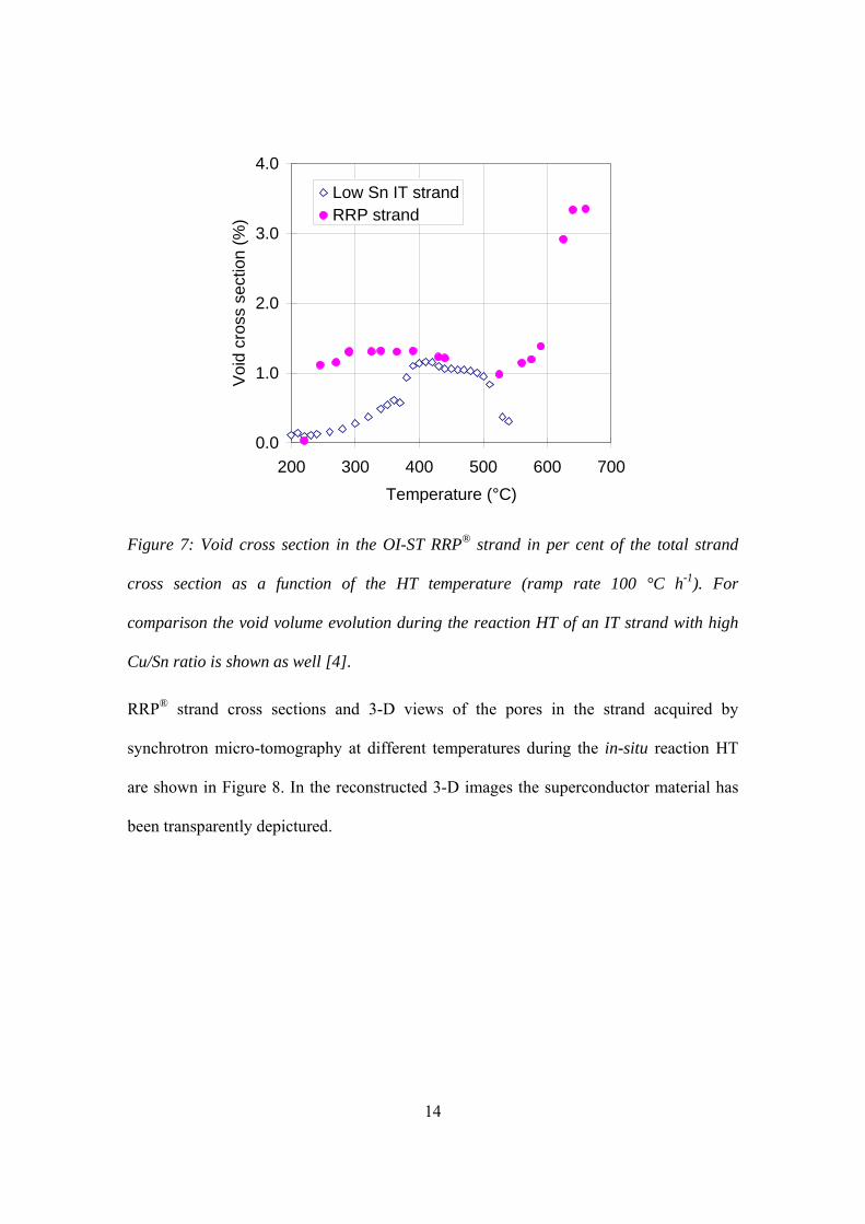
The void volume change has also been measured during an in-situ reaction HT of the
RRP® strand with a ramp rate of 100 °C h-1 (without any isothermal holding steps). The
void volume as a function of the HT temperature is shown in Figure 7. A first marked
increase of void volume occurs between 220 °C and 245 °C. The main void volume
increase occurs at temperatures above 600 °C. For comparison the void volume evolution
during the reaction HT of the IT strand with a Cu to Sn at.% ratio of 8 [4] is presented as
well.
14
0.0
1.0
2.0
3.0
4.0
200 300 400 500 600 700Temperature (°C)
Voi
d cr
oss
sect
ion
(%)
Low Sn IT strandRRP strand
Figure 7: Void cross section in the OI-ST RRP® strand in per cent of the total strand
cross section as a function of the HT temperature (ramp rate 100 °C h-1). For
comparison the void volume evolution during the reaction HT of an IT strand with high
Cu/Sn ratio is shown as well [4].
RRP® strand cross sections and 3-D views of the pores in the strand acquired by
synchrotron micro-tomography at different temperatures during the in-situ reaction HT
are shown in Figure 8. In the reconstructed 3-D images the superconductor material has
been transparently depictured.

15
Figure 8: 2-D cross sections of the RRP® strand (top) and the corresponding 3-D images
of the pores within the strand acquired by synchrotron micro-tomography at different
temperatures during in-situ HT with a ramp rate of 100 °C h-1. In the 3-D reconstructed
images the strand materials have been transparently depictured in order to visualise the
pores. The middle line shows a top view and the bottom line a lateral view on the pores.
4 Discussion
Phase transformations
The overall elemental composition of the Nb3Sn strand sub-elements has a strong
influence on the phase transformations that occur during the strand reaction HT. While in
low Jc strands with high Cu content only pure Sn liquefies during the reaction HT [4], in
high Jc strands, with much smaller Cu to Sn ratio, liquid phases are invariably present in
the strand during larger temperature intervals. In particular a peritectical decomposition
of Cu6Sn5 into Cu3Sn and liquid occurs at 415 °C. In strands that contain a relatively

16
large amount of Cu with respect to Sn, the Cu6Sn5 to Cu3Sn transformation readily takes
place at relatively low temperatures and it can be completed entirely below the Cu6Sn5
decomposition temperature of 415 °C [2,4].
The dissolution of the Nb filaments in a ternary phase and the transformation of the inner
Nb filaments into NbSn2, and possibly into Nb6Sn5, may degrade the microstructural and
microchemical homogeneity of the fully reacted strand. In the OI-ST RRP® strand the
Cu-Nb-Sn ternary phase has been detected in the temperature interval of approximately
345-575 °C, similar to the temperature interval during which the ternary phase exists in a
Nb3Sn PIT strand produced by SMI [5]. In both Nb3Sn strand types the ternary phase
disappears upon formation of NbSn2, which is present in the RRP® strand in the
temperature interval 545-630 °C, again similar to the temperature interval in which
NbSn2 is formed in the Nb tubes of the PIT strand.
A relatively small amount of Nb6Sn5 in the filament region closest to the Sn source is
observed in the metallographic OI-ST RRP® strand cross sections after 10 h ex-situ 590
°C HT. The amount of Nb6Sn5 that is formed during the in-situ HT with a ramp rate of
100 °C h-1 is so small that it can not be unambiguously detected by the diffraction
experiment. This is an important advantage of the OI-ST RRP® strand design over the
present SMI PIT [5] and Tube Type strands [11], in which more than 20 vol.% of the Nb
tubes can be transformed into Nb6Sn5 prior to the formation of Nb3Sn. It is assumed that
Nb6Sn5 formation in the Nb precursor tubes prior to Nb3Sn formation significantly
reduces the current carrying fine grain Nb3Sn cross sectional area.
As outlined above, the in-situ HT during the diffraction measurements reported here
differs from the HT schedule recommended by the strand manufacturer. Therefore, the
17
temperature intervals during which the different phases have been detected by the in-situ
XRD measurements might differ somewhat from the temperatures at which these phases
are present during the reaction HT of a magnet coil. The influence of the different HT
schedules depends on whether the phase transformations are mainly determined by the
thermodynamics or by the kinetics of formation. Only when the kinetics have a strong
influence the temperature intervals during which the different phases are detected will
shift to lower temperatures with decreasing ramp rate.
In order to predict the phases that can grow during the reaction HT of Nb3Sn strands with
different elemental composition and to optimise HT cycles, Cu-Nb-Sn ternary phase
diagrams, as they exist for instance for a temperature of 675 °C [12], are needed also at
lower temperatures. The influence of ternary and quaternary additions, in particular of Ti,
on the phase transformations needs to be considered as well [13].
Void formation
The void volume in the fully reacted RRP® strand, which corresponds to about 5% of the
total strand volume, is similar to the strand volume expansion during the reaction HT.
One reason for the void formation might be density changes during the strand reaction
HT.
It is well known that the Nb3Sn volume is approximately 37% larger than the Nb
precursor volume. However, the void and strand volume results presented here indicate
that the Nb3Sn volume does not increase with respect to the sum of the Nb and Sn
volumes from which it is formed. When void formation during the reaction HT of the
RRP® strand is suppressed by a high pressure thermal treatment [14], the strand cross
sectional area even shrinks by about 2% with respect to that of the non heat treated RRP®

18
strand. This indicates that the Nb3Sn density is higher than the density of the Nb and Sn
pre-cursor in the stoichiometric quantities, which can explain part of the void volume that
is formed in the RRP® strand. The calculated Nb3Sn density is indeed significantly higher
than the weighted average of the Cu and Sn densities (8.90 g cm-3 vs. 8.15 g cm-3,
respectively [15]). Therefore, a strand volume expansion during the reaction HT
invariably causes the formation of a corresponding void volume in the reacted strand.
As can be seen in Figure 7, the void volume evolution as a function of HT temperature
observed in the RRP® strand differs markedly from that in an IT strand with relatively
high Cu/Sn ratio studied previously [4]. In the high Cu/Sn ratio IT strand three different
void growth mechanisms could be distinguished, notably an agglomeration of pre-
existing voids that are initially so small that they can not be detected by synchrotron
micro-tomography, density changes during the formation of Cu-Sn intermetallics and the
formation of voids due to differences in the diffusivity of Cu in Sn and Sn in Cu
(Kirkendall voids [16]). The in-situ experiment of the high Cu/Sn ratio strand was
stopped at 540 °C, i.e. before the onset of Nb3Sn formation. Tomograms of the high
Cu/Sn ratio strand acquired after full ex-situ reaction HT have shown that the main void
volume increase in this strand occurs also above 540 °C, as it is observed in the RRP®
strand.
The first marked increase of void volume in the RRP® strand between 220 °C and 245 °C
coincides with the melting of pure Sn at 232 °C. Sn melting itself can only cause a slight
decrease of porosity, due to the Sn volume expansion upon melting. It can be assumed
that pre-existing pores agglomerate more easily in the presence of liquid Sn, which may
explain the volume increase of the detected pores in this temperature interval.

19
Unlike in the high Cu/Sn ratio strand, the formation of the relatively small Kirkendall
voids is not observed in the RRP® strand. One reason for this might be that the formation
of Kirkendall porosity in the RRP® strand is suppressed because of stresses in the strand
that prevent void growth, or that Kirkendall voids in the RRP® strand are so small that
they can not be resolved by synchrotron micro-tomography (the filament size and
interfilament spacing within the RRP® strand are much smaller than in the low Sn IT
strand studied previously). If Kirkendall porosity is suppressed in the RRP® strand this
can be advantageous in view of the homogeneity of Sn supply to the Nb precursor
filaments.
In the high Cu/Sn ratio strand the void volume decreases strongly upon transformation of
Cu-Sn intermetallics into lower density bronze. Due to the relatively small Cu to Sn ratio
in the RRP® strand, a transformation of Cu-Sn intermetallics into bronze can only take
place after a significant progress in the formation of Nb3Sn formation, such that the Sn
content in the Sn source is reduced below the Sn solubility limit in bronze. Therefore,
only a slight decrease of void volume is observed in the RRP® strand before the Sn starts
to diffuse into the Nb filaments.
5 Conclusion
The phase transformations during the reaction HT of a state-of-the-art high Jc Nb3Sn
strand of the RRP® design have been described. The phase transformations that occur in
the RRP® strand with relatively low Cu content are similar to those that have been
observed in a Nb3Sn PIT strand. However, an important advantage of the OI-ST RRP®
strand design over the PIT design is that much less Nb6Sn5 is formed during the reaction
HT of the RRP® strand. Isothermal holding steps below the Sn melting temperature of
20
232 °C and the Cu6Sn5 decomposition temperature of 415 °C do not have a strong
influence on the phases that are present in the RRP® strand at the onset temperature of
Nb3Sn formation.
Acknowledgments
The sample studied has been kindly provided by Oxford Instruments, Superconducting
Technology (OI-ST), USA. We are grateful to Jeff Parrell, Bernardo Bordini, Remo
Maccaferri and Davide Tommasini for stimulating discussions and suggestions.
We acknowledge the ESRF for beam time on ID15B.

21
References
1 J. A. Parrell, Y. Zhang, M.B. Field, P. Cisek, S. Hong, “High Field Nb3Sn Conductor Development at Oxford Superconducting Technology”, IEEE Trans. Appl. Supercon. 13(2), (2003), 3470-3473
2 M. T. Naus, P. J. Lee, and D. C. Larbalestier, “The Interdiffusion of Cu and Sn in Internal Sn Nb Sn Superconductors,” IEEE Trans. Appl. Supercon., 10(1), (2000), 983-987
3 M. T. Naus, P. J. Lee, and D. C. Larbalestier, “The Influence of the Starting Cu-Sn Phase on the Superconducting Properties of Subsequently Reacted Internal-Sn Nb3Sn Conductors”, IEEE Trans. Appl. Supercond., 11(1), (2001), 3569-3572
4 C. Scheuerlein, M. Di Michiel, A. Haibel, “On the formation of voids in internal tin Nb3Sn superconductors”, Applied Physics Letters, 90, 132510, (2007)
5 M. Di Michiel, C. Scheuerlein, “Phase transformations during the reaction heat treatment of powder-in-tube Nb3Sn superconductors”, Supercond. Sci. Technol. 20, (2007) L55-L58
6 B. Bordini, R. Maccaferri, L. Rossi, D. Tommasini, “Test Report of the Ceramic-Insulated Nb3Sn Small Split Solenoid”, CERN AT-MCS Internal Note 2008-02, EDMS Nr: 907758
7 M. Di Michiel, J.M. Merino, D. Fernandez-Carreiras, T. Buslaps, V. Honkimäki, P. Falus, T. Martins, O. Svensson, “Fast microtomography using high energy synchrotron tomography”, Rev. Sci. Instrum. 76, 043702, (2005)
8 P.J. Lee, D.C. Larbalestier, “Microstructural factors important for the development of high critical current density Nb3Sn strand” Cryogenics 48, (2008), pp. 283.292
9 M. Pojer, L. Rossi, “Development and Characterisation of ITD Multifilamentary Nb3Sn Superconductors for 10-15 T Field Magnets”, INFN report, INFN/TC-99/25, 1999
10 D.R. Dietderich, J.R. Litty, R.M. Scanlan., “Dimensional changes of Nb3Sn, Nb3Al, and Bi2Sr2CaCu2O8 conductors during heat treatment and their implication for coil design,” Adv. Cryo. Eng., vol. 44b, pp. 1013–1020
11 V.R. Nazareth, M.D. Sumption, X. Peng, E. Gregory, M.J. Tomsic, E.W. Collings, “Characterisation of the A15 Layer Growth and Microstructure for Varying Heat Treatments in Nb3Sn Tune Type Composites”, IEEE Trans. Appl. Supercond. Vol. 18(2), (2008), pp. 1005-1009,
12 W.L. Neijmeijer, B.H. Kolster, “The Ternary System Nb-Sn-Cu at 675 °C”, Z. Metallkde 78, (1978), pp. 730-737
13 X. Wu, X. Peng, M.D. Sumption, E. Gregory, M. Tomsic, E.W. Collings, “Titanium Diffusion and Phase Formation in Tube-type Rod-In-Tube and Internal Tin Nb3Sn Strands”, Advances in Cryogenic Engineering: Transactions of the International Cryogenic Materials Conference, ICMC, Vol. 52, (2006), pp. 504-512
No heat treatment

22
14 B. Seeber et al., “Electromagnetic properties and synchrotron micro-tomography of Nb3Sn wires with reduced void density obtained by hot isostatic pressing”, private communication, August 2008
15 D. Kapoor, R.N. Wright, “Structural Characteristics of Nb3Sn Produced by Three P/M Techniques”, Matallurgical Transactions A, Vol. 11A, (1980), pp.685-692
16 S. Cogan, D.S. Holmes, R.M. Rose, “On the elimination of Kirkendall voids in superconducting composites”, Appl. Phys. Lett. 35(7), pp. 557-559, (1979)
Copyright © 2022 FDOKUMEN


![MICROWAVE DIELECTRIC PROPERTIES OF CA[(LI1/3A2/3)1-XMX]O3-d [A=NB, TA AND M=TI, ZR, SN] COMPLEX PEROVSKITES: A REVIEW Sumesh](https://static.fdokumen.com/doc/165x107/6331727e2055169fc2032fb5/microwave-dielectric-properties-of-cali13a231-xmxo3-d-anb-ta-and-mti.jpg)