Phase-field model during static recrystallization based on crystal-plasticity theory
10
J Computer-Aided Mater Des (2007) 14:75–84 DOI 10.1007/s10820-007-9083-8 Phase-field model during static recrystallization based on crystal-plasticity theory T. Takaki · A. Yamanaka · Y. Higa · Y. Tomita Received: 28 February 2007 / Accepted: 3 April 2007 / Published online: 10 January 2008 © Springer Science+Business Media B.V. 2008 Abstract A numerical model and computational procedure for static recrystallization are developed using a phase-field method coupled with crystal-plasticity theory. In this model, first, the microstructure and dislocation density during the deformation process of a po- lycrystalline metal are simulated using a finite element method based on strain-gradient crystal-plasticity theory. Second, the calculated data are mapped onto the regular grids used in the phase-field simulation. The stored energy is calculated from the dislocation density and is smoothed to avoid computational difficulty. Furthermore, the misorientation required for nucleation criteria is calculated at all grid points. Finally, phase-field simulation of the nu- cleation and growth of recrystallization is performed using the mapped data. By performing a series of numerical simulations based on the proposed numerical procedure, it has been confirmed that the recrystallization microstructure can be reproduced from the deformation microstructure. Keywords Static recrystallization · Phase-field method · Crystal-plasticity · Coupled numerical model 1 Introduction A suitable computational model that can precisely predict the material microstructure and texture formed during annealing is indispensable for the optimum design of materials [1]. T. Takaki (B ) Graduate School of Science and Technology, Kyoto Institute of Technology, Kyoto, Japan e-mail: [email protected] A. Yamanaka Graduate School of Science and Technology, Kobe University, Kobe, Japan Y. Higa Department of Mechanical System Engineering, Okinawa National College of Technology, Nago, Japan Y. Tomita Graduate School of Engineering, Kobe University, Kobe, Japan 123
-
Upload
independent -
Category
Documents
-
view
1 -
download
0
Transcript of Phase-field model during static recrystallization based on crystal-plasticity theory

J Computer-Aided Mater Des (2007) 14:75–84DOI 10.1007/s10820-007-9083-8
Phase-field model during static recrystallization basedon crystal-plasticity theory
T. Takaki · A. Yamanaka · Y. Higa · Y. Tomita
Received: 28 February 2007 / Accepted: 3 April 2007 / Published online: 10 January 2008© Springer Science+Business Media B.V. 2008
Abstract A numerical model and computational procedure for static recrystallization aredeveloped using a phase-field method coupled with crystal-plasticity theory. In this model,first, the microstructure and dislocation density during the deformation process of a po-lycrystalline metal are simulated using a finite element method based on strain-gradientcrystal-plasticity theory. Second, the calculated data are mapped onto the regular grids usedin the phase-field simulation. The stored energy is calculated from the dislocation densityand is smoothed to avoid computational difficulty. Furthermore, the misorientation requiredfor nucleation criteria is calculated at all grid points. Finally, phase-field simulation of the nu-cleation and growth of recrystallization is performed using the mapped data. By performinga series of numerical simulations based on the proposed numerical procedure, it has beenconfirmed that the recrystallization microstructure can be reproduced from the deformationmicrostructure.
Keywords Static recrystallization · Phase-field method · Crystal-plasticity · Couplednumerical model
1 Introduction
A suitable computational model that can precisely predict the material microstructure andtexture formed during annealing is indispensable for the optimum design of materials [1].
T. Takaki (B)Graduate School of Science and Technology, Kyoto Institute of Technology, Kyoto, Japane-mail: [email protected]
A. YamanakaGraduate School of Science and Technology, Kobe University, Kobe, Japan
Y. HigaDepartment of Mechanical System Engineering, Okinawa National College of Technology, Nago, Japan
Y. TomitaGraduate School of Engineering, Kobe University, Kobe, Japan
123

76 T. Takaki etal.
In particular, because it is well known that the microstructure of recrystallized metal is largelydependent on the deformation microstructure formed during plastic working before annealing[2], the construction of a numerical model that can simulate the deformation and annealingprocesses continuously is essential.
Typical computational models for recrystallization are the Monte Carlo (MC) [3] andcellular automaton (CA) models [4]. Both models are very similar, and in the models thestate variables, e.g., crystal orientation and stored energy, are treated as discrete data [5]. Thetime and space used in the MC model are not absolute values; thus, spatial and kinetic scalingmust be introduced in order to match experiments [6]. Furthermore, in the MC model, thesites to update are chosen in random order, while the CA model conducts a simultaneousupdate. For 3D problems, therefore, CA simulations are more widely used than the MCmodel. However, the CA model does not allow for curvature as a driving force for grainboundary migration. To overcome the above disadvantage for both models, a hybrid modelof MC and CA has been proposed [7].
The phase-field method was first used to model dendrite formations [8,9], and over the pastdecade, it has been applied to various problems of material science. The phase-field methodcan easily reproduce a complicated shape and morphology without tracking the location ofthe interface, since the interface migration is described by the time evolution of an additionalorder parameter, or the phase field. In this model, the time and scale treated are the realvalues, and the effect of curvature is explicitly included. Phase-field models for the graingrowth problem of a polycrystal are roughly classified into two methods. One is proposedby Kobayashi, Warren and Carter, the KWC model [10], in which two order parameters,i.e., the phase field and crystal orientation, are used. The other one is the multi-phase-fieldmodel [11,12], in which one order parameter indicates one crystal orientation. Although thelatter method is used more commonly for the grain growth problem, it requires many orderparameters to describe a polycrystal with multiple crystal orientations. In the former method,the evolution equation becomes a singular diffusion equation [13]. However, an arbitrarynumber of crystal orientations can be described by only two order parameters. Therefore,the KWC model is believed to be a more promising method than the latter. Although theKWC model is widely adopted to the solidification problems of polycrystalline materials,to our knowledge, it has not been used for the grain growth process driven by the storedenergy during static recrystallization. Furthermore, although coupling models using MC[14] and CA [15] models based on crystal-plasticity have been proposed, the models arediscrete methods, as mentioned above, and in the phase-field method using a continuousorder parameter, therefore, we need a different method of data mapping.
In this study, in order to enable the simulation of the nucleation and growth of recrystallizedgrains based on the deformation microstructure, we generalize the KWC phase-field modelto the primary static recrystallization. Then, we establish a coupled numerical model byemploying the phase-field method and crystal-plasticity theory for the evaluation of themicrostructure and the mechanical characteristics of the materials.
2 Numerical model and procedure
The numerical procedure proposed in this study consists of the following three steps:
<Step 1> The crystal orientation and dislocation density during the deformation ofpolycrystalline metals are calculated by crystal-plasticity finite element simulation.
123
Phase-field model during static recrystallization based on crystal-plasticity theory 77
<Step 2> The calculated data are mapped onto a regular grid used in phase-field simulation.The misorientation distribution is determined, and the stored energies calculated from thedislocation density are smoothed.<Step 3> Phase-field simulation during recrystallization is performed using the mappeddata.
2.1 Crystal-plasticity theory
The deformation microstructures of polycrystal FCC metals are examined by finite elementsimulation based on crystal-plasticity theory. We adopt the strain-gradient crystal-plasticitytheory based on dislocation theory, by which the grain-size effect can be taken into account.Here, we briefly summarize the crystal-plasticity finite element method [16].
The following constitutive equation for single crystals, which takes the strain-ratedependent large-strain theory into account, is employed here.
∇Si j = De
i jkldkl −∑
(a)
R(a)i j γ̇ (a)
R(a)i j = De
i jkl P(a)kl + W (a)
im σmj − σim W (a)mj (1)
Here,∇S is the Jaumann rate of Kirchhoff stress, De is the elastic modulus, d is the deformation
rate, γ̇ (a) is the shear strain rate, σ is the Cauchy stress, and P(a) and W (a) are the symmetricand antisymmetric components of the tensor product s(a) ⊗ m(a), respectively. Here, m(a)
and s(a) are unit vectors normal to the slip surface and in the slip direction, respectively. Thesuperscript (a) denotes the ath slip system. We can obtain the strain-gradient crystal-plasticityfinite element equation by introducing Eq. 1 rearranged by the tangent modulus method [17]to the principle of virtual work.
The shear strain rate γ̇ (a) on the ath slip system is expressed by a power law [18,19]:
γ̇ (a) = γ̇(a)re f
τ (a)
g(a)
∣∣∣∣τ (a)
g(a)
∣∣∣∣1/κ−1
, (2)
where γ̇(a)re f , τ (a), g(a) and κ are the reference shear strain rate, resolved shear stress, criti-
cal resolved shear stress, and the strain-rate sensitivity parameter, respectively. The criticalresolved shear stress g(a) is assumed to be a Bailey-Hirsch-type function [20]:
g(a) = g(a)0 + aµb̃
∑
(b)
�ab
√ρ(b), (3)
where g(a)0 and ρ(a) are the critical resolved shear stress at the initial state and the dislocation
density that accumulates on the ath slip system, respectively. a is a numerical factor on theorder of 0.1, µ is the elastic shear modulus, and b̃ is the magnitude of the Burgers vector.The interactions between slip systems are controlled by the interaction matrix �ab.
The dislocation density on the ath slip system is expressed by ρ(a) = ρ(a)s +
∥∥∥ρ(a)G
∥∥∥,
where ρ(a)s is the statistically stored dislocation density (SSDs) and ρ
(a)G is the geometrically
necessity dislocation density (GNDs). The evolution equation of ρ(a)s is described by
ρ̇(a)S = 1
b̃
(1
L(a)− 2ycρ
(a)
) ∣∣∣γ̇ (a)∣∣∣ , (4)
123

78 T. Takaki etal.
where L(a) is the mean free path of the dislocations and is chosen to be L(a)=L(a)
0
(ρ
(a)0 /ρ(a)
)n, in which L(a)
0 , ρ(a)0 and n are the initial mean free path of the dislocations,
the initial dislocation density, and a material parameter, respectively. yc is the characteristiclength. The GNDs is expressed as the sum of the two density components of the edge ρ
(a)G,edge
and the screw ρ(a)G,screw.
∥∥∥ρ(a)G
∥∥∥ =√(
ρ(a)G,edge
)2 +(ρ
(a)G,screw
)2(5)
Both components are calculated from the following evolution equations, which are dependenton the gradient of the shear strain rate γ̇
(a),i :
ρ̇(a)G,edge = −1
b̃s(a)
i γ̇(a),i , ρ̇
(a)G,screw = 1
b̃ei jks(a)
j m(a)k γ̇
(a),i , (6)
where ei jk is the permutation tensor. In the finite element simulation, the crossed-triangleelement is used, and the dislocation density in a triangular element is expressed by ρ =∑
(a) ρ(a).In this crystal-plasticity model, since the critical resolved share stress is expressed by
the accumulated dislocation density, a simulation based on the physical dislocation theoryis possible. Furthermore, the grain-size effect explicitly appears by introducing the GNDsrepresented by Eq. 6.
2.2 Data mapping and smoothing
The crystal orientation and dislocation density calculated by the crystal-plasticity finite ele-ment analysis are utilized as the information on recrystallization nucleation and the drivingforce causing the migration of the grain boundary. Here, we must perform data mappingbecause of the difference in the size and shape of the finite element used for both simula-tions. The driving force must also be smoothed, since the phase-field method requires thedriving force to be distributed smoothly inside the interface region.
Figure 1 schematically shows the relationship between the triangular elements used inthe crystal-plasticity finite element simulation and the regular grids used in the phase-fieldsimulation. For the data mapping, we set the value of the crystal orientation and the dislocationdensity at a grid point to be the value of the triangular element. In other words, the values onall the grid points located in a triangular element are identical. The stored energy E , whichis the driving force of the grain boundary migration, is expressed by
E = 0.5ρµb̃2. (7)
Since the dislocation densities and the calculated stored energies abruptly change betweentwo neighboring triangular elements as a step function, the smoothing operation is carriedout using the equation
Enstore =
m∑
j=1
E jw j
/ m∑
j=1
w j . (8)
where Enstore is the smoothed stored energy at a grid point n (Fig. 1), m is the number of grid
points used in the smoothing operation, E j is the stored energy at local point j , and w j is aweight function expressed by w j = 1/r j , where r j is the distance between n and j .
123

Phase-field model during static recrystallization based on crystal-plasticity theory 79
Fig. 1 Triangular elements for crystal-plasticity finite element simulation and regular grids for phase-fieldsimulation
Fig. 2 Order-parameter profiles at grain boundaries (a) between deformed material and recrystallized grain,and (b) between recrystallized grains A and B
The nucleation criteria require a misorientation, as described later; the misorientation at agrid point l (Fig. 1) is determined to be the maximum value among �θ1, �θ2, �θ3 and �θ4,as shown in Fig. 1.
By the procedure described above, the crystal orientation θ , dislocation density ρ, smoo-thed stored energy Estore and misorientation �θ are determined at all grid points for thephase-field simulation. Note that the regular grid points are used for the data storage, sincethe adaptive mesh technique is adopted for the phase-field simulation.
2.3 Phase-field model
We generalize the KWC phase-field model [21] to the recrystallization problem in which thegrain boundary migration is driven by the stored energy. Two order parameters are used inthis model: one is the phase field φ, which takes a value of 0 for deformed material and 1for a recrystallized grain, the other one is the crystal orientation θ of the recrystallized grain.Figure 2 shows the profiles of the order parameters around two kinds of grain boundary: (a)between deformed material and a recrystallized grain and (b) between recrystallized grainsA and B.
The free energy functional using the order parameters φ and θ is expressed by the followingequation [22].
F =∫ [
α2
2|∇φ|2 + fd (φ) + fe (φ, ρ) + g (φ) s |∇θ |
]dV (9)
123

80 T. Takaki etal.
From Eq. 9, the time evolution equations for φ and θ are calculated as follows:
φ̇ = Mφ
{α2∇2φ − ∂ fd (φ)
∂φ− ∂ fe (φ, ρ)
∂φ− ∂g (φ)
∂φs |∇θ |
}(10)
θ̇ = Mθ
1
φ2 ∇ ·[
g (φ) s∇θ
|∇θ |]
, (11)
where fd (φ) is the double-well potential expressed by fd (φ) = Wq (φ), where W is the bar-rier height and q (φ) is a double-well function given by q (φ) = φ2 (1 − φ)2. fe (φ, ρ) is thestored energy density, and we use the equation fe (φ, ρ) = f r
e (ρ) p (φ)+ f me (ρ) (1 − p (φ)),
where f re (ρ) and f m
e (ρ) are the stored energy densities in the recrystallized grain and thedeformed material, respectively, and change smoothly inside the interface region using theinterpolating function p (φ) = φ3
(10 − 15φ + 6φ2
)[9]. Since it is known that the disloca-
tion density in the recrystallized grain is about five orders smaller than that in the deformedmaterial, here we choose f r
e (ρ) = 0 and f me (ρ) = Estore. g (φ) is a monotonically increa-
sing function, which eliminates the effect of misorientation inside the deformed material, andthe simple function g (φ) = φ2 is selected. The gradient coefficient α and the barrier heightW are related to the thickness of the grain boundary δ and the grain boundary energy σ asα = √
3δσ/b and W = 6σb/δ, respectively, where b = 2.20 when we define the interfaceregion as φ = [0.1, 0.9] [23]. Mφ and Mθ are the mobilities for φ and θ , respectively. Mφ isexpressed by Mφ = M
√2W/6α by considering a steady growth condition under the condi-
tions of ∇θ = 0 and a uniform driving force as a one-dimensional problem. Here, M is thegrain boundary mobility represented by M = M0 exp (−Q/RT ) = M0 exp
(−Q′/kB T),
where M0 is a pre-exponential factor, Q and Q′ are activation energies, R is the gas constant,T is the annealing temperature and kB is the Boltzmann constant. Although the KWC mo-del can reproduce the rotation of grains, here we restrict the rotation effects by settingMθ = (1 − p (φ)) M0
θ .In order to perform an effective numerical simulation, the adaptive finite element technique
[23] is employed here as a spatial discretization method; meanwhile, we use the Crank-Nicolson scheme for the time.
3 Simulation results
3.1 Crystal-plasticity FE simulation and data mapping
Figure 3 illustrates the computational polycrystal model consisting of 77 regular grainswith random orientations and boundary conditions for the crystal-plasticity finite elementsimulation. The square region of 204.8 × 204.8µm is meshed with 64 × 64 crossed-triangleelements. For simplicity, we assume a two-slip system, so that the crystal orientation θ
is defined as shown in the right figure of Fig. 3. The polycrystal model is compressed tohalf its thickness at a strain rate of 10−3/s, where the plane strain problem is assumed. Theemployed material parameters are as follows [24,25]: κ = 0.03, γ̇ (a)
re f = 0.5/s, E = 70.3 GPa,
n = 0.345, µ = 26.1 GPa, g(a)0 = 6.25 MPa, b̃ = 0.286 nm, a = 0.1, L(a)
0 = 0.2 mm,
ρ(a)0 = 104 1/mm2, yc = 4.85b̃, n = 0.5, �11 = �22 = 1 and �12 = �21 = 0.
Figures 4 (a) and (b) respectively show the numerical results of the crystal orientation andthe stored energy calculated by Eq. 7 and based on the dislocation density. The solid linesindicate the grain boundaries before deformation. Because of the restriction of the two-slip
123
Phase-field model during static recrystallization based on crystal-plasticity theory 81
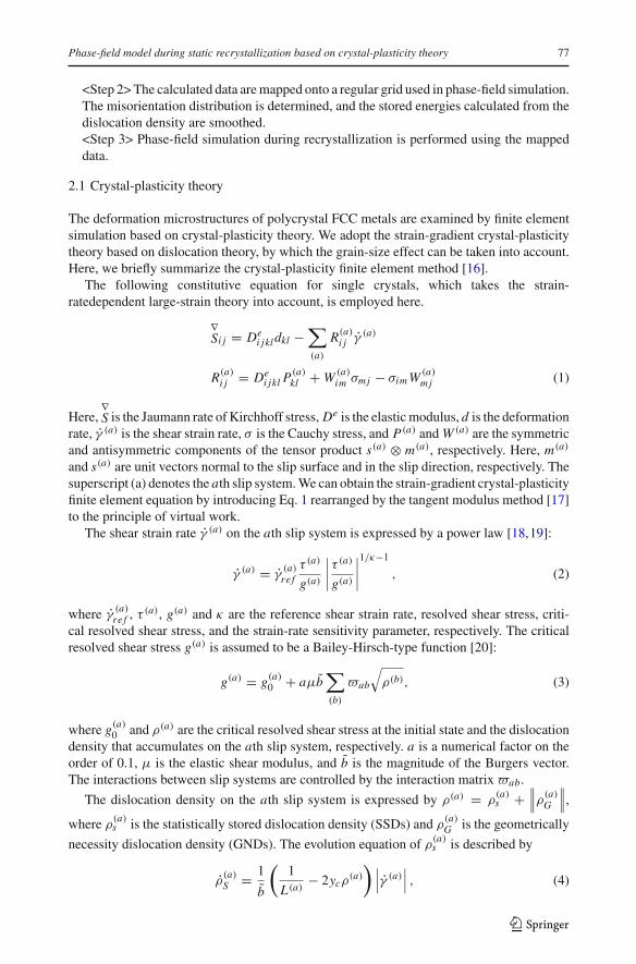
Fig. 3 Computational model and boundary conditions for crystal-plasticity finite element simulation anddefinition of crystal orientation θ
Fig. 4 Results of crystal-plasticity finite element simulation: (a) crystal orientation, (b) stored energy,(c) misorientation and (d) smoothed stored energy
system, some grains rotate toward θ = 0 or π and the others are refined. Inside the refinedgrains, high stored energies, or dislocation densities, are observed. Figure 4 (c) illustrates themisorientation distribution calculated using the orientations mapped to the regular grids. Forevery 5 degrees from 0 up to 15 degrees, the misorientations become dark in gray scale. Thearea shown in intense black, therefore, indicates a high-angle grain boundary of more than15 degrees. It is observed that the high-angle grain boundaries occur inside the refined grainsin addition to at the original grain boundaries. The results shown in Fig. 4(b) are smoothedby Eq. 8, and the smoothed stored energies are demonstrated in Fig. 4(d). Figure 5 shows thechanges in stored energy in the x-direction along the center line of y = 51.2µm of Figs. 4 (b)and (d). From Fig. 5, the results of crystal-plasticity finite element analysis change elementby element; meanwhile, it can be seen that the smoothed data are continuously distributed;the radius of the circle used for the smoothing operation is set to 3�x , where �x is the gridsize.
123

82 T. Takaki etal.
Fig. 5 Stored energy before and after smoothing operation
3.2 Phase-field simulation
The nucleation and growth of the recrystallized grains are simulated by the phase-fieldmethod based on the results of Figs. 4 (a), (c) and (d). The grain growth driven by the storedenergy follows the time-evolution equations of the two order parameters, i.e., Eqs. 10 and 11.Although there are still uncertainties about the nucleation, some mechanisms have been clari-fied [2]: (i) the high-angle grain boundary is necessary, (ii) the high strain energy is necessary,and (iii) the orientations of the nuclei are present in the deformed structure. From (i), theintense black region in Fig. 4 (c) is a possible nucleation area, since we define the high-anglegrain boundary to be more than 15 degrees. From (ii), we assume that the region where thestored energy is more than a critical value Ec is a possible nucleation site. Here, we assumethree valoues of Ec, or 0.6, 0.7 and 0.8 MPa. From (iii), the orientations shown in Fig. 4 (a)are used as the orientations of the nuclei. In addition to the above criteria, we set the distancebetween two neighboring nuclei to be more than 10�x , because the phase-field methoduses the diffusive interface region with a finite width. Here, we assume the site-saturatednucleation model.
Figures 6 (a-1), (b-1) and (c-1) show the nucleation sites satisfying the four above criteria.There are 940, 612 and 251 nuclei in Figs. 6 (a-1), (b-1) and (c-1), respectively. The radiusof the nuclei is set to be 3�x . Comparing Figs. 5 and 6, it is confirmed that an appropriatenucleation operation can be performed following the defined criteria. From these nuclei, thegrain growth simulation is started. Here, the following parameters are used in the phase-fieldsimulations: �x = 0.4µm, δ = 4�x , σ = 0.6 J/m2, T = 800 K, kB = 1.38 × 10⁻²³ [J/K],M0 = 6.2 × 10⁻⁶ [m3/Ns], Q′ = 2.08 × 10⁻¹⁹ J, s = α
√2W/π and M0
θ = Mφ . The zeroNeumann conditions for both φ and θ are applied on all boundaries of the computationaldomain. The numerical simulation is performed by employing the adaptive finite elementmethod using an isoparametric quadrilateral element [23]. Six levels of refinement, Level 0to Level 5, are used, so that the minimum element size, i.e., Level 5, is �x5 = �x = 0.4µmand the maximum one, i.e., Level 0, is �x0 = 25�x = 12.8µm. The refinement operationis performed when 0.001 ≤ φave ≤ 0.9 or |∇θave| ≥ 0.1, where the subscript ave meansthe average value of four gaussian points in an element. The nodes of the adaptive elementscorrespond to the regular grids used in data mapping.
Figure 7 shows the time evolution of the recrystallization grains together with the adaptivemesh for the case of Ec = 0.7. As we can see from Figs. 6 and 7, the nuclei are generated onthe original grain boundaries and inside the subdivided grains and grow into grains with lowstored energy. During recrystallization, new grain boundaries are formed. Figures 6 (a-2),(b-2) and (c-2) illustrate the final recrystallization microstructures. The recrystallized grainswith a characteristic vertically elongated shape can be observed for all the different values ofEc. As a result, it can be concluded that, using the numerical model and procedure proposed
123
Phase-field model during static recrystallization based on crystal-plasticity theory 83
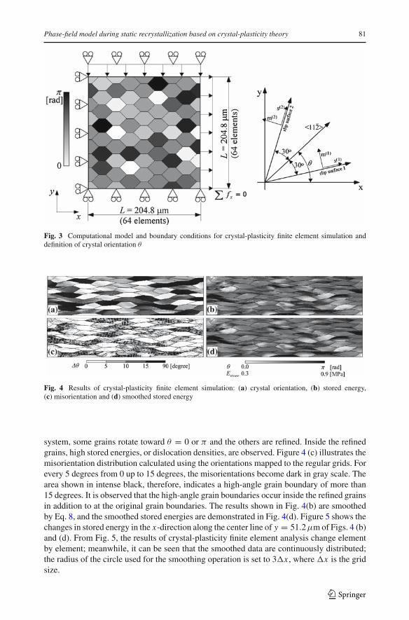
Fig. 6 Nucleation sites and recrystallization microstructures: Ec = (a) 0.6 MPa, (b) 0.7 MPa and (c) 0.8 MPa
Fig. 7 Time evolution of recrystallization region and adaptive mesh for Ec = 0.7 MPa. t = (a) 0 s, (b) 10 s,(c) 20 s and (d) 30 s
in this study, we can simulate the recrystallization microstructure based on the deformationmicrostructure without any experimental information. Furthermore, from Fig. 7, it is foundthat the adaptive meshes satisfactorily adapt to the migrating grain boundaries.
However, from Fig. 6, the sizes of recrystallized grains depend on the defined criteria,so that the establishment of precise nucleation criteria based on the nucleation mechanismis an urgent necessity. The other method is the establishment of a numerical model thatenables spontaneous nucleation during recovery, such as the abnormal grain growth andcoalescence due to the subgrain rotation. The abnormal grain growth can be simulated byboth the multi-phase-field method [11,12] and the KWC phase-field method [10,21,22].However, the rotation of the subgrain is reproduced only by the KWC model. Therefore,we can expect that the generalized KWC model using the numerical procedure proposed inthis study may provide a powerful tool for the solution of these problems. We will solve thisproblem as future work.
4 Conclusions
In order to enable the simulation of a recrystallization microstructure by taking the defor-mation microstructure into account, a coupled numerical model and procedure is proposedusing a phase-field method and crystal-plasticity theory. As the phase-field method, the KWCmodel is generalized to the primary static recrystallization in which the grain boundary mi-gration is driven by the stored energy due to the accumulation of dislocations. Furthermore,a data-mapping method and a smoothing method of stored energy are proposed in order to
123

84 T. Takaki etal.
transfer the data calculated by crystal-plasticity FE analysis to phase-field simulation. Byperforming a series of simulations, it is confirmed that the nucleation and grain growth ofrecrystallized grains based on the deformation microstructure can be reproduced.
References
1. Raabe, D.: Computational Materials Science. Federal Republic of Germany (1998)2. Humphreys, F.J., Hatherly, M.: Recrystallization and Related Annealing Phenomena, 2nd edn. Elsevier
(2004)3. Srolovitz, D.J., Grest, G.S., Anderson, M.P.: Computer simulation of recrystallization—I. Homogeneous
nucleation and growth. Acta Metal. 34, 1833–1845 (1986)4. Hesselbarth, H.W., Gobel, I.R.: Simulation of recrystallization by cellular automata. Acta Metall.
Mater. 39, 2135–2143 (1991)5. Miodownik, M.A.: A review of microstructural computer models used to simulate grain growth and
recrystallisation in aluminium alloys. J. Light Metals 2, 125–135 (2002)6. Raabe, D.: Scaling Monte Carlo kinetics of the Potts model using rate theory. Acta Mater. 48,
1617–1628 (2000)7. Rollet, A.D., Raabe, D.: A hybrid model for mesoscopic simulation of recrystallization. Comp. Mate.
Sci. 21, 69–78 (2001)8. Kobayashi, R.: Modeling and numerical simulations of dendritic crystal growth. Physica D 63,
410–423 (1993)9. Warren, J.A., Boettinger, W.J.: Prediction of dendritic growth and microsegregation patterns in a binary
alloy using the phase-field method. Acta Metal. 43, 689 (1995)10. Kobayashi, R., Warren, J.A., Carter, W.C.: A continuum model of grain boundaries. Physica D 140,
141–150 (2000)11. Chen, L.-Q., Yang, W.: Computer simulation of the domain dynamics of a quenched system with a large
number of nonconserved order parameters: The grain-growth kinetics. Phy. Rev. B 50,15752–15756 (1994)
12. Steinbach, I., Pezzolla, F.: A generalized field method for multiphase transformations using interfacefields. Physica D 134, 385–393 (1999)
13. Kobayashi, R., Giga, Y.: Equations with singular diffusivity. J. Statistical Physics 95, 1187–1220 (1999)14. Xiao, N., Tong, M., Lan, Y., Li, D., Li, Y.: Coupled simulation of the influence of austenite deformation
on the subsequent isothermal austenite-ferrite transformation. Acta Meter. 54, 1265–1278 (2006)15. Lan, Y.J., Xiao, N.M., Li, D.Z., Li, Y.Y.: Mesoscale simulation of deformed austenite decomposition
into ferrite by coupling a cellular automaton method with a crystal plasticity finite element model. ActaMeter. 53, 991–1003 (2005)
16. Higa, Y., Sawada, Y., Tomita, Y.: Computational simulation of characteristic length dependent deforma-tion behavior of polycrystalline metals. Trans. JSME A69, 523–529 (in Japanese) (2003)
17. Peirce, D., Shih, C.F., Needleman, A.: A tangent modulus method for rate dependent solids. Comput.Struc. 18, 875–887 (1984)
18. Hutchinson, J.W.: Bounds and self-consistent estimates for creep of polycrystalline materials. Proc. R.Soc. London. Series A 348, 101–127 (1976)
19. Pan, J., Rice, J.R.: Rate sensitivity of plastic flow and implications for yield-surface vertices. J. SolidsStruct. 19, 973–987 (1983)
20. Ohashi, T.: Numerical modelling of plastic multislip in metal crystals of f.c.c. type. Philos. Magaz.A 70, 793–803 (1994)
21. Warren, J.A., Kobayashi, R., Lobkovskey, A.E., Carter, W.C.: Extending phase field models of solidifi-cation to polycrystalline materials. Acta Mater. 51, 6035–6058 (2003)
22. Warren, J.A., Carter, W.C., Kobayashi, R.: A phase field model of the impingement of solidifyingparticles. Physica A 261, 159–166 (1998)
23. Takaki, T., Fukuoka, T., Tomita, Y.: Phase-field simulation during directional solidification of a binaryalloy using adaptive finite element method. J. Crys. Growth 283, 263–278 (2005)
24. Nakamachi, E., Ariyoshi, T., Kobayashi, Y., Hirose, M., Morimoto, H.: SEM-EBSD experimental andfinite element analyses of plastic deformation induced crystal rotation of pure aluminium single crys-tals. Trans. Japan Soc. Mech. Eng. A 69, 817–822 (2003)
25. Kuo, C.-M., Chu, H.-H.: Plastic deformation mechanism of pure aluminum at low homologous tempe-ratures. Mate. Sci. Eng. A 409, 59–66 (2005)
123