PEX/PISO-P32x32/x64 - Series Board User Manual - ICP DAS
93
PEX/PISO-P32x32/x64 Series Board User Manual Isolation Digital Input & Output Boards Version 4.9, Dec. 2018 SUPPORT This manual relates to the following boards: WARRANTY All products manufactured by ICP DAS are warranted against defective materials for a period of one year from the date of delivery to the original purchaser. WARNING ICP DAS assumes no liability for damages consequent to the use of this product. ICP DAS reserves the right to change this manual at any time without notice. The information furnished by ICP DAS is believed to be accurate and reliable. However, no responsibility is assumed by ICP DAS for its use, nor for any infringements of patents or other rights of third parties resulting from its use. COPYRIGHT Copyright © 2018 by ICP DAS. All rights are reserved. TRADEMARKS Names are used for identification purposes only and may be registered trademarks of their respective companies. CONTACT US If you have any question, feel to contact us by email at: Email: [email protected] or [email protected] We will respond to you within 2 working days.
-
Upload
khangminh22 -
Category
Documents
-
view
1 -
download
0
Transcript of PEX/PISO-P32x32/x64 - Series Board User Manual - ICP DAS

PEX/PISO-P32x32/x64 Series Board User Manual Isolation Digital Input & Output Boards Version 4.9, Dec. 2018
SUPPORT This manual relates to the following boards:
WARRANTY All products manufactured by ICP DAS are warranted against defective materials for a period of one year from the date of delivery to the original purchaser. WARNING ICP DAS assumes no liability for damages consequent to the use of this product. ICP DAS reserves the right to change this manual at any time without notice. The information furnished by ICP DAS is believed to be accurate and reliable. However, no responsibility is assumed by ICP DAS for its use, nor for any infringements of patents or other rights of third parties resulting from its use. COPYRIGHT Copyright © 2018 by ICP DAS. All rights are reserved. TRADEMARKS Names are used for identification purposes only and may be registered trademarks of their respective companies. CONTACT US If you have any question, feel to contact us by email at: Email: [email protected] or [email protected] We will respond to you within 2 working days.

Isolation Digital Input & Output Boards
User Manual, Ver. 4.9, Dec. 2018, PMH-0001-49 Page: 2
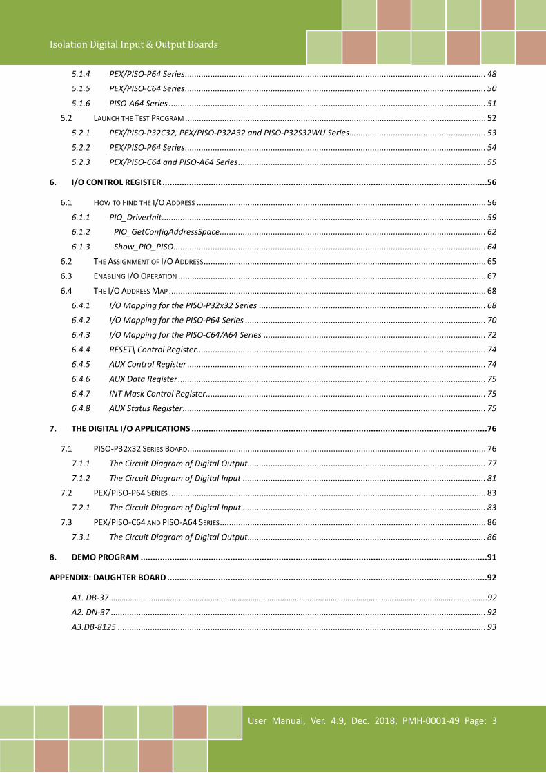
TABLE OF CONTENTS
PACKING LIST ................................................................................................................................................................ 4
1. INTRODUCTION ................................................................................................................................................... 5
1.1 FEATURES .............................................................................................................................................................. 7 1.2 SPECIFICATIONS ...................................................................................................................................................... 8
1.2.1 PEX/PISO-P32C32 Series ..................................................................................................................................... 8 1.2.2 PEX/PISO-P32A32 Series ..................................................................................................................................... 9 1.2.3 PISO-P32S32WU Series ..................................................................................................................................... 10 1.2.4 PEX/PISO-C64 Series ......................................................................................................................................... 11 1.2.5 PISO-A64 Series ................................................................................................................................................ 11 1.2.6 PEX/PISO-P64 Series ......................................................................................................................................... 12
2. HARDWARE CONFIGURATION ............................................................................................................................. 13
2.1 APPEARANCE ....................................................................................................................................................... 13 2.1.1 PEX/PISO-P32C32/P32A32 Series ..................................................................................................................... 13 2.1.2 PISO-P32S32WU ............................................................................................................................................... 16 2.1.3 PEX/PISO-P64 Series ......................................................................................................................................... 17 2.1.4 PEX/PISO-C64 and PISO-A64 Series .................................................................................................................. 20
2.2 CARD ID SWITCH (SW1)........................................................................................................................................ 22 2.3 ISOLATED DI ARCHITECTURE.................................................................................................................................... 23 2.4 ISOLATED DO ARCHITECTURE .................................................................................................................................. 24 2.5 PIN ASSIGNMENTS ................................................................................................................................................ 25
2.5.1 PEX/PISO-P32C32/P32A32 Series .............................................................................................................. 25 2.5.2 PISO-P32S32WU ........................................................................................................................................ 26 2.5.3 PEX/PISO-P64 Series .................................................................................................................................. 27 2.5.4 PEX/PISO-C64 and PISO-A64 Series ........................................................................................................... 28
3. HARDWARE INSTALLATION ................................................................................................................................. 29
4. SOFTWARE INSTALLATION .................................................................................................................................. 33
4.1 OBTAINING/INSTALLING THE DRIVER INSTALLER PACKAGE ............................................................................................. 33 4.2 PNP DRIVER INSTALLATION ..................................................................................................................................... 36 4.3 VERIFYING THE INSTALLATION .................................................................................................................................. 38
4.3.1 Accessing Windows Device Manager ........................................................................................................ 38 4.3.2 Check the Installation ................................................................................................................................ 41
5. BOARD TESTING ................................................................................................................................................. 42
5.1 SELF-TEST WIRING ................................................................................................................................................ 42 5.1.1 PEX/PISO-P32C32 Series ............................................................................................................................ 43 5.1.2 PEX/PISO-P32A32 Series ........................................................................................................................... 45 5.1.3 PISO-P32S32WU Series ............................................................................................................................. 47
Isolation Digital Input & Output Boards
User Manual, Ver. 4.9, Dec. 2018, PMH-0001-49 Page: 3
5.1.4 PEX/PISO-P64 Series .................................................................................................................................. 48 5.1.5 PEX/PISO-C64 Series .................................................................................................................................. 50 5.1.6 PISO-A64 Series ......................................................................................................................................... 51
5.2 LAUNCH THE TEST PROGRAM .................................................................................................................................. 52 5.2.1 PEX/PISO-P32C32, PEX/PISO-P32A32 and PISO-P32S32WU Series........................................................... 53 5.2.2 PEX/PISO-P64 Series .................................................................................................................................. 54 5.2.3 PEX/PISO-C64 and PISO-A64 Series ........................................................................................................... 55
6. I/O CONTROL REGISTER ...................................................................................................................................... 56
6.1 HOW TO FIND THE I/O ADDRESS ............................................................................................................................. 56 6.1.1 PIO_DriverInit ............................................................................................................................................ 59 6.1.2 PIO_GetConfigAddressSpace................................................................................................................... 62 6.1.3 Show_PIO_PISO ....................................................................................................................................... 64
6.2 THE ASSIGNMENT OF I/O ADDRESS .......................................................................................................................... 65 6.3 ENABLING I/O OPERATION ..................................................................................................................................... 67 6.4 THE I/O ADDRESS MAP ......................................................................................................................................... 68
6.4.1 I/O Mapping for the PISO-P32x32 Series .................................................................................................. 68 6.4.2 I/O Mapping for the PISO-P64 Series ........................................................................................................ 70 6.4.3 I/O Mapping for the PISO-C64/A64 Series ................................................................................................ 72 6.4.4 RESET\ Control Register............................................................................................................................. 74 6.4.5 AUX Control Register ................................................................................................................................. 74 6.4.6 AUX Data Register ..................................................................................................................................... 75 6.4.7 INT Mask Control Register ......................................................................................................................... 75 6.4.8 AUX Status Register ................................................................................................................................... 75
7. THE DIGITAL I/O APPLICATIONS .......................................................................................................................... 76
7.1 PISO-P32X32 SERIES BOARD................................................................................................................................. 76 7.1.1 The Circuit Diagram of Digital Output....................................................................................................... 77 7.1.2 The Circuit Diagram of Digital Input ......................................................................................................... 81
7.2 PEX/PISO-P64 SERIES ......................................................................................................................................... 83 7.2.1 The Circuit Diagram of Digital Input ......................................................................................................... 83
7.3 PEX/PISO-C64 AND PISO-A64 SERIES ................................................................................................................... 86 7.3.1 The Circuit Diagram of Digital Output....................................................................................................... 86
8. DEMO PROGRAM ............................................................................................................................................... 91
APPENDIX: DAUGHTER BOARD .................................................................................................................................... 92
A1. DB-37 ……………………………………………………………………………………………………………………………………………………………..92 A2. DN-37 .................................................................................................................................................................. 92 A3.DB-8125 ............................................................................................................................................................... 93
Isolation Digital Input & Output Boards
User Manual, Ver. 4.9, Dec. 2018, PMH-0001-49 Page: 4
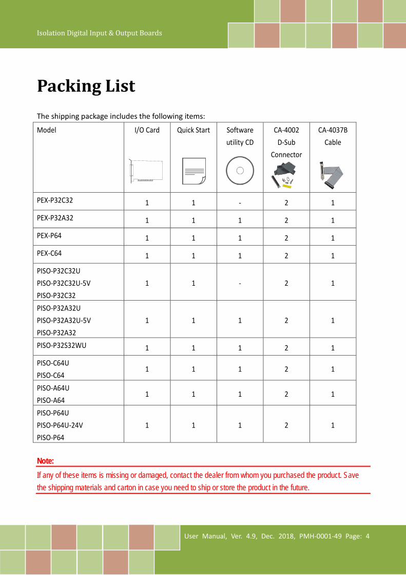
Packing List The shipping package includes the following items:
Model I/O Card Quick Start Software utility CD
CA-4002 D-Sub
Connector
CA-4037B Cable
PEX-P32C32 1 1 - 2 1
PEX-P32A32 1 1 1 2 1
PEX-P64 1 1 1 2 1
PEX-C64 1 1 1 2 1
PISO-P32C32U PISO-P32C32U-5V PISO-P32C32
1 1 - 2 1
PISO-P32A32U PISO-P32A32U-5V PISO-P32A32
1 1 1 2 1
PISO-P32S32WU 1 1 1 2 1
PISO-C64U PISO-C64
1 1 1 2 1
PISO-A64U PISO-A64
1 1 1 2 1
PISO-P64U PISO-P64U-24V PISO-P64
1 1 1 2 1
Note: If any of these items is missing or damaged, contact the dealer from whom you purchased the product. Save the shipping materials and carton in case you need to ship or store the product in the future.

Isolation Digital Input & Output Boards
User Manual, Ver. 4.9, Dec. 2018, PMH-0001-49 Page: 5
1. Introduction Comparison Table
Model Name Bus DI DO Channels
Channels Input Voltage
Low Drive
High Drive Type
PISO-P32S32WU Universal PCI 32 Logic 1: 9 ~ 24 V 24-ch 8-ch Current Sink,
NPN
PEX-P32C32 PCI Express 32 Logic 1: 9 ~ 24 V 32-ch - Current Sink,
NPN
PISO-P32C32U-5V Universal PCI 32 Logic 1: 5 ~ 12 V 32-ch - Current Sink,
NPN
PISO-P32C32U Universal PCI 32 Logic 1: 9 ~ 24 V 32-ch - Current Sink,
NPN
PEX-P32A32 PCI Express 32 Logic 1: 9 ~ 24 V 32-ch - Current Source,
PNP
PISO-P32A32U Universal PCI 32 Logic 1: 9 ~ 24 V 32-ch - Current Source,
PNP
PISO-P32A32U-5V 5 V PCI 32 Logic 1: 5 ~ 12 V 32-ch - Current Source,
PNP
PEX-P64 PCI Express 64 Logic 1: 5 ~ 24 V - - -
PISO-P64U Universal PCI 64 Logic 1: 5 ~ 24 V - - -
PISO-P64U-24V Universal PCI 64 Logic 1: 20 ~ 28 V - - -
PEX-C64 PCI Express - - 64-ch - Current Sink, NPN
PISO-C64U Universal PCI - - 64-ch - Current Sink, NPN
PISO-A64 5 V PCI - - 64-ch - Current Source, PNP
PISO-A64U Universal PCI - - 64-ch - Current Source, PNP
Isolation Digital Input & Output Boards
User Manual, Ver. 4.9, Dec. 2018, PMH-0001-49 Page: 6
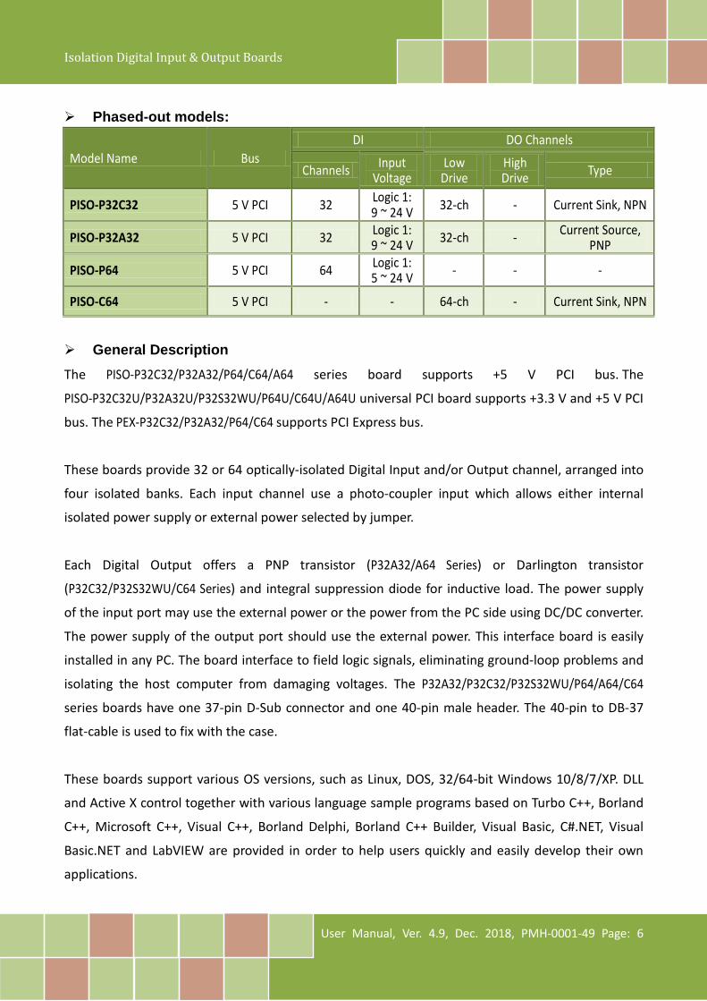
Phased-out models:
Model Name Bus DI DO Channels
Channels Input Voltage
Low Drive
High Drive Type
PISO-P32C32 5 V PCI 32 Logic 1: 9 ~ 24 V 32-ch - Current Sink, NPN
PISO-P32A32 5 V PCI 32 Logic 1: 9 ~ 24 V 32-ch - Current Source,
PNP
PISO-P64 5 V PCI 64 Logic 1: 5 ~ 24 V - - -
PISO-C64 5 V PCI - - 64-ch - Current Sink, NPN
General Description The PISO-P32C32/P32A32/P64/C64/A64 series board supports +5 V PCI bus. The
PISO-P32C32U/P32A32U/P32S32WU/P64U/C64U/A64U universal PCI board supports +3.3 V and +5 V PCI
bus. The PEX-P32C32/P32A32/P64/C64 supports PCI Express bus.
These boards provide 32 or 64 optically-isolated Digital Input and/or Output channel, arranged into
four isolated banks. Each input channel use a photo-coupler input which allows either internal
isolated power supply or external power selected by jumper.
Each Digital Output offers a PNP transistor (P32A32/A64 Series) or Darlington transistor
(P32C32/P32S32WU/C64 Series) and integral suppression diode for inductive load. The power supply
of the input port may use the external power or the power from the PC side using DC/DC converter.
The power supply of the output port should use the external power. This interface board is easily
installed in any PC. The board interface to field logic signals, eliminating ground-loop problems and
isolating the host computer from damaging voltages. The P32A32/P32C32/P32S32WU/P64/A64/C64
series boards have one 37-pin D-Sub connector and one 40-pin male header. The 40-pin to DB-37
flat-cable is used to fix with the case.
These boards support various OS versions, such as Linux, DOS, 32/64-bit Windows 10/8/7/XP. DLL
and Active X control together with various language sample programs based on Turbo C++, Borland
C++, Microsoft C++, Visual C++, Borland Delphi, Borland C++ Builder, Visual Basic, C#.NET, Visual
Basic.NET and LabVIEW are provided in order to help users quickly and easily develop their own
applications.

Isolation Digital Input & Output Boards
User Manual, Ver. 4.9, Dec. 2018, PMH-0001-49 Page: 7
1.1 Features
Interface: • Supports the +5 V PCI bus for PISO-P32A32/P32C32/P64/C64/A64.
• Supports the +3.3 V/+5 V PCI bus for PISO-P32A32U/P32C32U/P32S32WU/P64U/C64U/A64U.
• Supports PCI Express x 1 for PEX-P32C32/P32A32/P64/C64.
• Card ID function (SMD Switch) for PEX-P32C32/P32A32/P64/C64 and
PISO-P32C32U/P32A32U/P32S32WU/P64U/C64U/A64U.
Digital Input: • 32 optically-isolated Digital Input channels for PISO-P32A32/P32C32/P32S32WU and
PEX-P32C32/P32A32.
• 64 optically-isolated Digital Input channels for PEX-P64 and PISO-P64.
Digital Output: • 32 optically-isolated open collector output channels, as follow:
• Current Sink (NPN) for PEX-P32C32 and PISO-P32C32
• Current Source (PNP) for PEX-P32A32 and PISO-P32A32
• Current Sink (NPN), 500 mA (8-ch) high driving and 100 mA (24-ch) driving for
PISO-P32S32WU
• 64 optically-isolated DO, as follow:
• Current Sink (NPN) for PEX-C64 and PISO-C64/C64U
• Current Source (PNP) for PISO-A64/A64U
• Output status readback for PEX-P32C32/P32A32/C64 and
PISO-P32C32U/P32A32U/C64U/A64U.
Isolated Protection: • Built-in DC/DC converter providing 3000 VDC isolation for PEX-P32C32/P32A32/P64 and
PISO-P32C32U/P32A32U/P64U.
• 3750 Vrms photo-isolated protection.
Isolation Digital Input & Output Boards
User Manual, Ver. 4.9, Dec. 2018, PMH-0001-49 Page: 8
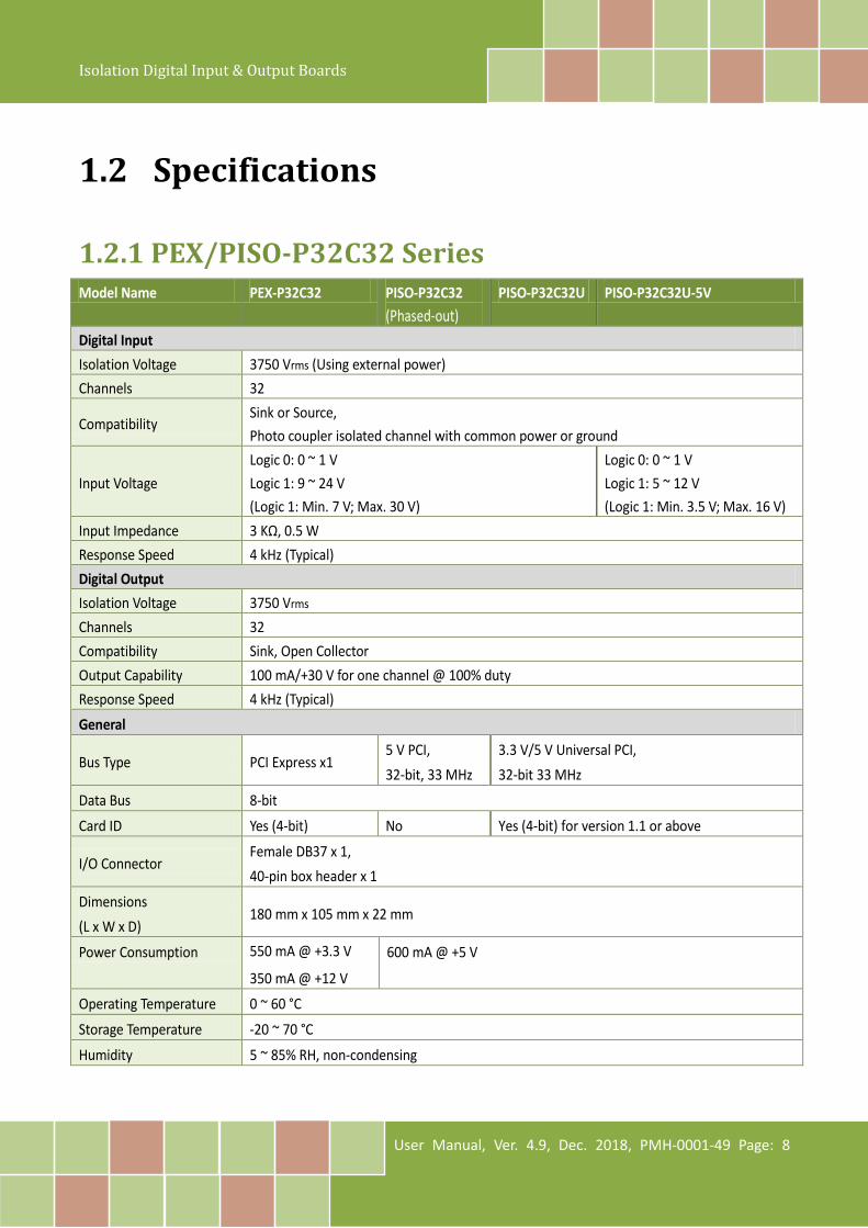
1.2 Specifications
1.2.1 PEX/PISO-P32C32 Series Model Name PEX-P32C32 PISO-P32C32
(Phased-out) PISO-P32C32U PISO-P32C32U-5V
Digital Input Isolation Voltage 3750 Vrms (Using external power) Channels 32
Compatibility Sink or Source, Photo coupler isolated channel with common power or ground
Input Voltage Logic 0: 0 ~ 1 V Logic 1: 9 ~ 24 V (Logic 1: Min. 7 V; Max. 30 V)
Logic 0: 0 ~ 1 V Logic 1: 5 ~ 12 V (Logic 1: Min. 3.5 V; Max. 16 V)
Input Impedance 3 KΩ, 0.5 W Response Speed 4 kHz (Typical) Digital Output Isolation Voltage 3750 Vrms Channels 32 Compatibility Sink, Open Collector Output Capability 100 mA/+30 V for one channel @ 100% duty Response Speed 4 kHz (Typical) General
Bus Type PCI Express x1 5 V PCI, 32-bit, 33 MHz
3.3 V/5 V Universal PCI, 32-bit 33 MHz
Data Bus 8-bit
Card ID Yes (4-bit) No Yes (4-bit) for version 1.1 or above
I/O Connector Female DB37 x 1, 40-pin box header x 1
Dimensions (L x W x D)
180 mm x 105 mm x 22 mm
Power Consumption 550 mA @ +3.3 V
350 mA @ +12 V
600 mA @ +5 V
Operating Temperature 0 ~ 60 °C
Storage Temperature -20 ~ 70 °C
Humidity 5 ~ 85% RH, non-condensing

Isolation Digital Input & Output Boards
User Manual, Ver. 4.9, Dec. 2018, PMH-0001-49 Page: 9
1.2.2 PEX/PISO-P32A32 Series Model Name PEX-P32A32 PISO-P32A32U PISO-P32A32U-5V PISO-P32A32
(Phased-out) Digital Input Isolation Voltage 3750 Vrms (Using external power) Channels 32 Compatibility Photo coupler isolated
Input Voltage
Logic 0: 0 ~ 1 V Logic 1: 9 ~ 24 V (Logic 1: Min. 7 V; Max. 30 V)
Logic 0: 0 ~ 1 V Logic 1: 5 ~ 12 V (Logic 1: Min. 3.5 V; Max. 16 V)
Logic 0: 0 ~ 1 V Logic 1: 9 ~ 24 V (Logic 1: Min. 7 V; Max. 30 V)
D/I Power External Internal/External External Input Impedance 3 KΩ, 0.5 W Response Speed 4 kHz (Typical) Digital Output Isolation Voltage 3750 Vrms Channels 32 Compatibility Source, Open Collector Output Capability 100 mA/+30 V for one channel @ 100% duty Response Speed 4 kHz (Typical) General
Bus Type PCI Express x1 3.3 V/5 V Universal PCI, 32-bit 33 MHz
3.3 V/5 V Universal PCI, 32-bit 33 MHz
5 V PCI, 32-bit, 33 MHz
Data Bus 8-bit
Card ID Yes(4-bit) No
I/O Connector Female DB37 x 1, 40-pin box header x 1
Dimensions (L x W x D) 180 mm x 105 mm x 22 mm Power Consumption 550 mA @ +3.3 V
350 mA @ +12 V
600 mA @ +5 V
Operating Temperature 0 ~ 60 °C
Storage Temperature -20 ~ 70 °C
Humidity 5 ~ 85% RH, non-condensing
Isolation Digital Input & Output Boards
User Manual, Ver. 4.9, Dec. 2018, PMH-0001-49 Page: 10
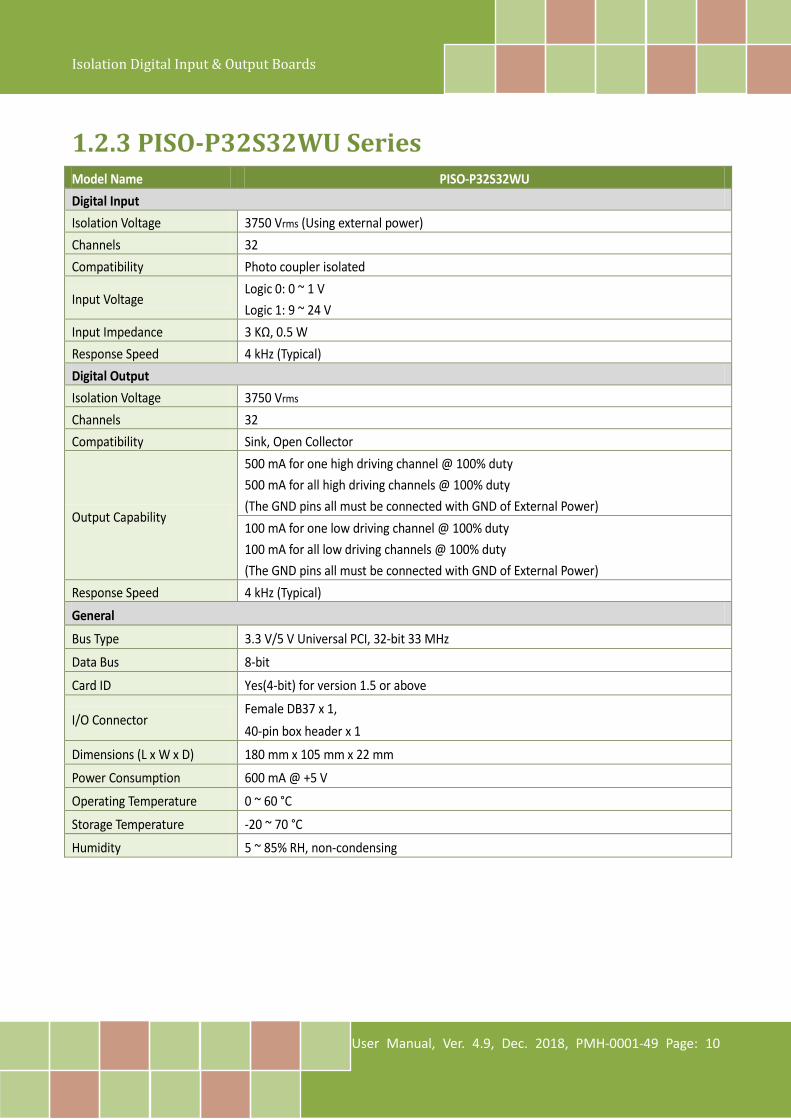
1.2.3 PISO-P32S32WU Series Model Name PISO-P32S32WU Digital Input Isolation Voltage 3750 Vrms (Using external power) Channels 32 Compatibility Photo coupler isolated
Input Voltage Logic 0: 0 ~ 1 V Logic 1: 9 ~ 24 V
Input Impedance 3 KΩ, 0.5 W Response Speed 4 kHz (Typical) Digital Output Isolation Voltage 3750 Vrms Channels 32 Compatibility Sink, Open Collector
Output Capability
500 mA for one high driving channel @ 100% duty 500 mA for all high driving channels @ 100% duty (The GND pins all must be connected with GND of External Power) 100 mA for one low driving channel @ 100% duty 100 mA for all low driving channels @ 100% duty (The GND pins all must be connected with GND of External Power)
Response Speed 4 kHz (Typical) General
Bus Type 3.3 V/5 V Universal PCI, 32-bit 33 MHz
Data Bus 8-bit
Card ID Yes(4-bit) for version 1.5 or above
I/O Connector Female DB37 x 1, 40-pin box header x 1
Dimensions (L x W x D) 180 mm x 105 mm x 22 mm
Power Consumption 600 mA @ +5 V
Operating Temperature 0 ~ 60 °C
Storage Temperature -20 ~ 70 °C
Humidity 5 ~ 85% RH, non-condensing
Isolation Digital Input & Output Boards
User Manual, Ver. 4.9, Dec. 2018, PMH-0001-49 Page: 11
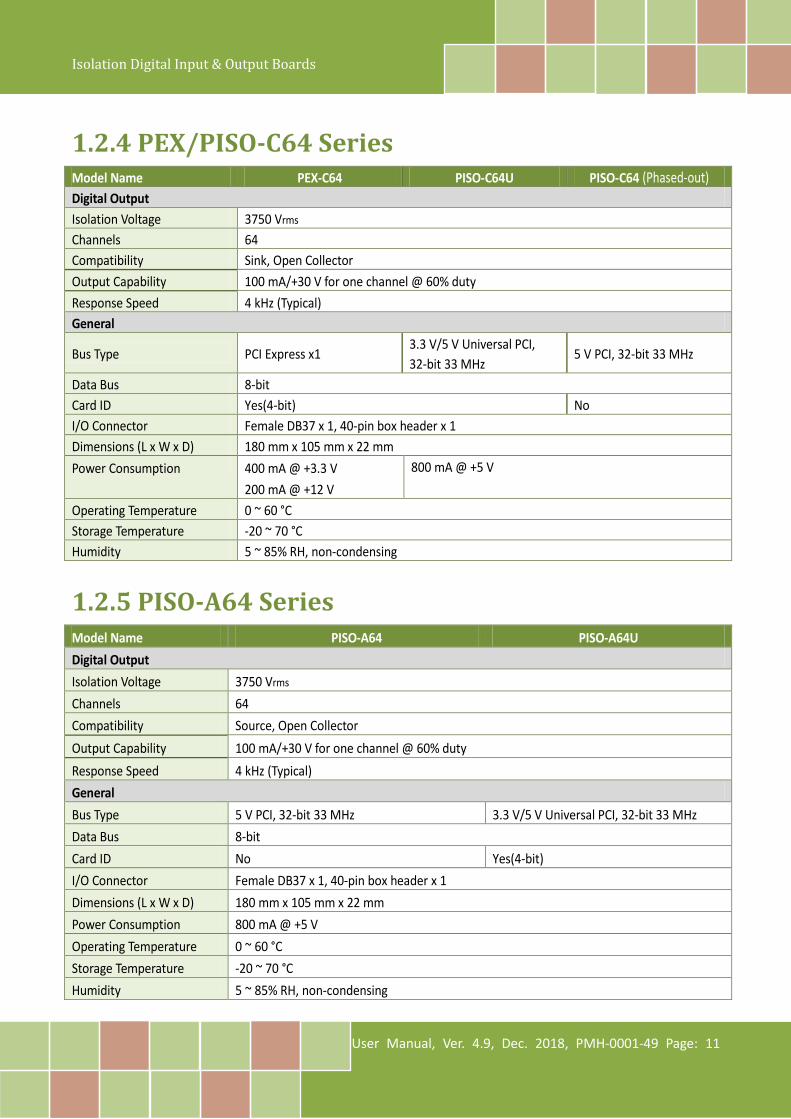
1.2.4 PEX/PISO-C64 Series Model Name PEX-C64 PISO-C64U PISO-C64 (Phased-out) Digital Output Isolation Voltage 3750 Vrms Channels 64 Compatibility Sink, Open Collector Output Capability 100 mA/+30 V for one channel @ 60% duty Response Speed 4 kHz (Typical) General
Bus Type PCI Express x1 3.3 V/5 V Universal PCI, 32-bit 33 MHz
5 V PCI, 32-bit 33 MHz
Data Bus 8-bit Card ID Yes(4-bit) No I/O Connector Female DB37 x 1, 40-pin box header x 1 Dimensions (L x W x D) 180 mm x 105 mm x 22 mm Power Consumption 400 mA @ +3.3 V
200 mA @ +12 V 800 mA @ +5 V
Operating Temperature 0 ~ 60 °C Storage Temperature -20 ~ 70 °C Humidity 5 ~ 85% RH, non-condensing
1.2.5 PISO-A64 Series Model Name PISO-A64 PISO-A64U Digital Output Isolation Voltage 3750 Vrms Channels 64 Compatibility Source, Open Collector Output Capability 100 mA/+30 V for one channel @ 60% duty Response Speed 4 kHz (Typical) General Bus Type 5 V PCI, 32-bit 33 MHz 3.3 V/5 V Universal PCI, 32-bit 33 MHz Data Bus 8-bit Card ID No Yes(4-bit) I/O Connector Female DB37 x 1, 40-pin box header x 1 Dimensions (L x W x D) 180 mm x 105 mm x 22 mm Power Consumption 800 mA @ +5 V Operating Temperature 0 ~ 60 °C Storage Temperature -20 ~ 70 °C Humidity 5 ~ 85% RH, non-condensing
Isolation Digital Input & Output Boards
User Manual, Ver. 4.9, Dec. 2018, PMH-0001-49 Page: 12
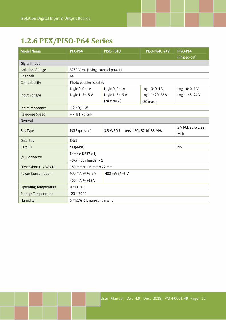
1.2.6 PEX/PISO-P64 Series Model Name PEX-P64 PISO-P64U PISO-P64U-24V PISO-P64
(Phased-out) Digital Input Isolation Voltage 3750 Vrms (Using external power) Channels 64 Compatibility Photo coupler isolated
Input Voltage Logic 0: 0~1 V Logic 1: 5~15 V
Logic 0: 0~1 V Logic 1: 5~15 V (24 V max.)
Logic 0: 0~1 V Logic 1: 20~28 V
(30 max.)
Logic 0: 0~1 V Logic 1: 5~24 V
Input Impedance 1.2 KΩ, 1 W Response Speed 4 kHz (Typical) General
Bus Type PCI Express x1 3.3 V/5 V Universal PCI, 32-bit 33 MHz 5 V PCI, 32-bit, 33 MHz
Data Bus 8-bit
Card ID Yes(4-bit) No
I/O Connector Female DB37 x 1, 40-pin box header x 1
Dimensions (L x W x D) 180 mm x 105 mm x 22 mm
Power Consumption 600 mA @ +3.3 V
400 mA @ +12 V
400 mA @ +5 V
Operating Temperature 0 ~ 60 °C
Storage Temperature -20 ~ 70 °C
Humidity 5 ~ 85% RH, non-condensing

Isolation Digital Input & Output Boards
User Manual, Ver. 4.9, Dec. 2018, PMH-0001-49 Page: 13
2. Hardware Configuration
2.1 Appearance
2.1.1 PEX/PISO-P32C32/P32A32 Series The following is an overview of the board layout for each of the PISO-P32C32/P32A32 and
PISO-P32C32U(-5V)/P32A32U(-5V).
CON1
1 2 3 4
CON2
LED1 LED2 LED3 LED4For PISO-P32C32U/
PISO-P32A32U onlyDC/DC1 DC/DC2
DI <0..15>DO <0..15>
DI <16..31>DO<16..31>
JP1 JP2
SW1
The following is an overview of the board layout for each of the PEX-P32C32/P32A32.
LED1 LED2 LED3 LED4
CON1 CON2
DI <0..15>DO <0..15>
DI <16..31>DO<16..31>
SW1
1 2 3 4
DC/DC1 DC/DC2JP1 JP2
Isolation Digital Input & Output Boards
User Manual, Ver. 4.9, Dec. 2018, PMH-0001-49 Page: 14
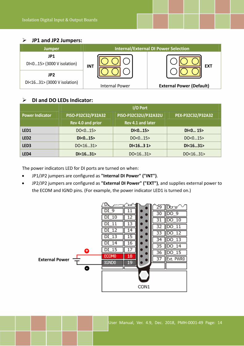
JP1 and JP2 Jumpers:
Jumper Internal/External DI Power Selection
JP1 DI<0…15> (3000 V isolation)
Internal Power
External Power (Default)
JP2 DI<16…31> (3000 V isolation)
DI and DO LEDs Indicator:
Power Indicator I/O Port
PISO-P32C32/P32A32 Rev 4.0 and prior
PISO-P32C32U/P32A32U Rev 4.1 and later
PEX-P32C32/P32A32
LED1 DO<0…15> DI<0…15> DI<0… 15> LED2 DI<0…15> DO<0…15> DO<0…15> LED3 DO<16…31> DI<16…3 1> DI<16…31>
LED4 DI<16…31> DO<16…31> DO<16…31>
The power indicators LED for DI ports are turned on when: • JP1/JP2 jumpers are configured as "Internal DI Power" ("INT"). • JP2/JP2 jumpers are configured as "External DI Power" ("EXT"), and supplies external power to
the ECOM and IGND pins. (For example, the power indicator LED1 is turned on.)
INT EXT
External Power
+
-
Isolation Digital Input & Output Boards
User Manual, Ver. 4.9, Dec. 2018, PMH-0001-49 Page: 15
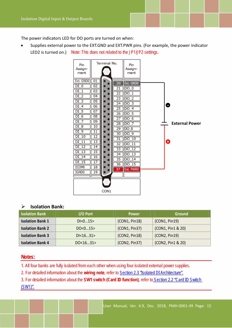
The power indicators LED for DO ports are turned on when: • Supplies external power to the EXT.GND and EXT.PWR pins. (For example, the power indicator
LED2 is turned on.) Note: This does not related to the JP1/JP2 settings.
Isolation Bank: Isolation Bank I/O Port Power Ground Isolation Bank 1 DI<0…15> (CON1, Pin18) (CON1, Pin19) Isolation Bank 2 DO<0…15> (CON1, Pin37) (CON1, Pin1 & 20) Isolation Bank 3 DI<16…31> (CON2, Pin18) (CON2, Pin19) Isolation Bank 4 DO<16…31> (CON2, Pin37) (CON2, Pin1 & 20)
Notes: 1. All four banks are fully isolated from each other when using four isolated external power supplies. 2. For detailed information about the wiring note, refer to Section 2.3 “Isolated DI Architecture”. 3. For detailed information about the SW1 switch (Card ID function), refer to Section 2.2 “Card ID Switch (SW1)”.
External Power
+
-

Isolation Digital Input & Output Boards
User Manual, Ver. 4.9, Dec. 2018, PMH-0001-49 Page: 16
2.1.2 PISO-P32S32WU The following is an overview of the board layout for each of the PISO-P32S32WU.
CON1 CON24 channels for 500 mA sink
current
12 channels for 100 mA sink
current
4 channels for 500 mA sink
current
12 channels for 100 mA sink
current
JP5
DI <0..15>
DO <0..15>
DI <16..31>
DO <16..31>
Card ID Jumper Setting (JP5)
Device 0 (Default) Device 1 Device 2 Device 3
Isolation Bank I/O Port Power Ground
Isolation Bank 1 DI <0…15>
(CON1,Pin37)
Isolation Bank 2
DO <0…3> High drive for 500 mA sink current, NPN (CON1,Pin18/Pin19)
DO <4…15> Low drive for 100 mA sink current, NPN (CON1,Pin1/Pin20)
Isolation Bank 3 DI<16…31>
(CON2,Pin37)
Isolation Bank 4
DO<16…19> High drive for 500 mA sink current, NPN (CON2,Pin18/Pin19)
DO<20…31> Low drive for 100 mA sink current, NPN (CON2,Pin1/Pin20)
Note: To prevent the board damaged forever by overload, the GND pins (CON1: pin 1/18/19/20, CON2: pin 1/18/19/20) all must be connected with GND of External Power.
Isolation Digital Input & Output Boards
User Manual, Ver. 4.9, Dec. 2018, PMH-0001-49 Page: 17
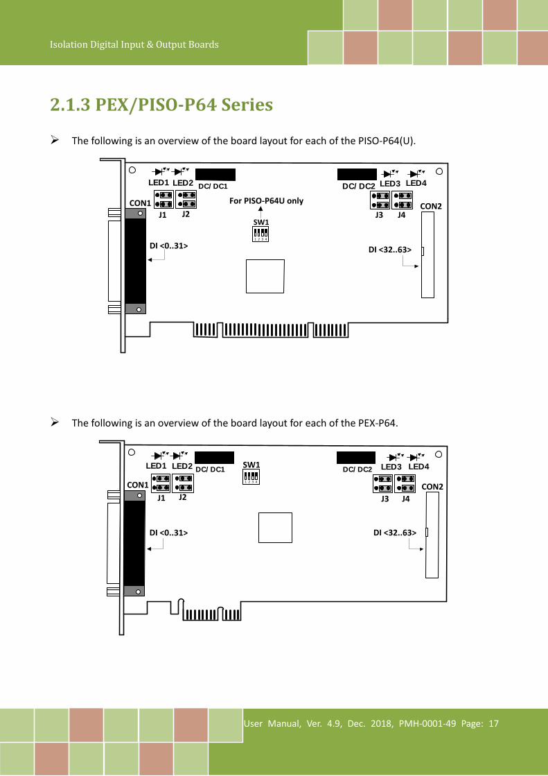
2.1.3 PEX/PISO-P64 Series The following is an overview of the board layout for each of the PISO-P64(U).
CON1
SW1
1 2 3 4
CON2
DI <0..31> DI <32..63>
LED1 LED2 LED3 LED4
For PISO-P64U only
DC/DC1 DC/DC2
J2J1 J3 J4
The following is an overview of the board layout for each of the PEX-P64.
LED1 LED2 LED3 LED4
CON1 CON2
DI <0..31> DI <32..63>
SW1
1 2 3 4
DC/DC1 DC/DC2
J2J1 J4J3
Isolation Digital Input & Output Boards
User Manual, Ver. 4.9, Dec. 2018, PMH-0001-49 Page: 18
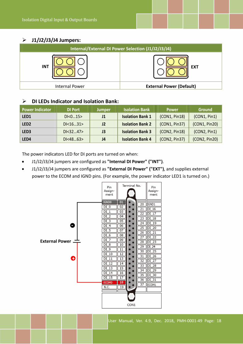
J1/J2/J3/J4 Jumpers:
Internal/External DI Power Selection (J1/J2/J3/J4)
Internal Power External Power (Default)
DI LEDs Indicator and Isolation Bank: Power Indicator DI Port Jumper Isolation Bank Power Ground LED1 DI<0…15> J1 Isolation Bank 1 (CON1, Pin18) (CON1, Pin1) LED2 DI<16…31> J2 Isolation Bank 2 (CON1, Pin37) (CON1, Pin20) LED3 DI<32…47> J3 Isolation Bank 3 (CON2, Pin18) (CON2, Pin1) LED4 DI<48…63> J4 Isolation Bank 4 (CON2, Pin37) (CON2, Pin20)
The power indicators LED for DI ports are turned on when: • J1/J2/J3/J4 jumpers are configured as "Internal DI Power" ("INT"). • J1/J2/J3/J4 jumpers are configured as "External DI Power" ("EXT"), and supplies external
power to the ECOM and IGND pins. (For example, the power indicator LED1 is turned on.)
INT EXT
External Power
-
+

Isolation Digital Input & Output Boards
User Manual, Ver. 4.9, Dec. 2018, PMH-0001-49 Page: 19
Notes: 1. The DC/DC1 provides the internal power supply for banks 1 and 2. 2. The DC/DC2 provides the internal power supply for banks 3 and 4. 3. All four banks are fully isolated from each other when using four isolated external power supplies. 4. For detailed information about the wiring note, refer to Section 2.3 “Isolated DI Architecture”. 5. For detailed information about the SW1 switch (Card ID function), refer to Section 2.2 “Card ID Switch
(SW1)”.
Isolation Digital Input & Output Boards
User Manual, Ver. 4.9, Dec. 2018, PMH-0001-49 Page: 20
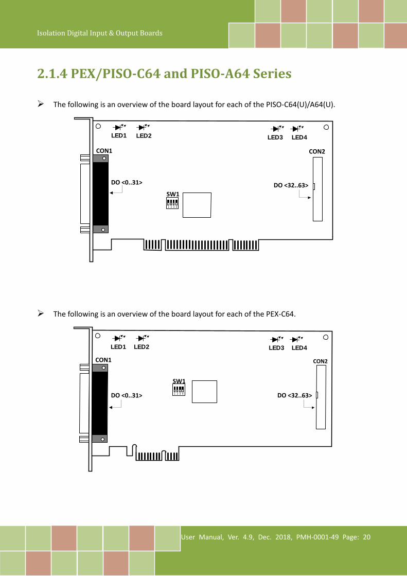
2.1.4 PEX/PISO-C64 and PISO-A64 Series The following is an overview of the board layout for each of the PISO-C64(U)/A64(U).
CON1
SW1
1 2 3 4
CON2
DO <0..31> DO <32..63>
LED1 LED2
LED3 LED4
The following is an overview of the board layout for each of the PEX-C64.
LED1 LED2
LED3 LED4
CON1 CON2
DO <0..31> DO <32..63>
SW1
1 2 3 4
Isolation Digital Input & Output Boards
User Manual, Ver. 4.9, Dec. 2018, PMH-0001-49 Page: 21
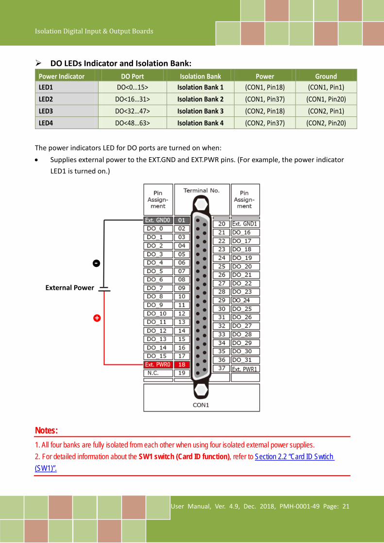
DO LEDs Indicator and Isolation Bank:
The power indicators LED for DO ports are turned on when: • Supplies external power to the EXT.GND and EXT.PWR pins. (For example, the power indicator
LED1 is turned on.) Notes: 1. All four banks are fully isolated from each other when using four isolated external power supplies. 2. For detailed information about the SW1 switch (Card ID function), refer to Section 2.2 “Card ID Swtich (SW1)”.
Power Indicator DO Port Isolation Bank Power Ground LED1 DO<0…15> Isolation Bank 1 (CON1, Pin18) (CON1, Pin1) LED2 DO<16…31> Isolation Bank 2 (CON1, Pin37) (CON1, Pin20) LED3 DO<32…47> Isolation Bank 3 (CON2, Pin18) (CON2, Pin1) LED4 DO<48…63> Isolation Bank 4 (CON2, Pin37) (CON2, Pin20)
External Power
-
+
Isolation Digital Input & Output Boards
User Manual, Ver. 4.9, Dec. 2018, PMH-0001-49 Page: 22
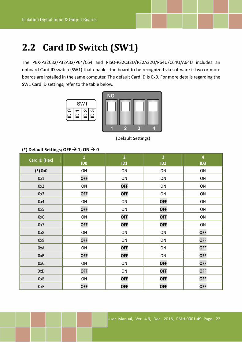
2.2 Card ID Switch (SW1) The PEX-P32C32/P32A32/P64/C64 and PISO-P32C32U/P32A32U/P64U/C64U/A64U includes an onboard Card ID switch (SW1) that enables the board to be recognized via software if two or more boards are installed in the same computer. The default Card ID is 0x0. For more details regarding the SW1 Card ID settings, refer to the table below.
(*) Default Settings; OFF 1; ON 0
Card ID (Hex) 1 ID0
2 ID1
3 ID2
4 ID3
(*) 0x0 ON ON ON ON 0x1 OFF ON ON ON
0x2 ON OFF ON ON 0x3 OFF OFF ON ON 0x4 ON ON OFF ON
0x5 OFF ON OFF ON
0x6 ON OFF OFF ON
0x7 OFF OFF OFF ON
0x8 ON ON ON OFF
0x9 OFF ON ON OFF
0xA ON OFF ON OFF
0xB OFF OFF ON OFF
0xC ON ON OFF OFF
0xD OFF ON OFF OFF
0xE ON OFF OFF OFF
0xF OFF OFF OFF OFF
(Default Settings)

Isolation Digital Input & Output Boards
User Manual, Ver. 4.9, Dec. 2018, PMH-0001-49 Page: 23
2.3 Isolated DI Architecture The DI architecture of the PEX-P32C32/P32A32/P64 and PISO-P32C32/P32A32/P32S32WU/P64 series boards is the same. Select either internal or external power to supply photo-couple Digital Input power. Note that the PISO-P32S32WU only supports external power mode. Here are diagrams for the various configurations: Jumper Settings:
Internal/External Power Selection (JP1/JP2)
Internal Power External Power (Default)
Input Wiring for the PEX-P32C32/P32A32/P64 and PISO-P32C32/P32A32/P32S32WU/P64 Series:
Input Type ON State as 0 OFF State as 1
Dry Contact (No Support: PISO-P32S32WU)
Close to GND Open
Wet Contact (Sink)
+(5)/+10 ~ +30 VDC +4 VDC Max.
Wet Contact (Source)
+(5)/+10 ~ +30 VDC +4 VDC Max.
COMBDCGNDDC5V
3K
To other channelsDI
DCGNDDC5V
3K
To other channels
COMB
DI
DCGNDDC5V
3K
To other channels
COMA
DI
DCGNDDC5V
3K
To other channels
COMA
DI
DCGNDDC5V
3K
To other channels
COMA
DI
DCGNDDC5V
3K
To other channels
COMA
DI
INT EXT
Isolation Digital Input & Output Boards
User Manual, Ver. 4.9, Dec. 2018, PMH-0001-49 Page: 24
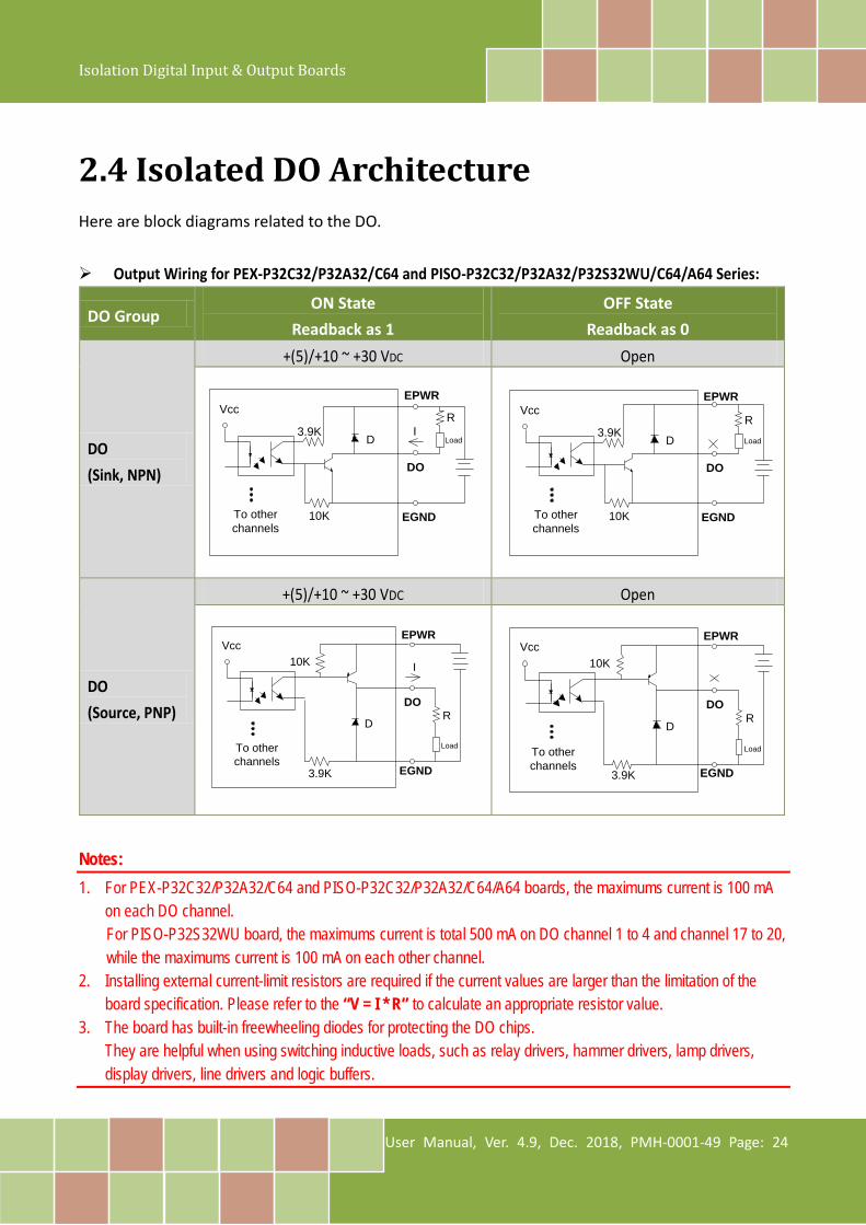
2.4 Isolated DO Architecture Here are block diagrams related to the DO.
Output Wiring for PEX-P32C32/P32A32/C64 and PISO-P32C32/P32A32/P32S32WU/C64/A64 Series:
DO Group ON State
Readback as 1 OFF State
Readback as 0
DO (Sink, NPN)
+(5)/+10 ~ +30 VDC Open
DO (Source, PNP)
+(5)/+10 ~ +30 VDC Open
Notes: 1. For PEX-P32C32/P32A32/C64 and PISO-P32C32/P32A32/C64/A64 boards, the maximums current is 100 mA
on each DO channel. For PISO-P32S32WU board, the maximums current is total 500 mA on DO channel 1 to 4 and channel 17 to 20, while the maximums current is 100 mA on each other channel.
2. Installing external current-limit resistors are required if the current values are larger than the limitation of the board specification. Please refer to the “V = I * R” to calculate an appropriate resistor value.
3. The board has built-in freewheeling diodes for protecting the DO chips. They are helpful when using switching inductive loads, such as relay drivers, hammer drivers, lamp drivers, display drivers, line drivers and logic buffers.
Vcc
To other channels
3.9K
10K
EPWR
DO
EGND
ID
R
Load
Vcc
To other channels
3.9K
10K
EPWR
DO
EGND
D
RLoad
Vcc
To other channels
3.9K
10K
EPWR
DO
EGND
I
DR
Load
Vcc
3.9K
10K
EPWR
DO
EGND
DR
LoadTo other channels
Isolation Digital Input & Output Boards
User Manual, Ver. 4.9, Dec. 2018, PMH-0001-49 Page: 25
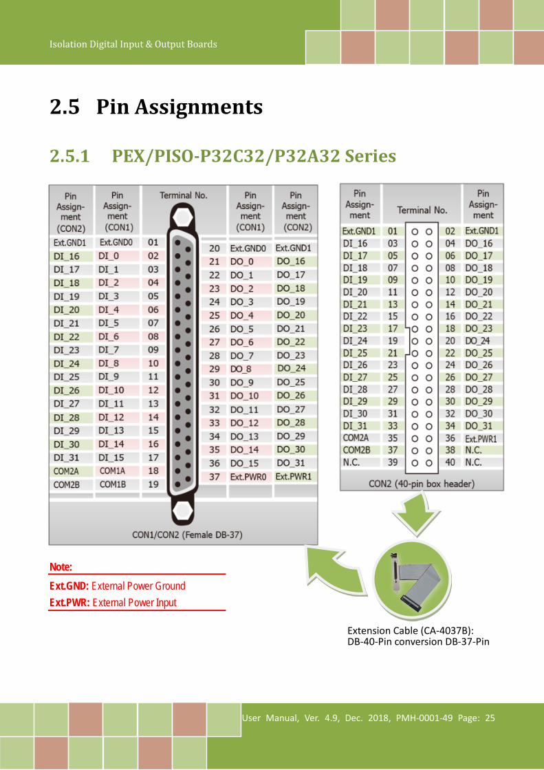
2.5 Pin Assignments
2.5.1 PEX/PISO-P32C32/P32A32 Series
Note: Ext.GND: External Power Ground Ext.PWR: External Power Input
Extension Cable (CA-4037B): DB-40-Pin conversion DB-37-Pin

Isolation Digital Input & Output Boards
User Manual, Ver. 4.9, Dec. 2018, PMH-0001-49 Page: 26
2.5.2 PISO-P32S32WU Note: Ext.GND: External Power Ground Ext.PWR: External Power Input HDO: DO for high drive HD_GND: GND for High drive
Extension Cable (CA-4037B): DB-40-Pin conversion DB-37-Pin
Isolation Digital Input & Output Boards
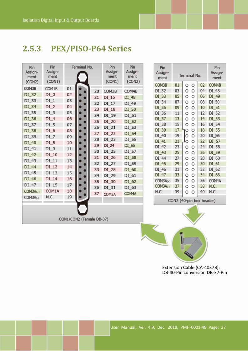
User Manual, Ver. 4.9, Dec. 2018, PMH-0001-49 Page: 27
2.5.3 PEX/PISO-P64 Series
Extension Cable (CA-4037B): DB-40-Pin conversion DB-37-Pin

Isolation Digital Input & Output Boards
User Manual, Ver. 4.9, Dec. 2018, PMH-0001-49 Page: 28
2.5.4 PEX/PISO-C64 and PISO-A64 Series Note: Ext.GND: External Power Ground Ext.PWR: External Power Input
Extension Cable (CA-4037B): DB-40-Pin conversion DB-37-Pin

Isolation Digital Input & Output Boards
User Manual, Ver. 4.9, Dec. 2018, PMH-0001-49 Page: 29
3. Hardware Installation Note: It is recommended that the driver is installed before installing the hardware as the computer may need to be restarted once the driver is installed in certain operating systems, such as Windows 2000 or Windows XP, etc. Installing the driver first helps reduce the time required for installation and restarting the computer. To install your PEX/PISO-P32x32/x64 Series board, follow the procedure described below: Step 1: Install the driver for your board on Host computer.
For detailed information about the driver installation, refer to Chapter 4 “Software Installation”.
Step 2: Configure the Card ID using the DIP Switch (SW1).
For detailed information about the card ID (SW1), refer to Section 2.2 “Card ID Switch (SW1)”. Note: The PISO-P32C3/P32A32/P32S32WU and PISO-A64/C64/P64 boards do not support Card ID function, so please skip this step.
Isolation Digital Input & Output Boards
User Manual, Ver. 4.9, Dec. 2018, PMH-0001-49 Page: 30
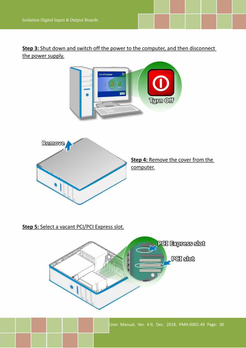
Step 3: Shut down and switch off the power to the computer, and then disconnect the power supply.
Step 4: Remove the cover from the computer.
Step 5: Select a vacant PCI/PCI Express slot.
Isolation Digital Input & Output Boards
User Manual, Ver. 4.9, Dec. 2018, PMH-0001-49 Page: 31
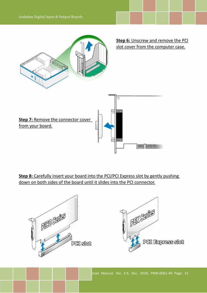
Step 6: Unscrew and remove the PCI slot cover from the computer case.
Step 7: Remove the connector cover from your board.
Step 8: Carefully insert your board into the PCI/PCI Express slot by gently pushing down on both sides of the board until it slides into the PCI connector.
Isolation Digital Input & Output Boards
User Manual, Ver. 4.9, Dec. 2018, PMH-0001-49 Page: 32
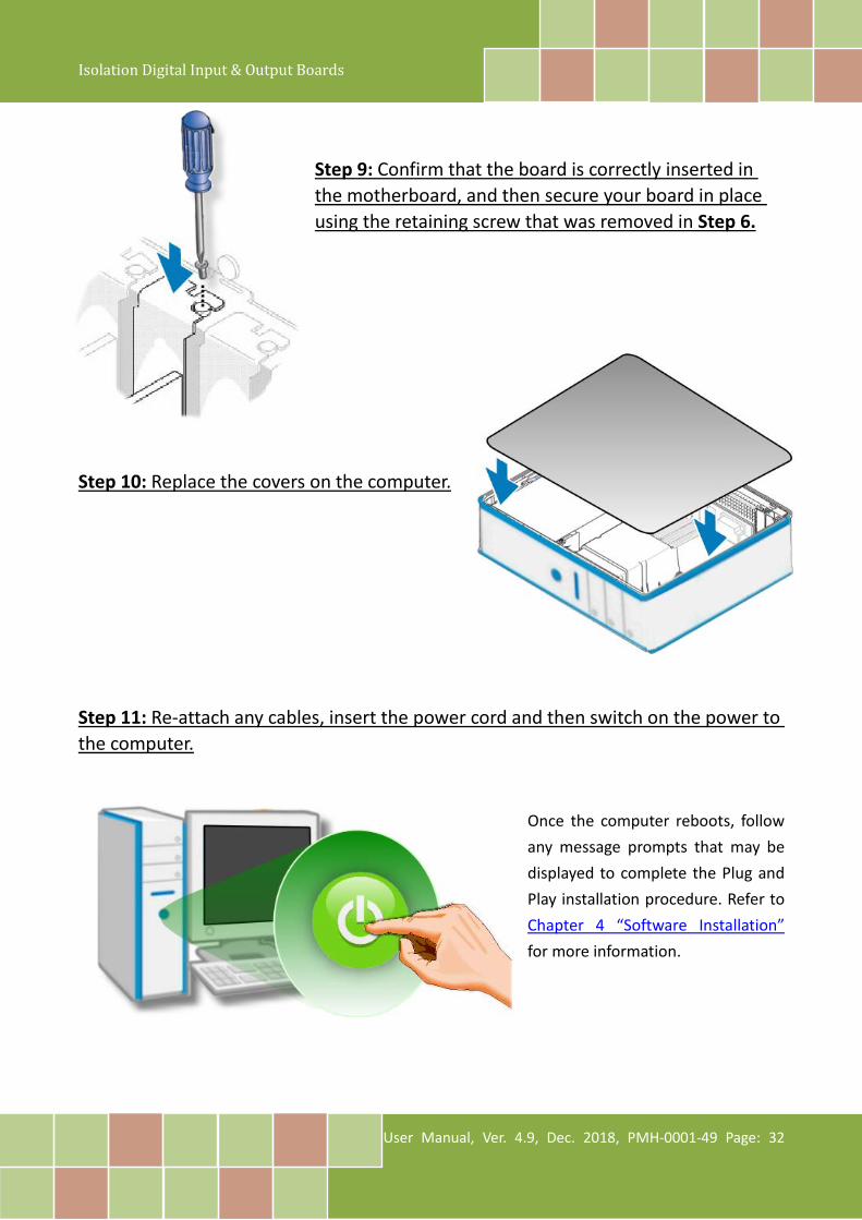
Step 9: Confirm that the board is correctly inserted in the motherboard, and then secure your board in place using the retaining screw that was removed in Step 6.
Step 10: Replace the covers on the computer.
Step 11: Re-attach any cables, insert the power cord and then switch on the power to the computer.
Once the computer reboots, follow any message prompts that may be displayed to complete the Plug and Play installation procedure. Refer to Chapter 4 “Software Installation” for more information.
Isolation Digital Input & Output Boards
User Manual, Ver. 4.9, Dec. 2018, PMH-0001-49 Page: 33
4. Software Installation This chapter provides a detailed description of the process for installing the driver for the PEX/PISO-P32x32/x64 Series board as well as how to verify whether your board was properly installed. PEX/PISO-P32x32/x64 Series can be used on DOS, Linux and 32/64-bit versions of Windows XP/2003/2008/7/8/10 based systems, and the drivers are fully Plug and Play compliant for easy installation.
4.1 Obtaining/Installing the Driver Installer Package
The driver installation package for PEX/PISO-P32x32/x64 Series board can be found on the companion CD-ROM, or can be obtained from the ICP DAS FTP web site. Install the appropriate
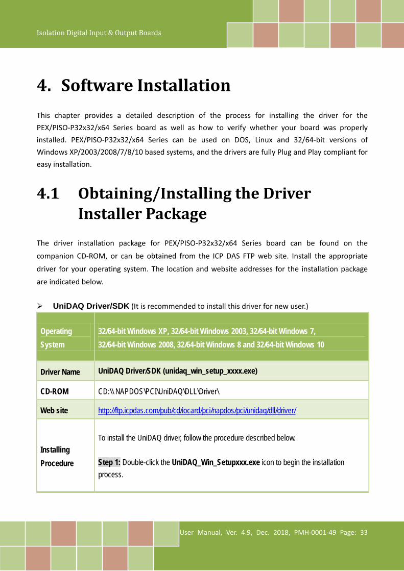
driver for your operating system. The location and website addresses for the installation package are indicated below. UniDAQ Driver/SDK (It is recommended to install this driver for new user.)
Operating System
32/64-bit Windows XP, 32/64-bit Windows 2003, 32/64-bit Windows 7, 32/64-bit Windows 2008, 32/64-bit Windows 8 and 32/64-bit Windows 10
Driver Name UniDAQ Driver/SDK (unidaq_win_setup_xxxx.exe)
CD-ROM CD:\\ NAPDOS\PCI\UniDAQ\DLL\Driver\
Web site http://ftp.icpdas.com/pub/cd/iocard/pci/napdos/pci/unidaq/dll/driver/
Installing Procedure
To install the UniDAQ driver, follow the procedure described below. Step 1: Double-click the UniDAQ_Win_Setupxxx.exe icon to begin the installation process.
Isolation Digital Input & Output Boards
User Manual, Ver. 4.9, Dec. 2018, PMH-0001-49 Page: 34
Installation Procedure
Step 2: When the “Welcome to the ICP DAS UniDAQ Driver Setup Wizard” screen is displayed, click the “Next>” button to start the installation. Step 3: On the “Information” screen, verify that the DAQ board is included in the list of supported devices, then click the “Next>” button. Step 4: On the “Select Destination Location” screen, click the “Next>” button to install the software in the default folder, C:\ICPDAS\UniDAQ. Step 5: On the “Select Components” screen, verify that the DAQ board is in the list of device, and then click the “Next>” button to continue.
Step 6: On the “Select Additional Tasks” screen, click the “Next>” button to continue.
Step 7: On the “Download Information” screen, click the “Next>” button to continue. Step 8: Once the installation has completed, click “No, I will restart my computer later”, and then click the “Finish” button. For more detailed information about how to install the UniDAQ driver, refer to Section 2.2 “Install UniDAQ Driver DLL” of the UniDAQ Software Manual, which can be found in the \NAPDOS\PCI\UniDAQ\Manual\ folder on the companion CD, or can be downloaded from: http://ftp.icpdas.com/pub/cd/iocard/pci/napdos/pci/unidaq/manual/

Isolation Digital Input & Output Boards
User Manual, Ver. 4.9, Dec. 2018, PMH-0001-49 Page: 35
PISO-DIO Series Classic Driver (Recommended to install this driver for have been used
PISO-DIO series boards of regular user)
Operating System
Windows 95/98/ME, Windows NT, Windows 2000, 32-bit Windows XP, 32-bit Windows 2003, 32-bit Windows Vista, 32-bit Windows 7 and 32-bit Windows 8
Driver Name PISO-DIO Series Classic Driver (PISO-DIO_win_xxxx.exe)
CD-ROM CD:\\NAPDOS\PCI\PISO-DIO\DLL_OXC\Driver\
Web site http://ftp.icpdas.com/pub/cd/iocard/pci/napdos/pci/piso-dio/dll_ocx/driver/
Installing Procedure
Please follow the following steps to setup software: Step 1: Double click the PISO-DIO Series Classic Driver to setup it. Step 2: When the Setup Wizard screen is displayed, click the Next> button. Step 3: Select the folder where the drivers are to install. The default path is C:\DAQPro\PISO-DIO. But if you wish to install the drivers to a different location , click the “Browse…” button and select the relevant folder and then click the Next> button. Step 4: Click the Install button to continue. Step 5: Select the item “No, I will restart my computer later”, press the Finish button. For detailed information about how to install the PISO-DIO Classic Driver, refer to the PISO-DIO Series Classic Driver DLL Software, which can be found in the \NAPDOS\PCI\PISO-DIO\Manual\ folder on the companion CD, or can be downloaded from: http://ftp.icpdas.com/pub/cd/iocard/pci/napdos/pci/piso-dio/manual/

Isolation Digital Input & Output Boards
User Manual, Ver. 4.9, Dec. 2018, PMH-0001-49 Page: 36
4.2 PnP Driver Installation
Step 1: Correctly shut down and power off your computer and disconnect the power supply, and
then install your board into the computer. For detailed information about the hardware installation
of PEX/PISO-P32x32/x64 Series board, refer to Chapter 3 “Hardware Installation”. Step 2: Power on the computer and complete the Plug and Play installation. Note:
More recent operating systems, such as Windows 7/8/10 will automatically detect the new hardware and install the necessary drivers etc., so Steps 3 to 5 can be skipped. Step 3: Select “Install the software automatically [Recommended]” and click the “Next>” button.
Isolation Digital Input & Output Boards
User Manual, Ver. 4.9, Dec. 2018, PMH-0001-49 Page: 37
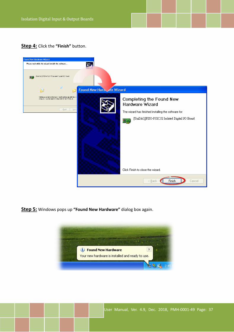
Step 4: Click the “Finish” button. Step 5: Windows pops up “Found New Hardware” dialog box again.
Isolation Digital Input & Output Boards
User Manual, Ver. 4.9, Dec. 2018, PMH-0001-49 Page: 38
4.3 Verifying the Installation To verify that the driver was correctly installed, use the Windows Device Manager to view and update the device drivers installed on the computer, and to ensure that the hardware is operating correctly. The following is a description of how access the Device Manager in each of the major versions of Windows. Refer to the appropriate description for the specific operating system to verify the installation.
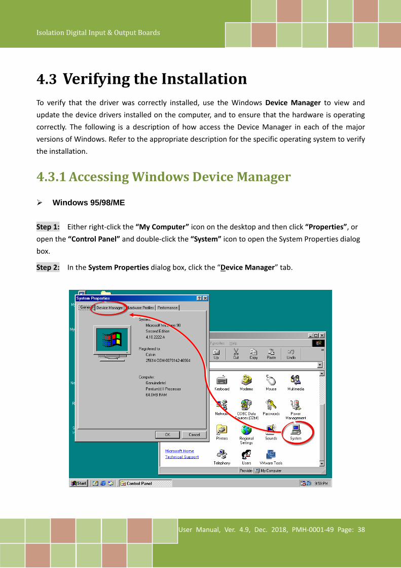
4.3.1 Accessing Windows Device Manager Windows 95/98/ME Step 1: Either right-click the “My Computer” icon on the desktop and then click “Properties”, or open the “Control Panel” and double-click the “System” icon to open the System Properties dialog box.
Step 2: In the System Properties dialog box, click the “Device Manager” tab.
Isolation Digital Input & Output Boards
User Manual, Ver. 4.9, Dec. 2018, PMH-0001-49 Page: 39
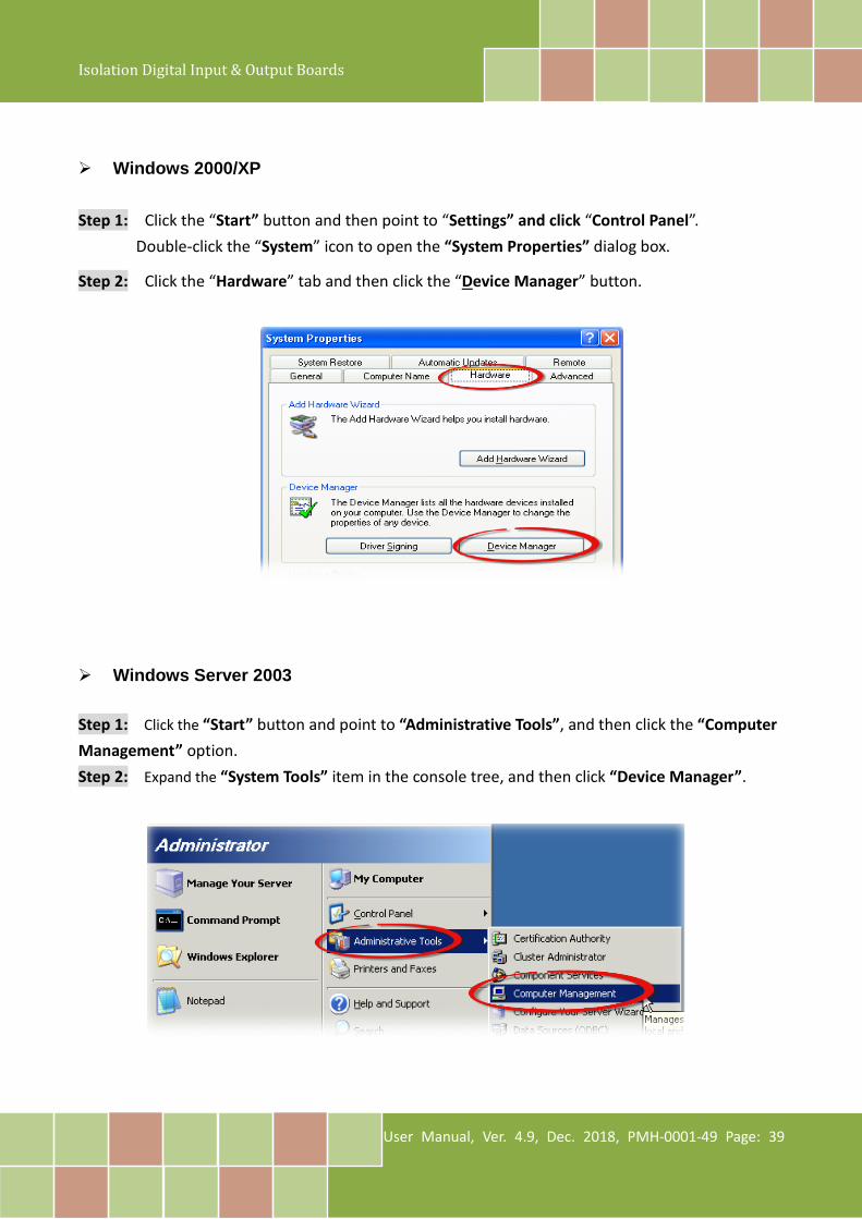
Windows 2000/XP Step 1: Click the “Start” button and then point to “Settings” and click “Control Panel”.
Double-click the “System” icon to open the “System Properties” dialog box.
Step 2: Click the “Hardware” tab and then click the “Device Manager” button.
Windows Server 2003 Step 1: Click the “Start” button and point to “Administrative Tools”, and then click the “Computer Management” option. Step 2: Expand the “System Tools” item in the console tree, and then click “Device Manager”.
Isolation Digital Input & Output Boards
User Manual, Ver. 4.9, Dec. 2018, PMH-0001-49 Page: 40
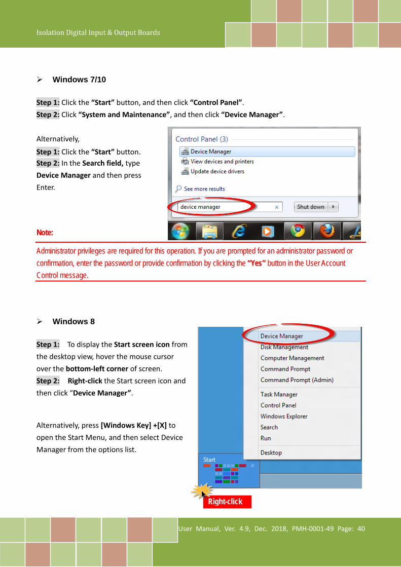
Windows 7/10 Step 1: Click the “Start” button, and then click “Control Panel”. Step 2: Click “System and Maintenance”, and then click “Device Manager”. Alternatively,
Step 1: Click the “Start” button. Step 2: In the Search field, type Device Manager and then press Enter.
Note:
Administrator privileges are required for this operation. If you are prompted for an administrator password or confirmation, enter the password or provide confirmation by clicking the “Yes” button in the User Account Control message.
Windows 8 Step 1: To display the Start screen icon from the desktop view, hover the mouse cursor over the bottom-left corner of screen. Step 2: Right-click the Start screen icon and then click “Device Manager”.
Alternatively, press [Windows Key] +[X] to open the Start Menu, and then select Device Manager from the options list.
Right-click
Isolation Digital Input & Output Boards
User Manual, Ver. 4.9, Dec. 2018, PMH-0001-49 Page: 41
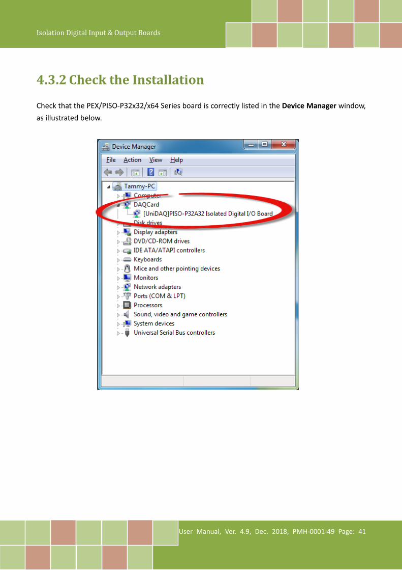
4.3.2 Check the Installation Check that the PEX/PISO-P32x32/x64 Series board is correctly listed in the Device Manager window, as illustrated below.
Isolation Digital Input & Output Boards
User Manual, Ver. 4.9, Dec. 2018, PMH-0001-49 Page: 42
5. Board Testing This chapter provides detailed information about the “Self-Test” process, which is used to confirm that the PEX/PISO-P32x32/x64 Series board is operating correctly. Before beginning the “Self-Test” process, ensure that both the hardware and driver installation procedures are fully completed. For detailed information about the hardware and driver installation, refer to Chapter 3 “Hardware Installation” and Chapter 4 “Software Installation”.
5.1 Self-Test Wiring The following is a description of how to configure the wiring in order to perform the “Self-Test” procedures for the Digital Input or/and Digital Output. Refer to the appropriate descriptions for PEX/PISO-P32x32/x64 Series board in Sections 5.1.1 to 5.1.6 for more detailed information. Before beginning the “Self-Test” procedure, ensure that the following items are available: A CA-3710 Cable (Optional, Website: http://www.icpdas.com/products/Accessories/cable/cable_selection.htm) A DN-37 Terminal Board (Optional, Website: http://www.icpdas.com/root/product/solutions/pc_based_io_board/daughter_boards/dn-37.html) An External power supply device, such as the DIN-KA52F or DP-660 (Optional, Website: http://www.icpdas.com/root/product/solutions/accessories/power_supply/ka52f.html http://www.icpdas.com/root/product/solutions/accessories/power_supply/dp-660.html)
Isolation Digital Input & Output Boards
User Manual, Ver. 4.9, Dec. 2018, PMH-0001-49 Page: 43
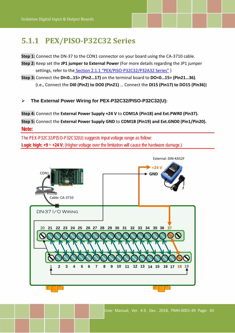
5.1.1 PEX/PISO-P32C32 Series Step 1: Connect the DN-37 to the CON1 connector on your board using the CA-3710 cable. Step 2: Keep set the JP1 jumper to External Power (For more details regarding the JP1 jumper
settings, refer to the Section 2.1.1 “PEX/PISO-P32C32/P32A32 Series” ) Step 3: Connect the DI<0…15> (Pin2…17) on the terminal board to DO<0…15> (Pin21…36).
(i.e., Connect the DI0 (Pin2) to DO0 (Pin21) … Connect the DI15 (Pin17) to DO15 (Pin36))
The External Power Wiring for PEX-P32C32/PISO-P32C32(U): Step 4: Connect the External Power Supply +24 V to COM1A (Pin18) and Ext.PWR0 (Pin37).
Step 5: Connect the External Power Supply GND to COM1B (Pin19) and Ext.GND0 (Pin1/Pin20).
Note: The PEX-P32C32/PISO-P32C32(U) suggests input voltage range as follow: Logic high: +9 ~ +24 V; (Higher voltage over the limitation will cause the hardware damage.)
DN-37 I/O Wiring
1 3 4 5 6 7 8 9 10 11 13 14 1715 16 18
20 21 22 23 24 25 26 27 28 29 30 31 32 33 34 35 36
122
37
19
CON1
Cable: CA-3710
External: DIN-KA52F
+24 VGND
Isolation Digital Input & Output Boards
User Manual, Ver. 4.9, Dec. 2018, PMH-0001-49 Page: 44
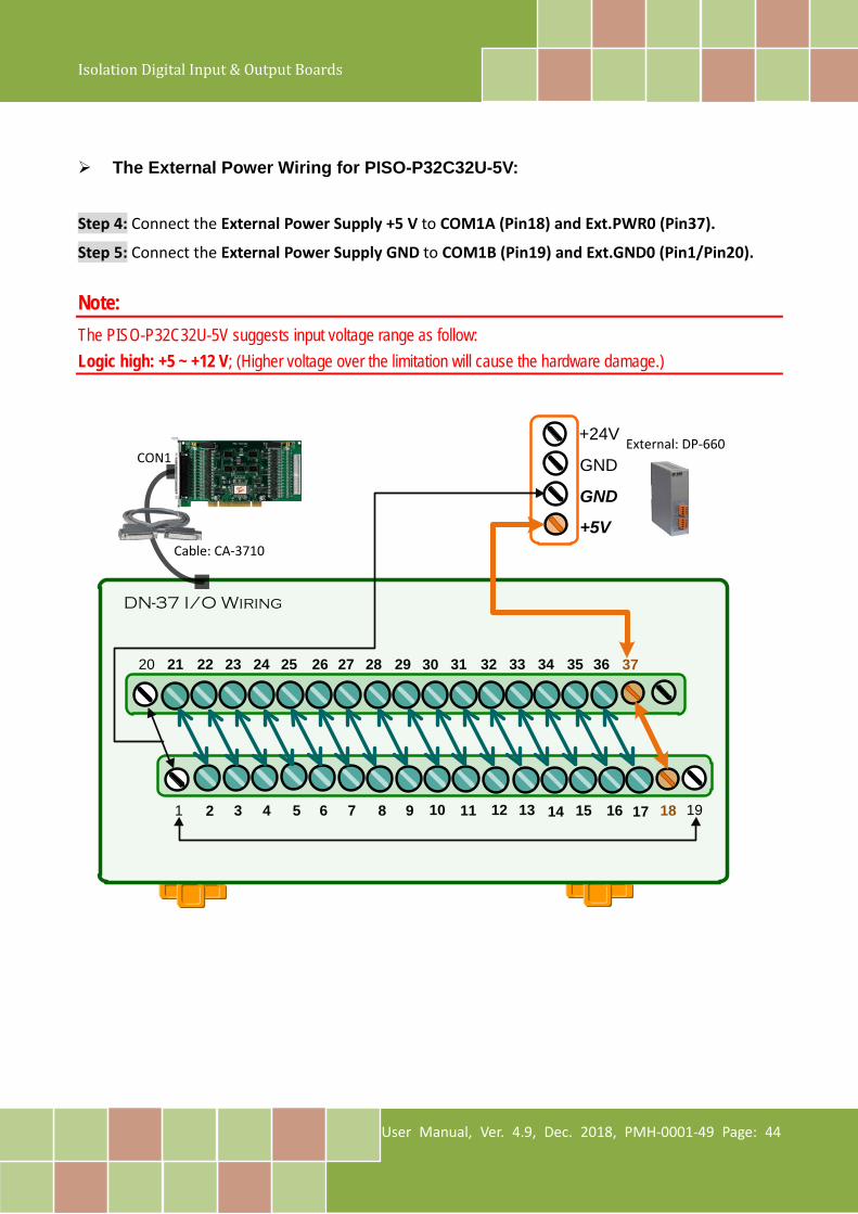
The External Power Wiring for PISO-P32C32U-5V:
Step 4: Connect the External Power Supply +5 V to COM1A (Pin18) and Ext.PWR0 (Pin37).
Step 5: Connect the External Power Supply GND to COM1B (Pin19) and Ext.GND0 (Pin1/Pin20). Note: The PISO-P32C32U-5V suggests input voltage range as follow: Logic high: +5 ~ +12 V; (Higher voltage over the limitation will cause the hardware damage.)
External: DP-660
DN-37 I/O Wiring
GND
GND
+5V
1 3 4 5 6 7 8 9 10 11 13 14 1715 16 18
20 21 22 23 24 25 26 27 28 29 30 31 32 33 34 35 36
122
+24V
37
19
CON1
Cable: CA-3710
Isolation Digital Input & Output Boards
User Manual, Ver. 4.9, Dec. 2018, PMH-0001-49 Page: 45
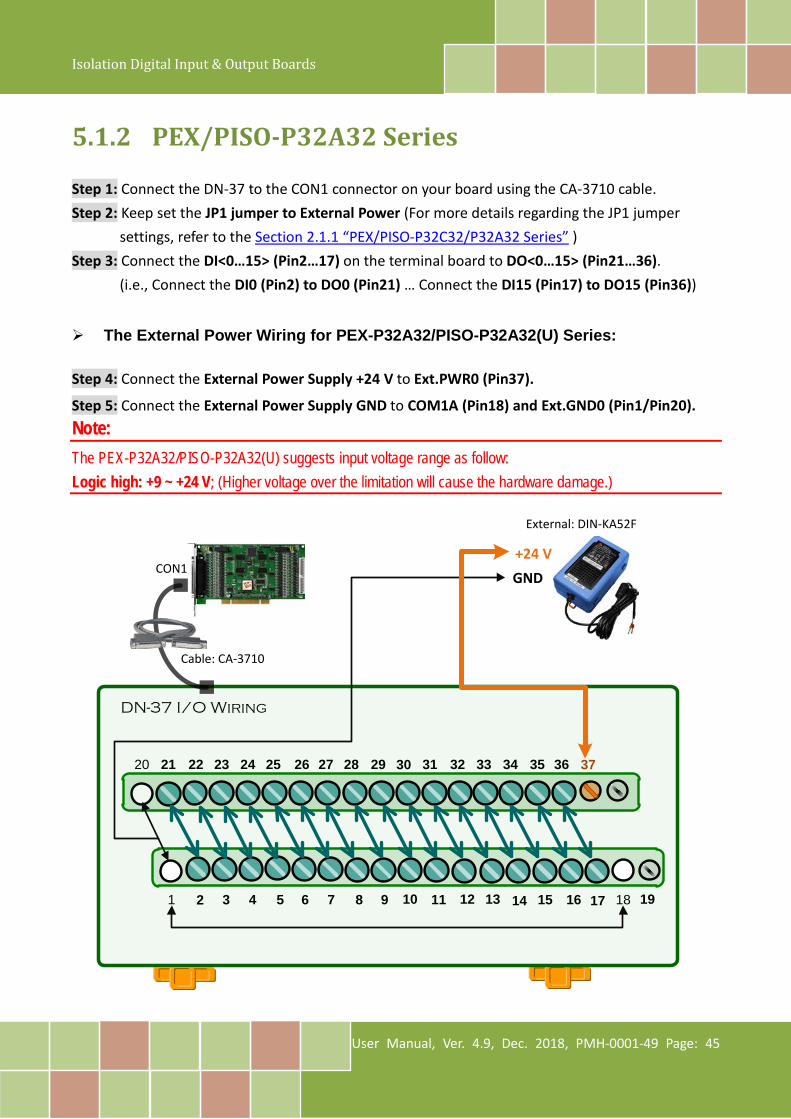
5.1.2 PEX/PISO-P32A32 Series Step 1: Connect the DN-37 to the CON1 connector on your board using the CA-3710 cable. Step 2: Keep set the JP1 jumper to External Power (For more details regarding the JP1 jumper
settings, refer to the Section 2.1.1 “PEX/PISO-P32C32/P32A32 Series” ) Step 3: Connect the DI<0…15> (Pin2…17) on the terminal board to DO<0…15> (Pin21…36).
(i.e., Connect the DI0 (Pin2) to DO0 (Pin21) … Connect the DI15 (Pin17) to DO15 (Pin36))
The External Power Wiring for PEX-P32A32/PISO-P32A32(U) Series:
Step 4: Connect the External Power Supply +24 V to Ext.PWR0 (Pin37).
Step 5: Connect the External Power Supply GND to COM1A (Pin18) and Ext.GND0 (Pin1/Pin20). Note: The PEX-P32A32/PISO-P32A32(U) suggests input voltage range as follow: Logic high: +9 ~ +24 V; (Higher voltage over the limitation will cause the hardware damage.)
DN-37 I/O Wiring
1 3 4 5 6 7 8 9 10 11 13 14 1715 16 18
20 21 22 23 24 25 26 27 28 29 30 31 32 33 34 35 36
122
37
19
CON1
Cable: CA-3710
External: DIN-KA52F
+24 VGND
Isolation Digital Input & Output Boards
User Manual, Ver. 4.9, Dec. 2018, PMH-0001-49 Page: 46
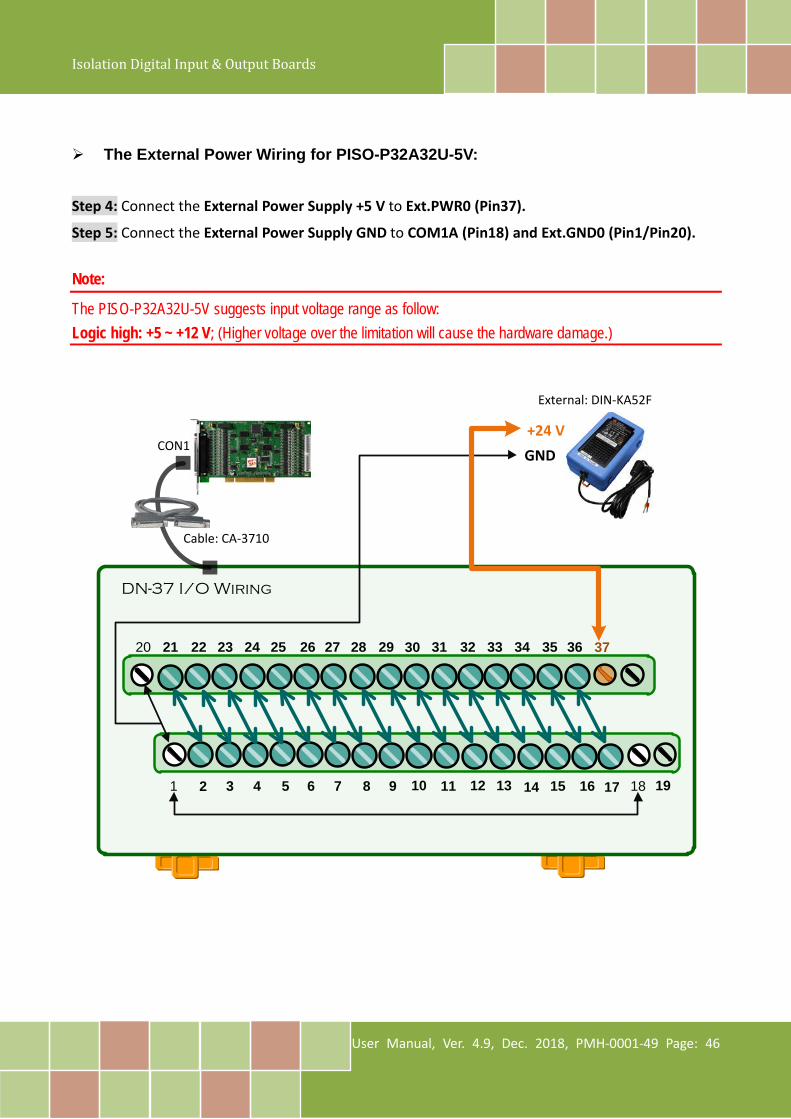
The External Power Wiring for PISO-P32A32U-5V: Step 4: Connect the External Power Supply +5 V to Ext.PWR0 (Pin37).
Step 5: Connect the External Power Supply GND to COM1A (Pin18) and Ext.GND0 (Pin1/Pin20). Note:
The PISO-P32A32U-5V suggests input voltage range as follow: Logic high: +5 ~ +12 V; (Higher voltage over the limitation will cause the hardware damage.)
DN-37 I/O Wiring
1 3 4 5 6 7 8 9 10 11 13 14 1715 16 18
20 21 22 23 24 25 26 27 28 29 30 31 32 33 34 35 36
122
37
19
CON1
Cable: CA-3710
External: DIN-KA52F
+24 VGND
Isolation Digital Input & Output Boards
User Manual, Ver. 4.9, Dec. 2018, PMH-0001-49 Page: 47
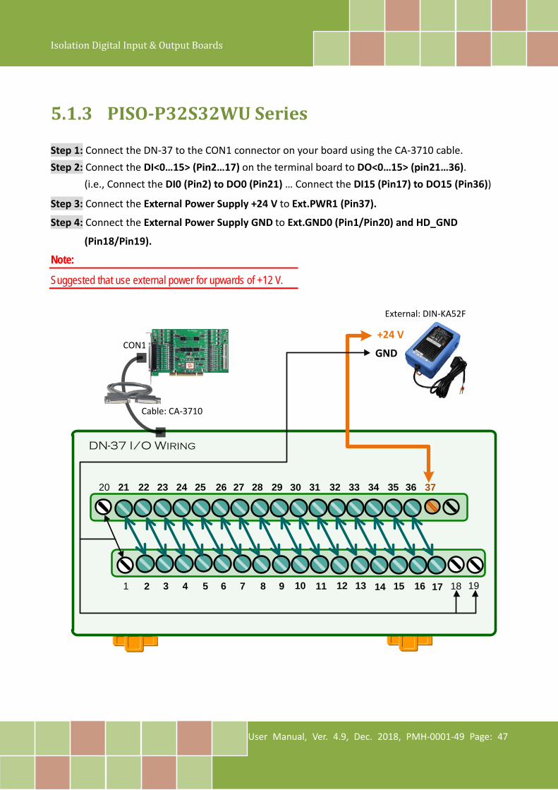
5.1.3 PISO-P32S32WU Series Step 1: Connect the DN-37 to the CON1 connector on your board using the CA-3710 cable. Step 2: Connect the DI<0…15> (Pin2…17) on the terminal board to DO<0…15> (pin21…36).
(i.e., Connect the DI0 (Pin2) to DO0 (Pin21) … Connect the DI15 (Pin17) to DO15 (Pin36))
Step 3: Connect the External Power Supply +24 V to Ext.PWR1 (Pin37).
Step 4: Connect the External Power Supply GND to Ext.GND0 (Pin1/Pin20) and HD_GND
(Pin18/Pin19).
Note:
Suggested that use external power for upwards of +12 V.
DN-37 I/O Wiring
1 3 4 5 6 7 8 9 10 11 13 14 1715 16 18
20 21 22 23 24 25 26 27 28 29 30 31 32 33 34 35 36
122
37
19
CON1
Cable: CA-3710
External: DIN-KA52F
+24 V
GND
Isolation Digital Input & Output Boards
User Manual, Ver. 4.9, Dec. 2018, PMH-0001-49 Page: 48
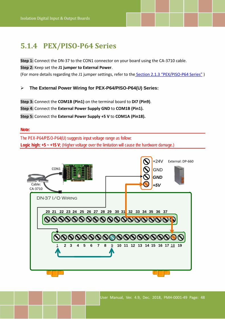
5.1.4 PEX/PISO-P64 Series Step 1: Connect the DN-37 to the CON1 connector on your board using the CA-3710 cable. Step 2: Keep set the J1 jumper to External Power. (For more details regarding the J1 jumper settings, refer to the Section 2.1.3 “PEX/PISO-P64 Series” ) The External Power Wiring for PEX-P64/PISO-P64(U) Series: Step 3: Connect the COM1B (Pin1) on the terminal board to DI7 (Pin9). Step 4: Connect the External Power Supply GND to COM1B (Pin1).
Step 5: Connect the External Power Supply +5 V to COM1A (Pin18).
Note:
The PEX-P64/PISO-P64(U) suggests input voltage range as follow: Logic high: +5 ~ +15 V; (Higher voltage over the limitation will cause the hardware damage.)
DN-37 I/O Wiring
1 3 4 5 6 7 8 9 10 11 13 14 15 16 17 18 19
20 21 22 23 24 25 26 27 28 29 30 31 32 33 34 35 36 37
122
+24V
GND
+5VCable: CA-3710
CON1 GND
External: DP-660
Isolation Digital Input & Output Boards
User Manual, Ver. 4.9, Dec. 2018, PMH-0001-49 Page: 49
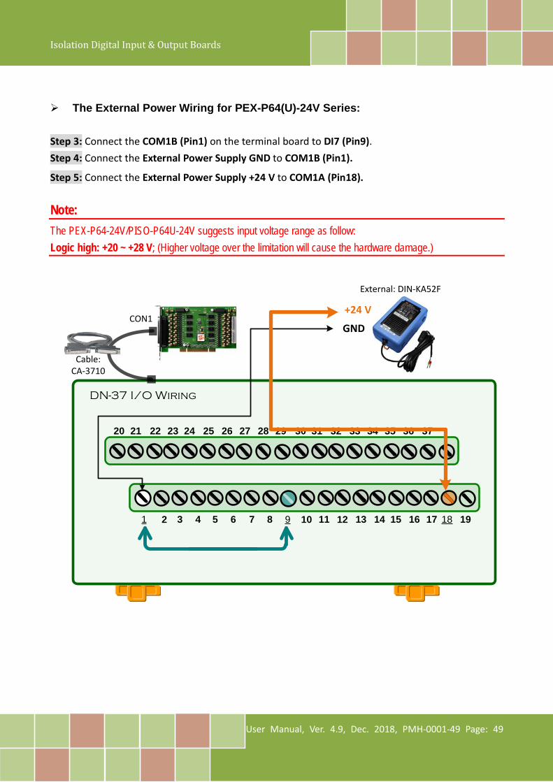
The External Power Wiring for PEX-P64(U)-24V Series: Step 3: Connect the COM1B (Pin1) on the terminal board to DI7 (Pin9). Step 4: Connect the External Power Supply GND to COM1B (Pin1).
Step 5: Connect the External Power Supply +24 V to COM1A (Pin18).
Note: The PEX-P64-24V/PISO-P64U-24V suggests input voltage range as follow: Logic high: +20 ~ +28 V; (Higher voltage over the limitation will cause the hardware damage.)
DN-37 I/O Wiring
1 3 4 5 6 7 8 9 10 11 13 14 15 16 17 18 19
20 21 22 23 24 25 26 27 28 29 30 31 32 33 34 35 36 37
122
Cable: CA-3710
CON1
External: DIN-KA52F
+24 V
GND
Isolation Digital Input & Output Boards
User Manual, Ver. 4.9, Dec. 2018, PMH-0001-49 Page: 50
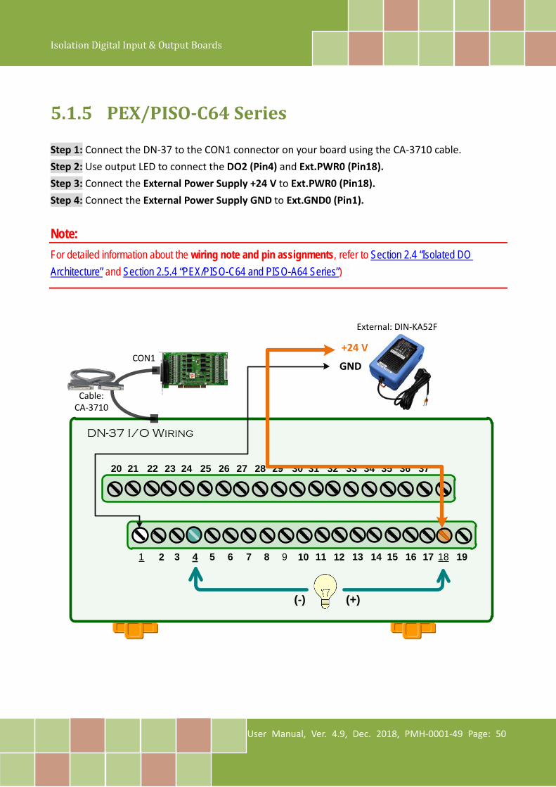
5.1.5 PEX/PISO-C64 Series Step 1: Connect the DN-37 to the CON1 connector on your board using the CA-3710 cable. Step 2: Use output LED to connect the DO2 (Pin4) and Ext.PWR0 (Pin18). Step 3: Connect the External Power Supply +24 V to Ext.PWR0 (Pin18). Step 4: Connect the External Power Supply GND to Ext.GND0 (Pin1).
Note: For detailed information about the wiring note and pin assignments, refer to Section 2.4 “Isolated DO Architecture” and Section 2.5.4 “PEX/PISO-C64 and PISO-A64 Series”)
DN-37 I/O Wiring
1 3 4 5 6 7 8 9 10 11 13 14 15 16 17 18 19
20 21 22 23 24 25 26 27 28 29 30 31 32 33 34 35 36 37
122
External: DIN-KA52F
+24 V
GNDCON1
Cable: CA-3710
(+)(-)

Isolation Digital Input & Output Boards
User Manual, Ver. 4.9, Dec. 2018, PMH-0001-49 Page: 51
5.1.6 PISO-A64 Series Step 1: Connect the DN-37 to the CON1 connector on your board using the CA-3710 cable. Step 2: Use output LED to connect the DO2 (Pin4) and Ext.GND0 (Pin1). Step 3: Connect the External Power Supply GND to Ext.GND0 (Pin1). Step 4: Connect the External Power Supply +24 V to Ext.PWR0 (Pin18).
Note:
For detailed information about the wiring note and pin assignments, refer to Section 2.4 “Isolated DO Architecture” and Section 2.5.4 “PEX/PISO-C64 and PISO-A64 Series”)
DN-37 I/O Wiring
1 3 4 5 6 7 8 9 10 11 13 14 15 16 17 18 19
20 21 22 23 24 25 26 27 28 29 30 31 32 33 34 35 36 37
122
External: DIN-KA52F
+24 V
GNDCON1
Cable: CA-3710
(+)(-)
Isolation Digital Input & Output Boards
User Manual, Ver. 4.9, Dec. 2018, PMH-0001-49 Page: 52
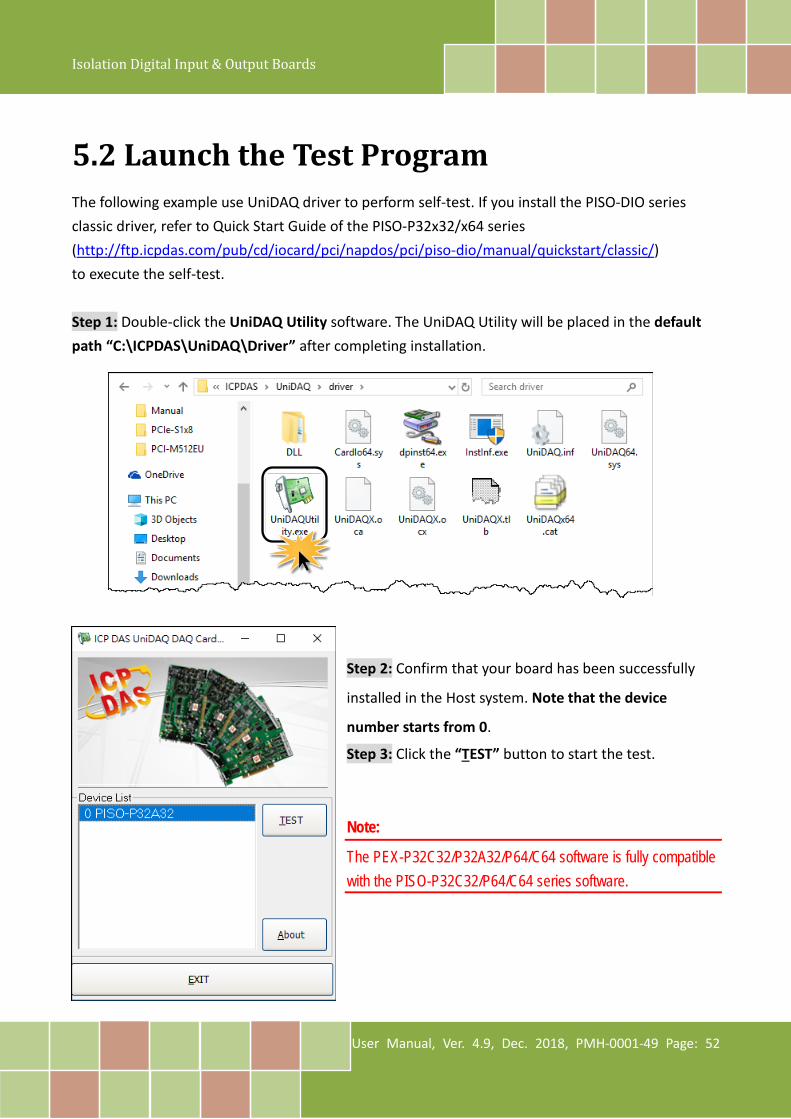
5.2 Launch the Test Program The following example use UniDAQ driver to perform self-test. If you install the PISO-DIO series classic driver, refer to Quick Start Guide of the PISO-P32x32/x64 series (http://ftp.icpdas.com/pub/cd/iocard/pci/napdos/pci/piso-dio/manual/quickstart/classic/) to execute the self-test. Step 1: Double-click the UniDAQ Utility software. The UniDAQ Utility will be placed in the default path “C:\ICPDAS\UniDAQ\Driver” after completing installation.
Step 2: Confirm that your board has been successfully
installed in the Host system. Note that the device
number starts from 0. Step 3: Click the “TEST” button to start the test.
Note:
The PEX-P32C32/P32A32/P64/C64 software is fully compatible with the PISO-P32C32/P64/C64 series software.
Isolation Digital Input & Output Boards
User Manual, Ver. 4.9, Dec. 2018, PMH-0001-49 Page: 53
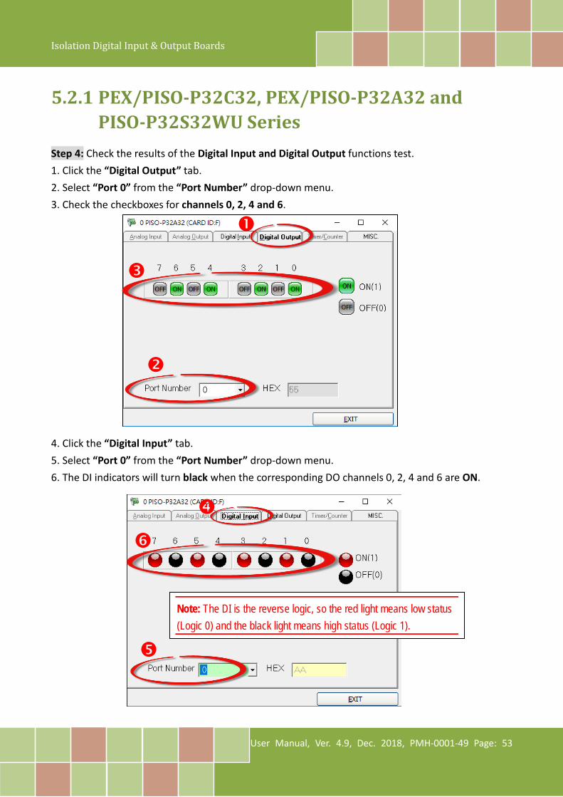
5.2.1 PEX/PISO-P32C32, PEX/PISO-P32A32 and PISO-P32S32WU Series
Step 4: Check the results of the Digital Input and Digital Output functions test. 1. Click the “Digital Output” tab. 2. Select “Port 0” from the “Port Number” drop-down menu. 3. Check the checkboxes for channels 0, 2, 4 and 6. 4. Click the “Digital Input” tab. 5. Select “Port 0” from the “Port Number” drop-down menu. 6. The DI indicators will turn black when the corresponding DO channels 0, 2, 4 and 6 are ON.
Note: The DI is the reverse logic, so the red light means low status (Logic 0) and the black light means high status (Logic 1).
Isolation Digital Input & Output Boards
User Manual, Ver. 4.9, Dec. 2018, PMH-0001-49 Page: 54
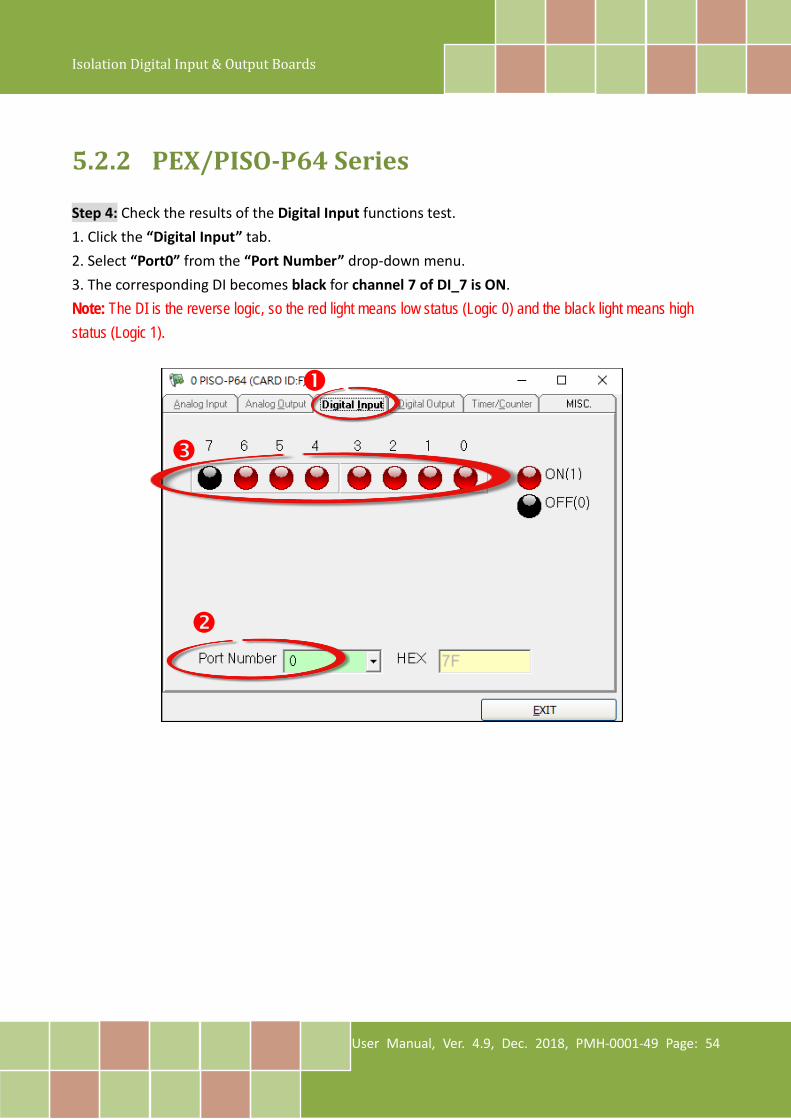
5.2.2 PEX/PISO-P64 Series Step 4: Check the results of the Digital Input functions test. 1. Click the “Digital Input” tab. 2. Select “Port0” from the “Port Number” drop-down menu. 3. The corresponding DI becomes black for channel 7 of DI_7 is ON.
Note: The DI is the reverse logic, so the red light means low status (Logic 0) and the black light means high status (Logic 1).
Isolation Digital Input & Output Boards
User Manual, Ver. 4.9, Dec. 2018, PMH-0001-49 Page: 55
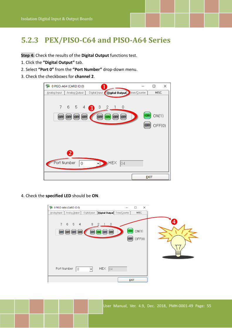
5.2.3 PEX/PISO-C64 and PISO-A64 Series Step 4: Check the results of the Digital Output functions test. 1. Click the “Digital Output” tab. 2. Select “Port 0” from the “Port Number” drop-down menu. 3. Check the checkboxes for channel 2. 4. Check the specified LED should be ON.

Isolation Digital Input & Output Boards
User Manual, Ver. 4.9, Dec. 2018, PMH-0001-49 Page: 56
6. I/O Control Register
6.1 How to Find the I/O Address During the power-on stage, the Plug and Play BIOS will assign an appropriate I/O address to each PEX/PISO-P32x32 and PEX/PISO-x64 Series board installed in the system. Each board includes four fixed ID numbers that are used to identify the board, and are indicated below: Table 6-1:
OLD Version (Vendor ID= 0xE159, Device ID= 0x02) Model Name Sub-Vender Sub-Device Sub-Aux Version PISO-C64(U) 0x80 0x08 0x00 1.0 ~ 3.0 PISO-P64(U)
0x80 0x08 0x10 1.0 ~ 3.0 PISO-P64U-24V PISO-P32C32(U)
0x80 0x08 0x20 1.0 ~ 4.0 1.4 PISO-P32C32U-5V
PISO-P32S32WU PISO-A64 0x80 0x08 0x50 1.0 ~ 2.0 PISO-P32A32(U)
0x80 0x08 0x70 1.0 ~ 2.0 PISO-P32A32U-5V
Table 6-2:
News Version (Vendor ID= 0xE159, Device ID= 0x01) Model Name Sub-Vender Sub-Device Sub-Aux Version PISO-C64(U)
0x0280 0x00 0x00 4.0 PEX-C64 PISO-P64(U) (-24V)
0x4280 0x00 0x10 4.4 PEX-P64 PISO-P32C32(U) (-5V)
0x4280 0x00 0x20 5.5 1.4 PEX-P32C32
PISO-P32S32WU PISO-A64
0x8280 0x00 0x50 3.0 PISO-A64U PISO-P32A32(U)
0xC280 0x00 0x70 4.0 and later PEX-P32A32 PISO-P32A32U-5V
Isolation Digital Input & Output Boards
User Manual, Ver. 4.9, Dec. 2018, PMH-0001-49 Page: 57
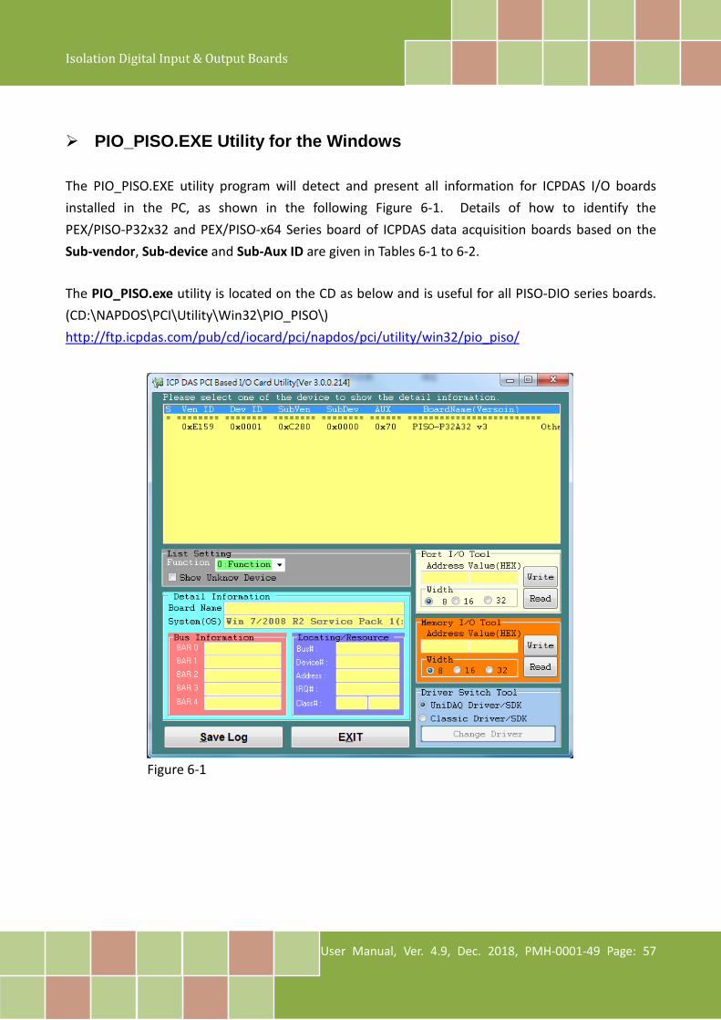
PIO_PISO.EXE Utility for the Windows The PIO_PISO.EXE utility program will detect and present all information for ICPDAS I/O boards installed in the PC, as shown in the following Figure 6-1. Details of how to identify the PEX/PISO-P32x32 and PEX/PISO-x64 Series board of ICPDAS data acquisition boards based on the Sub-vendor, Sub-device and Sub-Aux ID are given in Tables 6-1 to 6-2. The PIO_PISO.exe utility is located on the CD as below and is useful for all PISO-DIO series boards. (CD:\NAPDOS\PCI\Utility\Win32\PIO_PISO\) http://ftp.icpdas.com/pub/cd/iocard/pci/napdos/pci/utility/win32/pio_piso/
Figure 6-1

Isolation Digital Input & Output Boards
User Manual, Ver. 4.9, Dec. 2018, PMH-0001-49 Page: 58
We provide all necessary functions as follows:
1. PIO_DriverInit(&wBoard, wSubVendor, wSubDevice, wSubAux) 2. PIO_GetConfigAddressSpace(wBoardNo,*wBase,*wIrq, *wSubVendor,*wSubDevice, *wSubAux,
*wSlotBus, *wSlotDevice) 3. Show_PIO_PISO(wSubVendor, wSubDevice, wSubAux) All functions are defined in PISODIO.H. Refer to Section 6.4 “The I/O Address Map” for more information. The important driver information is given as follows:
Allocated resource information:
• wBase : BASE address mapping in this PC • wIrq: Allocated IRQ channel number of this board in this PC
PIO/PISO identification information:
• wSubVendor: subVendor ID of this board • wSubDevice: subDevice ID of this board • wSubAux: subAux ID of this board
PC’s physical slot information:
• wSlotBus: The bus number of the slot used by this board. • wSlotDevice: The device number of the slot used by this board.
Isolation Digital Input & Output Boards
User Manual, Ver. 4.9, Dec. 2018, PMH-0001-49 Page: 59
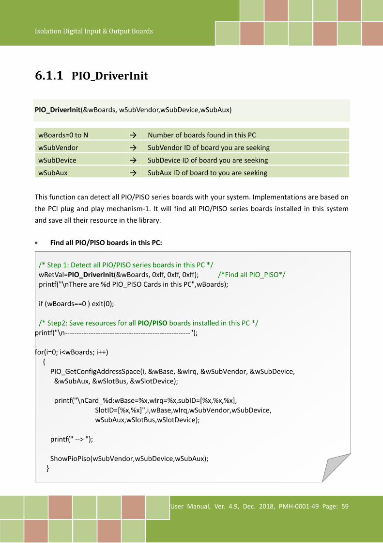
6.1.1 PIO_DriverInit
PIO_DriverInit(&wBoards, wSubVendor,wSubDevice,wSubAux)
wBoards=0 to N Number of boards found in this PC
wSubVendor SubVendor ID of board you are seeking
wSubDevice SubDevice ID of board you are seeking
wSubAux SubAux ID of board to you are seeking
This function can detect all PIO/PISO series boards with your system. Implementations are based on the PCI plug and play mechanism-1. It will find all PIO/PISO series boards installed in this system and save all their resource in the library. • Find all PIO/PISO boards in this PC:
/* Step 1: Detect all PIO/PISO series boards in this PC */ wRetVal=PIO_DriverInit(&wBoards, 0xff, 0xff, 0xff); /*Find all PIO_PISO*/ printf("\nThere are %d PIO_PISO Cards in this PC",wBoards); if (wBoards==0 ) exit(0); /* Step2: Save resources for all PIO/PISO boards installed in this PC */ printf("\n-----------------------------------------------------"); for(i=0; i<wBoards; i++) {
PIO_GetConfigAddressSpace(i, &wBase, &wIrq, &wSubVendor, &wSubDevice, &wSubAux, &wSlotBus, &wSlotDevice);
printf("\nCard_%d:wBase=%x,wIrq=%x,subID=[%x,%x,%x], SlotID=[%x,%x]",i,wBase,wIrq,wSubVendor,wSubDevice, wSubAux,wSlotBus,wSlotDevice);
printf(" --> ");
ShowPioPiso(wSubVendor,wSubDevice,wSubAux); }
Isolation Digital Input & Output Boards
User Manual, Ver. 4.9, Dec. 2018, PMH-0001-49 Page: 60
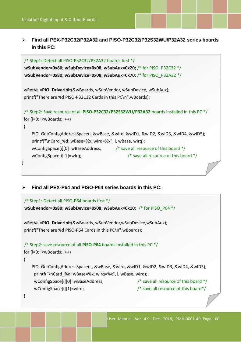
Find all PEX-P32C32/P32A32 and PISO-P32C32/P32S32WU/P32A32 series boards
in this PC:
/* Step1: Detect all PISO-P32C32/P32A32 boards first */ wSubVendor=0x80; wSubDevice=0x08; wSubAux=0x20; /* for PISO_P32C32 */ wSubVendor=0x80; wSubDevice=0x08; wSubAux=0x70; /* for PISO_P32A32 */ wRetVal=PIO_DriverInit(&wBoards, wSubVendor, wSubDevice, wSubAux); printf("There are %d PISO-P32C32 Cards in this PC\n",wBoards); /* Step2: Save resource of all PISO-P32C32/P32S32WU/P32A32 boards installed in this PC */ for (i=0; i<wBoards; i++) {
PIO_GetConfigAddressSpace(i, &wBase, &wIrq, &wID1, &wID2, &wID3, &wID4, &wID5); printf("\nCard_%d: wBase=%x, wIrq=%x", i, wBase, wIrq); wConfigSpace[i][0]=wBaseAddress; /* save all resource of this board */ wConfigSpace[i][1]=wIrq; /* save all resource of this board */
} Find all PEX-P64 and PISO-P64 series boards in this PC:
/* Step1: Detect all PISO-P64 boards first */ wSubVendor=0x80; wSubDevice=0x08; wSubAux=0x10; /* for PISO_P64 */ wRetVal=PIO_DriverInit(&wBoards, wSubVendor,wSubDevice,wSubAux); printf("There are %d PISO-P64 Cards in this PC\n",wBoards); /* Step2: save resource of all PISO-P64 boards installed in this PC */ for (i=0; i<wBoards; i++) {
PIO_GetConfigAddressSpace(i,, &wBase, &wIrq, &wID1, &wID2, &wID3, &wID4, &wID5); printf("\nCard_%d: wBase=%x, wIrq=%x", i, wBase, wIrq); wConfigSpace[i][0]=wBaseAddress; /* save all resource of this board */ wConfigSpace[i][1]=wIrq; /* save all resource of this board*/ }

Isolation Digital Input & Output Boards
User Manual, Ver. 4.9, Dec. 2018, PMH-0001-49 Page: 61
Find all PEX-C64 and PISO-C64/A64 series boards in this PC:
/* Step1: Detect all PISO-C64 boards first */ wSubVendor=0x80; wSubDevice=0x08; wSubAux=0x00; /* for PISO-C64 */ wSubVendor=0x80; wSubDevice=0x08; wSubAux=0x50; /* for PISO-A64 */ wRetVal=PIO_DriverInit(&wBoards, wSubVendor,wSubDevice,wSubAux); printf("There are %d PISO-C64 Cards in this PC\n",wBoards); /* Step2: save resource of all PISO-C64/A64 boards installed in this PC */ for (i=0; i<wBoards; i++) {
PIO_GetConfigAddressSpace(i,&wBase,&wIrq,&wID1,&wID2,&wID3,&wID4, &wID5); printf("\nCard_%d: wBase=%x, wIrq=%x", i, wBase, wIrq); wConfigSpace[i][0]=wBaseAddress; /* save all resource of this board */ wConfigSpace[i][1]=wIrq; /* save all resource of this board*/ }
Isolation Digital Input & Output Boards
User Manual, Ver. 4.9, Dec. 2018, PMH-0001-49 Page: 62
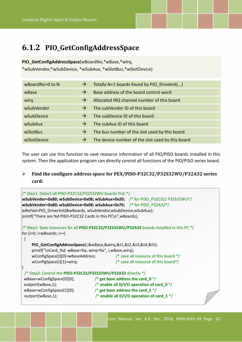
6.1.2 PIO_GetConfigAddressSpace
PIO_GetConfigAddressSpace(wBoardNo,*wBase,*wIrq, *wSubVendor,*wSubDevice, *wSubAux, *wSlotBus,*wSlotDevice)
wBoardNo=0 to N Totally N+1 boards found by PIO_DriveInit(...)
wBase Base address of the board control word
wIrq Allocated IRQ channel number of this board
wSubVendor The subVendor ID of this board
wSubDevice The subDevice ID of this board
wSubAux The subAux ID of this board
wSlotBus The bus number of the slot used by this board
wSlotDevice The device number of the slot used by this board
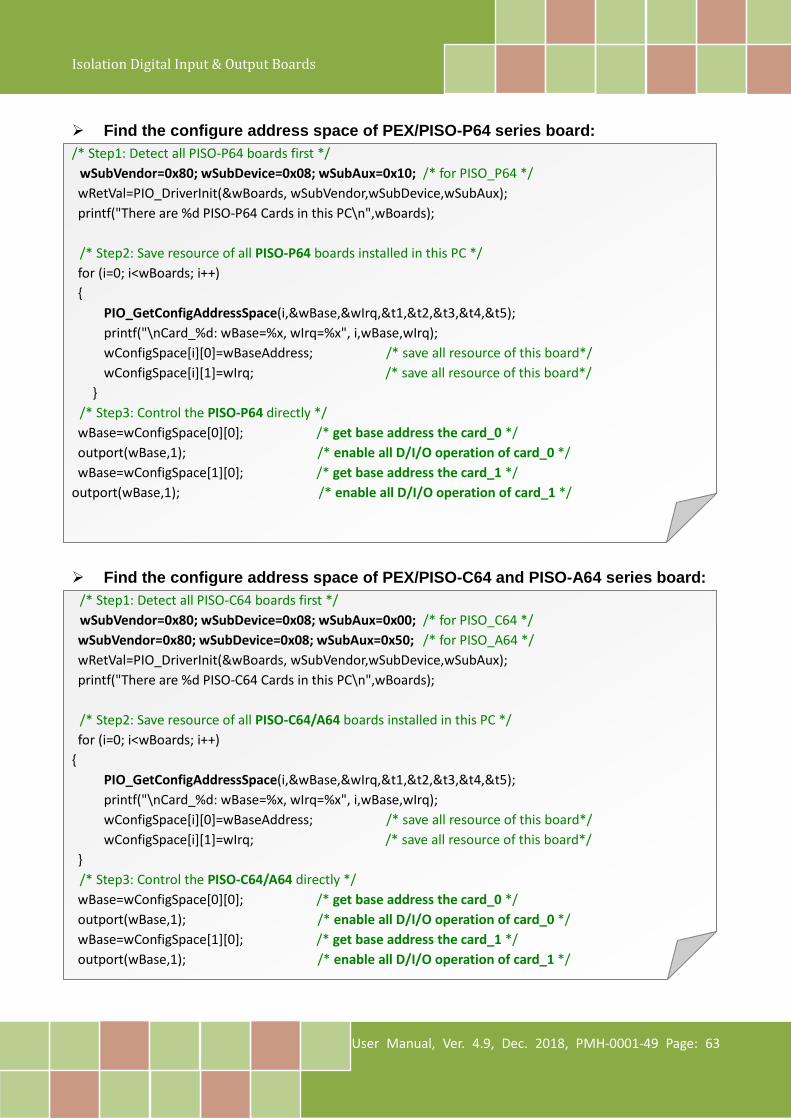
The user can use this function to save resource information of all PIO/PISO boards installed in this system. Then the application program can directly control all functions of the PIO/PISO series board. Find the configure address space for PEX/PISO-P32C32/P32S32WU/P32A32 series
card: /* Step1: Detect all PISO-P32C32/P32S32WU boards first */ wSubVendor=0x80; wSubDevice=0x08; wSubAux=0x20; /* for PISO_P32C32/ P32S32WU*/ wSubVendor=0x80; wSubDevice=0x08; wSubAux=0x70; /* for PISO_P32A32*/ wRetVal=PIO_DriverInit(&wBoards, wSubVendor,wSubDevice,wSubAux); printf("There are %d PISO-P32C32 Cards in this PC\n",wBoards); /* Step2: Save resources for all PISO-P32C32/P32S32WU/P32A32 boards installed in this PC */ for (i=0; i<wBoards; i++) {
PIO_GetConfigAddressSpace(i,&wBase,&wIrq,&t1,&t2,&t3,&t4,&t5); printf("\nCard_%d: wBase=%x, wIrq=%x", i,wBase,wIrq); wConfigSpace[i][0]=wBaseAddress; /* save all resource of this board */ wConfigSpace[i][1]=wIrq; /* save all resource of this board*/
} /* Step3: Control the PISO-P32C32/P32S32WU/P32A32 directly */ wBase=wConfigSpace[0][0]; /* get base address the card_0 */ outport(wBase,1); /* enable all D/I/O operation of card_0 */ wBase=wConfigSpace[1][0]; /* get base address the card_1 */ outport(wBase,1); /* enable all D/I/O operation of card_1 */
Isolation Digital Input & Output Boards
User Manual, Ver. 4.9, Dec. 2018, PMH-0001-49 Page: 63
Find the configure address space of PEX/PISO-P64 series board: /* Step1: Detect all PISO-P64 boards first */
wSubVendor=0x80; wSubDevice=0x08; wSubAux=0x10; /* for PISO_P64 */ wRetVal=PIO_DriverInit(&wBoards, wSubVendor,wSubDevice,wSubAux); printf("There are %d PISO-P64 Cards in this PC\n",wBoards); /* Step2: Save resource of all PISO-P64 boards installed in this PC */ for (i=0; i<wBoards; i++) {
PIO_GetConfigAddressSpace(i,&wBase,&wIrq,&t1,&t2,&t3,&t4,&t5); printf("\nCard_%d: wBase=%x, wIrq=%x", i,wBase,wIrq); wConfigSpace[i][0]=wBaseAddress; /* save all resource of this board*/ wConfigSpace[i][1]=wIrq; /* save all resource of this board*/
} /* Step3: Control the PISO-P64 directly */ wBase=wConfigSpace[0][0]; /* get base address the card_0 */ outport(wBase,1); /* enable all D/I/O operation of card_0 */ wBase=wConfigSpace[1][0]; /* get base address the card_1 */
outport(wBase,1); /* enable all D/I/O operation of card_1 */ Find the configure address space of PEX/PISO-C64 and PISO-A64 series board:
/* Step1: Detect all PISO-C64 boards first */ wSubVendor=0x80; wSubDevice=0x08; wSubAux=0x00; /* for PISO_C64 */ wSubVendor=0x80; wSubDevice=0x08; wSubAux=0x50; /* for PISO_A64 */ wRetVal=PIO_DriverInit(&wBoards, wSubVendor,wSubDevice,wSubAux); printf("There are %d PISO-C64 Cards in this PC\n",wBoards); /* Step2: Save resource of all PISO-C64/A64 boards installed in this PC */ for (i=0; i<wBoards; i++)
{ PIO_GetConfigAddressSpace(i,&wBase,&wIrq,&t1,&t2,&t3,&t4,&t5); printf("\nCard_%d: wBase=%x, wIrq=%x", i,wBase,wIrq); wConfigSpace[i][0]=wBaseAddress; /* save all resource of this board*/ wConfigSpace[i][1]=wIrq; /* save all resource of this board*/
} /* Step3: Control the PISO-C64/A64 directly */ wBase=wConfigSpace[0][0]; /* get base address the card_0 */ outport(wBase,1); /* enable all D/I/O operation of card_0 */ wBase=wConfigSpace[1][0]; /* get base address the card_1 */ outport(wBase,1); /* enable all D/I/O operation of card_1 */
Isolation Digital Input & Output Boards
User Manual, Ver. 4.9, Dec. 2018, PMH-0001-49 Page: 64
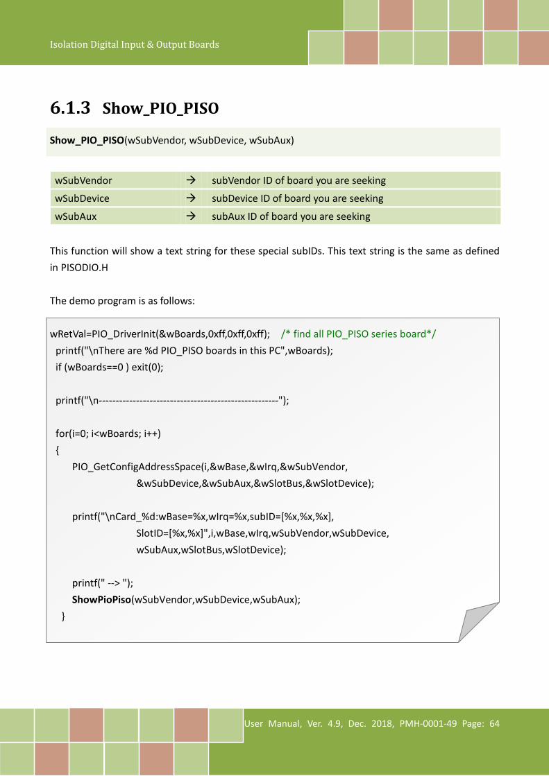
6.1.3 Show_PIO_PISO
Show_PIO_PISO(wSubVendor, wSubDevice, wSubAux) wSubVendor subVendor ID of board you are seeking
wSubDevice subDevice ID of board you are seeking
wSubAux subAux ID of board you are seeking
This function will show a text string for these special subIDs. This text string is the same as defined in PISODIO.H The demo program is as follows:
wRetVal=PIO_DriverInit(&wBoards,0xff,0xff,0xff); /* find all PIO_PISO series board*/ printf("\nThere are %d PIO_PISO boards in this PC",wBoards); if (wBoards==0 ) exit(0); printf("\n-----------------------------------------------------"); for(i=0; i<wBoards; i++) {
PIO_GetConfigAddressSpace(i,&wBase,&wIrq,&wSubVendor, &wSubDevice,&wSubAux,&wSlotBus,&wSlotDevice);
printf("\nCard_%d:wBase=%x,wIrq=%x,subID=[%x,%x,%x], SlotID=[%x,%x]",i,wBase,wIrq,wSubVendor,wSubDevice, wSubAux,wSlotBus,wSlotDevice);
printf(" --> "); ShowPioPiso(wSubVendor,wSubDevice,wSubAux);
}
Isolation Digital Input & Output Boards
User Manual, Ver. 4.9, Dec. 2018, PMH-0001-49 Page: 65
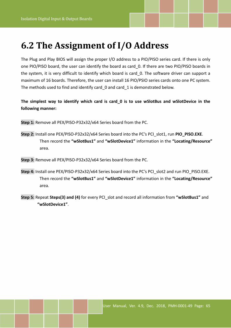
6.2 The Assignment of I/O Address The Plug and Play BIOS will assign the proper I/O address to a PIO/PISO series card. If there is only one PIO/PISO board, the user can identify the board as card_0. If there are two PIO/PISO boards in the system, it is very difficult to identify which board is card_0. The software driver can support a maximum of 16 boards. Therefore, the user can install 16 PIO/PSIO series cards onto one PC system. The methods used to find and identify card_0 and card_1 is demonstrated below. The simplest way to identify which card is card_0 is to use wSlotBus and wSlotDevice in the following manner: Step 1: Remove all PEX/PISO-P32x32/x64 Series board from the PC. Step 2: Install one PEX/PISO-P32x32/x64 Series board into the PC’s PCI_slot1, run PIO_PISO.EXE.
Then record the “wSlotBus1” and “wSlotDevice1” information in the “Locating/Resource” area.
Step 3: Remove all PEX/PISO-P32x32/x64 Series board from the PC. Step 4: Install one PEX/PISO-P32x32/x64 Series board into the PC’s PCI_slot2 and run PIO_PISO.EXE.
Then record the “wSlotBus1” and “wSlotDevice1” information in the “Locating/Resource” area.
Step 5: Repeat Steps(3) and (4) for every PCI_slot and record all information from “wSlotBus1” and
“wSlotDevice1”.

Isolation Digital Input & Output Boards
User Manual, Ver. 4.9, Dec. 2018, PMH-0001-49 Page: 66
The records may look similar to the table follows:
The above procedure will record all the “wSlotBus” and “wSlotBus” information on a PC. These
values will be mapped to this PC’s physical slot and this mapping will not be changed for any
PIO/PISO cards. Therefore, this information can be used to identify the specified PIO/PISO card by
following steps:
Step1: Using the “wSlotBus” and “wSlotDevice” information from Table 6-4.
Step2: Enter the board number into PIO_GetConfigAddressSpace(…) function to get the
information for a specific card, especially the “wSlotBus” and “wSlotDevice” details.
Step3: Identify the specific PIO/PISO card by comparing the data of the “wSlotBus” and
“wSlotDevice” from Step1 and Step2.
Note:
Normally the card installed in slot 0 is card0 and the card installed in slot1 is card1 for PIO/PISO series cards.
PC’s PCI Slot Locating/Resource
wSlotBus (Bus#) wSlotBus (Device#) Slot_1 0 0x07 Slot_2 0 0x08 Slot_3 0 0x09 Slot_4 0 0x0A PCI-BRIDGE Slot_5 1 0x0A Slot_6 1 0x08 Slot_7 1 0x09 Slot_8 1 0x07
Table 6-3
Isolation Digital Input & Output Boards
User Manual, Ver. 4.9, Dec. 2018, PMH-0001-49 Page: 67
6.3 Enabling I/O Operation When the PC is first powered-on, DI/DO operations are disabled. The enable/disable of DI/DO is controlled by the RESET\ signal. The powered-on states are given as follows:
All DI/DO operations are disabled All DO latch registers are clear
The DI/DO ports must be enabled by program before using. For example:
Step 1: Enable all DI/DO operation.
Step 2: Read from DI or write to DO
Refer to DEMO1.C for DOS demo program.
Isolation Digital Input & Output Boards
User Manual, Ver. 4.9, Dec. 2018, PMH-0001-49 Page: 68
6.4 The I/O Address Map The I/O address of the PIO/PISO series board is automatically assigned by the main board ROM BIOS. The I/O address can also be re-assigned by the user, but it is strongly recommended that the I/O address is not changed by user. The Plug and Play BIOS will assign an appropriate I/O address to each PIO/PISO series board. The I/O addresses of the PEX/PISO-P32x32 and PEX/PISO-x64 Series board are as follows, and are based on the base address of each board.
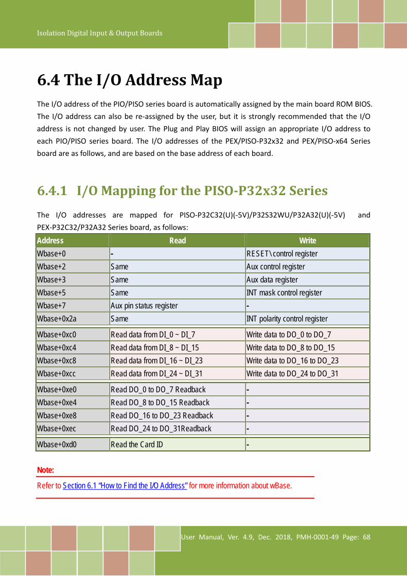
6.4.1 I/O Mapping for the PISO-P32x32 Series The I/O addresses are mapped for PISO-P32C32(U)(-5V)/P32S32WU/P32A32(U)(-5V) and PEX-P32C32/P32A32 Series board, as follows:
Address Read Write Wbase+0 - RESET\ control register Wbase+2 Same Aux control register Wbase+3 Same Aux data register Wbase+5 Same INT mask control register Wbase+7 Aux pin status register - Wbase+0x2a Same INT polarity control register
Wbase+0xc0 Read data from DI_0 ~ DI_7 Write data to DO_0 to DO_7 Wbase+0xc4 Read data from DI_8 ~ DI_15 Write data to DO_8 to DO_15 Wbase+0xc8 Read data from DI_16 ~ DI_23 Write data to DO_16 to DO_23 Wbase+0xcc Read data from DI_24 ~ DI_31 Write data to DO_24 to DO_31
Wbase+0xe0 Read DO_0 to DO_7 Readback - Wbase+0xe4 Read DO_8 to DO_15 Readback - Wbase+0xe8 Read DO_16 to DO_23 Readback - Wbase+0xec Read DO_24 to DO_31Readback -
Wbase+0xd0 Read the Card ID - Note:
Refer to Section 6.1 “How to Find the I/O Address” for more information about wBase.
Isolation Digital Input & Output Boards
User Manual, Ver. 4.9, Dec. 2018, PMH-0001-49 Page: 69
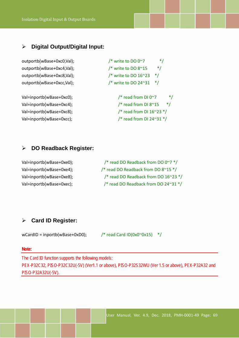
Digital Output/Digital Input: outportb(wBase+0xc0,Val); /* write to DO 0~7 */ outportb(wBase+0xc4,Val); /* write to DO 8~15 */ outportb(wBase+0xc8,Val); /* write to DO 16~23 */ outportb(wBase+0xcc,Val); /* write to DO 24~31 */ Val=inportb(wBase+0xc0); /* read from DI 0~7 */ Val=inportb(wBase+0xc4); /* read from DI 8~15 */ Val=inportb(wBase+0xc8); /* read from DI 16~23 */ Val=inportb(wBase+0xcc); /* read from DI 24~31 */
DO Readback Register: Val=inportb(wBase+0xe0); /* read DO Readback from DO 0~7 */ Val=inportb(wBase+0xe4); /* read DO Readback from DO 8~15 */ Val=inportb(wBase+0xe8); /* read DO Readback from DO 16~23 */ Val=inportb(wBase+0xec); /* read DO Readback from DO 24~31 */
Card ID Register: wCardID = inportb(wBase+0xD0); /* read Card ID(0x0~0x15) */ Note:
The Card ID function supports the following models: PEX-P32C32, PISO-P32C32U(-5V) (Ver1.1 or above), PISO-P32S32WU (Ver 1.5 or above), PEX-P32A32 and PISO-P32A32U(-5V).

Isolation Digital Input & Output Boards
User Manual, Ver. 4.9, Dec. 2018, PMH-0001-49 Page: 70
6.4.2 I/O Mapping for the PISO-P64 Series The I/O addresses are mapped for PISO-P64(U)(-24V) and PEX-P64 Series board, as follows:
Address Read Write wBase+0 - RESET\ control register wBase+2 Same Aux control register wBase+3 Same Aux data register
WBase+5 Same INT mask control register Wbase+7 Aux pin status register - Wbase+0x2a Same INT polarity control register
Wbase+0xc0 Read data from DI_0 ~ DI_7 Reserved Wbase+0xc4 Read data from DI_8 ~ DI_15 Reserved Wbase+0xc8 Read data from DI_16 ~ DI_23 Reserved Wbase+0xcc Read data from DI_24 ~ DI_31 Reserved WBase+0xd0 Read data from DI_32 ~ DI_39 Reserved WBase+0xd4 Read data from DI_40 ~ DI_47 Reserved WBase+0xd8 Read data from DI_48 ~ DI_55 Reserved WBase+0xdc Read data from DI_56 ~ DI_63 Reserved
WBase+0xf0 Read the Card ID - Note:
Refer to Section 6.1 “How to Find the I/O Address” for more information about wBase.
Digital Input: Val=inportb(wBase+0xc0); /* read from DI 0~7 */ Val=inportb(wBase+0xc4); /* read from DI 8~15 */ Val=inportb(wBase+0xc8); /* read from DI 16~23 */ Val=inportb(wBase+0xcc); /* read from DI 24~31 */ Val=inportb(wBase+0xd0); /* read from DI 32~39 */ Val=inportb(wBase+0xd4); /* read from DI 40~47 */ Val=inportb(wBase+0xd8); /* read from DI 48~55 */ Val=inportb(wBase+0xdc); /* read from DI 56~63 */
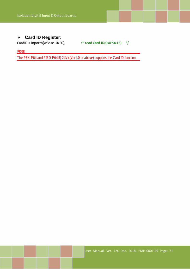
Isolation Digital Input & Output Boards
User Manual, Ver. 4.9, Dec. 2018, PMH-0001-49 Page: 71
Card ID Register: CardID = inportb(wBase+0xF0); /* read Card ID(0x0~0x15) */ Note: The PEX-P64 and PISO-P64U(-24V) (Ver1.0 or above) supports the Card ID function.
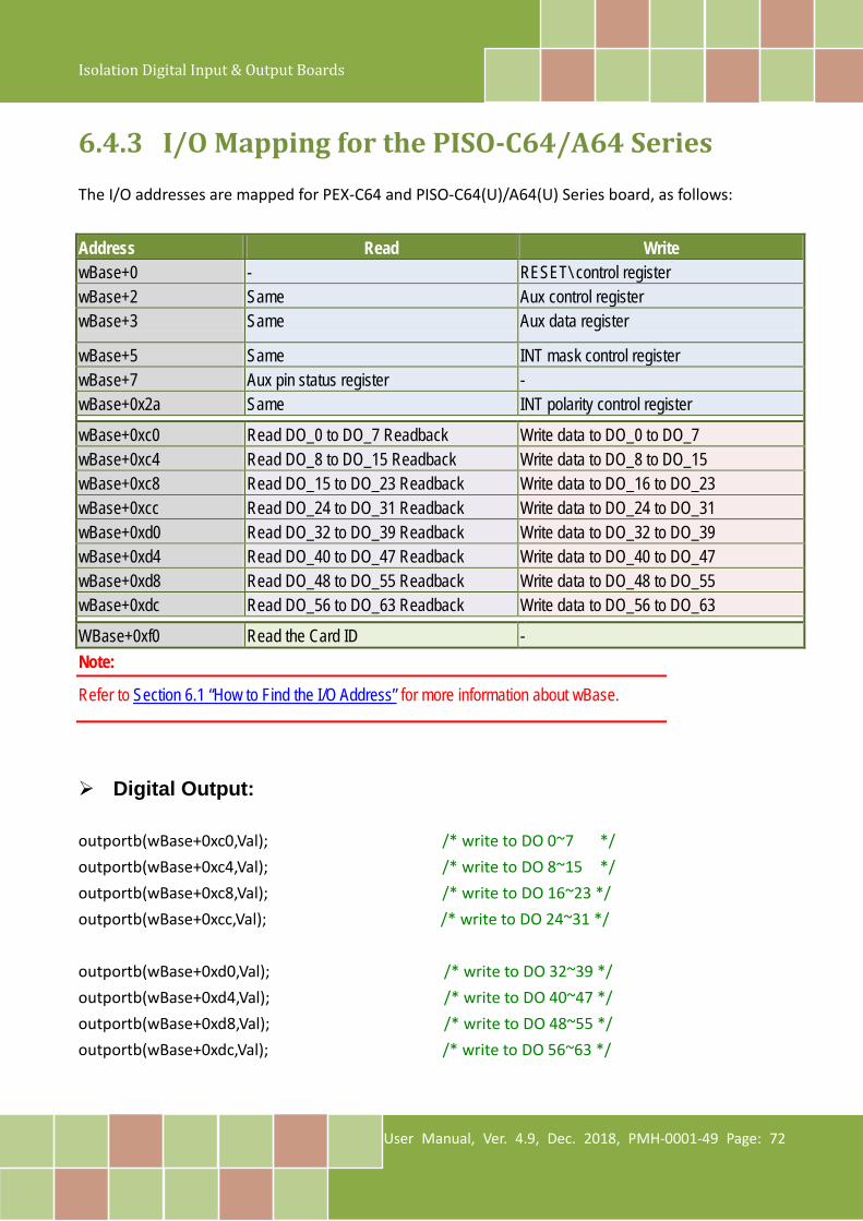
Isolation Digital Input & Output Boards
User Manual, Ver. 4.9, Dec. 2018, PMH-0001-49 Page: 72
6.4.3 I/O Mapping for the PISO-C64/A64 Series The I/O addresses are mapped for PEX-C64 and PISO-C64(U)/A64(U) Series board, as follows:
Address Read Write wBase+0 - RESET\ control register wBase+2 Same Aux control register wBase+3 Same Aux data register
wBase+5 Same INT mask control register wBase+7 Aux pin status register - wBase+0x2a Same INT polarity control register
wBase+0xc0 Read DO_0 to DO_7 Readback Write data to DO_0 to DO_7 wBase+0xc4 Read DO_8 to DO_15 Readback Write data to DO_8 to DO_15 wBase+0xc8 Read DO_15 to DO_23 Readback Write data to DO_16 to DO_23 wBase+0xcc Read DO_24 to DO_31 Readback Write data to DO_24 to DO_31 wBase+0xd0 Read DO_32 to DO_39 Readback Write data to DO_32 to DO_39 wBase+0xd4 Read DO_40 to DO_47 Readback Write data to DO_40 to DO_47 wBase+0xd8 Read DO_48 to DO_55 Readback Write data to DO_48 to DO_55 wBase+0xdc Read DO_56 to DO_63 Readback Write data to DO_56 to DO_63
WBase+0xf0 Read the Card ID - Note:
Refer to Section 6.1 “How to Find the I/O Address” for more information about wBase.
Digital Output: outportb(wBase+0xc0,Val); /* write to DO 0~7 */ outportb(wBase+0xc4,Val); /* write to DO 8~15 */ outportb(wBase+0xc8,Val); /* write to DO 16~23 */ outportb(wBase+0xcc,Val); /* write to DO 24~31 */ outportb(wBase+0xd0,Val); /* write to DO 32~39 */ outportb(wBase+0xd4,Val); /* write to DO 40~47 */ outportb(wBase+0xd8,Val); /* write to DO 48~55 */ outportb(wBase+0xdc,Val); /* write to DO 56~63 */

Isolation Digital Input & Output Boards
User Manual, Ver. 4.9, Dec. 2018, PMH-0001-49 Page: 73
DO Readback Register: Val=inportb(wBase+0xc0); /* read DO Readback from DO 0~7 */ Val=inportb(wBase+0xc4); /* read DO Readback from DO 8~15 */ Val=inportb(wBase+0xc8); /* read DO Readback from DO 16~23 */ Val=inportb(wBase+0xcc); /* read DO Readback from DO 24~31 */ Val=inportb(wBase+0xd0); /* read DO Readback from DO 32~39 */ Val=inportb(wBase+0xd4); /* read DO Readback from DO 40~47 */ Val=inportb(wBase+0xd8); /* read DO Readback from DO 46~55 */ Val=inportb(wBase+0xdc); /* read DO Readback from DO 56~63 */
Card ID Register: CardID = inportb(wBase+0xF0); /* read Card ID(0x0~0x15) */ Note:
The PEX-C64, PISO-C64U and PISO-A64U (Ver1.0 or above) supports the Card ID function.
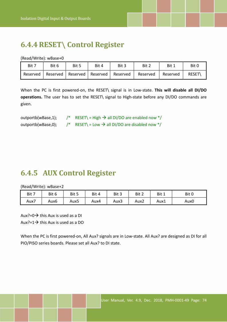
Isolation Digital Input & Output Boards
User Manual, Ver. 4.9, Dec. 2018, PMH-0001-49 Page: 74
6.4.4 RESET\ Control Register (Read/Write): wBase+0
Bit 7 Bit 6 Bit 5 Bit 4 Bit 3 Bit 2 Bit 1 Bit 0
Reserved Reserved Reserved Reserved Reserved Reserved Reserved RESET\
When the PC is first powered-on, the RESET\ signal is in Low-state. This will disable all DI/DO operations. The user has to set the RESET\ signal to High-state before any DI/DO commands are given. outportb(wBase,1); /* RESET\ = High all DI/DO are enabled now */ outportb(wBase,0); /* RESET\ = Low all DI/DO are disabled now */
6.4.5 AUX Control Register (Read/Write): wBase+2
Bit 7 Bit 6 Bit 5 Bit 4 Bit 3 Bit 2 Bit 1 Bit 0 Aux7 Aux6 Aux5 Aux4 Aux3 Aux2 Aux1 Aux0
Aux?=0 this Aux is used as a DI Aux?=1 this Aux is used as a DO When the PC is first powered-on, All Aux? signals are in Low-state. All Aux? are designed as DI for all PIO/PISO series boards. Please set all Aux? to DI state.
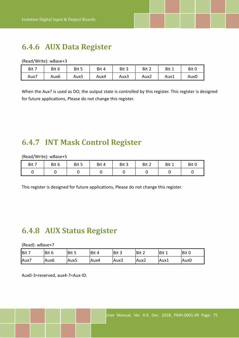
Isolation Digital Input & Output Boards
User Manual, Ver. 4.9, Dec. 2018, PMH-0001-49 Page: 75
6.4.6 AUX Data Register (Read/Write): wBase+3
Bit 7 Bit 6 Bit 5 Bit 4 Bit 3 Bit 2 Bit 1 Bit 0 Aux7 Aux6 Aux5 Aux4 Aux3 Aux2 Aux1 Aux0
When the Aux? is used as DO, the output state is controlled by this register. This register is designed for future applications, Please do not change this register.
6.4.7 INT Mask Control Register (Read/Write): wBase+5
Bit 7 Bit 6 Bit 5 Bit 4 Bit 3 Bit 2 Bit 1 Bit 0 0 0 0 0 0 0 0 0
This register is designed for future applications, Please do not change this register.
6.4.8 AUX Status Register (Read): wBase+7
Bit 7 Bit 6 Bit 5 Bit 4 Bit 3 Bit 2 Bit 1 Bit 0 Aux7 Aux6 Aux5 Aux4 Aux3 Aux2 Aux1 Aux0
Aux0-3=reserved, aux4-7=Aux-ID.
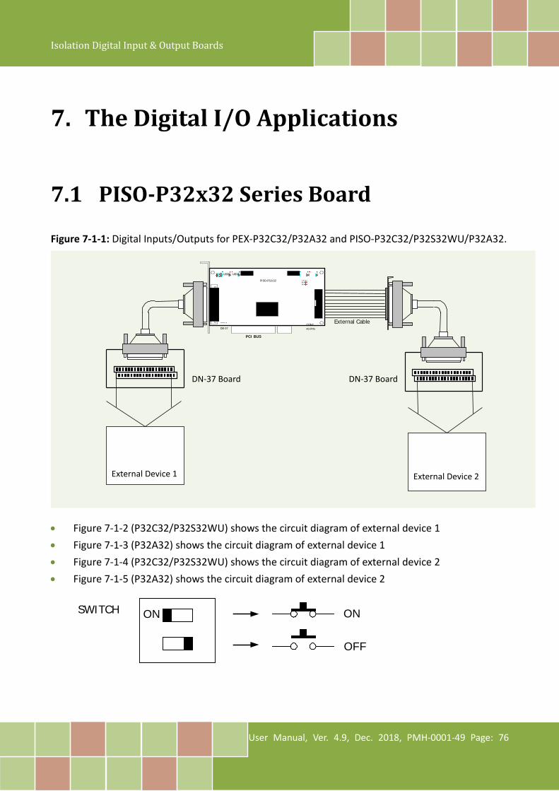
Isolation Digital Input & Output Boards
User Manual, Ver. 4.9, Dec. 2018, PMH-0001-49 Page: 76
7. The Digital I/O Applications
7.1 PISO-P32x32 Series Board Figure 7-1-1: Digital Inputs/Outputs for PEX-P32C32/P32A32 and PISO-P32C32/P32S32WU/P32A32.
• Figure 7-1-2 (P32C32/P32S32WU) shows the circuit diagram of external device 1 • Figure 7-1-3 (P32A32) shows the circuit diagram of external device 1 • Figure 7-1-4 (P32C32/P32S32WU) shows the circuit diagram of external device 2 • Figure 7-1-5 (P32A32) shows the circuit diagram of external device 2
ON ON
OFF
SWITCH
External Device 1 External Device 2
External Cable
DC/DC 1 DC/DC 2 JP1 LED3 LED4
DN-37 Board DN-37 Board
PCI BUS CON1 DB-37 CON2
40-PIN
JP2 LED1 LED2 PISO-P32c32
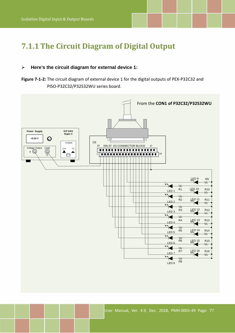
Isolation Digital Input & Output Boards
User Manual, Ver. 4.9, Dec. 2018, PMH-0001-49 Page: 77
7.1.1 The Circuit Diagram of Digital Output
Here’s the circuit diagram for external device 1: Figure 7-1-2: The circuit diagram of external device 1 for the digital outputs of PEX-P32C32 and
PISO-P32C32/P32S32WU series board.
DN-37 I/O CONNECTOR BLOCKCE
COM
Power Supply
+5.00 V
POWER
OnOFF
ICP DASSuper 2
Voltage Output
1 19
20 37
R1
R2
R3
R4
R5
R6
R7
R8
LED 1
LED 2
LED 3
LED 4
LED 5
LED 6
LED 7
LED 8
LED 9
LED 10
LED 11
LED 12
LED 13
LED 14
LED 15
LED 16
R9
R10
R11
R12
R13
R14
R15
R16
+
From the CON1 of P32C32/P32S32WU
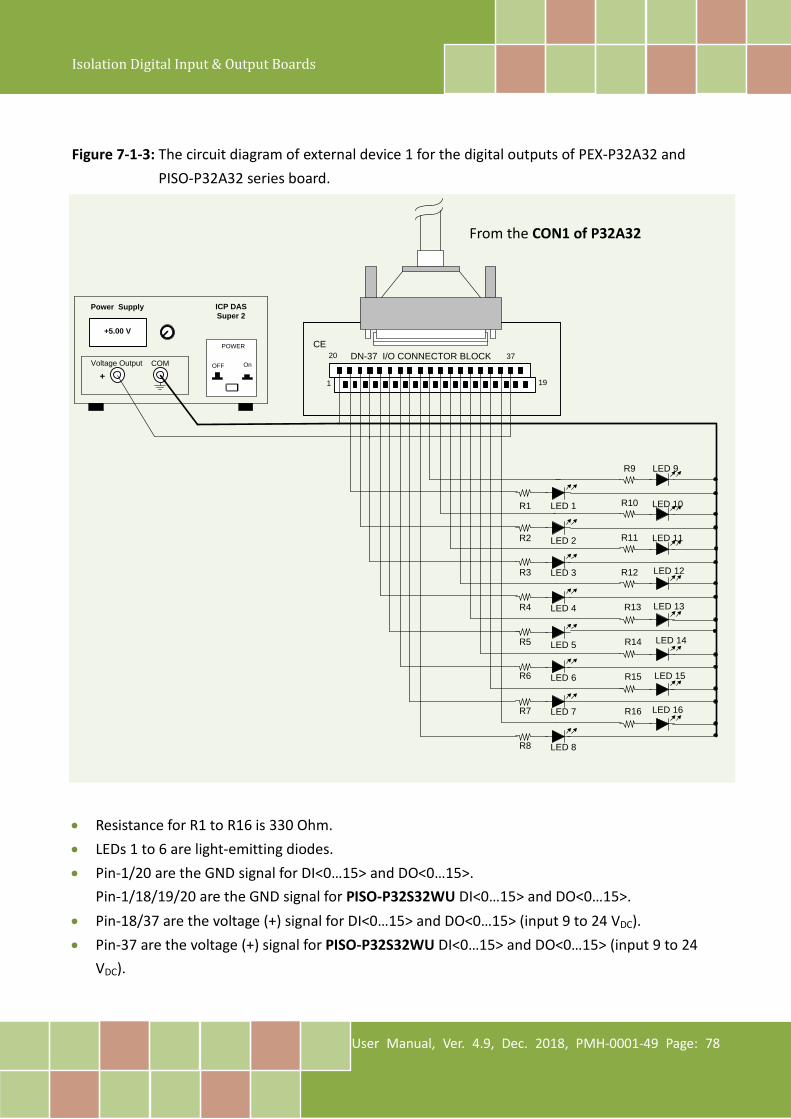
Isolation Digital Input & Output Boards
User Manual, Ver. 4.9, Dec. 2018, PMH-0001-49 Page: 78
Figure 7-1-3: The circuit diagram of external device 1 for the digital outputs of PEX-P32A32 and
PISO-P32A32 series board.
DN-37 I/O CONNECTOR BLOCKCE
COM
Power Supply
+5.00 V
POWER
OnOFF
ICP DASSuper 2
Voltage Output
1 19
20 37
R1
R2
R3
R4
R5
R6
R7
R8
LED 1
LED 2
LED 3
LED 4
LED 5
LED 6
LED 7
LED 8
LED 9
LED 10
LED 11
LED 12
LED 13
LED 14
LED 15
LED 16
R9
R10
R11
R12
R13
R14
R15
R16
+
• Resistance for R1 to R16 is 330 Ohm. • LEDs 1 to 6 are light-emitting diodes. • Pin-1/20 are the GND signal for DI<0…15> and DO<0…15>.
Pin-1/18/19/20 are the GND signal for PISO-P32S32WU DI<0…15> and DO<0…15>. • Pin-18/37 are the voltage (+) signal for DI<0…15> and DO<0…15> (input 9 to 24 VDC). • Pin-37 are the voltage (+) signal for PISO-P32S32WU DI<0…15> and DO<0…15> (input 9 to 24
VDC).
From the CON1 of P32A32
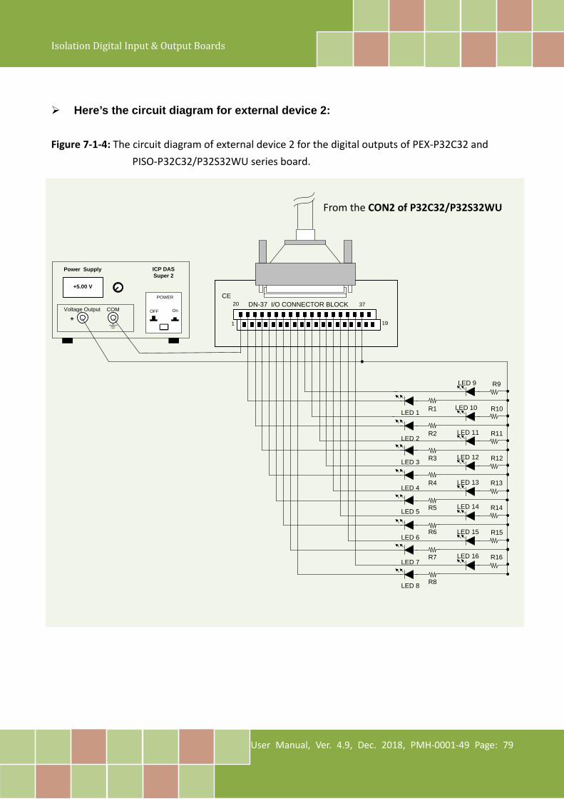
Isolation Digital Input & Output Boards
User Manual, Ver. 4.9, Dec. 2018, PMH-0001-49 Page: 79
Here’s the circuit diagram for external device 2:
Figure 7-1-4: The circuit diagram of external device 2 for the digital outputs of PEX-P32C32 and PISO-P32C32/P32S32WU series board.
DN-37 I/O CONNECTOR BLOCKCE
COM
Power Supply
+5.00 V
POWER
OnOFF
ICP DASSuper 2
Voltage Output
1 19
20 37
R1
R2
R3
R4
R5
R6
R7
R8
LED 1
LED 2
LED 3
LED 4
LED 5
LED 6
LED 7
LED 8
LED 9
LED 10
LED 11
LED 12
LED 13
LED 14
LED 15
LED 16
R9
R10
R11
R12
R13
R14
R15
R16
+
From the CON2 of P32C32/P32S32WU
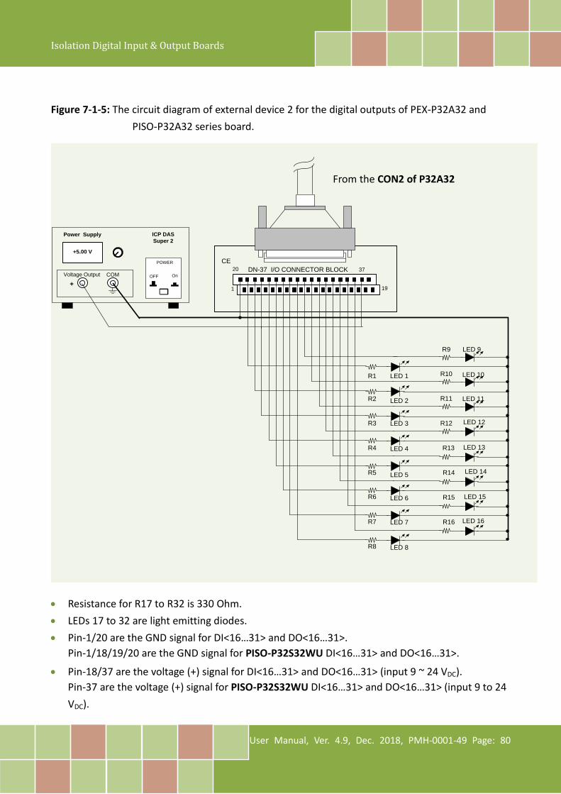
Isolation Digital Input & Output Boards
User Manual, Ver. 4.9, Dec. 2018, PMH-0001-49 Page: 80
Figure 7-1-5: The circuit diagram of external device 2 for the digital outputs of PEX-P32A32 and
PISO-P32A32 series board.
DN-37 I/O CONNECTOR BLOCKCE
COM
Power Supply
+5.00 V
POWER
OnOFF
ICP DASSuper 2
Voltage Output
1 19
20 37
R1
R2
R3
R4
R5
R6
R7
R8
LED 1
LED 2
LED 3
LED 4
LED 5
LED 6
LED 7
LED 8
LED 9
LED 10
LED 11
LED 12
LED 13
LED 14
LED 15
LED 16
R9
R10
R11
R12
R13
R14
R15
R16
+
• Resistance for R17 to R32 is 330 Ohm. • LEDs 17 to 32 are light emitting diodes. • Pin-1/20 are the GND signal for DI<16…31> and DO<16…31>.
Pin-1/18/19/20 are the GND signal for PISO-P32S32WU DI<16…31> and DO<16…31>.
• Pin-18/37 are the voltage (+) signal for DI<16…31> and DO<16…31> (input 9 ~ 24 VDC). Pin-37 are the voltage (+) signal for PISO-P32S32WU DI<16…31> and DO<16…31> (input 9 to 24 VDC).
From the CON2 of P32A32

Isolation Digital Input & Output Boards
User Manual, Ver. 4.9, Dec. 2018, PMH-0001-49 Page: 81
7.1.2 The Circuit Diagram of Digital Input Figure 7-1-6: The circuit diagram of external device 1 for the DI of PEX-P32C32/P32A32 and
PISO-P32C32/P32A32 series board.
DN-37 I/O CONNECTOR BLOCKCE
1 19
20 37
ON
ON
1
2
3
4
10
11
12
13
14
15
16
9
7
8
6
5
• The DI of CON1 for PEX-P32C32/P32A32 and PISO-P32C32/P32A32 is set to internal power. • Pin-19 is the GND signal for DI<0…15>. • Pin-18 is the voltage (+) signal for DI<0…15> (input 9 to 24 VDC).
From the CON1of P32C32/P32A32
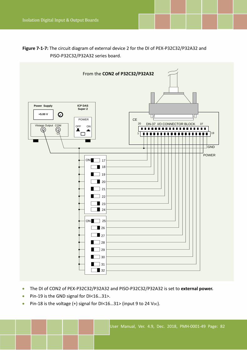
Isolation Digital Input & Output Boards
User Manual, Ver. 4.9, Dec. 2018, PMH-0001-49 Page: 82
Figure 7-1-7: The circuit diagram of external device 2 for the DI of PEX-P32C32/P32A32 and
PISO-P32C32/P32A32 series board.
DN-37 I/O CONNECTOR BLOCKCE
1 19
20 37
ON
ON
17
18
19
20
26
27
28
29
30
31
32
25
23
24
22
21
COM
Power Supply
+5.00 V
POWER
ONOFF
ICP DASSuper 2
Vlotage Output
GND
POWER
• The DI of CON2 of PEX-P32C32/P32A32 and PISO-P32C32/P32A32 is set to external power. • Pin-19 is the GND signal for DI<16…31>. • Pin-18 is the voltage (+) signal for DI<16…31> (input 9 to 24 VDC).
From the CON2 of P32C32/P32A32

Isolation Digital Input & Output Boards
User Manual, Ver. 4.9, Dec. 2018, PMH-0001-49 Page: 83
7.2 PEX/PISO-P64 Series
7.2.1 The Circuit Diagram of Digital Input Figure 7-2-1: Digital inputs for PEX-P64 and PISO-P64 series board.
• Refer to Figure 7-2-2 for the circuit diagram of external device 1. • Refer to Figure 7-2-3 for the circuit diagram of external device 2.
External Device 1 External Device 2
External Cable
PCI BUS
CON1
DB-37 CON2 40-PIN
J1 PISO-P64 J2 J3 J4 DC/DC 1 DC/DC 2
ON ON
OFF
SWITCH
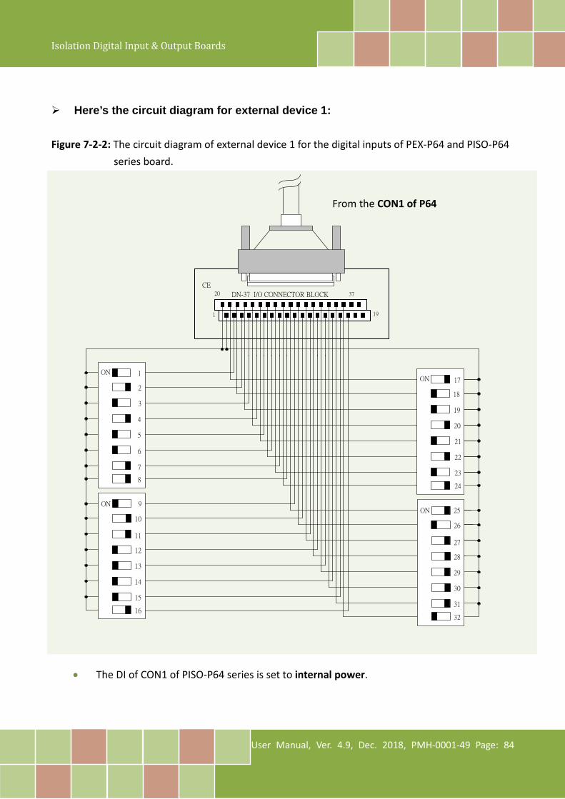
Isolation Digital Input & Output Boards
User Manual, Ver. 4.9, Dec. 2018, PMH-0001-49 Page: 84
Here’s the circuit diagram for external device 1: Figure 7-2-2: The circuit diagram of external device 1 for the digital inputs of PEX-P64 and PISO-P64
series board.
DN-37 I/O CONNECTOR BLOCK
CE
1 19
20 37
ON
ON
1
2
3
4
10
11
12
13
14
15
16
9
7
8
6
5
ON
ON
17
18
19
20
26
27
28
29
30
31
32
25
23
24
22
21
• The DI of CON1 of PISO-P64 series is set to internal power.
From the CON1 of P64
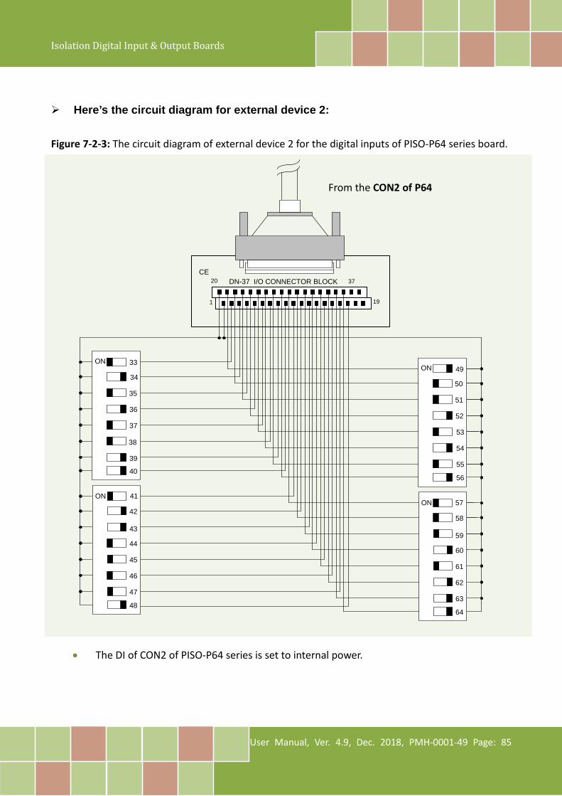
Isolation Digital Input & Output Boards
User Manual, Ver. 4.9, Dec. 2018, PMH-0001-49 Page: 85
Here’s the circuit diagram for external device 2: Figure 7-2-3: The circuit diagram of external device 2 for the digital inputs of PISO-P64 series board.
DN-37 I/O CONNECTOR BLOCKCE
1 19
20 37
ON
ON
33
34
35
36
42
43
44
45
46
47
48
41
39
40
38
37
ON
ON
49
50
51
52
58
59
60
61
62
63
64
57
55
56
54
53
• The DI of CON2 of PISO-P64 series is set to internal power.
From the CON2 of P64

Isolation Digital Input & Output Boards
User Manual, Ver. 4.9, Dec. 2018, PMH-0001-49 Page: 86
7.3 PEX/PISO-C64 and PISO-A64 Series
7.3.1 The Circuit Diagram of Digital Output Figure 7-3-1: The example of digital outputs for PEX-C64 and PISO-C64/A64 series board.
• Refer to Figure 7-3-2 (C64 series) for the circuit diagram of external device 1. • Refer to Figure 7-3-3 (A64) for the circuit diagram of external device 1. • Refer to Figure 7-3-4 (C64 series) for the circuit diagram of external device 2. • Refer to Figure 7-3-5 (A64) for the circuit diagram of external device 2.
External Device 1 External Device 2
External Cable
PCI BUS
CON1
DB-37 CON2 40-PIN
PISO-C64
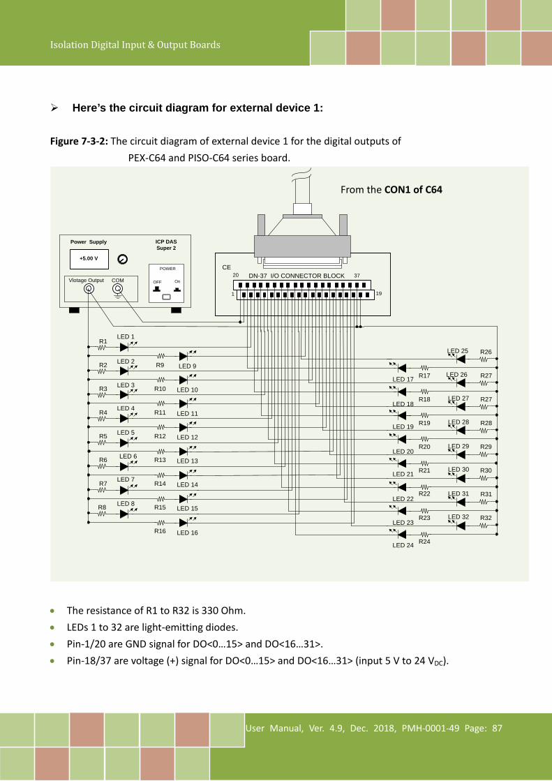
Isolation Digital Input & Output Boards
User Manual, Ver. 4.9, Dec. 2018, PMH-0001-49 Page: 87
Here’s the circuit diagram for external device 1: Figure 7-3-2: The circuit diagram of external device 1 for the digital outputs of
PEX-C64 and PISO-C64 series board.
DN-37 I/O CONNECTOR BLOCKCE
COM
Power Supply
+5.00 V
POWER
OnOFF
ICP DASSuper 2
Vlotage Output
1 19
20 37
R1
R2
R3
R4
R5
R6
R7
R8
R9
R10
R11
R12
R13
R14
R15
R16
LED 1
LED 2
LED 3
LED 4
LED 5
LED 6
LED 7
LED 8
LED 9
LED 10
LED 11
LED 12
LED 13
LED 14
LED 15
LED 16
R17
R18
R19
R20
R21
R22
R23
R24
LED 17
LED 18
LED 19
LED 20
LED 21
LED 22
LED 23
LED 24
LED 25
LED 26
LED 27
LED 28
LED 29
LED 30
LED 31
LED 32
R26
R27
R27
R28
R29
R30
R31
R32
• The resistance of R1 to R32 is 330 Ohm. • LEDs 1 to 32 are light-emitting diodes. • Pin-1/20 are GND signal for DO<0…15> and DO<16…31>. • Pin-18/37 are voltage (+) signal for DO<0…15> and DO<16…31> (input 5 V to 24 VDC).
From the CON1 of C64
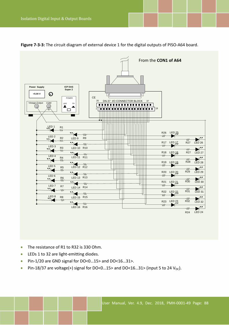
Isolation Digital Input & Output Boards
User Manual, Ver. 4.9, Dec. 2018, PMH-0001-49 Page: 88
Figure 7-3-3: The circuit diagram of external device 1 for the digital outputs of PISO-A64 board.
DN-37 I/O CONNECTOR BLOCKCE
COM
Power Supply
+5.00 V
POWER
OnOFF
ICP DASSuper 2
Vlotage Output
1 19
20 37
R1
R2
R3
R4
R5
R6
R7
R8
R9
R10
R11
R12
R13
R14
R15
R16
LED 1
LED 2
LED 3
LED 4
LED 5
LED 6
LED 7
LED 8
LED 9
LED 10
LED 11
LED 12
LED 13
LED 14
LED 15
LED 16
R17
R18
R19
R20
R21
R22
R23
R24
LED 17
LED 18
LED 19
LED 20
LED 21
LED 22
LED 23
LED 24
LED 25
LED 26
LED 27
LED 28
LED 29
LED 30
LED 31
LED 32
R26
R27
R27
R28
R29
R30
R31
R32
• The resistance of R1 to R32 is 330 Ohm. • LEDs 1 to 32 are light-emitting diodes. • Pin-1/20 are GND signal for DO<0…15> and DO<16…31>. • Pin-18/37 are voltage(+) signal for DO<0…15> and DO<16…31> (input 5 to 24 VDC).
From the CON1 of A64
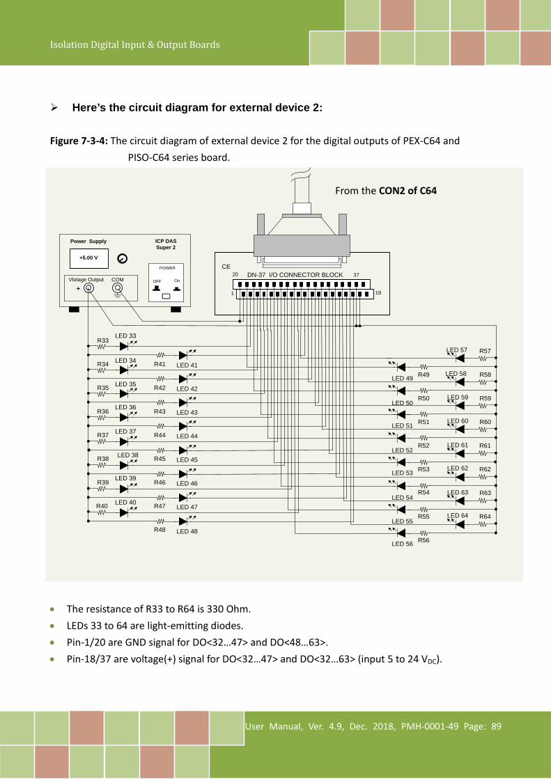
Isolation Digital Input & Output Boards
User Manual, Ver. 4.9, Dec. 2018, PMH-0001-49 Page: 89
Here’s the circuit diagram for external device 2:
Figure 7-3-4: The circuit diagram of external device 2 for the digital outputs of PEX-C64 and PISO-C64 series board.
DN-37 I/O CONNECTOR BLOCKCE
COM
Power Supply
+5.00 V
POWER
OnOFF
ICP DASSuper 2
Vlotage Output
1 19
20 37
R33
R34
R35
R36
R37
R38
R39
R40
R41
R42
R43
R44
R45
R46
R47
R48
LED 33
LED 34
LED 35
LED 36
LED 37
LED 38
LED 39
LED 40
LED 41
LED 42
LED 43
LED 44
LED 45
LED 46
LED 47
LED 48
R49
R50
R51
R52
R53
R54
R55
R56
LED 49
LED 50
LED 51
LED 52
LED 53
LED 54
LED 55
LED 56
LED 57
LED 58
LED 59
LED 60
LED 61
LED 62
LED 63
LED 64
R57
R58
R59
R60
R61
R62
R63
R64
+
• The resistance of R33 to R64 is 330 Ohm. • LEDs 33 to 64 are light-emitting diodes. • Pin-1/20 are GND signal for DO<32…47> and DO<48…63>. • Pin-18/37 are voltage(+) signal for DO<32…47> and DO<32…63> (input 5 to 24 VDC).
From the CON2 of C64
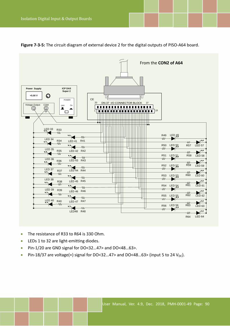
Isolation Digital Input & Output Boards
User Manual, Ver. 4.9, Dec. 2018, PMH-0001-49 Page: 90
Figure 7-3-5: The circuit diagram of external device 2 for the digital outputs of PISO-A64 board.
DN-37 I/O CONNECTOR BLOCKCE
COM
Power Supply
+5.00 V
POWER
OnOFF
ICP DASSuper 2
Vlotage Output
1 19
20 37
R33
R34
R35
R36
R37
R38
R39
R40
R41
R42
R43
R44
R45
R46
R47
R48
LED 33
LED 34
LED 35
LED 36
LED 37
LED 38
LED 39
LED 40
LED 41
LED 42
LED 43
LED 44
LED 45
LED 46
LED 47
LED48
R50
R51
R52
R53
R54
R55
R56
R64
LED 50
LED 51
LED 52
LED 53
LED 54
LED 55
LED 56
LED 64
LED 49
LED 57
LED 58
LED 59
LED 60
LED 61
LED 62
LED 63
R49
R57
R58
R59
R60
R61
R62
R63
• The resistance of R33 to R64 is 330 Ohm. • LEDs 1 to 32 are light-emitting diodes. • Pin-1/20 are GND signal for DO<32…47> and DO<48…63>. • Pin-18/37 are voltage(+) signal for DO<32…47> and DO<48…63> (input 5 to 24 VDC).
From the CON2 of A64

Isolation Digital Input & Output Boards
User Manual, Ver. 4.9, Dec. 2018, PMH-0001-49 Page: 91
8. Demo Program PEX/PISO-P32x32/x64 Series board provides Digital Input and Digital Output demo programs, together with the source code for the library, that can be used in either a Windows or a DOS environment, based on a variety of programming languages, including TC/BC/MSC (DOS), Borland C++, Delphi, Visual Basic, Visual C, VB.NET 2005, and C#.NET2005, etc. (Windows). Detailed information about the demo programs is provided below.
Sample Program UniDAQ SDK/Driver PISO-DIO Series Class Driver DOS
TC - - BC - - MSC - - Borland C++ Builder 4 - - Borland C++ Builder 6 - Delphi 4 - - Delphi 6 - - Visual Basic 6 - Visual C++ 6 - VB.NET 2005 (32-bit) - VB.NET 2005 (64-bit) - - C#.NET 2005 (32-bit) - C#.NET 2005 (64-bit) - - VC.NET 2005 (32-bit) - - VC.NET 2005 (64-bit) - - MATLAB - - LabVIEW -
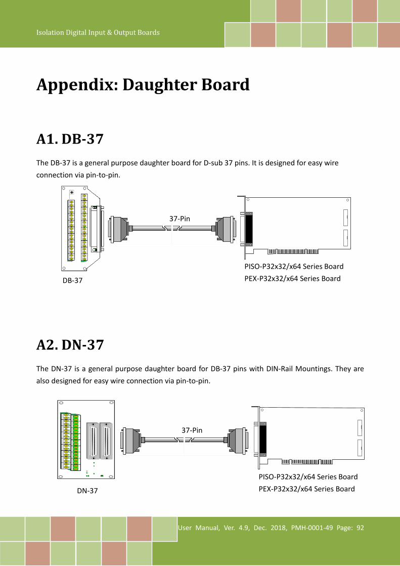
Isolation Digital Input & Output Boards
User Manual, Ver. 4.9, Dec. 2018, PMH-0001-49 Page: 92
Appendix: Daughter Board
A1. DB-37 The DB-37 is a general purpose daughter board for D-sub 37 pins. It is designed for easy wire connection via pin-to-pin.
A2. DN-37 The DN-37 is a general purpose daughter board for DB-37 pins with DIN-Rail Mountings. They are also designed for easy wire connection via pin-to-pin.
37-Pin
DB-37
PISO-P32x32/x64 Series Board PEX-P32x32/x64 Series Board
37-Pin
DN-37
PISO-P32x32/x64 Series Board PEX-P32x32/x64 Series Board

Isolation Digital Input & Output Boards
User Manual, Ver. 4.9, Dec. 2018, PMH-0001-49 Page: 93
A3.DB-8125 The DB-812 is a general-purpose screw terminal board. It is designed for easy wiring connection. The DB-8125 consists of one DB-37 and two 20-pin flat-cable headers.
37-Pin
PISO-P32x32/x64 Series Board PEX-P32x32/x64 Series Board
DB-8125