Performance of different configurations of hybrid growth membrane bioreactor (HG-MBR) for treatment...
8
Performance of different configurations of hybrid growth membrane bioreactor (HG-MBR) for treatment of mixed wastewater Fei Yang a , Ying Wang a , Amos Bick b, c , Jack Gilron a, e , Asher Brenner e , Leonid Gillerman a , Moshe Herzberg a , Gideon Oron a, d, e, ⁎ a J. Blaustein Institutes for Desert Research, Ben-Gurion University of the Negev, Midrashet Ben-Gurion, 84990, Israel b Dept. Industrial Engineering and Management, Jerusalem College of Technology, Jerusalem, Israel c Dept. Chemical Engineering/ Environmental section, Shenkar College of Engineering and Design, Ramat-Gan, Israel d Dept. Industrial Engineering and Management, Ben-Gurion University of the Negev, Beer Sheva, Israel e The Environmental Engineering Program, Ben-Gurion University of the Negev, Beer Sheva, Israel abstract article info Article history: Received 27 February 2011 Received in revised form 2 September 2011 Accepted 8 September 2011 Available online 6 October 2011 Keywords: Biofilm carriers Biomass fraction Fouling Hybrid growth membrane bioreactor (HG-MBR) Pollutants removal Improving biomass properties is a practical approach towards minimizing fouling in membrane bioreactors (MBRs). A possible and promising direction for reaching such purposes is the use of a hybrid growth MBR (HG-MBR) which combines activated sludge and biofilm processes. Four types of MBR of different design principles were examined in the present study: (i) an airlift MBR (A-MBR) equipped with a draft tube but without carriers (as a control); (ii) an HG-MBR containing carries but without a draft tube; (iii) an airlift HG-MBR (AHG-MBR) equipped with a draft tube and carriers, and; (iv) a fixed-bed HG-MBR (FHG-MBR) equipped with a draft tube and carriers, including two meshes around the bottom and top of the draft tube. For each of these configurations, a mixed wastewater consisting of domestic wastewater and chicken manure was treated, using a hollow fiber UF membrane module of ZW-10 under ambient desert conditions. The results demonstrate that generating adequate balance between MLSS and biofilm fractions is important in order to achieve high removal efficiency and low fouling tendency in an HG-MBR. The use of AHG-MBR and FHG-MBR has some limitations. Operation of the HG-MBR under appropriate aeration conditions which al- lows maintaining carriers’ recirculation and is advantageous. © 2011 Elsevier B.V. All rights reserved. 1. Introduction Membrane bioreactors (MBRs) have been used for efficient treat- ment of industrial wastewater, municipal wastewater, landfill leachate and supply of effluent reuse [1–4]. The use of membrane technology is expected to increase, well into the future [3,5]. However, in MBR appli- cations, fouling phenomena, related to physical, chemical and biological mechanisms, are an inevitable consequence of membrane filtration [6–8]. In addition, the operating conditions, membrane properties, biomass characteristics, including the mixed liquor suspended solids (MLSS) content, particle and floc size distribution and extracellular polymeric substances (EPS), are among the major factors that directly affect the fouling rate [7,9]. Therefore, improving biomass properties is a preferable alternative approach to minimize membrane fouling and to upgrade process efficiency. Biofilm processes have been ob- served during the removal of most constituents (organic matter, nutri- ents and others) which are contained in various wastewaters in a faster and more efficient way than in activated sludge processes, especially in industrial applications [10]. A promising approach to minimize mem- brane fouling and increasing treatment efficiency is the use of an ad- vanced hybrid growth membrane bioreactor (HG-MBR) [11,12]. An HG-MBR can be defined as the combination of a membrane sep- aration process and a hybrid growth biological reactor (HGBR), in which both activated sludge and biofilm processes are combined for efficient wastewater treatment. The membrane system can be either submerged [11] or externally configured to the HGBR [12–14]. The HG-MBR configuration is also known as a membrane-coupled moving bed biofilm reactor (M-CMBBR) [11], a moving-bed-biofilm reactor combined with membrane separation (Bio-Film-MBR) (BF-MBR) [12], or attached growth membrane bioreactor [15]. Hybrid growth processes combine treatment principles of activated sludge and bio- film processes, and have proven to offer improved biomass properties, organic matter stabilization including a nitrification phase [16–18]. The HG-MBR also offers an option to operate the system at lower MLSS concentrations, maintaining low fouling without loss of the treatment efficiency, due to the activity of the microorganisms Desalination 284 (2012) 261–268 ⁎ Corresponding author at: Environment Water Resources J. Blaustein Institutes for Desert Research Ben-Gurion University of the Negev Kiryat Sde-Boker 84990, Israel. Tel.: +972 8 659 6900; fax: +972 8 659 6909. E-mail addresses: [email protected] (F. Yang), [email protected] (Y. Wang), [email protected] (A. Bick), [email protected] (J. Gilron), [email protected] (A. Brenner), [email protected] (L. Gillerman), [email protected] (M. Herzberg), [email protected] (G. Oron). 0011-9164/$ – see front matter © 2011 Elsevier B.V. All rights reserved. doi:10.1016/j.desal.2011.09.009 Contents lists available at SciVerse ScienceDirect Desalination journal homepage: www.elsevier.com/locate/desal
-
Upload
independent -
Category
Documents
-
view
4 -
download
0
Transcript of Performance of different configurations of hybrid growth membrane bioreactor (HG-MBR) for treatment...
Desalination 284 (2012) 261–268
Contents lists available at SciVerse ScienceDirect
Desalination
j ourna l homepage: www.e lsev ie r .com/ locate /desa l
Performance of different configurations of hybrid growth membrane bioreactor(HG-MBR) for treatment of mixed wastewater
Fei Yang a, Ying Wang a, Amos Bick b,c, Jack Gilron a,e, Asher Brenner e, Leonid Gillerman a,Moshe Herzberg a, Gideon Oron a,d,e,⁎a J. Blaustein Institutes for Desert Research, Ben-Gurion University of the Negev, Midrashet Ben-Gurion, 84990, Israelb Dept. Industrial Engineering and Management, Jerusalem College of Technology, Jerusalem, Israelc Dept. Chemical Engineering/ Environmental section, Shenkar College of Engineering and Design, Ramat-Gan, Israeld Dept. Industrial Engineering and Management, Ben-Gurion University of the Negev, Beer Sheva, Israele The Environmental Engineering Program, Ben-Gurion University of the Negev, Beer Sheva, Israel
⁎ Corresponding author at: Environment Water ResoDesert Research Ben-Gurion University of the Negev KTel.: +972 8 659 6900; fax: +972 8 659 6909.
E-mail addresses: [email protected] (F. Yang), [email protected] (A. Bick), [email protected] (J. Gilr(A. Brenner), [email protected] (L. Gillerman), [email protected] (G. Oron).
0011-9164/$ – see front matter © 2011 Elsevier B.V. Alldoi:10.1016/j.desal.2011.09.009
a b s t r a c t
a r t i c l e i n f oArticle history:Received 27 February 2011Received in revised form 2 September 2011Accepted 8 September 2011Available online 6 October 2011
Keywords:Biofilm carriersBiomass fractionFoulingHybrid growth membrane bioreactor(HG-MBR)Pollutants removal
Improving biomass properties is a practical approach towards minimizing fouling in membrane bioreactors(MBRs). A possible and promising direction for reaching such purposes is the use of a hybrid growth MBR(HG-MBR) which combines activated sludge and biofilm processes. Four types of MBR of different designprinciples were examined in the present study: (i) an airlift MBR (A-MBR) equipped with a draft tube butwithout carriers (as a control); (ii) an HG-MBR containing carries but without a draft tube; (iii) an airliftHG-MBR (AHG-MBR) equipped with a draft tube and carriers, and; (iv) a fixed-bed HG-MBR (FHG-MBR)equipped with a draft tube and carriers, including two meshes around the bottom and top of the drafttube. For each of these configurations, a mixed wastewater consisting of domestic wastewater and chickenmanure was treated, using a hollow fiber UF membrane module of ZW-10 under ambient desert conditions.The results demonstrate that generating adequate balance between MLSS and biofilm fractions is importantin order to achieve high removal efficiency and low fouling tendency in an HG-MBR. The use of AHG-MBR andFHG-MBR has some limitations. Operation of the HG-MBR under appropriate aeration conditions which al-lows maintaining carriers’ recirculation and is advantageous.
urces J. Blaustein Institutes foriryat Sde-Boker 84990, Israel.
[email protected] (Y. Wang),on), [email protected]@bgu.ac.il (M. Herzberg),
rights reserved.
© 2011 Elsevier B.V. All rights reserved.
1. Introduction
Membrane bioreactors (MBRs) have been used for efficient treat-ment of industrial wastewater, municipal wastewater, landfill leachateand supply of effluent reuse [1–4]. The use of membrane technology isexpected to increase, well into the future [3,5]. However, in MBR appli-cations, fouling phenomena, related to physical, chemical and biologicalmechanisms, are an inevitable consequence of membrane filtration[6–8]. In addition, the operating conditions, membrane properties,biomass characteristics, including the mixed liquor suspended solids(MLSS) content, particle and floc size distribution and extracellularpolymeric substances (EPS), are among the major factors that directlyaffect the fouling rate [7,9]. Therefore, improving biomass propertiesis a preferable alternative approach to minimize membrane fouling
and to upgrade process efficiency. Biofilm processes have been ob-served during the removal of most constituents (organic matter, nutri-ents and others) which are contained in various wastewaters in a fasterand more efficient way than in activated sludge processes, especially inindustrial applications [10]. A promising approach to minimize mem-brane fouling and increasing treatment efficiency is the use of an ad-vanced hybrid growth membrane bioreactor (HG-MBR) [11,12].
An HG-MBR can be defined as the combination of amembrane sep-aration process and a hybrid growth biological reactor (HGBR), inwhich both activated sludge and biofilm processes are combined forefficient wastewater treatment. The membrane system can be eithersubmerged [11] or externally configured to the HGBR [12–14]. TheHG-MBR configuration is also known as a membrane-coupled movingbed biofilm reactor (M-CMBBR) [11], a moving-bed-biofilm reactorcombined with membrane separation (Bio-Film-MBR) (BF-MBR)[12], or attached growth membrane bioreactor [15]. Hybrid growthprocesses combine treatment principles of activated sludge and bio-film processes, and have proven to offer improved biomass properties,organic matter stabilization including a nitrification phase [16–18].The HG-MBR also offers an option to operate the system at lowerMLSS concentrations, maintaining low fouling without loss of thetreatment efficiency, due to the activity of the microorganisms
262 F. Yang et al. / Desalination 284 (2012) 261–268
attached to the support carriers. However, there is still a knowledgegap related to the efficacy of combining attached and suspendedgrowth processes in one reactor. It is subject to the design principlesof HG-MBR systems and their practical utilization that have not yetbeen fully investigated [13,19,20].
Airlift type bioreactors performance efficiently in reducing mem-brane fouling, by inducing flow circulation [21,22]. The enhancedcross flow velocity in an airlift MBR also offers a better driving forcefor carriers’ recirculation [32], and can be used for the design of anHG-MBR. The hypothesis of this study is that an HG-MBR operatedwith circulating (similar to [11]) or fixed carriers (similar to [15])(even under low aeration conditions) allows biofilm growth on thecarrier surface in one rector, thus reducing the suspended fraction,allowing to achieve mitigated membrane fouling without losing re-moval performance. Previous studies citing operating reactors of dif-ferent configurations, using various support media under varyingsolids retention time (SRT) conditions, treating diverse wastewatersstrengthen the above approach of distributing the biomass in theMBR [11,12,15]. Although bringing-up these works, there are limita-tions in a precise comparison of the HG-MBR performance withother systems.
The purpose of present study is to use one reactor however, withthree different HG-MBR configurations under ambient desert condi-tions enabling comparing and evaluating the performance for thetreatment of combined chicken manure and domestic wastewater.The comparison considers removal efficiencies, membrane filtrationperformance, biomass fraction, and an airlift MBR that does not con-tain biofilm support carriers.
Draft Tube
(c) AHG-MBR
Draft tube
Bac
Rotameter
Pressure Gauge
Blower
Process PumpE
Membran
Air Bubble
0.8mm screen
(a) A-MBR
Dra
(ExcesBioreactorVessel
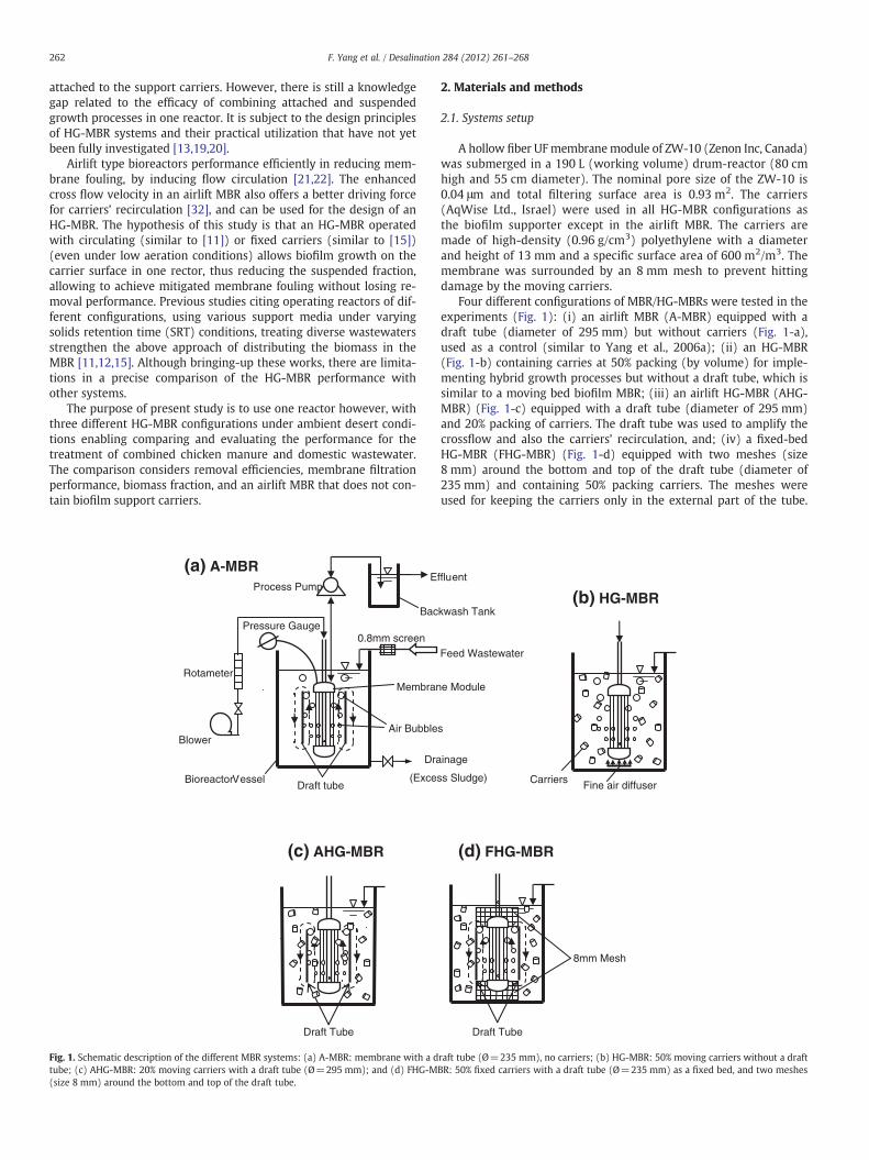
Fig. 1. Schematic description of the different MBR systems: (a) A-MBR: membrane with a dtube; (c) AHG-MBR: 20% moving carriers with a draft tube (Ø=295 mm); and (d) FHG-M(size 8 mm) around the bottom and top of the draft tube.
2. Materials and methods
2.1. Systems setup
A hollow fiber UFmembranemodule of ZW-10 (Zenon Inc, Canada)was submerged in a 190 L (working volume) drum-reactor (80 cmhigh and 55 cm diameter). The nominal pore size of the ZW-10 is0.04 μm and total filtering surface area is 0.93 m2. The carriers(AqWise Ltd., Israel) were used in all HG-MBR configurations asthe biofilm supporter except in the airlift MBR. The carriers aremade of high-density (0.96 g/cm3) polyethylene with a diameterand height of 13 mm and a specific surface area of 600 m2/m3. Themembrane was surrounded by an 8 mm mesh to prevent hittingdamage by the moving carriers.
Four different configurations of MBR/HG-MBRs were tested in theexperiments (Fig. 1): (i) an airlift MBR (A-MBR) equipped with adraft tube (diameter of 295 mm) but without carriers (Fig. 1-a),used as a control (similar to Yang et al., 2006a); (ii) an HG-MBR(Fig. 1-b) containing carries at 50% packing (by volume) for imple-menting hybrid growth processes but without a draft tube, which issimilar to a moving bed biofilm MBR; (iii) an airlift HG-MBR (AHG-MBR) (Fig. 1-c) equipped with a draft tube (diameter of 295 mm)and 20% packing of carriers. The draft tube was used to amplify thecrossflow and also the carriers’ recirculation, and; (iv) a fixed-bedHG-MBR (FHG-MBR) (Fig. 1-d) equipped with two meshes (size8 mm) around the bottom and top of the draft tube (diameter of235 mm) and containing 50% packing carriers. The meshes wereused for keeping the carriers only in the external part of the tube.
Draft Tube
8mm Mesh
(d) FHG-MBR
kwash Tank
ffluent
Feed Wastewater
e Module
s
Carriers
(b) HG-MBR
inage
s Sludge)Fine air diffuser
raft tube (Ø=235 mm), no carriers; (b) HG-MBR: 50% moving carriers without a draftBR: 50% fixed carriers with a draft tube (Ø=235 mm) as a fixed bed, and two meshes
263F. Yang et al. / Desalination 284 (2012) 261–268
Therefore, the carriers in the external part performed similar to afixed bed, and only activated sludge entered into the internal tube.The carriers’ circulation was driven by a Zenon air diffuser locatedat the bottom of the membrane module for the A-MBR, AHG andFHG-MBRs, while an additional fine air diffuser was installed at thebottom of the ZW-10 module for the HG-MBR, in order to maintaina smooth carrier flow. The detailed operational conditions are givenin Table 1. The systems were operated under constant-flux mode,with a mode of 5 min filtration and 15 s backwash. The SRT was main-tained around 26.7 days by regularly discharging excess sludge. Theabove-described systems were used to treat mixed wastewater(COD around 550 mg/L) consisting of domestic wastewater andchicken manure under ambient desert conditions (the Negev Desert,Israel).
Membrane cleanings were conducted by soaking-in 750 ppmNaClO plus 250 ppm sodiumdodecyl sulfate (SDS) solution repeatedlyfor 4 times after each experiment, until almost original membranepermeability was recovered. Subsequently, the recovered membranewas used for the next experiment.
2.2. Biofilm culture and adaption
Initially, carriers were placed directly in the reactor at a filling ratio of20% of the reactor volume,with the reactor containing aMLSS concentra-tion of 5.6 g/L. However, it was found that biofilm is not easily develop-ing on the carrier surface under these conditions. Therefore, thefollowing procedure was adopted: (i) complete removal of the sus-pended sludge from the reactor; and (ii) carriers were soaked in the re-actor by feeding themixedwastewater under a sequencing batch reactor(SBR) mode. After around 20 days a full biofilm was developed on thecarriers.
2.3. Determination and analysis methods
The airflow rate in the MBRs was controlled by a rotameter. Thefiltration flux was monitored using a volumetric method. The trans-membrane pressure (TMP) was monitored by a digital pressuregauge. Under constant-flux conditions, the TMP increased gradually
Table 1Operating conditions for the four MBRs.
Parameter A-MBR AHG-MBR FHG-MBR HG-MBR
Temperature 10.0–16.0 °C(mean12.8 °C)
21.7–28.5 °C(mean24.9 °C)
11.5–15.0 °C(mean13.4 °C)
15.5–29.4 °C(mean22.3 °C)
Initial membrane permeability(L/(m2.hr.bar)) at 20 °C
443.5 500.8 508.6 631.1
Initial membraneresistance (m−1)
0.79×10¹² 0.7×10¹² 0.70×10¹² 0.56×10¹²
Draft-tube diameter 295 mm 295 mm 235 mm noneFiltrate flux (L/(m2.hr)) 45.2 to
38.849.4 to42.1
49.7 to41.9
44.5 to38.9
Aeration rate (m3/hr)/pressure (bar)
3.4/0.05 3.4/0.05 3.4/0.05 2.3/0.21
Hydraulic retention time (hours) 4.5–5.9 4.6–5.3 4.5–5.4 5.1–5.8Solids retention time (days) 26.7 26.7 26.7 26.7pH in the reactor 6.7–7.7 7.0–7.6 7.6–7.8 6.6–7.8MLSS range (mg/L) 2.7 to 6.2 5.7 to10.7 0.13 to
0.33(internaltube)
2.4 to 4.6
Carriers packing rate (kg/190 Lof the reactor volume)
none 5.51 13.64 13.64
Approximate carriers packingratio (percent of the reactorworking volume)
none 20% 50% 50%
Operating time (days) 17.7 25.6 3.5 38.6
with time, indicating membrane fouling. The mixed liquor tempera-ture was monitored by a temperature gauge located on the reactorwall. The dissolved oxygen (DO) was monitored by a DO meter(Model 550, YSI, USA) at 6 points: upper, middle and bottom, locatedinside and outside of the draft tube, respectively.
Samples were taken separately from the influent, effluent and themixture in the reactor. The physico-chemical parameters includedpH, turbidity, TSS (MLSS), MLVSS (volatile MLSS), COD, BOD5, NH4
+–
N, TN, PO43−–P and alkalinity. All parameters were analyzed according
to Standard methods [23]. NO3−–N was determined with a second-
derivative spectroscopy according to Ferree and Shannon [24]. The at-tached biofilm biomass was determined by measuring the dryweights (at 105 °C) of 20 biofilm carriers before and after 5% NaClOwashing, and then calculated as concentration in the reactor, for thecomparison with the suspended biomass.
3. Results and discussion
3.1. General
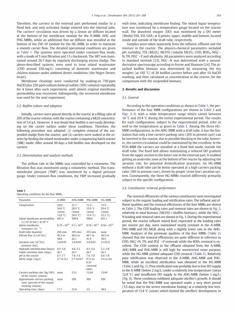
According to the operation conditions as shown in Table 1, the per-formance of the four MBR configurations are shown in Table 2 andFigs. 2–9, with a wide temperature range which varied between10 °C and 29.4 °C during the entire experimental period. The resultsfor each configuration, subject to the experimental period, refer aswell to the temperatures as given in Table 1. Among the three HG-MBR configurations, in the AHG-MBR with a draft tube, it has the lim-itation that only a low carriers packing ratio (20% in present case) canbe inserted in the reactor, due to possible blocking in the tube, howev-er, the carriers circulation could bemaintained by the crossflow. In theFGH-MBR the carriers are installed at a fixed bed mode, outside thedraft tube. The fixed bed allows maintaining a reduced DO gradientfrom the upper section to the lower one in the external part. It enabledgetting an anaerobic zone at the bottom of the reactor by adjusting theaeration rate, for potential denitrification processes. An HG-MBRwithout a draft tube can be better operated at a high carriers packingratio (50% in present case), driven by proper (even low) aeration sys-tem. Consequently, the three HG-MBRs reacted differently primarilysubject to the specific configuration.
3.2. Constituents' removal performance
The removal efficiencies of the various constituentswere investigatedsubject to the organic loading and nitrification rates. The influent and ef-fluent qualities and the removal efficiencies of the four MBRs are shownin Table 2. The COD loading rates and removal rates are shown in Fig. 2,relatively to total biomass (MLVSS+biofilm biomass), while the NH4
+–
N loading and removal rates are shown in Fig. 3. During the experimentalperiod, the reactor influent mixed feed, expressed as the loading ratesper reactor per day, were maintained nearly constant in the A-MBR,FHG-MBR and HG-MGR, along with a slightly lower rate in the AHG-MBR. Analyses of the permeate qualities of the four MBRs (Table 2)showed that the removal efficiencies are quite different in reference toCOD, NH4
+–N, TN, and PO43−–P removals while the BOD5 removal is ex-
cellent. The COD content in the effluent obtained from the A-MBR,AHG-MBR and FHG-MBR is still high for unrestricted reuse purpose,while the HG-MBR yielded adequate COD removal (Table 2). Relativelypoor nitrification was observed in the A-MBR, AHG-MBR and FHG-MBR, while an excellent nitrification was obtained in the HG-MBR(Table 2 and Fig. 3). Poor nitrificationwas probably due to lowDO supplyin the A-MBR (below 2 mg/L) under a relatively low temperature (mean12.8 °C) and insufficient DO supply in the AHG-MBR (below 1 mg/L)(Fig. 4). These conditions inhibited adequate nitrifier's growth. It shouldbe noted that the FHG-MBR was operated under a very short period(3.5 days, due to the severe membrane fouling) at a relatively low tem-perature of 13.4 °C (mean) which limited the nitrifiers’ development. In
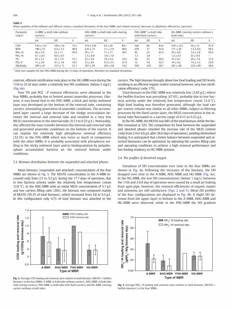
Table 2Water qualities of the influent and effluent (mean±standard deviation) of the four MBRs and related removal (decrease in alkalinity) efficiencies (percent).
Parameter(mg/L)
A-MBR (a draft tube withoutcarriers)
AHG-MBR (a draft tube with movingcarriers)
FHG-MBR* (a draft tubewith fixed carriers)
HG-MBR (moving carriers without adraft tube)
Inf. Eff. % Inf. Eff. % Inf. Eff. % Inf. Eff. %
COD 510±112 106±54 79.1 579±234 63±28 89.1 528 86 83.6 418±123 36±13 91.4BOD 188±57 6.4±3.3 96.6 225±73 3.1±2.0 98.6 259 17 93.6 171±45 1.3±0.4 99.2NH4–N 42±5.4 23±11 45.0 29±11 17±11 39.5 42 25 41.6 30±6.8 1.4±2.8 95.4NO3–N 0.7±0.5 8.0±6.5 – 1.3±0.8 3.4±7.0 – 1.3 2.8 – 1.2±0.5 22±9.4 –
TN 47±5.3 32±7.9 31.1 22±5.8 19±6.2 14.2 32 25 20.6 35±8.1 24±7.4 31.2PO4–P 11±2.0 9.1±1.8 16.3 12±4.9 9.3±3.5 21.4 12 5.9 52.3 10±4.2 7.6±3.3 25.0Alkalinity 269±41 213±71 21.1 307±50 263±82 14.2 350 243 30.7 301±40 125±89 58.6
* Only two samples for the FHG-MBR during the 3.5 days of operation, therefore no standard deviations.
264 F. Yang et al. / Desalination 284 (2012) 261–268
contrast, efficient nitrification took place in the HG-MBR even during the11th to 23 rd days under a relatively low DO conditions (below 2 mg/L)(Fig. 4a).
Poor TN and PO43−–P removal efficiencies were obtained in the
four MBRs, probably due to limited anoxic/anaerobic processes. Like-wise, it was found that in the FHG-MBR, a thick and sticky sedimentlayer was developed on the bottom of the external tube, containingcarriers, stimulating generation of anaerobic conditions. The accumu-lated layer caused a large decrease of the sludge recirculation be-tween the internal and external tube and resulted in a very lowMLSS concentration in the internal tube (0.13 to 0.33 g/L). Noticeably,this affected the mass transfer between the internal and external tubeand generated anaerobic conditions on the bottom of the reactor. Itcan explain the relatively high phosphorus removal efficiency(52.3%) in the FHG-MBR which was twice as much in comparisonwith the other MBRs. It is probably associated with phosphorus set-tling in the sticky sediment layer and/or biodegradation by polypho-sphate accumulated bacteria on the external bottom underconditions.
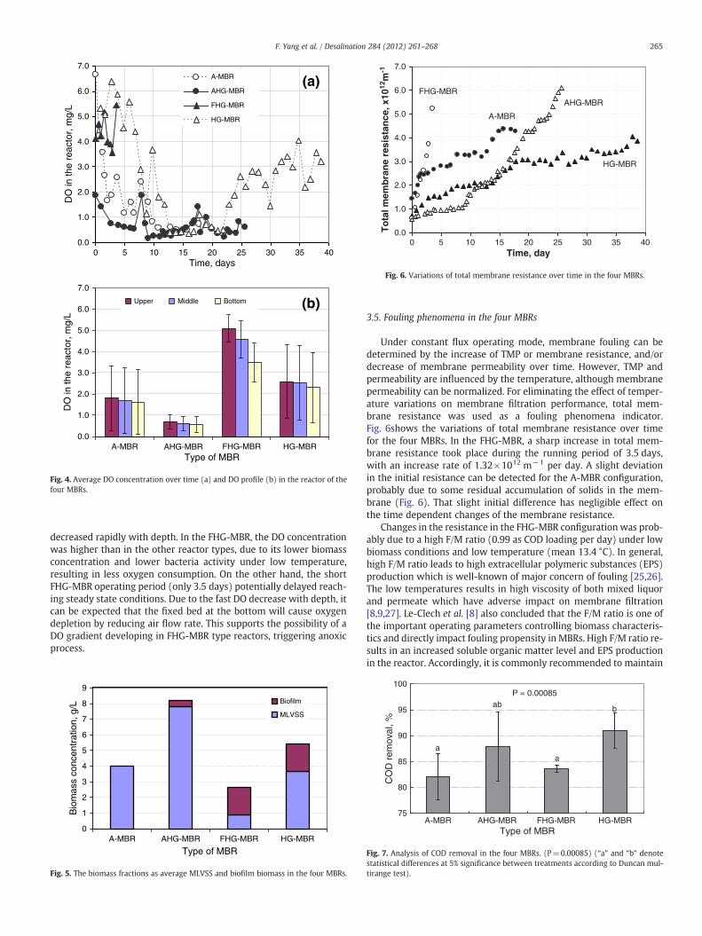
3.3. Biomass distribution between the suspended and attached phases
Mean biomass (suspended and attached) concentrations of the fourMBRs are shown in Fig. 5. The MLVSS concentration in the A-MBR in-creased only from 2.5 to 5.5 g/L during the 17.7 days of operation, dueto low bacteria activity under the relatively low temperature (mean12.8 °C). In the AHG-MBR with an initial MLSS concentration of 5.7 g/Land low carriers filling ratio (20%), the biomass was composed mainlyof MLVSS (95.3% of total biomass), which increased from 4.8 to 9.3 g/L.In this configuration only 4.7% of total biomass was attached to the
HG-MBRA-MBR AHG-MBR FHG-MBR
CO
D lo
adin
g a
nd
rem
ova
l rat
e(g
CO
D/g
bio
mas
s.d
ay)
0.0
.2
.4
.6
.8
1.0
1.2
1.4COD loading rateCOD removal rate
Type of MBR
Fig. 2. Average COD loading and removal rates relative to total biomass (MLVSS+biofilmbiomass) in the fourMBRs: A-MBR (a draft tubewithout carriers), AHG-MBR (a draft tubewith moving carriers), FHG-MBR (a draft tube with fixed carriers) and HG-MBR (movingcarriers without a draft tube).
carriers. The high biomass brought about low food loading and DO levels,resulting in an efficient organicmatter removal however, very low nitrifi-cation efficiency (only 17%).
Total biomass in the FHG-MBRwas relatively low (2.65 g/L) wherethe biofilm fraction was prevailing (67.6%), probably due to low bac-teria activity under the relatively low temperature (mean 13.4 °C).High food loading was therefore generated, although the load rateper reactor volume was similar to all other MBRs. Subject to filteringprocesses by the fixed carrier layer, the MLSS concentration in the in-ternal tube fluctuated in a narrow range of 0.13 to 0.33 g/L.
In theHG-MBR, theMLVSSwas 68%of the total biomasswhile the bio-film remained at 32%. The competition for food between the suspendedand attached phases retarded the increase rate of the MLSS content(only from2.4 to 4.6 g/L after 38.6 days of operation), yielding diminishedfouling. It is anticipated that a better balance between suspended and at-tached biomasses can be optimized, by adjusting the carriers filling ratioand operating conditions to achieve a high removal performance andlow fouling tendency in HG-MBR systems.
3.4. The profiles of dissolved oxygen
Variations of DO concentration over time in the four MBRs areshown in Fig. 4a. Following the increases of the biomass, the DOdropped over time in the A-MBR, AHG-MBR and HG-MBR (Fig. 4a).In the HG-MBR, the low DO concentrations (below 1 mg/L) betweenthe 11th and 23rd day of operation were caused by a small air leakingfrom aged pipe, however, the removal efficiencies of organic matterand ammonia are still satisfactory (Figs. 2 and 3). Mean DO profilesof the four configurations are displayed in Fig. 4b. A slight DO de-crease from the upper layer to bottom in the A-MBR, AHG-MBR andHG-MBR were observed, while in the FHG-MBR the DO gradient
A-MBR AHG-MBR FHG-MBR HG-MBR
NH
4+ -N
load
ing
an
d r
emo
val r
ate
(gN
H4+ -
N/g
bio
mas
s d
ay)
0.00
.02
.04
.06
.08
.10NH4
+-N loading rate
NH4+-N removal rate
Type of MBR
Fig. 3. Average NH4+–N loading and removal rates relative to total biomass (MLVSS+
biofilm biomass) in the four MBRs.
Time, days
DO
in th
e re
acto
r, m
g/L
A-MBR
AHG-MBR
FHG-MBR
HG-MBR
(a)
A-MBR AHG-MBR FHG-MBR HG-MBRType of MBR
DO
in th
e re
acto
r, m
g/L
Upper Middle Bottom (b)
0
7.0
6.0
5.0
4.0
3.0
2.0
1.0
0.0
7.0
6.0
5.0
4.0
3.0
2.0
1.0
0.0
5 10 15 20 25 30 35 40
Fig. 4. Average DO concentration over time (a) and DO profile (b) in the reactor of thefour MBRs.
Time, day
To
tal m
emb
ran
e re
sist
ance
, x10
12m
-1
HG-MBR
AHG-MBR
A-MBR
FHG-MBR
0 5 10 15 20 25 30 35 40
7.0
6.0
5.0
4.0
3.0
2.0
1.0
0.0
Fig. 6. Variations of total membrane resistance over time in the four MBRs.
265F. Yang et al. / Desalination 284 (2012) 261–268
decreased rapidly with depth. In the FHG-MBR, the DO concentrationwas higher than in the other reactor types, due to its lower biomassconcentration and lower bacteria activity under low temperature,resulting in less oxygen consumption. On the other hand, the shortFHG-MBR operating period (only 3.5 days) potentially delayed reach-ing steady state conditions. Due to the fast DO decrease with depth, itcan be expected that the fixed bed at the bottom will cause oxygendepletion by reducing air flow rate. This supports the possibility of aDO gradient developing in FHG-MBR type reactors, triggering anoxicprocess.
Bio
mas
s co
ncen
trat
ion,
g/L
Biofilm
MLVSS
9
8
7
6
5
4
3
2
1
0A-MBR AHG-MBR FHG-MBR HG-MBR
Type of MBR
Fig. 5. The biomass fractions as average MLVSS and biofilm biomass in the four MBRs.
3.5. Fouling phenomena in the four MBRs
Under constant flux operating mode, membrane fouling can bedetermined by the increase of TMP or membrane resistance, and/ordecrease of membrane permeability over time. However, TMP andpermeability are influenced by the temperature, although membranepermeability can be normalized. For eliminating the effect of temper-ature variations on membrane filtration performance, total mem-brane resistance was used as a fouling phenomena indicator.Fig. 6shows the variations of total membrane resistance over timefor the four MBRs. In the FHG-MBR, a sharp increase in total mem-brane resistance took place during the running period of 3.5 days,with an increase rate of 1.32×10¹² m−1 per day. A slight deviationin the initial resistance can be detected for the A-MBR configuration,probably due to some residual accumulation of solids in the mem-brane (Fig. 6). That slight initial difference has negligible effect onthe time dependent changes of the membrane resistance.
Changes in the resistance in the FHG-MBR configuration was prob-ably due to a high F/M ratio (0.99 as COD loading per day) under lowbiomass conditions and low temperature (mean 13.4 °C). In general,high F/M ratio leads to high extracellular polymeric substances (EPS)production which is well-known of major concern of fouling [25,26].The low temperatures results in high viscosity of both mixed liquorand permeate which have adverse impact on membrane filtration[8,9,27]. Le-Clech et al. [8] also concluded that the F/M ratio is one ofthe important operating parameters controlling biomass characteris-tics and directly impact fouling propensity in MBRs. High F/M ratio re-sults in an increased soluble organic matter level and EPS productionin the reactor. Accordingly, it is commonly recommended to maintain
75
80
85
90
95
100
FHG-MBR HG-MBRType of MBR
CO
D r
emov
al, %
b
AHG-MBR
ab
A-MBR
aa
P = 0.00085
Fig. 7. Analysis of COD removal in the four MBRs. (P=0.00085) (“a” and “b” denotestatistical differences at 5% significance between treatments according to Duncan mul-tirange test).
10
30
50
70
90
110
FHG-MBR HG-MBRType of MBR
NH
4+-N
rem
oval
, %
AHG-MBR
a a
A-MBR
a
bP = 8.03E-5
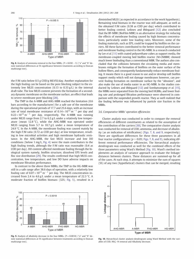
Fig. 8. Analysis of ammonia removal in the four MBRs. (P=8.03E−5) (“a” and “b” de-note statistical differences at 5% significance between treatments according to Duncanmultirange test).
266 F. Yang et al. / Desalination 284 (2012) 261–268
the F/M ratio below 0.5 g COD/g MLVSS/day. Another explanation forthe high fouling can be based on the pore blocking subject to the ex-tremely low MLSS concentration (0.13 to 0.33 g/L) in the internaldraft tube. The low MLSS content prevents the formation of a second-ary dynamic membrane on the membrane surface, an effect that leadsto severe membrane pore blocking [28].
The TMP in the A-MBR and AHG-MBR reached the limitation (0.6bars according to the manufacturer) for a safe use of the membraneduring the operational periods of 17.7 and 25.6 days, with an increaserate of total membrane resistance of 0.14×10¹² m−1 per day and0.22×1012 m−1 per day, respectively. The A-MBR was runningunder MLSS range from 2.7 to 6.2 g/L under a relatively low temper-ature (mean 12.8 °C), while the AHG-MBR was operated underMLSS ranging from 5.7 to 10.7 g/L under a mean temperature of24.9 °C. In the A-MBR, the membrane fouling was caused mainly bythe high F/M ratio (0.72 as COD per day) at low temperature, result-ing in low microbial activities and high membrane hydraulic resis-tance. In the AHG-MBR, the fast MLSS increase and low DOconditions (below 1 mg/L, Fig. 4) were the main contributors to thehigh fouling trends, although the F/M ratio was reasonable (0.4 asCOD per day). DO content affected membrane fouling through the bi-ological system namely, biofilm structure, dissolved EPS levels andfloc size distribution [29]. The results confirmed that high MLSS con-centration, low temperature, and low DO have adverse impacts onmembrane filtration performance.
In contrast to the above three MBRs, the TMP in the HG-MBR wasstill in a safe range after 38.6 days of operation, with a relatively lowfouling rate of 0.07×10¹² m−1 per day. The MLSS concentration in-creased from 2.4 to 4.6 g/L under a mean temperature of 22.3 °C. Amoderate fraction of biofilm biomass (32%; Fig. 5), resulted in a
0
20
40
60
80
100
FHG-MBR HG-MBR
Type of MBR
Alk
alin
ity d
ecre
ase,
%
AHG-MBR
a
A-MBR
ab
ab
bP = 0.0018
Fig. 9. Analysis of alkalinity decrease in the four MBRs. (P=0.0018) (“a” and “b” de-note statistical differences at 5% significance between treatments according to Duncanmultirange test).
diminishedMLSS (as expected in accordance to the work hypothesis).Remaining total biomass in the reactor was still adequate, as well asthe obtained F/M ratio (0.38 as COD per day) which contributed tobetter fouling control. Leiknes and Ødegaard [12] also concludedthat the BF-MBR (BioFilmMBR) is an alternative strategy for reducingthe effects of membrane fouling caused by high biomass concentra-tions, particularly under low loading rates. Moreover, some of thefouling materials, such as EPS, could be trapped by biofilm on the car-riers. All these factors contributed to the better removal performanceand membrane fouling control in the HG-MBR. In a research conductedby Lee et al. [11] with coated polyurethane cubes as support media, themembrane-coupled moving bed biofilm reactor (M-CMBBR) showedmuch lower biofouling than a conventional MBR. The authors also con-cluded that the collisions between the circulating media and mem-branes mitigate the formation of biofilms on the outer surface of thehollow fibers, and consequently fundamentally reducemembrane foul-ing. It means there is a good reason to use and/or develop soft biofilmsupport media which will not damage membranes however, can pre-vent fouling formation on membrane surface by the “abrasion”, andalso make the use of media easier in an HG-MBR. In the studies con-ducted by Leiknes and Ødegaard [12] and Sombatsompop et al. [15],the MBRs were separated from the moving bed HGBRs, and lower foul-ing rate and prolonged filtration performance were observed in com-parison with the suspended growth reactor. They as well realized thatthe fouling behavior was influenced by particle size fraction in theMBRs.
3.6. Comparative MBRs' operation efficiencies
Cluster analysis was conducted in order to compare the removalefficiencies of different constituents as related to the assumption ofthe contribution of the carriers [30]. The comparative cluster analysiswas conducted for removal of COD, ammonia, and decrease of alkalin-ity (as an indication of nitrification) (Figs. 7, 8, and 9, respectively).There are significant differences for these three parameters in allfour reactor configurations (pbb0.05; Figs. 7, 8, and 9), indicating dif-ferent removal performance efficiencies. The hierarchical analysis-dendrogram was conducted as well for the combined effects of thethree parameters using Ward's Method (Fig. 10). Ward's method im-plements an analysis of variance approach to evaluate the linkage/distances between clusters. These distances are summed-up for allof the cases. At each step, it attempts to minimize the sum of squares(SS) of any two (hypothetical) clusters that can be merged, resulting
Lin
kag
e d
ista
nce
1
2
3
4
Type of MBR
AHG-MBR A-MBR FHG-MBR HG-MBR
Fig. 10. Hierarchical cluster analysis-dendrogram using Ward Method with the vari-ables of COD, NH4
+–N removal and Alkalinity decrease.
267F. Yang et al. / Desalination 284 (2012) 261–268
in the smallest increase in the overall sum of the squared within-cluster distances. Typical of properties of variance for statisticaldecision-making, this tends to create two of many clusters of smallsizes because the more the observations scattered, the SS makes thedistance larger [31].
As indicated (Figs. 7–10), the performance of the HG-MBR wasstatistically the best, which is consistent with the actual performanceresults. As discussed in the previous sections, the HG-MBR was run-ning under a mean temperature of 22.3 °C and had an adequately bal-anced biomass between the suspended and attached phases, resultingin a relatively low MLSS concentration however, the total biomasswas still adequate for removal performance. The low MLSS is of ben-efit for the mass transfer, especially for oxygen. The DO conditionswere also reasonable. In addition, much better carrier recirculationin the HG-MBR was maintained, benefiting for biofilm growth onthe carriers. In comparison, the A-MBR and FHG-MBR were operatedunder a relatively low temperature. The FHG-MBR had also a relative-ly low total biomass. In the AHG-MBR, low DO conditions (below1 mg/L) were insufficient for oxidation to take place.
According to the cluster analysis according to Ward's method, thereis some similarity in operation efficiency between the A-MBR and theFHG-MBR (Fig. 10). This similarity could stem from the comparable ini-tial MLSS concentrations and operating temperature for the two MBRs.Both (merged as a cluster) are different from the AHG-MBR, and theHG-MBR has large difference from the others.
4. Conclusions
Three different HG-MBR configurations with the addition of carrierswere tested for performance evaluation in comparison with an A-MBR(without carriers). The comparative performance variables of the fourMBRs included air lift maintenance with a draft tube, recirculation ofsuspended carriers, and fixed carriers. The goal was to achievemaximalremoval of pollutants along with minimal membrane fouling. The re-sults demonstrate that an adequate balance between MLSS and biofilmfractions is important to achieve high removal efficiency and low foul-ing tendency in HG-MBRs. The AHG-MBR design has a limitation refer-ring to carrier packing ratio, therefore having limited biofilm fraction forthe reduction of MLSS. The FHG-MBR configuration can produce highbiofilm fraction, and may also yield higher total biomass under optimaloperating conditions for getting better removal performance. The FHG-MBR has the potential of getting a decreased oxygen gradient withdepth and for achieving an anoxic process. However, the extremelylowMLSS in the internal tube results in the loss of the “secondarymem-brane” on membrane surface and subsequently a severe membranefouling. The HG-MBR configuration without a draft tube has a highercarrier packing ratio, moderate biofilm fraction for reducing MLSS con-centration, adequate total biomass for oxidation performance, andmuchbetter carriers’ recirculation in the reactor. However, this requiresa proper aeration design for driving the carriers. Although it was diffi-cult to control the operating conditions such as temperature in anopen desert condition, the use of HG-MBR is the advantageous alterna-tive to reduce membrane fouling caused by high MLSS concentrationwithout loss of removal efficiency. It looks as if the AHG-MBR is the sec-ond preferable configuration, although the slight differences of the op-eration temperature range.
Acknowledgments
The work was partially supported by The IWRM (IntegratedWaterResource Management) - SMART (Sustainable Management of Avail-able Water Resources with Innovative Technologies) project on de-velopment, modeling and providing tools for optimal water use inarid regions, which is supported by The Federal Ministry of Educationand Research, Germany and The Ministry of Science and Technology(MOST) of the State of Israel, The Beracha Foundation of The Stephen
and Nancy Grand Water Research Institute, The Levin Family Founda-tion, Dayton, Ohio, USA, on Membrane Use for Wastewater Reclama-tion, and by The Research Authority of Jerusalem College ofTechnology (JCT), Israel. The authors thank AqWise - Wise WaterTechnologies Ltd. (Israel) for supplying the carriers.
The authors are indebted to the anonymous referees for their con-tributive comments.
References
[1] A. Bick, G. Oron, L. Gillerman, Y. Manor, Data envelopment analysis for assessingoptimal operation of ultra-filtration systems for effluent polishing, Water Sci.Technol. Water Supply 3 (2003) 379–384.
[2] G. Oron, A. Bick, L. Gillerman, Y. Manor, Hybrid membrane systems for secondaryeffluent polishing for unrestricted reuse for agricultural irrigation, Water Sci.Technol. 50 (2004) 305–312.
[3] T. Wintgens, T. Melin, A. Schafer, S. Khan, M. Muston, D. Bixio, C. Thoeye, The roleof membrane processes in municipal wastewater reclamation and reuse, Desali-nation 178 (1–3) (2005) 1–11.
[4] M.A. Shannon, P.W. Bohn, M. Elimelech, J.G. Georgiadis, B.J. Mariñas, A.M. Mayes,Science and technology for water purification in the coming decades, Nature 452(2008) 301–310.
[5] B. Lesjean, T. Leiknes, AMEDEUS and EUROMBRA projects: boosting the develop-ment of MBR technologies in Europe, Desalination 200 (2006) 710–711.
[6] W.J. Koros, Y.H. Ma, T. Shimidzu, Terminology for membranes and membraneprocesses, Pure Appl. Chem. 68 (1996) 1479–1489.
[7] I.S. Chang, P.L. Clech, P.B. Jefferson, S. Judd, Membrane fouling in membrane bio-reactors for wastewater treatment, J. Environ. Eng. 11 (2002) 1018–1029.
[8] P. Le-Clech, V. Chen, T.A.G. Fane, Fouling in membrane bioreactors used in waste-water treatment, J. Membr. Sci. 284 (1–2) (2006) 17–53.
[9] F. Yang, A. Bick, S. Shandalov, A. Brenner, G. Oron, Yield stress and rheologicalcharacteristics of activated sludge in an airlift membrane bioreactor, J. Membr.Sci. 334 (2009) 83–90.
[10] C. Nicolella, M.C.M. van Loosdrecht, J.J. Heijnen, Wastewater treatment with par-ticulate biofilm reactors, J. Biotechnol. 80 (2000) 1–33.
[11] W.-N. Lee, I.-J. Kang, C.-H. Lee, Factors affecting filtration characteristics in mem-brane coupled moving bed biofilm reactor, Water Res. 40 (2006) 1827–1835.
[12] T. Leiknes, H. Ødegaard, The development of a biofilm membrane bioreactor, De-salination 202 (2007) 135–143.
[13] R. Canziani, V. Emondi, M. Garavaglia, F. Malpei, E. Pasinetti, G. Buttiglieri, Effectof oxygen concentration on biological nitrification and microbial kinetics in across-flow membrane bioreactor (MBR) and moving-bed biofilm reactor(MBBR) treating old landfill leachate, J. Membr. Sci. 286 (2006) 202–212.
[14] E. Melin, T. Leiknes, H. Helness, V. Rasmussen, H. Ødegaard, Effect of organic load-ing rate on a wastewater treatment process combining moving bed biofilm andmembrane reactors, Water Sci. Technol. 51 (2005) 421–430.
[15] K. Sombatsompop, C. Visvanathan, R. Ben Aim, Evaluation of biofouling phenom-enon in suspended and attached growth membrane bioreactor systems, Desalina-tion 201 (1–3) (2006) 138–149.
[16] R. Nogueira, L.F. Melo, U. Purkhold, S. Wuertz, M. Wagner, Nitrifying and hetero-trophic population dynamics in biofilm reactors: effects of hydraulic retentiontime and the presence of organic carbon, Water Res. 36 (2) (2002) 469–481.
[17] I. Metcalf & Eddy, G. Tchobanoglous, F.L. Burton, H.D. Stencel, Wastewater engi-neering: treatment and reuse, 4th ed., McGraw-Hill Publishing Company Limited,New York, New York, 2003, p. 1408, (ISBN 0-07-112250-8).
[18] M. Herzberg, C.G. Dosoretz, M. Green, Increased biofilm activity in BGAC reactors,AICHE J. 51 (2005) 1042–1047.
[19] Q. Yang, J. Chen, F. Zhang, Membrane fouling control in a submergedmembrane bio-reactor with porous, flexible suspended carriers, Desalination 189 (2006) 292–302.
[20] I. Ivanovic, T. Leiknes, Impact of aeration rates on particle colloidal fraction in thebiofilm membrane bioreactor (BF-MBR), Desalination 231 (2008) 182–190.
[21] A. Sofia, W.J. Ng, S.L. Ong, Engineering design approaches for minimum fouling insubmerged MBR, Desalination 160 (2004) 67–74.
[22] F. Yang, A. Bick, S. Shandalov, G. Oron, Optimal performance of an immersedmembrane bioreactor equipped with a draft tube for domestic wastewater recla-mation, Water Sci. Technol. 54 (2006) 155–162.
[23] APHA, Standard methods for the examination of water and wastewater, 21th ed.,American Public Health Association, Washington D.C., 2005, p. 1368.
[24] M.A. Ferree, R.D. Shannon, Evaluation of a second derivative UV/visible spectros-copy technique for nitrate and total nitrogen analysis of wastewater samples,Water Res. 35 (2001) 327–332.
[25] I.S. Chang, C.H. Lee, Membrane filtration characteristics in membrane-coupled ac-tivated sludge system - the effect of physiological states of activated sludge onmembrane fouling, Desalination 120 (3) (1998) 221–233.
[26] S. Rosenberger, M. Kraume, Filterability of activated sludge in membrane bioreac-tors, Desalination 146 (1–3) (2002) 373–379.
[27] S.E. Judd, The MBR Book: Principles and Applications of Membrane Bioreactors forWater and Wastewater Treatment, Elsevier Science, Oxford, 2006.
[28] J.M. Lee, W.-Y. Ahn, C.H. Lee, Comparison of the filtration characteristics betweenattached and suspended growth microorganisms in submerged membrane biore-actor, Water Res. 35 (2001) 2435–2445.
[29] W. Lee, J.-H. Jeon, Y. Cho, K.Y. Chung, B.-R. Min, Behavior of TMP according tomembrane pore size, Proceedings of International Congress on Membranes and
268 F. Yang et al. / Desalination 284 (2012) 261–268
Membrane Processes (ICOM), 25–28 August 2005, Seoul, Korea, Published by theDepartment of Chemical Engineering, Tokyo Institute of Technology, Tokyo,Japan, 2005.
[30] A. Gorban, B. Kegl, D. Wunsch, A. Zinovyev (Eds.), Principal manifolds for data vi-sualisation and dimension reduction, LNCSE 58, Springer, ISBN: 978-3-540-73749-0, 2007.
[31] B.S. Everitt, S. Landau, M. Leese, Cluster Analysis, 4th Edition Oxford UniversityPress, Inc., New York, 2001.
[32] X. Huang, C.H. Wei, K.C. Yu, Mechanism of membrane fouling control by sus-pended carriers in a submerged membrane bioreactor, J. Membr. Sci. 309(2008) 7–16.