Lime Pretreatment of Sugarcane Bagasse for Bioethanol Production
Upload
khangminh22Category
view
0download
0
PERFORMANCE EVALUATION OF BOILER IN 46MW
BAGASSE BASED COGENERATION POWER PLANT Thesis submitted in the partial fulfilment of the
Requirement for the award of the degree
of
MASTER OF TECHNOLOGY
in
ENERGY SYSTEMS ENGINEERING
by
SHUBHAM RATHI
Registration No: 2015PGMEES06
Under the supervision of
Dr. Laljee Prasad
(Assistant Professor)
&
Mr. Vikas Agarwal
(AGM, Co-Gen, Power Plant)
DEPARTMENT OF MECHANICAL ENGINEERING
NATIONAL INSTITUTE OF TECHNOLOGY JAMSHEDPUR
JAMSHEDPUR-831014 (INDIA)
JUNE 2017
NATIONAL INSTITUTE OF TECHNOLOGY
JAMSHEDPUR
CERTIFICATE
I hereby certify that this work is being proposed in the thesis entitled “Performance
Evaluation of Boiler In 46MW Bagasse Based Cogeneration Power Plant.”In partial
fulfillment for the award of degree of Master of Technology and submitted in Mechanical
Engineering Department, National Institute of Technology, Jamshedpur is an authentic
record of my own work carried out during a period from August 2016 to May 2017 under the
supervision of Dr. Laljee Prasad, Assistant Professor, Department of Mechanical Engineering,
National Institute of Technology, Jamshedpur & Mr. Vikas Agarwal, (AGM) Cogeneration
Power Plant, Triveni Engineering and Industries Limited.
The matter embodied in this thesis has not been submitted by me for the award of any other
degree.
SHUBHAM RATHI
This is to certify that the above statement made by the candidate is true and correct to the best
of my/our knowledge and belief.
Date:
Dr. Laljee Prasad Mr. Vikas Agarwal
(Assistant Professor) ( AGM, Cogen, Power Plant)
( NIT Jamshedpur ) ( Triveni Engineering and industries ltd )
The viva-voce examination of Mr. Shubham Rathi has been held on………………
Examined and Approved
Internal Examiner External Examiner
Dr. Prabha Chand
H.O.D.(Dept. of Mechanical Engg. )

ACKNOWLEDGEMENT
I would like to thank, my guide Dr. Laljee Prasad, Assistant Professor, Department
of Mechanical Engineering, NIT Jamshedpur & Mr.Vikas Agarwal, (AGM) Cogeneration
Power Plant of Triveni Engineering and Industries Limited. for his support, encouragement
and guidance during the period with a keen interest, enthusiasm, vigor and his ever helping
nature from the starting of the project to the completion of this thesis. It is all because of his
untiring endeavours, able guidance and valuable suggestions, that could synchronize my
efforts in covering the many diverse features of the project and thus helped me for the smooth
progress and success of the project.
I express my sincere thanks to Dr. Prabha Chand, Head of the Department,
Mechanical Engineering, NIT Jamshedpur for providing me the necessary facilities in the
department.
I would also take this opportunity to express my gratitude and sincere thanks to Dr.
Laljee Prasad, Associate Professor, Department of Civil Engineering, NIT Jamshedpur &
Mr. Vikas Agarwal, (AGM) Cogeneration Power Plant of Triveni Engineering and
Industries Limited. for his kind co-operation during my dissertation work. I would like to
thank all the faculty members of the Department of Mechanical Engineering for their support
and guidance.
I sincerely acknowledge the education and working environment provided to me at
NIT, Jamshedpur. I have been fortunate to make good friends at NIT, Jamshedpur and the
times that have been spent with them are the best in my life. I acknowledge all my batch
mates with whom I have enjoyed the most and shared many happy moments. Finally, I
sincerely appreciate the consistent support and encouragement by my Parents and my Brother
in all my endeavors.
Date……………………..
Place: Jamshedpur Shubham Rathi
ABSTRACT
In the past years there are a number of ways to increase boiler performance like air pre-heater
which recover waste heat from flue gases then use it to pre-heat combustion air. Economizers
works much like pre-heaters takes waste heat and transfer it to boiler’s feedwater Rather then
combustion air. Preheated water is obviously closer to the temperature needed to produce
steam .So this saves energy when preheated feed water enters the steam drum or furnace. Air
infiltration reduction is also necessary for boiler and it’s auxiliaries performance
improvement. Air infiltration can cause negative pressure in furnace leading “Stack effect” or
“Thermal head” due to leakages power consumption of fans increases so we can locate the
sights where infiltration is occuring. Then prioritize repairs accordingly. Installation of VFDs
i.e variable frequency drives. But for better performance of sugar industry boiler and boiler
auxiliaries like boiler feed pump FD, ID, SA Fans. Bagasse drying technology is in use now
a days in many sugar industries cogeneration power plant because it reduces the moisture
content of bagasse and increase the GCV of fuel and at the same time volume of boiler exit
gas is reduced. Specific heat of water vapour is almost twice that of other gases the heat loss
by exit flue gases are also reduced.
Water vapour reduction also decreases the load of boiler auxiliaries like ID, FD, SA fans.
Bagasse drying can save more energy then APH. Drying sugar cane bagasse in an integrated
system makes possible to obtain exit gas from a steam generating system at lower
temperature. At present pneumatic dryers are used in cogeneration power plants because of
their low price and small area requirement. Bagasse dryer undoubtedly promote energy
saving as well as fuel saving that increase the efficiency of steam generation.
The objective of this paper is to do a comparative study of boiler performance with and
without using bagasse dryer. In this paper the data has been collected from two different sugar
industries and boiler performance has been checked by using bagasse dryer the performance
of boiler improves and major losses gets minimized. The cost estimation and amount of fuel
saving has also been done in this study on the basis of that the payback period of bagasse
dryer has also been calculated. This paper will be very helpful for researchers who are
working on biofuels like bagasse and are trying to analyse the energy potential of bagasse
because this fuel is been used by cogeneration power plants for power generation.

CONTENTS
CHAPTER-1 Introduction
1.1. Energy Alternatives…………………………………….………...1
1.2. Common type of Alternatives…………………………………....1
1.3. Energy potential of bagasse……………………………………...2
1.4. Need for Cogeneration…………………………………………...3
1.5. Principle of Cogeneration………………………………………..4
1.6. Cogeneration………………………………………………….....5
1.7. Steam Turbine Cogeneration System…………………………...6
CHAPTER- 2 Literature Review
2.1 Boiler…………………………………………………………...7
2.2 Boiler Types……………………………………………………8-11
2.3 Bagasse dryer…………………………………………………11-13
2.4 Types of Dryer………………………………………………..14-15
2.5 Review of drying concepts…………………………………...15-16
2.6 Bagasse drying Review……………………………………….16-21
2.7 Research Gap………………………………………………….21
2.8 Objective of study……………………………………………..22
CHAPTER- 3 Methodology
3.1 Direct method…………………………………………………...23
3.2 Indirect method………………………………………………....24
3.3 Application of bagasse dryer…………………………………..25
CHAPTER- 4 Experimental Setup and Fuel Analysis
4.1 Experimental Set-Up……………………………………………26-28
4.2 Data Collection………………………………………………....29
4.3 Fuel Analysis and losses………………………………………..30-32
4.4 Data Collection………………………………………………....33-36

CHAPTER- 5 Results And Discussion
5.1 Performance of boiler………………………………………..37-38
5.2 Losses in boiler without dryer…………………………….....39
5.3 Losses in boiler with dryer…………………………………..40
5.4 Comparison of major losses in boiler……………….……....41
5.5 Variation of efficiency of boiler…………………………….42-43
5.6 Amount of bagasse Saved and dryer cost estimation…….....44-46
CHAPTER- 6 Conclusion & Future Scope
Conclusion & Future Scope ……………………………………47-48
CHAPTER- 7. References ………………………………….……..49-51

LIST OF FIGURES
Title of figure Page No.
Fig 1.1: Balance in Typical Coal fired Power station……………………………….3
Fig 1.2: Cogeneration Advantage…………………………………………………...4
Fig 1.3: Schematic diagram of steam Turbine cogeneration system………………..6
Fig 2.1: Fire Tube Boiler……………………………………………………………8
Fig 2.2: Water Tube Boiler………………………………………………………....9
Fig 2.3: Spreader stoker…………………………………………………………….10
Fig 2.4: FBC Boiler………………………………………………………………...11
Fig 2.5: Schematic diagram of case 1……………………………………………...12
Fig 2.6: Flow diagram of case 2……………………………………………….... 13
Fig 2.7: Cyclone Type dryer……………………………………………………....14
Fig 3.1: Boiler Performance by direct method…………………………………….23
Fig 3.2: Boiler Performance by Indirect method……………………………….....24
Fig 4.1: Bomb Calorimeter………………………………………………………...26
Fig 4.2: Muffle Furnace……………………………………………………………27
Fig 4.3: Oven………………………………………………………………………28
Fig 5.1: Losses Without Dryer…………………………………………………....39
Fig 5.2: Losses With Dryer…………………………………………………….....40
Fig 5.3: Comparison of Major Losses in Boiler……………………………….....41
Fig 5.4: Variation of Boiler Efficiency without dryer……………………………42
Fig 5.5: Variation of Boiler Efficiency with dryer……………………………....43

NOMENCLATURE
O2 Oxygen
GCV Gross Calorific Value of Fuel
M Moisture
VM Volatile Matter
FC Fixed Carbon
H2 Amount of hydrogen In Fuel
N2 Amount of Nitrogen in Fuel
H2O Amount of Moisture in Fuel
m Mass flow Rate of dry flue gas
Cp Specific heat of dry flue gas
Tf Dry flue gas Temperature
Ta Ambient Temperature
L Losses in boiler
AAS Actual air supplied
EA Excess air
C Carbon
CO Carbon Monoxide
Cp Specific heat of moisture
S Amount of sulphur present in the Fuel

1
CHAPTER-1
INTRODUCTION
The rapid depletion of fossil fuel resources has necessitated an urgent search for
alternative sources of energy. Every country draws its energy needs from a variety of
sources. These sources can be categorized broadly as commercial sources and non –
commercial sources. The commercial sources include the fossil fuels ( coal, oil and
natural gases ), hydroelectric power and nuclear power, while the non-commercial
sources includes wood, animal wastes and agriculture wastes. In an industrialized
country like USA most of the energy requirements are met from commercial sources,
while in a industrially less developed like INDIA, The use of commercial and non-
commercial sources is about equal.
1.1. Energy Alternatives :-
1. Nuclear option
2. Miscellaneous sources
Of the many alternatives, Bio-fuel stands out as brightest long range promise towards
meeting the continuously increasing demand for energy . Bio-fuel is available freely
omnipresent and indigenous source of energy provides clean and pollution free
atmosphere. The simplest and the most efficient way to utilize bio- As conventional
sources of energy are depleting at alarming rate, It is evident that a need exists for
developing alternative energy sources. The primary sources of alternative energy which
hold potential for the future can be broadly classified under the categories as;
3. Solar option
fuel is to convert it into thermal energy for heating and steam producing in the
combined heat and power cycle used in cogeneration power plants.
1.2. Common types of alternative energy
Biofuel and Ethanol :- Biofuel and ethanol are plant derived substitutes of gasoline
for powering vehicles and producing electricity.

2
Solar Energy :- it is the generation of electricity from the sun.
Wind Energy :- it is the generation of electricity from the wind.
Geothermal Energy :- it is using hot water or steam from the earth’s interior for
heating building or electricity generation.
Nuclear Binding Energy :- it uses nuclear fission to create energy
1.3. Energy Potential of Bagasse
Sugarcane is one of the most promising agricultural source of biomass energy in the
world. Sugarcane produce mainly two types of biomass , cane trash and bagasse.
Bagasse is the fibrous residue left over after milling the cane , with 45-50% moisture
content. The composition of baggase depends on the variety and maturity of sugarcane.
Bagasse is usually combusted in furnaces to produce steam for power generation. The
value of bagasse as a fuel depends largely on its calorific value , which in turn is
affected by its composition, especially with respect to its water content and to the
calorific value of the sugarcane crop, which depends mainly on its sucrose content.
Moisture content is the main determinant of the calorific value i.e lower the moisture
content, higher the calorific value. A good milling process will result in low moisture
of 45%. Most mills produce bagasse of 50% moisture and most boilers are designed to
burn bagasse at around 50% moisture. For every 100 tons of sugarcane crushed, a sugar
factory produce nearly 30 tons of wet bagasse. Bagasse is often used as a primary fuel
source for sugar mills, when burned in quantity it produces sufficient heat and electrical
energy to supply all the needs of a typical sugar mill, with energy to spare. The
resulting CO2 emissions are equal to the amount of CO2 that the sugarcane plant
absorbed from the atmosphere during its growing phase, which makes the process of
cogeneration greenhouse gas-neutral. Cogeneration of bagase is one of the most
attractive and successful energy projects that have already been demonstrated in many
sugarcane producing countries. Combined heat and power from sugarcane in the form
of power generation offers renewable energy options that promote sustainable
development, take advantage of domestic resources, increase profitability and
competitiveness in the industry.

3
1.4. Need For Cogeneration
Thermal power plants are a major source of electricity supply in India. The
conventional method of power generation and supply to the customer is wasteful in the
sense that only about a third of the primary energy fed into the power plant is actually
made available to the user in the form of electricity (Figure 7.1). In conventional power
plant, efficiency is only 35% and remaining 65% of energy is lost. The major source of
loss in the conversion process is the heat rejected to the surrounding water or air due to
the inherent constraints of the different thermodynamic cycles employed in power
generation. Also further losses of around 10–15% are associated with the transmission
and distribution of electricity in the electrical grid.
.
Fig 1.1 BALANCE IN A TYPICAL COAL FIRED POWER STATION

4
1.5. Principle of Cogeneration
Cogeneration or Combined Heat and Power (CHP) is defined as the sequential
generation of two different forms of useful energy from a single primary energy source,
typically mechanical energy and thermal energy. Mechanical energy may be used either
to drive an alternator for producing electricity, or rotating equipment such as motor,
compressor, pump or fan for delivering various services. Thermal energy can be used
either for direct process applications or for indirectly producing steam, hot water, hot
air for dryer or chilled water for process cooling. Cogeneration provides a wide range
of technologies for application in various domains of economic activities. The overall
efficiency of energy use in cogeneration mode can be up to 85 per cent and above in
some cases.
Fig 1.2 Cogeneration advantage
For example in the scheme shown in Figure 1.2, an industry requires 24 units of
electrical energy and 34 units of heat energy. Through separate heat and power route
the primary energy input in power plant will be 60 units (24/0.40). If a separate boiler
is used for steam generation then the fuel input to boiler will be 40 units (34/0.85). If
the plant had cogeneration then the fuel input will be only 68 units (24+34)/0.85 to
meet both electrical and thermal energy requirements. It can be observed that the
losses, which were 42 units in the case of, separate heat and power has reduced to 10

5
units in cogeneration mode. Along with the saving of fossil fuels, cogeneration also
allows to reduce the emission of greenhouse gases (particularly CO2 emission). The
production of electricity being on-site, the burden on the utility network is reduced and
the transmission line losses eliminated. Cogeneration makes sense from both macro and
micro perspectives. At the macro level, it allows a part of the financial burden of the
national power utility to be shared by the private sector; in addition, indigenous energy
sources are conserved. At the micro level, the overall energy bill of the users can be
reduced, particularly when there is a simultaneous need for both power and heat at the
site, and a rational energy tariff is practiced in the country.
1.6. Cogeneration
Cogeneration is the production of more than one useful form of energy (such as process
heat and electric power) from the same energy source. Cogeneration systems often
capture otherwise wasted thermal energy, usually from an electricity producing device
like a heat engine (e.g., steam-turbine, gas-turbine, diesel-engine), and use it for space
and water heating, industrial process heating, or as a thermal energy source for another
system component.
The ‘‘cascading” of energy use from high- to low-temperature uses, often
distinguishes cogeneration systems from conventional separate electrical and thermal
energy systems (e.g., a power plant and an industrial boiler), and from simple heat
recovery strategies.
The principal technical advantage of cogeneration systems is their ability to improve
the efficiency of fuel use in the production of electrical and thermal energy. Less fuel is
required to produce a given amount of electrical and thermal energy in a single
cogeneration unit than is needed to generate the same quantities of both types of energy
with separate, conventional technologies (e.g., turbine- generator sets and steam
boilers). This is because heat from the turbine-generator set, which uses a substantial
quantity of fuel to fire the turbine, becomes useful thermal energy (e.g., process steam)
in a cogeneration system rather waste heat. Different types of co-generators have
different fuel-use characteristics and produce different proportions of electricity and
steam. The electricity to heat ratio refers to the relative proportions of electrical and
thermal energy produced by a cogeneration unit.
6
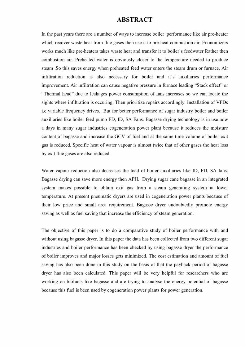
1.7 Steam Turbine Cogeneration System
The two types of steam turbines most widely used are backpressure and the extraction-
condensing type. The choice between back pressure turbine and extraction-condensing
turbine depends mainly on the quantities of power and heat, quality of heat and
economic factors. the extraction points of steam could be more than one, depending on
the temperatures levels of heat required by the processes.
Fig 1.4 Schematic Diagrams Of Steam Turbine Co-Genereation Systems

7
CHAPTER 2
LITERATURE REVIEW
2.1. Boiler
A boiler is an enclosed vessel that provides a means for combustion heat to be
transferred into water until it becomes heated water or steam. The hot water or steam
under pressure is then usable for transferring the heat to a process. Water is a useful
and cheap medium for transferring heat to a process. When water is boiled into steam
its volume increases about 1,600 times, producing a force that is almost as explosive as
gunpowder. This causes the boiler to be extremely dangerous equipment that must be
treated with utmost care.
The process of heating a liquid until it reaches its gaseous state is called evaporation.
Heat is transferred from one body to another by means of (1) radiation, which is the
transfer of heat from a hot body to a cold body without a conveying medium, (2)
convection, the transfer of heat by a conveying medium, such as air or water and (3)
conduction, transfer of heat by actual physical contact, molecule to molecule.
This section briefly describes the Boiler and various auxiliaries in the Boiler Room.A
boiler is an enclosed vessel that provides a means for combustion heat to be transferred
to water until it becomes heated water or steam. The hot water or steam under pressure
is then usable for transferring the heat to a process. Water is a useful and inexpensive
medium for transferring heat to a process. When water at atmospheric pressure is boiled
into steam its volume increases about 1,600 times, producing a force that is almost as
explosive as gunpowder. This causes the boiler to be an equipment that must be treated
with utmost care. The boiler system comprises of: a feed water system, steam system
and fuel system. The feed water system provides water to the boiler and regulates it
automatically to meet the steamdemand. Various valves provide access for maintenance
and repair. The steam systemcollects and controls the steam produced in the boiler.
Steam is directed through a piping system to the point of use. Throughout the system,
steam pressure is regulated using valves and checked with steam pressure gauges. The
fuel system includes all equipment used to provide fuel to generate the necessary heat.
8
The equipment required in the fuel system depends on the type of fuel used in the
system.
The water supplied to the boiler that is converted into steam is called feed water.
Thetwo sources of feed water are: Condensate or condensed steam returned from the
processes and Makeup water (treated raw water) which must come from outside the
boiler room and plant processes. For higher boiler efficiencies, an economizer preheats
the feed water using the waste heat in the flue gas.
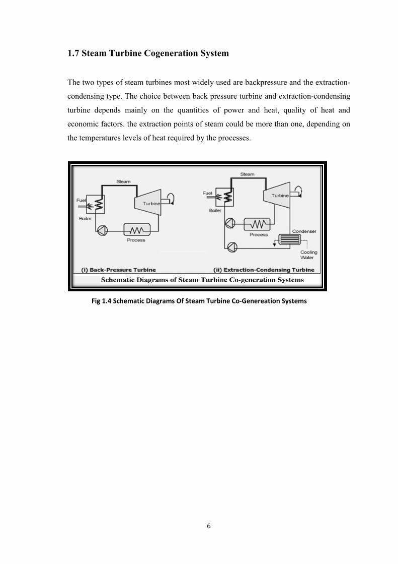
2.2. Boiler Types
There are virtually infinite numbers of boiler designs but generally they fit into one of
two categories:
Fire tube or “fire in tube” boilers; contain long steel tubes through which the hot
gasses from a furnace pass and around which the water to be converted to steam
circulates. (Refer Figure 2.2). Fire tube boilers, typically have a lower initial cost, are
more fuel efficient and easier to operate, but they are limited generally to capacities of
25 tons/hr and pressures of 17.5 kg/cm2.
Fig 2.1 Fire tube boiler
9
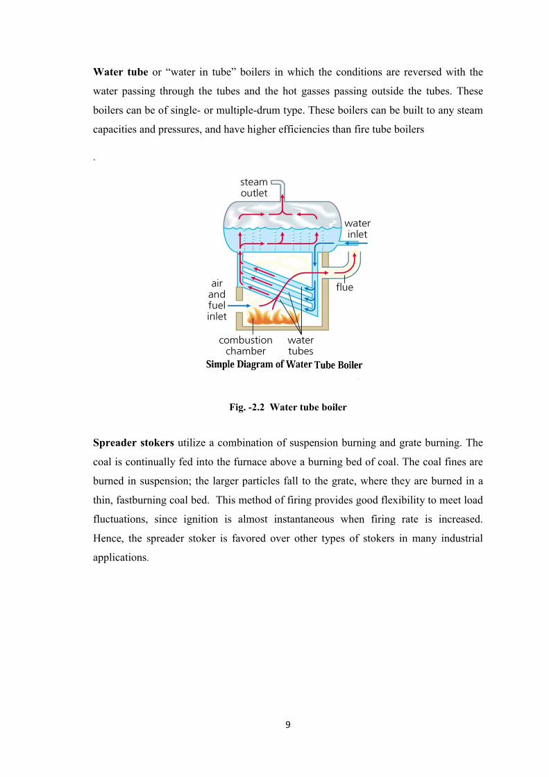
Water tube or “water in tube” boilers in which the conditions are reversed with the
water passing through the tubes and the hot gasses passing outside the tubes. These
boilers can be of single- or multiple-drum type. These boilers can be built to any steam
capacities and pressures, and have higher efficiencies than fire tube boilers
.
Fig. -2.2 Water tube boiler
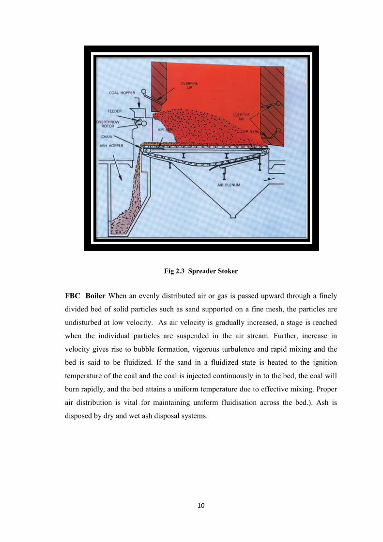
Spreader stokers utilize a combination of suspension burning and grate burning. The
coal is continually fed into the furnace above a burning bed of coal. The coal fines are
burned in suspension; the larger particles fall to the grate, where they are burned in a
thin, fastburning coal bed. This method of firing provides good flexibility to meet load
fluctuations, since ignition is almost instantaneous when firing rate is increased.
Hence, the spreader stoker is favored over other types of stokers in many industrial
applications.
10
Fig 2.3 Spreader Stoker
FBC Boiler When an evenly distributed air or gas is passed upward through a finely
divided bed of solid particles such as sand supported on a fine mesh, the particles are
undisturbed at low velocity. As air velocity is gradually increased, a stage is reached
when the individual particles are suspended in the air stream. Further, increase in
velocity gives rise to bubble formation, vigorous turbulence and rapid mixing and the
bed is said to be fluidized. If the sand in a fluidized state is heated to the ignition
temperature of the coal and the coal is injected continuously in to the bed, the coal will
burn rapidly, and the bed attains a uniform temperature due to effective mixing. Proper
air distribution is vital for maintaining uniform fluidisation across the bed.). Ash is
disposed by dry and wet ash disposal systems.

11
Fig 2.4 Fluidised Bed combustion
2.3. BAGASSE DRYERS
There are a number of methods for drying the bagasse. These methods can be
classified according to the drying medium to the followings: (a) bagasse drying by
using flue gases from boilers; (b) bagasse drying by using heated air (c) bagasse drying
by using solar energy and (d) bagasse drying by using high pressure superheated steam.
12
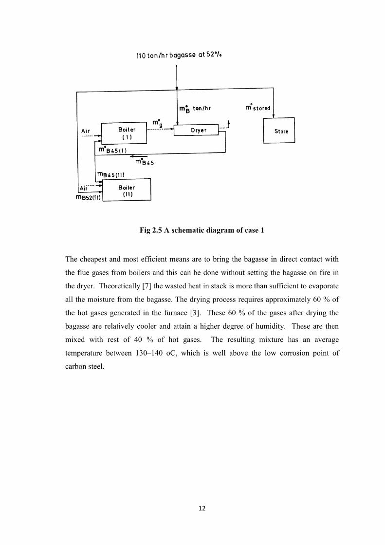
Fig 2.5 A schematic diagram of case 1
The cheapest and most efficient means are to bring the bagasse in direct contact with
the flue gases from boilers and this can be done without setting the bagasse on fire in
the dryer. Theoretically [7] the wasted heat in stack is more than sufficient to evaporate
all the moisture from the bagasse. The drying process requires approximately 60 % of
the hot gases generated in the furnace [3]. These 60 % of the gases after drying the
bagasse are relatively cooler and attain a higher degree of humidity. These are then
mixed with rest of 40 % of hot gases. The resulting mixture has an average
temperature between 130–140 oC, which is well above the low corrosion point of
carbon steel.

13
Fig 2.6 Flow diagram of case 2
The advantages of using the flue gases in drying of bagasse can be summarized as: (1)
reduction of the air pollution from values of about 10,000 mg/Nm3 of ash to less than
300 mg/Nm3 and (2) reduction of the heat losses in the flue gases due to decreasing the
exit temperature of gases. (The bagasse dryer allows cooling of the gases to 90oC the
only limit being imposed by the necessity to avoid cooling to the dew point of
60 – 70oc.) The types of dryers which can be used for bagasse drying by using the flue
gases are given below.

14
2.4. TYPES OF DRYERS
1 Tower Dryer
Tower dryer is the oldest type which was built in 1910 by E. W. Kerr
[2,7]. It is a square tower with bagasse descending and stack gas rising in a
countercurrent manner. The tower is equipped with deflectors to promote better gas-
solid contact. This dryer was not used commercially.
2 Rotary Drum Dryers
The principle of single or multiple passage of hot gases contact
in parallel with the bagasse to be dried inside a rotary drum type is similar to the sugar
dryer. The dry bagasse is then separated from the wet gases in large diameter cyclone.
as shown in Rotary drum dryers have the following advantages: (i) they can give
uniform final moisture content with non-uniform particle size and inflow; (ii) they are
more suitable for medium and large units; (iii) they tend to discharge less dust to
atmosphere; (iv) its specific energy consumption is less than pneumatic dryers (it is 20
kWh/t-water evaporated). But they are big dryers, of low efficiency, occupying large
areas. Their construction and installation are quite complex. They need an extra
conveyor to transport bagasse to the drums and then back to the boilers.
Fig 2.7 cyclone type dryer

15
Drying is perhaps the oldest and most diverse of engineering operations. Over four
hundred types of dryers have been reported in the literature and more than one hundred
distinct types are commonly available. Energy consumption in drying ranges from a
low value of under five percent in the chemical process industries to thirty five percent
in the papermaking operations (Syahrul et al., 2002). Drying occurs by effecting
vaporization of the liquid by supplying heat to the wet feedstock. This is one of the
most energy-intensive unit operations due to the high latent heat of vaporization and the
inherent inefficiency of using hot air as the (most common) drying medium. It is
reported that in most industrialized countries, the energy used in drying accounts for 7-
15% of the nation’s industrial energy, often with relatively low thermal efficiencies
(Syahrul et al., 2002). Over 85 percent of industrial dryers are of the convective type
with hot air or direct combustion gases as the drying medium. Over 99 percent of the
applications involve removal of water.
The sugar industry is a typical industry which uses its own by-product bagasse, as fuel.
As mentioned in the previous Chapter, the mill run bagasse has a high moisture content
which reduces its gross calorific value. The moisture level of the fuel can be reduced by
drying it, using the waste heat available in the plant. In this way, it is expected to
conserve bagasse, providing energy conservation in the process. Hence, in this study,
drying of bagasse using available waste heat is envisaged.
2.5. Review of drying concepts
Drying is generally used to remove moisture or liquid from a wet solid by bringing this
moisture into a gaseous state. In most drying operations, water is the liquid evaporated
and air is the normally employed purge gas. In general, the main goal of drying is to
decrease the moisture content of solid materials to below a certain limit, which results
in quality enhancement, and ease of handling and further processing (Sokhansanj and
Jayas 1995). A drying process is fundamentally a simultaneous heat and mass transfer
operation and is widely used in a variety of thermal energy applications (Hossain and
Bala 2002). Generally, the heat supplied is transported by convection from the
surroundings to the particle surfaces and from there by conduction further into the
particle throughout the drying process (Midilli 2001; Dincer and Hussain 2002). The
16
moisture is removed in the opposite direction as a liquid or vapor. On the surface, it
evaporates and passes on by convection to the surroundings (Midilli and Kucuk 2003;
Syahrul et al 2002).
Thus, one of the most important challenges of the drying industry is to reduce the cost
of energy sources for good quality dried products (Dincer 1998). The heat sources with
the greatest potential for drying energy in process industries are secondary heat flows
like flue gases and low pressure steam varying from 3 to 4 bar. Most investigations of
drying have been made from the external viewpoint, wherein the effects of the external
drying medium such as air velocity, humidity, temperature, and wet material shape and
subdivision are studied with respect to their influence on the drying rate. The results of
such investigations are usually presented as drying rate curves, and the natures of these
curves are used to interpret the drying mechanism.
2.6. Bagasse Drying Review
The flue gases flowing from bagasse fired boilers have temperatures around 300°C.
The first interest shown in bagasse drying with boiler stack gases dates back to 1910,
when Prof. E.W.Kerr (Louisiana Bulletin 1911) showed that it was impossible in Som
Louisiana mill at that time to cover the sugar mill’s energy demands with bagasse
alone, owing to its high moisture content. He built a dryer which reduced the moisture
content from 54.47 to 44.45 %, raising the steam production from 1.63 to 2.53 kg
steam/kg bagasse. His dryer was a square tower with bagasse descending and stack gas
rising in a counter current manner. The tower was equipped with deflectors to promote
better gas-solid contact. Between 1910 and 1970, only very few bagasse drying works
were reported. The reason for the lack of interest in bagasse drying during this period
was the low cost of fossil fuel. Bagasse was not very attractive as an alternative even in
cases where it was a residue, dueto the usage of cheap oil. Because of the energy crisis
in 1970’s, efforts have been concentrated in further reducing the bagasse moisture.
Since then a number of technical reports on bagasse drying both theoretical and
practical have appeared.
Roy et al., (1980) and Keenliside (1983) have reported the use of moving bed dryers for
bagasse drying. Roy et al., (1980) studied the effect of the temperature of the outgoing
flue gases, the velocity of air, length of dryer and annual profit with that of the
17
percentage of moisture removed the mass of air flow and the width of the drier and the
air heater. The air used for bagasse drying was first heated using flue gases and then
passed through bagasse. Keenliside (1983) compared three different boiler
configurations viz. i) boiler with no air preheater or bagasse dryer ii) boiler with air
preheater and iii) boiler with bagasse dryer. He showed that the overall increase in
steam production using a bagasse dryer is not significantly greater than when using air
pre-heaters due to the extra peripheral equipment required to operate the drying
systems. Massarani and Valenca (1981) studied intensively the drying of bagasse in a
moving bed dryer. They investigated from a laboratory scale to a pilot one. The pilot
installation was composed of a dryer of 0.40 x 0.50 x 2 m. These two steps led to
satisfactory results.
During the fuel crisis, Furines (1976) prepared a feasibility study of bagasse pre-drying
with waste stack gases. He worked with three rotary-drum type dryers of maximum
capacity to operate with the existing boilers, based on the flue gases temperature of
218ºC. These three dryers processed all the bagasse produced and lowered the moisture
content from 54 to 46% (w.b.), provided the gases had a temperature of 218ºC or more.
The use of rotary dryers for bagasse drying was also reported by Guanzon (1980) and
Sarnobat (1987). Guanzon (1980) plotted the capacity of dryer versus moisture content
of bagasse as a function of inlet flue gas temperature. The moisture removal rate
increases with an increase in the capacity of the bagasse dryer. Sarnobat (1987)
calculated the heat transfer area for a rotary drum dryer inclined at 30º. He reported a
bagasse saving of around 30% and pay back period of three months for a bagasse dryer.
In pneumatic transport, the velocity at which a gas will begin to transport a specific
particle is called the terminal velocity. The terminal velocity for different bagasse size
fractions were determined by Grobert (1971). They show that at a terminal velocity
higher than 13.9 m/s, all the bagasse particles will be transported pneumatically. At a
terminal velocity lower than 13.9 m/s the raw bagasse will be separated into two
fractions. This separation could enable the use of more efficient systems of pneumatic
transport, and storage in silos, which would be placed between the mill train and the
boilers.

18
Arrascaeta and Friedman (1987) designed and constructed a bagasse dryer in 1983 that
elutriates the bagasse, separating the particles in different sizes. This dryer could work
with 7 ton/hr and was in operation until 1985. Later the design was patented in 1987,
which used fluidized and pneumatic conceptions. Nebra and Macedo (1989), developed
an industrial dryer which was designed and built according to a project developed by
the Centro de Tecnologia Copersucar, Brazil. It was a flash drier that could work with
25 tons of bagasse/hour. That is the biggest flash dryer reported until now.
Alarcon and Justiz (1993) also worked with a pneumatic dryer which reduced the
moisture content from 50 to 30% (w.b.) and separated the particles into different sizes.
The biggest particles were used as raw material for paper and pharmacy industries and
the smaller ones were burned. Cardenas et al (1994), described a pneumatic dryer of an
industrial size. They studied the energetic and exergetic efficiencies of a boiler-dryer
system. They concluded that the use of a dryer will improve the boiler efficiency.
Keller (1980) reported the advantages of a suspension dryer over a rotary drum dryer.
He reported the effect of moisture content on combustion temperature in bagasse
furnaces. It was found that with a decrease in moisture content, furnace temperature
increases. He also reported an increase of heat transmitted to steam per kg of bagasse
with a reduction of bagasse moisture content. Morales (1982) reported the use of a
suspension type bagasse dryer consisting of two units. Each unit was designed for 17.5
ton/hr, with an initial moisture content of 56% to a final moisture content of 35%. He
has reported bagasse dryer operating data over a period of one year.
Bose et al., (1984) have carried out studies on a fluidized bed bagasse dryer. Results
show a reduction of moisture content from 49-50% to 41-42%. Steam generation
increased by 10% and a saving of 0.6 metric ton/hr of bagasse is achieved. Choh et al.,
(1984) investigated bagasse drying with an impulsive fluidized dryer. They found that
the temperature of the flue gases has a great influence on the bagasse drying. At a flue
gas temperature of 200°C, the moisture content of the bagasse could be lowered by
10%, whereas at about 140°C it was 6-8% only. An impulsive fluidized bed dryer with
a contracted-expanded pipe, had a better drying efficiency than a straight pipe, because
the impulsive action in the contracted-expanded pipe changes the relative velocity and
mixing of bagasse particles with the gas flow, inducing turbulence and improving the
heat and mass transfer. Besides, the velocity of the flow the power consumption is also
reduced. They have obtained a steam output with wet and dry bagasse as 1.94 and 2.4

19
kg/kg respectively indicating 23% more steam production using dry bagasse. Boiler
efficiency was also shown to increase from 63 to 79%.
In the past years there are a number of ways to increase boiler and boiler auxiliaries’
performance like air pre-heater, economizer, air infiltration reduction installation of
variable frequency drives etc. but for better performance of sugar industry boiler and
boiler auxiliaries like boiler feed pump FD,ID,SA Fans. Bagasse drying technology is
in use nowadays in many sugar industries cogeneration power plant because it reduce
the moisture content of bagasse and increases GCV of fuel and at the same time volume
of exit gases from boiler is also reduced. Water vapor reduction also decreases the load
of boiler auxiliaries like ID,FD,SA Fans. Bagasse drying can save more energy then
APH. Bagasse dryer promotes energy saving as well as fuel saving that increase the
efficiency of steam generation.
Jorge Barrosoet al. (2003)The present investigation has been carried out in order to
increase the efficiency of the boiler, used in the Cuban sugar mills. Test methods
generally used in the evaluation process and further adjustment of the boilers operation
have been analyzed, pointing the attention on the importance of the stoichiometric ratio
and steam power on the overall efficiency. Important general rules have been extracted
from the complete regular tests following ASME and GOST methodologies, and, as a
result, a simplified test code has been obtained. Boiler design optimization has also
been achieved determining the optimum waste heat recovery scheme from both,
thermal and economical viewpoints. As a result, the optimal stack gas temperature has
been calculated as well as the range of the optimal value for the excess air fraction.
Their influence on the efficiency has been analyzed and the total costs determined.
Once the total costs are included in the analysis, the most efficient low-temperature
heat recovery scheme results to be the combination of an economizer followed, in the
direction of the exhaust gas flow, by an air heater.
Juan H. Sosa and Silvia A Nebra (2009).In this paper bagasse dryer role is shown in the
enrgy recovery of water tube boiler the sugar and ethanol industry, which uses
sugarcane as raw material, utilizes the by-product, bagasse, as fuel. The bagasse is fed
with a moisture content of 50% (w.b). Dryers are not being used in the way it is

20
proposed here. This article proposes the introduction of bagasse dryers connected to the
energy recovery system of the boilers operating with the exhaust gases. The
combination of the dryer with other thermal energy recovery devices, such as an air
heater and economizer, is considered. The performance improvement is evaluated.
Costs are also taken into account. Finally, an optimized solution for the boiler energy
recovery system is proposed. A methodology to improve the design of thermal energy
recovery systems for biomass-fired boilers is shown in this study. The energy recovery
system proposal includes the use of an economizer, an air heater, and a dryer. The
whole system operates with the boiler exhaust gases.
Geethanjali S. Yarnal, Vinod S. Puranik (2010)In this paper baggase drying methods
based on flue gas and steam drying in the sugar industry are analyzed and new methods
are proposed for maximum removal of moisture to save energy. Wet bagasse having
50% moisture indian sugar cane industry has been taken as a case for improving
calorific value. The combined flue gas / steam drying techniques is compared with
parallel and sequential heating techniques for the moisture removal boiler efficiency,
increase in calorific value etc.In this article a new technique based on combined flue
gas and steam drying developed and the energy requirements for drying wet bagasse
are calculated theoretically also, the experiments were conducted to show the impact of
using the technique on the performance of boiler and boiler auxiliaries.
Juan H.Sosa et al. (2013) Sugar cane bagasse is the only fuel used in the sugar-alcohol
industry in Brazil, the world's leading sugar cane producer. The sugar alcohol industry
produces cogenerated electrical energy for its own consumption and the surplus is sold
to the market. Improving the use of bagasse in furnaces is currently an important
industrial strategy. The topic has aroused great interest due to an increase in the
cogeneration level in recent years. This work reviews the state of the art of sugar cane
bagasse drying.This paper focus on the reduction of cane bagasse moisture increase
LHV and at the same time volume of the boiler exit gas is reduced. Specific heat of
water vapour is almost twice that of other gases the heat loss by exit flue gas are also
reduced. Water vapourreduction also decrease the load of fans. Sugar cane bagasse
drying in an integrated system makes possible to obtain exit gas from steam generating
system at the lower temperature. Bagasse dryer undoubtedly promote energy savings
that increase the efficiency of steam generation.

21
Performance Assesment of Boilers (Bureau of Energy Efficiency)
Performance of the boiler, like efficiency and evaporation ratio reduces with time, due
to poor combustion, heat transfer fouling and poor operation and maintenance.
Deterioration of fuel quality and water quality also leads to poor performance of boiler.
Efficiency testing helps us to find out how far the boiler efficiency drifts away from the
best efficiency. Any observed abnormal deviations could therefore be investigated to
pinpoint the problem area for necessary corrective action. Hence it is necessary to find
out the current level of efficiency for performance evaluation, which is a pre requisite
for energy conservation action in industry.
2.7. Research Gap
In the past years there are a number of ways to increase boiler and boiler auxiliaries
performance like air pre-heater which recover waste heat from flue gases then use it to
pre-heat combustion air. Economizers works much like pre-heaters takes waste heat
and transfer it to boiler’s feed water Rather then combustion air. Preheated water is
obviously closer to the temperature needed to produce steam. So this saves energy
when preheated feedwater enters the steam drum or furnace. Air infiltration reduction is
also necessary for boiler and it’s auxiliaries performance improvement. Air infiltration
can cause negative pressure in furnace leading “Stack effect” or “Thermal head” due to
leakages pwer consumption of fans increases so we can locate the sights where
infiltration is occuring. Then prioritize repairs accordingly. Installation of VFDs i.e
variable frequency drives. But for better performance of sugar industry boiler and
boiler auxiliaries like boiler feed pump FD, ID, SA Fans. Bagasse drying technology is
in use now a days in many sugar industries cogeneration power plant because it
reduces the moisture content of bagasse and increase the GCV of fuel and at the same
time volume of boiler exit gas is reduced. Specific heat of water vapour is almost twice
that of other gases the heat loss by exit flue gases are also reduced.
Water vapour reduction also decreases the load of boiler auxiliaries like ID,FD,SA
fans. Bagasse drying can save more energy then APH. Drying sugar cane bagasse in an
integrated system makes possible to obtain exit gas from a steam generating system at
lower temperature. At present pneumatic dryers are used in cogeneration power plants

22
because of their low price and small area requirement. Bagasse dryer undoubtedly
promote energy saving as well as fuel saving that increase the efficiency of steam
generation.
2.8. Objective of this work are as follows :-
To evaluate the boiler performance without dryer and current boiler auxiliaries
To find the major losses related to boiler and to find optimum combustion zone
without dryer.
To evaluate the boiler performance with bagasse dryer.
.
To find the major losses related to boiler and to find out the optimum
combustion zone with dryer.
To find out the amount of fuel saving by applying bagasse dryer.

23
CHAPTER -3
METHODOLOGY
There are two methods to evaluate the boiler efficiency.
3.1 Direct Method
3.2 Indirect Method
3.1 Direct Method
This is also known as ’input-output method’ due to the fact that it needs only the useful
output (steam) and the heat input (i.e. fuel) for evaluating the efficiency. This efficiency
can be evaluated using the formula:
Fig 3.1 Boiler Performance by direct method
24
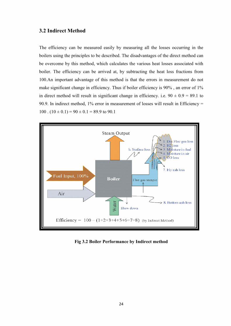
3.2 Indirect Method
The efficiency can be measured easily by measuring all the losses occurring in the
boilers using the principles to be described. The disadvantages of the direct method can
be overcome by this method, which calculates the various heat losses associated with
boiler. The efficiency can be arrived at, by subtracting the heat loss fractions from
100.An important advantage of this method is that the errors in measurement do not
make significant change in efficiency. Thus if boiler efficiency is 90% , an error of 1%
in direct method will result in significant change in efficiency. i.e. 90 ± 0.9 = 89.1 to
90.9. In indirect method, 1% error in measurement of losses will result in Efficiency =
100 . (10 ± 0.1) = 90 ± 0.1 = 89.9 to 90.1
Fig 3.2 Boiler Performance by Indirect method
25
Losses in Boiler:
The following losses are applicable to liquid, gas and solid fired boiler
L1. Loss due to dry flue gas (sensible heat)
L2. Loss due to hydrogen in fuel (H2)
L3. Loss due to moisture in fuel (H2O)
L4. Loss due to moisture in air (H2O)
L5. Loss due to carbon monoxide (CO)
L6. Loss due to surface radiation, convection and other unaccounted*.(Losses
which are insignificant and are difficult to measure)
The following losses are applicable to solid fuel fired boiler in addition to above
L7. Unburnt losses in fly ash (Carbon)
L8. Unburnt losses in bottom ash (Carbon)
Boiler Efficiency by indirect method = 100 - (L1 + L2 + L3 + L4 + L5 + L6 +
L7 + L8)
3.3 Application of Bagasse Dryer:
At present, pneumatic dryers are most often used in factories because of their low price
and small space requirements. Bagasse dryers undoubtedly promote energy savings that
increase the efficiency of the steam generation system. With the current increase in
export cogeneration in most Brazilian factories, the bagasse dryer could become an
important element of the system, even though studies about trade-off between the air
pre-heater, the economizer and the drier are necessary, taking into account costs and
energy consumption, aiming to determine the best seating arrangement between these
pieces of equipment.

26
CHAPTER-4
EXPERIMENTAL SETUP AND FUEL ANALYSIS
This chapter deals with the experimental setup used for fuel testing and fuel analysis for
boiler performance evaluation.
4.1 Experimental setup
Bomb Calorimeter
A bomb calorimeter is a type of constant volume calorimeter used measuring the heat
of combustion of a particular reaction. Electrical energy is used to ignite the fuel ; as
the fuel is burning, it will heat the surrounding air, which expands and escapes through
a tube that leads the air out of the tube. The change in temperature of water allows for
calculating calorie content of the fuel.
Fig 4.1 Bomb Calorimeter

27
Parameters
From the above set-up we can measure temperature diffrence, and with a bomb factor
(which dependent on the heat capacity of the metal bomb parts) is used to calculate the
energy given by sample burn.
GCV = Water Constant Temperature Change Of Fuel – (E1 + E2)
Taken Sample
Where,
E1 = Weight Of Cotton Thread 4.18 1000
E2 = Nichrome Wire Weight Loss 0.335 1000
Water Constant = 2511
Muffle Furnace
The woring principle of muffle furnace is to heat the air in the chamber by heating the
nichrome wires which are generally referred to as electrically operated heating
elements.The control of furnace temperature majorly depends on the efficency of
electronic controller unit and best results can only be obtaned from PID controlled
units, PID stands for proportional integral derivative controller.
Fig 4.2 Muffle Furnace
28
Parameters
The maximum working temperature of this muffle furnance 1100 – 1200 C.
Oven
Laboratory ovens are ovens for high-forced volume thermal convection applications.
These ovens generally provide uniform temperatures throughout. Process applications
for laboratory ovens can be for annealing, die-bond curing, drying, Polyimide baking,
sterilizing, and other industrial laboratory functions.
Fig 4.3 Oven
Parameters
The maximum working temperature of oven used in power plant to remove moisture is
250C.

29
4.2 Fuel Analysis and losses
Fuel analysis can be done by proximate and ultimate analysis without dryer.
Proximate Analysis of fuel i.e bagasse
4.2 Data collected from Triveni Engineering and industries ltd. Without dryer
( 24 hr. )
O2 % Unburnt Fly % Flue gas
temperature (Tf)
Unburnt
bottom %
GCV (kcal/kg)
3.6 11 130 35.67 2150.42
4.25 10.97 129 36.82 2182.72
4.22 12.52 132 38.44 2192.72
3.5 14.20 128 42.00 2160.64
3.2 11.56 130 40.4 2220.50
4 10.90 131 36.7 2170.82
4.02 12.44 127 42.8 2240.46
5.2 14.40 129 35.9 2170.24
3.9 12.20 132 36.27 2230.42
4.4 11.82 130 38.8 2160.24
5.6 11.56 128 40.23 2210.50
3.8 14.10 129 42.28 2180.30
1. Test for moisture of bagasse has been conducted, M=50%
2. Volatile matter test for bagasse has been conducted.VM= 40%
3. Ash test for bagasse has been conducted, ASH=1.75%
4. Fix carbon for bagasse can be calculated as
FC% = 100 – (VM% + M% + ASH%)
=100 – (40% + 0% + 1.75%)
=8.25% on dry basis

30
Ultimate Analysis of fuel.
Conversion formula for proximate analysis to ultimate analysis
%C = 0.97C + 0.7 (VM + 0.1A) - M(0.6 - 0.01M) = 31.125%
%H2 = 0.036C + 0.086 (VM - 0.1xA) - 0.0035M2 (1 - 0.02M) = 3.7219%
%N2 = 2.10 - 0.020 VM = 1.3%
%O2 = 13.8531%
%H2O = 50 %
where C = % of fixed carbon
A = % of ash
VM = % of volatile matter
M = % of moisture
Theoretical air required for combustion = 4.3032 kg/kg of fue
% of Excess Air supplied = 23.67%
Actual air supplied per kg of fuel = 5.32 kg / kg of fuel
Mass of dry flue gas, mdfg = 5.48 kg/ kg of fuel
31
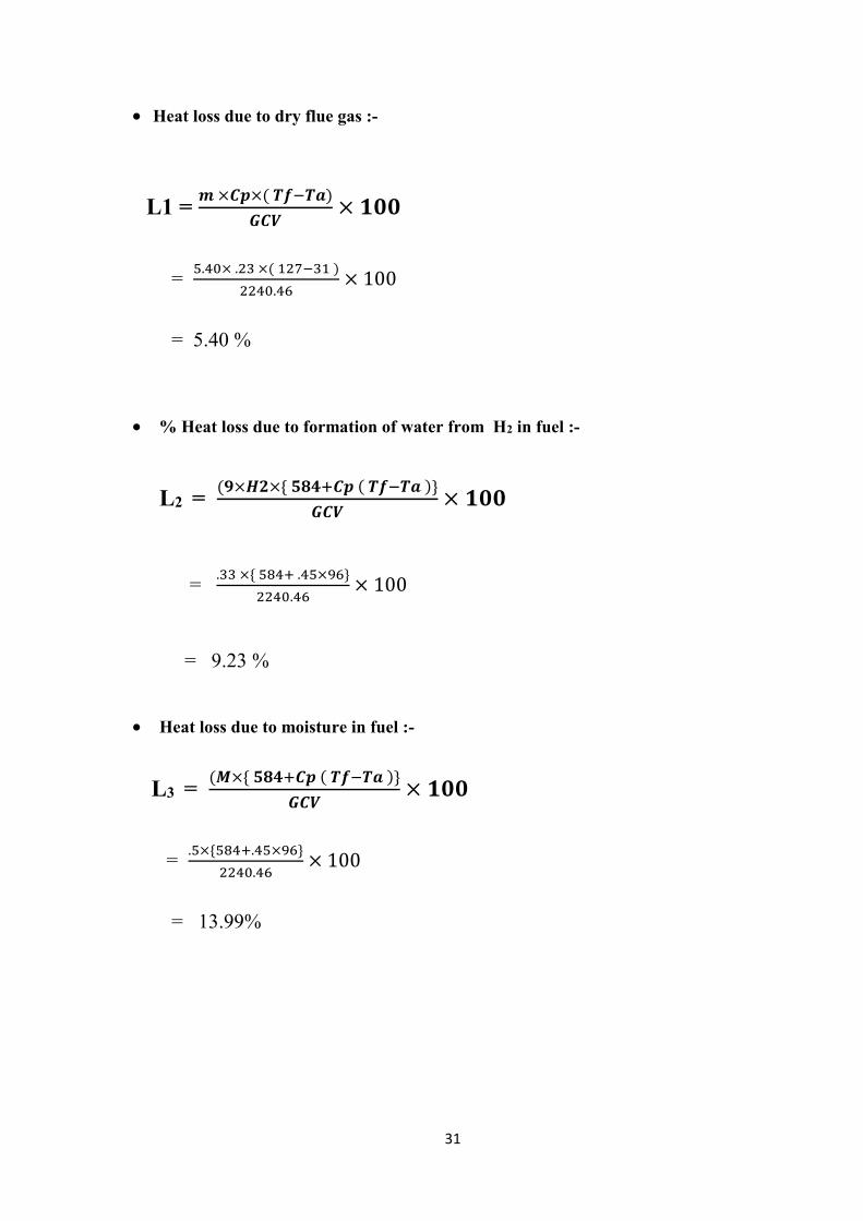
Heat loss due to dry flue gas :-
L1 = � ×��×( �����)
���× ���
= �.��× .�� ×( ������ )
����.��× 100
= 5.40 %
% Heat loss due to formation of water from H2 in fuel :-
L2 = (�×��×{ ������ ( ����� )}
���× ���
= .�� ×{ ���� .��×��}
����.��× 100
= 9.23 %
Heat loss due to moisture in fuel :-
L3 = (�×{ ������ ( ����� )}
���× ���
= .�×{����.��×��}
����.��× 100
= 13.99%

32
Heat loss due to moisture in air :-
L4 = ���×��������×��×(�����)
���× ���
= �.��×.����×.��×��
����.��× 100
= .20%
Heat loss due to partial conversion of C to CO :-
L5 = 2.5% ( standard )
Heat loss due to radiation
L6 = .25% ( standard )
Heat loss due to unburnt in fly ash :-
L7 = .53%
Heat loss due to unburnt in Bottom ash :-
L8 = .64%
33
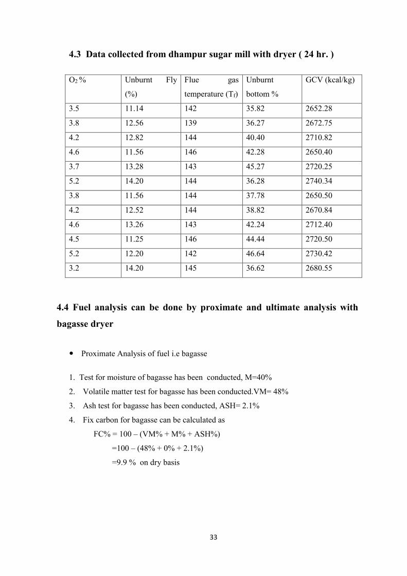
4.3 Data collected from dhampur sugar mill with dryer ( 24 hr. )
O2 % Unburnt Fly
(%)
Flue gas
temperature (Tf)
Unburnt
bottom %
GCV (kcal/kg)
3.5 11.14 142 35.82 2652.28
3.8 12.56 139 36.27 2672.75
4.2 12.82 144 40.40 2710.82
4.6 11.56 146 42.28 2650.40
3.7 13.28 143 45.27 2720.25
5.2 14.20 144 36.28 2740.34
3.8 11.56 144 37.78 2650.50
4.2 12.52 144 38.82 2670.84
4.6 13.26 143 42.24 2712.40
4.5 11.25 146 44.44 2720.50
5.2 12.20 142 46.64 2730.42
3.2 14.20 145 36.62 2680.55
4.4 Fuel analysis can be done by proximate and ultimate analysis with
bagasse dryer
Proximate Analysis of fuel i.e bagasse
1. Test for moisture of bagasse has been conducted, M=40%
2. Volatile matter test for bagasse has been conducted.VM= 48%
3. Ash test for bagasse has been conducted, ASH= 2.1%
4. Fix carbon for bagasse can be calculated as
FC% = 100 – (VM% + M% + ASH%)
=100 – (48% + 0% + 2.1%)
=9.9 % on dry basis

34
Ultimate Analysis of fuel with bagasse dryer.
Conversion formula for proximate analysis to ultimate analysis
%C = 0.97C + 0.7 (VM + 0.1A) - M(0.6 - 0.01M) = 35.35 %
%H2 = 0.036C + 0.086 (VM - 0.1xA) - 0.0035M2 (1 - 0.02M) = 3.33%
%N2 = 2.10 - 0.020 VM = 1.14%
%O2 = 20.18%
%H2O = 40 %
where C = % of fixed carbon
A = % of ash
VM = % of volatile matter
M = % of moisture
Theoretical air required for combustion = 4.38 kg/kg of fuel
% of Excess Air supplied = 22.09%
Actual air supplied per kg of fuel = 5.34 kg / kg of fuel
Mass of dry flue gas, mdfg = 5.42 kg/ kg of fuel
Heat loss due to dry flue gas :-
L1 = � ×��×( �����)
���× ���
= �.��× .�� ×( ������ )
����.��× 100
= 5.03 %
35
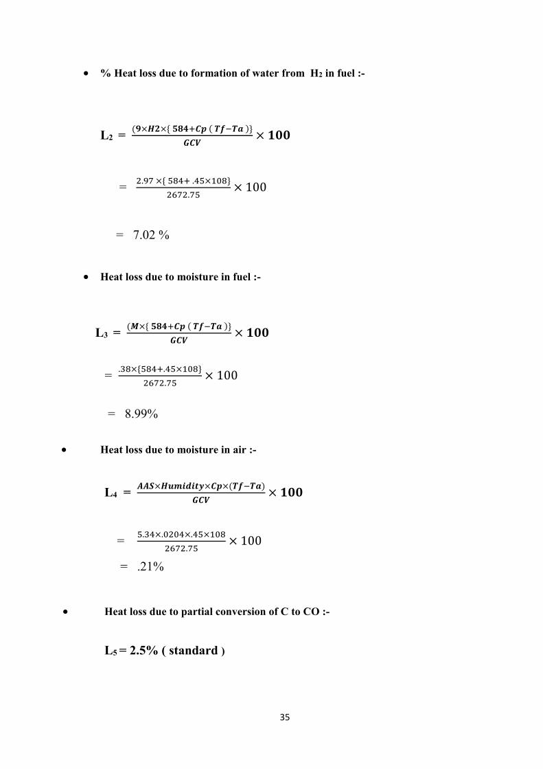
% Heat loss due to formation of water from H2 in fuel :-
L2 = (�×��×{ ������ ( ����� )}
���× ���
= �.�� ×{ ���� .��×���}
����.��× 100
= 7.02 %
Heat loss due to moisture in fuel :-
L3 = (�×{ ������ ( ����� )}
���× ���
= .��×{����.��×���}
����.��× 100
= 8.99%
Heat loss due to moisture in air :-
L4 = ���×��������×��×(�����)
���× ���
= �.��×.����×.��×���
����.��× 100
= .21%
Heat loss due to partial conversion of C to CO :-
L5 = 2.5% ( standard )

36
Heat loss due to radiation
L6 = .25% ( standard )
Heat loss due to unburnt in fly ash :-
L7 = .43%
Heat loss due to unburnt in Bottom ash :-
L8 = .80%
37
CHAPTER-5
RESULTS AND DISCUSSIONS
5.1 PERFORMANCE OF BOILER
In this section a comparative study is shown between performance of bagasse fired
boiler by using bagasse dryer and without using the bagasse dryer in the form of heat
balance sheet, bar chart for major losses and efficiency variation with excess air and
oxygen percentage inside the furnace.
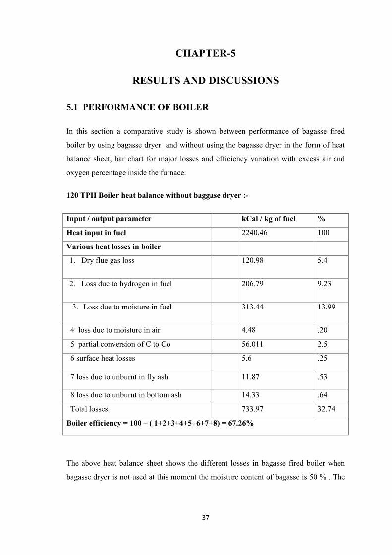
120 TPH Boiler heat balance without baggase dryer :-
Input / output parameter kCal / kg of fuel %
Heat input in fuel 2240.46 100
Various heat losses in boiler
1. Dry flue gas loss 120.98 5.4
2. Loss due to hydrogen in fuel 206.79 9.23
3. Loss due to moisture in fuel 313.44 13.99
4 loss due to moisture in air 4.48 .20
5 partial conversion of C to Co 56.011 2.5
6 surface heat losses 5.6 .25
7 loss due to unburnt in fly ash 11.87 .53
8 loss due to unburnt in bottom ash 14.33 .64
Total losses 733.97 32.74
Boiler efficiency = 100 – ( 1+2+3+4+5+6+7+8) = 67.26%
The above heat balance sheet shows the different losses in bagasse fired boiler when
bagasse dryer is not used at this moment the moisture content of bagasse is 50 % . The
38
major losses are dry flue gas loss, loss due to hydrogen in fuel and loss due to moisture
in fuel.
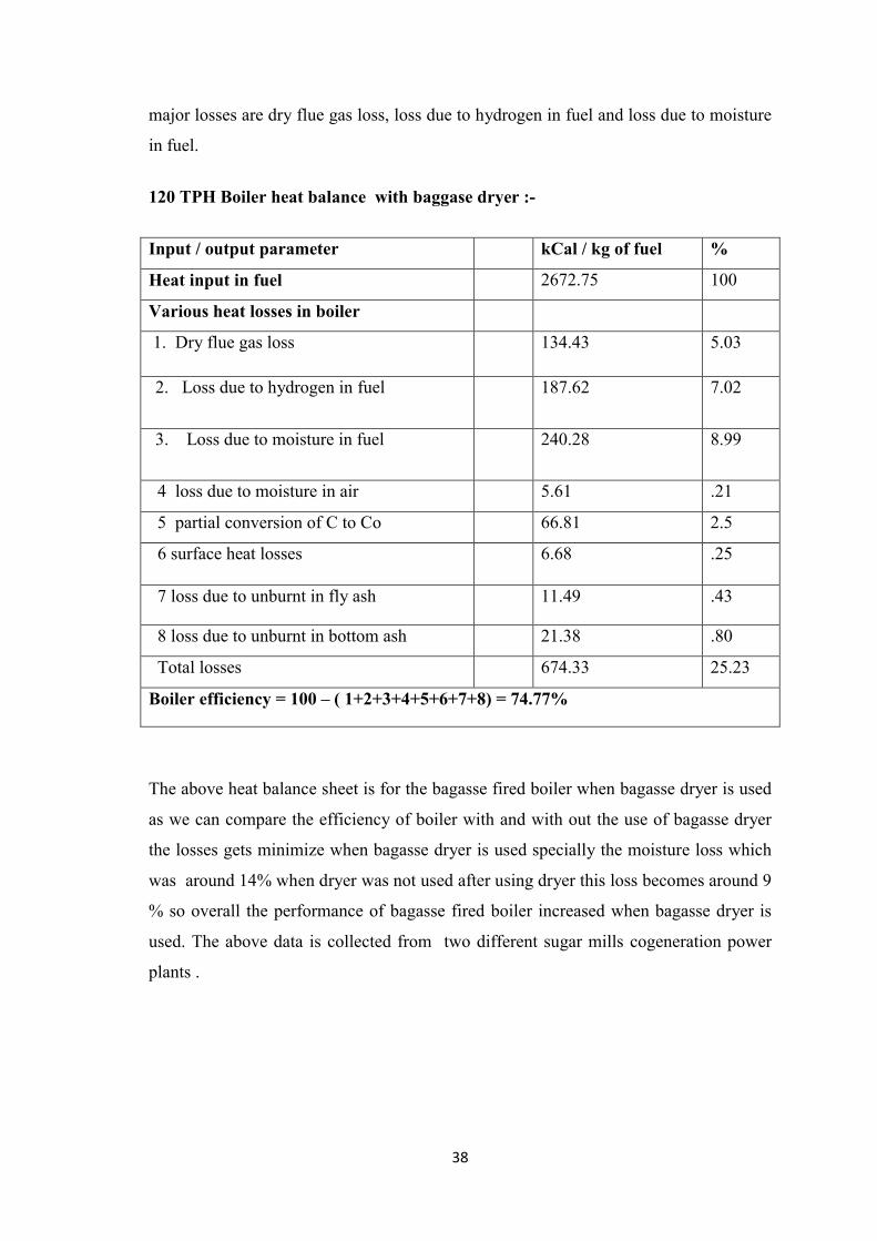
120 TPH Boiler heat balance with baggase dryer :-
Input / output parameter kCal / kg of fuel %
Heat input in fuel 2672.75 100
Various heat losses in boiler
1. Dry flue gas loss 134.43 5.03
2. Loss due to hydrogen in fuel 187.62 7.02
3. Loss due to moisture in fuel 240.28 8.99
4 loss due to moisture in air 5.61 .21
5 partial conversion of C to Co 66.81 2.5
6 surface heat losses 6.68 .25
7 loss due to unburnt in fly ash 11.49 .43
8 loss due to unburnt in bottom ash 21.38 .80
Total losses 674.33 25.23
Boiler efficiency = 100 – ( 1+2+3+4+5+6+7+8) = 74.77%
The above heat balance sheet is for the bagasse fired boiler when bagasse dryer is used
as we can compare the efficiency of boiler with and with out the use of bagasse dryer
the losses gets minimize when bagasse dryer is used specially the moisture loss which
was around 14% when dryer was not used after using dryer this loss becomes around 9
% so overall the performance of bagasse fired boiler increased when bagasse dryer is
used. The above data is collected from two different sugar mills cogeneration power
plants .

39
1 . TRIVENI ENGINEERING AND INDUSTRIES .LTD
2 . DHAMPUR SUGAR MILLS
5.2 LOSSES IN BOILER WITHOUT DRYER :-
Fig 5.1 - Losses In boiler without dryer
The above graph shows the different losses which occurs in boiler without dryer . There
are 8 losses in boiler some are major losses and some are minor losss
0
2
4
6
8
10
12
14
16
L
o
s
s
%
Losses
losses %
losses %

40
5.3 LOSSES IN BOILER WITH DRYER :-
Fig 5.2 – Losses in boiler with dryer
The above graph shows the different losses which occurs in boiler with dryer. There are
8 losses in boiler some are major losses and some are minor losses.
0
1
2
3
4
5
6
7
8
9
10
L
o
s
s
%
Losses
losses %
losses %

41
5.4 COMPARISON OF MAJOR LOSSES IN BOILER :-
Fig 5.3 -Comparison of major losses
There are 3 major losses in bagasse fired boiler which are shown by the above bar
graph. Here the comparison of all the major losses is shown for best performance of
bagasse fired boiler we can see with bagasse dryer all the major losses gets minimize
and performance of bagasse fired boiler gets increase. The bar graph gives the idea of
comparison of the major losses which occurs in boiler.
0
2
4
6
8
10
12
14
16
dry flue gasloss
loss due toformation of
water
loss due tomoisture
loss due tounburnt
L
o
s
s
%
Losses
losses without dryer
losses with dryer
42
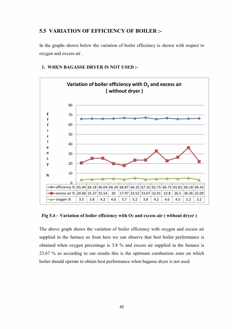
5.5 VARIATION OF EFFICIENCY OF BOILER :-
In the graphs shown below the variation of boiler efficiency is shown with respect to
oxygen and excess air .
1. WHEN BAGASSE DRYER IS NOT USED :-
Fig 5.4 – Variation of boiler efficiency with O2 and excess air ( without dryer )
The above graph shows the variation of boiler efficiency with oxygen and excess air
supplied in the furnace so from here we can observe that best boiler performance is
obtained when oxygen percentage is 3.8 % and excess air supplied in the furnace is
23.67 % so according to our results this is the optimum combustion zone on which
boiler should operate to obtain best performance when bagasse dryer is not used.
efficiency % 65.94 66.18 66.04 66.24 66.87 66.32 67.16 65.75 66.73 65.81 66.18 66.43
excess air % 20.68 25.37 25.54 20 17.97 23.52 23.67 32.91 22.8 26.5 36.36 22.09
oxygen % 3.5 3.8 4.2 4.6 3.7 5.2 3.8 4.2 4.6 4.5 5.2 3.2
0
10
20
30
40
50
60
70
80
E
f
f
i
c
i
e
n
c
y
%
Variation of boiler efficiency with O2 and excess air ( without dryer )

43
2. WHEN BAGASSE DRYER IS USED :-
Fig 5.5 - Variation of boiler efficiency with O2 and excess air ( with dryer )
The above graph shows the variation of boiler efficiency with oxygen and excess air
supplied in the furnace so from here we can observe that best boiler performance is
obtained when oxygen percentage is 3.8 % and excess air supplied in the furnace is
22.09 % so according to our results this is the optimum combustion zone on which
boiler should operate to obtain best performance when bagasse dryer is used.
efficiency % 74.31 74.77 74.34 73.62 74.74 74.48 74.31 74.31 74.18 74.44 74.12 74.5
excess air % 20 22.09 25 28.04 21.38 32.91 22.09 25 28.04 27.27 32.91 17.97
oxygen% 3.5 3.8 4.2 4.6 3.7 5.2 3.8 4.2 4.6 4.5 5.2 3.2
0
10
20
30
40
50
60
70
80
E
f
f
i
c
i
e
n
c
y
%
Variation of boiler efficiency with O2 and excess air
( with dryer )
44
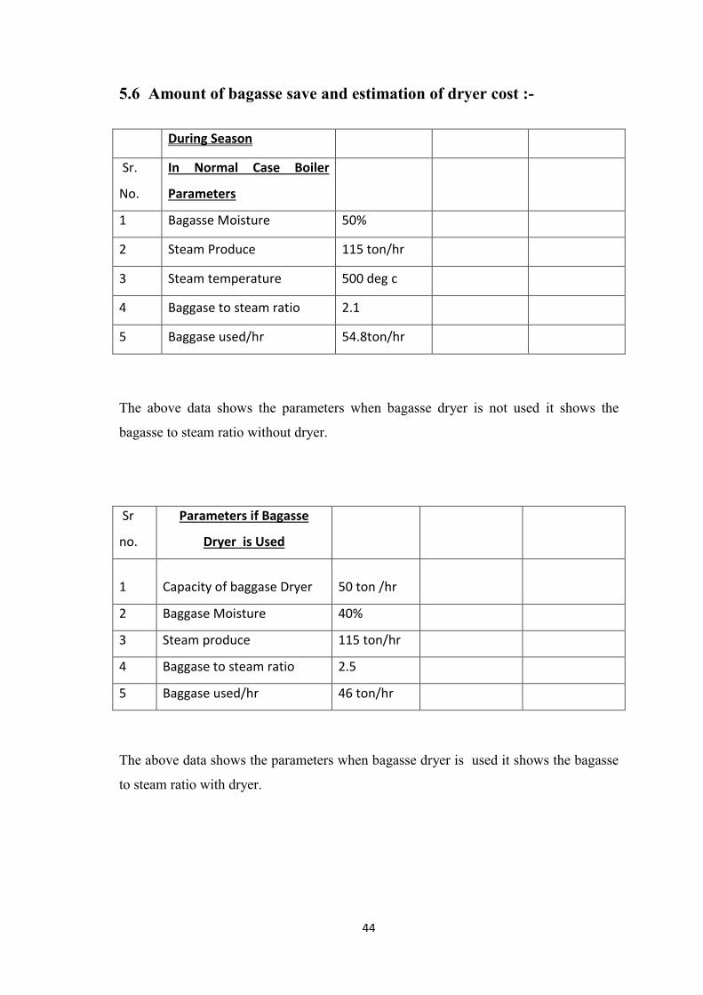
5.6 Amount of bagasse save and estimation of dryer cost :-
During Season
Sr.
No.
In Normal Case Boiler
Parameters
1 Bagasse Moisture 50%
2 Steam Produce 115 ton/hr
3 Steam temperature 500 deg c
4 Baggase to steam ratio 2.1
5 Baggase used/hr 54.8ton/hr
The above data shows the parameters when bagasse dryer is not used it shows the
bagasse to steam ratio without dryer.
Sr
no.
Parameters if Bagasse
Dryer is Used
1 Capacity of baggase Dryer 50 ton /hr
2 Baggase Moisture 40%
3 Steam produce 115 ton/hr
4 Baggase to steam ratio 2.5
5 Baggase used/hr 46 ton/hr
The above data shows the parameters when bagasse dryer is used it shows the bagasse
to steam ratio with dryer.

45
in normal case the temp. of id fan outlet is about 120 deg celcius but in case of bagasse
dryer it goes up to 140 degree for better result of bagasse dryer through this the
efficiency. Of boiler decreases by 1 % in both cases we consider this efficiency Matter
Sr
no.
Difference between in
normal case and if
bagasse dryer used
54.8-46 = 8.8
Ton
1
If rate of baggase is Rs
3000/ton
2 Net saving in one hr is
8.8x3000 = Rs
26,400
3 Net saving in one Day is
26400x 24 = Rs
6,33,600
4
If Season is about 120
Days
633600 x 120 =
Rs 7,60,32000
.
The above table shows the amount of bagasse save and the revenue generated by using
bagasse dryer in a complete season which is around 120 days in any sugar industry.
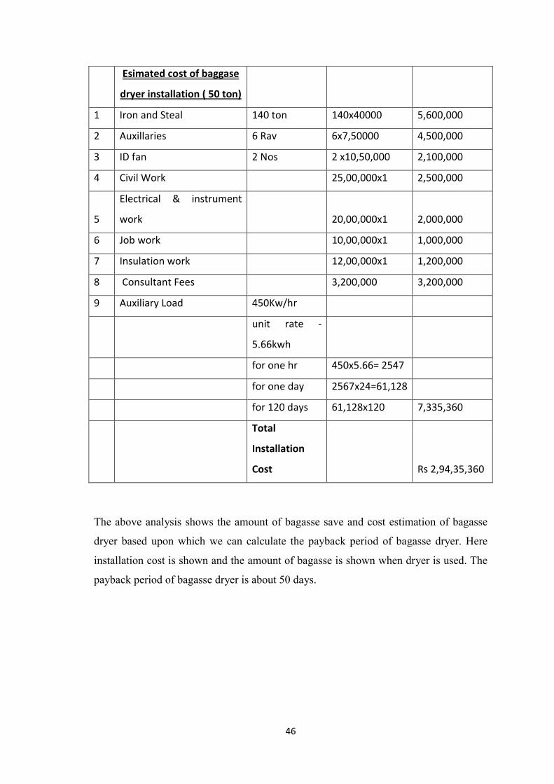
46
Esimated cost of baggase
dryer installation ( 50 ton)
1 Iron and Steal 140 ton 140x40000 5,600,000
2 Auxillaries 6 Rav 6x7,50000 4,500,000
3 ID fan 2 Nos 2 x10,50,000 2,100,000
4 Civil Work 25,00,000x1 2,500,000
5
Electrical & instrument
work 20,00,000x1 2,000,000
6 Job work 10,00,000x1 1,000,000
7 Insulation work 12,00,000x1 1,200,000
8 Consultant Fees 3,200,000 3,200,000
9 Auxiliary Load 450Kw/hr
unit rate -
5.66kwh
for one hr 450x5.66= 2547
for one day 2567x24=61,128
for 120 days 61,128x120 7,335,360
Total
Installation
Cost Rs 2,94,35,360
The above analysis shows the amount of bagasse save and cost estimation of bagasse
dryer based upon which we can calculate the payback period of bagasse dryer. Here
installation cost is shown and the amount of bagasse is shown when dryer is used. The
payback period of bagasse dryer is about 50 days.

47
CHAPTER 6
CONCLUSIONS AND FUTURE SCOPE
In this dissertation an attempt has been made to account various losses occurs in
bagasse fired boiler and to improve the performance boiler by using bagasse dryer .
Different losses are taken in to consideration to analyse and compare the performance
of boiler in cogeneration power plant .
On the basis of experimental work the following conclusions are drawn :
The performance of boiler increase with bagasse dryer.
The major losses like dry flue gas loss, loss due to formation of water from
hydrogen in fuel and loss due to moisture in fuel is less when bagasse dryer is
used
The aim of the introduction of dryer was to reduce the bagasse moisture content
in order to improve the boiler performance. The results obtained show that these
aims were succeeded.
It is important for all sugar mills to install bagasse dryer.
The bagasse drying by using the flue gases is an economic necessity for sugar
mills where it can realizes self sufficiency of fuel .
It is an environmental necessity where it reduces the air pollution.
Bagasse has not become by-product of sugar industry, but it has become main
product.
Many types of bagasse dryers have been installed in different countries.
Here we have shown the comparative study of boiler when it is used with dryer
and without dryer and we clearly shown the amount of bagasse saved when
dryer is used.
So overall we can say that installation of bagasse dryer is beneficial for any
sugar industry because it saves fuel as well as improve the performance of
boiler by minimizing the major losses which occurs in bagasse fired boiler.
The payback period of bagasse dryer is also very less it is around 50 days in
normal working season.

48
Scope for Future work :-
In this work the boiler performance has been analysed based on dryer and
without using bagasse dryer as we know there are different auxiliaries related to
boiler like feed pump, ID Fan , Primary air Fan , Secondary air fan so if we
calculate total auxiliaries power consumption without dryer and compare with
the power consumption of auxiliaries when bagasse dryer is used then overall
auxiliaries power consumption can be optimized and boiler operation will be
smooth there will not be any need to change the boiler parameters like furnace
draft, fuel feeding etc. so bagasse dryer can play in important role in the
optimization of auxiliaries power consumption related to boiler.

49
CHAPTER-7
REFERENCES
Geethanjali S. Yarnal, Vinod S. Puranik, (2009). Energy Management Study in
Sugar Industries By Various bagasse Drying Methods. Strategic planning for
energy and environment, 56-78.
Juan H.Sosa – Arnao, Jefferson L.G. Correa, Maria A. Silva and Silvia A.
Nebra(2006)Sugar cane Bagasse Drying – A Review, Research gate.
Acosta J.C.(1995),The boiler efficiency fuelled by bagasse, international sugar
journal,1997 (1158): 248-255(in spanish).
Bailliet,V.J.(1976), bagasse drying versus air preheating,The sugar
journal,38(10)52-53.
Juan H. Sosa and Silvia A Nebra (2009) Bagasse Dryer Role in the Energy
Recovery of Water Tube Boilers,Drying technology: An international journal
27:4,587-594.
Nebra,S.A.Macedo,I.;de,C.Pneumatic drying of bagasse sugar cane.
international sugar journal 1989,91(1081),3-7,12.
Energy Management Study in Sugar Industries By Various bagasse Drying
Methods
(Geethanjali S. Yarnal, Vinod S. Puranik).
Jorge Barroso, Felix Barreras, HippolyteAmaveda, Antonio Lozano On the
optimization of boiler efficiency using bagasse as fuel,Science direct, Fuel 82
(2003) 1451-1463.
AndriuchenkoA.Thermal Cycles and Process Optimization In The Electric
Power Station.Moscow:MIR; 1974, in Russian.
Performance Assesment of Boiler, Bureau of Energy Efficiency.
P.K. Nag (2013) Power Plant Engineering 3rd Edition. McGraw Hill Book
Company, New York.
Bejan A. (1998), ‘Advanced Engineering Thermodynamics’, John Wiley and
Sons, New York.

50
Bose S.C., Rohatgi V.K., Kumar G., Dhingra B.R. and Mishra B.K. (1984),
‘Continues mill wet bagassse dryer’, Proceedings of Sugar Technologists
Association of India, pp. 51-63
Brown (1988), ‘Introduction to Thermal Analysis’, Chapman and Hall, London.
Cardenas G., De Vasquez D. and Wittwer E. (1994), ‘Energy and Exergy
analysis of a combined bagasse dryer boiler system’, International Sugar
Journal, Vol. 96, pp. 213-219.
CEA (2007), ‘Baseline Carbon Dioxide Emission Database: Version 1.1’,
Central Electricity Authority (CEA), Ministry of Power, Government of India,
New Delhi.
Choh Y., Ren L.S and Zhang C.H. (1984), ‘Impulsive fluidized pipe dryer for
Bagasse’, Zuckerind, Vol. 109, pp. 552-554
Dincer I. and Sahin A.Z. (2004), ‘A new model for thermodynamic analysis of a
drying process’, International Journal of Heat and Mass Transfer, Vol. 47, No.
4, pp. 645-652.
Dinen K. Ghosh (2003), ‘Bagasse burning principle and care’, Proceedings of
Sugar Technology Association of India, Vol. 65, pp. 13-20.
Edwards B.P. (1981), ‘Bagasse drying’, Australian Society of Sugar Cane
Technologists, pp. 203-206
ESCAP (2000), Guidebook on Cogeneration as a Means of Pollution Control
and Energy Efficiency in Asia. Environment and Sustainable Development
Division (ESDD), United Nations Economic and Social Commission for Asia
and the Pacific (ESCAP), Bangkok.
Furines J.H. (1976), ‘Pre-Drying Bagasse using Flue Gases’, The sugar Journal,
Vol. 39, No. 3, pp. 39-40.
Goran Wall (1986), ‘Exergy – A useful concept’, Physical Resource Theory
Group’, 3rd Ed., Goteborg.
Guanzon F.P. (1980), ‘Bagasse drying for bigger profits’, Philippine Sugar
Technologist, pp. 338-349
Holmberg H. and Ahtila P. (2005), ‘Evaluation of energy efficiency in biofuel
drying by means of energy and exergy analyses’, Applied Thermal Engineering,
Vol. 25, pp. 3115-3128

51
Hugot E. (1986), ‘Handbook on cane sugar engineering’, Elsevier, London.
ICRA. (2006), ‘The Indian Sugar Industry: Information and Credit Rating
Agency (ICRA)’, Gurgaon.
Incropera. P (2001), ‘Introduction to Heat Transfer’, Wiley John & sons.
Keenliside B. (1983), ‘A Comparison of Air heaters and Bagasse drying
systems for energy efficiency’, International Society of Sugar Cane
Technologist, pp. 1508-1516.
Keey R.B. (1972), ‘Drying principles and practice’, New York: Pregoman
Press.
Keller W. (1980), ‘Conservation of energy through drying bagasse’, 27th
Annual Convention of Philippines Sugar Technologist
Kinoshita C.M. (1991), ‘Flue Gas Drying of Bagasse’, Applied Engineering in
Agriculture, Vol. 7, No. 6, pp. 729-734
Kline S.J. and Mc Clintock F.A. (1953), Mech. Engg. Journal, Vol. 75, p. 224.
Massarani G. and Valenca G.C. (1981), ‘Sugar cane bagasse drying, III
National drying meeting’, p. 355.
Meirelles A.J.A. (1984), ‘Cane bagasse drying in a fluidized bed’, M.Sc. Thesis,
State University of Campinas.
MNES (2006), ‘Annual Report: 2005–06. Ministry of Non-conventional Energy
Sources (MNES)’, Government of India, New Delhi.
Nanda Kumar R. and Nagesh Kumar L. (2001), ‘Efficiency improvement in a
cane sugar plant using a bagasse dryer’, International Society of Sugar Cane
Technologist, Vol. 24, pp. 250-252.
Prasertsan S. and Sajjakulnukit B. (2006), ‘Biomass and biogas energy in
Thailand: potential, opportunity and barriers’, Renewable Energy, Vol. 31, No.
5, pp. 599-610.

52
Copyright © 2022 FDOKUMEN