PERFORMANCE BASED WORK STATEMENT (PWS) - AWS
123
Attachment 1 Page 1 of 123 PERFORMANCE BASED WORK STATEMENT (PWS) FOR OPERATION AND MAINTENANCE (O&M) SERVICES BASE TELECOMMUNICATIONS SYSTEM (BTS) Services AT HOLLOMAN AIR FORCE BASE, NEW MEXICO 2021 CAMERON D. MCMULLEN TSgt, USAF Date Contracting Officer's Representative (COR) 49th Communications Squadron JOSEPH C. MURPHY, Lt Col, USAF Date COR Supervisor 49th Communications Squadron PATTI J. REN, Civ DAF Date Quality Assurance Program Coordinator (QAPC) 49th Contracting Squadron APPROVED BY: SALLY D. ROBERTS, Civ, DAF Date Contracting Officer (CO) 49th Contracting Squadron Sol. # FA480122R0002
-
Upload
khangminh22 -
Category
Documents
-
view
1 -
download
0
Transcript of PERFORMANCE BASED WORK STATEMENT (PWS) - AWS

Attachment 1 Page 1 of 123
PERFORMANCE BASED WORK STATEMENT (PWS)
FOR
OPERATION AND MAINTENANCE (O&M) SERVICES
BASE TELECOMMUNICATIONS SYSTEM (BTS) Services
AT
HOLLOMAN AIR FORCE BASE, NEW MEXICO
2021
CAMERON D. MCMULLEN TSgt, USAF Date Contracting Officer's Representative (COR) 49th Communications Squadron
JOSEPH C. MURPHY, Lt Col, USAF Date COR Supervisor 49th Communications Squadron
PATTI J. REN, Civ DAF Date Quality Assurance Program Coordinator (QAPC) 49th Contracting Squadron
APPROVED BY:
SALLY D. ROBERTS, Civ, DAF Date Contracting Officer (CO) 49th Contracting Squadron
Sol. # FA480122R0002

Attachment 1 Page 2 of 123
Table of Contents
1.0. DESCRIPTION OF SERVICES .................................................................................................................... 41.1. Scope of Work. ........................................................................................................................................ 41.2. General Requirements. ............................................................................................................................ 4
1.2.1. Hours of Operation. ....................................................................................................................... 41.2.2. After Hours Notification. .............................................................................................................. 41.2.3. Continuation of Mission Essential Services. ................................................................................. 41.2.4. Accident/Incident Reporting and Investigation. ............................................................................ 51.2.5. Subcontractor Compliance. ........................................................................................................... 51.2.6. Base Civil Engineering Work Clearance Requests. ...................................................................... 5
1.2.7. Personnel. ...................................................................................................................................... 51.2.8. Key Personnel Listing. .................................................................................................................. 5
1.3. Operation and Maintenance (O&M) Requirements................................................................................. 6 1.3.1. Telephone Switch System O&M ................................................................................................... 6
1.3.2. ISP and OSP O&M. ...................................................................................................................... 61.3.3. Enhanced-911 (E-911) System.. .................................................................................................... 61.3.4. Preventative Maintenance Inspections (PMIs). ............................................................................. 71.3.5. System and Service Outages and Trouble Calls/Tickets. .............................................................. 9
1.3.6. Alarm Notification. ..................................................................................................................... 101.3.7. Cable Location, Staking, and Marking. ....................................................................................... 10
1.3.8. System Cross-Connect and Disconnect Services. ....................................................................... 111.3.9. Fiber Optic Patching and Disconnect Services. ........................................................................... 11 1.3.10. Ethernet Patching & Disconnect Services .................................................................................. 11 1.3.11. Call Accounting System (CAS). ............................................................................................... 111.3.12. Voice Protection System (VPS). ............................................................................................... 111.3.13. Traffic Measurement and Analysis. .......................................................................................... 111.3.14. Contractor Support Services. ..................................................................................................... 121.3.15. Technical Solutions. .................................................................................................................. 121.3.16. Rough Order of Magnitude (ROM). .......................................................................................... 121.3.17. BTS Work Center Records. ....................................................................................................... 13
1.4. Work Orders .......................................................................................................................................... 171.4.1. Work Order Procedures. .............................................................................................................. 171.4.2. Work Order Classifications. ........................................................................................................ 181.4.3. Required Information on Work Orders. ...................................................................................... 181.4.4. Work Orders Subject to the Construction Wage Rate Requirements Statute. ............................. 191.4.5. Submittal of Completed Work Orders. ........................................................................................ 19
1.5. Special Project Requirements ................................................................................................................ 191.6. Invoicing Instructions ............................................................................................................................ 20
1.6.1. Invoicing via PIEE/WAWF......................................................................................................... 20 1.6.2. Payment via GPC ........................................................................................................................ 20
1.6.3. Government Internal Instructions for GPC ................................................................................. 20 1.7. Contractor Level I Antiterrorism Awareness Training (November 2019) ............................................ 20
2.0. SERVICE SUMMARY (SS). ....................................................................................................................... 212.1. Inspection of Services. .......................................................................................................................... 22
2.2. Non-Compliance. .................................................................................................................................. 22 2.2.1. Memorandum For Record (MFR). .............................................................................................. 22
2.2.2. Contract Discrepancy Report (CDR)........................................................................................... 223.0. GOVERNMENT-FURNISHED PROPERTY AND SERVICES ................................................................ 22
3.1. Air Force-Provided Spares\Contractor Logistic Support ....................................................................... 223.2. Base Support ....................................................................................................................................... 22
3.3. CVC Training ........................................................................................................................................ 244.0. GENERAL INFORMATION ............................................................................................................... 244.1. Contractor�s Quality Control Program .................................................................................................. 244.2. Security Requirements .......................................................................................................................... 24
Sol. # FA480122R0002

Attachment 1 Page 3 of 123
4.2.1. Illegal Aliens ............................................................................................................................... 25 4.2.2. Foreign National Employees. ...................................................................................................... 25 4.2.3. Listing of Employees .................................................................................................................. 25 4.2.4. In/Out Processing ........................................................................................................................ 25 4.2.5. Security Training. ........................................................................................................................ 26 4.2.6. Pass and Identification Items ....................................................................................................... 26 4.2.7. Retrieving Identification Media .................................................................................................. 26 4.2.8. Travel Restrictions ...................................................................................................................... 26 4.2.9. Traffic Laws. ............................................................................................................................... 26 4.2.10. Weapons, Firearms, and Ammunition ....................................................................................... 26 4.2.11. For Official Use Only (FOUO) ................................................................................................. 26 4.2.12. Reporting Requirements ............................................................................................................ 27 4.2.13. Physical Security. ...................................................................................................................... 27 4.2.14. Investigative Standards ............................................................................................................. 27 4.2.15. Information Technology/Information Systems (IT/IS) Access ................................................. 27 4.2.16. Controlled/Restricted Areas ...................................................................................................... 27 4.2.17. Photography .............................................................................................................................. 28 4.2.18. Key Control. .............................................................................................................................. 28 4.2.20. Security Guidelines ................................................................................................................... 28 4.2.21. National Agency Check with Inquiries (NACI) ........................................................................ 28
4.3. Safety, Security, and Environmental Meeting ....................................................................................... 29 4.3.1. Environmental Concerns ............................................................................................................. 30
4.4. Overtime ................................................................................................................................................ 315.0. APPENDICES .............................................................................................................................................. 32 Appendix 5.1 � Workload Estimates ............................................................................................................. 33 Appendix 5.2 � Items to be Maintained by the Contractor ............................................................................ 35 Appendix 5.3 � Glossary and Acronyms ....................................................................................................... 48 Appendix 5.4 � Voice Switching System (VSS) Sustainment ...................................................................... 59 Appendix 5.5 � Applicable Documents ......................................................................................................... 60 Appendix 5.6 � Instructions for Keeping CVC as-built records .................................................................... 63 Appendix 5.7 � Global Positioning System Service Documents ................................................................... 64 Appendix 5.8 � Equipment and Installation Performance Specification (EIPS) ........................................... 77 Appendix 5.9 � Operational Network Characteristics ................................................................................. 121
Sol. # FA480122R0002
Attachment 1 Page 4 of 123
1.0. DESCRIPTION OF SERVICES
1.1. Scope of Work. The Contractor shall provide all personnel, equipment, tools, materials, vehicles, supervision and other items and services, unless specified in this contract as Government Furnished Property (GFP)/Government Furnished Equipment (GFE) and Government Furnished Material (GFM). GFP is incidental in this requirement as defined in Federal Acquisition Regulation (FAR) 45.101. Work under this PWS will support the mission of 49th Communications Squadron at Holloman Air Force Base, New Mexico, by providing highly reliable wired telecommunications and networked voice, video and data services. The Contractor shall perform Operation and Maintenance (O&M) and other services required to ensure the Base Telecommunications System (BTS) is available 24 hours per day, seven (7) days per week. The BTS consists of the base telephone system switch, the outside plant (OSP) and inside plant (ISP) systems, network, transmission systems, and all associated equipment described in Appendix 5.2, which may include other systems (e.g., Voice over Internet Protocol (VoIP), etc.). The Contractor shall operate and maintain all BTS equipment and systems listed in Appendix 5.2 in accordance with (IAW) the Original Equipment Manufacturer (OEM) technical manuals and specifications, Department of Defense (DoD) and US Air Force (AF) policy and regulations, applicable federal, state, and local laws and regulations. 1.2. General Requirements. 1.2.1. Hours of Operation. The Contractor shall perform the services required under this contract from 7:30 am � 4:30 pm, Monday through Friday except Government holidays. 1.2.2. After Hours Notification. This contract does require the Contractor to respond to maintenance and work order after normal duty hours. The Contractor shall provide the Government with either an after duty phone number to recall personnel or a monthly standby roster providing name and phone number of standby personnel. 1.2.3. Continuation of Mission Essential Services. IAW Defense Federal Acquisition Regulation Supplement (DFARS) 252.237-7023 policy, it is determined that O&M services in PWS paragraphs 1.3.2 and 1.3.4.3 are essential for Contractor performance during a crisis situation. In the event of a crisis, additional areas may be identified by the CO. The Contractor may be required to support base mission changes; major or minor BTS infrastructure modifications; and other support requirements necessary for the BTS to meet mission requirements. Base exercises or actual ongoing base security events frequently interrupt missions. Support requirements may originate from technology changes, hardware and software systems upgrade, reconfigurations, new or additional equipment, local area network (LAN) cable installations and upgrade, and Dial Central Office (DCO) reconfigurations. This includes routing/diversity requirements and any other environmental changes that could impact or alter the BTS. Contractor shall submit its Mission-Essential Contractor Services Plan (MECSP) with proposal.
Sol. # FA480122R0002
Attachment 1 Page 5 of 123
1.2.4. Accident/Incident Reporting and Investigation. The Contractor shall record and report all available facts relating to each instance of accidental Government property damage or Contractor personnel injury to the CO within two (2) hours of the incident. The Contractor shall secure the scene of any accident and wreckage until released by the accident investigative authority through the CO. If the Government elects to conduct an investigation of the incident the Contractor shall cooperate fully with the COR, CO and other Government investigation personnel until the investigation is complete. 1.2.5. Subcontractor Compliance. The Contractor shall be responsible for ensuring Subcontractors satisfy the requirements set forth in the contract. The Contractor shall include a provision in all subcontracts to require Sub- contractor compliance with terms and conditions of this contract.
1.2.6. Base Civil Engineering Work Clearance Requests. The Contractor shall prepare and coordinate a Base Civil Engineering Work Clearance Request, AF Form 103, prior to any trenching or digging. The Contractor shall prepare and coordinate an AF Form 332, Base Civil Engineer Work Request, prior to any work requiring facility modification. Trenching, excavation, confined spaces entry, confined spaces atmospheric testing/forced air ventilation and marking and barricading of open trenches are to be performed IAW Occupational Safety and Health Act (OSHA) standards, AF Occupational Safety and Health (OSH), any local procedures, and other provisions of this contract. 1.2.7. Personnel. 1.2.7.1. Contractor Responsibility. The Contractor is solely responsible for ensuring sufficient personnel are assigned to this contract and all personnel are qualified and certified to perform the requirements listed herein, including those qualifications and certifications required by the OEM to maintain, install, and/or operate equipment listed in Appendix 5.2 and perform all contract support services covered by this contract. Technical support for equipment listed in Appendix 5.2 may require Tier I, II or III levels of troubleshooting support (ref. para 5.2.2 of Tier levels). The Contractor shall ensure personnel also meet the criterion stated in its proposal for this requirement. 1.2.7.2. Contractor Employees. Contractor employees shall present a neat appearance and be easily recognized as contractor employees. The Contractor shall provide each employee with an identification badge that shall include the employee�s name, employee�s photograph, and contractor name. Identification shall be available prior to employment and shall be worn/attached to the outer garment above the waist at all times.
1.2.8. Key Personnel Listing. The Contractor shall provide a key personnel listing, including contact information, to the CO and COR prior to commencing work. The Contractor shall update the listing when changes occur ensuring information is current and correct throughout the life of the contract. All personnel shall be proficient in understanding, reading, writing, and speaking the English language. The key personnel list shall list the employees� names, function they support, and whether they are supporting O&M or work orders, and what percentage of each support function the employee will perform.
Sol. # FA480122R0002

Attachment 1 Page 6 of 123
1.3. Operation and Maintenance (O&M) Requirements. Overall responsibility to properly operate and maintain the BTS shall rest with Contractor as described by the Maintenance Support Plan (MSP) (See PWS section 1.3.17.1 BTS Work Center Records) and the OEM�s recommended procedures. Appendix 5.2, Items to be maintained by Contractor, identifies GFM/GFE requirements. O&M actions include all actions taken by the Contractor to operate and maintain equipment and systems in a serviceable condition or to restore it to a serviceable condition to include purchasing of commercially available parts, inspection, periodic testing, adjustment, and repair. The effort may include the replacement of defective circuit packs and Customer Premise Equipment (CPE), preventive maintenance IAW applicable publications (OEM, Appendix 5.5, and otherwise specifically listed herein), and other routine work to optimize the life expectancy of the equipment and cable systems. Work orders will be accomplished IAW para 1.4. The Contractor shall not postpone or otherwise delay O&M efforts to accomplish work orders. The Contractor is responsible for completing both O&M and work orders simultaneously to ensure contractual timelines are met for both.
1.3.1. Telephone Switch System O&M. The Contractor shall operate and maintain the system(s) identified in Appendix 5.2. The Contractor must be Avaya qualified and certified to perform O&M on the switch. The Government will measure the acceptable standard performance level by a determination of the total systems availability (up time) and reliability rating during any given month. All equipment or services installed by the Contractor shall automatically become part of the O&M services. This includes, but is not limited to: management; administration and maintenance; performing software functions (i.e., number reclamation) and translations for any trunk or circuit of configurations required by on-base systems or users; data administration; trouble assistance; and records administration. The Contractor shall also include VoIP operations as part of the BTS. The O&M contractor shall be responsible for database administration of VoIP phones, software changes to include upgrades/patches, and troubleshooting. Demarcation of VoIP maintenance shall not extend beyond the end instrument and Ethernet ports of the switching equipment identified as the host and remote switches in Appendix 5.2.3.2 through 5.2.3.5. Note: Contractor will not be responsible for base network equipment (i.e., Information Transport Node (ITNs), LAN switches, etc.). 1.3.2. ISP and OSP O&M. The Contractor shall maintain ISP and OSP cable and equipment as identified in Appendix 5.2 and IAW applicable documents listed in Appendix 5.5 of this PWS. 1.3.3. Enhanced-911 (E-911) System.Contractor shall perform daily updates, or as phone number changes occur, by adding telephone number, building number, and room number for new and existing entries to the Government provided E-911 database. The Contractor shall manually enter the data into Cable Assignment Information Retrieval System (CAIRS) or any substitute record system as directed by a COR upon completion of individual work. The Contractor shall notify the COR by the last day of each month with all changes made in the E-911 database. Note: The Contractor will not be responsible for base E-911 equipment (i.e., consoles, servers, telephones, etc.).
Sol. # FA480122R0002

Attachment 1 Page 7 of 123
1.3.4. Preventative Maintenance Inspections (PMIs). The Contractor shall perform PMIs as required on all systems covered by this contract IAW OEM recommended or established schedules and/or manuals. Contractor shall elevate any problems and identify any trends to the CO and COR in writing within one (1) workday. Contractor shall correct deficiencies IAW the subparagraphs below.
1.3.4.1. Switch Power Test. The Contractor shall perform scheduled PMI tests of the telephone switch backup power system. PMIs shall test and document the power systems identified in Appendix 5.2. Each power system shall be tested IAW OEM specifications. Test results shall be documented IAW PWS para 1.3.17.2. 1.3.4.2. Spare Conductor Test. The Contractor shall perform a scheduled PMI test of all spare conductors. PMIs shall test and document at least two (2) selected, out of service pair (one low and one high numbered pair) in each 25-pair group of every cable terminating in the DCO-Bldg 221, Bldg 878 and Bldg 1081. These PMI tests are to be accomplished quarterly. Test results shall be documented and available for COR review. Contractor shall update CAIRS to indicate unusable cable pairs.
1.3.4.3. Manholes Handholes and/or Pull Boxes. The Contractor shall inspect five (5) COR approved manholes, handholes and/or pull boxes per month under the O&M portion of this contract. Additional inspections (over five (5) each) shall be accomplished as a work order IAW PWS para 1.4. If the Contractor is working in a manhole, handholes and/or pull boxes not scheduled for a PMI in that month, the Contractor must correct any discrepancies before the job is considered complete. This manhole will not be counted in that month�s PMI schedule. The Contractor shall inspect each manhole/handhole for the following discrepancies and correct as required:
1. All cables will be identified and tagged. At each splice, tags will be placed on each side of the splice identifying each cable. In manholes with pull through cables, each cable will be identified with a tag.
2. All cables will be racked to the manhole cable supports. 3. All ducts (vacant or occupied) will be sealed. 4. All manholes or handholes will be cleaned of mud, water and any other debris. 5. Update the Cyberspace Infrastructure Planning System (CIPS) Visualization Component
(CVC) database for the manhole/handhole inspected and record all descriptive information for splices, cables, ducts and other communication features in the manhole/handhole to include third party installations (if not already documented).
6. All splice closures will be bonded and grounded as required. 1.3.4.4. Terminals. The Contractor shall inspect five (5) COR approved terminals per month. Additional inspections over five (5) each shall be accomplished as a work order IAW PWS para 1.4. The Contractor shall inspect each terminal for the following discrepancies and correct as required:
1. Verify the correct location, number and cable count. 2. Ensure cable is properly clamped to the wall and entrance conduits are sealed. 3. Ensure cable is tagged correctly. 4. Verify all working numbers in the facility and remove any unused numbers.
Sol. # FA480122R0002
Attachment 1 Page 8 of 123
5. Remove all unused cross-connects, including those outside the DCO. 6. Ensure terminal is properly secured to the wall and is clean. 7. Update Telecommunication Management System (TMS). 8. Update the CVC/CAIRS database with descriptive information.
1.3.4.5. Distribution Pedestal Terminals. The Contractor shall inspect five (5) COR approved Distribution Pedestal terminals per month. Additional inspections over five (5) each shall be accomplished as a work order IAW PWS para 1.4. The Contractor shall inspect each terminal for the following discrepancies and correct as required:
1. Identify and tag each cable in the terminal if not already tagged. 2. Ensure cable is grounded to a ground rod; notify COR immediately if ground rod is not
available to complete maintenance action. 3. Inspect condition of cable and cable pairs for dry rot, exposed conductors and any
damage by rodents. 4. Ensure terminal is correctly installed. 5. Verify all working numbers and remove any unused. 6. Remove all unused cross-connects. 7. Update the CVC/CAIRS database with descriptive information.
1.3.4.6. Fiber Optic Distribution Panels. The Contractor shall inspect ten (10) COR approved Fiber Optic Distribution Panels (FODP) per month. Additional inspections over ten (10) each shall be accomplished as a work order IAW PWS para 1.4. The Contractor shall inspect each FODP for the following discrepancies and correct as required:
1. Identify and label each cable entering in the FODP if not already labeled. 2. Ensure cable is properly grounded; notify COR immediately if ground point is not
available to complete maintenance action. 3. Inspect condition of cable, splice trays, and individual buffered strands for damage. 4. Ensure panel is correctly installed and labeled. 5. Verify all working circuits. 6. Remove all unused fiber patches. 7. Clean fiber connector end faces in panel bulkheads and replace dust cap. 8. Update the CVC/CAIRS database with descriptive information.
1.3.4.7. Ethernet Patch Panels. The Contractor shall inspect ten (10) COR approved Ethernet Patch Panels per month. Additional inspections over ten (10) each shall be accomplished as a work order IAW PWS para 1.4. The Contractor shall inspect each panel for the following discrepancies and correct as required:
1. Ensure panel is correctly installed and labeled. 2. Ensure adequate cable management has been installed. 3. Verify all working circuits. 4. Remove all unused patch cables.
1.3.4.8. Cable Analysis. The Contractor shall review TMS records quarterly and perform cable analysis. The Contractor shall determine the number of bad pair(s) in each cable and report the
Sol. # FA480122R0002

Attachment 1 Page 9 of 123
percentage in each cable to COR. The Contractor shall also determine the cable fill rates and report to COR. The CVC will be updated as necessary to record accurate cable information.
1.3.4.9 Network Switch Power Test. The Contractor shall perform scheduled PMI tests of the network switch backup power system. PMIs shall test and document the power systems identified in Appendix 5.2. Each power system shall be tested IAW OEM specifications. Test results shall be documented IAW PWS para 1.3.17.2.
1.3.5. System and Service Outages and Trouble Calls/Tickets.
1.3.5.1. Contractor Availability. The Government shall be able to contact Contractor personnel 100 percent of the time. The Contractor shall respond in case of emergencies, outages, alerts and exercises, 24 hours a day, seven (7) days per week. If contacted, the Contractor shall report for duty and provide services as necessary until the emergency, alert, or exercise is completed. 1.3.5.2. Scheduled Outages. The Contractor shall identify, coordinate, and schedule service outages with the COR. The Contractor shall schedule such outages to minimize inconvenience to users based upon Government user work schedules. This may require working outside of normal duty hours. The user must release all affected equipment and circuits prior to any service disruption. The Contractor shall follow established local procedures for scheduling and implementing scheduled outages. Notification will be in writing and shall include the reason for the interruption, start and stop times, duration and the equipment, lines, and buildings affected.
1.3.5.3. Restoration/Completion of Outages, Trouble Calls/Tickets. The COR will assign the category of the outage/trouble and establish the repair priority if an outage occurs. The Contractor shall respond on-site and initiate repair actions within the specified time listed in the below sub-paragraphs from the time the COR advises the Contractor of the problem. However, exceptions to time limits may be allowed, with the written approval of the COR or CO, with appropriate justification. The Contractor shall restore services in the priority order determined by the COR. The Restoration Priority List (RPL) shall apply in the absence of the COR. The Contractor shall continue to work on repair actions until service is restored based on priority. The Contractor shall work closely with the COR on all service or system outages, trouble calls/tickets and notify the COR in writing upon restoration of service providing the time service was restored and a description of repair action. The Contractor shall coordinate with base Network Control Center (NCC) to restore any Internet Protocol (IP) phone set outages. The Contractor shall log the outage IAW the guidance in PWS para 1.3.17 (BTS Work Center Records). Outage/trouble call categories are further defined as: 1.3.5.3.1. Emergency. The Contractor shall respond on-site within one (1) hour, provide a fix action in writing within one (1) hour, and restore service within 12 hours of approved written fix or as approved by the COR, depending on the complexity of the requirement. Expedition of parts and/or labor is required at no additional charge to the Government. If an outage/trouble significantly affects a mission, the COR may declare the outage/trouble as an emergency. Emergency outages/troubles are classified as any of the following:
1. Loss of over 75 percent or more of total call handling capability of any communications
system
Sol. # FA480122R0002

Attachment 1 Page 10 of 123
2. Loss of any secondary crash system or any portion thereof 3. Failure of one or more circuits listed in the base RPL 4. Loss of LAN connectivity affecting 100 or more users 5. Affects security or emergency type operations, including Emergency Operations Center
(EOC) as well as those affecting safety 6. Affect specifically identified events and/or exercises
1.3.5.3.2. Priority. The Contractor shall respond on-site within four (4) hours, provide fix action in writing within one (1) hour of arrival and restore service soon as possible, but shall not exceed three (3) work days. Expedition of parts or labor may be required at no additional charge to the Government. Priority outages are classified as:
1. Loss of over 25 percent or more of total call handling capability of any communications system
2. Major alarm of any switching system identified in Appendix 5.2 3. Loss of the Commanders Net or Land Mobile Radio (LMR) telephone/radio circuits 4. Total loss of telephone service within a building IAW RPL or COR guidance 5. Loss of LAN connectivity affecting 15-99 users
1.3.5.3.3. Routine. The Contractor shall respond on-site within 24 hours and restore service as soon as practicable but not to exceed five (5) work days. Expedition of parts and/or labor is not required. Routine outages/troubles are any other outage(s) not included in the above categories. 1.3.5.3.4. Outage/Trouble Cause Identification. The Contractor shall determine if a recorded problem or system failure is attributable to the BTS or other causes. The Contractor shall immediately notify the COR if the malfunction is determined to be due to other causes (outside the Contractor-maintained system/equipment). The Contractor may be liable for the cost of any third party service calls or charges necessary to isolate and repair the problem if it is later determined that the cause of failure is related to the BTS or failure of proper O&M of the system. 1.3.6. Alarm Notification. The Contractor shall comply with the details of its alarm notification method as documented in the Contractor�s MSP and its proposal. Alarm notification shall not interfere with any Government-owned system. Alarm notification of the switch system(s) shall not require assistance from base personnel. Notification of switch outages shall not be through a continuous direct line to the switching system for security reasons. Contractor is responsible for all materials and equipment necessary to implement alarm notification and shall take all actions to implement the MSP. 1.3.7. Cable Location, Staking, and Marking. The Contractor shall locate, stake, and mark up to 75,000 feet of encased or direct buried conduits/cable per base period and each option period (if exercised) when requested by the COR. Marking shall be within three (3) feet of the actual location at ten (10)-foot intervals and at direction changes. The marking shall begin two (2) feet from the point of entry into the work area and shall continue two (2) feet past the point of exit from the work area. Contractor shall complete location, staking and marking within the specified time listed below from the time the COR advises the Contractor of the requirement unless additional time is permitted by the COR. The Contractor shall document time extensions in writing, which includes the signatures of the
Sol. # FA480122R0002
Attachment 1 Page 11 of 123
COR and the BTS Manager. Communication Feature Data (CFD) collection shall be accomplished via work order. See Appendix 5.7, Global Positioning System Service Documents and Appendix 5.8, Equipment and Installation Performance Specification (EIPS) when directed to collect CFD data by the COR. The Contractor shall comply with the following timelines for location, staking, and marking: 1.3.7.1. Emergency: Within two (2) hours of notification. 1.3.7.2. Priority: Within six (6) hours of notification. 1.3.7.3. Routine: Within twenty-four (24) hours of notification. 1.3.8. System Cross-Connect and Disconnect Services. The Contractor shall perform system cross-connect and disconnect services. All cross-connects and disconnects, which are required or incidental to the performance of O&M actions (including those outside of the DCO), shall be included as part of the O&M service. 1.3.9. Fiber Optic Patching and Disconnect Services. The Contractor shall perform fiber patching and disconnect services. All patches and disconnects, which are required or incidental to the performance of O&M actions (including those outside of the Fiber Expansion Room), shall be included as part of the O&M service. Final connections from the Fiber Optic Distribution Panel to the Equipment will be performed by the 49 CS. Patch cables shall be labeled with the circuit ID. 1.3.10. Ethernet Patching and Disconnect Services. The Contractor shall perform Ethernet patching and disconnect services. All patches and disconnects, which are required or incidental to the performance of O&M actions (including those outside of the NCC, Building 202), shall be included as part of the O&M service. 1.3.11. Call Accounting System (CAS). The Contractor shall operate and maintain the CAS to ensure data filled from base switch. This includes storage and output of records and formatting of the switching system. The Contractor is not responsible for input, manipulation, or analysis of data. The Contractor�s responsibility for any billing CAS will be limited to the same functions. 1.3.12. Voice Protection System (VPS). The routine maintenance of the VPS system is via Major Command (MAJCOM) Communication Control Center (MCCC). The Contractor shall respond to any requests for local maintenance as directed by the COR. 1.3.13. Traffic Measurement and Analysis. The COR may request up to six (6) traffic measurements and analysis per switch a year. The Contractor shall perform traffic measurement and analysis within system capabilities and limitations and perform analysis and studies on the base switching system when requested by the COR. The information required by the contract must cover no less than a five (5) day period, (Monday-Friday, excluding holidays). The Government may also request measurement and analysis reports for a particular line or group of lines.
Sol. # FA480122R0002

Attachment 1 Page 12 of 123
1.3.14. Contractor Support Services. The Contractor shall comply with FAR 9.5 and DFARS 209.5, Organizational and Consultant Conflicts of Interest, IAW support services. 1.3.14.1. Contractor Support for Government Engineering and Installation. The Contractor shall provide technical support to include an interchange of information on technical parameters and capabilities of the BTS; location and identification of building terminals and communication rooms; and verification of cable record information as directed by the COR or CO. These efforts include setting of equipment options to determine proper operational conditions; restoration of service to existing equipment; establishment of service to new facilities; establishment of service for existing facilities under renovation; transfer from one system to another system; and support of hardware and software upgrades. 1.3.14.2. Contractor Interface and Support for other Vendors. The Contractor shall cooperate, share and exchange routine or available technical and system equipment interface information with other vendors as directed by the COR or CO.
1.3.14.3. Workload/Status Meetings. The BTS Manager shall attend up to five (5) local meetings per month with the COR(s) and Communications Squadron Plans Office to discuss status of current and future work orders, trouble tickets, outages, PMIs, or any other work/event that may impact contractual performance. The Contractor shall provide a list of work orders, trouble tickets, etc., at the meeting for reconciliation and discussion with the COR(s) or other personnel (approved by the CORs and CO).
1.3.14.4. Design Review Meetings. The Contractor shall review program or project drawings and provide comments concerning communications requirements within five (5) working days from receipt when requested by the COR. The Contractor shall participate in designated design review meetings identified by the COR. The BTS Manager (Contractor) shall attend up to four (4) design review meetings per month. 1.3.15. Technical Solutions. The Contractor shall perform detailed technical solutions for work intended to be performed under this contract upon receipt of written request from the COR. The technical solution includes a listing of those efforts/items required to complete the job using existing Contract Line Item Numbers (CLINs)/product identifications (PIDs) and shall be provided to the COR using the work order format specified in PWS para 1.4.3. The Contractor shall provide the proposed solution to the COR within five (5) working days for ISP and ten (10) working days for OSP from receipt of requirement unless a longer period is agreed to by the COR and documented on the requirement. 1.3.16. Rough Order of Magnitude (ROM). The Contractor shall submit a ROM for work intended to be performed under this contract upon receipt of written request from the COR. The Contractor shall use existing CLINs/PIDs to calculate a �not to exceed� cost. The ROM shall be submitted to the COR on company letter head stationary. The Contractor shall provide the proposed solution to the COR within five (5) working days for ISP and ten (10) working days for OSP from receipt of requirement unless a longer period is agreed to by the COR and documented on the requirement.
Sol. # FA480122R0002

Attachment 1 Page 13 of 123
1.3.17. BTS Work Center Records. The Contractor shall establish and maintain BTS work center records. The Contractor shall update work center records within two (2) duty days after completion of the associated task(s) unless specified differently within this section. All BTS records and documents established and maintained by the Contractor are Government property and shall remain at the site and be turned over to the COR for disposition upon contract completion. Failure on the part of the Contractor to provide required records may result in the Government withholding of final payment until all records are recovered or a reduction in final payment for records lost or misplaced. The Government requires electronic maintenance and storage of records unless otherwise specified herein. The Contractor shall identify all acronyms, codes, abbreviations, signs and symbols used in each record. The Contractor shall use the same format for initial and all subsequent submissions of the same record unless otherwise approved by the CO. All records shall be readily available for review by the COR and CA, and other personnel (authorized in writing by the CO). The Contractor shall update all errors found or identified during review of the work center records. Contractor shall develop, update and/or maintain accurate, complete, and readable work center records as listed below: 1.3.17.1. Maintenance Support Plan (MSP) Record. The MSP shall enable the scheduling and tracking of preventive maintenance actions on Contractor-maintained equipment. This record shall be available within 30 calendar days after period of performance begins. When changes occur that affect the plan, revisions shall be submitted within ten (10) work days after the effective change (e.g., modification adding equipment) unless otherwise requested by the CO (e.g., with the proposal to add new equipment to maintenance). The Government will review and approve the revisions, or provide the Contractor with required corrections. Changes may be implemented only after CO approval. At a minimum, the MSP shall contain: a schedule of PMIs due on each piece of equipment being maintained (Appendix 5.2) for the life of the contract IAW equipment manufacturer�s recommendations; alarm notification procedures; and specific maintenance tasks to be performed on each system. 1.3.17.2. PMI Inspection Records and Malfunction Record. PMI records shall, at a minimum, contain: the date and time inspection was performed; a short description of inspection conducted; malfunctions or problems annotated on record with equipment data, serial number, etc.; the corrective action taken by the Contractor and the initials of the technician performing the inspection. 1.3.17.3. Maintenance/Repair Log Record. The Contractor shall establish and maintain an accurate and legible BTS Maintenance/Repair Log (e.g., maintenance actions, trouble tickets) to show all maintenance and inspections (other than PMIs) performed during each 24-hour period as a result of trouble report actions or scheduled/unscheduled outages utilizing the local base trouble ticket monitoring system (i.e., BMC Remedy IT Service Management Suite Software, TMS etc.). The log shall be initialed by the BTS Manager and shall include, as a minimum, initials of the person reporting a discrepancy; time a discrepancy was reported (start time); short description of the discrepancy; identification of the customer/user by station line affected (telephone number or circuit number); location of equipment (building and room number, etc.); time a technician(s) was dispatched; dates/times of coordination and restoration; time discrepancy was corrected (stop time) and annotation of log with the person or office contacted to provide status information; corrective action(s) taken; and restoration priority (emergency,
Sol. # FA480122R0002
Attachment 1 Page 14 of 123
priority, or routine outage(s)). For scheduled outages, also include the Government authorization.
1.3.17.4. Manhole, Handhole, Pull Boxes, Building Terminal and Distribution Pedestal Terminals Inspection/Maintenance/ Repair Records. The Contractor shall maintain manhole, handhole, distribution pedestal terminal, and building terminal inspection records as defined in PWS para 1.3. The Contractor shall update the CVC database with pertinent CFD information gathered during the inspections. The record shall be available for inspection and analysis by the Government. If other electronic documentation is implemented, the Contractor shall grant the Government access to those records. 1.3.17.5. Cable Installation/Repair Test Results Record. The Contractor shall develop and maintain a cable installation/repair test results record after the installation or repair of an OSP cable. Graphics and pictorials may be used to illustrate. The record shall, at a minimum, contain the purpose of test/inspection; complete identification of item tested/inspected and test equipment used; complete description of the physical set-up (e.g., item, facility, and equipment used); complete description of procedures used; copy of results/analysis; actual recorded data (e.g., instrument readings) (if extensive, provide as an Appendix); conclusions and recommendations; and authentication of results and acceptability. The Contractor shall update the CVC database with pertinent CFD information resulting from installation or repair. 1.3.17.6. Communications and Information Systems Installation Record (CSIR) and Cyberspace Infrastructure Planning System (CIPS). 1.3.17.6.1. New Developments for Maintaining CSIR Drawing Records. The AF is in the process of developing and implementing the CIPS/CVC. It changes the method of developing, maintaining, and editing information historically contained in installation drawings (CSIRs) from a Computer Aided Drawing and Design (CADD) process to a Geographic Information Systems (GIS) process that interfaces with the GeoBase initiative and provides an AF portal accessible, enterprise-wide database structure suitable for storing, visualizing, editing, and analyzing base-level communications and information systems infrastructure. At this time, CVC is not designed to store ISP information. Until such time as the CVC has standard provisions for recording inside plant information, ISP record drawings shall be maintained in the base�s existing drawing record systems or as directed by the CSIR Manager.
1.3.17.6.2. CVC Database Records. The Contractor shall produce, update, and post changes to drawings, plant records or documents using Government provided forms, software and web browser applications. Contractor shall load, edit, update and maintain CSIR information, for the OSP, in the CVC database. Contractor shall transfer to the CVC database all pertinent OSP CFD information from administrative and maintenance CSIR, Legacy CSIRs, work orders, inspection records, as-built and as-installed marked-up drawings, and GPS services produced as a result of the Contractor�s operations. The Contractor shall update the CVC database with OSP information from as-built drawings or other pertinent documents or electronic data pertaining to work done by third parties (organic or Contractor) when tasked through the work order process. A separate pre-priced CLIN/PID (Schedule B � CLIN X007 and GPS-CVC PIDs (8000-8003, 8100, and 8151-8153) on the Purchase, Installation, Relocation, Removal and Miscellaneous (PIRRM) Pricing Schedule shall be used for conversion of third party as-built drawings, document, or electronic data information. Contractor is responsible for verifying Contractor
Sol. # FA480122R0002

Attachment 1 Page 15 of 123
entered information, accuracy and completeness. Contractor will use the CVC Viewer/Editor to update the CVC by opening and utilizing Live Direct Edit Sessions. During the edit session the Contractor will update CVC with as-built information or with information transcribed from shape files created or produced IAW Appendix 5.7 (paragraph 5.7.5 and Table A). When the update is completed, the Contractor will close the session and notify the CSIR Manager the session edit is ready to be approved. The CSIR Manager will review the Contractor�s edit session and Quality Control (QC) approve or reject each Contractor�s Live Direct Session Edit by inspecting each feature added or modified during the Live Direct Edit Session. The CSIR Manager will notify the Contractor of each feature that was rejected during the quality control approval process in order for the Contractor to take corrective action. 1.3.17.6.3. Inside Plant Drawing Records. ISP Drawing Records are not being currently maintained in CVC at this time. However, this paragraph is provided as reference only as it is expected that during the life of the contract it may be added via negotiated modification. Note: As of February 2020, still a work in progress. 1.3.17.6.4. CIPS Account Records. The Contractor shall have an account in order to use CVC. The Contractor shall apply for a new account by visiting the CIPS website at https:// cipsaf.tinker.af.mil/cips5, selecting Create New Account and providing the required information.
1.3.17.7. Global Positioning System (GPS) Service Data Records. The Contractor shall collect, update and maintain the CFD and use the data to update the location and attributes of communication features in the CVC database IAW para 1.3.17.6 and Appendix 5.7 (for any GPS requirement).
1.3.17.8. Switching System and ISP & OSP Equipment Operational Records. The Contractor shall retain records on-site and make available for COR or CO/CA review at any time.
1.3.17.9. CLIN/SLIN/PID Utilization Record. The Contractor shall produce and maintain an electronic record of the CLINs/SLINs/PIDs, ordered under the contract. The record shall include: the CLIN, SLIN, or PID number; descriptions; and quantities of each item. The record shall exclude price information. Contractor shall update this record within two (2) days of work order completion. 1.3.17.10. AF Logistics Support Spares Records (Inventory). The Contractor shall maintain and update the AF logistics support spares records in the on-site work center. The COR will provide the initial inventory to the Contractor for maintenance. Records include spares inventory list and spares replacement log. Spares inventory list shall include, as a minimum, Product Engineering Code (PEC), serial number, description, quantity, and vendor. Spares replacement log shall include, as a minimum, name of calling and called personnel, time, requesting description, Material Return Authorization (MRA) number, equipment item�s PEC and serial number, shipping date, and material return date. 1.3.17.11. Contractor-Furnished Hazardous Material Records. The Contractor shall develop this record to document bringing or using hazardous material on Government facilities. Contractor shall develop this record not later than 30 calendar days after contract award and develop and maintain electronic updates to records quarterly thereafter. If no hazardous material
Sol. # FA480122R0002
Attachment 1 Page 16 of 123
is used in performance of the contract during the quarterly period, the Contractor shall indicate �none� on the applicable quarterly record. The record shall consist of the following:
Section 1, General Information. This section shall contain: Contract number; contract performance period; Contractor's name; date of record; name and phone number of on-base Contractor point of contact; emergency phone number; and address or physical location of the Contractor�s on-base field office. Section 2, Product Information. This section shall contain: product nomenclature; product trade name; product part number; manufacturer�s name and address; physical location(s) of on-base usage and storage; description of how product is used; justification for use. Section 3, Usage/Storage Amount. This section shall contain: unit of measure (e.g., gallons, quarts, pints, fluid ounces, pounds, other (specify); amount brought on installation; amount used during reporting period; amount stored; amount removed; and signature of responsible Contractor.
1.3.17.12. Equipment Inventory Records (Appendix 5.2). The Contractor shall maintain a working copy (in an MS Excel® document) of Appendix 5.2, which will be provided by the Government at the pre-performance conference. Appendix 5.2 shall identify equipment installed, changed, or removed via contract modification or the work order process identified in para 1.4. The record shall include all assemblies of the equipment configuration, which would be logically disassembled from the total configuration for the purpose of packing and shipping. The Contractor shall update the record when individual work orders are completed annotating changes as necessary (i.e. showing adds or deletions, dates, amounts, etc.) using MS Excel® software. 1.3.17.13. Telecommunications Management System (TMS) Record. The Contractor shall perform daily record updates using the TMS employed at the base. Some updates may require the Contractor to manually enter the data upon completion of individual work orders or record changes. Contractor shall also maintain cable pair assignment records using TMS. 1.3.17.14. Work Order Records, Including Warranty Records. The Contractor shall develop and maintain work order records. The Contractor shall update work center records within two (2) business days after completion of the task(s) specified on individual work orders and notify COR in writing. All physical records of work orders shall be retained and be available locally (on base). Electronic storage of completed (accepted by the COR) work orders is acceptable and preferred. Paper copies of completed work orders may be destroyed by using a cross cut shredder to prevent unauthorized disclosure after electronic storage is complete. 1.3.17.15. Traffic Measurement Records. The switch-generated record shall be used to satisfy this requirement as needed. The record shall contain an analysis of traffic measurements including a trunk traffic summary and individual analysis of each trunk group. The printed record shall be provided to the COR on an as-needed basis, not more than quarterly. The Government may also request measurement and analysis records for a particular line or group of lines. This selective record shall be maintained on site and made available to the COR within two (2) work days from occurrence of the traffic measurement analysis.
Sol. # FA480122R0002

Attachment 1 Page 17 of 123
1.3.17.16. System Capacity Records. The Contractor shall maintain system capacity records quarterly and be available upon request by the COR. Semi-annual system capacity records include OSP cables and building records. Records shall include each cable and terminated cable count, type of cable (bad and spare), and number of conductors used. Quarterly system capacity records shall be produced for the host switch and remotes. The records shall include total line ports, line ports in use, line port type (analog/digital/Integrated Service Digital Network (ISDN), etc.) total used, and DS-1 digital trunk ports (total ports used and available).
1.3.17.17. System Security Audit Record. The Contractor shall develop and maintain an electronic weekly user event log that contains, at a minimum: the number of logins (remote and local); number of login attempts (remote and local); password changes; and/or any critical table modifications including new user accounts as allowed by the switch. 1.3.17.18. Quality Control Plan (QCP) Record. The Contractor shall develop and maintain a highly effective QCP for all services provided under this PWS within thirty (30) calendar days of contract award for CO acceptance. Once accepted, the QCP shall remain in effect during the term of the contract (including any option periods if exercised). The Contractor shall maintain the QCP; retain a copy on site; and ensure availability at all times to all members of their on-site staff, as well as the COR and CA. The Contractor�s QCP shall reflect depot-level Contractor logistic support, centralized maintenance and remote monitoring from the I-Network Operations Center (OSC) and refrain from relying on Government CORs as a means to ensure their own quality control. The Contractor shall notify the parties specified in this paragraph of any changes to the QCP at least ten (10) work days prior to implementation of those changes. 1.4. Work Orders. The Contractor shall comply with the following work order requirements. Examples of work orders include, but are not limited to, equipment purchases, installations, removals, or relocations. Additionally, work orders may include installation or removal of cables/transmission media, as required for new requirements, and follow-on O&M of these equipment items/media. The COR will be notified of any installation found to be incomplete or not installed according to industry standards. The Contractor shall maintain the installed infrastructure and will not be held responsible for completing third party installations or bringing third party installations up to industry standard unless directed by issuance of a work order or contract modification. The EIPS provides detailed descriptions of the material and labor effort (e.g., material, labor, and incidentals for installation, removal, and/or relocation) required by the PIRRM pricing schedule and identified by PIDs. When an item is required to complete a work order which is not pre-priced within the PIRRM Schedule, the Government shall require at least two (2), preferably (3) three, quotes of the non-pre-priced items for review. The Government may negotiate the addition of these items, negotiate a special project (para 1.5), or opt to use another vehicle to accomplish the task. NOTE: Only the CO can negotiate pricing. 1.4.1. Work Order Procedures. 1.4.1.1. Work orders for pre-priced items may be prepared by the COR or by the Contractor. Work orders prepared by the Contractor shall be submitted to the COR for approval before work starts. All work orders shall be prepared via TMS (i.e., CIPS, Remedy), on DD Form 1367, Commercial Communications Work Order or equivalent (COR approved) form. Work order
Sol. # FA480122R0002
Attachment 1 Page 18 of 123
numbers shall be established by the COR. If necessary, the Contractor shall walk-through the proposed work site to ensure understanding of the work to be performed, which is not the same as a technical solution, (See FAR 52.236-3 -- Site Investigation and Conditions Affecting the Work). The Contractor may be accompanied by Government personnel.
1.4.1.1.2 Site Surveys. The Contractor shall perform detailed site surveys as directed by the COR and provide the solution to the COR using the standard work order format, listing those efforts/items required to complete the job. Upon receipt of a request for communications services from the COR, the Contractor shall review the document, perform the site survey, and provide a proposed technical solution using existing CLINs/PIDs. The Contractor shall provide the proposed solution to the COR within five (5) duty days for ISP work order and ten (10) duty days for OSP work orders from the date of receipt The Contractor shall accept either paper or electronic requirements documents from the government. 1.4.1.2. All work orders issued hereunder are subject to the terms and conditions of the contract. In the event of conflict with any work order, the contract will take precedence. The Contractor shall refer any questions, concerns, or disputes concerning work orders to the COR in writing within 24 hours (two (2) hours for emergencies) of receipt of the work order. In the case of misunderstanding or concern, the Contractor does not have the right to reject work orders. Should questions, concerns, or disputes occur, the Contractor shall continue work while elevating to the CO in writing for direction/resolution. 1.4.1.3. Work orders will be accomplished during normal duty hours; however, occasions may arise that require work to be accomplished outside of these hours. The Contractor shall be responsible for covering such situations with adequate personnel and completing the work within the stipulated time. The Contractor has the ability to manage the work load so overtime hours do not occur. (Reference para 4.4). 1.4.2. Work Order Classifications. The COR will classify work orders as routine, priority, or emergency. The COR is authorized to reclassify/reprioritize work orders without cost before work commences. The Contractor shall comply with the time limits listed below from the time of receipt of the work order. However, exceptions to time limits may be allowed, with the written approval of the COR or CO and appropriate justification. Failure to obtain materials due to supplier delay is not typically considered an adequate reason for an extension. All cable cut repairs shall be classified as emergency unless determined otherwise by the COR.
1.4.2.1 Emergency. Respond within two (2) hours and complete work as soon as possible upon approval. The COR may provide initial notification to the Contractor verbally, with a written follow-up within two (2) hours. The Contractor will keep the COR apprised of emergency work order status. 1.4.2.2. Priority. Complete within three (3) duty days
1.4.2.3. Routine. Complete within ten (10) duty days 1.4.3. Required Information on Work Orders. Work orders placed under the contract will contain the following information as a minimum:
Sol. # FA480122R0002
Attachment 1 Page 19 of 123
Date of preparation. Contract number and work order number. CLIN/SLIN/PID, description, quantity ordered, building number, room number, and
contract unit and extended prices and total Not To Exceed (NTE) price. The work order priority and established completion time. Statement �Construction Wage Rate Requirements Statute Applies�___Y or ___N
____(Contractor Initials)� Changes to work orders, as permitted by the terms within this PWS, shall reflect mutual
agreement by attaching supporting documentation; signatures of the COR and Contractor; and dates of signatures.
When complete, a stamp or other text block indicating customer acceptance, Contractor initials and dates of completion for work and applicable work center records.
Any other pertinent information required to properly document work performed. 1.4.4. Work Orders Subject to the Construction Wage Rate Requirements Statute. The COR is authorized to place work orders directly with the Contractor for all CLINs/PIDs. Work orders may be subject to the Davis-Bacon Act (DBA) dependent upon work effort to be performed. The Contractor shall identify work orders where the DBA applies on the face of the work order. A copy of all DBA work orders shall be forwarded to the CA when approved, changed and completed. 1.4.5. Submittal of Completed Work Orders. The Contractor shall provide copies of all completed work orders issued under this contract to the COR using CIPS electronic format within two (2) duty days of completion. Completed work orders shall have the date of completion of the work, the completion date of applicable deliverables, customer and Contractor initials. Work orders will not be considered complete until all updates have been made in TMS and CVC. 1.5. Special Project Requirements. Special projects, consisting mostly of non-pre-priced items, are Firm-Fixed-Price (FFP) negotiated requirements. The CO will request a proposal from the Contractor for special projects. The Government may negotiate a special project into the contract when an effort is needed that is not covered by current line items on the contract. These are one-time efforts that are within the scope of the contract. Special projects will not cumulatively total more than ten (10) projects per year and no more than $750,000.00 per project. Proposals shall be submitted in CIPS (or current electronic system), manually on DD Form 1367, Commercial Communications Work Order, or equivalent format and include the information listed in the subparagraphs below. 1.5.1. Contractor shall submit detailed proposals for work intended to be performed under special projects as requested by the CO at no additional price. Contractor shall provide its proposal to the CA/CO within five (5) work days. The Contractor�s proposal shall provide adequate detail of efforts/items required to complete the job, including but not limited to item description, quantity, unit of issue and extended prices. 1.5.2. Contractor�s proposal shall include all direct and indirect expenses and profit within the price of the items specified. Contractor�s proposal shall be priced for inspection/acceptance at final destination.
Sol. # FA480122R0002

Attachment 1 Page 20 of 123
1.5.3. Contractor�s proposal shall identify existing CLINs/PIDs, proposed for use on the special project.
1.6. Invoicing Instructions. Contractor shall be required to submit invoices via the Procurement Integrated Enterprise Environment (PIEE) Wide Area Workflow (WAWF) and/or shall accept payment via a Government Purchasing Card (GPC). 1.6.1. Invoicing via PIEE/WAWF. Work Orders issued through a task order, on Standard Form (SF) 1449, the Contractor shall invoice IAW DFARS clause 252.232-7006, Wide Area Workflow Payment Instructions. 1.6.2. Payment via GPC. The Contractor shall accept payment via GPC for any pre-priced work order, as defined in paragraph 1.4, accomplished below $25,000.00, depending on other factors such as performance period (PoP) and estimated man-hours. The Contractor shall also accept payment via GPC for any non-pre-priced work, as defined in Paragraph 1.4, accomplished below the micro-purchase thresholds, as defined in FAR Part 2, Definitions of Words and Terms, also depending on PoP and estimated man-hours . 1.6.2.1. Contractor Submission of Receiving Report in WAWF. The Contractor and Government shall follow the Government's "The GPC Expanded Use Guidebook" Part III, Use of the GPC for Contract Payments. Therefore, the Contractor shall use WAWF to create and submit a 'receiving report', only, to ensure compliance with the Prompt Payment Act requirement for written acceptance. These requirements are addressed in DFARS 232.7003(a). In order to ensure proper routing of contract transactions paid with the GPC, the code �CRCARD� must be in the Pay Official/DoDAAC field. The Government acceptor (aka COR) shall accept the receiving report in WAWF. The cardholder (CH) must verify acceptance has occurred in WAWF prior to submitting the contractor's invoice to CH's Certifying Officer for certification in order for the contractor to run the credit card. 1.6.2.2. The Contractor shall provide a monthly summary of charges differentiating method of payment via GPC and method of payment via Task Order (TO) to the CO. This monthly summary of charges will detail what method of payment was used for each work order, what CLINs were utilized and the dollar value assigned to each CLIN on that work order. The summary for the previous month will be delivered to the COR and CO no later than the fifth (5th) business day of each month. The CO has the discretion to change the method of payment from GPC to PIEE/WAWF.
1.6.3. Government Internal Instructions for GPC.
1.6.3.1. Any one job (aka WO) that is above the micro-purchase threshold for services (currently at $2,500.00), the COR will notify the CH they must accomplish an Express Contract Action Report (ECAR) in the ECAR System.
1.6.3.2. All jobs under the micro-purchase threshold shall be reported by the COR/CS cardholder each month. If the total of the jobs do not equal or exceed the micro-purchase
Sol. # FA480122R0002

Attachment 1 Page 21 of 123
threshold, the COR will rollover the total into the next month or until the total equals or exceeds the micro-purchase threshold for reporting.
1.7. Contractor Level I Antiterrorism Awareness Training (November 2019) Each contract employee must accomplish Antiterrorism Awareness (AT) Training as stated in the provision/clause DFARS 252.204-7004, LEVEL 1 ANTITERRORISM AWARENESS TRAINING FOR CONTRACTORS. This training provides contractor employees with the requisite knowledge necessary to remain vigilant for possible terrorist threats. Coordination for training should be done by the requiring Antiterrorism Representative (ATR) after contract award. Tracking for each contractor or subcontractor employee is the responsibility of the COR or unit ATR. Contractor employees are required to complete Level I antiterrorism awareness training within 30 days of requiring access and annually thereafter. AT certificates for each contract employee must be submitted to the COR or unit ATR. Level I AT awareness training can be taken at JKO https://jkodirect.jten.mil/Atlas2/faces/page/login/Login.seam for non-common access card (CAC) holders. CAC holders must take AT Level 1 training, course name "Force Protection," via myLearning at https://lms-jets.cce.af.mil/moodle/
2.0. SERVICE SUMMARY (SS).
Performance Objective PWS
Reference Performance Threshold (Monthly unless otherwise specified)
SS-1. Provide sufficient and qualified personnel to perform the requirements
1.2.5 & 1.2.7.1 No more than one (1) instance of insufficient or unqualified personnel
SS-2. Operate and maintain minimum switching system(s)
1.3.1 No more than two (2) instances of downtime shall be exceeded
SS-3. Perform PMI Switch Power Tests 1.3.4.1 No more than one (1) instance of failure to test IAW OEM specifications or document results
SS-4. Perform PMI tests of spare conductors 1.3.4.2 No more than one (1) instance of failure to test & document IAW PWS.
SS-5. Perform PMI of Manholes Handholes and Pullboxes
1.3.4.3 No more than one (1) instance of failure to perform PMIs IAW PWS
SS-6. Perform PMI Cable Analysis 1.3.4.8 No more than one (1) instance of failure to perform PMIs IAW PWS
SS-7. Respond to and restore all system and service outages within the required time constraints specified in the PWS
1.3.5.3. inclusive
Emergency � No more than zero instances exceeding response/restoration times Priority � No more than one (1) instance exceeding response/restoration times Routine � No more than one (1) instance exceeding response/restoration times
SS-8. Provide location, staking, and marking services
1.3.7 inclusive
Emergency � No more than zero instances exceeding completion time Priority � No more than zero instances exceeding completion time Routine � No more than one (1) instance exceeding completion time
SS-9. Provide Contractor support services IAW the PWS
1.3.14 inclusive & 1.3.15
No more than one (1) instance of failure to provide support/interface No more than one (1) unexcused meeting absence
SS-10. Update work center records after completion of new task/work orders
1.3.17 inclusive No more than two (2) instances exceeding timeframe specified within PWS No more than one (1) work-center records update error
Sol. # FA480122R0002

Attachment 1 Page 22 of 123
SS-11. Comply with established procedures for completion of work orders
1.4. inclusive
Emergency � No more than zero instances exceeding PWS timeframes Priority � No more than zero instances exceeding PWS timeframes Routine � No more than two (2) instances exceeding PWS time frame
2.1. Inspection of Services. See FAR 52.212-4(a), Inspection/Acceptance.
2.2. Non-Compliance.
2.2.1. Memorandum For Record (MFR). If the COR finds that the Contractor has deviated from established standards, but the deviation has little bearing on the service provided, the COR will document the finding in a memorandum for record (MFR). However, if the COR repeatedly identifies the same minor finding, it may be an indication that a major finding is occurring because the Contractor has not taken proper steps to prevent recurrence.
2.2.2. Contract Discrepancy Report (CDR). When the Contractor fails to meet contract performance requirements, the Government COR, CA, or CO may prepare a CDR. This report is forwarded to the CO for review, and subsequently processed through the Contractor for action/explanation before being returned to the CO. Upon receipt, the CO will review the response and determine whether to accept the Contractor's position, determine corrective action (reduction in the monthly payment due to unacceptable performance, cure notice, show cause, etc.), or take other appropriate contractual action. The Government reserves the right to make a partial payment for services performed prior to receipt and evaluation of the Contractor's response to a CDR.
3.0. GOVERNMENT-FURNISHED PROPERTY AND SERVICES. 3.1. Air Force-Provided Spares\Contractor Logistic Support. Contractor logistic support for Cyber Transport Systems (CTS) Sustainment and E-911 System Sustainment (for equipment identified under Appendix 5.2.) is managed by AFLCMC/HBZBH, Hill AFB, UT through a contract with Tyto Athene, LLC. CTS contract FA8732-15-D0035 FA8732-15-D-0025 (effective 24 January 2020), covers depot level support for Nortel, Avaya, Lucent and Siemens telephone switches. E-911 Sustainment contract FA873215D0035 (effective March 11, 2021) covers depot level support. Detailed procedures are described in the CTS Customer Service Guide. A follow-on contract for AF logistics support will be provided by the Government when this information is available. The COR will provide a copy of the Customer Service Guide upon contract award. 3.2. Base Support. Base support shall be provided by the Government to the Contractor in accordance with the terms of this contract. Failure by the Contractor to comply with the requirements shall release the Government, without prejudice, from its obligation to provide base support by 30 calendar days after contract award. If warranted, and if the Contractor has complied with the requirements, an equitable adjustment shall be made if the Government fails to provide base support by 90 calendar days after contract award.
Sol. # FA480122R0002

Attachment 1 Page 23 of 123
3.2.1. Base support includes Government-controlled working space, material, equipment, services (including automatic data processing), or other support (excluding use of the Defense Switched Network (DSN)) which the Government determines can be made available at, or through, any Air Force installation where this contract shall be performed. All Government property in the possession of the Contractor, provided through this section, shall be used and managed in accordance with the Government Property clauses.
3.2.2. The Contractor agrees to immediately report (with a copy to the cognizant COR) inadequacies, defective Government-Furnished Property (GFP), or non-availability of support stipulated by the contract schedule, together with a recommended plan for obtaining the required support within 30 calendar days after contract award. The Government agrees to determine (within ten (10) workdays) the validity and extent of the involved requirement and the method by which it shall be fulfilled (e.g., purchase, rental, lease, GFP, etc.). Facilities shall not be purchased under this contract. Additionally, the Contractor (or authorized representative) shall not purchase, or otherwise furnish any base support requirement (or authorize others to do so), without prior written approval of the CO regarding the price, terms, and conditions of the proposed purchase, or approval of other arrangements. 3.2.3. The Government support to be furnished under this contract is: 3.2.3.1. Office Space: Telephone switch room and administrative office space to include an area for spares and bench stock - approximately 1,500 square feet. 3.2.3.2. Utilities: Electricity, water, sewage, heating and air conditioning for Government-provided space and facilities. 3.2.3.3. Outdoor Storage: Contractor will be provided approximately 15,000 square feet for outdoor storage. 3.2.3.4. Telephones: Local telephone service consisting of on-base class �C� or equivalent telephone service. Telephone use is limited to matters related to the performance of this contract.
3.2.3.5. Base Refuse Collection: Trash disposal for all trash accumulated during administrative functions.
3.2.3.6. Insect and rodent control for all Government facilities.
3.2.3.7. Security Police: General on-base security police service. The Government will furnish appropriate telephone numbers. 3.2.3.8. Emergency Medical Service: Emergency medical treatment for Contractor personnel while they are performing duties associated with the contract. Contractor shall reimburse the Government for the cost of medical treatment and patient transportation at the current inpatient or outpatient treatment rate as appropriate.
Sol. # FA480122R0002

Attachment 1 Page 24 of 123
3.2.3.9. Forms and Publications: Government forms and publications required by the contract to perform the work required by the contract are available electronically as listed in Appendix 5.5. 3.2.3.10. Base Civil Engineers: Fire prevention, inspection, and maintenance of Government-furnished fire systems and extinguishers. 3.2.3.11. Parking: Space is available for common vehicles. 3.2.3.12. Computers: Government will furnish four (4) desktop computers, one (1) Multifunction device, one (1) plotter (located in Telephone Operations Office) for CVC drawings in order for Contractor to accomplish this requirement. 3.2.4. Because of the nature and location(s) of the work performed, the value of the Government furnished property and services specified in Paragraph 3.2. Base Support, is undeterminable. The Contractor shall not incur any cost resulting from lack of base support listed in Paragraph 3.2, if the Contractor identifies such cost prior to expenditure of any such cost and the CO provides concurrence. 3.2.5. The Contractor shall perform an initial inventory of items listed in Appendix 5.2, Items to be Maintained by the Contractor within 30 days of contract award. Thereafter, the Contractor is to maintain a working copy of equipment listed in Appendix 5.2 per para 1.3.15.12. Fifteen days prior to exercise of an option or expiration of the contract, the Contractor is to provide the final equipment inventory. 3.3. CVC Training. The Government will provide two (2) days of training for two (2) Contractor of in-resident training at Holloman AFB provided by the 49 CS. Contractor personnel who are designated to receive training are required to have a Government-issued Common Access Card (CAC) in their possession. The Contractor shall input the request for training through the COR. The COR shall manage all aspects of logistics and administration related to the training. The Government will provide the facilities, instructors, schedule of training dates, and all training materials and equipment. The Contractor is responsible for travel, lodging, and meals for Contractor personnel receiving training. 4.0. GENERAL INFORMATION. 4.1. Contractor�s Quality Control Program. The Contractor shall establish, operate, and maintain a highly effective and open quality control program for all services provided under this PWS. The Government will rely upon Contractor documentation for all services performed subject to periodic review and validation. The Contractor shall establish and monitor a customer feedback system for correction of validated complaints and notification of corrective action to customer. The Contractor shall retain quality control documentation, including QCP, on site in an orderly manner and make it available for Government review if requested IAW para 1.3.15.18. 4.2. Security Requirements. Project is unclassified � access to classified information not required.
Sol. # FA480122R0002

Attachment 1 Page 25 of 123
4.2.1. Illegal Aliens. The Contractor shall not hire an illegal alien to work or perform any service on Holloman AFB. Employees who are not U.S. citizens can only be persons possessing a current resident alien immigrant status (Green Card) or if a non-resident immigrant must possess a current Employment Authorization Document. While on Holloman AFB, non-U.S. citizen employees must be able to produce for inspection the appropriate credential: Green Card or Employment Authorization Document. Any illegal alien found on the installation shall be immediately detained by the base security forces and barred from the installation. 4.2.2. Foreign National Employees. The Contractor must obtain foreign national visitor approval for all employees requiring access to Holloman AFB who are not U.S. citizens. The 49 MSG/CC is the approval authority; the 49 MSG/CC may delegate approval authority to the 49 SFS/CC. 4.2.2.1. During increased force protection conditions Bravo through Delta, the Contractor must submit requests for all foreign national employee approvals through the CO to the 49 MSG/CC or 49 SFS/CC (if delegated) using the Holloman AFB Foreign Visit Request Form (available at the Holloman AFB Welcome Center). 4.2.2.2. Once coordination through the CO has been completed, the Holloman AFB Foreign Visit Request Form shall be forwarded to 49 SFS/S5AV for coordination. 49 SFS/S5AV will submit the completed form to the 49 MSG/CC or 49 SFS/CC (if delegated) for approval. The CO listed on the Foreign Visit Request Form will be contacted when a final decision has been made. 4.2.2.3. The Foreign Visit Request Form will be maintained by 49 SFS/S5AV and the Air Force Office of Special Investigation until the visit end date. 4.2.2.4. Employees who are not U.S. citizens will not be allowed to enter the installation until properly approved via the procedures outlined above. 4.2.3. Listing of Employees. The Contractor shall maintain a current listing of employees that require access to Holloman AFB. The list shall include the employee's name, social security number and type of investigation if contract work involves unescorted entry to Air Force (AF) restricted areas or other sensitive areas designated by the installation commander. The list shall be provided to the Program Manager and sponsoring agency (49 CS) Security Manager. An updated listing shall be provided when an employee's status or information changes (i.e. terminated for cause, reassignment, retirement, etc.) or when a new employee is added. 4.2.4. In/Out Processing. The Contractor shall ensure contractor employees in-process with the 49 CS Security Managers/cyber security liaison on the first day duty day in the government activity and out-process with the 49 CS Security Managers/cyber security liaison no later than the period of performance end date of this contract or no later than the last duty day in the government activity, whichever occurs first. This process will facilitate issuance/retrieval of Common Access Cards, restricted area badges, and issuance/termination of computer accounts as applicable.
Sol. # FA480122R0002

Attachment 1 Page 26 of 123
4.2.5. Security Training. The Contractor shall ensure all employees receive initial and recurring (annual) security education and training from the 49 CS Security Managers. Training must be conducted IAW DoDM 5200.01, DoD Information Security Program, and AFI 16-1404, Air Force Information Security Program. Contractor personnel who work in AF controlled/restricted areas must be training IAW AFI 31-101, Integrated Defense. The sponsoring agency controlled area monitor will provide this training when required. 4.2.6. Pass and Identification Items. The Contractor shall ensure the pass and identification items required for contract performance are obtained for employees. Employees shall only be granted access to the installation to perform functions directly related to their respective contract. 4.2.7. Retrieving Identification Media. The Contractor shall return all identification media from employees who depart for any reason before the contract expires; e.g., terminated for cause, reassignment, retirement, etc. The Contractor will notify the Government within 24 hours when unable to retrieve identification media from contract employees. 4.2.8. Travel Restrictions. The Contractor is prohibited in areas of the installation other than their appropriate place of work and the routes to and from installation entry/exit points. 4.2.9. Traffic Laws. The Contractor and its employees shall comply with base traffic regulations. Traffic regulations include, but are not limited to: 4.2.9.1. Employees shall wear a seatbelt when operating or riding in any military, contractor-owned, or privately-owned vehicle while on the installation. 4.2.9.2. Speed limits on Holloman AFB are 30 MPH unless otherwise posted. Be aware of reduced speed limits and exercise caution when driving in base housing and school zones. 4.2.9.3. All vehicle operators on the installation shall not use cell phones unless the vehicle is safely parked or unless they are using a hands-free device. The wearing of any other portable headphones, earphones or other listening devices (except for hand-free cellular phones) while operating a motor vehicle is prohibited. 4.2.10. Weapons, Firearms, and Ammunition. Employees are prohibited from possessing weapons, firearms, or ammunition on themselves or within military, contractor or privately-owned vehicles while on Holloman AFB. 4.2.11. For Official Use Only (FOUO). The Contractor shall comply with DoDM 5200.01-V4/E3, DoD Information Security Program: Controlled Unclassified Information (CUI), requirements. This manual sets policy and procedures for the disclosure of records to the public and for marking, handling, transmitting, and safeguarding FOUO material. If the Contractor determines that unauthorized personnel have
Sol. # FA480122R0002

Attachment 1 Page 27 of 123
had access to For Official Use Only (FOUO) material, such as the base map or CSIRs, the Contractor Site Manager will immediately notify the COR and cooperate fully with any investigation. 4.2.11.1. FOUO Material. If the Contractor determines that unauthorized personnel has access to FOUO material, such as the base map or CSIRs, the Contractor Site Manager will immediately notify the COR and cooperate fully with any investigation. The Contractor shall comply with DoDM 5200.01-V4/E3, DoD Information Security Program: Controlled Unclassified Information (CUI). This regulation establishes policy and procedures for the disclosure of records to the public and for marking, handling, transmitting, and safeguarding FOUO material. 4.2.12. Reporting Requirements. Contractor personnel shall report to an appropriate authority any information or circumstances of which they are aware may pose a threat to the security of DoD personnel, contractor personnel, resources, and classified or unclassified defense information. 4.2.13. Physical Security. The Contractor shall be responsible for safeguarding all Government property and controlled forms provided for contractor use. At the end of each work period, all Government facilities, equipment, and materials shall be secured. 4.2.14. Investigative Standards. Trustworthiness determinations are required for access to unclassified government Information Technology/Information Systems (IT/IS) and routine physical access to a federally-controlled facility. A favorable Tier 1 security investigation is required for IT Level III access and issuance of a DoD Common Access Card. The Contractor and 49 CS Security Managers shall follow procedures established by 49 WG/IP for processing Tier 1 security investigations. 4.2.15. Information Technology/Information Systems (IT/IS) Access. When required for contract performance, the Government will provide unclassified network access, to include, access to Government IT/IS. Contractor employees will be held strictly accountable for the actions they initiate on the network and will conduct business in accordance with USAF, AETC, and Holloman AFB instructions and policies. 49 CS will ensure Contractor employees receive Information Assurance training prior to network access. Contractor employees must have a completed a favorable Tier 1 security investigation prior to access being granted. Interim access can be granted IAW AFI 31-501, Personnel Security Program Management. The 49 CS Security Managers will process Tier 1 security investigations through 49 WG/IP. 4.2.16. Controlled/Restricted Areas. The Contractor shall implement local base procedures for entry to AF controlled/restricted areas where contractor personnel will work.
4.2.16.1. Escorted Entry Procedures. Unless granted unescorted entry, contractor employees will be escorted while in AF controlled/restricted areas on Holloman AFB. When escorted, employees shall remain with their assigned escort at all times while in controlled/restricted areas. Escort responsibility rests with
Sol. # FA480122R0002

Attachment 1 Page 28 of 123
the sponsoring agency. An escort briefing will be provided to all escorted employees prior to entering a controlled/restricted area. Persons providing escort are responsible for providing this briefing. Escort officials assume responsibility for the safe and secure conduct of escorted employees and are required to maintain constant surveillance and control of employees at all times while in a controlled/restricted area. 4.2.16.2. Unescorted Entry Procedures. An AF Form 2586, Unescorted Entry Authorization Certificate, must be completed and signed by the 49 CS Security Managers before a restricted area badge will be issued. Employees must have a completed and favorable Tier 1 security investigation before receiving a restricted area badge. Interim access can be granted in accordance with AFI 31-501, Personnel Security Program Management (changing to AFI 16-1405, Air Force Personnel Security Program). The 49 CS Security Managers will process Tier 1 security investigation through 49 WG/IP. Unescorted entry will never be granted solely to avoid the inconvenience of escorted entry. 4.2.17. Photography. Photography in or within the close proximity of an AF controlled/restricted area, flightline, or taxiway is strictly prohibited. 4.2.18. Key Control. The Contractor shall establish and implement methods of making sure all keys and/or combinations issued to the contractor by the Government are not lost or misplaced and are not used by unauthorized persons. The Contractor shall not duplicate any keys issued by the Government. 4.2.18.1. The Contractor shall immediately report to the COR or Program Manager any occurrences of lost or duplicated keys, compromised lock combinations, or use by unauthorized persons. 4.2.18.2. In the event keys, other than master keys, are lost or duplicated, the Contractor may be required, upon written direction of the CO, to re-key or replace the affected lock or locks without cost to the Government. The Government may, however, at its option, replace the affected lock or locks or perform re-keying and deduct the cost of such from the monthly payment due the Contractor. In the event a master key is lost or duplicated, all locks and keys for that system shall be replaced by the Government and the total cost deducted from the monthly payment due the Contractor. 4.2.18.3. The Contractor shall prohibit the use of keys or combinations, issued by the Government, by any other persons other than the contractor�s employees and the opening of locked areas by contractor employees to permit entrance of persons other than contractor employees engaged in performance of contract work requirements in those areas. 4.2.20. Security Guidelines. The Contractor shall follow security guidelines IAW AFI 33-111 (Section G), DoDI 8100.4 and the Defense Switch Network Security Technical Implementation Guide (DSN STIG) and applicable security documents listed in Appendix 5.5. At the end of each work period, all Government facilities, equipment, and materials shall be secured.
Sol. # FA480122R0002

Attachment 1 Page 29 of 123
4.2.21. National Agency Check with Inquiries (NACI). IAW 5352.242-9000, 5352.242-9001, and local security policy/procedures, a NACI may be required for Contractor personnel prior to start of work. The NACI is not to be misinterpreted as a security clearance, nor does it form the basis for a security clearance investigation. Contractor personnel shall submit the required documentation to the COR, who will forward to the appropriate office for action.
4.3. Safety, Security, and Environmental Meeting. The Contractor shall initially meet with appropriate local safety and health, security, environmental, and civil engineering offices within ten (10) days after start of contract performance to:
Determine any potential problems with the projected work in areas contain asbestos, hazardous materials, and hazardous wastes and local procedures to be followed in the event such problems are encountered.
Determine local procedures to be followed concerning the use, disposal, or reporting of use of hazardous materials. Material Safety Data Sheets (MSDS) shall be submitted IAW FAR Clause 52.223-3, �Hazardous Material Identification and Material Safety Data,� for any hazardous materials (paints, solvents, cleaners, encapsulating compound, etc.) to be used in performance of the contract. The MSDS must be on file with the Base Environmental Management Office prior to any use of the hazardous material.
Ensure any required environmental surveys have been accomplished and any problems identified have been resolved. An environmental survey is required at each site requiring demolition/construction/upgrade before work can begin. The Contractor shall advise the COR immediately upon learning an environmental survey has not been accomplished. The Contractor shall not begin work until the environmental survey has been accomplished and any problems identified have been resolved.
Determine any site-specific security requirements and ensure compliance by all personnel.
All Contractor employees will be required to complete AF-provided initial Environmental Management Systems (EMS) awareness level training within 90 days of contract award or with a new contract employee beginning work on the AF Installation. The appropriate documentation of training will be provided to the COR office.
Sol. # FA480122R0002

Attachment 1 Page 30 of 123
4.3.1. Environmental Concerns.
4.3.1.1. Section 106 of the National Historic Preservation Act requires federal actions, or actions on federal facilities, or actions completed with federal dollars, to be examined for impacts to historic properties prior to the action taking place. The law has a negative reporting requirement; that is, if an action is not going to have an adverse effect, or does not occur on a historic property, Section 106 consultation must still occur with the State Historic Preservation Officer (SHPO). In order to reduce the consultation burden on the installation for actions that will not have an adverse effect, or will not occur on historic properties, Holloman AFB developed a Programmatic Agreement (PA) with the SHPO for certain categories of actions. This PA allows the base cultural Resource Manager to determine when consultation is needed. In order to ensure that the base CRM reviews all projects to see if the PA applies, or if Section 106 consultation is necessary, all projects must be submitted for review on an AF Form 332 or AF Form 813.
4.3.1.2. If cultural material is identified during work, work must stop immediately. 49 CS/CEAN must be immediately contacted at 572-3932 or 572-5062 or this is a violation of law. Cultural material is ANY object made or used by humans and includes, but is not limited to, in whole or in part � bottles, glass, cans, dishes, bricks, paper, household or military goods, textiles, worked stone artifacts, wooden artifacts, toys, wire, metal objects, construction footprints and foundations, darkened soil layers, burned wood, etc. 4.3.1.3. Existing trees must remain on site unharmed. Do not compact root zone. All ground disturbance and equipment and materials staging must be at least a 10 foot radius from tree trunks. 4.3.1.4. All soils must remain on site if chlordane soils are suspected. All soils work must be IAW consent order. Replace all soils into their original location � do not spread soils around site. For areas around foundations, the pesticide concerns are within 2 feet of the existing foundation. Many areas on base, in both housing and the industrial side of base, have had prior buildings demolished and this is not apparent. For work on base, consult with 49 CES/CEAN prior to ground disturbance in order to assess building footprint histories and the likelihood of chlordane containing soils in the project area. Call CES/CEAN at 572-3932 or 572-7228. If soil disposition is required, all soils must be tested for pesticides and test results provided to 49 CES/CEAN, 572-3932 or 572-5040, prior to disposal. 4.3.1.5. NPDES general permit is required for disturbance of one (1) acre or larger. Coordinate and provide a copy to 49 CES/CEAN at 572-3932. 4.3.1.6. Underground petroleum oil (POL) tanks may be present in work area. Report immediately to 49 CES/CEAN, 572-3932, if found. 4.3.1.7. Dust must be continually abated on site. 4.3.1.8. Asbestos cement (transite pipe) may occur in project area. If uncovered, stop work immediately and notify 49 CES/CEAN, 572-3932. 4.3.1.9. All hazardous waste and solid waste must be disposed of IAW applicable laws. Provide all hazardous waste information to 49 CES/CEAN, 572-7228.
Sol. # FA480122R0002

Attachment 1 Page 31 of 123
4.3.1.10. Construction and demolition debris must be disposed of properly in permitted landfill off base. Provide all solid waste, construction & demolition debris, and recycling weights to Recycle Center Manager, 572-3932. Any recyclable materials should be recycled through the base recycle center. Call Recycle Center Manager prior to demolition for recycling coordination.
4.3.1.11. Do not disturb ground nesting birds. Nesting birds are protected under the Migratory Bird Treaty Act. Call 49 CES/CEAN, 572-3932, for assistance with wildlife/bird conflict issues.
4.3.1.12. All site specific work, trenching, digging, intrusive work into structures, and other project footprints must be submitted for base review on an AF Form 332 or AF Form 813. Work in base historical buildings must be reviewed and determined to have no adverse effect prior to work start.
4.4. Overtime. Overtime premiums are not reimbursed by the Government under the terms of the contract as it is included within the prices proposed; therefore, change in shift or shift premiums/ reimbursement shall be negotiated solely between the Contractor and its employees IAW applicable labor laws. 4.5. Certificate of Insurance (COI) � Working on Government Installation. (January 1997). In accordance with FAR 28.306, Insurance under fixed-priced contracts, paragraph (b)(1), contractor shall carry the minimum coverage of insurance as outlined in FAR 28.307-2, Liability; (a) Workers' Compensation and employer's liability; (b) General liability; (c) Automobile liability; and if applicable (d) Aircraft public and passenger liability or (e) Vessel liability. The Contractor shall provide proof of insurance coverage within fourteen (14) days of award to the Contracting Officer. NOTE: COI document (e.g. ACORD 25) shall have the 13-digit "Contract", not solicitation, Number on the document.
4.6. Records Management and Freedom of Information Action (FOIA) Requirements. (March 2020) 4.6.1 Records Management (RM). IAW AFI 33-322, Records Management and Information Governance Program � Records (section 1.3.6) the Contractor shall provide accountability and ensure all records and documents generated during the period of this contract are made available to the Government at all times. Records relating to work that contractors perform are maintained according to AFI 33-322- Records Management and Information Governance Program, Air Force Records Information Management System (AFRIMS RDS), Federal Records Management (https://www.archives.gov/records-mgmt/policy/records-mgmt-language), the Federal Acquisition Regulation, and the Defense Federal Acquisition Regulation Supplement, as applicable. When contractors create data for the government�s use, the contract must identify the background data that contractors must deliver to the government for possible reuse. Before identifying background data that contractors must deliver to the government, program and contracting officers must coordinate with stakeholders. These include records and information managers, historians and other United States Government agencies as appropriate. This is to ensure that all government needs are met, particularly when the data supports new missions or programs. When the background data includes records, the contractor must deliver enough technical documentation to allow the Air Force or other agencies to use the data. Manage all data
Sol. # FA480122R0002

Attachment 1 Page 32 of 123
created for government use or legally controlled by the government according to the records management procedures in this instruction.
4.6.2 Freedom of Information Act (FOIA) and Privacy Act (PA). The Contractor shall comply with DoDM 5400.7_R, DoD Freedom of Information Act (FOIA) Program, DoD5400_7-R_AFMAN33-302, Freedom of Information Act Program, and AFI 33-332, Air Force Privacy and Civil Liberties Program. These regulations set policy and procedures for the disclosure of records to the public and for marking, handling, transmitting, and safeguarding Personally Identifiable Information (PII) material.
4.6.3. Contractor Records. The Contractor shall maintain all government records IAW AFI 33-322, Records Management and Information Governance Program � Managing Records (Chapter 3), in order to support the COR who is responsible for all lifecycle record management and all duties assigned to the organization's Record Professional (RP) (Tier-1 (T-1)). [AFI 33-360, Publications and Forms Management, Table 1.1 outlines description of the authorities for T-1.]
5.0. Appendices. 5.1. Workload Estimates 5.2. Items to be Maintained by Contractor 5.3. Glossary and Acronyms 5.4. Voice Switching System (VSS) Sustainment 5.5 Applicable Documents 5.6. Instructions for Keeping CSIR As-build Records 5.7. Global Positioning System Service Documents 5.8. Equipment and Installation Performance Specification (EIPS) 5.9. Operational Network Characteristics
Sol. # FA480122R0002

A5.1-33 Page 33 of 123
APPENDIX 5.1 - WORKLOAD ESTIMATES
5.1.1. General. The following workload estimates are established based upon those tasks identified in Section 1 of the PWS. Estimates are yearly unless stated otherwise and are based upon previous history and current requirements. Estimates are not to be construed as �not to exceed� limitations.
5.1.2. Operation and Maintenance (O&M) Services (See PWS 1.3)
5.1.2.1. Restore Outages. (Major Task #1) (See PWS para 1.3.4.) Main Base Emergency 60 ea Priority 60 ea Routine 800 ea
5.1.2.2. Work Orders. (Major Task #2)(See PWS para 1.4.) Main Base Emergency Orders 50 ea Priority Orders 50 ea Routine Orders 750 ea 5.1.2.3. Locate and Mark Cable. (Major Task #3) (See PWS para 1.3.6) Main Base (Yearly Avg Total) 75,000 Ft
5.1.2.4. Site Surveys (Major Task #4) (See PWS para 1.4.) Main Base (Yearly Avg Total) Routine Orders 650 ea
5.1.2.5 Prepriced Work Orders. (See PWS para 1.4) Main Base (Yearly Avg Total) Emergency Order 50 ea Priority Orders 50 ea Routine Orders 750 ea
Sol. # FA480122R0002
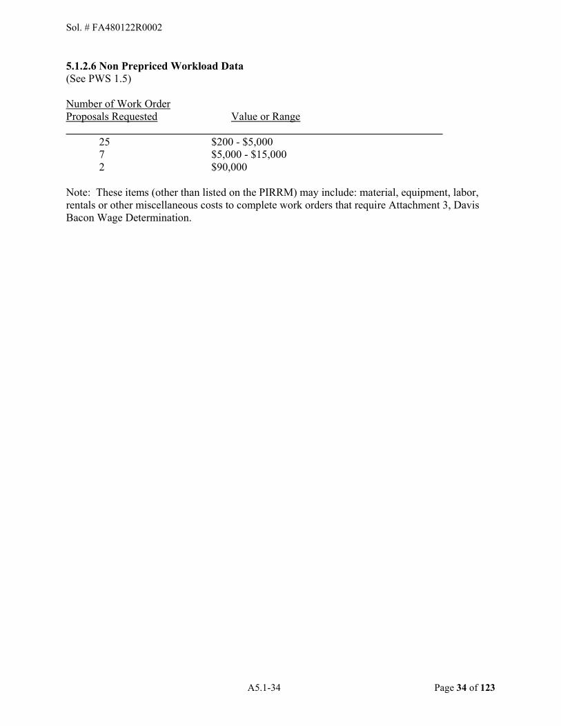
A5.1-34 Page 34 of 123
5.1.2.6 Non Prepriced Workload Data (See PWS 1.5)
Number of Work Order Proposals Requested Value or Range
25 $200 - $5,000 7 $5,000 - $15,000 2 $90,000
Note: These items (other than listed on the PIRRM) may include: material, equipment, labor, rentals or other miscellaneous costs to complete work orders that require Attachment 3, Davis Bacon Wage Determination.
Sol. # FA480122R0002

A5.2-35 Page 35 of 123
APPENDIX 5.2 - ITEMS TO BE MAINTAINED BY THE CONTRACTOR 5.2.1. General. This appendix identifies the items, equipment, material, and facilities to be maintained by Contractor. 5.2.2. Contractor-Furnished Equipment (CFE)/Contractor-Furnished Material. Contractor shall operate, maintain and provide all technical support, to include Tier I, II & III, for these items IAW the requirements specified in this PWS. Contractor is responsible for providing all labor, tools, materials and incidentals necessary for operating, maintaining and providing technical support.
Tier I: BTS Contractor Tier II & Tier III: Sustainment contract (Tyto Athene)
The Contractor will be responsible to contact the sustainment helpdesk and open a trouble ticket IAW the Appendix 5-4. 5.2.2.1 Miscellaneous Equipment. 5.2.2.1.1 Secondary Crash Systems. Secondary Crash Alert, Manufactured by Forum IT in Bldg. 221. Description Qty Control Rack 4 Station Card 5 Power/Modem box 1
5.2.2.1.2 Customer Premise Equipment.
Description Qty. Manufacture Single Line Sets 2373 Various Models/Manufacturers Digital Sets 2557 Various Models/Manufacturers VoIP Sets 2636 Various Models/Manufacturers
Sol. # FA480122R0002
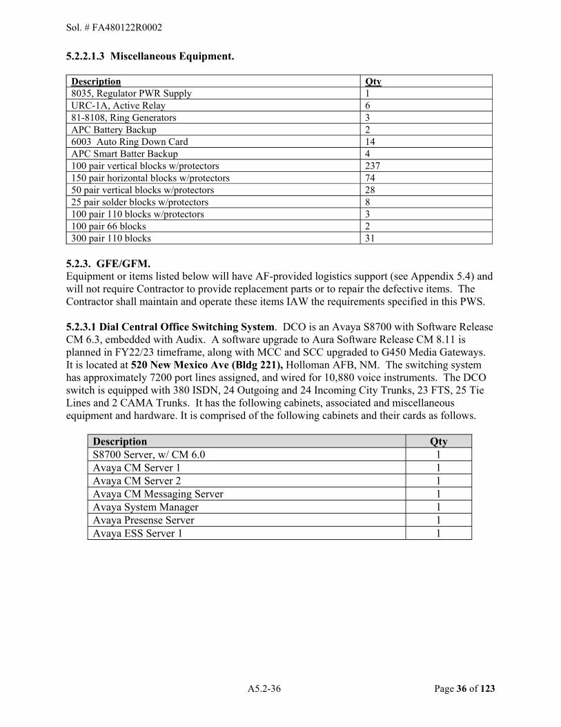
A5.2-36 Page 36 of 123
5.2.2.1.3 Miscellaneous Equipment.
Description Qty 8035, Regulator PWR Supply 1 URC-1A, Active Relay 6 81-8108, Ring Generators 3 APC Battery Backup 2 6003 Auto Ring Down Card 14 APC Smart Batter Backup 4 100 pair vertical blocks w/protectors 237 150 pair horizontal blocks w/protectors 74 50 pair vertical blocks w/protectors 28 25 pair solder blocks w/protectors 8 100 pair 110 blocks w/protectors 3 100 pair 66 blocks 2 300 pair 110 blocks 31
5.2.3. GFE/GFM. Equipment or items listed below will have AF-provided logistics support (see Appendix 5.4) and will not require Contractor to provide replacement parts or to repair the defective items. The Contractor shall maintain and operate these items IAW the requirements specified in this PWS. 5.2.3.1 Dial Central Office Switching System. DCO is an Avaya S8700 with Software Release CM 6.3, embedded with Audix. A software upgrade to Aura Software Release CM 8.11 is planned in FY22/23 timeframe, along with MCC and SCC upgraded to G450 Media Gateways. It is located at 520 New Mexico Ave (Bldg 221), Holloman AFB, NM. The switching system has approximately 7200 port lines assigned, and wired for 10,880 voice instruments. The DCO switch is equipped with 380 ISDN, 24 Outgoing and 24 Incoming City Trunks, 23 FTS, 25 Tie Lines and 2 CAMA Trunks. It has the following cabinets, associated and miscellaneous equipment and hardware. It is comprised of the following cabinets and their cards as follows.
Description Qty S8700 Server, w/ CM 6.0 1 Avaya CM Server 1 1 Avaya CM Server 2 1 Avaya CM Messaging Server 1 Avaya System Manager 1 Avaya Presense Server 1 Avaya ESS Server 1 1
Sol. # FA480122R0002
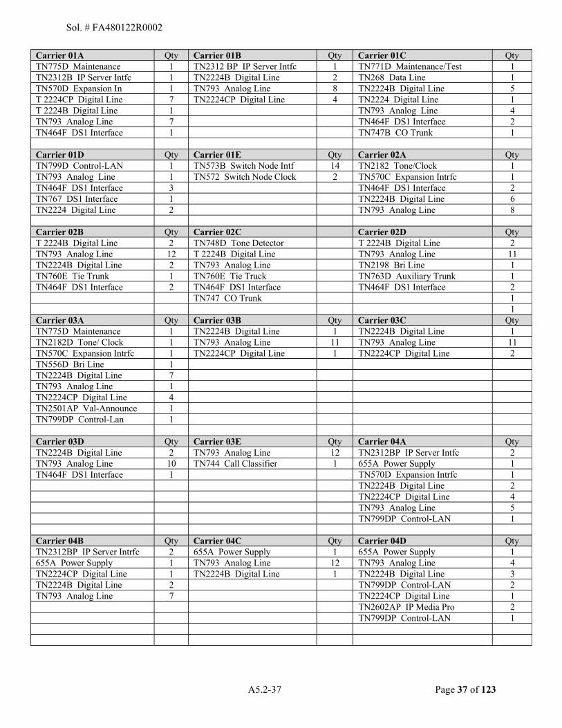
A5.2-37 Page 37 of 123
Carrier 01A Qty Carrier 01B Qty Carrier 01C Qty TN775D Maintenance 1 TN2312 BP IP Server Intfc 1 TN771D Maintenance/Test 1 TN2312B IP Server Intfc 1 TN2224B Digital Line 2 TN268 Data Line 1 TN570D Expansion In 1 TN793 Analog Line 8 TN2224B Digital Line 5 T 2224CP Digital Line 7 TN2224CP Digital Line 4 TN2224 Digital Line 1 T 2224B Digital Line 1 TN793 Analog Line 4 TN793 Analog Line 7 TN464F DS1 Interface 2 TN464F DS1 Interface 1 TN747B CO Trunk 1 Carrier 01D Qty Carrier 01E Qty Carrier 02A Qty TN799D Control-LAN 1 TN573B Switch Node Intf 14 TN2182 Tone/Clock 1 TN793 Analog Line 1 TN572 Switch Node Clock 2 TN570C Expansion Intrfc 1 TN464F DS1 Interface 3 TN464F DS1 Interface 2 TN767 DS1 Interface 1 TN2224B Digital Line 6 TN2224 Digital Line 2 TN793 Analog Line 8
Carrier 02B Qty Carrier 02C Carrier 02D Qty T 2224B Digital Line 2 TN748D Tone Detector T 2224B Digital Line 2 TN793 Analog Line 12 T 2224B Digital Line TN793 Analog Line 11 TN2224B Digital Line 2 TN793 Analog Line TN2198 Bri Line 1 TN760E Tie Trunk 1 TN760E Tie Truck TN763D Auxiliary Trunk 1 TN464F DS1 Interface 2 TN464F DS1 Interface TN464F DS1 Interface 2 TN747 CO Trunk 1 1 Carrier 03A Qty Carrier 03B Qty Carrier 03C Qty TN775D Maintenance 1 TN2224B Digital Line 1 TN2224B Digital Line 1 TN2182D Tone/ Clock 1 TN793 Analog Line 11 TN793 Analog Line 11 TN570C Expansion Intrfc 1 TN2224CP Digital Line 1 TN2224CP Digital Line 2 TN556D Bri Line 1 TN2224B Digital Line 7 TN793 Analog Line 1 TN2224CP Digital Line 4 TN2501AP Val-Announce 1 TN799DP Control-Lan 1 Carrier 03D Qty Carrier 03E Qty Carrier 04A Qty TN2224B Digital Line 2 TN793 Analog Line 12 TN2312BP IP Server Intfc 2 TN793 Analog Line 10 TN744 Call Classifier 1 655A Power Supply 1 TN464F DS1 Interface 1 TN570D Expansion Intrfc 1 TN2224B Digital Line 2 TN2224CP Digital Line 4 TN793 Analog Line 5 TN799DP Control-LAN 1 Carrier 04B Qty Carrier 04C Qty Carrier 04D Qty TN2312BP IP Server Intrfc 2 655A Power Supply 1 655A Power Supply 1 655A Power Supply 1 TN793 Analog Line 12 TN793 Analog Line 4 TN2224CP Digital Line 1 TN2224B Digital Line 1 TN2224B Digital Line 3 TN2224B Digital Line 2 TN799DP Control-LAN 2 TN793 Analog Line 7 TN2224CP Digital Line 1 TN2602AP IP Media Pro 2 TN799DP Control-LAN 1
Sol. # FA480122R0002

A5.2-38 Page 38 of 123
5.2.3.1.1 Power Equipment.
Description P/N Model Qty 9355-30 BATTERY CABINET 103004868 Power ware
SERIAL NUMBERS CABINET 1 BC213KXX05 1 CABINET 2 BC213KXX07 1 CABINET 3 BC213KXX08 1 CABINET 4 BC213KXX06 1
9355-30 POWER SUPPLY
CONFIGURATION: KB2013130000010 SN: BC222KXX09 20
5.2.3.1.2 Peripheral Equipment.
Description Qty AHF110 (Spare) TDM/LAN Bus Terminal 1 AHF111 (Spare) PX terminator 1 CFY1B (Spare) Current Limiter 1 ZAHF4 v2 (Spare) SNI Terminal 1
5.2.3.1.3 Switch Miscellaneous Equipment.
Description Manufacturer Qty Clientpro PC w/tube and keyboard Micron 1 Acculink FTS Paradyne 1 Campus T-1 Pairgain 4 P133G2 Avaya 1
5.2.3.2 West Area Expansion Port Network (EPN), located in Building 878. The West Remote Switching System is located at Building 878, Holloman AFB, NM. It is equipped with an EPN and an Avaya 8700. A software upgrade to Aura Software Release CM 8.11 is planned in FY22/23 timeframe, along with MCC and SCC upgraded to G450 Media Gateways. The Government will provide a single-mode fiber. It has the following cabinets and miscellaneous equipment. This switch is configured as follows:
Carrier 06A Qty Carrier 06B Qty Carrier 06C Qty TN775D Maintenance 1 TN2312BP IP server Infc 1 TN556D Bri Line 1 TN2312BP IP Server Infc 2 TN2224B Digital Line 3 TN771DP Maintenance Test 1 TN570D Expansion Intrfc 1 TN2224CP Digital Line 3 TN793 Analog Line 13 TN2224B Digital Line 4 TN793 Analog Line 13 TN2224B Digital Line 1 TN2223B Digital Line 4 TN2224CP Digital Line 3 TN2224CP Digital Line 3 TN793B Analog Line 2 TN2224CP Digital Line 8 Carrier 06D Qty Carrier 06E Qty TN793B Analog Line 1 TN746B Analog Line 14 TN793 Analog Line 12 TN2224CP Digital Line 2 TN2224B Digital Line 1 TN2198 Bri Line 1 TN2224CP Digital Line 2
Sol. # FA480122R0002

A5.2-39 Page 39 of 123
5.2.3.2.1 Power Equipment.
Description Part Number Model Qty PW9155 EBM-96 Cabinet 103004193-5501 192V 100A EATON POWERWARE 1
Cabinet 1 SN: BC215GAA05 1 Cabinet 2 SN: BC215GAA06 1 Cabinet 3 SN: BC215GAA04 1 Configuration: K4121203S000000 SN: BC223FB10 1
5.2.3.2.2 Miscellaneous Equipment.
Description Part Number Model Qty ESS Server 2 SN:14AN4400010 Avaya 1 300 pair 110 block w/ protectors AT&T 10 300 pair 110 block w/o protectors AT&T 140 200 pair vertical blocks (solder) w/ protectors AT&T 5
5.2.3.3 North Area EPN, located in building 1081. The West Remote Switching System is located at Building 1081 at Holloman AFB, NM. It is equipped with an EPN and an Avaya 8700. A software upgrade to Aura Software Release CM 8.11 is planned in FY22/23 timeframe, along with MCC and SCC upgraded to G450 Media Gateways. The Government will provide a single-mode fiber. It has the following cabinets and miscellaneous equipment. This switch is configured as follows:
Carrier 05A Qty Carrier 05B Qty Carrier 05C Qty TN755D Maintenance 1 TN2312BP IP server Intrfc 2 TN746B Analog Line 8 TN2312BP IP Server Intrfc 2 T 2224B Digital Line 2 TN570D Expansion Intrfc 1 TN746B Analog line 7 TN744D Call Classifier 1 TN793 Analog Line 3 TN2224B Digital Line 5 TN793B Analog Line 1 TN793 Analog Line 1 TN2224CP Digital Line 3 TN747B CO Trunk 2 Carrier 05D Qty TN2198 Bri Line 1 TN746B Analog line 6 TN793B Analog Line 1
5.2.3.3.1 Transport Equipment.
Description Manufacture Qty EC-1E469-30, MAAP AT&T 1 Fiber Connector, 24SM and 8MM 1 J58889AD-1 AT&T 2
Sol. # FA480122R0002
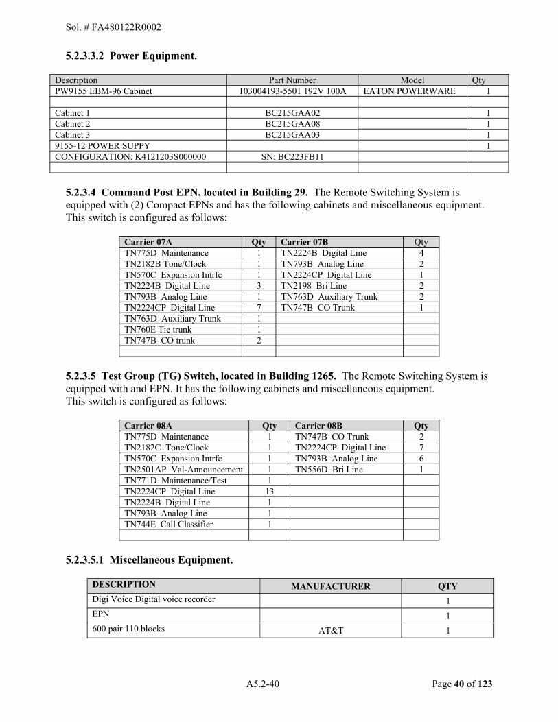
A5.2-40 Page 40 of 123
5.2.3.3.2 Power Equipment.
Description Part Number Model Qty PW9155 EBM-96 Cabinet 103004193-5501 192V 100A EATON POWERWARE 1
Cabinet 1 BC215GAA02 1 Cabinet 2 BC215GAA08 1 Cabinet 3 BC215GAA03 1 9155-12 POWER SUPPY 1 CONFIGURATION: K4121203S000000 SN: BC223FB11
5.2.3.4 Command Post EPN, located in Building 29. The Remote Switching System is equipped with (2) Compact EPNs and has the following cabinets and miscellaneous equipment. This switch is configured as follows:
Carrier 07A Qty Carrier 07B Qty TN775D Maintenance 1 TN2224B Digital Line 4 TN2182B Tone/Clock 1 TN793B Analog Line 2 TN570C Expansion Intrfc 1 TN2224CP Digital Line 1 TN2224B Digital Line 3 TN2198 Bri Line 2 TN793B Analog Line 1 TN763D Auxiliary Trunk 2 TN2224CP Digital Line 7 TN747B CO Trunk 1 TN763D Auxiliary Trunk 1 TN760E Tie trunk 1 TN747B CO trunk 2
5.2.3.5 Test Group (TG) Switch, located in Building 1265. The Remote Switching System is equipped with and EPN. It has the following cabinets and miscellaneous equipment. This switch is configured as follows:
Carrier 08A Qty Carrier 08B Qty TN775D Maintenance 1 TN747B CO Trunk 2 TN2182C Tone/Clock 1 TN2224CP Digital Line 7 TN570C Expansion Intrfc 1 TN793B Analog Line 6 TN2501AP Val-Announcement 1 TN556D Bri Line 1 TN771D Maintenance/Test 1 TN2224CP Digital Line 13 TN2224B Digital Line 1 TN793B Analog Line 1 TN744E Call Classifier 1
5.2.3.5.1 Miscellaneous Equipment.
DESCRIPTION MANUFACTURER QTY Digi Voice Digital voice recorder 1
EPN 1
600 pair 110 blocks AT&T 1
Sol. # FA480122R0002

A5.2-41 Page 41 of 123
5.2.3.5.2 Power Equipment.
Description Model Qty Avaya 200AH Battery cabinet Avaya 1 649A Power supply APC 4
5.2.3.6 Building 525, EPN. This switch is configured as follows:
Carrier 09A Qty TN775C Maintenance 1 TN2182B Tone/Clock 2 TN570C Expansion Intrfc 1 TN2224 Digital Line 3 TN793 Analog Line 1 TN464F DS1 Interface 1 TN2224CP Digital Line 1
5.2.3.7 Building 902, EPN. This switch is configured as follows:
Carrier 10A Qty TN775C Maintenance 1 TN2182B Tone/Clock 2 TN570C Expansion Intrfc 1 TN2224CP Digital Line 6 TN793 Analog Line 1
5.2.3.8 Building 1219, EPN. This switch is configured as follows:
Carrier 11A Qty TN775D Maintenance 1 TN2182B Tone/Clock 2 TN570C Expansion Intrfc 1 TN2224B Digital Line 1 TN2224CP Digital Line 3 TN793 Analog Line 1
5.2.3.9 Building 1053, EPN. This switch is configured as follows:
Carrier 12A Qty TN775C Maintenance 1 TN2182B Tone/Clock 2 TN570C Expansion Intrfc 1 TN2224B Digital Line 1 TN793 Analog Line 1
Sol. # FA480122R0002

A5.2-42 Page 42 of 123
5.2.3.10 Building 513, EPN. This switch is configured as follows:
Carrier 13A Qty TN775D Maintenance 1 TN2182B Tone/Clock 2 TN570C Expansion Intrfc 1 TN2224B Digital Line 3 TN793 Analog Line 1
5.2.3.11 LAN Support. Holloman AFB has approximately 10,000 LAN connections, base-wide. These connections are on computers, printers, routers, etc., and require testing and repair. 5.2.3.12 Network Switch Uninterrupted Power Supply (UPS). Holloman AFB has approximately 567 network switches base wide. Attached to each network switch is an UPS device. A preventative maintenance inspection is required on all 49 CS installed UPS devices and report any discrepancies of UPS devices to the 49 CS for 49 CS to perform further troubleshooting and/or replacement. 5.2.4 Cable Plant. The cable plant encompasses equipment and facilities such as twisted pair cable, fiber optic cable, ducts, raceways, cable vaults, manholes, handholes, pull boxes, splice and pedestal enclosures, distribution terminals and blocks, load coils, lightning protectors, building entrance cable, and house cable for the main base and billeting. The following subparagraphs are the Government�s best estimate of the existing cable plant.
5.2.4.1 Distribution System. The distribution system supports both analog and digital circuits (voice and data), VoIP, subscriber loops, off-premise extensions, tie lines, T-1 carriers, LANs, local and long-distance network trunks and dedicated data or non-switched circuits.
5.2.4.2 Manholes. The site(s) contain approximately 400 manholes/hand-holes and pull-boxes of various conduit capacity. The following is the Government�s best estimate of the existing base distribution system:
A. Premise Cable Plant. Holloman AFB has approximately 875 facilities with Premise Cable Plant. The average of inside wiring from building entrance to customer location within each building is 300 feet. Approximately 1% of base cable is Aerial, remaining cable is underground/direct buried.
Sol. # FA480122R0002
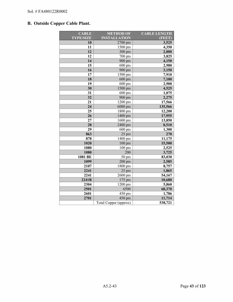
A5.2-43 Page 43 of 123
B. Outside Copper Cable Plant.
CABLE TYPE/SIZE
METHOD OF INSTALLATION
CABLE LENGTH (FEET)
10 2700 prs 3,525 11 1500 prs 4,350 12 300 prs 2,000 12 700 prs 3,825 14 900 prs 4,150 15 600 prs 2,980 16 900 prs 3,150 17 1500 prs 7,910 18 600 prs 7,100 19 600 prs 2,900 30 1500 prs 4,525 31 600 prs 1,075 32 900 prs 2,275 21 1200 prs 17,566 24 6000 prs 135,566 25 1800 prs 12,200 26 1400 prs 17,955 27 1600 prs 13,850 28 2400 prs 8,510 29 600 prs 1,300
863 25 prs 270 878 1400 prs 11,175
1020 100 prs 15,500 1080 100 prs 2,525 1080 200 3,725
1081 BE 50 prs 83,030 1099 200 prs 2,585 2107 1800 prs 8,757 2241 25 prs 1,865 2241 2600 prs 54,167
2241B 175 prs 10,680 2304 1200 prs 5,860 2501 6500 68,370 2601 450 prs 1,786 2701 450 prs 11,714
Total Copper (approx) 538,721
Sol. # FA480122R0002
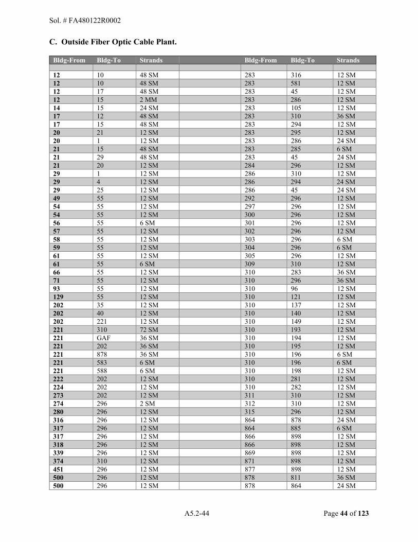
A5.2-44 Page 44 of 123
C. Outside Fiber Optic Cable Plant.
Bldg-From Bldg-To Strands Bldg-From Bldg-To Strands
12 10 48 SM
283 316 12 SM 12 10 48 SM
283 581 12 SM
12 17 48 SM
283 45 12 SM 12 15 2 MM
283 286 12 SM
14 15 24 SM
283 105 12 SM 17 12 48 SM
283 310 36 SM
17 15 48 SM
283 294 12 SM 20 21 12 SM
283 295 12 SM
20 1 12 SM
283 286 24 SM 21 15 48 SM
283 285 6 SM
21 29 48 SM
283 45 24 SM 21 20 12 SM
284 296 12 SM
29 1 12 SM
286 310 12 SM 29 4 12 SM
286 294 24 SM
29 25 12 SM
286 45 24 SM 49 55 12 SM 292 296 12 SM 54 55 12 SM
297 296 12 SM
54 55 12 SM
300 296 12 SM 56 55 6 SM
301 296 12 SM
57 55 12 SM
302 296 12 SM 58 55 12 SM
303 296 6 SM
59 55 12 SM
304 296 6 SM 61 55 12 SM
305 296 12 SM
61 55 6 SM
309 310 12 SM 66 55 12 SM
310 283 36 SM
71 55 12 SM
310 296 36 SM 93 55 12 SM
310 96 12 SM
129 55 12 SM
310 121 12 SM 202 35 12 SM
310 137 12 SM
202 40 12 SM
310 140 12 SM 202 221 12 SM
310 149 12 SM
221 310 72 SM
310 193 12 SM 221 GAF 36 SM
310 194 12 SM
221 202 36 SM 310 195 12 SM 221 878 36 SM
310 196 6 SM
221 583 6 SM 310 196 6 SM 221 588 6 SM
310 198 12 SM
222 202 12 SM
310 281 12 SM 224 202 12 SM
310 282 12 SM
273 202 12 SM
311 310 12 SM 274 296 2 SM
312 310 12 SM
280 296 12 SM
315 296 12 SM 316 296 12 SM
864 878 24 SM
317 296 12 SM
864 885 6 SM 317 296 12 SM
866 898 12 SM
318 296 12 SM
866 898 12 SM 339 296 12 SM
869 898 12 SM
374 310 12 SM
871 898 12 SM 451 296 12 SM
877 898 12 SM
500 296 12 SM
878 811 36 SM 500 296 12 SM
878 864 24 SM
Sol. # FA480122R0002

A5.2-45 Page 45 of 123
Bldg-From Bldg-To Strands Bldg-From Bldg-To Strands 508 296 12 SM
878 898 24 SM
513 296 12 SM
878 221 24 SM 520 296 12 SM
878 913 12 SM
523 296 12 SM
883 898 12 SM 572 296 12 SM
883 898 12 SM
576 296 12 SM
887 811 12 SM 577 296 12 SM
888 898 12 SM
578 296 12 SM
892 898 12 SM 582 583 2 SM
894 898 12 SM
583 221 6 SM
895 864 6 SM 583 582 2 SM
901 811 12 SM
588 221 6 SM
902 811 6 SM 642 296 6 SM
903 811 12 SM
644 296 6 SM
906 811 12 SM 700 310 12 SM
908 811 12 SM
701 310 12 SM
910 878 6 SM 702 310 12 SM
910 913 6 SM
704 310 12 SM
913 878 8 SM 800 811 12 SM
913 910 6 SM
806 811 12 SM 913 914 12 SM 809 811 12 SM
914 913 12 SM
816 811 12 SM
917 811 12 SM 820 811 12 SM
918 811 12 SM
823 811 12 SM
927 811 12 SM 824 811 12 SM
933 811 12 SM
825 811 6 SM
939 811 12 SM 830 811 12 SM
953 811 6 SM
839 811 12 SM
1081 1086 24 SM 847 811 12 SM
1081 1098 12 SM
850 811 12 SM
1081 1099 12 SM 851 811 12 SM
1097 1099 6 SM
854 811 12 SM
1098 1081 12 SM 855 811 6 SM
1099 1097 6 SM
1099 1081 12 SM
11649 811 12 SM 1211 1219 12 SM
21808 898 12 SM
1218 1086 12 SM
21810 898 12 SM 1219 1086 24 SM
21812 898 12 SM
1219 1211 12 SM 21813 898 12 SM 1222 1086 12 SM
21814 898 12 SM
1226 1086 12 SM 21815 898 12 SM 1235 1086 12 SM
21817 898 12 SM
1239 1086 12 SM
21818 898 12 SM 1278 1086 12 SM
21819 898 12 SM
1290 2086 12 SM
21819 898 12 SM 302 GDT 72 SM
55 35 24 SM
1080 GDT 72 SM
202 520 24 SM 811 937 6 SM
202 878 24 SM
55 49 12 SM
221 45 24 SM 55 54 12 MM
296 898 12 SM
55 56 12 MM
1080 1098 24 SM 55 58 12 MM
898 296 24 SM
55 59 12 MM
1080 1098 24 SM 55 66 MM
1080 1262 24 SM
55 71 12 MM
Sol. # FA480122R0002

A5.2-46 Page 46 of 123
Bldg-From Bldg-To Strands Bldg-From Bldg-To Strands 55 93 12 MM
29 55 36 SM
15 22 12 SM
29 296 36 SM 29 35 12 SM
55 310 36 SM
29 SHCC 12 SM
202 29 36 SM 55 80 12 SM
202 296 36 SM
202 5 12 SM
202 525 36 SM 202 15 12 SM
202 784 36 SM
202 55 12 SM
202 788 36 SM 202 115 12 SM
202 1080 36 SM
202 231 12 SM
221 318 36 SM 202 232 12 SM
296 898 36 SM
202 234 12 SM
310 642 36 SM 202 270 12 SM
310 1265 36 SM
202 274 12 SM
202 29 72 SM 202 325 12 SM
202 35 72 SM
202 468 12 SM
202 1080 72 SM 202 598 12 SM
202 1265 72 SM
202 790 12 SM
221 29 72 SM 221 227 12 SM
221 583 72 SM
296 336 12 SM 221 588 72 SM 310 301 12 SM
296 898 72 SM
310 303 12 SM
811 878 72 SM 310 304 12 SM
878 1080 72 SM
310 375 12 SM
1265 La Luz Gate 72 SM 811 812 12 SM
202 302 144 SM
811 817 12 SM
202 1080 144 SM 811 868 12 SM
202 1265 144 SM
864 1091 12 SM
221 202 144 SM 878 818 12 SM
294 MH 75 96 SM
898 893 12 SM
MH 75 MH 72 48 SM 45 221 24 SM MH 72 105 24 SM 45 MH 73 144 SM MH 72 286 24 SM MH 73 105 12 MH 75 MH 79 24 SM MH 73 MH72-1A 48 SM MH 79 316 24 SM MH 72-1A 310 6 SM MH 79 581 24 SM
MH 72-1A 286 24 SM MH 72-1A 283 6 SM
21295 283 6 SM 283 21296 6 SM 283 21297 6 SM MH 73 MH 75 96 SM MH 75 294 48 SM MH 75 295 6 SM MH 75 MH 79 24 SM MH 79 315 12 SM MH 79 581 12 SM
TOTAL FIBER (approximate) 515,291 ft
Sol. # FA480122R0002

A5.2-47 Page 47 of 123
5.2.5 Main Distribution Frame (MDF). The MDF shall include terminal blocks on the horizontal side of the frame, all gray wiring between the horizontal blocks and the switches, central office connectors (vertical block) including the protector modules installed on the vertical side of the frame, all cross-connect wiring between the horizontal blocks and the switch, horizontal block to horizontal block, horizontal block to vertical block and vertical block to vertical block and all fiber optic equipment including the light guide distribution shelf, patch panel and associated equipment.
Sol. # FA480122R0002

A5.3-48 Page 48 of 123
APPENDIX 5.3 - GLOSSARY AND ACRONYMS
5.3.1. Purpose. Definitions and terms in this appendix provide additional guidance of interpreting this PWS.
5.3.2. Definitions.
Access. The ability to enter or gain admittance to a facility; and/or the connection to a communications channel path or its equipment. Activation. The efforts to bring into service a channel, equipment, or circuit (other than those associated with work orders) to replace a defective channel. Also includes software data administration of features and lines associated with in-service and operational switching systems and key systems. Ancillary Equipment. Equipment, supplementary or auxiliary to a telephone system or instrument, which includes such components as speakerphones, line busy indicators, buzzers, headsets, jacks, terminals, voice processing systems, accounting systems, conferencing systems, printers, maintenance and administration terminals, etc. Base Telecommunication System (BTS). A system to provide total telephone service, which may include the telephone switch, remote switching equipment, ISP/OSP and equipment, reserve power equipment, network, and other necessary ancillary equipment. Base Telecommunication System (BTS) Manager. The individual designated to manage the base telecommunication system. This individual shall have full authority to act for the AF on all matters related to O&M and properly executed work orders. This does not include the authority to commit the Contractor to any contractual modifications. Budgetary Estimate/Rough Order of Magnitude (ROM). These are non-binding estimates provided on a quick turn-around basis. A budgetary estimate or ROM should not require the Contractor to perform a large or complex technical solution. These should easily be turned around within the days specified within 1.3.13 of this PWS; and should be for work projected to be accomplished by this Contractor.
Cable Maintenance. Includes random testing, swapping pairs, tagging, identifying, pair/strand testing and repairing and ensuring splice case enclosure integrity (when visible to inspect). When the Communications and Information Systems Officer (CSO), in conjunction with the CO, determines that an excessive number of pairs are defective, the CSO may direct under O&M that repairs be undertaken. Replacement of an entire cable under O&M is not expected, only repairs of splices, bad cross-connections, etc.
Central Office. The base telephone exchange, AF Network Control Center, or other Government node installation that provides centralized communications services and facilities. These installations provide connectivity between customer premise workstations and on/off-base network equipment. Also called Dial Central Office.
Sol. # FA480122R0002

A5.3-49 Page 49 of 123
Channel. A circuit path. Several channels may share a common transmission system.
Circuit. A means of two-way communications between two (2) points.
Circuit Availability. The percent of time a circuit was operational or up during a specified period of time. Circuit Availability = (Uptime (Downtime + Uptime)) X 100.
CIPS Visualization Component (CVC) � A GIS appliance in the CIPS toolset providing a computerized graphical interface joining the communications and information systems infrastructure (both existing and planned) graphics with the GeoBase Common Installation Picture (CIP) at the base level. Communication features, such as manholes, paths of duct banks and direct buried cable, are shown in a geospatially precise relationship to roads, buildings, airfields, base perimeters, aerial photography, and other installation infrastructure features. CVC is an AF Enterprise application providing real-time situational awareness and analytical tools not available with the Legacy CSIRs and other static drawings and diagrams. To be of optimal functional use at an installation, CVC requires transformation of engineering data contained in the Legacy CSIR drawings into the CIPS database and, outside plant features are required to be precisely located using GPS or land surveying technologies.
Communications Feature Data (CFD). Data containing descriptive information about communication features collected for the purpose of importing or transferring the information into the CVC database. CFD can include information about any feature in the communications and information systems inside and outside plant infrastructure recorded in the CVC. Information collected during PMI and GPS Services is a part of CFD. Communications and Information Systems Installation Records (CSIR). Collection of records, including the CVC database, associated with the installation of a communications and information system in a facility, building, or location. CSIR is an AF communications community term originally used to refer to the official communications and information systems installation master record (Legacy CSIRs) drawings developed and maintained, at the communications Engineering Data Service Center (EDSC) using CADD software formats. Developing and maintaining CSIR using CADD processes is being phased out. The CVC is the standard AF application for developing and maintaining CSIR IAW with AFI 33-150.
Communications and Information Systems Officer (CSO). For the purpose of this contract activity, references to the CSO shall mean the Contractor shall coordinate primarily with the CSO�s designated representative, Quality Assurance Personnel (COR).
Communication Room. Any space which houses telecommunications switching equipment, transmission equipment or terminal connection blocks.
Communications System. An overall term used to describe communications facilities including associated equipment and transmission media.
Contract Administrator (CA). The person working within a contracting office that administers or manages the official contract file or portions delegated thereof. This person may also be a CO.
Sol. # FA480122R0002
A5.3-50 Page 50 of 123
Contracting Officer (CO). The only person authorized to obligate the Government to a course of action and is responsible for all contractual aspects of the contract.
Contractor Furnished Equipment (CFE)/Contractor Furnished Material (CFM). Contractor assets furnished by the Contractor to perform a Government function. Cross-Connects. Wire or electrical connections at distribution system equipment interface points to establish an overall end-to-end service between facility segments. A cross-connect may physically or electronically interconnect channels. Cross-connect efforts shall include testing and records updating. Customer Premise Equipment (CPE). CPE consists of those items at or near the customer workstation area to conduct electronic communications. CPE includes telephone instruments, key systems, alarm systems, paging systems, and terminal equipment (This does not include Automatic Data Processing Equipment).
Cyberspace. A domain characterized by the use of electronics and the electromagnetic spectrum to store, modify and exchange data via networked systems and associated physical infrastructure.
Cyberspace Infrastructure Planning System (CIPS). The web-based AF enterprise toolset used to develop, analyze, update, justify and disseminate cyberspace infrastructure plans. This system is used to effectively maintain and modernize the AF�s cyberspace infrastructure. CIPS serves as a multifaceted system that performs cyberspace configuration management, architectural development, infrastructure planning, and technology insertion analysis and implementation management. Also, CIPS contains a toolset called the CIPS Visualization Component (CVC) that modernizes the processes for maintaining data historically recorded in the CSIR. CIPS supports the AF mission at the following levels: base cyberspace infrastructure operations, maintenance and planning; MAJCOM architecture and funding. CIPS is the current format used by AETC to process NEW (moves, add or changes) communications service requests. This system is not for outages (trouble tickets). Funding is required.
Data Administration (System Administration). O&M effort required to add, remove, change, update or query system data. Defined as follows:
Customer Data Modification (CDM). Modification of directory numbers, classes of service, features, VPS, etc. Office Data Modification (ODM). Modification of trunk group numbers, trunk type, service circuit type, digital and route translations, message routes, thresholds, test tables, network management control variables, etc. Translation. Call routing process controlled by dialed digits and converted into a destination termination.
Data Dictionary. A collection of descriptions for features or items in a data model for the benefit of programmers, data collectors and other users who need to refer to them. Features with which users interact and the relationship between features are identified. Each feature or item is given a descriptive name, its relationship is described, the type of data (such as text or image or
Sol. # FA480122R0002

A5.3-51 Page 51 of 123
binary value) is described, possible predefined values are listed, and a brief textual description is provided. Data dictionaries are consulted to understand where feature or item data fits in the data model structure, what values it may contain and basically what the data means in real-world terms. Table A of Appendix 5.7 is an example of a data dictionary. Deactivate. All O&M service actions and efforts necessary to discontinue the end-to-end service and connectivity, �turn-off� service equipment and update data/system administration records. Includes all labor, tools, and miscellaneous materials necessary to accomplish the deactivation. Deactivating a service or equipment implies the equipment will remain in place to be reactivated at some future time with different characteristics. In the case of removal actions return CPE to the COR and clear all cross-connects from patch panels and terminals. Reactivate actions �turn-on� equipment that was �deactivated.�
Dial Central Office (DCO). The telephone exchange on a Government installation. These switching systems consist of Government-owned telephone switches (typically Nortel, Avaya, Lucent, and Siemens) of various line and trunk sizes and configurations. Some of these switches function as end offices or small end offices and are capable of sophisticated routing and trunking. Directory Assistance Information. Provides the person�s address as well as Defense Switched Network (DSN) phone number.
Equipment and Installation Performance Specification (EIPS). Establishes the technical requirements for BTS system equipment.
Fault Detection. Perform diagnostics, initiate alarms and report faults. Includes test equipment necessary to measure or obtain circuit operating parameters and accomplish end-to-end testing of a channel. Test applications include ISDN, DS1, DS3, OC-1, 10 Mbps Ethernet, etc. Operating conditions include attenuation levels and bit error rates. Circuit types range from low bandwidth applications (e.g., voice grade, DS1, etc.) to high bandwidth applications (e.g., OC-3, multi-mega bit packet data streams, etc.). Fault Notification. Alert maintenance personnel by audible, visual, or print output message.
Fault Verification. Distinguish between failures and errors. Verify no-trouble-found (NTF) problems. (NTF indicates the identified fault occurs intermittently).
Fault Location. Troubleshoot the fault area and take repair action.
Fault Repair. Replace defective parts and/or make corrective adjustments.
Geospatial Data. Also known as spatial data or geographic information is the data or information that identifies the geographic location of features and boundaries on earth, such as natural or constructed features, oceans, and more. Geospatial data is usually stored as coordinates, attributes and topology, and is data that can be mapped. Geospatial data is often accessed, manipulated or analyzed through GIS. Geographic Information System (GIS). An electronic system of software and hardware that provides a graphical user interface for the display of cartographic drawings and attribute data for
Sol. # FA480122R0002

A5.3-52 Page 52 of 123
the graphical features in the drawing, generally containing longitude and latitude data for each feature. CVC is a GIS.
Global Positioning System. A network of earth orbital satellites and ground based stations that provide precision longitude and latitude data to ground based receivers.
Government Furnished Equipment (GFE)/Government Furnished Material (GFM). Government assets furnished to a Contractor to perform a Government function.
IT/NSS. IT is the term "Information Technology" as defined in OMB Circular A-130, Management of Federal Information Resources. NSS is the term "National Security System" as defined in the Clinger-Cohen Act, Sec. 5142.
Inside Plant (ISP). Equipment associated with a DCO or communication room, which contains electronic equipment, a distribution frame, cable rack and power system.
Inside Wiring. That part of the OSP within buildings that includes house cable (horizontal cable and riser cable, also called backbone cable), station wiring, and horizontal distribution wiring for local area networks up to and including the telecommunications outlet, cross-connections, and mechanical terminations in the telecommunications closet. Functionally, it is the distribution cable within the confines of a single building or group of related buildings excluding the entrance cable to the building main terminal. Inside wiring is also known as building cabling/wiring or structured wiring or premise wiring. Isolation. The action required to locate a failure within a system using test equipment.
Local Area Network (LAN). A telecommunications system designed to provide data, voice, imagery, video, graphics and other forms of electronic communications.
Locate and Mark. Determine the underground route of cable and conduit facilities and identify the route of these facilities by means of paint, flags, stakes, etc.
Main Distribution Frame (MDF). A distribution frame which terminates the permanent outside lines entering the telephone switching system and also terminates the telephone switching equipment.
Normal Duty Hours. The hours the Contractor�s key personnel are required to be on-site. The normal hours of operation are Monday through Friday, between 07:30 am � 4:30 pm. This excludes holidays specified within the applicable Service Contract Wage Determination.
On-Call Duty. A technician is not required to be physically present in the work center. However, personnel performing on-call duty must have a means of being contacted (telephone, beeper, etc.) so they can respond to designated outages within a specified time limit.
Operations and Maintenance (O&M). All actions taken (IAW applicable publications) to maintain equipment in a serviceable condition or to restore it to a serviceable condition to include inspection, periodic testing, adjustment, repair, rebuilding, and reclamation. The effort includes the replacement of defective circuit packs (e.g., line and trunk cards, common control cards, data
Sol. # FA480122R0002
A5.3-53 Page 53 of 123
interface cards, etc.) and CPE. O&M does not include repair of building inside structure cable, but does include troubleshooting and fault isolation. BISC items will be repaired by replacement via appropriate contract line items. O&M includes, but is not limited to:
Activation Cable Maintenance Cross-connects Fiber Patching Ethernet Patching Data Administration Deactivate Fault Detection Fault Notification Fault Verification Fault Location Fault Repair Reactivation Service Verification
Operational Records. Include warranty records, service orders, Communication-Computer Systems Installation Records, Scheduled Service Interruption Records, Service Order Records, Telecommunications Management System Records, Call Accounting System Records, Quality Control Records, Switching System Records, Inside and Outside Cable Plant Records, Ancillary and Premise Equipment Records, Cable Pair Assignment Records, etc.
Outside Plant (OSP). The OSP is a base-level information transfer network, which includes the transmission media (e.g., twisted pair, fiber optics, etc.) and associated hardware (e.g., distribution frames, multiplexer, modem and repeater). OSP cable demarcations at the vertical side of the DCO distribution frame/patch panels and extends to the building entrance terminal. Inside Wire continues from the building terminal to the horizontal wire modular jack. Manhole and duct system and other supporting structure are part of the OSP, but may be treated differently for maintenance because of real property rules. The following outside cable segment types are used to determine the area of the cable distribution:
Feeder Distribution Cable - cable for a service zone area Branch Distribution Cable - cable branching from a feeder cable to serve a
building(s) Taper Point - cable transition from a larger count to a smaller count Distribution Cable - (building entrance terminal cable) cable to a building
entrance terminal block Service Cable - 4/6-wire cable to a single user (not premise wiring) Trunk Cable - cable connecting two (2) DCOs
Premise Wire. See Inside Wiring.
Preventive Maintenance. The periodic inspection, cleaning, adjusting and repairing to prevent problems before they affect service.
Sol. # FA480122R0002
A5.3-54 Page 54 of 123
Product Identification (PID). A unique term used in the PIRRM pricing schedule to identify products and services ordered.
Quality Control Records. Records to include all inspections of services and necessary corrective actions taken IAW Contractor�s Quality Control Plan.
Reactivate. All O&M services actions and efforts necessary to restore the end-to-end service and connectivity, �turn-on� service equipment and update data/system administration records. Includes all labor, tools, and miscellaneous materials necessary to accomplish the restoration. Reactivating a service or equipment implies the equipment and facilities are in place. Effort includes assignment of characteristics. Reliability. The probability an electronic item will perform its intended function for a specified interval under stated conditions.
Relocate. Includes all labor, tools, and miscellaneous materials necessary to deactivate a service, move equipment to another location, and reactivate equipment or hardware at the new location. The relocation of active equipment involves removal of cross-connects from the old circuit path and installing cross-connects for the new circuit path. This effort includes the data/system administration actions necessary to complete the relocation.
Removal. Includes all labor, tools, and miscellaneous materials necessary to deactivate services, clear associated cross-connect from frames and terminals, remove, return, and dispose of equipment and/or hardware and material as determined by the COR. Response Time. The time between notification and arrival at the location of a fault or degradation.
Restoration Priority List (RPL). A list of systems, equipment, or circuits, and their restoration criteria established by the COR. The Government will provide a new RPL as changes occur. Scheduled Maintenance Outage. A break in service availability scheduled to permit maintenance.
Service Verification. Verify fault is cleared, assure service is restored and initiate completion paperwork.
Shape File. A GIS file format developed by Environmental Systems Research Institute.
System Administration (Data administration). See Data Administration.
Technical Solution. These are solutions provided by the Contractor for the express purpose of implementation under this contract. They usually require more than a short walk-through and use existing contract CLINs/SLINs/PIDs in the standard work order format. Government shall retain the right to approve the proposed solution or recommend changes where necessary.
Sol. # FA480122R0002

A5.3-55 Page 55 of 123
Transmission Equipment. Equipment that sends or receives information signals. Includes multiplexers, T-1 spans, channel banks, microwave equipment, repeaters, data terminal equipment, modems, channel service units, data service units, etc.
Trouble Tickets (Remedy). The current system (vESD on PC desktop) used to report an outage on an existing service. For example, if your phone was working yesterday and today it�s not, then you need to call 49 CS/Helpdesk at 572-3000 option 4. The CIPS system is not used. Cost is covered under monthly maintenance.
Trunk. A communications channel between two (2) switching system facilities.
Voice over Internet Protocol (VoIP). The VoIP phone is connected directly to the LAN. Installation and activation requires an Ethernet port with power provided by a LAN Ethernet switch. Some phones (i.e., I2004) have a power supply transformer when LAN switch power is not available. Voice Protection System (VPS). A patented (registered) Enterprise Telephony Management System (ETM) manufactured by SecureLogix (registered) Corporation with a trademark, We See Your Voice. This system is installed in a serial manner on voice trunks to monitor calls to identify modem, secure voice and related call activity to determine if consistent with security policy for that telephone line. VPS configuration is centrally managed and controlled.
Work Area. The area provided by the base or Contractor for employees to perform assigned work as required for Contractor operations.
5.3.3. Acronyms. A
AF Air Force AFB Air Force Base AFFARS Air Force Federal Acquisition Regulation Supplement AFI Air Force Instruction AFOSH Air Force Occupational Safety and Health ALC Air Logistics Center
B BTS Base Telecommunications System
C CA Contract Administrator CADD Computer Aided Drafting and Design CAIRS Cable Assignment Information Retrieval System CAS Call Accounting System CCS Centi Call Seconds CCWO Commercial Communications Work Order CDM Customer Data Modification CDR Contract Discrepancy Report
Sol. # FA480122R0002

A5.3-56 Page 56 of 123
CFE Contractor Furnished Equipment CFD Communication Feature Data CFM Contractor Furnished Material CFR Code of Federal Regulations CIPS Cyberspace Infrastructure Planning System CITS Combat Information Transport System CLIN Contract Line Item Number CLS Contractor Logistic Support CO Contracting Officer COR Contracting Officer's Representative CPE Customer Premise Equipment CSIR Communications and Information Systems Installation Records CSO Communications Systems Officer or Designee CVC CIPS Visualization Component
D DCO Dial Central Office DoD Department of Defense DSN STIG Defense Switched Network Security Technical Implementation
Guide E
EDSC Engineering Data Service Center EMS Environmental Management Systems ENSC Enterprise Network Support Center EOC Emergency Operations Center EPA Environmental Protection Agency EIPS Equipment and Installation Performance Specification
F FAR Federal Acquisition Regulation FGDC Federal Geographic Data Committee FOIA Freedom of Information Act FOUO For Official Use Only FTS Federal Telecommunications System
G GFE Government Furnished Equipment GFM Government Furnished Material GFP Government Furnished Property GOS Grade of Service GPS Global Positioning System
I IAW In Accordance With IP Internet Protocol
Sol. # FA480122R0002

A5.3-57 Page 57 of 123
ISDN Integrated Services Digital Network ISP Inside Plant ITN Internet Transport Node IT/NSS Information Technology/National Security System
L LAN Local Area Network LFC Local Files Check LMR Land Mobile Radio
M MAJCOM Major Command MDC Maintenance Data Collection MDF Main Distribution Frame MRA Material Return Authorization MSDS Material Safety Data Sheets MSP Maintenance Support Plan
NNCC Network Control Center NOSC Network Operations Center NTE Not-to-Exceed
O ODM Office Data Modification O&M Operations and Maintenance OEM Original Equipment Manufacturer OSHA Occupational Safety and Health Administration OSP Outside Plant
P PID Product Identification PEC Product Engineering Code PABX Private Automatic Branch Exchange PMI Preventive Maintenance Inspection PWS Performance Work Statement
Q QCP Quality Control Plan
RRNOSC Remote Network Operations Security Center ROM Rough Order of Magnitude RPL Restoration Priority List
Sol. # FA480122R0002
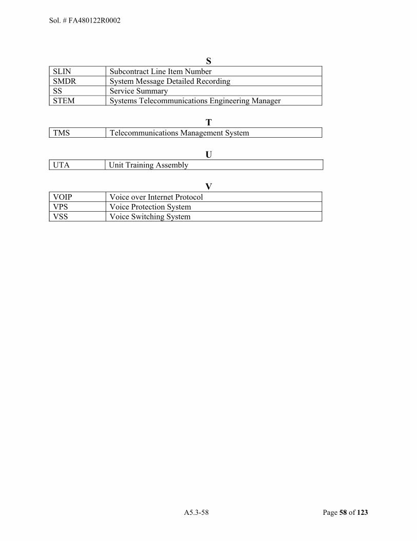
A5.3-58 Page 58 of 123
SSLIN Subcontract Line Item Number SMDR System Message Detailed Recording SS Service Summary STEM Systems Telecommunications Engineering Manager
T TMS Telecommunications Management System
U UTA Unit Training Assembly
VVOIP Voice over Internet Protocol VPS Voice Protection System VSS Voice Switching System
Sol. # FA480122R0002
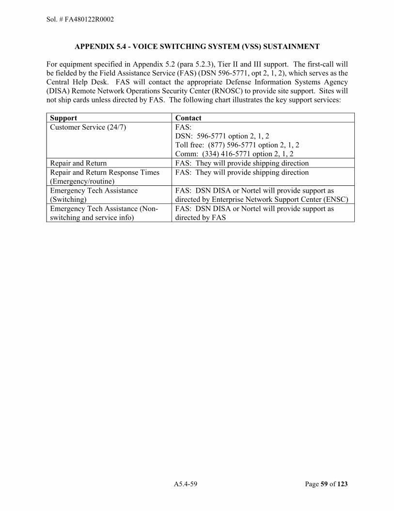
A5.4-59 Page 59 of 123
APPENDIX 5.4 - VOICE SWITCHING SYSTEM (VSS) SUSTAINMENT
For equipment specified in Appendix 5.2 (para 5.2.3), Tier II and III support. The first-call will be fielded by the Field Assistance Service (FAS) (DSN 596-5771, opt 2, 1, 2), which serves as the Central Help Desk. FAS will contact the appropriate Defense Information Systems Agency (DISA) Remote Network Operations Security Center (RNOSC) to provide site support. Sites will not ship cards unless directed by FAS. The following chart illustrates the key support services: Support Contact Customer Service (24/7) FAS:
DSN: 596-5771 option 2, 1, 2 Toll free: (877) 596-5771 option 2, 1, 2 Comm: (334) 416-5771 option 2, 1, 2
Repair and Return FAS: They will provide shipping direction Repair and Return Response Times (Emergency/routine)
FAS: They will provide shipping direction
Emergency Tech Assistance (Switching)
FAS: DSN DISA or Nortel will provide support as directed by Enterprise Network Support Center (ENSC)
Emergency Tech Assistance (Non-switching and service info)
FAS: DSN DISA or Nortel will provide support as directed by FAS
Sol. # FA480122R0002

A5.5-60 Page 60 of 123
APPENDIX 5.5 - APPLICABLE DOCUMENTS
5.5.1. Government Documents.
DOCUMENT DATE TITLE DOD Telecommunications
DISA Field Security Operations Developed by DISA for the DoD
DODM 8570.01 19 Dec 05, Incorporating Change 4 dated 10 Nov 15
Information Assurance Workforce Improvement Program
Copies of the above DoDI and DODM documents may be obtained from https://www.esd.whs.mil/DD/DoD-Issuances/.
5.5.2. Air Force Instructions (AFIs) / AF Manuals (AFMAN).
DOCUMENT DATE TITLE
AFM 16-1405 01 Aug 2018 Personnel Security Program Management
AFI 33-360 21 Oct 2020 Publications and Forms Management (Table 1.1 IAW AFMAN 33-363)
AFI 63-138 30 Sep 2019 Acquisition of Services
AFMAN 93-203 08 Sep 2020 Air Force Occupational Safety, Fire and Health Standards
AFI 16-1404 23 Nov 2020 Information Security Program
Copies of AFIs & AFMANs can be obtained at: www.e-publishing.af.mil.
Sol. # FA480122R0002
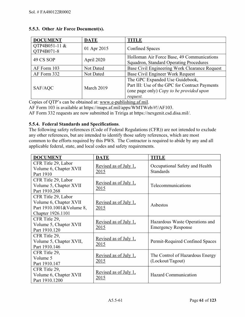
A5.5-61 Page 61 of 123
5.5.3. Other Air Force Document(s).
DOCUMENT DATE TITLE QTP4B051-11 & QTP4B071-8
01 Apr 2015 Confined Spaces
49 CS SOP April 2020 Holloman Air Force Base, 49 Communications Squadron, Standard Operating Procedures
AF Form 103 Not Dated Base Civil Engineering Work Clearance Request AF Form 332 Not Dated Base Civil Engineer Work Request
SAF/AQC March 2019
The GPC Expanded Use Guidebook, Part III: Use of the GPC for Contract Payments (one page only) Copy to be provided upon request.
Copies of QTP�s can be obtained at: www.e-publishing.af.mil. AF Form 103 is available at https://maps.af.mil/apps/WMTWeb/#!/AF103. AF Form 332 requests are now submitted in Tririga at https://nexgenit.csd.disa.mil/.
5.5.4. Federal Standards and Specifications. The following safety references (Code of Federal Regulations (CFR)) are not intended to exclude any other references, but are intended to identify those safety references, which are most common to the efforts required by this PWS. The Contractor is required to abide by any and all applicable federal, state, and local codes and safety requirements.
DOCUMENT DATE TITLE CFR Title 29, Labor Volume 6, Chapter XVII Part 1910
Revised as of July 1, 2015
Occupational Safety and Health Standards
CFR Title 29, Labor Volume 5, Chapter XVII Part 1910.268
Revised as of July 1, 2015
Telecommunications
CFR Title 29, Labor Volume 6, Chapter XVII Part 1910.1001&Volume 8, Chapter 1926.1101
Revised as of July 1, 2015
Asbestos
CFR Title 29, Volume 5, Chapter XVII Part 1910.120
Revised as of July 1, 2015
Hazardous Waste Operations and Emergency Response
CFR Title 29, Volume 5, Chapter XVII, Part 1910.146
Revised as of July 1, 2015
Permit-Required Confined Spaces
CFR Title 29, Volume 5 Part 1910.147
Revised as of July 1, 2015
The Control of Hazardous Energy (Lockout/Tagout)
CFR Title 29, Volume 6, Chapter XVII Part 1910.1200
Revised as of July 1, 2015
Hazard Communication
Sol. # FA480122R0002

A5.5-62 Page 62 of 123
CFR Title 29, Volume 8, Chapter XVII Parts 1926.650, 651 & 652
Revised as of July 1, 2015
--Scope, Application, and Definitions Applicable to this Subpart --Specific Excavation Requirements --Requirements for Protective Systems
CFR Title 40, Volume 32, Chapter V, Parts 1500-1508
Revised as of July 1, 2015
Council on Environment Quality, To include National Environmental Policy Act (NEPA)
CFR Title 40, Volume 25, Chapter I, Parts 260, 261, 262, 263, 264 & 265
Revised as of July 1, 2015
Hazardous Waste Management System: General Identification & Listing of Hazardous Waste
CFR Title 47, Volume 3, Chapter I, Part 68
Revised as of October 1, 2015
Connection of Terminal Equipment to the Telephone Network
CFR Title 32, Volume 6, Chapter VII, Part 989
Revised as of July 1, 2015
Environmental Impact Analysis Process (EIAP)
Copies of the above document may be obtained from www.gpoaccess.gov or http://www.access.gpo.gov/nara/cfr/cfr-table-search.html.
5.5.5. Vendor Documents.
Contractor is to check applicable OEM web sites for specific equipment O&M guidance. Contractor is responsible for obtaining and maintaining OEM manuals or other documentation necessary on-site for operating, maintaining, upgrading and/or repairing equipment specified in Appendix 5.2 of this PWS. Contractor shall also make available such documentation to COR (for viewing) to ensure compliance with OEM guidance.
Sol. # FA480122R0002

A5.6-63 Page 63 of 123
APPENDIX 5.6 - INSTRUCTIONS FOR KEEPING CVC AS-BUILT RECORDS 5.6.1. This appendix expands on the guidance provided in para 1.3.15.6. Communications and Information Systems Installation Records. This appendix provides for keeping as-built records. At this time, the CVC is not designed to keep as-built records for specific installation projects. Information put into the CVC is merged into a dynamic, ever-changing, database and information as to the cause of changes or modifications is not automatically recorded. Until such time as the CVC has standard provisions for providing a static as-built picture of completed projects, or for recording the nature and cause of changes within CVC, the CSIR Manager requiring as-built records not subject to change, must keep non-CVC as-built records in either paper or electronic file format. 5.6.2. All Contractor and third party as-builts drawings submitted to the CSIR Manager will be in VISIO or CVC format as directed by the COR. The Contractor shall provide correctly annotated paper copies in addition to the electronic files until the electronic submittal process has been validated at which time the paper copy requirement may be waived. Color plots of electronic files are acceptable providing they show the same information that would be shown in a manually marked up drawing. 5.6.3. Contractor�s will produce drawings to support engineering initiatives. 5.6.4. All electronic submissions shall comply with the following standard: 5.6.4.1. All changes/additions shall be made on the Government provided electronic file. The electronic files shall be renamed in the CSIR Manager designated naming and numbering format. 5.6.4.2. The Contractor as-built drawings shall be transmitted to the CSIR Manager. The 49 CONS will not accept updates/as-builts from any Government or contracting activity, the COR, or the Contractor. The Base CSIR Manager will manage all updates/as-builts and permanent drawing records.
Sol. # FA480122R0002
A5.7-64 Page 64 of 123
APPENDIX 5.7 � GLOBAL POSITIONING SYSTEM SERVICE DOCUMENTS 5.7.1. Global Positioning System (GPS) Service. Contractor shall use GPS technology to provide geospatial coordinates and feature description data of cable installation pathway, which includes but is not limited to data on new, modified, and repaired underground, buried and aerial communications cables, cable trenches, ducts, duct banks, manholes, handholes, building entries, terminals, distribution pedestal terminals, and splices. Contractor shall ensure data compatibility with the CIPS Visualization Component (CVC) database and shall upload the data into the CVC database. 5.7.1.1. The Contractor shall use GPS equipment and technology supplemented with electronic underground cable locating equipment and land surveying operations necessary to collect required CFD following the Federal Geographic Data Committee (FGDC)-STD-007.4-2002 specified in PWS Appendix 5.5.
5.7.1.2. Each communication feature requiring geospatial coordinates shall be located to within one (1) meter of its true ground position, in the horizontal plane, with a 95 percent spatial accuracy confidence level as defined in FGDC-STD-007.3-1998, specified in PWS Appendix 5.5.
5.7.1.3. Geospatial coordinates for the location of manholes and cable vaults shall be recorded for the center of the manhole lid. Geospatial coordinates for the location of handholes, pull boxes, pedestals and buried splices shall be recorded for the top center of the feature. Geospatial coordinate data for the location of utility lines shall be recorded at a minimum every 50 feet, and each turn or bend in a cable installation pathway must also be recorded so the coordinates for any point along the turn pathway will fall within the allowable accuracy. 5.7.2 The Contractor shall be responsible for providing all required equipment including software, hardware and any other tools, labor, and materials necessary to provide CFD on electronic storage media in the specified formats. 5.7.2.1. The GPS collected CFD attribute, metadata, and location information shall be stored and submitted in an Environmental Systems Research Institute (ESRI) Shape File format. The shape files must be compatible with the CVC Viewer/Editor web-browser application, currently accessible at https://cipsaf.tinker.af.mil/cips/mycips.aspx. The format shall be within a folder named the same as the prefix of the shape file. For example, if the shape file is named "points_lafb_28.shp" the folder would be named "points_lafb_28�. The folder shall contain all the files that make up the general shape file, i.e., �.shp�, �.shx�, �.dbf�, etc. along with the specified metadata file. The shape files shall have a geospatial reference (.prj) file included that specifies the parameters of the coordinate system. 5.7.2.1.1. The Contractor shall use GPS to determine horizontal position of communication features and will format CFD entry using the entity naming convention, attribute fields and domain values as specified by Appendix 5.7, Table A.
5.7.2.1.2. The Contractor shall collect CFD in GPS data loggers and will use Table A to produce the CFD data dictionary for use in the logger.
Sol. # FA480122R0002

A5.7-65 Page 65 of 123
5.7.2.1.3. For each set of CFD collected using GPS, the Contractor shall complete all metadata elements marked mandatory as defined by the FGDC �STD-001-1998 specified in PWS Appendix 5.5. Metadata shall be formatted and stored as an �xml� document compatible with the submitted shape files and software of the organization specified in para 5.7.2.1.
5.7.2.2. Calculation worksheets showing compliance with National Standard for Spatial Data Accuracy (NSSDA) statement at the 95 percent confidence level as required by para 5.7.2.1 shall be submitted as an Excel (.xls) file. Example calculation worksheets in Excel format can be downloaded from a FGDC website: http://www.fgdc.gov/.
5.7.2.3. Geospatial data shall overlay on the installation�s most current GeoBase Common Installation Picture (CIP) provided by the base Communications Squadron. The collected data will incorporate the coordinate and projection system of the Holloman AFB, New Mexico CIP: World Geodetic System 1984 (WGS84), Universal Transverse Mercator (UTM) Zone 11, Latitude Band T (40 to 48 degrees North).
5.7.3. Quality Control. The Contractor shall utilize a topology build and clean routine and assure the Shape files containing CFD have the following:
5.7.3.1.. No erroneous overshoots, undershoots, dangles or intersections in the line work.
5.7.3.2. Features shall be snapped where applicable, for example, GPS_Dbsplice snapped to GPS_Path_Segment.
5.7.3.3. Lines should all be continuous, with no pseudo-nodes. Nodes should only exist where the attributes of a line change.
5.7.3.4. No sliver polygons.
5.7.3.5. All polygons completely close and have a single unique centroid.
5.7.3.6. Digital representation of the common boundaries for all graphic features must be coincident, regardless of feature layer. 5.7.4. Data Records. CFD shape files, metadata �xml� files, the quality control report and calculation worksheets validating the NSSDA accuracy statement shall be maintained by the Contractor and made available upon request by the COR. 5.7.5. Updating CVC With GPS Collected CFD The Contractor shall store the collected outside plant infrastructure features and communications pathways shape files in the local Government provided computer workstation, and shall transcribe information from the local workstation shape file into the CVC database using the CVC Viewer/Editor web-browser application, accessible at https://cipsaf.tinker.af.mil/cips/mycips.aspx or search for CIPS at the Air Force Portal.
Sol. # FA480122R0002

A5.7-66 Page 66 of 123
TABLE A Entities, Attributes, and Domain Values for Recording Required
Communication Feature Data (BASIC COMM PATH TEMPLATE)
A.1. Feature Attributes for Comm-Path Entities.
A.1.1. GPS_MANHOLE.
A.1.1.1. Definition. An enclosed structure (manhole, handhole and pull box). A butterfly layout is used that shows the floor and walls flattened out so duct openings can be drawn on the walls. This must be represented as one polygon (one row in the table). The point is used to show the center of the manhole/handhole cover.
A.1.1.2. Geometry type. Site (Point). A.1.1.3 Attributes.
Column Name SDSFIE Common
Name Description
Data Type
Use Domain Table
NAME Identifier Name
The standard identifier name (e.g., MH-19).
Char(20) Required
MH_TYPE_D A description for the type of manhole.
Char(16) Recommended D_MHTYP
MH_MAT_D Discriminator References D_COSTRM table. Used to describe the material composition of the manhole.
Char(16) Recommended D_COSTRM
FLOOR_ELEV Floor Elevation Dimension
The height (or depth) of the bottom of the manhole measured from grade.
Real Recommended
RIM_ELEV Rim Elevation Dimension
The height of the top of the rim of the manhole measured from grade.
Real Recommended
DISPOSTN_D Disposition Code
The status of the subject item (e.g., permanent, temporary, proposed, abandoned, etc.), from lists or entered from field inspections.
Char(16) Required D_DPOBJ
Sol. # FA480122R0002

A5.7-67 Page 67 of 123
Column Name SDSFIE Common
Name Description
Data Type
Use Domain Table
MAPSRC_D Map Source Discriminator
DISCRIMINATOR - Used to indicate the source of data for the spatial position of this graphic.
Char(16) Required D_DATSRC
MAPACU Spatial Accuracy in Meters
Describes the spatial accuracy of mapsrc_d. in meters, +/- of where the feature may actually be. For example, if you are using GPS and it�s only accurate to one (1) meter, put a one (1) in this field.
Real Required
A.1.2. GPS_VAULT/
A.1.2.1. Definition. An enclosed structure in a facility used for cable entrance.
A.1.2.2. Geometry type. Site (Point). A.1.2.3 Attributes.
Column Name
SDSFIE Common
Name Description
Data Type
Use Domain Table
NAME Identifier Name
The standard identifier name (i.e. V-19).
Char(20) Required
VLT_MAT_D Vault Material Code
Discriminator References D_COSTRM table. Used to describe the material composition of the vault.
Char(16) Recommended D_COSTRM
DISPOSTN_D Disposition Code
The status of the subject item (e.g., permanent, temporary, proposed, abandoned, etc.), from lists or entered from field inspections.
Char(16) Required D_DPOBJ
Sol. # FA480122R0002
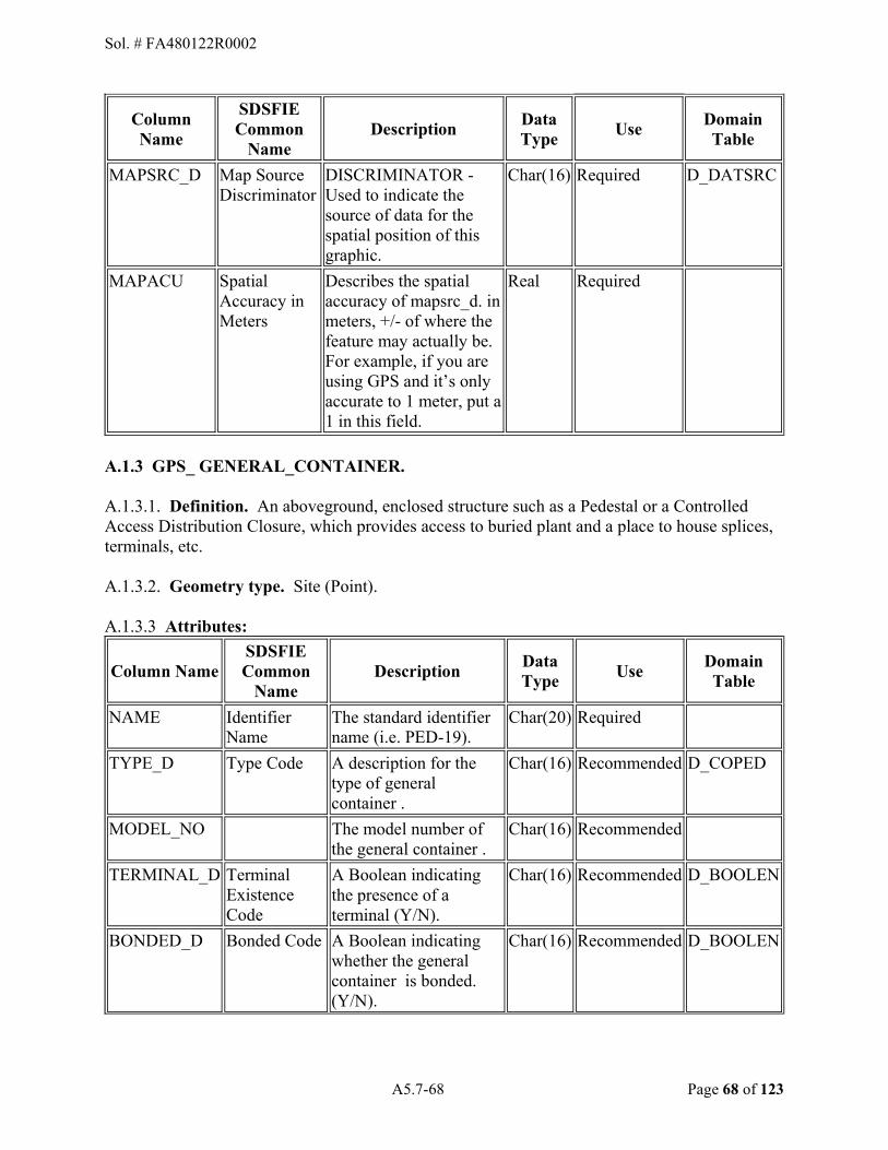
A5.7-68 Page 68 of 123
Column Name
SDSFIE Common
Name Description
Data Type
Use Domain Table
MAPSRC_D Map Source Discriminator
DISCRIMINATOR - Used to indicate the source of data for the spatial position of this graphic.
Char(16) Required D_DATSRC
MAPACU Spatial Accuracy in Meters
Describes the spatial accuracy of mapsrc_d. in meters, +/- of where the feature may actually be. For example, if you are using GPS and it�s only accurate to 1 meter, put a 1 in this field.
Real Required
A.1.3 GPS_ GENERAL_CONTAINER.
A.1.3.1. Definition. An aboveground, enclosed structure such as a Pedestal or a Controlled Access Distribution Closure, which provides access to buried plant and a place to house splices, terminals, etc. A.1.3.2. Geometry type. Site (Point). A.1.3.3 Attributes:
Column Name SDSFIE Common
Name Description
Data Type
Use Domain Table
NAME Identifier Name
The standard identifier name (i.e. PED-19).
Char(20) Required
TYPE_D Type Code A description for the type of general container .
Char(16) Recommended D_COPED
MODEL_NO The model number of the general container .
Char(16) Recommended
TERMINAL_D Terminal Existence Code
A Boolean indicating the presence of a terminal (Y/N).
Char(16) Recommended D_BOOLEN
BONDED_D Bonded Code A Boolean indicating whether the general container is bonded. (Y/N).
Char(16) Recommended D_BOOLEN
Sol. # FA480122R0002

A5.7-69 Page 69 of 123
Column Name SDSFIE Common
Name Description
Data Type
Use Domain Table
DISPOSTN_D Disposition Code
The status of the subject item (e.g., permanent, temporary, proposed, abandoned, etc.), from lists or entered from field inspections.
Char(16) Required D_DPOBJ
MAPSRC_D Map Source Discriminator
DISCRIMINATOR - Used to indicate the source of data for the spatial position of this graphic.
Char(16) Required D_DATSRC
MAPACU Spatial Accuracy in Meters
Describes the spatial accuracy of mapsrc_d. in meters, +/- of where the feature may actually be. For example, if you are using GPS and it�s only accurate to 1 meter, put a 1 in this field.
Real Required
A.1.4. GPS_DBSPLICE.
A.1.4.1. Definition. An enclosed structure that represents a splice case (aerial or buried). A.1.4.2. Geometry type. Site (Point). A.1.4.3 Attributes:
Column Name
SDSFIE Common
Name Description
Data Type
Use Domain Table
NAME Identifier Name
The standard identifier name (e.g. DBS01.1-1200_1-900).
Char(20) Required
CAS_MAT_D Case Material Code
Used to describe the material composition of the splice case.
Char(16) Recommended D_SPCMAT
CAS_TYP_D Case Type Code
Used to describe the type of splice case.
Char(16) Recommended D_SPCCAS
Sol. # FA480122R0002

A5.7-70 Page 70 of 123
Column Name
SDSFIE Common
Name Description
Data Type
Use Domain Table
MAPSRC_D Map Source Discriminator
DISCRIMINATOR - Used to indicate the source of data for the spatial position of this graphic.
Char(16) Required D_DATSRC
MAPACU Spatial Accuracy in Meters
Describes the spatial accuracy of mapsrc_d. in meters, +/- of where the feature may actually be. For example, if you are using GPS and it�s only accurate to 1 meter, put a 1 in this field.
Real Required
A.1.5. GPS_PATH_SEGMENT.
A.1.5.1. Definition. Link that represents an enclosure path of comm. items outside of a building, manhole, pedestal or other enclosed structure. For duct banks, comm-path segment can represent the virtual path, duct bank, duct, and innerducts. For ducts, comm-path segment can represent the virtual path, duct, and innerducts. For direct-buried cables at road-crossings, comm-path segment can represent the virtual path, road-crossing duct, and direct-buried cables. It can also represent the path of aerial cable, cable-bridges, and cable-troughs. A.1.5.2. Geometry type. Polyline. A.1.5.3 Attributes:
Column Name SDSFIE Common
Name Description
Data Type
Use Domain Table
PATH_TYP_D Comm-Path Type Code
A discriminator field that describes what type of communications path this segment is representing.
Char(16) Required D_COPTHT
COVERDEPTH The minimum depth of this part of the path from grade, in inches. This is mainly used for digging permits
Real Recommended
Sol. # FA480122R0002
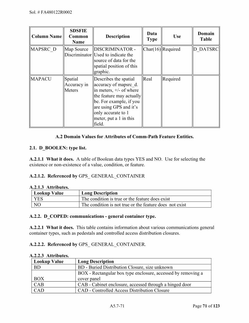
A5.7-71 Page 71 of 123
Column Name SDSFIE Common
Name Description
Data Type
Use Domain Table
MAPSRC_D Map Source Discriminator
DISCRIMINATOR - Used to indicate the source of data for the spatial position of this graphic.
Char(16) Required D_DATSRC
MAPACU Spatial Accuracy in Meters
Describes the spatial accuracy of mapsrc_d. in meters, +/- of where the feature may actually be. For example, if you are using GPS and it�s only accurate to 1 meter, put a 1 in this field.
Real Required
A.2 Domain Values for Attributes of Comm-Path Feature Entities.
2.1. D_BOOLEN: type list.
A.2.1.1 What it does. A table of Boolean data types YES and NO. Use for selecting the existence or non-existence of a value, condition, or feature.
A.2.1.2. Referenced by GPS_ GENERAL_CONTAINER
A.2.1.3 Attributes. Lookup Value Long Description YES The condition is true or the feature does exist NO The condition is not true or the feature does not exist
A.2.2. D_COPED: communications - general container type.
A.2.2.1 What it does. This table contains information about various communications general container types, such as pedestals and controlled access distribution closures. A.2.2.2. Referenced by GPS_ GENERAL_CONTAINER. A.2.2.3 Attributes.
Lookup Value Long Description BD BD - Buried Distribution Closure, size unknown
BOX BOX - Rectangular box type enclosure, accessed by removing a cover panel
CAB CAB - Cabinet enclosure, accessed through a hinged door CAD CAD - Controlled Access Distribution Closure
Sol. # FA480122R0002
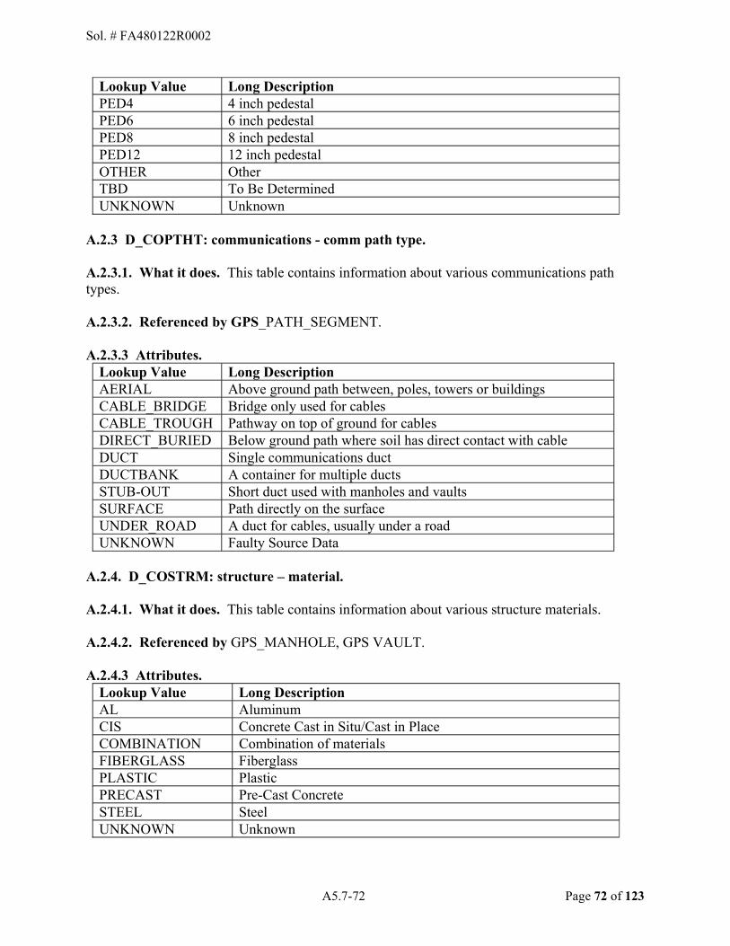
A5.7-72 Page 72 of 123
Lookup Value Long Description PED4 4 inch pedestal PED6 6 inch pedestal PED8 8 inch pedestal PED12 12 inch pedestal OTHER Other TBD To Be Determined UNKNOWN Unknown
A.2.3 D_COPTHT: communications - comm path type.
A.2.3.1. What it does. This table contains information about various communications path types.
A.2.3.2. Referenced by GPS_PATH_SEGMENT.
A.2.3.3 Attributes. Lookup Value Long Description AERIAL Above ground path between, poles, towers or buildings CABLE_BRIDGE Bridge only used for cables CABLE_TROUGH Pathway on top of ground for cables DIRECT_BURIED Below ground path where soil has direct contact with cable DUCT Single communications duct DUCTBANK A container for multiple ducts STUB-OUT Short duct used with manholes and vaults SURFACE Path directly on the surface UNDER_ROAD A duct for cables, usually under a road UNKNOWN Faulty Source Data
A.2.4. D_COSTRM: structure � material.
A.2.4.1. What it does. This table contains information about various structure materials. A.2.4.2. Referenced by GPS_MANHOLE, GPS VAULT. A.2.4.3 Attributes.
Lookup Value Long Description AL Aluminum CIS Concrete Cast in Situ/Cast in Place COMBINATION Combination of materials FIBERGLASS Fiberglass PLASTIC Plastic PRECAST Pre-Cast Concrete STEEL Steel UNKNOWN Unknown
Sol. # FA480122R0002

A5.7-73 Page 73 of 123
A.2.5. D_DATSRC: source list � data.
A.2.5.1. What it does. Allowable input values for data sources.
A.2.5.2. Referenced by GPS_DBSPLICE, GPS_MANHOLE, GPS_PATH_SEGMENT, GPS_ GENERAL_CONTAINER , GPS_VAULT.
A.2.5.3 . Attributes.
Lookup Value Long Description AER_PHOTO Aerial photography AS_BUILT As-built drawings CSIR CSIR - Communications System Installation Record FLDLOC_SURVEY Field location survey GPS_FLDLOC GPS field located and verified data HAND_DRAFT Hand-drafted map MAP_TAB Tab Map series NGS National Geodetic Survey data SATELLITE Satellite imagery UNKNOWN Unknown
A.2.6 D_DPOBJ: disposition list � object.
A.2.6.1. What it does. Allowable input for the disposition of an object.
A.2.6.2. Referenced by, GPS_MANHOLE, GPS_ GENERAL_CONTAINER , GPS_VAULT.
A.2.6.3 . Attributes. Lookup Value Long Description ABANDONED Abandoned in place (not in use) TEMPORARY Temporary PROPOSED Proposed IN_SERVICE In service and being used. COLLAPSED An unserviceable item UNKNOWN Unknown TBD To Be Determined
A.2.7. D_MHTYP: type list - comm manhole.
A.2.7.1. What it does. The type of manhole.
A.2.7.2. Referenced by GPS_MANHOLE.
A.2.7.3 Attributes. Lookup Value Long Description 1T1 1T1 4T1 4T1
Sol. # FA480122R0002
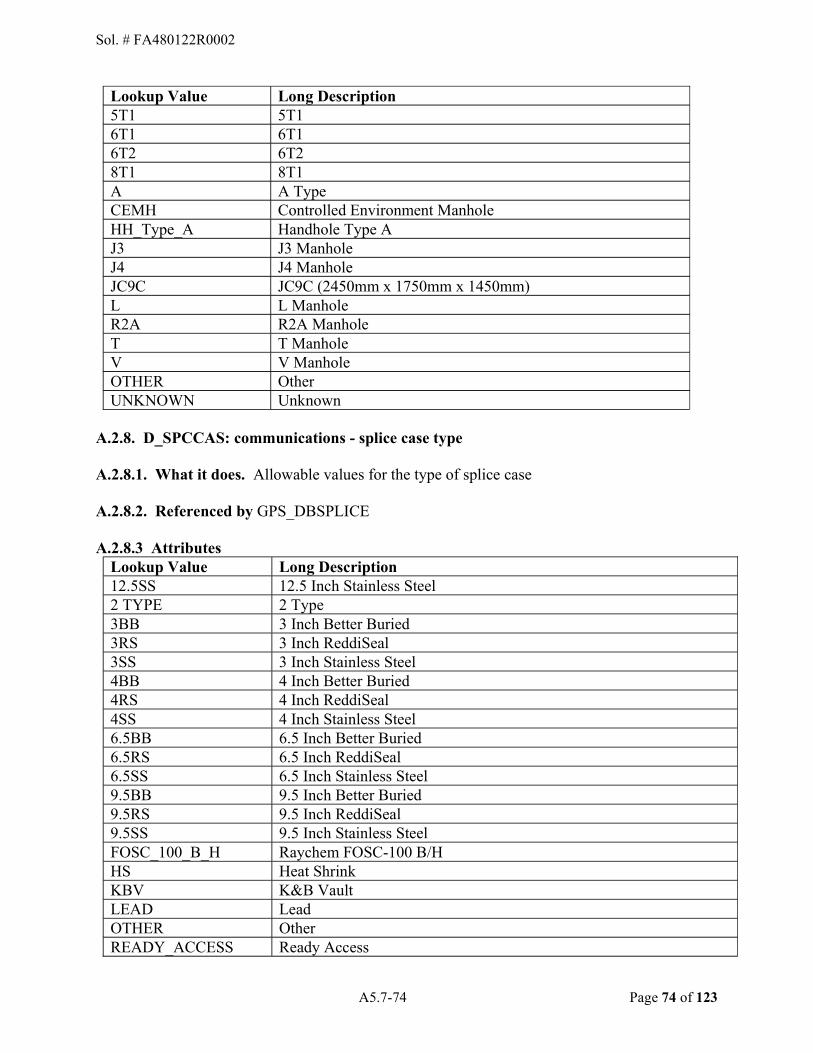
A5.7-74 Page 74 of 123
Lookup Value Long Description 5T1 5T1 6T1 6T1 6T2 6T2 8T1 8T1 A A Type CEMH Controlled Environment Manhole HH_Type_A Handhole Type A J3 J3 Manhole J4 J4 Manhole JC9C JC9C (2450mm x 1750mm x 1450mm) L L Manhole R2A R2A Manhole T T Manhole V V Manhole OTHER Other UNKNOWN Unknown
A.2.8. D_SPCCAS: communications - splice case type
A.2.8.1. What it does. Allowable values for the type of splice case
A.2.8.2. Referenced by GPS_DBSPLICE
A.2.8.3 Attributes Lookup Value Long Description 12.5SS 12.5 Inch Stainless Steel 2 TYPE 2 Type 3BB 3 Inch Better Buried 3RS 3 Inch ReddiSeal 3SS 3 Inch Stainless Steel 4BB 4 Inch Better Buried 4RS 4 Inch ReddiSeal 4SS 4 Inch Stainless Steel 6.5BB 6.5 Inch Better Buried 6.5RS 6.5 Inch ReddiSeal 6.5SS 6.5 Inch Stainless Steel 9.5BB 9.5 Inch Better Buried 9.5RS 9.5 Inch ReddiSeal 9.5SS 9.5 Inch Stainless Steel FOSC_100_B_H Raychem FOSC-100 B/H HS Heat Shrink KBV K&B Vault LEAD Lead OTHER Other READY_ACCESS Ready Access
Sol. # FA480122R0002

A5.7-75 Page 75 of 123
UC_6_9 Siemens UC 6-9 UCN_7_10 Siemens UCN 7-10 UNKNOWN Unknown
Sol. # FA480122R0002
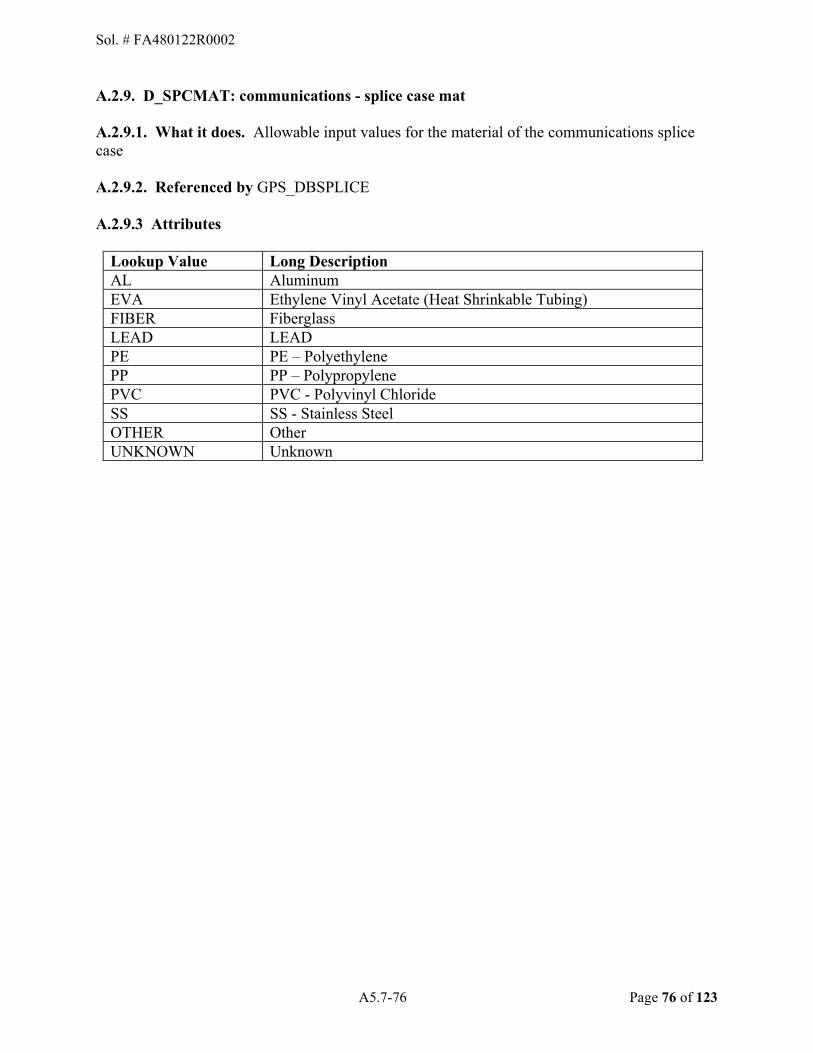
A5.7-76 Page 76 of 123
A.2.9. D_SPCMAT: communications - splice case mat
A.2.9.1. What it does. Allowable input values for the material of the communications splice case
A.2.9.2. Referenced by GPS_DBSPLICE
A.2.9.3 Attributes
Lookup Value Long Description AL Aluminum EVA Ethylene Vinyl Acetate (Heat Shrinkable Tubing) FIBER Fiberglass LEAD LEAD PE PE � Polyethylene PP PP � Polypropylene PVC PVC - Polyvinyl Chloride SS SS - Stainless Steel OTHER Other UNKNOWN Unknown
Sol. # FA480122R0002
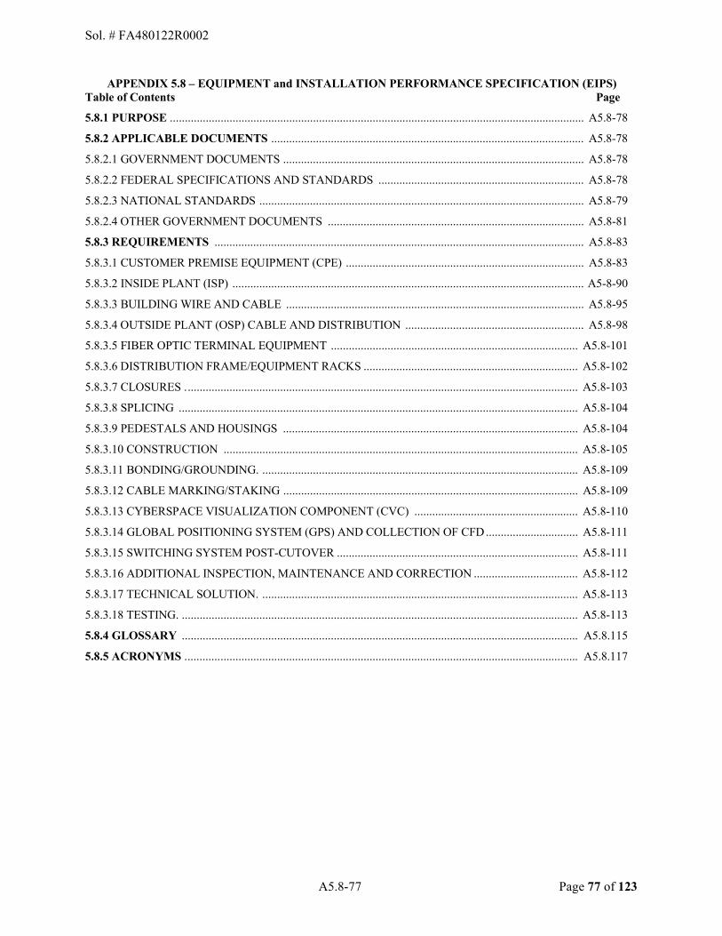
A5.8-77 Page 77 of 123
APPENDIX 5.8 � EQUIPMENT and INSTALLATION PERFORMANCE SPECIFICATION (EIPS) Table of Contents Page
5.8.1 PURPOSE ........................................................................................................................................... A5.8-78
5.8.2 APPLICABLE DOCUMENTS ......................................................................................................... A5.8-78
5.8.2.1 GOVERNMENT DOCUMENTS ..................................................................................................... A5.8-78
5.8.2.2 FEDERAL SPECIFICATIONS AND STANDARDS ..................................................................... A5.8-78
5.8.2.3 NATIONAL STANDARDS ............................................................................................................. A5.8-79
5.8.2.4 OTHER GOVERNMENT DOCUMENTS ...................................................................................... A5.8-81
5.8.3 REQUIREMENTS ............................................................................................................................ A5.8-83
5.8.3.1 CUSTOMER PREMISE EQUIPMENT (CPE) ................................................................................ A5.8-83
5.8.3.2 INSIDE PLANT (ISP) ...................................................................................................................... A5-8-90
5.8.3.3 BUILDING WIRE AND CABLE .................................................................................................... A5.8-95
5.8.3.4 OUTSIDE PLANT (OSP) CABLE AND DISTRIBUTION ............................................................ A5.8-98
5.8.3.5 FIBER OPTIC TERMINAL EQUIPMENT ................................................................................... A5.8-101
5.8.3.6 DISTRIBUTION FRAME/EQUIPMENT RACKS ........................................................................ A5.8-102
5.8.3.7 CLOSURES . ................................................................................................................................... A5.8-103
5.8.3.8 SPLICING ...................................................................................................................................... A5.8-104
5.8.3.9 PEDESTALS AND HOUSINGS ................................................................................................... A5.8-104
5.8.3.10 CONSTRUCTION ....................................................................................................................... A5.8-105
5.8.3.11 BONDING/GROUNDING. .......................................................................................................... A5.8-109
5.8.3.12 CABLE MARKING/STAKING ................................................................................................... A5.8-109
5.8.3.13 CYBERSPACE VISUALIZATION COMPONENT (CVC) ....................................................... A5.8-110
5.8.3.14 GLOBAL POSITIONING SYSTEM (GPS) AND COLLECTION OF CFD ............................... A5.8-111
5.8.3.15 SWITCHING SYSTEM POST-CUTOVER ................................................................................. A5.8-111
5.8.3.16 ADDITIONAL INSPECTION, MAINTENANCE AND CORRECTION ................................... A5.8-112
5.8.3.17 TECHNICAL SOLUTION. .......................................................................................................... A5.8-113
5.8.3.18 TESTING. . .................................................................................................................................... A5.8-113
5.8.4 GLOSSARY ..................................................................................................................................... A5.8.115
5.8.5 ACRONYMS . ................................................................................................................................... A5.8.117
Sol. # FA480122R0002

A5.8-78 Page 78 of 123
5.8.1 PURPOSE Appendix 5.8, Equipment and Installation Performance Specifications, identifies procedures to support Operations and Maintenance (O&M) of the Base Telecommunications System (BTS).
5.8.2 APPLICABLE DOCUMENTS
5.8.2.1 GOVERNMENT DOCUMENTS
Military Standard (MIL-STD)-188-124B 30 Jan 98
Grounding, Bonding, and Shielding for Common/ Long Haul/Tactical Communications Systems Including Ground Based Communications-Electronics Facilities and Equipment
(Copies of MIL-STD may be obtained from the Document Automation & Production Service, Defense Logistics Agency (DLA) Document Service Headquarters, 5450 Carlisle Pike Bldg 09, PO Box 2020, Mechanicsburg, PA 17055-0788, Ph. 1-717-605-3971/1-877-DAPS-CAN, or from http://www.daps.dla.mil/dapsonline.html or [email protected].
5.8.2.2 FEDERAL SPECIFICATIONS AND STANDARDS. The following safety references (Code of Federal Regulations (CFR)) are not intended to exclude any other references, but are intended to identify those safety references, which are most common to the efforts required by the PWS. The Contractor is required to abide by any and all applicable federal, state, and local codes and safety requirements. CFR Title 7, Agriculture Volume 11, Chapter XVII, Part 1755, Sec 1755.370
Rural Utilities Service (RUS) Specification for Seven Wire Galvanized Steel Strand
CFR Title 47, Telecommunications Volume 3, Chapter I, Part 68
Federal Communications Commissions (FCC) Connection of Terminal Equipment to the Telephone Network
CFR Title 40, Protection of Environment, Volume 25, Chapter I, Part 260,
Hazardous Waste Management System: General
CFR Title 40, Protection of Environment, Volume 25, Chapter I, Part 261
Identification & Listing of Hazardous Waste
CFR Title 40, Protection of Environment, Volume 25, Chapter I, art 262
Standards Applicable to Generators of Hazardous Waste
CFR Title 40, Protection of Environment, Volume 25, Chapter I, Part 263
Standards Applicable to Transporters of Hazardous Waste
CFR Title 40, Protection of Environment, Volume 25, Chapter I, Part 264
Standards for Owners & Operators of Hazardous Waste Treatment & Disposal Facilities
CFR Title 40, Protection of Environment, Volume 25, Chapter I, Part 265
Interim Status Standards for Owners & Operators of Hazardous Waste Treatment, Storage & Disposal Facilities
Sol. # FA480122R0002

A5.8-79 Page 79 of 123
(Copies of the above documents may be obtained from the GPO Regional Printing Procurement Office, 928 Jaymore Rd, Suite A-190, Southhampton, PA 18966-3820, Phone (215) 364-6465; FAX (215) 364-6479 or http://www.gpoaccess.gov/cfr/.
Copies of the above documents may be obtained from the GPO Regional Printing Procurement Office, Denver Regional Office, 12345W. Alameda Parkway, Suite 208, Lakewood, CO 80228-2842, phone 303-236-5292, FAX 303-236-5304, [email protected] or http://www.gpoaccess.gov/cfr/.
CFR Title 29, Labor Volume 6, Chapter XVII, Part 1910
Occupational Safety and Health Standards
CFR Title 29, Labor Volume 5, Chapter XVII, Part 1910.268
Telecommunications
CFR Title 29, Labor Volume 6, Chapter XVII, Part 1910.1001&Volume 8, Part 1926.1101
Asbestos
CFR Title 29, Labor Volume 8, Chapter XVII, Part 1926.650
Scope, Application, and Definitions Applicable to this Subpart
CFR Title 29, Labor Volume 8, Chapter XVII, Part 1926.651
Specific Excavation Requirements for Protective Systems
CFR Title 29, Labor Volume 8, Chapter XVII, Part 1926.652
Requirements for Protective Systems
CFR Title 29, Labor Volume 5, Chapter XVII, Part 1910.120
Hazardous Waste Operations and Emergency Response
CFR Title 29, Labor Volume 5, Chapter XVII, 1910.146
Permit-Required Confined Spaces
CFR Title 29, Labor Volume 5, Chapter XVII, Part 1910.147
The Control of Hazardous Energy (Lockout/Tagout)
CFR Title 29, Labor Volume 6, Chapter XVII, Part 1910.1200
Hazard Communication
(Copies of the above documents may be obtained from www.gpoaccess.gov or http://www.accessgpo.gov/nara/cfr/cfr-table-search.html)
5.8.2.3 NATIONAL STANDARDS
National Fire Protection Association National Electrical Code (NEC) (NFPA), NFPA 70, Edition 20, 2020
Sol. # FA480122R0002
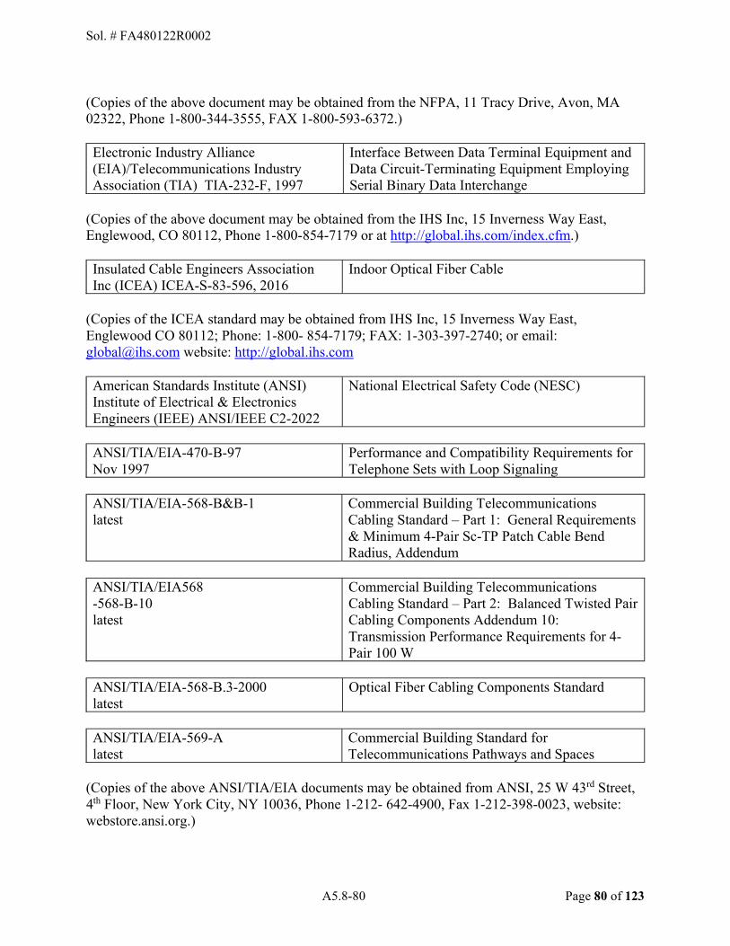
A5.8-80 Page 80 of 123
(Copies of the above document may be obtained from the NFPA, 11 Tracy Drive, Avon, MA 02322, Phone 1-800-344-3555, FAX 1-800-593-6372.)
Electronic Industry Alliance (EIA)/Telecommunications Industry Association (TIA) TIA-232-F, 1997
Interface Between Data Terminal Equipment and Data Circuit-Terminating Equipment Employing Serial Binary Data Interchange
(Copies of the above document may be obtained from the IHS Inc, 15 Inverness Way East, Englewood, CO 80112, Phone 1-800-854-7179 or at http://global.ihs.com/index.cfm.)
Insulated Cable Engineers Association Inc (ICEA) ICEA-S-83-596, 2016
Indoor Optical Fiber Cable
(Copies of the ICEA standard may be obtained from IHS Inc, 15 Inverness Way East, Englewood CO 80112; Phone: 1-800- 854-7179; FAX: 1-303-397-2740; or email: [email protected] website: http://global.ihs.com
American Standards Institute (ANSI) Institute of Electrical & Electronics Engineers (IEEE) ANSI/IEEE C2-2022
National Electrical Safety Code (NESC)
ANSI/TIA/EIA-470-B-97 Nov 1997
Performance and Compatibility Requirements for Telephone Sets with Loop Signaling
ANSI/TIA/EIA-568-B&B-1 latest
Commercial Building Telecommunications Cabling Standard � Part 1: General Requirements & Minimum 4-Pair Sc-TP Patch Cable Bend Radius, Addendum
ANSI/TIA/EIA568 -568-B-10 latest
Commercial Building Telecommunications Cabling Standard � Part 2: Balanced Twisted Pair Cabling Components Addendum 10: Transmission Performance Requirements for 4-Pair 100 W
ANSI/TIA/EIA-568-B.3-2000 latest
Optical Fiber Cabling Components Standard
ANSI/TIA/EIA-569-A latest
Commercial Building Standard for Telecommunications Pathways and Spaces
(Copies of the above ANSI/TIA/EIA documents may be obtained from ANSI, 25 W 43rd Street, 4th Floor, New York City, NY 10036, Phone 1-212- 642-4900, Fax 1-212-398-0023, website: webstore.ansi.org.)
Sol. # FA480122R0002
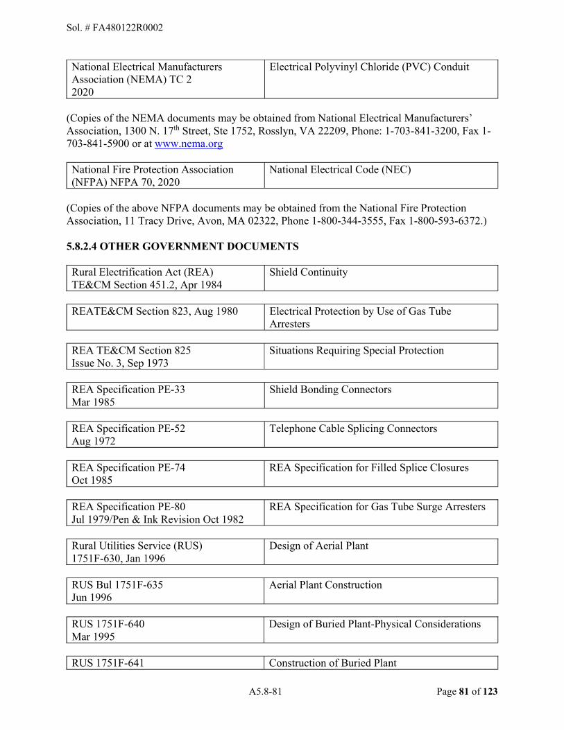
A5.8-81 Page 81 of 123
National Electrical Manufacturers Association (NEMA) TC 2 2020
Electrical Polyvinyl Chloride (PVC) Conduit
(Copies of the NEMA documents may be obtained from National Electrical Manufacturers� Association, 1300 N. 17th Street, Ste 1752, Rosslyn, VA 22209, Phone: 1-703-841-3200, Fax 1-703-841-5900 or at www.nema.org
National Fire Protection Association (NFPA) NFPA 70, 2020
National Electrical Code (NEC)
(Copies of the above NFPA documents may be obtained from the National Fire Protection Association, 11 Tracy Drive, Avon, MA 02322, Phone 1-800-344-3555, Fax 1-800-593-6372.) 5.8.2.4 OTHER GOVERNMENT DOCUMENTS Rural Electrification Act (REA) TE&CM Section 451.2, Apr 1984
Shield Continuity
REATE&CM Section 823, Aug 1980 Electrical Protection by Use of Gas Tube Arresters
REA TE&CM Section 825 Issue No. 3, Sep 1973
Situations Requiring Special Protection
REA Specification PE-33 Mar 1985
Shield Bonding Connectors
REA Specification PE-52 Aug 1972
Telephone Cable Splicing Connectors
REA Specification PE-74 Oct 1985
REA Specification for Filled Splice Closures
REA Specification PE-80 Jul 1979/Pen & Ink Revision Oct 1982
REA Specification for Gas Tube Surge Arresters
Rural Utilities Service (RUS) 1751F-630, Jan 1996
Design of Aerial Plant
RUS Bul 1751F-635 Jun 1996
Aerial Plant Construction
RUS 1751F-640 Mar 1995
Design of Buried Plant-Physical Considerations
RUS 1751F-641 Construction of Buried Plant
Sol. # FA480122R0002

A5.8-82 Page 82 of 123
Jun 1995
RUS 1751F-642 Jun 1995
Construction Route Planning of Buried Plant
RUS 1751F-643 Aug 2002
Underground Plant Design
RUS 1751F-644 Aug 2002
Underground Plant Construction
RUS 1751F-650 Jul 1996
Aerial Plant Guying and Anchoring
RUS 1751F-805 May 1995
Electrical Protection at Customer Locations
RUS 1751-815 May 1995
Electrical Protection of Outside Plant
RUS 1753F-150 Sep 2001
Specifications and Drawings for Construction of Direct Buried Plant
RUS 1753F-151 Aug 2001
Specifications and Drawings for Construction of Underground Plant
RUS 1753F-152 Sep 2001
Specifications and Drawings for Construction of Aerial Plant
RUS 1753F-153 Sep 2001
Specifications and Drawings for Service Installation at Customer Access Locations
RUS 1753F-201 (PC-4) June 2, 1997
Standard for Acceptance Tests and Measurements of Telecommunications Plant
RUS 1753F-205 (PE-39) Jun 1993
REA Specification for Filled Telephone Cable
RUS 1753F-207 (PE-87) Jul 1994
REA Specification for Terminating Cables
RUS 1753F-208 (PE-89) June 1993
REA Specification for Filled Telephone Cables With Expanded Insulation
Sol. # FA480122R0002
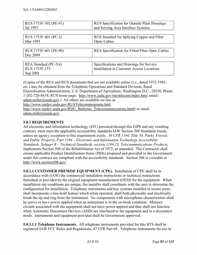
A5.8-83 Page 83 of 123
RUS 1753F-302 (PE-91) Jul 1997
RUS Specification for Outside Plant Housings and Serving Area Interface Systems
RUS 1753F-401 (PC-2) Mar 1995
RUS Standard for Splicing Copper and Fiber Optic Cables
RUS 1753F-601 (PE-90) Dec 2009
REA Specification for Filled Fiber Optic Cables
REA Standard (PC-5A) RUS 1753F-153 Sep 2001
Specifications and Drawings for Service Installation at Customer Access Locations
(Copies of the REA and RUS documents that are not available online (i.e., dated 1972-1985, etc.) may be obtained from the Telephone Operations and Standard Division, Rural Electrification Administration, U.S. Department of Agriculture, Washington D.C., 20250, Phone 1-202-720-8674; RUS home page: http://www.usda.gov/rus/telecom/index.htm; email: [email protected].) All others are available on-line at: http://www.rurdev.usda.gov/RUSTelecomprograms.hml; http://www.rurdev.usda.gov/RDU_Bulletins_Telecommunications.html) or email [email protected].
5.8.3 REQUIREMENTS All electronic and information technology (EIT) procured through this EIPS and any resulting contract, must meet the applicable accessibility standards IAW Section 508 Standards Guide, unless an agency exception to this requirement exists. 36 CFR 1194, Title 36, Parks, Forests, and Public Property, Part 1194 � Electronic and Information Technology Accessibility Standards, Subpart B � Technical Standards, section 1194.23, Telecommunications Products, implements Section 508 of the Rehabilitation Act of 1973, as amended. The Contractor shall ensure applicable Product Identification Items (PIDs) proposed and provided to the Government under this contract are compliant with the accessibility standards. Section 508 is viewable at http://www.section508.gov/
5.8.3.1 CUSTOMER PREMISE EQUIPMENT (CPE). Installation of CPE shall be in accordance with (IAW) the commercial installation instructions or technical instructions furnished or provided by the original equipment manufacturer (OEM) for the equipment. When installation site conditions are unique, the installer shall coordinate with the user to determine the configuration for installation. Telephone instruments and key systems installed in secure areas shall incorporate a line-hold feature which when operated, shall both physically and electrically break the tip and ring from the instrument. No components with microphone characteristics shall be active or have power applied when an instrument is in the on-hook condition. Memory circuits associated with the equipment shall not have power applied and thus shall not function when Automatic Disconnect Devices (ADD) are interfaced to the equipment and in a disconnect mode. Instruments and equipment provided shall be Government approved. 5.8.3.1.1 Telephone Instruments. All telephone instruments provided for this BTS shall be registered IAW FCC Rules and Regulations, 47 CFR Part 68. Telephone instruments for use in
Sol. # FA480122R0002

A5.8-84 Page 84 of 123
secure areas must be Government approved. Approval of other devices may be obtained from the Defense Intelligence Agency, ATTENTION: OS-2, Washington, CD 20331-6111; or the Telephone Security Panel of the National Foreign Security Committee recognized by HQ AFOSI/IVS. The base TEMPEST officer will provide information concerning other devices that have been approved. Instruments shall be fully operational and compatible with the switching equipment to which they are connected. Telephone instruments purchased, if not new, shall represent the best possible appearance on the user�s desk (i.e., not scratched, dirty, torn or ripped labels.) All telephone instruments shall include the batteries and power supply modules required to support the unit. The color of the handset, handset cord, and base unit, including the dial blank or keypad, shall be standard and uniform throughout. Distinctive colored phones shall be provided for special categories, as identified by the COR. Telephone keys or buttons shall be relabeled on all changes or relocates. Labels shall be printed, not hand written, permanently affixed and not easily detached or smeared. The label shall indicate information relevant to the device installed. Installation shall include data administration activation of all required features of equipment, mounting and placement of the telephone instrument, all cross-connects (jumper or patch cords), and connecting the line cord and power supply if needed to the wall outlet at the customer premise as well as labeling or relabeling the phone instrument with the correct phone numbers on the phone or lines (if multiple line phone). This does not include programmable or speed-dial type buttons.
5.8.3.1.1.1 Basic Telephone. Basic telephone is an analog instrument which shall meet the specifications as stated in ANSI/TIA/EIA 470-B. The telephone shall be a fully modular telephone equipped with a standard modular handset, modular retractile-coiled handset cord, and base unit. The handset shall have a flush mounted modular jack located on the transmitter end, and be accessible without removal of the handset housing. The base unit shall house the 12-button Dual-Tone, Multi-Frequency (DTMF) keypad, switch-hook assembly, ringer, and auxiliary hardware necessary for telephone operation. In addition, the base unit shall be equipped with a ringer number identification label and the base unit shall be equipped with a ringer level control (loud and soft). The base unit shall provide a plastic covered insert for directory number identification label or labels for multi-line units. The base unit shall provide sufficient adhesion to the surface on which it is placed to prevent movement during dialing or normal stretching of the handset cord. The objective of the types of analog telephone instruments listed below is to identify additional capabilities and functions of the analog telephone instruments required by the BTS. 5.8.3.1.1.1.1 Wall mounted Telephone Instrument. The wall-mounted instrument shall mount to a standard modular wall plate jack without the need for a telephone line cord. Instruments not designed to mount on a wall plate jack, shall be connected to wall jack with a line cord. The handset shall be securely held on the handset rest to prevent an accidental off-hook condition. Mounting components shall be provided with the telephone stations. 5.8.3.1.1.1.2 Telephone with Message Waiting Lamp. This telephone instrument functions with a Private Automatic Branch Exchange (PABX) or key system unit feature that provides voice mail or a message desk function by providing an illuminated indication of a pending message. The message-waiting lamp is located on the face of the telephone instrument.
Sol. # FA480122R0002

A5.8-85 Page 85 of 123
5.8.3.1.1.1.3 Telephone with Data Jack. The jack port supports an RJ-11 connector to interface a laptop personal computer. This jack permits the user to access the jack port in lieu of the telephone instrument.
5.8.3.1.1.1.4 Autodial Telephone. This instrument has an integrated electronic auto dialer capable of 10-user programmable memory registers with one button for last number redial and the remaining buttons for autodialing. Each memory register shall store a phone number up to 15 digits in length including a pause into the digit string accessing second dial tone circuits. The user shall implement autodialing by pressing no more than two buttons. The instrument shall provide a minimum of 30 minutes memory retention during an AC power failure or removal of the telephone line cord. The basic instrument shall be telephone line DC powered. External DC powering may be employed to support additional functions.
5.8.3.1.1.1.5 Telephone with Integrated Speakerphone. This instrument allows full duplex operation. Operation of the instrument in the hands-free mode, at full volume, shall not produce audible feedback. The instrument shall be equipped with a button to select either handset or hands-free operation. Separate hold and mute buttons and speaker level adjustment shall be provided. The basic instrument shall be telephone line DC powered. External DC powering may be employed to support additional functions. 5.8.3.1.1.1.6 Basic Telephone Instrument Non-dial. This instrument shall be designed to terminate a single 2-wire voice switched or non-switched line that has a blank faceplate, i.e., no dial pad or rotary dial. 5.8.3.1.1.1.7 Elevator Mount. This telephone instrument shall be suitable for mounting in an elevator emergency telephone inset. The Contractor may be required to contact elevator provider to obtain a compatible telephone instrument. 5.8.3.1.1.1.8 Outdoor Telephone. This instrument shall be a sealed outdoor weatherproof telephone designed to terminate a single switched or non-switched line. The enclosure shall be externally labeled, and/or provided with a mechanical door lock. 5.8.3.1.1.1.9 Hazardous Area/Explosion Proof Telephone. This instrument shall be an explosion-proof phone enclosed in a sealed metal housing containing all electrical components except for the handset and cord. The housing shall provide protection against an internal spark or flame from reaching the surrounding atmosphere. This telephone shall be designed for both indoor and outdoor hazardous areas, and shall operate in hazardous locations Class I (Groups B, C, D), Class II (Groups E, F, G), and Class III for both Divisions I and II as defined in the ANSI C2 NESC, Article 500.
5.8.3.1.1.1.10 Two-Line Telephone. This instrument shall be an electronic fully modular telephone. This phone shall be designed to terminate a minimum of two switched or non-switched lines, or any combination thereof. When required for a two-line instrument, a separate distinct audible ringing tone shall be provided for each line. The basic instrument shall be telephone line DC powered. External DC powering may be employed to support additional functions. 5.8.3.1.1.2 Proprietary Telephone. Electronic/digital telephone instruments (Proprietary
Sol. # FA480122R0002

A5.8-86 Page 86 of 123
Telephone Sets (P-Sets)) shall be compatible with the switching equipment to which they are connected. Installation services shall include service activation for the Proprietary Telephone (P-Phone) instrument, the station features, the line appearances, and the faceplate details.
5.8.3.1.1.2.1 Multi-Button Instrument with Integrated Speakerphone. These telephone instruments shall provide an integrated speakerphone and allow full duplex operation. Operation of the instrument in hands-free mode, at full volume, shall not produce audible feedback. The instrument shall be equipped with a button to select either handset or hands-free operation. Separate hold and mute buttons and speaker level adjustment shall be provided. The instrument shall be telephone line DC powered. External DC powering may be employed via the telephone line cord. 5.8.3.1.1.2.2 Multi-Button Instrument with Display. A 16-character Liquid Crystal Display (LCD) shall be available for 10-, 20-, and 30-button key system telephones. An alphanumeric display shall be available for 40-button or larger key system telephone. An alphanumeric display shall have the following capabilities: internal calling party identification, number dial display, code display, clock, calendar, etc. These multi-button telephones with display shall be designed and constructed as a single integrated instrument. 5.8.3.1.1.2.3 Add-on Button Modules. When a P-Phone telephone instrument can accept add-on modules to support additional buttons for lines and features, installation and service shall include the appropriate electrical and mechanical connections to the base instrument. Installation and service activation for the add-on modules include the supported station features, line appearances, and face plate details. 5.8.3.1.1.3 PABX Telephone Instruments. For operational key systems using PABX telephone line port appearance connectivity, installation service is treated the same as required for a basic telephone. It includes the data administration of the key system and the PABX to activate the telephone line connection. 5.8.3.1.1.4 Voice over Internet Protocol (VoIP) Phones. The Contractor shall install VoIP telephones via the work order process. The VoIP phone is connected directly to the Local Area Network (LAN). The battery/power for these phones is provided by the Ethernet switch to which these phones are connected. This battery/power will not be constant unless an Uninterrupted Power Source is powering the switch. 5.8.3.1.2 Ancillary Equipment 5.8.3.1.2.1 Ringer Isolator. This unit shall operate as an electronic switch controlled by ringing voltage. When the ringing voltage is present, this unit shall provide a connection and allow current to pass through to the ringer coil. When ringing voltage is absent, this unit shall prevent current from passing through to the ringer coil. Installation of this device provides the necessary ringer security without removing the ringer normally supplied with the instrument. 5.8.3.1.2.2 External Ringer. This unit shall provide audible ringing when a signal is generated. This device shall operate with the telephone low-pass line-filter identified below. Where the ringer isolator is not used, the internal ringer normally supplied with the instrument shall be removed, or the ringer signal leads electrically disconnected and isolated or shorted. The ringer
Sol. # FA480122R0002
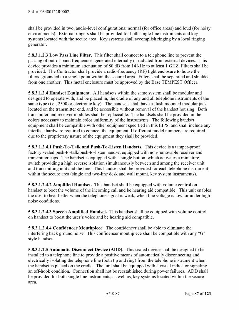
A5.8-87 Page 87 of 123
shall be provided in two, audio-level configurations: normal (for office areas) and loud (for noisy environments). External ringers shall be provided for both single line instruments and key systems located with the secure area. Key systems shall accomplish ringing by a local ringing generator.
5.8.3.1.2.3 Low Pass Line Filter. This filter shall connect to a telephone line to prevent the passing of out-of-band frequencies generated internally or radiated from external devices. This device provides a minimum attenuation of 80 dB from 14 kHz to at least 1 GHZ. Filters shall be provided. The Contractor shall provide a radio-frequency (RF) tight enclosure to house the filters, grounded to a single point within the secured area. Filters shall be separated and shielded from one another. This metal enclosure must be approved by the Base TEMPEST Officer. 5.8.3.1.2.4 Handset Equipment. All handsets within the same system shall be modular and designed to operate with, and be placed in, the cradle of any and all telephone instruments of the same type (i.e., 2500 or electronic key). The handsets shall have a flush mounted modular jack located on the transmitter end, and be accessible without removal of the handset housing. Both transmitter and receiver modules shall be replaceable. The handsets shall be provided in the colors necessary to maintain color uniformity of the instruments. The following handset equipment shall be compatible with other equipment specified in this EIPS, and shall include any interface hardware required to connect the equipment. If different model numbers are required due to the proprietary nature of the equipment they shall be provided. 5.8.3.1.2.4.1 Push-To-Talk and Push-To-Listen Handsets. This device is a tamper-proof factory sealed push-to-talk/push-to-listen handset equipped with non-removable receiver and transmitter caps. The handset is equipped with a single button, which activates a miniature switch providing a high reverse isolation simultaneously between and among the receiver unit and transmitting unit and the line. This handset shall be provided for each telephone instrument within the secure area (single and two-line desk and wall mount, key system instruments). 5.8.3.1.2.4.2 Amplified Handset. This handset shall be equipped with volume control on handset to boot the volume of the incoming call and be hearing aid compatible. This unit enables the user to hear better when the telephone signal is weak, when line voltage is low, or under high noise conditions. 5.8.3.1.2.4.3 Speech Amplified Handset. This handset shall be equipped with volume control on handset to boost the user�s voice and be hearing aid compatible. 5.8.3.1.2.4.4 Confidencer Mouthpiece. The confidencer shall be able to eliminate the interfering back ground noise. This confidencer mouthpiece shall be compatible with any "G" style handset. 5.8.3.1.2.5 Automatic Disconnect Device (ADD). This sealed device shall be designed to be installed to a telephone line to provide a positive means of automatically disconnecting and electrically isolating the telephone line (both tip and ring) from the telephone instrument when the handset is placed on the cradle. The unit shall be equipped with a visual indicator signaling an off-hook condition. Connection shall not be reestablished during power failures. ADD shall be provided for both single line instruments, as well as, key systems located within the secure area.
Sol. # FA480122R0002

A5.8-88 Page 88 of 123
5.8.3.1.2.6 Indicator Lamps. The indicator lamp shall be wall mounted with concealed wiring. The lamp shall provide a visual indication of a ring condition on a telephone line. The lamp shall be equipped with lenses in four distinct colors, two of which shall be red or yellow. Lamp assemblies shall be provided containing single, dual, triple, or quadruple lamps.
5.8.3.1.2.7 Strobe Lamp. The high intensity flashing strobe light shall be designed to signal/flash for incoming calls on a single telephone line. The strobe shall incorporate a solid-state design using a xenon flash tube designed for a minimum 65000 peak candlepower at one or two flashes per second. The unit shall be contained in a tamperproof housing w/lens, and designed for both indoor and outdoor use. This unit shall be clearly labeled as a telephone strobe lamp either on or near the housing. An external AC power source may be used. 5.8.3.1.2.8 Headsets. The following headsets shall operate with any of the telephone instruments specified herein, and shall be designed to directly plug into the handset�s modular jack located on the telephone base unit. The following equipment shall be compatible with other equipment specified herein, and shall include any interface hardware (adapter, amplifier, modular/plug prong base unit, etc.) required to connect the equipment. If different model numbers are required due to the proprietary nature of the equipment, they shall be provided. 5.8.3.1.2.8.1 Single/Dual Muff Headset. This lightweight, hands-free unit shall include a headband equipped with a single/dual ear receiver and omni-directional microphone, minimum eight-foot coiled cord, and amplifier assembly. The headset, including the microphone boom, ear receiver, and headband shall be comfortable and fully adjustable and allow the user to swivel the headband away from the head and be used as a headset. The ear receiver shall not extend into the ear, and shall be surrounded with replaceable foam padding or other similar soft cushioned material providing the user comfortable extended wear. The headset assembly shall be equipped with a quick-disconnect plug and jack arrangement to allow the user to disconnect the headband assembly from the coiled cord for free movement. The amplifier unit shall contain a volume control (accessible to the user) and modular jack, and designed to provide protection against unexpected loud noises. 5.8.3.1.2.8.2 Headset Cords. These modular, retractile headset cords shall be equipped with the connectors necessary for mating with the headsets specified herein. Headset cords shall be equipped with a quick-disconnect capability. These cords shall be provided in lengths specified in the CLINs/PIDs. 5.8.3.1.2.8.3 Headset/Handset Adapter. This unit plugs directly into the telephone base unit�s handset jack and connects both the handset and headset to the telephone. The adapter provides the user the option of selecting either headset or handset operation by means of a switch. The Headset/Handset adapter shall be equipped with a quick disconnect capability. 5.8.3.1.2.8.4 Cords, Lines, and Adapters. Telephone line and headset cords provided shall be Underwriters Laboratory (UL) approved. Modular plugs and jacks utilized on the following equipment shall be IAW FCC Part 68 to include 8-position standard modular plugs and jacks. The Contractor shall provide these cords, lines and adapters as well as additional hardware adapters necessary to interface with various equipment as specified in Performance Work Statement (PWS), Appendix 5.2.
Sol. # FA480122R0002
A5.8-89 Page 89 of 123
5.8.3.1.2.8.5 Straight Telephone Line/Mounting Cords. These straight telephone line/mounting cords shall be designed to operate with any of the terminal equipment. At a minimum, the line cord shall be silver satin or transparent and provided in any combination/configuration of length.
5.8.3.1.2.9 Internal Speakers. This unit shall provide one-way communication (receive only). This adjunct desktop and wall-mount speaker shall connect to an external two-wire audible source. If connected to a telephone, the unit shall allow the user to hear both sides of the conversation. The unit shall be equipped with a self-contained speaker, internal amplifier with Automatic Gain Control (AGC) circuitry, and on/off switch. The speaker shall be equipped with wattage selectable tap settings or volume control, if specified. A means to select different line impedance (i.e., 300, 600, and 900 ohm) shall be provided. The unit shall be powered by 120 VAC. The Contractor may use AC to DC or AC to AC adapters/transformers. 5.8.3.1.2.10 Door-phone Speakers. The door-phone speaker, equipped with volume control, shall provide 2-way voice communication between telephone system and the door-phone speaker. A door-phone controller or adapter shall also be provided with the door-phone speaker if required. 5.8.3.1.2.11 Signaling Devices. The following devices shall be controlled and powered by the analog telephone instrument line ringing voltage without the need of an external power source unless specified otherwise. The following equipment shall be compatible with other equipment and shall include any interface hardware required to connect the equipment. If different model numbers are required due to the proprietary nature of the equipment they shall be provided. 5.8.3.1.2.11.1 Indoor Bell Ringer. This wall-mounted, indoor electromechanical ringer shall consist of a single or dual bell and be equipped with a volume control. 5.8.3.1.2.11.2 Indoor Electronic Tone Ringer. This wall-mounted indoor electronic tone ringer (chirper) shall be equipped with a volume control. 5.8.3.1.2.11.3 Indoor Bell Chime Ringer. This wall-mounted indoor telephone bell chime shall be equipped with dual gongs tuned to approximately 700 Hz +/- 200 Hz. 5.8.3.1.2.11.4 Indoor Buzzer. This indoor buzzer shall be equipped for wall mounting. 5.8.3.1.2.11.5 Loud Indoor Bell/Ringer. This loud bell/ringer shall be equipped with dual gongs. This ringer shall produce an audible output up to 95 dB at 10 ft. External AC powering may be employed. 5.8.3.1.2.11.6 Indoor Horn/Howler. This wall-mounted, loud indoor telephone signaling horn may use an external AC power source. Audible output shall be up to 95 dB at 10 ft. 5.8.3.1.2.11.7 Loud Outdoor Bell Ringer. The loud bell ringer shall be equipped with dual gongs. This ringer shall produce an audible output up to 95 dB at 10 ft. The ringer, including any adapters, shall be designed for wall and pole mountings, and shall be sealed in a weather- proof corrosion resistant housing. The unit may use an external AC power source.
Sol. # FA480122R0002

A5.8-90 Page 90 of 123
5.8.3.1.2.11.8 Outdoor Horn/Howler. This loud outdoor telephone signaling horn shall be designed for both wall and pole mountings, and may use an external AC power source. The horn and any necessary adapters shall be sealed in a weatherproof corrosion resistant housing. Audible output shall be up to 95 dB at 10 ft. A horn shall be equipped with wattage selectable tap settings for volume control, if required. The explosion-proof horn shall be provided if required. The explosion-proof horn shall be UL listed for areas where explosive, flammable and/or corrosive substances are present. 5.8.3.1.2.12 Modem. This comprises equipment that converts digital signals to analog signals and vice versa. Each job includes installation and service activation for the required equipment; installing the cross-connects, cable connectors and cords required to complete the circuit path to the modem; testing associated with service activation; and assisting the customer with operational setup. The customer is responsible to complete final operational configuration for the modem. 5.8.3.1.2.13 Multiplexer. This electronic equipment allows two or more signals to pass over one communications circuit device. The circuit may be either analog or digital modes of data transfer. Equipment is installed at the DCO; however, equipment could be installed at the customer premise. The units are rack-mounted, but some equipment is stand-alone and located near the customer premise workstation. 5.8.3.1.2.14 Channel Service Unit (CSU) and Mounting Shelf. Each installation includes activity to install, place, and mount the required equipment; install the cable connectors and cords required for CSU operation; and install the power supplies required for CSU operation. The shelf shall be fully wired and cabled to the distribution frame. The power supply to the shelf shall be supported by a local -48Vdc power supply. 5.8.3.1.3 Integrated Services Digital Network (ISDN) Basic Rate Interface (BRI). ISDN telephone instruments shall be compatible with the switching equipment to which they are connected. The NT1 rack-mounted unit is powered from the shelf. The shelf is powered as a unit, with power supply backup as required. As a result, the ISDN telephone unit can be powered via the line cord, and no additional power module is required at the workstation location. Each installation includes the mounting shelf, power supplies, backplane wiring, and cable connectivity to the distribution frame terminal block. All available shelf slots that support NT1 units shall be functionally wired and powered to accept a NT1 card. Rack mounted units shall include NT1 rack-mounted unit and associated support hardware. Terminations to the distribution frame are made at the mounting shelf. Any other connectivity is provided by the installation of the ISDN telephone instrument. Most ISDN telephone instruments are S/T interface and accept 8-wire connections. There are some types that include the NT1 interface and will accept a 2-wire interface. This includes the data administration activation programming of multi-line proprietary or key system telephone instruments.
5.8.3.2 INSIDE PLANT (ISP) Inside plant equipment is equipment used at the telephone DCO, transmission equipment used to provide circuit termination to CPE, transmission systems to connect one node site to another node site, or hardware required to support mounting of equipment or routing of cables and wiring. Installation for the devices include cross-connects and end-to-end channel tests to assure
Sol. # FA480122R0002

A5.8-91 Page 91 of 123
operational parameters are met for the connected equipment. Equipment varies in two modes of installation: customer premise with a transmission channel to the DCO with the channel/circuit continuing off-site or customer premise with a transmission channel to the DCO with another leg to another customer premise location on the site. 5.8.3.2.1 Channel Activation. When equipment (single channel, DS1, Synchronous Optical Network (SONET), etc.) is installed at the customer location, the channel path (circuit leg) will follow through to the DCO. Cross-connects at the DCO shall be included and be provided for the channel activation. Each job includes activation of the channel path, adjustments for the transmission characteristics, network build-out balancing, cross-connects, and patch cable assembly. The entire path shall be tested end-to-end consistent with the type of channel medium, which includes assisting the customer with initial operational setup.
5.8.3.2.2 Switch Expansion Equipment. The expansion of an operational switching system provides modular expansion growth requiring only station line or trunk port cards to provide the needed lines and trunks. Any major expansion will be accomplished through Network-Centric Solutions (NETCENTS) which is an AF IDIQ contract or other source/contract initiative for strategic acquisition.
5.8.3.2.3 Voice Mail Interface. When the customer requires voice mail functionality, the requirement shall be provided consistent with the equipment listed in Appendix 5.2 (PABX, key system, etc.). The effort shall include appropriate equipment software and interface ports. When identified by the CLIN/PID, the Contractor shall propose and provide a voice mail system compatible with the listed equipment.
5.8.3.2.4 Uninterruptible Power Supply for Inside Plant Locations. Uninterruptible power supplies provide backup power during power outages. This includes uninterruptible power supply equipment and wiring to provide input AC power and output backup power. Signal and alarm wiring shall be included to provide system status to external monitoring system. Each installation includes mounting and securing the power system, installation and termination of the power cables, and termination of the wiring for signal and alarm to a designated monitoring system. The back-up capacity shall be specified in the work order(s). The power supply shall be composed of chargers and batteries, and other equipment required to provide backup power for a system. The power output shall provide -48 to -52 volts DC (VDC). 5.8.3.2.5 Digital Signal Cross-Connecting Panels. Digital signal cross-connecting (DSX-1) panels are used to provide equipment connection (demarcation) and cross-connecting to another DS1 system. The panel shall provide a monitor jack, an IN jack, and an OUT jack to permit DS1 circuit monitoring and testing. For planning and provisioning, the DSX-1 panel shall be equipped with light emitting diodes (LED) indicators for monitor jacks. The quantity of DS1 systems per jack panel will be specified in the work order(s). When DS1s are required at a location, shelf mountable DS1 jack ports shall be provided. The shelf shall support the addition of modular groupings (i.e., grouping of 5) of these DS1 jack ports. Cross-connects shall be installed on the face (front) of the panels. The panel shall mount into a 24-inch relay rack and includes mounting the cross-connect panel.
Sol. # FA480122R0002

A5.8-92 Page 92 of 123
5.8.3.2.6 Terminal Block. Rack mounting, distribution frame, or wall board mounting terminal blocks for voice and data for distribution required for equipment connection are specified in the CLINs/PIDs.
5.8.3.2.6.1 Voice/Data Distribution Frame Terminal Block. The horizontal distribution frame or wall mounted distribution frame terminal block shall be connected using 50-pin connectors or wire-wrap as specified. The terminal blocks shall mount to the horizontal distribution frame. Inside plant terminal blocks shall be wire-wrapped on cross-connect side and connected or wire-wrapped on the equipment side. Solder or punch-down terminal blocks shall not be used. The location of the terminal block shall be documented on Communications and Information Systems Installation Records (CSIRs) in CVC format if required. 5.8.3.2.6.2 Protected Vertical Terminal Blocks. Terminal blocks equipped with telephone inside plant stub cable provide the transition from outside to inside plant facilities. Notify the COR when the distribution frame does not have sufficient space to mount the terminal block. Purchase shall include the assembly of the protector block with the gas protector modules/cable stub.
5.8.3.2.6.3 Cross-Connect Terminal Blocks. Terminal blocks shall be provided to cross-connect and terminate house backbone cable (including riser and plenum applications), and house distribution cable. Terminal blocks shall consist of snap-in modular terminal connectors (strips) and 89B type brackets (or equivalent) with each connector strip designed to terminate a minimum of 25 pair cable (22 to 26 AWG). Connector strips shall utilize multi-pair punch-down connectors, which do not have exposed metal terminals, or use soldered connections. Each strip shall be equipped with a designation label, which shall show its respective pair counts. Terminal blocks exposed outside a closet or dedicated room shall be provided with protective covers. Jumper wire shall be provided for connections between building entrance terminal and adjacent cross-connect terminal blocks at the service entrance area, or between adjacent cross-connect terminals at a building distribution center. Jumper wire(s) shall be 20 AWG insulated conductors where single conductors are required, and shall be 22 AWG insulated conductors where multiple conductors are required. Jumper wire shall be secured in an organized fashion using distribution rings. 5.8.3.2.6.4 Voice/Data Rack Mount Terminal Block. Data terminal blocks for data rates less than 64 Kbps are permitted to use the voice terminal block. For data applications, RJ-45 cross-connecting terminal block panels shall be provided. These panels shall be mounted on a relay rack. The quantity of jack ports shall be specified in the CLINs/PIDs. Connections to these terminal blocks shall be Category (CAT) 5/5e and CAT 6 wiring procedures IAW TIA/EIA 568A and B. 5.8.3.2.6.5 House Cable Terminal Blocks. Connector blocks shall be provided to cross-connect and terminate house backbone and distribution cable. Connector blocks shall consist of snap-in modular terminal connectors and 89B type brackets (or equivalent) with each connector strip designed to terminate a minimum 25 pair cable (22 to 26 AWG). Connector strips shall utilize multi-pair punch-down connectors, which do not have exposed metal terminals, or use soldered connections. Each strip shall be equipped with a designation label, which shall show its respective pair counts. Connector blocks, which are not located in a wire or equipment closet, shall be enclosed in a protective cabinet/housing. Distribution rings and posts shall be provided
Sol. # FA480122R0002

A5.8-93 Page 93 of 123
to hold and support cables in a neat and organized manner. Cross-connects (minimum 24 AWG) shall be provided such that all house distribution cable pairs appear and terminate at the terminal station protector(s). When service is disconnected, all unused cross-connects shall be removed from the connector blocks. When specified, connector blocks, which provide bridge clip isolation, shall be furnished. 5.8.3.2.6.6 Point-to-Point Cross-Connection. A Point-to-Point telecommunications circuit is exclusively assigned to the use of two end devices or end equipment supplied by the Government. This is not a central office telephone switched circuit, but a 2 or 4 wire dedicated circuit with A and Z location established as part of the overall Point-to-Point circuit design. The Point-to-Point circuit is of voice grade quality unless special conditioning is requested and the end user will install their equipment on each end of the circuit. The establishment of the Point-to-Point circuit includes any channel bank or port activation, circuit repeaters due to distance limitations, jumpers/patch cords, all cross connections, cross connecting blocks or terminals and associated hardware such as D rings, jumper wire, jacks, etc., that is required to complete the circuit in its entirety from A to Z locations. The Point-to-Point circuit can also be a T1, PRI, or BRI and apply to voice, video and data, LAN, ATM, Fiber Multiplexer, etc. Testing of the complete Point-to-Point circuit, end to end is required to ensure complete stable continuity prior to Government acceptance. 5.8.3.2.6.7 Point-to-Multipoint Circuit. A dedicated circuit that connects a single originating A location to multiple outlying locations. A simple bridge connects the links from the primary location to the circuit(s) that connects to each leg or branch of the multipoint circuit. Such a circuit is also known as a multi-drop circuit or a fantail circuit, as the circuit fans out like a tail from the originating A location. Point-to-Multipoint circuits generally are phrased in the context of a Government or FAA Primary Crash circuit and generally are provided as a carrier service. This is not a central office telephone switched circuit, but a 2 or 4 wire dedicated circuit configuration with a primary A location with many outlying locations established as part of the overall Point-to-Multipoint circuit configuration. The Point-to-Multipoint circuit is of voice grade quality unless special conditioning is requested and the end user will install their equipment on each end of the circuit legs or branches. The establishment of the Point-to-Multipoint circuit includes any channel bank or port activation, circuit repeaters due to distance limitations, jumpers/patch cords, all cross connections, cross connecting blocks or terminals and associated hardware such as D rings, jumper wire, jacks, etc., that is required to complete the Point-to-Multipoint circuit in its entirety from primary A to all other outlying locations within the Point-to-Multipoint circuit configuration. The Point-to-Multipoint circuit configuration can also be a T1, PRI, and apply to voice and data, LAN, ATM, Fiber Multiplexer, etc. Testing of the complete Point-to-Multipoint circuit, from originating point to all legs or branches is required to ensure complete stable continuity on all circuits prior to Government acceptance. 5.8.3.2.7 Relay Rack Frames. The relay rack shall be floor mounted, installed and connected to existing framework per established procedures and appropriate hardware. The installation shall adhere to seismic zone requirements. Relay racks are provided in various mounting hole-types and heights as open-faced, two-frame iron-work. The DCO uses supported relay rack(s) anchored to the floor and secured to the overhead cable rack structure. A self-supporting relay rack includes the mounting anchor shields and bolts, and frame work to anchor the non-self-supporting rack to the overhead cable rack structure.
Sol. # FA480122R0002
A5.8-94 Page 94 of 123
5.8.3.2.8 Cable Rack (Ladder). The cable rack shall be mounted, installed and connected to existing framework per manufacturer�s specifications. Purchase price includes appropriate mounting and incidental hardware. Additional supporting channel or angle framework shall be identified when installation of the relay rack will be unstable due to limited existing frame structure. The installation shall adhere to seismic zone requirements. Cable rack provides a lattice type route or trough for cable installation from equipment to a distribution frame. The cable rack is suspended from overhead framing bars and includes the mounting hardware, j-bolts, and framework to connect end pieces of cable rack structure. Cable rack shall be grounded to existing building ground. 5.8.3.2.9 Installation for Secure Areas. All cables and wires shall be placed in rigid nonferrous metal conduit throughout the secure area. There shall be one point of egress for all cables and wiring exiting the secure area. A rigid, non-conducting section of conduit shall be used at the point of egress to preclude any electrical path on the conduit from reaching outside the secure area. All wiring and conduit shall be installed to permit visual inspection inside the secure areas (Wire runs in false ceilings or computer floors are considered accessible to visual inspection). Single line filters shall be installed inside the secure area and shall be connected to all lines exiting the secure area. Each filter shall be installed within a metal RF tight-shielded enclosure on the wall as near as possible to the point of egress. Lines to and from the filter shall be separated and shielded to prevent high-frequency signal radiation. Filters shall be grounded to a low-impedance ground within the secure area. Every conductor that enters or leaves the secure area shall be accounted for at the point of egress. Identify, through labeling and log/journal entries, the current precise use of every conductor. A copy of the log shall be located and maintained at each egress point. This identification applies equally to excess conductors, which must be terminated at the point of egress by connection to an appropriate connector and ground. Automatic disconnects shall be installed on those lines identified by the COR. To ensure the safety of the occupants in the secure area during a power failure, one or more lines servicing the area shall be equipped with manual plug and jack disconnects as identified by the COR. Ringing shall be accomplished by the use of ringer isolators and external ringers. Installations are subject to inspection and approval by the Emissions Security Officer and COR. 5.8.3.2.10 Organizational Moves. These moves are bulk moves and relocations of personnel by office (or parts of an office) or organization. Line assignments and features should change nominally. Each job will require the contractor to select the appropriate relocation PID pricing items on the PIRRM to match the quantity of telephone stations to be moved (basic desktop, P-Phone, ISDN phone, etc.). The contractor must use the single relocation PID item multiple times to achieve the total organizational move and the total number of relocations required. When a group of telephone users/customers are involved in a move from one office location to another, the personnel relocation activities shall include and provide for the following types of actions in paragraphs 5.8.3.2.10.1 through 5.8.3.2.10.3 (if applicable): 5.8.3.2.10.1 Existing Disconnected Instruments. Relocation of personnel to other office locations where existing disconnected telephone instruments are located. Installation and service actions include data administration and activation for restoration of service to the existing equipment. The face-plates/phones shall be updated to reflect new telephone numbers. 5.8.3.2.10.2 Existing Deactivated Instruments. Relocation of personnel to other office locations where existing deactivated telephone key system equipment and instruments are
Sol. # FA480122R0002

A5.8-95 Page 95 of 123
located: Installation and service actions include the Data Administration Activation for restoration of service to the existing key system equipment with the new phone numbers. The face-plates shall be updated to reflect new telephone numbers.
5.8.3.2.10.3 Existing Equipment Relocated. Relocation of personnel to other office locations where the existing equipment at the old office location will be relocated to the new location. Installation and service actions include data administration and activation for the equipment. Because the same equipment will be reused, the primary activity should be the equipment relocation and the data administration required to assure directory numbers are available at the new location. 5.8.3.3 BUILDING WIRE AND CABLE The guidelines of ANS/TIA/EIA-568, ANSI/TIA/EIA-569, and 49 CS Standard Operating Procedures apply. 5.8.3.3.1 Building Distribution System. The building distribution system consists of the building entrance terminals with protector modules; station connector (terminal) blocks; station wiring; riser cable/distribution to distribution room backbone tie cable; modular RJ-type jack; conduit and duct for concealed distribution station wiring; and raceways for exposed distribution station wiring. 5.8.3.3.2 Premise/House Wiring. Station installation and house wiring will be IAW ANSI C2-1997, Article 800; ANSI/TIA/EIA-568-A and B, RUS 1751F-805, and REA PC-5A. Protector blocks, gas tube protectors, and terminal station protectors will be provided IAW REA TE&CM 823, and REA TE&CM 825. Provide a separate home run to each outlet. Location of keyed outlets will be identified by the COR. Where specified, an indoor conduit system shall be provided. The conduit system shall be comprised of type C steel conduit, pull boxes, cable guards, couplers, and inner-duct transition adapters, along with installation hardware. Where specified, an inside-the-wall inner-duct/conduit with installation hardware for mounting and connection to junction and outlet boxes shall be provided. Pull boxes will be provided for conduit runs at points where cable or wiring is distributed to other locations. All cable entering or leaving a pull box will be in conduit. Where inner-duct is installed in a conduit/duct, spare inner-ducts will be provided up to the capacity of the conduit/duct. Wiring installed above suspended ceilings and under false floors will be concentrated and routed along the supporting members of the structure and not across tiles or openings. Plenum-rated cable shall be used, when specified. 5.8.3.3.2.1 Building Distribution. UL Listing as Optical Fiber Conductive (OFC) or Optic Fiber Nonconductive (OFN) shall be the minimum requirement for cable used in building distribution. 5.8.3.3.2.2 Building Riser. UL Listing as Optical Fiber Conductive Riser (OFCR) or Optical Fiber Nonconductive Riser (OFNR) shall be the minimum requirement for riser and distribution cable installed in building risers. 5.8.3.3.2.3 Plenum. UL Listing as Optical Fiber Conductive Plenum (OFCP) or Optical Fiber Nonconductive Plenum (OFNP) shall be the minimum requirement for cables intended for placement in air plenums.
Sol. # FA480122R0002
A5.8-96 Page 96 of 123
5.8.3.3.2.4 Concealed House Wiring. All wiring in walls, under floors, above ceilings, etc., shall be concealed to the maximum extent possible in office, maintenance, and data areas. When installation of house wiring within walls is impractical and another solution is approved by the COR; moldings, ducts, conduits, raceways, utility poles, etc. can be used to conceal wiring. Wiring shall be installed and secured with appropriate hardware IAW REA PC-5A. Where cable or hardware is exposed, it shall maintain low visibility. Color of hardware used in office areas will be neutral in color (tan, beige, ivory, gray, etc.) and blend with the surrounding decor. Coordinate house wiring installation activities with the user and COR. Adhesive-backed hardware shall not be used unless authorized by the COR. Limit exposed wiring located in the work area. If necessary, temporarily remove carpeting, panels, moldings, or other hardware for the purpose of installation and restore to original condition. 5.8.3.3.3 Telephone and Data Jack Outlets (Receptacles and Faceplates). Flush or surface-mounted wall receptacles for telephone and data jack outlets shall be provided per site requirement. Flush mounted type receptacles shall be suitable for mounting in (e.g., electrical) outlet boxes. Surface mounted types shall be suitable for mounting on walls and baseboards and shall not protrude more than one inch from the wall surface. Outdoor locations which have instruments permanently connected shall be hard-wired in a manner to prevent theft or tampering. 5.8.3.3.3.1 Single Outlet. Single receptacles housing one modular jack shall be provided for indoor and outdoor locations which do not have (outdoor) instruments permanently connected. 5.8.3.3.3.2 Duplex Outlet. Duplex receptacles housing two modular jacks shall be provided for all office, maintenance, and data equipment/transfer areas. An office area, as defined herein, shall be any area containing a desk or personnel work area. 5.8.3.3.3.3 Demarcation Point Cross-Connection. Demarcation point cross-connection provides the cross-connection of ports (e.g., with CAT 6) in a centralized communication room or demarcation point. Ports can include LAN, Asynchronous Transfer Mode (ATM), Fiber Multiplexer, etc., where testing of completed circuits is not expected or required. Each work order includes the cross-connection, jumper/patch cord to connect the (data equipment)/ (demarcation) port to the termination blocks/jacks/panels/etc. 5.8.3.3.3.4 Voice/Data Jacks (Any color requested). Each office area jack (FCC 47 CFR Part 68 approved) shall be an 8-wire modular jack type: both to support regular voice & data. The number of jack positions shall be specified in the CLINs/PIDs. 5.8.3.3.3.4.1 Voice/Data/CAT 6/fiber Jacks (Any color requested). Jacks will be specified on individual work orders. Jacks shall meet TIA/EIA-568B standards. 5.8.3.3.3.4.2 Quad (or More) Outlet. Quad receptacles housing two duplex modular jacks shall be provided for office, maintenance, and data equipment/transfer areas, as required. Outlets with more than four jacks may also be required and will be specified on individual work orders and price specified on the pricing table. Type and number of jacks installed in these outlets (e.g., two data and four voice or other) will be approved by the COR.
Sol. # FA480122R0002
A5.8-97 Page 97 of 123
5.8.3.3.3.4.3 Associated Station Installation Equipment. Associated station equipment used in establishing the modular jack installation shall meet NEC fire safety requirements. In addition, power and communications (PAC) utility columns/poles shall be provided, equipped with duplex modular telephone outlets, and be designed for suspended ceilings and raceway systems. The number of jack positions will be specified in the work order(s). Installation includes elbows and connectors to make connections to terminal boxes and to straight lengths and the elbows. 5.8.3.3.4 Voice/Data Patch Panels. CAT 6 terminal panels for communication room cables shall be rack mounted and support the port quantities specified in the CLINs/PIDs. 5.8.3.3.5 House Backbone Cable. House backbone cable shall consist of riser cable or tie cable. Cables shall be provided in multiples of 25 pairs, with riser cables being UL type, Common Mode Rejection (CMR) rated. The backbone cable shall be designed to interconnect each building distribution center to its service entrance area with dedicated pair counts (i.e., no multiple connections) such that all pairs appear at the building service entrance. Where distribution centers require connectivity, those connections shall be made at the service entrance area and not by direct center-to-center cable connections. All pairs at each end of every cable shall be terminated. Each installation job (ordered per foot) shall include tools and materials required to install the cable, terminate to the terminal block, and secure the riser or backbone cable. Termination to connector blocks shall include appropriate fanning and forming of the cable. 5.8.3.3.6 Coax Cable. The installation includes the Bayonet Neill-Concelman (BNC) connector for the wall outlet. Each installation job (ordered per foot) shall include the tools and materials required to terminate the cable. The job includes material to assemble the coax cable and connector and install the outlet box and connector.
5.8.3.3.7 Surface Mounted Raceway. This includes securing/mounting clamps, and raceway connecting hardware. Each job includes tools and materials required to install the raceway, bushings, connector box clamps, and securing the raceway.
5.8.3.3.8 Cable/Wiring Support. All indoor cable and wiring (with the exception of 4- to 8-conductor station wiring, and cable inside inner duct), including any outside cable entering a structure, will be supported every 18 inches or less with hardware such as metal cable straps, hangers, D-rings, racks, etc. Cable and wiring support hardware will be self-supporting (i.e., not rely on or be supported by other pipes, cables, or conduits). Cables entering and leaving a conduit or duct will be supported so the cable is not stressed at the rim of the conduit. Indoor conduit will be firmly supported and installed IAW ANSI C2-1997. Building riser cable will be supported.
5.8.3.3.9 Fiber Optic Premise Wiring. Fiber optic premise wiring to the workstation terminal equipment shall terminate into a wall receptacle installed with a bulkhead connector IAW TIA/EIA 568-B.3. A cable assembly (patch cord) shall be used to complete the connection from the wall receptacle. All fiber optic cable used indoors shall comply with RUS 1753F-601 (PE-90) paragraphs 2 through 6, except for loose tube requirements, and ANSI-ICEA-83-596-2001 and Telecordia GR-409. The Contractor shall provide fiber optic cables suitable for specific environments and applications. Each installation job shall include routing, mounting, securing, and installing of the cables. It includes fiber optic cable installation, connection to the fiber optic
Sol. # FA480122R0002

A5.8-98 Page 98 of 123
patch panel, and materials required to secure the cable within the building. Also, it includes buffer tube and fiber optic termination kit.
5.8.3.3.9.1 Fiber Optic Patch Panel. The fiber optic patch panel provides cross-connect capability for the fiber optic cable. The patch panel includes the splice tray for the pigtails. The fiber panel to be used to terminate the fiber optic cable may be sized to permit other fiber cables to be terminated to the panel. The fiber optic cable strand organizer shall be installed to accommodate the strands to the patch panel. Each installation job shall include installation, mounting, and securing the fiber optic equipment (panel and organizer) to existing relay rack frames. 5.8.3.3.9.2. Fiber Optic Patch Cable Assemblies. The fiber optic patch cable assemblies provide connectivity from the patch panel to patch panel, patch panel to FODP, or patch panel to the equipment. The patch cable shall be included as a part of the circuit service activation. The cable assembly includes two fiber optic cables and the appropriate fiber optic connectors. The termination will be a wall jack with a fiber optic cable assembly to complete the connection to the equipment.
5.8.3.3.9.3 Fiber Optic Pigtails. Fiber optic pigtails provide the final termination from the fiber optic cable to the fiber optic patch panel. The pigtails shall be fusion spliced to the fiber strand. Pigtails are associated with fiber optic patch panel installation and are not purchased separately as a PID item.
5.8.3.3.9.4 Patch Panel Cord Manager. These are cord organizers used for routing patch cords in frames and wall adapters. Each installation of a patch panel shall include installation of the Patch Panel Cord Manager and any incidental material.
5.8.3.3.9.5 Fiber Optic Distribution Panel. This panel shall be provided IAW the description provided by the OSP cable requirements.
5.8.3.3.9.6 Fiber Optic Cable Assembly to the Premise Equipment. Each installation shall include labor for a 25-100 foot run with two connectors, routing, mounting, securing, and installation of the cable assemblies. It includes fiber optic cable installation, connection to the fiber optic patch panel, and materials required to secure the cable assembly. 5.8.3.3.9.7 LAN Hub Fault Isolation and Testing. Conduct fault isolation and coordinate restoration of LAN connectivity (i.e., CAT 6 connector and cable, wall jack, to building equipment room, patch panels or cross-connects, and wiring connection to central hub) with the COR. This includes visual inspection of cables, connectors, cards, etc; card replacement as indicated; and data rate test up to eight ports IAW EIA/TIA-568-B1/B2/B3/and EIA/TIA-569. Each installation shall include fault isolation and testing only. If any repair or equipment replacement is indicated, the materials required will be provided either as Government-furnished equipment (GFE) or call out by product identification (PID).
5.8.3.4 OUTSIDE PLANT (OSP) CABLE AND DISTRIBUTION The cable plant shall consist of building entrance, direct buried, and underground distribution system comprised of metallic and fiber optic transmission channels as specified in RUS 1751F-640, RUS 1751F-641, RUS 1751F-643, RUS 1751F-644, RUS 1753F-150, RUS 1753F-151, and
Sol. # FA480122R0002
A5.8-99 Page 99 of 123
RUS 1753F-153. The cable plant shall provide analog and digital circuits. An aerial cable distribution system shall be utilized only where approved by the Government. The aerial system shall comply with RUS 1751F-630, RUS 1751F-635, RUS 1751F-650 and RUS 1753F-152.
5.8.3.4.1 Configuration. The cable plant shall be comprised of building entrance, direct buried, and underground metallic and fiber optic cables, fiber optic equipment, distribution frames, cable vaults, manholes, handholes, underground cable ducts, pedestal and housings, enclosures, telephone poles, line conditioning equipment, protector blocks, terminal blocks, connector blocks, station outlets, and all other equipment necessary for a complete cable distribution system.
5.8.3.4.2 Outside Distribution. Buried or underground outside metallic cable shall be fill core type. Twisted pair cable shall be IAW RUS 1753F-205 (PE-39) or RUS 1753F-208 (PE-89) or equivalent. Subject to Government approval, deviations to REA/RUS specifications may be considered if the proposed cable meets or exceeds the performance requirements of RUS 1753F-205 (PE-39) and RUS 1753F-208 (PE-89) and adequate technical justification is provided. In addition, flat aluminum shielding may be substituted for corrugated aluminum shielding if approved by the COR. Splicing connectors shall be IAW REA PE-52. Armored (rodent-proof IAW RUS 1753F-205 (PE-39) or RUS 1753F-208 (PE-89) paragraph 12) cable shall be provided for direct buried installation. Splicing shall be performed using the materials and methods specified in RUS 1753F-401 (PC-2). Where self-supporting aerial cable is authorized, it shall also meet REA PE-38 paragraphs 10 and 11.4. Support strands and guy wire shall be IAW 7 CFR 1755.370. Cable intended for T-carriers shall meet the requirements for a core separator tape (screen shield) as specified in paragraph 7 of RUS 1753F-205 (PE-39) for cable with solid plastic insulated conductors or paragraph 7 of RUS 1753F-208 (PE-89) for cable with expanded foam insulated conductors. 5.8.3.4.3 Cable Entrances. Where outdoor cable enters a facility, the point of entry shall remain hidden below ground. The Contractor shall coordinate with base Civil Engineering (see Attachment 1, PWS paragraph 1.2.6) prior to building penetrations and inside building installation to determine potential safety or environmental hazards. However, if below ground entrances are not feasible, written permission shall be obtained from the COR to use above-ground entrances which shall be placed as close to the ground as possible and positioned for low visibility. Cable installation shall comply with ANSI C2-1997, Chapter 8. Cable entrances shall be IAW RUS 1753F-153. The OSP pedestal provides for the termination of outside cable plant into a weather-protected terminal box. Each installation job shall include installing the cable/protector module assembly to the pedestal, digging, installing mounting hardware, securing the pedestal, and miscellaneous materials. Submit drawings showing all proposed entrances to the COR for approval. The Contractor shall prepare and submit (and coordinate if necessary) an AF Form 332 for each building entrance stating entrance to be used. 5.8.3.4.4 Fiber Optic Cable System. The fiber optic system shall consist of fiber optic cable, connectors, splicing organizers, splicing closures, ducting, manholes, and any associated equipment, or hardware required for complete operating system. The filled fiber optic cable portion of the OSP shall comply with RUS 1753F-601 (PE-90), except bend radius of the cable shall not be less than ten times the outside diameter of the cable with no load, and the cable shall withstand an installation tensile load of 600 lbs with a strength member or 250 lbs without a strength member. The bend radius of the cable during installation shall not be less than 15 times
Sol. # FA480122R0002
A5.8-100 Page 100 of 123
the outside diameter of the cable. The fiber optic cable used indoors shall comply with RUS 1753F-601 (PE-90) paragraphs 2 through 6, except for loose tube requirements.
5.8.3.4.5 Terminations. Metallic distribution cables, both internal and external, shall be terminated on the vertical side of the distribution frame, and on terminal station protectors and cross-connect blocks in buildings. Optical cable shall be terminated on Fiber Optic Distribution Panel (FODP). All terminals shall be tinned or plated and shall be connected IAW commercial telephone industrial practices. Soldered connections shall not be utilized. Blocks and modules shall be electrically designed to withstand surge voltages and currents without causing a fire or permanently damaging other protector blocks. All indoor protected connections shall be designed to allow grounding modules and protector modules to be interchanged. Cable pairs shall be labeled IAW TIA/EIA standards. 5.8.3.4.6 DCO Connector. Vertical protector blocks shall be UL approved. Protector blocks shall have a dead front whereby live metal parts are not readily accessible from the front side. The protector blocks shall also provide an accessible terminal for each conductor, which is suitable for the attachment of a temporary test lead. The design of the protector shall permit auxiliary test fixtures to be applied for opening and testing the line or trunk circuit toward both the line and the equipment side. Vertical protector blocks shall accommodate a minimum 1000 pair capacity (based upon a 9'0" vertical frame). Unless specified, vertical protector blocks shall be equipped with plug-in gas tube protection modules for all pairs. All protector blocks shall be pre-stubbed with tip cables IAW RUS 1753F-207 (PE-87). Gas tube protector modules shall comply with REA PE-80 and TE&CM 823. All protector blocks shall be designed to allow grounding modules, gas tube modules or zener diode modules to be interchanged. Each installation job shall include installing, mounting, and securing the terminal block to the distribution frame, cable to the vertical frame bars, cable to wall or support structures, and sealing/packing of cable entrance ports. Each installation shall include the protector module assembly; mounting hardware; securing the protector module assembly; and miscellaneous material. 5.8.3.4.7 Building Entrance Terminals (BET). The BET shall be UL approved and shall terminate, protect, and distribute metallic cable pairs on the users� premises. Terminal station protectors shall be provided to terminate all outside metallic cable (e.g., for station locations, at building service entrance areas, etc.). Unless specified, protector blocks shall be equipped with plug-in gas tube protector for all working cable pairs and ground modules for all unused cable pairs. The terminal station protector shall have a built-in splice chamber with splicing modules for sizes greater than 12 pair. When specified, stub cables for BETs shall be 24-gauge. Blocking kits shall be provided for filled cable entering the terminal. Terminal station protectors mounted indoors shall utilize punch down type connections on the terminal block. Protector blocks shall be designed for the gas tube protector module and the grounding module to be interchanged. Terminal station protectors mounted outdoors shall be enclosed in a weatherproof enclosure. 5.8.3.4.8 Plug-In Protector Modules. Gas tube protector modules shall be provided to protect against transient over-voltages and sneak currents, which could damage equipment, buildings, or injure maintenance personnel. Gas tube protector unit shall be maintenance free and shall not deteriorate with age or number of operations. Gas tube protector modules shall provide equal or better performance characteristics for DC breakdown voltage, impulse breakdown voltage (both 100V/ sec and 10kV/ sec impulses), DC holdover time, surge life and mechanical reliability as
Sol. # FA480122R0002

A5.8-101 Page 101 of 123
defined for gas tube protectors in REA PE-80. Gas tube protector modules shall include a fail-short feature, which permanently grounds extraneous surge currents exceeding the gas tube's discharge capabilities. When specified and approved, the Contractor may install solid-state protectors that meet the requirements in REA PE-80.
5.8.3.4.9 Wall Board Mount. The terminal block shall mount on a wall-mounted backboard, which is purchased separately using an associated CLIN/PID. The equipment side connection shall be connected using 50 pin connectors or shall be wire-wrapped as specified.
5.8.3.5 FIBER OPTIC TERMINAL EQUIPMENT.
5.8.3.5.1 Fiber Optic Distribution Panel (FODP). The FODP shall consist of a splice organizer, connector sleeves, connectorized pigtails and other miscellaneous hardware. The FODP shall provide connectivity between indoor and outdoor fiber optic cable (for single mode and for multimode). FODP shall be capable, as specified, of housing and connecting the various single mode or multimode optical fiber sizes: 12, 24, 36, 48, 60, 72, 96 and 144. The FODP shall allow easily accessible patching and distribution. The splice organizer shall provide protection for both the splices and the fiber. In addition, the splice organizer shall be equipped with a tray-to- store excess fiber (minimum 4 meter length) in a neat and orderly manner without kinks or twists. The FODP shall be provided in wall and rack-mount versions with 19 and 23- inch widths. The FODP shall have access from top or bottom and be able to interconnect when multiple FODP are placed together in the same terminal point. Connectors and connector sleeves used with the FODP shall be as described below. Designation labels/strips shall be provided to identify fiber. 5.8.3.5.2 Fan-out Kits for Fiber Optic Terminations. Fan-out kits for fiber optic cable shall provide protection and additional pull-out strength to unjacketed fibers. They shall be used in support of connections of optical fibers when specified. 5.8.3.5.3 Fiber Optic Connectors. The Contractor shall provide LC or SC compatible connectors as specified. The single-mode connectors shall have less than 0.45 dB loss per mated coupling. The multimode connectors shall have less than 0.8 dB loss per mated coupling. The connector loss shall not exceed 2.0 dB after 500 disconnect/reconnect cycles. Unused optical connectors shall be equipped with protective dust covers. The connectors shall be installed on buffered fiber cables, inside building cables, and equipment inter-connect cables. 5.8.3.5.4 Fiber Optic Interconnection Sleeves. Unless specified, the Contractor shall provide the connection sleeve as an LC to LC compatible type, or SC to SC compatible type, and shall be used within all patch panels. One exception will be at the "workstation outlet," where the LC or SC compatible to FDDI interconnect sleeve shall be used if specified. Unless specified, the multimode interconnection sleeve shall be ceramic, and the single-mode interconnection sleeve shall be ceramic or metallic (i.e., copper-beryllium). 5.8.3.5.5 Optical Attenuators. Optical attenuators shall be provided when the incoming signal level exceeds the operating range of the opto-electronic equipment. Attenuators shall fit directly in the FODP provided, and shall also be compatible with optical jumpers.
Sol. # FA480122R0002

A5.8-102 Page 102 of 123
5.8.3.5.6 Connectorized Pigtails and Optical (Cable Assembly) Jumpers. Fiber optic cable assemblies for both single mode and multimode optical transmission shall consist of connectorized pigtails and optical jumpers. The assembly connectors shall be LC or SC compatible as specified. These are included with applicable equipment installations and are not separately priced.
5.8.3.5.7 Fiber Optic Storage Panel (FOSP). The FOSP shall be provided to store excess fiber optic cable (single and multimode). The panel shall be provided in the sizes necessary to house single and multimode fiber (in separate trays), the following minimum number of fibers in the lengths specified: 12 fibers - minimum 6 meter lengths, 5 fibers minimum 12 meter lengths, 4 fibers - minimum 32 meter lengths. Storage trays shall be designed to prevent the fiber from becoming kinked, twisted, or otherwise damaged. The FOSP shall be provided in both wall and rack mounted configurations in 19 and 23-inch widths.
5.8.3.6 DISTRIBUTION FRAME/EQUIPMENT RACKS. Depending on the specific configuration, the distribution frame will function as a main distribution frame (MDF), an intermediate distribution frame (IDF) or a combined distribution frame (CDF). The distribution frame shall be an open metal framework that provides a vertical side for mounting protectors for termination of outside cable pairs. The horizontal side terminal blocks, terminal strips or connector blocks shall be mounted for terminating circuits. The distribution frame shall consist of vertical sections fabricated of angle, channel and bar stock. The vertical, longitudinal and lateral members of the frame shall provide runways for the jumpers, which connect the circuits to the OSP cable pairs. The vertical sections shall be spaced on 8-inch centers. 5.8.3.6.1 Distribution Frame Type. The distribution frame shall be either floor-mounted universal double sided or wall mounted single sided. 5.8.3.6.2 Distribution Frame Height and Size. The frame height shall be double-sided floor mounted or single sided wall mounted as specified. 5.8.3.6.3 Distribution Frame Mounting Brackets. The distribution frame shall be equipped with universal vertical mounting assemblies. At least 15 percent of the horizontal positions shall be equipped with universal stiffening bars, which permit the center and end mounting of terminal blocks. The terminal blocks shall be equipped with swivel type mounting brackets. These brackets shall swivel 45 degrees and lock on each side of its center position, and be mounted horizontally or vertically.
5.8.3.6.4 Distribution Frame Jumper Rings, Guardrail and Ladders. Insulated jumper rings shall be provided at each horizontal shelf channel. An adjustable guardrail or equivalent shall be provided which runs the entire length of the distribution frame. MDF ladders shall be provided when the frame height is 9'-0" or 11'-6". 5.8.3.6.5 Distribution Frame Grounding. The distribution frame shall be equipped with a copper ground bus bar running the entire length of the frame. The bus bar shall have a resistance to ground of 10 ohms or less. The conductor from the distribution frame bus bar to the building station ground shall be 4 AWG stranded, non-insulated, wire unless specified otherwise.
Sol. # FA480122R0002
A5.8-103 Page 103 of 123
5.8.3.6.6 Mounting Central Office Connectors. Central office connectors shall be mounted on vertical supports with centers not greater than 8 inches. The space between these protector blocks shall be adequate for terminating conductors on the line and equipment side. Protector blocks shall be easily removable by using common hand tools. Unless specified, protector blocks shall be mounted and arranged to allow cable pairs to be terminated on the left side of the protector block, when viewed from the vertical side of the distribution frame or on the back surface of the protector block. When distribution frame (DF) connector mounting bars are used, ground the connector mounting bars to the DF ground bus bar using insulated 6 AWG wire.
5.8.3.6.7 Equipment Racks. Equipment racks or cabinets shall be capable of supporting standard communication equipment shelves. Rack mounted equipment shall not protrude more than 3 inches beyond the front plane of the rack. All cables shall be covered or otherwise protected. The equipment racks shall be available in 19" and 23" widths and a variety of heights from 3' - 9'. Unless specified, the rack height shall be equivalent to the heights of other collocated racks and cabinets. Where the rack is not collocated with other equipment, rack height shall be 84 inches. Blank panels shall be provided for all unused shelf locations. 5.8.3.7 CLOSURES. 5.8.3.7.1 Aerial. The aerial closure shall be sealed, and suitable for housing straight and branch splices of non-pressurized or pressurized communications cables. 5.8.3.7.2 Buried. The buried closure shall be sealed or pressurized, and suitable for enclosing straight, butt, and branch splices. The splice case shall be filled with an insulating compound. The closure shall have adequate strength to protect the splice and maintain cable sheath electrical continuity. The insulating compound shall be re-enterable and shall not alter the chemical stability of the closure. Filled splice cases shall comply with REA PE-74. 5.8.3.7.3 Underground. The underground closure shall be filled pressurized, or non-filled and suitable to house a splice organizer in a protective housing. A splice enclosure shall be filled with an insulating compound. The underground closure shall be sealed and suitable to house straight, butt, and branch splices in a protective housing. The closure shall be of a stainless steel material supplying structural strength necessary to pass the mechanical and electrical requirements in a vault, handhole, or manhole environment. If the filled type, the insulating compound shall be re-enterable (causing no damage to the enclosed splice(s) upon reentry) and shall not alter the chemical stability of the enclosure. 5.8.3.7.4 Cable/Conduit Damage and Repair. The effort is accomplished by work order to provide excavation, materials, repair, and any other necessary work or material required for the restoration of service. 5.8.3.7.4.1 Cable Cut Repair. The effort consists of cutting away the bad section of cable, disposing of the bad cable, and cleaning around the cut ends to prepare for splicing. Cable cut repair is distinct and separate from efforts associated with new cable installation. 5.8.3.7.4.2 Conduit Damage. The effort is accomplished by work order to provide excavation, materials, repair, and any other necessary work or material required for the restoration of service. This effort essentially consists of cutting away the bad section of conduit, disposing of the bad
Sol. # FA480122R0002

A5.8-104 Page 104 of 123
conduit, and cleaning around the cut ends to prepare for installation of new conduit. Each installation job shall include the effort required to prepare, remove, and/or setup the damaged conduit. The Contractor shall provide all miscellaneous materials (e.g., split couplings, pull rope) and tools needed to accomplish the repair. 5.8.3.7.4.3 Conduit Damage with (Undamaged) Cable Installed. This effort is accomplished by providing excavation, materials, repair, and any other necessary work or material required for the restoration of service. Each installation shall include the effort required to prepare, remove, and/or setup the damaged conduit. The Contractor shall provide all miscellaneous materials (e.g., split couplings) and tools needed to accomplish the repair. 5.8.3.7.4.4 Conduit Damage with (Damaged) Cable Installed. The effort is accomplished by a providing excavation, materials, repair, and any other necessary work or material required for the restoration of service. Each installation shall include the effort required to prepare, remove, and/or setup the damaged cable and conduit. The Contractor shall provide all miscellaneous materials (e.g., split couplings, pull rope), tools, and testing needed to accomplish the repair. 5.8.3.8 SPLICING. 5.8.3.8.1 Splicing Connectors of Metallic Conductors. Splicing connectors shall be IAW REA PE-52. Modular connectors shall be capable of splicing 25 pairs of insulated conductors simultaneously (excluding conductors in CAT 6 cable). Splicing connectors shall allow bridge, half-tap and straight splicing of cable pairs. Splicing connectors shall be encapsulated type. The cable termination splice supports cable of more than 100 pair at the building entrance facility. The splice case supports transition from the larger than 100 pair cable to individual telephone inside plant (building/riser) 100 pair cables for termination onto a protected terminal block. Each installation shall include the vault splice with required connectors in the communication room; mounting hardware; terminating the cables to the protector module assembly; and miscellaneous materials. 5.8.3.8.2 Splicing of Optical Fibers. Fiber optic cable splices shall consist of fusion splices. Fusion splices shall have a maximum loss of 0.10 dB loss/splice. 5.8.3.8.3 Fiber Optic Splice Organizer. The splice organizer shall consist of splice trays and protective shelves, shield bond connectors, and ancillary hardware necessary to house fiber optic splices. The splice organizer shall house a minimum of 12 fiber optic fusion or mechanical splices in a neat and orderly fashion. The splice organizer shall provide individual support for each splice. The organizer shall allow for a minimum of one meter of fiber to be neatly stored without kinks, twists or micro-bends. The organizer shall be suitable for reentry, for future maintenance or modification, without damage to the fiber or splices. Organizers shall be provided for both indoor and outdoor applications. Organizers utilized outdoors shall be sealed in a weatherproof sealed closure. Organizers used indoors shall be provided in both wall and rack mounted (19" and 23" widths) configurations for FODP. 5.8.3.9 PEDESTALS AND HOUSINGS. Pedestals and housings designed for outdoor applications shall be provided when specified. They shall provide a sealed weatherproof environment to protect the enclosed equipment. Covers and doors shall be designed to discourage unauthorized access to the equipment.
Sol. # FA480122R0002
A5.8-105 Page 105 of 123
Pedestals and housings shall be corrosion resistant and be provided for above ground, below ground, pad mount, pole mount, and wall mount. Pedestal and housings shall be IAW RUS 1753F-302 (PE-91) and be sized to appropriately suit the application.
5.8.3.9.1 Span Line Repeater Housings. Miniature type repeater housings shall be provided for pole, pedestal, or underground installations. The miniature repeater housing shall provide a sealed weatherproof watertight corrosion resistant enclosure for housing span line repeater, fault filter units, load coil/bypass unit(s), and order-wire unit. The housing shall be designed to protect the repeater equipment from damage or faulty operation due to the environment. The housing shall accommodate a minimum of 12 miniature span repeaters. The repeater housing shall be provided with a minimum six-foot cable stub and gas tube protection for all cable pairs. Cable strain reliefs shall be incorporated having a minimum pull-out strength of 150 lbs. Externally mounted order-wire terminals shall be provided on all repeater housings to allow access to the order-wire circuit without removing the housing cover. A wire terminal shall be provided on the exterior of the housing for grounding purposes. Terminals mounted on the exterior cover of the housing shall be corrosion proof and protected from dirt and moisture. Housing shall be IAW RUS 1753F-302 (PE-91). 5.8.3.9.2 Non-Pressurized Housing for Metallic Cable. Non-pressurized housings shall be provided with filled core cable stubs. 5.8.3.9.3 Splice Pit Excavation. Splice pit excavation provides access to buried cable facilities. The Contractor shall excavate as required to perform work on a splice or cable. However, if the work does not require a cable splice or repair, then the associated PID may be used to perform excavation services only. The Contractor shall be responsible for all tools, equipment, labor, and materials to perform the excavation, back fill the splice pit, and compact the soil. If the Government provides for the excavation and closure of the splice area, the Contractor shall be entitled to only 25 percent of the splice pit excavation price which would cover the preparation of the cable for splicing.
5.8.3.10 CONSTRUCTION.
5.8.3.10.1 Vaults, Handholes, and Manholes. When vaults, handholes, manholes, ducts, or conduit are required, they shall be provided IAW RUS 1751F-643 and RUS 1753F-151. Manholes shall be constructed from a precast waterproof concrete; equipped with a removable cover/lid. The Contractor shall select MH/HH covers based on the environment where they are placed. For instance, a MH located beneath a traffic lane must have a cover capable of supporting the traffic�s weight (e.g., type B, SB). For light loads such as grass areas, use type R. The manhole size and type will be specified. Manhole wall recesses, cable rack supports, sumps, pulling irons, frame and cover and ground rod shall be provided in all manholes. Manholes shall be equipped with knockout plugs for unused duct bank ports. Handholes shall be minimally 4' x 4' x 4' inside dimensions and provided with a ground rod, cable rack supports, a sump, and pulling-in irons. 5.8.3.10.1.1 Manhole Security System. A manhole security device shall be installed. It will be capable of one-person installation and removal and of complete removal for unobstructed access to the manhole. Locking hardware shall be integral to the device to block unauthorized entry into the manhole. The Contractor is to include all miscellaneous material required for installation.
Sol. # FA480122R0002
A5.8-106 Page 106 of 123
5.8.3.10.2 Ground Rod. A ¾-inch x 10 foot copper clad steel ground rod shall be installed in the floor of each manhole/handhole provided. Four inches of the rod, plus or minus 1/2 inch, shall extend above the finished floor level. The rod shall not enter the manhole/handhole more than three inches, nor less than two inches out from the vertical surface of the adjacent wall. The installed ground shall have an impedance of 25 ohms or less. Precast manholes provided may require the ground rod to enter through the duct window. Cable bonding shall be thermal weld. 5.8.3.10.3 Pulling-In Irons. Cable pulling irons shall be installed on the wall opposite each main conduit entrance location placed and embedded during the construction of the manhole wall, and located six inches to nine inches from the manhole floor, in line with the conduit entrance. 5.8.3.10.4 Frame, Cover and Extension Ring (Collar). Frames and covers (handle-less type) of unpainted grey cast iron shall be installed by the Contractor. Frames shall be secured to the manhole using appropriate bolts. A machine finish set shall be provided to ensure perfect fit between the frame and cover. Minimum diameter of frame opening shall be 30 inches. Frame set shall be in paved areas; the cover and rim shall extend no more than 1/2 inch above the paved surface with use of extension rings. When required, extension rings shall consist of cast iron rings with a Z-shaped cross section, and are designed to seat on the frame and provide a new seat for the cover at the desired height. If one ring will not provide the desired additional height, two rings may be combined. However, if two rings do not provide a sufficient increase in height, the manhole frame itself should be raised. All manhole covers shall be imprinted "TELEPHONE" or "SIGNAL". 5.8.3.10.5 Sump. The sump shall be cast into the floor of the manhole. The floor shall slope toward the sump to provide drainage from all areas into the sump. The sump shall be 8 inches in diameter and 6 inches deep with a removable perforated or punched steel plate to permit drainage. The sump shall be approximately 13 inches square and 4 inches deep and covered with a removable perforated or punched steel plate to permit drainage. The cover shall be fastened to the housing by a chain or hinge. 5.8.3.10.6 Ladder and Steps. Manhole ladders and steps shall be provided. Manhole steps shall be made of 3/4 inch diameter iron rods. 5.8.3.10.7 Cable Racks and Cable Rack Supports. Cable racks, 37-hole or 8-hole, shall be provided in manholes, handholes, or cable vaults, and shall be located on the two long walls of the manhole, handhole, or cable vault. Cable hooks shall be provided to support cables. The cable hooks shall be secured using cable rack locking clips. All splice enclosures shall be supported using racking clips, cable racks, and cable hooks. 5.8.3.10.8 Underground Duct System. The duct system shall be corrosion resistant and consist of 4-inch minimum bore size [inner diameter (ID)] round conduit(s). Multi-duct arrangements shall be configured in 2-way, 4-way; 6-way, etc., duct banks depending on the number of conduits to be installed (See configuration descriptions in the subparagraphs below). The conduit shall be EPC-40-PVC (Schedule 40), IAW NEMA TC-2, suitable for direct buried or concrete encasement. The conduit shall be clearly labeled "Schedule 40" as appropriate. Schedule 80 conduit shall be clearly labeled "Schedule 80 PVC." Conduits shall have a sleeve or
Sol. # FA480122R0002
A5.8-107 Page 107 of 123
bell end type coupling and shall be watertight when assembled. Bends, plugs, cable guards, couplings, transition adapters and other accessories, as required, shall be provided. End bells or a duct terminator suitable for the application shall be provided on all duct ends terminated in manholes, buildings or cable vaults. In each duct opening, a waterproof corrosion resistant pull line that extends at least three feet out of the duct shall be provided and attached to some secure point (cable rack, etc.).
5.8.3.10.8.1 Conduits between Manholes/Handholes and/or Buildings. Conduits provide the underground system through which cable runs. Concrete encasement ducting shall be used for protection of the conduit system when called out by individual work order(s). Minimum bending radius for ducts between manholes and between a manhole/handhole and a building shall be no less than 25 feet, except for bends in the entrance riser ducts at/into the building, maintain a minimum bending radius no less than ten times the inside diameter of the conduit. 5.8.3.10.8.2 Conduit Protection. Appropriate physical protection [e.g., concrete encasement, steel tube (casing)] shall be provided for buried PVC conduits to be installed, consistent with commonly accepted telecommunications industry practices IAW EIPS Section 2 above, relative to the task and to the environment in which they are installed and the loads (H-5, H-10, H-20, railroads, flight line, etc.) to which they are expected to be exposed. Type of protection may be dependent upon specific application and shall be IAW applicable federal, state or local procedures. Conduits placed under railroads, highways, taxiways, runways, and aircraft parking ramps shall be approved by the authority having jurisdiction. 5.8.3.10.9 Boring (Trenchless Technology). Trenchless technology provides a method to install conduits, and/or casings, underground without disturbing the surface. On a per foot basis, the boring effort shall include all pits required to support boring equipment. The Contractor shall prepare each end of the bore as required to extend the conduit into the trench or manhole. The Contractor shall be responsible for all tools, equipment, labor, and materials to perform the excavation, back fill the excavation, and restore the surface to its original condition. Boring includes installation of the conduit and casing and the sand fill, if required, inside the casing. The Contractor shall determine, relative to presumed risk, the most appropriate trenchless technique (directional or non-directional) to be used to accomplish the bore. Risk would primarily be the consequences to be incurred if a non-directional boring tool should unknowingly be deflected from its intended path. The desired result, regardless of bore length, technique or trenchless method used [horizontal directional drilling (HDD), auger boring, micro tunneling with pipe jacking, etc.], is a straight bore at the appropriate depth along the entire path of the bore. 5.8.3.10.10 Trenching. Trenching provides access for installation of buried conduit and cable. The Contractor shall excavate a trench large enough to prepare and set up conduit/cable. The Contractor shall be responsible for all tools, equipment, labor, and materials to perform trenching, backfill the trench, and compact the soil. 5.8.3.10.11 Fiber Optic Duct. A multi-cell round duct shall be provided for fiber optic cables. The sections of duct shall consist of a 4-inch ID PVC outer shell containing four (4) 1-inch ID PVC, preinstalled, pre-lubricated innerducts (subducts), coupled together by spacers, in a 2x2 configuration. This duct shall not require innerduct; nor shall it be used for metallic cables. The duct shall have a size and stiffness equal to Schedule 40 conduit, and shall be suitable for direct
Sol. # FA480122R0002

A5.8-108 Page 108 of 123
buried or concrete encased applications. The duct shall be provided in minimum 20 foot sections. The duct shall have sleeve or bell end type couplings and shall be watertight when assembled. An end bell or terminator suitable for the application shall be used to terminate the duct in manhole/handhole/building, etc. Bends, plugs, couplings, transition adapters and other accessories, as required, shall be provided with this duct unit. Minimum bending radius for ducts between manholes and between a manhole/handhole and a building shall be no less than 25 feet, except for bends in the entrance riser ducts at/into the building, maintain a minimum bending radius no less than ten times the inside diameter of the conduit. In each subduct opening, a waterproof corrosion resistant pull line that extends at least three feet out of the duct shall be provided and attached to some secure point (cable rack, etc). Comm path tone-tracing capability may use an existing conductive pathway; however, if an all dielectric cable is to be installed along a route and there is no existing conductive pathway, a tracer wire of 14 AWG with THHN two part insulation shall be installed manhole-to-manhole, manhole-to-building, etc. The ends of the tracer wire shall be capped (insulated), secured to the manhole/building wall and tagged with a label indicating it is a Duct Tracer Wire to XXX- Do Not Remove (where XXX is the other end if the wire). 5.8.3.10.12 Fiber Optic Innerduct. Corrugated innerduct shall provide physical protection of fiber optic cables when installed in existing ducts. The innerduct shall have a minimum tensile strength of 600 lbs and shall be constructed of single continuous, orange-colored, corrugated plastic extruded from polyethylene, nominal diameter of 1.0" ID, maximum OD of 1.3"; or 1.25 ID, maximum OD 1.6 . The intent is to make the most efficient use of the duct space in which the innerducts are installed, depending on the size of the cable to be installed in the innerduct. Material strength shall not be degraded when submersed in water, or exposed to temperatures ranging from -30° C to +60° C. The innerduct shall have a maximum weight of 25 pounds per 100 feet. There shall be a corrosion resistant waterproof pull line with a minimum tensile strength of 700 lbs or greater provided within the innerduct. 5.8.3.10.12.1 Innerduct Splice. The innerduct shall not be spliced where installation lengths are 1600 feet or less. The innerduct system shall provide a watertight assembly when joints are made by threaded coupling and sealed with heat shrink or cold shrink material. Duct plugs or foam sealant shall be provided for sealing between innerducts in a conduit; for sealing around fiber optic cables in innerducts; and for sealing vacant innerducts to prevent the ingress of water and other contaminates. Split design shall allow the plugs to be retrofit, as well as, removable and reusable. 5.8.3.10.12.2 Special Fitting. The innerduct shall be relatively flexible as to allow, without kinking, a maximum of a four foot bend radius. Special fittings shall not be required for turns, dips, and bends meeting the bend radius. The pull line shall extend at least three feet out of the innerduct and shall be attached to some secure point (cable rack, etc.). 5.8.3.10.12.3 Innerduct Plugs. Inner-duct plugs shall be provided to plug ends on unused inner-ducts. Slit inner-duct plugs shall be provided to seal inner-duct containing fiber optic cable. The slit/hole shall allow the cable to fit snugly in the plug. 5.8.3.10.12.4 Innerduct Threaded Coupling. Innerduct threaded coupling constructed of aluminum alloy to join two ends of corrugated innerduct.
Sol. # FA480122R0002
A5.8-109 Page 109 of 123
5.8.3.10.12.5 Fiber Optic Cable Lubricant. Cables shall be lubricated with lubricants IAW cable manufacturer�s recommendations, or specifications in this appendix, EIPS, paragraph 5.8.2.0. Lubricants shall comply with EPA clauses/laws regarding environmental impact. 5.8.3.10.12.6 Maxcell Fiber Innerduct. Detectable Outdoor Textile Innerduct: Micro (33mm), 2-inch, 3-inch and 4-inch single or multi-cell polyester/nylon textile innerduct containing 1250lb polyester flat woven pull tape, and a solid copper, polyvinyl color coated conductor (19AWG minimum) for tracing and rated for a minimum of 6 amps and 600 volts. Conductor shall be placed in the sidewall edge fold of the textile sleeve. When installed in 4� conduit, use two 3� 3-Cell packs with an additional pull tape on the outside for future pulls in each conduit. 5.8.3.11 BONDING/GROUNDING. 5.8.3.11.1 Shield Bonding Connectors. Shield bonding connectors, bond bars, braids, ribbons, clamps, etc., shall be provided to maintain cable shield continuity at splices and at ground connections. Bonding connectors provided shall be IAW REA PE-33. Shields shall be grounded and continuous throughout the cable distribution system as specified by REA TE&CM 451.2. Non-oxide grease shall be applied to all grounding/bonding connections and grounding/ bonding points (e.g., water pipes). 5.8.3.11.2 Hardware Grounding. Grounding hardware such as corrosion resistant grounding rods, wire, clamps, etc., necessary to properly ground the cable distribution system shall be provided. Grounding will have a measured grounding potential value of 10 ohms or less and be IAW MIL-STD-188-124. 5.8.3.12 CABLE MARKING/STAKING. Stake outside plant cable IAW RUS 1751F-642. As part of cable installation, install cable-warning signs. Markers will be flush with the ground and not interfere with mowing or other landscaping activities. For each marker, a small area will be cleared and covered with pea-size landscape gravel extending six inches beyond the perimeter of the sign (Other materials or methods may be used, provided they are approved by the COR). Stake or pole-mount warning signs shall be used only in locations where COR�s approval is given, and where the environment is such that flush-mounted signs may not be visible from a distance of eight feet. At a minimum, markers will be installed at each splice location, change in direction, at 500-foot intervals along straight lines, and at locations where minimum depths were not maintained due to underground obstacles. Markers will be installed two feet from the cable trench with directional arrows properly oriented. At a minimum, the following information will be on the marker: cable type, gauge, and count; cable direction; and splice location, arrow and distance in inches from trench. 5.8.3.12.1 Cable Warning Tape, Tags, and Signs. Cable warning tape shall be a minimum of three inches wide, orange in color, and used for buried applications to mark cable paths. Cable tags shall be provided for all cables and labeled as specified by RUS 1753F-401 (PC-2). All signs and tags shall be permanently labeled and corrosion resistant. 5.8.3.12.2 Pedestal Marking. All pedestals and outdoor housings shall be permanently labeled using not less than 1/4 inch stamped or painted lettering and shall include the terminal number, cable number and pair count. Where there are cable load points, identify the Load Point number for the cable.
Sol. # FA480122R0002

A5.8-110 Page 110 of 123
5.8.3.12.3 Surface Restoration. The Contractor shall be responsible for surface restoration. Restoration includes reseeding/re-sodding or repaving and provision of all material and labor needed for restoration (see this appendix, paragraph 5.8.4.0, Glossary for definition of soil/surface types).
5.8.3.12.3.1 Reseeding/Re-sodding. Should installation activities damage grass in cultivated areas of the base, provide and install pre-germinated sod equivalent to the original turf. Perform follow-up surface restoration if location is not up to its original condition within 30 days due to surface settling, lack of turf germination, or seeding.
5.8.3.12.3.2 Asphalt/Concrete. Provide all material and labor needed for surface restoration of asphalt/concrete surfaces to include repair/replace asphalt/concrete surfaces. Repair/restoration includes remarking of traffic patterns with appropriate reflective paint.
5.8.3.13 CYBERSPACE VISUALIZATION COMPONENT (CVC).
5.8.3.13.1 Convert Legacy CSIR Manhole Racking Diagram Drawing or 3rd Party Manhole Racking Diagram As-Built Drawing MH data of Simple Complexity to CVC. (Each = price per each MH converted). Convert Legacy CSIR Manhole Racking Diagram Drawing or 3d Party Manhole Racking Diagram As-Built Drawing MH data involves placing and orientating a manhole or handhold in CVC, connecting the manhole by a communications path segment (i.e., duct, duct bank, direct buried) to other manholes, vaults, direct buried splices, pedestal terminals or building entry terminals and placing cable between the manhole and communications path features at the other ends of the comm. path segments running from the manhole. Manholes of simple complexity have fewer than six new cables. When CSIR Manhole Racking Diagram Drawings are not available, manhole maintenance inspection services are obtained through the appropriate CLIN)/Product Identification (PID) number and CVC work is accomplished under separate CLIN. 5.8.3.13.2 Convert Legacy CSIR Manhole Racking Diagram Drawing MH or 3rd Party Manhole Racking Diagram As-Built Drawing data of Medium Complexity to CVC. (Each = price per each MH converted). Convert Legacy CSIR Manhole Racking Diagram Drawing or 3d Party Manhole Racking Diagram As-Built Drawing MH data involves placing and orientating a manhole or handhole in CVC, connecting the manhole by a communications path segment (i.e. duct, duct bank, direct buried) to other manholes, vaults, direct buried splices, pedestal terminals or building entry terminals and placing cable between the manhole and communications path features at the other ends of the comm. path segments running from the manhole. Manholes of medium complexity have from six to twenty new cables. When CSIR Manhole Racking Diagram Drawings are not available, manhole maintenance inspection services are obtained through the appropriate CLIN/PID number and CVC work is accomplished under separate CLIN. 5.8.3.13.3 Convert Legacy CSIR Manhole Racking Diagram Drawing MH or 3rd Party Manhole Racking Diagram As-Built Drawing data of Major Complexity to CVC. (Each = price per each MH converted). Convert Legacy CSIR Manhole Racking Diagram Drawing or 3d Party Manhole Racking Diagram As-Built Drawing MH data involves placing and orientating a manhole in CVC, connecting the manhole by a communications path segment (i.e., duct, duct
Sol. # FA480122R0002
A5.8-111 Page 111 of 123
bank, direct buried) to other manholes, vaults, direct buried splices, pedestal terminals or building entry terminals and placing cable between the manhole and communications path features at the other ends of the comm. path segments running from the manhole. Manholes of medium complexity have over twenty new cables. When CSIR Manhole Racking Diagram Drawings are not available, manhole maintenance inspection services are obtained through the appropriate CLIN/PID number and CVC work is accomplished under separate CLIN. 5.8.3.13.4 Convert Legacy CSIR Cable Vault Drawing Data to CVC. (Each = price per each Cable Vault converted). Convert Legacy Vault Drawing or Third Party Vault As-Built Drawing MH data to CVC. Conversion consists of placing and orientating a vault in CVC, connecting the vault by a communications path segment (i.e., duct, duct bank, direct buried) to other manholes, or building entry terminals and placing cables between the vault and adjacent buildings and manholes. When CSIR Vault As-Built Drawings are not available, vault maintenance inspection services are obtained through the appropriate CLIN/PID number and CVC work accomplished under separate CLIN. 5.8.3.13.5 Convert Legacy CSIR Cable Diagram Drawing or 3d Party As-Built Drawing data to CVC. (Each = price per drawing converted). Converting a Legacy CISR Cable Diagram to CVC requires transferring, communications path, and cable information from Cable Diagrams to CVC. This work can be done in conjunction with work required as a work order under this appendix, paragraphs 5.8.3.13.1 through 5.8.3.3.13.4 to convert manhole and cable information in legacy manhole racking diagrams, CSIR drawings, or as�built drawings to CVC. Converting Cable Diagrams serves the purpose of verifying that manhole, and duct information in CVC is accurate and complete. Cable Diagram conversion involves properly drawing, placing, and entering information for all features required to accurately reflect the information in the original drawing, in CVC. Cable information on the Manhole Racking Diagrams should be cross checked against cable information on the Cable Diagrams. 5.8.3.13.6 Convert CITS CFLD EXCEL Spreadsheet data for a comm path segment to CVC (Points converted.) Convert CITS Communications Feature Location Data (CFLD) Excel Spreadsheet Table data for a communications path segment to CVC. Consists of placing a communication path segment (i.e. duct, ductbank, direct buried) using X (East) and Y (North) coordinates from a CITS CFLD Table in CVC. 5.8.3.14 GLOBAL POSITIONING SYSTEM (GPS) AND COLLECTION OF CFD. GPS Service and collection of CFD shall be issued by work order under CLIN X007 when authorized by the COR. Contractor shall provide a GPS Service to collect and record geospatial and feature attribute data on the repairs, modifications or additions to the OSP cable installation pathway. The collected data shall be recorded in the CVC. These data, included in CFD, consist of geospatial location and attribute information on physical features in the cable installation pathway. Features include, but are not limited to, communications cables (buried, underground, open trench, and above ground) and associated structures and equipment such as manholes, handholes, duct banks, conduits, buried splice points, exterior building entry points, and pedestals. The method for collecting and formatting data and recording data in the CVC shall be done IAW this Appendix 5.8, paragraph 5.8.3.13 and PWS paragraph 1.3.14 (Work Center Records Section). 5.8.3.15 SWITCHING SYSTEM POST-CUTOVER.
Sol. # FA480122R0002

A5.8-112 Page 112 of 123
If necessary during the performance of this contract, the Contractor shall support BTS cutover requirements. The Contractor shall provide the expertise necessary to correct the ISP, OSP, and premise equipment cutover errors and anomalies encountered with a complete switching system and/or OSP replacement. The Contractor shall provide all material, labor, tools, and equipment necessary to correct these errors. The COR will provide prioritization of corrections as needed. The period will also include the first weekend after switch cutover. Efforts include trouble shooting, repairing, and isolating failures such as database changes (in the switches, records management system, or cutover sheets); trouble isolation in OSP; isolating cross-connect errors and making corrections in premise equipment and Main Distribution Frame (MDF); Proprietary Phone (P-Phone) placement errors/correction, etc. 5.8.3.16 ADDITIONAL INSPECTION, MAINTENANCE AND CORRECTION This is work in addition to preventative maintenance inspections specified in Attachment 1, PWS paragraph 1.3.4. 5.8.3.16.1 Terminals. The Contractor shall, when tasked by the COR, inspect work order identified terminals. The Contractor shall inspect each terminal for the following items listed below and correct if any discrepancies are noted during the inspection:
Ensure cable is properly clamped to the wall and entrance conduits are sealed. Ensure cable is tagged correctly. Verify all working numbers in the facility and remove any unused numbers. Remove all unused cross-connects, including those outside the DCO. Ensure terminal is properly secured to the wall and is clean. Update TMS. Update the CVC database and record all descriptive information.
5.8.3.16.2. Distribution Pedestal Terminals. The Contractor shall, when tasked by the COR, inspect work order identified Distribution Pedestal terminals. The Contractor shall inspect each pedestal terminal for the following items listed below and correct if any discrepancies are noted during the inspection:
Identify and tag each cable in the terminal if not already tagged. Ensure cable is grounded to a ground rod; notify COR immediately if ground rod is not
available to complete maintenance action. Inspect condition of cable and cable pairs for dry rot, exposed conductors and any
damage by rodents. Ensure terminal is correctly installed. Verify all working numbers and remove any unused. Remove all unused cross-connects. Update the CVC database with all descriptive information.
5.8.3.16.3. Fiber Optic Distribution Panels. The Contractor shall, when tasked by the COR, inspect work order identified FODP�s. The Contractor shall inspect each panel for the following items listed below and correct if any discrepancies are noted during the inspection:
Identify and tag each cable in the terminal if not already tagged.
Sol. # FA480122R0002

A5.8-113 Page 113 of 123
Ensure cable is grounded to a ground rod if metallic sheathed; notify COR immediately if ground rod is not available to complete maintenance action.
Inspect condition of cable, splice trays, and individual buffered strands for damage. Ensure terminal is correctly installed. Verify all working circuits. Remove all unused fiber patches. Clean fiber connector end faces and replace dust caps. Update the CVC database with all descriptive information.
5.8.3.16.4. Manholes and/or Handholes. The Contractor shall inspect each additional manhole and/or handhole designated in the work order. The Contractor must correct any discrepancies before the job is considered complete. Each manhole/handhole will be inspected for the following items listed below and correct if any discrepancies are noted during the inspection:
All cables will be identified and tagged. At each splice, tags will be placed on each side of the splice identifying each cable. In manholes with pull through cables, each cable will be identified with a tag.
All cables will be racked to the manhole cable supports. All ducts (vacant or occupied) will be sealed. All manholes or handholes will be cleaned of mud, water and any other debris. Update the CVC database by recording for the manhole or handhole and all descriptive
information for splices, cables, ducts and other communication features in the manhole or handhole to include third party installations (if not already documented).
5.8.3.17 TECHNICAL SOLUTION.
5.8.3.17.1. Contractor shall perform detailed technical solutions as directed by the COR and provide to the COR using the standard work order format, listing those efforts/items required to complete the job. 5.8.3.17.2. Upon receipt of a requirement and written request from the COR, the Contractor shall review the requirement and provide a detailed technical solution using existing CLINs/PIDs. 5.8.3.17.3. The Contractor shall provide the proposed solution to the COR (within five (5) working days for ISP or ten (10) working days for OSP) from receipt unless a longer period is agreed to by the COR and documented on the requirement. 5.8.3.18 TESTING. Testing will demonstrate the ability to meet the performance requirements stated in this EIPS, paragraph 5.8.2.0, and shall be documented. See Attachment 1, PWS, paragraph 1.3.14, Work Center Records Section, for specific requirements. If not stated, the Contractor may develop a format for reports to include the test information listed in paragraphs 5.8.3.18.1 through 5.8.3.18.8 type of test equipment used, results, and date and shall provide report/results to COR with completed work order.
Sol. # FA480122R0002

A5.8-114 Page 114 of 123
5.8.3.18.1 Functional Operation Tests. These tests are performed at the BDS with all circuits and equipment connected. These tests validate all specified features of each circuit, fiber optic link, premise equipment, and associated ancillary equipment connected to the BDS.
5.8.3.18.2 Load Tests. These tests include, as a minimum: traffic simulation and maintenance features (manual and automatic testing, etc.). These tests are conducted, as a minimum, on electronic key systems, optical systems, and associated ancillary equipment.
5.8.3.18.3 Inter/Intra-Operability Test. Inter/Intra-operability tests are conducted to assure the compatible inter/intra-operability of all BDS systems including tie lines/links. In addition, inter/intra-operability tests are conducted to verify the interoperation of the BDS with external systems and networks, public switched telephone networks and Government unique networks such as Defense Switched Network (DSN), Federal Telecommunications System (FTS), and Defense Commercial Telecommunications Network. 5.8.3.18.4 Cable and Circuit Tests. Station loops, fiber optic links, tie lines and trunks, etc., are tested which includes all splices, cross-connects, connectors, etc., present between the near end and the far end of the completed circuit including the terminating equipment (i.e., end-to-end). Both transmit and receive circuits are tested. Cable and circuit testing shall be IAW RUS 1753F-201 (PC-4) and shall meet the testing parameters and values, which provide the highest performance as stated therein. The Contractor shall identify testing procedures used for tests which are not identified in the following paragraphs. 5.8.3.18.5 Twisted Pair Cable Tests. Tests are conducted on all cables and all cable groups. Defective pairs which have been identified by the manufacturer shall not be used or tested. In addition, the following tests are conducted on every cable.
5.8.3.18.5.1 Conductor Continuity. Test all pairs for opens, shorts, grounds, crosses, split pairs, reversed pairs, and transposed pairs. 5.8.3.18.5.2 Conductor DC Resistance. Test all pairs.
5.8.3.18.5.3 Cable Shield Continuity. Test all cables. 5.8.3.18.5.4 Ground Resistance. Test all locations where electrical grounding has been provided including central office grounds, station grounds, pedestal and pole grounds, service entrance grounds, manhole grounds, etc.
5.8.3.18.5.5 Insulation Resistance. Test between all groups and ground/shield; between a minimum of 20 percent of the conductors in each group.
5.8.3.18.5.6 Other Tests as Specified in RUS 1753F-201 (PC-4). The number of pairs to be tested shall be as specified therein, but not less than 10 percent of the pairs from each group of every cable.
5.8.3.18.6 Fiber Optic Cable Tests. Testing shall be performed on each segment of the cable as each splice or connector is installed to check for continuity and loss, and followed by a complete
Sol. # FA480122R0002
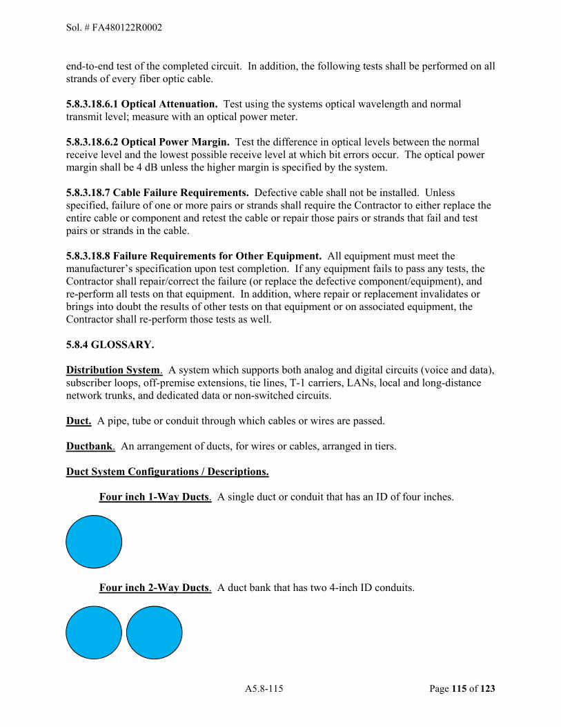
A5.8-115 Page 115 of 123
end-to-end test of the completed circuit. In addition, the following tests shall be performed on all strands of every fiber optic cable.
5.8.3.18.6.1 Optical Attenuation. Test using the systems optical wavelength and normal transmit level; measure with an optical power meter.
5.8.3.18.6.2 Optical Power Margin. Test the difference in optical levels between the normal receive level and the lowest possible receive level at which bit errors occur. The optical power margin shall be 4 dB unless the higher margin is specified by the system. 5.8.3.18.7 Cable Failure Requirements. Defective cable shall not be installed. Unless specified, failure of one or more pairs or strands shall require the Contractor to either replace the entire cable or component and retest the cable or repair those pairs or strands that fail and test pairs or strands in the cable. 5.8.3.18.8 Failure Requirements for Other Equipment. All equipment must meet the manufacturer�s specification upon test completion. If any equipment fails to pass any tests, the Contractor shall repair/correct the failure (or replace the defective component/equipment), and re-perform all tests on that equipment. In addition, where repair or replacement invalidates or brings into doubt the results of other tests on that equipment or on associated equipment, the Contractor shall re-perform those tests as well.
5.8.4 GLOSSARY.
Distribution System. A system which supports both analog and digital circuits (voice and data), subscriber loops, off-premise extensions, tie lines, T-1 carriers, LANs, local and long-distance network trunks, and dedicated data or non-switched circuits.
Duct. A pipe, tube or conduit through which cables or wires are passed.
Ductbank. An arrangement of ducts, for wires or cables, arranged in tiers.
Duct System Configurations / Descriptions.
Four inch 1-Way Ducts. A single duct or conduit that has an ID of four inches.
Four inch 2-Way Ducts. A duct bank that has two 4-inch ID conduits.
Sol. # FA480122R0002

A5.8-116 Page 116 of 123
Four inch 4-Way Ducts. A duct bank that has four 4- inch ID conduits.
Four inch 4-Way Ducts; includes 1 ea 4-way fiber Duct. A duct bank that has four 4-inch ID conduits. One of the conduits contains four 1-inch ID fiber ducts or a least one 3-cell maxcell.
Four inch Fiber Ducts. A single duct or conduit that has an ID of four inches that contains four 1-inch ID fiber ducts or a least one 3-cell maxcell.
Premise Circuit:
Switched Line: Any 2-wire loop start station connected to a switching system.
Non-switched Line: Any line not connected to a switching system (e.g., foreign exchange line, auto ring-down line, private line, PABX/DCO line, etc.).
Two-way: A full duplex communication path in which a call originates at either end. Unless specified otherwise, all paths are two-way.
One-way: A full duplex communication path in which a call originates at only one end. Unless specified otherwise, equipment shall be designed to allow configuring either end as the originator.
Sol. # FA480122R0002

A5.8-117 Page 117 of 123
Proprietary Telephone. Telephones designed for use in specific telephone systems. Normally such telephones are not interoperable with other brands of systems.
Soil/Surface Types.
Soft soils are those soils native to the area that do not contain rock as part of the natural composition. Compacted areas with less than six inches of gravel or shell rock over the native soil are considered soft areas.
Hard soils are those soils native to the area that do contain rock as part of the natural composition. Compacted areas with a hard surface such as asphalt, concrete, or more than six inches of gravel, shell rock, or clay are considered hard areas.
Voice Over Internet Protocol (VoIP). Voice transmitted over VoIP compatible digital networks by converting voice communications into data packets.
5.8.5.0 ACRONYMS/ A
ADD Automatic Disconnect Devices AGC Automatic Gain Control ANSI American National Standards Institute ATM Asynchronous Transfer Mode B B BET Building Entrance Terminal BNC Bayonet Niell-Concelman BRI Basic Rate Interface BTS Base Telecommunications System
C CAT Category (as pertains to UTP cabling) CDF Combined Distribution Frame CFR Code of Federal Regulations CLIN Contract Line Item Number CMR Common Mode Rejection CPE Customer Premise Equipment CSIR Communications and Information Systems Installation Records CVC Cyberspace Infrastructure Planning System (CIPS) Visualization Component CSU Channel Service Unit
D DCO Dial Central Office DF Distribution Frame DTMF Dual-Tone, Multi-Frequency DDN Defense Data Network
Sol. # FA480122R0002
A5.8-118 Page 118 of 123
DSN Defense Switched Network DSX Digital Signal Cross-Connecting
E
EIPS Equipment Installation Performance Specification
EIA Electronic Industry Alliance EPA Environmental Protection Agency
F FCC Federal Communications Commission FDDI Fiber Distributed Data Interface FODP Fiber Optic Distribution Panel FOSP Fiber Optic Storage Panel FTS Federal Telecommunications System
G GFE Government-Furnished Equipment
I IAW In Accordance With
ICEA Insulated Cable Engineers Association
ID Inner Diameter IDF Intermediate Distribution Frame ISDN Integrated Services Digital Network ITB Information Transport Building (same as ITN) ITN Information Transport Node (same as ITB)
L LAN Local Area Network LCD Liquid Crystal Display LED Light emitting diodes
M MCC Multi Carrier Cabinet MDF Main Distribution Frame MIL-STD Military Standard
N NEC National Electrical Code
NEMA National Electrical Manufacturers' Association
NESC National Electrical Safety Code NFPA National Fire Protection Association
O O&M Operation & Maintenance OEM Original Equipment Manufacturer
Sol. # FA480122R0002
A5.8-119 Page 119 of 123
OSHA Occupational Safety and Health Administration
OFC Optical Fiber Conductive OFCP Optical Fiber Conductive Plenum OFCR Optical Fiber Conductive Riser OFN Optic Fiber Nonconductive OFNP Optical Fiber Nonconductive Plenum OFNR Optical Fiber Nonconductive Riser OSP Outside Plant P PABX Private Automatic Branch Exchange PAC Power and Communications PID Product Identification P-Phone Proprietary Telephone PWS Performance Work Statement Q COR Quality Assurance Personnel R REA Rural Electrification Administration RUS Rural Utility Service RF Radio Frequency S SCC Single Carrier Cabinet SONET Synchronous Optical Network SLIN Sub Line Item Number T TIA Telecommunications Industry Association TO Technical Order U UL Underwriters Laboratory
UNIT OF ISSUE & PRICING TABLE ACRONYMS EA Each EST Estimated FT Foot or Feet HR Hour JB Job LF Linear Foot / Linear Feet LS Lump Sum MO Month MR Meter
Sol. # FA480122R0002

A5.8-120 Page 120 of 123
NTE Not To Exceed OPT Option Period QTY Quantity SQ FT Square Foot / Square Feet SQ YD Square Yard
Sol. # FA480122R0002

A5.9-121 Page 121 of 123
APPENDIX 5.9 OPERATIONAL NETWORK CHARACTERISTICS
5.9.1. Priority System.
5.9.1.1. The following Holloman core network facilities house functions carrying out the base mission or support. Technicians will respond to network failures in Category One and Category Two facilities before resolving any Category Three or Category Four facility problems.
CATEGORY ONE: COMBAT OPERATIONS 1) Primary Communications/Data Processing Facilities
a) DCO/RSTs - Building 221/29/878/1081b) NCC - Building 202c) ITNs � Building 202/1265/310/296/29/55/898/1086/901/1179
2) Wing Headquartersa) Wing CC - Building 29b) Wing CV- Building 29
3) Wing Operations Centersa) Emergency Operations Center (EOC) - Building 29b) Operations Command Post - Building 29
4) Group Headquartersa) OG/CC - Building 296b) MXG/CC - Building 811c) MSG/CC - Building 29d) MDG/CC � Buildinge) MMG/CC - Building 901
5) Operations Groupa) 49 OSS - Building 317b) 7 FS - Building 317c) 16 TRS � Building 5136 RS � Building 302/318d) 29 ATKS � Building 302/318e) 9 ATKS � Building 302/318
6) Wing Intelligence Facilitiesa) Wing Intel - Building 317
7) Air Traffic Control Facilitiesa) Control Tower - Building 864b) RAPCON - WSMRc) Base Weather/Airfield Operations - Building 577d) DASR - Building 13660
8) Major Tenant, Headquartersa) 96 Test Group - Building 1086b) 704 Test Group � Building 1265c) 56 FW Det 1 � Building 311d) 54 FG � Building 45
CATEGORY TWO: COMBAT SUPPORT 1) Maintenance Group, Squadron HQs
a) 849 AMXS - Building 500b) 49 MXS - Building 811
Sol. # FA480122R0002
A5.9-122 Page 122 of 123
c) 49 AMXS - Building 8682) Support Group, Squadron HQs
a) 49 CS - Building 220b) 49 SFS - Building 35c) 49 CES - Building 55d) 49 FSS � Building 224e) 49 CONS � Building 29f) 49 LRS � Building 310
3) Medical Group, Squadron HQsa) 49 AMDS - Building 23/17/20/520b) 49 MDSS - Building 23c) 49 MDOS - Building 23
4) Material Maintenance Group, Squadron HQsa) 49 MMG - Building 901b) 49 MMS - Building 901c) 49 MMSS - Building 953
CATEGORY THREE: BASE SUPPORT 1) Wing Mission Support
a) 49 AMDS (Dental) - Building 20b) DynCorp/MAP - Building 578c) DynCorp/MAMMP- Building 300d) DynCorp/MAMGFW- Building 301e) DynCorp/MAMMAP- Building 315f) DynCorp/MAGFP - Building 500g) 49 MXS/LGMP (Jet Engine) - Building 800h) 49 MXS/LGMD (PMEL) - Building 839i) 49 MXS/LGMT - Building 866j) 49 MXS/LGMCG - Building 877k) 49 MXS/LGMW (Ammo) - Building 1219
2) C4I Systems, User Locations, (< 10 C4I System Users)a) Processing (GCSS, IMDS)b) Messaging (DMS)c) PC Plans, AIS Users
3) Contingency Support Facilitiesa) Det 225 OSI - Building 293
CATEGORY FOUR: COMMUNITY SUPPORT 1) Schools (DoDDS Schools Network Facilities)
a) Middle School - Building 768b) Intermediate School - Building 769c) Primary School - Building 770
2) Misc. Station (Guard Houses)a) Main Gate - Building 5b) West Gate - Building 598
3) MWR Facilitiesa) Officers Club - Building 531b) Enlisted Club - Building 214
Sol. # FA480122R0002
A5.9-123 Page 123 of 123
c) Fitness Center - Building 450d) Arts and Crafts - Building 232e) Auto Hobby - Building 231f) Bowling Center - Building 468
4) Community Supporta) Chapel - Building 784b) Rec. Center - Building 325c) BX and Commissary - Building 787d) Library - Building 224
5) Youth Activitiesa) Child Development Center - Building 792b) Youth Center - Building 647
6) Other Base Supporta) Shoppette - Building 19b) Service Station - Building 18
END PERFORMANCE WORK STATEMENT
Sol. # FA480122R0002