
Performance Analysis of Direct Torque Controllers in Five ...
19
applied sciences Article Performance Analysis of Direct Torque Controllers in Five-Phase Electrical Drives Mario Bermúdez 1 , Federico Barrero 2, * , Cristina Martín 1 and Manuel Perales 2 Citation: Bermúdez, M.; Barrero, F.; Martín, C.; Perales, M. Performance Analysis of Direct Torque Controllers in Five-Phase Electrical Drives. Appl. Sci. 2021, 11, 11964. https://doi.org/ 10.3390/app112411964 Academic Editor: Gaetano Zizzo Received: 18 November 2021 Accepted: 7 December 2021 Published: 16 December 2021 Publisher’s Note: MDPI stays neutral with regard to jurisdictional claims in published maps and institutional affil- iations. Copyright: © 2021 by the authors. Licensee MDPI, Basel, Switzerland. This article is an open access article distributed under the terms and conditions of the Creative Commons Attribution (CC BY) license (https:// creativecommons.org/licenses/by/ 4.0/). 1 Department of Electrical Engineering, University of Seville, 41092 Seville, Spain; [email protected] (M.B.); [email protected] (C.M.) 2 Department of Electronic Engineering, University of Seville, 41092 Seville, Spain; [email protected] * Correspondence: [email protected] Abstract: The industrial application of electric machines has grown in the last decades, thanks to the development of microprocessors and power converters, which have permitted their use as variable-speed drives. Although three-phase machines are the common trend, the interest of the research community has recently focused on machines with more than three phases, known as multiphase machines. The principal reason lies in the exploitation of their advantages in terms of reliability, i.e., post-fault operating capability. Additionally, multiphase machines provide a better current distribution among phases, and lower current harmonic production in the power converter, than conventional three-phase machines. However, multiphase drive applications require the development of complex controllers to regulate the torque (or speed) and flux of the machine. In this regard, direct torque controllers have appeared as a viable alternative due to their easy formulation and high flexibility to incorporate control objectives. However, these controllers face some peculiarities and limitations in their use that require attention. This work aims to tackle direct torque control as a viable alternative for the regulation of multiphase drives. Special attention will be paid to the development of the control technique and the expected benefits and limitations in the obtained results. Case examples based on symmetrical five-phase induction machines with distributed windings in the motoring mode of operation will be used to this end. Keywords: direct torque control; multiphase; electrical drives 1. Introduction It is expected that about 80% of all the produced energy will be used by electric drives by 2030, playing a major role in the automotive field, where they will dominate almost 50% of the market by that year. Furthermore, electric drives are the basis of locomotive traction, electric ship propulsion, electric aircraft with various auxiliary functions (e.g., fuel pumps, starter/generator solutions, etc.), and renewable energy production. Although conventional three-phase drives represent the principal choice for industrial applications, multiphase ones have recently aroused the interest of practitioner engineers and researchers in the field. Any energy conversion system formed by a multiphase electric machine and converter and regulated by a certain control technique is called a multiphase drive. The first application of such a system, particularly for a five-phase drive, was used in the late 1960s [1], showing the advantages of multiphase systems over conventional three-phase ones. The main interest in the proposal was that the higher number of phases yields a torque ripple three times lower with respect to the equivalent three-phase case due to a better power distribution per phase, this being one of the most reported problems in conventional drives at that time. However, it was not until the end of the 20th and the beginning of the 21st centuries that the interest of researchers in multiphase machines was renewed due to two main reasons. First, the development of high-power and high- frequency semiconductors and, consequently, the appearance of pulse width modulation (PWM) methods to control the ON and OFF states of these electronic devices, as well as the Appl. Sci. 2021, 11, 11964. https://doi.org/10.3390/app112411964 https://www.mdpi.com/journal/applsci
-
Upload
khangminh22 -
Category
Documents
-
view
4 -
download
0
Transcript of Performance Analysis of Direct Torque Controllers in Five ...
applied sciences
Article
Performance Analysis of Direct Torque Controllers inFive-Phase Electrical Drives
Mario Bermúdez 1 , Federico Barrero 2,* , Cristina Martín 1 and Manuel Perales 2
Citation: Bermúdez, M.; Barrero, F.;
Martín, C.; Perales, M. Performance
Analysis of Direct Torque Controllers
in Five-Phase Electrical Drives. Appl.
Sci. 2021, 11, 11964. https://doi.org/
10.3390/app112411964
Academic Editor: Gaetano Zizzo
Received: 18 November 2021
Accepted: 7 December 2021
Published: 16 December 2021
Publisher’s Note: MDPI stays neutral
with regard to jurisdictional claims in
published maps and institutional affil-
iations.
Copyright: © 2021 by the authors.
Licensee MDPI, Basel, Switzerland.
This article is an open access article
distributed under the terms and
conditions of the Creative Commons
Attribution (CC BY) license (https://
creativecommons.org/licenses/by/
4.0/).
1 Department of Electrical Engineering, University of Seville, 41092 Seville, Spain; [email protected] (M.B.);[email protected] (C.M.)
2 Department of Electronic Engineering, University of Seville, 41092 Seville, Spain; [email protected]* Correspondence: [email protected]
Abstract: The industrial application of electric machines has grown in the last decades, thanksto the development of microprocessors and power converters, which have permitted their use asvariable-speed drives. Although three-phase machines are the common trend, the interest of theresearch community has recently focused on machines with more than three phases, known asmultiphase machines. The principal reason lies in the exploitation of their advantages in termsof reliability, i.e., post-fault operating capability. Additionally, multiphase machines provide abetter current distribution among phases, and lower current harmonic production in the powerconverter, than conventional three-phase machines. However, multiphase drive applications requirethe development of complex controllers to regulate the torque (or speed) and flux of the machine.In this regard, direct torque controllers have appeared as a viable alternative due to their easyformulation and high flexibility to incorporate control objectives. However, these controllers facesome peculiarities and limitations in their use that require attention. This work aims to tackle directtorque control as a viable alternative for the regulation of multiphase drives. Special attention willbe paid to the development of the control technique and the expected benefits and limitations inthe obtained results. Case examples based on symmetrical five-phase induction machines withdistributed windings in the motoring mode of operation will be used to this end.
Keywords: direct torque control; multiphase; electrical drives
1. Introduction
It is expected that about 80% of all the produced energy will be used by electric drivesby 2030, playing a major role in the automotive field, where they will dominate almost50% of the market by that year. Furthermore, electric drives are the basis of locomotivetraction, electric ship propulsion, electric aircraft with various auxiliary functions (e.g., fuelpumps, starter/generator solutions, etc.), and renewable energy production. Althoughconventional three-phase drives represent the principal choice for industrial applications,multiphase ones have recently aroused the interest of practitioner engineers and researchersin the field. Any energy conversion system formed by a multiphase electric machine andconverter and regulated by a certain control technique is called a multiphase drive. Thefirst application of such a system, particularly for a five-phase drive, was used in the late1960s [1], showing the advantages of multiphase systems over conventional three-phaseones. The main interest in the proposal was that the higher number of phases yields atorque ripple three times lower with respect to the equivalent three-phase case due toa better power distribution per phase, this being one of the most reported problems inconventional drives at that time. However, it was not until the end of the 20th and thebeginning of the 21st centuries that the interest of researchers in multiphase machineswas renewed due to two main reasons. First, the development of high-power and high-frequency semiconductors and, consequently, the appearance of pulse width modulation(PWM) methods to control the ON and OFF states of these electronic devices, as well as the
Appl. Sci. 2021, 11, 11964. https://doi.org/10.3390/app112411964 https://www.mdpi.com/journal/applsci
Appl. Sci. 2021, 11, 11964 2 of 19
energy conversion process. Second, there is the development of microelectronic technologyand the appearance of powerful electronic devices with the ability to implement controlalgorithms in real time, such as digital signal processors (DSPs) and field-programmablegate arrays (FPGAs).
Notwithstanding the above, the crucial reason for the renewed interest in multiphasedrives can be found in the intrinsic benefits that they provide versus the conventionalthree-phase ones. These benefits are based on the extra degrees of freedom introduced bythe higher number of phases and are principally the following:
• The fault-tolerant capability against a fault situation in the machine and/or the powerconverter, first presented in [2]. An n-phase machine can operate after one or severalfault occurrences without any external equipment, as long as the number of healthyphases remains greater than or equal to three (assuming a single isolated neutralconnection). Consequently, the system reliability is enhanced at the expense of areduction in the post-fault electrical torque production.
• The capability of increasing the power density in healthy operation by injecting specificcurrent harmonics, exposed in [3]. This is possible in certain multiphase machineconfigurations based on concentrated windings, where the lower current harmoniccomponents can be used to increase the torque production.
These advances and advantages underlie the adoption of multiphase drives in specificindustry applications such as variable-speed drives [4,5]. Electric propulsion of ships,electric vehicle traction (hybrid/electric vehicles and locomotives), wind energy generation,and low-power electric systems for more electric aircrafts are fields where research hasbeen focused in the last 20 years [6,7]. The interest of multiphase machines in the citedapplications, instead of the conventional three-phase counterparts, arises from the high-torque/current production and/or more robust and cheaper fault-tolerant capability thatare usually required. Benchmark solutions adopted by important companies are: theHyundai ultra-high-speed elevator, based on a 1.1 MW nine-phase electric drive; the 5 MW12-phase electric drives in the Gamesa wind turbines for onshore and offshore plants;and the 20 MW 15-phase electric drive for ship propulsion introduced by the GE PowerConversion company in the Royal Navy.
To create a body of knowledge, recent research works review advances in the field ofmultiphase drives including their industrial applications, machine design and modeling,types of converters, modulation techniques, and control strategies; and explore innovativeuses of their degrees of freedom (i.e., multimotor drives, battery chargers, post-faultcontrol, or dynamic breaking) [8–11]. Then, these state-of-the-art analyses in the multiphasedrives’ topic set the advances in the area in the last decades. In general, they show thatsymmetrical five-phase and asymmetrical six-phase machines with isolated neutrals arethe most popular multiphase machine types in the research community, while an evolutionin the control techniques has been necessary in order to optimally exploit their inherentadvantages. In this regard, asymmetric six-phase machines with isolated neutrals can beconsidered as two conventional three-phase machines coupled in a common case, whilethe five-phase drive can be considered the ideal case example to illustrate any study in themultiphase drive field.
Although field-oriented control (FOC) methods, based on decoupled control of theflux and electromagnetic torque and assisted by modulation stages, can be considered asthe most popular control technique for conventional and multiphase drives [8,9], directcontrol techniques have recently been presented as interesting competitors [12–14]. Theessence of direct controllers is to eliminate any form of modulation, forcing the statesof the power switches to rapidly track a reference value. Then, the meaning of ‘directcontrol’ techniques is related to control strategies without the intervention of a pulse widthmodulation or any other form of modulation, providing control commands that are applieddirectly to the power converter. As a main consequence, direct controllers, being directtorque controllers (DTC) are the most extended industrial alternative, can favor fast torqueresponses and control robustness with respect to the variation of the electrical parameters
Appl. Sci. 2021, 11, 11964 3 of 19
of the machine. In this regard, DTC appears to be a viable (from a commercial perspective)control alternative in conventional three-phase drives due to an easy formulation andhigh flexibility to incorporate different control objectives. However, the use of DTC inmultiphase drives is restricted in normal operation due to the impossibility of regulatingmore than two degrees of freedom (electrical torque and stator flux).
The objective of our work is to review the main concepts and interest of DTC con-trollers and to perform a performance analysis in multiphase drives, particularizing to thefive-phase case. Different operating conditions, including normal operation and limitedelectrical/magnetic or faulty situations, are analyzed, where the DTC technique is effec-tively extended to face the operation of the five-phase induction machine. Experimentaltests are provided to show that the speed, torque, and flux references are successfullytracked in all cases.
2. The Case Study: Five-Phase Distributed Windings Induction Motor Drive Using aConventional Two-Level VSI
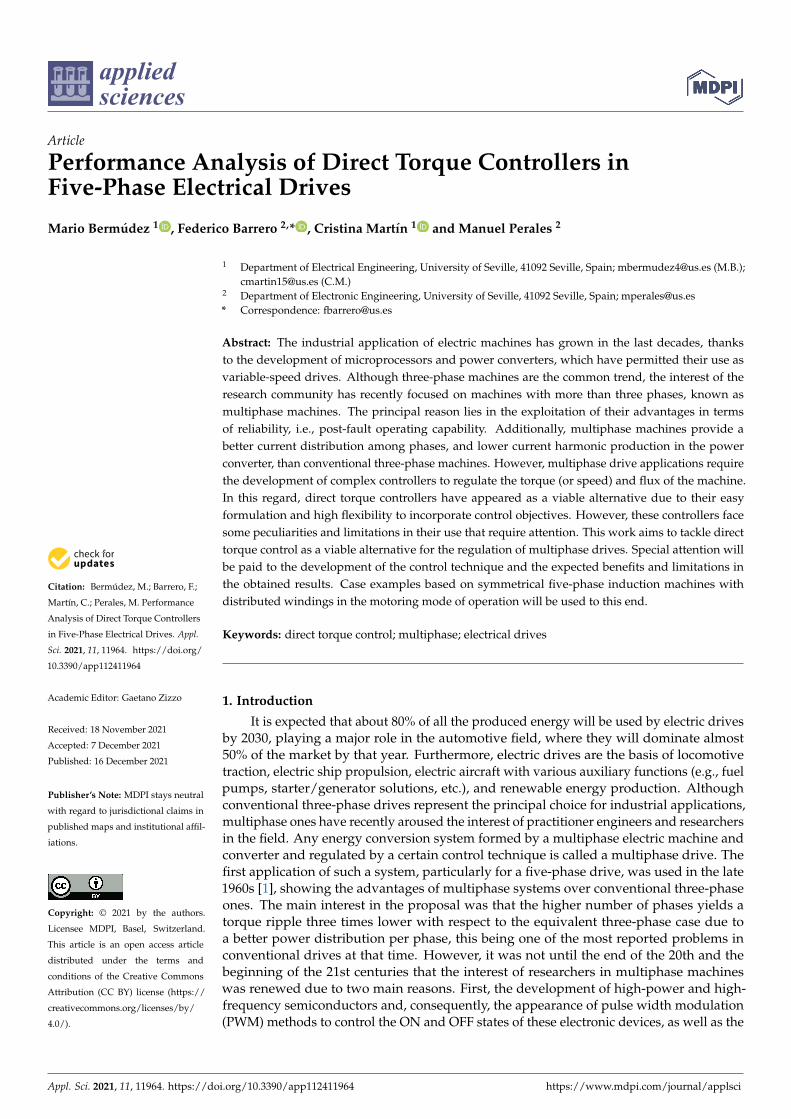
The system under study will be analytically examined in this section. It is based on afive-phase Induction Machine (IM) with a squirrel-cage rotor and symmetrically distributedstator windings (spatial equal displacement between windings) fed by a DC power supplythrough a five-phase two-level voltage source inverter (VSI). A graphical representation ofthe analyzed system is shown in Figure 1.
Figure 1. Schematic diagram of the case study.
The five-phase two-level VSI has 25 = 32 different switching states characterized by theswitching vector [Sa Sb Sc Sd Se]T, with Sk = 0,1. Therefore, the phase voltages generatedin the stator (subindex s), [vsa vsb vsc vsd vse]T, can be defined as a function of the switchingstates as follows:
vsavsbvscvsdvse
=Vdc5·
4 −1 −1 −1 −1−1 4 −1 −1 −1−1 −1 4 −1 −1−1 −1 −1 4 −1−1 −1 −1 −1 4
·
SaSbScSdSe
Note that the midpoint of the external DC power supply (Vdc) is assumed to be the
ground of the electrical system and a balanced load is also considered, so the sum of allphase voltages must be equal to zero (vsa + vsb + vsc + vsd + vse = 0).
The machine is modeled in the stationary reference frame (a, b, c, d, e) with a set ofvoltage equilibrium equations obtained from the electromagnetic circuits of the stator androtor (subindexes s and r, respectively), but then represented in two orthogonal planes,namely, α–β and x–y, plus the homopolar component z as follows:
vsα
vsβ
vsxvsyvsz
= Rs ·
isα
isβ
isxisyisz
+ddt
λsα
λsβ
λsxλsyλsz
Appl. Sci. 2021, 11, 11964 4 of 19
λsα
λsβ
λsxλsyλsz
=
Ls 0 0 0 00 Ls 0 0 00 0 Lls 0 00 0 0 Lls 00 0 0 0 Lls
·
isα
isβ
isxisyisz
+
Lm 0 0 0 00 Lm 0 0 00 0 0 0 00 0 0 0 00 0 0 0 0
·
irα
irβ
irxiryirz
00000
= Rr ·
irα
irβ
irxiryirz
+ddt
λrα
λrβ
λrxλryλrz
+
0 ωr 0 0 0−ωr 0 0 0 0
0 0 0 0 00 0 0 0 00 0 0 0 0
·
λrα
λrβ
λrxλryλrz
λrα
λrβ
λrxλryλrz
=
Lr 0 0 0 00 Lr 0 0 00 0 Llr 0 00 0 0 Llr 00 0 0 0 Llr
·
irα
irβ
irxiryirz
+
Lm 0 0 0 00 Lm 0 0 00 0 0 0 00 0 0 0 00 0 0 0 0
·
isα
isβ
isxisyisz
where λ denotes flux variables, ωr is the electrical equivalent speed of the rotor, theresistances of the stator, and the rotor are Rs and Rr, respectively, the mutual inductance isrepresented by Lm, while Lls and Llr designate the leakage inductances of the stator andthe rotor, respectively. Finally, Ls = Lls + Lm and Lr = Llr + Lm are called stator and rotorinductances. This is called the Clarke decoupled model of the electrical machine because aClarke transformation (C5 shown below, with ϑ = 2π/5) is used to refer the rotor variablesto the stator reference frame, leading to an invariant transformation of voltage and currentmagnitudes and allowing a considerable simplification of the machine model.
[C5] =25·
1 cos(ϑ) cos(2ϑ) cos(3ϑ) cos(4ϑ)0 sin(ϑ) sin(2ϑ) sin(3ϑ) sin(4ϑ)1 cos(2ϑ) cos(4ϑ) cos(6ϑ) cos(8ϑ)0 sin(2ϑ) sin(4ϑ) sin(6ϑ) sin(8ϑ)12
12
12
12
12
Note that the stator voltages applied to the electrical machine using the power con-
verter must be referred to the same coordinates, which is easily done by multiplying C5 byvoltages in the (a, b, c, d, e) reference frame. The same happens with the stator current andflux, as well as with the rotor magnitudes (voltage, current, and flux).
vsα
vsβ
vsxvsyvsz
= C5 ·
vsavsbvscvsdvse
Applying this transformation, 30 active voltage vectors and 2 null vectors can be
applied at the connection terminals of the electrical machine. Figure 2 shows the two-dimensional projections obtained for every vector, identified with the decimal numberequivalent of their respective switching state [Sa Sb Sc Sd Se]T expressed in binary logic (1or 0), being Sa and Se the most and the least significant bits, respectively. These vectorsuniformly divide the space that they occupy in 10 sectors with a separation of π/5 betweenthem. Likewise, active voltage vectors can be classified according to their magnitude inlong (0.647 Vdc), medium (0.4 Vdc), and short (0.247 Vdc) vectors. The switching states thatgenerate long vectors in the α–β plane correspond to those that generate short vectors inthe plane x–y and vice versa. The switching states corresponding to vectors of mediummagnitude in the α–β plane, also generate medium vectors in the plane x–y. Null vectorsare generated by the same switching states in both planes. This transformation allows for adetailed study of the harmonic components, since they are projected in certain planes. In
Appl. Sci. 2021, 11, 11964 5 of 19
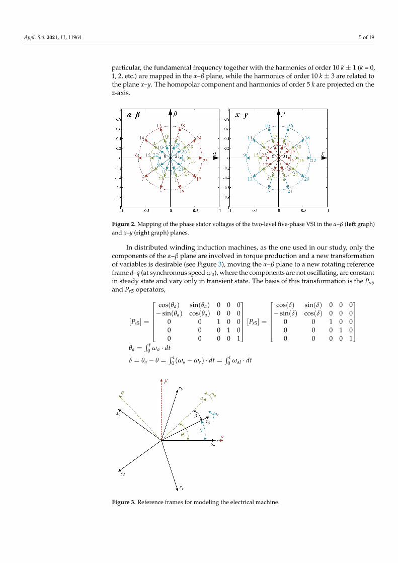
particular, the fundamental frequency together with the harmonics of order 10 k ± 1 (k = 0,1, 2, etc.) are mapped in the α–β plane, while the harmonics of order 10 k ± 3 are related tothe plane x–y. The homopolar component and harmonics of order 5 k are projected on thez-axis.
Figure 2. Mapping of the phase stator voltages of the two-level five-phase VSI in the α–β (left graph)and x–y (right graph) planes.
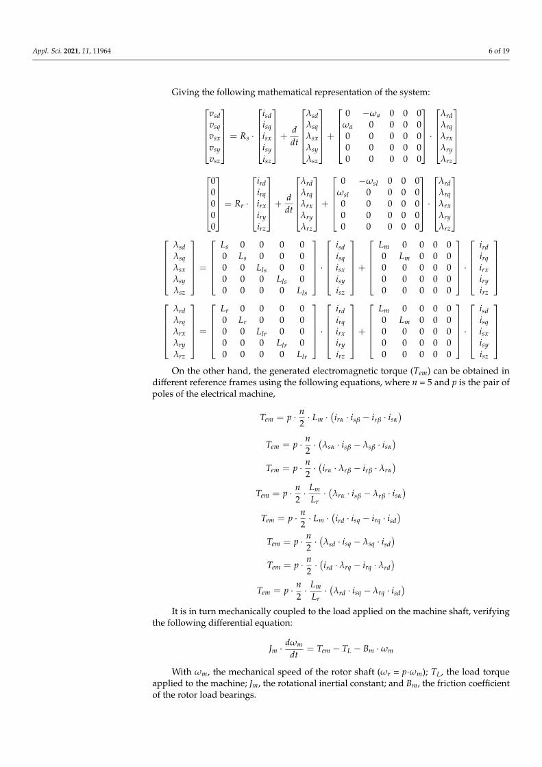
In distributed winding induction machines, as the one used in our study, only thecomponents of the α–β plane are involved in torque production and a new transformationof variables is desirable (see Figure 3), moving the α–β plane to a new rotating referenceframe d–q (at synchronous speed ωa), where the components are not oscillating, are constantin steady state and vary only in transient state. The basis of this transformation is the Ps5and Pr5 operators,
[Ps5] =
cos(θa) sin(θa) 0 0 0− sin(θa) cos(θa) 0 0 0
0 0 1 0 00 0 0 1 00 0 0 0 1
[Pr5] =
cos(δ) sin(δ) 0 0 0− sin(δ) cos(δ) 0 0 0
0 0 1 0 00 0 0 1 00 0 0 0 1
θa =
∫ t0 ωa · dt
δ = θa − θ =∫ t
0 (ωa −ωr) · dt =∫ t
0 ωsl · dt
Figure 3. Reference frames for modeling the electrical machine.
Appl. Sci. 2021, 11, 11964 6 of 19
Giving the following mathematical representation of the system:vsdvsqvsxvsyvsz
= Rs ·
isdisqisxisyisz
+ddt
λsdλsqλsxλsyλsz
+
0 −ωa 0 0 0
ωa 0 0 0 00 0 0 0 00 0 0 0 00 0 0 0 0
·
λrdλrqλrxλryλrz
00000
= Rr ·
irdirqirxiryirz
+ddt
λrdλrqλrxλryλrz
+
0 −ωsl 0 0 0
ωsl 0 0 0 00 0 0 0 00 0 0 0 00 0 0 0 0
·
λrdλrqλrxλryλrz
λsdλsqλsxλsyλsz
=
Ls 0 0 0 00 Ls 0 0 00 0 Lls 0 00 0 0 Lls 00 0 0 0 Lls
·
isdisqisxisyisz
+
Lm 0 0 0 00 Lm 0 0 00 0 0 0 00 0 0 0 00 0 0 0 0
·
irdirqirxiryirz
λrdλrqλrxλryλrz
=
Lr 0 0 0 00 Lr 0 0 00 0 Llr 0 00 0 0 Llr 00 0 0 0 Llr
·
irdirqirxiryirz
+
Lm 0 0 0 00 Lm 0 0 00 0 0 0 00 0 0 0 00 0 0 0 0
·
isdisqisxisyisz
On the other hand, the generated electromagnetic torque (Tem) can be obtained in
different reference frames using the following equations, where n = 5 and p is the pair ofpoles of the electrical machine,
Tem = p · n2· Lm ·
(irα · isβ − irβ · isα
)Tem = p · n
2·(λsα · isβ − λsβ · isα
)Tem = p · n
2·(irα · λrβ − irβ · λrα
)Tem = p · n
2· Lm
Lr·(λrα · isβ − λrβ · isα
)Tem = p · n
2· Lm ·
(ird · isq − irq · isd
)Tem = p · n
2·(λsd · isq − λsq · isd
)Tem = p · n
2·(ird · λrq − irq · λrd
)Tem = p · n
2· Lm
Lr·(λrd · isq − λrq · isd
)It is in turn mechanically coupled to the load applied on the machine shaft, verifying
the following differential equation:
Jm ·dωm
dt= Tem − TL − Bm ·ωm
With ωm, the mechanical speed of the rotor shaft (ωr = p·ωm); TL, the load torqueapplied to the machine; Jm, the rotational inertial constant; and Bm, the friction coefficientof the rotor load bearings.
Appl. Sci. 2021, 11, 11964 7 of 19
3. DTC in Five-Phase Drives
Direct Torque Control is a well-known strategy for three-phase electrical drives. It waspresented in the mid-1980s by Takahashi [15] and Depenbrock [16], showing fast flux andtorque responses, as well as more robustness with respect to the variation of the electricalparameters of the machine and generating a high-torque/flux ripple and harmonic currentcontent, compared to the more standard field-oriented control technique. The operatingprinciple is based on an off-line look-up table, which is used to select the stator voltageto be applied to the machine. The selection is made taking into account the position ofthe flux vector and the stator flux and electromagnetic torque error signals, obtained fromthe difference between reference and estimated values and processed using hysteresiscomparators. Another disadvantage of DTC that should be considered from the analysis ofits operating principle is that it does not generate a constant switching frequency. In fact,this switching frequency is variable and depends on the operating point and the bandwidthof the hysteresis controllers. Note, however, that DTC schemes have been proposed to alsobe used with PI regulators and space vector PWM methods (see [17]), to compensate forthe variable switching frequency and reduce the torque and flux ripple.
DTC has been commercialized [18] and extended to the case of multiphase drivesin recent times, considering different types of machines [19,20], machine neutral connec-tions [21,22], and drives without speed sensors [23]. In the case of multiphase drives,since the controller has only two freedom degrees (stator flux and electromagnetic torque),there is no chance of regulating the current and voltage components in the orthogonalα–β and x–y planes. In this sense, some DTC strategies have been developed that satisfythis additional requirement, controlling the current and voltage components in the α–βplane while reducing at the same time the current and voltage components in the x–yplane. For example, in [24,25], a modification of the traditional control scheme is proposed,performing a two-step search to minimize the effect of low-order harmonics. Alternatively,the use of virtual vectors has been suggested to reduce current distortion [23]. Some criteriahave also been included in the selection process within the look-up table to improve itsperformance in the low-speed region and an optimization between the two zero vectors tominimize the average switching frequency obtained [26]. On the other hand, and basedon the virtual vectors defined in [23], different DTC schemes are presented defining newvirtual vectors and avoiding the use of the zero vector to reduce the common-mode voltagegenerated by the VSI in [27,28], to improve open-phase fault operations in [29], or to avoidany reconfiguration of the controller when open-phase faults appear [30].
In our case example, the five-phase IM with distributed windings, the control goalis reduced to the α–β plane (torque and flux regulation), while the x–y components arenullifying. The analysis is based on the machine model in the stationary reference frame,which defines the variation of the stator flux in the α–β subspace using a vector notation as:
∆→λ sαβ =
∫ t
0
(→v sαβ − Rs ·
→i sαβ
)· dt
If the voltage drop in the stator resistance is ignored for simplicity, it can be assumedthat the variation in the modulus of the flux vector in a sampling period (Ts) depends onthe voltage vector as follows:
∆→λ sαβ ≈
→v sαβ · Ts
The electromagnetic torque behavior can be determined by the following expression:
Tem = 52 ·
p·krσ·Ls·(→
λ rαβ ×→λ sαβ
)= 5
2 ·p·krσ·Ls·∥∥∥∥→λ rαβ
∥∥∥∥ · ∥∥∥∥→λ sαβ
∥∥∥∥ · sin γ
σ = 1−(
L2m
Ls ·Lr
)kr =
LmLr
Appl. Sci. 2021, 11, 11964 8 of 19
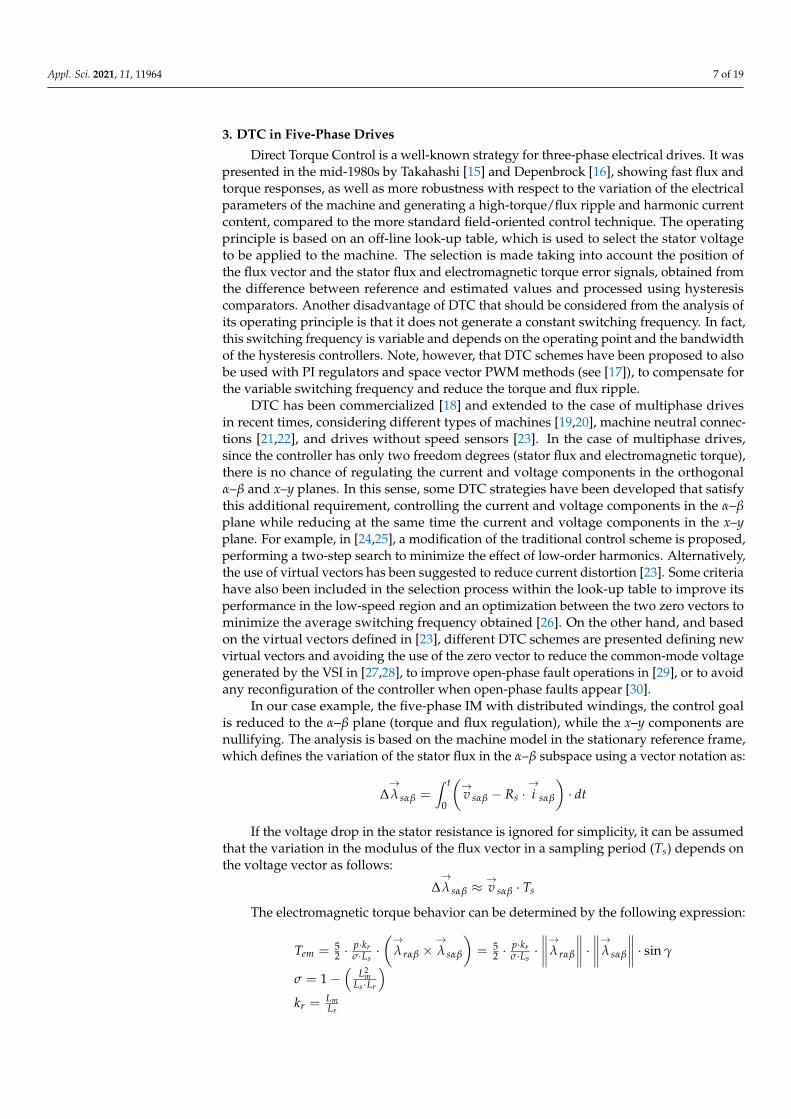
where γ is the angle of load (angle between the flux vectors of the stator and the rotor).Then, a change in γ, obtained by applying a voltage vector, produces an increase or decreasein Tem. Note that the rotor time constant is greater than the stator time constant, so it canbe assumed that a slower variation of the rotor flux compared to the stator flux, andtherefore the rotor flux, can be considered constant in a sampling time. Note also thatthere is an impact of a spatial voltage vector on the magnitude of the stator flux. Differentresults are obtained depending on the applied stator voltage (32 alternatives using thefive-phases two-level VSI, being 30 active vectors and 2 null vectors; see Figure 4). Inshort, the applied voltage vector can be divided into a tangential and a radial componentwith respect to the flux. The tangential component produces a change in machine torque,increasing or decreasing the sine of the angle γ, while the radial component modifies themagnitude of the stator flux, increasing or decreasing its modulus. Hence, the flux and theelectromagnetic torque are controlled simultaneously using DTC.
Figure 4. Impact of voltage vectors on the stator flux and the load angle for the application of DTC.(a) Estimated phasor diagram. (b) Alternatives available using the 2-level 5-phase VSI.
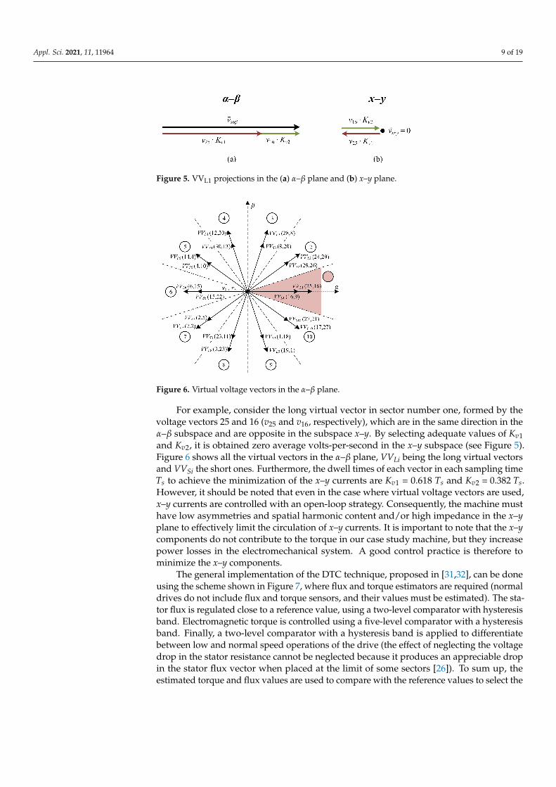
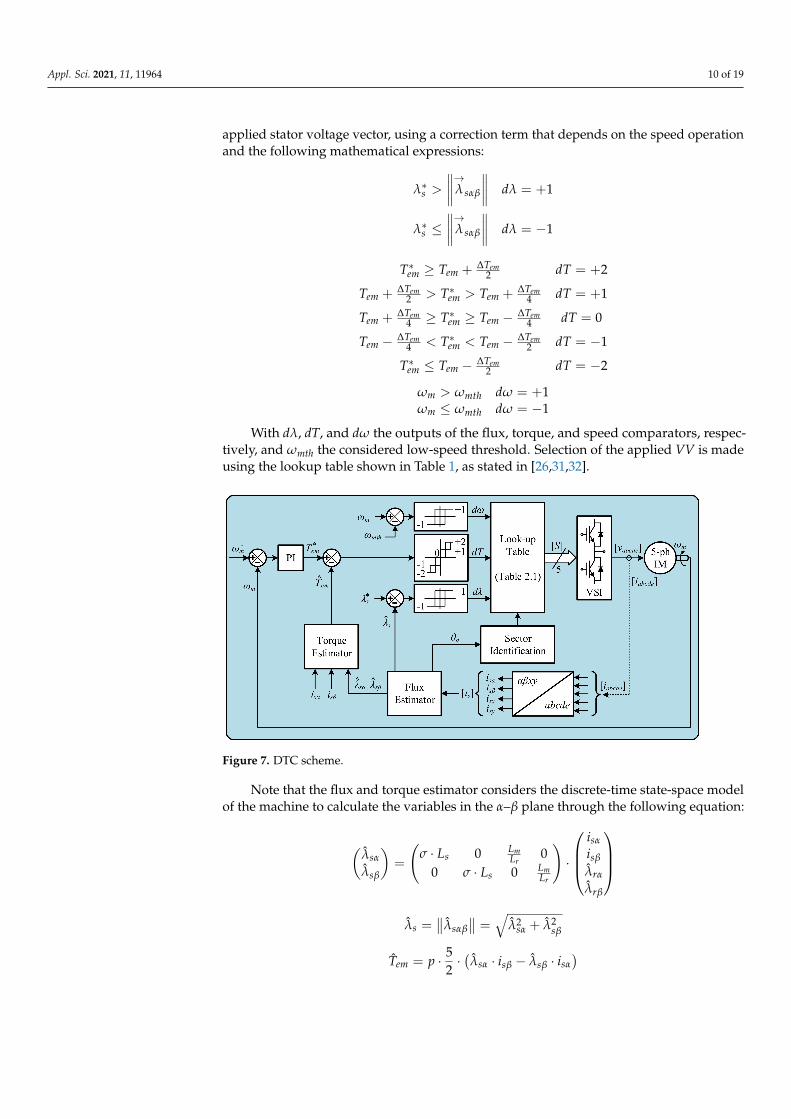
The application of the voltage vector controls the flux and electromagnetic torqueand affects not only the α–β plane, but also the plane x–y, where losses and unwantedvoltage and current harmonics are generated in the case study machine. Figures 2 and 4show that 32 voltage vectors with 4 different magnitudes can be applied: 2 null vectors(0 volts applied), 10 short vectors (0.247 Vdc volts applied), 10 medium vectors (0.4 Vdcvolts applied), and 10 long vectors (0.647 Vdc volts applied). Note also (see Figure 2) thatswitching states that represent long vectors in the α–β plane, symbolize short vectors in thex–y plane (and vice versa), while switching states that generate medium vectors in the α–βplane also cause medium vectors in the x–y plane. In addition, long and medium voltagevectors with the same direction in the α–β subspace, are equivalent to medium and shortvectors with opposite directions in the x–y subspace. The same happens with mediumand short vectors in the α–β plane, since they are equivalent to medium and long vectorswith opposite directions in the plane x–y. These geometrical characteristics make possiblethe definition of a kind of voltage vector, called virtual voltage vector or VVi [23], whichminimizes currents in the x–y plane. Each virtual vector is based on the application of twoavailable voltage vectors (v1 and v2) during adequate dwell time ratios (Kv1 and Kv2) togenerate zero average volts per second in the x–y subspace. It is then possible to define ineach sector a long virtual vector (formed by a long and a medium vector in the α–β plane)and a short virtual vector (formed by a medium and a short vector in the α–β plane), asshown in the following equations and in Figures 5 and 6:
VVLi = vLong · Kv1 + vMedium · Kv2
VVSi = vMedium · Kv1 + vShort · Kv2
Appl. Sci. 2021, 11, 11964 9 of 19
Figure 5. VVL1 projections in the (a) α–β plane and (b) x–y plane.
Figure 6. Virtual voltage vectors in the α–β plane.
For example, consider the long virtual vector in sector number one, formed by thevoltage vectors 25 and 16 (v25 and v16, respectively), which are in the same direction in theα–β subspace and are opposite in the subspace x–y. By selecting adequate values of Kv1and Kv2, it is obtained zero average volts-per-second in the x–y subspace (see Figure 5).Figure 6 shows all the virtual vectors in the α–β plane, VVLi being the long virtual vectorsand VVSi the short ones. Furthermore, the dwell times of each vector in each sampling timeTs to achieve the minimization of the x–y currents are Kv1 = 0.618 Ts and Kv2 = 0.382 Ts.However, it should be noted that even in the case where virtual voltage vectors are used,x–y currents are controlled with an open-loop strategy. Consequently, the machine musthave low asymmetries and spatial harmonic content and/or high impedance in the x–yplane to effectively limit the circulation of x–y currents. It is important to note that the x–ycomponents do not contribute to the torque in our case study machine, but they increasepower losses in the electromechanical system. A good control practice is therefore tominimize the x–y components.
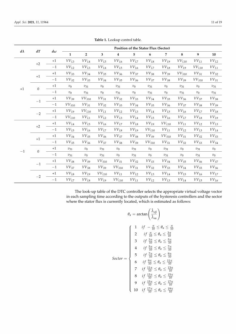
The general implementation of the DTC technique, proposed in [31,32], can be doneusing the scheme shown in Figure 7, where flux and torque estimators are required (normaldrives do not include flux and torque sensors, and their values must be estimated). The sta-tor flux is regulated close to a reference value, using a two-level comparator with hysteresisband. Electromagnetic torque is controlled using a five-level comparator with a hysteresisband. Finally, a two-level comparator with a hysteresis band is applied to differentiatebetween low and normal speed operations of the drive (the effect of neglecting the voltagedrop in the stator resistance cannot be neglected because it produces an appreciable dropin the stator flux vector when placed at the limit of some sectors [26]). To sum up, theestimated torque and flux values are used to compare with the reference values to select the
Appl. Sci. 2021, 11, 11964 10 of 19
applied stator voltage vector, using a correction term that depends on the speed operationand the following mathematical expressions:
λ∗s >
∥∥∥∥→λ sαβ
∥∥∥∥ dλ = +1
λ∗s ≤∥∥∥∥→λ sαβ
∥∥∥∥ dλ = −1
T∗em ≥ Tem + ∆Tem2 dT = +2
Tem + ∆Tem2 > T∗em > Tem + ∆Tem
4 dT = +1
Tem + ∆Tem4 ≥ T∗em ≥ Tem − ∆Tem
4 dT = 0
Tem − ∆Tem4 < T∗em < Tem − ∆Tem
2 dT = −1
T∗em ≤ Tem − ∆Tem2 dT = −2
ωm > ωmth dω = +1ωm ≤ ωmth dω = −1
With dλ, dT, and dω the outputs of the flux, torque, and speed comparators, respec-tively, and ωmth the considered low-speed threshold. Selection of the applied VV is madeusing the lookup table shown in Table 1, as stated in [26,31,32].
Figure 7. DTC scheme.
Note that the flux and torque estimator considers the discrete-time state-space modelof the machine to calculate the variables in the α–β plane through the following equation:
(λsα
λsβ
)=
(σ · Ls 0 Lm
Lr0
0 σ · Ls 0 LmLr
)·
isα
isβ
λrα
λrβ
λs =
∥∥λsαβ
∥∥ =√
λ2sα + λ2
sβ
Tem = p · 52·(λsα · isβ − λsβ · isα
)
Appl. Sci. 2021, 11, 11964 11 of 19
Table 1. Lookup control table.
dλ dT dωPosition of the Stator Flux (Sector)
1 2 3 4 5 6 7 8 9 10
+1
+2+1 VVL3 VVL4 VVL5 VVL6 VVL7 VVL8 VVL9 VVL10 VVL1 VVL2
−1 VVL2 VVL3 VVL4 VVL5 VVL6 VVL7 VVL8 VVL9 VVL10 VVL1
+1+1 VVS3 VVS4 VVS5 VVS6 VVS7 VVS8 VVS9 VVS10 VVS1 VVS2
−1 VVS2 VVS3 VVS4 VVS5 VVS6 VVS7 VVS8 VVS9 VVS10 VVS1
0+1 v0 v31 v0 v31 v0 v31 v0 v31 v0 v31
−1 v0 v31 v0 v31 v0 v31 v0 v31 v0 v31
−1+1 VVS9 VVS10 VVS1 VVS2 VVS3 VVS4 VVS5 VVS6 VVS7 VVS8
−1 VVS10 VVS1 VVS2 VVS3 VVS4 VVS5 VVS6 VVS7 VVS8 VVS9
−2+1 VVL9 VVL10 VVL1 VVL2 VVL3 VVL4 VVL5 VVL6 VVL7 VVL8
−1 VVL10 VVL1 VVL2 VVL3 VVL4 VVL5 VVL6 VVL7 VVL8 VVL9
−1
+2+1 VVL4 VVL5 VVL6 VVL7 VVL8 VVL9 VVL10 VVL1 VVL2 VVL3
−1 VVL5 VVL6 VVL7 VVL8 VVL9 VVL10 VVL1 VVL2 VVL3 VVL4
+1+1 VVS4 VVS5 VVS6 VVS7 VVS8 VVS9 VVS10 VVS1 VVS2 VVS3
−1 VVS5 VVS6 VVS7 VVS8 VVS9 VVS10 VVS1 VVS2 VVS3 VVS4
0+1 v31 v0 v31 v0 v31 v0 v31 v0 v31 v0
−1 v31 v0 v31 v0 v31 v0 v31 v0 v31 v0
−1+1 VVS8 VVS9 VVS10 VVS1 VVS2 VVS3 VVS4 VVS5 VVS6 VVS7
−1 VVS7 VVS8 VVS9 VVS10 VVS1 VVS2 VVS3 VVS4 VVS5 VVS6
−2+1 VVL8 VVL9 VVL10 VVL1 VVL2 VVL3 VVL4 VVL5 VVL6 VVL7
−1 VVL7 VVL8 VVL9 VVL10 VVL1 VVL2 VVL3 VVL4 VVL5 VVL6
The look-up table of the DTC controller selects the appropriate virtual voltage vectorin each sampling time according to the outputs of the hysteresis controllers and the sectorwhere the stator flux is currently located, which is estimated as follows:
θa = arctan
(λsβ
λsα
)
Sector =
1 i f − π10 ≤ θa ≤ π
10
2 i f π10 ≤ θa ≤ 3π
10
3 i f 3π10 ≤ θa ≤ 5π
10
4 i f 5π10 ≤ θa ≤ 7π
10
5 i f 7π10 ≤ θa ≤ 9π
10
6 i f 9π10 ≤ θa ≤ 11π
10
7 i f 11π10 ≤ θa ≤ 13π
10
8 i f 13π10 ≤ θa ≤ 15π
10
9 i f 15π10 ≤ θa ≤ 17π
10
10 i f 17π10 ≤ θa ≤ 19π
10
Appl. Sci. 2021, 11, 11964 12 of 19
4. Results and Discussion
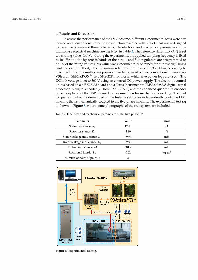
To assess the performance of the DTC scheme, different experimental tests were per-formed on a conventional three-phase induction machine with 30 slots that was redesignedto have five phases and three pole pairs. The electrical and mechanical parameters of themultiphase electrical machine are depicted in Table 2. The reference stator flux (λs*) is setto its rating value (0.4 Wb) during the experiments, the applied sampling frequency is fixedto 10 kHz and the hysteresis bands of the torque and flux regulators are programmed tobe 1% of the rating values (this value was experimentally obtained for our test rig using atrial and error method). The maximum reference torque is set to 3.25 N·m, according tomachine limits. The multiphase power converter is based on two conventional three-phaseVSIs from SEMIKRON® (two SKS-22F modules in which five power legs are used). TheDC link voltage is set to 300 V using an external DC power supply. The electronic controlunit is based on a MSK28335 board and a Texas Instruments® TMS320F28335 digital signalprocessor. A digital encoder (GHM510296R/2500) and the enhanced quadrature encoderpulse peripheral of the DSP are used to measure the rotor mechanical speed ωm. The loadtorque (TL), which is demanded in the tests, is set by an independently controlled DCmachine that is mechanically coupled to the five-phase machine. The experimental test rigis shown in Figure 8, where some photographs of the real system are included.
Table 2. Electrical and mechanical parameters of the five-phase IM.
Parameter Value Unit
Stator resistance, Rs 12.85 Ω
Rotor resistance, Rr 4.80 Ω
Stator leakage inductance, Lls 79.93 mH
Rotor leakage inductance, Llr 79.93 mH
Mutual inductance, M 681.7 mH
Rotational inertia, Jm 0.02 kg-m2
Number of pairs of poles, p 3 -
Figure 8. Experimental test rig.
Appl. Sci. 2021, 11, 11964 13 of 19
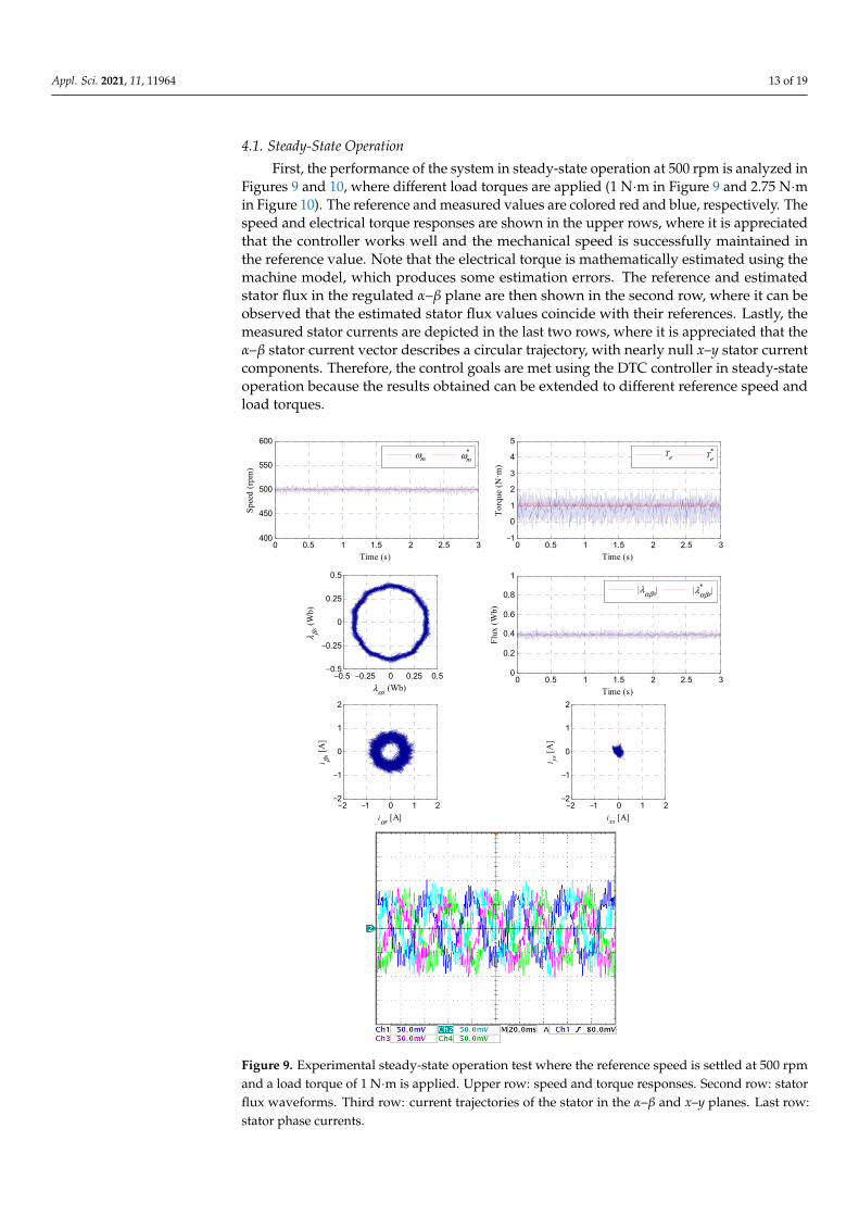
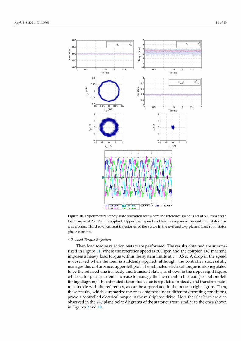
4.1. Steady-State Operation
First, the performance of the system in steady-state operation at 500 rpm is analyzed inFigures 9 and 10, where different load torques are applied (1 N·m in Figure 9 and 2.75 N·min Figure 10). The reference and measured values are colored red and blue, respectively. Thespeed and electrical torque responses are shown in the upper rows, where it is appreciatedthat the controller works well and the mechanical speed is successfully maintained inthe reference value. Note that the electrical torque is mathematically estimated using themachine model, which produces some estimation errors. The reference and estimatedstator flux in the regulated α–β plane are then shown in the second row, where it can beobserved that the estimated stator flux values coincide with their references. Lastly, themeasured stator currents are depicted in the last two rows, where it is appreciated that theα–β stator current vector describes a circular trajectory, with nearly null x–y stator currentcomponents. Therefore, the control goals are met using the DTC controller in steady-stateoperation because the results obtained can be extended to different reference speed andload torques.
Appl. Sci. 2021, 11, x FOR PEER REVIEW 13 of 19
Rotor leakage inductance, Llr 79.93 mH Mutual inductance, M 681.7 mH Rotational inertia, Jm 0.02 kg-m2
Number of pairs of poles, p 3 -
4.1. Steady-State Operation First, the performance of the system in steady-state operation at 500 rpm is analyzed
in Figures 9 and 10, where different load torques are applied (1 N·m in Figure 9 and 2.75 N·m in Figure 10). The reference and measured values are colored red and blue, respec-tively. The speed and electrical torque responses are shown in the upper rows, where it is appreciated that the controller works well and the mechanical speed is successfully main-tained in the reference value. Note that the electrical torque is mathematically estimated using the machine model, which produces some estimation errors. The reference and es-timated stator flux in the regulated α–β plane are then shown in the second row, where it can be observed that the estimated stator flux values coincide with their references. Lastly, the measured stator currents are depicted in the last two rows, where it is appreciated that the α–β stator current vector describes a circular trajectory, with nearly null x–y stator current components. Therefore, the control goals are met using the DTC controller in steady-state operation because the results obtained can be extended to different reference speed and load torques.
-2 -1 0 1 2-2
-1
0
1
2
iαs [A]
i βs [A
]
-2 -1 0 1 2-2
-1
0
1
2
ixs [A]
i ys [
A]
0 0.5 1 1.5 2 2.5 3400
450
500
550
600
Time (s)
Spee
d (r
pm)
ωm ω*m
-0.5 -0.25 0 0.25 0.5-0.5
-0.25
0
0.25
0.5
λαs (Wb)
λ βs (W
b)
0 0.5 1 1.5 2 2.5 30
0.2
0.4
0.6
0.8
1
Time (s)
Flux
(Wb)
|λαβs| |λαβs
* |
0 0.5 1 1.5 2 2.5 3-1
0
1
2
3
4
5
Time (s)
Torq
ue (N
·m)
Te Te
*
‒
‒ ‒
‒
‒
‒
‒ ‒
‒
‒
‒ ‒
‒
Figure 9. Experimental steady-state operation test where the reference speed is settled at 500 rpm and a load torque of 1 N·m is applied. Upper row: speed and torque responses. Second row: stator
Figure 9. Experimental steady-state operation test where the reference speed is settled at 500 rpmand a load torque of 1 N·m is applied. Upper row: speed and torque responses. Second row: statorflux waveforms. Third row: current trajectories of the stator in the α–β and x–y planes. Last row:stator phase currents.
Appl. Sci. 2021, 11, 11964 14 of 19
Appl. Sci. 2021, 11, x FOR PEER REVIEW 14 of 19
flux waveforms. Third row: current trajectories of the stator in the α–β and x–y planes. Last row: stator phase currents.
-2 -1 0 1 2-2
-1
0
1
2
ixs (A)
i ys (
A)
-2 -1 0 1 2-2
-1
0
1
2
iαs (A)
i βs (A
)
0 0.5 1 1.5 2 2.5 3400
450
500
550
600
Time (s)Sp
eed
(rpm
)
ωm ω*m
0 0.5 1 1.5 2 2.5 3-1
0
1
2
3
4
5
Time (s)
Torq
ue (N
·m)
Te Te
*
-0.5 -0.25 0 0.25 0.5-0.5
-0.25
0
0.25
0.5
λαs (Wb)
λ βs (W
b)
0 0.5 1 1.5 2 2.5 30
0.2
0.4
0.6
0.8
1
Time (s)
Flux
(Wb)
|λαβs| |λαβs
* |
‒
‒ ‒
‒
‒
‒ ‒
‒
‒
‒ ‒
‒
‒
Figure 10. Experimental steady-state operation test where the reference speed is set at 500 rpm and a load torque of 2.75 N·m is applied. Upper row: speed and torque responses. Second row: stator flux waveforms. Third row: current trajectories of the stator in the α–β and x–y planes. Last row: stator phase currents.
4.2. Load Torque Rejection Then load torque rejection tests were performed. The results obtained are summa-
rized in Figure 11, where the reference speed is 500 rpm and the coupled DC machine imposes a heavy load torque within the system limits at t = 0.5 s. A drop in the speed is observed when the load is suddenly applied; although, the controller successfully man-ages this disturbance, upper-left plot. The estimated electrical torque is also regulated to be the referred one in steady and transient states, as shown in the upper right figure, while stator phase currents increase to manage the increment in the load (see bottom-left timing diagram). The estimated stator flux value is regulated in steady and transient states to coincide with the references, as can be appreciated in the bottom right figure. Then, these results, which summarize the ones obtained under different operating conditions, prove a controlled electrical torque in the multiphase drive. Note that flat lines are also observed in the x–y plane polar diagrams of the stator current, similar to the ones shown in Figures 9 and 10.
Figure 10. Experimental steady-state operation test where the reference speed is set at 500 rpm and aload torque of 2.75 N·m is applied. Upper row: speed and torque responses. Second row: stator fluxwaveforms. Third row: current trajectories of the stator in the α–β and x–y planes. Last row: statorphase currents.
4.2. Load Torque Rejection
Then load torque rejection tests were performed. The results obtained are summa-rized in Figure 11, where the reference speed is 500 rpm and the coupled DC machineimposes a heavy load torque within the system limits at t = 0.5 s. A drop in the speedis observed when the load is suddenly applied; although, the controller successfullymanages this disturbance, upper-left plot. The estimated electrical torque is also regulatedto be the referred one in steady and transient states, as shown in the upper right figure,while stator phase currents increase to manage the increment in the load (see bottom-lefttiming diagram). The estimated stator flux value is regulated in steady and transient statesto coincide with the references, as can be appreciated in the bottom right figure. Then,these results, which summarize the ones obtained under different operating conditions,prove a controlled electrical torque in the multiphase drive. Note that flat lines are alsoobserved in the x–y plane polar diagrams of the stator current, similar to the ones shownin Figures 9 and 10.
Appl. Sci. 2021, 11, 11964 15 of 19Appl. Sci. 2021, 11, x FOR PEER REVIEW 15 of 19
0 0.5 1 1.5 2 2.5 3-4
-2
0
2
4
Time (s)
Curr
ent (
A)
iasibsicsidsies
0 0.5 1 1.5 2 2.5 30
0.2
0.4
0.6
0.8
1
Time (s)
Flux
(Wb)
|λαβs| |λαβs
* |
0 0.5 1 1.5 2 2.5 3
0
2
4
6
Time (s)
Torq
ue (N
·m)
Te Te
*
0 0.5 1 1.5 2 2.5 3400
450
500
550
600
Time (s)
Spee
d (r
pm)
ωm ω*m
‒
‒
Figure 11. Experimental response of the controlled system in a load torque rejection test. The refer-ence speed is 500 rpm and a load torque is applied at 0.5 s. The upper row shows the speed and torque responses. The lower row shows the stator current waveform and modulus of the stator flux during the test.
4.3. Step-Speed and Reverse Speed Tests Then, experimental tests were conducted to evaluate the step-speed response of the
system. Figure 12 reviews the results obtained. In the experiment, the machine is initially magnetized and the reference speed is changed from 0 to 500 rpm at t = 0.2 s. The perfor-mance of the mechanical speed (upper row, left plot), the electrical torque (upper row, right figure), stator phase currents (bottom row, left illustration), and the stator flux (bot-tom row, right drawing) is shown. Again, it can be observed that the DTC scheme pro-vides accurate tracking of the reference speed and electrical torque, while the stator flux is maintained constant and equal to the reference value.
0 0.5 1 1.5 2 2.5 3-4
-2
0
2
4
Time (s)
Curr
ent (
A)
iasibsicsidsies
0 0.5 1 1.5 2 2.5 30
0.2
0.4
0.6
0.8
1
Time (s)
Flux
(Wb)
|λαβs| |λαβs
* |
0 0.5 1 1.5 2 2.5 3
0
200
400
600
Time (s)
Spee
d (r
pm)
ωm ω*m
0 0.5 1 1.5 2 2.5 3-2
0
2
4
6
Time (s)
Torq
ue (N
·m)
Te Te
*
‒
‒
‒
Figure 12. Experimental response of the controlled system in a step speed test. The reference speed is changed from 0 to 500 rpm at 0.2 s. The upper row shows the speed and torque responses. The lower row shows the stator current waveform and modulus of the stator flux during the test.
Finally, a reverse speed test is generated, where a change in the reference speed from 500 to –500 rpm is forced at t = 0.2 s. The obtained results are shown in Figure 13. Appro-priate tracking is observed in the speed and the electrical torque, as can be seen in the upper row plots, left and right ones, respectively, while the expected stator phase current
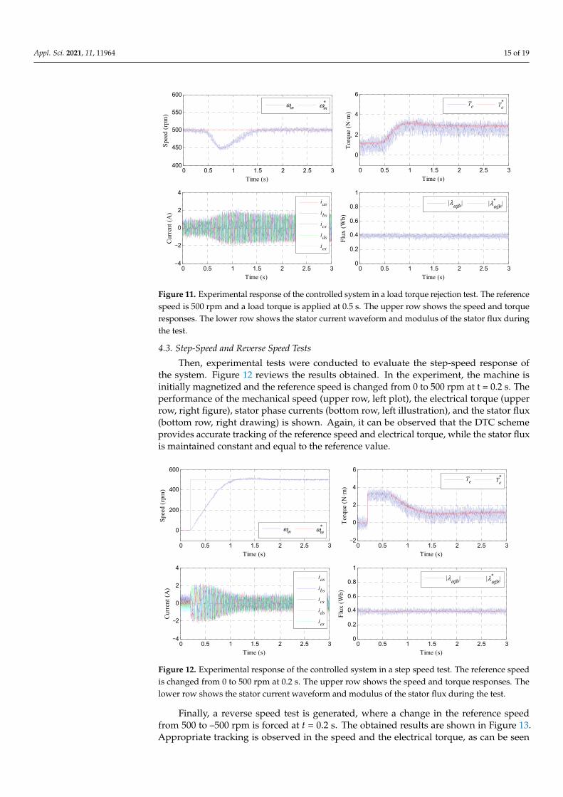
Figure 11. Experimental response of the controlled system in a load torque rejection test. The referencespeed is 500 rpm and a load torque is applied at 0.5 s. The upper row shows the speed and torqueresponses. The lower row shows the stator current waveform and modulus of the stator flux duringthe test.
4.3. Step-Speed and Reverse Speed Tests
Then, experimental tests were conducted to evaluate the step-speed response ofthe system. Figure 12 reviews the results obtained. In the experiment, the machine isinitially magnetized and the reference speed is changed from 0 to 500 rpm at t = 0.2 s. Theperformance of the mechanical speed (upper row, left plot), the electrical torque (upperrow, right figure), stator phase currents (bottom row, left illustration), and the stator flux(bottom row, right drawing) is shown. Again, it can be observed that the DTC schemeprovides accurate tracking of the reference speed and electrical torque, while the stator fluxis maintained constant and equal to the reference value.
Appl. Sci. 2021, 11, x FOR PEER REVIEW 15 of 19
0 0.5 1 1.5 2 2.5 3-4
-2
0
2
4
Time (s)
Curr
ent (
A)
iasibsicsidsies
0 0.5 1 1.5 2 2.5 30
0.2
0.4
0.6
0.8
1
Time (s)
Flux
(Wb)
|λαβs| |λαβs
* |
0 0.5 1 1.5 2 2.5 3
0
2
4
6
Time (s)
Torq
ue (N
·m)
Te Te
*
0 0.5 1 1.5 2 2.5 3400
450
500
550
600
Time (s)Sp
eed
(rpm
)
ωm ω*m
‒
‒
Figure 11. Experimental response of the controlled system in a load torque rejection test. The refer-ence speed is 500 rpm and a load torque is applied at 0.5 s. The upper row shows the speed and torque responses. The lower row shows the stator current waveform and modulus of the stator flux during the test.
4.3. Step-Speed and Reverse Speed Tests Then, experimental tests were conducted to evaluate the step-speed response of the
system. Figure 12 reviews the results obtained. In the experiment, the machine is initially magnetized and the reference speed is changed from 0 to 500 rpm at t = 0.2 s. The perfor-mance of the mechanical speed (upper row, left plot), the electrical torque (upper row, right figure), stator phase currents (bottom row, left illustration), and the stator flux (bot-tom row, right drawing) is shown. Again, it can be observed that the DTC scheme pro-vides accurate tracking of the reference speed and electrical torque, while the stator flux is maintained constant and equal to the reference value.
0 0.5 1 1.5 2 2.5 3-4
-2
0
2
4
Time (s)
Curr
ent (
A)
iasibsicsidsies
0 0.5 1 1.5 2 2.5 30
0.2
0.4
0.6
0.8
1
Time (s)
Flux
(Wb)
|λαβs| |λαβs
* |
0 0.5 1 1.5 2 2.5 3
0
200
400
600
Time (s)
Spee
d (r
pm)
ωm ω*m
0 0.5 1 1.5 2 2.5 3-2
0
2
4
6
Time (s)
Torq
ue (N
·m)
Te Te
*
‒
‒
‒
Figure 12. Experimental response of the controlled system in a step speed test. The reference speed is changed from 0 to 500 rpm at 0.2 s. The upper row shows the speed and torque responses. The lower row shows the stator current waveform and modulus of the stator flux during the test.
Finally, a reverse speed test is generated, where a change in the reference speed from 500 to –500 rpm is forced at t = 0.2 s. The obtained results are shown in Figure 13. Appro-priate tracking is observed in the speed and the electrical torque, as can be seen in the upper row plots, left and right ones, respectively, while the expected stator phase current
Figure 12. Experimental response of the controlled system in a step speed test. The reference speedis changed from 0 to 500 rpm at 0.2 s. The upper row shows the speed and torque responses. Thelower row shows the stator current waveform and modulus of the stator flux during the test.
Finally, a reverse speed test is generated, where a change in the reference speedfrom 500 to –500 rpm is forced at t = 0.2 s. The obtained results are shown in Figure 13.Appropriate tracking is observed in the speed and the electrical torque, as can be seen
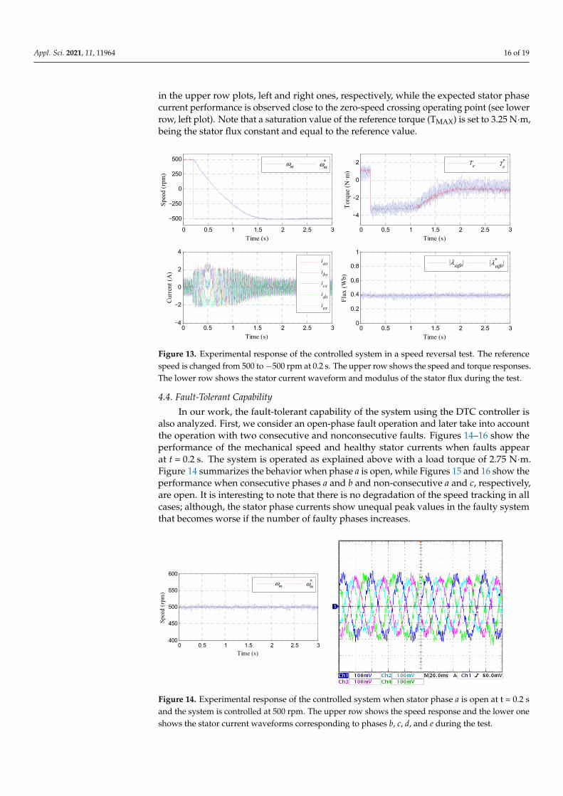
Appl. Sci. 2021, 11, 11964 16 of 19
in the upper row plots, left and right ones, respectively, while the expected stator phasecurrent performance is observed close to the zero-speed crossing operating point (see lowerrow, left plot). Note that a saturation value of the reference torque (TMAX) is set to 3.25 N·m,being the stator flux constant and equal to the reference value.
Appl. Sci. 2021, 11, x FOR PEER REVIEW 16 of 19
performance is observed close to the zero-speed crossing operating point (see lower row, left plot). Note that a saturation value of the reference torque (TMAX) is set to 3.25 N·m, being the stator flux constant and equal to the reference value.
0 0.5 1 1.5 2 2.5 3-4
-2
0
2
4
Time (s)
Curr
ent (
A)
iasibsicsidsies
0 0.5 1 1.5 2 2.5 30
0.2
0.4
0.6
0.8
1
Time (s)Fl
ux (W
b)
|λαβs| |λαβs
* |
0 0.5 1 1.5 2 2.5 3
-4
-2
0
2
Time (s)
Torq
ue (N
·m)
Te Te
*
0 0.5 1 1.5 2 2.5 3
-500
-250
0
250
500
Time (s)
Spee
d (r
pm)
ωm ω*m
‒
‒
‒ ‒
‒
‒
Figure 13. Experimental response of the controlled system in a speed reversal test. The reference speed is changed from 500 to −500 rpm at 0.2 s. The upper row shows the speed and torque re-sponses. The lower row shows the stator current waveform and modulus of the stator flux during the test.
4.4. Fault-Tolerant Capability In our work, the fault-tolerant capability of the system using the DTC controller is
also analyzed. First, we consider an open-phase fault operation and later take into account the operation with two consecutive and nonconsecutive faults. Figures 14–16 show the performance of the mechanical speed and healthy stator currents when faults appear at t = 0.2 s. The system is operated as explained above with a load torque of 2.75 N·m. Figure 14 summarizes the behavior when phase a is open, while Figures 15 and 16 show the per-formance when consecutive phases a and b and non-consecutive a and c, respectively, are open. It is interesting to note that there is no degradation of the speed tracking in all cases; although, the stator phase currents show unequal peak values in the faulty system that becomes worse if the number of faulty phases increases.
0 0.5 1 1.5 2 2.5 3400
450
500
550
600
Time (s)
Spee
d (r
pm)
ωm ω*m
Figure 14. Experimental response of the controlled system when stator phase a is open at t = 0.2 s and the system is controlled at 500 rpm. The upper row shows the speed response and the lower one shows the stator current waveforms corresponding to phases b, c, d, and e during the test.
Figure 13. Experimental response of the controlled system in a speed reversal test. The referencespeed is changed from 500 to−500 rpm at 0.2 s. The upper row shows the speed and torque responses.The lower row shows the stator current waveform and modulus of the stator flux during the test.
4.4. Fault-Tolerant Capability
In our work, the fault-tolerant capability of the system using the DTC controller isalso analyzed. First, we consider an open-phase fault operation and later take into accountthe operation with two consecutive and nonconsecutive faults. Figures 14–16 show theperformance of the mechanical speed and healthy stator currents when faults appearat t = 0.2 s. The system is operated as explained above with a load torque of 2.75 N·m.Figure 14 summarizes the behavior when phase a is open, while Figures 15 and 16 show theperformance when consecutive phases a and b and non-consecutive a and c, respectively,are open. It is interesting to note that there is no degradation of the speed tracking in allcases; although, the stator phase currents show unequal peak values in the faulty systemthat becomes worse if the number of faulty phases increases.
Appl. Sci. 2021, 11, x FOR PEER REVIEW 16 of 19
performance is observed close to the zero-speed crossing operating point (see lower row, left plot). Note that a saturation value of the reference torque (TMAX) is set to 3.25 N·m, being the stator flux constant and equal to the reference value.
0 0.5 1 1.5 2 2.5 3-4
-2
0
2
4
Time (s)
Curr
ent (
A)
iasibsicsidsies
0 0.5 1 1.5 2 2.5 30
0.2
0.4
0.6
0.8
1
Time (s)Fl
ux (W
b)
|λαβs| |λαβs
* |
0 0.5 1 1.5 2 2.5 3
-4
-2
0
2
Time (s)
Torq
ue (N
·m)
Te Te
*
0 0.5 1 1.5 2 2.5 3
-500
-250
0
250
500
Time (s)
Spee
d (r
pm)
ωm ω*m
‒
‒
‒ ‒
‒
‒
Figure 13. Experimental response of the controlled system in a speed reversal test. The reference speed is changed from 500 to −500 rpm at 0.2 s. The upper row shows the speed and torque re-sponses. The lower row shows the stator current waveform and modulus of the stator flux during the test.
4.4. Fault-Tolerant Capability In our work, the fault-tolerant capability of the system using the DTC controller is
also analyzed. First, we consider an open-phase fault operation and later take into account the operation with two consecutive and nonconsecutive faults. Figures 14–16 show the performance of the mechanical speed and healthy stator currents when faults appear at t = 0.2 s. The system is operated as explained above with a load torque of 2.75 N·m. Figure 14 summarizes the behavior when phase a is open, while Figures 15 and 16 show the per-formance when consecutive phases a and b and non-consecutive a and c, respectively, are open. It is interesting to note that there is no degradation of the speed tracking in all cases; although, the stator phase currents show unequal peak values in the faulty system that becomes worse if the number of faulty phases increases.
0 0.5 1 1.5 2 2.5 3400
450
500
550
600
Time (s)
Spee
d (r
pm)
ωm ω*m
Figure 14. Experimental response of the controlled system when stator phase a is open at t = 0.2 s and the system is controlled at 500 rpm. The upper row shows the speed response and the lower one shows the stator current waveforms corresponding to phases b, c, d, and e during the test.
Figure 14. Experimental response of the controlled system when stator phase a is open at t = 0.2 sand the system is controlled at 500 rpm. The upper row shows the speed response and the lower oneshows the stator current waveforms corresponding to phases b, c, d, and e during the test.
Appl. Sci. 2021, 11, 11964 17 of 19Appl. Sci. 2021, 11, x FOR PEER REVIEW 17 of 19
0 0.5 1 1.5 2 2.5 3400
450
500
550
600
Time (s)
Spee
d (r
pm)
ωm ω*m
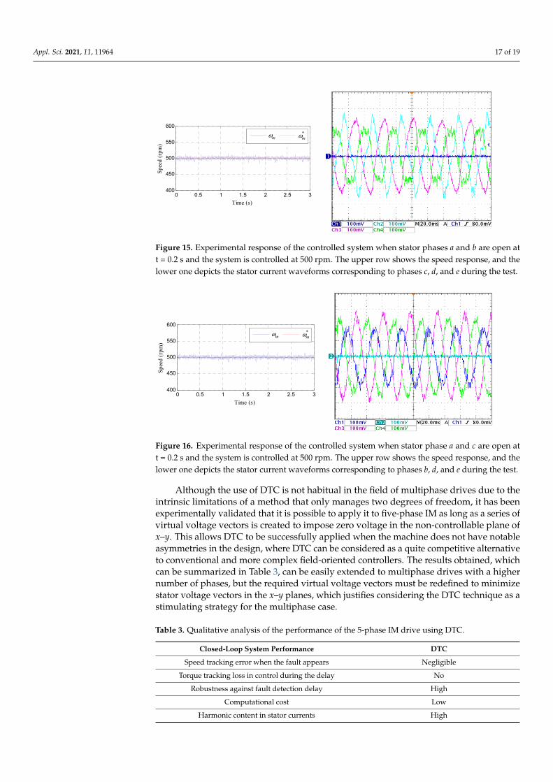
Figure 15. Experimental response of the controlled system when stator phases a and b are open at t = 0.2 s and the system is controlled at 500 rpm. The upper row shows the speed response, and the lower one depicts the stator current waveforms corresponding to phases c, d, and e during the test.
0 0.5 1 1.5 2 2.5 3400
450
500
550
600
Time (s)
Spee
d (r
pm)
ωm ω*m
Figure 16. Experimental response of the controlled system when stator phase a and c are open at t = 0.2 s and the system is controlled at 500 rpm. The upper row shows the speed response, and the lower one depicts the stator current waveforms corresponding to phases b, d, and e during the test.
Although the use of DTC is not habitual in the field of multiphase drives due to the intrinsic limitations of a method that only manages two degrees of freedom, it has been experimentally validated that it is possible to apply it to five-phase IM as long as a series of virtual voltage vectors is created to impose zero voltage in the non-controllable plane of x–y. This allows DTC to be successfully applied when the machine does not have nota-ble asymmetries in the design, where DTC can be considered as a quite competitive alter-native to conventional and more complex field-oriented controllers. The results obtained, which can be summarized in Table 3, can be easily extended to multiphase drives with a higher number of phases, but the required virtual voltage vectors must be redefined to minimize stator voltage vectors in the x–y planes, which justifies considering the DTC technique as a stimulating strategy for the multiphase case.
Table 3. Qualitative analysis of the performance of the 5-phase IM drive using DTC.
Closed-Loop System Performance DTC Speed tracking error when the fault appears Negligible
Torque tracking loss in control during the delay No Robustness against fault detection delay High
Computational cost Low Harmonic content in stator currents High
Figure 15. Experimental response of the controlled system when stator phases a and b are open att = 0.2 s and the system is controlled at 500 rpm. The upper row shows the speed response, and thelower one depicts the stator current waveforms corresponding to phases c, d, and e during the test.
Appl. Sci. 2021, 11, x FOR PEER REVIEW 17 of 19
0 0.5 1 1.5 2 2.5 3400
450
500
550
600
Time (s)
Spee
d (r
pm)
ωm ω*m
Figure 15. Experimental response of the controlled system when stator phases a and b are open at t = 0.2 s and the system is controlled at 500 rpm. The upper row shows the speed response, and the lower one depicts the stator current waveforms corresponding to phases c, d, and e during the test.
0 0.5 1 1.5 2 2.5 3400
450
500
550
600
Time (s)
Spee
d (r
pm)
ωm ω*m
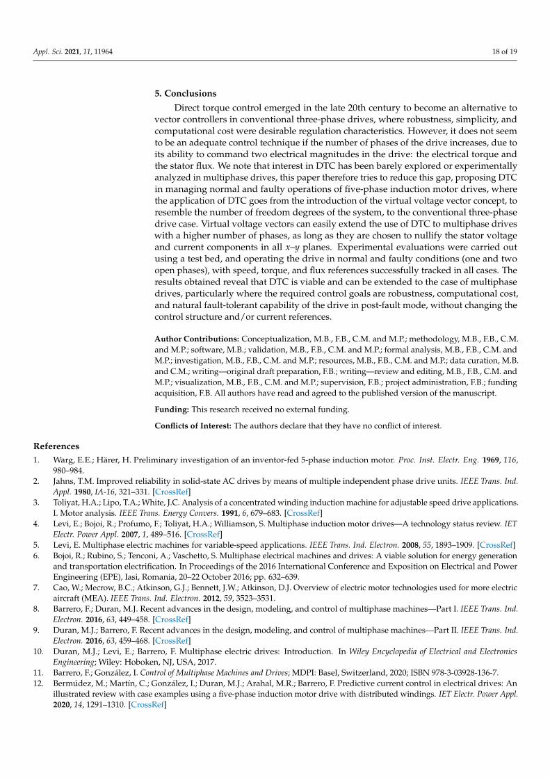
Figure 16. Experimental response of the controlled system when stator phase a and c are open at t = 0.2 s and the system is controlled at 500 rpm. The upper row shows the speed response, and the lower one depicts the stator current waveforms corresponding to phases b, d, and e during the test.
Although the use of DTC is not habitual in the field of multiphase drives due to the intrinsic limitations of a method that only manages two degrees of freedom, it has been experimentally validated that it is possible to apply it to five-phase IM as long as a series of virtual voltage vectors is created to impose zero voltage in the non-controllable plane of x–y. This allows DTC to be successfully applied when the machine does not have nota-ble asymmetries in the design, where DTC can be considered as a quite competitive alter-native to conventional and more complex field-oriented controllers. The results obtained, which can be summarized in Table 3, can be easily extended to multiphase drives with a higher number of phases, but the required virtual voltage vectors must be redefined to minimize stator voltage vectors in the x–y planes, which justifies considering the DTC technique as a stimulating strategy for the multiphase case.
Table 3. Qualitative analysis of the performance of the 5-phase IM drive using DTC.
Closed-Loop System Performance DTC Speed tracking error when the fault appears Negligible
Torque tracking loss in control during the delay No Robustness against fault detection delay High
Computational cost Low Harmonic content in stator currents High
Figure 16. Experimental response of the controlled system when stator phase a and c are open att = 0.2 s and the system is controlled at 500 rpm. The upper row shows the speed response, and thelower one depicts the stator current waveforms corresponding to phases b, d, and e during the test.
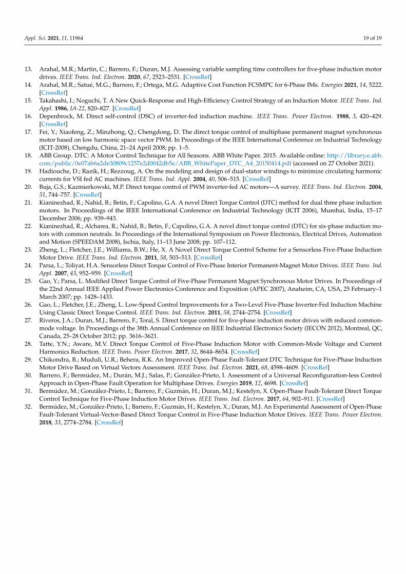
Although the use of DTC is not habitual in the field of multiphase drives due to theintrinsic limitations of a method that only manages two degrees of freedom, it has beenexperimentally validated that it is possible to apply it to five-phase IM as long as a series ofvirtual voltage vectors is created to impose zero voltage in the non-controllable plane ofx–y. This allows DTC to be successfully applied when the machine does not have notableasymmetries in the design, where DTC can be considered as a quite competitive alternativeto conventional and more complex field-oriented controllers. The results obtained, whichcan be summarized in Table 3, can be easily extended to multiphase drives with a highernumber of phases, but the required virtual voltage vectors must be redefined to minimizestator voltage vectors in the x–y planes, which justifies considering the DTC technique as astimulating strategy for the multiphase case.
Table 3. Qualitative analysis of the performance of the 5-phase IM drive using DTC.
Closed-Loop System Performance DTC
Speed tracking error when the fault appears Negligible
Torque tracking loss in control during the delay No
Robustness against fault detection delay High
Computational cost Low
Harmonic content in stator currents High
Appl. Sci. 2021, 11, 11964 18 of 19
5. Conclusions
Direct torque control emerged in the late 20th century to become an alternative tovector controllers in conventional three-phase drives, where robustness, simplicity, andcomputational cost were desirable regulation characteristics. However, it does not seemto be an adequate control technique if the number of phases of the drive increases, due toits ability to command two electrical magnitudes in the drive: the electrical torque andthe stator flux. We note that interest in DTC has been barely explored or experimentallyanalyzed in multiphase drives, this paper therefore tries to reduce this gap, proposing DTCin managing normal and faulty operations of five-phase induction motor drives, wherethe application of DTC goes from the introduction of the virtual voltage vector concept, toresemble the number of freedom degrees of the system, to the conventional three-phasedrive case. Virtual voltage vectors can easily extend the use of DTC to multiphase driveswith a higher number of phases, as long as they are chosen to nullify the stator voltageand current components in all x–y planes. Experimental evaluations were carried outusing a test bed, and operating the drive in normal and faulty conditions (one and twoopen phases), with speed, torque, and flux references successfully tracked in all cases. Theresults obtained reveal that DTC is viable and can be extended to the case of multiphasedrives, particularly where the required control goals are robustness, computational cost,and natural fault-tolerant capability of the drive in post-fault mode, without changing thecontrol structure and/or current references.
Author Contributions: Conceptualization, M.B., F.B., C.M. and M.P.; methodology, M.B., F.B., C.M.and M.P.; software, M.B.; validation, M.B., F.B., C.M. and M.P.; formal analysis, M.B., F.B., C.M. andM.P.; investigation, M.B., F.B., C.M. and M.P.; resources, M.B., F.B., C.M. and M.P.; data curation, M.B.and C.M.; writing—original draft preparation, F.B.; writing—review and editing, M.B., F.B., C.M. andM.P.; visualization, M.B., F.B., C.M. and M.P.; supervision, F.B.; project administration, F.B.; fundingacquisition, F.B. All authors have read and agreed to the published version of the manuscript.
Funding: This research received no external funding.
Conflicts of Interest: The authors declare that they have no conflict of interest.
References1. Warg, E.E.; Härer, H. Preliminary investigation of an inventor-fed 5-phase induction motor. Proc. Inst. Electr. Eng. 1969, 116,
980–984.2. Jahns, T.M. Improved reliability in solid-state AC drives by means of multiple independent phase drive units. IEEE Trans. Ind.
Appl. 1980, IA-16, 321–331. [CrossRef]3. Toliyat, H.A.; Lipo, T.A.; White, J.C. Analysis of a concentrated winding induction machine for adjustable speed drive applications.
I. Motor analysis. IEEE Trans. Energy Convers. 1991, 6, 679–683. [CrossRef]4. Levi, E.; Bojoi, R.; Profumo, F.; Toliyat, H.A.; Williamson, S. Multiphase induction motor drives—A technology status review. IET
Electr. Power Appl. 2007, 1, 489–516. [CrossRef]5. Levi, E. Multiphase electric machines for variable-speed applications. IEEE Trans. Ind. Electron. 2008, 55, 1893–1909. [CrossRef]6. Bojoi, R.; Rubino, S.; Tenconi, A.; Vaschetto, S. Multiphase electrical machines and drives: A viable solution for energy generation
and transportation electrification. In Proceedings of the 2016 International Conference and Exposition on Electrical and PowerEngineering (EPE), Iasi, Romania, 20–22 October 2016; pp. 632–639.
7. Cao, W.; Mecrow, B.C.; Atkinson, G.J.; Bennett, J.W.; Atkinson, D.J. Overview of electric motor technologies used for more electricaircraft (MEA). IEEE Trans. Ind. Electron. 2012, 59, 3523–3531.
8. Barrero, F.; Duran, M.J. Recent advances in the design, modeling, and control of multiphase machines—Part I. IEEE Trans. Ind.Electron. 2016, 63, 449–458. [CrossRef]
9. Duran, M.J.; Barrero, F. Recent advances in the design, modeling, and control of multiphase machines—Part II. IEEE Trans. Ind.Electron. 2016, 63, 459–468. [CrossRef]
10. Duran, M.J.; Levi, E.; Barrero, F. Multiphase electric drives: Introduction. In Wiley Encyclopedia of Electrical and ElectronicsEngineering; Wiley: Hoboken, NJ, USA, 2017.
11. Barrero, F.; González, I. Control of Multiphase Machines and Drives; MDPI: Basel, Switzerland, 2020; ISBN 978-3-03928-136-7.12. Bermúdez, M.; Martín, C.; González, I.; Duran, M.J.; Arahal, M.R.; Barrero, F. Predictive current control in electrical drives: An
illustrated review with case examples using a five-phase induction motor drive with distributed windings. IET Electr. Power Appl.2020, 14, 1291–1310. [CrossRef]
Appl. Sci. 2021, 11, 11964 19 of 19
13. Arahal, M.R.; Martin, C.; Barrero, F.; Duran, M.J. Assessing variable sampling time controllers for five-phase induction motordrives. IEEE Trans. Ind. Electron. 2020, 67, 2523–2531. [CrossRef]
14. Arahal, M.R.; Satué, M.G.; Barrero, F.; Ortega, M.G. Adaptive Cost Function FCSMPC for 6-Phase IMs. Energies 2021, 14, 5222.[CrossRef]
15. Takahashi, I.; Noguchi, T. A New Quick-Response and High-Efficiency Control Strategy of an Induction Motor. IEEE Trans. Ind.Appl. 1986, IA-22, 820–827. [CrossRef]
16. Depenbrock, M. Direct self-control (DSC) of inverter-fed induction machine. IEEE Trans. Power Electron. 1988, 3, 420–429.[CrossRef]
17. Fei, Y.; Xiaofeng, Z.; Minzhong, Q.; Chengdong, D. The direct torque control of multiphase permanent magnet synchronousmotor based on low harmonic space vector PWM. In Proceedings of the IEEE International Conference on Industrial Technology(ICIT-2008), Chengdu, China, 21–24 April 2008; pp. 1–5.
18. ABB Group. DTC: A Motor Control Technique for All Seasons. ABB White Paper. 2015. Available online: http://library.e.abb.com/public/0e07ab6a2de30809c1257e2d0042db5e/ABB_WhitePaper_DTC_A4_20150414.pdf (accessed on 27 October 2021).
19. Hadiouche, D.; Razik, H.; Rezzoug, A. On the modeling and design of dual-stator windings to minimize circulating harmoniccurrents for VSI fed AC machines. IEEE Trans. Ind. Appl. 2004, 40, 506–515. [CrossRef]
20. Buja, G.S.; Kazmierkowski, M.P. Direct torque control of PWM inverter-fed AC motors—A survey. IEEE Trans. Ind. Electron. 2004,51, 744–757. [CrossRef]
21. Kianinezhad, R.; Nahid, B.; Betin, F.; Capolino, G.A. A novel Direct Torque Control (DTC) method for dual three phase inductionmotors. In Proceedings of the IEEE International Conference on Industrial Technology (ICIT 2006), Mumbai, India, 15–17December 2006; pp. 939–943.
22. Kianinezhad, R.; Alcharea, R.; Nahid, B.; Betin, F.; Capolino, G.A. A novel direct torque control (DTC) for six-phase induction mo-tors with common neutrals. In Proceedings of the International Symposium on Power Electronics, Electrical Drives, Automationand Motion (SPEEDAM 2008), Ischia, Italy, 11–13 June 2008; pp. 107–112.
23. Zheng, L.; Fletcher, J.E.; Williams, B.W.; He, X. A Novel Direct Torque Control Scheme for a Sensorless Five-Phase InductionMotor Drive. IEEE Trans. Ind. Electron. 2011, 58, 503–513. [CrossRef]
24. Parsa, L.; Toliyat, H.A. Sensorless Direct Torque Control of Five-Phase Interior Permanent-Magnet Motor Drives. IEEE Trans. Ind.Appl. 2007, 43, 952–959. [CrossRef]
25. Gao, Y.; Parsa, L. Modified Direct Torque Control of Five-Phase Permanent Magnet Synchronous Motor Drives. In Proceedings ofthe 22nd Annual IEEE Applied Power Electronics Conference and Exposition (APEC 2007), Anaheim, CA, USA, 25 February–1March 2007; pp. 1428–1433.
26. Gao, L.; Fletcher, J.E.; Zheng, L. Low-Speed Control Improvements for a Two-Level Five-Phase Inverter-Fed Induction MachineUsing Classic Direct Torque Control. IEEE Trans. Ind. Electron. 2011, 58, 2744–2754. [CrossRef]
27. Riveros, J.A.; Duran, M.J.; Barrero, F.; Toral, S. Direct torque control for five-phase induction motor drives with reduced common-mode voltage. In Proceedings of the 38th Annual Conference on IEEE Industrial Electronics Society (IECON 2012), Montreal, QC,Canada, 25–28 October 2012; pp. 3616–3621.
28. Tatte, Y.N.; Aware, M.V. Direct Torque Control of Five-Phase Induction Motor with Common-Mode Voltage and CurrentHarmonics Reduction. IEEE Trans. Power Electron. 2017, 32, 8644–8654. [CrossRef]
29. Chikondra, B.; Muduli, U.R.; Behera, R.K. An Improved Open-Phase Fault-Tolerant DTC Technique for Five-Phase InductionMotor Drive Based on Virtual Vectors Assessment. IEEE Trans. Ind. Electron. 2021, 68, 4598–4609. [CrossRef]
30. Barrero, F.; Bermúdez, M.; Durán, M.J.; Salas, P.; González-Prieto, I. Assessment of a Universal Reconfiguration-less ControlApproach in Open-Phase Fault Operation for Multiphase Drives. Energies 2019, 12, 4698. [CrossRef]
31. Bermúdez, M.; González-Prieto, I.; Barrero, F.; Guzmán, H.; Duran, M.J.; Kestelyn, X. Open-Phase Fault-Tolerant Direct TorqueControl Technique for Five-Phase Induction Motor Drives. IEEE Trans. Ind. Electron. 2017, 64, 902–911. [CrossRef]
32. Bermúdez, M.; González-Prieto, I.; Barrero, F.; Guzmán, H.; Kestelyn, X.; Duran, M.J. An Experimental Assessment of Open-PhaseFault-Tolerant Virtual-Vector-Based Direct Torque Control in Five-Phase Induction Motor Drives. IEEE Trans. Power Electron.2018, 33, 2774–2784. [CrossRef]