PeopleTools 8.55: Integration Broker - Oracle Help Center
658
PeopleTools 8.55: Integration Broker November 2017
-
Upload
khangminh22 -
Category
Documents
-
view
0 -
download
0
Transcript of PeopleTools 8.55: Integration Broker - Oracle Help Center
PeopleTools 8.55: Integration Broker
November 2017
PeopleTools 8.55: Integration BrokerCopyright © 1988, 2017, Oracle and/or its affiliates. All rights reserved.
This software and related documentation are provided under a license agreement containing restrictions on use anddisclosure and are protected by intellectual property laws. Except as expressly permitted in your license agreementor allowed by law, you may not use, copy, reproduce, translate, broadcast, modify, license, transmit, distribute,exhibit, perform, publish, or display any part, in any form, or by any means. Reverse engineering, disassembly, ordecompilation of this software, unless required by law for interoperability, is prohibited.
The information contained herein is subject to change without notice and is not warranted to be error-free. If youfind any errors, please report them to us in writing.
If this is software or related documentation that is delivered to the U.S. Government or anyone licensing it on behalfof the U.S. Government, then the following notice is applicable:
U.S. GOVERNMENT END USERS: Oracle programs, including any operating system, integrated software, anyprograms installed on the hardware, and/or documentation, delivered to U.S. Government end users are "commercialcomputer software" pursuant to the applicable Federal Acquisition Regulation and agency-specific supplementalregulations. As such, use, duplication, disclosure, modification, and adaptation of the programs, including anyoperating system, integrated software, any programs installed on the hardware, and/or documentation, shall besubject to license terms and license restrictions applicable to the programs. No other rights are granted to the U.S.Government.
This software or hardware is developed for general use in a variety of information management applications. It isnot developed or intended for use in any inherently dangerous applications, including applications that may create arisk of personal injury. If you use this software or hardware in dangerous applications, then you shall be responsibleto take all appropriate fail-safe, backup, redundancy, and other measures to ensure its safe use. Oracle Corporationand its affiliates disclaim any liability for any damages caused by use of this software or hardware in dangerousapplications.
Oracle and Java are registered trademarks of Oracle and/or its affiliates. Other names may be trademarks of theirrespective owners.
Intel and Intel Xeon are trademarks or registered trademarks of Intel Corporation. All SPARC trademarks are usedunder license and are trademarks or registered trademarks of SPARC International, Inc. AMD, Opteron, the AMDlogo, and the AMD Opteron logo are trademarks or registered trademarks of Advanced Micro Devices. UNIX is aregistered trademark of The Open Group.
This software or hardware and documentation may provide access to or information about content, products, andservices from third parties. Oracle Corporation and its affiliates are not responsible for and expressly disclaim allwarranties of any kind with respect to third-party content, products, and services unless otherwise set forth in anapplicable agreement between you and Oracle. Oracle Corporation and its affiliates will not be responsible for anyloss, costs, or damages incurred due to your access to or use of third-party content, products, or services, except asset forth in an applicable agreement between you and Oracle.
Documentation Accessibility
For information about Oracle's commitment to accessibility, visit the Oracle Accessibility Program website at http://www.oracle.com/pls/topic/lookup?ctx=acc&id=docacc.
Access to Oracle Support
Oracle customers that have purchased support have access to electronic support through My Oracle Support. Forinformation, visit http://www.oracle.com/pls/topic/lookup?ctx=acc&id=info or visit http://www.oracle.com/pls/topic/lookup?ctx=acc&id=trs if you are hearing impaired.

Contents
Preface: Preface.........................................................................................................................................xixUnderstanding the PeopleSoft Online Help and PeopleBooks........................................................... xix
PeopleSoft Hosted Online Help.................................................................................................... xixLocally Installed Help................................................................................................................... xixDownloadable PeopleBook PDF Files..........................................................................................xixCommon Help Documentation.......................................................................................................xxField and Control Definitions........................................................................................................ xxTypographical Conventions............................................................................................................ xxISO Country and Currency Codes................................................................................................ xxiRegion and Industry Identifiers.................................................................................................... xxiTranslations and Embedded Help................................................................................................ xxii
Using and Managing the PeopleSoft Online Help.............................................................................xxiiUnderstanding PeopleSoft Integration Broker................................................................................... xxiiPeopleTools Related Links................................................................................................................ xxiiiContact Us..........................................................................................................................................xxiiiFollow Us...........................................................................................................................................xxiii
Chapter 1: Getting Started with PeopleSoft Integration Broker..........................................................25PeopleSoft Integration Broker Overview............................................................................................. 25Implementing PeopleSoft Integration Broker.......................................................................................25Other Sources of Information...............................................................................................................28
Chapter 2: Understanding PeopleSoft Integration Broker................................................................... 29Introduction to PeopleSoft Integration Broker..................................................................................... 29
Web Services.................................................................................................................................. 29Integration Gateway....................................................................................................................... 30Integration Engine.......................................................................................................................... 30
Integration Gateway Architecture.........................................................................................................31Architecture Elements.................................................................................................................... 31Connectors...................................................................................................................................... 32Gateway Manager...........................................................................................................................33Gateway Services........................................................................................................................... 33
Integration Engine Architecture............................................................................................................34Service Operations................................................................................................................................ 35Service Operation Types.......................................................................................................................36
Operation Types..............................................................................................................................36Inbound and Outbound Request Flows................................................................................................ 38
Inbound Request Flow................................................................................................................... 39Outbound Request Flow.................................................................................................................41
Chapter 3: Understanding Messaging..................................................................................................... 45Messaging Types...................................................................................................................................45Asynchronous Messaging..................................................................................................................... 45
Brokers, Contractors and Queues...................................................................................................45Messaging System Server Processes..............................................................................................47Dispatchers and Handlers...............................................................................................................47Asynchronous Service Operation Publication................................................................................48Asynchronous Service Operation Subscription..............................................................................52
Synchronous Messaging........................................................................................................................56
Copyright © 1988, 2017, Oracle and/or its affiliates. All rights reserved. iii

Contents
Synchronous Service Operation Publication..................................................................................56Synchronous Service Operation Subscription................................................................................58
Chapter 4: Understanding PeopleSoft Integration Broker Metadata..................................................61PeopleSoft Integration Broker Metadata.............................................................................................. 61Order of Precedence for Creating Integration Metadata...................................................................... 62
Chapter 5: Understanding Supported Message Structures...................................................................63Supported Message Structures..............................................................................................................63Integration Broker Message Structures................................................................................................ 63
Internal Message Format for Request Messages........................................................................... 63Internal Message Format for Response Messages.........................................................................71Local Compression......................................................................................................................... 74Accessing IBInfo Elements Using PeopleCode.............................................................................75
PeopleSoft Rowset-Based Message Format......................................................................................... 76Understanding the PeopleSoft Rowset-Based Message Format.................................................... 77Rowset-Based Message Template.................................................................................................. 78FieldTypes Section......................................................................................................................... 78MsgData Section.............................................................................................................................79PSCAMA........................................................................................................................................ 80Identifying Changes to Field-Level Attributes.............................................................................. 83PeopleSoft Timestamp Format....................................................................................................... 83CDATA and Special Characters..................................................................................................... 83Schema Restrictions....................................................................................................................... 84Rowset-Based Message Example...................................................................................................84
Nonrowset-Based Message Structures..................................................................................................86XML Messages...............................................................................................................................86SOAP-Compliant Messages........................................................................................................... 87Non-XML Files.............................................................................................................................. 87Using Nonrowset-Based Messages in Service Operations Exposed as WSDL............................. 89
Message Part Structures........................................................................................................................89Understanding Message Part Structures.........................................................................................89Rowset-Based Message Parts.........................................................................................................89Nonrowset-Based Message Parts................................................................................................... 91
Message Container Structures.............................................................................................................. 92Example 1: XML Schema of a Container Message with Rowset-Based Message Parts............... 92Example 2: XML Schema of a Container Message with Nonrowset-Based Message Parts.......... 92
Chapter 6: Managing Messages............................................................................................................... 95Understanding Managing Messages..................................................................................................... 95
Message Definitions....................................................................................................................... 95Message Types................................................................................................................................95Naming Conventions for Message Metadata.................................................................................96Message Record Structure..............................................................................................................96Underlying Record Definitions...................................................................................................... 96Fields Defined as Uppercase..........................................................................................................97Message Aliases and Message Versions........................................................................................ 97Restrictions for Modifying Messages............................................................................................ 97
Searching for Message Definitions.......................................................................................................97Adding Message Definitions................................................................................................................ 98
Understanding Adding Message Definitions................................................................................. 99Adding Rowset, Nonrowset or Part Message Definitions............................................................. 99Adding Document Message Definitions...................................................................................... 103
Managing Rowset-Based Messages....................................................................................................105
iv Copyright © 1988, 2017, Oracle and/or its affiliates. All rights reserved.

Contents
Understanding Managing Rowset-Based Messages.....................................................................106Viewing Rowset-Based Message Structures................................................................................ 106Inserting Root Records.................................................................................................................109Inserting Child and Peer Records................................................................................................ 110Specifying Record Aliases........................................................................................................... 112Deleting Records.......................................................................................................................... 112Excluding Fields from Messages................................................................................................. 112Specifying Field Name Aliases....................................................................................................113Including Fields in CData Sections in Generated XML..............................................................114Managing XML Message Schemas for Rowset-Based Messages............................................... 115Enforcing Message Record and Field Aliases in Generated WSDL........................................... 117
Managing Nonrowset-Based Messages.............................................................................................. 117Understanding Managing Nonrowset-Based Messages............................................................... 118Adding XML Message Schemas to Nonrowset-Based Messages............................................... 118Editing Nonrowset-Based XML Schemas................................................................................... 118Deleting Nonrowset-Based XML Message Schemas.................................................................. 119
Managing Message Parts.................................................................................................................... 120Understanding Message Parts...................................................................................................... 120Creating Part Messages................................................................................................................ 121Distinguishing Blank from Zero in Rowset-Based Part Messages.............................................. 121
Reusing Rowset-Based Message Parts............................................................................................... 122Understanding Reusing Rowset-Based Message Parts................................................................ 122Reusing Rowset-Based Message Parts by Reference.................................................................. 122
Managing Container Messages........................................................................................................... 126Understanding Managing Container Messages............................................................................126Understanding Including Level 0 Rows for Message Parts in Container Messages....................127Adding Message Parts to Container Messages............................................................................ 128Adding and Getting Container Messages Attributes................................................................... 132Generating XML Message Schemas for Container Messages.....................................................136
Managing Document Messages.......................................................................................................... 137Viewing Service Operations that Reference Messages...................................................................... 137Resolving Inconsistencies in Exported WSDL and WADL Documents............................................ 138
Understanding Using Project Copy and Exported WSDL and WADL....................................... 138Viewing Services Operations with Exported WSDL/WADL Inconsistencies............................. 138Clearing Exported WSDL/WADL Status Flags...........................................................................140
Renaming and Deleting Message Definitions.................................................................................... 141Renaming Message Definitions....................................................................................................142Deleting Message Definitions...................................................................................................... 143
Deleting Messages During Upgrade...................................................................................................143Chapter 7: Sending and Receiving Messages....................................................................................... 145
Understanding Sending and Receiving Messages.............................................................................. 145Prerequisites for Sending and Receiving Messages.....................................................................145Messaging Process Flows.............................................................................................................145
Understanding Integration PeopleCode.............................................................................................. 147Sending and Receiving PeopleCode............................................................................................ 147Application Classes...................................................................................................................... 148Routing Methods.......................................................................................................................... 149Messaging Methods......................................................................................................................152Messaging PeopleCode.................................................................................................................157Document PeopleCode................................................................................................................. 157
Generating and Sending Messages..................................................................................................... 158
Copyright © 1988, 2017, Oracle and/or its affiliates. All rights reserved. v

Contents
Understanding Outbound Messaging........................................................................................... 159Handling Outbound Asynchronous Message Transmission.........................................................160Handling Outbound Asynchronous Request/Response Message Transmission...........................162Handling Outbound Synchronous Transactions...........................................................................162Reading Exceptions for Outbound Synchronous Integrations..................................................... 164Overriding Synchronous Timeout Intervals at Runtime.............................................................. 164Handling Cookies......................................................................................................................... 165Setting and Overriding Target Connector Properties at Runtime................................................ 165
Receiving and Processing Messages.................................................................................................. 168Handling Inbound Asynchronous Transactions........................................................................... 169Handling Inbound Asynchronous Request/Response Transactions............................................. 178Handling Inbound Synchronous Transactions............................................................................. 179Simulating Receiving Messages from External Nodes................................................................181
Processing Inbound Errors..................................................................................................................181Validating Data............................................................................................................................. 182Using the Exit Built-in Function..................................................................................................183
Using Message Object Functionality With Nonrowset-Based Messages...........................................184Using the SetXMLDoc Method................................................................................................... 185Using the GetXMLDoc Method.................................................................................................. 185
Generating Test Messages...................................................................................................................185Working With Message Segments......................................................................................................185
Understanding Message Segments...............................................................................................186Understanding PeopleCode used to Work with Message Segments............................................186Configuring Nodes to Handle Segmented Messages...................................................................188Setting the Maximum Number of Message Segments in Messages............................................ 188Creating Message Segments.........................................................................................................188Deleting Message Segments.........................................................................................................191Sending and Receiving Segmented Messages between PeopleSoft Systems.............................. 192Sending and Receiving Segmented Messages to/from Third-Party Systems...............................192Sending, Receiving, and Correlating Multiple Segmented Messages......................................... 195Accessing Segments in Messages................................................................................................ 196Viewing Message Segment Data..................................................................................................197Using Restartable Processing for Publishing Large Messages in Batch......................................197
Populating and Retrieving Document Data........................................................................................199Understanding Populating and Retrieving Document Data......................................................... 199Instantiating Document Objects................................................................................................... 199Populating Document Data.......................................................................................................... 200Retrieving Document Data...........................................................................................................201
Sending and Receiving Binary Data.................................................................................................. 204Understanding Sending and Receiving Binary Data................................................................... 204Sending MTOM-Encoded Binary Data........................................................................................204Receiving Binary Data................................................................................................................. 207
Using PeopleCode to Manage REST Service Operations..................................................................210Using PeopleCode to Manage Provider REST Service Operations.............................................211Using PeopleCode to Manage Consumer REST Service Operations.......................................... 214Generating Fully-Qualified URLs for REST Resources..............................................................215
Chapter 8: Building Message Schemas..................................................................................................217Understanding the Message Schema Builder..................................................................................... 217
Message Schemas......................................................................................................................... 217Building, Importing, Modifying and Deleting Message Schemas...............................................217
Selecting and Viewing Data in the Message Schema Builder........................................................... 218
vi Copyright © 1988, 2017, Oracle and/or its affiliates. All rights reserved.
Contents
Selecting Data in the Message Schema Builder.......................................................................... 218Viewing Message Schema Details............................................................................................... 220Viewing XML Message Schema..................................................................................................221
Building Message Schemas for Rowset-Based Messages..................................................................222Building a Message Schema for a Rowset-Based Message........................................................ 222
Importing Message Schemas for Nonrowset-Based Messages.......................................................... 223Importing a Message Schema for a Nonrowset-Based Message................................................. 223
Modifying Message Schemas............................................................................................................. 223Modifying a Message Schema..................................................................................................... 224
Deleting Message Schemas................................................................................................................ 224Understanding Deleting Message Schemas................................................................................. 224Using the Message Schema Builder Page to Delete Message Schemas...................................... 225
Chapter 9: Managing Services............................................................................................................... 227Understanding Managing Services..................................................................................................... 227Common Elements Used to Manage Services................................................................................... 227Accessing and Viewing Service Definitions...................................................................................... 229
Accessing Service Definitions......................................................................................................229Viewing WSDL Documents Generated for Services...................................................................230Viewing Service Operation Information...................................................................................... 233Viewing Messages Defined for Service Operations.................................................................... 233
Adding Service Definitions................................................................................................................ 233Understanding Naming Services and Service Aliases................................................................. 233Adding Service Definitions..........................................................................................................234
Adding Service Operations to Service Definitions............................................................................ 236Understanding Adding Service Operations to Service Definitions..............................................236Adding Existing Service Operations to Service Definitions........................................................236Defining New Service Operations for SOAP-Based Service Definitions....................................237
Creating and Managing Integration Groups....................................................................................... 237Understanding Integration Groups............................................................................................... 238Adding Integration Groups...........................................................................................................238Adding Services to Integration Groups....................................................................................... 240Adding Integration Subgroups..................................................................................................... 241Deleting Services from Integration Groups and Integration Subgroups...................................... 241Renaming and Deleting Integration Groups................................................................................ 242Copying Integration Groups Using Project Copy........................................................................243
Restricting and Enabling Write Access to Service Definitions..........................................................243Understanding Restricting Write Access to Service Definitions................................................. 244Restricting Write Access to Service Definitions..........................................................................244Enabling Write Access to Service Definitions.............................................................................245
Renaming and Deleting Service Definitions...................................................................................... 246Renaming Service Definitions......................................................................................................246Deleting Service Definitions........................................................................................................ 247
Activating and Deactivating Service Definitions in Bulk.................................................................. 247Chapter 10: Managing Service Operations...........................................................................................251
Understanding Managing Service Operations.................................................................................... 251Service Operations........................................................................................................................251Services Operation Types.............................................................................................................251Naming Conventions for Service Operation Metadata................................................................ 252Service Operation Aliases............................................................................................................ 252Service Operation Versions.......................................................................................................... 252Monitoring Service Operations.................................................................................................... 253
Copyright © 1988, 2017, Oracle and/or its affiliates. All rights reserved. vii

Contents
Accessing and Viewing Service Operation Definitions..................................................................... 253Accessing Service Operation Definitions.................................................................................... 254Viewing Service Operation Definitions....................................................................................... 255
Adding Service Operation Definitions............................................................................................... 258Configuring Service Operation Definitions........................................................................................258
Specifying General Service Operation Information.....................................................................259Defining Service Operation Version Information........................................................................ 259Adding Handlers to Service Operations...................................................................................... 262Adding Routing Definitions......................................................................................................... 262Activating and Inactivating Routing Definitions......................................................................... 262
Setting Permissions to Service Operations.........................................................................................263Understanding Setting Permission to Service Operations........................................................... 263Setting Permission Access to Service Operations....................................................................... 263
Managing Service Operation Versions............................................................................................... 263Creating Service Operation Versions........................................................................................... 264Using Non-Default Service Operation Versions.......................................................................... 264
Attaching Files to Service Operations................................................................................................265Understanding Attaching Files to Service Operations.................................................................265Using the FTP Attachment Utility...............................................................................................265Sending Attachment Information with Service Operations......................................................... 266Processing Attachment Information Included in Service Operations.......................................... 267
Assigning Multiple Queues to Process Service Operations............................................................... 268Understanding Assigning Multiple Queues to Process Service Operations.................................268Enabling Multi-Queue Service Operation Processing................................................................. 268Specifying Multiple Queues to Process Service Operations........................................................268
Invoking Multiple Service Operations................................................................................................270Renaming and Deleting Service Operations.......................................................................................270
Renaming Service Operations...................................................................................................... 271Deleting Service Operations.........................................................................................................272
Chapter 11: Managing REST Services.................................................................................................. 273Understanding Managing REST Services.......................................................................................... 273Common Elements Used to Manage REST Services.........................................................................273Accessing and Viewing REST Service Definitions............................................................................275
Accessing REST Service Definitions...........................................................................................275Viewing WADL Documents for REST Services......................................................................... 277Viewing REST Service Operation Information........................................................................... 279View Messages Defined for REST Service Operations...............................................................279
Adding REST Service Definitions..................................................................................................... 279Understanding Naming Services and Service Aliases for REST Service Definitions................. 279Adding REST Service Definitions...............................................................................................280
Adding Service Operations to REST Service Definitions..................................................................282Understanding Adding Service Operations to REST Service Definitions................................... 282Adding Existing Service Operations to REST Service Definitions.............................................282Adding New Service Operation Definitions for REST Services................................................. 282
Restricting and Enabling Write Access to REST Service Definitions............................................... 285Renaming and Deleting REST Service Definitions........................................................................... 285Activating and Deactivating REST Service Definitions in Bulk....................................................... 285
Chapter 12: Managing REST Service Operations............................................................................... 287Understanding REST Service Operations.......................................................................................... 287
REST Service Operations.............................................................................................................287REST Service Operations Types..................................................................................................287
viii Copyright © 1988, 2017, Oracle and/or its affiliates. All rights reserved.

Contents
REST Methods............................................................................................................................. 288REST Resource Definitions......................................................................................................... 288REST Messages............................................................................................................................288Naming Conventions for REST Service Operation Metadata..................................................... 289REST Service Operation Aliases................................................................................................. 290REST Service Operation Versions............................................................................................... 290WADL Node................................................................................................................................. 290Monitoring REST Service Operations......................................................................................... 290
Accessing and Viewing REST Service Operation Definitions...........................................................291Accessing REST Service Operation Definitions......................................................................... 291Viewing REST Service Operation Definitions............................................................................ 293
Adding REST Service Operations......................................................................................................296Defining General REST Service Operation Information................................................................... 296Managing REST Resource Definitions.............................................................................................. 297
Understanding Managing REST Resource Definitions............................................................... 298Understanding REST Resource Definition Concepts.................................................................. 298Understanding URI Template Expressions and Expansions........................................................299Prerequisites for Managing REST Resource Definitions............................................................ 302Configuring REST Resource Definitions.....................................................................................302Defining REST Base URLs......................................................................................................... 303Defining Document Templates.....................................................................................................305Building URI Templates...............................................................................................................305Building URI Templates Manually.............................................................................................. 306Building URI Templates Using the URI Template Builder......................................................... 307Validating URI Templates............................................................................................................ 310Example: Using the URI Template Builder to Build URI Templates..........................................314Adding the Example URI Template to the REST Resource Definition.......................................322
Defining REST Service Operation Version Information....................................................................323Understanding Default REST Service Operations.......................................................................323Defining Default REST Service Operation Versions...................................................................323Defining Message Instances for REST Service Operations........................................................ 324Defining Fault Messages for REST Service Operations............................................................. 326
Managing Provider REST Service Operations...................................................................................328Managing Target Connectors for Provider REST Service Operations.........................................328Managing Messages for Provider REST Service Operations...................................................... 328Securing Provider REST Service Operations.............................................................................. 328Adding Handlers to Provider REST Services Operations........................................................... 329Managing Routing Definitions for Provider REST Service Operations...................................... 329Defining Routing Header Properties for Provider REST Service Operations............................. 330
Managing Consumer REST Service Operations................................................................................ 331Adding Handlers to Consumer REST Service Operations.......................................................... 332Manage Routing Definitions for Consumer REST Service Operations.......................................332Securing Consumer REST Service Operations............................................................................332
Managing REST Service Operation Versions.................................................................................... 335Setting Compression for REST Service Operations...........................................................................336
Understanding Setting Compression for REST Service Operations............................................336Setting Compression for Provider REST Service Operations..................................................... 336Defining Compression for Consumer REST Service Operations................................................ 338
Renaming and Deleting REST Service Operations............................................................................340Chapter 13: Managing Service Operation Queues.............................................................................. 341
Understanding Service Operation Queues..........................................................................................341
Copyright © 1988, 2017, Oracle and/or its affiliates. All rights reserved. ix

Contents
Adding Queue Definitions.................................................................................................................. 341Applying Queue Partitioning.............................................................................................................. 343
Understanding Queue Partitioning............................................................................................... 343Selecting Partitioning Fields........................................................................................................ 344
Renaming and Deleting Queues......................................................................................................... 345Renaming Queue Definitions....................................................................................................... 346Deleting Queue Definitions..........................................................................................................346
Deleting Queues During Upgrade...................................................................................................... 347Chapter 14: Enabling Runtime Message Schema Validation..............................................................349
Understanding Message Schema Validation.......................................................................................349Message Schema Validation.........................................................................................................349Message Schema Validation and Transformations.......................................................................349Message Schema Validation and Part Messages..........................................................................349
Prerequisites for Validating Message Schemas.................................................................................. 350Selecting Service Operations.............................................................................................................. 350
Selecting a Service Operation...................................................................................................... 350Viewing Defined Message Schemas...................................................................................................352
Viewing XML Schemas Defined for Messages...........................................................................352Enabling Runtime Message Schema Validation.................................................................................353
Using the Service Schema Validation Page to Enable Runtime Message Schema Validation..... 353Using the Service Operations page to Enable Runtime Message Schema Validation..................354
Chapter 15: Creating Component Interface-Based Services...............................................................355Understanding Creating Component Interface-Based Services..........................................................355
Naming Conventions Integration Metadata Created....................................................................355User-Defined Method Restrictions...............................................................................................356Impact of Changing Component Interfaces................................................................................. 356
Prerequisites for Creating Component Interface-Based Services.......................................................357Selecting Component Interfaces to Expose as Services.....................................................................357Selecting Component Interface Methods to Include as Service Operations.......................................358Generating Component Interface-Based Services.............................................................................. 360
Generating Services and Service Operations from Component Interface Methods.....................361Inheriting Component Interface Security Permission Lists......................................................... 362Adding Message Names and Descriptions to Generated Service Operations..............................363
Viewing Component Interface-Based Service Definitions.................................................................363Chapter 16: Managing Service Operation Handlers........................................................................... 367
Understanding Service Operation Handlers....................................................................................... 367Service Operation Handler Types................................................................................................ 367Handler Types and Messaging Types.......................................................................................... 367
Understanding Implementing Handlers.............................................................................................. 369Adding Handlers to Service Operations.............................................................................................370
Understanding Adding Handler Definitions to Service Operations.............................................370Adding a Handler to a Service Operation................................................................................... 370Specifying General Handler Details.............................................................................................372
Implementing Handlers Using Application Classes........................................................................... 372Understanding Implementing Handlers Using Application Classes............................................ 373Developing Application Classes for Implementing Handlers......................................................373Specifying Application Class Implementation Details................................................................ 375
Implementing Handlers Using Application Engine Programs........................................................... 375Understanding Implementing Handlers Using Application Engine Programs.............................376Specifying Application Engine Handler Implementation Details................................................377Retrieving Service Operation Content from Application Engine Programs................................ 377
x Copyright © 1988, 2017, Oracle and/or its affiliates. All rights reserved.
Contents
Viewing Subscription Contract Status......................................................................................... 378Implementing Handlers Using Component Interfaces....................................................................... 379
Understanding Implementing Handlers Using Component Interfaces.........................................379Specifying Component Interface Handler Implementation Details............................................. 380
Implementing Handlers Using Bulk Load Processing....................................................................... 380Understanding Implementing Handlers Using the Bulk Load Handler....................................... 380Enabling Transactional Rollback................................................................................................. 382Enabling Table Truncation........................................................................................................... 383Specifying XML Record Attribute Values...................................................................................384Adding Data Structures for Nonrowset-Based Messages............................................................ 384
Implementing Handlers Using Deprecated PeopleCode Handlers..................................................... 386Understanding the Deprecated PeopleCode Handler...................................................................387Deleting Deprecated PeopleCode Handlers................................................................................. 387
Chapter 17: Managing Service Operation Routing Definitions..........................................................389Understanding Routing Definitions.................................................................................................... 389
Routing Definitions...................................................................................................................... 389Routing Types...............................................................................................................................389Defining Routing Definitions.......................................................................................................390Methods for Generating and Defining Routing Definitions........................................................ 390Routing Definition Naming Conventions.................................................................................... 391Routing Definition External Aliases............................................................................................ 392Service Operation Mapping......................................................................................................... 392Graphical Routings View............................................................................................................. 393Integration Status..........................................................................................................................393
Managing System-Generated Routing Definitions.............................................................................393Understanding Managing System-Generated Routing Definitions..............................................393Viewing System-Generated Routing Definition Status................................................................393Initiating System-Generated Routing Definitions........................................................................394Regenerating System-Generated Routing Definitions................................................................. 396
Adding Routing Definitions................................................................................................................396Understanding Adding Routing Definitions................................................................................ 397Adding Routing Definitions Using the Routings Component..................................................... 397Adding Routing Definitions From Service Operation Definitions.............................................. 398Adding Routing Definitions Using the Nodes Component......................................................... 399
Configuring Routing Definitions........................................................................................................ 400Defining General Routing Information........................................................................................400Defining Routing Parameters....................................................................................................... 404Defining and Overriding Gateway and Connector Properties..................................................... 409Defining Routing Properties.........................................................................................................411
Activating and Inactivating Routing Definitions................................................................................412Understanding Activating and Inactivating Routing Definitions.................................................413Activating and Inactivating Routing Definitions in the Routing Component..............................413Activating and Inactivating Routing Definitions in the Service Operations Component.............413Activating and Inactivating Routing Definitions in the Nodes Component................................ 413
Viewing Routing Definitions in Graphical Format............................................................................ 414Common Elements Used to View Routing Definitions in Graphical Format.............................. 414Viewing a Routing Definition in Graphical Format.................................................................... 416
Viewing Integration Status and Activating Integration Metadata...................................................... 417Understanding Viewing Integration Status and Activating Integration Metadata........................417Viewing Inactive Integration Metadata........................................................................................417Activating Integration Metadata Using the Integration Status Page............................................418
Copyright © 1988, 2017, Oracle and/or its affiliates. All rights reserved. xi

Contents
Retrieving Routing Properties Programmatically...............................................................................418Configuring Routing Definitions for Deployment............................................................................. 419
Understanding Configuring Routing Definitions for Deployment.............................................. 419Understanding Using Routing Deployment Configuration..........................................................419Using the Deployment Configuration Page................................................................................. 420Using the Routing Deployment Grids......................................................................................... 422Using the Get Routing Information Page.................................................................................... 426Selecting Routing Definitions for Routing Deployment Configuration...................................... 427Populating Deployment Configurations from Routing Definitions............................................. 428Adding Routing Definitions for Deployment.............................................................................. 428Updating Release Levels..............................................................................................................429
Searching for Duplicate External Routing Aliases.............................................................................429Renaming and Deleting Routing Definitions..................................................................................... 431
Renaming Routing Definitions.....................................................................................................432Deleting Routing Definitions....................................................................................................... 432
Deleting Duplicate Routing Definitions............................................................................................. 432Chapter 18: Applying Filtering, Transformation and Translation.....................................................435
Understanding Filtering, Transformation, and Translation................................................................ 435Understanding Transform Programs...................................................................................................435
Transform Programs..................................................................................................................... 436Transformation Programming Languages...........................................................................................437Third-Party Considerations................................................................................................................. 437Defining Transform Programs............................................................................................................ 438
Understanding Defining Transform Programs............................................................................. 438Defining a Transform Program.................................................................................................... 439
Developing Transform Programs Using PeopleSoft Application Engine.......................................... 440Understanding Developing Transform Programs Using PeopleSoft Application Engine............440Inserting Steps and Actions into Transform Programs................................................................ 441Making Working Storage Data Available Globally..................................................................... 442Preserving Record and Field Aliases........................................................................................... 443Tracing Transform Programs........................................................................................................444
Developing Transforms Using Oracle XSL Mapper..........................................................................444Understanding Oracle XSL Mapper.............................................................................................444Development Considerations........................................................................................................445Prerequisites for Developing Transforms Using Oracle XSL Mapper........................................ 445Installing Oracle XSL Mapper.....................................................................................................446Specifying the Installation Path and Classpath for Oracle XSL Mapper.....................................446Launching Oracle XSL Mapper...................................................................................................447Accessing Oracle JDeveloper Documentation and Online Resources.........................................448Navigating in Oracle XSL Mapper..............................................................................................449Mapping Records and Fields....................................................................................................... 451Deleting Record and Field Maps................................................................................................. 452Viewing Raw XSLT Code............................................................................................................453Testing XSL Maps........................................................................................................................453Adding and Modifying XSL Map Code...................................................................................... 454
Developing Transform Programs Using the XSLT Transform Builder..............................................455Understanding the XSLT Transform Builder...............................................................................456Understanding Using Oracle XSL Mapper to Build Transformation Programs in the XSLTTransform Builder........................................................................................................................ 456Prerequisites for Using the XSLT Transform Builder................................................................. 456Navigating the XSLT Transform Builder.................................................................................... 457
xii Copyright © 1988, 2017, Oracle and/or its affiliates. All rights reserved.

Contents
Adding Transformation Programs to the XSLT Transform Builder............................................ 460Defining Transformation Program Metadata Properties.............................................................. 460Manually Building Transformation Programs in the XSLT Transform Builder.......................... 460Using the Oracle XSLT Mapper to Build Transformation Programs in the XSLT TransformBuilder...........................................................................................................................................460
Invoking Transform Programs............................................................................................................ 461Accessing Transform Message Data...................................................................................................461Renaming or Deleting Transform Programs...................................................................................... 463Filtering Messages.............................................................................................................................. 463
Understanding Message Filtering.................................................................................................463PeopleCode Filtering Example.....................................................................................................464
Applying Transformations.................................................................................................................. 465Understanding Transformation..................................................................................................... 465Using XSLT for Transformation.................................................................................................. 466
Applying Message Transformations at the Integration Gateway....................................................... 467Understanding Applying Message Transformations at the Integration Gateway.........................467Developing and Implementing Gateway-Based Transformation Programs.................................468Setting Integration Gateway Properties for Gateway-Based Transformations.............................468Understanding Logged Errors...................................................................................................... 470
Performing Data Translation...............................................................................................................471Understanding Data Translation...................................................................................................471Defining Codeset Groups............................................................................................................. 473Defining Codesets.........................................................................................................................474Defining Codeset Values.............................................................................................................. 475Importing and Exporting Codesets Between Databases.............................................................. 477Deleting Codesets......................................................................................................................... 477Using XSLT for Data Translation................................................................................................477XSLT Translation Example.......................................................................................................... 479PeopleCode Translation Example................................................................................................ 481
Rejecting Transformation Programs................................................................................................... 483Terminating Transformation Programs............................................................................................... 483
Chapter 19: Managing Error Handling, Logging, Tracing, and Debugging..................................... 485Understanding Error Handling, Logging, Tracing and Debugging.................................................... 485Understanding Integration Gateway Error Handling..........................................................................485
Target Connector Error Handling.................................................................................................485Listening Connector Error Handling............................................................................................485Integration Gateway Exception Types......................................................................................... 486
Managing Integration Gateway Message and Error Logging............................................................ 487Understanding Message and Error Logging................................................................................ 488Setting Up Message and Error Logging...................................................................................... 488Viewing Non-English Characters in Integration Gateway Log Files...........................................488Managing Message Logging........................................................................................................ 488Managing Error Logging..............................................................................................................490
Managing Application Server Logging and Tracing..........................................................................491Debugging Integrations.......................................................................................................................492
Debugging Handler PeopleCode.................................................................................................. 492Handling Common Issues............................................................................................................ 492
Chapter 20: Providing Services.............................................................................................................. 495Understanding Providing Services......................................................................................................495Understanding the Provide Web Service Wizard............................................................................... 495Understanding Providing WSDL Documents.....................................................................................495
Copyright © 1988, 2017, Oracle and/or its affiliates. All rights reserved. xiii

Contents
WSDL Features............................................................................................................................ 495WSDL Document Specifications................................................................................................. 496Supported Operation Types for WSDL Documents.................................................................... 496Requirements for Nonrowset-Based Message Schemas.............................................................. 497Locations for Publishing WSDL Documents...............................................................................497UDDI Repositories and Endpoints...............................................................................................497WSDL URL Formats................................................................................................................... 498Provided WSDL Documents........................................................................................................498PartnerLinkType Support..............................................................................................................506
Understanding WADL Documents..................................................................................................... 508Supported Operation Types for WADL Documents.................................................................... 508Locations for Publishing WADL Documents.............................................................................. 508WADL URL Format.....................................................................................................................509Provided WADL Documents........................................................................................................509
WSDL Document and WADL Document Versioning........................................................................512Prerequisites for Providing Services...................................................................................................512Common Elements Used to Provide Services....................................................................................513Providing Services.............................................................................................................................. 514
Understanding Using the Provide Web Service Wizard.............................................................. 514Step 1: Select Services to Provide............................................................................................... 515Step 2: Select Service Operations................................................................................................516Step 3: View WSDL Documents or WADL Documents............................................................. 517Step 4: Specify Publishing Options............................................................................................. 519Step 5: View the WSDL/WADL Generation Log........................................................................521
Accessing Generated WSDL Documents and WADL Documents.................................................... 522Using WSDL and WADL URLs To Access Generated WSDL and WADL Documents.............522Using the WSDL Repository to Access Generated WSDL and WADL Documents................... 522
Deleting WSDL and WADL Documents........................................................................................... 523Understanding Deleting WSDL Documents................................................................................ 523Deleting a WSDL or WADL Document......................................................................................524
Chapter 21: Consuming Services........................................................................................................... 525Understanding Consuming Services................................................................................................... 525Understanding the Consume Web Service Wizard.............................................................................525
Consume Web Service Wizard Features...................................................................................... 525Operation Types Supported.......................................................................................................... 525Sources for Consuming WSDL Document..................................................................................525Integration Metadata Created by the Consume Web Service Wizard..........................................526Messages Generated..................................................................................................................... 528Fault Messages............................................................................................................................. 528Multiple Root Elements in Message Schemas.............................................................................528Delivered Queues and Nodes.......................................................................................................529Binding Style of Consumed WSDL Documents......................................................................... 529Working with Asynchronous Request/Response Service Operations.......................................... 529
Prerequisites for Consuming Services................................................................................................529Common Elements Used to Consume Services................................................................................. 529Using the Consume Web Service Wizard.......................................................................................... 531
Step 1: Select WSDL Source.......................................................................................................531Step 2: Select Service.................................................................................................................. 533Step 3: Select Service Ports......................................................................................................... 534Step 4: Select Service Operations................................................................................................535Step 5: Convert Asynchronous Operations..................................................................................535
xiv Copyright © 1988, 2017, Oracle and/or its affiliates. All rights reserved.
Contents
Step 6: Rename Operation Messages...........................................................................................537Step 7: Select a Queue for Asynchronous Operations.................................................................539Step 8: Select the Receiver Node................................................................................................ 540Confirm and View Results........................................................................................................... 541
Accessing Integration Metadata for Consumed Services................................................................... 542Chapter 22: Integrating with BPEL Process-Based Services..............................................................545
Understanding Integrating with BPEL Processes...............................................................................545Oracle BPEL Process Manager....................................................................................................545PeopleSoft-Delivered Application Classes for BPEL Integrations..............................................545Monitoring BPEL Process-Based Integrations............................................................................ 546Securing BPEL Process-Based Integrations................................................................................ 546
Prerequisites for Integrating with BPEL Processes............................................................................547Configuring the PeopleSoft-Delivered BPEL Node...........................................................................547Consuming BPEL Process–Based Services........................................................................................548
Understanding Consuming BPEL Process-Based Services......................................................... 548Deploying BPEL Processes..........................................................................................................549Consuming WSDL Documents from BPEL Processes................................................................549Consuming Synchronous BPEL Operations................................................................................ 550Consuming Asynchronous Request/Response BPEL Operations................................................551Consuming Asynchronous Fire-and-Forget (One-Way) BPEL Operations................................. 554
Providing PeopleSoft Services to BPEL Processes............................................................................556Understanding Providing PeopleSoft Services to BPEL Processes.............................................556Providing Synchronous PeopleSoft Operations to BPEL Processes............................................557Providing Asynchronous PeopleSoft Request/Response Operations to BPEL Processes............559
Chapter 23: Integrating with Oracle Mediator and Oracle ESB-Based Services............................. 563Understanding Integrating with Oracle Mediator and Oracle ESB-Based Services...........................563
Oracle Mediator and Oracle ESB................................................................................................ 563Software Components...................................................................................................................563Securing Oracle Mediator and Oracle ESB-Based Services........................................................564
Prerequisites for Integrating with Oracle Mediator/ESB–Based Services......................................... 565Consuming and Invoking Oracle Mediator/ESB-Based Services...................................................... 566
Understanding Consuming and Invoking Oracle Mediator/ESB-Based Services........................566Providing Oracle Mediator/ESB–Based Services for Consuming in PeopleSoft.........................569Consuming Oracle Mediator/ESB-Based Services...................................................................... 569Invoking Synchronous Oracle Mediator/ESB-Based Services.................................................... 570Invoking Asynchronous Oracle Mediator/ESB-Based Services.................................................. 571Invoking Asynchronous Request/Response Oracle Mediator-Based Services............................ 575
Providing and Invoking PeopleSoft Services in Oracle Mediator/ESB............................................. 576Understanding Providing and Invoking PeopleSoft Services in Oracle Mediator/ESB...............576Prerequisites for Providing and Invoking PeopleSoft Services in Oracle Mediator/ESB............ 576Providing PeopleSoft Services..................................................................................................... 576Invoking PeopleSoft Services in Oracle Mediator/ESB.............................................................. 577
Chapter 24: Using the Inbound File Loader Utility............................................................................ 579Understanding the Inbound File Loader Utility................................................................................. 579
File Processing..............................................................................................................................579Understanding Development Activities..............................................................................................580
General Development Activities.................................................................................................. 581Development Activities for PeopleSoft Integration Broker Processing.......................................581Creating File Layout Definitions................................................................................................. 582Development Activities for Application Class Processing.......................................................... 582
Prerequisites for Using the Inbound File Loader Utility....................................................................584
Copyright © 1988, 2017, Oracle and/or its affiliates. All rights reserved. xv

Contents
Setting Up Inbound File Loader Processing Rules............................................................................ 585Understanding Setting Up Inbound File Loader Processing Rules..............................................585Setting Up Inbound File Loader Processing Rules......................................................................585
Initiating File Processing.................................................................................................................... 588Understanding Initiating File Processing..................................................................................... 588Initiating Inbound Flat File Processing........................................................................................589
Testing Inbound Flat File Processing................................................................................................. 590Chapter 25: Copying Integration Metadata between PeopleSoft Databases.....................................593
Copying Integration Metadata Between PeopleSoft Databases......................................................... 593Understanding Copying Integration Metadata Between PeopleSoft Databases...........................593Understanding Data Dependencies and Relationships for Copying Data....................................593
Using Data Mover Scripts to Copy Message Schema and WSDL Data............................................596Converting WSDL Documents and Message Schemas to Managed Objects.....................................597
Understanding Converting WSDL Documents and Message Schema to Managed Objects........ 597Using the Metadata Convert/Schema Convert Page....................................................................598Converting WSDL Documents to Managed Objects...................................................................598Converting Message Schemas to Managed Objects.................................................................... 599Deleting Data from the Deprecated Data Repository.................................................................. 600
Managing Nodes Copied Between Databases and Upgraded from Earlier PeopleTools Releases..... 601Appendix A: Integration Scenarios........................................................................................................603
Understanding the Integration Scenarios............................................................................................603Understanding Integration Setup for the Integration Scenarios......................................................... 603Integrating with PeopleSoft Integration Broker Systems................................................................... 607
Understanding This Scenario....................................................................................................... 607Configuring the System for This Scenario.................................................................................. 608
Integrating with PeopleSoft Integration Broker Systems Through Firewalls.....................................610Understanding This Scenario....................................................................................................... 610Configuring the System for This Scenario.................................................................................. 612
Integrating with PeopleSoft Integration Broker Systems by Using Hubs.......................................... 614Understanding This Scenario....................................................................................................... 614Understanding Hub Routing Types..............................................................................................615Configuring Generic-Routing Hubs............................................................................................. 616Configuring Sender-Specified Routing Hubs.............................................................................. 618
Integrating with Third-Party Systems.................................................................................................621Understanding This Scenario....................................................................................................... 621Configuring the System for This Scenario.................................................................................. 622
Integrating with Third-Party Systems by Using Remote Gateways...................................................623Understanding This Scenario....................................................................................................... 624Sending Messages to Third-Party Systems..................................................................................626Receiving Messages from Third-Party Systems.......................................................................... 628
Integrating with PeopleTools 8.47 and Earlier PeopleTools 8.4x Systems........................................ 631Understanding This Scenario....................................................................................................... 631Configuring the System for This Scenario.................................................................................. 632
Integrating with PeopleTools 8.1x Systems....................................................................................... 633Understanding This Scenario....................................................................................................... 633Configuring the System for This Scenario.................................................................................. 634
Appendix B: Transformation Example: Integration Between Two PeopleSoft Nodes......................637Understanding the Transformation Example...................................................................................... 637
Using the Example....................................................................................................................... 637Integration Metadata for This Example....................................................................................... 637
Creating Message Definitions.............................................................................................................638
xvi Copyright © 1988, 2017, Oracle and/or its affiliates. All rights reserved.

Contents
Message Definition: PeopleSoft SCM Node............................................................................... 638Message Definition: PeopleSoft CRM Node............................................................................... 639
Setting Up the Codesets..................................................................................................................... 640Setting Up the Transformation........................................................................................................... 642XSL Walkthrough............................................................................................................................... 643
Transformation Processing: First Pass......................................................................................... 644Transformation Processing: Second Pass.....................................................................................647
Testing the Transformation................................................................................................................. 647Appendix C: Understanding Migrated Integration Metadata............................................................ 649
Understanding Migrated Integration Metadata...................................................................................649Node Objects................................................................................................................................ 649Channel Objects............................................................................................................................649Message Objects........................................................................................................................... 650Node Transaction and Relationship Objects................................................................................ 650
Understanding Migrated Integration PeopleCode.............................................................................. 651Application Classes...................................................................................................................... 652PeopleCode Methods....................................................................................................................652Built-In Functions.........................................................................................................................653Other Migrated Constructs........................................................................................................... 653Special Characters........................................................................................................................ 653
Correcting Integration PeopleCode That Did Not Migrate................................................................ 653Understanding Integration PeopleCode That Did Not Migrate................................................... 653Correcting Non-Migrated Integration PeopleCode...................................................................... 654
Appendix D: Setting PS_FILEDIR and PS_SERVDIR Environment Variables.............................. 657Understanding Setting PS_FILEDIR and PS_SERVDIR Environment Variables............................. 657Setting PS_FILEDIR and PS_SERVDIR in Microsoft Windows Environments............................... 657Setting PS_FILEDIR and PS_SERVDIR in UNIX Environments.....................................................658
Copyright © 1988, 2017, Oracle and/or its affiliates. All rights reserved. xvii

Contents
xviii Copyright © 1988, 2017, Oracle and/or its affiliates. All rights reserved.

Preface
Understanding the PeopleSoft Online Help and PeopleBooks
The PeopleSoft Online Help is a website that enables you to view all help content for PeopleSoftApplications and PeopleTools. The help provides standard navigation and full-text searching, as well ascontext-sensitive online help for PeopleSoft users.
PeopleSoft Hosted Online HelpYou access the PeopleSoft Online Help on Oracle’s PeopleSoft Hosted Online Help website, whichenables you to access the full help website and context-sensitive help directly from an Oracle hostedserver. The hosted online help is updated on a regular schedule, ensuring that you have access to themost current documentation. This reduces the need to view separate documentation posts for applicationmaintenance on My Oracle Support, because that documentation is now incorporated into the hostedwebsite content. The Hosted Online Help website is available in English only.
Note: Only the most current release of hosted online help is updated regularly. After a new release isposted, previous releases remain available but are no longer updated.
Locally Installed HelpIf your organization has firewall restrictions that prevent you from using the Hosted Online Helpwebsite, you can install the PeopleSoft Online Help locally. If you install the help locally, you have morecontrol over which documents users can access and you can include links to your organization’s customdocumentation on help pages.
In addition, if you locally install the PeopleSoft Online Help, you can use any search engine for full-text searching. Your installation documentation includes instructions about how to set up Oracle SecureEnterprise Search for full-text searching. See PeopleTools Installation for your database platform,“Installing PeopleSoft Online Help.” If you do not use Secure Enterprise Search, see the documentationfor your chosen search engine.
Note: Beginning with PeopleSoft PeopleTools 8.55.11, you can use Elasticsearch as the search engine forlocally installed PeopleSoft Online Help.See Oracle Support Document 2189508.1 (PeopleTools 8.55.11 Elasticsearch Documentation HomePage) for more information on using Elasticsearch with PeopleSoft.
Note: Before users can access the search engine on a locally installed help website, you must enable theSearch field. For instructions, select About This Help, Managing Locally Installed PeopleSoft OnlineHelp, Enabling the Search Button and Field in the Contents sidebar of the online help site.
Downloadable PeopleBook PDF FilesYou can access downloadable PDF versions of the help content in the traditional PeopleBook format.The content in the PeopleBook PDFs is the same as the content in the PeopleSoft Online Help, but it has
Copyright © 1988, 2017, Oracle and/or its affiliates. All rights reserved. xix

Preface
a different structure and it does not include the interactive navigation features that are available in theonline help.
Common Help DocumentationCommon help documentation contains information that applies to multiple applications. The two maintypes of common help are:
• Application Fundamentals
• Using PeopleSoft Applications
Most product families provide a set of application fundamentals help topics that discuss essentialinformation about the setup and design of your system. This information applies to many or allapplications in the PeopleSoft product family. Whether you are implementing a single application, somecombination of applications within the product family, or the entire product family, you should be familiarwith the contents of the appropriate application fundamentals help. They provide the starting points forfundamental implementation tasks.
In addition, the PeopleTools: Applications User's Guide introduces you to the various elements of thePeopleSoft Pure Internet Architecture. It also explains how to use the navigational hierarchy, components,and pages to perform basic functions as you navigate through the system. While your application orimplementation may differ, the topics in this user’s guide provide general information about usingPeopleSoft Applications.
Field and Control DefinitionsPeopleSoft documentation includes definitions for most fields and controls that appear on applicationpages. These definitions describe how to use a field or control, where populated values come from, theeffects of selecting certain values, and so on. If a field or control is not defined, then it either requiresno additional explanation or is documented in a common elements section earlier in the documentation.For example, the Date field rarely requires additional explanation and may not be defined in thedocumentation for some pages.
Typographical ConventionsThe following table describes the typographical conventions that are used in the online help.
Typographical Convention Description
Key+Key Indicates a key combination action. For example, a plus sign (+) between keys means that you must hold down the first keywhile you press the second key. For Alt+W, hold down the Altkey while you press the W key.
. . . (ellipses) Indicate that the preceding item or series can be repeated anynumber of times in PeopleCode syntax.
{ } (curly braces) Indicate a choice between two options in PeopleCode syntax. Options are separated by a pipe ( | ).
[ ] (square brackets) Indicate optional items in PeopleCode syntax.
xx Copyright © 1988, 2017, Oracle and/or its affiliates. All rights reserved.

Preface
Typographical Convention Description
& (ampersand) When placed before a parameter in PeopleCode syntax, an ampersand indicates that the parameter is an alreadyinstantiated object.
Ampersands also precede all PeopleCode variables.
⇒ This continuation character has been inserted at the end of aline of code that has been wrapped at the page margin. Thecode should be viewed or entered as a single, continuous lineof code without the continuation character.
ISO Country and Currency CodesPeopleSoft Online Help topics use International Organization for Standardization (ISO) country andcurrency codes to identify country-specific information and monetary amounts.
ISO country codes may appear as country identifiers, and ISO currency codes may appear as currencyidentifiers in your PeopleSoft documentation. Reference to an ISO country code in your documentationdoes not imply that your application includes every ISO country code. The following example is acountry-specific heading: "(FRA) Hiring an Employee."
The PeopleSoft Currency Code table (CURRENCY_CD_TBL) contains sample currency code data. TheCurrency Code table is based on ISO Standard 4217, "Codes for the representation of currencies," andalso relies on ISO country codes in the Country table (COUNTRY_TBL). The navigation to the pageswhere you maintain currency code and country information depends on which PeopleSoft applicationsyou are using. To access the pages for maintaining the Currency Code and Country tables, consult theonline help for your applications for more information.
Region and Industry IdentifiersInformation that applies only to a specific region or industry is preceded by a standard identifier inparentheses. This identifier typically appears at the beginning of a section heading, but it may also appearat the beginning of a note or other text.
Example of a region-specific heading: "(Latin America) Setting Up Depreciation"
Region IdentifiersRegions are identified by the region name. The following region identifiers may appear in the PeopleSoftOnline Help:
• Asia Pacific
• Europe
• Latin America
• North America
Copyright © 1988, 2017, Oracle and/or its affiliates. All rights reserved. xxi
Preface
Industry IdentifiersIndustries are identified by the industry name or by an abbreviation for that industry. The followingindustry identifiers may appear in the PeopleSoft Online Help:
• USF (U.S. Federal)
• E&G (Education and Government)
Translations and Embedded HelpPeopleSoft 9.2 software applications include translated embedded help. With the 9.2 release, PeopleSoftaligns with the other Oracle applications by focusing our translation efforts on embedded help. Weare not planning to translate our traditional online help and PeopleBooks documentation. Instead weoffer very direct translated help at crucial spots within our application through our embedded helpwidgets. Additionally, we have a one-to-one mapping of application and help translations, meaning thatthe software and embedded help translation footprint is identical—something we were never able toaccomplish in the past.
Using and Managing the PeopleSoft Online Help
Click the Help link in the universal navigation header of any page in the PeopleSoft Online Help to seeinformation on the following topics:
• What’s new in the PeopleSoft Online Help.
• PeopleSoft Online Help accessibility.
• Accessing, navigating, and searching the PeopleSoft Online Help.
• Managing a locally installed PeopleSoft Online Help website.
Understanding PeopleSoft Integration Broker
PeopleSoft Integration Broker facilitates integrations with PeopleSoft and third-party systems. It featuresa services-oriented architecture that enables you to expose PeopleSoft business logic as services toPeopleSoft and third-party systems. It also allows you to consume and invoke services from otherPeopleSoft and third-party systems. The PeopleSoft Integration Broker services framework supportssynchronous and asynchronous messaging, and enables you to use a variety of communication protocols,while managing message structure, message content, and transport disparities.
This product documentation describes the procedures for using PeopleSoft Integration Broker to developand administer services. These procedures include defining services, service operations, messages,queues, routings, and transformations.
This product documentation also discusses developing the necessary PeopleCode to send, receive, androute service operations. It also discusses how to develop PeopleCode and XSLT code to filter, transform,and translate message content.
xxii Copyright © 1988, 2017, Oracle and/or its affiliates. All rights reserved.

Preface
Though not intended for use in production environments, code examples are included throughout thisproduct documentation to help illustrate technology concepts and the use of product features.
Other PeopleTools product documentation discusses configuring and administering the integrationsystem, monitoring integrations, and testing integrations. See the following resources for moreinformation:
• Product documentation for PeopleTools 8.55: PeopleSoft Integration Broker Administration.
• Product documentation for PeopleTools 8.55: Integration Broker Service Operation Monitor.
• Product documentation for PeopleTools 8.55: Integration Broker Testing Tools and Utilities.
PeopleTools Related Links
Hosted Online Help Home
PeopleSoft Information Portal
My Oracle Support
Oracle University
Oracle's PeopleSoft PeopleTools 8.55 Documentation Home Page (Doc ID 2052626.1)
"PeopleTools Product/Feature PeopleBook Index" (PeopleTools 8.55: Getting Started with PeopleTools)
Contact Us
Send your suggestions to [email protected]. Please include release numbers forthe PeopleTools and applications that you are using.
Follow Us
Facebook.
YouTube
Twitter@PeopleSoft_Info.
PeopleSoft Blogs
Copyright © 1988, 2017, Oracle and/or its affiliates. All rights reserved. xxiii

Preface
xxiv Copyright © 1988, 2017, Oracle and/or its affiliates. All rights reserved.

Chapter 1
Getting Started with PeopleSoft IntegrationBroker
PeopleSoft Integration Broker Overview
This subject describes using PeopleSoft Integration Broker to:
• Perform asynchronous and synchronous messaging among internal systems and third-party systems.
• Expose PeopleSoft business logic as web services to PeopleSoft and third-party systems.
• Consume and invoke web services from third-party and PeopleSoft systems.
Implementing PeopleSoft Integration Broker
This section provides information to consider before you begin to use PeopleSoft Integration Broker.
Planning the Integration ArchitectureThe two major components of PeopleSoft Integration Broker are the integration gateway and theintegration engine. The integration gateway is a platform that manages the receipt and delivery ofmessages passed among systems through PeopleSoft Integration Broker. The integration engine is anapplication server process that routes messages to and from PeopleSoft applications as well as transformsthe structure of messages and translates data according to specifications that you define.
When planning the integration architecture, evaluate historical integration data, current data, as well asexpected growth and increased traffic. Consider the number of interfaces you have in production andhow much system resources they use. Also consider how many of the interfaces will be nightly batch fileloads, versus how many will be real-time service-based integrations. Devise simulated real-life integrationscenarios where you can estimate the volume and the size of the transactions to a certain degree. Then usethis information for benchmarking and stress testing–which should lead to performance tuning, hardwaresizing, and so on.
Planning IntegrationsIn planning the integrations to develop and execute, consider the following:
• Real-time integrations or scheduled integrations.
Determine if your business needs are best served with real-time integration or scheduled integrations.
Scheduled batch processing and file loads are discussed in other PeopleTools subjects.
Copyright © 1988, 2017, Oracle and/or its affiliates. All rights reserved. 25

Getting Started with PeopleSoft Integration Broker Chapter 1
See the product documentation for PeopleTools 8.55: Process Scheduler and PeopleTools 8.55:Application Engine.
• Inventory the integrations to develop.
Determine the systems and applications that will participate in each integration.
Consider dependencies on other systems owned by other groups having concurrent releases, and datadependencies within the context of synchronizing data between systems. Also consider if you willneed permission from business owners to integrate with their systems.
• Generic integrations.
Consider if you can develop generic integrations. Perhaps in your current environment only twosystems need to exchange information and they do so in a proprietary way. But consider that one dayperhaps additional systems in your enterprise may also need to exchange that information with thesource system. Will you need to develop transformations for systems that will be integrating later on?Can you develop the integration in a way so that other systems will be able to consume the service orsubscribe to the information without requiring complex transformations?
• Determine the integrations that will require synchronous messaging and those that will asynchronousmessaging.
In PeopleSoft Integration Broker synchronous integrations, all processing stops until a response isreceived. In PeopleSoft Integration Broker asynchronous integrations, each request is placed in aqueue and is processed as soon as the system can accommodate the request.
Perhaps you may need to stop the processing of fulfilling an order until the system verifies that allrequested items are available in inventory. In such a case, a synchronous integration is needed.
However the processing of support tickets probably should not stop if a system uses integration to adda new ticket to a queue. In such a scenario, an asynchronous integration might be appropriate.
• Prioritize integration development.
Plan to develop mission-critical integrations first, standard integrations next, and nice-to-haveintegrations last.
• Determine if data will need transformation or translation.
• Plan on using integration simulation tools.
Plan on using simulation tools such as PeopleSoft Send Master to simulate integrations with externalsystems that are not under your control. Even when you do control all systems that are beingintegrated, if you can’t get the integration to work using Send Master, you definitely won’t be able toget it working from the external system. Test integrations using Send Master before spending hoursdebugging a system.
See "Understanding Send Master" (PeopleTools 8.55: Integration Broker Testing Utilities and Tools).
Determining SecurityUnlike a public web service on the internet that retrieves a stock quote for a given ticker symbol, theweb services and integrations in your PeopleSoft applications can expose sensitive information such
26 Copyright © 1988, 2017, Oracle and/or its affiliates. All rights reserved.

Chapter 1 Getting Started with PeopleSoft Integration Broker
as financial data. PeopleSoft Integration Broker facilitates transfer of information between systems;however, a security analyst must evaluate security requirements for each individual integration.
For example, security requirements might differ when interfacing with credit card processing vendors,versus publishing salary information out of human resources, versus synchronizing business unitsbetween applications, and so on.
Perhaps certain information should be available to the public, including systems outside of your company,such as how many inventory items are available for sale. Other information might be restricted to internalemployees only, internal application systems only, or perhaps only certain users of a particular applicationsystem.
PeopleSoft Integration Broker allows you to secure each individual integration to the level of securityrequired, as well as all integration data flowing over the wire.
Planning for SupportDevelop a support plan for after “go-live.” In doing so, consider the following:
• Determine who in your organization will support integration development and administration.
• Determine the type of error-notification and exception handling to implement to meet your supportrequirements. Consider that while system administrators can resolve communication failure betweenmachines, they may not be able to resolve errors resulting from one system transmitting bad data toanother. Analyst intervention may be required to correct the data. Stronger validation at point of dataentry will result in fewer calls to a functional analyst to resolve integration issues.
Assessing Staff SkillsAssess the skills of the people who will perform development and administrative functions.
Developers working on the implementation of PeopleSoft Integration Broker should have familiarity,training or experience in the following PeopleSoft areas:
• PeopleTools.
• PeopleCode.
• Application Engine.
In addition, developers should have an understanding and research capabilities in:
• Extensible Markup Language (XML).
• XML schema.
• Simple Object Access Protocol (SOAP).
• Hypertext Transfer Protocol (HTTP).
• Web Services Description Language (WSDL).
• Web Application Description Language (WADL).
• Universal Description, Discovery and Integration (UDDI) standard.
Copyright © 1988, 2017, Oracle and/or its affiliates. All rights reserved. 27
Getting Started with PeopleSoft Integration Broker Chapter 1
• Java programming language.
Other Sources of Information
In addition to the implementation considerations presented in this topic, take advantage of all PeopleSoftsources of information, including the installation guides, release notes, product documentation,curriculum, and red papers.
The PeopleTools 8.55: Getting Started with PeopleTools documentation may also provide some usefulinformation.
28 Copyright © 1988, 2017, Oracle and/or its affiliates. All rights reserved.

Chapter 2
Understanding PeopleSoft IntegrationBroker
Introduction to PeopleSoft Integration Broker
PeopleSoft Integration Broker is a middleware technology that:
• Performs asynchronous and synchronous messaging among internal systems and third-party systems.
• Exposes PeopleSoft business logic as web services to PeopleSoft and third-party systems.
• Consumes and invokes web services from third-party and PeopleSoft systems.
PeopleSoft Integration Broker enables you to perform these integrations among internal systems andthird-party integration partners, while managing data structure, data format and transport disparities.Because of its modular design, you can reuse many elements that you develop for integrations.
PeopleSoft Integration Broker consists of two subsystems: the integration gateway and the integrationengine. The integration gateway resides on a PeopleSoft web server, and the integration engine is installedon an application server as part of the PeopleSoft application.
Important! PeopleSoft Integration Broker interacts with a wide variety of third-party products. Thisdocumentation is not an authoritative source of information about any third-party product. Most third-party products are delivered with their own documentation, which you should use as the primary sourcefor information about them. This product documentation provides guidance that enables you to determinethe configuration settings that PeopleSoft Integration Broker requires to work with third-party products.It does not address all configuration permutations. Examples of settings and data relative to a third-partyproduct may not be correct for your particular situation. To properly configure PeopleSoft IntegrationBroker, you must apply your own expertise and obtain the most accurate and current information aboutthird-party products.
Web ServicesPeopleSoft Integration Broker enables you to provide web services to other PeopleSoft systems andexternal integration partners by generating Web Services Description Language (WSDL) documents andWeb Application Definition Language (WADL) document from integration metadata. PeopleSoft supportsproviding WSDL documents and WADL documents to the PeopleSoft WSDL repository. The systemalso supports providing WSDL documents to Universal Description, Discovery, and Integration (UDDI)repositories.
The system enables you to consume WSDL documents from other PeopleSoft and third-party systems,and automatically creates integration metadata based on the consumed WSDL documents for processingintegrations. You can consume WSDL documents from other PeopleSoft systems, UDDI repositories,WSDL URLs, and Web Services Inspection Language (WSIL) URLs.
Copyright © 1988, 2017, Oracle and/or its affiliates. All rights reserved. 29
Understanding PeopleSoft Integration Broker Chapter 2
Integration GatewayThe integration gateway is a platform that manages the receipt and delivery of messages passed amongsystems through PeopleSoft Integration Broker. It supports the leading TCP/IP application protocols usedin the marketplace today and provides extensible interfaces to develop new connectors for communicationwith legacy, enterprise resource planning, and internet-based systems.
Additional features include:
• Backward compatibility for Extensible Markup Language (XML) links and PeopleSoft ApplicationMessaging.
• Listening connectors and target connectors that transport messages between integration participantsand the integration engine.
Note: This feature also enables you to build your own connectors to complement those delivered withPeopleSoft Integration Broker.
• Basic logging information concerning message receipt, delivery, and errors.
• Connection persistence with continuous open feeds to external systems through connectors, with fullfailover capabilities.
• Transport protocol and message format management so that when messages reach the integrationengine, they have a PeopleSoft-compatible message format.
Related LinksIntegration Gateway Architecture
Integration EngineThe integration engine runs on the PeopleSoft application server. Rather than communicating directlywith other applications, the integration engine sends and receives messages through one or moreseparately installed integration gateways.
The integration engine:
• Uses a modular architecture, so it can treat gateways as black boxes and communicate with themusing standard connectors.
• Adapts elements of an existing integration to produce a new integration with only minor adjustments.
• Handles messages containing data in a variety of formats. Formats include the PeopleSoft rowset-based message format, and nonrowset-based message structures including , XML document objectmodel messages, Simple Object Access Protocol (SOAP) messages, and non-XML files.
• Sends and receives messages asynchronously (like email) or synchronously (suspending activity towait for a response).
• Applies message transmission type and routing based on specifications that you define in a PeopleSoftPure Internet Architecture component.
30 Copyright © 1988, 2017, Oracle and/or its affiliates. All rights reserved.
Chapter 2 Understanding PeopleSoft Integration Broker
• By developing and applying application engine transform programs, the application engine cantransform message structure and translate data content according to specifications that you define inPeopleSoft Pure Internet Architecture components.
You develop transform application engine programs in PeopleCode or Extensible Stylesheet LanguageTransformation (XSLT) code.
These specifications can be reused for other integrations.
• Handles security features such as authentication, nonrepudiation, and cookies.
Related LinksIntegration Engine Architecture
Integration Gateway Architecture
This section discusses:
• Architecture components.
• Connectors.
• Gateway manager.
• Gateway services.
Architecture ElementsYou use an integration gateway to receive and send messages among integration participant systems.
Listening connectors receive incoming messages and deliver the incoming requests to the gatewaymanager, which is a dispatcher for messages that flow through an integration gateway. The gatewaymanager determines which target connector to use to properly deliver the messages to their intendedrecipients. The target connector then delivers the messages to the intended recipients using the recipients’preferred protocols.
Copyright © 1988, 2017, Oracle and/or its affiliates. All rights reserved. 31
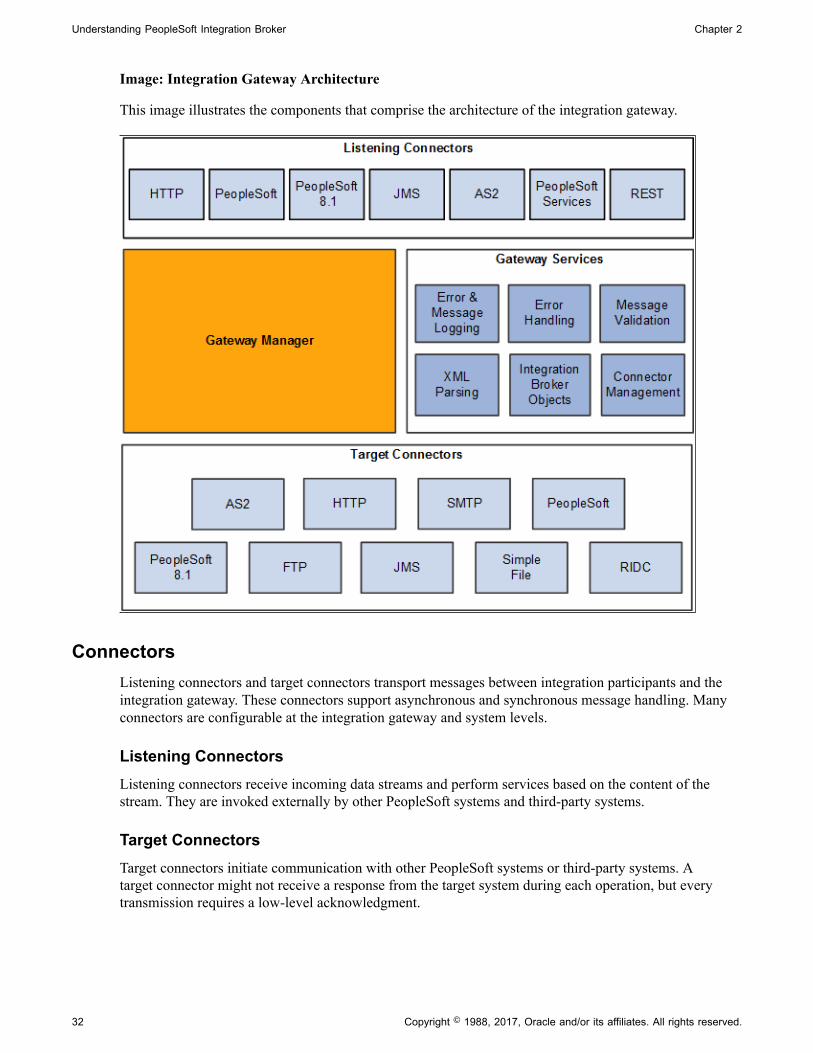
Understanding PeopleSoft Integration Broker Chapter 2
Image: Integration Gateway Architecture
This image illustrates the components that comprise the architecture of the integration gateway.
ConnectorsListening connectors and target connectors transport messages between integration participants and theintegration gateway. These connectors support asynchronous and synchronous message handling. Manyconnectors are configurable at the integration gateway and system levels.
Listening ConnectorsListening connectors receive incoming data streams and perform services based on the content of thestream. They are invoked externally by other PeopleSoft systems and third-party systems.
Target ConnectorsTarget connectors initiate communication with other PeopleSoft systems or third-party systems. Atarget connector might not receive a response from the target system during each operation, but everytransmission requires a low-level acknowledgment.
32 Copyright © 1988, 2017, Oracle and/or its affiliates. All rights reserved.
Chapter 2 Understanding PeopleSoft Integration Broker
PeopleSoft Integration Broker Connector SDKThe integration gateway provides a fully extensible model for developing new connectors built tothe interface specification of the PeopleSoft Integration Broker software development kit (SDK) byPeopleSoft customers, consultants, and application developers.
Related Links"Understanding Listening Connectors and Target Connectors" (PeopleTools 8.55: Integration BrokerAdministration)"Understanding the PeopleSoft Integration Broker Connector SDK" (PeopleTools 8.55: IntegrationBroker Administration)
Gateway ManagerThe gateway manager processes every message that flows through an integration gateway and maintainslinks to the other major integration gateway components, including target connectors, listeningconnectors, and each of the gateway services.
Listening connectors invoke the gateway manager when they receive a request. The gateway manageruses the messaging objects IBRequest and IBResponse to determine how to route each request.
The gateway manager uses a number of the gateway services during this stage to perform operations suchas message validation. The gateway manager then invokes the appropriate target connector based on thecontent of the message object and waits for a reply from the target connector. When the reply is received,the gateway manager forwards the reply to the calling listening connector.
If an error occurs, the gateway manager uses the error handling service and works with the service toprepare an error reply for the listening connector.
Gateway ServicesThis section describes the gateway services that the gateway manager uses.
XML ParsingMost IBRequest objects and IBResponse objects that are processed in the system contain a content sectionthat represents the actual business content sent.
Most of the time, these content sections contain XML data. Consequently, often connectors must parseand traverse XML. The standard Java XML objects are cumbersome for manipulating XML, so theintegration gateway includes an XML parsing service consisting of objects that provide an intuitiveinterface for manipulating XML objects. This service is delivered as a set of three classes: XmlDocument,XmlNode and XmlNodeList.
See the product documentation for PeopleTools 8.55: PeopleCode API Reference .
Integration Broker ObjectsTwo objects comprise the messaging objects service in the integration gateway:
• IBRequest
Copyright © 1988, 2017, Oracle and/or its affiliates. All rights reserved. 33

Understanding PeopleSoft Integration Broker Chapter 2
• IBResponse
These objects represent the request and response that enter and exit PeopleSoft Integration Broker.
See Supported Message Structures.
Connector ManagementThe connector management service is a composite of several services that manage connectors. Thegateway processes each IBRequest to determine the appropriate connector to call in each situation.This is primarily a message routing function that has varying levels of complexity abstracted fromthe connectors. The connector management service also processes the IBResponse returned by eachconnector.
WS-SecurityWS-Security is an extension to the concept of the SOAP envelope header that enables applications toconstruct secure SOAP message exchanges. It also provides a means for associating security tokens withmessages.
See "Implementing Web Services Security" (PeopleTools 8.55: Integration Broker Administration).
Error and Service Operation LoggingMost components in the system use a standard error logging interface.
Each PeopleSoft-delivered connector uses the logging API in the same fashion, ensuring that anadministrator can quickly drill down on problems or simply review the logs to see the IBRequest object,the IBResponse object, and even the raw data exchanged with integration participants.
See Understanding Error Handling, Logging, Tracing and Debugging.
Error HandlingThe integration gateway provides a standard error handling interface that is exposed to each connector.This service provides error handling and error logging for most connectors delivered with PeopleSoftIntegration Broker.
Message ValidationMessages that pass into PeopleSoft Integration Broker must contain certain elements to be processed.Because the integration gateway is the first component that processes messages sent to a PeopleSoftapplication, it performs basic validation—such as making sure that the message identifies its requestorand service operation name—to ensure that the integration engine and the target application can processthem.
Integration Engine Architecture
The integration engine uses a variety of PeopleTools elements to create, implement, manage, and enhanceintegrations. Its modular architecture separates integration development activities from administrativeactivities.
34 Copyright © 1988, 2017, Oracle and/or its affiliates. All rights reserved.

Chapter 2 Understanding PeopleSoft Integration Broker
The integration engine is a combination of PeopleSoft Application Designer definitions, PeopleSoft PureInternet Architecture definitions, PeopleCode, and XSLT code, along with the underlying mechanismsthat tie all these elements together. The underlying mechanisms include the request handlers thatprocess both inbound and outbound messages according to the specifications in the development andadministrative elements.
The integration engine resides on the PeopleSoft application server.
Image: Integration engine architecture
This diagram illustrates the integration components that reside on the integration engine and the types ofprocessing it performs.
Service Operations
A service operation in the PeopleSoft system contains the processing logic for an integration anddetermines if the integration is to be processed synchronously or asynchronously. A service operationdefinition contains the following definitions:
• Message. A message contains the payload of the integration.
Copyright © 1988, 2017, Oracle and/or its affiliates. All rights reserved. 35

Understanding PeopleSoft Integration Broker Chapter 2
• XML message schema. Message schemas provide the physical description of the data that is beingsent, including descriptions of fields, field types, field lengths, and so on.
• Handler. A service operation handler contains the processing logic for the service operation.
• Routing. A routing definition specifies the direction of the integration (inbound or outbound), routingalias names, transformations, and more.
Service Operation Types
PeopleSoft Integration Broker supports four types of service operations:
• Asynchronous one-way.
• Asynchronous request/response.
• Asynchronous to synchronous.
• Synchronous
Note: In this section the term transaction is used to describe the exchange of data between integrationpartners.
When PeopleSoft Integration Broker sends a service operation, the receiving system returns a responseback to the sender. With asynchronous transactions, the response is automatically generated by theintegration gateway, and it serves only to notify the sending system of the transmission status of therequest . It is processed automatically by the application server, which uses that status information toupdate the Service Operations Monitor. With synchronous transactions, however, the response includesthe content that is requested by the sending system, and it must be generated and returned by the receivingsystem.
Operation TypesPeopleSoft Integration Broker supports the operation types listed in the table.
For any operation type, the application must invoke PeopleCode, a component interface or data moverscript to generate and send a service operation or to receive and process a service operation.
Operation Type Routing Actions
Asynchronous — One Way. Outbound. 1. The application generates and sendsa request.
2. One or more target system receivesand processes the request.
36 Copyright © 1988, 2017, Oracle and/or its affiliates. All rights reserved.

Chapter 2 Understanding PeopleSoft Integration Broker
Operation Type Routing Actions
Asynchronous — Request/Response. Outbound. 1. The application generates and sendsa request.
2. The target system receives andprocesses the request.
3. Sometime later the target systemsends a response which containsthe transaction ID from the originalrequest. This ID serves as thecorrelation ID.
4. The application processes theresponse using the correlation ID tomap it back to the original request.The message sent back is a responsein the form of a request.
Asynchronous to Synchronous. Outbound. 1. The application generates and sendsa request.
2. A single target system receives andprocesses the request, then generatesand sends a response.
3. The application receives andprocesses the response.
Synchronous. Outbound. 1. The application generates and sendsa request.
2. The application suspends activityand waits for a response.
3. A single target system receives andprocesses the request, then generatesand sends a response.
4. The application resumes its activityand receives and processes theresponse.
Asynchronous — One way. Inbound. 1. A source system generates andsends a request.
2. The application receives andprocesses the request.
Copyright © 1988, 2017, Oracle and/or its affiliates. All rights reserved. 37
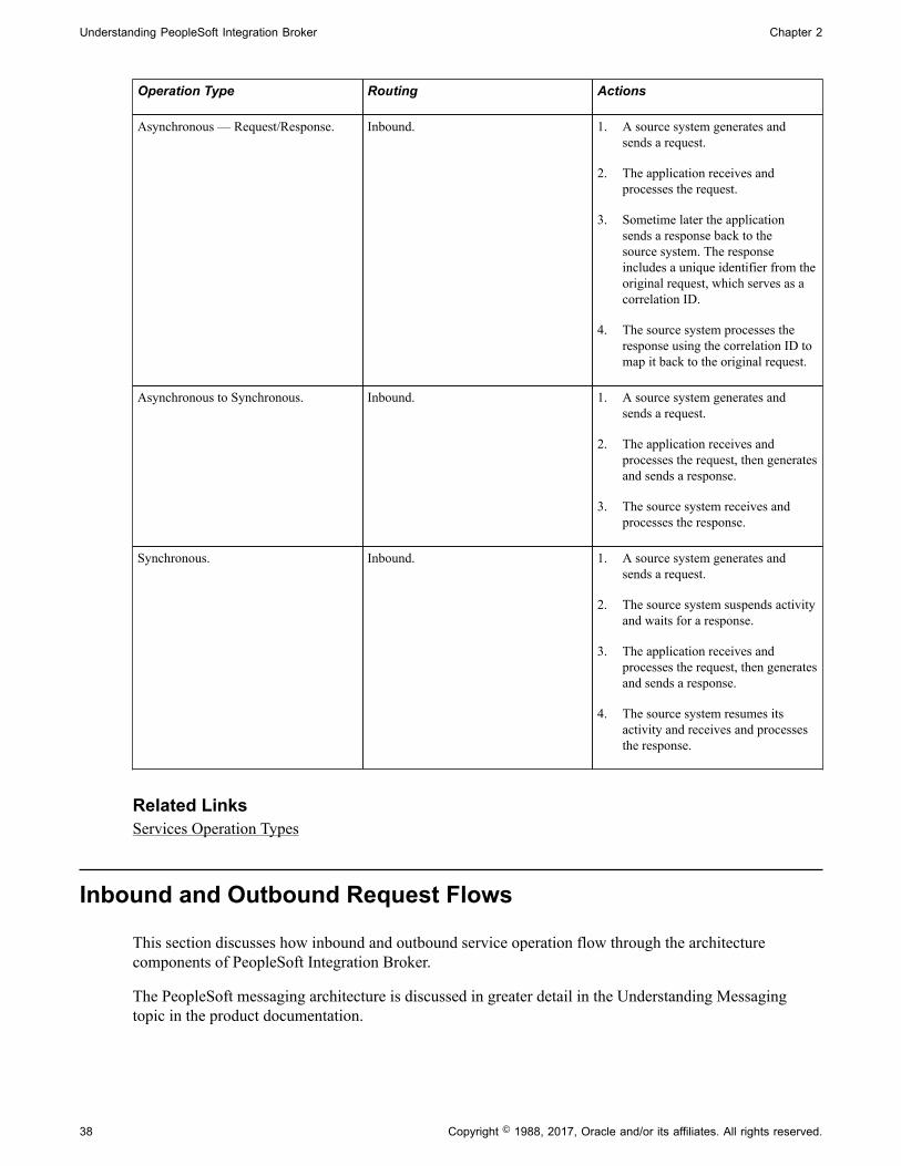
Understanding PeopleSoft Integration Broker Chapter 2
Operation Type Routing Actions
Asynchronous — Request/Response. Inbound. 1. A source system generates andsends a request.
2. The application receives andprocesses the request.
3. Sometime later the applicationsends a response back to thesource system. The responseincludes a unique identifier from theoriginal request, which serves as acorrelation ID.
4. The source system processes theresponse using the correlation ID tomap it back to the original request.
Asynchronous to Synchronous. Inbound. 1. A source system generates andsends a request.
2. The application receives andprocesses the request, then generatesand sends a response.
3. The source system receives andprocesses the response.
Synchronous. Inbound. 1. A source system generates andsends a request.
2. The source system suspends activityand waits for a response.
3. The application receives andprocesses the request, then generatesand sends a response.
4. The source system resumes itsactivity and receives and processesthe response.
Related LinksServices Operation Types
Inbound and Outbound Request Flows
This section discusses how inbound and outbound service operation flow through the architecturecomponents of PeopleSoft Integration Broker.
The PeopleSoft messaging architecture is discussed in greater detail in the Understanding Messagingtopic in the product documentation.
38 Copyright © 1988, 2017, Oracle and/or its affiliates. All rights reserved.
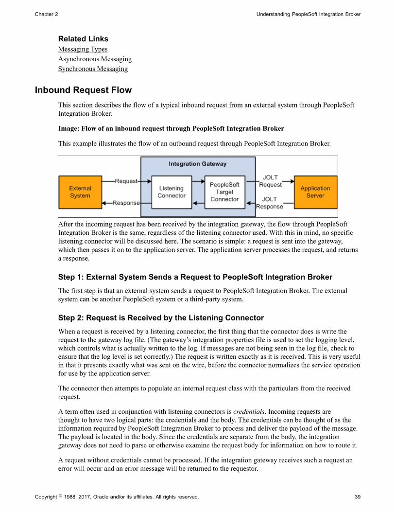
Chapter 2 Understanding PeopleSoft Integration Broker
Related LinksMessaging TypesAsynchronous MessagingSynchronous Messaging
Inbound Request FlowThis section describes the flow of a typical inbound request from an external system through PeopleSoftIntegration Broker.
Image: Flow of an inbound request through PeopleSoft Integration Broker
This example illustrates the flow of an outbound request through PeopleSoft Integration Broker.
After the incoming request has been received by the integration gateway, the flow through PeopleSoftIntegration Broker is the same, regardless of the listening connector used. With this in mind, no specificlistening connector will be discussed here. The scenario is simple: a request is sent into the gateway,which then passes it on to the application server. The application server processes the request, and returnsa response.
Step 1: External System Sends a Request to PeopleSoft Integration BrokerThe first step is that an external system sends a request to PeopleSoft Integration Broker. The externalsystem can be another PeopleSoft system or a third-party system.
Step 2: Request is Received by the Listening ConnectorWhen a request is received by a listening connector, the first thing that the connector does is write therequest to the gateway log file. (The gateway’s integration properties file is used to set the logging level,which controls what is actually written to the log. If messages are not being seen in the log file, check toensure that the log level is set correctly.) The request is written exactly as it is received. This is very usefulin that it presents exactly what was sent on the wire, before the connector normalizes the service operationfor use by the application server.
The connector then attempts to populate an internal request class with the particulars from the receivedrequest.
A term often used in conjunction with listening connectors is credentials. Incoming requests arethought to have two logical parts: the credentials and the body. The credentials can be thought of as theinformation required by PeopleSoft Integration Broker to process and deliver the payload of the message.The payload is located in the body. Since the credentials are separate from the body, the integrationgateway does not need to parse or otherwise examine the request body for information on how to route it.
A request without credentials cannot be processed. If the integration gateway receives such a request anerror will occur and an error message will be returned to the requestor.
Copyright © 1988, 2017, Oracle and/or its affiliates. All rights reserved. 39

Understanding PeopleSoft Integration Broker Chapter 2
Step 3: Request is Processed by the PeopleSoft Target ConnectorIn order for a request to be sent from the gateway to the application server, it must pass through thePeopleSoft target connector. This connector has two major responsibilities: it serializes the request to astring, and sends that string via a JOLT connection to the application server.
All communication between the gateway and the application server is done via the use of MultipurposeInternet Mail Extensions (MIME) messages. When the request is received by the connector, it builds aMIME message. Typically the MIME message will only have two sections. In the first, the credentials arestored in an XML document in a specific format. The second section stores the body.
At this point the request is in a standard format understood by both the gateway and the application server.All requests must eventually resolve to this format before they can be sent to the application server forprocessing. This format effectively isolates the application server from the protocols supported by thegateway; for the most part, there is no information present about what listening connector was initiallyinvoked by the external request.
One credential element that may be present is the one for cookies. Obviously if this is set, the applicationserver would be right in assuming that the request came through the HTTP listening connector. However,as a general rule the application server is isolated from the details of the protocol and the general brokercode on the server does not care what listening connector was used for a given request.
Once the MIME message has been built, it is written to the gateway log.
Finally, the connector looks up the JOLT connection properties from the integration properties file andattempts to send the MIME to the application server. If these properties are not set up correctly, thegateway will be unable to send requests. This is a common source of error, so care should be taken whenconfiguring this file.
An important point to keep in mind is that even though the MIME request to the application server mayappear in the gateway log file, the actual request may not have made it to the application server, since thelog entry is written before the service operation is sent. If a communication error occurs, the entry willstill be present in the log file. However, if this situation occurs an exception will be thrown and an errorlog entry will also be created.
Step 4: Request is Received by the Application ServerWhen the MIME request is received by the application server, the system parses it into a request object.The MIME structure is not propagated into the server.
Assuming the request parses without error, the application server pre-processes it.
Pre-processing involves:
• Authenticating the service operation, depending on the authentication scheme configured. If therequest fails authentication, an error is returned.
• Determining the direction of the service operation, by looking at the external alias on the routingdefinition that is associated with the service operation.
• Determining the runtime handler to invoke. Currently, there are three handler types supported by theintegration broker: Ping, Synchronous, and Asynchronous. The service operation type determinesthe handler code to invoke. Synchronous service operations are passed to sync-specific code, andasynchronous service operations are passed to the publish/subscribe subsystem.
40 Copyright © 1988, 2017, Oracle and/or its affiliates. All rights reserved.

Chapter 2 Understanding PeopleSoft Integration Broker
Once a request has been passed to its respective handler, further processing is dictated by the dataand PeopleCode specific to a particular system. Or in the case of hub configurations, the request mayimmediately be routed to another external system.
Step 5: Response is Returned by the Application ServerRegardless of how the request is processed, a response must be returned by the application server to thegateway in the same thread of execution. The connection between the gateway and the application serveris essentially synchronous, independent of the type of the service operation type. When the gateway sendsa request to the application server, it expects and must get a response.
In the case of synchronous processing, the generation of the response is blocked by the processing ofthe request. A response cannot be generated until the service operation runs to completion. There maybe a noticeable delay in receiving the response, depending on the processing required by the OnRequestmethod or if the request is being sent out of the broker to an external system for additional processing.
Asynchronous requests behave differently. Unlike synchronous requests, there is no blocking. A responseis generated for an asynchronous request as soon as the request is placed on the publication queue.Because of this, a response generated for an asynchronous request is not a response in the strictest senseof the term. Such responses should really be considered acknowledgments that the pub/sub systemhas received the request. Receipt of such a response is not a guarantee that any applicable notificationPeopleCode has been successfully run.
Responses are converted to the MIME standard by the application server, and are returned to the gateway.
Step 6: Response is Received by the PeopleSoft Target ConnectorAs soon as the MIME response is received by the PeopleSoft target connector, it is written to the gatewaylog file.
The MIME response is then parsed back into a gateway request object, and is then returned to thelistening connector.
Step 7: Response is Received by the Listening ConnectorThe response object is returned to the listening connector, upon which the response is mapped to aresponse suitable for the given protocol.
It should be emphasized that, from the viewpoint of the listening connector, the processing of requestsis done synchronously. A request is received by a listening connector which then coverts it to a suitableformat, makes a blocking call to the gateway to handle the message, and ultimately gets a response backall in the same thread of execution.
Outbound Request FlowThe following diagram shows an outgoing request through PeopleSoft Integration Broker.
Copyright © 1988, 2017, Oracle and/or its affiliates. All rights reserved. 41

Understanding PeopleSoft Integration Broker Chapter 2
Image: Outgoing request through PeopleSoft Integration Broker to an external system
This example illustrates and outbound request through PeopleSoft Integration Broker to an externalsystem.
There are several scenarios that might result in a request being sent out of the broker. Requests can be sentin PeopleCode by using the Publish or SyncRequest methods of the Integration Broker class.
Regardless of how the request is created, the mechanism for sending it out of the broker is the same, andthe flow is the same regardless of the specific outgoing target connector you invoke.
Step 1: Application Server Generates RequestOnce an outgoing request has been generated, the application server must perform some basic processingbefore it can be sent out.
The application server looks at the request, and extracts the information about the node that it is beingsent to.
If target connector information was not supplied via PeopleCode or as part of the routing, then the nodename is then used to look up the name of the gateway to use, the target connector to use on that gateway,as well as any specific connector properties that need to be passed to the connector in order to handle therequest. If this information is not found, an error will occur.
The application server modifies the outgoing request with the appropriate connector information.
The request is then converted to the MIME standard format, and is sent to the gateway over an HTTPconnection.
The request must be sent to the PeopleSoft listening connector on the gateway. The application serveruses the value of the Gateway URL defined for the given gateway. If this URL is not valid or does notpoint to the PeopleSoft listening connector, the application server will be unable to send the request.
Step 2: Request is Received by the PeopleSoft Listening ConnectorWhen the MIME request is received by the PeopleSoft listening connector, it is written to the gateway logfile.
The request is converted from MIME format to a gateway request object.
The connector then examines the request to determine what target connector the request is to be sent to;that target connector is then invoked.
42 Copyright © 1988, 2017, Oracle and/or its affiliates. All rights reserved.

Chapter 2 Understanding PeopleSoft Integration Broker
Step 3: Request is Received by the Target ConnectorThe target connector validates the request. Each connector requires certain properties to be set, otherwisethe request cannot be sent. For example, the HTTP target connector requires that the PrimaryURL be set.If any mandatory connector properties are missing or are invalid, an error will be thrown.
The target connector then converts the request into whatever format is required by the protocol.
The modified request is then written to the gateway log, and then sent out.
Step 4: Response is Received by the Target ConnectorThe response received by the target connector is written to the gateway log, and the response is used tobuild a gateway response object, which is then returned to the PeopleSoft listening connector.
Step 5: Response is Received by the PeopleSoft Listening ConnectorThe response object is then converted to the MIME standard format by the connector.
The MIME response is then written to the gateway log file, and is then returned to the application server.
Interactions with the gateway are always synchronous. If a request is sent to the gateway, a responseshould be expected.
Step 2 is an HTTP POST request made of the gateway, and the response created here in Step 5 is returnedin response to that HTTP request. The HTTP connection is open for the duration of the processing for thatrequest.
The response object is returned to the listening connector, upon which the response is mapped to aresponse suitable for the given protocol.
Copyright © 1988, 2017, Oracle and/or its affiliates. All rights reserved. 43

Understanding PeopleSoft Integration Broker Chapter 2
44 Copyright © 1988, 2017, Oracle and/or its affiliates. All rights reserved.
Chapter 3
Understanding Messaging
Messaging Types
PeopleSoft Integration Broker supports asynchronous and synchronous messaging.
Synchronous messaging In synchronous messaging, a message is sent to a target system. The sending system must receive a response from the targetsystem before it continues to process additional messages.
Asynchronous messaging In asynchronous messaging, a message is sent to a targetsystem. However, the sending system does not need to receivea response from the target system before it can continueprocessing messages. This type of messaging is also referred toas fire-and-forget messaging.
The remainder of this topic discusses the PeopleSoft Integration Broker architecture for these messagingtypes.
Note: For compatibility with previous PeopleTools releases, the PeopleSoft Integration Broker services-oriented architecture introduced in PeopleTools 8.48 overlays the messaging architecture from earlierPeopleTools 8.4x releases.
Asynchronous Messaging
This section discusses the PeopleSoft Integration Broker asynchronous messaging architecture.
Brokers, Contractors and QueuesThe publication broker, publication contractor, and subscription contractor services are the primaryapplication server elements required for asynchronous messaging. The publication broker service routesthe workload to both contractor server processes.
Copyright © 1988, 2017, Oracle and/or its affiliates. All rights reserved. 45

Understanding Messaging Chapter 3
Image: Brokers, contractors, and queues
This example illustrates the publication broker service routing the workload the contractor serverprocesses.
Publication broker Acts as the routing mechanism. When an asynchronous serviceoperation arrives in its queue, the publication broker serviceruns the defined routing rules. If the service operation needs tobe published to a remote node, it routes the service operationto the publication contractor service. If the service operationis subscribed to on the local node, then the publication brokerroutes the service operation to the subscription contractorservice. Routing involves submitting either a subscription orpublication contract to the appropriate contractor, followed byan asynchronous call to the contractor service notifying it thatwork is waiting in the queue.
Publication contractor References the publication contract submitted by the publicationbroker service and performs an HTTP post of the publicationservice operation to the integration gateway. When theintegration gateway sends a reply indicating that it received thepublication service operation, the publication contractor serviceupdates the publication contract with the status of subscriptionprocessing (Done or Retry).
Subscription contractor References the subscription contract submitted by thepublication broker service and runs the appropriate notificationPeopleCode. Then it updates the subscription contractconcerning the status of the subscription processing.
46 Copyright © 1988, 2017, Oracle and/or its affiliates. All rights reserved.
Chapter 3 Understanding Messaging
Messaging System Server ProcessesThe application server offers six server processes to handle asynchronous service operations. They workin pairs to provide three primary services:
Service Server Processes
Publication broker • Broker dispatcher (PSBRKDSP)
• Broker handler (PSBRKHND)
Publication contractor • Publication dispatcher (PSPUBDSP)
• Publication handler (PSPUBHND)
Subscription contractor • Subscription dispatcher (PSSUBDSP)
• Subscription handler (PSSUBHND)
Dispatchers and HandlersEach of the publication broker, publication contractor, and subscription contractor is comprised of twoindividual server processes that work together to handle incoming requests. One server process functionsas a dispatcher, while the other functions as a handler.
This relationship is analogous to the way that the application server handles workstation connectionsand requests. To handle the incoming client requests, the application server has a listener and a handler(or a pool of handlers). The listener receives the incoming requests and then routes them to an availablehandler.
Typically, one listener serves many handlers. The relationship between the dispatcher and the handlers isanalogous to the relationship between the Jolt Server Listener (JSL) and the Jolt Server handler (JSH).In the case of the application messaging server processes, the dispatcher functions as the listener, and thehandler as similar to the JSH.
For the services discussed in this section (publication contractor, subscription contractor, and publicationbroker) there are at least two server processes: a single dispatcher and one or more handlers. ThePSxxxDSP server process is the dispatcher, and the PSxxxHND server process is the handler.
Note: The xxx represents BRK, PUB, or SUB. For example, in the case of the publication broker,PSBRKDSP is the dispatcher and PSBRKHND is the handler.
Copyright © 1988, 2017, Oracle and/or its affiliates. All rights reserved. 47

Understanding Messaging Chapter 3
Image: Dispatchers and handlers
This example illustrates the messaging server processes grouped by their functions in the messagingarchitecture:
Asynchronous Service Operation PublicationThis section discusses:
• Asynchronous publish of a service operation instance.
• Asynchronous publish of a publication contract.
Understanding Asynchronous Service Operation PublicationThis section describes the flow of an asynchronous service operation publication through PeopleSoftIntegration Broker, as well as the status of the service operations as they appear in Service OperationsMonitor.
Asynchronous Publish of Service Operation InstancesThis topic describes asynchronous publishing of service operation instances in PeopleSoft IntegrationBroker.
48 Copyright © 1988, 2017, Oracle and/or its affiliates. All rights reserved.

Chapter 3 Understanding Messaging
Image: Asynchronous publication of an operation instance
This example illustrates asynchronous publish of a service operation instance in the messaging system:
The following table describes the processing steps of an asynchronous publication of a service operationinstance in PeopleSoft Integration Broker:
Step Process
1 The service operation is published and enters the messagequeue.
The instance is written to the PSAPMSGPUBHDR table in thedatabase, but is not yet dispatched.
The broker dispatcher process picks up the service operationinstance from its queue.
During this stage, the service operation instance status in theService Operations Monitor is New.
2 The broker dispatcher process passes the service operationinstance to the broker handler process.
During this stage, the service operation instance status in theService Operations Monitor is Started.
Copyright © 1988, 2017, Oracle and/or its affiliates. All rights reserved. 49

Understanding Messaging Chapter 3
Step Process
3 The broker handler process accepts the service operationinstance, reads the data, and runs the routing rules to determinewhere the publication needs to be delivered.
The broker handler process then writes a publication contractin the PSAPMSGPUBCON table and notifies the publicationcontractor service that it has an item to process.
During this stage, the service operation instance status in theService Operation Monitor is Working.
4 After the service operation is stored in the publication contactqueue, the status of the publication contract in the ServiceOperations Monitor is New, the service operation instancestatus is Done, and the publication dispatcher process picks upthe publication contract from its queue.
5 The publication dispatcher process passes the service operationinstance to the publication handler process.
During this stage, the publication contract status in the ServiceOperations Monitor is Started.
You view service operation instance status information on the Operation Instances page of the ServiceOperations Monitor. To access the page select PeopleTools, Integration Broker, Service OperationsMonitor, Monitor, Asynchronous Services, Operation Instances.
See "Monitoring Asynchronous Service Operation Instances" (PeopleTools 8.55: Integration BrokerService Operations Monitor).
Asynchronous Publish of Publication ContractsThis topic discusses asynchronous publishing of publication contracts in PeopleSoft Integration Broker.
50 Copyright © 1988, 2017, Oracle and/or its affiliates. All rights reserved.

Chapter 3 Understanding Messaging
Image: Asynchronous publish of a publication contract
This example illustrates the flow of an asynchronous publication contract through the messaging system.
The following table describes the processing steps of an asynchronous publish of a publication contract inPeopleSoft Integration Broker:
Step Process
1 The publication dispatcher picks up the publication contractfrom the publication contract queue.
2 The publication contract is written to the PSAPMSGPUBCONtable in the database, but is not yet dispatched. The publicationdispatcher process passes the publication contract to thepublication handler process.
At this stage the status of the publication contract in theService Operation Monitor is Started.
3 The publication handler process accepts the publicationcontract and attempts to deliver the service operation to theintegration gateway.
At this stage, the status of the publication contract in theService Operations Monitor is Working.
Copyright © 1988, 2017, Oracle and/or its affiliates. All rights reserved. 51
Understanding Messaging Chapter 3
Step Process
4 The integration gateway attempts to pass the publicationcontract to the destination node.
5 The integration gateway passes the status of the publicationcontract back to the publication handler.
6 The publication handler updates the Service OperationsMonitor with the status of the publication contract. The typicalstatuses that displays in the Service Operations Monitor are:
• Done. The subscribing node successfullyreceived the contract.
• Timeout.The system timed out before thetransaction processing was completed.
• Retry.The system encountered and error.The retry is automatic.
When service operations have Retry status, the serviceoperations are not resent until an internal ping issuccessful. This ping is similar to a node ping. Thepublication Contract dispatcher, as part of its on idleprocessing, pings a node that is in Retry status andverifies if the connection is reestablished. When the pingis successful the publication Contract dispatcher resendsthe service operation. The service operation goes back tothe publication handler process and returns to Workingstatus.
You can view the status information for the publication contract using the publication Contracts page inthe Service Operations Monitor. To access the page, select PeopleTools, Integration Broker, ServiceOperations Monitor, Monitor, Asynchronous Services, Publication Contracts.
See "Monitoring Publication Contracts" (PeopleTools 8.55: Integration Broker Service OperationsMonitor).
The Service Operations Monitor may display statuses for publication contracts other than those discussedin this section.
See "Understanding Asynchronous Service Operations Statuses" (PeopleTools 8.55: Integration BrokerService Operations Monitor)
Asynchronous Service Operation SubscriptionThis section discusses:
• Asynchronous subscription of a service operation instance.
52 Copyright © 1988, 2017, Oracle and/or its affiliates. All rights reserved.

Chapter 3 Understanding Messaging
• Asynchronous subscription contracts.
Understanding Asynchronous Service Operation SubscriptionThis section describes the flow of an asynchronous service operation subscription through PeopleSoftIntegration Broker, as well as the service operation status at each stage of the process.
Asynchronous Subscription of Service Operation InstancesThis topic describes asynchronous subscription process of service operation instances in PeopleSoftIntegration Broker.
Image: Asynchronous subscription of a service operation instance
This example illustrates the flow of an asynchronous service operation subscription through PeopleSoftIntegration Broker.
The following table describes the processing steps of an asynchronous subscription of a service operationinstance in PeopleSoft Integration Broker:
Copyright © 1988, 2017, Oracle and/or its affiliates. All rights reserved. 53

Understanding Messaging Chapter 3
Step Process
1 The service operation enters the message queue. The instanceis written to the database, but not yet dispatched
The broker dispatcher process picks up the service operationinstance from its queue.
During this stage, the status of the service operation instance inthe Service Operations Monitor is New.
2 The broker dispatcher process passes the service operationinstance to the broker handler process.
During this stage, the status of the service operation instance inthe Service Operations Monitor is Started.
3 The broker handler process accepts the service operationinstance, reads the data, and runs the subscription routing rulesto determine if the service operation needs to be processedlocally.
During this stage, the status of the service operation instance inthe Service Operations Monitor is Working.
4 The broker handler process then writes a subscription contractin the PSAPMSGPUBCON table (the subscription contractqueue) and notifies the subscription contractor service that ithas an item to process.
During this stage, the status of the service operation instance inthe Service Operations Monitor is Working.
5 Once the service operation is stored in the subscription contactqueue, the status of the service operation instance in theService Operations Monitor is Done.
Processing of the subscription contract begins as thesubscription dispatcher process picks up the subscriptioncontract from its queue, and the status of the subscriptioncontract in the Service Operations Monitor is New.
In this example, at the point when the status of theasynchronous service operation instance is Done, thesubscription contract status is New.
Asynchronous subscription contract processing is described inthe next section.
You can view service operation instance status on the Operation Instances page of the Service OperationsMonitor. To access this page, select PeopleTools, Integration Broker, Service Operations Monitor, Monitor, Asynchronous Services, Operation Instances.
54 Copyright © 1988, 2017, Oracle and/or its affiliates. All rights reserved.
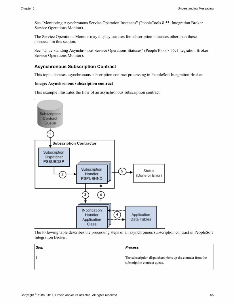
Chapter 3 Understanding Messaging
See "Monitoring Asynchronous Service Operation Instances" (PeopleTools 8.55: Integration BrokerService Operations Monitor).
The Service Operations Monitor may display statuses for subscription instances other than thosediscussed in this section.
See "Understanding Asynchronous Service Operations Statuses" (PeopleTools 8.55: Integration BrokerService Operations Monitor).
Asynchronous Subscription ContractThis topic discuses asynchronous subscription contract processing in PeopleSoft Integration Broker.
Image: Asynchronous subscription contract
This example illustrates the flow of an asynchronous subscription contract.
The following table describes the processing steps of an asynchronous subscription contract in PeopleSoftIntegration Broker:
Step Process
1 The subscription dispatchers picks up the contract from thesubscription contract queue.
Copyright © 1988, 2017, Oracle and/or its affiliates. All rights reserved. 55

Understanding Messaging Chapter 3
Step Process
2 The subscription dispatcher process passes the subscriptioncontract to the subscription handler process.
At this stage the status of the subscription contract in theService Operations Monitor is Started.
3 The subscription handler process accepts the subscriptioncontract and runs the notification PeopleCode.
4 In the example shown in the diagram, the notificationPeopleCode then uses the service operation data to updateapplication data tables. However, the notification PeopleCodecan use the service operation data as input to look upinformation, create and publish another service operation, andso forth.
At this stage, the status of the publication contract in theService Operations Monitor is Working.
5 The subscription handler passes the status of the subscriptioncontract to the Service Operations Monitor. The typicalstatuses that display in the Service Operations Monitor for anasynchronous subscription contract are:
• Done. The notification PeopleCode ran successfully.
• Error. An error occurred.
To view status information for subscription contracts, use the Subscription Contracts page in the ServicesOperation Monitor. To access the page select PeopleTools, Integration Broker, Service OperationsMonitor, Monitor, Asynchronous Services, Subscription Contracts.
See "Monitoring Subscription Contracts" (PeopleTools 8.55: Integration Broker Service OperationsMonitor).
The Service Operations Monitor may display statuses for subscription contracts other than those discussedin this section.
See "Understanding Asynchronous Service Operations Statuses" (PeopleTools 8.55: Integration BrokerService Operations Monitor).
Synchronous Messaging
This section discusses synchronous messaging in PeopleSoft Integration Broker.
Synchronous Service Operation PublicationThis topic discusses synchronous service operation publication in PeopleSoft Integration Broker.
56 Copyright © 1988, 2017, Oracle and/or its affiliates. All rights reserved.

Chapter 3 Understanding Messaging
Image: Synchronous service operation publication
This example illustrates using PeopleSoft Integration Broker to consume a synchronous service operation.
The following table describes the processing steps for a synchronous publication of a service operation inPeopleSoft Integration Broker:
Step Process
1 The integration engine sends the service operation to theintegration gateway.
2 The integration gateway attempts to deliver the serviceoperation to the destination node.
3 The integration gateway sends back the status information tothe integration engine
4 The integration engine updates the database tables as wellas sends the status information to the Service OperationsMonitor.
The possible statuses in the Service Operations Monitor for asynchronous publication are:
• Done. The integration gateway was able to deliver theservice operation to the destination node.
• Error. The integration gateway was not able to deliver theservice operation to the destination node.
Copyright © 1988, 2017, Oracle and/or its affiliates. All rights reserved. 57

Understanding Messaging Chapter 3
You can view the status information for the invocation in the Service Operations Monitor using theSynchronous Services page. To access the page select PeopleTools, Integration Broker, ServiceOperations Monitor, Monitor, Synchronous Services.
For status information for synchronous integrations to be available in the Service Operations Monitor, youmust set the Log Detail parameter in the routing definition for the service operation.
Related LinksDefining General Routing Information"Understanding Synchronous Service Operation Statuses" (PeopleTools 8.55: Integration Broker ServiceOperations Monitor)"Filtering Synchronous Service Operations Data" (PeopleTools 8.55: Integration Broker ServiceOperations Monitor)"Viewing Monitor Output for Synchronous Service Operations Data" (PeopleTools 8.55: IntegrationBroker Service Operations Monitor)
Synchronous Service Operation SubscriptionThis topic discusses synchronous service operation subscription in PeopleSoft Integration Broker.
58 Copyright © 1988, 2017, Oracle and/or its affiliates. All rights reserved.

Chapter 3 Understanding Messaging
Image: Synchronous service operation subscription
This example illustrates providing a synchronous service operation through PeopleSoft IntegrationBroker.
The following table describes the processing steps of a synchronous service operation subscription inPeopleSoft Integration Broker:
Step Process
1 The integration gateway passes an inbound synchronousservice operation to the integration engine.
2 The integration engine runs an OnRequest PeopleCode eventprogram.
3 The OnRequest PeopleCode program attempts to update theapplication data tables.
Copyright © 1988, 2017, Oracle and/or its affiliates. All rights reserved. 59
Understanding Messaging Chapter 3
Step Process
4 The integration engine updates the database tables as wellas sends the status information to the Service OperationsMonitor.
The possible statuses in the Service Operations Monitor for asynchronous publication are:
• Done. The integration gateway was able to deliver theservice operation to the destination node.
• Error. The integration gateway was not able to deliver theservice operation to the destination node.
For status information for synchronous integrations to be available in the Service Operations Monitor, youmust set the Log Detail parameter in the routing definition for the service operation.
You can view the status information for the publication in the Service Operations Monitor by using theSynchronous Services page. Access this page by selecting PeopleTools, Integration Broker, ServiceOperations Monitor, Monitor, Synchronous Services.
Related LinksDefining General Routing Information"Understanding Synchronous Service Operation Statuses" (PeopleTools 8.55: Integration Broker ServiceOperations Monitor)"Filtering Synchronous Service Operations Data" (PeopleTools 8.55: Integration Broker ServiceOperations Monitor)"Viewing Monitor Output for Synchronous Service Operations Data" (PeopleTools 8.55: IntegrationBroker Service Operations Monitor)
60 Copyright © 1988, 2017, Oracle and/or its affiliates. All rights reserved.

Chapter 4
Understanding PeopleSoft IntegrationBroker Metadata
PeopleSoft Integration Broker Metadata
You use the following integration metadata to create and implement integrations using PeopleSoftIntegration Broker
Integration PeopleCode You use integration PeopleCode to send and receive messages, route messages and manipulate message content.
Integration gateway definitions This definition is an application’s internal representation of aninstalled integration gateway. An application requires at least thelocal gateway, through which it can send and receive messages. Multiple nodes can share the same local gateway, which mightbe the only gateway that you need for all of the integrations.
Message definitions Message definitions provide the physical description of the datathat is being sent, including fields, field types, and field lengths.
Node definitions Nodes represent any organization, application or systemthat will play a part in integrations. For example, nodes canrepresent customers, business units, suppliers, other tradingpartners, external or third-party software systems, and so on.
Node definitions define the locations to or from which messagescan be routed.
Because an application can send messages to itself, a defaultlocal node definition that represents the application is deliveredas part of the integration engine. Each PeopleSoft installationmust have one, and only one, default local node
Queue definitions Queues group asynchronous services for processing. In addition, they can dictate the order of processing of the asynchronousservice operations .
Routing definitions Routing definitions determine the sender and receiver of anintegration. Routing definitions allow you to specify inboundand outbound transformations that enable you to transform datastructures into those that the sending or receiving systems canunderstand.
Service definitions Service definitions group service operations into logical groupsor categories.
Copyright © 1988, 2017, Oracle and/or its affiliates. All rights reserved. 61

Understanding PeopleSoft Integration Broker Metadata Chapter 4
Service operation definitions Service operations define the processing logic of an integration. They specify the inbound, outbound and fault messagesassociated with an integration, the integration PeopleCode toinvoke, and the routing to use.
Transformation programs A transformation or transform program is a type of ApplicationEngine program that you develop and specify as part of arouting definition. PeopleSoft Integration Broker supports theuse of Extensible Stylesheet Language Transformation (XSLT)code and PeopleCode for developing transform programs.
Transform programs can transform, filter and translate data.
Order of Precedence for Creating Integration Metadata
Create integration metadata in the following order:
1. Integration gateway definition.
2. Node definition.
3. Message definition.
4. Integration PeopleCode.
5. Transformation programs.
6. Queue definition.
7. Service definition.
8. Service operation definition.
9. Handler definition.
10. Routing definition.
Related Links"Administering Integration Gateways" (PeopleTools 8.55: Integration Broker Administration)"Configuring Nodes" (PeopleTools 8.55: Integration Broker Administration)Understanding Managing MessagesUnderstanding Filtering, Transformation, and TranslationUnderstanding Service Operation QueuesUnderstanding Sending and Receiving MessagesUnderstanding Managing ServicesUnderstanding Managing REST ServicesUnderstanding Managing Service OperationsUnderstanding REST Service OperationsUnderstanding Routing Definitions
62 Copyright © 1988, 2017, Oracle and/or its affiliates. All rights reserved.
Chapter 5
Understanding Supported MessageStructures
Supported Message Structures
This topic discusses the message structures used by PeopleSoft Integration Broker to exchange requestand response messages between the integration gateway and the application server, between otherPeopleSoft systems, and between third-party integration partners.
Note: The code examples in this topic are for illustrative purposes only and are not intended to be used ina production environment.
Integration Broker Message Structures
This section discusses the internal message formats for request messages and response messages, localcompression, and how to access IBInfo elements.
Internal Message Format for Request MessagesThis section discusses the format used to exchange request messages between the integration gateway andthe application server. These messages are frequently referred to as IBRequest messages.
The Multipurpose Internet Mail Extension standard (MIME) is used as the basic structure for internalmessaging. MIME has several advantages in that the standard is well-known and supported, and becauseit is text-based, it is human readable and easily serializable.
Messages using the internal format display in the integration gateway log file. Since the log file is avaluable tool for debugging, anyone reading the file will need to understand how the messages arestructured.
Every request message contains three parts:
Headers The first part of a request message contains headers whichdescribe the attributes of the whole message.
IBInfo (Integration BrokerInformation)
The IBInfo (Integration Broker Information) section containsthe credentials of the request as well as all other informationrequired by the PeopleSoft Integration Broker to process themessage. The IBInfo for a request has a specific XML structurewhich is used for all request messages in the system, regardlessif the message is being sent to the application server or to theintegration gateway.
Copyright © 1988, 2017, Oracle and/or its affiliates. All rights reserved. 63

Understanding Supported Message Structures Chapter 5
Content section The final section contains the message body of the originalrequest. This is the payload and is what is ultimately deliveredto the final destination.
The following is an example of a request message in the PeopleSoft internal MIME format:
Message-ID: <-123.123.123.123@nowhere >Mime-Version: 1.0Content-Type: multipart/related; boundary="Integration_Server_MIME_Boundary"Content-ID: PeopleSoft-Internal-Mime-MessagePeopleSoft-ToolsRelease: 8.55
--Integration_Server_MIME_BoundaryContent-Type: text/plain; charset=UTF-8Content-Transfer-Encoding: 8bitContent-ID: IBInfoContent-Disposition: inline
<?xml version="1.0" ?> <IBInfo> <TransactionID> <![CDATA[ caa3a040-bde5-11da-914c-ecaede80d83b]]> </TransactionID> <ExternalOperationName> <![CDATA[ QE_FLIGHTPLAN_TRANSFORM.VERSION_1]]> </ExternalOperationName> <OperationType>async</OperationType> <From> <RequestingNode> <![CDATA[ QE_LOCAL]]> </RequestingNode> <RequestingNodeDescription> <![CDATA[ ]]> </RequestingNodeDescription> <NodePassword> <![CDATA[ password]]> </NodePassword> <ExternalUserName> <![CDATA[ ]]> </ExternalUserName> <ExternalUserPassword> <![CDATA[ ]]> </ExternalUserPassword> <AuthToken> <![CDATA[ owAAAAQDAgEBAAAAvAIAAAAAAAAsAAAABABTaGRyAk4AbQg4AC4AMQ AwABTFZOonLEjJaPtR6v02oadvRUoSq2MAAAAFAFNkYXRhV3icHYhNDkAwGERfEQ srFyFN0cZSaGz8xAmcwA0dzug3yZv53gMUeWaM+s1IV11EFnZOysjBSv2bm01mZl L3Dqt4GrETHSHtQCs6cWBM2ybr9fMBbP0LSQ==]]> </AuthToken> <WSA-ReplyTo> <![CDATA[ ]]> </WSA-ReplyTo> <NodeDN> <![CDATA[ ]]> </NodeDN> <OrigUser> <![CDATA[ QEDMO]]> </OrigUser> <OrigNode> <![CDATA[ QE_LOCAL]]> </OrigNode> <OrigProcess> <![CDATA[ QE_FLIGHTDATA]]> </OrigProcess> <OrigTimeStamp>2006-03-27T15:02:39.280000-0800</OrigTimeStamp> <DirectGatewayRequest /> <SyncServiceTimeout /> <ExternalMessageID> <![CDATA[ ]]> </ExternalMessageID>
64 Copyright © 1988, 2017, Oracle and/or its affiliates. All rights reserved.

Chapter 5 Understanding Supported Message Structures
<SegmentsUnOrder>N</SegmentsUnOrder> <ConversationID> <![CDATA[ ]]> </ConversationID> <WSA-MessageID> <![CDATA[ ]]> </WSA-MessageID> <InReplyToID> <![CDATA[ ]]> </InReplyToID> <DataChunk> <![CDATA[ ]]> </DataChunk> <DataChunkCount> <![CDATA[ ]]> </DataChunkCount> </From> <WS-Security> <WSTokenType> <![CDATA[ ]]> </WSTokenType> </WS-Security> <To> <DestinationNode> <![CDATA[ QE_IBTGT]]> </DestinationNode> <FinalDestinationNode> <![CDATA[ ]]> </FinalDestinationNode> <AppServerDomain> <![CDATA[ ]]> </AppServerDomain> </To> <Cookies> <![CDATA[ ]]> </Cookies> <PathInfo> <![CDATA[ ]]> </PathInfo> <HttpSession> <SessionID> <![CDATA[ ]]> </SessionID> </HttpSession> <QStrArgs /> <ContentSections> <ContentSection> <ID>ContentSection0</ID> <NonRepudiation>N</NonRepudiation> <Headers> <version> <![CDATA[ VERSION_1]]> </version> <encoding> <![CDATA[ base64(deflate)]]> </encoding> <encodedlength> <![CDATA[ 948(709)]]> </encodedlength> <length> <![CDATA[ 2840]]> </length> </Headers> </ContentSection> </ContentSections> <PublishNode> <![CDATA[ QE_LOCAL]]> </PublishNode> <Queue> <![CDATA[ QE_FLIGHTPLAN_CHNL]]> </Queue>
Copyright © 1988, 2017, Oracle and/or its affiliates. All rights reserved. 65

Understanding Supported Message Structures Chapter 5
<SubQueue> <![CDATA[ c9de8110-bde5-11da-be79-846b4e717ebf]]> </SubQueue> <VisitedNodes> <![CDATA[ QE_LOCAL|]]> </VisitedNodes> <Connector> <ConnectorName> <![CDATA[ PSFTTARGET]]> </ConnectorName> <ConnectorClassName> <![CDATA[ PeopleSoftTargetConnector]]> </ConnectorClassName> <RemoteFrameworkURL> <![CDATA[ ]]> </RemoteFrameworkURL> <ConnectorParameters> <ConnectorParam> <Name> <![CDATA[ URL]]> </Name> <Value> <![CDATA[ ]]> </Value> </ConnectorParam> </ConnectorParameters> <ConnectorHeaders /> </Connector> <AttachmentSection ResponseAsAttachment="N" /> </IBInfo>
--Integration_Server_MIME_BoundaryContent-Type: text/plain; charset=UTF-8Content-Transfer-Encoding: 8bitContent-ID: ContentSection0Content-Disposition: inline
eJydll1P2zAUhu8n7T+g/gAKFdt6UYxOHCe1FH9gO1RwE1UMTUiMTRRN27+fk7SpvwItd/F57cTvG+c5WVz9/fl08ufhZfP46/lycn56NrlCnz8trklTVLRcGlkBb4wCrguhGFoUjw9P382/3w8btJ+Ug4GT+6f1ZnM5UZNOAMxrlhF18mrnXk76wWTaaUzTRhOuxU7FS9hpopBxEbC5lSSuY6gqTUseK/q6hlyJhIIFY+fp8iwuE8yCYk40VpXgZVCfeml0i1eSN1IRTYw+Ih1twFDBG569KUuhU/KKgBQ8HVdR37VGeUHDzW9FIdtbx9oK1JJAnnDsWOxmcrihZbfBIxyv4FYKys2Y5YyAolHgVrDHskz4hMpQU+cJpYJRxb7REam1nnz8DakEpoYSHWs2iPakJCLbR7T1kIPaZnhEZv0yTSqCnXcWT2EiZalfLSQZ0TNQGkPiJHQLR2I3pYFU3V5yTqrWX/yq7iirzTIWpCoS2blh9esVA0b4Mcm9831BORIJTWy//9q0JDg8AlNnc2ghbZrMQ6TFalnbuBocflZQ59S0yAvjz0C3J3hsHdOlPQ/XFkLhUZVKYKJ1Q7n1zjGJbMs6q6heNqquSEMTN+Y2Em69hCZ7X/bCbQts8yNfv67Rwrysnzfr+1fbWg5rFmj+bT7ro9tV/H6B7C1UN8GpbdsGmp9eXHRaO9i3DVScz7f37IZue0Bfv1z0DxwqQ49AGXRKPxh6BMrwUJ7tegSyiRRduR3se8TAgrehiBKmXSh6GHTQ5+POR1yANQ9lIb48ZH0YUykXAaYCMKVg5AEohI4LmhAuHlAGiHwQHCkvDjhcVAx4iJAwPfAv4KCHOX0/7PRRdw87utfFU53bp1X4K/MmvRDh5WLqFhyCJajVz4+qLr4SyEJnFjZhLeSWzyqPTx6KpgOh9k6D/9z/1gQ1Ww==--Integration_Server_MIME_Boundary--
IBRequest Header SectionThe first part of a request message contains headers which describe the attributes of the whole message.
Message-ID: <-123.123.123.123@nowhere >Mime-Version: 1.0Content-Type: multipart/related; boundary="Integration_Server_MIME_Boundary"Content-ID: PeopleSoft-Internal-Mime-MessagePeopleSoft-ToolsRelease: 8.55
--Integration_Server_MIME_BoundaryContent-Type: text/plain; charset=UTF-8Content-Transfer-Encoding: 8bitContent-ID: IBInfoContent-Disposition: inline
66 Copyright © 1988, 2017, Oracle and/or its affiliates. All rights reserved.
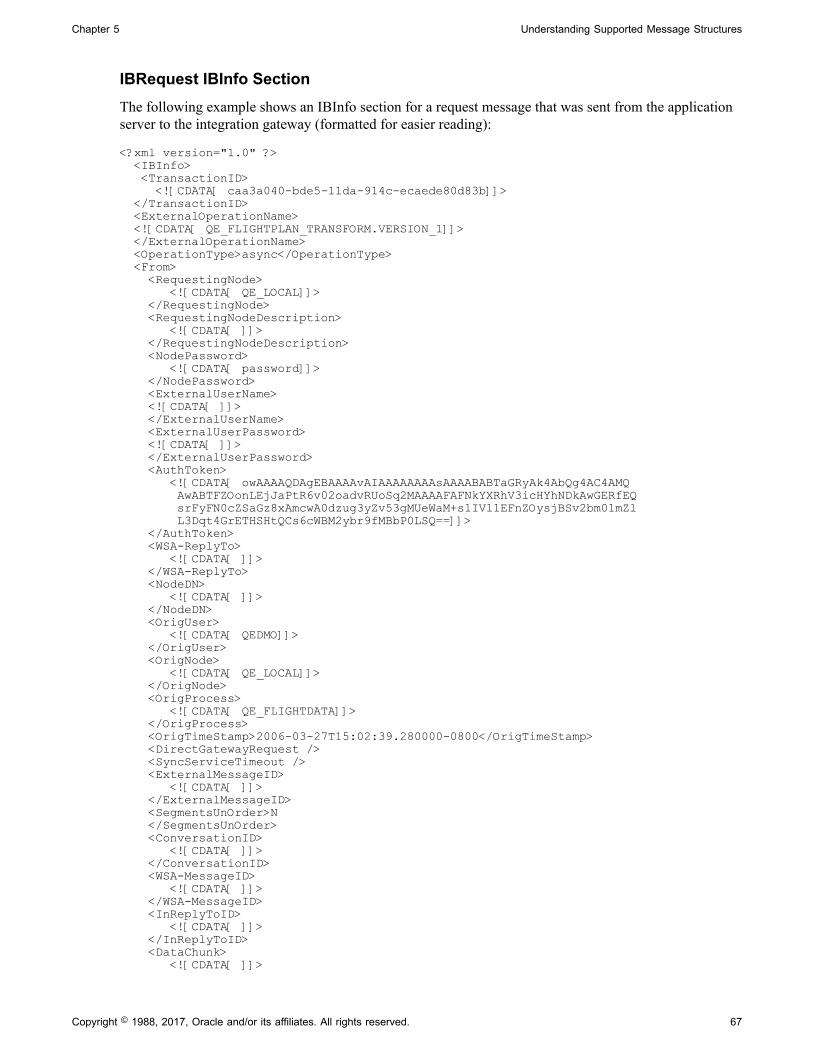
Chapter 5 Understanding Supported Message Structures
IBRequest IBInfo SectionThe following example shows an IBInfo section for a request message that was sent from the applicationserver to the integration gateway (formatted for easier reading):
<?xml version="1.0" ?> <IBInfo> <TransactionID> <![CDATA[ caa3a040-bde5-11da-914c-ecaede80d83b]]> </TransactionID> <ExternalOperationName> <![CDATA[ QE_FLIGHTPLAN_TRANSFORM.VERSION_1]]> </ExternalOperationName> <OperationType>async</OperationType> <From> <RequestingNode> <![CDATA[ QE_LOCAL]]> </RequestingNode> <RequestingNodeDescription> <![CDATA[ ]]> </RequestingNodeDescription> <NodePassword> <![CDATA[ password]]> </NodePassword> <ExternalUserName> <![CDATA[ ]]> </ExternalUserName> <ExternalUserPassword> <![CDATA[ ]]> </ExternalUserPassword> <AuthToken> <![CDATA[ owAAAAQDAgEBAAAAvAIAAAAAAAAsAAAABABTaGRyAk4AbQg4AC4AMQ AwABTFZOonLEjJaPtR6v02oadvRUoSq2MAAAAFAFNkYXRhV3icHYhNDkAwGERfEQ srFyFN0cZSaGz8xAmcwA0dzug3yZv53gMUeWaM+s1IV11EFnZOysjBSv2bm01mZl L3Dqt4GrETHSHtQCs6cWBM2ybr9fMBbP0LSQ==]]> </AuthToken> <WSA-ReplyTo> <![CDATA[ ]]> </WSA-ReplyTo> <NodeDN> <![CDATA[ ]]> </NodeDN> <OrigUser> <![CDATA[ QEDMO]]> </OrigUser> <OrigNode> <![CDATA[ QE_LOCAL]]> </OrigNode> <OrigProcess> <![CDATA[ QE_FLIGHTDATA]]> </OrigProcess> <OrigTimeStamp>2006-03-27T15:02:39.280000-0800</OrigTimeStamp> <DirectGatewayRequest /> <SyncServiceTimeout /> <ExternalMessageID> <![CDATA[ ]]> </ExternalMessageID> <SegmentsUnOrder>N </SegmentsUnOrder> <ConversationID> <![CDATA[ ]]> </ConversationID> <WSA-MessageID> <![CDATA[ ]]> </WSA-MessageID> <InReplyToID> <![CDATA[ ]]> </InReplyToID> <DataChunk> <![CDATA[ ]]>
Copyright © 1988, 2017, Oracle and/or its affiliates. All rights reserved. 67
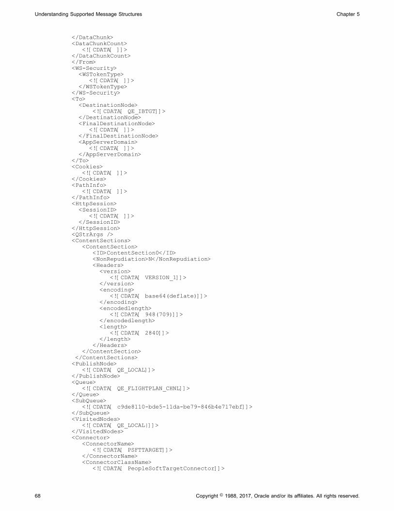
Understanding Supported Message Structures Chapter 5
</DataChunk> <DataChunkCount> <![CDATA[ ]]> </DataChunkCount> </From> <WS-Security> <WSTokenType> <![CDATA[ ]]> </WSTokenType> </WS-Security> <To> <DestinationNode> <![CDATA[ QE_IBTGT]]> </DestinationNode> <FinalDestinationNode> <![CDATA[ ]]> </FinalDestinationNode> <AppServerDomain> <![CDATA[ ]]> </AppServerDomain> </To> <Cookies> <![CDATA[ ]]> </Cookies> <PathInfo> <![CDATA[ ]]> </PathInfo> <HttpSession> <SessionID> <![CDATA[ ]]> </SessionID> </HttpSession> <QStrArgs /> <ContentSections> <ContentSection> <ID>ContentSection0</ID> <NonRepudiation>N</NonRepudiation> <Headers> <version> <![CDATA[ VERSION_1]]> </version> <encoding> <![CDATA[ base64(deflate)]]> </encoding> <encodedlength> <![CDATA[ 948(709)]]> </encodedlength> <length> <![CDATA[ 2840]]> </length> </Headers> </ContentSection> </ContentSections> <PublishNode> <![CDATA[ QE_LOCAL]]> </PublishNode> <Queue> <![CDATA[ QE_FLIGHTPLAN_CHNL]]> </Queue> <SubQueue> <![CDATA[ c9de8110-bde5-11da-be79-846b4e717ebf]]> </SubQueue> <VisitedNodes> <![CDATA[ QE_LOCAL|]]> </VisitedNodes> <Connector> <ConnectorName> <![CDATA[ PSFTTARGET]]> </ConnectorName> <ConnectorClassName> <![CDATA[ PeopleSoftTargetConnector]]>
68 Copyright © 1988, 2017, Oracle and/or its affiliates. All rights reserved.

Chapter 5 Understanding Supported Message Structures
</ConnectorClassName> <RemoteFrameworkURL> <![CDATA[ ]]> </RemoteFrameworkURL> <ConnectorParameters> <ConnectorParam> <Name> <![CDATA[ URL]]> </Name> <Value> <![CDATA[ ]]> </Value> </ConnectorParam> </ConnectorParameters> <ConnectorHeaders /> </Connector> <AttachmentSection ResponseAsAttachment="N" /> </IBInfo>
While the basic structure is the same for all requests, not all elements are always required. An exampleof this is the Connector section. The Connector XML is used to tell the integration gateway to route amessage to the named target connector. It also lists configuration parameters for the outbound request.This XML would only be seen in requests sent from the application server to the integration gateway. Forrequests going in the other direction, the section would be empty.
Note: The only element that is always required is ExternalOperationName.
The following is a list of the most important elements that may appear in the IBInfo section of a requestmessage:
Element Description
IBInfo / ExternalOperationName The name of the requested service operation.
IBInfo / Operation Type (Optional.) This is the type of service operation. The validvalues are: asynchronous, synchronous and ping.
IBInfo / TransactionID (Optional.) The transaction ID is used to uniquely identify arequest.
IBInfo / From / RequestingNode (Optional.) The requesting node is the node that sent therequest to the current system.
IBInfo / From / Password (Optional.) This is the password for the requesting node.
IBInfo / From / DN (Optional.) For incoming requests, the DN gives theDistinguished Name extracted from the certificateauthentication process.
IBInfo / From / OrigNode (Optional.) For requests that cross multiple nodes, OrigNode isused to identify the node that initiated the request.
IBInfo / From / OrigTimeStamp (Optional.) This timestamp corresponds to the time that therequest was created. For requests that cross nodes, this is thetime that the first request was created.
Copyright © 1988, 2017, Oracle and/or its affiliates. All rights reserved. 69
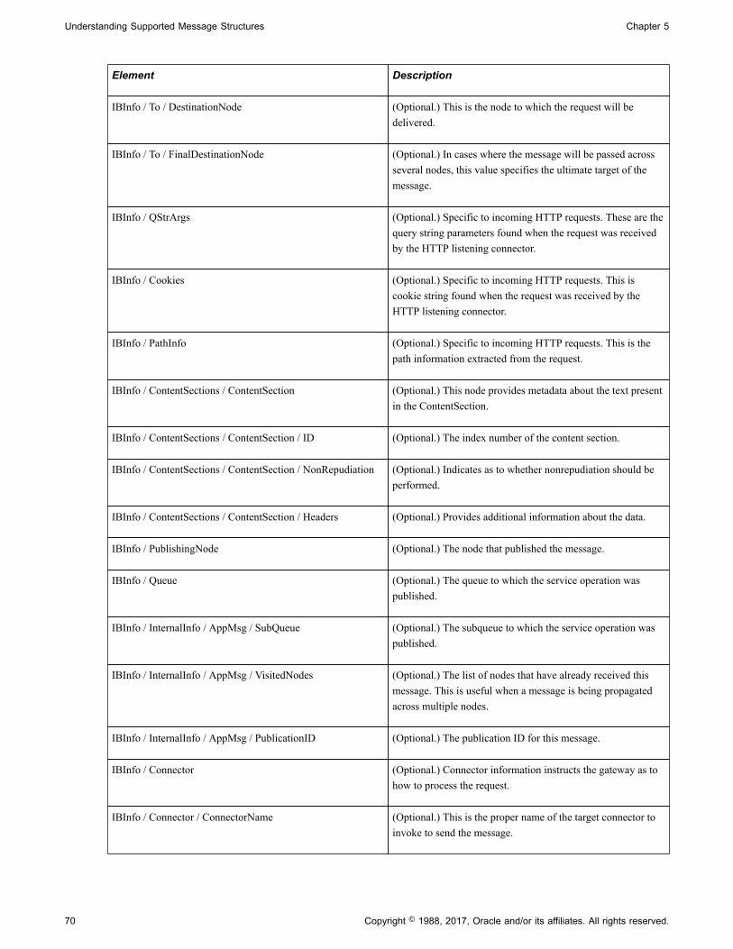
Understanding Supported Message Structures Chapter 5
Element Description
IBInfo / To / DestinationNode (Optional.) This is the node to which the request will bedelivered.
IBInfo / To / FinalDestinationNode (Optional.) In cases where the message will be passed acrossseveral nodes, this value specifies the ultimate target of themessage.
IBInfo / QStrArgs (Optional.) Specific to incoming HTTP requests. These are thequery string parameters found when the request was receivedby the HTTP listening connector.
IBInfo / Cookies (Optional.) Specific to incoming HTTP requests. This iscookie string found when the request was received by theHTTP listening connector.
IBInfo / PathInfo (Optional.) Specific to incoming HTTP requests. This is thepath information extracted from the request.
IBInfo / ContentSections / ContentSection (Optional.) This node provides metadata about the text presentin the ContentSection.
IBInfo / ContentSections / ContentSection / ID (Optional.) The index number of the content section.
IBInfo / ContentSections / ContentSection / NonRepudiation (Optional.) Indicates as to whether nonrepudiation should beperformed.
IBInfo / ContentSections / ContentSection / Headers (Optional.) Provides additional information about the data.
IBInfo / PublishingNode (Optional.) The node that published the message.
IBInfo / Queue (Optional.) The queue to which the service operation waspublished.
IBInfo / InternalInfo / AppMsg / SubQueue (Optional.) The subqueue to which the service operation waspublished.
IBInfo / InternalInfo / AppMsg / VisitedNodes (Optional.) The list of nodes that have already received thismessage. This is useful when a message is being propagatedacross multiple nodes.
IBInfo / InternalInfo / AppMsg / PublicationID (Optional.) The publication ID for this message.
IBInfo / Connector (Optional.) Connector information instructs the gateway as tohow to process the request.
IBInfo / Connector / ConnectorName (Optional.) This is the proper name of the target connector toinvoke to send the message.
70 Copyright © 1988, 2017, Oracle and/or its affiliates. All rights reserved.

Chapter 5 Understanding Supported Message Structures
Element Description
IBInfo / Connector / ConnectorClassName (Optional.) This is the class name of the target connector toinvoke.
IBInfo / Connector / ConnectorParameters (Optional.) Connector parameters are processing instructionsfor the target connector to be invoked.
IBInfo / Connector / ConnectorHeaders (Optional.) Connector headers provide further metadata aboutthe contents of the message to be sent.
IBRequest Content SectionThe content section of a request message features the message body.
--Integration_Server_MIME_BoundaryContent-Type: text/plain; charset=UTF-8Content-Transfer-Encoding: 8bitContent-ID: ContentSection0Content-Disposition: inlineeJydll1P2zAUhu8n7T+g/gAKFdt6UYxOHCe1FH9gO1RwE1UMTUiMTRRN27+fk7SpvwItd/F5eJydll1P2zAUhu8n7T+7c TvG+c5WVz9/fl08ufhZfP46/lycn56NrlCnz8trklTVLRcGlkBb4wCrguhGFoUjw9P382/3w TvG+8btJ+Ug4GT+6f1ZnM5UZNOAMxrlhF18mrnXk76wWTaaUzTRhOuxU7FS9hpopBxEbC5lSSuY6gqtJ+Ug4GT+TUseK/q6hlyJhIIFY+fp8iwuE8yCYk40VpXgZVCfeml0i1eSN1IRTYw+Ih1twFDBG569KUuhU/KKgBQ8HVdR37VGeUHDzW9FIdtbx9oK1JJAnnDsWOxmcrihZbfBIxyv4FYKys2Y5YyAolHgVrDHskz4hMpQU+cJpYJRxb7REam1nnz8DakEpoYSHWs2iPakJCLbR7T1kIPaZnhEZv0yTSqCnXcWT2z4hMpQU+EiZalfLSQZ0TNQGkPiJHQLR2I3pYFU3V5yTqrWX/yq7iirzTIWpCoS2blh9esVA0b4Mcm9831BORIJTWy//9q0JDg8AlNnc2ghbZrMQ6TFalnbuBocflZQ59S0yAvjz0C3J3hsHdOlPQ/XFkLhUZVKYKJ1Q7n1zjGJbMs6q6heNqquSEMTN+Y2Em69hCZ7X/bCbQts8yNfv67Rwrysnzfr+1fbWg5rFmj1Q7n1zjGJbMs6q6heNqquSEMTN++bT7ro9tV/H6B7C1UN8GpbdsGmp9eXHRaO9i3DVScz7f37IZue0Bfv1z0DxwqQ49AGXRKPxh6BMrwUJ7tegSyiRRduR3se8TAgrehiBKmXSh6GHTQ5+POR1yANQ9lIb48ZH0YUykXAaYCMKVg5AEohJ7tegSyiRRduR3se8TAgrehiBKmXSh6GHTQ5+I4LmhAuHlAGiHwQHCkvDjhcVAx4iJAwPfAv4KCHOX0/7PRRdw87utfFU53bp1X4K/MmvRDh5WLqFhyCJajVz4+qLr4SyEJnFjZhLeSWzyqPTx6KpgOh9k6D/9z/1gQ1Ww==
Internal Message Format for Response MessagesThe internal format for response messages parallels that for request messages, and has the same basicMIME structure. These messages are frequently referred to as IBResponse messages.
There are three logical components to a MIME response message: the IBResponse header section, theIBInfo section, and the Content section.
The following code shows an example of a response message:
Message-ID: <32004392.1143500580241.JavaMail.KCOLLIN2@PLE-KCOLLIN2>Date: Mon, 27 Mar 2006 15:03:00 -0800 (PST)Mime-Version: 1.0Content-Type: multipart/related; boundary="----=_Part_4_9069393.1143500580221"Content-ID: PeopleSoft-Integration-Broker-Internal-Mime-MessagePeopleSoft-ToolsRelease: 8.55
------=_Part_4_9069393.1143500580221Content-Type: text/plain; charset=UTF-8Content-Transfer-Encoding: 8bitContent-Disposition: inlineContent-ID: IBInfo
<?xml version="1.0"?><IBInfo><Status><StatusCode>0</StatusCode>
Copyright © 1988, 2017, Oracle and/or its affiliates. All rights reserved. 71

Understanding Supported Message Structures Chapter 5
<MsgSet>158</MsgSet>
<MsgID>10000</MsgID><DefaultTitle>Integration Broker Response Message</DefaultTitle>
</Status><ContentSections><ContentSection><ID>ContentSection0</ID><NonRepudiation>N</NonRepudiation></ContentSection></ContentSections></IBInfo>------=_Part_4_7210339.1008355101202
IBResponse HeaderThe first part of a response message contains headers which describe the attributes of the whole message.
Message-ID: <32004392.1143500580241.JavaMail.KCOLLIN2@PLE-KCOLLIN2>Date: Mon, 27 Mar 2006 15:03:00 -0800 (PST)Mime-Version: 1.0Content-Type: multipart/related; boundary="----=_Part_4_9069393.1143500580221"Content-ID: PeopleSoft-Integration-Broker-Internal-Mime-MessagePeopleSoft-ToolsRelease: 8.55
IBResponse IBInfo SectionThe format for the XML for the IBInfo for a response message is different than that for the requestmessage. The following is a sample (formatted for easier reading):
<?xml version="1.0"?><IBInfo> <Status> <StatusCode>0</StatusCode> <MsgSet>158</MsgSet> <MsgID>10000</MsgID> <DefaultMsg>OK</DefaultMsg> <DefaultTitle>Integration Broker Response Message</DefaultTitle> </Status> <ContentSections> <ContentSection> <ID>ContentSection0</ID> <NonRepudiation>N</NonRepudiation> </ContentSection> </ContentSections></IBInfo>
The following is the list of all the elements that may be present in the IBInfo for a response message:
Element Description
IBInfo / Status / StatusCode Describes the result of the request. The possible values are:
• 0 (zero). Request successfully processed.
• 10. Temporary error occurred. Request can be resent.
• 20. Fatal error occurred. Do not resend request.
• 30. Request message is a duplicate of a messagepreviously received.
IBInfo / Status / MsgSet The MessageSetNumber for this message in the MessageCatalog. Message set number 158 is assigned to the PeopleSoftIntegration Broker.
72 Copyright © 1988, 2017, Oracle and/or its affiliates. All rights reserved.

Chapter 5 Understanding Supported Message Structures
Element Description
IBInfo / Status / MsgID The Message Number for this message in the MessageCatalog. If no errors occurred during the processing of therequest, the MsgID will be set to the value ‘10000’.
IBInfo / Status / DefaultTitle Used if the message catalog is unavailable. This valuecorresponds to the “Message Text” for a given entry in themessage catalog.
IBInfo / Status / DefaultMsg Used if the message catalog is unavailable. This valuecorresponds to the “Explanation” for a given entry in themessage catalog.
IBInfo / Status / Parameters Parameters may be used to provide additional information forerror responses.
IBInfo / ContentSection A description of the content section returned with theresponse.
Note: Not all response messages will have a content section. The structure of the content section and all child elements isthe same as was seen in the request IBInfo.
IBResponse Content SectionThe content section of a response message features the message body only when working withSyncRequests
<?xml version="1.0"?><TestXml>This is a sample response message.</TestXml>
Error Codes and Message Catalog EntriesA response message may contain data relating to the processing of the request message, or it may containerror information if there were problems in fulfilling the request.
The status code describes the nature of the response message. The following table describes possiblerequest message status codes and their meaning.
Value Meaning Description
0 Success The message transport and processingwere successful.
10 Retry The transport was not successful. PeopleSoft Integration Broker willperform its retry logic and send themessage again.
20 Error An error occurred.
Copyright © 1988, 2017, Oracle and/or its affiliates. All rights reserved. 73

Understanding Supported Message Structures Chapter 5
Value Meaning Description
30 Duplicate message The transaction ID for the message hasalready been received.
40 Acknowledgement error This status is used for SOAP messagesand indicates that the contents of thedata is not proper, but the transport wassuccessful.
50 Acknowledgement hold Used for asynchronous chunking ofmessages from PeopleSoft to PeopleSoftnodes when sending multiple messagesegments.
All PeopleSoft Integration Broker error messages are stored in the message catalog. A short and longdescription for every error can be found there. Catalog entries are given a number, and this number is usedin the response messages.
Here is a sample error message:
Message-ID: <32004392.1143500580241.JavaMail.KCOLLIN2@PLE-KCOLLIN2>Date: Mon, 27 Mar 2006 15:03:00 -0800 (PST)Mime-Version: 1.0Content-Type: multipart/related; boundary="----=_Part_4_9069393.1143500580221"Content-ID: PeopleSoft-Integration-Broker-Internal-Mime-MessagePeopleSoft-ToolsRelease: 8.55
------=_Part_25_2235074.1008270392277Content-Type: text/plain; charset=UTF-8Content-Transfer-Encoding: 8bitContent-Disposition: inlineContent-ID: IBInfo
<?xml version="1.0"?><IBInfo><Status><StatusCode>10</StatusCode><MsgSet>158</MsgSet><MsgID>10721</MsgID><Parameters count="1"><Parm>404</Parm></Par⇒ameters><DefaultTitle>Integration Gateway Error</DefaultTitle></Status></IBInfo>------=_Part_25_2235074.1008270392277--
All PeopleSoft Integration Broker errors use message set 158. The actual error seen here is 10721. Goingto the message catalog, the description for message set 158, error 10721 is:
Message Text: Integration Gateway - External System Contact Error
Explanation: Integration Gateway was not able to contact the external system. The network location specified may be incorrect, or the site is permanently or temporarily down.
Therefore this error was created by the integration gateway when it tried to send a request message to anexternal system.
Local CompressionThis section provides an overview of local compression and discusses how to:
• Set local compression for asynchronous messages.
74 Copyright © 1988, 2017, Oracle and/or its affiliates. All rights reserved.
Chapter 5 Understanding Supported Message Structures
• Set local compression for synchronous messages.
• Override local compression for synchronous messages.
Understanding Local CompressionThe integration engine compresses and base64–encodes messages destined for the PeopleSoft listeningconnector on its local integration gateway.
Setting Local Compression for Asynchronous MessagesAsynchronous messages are always compressed and base64 encoded when sent to the integrationgateway. There are no settings you need to make.
Setting Local Compression for Synchronous MessagesIn PSAdmin you can set a threshold message size above which the system compresses synchronousmessages. The setting is shown here:
Values for config section - Integration Broker Min Message Size For Compression=10000
Do you want to change any values (y/n)? [n]:
The value is the message size in bytes; the default value is 10000 (10 kilobytes). You can specify a settingof 0 to compress all messages.
To turn off compression, set the value to -1.
Warning! Turning compression off can negatively impact system performance when transportingsynchronous messages greater than 1 MB. As a result, you should turn off compression only duringintegration development and testing.
Note: This setting does not affect the compression of messages that the integration gateway sends usingits target connectors.
Overridding Local Compression for Synchronous MessagesYou can override the PSAdmin message compression setting for synchronous messages at the transactionlevel. The following method on the IBInfo object in the Message class is provided for this purpose:
&MSG.IBInfo.CompressionOverride
The valid parameters for this method are: %IntBroker_Compress, %IntBroker_UnCompress, and%IntBroker_Compress_Reset.
See ."Understanding Message Classes" (PeopleTools 8.55: PeopleCode API Reference)
Accessing IBInfo Elements Using PeopleCodeYou can use the PeopleCode Message object to access IBRequest and IBResponse IBInfo data.
Copyright © 1988, 2017, Oracle and/or its affiliates. All rights reserved. 75

Understanding Supported Message Structures Chapter 5
The following example demonstrates reading target connector information on a notification method for arowset-based asynchronous message.
method OnNotify /+ &_MSG as Message +/ /+ Extends/implements PS_PT:Integration:INotificationHandler.OnNotify +/ /* Variable Declaration */
integer &i; string &strReturn; rowset &RS; For &i = 1 To &MSG.IBInfo.IBConnectorInfo.GetNumberOfConnectorProperties() /* get Query arguments */ &strReturn = &MSG.IBInfo.IBConnectorInfo.GetQueryStringArgName(&i); &strReturn = &MSG.IBInfo.IBConnectorInfo.GetQueryStringArgValue(&i); End-For; /* access the content data */
&RS = &MSG.GetRowset(); end-method;
The following example demonstrates reading target connector information on notification method for anonrowset-based asynchronous message.
method OnNotify /+ &_MSG as Message +/ /+ Extends/implements PS_PT:Integration:INotificationHandler.OnNotify +/ /* Variable Declaration */
integer &i;
string &&strReturn;
xmldoc &xmldoc; For &i = 1 To &MSG.IBInfo.IBConnectorInfo.GetNumberOfConnectorProperties() &strReturn = &MSG.IBInfo.IBConnectorInfo.GetQueryStringArgName(&i); &strReturn = &MSG.IBInfo.IBConnectorInfo.GetQueryStringArgValue(&i); End-For; /* access the content data */
&xmldoc = &MSG.GetXmlDoc(); end-method;
If an HTTP header is passed with a dollar sign ($), PeopleSoft Integration Broker converts the dollar signto an underscore (_).
PeopleSoft Rowset-Based Message Format
This section discusses the PeopleSoft rowset-based message format and discusses:
• FieldTypes section of a rowset-based message.
• MsgData section of a rowset-based message.
76 Copyright © 1988, 2017, Oracle and/or its affiliates. All rights reserved.
Chapter 5 Understanding Supported Message Structures
• PeopleSoft rowset-based message example.
• PeopleSoft timestamp format.
• CDATA and special characters.
• Schema restrictions.
This section also provides an example of a rowset-based message.
Related LinksMessage Part Structures
Understanding the PeopleSoft Rowset-Based Message FormatTo work with rowset-based messages—the PeopleSoft native format—you define a message in thePeopleSoft Pure Internet Architecture, insert records into the message definition in a hierarchicalstructure, and then populate the message and manipulate its contents by using the PeopleCode Rowset andMessage classes. Externally, the message is transmitted as XML with a prescribed PeopleSoft schema.
The PeopleSoft message schema includes a PSCAMA record, which PeopleTools adds to every level ofthe message structure to convey basic information about the message and its data rows.
The Rowset and IntBroker classes are recommended for messaging between PeopleSoft applications.If a message is populated with data from a PeopleSoft application’s database or component buffer, theMessage class is best for handling that data.
Record and Field AliasesYou can specify an alias for any record or field in a rowset-based message definition. Each nodeparticipating in a transaction maintains its own independent definition of the message and its versions,including record and field names and their aliases.
When you send a message with an alias defined and the message is converted to XML for sending,only the alias appears in the XML. If you don’t specify an alias, the original name is used. If the serviceoperation is routed to multiple target nodes with different record or field naming schemes, you create foreach target a separate service operation version with its own aliases and send each version separately.
The only requirement for a successful transaction is that the record and field names in the XML matcheither the original names or the aliases that are defined for that message and version at the node receivingthe message. This behavior applies to both request and synchronous response messages, but typically onlythe source node applies aliases to accommodate the target node’s naming scheme in both directions.
In a synchronous transaction, the request and response messages can be completely different from eachother. Upon receiving a synchronous request, the target node generates and sends a response message.Upon receiving the response, the source node uses its defined aliases to find and reapply its originalrecord and field names. The resulting inbound message contains the original names that were defined atthe source node, not the aliases. Therefore, both the sending and receiving PeopleCode at the source nodeshould expect to work with the source node’s original record and field names.
Related LinksPSCAMA
Copyright © 1988, 2017, Oracle and/or its affiliates. All rights reserved. 77

Understanding Supported Message Structures Chapter 5
Understanding Integration PeopleCodeUnderstanding Filtering, Transformation, and Translation
Rowset-Based Message TemplateThe following template shows the overall structure of a message in the PeopleSoft rowset-based messageformat:
<?xml version="1.0"?> <psft_message_name> <FieldTypes> ... </FieldTypes> <MsgData> <Transaction> ... </Transaction> </MsgData> </psft_message_name>
Note: Psft_message_name is the name of the message definition in the PeopleSoft database. IntegrationBroker inserts this message content into a standard PeopleSoft XML message wrapper for transmission.
FieldTypes SectionEach PeopleSoft message includes field type information. Fieldtype information conveys the name ofeach data record and its constituent fields, along with each field’s data type. Your receiving applicationcan use this information to validate data types. The field type information is contained in the FieldTypessection of the message.
There are two FieldTypes tags:
• Each record tag consists of the name of a record, followed by a class attribute with a single validvalue: R. The record tag encloses that record’s field tags.
• Each field tag consists of the name of a field, followed by a type attribute with three valid values:CHAR for a character field, DATE for a date field, and NUMBER for a numeric field.
Following is a simple FieldTypes template.
<FieldTypes> <recordname1 class="R"> <fieldname1 type="CHAR"/> <fieldname2 type="DATE"/> <fieldname3 type="NUMBER"/> </recordname1> <recordname2 class="R"> <fieldname4 type="NUMBER"/> </recordname2><FieldTypes>
Note: Third-party sending applications must include a valid FieldTypes section in each message. ThePeopleSoft system expects fieldtype information for each record and field in the message.
78 Copyright © 1988, 2017, Oracle and/or its affiliates. All rights reserved.
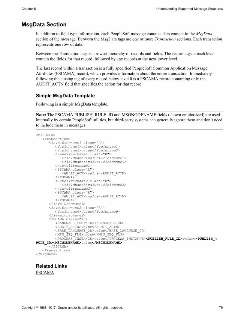
Chapter 5 Understanding Supported Message Structures
MsgData SectionIn addition to field type information, each PeopleSoft message contains data content in the MsgDatasection of the message. Between the MsgData tags are one or more Transaction sections. Each transactionrepresents one row of data.
Between the Transaction tags is a rowset hierarchy of records and fields. The record tags at each levelcontain the fields for that record, followed by any records at the next lower level.
The last record within a transaction is a fully specified PeopleSoft Common Application MessageAttributes (PSCAMA) record, which provides information about the entire transaction. Immediatelyfollowing the closing tag of every record below level 0 is a PSCAMA record containing only theAUDIT_ACTN field that specifies the action for that record.
Simple MsgData TemplateFollowing is a simple MsgData template.
Note: The PSCAMA PUBLISH_RULE_ID and MSGNODENAME fields (shown emphasized) are usedinternally by certain PeopleSoft utilities, but third-party systems can generally ignore them and don’t needto include them in messages.
<MsgData> <Transaction> <level0recname1 class="R"> <fieldname1>value</fieldname1> <fieldname2>value</fieldname2> <level1recname1 class="R"> <fieldname3>value</fieldname3> <fieldname4>value</fieldname4> </level1recname1> <PSCAMA class="R"> <AUDIT_ACTN>value</AUDIT_ACTN> </PSCAMA> <level1recname2 class="R"> <fieldname5>value</fieldname5> </level1recname2> <PSCAMA class="R"> <AUDIT_ACTN>value</AUDIT_ACTN> </PSCAMA> </level0recname1> <level0recname2 class="R"> <fieldname6>value</fieldname6> </level0recname2> <PSCAMA class="R"> <LANGUAGE_CD>value</LANGUAGE_CD> <AUDIT_ACTN>value</AUDIT_ACTN> <BASE_LANGUAGE_CD>value</BASE_LANGUAGE_CD> <MSG_SEQ_FLG>value</MSG_SEQ_FLG> <PROCESS_INSTANCE>value</PROCESS_INSTANCE><PUBLISH_RULE_ID>value</PUBLISH_⇒RULE_ID><MSGNODENAME>value</MSGNODENAME> </PSCAMA> <Transaction></MsgData>
Related LinksPSCAMA
Copyright © 1988, 2017, Oracle and/or its affiliates. All rights reserved. 79

Understanding Supported Message Structures Chapter 5
PSCAMAPeopleTools adds the PSCAMA record to every level of the message structure during processing. It isn’taccessible in the message definition, but you can reference it as part of the Message object in the sendingand receiving PeopleCode, and you can see it in the Integration Broker Monitor. PeopleCode processesthis record the same way as any other record.
Note: PSCAMA records are automatically included in messages only if you insert database records todefine the message structure. You can use the PeopleCode XmlDoc class to handle an inbound messagecontaining PSCAMA records, but the PeopleCode Message class is much better suited for this.
PSCAMA contains fields that are common to all messages. The <PSCAMA> tag repeats for each row ineach level of the transaction section of the message. The sender can set PSCAMA fields to provide basicinformation about the message; for example, to indicate the message language or the type of transactiona row represents. When receiving a message, your PeopleCode should inspect the PSCAMA records forthis information and respond accordingly.
PSCAMA Record DefinitionThe PSCAMA record definition includes the following fields:
LANGUAGE_CD Indicates the language in which the message is generated, sothe receiving application can take that information into accountwhen processing the message. When sending a message withcomponent PeopleCode, the system sets this field to the user’sdefault language code.
AUDIT_ACTN Identifies each row of data as an Add, Change, or Delete action.
BASE_LANGUAGE_CD (Optional.) Indicates the base language of the sending database. This is used by generic, full-table subscription PeopleCode tohelp determine which tables to update.
MSG_SEQ_FLG (Optional.) Supports the transmission of large transactions thatmay span multiple messages. Indicates whether the message isa header (H) or trailer (T) or contains data (blank). The headerand trailer messages don’t contain message data. The receivingsystem can use this information to determine the start and endof the set of messages and initiate processes accordingly. Forexample, the header message might cause staging tables to becleared, while the trailer might indicate that all of the data hasbeen received and an update job should be initiated.
PROCESS_INSTANCE (Optional.) Process instance of the batch job that created themessage. Along with the sending node and publication ID, thereceiving node can use this to identify a group of messages fromthe sending node.
PUBLISH_RULE_ID (Optional.) Indicates the publish rule that is invoked to createthe message. This is used by routing PeopleCode to locate theappropriate chunking rule, which then determines to whichnodes the message should be sent. Third-party applications canignore this field.
80 Copyright © 1988, 2017, Oracle and/or its affiliates. All rights reserved.

Chapter 5 Understanding Supported Message Structures
MSGNODENAME (Optional.) The node to which the message should be sent. Thisfield is passed to the Publish utility by the Application Engineprogram. Routing PeopleCode must look for a value in thisfield and return that value to the application server. Third-partyapplications can ignore this field.
Language CodesEach message can contain only one language code (the LANGUAGE_CD field) in the first PSCAMArecord.
PeopleSoft language codes contain three characters and are mapped to corresponding InternationalOrganization for Standardization (ISO) locale codes in an external properties file. This mapping enablesthe PeopleSoft Pure Internet Architecture to derive certain defaults from the ISO locales that are storedin a user's browser settings. Your PeopleSoft application is delivered with a set of predefined languagecodes; you can define your own codes, as well.
Note: There can be only one language code for the entire message. To send messages in multiplelanguages, send multiple messages.
See "Understanding International Preferences" (PeopleTools 8.55: Global Technology).
Audit Action CodesA PSCAMA record appears following each row of the message. At a minimum, it contains an audit actioncode (the AUDIT_ACTN field), denoting the action to be applied to the data row. The audit action isrequired so that the receiving system knows how to process the incoming data.
The valid audit action codes match those that are used in the PeopleSoft audit trail processing: A, C, D, K,N, O, and blank.
The audit action values are set by the system or by the sending PeopleCode to specify that a record shouldbe added, changed, or deleted:
Audit Action Code Description
A Add a noneffective or effective-dated row.
To add an effective-dated row, the value is A.
If you populate the row data by using theCopyRowsetDeltaOriginal method in the PeopleCode Messageclass, an additional record is created with an audit action valueof O, containing the original values of the current effective-dated row.
C Change non-key values in a row.
D Delete a row.
Copyright © 1988, 2017, Oracle and/or its affiliates. All rights reserved. 81

Understanding Supported Message Structures Chapter 5
Audit Action Code Description
K If you change at least one key value in a row (in addition toany non-key values) and then populate the row data by usingthe CopyRowsetDeltaOriginal or CopyRowsetDelta methodsin the Message class, an additional record is created with anaudit action value of K, containing the original values of thecurrent effective-dated row.
N Change at least one key value in a row (in addition to any non-key values).
O If you change non-key values in a row and populate the rowdata by using the CopyRowsetDeltaOriginal method in theMessage class, an additional record is created with an auditaction value of O, containing the original values of the currenteffective-dated row.
Blank Default value.
If a row’s content hasn’t changed, the value is blank.
This audit action code is also used to tag the parents of rowsthat have changed.
Other PSCAMA ConsiderationsYou can update values on the PSCAMA record just like any other record in the message definition beforesending the message.
The receiving process can access the fields in this record just like any other fields in the message.
The size of the PSCAMA record varies. In particular, notice a difference between the first PSCAMArecord and the ones that follow. The first record contains all of the fields, while the other PSCAMArecords have only the AUDIT_ACTN field, which is the only field that can differ for each row of data.
Although the first PSCAMA record is always present, not all of the remaining PSCAMA records aresent in the message. If a <PSCAMA> tag is not included for a specific row, you can assume that the rowhasn’t changed. In addition, if the <AUDIT_ACTN> tag is blank or null, you can also assume the rowhasn’t changed.
If you’re receiving a message that has incremental changes, only the rows that have changed and theirparent rows are present in the message.
You can view an example of an outbound message with the PSCAMA records inserted by testing yourmessage definition using the Schema Tester.
See "Understanding the Schema Tester Utility" (PeopleTools 8.55: Integration Broker Testing Utilitiesand Tools).
82 Copyright © 1988, 2017, Oracle and/or its affiliates. All rights reserved.
Chapter 5 Understanding Supported Message Structures
Identifying Changes to Field-Level AttributesWhen sending and receiving messages, all blank data values get stripped. As a result, you cannotdetermine if a field value is blank by definition, or if its value was stripped in the messaging process.
The PeopleCode CopyRowset functions CopyRowset, CopyRowsetDelta and CopyRowsetDeltaOriginal,feature an IsChanged attribute that automatically gets set to identify fields that have been changed. Anyfield that has been changed displays the attribute IsChanged="Y".
Note: The IsChanged attribute applies only to rowset-based messages. For rowset-based message parts,use the Message Part Default Indicator field to distinguish blanks from zeros in part messages. TheIsChanged attribute does not apply to nonrowset-based messages, including nonrowset-based containermessages and nonrowset-based part messages.
For example:
<QE_ACNUMBER IsChanged="Y">2</QE_ACNUMBER>
Fields that had data and then were blanked contain the IsChanged attribute.
For example:
<DESCRLONG IsChanged="Y"/>
Fields that were always blank and thus were not changed do not feature this attribute. For example:
<QE_NAVDESC/>
If you are writing subscription PeopleCode you reference the IsChanged value of the field in the messagerowset, as always. However, the blanks appear with the attribute IsChanged="Y".
Related LinksDistinguishing Blank from Zero in Rowset-Based Part Messages
PeopleSoft Timestamp FormatThe PeopleSoft format for all timestamps is ISO-8601. If any message fields are type timestamp, thefollowing format is used:
CCYY-MM-DDTHH:MM:SS.ssssss+/-hhmm
Note: The ISO format specifies that the +/-hhmm parameter is optional, but PeopleSoft requires it. Alldate and time stamps in the header and the body of the message must include the Greenwich Mean Time(GMT) offset as +/-hhmm. This ensures that the timestamp is correctly understood by the receivingapplication.
CDATA and Special CharactersConsider the following points regarding rowset-based messages:
• You cannot use CDATA in message XML if you plan to use GetRowSet to parse the message.
• When using the ampersand character (&) in a string, it must be URL-encoded. For example: &.Passing only the ampersand character results in a PeopleCode error when you get the rowset values.
Copyright © 1988, 2017, Oracle and/or its affiliates. All rights reserved. 83

Understanding Supported Message Structures Chapter 5
• Other special characters are best passed encoded as well, such as > for “<” and < ">."
Schema RestrictionsFor stronger schema validation control, some PeopleSoft field types have certain implicit restrictionsregarding the format of field data that is acceptable in a runtime message. These restrictions appear inmessage schema.
The restrictions apply to fields having the following formats.
• Mixed case.
• Name.
• Phone number.
• Social security number.
• Uppercase.
• Zip code.
Note: These restrictions apply to rowset-based messages and rowset-based message parts.
The restrictions for each are shown in the following example:
<xsd:simpleType name="BASE_LANGUAGE_CD_TypeDef"> <xsd:annotation> <xsd:documentation>BASE_LANGUAGE_CD is a character of length 3. Allows Uppercase characters including numbers </xsd:documentation> </xsd:annotation> <xsd:restriction base="xsd:string"> <xsd:maxLength value="3"/> <xsd:whiteSpace value="preserve"/> <xsd:pattern value="([A-Z]|[0-9]|\p{Z}|\p{P}|\p{Lu})*"/> </xsd:restriction> </xsd:simpleType>
Rowset-Based Message ExampleThe message data is enclosed in a tag with the name of the message, and consists of one FieldTypessection followed by one MsgData section. The FieldTypes section describes the records and fields thatappear in the MsgData section, which contains the actual data.
Note: The PSCAMA record requires field type information just like any other record.
<SDK_BUS_EXP_APPR_MSG> <FieldTypes> <SDK_BUS_EXP_PER class="R"> <SDK_EMPLID type="CHAR"/> <SDK_EXP_PER_DT type="DATE"/> <SDK_SUBMIT_FLG type="CHAR"/> <SDK_INTL_FLG type="CHAR"/> <SDK_APPR_STATUS type="CHAR"/> <SDK_APPR_INSTANCE type="NUMBER"/> <SDK_DESCR type="CHAR"/> <SDK_COMMENTS type="CHAR"/> </SDK_BUS_EXP_PER> <SDK_DERIVED class="R">
84 Copyright © 1988, 2017, Oracle and/or its affiliates. All rights reserved.

Chapter 5 Understanding Supported Message Structures
<SDK_BUS_EXP_SUM type="NUMBER"/> </SDK_DERIVED> <SDK_BUS_EXP_DTL class="R"> <SDK_CHARGE_DT type="DATE"/> <SDK_EXPENSE_CD type="CHAR"/> <SDK_EXPENSE_AMT type="NUMBER"/> <SDK_CURRENCY_CD type="CHAR"/> <SDK_BUS_PURPOSE type="CHAR"/> <SDK_DEPTID type="CHAR"/> </SDK_BUS_EXP_DTL> <PSCAMA class="R"> <LANGUAGE_CD type="CHAR"/> <AUDIT_ACTN type="CHAR"/> <BASE_LANGUAGE_CD type="CHAR"/> <MSG_SEQ_FLG type="CHAR"/> <PROCESS_INSTANCE type="NUMBER"/> </PSCAMA> </FieldTypes> <MsgData> <Transaction> <SDK_BUS_EXP_PER class="R"> <SDK_EMPLID>8001</SDK_EMPLID> <SDK_EXP_PER_DT>1998-08-22</SDK_EXP_PER_DT> <SDK_SUBMIT_FLG>N</SDK_SUBMIT_FLG> <SDK_INTL_FLG>N</SDK_INTL_FLG> <SDK_APPR_STATUS>P</SDK_APPR_STATUS> <SDK_APPR_INSTANCE>0</SDK_APPR_INSTANCE> <SDK_DESCR>Regional Users Group Meeting</SDK_DESCR> <SDK_COMMENTS>Attending Northeast Regional Users Group Meeting and presented new release functionality. </SDK_COMMENTS> <SDK_BUS_EXP_DTL class="R"> <SDK_CHARGE_DT>1998-08-22</SDK_CHARGE_DT> <SDK_EXPENSE_CD>10</SDK_EXPENSE_CD> <SDK_EXPENSE_AMT>45.690</SDK_EXPENSE_AMT> <SDK_CURRENCY_CD>USD</SDK_CURRENCY_CD> <SDK_BUS_PURPOSE>Drive to Meeting</SDK_BUS_PURPOSE> <SDK_DEPTID>10100</SDK_DEPTID> </SDK_BUS_EXP_DTL> <PSCAMA class="R"> <AUDIT_ACTN>A</AUDIT_ACTN> </PSCAMA> <SDK_BUS_EXP_DTL class="R"> <SDK_CHARGE_DT>1998-08-22</SDK_CHARGE_DT> <SDK_EXPENSE_CD>09</SDK_EXPENSE_CD> <SDK_EXPENSE_AMT>12.440</SDK_EXPENSE_AMT> <SDK_CURRENCY_CD>USD</SDK_CURRENCY_CD> <SDK_BUS_PURPOSE>City Parking</SDK_BUS_PURPOSE> <SDK_DEPTID>10100</SDK_DEPTID> </SDK_BUS_EXP_DTL> <PSCAMA class="R"> <AUDIT_ACTN>A</AUDIT_ACTN> </PSCAMA> </SDK_BUS_EXP_PER> <SDK_DERIVED class="R"> <SDK_BUS_EXP_SUM>58.13</SDK_BUS_EXP_SUM> </SDK_DERIVED> <PSCAMA class="R"> <LANGUAGE_CD>ENG</LANGUAGE_CD> <AUDIT_ACTN>A</AUDIT_ACTN> <BASE_LANGUAGE_CD>ENG</BASE_LANGUAGE_CD> <MSG_SEQ_FLG></MSG_SEQ_FLG> <PROCESS_INSTANCE>0</PROCESS_INSTANCE> </PSCAMA> </Transaction> </MsgData></SDK_BUS_EXP_APPR_MSG>
Copyright © 1988, 2017, Oracle and/or its affiliates. All rights reserved. 85

Understanding Supported Message Structures Chapter 5
Nonrowset-Based Message Structures
This section discusses nonrowset-based message structures that you can use with PeopleSoft IntegrationBroker. This section discusses:
• XML messages.
• SOAP-compliant messages.
• Non-XML files.
XML MessagesThe World Wide Web Consortium (W3C) has established a Document Object Model (DOM) foraccessing and manipulating structured data. The DOM specifies a standardized application programminginterface (API) that provides a consistent, familiar way to work with almost any XML data. This API—the XML DOM—enables you to create, retrieve, navigate, and modify messages.
You define an XML message in the PeopleSoft Pure Internet Architecture by either uploading an XMLfile or entering an XML schema definition. The following example shows an XML message schema:
<?xml version="1.0"?><xsd:schema xmlns:xsd="http://www.w3.org/2001/XMLSchema" targetNamespace="http://xmlns.oracle.com/Common/schemas/COMPANY" xmlns="http://xmlns.oracle.com/Common/schemas/COMPANY" elementFormDefault="qualified"> <xsd:element name="Company" type="CompanyType"/> <xsd:complexType name="CompanyType"> <xsd:sequence> <xsd:element name="Person" type="PersonType"/> <xsd:element name="Product" type="ProductType"/> </xsd:sequence> </xsd:complexType> <xsd:complexType name="PersonType"> <xsd:sequence> <xsd:element name="Name" type="xsd:string"/> <xsd:element name="SSN" type="xsd:string"/> </xsd:sequence> </xsd:complexType> <xsd:complexType name="ProductType"> <xsd:sequence> <xsd:element name="Type" type="xsd:string"/> </xsd:sequence> </xsd:complexType></xsd:schema>
Then populate the message and manipulate its contents by using the PeopleCode XmlDoc class and built-in functions, which reflect the XML DOM.
Note: You can use the XmlDoc class to access inbound, rowset-based messages; however, thePeopleCode Message and Rowset classes handle the PeopleSoft native format more easily.
Use the XmlDoc class if any of the following is true:
• The message structure doesn’t fit the PeopleSoft rowset model.
• The message data doesn’t come from PeopleSoft database records.
86 Copyright © 1988, 2017, Oracle and/or its affiliates. All rights reserved.

Chapter 5 Understanding Supported Message Structures
• The third-party source or target node requires non-XML message data.
Although you can use the XmlDoc class to generate or process messages that use the SOAP protocol, thePeopleCode SoapDoc class is more efficient and is strongly recommended.
Note: Non-XML message data must be embedded in an XML wrapper, which you send and receive byusing the XmlDoc class.
SOAP-Compliant MessagesThe W3C SOAP specification defines synchronous transactions in a distributed web environment. SOAPis appropriate for Universal Description, Discovery, and Integration (UDDI) interactions, or to interactwith SOAP-compliant servers.
You define a message in PeopleSoft Application Designer without inserting any records to define itsstructure, then populate the message and manipulate its contents by using the PeopleCode SoapDoc classand built-in functions, which comply with the W3C SOAP specification. The SoapDoc class is well-suited for messages that are populated with SOAP-compliant XML data.
SoapDoc complies with the W3C XML DOM specification. The SoapDoc class is based on thePeopleCode XmlDoc class, with some identical methods and properties. To send and receive SoapDocmessages, you must convert them to XmlDoc objects and use the XMLDoc built-in functions,SyncRequestXmlDoc and GetMessageXmlDoc. SoapDoc provides a property for handling the conversioneasily.
Use the SoapDoc class if all of the following are true:
• The third-party source or target node requires SOAP-compliant messages.
• The third-party source or target node requires synchronous transactions.
• The message conforms to the SOAP specification.
Related LinksGenerating and Sending MessagesReceiving and Processing Messages
Non-XML FilesTo send non-XML files through PeopleSoft Integration Broker to their destination, you must wrap themin the PeopleSoft non-XML message element, CDATA. However, when you send messages to third-partysystems, the recipient systems may not be able to interpret that element.
The Message class features a method, SetXMLDoc, that you can use to remove the tags upon executionof the method. Another alternative to removing the tags is to write a transformation to do so. If you do notuse either option, the data remains in the wrapper through to the destination.
The following code example shows a non-XML file wrapped in the PeopleSoft non-XML messageelement, PsNonXmL, for transport through PeopleSoft Integration Broker:
Copyright © 1988, 2017, Oracle and/or its affiliates. All rights reserved. 87

Understanding Supported Message Structures Chapter 5
Note: The element PsNonXml is not case-sensitive.
<?xml version="1.0"?><AsyncRequest> <data PsNonXml="Yes"> <![CDATA[<?xml version="1.0"?>101 123456789 12345678902 0510145 60094101First Bank First Bank 5200 University 000001 PPDDIRECT PAY020510020510000112345678000000162200000111 222 0000001000USA0000001 USA0000001 0000001110000001627123456 789131415511 0000001000 University 0123456780000 002 82000000020012345789000000001000000000001000 123456780000001 90000010000010000000200123457890000000010000000000010009999999999 99999999999999999999999999999999999999999999999999999999999999999 99999999999999999999999999999999999999999999999999999999999999999 99999999999999999999999999999999999999999999999999999999999999999 99999999999999999999999999999999999999999999999999999999999999999 99999999999999999999999999999999999999999999999999999999999999999 99999999999999999999999999999999999999999 ]]> </data></AsyncRequest>
The following example shows an alternative way to wrap a non-XML file in the PeopleSoft non-XMLmessage element for transport through PeopleSoft Integration Broker:
<?xml version="1.0"?><AsyncRequest PsNonXml = ’Yes’><![CDATA[<?xml version="1.0"?>101 123456789 123456789020510145 60094101First Bank First Bank 5200 University 000001 PPDDIRECT PAY020510020510000112345678000000162200000111 2220000001000USA0000001 USA0000001 0000001110000001627123456789131415511 0000001000 University 0123456780000002 82000000020012345789000000001000000000001000 12345678000000190000010000010000000200123457890000000010000000000010009999999999999999999999999999999999999999999999999999999999999999999999999999999999999999999999999999999999999999999999999999999999999999999999999999999999999999999999999999999999999999999999999999999999999999999999999999999999999999999999999999999999999999999999999999999999999999999999999999999999999999999999999999999999999999999999999999999999999999999999999999999999999999]]></AsyncRequest>
The following example shows using the SetXMLDoc method to remove the PsNonXML wrapper from amessage:
// create xmldoc with PSNonXml tag and load it into the message
// create an instance of the Message object &MSG = CreateMessage(OPERATION.QE_F18_ASYNC_XMLDOC);
// Load the Message object via the SetXmlDoc method with the xmldoc data. // This will also remove the PSNonXml wrapper&MSG.SetXmlDoc(&XmlDoc);
// perform a publish for the nonrowset-based message%IntBroker.Publish(&MSG);
As stated previously in this section, if you do not use the SetXMLDoc method to remove the PsNonXmlwrapper, you must write a transformation to physically remove the tags.
Related Links"Understanding Message Classes" (PeopleTools 8.55: PeopleCode API Reference)Understanding Filtering, Transformation, and Translation
88 Copyright © 1988, 2017, Oracle and/or its affiliates. All rights reserved.

Chapter 5 Understanding Supported Message Structures
"Complying With Message Formatting and Transmission Requirements" (PeopleTools 8.55: IntegrationBroker Administration)
Using Nonrowset-Based Messages in Service Operations Exposed asWSDL
If a nonrowset-based message is used in a service operation which will be exposed as a WSDL to thirdparties, the schema cannot be empty. The schema has to have at least the header elements, as shown in thefollowing example:
<?xml version="1.0"?> <xsd:schema xmlns:xsd="http://www.w3.org/2001/XMLSchema"/>
Message Part Structures
This section discusses:
• Rowset-based message parts.
• Nonrowset-based message parts.
Understanding Message Part StructuresMessage parts are rowset-based messages or nonrowset-based messages that you designate as a partmessage on the message definition. Message parts are used in container messages
Message parts can be re-used in multiple containers.
All parts in a container must be of the same type (Rowset-based or Nonrowset-based).
You create messages using the Message Builder page in the PeopleSoft Pure Internet Architecture.
Related LinksPeopleSoft Rowset-Based Message FormatNonrowset-Based Message StructuresUnderstanding Managing Messages
Rowset-Based Message PartsRowset-based message parts provide all the ease of use of using rowsets, yet the generated XML messageis industry standard and not PeopleSoft proprietary. Rowset-based message parts, like nonrowset-basedparts, can only be part of a container type message.
These are the benefits of using Rowset-based parts:
• The XML schema generated is standard XML and not the PeopleSoft message format. Rowset-basedmessage parts do not have a PSCAMA section, FieldTypes section, IsChanged attributes, and so forth.
• The message API for rowset-based parts is simple to use and understand.
Copyright © 1988, 2017, Oracle and/or its affiliates. All rights reserved. 89

Understanding Supported Message Structures Chapter 5
• XML serialization and deserialization to and from part rowset is provided by Integration Brokerframework.
• You can use a CopyRowSet type method to populate the rowset from another rowset (componentrowset).
The following example shows a sample schema from a rowset-based message part:
<?xml version="1.0"?> <xsd:schema elementFormDefault="qualified" targetNamespace="http://xmlns.oracle.com/Enterprise/Tools/schemas/Part_1.V1" xmlns="http://xmlns.oracle.com/Enterprise/Tools/schemas/Part_1.V1" xmlns:xsd="http://www.w3.org/2001/XMLSchema"> <xsd:element name="Part_1" type="Part_1_TypeShape"/> <xsd:complexType name="Part_1_TypeShape"> <xsd:sequence> <xsd:element name="First_Part" type="First_PartMsgDataRecord_TypeShape"/> </xsd:sequence> </xsd:complexType> <xsd:complexType name="First_PartMsgDataRecord_TypeShape"> <xsd:sequence> <xsd:element name="QE_ACNUMBER" type="QE_ACNUMBER_TypeDef"/> <xsd:element name="QE_WAYPOINT_NBR" type="QE_WAYPOINT_NBR_TypeDef"/> <xsd:element minOccurs="0" name="QE_BEARING" type="QE_BEARING_TypeDef"/> <xsd:element minOccurs="0" name="QE_RANGE" type="QE_RANGE_TypeDef"/> <xsd:element minOccurs="0" name="QE_ALTITUDE" type="QE_ALTITUDE_TypeDef"/> <xsd:element minOccurs="0" name="QE_LATITUDE" type="QE_LATITUDE_TypeDef"/> <xsd:element minOccurs="0" name="QE_LONGITUDE" type="QE_LONGITUDE_TypeDef"/> <xsd:element name="QE_HEADING" type="QE_HEADING_TypeDef"/> <xsd:element name="QE_VELOCITIES" type="QE_VELOCITIES_TypeDef"/> <xsd:element minOccurs="0" name="QE_NAVDESC" type="QE_NAVDESC_TypeDef"/> </xsd:sequence> <xsd:attribute fixed="R" name="class" type="xsd:string" use="required"/> </xsd:complexType> <xsd:simpleType name="QE_ACNUMBER_TypeDef"> <xsd:annotation> <xsd:documentation>QE_ACNUMBER is a number of length 10 with a decimal position of 0</xsd:documentation> </xsd:annotation> <xsd:restriction base="xsd:integer"> <xsd:totalDigits value="10"/> </xsd:restriction> </xsd:simpleType> <xsd:simpleType name="QE_WAYPOINT_NBR_TypeDef"> <xsd:annotation> <xsd:documentation>QE_WAYPOINT_NBR is a number of length 3 with a decimal position of 0</xsd:documentation> </xsd:annotation> <xsd:restriction base="xsd:integer"> <xsd:totalDigits value="3"/> </xsd:restriction> </xsd:simpleType> <xsd:simpleType name="QE_BEARING_TypeDef"> <xsd:annotation> <xsd:documentation>QE_BEARING is a character of length 10</xsd:documentation>⇒ </xsd:annotation> <xsd:restriction base="xsd:string"> <xsd:maxLength value="10"/> <xsd:whiteSpace value="preserve"/> </xsd:restriction> </xsd:simpleType> <xsd:simpleType name="QE_RANGE_TypeDef"> <xsd:annotation> <xsd:documentation>QE_RANGE is a character of length 10</xsd:documentation> </xsd:annotation> <xsd:restriction base="xsd:string"> <xsd:maxLength value="10"/> <xsd:whiteSpace value="preserve"/>
90 Copyright © 1988, 2017, Oracle and/or its affiliates. All rights reserved.
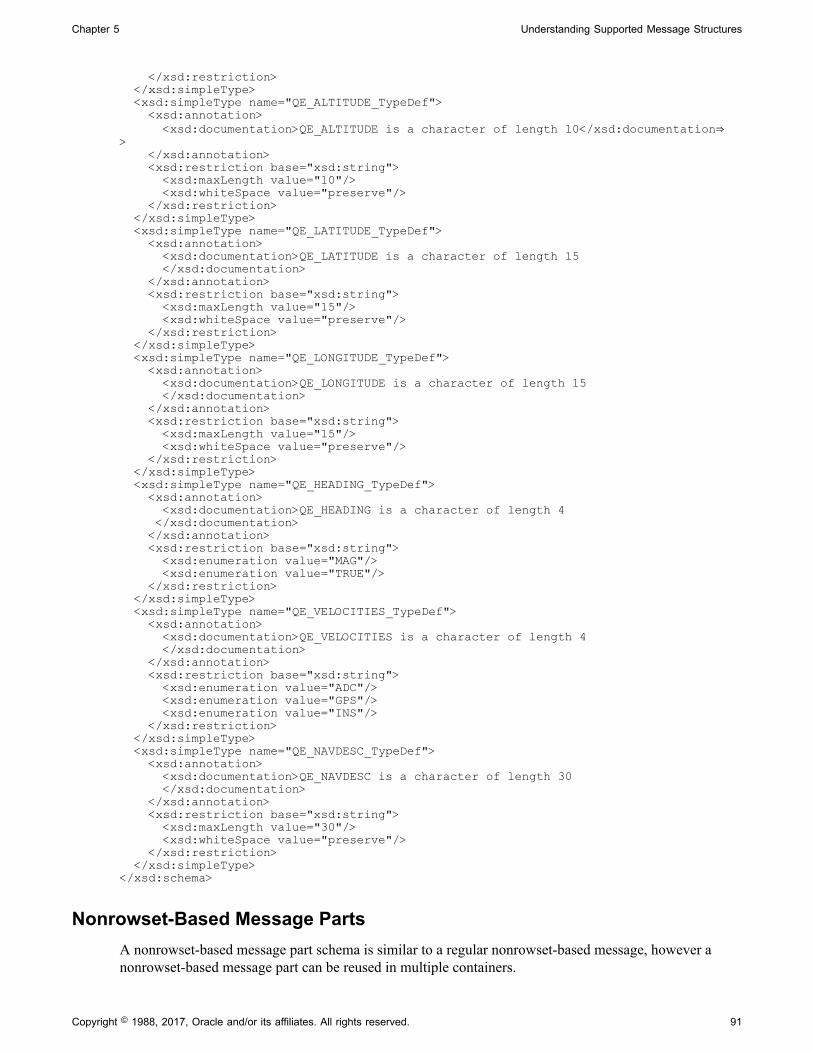
Chapter 5 Understanding Supported Message Structures
</xsd:restriction> </xsd:simpleType> <xsd:simpleType name="QE_ALTITUDE_TypeDef"> <xsd:annotation> <xsd:documentation>QE_ALTITUDE is a character of length 10</xsd:documentation⇒> </xsd:annotation> <xsd:restriction base="xsd:string"> <xsd:maxLength value="10"/> <xsd:whiteSpace value="preserve"/> </xsd:restriction> </xsd:simpleType> <xsd:simpleType name="QE_LATITUDE_TypeDef"> <xsd:annotation> <xsd:documentation>QE_LATITUDE is a character of length 15 </xsd:documentation> </xsd:annotation> <xsd:restriction base="xsd:string"> <xsd:maxLength value="15"/> <xsd:whiteSpace value="preserve"/> </xsd:restriction> </xsd:simpleType> <xsd:simpleType name="QE_LONGITUDE_TypeDef"> <xsd:annotation> <xsd:documentation>QE_LONGITUDE is a character of length 15 </xsd:documentation> </xsd:annotation> <xsd:restriction base="xsd:string"> <xsd:maxLength value="15"/> <xsd:whiteSpace value="preserve"/> </xsd:restriction> </xsd:simpleType> <xsd:simpleType name="QE_HEADING_TypeDef"> <xsd:annotation> <xsd:documentation>QE_HEADING is a character of length 4 </xsd:documentation> </xsd:annotation> <xsd:restriction base="xsd:string"> <xsd:enumeration value="MAG"/> <xsd:enumeration value="TRUE"/> </xsd:restriction> </xsd:simpleType> <xsd:simpleType name="QE_VELOCITIES_TypeDef"> <xsd:annotation> <xsd:documentation>QE_VELOCITIES is a character of length 4 </xsd:documentation> </xsd:annotation> <xsd:restriction base="xsd:string"> <xsd:enumeration value="ADC"/> <xsd:enumeration value="GPS"/> <xsd:enumeration value="INS"/> </xsd:restriction> </xsd:simpleType> <xsd:simpleType name="QE_NAVDESC_TypeDef"> <xsd:annotation> <xsd:documentation>QE_NAVDESC is a character of length 30 </xsd:documentation> </xsd:annotation> <xsd:restriction base="xsd:string"> <xsd:maxLength value="30"/> <xsd:whiteSpace value="preserve"/> </xsd:restriction> </xsd:simpleType> </xsd:schema>
Nonrowset-Based Message PartsA nonrowset-based message part schema is similar to a regular nonrowset-based message, however anonrowset-based message part can be reused in multiple containers.
Copyright © 1988, 2017, Oracle and/or its affiliates. All rights reserved. 91

Understanding Supported Message Structures Chapter 5
Message Container Structures
Message container structures hold rowset-based or nonrowset-based message part structures. All messageparts assigned to a container must of the same type, rowset-based or nonrowset-based.
A message container is always a nonrowset-based message.
You create container messages using the Message Builder in the PeopleSoft Pure Internet Architecture.
Related LinksNonrowset-Based Message StructuresUnderstanding Managing Messages
Example 1: XML Schema of a Container Message with Rowset-BasedMessage Parts
The following example shows a sample schema of a container message with three rowset-based messageparts:
<?xml version="1.0"?> <xsd:schema elementFormDefault="unqualified" targetNamespace="http://xmlns.oracle.com/Enterprise/Tools/schemas/Part_Container.V1" xmlns="http://xmlns.oracle.com/Enterprise/Tools/schemas/Part_Container.V1" xmlns:Part_1.V1="http://xmlns.oracle.com/Enterprise/Tools/schemas/Part_1.V1" xmlns:Part_2.V1="http://xmlns.oracle.com/Enterprise/Tools/schemas/Part_2.V1" xmlns:Part_3.V1="http://xmlns.oracle.com/Enterprise/Tools/schemas/Part_3.V1" xmlns:xsd="http://www.w3.org/2001/XMLSchema"> <xsd:import namespace="http://xmlns.oracle.com/Enterprise/Tools/schemas/ Part_1.V1" schemaLocation="http://kcollin2042803:5000/PSIGW/PeopleSoft ServiceListeningConnector?Operation=GetSchema&xsd=Part_1.V1"/> <xsd:import namespace="http://xmlns.oracle.com/Enterprise/Tools/schemas/ Part_3.V1" schemaLocation="http://kcollin2042803:5000/PSIGW/PeopleSoft ServiceListeningConnector?Operation=GetSchema&xsd=Part_3.V1"/> <xsd:import namespace="http://xmlns.oracle.com/Enterprise/Tools/schemas/ Part_2.V1" schemaLocation="http://kcollin2042803:5000/PSIGW/PeopleSoft ServiceListeningConnector?Operation=GetSchema&xsd=Part_2.V1"/> <xsd:element name="Part_Container" type="Part_ContainerType"/> <xsd:complexType name="Part_ContainerType"> <xsd:sequence> <xsd:element maxOccurs="unbounded" minOccurs="0" name="Part_1" type=" Part_1.V1:Part_1_TypeShape"/> <xsd:element maxOccurs="10" minOccurs="0" name="Part_3" type="Part_3.V1: Part_3_TypeShape"/> <xsd:element maxOccurs="unbounded" minOccurs="0" name="Part_2" type=" Part_2.V1:Part_2_TypeShape"/> </xsd:sequence> </xsd:complexType> </xsd:schema>
Example 2: XML Schema of a Container Message with Nonrowset-BasedMessage Parts
The following example shows a sample schema from a container message that contains three nonrowset-based parts:
<?xml version="1.0"?> <xsd:schema elementFormDefault="unqualified" targetNamespace="http://xmlns. oracle.com/Enterprise/Tools/schemas/NonRowSetContainer.v1"
92 Copyright © 1988, 2017, Oracle and/or its affiliates. All rights reserved.

Chapter 5 Understanding Supported Message Structures
xmlns="http://xmlns.oracle.com/Enterprise/Tools/schemas/NonRowSetContainer.v1" xmlns:Part_One_NonRowset.v1="http://xmlns.oracle.com/Enterprise/Tools/ schemas/Part_One.v1" xmlns:Part_Three_NonRowset.v1="http://xmlns.oracle.com/Enterprise/Tools/ schemas/Part_Two.v1" xmlns:Part_Two_NonRowset.v1="http://xmlns.oracle.com/Enterprise/Tools/ schemas/Part_Three.v1" xmlns:xsd="http://www.w3.org/2001/XMLSchema"> <xsd:import schemaLocation="http://kcollin2042803:5000/PSIGW/PeopleSoft ServiceListeningConnector?Operation=GetSchema&xsd=Part_One_NonRowset.v1"/> <xsd:import schemaLocation="http://kcollin2042803:5000/PSIGW/PeopleSoft ServiceListeningConnector?Operation=GetSchema&xsd=Part_Two_NonRowset.v1"/> <xsd:import schemaLocation="http://kcollin2042803:5000/PSIGW/PeopleSoft ServiceListening Connector?Operation=GetSchema&xsd=Part_Three_NonRowset.v1"/> <xsd:element name="NonRowSetContainer" type="NonRowSetContainerType"/> <xsd:complexType name="NonRowSetContainerType"> <xsd:sequence> <xsd:element maxOccurs="unbounded" minOccurs="0" name="Part_One_NonRowset" type="Part_One_NonRowset.v1:Part_One_TypeShape"/> <xsd:element maxOccurs="unbounded" minOccurs="0" name="Part_Two_NonRowset" type="Part_Two_NonRowset.v1:Part_Two_TypeShape"/> <xsd:element maxOccurs="unbounded" minOccurs="0" name="Part_Three_NonRowset" type="Part_Three_NonRowset.v1:Part_Three_TypeShape"/> </xsd:sequence> </xsd:complexType> </xsd:schema>
Copyright © 1988, 2017, Oracle and/or its affiliates. All rights reserved. 93

Understanding Supported Message Structures Chapter 5
94 Copyright © 1988, 2017, Oracle and/or its affiliates. All rights reserved.

Chapter 6
Managing Messages
Understanding Managing Messages
This section provides an overview of messages.
Message DefinitionsMessage definitions provide the physical description of the data that is being sent, including fields, fieldtypes, and field lengths. You create message definitions in the PeopleSoft Internet Architecture.
Note: Messages are shapes that describe the contents of a service operation transaction. Unlike priorPeopleTools releases, messages do not contain any processing logic. All processing logic is defined inservice operations, using service operation handlers.
Message TypesFive types of messages are available:
Rowset-based messages For hierarchical data that is based on PeopleSoft records, youcreate a message definition by assembling records, organizingthem into a hierarchy, and selecting fields from those records toinclude in the message. The result is a rowset that doesn't needto match an existing rowset structure in the application. Use thePeopleCode Rowset and operation classes to generate, send, receive, and process these messages.
Nonrowset-based messages These messages can have virtually any structure and content. You create a message definition, but you do not insert anyrecords. The message definition serves as a placeholder for theactual message. Use the PeopleCode XmlDoc and operationclasses to generate, send, receive, and process these messages. If you're handling Simple Object Access Protocol (SOAP)compliant data, you can also use the SoapDoc class to generateand process these messages.
Container messages A container message is a nonrowset-based message that holdsone or more part messages.
A container message must contain all rowset-based messages orall nonrowset-based message parts.
Message parts Message parts are rowset-based messages or nonrowset-basedmessages that you designate as a part message, to be used in acontainer message.
Copyright © 1988, 2017, Oracle and/or its affiliates. All rights reserved. 95

Managing Messages Chapter 6
Document messages A document messages are messages based on the PeopleSoftXML document technology. You create and manage thesemessages in the PeopleSoft Document Builder, either bycreating the XML documents from the ground up, importingthem from schema definitions, or from PeopleSoft records.
The following table describes when to use a given message type:
Message Type When to Use
Rowset-based message. All PeopleSoft-to-PeopleSoft integrations.
Nonrowset-based message. Integrations with third-party systems.
Container message with rowset-based message parts. Exposing PeopleSoft services to third-party systems.
Container message with nonrowset-based message parts. Exposing PeopleSoft services to third-party systems and needto provide nested parts.
Document message. Integrations with third-party systems.
Naming Conventions for Message MetadataWhen naming the following message metadata, names cannot start with “xml,” digits or specialcharacters:
• Message names.
• Message aliases.
• Record aliases.
• Field aliases.
Message Record StructureIf a message handles PeopleSoft record data, that is, a rowset-based message, you must insert records inthe message definition in an appropriate hierarchical structure.
However, if the message data doesn't map to a record hierarchy, do not insert any records. You supplyor receive the data and its structure from an external source, using the PeopleCode XmlDoc or SoapDocclasses.
See Understanding Sending and Receiving Messages.
Underlying Record DefinitionsRecords that you insert in a message definition have live references to the original record definitions.Any change that you make to an underlying record definition is automatically reflected by a change in thecorresponding record in the message definition.
96 Copyright © 1988, 2017, Oracle and/or its affiliates. All rights reserved.

Chapter 6 Managing Messages
Fields Defined as UppercaseIf a message definition includes character fields that are defined as uppercase, then character data in thosefields is automatically converted to uppercase when the message is received. This happens when thereceiving PeopleCode inserts the message data in a rowset, and it overrides any previous changes in thedata, including transformation and data translation.
Message Aliases and Message VersionsMessage aliases are read-only once you save the message definition. As a result, once you create amessage alias for a message definition, any subsequent versions of the message that you create use theoriginal alias.
Restrictions for Modifying MessagesThis section lists the conditions under which a message may become restricted and read-only. This listapplies to all message types, including rowset-based messages, nonrowset-based messages, containermessages, part messages, and subpart messages.
You cannot modify a message if one or more of the following conditions exists:
• The service to which a message is contained in a restricted service.
• The message is used internally by the system. For example, the delivered IB_GENERIC message isread-only and is used internally by the system.
• The message is referenced in the runtime tables.
To work around this, you must remove any entries in the runtime tables that reference the message.
• The message is used in a service operation where WSDL documents have been generated.
• The message is used in a service operation that has validation enabled.
Searching for Message Definitions
To search for an existing message definition in the system use the Messages - Search page(IB_MSGSEARCH). To access the page select PeopleTools, Integration Broker, Integration Setup,Messages.
Copyright © 1988, 2017, Oracle and/or its affiliates. All rights reserved. 97

Managing Messages Chapter 6
Image: Messages – Search page
This example illustrates the Messages – Search page.
To search for a message definition:
1. Access the Messages - Search page (PeopleTools, Integration Broker, Integration Setup, Messages).
2. Search for a message definition.
You can search for message definition in one of two ways:
• Enter search criteria in one or more of the following fields, and then click the Search button:
Type From the drop-down list, select the type of message forwhich you are searching. The options are:
• Container.
• Document.
• Nonrowset.
• Part nonrowset.
• Part rowset.
• Rowset.
Message Name Enter the name of the message.
Version Enter the version of the message.
• Click the Search button to display all message definitions in the system.
The results appear in the Search Results grid.
3. Click the name of the message to view.
Adding Message Definitions
This section discusses how to:
98 Copyright © 1988, 2017, Oracle and/or its affiliates. All rights reserved.

Chapter 6 Managing Messages
• Add rowset, nonrowset and part message definitions.
• Add document message definitions.
Understanding Adding Message DefinitionsWhen you add a message definition to the system you first give the message a name and specify amessage version. After doing so, you can then define additional aspects of the message definition.
Adding Rowset, Nonrowset or Part Message DefinitionsUse the Add a New Message page (IB_MSGSEARCH_ADD) to name a new message definition andassign a version to it:
Image: Add New Message page
This example illustrates the Add a New Message page.
After you add a new message definition and version to the system, you can configure the message.
Use the Messages - Message Definition page (IB_MESSAGE_BUILDER) to configure a message afteryou create the message definition.
Image: Messages - Message Definition page
This example illustrates the Messages – Message Definition page.
Copyright © 1988, 2017, Oracle and/or its affiliates. All rights reserved. 99

Managing Messages Chapter 6
The example shows the page when the message type is a Nonrowset-based message. Different optionsappear on the Message–Message Definition page, depending on the type of message that you are defining.
Note: You determine the message type when you create the definition using the Add New Message page.The Message Type group box options on the Messages – Message Definition page are read-only.
Additional options appear on the Messages – Message Definition page when you are working withRowset-based or Container message types.
Image: Messages - Message Definition page
This example illustrates the Messages – Message Definition page. The example shows the page when themessage type is a Rowset-based message type.
In the previous example, notice the additional options that display on the upper right portion of the page.
When you define a container message, it, too, has its own unique options that you define.
100 Copyright © 1988, 2017, Oracle and/or its affiliates. All rights reserved.

Chapter 6 Managing Messages
Image: Messages - Message Definition page
This example illustrates the Messages – Message Definition page. The example shows the page when themessage type is a Container message.
Note: For asynchronous integrations, define a single message. For synchronous integrations, define twomessages: one request message and one response message, unless the request and response have the sameshape.
To add a rowset, nonrowset, or part message definition:
1. Select PeopleTools, Integration Broker, Integration Setup, Messages.
The Messages – Search page appears.
2. Click the Add a New Valuelink.
3. From the Type drop-down list, select a message type to create. The options are:
• Container. Select this value to add a container message to the system.
• Document. Select this value to add a document message to the system.
Adding a document message type to the system is described elsewhere in this section.
See Adding Document Message Definitions.
• Nonrowset. Select this value to add a nonrowset-based message to the system.
• Part Nonrowset. Select this value to add a nonrowset-based message part to the system.
• Part Rowset. Select this value to add a rowset-based message part to the system.
Copyright © 1988, 2017, Oracle and/or its affiliates. All rights reserved. 101

Managing Messages Chapter 6
• Rowset. Select this value to add a rowset-based message to the system.
4. In the Message Name field, enter a name for the message.
The message name cannot exceed 30 characters. Do not include any spaces in the message name.
5. In the Version field, enter a version for the message.
The message version cannot exceed 30 characters. Do not include any spaces in the message version.
Accepted formats for the message version include:
• Version_1.
• V1.
6. Click the Add button.
The Messages - Message Definition page appears.
7. (Optional) In the Alias field, enter the name that the external system is expecting, if different from thevalue in the Message Name field.
This field appears only when you are defining nonrowset-based or container messages.
8. (Optional) Select the Message Parts check box if the message will be used as a message part in acontainer message definition.
9. (Optional) In the Description field, enter a description for the definition.
10. (Optional) From the Owner ID drop-down list box, select an owner for the definition.
The owner ID helps to determine the application team that last made a change to the definition.The values in the drop-down list box are translate table values that you can define in theOBJECTOWNERID field record.
11. (Optional) In the Comment field, enter any pertinent comments about the definition.
12. In the Root Element field, enter a value to appear in the root element in generated WADL documentswhen the message is used in a REST service operation.
Note: You must provide a value in this field if you are using the message in a REST-based serviceoperation. This field value is required for proper WADL document generation.
This field appears only when you are defining nonrowset-based messages.
13. The next steps to adding a message definition depend on the type of message definition that you arecreating:
• Rowset-Based Message or Message Part. You must add a root record to the definition before youcan save it.
See Managing Rowset-Based Messages.
102 Copyright © 1988, 2017, Oracle and/or its affiliates. All rights reserved.

Chapter 6 Managing Messages
• Nonrowset-Based Message or Message Part. The message definition is complete and you canclick the Save button to save the changes. You can now add an XML message schema to thedefinition.
See Managing Nonrowset-Based Messages.
• Container Message. You must add at least one message part to the definition before you can savethe changes.
See Managing Container Messages.
Adding Document Message DefinitionsThis section discusses adding document message definitions.
Understanding Adding Document Message DefinitionsWhen you create a document message definition in the system, you create a message definition thatreferences a document. .
Prerequisites for Adding Document Message DefinitionsBefore you add a document message definition to the system, the document definition that the messagewill reference must exist in the system
Adding a Document Message DefinitionWhen you add a document message definition, additional options appear on the page than when you addother message types.
Copyright © 1988, 2017, Oracle and/or its affiliates. All rights reserved. 103

Managing Messages Chapter 6
Image: Add a New Value page
This example illustrates the Add a New Value page. The example shows adding a Document message typeto the system.
After you provide a message name, version, and optional alias, you specify the document package,document name, and version to which to link the message.
After you click the Add button, the document that you specified in the message definition appears in theDocument Builder – Document page.
Image: Document Builder – Document page
This example illustrates the Document Builder – Document page. In the example the Metadata Referencessection shows that the message TEST_DOC_MSG.v1 references the document.
The Metadata References section in the definition shows that there is an Integration Broker messagecalled TEST_DOC_MSG.v1 that references the document.
104 Copyright © 1988, 2017, Oracle and/or its affiliates. All rights reserved.

Chapter 6 Managing Messages
Note that the message definition is not saved until you click the Save button in the Document Builder.
To add a document message definition:
1. Select PeopleTools, Integration Broker, Integration Setup, Messages.
2. Select the Add New Value tab.
3. From the Type drop-down list, select Document.
4. In the Message Name field, enter a name for the message.
The message name cannot exceed 30 characters. Do not include any spaces in the message name.
5. In the Version field, enter a version for the message.
The message version cannot exceed 30 characters. Do not include any spaces in the message version.
Accepted formats for the message version include:
• Version_1.
• V1.
6. (Optional) In the Alias field, enter the name that the external system is expecting, if different from thevalue in the Message Name field.
7. In the Package field, enter the document package or click the Lookup button to search for one.
8. In the Document field, enter the document name or click the Lookup button to search for one.
9. In the Version field, enter the document version or click the Lookup button to search for one.
10. Click the Add button.
The Document Builder–Document page appears, displaying the document definition for the documentyou specified. The Metadata References grid displays the name of the message definition you added.
11. Click the Save button.
Managing Rowset-Based Messages
This section provides an overview of managing rowset-based message definitions and discusses how to:
• View rowset-based message structures.
• Insert root records.
• Insert child and peer records.
• Specify record aliases.
• Delete records.
• Exclude fields from messages.
Copyright © 1988, 2017, Oracle and/or its affiliates. All rights reserved. 105

Managing Messages Chapter 6
• Specify field name aliases.
• Manage XML message schemas for rowset-based messages.
• Enforce message record and field aliases in generated WSDL.
Understanding Managing Rowset-Based MessagesThis section provides overview information about managing rowset-based message definitions.
Root RecordsWhen you create a rowset-based message, you must at a minimum insert a root record (level 0) into thedefinition.
Records and Record FieldsYou create and modify records and record fields in PeopleSoft Application Designer.
Note: Avoid using derived/work records in messages. Work records don't behave like regular recordswhen used with PeopleCode rowset methods. A good alternative is to use dynamic views.
Record and Record Field AliasesRecord and field aliases are optional parameters that are used for schema and XML generation.
When record and field aliases are used, the receiver of a message sees the alias names instead of theactual record and field names. The alias names are seen in the message definition, in message schemas,and on generated runtime XML that is sent to the receiver.
Note that the sender still codes to the actual record and field name.
XML Schema for Rowset-Based MessagesWhen you create or make changes to a rowset-based message definition, the system automaticallygenerates message schema.
Viewing Rowset-Based Message StructuresThis section discusses the three ways to view the structure of rowset-based message definitions. Thissection discusses how to:
• View the entire structure of rowset-based message definitions.
• View only the records in rowset-based message definitions.
• View only included records fields in rowset-based message definitions.
Viewing the Entire Structure of Rowset-Based Message DefinitionsBy default, when you open a rowset-based message definition in the Messages – Message Definitionpage, PeopleSoft Integration Broker displays the complete message definition structure.
106 Copyright © 1988, 2017, Oracle and/or its affiliates. All rights reserved.
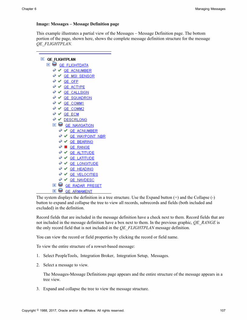
Chapter 6 Managing Messages
Image: Messages – Message Definition page
This example illustrates a partial view of the Messages – Message Definition page. The bottomportion of the page, shown here, shows the complete message definition structure for the messageQE_FLIGHTPLAN.
The system displays the definition in a tree structure. Use the Expand button (+) and the Collapse (-)button to expand and collapse the tree to view all records, subrecords and fields (both included andexcluded) in the definition.
Record fields that are included in the message definition have a check next to them. Record fields that arenot included in the message definition have a box next to them. In the previous graphic, QE_RANGE isthe only record field that is not included in the QE_FLIGHTPLAN message definition.
You can view the record or field properties by clicking the record or field name.
To view the entire structure of a rowset-based message:
1. Select PeopleTools, Integration Broker, Integration Setup, Messages.
2. Select a message to view.
The Messages-Message Definitions page appears and the entire structure of the message appears in atree view.
3. Expand and collapse the tree to view the message structure.
Copyright © 1988, 2017, Oracle and/or its affiliates. All rights reserved. 107
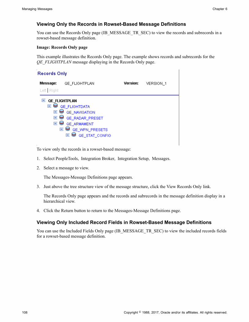
Managing Messages Chapter 6
Viewing Only the Records in Rowset-Based Message DefinitionsYou can use the Records Only page (IB_MESSAGE_TR_SEC) to view the records and subrecords in arowset-based message definition.
Image: Records Only page
This example illustrates the Records Only page. The example shows records and subrecords for theQE_FLIGHTPLAN message displaying in the Records Only page.
To view only the records in a rowset-based message:
1. Select PeopleTools, Integration Broker, Integration Setup, Messages.
2. Select a message to view.
The Messages-Message Definitions page appears.
3. Just above the tree structure view of the message structure, click the View Records Only link.
The Records Only page appears and the records and subrecords in the message definition display in ahierarchical view.
4. Click the Return button to return to the Messages-Message Definitions page.
Viewing Only Included Record Fields in Rowset-Based Message DefinitionsYou can use the Included Fields Only page (IB_MESSAGE_TR_SEC) to view the included records fieldsfor a rowset-based message definition.
108 Copyright © 1988, 2017, Oracle and/or its affiliates. All rights reserved.
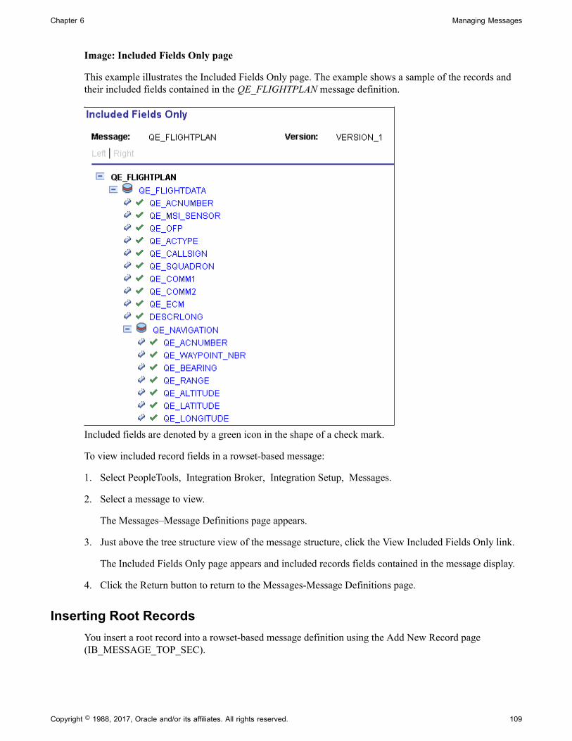
Chapter 6 Managing Messages
Image: Included Fields Only page
This example illustrates the Included Fields Only page. The example shows a sample of the records andtheir included fields contained in the QE_FLIGHTPLAN message definition.
Included fields are denoted by a green icon in the shape of a check mark.
To view included record fields in a rowset-based message:
1. Select PeopleTools, Integration Broker, Integration Setup, Messages.
2. Select a message to view.
The Messages–Message Definitions page appears.
3. Just above the tree structure view of the message structure, click the View Included Fields Only link.
The Included Fields Only page appears and included records fields contained in the message display.
4. Click the Return button to return to the Messages-Message Definitions page.
Inserting Root RecordsYou insert a root record into a rowset-based message definition using the Add New Record page(IB_MESSAGE_TOP_SEC).
Copyright © 1988, 2017, Oracle and/or its affiliates. All rights reserved. 109

Managing Messages Chapter 6
Image: Add New Record page
This example illustrates the Add New Record page.
Note: There can only be one root record defined for each rowset-based message.
To insert a root record into a definition:
1. Access the Add New Record page.
Select PeopleTools, Integration Broker, Integration Setup, Messages. The Messages-MessageDefinitions page appears. Click the Add Record to Root link.
2. In the New Record Name field, enter the name of the record to add, or click the Lookup button tosearch for and select one.
3. Click the OK button.
The root record appears in the tree structure. Click the Expand button (+) to expand the tree and viewfields that are associated with the record.
You can exclude fields from the record and specify field name aliases. Steps for performing these actionsare described elsewhere in this topic.
See Excluding Fields from Messages.
See Specifying Field Name Aliases.
Inserting Child and Peer RecordsYou insert child and peer records into a rowset-based message definition using the Message RecordProperties page (IB_MESSAGE_REC_SEC).
110 Copyright © 1988, 2017, Oracle and/or its affiliates. All rights reserved.
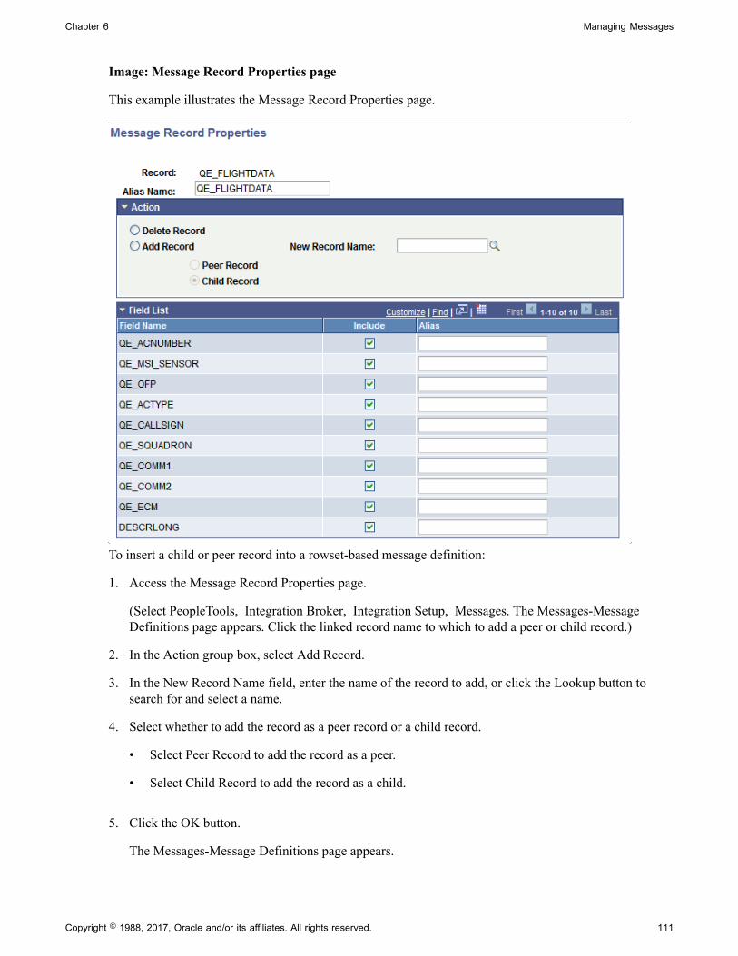
Chapter 6 Managing Messages
Image: Message Record Properties page
This example illustrates the Message Record Properties page.
To insert a child or peer record into a rowset-based message definition:
1. Access the Message Record Properties page.
(Select PeopleTools, Integration Broker, Integration Setup, Messages. The Messages-MessageDefinitions page appears. Click the linked record name to which to add a peer or child record.)
2. In the Action group box, select Add Record.
3. In the New Record Name field, enter the name of the record to add, or click the Lookup button tosearch for and select a name.
4. Select whether to add the record as a peer record or a child record.
• Select Peer Record to add the record as a peer.
• Select Child Record to add the record as a child.
5. Click the OK button.
The Messages-Message Definitions page appears.
Copyright © 1988, 2017, Oracle and/or its affiliates. All rights reserved. 111
Managing Messages Chapter 6
6. Click the Save button.
Specifying Record AliasesYou can specify aliases of the root, peer, and child records that you insert into rowset-based messagesusing the Message Record Properties page.
To specify a record alias:
1. Access the Message Record Properties page.
(Select PeopleTools, Integration Broker, Integration Setup, Messages. The Messages-MessageDefinitions page appears. Click the linked record name to which to specify an alias.)
2. In the Alias Name field, enter an alias name.
3. Click the OK button.
The Messages-Message Definitions page appears.
4. Click the Save button.
Related LinksMessage Aliases and Message Versions
Deleting RecordsThis section describes how to delete records from a rowset-based message.
Note: Deleting the root record deletes all records and their associated fields that are inserted into thedefinition.
To delete a record:
1. Access the Message Record Properties page.
(Select PeopleTools, Integration Broker, Integration Setup, Messages. The Messages-MessageDefinitions page appears. Click the name of the record to delete.)
2. In the Action group box, select Delete Record.
3. Click the OK button.
The Messages-Message Definitions page appears.
4. Click the Save button.
Excluding Fields from MessagesYou can exclude record fields from inclusion in a rowset-based message definition using the MessageField Properties page.
112 Copyright © 1988, 2017, Oracle and/or its affiliates. All rights reserved.

Chapter 6 Managing Messages
After you exclude fields from records, the tree view of the message definition on the Message Definitionspage displays a red icon in the shape of box next to the excluded fields.
Image: Message Field Properties page
This example illustrates a partial view of the Message Field Properties page. The example shows that thefield QE_ACNUMBER has been excluded from the QE_FLIGHTDATA record.
To exclude fields:
1. Access the Message Field Properties page.
a. Select PeopleTools, Integration Broker, Integration Setup, Messages. The Messages-MessageDefinitions page appears.
b. Click the Expand button (+) to expand the record tree structure, and locate the field to excludefrom the definition.
c. Click the name of the field to exclude.
The Message Field Properties page appears.
2. Click the name of the field to exclude.
3. Deselect the Include check box.
4. Click the OK button.
The Messages-Message Definitions page appears.
5. Click the Save button.
Specifying Field Name AliasesUse the Message Field Properties page to specify field name aliases.
To specify a field name alias:
1. Access the Message Field Properties page.
a. Select PeopleTools, Integration Broker, Integration Setup, Messages. The Messages-MessageDefinitions page appears.
Copyright © 1988, 2017, Oracle and/or its affiliates. All rights reserved. 113
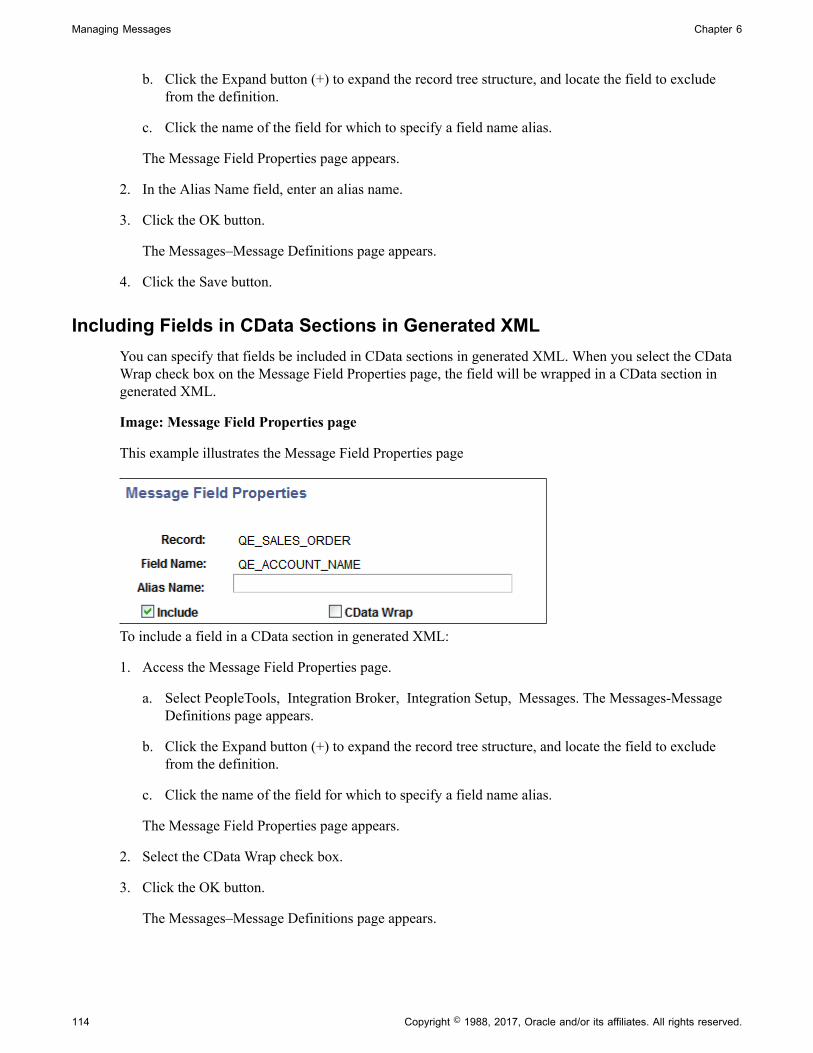
Managing Messages Chapter 6
b. Click the Expand button (+) to expand the record tree structure, and locate the field to excludefrom the definition.
c. Click the name of the field for which to specify a field name alias.
The Message Field Properties page appears.
2. In the Alias Name field, enter an alias name.
3. Click the OK button.
The Messages–Message Definitions page appears.
4. Click the Save button.
Including Fields in CData Sections in Generated XMLYou can specify that fields be included in CData sections in generated XML. When you select the CDataWrap check box on the Message Field Properties page, the field will be wrapped in a CData section ingenerated XML.
Image: Message Field Properties page
This example illustrates the Message Field Properties page
To include a field in a CData section in generated XML:
1. Access the Message Field Properties page.
a. Select PeopleTools, Integration Broker, Integration Setup, Messages. The Messages-MessageDefinitions page appears.
b. Click the Expand button (+) to expand the record tree structure, and locate the field to excludefrom the definition.
c. Click the name of the field for which to specify a field name alias.
The Message Field Properties page appears.
2. Select the CData Wrap check box.
3. Click the OK button.
The Messages–Message Definitions page appears.
114 Copyright © 1988, 2017, Oracle and/or its affiliates. All rights reserved.

Chapter 6 Managing Messages
4. Click the Save button.
Managing XML Message Schemas for Rowset-Based MessagesThis section discusses how to:
• View XML message schemas for rowset-based messages.
• Exclude descriptions in XML message schemas.
• Choose the number of level 0 rows to include in generated XML message schema.
• Include namespaces in generated XML message schemas.
• Suppress empty XML tags in message schema.
Viewing XML Message Schemas for Rowset-Based MessagesPeopleSoft Integration Broker automatically generates message schema for rowset-based messages whenyou save the message definition.
After you save a message definition on the Messages-Message Definitions page, click the Schema tab toview the generated XML message schema.
Excluding Descriptions in XML Message SchemasMessage data that is used to define services can have actual database record and field names in thegenerated XML message schema. PeopleSoft Integration Broker provides an option where you canexclude descriptions in generated message schemas so that sensitive information is not exposed.
The Messages–Message Definitions page features an Exclude Descriptions in Schema check box thatenables you to suppress descriptions in generated schema.
To exclude descriptions in XML message schemas:
1. Access the Messages–Message Definition page (PeopleTools, Integration Broker, Integration Setup,Messages.
2. Select the Exclude Description in Schema check box.
3. Save the changes.
See Managing XML Message Schemas for Rowset-Based Messages.
Choosing the Number of Level 0 Rows to Include in Generated XML MessageSchemaYou can choose to include a single level 0 row in the generated schema or all level 0 rows in the generatedschema.
When you select the Single Level 0 Row check box, PeopleSoft Integration Broker includes a single level0 row in the XML message schema when you Save the definition. If this box is not selected, then thesystem includes all level 0 rows in the message in the generated schema.
By default the Single Level 0 Row check box is not selected.
Copyright © 1988, 2017, Oracle and/or its affiliates. All rights reserved. 115

Managing Messages Chapter 6
If you check the Single Level 0 Row check box to generate schema with one level 0 row, the level 0 rowincluded in the schema is the first level 0 row the system encounters in the message.
Including Namespaces in Generated XML Message SchemasPeopleSoft Integration Broker enables you to include a namespace in XML message schemas that yougenerate for rowset-based messages.
When working with a rowset-based message type, the Messages–Message Definition page displays anInclude Namespace check box. When the Include Namespace check box is selected, you can specify anamespace to include in the generated schema on the Messages-Schema page.
Image: Messages–Schema page
This example illustrates the Messages – Schema page. The example shows the Namespace field ispopulated with the namespace as defined in the Service Configuration page.
By default the Namespace field is populated with the namespace defined on the Service Configurationpage, however you can change the namespace to use in the message schema as required.
To include a namespace in generated schema:
1. Access the Messages–Message Definition page (PeopleTools, Integration Broker, Integration Setup, Messages).
2. Select the Include Namespace check box.
3. Click the Schema tab.
The Messages–Schema page appears. By default the namespace as defined on the ServiceConfiguration page populates the Namespace field.
4. In the Namespace field enter the namespace to use in the generated XML message schema.
5. Click the Message Definition tab.
6. Save your changes.
The system generates the message schema and includes the namespace specified.
Suppressing Empty XML Tags in Message SchemaPeopleSoft Integration Broker enables you to suppress empty XML tags in message schema of rowset-based messages.
116 Copyright © 1988, 2017, Oracle and/or its affiliates. All rights reserved.
Chapter 6 Managing Messages
The Messages-Message Definition page features a Suppress Empty XML Tags check box.
When you select this box, message schema generated for the message will not include any XML tags thatcontain empty or Null values.
Enforcing Message Record and Field Aliases in Generated WSDLPeopleSoft Integration Broker enables you to enforce record and field aliases in generated WSDL.
The Service Configuration page features a WSDL Generation Alias Check drop-down list that enablesyou to set a system check level for aliases on message definition records and fields.
You can set the following check levels:
Check Level Description
Error. If the system encounters a message definition without properrecord and field aliases, it displays an error and it will notgenerate a WSDL document.
None. Default. The system creates a WSDL document regardless ofwhether message records and fields are aliased or not.
Warning. As the system creates a WSDL document it displays a warningit encounters messages definitions that do not have completealiasing for records and/or fields. If the system encountersrecords or fields that do not have aliases defined, you cancontinue to generate the WSDL document or terminate thegeneration of the WSDL document.
To enforce message record and field aliases in generated WSDL:
1. Access the Service Configuration page (PeopleTools, Integration Broker, Configuration, ServiceConfiguration).
2. From the WSDL Generation Alias Check drop-down list, select a value. The valid options are:
• Error.
• None.
• Warning.
Managing Nonrowset-Based Messages
This section provides an overview of managing nonrowset-based messages and discusses how to:
• Add XML message schemas to nonrowset-based messages.
• Edit nonrowset-based XML message schemas.
Copyright © 1988, 2017, Oracle and/or its affiliates. All rights reserved. 117

Managing Messages Chapter 6
Understanding Managing Nonrowset-Based MessagesAfter you create a nonrowset-based message definition, you do not need to complete any additionalconfiguration steps for the definition, except to add an XML schema. The XML schema describes the datato be sent, and includes the field names, data types, field lengths and so on.
You may add or replace message schemas that are referenced by nonrowset-based messages in runtimetables. However, once you change a message schema for a nonrowset-based message, you must adjust themessage for a successful integration.
Related LinksAdding Message Definitions
Adding XML Message Schemas to Nonrowset-Based MessagesTo add an XML message schema to nonrowset-based messages:
Note: You cannot regenerate message schemas for messages that are defined as part of a restrictedservice.
1. Select PeopleTools, Integration Broker, Integration Setup, Messages.
2. Select the nonrowset-based definition to which you want to add an XML schema.
The Messages - Message Definitions page appears.
3. Click the Schema tab.
4. Click the Add Schema button.
The Schema page appears.
5. Add the XML schema to the message.
You can add the schema to the message in two ways:
• Click the Upload Schema From File button to browse for and upload a schema that you havealready saved to a file.
• Enter the XML schema in the Schema text box that is provided.
6. Click the Save button.
If you define the message as a message part, you must supply a schema to save the message. All messageparts require a schema at save time.
Editing Nonrowset-Based XML SchemasAfter an XML message schema is added to a nonrowset-based message, you can edit the schema usingthe Schema page.
118 Copyright © 1988, 2017, Oracle and/or its affiliates. All rights reserved.

Chapter 6 Managing Messages
Note: You cannot regenerate message schemas for messages that are defined as part of a restrictedservice.
To edit nonrowset-based XML message schemas:
1. Select PeopleTools, Integration Broker, Integration Setup, Messages.
2. Select the nonrowset-based definition that contains the schema that you want to edit.
The Messages - Message Definitions page appears.
3. Click the Schema tab.
The Schema page appears and displays the existing XML message schema for the definition.
4. Click the Edit Schema button.
5. In the Schema text box, make your changes and additions to the XML schema.
6. Click the Save button.
Deleting Nonrowset-Based XML Message SchemasThis section discusses how to:
• Delete individual nonrowset-based XML message schemas.
• Delete nonrowset-based XML message schema in bulk.
Deleting Individual Nonrowset-Based XML Message SchemasUse the Messages-Schema page (IB_MESSAGE_BUILD2) to delete individual nonrowset-based XMLmessage schema.
To delete an individual nonrowset-based XML message schema:
1. Select PeopleTools, Integration Broker, Integration Setup, Messages.
The Messages-Message Definitions page appears.
2. Click the Schema tab.
The Messages-Schema page appears.
3. Click the Delete Schema button.
Deleting Nonrowset-Based XML Message Schemas in BulkTo delete one or more nonrowset-based XML message schemas, use the Message Schemas page(IB_HOME_PAGE6) in the Service Administration component (IB_HOME_PAGE).
Copyright © 1988, 2017, Oracle and/or its affiliates. All rights reserved. 119

Managing Messages Chapter 6
Image: Service Administration – Message Schemas page
This example illustrates the Service Administration – Message Schemas page.
To delete nonrowset-based XML message schemas in bulk:
1. Select PeopleTools, Integration Broker, Service Utilities, Service Administration.
2. Click the Message Schemas tab.
3. Choose the schema or schemas to delete.
To delete an individual schema, in the Message Name field enter the name of the message thatcontains the schema to delete.
To delete more than one schema, click the Search button to display all nonrowset-based message inthe system than contain schema.
The message or messages appear in the Messages with Schema grid.
4. In the Select column, select the check box next to each message name that contain schema you wantto delete.
If deleting multiple schemas, use the forward and backward arrows and/or the Last and First links topage through the results and select schemas to delete.
5. Click the Delete button.
Managing Message Parts
This section discusses how to create message parts.
Understanding Message PartsMessage parts are individual message definitions that get used in container messages.
120 Copyright © 1988, 2017, Oracle and/or its affiliates. All rights reserved.
Chapter 6 Managing Messages
While message parts can be rowset-based or nonrowset-based, the advantage of using message partscomes when working with rowset-based messages. By using nonrowset-based message parts, you cannottake advantage of PeopleSoft Integration Broker's framework for creating message definitions, use ofPeopleCode, serialization, porting, and so on. The following table highlights some of the advantages ofusing rowset-based message parts:
Rowset-Based Message Parts Nonrowset-Based Message Parts
You can use the PeopleSoft Pure Internet Architecture to buildrowset-based message parts.
You cannot use the PeopleSoft Pure Internet Architecture tobuild nonrowset-based message parts.
Message schema is automatically generated for rowset-basedmessages.
You must generate message schema for nonrowset-basedmessage parts.
The mapping from XML to rowset is managed by theframework.
You must use the XMLDoc class to manipulate nonrowset-based message content.
In addition, you must manually map the XML into XMLDocfor the parts.
Container messages are always nonrowset-based. So, if you use a container message that contains rowset-based part messages, the container messages sends XML that contains none of the standard PeopleSoftmessage XML structures, such as PSCAMA, FieldTypes, and so on. However, you can use the rowset-based classes and methods to populate and read the structure of each part message.
Creating Part MessagesTo create a part message, create a standard rowset-based or nonrowset-based message and select the PartMessage check box on the Message Definition page.
When the service system status is set to Production, once a message is used in a container message, youcannot alter the message while it is associated with a container message.
You must generate schemas for all part messages before you can save them.
Schemas for rowset-based messages are automatically built when the message is saved. Schemas fornonrowset-based parts must be added in order to save the message.
Related LinksAdding Message DefinitionsManaging Container Messages
Distinguishing Blank from Zero in Rowset-Based Part MessagesThe Message Definitions page features a Message Part Default Indicator field that appears when youselect or define a rowset-based message part.
When you select the check box, XML that has a value of 0 (zero) passed in an integer field, whenserialized to a rowset, causes the IsChanged property flag on the field to set to True.
By default an integer field has a value of 0. So if a 0 or <blank> is passed in a field, the end result is a 0when accessing the field via the rowset. However, if you select the Message Part Default Indicator checkbox the IsChanged property on such a field is set to True, meaning that a 0 (zero) was passed in the field.
Copyright © 1988, 2017, Oracle and/or its affiliates. All rights reserved. 121

Managing Messages Chapter 6
Reusing Rowset-Based Message Parts
This section discusses how to:
• Reuse rowset-based message parts by reference.
• Reuse rowset-based message parts by copy.
Understanding Reusing Rowset-Based Message PartsPeopleSoft Integration Broker enables you to reuse rowset-based message parts by referencing anothermessage part or by copying another message part.
Note: You cannot reuse message parts at Level 0.
Referencing Message PartsA reference to a message part is read-only in the message part where it is referenced. To make changesto a referenced message part, you must make the changes to the referenced message part directly. Allchanges are then propagated to every message in which the message part is referenced.
Copying Message PartsIf you copy a message part, the system copies all records and fields and displays them at the record level.The records and fields become permanent to the new message and you can edit all records and fieldsdirectly in the message where the copied part exists. Changes you make to a copied message part arenot propagated to other copies of the message part that may exist. You must make changes to a copiedmessage part, you do so manually to each message part that you want to change.
Reusing Rowset-Based Message Parts by ReferenceThis section discusses how to:
• Reuse a message part by reference.
• Check for recursion.
• View referenced message part information.
• View where message parts are referenced.
• Modify referenced message parts.
• Delete referenced message parts.
Reusing a Message Part by ReferenceTo reuse a message part by reference:
1. Create a rowset-based message part.
122 Copyright © 1988, 2017, Oracle and/or its affiliates. All rights reserved.
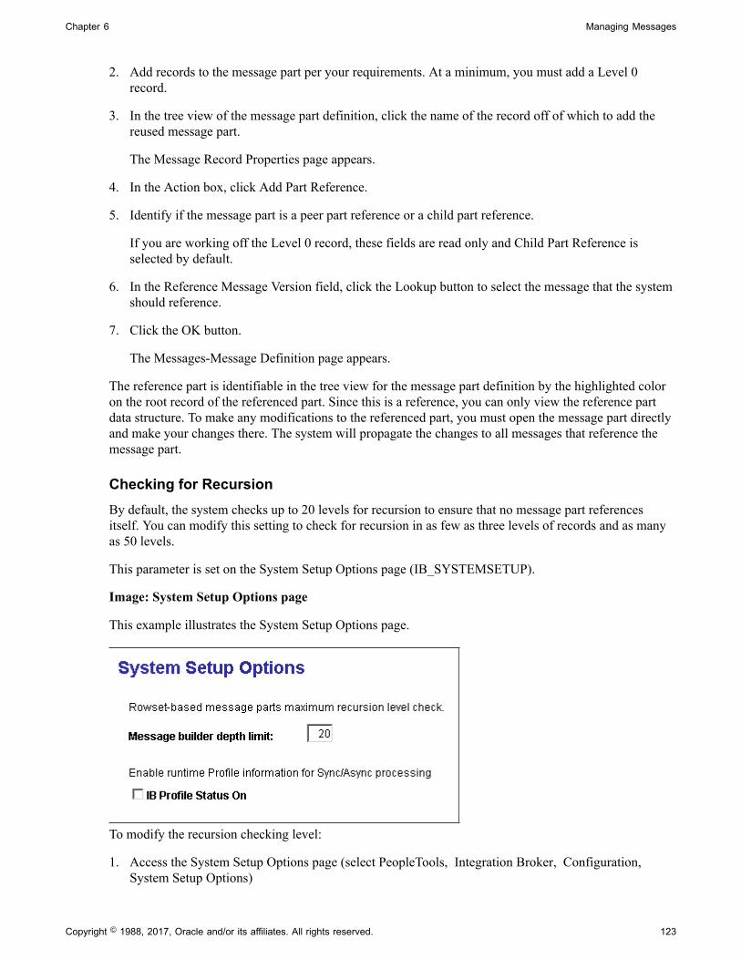
Chapter 6 Managing Messages
2. Add records to the message part per your requirements. At a minimum, you must add a Level 0record.
3. In the tree view of the message part definition, click the name of the record off of which to add thereused message part.
The Message Record Properties page appears.
4. In the Action box, click Add Part Reference.
5. Identify if the message part is a peer part reference or a child part reference.
If you are working off the Level 0 record, these fields are read only and Child Part Reference isselected by default.
6. In the Reference Message Version field, click the Lookup button to select the message that the systemshould reference.
7. Click the OK button.
The Messages-Message Definition page appears.
The reference part is identifiable in the tree view for the message part definition by the highlighted coloron the root record of the referenced part. Since this is a reference, you can only view the reference partdata structure. To make any modifications to the referenced part, you must open the message part directlyand make your changes there. The system will propagate the changes to all messages that reference themessage part.
Checking for RecursionBy default, the system checks up to 20 levels for recursion to ensure that no message part referencesitself. You can modify this setting to check for recursion in as few as three levels of records and as manyas 50 levels.
This parameter is set on the System Setup Options page (IB_SYSTEMSETUP).
Image: System Setup Options page
This example illustrates the System Setup Options page.
To modify the recursion checking level:
1. Access the System Setup Options page (select PeopleTools, Integration Broker, Configuration, System Setup Options)
Copyright © 1988, 2017, Oracle and/or its affiliates. All rights reserved. 123

Managing Messages Chapter 6
2. In the Message Builder Depth Limit field, enter a value between 3 and 50.
3. Click the Save button.
Viewing Referenced Message Part InformationA referenced message part appears highlighted in the tree structure for a message in the Messages –Message Definition page.
Image: Messages – Message Definition page
This example illustrates the Messages – Message Definition page. In the example the message structurefor the FLIGHTDATA message is shown. In the tree structure the message record QE_ARMAMENT ishighlighted and is therefore a referenced message part in the FLIGHTDATA message.
Note: You can make changes to a message part that is referenced in another part or subpart, as long as themessage part is not in the runtime tables, has not been exported as WSDL, or is a restricted message.
If you click a referenced message part, the Part Reference page (IB_MESSAGE_PARTS2) appears.
124 Copyright © 1988, 2017, Oracle and/or its affiliates. All rights reserved.
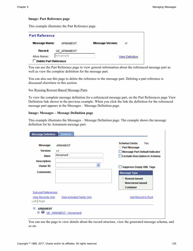
Chapter 6 Managing Messages
Image: Part Reference page
This example illustrates the Part Reference page.
You can use the Part Reference page to view general information about the referenced message part aswell as view the complete definition for the message part.
You can also use this page to delete the reference to the message part. Deleting a part reference isdiscussed elsewhere in this section.
See Reusing Rowset-Based Message Parts
To view the complete message definition for a referenced message part, on the Part References page ViewDefinition link shown in the previous example. When you click the link the definition for the referencedmessage part appears in the Messages – Message Definition page.
Image: Messages – Message Definition page
This example illustrates the Messages – Message Definition page. The example shows the messagedefinition for he Armament message part.
You can use the page to view details about the record structure, view the generated message schema, andso on.
Copyright © 1988, 2017, Oracle and/or its affiliates. All rights reserved. 125
Managing Messages Chapter 6
Modifying Referenced Message PartsTo make a modification to a referenced message part, you must make the modification in the message partdefinition itself. You cannot modify a referenced message part from a message in which it is referenced.
Deleting Referenced Message PartsYou delete a referenced message part in the message where the part is referenced.
To delete a referenced message part:
1. Open the message definition that contains the referenced message part to delete.
2. In the tree structure view of the message definition, click the name of the referenced message part todelete.
The Part Reference page appears.
3. Select the Delete Part Reference check box.
4. Click the OK button.
Managing Container Messages
This section provides an overview of managing container messages and discusses how to:
• Add message parts to container messages.
• Add and get container message attributes.
• Generate XML message schemas for container messages.
Understanding Managing Container MessagesContainer messages are used for those situations where you want to produce XML that contains none ofthe standard PeopleSoft messaging XML structures, such as PSCAMA, FieldType, and so on, yet youwant to use PeopleSoft rowset-based classes and methods to populate and read the message structure.
Container messages:
• Hold one or more message parts.
• Are always nonrowset-based messages.
The message parts you add to a container message must all be rowset-based message parts, or allnonrowset-based message parts.
When working with container messages that contain rowset-based message, PeopleSoft IntegrationBroker enables you to add attributes and attribute values to the container messages. Adding attributesto container messages enables you to provide integration partners with data and information, withoutthe need to modify or provide the information in the container message definition or in any of the partmessage definitions.
126 Copyright © 1988, 2017, Oracle and/or its affiliates. All rights reserved.

Chapter 6 Managing Messages
Understanding Including Level 0 Rows for Message Parts in ContainerMessages
When you are working with a container message that holds rowset-based message parts, you can specifythe minimum and the maximum number of level 0 rows for each message part.
When you are working with a container message, the Message Definition page, the Parts grid displays thefollowing fields:
Minimum Occurs The value you enter determines the minimum number of level 0rows in the message part to include in the container message.
Maximum Occurs The value you enter in this field determines the maximumnumber of level 0 rows in the message part to include in thecontainer message.
By default the Maximum Occurs value is set to 1 to representthe single row of data on the level 0 record defined on the part (typical for component processing). However, for the case wheremore then one row of data is to be passed on the level 0 record, for example there is a single record defined on the message partand you want to send x number of rows of data, then increasethe Maximum Occurs value to the value of x (the number ofrows of data you are sending) or set the Unbounded Maximumfield to Y.
Maximum Unbounded The value you select determines if the system includes unlimitedlevel 0 rows from the message part in the container message. The valid values are:
• Y. The number of level 0 rows from the part message that thesystem includes in the container messages is unlimited, orunbound. When you select this option all rows from a partmessage are included in the container message.
• N. (Default) The number of level 0 rows from the partmessage that the system includes in the container message islimited. You must enter the maximum number of rows fromthe part message to include in the container message in theMaximum Occurs field.
Example: Message XML when Maximum Occurs is Set to a Non-Default ValueThe section contains a example of a container message with three message parts: QE_PART_1,QE_PART_2, and QE_PART_3.
Each part contains only one record (level 0 record).
As described earlier in this section, the Maximum Occurs value is 1 by default.
Copyright © 1988, 2017, Oracle and/or its affiliates. All rights reserved. 127

Managing Messages Chapter 6
In the following example QE_PART_1 is defined on the container with a Maximum Occurs value of 2 andwhat is actually published in this case is two rows on the level 0 record for QE_PART_1, as shown in theexample.
<?xml version="1.0"?><QE_PARTS xmlns="http://xmlns.oracle.com/Enterprise/Tools/schemas/ QE_PARTS.VERSION_1"> <QE_PART_1> <QE_NAVIGATION class="R" xmlns="http://xmlns.oracle.com/Enterprise/ Tools/schemas/QE_PART_1.VERSION_1"> <QE_ACNUMBER>100</QE_ACNUMBER> <QE_WAYPOINT_NBR>10</QE_WAYPOINT_NBR> <QE_BEARING/> <QE_RANGE/> <QE_ALTITUDE/> <QE_LATITUDE/> <QE_LONGITUDE/> <QE_HEADING/> <QE_VELOCITIES/> <QE_NAVDESC/> </QE_NAVIGATION> </QE_PART_1> <QE_PART_1> <QE_NAVIGATION class="R" xmlns="http://xmlns.oracle.com/Enterprise/ Tools/schemas/QE_PART_1.VERSION_1"> <QE_ACNUMBER>100</QE_ACNUMBER> <QE_WAYPOINT_NBR>20</QE_WAYPOINT_NBR> <QE_BEARING/> <QE_RANGE/> <QE_ALTITUDE/> <QE_LATITUDE/> <QE_LONGITUDE/> <QE_HEADING/> <QE_VELOCITIES/> <QE_NAVDESC/> </QE_NAVIGATION> </QE_PART_1> <QE_PART_2> <QE_RADAR_PRESET class="R" xmlns="http://xmlns.oracle.com/Enterprise/ Tools/schemas/QE_PART_2.VERSION_1"> <QE_ACNUMBER>2</QE_ACNUMBER> <QE_RADAR_SELECTION>1</QE_RADAR_SELECTION> <QE_RADARMODE>TWS</QE_RADARMODE> <QE_RADAR_OPERMODE>N</QE_RADAR_OPERMODE> <QE_BARSCAN>4B</QE_BARSCAN> <QE_RADARRANGE>40</QE_RADARRANGE> <QE_TGTAGE>8</QE_TGTAGE> <QE_CHANNELSET>B</QE_CHANNELSET> <QE_AZIMUTH>80</QE_AZIMUTH> <QE_PRF>H</QE_PRF> </QE_RADAR_PRESET> </QE_PART_2> <QE_PART_3> <QE_ARMAMENT class="R" xmlns="http://xmlns.oracle.com/Enterprise/Tools/ schemas/QE_PART_3.VERSION_1"> <QE_ACNUMBER>2</QE_ACNUMBER> <QE_STATION_NBR>1</QE_STATION_NBR> <QE_AGMODE>CCIP</QE_AGMODE> <QE_BIT>SBIT</QE_BIT> <QE_WEAPONSPECS/> </QE_ARMAMENT> </QE_PART_3></QE_PARTS>
Adding Message Parts to Container MessagesThis section discusses how to add message parts to container messages.
128 Copyright © 1988, 2017, Oracle and/or its affiliates. All rights reserved.
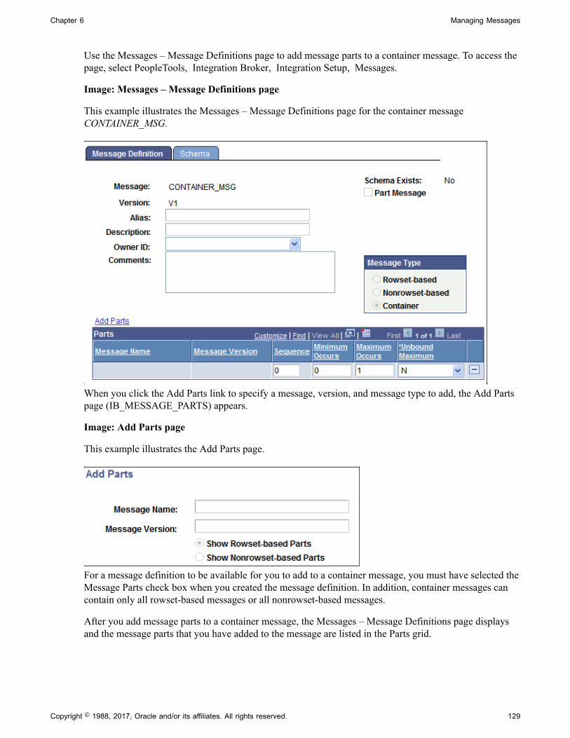
Chapter 6 Managing Messages
Use the Messages – Message Definitions page to add message parts to a container message. To access thepage, select PeopleTools, Integration Broker, Integration Setup, Messages.
Image: Messages – Message Definitions page
This example illustrates the Messages – Message Definitions page for the container messageCONTAINER_MSG.
When you click the Add Parts link to specify a message, version, and message type to add, the Add Partspage (IB_MESSAGE_PARTS) appears.
Image: Add Parts page
This example illustrates the Add Parts page.
For a message definition to be available for you to add to a container message, you must have selected theMessage Parts check box when you created the message definition. In addition, container messages cancontain only all rowset-based messages or all nonrowset-based messages.
After you add message parts to a container message, the Messages – Message Definitions page displaysand the message parts that you have added to the message are listed in the Parts grid.
Copyright © 1988, 2017, Oracle and/or its affiliates. All rights reserved. 129

Managing Messages Chapter 6
Image: <Messages – Message Definitions
This example illustrates the Messages – Message Definitions page. The example shows three messageparts added to the container message.
Click the name of any of the message parts that appear in the grid to open the individual messagedefinition. If the service system status is set to Production, when assigned to a container message, youcannot modify a message definition. To modify the definition, you must delete it from the containermessage first.
130 Copyright © 1988, 2017, Oracle and/or its affiliates. All rights reserved.
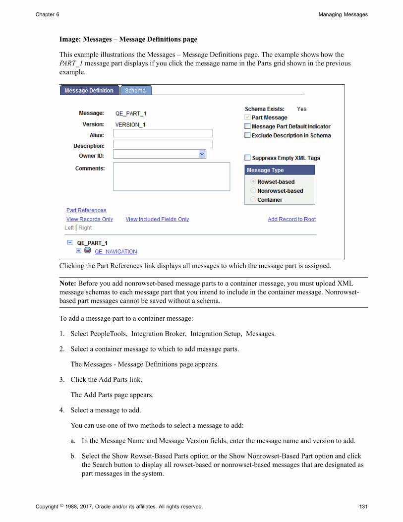
Chapter 6 Managing Messages
Image: Messages – Message Definitions page
This example illustrations the Messages – Message Definitions page. The example shows how thePART_1 message part displays if you click the message name in the Parts grid shown in the previousexample.
Clicking the Part References link displays all messages to which the message part is assigned.
Note: Before you add nonrowset-based message parts to a container message, you must upload XMLmessage schemas to each message part that you intend to include in the container message. Nonrowset-based part messages cannot be saved without a schema.
To add a message part to a container message:
1. Select PeopleTools, Integration Broker, Integration Setup, Messages.
2. Select a container message to which to add message parts.
The Messages - Message Definitions page appears.
3. Click the Add Parts link.
The Add Parts page appears.
4. Select a message to add.
You can use one of two methods to select a message to add:
a. In the Message Name and Message Version fields, enter the message name and version to add.
b. Select the Show Rowset-Based Parts option or the Show Nonrowset-Based Part option and clickthe Search button to display all rowset-based or nonrowset-based messages that are designated aspart messages in the system.
Copyright © 1988, 2017, Oracle and/or its affiliates. All rights reserved. 131

Managing Messages Chapter 6
Select one or more messages to include in the container message.
5. Click the OK button.
The Messages - Message Definitions page appears, with the Parts grid populated with the message ormessages that you selected.
6. (Optional.) In the Parts grid, enter numeric values in the Sequence column to order message partplacement in the container message.
If you do not enter any values, the system sequences the messages in the order in which you add themto the container message.
7. (Optional.) In the Minimum Occurs field, enter the number of minimum rows in the message part toinclude in the container message.
8. In the Maximum Occurs field, enter the maximum number of level 0 rows from the part message toinclude in the container message.
9. In the Unbound Maximum drop-down list, select whether to include all level 0 rows from the part inthe container message.
Note: If you select Y, note that the Maximum Occurs field no longer displays on the page, as all rowsare included in the container message.
The Minimum Occurs, Maximum Occurs and Unbound Maximum fields are described elsewhere in thissection.
See Understanding Including Level 0 Rows for Message Parts in Container Messages.
Adding and Getting Container Messages AttributesThis section discusses how to:
• Add the language code of the message sender as an attribute to a container message.
• Add attribute names to a container message.
• Populate attribute values for container message attributes.
• Get attribute names and values from a container message.
This section also provides a summary of PeopleCode that you can use to populate attribute values and getattribute data from container messages.
Understanding Adding, Populating, and Getting Container Message AttributesYou can add attributes to container messages that contain rowset-based message parts to provideintegration partners with data and information, without adding the information to the message definition.
To add attributes to a container message, you first define the attribute name, length, and required flagin the container message definition in the PeopleSoft Pure Internet Architecture. This informationappears in generated container message schema. At runtime the attributes appear at the root level of the
132 Copyright © 1988, 2017, Oracle and/or its affiliates. All rights reserved.

Chapter 6 Managing Messages
generated XML. Next you use PeopleCode to populate the attribute values using the IBInfo object. Atruntime, PeopleSoft Integration Broker validates the attribute values against the lengths you defined in thecontainer message definition.
PeopleSoft provides a number of IBInfo object methods to get attributes from container messages.
Adding Language Codes of the Message Senders as Attributes to ContainerMessagesThe language code of the user who executed the publish or sync request is a common attribute to add toa container message. As such, PeopleSoft provides an Include Language Code attribute box, that whenselected automatically includes the information as an attribute name and value in the container message.
Image: Container Attributes page
This example illustrates the Container Attributes page. The example shows that the Include LanguageCode check box is selected.
To add the language code of the message sender as an attribute:
1. Access the Container Attributes page (PeopleTools, Integration Broker, Integration Setup, Messagesand click the Container Attributes link).
2. Select the Include Language Code check box.
3. Click the OK button.
4. The Messages–Message Definitions page appears.
Adding Attribute Names to Container MessagesAfter you add one or more rowset-based message parts to a container message and save the message,a Container Attributes link appears on the Messages-Message Definition page under the MessageType group box. When you click the Container Attributes link, the Container Attributes page(IB_MESSAGE_ATT_SEC).
Copyright © 1988, 2017, Oracle and/or its affiliates. All rights reserved. 133

Managing Messages Chapter 6
Image: Container Attributes page
This example illustrates the Container Attributes page. In the example two attribute names are defined,MessageImportance and DeveloperID.
To add an attribute name to a container message:
1. Access the Container Attributes page (PeopleTools, Integration Broker, Integration Setup, Messagesand click the Container Attributes link).
2. In the Attribute Name field, enter a name for the attribute.
3. In the Length field, enter a numeric field length value.
4. (Optional.) Select the Required check box if you want the attribute name to be required.
5. Click the OK button.
The Messages–Message Definitions page appears.
Populating Attribute Values for Container Message AttributesPeopleSoft provides several IBInfo object methods within the Message object to populate containermessage attributes.
Here is an example of how to populate attributes. The attribute values will be validated at runtime againstthe defined lengths.
&MSG = CreateMessage(Operation.MY_SVC_OPERATION);
&ret = &MSG.IBInfo.AddContainerAttribute("MessageImportance", "Medium");&ret = &MSG.IBInfo.AddContainerAttribute("DeveloperID", "mdawson");
Additional IBInfo objects that you can use for working with container message attributes are describedelsewhere in this section.
Getting Attribute Names and Values from Container MessagesPeopleSoft provides several IBInfo object methods within the Message object to Get attribute informationfrom container messages.
134 Copyright © 1988, 2017, Oracle and/or its affiliates. All rights reserved.
Chapter 6 Managing Messages
Note that if you attempt to read attributes within an Integration Broker event, such as OnNotify,OnRequest, and so on, you must first Get a part rowset to load the attributes into the Message object fromthe XML.
The following code snippet shows one example of how to read attributes from a container message:
RowSet = &MSG.GetPartRowset(1);&index = &MSG.Ibinfo.GetNumberOfContainerAttributes();
For &i = 1 To &index &attrName = &MSG.Ibinfo.GetContainerAttributeName(&i); &attrValue = &MSG.Ibinfo.GetContainerAttributeValue(&i); End-For;
Additional IBInfo objects that you can use for working with container message attributes are describedelsewhere in this section.
Summary of PeopleCode Use for Working With Container Message AttributesThe following table summarizes the PeopleCode methods that you can use for working with containermessage attributes.
Method Description
GetNumberOfContainerAttributes
Syntax:
&Integer = &MSG.IBInfo.GetNumberOfContainerAttributes();
Gets the number of container attributes
GetContainerAttributeName
Syntax:
&String = &MSG.IBInfo.GetContainerAttributeName(Integer nIndex);
Returns the name of the container attribute based on an index.
GetContainerAttributeValue
Syntax:
&String = &MSG.IBInfo.GetContainerAttributeValue(Integer nIndex);
Returns the value of the container attribute based on an index.
AddContainerAttribute
Syntax:
&Bool = &MSG.IBInfo.AddContainerAttribute(string name, string value);
Add container attributes by passing in attribute name andvalue.
DeleteContainerAttribute
Syntax:
&Bool = &MSG.IBInfo.DeleteContainerAttribute(string name);
Delete a container attribute based on the attribute name.
Copyright © 1988, 2017, Oracle and/or its affiliates. All rights reserved. 135
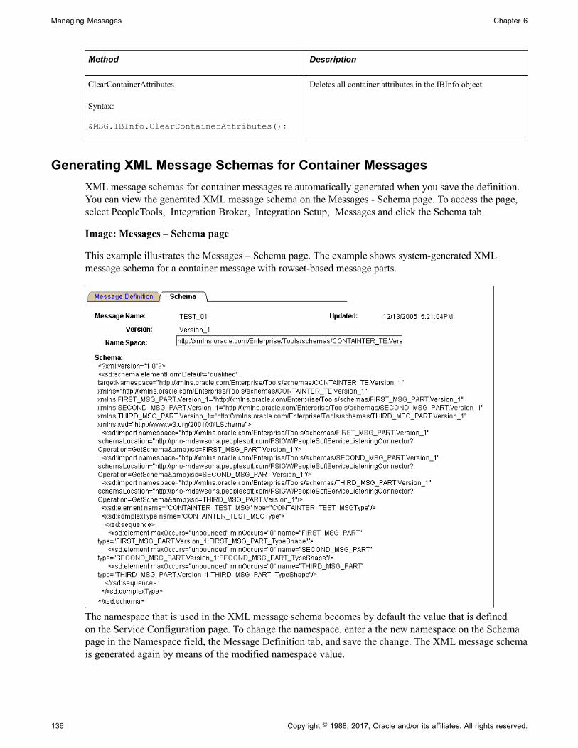
Managing Messages Chapter 6
Method Description
ClearContainerAttributes
Syntax:
&MSG.IBInfo.ClearContainerAttributes();
Deletes all container attributes in the IBInfo object.
Generating XML Message Schemas for Container MessagesXML message schemas for container messages re automatically generated when you save the definition.You can view the generated XML message schema on the Messages - Schema page. To access the page,select PeopleTools, Integration Broker, Integration Setup, Messages and click the Schema tab.
Image: Messages – Schema page
This example illustrates the Messages – Schema page. The example shows system-generated XMLmessage schema for a container message with rowset-based message parts.
The namespace that is used in the XML message schema becomes by default the value that is definedon the Service Configuration page. To change the namespace, enter a the new namespace on the Schemapage in the Namespace field, the Message Definition tab, and save the change. The XML message schemais generated again by means of the modified namespace value.
136 Copyright © 1988, 2017, Oracle and/or its affiliates. All rights reserved.
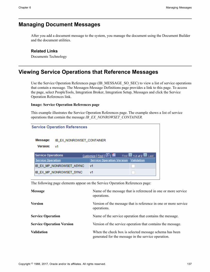
Chapter 6 Managing Messages
Managing Document Messages
After you add a document message to the system, you manage the document using the Document Builderand the document utilities.
Related LinksDocuments Technology
Viewing Service Operations that Reference Messages
Use the Service Operation References page (IB_MESSAGE_SO_SEC) to view a list of service operationsthat contain a message. The Messages-Message Definitions page provides a link to this page. To accessthe page, select PeopleTools, Integration Broker, Integration Setup, Messages and click the ServiceOperation References link.
Image: Service Operation References page
This example illustrates the Service Operation References page. The example shows a list of serviceoperations that contain the message IB_EX_NONROWSET_CONTAINER.
The following page elements appear on the Service Operation References page:
Message Name of the message that is referenced in one or more serviceoperations.
Version Version of the message that is reference in one or more serviceoperations.
Service Operation Name of the service operation that contains the message.
Service Operation Version Version of the service operation that contains the message.
Validation When the check box is selected message schema has beengenerated for the message in the service operation.
Copyright © 1988, 2017, Oracle and/or its affiliates. All rights reserved. 137

Managing Messages Chapter 6
Resolving Inconsistencies in Exported WSDL and WADLDocuments
This section discusses how to:
• View service operations with exported WSDL or WADL inconsistencies.
• Clear exported WSDL/WADL status flags.
Understanding Using Project Copy and Exported WSDL and WADLWhen you generate WSDL or WADL for a service operation, the system sets an internal flag on theservice operation that indicates that WSDL/WADL has been generated or exported for the specific serviceoperation.
The system uses the same repository for WSDL and WADL documents. The WSDL metadata object isused for project copy of WSDL and WADL. There is no WADL metadata object only WSDL.
You may later decided to use Project Copy to copy the service operation to a new database. But you maydecide not to or simply neglect to copy the exported WSDL or WADL to the new database.
Even though you have not copied the WSDL/WADL to the new database, the internal flag that saysWSDL/WADL has been generated is still set on the service operation. As a result, the system expectsWSDL/WADL to exist in the new database, when it does not. When this condition exists, the systemdisplays a status message on the message definition(s) of messages referenced in the service operation.
When this condition exists, the options are:
• Clear the internal WSDL/WADL exported flag on the service operation.
Information about how to perform this task is discussed in this section.
• Use Project Copy to copy the WSDL/WADL to the new database.
See "Copying Projects" (PeopleTools 8.55: Lifecycle Management Guide).
• Regenerate the WSDL/WADL on the new database using the Provide Web Service wizard.
See Providing Services.
Viewing Services Operations with Exported WSDL/WADL InconsistenciesIf the system detects a WSDL/WADL flag inconsistency, the following status message appears on theMessages-Message Definitions page for those message definitions referenced in the service operation forthe WSDL/WADL in question:
Exported WSDL flag inconsistency detected. WSDL does not exist.
138 Copyright © 1988, 2017, Oracle and/or its affiliates. All rights reserved.

Chapter 6 Managing Messages
Image: Messages-Message Definitions page
This example illustrates the Messages – Message Definitions page. The example shows the “ExportedWSDL flag inconsistency detected” status message and the Exported WSDL Inconsistency link appearingon the page.
In addition, an Exported WSDL Inconsistency link appears on the Messages-Message Definitions page.Click this link to view the Exported WSDL Inconsistencies page (IB_HOME_PAGE7_SEC).
Image: Exported WSDL Inconsistencies page
This example illustrates the Exported WSDL Inconsistencies page
The page displays service operations that exist in the database that are flagged as having WSDL/WADLexported, yet no WSDL/WADL exists in the database for them. The Exported WSDL Inconsistenciespage features a Service Admin link. Clicking the link opens the Service Administration-WSDL page(IB_HOME_PAGE7). The Service Administration-WSDL page provides options to clear the internalexported WSDL flag.
Copyright © 1988, 2017, Oracle and/or its affiliates. All rights reserved. 139

Managing Messages Chapter 6
Clearing Exported WSDL/WADL Status FlagsThe Clear WSDL Status page (IB_HOME_PAGE7_SEC) enables you to clear the internal exportedWSDL/WADL status flag for service operations that contain specific messages, or for all serviceoperations in the database.
Note: Clearing the internal exported WSDL/WADL status flag on a service operation is one way toresolve a WSDL/WADL flag inconsistency. Other options for resolving this condition are discussedelsewhere in this topic.
See Understanding Using Project Copy and Exported WSDL and WADL.
Image: Clear WSDL Export Status page
This example shows the Clear WSDL Export Status page
Up to this point, this section has demonstrated accessing the Clear WSDL Export Status page startingfrom the Export WSDL Inconsistency link on a message definition, and then clicking on the ServiceAdmin link from the Exported WSDL Inconsistencies page. When you access the page using thisnavigation, only the service operations that reference the message definition that you were originallyviewing on the Messages – Message Definitions page appear. Further, those service operations that appearare those that are flagged has having WSDL/WADL exported, but for which there is none in the database.
You can also clear the WSDL/WADL export status flag for all service operations in the database that arein the inconsistent state of having been flagged as having WSDL/WADL generated, but no WSDL/WADLexists in the database for them. You can do so by accessing the Service Administration-WSDL page andclicking the Clear WSDL Export Status link.
140 Copyright © 1988, 2017, Oracle and/or its affiliates. All rights reserved.

Chapter 6 Managing Messages
Image: Clearing the WSDL Export Status page
This example illustrates the Clear WSDL Export Status page. The example shows a list of serviceoperation in the database that have inconsistent WSDL.
To clear the WSDL/WADL exported status flag:
1. Access the WSDL Export Status page using one of the following methods:
• From a message definition that displays the “Exported WSDL flag inconsistency” status message:Click the Exported WSDL Inconsistency link. The Exported WSDL Inconsistencies page appears.Click the Service Admin link.
• From the PeopleTools menu: Select PeopleTools, Integration Broker, Service Utilities, ServiceAdministration. The Service Administration page appears. Click the WSDL tab. Click the ClearWSDL Export Status link.
2. Click the Clear Export Status button.
Renaming and Deleting Message Definitions
You can rename and delete messages using the Messages page (IB_HOME_PAGE5) in the ServicesAdministration component (IB_HOME_PAGE). The Message page contains two sections: a Deletesection that enables you to delete message definitions and a Rename section that enables you to renamemessage definitions.
To access the page, select PeopleTools, Integration Broker, Service Utilities, Service Administration andclick the Messages tab.
Copyright © 1988, 2017, Oracle and/or its affiliates. All rights reserved. 141

Managing Messages Chapter 6
When you first access the Messages page, all sections are collapsed. Click the section header arrowbuttons to expand and collapse each section.
Image: Services Administration – Messages page
This example illustrates the Services Administration – Messages page. In the example the Delete andRename sections are expanded.
At the top of the page, the Service System Status field displays the current setting. The service systemstatus, set on the Service Configuration page, affects the ability to rename and delete messages.
See "Understanding Configuring PeopleSoft Integration Broker for Handling Services" (PeopleTools8.55: Integration Broker Administration).
Renaming Message DefinitionsTo rename a message definition:
Note: Renaming a message definition renames all versions.
1. Access the Services Administration - Messages page.
Select PeopleTools, Integration Broker, Service Utilities, Service Administration. Click theMessages tab.
2. Click the arrow next to the Rename section header to expand the section.
3. In the Message Name field, enter the message definition to rename, or click the Lookup button tosearch for and select the message to rename.
4. (Optional.) Click the Message Builder link to view details about the selected message in the Messages- Message Definitions page.
142 Copyright © 1988, 2017, Oracle and/or its affiliates. All rights reserved.

Chapter 6 Managing Messages
When you are done viewing the message details, click the Return button to return to the ServicesAdministration - Messages page.
5. In the New Name field, enter the new name for the message definition.
6. Click the Rename button.
Deleting Message DefinitionsWhen you delete a message definition the system also deletes it's associated schema.
To delete a message definition:
1. Access the Services Administration - Messages page.
Select PeopleTools, Integration Broker, Service Utilities, Service Administration. Click theMessages tab.
2. Click the arrow next to the Delete section header to expand the section.
3. In the Message Name field, enter the name of the message to delete, and click the Search button.
Search results appear in the results grid.
4. In the results grid, select the check box next to the message or messages to delete.
5. Click the Delete button.
Deleting Messages During Upgrade
To delete a message definition in an application upgrade project, you must first make sure that no liveinstances of the message exist. Archive or delete any such messages in both the source and the targetdatabase. Otherwise, you receive an error message during the copy process indicating that the object is inuse.
Copyright © 1988, 2017, Oracle and/or its affiliates. All rights reserved. 143

Managing Messages Chapter 6
144 Copyright © 1988, 2017, Oracle and/or its affiliates. All rights reserved.

Chapter 7
Sending and Receiving Messages
Understanding Sending and Receiving Messages
To send and receive messages you use PeopleCode to:
• Send request messages from PeopleSoft Integration Broker to other systems.
• Receive response messages from other systems.
• Route messages.
• Manipulate message content.
You can also send messages directly to the integration gateway, thereby bypassing processing on theintegration engine.
Note: The code examples in this topic are for illustrative purposes only and are not intended to be used ina production environment.
Prerequisites for Sending and Receiving MessagesBefore you can define PeopleCode to generate, send, receive, and process messages, you must define themessage in PeopleSoft Internet Architecture.
Note: Once you create PeopleCode, you must also define nodes, services and service operations toimplement a complete integration.
See PeopleSoft Integration Broker Metadata.
Messaging Process Flows
The integration engine uses asynchronous request processes and synchronous request processes tomanage outbound and inbound messages. These processes examine the messaging elements that youcreate to determine how to treat each message.
Outbound Message Processing FlowThis section discusses message processing flow for outbound messages. In this section, the term processis used, and refers to either the integration engine's asynchronous request process or its synchronousrequest process, depending on the type of integration you are preforming.
Outbound messages you send go through the following steps.
1. The application triggers the sending PeopleCode that you developed.
Copyright © 1988, 2017, Oracle and/or its affiliates. All rights reserved. 145
Sending and Receiving Messages Chapter 7
2. The PeopleCode program populates and sends the message by using an asynchronous or synchronousmethod.
3. The method that the PeopleCode uses to send the message triggers a request process in theapplication’s integration engine.
4. The process searches the outbound routings that are associated with that service operation todetermine the valid target nodes for the message.
The asynchronous process examines only asynchronous routings, and the synchronous processexamines only synchronous routings. If for synchronous processing, a valid single outbound routingcannot be found, the sending method returns an error.
Note: Only active routings are considered for processing.
5. For each outbound routing that it finds, the process submits the message to the local gateway, alongwith transaction information about the node and the target connector that should be used to send themessage.
6. The local gateway transmits the message to the specified target node through the specified targetconnector.
7. If this is a synchronous message, the process waits for the target node to pass a response messageback through the gateway, then returns it to the calling PeopleCode method.
Inbound Message Processing Flow
Each received message goes through the following steps:
1. The application’s gateway receives a request message from a remote node or gateway, which specifiesthe application as its target node.
2. The gateway submits the message to the application’s integration engine, which searches for anyinbound request routing parameter which has the same alias name as the external operation namepassed in.
3. If a matching routing alias name isn’t found, the integration engine returns an error message throughthe gateway to the sending node.
If a routing alias name is found, the integration engine invokes either the asynchronous requestprocess or the synchronous request process, as appropriate, to handle the message.
Note: Any inbound routing alias that is found must have the proper permissions for that serviceoperation for the process to proceed.
4. The process accesses the service operation that matches the routing alias name and passes the messageto the service operation's handler associated with receiving PeopleCode.
• The asynchronous request process invokes the service operation's handler OnNotify eventPeopleCode.
• The synchronous request process invokes the service operation's handler OnRequest eventPeopleCode.
146 Copyright © 1988, 2017, Oracle and/or its affiliates. All rights reserved.

Chapter 7 Sending and Receiving Messages
5. If this is a synchronous transaction, the process waits for the receiving PeopleCode to generate andreturn a response message, then passes it back to the sending node through the gateway.
Understanding Integration PeopleCode
This section discusses the PeopleCode used for integrations and describes:
• Sending and receiving PeopleCode.
• Integration application classes.
• Integration methods.
• Messaging methods.
• Error-handling methods.
• Messaging PeopleCode.
• Documents PeopleCode.
Sending and Receiving PeopleCodeThis section discusses the PeopleCode you use for sending messages from PeopleSoft Integration Brokerto other systems, and the PeopleCode you use for receiving messages from other systems.
Sending PeopleCodePeopleCode for sending messages can be located in PeopleCode events associated with records, recordfields, and components, and in application engine programs.
The PeopleCode method used to send messages is highlighted in the following table.
Transmission Type Sending PeopleCode Comments
Synchronous SyncRequest method. The SyncRequest method belongs to theIntBroker class.
Asynchronous Publish method. The Publish method belongs to theIntBroker class.
To work with rowset-based messages in SOAP format, transform the SOAP documents into XMLdocuments and then use the IntBroker class SyncRequest or Publish methods. To work with nonrowset-based messages in SOAP format use the SOAPDoc class.
Receiving PeopleCodeThe PeopleCode that you use to receive a message must be associated with the message definition. Thetransmission type of the message determines the location of the PeopleCode program.
Copyright © 1988, 2017, Oracle and/or its affiliates. All rights reserved. 147

Sending and Receiving Messages Chapter 7
Implement the OnRequest method for synchronous messages. Implement the OnNotify method forasynchronous messages. Both methods are located in the PS_PT application package, in the Integrationsub-package, in the IRequestHandler and INotificationHandler classes, respectively.
Transmission Type Message Structure Receiving PeopleCode Comments
Synchronous Rowset-based Message is passed into themethod.
Implement theOnRequest method in theIRequestHandler applicationinterface.
Synchronous Nonrowset-based Message is passed into themethod.
Implement theOnRequest method in theIRequestHandler applicationinterface.
Asynchronous Rowset-based Message is passed into themethod.
Implement theOnNotify method in theINotificationHandlerapplication interface.
Asynchronous Nonrowset-based Message is passed into themethod.
Implement theOnNotify method in theINotificationHandlerapplication interface.
To get content data out of a request message, use the following guidelines.
Message Structure PeopleCode Comments
Rowset-based GetRowSet method. None.
Nonrowset-based GetXMLDoc method. You can also use Message classfunctionality with nonrowset-basedmessages.
See Using Message Object FunctionalityWith Nonrowset-Based Messages.
Application ClassesApplication classes house the processing logic for asynchronous and synchronous messages. Byimplementing the Integration Broker application classes, you can reuse code and access other benefits ofapplication classes.
The following application classes exist for PeopleSoft Integration Broker. See the individual applicableapplication class interfaces for more information about the methods contained in an application class.
To access these application classes, in PeopleSoft Application Designer, open the PS_PT applicationpackage and open the Integration subpackage.
148 Copyright © 1988, 2017, Oracle and/or its affiliates. All rights reserved.
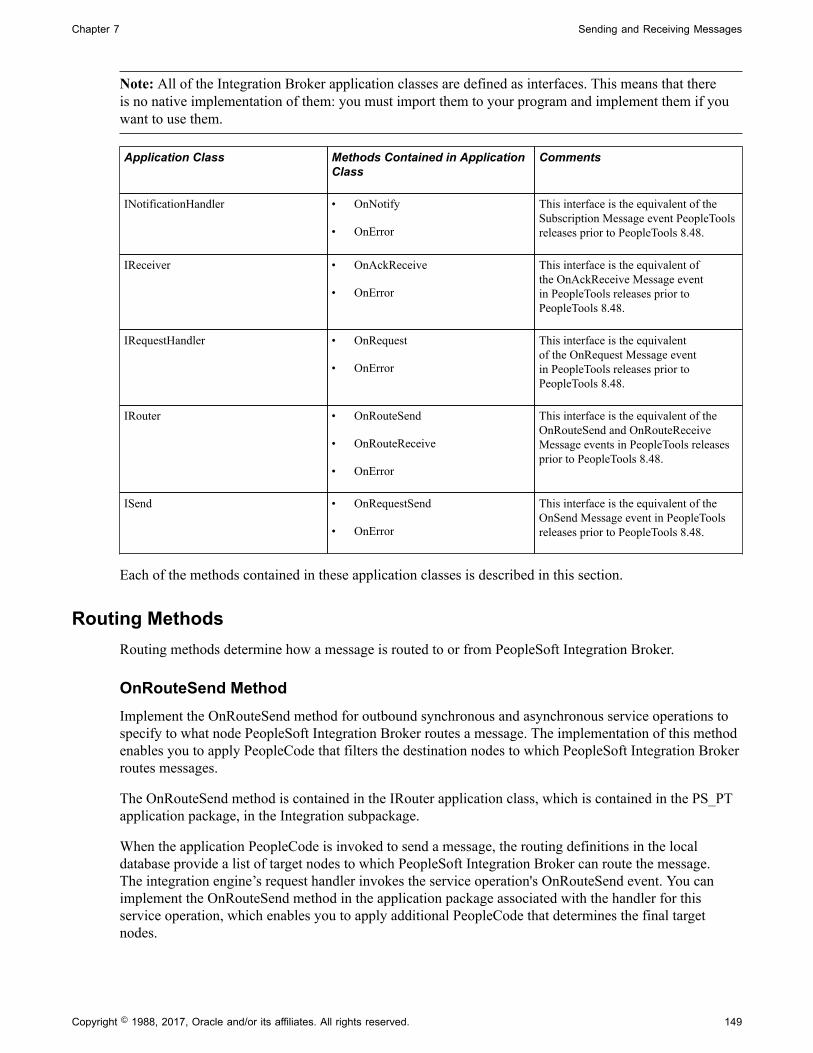
Chapter 7 Sending and Receiving Messages
Note: All of the Integration Broker application classes are defined as interfaces. This means that thereis no native implementation of them: you must import them to your program and implement them if youwant to use them.
Application Class Methods Contained in ApplicationClass
Comments
INotificationHandler • OnNotify
• OnError
This interface is the equivalent of theSubscription Message event PeopleToolsreleases prior to PeopleTools 8.48.
IReceiver • OnAckReceive
• OnError
This interface is the equivalent ofthe OnAckReceive Message eventin PeopleTools releases prior toPeopleTools 8.48.
IRequestHandler • OnRequest
• OnError
This interface is the equivalentof the OnRequest Message eventin PeopleTools releases prior toPeopleTools 8.48.
IRouter • OnRouteSend
• OnRouteReceive
• OnError
This interface is the equivalent of theOnRouteSend and OnRouteReceiveMessage events in PeopleTools releasesprior to PeopleTools 8.48.
ISend • OnRequestSend
• OnError
This interface is the equivalent of theOnSend Message event in PeopleToolsreleases prior to PeopleTools 8.48.
Each of the methods contained in these application classes is described in this section.
Routing MethodsRouting methods determine how a message is routed to or from PeopleSoft Integration Broker.
OnRouteSend MethodImplement the OnRouteSend method for outbound synchronous and asynchronous service operations tospecify to what node PeopleSoft Integration Broker routes a message. The implementation of this methodenables you to apply PeopleCode that filters the destination nodes to which PeopleSoft Integration Brokerroutes messages.
The OnRouteSend method is contained in the IRouter application class, which is contained in the PS_PTapplication package, in the Integration subpackage.
When the application PeopleCode is invoked to send a message, the routing definitions in the localdatabase provide a list of target nodes to which PeopleSoft Integration Broker can route the message.The integration engine’s request handler invokes the service operation's OnRouteSend event. You canimplement the OnRouteSend method in the application package associated with the handler for thisservice operation, which enables you to apply additional PeopleCode that determines the final targetnodes.
Copyright © 1988, 2017, Oracle and/or its affiliates. All rights reserved. 149

Sending and Receiving Messages Chapter 7
You can use OnRouteSend to validate the outbound service operation's target node list, prevent themessage from transmitting, or redirect it to a completely different set of targets.
The following table lists the PeopleCode built-in constants that you can use with the OnRouteSendmethod:
Constant Description
%IntBroker_ROUTE_NONE Do not send this operation to any of the possible nodes.
%IntBroker_ROUTE_SOME Send this operation to a selected list of nodes. The node listshould be an array of strings in the property destinationNodes.
%IntBroker_ROUTE_ALL Send this operation to all nodes that have a valid routing.
OnRouteSend enables you to account for multiple synchronous targets. Only one target node at a timecan receive a request message sent with a synchronous transaction. Even though you can define the sameoutbound synchronous transaction for multiple nodes, you must make sure the transaction resolves to asingle target node or the transaction fails.
The following code example shows an implementation of this class:
import PS_PT:Integration:IRouter;
class RoutingHandler implements PS_PT:Integration:IRouter method RoutingHandler(); property array of any destinationNodes; method OnRouteSend(&_MSG As Message) Returns integer;end-class;
/* constructor */method RoutingHandlerend-method;
method OnRouteSend /+ &_MSG as Message +/ /+ Returns Integer +/ /+ Extends/implements PS_PT:Integration:IRouter.OnRouteSend +/ /* Variable Declaration */ Local any &aNodeList; Local any &rootNode; Local any &xmlDoc; /* Check the message for the instructions on how to execute the OnRouteSend.*/ &xmlDoc = &_MSG.GetXmlDoc(); &rootNode = &xmlDoc.DocumentElement; &aNodeList = &rootNode.GetElementsByTagName("OnRouteSend"); If (&aNodeList.Len <> 1) Then /* No Nodes are in the list, therefore exit. */ Exit; Else /* check the value of the node to determine the action to take. */ Evaluate &aNodeList [1].NodeValue When "True" Return (%IntBroker_ROUTE_ALL); Break;
150 Copyright © 1988, 2017, Oracle and/or its affiliates. All rights reserved.

Chapter 7 Sending and Receiving Messages
When "False" Return (%IntBroker_ROUTE_NONE); Break; When-Other /* assume that this is to be routed to the node given */ Local array &nodeArray; &nodeArray = CreateArray(); &nodeArray.Push(&aNodeList [1].NodeValue); Local string &sIBVariableTest = GetCurrentType(&nodeArray); Evaluate &sIBVariableTest When "Array" &destinationNodes = &nodeArray.Clone(); Return %IntBroker_ROUTE_SOME; When "BooleanTrue" Return %IntBroker_ROUTE_ALL; When "BooleanFalse" Return %IntBroker_ROUTE_NONE; End-Evaluate; Break; End-Evaluate; End-If; end-method;
OnRouteReceive MethodImplement the OnRouteReceive method for inbound synchronous and asynchronous service operations toapply PeopleCode that determines whether the default local node accepts inbound messages.
The OnRouteReceive method is contained in the IRouter application class, which is contained in thePS_PT application package, in the Integration subpackage.
When the integration engine receives a message, the transaction definitions in the local database providea list of source nodes from which the application can accept the message. The integration engine’s requesthandler invokes the service operation's OnRouteReceive event. You can implement the OnRouteReceivemethod in the application package associated with the handler for this service operation, which enablesyou to apply PeopleCode that determines whether the default local node accepts the inbound message.You can employ this event regardless of the message transmission type.
The following is an example implementation of this method:
import PS_PT:Integration:IRouter;
class RoutingHandler implements PS_PT:Integration:IRouter method RoutingHandler(); property array of any destinationNodes; method OnRouteReceive(&_MSG As Message) Returns boolean;end-class;
/* constructor */method RoutingHandlerend-method;
method OnRouteReceive /+ &_MSG as Message +/ /+ Returns Boolean +/ /+ Extends/implements PS_PT:Integration:IRouter.OnRouteReceive +/ /* Variable Declaration */ Local any &aNodeList; Local any &rootNode; Local any &xmlDoc;
Copyright © 1988, 2017, Oracle and/or its affiliates. All rights reserved. 151

Sending and Receiving Messages Chapter 7
/* Check the message for instructions on how to execute the OnRouteReceive.*/ &xmlDoc = &_MSG.GetXmlDoc(); &rootNode = &xmlDoc.DocumentElement; &aNodeList = &rootNode.GetElementsByTagName("OnRouteReceive"); If (&aNodeList.Len <> 1) Then /* A single node must be present. */ Exit; Else /* check the value of the node to determine the action to take. */ Evaluate &aNodeList [1].NodeValue When "True" Return ( True); Break; When "False" Return ( False); Break; When-Other /* don't recognize the value. */ Exit; End-Evaluate; End-If; end-method;
Messaging MethodsThis section describes methods used in messaging and the application classes in which they are contained.
Outbound Messaging MethodsThis section describes methods used on outbound messages from PeopleSoft to other systems.
OnRequestSend Implement for outbound synchronous and asynchronous serviceoperations to override connector properties before sending amessage to the integration gateway.
This method is contained in the ISend application class.
The OnRequestSend method passes in a message to yourderived application class method. The returned value needs tobe a message.
The following is an example implementation of this method.
import PS_PT:Integration:ISend;
class SendHandler implements PS_PT:Integration:ISend method SendHandler(); method OnRequestSend(&_MSG As Message) Returns Message;end-class;
/* constructor */method SendHandlerend-method;
152 Copyright © 1988, 2017, Oracle and/or its affiliates. All rights reserved.

Chapter 7 Sending and Receiving Messages
method OnRequestSend /+ &_MSG as Message +/ /+ Returns Message +/ /+ Extends/implements PS_PT:Integration:ISend. +/ /+ OnRequest Send +/ /* Variable Declaration */ Local any &tempNode; Local any &rootNode; Local any &xmlDoc; Local any &msg; &msg = &_MSG; &xmlDoc = &msg.GetXmlDoc(); /* Add a node to the doc to prove that we can edit it in this event. */ &rootNode = &xmlDoc.DocumentElement; &tempNode = &rootNode.AddElement("OnSend"); &tempNode.NodeValue = "If you see this, then the Sync OnSend PCode has altered the message"; /* and write the data back into the message */ &msg.SetXmlDoc(&xmlDoc); Return (&msg); end-method;
See Setting and Overriding Target Connector Properties atRuntime.
When using the ISend handler with message parts, specificallywith rowset-based message parts, the rowsets of the parts mustbe retrieved in the order that the content data will be sent.
The following is an example that can be used for ISend eventsthat use rowset-based parts (even for the cases where one is justoverriding the connectors):
method OnRequestSend /+ &MSG as Message +/ /+ Returns Message +/ /+ Extends/implements PS_PT:Integration:ISend. +/ /+ OnRequestSend +/ If (&MSG.IsPartsStructured) Then Local number &i; Local Rowset &rs; For &i = 1 To &MSG.PartCount &rs = &MSG.GetPartRowset(&i); End-For; End-If;
Return &MSG; end-method;
OnAckReceive Implement for outbound asynchronous service operations toaccess the body of a message acknowledgement to check forSOAP faults.
This method is contained in the IReceiver application class.
Copyright © 1988, 2017, Oracle and/or its affiliates. All rights reserved. 153

Sending and Receiving Messages Chapter 7
The following is an example implementation of this method.
import PS_PT:Integration:IReceiver;
class AckReceiveHandler implements PS_PT: Integration:IReceiver method AckReceiveHandler(); method OnAckReceive(&_MSG As Message) Returns integer;end-class;
/* constructor */method AckReceiveHandlerend-method;
method OnAckReceive /+ &_MSG as Message +/ /+ Returns Integer +/ /+ Extends/implements PS_PT:Integration:+/ /+ IReceiver.OnAck Receive +/ /* Variable Declaration */ /* /* We return a hardcoded value. In this case, a message error.*/ Return (%Operation_Error); end-method;
See Handling Inbound Asynchronous Transactions.
Inbound Messaging MethodsThis section describes methods used on inbound messages to PeopleSoft from other systems.
OnRequest Implement for inbound synchronous service operations.
This method is contained in the IRequestHandler applicationclass.
The following is an example implementation of this method:
class RequestHandler implements PS_PT:Integration: IRequestHandler method RequestHandler(); method OnRequest(&_MSG As Message) Returns Message;end-class;
/* constructor */method RequestHandlerend-method;
method OnRequest /+ &_MSG as Message +/ /+ Returns Message +/ /+ Extends/implements PS_PT:Integration:+/ /+ IRequestHandler.OnRequest +/ /* Variable Declaration */ Local any &tempNode; Local any &descNode; Local any &rootNode; Local any &xmlDoc; Local any &xmldata; Local any &msg;
154 Copyright © 1988, 2017, Oracle and/or its affiliates. All rights reserved.

Chapter 7 Sending and Receiving Messages
&msg = CreateMessage(Operation.QE_IB_SYNC_RESP,%IntBroker_response); &xmldata = "<?xml version='1.0'?> <QE_IB_PeopleCode_Test⇒/>"; &xmlDoc = CreateXmlDoc(&xmldata); &rootNode = &xmlDoc.documentelement; &descNode = &rootNode.AddElement("Description"); &descNode.NodeValue = "Sync test of OnRouteSend."; &tempNode = &rootNode.addelement("OnRequest"); &tempNode.NodeValue = "If you see this, then the On Request PCode created the response message"; &msg.SetXmlDoc(&xmlDoc); Return &msg;
OnNotify Implement for inbound asynchronous service operations. Thismethod can be used for code that does subscription processing, and for validating and loading message data.
This method is contained in the INotificationHandler applicationclass.
The following is an example implementation of this method:
import PS_PT:Integration:INotificationHandler;
class NotificationHandler implements PS_PT:Integration: INotificationHandler method NotificationHandler(); method OnNotify(&_MSG As Message);end-class;
/* constructor */method NotificationHandlerend-method;
method OnNotify /+ &_MSG as Message +/ /+ Extends/implements PS_PT:Integration: +/ /+ INotificationHandler.OnNotify +/ /* Variable Declaration */ Local Rowset &rs; &rs = &MSG.GetRowset(); /* process data from rowset */end-method;
OnResponse Implement for inbound response asynchronous serviceoperations.
This method can be used for code that does responsesubscription processing. This method is contained in theINotificationHandler application class.
Copyright © 1988, 2017, Oracle and/or its affiliates. All rights reserved. 155

Sending and Receiving Messages Chapter 7
The following is an example implementation of this method andshows how to get the request TransactionID.
import PS_PT:Integration:INotificationHandler;
class RESPONSE_NOTIFICATION implements PS_PT: Integration:INotificationHandler method RESPONSE_NOTIFICATION(); method OnNotify(&MSG As Message); end-class;
/* constructor */method RESPONSE_NOTIFICATION %Super = create PS_PT:Integration:INotificationHandler();end-method;
method OnNotify /+ &MSG as Message +/ /+ Extends/implements PS_PT:Integration:+/ /+ INotification Handler.OnNotify +/ Local Rowset &rs; Local boolean &Ret; Local string &TransactionID; &rs = &MSG.GetRowset(); If &MSG.IsSourceNodeExternal Then /* if the request came from an external non PeopleSoft System then you can get the original TransactionID from the WSA_MessageID from the request message. */ &TransactionID = &MSG.IBInfo.WSA_MessageID; Else /* if the request came from a PeopleSoft System then get the original TransactionID from the nReplyToID */ &TransactionID = &MSG.IBInfo.InReplyToID; End-If; end-method;
Error-Handling MethodsEach application class contained in the Integration application subpackage contains an OnError methodthat you can use for custom error handling.
Custom error handling can include sending an email notification or entering data in a log when an erroroccurs.
For the IRequestHandler application class, the OnError function returns a string. This enables you to sendback custom error messages, for example SOAP faults, to non-PeopleSoft consumers. If the messageconsumed was a SOAP message and the custom error message is already wrapped in SOAP, it will notbe modified and is sent as-is. However, if the OnError message is not SOAP, it is wrapped as a standardSOAP fault and returned to the sender.
If the message consumer is another PeopleSoft system the message set/message ID framework applies.
156 Copyright © 1988, 2017, Oracle and/or its affiliates. All rights reserved.

Chapter 7 Sending and Receiving Messages
If an error occurs the OnError method, if implemented, is automatically invoked. The type of exceptioncan be viewed by using the Message object to retrieve an Exception object populated with informationabout the error, using the message class IBException property.
The following is an example of the OnError method implementation:
/*On Error Implementation */method OnError /+ &MSG as Message +/ /+ Returns String +/ /+ Extends/implements PS_PT:Integration:IRequestHandler.OnError +/ Local integer &nMsgNumber, &nMsgSetNumber; Local string &sText; &nMsgNumber = &MSG.IBException.MessageNumber; &nMsgSetNumber = &MSG.IBException.MessageSetNumber; rem &sText = &exception.DefaultText; &sText = &MSG.IBException.ToString(); /* ADD SPECIFIC ERROR INFO HERE */ Return &sText; end-method;
See "Understanding Exception Class" (PeopleTools 8.55: PeopleCode API Reference).
See "IBException" (PeopleTools 8.55: PeopleCode API Reference).
Messaging PeopleCodeMessaging PeopleCode enables you to manipulate message content. The messaging PeopleCode classesyou can use for this are:
Message classes Use for rowset or nonrowset-based messages.
SOAPDoc class Use for SOAP-compliant messages.
XMLDoc classes Use for XML messages.
Document class Use for Document type messages.
XML and SOAP-compliant messages are nonrowset-based messages. You can use their respective classesto manipulate message content, or use the Message classes.
Related LinksUsing Message Object Functionality With Nonrowset-Based Messages"Understanding XmlDoc Classes" (PeopleTools 8.55: PeopleCode API Reference)"Understanding theSOAPDoc Class" (PeopleTools 8.55: PeopleCode API Reference)"Understanding Message Classes" (PeopleTools 8.55: PeopleCode API Reference)
Document PeopleCodePeopleSoft provides a Document API for populating and retrieving document data that includes severalbuilt-in functions and classes.
The built-in functions are:
Copyright © 1988, 2017, Oracle and/or its affiliates. All rights reserved. 157

Sending and Receiving Messages Chapter 7
CreateDocument Use this built-in function to instantiate a Document object.
CreateDocumentKey Use this built-in function to instantiate a Document Key object
The classes are:
• Document class.
Use the methods and properties in this class to populate and retrieve document data.
• DocumentKey class.
Use the methods and properties in this class to create document keys.
Document keys enable you to map the document package, document name, and document version, toone string. As a result, when you populate or retrieve data from a document, you can specify the onedocument key, instead of specifying the document package, name, and version.
populating or retrieving data from a document, you can use the one document key
• Primitive class.
Use the methods and properties in this class to populate and retrieve document data from primitiveelements.
• Compound class.
Use the methods and properties in this class to populate and retrieve document data from compoundelements.
• Collection class.
Use the methods and properties in this class to populate and retrieve document data from collectionelements.
The Document API is discussed in the product documentation for PeopleTools 8.55: PeopleCode APIReference.
Examples of populating and retrieving document data are provided elsewhere in this topic.
Generating and Sending Messages
This section provides an overview of outbound messaging and discusses how to:
• Handle outbound asynchronous message transmission.
• Handle outbound asynchronous request/response message transmission.
• Handle outbound synchronous message transmission.
• Read exceptions for outbound synchronous integrations.
• Handle cookies in messages.
158 Copyright © 1988, 2017, Oracle and/or its affiliates. All rights reserved.

Chapter 7 Sending and Receiving Messages
Understanding Outbound MessagingSuccessful outbound messaging relies on sending messages in the proper order and on testing themessages. Messages containing non-XML data have special considerations.
Message OrderPeopleSoft Integration Broker guarantees that messages are delivered in the order in which you send themand that they are single-threaded at the PeopleSoft receiving node. However, message order is not part ofthe queue definition. You must send messages in the proper order.
Note: You can modify this behavior by using queue partitioning.
See Applying Queue Partitioning.
Message TestingMake sure that you adequately unit-test and system-test your messages.
Unit-test a message by triggering the PeopleCode that sends the message and then view the messagedetails in Service Operations Monitor. From the Service Operations Monitor, you can view the contents ofeach field to verify that the message data is formatted correctly.
See the product documentation for PeopleTools 8.55: Integration Broker Service Operations Monitor.
You can also test handler code using the Handler Tester utility. See the product documentation forPeopleTools 8.55: Integration Testing Utilities and Tools for more information.
Message Class Outbound PeopleCodeUse the record class SelectByKey method whenever possible to get data that isn’t in the componentbuffer.
If the record names are the same, use the standard record methods, such as SelectByKey, Insert, andUpdate, on the message records.
There are no automatic checks for message size. You must do it programmatically. Use the following codeat level 0 to control message size when dealing with multiple transactions:
If &Msg.Size > %MaxMessageSize
Note: The OnRouteSend method enables you to apply PeopleCode that filters the destination nodes.
See "Understanding Record Class" (PeopleTools 8.55: PeopleCode API Reference).
Non-XML DataIf you’re generating a non-XML outbound message, it’s up to you to insert the message content into aspecial XML section containing a CDATA tag:
<xml psnonxml="yes"> <![CDATA[nonXML_message_data]]>
Copyright © 1988, 2017, Oracle and/or its affiliates. All rights reserved. 159

Sending and Receiving Messages Chapter 7
Outbound Messaging and Global VariablesWhen you invoke a SyncRequest method the system clears any declared global variables afterOnRouteSend or OnSend PeopleCode events are fired. If a component attempts to access any of theglobal variables after the SyncRequest method, a context error occurs.
OnRouteSend and OnSend events are primarily used for asynchronous messaging, however they can beuse for synchronous messages.
To avoid context errors when using OnRouteSend or OnSend events for synchronous messaging,following these guidelines:
1. Do not use global variables.
2. If you must use global variables, save them as temporary variables prior to executing a SyncRequestevent, then after the event is fired re-assign them back to the globals.
3. Run OnRouteSend or OnSend logic prior to the SyncRequest and after the node is obtained usesender-specific routing. In sender-specific routing you pass the node as part of the SyncRequest call.This will send the request to the node as long as there is an active routing. Any connector overridescan be performed prior to the SyncRequest call and set on the message.
Handling Outbound Asynchronous Message TransmissionTo send a message asynchronously, use the IntBroker class Publish method in:
• A record field PeopleCode event.
• A component PeopleCode event.
When publishing from a component, publish messages only from the SavePostChange event, usingthe deferred mode property.
• An Application Engine program.
• An implementation of the OnNotify method.
• An implementation of the OnRequest method .
The OnRequest service operation event is triggered only when an inbound transaction occurs.However, when the receiving PeopleCode runs, the program can also send messages.
Message Class Outbound Asynchronous ExampleThe following example uses the Publish method in the PeopleCode IntBroker class:
Local Message &MSG;Local Rowset &SALES_ORDER, &RS;
/*Get a pointer to the component buffer rowset */&SALES_ORDER = GetLevel0();/*Create an instance of the SALES_ORDER_ASYNC message object */&MSG = CreateMessage(OPERATION.SALES_ORDER_ASYNC);
/*Copy the rows from the rowset to the message object */&MSG.CopyRowset(&SALES_ORDER);/*Send the message */%IntBroker.Publish(&MSG);
160 Copyright © 1988, 2017, Oracle and/or its affiliates. All rights reserved.

Chapter 7 Sending and Receiving Messages
XmlDoc Class Outbound Asynchronous ExampleThe following example uses the Publish method:
Local XmlDoc &xmlRequestDoc;Local Message &MSG;
/*Create an XmlDoc Object */&xmlRequestDoc = CreateXmlDoc();
/* Parse a URL or input XML file into an XmlDoc */
&bool = &xmlRequestDoc.ParseXmlFrom URL("C:\pt\appserv\files\input.xml");
/* Populate message with XML data */&MSG = CreateMessage(OPERATION.XmlRequest);
&MSG.SetXmlDoc(&xmlRequestDoc);
/* Sent request */
%IntBroker.Publish(&MSG);
Identifying SOAP FaultsYou can implement the OnAckReceive method to access IBInfo data. This enables you to read the contentof acknowledgements returned by recipient systems of asynchronous SOAP messages. The ability toaccess acknowledgement content is useful when sending SOAP messages, since although there may be noHTTP protocol errors while sending them, SOAP faults may occur.
If the message is nonrowset-based, use the message class GetXmlDoc method to get the response data.This returns an XmlDoc object.
If the message is rowset-based, use the message class GenXMLString method to get the response data.This returns a string object which you can load into an XmlDoc object.
If SOAP faults are found, you can set the status equal to Error so that the errors appear in the ServiceOperations Monitor for the publication contract.
The following code example shows how to use GetXmlDoc and GenXMLString in an implementationof the OnAckReceive method. Valid status overrides are %Operation_Done, %Operation_Error, and%Operation_Retry:
import PS_PT:Integration:IReceiver;
class AckReceiveHandler implements PS_PT:Integration:IReceiver method AckReceiveHandler(); method OnAckReceive(&_MSG As Message) Returns integer;end-class;
/* constructor */method AckReceiveHandlerend-method;
method OnAckReceive /+ &_MSG as Message +/ /+ Returns Integer +/ /+ Extends/implements PS_PT:Integration:IReceiver.OnAckReceive +/ /* Variable Declaration */ If &MSG.IsStructure Then
/* if message is rowset-based */&str = &MSG.GenXMLString();
Copyright © 1988, 2017, Oracle and/or its affiliates. All rights reserved. 161

Sending and Receiving Messages Chapter 7
Else/* if message is nonrowset-based */&xmldoc = &MSG.GetXmlDoc();
End-If;
Return (%Operation_Done);
end-method;
You can also implement the OnAckReceive method to read response content data returned from third-party systems when using the HTTP target connector.
Related Links"Understanding XmlDoc Classes" (PeopleTools 8.55: PeopleCode API Reference)
Handling Outbound Asynchronous Request/Response MessageTransmission
To transmit an outbound asynchronous request/response message, send the message asynchronously usingthe Publish method.
See Handling Outbound Asynchronous Message Transmission.
Handling Outbound Synchronous TransactionsUse the IntBroker class SyncRequest method for handling outbound synchronous transfers. To send amessage synchronously, you can employ SyncRequest in:
• The record field SavePreChange PeopleCode event.
• The record field SavePostChange PeopleCode event.
• The record field Workflow PeopleCode event.
• The record field FieldChange PeopleCode event.
• An implementation of the OnRequest method.
• An implementation of the OnNotify method.
Note: The OnRequest and OnNotify events are triggered only when an inbound transaction occurs,however, when the receiving PeopleCode runs, it can also send messages.
The response message that is returned from an outbound synchronous transaction is no different from aninbound request message. Once you have it in a Message, XmlDoc, or SoapDoc object, it has the sameproperties as any other object of that type and can, therefore, be treated exactly the same way.
See Receiving and Processing Messages.
Message Class Outbound Synchronous Example 1The following example uses the IntBroker class SyncRequest method:
Local Message &MSG, &response;
162 Copyright © 1988, 2017, Oracle and/or its affiliates. All rights reserved.

Chapter 7 Sending and Receiving Messages
Local Rowset &SALES_ORDER; &SALES_ORDER = GetLevel0();&MSG = CreateMessage(OPERATION.SALES_ORDER_SYNC);&MSG.CopyRowsetDelta(&SALES_ORDER); /* send the synchronous request; the return value is the response message object */&response = %IntBroker.SyncRequest(&MSG); /* check the response status; 0 means OK */If (&response.ResponseStatus = 0) Then /* process the response */ MY_SALES_ORDER_SYNC.ORDER_ID = &response.GetRowset().GetRow(1).GetRecord(Record.SO_RESPONSE).GetField(Field.ORDER_ID).Value);else /* do error handling */ End-If;
Message Class Outbound Synchronous Example 2The following example shows the use of CopyTo to get the data back from the response and into thecomponent buffer, and therefore the page:
Local Message &msgZipRequest, &msgZipResponse;Local Rowset &RS, &rsMessageRowset;
&RS = GetLevel0();&msgZipRequest = CreateMessage(OPERATION.ZIP_REQUEST);&msgZipRequest.CopyRowset(&RS);/* send the synchronous request; the return value is the response message object */
&msgZipResponse = %IntBroker.SyncRequest(&msgZipRequest,Node.ZIPTOCITYANDSTATE);
/* check the response status; 0 means OK */If (&msgZipResponse.ResponseStatus = 0) Then /* process the response */ &rsMessageRowset = &msgZipResponse.GetRowset(); &rsMessageRowset.CopyTo(&RS);else /* do error handling */End-If;
XmlDoc Class Outbound Synchronous ExampleThe following example uses the IntBroker class SyncRequest method:
Local Message &MSG, &RESP_MSG;Local XmlDoc &flightplan_xmldoc, &xmldocReturn;Local XmlNode &ac_number, &msi_sensor, &ofp;
&flightplan_xmldoc = CreateXmlDoc("");
&ac_number = &flightplan_xmldoc.CreateDocumentElement("flightplan");
&msi_sensor = &ac_number.AddElement("msi_sensor");&msi_sensor.NodeValue = "flir";&ofp = &ac_number.AddElement("ofp");&ofp.NodeValue = "8.44";
&MSG = CreateMessage(Message.SYNC_REQUEST_EXAMPLE);
&MSG.SetXmlDoc(&flightplan_xmldoc);
Copyright © 1988, 2017, Oracle and/or its affiliates. All rights reserved. 163

Sending and Receiving Messages Chapter 7
&RESP_MSG = &MSG.SyncRequest();
&xmldocReturn = &RESP_MSG.GetXmlDoc();
&return_data = &xmldocReturn.GenXmlString();
Related Links"Understanding XmlDoc Classes" (PeopleTools 8.55: PeopleCode API Reference)
Reading Exceptions for Outbound Synchronous IntegrationsThe Routing – Routings Definition page features a User Exception check box that enables you to captureIntegration Broker exceptions for outbound synchronous integrations using PeopleCode.
Note: Do not use Try/Catch PeopleCode to attempt to read exceptions on outbound SyncRequest calls.
The following code example shows how to read captured exceptions:
&Return_MSG = %IntBroker.SyncRequest(&MSG);If &Return_MSG.ResponseStatus = %IB_Status_Success Then
/* process the response message */ &RS = &MSG.GetPartRowset(); Else
/* evauate the error and either throw a PeopleCode exception or continue proces⇒sing */ &error_string = &Return_MSG.IBException.ToString()); &nErrorMsgNumber = &Return_MSG.IBException.MessageNumber; &nErrorMsgSetNumber = &Return_MSG.IBException.MessageSetNumber;
End-If;
Related LinksDefining General Routing Information
Overriding Synchronous Timeout Intervals at RuntimeFor long-running outbound synchronous transactions, you can override the default timeout period thetransaction at runtime using the SyncServiceTimeout property. The default synchronous timeout period isfive minutes.
The HTTP header file is modified to take this parameter. The value you set is sent to the integrationgateway where it is used for the HTTP timeout.
The SyncServiceTimeout property takes a time (in seconds). The property is read-write.
The following code example shows how to use the property. To use this property, note that you mustoverride and setup the target connector properties for the transaction. As the example demonstrates, thereare helper methods that load properties based on node or transaction.
&MSG.SetXmlDoc(&xmlReq);&MSG.IBInfo.LoadConnectorPropFromNode(Node.EAI);&MSG.IBInfo.SyncServiceTimeout = 360000;&MSG.IBInfo.ConnectorOverride = True;&MSG_Resp = %IntBroker.SyncRequest(&MSG, Node.EAI);
164 Copyright © 1988, 2017, Oracle and/or its affiliates. All rights reserved.

Chapter 7 Sending and Receiving Messages
&xmlResponseDoc = &MSG_Resp.GetXmlDoc();
Related LinksSetting and Overriding Target Connector Properties at Runtime
Handling CookiesPeopleSoft Integration Broker provides basic cookie handling for exchanges that are initiated by yourPeopleSoft application. You can accept a synchronous response message containing cookies, save thosecookies in a global variable, and later return them to the remote node in an outbound synchronous orasynchronous request message. This is a typical application of cookies in a web interaction.
Cookies are implemented as an IBInfo class property, Cookies. You can access this property only in aninbound synchronous response message or an outbound request message.
Receiving Cookies ExampleThe following example retains the cookies from a response message to a global variable:
Local Message &SalesRequest, &SalesResponse;Local Rowset &SALES_ORDER;Global string &SalesCookies; &SALES_ORDER = GetLevel0();&SalesRequest = CreateMessage(OPERATION.SALES_ORDER_SYNC);&SalesRequest.CopyRowsetDelta(&SALES_ORDER); /* Send the synchronous request; the return value is the response message object */&SalesResponse = %IntBroker.SyncRequest(&SalesRequest); /* Retrieve cookies from the response message */&SalesCookies = &SalesResponse.IBInfo.IBConnectorInfo.Cookies;
Returning Cookies ExampleThe following example retrieves the previously retained cookies from the global variable and inserts theminto a new request message:
Local Message &SalesRequest, &SalesResponse;Local Rowset &SALES_ORDER;Global string &SalesCookies; &SALES_ORDER = GetLevel0();&SalesRequest = CreateMessage(OPERATION.SALES_ORDER_SYNC);&SalesRequest.CopyRowsetDelta(&SALES_ORDER); /* Insert the cookies in the request message */&SalesRequest.IBInfo.IBConnectorInfo.Cookies = &SalesCookies; /* Send the asynchronous request */%IntBroker.Publish(&SalesRequest);
Setting and Overriding Target Connector Properties at Runtime
PeopleSoft Integration Broker enables you to dynamically override target connector properties at runtimethat have previously been set at the node, connector and transaction levels. To set or override target
Copyright © 1988, 2017, Oracle and/or its affiliates. All rights reserved. 165

Sending and Receiving Messages Chapter 7
connectors at runtime, use the PeopleCode IBInfo object, the Connector Info object and implement theOnRequestSend method.
Note: Properties set at the PeopleCode level take precedence over those set at the node, connector androuting level.
IBInfo object An IBInfo object is instantiated from a message object.
You can use this object in publishing or synchronous requestPeopleCode. You can also use it in your implementation of theOnRequestSend method.
ConnectorInfo object A ConnectorInfo object is instantiated from an IBInfo object. Use this object for reading and writing connector name/valuepair information to and from the IBRequest.
You can use this object in publishing or synchronous requestPeopleCode. You can also use it in your implementation of theOnRequestSend method.
OnRequestSend Method The OnRequestSend method is included in the ISend applicationclass. Use your implementation of this method to overridetarget connector properties at runtime for a subscribing nodetransaction.
This event associated with the service operation executes beforeany transformations are processed.
You can use this event for asynchronous and synchronousmessages.
Since data is always carried with the message, you can use the IBInfo object, ConnectorInfo object andyour implementation of the OnRequestSend method to populate connector information in the publishingPeopleCode and then override it for a specific node.
Setting and Overriding Target Connector Properties Using the OnRequestSendMethodYou can use implement the OnRequestSend method to override IBInfo and connector properties atruntime for a subscribing node transaction.
Any content data that is changed on the message or XMLDoc is sent to the subscribing node or usedwithin a transformation.
To override the properties of a target connector, you must set the following statement to true:
&MSG.IBInfo.ConnectorOverride=true
If a publication contract fails as a result of using an implementation of the OnRequestSend method tooverride connector properties at runtime, correct the PeopleCode in your implementation and resubmit themessage.
166 Copyright © 1988, 2017, Oracle and/or its affiliates. All rights reserved.
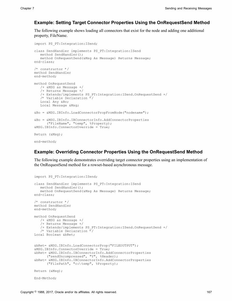
Chapter 7 Sending and Receiving Messages
Example: Setting Target Connector Properties Using the OnRequestSend MethodThe following example shows loading all connectors that exist for the node and adding one additionalproperty, FileName.
import PS_PT:Integration:ISend;
class SendHandler implements PS_PT:Integration:ISend method SendHandler(); method OnRequestSend(&Msg As Message) Returns Message;end-class;
/* constructor */method SendHandlerend-method;
method OnRequestSend /+ &MSG as Message +/ /+ Returns Message +/ /+ Extends/implements PS_PT:Integration:ISend.OnRequestSend +/ /* Variable Declaration */ Local Any &Bo; Local Message &Msg; &Bo = &MSG.IBInfo.LoadConnectorPropFromNode("nodename");
&Bo = &MSG.IBInfo.IBConnectorInfo.AddConnectorProperties ("FileName", "temp", %Property);&MSG.IBInfo.ConnectorOverride = True;
Return (&Msg); end-method;
Example: Overriding Connector Properties Using the OnRequestSend MethodThe following example demonstrates overriding target connector properties using an implementation ofthe OnRequestSend method for a rowset-based asynchronous message.
import PS_PT:Integration:ISend;
class SendHandler implements PS_PT:Integration:ISend method SendHandler(); method OnRequestSend(&Msg As Message) Returns Message;end-class;
/* constructor */method SendHandlerend-method;
method OnRequestSend /+ &MSG as Message +/ /+ Returns Message +/ /+ Extends/implements PS_PT:Integration:ISend.OnRequestSend +/ /* Variable Declaration */Local Boolean &bRet;
&bRet= &MSG.IBInfo.LoadConnectorProp("FILEOUTPUT"); &MSG.IBInfo.ConnectorOverride = True; &bRet= &MSG.IBInfo.IBConnectorInfo.AddConnectorProperties ("sendUncompressed", "Y", %Header);&bRet= &MSG.IBInfo.IBConnectorInfo.AddConnectorProperties ("FilePath", "c:\temp", %Property);
Return (&Msg);
End-Method;
Copyright © 1988, 2017, Oracle and/or its affiliates. All rights reserved. 167
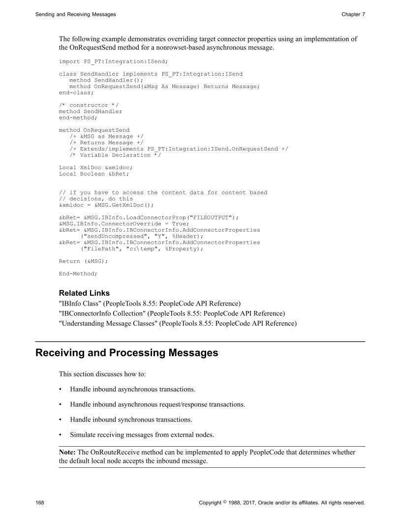
Sending and Receiving Messages Chapter 7
The following example demonstrates overriding target connector properties using an implementation ofthe OnRequestSend method for a nonrowset-based asynchronous message.
import PS_PT:Integration:ISend;
class SendHandler implements PS_PT:Integration:ISend method SendHandler(); method OnRequestSend(&Msg As Message) Returns Message;end-class;
/* constructor */method SendHandlerend-method;
method OnRequestSend /+ &MSG as Message +/ /+ Returns Message +/ /+ Extends/implements PS_PT:Integration:ISend.OnRequestSend +/ /* Variable Declaration */
Local XmlDoc &xmldoc;Local Boolean &bRet;
// if you have to access the content data for content based // decisions, do this&xmldoc = &MSG.GetXmlDoc();
&bRet= &MSG.IBInfo.LoadConnectorProp("FILEOUTPUT"); &MSG.IBInfo.ConnectorOverride = True; &bRet= &MSG.IBInfo.IBConnectorInfo.AddConnectorProperties ("sendUncompressed", "Y", %Header);&bRet= &MSG.IBInfo.IBConnectorInfo.AddConnectorProperties ("FilePath", "c:\temp", %Property);
Return (&MSG);
End-Method;
Related Links"IBInfo Class" (PeopleTools 8.55: PeopleCode API Reference)"IBConnectorInfo Collection" (PeopleTools 8.55: PeopleCode API Reference)"Understanding Message Classes" (PeopleTools 8.55: PeopleCode API Reference)
Receiving and Processing Messages
This section discusses how to:
• Handle inbound asynchronous transactions.
• Handle inbound asynchronous request/response transactions.
• Handle inbound synchronous transactions.
• Simulate receiving messages from external nodes.
Note: The OnRouteReceive method can be implemented to apply PeopleCode that determines whetherthe default local node accepts the inbound message.
168 Copyright © 1988, 2017, Oracle and/or its affiliates. All rights reserved.
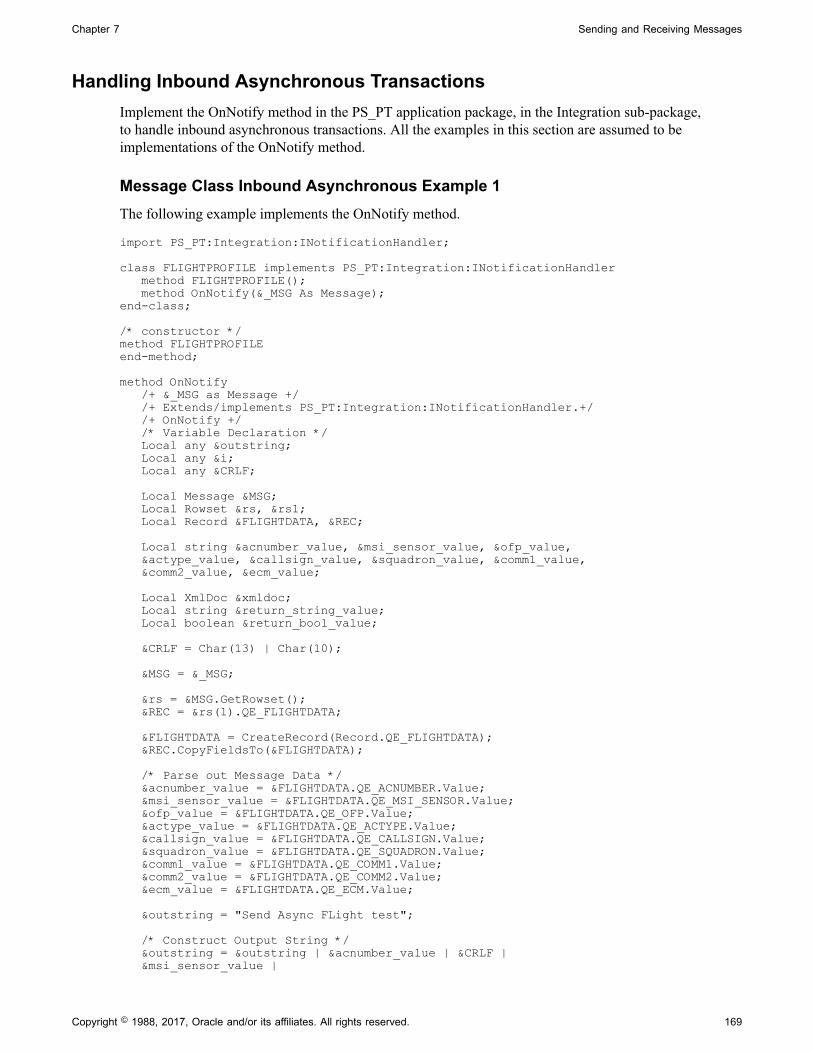
Chapter 7 Sending and Receiving Messages
Handling Inbound Asynchronous TransactionsImplement the OnNotify method in the PS_PT application package, in the Integration sub-package,to handle inbound asynchronous transactions. All the examples in this section are assumed to beimplementations of the OnNotify method.
Message Class Inbound Asynchronous Example 1The following example implements the OnNotify method.
import PS_PT:Integration:INotificationHandler;
class FLIGHTPROFILE implements PS_PT:Integration:INotificationHandler method FLIGHTPROFILE(); method OnNotify(&_MSG As Message);end-class;
/* constructor */method FLIGHTPROFILEend-method;
method OnNotify /+ &_MSG as Message +/ /+ Extends/implements PS_PT:Integration:INotificationHandler.+/ /+ OnNotify +/ /* Variable Declaration */ Local any &outstring; Local any &i; Local any &CRLF; Local Message &MSG; Local Rowset &rs, &rs1; Local Record &FLIGHTDATA, &REC; Local string &acnumber_value, &msi_sensor_value, &ofp_value, &actype_value, &callsign_value, &squadron_value, &comm1_value, &comm2_value, &ecm_value; Local XmlDoc &xmldoc; Local string &return_string_value; Local boolean &return_bool_value; &CRLF = Char(13) | Char(10); &MSG = &_MSG; &rs = &MSG.GetRowset(); &REC = &rs(1).QE_FLIGHTDATA; &FLIGHTDATA = CreateRecord(Record.QE_FLIGHTDATA); &REC.CopyFieldsTo(&FLIGHTDATA); /* Parse out Message Data */ &acnumber_value = &FLIGHTDATA.QE_ACNUMBER.Value; &msi_sensor_value = &FLIGHTDATA.QE_MSI_SENSOR.Value; &ofp_value = &FLIGHTDATA.QE_OFP.Value; &actype_value = &FLIGHTDATA.QE_ACTYPE.Value; &callsign_value = &FLIGHTDATA.QE_CALLSIGN.Value; &squadron_value = &FLIGHTDATA.QE_SQUADRON.Value; &comm1_value = &FLIGHTDATA.QE_COMM1.Value; &comm2_value = &FLIGHTDATA.QE_COMM2.Value; &ecm_value = &FLIGHTDATA.QE_ECM.Value; &outstring = "Send Async FLight test"; /* Construct Output String */ &outstring = &outstring | &acnumber_value | &CRLF | &msi_sensor_value |
Copyright © 1988, 2017, Oracle and/or its affiliates. All rights reserved. 169

Sending and Receiving Messages Chapter 7
&CRLF | &ofp_value | &CRLF | &actype_value | &CRLF | &callsign_value | &CRLF | &squadron_value | &CRLF | &comm1_value | &CRLF | &comm2_value | &CRLF | &ecm_value; /* Log Output String into page record */ &FLIGHTDATA.GetField(Field.DESCRLONG).Value = &outstring; SQLExec("DELETE FROM PS_QE_FLIGHTDATA"); &FLIGHTDATA.Insert(); end-method;
Message Class Inbound Asynchronous Example 2The following example shows notification PeopleCode that checks the PSCAMA to determine the auditaction code and that examines the language code to determine whether related language processing isneeded:
method OnNotify /+ &MSG as Message +/ /* Simple PeopleCode Notifcation- - Check the PSCAMA*/ Local Rowset &MSG_RS; Local Record &REC_NAME_PREFIX, &REC, &REC_RL; Local integer &I; Local string &ACTION, &LNG, &BASE_LNG, &RELLNG, &KEY1, &KEY2; &MSG_RS = &MSG.GetRowset(); For &I = 1 To &MSG_RS.RowCount /* Loop through all transactions */ &REC = &MSG_RS.GetRow(&I).GetRecord(Record.NAME_PREFIX_TBL); /* Get Audit Action for this transaction */ &ACTION = &MSG_RS.GetRow(&I).PSCAMA.AUDIT_ACTN.Value; /* Get Language code for this transaction */ &LNG = &MSG_RS.GetRow(&I).PSCAMA.LANGUAGE_CD.Value; &BASE_LNG = %Language; Evaluate &ACTION /*****************************/ /******** Add a Record *******/ /*****************************/ When "A" /* Add the base language record */ &REC_NAME_PREFIX = CreateRecord(Record.NAME_PREFIX_TBL); &REC.CopyFieldsTo(&REC_NAME_PREFIX); &REC_NAME_PREFIX.ExecuteEdits(); If &REC_NAME_PREFIX.IsEditError Then /* error handling */ Else &REC_NAME_PREFIX.Insert(); /* Need error handling here if insert fails */ If &LNG <> %Language Then /* add related language record */ &RELLNG = &REC.RelLangRecName; &REC_RL = CreateRecord(Record.NAME_PREFIX_LNG); &REC.CopyFieldsTo(&REC_RL); &REC_RL.LANGUAGE_CD.Value = &LNG; &REC_RL.Insert(); /* Need error handling here if insert fails */ End-If; End-If; /*****************************/ /***** Change a Record *******/ /*****************************/ /**** Using record objects ***/
170 Copyright © 1988, 2017, Oracle and/or its affiliates. All rights reserved.
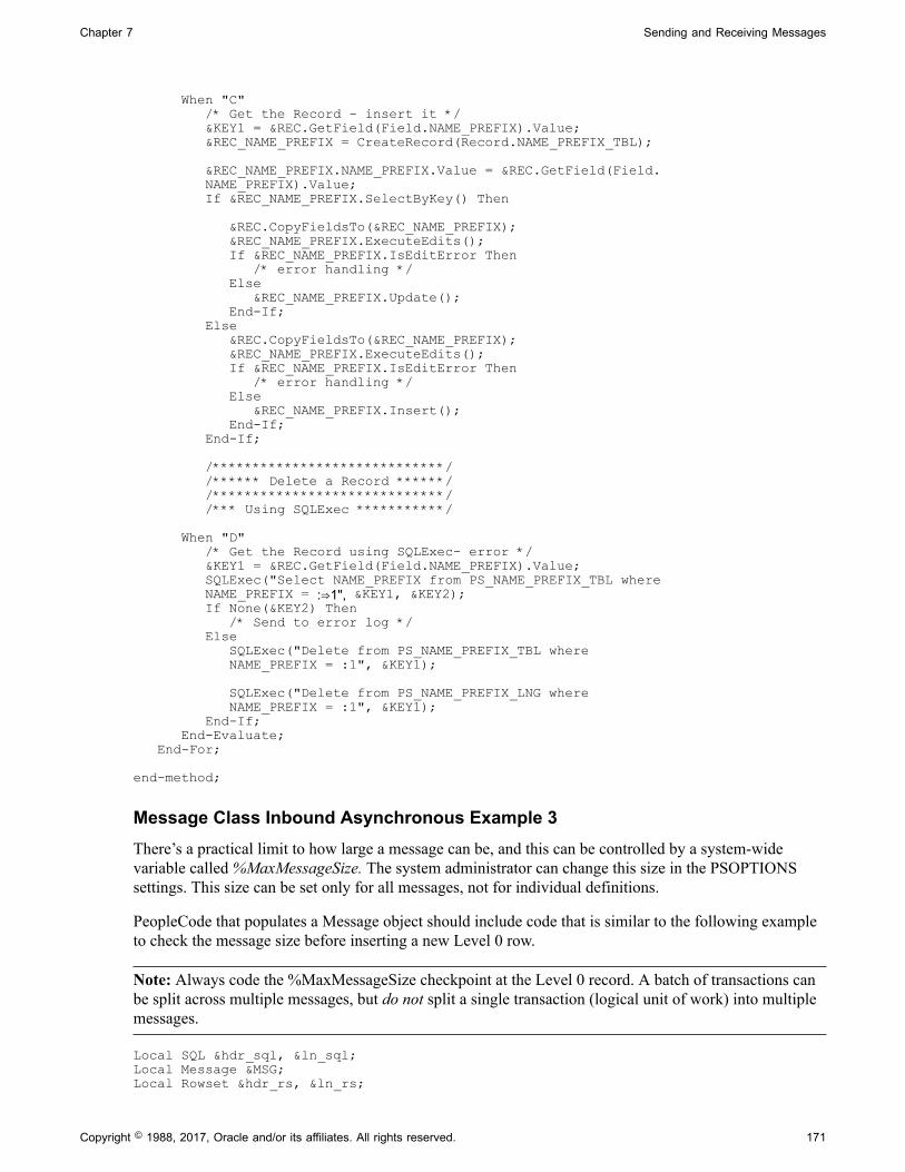
Chapter 7 Sending and Receiving Messages
When "C" /* Get the Record - insert it */ &KEY1 = &REC.GetField(Field.NAME_PREFIX).Value; &REC_NAME_PREFIX = CreateRecord(Record.NAME_PREFIX_TBL); &REC_NAME_PREFIX.NAME_PREFIX.Value = &REC.GetField(Field. NAME_PREFIX).Value; If &REC_NAME_PREFIX.SelectByKey() Then &REC.CopyFieldsTo(&REC_NAME_PREFIX); &REC_NAME_PREFIX.ExecuteEdits(); If &REC_NAME_PREFIX.IsEditError Then /* error handling */ Else &REC_NAME_PREFIX.Update(); End-If; Else &REC.CopyFieldsTo(&REC_NAME_PREFIX); &REC_NAME_PREFIX.ExecuteEdits(); If &REC_NAME_PREFIX.IsEditError Then /* error handling */ Else &REC_NAME_PREFIX.Insert(); End-If; End-If; /*****************************/ /****** Delete a Record ******/ /*****************************/ /*** Using SQLExec ***********/ When "D" /* Get the Record using SQLExec- error */ &KEY1 = &REC.GetField(Field.NAME_PREFIX).Value; SQLExec("Select NAME_PREFIX from PS_NAME_PREFIX_TBL where NAME_PREFIX = :⇒1", &KEY1, &KEY2); If None(&KEY2) Then /* Send to error log */ Else SQLExec("Delete from PS_NAME_PREFIX_TBL where NAME_PREFIX = :1", &KEY1);
SQLExec("Delete from PS_NAME_PREFIX_LNG where NAME_PREFIX = :1", &KEY1); End-If; End-Evaluate; End-For; end-method;
Message Class Inbound Asynchronous Example 3There’s a practical limit to how large a message can be, and this can be controlled by a system-widevariable called %MaxMessageSize. The system administrator can change this size in the PSOPTIONSsettings. This size can be set only for all messages, not for individual definitions.
PeopleCode that populates a Message object should include code that is similar to the following exampleto check the message size before inserting a new Level 0 row.
Note: Always code the %MaxMessageSize checkpoint at the Level 0 record. A batch of transactions canbe split across multiple messages, but do not split a single transaction (logical unit of work) into multiplemessages.
Local SQL &hdr_sql, &ln_sql;Local Message &MSG;Local Rowset &hdr_rs, &ln_rs;
Copyright © 1988, 2017, Oracle and/or its affiliates. All rights reserved. 171

Sending and Receiving Messages Chapter 7
Local Record &hdr_rec, &ln_rec, &hdr_rec_msg, &ln_rec_msg; /* This PeopleCode will publish messages for a simple Header/Line record combination. Multiple Header/Lines are copied to the message until the %MaxMessageSize is exceeded at which point a new message is built. This references MSR_HDR_INV (Header) and DEMAND_INF_INV (Line) records */ /* Create an instance of the STOCK_REQUEST message */&MSG = CreateMessage(OPERATION.STOCK_REQUEST); /* Create an App. Message Rowset that includes the MSR_HDR_INV (Header) and DEMAND_INF_INV (Line)*/&hdr_rs = &MSG.GetRowset(); /* Create a SQL object to select the Header rows */&hdr_sql = CreateSQL("Select * from PS_MSR_HDR_INV WHERE BUSINESS_UNIT='M04A1' AND ORDER_NO LIKE 'Z%' ORDER BY BUSINESS_UNIT,ORDER_NO");&I = 1; /* Create record objects for the Header and Lines */&ln_rec = CreateRecord(Record.DEMAND_INF_INV);&hdr_rec = CreateRecord(Record.MSR_HDR_INV); /* Loop through each Header row that is fetched */While &hdr_sql.Fetch(&hdr_rec) /* Publish the message if its size exceeds the MaxMessageSize /* specified in Utilities/Use/PeopleTools Options */ If &MSG.Size > %MaxMessageSize Then %IntBroker.Publish(&MSG); &I = 1; /* Create a new instance of the message object */ &MSG = CreateMessage(OPERATION.STOCK_REQUEST); &hdr_rs = &MSG.GetRowset(); End-If; If &I > 1 Then &hdr_rs.InsertRow(&I - 1); End-If; /* Instantiate the row within the Header portion of the App Message rowset to which data will be copied */ &hdr_rec_msg = &hdr_rs.GetRow(&I).GetRecord(Record.MSR_HDR_INV); /* Copy data into the level 0 (Header portion) of /* &MSG message structure */ &hdr_rec.CopyFieldsTo(&hdr_rec_msg); /* Publish the last message if it has been changed*/ If &hdr_rec_msg.IsChanged Then %IntBroker.Publish(&MSG); End-If;End-While;
Message Class Inbound Asynchronous Example 4The following code example shows how to get data out of the IBInfo object for a rowset-based message.
Local Rowset &rs, &rs1;Local Record &FLIGHTDATA, &REC;
Local string &acnumber_value, &msi_sensor_value, &ofp_value, &actype_value, &callsign_value, &squadron_value, &comm1_value, &comm2_value, &ecm_value, &datetime;Local XmlDoc &xmldoc;Local string &data;Local boolean &return_bool_value;
&CRLF = Char(13) | Char(10);
/* this is how one would access data from IBinfo and /* IBConnectorInfo objects*/
172 Copyright © 1988, 2017, Oracle and/or its affiliates. All rights reserved.

Chapter 7 Sending and Receiving Messages
&return_bool_value = &MSG.IBInfo.ConnectorOverride;
For &i = 1 To &MSG.IBInfo.IBConnectorInfo.GetNumberOfConnectorProperties() &data = &MSG.IBInfo.IBConnectorInfo.GetQueryStringArgName(&i); &data = &MSG.IBInfo.IBConnectorInfo.GetQueryStringArgValue(&i); End-For;
&MSG.IBInfo.IBConnectorInfo.ClearConnectorProperties();
&data = &MSG.IBInfo.IBConnectorInfo.ConnectorName;&data = &MSG.IBInfo.IBConnectorInfo.ConnectorClassName;&data = &MSG.IBInfo.IBConnectorInfo.RemoteFrameworkURL;&data = &MSG.IBInfo.IBConnectorInfo.PathInfo;&data = &MSG.IBInfo.IBConnectorInfo.Cookies;
For &i = 1 To &MSG.IBInfo.IBConnectorInfo.GetNumberOfQueryStringArgs() &data = &MSG.IBInfo.IBConnectorInfo.GetConnectorPropertiesName(&i); &data = &MSG.IBInfo.IBConnectorInfo.GetConnectorPropertiesValue (&i); &data = &MSG.IBInfo.IBConnectorInfo.GetConnectorPropertiesType(&i); End-For;
&MSG.IBInfo.IBConnectorInfo.ClearQueryStringArgs();
&data = &MSG.IBInfo.MessageType;&data = &MSG.IBInfo.RequestingNodeName;&data = &MSG.IBInfo.OrigUser;&data = &MSG.IBInfo.OrigNode;&data = &MSG.IBInfo.AppServerDomain;&data = &MSG.IBInfo.OrigProcess;&data = &MSG.IBInfo.OrigTimeStamp;&data = &MSG.IBInfo.DestinationNode;&data = &MSG.IBInfo.FinalDestinationNode;&data = &MSG.IBInfo.SourceNode;&data = &MSG.IBInfo.MessageName;&data = &MSG.IBInfo.MessageVersion;&data = &MSG.IBInfo.VisitedNodes;
/* get the content data from the message rowset*/&rs = &MSG.GetRowset();&REC = &rs(1).QE_FLIGHTDATA;
&FLIGHTDATA = CreateRecord(Record.QE_FLIGHTDATA);&REC.CopyFieldsTo(&FLIGHTDATA);
/* Parse out Message Data */&acnumber_value = &FLIGHTDATA.QE_ACNUMBER.Value;&msi_sensor_value = &FLIGHTDATA.QE_MSI_SENSOR.Value;&ofp_value = &FLIGHTDATA.QE_OFP.Value;&actype_value = &FLIGHTDATA.QE_ACTYPE.Value;&callsign_value = &FLIGHTDATA.QE_CALLSIGN.Value;&squadron_value = &FLIGHTDATA.QE_SQUADRON.Value;&comm1_value = &FLIGHTDATA.QE_COMM1.Value;&comm2_value = &FLIGHTDATA.QE_COMM2.Value;&ecm_value = &FLIGHTDATA.QE_ECM.Value;&datetime = &FLIGHTDATA.ACTIONDTTM.Value;
&outstring = "Send Async FLight test";
/* Construct Output String */&outstring = &outstring | &acnumber_value | &CRLF | &msi_sensor_value | &CRLF | &ofp_value | &CRLF | &actype_value | &CRLF | &callsign_value | &CRLF | &squadron_value | &CRLF | &comm1_value | &CRLF | &comm2_value | &CRLF | &ecm_value | &datetime;
Copyright © 1988, 2017, Oracle and/or its affiliates. All rights reserved. 173
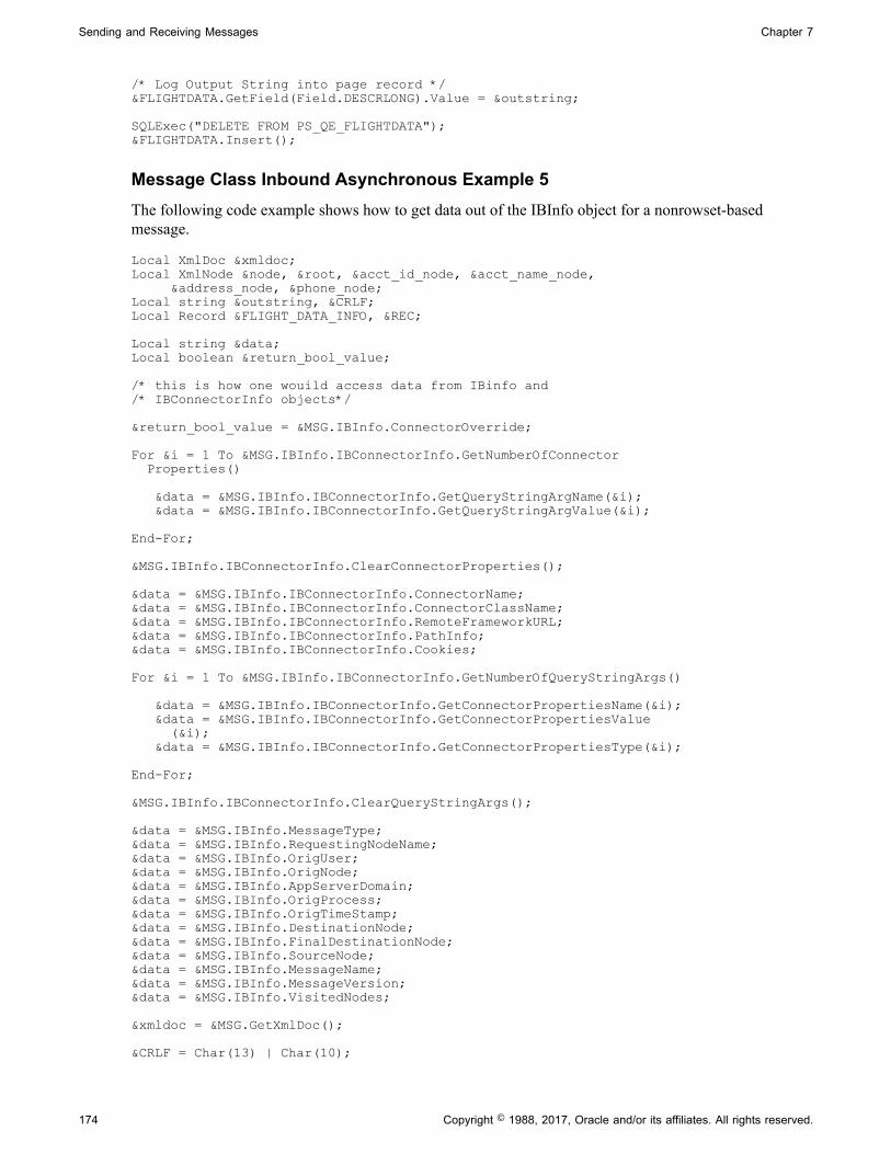
Sending and Receiving Messages Chapter 7
/* Log Output String into page record */&FLIGHTDATA.GetField(Field.DESCRLONG).Value = &outstring;
SQLExec("DELETE FROM PS_QE_FLIGHTDATA");&FLIGHTDATA.Insert();
Message Class Inbound Asynchronous Example 5The following code example shows how to get data out of the IBInfo object for a nonrowset-basedmessage.
Local XmlDoc &xmldoc;Local XmlNode &node, &root, &acct_id_node, &acct_name_node, &address_node, &phone_node;Local string &outstring, &CRLF;Local Record &FLIGHT_DATA_INFO, &REC;
Local string &data;Local boolean &return_bool_value;
/* this is how one wouild access data from IBinfo and /* IBConnectorInfo objects*/
&return_bool_value = &MSG.IBInfo.ConnectorOverride;
For &i = 1 To &MSG.IBInfo.IBConnectorInfo.GetNumberOfConnector Properties() &data = &MSG.IBInfo.IBConnectorInfo.GetQueryStringArgName(&i); &data = &MSG.IBInfo.IBConnectorInfo.GetQueryStringArgValue(&i); End-For;
&MSG.IBInfo.IBConnectorInfo.ClearConnectorProperties();
&data = &MSG.IBInfo.IBConnectorInfo.ConnectorName;&data = &MSG.IBInfo.IBConnectorInfo.ConnectorClassName;&data = &MSG.IBInfo.IBConnectorInfo.RemoteFrameworkURL;&data = &MSG.IBInfo.IBConnectorInfo.PathInfo;&data = &MSG.IBInfo.IBConnectorInfo.Cookies;
For &i = 1 To &MSG.IBInfo.IBConnectorInfo.GetNumberOfQueryStringArgs() &data = &MSG.IBInfo.IBConnectorInfo.GetConnectorPropertiesName(&i); &data = &MSG.IBInfo.IBConnectorInfo.GetConnectorPropertiesValue (&i); &data = &MSG.IBInfo.IBConnectorInfo.GetConnectorPropertiesType(&i); End-For;
&MSG.IBInfo.IBConnectorInfo.ClearQueryStringArgs();
&data = &MSG.IBInfo.MessageType;&data = &MSG.IBInfo.RequestingNodeName;&data = &MSG.IBInfo.OrigUser;&data = &MSG.IBInfo.OrigNode;&data = &MSG.IBInfo.AppServerDomain;&data = &MSG.IBInfo.OrigProcess;&data = &MSG.IBInfo.OrigTimeStamp;&data = &MSG.IBInfo.DestinationNode;&data = &MSG.IBInfo.FinalDestinationNode;&data = &MSG.IBInfo.SourceNode;&data = &MSG.IBInfo.MessageName;&data = &MSG.IBInfo.MessageVersion;&data = &MSG.IBInfo.VisitedNodes;
&xmldoc = &MSG.GetXmlDoc();
&CRLF = Char(13) | Char(10);
174 Copyright © 1988, 2017, Oracle and/or its affiliates. All rights reserved.

Chapter 7 Sending and Receiving Messages
&root = &xmldoc.DocumentElement;
/* Get values out of XMLDoc */&node_array = &root.GetElementsByTagName("actype");&ac_type_node = &node_array.Get(1);&ac_type_value = &ac_type_node.NodeValue;
&node_array = &root.GetElementsByTagName("msi_sensor");&msi_sensor_node = &node_array.Get(1);&msi_sensor_value = &msi_sensor_node.NodeValue;
&node_array = &root.GetElementsByTagName("callsign");&callsign_node = &node_array.Get(1);&callsign_value = &callsign_node.NodeValue;
&node_array = &root.GetElementsByTagName("ofp");&ofp_node = &node_array.Get(1);&ofp_value = &ofp_node.NodeValue;
&outstring = "GetDataout of xmldoc Test";
&outstring = &outstring | &CRLF | &ac_type_value | &CRLF | &msi_sensor_node | &CRLF | &callsign_value | &CRLF | &ofp_value;
/* Write out the result string */SQLExec("DELETE FROM PS_QE_FLIGHT_DATA");&FLIGHT_DATA_INFO = CreateRecord(Record.QE_FLIGHT_DATA);&FLIGHT_DATA_INFO.GetField(Field.DESCRLONG).Value = &outstring;&FLIGHT_DATA_INFO.Insert();
Message Class Inbound Asynchronous Example 6The following example show a notification that could be an implementation of the OnNotify method,using a component interface in the notification. This example shows error trapping and has multilanguagesupport:
Component string &PUBNODENAME; /* save pubnodename to prevent circular publishes */Local Message &MSG;Local Rowset &MSG_ROWSET, &cur_rowset;Local ApiObject &oSession;Local ApiObject &CONTACT_CI;Local number &I;Local string &KEY1;Local Record &REC;Local boolean &BC_CREATE, &ADD;Local boolean &TRANSACTION_ERROR, &MSG_ERROR; /** Transaction/Message Error Flags**/
Function errorHandler() Local ApiObject &oPSMessageColl; Local ApiObject &oPSMessage; Local string &strErrMsgSetNum, &strErrMsgNum, &strErrMsgText, &strErrType; &oPSMessageColl = &oSession.PSMessages; For &I = 1 To &oPSMessageColl.Count &oPSMessage = &oPSMessageColl.Item(&I); &strErrMsgSetNum = &oPSMessage.MessageSetNumber; &strErrMsgNum = &oPSMessage.MessageNumber; &strErrMsgText = &oPSMessage.Text; &LogFile.WriteLine(&strErrType | " (" | &strErrMsgSetNum | "," | &strErrMsgNum | ") - " | &strErrMsgText); End-For; rem ***** Delete the Messages from the collection *****; &oPSMessageColl.DeleteAll();End-Function;
Copyright © 1988, 2017, Oracle and/or its affiliates. All rights reserved. 175

Sending and Receiving Messages Chapter 7
Function DO_CI_SUBSCRIBE() &oSession = %Session; &CONTACT_CI = &oSession.GETCOMPONENT(CompIntfc.CONTACT); If (&CONTACT_CI = Null) Then /* Replace this message with Tools message set when available */ Error MsgGet(91, 58, " Unable to get the Component Interface."); Exit (1); End-If; /** Set Component Interface Properties **/ &CONTACT_CI.GetHistoryItems = True; &CONTACT_CI.Interactivemode = False; /** set this to True while debugging **/ rem Send messages to the PSMessage Collection; &oSession.PSMessagesMode = 1; &MSG_ERROR = False; For &I = 1 To &MSG_ROWSET.ActiveRowCount /** Set Session Language Code Property **/ ®IONALSETTINGS = &oSession.RegionalSettings; ®IONALSETTINGS.LanguageCd = &MSG_ROWSET(&I).PSCAMA. LANGUAGE_CD.Value; &TRANSACTION_ERROR = False; &BC_CREATE = False; /** Instantiate Component Interface **/ &KEY1 = &MSG_ROWSET(&I).CONTACT_TBL.PERSON_ID.Value; &CONTACT_CI.PERSON_ID = &KEY1; Evaluate &MSG_ROWSET(&I).PSCAMA.AUDIT_ACTN.Value When = "A" When = "N" &ADD = True; /* Check if Keys already exist. */ &CONTACT_CIColl = &CONTACT_CI.Find(); /*If None(&EXISTS) Then*/ If &CONTACT_CIColl.Count = 0 Then If &CONTACT_CI.Create() Then &BC_CREATE = True; Else /* Replace this message with Tools message set when available */ Warning MsgGet(18022, 56, "Error creating Component Interface for transaction %1", &I); &TRANSACTION_ERROR = True; End-If; Else If Not &CONTACT_CI.Get() Then /* Replace this message with Tools message set when available */ Warning MsgGet(18022, 59, "Could not Get Component Interface for transaction %1", &I); &TRANSACTION_ERROR = True; End-If; End-If; Break; When = "C" &ADD = False; If Not &CONTACT_CI.Get() Then /* Replace this message with Tools message set when available */ Warning MsgGet(18022, 59, "Could not Get Component Interface for transaction %1", &I); &TRANSACTION_ERROR = True;
176 Copyright © 1988, 2017, Oracle and/or its affiliates. All rights reserved.

Chapter 7 Sending and Receiving Messages
End-If; Break; When = "D" When = "K" When-Other /* delete and old key action codes not allowed at this time */ &TRANSACTION_ERROR = True; Warning MsgGet(18022, 61, "Audit Action 'D' not allowed on transaction %1", &TRANSACTION); Break; End-Evaluate; &CONTACT_CI.CopyRowset(&MSG_ROWSET, &I); If Not &TRANSACTION_ERROR Then If Not &CONTACT_CI.save() Then /* Replace this message with Tools message set when available */ Warning MsgGet(18022, 57, "Error saving Component Interface for transaction %1", &TRANSACTION); &TRANSACTION_ERROR = True; End-If; End-If; /** close the last Component Interface in preparation for getting the next **/ If Not &CONTACT_CI.Cancel() Then /* Replace this message with Tools message set when available */ Warning MsgGet(18022, 58, "Error Canceling Component Interface for transaction %1", &TRANSACTION); Exit (1); End-If; /* Reset &TRANSACTION_ERROR to "False" for &BusComp.Save() to execute if no /* Transaction Error found in the next Transaction. */ &TRANSACTION_ERROR = False; End-For; If &TRANSACTION_ERROR Then &MSG_ERROR = True; End-If; End-Function;
/**** Main Process ****/&MSG.ExecuteEdits(%Edit_Required + %Edit_TranslateTable);If &MSG.IsEditError Then &MSG_ERROR = True;Else &PUBNODENAME = &MSG.PubNodeName; &MSG_ROWSET = &MSG.GetRowset(); /* Do Component Interface subscribe */ DO_CI_SUBSCRIBE();End-If;
If &MSG_ERROR Then Exit (1);End-If;
XmlDoc Class Inbound Asynchronous ExampleThe following example uses the GetXmlDoc method.
Local XmlDoc &Document;Local XmlNode &node, &root;Local string &outstring;
Copyright © 1988, 2017, Oracle and/or its affiliates. All rights reserved. 177
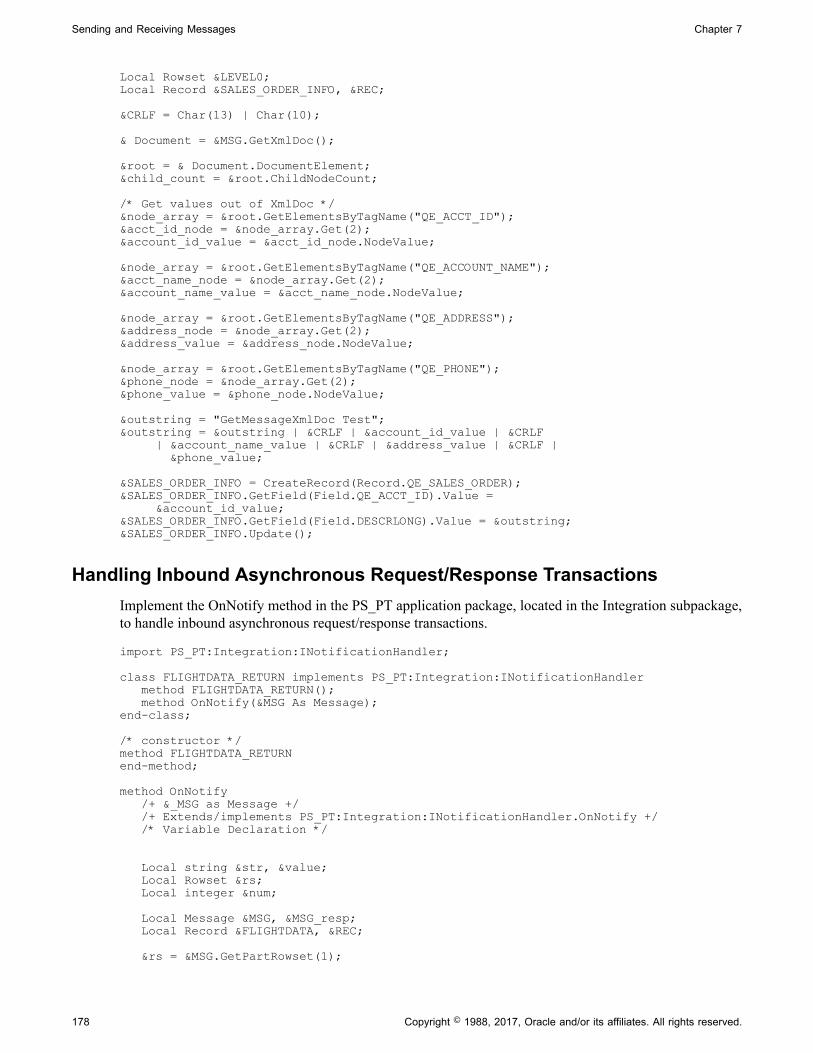
Sending and Receiving Messages Chapter 7
Local Rowset &LEVEL0;Local Record &SALES_ORDER_INFO, &REC; &CRLF = Char(13) | Char(10); & Document = &MSG.GetXmlDoc(); &root = & Document.DocumentElement;&child_count = &root.ChildNodeCount; /* Get values out of XmlDoc */&node_array = &root.GetElementsByTagName("QE_ACCT_ID");&acct_id_node = &node_array.Get(2);&account_id_value = &acct_id_node.NodeValue; &node_array = &root.GetElementsByTagName("QE_ACCOUNT_NAME");&acct_name_node = &node_array.Get(2);&account_name_value = &acct_name_node.NodeValue; &node_array = &root.GetElementsByTagName("QE_ADDRESS");&address_node = &node_array.Get(2);&address_value = &address_node.NodeValue; &node_array = &root.GetElementsByTagName("QE_PHONE");&phone_node = &node_array.Get(2);&phone_value = &phone_node.NodeValue; &outstring = "GetMessageXmlDoc Test";&outstring = &outstring | &CRLF | &account_id_value | &CRLF | &account_name_value | &CRLF | &address_value | &CRLF | &phone_value; &SALES_ORDER_INFO = CreateRecord(Record.QE_SALES_ORDER);&SALES_ORDER_INFO.GetField(Field.QE_ACCT_ID).Value = &account_id_value;&SALES_ORDER_INFO.GetField(Field.DESCRLONG).Value = &outstring;&SALES_ORDER_INFO.Update();
Handling Inbound Asynchronous Request/Response TransactionsImplement the OnNotify method in the PS_PT application package, located in the Integration subpackage,to handle inbound asynchronous request/response transactions.
import PS_PT:Integration:INotificationHandler; class FLIGHTDATA_RETURN implements PS_PT:Integration:INotificationHandler method FLIGHTDATA_RETURN(); method OnNotify(&MSG As Message);end-class; /* constructor */method FLIGHTDATA_RETURNend-method; method OnNotify /+ &_MSG as Message +/ /+ Extends/implements PS_PT:Integration:INotificationHandler.OnNotify +/ /* Variable Declaration */ Local string &str, &value; Local Rowset &rs; Local integer # Local Message &MSG, &MSG_resp; Local Record &FLIGHTDATA, &REC; &rs = &MSG.GetPartRowset(1);
178 Copyright © 1988, 2017, Oracle and/or its affiliates. All rights reserved.

Chapter 7 Sending and Receiving Messages
/* process request rowset */ &MSG_resp = CreateMessage(Operation.FLIGHTPLAN_ARR, %IntBroker_Response); &rs = &MSG_resp.GetPartRowset(1); /* populate response rowset */
&MSG_resp.IBInfo.WSA_MessageID = &MSG.IBInfo.WSA_MessageID; &MSG_resp.IBInfo.WSA_ReplyTo = &MSG.IBInfo.WSA_ReplyTo; &MSG_resp.IBInfo.WS_RequestAliasName = &MSG.IBInfo.WS_RequestAliasName; %IntBroker.Publish(&MSG_resp);end-method;
Handling Inbound Synchronous TransactionsImplement the OnRequest method in the PS_PT application package, in the Integration subpackage,to handle inbound synchronous transactions. All the examples in this section are assumed to beimplementations of the OnRequest method.
Message Class Inbound Synchronous ExampleThe following example implements both the OnRequest method and the OnError method
import PS_PT:Integration:IRequestHandler;
class RequestMan implements PS_PT:Integration:IRequestHandler method RequestMan(); method OnRequest(&MSG As Message) Returns Message; method OnError(&MSG As Message) Returns string;end-class;
/* constructor */method RequestMan %Super = create PS_PT:Integration:IRequestHandler();end-method;
method OnRequest /+ &MSG as Message +/ /+ Returns Message +/ Local Message &response; &response = CreateMessage(Operation.SYNC_REMOTE, %IntBroker_Response); &response.GetRowset().GetRow(1).GetRecord(Record.QE_FLIGHTDATA). GetField (Field.DESCRLONG).Value = &MSG.GenXMLString(); Return &response; end-method;
method OnError /+ &MSG as Message +/ /+ Returns String +/ /+ Extends/implements PS_PT:Integration:IRequestHandler.OnError +/ Local integer &nMsgNumber, &nMsgSetNumber; Local string &sText; &nMsgNumber = &MSG.IBException.MessageNumber; &nMsgSetNumber = &MSG.IBException.MessageSetNumber; rem &sText = &exception.DefaultText; &sText = &MSG.IBException.ToString(); /* ADD SPECIFIC ERROR INFO HERE */
Copyright © 1988, 2017, Oracle and/or its affiliates. All rights reserved. 179

Sending and Receiving Messages Chapter 7
Return &sText; end-method;
XmlDoc Class Inbound Synchronous ExampleThe following example uses the GetXmlDoc method:
Local XmlDoc &xmlRequestDoc;Local XmlDoc &xmlResponseDoc;Local XmlNode &select;Local Message &Return_MSG;Local array of XmlNode &whereClause; Local string &recordName;Local string &fieldName;Local string &fieldValue;Local Rowset &outputRowset;Local boolean &return_bool_value; &xmlRequestDoc = &MSG.GetXmlDoc();&select = &xmlRequestDoc.DocumentElement; &recordName = &select.GetAttributeValue("record");&outputRowset = CreateRowset(@("Record." | &recordName)); &whereClause = &select.GetElementsByTagName("where");If &whereClause <> Null And &whereClause.Len <> 0 Then &fieldName = &whereClause.Get(1).GetAttributeValue("field"); &fieldValue = &whereClause.Get(1).GetAttributeValue("value"); &outputRowset.Fill("WHERE " | &fieldName | "= :1", &fieldValue);Else &outputRowset.Fill();End-If; &Return_MSG = CreateMessage(OPERATION.EXAMPLE, %IntBroker_Response);&xmlResponseDoc = &Return_MSG.GetXmlDoc();&b = &xmlResponseDoc.CopyRowset(&outputRowset);Return &Return_MSG;
SoapDoc Class Inbound Synchronous ExampleThe following example uses the GetXmlDoc method.
Note: Because GetXmlDoc returns an XmlDoc object, you must receive the inbound request message asan XmlDoc object, then convert it to a SoapDoc object to process it with SOAP methods.
Local XmlDoc &request, &response;Local string &strXml;Local SoapDocs &soapReq, &soapRes;Local Message &Response_Message; &soapReq = CreateSoapDoc(); &request = &MSG.GetXmlDoc();&soapReq.XmlDoc = &request;&OK = &soapReq.ValidateSoapDoc();&parmN = &soapReq.GetParmName(1);&parmV = &soapReq.GetParmValue(1); &Response_Message = CreateMessage(OPERATION.SoapExample, %IntBroker_Response);
&response = &Response_Message.GetXmlDoc();&soapRes = CreateSoapDoc();&soapRes.AddEnvelope(0);
180 Copyright © 1988, 2017, Oracle and/or its affiliates. All rights reserved.

Chapter 7 Sending and Receiving Messages
&soapRes.AddBody();&soapRes.AddMethod("StockPrice", 1);&soapRes.AddParm(&parmN, &parmV);&soapRes.AddParm("Price", "29");&OK = &soapRes.ValidateSoapDoc(); &response = &soapRes.XmlDoc;Return &Response_Message;
Simulating Receiving Messages from External NodesYou can use PeopleCode to simulate receiving asynchronous messages from external nodes, includingrunning transformations.
Use can use the IntBroker class InboundPublish method to work with rowset-based and nonrowset-basedmessages.
The following example shows an inbound publish as part of an OnNotify method implementation with arowset-based message:
Local Message &MSG_REMOTE;Local Rowset &rs;
&rs = &MSG.GetRowset();/*create the message to be re-published from a simualted remote node*/
&MSG_REMOTE = CreateMessage(OPERATION.QE_FLIGHTPLAN);
&MSG_REMOTE.IBInfo.RequestingNodeName = "QE_IBTGT";
&MSG_REMOTE.IBInfo.ExternalOperationName = &MSG_REMOTE.OperationName | "." |
&MSG_REMOTE.OperationVersion;
&MSG_REMOTE.CopyRowset(&rs);
&Ret = %IntBroker.InBoundPublish(&MSG_REMOTE);
The following example shows an inbound publish as part of an OnNotify implementation with anonrowset-based message:
Local Message &MSG_REMOTE;Local XmlDoc &xmldoc;Local Rowset &rs;
&xmldoc = &MSG.GetXmlDoc();/*create the message to be re-published from a simualted remote node*/
&MSG_REMOTE = CreateMessage(OPERATION.QE_FLIGHTPLAN);
/* populate the Remote Message with data to be re-published*/
&MSG_REMOTE.SetXmlDoc(&xmldoc);
%IntBroker.InBoundPublish(&MSG_REMOTE, Node.REMOTE_NODE);
Processing Inbound Errors
This section discusses how to:
• Validate data.
Copyright © 1988, 2017, Oracle and/or its affiliates. All rights reserved. 181

Sending and Receiving Messages Chapter 7
• Use the Exit built-in function.
• Correct messaging errors.
Validating DataYou validate data differently depending on the PeopleCode class that you’re using to receive the message.
XMLDoc Class ValidationYou can validate incoming XML DOM-compliant messages by using the XmlDoc document typedefinition (DTD) that is delivered with your PeopleSoft application.
See "Understanding XmlDoc Classes" (PeopleTools 8.55: PeopleCode API Reference).
SoapDoc Class ValidationYou can validate SOAP-compliant messages by using the ValidateSoapDoc method in the PeopleCodeSoapDoc class.
See "Understanding theSOAPDoc Class" (PeopleTools 8.55: PeopleCode API Reference).
Message Class ValidationHave a message receiving process validate incoming data by:
• Using the ExecuteEdits method in the code to invoke the definitional edits.
• Calling PeopleCode validation built-in functions (if they already exist, for example in a FUNCLIBrecord, or if validation logic can be encapsulated within a small set of built-in functions) from withinthe receiving PeopleCode.
• Calling a component interface or Application Engine program from the receiving process (forcomplex validation logic).
This enables you to reuse logic that is embedded in the component.
The ExecuteEdits method uses the definitional edits to validate the message. You can specify thefollowing system variables alone or in combination. If you don’t specify a variable, all of the edits areprocessed.
• %Edit_DateRange
• %Edit_OneZero
• %Edit_PromptTable
• %Edit_Required
• %Edit_TranslateTable
• %Edit_YesNo
The following example processes all edits for all levels of data in the message structure:
&MYMSG.ExecuteEdits();
182 Copyright © 1988, 2017, Oracle and/or its affiliates. All rights reserved.

Chapter 7 Sending and Receiving Messages
The following example processes the Required Field and Prompt Table edits:
&RECPURCHASEORDER.ExecuteEdits(%Edit_Required + %Edit_PromptTable);
ExecuteEdits uses set processing to validate data. Validation by using a component interface or aPeopleCode built-in function is usually done with row-by-row processing. If a message contains a largenumber of rows per rowset, consider writing the message to a staging table and calling an ApplicationEngine program to do set processing if you want additional error checking.
ExecuteEdits sets several properties on several objects if there are any errors:
• IsEditError is set on the Message, Rowset, Row, and Record objects if any fields contain errors.
• EditError, MessageNumber, and MessageSetNumber are set on the Field object that contains the error.
If you don’t want to use ExecuteEdits, you can set your own errors by using the field properties. Settingthe EditError property to True automatically sets the IsEditError message property to True. You can alsospecify your own message number, message set number, and so on, for the field. If you use the Exit(1)built-in function, the message status changes to Error when you finish setting the fields that are in error.
Using the Exit Built-in FunctionUse the Exit built-in function to invoke a messaging error process when the application finds an error.This works only when you use the PeopleCode Message class to process inbound transactions. The sameerror processing is invoked automatically if PeopleTools finds an unexpected error, such as a StructuredQuery Language (SQL) error. The Exit built-in function has an optional parameter that affects how theerror is handled.
To handle error processing in application tables, use the Exit built-in function with no parameter, or justlet the notification process finish normally. This marks the message receipt as successful and commits thedata.
To handle the error tracking and correction with PeopleSoft Integration Broker, use the Exit built-infunction with 1 as a parameter to log the errors, perform a rollback, and stop processing.
Using the Exit Built-in Function Without ParametersIn the Exit( ) form (that is, Exit without any parameters specified), all data is committed and themessage is marked as complete. Use this to indicate that everything processed correctly and to stopprogram processing. Note, though, that the message status is set to Complete; therefore, you can’t detector access errors in the Service Operations Monitor. If errors did occur, the subscription code should writethem to a staging table, and then you must handle all of the error processing.
The Exit built-in function:
• Sets the message status in the application message queue for the subscription to Done.
• Commits the transaction.
• Stops processing.
Following is an example of using Exit without a parameter:
&MSG.ExecuteEdits();If &MSG.IsEditError then
Copyright © 1988, 2017, Oracle and/or its affiliates. All rights reserved. 183

Sending and Receiving Messages Chapter 7
App_Specific_Error_Processing(); Exit();Else Specific_Message_Processing();End-if;
Using the Exit Built-in Function with ParametersWhen you supply a 1 as a parameter for the Exit built-in function, the function:
• Processes a rollback.
• Sets the message status in the message queue for the subscription to Error.
• Writes the errors to the subscription contract error table.
• Stops processing.
You can view all errors that have occurred for this message in the Service Operations Monitor, even thoseerrors that are detected by ExecuteEdits.
Following is an example of using the Exit function with 1 as a parameter:
&MSG.ExecuteEdits();If &MSG.IsEditError then Exit(1);Else Process_Message();End-if;
Related LinksIntegration Broker Service Operations Monitor
Using Message Object Functionality With Nonrowset-BasedMessages
Prior to the PeopleTools 8.44 release, there were two distinct paths for writing and executing PeopleCodefor PeopleSoft Integration Broker which were based on whether you were working with rowset-basedXML messages or nonrowset-based XML messages.
For rowset-based XML messages, you could use a rowset and all the properties and methods associatedwith the Message class. For nonrowset-based XML messages, you could not use the Message class,but instead used built-in functions such as PublishXmlDoc and GetMessageXmlDoc. In addition, whenworking with nonrowset-based messages and these built-in functions, you could only access content data.
Effective with the PeopleTools 8.44 release, when working with nonrowset-based XML messages you canuse all of the functionality of the Message object using two new methods, SetXMLDoc and GetXMLDoc.
SetXMLDoc Use this method to load and pass nonrowset-based data into theMessage object.
GetXMLDoc Use this method to get nonrowset-based data out of the messageobject.
184 Copyright © 1988, 2017, Oracle and/or its affiliates. All rights reserved.
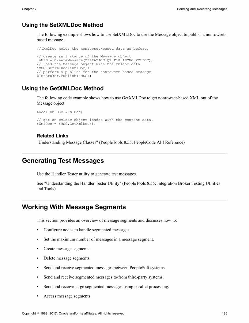
Chapter 7 Sending and Receiving Messages
Using the SetXMLDoc MethodThe following example shows how to use SetXMLDoc to use the Message object to publish a nonrowset-based message.
//&XmlDoc holds the nonrowset-based data as before.
// create an instance of the Message object &MSG = CreateMessage(OPERATION.QE_F18_ASYNC_XMLDOC);// Load the Message object with the xmldoc data.&MSG.SetXmlDoc(&XmlDoc);// perform a publish for the nonrowset-based message%IntBroker.Publish(&MSG);
Using the GetXMLDoc MethodThe following code example shows how to use GetXMLDoc to get nonrowset-based XML out of theMessage object.
Local XMLDOC &XmlDoc;
// get an xmldoc object loaded with the content data. &XmlDoc = &MSG.GetXmlDoc();
Related Links"Understanding Message Classes" (PeopleTools 8.55: PeopleCode API Reference)
Generating Test Messages
Use the Handler Tester utility to generate test messages.
See "Understanding the Handler Tester Utility" (PeopleTools 8.55: Integration Broker Testing Utilitiesand Tools)
Working With Message Segments
This section provides an overview of message segments and discusses how to:
• Configure nodes to handle segmented messages.
• Set the maximum number of messages in a message segment.
• Create message segments.
• Delete message segments.
• Send and receive segmented messages between PeopleSoft systems.
• Send and receive segmented messages to/from third-party systems.
• Send and receive large segmented messages using parallel processing.
• Access message segments.
Copyright © 1988, 2017, Oracle and/or its affiliates. All rights reserved. 185
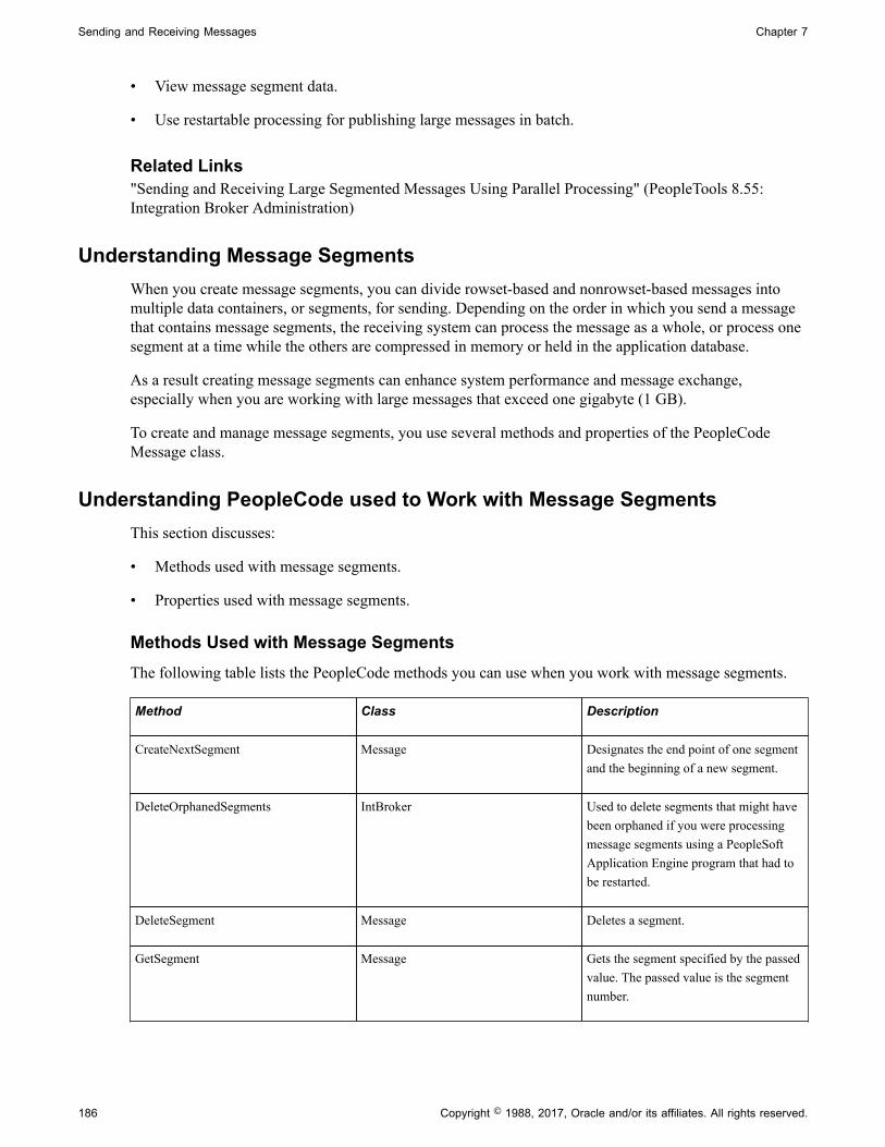
Sending and Receiving Messages Chapter 7
• View message segment data.
• Use restartable processing for publishing large messages in batch.
Related Links"Sending and Receiving Large Segmented Messages Using Parallel Processing" (PeopleTools 8.55:Integration Broker Administration)
Understanding Message SegmentsWhen you create message segments, you can divide rowset-based and nonrowset-based messages intomultiple data containers, or segments, for sending. Depending on the order in which you send a messagethat contains message segments, the receiving system can process the message as a whole, or process onesegment at a time while the others are compressed in memory or held in the application database.
As a result creating message segments can enhance system performance and message exchange,especially when you are working with large messages that exceed one gigabyte (1 GB).
To create and manage message segments, you use several methods and properties of the PeopleCodeMessage class.
Understanding PeopleCode used to Work with Message SegmentsThis section discusses:
• Methods used with message segments.
• Properties used with message segments.
Methods Used with Message SegmentsThe following table lists the PeopleCode methods you can use when you work with message segments.
Method Class Description
CreateNextSegment Message Designates the end point of one segmentand the beginning of a new segment.
DeleteOrphanedSegments IntBroker Used to delete segments that might havebeen orphaned if you were processingmessage segments using a PeopleSoftApplication Engine program that had tobe restarted.
DeleteSegment Message Deletes a segment.
GetSegment Message Gets the segment specified by the passedvalue. The passed value is the segmentnumber.
186 Copyright © 1988, 2017, Oracle and/or its affiliates. All rights reserved.

Chapter 7 Sending and Receiving Messages
Method Class Description
UpdateSegment Message Use this method to update data withinthe current segment.
Note: Use the DeleteSegment and UpdateSegment methods only when storing segments data in memory.These methods do not function when segment data is stored in the database.
Properties Used with Message SegmentsThe following table lists PeopleCode properties that you can use when you work with message segments.
Property Class Description
CurrentSegment Message Returns a number, indicating whichsegment is the current segment.
SegmentsUnOrder IBInfo Determines whether to process messagesegments in order or unordered. Thisproperty pertains to asynchronousmessages only.
The values are:
• True: Process message segmentsunordered.
• False: Process message segments inorder. (Default.)
SegmentCount Message Returns the total number of segments ina message.
SegmentsByDatabase Message Enables you to override where messagesegment data is stored for a message.
The values are:
• True: Store message segmentsawaiting processing in theapplication database.
• False: Store message segmentsawaiting processing in memory. (Default.)
Related LinksPeopleCode API Reference
Copyright © 1988, 2017, Oracle and/or its affiliates. All rights reserved. 187
Sending and Receiving Messages Chapter 7
Configuring Nodes to Handle Segmented MessagesThis section describes how to configure nodes to handle segmented messages.
Understanding Configuring Nodes to Handle Segmented MessagesBefore you can send segmented messages, you must configure the remote node defined on the localsystem to handle segmented messages by setting the Segment Aware option on the Node Definitions pagein the PeopleSoft Pure Internet Architecture.
Warning! Do not set the Segment Aware option for remote PeopleSoft 8.45 or earlier nodes, or for third-party systems. If you do so, the receiving system will consume only the first segment of the messages andignore any subsequent segments.
Configuring a Node to Handle Segmented MessagesTo configure a node to handle segmented messages:
1. Select PeopleTools, Integration Broker, Integration Setup, Node Definitions.
2. Select a node with which to work and click OK.
The Node Definitions page appears.
3. Select the Segment Aware check box.
4. Click the Save button.
Setting the Maximum Number of Message Segments in MessagesThe Maximum Number of Segments parameter is a built-in global parameter that determines themaximum number of segments that can exist in a message. When the number is met, a new message iscreated and begins to be populated.
The default value is 10.
The Maximum Number of Segments parameter is set on the PeopleTools Options page (PSOPTIONS). Toaccess the page select PeopleTools, Utilities, Administration, PeopleTools Options.
You can also manipulate the maximum number of message segments for a message in PeopleCode usingthe %MAXNBRSEGMENTS built-in function.
Creating Message SegmentsThis section provides an overview of creating message segments and message segment numbers anddiscusses how to:
• Create message segments.
• Count the number of segments in messages.
• Store message segments awaiting processing.
• Override where to store message segment awaiting processing.
188 Copyright © 1988, 2017, Oracle and/or its affiliates. All rights reserved.

Chapter 7 Sending and Receiving Messages
• Specify the order in which to process message segments.
• Chunk asynchronous segmented messages.
Understanding Creating Message SegmentsBy default every message has one segment.
To create multiple message segments use the CreateNextSegment method in the location in the messagewhere you want one segment to end and next segment to begin. Continue this process until you havecreated the desired number of segments for the message.
Segments can contain any number of rowsets of data (rowset-based messages) or rows of data(nonrowset-based messages).
Understanding Message Segment NumbersWhen you create a message segment, PeopleSoft Integration Broker assigns a message segment numberto the segment.
The first message segment has a message segment number or 1, and message segment numbers areincrement by one sequentially thereafter. As an example, if you break a message into three segments, thefirst segment number is 1, the second segment number is 2, and the third segment number is 3.
Creating Message SegmentsThe following example shows using the CreateNextSegment method to create three segments in themessage QE_FLIGHTPLAN, populating each segment with data from the component buffer.
&MSG = CreateMessage(OPERATION.QE_FLIGHTPLAN);
&rs=&MSG.GetRowset();//Now populate rowset// End of first segment. Beginning of second segment.&MSG.CreateNextSegment();
&rs=&MSG.GetRowset();//Now populate rowset//End of second segment. Beginning of third segment.&MSG.CreateNextSegment();
&rs=&MSG.GetRowset();//Now populate rowset
%IntBroker.Publish(&MSG);
Counting the Number of Segments in MessagesYou might have the need to determine the number of segments in a message. Use the SegmentCountproperty to determine this information.
Storing Message Segments Awaiting ProcessingBy default, message segments awaiting processing are stored in memory until all segments are processed.Once all segments are processed, PeopleSoft Integration Broker sends all data as one message.
Use the MessageSegmentFromDB parameter in PSAdmin to specify the number of segments to keep inmemory before writing segmented messages to the database. The default value is 10.
Copyright © 1988, 2017, Oracle and/or its affiliates. All rights reserved. 189
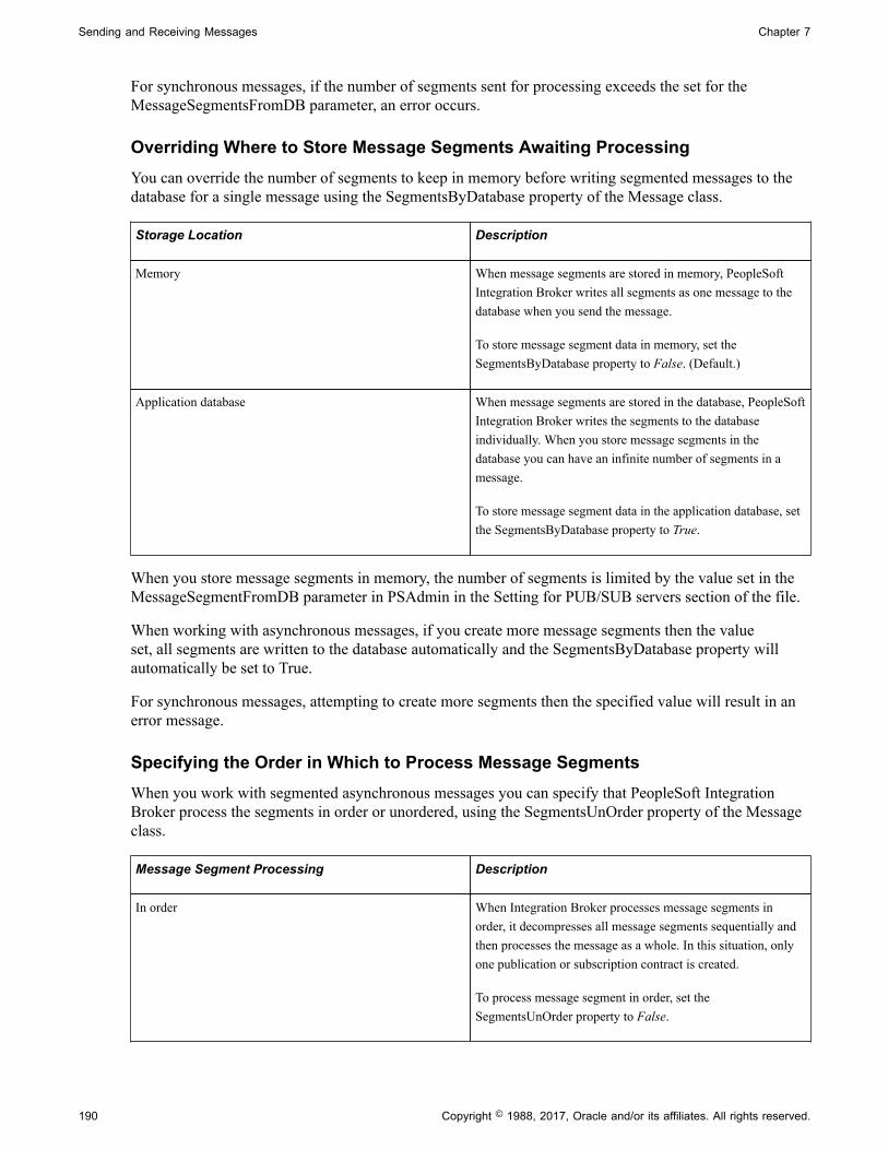
Sending and Receiving Messages Chapter 7
For synchronous messages, if the number of segments sent for processing exceeds the set for theMessageSegmentsFromDB parameter, an error occurs.
Overriding Where to Store Message Segments Awaiting ProcessingYou can override the number of segments to keep in memory before writing segmented messages to thedatabase for a single message using the SegmentsByDatabase property of the Message class.
Storage Location Description
Memory When message segments are stored in memory, PeopleSoftIntegration Broker writes all segments as one message to thedatabase when you send the message.
To store message segment data in memory, set theSegmentsByDatabase property to False. (Default.)
Application database When message segments are stored in the database, PeopleSoftIntegration Broker writes the segments to the databaseindividually. When you store message segments in thedatabase you can have an infinite number of segments in amessage.
To store message segment data in the application database, setthe SegmentsByDatabase property to True.
When you store message segments in memory, the number of segments is limited by the value set in theMessageSegmentFromDB parameter in PSAdmin in the Setting for PUB/SUB servers section of the file.
When working with asynchronous messages, if you create more message segments then the valueset, all segments are written to the database automatically and the SegmentsByDatabase property willautomatically be set to True.
For synchronous messages, attempting to create more segments then the specified value will result in anerror message.
Specifying the Order in Which to Process Message SegmentsWhen you work with segmented asynchronous messages you can specify that PeopleSoft IntegrationBroker process the segments in order or unordered, using the SegmentsUnOrder property of the Messageclass.
Message Segment Processing Description
In order When Integration Broker processes message segments inorder, it decompresses all message segments sequentially andthen processes the message as a whole. In this situation, onlyone publication or subscription contract is created.
To process message segment in order, set theSegmentsUnOrder property to False.
190 Copyright © 1988, 2017, Oracle and/or its affiliates. All rights reserved.

Chapter 7 Sending and Receiving Messages
Message Segment Processing Description
Unordered When Integration Broker processes message segmentsunordered, it decompresses and processes all segments inparallel. In this situation, the system creates one publication orsubscription contract for each message segment.
To process message segment unordered, set theSegmentsUnOrder property to True.
If you attempt to send ordered segmented messages to a node that is not segment aware an error messagewill be created and can be viewed on the Message Errors tab on the Message Details page in ServiceOperations Monitor.
See the product documentation for PeopleTools 8.55: Integration Broker Service Operations Monitor.
Chunking Asynchronous Segmented MessagesChunking asynchronous segmented messages sends message in blocks to the receiving node.
When using chunking, message instances display in Hold status in the Service Operations Monitor untilall chunks are received. Once all chunks are received, the message status switches to New.
Note: Chunking applies to ordered asynchronous messages only.
The number of segments to chunk for an asynchronous message is determined by the value you set for theMessageSegmentByDatabase parameter in PSAdmin. The default value is 10.
As an example, if a message has 20 segments and you set MessageSegmentByDatabase to 5, PeopleSoftIntegration Broker will send four groups (array of messages) of segments to the integration gateway, andeach group will contain five segments.
Deleting Message SegmentsYou can delete message segments in a message only before you publish the message.
Use the DeleteSegment method of the Message class to perform the action.
You cannot delete the first segment in a message.
The following example demonstrates using the DeleteSegment method in an implementation of theOnRequestSend method.
import PS_PT:Integration:ISend;
class Send implements PS_PT:Integration:ISend method Send(); method OnRequestSend(&message As Message) Returns Message; method OnError(&message As Message)end-class;
/* constructor */method Send %Super = create PS_PT:Integration:ISend();end-method;
method OnRequestSend
Copyright © 1988, 2017, Oracle and/or its affiliates. All rights reserved. 191
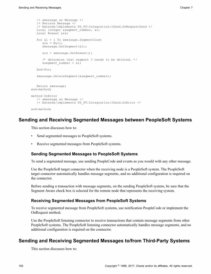
Sending and Receiving Messages Chapter 7
/+ &message as Message +/ /+ Returns Message +/ /+ Extends/implements PS_PT:Integration:ISend.OnRequestSend +/ Local integer &segment_number, &i; Local Rowset &rs; For &i = 1 To &message.SegmentCount &rs = Null; &message.GetSegment(&i); &rs = &message.GetRowset(); /* determine that segment 3 needs to be deleted. */ &segment_number = &i; End-For; &message.DeleteSegment(&segment_number); Return &message;end-method;
method OnError /+ &message as Message +/ /+ Extends/implements PS_PT:Integration:ISend.OnError +/ end-method;
Sending and Receiving Segmented Messages between PeopleSoft SystemsThis section discusses how to:
• Send segmented messages to PeopleSoft systems.
• Receive segmented messages from PeopleSoft systems.
Sending Segmented Messages to PeopleSoft SystemsTo send a segmented message, use sending PeopleCode and events as you would with any other message.
Use the PeopleSoft target connector when the receiving node is a PeopleSoft system. The PeopleSofttarget connector automatically handles message segments, and no additional configuration is required onthe connector.
Before sending a transaction with message segments, on the sending PeopleSoft system, be sure that theSegment Aware check box is selected for the remote node that represents the receiving system.
Receiving Segmented Messages from PeopleSoft SystemsTo receive segmented message from PeopleSoft systems, use notification PeopleCode or implement theOnRequest method.
Use the PeopleSoft listening connector to receive transactions that contain message segments from otherPeopleSoft systems. The PeopleSoft listening connector automatically handles message segments, and noadditional configuration is required on the connector.
Sending and Receiving Segmented Messages to/from Third-Party SystemsThis section discusses how to:
192 Copyright © 1988, 2017, Oracle and/or its affiliates. All rights reserved.

Chapter 7 Sending and Receiving Messages
• Send segmented messages to third-party systems.
• Receive segmented messages from third-party systems.
Understanding DataChunkCount and DataChunk PropertiesPeopleSoft Integration Broker uses two properties to communicate to sending and receiving systems thenumber of message segments that are contained in a transaction:
DataChunkCount Indicates the total number of data chunks or message segmentscontained in the transaction.
DataChunk Indicates the number of the data chunk or message segment thatyou are sending.
For example, if there are a total of seven data chunks in thetransaction, and the current segment is the third chunk, theDataChunk value for the current message is 3.
Note that when you are sending and receiving message segments between PeopleSoft systems theseproperties are not used. The PeopleSoft target and listening connectors perform all necessary processing.
Sending Segmented Messages to Third-Party SystemsTo send segmented messages from PeopleSoft systems to third-party system, use one of the followingtarget connectors:
• AS2 target connector
• HTTP target connector
• JMS target connector
• SMTP target connector
No additional target connector configuration is required to send segmented messages. These connectorsread the messaging PeopleCode on the integration gateway and determine the number of segmentscontained in the transaction. They then populate the DataChunkCount and DataChunk parameters andinclude this information with each outbound segment sent. All of these connectors except for the HTTPtarget connector send the DataChunkCount and DataChunk information in the message header of eachoutbound message segment. The HTTP target connector includes the DataChunkCount and DataChunkparameter information in the HTTP header of each outbound message segment.
Before sending a transaction with message segments, on the PeopleSoft system, be sure that the SegmentAware check box is selected for the remote node that represents the third-party integration partner.
Receiving Segmented Messages from Third-Party SystemsAt this time, only the HTTP listening connector can be used to receive message segments from third-partysystems.
To receive segmented messages with third-party integration partners, the third-party must specify thefollowing DataChunkCount and DataChunk parameters in the HTTP properties, query arguments, orSOAP header:
Copyright © 1988, 2017, Oracle and/or its affiliates. All rights reserved. 193

Sending and Receiving Messages Chapter 7
The receiving PeopleSoft system must use the HTTP listening connector as only this connector monitorstransactions for these parameters.
After the third party sends in the first segment, the PeopleSoft system sends an acknowledgement to thethird-party system. The acknowledgment contains a transaction ID that the third-party integration partnermust include with all subsequent segments.
The following bullet points describe sample processing for a third-party integration partner sending atransaction to a PeopleSoft system that contains three segments:
1. First segment processing:
a. The third-party integration partner prepares the first message/segment of the transaction. In theHTTP properties, query string, or SOAP header, it sets the DataChunk equal to 1 indicating thefirst chunk, and sets the DataChunkCount equal to 3 indicating total number of chunks to be sentfor the transaction.
b. When the request is received by the PeopleSoft system the data chunk is saved in the database as asegment.
c. In the Service Operations Monitor the transaction displays a status of Hold.
d. The PeopleSoft system sends an acknowledgement to the third-party system, which includes atransaction ID.
Note: The third-party integration partner must include the transaction ID as part of all subsequentrequests for the transaction. The PeopleSoft system uses the transaction ID to identify thesegments that belong to the transaction.
2. Second segment processing:
a. The third-party integration partner prepares the second message/segment of the transaction. In theHTTP properties, query string, or SOAP header, it sets the DataChunk equal to 2 indicating thatthe message is the second chunk, and sets the DataChunkCount equal to 3 indicating total numberof chunks to be sent for the transaction. It also specifies the transaction ID sent by the PeopleSoftsystem in the acknowledgement for the first segment.
b. When the request is received by the PeopleSoft system the data chunk is saved in the database as asegment.
c. In the Service Operations Monitor the transaction displays a status of Hold.
3. Third segment processing:
a. The third-party integration partner prepares the third message/segment of the transaction. In theHTTP properties, query string, or SOAP header, it sets the DataChunk equal to 3 indicating thatthe message is the third chunk, and sets the DataChunkCount equal to 3 indicating total numberof chunks to be sent for the transaction. It also specifies the transaction ID sent by the PeopleSoftsystem in the acknowledgement for the first segment.
b. When the request is received by the PeopleSoft system the data chunk is saved in the database as asegment.
194 Copyright © 1988, 2017, Oracle and/or its affiliates. All rights reserved.

Chapter 7 Sending and Receiving Messages
c. Since the PeopleSoft system has received all of the segments in the transaction, in the ServiceOperations Monitor the transaction displays a status of New.
d. The PeopleSoft system processing the transaction like any other transaction at this point.
The PeopleCode to read the data chunks/segments is the Message Segment API.
Sending, Receiving, and Correlating Multiple Segmented MessagesPrevious sections in this topic have discussed sending one message that contains multiple messagesegments. For very large messages this can have performance impact due to the large number ofsegments.
PeopleSoft provides PeopleCode that allows you to send multiple messages with multiple segments andthen correlate them into one transaction on the receiving system. So instead of sending one message with50 message segments, you can send 10 messages with 5 message segments using parallel processing, andthen correlate the 10 messages on the receiving system.
The InitializeConversationId property on the Message object, provides the correlation between messages.The FirstCorrelation method on the Message object ensures that the database table is truncated afterreceipt of the first message only.
On the first message to be published set the InitializeConversationId property to True. After themessage is published retrieve the transaction ID from the message. For all subsequent messages, set theCorrelationID property to the value of the transaction ID returned from the first message. As a result,when the messages arrive at the receiving system they have different transaction IDs, but all have thesame correlation ID.
On the receiving system when the first message is received the database table is truncated. To preventa destructive load from occurring with the receipt and processing of each subsequent message, use thePreNotify event. You can use the PreNotify event to truncate the database table upon receipt of the firstmessage. In subsequent messages use the FirstCorrelation method in the event, setting the method to True,to determine if a prior message with the same correlation ID has already run the event.
The following example shows an example of how the sending system uses the InitializeConversationIdproperty:
/*First Message to Publish */ &MSG. InitializeConversationId = true;%IntBroker.Publish(&MSG);&strCorrelationID = &MSG.TransactionId;
/* all subsequent message to correlate*/
&MSG. IBInfo.ConversationID = &strCorrelationID;%IntBroker.Publish(&MSG);
The following example shows an example of how the receiving system uses the FirstCorrelation methodin the PreNotify event:
PreNotify Event:
If &MSG.FirstCorrelation() = true Then/* process the event logic */
Copyright © 1988, 2017, Oracle and/or its affiliates. All rights reserved. 195

Sending and Receiving Messages Chapter 7
End-If;
Accessing message segments is described elsewhere in this section.
See Accessing Segments in Messages.
Related Links"FirstCorrelation" (PeopleTools 8.55: PeopleCode API Reference)"InitializeConversationId" (PeopleTools 8.55: PeopleCode API Reference)"Sending and Receiving Large Segmented Messages Using Parallel Processing" (PeopleTools 8.55:Integration Broker Administration)
Accessing Segments in MessagesAfter you receive a segmented message, use the GetSegment method of the Message class to accessmessage segment data.
After you access a message segment, use the Message class GetRowset or GetXmlDoc methods to workwith the contents of the segment.
Warning! You can access only one segment in a message at a time. When you access a message segment,PeopleSoft Integration Broker removes the previously accessed message segment from memory.
When you access a message segment, set the existing rowset to null to eliminate storing multiple rowsetsin the data cache.
The following example shows using the GetSegment method to access a message segment in the messageQE_FLIGHTDATA.
For &i = 1 To &MSG.SegmentCount &rs = Null; //Null the rowset to remove it from memory &MSG.GetSegment(&i); &rs = &MSG.GetRowset(); &REC = &rs(1).QE_FLIGHTDATA; &FLIGHTDATA = CreateRecord(Record.QE_FLIGHTDATA); &REC.CopyFieldsTo(&FLIGHTDATA); /* Parse out Message Data */ &acnumber_value = &FLIGHTDATA.QE_ACNUMBER.Value; &msi_sensor_value = &FLIGHTDATA.QE_MSI_SENSOR.Value; &ofp_value = &FLIGHTDATA.QE_OFP.Value; &actype_value = &FLIGHTDATA.QE_ACTYPE.Value; &callsign_value = &FLIGHTDATA.QE_CALLSIGN.Value; &squadron_value = &FLIGHTDATA.QE_SQUADRON.Value; &comm1_value = &FLIGHTDATA.QE_COMM1.Value; &comm2_value = &FLIGHTDATA.QE_COMM2.Value; &ecm_value = &FLIGHTDATA.QE_ECM.Value; &outstring = "Send Async Flight test"; /* Construct Output String */ &outstring = &outstring | &acnumber_value | &CRLF | &msi_sensor_value | &CRLF | &ofp_value | &CRLF | &actype_value | &CRLF | &callsign_value | &CRLF | &squadron_value | &CRLF | &comm1_value | &CRLF | &comm2_value | &CRLF | &ecm_value; /* Log Output String into page record */ &FLIGHTDATA.GetField(Field.DESCRLONG).Value = &outstring;
196 Copyright © 1988, 2017, Oracle and/or its affiliates. All rights reserved.

Chapter 7 Sending and Receiving Messages
SQLExec("DELETE FROM PS_QE_FLIGHTDATA"); &FLIGHTDATA.Insert(); End-For;
Viewing Message Segment DataThe Service Operations Monitor Message Details page provides information about messages that containsegments.
Related Links"Viewing Asynchronous Service Operation Instance Details" (PeopleTools 8.55: Integration BrokerService Operations Monitor)
Using Restartable Processing for Publishing Large Messages in BatchThis section provides an overview, prerequisites and setup steps for using restartable processing forpublishing large asynchronous segmented messages in batch.
Understanding Using Restartable ProcessingPeopleSoft provides a PeopleSoft Application Engine library module, IB_SEGTEST, that you can useas a template to create a module to aid in processing large messages and messages in batch for outboundasynchronous PeopleSoft Integration Broker segment data with restart capability.
With restart capability, if there is an abnormal program termination, you can correct any data errors andcontinue processing from the point of the last commit without having to reload message segment datafrom the beginning.
Understanding the IB_SEGTEST Application Engine Library ModuleThis section provides overview information for using the IB_SEGTEST
The IB_SEGTEST library module consists of three sections:
• Section 1: Section1. The main processing section.
• Section 2: ABORT. Use to trigger a user abort of the running application engine program
• Section 3: CLEANSEG. An independent section you can call to clean up pending segment data thathad been committed to the database but is no longer to be used.
PrerequisitesTo use the information provided in this section, you should have a thorough understanding of PeopleSoftApplication Engine.
Using the IB_SEGTEST Library ModuleThis section provides an overview of the high-level list of tasks to perform to set up a PeopleSoftApplication Engine program to perform restartable message processing.
1. Make a copy of IB_SEGTEST, including all sections and PeopleCode.
Copyright © 1988, 2017, Oracle and/or its affiliates. All rights reserved. 197
Sending and Receiving Messages Chapter 7
From here on, the copy of the application engine library module is referred to as IB_SEGTEST1, butyou can use any name you choose.
2. In the State Records tab of IB_SEGTEST1, verify that PSIBSEGRSTR_AET is the default staterecord. Replace PT_EIP_ERR_AET with whatever state record is used in the main application engineprogram that will be calling the Library module.
Note that IB_SEGTEST1 is flagged as not restartable. Since database commits will be performed inthe middle of PeopleCode processing, the only way the commits can take effect is if the module isflagged as not restartable.
3. The application engine program used to call IB_SEGTEST1 should be restartable.
Always issue a commit in the step prior to calling the library module IB_SEGTEST1.
4. In the application engine program that will be calling IB_SEGTEST1, insert a step to callIB_SEGTEST1, section Section1. Insert the step at the point in time when you want to do the messagepublish. You must issue a commit prior to calling this section, otherwise there will be a ‘Unable toProcess Commit’ error issued from within IB_SEGTEST1.
5. Add PSIBSEGRSTR_AET as an additional state record to the calling application engine program.
6. Since both programs now share state records, when IB_SEGTEST1 is called, all state recordvalues will be passed on to the called module. Presumably all application values needed to extractapplication data would be stored in the application state record.
7. Modify the PeopleCode in IB_SEGTEST1.Section1. Several comments have been added to the codeto aid in the modifications. Note the following:
• Change &MSG = CreateMessage(OPERATION.QE_FLIGHTPLAN) to create whatevermessage will be used.
• SegmentsByDatabase should always be set to True.
• The While loop is used to simulate application code processing large volumes of data. This can bechanged to meet application needs. However, pay close attention as to when commits are issued,when state records are updated, when new segments are created, and finally, when the messagepublish is executed. The order of these events is crucial to proper workability. In the sampleprogram, also note how to break out of the While loop.
• Note the location where the application state record needs to be updated. A comment instructs inthe PeopleCode provides instructions on where to perform this task.
• Do not remove the Exit(1) from the end of the PeopleCode. This is necessary to bypass theAbort action that is coded into the same Step.
• If in the middle of processing, the application code determines that an abort needs to be triggered,an Exit(0) can be coded. This triggers the Abort step to be called, which will terminateapplication engine processing. A restart could then be issued if processing needs to continue.
If you determine that a message no longer needs to be published, the calling application engineprogram could then call the CLEANSEG step to get rid of all the pending data that has been saved
198 Copyright © 1988, 2017, Oracle and/or its affiliates. All rights reserved.

Chapter 7 Sending and Receiving Messages
in the database. Alternatively, the Abort step could be modified to call CLEANSEG if on anyabort, no old data is to be kept.
See the product documentation for PeopleTools 8.55: PeopleSoft Application Engine for moreinformation about application engine programs.
Populating and Retrieving Document Data
This section discusses how to:
• Instantiate Documents objects.
• Populate document data.
• Retrieve document data.
Understanding Populating and Retrieving Document DataThis section provides guidelines for instantiating Document objects, and populating and retrievingdocument data from document message types.
Memory Management in Message Segments that Use DocumentsFollowing these guidelines when populating or retrieving document data from message segments:
• After your code to populate a segment, set the following statement to NULL:
&DOC = null;
Including this statement in your code releases the segment data from memory. If you do not includethis statement in your code, data from all segments accumulates in memory.
• Start each new segment processing section by setting the following statement to TRUE:
&DOC = &MSG.GetDocument(true)
Including this statement in your code guarantees that only one segment is in memory at a given time.
Instantiating Document ObjectsThis section discusses and provides examples for how to:
• Instantiate Document objects using package, name, and version.
• Instantiate Document objects using document keys.
• Instantiate Document objects for document message types.
Copyright © 1988, 2017, Oracle and/or its affiliates. All rights reserved. 199

Sending and Receiving Messages Chapter 7
Instantiating Document Objects Using Package, Name, and VersionYou can instantiate a Document object using the CreateDocument built-in function. Using this approach,you use the Create Document built-in function, and then specify the document package name, thedocument name, and the document version, as shown in the following example:
&DOC = CreateDocument("Purchasing", "PurchaseOrder", "v1");
Instantiating Document Objects Using Document KeysThe following code example shows instantiating a Document object using the a document key. Thisapproach uses the CreateDocumentKey and CreateDocument built-in functions.
First you instantiate a Document Key object, using the CreateDocumentKey built-in function and passingin the document package name, document name, and document version. You then instantiate a Documentobject using the CreateDocument built-in function, and pass in the document key.
&DOCKEY = CreateDocumentKey("Purchasing", "PurchaseOrder", "v1");&DOC = CreateDocument(&DOCKEY);
Instantiating Document Objects for Document Message TypesThe following example shows how to instantiate a document object when the document is being used as amessage type.
&DOC = &MSG.GetDocument();
Populating Document DataThis section discusses and provides examples for how to:
• Populate documents from messages.
• Populate document using rowsets.
• Populate message segments with documents.
Populating Documents from MessagesThe following example shows how to use the CreateMessage built-in function to populate a documentfrom a message:
&MSG = CreateMessage(Operation.PURCHASE_ORDER);&DOC = &MSG.GetDocument();
Populating Documents Using RowsetsThe following example shows using the CreateMessage built-in function and the Document class topopulate a document using a rowset:
Local Message &MSG;Local Document &DOC;
&MSG = CreateMessage(Operation.PURCHASE_ORDER);&DOC = &MSG.GetDocument();
/* Get Rowset */
200 Copyright © 1988, 2017, Oracle and/or its affiliates. All rights reserved.

Chapter 7 Sending and Receiving Messages
&Rowset = &DOC.GetRowset();
/* populate rowset like any other rowset
/* update document with popualted rowset * /&nRet = &DOC.UpdateFromRowset(&Rowset);
If (&nRet) = True Then %IntBroker.Publish(&MSG);End-If;
Populating Message Segments with DocumentsThe following example shows code for populating message segments with documents.
After you code to populate a segment, set the following statement to NULL to release memory:
&DOC = null;
Then, set the following statement to TRUE to manage memory and guarantee that only one segment is inmemory at a given time:
&DOC = &MSG.GetDocument(true);
If you do not following these coding guidelines, memory will get filled with data from all segments in themessage.
The previous statements are in emphasis in the following example:
Declare Function PopulateDocument PeopleCode QE_FLIGHTDATA.QE_ACNUMBER FieldFormula⇒;
Local Document &DOC;
&MSG = CreateMessage(Operation.FLIGHTPLAN_DOC);
/*pass in true to get ownership of the object*//&DOC = &MSG.GetDocument(true);
/*popualte the docment with data */PopulateDocument(&DOC, 1);
/*create a new segment */&MSG.CreateNewSegment();
/* null out object to release memory */&DOC = null;&DOC = &MSG.GetDocument(true);PopulateDocument(&DOC, 2);&MSG.CreateNewSegment();&DOC = null;&DOC = &MSG.GetDocument(true);PopulateDocument(&DOC, 3);
/* publish segmented Message (3 segments) */%IntBroker.Publish(&MSG);
Retrieving Document DataThis section discusses and provides code examples for how to:
• Retrieve document data from the Message object.
• Retrieve document data from message segments.
Copyright © 1988, 2017, Oracle and/or its affiliates. All rights reserved. 201

Sending and Receiving Messages Chapter 7
• Retrieve document data within a Notification event using message segments
Retrieving Document Data from the Message ObjectThe following code provides an example of how to retrieve a document from the Message object:
Local Message &MSG;Local Document &DOC;Local Primitive &PRIM;Local Compound &COM, &COM_ID, &COM_BILL, &COM_SHIP, &COM_ITEM;Local Collection &COL_ITEM;
&MSG = CreateMessage(Operation.PURCHASE_ORDER);&DOC = &MSG.GetDocument();&COM = &DOC.DocumentElement;
&COM.GetPropertyByName("LanguageCode").Value = "ENG";
/* Populate TransactionID Compound */&COM_ID = &COM.GetPropertyByName("TransactionId");&COM2.GetPropertyByIndex(1).value = "KAC";&COM2.GetPropertyByIndex(1).value = "12345678";
/* Populate BillTo Compound */&COM_BILL = &COM.GetPropertyByName("BillTo");&COM5.GetPropertyByName("name").Value = "RobbyNash";&COM5.GetPropertyByName("number").Value = 713;&COM5.GetPropertyByName("street").Value = "High Wind";&COM5.GetPropertyByName("unit").Value = "";&COM5.GetPropertyByName("city").Value = "Paia";&COM5.GetPropertyByName("state").Value = "Maui HI";&COM5.GetPropertyByName("zipcode").Value = "96779";
/* Populate item_collection Collection (2 rows) */&COL_ITEM = &COM.GetPropertyByName("item_collection");
&COM_ITEM = &COL_ITEM.CreateItem();&PRIM = &COM_ITEM.GetPropertyByName("item");&PRIM.Value = "mast";&PRIM = &COM_ITEM.GetPropertyByName("sku");&PRIM.Value = "123322";&PRIM = &COM_ITEM.GetPropertyByName("price");&PRIM.Value = 300;&PRIM = &COM_ITEM.GetPropertyByName("quantity");&PRIM.Value = 12;&nRet = &COL_ITEM.AppendItem(&COM_ITEM);
&COM_ITEM = &COL_ITEM.CreateItem();&COM5.GetPropertyByName("item").Value = "boom";&COM5.GetPropertyByName("sku").Value = "123334";&COM5.GetPropertyByName("price").Value = 270;&COM5.GetPropertyByName("quantity").Value = 10;&nRet = &COL_ITEM.AppendItem(&COM_ITEM);
%IntBroker.Publish(&MSG);
Retrieving Document Data from Message SegmentsThe following code example shows an example of retrieving document data from message segments. Asdiscussed elsewhere in this section, the example shows setting the following statement to NULL :
&DOC = Null;
Setting the statement to NULL clears memory between segment loops:
import PS_PT:Integration:INotificationHandler;
202 Copyright © 1988, 2017, Oracle and/or its affiliates. All rights reserved.
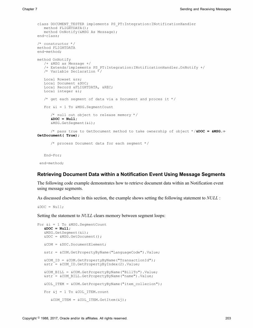
Chapter 7 Sending and Receiving Messages
class DOCUMENT_TESTER implements PS_PT:Integration:INotificationHandler method FLIGHTDATA(); method OnNotify(&MSG As Message);end-class;
/* constructor */method FLIGHTDATAend-method;
method OnNotify /+ &MSG as Message +/ /+ Extends/implements PS_PT:Integration:INotificationHandler.OnNotify +/ /* Variable Declaration */ Local Rowset &rs; Local Document &DOC; Local Record &FLIGHTDATA, &REC; Local integer &i; /* get each segment of data via a Document and proces it */ For &i = 1 To &MSG.SegmentCount /* null out object to release memory */ &DOC = Null; &MSG.GetSegment(&i); /* pass true to GetDocument method to take ownership of object */&DOC = &MSG.⇒GetDocument( True); /* process Document data for each segment */ End-For; end-method;
Retrieving Document Data within a Notification Event Using Message SegmentsThe following code example demonstrates how to retrieve document data within an Notification eventusing message segments.
As discussed elsewhere in this section, the example shows setting the following statement to NULL :
&DOC = Null;
Setting the statement to NULL clears memory between segment loops:
For &i = 1 To &MSG.SegmentCount &DOC = Null; &MSG.GetSegment(&i); &DOC = &MSG.GetDocument(); &COM = &DOC.DocumentElement; &str = &COM.GetPropertyByName("LanguageCode").Value; &COM_ID = &COM.GetPropertyByName("TransactionId"); &str = &COM_ID.GetPropertyByIndex(2).Value; &COM_BILL = &COM.GetPropertyByName("BillTo").Value; &str = &COM_BILL.GetPropertyByName("name").Value; &COL_ITEM = &COM.GetPropertyByName("item_collecion"); For &j = 1 To &COL_ITEM.count &COM_ITEM = &COL_ITEM.GetItem(&j);
Copyright © 1988, 2017, Oracle and/or its affiliates. All rights reserved. 203

Sending and Receiving Messages Chapter 7
&str = &COM_ITEM.GetPropertyByName("item").Value; End-For;End-For;
Sending and Receiving Binary Data
This section discusses how to:
• Send binary data.
• Receive binary data.
Understanding Sending and Receiving Binary DataPeopleSoft supports the MTOM protocol for sending and receiving binary data using service operations.While you can send and receive binary data using SOAP, doing so requires that you Base64-encode thedata, which can increase message size by 33 percent or more. The MTOM protocol enables you to sendand receive binary data in its original binary form, without any increase in size due to encoding.
Whether sending or receiving MTOM-encoded binary data, you use message segments to store the data.The SegmentContentType property of the Message object is used to set or read the content type of eachmessage segment.
Sending MTOM-Encoded Binary DataThis section discusses how to send MTOM-encoded binary data and discusses how to:
• Set target connector properties to send MTOM-encoded binary data.
• Develop messages to send MTOM-encoded binary data.
Setting Target Connector Properties to Send MTOM-Encoded Binary DataWhen sending MTOM-encoded binary data, you must use the HTTP target connector. The HTTP targetconnector features an MTOM property that you must set to Y for MTOM encoding to occur. When youset the MTOM property to Y, the HTTP target connector attempts to convert all outgoing message to theMTOM wire format.
See "Using the HTTP Target Connector" (PeopleTools 8.55: Integration Broker Administration).
Developing Messages to Send MTOM-Encoded Binary DataAn outgoing MTOM message is composed of a SOAP message and one or more sets of binary data.Segments are used to add the binary data to the outgoing request.
For each chunk of data, use a single segment as follows:
1. Create the segment.
2. Copy the data to the segment.
204 Copyright © 1988, 2017, Oracle and/or its affiliates. All rights reserved.

Chapter 7 Sending and Receiving Messages
3. Add the MIME type that is to appear for the MIME part containing the binary in the outgoing MTOMwire message.
4. Set the content transfer encoding to binary.
In PeopleCode this appears as:
&theMessage.CreateNextSegment();
If (&theMessage.SetContentString(&dataString)) Then &theMessage.SegmentContentType = "image/jpeg"; &theMessage.SegmentContentTransfer = %ContentTransfer_Binary; End-If;
The SetContentString method requires character data, and is not capable of passing binary data.For MTOM, pass in a Base64–encoded string that contains the binary data. The File object methodGetBase64StringFromBinary allows a binary file to be read in and captured as a string; use this string toset the data for the newly created segment.
See "SetContentString" (PeopleTools 8.55: PeopleCode API Reference), "GetBase64StringFromBinary"(PeopleTools 8.55: PeopleCode API Reference).
When seen on the wire, the SOAP XML in the MIME multipart message contains xop:Include references.These references point to the MIME parts that contain the binary data. In order to be able to constructthese references, Integration Broker requires that a specific XML element, PsftXopInclude, is present inthe outgoing message.
Each PsftXopInclude element corresponds directly to an xop:include in the outgoing wire message, andtherefore each PsftXopInclude element logically corresponds to an instance of binary data. Placement ofthe PsftXopInclude element in the XML is application-specific; Integration Broker does not require anyparticular location.
In the following example the first instance of the PsftXopInclude element corresponds to the logical pointto include an image and the second PsftXopInclude element corresponds to the logical point to include abinary document:
<?xml version='1.0'?><JobApplication> <Photo name='JohnSmith'> <PsftXopInclude SegmentNumber='1'/> </Photo> <Resume name='JohnSmithCV'> <PsftXopInclude SegmentNumber='2'/> </Resume></JobApplication>
The value of the SegmentNumber attribute is used by Integration Broker to link the PsftXopInclude entryto a specific segment used to add the data. For the purposes of MTOM, the first segment used to addbinary data is considered to be number 1, the second segment, number 2, and so on. Care should be takenwhen setting these values as Integration Broker does not check to ensure that they are correct; they areused as-is to build the xop:include references in the wire message.
In the previous example, the message data is not SOAP-wrapped. You can choose to build your ownSOAP wrapper or elect to have Integration Broker SOAP-wrap the message. If Integration Broker is toSOAP wrap the message, you must set the HTTP target connector property SOAPUpContent to Y.
See "Using the HTTP Target Connector" (PeopleTools 8.55: Integration Broker Administration).
Copyright © 1988, 2017, Oracle and/or its affiliates. All rights reserved. 205
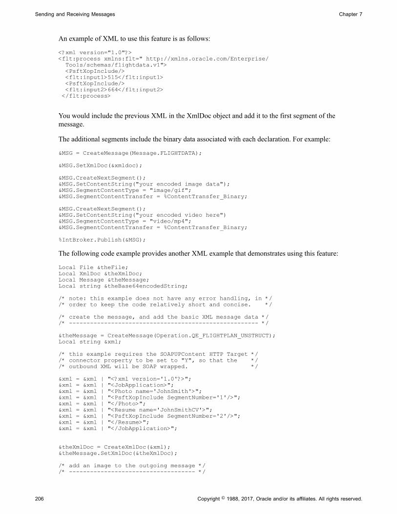
Sending and Receiving Messages Chapter 7
An example of XML to use this feature is as follows:
<?xml version="1.0"?><flt:process xmlns:flt=" http://xmlns.oracle.com/Enterprise/ Tools/schemas/flightdata.v1"> <PsftXopInclude/> <flt:input1>515</flt:input1> <PsftXopInclude/> <flt:input2>664</flt:input2> </flt:process>
You would include the previous XML in the XmlDoc object and add it to the first segment of themessage.
The additional segments include the binary data associated with each declaration. For example:
&MSG = CreateMessage(Message.FLIGHTDATA);
&MSG.SetXmlDoc(&xmldoc);
&MSG.CreateNextSegment();&MSG.SetContentString("your encoded image data");&MSG.SegmentContentType = "image/gif";&MSG.SegmentContentTransfer = %ContentTransfer_Binary;
&MSG.CreateNextSegment();&MSG.SetContentString("your encoded video here")&MSG.SegmentContentType = "video/mp4";&MSG.SegmentContentTransfer = %ContentTransfer_Binary;
%IntBroker.Publish(&MSG);
The following code example provides another XML example that demonstrates using this feature:
Local File &theFile;Local XmlDoc &theXmlDoc;Local Message &theMessage;Local string &theBase64encodedString;
/* note: this example does not have any error handling, in *//* order to keep the code relatively short and concise. */
/* create the message, and add the basic XML message data *//* ------------------------------------------------------ */
&theMessage = CreateMessage(Operation.QE_FLIGHTPLAN_UNSTRUCT);Local string &xml;
/* this example requires the SOAPUPContent HTTP Target *//* connector property to be set to "Y", so that the *//* outbound XML will be SOAP wrapped. */
&xml = &xml | "<?xml version='1.0'?>";&xml = &xml | "<JobApplication>";&xml = &xml | "<Photo name='JohnSmith'>";&xml = &xml | "<PsftXopInclude SegmentNumber='1'/>";&xml = &xml | "</Photo>";&xml = &xml | "<Resume name='JohnSmithCV'>";&xml = &xml | "<PsftXopInclude SegmentNumber='2'/>";&xml = &xml | "</Resume>";&xml = &xml | "</JobApplication>";
&theXmlDoc = CreateXmlDoc(&xml);&theMessage.SetXmlDoc(&theXmlDoc);
/* add an image to the outgoing message *//* ------------------------------------ */
206 Copyright © 1988, 2017, Oracle and/or its affiliates. All rights reserved.
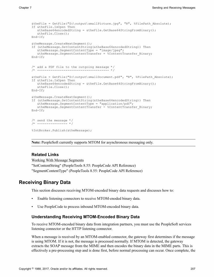
Chapter 7 Sending and Receiving Messages
&theFile = GetFile("D:\output\smallPicture.jpg", "R", %FilePath_Absolute);If &theFile.IsOpen Then &theBase64encodedString = &theFile.GetBase64StringFromBinary(); &theFile.Close();End-If;
&theMessage.CreateNextSegment();If (&theMessage.SetContentString(&theBase64encodedString)) Then &theMessage.SegmentContentType = "image/jpeg"; &theMessage.SegmentContentTransfer = %ContentTransfer_Binary;End-If;
/* add a PDF file to the outgoing message *//* -------------------------------------- */
&theFile = GetFile("D:\output\smallDocument.pdf", "R", %FilePath_Absolute);If &theFile.IsOpen Then &theBase64encodedString = &theFile.GetBase64StringFromBinary(); &theFile.Close();End-If;
&theMessage.CreateNextSegment();If (&theMessage.SetContentString(&theBase64encodedString)) Then &theMessage.SegmentContentType = "application/pdf"; &theMessage.SegmentContentTransfer = %ContentTransfer_Binary;End-If;
/* send the message *//* ---------------- */
%IntBroker.Publish(&theMessage);
Note: PeopleSoft currently supports MTOM for asynchronous messaging only.
Related LinksWorking With Message Segments"SetContentString" (PeopleTools 8.55: PeopleCode API Reference)"SegmentContentType" (PeopleTools 8.55: PeopleCode API Reference)
Receiving Binary DataThis section discusses receiving MTOM-encoded binary data requests and discusses how to:
• Enable listening connectors to receive MTOM-enoded binary data.
• Use PeopleCode to process inbound MTOM-encoded binary data.
Understanding Receiving MTOM-Encoded Binary DataTo receive MTOM-encoded binary data from integration partners, you must use the PeopleSoft serviceslistening connector or the HTTP listening connector.
When a message is received by an MTOM-enabled connector, the gateway first determines if the messageis using MTOM. If it is not, the message is processed normally. If MTOM is detected, the gatewayextracts the SOAP message from the MIME and then encodes the binary data in the MIME parts. This iseffectively a pre-processing step and is done first, before normal processing can occur. Once complete, the
Copyright © 1988, 2017, Oracle and/or its affiliates. All rights reserved. 207

Sending and Receiving Messages Chapter 7
SOAP message is then treated no differently from any other SOAP message received. The binary data isBase64 encoded, and is attached to the message in the form of segments.
Enabling Listening Connectors to Receive MTOM-Encoded Binary DataThe following listening connectors can receive and process MTOM-encoded messages:
• PeopleSoft services listening connector.
• HTTP listening connector.
You must enable these connectors for receiving and processing MTOM messages for any MTOMprocessing to occur. You enable these properties in the integration gateway properties file. The propertiesappear the MTOM Enable ListeningConnectors section as shown in the following example:
# MTOM Enable ListeningConnectors##ig.MTOM.enablePeopleSoftServiceListeningConnector=true#ig.MTOM.enableHttpListeningConnector=true
By default the properties are not enabled and are commented out.
To enable a given connector, remove the comment (#) and ensure that the property is set to true.
Note: When these properties are enabled there is a slight performance degradation to all non-MTOMrequests sent to the connectors. The degradation is a result of system process that takes place to determineif requests are MTOM-encoded messages.
Using PeopleCode to Process Inbound MTOM–Encoded Binary DataMTOM messages are processed in the form of message segments. The system processes inbound MTOMrequests in two general steps:
• Process the XML data contained in the first segment.
• For each subsequent segment, process the binary data.
The first segment contains the XML data. The xop:include references in the XML are replaced withPsftXopInclude elements, and each instance will point to the segment containing the associated binarydata.
The structure of this XML is application-specific, and therefore processing of this XML cannot be easilygeneralized. You may be able to use the location of the PsftXopInclude elements in the XML to deriveinformation about the binary data segments.
Consider the following inbound MTOM request example:
<?xml version='1.0'?><JobApplication> <Photo name='JohnSmith'> <PsftXopInclude SegmentNumber='2'/> </Photo> <Resume name='JohnSmithCV'> <PsftXopInclude SegmentNumber='3'/> </Resume></JobApplication>
In this example, the XML has been structured such that the parent element contains a name value for theassociated binary content. A more complete XML might also contain information such as file type, size,
208 Copyright © 1988, 2017, Oracle and/or its affiliates. All rights reserved.
Chapter 7 Sending and Receiving Messages
or creation date. Again, the structure of this XML is not necessarily determined by Integration Broker, butrather by the design of the application itself.
All segments after the first contain the Base64–encoded binary data. This data is accessible as a string.Processing of this is also application-specific. Some applications may decide to store the encoded stringfor later use, while others may wish to decode it immediately.
To process the string immediately, use the PeopleCode File object method WriteBase64StringToBinary todecode the string and to write it out as a byte array to a file. Once the method has completed and the fileclosed, the file can be accessed as any other file on the file system.
See "WriteBase64StringToBinary" (PeopleTools 8.55: PeopleCode API Reference).
The following code example shows how to use PeopleCode to process and inbound MTOM request:
import PS_PT:Integration:INotificationHandler;
class MTOM_CLASS implements PS_PT:Integration:INotificationHandler method MTOM_CLASS(); method OnNotify(&MSG As Message); method getFileExtensionForContentType(&contentType As string) Returns string;end-class;
/* constructor */method MTOM_CLASSend-method;
method getFileExtensionForContentType /+ &contentType as String +/ /+ Returns String +/ Evaluate &contentType When = "image/jpeg" Return "jpg" When = "application/pdf" Return "pdf" When-Other Return "unk" End-Evaluate; end-method;
method OnNotify /+ &MSG as Message +/ /+ Extends/implements PS_PT:Integration:INotificationHandler.OnNotify +/
/* note: this example does not have any error handling, in */ /* order to keep the code relatively short and concise. */
/* Variable Declaration */ Local integer &i, &j; Local string &contentSectionData, &contentSectionType; Local File &theFile; Local XmlDoc &theXml; /* the first section will be XML */ /* ----------------------------- */ &MSG.GetSegment(1); &contentSectionData = &MSG.GetContentString(1); &theXml = CreateXmlDoc(&contentSectionData);
Copyright © 1988, 2017, Oracle and/or its affiliates. All rights reserved. 209

Sending and Receiving Messages Chapter 7
Local array of XmlNode &nodeList; /* get all PsftXopInclude nodes, ignore namespaces */ &nodeList = &theXml.DocumentElement.FindNodes("//*[local-name()= 'PsftXopInclude']"); /* all subsequent sections will be binary data */ /* ------------------------------------------- */ For &i = 2 To &MSG.SegmentCount &MSG.GetSegment(&i); &contentSectionData = &MSG.GetContentString(&i); /* get the type information directly from the segment */ /* we'll use this to determine the file extension */ &contentSectionType = &MSG.SegmentContentType; Local string &theFileName = "D:\output\"; For &j = 1 To &nodeList.Len If (&nodeList [&j].GetAttributeValue("SegmentNumber") = String(&i)) Then rem we've found the entry that matches this content section; rem use the 'name' attribute from the parent XML element to rem get the file name rem NOTE - this assumes a particular XML format that may not rem be the same for most applications;
&theFileName = &theFileName | &nodeList [&j].ParentNode. GetAttributeValue("name"); End-If; End-For; rem build the complete filename, including the extension; &theFileName = &theFileName | "." | %This.getFileExtensionForContentType (&contentSectionType); &theFile = GetFile(&theFileName, "W", %FilePath_Absolute); If &theFile.IsOpen Then &theFile.WriteBase64StringToBinary(&contentSectionData); &theFile.Close(); End-If; End-For; end-method;
Note: PeopleSoft currently supports MTOM for asynchronous messaging only.
Related Links"Using the integrationGateway.properties File" (PeopleTools 8.55: Integration Broker Administration)Working With Message Segments"WriteBase64StringToBinary" (PeopleTools 8.55: PeopleCode API Reference)
Using PeopleCode to Manage REST Service Operations
This section discusses how to:
210 Copyright © 1988, 2017, Oracle and/or its affiliates. All rights reserved.

Chapter 7 Sending and Receiving Messages
• Use PeopleCode to manage provider REST service operations.
• Use PeopleCode to manage consumer REST service operations.
• Generate fully-qualified URLs for REST resources.
Using PeopleCode to Manage Provider REST Service OperationsThis section discusses how to:
• Read document template data and populate response messages.
• Set HTTP response headers.
• Retrieve HTTP response header data.
• Set server-side caching.
Reading Document Template Data and Populating Response MessagesTo read document template data and populate provider response messages, use the OnRequest method.You implement the OnRequest method using an application class, specifically using the IRequestHandlerapplication interface.
When the OnRequest event is fired the document template is populated with the values based on thecorresponding URI template. You can use the populated primitive values along with the URI Templateindex to determine the proper response message data to send back to the client. The code snippet belowshows a simple example of reading the document template data and populating the response message.Note that one can override the HTTP return code that is sent as part of the response to the client.
import PS_PT:Integration:IRequestHandler;
class WeatherData implements PS_PT:Integration:IRequestHandler method WeatherData(); method OnRequest(&MSG As Message) Returns Message; method OnError(&request As Message) Returns string;end-class;
/* constructor */method WeatherDataend-method;
method OnRequest /+ &MSG as Message +/ /+ Returns Message +/ /+ Extends/implements PS_PT:Integration:IRequestHandler.OnRequest +/ /* Variable Declaration */ Local Document &Doc; Local Compound &COM; Local Message &response; Local XmlDoc &weather_xmldoc; Local XmlNode &info, &country, &state, &city, &day, &data, &flightdata; Local Rowset &RS; /* get populated Document Template */ &Doc = &MSG.GetURIDocument(); &COM = &Doc.DocumentElement; &weather_xmldoc = CreateXmlDoc(""); /* populate xmldoc with data from the Document Template */
Copyright © 1988, 2017, Oracle and/or its affiliates. All rights reserved. 211

Sending and Receiving Messages Chapter 7
&info = &weather_xmldoc.CreateDocumentElement("WeatherInformation"); &country = &info.AddElement("Country"); &country.NodeValue = &COM.GetPropertyByName("country").Value; &state = &info.AddElement("State"); &state.NodeValue = &COM.GetPropertyByName("state").Value; &city = &info.AddElement("City"); &city.NodeValue = &COM.GetPropertyByName("city").Value; &day = &info.AddElement("Day"); &day.NodeValue = &COM.GetPropertyByName("day").Value; /* determine HTTP method that was invoked to determine proper response /* message */ If &MSG.HTTPMethod = %IntBroker_HTTP_GET Then &data = &info.AddElement("Forecast"); &data.NodeValue = "55 degrees and raining"; &response = CreateMessage(Operation.WEATHERSTATION_GET, %IntBroker_Response); &response.SetXmlDoc(&weather_xmldoc); End-If; If &MSG.HTTPMethod = %IntBroker_HTTP_DELETE Then &data = &info.AddElement("Forecast"); &data.NodeValue = "deleted"; &response = CreateMessage(Operation.WEATHERSTATION_DELETE, %IntBroker_Response); &response.SetXmlDoc(&weather_xmldoc); End-If; Return &response; end-method;
method OnError /+ &request as Message +/ /+ Returns String +/ /+ Extends/implements PS_PT:Integration:IRequestHandler.OnError +/ Local Message &Fault_Msg; Local Document &fault_doc; Local Compound &COM; If &request.HTTPMethod = %IntBroker_HTTP_GET Then &Fault_Msg = CreateMessage(Operation.WEATHERSTATION_GET, %IntBroker_Fault); &fault_doc = &Fault_Msg.GetDocument(); &COM = &fault_doc.DocumentElement; &COM.GetPropertyByName("fault_data").Value = &request.IBException. ToString(); Return &fault_doc.GenXmlString(); End-If; Return ""; end-method;
Setting HTTP Reponse HeadersUse the LoadRESTHeaders method of the IBInfo class to load the response headers defined on therouting for a REST-based service operation. Once loaded, the headers can be modified without specifyingthe connector override property.
212 Copyright © 1988, 2017, Oracle and/or its affiliates. All rights reserved.

Chapter 7 Sending and Receiving Messages
The code snippet below shows how to add HTTP response headers to the any REST based serviceoperation response within the OnRequest event.
&response = CreateMessage(Operation.WEATHERSTATION_GET, %IntBroker_Response); &bRet = &response.IBInfo.LoadRESTHeaders();
/* any/ modify additional Headers not defined on Routing */&bRet = &response.IBInfo.IBConnectorInfo.AddConnectorProperties ("Content-Language ", "eng ", %HttpHeader); Return &response;
Retrieving Response HTTP Header DataYou can use the REST method type Head to retrieve meta-information written in response HTTP headers,without having to transport the entire content.
The REST-based service operation created with a method of HEAD does not have a request or responsemessage.
You can assign the OnRequest handler used for the GET method to the service operation to check if themethod type is HEAD and, if so, simply send back the HTTP response headers.
The following code snippet shows how to use the OnRequest method to retrieve HTTP response headers
Note: HTTP response headers can be sent back to the client for all REST method types.
If &MSG.HTTPMethod = %IntBroker_HTTP_HEAD Then
&response = CreateMessage(Operation.WEATHERSTATION_HEAD, %IntBroker_Response); &bRet = &response.IBInfo.LoadRESTHeaders();
/* any additional Headers not defined on Routing */&bRet = &response.IBInfo.IBConnectorInfo.AddConnectorProperties ("Content-Language ","eng ", %HttpHeader);
&bRet = &response.IBInfo.IBConnectorInfo.AddConnectorProperties ("WWW-Authenticate", "Basic", %HttpHeader); Return &response;End-If;
Setting Server-Side CachingFor provider REST GET service operations you can set server-side caching by setting the SetRESTCachemethod on the Message object in the OnRequest PeopleCode event. The SetRESTCache method takes afuture Date Time object.
If you set server-side caching the system caches the entire transactional data for the specific URI resource.Subsequent requests from a client with an identical resource will result in the data being pulled frommemory/file cache.
At any time you can delete the cache by calling the DeleteRESTCache method on the IntBrokerPeopleCode object. The DeleteRESTCache method takes the service operation and service operationversion as input variables.
Copyright © 1988, 2017, Oracle and/or its affiliates. All rights reserved. 213

Sending and Receiving Messages Chapter 7
Using PeopleCode to Manage Consumer REST Service OperationsThis section discusses how to:
• Invoke a consumer REST service operation.
• Add REST HTTP connector headers.
Invoking a Consumer REST Service OperationsTo invoke a consumer REST service operation, the message is instantiated and then the documenttemplate is retrieved and populated. The URI index is selected and a SyncRequest method is invoked.The response message contains the HTTP return code. Processing of the data is the same as any otherSyncRequest method. In the case of an error, if the User Exception option is selected on the routing, youcan attempt to read the fault if defined on the service operation. If the HTTP response code is the same asthat defined on the fault message, then the fault message is created and returned. You can read the fault inthe document, if the fault message is a Document message type. The message property IsFault is read todetermine if a fault message was created.
The code example shows a simple example of populating the document template data and entering theURI resource index to use and invoking the SyncRequest method.
The GetURIDocument method of the Message class is used to retrieve the URI for the REST based onthe specified index. The URIResourceIndex property of the Message class is used to set or return theindex for the URI as an integer. This index corresponds to the row number in the URI grid of the RESTResource Definition section of the service operation definition.
Declare Function out_BI_results PeopleCode QE_FLIGHTDATA.QE_ACNUMBER FieldFormula; &MSG = CreateMessage(Operation.MAPS_GET);
/* Get URI Document and populate with data */&DOC = &MSG.GetURIDocument();
&COM = &DOC.DocumentElement;
&COM.GetPropertyByName("MapType").Value = "topographic";&COM.GetPropertyByName("Scale").Value = "1:63";&COM.GetPropertyByName("Planet").Value = "Earth";&COM.GetPropertyByName("Country").Value = "USA";&COM.GetPropertyByName("City").Value = "WhiteSalmon";&COM.GetPropertyByName("Name").Value = "MainSteet";
/* Set URI Resource Index to be used */&MSG.URIResourceIndex = 1;&return_message = %IntBroker.SyncRequest(&MSG);
/* Get return data and display */
If &return_message.ResponseStatus = %IB_Status_Success Then &xmldocReturn = &return_mesage.GetXmlDoc(); out_BI_results(&xmldocReturn.GenXmlString()); /* Read Response Headers if set */ For &i = 1 To &MSG.IBInfo.IBConnectorInfo.GetNumberOfConnectorProperties() If &MSG.IBInfo.IBConnectorInfo.GetConnectorPropertiesType(&i) = %HttpHeader Then
214 Copyright © 1988, 2017, Oracle and/or its affiliates. All rights reserved.
Chapter 7 Sending and Receiving Messages
&name = &MSG.IBInfo.IBConnectorInfo.GetConnectorPropertiesName(&i); &value = &MSG.IBInfo.IBConnectorInfo.GetConnectorPropertiesValue(&i); End-If; End-For; Else If &return_message.IsFault = True Then &Fault_Doc = &return_message.GetDocument(); &COM = &Fault_Doc.DocumentElement; out_BI_results(&COM.GetPropertyByName("fault_data").Value); Else out_BI_results(&return_message.IBException.ToString()); End-If; End-If;
Adding REST HTTP Connector HeadersUse the LoadRESTHeader method of the Message class to add HTTP header properties not defined on therouting for the service operation.
The code snippet below shows how to modify HTTP headers using PeopleCode
Note: The connector override flag in PeopleCode does not need to be set in this case.
No HTTP properties are currently applicable for REST and will be removed by the Integration Brokerframework.
&request = CreateMessage(Operation.MAPS_GET); &bRet = &request.LoadRESTHeaders();
/* add any additional Headers not defined on Routing */ &bRet = &request.IBInfo.IBConnectorInfo.AddConnectorProperties ("Content-Language ", "eng ", %HttpHeader);
Generating Fully-Qualified URLs for REST ResourcesIn most REST-based services, representations are hypermedia documents that contain not just data, butlinks to other resources.
Use the GetUrl method contained in the %IntBroker class to generate fully-qualified URLs for RESTservice operation resources. You can use the URLs with defined HTML definitions to dynamically addREST-based web service URL links.
Note: A provider or a consumer REST based service operation representation can be used to generate thefully-qualified link(s).
The syntax of the GetUrl method is:
string &str = %IntBroker.GetURL( string <Service Operation>, integer <Resource Index of Service Operation>, document <Document object defined for document Template> , <optional> bool <secure/ unsecure REST tgt location>, <optional> bool <add encoding for unsafe characters >
Copyright © 1988, 2017, Oracle and/or its affiliates. All rights reserved. 215

Sending and Receiving Messages Chapter 7
The following example shows within an implementation (OnRequest event) of a REST-based providerservice, HTML is generated using links defined from other REST-based service operations.
method OnRequest
Local Document &Doc_Tmpl, &DOC; Local Compound &COM_Tmpl, &COM; Local Message &response; Local string &STR, &STR1, &STR2, &STR3, &STR4, &strHTML; Local boolean &bRet; &response = CreateMessage(Operation.WEATHERSTATION_GET, %IntBroker_Response);
/* read URI Document to get parms out from the request*/ &Doc_Tmpl = &MSG.GetURIDocument(); &COM_Tmpl = &Doc_Tmpl.DocumentElement; /* Instantiate a Document object based on the REST based Service */ /* Operations Document Template for which to create a link. */
&DOC = CreateDocument("Weather", "WeatherTemplate", "v1"); &COM = &DOC.DocumentElement;
/* based off the data from the request populate the Document object */ If &COM_Tmpl.GetPropertyByName("state").Value = "Washington" Then &COM.GetPropertyByName("state").Value = "Washington";
/* call new method to create fully qualified URL(s) */
&COM.GetPropertyByName("city").Value = "WhiteSalmon"; &STR = %IntBroker.GetURL("WEATHERSTATION_GET", 2, &DOC); &COM.GetPropertyByName("city").Value = "Troutlake"; &STR1 = %IntBroker.GetURL("WEATHERSTATION_GET", 2, &DOC); &COM.GetPropertyByName("city").Value = "Yakima"; &STR2 = %IntBroker.GetURL("WEATHERSTATION_GET", 2, &DOC); &COM.GetPropertyByName("city").Value = "Lyle"; &STR3 = %IntBroker.GetURL("WEATHERSTATION_GET", 2, &DOC); /* use these URLs as bind variables for the HTML definition */ &strHTML = GetHTMLText(HTML.WEATHER_CITIES, &STR, &STR1, &STR2, &STR3);
/* set the data in the response message */ &bRet = &response.SetContentString(&strHTML); End-If;
Return &response;end-method;
216 Copyright © 1988, 2017, Oracle and/or its affiliates. All rights reserved.

Chapter 8
Building Message Schemas
Understanding the Message Schema Builder
The message Schema Builder enables you to build, import, modify and delete XML message schemas.
Note: The terms message schema, XML message schema, and schema are used interchangeably in thistopic.
To test message schemas during development, use the Schema Tester utility.
Use the Service Operations - General page to enable runtime validation for a service operation, or use theService Schema Validation page to enable validation for several service operations at a time.
Related Links"Understanding the Schema Tester Utility" (PeopleTools 8.55: Integration Broker Testing Utilities andTools)Understanding Message Schema ValidationEnabling Runtime Message Schema Validation
Message SchemasAn XML message schema describes a model for the arrangement of tags and text in a valid XMLdocument. A schema provides a common vocabulary for a particular application that exchangesdocuments.
Building, Importing, Modifying and Deleting Message SchemasYou can use the Message Schema Builder to manage message schemas for rowset-based messages in theapplication database.
Note: You can also use the pages of the Message Builder component to manage rowset-based andnonrowset-based schemas. However, the Message Builder enables you to work with only one messageschema at a time, whereas , the Message Schema Builder enables you to perform actions, such as buildingand deleting message schemas, on multiple messages at a time.
Note: You cannot use the Message Schema Builder to build schemas for message parts or containermessages. You must use the Message Builder component to build schemas for these message types.
Rowset-Based Message SchemasUse the Message Schema Builder to generate, regenerate, view or delete rowset-based message schemas.
Copyright © 1988, 2017, Oracle and/or its affiliates. All rights reserved. 217

Building Message Schemas Chapter 8
You cannot regenerate or delete a rowset-based message schema that is a message part. Part and containerschemas are automatically generated at save time so there's no need to explicitly regenerate or deletethem.
Nonrowset-Based Message SchemasUse the Message Schema Builder to import new nonrowset-based schemas into the database, modifyexisting nonrowset-based message schemas, or delete them.
Schemas for nonrowset-based message parts can be deleted or modified, but message parts should neverbe without a schema. After deleting a nonrowset-based message part, you should always import or enter anew schema for the message.
Selecting and Viewing Data in the Message Schema Builder
This section discusses how to:
• Select data in the Message Schema Builder.
• View message schema data details.
• View XML message schema code.
Selecting Data in the Message Schema BuilderWhen you access the Message Schema Builder component (IB_SCHEMABUILD) the Schema Builderpage (IB_SCHEMABUILD) displays a search engine to use to search for messages and message schemadata with which to work and view.
To access the Schema Builder page, select PeopleTools, Integration Broker, Service Utilities, MessageSchema Builder.
218 Copyright © 1988, 2017, Oracle and/or its affiliates. All rights reserved.
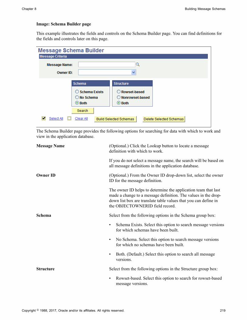
Chapter 8 Building Message Schemas
Image: Schema Builder page
This example illustrates the fields and controls on the Schema Builder page. You can find definitions forthe fields and controls later on this page.
The Schema Builder page provides the following options for searching for data with which to work andview in the application database.
Message Name (Optional.) Click the Lookup button to locate a messagedefinition with which to work.
If you do not select a message name, the search will be based onall message definitions in the application database.
Owner ID (Optional.) From the Owner ID drop-down list, select the ownerID for the message definition.
The owner ID helps to determine the application team that lastmade a change to a message definition. The values in the drop-down list box are translate table values that you can define inthe OBJECTOWNERID field record.
Schema Select from the following options in the Schema group box:
• Schema Exists. Select this option to search message versionsfor which schemas have been built.
• No Schema. Select this option to search message versionsfor which no schemas have been built.
• Both. (Default.) Select this option to search all messageversions.
Structure Select from the following options in the Structure group box:
• Rowset-based. Select this option to search for rowset-basedmessage versions.
Copyright © 1988, 2017, Oracle and/or its affiliates. All rights reserved. 219

Building Message Schemas Chapter 8
• Nonrowset-based. Select this option to search fornonrowset-based message versions.
• Both. (Default.) Select this option to search for rowset-basedand nonrowset-based message versions.
Search Click the button to search the database based on the criteriaselected.
Viewing Message Schema DetailsWhen you search for data in the Schema Builder, message detail results appear in the Message Schemasgrid.
Image: Message Schema Builder page
This example illustrates the Message Schema Builder page. The example shows search results appearingin the Message Schemas grid at the bottom of the page.
Message Message name returned from the search of the applicationdatabase.
Message Version Version of the message returned from the search of theapplication database.
220 Copyright © 1988, 2017, Oracle and/or its affiliates. All rights reserved.

Chapter 8 Building Message Schemas
Rowset-based Indicates the structure of the message. The valid values are:
• Yes. Indicates that the message is a rowset-based message.
• No. Indicates that the message is a nonrowset-basedmessage.
Exists Indicates whether a schema has been built for the message. Thevalid values are:
• Yes. A schema has been built for the message.
• No. A schema has not been built for the message.
Updated On Timestamp of the last update of the record. A new timestampdisplays when a schema is generated or deleted for a message.
Build Results Displays the results of actions performed on a schema.
Build Selected Schemas Click the button to build schemas for the selected messages.
Delete Selected Schemas Click the button to delete schemas that exist for the selectedmessages.
Viewing XML Message SchemaIf a message schema exists for a message, click the message name in the Message Schema grid to viewthe schema details in the Schema Viewer page (IB_SCHEMABUILD_SEC).
Copyright © 1988, 2017, Oracle and/or its affiliates. All rights reserved. 221

Building Message Schemas Chapter 8
Image: Schema details for version 1 of the QE_FLIGHTPLAN message definition
This example illustrates the Schema Viewer page. The example shows schema details for version 1 of theQE_FLIGHTPLAN message definition
Note: For easier viewing, highlight the data with your cursor.
Message schemas for rowset-based messages are read-only. You can edit message schemas for nonrowset-based messages.
Building Message Schemas for Rowset-Based Messages
This section discusses how to build message schemas for rowset-based messages.
Building a Message Schema for a Rowset-Based MessageTo build a message schema for a rowset-based message:
1. Access the Schema Builder page (PeopleTools, Integration Broker, Service Utilities, Message SchemaBuilder).
2. Search the application database for the message or messages for which to build schemas.
See Selecting Data in the Message Schema Builder.
3. Select the check box next to the message or messages for which to build schemas.
4. Click the Build Selected Schemas button.
222 Copyright © 1988, 2017, Oracle and/or its affiliates. All rights reserved.
Chapter 8 Building Message Schemas
When the schema is built successfully, a timestamp appears in the Updated On field and the Build Resultsfield displays Successful Schema Insert.
Importing Message Schemas for Nonrowset-Based Messages
This section discusses how to import message schemas for nonrowset-based messages.
Importing a Message Schema for a Nonrowset-Based MessageTo import schemas for nonrowset-based messages:
1. Access the Schema Builder page (PeopleTools, Integration Broker, Service Utilities, Message SchemaBuilder).
2. Use the Message Schema Builder search engine to locate the message for which you want to import aschema.
See Selecting Data in the Message Schema Builder.
3. In the Message Schema grid, click the message name link for the message for which you want toimport a schema.
4. Import the schema.
• Import a schema from a file.
You can import a schema from a file by using the Upload Schema from File button and selectingthe file to import. After you import the file, the contents displays in the Schema text box.
Note: If you receive the error, “Error retrieving the file from database,” verify that one of thevariables PS_FILEDIR or PS_SERVDIR is defined in the system variables on your machine.
See Understanding Setting PS_FILEDIR and PS_SERVDIR Environment Variables.
• Direct data entry.
You can also enter the schema directly in the Schema text box.
5. Click the Save button.
The Schema Builder page appears.
A timestamp appears in the Updated On field and the Build Results field displays Successful SchemaInsert.
Modifying Message Schemas
This section discusses how to modify message schemas.
Copyright © 1988, 2017, Oracle and/or its affiliates. All rights reserved. 223

Building Message Schemas Chapter 8
Note: You can modify the content of message schemas built for nonrowset-based messages only.
To modify a schema, you can edit it directly in the Message Schema Builder, or you can export to makechanges.
Modifying a Message SchemaTo modify a message schema:
1. Select PeopleTools, Integration Broker, Service Utilities, Message Schema Builder.
The Schema Builder search page appears.
2. Locate the message with which you want to work.
See Selecting Data in the Message Schema Builder.
3. In the Message Schema grid, click the message name link.
A new page displays with the message schema populated in a text box.
4. Modify the schema as needed.
• Modify the schema directly in the text box, or
• Modify the schema in the editor of your choice.
Use your cursor to highlight the contents of the text box and use the keyboard command CTRL+ C to copy the contents of the text box. Paste the contents into your editor using the keyboardcommand CTRL + V. Modify the content as needed. Import the content back into the MessageSchema Builder using the instructions described previously in this topic for importing messageschemas for nonrowset-based messages.
See Importing Message Schemas for Nonrowset-Based Messages.
5. Click the Save button.
The Schema Builder page displays and the Updated On field displays the date and time of themodification, and the Build Results field displays the results of the new schema build.
Deleting Message Schemas
This section discusses how to delete message schemas.
Understanding Deleting Message SchemasYou can delete message schemas using the Message Schema Builder page in the Message Schema Buildercomponent (IB_SCHEMABUILD) or using the Message Schemas page in the Service Administrationcomponent (IB_HOME_PAGE).
224 Copyright © 1988, 2017, Oracle and/or its affiliates. All rights reserved.

Chapter 8 Building Message Schemas
Note: The Message Schema Builder page provides more comprehensive capabilities for searching formessage schema.
You cannot delete a message schema when the message on which the schema is based is:
• Referenced in a service operation.
• Referenced as a message part in a container message.
• A rowset-based message part.
• A container message.
• Referenced in a provided WSDL document.
Using the Message Schema Builder Page to Delete Message SchemasWhen deleting a schema using the Message Schema Builder page use only the Delete Selected Schemasbutton. Do not attempt to delete message schemas by deleting content in the Schema text box in theschema details view; if you save the changes, PeopleSoft Integration Broker will attempt to validate theblank schema at runtime and the validation will fail.
You cannot delete message schemas when the service system status is set to Production.
The service system status that is set on the Service Configuration page.
See "Understanding Configuring PeopleSoft Integration Broker for Handling Services" (PeopleTools8.55: Integration Broker Administration).
To delete a message schema:
1. Access the Message Schema Builder page (PeopleTools, Integration Broker, Service Utilities,Message Schema Builder).
The Schema Builder search page appears.
2. Locate the message with which you want to work.
See Selecting Data in the Message Schema Builder.
The Schema Builder page appears.
3. In the Message Schema section, select the check boxes next to the message names that containschemas you want to delete.
4. Click the Delete Selected Schemas button.
Copyright © 1988, 2017, Oracle and/or its affiliates. All rights reserved. 225

Building Message Schemas Chapter 8
226 Copyright © 1988, 2017, Oracle and/or its affiliates. All rights reserved.
Chapter 9
Managing Services
Understanding Managing Services
Services are used to logically group a set of service operations.
For example, if you have a number of service operations that are related to customers, such as thosepertaining to customer information, adding customers, updating customers, deleting customers, and so on,you can create a customer web service and then associate the related service operations with that service.
Warning! PeopleSoft delivers two services with PeopleSoft Integration Broker: IB_GENERIC andIB_UTILITY. These services are used internally by the system. Do not delete or modify these services.
Before you can provide or consume services in a PeopleSoft system, you must configure the system forhandling services."Configuring the Integration System to Handle Services" (PeopleTools 8.55: IntegrationBroker Administration)
Common Elements Used to Manage Services
Comments (Optional.) Enter comments about the service or servicedefinition.
Description Description of the service.
Generate SOAP Template Click to open the Generate SOAP Template utility. The utilityenables you to generate SOAP documents for each serviceoperation in a service for testing purposes.
The link appears when working with a SOAP-based service andonly if WSDL has been generated for the service. Note that youcan use the Provide Web Service link on the Services page togenerate WSDL for the service.
Link Existing Operations Click to add service operations already defined in the system toa service.
Object Owner ID (Optional.) Indicates the owner of the service.
The owner ID helps to determine the application team that lastmade a change to a service definition. The values in the drop-down list box are translate table values that you can define inthe OBJECTOWNERID field record.
Operation Type Specifies how the service is transmitted.
Copyright © 1988, 2017, Oracle and/or its affiliates. All rights reserved. 227

Managing Services Chapter 9
On the Service page this field defines the operation type of theservice operation added.
Provide Web Service Click to launch the Provide Web Services component and exportPeopleSoft services as WSDL documents.
Schema Namespace Provides qualification for attributes and elements within anXML schema document (XSD).
The default is http://xmlns.oracle.com/Enterprise/Tools/schemas.
The namespace on the message definition defaults to the schemanamespace you set as the default on the Service Configurationpage.
Note: If you change the namespace, all future messages willhave the new namespace.
Service The name of the service.
Service Alias (Optional.) Overrides the service name and will be the name ofthe service when the WSDL is provided or exported. The aliasenables you to use mixed case in the name.
Service Operation The name of the service operation to associate with the service.
On the Services page, use this field to add new serviceoperations for the current service.
Service Namespace andNamespace The namespace field on the Service pages provides qualificationfor attributes and elements within a WSDL document.
The value defined in the Service Namespace field in the ServiceConfiguration page is used as the default service namespace onthe Services page. The default value is http://xmln.oracle.com/enterprise/tools/service.
Service System Status The status that is selected restricts rename, delete, and otheradministrative actions that users can perform on integrationmetadata in the Services Administration component.
Values are:
• Production.
• Development.
See "Understanding Configuring PeopleSoft Integration Brokerfor Handling Services" (PeopleTools 8.55: Integration BrokerAdministration).
Target Location Specifies the URL to be used for service requests.
228 Copyright © 1988, 2017, Oracle and/or its affiliates. All rights reserved.

Chapter 9 Managing Services
You must define this location before creating services andservice schemas.
View WSDL Click to view WSDL documents in the WSDL repository thathave been generated for the service.
This link appears only when the service you are viewing is aSOAP-based service.
Accessing and Viewing Service Definitions
This section discusses how to.
• Access service definitions.
• View WSDL documents generated for services.
• View service operation information.
• View messages defined for services.
Accessing Service DefinitionsService definitions appear on the Services page (IB_SERVICEDEFN) in the Service component(IB_SERVICEDEFN).
To access the Services page, select PeopleTools, Integration Broker, Integration Setup, Services.
Copyright © 1988, 2017, Oracle and/or its affiliates. All rights reserved. 229

Managing Services Chapter 9
Image: Services page
This example illustrates the Services page. The example shows the service definition for theIB_EXAMPLES service.
The top of the Service page displays general information about the service, including the name of theservice, its description, its alias name, and so on.
Viewing WSDL Documents Generated for ServicesClick the View WSDL link to display the WSDL Repository page (IB_SERVICEDEFN_SEC). This pageprovides a summary of all the WSDL documents that are generated for the service, as well as the serviceoperations, request messages, response messages, and fault messages that are contained in each.
Note: Service operations must exist for a service to view WSDL documents for the service.
230 Copyright © 1988, 2017, Oracle and/or its affiliates. All rights reserved.

Chapter 9 Managing Services
Image: WSDL Repository page
This example illustrates the WSDL Repository page. The example shows the WSDL in the repository ofthe IB_EXAMPLE service. The example shows that WSDL has been exported for one service operation inthe service.
Click the View WSDL link on the WSDL Repository page to view the WSDL document in the WSDLViewer page (IB_SERVICEWSDL_SEC).
Copyright © 1988, 2017, Oracle and/or its affiliates. All rights reserved. 231

Managing Services Chapter 9
Image: WSDL Viewer page
This example illustrates the WSDL Viewer page. The example shows the WSDL document for theIB_EXAMPLES.1.
To view a WSDL document generated for a service:
1. Access the service definition. (PeopleTools, Integration Broker, Integration Setup, Services.)
2. Click the View WSDL link.
The WSDL Repository page appears.
3. Click the View WSDL link.
The document appears in the WSDL Viewer page.
4. Click the Return button to return to the WSDL Repository page.
5. Click the Return button again to return to the Services page.
232 Copyright © 1988, 2017, Oracle and/or its affiliates. All rights reserved.
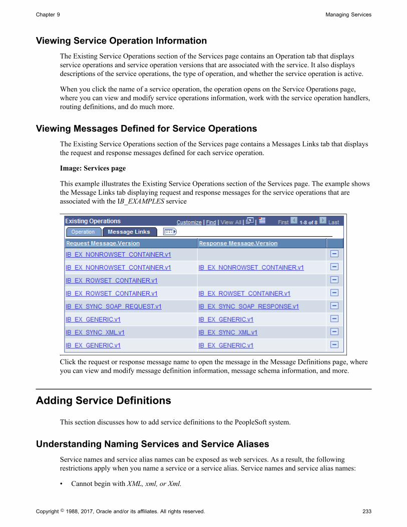
Chapter 9 Managing Services
Viewing Service Operation InformationThe Existing Service Operations section of the Services page contains an Operation tab that displaysservice operations and service operation versions that are associated with the service. It also displaysdescriptions of the service operations, the type of operation, and whether the service operation is active.
When you click the name of a service operation, the operation opens on the Service Operations page,where you can view and modify service operations information, work with the service operation handlers,routing definitions, and do much more.
Viewing Messages Defined for Service OperationsThe Existing Service Operations section of the Services page contains a Messages Links tab that displaysthe request and response messages defined for each service operation.
Image: Services page
This example illustrates the Existing Service Operations section of the Services page. The example showsthe Message Links tab displaying request and response messages for the service operations that areassociated with the IB_EXAMPLES service
Click the request or response message name to open the message in the Message Definitions page, whereyou can view and modify message definition information, message schema information, and more.
Adding Service Definitions
This section discusses how to add service definitions to the PeopleSoft system.
Understanding Naming Services and Service AliasesService names and service alias names can be exposed as web services. As a result, the followingrestrictions apply when you name a service or a service alias. Service names and service alias names:
• Cannot begin with XML, xml, or Xml.
Copyright © 1988, 2017, Oracle and/or its affiliates. All rights reserved. 233

Managing Services Chapter 9
• Cannot begin with a digit.
• Cannot begin with a character.
Adding Service DefinitionsTo add a service definition to the system, use the Add a New Value link on the Services search page. Toaccess this page, select PeopleTools, Integration Broker, Integration Setup, Services. Then select theAdd a New Value link.
Image: Add a New Service page
This example shows the Add New Service page.
Note: Before you can add a service, you must configure PeopleSoft Integration Broker to handle servicesusing the Service Configuration page.
See "Understanding Configuring PeopleSoft Integration Broker for Handling Services" (PeopleTools8.55: Integration Broker Administration).
After you add a service definition to the system, the Services page (IB_SERVICEDEFN) appears whereprovide additional service definition information.
234 Copyright © 1988, 2017, Oracle and/or its affiliates. All rights reserved.

Chapter 9 Managing Services
Image: Services page
This example illustrates the Services page. The example shows the definition for a non-REST servicecalled DEMO_SOAP_SERVICE.
To add a service definition:
1. Access the Services page (PeopleTools, Integration Broker, Integration Setup, Services).
2. Click the Add a New Value link.
3. In the Service field, enter a name for the service.
Restrictions for naming services are discussed elsewhere in this section.
See Understanding Naming Services and Service Aliases.
4. Click the Add button.
The Services page appears.
5. In the Description field, enter a description for the service.
6. (Optional.) If the service is REST-based, select the Is Provider check box to define the service as aprovider service.
By default, when you add a REST-based service to the system it is a provider service.
7. (Optional.) In the Comments field, enter comments about the service or the service.
8. (Optional.) In the Service Alias field, enter an alias name for the service.
Restrictions for naming service aliases are discussed elsewhere in this section.
Copyright © 1988, 2017, Oracle and/or its affiliates. All rights reserved. 235

Managing Services Chapter 9
See Understanding Naming Services and Service Aliases.
9. (Optional.) From the Object Owner ID drop-down list box, select the owner of the service.
10. In the Namespace field, enter a namespace URI for the service.
The default value is the namespace that is declared in the Service Namespace field on the ServiceConfiguration page.
11. Click the Save button.
Related LinksAdding Service Operations to Service Definitions
Adding Service Operations to Service Definitions
This section discusses how to:
• Add existing service operations to service definitions.
• Define new service operations for SOAP-based service definitions.
• Define new service operations for REST-based service definitions.
Understanding Adding Service Operations to Service DefinitionsYou can add a service operation that already exists in the database to a service definition, or you can addand configure a new service operation and then add it to a service.
Adding Existing Service Operations to Service DefinitionsTo add an existing service operation to a service:
1. Access the Add Existing Operations page (PeopleTools, Integration Broker, Integration Setup,Services and click the Link Existing Operations link).
The Add Existing Operations page appears.
2. Select a service operation to add to the service.
a. In the Service Operation field, enter the name of the service operation to add to the service andclick the Search button. The service operation appears in the Available Service Operations grid.
Select the check box next to the service operation name.
b. In the Service Operation field, click the Lookup button. The Look Up Service Operation pageappears.
Select a service operation from the list to add to the service.
c. Click the Search button to show a list of service operations in the database.
236 Copyright © 1988, 2017, Oracle and/or its affiliates. All rights reserved.

Chapter 9 Managing Services
Select one or more service operations to add to the service.
3. On the Add Existing Operations page, click the Save button.
The Services page appears and the service operations that you added appear in the ExistingOperations grid.
4. On the Services page, click the Save button.
Defining New Service Operations for SOAP-Based Service DefinitionsThis section describes how to define new service operations for SOAP-based services.
To add and configure a new service operation for a SOAP-based service:
1. Access the Services page (PeopleTools, Integration Broker, Integration Setup, Services).
The Services page appears.
2. In the Service Operations section, locate the Service Operation field and enter a name for the newservice operation.
3. From the Operation Type drop-down list, select the type of service operation you are adding.
The valid values are:
• Asynch Request/Response.
• Asynch to Synch.
• Asynch–One Way.
• Synchronous.
Service operation types are discussed elsewhere in the product documentation.
See Services Operation Types.
4. Click the Add button.
The Service Operations-Definitions page appears. Use the page to configure the service operation.
See Configuring Service Operation Definitions.
Creating and Managing Integration Groups
This section provides and overview of integration groups and discusses how to:
• Add integration groups.
• Add integration subgroups.
• Add services to integration groups and subgroups.
Copyright © 1988, 2017, Oracle and/or its affiliates. All rights reserved. 237

Managing Services Chapter 9
• Rename and delete integration groups.
• Copy integration groups using Project Copy.
Understanding Integration GroupsPeopleSoft provides you with the ability to great groups and subgroups of integrations that you can thendeploy using the Integration Network. Your PeopleSoft integration partners can then use the IntegrationNetwork to introspect and activate those integrations on their systems.
You can assign services to one or more integration groups or subgroups. However, there can only be oneinstance of a service within a group or subgroup assignment.
Adding Integration GroupsTo add an integration group to the system, use the Integration Group search page. To access the pageselect PeopleTools, Integration Broker, Integration Setup, Integration Groups.
Image: Integration Groups – Add a New Value tab
This example shows the Integration Groups – Add a New Value tab.
After you name the integration group, the Integration Group Definitions page (IB_INTGROUPDEFN)appears where you can add an optional description for the group and save the definition.
238 Copyright © 1988, 2017, Oracle and/or its affiliates. All rights reserved.

Chapter 9 Managing Services
Image: Integration Group Definitions page
This example illustrates the Integration Group Definitions page.
To add a service integration group:
1. Select PeopleTools, Integration Broker, Integration Setup, Integration Groups.
The Integration Group search page appears.
2. Click the Add a New Value tab.
3. In the Integration Group Name field, enter a name for the integration group.
4. Click the Add button.
The Integration Group Definitions page appears.
5. In the Description field, add a description for the group.
6. (Optional.) From the Object Owner ID field, select the owner of the object.
7. Click the Save button.
After you have added the definition to the system you can proceed to add services to the integrationgroup, as well as create integration subgroups and add services to them.
Copyright © 1988, 2017, Oracle and/or its affiliates. All rights reserved. 239

Managing Services Chapter 9
The process for adding services to integration groups and to integration subgroups is identical and isdescribed elsewhere in this section.
See Adding Services to Integration Groups.
Adding Services to Integration GroupsUse the Integration Group Definitions page shown in the previous section to add services to integrationgroups.
Note: The information presented in this section for searching for services to add to an integration groupalso applies to searching for services to add to integration subgroups.
You can search for the services to add to a group (or subgroup) by using the Add Services link on theIntegration Group Definitions page to access the Add Services page (IB_INTGROUP_SEC).
Image: Add Services page
This example illustrates the Add Services page.
You can search for a service by entering a partial or complete service name in the Service Name field andthen clicking the Search button. You can also leave the Service Name field blank and click the Searchbutton to display a list of all services in the database.
After you locate the service or services to add to the group, select the Select check box next to eachservice name to add to the group and click the OK button.
To add services to an integration group:
1. Access the Integration Group Definitions page (PeopleTools, Integration Broker, Integration Setup,Integration Groups).
2. Click the Add Services link.
The services search page appears.
3. Search for one or more services to add to the integration group, as described previously in this section.
4. Click the OK button to return to the Integration Group Definitions page.
5. Click the Save button.
240 Copyright © 1988, 2017, Oracle and/or its affiliates. All rights reserved.

Chapter 9 Managing Services
Adding Integration SubgroupsThe Integration Group Definitions page features a Subgroups section where you define subgroups for anintegration group and then add services to the subgroups.
Image: Integration Group Definitions page
This example shows the Subgroups section of the Integration Group Definitions page. Use this section ofthe page to add subgroups to an integration group.
To add a service integration subgroup:
1. Access the Integration Group Definitions page (PeopleTools, Integration Broker, Integration Setup,Integration Groups).
2. Locate the Subgroup section of the page.
3. In the Integration Subgroup Name field, enter a name for the subgroup.
4. In the Description field, enter a description for the subgroup.
5. Click the Add Services link to add services to the subgroup.
The process for adding services to integration groups and to integration subgroups is identical and isdescribed elsewhere in this section.
See Adding Services to Integration Groups.
6. Click the Save button.
To add additional subgroups to the integration group, in the Subgroups section title, click the Add Rowbutton (+) to add another subgroups grid to the page and repeat the steps described in this section todefine the subgroup and add services to it.
Deleting Services from Integration Groups and Integration SubgroupsTo delete a service from an integration group or an integration subgroup:
1. Access the Integration Group Definition page (PeopleTools, Integration Broker, Integration Setup,Integration Groups).
Copyright © 1988, 2017, Oracle and/or its affiliates. All rights reserved. 241

Managing Services Chapter 9
2. In the Services or Subgroup Services section of the page, click the Delete Row button (-) next to thename of the service to delete.
3. Click the Save button.
Renaming and Deleting Integration GroupsThis section discusses how to:
• Rename integration groups.
• Delete integration groups.
Understanding Renaming and Deleting Integration GroupsYou can rename and delete integration groups using the Integration Groups tab (IB_INTGROUPADM) inthe Service Administration component (IB_HOME_PAGE).
The Integration Group tab contains two sections: a Delete section that enables you to delete integrationgroups and a Rename section that enables you to rename integration groups. When you first access theIntegration Groups tab, both sections are collapsed. Click the section header arrow buttons to expand andcollapse each section.
Image: Service Administration – Integration Groups tab
This example illustrates the Service Administration – Integration Groups page. The example shows theDelete section and Rename section expanded.
The service system status has no impact on renaming or deleting integration groups.
242 Copyright © 1988, 2017, Oracle and/or its affiliates. All rights reserved.

Chapter 9 Managing Services
Renaming Integration GroupsTo rename and integration group:
1. Access the Service Administration – Integration Groups page (PeopleTools, Integration Broker,Service Utilities, Service Administration and click the Integration Groups tab).
2. Click the arrow next to the Rename section header to expand the section.
3. In the Integration Group Name field, enter the service to rename, or click the Lookup button to searchfor and select the group to rename.
4. In the New Name field, enter the new name for the integration group.
5. Click the Rename button.
After you click the Rename button, the Results field displays a message that the action was successful ordisplays a warning or error message with a description of the problem.
Deleting Integration GroupsTo delete and integration group:
1. Access the Service Administration – Integration Groups page (PeopleTools, Integration Broker,Service Utilities, Service Administration and click the Integration Groups tab).
2. Click the arrow next to the Delete section header to expand the section.
3. In the Integration Group Name field, enter the integration group to delete, and click the Search button.Search results display in the results grid.
4. In the results grid, select the check box next to the integration group or groups to delete.
5. Click the Delete button.
Copying Integration Groups Using Project CopyYou can copy integration groups between PeopleSoft databases using Project Copy.
When using Project Copy to copy integration groups select the Integration Groups as one of the definitiontypes. To copy all of the service information, such as service, service operation, handler, and so on, selectall of the definitions in the Related Definitions box.
Note: At a minimum you must select Services in the Related Definitions box.
Restricting and Enabling Write Access to Service Definitions
This section provides an overview of restricting access to services and discusses how to:
• Restrict write access to services.
• Enable write access to services.
Copyright © 1988, 2017, Oracle and/or its affiliates. All rights reserved. 243
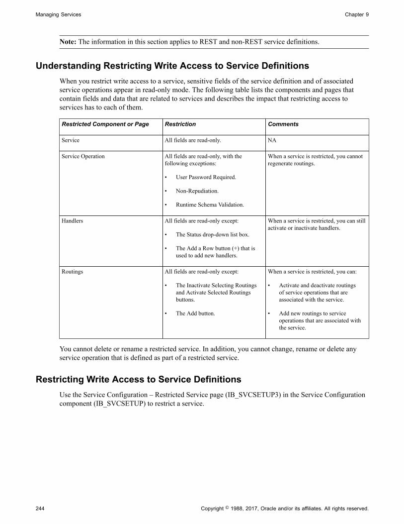
Managing Services Chapter 9
Note: The information in this section applies to REST and non-REST service definitions.
Understanding Restricting Write Access to Service DefinitionsWhen you restrict write access to a service, sensitive fields of the service definition and of associatedservice operations appear in read-only mode. The following table lists the components and pages thatcontain fields and data that are related to services and describes the impact that restricting access toservices has to each of them.
Restricted Component or Page Restriction Comments
Service All fields are read-only. NA
Service Operation All fields are read-only, with thefollowing exceptions:
• User Password Required.
• Non-Repudiation.
• Runtime Schema Validation.
When a service is restricted, you cannotregenerate routings.
Handlers All fields are read-only except:
• The Status drop-down list box.
• The Add a Row button (+) that isused to add new handlers.
When a service is restricted, you can stillactivate or inactivate handlers.
Routings All fields are read-only except:
• The Inactivate Selecting Routingsand Activate Selected Routingsbuttons.
• The Add button.
When a service is restricted, you can:
• Activate and deactivate routingsof service operations that areassociated with the service.
• Add new routings to serviceoperations that are associated withthe service.
You cannot delete or rename a restricted service. In addition, you cannot change, rename or delete anyservice operation that is defined as part of a restricted service.
Restricting Write Access to Service DefinitionsUse the Service Configuration – Restricted Service page (IB_SVCSETUP3) in the Service Configurationcomponent (IB_SVCSETUP) to restrict a service.
244 Copyright © 1988, 2017, Oracle and/or its affiliates. All rights reserved.
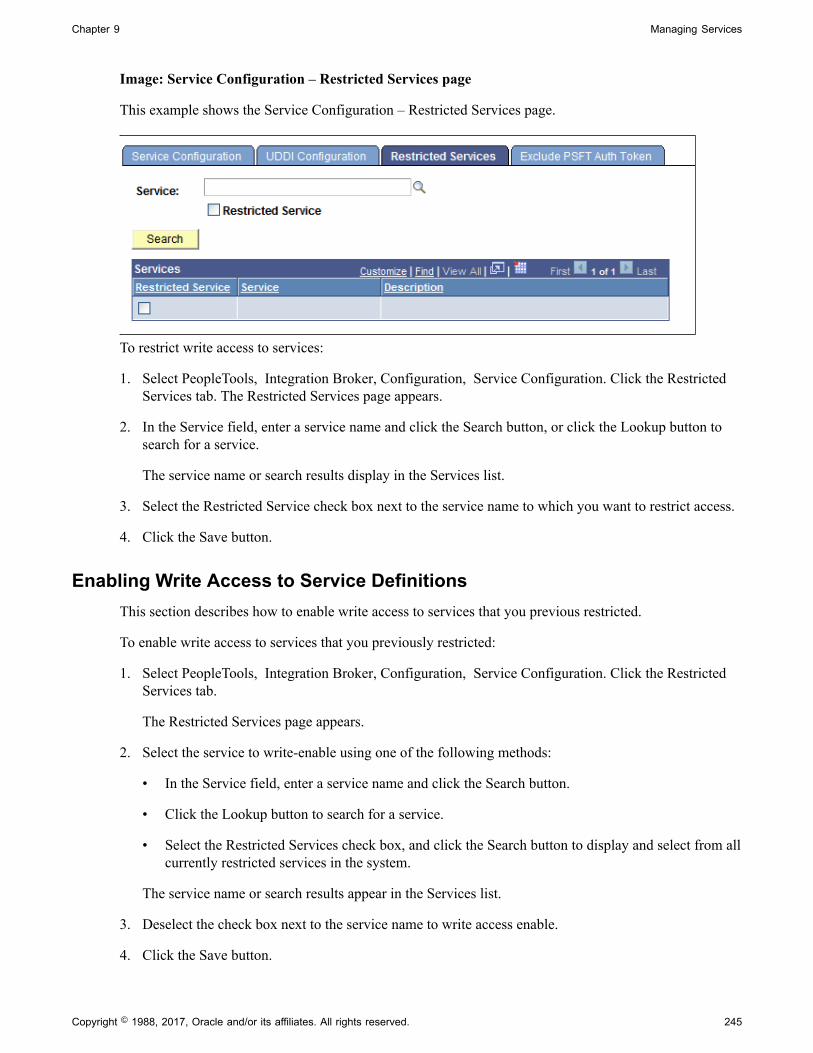
Chapter 9 Managing Services
Image: Service Configuration – Restricted Services page
This example shows the Service Configuration – Restricted Services page.
To restrict write access to services:
1. Select PeopleTools, Integration Broker, Configuration, Service Configuration. Click the RestrictedServices tab. The Restricted Services page appears.
2. In the Service field, enter a service name and click the Search button, or click the Lookup button tosearch for a service.
The service name or search results display in the Services list.
3. Select the Restricted Service check box next to the service name to which you want to restrict access.
4. Click the Save button.
Enabling Write Access to Service DefinitionsThis section describes how to enable write access to services that you previous restricted.
To enable write access to services that you previously restricted:
1. Select PeopleTools, Integration Broker, Configuration, Service Configuration. Click the RestrictedServices tab.
The Restricted Services page appears.
2. Select the service to write-enable using one of the following methods:
• In the Service field, enter a service name and click the Search button.
• Click the Lookup button to search for a service.
• Select the Restricted Services check box, and click the Search button to display and select from allcurrently restricted services in the system.
The service name or search results appear in the Services list.
3. Deselect the check box next to the service name to write access enable.
4. Click the Save button.
Copyright © 1988, 2017, Oracle and/or its affiliates. All rights reserved. 245
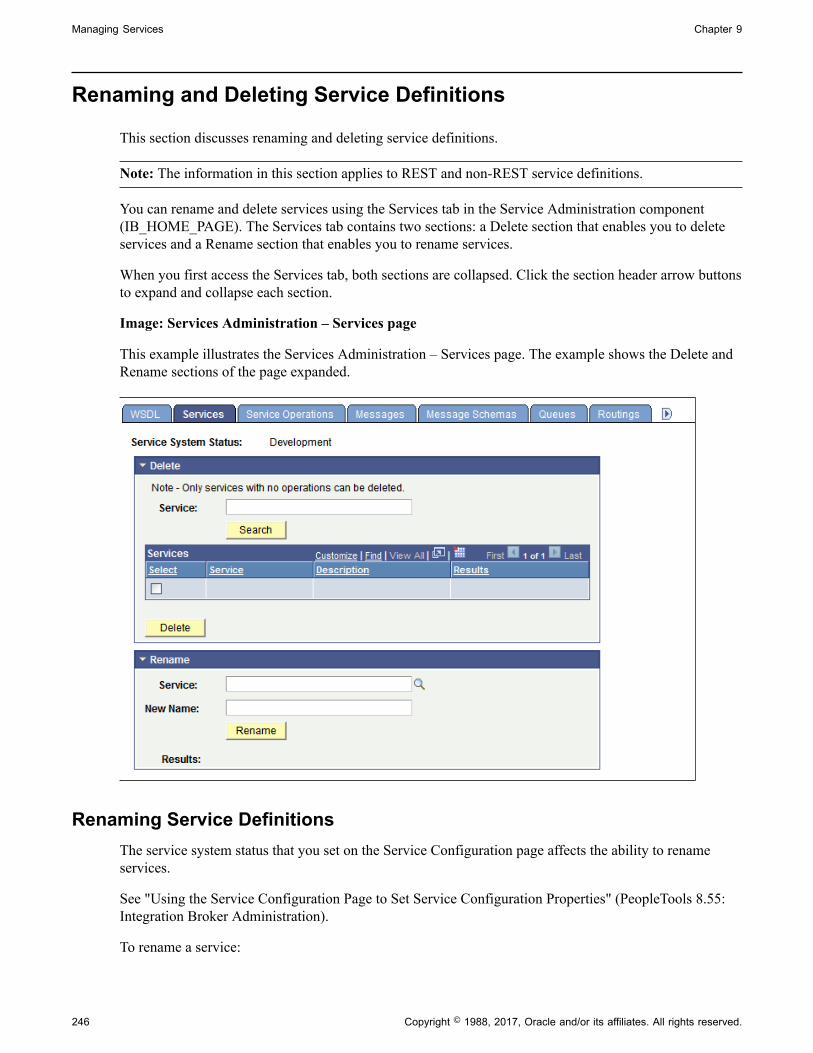
Managing Services Chapter 9
Renaming and Deleting Service Definitions
This section discusses renaming and deleting service definitions.
Note: The information in this section applies to REST and non-REST service definitions.
You can rename and delete services using the Services tab in the Service Administration component(IB_HOME_PAGE). The Services tab contains two sections: a Delete section that enables you to deleteservices and a Rename section that enables you to rename services.
When you first access the Services tab, both sections are collapsed. Click the section header arrow buttonsto expand and collapse each section.
Image: Services Administration – Services page
This example illustrates the Services Administration – Services page. The example shows the Delete andRename sections of the page expanded.
Renaming Service DefinitionsThe service system status that you set on the Service Configuration page affects the ability to renameservices.
See "Using the Service Configuration Page to Set Service Configuration Properties" (PeopleTools 8.55:Integration Broker Administration).
To rename a service:
246 Copyright © 1988, 2017, Oracle and/or its affiliates. All rights reserved.

Chapter 9 Managing Services
1. Select PeopleTools, Integration Broker, Service Utilities. Click the Services tab.
The Service page displays.
2. Click the arrow next to the Rename section header to expand the section.
3. In the Service field, enter the service to rename, or click the Lookup button to search for and select theservice to rename.
4. In the New Name field, enter the new name for the service.
5. Click the Rename button.
After you click the Rename button, the Results field displays a message that the action was successful ordisplays a warning or error message with a description of the problem.
Deleting Service DefinitionsYou can delete services only when the service has no service operations associated with it. When yousearch for a service to delete, only such services that have no service operations associated with them areretrieved from the system.
To delete a service:
1. Select PeopleTools, Integration Broker, Service Utilities. Click the Services tab.
The Service tab displays.
2. Click the arrow next to the Delete section header to expand the section.
3. In the Service field, enter the service name to delete, and click the Search button.
Search results display in the results grid.
4. In the results grid, select the check box next to the service or services to delete.
5. Click the Delete button.
Activating and Deactivating Service Definitions in Bulk
This section describes activating and deactivating service definitions in bulk.
Note: The information in this section applies to REST and non-REST service definitions.
The Service Administration – Service Activate/Deactivate page (IB_HOME_PAGE9) in the ServiceAdministration component enables you to activate and deactivate services in bulk.
This page enables you to quickly activate or deactivate services. If any problems occur during activation,the system displays a message indicating a problem activating a certain object, for example routing,handler, and so on. If such a message occurs, you must look at the corresponding object definition todetermine the problem. This page is not intended to be used to debug activation problems or problemswith integration metadata definitions.
Copyright © 1988, 2017, Oracle and/or its affiliates. All rights reserved. 247

Managing Services Chapter 9
Image: Service Administration – Service Activate/Deactivate page
This example shows the Service Administration – Service Activate/Deactivate page.
When you activate one or more services, all of the default service operation associated with the servicesbecome active. In addition, the handlers, routings and queues associated with the service operationsbecome active as well.
When you deactivate one or more services, all selected services become deactivated. The default serviceoperations for the services become deactivated as well. In addition, the handlers and routing definitionsassociated with the service operations become deactivated. Queues do not become deactivated, since theycan be shared with other service operations.
You can search for services to activate or deactivate by integration group name and related parameters orby service name.
The following controls appear on this page:
Integration Group (Default.) Select the control to search the database for servicesto activate or deactivate by integration group.
Use one of the following integration group filters:
• Show All Subgroups. (Default.) Select the radio button todisplay all integration subgroups associated with integrationgroups in the system.
• Filter by Subgroup. Select the radio button to search for aspecific integration subgroup and enter its name in the field.
• No Subgroups. Select the radio button to omit integrationsubgroups from your search.
248 Copyright © 1988, 2017, Oracle and/or its affiliates. All rights reserved.

Chapter 9 Managing Services
• Show Services Tied to Group.(Default.) Check the box toinclude the services tied to an integration group in the searchresults. By default this option is selected.
Integration Group Name If searching by integration group, enter the integration groupname by which to search or click the Lookup button to searchfor one.
Service Select the radio button and enter the name of the service bywhich to search or click the Lookup button to search for one.
Search Click the button to search the database for services based on thecriteria entered.
Services (grid) This grid displays the search results and features this controls:
• Select. Check the box to select one or more services in thegrid to activate or deactivate.
• Service. Indicates the name of the service.
• Description. Description of the service.
• Results. Displays the results of the activate or deactivateaction.
Activate Click the button to activate the services selected in the Servicesgrid.
Deactivate Click the button to deactivate the services selected in theServices grid.
To activate or deactivate services in bulk:
1. Access the Service Activate/Deactivate page (PeopleTools, Integration Broker, Service Utilities,Service Administration and click the Service Activate/Deactivate tab).
2. Search for services to activate or deactivate:
To search by integration group:
a. Click the Integration Group control.
b. In the Integration Group Name field, enter or search for the integration group by which to search.
c. If appropriate, select additional integration groups filters as described previously in this section.
To search by service in the Service field enter or search for the service name by which to search.
3. Click the Search button.
4. Select the Select check box next to each service to activate or deactivate.
5. Click the Activate button to activate the selected services; click the Deactivate button to deactivate theselected services.
Copyright © 1988, 2017, Oracle and/or its affiliates. All rights reserved. 249

Managing Services Chapter 9
When the system has performed the selected action, the Results column displays Success for eachservice you activated or deactivated.
250 Copyright © 1988, 2017, Oracle and/or its affiliates. All rights reserved.

Chapter 10
Managing Service Operations
Understanding Managing Service Operations
This section discusses:
• Service operations.
• Service operation types.
• Naming conventions for service operation metadata.
• Service operation aliases.
• Service operation versions.
• Monitoring service operations.
Note: Before you can provide or consume services in a PeopleSoft system, you must configure the systemfor handling services.
Related Links"Understanding Configuring PeopleSoft Integration Broker for Handling Services" (PeopleTools 8.55:Integration Broker Administration)
Service OperationsA service operation definition consists of general information about an operation, such as its name,description, and so on. It also specifies an operation type, which determines how the operation is tobe processed, synchronously or asynchronously. In addition, it contains routings, which determine thedirection, inbound or outbound, of the service operation. A service operation has one or more handlers,which contain and run the programming logic for sending or receiving the message, manipulatingmessage content, and so on.
Note: Beginning with the PeopleTools 8.48 release, service operations house the processing logic foundin messages, transactions and relationships used in earlier versions of PeopleSoft Integration Broker.
Services Operation TypesWhen you create a web service operation you must specify a service operation type. Service operationtypes determine the type of message processing.
There are four service operation types:
Copyright © 1988, 2017, Oracle and/or its affiliates. All rights reserved. 251

Managing Service Operations Chapter 10
Asynchronous Request/Response The sending system invokes a service operation asynchronouslyand processes the response from the receiving systemasynchronously. Unlike a synchronous operation type, theresponse is not processed on the same thread as the response, and it is processed sometime in the future.
Asynchronous to Synchronous The sending system's asynchronous process sends asynchronous request to a remote system.
The sending asynchronous system expects the receiving systemto send a synchronous response back. The sending asynchronoussystem transforms the response and puts it back in the queue forasynchronous consumption.
Asynchronous – One Way The service operation is queued and sent in near real-time. Processing on the sending system continues without a responsefrom the receiving system.
Synchronous The service operation is processed in real-time. Processing onthe sending system does not continue until it receives a responsefrom the receiving system.
Naming Conventions for Service Operation MetadataWhen naming the following service operation metadata, names cannot start with “xml,” digits or specialcharacters:
• Service operation names.
• Service operation aliases.
Service Operation AliasesA service operation alias or operation alias is the service operation name that displays for the serviceoperation when WSDL or WADL is provided.
Service operation aliases may be mixed case.
Duplicate service operation alias names within a service are not allowed.
Service Operation VersionsWhen you create a service operation, the operation that you create automatically becomes the defaultservice operation version.
If you add a new version to the operation, the newly added version automatically becomes the default.The previous version of the service operation remains in the database as a non-default version and youstill may use that the non-default version.
See Using Non-Default Service Operation Versions.
252 Copyright © 1988, 2017, Oracle and/or its affiliates. All rights reserved.
Chapter 10 Managing Service Operations
Monitoring Service OperationsThis section describes several options for monitoring service operation performance.
Monitoring Service Operations in the Integration Broker Service OperationsMonitorPeopleSoft provides an Integration Broker Service Operations Monitor that enables you to monitorasynchronous and synchronous service operation information, node status, queue status, manage domains,and more, from within the PeopleSoft Pure Internet Architecture.
See the product documentation for PeopleTools 8.55: Integration Broker Service Operations Monitor
Monitoring Service Operations in the Integration Network MonitorThe Integration Network provides a Network Monitor that enables you to monitor local integrations andintegrations from all remote PeopleSoft nodes defined in the Integration Network.
See "Using the Integration Network Monitor" (PeopleTools 8.55: Integration Broker Administration).
Monitoring Service Operations in the Integration Network Transactional TrackerThe Integration Network provides a Transactional Tracker that enables you to monitor transactionsbetween the local system and remote PeopleSoft nodes defined in the Integration Network.
See "Using the Integration Network Transactional Tracker" (PeopleTools 8.55: Integration BrokerAdministration).
Monitoring Service Operations in Performance Monitoring Tools Using Moduleand Action InformationSeveral system monitoring tools report metrics by capturing Module and Action information. Onan Oracle database, PeopleSoft provides service operation name and PeopleCode event name asModule name and Action name respectively. On an IBM DB2 database, PeopleSoft provides serviceoperationname as Module name (no Action information is provided for DB2 systems). This informationenables you to associate service operations with database transactions for monitoring and troubleshooting.
To enable capturing service operation and PeopleCode event metrics you must set theEnableDBMonitoring option in PSADMIN.
See "Monitoring PeopleSoft MODULE and ACTION Information" (PeopleTools 8.55: DataManagement)"Associating PeopleSoft Users, Modules, and Actions with DB2 UDB Threads"(PeopleTools 8.55: Data Management), "Monitoring Module and Action Information" (PeopleTools 8.55:Data Management).
Accessing and Viewing Service Operation Definitions
This section discusses how to:
• Access service operation definitions.
• View service operation definitions.
Copyright © 1988, 2017, Oracle and/or its affiliates. All rights reserved. 253

Managing Service Operations Chapter 10
Accessing Service Operation DefinitionsUse the pages in the Service Operations component (IB_SERVICE) to access and view service operationdefinitions.
Image: Service Operations — General page
The example shows the Service Operations – General page. The example shows the definition for theQE_FLIGHTPLAN_SYNC service operation.
To access a service operation definition:
1. Select PeopleTools, Integration Broker, Integration Setup, Service Operations.
The Service Operations– Search page appears.
2. Search for a service operation definition to view.
You can search for an operation in one of two ways:
• Click the Search button to display all service operation definitions in the system.
• Enter search criteria in one or more of the following fields, and then click the Search button:
254 Copyright © 1988, 2017, Oracle and/or its affiliates. All rights reserved.

Chapter 10 Managing Service Operations
Service Enter the service name that contains the serviceoperation that you want to view, or click the Lookupbutton to search for and select a service name.
Service Operation Enter the name of the service operation to view, or clickthe Lookup button to search for and select an operation.
Operation Type This search option is for web service operations only.
From the Operation Type drop-down list box, select anoperation type. Values are:
• Asynch Request/Response
• Asynch to Synch
• Asynchronous – One Way
• Synchronous
3. In the Service Operations results grid, click the name of the service operation to view.
The Service Operations – General tab appears with data for the service operation that you selected.
Viewing Service Operation DefinitionsThe Service Operations component includes three pages:
General Tab Features general-service and default-service operationinformation.
Handlers Tab Provides summary information about handlers that have beenadded to an operation. Service operation handlers contain theprogramming logic for sending and receiving service operationsand their contained messages, and for manipulating content.
Routings Tab Provides summary information about service operationsroutings. Routing definition determine the direction—inbound, outbound or hub—of service operations.
Viewing General Service Operation InformationWhen you access a service operation ( PeopleTools, Integration Broker, Integration Setup, ServiceOperations, the Service Operations - General page (IB_SERVICE) appears.
The top portion of this page contains basic information about a service operation, including its name,description, and so on. The Service Operation Security link opens the permission list for the service. Notethat the Service Operation Security link appears only after a service operation definition is saved.
Note: The Conditional Navigation control is reserved for future use.
Copyright © 1988, 2017, Oracle and/or its affiliates. All rights reserved. 255

Managing Service Operations Chapter 10
The Runtime Schema Validation group box shows if runtime schema validation is selected for the requestand response messages.
The Routing Status group box shows if any-to-local, local-to-local, or in the case of feeds, local-to-Atom,routing definitions have been generated for the service operation. Click the Routings tab to view detailedinformation about routing definitions that exist for a service operation.
The Routing Actions Upon Save group box shows the possible routings that the system can generatewhen the service operation definition is saved.
The Message Information section displays the request message, response message information, and faultmessage for the service operation. The View Message links in this section open the displayed messageon the Message Definition page, where you can view additional information about the message. Formessages defined for web services, all service operations with operation types other than Synchronous,the queue to which a message belongs also appears. Click the View Queue link or the Add New Queuelink to open the Queue Definition page to view additional queue definition information or to add orchange a queue to which a message belongs.
Viewing Handler InformationTo view service operation handler information, click the Handlers tab. Doing so displays the ServiceOperations - Handlers page (IB_SERVICEHDLR) which lists summary information about handlers thathave been added to an operation.
Image: Service Operations – Handlers page
This example illustrates the Service Operations – Handlers page.
This example shows the Service Operations – Handlers page for an asynchronous service operation,QE_FLIGHTPLAN.
The summary information includes the handler name, the handler type, and the implementation methodfor the handler. The status of the handler, active or inactive, also appears.
Click the Details link to open the Handler Details page (IB_SERVICEHDLR_SEC) for the handler.
256 Copyright © 1988, 2017, Oracle and/or its affiliates. All rights reserved.

Chapter 10 Managing Service Operations
Image: Handler Details page
This example illustrates the Handler Details page.
The Handler Details page shows additional information about the handler, including the owner andapplication class or component interface details.
You can also use this page to specify the handler details.
Viewing Routing InformationClick the Routings tab to open the Service Operations - Routings page (IB_SERVICERTNGS) to view asummary of routing definitions for an operation.
Image: Service Operations – Routings page
This example illustrates the Service Operations – Routings page.
The Routings Definition grid on the page lists summary information for routings that are defined for aservice operation. Summary information that is displayed includes the routing definition name, serviceoperation version, routing type, sending node, receiving node, direction of the routing and the routingstatus.
Copyright © 1988, 2017, Oracle and/or its affiliates. All rights reserved. 257
Managing Service Operations Chapter 10
Click a routing definition name to open the routing in the Routing Definitions component, where you canview additional information about the routing.
See Viewing Routing Definitions in Graphical Format.
You can also use this page to add routing definitions to a service operation and to activate or deactivateroutings for an operation.
See Adding Routing Definitions, Activating and Inactivating Routing Definitions.
Adding Service Operation Definitions
This section describes how to add web service operation definitions to the PeopleSoft system.
To add a service operation definition:
1. Select PeopleTools, Integration Broker, Integration Setup, Service Operations.
The Service Operations – Search page appears.
2. Click the Add a New Value link.
3. In the Service field, enter the service name to which the new operation will belong or click theLookup button to search for a service name.
4. In the Service Operation field, enter a name for the service operation.
5. From the Operation Type drop-down list box, select an operation type. Values are:
• Asynchronous – One Way
• Synchronous
• Asynch Request/Response
• Asynch to Synch
6. Click the Add button.
The new definition appears on the General tab of the Service Operation component, and you can nowdefine the service operation.
Configuring Service Operation Definitions
After you add a service operation definition to the system, you can define the service operation.
This section discusses how to:
• Specify general service operation information.
• Define service operation version information.
258 Copyright © 1988, 2017, Oracle and/or its affiliates. All rights reserved.

Chapter 10 Managing Service Operations
• Add handlers to service operations.
• Add routing definitions.
• Activate and inactivate routings.
Specifying General Service Operation InformationTo specify general service operation information:
1. Access the Service Operations-General page (PeopleTools, Integration Broker, Integration Setup,Service Operations).
2. In the Operation Description field, enter a description for the operation.
3. (Optional.) Select the User ID/ Password Required check box to require a user ID and password forinbound service operations.
See "Managing User Authentication" (PeopleTools 8.55: Integration Broker Administration).
4. From the Security Verification drop-down list, select the level of security with which inboundintegrations must be sent.
See "Validating Security on Inbound Integrations" (PeopleTools 8.55: Integration BrokerAdministration).
5. (Optional.) In the Operation Comments field, enter comments about the service operation.
6. (Optional.) From the Object Owner ID field, select the owner of the definition.
The owner ID helps to determine the application team that last made a change to a servicedefinition. The values in the drop-down list box are translate table values that you can define in theOBJECTOWNERID field record.
7. (Optional.) In the Operation Alias field, enter an alias name for the service operation.
When working with a web service operation, the general information section of this page includes aService Operation Security link. Granting permissions to service operations is discussed elsewhere in thistopic.
Before you can save the service operation definition, you specify messages for the service operation, asdescribed in the next section.
See Setting Permissions to Service Operations.
Defining Service Operation Version InformationWhen you first create a service operation definition, the definition that you initially define is the defaultversion.
When the newly created service operation definition opens, the Default check box is enabled and is read-only.
You can subsequently define additional service operation versions and assign them as the default.
Copyright © 1988, 2017, Oracle and/or its affiliates. All rights reserved. 259

Managing Service Operations Chapter 10
See Managing Service Operation Versions.
Defining General Version InformationTo define the service operation default version:
1. Access the Service Operations - General page (PeopleTools, Integration Broker, Integration Setup,Service Operations).
2. In the Version field, enter a version identifier.
The default is v1.
3. (Optional.) In the Version Description field, enter a description for the operation version.
If you enter no information, the description by default is the name of the service operation when yousave the definition.
4. (Optional.) In the Version Comments box, enter comments about the version.
5. (Optional.) Select the Non-Repudiation check box to apply nonrepudiation to the message.
6. (Optional.) Select the Runtime Schema Validation check box to enable service schema validation atruntime. You can set validation for the request message, response message, or both.
Continue to the next section to specify messages for service operations. You cannot save the serviceoperation definition until you define messages for it.
Specifying Messages for Service OperationsYou specify messages for service operations in the Message Information section of the Service Operations– General page.
The messages that you specify define the structure of the data that is contained in the service operation.
The service operation type determines the number of messages and message types (request or response)that you specify.
To specify messages for a service operation:
1. Locate the Message Information section on the Service Operations – General page.
2. Locate the Type field, and take note of the message type to define.
3. In the Message.Version field, enter the message name followed by a dot and version, or click theLookup button to search for one.
After you select the message, you can click the View Message link to view the message.
4. Specify the queue for the message.
Note: If you are defining a message for a synchronous operation type, you do not need to define aqueue.
Your options are:
260 Copyright © 1988, 2017, Oracle and/or its affiliates. All rights reserved.

Chapter 10 Managing Service Operations
• In the Queue Name field, enter the queue name.
• Click the Lookup button to search for a queue.
• Click the Add Queue link to open the Queue Definitions page and define a new queue for themessage.
See Adding Queue Definitions.
• Click the Multi-Queues link to open the Queue List page and assign multiple queues to processthe message.
The Multi-Queue link appears only when you have enabled the multi-queue feature and when youare working with asynchronous service operations.
See Assigning Multiple Queues to Process Service Operations.
5. Repeat steps 1 through 4 for each message type that appears in the Message Information section.
6. Click the Save button.
Specifying Fault Messages for Service OperationsYou can specify fault messages for service operations for error handling.
Note the following about fault messages:
• You cannot add fault messages to asynchronous service operations.
• Fault messages must be nonrowset-based messages, container messages, or document messages. Faultmessages cannot be rowset-based messages.
To specify a fault message:
1. Locate the Default Service Operation Version section on the Service Operations – General tab.
2. Click the Add Fault Type button.
A new row appears in which to specify a message. Note that the Type field in the new row displaysFault.
3. In the Message.Versionfield, enter the message name, or click the Lookup button to search for one.
After you select the message, you can click the View Message link to view the message.
4. Click the Save button.
To delete a fault message, in the Default Service Operation Version section, click the Delete Fault Typebutton. Then click the Save button.
Generating Local-to-Local and Any-to-Local Routing DefinitionsUse the Service Operations-General page to initiate generating local-to-local and any-to-local routingdefinitions.
Copyright © 1988, 2017, Oracle and/or its affiliates. All rights reserved. 261

Managing Service Operations Chapter 10
See Initiating System-Generated Routing Definitions.
Adding Handlers to Service OperationsAdding handlers to service operations is discussed elsewhere in the product documentation
See Understanding Service Operation Handlers.
Adding Routing DefinitionsThis section describes how to create point-to-point service operation routing definitions from the ServiceOperations – Routing page.
To add a routing to a service operation:
1. Access the Service Operations - Routings page (PeopleTools, Integration Broker, Integration Setup,Service Operations and click the Routings tab).
2. In the Routing Name field, enter a name for the routing.
3. Click the Add button.
The Routing Definition page appears.
Creating and defining a routing is discussed elsewhere in the product documentation.
The next section describes how to activate routings.
Related LinksUnderstanding Routing DefinitionsAdding Routing Definitions
Activating and Inactivating Routing DefinitionsTo activate or inactivate a routing:
1. On the Service Operations component, click the Routings tab.
The Routings page appears.
2. Select the check box in the Select column next to the routing definition names that you want toactivate or inactivate.
3. Activate or inactivate the routing definition.
• To activate the routings, click the Activate Selected Routings button.
• To inactivate the routings, click the Inactivate Selected Routings button.
4. Click the Save button.
262 Copyright © 1988, 2017, Oracle and/or its affiliates. All rights reserved.

Chapter 10 Managing Service Operations
Setting Permissions to Service Operations
This section describes how to use the Service Operations component to set permissions to access serviceoperations. You can also set these permission in the Security component.
Understanding Setting Permission to Service OperationsSecurity operations are secured using permission lists.
When you select the User/Password Required check box on the Service Operations-General page, oninbound integrations, your integration partners must supply a valid user ID that is associated with thepermission list you specify to invoke service operations.
Setting Permission Access to Service OperationsTo grant permissions to service operations:
1. Select PeopleTools, Integration Broker, Integration Setup, Service Operations and select a serviceoperation with which to work.
The Service Operations - General page appears.
2. Click the Service Operation Security link.
The Web Service Access page appears.
3. In the Permission List field, enter a permission list for the service operation, or click the Lookupbutton to search for and select one.
4. From the Access drop-down list, select an access level for the service operation. Values are:
• Full Access. (Default.)
• No Access.
5. Click the Save button.
Related Links"Defining Permissions" (PeopleTools 8.55: Security Administration)
Managing Service Operation Versions
This section discusses how to:
• Create service operation versions.
• Use non-default service operation versions.
Copyright © 1988, 2017, Oracle and/or its affiliates. All rights reserved. 263

Managing Service Operations Chapter 10
Creating Service Operation VersionsThe information in this section pertains to REST and non-REST service operations.
When you create a new service operation version, the new version automatically becomes the activedefault version.
If you have generated WSDL or WADL for the current service operation, after you create the new versionyou are prompted to generate WSDL or WADL for the new version.
To create a new service operation version:
1. Select PeopleTools, Integration Broker, Integration Setup, Service Operations.
Select the service operation with which to work. The Service Operations–General page appears.
2. At the bottom of the page, click the Add Version link.
The Service Operation Versions page appears.
3. In the Service Operations Version field, enter the new version and click the OK button.
The Service Operations Version page appears.
4. Complete the fields as appropriate for the new service operation version.
See Defining Service Operation Version Information.
5. Click the Save button.
The new service operation version appears in the Service Operations–General page.
A Non-Default Versions grid appears at the bottom of the page that lists and provides access to theprevious service operation version. Note that all versions that display in this grid have a status of Inactive.
Using Non-Default Service Operation VersionsPeopleCode processing for service operation handlers takes place on the default service operation version.
To continue using non-default service operation version you must write and apply transformations totransform message shapes contained in the non-default service operation version to the message shapescontained in the default version so that handler processing of the service operation can occur.
You need to write and apply transformations only for the changed message shapes. For example, ifa service operation contains request and response messages, but only the request message shape haschanged between versions, you need only write and apply a transform program to transform the requestmessage on the request message that is contained in the non-default service operation version to the shapeof the request message in the default version.
The non-default versions are inactive until the transformations are entered and the status is changed toActive. Then the grid shows the version with Active.
264 Copyright © 1988, 2017, Oracle and/or its affiliates. All rights reserved.

Chapter 10 Managing Service Operations
Attaching Files to Service Operations
This section provides an overview of attaching files to service operations and discusses how to:
• Use the FTP Attachment utility.
• Send attachment information with service operations.
• Process attachment information that is included in service operations.
Understanding Attaching Files to Service OperationsPeopleSoft Integration Broker provides an FTP Attachment Upload utility that enables you to uploadattachments from any directory to your FTP server and then provide the location of the attachments inservice operation PeopleCode. The attachments can be in any file format, such as text files, EDI files,word processing files, and so on.
As the operation is consumed, you can access these attachments using the attachment API. The recipientcan get the necessary information about the attachment and can retrieve it using a URL or file locationthat you provide.
Note: The FTP Attachment Upload utility does not support uploading attachments from the database. Toupload attachments from the database, manually retrieve and copy them to the FTP server.
Using the FTP Attachment UtilityUse the FTP Attachment Upload page in the Files Utilities component (IB_FILEUPLOAD) to uploadfiles to your FTP server for attaching to service operations.
To access the FTP Attachment Upload page, select PeopleTools, Integration Broker, File Utilities, FileUpload.
Copyright © 1988, 2017, Oracle and/or its affiliates. All rights reserved. 265

Managing Service Operations Chapter 10
Image: FTP Attachment Upload page
This example illustrates the fields and controls on the FTP Attachment Upload page. You can finddefinitions for the fields and controls later on this page.
You work with the following page elements:
User Indicates the user ID of the FTP server.
Password Indicates the password to the FTP server.
FTP Host Indicates the machine name of the FTP server.
Remote Directory Indicates the directory path to the file to upload.
File Name Prepend Enter text to prepend the file name to build the final file name tocopy to the target directory.
Add Attachment Click to upload the indicated file.
Sending Attachment Information with Service OperationsThe following example shows sample PeopleCode for sending attachment information:
Local Message &MSG;Local Rowset &Flight_Profile;Local String &Attachment_id;
QE_FLIGHTDATA.QE_ACNUMBER.Value = QE_FLIGHTDATA.QE_ACNUMBER + 1;
&FLIGHT_PROFILE = GetLevel0();
&MSG = CreateMessage (Operation.ASYNC_RR);
&Attachment_id = &MSG.IBInfo.AddAttachment (c:\\temp\\myfile.txt);
&attachReturn = &MSG.IBInfo.SetAttachmentProperty(&Attachment_id, %Attachment_Encoding, "UTF-8");
&attachReturn = &MSG.IBInfo.SetAttachmentProperty(&Attachment_id, %Attachment_Base, "Standard");
266 Copyright © 1988, 2017, Oracle and/or its affiliates. All rights reserved.
Chapter 10 Managing Service Operations
&attachReturn = &MSG.IBInfo.SetAttachmentProperty(&Attachment_id, %Attachment_Disposition, "Pending");
&attachReturn = &MSG.IBInfo.SetAttachmentProperty(&Attachment_id, %Attachment_Language, "English");
&attachReturn = &MSG.IBInfo.SetAttachmentProperty(&Attachment_id, %Attachment_Description, "Parts data");
&MSG.CopyRowset (&FLIGHT_PROFILE);
%IntBroker.Publish(&MSG);
Processing Attachment Information Included in Service OperationsThe following example shows sample PeopleCode for processing an attachment from a notification:
import PS_PT:Integration:INotificationHandler;
class FLIGHTPROFILE implements PS_PT:Integration:INotificationHandler; method FLIGHTPROFILE(); method OnNotify(&MSG As Message);
end-class;
/* Constructor */method FLIGHTPROFILE %Super = create PS_PT:Integration:INotificationHandler();end method;
method OnNotify /+ $MSG as Message +/ /+ Extends/implements PS_PT:Integration:INotificationHandler.OnNotify +/
Local Rowset &rs; Local integer &count; Local string &Attachment_ID &Results;
&rs = &MSG.GetRowset();
&count = &MSG.IBInfo.NumberOfAttachments; If &count > 0 Then
&Attachment_ID = &MSG.IBInfo.GetAttachmentContentID(1); &Results = &MSG.IBInfo.GetAttachmentProperty(&Attachment_ID, %Attachment_Encoding); &Results = &MSG.IBInfo.GetAttachmentProperty(&Attachment_ID, %Attachment_Type); &Results = &MSG.IBInfo.GetAttachmentProperty(&Attachment_ID, %Attachment_URL); &Results = &MSG.IBInfo.GetAttachmentProperty(&Attachment_ID, %Attachment_Base); &Results = &MSG.IBInfo.GetAttachmentProperty(&Attachment_ID, %Attachment_Location); &Results = &MSG.IBInfo.GetAttachmentProperty(&Attachment_ID, %Attachment_Disposition); &Results = &MSG.IBInfo.GetAttachmentProperty(&Attachment_ID, %Attachment_Description);
End-If; /* Process data from message */
end-method;
Copyright © 1988, 2017, Oracle and/or its affiliates. All rights reserved. 267

Managing Service Operations Chapter 10
Assigning Multiple Queues to Process Service Operations
This section discusses how to:
• Enable multi-queue service operation processing.
• Specify multiple queues to process service operations.
Understanding Assigning Multiple Queues to Process Service OperationsYou can assign a service operation to multiple queues for unordered processing.
Assigning multiple queues to process service operations is a good approach to distribute messageprocessing for inbound integrations with third-party integration partners. To distribute message processingfor integrations with PeopleSoft Integration partners use the master-slave dispatcher functionalitydelivered with Integration Broker.
The Service Operations page features a Multi-Queues link that enables you to specify multiple queues tohandle inbound or outbound service operations. When you use the multi-queue option, the requests aresplit across multiple queues.
The Multi-Queues link is enabled only when a message is assigned to an unordered queue.
Before you can use this feature you must enable it in the Service Configuration page.
Related Links"Implementing Master-Slave Dispatchers" (PeopleTools 8.55: Integration Broker Administration)
Enabling Multi-Queue Service Operation ProcessingBefore you can assign multiple queues to process a service operation, you must enable the multi-queueprocessing feature on the Service Configuration page.
To enable multi-queue service operation processing:
1. Access the Service Configuration page (PeopleTools, Integration Broker, Configuration, ServiceConfiguration).
2. Select the Enable Multi-Queue check box.
3. Click the Save button.
Specifying Multiple Queues to Process Service OperationsWhen a service operation contains a message assigned to an unordered queue, the Service Operations–General page displays a Multi-Queues link. The Multi-Queues link displays in the Message Informationsection of the page.
Use the link to specify multiple queues to process the service operation.
268 Copyright © 1988, 2017, Oracle and/or its affiliates. All rights reserved.

Chapter 10 Managing Service Operations
Image: Service Operations – General tab
This example illustrates the Message Information section on the Service Operations – General tab. AMulti-Queues link appears to the right of the Queue Name field.
When you click the Multi-Queues link, the Queues List page (IB_SERVICEQUEUES) appears.
Image: Queues List page
This example illustrates the Queues List page. The example shows that one queue, IB_EXAMPLES, hasbeen assigned to process the service operation.
The Queues List page shows the queues assigned to process a service operation. Use the Add Row button(+) to add new rows and use the Lookup button to search for and specify additional queues to process theservice operation. Note that when you use the Lookup button to search for a queue, only those queues thatare active and unordered are available to select.
To assign multiple queues to process an inbound service operation:
1. Access the Service Operations–General page (PeopleTools, Integration Broker, Integration Setup,Service Operations).
2. In the Message Information section, click the Multi-Queues link. The Queue List page appears.
3. Click the Add Row button (+) to add a new row. A new row appears.
4. Click the Lookup button to search for an select an unordered queue.
5. Repeat steps 3 and 4 to assign additional queues to process the service operation.
6. Click the OK button. The Service Operations–General page appears.
7. Click the Save button.
To remove a queue, click the Delete Row button (-) next to the queue name to remove. Click the OKbutton to return to the Service Operations–General page. Then, click the Save button.
Copyright © 1988, 2017, Oracle and/or its affiliates. All rights reserved. 269

Managing Service Operations Chapter 10
Invoking Multiple Service Operations
You can invoke multiple service operations on the receiving system using a single inbound serviceoperation. This process is sometimes referred to as service operation fan out.
Invoking multiple service operations using a single inbound service operation applies to asynchronousservice operations only.
To invoke multiple service operations on the receiving system using one inbound service operation,you must specify the name of the inbound service operation in the External Alias field on the routingdefinition of each service operation on the receiving system that you want to invoke.
The service operations on the receiving system do not need to be assigned to the same queue; PeopleSoftIntegration Broker will invoke service operations assigned to different queues.
If the sending system sends in a partition key (using the SubQueue HTTP listening connector orPeopleSoft services listening connector parameter), the receiving PeopleSoft system will honor it. If thereis a transformation defined for the service operation, partitioning occurs after the transformation. If thesending system does not send in a partition key, the receiving PeopleSoft system applies partitioningaccording to the queue definition defined for the service operation.
Renaming and Deleting Service Operations
The information in this section pertains to REST and non-REST service operations.
You can rename and delete service operations using the Services Operations page in the ServiceAdministration component. The Services Operations page contains three sections: a Delete section thatenables you to delete service operations, a Rename section that enables you to rename service operations,and a Service Change section that enables you to change the service with which a service operation isassociated.
To access the page, select PeopleTools, Integration Broker, Service Utilities, Services Administrationand click the Service Operations tab.
When you first access the Services Operations page, all sections are collapsed. Click the section headerarrow buttons to expand and collapse each section.
270 Copyright © 1988, 2017, Oracle and/or its affiliates. All rights reserved.
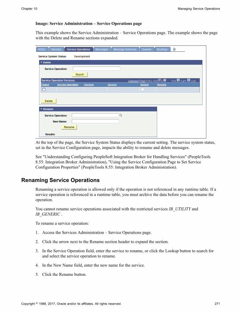
Chapter 10 Managing Service Operations
Image: Service Administration – Service Operations page
This example shows the Service Administration – Service Operations page. The example shows the pagewith the Delete and Rename sections expanded.
At the top of the page, the Service System Status displays the current setting. The service system status,set in the Service Configuration page, impacts the ability to rename and delete messages.
See "Understanding Configuring PeopleSoft Integration Broker for Handling Services" (PeopleTools8.55: Integration Broker Administration), "Using the Service Configuration Page to Set ServiceConfiguration Properties" (PeopleTools 8.55: Integration Broker Administration).
Renaming Service OperationsRenaming a service operation is allowed only if the operation is not referenced in any runtime table. If aservice operation is referenced in a runtime table, you must archive the data before you can rename theoperation.
You cannot rename service operations associated with the restricted services IB_UTILITY andIB_GENERIC .
To rename a service operation:
1. Access the Services Administration – Service Operations page.
2. Click the arrow next to the Rename section header to expand the section.
3. In the Service Operation field, enter the service to rename, or click the Lookup button to search forand select the service operation to rename.
4. In the New Name field, enter the new name for the service.
5. Click the Rename button.
Copyright © 1988, 2017, Oracle and/or its affiliates. All rights reserved. 271
Managing Service Operations Chapter 10
Deleting Service OperationsYou can delete service operations individually, with the exception of the default service operation version.If you mark the default service operation for deletion, the system marks all versions for deletion and theentire service operation is deleted.
When you delete a service operation, you are actually deleting a version of a service operation. A serviceoperation cannot exist without at least one default version.
Note: If you delete the default version of a service operation, the system deletes all versions of the serviceoperation.
Deleting a service operation is allowed only if the operation is not referenced in any runtime table. Ifa service operation is referenced in a runtime table, you must first archive the data before deleting theservice operation. Use the Service Operations Monitor to archive data.
See "Archiving Service Operations" (PeopleTools 8.55: Integration Broker Service Operations Monitor).
You cannot delete service operations associated with the restricted services IB_UTILITY andIB_GENERIC .
To delete a service operation:
1. Access the Services Administration – Service Operations page.
2. Click the arrow next to the Delete section header to expand the section.
3. In the Service Operations field, enter the service operation name to delete and click the Search button.
Search results appear in the results grid.
4. In the results grid, select the check box next to the service operation or service operations to delete.
5. Click the Delete button.
272 Copyright © 1988, 2017, Oracle and/or its affiliates. All rights reserved.

Chapter 11
Managing REST Services
Understanding Managing REST Services
As non-REST services are used to logically group a set of non-REST service operations, REST servicesare used to logically group a set of REST service operations.
For example, if you have a number of REST service operations that are related to customers, such asthose pertaining to customer information, adding customers, updating customers, deleting customers, andso on, you can create a customer REST service and then associate the related REST service operationswith that REST service.
Before you can provide or consume REST services in a PeopleSoft system, you must configure thesystem for handling services."Configuring the Integration System to Handle Services" (PeopleTools 8.55:Integration Broker Administration)
Common Elements Used to Manage REST Services
Comments (Optional.) Enter comments about the service or servicedefinition.
Description Description of the service.
Is Provider This option appears when the service is defined as a REST-based service.
Select the check box to define the service as a provider service.
Link Existing Operations Click to add service operations already defined in the system toa service.
Object Owner ID (Optional.) Indicates the owner of the service.
The owner ID helps to determine the application team that lastmade a change to a service definition. The values in the drop-down list box are translate table values that you can define inthe OBJECTOWNERID field record.
Operation Type Specifies how the service is transmitted.
On the Service page this field defines the operation type of theservice operation added.
Provide Web Service Click to launch the Provide Web Services component and exporta PeopleSoft REST service as a WADL document.
Copyright © 1988, 2017, Oracle and/or its affiliates. All rights reserved. 273
Managing REST Services Chapter 11
This link appears only when the service is a provider RESTservice.
REST Method Indicates the HTTP method for manipulating REST resources.
REST Service The service is defined as a REST-based service when this box isselected.
Schema Namespace Provides qualification for attributes and elements within anXML schema document (XSD).
The default is http://xmlns.oracle.com/Enterprise/Tools/schemas.
The namespace on the message definition defaults to the schemanamespace you set as the default on the Service Configurationpage.
Note: If you change the namespace, all future messages willhave the new namespace.
Service The name of the service.
Service Alias (Optional.) Overrides the service name and will be the name ofthe service when the WSDL is provided or exported. The aliasenables you to use mixed case in the name.
Service Operation The name of the service operation to associate with the service.
On the Services page, use this field to add new serviceoperations for the current service.
Namespace The namespace field on the Service pages provides qualificationfor attributes and elements within a WADL document.
The value defined in the Service Namespace field in the ServiceConfiguration page is used as the default service namespace onthe Services page. The default value is http://xmln.oracle.com/enterprise/tools/service.
Service System Status The status that is selected restricts rename, delete, and otheradministrative actions that users can perform on integrationmetadata in the Services Administration component.
Values are:
• Production.
• Development.
See "Understanding Configuring PeopleSoft Integration Brokerfor Handling Services" (PeopleTools 8.55: Integration BrokerAdministration).
274 Copyright © 1988, 2017, Oracle and/or its affiliates. All rights reserved.

Chapter 11 Managing REST Services
View WADL Click the link to view WADL documents in the WSDLrepository that have been generated for the service
This link appears only when the service you are viewing is aREST-based provider service.
Accessing and Viewing REST Service Definitions
This section discusses how to:
• Access REST service definitions.
• View WADL documents for REST services.
• View REST service operation information.
• View messages defined for REST service operations.
Accessing REST Service DefinitionsREST service definitions appear on the Services page (IB_SERVICEDEFN) in the Service component(IB_SERVICEDEFN).
Use the Services – Search page to search for and access REST definitions in the database.
Image: Services – Search page
This example illustrates the Services – Search page.
Note that the Services – Search page features a REST Service check box. To access a REST service inthe database you must select the REST Service check box. If you do not select the check box, the systemsearches the database for non-REST services only.
After a successful search for a REST service, the system displays the definition in the Services page.
Copyright © 1988, 2017, Oracle and/or its affiliates. All rights reserved. 275
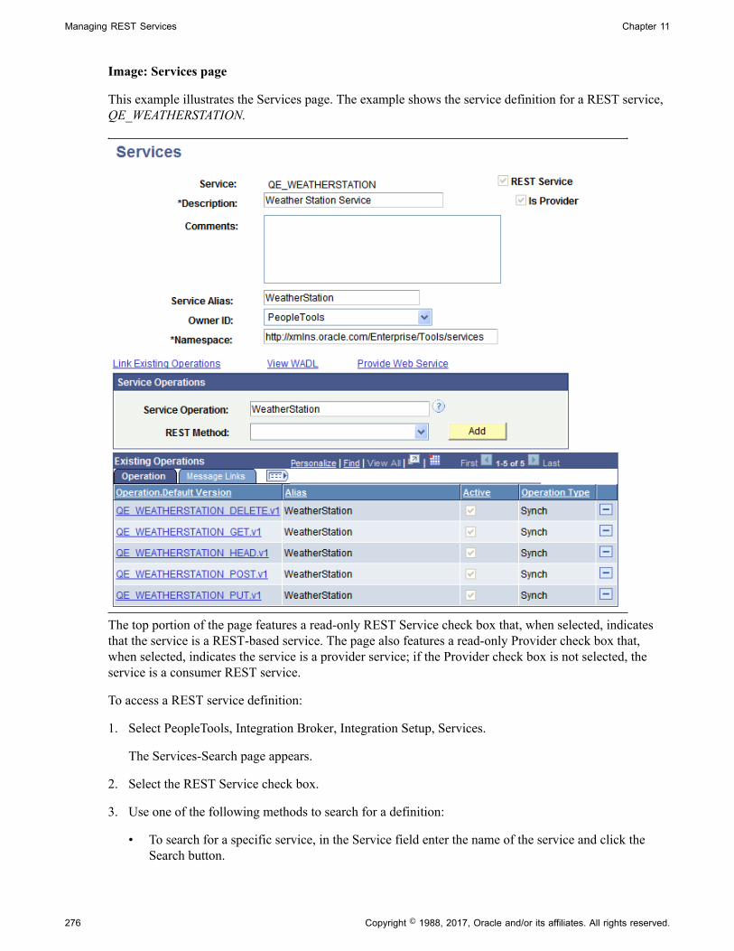
Managing REST Services Chapter 11
Image: Services page
This example illustrates the Services page. The example shows the service definition for a REST service,QE_WEATHERSTATION.
The top portion of the page features a read-only REST Service check box that, when selected, indicatesthat the service is a REST-based service. The page also features a read-only Provider check box that,when selected, indicates the service is a provider service; if the Provider check box is not selected, theservice is a consumer REST service.
To access a REST service definition:
1. Select PeopleTools, Integration Broker, Integration Setup, Services.
The Services-Search page appears.
2. Select the REST Service check box.
3. Use one of the following methods to search for a definition:
• To search for a specific service, in the Service field enter the name of the service and click theSearch button.
276 Copyright © 1988, 2017, Oracle and/or its affiliates. All rights reserved.
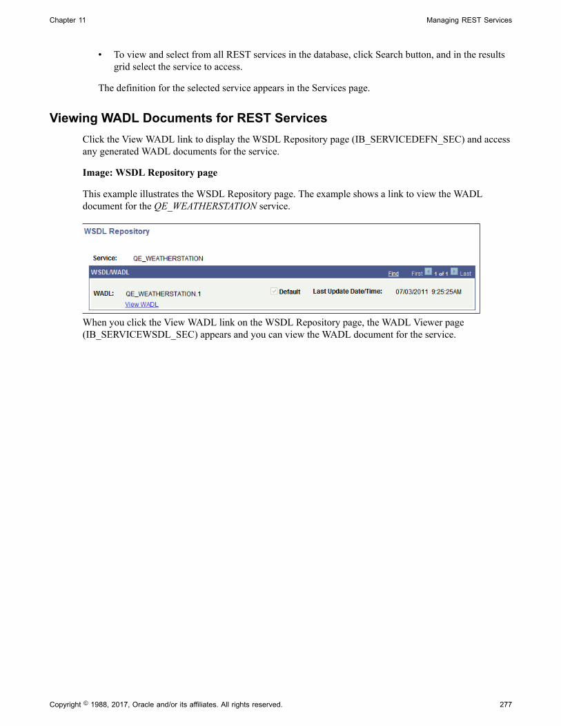
Chapter 11 Managing REST Services
• To view and select from all REST services in the database, click Search button, and in the resultsgrid select the service to access.
The definition for the selected service appears in the Services page.
Viewing WADL Documents for REST ServicesClick the View WADL link to display the WSDL Repository page (IB_SERVICEDEFN_SEC) and accessany generated WADL documents for the service.
Image: WSDL Repository page
This example illustrates the WSDL Repository page. The example shows a link to view the WADLdocument for the QE_WEATHERSTATION service.
When you click the View WADL link on the WSDL Repository page, the WADL Viewer page(IB_SERVICEWSDL_SEC) appears and you can view the WADL document for the service.
Copyright © 1988, 2017, Oracle and/or its affiliates. All rights reserved. 277

Managing REST Services Chapter 11
Image: WADL Viewer page
This example illustrates the WADL Viewer page. The example shows the generated WADL document forthe QE_WEATHERSTATION service appearing on the page.
To view a WADL document for a REST service:
1. Access the service definition (PeopleTools, Integration Broker, Integration Setup, Services).
2. Click the View WADL link.
The WSDL Repository page appears.
3. Click the View WADL link.
The document appears in the WADL Viewer page.
4. Click the Return button to return to the WSDL Repository page.
5. Click the Return button again to return to the Services page.
278 Copyright © 1988, 2017, Oracle and/or its affiliates. All rights reserved.

Chapter 11 Managing REST Services
Viewing REST Service Operation InformationThe Existing Service Operations section of the Services page contains an Operation tab that displaysservice operations and service operation versions that are associated with the service. It also displaysdescriptions of the service operations, the type of operation, and whether the service operation is active.When you click the name of a service operation, the operation opens on the Service Operations page,where you can view and modify service operations information, work with the service operation handlers,routing definitions, and do much more.
View Messages Defined for REST Service OperationsThe Existing Service Operations section of the Services page contains a Messages Links tab that displaysthe request and response messages defined for each REST service operation in the service.
Image: Services page
This example illustrates the Existing Service Operations section of the Services page. The example showsthe Message Links tab displaying request and response messages for the service operations that areassociated with the QE_WEATHERSTATION service
Click the request or response message name to open the message in the Message Definitions page, whereyou can view and modify message definition information, message schema information, and more.
Adding REST Service Definitions
This section discusses how to add REST service definitions to the PeopleSoft system.
Understanding Naming Services and Service Aliases for REST ServiceDefinitions
REST service names and REST service alias names can be exposed as REST services. As a result, thefollowing restrictions apply when you name a REST service or a REST service alias. REST service namesand REST service alias names:
• Cannot begin with XML, xml, or Xml.
• Cannot begin with a digit.
• Cannot begin with a character.
Copyright © 1988, 2017, Oracle and/or its affiliates. All rights reserved. 279
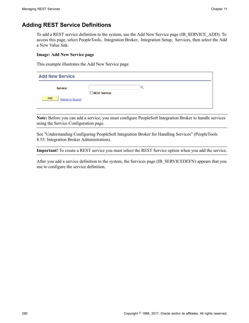
Managing REST Services Chapter 11
Adding REST Service DefinitionsTo add a REST service definition to the system, use the Add New Service page (IB_SERVICE_ADD). Toaccess this page, select PeopleTools, Integration Broker, Integration Setup, Services, then select the Adda New Value link.
Image: Add New Service page
This example illustrates the Add New Service page.
Note: Before you can add a service, you must configure PeopleSoft Integration Broker to handle servicesusing the Service Configuration page.
See "Understanding Configuring PeopleSoft Integration Broker for Handling Services" (PeopleTools8.55: Integration Broker Administration).
Important! To create a REST service you must select the REST Service option when you add the service.
After you add a service definition to the system, the Services page (IB_SERVICEDEFN) appears that youuse to configure the service definition.
280 Copyright © 1988, 2017, Oracle and/or its affiliates. All rights reserved.

Chapter 11 Managing REST Services
Image: Services page
This example illustrates the Services page. The example shows that a REST-based service definitioncalled DEMO_REST_SERVICE has been added to the system. Note that the REST Service check box atthe top of the page is checked, signifying that the service is REST-based.
To add and configure a REST service definition:
1. Access the Services page (PeopleTools, Integration Broker, Integration Setup, Services).
2. Click the Add a New Value link.
3. In the Service field, enter a name for the service.
Restrictions for naming services are discussed elsewhere in this section.
See Understanding Naming Services and Service Aliases for REST Service Definitions.
4. Select the Rest Service check box.
5. Click the Add button.
The Services page appears.
6. In the Description field, enter a description for the service.
7. (Optional.) Select the Is Provider check box to define the service as a provider service.
By default, when you add a REST-based service to the system it is a provider service.
8. (Optional.) In the Comments field, enter comments about the service or the service.
9. (Optional.) In the Service Alias field, enter an alias name for the service.
Copyright © 1988, 2017, Oracle and/or its affiliates. All rights reserved. 281
Managing REST Services Chapter 11
Restrictions for naming service aliases are discussed elsewhere in this section.
See Understanding Naming Services and Service Aliases for REST Service Definitions.
10. (Optional.) From the Object Owner ID drop-down list box, select the owner of the service.
11. In the Namespace field, enter a namespace URI for the service.
The default value is the namespace that is declared in the Service Namespace field on the ServiceConfiguration page.
12. Click the Save button.
Adding Service Operations to REST Service Definitions
This section discusses how to:
• Add existing service operations to REST service definitions.
• Define new service operations for REST service definitions.
Understanding Adding Service Operations to REST Service DefinitionsYou can add a REST service operation that already exists in the database to a REST service definition, oryou can add a new REST service operation to the database.
Adding Existing Service Operations to REST Service DefinitionsThe process for adding existing REST service operations to REST services is identical to the process foradding non-REST services to non-REST service operations.
Important! You can add only those service operations defined as REST service operations to RESTservice definitions; you cannot add non-REST service operations to REST services and you cannot addREST service operations to non-REST services.
See Adding Existing Service Operations to Service Definitions.
Adding New Service Operation Definitions for REST ServicesThe only way to add a new REST service operation to the database is from a REST service, using the Addbutton in the Service Operations section of the Services page (IB_SERVICEDEFN).
The type of service, provider or consumer, determines the type of service operation that the system adds.If you are working with a provider service and add a service operation, a provider service operation isadded to the service; if you are working with a consumer service and add a service operation, the systemadds a consumer service operation.
282 Copyright © 1988, 2017, Oracle and/or its affiliates. All rights reserved.

Chapter 11 Managing REST Services
Image: Services page
This example illustrates the Services page. The example shows the service definition for theWEATHERSTATION service. The service is a provider service, as indicated by the selection of the IsProvider check box.
Use the Service Operations section on the Services page to add REST service operation definitions tothe system. The system automatically appends the service operation name with the name of the selectedREST method. This functionality allows you to reuse the service operation name using other methodtypes. The system allows you to enter a service operation name in mixed-cased. The service operationname you enter becomes the default service operation alias.
So for example, if you enter a service operation name of WeatherStation and select the GET method fromthe REST Method drop-down list, the system names the operation WEATHERSTATION_GET and theservice operation alias is WeatherStation.
If a service is defined as a provider service, all service operations you create from the service definitionare provider services operations. If a service is defined as a consumer service, all service operations youcreate from the service definition are consumer service operation.
After you provide a service operation name and a REST method and click the Add button, the new serviceoperation appears in the Service Operations component and you can proceed to configure the operation.
Copyright © 1988, 2017, Oracle and/or its affiliates. All rights reserved. 283

Managing REST Services Chapter 11
Image: Service Operations – General tab
This example illustrates the Service Operations – General tab. The example shows a new REST serviceoperation called WEATHERSTATION_GET.
To add a new service operation for a REST-based service:
1. Access the Services page (PeopleTools, Integration Broker, Integration Setup, Services).
The Services page appears.
2. In the Service Operations section, locate the Service Operation field and enter a name for the newservice operation.
284 Copyright © 1988, 2017, Oracle and/or its affiliates. All rights reserved.

Chapter 11 Managing REST Services
3. From the REST Method drop-down list, select the HTTP method for manipulating the resourcesdefined in the service operation. The valid values are:
• Delete.
• Get.
• Head.
• Post.
• Put.
REST methods are defined elsewhere in the product documentation.
4. Click the Add button.
The Service Operations-Definitions page appears. Use the page to configure the service operation.
Restricting and Enabling Write Access to REST ServiceDefinitions
You can restrict write access to a REST service so that sensitive fields of the service definitionand of associated service operations appear in read-only mode. Use the Restricted Service page(IB_SVCSETUP3) in the Service Configuration component (IB_SVCSETUP) to restrict a service. Usethe process for restricting and enabling write access to non-REST service definition for restricting andenabling write access to REST service definitions.
See Restricting and Enabling Write Access to Service Definitions.
Renaming and Deleting REST Service Definitions
You can rename and delete services using the Services tab in the Service Administration component(IB_HOME_PAGE). Use the process for renaming and deleting non-REST service definitions forrenaming and deleting REST service definitions.
See Renaming and Deleting Service Definitions.
Activating and Deactivating REST Service Definitions in Bulk
You can activate and deactivate services in bulk using the Service Activate/Deactivate page(IB_HOME_PAGE9) in the Service Administration component. Use the process for activating anddeactivating non-REST services in bulk for activating and deactivating REST services in bulk.
See Activating and Deactivating Service Definitions in Bulk.
Copyright © 1988, 2017, Oracle and/or its affiliates. All rights reserved. 285

Managing REST Services Chapter 11
286 Copyright © 1988, 2017, Oracle and/or its affiliates. All rights reserved.
Chapter 12
Managing REST Service Operations
Understanding REST Service Operations
This section discusses:
• REST service operations.
• REST service operation types.
• REST methods.
• REST resource definitions.
• REST messages.
• Naming conventions for REST service operation metadata.
• REST service operation aliases.
• REST service operation versions.
• Monitoring service operations.
REST Service OperationsA REST service operation definition consists of general information about an operation, such as its name,description, request and response messages, and so on.
REST services operations are synchronous service operations.
Like a non-REST service operations, a REST service operation contain a routing, which determines thedirection, inbound or outbound, of the service operation.
For a provider REST service operation the system creates an any-to-local routing definition whenyou save the service operation. You have the option to generate a local-to-local routing definition. Forconsumer REST service operations the system creates an outbound local-toWADL routing definitionwhen you save the service operation. You cannot add routing definitions to provider or consumer RESTservice operations.
A REST service operation definition also contains a handler, which contains and runs the programminglogic for providing or consuming the service operation, manipulating message content, and so on.
REST Service Operations TypesAll REST service operations are synchronous service operations.
Copyright © 1988, 2017, Oracle and/or its affiliates. All rights reserved. 287

Managing REST Service Operations Chapter 12
A synchronous service operations is processed in real time. Processing on the sending system does notcontinue until it receives a response from the receiving system.
REST MethodsREST methods determine the HTTP method for manipulating the resources defined in the serviceoperation. The valid values are listed and described in the following table and can all be used for providerand consumer service operations:
DELETE Delete an existing resource.
GET Retrieve a representation of a resource.
HEAD Identical to a GET except that no message body is returned inthe response.
POST Create a new resource to an existing URL.
PUT Create a new resource to a new URL, or modify an existingresource to an existing URL.
REST Resource DefinitionsREST service operation definitions contain a REST Resource Definition section where you define theREST base URL, resource URI templates, URI indexes, and document template. These components arediscussed in greater detail elsewhere in the product documentation.
REST MessagesThis section provides information about request and response messages used in REST service operations.
Request and Response Message CombinationsThe REST method you select for a REST service operation determines the request and response messagecombination that you can use for the operation. The following table lists the allowable request andresponse message combinations for each REST method:
REST Method Request Message Response Message
Delete Optional. Optional.
Get Optional. Optional.
Head No. Optional.
Post No. Yes.
Put No. No.
288 Copyright © 1988, 2017, Oracle and/or its affiliates. All rights reserved.

Chapter 12 Managing REST Service Operations
MIME Content-TypesWhen you specify a message for a REST service operation, you must also specify the MIME content-typeof the message. PeopleSoft supports the following content types for request and response messages usedfor REST service operations:
• application/json
• application/xml
• text/xml
• text/plain
• text/html
HTTP Status CodesWhen you define a message for a REST service operation, along with the MIME content-type, specify theHTTP response code to return to the integration partner. Note that the content-type defines the acceptableHTTP media type.
PeopleSoft supports the following HTTP status codes:
• 200. (Default.)
• 201. This value is valid only when the REST method is Post.
• 202.
• 203. This value is valid only when the REST method is Get.
• 204.
• 205.
• 206.
• 207.
Optional MIME Content-Types and HTTP Status CodesYou can assign optional content-types and status codes to message instances on REST service operations.
Generated WADL documents will reflect the optional content-type values, allowing consumers to requestthe content type they prefer.
You can define optional content types on request, response, and fault message instances.
You can define optional status codes on response message instances.
Naming Conventions for REST Service Operation MetadataThe same naming convention restrictions that apply to non-REST service operations apply to RESTservice operations.
See Naming Conventions for Service Operation Metadata.
Copyright © 1988, 2017, Oracle and/or its affiliates. All rights reserved. 289

Managing REST Service Operations Chapter 12
REST Service Operation AliasesA service operation alias or operation alias is the service operation name that displays for the serviceoperation when WADL is provided.
REST service operation aliases may be mixed case.
Service operation alias names for REST service operations can be the same across types. For example,you can have the same alias, for example MY_ALIAS, for Delete, Get, Put, Post and Head REST serviceoperations.
REST Service Operation VersionsThe same information about non-REST service operation versions applies to REST service operationversions.
See Service Operation Versions.
WADL NodePeopleTools delivers a WADL node that is the default node for consumer REST services.
Monitoring REST Service OperationsYou can use the same tools to monitor REST service operations as those you use to monitor non-RESTservice operations. These tools include:
• The Service Operations Monitor.
• The Integration Network Monitor.
• The Integration Network Transactional Tracker.
• Performance monitoring tools.
The Managing Service Operations topic in the product documentation provides a brief summary of eachof these tools.
See Monitoring Service Operations.
You can also find complete documentation for these tools elsewhere in the product documentation.
Related LinksIntegration Broker Service Operations Monitor"Using the Integration Network Monitor" (PeopleTools 8.55: Integration Broker Administration)"Using the Integration Network Transactional Tracker" (PeopleTools 8.55: Integration BrokerAdministration)"Monitoring PeopleSoft MODULE and ACTION Information" (PeopleTools 8.55: Data Management)"Associating PeopleSoft Users, Modules, and Actions with DB2 UDB Threads" (PeopleTools 8.55: DataManagement)"Monitoring Module and Action Information" (PeopleTools 8.55: Data Management)
290 Copyright © 1988, 2017, Oracle and/or its affiliates. All rights reserved.
Chapter 12 Managing REST Service Operations
Accessing and Viewing REST Service Operation Definitions
This section discusses how to:
• Access REST service operation definitions.
• View REST service operation definitions.
Accessing REST Service Operation DefinitionsYou access a REST service operation definition from the service definition that contains the operation youwant to access.
Use the Services page (IB_SERVICE) to list and access REST service operations; use the ServiceOperations page (IB_SERVICE_REST) to view and work with REST service operations.
Copyright © 1988, 2017, Oracle and/or its affiliates. All rights reserved. 291
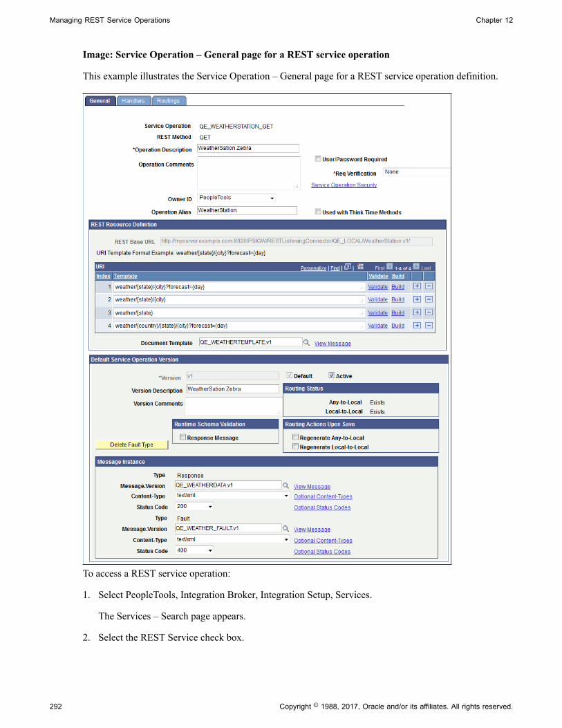
Managing REST Service Operations Chapter 12
Image: Service Operation – General page for a REST service operation
This example illustrates the Service Operation – General page for a REST service operation definition.
To access a REST service operation:
1. Select PeopleTools, Integration Broker, Integration Setup, Services.
The Services – Search page appears.
2. Select the REST Service check box.
292 Copyright © 1988, 2017, Oracle and/or its affiliates. All rights reserved.

Chapter 12 Managing REST Service Operations
Important! You must select the REST Service box to retrieve a REST service operation from thedatabase. If you do not select this option, the system retrieves non-REST services when you performthe search.
3. In the Service field, perform one of the following actions:
• Enter all or part of the service name.
• Click the Lookup button to search for and select a service name.
• Leave the field blank to retrieve a list of all REST services in the database.
4. Click the Searchbutton.
The Services grid displays a list of results.
5. Click the name of the service that contains the service operation that you want to access.
The service definition appears.
6. In the Existing Service Operations grid, click the service operation name.
The Service Operations – General tab appears with data for the service operation that you selected.
Viewing REST Service Operation DefinitionsThe Service Operations component includes three pages:
General Tab Features general-service and default-service operationinformation.
This page also features REST resource definition informationif the service operation you are viewing is a REST serviceoperation.
Handlers Tab Provides summary information about handlers that have beenadded to an operation. Service operation handlers contain theprogramming logic for sending and receiving service operationsand their contained messages, and for manipulating content.
Note that handlers are not used for REST consumer-basedservice operations and the Handler tab does not appear whenyou view or work with a consumer REST service operation.
Routings Tab Provides summary information about service operationsroutings. Routing definition determine the direction — inbound, outbound — of service operations.
Copyright © 1988, 2017, Oracle and/or its affiliates. All rights reserved. 293

Managing REST Service Operations Chapter 12
Viewing General Service Operation InformationThe top portion of this page contains basic information about a service operation, including its name,description, and so on. The Service Operation Security link opens the permission list for the service. Notethat the Service Operation Security link appears only after a service operation definition is saved.
The page features a REST Resource Definition section that displays the REST base URL, resourcesdefined for the service operation, and the name of the document template associated with the serviceoperation. This section of the page also provides access to the URI Template Builder and to build URItemplates as well as to a page to validate URIs.
The Default Service Operation Version section displays service-operation version information andwhether runtime schema validation is enabled.
The Runtime Schema Validation group box shows if runtime schema validation is selected for the requestand response messages.
The Routing Status group box shows if any-to-local or local-to-local routing definitions have beengenerated for the service operation. Click the Routings tab to view detailed information about routingdefinitions that exist for a service operation.
The Routing Actions Upon Save group box shows the possible routings that the system can generatewhen the service operation definition is saved.
The Message Information section displays the request message, response message information, and faultmessage for the service operation. The View Message links in this section open the displayed message onthe Message Definition page, where you can view additional information about the message.
Viewing Handler InformationTo view service operation handler information, click the Handlers tab. Doing so displays the ServiceOperations - Handlers page (IB_SERVICEHDLR) which lists summary information about handlers thathave been added to an operation.
Image: Service Operations – Handlers page
This example illustrates the Service Operations – Handlers page
Each REST-based provider service operation has a single handler; REST-based consumer serviceoperations do not have handlers.
Note: There are no handlers for REST-based consumer service operations and the Handler tab does notappear when you view and work with consumer REST service operations.
294 Copyright © 1988, 2017, Oracle and/or its affiliates. All rights reserved.

Chapter 12 Managing REST Service Operations
The only handler Type available for provider REST services is the OnRequest handler. When workingwith REST provider service operations you can implement the OnRequest handler as an application classonly. The application class is implemented as any other OnRequest integration broker event.
The summary information includes the handler name, the handler type, and the implementation methodfor the handler. The status of the handler, active or inactive, also appears.
Click the Details link to open the Handler Details page (IB_SERVICEHDLR_SEC) for the handler.
Image: Handler Details page
This example illustrates the Handler Details page.
The Handler Details page shows additional information about the handler, including the owner andapplication class details.
You can also use this page to specify the handler details.
Viewing Routing InformationClick the Routings tab to open the Service Operations - Routings page (IB_SERVICERTNGS) to view asummary of routing definitions for an operation.
Copyright © 1988, 2017, Oracle and/or its affiliates. All rights reserved. 295

Managing REST Service Operations Chapter 12
Image: Service Operations – Routings page
This example illustrates the Service Operations – Routings page.
The Routings Definition grid on the page lists summary information for routings that are defined for aservice operation. Summary information that is displayed includes the routing definition name, serviceoperation version, routing type, sending node, receiving node, direction of the routing and the routingstatus.
Click a routing definition name to open the routing in the Routing Definitions component, where you canview additional information about the routing.
When you create a provider REST service operation the system automatically creates an any-to-localrouting. You can also generate local-to-local routings for a provider REST service operation.
When you create a consumer REST service operation the system automatically creates a local-to-WADLrouting definition. Local-to-WADL is the only routing type you can use with consumer REST serviceoperations.
See Viewing Routing Definitions in Graphical Format.
You can also use this page to activate or inactivate routings for an operation.
See Adding Routing Definitions, Activating and Inactivating Routing Definitions.
Adding REST Service Operations
To add a REST service operation to the system, you must first create a REST service using the Servicescomponent.
Information fro adding REST services and adding REST service operations to those services is describedelsewhere in the product documentation.
See Adding REST Service DefinitionsAdding REST Service Operations
Defining General REST Service Operation Information
To define general REST service operation information:
1. Access the Service Operations-General page (PeopleTools, Integration Broker, Integration Setup,Services . Select the service that contains the service operation with which you want to work. The
296 Copyright © 1988, 2017, Oracle and/or its affiliates. All rights reserved.
Chapter 12 Managing REST Service Operations
Services page appears. In the Existing Service Operations section, select the service operation. TheService Operations – General page appears.
2. In the Operation Description field, enter a description for the operation.
3. (Optional.) Select the User ID/ Password Required check box to require a user ID and password forinbound service operations.
See "Managing User Authentication" (PeopleTools 8.55: Integration Broker Administration).
4. The Security Verification drop-down list appears when you are configuring a provider serviceoperation, and you may select the level of security with which inbound integrations must be sent. Thevalid options for REST based provider/inbound service operations are:
• Basic Authentication.
• Basic Authentication and SSL.
• PeopleSoft Token.
• PeopleSoft Token and SSL.
• None. (Default.)
• SSL.
Validating security on inbound integrations is described in other topics in the product documentation.
See "Validating Security on Inbound Integrations" (PeopleTools 8.55: Integration BrokerAdministration).
5. (Optional.) In the Operation Comments field, enter comments about the service operation.
6. (Optional.) From the Object Owner ID field, select the owner of the definition.
The owner ID helps to determine the application team that last made a change to a servicedefinition. The values in the drop-down list box are translate table values that you can define in theOBJECTOWNERID field record.
7. (Optional.) In the Operation Alias field, enter an alias name for the service operation.
When working with REST service operations the service operation alias is automatically populatedwith the service operation name as you entered it when you created the service operation.
Managing REST Resource Definitions
This section discusses how to:
• Configure a REST resource definition.
• Define a REST base URL.
• Define a document template.
• Define a URI template.
Copyright © 1988, 2017, Oracle and/or its affiliates. All rights reserved. 297

Managing REST Service Operations Chapter 12
• Use the URI Template Builder.
• Validate a URI template.
• Use the URI Template Builder to build a URI template.
Understanding Managing REST Resource DefinitionsWhen you configure a REST resource definition the end result is the URL that the service consumer usesto invoke the service.
The information defined in the REST resource definition is included in the WADL document that theservice provider furnishes to the service consumer. The service consumer then extracts the informationfrom the WADL document and defines it in the consumer service operation it creates for the service.
REST service operation definitions contain a REST Resource Definition section where you configure andmanage the resource definition.
The REST resource definition is where you define the REST base URL, one or more URI templates, anda document template. The section also contains a feature that enables you to validate the defined URItemplates.
To build URI templates you can manually enter template strings or use the URI Template Builder.
Understanding REST Resource Definition ConceptsThis section describes REST resource definition concepts.
REST Base URLThe REST base URL is the common part of the URL to invoke the provider or consumer web service.
For a REST service provider this value is always the REST target location entry defined on the ServiceConfiguration page for provider service operations. When the Provide Web Service wizard is used tocreate the WADL document, the option to select a secure REST target location can be selected. Forprovider service operations this URL is simply informational to show what would be used when creatingthe complete URL(s).
The REST base URL is constructed as part of the initialization/retrieval of the service operation and usesthe following format:
<Provider REST target location>/< External alias from any-to-local routing>/
For a REST consumer the common part of the URL defined is the provider's WADL document.
Document TemplateA document template is a Document type message that define in the REST resource definition. Thedocument message has primitive elements and collection elements defined with names used for valuereplacement within the URI template. This document can only contain primitive elements and collectionelements. The document cannot contain any imports (compounds) or compound elements. The advantageof using documents is that they cannot be inadvertently changed, as is not the case with defined recordsand/or fields.
298 Copyright © 1988, 2017, Oracle and/or its affiliates. All rights reserved.
Chapter 12 Managing REST Service Operations
Note: In the Document definition, the variables defined with the braces ( {} ) in the URI template mustbe the exact name of the element name defined on the Document page, not the Tag Name defined on theXML page.A document template is a URI on the wire with values in it.
URI TemplateResources are constructed using URI templates. URI templates use a simple syntax where braces denotevariables to be replaced when the templates are converted to actual URLs. You define the values for theURI template variables in the REST document template.
You can define one or more URI template strings to define one or more resources for the definition
Note: PeopleSoft supports direct variable substitution.
The following example shows a sample URI template syntax:
weather/{state}/{city}?forecast={day}
The denoted variables identified with the braces ( {} ) are replaced with the actual values as defined in thedocument template. In the example shown the variables are state, city and day.
The system validates the string entered for the template to ensure that there is no equivalent or ambiguousdefined templates currently entered on the grid. Moreover the values used within the braces ( {} ) must bedefined on the document template to pass validation.
You can build URI templates by manually entering variable strings in the template fields in the RESTResource Definition or you can use the URI Builder. Each of these methods for building URI templates isdiscussed later in this topic.
URI IndexThe system assigns an integer index value to each URI template you create for a REST service operationupon save.
You will later use these index numbers in PeopleCode to call and manipulate the associate URI template.
URI Template ValidationWhen you construct a URI template, you can verify the URL produced.
The REST Resource Definition URI grid features a Validate link that provides access to the Validate URIpage where you can populate the URI with values from the document template and then test the link.
Understanding URI Template Expressions and ExpansionsWhen building URI templates it is necessary to know these terms:
Expression The text between ‘{‘and ‘}’, including the enclosing braces.
Expansion The string result obtained from a template expression afterprocessing it according to its expression type, list of variablesnames, and value modifiers.
Copyright © 1988, 2017, Oracle and/or its affiliates. All rights reserved. 299

Managing REST Service Operations Chapter 12
PeopleSoft supports the URI template expressions shown in the table. The table summarizes each typeof template expression by its associated operator. The example expansions are based on the followingvariables and values:
var := “value”tools := “tools rules!”empty := “”list := [ “val1”, “val2”, “val3” ]path := “/foo/bar”x := 1024y := 768
300 Copyright © 1988, 2017, Oracle and/or its affiliates. All rights reserved.

Chapter 12 Managing REST Service Operations
In each code example, the values in the first column are the expressions and the values in the secondcolumn are the expansions.
Expression Type Operator Description
Form-Style (Continuation.)
& Form-style query continuation
{&x,y} &x=1024&y=768{&x,y,empty} &x=1024&y=768&empty={&list} &list=val1,val2,val3{&list*} &list=val1&list=val2&list=val3
Form-Style (Expansion.)
? Form-style query expansion.
{?x,y} ?x=1024&y=768{?x,y,empty} ?x=1024&y=768&empty={?list} ?list=val1,val2,val3{?list*} ?list=val1&list=val2&list=val3
Note that the expansion process omits the equal sign ( = ) when the variable value isempty.
Fragment. # Fragment expansion with comma-separated values.
{#var} #value{#tools} #tools%20rules!{#path}/here #/foo/bar/here{#path,x}/here #/foo/bar,1024/here{#path{x}/here #/foo/bar1024/here{#empty}/here #/here{#list} #val1,val2,val3{#list*} #val1,val2,val3
Label. . Label expansion, dot-prefixed
X{.var} X.valueX(.empty} X.X{.list} X.val1,val2,val3X{.list*} X.val1,val2,val3
Path-Segment. / Path-segments, slash-separated
{/var} /value(/var,empty} /value/{/list} /val1,val2,val3{/list*} /val1,val2,val3
Path-Style. ; Path-style parameters, semicolon-prefixed.
{;x,y} ;x=1024;y=768{;x,y,empty} ;x=1024;y=768;empty{;list} ;list=val1,val2,val3{;list*} ;list=val1;list=val2;list=val3
Note that the expansion process omits the equal sign ( = ) when the variable value isempty.
Reserved. + Reserved expansion with comma-separated values.
{+var} value{+tools} tools%20rules!{+path}/here /foo/bar/here{+path,x}/here /foo/bar,1024/here{+path{x}/here /foo/bar1024/here{+empty}/here /here
Copyright © 1988, 2017, Oracle and/or its affiliates. All rights reserved. 301

Managing REST Service Operations Chapter 12
Expression Type Operator Description
{+list} val1,val2,val3{+list*} val1,val2,val3
Simple String. NA Simple expansion with comma-separated values.
{var} value{tools} tools%20rules%21{path}/here %2Ffoo%2Fbar/here{x,y} 1024,768{var=default} value{list} val1,val2,val3{list*} val1,val2,val3
Note the following about the operators, expressions, and expansions shown in the table:
• The operator’s associated delimiter (“;”, “?”,”/”,”.”,”#”) is omitted when none of the listed variablesare defined.
• Multiple variables and list values have their values joined with a comma (“,”) if there is no predefinedjoining mechanism for the operator.
• The operators plus ( + ) and fragment ( # ) substitute non-encoded reserved characters found inside thevariables value; the other operators pct-encode reserved characters found in the variable values priorto expansion.
• The explode modifier (“*”) indicates that the variable represents a composite value that may besubstituted in full or partial forms, depending on the variables type or schema. The asterisk (“*”)indicates that just the component names and values are included in the expansion.
Prerequisites for Managing REST Resource DefinitionsThe REST target URL must be specified on the Service Configuration – Target Locations page. The stepsfor defining the REST target location are described elsewhere in the product documentation.
See "Understanding Configuring PeopleSoft Integration Broker for Handling Services" (PeopleTools8.55: Integration Broker Administration).
You must have created a Document type message that contains the values for any variable data you planto use in the URI templates. For this reason you must have an understanding of PeopleSoft DocumentsTechnology to create and manipulate Document type messages.
For information on PeopleSoft Documents Technology see the product documentation for PeopleTools8.55: PeopleSoft Documents Technology.
Configuring REST Resource DefinitionsThis section lists the steps to configure a REST resource definition. Other section within this topicprovide in-depth information and procedures to complete each step.
To configure a REST resource definition:
1. Access the Service Operations – General page (select PeopleToolsIntegration BrokerIntegrationSetupService Operations).
302 Copyright © 1988, 2017, Oracle and/or its affiliates. All rights reserved.

Chapter 12 Managing REST Service Operations
2. Locate the REST Resource Definition section of the page.
3. In the REST Base URL field, enter the base URL.
4. In the Document Template field, enter the name of the document message to associate to the resourcedefinition or click the Lookup button to search the database.
5. In the Template field, enter the syntax for the URI template.
There are two options to create and enter the URI template syntax:
• Manually create and enter the syntax.
• Use the URI Template Builder page to create and enter the syntax.
6. Click the Save button.
7. (Optional.) Click the Validate link to validate a URI template.
Defining REST Base URLsThis section describes defining REST base URLs for provider and consumer service operations.
Understanding Defining REST Base URLsFor provider service operations the system auto-populates the REST base URL. As mentioned elsewherein the product documentation, the base URL is composed of the REST target namespace defined on theService Configuration page and the routing alias defined on the Routings – Parameters page on the any-to-local routing for the service operation. The REST base URL takes the following format:
http://<ProviderRESTTargetNamespace>/<RoutingAlias>
For example:
http://providerserver.example.com:8010/PSIGW/RESTListeningConnector/weatherstation.⇒v1
For consumer service operations you obtain the REST base URL from the WADL document furnishedto you by the service provider. You specify the URL in the REST Base URL field in the REST ResourceDefinition section of the Service Operations – General page.
Specifying REST Base URLs (Provider Services)As described previously, the REST base URL for a provider service operation is auto-populated by thesystem. The value populated comes from the REST target location defined on the system and the routingalias defined on the any-to-local routing definition for the service operation.
The REST base URL for a provider service operation appears in a read-only field in the REST ResourceDefinition section of the Service Operations – General page.
To access the Service Operations – General page select PeopleToolsIntegration BrokerIntegrationSetupService Operations.
Copyright © 1988, 2017, Oracle and/or its affiliates. All rights reserved. 303
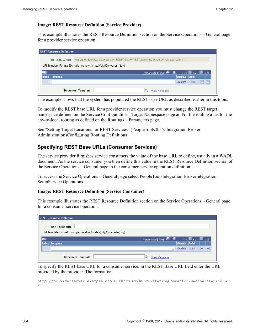
Managing REST Service Operations Chapter 12
Image: REST Resource Definition (Service Provider)
This example illustrates the REST Resource Definition section on the Service Operations – General pagefor a provider service operation.
The example shows that the system has populated the REST base URL as described earlier in this topic.
To modify the REST base URL for a provider service operation you must change the REST targetnamespace defined on the Service Configuration – Target Namespace page and/or the routing alias for theany-to-local routing as defined on the Routings – Parameters page.
See "Setting Target Locations for REST Services" (PeopleTools 8.55: Integration BrokerAdministration)Configuring Routing Definitions
Specifying REST Base URLs (Consumer Services)The service provider furnishes service consumers the value of the base URL to define, usually in a WADLdocument. As the service consumer you then define this value in the REST Resource Definition section ofthe Service Operations – General page in the consumer service operation definition.
To access the Service Operations – General page select PeopleToolsIntegration BrokerIntegrationSetupService Operations.
Image: REST Resource Definition (Service Consumer)
This example illustrates the REST Resource Definition section on the Service Operations – General pagefor a consumer service operation.
To specify the REST base URL for a consumer service, in the REST Base URL field enter the URLprovided by the provider. The format is:
http://providerserver.example.com:8010/PSIGW/RESTListeningConnector/weatherstation.⇒v1
304 Copyright © 1988, 2017, Oracle and/or its affiliates. All rights reserved.
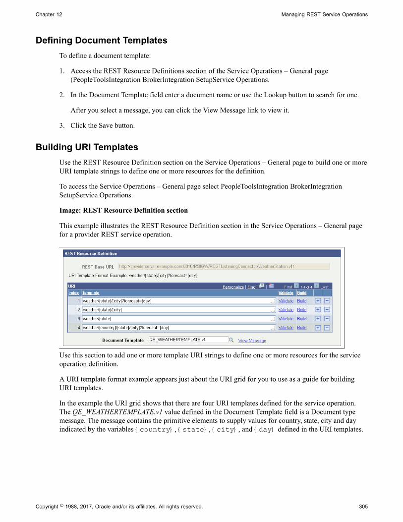
Chapter 12 Managing REST Service Operations
Defining Document TemplatesTo define a document template:
1. Access the REST Resource Definitions section of the Service Operations – General page(PeopleToolsIntegration BrokerIntegration SetupService Operations.
2. In the Document Template field enter a document name or use the Lookup button to search for one.
After you select a message, you can click the View Message link to view it.
3. Click the Save button.
Building URI TemplatesUse the REST Resource Definition section on the Service Operations – General page to build one or moreURI template strings to define one or more resources for the definition.
To access the Service Operations – General page select PeopleToolsIntegration BrokerIntegrationSetupService Operations.
Image: REST Resource Definition section
This example illustrates the REST Resource Definition section in the Service Operations – General pagefor a provider REST service operation.
Use this section to add one or more template URI strings to define one or more resources for the serviceoperation definition.
A URI template format example appears just about the URI grid for you to use as a guide for buildingURI templates.
In the example the URI grid shows that there are four URI templates defined for the service operation.The QE_WEATHERTEMPLATE.v1 value defined in the Document Template field is a Document typemessage. The message contains the primitive elements to supply values for country, state, city and dayindicated by the variables {country}, {state}, {city}, and {day} defined in the URI templates.
Copyright © 1988, 2017, Oracle and/or its affiliates. All rights reserved. 305

Managing REST Service Operations Chapter 12
Image: Document Builder – Document page
This example illustrates the primitive elements defined in a sample document calledQE_WEATHERTEMPLATE.
You cannot save a URI template until you define a document template. The processes for definingdocument templates is described earlier in this topic. Note, too, that when you save the resourcedefinition, the system assigns a sequential URI index to each URI template.
Building URI Templates ManuallyTo manually build a URI template enter the URI string in the Template field in the REST ResourceDefinition section of the Service Operations – General page. The URI template expressions supported aredescribed earlier in this topic.
To access the page select PeopleToolsIntegration BrokerIntegration SetupService Operations.
306 Copyright © 1988, 2017, Oracle and/or its affiliates. All rights reserved.

Chapter 12 Managing REST Service Operations
Image: REST Resource Definition
This example illustrates two URI templates added to a REST resource definition for a provider service.
This example shows two URI template strings added to template, weather/{state}/{city} andweather/{state}. Note that neither of the added URI strings has an index value. When the page issaved, the system assigns a sequential index values to each URI string added.
To manually build a URI template:
1. Access the REST Resource Definition section on the Service Operations – General page.
To access the page select PeopleToolsIntegration BrokerIntegration SetupService Operations.
2. In the URI grid, click the Add a Row button (+) to add a row for the template.
3. Manually enter the URI string.
4. Click the Save button.
Building URI Templates Using the URI Template BuilderUsing the URI Template Builder page (IB_URIBUILDER_SEC) to build URI templates can simplifybuilding complex or lengthy URIs.
This section describes how to access the URI Template Builder page and describes the fields and controlsyou use to build a URI template.
The steps to build a URI template using the URI Template Builder page vary, depending on the documenttemplate defined and the business requirements and goals of each URI template. An example thatillustrates using the URI Template builder to build a URI template appears at the end of this topic.
Prerequisites for Using the URI Template BuilderTo build a URI template using the URI Template Builder you must first define a document template in theresource definition. The document template must contain the values for the variables you plan to build outin the URI template.
Using the URI Template BuilderTo access the URI Template Builder select PeopleToolsIntegration BrokerIntegration SetupServiceOperations. The Service Operations – General page appears. In the REST Resource Definition section ofthe page, click the Build link.
Copyright © 1988, 2017, Oracle and/or its affiliates. All rights reserved. 307
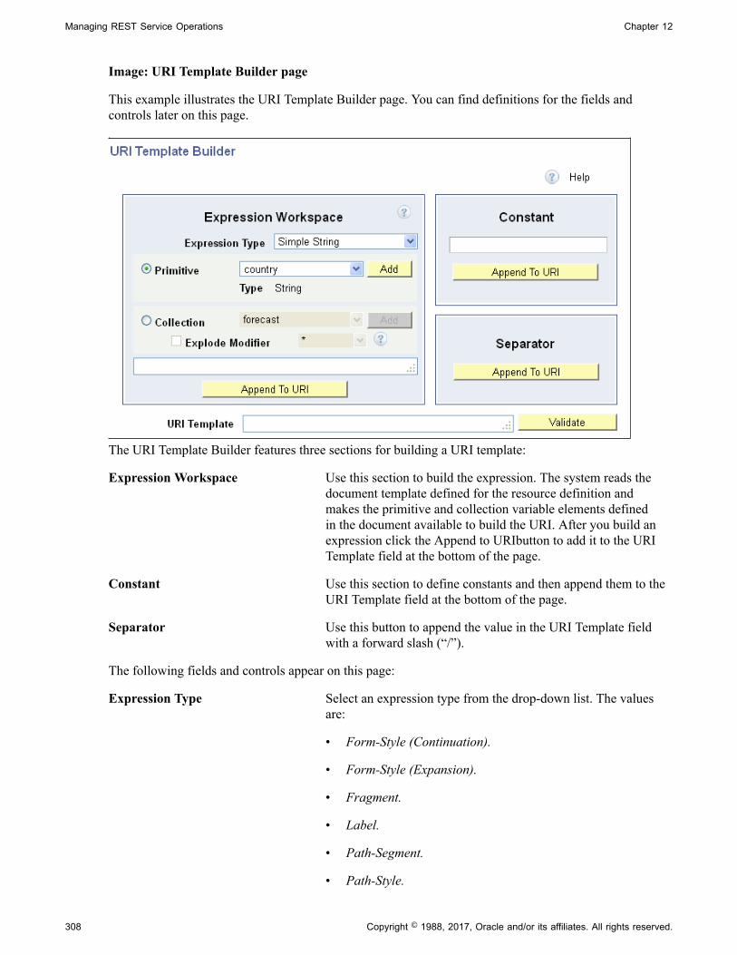
Managing REST Service Operations Chapter 12
Image: URI Template Builder page
This example illustrates the URI Template Builder page. You can find definitions for the fields andcontrols later on this page.
The URI Template Builder features three sections for building a URI template:
Expression Workspace Use this section to build the expression. The system reads thedocument template defined for the resource definition andmakes the primitive and collection variable elements definedin the document available to build the URI. After you build anexpression click the Append to URIbutton to add it to the URITemplate field at the bottom of the page.
Constant Use this section to define constants and then append them to theURI Template field at the bottom of the page.
Separator Use this button to append the value in the URI Template fieldwith a forward slash (“/”).
The following fields and controls appear on this page:
Expression Type Select an expression type from the drop-down list. The valuesare:
• Form-Style (Continuation).
• Form-Style (Expansion).
• Fragment.
• Label.
• Path-Segment.
• Path-Style.
308 Copyright © 1988, 2017, Oracle and/or its affiliates. All rights reserved.
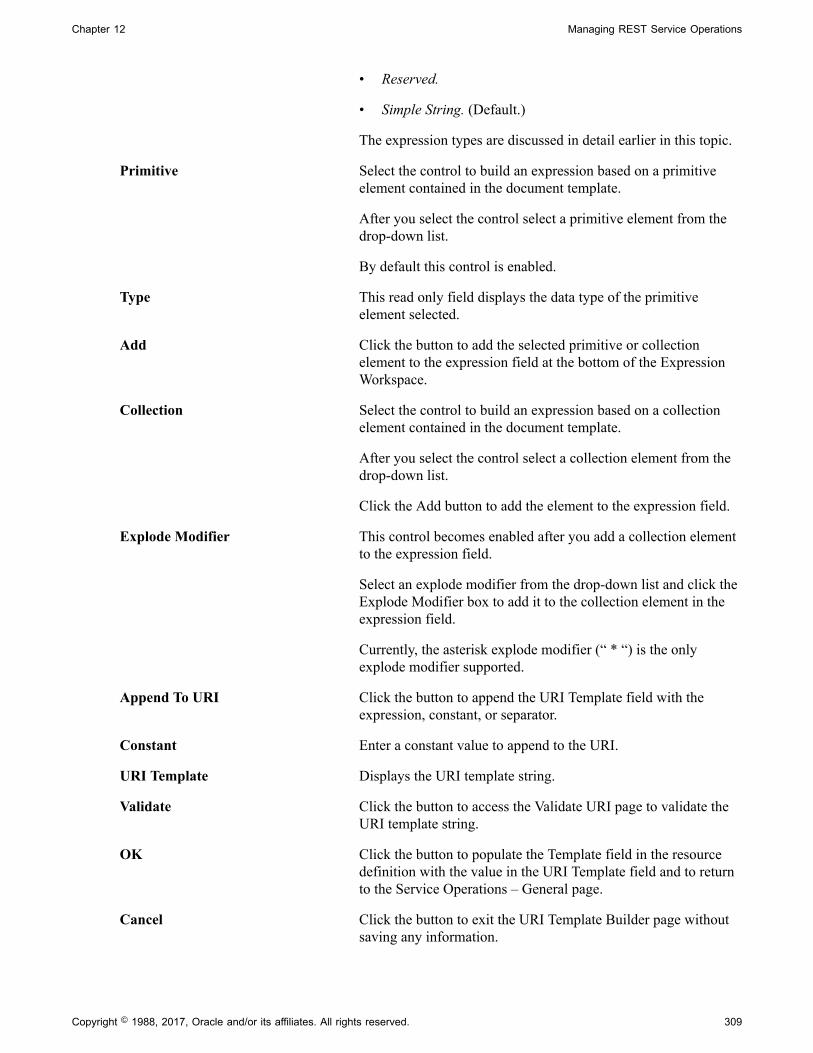
Chapter 12 Managing REST Service Operations
• Reserved.
• Simple String. (Default.)
The expression types are discussed in detail earlier in this topic.
Primitive Select the control to build an expression based on a primitiveelement contained in the document template.
After you select the control select a primitive element from thedrop-down list.
By default this control is enabled.
Type This read only field displays the data type of the primitiveelement selected.
Add Click the button to add the selected primitive or collectionelement to the expression field at the bottom of the ExpressionWorkspace.
Collection Select the control to build an expression based on a collectionelement contained in the document template.
After you select the control select a collection element from thedrop-down list.
Click the Add button to add the element to the expression field.
Explode Modifier This control becomes enabled after you add a collection elementto the expression field.
Select an explode modifier from the drop-down list and click theExplode Modifier box to add it to the collection element in theexpression field.
Currently, the asterisk explode modifier (“ * “) is the onlyexplode modifier supported.
Append To URI Click the button to append the URI Template field with theexpression, constant, or separator.
Constant Enter a constant value to append to the URI.
URI Template Displays the URI template string.
Validate Click the button to access the Validate URI page to validate theURI template string.
OK Click the button to populate the Template field in the resourcedefinition with the value in the URI Template field and to returnto the Service Operations – General page.
Cancel Click the button to exit the URI Template Builder page withoutsaving any information.
Copyright © 1988, 2017, Oracle and/or its affiliates. All rights reserved. 309

Managing REST Service Operations Chapter 12
Validating URI TemplatesThis section discusses how to:
• Use the Validate URI page.
• Use the Set Value page.
• Validate a URI template.
Using the Validate URI PageAfter you construct a URI template you can verify the URL produced by using the Validate URI page(IB_SVCVERIFY_SEC). Use the Set Value page (IB_LSTESTER_SEC) to set test values for the URL.
To access the Validate URI page select PeopleTools, Integration Broker, Service Operations and click theValidate link next to the URI template for the URL to validate.
Image: Validate URI page
This example illustrates the fields and controls on the Validate URI page. You can find definitions for thefields and controls later on this page.
The Validate URI page displays the document information and the elements defined in the documenttemplate specified for the REST resource definition.
310 Copyright © 1988, 2017, Oracle and/or its affiliates. All rights reserved.
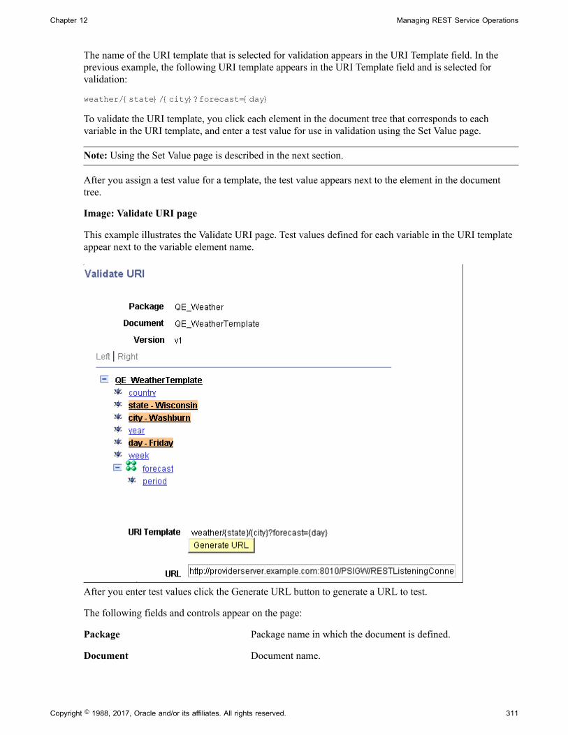
Chapter 12 Managing REST Service Operations
The name of the URI template that is selected for validation appears in the URI Template field. In theprevious example, the following URI template appears in the URI Template field and is selected forvalidation:
weather/{state}/{city}?forecast={day}
To validate the URI template, you click each element in the document tree that corresponds to eachvariable in the URI template, and enter a test value for use in validation using the Set Value page.
Note: Using the Set Value page is described in the next section.
After you assign a test value for a template, the test value appears next to the element in the documenttree.
Image: Validate URI page
This example illustrates the Validate URI page. Test values defined for each variable in the URI templateappear next to the variable element name.
After you enter test values click the Generate URL button to generate a URL to test.
The following fields and controls appear on the page:
Package Package name in which the document is defined.
Document Document name.
Copyright © 1988, 2017, Oracle and/or its affiliates. All rights reserved. 311

Managing REST Service Operations Chapter 12
Version Document version.
Document Tree Displays the element defined in the document template. Click anelement name to access the Set Value page and to set test valuesfor the element.
URI Template This field displays the URI template string created using theURI Template Builder page.
Generate URL Click the button to generate a URL based on the test valuesentered.
URL After you click the Generate URL button, this field displays thegenerated URL.
Return Click the button to return to the URI Template Builder page.
Using the Set Value PageUse the Set Value page to enter test values for URI template validation.
When you click an element in the document tree on the Validate URI page, the Set Value page(IB_LSTESTER_SEC) appears.
Image: Set Value page
This example illustrates the fields and controls on the Set Value page. You can find definitions for thefields and controls later on this page.
The Set Value page provides information about the primitive element selected to assist you in providinga useful value to test. The information that appears varies, depending on the primitive type for which youare providing a value. After you set a test value for an element, the test value appears next to the elementname on the document tree.
The Element Name field displays the element name with which you're working.
In the example, the Primitive Type field and Field Length field display the data type and length as definedfor the element in the document.
The name of the field where you enter a test value depends on the data type. In the previous example, thedata type is a string, and therefore the system prompts you to enter a Long value.
The following table lists the possible labels for the field where you enter a test value:
312 Copyright © 1988, 2017, Oracle and/or its affiliates. All rights reserved.
Chapter 12 Managing REST Service Operations
Data Type Primitive Type Field Label Test Value Field Label
Binary Bin Long
Boolean Bool Page displays a check box.
Character Character Char
Date Date Date
DateTime DT Datetime
Decimal Dec Numeric
Integer Int Numeric
String String Long
Text Text Long
Time Time Time
When you have defined test values for all variables in the URI template, click the Generate URL button togenerate a URL based on the test values you entered.
Validate URI TemplatesTo validate a URI template:
1. Access the Validate URI page ( PeopleTools, Integration Broker, Service Operations and click theValidate link next to the URI template for the URL to validate.
2. In the document tree click an element to define a test value.
The Set Value page appears.
3. Enter a test value for the element and click the OK button.
The Validate URI page appears.
4. Repeat step 2 and step 3 for each variable element in the URI template.
5. On the Validate URI page, click the Generate URL button.
The URL generated based on the test values entered appears in the URL field.
6. Cut and paste the URL into a browser to test.
7. Click the Return button to return to the Service Operations – General page.
Copyright © 1988, 2017, Oracle and/or its affiliates. All rights reserved. 313

Managing REST Service Operations Chapter 12
Example: Using the URI Template Builder to Build URI TemplatesThis section provides an example of using the URI Template Builder to build a URI template. Thissection discusses how to:
• Access the URI Template Builder.
• Build the expression string for the example URI template.
• Append the expression string to the example URI template.
• Add a separator to the example URI template.
• Add a constant to the example URI template.
• Validate the example URI template.
• Add the example URI template to the REST resource definition.
Understanding the URI Template Builder ExampleThe documentation in this section describes how to use the URI Template Builder page to create aURI template for the provider service QE_WEATHERSTATION using the QE_WEATHERSTATION.V1document template illustrated throughout this topic.
This example illustrates building the following URI template:
{state,country}/WhiteSalmon
In this example:
• There is one simple string expression, {state, country}.
This expression consists of two primitive elements.
• There is one constant, WhiteSalmon.
• The expression and constant are separated by a separator (“ / “).
Note: In this example, the prerequisites for building a URI template have already been met: the RESTbase URL is defined and the document template is defined.
Accessing the URI Template BuilderTo start, access the REST resource definition for the service operation (PeopleToolsIntegrationBrokerIntegration SetupService Operations. The Service Operations – General page appears).
314 Copyright © 1988, 2017, Oracle and/or its affiliates. All rights reserved.

Chapter 12 Managing REST Service Operations
Image: REST Resource Definition
This example illustrates the configuration of the REST resource definition before building the fourth URItemplate.
The service operation is currently defined with three URI templates. In this example a fourth URItemplate will be defined using the URI Template Builder page.
In the last row in the URI grid, click the Build link. The URI Template page appears.
Image: URI Template Builder page
This example illustrates the URI Template Builder page.
Building the Expression String for the Example URI TemplateThis section describes how to build the expression string {state,country}.
To build an expression string, use the Expression Workspace section of the URI Template Builder page.
Copyright © 1988, 2017, Oracle and/or its affiliates. All rights reserved. 315

Managing REST Service Operations Chapter 12
Image: Expression Workspace section
This example illustrates the Expression Workspace of URI Template Builder after the expression string isbuilt. The string appears in the expression field at the bottom of the workspace.
To build the expression string:
1. In the Expression Workspace, from the Expression Type drop-down list, select Simple String.
2. Click Primitive. and from the Primitive drop-down list, select state and click the Add button
The {state} expression appears in the expression field.
3. From the Primitive drop-down list, select country. and click the Add button.
The country element is added to the {state} expression. And the value in the expression field is{state,country} as shown in the previous example.
4. Click the Append to URI button.
5. In the Separator section, click the Append to URI button.
A forward slash is added to the URI in the which now appears as {state,country}/
6. In the Constant section, enter White Salmon and click the Append to URI button.
The constant is added to the URI and now appears as {state,country}/WhiteSalmon.
7. Under the URI string, click the Append to URI button.
The string is added to the URI Template field and the template is complete.
Appending the Expression String to the Example URI TemplateAfter you have created an expression you add it to the URL template.
316 Copyright © 1988, 2017, Oracle and/or its affiliates. All rights reserved.

Chapter 12 Managing REST Service Operations
Image: URI Template field
This example illustrates an expression string appended to the URL template. The URL Template fieldcontains the string created in the previous section.
To append an expression from the Expression Workspace to the URL Template field, click the Append toURI button at the bottom of the Expression Workspace.
Adding a Separator to the Example URI TemplateTo add a separator to a URI template, click the Append to URI button in the Separator section of the URITemplate Builder page.
Image: Separator section
This example illustrates the Separator section of the URI Template Builder page.
When you click the Append to URI button in this section, the system appends the value in the URITemplate field with a forward slash (“/”).
Image: URI Template field
This example illustrates a separator appended to the expression string created in the previous section.
Adding a Constant to the Example URI TemplateThe constant to add to the URI template for this example is WhiteSalmon.
To add a constant to a URI template use the Constant section of the URI Template Builder page.
Copyright © 1988, 2017, Oracle and/or its affiliates. All rights reserved. 317

Managing REST Service Operations Chapter 12
Image: Constant section
This example illustrates the Constant section of the URI Template page with a constant value entered.
When you click the Append to URI button in the Constant section, the value entered is appended to theURI template in the URI Template field.
Image: URI Template field
This example illustrates a constant appended to the URI template.
To add a constant to a URI template:
1. Enter the constant value in the Constant field.
2. Click the Append to URI button.
Validating the Example URI TemplateClick the Validate button on the URI Template Builder page to access the Validate URI page to validateand test the URI template. Use the page to define test values for the variable elements in the URItemplate.
318 Copyright © 1988, 2017, Oracle and/or its affiliates. All rights reserved.

Chapter 12 Managing REST Service Operations
Image: Validate URI page
This example illustrates the Validate URI page.
The top of the page shows the document template metadata information. The tree structure shows theelements used in the document template. And the URI Template field shows the URI template to test.
In this example the URI template to test is {state,country}/WhiteSalmon. The variables in thetemplate are those in the expression {state,country} and WhiteSalmon is a constant. Since onlytest values for variables are defined for testing, test values will be set for the state and country elements.
In this example the following test values are set to test the URI template:
Document Template Element Test Value
state Washington
country United States
To define test values, click an element in the document tree structure to access the Set Value page.
Copyright © 1988, 2017, Oracle and/or its affiliates. All rights reserved. 319

Managing REST Service Operations Chapter 12
Image: Set Value page
This example illustrates setting the test value for the state element. The example shows that Washingtonhas been defined for the element.
After you set a value for an element, the value appears in the document tree view on the Set Value page.
Image: Set Value page
This example illustrates that the test value Washington has been set for the state element in the documenttemplate.
After you defined test values for all variable elements in the URI template, click the Generate URL buttonto generate a URL to test.
320 Copyright © 1988, 2017, Oracle and/or its affiliates. All rights reserved.
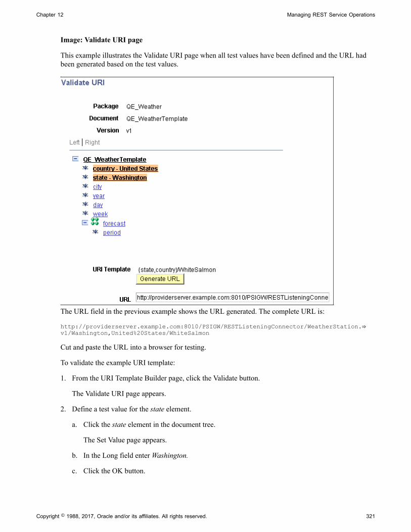
Chapter 12 Managing REST Service Operations
Image: Validate URI page
This example illustrates the Validate URI page when all test values have been defined and the URL hadbeen generated based on the test values.
The URL field in the previous example shows the URL generated. The complete URL is:
http://providerserver.example.com:8010/PSIGW/RESTListeningConnector/WeatherStation.⇒v1/Washington,United%20States/WhiteSalmon
Cut and paste the URL into a browser for testing.
To validate the example URI template:
1. From the URI Template Builder page, click the Validate button.
The Validate URI page appears.
2. Define a test value for the state element.
a. Click the state element in the document tree.
The Set Value page appears.
b. In the Long field enter Washington.
c. Click the OK button.
Copyright © 1988, 2017, Oracle and/or its affiliates. All rights reserved. 321

Managing REST Service Operations Chapter 12
The Validate URI page appears and the test value Washington appears after the state element inthe document tree structure.
3. Define a test value for the country element.
a. Click the country element in the document tree.
The Set Value page appears.
b. In the Long field enter United States
c. Click the OK button.
The Validate URI page appears and the test value United States appears after the country elementin the document tree structure.
4. Click the Generate URL button
The generated URL appears in the URL field.
5. Copy the URL to test in a browser.
6. Click the Return button to return to the URL Template Builder page.
Adding the Example URI Template to the REST Resource Definition.After you have created the URI template and performed any necessary validation, add it to the RESTresource definition.
The URI template appears in the REST Resource Definition section of the Service Operations – Generalpage.
Image: REST Resource Definition section
This example illustrates the REST Resource Definition section with the example URI template added tothe last row in the URI grid.
The URI template created in this example appears in the last row of the URI grid. Note that you must savethe service operation definition to save the URI template. When you save the service operation definitionthe system assigns an index to the URI template.
322 Copyright © 1988, 2017, Oracle and/or its affiliates. All rights reserved.

Chapter 12 Managing REST Service Operations
In the example shown, the service operation has been saved as indicated by an index number appearingnext to the example URI template.
To add a URI template to the REST resource definition:
1. After you complete the URI template and perform any validation, on the URI Template Builder pageclick the OK button.
The Service Operations – General page appears. The URI template appears in REST ResourceDefinition section of the page in the URI grid.
2. Click the Save button.
The URI template is saved and the system assigns an index to the URI template.
Defining REST Service Operation Version Information
This section discusses how to:
• Define default REST service operation versions.
• Define message instances for REST service operations.
• Define fault messages for REST service operations.
Understanding Default REST Service OperationsWhen you first create a service operation definition, the definition that you initially define is the defaultversion.
When the newly created service operation definition opens, the Default check box is enabled and is read-only.
You can subsequently define additional service operation versions and assign them as the default.
Defining Default REST Service Operation VersionsTo define the REST service operation default version:
1. Access the Service Operations - General page (PeopleTools, Integration Broker, Integration Setup,Service Operations).
2. In the Version field, enter a version identifier.
The default is v1.
3. (Optional.) In the Version Description field, enter a description for the operation version.
If you enter no information, the description by default is the name of the service operation when yousave the definition.
4. (Optional.) In the Version Comments check box, enter comments about the version.
Copyright © 1988, 2017, Oracle and/or its affiliates. All rights reserved. 323

Managing REST Service Operations Chapter 12
5. (Optional.) Select the Runtime Schema Validation check box to enable service schema validation atruntime.
6. (Optional.). In the Routing Actions Upon Save box, check the Generate Local-to-Local routing box togenerate the routing when you save the service operation definition.
Note that the Any-to-Local box is read-only and selected by default and an any-to-local routing iscreated upon save.
This box only appears when working with provider service operations.
More information about routing definitions for provider REST services is available in the productdocumentation.
See Managing Provider REST Service Operations
When working with REST provider service operations a
Continue to the next section to specify messages for service operations. You cannot save the serviceoperation definition until you define messages for it.
Defining Message Instances for REST Service OperationsYou specify messages for service operations in the Message Information section of the Service Operations– General page.
The messages that you specify define the structure of the data that is contained in the service operation.
The REST method type determines the number of messages and message types (request or response)that you specify. The possible request and response message combinations by REST method type aredescribed elsewhere in this topic.
To specify messages for a REST service operation:
1. Locate the Message Information section on the Service Operations – General page.
2. Locate the Type field, and take note of the message type to define.
3. In the Message.Version field, enter the message name followed by a dot and version, or click theLookup button to search for one.
After you select the message, you can click the View Message link to view the message.
4. From the Content-Type drop-down list, select the MIME content type for the message. The validvalues are:
• application/json
• application/xml
• text/xml
• text/plain
• text/html
324 Copyright © 1988, 2017, Oracle and/or its affiliates. All rights reserved.

Chapter 12 Managing REST Service Operations
5. (Optional) Define optional content-types.
To define optional content-types:
a. Click the Optional Content-Types link.
The Set Content Type page appears.
b. From the Content-Type drop-down list, select a content type.
The valid values are the same as those listed in Step 4.
c. To add additional content-types, click the Add Row button (+) and select a content-type from thelist.
d. Click the OK button.
The Service Operations – General page appears.
6. From the Status Code drop-down list, select the HTTP response code to return to the integrationpartner.
Note that the content-type defines the acceptable HTTP media type.
The valid HTTP status code values are:
• 200. (Default.)
• 201. This value is valid only when the REST method is Post.
• 202
• 203. This value is valid only when the REST method is Get.
• 204
• 205
• 206
• 207
7. (Optional) Define optional status codes.
You can defined optional status codes on response messages only.
Tp define optional status codes:
a. Click the Optional Status Codes link.
The Set Status Codes page appears.
b. From the Status Code drop-down list, select a status code.
The valid values are the same as those listed in Step 6.
Copyright © 1988, 2017, Oracle and/or its affiliates. All rights reserved. 325

Managing REST Service Operations Chapter 12
c. To add additional status codes, click the Add Row button (+) and select a status code from the list.
d. Click the OK button.
The Service Operations – General page appears.
8. Repeat steps 1 through 7 for each message type that appears in the Message Information section.
9. Click the Save button.
Defining Fault Messages for REST Service OperationsThis section describes how to specify fault messages for REST service operations.
Understanding Fault Messages for REST Service OperationsYou can specify fault messages for service operations for error handling.
Note the following about fault messages:
• You cannot add fault messages to asynchronous service operations.
• Fault messages must be nonrowset-based messages, container messages, or document messages. Faultmessages cannot be rowset-based messages.
Understanding Fault Message HTTP Return Status Codes for REST ServiceOperations and the OnError MethodThe system recognizes and uses fault message HTTP status codes only if the fault Message is used in theOnError method. Simply using the fault message within the OnRequest method will be treated like anyother message.
Understanding Fault Message HTTP Return Status Codes and Service SystemStatus for Provider REST Service OperationsIf you specify fault messages for provider REST service operations, the service system status impacts theHTTP return status codes as follows:
Production If the service system status is set to Production any errors by theframework or that are not part of a fault message defined in theOnError method will result in an HTTP status code returned of500 with the errors not included in the payload.
If a fault message is defined on the service operation andinvoked within the OnError method then the status code of 400 (or any other status code set for the fault) will be returned as theHTTP status code along with the error message.
Development If the service system statu is set to Development any errors bythe framework or that are not part of a fault message defined inthe OnError method will result in an HTTP status code returnedof 500 with the error message included in the payload.
326 Copyright © 1988, 2017, Oracle and/or its affiliates. All rights reserved.

Chapter 12 Managing REST Service Operations
If the fault message is defined on the service operation andinvoked within the OnError method then the status code of 400 (or any other status code set for the fault) will be returned as theHTTP status code along with the error message.
Defining Fault Messages for REST Service OperationsTo define a fault message for a REST service operation:
1. Locate the Default Service Operation Version section on the Service Operations – General tab.
2. Click the Add Fault Type button.
A new row appears in which to specify a message. Note that the Type field in the new row displaysFault.
3. In the Message.Version field, enter the message name, or click the Lookup button to search for one.
After you select the message, you can click the View Message link to view the message.
4. From the Content-Type drop-down list, select the MIME content type of the message.
The valid values are:
• application/json
• application/xml
• text/xml
• text/plain
• text/html
5. (Optional) Define optional content-types.
To define optional content-types:
a. Click the Optional Content-Types link.
The Set Content Type page appears.
b. From the Content-Type drop-down list, select a content type.
The valid values are the same as those listed in Step 4.
c. To add additional content-types, click the Add Row button (+) and select a content-type from thelist.
d. Click the OK button.
The Service Operations – General page appears.
6. From the Status drop-down list, select a status code. The default and only value is 400.
Copyright © 1988, 2017, Oracle and/or its affiliates. All rights reserved. 327

Managing REST Service Operations Chapter 12
7. Click the Save button.
To delete a fault message, in the Default Service Operation Version section, click the Delete Fault Typebutton. Then click the Save button.
Managing Provider REST Service Operations
This section describes configuration tasks and considerations specific to managing provider REST serviceoperations. This section discusses how to:
• Manage target connectors for provider REST service operations.
• Manage messages for provider REST service operations.
• Secure provider REST service operations.
• Add handlers to provider REST service operations.
• Manage routings definitions for provider REST service operations.
• Define routing header properties for provider REST service operations.
Managing Target Connectors for Provider REST Service OperationsOnly the HTTP target connector is supported for providing REST service operations.
Managing Messages for Provider REST Service OperationsFor a provider REST service operations defined with a nonrowset-based message, the Root Elementfield on the message definition must be populated. The root element value you specify is used for properWADL generation.
Related LinksAdding Rowset, Nonrowset or Part Message Definitions
Securing Provider REST Service OperationsThis section discusses securing provider REST service operations.
Requiring Secured Inbound Consumer RequestsWhen you create provider REST services you can set the level of security with which inbound serviceoperations must be sent using options in the Req Verification drop-down list on the Service Operationspage. If you set a required inbound security level and inbound messages do not meet the requirement, themessages are rejected.
The following security levels are supported for provider REST service operations: none, SSL, basicHTTP authentication, and basic HTTP authentication and SSL.
• Basic HTTP authentication.
328 Copyright © 1988, 2017, Oracle and/or its affiliates. All rights reserved.

Chapter 12 Managing REST Service Operations
• Basic HTTP authentication and SSL.
• None.
• SSL.
See "Validating Security on Inbound Integrations" (PeopleTools 8.55: Integration Broker Administration).
Setting Permissions for Provider REST Service OperationsProvider REST service operations are secured using permission lists. The process for setting permissionsfor provider REST service operations is identical to the process for setting permissions for non-RESTservice operations.
See Setting Permissions to Service Operations.
Adding Handlers to Provider REST Services OperationsThe only Handler Type available for provider REST services is the OnRequest handler and the handleris implemented as an application class. The application class is implemented as any other OnRequestintegration broker event.
Implementing handlers is discussed in greater detail elsewhere in the product documentation
See Understanding Service Operation Handlers.
See Using PeopleCode to Manage REST Service Operations.
Managing Routing Definitions for Provider REST Service OperationsThis section discusses how to manage routing definitions for Provider REST service operations.
Working with System-Generating Routing Definitions for REST ServiceOperationsAn any-to-local routing is always created for a provider REST service operation you initially savethe service operation definition. The routing name is a system-generated name with the format~GENERATED~<unique number>. You cannot delete this system-generated routing but you caninactivate it. You can also regenerate the any-to-local routing in the Routing Actions Upon Save sectionon the Service Operations-General tab. Note that if you regenerate the routing and request or responseheaders you have defined on the routing are deleted.
You can also generate a local-to-local routing for any REST-based service operation in the RoutingActions Upon Save section on the Service Operations-General tab. You may also inactivate local-to-localroutings you create for a REST service.
Any-to-local and local-to-local routing types are discussed elsewhere in the product documentation.
See Routing Types.
You cannot create point-to-point routings for REST-based service operations.
Additional information about configuring and working with routing definitions is described elsewhere inthe product documentation.
Copyright © 1988, 2017, Oracle and/or its affiliates. All rights reserved. 329

Managing REST Service Operations Chapter 12
Related LinksManaging System-Generated Routing DefinitionsConfiguring Routing DefinitionsActivating and Inactivating Routing Definitions
Defining Routing Header Properties for Provider REST Service OperationsOn provider REST–based service operations the any-to-local routing definition features a HeaderProperties page (IB_ROUTINGRESTPROP) where you add request message and response headers to theservice operation. The headers are shown in the generated WADL document for the service operation.
To access the Header Routings page Routings-Header Properties page select PeopleTools, IntegrationBroker, Integration Setup, Routings and click the Header Properties tab.
Image: Routings – Header Properties page
This example illustrates the Routings – Header Properties page. The example shows the header propertiesfor a system-generated any-to-local routing for a REST-based provider service operation.
The request and response headers that you can add are standard HTTP request and response header fields.There are several sources for addition information and descriptions of HTTP header fields. One suchsource is the World Wide Web Consortium (W3C).
See World Wide Web Consortium.
Note: If you regenerate a routing any header fields defined for the routing are deleted and you mustrecreate them.
You also use this page to define compression on provider service operations requests and responses.
330 Copyright © 1988, 2017, Oracle and/or its affiliates. All rights reserved.

Chapter 12 Managing REST Service Operations
See Setting Compression for REST Service Operations.
Use the LoadRESTHeaders method of the IBInfo class to load the response and request headers atruntime.
See Using PeopleCode to Manage Provider REST Service Operations.
Adding Request Header PropertiesTo add a request header property:
1. Access the Routings-Header Properties page (PeopleTools, Integration Broker, Integration Setup,Routings and click theHeader Properties tab).
2. In the Request Headers section of the page, click the Add Row button (+) to add a row.
3. In the Property Name field, click the Lookup button and select a property to add.
The system adds the property to the grid.
4. In the Comments field, enter a comment about the property.
5. Repeat steps 2–4 to add additional request header properties.
6. Click the Save button.
Adding Response Header PropertiesTo add a response header property:
1. Access the Routings-Header Properties page (PeopleTools, Integration Broker, Integration Setup,Routings and click the Header Properties tab).
2. In the Response Headers section of the page, click the Add Row button (+) to add a row.
3. In the Property Name field click the Lookup button and select a property to add.
The system adds the property to the grid.
4. In the Value field enter a value for the property.
5. In the Comment column enter a comment for the property.
6. Repeat Steps 2–5 to add additional response header properties.
7. Click the Save button.
Managing Consumer REST Service Operations
This section describes configuration tasks and considerations specific to managing consumer RESTservice operations. This section discusses how to:
• Add handlers to consumer REST service operations.
• Manage routing definitions for consumer REST service operations.
Copyright © 1988, 2017, Oracle and/or its affiliates. All rights reserved. 331

Managing REST Service Operations Chapter 12
• Secure consumer REST service operations.
Adding Handlers to Consumer REST Service OperationsThere are no handlers for consumer REST service operations. You may add connector properties toconsumer service operations on the routing definition using the Routings-Connector Properties page oradd them dynamically by using PeopleCode.
See Defining and Overriding Gateway and Connector PropertiesUsing PeopleCode to Manage RESTService Operations.
Manage Routing Definitions for Consumer REST Service OperationsThe system creates a single outbound local-to-WADL node routing when you initially save aconsumer REST service operation. The routing name is a system-generated name with the format~GENERATED~<unique number>. You cannot delete this system-generated routing but you caninactivate it.
Additional information about configuring and working with routing definitions is described elsewhere inthe product documentation.
Related LinksManaging System-Generated Routing DefinitionsConfiguring Routing DefinitionsActivating and Inactivating Routing Definitions
Securing Consumer REST Service OperationsA PeopleSoft REST service operation provider may require that consumer services be sent secured.PeopleSoft REST providers may communicate to you that they require consumer REST service operationbe secured using SSL, basic authentication, or basic authentication and SSL.
Securing Consumer REST Requests Using SSL/TLSYou can determine any SSL requirement based on the REST base URL the provider supplies and asdefined on the Service Operations – General page. If the URL is a Hypertext Transfer Protocol SecureURL (HTTPS), then the provider has implemented SSL and your consumer request must also be sentusing the SSL protocol. Information for setting up SSL/TLS is provided elsewhere in the productdocumentation.
See "Implementing Web Server SSL/TLS Encryption" (PeopleTools 8.55: Integration BrokerAdministration).
Securing Consumer REST Requests Using Basic AuthenticationIf a PeopleSoft REST provider system is defined in your integration network, you can use basic HTTPauthentication or PeopleSoft tokens to secure consumer requests and the PeopleSoft providing systemaccepts the requests as meeting the basic authentication requirement. When using PeopleSoft tokens,the system sends the token as an HTTP header property as part of the request. This behavior allows youto securely pass user credentials for proper authentication instead of using basic authentication whichrequires that you set an external user name and external password on the routing. If the provider has basic
332 Copyright © 1988, 2017, Oracle and/or its affiliates. All rights reserved.

Chapter 12 Managing REST Service Operations
authentication selected for inbound security verification and no PeopleSoft token or basic authenticationcredentials are passed, a basic authentication pop-up window appears and the user must enter his or hercredentials at that time. The PeopleSoft token option is a way to not have to prompt for user credentialsfor PeopleSoft-to-PeopleSoft integrations.
If a PeopleSoft REST provider is not in your integration network and the provider requires inbound basicauthentication, you cannot secure the request with a PeopleSoft token. The providing system will rejectsuch a request. You must secure the request using basic HTTP authentication.
If the consumer system is a third-party system and the provider requires inbound basic authentication, thethird-party system must secure the request using basic HTTP authentication.
You specify basic HTTP authentication for a consumer outbound request on the routing definition onthe Routings – Parameters page (IB_ROUTINGDEFNDOC). The Parameters section for the outboundrequest features a WS Security link that enables you to set the security level for the outbound consumerrequest.
To access the Routings – Parameters page select PeopleTools, Integration Broker, Integration Setup,Routings and click the Parameters tab.
Copyright © 1988, 2017, Oracle and/or its affiliates. All rights reserved. 333

Managing REST Service Operations Chapter 12
Image: Routings – Parameters page
This example illustrates the Routings – Parameters page. Click the WS Security link to set the securitylevel for outbound requests.
When you click the WS Security link the Routing Security page (IB_ROUTINGDEFN_SEC) appears.
Image: Routing Security page
This example illustrates the Routing Security page.
Use Authentication Option drop-down list to select the authentication option for the request. If you selectbasic authentication as the authentication option, External User ID and External Password fields appearand you must enter the external user ID and password values as furnished by the provider.
334 Copyright © 1988, 2017, Oracle and/or its affiliates. All rights reserved.

Chapter 12 Managing REST Service Operations
Image: Routing Security page
This example illustrates the Routing Security page. The example shows the page when BasicAuthentication is selected as the authentication option
Keep in mind that in addition to basic authentication, the provider may require that you send the requestsecured by SSL.
To secure a REST consumer request using basic authentication:
1. Access the Routings-Parameters page (PeopleTools, Integration Broker, Integration Setup, Routingsand click the Parameters tab).
2. In the parameters section for the outbound request, click the WS Security link.
The Routing Security drop-down list appears:
3. From the Authentication Option drop-down list, select an authentication method. The options are:
• Basic Authentication.
If you select this option, go to step 4.
• None. (Default)
If you select this option, go to step 6.
• PeopleSoft Token.
If you select this option, go to step 6.
4. In the External User ID field, enter the ID furnished to you by the REST provider.
5. In the External Password field, enter the password furnished to you by the REST provider.
6. Click the OK button.
Related Links"Validating Security on Inbound Integrations" (PeopleTools 8.55: Integration Broker Administration)
Managing REST Service Operation Versions
You can create and use different versions of service operations. The process for managing REST serviceoperation versions is identical to the process for managing non-REST service operation versions.
Copyright © 1988, 2017, Oracle and/or its affiliates. All rights reserved. 335

Managing REST Service Operations Chapter 12
See Managing Service Operation Versions.
Note, however, that REST resource definition are defined at the service operation level and not the serviceoperation version level. As a result, REST resource definitions cannot be versioned.
Setting Compression for REST Service Operations
This section discusses how to:
• Set compression for provider REST service operations.
• Set compression for consumer REST service operations.
Understanding Setting Compression for REST Service OperationsPeopleSoft supports gzip and base64 (deflate) compression.
A REST service operation provider may request that inbound consumer requests be compressed usinggzip or base64 (deflate) compression. The consumer is not required to send the data compressed.
The provider specifies the compression preference and the type of compression that the provider systemcan process on the routing definition using the Routings – Header Properties page. The compressionpreferences are then included in the WADL document that the provider furnishes to the consumer. TheREST consumer can then view the compression preferences of the provider.
A REST service operation consumer may specify that a response from the provider be compressed usinggzip or base64 (deflate) compression. The consumer specifies this request on the outbound request routingdefinition using the Routings – Connector Properties page. The compression requirement for the providerresponse is then included in the HTTP target connector headers. The REST provider can then ensure thatits response meets the compression requirement of the consumer.
Setting Compression for Provider REST Service OperationsThis section discusses how to set compression for Provider REST service operations.
Understanding Setting Compression for Provider REST Service OperationsYou use the Routings – Header Properties page (IB_ROUTINGRESTPROP) to specify the compressionmethod that the providing system will accept on inbound requests from a consumer, as well as thecompression method the provider is using on the response to the consumer.
The two properties to use to specify message compression on the provider system are Accept-Encodingand Content-Encoding.
For provider request and response headers set compression as follows:
Provider Request Header Use the Accept-Encoding property for the Request Header toindicate the compression method the providing system willaccept on inbound requests from the consumer. The informationyou specify here is included in generated WADL documents thatyou provide consumers.
336 Copyright © 1988, 2017, Oracle and/or its affiliates. All rights reserved.

Chapter 12 Managing REST Service Operations
There are no values to select, rather you specify the compressionmethod in the Comments field. The valid compression methodsare:
• base64 (deflate).
• gzip.
Provider Response Header Use the Content-Encoding property for the Response Header toindicate the compression method used on the outbound responseto the consumer. The information you specify here is includedin generated WADL documents that you provide consumers. The compression method used should match the compressionmethod that the consumer specifies in the connector propertiesin the inbound request. The valid values are:
• base64 (deflate).
• gzip.
Setting Compression for Provider REST Service OperationsUse the Routings – Header Properties page (IB_ROUTINGRESTPROP) to set compression for providerREST service operations. To access the page, select PeopleTools, Integration Broker, Integration Setup,Routings and click the Header Properties tab.
Image: Routings – Header Properties page
This example illustrates the Routings – Header Properties page.
The previous example shows that the Request Header is set to Accept-Encoding and that the providerwill accept requests that are gzip or base64 (deflate) compressed. The example shows that the ResponseHeader is set to Content-Encoding and that the provider will send its response to the consumer base64(deflate) compressed.
To set compression for provider REST service operations:
1. Access the Routings–Header Properties page:
Copyright © 1988, 2017, Oracle and/or its affiliates. All rights reserved. 337

Managing REST Service Operations Chapter 12
a. Select PeopleTools, Integration Broker, Integration Setup, Services and in the Existing Operationssection click the name of the service operation. The Service Operations – General page appears.
b. Click the Routings tab and in the Routing Definitions grid click the name of the routing definition.The Routing-Definitions page appears.
c. Click the Header Properties tab.
2. Set the request header.
In the Request Headers section:
a. In the Property Name field click the Lookup button and choose Accept-Encoding from the list.
b. In the Comment field enter a comment regarding the compression method the provider systemwill accept for the inbound request from the consumer.
3. Set the response header.
In the Response Headers section:
a. In the Property Name field click the Lookup button and choose Content-Encoding from the list.
b. In the Value field click the Lookup button and choose the compression used for the responsemessage to the consumer. The valid values arebase64 (deflate) or gzip.
4. Click the Save button.
The other options featured on the Routings – Header Properties page are discussed elsewhere in theproduct documentation.
See Defining Routing Header Properties for Provider REST Service Operations.
Defining Compression for Consumer REST Service OperationsThis section discusses how to define compression for consumer REST service operations.
Understanding Setting Compression for Consumer REST Service OperationsA WADL document furnished to a REST consumer by a REST provider indicates if requests must becompressed and if so the compression method the provider system accepts. In addition, as a RESTconsumer you may require that responses from the provider be compressed and that the system can handlea specific compression method.
The two properties to use to specify message compression on consumer systems are Accept-Encoding andContent-Encoding.
For consumer request and response headers set compression as follows:
Consumer Response Headers Use the Accept-Encoding property to indicate to the providerthe compression method to use in its response to your consumersystem. The valid options are:
338 Copyright © 1988, 2017, Oracle and/or its affiliates. All rights reserved.

Chapter 12 Managing REST Service Operations
• base64 (deflate).
• gzip.
Consumer Request Headers Use the Content-Encoding property to indicate to the providerthe compression method used on the outgoing request. The validoptions are:
• base64 (deflate).
• gzip.
Setting Compression for REST Consumer Service OperationsYou use the Routings – Connector Properties page (IB_ROUTINGRESTCPRP) to specify thecompression method used for the outbound request and the compression method(s) the system can acceptfor the provider's response.
To access the Routings – Connector Properties page, select PeopleTools, Integration Broker, IntegrationSetup, Routings.
Image: Routings – Connector Properties page
This example illustrates the Routings – Connector Properties page.
The previous example shows that on the REST consumer has set Content-Encoding and Accept-Encodingto base64 (deflate). By setting the Content-Encoding property to base64(deflate), the consumer isindicating that it is sending the consumer request to the provider base64 (deflate) compressed. By settingthe Accept-Encoding property to base64(deflate), the REST consumer is indicating to the REST providerthat it will accept a response that is base64 (deflate) compressed.
To set compression for consumer REST service operations:
1. Access the Routings – Connector Properties page:
a. Select PeopleTools, Integration Broker, Integration Setup, Services and in the Existing Operationssection click the name of the service operation. The Service Operations – General page appears.
Copyright © 1988, 2017, Oracle and/or its affiliates. All rights reserved. 339

Managing REST Service Operations Chapter 12
b. Click the Routings tab and in the Routing Definitions grid click the name of the routing definition.The Routing-Definitions page appears.
c. Click the Connector Properties tab.
2. Set the request header.
a. In the Property Name field click the Lookup button and choose Content-Encoding from the list.
b. In the Value field click the Lookup button and choose the compression method used for theoutbound request. The valid values are base64 (deflate) or gzip.
3. Set the response header.
a. In the Property Name field click the Lookup button and choose Accept-Encoding from the list.
b. In the Value field click the Lookup button and choose the compression method that the providershould use for the response back to the consumer. The valid values are base64 (deflate) or gzip.
4. Click the Save button.
The other options featured on the Routings-Connector Properties page are discussed elsewhere in theproduct documentation.
See Defining and Overriding Gateway and Connector Properties.
Renaming and Deleting REST Service Operations
You can rename and delete service operations using the Services Operations page in the ServiceAdministration component. The process for renaming and deleting REST service operations is identical tothe process for renaming and deleting non-REST service operations.
See Renaming and Deleting Service Operations.
340 Copyright © 1988, 2017, Oracle and/or its affiliates. All rights reserved.

Chapter 13
Managing Service Operation Queues
Understanding Service Operation Queues
Service operations queues are used to queue service operations for processing.
Adding Queue Definitions
Use the Queue Definitions page (IB_QUEUEDEFN) to add queue definitions to the system. To access theQueue Definitions page, select PeopleTools, Integration Broker, Integration Setup, Queues.
Image: Queue Definitions page
This example illustrates the Queue Definitions page.
The Operations Assigned to Queue check box displays the names of the service operations assigned to aqueue. Click a service operation name to open the service operation definition.
You work with the following page elements when you add a queue.
Copyright © 1988, 2017, Oracle and/or its affiliates. All rights reserved. 341

Managing Service Operation Queues Chapter 13
Queue Name Enter the name of the queue.
Archive Select to archive service operation instances that are assigned tothe queue. By default, archiving is not enabled.
When you enable archiving, you can archive or deletetransactions in the Asynchronous Details component of theService Operations Monitor. This check box also controlswhether the Archive or Delete action is available in theAsynchronous Details component of the Services OperationsMonitor.
If archiving is not enabled, the system purges the queue entriesthat have been processed.
Note: This setting controls whether archiving is available forasynchronous transactions only and pertains to transactions in aspecific queue.
Unordered Select to enable field partitioning and to process serviceoperations unordered.
By default, the check box is deselected and inbound serviceoperations that are assigned to a queue are processed one at atime sequentially in the order that they are sent.
Select to force the channel to handle all of its service operationsin parallel (unordered), which does not guarantee a particularprocessing sequence. This disables the channel’s partitioningfields.
Deselect this check box if you want all of the queues’s serviceoperations processed sequentially or if you want to use thepartitioning fields.
Description Enter a description for the queue.
Queue Status Values are:
Run: (default) Service operations that are assigned to this queueare received and processed normally.
Pause: Service operations are received but not processed untilthe status is reset to Run.
Note: You can also pause and restart queues in the ServiceOperations Monitor.
Object Owner ID From the drop-down list box, select the object owner.
The owner ID helps to determine the application team that lastmade a change to the definition. The values in the drop-down
342 Copyright © 1988, 2017, Oracle and/or its affiliates. All rights reserved.

Chapter 13 Managing Service Operation Queues
list box are translate table values that you can define in theOBJECTOWNERID field record.
Comments Use this area to enter comments about the definition.
Operations Assigned to Queue This read-only section lists all service operations that areassigned to the queue.
Include Select the Include check box next to a field name to include thefield in queue partitioning.
Add Field Click to view and select partitioning fields.
Related LinksApplying Queue Partitioning"Understanding Pausing Nodes" (PeopleTools 8.55: Integration Broker Service Operations Monitor)
Applying Queue Partitioning
This section provides an overview of queue partitioning and discusses how to select partitioning fields.
Understanding Queue PartitioningThis section discusses queue partitioning
Queue PartitioningBy default, all inbound service operations that are assigned to a given service operation queue areprocessed one at a time, in the order they are sent. Consequently, the sending node can engage in aseries of transactions that modify a specific record, and the changes are applied by the receiving nodein the correct order. This can be inefficient if the sequence does not matter or if the sequence is relevantonly within groups of service operations with the same key values. One solution to this inefficiency ispartitioning.
Note: Partitioning applies only to asynchronous messaging.
To maximize messaging efficiency and throughput, you want the system to simultaneously process asmany service operations as possible. Because queues enforce service operation sequence, ideally you havea separate service operation queue for each group of service operations that must be processed in order.You can achieve this goal by designating specific fields that are common to the service operations that areassigned to a queue. These fields partition, or divide, the queues into subqueues. PeopleSoft IntegrationBroker creates these subqueues at runtime.
Each subqueue processes only the service operations for which the designated common fields have anidentical combination of values. The service operations within each subqueue are processed in the orderthat they are sent, so they remain in sequence. Each subqueue works in parallel with the other subqueues—all subqueues simultaneously process their own associated service operations.
You implement partitioning by designating the partitioning fields in the queue definition; no other stepsare required.
Copyright © 1988, 2017, Oracle and/or its affiliates. All rights reserved. 343

Managing Service Operation Queues Chapter 13
Note: The more partitioning fields that you designate, the more subqueues are generated. If you designatea combination of fields that are unique for each service operation, all service operations are processedsimultaneously, in their own subqueues, without regard to sending order. This is the equivalent ofselecting the Unordered check box in the queues definition.
Note: For inbound transactions, re-partitioning (re-running of the queue partition logic) could take placeas a result of a successful inbound transform if no partition key was passed as part of the request.
Queue Partitioning FieldsWhen working with queue partitioning fields, note the following points:
• The maximum length of a queue partitioning value should not exceed 60 characters. The systemtruncates any value longer than 60 characters when you use the PeopleCode SubQueueName property.
• Fields of types image and long character aren’t available for partitioning.
• When you are partitioning nonrowset-based or inbound messages, tags cannot be mixed case.
Selecting Partitioning FieldsYou can partition queues using any combination of:
• Database record fields.
• Message header fields.
• Message XML fields.
Database Record FieldsDatabase record fields are the data fields in a PeopleSoft rowset-compatible message. Typically, the moreservice operations that you assign to the queue, the fewer fields they have in common.
The database record fields that are common to all service operations in the queues appear in the queues’sCommon Field list. If only one service operation is assigned to the queues, all of its fields appear on thepartitioning list.
To designate a field as a partitioning key, select the check box next to its name.
Message Header FieldsThe message header fields are system-maintained fields that are common to all service operations,regardless of format. If a queue includes any nonrowset-compatible service operations, the messageheader fields are the only ones that PeopleSoft Integration Broker recognizes as common to every serviceoperation. You can view them as part of the message XML in Integration Broker Monitor. You can alsoaccess some of them using equivalent PeopleCode Message class properties, as indicated later in thistopic. The message header fields are:
• OPERATIONNAME: This field contains the name of the operation in the PeopleSoft Pure InternetArchitecture.
• PUBLISHER: This field contains the user ID that is in effect when the service operation is published,that is, the ID of the user who is signed in to the publishing database.
344 Copyright © 1988, 2017, Oracle and/or its affiliates. All rights reserved.

Chapter 13 Managing Service Operation Queues
• PUBPROC: This field refers to the PeopleSoft process that publishes the service operation.
It is generated when the service operation is published, and it can be the name of a component, anApplication Engine program, or an iScript program.
These header fields are always available in the queue’s partitioning field list. To designate a field as apartitioning key, select the Include check box next to its name.
Message XML FieldsThe message XML fields comprise all the fields that exist anywhere in a message, including PeopleSoftcommon application message attributes (PSCAMA) record fields. Such fields may not be visible in thequeues’s partitioning field list, but they are valid for partitioning. Message XML fields can have aliases,allowing for support of mixed-case names.
To designate a message XML field as a partitioning key:
1. Access the Queue Definitions page (PeopleTools, Integration Broker, Integration Setup, Queues).
2. Click the Add Field button.
3. Enter the tag name of the XML field, or click the Lookup button to search for one.
The value does not have to be in the database.
All names are uppercase by default. You can then add an alias, which can be mixed-case forpartitioning.
At runtime, the integration engine searches each message for the first instance of that field tag and usesthe value that is associated with it for partitioning. Therefore, if you have common fields in the PSCAMArecord that are specific to a batch publish set, you can use those fields.
Renaming and Deleting Queues
You can rename and delete queue definitions using the Queue page (IB_HOME_PAGE3) in the ServiceAdministration component (IB_HOME_PAGE).
The Queues page contains two sections: a Delete section that enables you to delete a queue definition anda Rename section that enables you to rename a queue definition.
To access the page, select PeopleTools, Integration Broker, Service Utilities, Services Administrationand select the Queues tab.
When you first access the page, both sections are collapsed. Click the section-header arrow buttons toexpand and collapse each section.
Copyright © 1988, 2017, Oracle and/or its affiliates. All rights reserved. 345
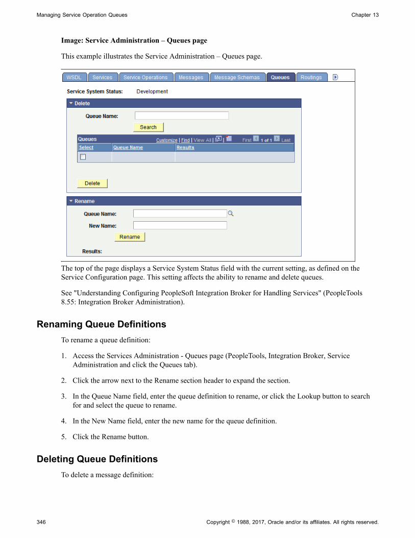
Managing Service Operation Queues Chapter 13
Image: Service Administration – Queues page
This example illustrates the Service Administration – Queues page.
The top of the page displays a Service System Status field with the current setting, as defined on theService Configuration page. This setting affects the ability to rename and delete queues.
See "Understanding Configuring PeopleSoft Integration Broker for Handling Services" (PeopleTools8.55: Integration Broker Administration).
Renaming Queue DefinitionsTo rename a queue definition:
1. Access the Services Administration - Queues page (PeopleTools, Integration Broker, ServiceAdministration and click the Queues tab).
2. Click the arrow next to the Rename section header to expand the section.
3. In the Queue Name field, enter the queue definition to rename, or click the Lookup button to searchfor and select the queue to rename.
4. In the New Name field, enter the new name for the queue definition.
5. Click the Rename button.
Deleting Queue DefinitionsTo delete a message definition:
346 Copyright © 1988, 2017, Oracle and/or its affiliates. All rights reserved.

Chapter 13 Managing Service Operation Queues
1. Access the Services Administration - Queues page (PeopleTools, Integration Broker, ServiceAdministration and click the Queues tab).
2. Click the arrow next to the Delete section header to expand the section.
3. In the Queue Name field, enter the name of the queue definition to delete, and click the Search button.
Search results appear in the results grid.
4. In the results grid, select the check box next to the queue or queues to delete.
5. Click the Delete button.
Deleting Queues During Upgrade
To delete a queue definition in an application upgrade project, first ensure that no live instances ofmessages are assigned to that queue. Archive or delete any such messages in both the source and thetarget database. Otherwise, an error message appears during the copy process indicating that the messageis in use.
Copyright © 1988, 2017, Oracle and/or its affiliates. All rights reserved. 347

Managing Service Operation Queues Chapter 13
348 Copyright © 1988, 2017, Oracle and/or its affiliates. All rights reserved.
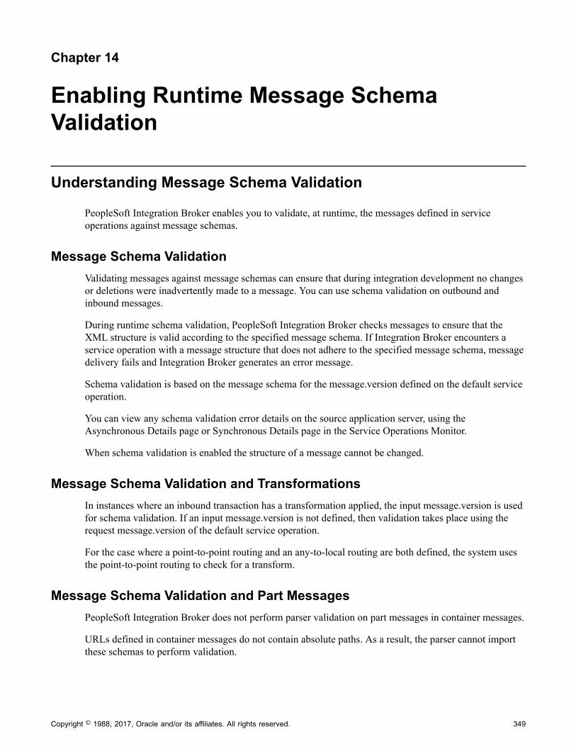
Chapter 14
Enabling Runtime Message SchemaValidation
Understanding Message Schema Validation
PeopleSoft Integration Broker enables you to validate, at runtime, the messages defined in serviceoperations against message schemas.
Message Schema ValidationValidating messages against message schemas can ensure that during integration development no changesor deletions were inadvertently made to a message. You can use schema validation on outbound andinbound messages.
During runtime schema validation, PeopleSoft Integration Broker checks messages to ensure that theXML structure is valid according to the specified message schema. If Integration Broker encounters aservice operation with a message structure that does not adhere to the specified message schema, messagedelivery fails and Integration Broker generates an error message.
Schema validation is based on the message schema for the message.version defined on the default serviceoperation.
You can view any schema validation error details on the source application server, using theAsynchronous Details page or Synchronous Details page in the Service Operations Monitor.
When schema validation is enabled the structure of a message cannot be changed.
Message Schema Validation and TransformationsIn instances where an inbound transaction has a transformation applied, the input message.version is usedfor schema validation. If an input message.version is not defined, then validation takes place using therequest message.version of the default service operation.
For the case where a point-to-point routing and an any-to-local routing are both defined, the system usesthe point-to-point routing to check for a transform.
Message Schema Validation and Part MessagesPeopleSoft Integration Broker does not perform parser validation on part messages in container messages.
URLs defined in container messages do not contain absolute paths. As a result, the parser cannot importthese schemas to perform validation.
Copyright © 1988, 2017, Oracle and/or its affiliates. All rights reserved. 349
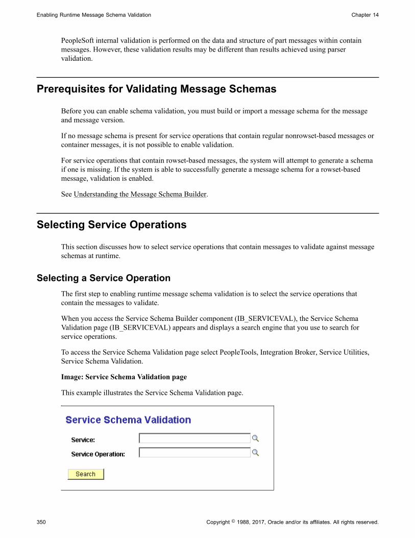
Enabling Runtime Message Schema Validation Chapter 14
PeopleSoft internal validation is performed on the data and structure of part messages within containmessages. However, these validation results may be different than results achieved using parservalidation.
Prerequisites for Validating Message Schemas
Before you can enable schema validation, you must build or import a message schema for the messageand message version.
If no message schema is present for service operations that contain regular nonrowset-based messages orcontainer messages, it is not possible to enable validation.
For service operations that contain rowset-based messages, the system will attempt to generate a schemaif one is missing. If the system is able to successfully generate a message schema for a rowset-basedmessage, validation is enabled.
See Understanding the Message Schema Builder.
Selecting Service Operations
This section discusses how to select service operations that contain messages to validate against messageschemas at runtime.
Selecting a Service OperationThe first step to enabling runtime message schema validation is to select the service operations thatcontain the messages to validate.
When you access the Service Schema Builder component (IB_SERVICEVAL), the Service SchemaValidation page (IB_SERVICEVAL) appears and displays a search engine that you use to search forservice operations.
To access the Service Schema Validation page select PeopleTools, Integration Broker, Service Utilities,Service Schema Validation.
Image: Service Schema Validation page
This example illustrates the Service Schema Validation page.
350 Copyright © 1988, 2017, Oracle and/or its affiliates. All rights reserved.

Chapter 14 Enabling Runtime Message Schema Validation
To search for a service operation, enter the service or service operation with which to work and click theSearch button. A list of results displays in the Service Operations grid. If you do not enter any searchcriteria and click the Search button, the system returns all services and service operations in the database.
When you search for service schema validation data, the system returns the results in the ServiceOperations grid shown on the Service Schema Validation.
Image: Service Schema Validation page
This example illustrates the fields and controls on the Service Schema Validation page. You can finddefinitions for the fields and controls later on this page.
Service Indicates the name of the service.
Service Operation Indicates the name of the service operation.
Version Indicates the version of the service operation.
Validation Indicates if runtime schema validation is enabled.
When the check box is selected, schema validation is enabled.
Results Displays validation results.
The valid values are:
• Error generating schema. Unable to turn on validation.
This message appears if one or more of the messages in theservice operation is nonrowset-based and schemas do notexist for the nonrowset-based messages.
• Service operation saved.
This message appears when you have successfully enabledruntime schema validation and saved the changes.
Copyright © 1988, 2017, Oracle and/or its affiliates. All rights reserved. 351

Enabling Runtime Message Schema Validation Chapter 14
• Error saving service operation.
Schema Click the link to access message schemas for all messagesdefined on the service operation.
See Viewing Defined Message Schemas.
Viewing Defined Message Schemas
This section discusses how to view defined XML schemas for messages.
Viewing XML Schemas Defined for MessagesTo view defined message schemas for all messages contained in a service operation, in the ServiceOperations grid, locate a service operation with which to work and click the Schema link. The systemsdisplays the service operation in the Schema Builder page (IB_SCHEMABUILD).
Image: Schema Builder page
This example illustrates the Message Schema Builder page. The example shows the pagedisplaying twomessages for the MCFEM_REQ_MKFOLDER service operation.
The Exists field displays a value of Yes for both messages and indicates schemas have been built for bothmessages.
If schemas are not built for a message or messages, you can build them directly from this page byselecting the check boxes next to each message name and clicking the Build Selected Schemas button.
To view the XML schema for a message, click the message name link.
352 Copyright © 1988, 2017, Oracle and/or its affiliates. All rights reserved.

Chapter 14 Enabling Runtime Message Schema Validation
Image: Message schema page
This example illustrates the message schema for the MCFEM_REQ_MKFOLDER message.
To return to the Schema Builder page, click the Return button.
Using the Schema Builder page is documented in detail elsewhere in the product documentation.
Related LinksUnderstanding the Message Schema Builder
Enabling Runtime Message Schema Validation
This section discusses how to enable runtime schema validation for all messages defined in a serviceoperation:
You can enable runtime message schema validation from the Service Schema Validation page or from theService Operations page.
Using the Service Schema Validation Page to Enable Runtime MessageSchema Validation
To enable runtime schema validation using the Service Schema Validation page:
1. Access the Service Schema Validation page (PeopleTools, Integration Broker, Service Utilities,Service Schema Validation).
2. Select a service operation that contains messages against which you want to validate messageschemas.
See Selecting Service Operations.
3. Select the Validation check box.
Copyright © 1988, 2017, Oracle and/or its affiliates. All rights reserved. 353

Enabling Runtime Message Schema Validation Chapter 14
4. Click the Save button.
Using the Service Operations page to Enable Runtime Message SchemaValidation
To enable runtime schema validation using the Service Operations page:
1. Access the Service Operations page (PeopleTools, Integration Broker, Integration Setup, ServiceOperations).
2. In the Default Service Operation Version section of the page, select the Runtime Schema Validationcheck box.
3. Click the Save button.
354 Copyright © 1988, 2017, Oracle and/or its affiliates. All rights reserved.

Chapter 15
Creating Component Interface-BasedServices
Understanding Creating Component Interface-Based Services
PeopleSoft Integration Broker enables you to take an existing component interface and create a servicethat can be used to invoke the component interface. Further, it creates service operations, includingrequest messages and response messages (if appropriate). The system creates an inbound any-to-localrouting for the service operation version, as well as handlers for each method you choose to include in theservice.
All service operations you generate from component interfaces are synchronous service operations.
Naming Conventions Integration Metadata CreatedThis section highlight the naming conventions that the PeopleSoft system uses when it creates servicesand services-related data based on component interfaces.
When it creates a web service from a component interface, the PeopleSoft system adds a CI_ prefix tothe component interface name. So if the component interface name is MYCI, the service name the systemcreates is CI_MYCI
The following table highlights naming conventions the PeopleSoft systems applies to other services databased on the method with which you are working:
ComponentInterfaceMethod
ServiceOperation Name
Message Name ComponentInterfaceHandler
RequestMessage Shape
ResponseMessage Shape
Create <service_name>_C Mxxxxxx ONREQUESTHDLRCI Buffer Key
Find <service_name>_F Mxxxxxx ONREQUESTHDLRGet Keys CI Buffer
Get <service_name>_G Mxxxxxx ONREQUESTHDLRFind Keys Key Collection
Update <service_name>_UP
Mxxxxxx ONREQUESTHDLRCI Buffer Notification
Updatedata <service_name>_UD
Mxxxxxx ONREQUESTHDLRCI Buffer Notification
User-defined <service_name>_<method_name>
Mxxxxxx ONREQUESTHDLRCI Buffer Method ReturnType
The naming convention used for message names, Mxxxxxx, is the letter M followed by a random six-digitnumber, as denoted by the x's. An example of a message name is M548902.
Copyright © 1988, 2017, Oracle and/or its affiliates. All rights reserved. 355

Creating Component Interface-Based Services Chapter 15
Note: The maximum number of characters for a service operation name is 30. If using a user-definedmethod name yields a greater result, the name is used is <service_name>_Mxxx, where xxx is a three-digit random number. An example of such a name is CI_USERCI_M101023.
User-Defined Method RestrictionsThis section discusses restrictions related to using user-defined methods when exposing componentinterfaces as services.
User-Defined Method ActionsUser-defined methods which are executed with the Create action should not be exposed as web services.
Specifying Method Parameters and Parameter NamesAll user defined methods that will be accessed via the service interface must have a doc string.
The doc string contains:
1. The keyword GET. .
2. An ordered list of parameter names corresponding to the method's parameters.
The following example shows the format of the doc string:
Function simpleFunction(&sParm As string, &dParm As date, &nParm As number, &bParm As boolean) Returns string Doc "GET, StringParm, DateParm, NumParm , BoolParm" Local string &aString = &sParm; &aString = &aString | " -- " | &dParm; &aString = &aString | " -- " | &nParm; &aString = &aString | " -- " | &bParm; Return &aString; End-Function;
The contents of the doc string are used when the function is invoked. For example, if GET is specified,then the GET keys are set, and GET is called on the component interface before the used-defined methodis invoked.
The list of parameters are used at runtime to match the data in the input message with the method'sparameters. This is an ordered list; if the parameter list in the doc string and the method parameters don'tmatch, then the method may not work correctly. The names in the doc parameter list will be the namesvisible in any WSDL created for the service.
Method parameters and return values must be of a primitive type, such as a string, date or number. Objectparameters or return values are not supported.
Impact of Changing Component InterfacesIf a user modifies or deletes a component interface in PeopleSoft Application Designer, when the usersaves the changes, PeopleSoft Integration Broker checks if a service exists for the component interface.If a service exists, and the component structure/properties have changed in the component interface, awarning message appears stating that a service exists for the component interface.
356 Copyright © 1988, 2017, Oracle and/or its affiliates. All rights reserved.

Chapter 15 Creating Component Interface-Based Services
If the component interface structure changes, a status of Does not match appears in the CI-Based ServicesReview Status grid, and the operation appears as active in the Service Operations component.
Prerequisites for Creating Component Interface-Based Services
Prior to creating any component interface-based web services and service operations, you must define theschema namespace, service namespace, and target location in the Service Configuration page
See "Understanding Configuring PeopleSoft Integration Broker for Handling Services" (PeopleTools8.55: Integration Broker Administration).
Selecting Component Interfaces to Expose as Services
This section discusses how to select component interfaces to expose as web services.
The first step to creating component interface-based services is to choose the component interface onwhich to base a service. To do so, use the CI-Based Services component (IB_CISERVICES) and theSelect Component Interface page (IB_CISERVICES).
Image: Select Component Interfaces page
This example illustrates the Select Component Interfaces page.
When you search for component interfaces to select, the system returns results only for those componentinterfaces to which you have permissions.
To select a component interface:
1. Access the Select Component Interfaces page (PeopleTools, Integration Broker, Web Services, CI-Based Services).
2. Search for a component interface:
Note: You can search only for those component interfaces to which you have permissions.
• Click the Search button to search from all component interfaces in the database, or
Copyright © 1988, 2017, Oracle and/or its affiliates. All rights reserved. 357

Creating Component Interface-Based Services Chapter 15
• Select one or more of the following criteria to narrow your search and then click the Searchbutton.
Component Interface Name Enter part or all of the name of the component interfaceto use, or click the Lookup button to search for one.
Component Name Enter part or all of the component name to which acomponent interface belongs.
Owner ID Owner ID drop-down list box, select the person or groupthat owns the component interface.
The Select CIs grid displays are component interfaces that match your search.
3. Select the Select check box next to one or more component interfaces.
4. Click the Review CI Status button.
The Review CI Status page appears where you can review details about the select component interfaceand select the methods to include as operations in the service.
Selecting Component Interface Methods to Include as ServiceOperations
This section discusses using the Review Status page (IB_CISERVICES2) to select methods to includeweb services as service operations.
Image: Review Status page
This example illustrates the fields and controls on the Review Status page. You can find definitions for thefields and controls later on this page.
358 Copyright © 1988, 2017, Oracle and/or its affiliates. All rights reserved.

Chapter 15 Creating Component Interface-Based Services
The Review Status page shows the following information about the component interface you select toexpose as a service:
CI Name Name of the component interface.
Service Name of the service created based on the component interface.
Note that the service name is the component interface name withCI_ added as a prefix.
Description A description of the component interface. This information istaken from the component interface record and displays if itexists.
Status (Service) Displays the status of the service. The valid values are:
• Service does not exist and will be created. Indicates that aservices does not exist for the service and the system willcreate one.
• Service Exists. Indicates that a service has already beencreated for the component interface.
Select Select the check box to include a method as an operation for theservice.
If the check box is disabled, the method has already beenincluded in the operation and the Service Operation fielddisplays the name of the operation created.
You can select one or more methods at a time.
Action Displays the action available to perform on the method. Thevalid values are:
• Create Operation. This action displays if no serviceoperation exists for the method.
• Create New Version. This action displays if the currentrequest or response shape do not match the shapespreviously generated. A new service operation version isgenerated.
• None. If an operation exists, it compares the componentinterface and the service operation. If they are in sync, noaction is required.
Method Name of the component interface method.
The system displays user-defined and standard methods. Alluser-defined methods appear in lowercase.
You can create service operations based on the followingstandard component interface methods:
• Create.
Copyright © 1988, 2017, Oracle and/or its affiliates. All rights reserved. 359
Creating Component Interface-Based Services Chapter 15
• Get.
• Find.
• Update.
• Updatedata.
• User-defined methods.
Update and Updatedata appear if both Get and Save have beenenabled in the component interface.
Note: All user-defined methods are lowercase. If you have auser-defined method called update, it is a different method thanthe Update method used here.
Service Operation Name of the service operation, if one exists for a method.
The name the system give the service operation depends on theservice name as well as the component interface method.
Status (Service Operation) The status corresponds to the value in the Action field. Thevalid values are:
• Does not exist. No service operation exists for the method.
• Does not match. The service operation does not match theexisting component interface.
• OK. The service operation matches the existing componentinterface.
• Operation created. The system created the operation.
Display Selected Actions Click the button to display a summary of the actions requestedand then generate services and service operations.
Generating Component Interface-Based Services
This section discusses how to:
• Generate services and service operations from component interface methods.
• Inherit component interface security permission lists.
• Add message names and descriptions to generated service operations.
360 Copyright © 1988, 2017, Oracle and/or its affiliates. All rights reserved.
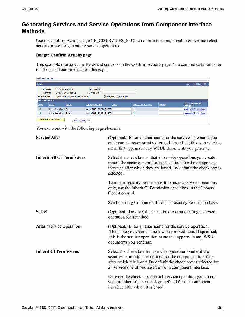
Chapter 15 Creating Component Interface-Based Services
Generating Services and Service Operations from Component InterfaceMethods
Use the Confirm Actions page (IB_CISERVICES_SEC) to confirm the component interface and selectactions to use for generating service operations.
Image: Confirm Actions page
This example illustrates the fields and controls on the Confirm Actions page. You can find definitions forthe fields and controls later on this page.
You can work with the following page elements:
Service Alias (Optional.) Enter an alias name for the service. The name youenter can be lower or mixed-case. If specified, this is the servicename that appears in any WSDL documents you generate.
Inherit All CI Permissions Select the check box so that all service operations you createinherit the security permissions as defined for the componentinterface after which they are based. By default the check box isselected.
To inherit security permissions for specific service operationsonly, use the Inherit CI Permission check box in the ChooseOperation grid.
See Inheriting Component Interface Security Permission Lists.
Select (Optional.) Deselect the check box to omit creating a serviceoperation for a method.
Alias (Service Operation) (Optional.) Enter an alias name for the service operation. The name you enter can be lower or mixed-case. If specified, this is the service operation name that appears in any WSDLdocuments you generate.
Inherit CI Permissions Select the check box for a service operation to inherit thesecurity permissions as defined for the component interfaceafter which it is based. By default the check box is selected forall service operations based off of a component interface.
Deselect the check box for each service operation you do notwant to inherit the permissions defined for the componentinterface after which it is based.
Copyright © 1988, 2017, Oracle and/or its affiliates. All rights reserved. 361
Creating Component Interface-Based Services Chapter 15
See Inheriting Component Interface Security Permission Lists.
Version (Optional.) Service operations created default version V1.
You may enter a different value to use as the version when theservice operation is created.
This field is a text field, so you may enter numeric or textvalues.
Message Names and Descriptions (Optional.) Click the link to specify names and descriptionsfor messages in the service operation. The message names anddescriptions will appear in the generated XML message schema.
If you do not enter message names or descriptions, PeopleSoftIntegration Broker assigns system-generated names to themessages. The following example shows a sample system-generated message name: M702221.V1
Perform Selected Action Click the button to generate services and service operations forthe component interface and selected methods.
After the service and service operations are created, the ReviewStatus page displays and you can review the actions performedas well as access the service definition created.
Return to Select CIs Click the link to return to the previous page, the Review Statuspage.
Inheriting Component Interface Security Permission ListsYou can specify that all or select component interface-based service operations inherit the securitypermission list(s) of the component interface from which they are derived. This feature allows you tobypass the process of manually assigning permission lists to the service operations after you generatethem.
The Confirm Actions page (IB_CISERVICES_SEC) shown in the previous section contains an Inherit AllCI Permissions check box located on the upper half of the page. The Choose Operation grid of the pagefeatures an Inherit CI Permissions check box for each service operation to be generated.
Important! Permission lists granted to a component interface after the service operation is created are notpropagated to the service operations and you must manually add them.
Inherit All CI Permissions Select the check box for all service operations to inherit thepermission lists of the component interface from which they arebased. By default the check box is selected.
Deselect the check box to choose select service operations toinherit the permission list(s) of the base component interface orto manually define permission lists for the service operations inthe PeopleTools Security component.
362 Copyright © 1988, 2017, Oracle and/or its affiliates. All rights reserved.

Chapter 15 Creating Component Interface-Based Services
Inherit CI Permissions Select the check box for each service operation that is to inheritthe permission list(s) of the base component interface.
Deselect the check box for each service operation this is not toinherit the permission list(s) of the base component.
The system generates service operations for the Update and UpdateData methods based the existenceof the Get method. Therefore, the same permissions granted to a component interface's Get method areinherited by service operations based on the Update and UpdateData methods
Related LinksGenerating Services and Service Operations from Component Interface MethodsSetting Permissions to Service Operations
Adding Message Names and Descriptions to Generated Service OperationsThe Confirm Actions page features a Message Names and Descriptions link for each service operation.Click the link to open the Message Names and Descriptions page (IBCISERVICES2_SEC). On the pageyou can enter names for each message in the service operations. You can also enter a description for eachmessage name. The message names and description will appear in the generated XML message schemafor the service operation.
Image: Message Names and Descriptions page
This example illustrates the Message Names and Descriptions page.
In the message name fields, enter a message name. You do not need to append the message name with aversion number. The system automatically creates versions the message as version one, and appends themessage name with .V1.
When you have completed entering message names and descriptions, click the OK button to return to theConfirm Actions page.
Viewing Component Interface-Based Service Definitions
After you generate services and service operations, the Review Status page (IB_SERVICES2) appears.
Copyright © 1988, 2017, Oracle and/or its affiliates. All rights reserved. 363

Creating Component Interface-Based Services Chapter 15
Use the page to review the actions performed.
Image: Review Status page
This example illustrates the Review Status page.
For example, the previous graphic shows the names of the two service operations created as well as theservice operation status of Operation created
From this page you can continue to create additional service operations using the remaining availablemethods for the component interface.
Or, you can click the Return to Select CI link to return to the Select Component Interface page to selectnew component interfaces for which to generate services and service operations.
You can also click the View Service Definition link to view the service definition for the service created.
When you click the View Service Definition link the service you created, CI_CURRENCY_CD_CIappears in the Services page.
364 Copyright © 1988, 2017, Oracle and/or its affiliates. All rights reserved.

Chapter 15 Creating Component Interface-Based Services
Image: Services page
This example illustrates the Services page.
From this page you can perform actions as you would on any other service, including:
• Click the Provide Web Service link to generate WSDL for the service.
• Use the Service Operations check box to add additional service operations to the service.
• Click either of the operations that display in the Existing Operations check box to generate routingdefinitions, view the response, request or fault messages, view handler details, and more.
• And so on.
Related LinksUnderstanding Managing ServicesUnderstanding Managing REST ServicesUnderstanding Managing Service OperationsUnderstanding REST Service Operations
Copyright © 1988, 2017, Oracle and/or its affiliates. All rights reserved. 365

Creating Component Interface-Based Services Chapter 15
366 Copyright © 1988, 2017, Oracle and/or its affiliates. All rights reserved.

Chapter 16
Managing Service Operation Handlers
Understanding Service Operation Handlers
Messaging handlers, or handlers are associated with a service operation on the Handlers tab of the ServiceOperations page.
Handlers define additional programming to be used with processing the message associated with theservice operation.
Service Operation Handler TypesThe following are the different types of handlers:
• On Notify
• On Pre-notify
• OnPost-notify
• On Receive
• On Request
• On Response
• On Route
• On Send
Handler Types and Messaging TypesThe availability of each handler type depends on the type of service operation you are using. Thefollowing tables list the message types used for each service operation type and the handler typesavailable for use.
Table 1: Handler Types and Messaging Types
Service OperationType
On Notify HandlerType
On Pre-NotifyHandler Type
On Post-NotifyHandler Type
On Receive HandlerType
Asynchronous one-way Request message Request message Request message Request message
Asynchronous request /response
Request message NA NA Request message
Copyright © 1988, 2017, Oracle and/or its affiliates. All rights reserved. 367

Managing Service Operation Handlers Chapter 16
Service OperationType
On Notify HandlerType
On Pre-NotifyHandler Type
On Post-NotifyHandler Type
On Receive HandlerType
Asynchronous tosynchronous
Request message NA NA NA
Synchronous NA NA NA NA
Table 2: Handler Types and Messaging Types (cont.)
Service OperationType
On Request HandlerType
On ResponseHandler Type
On Route HandlerType
On Send HandlerType
Asynchronous one-way NA NA Request message Request message
Asynchronous request /response
NA Response message *Request message
*Response message
Request message
Asynchronous tosynchronous
Request message Response message *Request message
*Response message
Request message
Synchronous Request message NA Request message Request message
Note: For On Route with On Send, the message structure is a request message. For On Route with OnReceive, the message structure is a response message.
The On Response handler type is used to identify the type of On Notify event to be fired. For example,assume there are four On Notify handlers that are to be fired—three are general On Notify events, that is,the message is processed as part of the request, and the fourth is a response to the original asynchronousrequest. The fourth one is specified with a handler type of On Response, and the application class selectedis the base class OnNotify.
Table 3: Handler Types and Messaging Types (REST service operations).
REST ProviderHTTP Method
On Request HandlerType
On ResponseHandler Type
On Route HandlerType
On Send HandlerType
Delete NA NA NA NA
Get NA NA NA NA
Head NA NA NA NA
Post Request message NA NA NA
Put Request message NA NA NA
There are no handlers for REST consumer service operations. You may add connector properties toconsumer service operations on the routing definition using the Routings-Connector Properties page oradd them dynamically by using PeopleCode.
368 Copyright © 1988, 2017, Oracle and/or its affiliates. All rights reserved.

Chapter 16 Managing Service Operation Handlers
See Defining and Overriding Gateway and Connector PropertiesUsing PeopleCode to Manage RESTService Operations.
Related LinksAdding Handlers to Service Operations
Understanding Implementing Handlers
You can implement handlers using application classes, application engine programs, componentinterfaces, data mover scripts or pre-PeopleTools 8.48 integration PeopleCode constructs.
The following tables list the handlers you can implement using application classes, application engineprograms, component interfaces and bulk-load processing.
Note: For REST provider services you may only implement the OnRequest handler using an applicationclass.
Table 1:
Implementation On Notify Handler On Pre-notify On Post-notify On Receive Handler
Application class Y Y Y Y
Application Engine Y N N N
Component interface Y N N N
Bulk load Y N N N
Table 2:
Implementation On Route Handler On Send Handler On Request Handler On ResponseHandler
Application class Y Y Y Y
Application Engine N N N N
Component interface N N Y Y
Bulk load N N N N
In addition to the implementation methods listed in the table, there is also a deprecated PeopleCodehandler (DPC handler) that the system automatically creates for any integration PeopleCode that cannotbe migrated to the PeopleTools 8.48 or higher systems.
The handler implementation methods listed in the tables are discussed in greater detail in subsequentsections of this topic.
Copyright © 1988, 2017, Oracle and/or its affiliates. All rights reserved. 369
Managing Service Operation Handlers Chapter 16
Related LinksImplementing Handlers Using Application ClassesImplementing Handlers Using Application Engine ProgramsImplementing Handlers Using Component InterfacesImplementing Handlers Using Bulk Load ProcessingImplementing Handlers Using Deprecated PeopleCode Handlers
Adding Handlers to Service Operations
This section describes how to:
• Add a handler to a service operation.
• Set handler processing sequence.
Understanding Adding Handler Definitions to Service OperationsWhen you create a handler definition you supply basic information about the handler, then defineinformation specific to the implementation method for the handler.
You can create and use multiple handlers for a service operation. In addition you can set the sequence inwhich the system performs handler processing.
Handler Processing SequenceThe Sequence field enables you to select the order in which PeopleSoft Integration Broker performshandler processing. A handler with a sequence value of 1 is processed first, followed by that with a valueof 2, and so on.
If multiple notification handlers exist and are active, but no sequence is set, the system processes handlersalphabetically.
If an error occurs in a notification, all subsequent handler processing stops until the error is corrected, theservice operation is resubmitted, and the handler runs successfully.
In an error situation, the Service Operation Monitor shows a status of Error for the handler with the error,and all remaining handlers to be processed are in a status of New.
Adding a Handler to a Service OperationTo add a handler to a service operation use the Service Operations – Handlers page(IB_SERVICEHDLR).
370 Copyright © 1988, 2017, Oracle and/or its affiliates. All rights reserved.

Chapter 16 Managing Service Operation Handlers
Image: Service Operations – Handlers page
This example illustrates the Service Operations – Handlers page.
To create a handler definition:
1. Access the Service Operations–Handlers page (PeopleTools, Integration Broker, Integration Setup,Service Operations and click the Handlers tab).
2. In the Handlers section, enter a handler name in theName field.
Note that for OnRequest, and OnRoute handlers, you need not enter a name. The system adds ahandler name after you provide the handler details.
3. From the Type drop-down list box, select the handler type.
The service operation type determines the handler types that are available to choose.
See Handler Types and Messaging Types.
The valid values are:
4. In the Sequence field, enter a number to specify the order of processing for the handler.
The Sequence field appears only when there are multiple notification handlers defined and active forthe service operation.
5. From the Implementation drop-down list box, select the method to use to implement the handler.
The handler type determines the available implementation methods.
See Understanding Implementing Handlers.
6. From the Status drop-down list box, select a status for the handler.
Values are:
• Active. (Default.) Select to make the handler active.
• Inactive. Select to make the handler inactive.
Copyright © 1988, 2017, Oracle and/or its affiliates. All rights reserved. 371

Managing Service Operation Handlers Chapter 16
7. Click the Save button.
Repeat these steps to add additional handlers to the service operation.
Specifying General Handler DetailsThe details you enter for a handler depend on the implementation method of the handler.
This section describes general handler detail information you must specify for implementing handlersusing application classes and component interfaces.
There are additional details you must define for these implementation methods, as well as for applicationengine and data mover script implementation methods. See the sections for each implementation methodfor additional information you must specify.
Note: You do not enter handler details for handler implementations using a deprecated PeopleCodehandler.
To add general handler details:
1. On the Handlers tab of the Service Operations – Handlers tab, in the Handlers section, click theDetails link.
The Action Details page appears.
2. In the Description field, enter a description for the handler. By default, the system populates this fieldwith the name of the service operation associated with the handler.
3. (Optional.) In the Comments field, enter comments about the handler.
4. (Optional.) In the Handler Owner field, enter the name of the person or group that owns or maintainsthe handler.
Related LinksImplementing Handlers Using Application ClassesImplementing Handlers Using Application Engine ProgramsImplementing Handlers Using Component InterfacesImplementing Handlers Using Bulk Load ProcessingImplementing Handlers Using Deprecated PeopleCode Handlers
Implementing Handlers Using Application Classes
This section provides an overview of implementing handlers using application classes and discusses howto:
• Develop an application class for implementing a handler.
• Specify application class implementation details.
372 Copyright © 1988, 2017, Oracle and/or its affiliates. All rights reserved.
Chapter 16 Managing Service Operation Handlers
Understanding Implementing Handlers Using Application ClassesYou can specify an application class as a handler for a service operation. This is the most typicalimplementation of a handler.
The process for implementing a handler using an application class is:
1. Develop an application class for implementing the handler.
This process is discussed in this section.
See Developing Application Classes for Implementing Handlers.
2. Add a handler to the service operation.
This process is discussed elsewhere in this topic.
See Adding a Handler to a Service Operation.
3. Specify general handler details.
This process is discussed elsewhere in this topic.
See Specifying General Handler Details.
4. Specify application class details for the handler.
This process is discussed in this section.
See Specifying Application Class Implementation Details.
Developing Application Classes for Implementing HandlersThis section discusses how to develop application classes for implementing service operation handlers.
After you create the application package, you must specify the application package, class and method inthe service operation definition as part of the handler details.
Understanding Interfaces and Deriving Application ClassesFor each handler type, the following table lists the interface from which to derive the application class.The interfaces are located in the PS_PT application package:
Handler Type Application Class Interface
On Notify INotificationHandler
On Post Notify IPrePostNotification
On Pre Notify IPrePostNotification
On Response INotificationHandler
On Receive IReceiver
Copyright © 1988, 2017, Oracle and/or its affiliates. All rights reserved. 373

Managing Service Operation Handlers Chapter 16
Handler Type Application Class Interface
On Request IRequestHandler
On Send ISend
On Route IRouter
Understanding Input and Output ParametersFor application class handlers, the names that populate the drop-down used for selecting the appropriatemethod must have the exact signature required for the method.
Handler Type Input Parameter to Method Method Output Parameter
On Notify Message Void (none)
On Response Message Void (none)
On Receive Message Int
On Request Message Message
On Send Message Message
On Route* Message Integer or Boolean
For the On Route handler type, if you select a method that returns as integer, the handler type is On RouteSend. If you select a method that returns as Boolean, the handler type is On Route Receive.
Developing an Application Class for Implementing a HandlerTo develop an application class for implementing a handler:
1. Select the Integration Broker method that you want to implement based on the type of serviceoperation you are creating.
2. Create a new application class, and import the appropriate Integration Broker application class. Forexample:
import PS_PT:Integration:INotificationHandler;
3. Define a class that implements the Integration Broker application class.
4. Define the method that implements the Integration Broker method, with the appropriate signature. Inthe following example, the OnNotify method would be available as a handler method.
class RESPONSE_NOTIFICATION implements PS_PT:Integration:INotificationHandler ⇒
method RESPONSE_NOTIFICATION(); method OnNotify(&MSG As Message);
end-class;
374 Copyright © 1988, 2017, Oracle and/or its affiliates. All rights reserved.

Chapter 16 Managing Service Operation Handlers
5. In the definition of the class, create the program-specific code to be used for this handler.
Specifying Application Class Implementation DetailsBefore specifying application class implementation details for a handler, you must first create theapplication class to implement the handler, add a handler to the service operation definition, and specifygeneral handler details.
To specify application class implementation details:
1. On the Service Operations – Handlers tab, in the Handlers section, click the Details link.
The Handler Details page appears.
2. Complete the following fields:
Package Name Enter the package name that contains the class that you wantto specify, or use the Lookup button to search for and selectone.
Path Enter the name or names of any subpackages that containthe application class that you want to specify, or use theLookup button to search for and select one.
Class ID Enter the name of the application class that contains themethod that you want to specify, or use the Lookup button tosearch for and select one.
Only application classes that implement an appropriate baseclass are shown. The base class is dependent on the handlertype.
Method From the Method drop-down list box, select the methodfrom the selected application class that you want to specify.
Only methods with the correct signature for the currenthandler type are shown.
3. Click the OK button.
4. Click the Save button.
Implementing Handlers Using Application Engine Programs
This section provides and overview of implementing handlers using application engine programs anddiscusses how to:
• Specify application engine implementation details.
• Retrieve service operation content from application engine programs.
Copyright © 1988, 2017, Oracle and/or its affiliates. All rights reserved. 375
Managing Service Operation Handlers Chapter 16
• View subscription contract status.
Understanding Implementing Handlers Using Application Engine ProgramsApplication engine handlers are available for notification events (OnNotify) and schedule an applicationengine program to run within PeopleSoft Process Scheduler to process service operation content. Thishandler is a good alternative for long-running programs or service operations that have large amounts ofdata to process, since processing is performed by PeopleSoft Process Scheduler and not in the PeopleSoftIntegration Broker runtime environment.
After the service operation is invoked, you can track the process by viewing the subscription contract inthe Service Operations Monitor.
When you implement a handler using an application engine program, you must retrieve the transactionID that you use to get message data from within the application engine program. The run control recordPSIBRUNCNTL is populated with the transaction ID prior to scheduling the actual application engineprogram. Note that it is not required to retrieve the transaction ID, therefore any application engineprogram can be scheduled that does not require initialization parameters via a run control table.
The process for implementing a handler using and application engine program is:
1. Develop the application engine program.
Developing application engine programs is discussed elsewhere in the PeopleTools productdocumentation.
See "Application Engine Overview" (PeopleTools 8.55: Application Engine)
2. Add a handler to the service operation.
This process is discussed elsewhere in this topic.
See Adding a Handler to a Service Operation.
3. Specify general handler details.
This process is discussed elsewhere in this topic.
See Specifying General Handler Details.
4. Specify application engine handler implementation details.
This process is discussed in this section.
See Specifying Application Engine Handler Implementation Details.
5. Retrieve service operation content from the application engine program.
This process is discussed in this section.
See Retrieving Service Operation Content from Application Engine Programs.
6. View subscription contract status.
This process is discussed in this section.
376 Copyright © 1988, 2017, Oracle and/or its affiliates. All rights reserved.
Chapter 16 Managing Service Operation Handlers
See Viewing Subscription Contract Status.
Specifying Application Engine Handler Implementation DetailsBefore specifying application engine handler implementation details, you must first create the applicationengine program to process the service operation, add a handler to the service operation definition, andspecify general handler details.
To specify application class implementation details:
1. On the Service Operations – Handlers tab, in the Handlers section, click the Details link.
The Action Details page appears.
2. In the Program Name field, click the Lookup button to locate the name of the application engineprogram to use.
3. Click the OK button.
4. Click the Save button.
Retrieving Service Operation Content from Application Engine ProgramsThis section discusses how to:
• Retrieve a transaction ID from an application engine program.
• Instantiate a Message object using a transaction ID.
Understanding Retrieving Service Operation Content from Application EngineProgramsWithin the application engine program, you can retrieve the transaction ID and thereby get an instantiatedMessage object to retrieve the content data respectively.
Retrieving Transaction IDs from Application Engine ProgramsUse the GetIBTransactionIDforAE method on the %IntBroker object to get the transaction ID or simplywrite the SQL to retrieve the ID.
The following examples show how to get the transaction ID from an application engine program andinstantiate a Message object.
Method from %IntBroker Object:
StrTransaction = %IntBroker.GetIBTransactionIDforAE(string OperID, string Run Control ID);
&MSG = %IntBroker.GetMessage(StrTransaction, %IntBroker_SUB);
Or, you can write code within a SQL step similar to the following:
%SelectInit(IBTRANSACTIONID) SELECT IBTRANSACTIONID FROM PSIBRUNCNTL WHERE OPRID = %Bind(OPRID)
Copyright © 1988, 2017, Oracle and/or its affiliates. All rights reserved. 377

Managing Service Operation Handlers Chapter 16
AND RUN_CNTL_ID = %Bind(RUN_CNTL_ID)
Or, you can perform a simple SQLExec as follows:
SQLExec("select ibtransactionid from psibruncntl where oprid = :1 and run_cntl_id = :2",
j_book_aet.oprid, j_book_aet.run_cntl_id, &ibtransid);
Instantiating Message Objects Using Transaction IDsThe following code example shows how to instantiate a Message object using the transaction ID from anapplication engine program:
&MSG = %IntBroker.GetMessage(J_BOOK_AET.IBTRANSACTIONID, %IntBroker_SUB);
Viewing Subscription Contract StatusThe following table lists the possible contract statuses that may display in the Service Operations Monitorwhen implementing a handler using an application engine program:
Service Operations Monitor Status Description
Working At runtime, the Service Operations Monitor shows a status ofWorking for the subscription contract when it is picked up bythe subscription contract handler.
Submit After the application engine program is scheduledsuccessfully, the state of contracts changes to Submit in theService Operations Monitor. This status indicates that theapplication engine program has been successfully submittedand a process instance has been returned.
Error • If the program does not get scheduled successfully, thestatus is set to Error
• A Process Monitor status of Error will change thesubscription contract status in the Service OperationsMonitor to Error. You must read the error details fromthe Process Monitor Details page, since the ServiceOperations Monitor does not have access to the ProcessMonitor error tables.
Done When the application engine program has been processedsuccessfully, the status of the contract in the ServiceOperations Monitor is Done.
Cancel • For application engine programs that have ProcessMonitor status of Cancel or Delete, the status of thesubscription contract in the Service Operations Monitor ischanged to Cancel.
• If the instance is deleted from the process scheduler tablethen the status of the subscription contract is Cancel. Thiswill clear out the contract in the partitioned queue so thatthe next contract in sequence can be processed.
378 Copyright © 1988, 2017, Oracle and/or its affiliates. All rights reserved.
Chapter 16 Managing Service Operation Handlers
Note: In the Service Operations Monitor the Submit status has the same behavior as the Working status,thus proper queue partitioning behavior is maintained. Therefore, intelligent queue partitioning should betaken into account for service operations using the application engine handler.
A Subscription Contract processing an application engine handler cannot be cancelled or resubmittedfrom the Service Operations Monitor, but rather must be done in the Process Monitor. Once you resubmitor cancel the program in the Process Monitor, the status is updated for the subscription contract. Refreshthe Service Operations Monitor page to view the updated status. Note that there could be a delay fromwhen the time you cancel or resubmit the application engine program in the Process Monitor and whenthe update is seen in the Service Operations Monitor. In addition, at least one Pub/Sub domain must beactive for this status update to happen.
Implementing Handlers Using Component Interfaces
You can implement a component interface as a handler to access extant business rules and processes to beused with the service operation data.
Understanding Implementing Handlers Using Component InterfacesThis section provides an overview of implementing handlers using component interfaces.
You can only use a component interface for On Notify, On Request and On Response handler types.
Component interfaces can be used as handlers for asynchronous and synchronous service operations.Asynchronous service operations should only be used with component interface methods that do notrequire a response, such as Update or Insert.
You must expose a component interface as a service before you can implement any of the componentinterface methods as handler actions.
The standard methods for a component interface (such as Find, Get, Save, Update, and so on) areautomatically available for a handler. However, if you want to use a user-defined method, you mustinclude the keyword Doc as part of the signature.
The process for implementing a handler using a component interface is:
1. Expose the component interface as a service.
See Selecting Component Interfaces to Expose as Services.
2. Add a handler to the service operation.
See Adding a Handler to a Service Operation.
3. Specify general handler details.
See Specifying General Handler Details.
4. Specify component interface handler implementation details.
See Specifying Component Interface Handler Implementation Details.
Copyright © 1988, 2017, Oracle and/or its affiliates. All rights reserved. 379

Managing Service Operation Handlers Chapter 16
Specifying Component Interface Handler Implementation DetailsBefore specifying component interface handler implementation details, you must first create a servicefrom the component interface, add a handler to the service operation definition, and specify generalhandler details.
To specify component interface implementation details:
1. On the Service Operations – Handlers tab, in the Handlers section, click the Details link.
The Action Details page appears.
2. In the Name field enter the component interface name, or use the Lookup button to search for andselect one.
3. From the Action drop-down list box, select an action.
4. Click the OK button.
5. Click the Save button.
Implementing Handlers Using Bulk Load Processing
This section provides and overview of implementing handlers using the bulk load processing anddiscusses how to:
• Enable transactional rollback.
• Enable table truncation.
• Specify XML attributes for nonrowset-based messages.
• Add data structures to nonrowset-based messages.
Understanding Implementing Handlers Using the Bulk Load HandlerYou can bulk load large amounts of data (large messages) into a local table using the bulk load handler.
Note: Bulk load handlers are allowed only on asynchronous service operations and only one bulk loadhandler is allowed per service operation.
When you implement a handler using a data mover script use the OnNotify event. When the OnNotifyevent is fired, the message data is inserted into the tables. Bulk load handlers do not perform any datavalidation.
Bulk Load Handler Message TypesYou can use bulk load handlers for service operations that contain the following types of asynchronousmessages:
• Rowset-based messages.
380 Copyright © 1988, 2017, Oracle and/or its affiliates. All rights reserved.

Chapter 16 Managing Service Operation Handlers
For service operations that contain rowset-based messages, the message structure determinesprocessing.
• Nonrowset-based messages.
For service operations that contain nonrowset-based messages, you define the structure for processingby mapping data to PeopleSoft records and providing attribute names and values.
• Container messages that contain rowset-based messages parts.
For service operations with container messages that contain rowset-based message parts, the bulk loadhandler uses the message structure of the message parts to determine processing.
Transactional RollbackBulk load handler processing is destructive load processing, meaning that the handler deletes existingdata from the table and then bulk inserts the new data.
PeopleSoft Integration Broker provides an optional transaction rollback feature that enables you torollback the database to the pre-bulk insert state if needed.
Transactional rollback is dependent on the bulk size of the data to be updated. Therefore, when you selectthe rollback option, a Rollback Size field appears where you specify a rollback value. The default value is32 kilobytes.
Table TruncationBy default, the bulk load handler truncates table data before performing any processing.
PeopleSoft Integration Broker enables you to disable table truncation.
Nonrowset-Based Messages and the Bulk Load HandlerIf a service operation contains a nonrowset-based message, you must add a data structure to define themessage content, thereby allowing non-PeopleSoft data to map to the records and fields in the database.
In addition, you can provide an XML attribute name/value pair to distinguish record and field nodes onincoming XML content.
Process Overview for Implementing Handlers Using Bulk Load HandlersThe process for implementing a bulk load handler is:
1. Add a bulk load handler to the service operation on the target system.
This procedure is discussed elsewhere in this topic.
See Adding a Handler to a Service Operation.
2. Specify general handler details.
This procedure is discussed elsewhere in this topic.
See Specifying General Handler Details.
Copyright © 1988, 2017, Oracle and/or its affiliates. All rights reserved. 381

Managing Service Operation Handlers Chapter 16
3. (Optional.) Enable transactional rollback and the rollback size.
This procedure is discussed in this section.
4. (Optional.) Specify XML record attributes.
This procedure is discussed in this section.
5. Add the data structure for the message contained in the service operation.
The step is required only when a nonrowset-based message is contained in the service operation.
This procedure is discussed in this section.
Enabling Transactional RollbackThe Bulk Load Handler page (IB_SERVICEHDL5_SEC) features a Rollback Non-Destructive Loadoption that you can set to enable transaction rollback.
Image: Bulk Load Handler page
This example illlustrates the Bulk Load Handler page. The example shows the page when the serviceoperation contains a nonrowset-based message.
The previous example shows the Bulk Load Handler page that displays when the service operationcontains a nonrowset-based message.
If the service operation contains a rowset-based message, the page does not display the XML attributefields or the data tree structure controls.
382 Copyright © 1988, 2017, Oracle and/or its affiliates. All rights reserved.
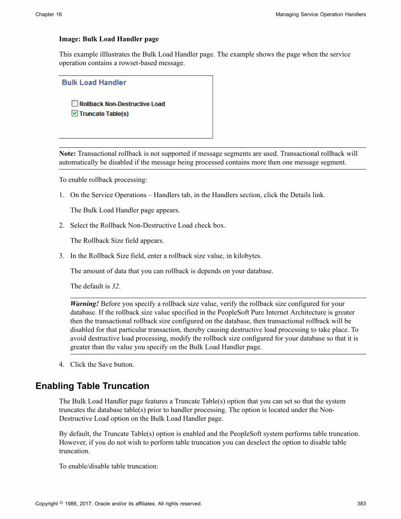
Chapter 16 Managing Service Operation Handlers
Image: Bulk Load Handler page
This example illlustrates the Bulk Load Handler page. The example shows the page when the serviceoperation contains a rowset-based message.
Note: Transactional rollback is not supported if message segments are used. Transactional rollback willautomatically be disabled if the message being processed contains more then one message segment.
To enable rollback processing:
1. On the Service Operations – Handlers tab, in the Handlers section, click the Details link.
The Bulk Load Handler page appears.
2. Select the Rollback Non-Destructive Load check box.
The Rollback Size field appears.
3. In the Rollback Size field, enter a rollback size value, in kilobytes.
The amount of data that you can rollback is depends on your database.
The default is 32.
Warning! Before you specify a rollback size value, verify the rollback size configured for yourdatabase. If the rollback size value specified in the PeopleSoft Pure Internet Architecture is greaterthen the transactional rollback size configured on the database, then transactional rollback will bedisabled for that particular transaction, thereby causing destructive load processing to take place. Toavoid destructive load processing, modify the rollback size configured for your database so that it isgreater than the value you specify on the Bulk Load Handler page.
4. Click the Save button.
Enabling Table TruncationThe Bulk Load Handler page features a Truncate Table(s) option that you can set so that the systemtruncates the database table(s) prior to handler processing. The option is located under the Non-Destructive Load option on the Bulk Load Handler page.
By default, the Truncate Table(s) option is enabled and the PeopleSoft system performs table truncation.However, if you do not wish to perform table truncation you can deselect the option to disable tabletruncation.
To enable/disable table truncation:
Copyright © 1988, 2017, Oracle and/or its affiliates. All rights reserved. 383

Managing Service Operation Handlers Chapter 16
1. Access the Bulk Load Handler page (PeopleTools, Integration Broker, Integration Setup, ServiceOperations and click the Handlers tab. Click the Details link for the bulk load handler).
2. On the Truncate Table(s) check box perform one of the following options:
• To enable table truncation, select the check box.
• To disable table truncation, deselect the check box.
3. Click the OK button.
Specifying XML Record Attribute ValuesUse the XML Record Indicator Attribute check box on the Bulk Load Handler page to distinguish andspecify records and fields on incoming XML content of nonrowset-based messages.
Image: Bulk Load Handler page
This example illustrates a partial view of the Bulk Load Handler page. The example shows the XMLRecord Indicator Attribute section of the page that you use to specify an attribute name and value fornonrowset-based messages.
When you specify an attribute name and value, the system recognizes content with that name and value asa record. Content placed in the message after that attribute name/value pair is considered child data.
When the service operation contains a nonrowset-based message, you must specify an attribute name andattribute value. If you do not supply values for these fields, an error message appears. These fields areoptional when the service operation contains a rowset-based message.
To specify XML record attribute values:
1. Access the Bulk Load Handler page (PeopleTools, Integration Broker, Integration Setup, ServiceOperations and click the Handlers tab. Click the Details link for the bulk load handler).
2. In the Attribute Name field, enter the attribute name that the system should recognize as the record.
For example, Class.
3. In the Attribute Value field, enter the value for the attribute name.
For example, R.
4. Click the Save button.
Adding Data Structures for Nonrowset-Based MessagesThis section discusses how to:
• Build data structures for nonrowset-based data structures.
384 Copyright © 1988, 2017, Oracle and/or its affiliates. All rights reserved.

Chapter 16 Managing Service Operation Handlers
• Insert nonrowset-based messages in project definitions.
Building Nonrowset-Based Data StructuresThe Bulk Load Handler details page provides a data tree, similar to that found in the Messagescomponent, that you use to build the structure of the nonrowset-based message.
You must define a minimum of one record to save the handler definition.
For building the data structure you use the same graphical user interface and procedures that you wouldfor managing rowset-based messages in the Messages component.
By clicking the Add Record to Root link you can begin to create the data structure by adding a rootrecord. As with the Messages component, you can select to include or exclude fields and specify fieldaliases. One unique difference here, however, is that you can build structures with multiple level 0records. At save time, the system builds a message for each level 0 record found in the structure.
Note that message references are not allowed.
Message structures you create on the Bulk Load Handler details page are not accessible in the Messagescomponent and appear only as part of the bulk load handler.
The message names start with ~IB_M_DMS~.
See the documentation elsewhere in the product documentation for managing rowset-based messages forcreating the data structure. Again, even though here you are building the structure of a nonrowset-basedmessage, you will use the same graphical user interface and procedures as those for working with rowset-based messages.
See Managing Rowset-Based Messages.
Inserting Nonrowset–Based Messages in Project DefinitionsYou must assign nonrowset-based messages you create using the Bulk Load Handler page to a bulk loadhandler. To accomplish this task, in PeopleSoft Application Designer when you insert a service operationhandler definition into a project, you must include the message(s) as a related definition.
Copyright © 1988, 2017, Oracle and/or its affiliates. All rights reserved. 385
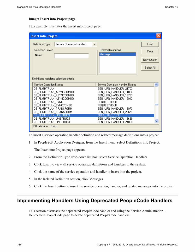
Managing Service Operation Handlers Chapter 16
Image: Insert into Project page
This example illustrates the Insert into Project page.
To insert a service operation handler definition and related message definitions into a project:
1. In PeopleSoft Application Designer, from the Insert menu, select Definitions info Project.
The Insert into Project page appears.
2. From the Definition Type drop-down list box, select Service Operation Handlers.
3. Click Insert to view all service operation definitions and handlers in the system.
4. Click the name of the service operation and handler to insert into the project.
5. In the Related Definition section, click Messages.
6. Click the Insert button to insert the service operation, handler, and related messages into the project.
Implementing Handlers Using Deprecated PeopleCode Handlers
This section discusses the deprecated PeopleCode handler and using the Service Administration –Deprecated PeopleCode page to delete deprecated PeopleCode handlers.
386 Copyright © 1988, 2017, Oracle and/or its affiliates. All rights reserved.

Chapter 16 Managing Service Operation Handlers
Understanding the Deprecated PeopleCode HandlerDuring the upgrade process, the PeopleSoft system creates a deprecated PeopleCode handler (DPChandler) for any integration PeopleCode that cannot be migrated from a PeopleTools 8.47 or earliersystem to a PeopleTools 8.55 system. Deprecated handlers enable you to run PeopleTools 8.47 andearlier PeopleCode (subscription or OnRequest). However, PeopleSoft recommends that you correct thePeopleCode and migrate the code into an Application Class type handler for use in PeopleTools 8.55systems.
Deleting Deprecated PeopleCode HandlersUse the Service Administration – Deprecated PeopleCode page (IB_HOME_PAGE8) to delete deprecatedPeopleCode and its associated handler(s).
To access the page select PeopleTools, Integration Broker, Service Utilities, Service Administration andclick the Deprecated PeopleCode tab.
Image: Service Administration – Deprecated PeopleCode page
This example illustrates the Service Administration – Deprecated PeopleCode page.
The page enables you to delete the PeopleCode that was assigned to the Pre-PeopleTools 8.48subscription, along with the (deprecated) handler that was created to invoke the PeopleCode.
Warning! Deleted deprecated PeopleCode cannot be recreated.
To delete a deprecated PeopleCode handler:
1. Access the Service Administration – Deprecated PeopleCode page (PeopleTools, Integration Broker,Service Utilities, Service Administration and click the Deprecated PeopleCode tab).
2. In the Service Operation field, enter the name of the service operation that contains the deprecatedPeopleCode handler, or click the Lookup button to search for one.
3. Click the Search button.
The search results appear in the Deprecated PeopleCode Handler grid.
4. Select the Select check box next to the handler to delete.
5. Click the Delete button.
Copyright © 1988, 2017, Oracle and/or its affiliates. All rights reserved. 387

Managing Service Operation Handlers Chapter 16
388 Copyright © 1988, 2017, Oracle and/or its affiliates. All rights reserved.

Chapter 17
Managing Service Operation RoutingDefinitions
Understanding Routing Definitions
This section provides overview information about routing definitions.
Routing DefinitionsA routing definition defines the sending and receiving nodes for a transaction, specifies any inboundand outbound transformations to invoke and defines external aliases. It also defines overrides that thedefault integration gateway and the default target connector that the local node use to communicate withan integration endpoint.
Routing TypesThere are four routing types:
Any-to-local An any-to-local routing enables the local node to receivetransactions from any node.
This routing type is for inbound transactions only and the “any”node is always the sending node.
You can use this routing type for all service operation types, except for asynchronous-to-synchronous service operations.
Local-to-local A local-to-local routing is a routing in which transactions aresent and received within the local database.
When working with synchronous service operations, youhave the option to generate transactional routings, wherebythe OnRequest event will run under the existing transactionboundary of the component.
Local-to-Atom A local-to-Atom routing is used exclusively with feedsfunctionality.
See PeopleTools 8.55: Feeds Publishing Framework
Point-to-point A point-to-point routing requires that specific nodes that youdefine send and receive a transaction.
Copyright © 1988, 2017, Oracle and/or its affiliates. All rights reserved. 389
Managing Service Operation Routing Definitions Chapter 17
Defining Routing DefinitionsA routing definition must exist on each system that is participating in a particular transaction.
For example, let's say that System A is going to send a service operation to System B and a point-to-pointrouting needs to be created between the two systems. Further, the local node on System A is called NodeA, and the local node on System B is called Node B.
System A and System B need to have the identical service operation defined on each of their systems.
In addition, System A needs to have an outbound routing definition defined on its system that specifies itslocal node, Node A, as the sending node. The routing definition must specify System B's local node, NodeB, as the receiving node.
System B needs to have an inbound routing definition defined on its system that specifies its local node,Node B, as the receiving node. The routing definition on System B also needs to specify System A's localnode, Node A, as the sending node.
The exception to this is when a receiving system generates an any-to-local routing for a service operation.If the receiving system has an any-to-local routing definition defined for a particular service operation, itwill accept requests from any node without the need of a specific point-to-point routing definition.
So using the examples of System A being the sending system and System B being the receiving system,this is what happens when an any-to-local routing is defined. System A still needs to have a routingdefinition defined on its system where its local node, Node A, is defined as the sending node, andSystem's B local node, Node B, is defined as the receiving node. On System B, when the any-to-localrouting was generated, the PeopleSoft system automatically populated System B's local node, Node B,as the receiving node and listed the value of ~Any~ as the sending node to designate that the system willaccept the service operation specified on the routing from any node.
Methods for Generating and Defining Routing DefinitionsThis section discusses methods of generating and defining routing definitions.
System-Generated Routing Definitions During UpgradeIf upgrading from a PeopleTools 8.47 or earlier release, during the upgrade process the PeopleSoft systemcreates routing definitions from node transaction and relationship data defined in your earlier PeopleTools8.4x release.
System-Generated Routing Definitions During Consuming ServicesWhen you consume a service using the Consume Web Service wizard, the system creates PeopleSoftintegration metadata for the imported service, including routing definitions.
System-Generated Routing Definitions at RuntimeThe PeopleSoft system can generate any-to-local and local-to-local routing definition for you. The systemtakes integration metadata from the service operation, including service operation name, service operationversion, service operation type, local node information, and other data, and generates a routing definition.
If you make any subsequent modifications to the service operation, you can regenerate the routingdefinition to reflect the changes. In addition, at any point you can open the definition and manually
390 Copyright © 1988, 2017, Oracle and/or its affiliates. All rights reserved.

Chapter 17 Managing Service Operation Routing Definitions
modify it to include transformations, as well as override default integration gateway and target connectorsettings.
You use the Service Operations-General page to generate any-to-local and local-to-local routingdefinitions.
You may also manually create local-to-local routing definitions. However, you must always system-generate any-to-local routing definition.
See Managing System-Generated Routing Definitions.
User-Defined Routing DefinitionsWhen you require a point-to-point routing, you must manually create it. You can also manually createlocal-to-local routing definitions.
However, you must always system generate any-to-local routing definitions.
To create user-defined routing definitions, use the Routings component or the Service Operations-Routings page.
See Adding Routing Definitions.
Summary of Methods for Creating and Generating Routing DefinitionsThe following table summarizes the method for generating and defining routing definitions:
Routing Type System-Generated User-Defined
Any-to-local Yes No
Local-to-local Yes Yes
Point-to-point No Yes
Routing Definition Naming ConventionsThe following table lists the naming conventions for routing definitions:
Method for Generating andCreating Routing Definitions
Convention Description
System-generated during upgrade. ~GEN_UPG~<unique number>
For example: ~GEN_UPG~10062
Routing definitions generated during theupgrade process. These may be any-to-local, local-to-local, or point-to-pointrouting definitions.
System-generated at runtime. ~GENERATED~<unique number>
For example: ~GENERATED~15312
Routing definitions generated by thePeopleSoft system from the ServiceOperations-General tab. These routingdefinitions are any-to-local or local-to-local.
Copyright © 1988, 2017, Oracle and/or its affiliates. All rights reserved. 391
Managing Service Operation Routing Definitions Chapter 17
Method for Generating andCreating Routing Definitions
Convention Description
System generated by the Consume WebService wizard.
~IMPORTED~<unique number>
For example:~IMPORTED~14857
Routing definitions generated using theConsume Web Service wizard.
User-defined. Up to 30 characters, no spaces.
For example: QE_ROUTING.
No special characters, such as dots (“.”)and slashes (“/” or “\”), are permitted.
Manually created point-to-point routingdefinitions and local-to-local routings. You can also rename system-generatedrouting definitions using the ServiceAdministration component.
Routing Definition External AliasesWhen working with routing definitions you have the option of creating a routing alias. This alias is usedas a SOAPAction attribute in the WSDL binding to identify the service operation in the Integration Brokermetadata.
The routing external alias defaults to <ServiceOperationAlias>.<Version>, if present. Otherwise itdefaults to <ServiceOperation>.<Version>.
In an asynchronous request/response any-to-local routing, the outbound routing alias format is <AliasName>_CALLBACK.<Version>.
For inbound transactions you can fire multiple service operations for one invocation when external aliaseson the routing definition are the same for each service operation. This is called service operation mapping.
Related LinksSearching for Duplicate External Routing AliasesService Operation Mapping
Service Operation MappingYou can map inbound asynchronous transactions to one or more service operations by specifying thename of the inbound transaction as the external alias on the routing for each service operation that youwant to invoke.
Note: Service operation mapping is supported for inbound asynchronous transactions only.
For example, there is an inbound asynchronous transaction from SAP called Customer_SAP. However,the service operation contained in that transaction maps to two service operations on the PeopleSoftsystem, Customer_Get and Customer_Update. To invoke both service operations, change the externalalias name on the inbound routing definition for the Customer_Get and Customer_Update serviceoperations to Customer_SAP. When the routings are determined at runtime for this external serviceoperation name, PeopleSoft Integration Broker will find both service operations (Customer_Get andCustomer_Update) and process them accordingly.
392 Copyright © 1988, 2017, Oracle and/or its affiliates. All rights reserved.

Chapter 17 Managing Service Operation Routing Definitions
Graphical Routings ViewThe Routing Definitions page provides a Graphical View link that enables you to view routing definitionsin graphical format. The graphical routings view is intended to provide you with a view of the flow ofdata between integration partners.
Related LinksViewing Routing Definitions in Graphical Format
Integration StatusWhen you use the Graphical View link to view a routing definition in graphical format, an Integration NotActive link displays if any metadata associated with the integration is inactive. Inactive metadata mightinclude the routing definition, the service operation, a service operation handler, and so on.
If you click the Integration Not Active link an Integration Status page appears and you can view activatethe metadata.
Managing System-Generated Routing Definitions
This section discusses how to:
• View system-generated routing definition status.
• Initiate system-generated routing definitions.
• Regenerate system-generated routing definitions.
Understanding Managing System-Generated Routing DefinitionsThe PeopleSoft system can automatically generate any-to-local and local-to-local routing definitionswhen you save a service operation definition.
After the system generates the routing definition, you can view and fine-tune the definition as neededusing the pages in the Routings component.
In addition, if you make any changes to a service operation after the system has generated a routingdefinition for it, you can have the system regenerate a routing definition. However, any modificationsmade to the routing definition are lost when you regenerate it.
Viewing System-Generated Routing Definition StatusThe Service Operations – General page (IB_SERVICE) features a Routing Status check box that you canuse to verify if any system-generated routing definitions exist for a service operation. To access the pageselect PeopleTools, Integration Broker, Integration Setup, Service Operations.
Copyright © 1988, 2017, Oracle and/or its affiliates. All rights reserved. 393

Managing Service Operation Routing Definitions Chapter 17
Image: Routing Status group box
This example illustrates the Routing Status group box on the Service Operations – General page.
When an any-to-local, local-to-local, or local-to Atom routing definition exists for the service operation,the corresponding field displays a status of Exists. When no routing definition exists, the correspondingfield displays Does not exist.
Note: The system generates a Local-to-Atom routing definition when you publish a service operation as afeed. Using and managing feeds is described elsewhere in the product documentation.
See the product documentation for PeopleTools 8.55: Feed Publishing Framework.
Initiating System-Generated Routing Definitions
The Default Service Operation Version section of the Service Operations-General page features a RoutingActions Upon Save group box where you can choose the type of routing to generate, any-to-local or local-to-local.
To access the Service Operations-General page select PeopleTools, Integration Broker, IntegrationSetup, Service Operations.
Image: Routing Actions Upon Save group box (asynchronous service operations)
This example illustrates the Routings Actions Upon Save group box that appears on the ServiceOperations – General page when you are working with an asynchronous service operation definition.
The previous example shows the Routing Actions Upon Save group box that appears when you areworking with an asynchronous service operation definition. When you are working with a synchronousservice operation definition, the group box features an additional control.
394 Copyright © 1988, 2017, Oracle and/or its affiliates. All rights reserved.

Chapter 17 Managing Service Operation Routing Definitions
Image: Routing Actions Upon Save group box (synchronous service operations)
This example illustrates the Routings Actions Upon Save group box that appears on the ServiceOperations – General page when you are working with a synchronous service operation definition.
When you select Generate Local-to-Local, the Transactional check box becomes available for selection.By choosing the Transactional check box, the system routes the service operations using the OnRequestevent on a single transaction.
When you initiate system-generated any-to-local or local-to-local routings, PeopleSoft Integration Brokerchecks to see if the routing you are initiating is already in the system. This situation can arise when any-to-local and local-to-local routings are created in another database and are imported into the currentdatabase. If the routing already exists in the current database, a message appears indicating so and no newrouting is generated. You must remove the routing before generating a new one.
See Deleting Duplicate Routing Definitions.
Note: Any-to-Local routing definitions are read-only, with the exception of the external alias name andtransform information. You may need to change the external alias name for WSDL generation.
To initiate a system-generated routing definition:
1. From the Service Operations-General page, locate the Default Service Operation Version section.
2. In the Routing Actions Upon Save group box select one of the following options:
• Generate Any-to-Local. Generates an any-to-local routing definition when you save the serviceoperation record.
• Generate Local-to-Local. Generates a local-to-local routing definition when you save the serviceoperation.
If working with a synchronous service operation, click the Transactional check box if you want togenerate a transactional local-to-local routing.
3. Click the Save button.
When you save the service operation the system generates the routing definition that you selected.
After you save the service operation definition the Routing Status group box displays a status of Exists forthe routing definition generated.
To view the routing definition , click the Service Operations – Routings tab and click the name of therouting. The Routing Definitions page appears and you can view and modify routing definition details.
Related LinksRouting Definition Naming Conventions
Copyright © 1988, 2017, Oracle and/or its affiliates. All rights reserved. 395
Managing Service Operation Routing Definitions Chapter 17
Defining General Routing InformationDefining Routing ParametersDefining and Overriding Gateway and Connector Properties
Regenerating System-Generated Routing Definitions
If a system-generated routing exists for a service operation and you change some aspect of the serviceoperation, you can have the system regenerate the routing definition. However, any modifications made tothe routing definition are lost when you regenerate it.
To initiate the regeneration of a routing definition, use the Routing Actions Upon Save box on the ServiceOperations-General page to regenerate the routing. To access this page select PeopleTools, IntegrationBroker, Integration Setup, Service Operations.
To regenerate a system-generated routing definition:
1. Access the Service Operations-General page (PeopleTools, Integration Broker, Integration Setup, Service Operations).
2. On the page, locate the Default Service Operation Version section.
3. In the Routing Actions Upon Save group box select one of the following options:
• Regenerate Any-to-Local. Regenerates an any-to-local routing definition when you save theservice operation definition.
• Regenerate Local-to-Local. Regenerates a local-to-local routing definition when you save theservice operation.
4. Click the Save button.
When you save the service operation the system regenerates the routing definition that you selected.
After you save the service operation record the Routing Status group box displays a status of Exists forthe routing definition generated.
Adding Routing Definitions
This section discusses how to:
• Add a routing definition.
• Define general routing definition information.
• Define routing parameters for requests and responses.
• Define routing properties.
• Define and override gateway and connector properties.
396 Copyright © 1988, 2017, Oracle and/or its affiliates. All rights reserved.

Chapter 17 Managing Service Operation Routing Definitions
Understanding Adding Routing DefinitionsThe following table describes the locations within the PeopleSoft system where you can add routingdefinitions:
Page Page Object ID Component Component ObjectID
Navigation
Routings Definition IB_ROUTINGDEFN Routings IB_ROUTINGDEFN PeopleTools,Integration Broker,Integration Setup,Routings.
Service Operations -Routings
IB_SERVICERTNGS Service Operations IB_SERVICE PeopleTools,Integration Broker,Integration Setup,Service Operations andclick the Routings tab.
Node - Routings IB_NODEROUTINGS Nodes IB_NODE PeopleTools,Integration Broker,Integration Setup,Nodes and click theRoutings tab.
Note: When using the RSS feeds functionality you may need to create a routing definition for a non-default service operation version. The only location that you can add a routing definition for a non-defaultservice operation version is in the Routings component.
Note: You cannot add routings to the system for REST-based services. You can only use systemgenerated routings (any-to-local or local-to-local) for REST-based services.
Adding Routing Definitions Using the Routings ComponentThis section describes adding routing definitions using the Routings component (IB_ROUTINGDEFN).
To add a routing definition using the Routings component you first add the definition to the system andthen configure the routing.
Use the Routing Definitions – Add a New Value page to add the definition to the system. To access thepage select PeopleTools, Integration Broker, Integration Setup, Routings and click the Add a New Valuetab.
Copyright © 1988, 2017, Oracle and/or its affiliates. All rights reserved. 397
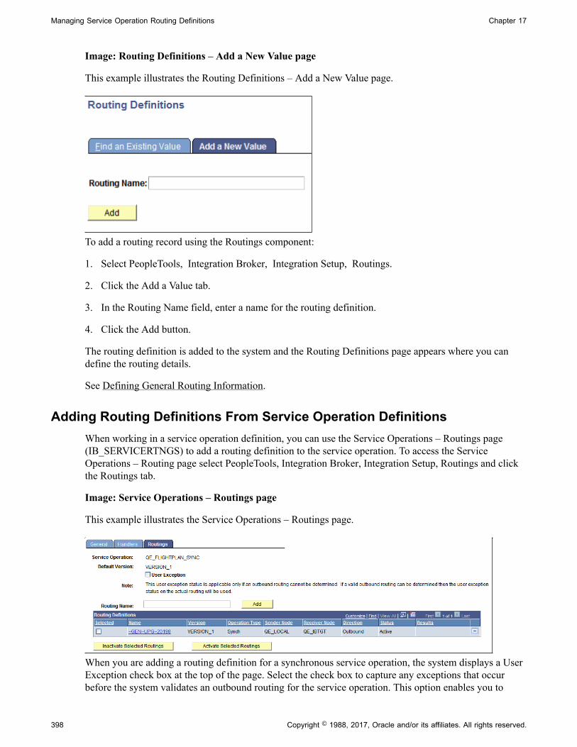
Managing Service Operation Routing Definitions Chapter 17
Image: Routing Definitions – Add a New Value page
This example illustrates the Routing Definitions – Add a New Value page.
To add a routing record using the Routings component:
1. Select PeopleTools, Integration Broker, Integration Setup, Routings.
2. Click the Add a Value tab.
3. In the Routing Name field, enter a name for the routing definition.
4. Click the Add button.
The routing definition is added to the system and the Routing Definitions page appears where you candefine the routing details.
See Defining General Routing Information.
Adding Routing Definitions From Service Operation DefinitionsWhen working in a service operation definition, you can use the Service Operations – Routings page(IB_SERVICERTNGS) to add a routing definition to the service operation. To access the ServiceOperations – Routing page select PeopleTools, Integration Broker, Integration Setup, Routings and clickthe Routings tab.
Image: Service Operations – Routings page
This example illustrates the Service Operations – Routings page.
When you are adding a routing definition for a synchronous service operation, the system displays a UserException check box at the top of the page. Select the check box to capture any exceptions that occurbefore the system validates an outbound routing for the service operation. This option enables you to
398 Copyright © 1988, 2017, Oracle and/or its affiliates. All rights reserved.

Chapter 17 Managing Service Operation Routing Definitions
capture errors such as inactive routing definitions, multiple routing definitions, any errors that result fromrunning the OnRouteSend PeopleCode event, and other initialization errors. When the User Exceptionoption is enabled and if an exception does occur before a routing can be validated, the system returns aresponse message to the integration partner that contains the exception.
To add a routing definition from a service operation definition:
1. Access the Service Operations - Routings page (PeopleTools, Integration Broker, Integration Setup,Service Operations and click the Routings tab).
2. (Optional.) Select the User Exception check box to capture exceptions before routing validation.
3. In the Routing Name field, enter a name for the routing definition.
4. Click the Add button.
The routing definition is added to the system and the Routing Definitions page appears where you candefine the routing details.
See Defining General Routing Information.
Adding Routing Definitions Using the Nodes ComponentThis section describes adding routing definitions using the Nodes component (IB_NODEROUTINGS).
To add a routing definition using the Nodes component you first add the definition to the system and thenconfigure the routing.
Use the Nodes – Routings page to add the definition to the system. To access the page select PeopleTools,Integration Broker, Integration Setup, Nodes and click the Routings tab.
Image: Nodes – Routings page
This example illustrates the Nodes – Routings page.
To add a routing definition from the Nodes-Routings page:
1. Access the Nodes-Routings page (PeopleTools, Integration Broker, Integration Setup, Nodes and clickthe Routings tab).
2. In the Routing Name field, enter a name for the routing definition.
3. Click the Add button.
The routing definition is added to the system and the Routing Definitions page appears where you candefine the routing details.
See Defining General Routing Information.
Copyright © 1988, 2017, Oracle and/or its affiliates. All rights reserved. 399

Managing Service Operation Routing Definitions Chapter 17
Configuring Routing Definitions
This section discusses how to:
• Define general routing information.
• Define routing parameters.
• Define and override gateway and connector properties.
• Define routing properties.
Defining General Routing InformationAfter you add a routing definition to the system use the pages of the Routing component to define therouting details. Use the Routings – Routing Definitions page to define general routing information.
Image: Routings – Routing Definitions page
This example illustrates the fields and controls on the Routings – Routing Definitions page when you areworking with a synchronous service operation. You can find definitions for the fields and controls later onthis page.
The fields that appear on the Routing–Routing Definitions page vary based on if you are defining arouting for a synchronous service operation or an asynchronous service operations.
The various ways to access this page are discussed in the previous section.
See Understanding Adding Routing Definitions.
400 Copyright © 1988, 2017, Oracle and/or its affiliates. All rights reserved.
Chapter 17 Managing Service Operation Routing Definitions
When you add a routing definition from a service operation record, the PeopleSoft system automaticallypopulates some of the data on this page based on the data in the service operations record from whichyou created the routing. Automatically populated data includes the service operation name, version, androuting type.
Routing Name Indicates the name of the routing definition. This name isspecified when you add a routing definition to the system.
Service Operation Enter the name of the service operation that will use the routing.
If you access the Routings component from the ServiceOperations – Routings tab, PeopleSoft Integration Brokerautomatically populates this information.
Active (Optional.) Select the check box to activate the routing.
By default, new routing definition are active.
If any of the referenced nodes are inactive, you cannot activatethe routing.
System Generated When selected, indicates that the PeopleSoft system generatedthe routing definition.
Version Indicates the version of the service operation selected.
Description Description of the routing definition. If you do not enter adescription, this value defaults to the name of the serviceoperation associated with the routing definition upon save.
Graphical View Click this link to view saved routing definitions in graphicalformat.
See Viewing Routing Definitions in Graphical Format.
Comments (Optional.) Enter comments about the routing definition.
Sender Node Enter the name of the sending node.
Receiving Node Enter the name of the receiving node.
Unordered Segments (Optional.) Select the check box to indicate that system shouldprocess the service operation messages in parallel.
The Unordered Segments check box appears only under thefollowing conditions:
• The local node is the receiving node.
• After you save the initial routing definition
This feature is frequently used in conjunction with theOnPreNotify Handler and OnPostNotify Handler fields toperform pre- or post-processing on segmented messages.
Copyright © 1988, 2017, Oracle and/or its affiliates. All rights reserved. 401

Managing Service Operation Routing Definitions Chapter 17
Operation Type Indicates the service operation type. PeopleSoft IntegrationBroker automatically populates this information when you selectthe service operation.
User Exception The User Exception check box displays only for synchronousservice operations.
(Optional.) Select the check box to enable exception handlingusing PeopleCode.
When enabled and an error occurs you can handle any errors inthe calling PeopleCode.
If not enabled any errors that occur cause the program to stop.
Object Owner ID (Optional.) From the drop-down list box, select the owner of thedefinition.
The owner ID helps to determine the application team that lastmade a change to the definition. The values in the drop-downlist box are translate table values that you can define in theOBJECTOWNERID field record.
OnPreNotify Handler (Optional.) From the drop-down list box, select an OnPreNotifyhandler to perform pre-processing on segmented messages beingprocessed in parallel by the system.
This page control appears only when the Unordered Segmentscheck box is selected.
OnPostNotify Handler (Optional.) From the drop-down list box, select anOnPostNotify handler to perform post-processing on segmentedmessages being processed in parallel by the system.
This page control appears only when the Unordered Segmentscheck box is selected.
Accept Compression (Optional.) The Accept Compression check box displays onlyfor inbound synchronous non-REST service operations.
Setting compression for REST service operations is discussedelsewhere in the product documentation.
See Setting Compression for REST Service Operations.
Select the check box for the system to send the response to theconsumer compressed.
You must compress the response before sending, usingPeopleCode or by setting the Min Message Size Compressionparameter in PSAdmin.
You can override the compression of the response usingPeopleCode by setting the CompressionOverride property on
402 Copyright © 1988, 2017, Oracle and/or its affiliates. All rights reserved.

Chapter 17 Managing Service Operation Routing Definitions
IBInfo. The following example shows sample PeopleCode tooverride compression of the response message:
&MSG.IBInfo.CompressionOverride = %IntBroker_Compress;Set/Get property for Compression override. Valid parms : %IntBroker_Compress, %IntBroker_UnCompress, %IntBroker_Compress_Reset
Log Detail The Log Detail drop-down list box displays only forsynchronous service operations.
This option enables you to set the level of information loggingfor synchronous messages that is viewable in the ServiceOperations Monitor.
The valid values are:
• Header.
Log header information only. With this option, you can viewsynchronous message header information in the ServiceOperations Monitor.
• Header and Detail. Log header and message detailinformation. With this option, you can view synchronousmessage header information and XML message content onin the Service Operations Monitor.
When you select this option for a consumer REST serviceoperation routing, a Service Operation Security link appearsand you can add permissions to the service operation. Doingso enables access to service operation details in the ServiceOperations Monitor.
• No Logging. (Default.) Turn off all logging. No informationis available to view in the Service Operations Monitor.
Service Operation Security A Service Operation Security link appears when the selectedrouting definition is for an outbound REST-based serviceoperation
Click the link to access the Web Service Access page and to addpermissions to the view details for the service operation in theService Operations Monitor.
OnSend Handler This field displays when an OnSend handler is defined for theservice operation and the sending node is the local node. It alsodisplays when the system is serving as a hub, and neither thesender nor receiver are local.
Select a handler from the list. This handler runs when a messageis sent or received to perform processing logic.
Schema Validation Details This field displays only when working with any-to-local routingdefinitions.
(Optional.) When this check box is selected and a schemavalidation error occurs the raw schema parser errors are returned
Copyright © 1988, 2017, Oracle and/or its affiliates. All rights reserved. 403

Managing Service Operation Routing Definitions Chapter 17
to the consumer within the default message CDATA tag. If thecheck box is not selected (Default) then if a schema validationerror occurs the systems uses the standard message set/ IDframework to generate the error.
OnReceive Handler This field displays when an OnReceive handler is defined forthe service operation and one of the following conditions exists:
• The sending node is the local node, or
• The service operation type is asynchronous request/responsewhere the sender is not local and the receiver is local, or.
• The system is serving as a hub, and neither the sender (initiator) nor final receiver are local.
Select a handler from the list. This handler runs when a messageis sent or received to perform processing logic.
Use Secure Target Location This check box appears only when you are working with anoutbound asynchronous request/response service operation.
Select the check box to use the secure target location as theendpoint for the response. If the check box is not selected, the (unsecured) target location is used.
Defining Routing ParametersThis section provides an overview of defining transformations for any-to-local routing definitions anddiscusses how to define general routing parameters.
Understanding Routing Parameters for Requests and ResponsesA routing definition contains routing parameters for each inbound request, inbound response, outboundrequest and outbound response associated with a service operation. The routing parameters that youcan define include for each request or response include, routing alias, message names before and aftertransformation, and transformation program names.
You define routing parameters using the Routings – Parameters page in the Routings component.
The following tables list the number of routing parameters a routing definition contains based on theservice operation type and whether the sending and receiving nodes are local.
Note: Parameters for routing definitions for REST service operations are not included in the followingtables, since they are system generated.
Asynchronous service operations have the following routing parameters:
404 Copyright © 1988, 2017, Oracle and/or its affiliates. All rights reserved.

Chapter 17 Managing Service Operation Routing Definitions
ServiceOperationType
Sender isLocal
Receiver isLocal
InboundRequestRouting
OutboundRequestRouting
InboundResponseRouting
OutboundResponseRouting
AsynchronousOne- Way
Y Y N Y N N
AsynchronousOne- Way
Y N N Y N N
AsynchronousOne- Way
N Y Y N N N
AsynchronousOne- Way
N N Y Y N N
Synchronous service operations have the following routing parameters:
ServiceOperationType
Sender isLocal
Receiver isLocal
InboundRequestRouting
OutboundRequestRouting
InboundResponseRouting
OutboundResponseRouting
Synchronous Y Y Y Y Y Y
Synchronous Y N N Y Y N
Synchronous N Y Y N N Y
Synchronous N N Y Y Y Y
Asynchronous-to-synchronous service operations may have the following routing parameters:
ServiceOperationType
Sender isLocal
Receiver isLocal
InboundRequestRouting
OutboundRequestRouting
InboundResponseRouting
OutboundResponseRouting
Asynchronous-to-synchronous
Y Y Y N N Y
Asynchronous-to-synchronous
Y N N Y Y N
Asynchronous-to-synchronous
N Y Y N N Y
Asynchronous-to-synchronous
N N Y Y Y Y
Asynchronous request/response service operations may have the following routing parameters:
Copyright © 1988, 2017, Oracle and/or its affiliates. All rights reserved. 405

Managing Service Operation Routing Definitions Chapter 17
ServiceOperationType
Sender isLocal
Receiver isLocal
InboundRequestRouting
OutboundRequestRouting
InboundResponseRouting
OutboundResponseRouting
AsynchronousRequest /Response
Y Y N Y Y N
AsynchronousRequest /Response
Y N N Y Y N
AsynchronousRequest /Response
N Y Y N N Y
AsynchronousRequest /Response
N N Y Y Y Y
Understanding Transformations on Any-to-Local Routing DefinitionsIf you define a transformation on an any-to-local routing definition, the system uses the inputmessage.version on the transform for the inbound request for WSDL. If a transform is defined on theoutbound response, then the system uses the message.version on the output of the transformation forWSDL.
In cases where the input message.version or output message.version are not defined on the transform, thesystem uses the request or response message.version defined on the service operation for WSDL.
Note that any-to-local routing definitions are read-only when WSDL has been exported. As a result, youcannot change the in/out message transformation, aliases, and so on.
Defining Routing Parameters for Requests and ResponsesUse the Routings-Parameters page (IB_ROUTINGDEFNDOC) to view and define parameters forrequests and responses associated with a service operation. Information you define includes, routingexternal aliases for inbound and outbound requests and responses, as well as any inbound or outboundtransformations to invoke.
To access the Routings - Parameters page, select PeopleTools, Integration Broker, Integration Setup, Routings and click the Parameters tab.
406 Copyright © 1988, 2017, Oracle and/or its affiliates. All rights reserved.

Chapter 17 Managing Service Operation Routing Definitions
Image: Routings – Parameters page
This example illustrates the fields and controls on the Routings – Parameters page. You can finddefinitions for the fields and controls later on this page.
The following page elements display on the Routings-Parameters page:
Type Specifies the routing direction and the type of message (request or response) associated with the service operation. This information is automatically populated from the serviceoperation definition.
External Alias This alias is used as a SOAPAction attribute in the WSDLbinding to identify the service operation in the IntegrationBroker metadata.
Copyright © 1988, 2017, Oracle and/or its affiliates. All rights reserved. 407
Managing Service Operation Routing Definitions Chapter 17
The routing external alias defaults to <ServiceOperationAlias>.<Version>, if present. Otherwise it defaults to<ServiceOperation>.<Version>.
In an asynchronous request/response any-to-local routing, theoutbound routing alias format is <Alias Name>_CALLBACK.<Version>.
For inbound transactions you can fire multiple serviceoperations for one invocation when external aliases on therouting definition are the same for each service operation. Thisis called service operation mapping.
See Service Operation Mapping.
Duplicate external aliases are not allowed for synchronousoperations.
See Searching for Duplicate External Routing Aliases.
Alias References Click the link to view other routing definitions with the sameexternal alias.
See Searching for Duplicate External Routing Aliases.
WS Security This link appears on the Parameters page when you are workingwith:
• Non-REST service operations and are integrating withexternal nodes.
Click the link to override WS Security settings configured atthe node level for the outbound request or response.
See "Overriding Node-Level WS-Security Settings onRouting Definitions" (PeopleTools 8.55: Integration BrokerAdministration).
• Outbound consumer REST service operations.
Click the link to set the security level of the outboundrequest as required by the REST provider.
See Securing Consumer REST Service Operations.
Message.Ver into Transform 1 Displays the name of the request or response message associatedwith the service operation before any transformations areapplied.
For inbound transactions, this is the message name and versionas it arrives from the integration partner system, before anytransformations are applied.
408 Copyright © 1988, 2017, Oracle and/or its affiliates. All rights reserved.

Chapter 17 Managing Service Operation Routing Definitions
For outbound transactions, this is the message name and versiondirectly from the PeopleSoft system, before any transformationsare applied.
Transform Program 1 (Optional.) Enter the name of the transform program to invokeon the message listed in the Message.Ver into Transform 1 field.
Transform Program 2 (Optional.) Enter the name of the transform program to invokeafter the transform program in the Transform Program 1 fieldhas completed processing.
When you invoke two transform programs, the output from thefirst transform program (Transform Program 1) is used as theinput into the second transform program (Transform Program2).
Message.Ver out of Transforms (Optional.) Enter the name of the message after all transformprogram have completed processing.
For inbound messages, this is the message name and versionthat the PeopleSoft system is expecting.
For outbound messages, this is the message name and versionthat the integration partner system is expecting.
When the Routings-Parameters page first displays values for the Message.Ver into Transform 1 andMessage.Ver out of Transforms fields display values to assist you in choosing transform programs. Afteryou save the page, values do not appear in these fields unless the transform programs have an input/outputmessages associated with them.
Note: Based on the transform selected, the message.version of the inbound request or response andthe message.version of the outbound request or response that the system populated on the page can bedifferent then those specified on the component. Should this occur a warning message displays and youcan accept or reject the message.version information populated on the Routings - Parameters page. Ifyou reject the message.version information populated on the page, you can modify the fields with theappropriate message.version information, or change the information that is specified on the component.
Defining and Overriding Gateway and Connector PropertiesThe Routings-Connector Properties page (IB_ROUTINGDEFCON) enables you to define and overridethe default integration gateway and target connector that the local node uses to communicate with anendpoint for a specific routing definition.
To access the Routings – Connector Properties page select PeopleTools, Integration Broker, IntegrationSetup, Routings and click the Connector Properties tab.
Note: The Routings – Connector Properties page displays in the Routings component only if the receivingnode is not the local node.
Copyright © 1988, 2017, Oracle and/or its affiliates. All rights reserved. 409
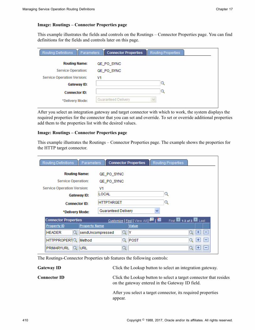
Managing Service Operation Routing Definitions Chapter 17
Image: Routings – Connector Properties page
This example illustrates the fields and controls on the Routings – Connector Properties page. You can finddefinitions for the fields and controls later on this page.
After you select an integration gateway and target connector with which to work, the system displays therequired properties for the connector that you can set and override. To set or override additional propertiesadd them to the properties list with the desired values.
Image: Routings – Connector Properties page
This example illustrates the Routings – Connector Properties page. The example shows the properties forthe HTTP target connector.
The Routings-Connector Properties tab features the following controls:
Gateway ID Click the Lookup button to select an integration gateway.
Connector ID Click the Lookup button to select a target connector that resideson the gateway entered in the Gateway ID field.
After you select a target connector, its required propertiesappear.
410 Copyright © 1988, 2017, Oracle and/or its affiliates. All rights reserved.

Chapter 17 Managing Service Operation Routing Definitions
Delivery Mode Select one of the following options:
• Guaranteed. (Default.)
• Best Effort.
These options are discussed in detail elsewhere in the productdocumentation.
See "Setting Target Connector Delivery Modes" (PeopleTools8.55: Integration Broker Administration).
Save Click the Save button to save your changes.
Overriding Default Integration GatewaysTo override the default integration gateway, use the Gateway ID field Lookup button to select a gateway.You must also select a target connector on the new gateway to use and define properties for thatconnector.
Overriding Default Target ConnectorsTo override the default target connector on the default integration gateway, use the Gateway ID fieldLookup to select the default gateway. Use the Gateway ID field Lookup to select a different targetconnector that resides on the gateway and then define properties for the new connector.
For REST-based services the connector ID default to HTTPTARGET and cannot be changed.
Overriding Default Connector PropertiesTo override the default target properties for the default target connector, use the Gateway ID field Lookupbutton to select the default gateway. Use the Connector ID field Lookup to select the default targetconnector and then adjust the gateway properties as appropriate.
HTTP header properties, those with the property ID of HEADER, are the only properties you can add forroutings for outbound REST-based service operations.
Defining Routing PropertiesThis section provides an overview of routing properties and discusses how to add them in the form ofname/value pairs to routing definitions.
Understanding Routing PropertiesRouting properties are user-defined name/value pairs that denote data contained in transformationsdefined for a routing definition.
Once they know the name/value pairs in a transformation, developers can extract the data fromtransformations using application classes. Developers might use the name/value pairs data to add to XML,perform SELECT actions in tables, and so on.
Copyright © 1988, 2017, Oracle and/or its affiliates. All rights reserved. 411
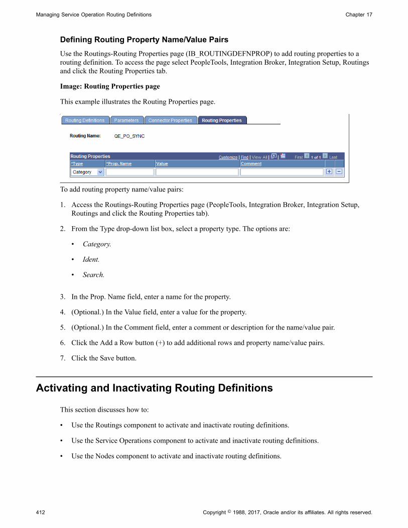
Managing Service Operation Routing Definitions Chapter 17
Defining Routing Property Name/Value PairsUse the Routings-Routing Properties page (IB_ROUTINGDEFNPROP) to add routing properties to arouting definition. To access the page select PeopleTools, Integration Broker, Integration Setup, Routingsand click the Routing Properties tab.
Image: Routing Properties page
This example illustrates the Routing Properties page.
To add routing property name/value pairs:
1. Access the Routings-Routing Properties page (PeopleTools, Integration Broker, Integration Setup,Routings and click the Routing Properties tab).
2. From the Type drop-down list box, select a property type. The options are:
• Category.
• Ident.
• Search.
3. In the Prop. Name field, enter a name for the property.
4. (Optional.) In the Value field, enter a value for the property.
5. (Optional.) In the Comment field, enter a comment or description for the name/value pair.
6. Click the Add a Row button (+) to add additional rows and property name/value pairs.
7. Click the Save button.
Activating and Inactivating Routing Definitions
This section discusses how to:
• Use the Routings component to activate and inactivate routing definitions.
• Use the Service Operations component to activate and inactivate routing definitions.
• Use the Nodes component to activate and inactivate routing definitions.
412 Copyright © 1988, 2017, Oracle and/or its affiliates. All rights reserved.

Chapter 17 Managing Service Operation Routing Definitions
Understanding Activating and Inactivating Routing DefinitionsYou can use the Routings component or the Service Operations component to activate and inactivaterouting definitions.
Activating and Inactivating Routing Definitions in the Routing ComponentYou can use the Routings-Routing Definitions page to activate and inactivate a routing definition.
To activate or inactivate a routing definition:
1. Select PeopleTools, Integration Broker, Integration Setup, Routings.
Select a routing definition with which to work.
2. Perform one of the following actions:
• To activate the routing definition, select the Active check box.
• To inactivate the routing definition, deselect the Active check box.
3. Click the Save button.
Activating and Inactivating Routing Definitions in the Service OperationsComponent
You can also activate and inactivate routing definitions in the Service Operations component using theService Operations-Routings page.
See Activating and Inactivating Routing Definitions.
Activating and Inactivating Routing Definitions in the Nodes ComponentYou can use the Nodes – Routings page to access a routing definition and to activate or inactivate arouting.
To activate or inactivate a routing definition from the Nodes component:
1. Select PeopleTools, Integration Broker, Integration Setup, Nodes.
2. Click the Routings tab.
3. Locate the routing definition to activate or inactivate and click the Details link.
The routing definition appears in the Routing Definitions page.
4. Perform one of the following actions:
• To activate the routing definition, select the Active check box.
• To inactivate the routing definition, deselect the Active check box.
Copyright © 1988, 2017, Oracle and/or its affiliates. All rights reserved. 413
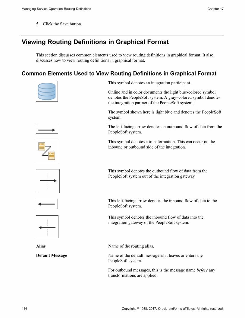
Managing Service Operation Routing Definitions Chapter 17
5. Click the Save button.
Viewing Routing Definitions in Graphical Format
This section discusses common elements used to view routing definitions in graphical format. It alsodiscusses how to view routing definitions in graphical format.
Common Elements Used to View Routing Definitions in Graphical FormatThis symbol denotes an integration participant.
Online and in color documents the light blue-colored symboldenotes the PeopleSoft system. A gray–colored symbol denotesthe integration partner of the PeopleSoft system.
The symbol shown here is light blue and denotes the PeopleSoftsystem.
The left-facing arrow denotes an outbound flow of data from thePeopleSoft system.
This symbol denotes a transformation. This can occur on theinbound or outbound side of the integration.
This symbol denotes the outbound flow of data from thePeopleSoft system out of the integration gateway.
This left-facing arrow denotes the inbound flow of data to thePeopleSoft system.
This symbol denotes the inbound flow of data into theintegration gateway of the PeopleSoft system.
Alias Name of the routing alias.
Default Message Name of the default message as it leaves or enters thePeopleSoft system.
For outbound messages, this is the message name before anytransformations are applied.
414 Copyright © 1988, 2017, Oracle and/or its affiliates. All rights reserved.

Chapter 17 Managing Service Operation Routing Definitions
For inbound messages, this is the message name after anytransformations are applied.
In Message The inbound message name before any transformations havebeen applied.
In Resp Transform Click the link to view information about transformations appliedto the inbound response message.
Integration Not Active This link displays when one or more of the following items areinactive for an integration:
• Routing definition.
• Service operation version.
• Handler.
• Service operation permissions.
Click the link to view the inactive items.
See Viewing Integration Status and Activating IntegrationMetadata.
Out Message Name of the outbound message after any transformation havebeen applied.
Out Req Transform Click the link to view information about transformations appliedto the outbound request message.
Receiver Name of the receiving node.
Return Click the button to return to the previous page.
Routing Name Name of the routing definition.
Operation Type The service operation type.
Sender Name of the sending node.
Service Operation Service operation name and version.
Type Type of request on the PeopleSoft system. The possible valuesare:
• Outbound Request.
• Inbound Request.
• Inbound Response.
• Outbound Response.
Copyright © 1988, 2017, Oracle and/or its affiliates. All rights reserved. 415

Managing Service Operation Routing Definitions Chapter 17
Viewing a Routing Definition in Graphical FormatThe Integration Broker Routing Graphic page (IB_IMAGETEST2) displays routing definition data ingraphical format.
Image: Integration Broker Routing Graphic page
This example illustrates the Integration Broker Routing Graphic page. The example shows a synchronousrouting definition, QE_PO_SYNC, in graphical format.
The example shows that the service operation QE_PO_SYNC is associated with the routing. It also showsthat the routing type is Synchronous.
The sending node is QE_LOCAL, and the node is depicted graphically by the cylinders on the left side ofthe example. The receiving node is QE_IBTGT and is depicted graphically by the cylinders on the rightside of the example.
The example shows the outbound request from the node QE_LOCAL to the node QE_IBTGT has arouting alias of OUTBOUND_ROUTING_ALIAS.V1. It also shows that the outbound default messageassociated with the routing is QE_PO_MSG.VERSION_1.
When the node QE_IBTGT sends back its response, it has a routing alias ofINBOUND_ROUTING_ALIAS.V1 and the message associated with the response isQE_PO_MSG.VERSION_1.
The dotted line depicts the integration gateway, and depending on the arrow direction shows the serviceoperation leaving or entering the gateway.
416 Copyright © 1988, 2017, Oracle and/or its affiliates. All rights reserved.

Chapter 17 Managing Service Operation Routing Definitions
Note in the example that an Integration Not Active link displays at the top right of the page. This indicatesthat one or more pieces of metadata associated with the integration is not active. Click the link to viewand activate the data.
Related LinksViewing Integration Status and Activating Integration Metadata
Viewing Integration Status and Activating Integration Metadata
This section discusses how to:
• View inactive integration metadata.
• Activate integration metadata using the Integration Status page.
Understanding Viewing Integration Status and Activating IntegrationMetadata
When you view a routing definition in graphical format, if any metadata associated with the integration isinactive, an Integration Not Active link displays on the Integration Broker Routing Graphic page. You canclick the link to open an Integration Status page, where you can view the inactive metadata and activatethe data.
Note: The Integration Not Active link displays only when an integrations contains metadata that is not setto Active.
Viewing Inactive Integration MetadataUse the Integration Status page (IB_IMAGETEST_SEC) to view inactive metadata for an integration.To access the Integration Status page, from the Integration Broker Routing Graphic page, click theIntegration Not Active link.
Image: Integration Status page
This example illustrates the Integration Status page.
The Issues Encountered section lists the metadata that is inactive and that you must activate before youcan invoke the service operation.
The links in the Actions column enable you to activate the associated metadata directly from this page.
Copyright © 1988, 2017, Oracle and/or its affiliates. All rights reserved. 417

Managing Service Operation Routing Definitions Chapter 17
See Activating Integration Metadata Using the Integration Status Page.
Activating Integration Metadata Using the Integration Status PageThe system activates the associated metadata and displays a message when the data is successfullyactivated.
Image: Message box
This example shows a Message box that indicates a service operation version was successfully activated.
To activate metadata for an integration using the Integration Status page:
1. From the Integration Broker Routing Graphic page, click the Integration Not Active link.
The Integration Status page appears.
2. In the Actions column, click an action to complete.
The system processes the action and displays a message that the metadata is activated.
3. Click the OK button.
4. Repeat the steps to activate additional metadata.
5. Click the Return button to go back to the Integration Broker Routing Graphic page.
Retrieving Routing Properties Programmatically
The %TransformData.routingDefnName property enables you to retrieve the routing definition name for atransaction, and allows you to retrieve the routing properties respectfully.
418 Copyright © 1988, 2017, Oracle and/or its affiliates. All rights reserved.

Chapter 17 Managing Service Operation Routing Definitions
You use this property in a PeopleSoft Application Engine program as follows:
string rtgDefnName = %TransformData.routingDefnName
Configuring Routing Definitions for Deployment
This topic discusses how to:
• Use the Deployment Configuration page.
• Use the Deployment Configuration grids.
• Use the Get Routing Information page.
• Select routing definitions for routing deployment configurations.
• Populate deployment configurations from routing definitions.
• Add routing definitions for deployment.
• Update release levels.
Understanding Configuring Routing Definitions for DeploymentMany PeopleSoft applications deliver integrations. The routing definitions on these integrations arefrequently delivered inactive, because:
• The node names defined in the delivered routing definitions do not march the names integrationpartners have assigned to the source and target systems.
• The information on the routing is not applicable to the application version for the integration.
PeopleTools enables you to store specific routing information in a deployment table in the database forintegrations among PeopleSoft applications, thereby allowing routing definitions to be excluded fromdeployment metadata.
Understanding Using Routing Deployment ConfigurationPrior to a new application release or patch create an integration group or subgroup. For any new ormodified integrations, add the services and service operations to the newly defined integration group orsubgroup.
After quality assurance testing with other PeopleSoft integration partners, and prior to creating thefinal project, examine the new or modified integrations and determine if you need to add any routingdefinitions. If so, use the Deployment Configuration page in the Service Utilities component to add therouting definitions. The routing metadata gets saved as part of the service operation version.
Note: The routing information you define using the routing deployment configuration pages is saved aspart of the service operation version.
The associated physical routing(s) defined in the Routings component can then be deleted.
Copyright © 1988, 2017, Oracle and/or its affiliates. All rights reserved. 419

Managing Service Operation Routing Definitions Chapter 17
Integration partners then upload the project and use the Integration Network Introspection andDeployment feature to introspect and deploy the integrations to all PeopleSoft integration partners usingthe integration group name you created earlier.
When introspection takes place the receiving system is interrogated to get the application versioninformation. The information is used to determine the PeopleSoft application (for example, HCM, SCM,and so on) for look up against the deployment configuration metadata to determine an integration match.
Note: You need to add routing information to the deployment table using the Deployment Configurationpage only if specific routing data needs to be part of an auto-generated routing, such as transformationinformation, alias name (if different from the default), and so on. Therefore, not all PeopleSoft-to-PeopleSoft routing definitions need to be added to the deployment table using the DeploymentConfiguration page.Routing deployment configuration metadata is only applicable for a defined PeopleSoft application.This means that the source system where introspection is invoked can have deployment configurationinformation, while the receiving system does not have deployment configuration information. As a result,you only need to update the deployment data for your own application.
The introspection process uses the following order to determine proper integration bindings:
1. Valid routing. The sending and receiving nodes match, the alias name matches.
2. Deployment configuration metadata (as defined in the Deployment Configuration page). Routingname matches.
3. Service operation and version match.
During introspection processing, the system examines the deployment configuration metadata andcan determine the proper routing (if one is available) based on the PeopleSoft application name andapplication version.
Using the Deployment Configuration PageUse the Deployment Configuration pages (IB_INTDEPLOY) to select services for routing deploymentconfiguration and to define routing parameters.
To access the Deployment and Configuration pages select PeopleTools, Integration Broker, ServiceUtilities, Deployment Configuration.
420 Copyright © 1988, 2017, Oracle and/or its affiliates. All rights reserved.

Chapter 17 Managing Service Operation Routing Definitions
Image: Deployment Configuration page
This example illustrates the fields and controls on the Deployment Configuration page. You can finddefinitions for the fields and controls later on this page.
The following fields and controls appear on the page:
Integration Group Select the radio button to search for service operations byintegration group.
Use one of the following integration group filters:
• Show All Subgroups. (Default.) Select the radio button todisplay all integration subgroups associated with integrationgroups in the system.
• Filter by Subgroup. Select the radio button to search for aspecific integration subgroup and enter its name in the field.
• No Subgroups. Select the radio button to omit integrationsubgroups from your search.
• Show Services Tied to Group. Check the box to include theservices tied to an integration group in the search results. Bydefault this option is selected.
• Show Services Tied to Group. (Default.) Check the box toinclude the services tied to an integration group in the searchresults.
Integration Group Name If searching by integration group, enter the integration groupname to search, or click the Lookup button to search for one.
Service Select the radio button to search for service operations byservice.
Copyright © 1988, 2017, Oracle and/or its affiliates. All rights reserved. 421

Managing Service Operation Routing Definitions Chapter 17
When you select this option a Lookup button appears next to theService field.
Service Operation Select the radio button to search for service operations byservice operation.
When you select this option a Lookup button appears next to theOperation field. Click the Lookup button to search for a serviceoperation to introspect and deploy or enter the name directly inthe field.
Search Click the button to search the database for service operationsbased on the search criteria entered.
Select Items to Process (grid) This grid displays the search results and contains the followingfields and controls:
• Select. Select the box to configure routing definitions for theservice, service operation or integration group.
• Service. Name of service.
• Service Operation. Name of service operation.
• Integration Group Name. Name of integration group.
Select All Select the box to select configure routing definitions for allitems in the Select Items to Process grid.
Deselect All Select the box to clear all selections in the Select Items toProcess grid.
Continue Click the button to define routing parameters for selected itemsin the Select Items to Process grid.
Using the Routing Deployment GridsTo define routing parameters for selected services, service operations or integrations groups, use theDeployment Configuration grid (IB_INTDEPLOY2).
To access the grid click the Continue button after you search for and select integrations for which toconfigure routings. This example illustrates the Deployment Configuration grid used to define routingparameters. You can find definitions for the fields and controls later on this page.
422 Copyright © 1988, 2017, Oracle and/or its affiliates. All rights reserved.

Chapter 17 Managing Service Operation Routing Definitions
Image: Deployment Configuration grid
This example illustrates the fields and controls on the Deployment Configuration grid. You can finddefinitions for the fields and controls later on this page.
If on the Deployment Configuration page you select a service or integration group, separate grids appearon the page for each service operation in the service or integration group
Image: Deployment Configuration grids
This example illustrates the fields and controls on the Deployment Configuration grids. You can finddefinitions for the fields and controls later on this page.
You can create routing definitions for each application or patch release, or populate the grid with datafrom the existing routing definition in the database.
To configure a different routing definition for another release, click the Add Row button (+) to create anew row, configure another definition.
You can manually create and configure routing definitions to deploy by entering and selecting fieldson the page. You can also populate a definition using the existing routing definition data defined in theRoutings component using the Get Routing Information link. When you click the link the existing routingdefinition for the service operation appears and you can choose to populate the page with that data.Information on using the Get Routing Information link appears later in this topic.
The following fields and controls appear on the page:
Save When you have completed configuring routing definitionson the page, click the button to save the changes. The mainDeployment Configuration page appears after the save action
Copyright © 1988, 2017, Oracle and/or its affiliates. All rights reserved. 423
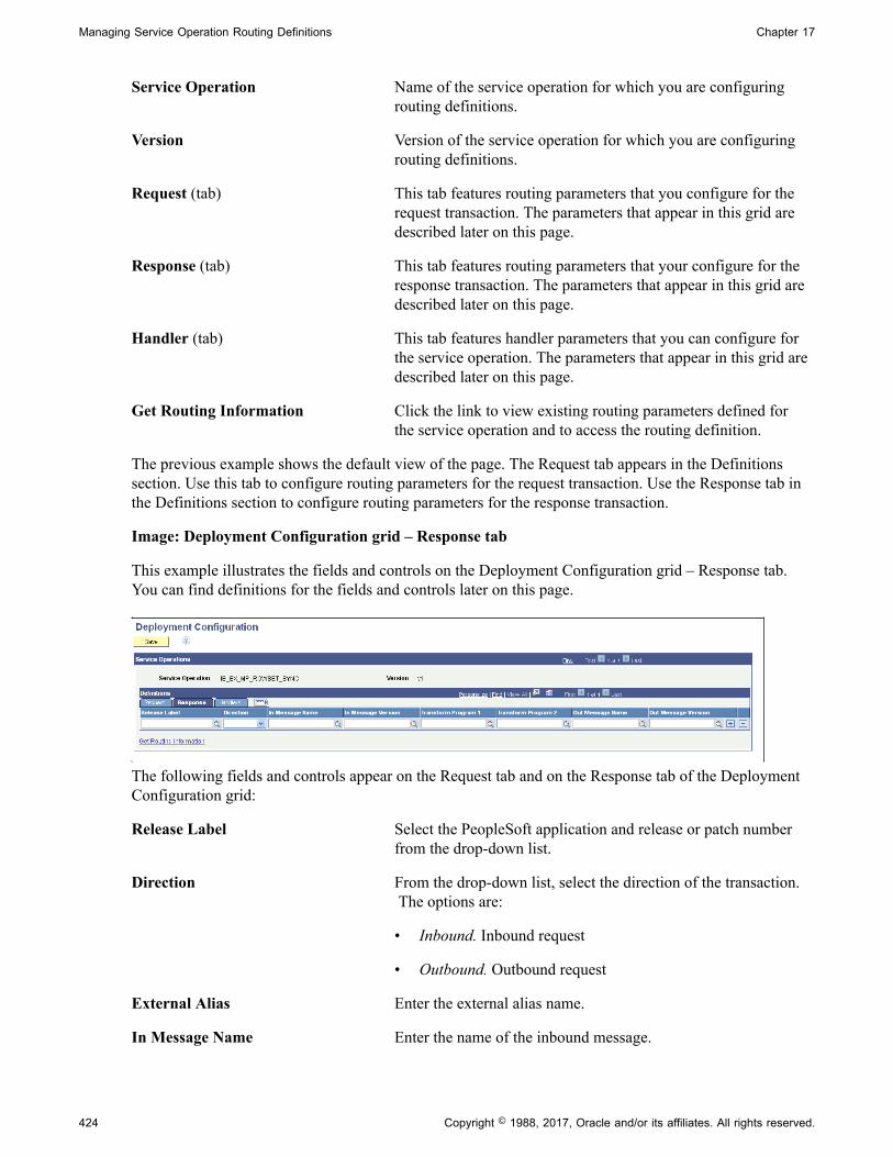
Managing Service Operation Routing Definitions Chapter 17
Service Operation Name of the service operation for which you are configuringrouting definitions.
Version Version of the service operation for which you are configuringrouting definitions.
Request (tab) This tab features routing parameters that you configure for therequest transaction. The parameters that appear in this grid aredescribed later on this page.
Response (tab) This tab features routing parameters that your configure for theresponse transaction. The parameters that appear in this grid aredescribed later on this page.
Handler (tab) This tab features handler parameters that you can configure forthe service operation. The parameters that appear in this grid aredescribed later on this page.
Get Routing Information Click the link to view existing routing parameters defined forthe service operation and to access the routing definition.
The previous example shows the default view of the page. The Request tab appears in the Definitionssection. Use this tab to configure routing parameters for the request transaction. Use the Response tab inthe Definitions section to configure routing parameters for the response transaction.
Image: Deployment Configuration grid – Response tab
This example illustrates the fields and controls on the Deployment Configuration grid – Response tab.You can find definitions for the fields and controls later on this page.
The following fields and controls appear on the Request tab and on the Response tab of the DeploymentConfiguration grid:
Release Label Select the PeopleSoft application and release or patch numberfrom the drop-down list.
Direction From the drop-down list, select the direction of the transaction. The options are:
• Inbound. Inbound request
• Outbound. Outbound request
External Alias Enter the external alias name.
In Message Name Enter the name of the inbound message.
424 Copyright © 1988, 2017, Oracle and/or its affiliates. All rights reserved.

Chapter 17 Managing Service Operation Routing Definitions
In Message Version Enter the version of the inbound message.
Transform Program 1 Enter the name of transform program number one.
Transform Program 2 Enter the name of transform program number two.
Out Message Name Enter the name of the outbound message.
Out Message Version Enter the version of the outbound message.
User Exception Check the box to enable user exception handling usingPeopleCode.
This control appears on the Request grid only and is applicableto synchronous service operation processing only.
When enabled and an error occurs you can handle any errorsin the calling PeopleCode. If not enabled any errors that occurcause the program to stop.
Use the Handlers tab to configure and populate handler metadata for the service operation.
Image: Deployment Configuration grid – Handler tab
This example illustrates the fields and controls on the Deployment Configuration grid – Handler tab. Youcan find definitions for the fields and controls later on this page.
The following fields and controls appear on the Handlers tab of the Deployment Configuration grid:
Direction From the drop-down list, select the direction of the transaction. The options are:
• Inbound. Inbound request
• Outbound. Outbound request
OnPreNotify Handler Enter the name of the OnPreNotify service operation handler toperform pre-processing on segmented messages.
This option is relevant only when using the unordered segmentsoption to process service operation messages in parallel.
OnPostNotify Handler Enter the name of the OnPostNotify service operation handlerto perform post-processing on segmented messages beingprocessed in parallel.
Copyright © 1988, 2017, Oracle and/or its affiliates. All rights reserved. 425

Managing Service Operation Routing Definitions Chapter 17
This option is relevant only when using the unordered segmentsoption to process service operation messages in parallel.
OnReceive Handler Enter the name of the OnReceive service operation handler toperform processing logic:
To use this handler for deployment one of the followingconditions must exist:
• The sending node must be the local node, or
• The service operation type must be asynchronous request/response where the sender is not local and the receiver islocal, or.
• The system is serving as a hub, and neither the sender (initiator) nor final receiver are local.
OnSend Handler Enter the name of the OnSend service operation handler toperform processing logic.
To use this handler for deployment configuration:
• The sending node must be the local node, or
• The system is serving as a hub, and neither the sender norreceiver are local.
Unorder Segments Check the box to indicate that the system should process serviceoperation messages in parallel.
To use this option the local node must be the receiving node.
This option is frequently used in conjunction with theOnPreNotify handler and OnPostNotify handler to perform pre-or post-processing on segmented messages
Using the Get Routing Information PageUse the Get Routing Information page (IB_INTDEPLOY_SEC) to view the existing routing definition fora service operation and to add the data to the deployment configuration table.
To access the page, on the Deployment Configuration grid page, click the Get Routing Information link.
426 Copyright © 1988, 2017, Oracle and/or its affiliates. All rights reserved.
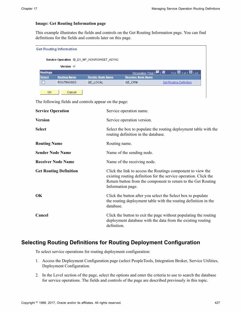
Chapter 17 Managing Service Operation Routing Definitions
Image: Get Routing Information page
This example illustrates the fields and controls on the Get Routing Information page. You can finddefinitions for the fields and controls later on this page.
The following fields and controls appear on the page:
Service Operation Service operation name.
Version Service operation version.
Select Select the box to populate the routing deployment table with therouting definition in the database.
Routing Name Routing name.
Sender Node Name Name of the sending node.
Receiver Node Name Name of the receiving node.
Get Routing Definition Click the link to access the Routings component to view theexisting routing definition for the service operation. Click theReturn button from the component to return to the Get RoutingInformation page.
OK Click the button after you select the Select box to populatethe routing deployment table with the routing definition in thedatabase.
Cancel Click the button to exit the page without populating the routingdeployment database with the data from the existing routingdefinition.
Selecting Routing Definitions for Routing Deployment ConfigurationTo select service operations for routing deployment configuration:
1. Access the Deployment Configuration page (select PeopleTools, Integration Broker, Service Utilities,Deployment Configuration.
2. In the Level section of the page, select the options and enter the criteria to use to search the databasefor service operations. The fields and controls of the page are described previously in this topic.
Copyright © 1988, 2017, Oracle and/or its affiliates. All rights reserved. 427

Managing Service Operation Routing Definitions Chapter 17
3. Click the Search button.
The search results appear in the Select Items to Process grid.
4. Select the box next to each service operation, service, or integration group for which to configureroutings for deployment.
5. Click the Continue button.
Deployment Configuration grids appear and you can configure or add routings for deployment.
Populating Deployment Configurations from Routing DefinitionsYou can populate the grids on the Deployment Configuration page with data from existing routingdefinitions.
To populate deployment configurations from routing definitions:
1. Access the Deployment Configuration grid (PeopleTools, Integration Broker, Service Utilities,Deployment Configuration. Select the service operation(s) with which to work and click the Continuebutton).
2. Select the Request tab or the Response tab, depending on the transaction for which you areconfiguring the routing.
3. From the Release Level drop-down list, select an application or patch version from the list.
The value you select should be the application/patch version that the remote node on the routing isrunning.
4. Click the Get Routing Information link.
The Get Routing Information page appears.
5. (Optional.) Click the Get Routing Definition link to view the routing definition associated with theservice operation in the Routings component. Click the Return button to return to the Get RoutingInformation page.
6. Select the Select box.
7. Click the OK button.
The Deployment Configuration (grids) page appears and the routing data from the routing definitionappears in the Request or Response grid.
8. (Optional.) Click the Add Row button (+) to add a row and configure another routing for anotherapplication or patch version and repeat steps 2 through 6.
9. Click the Save button.
Adding Routing Definitions for DeploymentAdd routing definitions for deployment using the Deployment Configuration (grids) page.
To add routing definitions:
428 Copyright © 1988, 2017, Oracle and/or its affiliates. All rights reserved.

Chapter 17 Managing Service Operation Routing Definitions
1. Access the Deployment Configuration (grids) page (PeopleTools, Integration Broker, ServiceUtilities, Deployment Configuration. Select the service operation(s) with which to work and click theContinue button).
2. Select the Request tab or the Response tab, depending on the transaction for which you areconfiguring the routing.
3. From the Release Level drop-down list, select an application or patch version from the list.
The value you select should be the application/patch version that the remote node on the routing isrunning.
4. Use the fields and controls on the tab to configure the routing. The fields and control that appear onthe Request and Response tabs are described earlier in this topic.
5. Click the Save button.
Updating Release LevelsAs new application versions and patches are released add the appropriate application versions and patchesto the PS_IB_REL_LOOKUP table so that they are available for selection for this feature.
Searching for Duplicate External Routing Aliases
The Alias Name Reference page (IB_ALIASXREF_SEC) displays duplicate external routing aliases thatexist for a routing definition.
To access the Alias Name Reference page, select PeopleTools, Integration Broker, Integration Setup,Routings. Click the Parameters tab and click the Alias Reference link for a request or response.
Copyright © 1988, 2017, Oracle and/or its affiliates. All rights reserved. 429
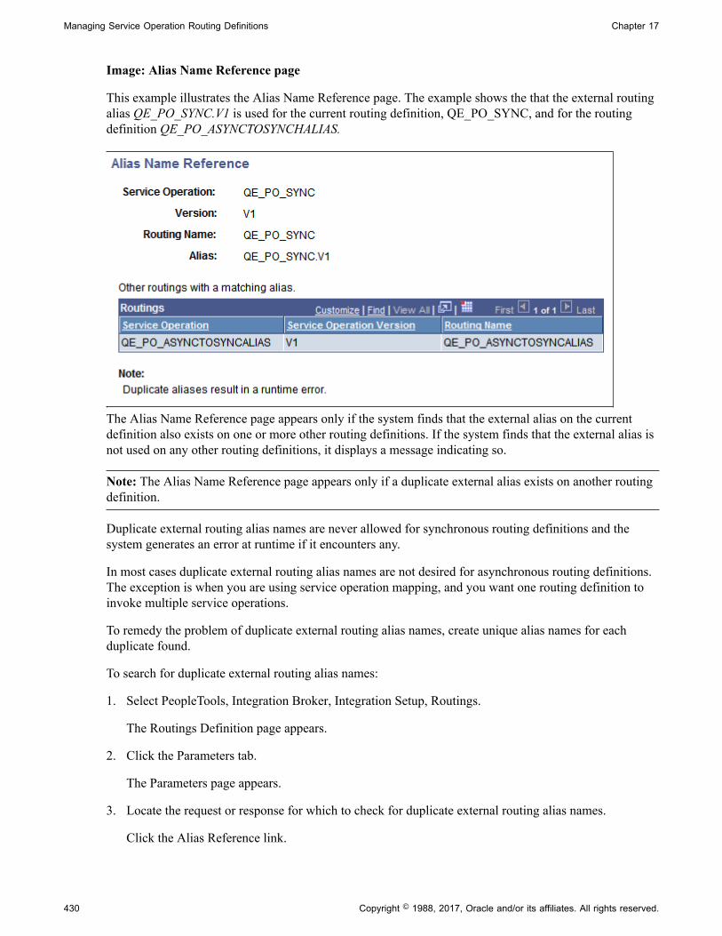
Managing Service Operation Routing Definitions Chapter 17
Image: Alias Name Reference page
This example illustrates the Alias Name Reference page. The example shows the that the external routingalias QE_PO_SYNC.V1 is used for the current routing definition, QE_PO_SYNC, and for the routingdefinition QE_PO_ASYNCTOSYNCHALIAS.
The Alias Name Reference page appears only if the system finds that the external alias on the currentdefinition also exists on one or more other routing definitions. If the system finds that the external alias isnot used on any other routing definitions, it displays a message indicating so.
Note: The Alias Name Reference page appears only if a duplicate external alias exists on another routingdefinition.
Duplicate external routing alias names are never allowed for synchronous routing definitions and thesystem generates an error at runtime if it encounters any.
In most cases duplicate external routing alias names are not desired for asynchronous routing definitions.The exception is when you are using service operation mapping, and you want one routing definition toinvoke multiple service operations.
To remedy the problem of duplicate external routing alias names, create unique alias names for eachduplicate found.
To search for duplicate external routing alias names:
1. Select PeopleTools, Integration Broker, Integration Setup, Routings.
The Routings Definition page appears.
2. Click the Parameters tab.
The Parameters page appears.
3. Locate the request or response for which to check for duplicate external routing alias names.
Click the Alias Reference link.
430 Copyright © 1988, 2017, Oracle and/or its affiliates. All rights reserved.

Chapter 17 Managing Service Operation Routing Definitions
If duplicate external routing alias names are found, the Alias Name Reference page appears and liststhe routing definitions with which any duplicate aliases are associated. Otherwise, the system displaysa message indicating that no duplicate aliases exist in the system.
Renaming and Deleting Routing Definitions
You can rename and delete routing definitions using the Routings page (IB_HOME_PAGE_4) in theService Administration component (IB_HOME_PAGE).
The Routings tab contains three sections: a Delete section that enables you to delete routing definition, aRename section that enables you to rename routing definitions, and a Delete Duplicate Routings sectionthat enables you to view and delete duplicate routing definitions.
When you first access the Routings tab, the sections are collapsed. Click the section header arrow buttonsto expand and collapse each section.
Image: Service Administration – Routings page
This example shows the Service Administration – Routings page. The example shows the page with boththe Delete and Rename sections expanded.
The service system status that you set on the Service Configuration page affects the ability to renameservices.
Copyright © 1988, 2017, Oracle and/or its affiliates. All rights reserved. 431

Managing Service Operation Routing Definitions Chapter 17
This section discusses renaming and deleting routings. See the following section for information aboutdeleting duplicate routings.
See "Understanding Configuring PeopleSoft Integration Broker for Handling Services" (PeopleTools8.55: Integration Broker Administration), "Using the Service Configuration Page to Set ServiceConfiguration Properties" (PeopleTools 8.55: Integration Broker Administration), Deleting DuplicateRouting Definitions.
Renaming Routing DefinitionsTo rename a routing definition:
1. Select PeopleTools, Integration Broker, Service Utilities, Service Administration. Click theRoutings tab.
The Routing page appears.
2. Click the arrow next to the Rename section header to expand the section.
3. In the Routing Name field, enter the routing definition to rename, or click the Lookup button to searchfor and select one.
4. In the New Name field, enter the new name for the routing definition.
5. Click the Rename button.
After you click the Rename button, the Results field displays a message that the action was successful ordisplays a warning or error message with a description of the problem.
Deleting Routing DefinitionsTo delete a routing definition:
1. Select PeopleTools, Integration Broker, Service Utilities, Service Administration. Click theRoutings tab.
The Routing page appears.
2. Click the arrow next to the Delete section header to expand the section.
3. In the Routing Name field, enter the name of the routing definition to delete, and click the Searchbutton.
Search results display in the Routings grid.
4. Select the check box next to the routing definition or routing definitions to delete.
5. Click the Delete button.
Deleting Duplicate Routing Definitions
Application upgrades and the PeopleSoft Application Designer project copy process can cause duplicateroutings in the PeopleSoft system.
432 Copyright © 1988, 2017, Oracle and/or its affiliates. All rights reserved.

Chapter 17 Managing Service Operation Routing Definitions
The Service Administration - Routings page (IB_HOME_PAGE_4) features a Delete Duplicate Routingssection that enables you to search for duplicate routings in the system and delete them. When you firstaccess the page, all sections on the page are collapsed. Click the arrow next to the Delete DuplicateRoutings section title to expand the section.
Image: Service Administration – Routings page
This example illustrates the Service Administration – Routings page. The example shows the DeleteDuplicate Routings section expanded.
The page displays active duplicate routings only.
To delete duplicate routings:
1. Select PeopleTools, Integration Broker, Service Utilities, Service Administration. Click theRoutings tab.
The Routings page appears.
2. Click the arrow next to the Delete Duplicate Routings section title to expand the section.
3. Click the Search button to search the system for duplicate routing definitions.
Duplicate routing definitions populate the Routing Definitions grid and all duplicates are selected fordeletion.
4. Deselect the Select check box for any routing definitions you do not want to delete.
5. Click the Delete button.
The Routing Definitions grid displays up to 100 routing definitions at a time. The maximum number ofrows returned at a time is 1000. Use the arrow buttons to move from page to page through the searchresults. If the maximum number of rows is reached, an information message appears that indicates themaximum has been reached. After you delete the routing definitions, click the Search button again toreturn more rows.
Copyright © 1988, 2017, Oracle and/or its affiliates. All rights reserved. 433

Managing Service Operation Routing Definitions Chapter 17
434 Copyright © 1988, 2017, Oracle and/or its affiliates. All rights reserved.

Chapter 18
Applying Filtering, Transformation andTranslation
Understanding Filtering, Transformation, and Translation
This topic describes how to use filtering, transformations and translations for integrations. This topic alsofeatures code examples to help illustrate how to filter, transform and translate integrations.
Note: The code examples in this topic are for illustrative purposes only and are not intended to be used ina production environment.
Filtering, transformation, and translation are all accomplished by applying an Application Enginetransform program to an outbound or inbound message. You can use these programs to:
• Filter a message based on its content, to determine whether to pass it through to its destination or tosubsequent steps of the transform program.
• Perform transformation on a message to make its structure comply with the receiving system’srequirements.
• Perform data translation on a message so that its data is represented according to the receivingsystem’s conventions.
Simple translation might be required if the two systems use different values to represent the sameinformation for a given field.
Complex translation might involve augmenting or replacing groups of fields with a completelydifferent structure and encoding.
If your PeopleSoft application uses the PeopleCode XmlDoc or SoapDoc classes to generate or process amessage, the message probably doesn’t adhere to the PeopleSoft rowset-based message format.
Filtering, transformation, or translation can be necessary for messages sent between two PeopleSoftIntegration Broker nodes, or between a PeopleSoft Integration Broker node and a third-party application.
Related LinksSupported Message Structures
Understanding Transform Programs
This section provides overview information about transform programs.
Copyright © 1988, 2017, Oracle and/or its affiliates. All rights reserved. 435

Applying Filtering, Transformation and Translation Chapter 18
Transform ProgramsA transform program is a type of PeopleSoft Application Engine program. After you create a newtransform application engine program, you add steps and actions to the program, and then add code to thesteps and actions that performs data transformation, filtering or translation.
To develop a transform program, you must know the initial structure and possibly the content of themessage with which you are working, as well as the structure (and content) of the result you wantto achieve. Make sure that all participating nodes agree on a format or employ transformations toaccommodate the variations from node to node.
The message data is made available to your transform program in a PeopleCode system variable afterbeing extracted from the wrapper in which it was transmitted. The format of this wrapper depends on thetransmission method, but is irrelevant to the transform program.
Any participating node with PeopleSoft Integration Broker installed — the source, the target, or a hub —can apply a transform program to a given message.
You specify which transform program to apply within a routing definition for a service operation.
Note: With PeopleSoft Integration Broker, the term node refers to a system or application participating inan integration, but in this topic a node is also a structural element in an XML document. The context inwhich the term is used should make its meaning clear.
Transform programs cannot modify the following messaging features:
• Transmission protocols.
You handle a given protocol by selecting an appropriate target connector for the target node's localgateway, or by directing a third-party sender to the appropriate listening connector on the default localnode’s local gateway. You can select from the delivered connectors or develop new ones.
• Character set encoding.
This is handled by the PeopleSoft globalization system.
Use a transformation when one node sends a request or response message with a data structure differentfrom the structure required by the other node. One or both of the participating nodes can be PeopleSoftapplications. At either end of the transaction, any of the following structure types may be required:
• The PeopleSoft rowset-based message format.
• An XML DOM-compliant non-rowset-based structure. This is generic XML data.
• A SOAP-compliant XML structure. This is also XML DOM-compliant.
• A non-XML structure. Third-party applications are more likely than PeopleSoft applications torequire this type.
Your transformation can be between different structure types or between different structures of the sametype.
436 Copyright © 1988, 2017, Oracle and/or its affiliates. All rights reserved.

Chapter 18 Applying Filtering, Transformation and Translation
Transformation Programming Languages
You can use PeopleCode or Extensible Stylesheet Language Transformation (XSLT) as programminglanguages for creating transformation logic.
XSLT is a well-recognized standard language perfectly suited to manipulating XML structures, so it’shighly recommended for transformations. Because of its straightforward template-based approach toaccessing the codeset repository, XSLT is also recommended for data translation.
Note: When programming using XSLT, you can hand-code the XSLT or use the Oracle XSL Mapper tographically associate records and fields. The Oracle XSL Mapper then automatically generates the XSLTcode.
However, you cannot use XSLT to filter messages based on content, so filtering must be implemented inPeopleCode.
Note: Filtering must be implemented using PeopleCode
You can use both XSLT and PeopleCode steps in a single transform program.
Each XSLT program must be enclosed in the following wrapper:
Note: When using Oracle XSL Mapper, the mapper automatically encloses the program in this wrapper.
<?xml version="1.0"?><xsl:stylesheet xmlns:xsl="http://www.w3.org/1999/XSL/Transform" version="1.0"> your_xslt_program</xsl:stylesheet>
Third-party XSLT development tools may generate a wrapper that specifies a different URI. Make surethe URI in your program is exactly as shown here, or your program may not work as expected.
You can find more information about XSLT at the World Wide Web Consortium (W3C) web site.
Third-Party Considerations
When no transformation is applied, applications using PeopleSoft Integration Broker send, and expect toreceive, messages containing data that conforms to a minimum XML message structure: the PeopleSoftrowset-based message format.
When exchanging messages with third-party applications, you can:
• Employ a transformation at the PeopleSoft end of each transaction to convert messages to or from thePeopleSoft rowset-based message format.
• Require third-party applications to send and receive messages that comply with the PeopleSoftrowset-based message format. Third-party applications must comply with the rowset-based messageformat if both of the following are true:
• Your PeopleSoft application uses the PeopleCode Message and Rowset classes to generate andsend, or receive and process messages with Integration Broker.
Copyright © 1988, 2017, Oracle and/or its affiliates. All rights reserved. 437

Applying Filtering, Transformation and Translation Chapter 18
• You don’t want to employ PeopleSoft Integration Broker transformations to accommodate thethird-party application.
Note: Third parties can submit messages to PeopleSoft Integration Broker systems using any listeningconnector registered with the local gateway. Regardless of the message data format, the third-partysystem is responsible for properly constructing the wrapper that contains the message data, and using theappropriate tools and protocols to address the connector.
Defining Transform Programs
This section discusses how to define transform programs.
Understanding Defining Transform ProgramsThis section contains information about defining transform programs
Transform Program TypeTo create a transform program, in the Program Properties dialog box for the application engine programyou must specify that the program type is Transform Only. After you select this option, input messagename, output message name, input root element and output root element fields display.
Input and Output Message NamesWhen developing a transformation program, PeopleSoft Integration Broker enables you to specify theschema of the message that is going into the transform (input message and version), as well as the schemaof the message that is the output of the program (output message and version).
Note: You must specify this information when using the Oracle XSL Mapper to develop transformationprograms.
These fields are required when developing transformations using the Oracle XSL Mapper.
In all other cases, these fields are optional, since there may be occasions where a transformation is generalin nature and used by many messages. For example, it might be a transform that changes certain fieldsregardless of the message shape. In cases such as these, you would not want to define a specific input oroutput shape, since the transform program is only changing fields.
Input and Output Root ElementsWhen working with nonrowset-based messages, there may be situations where the schemas for input andoutput messages have multiple root elements. However, Oracle XSL Mapper uses only one of the rootelements on the input side as well as only one on the output side.
When using Oracle XSL Mapper to build XSLT transformations, you may specify the input and outputroot elements in the Program Properties dialog box. If you do not specify an input or output root element,Oracle XSL Mapper uses the first root element in the schema.
438 Copyright © 1988, 2017, Oracle and/or its affiliates. All rights reserved.

Chapter 18 Applying Filtering, Transformation and Translation
Defining a Transform ProgramTo define a transform program, create a new application engine object in PeopleSoft ApplicationDesigner. Then in the Program Properties dialog box you specify the program type as a transformprogram.
Image: Program Properties – Advanced tab
This example illustrates the Program Properties – Advanced page for an application engine program.
In the previous example, note that the Program Type field displays Transform Only.
To define a transform program:
1. In PeopleSoft Application Designer, select File, New, App Engine Program and click the OK button.
A new application engine program window appears.
2. On the toolbar, click the Properties button.
The Program Properties dialog box appears.
3. Click the Advanced tab.
4. From the Program Type drop-down list box, select Transform Only.
Additional fields relating to input messages, output messages and root elements appear.
Copyright © 1988, 2017, Oracle and/or its affiliates. All rights reserved. 439
Applying Filtering, Transformation and Translation Chapter 18
5. Select an input message and version:
a. From the Input Message Name drop-down list box, select the name of the message beforetransformation is applied.
b. From the Input Message Version drop-down list box, select the version of the input message.
6. In the Input Root Element field, enter the name of the input schema root element to use.
Enter a value in this field if the input message has multiple root elements. If the input messagehas multiple root elements and you do not enter an input root element, the first root element in themessage is used for transformation.
This field is disabled when the input message is a rowset-based message.
7. Select an output message and version.
a. From the Output Message Name drop-down list box, select the name of the message aftertransformation is applied.
b. From the Output Message Version drop-down list box, select the version of the output message.
8. In the Output Root Element field, enter the name of the output schema root element to use.
This field is disabled when working with rowset-based messages.
9. Click the OK button.
10. The Program Properties dialog box closes.
11. Select File, Save.
Developing Transform Programs Using PeopleSoft ApplicationEngine
This section discusses how to:
• Insert steps and actions into transform programs.
• Work with transform programs.
• Access message data.
• Make working data available globally.
• Preserve record and field aliases.
Understanding Developing Transform Programs Using PeopleSoftApplication Engine
Following are some points to keep in mind when working with transform programs:
440 Copyright © 1988, 2017, Oracle and/or its affiliates. All rights reserved.

Chapter 18 Applying Filtering, Transformation and Translation
• Each transform program step operates on the message content that results from the previous step, soyou can break your transform program into a sequence of discrete steps.
• Multiple transform actions within a step can produce unwanted effects, so insert each XSLT orPeopleCode action in its own step.
• XSLT works only on XML DOM-compliant data, so PeopleSoft Integration Broker assures that bothoutbound and inbound messages are in XML DOM-compliant form when transform programs areapplied to them.
• XSLT is not supported by PeopleSoft on the OS/390 or z/OS operating systems. Transformations mustuse PeopleCode on these platforms.
A transformation can modify an entire message until it no longer resembles the original. So can a datatranslation. In a transformation, you must hard-code what you want to accomplish, whereas the datatranslation relies on a repository of codeset metadata that you define. This means you can establishconsistent rule-based translations and reuse the same translation rules without having to reenter them.
Although you can combine transformation and data translation in a single transform step, it’s better tokeep these processes in separate steps and produce a modular program that you can more easily maintain,with code you can reuse in other transform programs.
Inserting Steps and Actions into Transform ProgramsThis section describes how to insert steps and actions into transform programs.
Understanding Inserting Steps and ActionsAfter you define a transform program, you insert steps and actions as you would with any otherapplication engine program to construct the transformation program.
The two types of actions you can add to steps when building a transform program are XSLT andPeopleCode.
Inserting XSLT ActionsWhen you select XSLT as the step action type you can develop the transform code using Oracle XSLMapper or you can hand-code the program.
Installing, configuring and using Oracle XSL Mapper to develop transform programs is discussedelsewhere in this topic.
See Developing Transforms Using Oracle XSL Mapper.
Note: After selecting XSLT as the action type, you must save the program before you can choose to useOracle XSL Mapper or hand-code the program.
To insert XSLT actions:
1. From the Action Type drop-down list, select XSLT.
2. (Optional.) In the XSLT Description field, enter a description for the XSLT action.
3. Save the transform program.
Copyright © 1988, 2017, Oracle and/or its affiliates. All rights reserved. 441
Applying Filtering, Transformation and Translation Chapter 18
A Graphical Mapper drop-down list appears.
4. Choose how to code the XSLT action:
• To use Oracle XSL Mapper , click the XSLT action to highlight it. Then double-click the action tolaunch the mapper tool.
• To hand-code the program, from the Graphic Mapper drop-down list box, select No. Right-clickthe action and select View XSLT.
5. Create code for the step/action.
• If using Oracle XSL Mapper, beginning mapping records and fields as appropriate.
• If hand-coding using XSLT, right-click the action and select View XSLT. The programmingwindow appears and you can begin coding.
Inserting PeopleCode ActionsTo insert PeopleCode actions:
1. From the Action Type drop-down list, select PeopleCode.
2. (Optional.) In the PeopleCode Description field, enter a description for the PeopleCode action.
3. Save the program.
4. Right-click and select View PeopleCode to open the programming window.
5. Enter PeopleCode appropriate for the step and action.
Making Working Storage Data Available GloballyXSLT transform steps can’t access external data, but PeopleCode can. XSLT also has no global variables.However, the message itself is global, and can be used to pass working or external data to all steps in thetransform program. During a PeopleCode step, you can add a special node to the message to contain thedata, which is then available to subsequent transform steps.
Following is an example of a minimal input message:
<?xml version="1.0"?><Header> <LANGUAGE_CODE>en_us</LANGUAGE_CODE> <STATUS_CODE>1000</STATUS_CODE></Header>
The following PeopleCode inserts a node in the message to contain working data, by convention calledpsft_workingstorage. Then the PeopleCode inserts the current system date into that node:
/* Get the data from the AE Runtime */Local TransformData &incomingData = %TransformData;/* Set a temp object to contain the incoming document */Local XmlDoc &inputDoc = &incomingData.XmlDoc;/* Add a working storage node*/Local XmlNode &wrkStorageNode = &inputDoc.DocumentElement.AddElement("psft_workingstorage");
442 Copyright © 1988, 2017, Oracle and/or its affiliates. All rights reserved.

Chapter 18 Applying Filtering, Transformation and Translation
/* Add the current system date to the working storage*/Local XmlNode &sysDateNode = &wrkStorageNode.AddElement("sysdate");&sysDateNode.NodeValue = String(%Date);
Following is the resulting output message:
<?xml version="1.0"?><Header> <LANGUAGE_CODE>en_us</LANGUAGE_CODE> <STATUS_CODE>0</STATUS_CODE> <psft_workingstorage> <sysdate>2002-01-24</sysdate> </psft_workingstorage></Header>
Any subsequent transform step now has access to the current system date. Make sure the last step thatuses the psft_workingstorage node removes it from the final output, as with this XSLT fragment:
<xsl:template match="psft_workingstorage"> <!-- Do not copy this node --></xsl:template>
Preserving Record and Field AliasesWhen you apply a transform program to a rowset-based message, Integration Broker submits the messageto the program in its final XML DOM compliant form, with any aliases you defined in place of thecorresponding original record and field names.
In a PeopleCode transformation, the message is initially available as an XmlDoc object. However, youmay want to transform the message using the PeopleCode Rowset class. Because XmlDoc object structureis compatible with Rowset object structure, you can copy the XML data to a rowset using the XmlDocclass CopyToRowset method.
Because the rowset to which you copy the data must be based on a message object instantiated from youroriginal message, the rowset uses the message’s original record and field names. If you defined aliasesfor any of the message records or fields, you must ensure that the rowset uses those aliases instead, or theXmlDoc data won’t copy successfully.
The following set of conditions summarizes this situation:
• The message definition includes at least one record or field alias.
• You’re applying a transform program to the message.
• Your transform program includes a PeopleCode step.
• The PeopleCode step uses a Rowset object to hold the message data.
Using Optional CopyToRowset ParametersTo make sure the rowset object uses the record and field aliases that exist in the XML data, you mustspecify two optional string parameters in the CopyToRowset method, which convey the message nameand version:
CopyToRowset(&Rowset, Message_Name, Version)
Copyright © 1988, 2017, Oracle and/or its affiliates. All rights reserved. 443
Applying Filtering, Transformation and Translation Chapter 18
The integration engine uses any aliases it finds in the specified message definition to rename theappropriate records and fields in the rowset object before copying the data. Following is an example of arowset-based transform step that preserves aliases:
Local Message &TempMSG;Local Rowset &TempRS;
/* Get the data from the AE Runtime */Local TransformData &tempData = %TransformData;/* Set a temp object to contain the incoming document */Local XmlDoc &tempDoc = &tempData.XmlDoc;
/* Create a working rowset (no aliases used) */&TempMSG = CreateMessage(Message.MyMsgName);&TempRS = &TempMSG.GetRowset();
/* Copy message data to rowset (restoring aliases) */&OK = &tempDoc.CopyToRowset(&TempRS, "MY_MSG_NAME", "MY_MSG_VERSION");
/* . . .Transform rowset data. . . */
/* Copy transformed rowset back to XmlDoc object */&OK = &tempDoc.CopyRowset(&TempRS, "MY_MSG_NAME", "MY_MSG_VERSION");
Related Links"XmlDoc Class Methods" (PeopleTools 8.55: PeopleCode API Reference)
Tracing Transform ProgramsFor debugging purposes, you can trigger a trace of your transform program by adding a specific value tothe Application Engine trace parameter, in one of the following ways:
• Specify the TRACE switch on the Application Engine command line, with the value 8192 added, forexample:
-TRACE 8192
• Add the value 8192 to the TRACEAE parameter in the appropriate application server or ProcessScheduler server configuration file, for example:
TRACEAE=8192
Related Links"Understanding XmlDoc Classes" (PeopleTools 8.55: PeopleCode API Reference)"Understanding Tracing Application Engine Programs" (PeopleTools 8.55: Application Engine)"Using PSADMIN" (PeopleTools 8.55: System and Server Administration)
Developing Transforms Using Oracle XSL Mapper
This section discusses how to develop transformations using Oracle XSL Mapper.
Understanding Oracle XSL MapperOracle America has developed a tool that enables you to graphically map records and fields and thatcreates the underlying XSLT transformation code for you. You launch this tool directly from a PeopleSoft
444 Copyright © 1988, 2017, Oracle and/or its affiliates. All rights reserved.

Chapter 18 Applying Filtering, Transformation and Translation
application engine transformation program. When you save the XSLT code in Oracle XSL Mapper, itautomatically gets saved to the application database and your application engine transform program.
Note: You cannot use Oracle XSL Mapper to modify XSLT that you've hand-coded or created with anyother XSLT editing tool.
Oracle XSL Mapper is an Oracle JDeveloper plug-in. Check the My Oracle Support website forinformation about supported versions.
See Oracle Website.
Development ConsiderationsNote the following as you develop transformations using Oracle XSL Mapper:
• When you save XSL maps that you create in the mapper, the underlying XSL code is automaticallysaved to the application engine program.
• The mapper does not support codesets and working storage constructs. You must add these constructsmanually into the XSL code using the Source view of the mapper.
Prerequisites for Developing Transforms Using Oracle XSL MapperTo use Oracle XSL Mapper you must:
• Install Oracle JDeveloper.
Oracle XSL Mapper is part of Oracle JDeveloper .
See Installing Oracle XSL Mapper.
• In PeopleSoft Configuration Manager, specify the path to the Oracle JDeveloper installation location.
See Specifying the Installation Path and Classpath for Oracle XSL Mapper.
• All messages used in the mapper must have schemas generated for them.
For rowset-based messages, use the Message Definitions – Schema page to generate schemas. Fornonrowset-based messages, use the Message Definitions – Schema page to add or import schemas forthese types of messages.
See Managing XML Message Schemas for Rowset-Based MessagesAdding XML Message Schemasto Nonrowset-Based Messages.
• You must create a Transform Only application engine program and define the program propertiesdescribed earlier in this topic.
See Defining a Transform Program.
• If you are using Oracle JDeveloper 11g, the JDK folder and its contents must exist inside theJDeveloper home location. Therefore you must install JDK 1.6 or use an existing installation of JDK1.6, and copy all the contents inside the <JDEV_HOME> directory. The following example shows theinstallation path: <JDEV11_HOME>/jdk/<jdk_copied_contents>
Copyright © 1988, 2017, Oracle and/or its affiliates. All rights reserved. 445
Applying Filtering, Transformation and Translation Chapter 18
• If you are using Oracle 11gR2 or a later release, you must move the following folders from<Middleware_Home>\oracle_common\modules to <Middleware_Home>\jdeveloper\modules:
• \oracle.xdk_11.1.0
• \oracle.xmlef_11.1.1
• \oracle.javatools_11.1.1
Installing Oracle XSL MapperOracle XSL Mapper is a tool that provides the ability to rapidly create XSL-based transformation mapsto support integration of PeopleSoft to third-party applications deployed through Integration Broker. TheOracle XSL Mapper is a component of Oracle BPEL Designer and is included in Oracle JDeveloper.Access to this feature requires the download of Oracle JDeveloper at the location below.
See Oracle Website.
Note: After you install Oracle XSL Mapper do not move or delete the installed jar files from the defaultinstallation location. The PeopleSoft system reads this information from the default location for properfunctioning of the feature.
Specifying the Installation Path and Classpath for Oracle XSL MapperFor Oracle XSL mapper to function, the JDeveloper installation location and classpath must be specifiedin the PeopleSoft system in the PeopleSoft Configuration Manager. You enter this information on theConfiguration Manager – Bus. Interlinks/JDeveloper page.
To specify the path to the Oracle XSL Mapper installation location and classpath:
1. Open PeopleSoft Configuration Manager (pscfg.exe).
2. Click the Bus. Interlink/JDeveloper tab.
3. Locate the JDeveloper Home Directory section at the bottom of the page.
4. In the JDeveloper Home field, enter the path or browse to the location where JDeveloper is installed.
5. Click the Apply button.
If you are using JDeveloper version 10.1.3 or 10.1.2, Configuration Manager populates theJDeveloper Launch Mapper Classpath field with the appropriate variables for your version ofJDeveloper.
If you are using JDeveloper version 11.1.1 enter the following classpath in the JDeveloper LaunchMapper Classpath field:
<ORACLE_HOME>\jdeveloper\ide\extensions\oracle.ide.jar; <ORACLE_HOME>\jdevelop⇒er\jdev\extensions\oracle.ide.xmlef.jar; <ORACLE_HOME>\jdeveloper\jdev\extensi⇒ons\oracle.bpm.mapper.jar; <ORACLE_HOME>\jdeveloper\integration\lib\bpm-ide-co⇒mmon.jar; <ORACLE_HOME>\jdeveloper\ide\lib\javatools.jar; <ORACLE_HOME>\jdevel⇒oper\jdev\lib\xmleditor.jar; <ORACLE_HOME>\oracle_common\modules\oracle.xdk_11⇒.1.0\xmlparserv2.jar; <ORACLE_HOME>\oracle_common\modules\oracle.xmlef_11.1.1\⇒xmlef.jar;C:\JDeveloper11g\oracle_common\modules\oracle.javatools_11.1.1\javat⇒ools-nodeps.jar
446 Copyright © 1988, 2017, Oracle and/or its affiliates. All rights reserved.
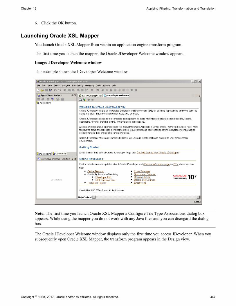
Chapter 18 Applying Filtering, Transformation and Translation
6. Click the OK button.
Launching Oracle XSL MapperYou launch Oracle XSL Mapper from within an application engine transform program.
The first time you launch the mapper, the Oracle JDeveloper Welcome window appears.
Image: JDeveloper Welcome window
This example shows the JDeveloper Welcome window.
Note: The first time you launch Oracle XSL Mapper a Configure Tile Type Associations dialog boxappears. While using the mapper you do not work with any Java files and you can disregard the dialogbox.
The Oracle JDeveloper Welcome window displays only the first time you access JDeveloper. When yousubsequently open Oracle XSL Mapper, the transform program appears in the Design view.
Copyright © 1988, 2017, Oracle and/or its affiliates. All rights reserved. 447

Applying Filtering, Transformation and Translation Chapter 18
Image: Oracle XSL Mapper – Design view
This example illustrates the Oracle XSL Mapper – Design view.
The transform program name in the mapper takes the following format:
<transform_program_name>.<section_name>.<step_name>.xsl
To launch Oracle XSL Mapper:
1. Create a Transform Only application engine program and define the program properties describedearlier in this topic.
2. Double-click the XSLT action.
3. Access the Oracle XSL Mapper–Design view.
When accessing the mapper for the first time, when you double-click the XSLT action and launchOracle JDeveloper the JDeveloper Welcome window appears. To switch to the Design view, abovethe Source pane, click the transform file name tab or from the Window menu click the transform filename.
In subsequent attempts to launch the mapper, double-clicking the XSLT action automatically opensthe transform program in the Design view.
Accessing Oracle JDeveloper Documentation and Online ResourcesThis section provides information for access online Help, documentation and other resources for usingOracle XSL Mapper.
448 Copyright © 1988, 2017, Oracle and/or its affiliates. All rights reserved.

Chapter 18 Applying Filtering, Transformation and Translation
Online HelpOnline Help is available via the Help menu while working with Oracle XSL Mapper.
Additional Oracle JDeveloper Documentation and Online ResourcesAs mentioned earlier in this section, Oracle XSL Mapper is a plug-in to Oracle JDeveloper.Documentation for the mapper is contained in the Oracle JDeveloper documentation set.
Note: The information provided in this section is current as of the publish date of the productdocumentation.
On the Developer Welcome page of the Oracle XSL Mapper there are links to documentation and onlineresources located on the Oracle web site.
In addition you can visit the Oracle Technology Network website to access documentation. OracleJDeveloper documentation resources that may be helpful include:
• Oracle Application Development Framework Guidelines Manual .
• Oracle Application Development Framework Case Manual.
• Installation Guide.
• Release Notes.
• J2EE Developer Online Help (the main documentation library)
Navigating in Oracle XSL MapperThis discusses how to:
• Navigate in the Design View.
• Navigate in the Source View.
Note: This section features a brief discussion of some of the key components and areas of the Oracle XSLMapper development tool. The Oracle JDeveloper documentation provides in-depth details about usingthe Oracle XSL Mapper.
Navigating in the Design ViewTo access the Design view of Oracle XSL Mapper, click the Design tab at the bottom of the mapper.
Copyright © 1988, 2017, Oracle and/or its affiliates. All rights reserved. 449

Applying Filtering, Transformation and Translation Chapter 18
Image: Oracle XSL Mapper – Design view
This example illustrates the fields and controls on the Oracle XSL Mapper – Design view. You can finddefinitions for the fields and controls later on this page.
Use the Design view to map records and fields.
A few of the key areas of the Design view are discussed here. For additional information on Design viewfeatures, see the Oracle XSL Mapper documentation.
Title Bar The title bar displays the full path to the Oracle JDeveloperinstallation location and the name of the current transformprogram.
Developer Welcome (tab) Click the tab to display links to online resources, such asdocumentation, online demos and code samples.
Transform Program name (tab) Click to access the transform program.
Source The Source pane in the Oracle XSL Mapper main developmentview provides a hierarchical view of the source or inputmessage and schema.
Click the Expand button (+) button and the Collapse button (-)to expand and collapse data shown.
Drag the edges of the pane in or out to adjust the viewing area.
Target The Target pane in the Oracle XSL Mapper main developmentview provides a hierarchical view of the target or outputmessage and schema.
450 Copyright © 1988, 2017, Oracle and/or its affiliates. All rights reserved.

Chapter 18 Applying Filtering, Transformation and Translation
Click the Expand button (+) button and the Collapse button (-)to expand and collapse data shown.
Drag the edges of the pane in or out to adjust the viewing area.
Design (tab) Located at the bottom left-side of the window, click the tab todisplay the area where you map records and fields.
Source (tab) Located at the bottom left-side of the window, click the tab toview and edit the raw XSLT code generated by Oracle XSLMapper.
Navigating in the Source ViewTo access the Source view of Oracle XSL Mapper, click the Source tab at the bottom or the mapper.
Image: Oracle XSL Mapper–Source view
This example illustrates the Oracle XSL Mapper–Source view.
Use the Source view to view and edit the raw XSL code generated by the mapper.
For additional information on Source view features, see the Oracle XSL Mapper documentation.
Mapping Records and FieldsTo map records and fields, use the Oracle XSL Mapper – Design view to drag record names and fieldnames from the source pane to the target pane in the mapper.
Copyright © 1988, 2017, Oracle and/or its affiliates. All rights reserved. 451

Applying Filtering, Transformation and Translation Chapter 18
Image: Oracle XSL Mapper – Design view
This example illustrates the Oracle XSL Mapper – Design view.
A solid green line appears as you drag the cursor from the source pane to the target pane. When yourelease the cursor, the line turns blue to show the association.
To map records and fields:
1. Open the Design view of Oracle XSL Mapper.
2. Expand the contents of both the source and target panes.
Click the Expand button (+) to expand each level or section until all records and fields appear.
Note: When working with rowset-based messages the content to map is located in the MsgDatasection.
3. In the source pane, click on the icon to the left of a record or field name and drag it to the name of therecord or field in the target pane to which you want to map.
Repeat this step for each record or field to map.
4. Click the Save button.
Deleting Record and Field MapsIf you have not saved the program and want to delete the last map you made, simply right click in theDesign view and select Undo Link. Otherwise, follow the instructions in this section.
To delete a record or field map:
1. In the source pane, click the record or field name.
2. From the Edit menu, click Delete.
3. Save the changes.
452 Copyright © 1988, 2017, Oracle and/or its affiliates. All rights reserved.

Chapter 18 Applying Filtering, Transformation and Translation
Viewing Raw XSLT CodeAfter you have made all of the record and field maps for the program. Click the Source tab at the bottomof the window to generate and view the raw XSL.
Testing XSL MapsYou can test XSL maps for validity that you generate in the mapper using the Test XSL Map window. Toaccess the Test XSL Map window, right-click anywhere in the code area and select Test.
Image: Test XSL Map window
This example illustrates the Test XSL Map window.
The code created by the record and field mapping displays in the bottom portion of the window.
Note: This Oracle XSL Mapper test feature tests the validity of the XSLT map code. It does not test thetransformation. To test a transformation, use the Transformation Test tool in the PeopleSoft Pure InternetArchitecture.
To test XSLT code:
1. Access the Oracle XSL Mapper–Source view.
2. Right-click anywhere in the code area and select Test.
The Test XSL Map window appears.
Copyright © 1988, 2017, Oracle and/or its affiliates. All rights reserved. 453

Applying Filtering, Transformation and Translation Chapter 18
3. In the XSL Map section of the window, click the Validate button.
A validation success or error message displays.
Related Links"Running the Transformation Test Utility" (PeopleTools 8.55: Integration Broker Testing Utilities andTools)
Adding and Modifying XSL Map CodeIf you add code to XSLT that you create using Oracle XSL Mapper that contains any PeopleSoft-relatedelements it will not compile successfully, unless you create a configuration file of PeopleSoft elementsthat the mapper should ignore. After you create this file specify the file location and name in the OracleXSL Mapper Preferences.
Creating Elements to Ignore Configuration FilesFor example, you could add code that contains the following elements:
<element name = "psft_function"><element name = "psft_workingstorage">
You would create a file using the following format, which tells Oracle XSL Mapper to ignore thoseelements:
<?XML version='1.0' encoding='windows-1252'?><elements-to-ignore> <element name = "psft_function"/> <element name = "psft_workingstorage"/></elements-to-ignore>
Specifying Elements to Ignore Configuration Files in Oracle XSL MapperPreferencesOnce you create the file of PeopleSoft elements to ignore, enter the file location and name in the mapperPreferences dialog box.
454 Copyright © 1988, 2017, Oracle and/or its affiliates. All rights reserved.

Chapter 18 Applying Filtering, Transformation and Translation
Image: Preferences dialog box
This example illustrates the Preferences dialog box in the Oracle XSL Mapper.
To specify an elements to ignore configuration file in Oracle XSL Mapper preferences:
1. In Oracle XSL Mapper, from the Tools menu, select Preferences.
The Preferences dialog appears.
2. In the list on the left-side of the window, click XSL Maps.
3. In the Elements to Ignore Conf. File (Requires Restart) field, enter or browse to the location of theelements to ignore configuration file that you created.
4. Click the OK button.
You must restart Oracle JDeveloper for the system to recognize the configuration file.
Developing Transform Programs Using the XSLT TransformBuilder
This topic discusses how to:
• Navigate the XSLT Transform Builder.
• Add transformation programs to the XSLT Transform Builder.
Copyright © 1988, 2017, Oracle and/or its affiliates. All rights reserved. 455

Applying Filtering, Transformation and Translation Chapter 18
• Define transformation metadata and properties.
• Manually build transformation program in the XSLT Transform Builder.
• Use the Oracle XSLT Mapper to build transformation programs in the XSLT Transform Builder.
Understanding the XSLT Transform BuilderThe XSLT Transform Builder provides an alternative to using PeopleSoft Application Engine to buildtransformation programs.
The XSLT Transform Builder page (IB_XSLTBUILDER) enables you to build XSLT transformation stepsusing the PeopleSoft Pure Internet Architecture without having to access PeopleSoft Application Designerto create an Application Engine program.
Note: You can create and save only single transformation steps using the XSLT Transform Builder.
Using the XSLT Transform Builder you can manually code transformation programs. You can also launchthe Oracle XSL Mapper from the XSLT Transform Builder page to develop transformation programs.
Understanding Using Oracle XSL Mapper to Build TransformationPrograms in the XSLT Transform Builder
You can create transformation programs in the XSLT Transform Builder by accessing Oracle XSLMapper.
As of the publication date of this documentation the Oracle XSL Mapper is a component of Oracle BPELDesigner and is included in Oracle JDeveloper.
The documentation in this topic describes prerequisites for using Oracle XSL Mapper to buildtransformation programs in the XSLT Transform Builder and how to launch the Oracle XSL Mapperfrom the XSLT Transform Builder page. The documentation in this topic does not describe how to use theOracle XSL Mapper. See the Oracle XSL Mapper product documentation for information on how to usethe tool.
Note: You cannot use Oracle XSL Mapper to modify XSLT that you've hand-coded or created with anyother XSLT editing tool.
Prerequisites for Using the XSLT Transform BuilderThere are no prerequisites for manually building transformation programs using the XSLT TransformBuilder.
If you plan to use the Oracle XSL Mapper to build transformation programs in the XSLT TransformBuilder you must:
• Download, install and configure the Oracle XSLT Mapper.
Oracle XSL Mapper is an Oracle JDeveloper plug-in. Check the My Oracle Support website forinformation about supported versions and for installation, configuration, and user documentation.
456 Copyright © 1988, 2017, Oracle and/or its affiliates. All rights reserved.

Chapter 18 Applying Filtering, Transformation and Translation
Important! After you install Oracle XSL Mapper do not move or delete the installed jar files from thedefault installation location, unless instructed otherwise in the product documentation. The PeopleSoftsystem reads this information from the default location for proper functioning of the feature.
• If you are using Oracle JDeveloper 11g, the JDK folder and its contents must exist inside theJDeveloper home location. Therefore you must install JDK 1.6 or use an existing installation of JDK1.6, and copy all the contents inside the <JDEV_HOME> directory. The following example shows theinstallation path:
<JDEV11_HOME>/jdk/<jdk_copied_contents>
• If you are using Oracle 11gR2 or a later release, you must move the following folders from<Middleware_Home>\oracle_common\modules to <Middleware_Home>\jdeveloper\modules:
• \oracle.xdk_11.1.0.
• \oracle.xmlef_11.1.1.
• \oracle.javatools_11.1.1.
• Set the JDeveloper home location (JDEV_HOME) in the Windows environment variables as follows:
<ORACLE_HOME>\jdeveloper
• Set the Mapper classpath (JDEV_MAPPER_CLASSPATH) in the Windows environment variables asfollows:
<ORACLE_HOME>\jdeveloper\ide\extensions\oracle.ide.jar; <ORACLE_HOME>\jdevelop⇒er\jdev\extensions\oracle.ide.xmlef.jar; <ORACLE_HOME>\jdeveloper\jdev\extensi⇒ons\oracle.bpm.mapper.jar; <ORACLE_HOME>\jdeveloper\integration\lib\bpm-ide-co⇒mmon.jar; <ORACLE_HOME>\jdeveloper\ide\lib\javatools.jar; <ORACLE_HOME>\jdevel⇒oper\jdev\lib\xmleditor.jar; <ORACLE_HOME>\oracle_common\modules\oracle.xdk_11⇒.1.0\xmlparserv2.jar; <ORACLE_HOME>\oracle_common\modules\oracle.xmlef_11.1.1\⇒xmlef.jar;C:\JDeveloper11g\oracle_common\modules\oracle.javatools_11.1.1\javat⇒ools-nodeps.jar
• Generate message schemas for messages. All messages used in the mapper must have schemasgenerated for them.
For rowset-based messages, use the Message Definitions–Schema page to generate schemas. Fornonrowset-based messages, use the Message Definitions–Schema page to add or import schemas forthese types of messages.
Managing Rowset-Based MessagesManaging Nonrowset-Based Messages
Navigating the XSLT Transform BuilderTo access the XSLT Transform Builder page select PeopleTools, Integration Broker, Service Utilities,XSLT Transform Builder.
Copyright © 1988, 2017, Oracle and/or its affiliates. All rights reserved. 457
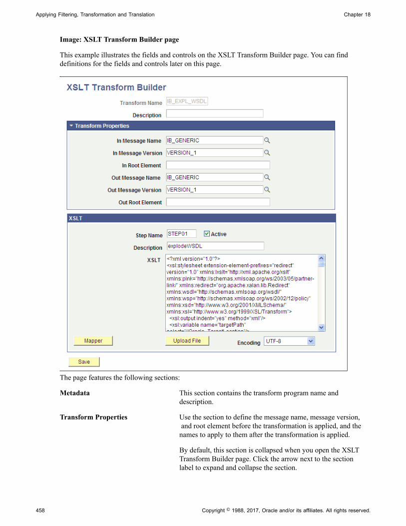
Applying Filtering, Transformation and Translation Chapter 18
Image: XSLT Transform Builder page
This example illustrates the fields and controls on the XSLT Transform Builder page. You can finddefinitions for the fields and controls later on this page.
The page features the following sections:
Metadata This section contains the transform program name anddescription.
Transform Properties Use the section to define the message name, message version, and root element before the transformation is applied, and thenames to apply to them after the transformation is applied.
By default, this section is collapsed when you open the XSLTTransform Builder page. Click the arrow next to the sectionlabel to expand and collapse the section.
458 Copyright © 1988, 2017, Oracle and/or its affiliates. All rights reserved.

Chapter 18 Applying Filtering, Transformation and Translation
XSLT Use this section to define the step and XSLT code to programthe step.
You can code step manually in the space provided or uploadcode from a file.
When using the Oracle XSL Mapper to code a step, after youexit the Oracle XSL Mapper, the code appears in this space.
The page features the following fields and controls:
Transform Name Name of the transformation program.
Description Description of the transformation step.
In Message Name Message name before transformation.
In Message Version Message version before transformation.
In Root Element Name of the root element before transformation.
This field is required with the message type is a nonrowset-based message.
Out Message Name Message name after transformation.
Out Message Version Message version after transformation.
Out Root Element Name of the root element after transformation.
This field is required with the message type is a nonrowset-based message.
Step Name Name of the step.
Active Check the box to indicate the transformation step is active. Clearthe box to deactivate the transformation step.
Mapper Click the button to launch the Oracle XSL Mapper to code thetransformation.
Upload File Click the button to upload transformation code from a file.
Encoding If uploading transformation code from a file, select the encodingapplied to file from the list. The options are:
• Non-Unicode.
• UTF-16.
• UTF-8. (Default.)
Save Click the button to save the transformation program.
Copyright © 1988, 2017, Oracle and/or its affiliates. All rights reserved. 459

Applying Filtering, Transformation and Translation Chapter 18
Adding Transformation Programs to the XSLT Transform BuilderTo add a transformation program to the XSLT Transform Builder:
1. Select PeopleTools, Integration Broker, Service Utilities, XSLT Transform Builder.
2. Click the Add a New Value tab.
3. In the Program Name field enter a name.
4. Click the Add button.
Defining Transformation Program Metadata PropertiesIn the metadata section at the top of the page and in the Transform Properties section of the page, enterthe appropriate values for the fields and properties. See the Navigating the XSLT Transform Buildersection earlier in this topic for descriptions of all fields that appear in these sections.
Manually Building Transformation Programs in the XSLT Transform BuilderUse the XSLT section of the XSLT Transform Builder page to manually build transformation programs.
To manually build a transformation program in the XSLT Transform Builder:
1. Define the metadata and transformation properties on the XSLT Transform Builder page describedearlier in this topic.
2. In the Step Name field enter the step name.
The value cannot exceed eight characters.
3. Select the Active box to activate the step. Clear the box to deactivate the step.
4. In the Description field enter a description for the step.
The description cannot exceed 30 characters.
5. In the XSLT box enter code for the step using one of the following methods:
• Manually enter code in the box.
• Upload transformation code from a file.
From the Encoding list select the file encoding of the file you want to upload. Click the Uploadbutton and browse to and select the file. The contents of the file appears in the XSLT box.
6. Click the Save button.
Using the Oracle XSLT Mapper to Build Transformation Programs in theXSLT Transform Builder
You can launch the Oracle XSLT Mapper to build transformation steps in the XSLT Transform Builder.
To use the Oracle XSLT Mapper to build transformation steps in the XSLT Transform Builder:
460 Copyright © 1988, 2017, Oracle and/or its affiliates. All rights reserved.

Chapter 18 Applying Filtering, Transformation and Translation
1. Review and perform the prerequisites for using the Oracle XSLT Mapper described earlier in thistopic.
2. Define the metadata and transformation properties on the XSLT Transform Builder page describedpreviously in this topic.
3. Click the Launch button to access the Oracle XSLT Mapper.
The XSLT Transform Builder page appears. The transformation code appears in the XSLT box and isread-only.
4. Click the Refresh button to enable editing of the code in the XSLT box.
5. Perform any additional code manipulation.
6. Click the Save button.
Invoking Transform Programs
Your transform program is invoked by PeopleSoft Integration Broker if you specify its name in the arouting definition for a service operation.
Accessing Transform Message Data
When PeopleSoft Integration Broker invokes a transform program, it inserts the message content into aPeopleCode system variable, %TransformData, which remains in scope throughout the program. Eachstep can access the variable in turn and modify its content, which then becomes available to the next step.
XSLT and PeopleCode steps access %TransformData differently:
• In XSLT, the data is automatically made available to your program. The XSLT program is literallya presentation of the output structure and data, which includes xsltags that reference, processand incorporate the input data into the output structure. There’s no need to explicitly refer to%TransformData, which automatically receives the interpreted result of the XSLT.
• In PeopleCode, use the PeopleCode TransformData class to access %TransformData. You then accessthe XML data as a property of the TransformData object called XmlDoc, which you assign to anXmlDoc object and process normally. Because the XmlDoc object is a reference to the data portion of%TransformData, your modifications are automatically passed back to the system variable.
Using the TransformData ClassThe PeopleCode TransformData class has several properties:
Property Description
XmlDoc Contains the XML message data. You can assign this to anXmlDoc object and process the data using the XmlDoc classmethods and properties. This property is read/write.
Copyright © 1988, 2017, Oracle and/or its affiliates. All rights reserved. 461
Applying Filtering, Transformation and Translation Chapter 18
Property Description
Status Communicates the success or failure of the transform programstep to PeopleSoft Integration Broker. Set to 0 for success, the default value. Set to 1 to indicate that the message faileda filtering step. Set to 2 to indicate an error occurred. Thisproperty is read/write.
See Filtering Messages.
SourceNode The name of the node sending the message. This property isread only.
DestNode The name of the node receiving the message. This property isread only.
SourceMsgName The name of the message at the sending node. This property isread only.
DestMsgName The name of the message at the receiving node. This propertyis read only.
SourceMsgVersion The name of the message version at the sending node. Thisproperty is read only.
DestMsgVersion The name of the message version at the receiving node. Thisproperty is read only.
routingDefnName Retrieves the routing definition name for the transaction. Youcan then programmatically retrieve the routing propertiesspecified on the Routings - Routing Properties page.
rejectTransform Terminates the transaction for asynchronous service operationtypes.
If you set this property for a transform in inboundasynchronous transaction the system will not create asubscription contract. In the Service Operation Monitor Detailspage for the transaction an informational message will be partof the error message link indicating that the transaction wasterminated.
If you set this property for an outbound asynchronoustransactions the publication contract status in the ServiceOperation Monitor will be updated to Done. The message willnot be sent out and an error message will once again be part ofthe Service Operation Monitor Details page for the transactionindicating the transaction was terminated.
462 Copyright © 1988, 2017, Oracle and/or its affiliates. All rights reserved.

Chapter 18 Applying Filtering, Transformation and Translation
Note: Because transform programs can apply to both request and synchronous response messages, thenode sending the message could be a synchronous transaction target node that’s sending a response backto the synchronous transaction source node, which in this case is the receiving node.
Handling Non-XML DataBecause they work only with XML DOM-compliant data, neither XSLT nor PeopleCode transformsteps can process non-XML data. The XML DOM provides a way to incorporate such data into an XMLstructure so your transform programs won’t produce errors.
If you’re generating a non-XML outbound message in your PeopleSoft application, it’s up to you to insertyour message content into a special element containing a CDATA tag, as follows:
<any_tag psnonxml="yes"> <![CDATA[your_nonXML_message_content]]></any_tag>
Note: Any_tag can be any tag you want to use.
The following restrictions apply to the content of inbound non-XML messages, such as those in CSV orPDF format, sent by third-party applications:
• Inbound non-XML text messages must be encoded as UTF-8-compliant characters.
• Inbound non-text, or binary, messages must be encoded in base64 format.
Renaming or Deleting Transform Programs
To invoke a transform program, you specify it as part of a routing definition. If you subsequently renameor delete that transform program, it still appears in the routing definition, so service operations using thatmodifier will fail. To prevent this, do the following:
• If you rename a transform program, make sure you reselect it by its new name in any routingdefinitions that apply it.
• If you delete a transform program, make sure you select a different program (or no program) in anyrouting definitions where that apply it.
Filtering Messages
This section provides an overview of message filtering and discusses how to work with a PeopleCodefiltering example.
Understanding Message FilteringYou use filtering to suppress an input message based on its content. For example, you can suppress allinbound purchase order messages that specify order quantities less than the minimum number required fora discount.
Copyright © 1988, 2017, Oracle and/or its affiliates. All rights reserved. 463

Applying Filtering, Transformation and Translation Chapter 18
Place filtering steps early in your Application Engine transform program; each message suppressed by thefilter is one less message for subsequent steps to process.
You must use PeopleCode for filtering, so it'll probably be a distinct step. Because you must use theXmlDoc and XmlNode classes in your PeopleCode transform steps, you can analyze messages in any waythat those classes support.
Filtering requires the following actions in your PeopleCode program:
1. Retrieve the message content from the %TransformData system variable.
2. Examine your filtering criteria.
3. If the message meets your criteria, do nothing further. It remains intact in the %TransformData systemvariable for the next transform program step to process.
4. If the message fails to meet your criteria, replace the entire message content with a single node calledFilter, containing the reason it failed.
<?xml version="1.0"?><Filter>reason_for_failure</Filter>
5. Set the TransformData Status property to 1 to indicate failure.
PeopleSoft Integration Broker examines the Status property after each step, and terminates the transformprogram if its value is 1. You can then view the message in Integration Broker Monitor and see the reasonfor the failure.
PeopleCode Filtering ExampleThe following example of filtering presents an input message, the PeopleCode filtering program, and theresulting output message.
Input MessageThis is the input to the filtering step. Notice the line item order quantities (shown in emphasis):
<?xml version="1.0"?><PurchaseOrder> <Destination> <Address>123 Vine Street</Address> <Contact> <Name>Joe Smith</Name> </Contact> <Delivery type="ground"> <Business>FedEx</Business> </Delivery> </Destination> <Payment> <CreditCard cardtype="visa">9999-9999-9999-9999</CreditCard> </Payment> <LineItems count="2"> <Li locale="en_us" number="1"> <Quantity>4</Quantity> <ProductName>pencil</ProductName> <UOM>box</UOM> </Li> <Li locale="en_us" number="2"><Quantity>10</Quantity> <ProductName>paper</ProductName> <UOM>large box</UOM> </Li>
464 Copyright © 1988, 2017, Oracle and/or its affiliates. All rights reserved.

Chapter 18 Applying Filtering, Transformation and Translation
</LineItems></PurchaseOrder>
Note: Although this input message isn’t in the PeopleSoft rowset-based message format, it is valid XML.
PeopleCode Filtering ProgramThis filtering program examines the line item order quantities of the input message and generates theoutput message that follows. The key statements are in bold:
/* Get the data from the AE Runtime */Local TransformData &tempData = %TransformData;/* Set a temp object to contain the incoming document */Local XmlDoc &tempDoc = &tempData.XmlDoc;
/* Find the line items quantities contained in the incoming Purchase Order */Local array of XmlNode &quantities = &tempDoc.DocumentElement.FindNodes("LineItems/Li/Quantity");/* Temp storage of a node */Local XmlNode &tempNode;
/* Loop through the quantities and make sure they are all above 5 */For &i = 1 To &quantities.Len /* Set the temp node*/ &tempNode = &quantities [&i]; /* Make sure the node isn't empty*/ If ( Not &tempNode.IsNull) Then
/* Check the value, if not greater than 5 this does not pass filter*/ If (Value(&tempNode.NodeValue) < 5) Then /* Clear out the doc and put in the "Filter" root node */If (&tempDoc.Pars⇒eXmlString("<?xml version=""1.0""?><Filter/>")) Then /* Get the new root node and set the value /* to be the reason for failing filter */&rootNode = &tempDoc.Docu⇒mentElement;&rootNode.NodeValue = "Line item quantity was found that was less than ⇒5!"; /* Set the status of the transformation to 1 for failed filter*/&tempDa⇒ta.Status = 1;End-If;Break;End-If
End-IfEnd-For;
Output MessageThis is the result of applying the PeopleCode filtering program:
<?xml version="1.0"?><Filter>Line item quantity was found that was less than 5!</Filter>
Applying Transformations
This section provides an overview of transformation and discusses using XSLT for transformation.
Understanding TransformationUse a transformation when one node sends a request or response message with a data structure differentfrom the structure required by the other node. One or both of the participating nodes can be PeopleSoftapplications. At either end of the transaction, any of the following structure types may be required:
Copyright © 1988, 2017, Oracle and/or its affiliates. All rights reserved. 465

Applying Filtering, Transformation and Translation Chapter 18
• The PeopleSoft rowset-based message format.
• An XML DOM-compliant non-rowset-based structure. This is generic XML data.
• A SOAP-compliant XML structure. This is also XML DOM-compliant.
• A non-XML structure. Third-party applications are more likely than PeopleSoft applications torequire this type.
Your transformation can be between different structure types or between different structures of the sametype.
Related LinksSupported Message Structures
Using XSLT for TransformationAn XSLT transformation simulates the original message structure, then specifies how to treat nodeswithin that structure. You can:
• Copy the original content of a node without changing anything.
• Define and insert a new version of a node.
• Enter any structure or content directly.
• Eliminate a node by omitting reference to it, or by not inserting anything new in its place.
XSLT Transformation ExampleThe XSLT wrapper is required.
<?xml version="1.0"?><xsl:stylesheet xmlns:xsl="http://www.w3.org/1999/XSL/Transform" version="1.0">
The primary node tag matches the original message structure by matching its top level content tag, themessage name (QE_SYNC_MSG). Between the message template tags, you can insert any structureor content you want. PeopleSoft Integration Broker replaces each xsl tag with the data it references,producing a transformed message as the output of the step.
<xsl:template match="QE_SYNC_MSG"> <QE_SYNC_MSG> <xsl:copy-of select="FieldTypes"/> <MsgData> <Transaction> <xsl:apply-templates select="MsgData/Transaction/QE_SALES_ORDER"/> <xsl:copy-of select="MsgData/Transaction/PSCAMA"/> </Transaction> </MsgData> </QE_SYNC_MSG> </xsl:template>
The following node example is defined to match a record in the input message by its top level content tag,the record name (QE_SALES_ORDER). This template is applied by the xsl:apply-templates tag of thepreceding node (shown emphasized).
Between the record template tags, you can insert any structure or content you want. In this example,90 is prepended to the QE_ACCT_ID value, and the QE_ACCOUNT_NAME field is renamed to
466 Copyright © 1988, 2017, Oracle and/or its affiliates. All rights reserved.

Chapter 18 Applying Filtering, Transformation and Translation
QE_ACCOUNT (shown emphasized). Also, any existing value in the DESCRLONG field is removed, andthe remaining fields are passed through with their original values.
<xsl:template match="QE_SALES_ORDER"> <QE_SALES_ORDER><xsl:attribute name="class"> <xsl:value-of select="@class"/></xsl:attribute> <xsl:variable name="temp" select="QE_ACCT_ID"/> <QE_ACCT_ID><xsl:value-of select="concat(90,$temp)"/></QE_ACCT_ID><QE_ACCO⇒UNT><xsl:value-of select="QE_ACCOUNT_NAME"/></QE_ACCOUNT> <QE_ADDRESS><xsl:value-of select="QE_ADDRESS"/></QE_ADDRESS> <QE_PHONE><xsl:value-of select="QE_PHONE"/></QE_PHONE> <QE_FROMROWSET/> <QE_TOROWSET/> <QE_SEND_SOA_BTN/> <QE_SEND_SOS_BTN/> <DESCRLONG></DESCRLONG> </QE_SALES_ORDER> </xsl:template>
Finally, you need the closing wrapper tag:
</xsl:stylesheet>
Note: You can find more information about XSLT at the World Wide Web Consortium (W3C) web site.
Note: A working transformation example using XSLT is provided in the PeopleTools SDK. The locationof the example is <PS_HOME> \sdk\pstransform\samples\TRANSFORMTST.xml.
Applying Message Transformations at the Integration Gateway
Typically, you apply filtering, transformation, and data translation to a message at the node level on theapplication server by using a transaction modifier to invoke an Application Engine transform program.However, on systems with high transaction volumes, Application Engine transformations can constrictmessage throughput. To improve performance, you can apply XSLT transformation programs at anintegration gateway.
Note: While you may apply transformations at the integration gateway level, PeopleSoft stronglyrecommends that you apply them at the application server level due to a more robust infrastructure tosupport them.
See Apache Website.
Understanding Applying Message Transformations at the IntegrationGateway
Only XSLT transformations can be applied at the gateway. Message filtering, data translation, andPeopleCode transformations must still be applied at the node using an Application Engine transformprogram, and can be applied in addition to gateway-based transformations.
You can apply XSLT transformations at any gateway that handles the message you want to transform.
When a gateway with transformation enabled processes an IBRequest, it examines the transformationproperties in the integrationGateway.properties file to determine if they specify a transformation forthe same message with the same source and target nodes as the IBRequest. If these values match, the
Copyright © 1988, 2017, Oracle and/or its affiliates. All rights reserved. 467

Applying Filtering, Transformation and Translation Chapter 18
gateway compiles the specified XSLT transformation program and applies it to the message, then sendsthe transformed message to the target node.
Note: The IBRequest can specify only a RequestingNode or only a DestinationNode, but it must specifyat least one of these values—ig.DefaultServer.LocalNode supplies the other one.
With synchronous transactions, the gateway applies transformations only to the request message, notto the response message. If the original message is compressed and base64 encoded, the gatewaydecompresses and decodes it before applying the transformation, then compresses and encodes it againbefore sending.
Note: The integration gateway retains all compiled XSLT transformation programs in a memory cache toimprove performance during subsequent transformations. If you edit the code of a transformation programthat’s been used before, you must purge the compiled programs from the cache so the new version will berecompiled. To do this, click the Refresh button on the gateway definition.
Developing and Implementing Gateway-Based Transformation ProgramsDeveloping and implementing gateway-based transform programs requires the following activities:
1. Determine if the message you want to transform qualifies for gateway-based transformation:
• The message content must be XML-DOM compliant.
• The message must not have nonrepudiation activated.
2. Develop the XSLT transformation program.
See Applying Transformations.
You can develop, test and debug the program within Application Engine, but you must save theprogram code as an external text file. Place the file in any location that can be accessed from theintegration gateway machine, for example:
C:\XSLProgs\MyTransform.xsl
3. Configure the appropriate gateway property settings in the integrationGateway.properties file toenable the transformation.
See Setting Integration Gateway Properties for Gateway-Based Transformations.
4. Refresh the gateway properties.
Setting Integration Gateway Properties for Gateway-Based TransformationsTo apply gateway-based transformations, set the following properties in the integrationGateway.propertiesfile.
For each message you want to transform, you must create a set of property entries using the same number,which associate a given transformation program with that message. However, you can specify the sametransformation program for multiple messages.
468 Copyright © 1988, 2017, Oracle and/or its affiliates. All rights reserved.

Chapter 18 Applying Filtering, Transformation and Translation
When entering these settings, each transformation must be numbered for identification, using theconvention ig.transform1, ig.transform2, ig.transform3, and so on.
Property Description
ig.isGatewayTransformationEnabled Specify whether transformation is enabled for this gateway. Valid values are:
• TRUE. Transformation is enabled.
• FALSE. Transformation is disabled — the integrationgateway will ignore the other transformation properties. This is the default value.
ig.DefaultServer.LocalNode Enter the name of the node definition that will be used as thesource or destination node for a given transformation if eitherof those values isn’t identified; for example you must specify:
ig.DefaultServer.LocalNode=DEF_NODE
All transformations require that you specify both a sourcenode and a destination node. This property applies ifeither the ig.transformN.SourceNode property or the ig.transformN.DestinationNode property is empty or invalid, orif the IBRequest doesn’t specify either RequestingNode orDestinationNode.
ig.transforms Specify the number of transformations configured in theintegrationGateway.properties file; for example:
ig.transforms=7
ig.transformN.XSL Enter the full path and filename of transformation program N.
Your path specification must use either double back slashes orsingle forward slashes as separators; for example:
ig.transform4.XSL=C:\\XSLProgs\\MyTransform.xsl
ig.transform4.XSL=C:/XSLProgs/MyTransform.xsl
ig.transform4.XSL=/usr/xsls/MyTransform.xsl
ig.transformN.MessageName Enter the name of the message to be transformed bytransformation program N; for example:
ig.transform4.MessageName=MY_MSG_A
ig.transformN.SourceNode Enter the name of the source node from which the originalmessage is being sent, or enter the value ANY; for example:
ig.transform4.SourceNode=NODE_Aig.transform4.SourceNode=ANY
If this value is ANY, the value of the ig.DefaultServer.LocalNode property will be used instead.
Copyright © 1988, 2017, Oracle and/or its affiliates. All rights reserved. 469
Applying Filtering, Transformation and Translation Chapter 18
Property Description
ig.transformN.DestinationNode Enter the name of the target node to which the transformedmessage is being sent, or enter the value ANY; for example:
ig.transform4.DestinationNode=NODE_Big.transform4.DestinationNode=ANY
If this value is ANY, the value of the ig.DefaultServer.LocalNode property will be used instead.
ig.transformN.DestinationMessageName (Optional.) Enter the name that the target node uses for thetransformed version of the message, if it’s different from theoriginal message name; for example:
ig.transform4.DestinationMessageName=MY_MSG_B
This enables the gateway to rename the message beforesending it, so the target node will recognize and accept it.
Understanding Logged ErrorsIf an error occurs when you refresh the gateway properties or during a transformation, it’s entered in thegateway’s error log file.
Integration Gateway Refresh ErrorsAfter you specify integration gateway properties and refresh the gateway, errors can be generated for thefollowing reasons:
• No value is specified for ig.transformN.XSL.
• No value is specified for ig.transformN.MessageName.
• No value is specified for both ig.DefaultServer.LocalNode and ig.transformN.SourceNode.
• No value is specified for both ig.DefaultServer.LocalNode and ig.transformN.DestinationNode.
• The gateway is in the process of loading, compiling or caching a transformation program.
Runtime Transformation ErrorsErrors are generated for the following reasons when the gateway attempts to apply a transformation:
• Nonrepudiation is enabled for the message.
• The integration gateway is unable to transform the message.
• The integration gateway is unable to decompress and decode the message.
• The integration gateway is unable to compress and encode the message.
• The IBRequest does not specify a RequestingNode and no value is specified forig.DefaultServer.LocalNode.
• The IBRequest does not specify a DestinationNode and no value is specified forig.DefaultServer.LocalNode.
470 Copyright © 1988, 2017, Oracle and/or its affiliates. All rights reserved.
Chapter 18 Applying Filtering, Transformation and Translation
• The IBRequest specifies neither a RequestingNode nor a DestinationNode.
Performing Data Translation
This section provides an overview of data translation and discusses how to:
• Define codeset groups.
• Define codesets.
• Define codeset values.
• Import and export codesets between databases.
• Delete codesets.
• Use XSLT for data translation.
• Work with an XSLT translation example.
• Work with a PeopleCode translation example.
Understanding Data TranslationUse data translation to modify message content rather than structure, although you can also make localstructural changes. It’s most appropriate when the sending and receiving systems use different fieldvalues, or different combinations of fields and their values, to represent the same information.
Following is a sample scenario:
• Application A transmits customer names in four fields: Title, First, Middle, and Last.
• Application B uses two fields: Last and First. It doesn’t use a title, but includes the middle name aspart of the First field.
• Application C uses only one field: AccountID.
Clearly the representation used by one application won’t be understood by either of the other two.PeopleSoft Integration Broker can apply a transform program to translate each of these representationsinto a version appropriate to the receiving application.
One Integration Broker node can store in its codeset repository the equivalent fields and values used byanother node. When it receives a message from the other node containing a customer name, it can use itscodeset repository to translate the information into the form it prefers. It can likewise reverse the processfor messages outbound to the other node.
For a given integration, you can allocate the responsibility for performing data translation in differentways. You can distribute the translation activity among the participating nodes, or you can designateone Integration Broker node to do all the data translation as a hub, whether the messages are inbound,outbound, or being redirected between the other nodes. Using a single node, if possible, can reduce theneed for duplicating repository data.
Copyright © 1988, 2017, Oracle and/or its affiliates. All rights reserved. 471
Applying Filtering, Transformation and Translation Chapter 18
Data Translation ElementsThe following elements constitute the codeset repository, managed as PeopleSoft Pure InternetArchitecture components:
Codeset group Maintains a list of the significant data fields and their values thata particular node might send in an initial message. These arename/value pairs a translation program might find (match) anduse as the basis for determining what the result message shouldcontain. These name/value pairs are known as match names andmatch values.
Each PeopleSoft Integration Broker node that requires datatranslation must belong to a codeset group.
Codeset A specific set of match name/match value pairs selected froman existing codeset group. The selected name/value pairs arethe basis for possible field value combinations that you wantto match in a message, and to which your translation programcan respond by modifying the message content. Each codesettypically represents one set of fields that require translation for agiven message.
Codeset values A codeset value is a named value you define, also known as areturn value. Your translation program can output the returnvalue as a result of matching a specific combination of matchvalues from a codeset.
You associate multiple combinations of codeset values withthe combination of an initial codeset group, a codeset from thatinitial group, and a result codeset group. For each permutationof match values selected from the codeset, you define a differentcombination of codeset values to apply to your result message.
The other key element of data translation is your translation program, which invokes the codesets andcodeset values you’ve defined.
Data Translation Development SequenceYou must initially define these elements in a particular order:
1. Two codeset groups.
2. A codeset based on one of the codeset groups.
3. A set of codeset values.
4. A data translation program, in XSLT or PeopleCode.
However, it’s unlikely that you’ll be able to fully define any of these elements without some trial anderror. You may find you’ll have to modify and extend each element in turn as you develop your datatranslation program.
472 Copyright © 1988, 2017, Oracle and/or its affiliates. All rights reserved.

Chapter 18 Applying Filtering, Transformation and Translation
Defining Codeset GroupsUse the Codeset Groups page (IB_CODESETGRPVAL) in the Codeset Groups component(IB_CODESETGROUP) to define codeset groups. To access the Codeset Groups page, selectPeopleTools, Integration Broker, Integration Setup, Codesets, Codeset Groups.
Image: Codeset Groups page
This example illustrates the Codeset Groups page.
To define a codeset group:
1. Add a new value, enter a codeset group name, and click Add.
Enter a name that reflects a common quality of the nodes you plan to assign to this group; forexample, the name of the software they all use to manage shipping.
The Codeset Group page appears.
2. Add a new row.
3. Enter a match name.
This is the name of a data field that might be part of a message sent by a node belonging to thiscodeset group. You don’t have to create an entry for every field, just the ones that you’ll need totranslate or use for reference in a translation.
4. Enter a match value.
This is one of the possible values of the data field represented by the match name.
5. Repeat steps 2 through 4 for each significant name/value pair that you expect to appear in a message.
This doesn’t need to be all possible values of all of the message fields, just the names and values youexpect to require translation.
6. Assign one or more nodes to this codeset group.
Every initial and result node involved in a data translation must belong to a codeset group. You mustassign each participating node to an appropriate codeset group by an entry in its node properties.
Copyright © 1988, 2017, Oracle and/or its affiliates. All rights reserved. 473

Applying Filtering, Transformation and Translation Chapter 18
Note: The assignment for each node is required only in the database of the node performing thedata translation. This translating node needn’t be either the source or the target. Multiple nodes thatrepresent data the same way may be assigned to the same codeset group.
Related Links"Configuring Nodes" (PeopleTools 8.55: Integration Broker Administration)
Defining CodesetsUse the Codesets page (IB_CODESET) in the Codesets component. (IB_CODESET). Select PeopleTools,Integration Broker, Integration Setup, Codesets, Codesets to access the Codeset page.
Image: Codesets page
This page illustrates the Codesets page.
To define a codeset:
1. Add a new value and enter a codeset group name on which to base this codeset.
2. Enter a codeset name and click Add.
Enter a name that reflects the purpose of this codeset; for example, SAP_SHIP_METHOD, to translatethe representation of a shipping method in a message. The Codesets page appears.
3. Add a new row.
4. Select a match name from the set defined for the associated codeset group.
5. Select a match value from the set defined for the selected match name.
Note: You can leave the value blank. If so, you should do the same for each match name in thiscodeset, in addition to any other values you select for them. A combination consisting of all blankvalues is treated as a wild card by PeopleSoft Integration Broker, which enables it to respond tounanticipated values specified in your translation program with default behavior that you define.
6. Repeat steps 3 through 5 to enter all the name/value pairs that may need to be matched.
474 Copyright © 1988, 2017, Oracle and/or its affiliates. All rights reserved.

Chapter 18 Applying Filtering, Transformation and Translation
The name/value pairs you select should encompass only the possible value combinations that yourtranslation program needs to match for a single translation. You define a different codeset for eachtranslation based on this codeset group.
Defining Codeset ValuesUse the Codeset Values page (IB_CODESETVAL) in the Codeset Values component(IB_CODESETVAL). Select PeopleTools, Integration Broker, Integration Setup, Codesets, CodesetValues to access the Codeset Values page.
Image: Codeset Values page
This example illustrates the Codeset Values page.
To define codeset values:
1. Add a new value and select a codeset group name for the From group.
This is the codeset group to which the initial node belongs.
2. Select a codeset name from the codesets based on the group you selected.
This is the codeset whose match name/match value permutations you wish to match.
Copyright © 1988, 2017, Oracle and/or its affiliates. All rights reserved. 475

Applying Filtering, Transformation and Translation Chapter 18
3. Select a codeset group name for the To group.
This is the codeset group to which the result node belongs.
4. Click Add.
The Codeset Values page appears. The upper grid contains the selected codeset’s match name/matchvalue pairs, and the lower grid contains the return values you specify. Each permutation that youdefine has its own Description field, which can help you distinguish between permutations that maybe subtly different from each other.
Note: To configure an existing codeset values definition, enter its From group, codeset name and Togroup on the search page.
5. Select check boxes to define a permutation of match name/match value pairs.
For each match name, you can select at most one match value.
A permutation consisting of all blank values serves as a wild card; it matches any input valuecombination that isn’t matched by any other permutation. However, a permutation with some blankand some non-blank values works differently; it requires the names with blank values to actuallymatch blank field values in the input data.
Note: You’ll generally define only permutations that you expect the input data to contain, but makesure you allow for unforeseen match values by including permutations with all blank values. You canthen specify default return values for those permutations. With a large number of match names in thecodeset, you can make sure to catch all unforeseen combinations by defining a permutation with allblank match values.
6. In the Code Set Values grid, enter a return name, and a return value for that name.
You can use any return name you want, because only your codeset translation program refers to it.Your translation program can use the return value as a field value or as a node name in the output data.
Important! The set of return names you define must be identical for all of the permutations of matchname/match value pairs for the current codeset in this definition. Your translation program invokes thecodeset and applies the return names from this definition, but it can’t anticipate which permutationswill be matched, or which actual return values it’s applying — just the return names.
7. (Optional.) In the Code Set Values grid, add a new row and repeat step 6.
Add as many return name/return value pairs as you need for your output based on the currentpermutation. If the permutation is matched in the input data, the code set values you define for thatpermutation become available for you to call and insert in the output data.
8. (Optional.) At the top level of this page, add a new row and repeat steps 5 through 7.
This inserts a new permutation row, in which you can define a different permutation of match name/match value pairs that you expect for the current codeset. For each permutation, you’ll define aseparate, independent set of codeset values.
476 Copyright © 1988, 2017, Oracle and/or its affiliates. All rights reserved.

Chapter 18 Applying Filtering, Transformation and Translation
Importing and Exporting Codesets Between DatabasesPeopleSoft provides two Data Mover scripts that you can use to import and export codesets betweendatabases:
• CODESET_DELETE_IMPORT.DMS
Use this script to purge and then import codeset data into a target database.
• CODESET_EXPORT.DMS
Use this script to export codeset data from a source database to a target database.
Deleting CodesetsBefore you delete a codeset, you must delete any codeset values associated with it.
Deleting Codeset ValuesTo delete codeset values for a codeset:
1. Select PeopleTools, Integration Broker, Integration Setup, Codesets, Codeset Values. The CodesetValues page displays.
2. In the Find an Existing Value tab, in the Codeset Name field, enter the name of the code set you wantto delete, or use the Lookup button to locate it.
3. In the Codeset Values section, deselect the Select check box for each match name corresponding tothe code set match name you want to delete, or click the Delete a Row button (-).
Repeat this process for as many codeset match names that are used.
4. Click the Save button.
Deleting CodesetsTo delete a codeset:
1. Select PeopleTools, Integration Broker, Integration Setup, Codesets, Codeset.
2. Select the codeset to delete. The Codeset page displays.
3. Locate the row that contains the codeset you want to delete, and click the Delete a Row button (-)button on that row.
4. Click the Save button.
Using XSLT for Data TranslationOnce you’ve defined the match name/match value permutations for a given codeset and defined the returnvalues for those permutations, you can write an XSLT translation program that invokes the codeset andapplies the return values.
Copyright © 1988, 2017, Oracle and/or its affiliates. All rights reserved. 477

Applying Filtering, Transformation and Translation Chapter 18
An XSLT translation is based on XSLT transformation structure. However, although you couldcombine both tasks into a single program, it’s better to keep them separate for easier understanding andmaintenance.
Psft_function NodesTo implement data translation capability, PeopleSoft Integration Broker provides a custom XSLT tagcalled psft_function. Each psft_function node in your program comprises a single instance of datatranslation that invokes a particular codeset and applies a specified set of codeset values.
Runtime invocation of codesets in XSLT is a two part process: first the input document is transformed andthen all instances of psft_function are resolved in the output document.
Note: You can insert a psft_function node anywhere inside the XSLT template containing the fields youwant to translate. However, you’ll find it easiest to place it at or near the point in the template where thereturn values will go, to avoid having to specify a complex path to that location.
The psft_function tag has the following attributes:
Attribute Description
name Set to codeset.
codesetname Identifies the codeset whose name/value permutations youwant to match in the input data. The routing that invokesthis transform program identifies the initial and result nodesinvolved, and PeopleSoft Integration Broker examines theirdefinitions to determine the From group and To group. Thecombination of these two keys and the codeset name identifiesthe codeset values definition to apply.
source (Optional.) Overrides the name of the initial node specified bythe routing. PeopleSoft Integration Broker uses the specifiednode’s codeset group as the From group key, thus invoking adifferent codeset values definition.
dest (Optional.) Overrides the name of the result node specified bythe routing. PeopleSoft Integration Broker uses the specifiednode’s codeset group as the To group key, thus invoking adifferent codeset values definition.
Note: The source and dest attributes don’t change the initial and result nodes specified in the routing; theyjust invoke the codeset groups to which those nodes belong.
Following is an example of psft_function using all of its attributes:
<psft_function name="codeset" codesetname="PS_SAP_PO_01" source="SAP_02" dest="PSFT_03">...</psft_function>
Parm and Value NodesThe psft_function node can contain two tags, parm and value:
478 Copyright © 1988, 2017, Oracle and/or its affiliates. All rights reserved.

Chapter 18 Applying Filtering, Transformation and Translation
• Use the parm tag to specify a match name from the codeset values definition that you specified forthis translation. You do this with the tag’s only attribute: name. Set this to a match name from thecodeset values definition.
The parm node should contain a match value, usually specified as an xsl:value-of tag that identifieswhere the value resides in the input data. Use one parm node for each distinct match name in thecodeset values definition.
• Use the value tag to specify a return name from the codeset values definition that you specified forthis translation. Also use the value tag to identify where to place the return value assigned to thatreturn name for the matched permutation and how to apply that value.
Use one value node for each return name in the codeset values definition that you want in your output.
Value Tag AttributesThe value tag has the following attributes:
Attribute Description
name Identifies a return name from the codeset values definition youspecified for this translation. The return value assigned to thisreturn name can be used as a data value or as a node name inyour output depending on the attributes you specify.
select Identifies an XSLT path (XPATH) to the location where thereturn value should be applied in the output data.
createIfDNE (Optional.) Set to yes to ensure that the node specified by theselect attribute is created if it does not exist yet. The returnvalue is inserted as the value of that node.
createNodeFromValue (Optional.) Set to yes to use the return value as the name ofa new node, created where the select attribute specifies. Thevalue tag can contain a valid XSLT value for that node, usuallyspecified as an xsl:value-of tag that identifies where the valueresides in the input data.
Following is an example of a value node:
<value name="PS_RET_01" select="." createNodeFromValue="yes"><xsl:value-of select="CreditCard"/></value>
Related LinksUsing XSLT for Transformation
XSLT Translation ExampleThe following example of XSLT data translation presents an example input message, the XSLTtranslation program, and the resulting output message.
Copyright © 1988, 2017, Oracle and/or its affiliates. All rights reserved. 479
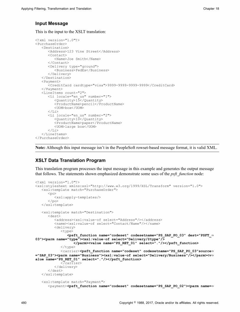
Applying Filtering, Transformation and Translation Chapter 18
Input MessageThis is the input to the XSLT translation:
<?xml version="1.0"?><PurchaseOrder> <Destination> <Address>123 Vine Street</Address> <Contact> <Name>Joe Smith</Name> </Contact> <Delivery type="ground"> <Business>FedEx</Business> </Delivery> </Destination> <Payment> <CreditCard cardtype="visa">9999-9999-9999-9999</CreditCard> </Payment> <LineItems count="2"> <Li locale="en_us" number="1"> <Quantity>15</Quantity> <ProductName>pencil</ProductName> <UOM>box</UOM> </Li> <Li locale="en_us" number="2"> <Quantity>10</Quantity> <ProductName>paper</ProductName> <UOM>large box</UOM> </Li> </LineItems></PurchaseOrder>
Note: Although this input message isn’t in the PeopleSoft rowset-based message format, it is valid XML.
XSLT Data Translation ProgramThis translation program processes the input message in this example and generates the output messagethat follows. The statements shown emphasized demonstrate some uses of the psft_function node:
<?xml version="1.0"?><xsl:stylesheet xmlns:xsl="http://www.w3.org/1999/XSL/Transform" version="1.0"> <xsl:template match="PurchaseOrder"> <po> <xsl:apply-templates/> </po> </xsl:template> <xsl:template match="Destination"> <dest> <address><xsl:value-of select="Address"/></address> <name><xsl:value-of select="Contact/Name"/></name> <delivery> <type> <psft_function name="codeset" codesetname="PS_SAP_PO_03" dest="PSFT_⇒03"><parm name="type"><xsl:value-of select="Delivery/@type"/> </parm><value name="PS_RET_01" select="."/></psft_function> </type> <carrier><psft_function name="codeset" codesetname="PS_SAP_PO_03"source⇒="SAP_03"><parm name="Business"><xsl:value-of select="Delivery/Business"/></parm><v⇒alue name="PS_RET_01" select="."/></psft_function> </carrier> </delivery> </dest> </xsl:template> <xsl:template match="Payment"> <payment><psft_function name="codeset" codesetname="PS_SAP_PO_02"><parm name=⇒
480 Copyright © 1988, 2017, Oracle and/or its affiliates. All rights reserved.

Chapter 18 Applying Filtering, Transformation and Translation
"cardtype"><xsl:value-of select="CreditCard/@cardtype"/></parm><value name="PS_RET_⇒01" select="."createNodeFromValue="yes"><xsl:value-of select="CreditCard"/></value><⇒/psft_function> </payment> </xsl:template> <xsl:template match="Li"> <li><xsl:attribute name="id"><xsl:value-of select="@number"/></xsl:attribute> <name><xsl:value-of select="ProductName"/></name> <qty><xsl:value-of select="Quantity"/></qty> <uom><psft_function name="codeset" codesetname="PS_SAP_PO_01"><parm name="⇒locale"><xsl:value-of select="@locale"/></parm><parm name="uom"><xsl:value-of selec⇒t="UOM"/></parm><value name="PS_RET_01" select="."/><value name="PS_RET_02" select=⇒"../type" createIfDNE="yes"/></psft_function> </uom> </li> </xsl:template></xsl:stylesheet>
Output MessageThis is the result of applying the XSLT translation:
<po> <li id=""> <name>pencil</name> <qty>15</qty> <uom>Carton</uom> <type>Bic</type> </li> <li id=""> <name>paper</name> <qty>10</qty> <uom>Box</uom> <type>Bic</type> </li> <dest> <address>123 Vine Street</address> <name>Joe Smith</name> <delivery> <type>Ground</type> <carrier>Federal Express</carrier> </delivery> </dest> <payment> <VISA>4024-9920-9892-8982</VISA> </payment></po>
PeopleCode Translation ExampleAlthough XSLT is the recommended language for using the codeset repository to translate messagedata, you can use PeopleCode for this purpose as well. Because XSLT works only with XML DOM-compliant message data, you must use PeopleCode if the message you’re translating contains non-XMLdata, including formats like comma separated values (CSV).
Once you’ve defined the match name/match value permutations for a codeset with respect to a giventarget codeset group and defined the return values for those permutations, you can write a PeopleCodetranslation program that invokes that codeset and applies the return values.
Copyright © 1988, 2017, Oracle and/or its affiliates. All rights reserved. 481
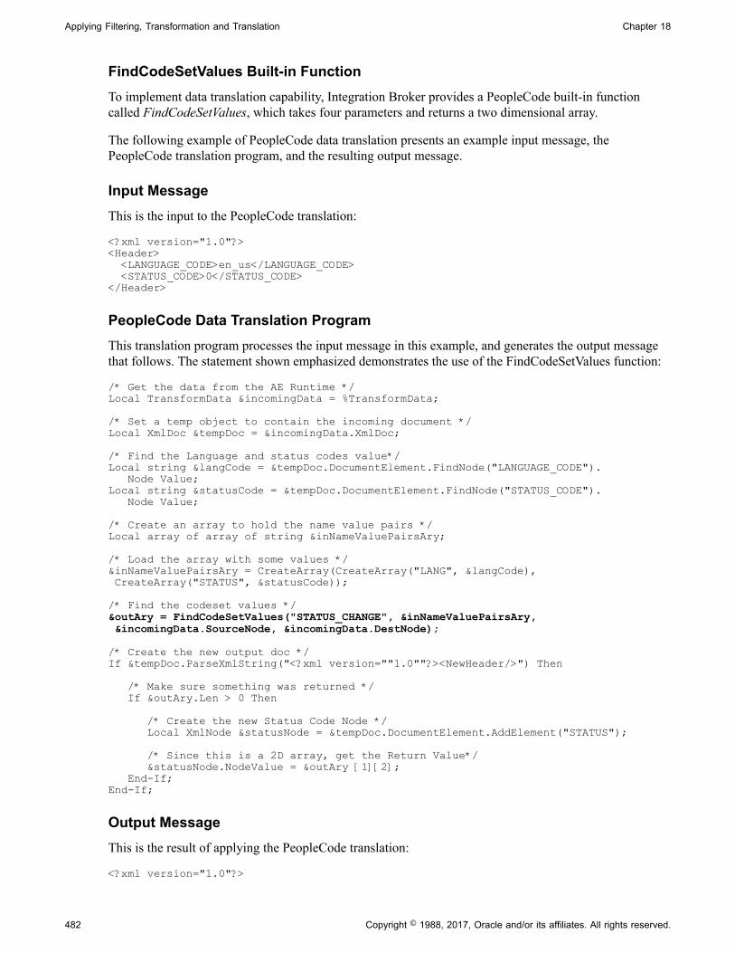
Applying Filtering, Transformation and Translation Chapter 18
FindCodeSetValues Built-in FunctionTo implement data translation capability, Integration Broker provides a PeopleCode built-in functioncalled FindCodeSetValues, which takes four parameters and returns a two dimensional array.
The following example of PeopleCode data translation presents an example input message, thePeopleCode translation program, and the resulting output message.
Input MessageThis is the input to the PeopleCode translation:
<?xml version="1.0"?><Header> <LANGUAGE_CODE>en_us</LANGUAGE_CODE> <STATUS_CODE>0</STATUS_CODE></Header>
PeopleCode Data Translation ProgramThis translation program processes the input message in this example, and generates the output messagethat follows. The statement shown emphasized demonstrates the use of the FindCodeSetValues function:
/* Get the data from the AE Runtime */Local TransformData &incomingData = %TransformData;
/* Set a temp object to contain the incoming document */Local XmlDoc &tempDoc = &incomingData.XmlDoc;
/* Find the Language and status codes value*/Local string &langCode = &tempDoc.DocumentElement.FindNode("LANGUAGE_CODE"). Node Value;Local string &statusCode = &tempDoc.DocumentElement.FindNode("STATUS_CODE"). Node Value;
/* Create an array to hold the name value pairs */Local array of array of string &inNameValuePairsAry;
/* Load the array with some values */&inNameValuePairsAry = CreateArray(CreateArray("LANG", &langCode), CreateArray("STATUS", &statusCode));
/* Find the codeset values */&outAry = FindCodeSetValues("STATUS_CHANGE", &inNameValuePairsAry, &incomingData.SourceNode, &incomingData.DestNode);
/* Create the new output doc */If &tempDoc.ParseXmlString("<?xml version=""1.0""?><NewHeader/>") Then
/* Make sure something was returned */ If &outAry.Len > 0 Then
/* Create the new Status Code Node */ Local XmlNode &statusNode = &tempDoc.DocumentElement.AddElement("STATUS");
/* Since this is a 2D array, get the Return Value*/ &statusNode.NodeValue = &outAry [1][2]; End-If;End-If;
Output MessageThis is the result of applying the PeopleCode translation:
<?xml version="1.0"?>
482 Copyright © 1988, 2017, Oracle and/or its affiliates. All rights reserved.

Chapter 18 Applying Filtering, Transformation and Translation
<NewHeader> <STATUS>Open</STATUS></NewHeader>
Related Links"FindCodeSetValues" (PeopleTools 8.55: PeopleCode Language Reference)
Rejecting Transformation Programs
Situations may arise when you may want to terminate a transaction. For example, you may not want atransaction published to a specific node.
Using the %TransformData.rejectTransform property and the %IB_Transform_Rejected built-in function,you can terminate asynchronous transactions based on content data.
You set this property in a PeopleSoft Application Engine transform program as follows:
%TransformData.rejectTransform = %IB_Transform_Rejected;
If you set the %TransformData.rejectTransform property within a transform of an inbound asynchronoustransaction, the system will not create a subscription contract and the data is not sent. If you view such atransaction in the Service Operations Monitor, the Operation Instances page displays a status of Done. Ifyou open the Asynchronous Details page in the monitor, an Error link displays. If you click the link aninformational message appears that indicates that the transaction was terminated.
If you set this property for an outbound asynchronous transaction, the Publication Contracts page in theService Operations Monitor will show a contract status of Done for the transaction. However, the systemdoes not send the message and, as with the inbound scenario, the Asynchronous Details page for thetransaction will display an Error link. If you click the link an informational message appears that indicatesthat the transaction was terminated.
Related Links"Understanding Asynchronous Service Operations Statuses" (PeopleTools 8.55: Integration BrokerService Operations Monitor)"Monitoring Asynchronous Service Operation Instances" (PeopleTools 8.55: Integration Broker ServiceOperations Monitor)"Understanding Viewing Asynchronous Service Operation Details" (PeopleTools 8.55: Integration BrokerService Operations Monitor)
Terminating Transformation Programs
If you need to terminate a transform program for reasons that aren’t considered error conditions byPeopleSoft Integration Broker, you can use a PeopleCode step to force the transform program to terminateand generate a readable error message as well.
To generate an error:
Copyright © 1988, 2017, Oracle and/or its affiliates. All rights reserved. 483

Applying Filtering, Transformation and Translation Chapter 18
1. Replace the entire message content with a single node called Error, containing the reason for theerror.
<?xml version="1.0"?><Error>reason_for_error</Error>
2. Set the TransformData Status property to 2 to indicate error status.
PeopleSoft Integration Broker examines the Status property after each step and terminates the transformprogram if its value is 2. You can then view the message in Service Operations Monitor and see the reasonfor the error.
Note: If an XSLT or PeopleCode step fails for reasons that you haven’t taken into account, IntegrationBroker automatically sets the Status property to 2 and aborts the transform program, but you can’t provideyour own error message.
484 Copyright © 1988, 2017, Oracle and/or its affiliates. All rights reserved.

Chapter 19
Managing Error Handling, Logging, Tracing,and Debugging
Understanding Error Handling, Logging, Tracing and Debugging
This topic provides an overview of error handling, logging, tracing and debugging.
Error handling, logging, tracing, and debugging with PeopleSoft Integration Broker can occur on anintegration gateway, application server, or application engine, depending on the type and location ofprocessing.
Understanding Integration Gateway Error Handling
Error handling is an integration gateway service that assists connectors to manage errors that occur duringprocessing. Errors on the integration gateway are handled by target connectors and listening connectors.
This section discusses:
• Target connector error handling.
• Listening connector error handling.
• Integration gateway exception types.
Target Connector Error HandlingThe Target Connector Interface (TCI) specifies the methods that target connectors must implement forthe integration gateway to manage them. These methods include a set of standard exceptions that targetconnectors generate when they experience errors during processing.
Listening connectors or the gateway manager catch these exceptions and provide an appropriateimplementation for each. When the source of the message is an integration engine, the gateway managercatches the exceptions. Otherwise, listening connectors are responsible for handling exceptions that aregenerated during processing.
Listening Connector Error HandlingUnlike target connectors, listening connectors are not managed by the gateway manager and, therefore,do not adhere to any interface. However, a listening connector must invoke the gateway manager to pass amessage from the integration gateway to the integration engine.
The gateway manager has predefined exceptions.
Copyright © 1988, 2017, Oracle and/or its affiliates. All rights reserved. 485

Managing Error Handling, Logging, Tracing, and Debugging Chapter 19
In general, exceptions are thrown in a target connector and caught by a listening connector. As a result, alistening connector must catch these exceptions and handle them as appropriate. Typically, the listeningconnector generates an error message and sends it back to the requester.
Integration Gateway Exception TypesThis section discusses integration gateway exception types.
Standard ExceptionsThe following standard error and exception types are handled by the integration gateway, targetconnectors, and listening connectors:
Exception Type Description
DuplicateMessageException A target connector attempted to process a message that hasalready been processed. This is usually discovered based onan error that is attained from the external system that is beingcontacted.
Of the connectors that are delivered with the PeopleSoftsoftware, only the PeopleSoft 8.1 target connector (PSFT81TARGET) can generate this exception. Targetconnectors are not required to generate this exception.
ExternalApplicationException The message reached its intended destination but could not beprocessed.
Determining that the destination could not process a messagerequires significant knowledge of the destination system, which a target connector might not have. Whenever possible, a target connector should attempt to determine this situation;otherwise this task must be decentralized and handled outsideof the integration gateway.
For example, the HTTP target connector (HTTPTARGET)generates this exception when the external system returns anHTTP system code of 500.
ExternalSystemContactException The target connector cannot establish a connection withthe intended destination. This is one of the most commonexceptions.
When this exception is thrown during an asynchronoustransaction, PeopleSoft Integration Broker tries to resend themessage until successful.
GeneralFrameworkException A general error occurred.
InvalidMessageException A connector or the gateway manager determined that themessage cannot be processed because of missing or erroneousinformation in a request or response.
486 Copyright © 1988, 2017, Oracle and/or its affiliates. All rights reserved.

Chapter 19 Managing Error Handling, Logging, Tracing, and Debugging
Exception Type Description
MessageMarshallingException A gateway service’s attempt to get information from anIBRequest or IBResponse failed. This can occur when thegateway services attempt to access a content section of adocument by using an out-of-range index from one of thefollowing methods:
• GetContentSectionAt(index)
• GetContentSectionInfoAt(index)
• RemoveContentSectionAt(index)
If you try to access IBRequest or IBResponse with an out-of-range index by using any of these methods, this exception isthrown automatically and processing is interrupted.
MessageUnmarshallingException A gateway service’s attempt to build an IBRequest orIBResponse failed. Failure can occur when:
• Instantiating an IBRequest or IBResponse from aMultipurpose Internet Mail Extensions (MIME) formatwhere the message that was sent does not comply with thePeopleSoft MIME format.
• Instantiating an IBRequest by using the PS_XML formatand passing an invalid PS_XML message.
This is typically from the HTTP listening connector.
• Setting invalid values to methods, such assetTransactionID or setMessageType.
These failures cause the integration gateway to generate thisexception automatically and processing is interrupted.
Java ExceptionsTarget connectors and listening connectors can handle miscellaneous Java exceptions, such asNullPointerException and ArrayOutOfBoundsException.
Managing Integration Gateway Message and Error Logging
This section provides an overview of message and error logging and discusses how to:
• Set up message and error logging.
• View non-English characters in integration gateway log files.
• Manage message logging.
Copyright © 1988, 2017, Oracle and/or its affiliates. All rights reserved. 487

Managing Error Handling, Logging, Tracing, and Debugging Chapter 19
• Manage error logging.
Understanding Message and Error LoggingError and message logging is a gateway service that you use to monitor messages that flow through theintegration gateway.
Logging takes place within both target and listening connectors. Connectors can log all message requestsand responses. As a result, you can use logging to:
• Track message flow.
• Troubleshoot processing errors.
Setting Up Message and Error LoggingBy default, an integration gateway logs all errors and warnings, as well as information of important,standard, and low importance.
Set up message and error logging by using the integrationGateway.properties file. Use the LoggingSetting section to view or change default settings, such as the level of gateway logging, where the systemwrites log files, the maximum size of the log file, and the number of file backups or archives to keep.
Related Links"Setting Logging Properties" (PeopleTools 8.55: Integration Broker Administration)
Viewing Non-English Characters in Integration Gateway Log FilesTo view non-English characters in integration gateway log files, enable UTF-8 encoding in your webbrowser. For example, if you are using Microsoft Internet Explorer, you can enable UTF-8 encoding byselecting View, Encoding, Unicode (UTF-8). If you are using Mozilla FireFox, you can enable UTF-8encoding by selecting View, Character Encoding, Unicode (UTF-8).
Managing Message LoggingMessage logging records the following information for messages that pass through the integrationgateway:
• Time and date.
• Message description.
• Content of the passed message object.
• Message level.
The default location of the integration gateway message log is <PIA_HOME>\webserv\<DOMAIN>\applications\peoplesoft\PSIGW.war\msgLog.html.
Change the location of the log in the integrationGateway.properties file.
488 Copyright © 1988, 2017, Oracle and/or its affiliates. All rights reserved.
Chapter 19 Managing Error Handling, Logging, Tracing, and Debugging
Message Logging in Target ConnectorsMessage logging in a target connector occurs:
• Before delivering the request to the external system.
The connector logs the request in the format in which the external system delivered it. For example,an HTTP target connector logs the exact HTTP output stream request. The PeopleSoft targetconnector logs the MIME request to be sent to the integration engine.
• After it receives a response from the external system.
The connector logs the response in the format in which it receives it. For example, an HTTP targetconnector logs the exact HTTP input stream response. The PeopleSoft target connector logs theMIME response that it received from the integration engine.
Message Logging in Listening ConnectorsMessage logging in a listening connector occurs:
• At the point where the request enters the system.
The connector logs the request in the format in which the sending system delivers it. For example,the HTTP listening connector logs the exact HTTP input stream request. The PeopleSoft listeningconnector logs the MIME request that it received from the integration engine.
• Following the delivery of a response to the requestor system.
The connector logs the response in the format in which it was delivered. For example, the HTTPlistening connector logs the exact HTTP output stream response. The PeopleSoft listening connectorlogs the MIME response that it sent back to the integration engine.
Message Logging Methods and ParametersInvoke the logMessage method for integration gateway message logging:
logMessage(String Description, Object message, int MessageLevel)
Use the following parameters:
Parameter Description
Description Specify a description as a string.
Object Specify the message object. Typically this object is anIBRequest or IBResponse. If another object is passed, thetoString method is invoked for the object, and the result islogged.
Copyright © 1988, 2017, Oracle and/or its affiliates. All rights reserved. 489
Managing Error Handling, Logging, Tracing, and Debugging Chapter 19
Parameter Description
MessageLevel Set the relative importance of the information that youare logging. The ig.log.level property setting in theintegrationGateway.properties file determines the log level thatis currently in effect. If the MessageLevel value that is passedhere is less than or equal to the ig.log.level property setting, the message is written to the log file.
Values are:
• 3: Important information.
• 4: Standard information.
• 5: Low-importance information.
The ig.messageLog.filename property in theintegrationGateway.properties file determines the log filelocation.
Managing Error LoggingError logging captures processing errors that occur in the integration gateway. When an error occurs, thefollowing information is logged:
• Error level.
• Description.
• Message catalog entry information.
• Stack trace identifying the problem.
• IBRequest and IBResponse (if available).
The default location of the integration gateway error log is <PIA_HOME>\webserv\<DOMAIN>\applications\peoplesoft\PSIGW.war\errorLog.html.
Change the location of the log in the integrationGateway.properties file.
Error Logging Methods and ParametersInvoke the logError method for integration gateway error logging:
logError (String Description, IBRequest, IBResponse, int ErrorLevel, Throwable)
Use the following parameters:
Parameter Description
Description Specify a description as a string.
490 Copyright © 1988, 2017, Oracle and/or its affiliates. All rights reserved.
Chapter 19 Managing Error Handling, Logging, Tracing, and Debugging
Parameter Description
IBRequest Specify the IBRequest for this transaction, if available. If notavailable, pass Null.
IBResponse Specify the IBResponse for this transaction, if available. If notavailable, pass Null.
ErrorLevel Specify whether the log is written to permanent storage. Thisdetermines the severity of the error. The ig.log.level propertyin the integrationGateway.properties file determines the loglevel that is currently in effect. If the ErrorLevel value that ispassed here is less than or equal to the ig.log.level propertysetting, the error is written to the log file.
Values are:
• 100: Language exception.
• 1: Standard gateway exception.
• 2: Warning.
The ig.errorLog.filename property in the integrationGateway.properties file determines the log file location.
Throwable Specify the Java exception or error that is associated with theerror. This is used to log the stack trace that is associated withthe error.
The gateway manager and delivered listening connectors feature built-in error logging that invokesthe logError method. The delivered target connectors do not feature built-in error logging, and insteadgenerate errors to the gateway manager or listening connectors, where they are handled or logged.
Managing Application Server Logging and Tracing
Use the PeopleSoft Application Server Administration menu to:
• View application server and Oracle Tuxedo log files.
See "Editing Configuration and Log Files" (PeopleTools 8.55: System and Server Administration).
• Trace Structured Query Language (SQL) and PeopleCode on your domains.
See "Trace Options" (PeopleTools 8.55: System and Server Administration).
• Set the level of network tracing (log fence).
See "Domain Settings" (PeopleTools 8.55: System and Server Administration).
• View the certificate authentication logs, including information about mismatched distinguished namesand certificates that are not in the database.
Copyright © 1988, 2017, Oracle and/or its affiliates. All rights reserved. 491
Managing Error Handling, Logging, Tracing, and Debugging Chapter 19
This information is contained in the APPSRV.LOG file.
You can also use the tracing functionality in PeopleSoft Application Engine, which enables you tomonitor the performance of transforms in your implementation of PeopleSoft Integration Broker.
Related LinksUnderstanding Filtering, Transformation, and Translation"Understanding Tracing Application Engine Programs" (PeopleTools 8.55: Application Engine)
Debugging Integrations
This section discusses how to:
• Debug handler PeopleCode.
• Handle common issues.
Debugging Handler PeopleCodeUse the Handler Tester utility to debug service operation handler PeopleCode.
The Handler Tester utility enables you to use the PeopleSoft Pure Internet Architecture to test any of thefollowing handler types:
• OnSend.
• OnRequest
• OnRouteReceive
• OnRouteSend.
• OnAckReceive
• OnNotify.
You can test handlers without setting up a routing definition, without having pub/sub booted on yourapplication server, and without impacting other developer activity on the system.
Related Links"Understanding the Handler Tester Utility" (PeopleTools 8.55: Integration Broker Testing Utilities andTools)
Handling Common IssuesUse this table to handle common issues in PeopleSoft Integration Broker:
492 Copyright © 1988, 2017, Oracle and/or its affiliates. All rights reserved.
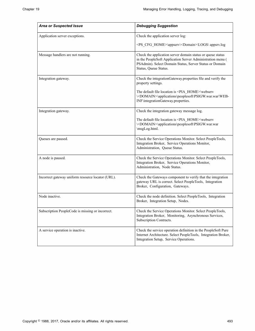
Chapter 19 Managing Error Handling, Logging, Tracing, and Debugging
Area or Suspected Issue Debugging Suggestion
Application server exceptions. Check the application server log:
<PS_CFG_HOME>\appserv\<Domain>\LOGS\ appsrv.log
Message handlers are not running. Check the application server domain status or queue statusin the PeopleSoft Application Server Administration menu (PSAdmin). Select Domain Status, Server Status or DomainStatus, Queue Status.
Integration gateway. Check the integrationGateway.properties file and verify theproperty settings.
The default file location is <PIA_HOME>\webserv\<DOMAIN>\applications\peoplesoft\PSIGW.war.war\WEB-INF\integrationGateway.properties.
Integration gateway. Check the integration gateway message log.
The default file location is <PIA_HOME>\webserv\<DOMAIN>\applications\peoplesoft\PSIGW.war.war\msgLog.html.
Queues are paused. Check the Service Operations Monitor. Select PeopleTools, Integration Broker, Service Operations Monitor, Administration, Queue Status.
A node is paused. Check the Service Operations Monitor. Select PeopleTools, Integration Broker, Service Operations Monitor, Administration, Node Status.
Incorrect gateway uniform resource locator (URL). Check the Gateways component to verify that the integrationgateway URL is correct. Select PeopleTools, IntegrationBroker, Configuration, Gateways.
Node inactive. Check the node definition. Select PeopleTools, IntegrationBroker, Integration Setup, Nodes.
Subscription PeopleCode is missing or incorrect. Check the Service Operations Monitor. Select PeopleTools, Integration Broker, Monitoring, Asynchronous Services, Subscription Contracts.
A service operation is inactive. Check the service operation definition in the PeopleSoft PureInternet Architecture. Select PeopleTools, Integration Broker, Integration Setup, Service Operations.
Copyright © 1988, 2017, Oracle and/or its affiliates. All rights reserved. 493

Managing Error Handling, Logging, Tracing, and Debugging Chapter 19
Area or Suspected Issue Debugging Suggestion
There are transform problems. • Check the Application Engine object in PeopleSoftApplication Designer.
• For before and after images, check the Service OperationsMonitor.
For asynchronous service operations, select PeopleTools, Integration Broker, Service Operations Monitor, Monitoring, Asynchronous Details. Click the View XMLlink for the publication contract or subscription contract.
For synchronous service operations, select PeopleTools, Integration Broker, Service Operations Monitor, Monitoring, Synchronous Details. Use the Log Typedrop-down list box to select Request Transformed orResponse Transformed, and then click View XML.
• Verify that the TraceAE flag in the following directoryequals 8192:
<PS_CFG_HOME>\appserv\<Domain>\psappsrv.cfg
Setting the TraceAE flag in the psappsrv.cfg file instructsthe application server to generate a transformation tracelog with the .aet extension, written to the followingdirectory:
<PS_CFG_HOME>\appserv\<Domain>\LOGS\<operID>_<machine name>.AET
The log file contains:
• The original XML structure as it entered thetransformation engine.
• The output of the XML as it passed through each stepof the transform program.
Integration Broker security Set the application server logging level to 4 or greater tocapture information related to the following situations:
• No routing at source node.
• No routing at target node.
• User invoking a service operation has differentpermissions than specified on the service operation on thesource node.
• No node password found on source node.
• No node password found on target node.
• Mismatched node password on source and target nodes.
• No permissions set for the service operation on the sourcenode.
494 Copyright © 1988, 2017, Oracle and/or its affiliates. All rights reserved.
Chapter 20
Providing Services
Understanding Providing Services
This topic describes how to provide services using the Provide Web Service wizard, access generatedWSDL and WADL documents, and delete WSDL and WADL document.
The topic also describes WSDL and WADL documents that the system generates.
Note: The code examples in this topic are for illustrative purposes only and are not intended to be used ina production environment.
Understanding the Provide Web Service Wizard
PeopleSoft Integration Broker features a Provide Web Service wizard that steps you through the task ofproviding web services.
The Provide Web Service component (IB_WSDL_EXPORT) features a wizard you can use to provideweb services. You can publish WSDL and WADL documents to the WSDL repository in the PeopleSoftsystem or publish WSDL documents to external UDDI repositories.
After you generate a WSDL or WADL document, the Provide Web Service wizard displays a URL foreach document you generated. This enables you to access the WSDL document or WADL documentcontent using the URL. In addition, PeopleSoft Integration Broker provides a WSIL URL which lists theprovided services and corresponding WSDL URLs.
You can use the Provide Web Service wizard to select one or more services for which to generate WSDLdocuments or WADL documents. The system generates a separate document for each service.
Understanding Providing WSDL Documents
This section provides an overview of provided WSDL documents provided by the Provide Web Servicewizard.
WSDL FeaturesProvided WSDL documents include support WS-interoperability standards for WSDL and include:
• WS-Addressing header elements for asynchronous request/response operation types.
• WS-Security elements UsernameToken and SAMLToken.
Copyright © 1988, 2017, Oracle and/or its affiliates. All rights reserved. 495

Providing Services Chapter 20
In addition, provided WSDL document feature PartnerLinkType elements which are used when consumedby a BPEL application.
WSDL Document SpecificationsIntegration Broker can provide WSDL documents in WSDL 1.1 or WSDL 2.0 format. By default, theProvide Web Service wizard used to provide WSDL documents generates WSDL in 1.1 format andfeatures and option to generate WSDL documents in WSDL 2.0 format.
See Step 1: Select Services to Provide.
The following graphic illustrates the differences between WSDL 1.1 and WSDL 2.0 documents at theabstract and concrete layers:
Image: Abstract and concrete layers of WSDL 1.1 and WSDL 2.0 documents
This diagram illustrates the differences between the abstract and concrete layers of the WSDL 1.1 andWSDL 2.0 specifications.
Additional information about the elements in WSDL 1.1 documents and WSDL 2.0 documents isprovided elsewhere in this topic.
See Provided WSDL Documents.
Supported Operation Types for WSDL DocumentsThe Provide Web Service wizard can create WSDL documents for service operations having thefollowing operation types:
• Synchronous.
• Asynchronous one-way.
496 Copyright © 1988, 2017, Oracle and/or its affiliates. All rights reserved.
Chapter 20 Providing Services
• Asynchronous request/response.
Requirements for Nonrowset-Based Message SchemasThis section discusses requirements and considerations for creating nonrowset-based message schemasfor service operations in order to generate WSDL documents using the Provide Web Service wizard.
Note: The PeopleSoft system automatically generates message schemas for rowset-based messages.
Target NamespaceNonrowset-based message schemas must contain a target namespace. If no target namespace exists in theschema an error occurs when the system generates the WSDL document.
You may define multiple schema imports to the same target namespace, but different schema locationsmust be defined.
Multiple Root Element and Complex Type TagsIf the PeopleSoft system finds multiple root <element> or <complexType> tags in nonrowset-basedmessage schemas, only the first one is referenced in the WSDL document or container message schema.
In addition, the WSDL would allow schema imports to the same target namespace but different schemalocations and use <xsd:include> when the schema Namespace is same as the WSDL namespace.
Related LinksPrerequisites for Providing Services
Locations for Publishing WSDL DocumentsUsing the Provide Web Service wizard, you can publish WSDL documents to the follow locations:
• PeopleSoft WSDL repository. (Application database.)
The PeopleSoft WSDL repository is the default publishing location. All generated WSDL documentsare published to the PeopleSoft WSDL repository. You may publish WSDL documents to a UDDIrepository in addition to the WSDL repository.
• Universal Description, Discovery, and Integration (UDDI) repositories.
Services published to UDDI repositories are available to other PeopleSoft and external systems.If another PeopleSoft system wants to invoke an exported service from UDDI, it can consume theWSDL document from the UDDI reference into its system to create a service and routing definition.
UDDI Repositories and EndpointsWhen publishing a WSDL document to a UDDI repository, the PeopleSoft system publishes the currentendpoint value defined in the Target Location field in the Service Configuration page.
The endpoint value in the actual WSDL document is a dynamic one, since you can change the targetlocation value, for example, when you move from development to production.
Copyright © 1988, 2017, Oracle and/or its affiliates. All rights reserved. 497

Providing Services Chapter 20
If you change the target location you should change the endpoints of previously published WSDLdocuments, either manually in the UDDI registry or by republishing the WSDL documents to your UDDIrepository using the changed endpoint.
WSDL URL FormatsAfter you a publish a WSDL document using the Provide Web Service wizard, the system displays aWSDL URL. The URL provided is the path to the WSDL document location in the WSDL repository inthe PeopleSoft Pure Internet Architecture. The URL is used by external systems that will be invoking aPeopleSoft service.
The default URL format is path style. The following example shows a WSDL URL in path format:
http://localhost/PSIGW.war/PeopleSoftServiceListeningConnector/PT_WORKLIST.1.wsdl
The path style URL is generated by appending the WSDL document name to the target location valuespecified in the Service Configuration page.
PeopleSoft Integration Broker also supports a query parameter format. The following example shows aWSDL URL in query parameter format:
http://PeopleSoftServiceListeningConnector?Operation=GetWSDL&wsdl=PT_WORKLIST.1
The query parameter style URL is generated by passing either the WSDL document name or servicename.version or service alias.version as a query parameter.
PeopleSoft still supports the query parameter format, however path format is preferred. Note that if usingquery parameter format, manual intervention may be required if the schema target location is changed.
Provided WSDL DocumentsEvery WSDL document you generate using PeopleSoft Integration Broker is divided into sections. Thissection describes the WSDL document sections and provides an example of the WSDL template thatthe PeopleSoft system uses to generate WSDL, as well as example WSDL documents for each of thesupported operation types.
Sections of Provided WSDL DocumentsWSDL documents that you provide using PeopleSoft Integration Broker contain the following sections:
498 Copyright © 1988, 2017, Oracle and/or its affiliates. All rights reserved.

Chapter 20 Providing Services
Section WDSL 1.1 Description WSDL 2.0 Description
<definitions> Specifies the namespaces for the WSDLdocument, W3C XML Schema andSOAP. A unique namespace will becaptured from the Service definition, which will be used to define theWSDL namespaces. The format of thisnamespace is as follows: http://xmlns.oracle.com/Enterprise/<App Name>/<Service Name>.
When a service is defined within anapplication database, the namespace fieldis defaulted to the service namespacedefined on the Service Configurationpage.
NA.
The <description> element serves thesame purpose in WSDL 2.0 documents.
See <description>.
<description> NA.
The <definitions> element serves thesame purpose in WSDL 1.1 documents.
See <definitions>.
Specifies the namespaces for the WSDLdocument, W3C XML Schema andSOAP. A unique namespace will becaptured from the Service definition, which will be used to define theWSDL namespaces. The format of thisnamespace is as follows: http://xmlns.oracle.com/Enterprise/<App Name>/<Service Name>.
When a service is defined within anapplication database, the namespace fieldis defaulted to the service namespacedefined on the Service Configurationpage.
<partnerLinktype> A partnerLinkType defines the role ofservices and the port Type.
No change from WSDL 1.1.
See WSDL 1.1 description.
<types> Captures the simple and complex typesrequired by the schema of the requestand response message definitions of theservice operations. For services withcomponent interface handlers, someof the system methods, such as Createand Get, will require complex messagetypes resembling the structure of thecomponent interface buffer.
No change from WSDL 1.1.
See WSDL 1.1 description.
<message> Defines the abstract messages requiredfor the selected operations. The datatypes for these are obtained from theTypes section of the WSDL document.
There are no <message> elementsin WSDL2.0. Instead, the operationswithin the interface refer to the schemaelements directly.
Copyright © 1988, 2017, Oracle and/or its affiliates. All rights reserved. 499

Providing Services Chapter 20
Section WDSL 1.1 Description WSDL 2.0 Description
<portType> Features a named set of abstractoperations and the abstract messagesinvolved. This section includes alloperations of the service selected forexport.
NA.
See <interface>
<interface> NA
See <portType>
WSDL 2.0 features an <interface>element that replaces the <portType>element in WSDL 1.1.
Unlike the <portType> element inWSDL 1.1, the operations within the<interface> element do not point tomessages, but instead point to theschema elements contained within the<types> element.
<binding> Specifies the network protocol and dataformat of messages used for a specificport type. For providing web servicesPeopleSoft utilizes SOAP packagingand HTTP transport protocols. The dataformat of messages is the Documentstyle format.
No change from WSDL 1.1.
See WSDL 1.1 description.
<operation> This is an abstract definition of a serviceoperation, which specifies request/response/fault messages.
No change from WSDL 1.1.
See WSDL 1.1 description.
<service> A service groups together endpoints thatimplement a common interface.
No change from WSDL 1.1.
See WSDL 1.1 description.
<port> In WSDL 1.1 the <port> elementcontains the definition of the addressto which the client should request theservice. The <port> element also hasreference to binding used by the service
NA.
See <endpoint>.
<endpoint> NA.
See <port>.
In WSDL 2.0 the <port> element isreplaced by the <endpoint> element. Thelocation attribute of endpoint containsthe definition of the address to whichthe client should request the service. The<endpoint> element also has reference tobinding used by the service
Note: In WSDL documents generated by the PeopleSoft system, WS-Security policies are assigned to thebind operation section.
500 Copyright © 1988, 2017, Oracle and/or its affiliates. All rights reserved.

Chapter 20 Providing Services
Example 1: WSDL TemplateThe following example is the WSDL document template that the PeopleSoft system uses when itgenerates WSDL documents. The elements in bold are WSDL document sections discussed in theprevious section:
definitions name="DefinitionsName" targetNamespace="NamespaceURI" xmlns:prefix="NamespaceURI" xmlns:soap="http://schemas.xmlsoap.org/wsdl/soap/" xmlns:xsd="http://www.w3.org/2001/XMLSchema" xmlns="http://schemas.xmlsoap.org/wsdl/"> <plnk:partnerLinkType name="PartnerLinkTypeName"> <!-- Provider Role --> <plnk:role name="ProviderRoleName"> <plnk:portType name="ProviderPortTypeReference"> </plnk:role> <!-- In case of Async Request/Response this role is also required --> <plnk:role name="RequestorRoleName"> <plnk:portType name="CallbackPortTypeReference"> </plnk:role> </plnk:partnerLinkType><types> <!-- One or more schemas --> </types> <message name="MessageName"> <part name="PartName" type="TypeNameReference"/> </message> <portType name="PortName"> <operation name="OperationName"> <input message="MessageNameReference"/> <output message="MessageNameReference"/> <fault message="MessageNameReference"/> </operation> </portType> <binding name="BindingName" type="PortNameReference"> <soap:binding style="rpc|document" transport="http://schemas.xmlsoap.org/soap/http"/> <operation name="OperationName"> <soap:operation soapAction="ActionValue"/> <input> <soap:body encodingStyle="http://schemas.xmlsoap.org/soap/encoding/" namespace="TargetNamespace" use="encoded"/> </input> <output> <soap:body encodingStyle="http://schemas.xmlsoap.org/soap/encoding/" namespace="TargetNamespace" use="encoded"/> </output> </operation> </binding> <service name="ServiceName"> <port name="PortName" binding="BindingNameReference"> <soap:address location="URL"/> </port> </service></definitions>
Example 2: Synchronous WSDL ExampleThe following example shows a synchronous WSDL document provided by the PeopleSoft system:
<?xml version="1.0" ?> <wsdl:definitions name="PT_WORKLIST.1"
Copyright © 1988, 2017, Oracle and/or its affiliates. All rights reserved. 501

Providing Services Chapter 20
targetNamespace="http://xml.namespace.oracle.com/services" xmlns:GetWorklistEntryStatusRequest.v1="http://xmlns.oracle.com/ Enterprise/Tools/schemas/PT_WL_GET_INSTANCE_REQ_CONT.v1" xmlns:GetWorklistEntryStatusResponse.v1="http://xmlns.oracle.com/ Enterprise/Tools/schemas/PT_WL_GET_INSTANCE_RESP_CONT.v1" xmlns:OperationFault.V1="http://xmlns.oracle.com/schemas/Fault" xmlns:plnk="http://schemas.xmlsoap.org/ws/2003/05/partner-link/" xmlns:soap="http://schemas.xmlsoap.org/wsdl/soap/" xmlns:tns="http: //xml.namespace.oracle.com/services" xmlns:wsdl="http://schemas.xmlsoap.org/wsdl/" xmlns:wsp="http://schemas.xmlsoap.org/ws/2002/12/policy"> <wsp:UsagePolicy wsdl:Required="true" /> <plnk:partnerLinkType name="PT_WORKLIST_PartnerLinkType"> <plnk:role name="PT_WORKLIST_Provider"> <plnk:portType name="tns:PT_WORKLIST_PortType" /> </plnk:role> </plnk:partnerLinkType> <wsdl:types> <xsd:schema elementFormDefault="qualified" xmlns:xsd="http://www.w3.org/2001/XMLSchema"> <xsd:import namespace="http://xmlns.oracle.com/Enterprise/Tools/ schemas/PT_WL_GET_INSTANCE_REQ_CONT.v1" schemaLocation="Get WorklistEntryStatusRequest.v1.xsd" /> <xsd:import namespace="http://xmlns.oracle.com/Enterprise/Tools/ schemas/PT_WL_GET_INSTANCE_RESP_CONT.v1" schemaLocation=" GetWorklistEntryStatusResponse.v1.xsd" /> <xsd:import namespace="http://xmlns.oracle.com/schemas/Fault" schemaLocation="OperationFault.V1.xsd" /> </xsd:schema> </wsdl:types> <wsdl:message name="GetWorklistEntryStatusRequest.v1"> <wsdl:part element="GetWorklistEntryStatusRequest.v1:GetWorklist EntryStatusRequest" name="parameter" /> </wsdl:message> <wsdl:message name="GetWorklistEntryStatusResponse.v1"> <wsdl:part element="GetWorklistEntryStatusResponse.v1:GetWorklist EntryStatusResponse" name="parameter" /> </wsdl:message> <wsdl:message name="OperationFault.V1"> <wsdl:part element="OperationFault.V1:OperationFault" name="parameter" /> </wsdl:message> <wsdl:portType name="PT_WORKLIST_PortType"> <wsdl:operation name="GetWorklistEntryStatus"> <wsdl:documentation>Get worklist keys and status</wsdl:documentation> <wsdl:input message="tns:GetWorklistEntryStatusRequest.v1" name= "GetWorklistEntryStatusRequest.v1" /> <wsdl:output message="tns:GetWorklistEntryStatusResponse.v1" name= "GetWorklistEntryStatusResponse.v1" /> <wsdl:fault message="tns:OperationFault.V1" name="OperationFault.V1" /> </wsdl:operation> </wsdl:portType> <wsdl:binding name="PT_WORKLIST_Binding" type="tns:PT_WORKLIST_PortType"> <soap:binding style="document" transport="http://schemas.xmlsoap.org/ soap/http" /> <wsdl:operation name="GetWorklistEntryStatus"> <soap:operation soapAction="GetWorklistEntryStatus.V1" style= "document" /> <wsp:Policy wsu:Id="UsernameTokenSecurityPolicyPasswordOptional" xmlns:wsu="http://docs.oasis-open.org/wss/2004/01/oasis-200401- wss-wssecurity-utility-1.0.xsd"> <wsp:ExactlyOne> <wsp:All> <wsse:SecurityToken wsp:Usage="wsp:Required" xmlns:wsse=" http://docs.oasis-open.org/wss/2004/01/oasis-200401-wss- wssecurity-secext-1.0.xsd"> <wsse:TokenType>wsse:UserNameToken</wsse:TokenType> <Claims> <SubjectName MatchType="wsse:Exact" /> <UsePassword wsp:Usage="wsp:Optional" /> </Claims> </wsse:SecurityToken>
502 Copyright © 1988, 2017, Oracle and/or its affiliates. All rights reserved.

Chapter 20 Providing Services
</wsp:All> </wsp:ExactlyOne> </wsp:Policy> <wsdl:input name="GetWorklistEntryStatusRequest.v1"> <soap:body encodingStyle="http://schemas.xmlsoap.org/soap/encoding/" use="literal" /> </wsdl:input> <wsdl:output name="GetWorklistEntryStatusResponse.v1"> <soap:body encodingStyle="http://schemas.xmlsoap.org/soap/encoding/" use="literal" /> </wsdl:output> <wsdl:fault name="OperationFault.V1"> <soap:fault encodingStyle="http://schemas.xmlsoap.org/soap/ encoding/" name="OperationFault.V1" use="literal" /> </wsdl:fault> </wsdl:operation> </wsdl:binding> <wsdl:service name="WorklistServices"> <wsdl:documentation>Peopletools Worklist</wsdl:documentation> <wsdl:port binding="tns:PT_WORKLIST_Binding" name="PT_WORKLIST_Port"> <soap:address location="http://sbandyop-pc/PSIGW.war/PeopleSoftService ListeningConnector" /> </wsdl:port> </wsdl:service> </wsdl:definitions>
Example 3: Asynchronous Request/Response WSDL DocumentThe following example shows an asynchronous request/response WSDL document provided by thePeopleSoft system:
<?xml version="1.0"?><wsdl:definitions name="PT_WORKLIST.1" targetNamespace="http://xml.namespace.oracle.com/services" xmlns:CreateWorklistEntryRequest.v1="http://xmlns.oracle.com/Enterprise/ Tools/schemas/PT_WL_CREATE_REQUEST_CONT.v1" xmlns:CreateWorklistEntryResponse.v1="http://xmlns.oracle.com/Enterprise/ Tools/schemas/PT_WL_CREATE_RESPONSE_CONT.v1" xmlns:plnk="http://schemas.xmlsoap.org/ws/2003/05/partner-link/" xmlns:soap="http://schemas.xmlsoap.org/wsdl/soap/" xmlns:tns="http://xml. namespace.oracle.com/services" xmlns:wsa="http://schemas.xmlsoap.org/ws/ 2003/03/addressing" xmlns:wsdl="http://schemas.xmlsoap.org/wsdl/" xmlns:wsp="http://schemas.xmlsoap.org/ws/2002/12/policy"> <wsp:UsagePolicy wsdl:Required="true"/> <plnk:partnerLinkType name="PT_WORKLIST_PartnerLinkType"> <plnk:role name="PT_WORKLIST_Provider"> <plnk:portType name="tns:PT_WORKLIST_PortType"/> </plnk:role> <plnk:role name="PT_WORKLIST_Requester"> <plnk:portType name="tns:PT_WORKLIST_CallbackPortType"/> </plnk:role> </plnk:partnerLinkType> <wsdl:types> <xsd:schema elementFormDefault="qualified" xmlns:xsd="http://www.w3.org/ 2001/XMLSchema"> <xsd:import namespace="http://xmlns.oracle.com/Enterprise/Tools/ schemas/PT_WL_CREATE_REQUEST_CONT.v1" schemaLocation="CreateWorklist EntryRequest.v1.xsd"/> <xsd:import namespace="http://xmlns.oracle.com/Enterprise/Tools/ schemas/PT_WL_CREATE_RESPONSE_CONT.v1" schemaLocation="CreateWorklist EntryResponse.v1.xsd"/> <xsd:import namespace="http://schemas.xmlsoap.org/ws/2003/03/ addressing" schemaLocation="http://schemas.xmlsoap.org/ws/2003/ 03/addressing/"/> </xsd:schema> </wsdl:types> <wsdl:message name="CreateWorklistEntryRequest.v1"> <wsdl:documentation>Create worklist item Request</wsdl:documentation> <wsdl:part element="CreateWorklistEntryRequest.v1:CreateWorklist
Copyright © 1988, 2017, Oracle and/or its affiliates. All rights reserved. 503

Providing Services Chapter 20
EntryRequest" name="parameter"/> </wsdl:message> <wsdl:message name="CreateWorklistEntryResponse.v1"> <wsdl:part element="CreateWorklistEntryResponse.v1:CreateWorklist EntryResponse" name="parameter"/> </wsdl:message> <wsdl:message name="InitiateHeader"> <wsdl:documentation>SOAP Header message for correlating Asynchronous callback</wsdl:documentation> <wsdl:part element="wsa:MessageID" name="MessageID"/> <wsdl:part element="wsa:ReplyTo" name="ReplyTo"/> </wsdl:message> <wsdl:message name="CallbackHeader"> <wsdl:documentation>SOAP Header message for callback Asynchronous operation </wsdl:documentation> <wsdl:part element="wsa:RelatesTo" name="RelatesTo"/> </wsdl:message> <wsdl:portType name="PT_WORKLIST_PortType"> <wsdl:operation name="CreateWorklistEntry"> <wsdl:documentation>Create worklist Entry. This is the Request Operation in a Asynchronous Request/Response pair. Callback Operation : CreateWorklistEntry_CALLBACK</wsdl:documentation> <wsdl:input message="tns:CreateWorklistEntryRequest.v1" name=" CreateWorklistEntryRequest.v1"/> </wsdl:operation> </wsdl:portType> <wsdl:portType name="PT_WORKLIST_CallbackPortType"> <wsdl:operation name="CreateWorklistEntry_CALLBACK"> <wsdl:documentation>Create worklist Entry - Callback. This is the Callback Operation in a Asynchronous Request/Response pair. </wsdl:documentation> <wsdl:input message="tns:CreateWorklistEntryResponse.v1" name= "CreateWorklistEntryResponse.v1"/> </wsdl:operation> </wsdl:portType> <wsdl:binding name="PT_WORKLIST_Binding" type="tns:PT_WORKLIST_PortType"> <soap:binding style="document" transport="http://schemas.xmlsoap. org/soap/http"/> <wsdl:operation name="CreateWorklistEntry"> <soap:operation soapAction="CreateWorklistEntry.V1" style="document"/> <wsp:Policy wsu:Id="UsernameTokenSecurityPolicyPasswordOptional" xmlns:wsu="http://docs.oasis-open.org/wss/2004/01/oasis-200401-wss- wssecurity-utility-1.0.xsd"> <wsp:ExactlyOne> <wsp:All> <wsse:SecurityToken wsp:Usage="wsp:Required" xmlns:wsse= "http://docs.oasis-open.org/wss/2004/01/oasis-200401-wss- wssecurity-secext-1.0.xsd"> <wsse:TokenType>wsse:UserNameToken</wsse:TokenType> <Claims> <SubjectName MatchType="wsse:Exact"/> <UsePassword wsp:Usage="wsp:Optional"/> </Claims> </wsse:SecurityToken> </wsp:All> </wsp:ExactlyOne> </wsp:Policy> <wsdl:input name="CreateWorklistEntryRequest.v1"> <soap:header encodingStyle="" message="tns:InitiateHeader" part= "MessageID" use="literal" wsdl:required="false"/> <soap:header encodingStyle="" message="tns:InitiateHeader" part= "ReplyTo" use="literal" wsdl:required="false"/> <soap:body encodingStyle="http://schemas.xmlsoap.org/soap/encoding/" use="literal"/> </wsdl:input> </wsdl:operation> </wsdl:binding> <wsdl:binding name="PT_WORKLIST_CallbackBinding" type="tns: PT_WORKLIST_CallbackPortType"> <soap:binding style="document" transport="http://schemas.xmlsoap.
504 Copyright © 1988, 2017, Oracle and/or its affiliates. All rights reserved.

Chapter 20 Providing Services
org/soap/http"/> <wsdl:operation name="CreateWorklistEntry_CALLBACK"> <soap:operation soapAction="CreateWorklistEntry_CALLBACK.V1" style= "document"/> <wsp:Policy wsu:Id="UsernameTokenSecurityPolicyPasswordOptional" xmlns:wsu="http://docs.oasis-open.org/wss/2004/01/oasis-200401-wss- wssecurity-utility-1.0.xsd"> <wsp:ExactlyOne> <wsp:All> <wsse:SecurityToken wsp:Usage="wsp:Required" xmlns:wsse= "http://docs.oasis-open.org/wss/2004/01/oasis-200401-wss- wssecurity-secext-1.0.xsd"> <wsse:TokenType>wsse:UserNameToken</wsse:TokenType> <Claims> <SubjectName MatchType="wsse:Exact"/> <UsePassword wsp:Usage="wsp:Optional"/> </Claims> </wsse:SecurityToken> </wsp:All> </wsp:ExactlyOne> </wsp:Policy> <wsdl:input name="CreateWorklistEntryResponse.v1"> <soap:header encodingStyle="" message="tns:CallbackHeader" part="RelatesTo" use="literal" wsdl:required="true"/> <soap:body encodingStyle="http://schemas.xmlsoap.org/soap/encoding/" use="literal"/> </wsdl:input> </wsdl:operation> </wsdl:binding> <wsdl:service name="WorklistServices"> <wsdl:documentation>Peopletools Worklist</wsdl:documentation> <wsdl:port binding="tns:PT_WORKLIST_Binding" name="PT_WORKLIST_Port"> <soap:address location="http://ORACLE_ENDPOINT"/> </wsdl:port> </wsdl:service> <wsdl:service name="WorklistServices_Callback"> <wsdl:documentation>Peopletools Worklist - Callback</wsdl:documentation> <wsdl:port binding="tns:PT_WORKLIST_CallbackBinding" name= "PT_WORKLIST_Callback_Port"> <soap:address location="http://Client.EndPoint.Set.By.Caller"/> </wsdl:port> </wsdl:service></wsdl:definitions>
Example 4: Asynchronous One-Way WSDL DocumentThe following example shows an asynchronous one-way WSDL document provided by the PeopleSoftsystem:
<?xml version="1.0" ?> <wsdl:definitions name="QEPC_FLO_MSG.1" targetNamespace="http://xmlns.oracle.com/Enterprise/Tools/services/QEPC_FLO_MSG.1" xmlns QEPC_FLO_MSG.VERSION_1="http://xmlns.oracle.com/Enterprise/ Tools/schemas/QEPC_FLO_MSG.VERSION_1" xmlns:plnk="http://schemas. xmlsoap.org/ws/2003/05/partner-link/" xmlns:soap="http://schemas.xmlsoap.org/wsdl/soap/" xmlns:tns="http: //xmlns.oracle.com/Enterprise/Tools/services/QEPC_FLO_MSG.1" xmlns:wsdl="http://schemas.xmlsoap.org/wsdl/" xmlns:wsp="http://schemas.xmlsoap.org/ws/2002/12/policy"> <wsp:UsagePolicy wsdl:Required="true" /> <plnk:partnerLinkType name="QEPC_FLO_MSG_PartnerLinkType"> <plnk:role name="QEPC_FLO_MSG_Provider"> <plnk:portType name="tns:QEPC_FLO_MSG_PortType" /> </plnk:role> </plnk:partnerLinkType> <wsdl:types> <xsd:schema elementFormDefault="qualified" targetNamespace="http://xmlns.oracle.com/Enterprise/Tools/schemas/ QEPC_FLO_MSG.VERSION_1" xmlns="http://xmlns.oracle.com/Enterprise/Tools/schemas/
Copyright © 1988, 2017, Oracle and/or its affiliates. All rights reserved. 505

Providing Services Chapter 20
QEPC_FLO_MSG.VERSION_1" xmlns:xsd="http://www.w3.org/2001/XMLSchema"> <xsd:element name="QEPC_FLO_MSG" type="xsd:string" /> </xsd:schema> </wsdl:types> <wsdl:message name="QEPC_FLO_MSG.VERSION_1"> <wsdl:part element="QEPC_FLO_MSG.VERSION_1:QEPC_FLO_MSG" name= "parameter" /> </wsdl:message> <wsdl:portType name="QEPC_FLO_MSG_PortType"> <wsdl:operation name="QEPC_FLO_MSG"> <wsdl:documentation>Test</wsdl:documentation> <wsdl:input message="tns:QEPC_FLO_MSG.VERSION_1" name="QEPC_FLO_ MSG.VERSION_1" /> </wsdl:operation> </wsdl:portType> <wsdl:binding name="QEPC_FLO_MSG_Binding" type="tns:QEPC_FLO_MSG_ PortType"> <soap:binding style="document" transport="http://schemas.xmlsoap. org/soap/http" /> <wsdl:operation name="QEPC_FLO_MSG"> <soap:operation soapAction="QEPC_FLO_MSG.v1" style="document" /> <wsp:Policy wsu:Id="UsernameTokenSecurityPolicyPasswordOptional" xmlns:wsu="http://docs.oasis-open.org/wss/2004/01/oasis-200401- wss-wssecurity-utility-1.0.xsd"> <wsp:ExactlyOne> <wsp:All> <wsse:SecurityToken wsp:Usage="wsp:Required" xmlns:wsse=" http://docs.oasis-open.org/wss/2004/01/oasis-200401-wss- wssecurity-secext-1.0.xsd"> <wsse:TokenType>wsse:UserNameToken</wsse:TokenType> <Claims> <SubjectName MatchType="wsse:Exact" /> <UsePassword wsp:Usage="wsp:Optional" /> </Claims> </wsse:SecurityToken> </wsp:All> </wsp:ExactlyOne> </wsp:Policy> <wsdl:input name="QEPC_FLO_MSG.VERSION_1"> <soap:body encodingStyle="http://schemas.xmlsoap.org/soap/ encoding/" use="literal" /> </wsdl:input> </wsdl:operation> </wsdl:binding> <wsdl:service name="QEPC_FLO_MSG"> <wsdl:documentation>File Utilities Test</wsdl:documentation> <wsdl:port binding="tns:QEPC_FLO_MSG_Binding" name="QEPC_FLO_MSG_Port"> <soap:address location="http://sbandyop-pc/PSIGW.war/PeopleSoft ServiceListeningConnector" /> </wsdl:port> </wsdl:service></wsdl:definitions>
PartnerLinkType SupportA service may play a single or dual role in a partnership with a business process.
In a one-way partnership the service may play a single role of provider, whereas in a two-way partnershipthe service may play the roles of a provider as well as a requester (for callbacks). This type of partnershipis termed by Business Process Execution Language (BPEL) as a PartnerLinkType.
A service may participate in different types of partnerships with a process or another service. In each ofthese partnerships, the service may play a single or dual role.
506 Copyright © 1988, 2017, Oracle and/or its affiliates. All rights reserved.

Chapter 20 Providing Services
PartnerLinkType StructureTo ease the task of process developers consuming PeopleSoft services, a basic PartnerLinkType structureis provided in the PeopleSoft-provided WSDL. Process developers may or may not choose to use thisPartnerLinkType structure.
The following table describes details of the PartnerLinkType structure for each service operation type:
Operation Type PartnerLinkType Description
Synchronous The PartnerLinkType has a single Provider role.
Asynchronous one-way The PartnerLinkType has a single Provider role.
Asynchronous Request/Response The PartnerLinkType has two roles for the Provider portTypeand the Requester Callback portType.
The following sections feature examples of the PartnerLinkType structures the PeopleSoft systemgenerates for each service operation type.
Example 1: Synchronous PartnerLinkType StructureThe following example shows the PartnerLinkType structure that the PeopleSoft system generates for aninbound synchronous service operation:
<portType name="HelloWorldSync"> <operation name="process"> <input message="client:HelloWorldSyncRequestMessage"/> <output message="client:HelloWorldSyncResponseMessage"/> </operation> </portType>
<plnk:partnerLinkType name="HelloWorldSyncPLType"> <plnk:role name="HelloWorldSyncProvider"> <plnk:portType name="wsdl_target:HelloWorldSync"/> </plnk:role> </plnk:partnerLinkType>
Example 2: Asynchronous One-Way PartnerLinkType StructureThe following example shows the PartnerLinkType structure that the PeopleSoft system generates for aninbound asynchronous one-way service operation.
<portType name="UpdateOrderAsync"> <operation name="UpdateOrder"> <input message="client:OrderRequestMessage"/> </operation> </portType>
<plnk:partnerLinkType name="UpdateOrderAsyncPLType"> <plnk:role name="UpdateOrderAsyncProvider"> <plnk:portType name="wsdl_target:UpdateOrderAsync"/> </plnk:role> </plnk:partnerLinkType>
Copyright © 1988, 2017, Oracle and/or its affiliates. All rights reserved. 507

Providing Services Chapter 20
Example 3: Asynchronous Request/Response PartnerLinkType StructureThe following example shows the PartnerLinkType structure that the PeopleSoft system generates for aninbound asynchronous request/response service operation:
<!-- PortType definition -->
<!-- portType implemented by the QuoteConsumer PeopleSoft service --> <portType name="QuoteConsumer"> <operation name="GetQuote"> <input message="tns:QuoteConsumerRequestMessage"/> </operation> </portType>
<!-- portType implemented by the requester of QuoteConsumer PeopleSoft service for asynchronous callback purposes --> <portType name="QuoteConsumerCallback"> <operation name="GetQuoteCallback"> <input message="tns:QuoteConsumerResultMessage"/> </operation> </portType> <!-- PartnerLinkType definition -->
<!-- the QuoteConsumer partnerLinkType binds the service and requestor portType into an asynchronous conversation. --> <plnk:partnerLinkType name="QuoteConsumerPLType"> <plnk:role name="QuoteConsumerProvider"> <plnk:portType name="wsdl_target:QuoteConsumer"/> </plnk:role> <plnk:role name="QuoteConsumerRequester"> <plnk:portType name="wsdl_target:QuoteConsumerCallback"/> </plnk:role> </plnk:partnerLinkType> </definitions>
Understanding WADL Documents
This section discusses WADL documents.
Supported Operation Types for WADL DocumentsPeopleSoft Integration Broker provides WADL documents for REST services only. REST services aresynchronous service operations.
Locations for Publishing WADL DocumentsUsing the Provide Web Service wizard, you can publish WADL documents to the PeopleSoft WSDLrepository in the PeopleTools database.
You can access a WADL document in the WSDL Repository using the Services component or by usingthe URL generated by the Provide Web Service Wizard when you provide a REST service.
508 Copyright © 1988, 2017, Oracle and/or its affiliates. All rights reserved.

Chapter 20 Providing Services
Related LinksAccessing Generated WSDL Documents and WADL Documents
WADL URL FormatAfter you a publish a WADL document using the Provide Web Service wizard, the system displays aWADL URL. The URL provided is the path to the WADL document in the WSDL repository in thePeopleSoft Pure Internet Architecture. The URL is used by external systems that will be invoking aPeopleSoft service.
The WADL URL format is path style. The following example shows a WADL URL in path format wherethe service provided is QE_WEATHERSTATION:
http://<machine>:<port>/PSIGW/RESTListeningConnector/QE_WEATHERSTATION.1.wadl
Provided WADL DocumentsEvery WADL document you generate using PeopleSoft Integration Broker is divided into sections. Thissection describes the WADL document sections and provides an example of a WADL document generatedby the system.
The following example shows a WADL document provided by the PeopleSoft system:
<?xml version="1.0"?><application xmlns="http://xmlns.oracle.com/Enterprise/Tools/services" xmlns:QE_FLIGHTPLAN_SYNC.VERSION_1="http://xmlns.oracle.com/Enterprise/Tools/schemas/QE_FLIGHTPLAN_SYNC.VERSION_1" xmlns:WEATHERDATA.v1="http://xmlns.oracle.com/Enterprise/Tools/schemas/WEATHERDATA.v1" xmlns:WEATHER_FAULT.v1="http://xmlns.oracle.com/Enterprise/Tools/schemas/Weather.Weather_Fault.v1" xmlns:xsi="http://www.w3.org/2001/XMLSchema-instance"> <grammars> <include href="WEATHERDATA.v1.xsd"/> <include href="WEATHER_FAULT.v1.xsd"/> <include href="QE_FLIGHTPLAN_SYNC.VERSION_1.xsd"/> </grammars> <resources base=" http://kcollins-t61/PSIGW/RESTListeningConnector/ QE_LOCAL"> <resource uri="WeatherStation.v1"> <method href="#GETWeatherStation.v1"/> <method href="#HEADWeatherStation.v1"/> <method href="#POSTWeatherStation.v1"/> <method href="#PUTWeatherStation.v1"/> <method href="#DELETEWeatherStation.v1"/> </resource> </resources> <method id="DELETEWeatherStation.v1" name="DELETE"> <request> <resource path="weather/{state}/{city}?forecast={day}"> <param name="state" required="true" style="template" type="xsd:string"/> <param name="city" required="true" style="template" type="xsd:string"/> <param name="day" required="true" style="template" type="xsd:string"/> </resource> <resource path="weather/{state}/{city}"> <param name="state" required="true" style="template" type="xsd:string"/> <param name="city" required="true" style="template" type="xsd:string"/> </resource> <resource path="weather/{state}"> <param name="state" required="true" style="template" type="xsd:string"/> </resource> </request> <response Status="200"> <representation element="WEATHERDATA.v1:WeatherInfo" id="WEATHERDATA.v1.xsd"
Copyright © 1988, 2017, Oracle and/or its affiliates. All rights reserved. 509

Providing Services Chapter 20
mediaType="text/xml"/> </response> </method> <method id="GETWeatherStation.v1" name="GET"> <request> <resource path="weather/{state}/{city}?forecast={day}"> <param name="state" required="true" style="template" type="xsd:string"/> <param name="city" required="true" style="template" type="xsd:string"/> <param name="day" required="true" style="template" type="xsd:string"/> </resource> <resource path="weather/{state}/{city}"> <param name="state" required="true" style="template" type="xsd:string"/> <param name="city" required="true" style="template" type="xsd:string"/> </resource> <resource path="weather/{state}"> <param name="state" required="true" style="template" type="xsd:string"/> </resource> <param name="Accept-Charset" style="header" type="xsd:string"> <doc xml:lang="ENG">Character sets that are acceptable: utf-8</doc> </param> <param name="Accept-Language" style="header" type="xsd:string"> <doc xml:lang="ENG">Acceptable languages for response en-US</doc> </param> <param name="If-Modified-Since" style="header" type="xsd:string"> <doc xml:lang="ENG">Allows a 304 Not Modified to be returned if content is unchanged</doc> </param> <param name="Authorization" required="true" style="header"> <doc xml:lang="en">Web Service call must be autheticated using Basic HTTP auth.</doc> </param> </request> <response Status="200"> <representation element="WEATHERDATA.v1:WeatherInfo" id="WEATHERDATA.v1.xsd" mediaType="text/html"/> <param name="Allow" style="header" type="xsd:string"> <doc xml:lang="ENG">Valid actions for a specified resource.</doc> </param> <param name="Content-Language" style="header" type="xsd:string"> <doc xml:lang="ENG">The language the content is in</doc> </param> <param name="Date" style="header" type="xsd:string"> <doc xml:lang="ENG">The date and time that the message was sent</doc> </param> <param name="Expires" style="header" type="xsd:string"> <doc xml:lang="ENG">Gives the date/time after which the response is conside⇒red stale</doc> </param> <param name="Host" style="header" type="xsd:string"> <doc xml:lang="ENG">Transaction Server</doc> </param> <param name="Warning" style="header" type="xsd:string"> <doc xml:lang="ENG">A general warning about possible problems with the enti⇒ty body.</doc> </param> <fault Status="400" element="Weather_Fault" id="WEATHER_FAULT.v1" mediaType="⇒text/xml"/> </response> </method> <method id="HEADWeatherStation.v1" name="HEAD"> <request> <resource path="weather/{state}/{city}?forecast={day}"> <param name="state" required="true" style="template" type="xsd:string"/> <param name="city" required="true" style="template" type="xsd:string"/> <param name="day" required="true" style="template" type="xsd:string"/> </resource> <resource path="weather/{state}/{city}"> <param name="state" required="true" style="template" type="xsd:string"/> <param name="city" required="true" style="template" type="xsd:string"/>
510 Copyright © 1988, 2017, Oracle and/or its affiliates. All rights reserved.

Chapter 20 Providing Services
</resource> <resource path="weather/{state}"> <param name="state" required="true" style="template" type="xsd:string"/> </resource> <param name="Accept-Charset" style="header" type="xsd:string"> <doc xml:lang="ENG">Character sets that are acceptable: utf-8</doc> </param> <param name="Accept-Language" style="header" type="xsd:string"> <doc xml:lang="ENG">Acceptable languages for response en-US</doc> </param> <param name="If-Modified-Since" style="header" type="xsd:string"> <doc xml:lang="ENG">Allows a 304 Not Modified to be returned if content is unchanged</doc> </param> </request> <response Status="0"> <param name="Allow" style="header" type="xsd:string"> <doc xml:lang="ENG">Valid actions for a specified resource.</doc> </param> <param name="Content-Language" style="header" type="xsd:string"> <doc xml:lang="ENG">The language the content is in</doc> </param> <param name="Date" style="header" type="xsd:string"> <doc xml:lang="ENG">The date and time that the message was sent</doc> </param> <param name="Expires" style="header" type="xsd:string"> <doc xml:lang="ENG">Gives the date/time after which the response is considered stale</doc> </param> <param name="Host" style="header" type="xsd:string"> <doc xml:lang="ENG">Transaction Server</doc> </param> <param name="Warning" style="header" type="xsd:string"> <doc xml:lang="ENG">A general warning about possible problems with the entity body.</doc> </param> </response> </method> <method id="POSTWeatherStation.v1" name="POST"> <request> <resource path="weather/{state}/{city}?forecast={day}"> <param name="state" required="true" style="template" type="xsd:string"/> <param name="city" required="true" style="template" type="xsd:string"/> <param name="day" required="true" style="template" type="xsd:string"/> </resource> <resource path="weather/{state}/{city}"> <param name="state" required="true" style="template" type="xsd:string"/> <param name="city" required="true" style="template" type="xsd:string"/> </resource> <resource path="weather/{state}"> <param name="state" required="true" style="template" type="xsd:string"/> </resource> <representation element="QE_FLIGHTPLAN_SYNC.VERSION_1:QE_FLIGHTPLAN_SYNC" id="QE_FLIGHTPLAN_SYNC.VERSION_1.xsd" mediaType="text/xml"/> </request> <response Status="201"> <representation element="WEATHERDATA.v1:WeatherInfo" id="WEATHERDATA.v1.xsd" mediaType="text/xml"/> <fault Status="400" element="Weather_Fault" id="WEATHER_FAULT.v1" mediaType=" text/xml"/> </response> </method> <method id="PUTWeatherStation.v1" name="PUT"> <request> <resource path="weather/{state}/{city}?forecast={day}"> <param name="state" required="true" style="template" type="xsd:string"/> <param name="city" required="true" style="template" type="xsd:string"/> <param name="day" required="true" style="template" type="xsd:string"/> </resource> <resource path="weather/{state}/{city}"> <param name="state" required="true" style="template" type="xsd:string"/>
Copyright © 1988, 2017, Oracle and/or its affiliates. All rights reserved. 511
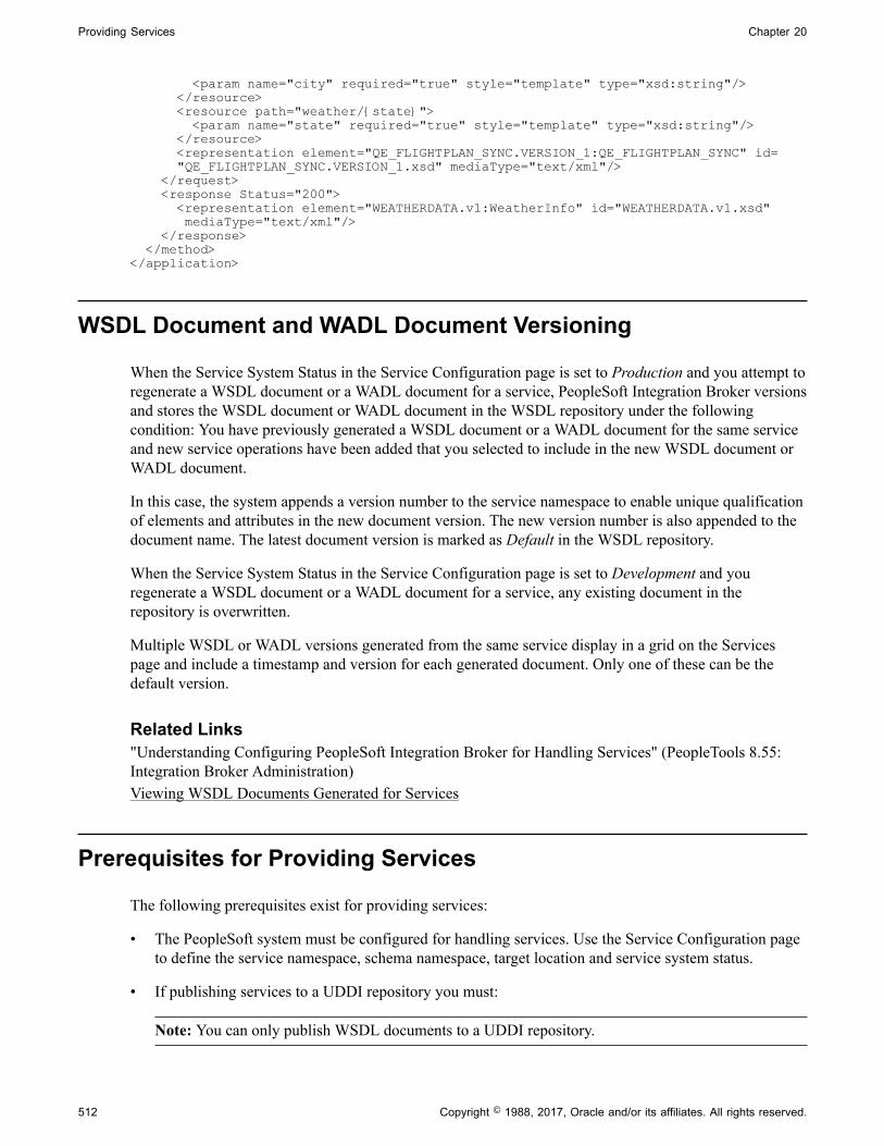
Providing Services Chapter 20
<param name="city" required="true" style="template" type="xsd:string"/> </resource> <resource path="weather/{state}"> <param name="state" required="true" style="template" type="xsd:string"/> </resource> <representation element="QE_FLIGHTPLAN_SYNC.VERSION_1:QE_FLIGHTPLAN_SYNC" id= "QE_FLIGHTPLAN_SYNC.VERSION_1.xsd" mediaType="text/xml"/> </request> <response Status="200"> <representation element="WEATHERDATA.v1:WeatherInfo" id="WEATHERDATA.v1.xsd" mediaType="text/xml"/> </response> </method></application>
WSDL Document and WADL Document Versioning
When the Service System Status in the Service Configuration page is set to Production and you attempt toregenerate a WSDL document or a WADL document for a service, PeopleSoft Integration Broker versionsand stores the WSDL document or WADL document in the WSDL repository under the followingcondition: You have previously generated a WSDL document or a WADL document for the same serviceand new service operations have been added that you selected to include in the new WSDL document orWADL document.
In this case, the system appends a version number to the service namespace to enable unique qualificationof elements and attributes in the new document version. The new version number is also appended to thedocument name. The latest document version is marked as Default in the WSDL repository.
When the Service System Status in the Service Configuration page is set to Development and youregenerate a WSDL document or a WADL document for a service, any existing document in therepository is overwritten.
Multiple WSDL or WADL versions generated from the same service display in a grid on the Servicespage and include a timestamp and version for each generated document. Only one of these can be thedefault version.
Related Links"Understanding Configuring PeopleSoft Integration Broker for Handling Services" (PeopleTools 8.55:Integration Broker Administration)Viewing WSDL Documents Generated for Services
Prerequisites for Providing Services
The following prerequisites exist for providing services:
• The PeopleSoft system must be configured for handling services. Use the Service Configuration pageto define the service namespace, schema namespace, target location and service system status.
• If publishing services to a UDDI repository you must:
Note: You can only publish WSDL documents to a UDDI repository.
512 Copyright © 1988, 2017, Oracle and/or its affiliates. All rights reserved.

Chapter 20 Providing Services
• Have the UDDI server set up, configured and running.
• Have business entities and categories set up on the UDDI server that you intent to query from theProvide Web Service wizard.
• Specify the UDDI server and other relevant information within the PeopleSoft system using theService Configuration-UDDI Configuration page.
• Service operations in services to provide must have any-to-local routing definitions defined.
• There must be a minimum of one service operation associated with the service that you select forwhich to generate a WSDL document or a WADL document.
• For services that contain service operations with nonrowset-based messages, schemas must exist. Themessage schema must contain a target namespace. If no target namespace exists an error will occurwhen the system attempts to generate the WSDL or WADL document.
PeopleSoft automatically generates schema for services that contain operations with rowset-basedmessages.
Related Links"Understanding Configuring PeopleSoft Integration Broker for Handling Services" (PeopleTools 8.55:Integration Broker Administration)"Understanding Specifying UDDI Repositories in PeopleSoft Systems" (PeopleTools 8.55: IntegrationBroker Administration)Understanding Routing DefinitionsUnderstanding Managing Service OperationsUnderstanding the Message Schema Builder
Common Elements Used to Provide Services
Description Description of the service, service operation or WSDL source.
Fault Message Name of the fault message.
Depending on how generated, the name of the fault messagecan include the version in the following format: MessageName.Version.
Operation Type andOperation Type of service operation.
See Services Operation Types.
Request Message Name and version of the request message in the followingformat: MessageName.Version.
Response Message Name and version of the response message in the followingformat: MessageName.Version.
Copyright © 1988, 2017, Oracle and/or its affiliates. All rights reserved. 513

Providing Services Chapter 20
Routing External Alias External Alias from the routing definition for a serviceoperation. Unless overridden, defaults to the formatOperationAlias.Version.
Select Select the box to select the WSDL or WADL.
Service Name of the service that contains the service operations toinclude in the generated WSDL or WADL documents.
Service Operation Name of the service operation for which to generate WSDL orWADL documents.
Providing Services
This section discusses how to use the Provide Web Service wizard to:
• Select services to provide.
• Select service operations.
• View WSDL documents and WADL documents.
• Specify publishing options.
• View the WSDL Generation Log.
Understanding Using the Provide Web Service WizardThe Provide Web Service component (IB_WSDLEXP_SRCH) features a wizard you can use to provideweb services. You can publish WSDL and WADL documents to the WSDL repository in the PeopleSoftsystem or external UDDI repositories.
After you generate a WSDL document or a WADL document, the Provide Web Service wizard displaysa WSDL URL or a WADL URL for each document you generated. This enables you to access WSDLdocument or WADL document content using the URL.
In addition, you can modify a WSDL URL to access the WSDL document content using a WSIL URL.
Note: For a service to be available to provide, an any-to-local routing must exist for the service. Inaddition, there must be a minimum of one service operation associated with the service.You can use the Provide Web Service wizard to select one or more services for which to generate WSDLdocuments or WADL documents. A separate document is generated for each service.
Related LinksPrerequisites for Providing Services
514 Copyright © 1988, 2017, Oracle and/or its affiliates. All rights reserved.

Chapter 20 Providing Services
Step 1: Select Services to ProvideUse the Select Services page (IB_WSDLEXP_SRCH) to search for and select the services that containthe service operations to include the WSDL documents that you generate. To access the page selectPeopleTools, Integration Broker, Web Services, Provide Services.
Image: Select Services to Provide page
This example illustrates the Select Services to Provide page.
You can search by the full or partial service name and service description. You can also search by objectowner ID, if one is defined for the service. You can enter one or more of these criteria when performingyour search.
To search for REST-based services, you must select the REST Service check box. To search for non-REST services, ensure that the REST Service check box is not selected.
To select services to provide:
1. Access the Provide Web Service Wizard – Select Services page (PeopleTools, Integration Broker,Web Services, Provide Services.).
2. Enter search criteria for the services to provide by performing one or more of the following:
• In the Service Name field, enter a full or partial service name.
• In the Description field, enter the full or partial description of the service.
• From the Object Owner ID drop-down list box, select the object owner of the service to provide.
• Select no search criteria to retrieve a list of all services in the database for which any-to-localrouting definitions have been generated.
3. Select the REST Service check box to limit the search for REST-based services. Deselect the RESTService check box to search for non-REST services.
4. Click the Search button.
A Services grid appears that contains the search results.
Copyright © 1988, 2017, Oracle and/or its affiliates. All rights reserved. 515
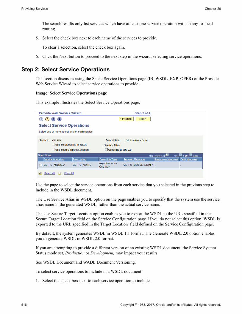
Providing Services Chapter 20
The search results only list services which have at least one service operation with an any-to-localrouting.
5. Select the check box next to each name of the services to provide.
To clear a selection, select the check box again.
6. Click the Next button to proceed to the next step in the wizard, selecting service operations.
Step 2: Select Service OperationsThis section discusses using the Select Service Operations page (IB_WSDL_EXP_OPER) of the ProvideWeb Service Wizard to select service operations to provide.
Image: Select Service Operations page
This example illustrates the Select Service Operations page.
Use the page to select the service operations from each service that you selected in the previous step toinclude in the WSDL document.
The Use Service Alias in WSDL option on the page enables you to specify that the system use the servicealias name in the generated WSDL, rather than the actual service name.
The Use Secure Target Location option enables you to export the WSDL to the URL specified in theSecure Target Location field on the Service Configuration page. If you do not select this option, WSDL isexported to the URL specified in the Target Location field defined on the Service Configuration page.
By default, the system generates WSDL in WSDL 1.1 format. The Generate WSDL 2.0 option enablesyou to generate WSDL in WSDL 2.0 format.
If you are attempting to provide a different version of an existing WSDL document, the Service SystemStatus mode set, Production or Development, may impact your results.
See WSDL Document and WADL Document Versioning.
To select service operations to include in a WSDL document:
1. Select the check box next to each service operation to include.
516 Copyright © 1988, 2017, Oracle and/or its affiliates. All rights reserved.

Chapter 20 Providing Services
To clear a selection, select the check box again.
2. (Optional) Select the Use Service Alias in WSDL check box to include the alias name for the servicein the generated WSDL instead of the actual service name.
3. (Optional) Select the Use Target Location check box to export WSDL to the secure target locationURL defined on the Service Configuration page.
4. (Optional) Select the WSDL 2.0 check box to generate WSDL in WSDL 2.0 format.
5. Click the Next button to proceed to the next step in the wizard.
The next step to providing WSDL documents is previewing the WSDL document that will be provided.
Related Links"Target Locations" (PeopleTools 8.55: Integration Broker Administration)
Step 3: View WSDL Documents or WADL DocumentsAfter you select the service operations to include in a WSDL document or a WADL document, youcan preview the WSDL or WADL in the View WSDL page (IB_WSDLEXP_PVIEW) before actuallypublishing it.
Image: View WSDL page
This example illustrates the View WSDL page.
When you are generating a WADL document the page that appears is the View WADL page(IB_WSDLEXP_PVIEW).
Copyright © 1988, 2017, Oracle and/or its affiliates. All rights reserved. 517

Providing Services Chapter 20
Image: View WADL page
This example illustrates the View WADL page.
Each service for which a WSDL document will be generated is listed. Click theView WSDL link to viewthe WSDL document for each service that you have selected.
When you click the View WSDL link or the View WADL link, the WSDL or WADL displays in theWSDL Viewer page (IB_WSDEXPPVIEW_SEC) or the WADL Viewer page, respectively.
Image: WSDL Viewer page
This example illustrates the WSDL Viewer page. The example shows generated WSDL for the QE_POservice.
518 Copyright © 1988, 2017, Oracle and/or its affiliates. All rights reserved.

Chapter 20 Providing Services
To preview WSDL documents and WADL documents:
1. Click the View WSDL link or View WADL link for a service.
The WSDL document or WADL document for the service appears in the WSDL Viewer or WADLViewer.
2. Click the Return button to return to the View WSDL or View WADL page.
3. Click the Next button to proceed to the next step in the wizard.
The next section discusses the next step to providing a service, selecting the location of where to publishWSDL documents and WADL documents.
Step 4: Specify Publishing OptionsAfter you preview the WSDL document or WADL document, use the Specify Publishing Options page(IB_WSDLEXP_LOC) to specify the publish location of the generated documents.
Image: Specify Publishing Options page
This example illustrates the Specify Publishing Options page. The example shows the options that appearon the page when you are publishing a WSDL document.
By default the system publishes WSDL documents and WADL document to the PeopleSoft WSDLrepository.
Note: WADL documents can only be published to the WSDL Repository.
Select the Publish to UDDI check box to publish the WSDL to a UDDI repository in addition to thePeopleSoft WSDL repository.
Providing WSDL Documents to UDDI RepositoriesBefore providing a WSDL document to a UDDI repository, you must configure the UDDI repository inthe PeopleSoft system.
See "Understanding Specifying UDDI Repositories in PeopleSoft Systems" (PeopleTools 8.55:Integration Broker Administration).
When you select the Publish to UDDI check box, the Select UDDI Servers box appears where you specifythe UDDI repository to which to publish the WSDL.
Copyright © 1988, 2017, Oracle and/or its affiliates. All rights reserved. 519

Providing Services Chapter 20
Image: Specify Publishing Options page
This example illustrates the Specify Publishing Options page. The example shows the page when thePublish to UDDI option is selected for publishing the WSDL to a UDDI repository. When the option isselected, the Select UDDI Servers section appears and you select the UDDI server to which to publish theWSDL document.
To provide a WSDL document to a UDDI repository:
1. From the UDDI Name drop-down list box, select the UDDI server to which you are publishing theWSDL.
2. Click the Get Bus. Entities button.
The Select Business Entity section lists the business entities that are available to select for the UDDIserver.
3. Select the check box next to each business entity name to include.
4. Click the UDDI Category Name lookup button to display a list of UDDI categories and select a UDDIcategory. Click the OK button.
5. In the Category Value field, enter a value for the category.
6. To add additional categories, in the Select UDDI Categories section, click the Add a Row button (+)to add a row and repeat step 5 and step 6.
520 Copyright © 1988, 2017, Oracle and/or its affiliates. All rights reserved.
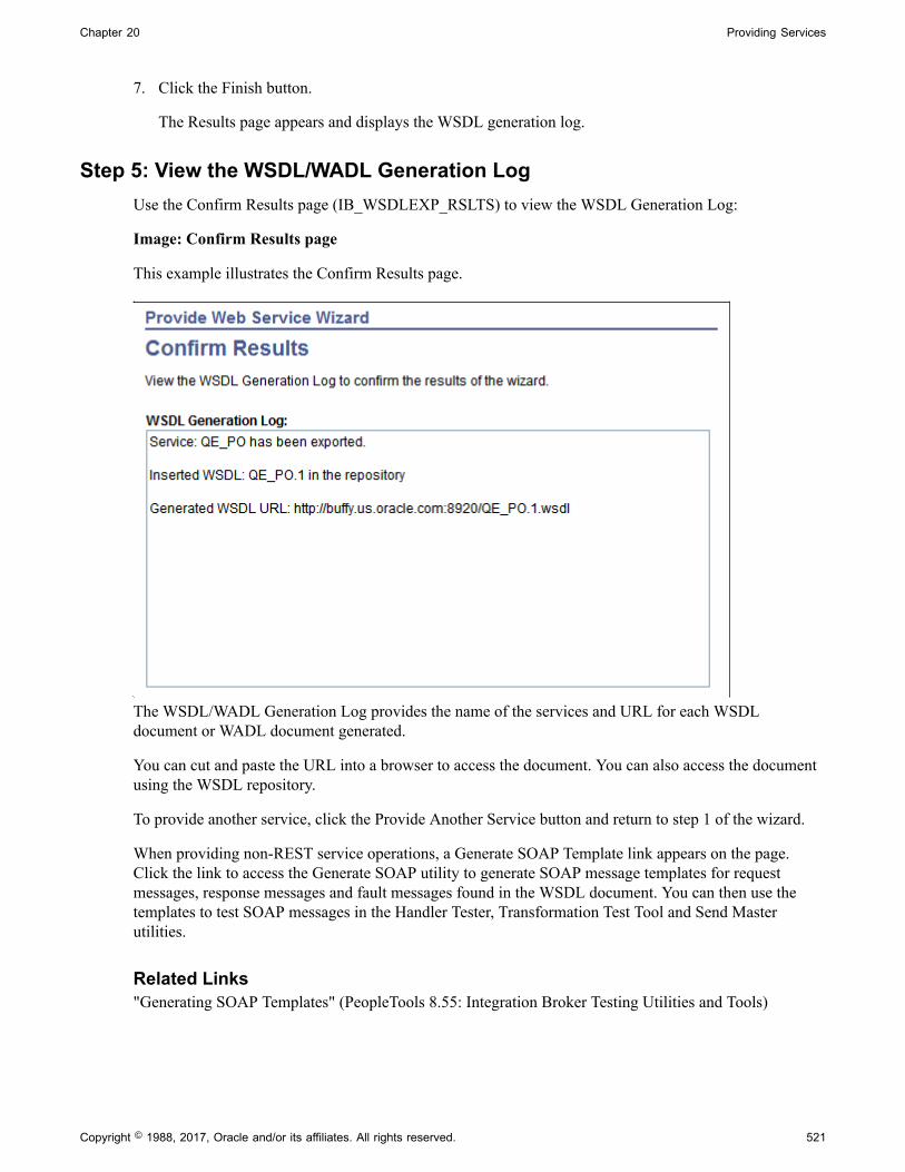
Chapter 20 Providing Services
7. Click the Finish button.
The Results page appears and displays the WSDL generation log.
Step 5: View the WSDL/WADL Generation LogUse the Confirm Results page (IB_WSDLEXP_RSLTS) to view the WSDL Generation Log:
Image: Confirm Results page
This example illustrates the Confirm Results page.
The WSDL/WADL Generation Log provides the name of the services and URL for each WSDLdocument or WADL document generated.
You can cut and paste the URL into a browser to access the document. You can also access the documentusing the WSDL repository.
To provide another service, click the Provide Another Service button and return to step 1 of the wizard.
When providing non-REST service operations, a Generate SOAP Template link appears on the page.Click the link to access the Generate SOAP utility to generate SOAP message templates for requestmessages, response messages and fault messages found in the WSDL document. You can then use thetemplates to test SOAP messages in the Handler Tester, Transformation Test Tool and Send Masterutilities.
Related Links"Generating SOAP Templates" (PeopleTools 8.55: Integration Broker Testing Utilities and Tools)
Copyright © 1988, 2017, Oracle and/or its affiliates. All rights reserved. 521

Providing Services Chapter 20
Accessing Generated WSDL Documents and WADL Documents
This section discusses how to:
• Use WSDL and WADL URLs to access generated WSDL and WADL documents.
• Use the WSDL repository to access generated WSDL and WADL documents.
Using WSDL and WADL URLs To Access Generated WSDL and WADLDocuments
The last page of the Provide Web Service wizard, the Confirm Results page (IB_WSDLEXP_RSLTS),displays a WSDL/WADL generation log. The text box contains WSDL URLs for each WSDL documentyou generated or WADL URLs for each WADL document you generated.
To access a document copy the WSDL URL or WADL URL from the generation log and paste it into abrowser of your choice to access the document.
Using the WSDL Repository to Access Generated WSDL and WADLDocuments
Access the WSDL Repository page (IB_SERVICEDEFN_SEC) (PeopleTools, Integration Broker, Integration Setup, Services. Click the View WSDL link or the View WADL link.
Image: WSDL Repository page
This example illustrates the WSDL Repository page. The example shows that there is WSDL in therepository for the QE_PO service and that the WSDL document contains information for the three serviceoperations listed in the Exported Service Operations section of the page.
The WSDL Repository page lists the WSDL or WADL documents that exist for a service.
The Default option on the page is selected and disabled. This indicates that the WSDL shown is thedefault WSDL document for the service. The WSDL document that is last generated is the default versionfor the service.
Note: Default WSDL documents for a service are used only when the service system status is Production.
To change the default version, you must provide the service again, and choose a different set of serviceoperations to include in the new default version.
522 Copyright © 1988, 2017, Oracle and/or its affiliates. All rights reserved.

Chapter 20 Providing Services
To access the WSDL document, click the View WSDL link. the WSDL Viewer page(IB_SERVICEWSDL_SEC) appears and displays the content of the WSDL document.
Image: WSDL Viewer
This example illustrates the WSDL Viewer page. The example shows the WSDL document generated forthe QE_PO.1 service.
Click the Return button to return to the WSDL Repository page.
Related LinksWSDL Document and WADL Document Versioning
Deleting WSDL and WADL Documents
This section discusses how to delete WSDL and WADL documents.
Understanding Deleting WSDL DocumentsThe service system status affects the ability to delete WSDL and WADL documents.
Copyright © 1988, 2017, Oracle and/or its affiliates. All rights reserved. 523

Providing Services Chapter 20
See "Understanding Configuring PeopleSoft Integration Broker for Handling Services" (PeopleTools8.55: Integration Broker Administration), "Using the Service Configuration Page to Set ServiceConfiguration Properties" (PeopleTools 8.55: Integration Broker Administration).
Deleting a WSDL or WADL DocumentUse the Service Administration – WSDL page (IB_HOME_PAGE7) to delete WSDL documents orWADL documents generated for a service. To access the page select PeopleTools, Integration Broker,Service Utilities, Service Administration and click the WSDL tab.
Image: Service Administration – WSDL page
This example illustrates the Service Administration – WSDL page.
To delete a WSDL or WADL document
1. Access the Services Administration - WSDL page (select PeopleTools, Integration Broker, ServiceUtilities, Service Administrations).
2. Click the arrow next to the Delete section header to expand the section.
3. In the Service field, enter the name of the service that contains the WSDL document or WADLdocument to delete.
4. Click the Search button.
Search results appear in the WSDL/WADL results grid.
5. In the results grid, select the check box next to the WSDL document or WADL document to delete.
6. Click the Delete button.
The Clear WSDL Export Status link that appears on this page is discussed elsewhere in the productdocumentation.
See Resolving Inconsistencies in Exported WSDL and WADL Documents.
524 Copyright © 1988, 2017, Oracle and/or its affiliates. All rights reserved.

Chapter 21
Consuming Services
Understanding Consuming Services
PeopleSoft Integration Broker can consume external services by way of consuming WSDL documentsand generates PeopleSoft integration metadata, so that PeopleSoft applications can invoke outboundsynchronous and outbound asynchronous services.
PeopleSoft Integration Broker features a Consume Web Service wizard that steps you through the task ofconsuming WSDL documents.
Understanding the Consume Web Service Wizard
This section discusses the Consume Web Service wizard.
Consume Web Service Wizard FeaturesThe Consume Web Service wizard supports:
• WS-interoperability standards for WSDL.
• Consumption of WSDL version 1.1 documents.
• Consuming WSDL with SOAP, HTTP–GET/POST bindings.
• Nested URIs to resolve WSDL fragments.
Operation Types SupportedYou can consume WSDL documents for the following service operation types:
• Synchronous.
• Asynchronous one-way.
• Asynchronous request/response.
Sources for Consuming WSDL DocumentYou can use the Consume Web Service wizard to consume WSDL documents from the following sources:
• UDDI repositories.
• WSDL URL.
Copyright © 1988, 2017, Oracle and/or its affiliates. All rights reserved. 525
Consuming Services Chapter 21
• WSIL registries.
• File.
• Legacy PeopleSoft WSDL documents.
Integration Metadata Created by the Consume Web Service WizardThe Consume Web Service wizard creates the following integration metadata in the PeopleSoft systemfrom the consumed WSDL documents:
Note: The internal name is the name that the PeopleSoft system assigns to the metadata and is thedefinition name that appears in the PeopleSoft system.
Metadata Internal Name Version Comments
Service definitions System generated name inthe format:<WSDL servicename>_ <four randomgenerated numbers>.
Version one, denoted as:
.V1
NA
Service operation definitions System generated name inthe format:<WSDL ServiceOperation Name>_ <fourrandom generated numbers>.
Version one, denoted as:
.V1
NA
526 Copyright © 1988, 2017, Oracle and/or its affiliates. All rights reserved.

Chapter 21 Consuming Services
Metadata Internal Name Version Comments
Message definitions System-generated name in theformat: M<unique number>.
For example: M120508438.
Version one, denoted as:
.V1
By default, the system createsdocument type messages.
Includes request messages, response messages. and faultmessages, as appropriate.
You can rename the system-generated message namesin the wizard using moremeaningful names.
The consume process alsogenerates schemas for eachmessage. All schemas areunstructured.
If you chose not to createdocument type messages, it creates nonrowset-basedor container messages withreferences to schemas.
Note: Any integers ordecimals not defined with alength in the WSDL will bedefined in the document asunbounded. The maximumlength that fields are definedin the database for Number orSigned Number is 31, whichincludes the negative (ifapplicable) and the fractionalpart (for decimal). If the valueneeds to be larger than 31, string should be used.
Additional information aboutmessages that the ConsumeWeb Service wizard generatesis featured in this section.
Document definitions The following metadatanames are system generated:
• Package name: <Service_Naame>.
• Document name: <WSDL_ Operation (input/output)_Message_Name>.
Version one, denoted as:
.V1
NA
Copyright © 1988, 2017, Oracle and/or its affiliates. All rights reserved. 527

Consuming Services Chapter 21
Metadata Internal Name Version Comments
Routing definitions System-generatedname in the format~IMPORTED~<uniquenumber>.
For example:~IMPORTED~14857.
Version one, denoted as:
.V1
System creates a point-to-point routing.
Messages GeneratedBy default, the system creates document type messages based on the message schema(s). Documentsgenerated are restricted. To modify the document, you must use the Restricted Documents page to clearthe restricted status.
If the system cannot create document type messages or if you chose not to create document typemessages, it creates nonrowset-based or container messages with references to schemas.
Related Links"Managing Write-Access to Documents" (PeopleTools 8.55: Documents Technology)
Fault MessagesBy default, the Consume Web Service wizard builds document type messages and will create a singlefault message.
To read faults in document type messages generated by the Consume Web Service wizard, use theGetContentString() method of the Message object.
To process multiple faults, you can examine the stored WSDL generated by the wizard.
Another option to capturing and reading multiple faults is to clear the Build Document Messagesoption in Step 1 of the wizard so that the system generates nonrowset–based messages. If generatingnonrowset-based messages, PeopleSoft Integration Broker creates a part message for each fault in theWSDL operation. The system then creates a container message and places the fault part messages in thecontainer. The container message is assigned as a fault message to the created service operation.
Multiple Root Elements in Message SchemasIn a WSDL document, the schema defined in the <types> section may have multiple root elements,corresponding to multiple messages used by one or more operations. When the PeopleSoft systemconsumes such a WSDL document, the entire message schema contained in the WSDL documentgets associated with each of the service operation messages when the PeopleSoft system generates theintegration metadata.
Use the element name that appears in the Comments text box of the message definition to construct theXML data for the correct schema fragment in the message.
528 Copyright © 1988, 2017, Oracle and/or its affiliates. All rights reserved.
Chapter 21 Consuming Services
Delivered Queues and NodesPeopleSoft delivers a queue, WSDL_QUEUE, and a node, WSDL_NODE, that the Consume Web Servicewizard uses as defaults.
You may use these objects or select other existing queues or nodes.
Binding Style of Consumed WSDL DocumentsThe binding style of consumed WSDL documents appears in the service operation definition for theconsumed service. The Default Service Operation Version section of the Service Operations page featuresa Comments box. The binding style appears in that box.
Working with Asynchronous Request/Response Service OperationsIf a WSDL document has two port types with a single input message in each operation, the Consume WebService wizard displays step where you can convert a pair of asynchronous one-way operations to a singleasynchronous request/response operation. In this step you can special the request and callback serviceoperations and convert the operation.
Prerequisites for Consuming Services
To consume services you must set properties in the Service Configuration component as follows:
• Use the Service Configuration page to define the service namespace, schema namespace, targetlocation, and service system status.
See "Understanding Configuring PeopleSoft Integration Broker for Handling Services" (PeopleTools8.55: Integration Broker Administration).
• If consuming services from a UDDI repository, you must first specify the UDDI server andother relevant information within the PeopleSoft system using the Service Configuration-UDDIConfiguration page.
See "Understanding Specifying UDDI Repositories in PeopleSoft Systems" (PeopleTools 8.55:Integration Broker Administration).
To consume WSDL from a file, you must set the PS_FILEDIR environment variable on the machine onwhich the application server resides. If you do not set this variable and attempt to consume WSDL from afile, you will receive an error that the WSDL cannot be parsed.
See Understanding Setting PS_FILEDIR and PS_SERVDIR Environment Variables.
Before consuming services evaluate your security requirements.
Common Elements Used to Consume Services
Description Description of the WSDL source.
Copyright © 1988, 2017, Oracle and/or its affiliates. All rights reserved. 529
Consuming Services Chapter 21
Endpoint According to the Word Wide Web Consortium (W3C), “Anassociation between a binding and a network address, specifiedby a URI, that may be used to communicate with an instance ofa service.”
A URI that accepts messages containing document-oriented orprocedure-oriented information.
Internal Message Name of the consumed request message, response message orfault message in the PeopleSoft system
Internal Operation Name of the consumed service operation in the PeopleSoftsystem
Internal Service Name of the consumed service in the PeopleSoft system
Next Click the button to advance to the next step in the wizard.
Operation Type/Operation Type of service operation.
See Services Operation Types.
Previous Click the button to go back to the previous step in the wizard.
Select Select the check box to select the WSDL service or WSDLoperation on which to perform an action.
View WSDL Click the link to view the WSDL document for a service fromthe WSDL source.
WSDL Port According to the W3C:
• “A port indicates a specific location for accessing a serviceusing a specific protocol and data format.”
• “The network address of an endpoint and the binding towhich it adheres.”
WSDL Fault Message Name of the fault message specified in the WSDL documentthat the PeopleSoft system is consuming.
WSDL Request Message Name of the request message specified in the WSDL documentthat the PeopleSoft system is consuming.
WSDL Response Message Name of the response message specified in the WSDLdocument that the PeopleSoft system is consuming.
WSDL Service The name of the external service in the WSDL document thatthe PeopleSoft system is consuming.
WSDL Source Indicates the source of the service that the PeopleSoft system isconsuming.
WSDL URL Displays the WSDL URL, WSIL URL, File name or UDDIserver name of the WSDL source.
530 Copyright © 1988, 2017, Oracle and/or its affiliates. All rights reserved.

Chapter 21 Consuming Services
Related LinksWord Wide Web Consortium
Using the Consume Web Service Wizard
This section discusses how to use the Consume Web Service wizard to:
• Select the WSDL source.
• Select a service.
• Select a service port.
• Select service operations.
• Convert asynchronous operations.
• Rename operation messages.
• Select a queue for asynchronous operations.
• Select the receiver node.
• Confirm and view results.
Step 1: Select WSDL SourceUse the Select WSDL Source page (IB_WSDL_IMP_LOC) to select the source for consuming a WSDLdocument.
Copyright © 1988, 2017, Oracle and/or its affiliates. All rights reserved. 531
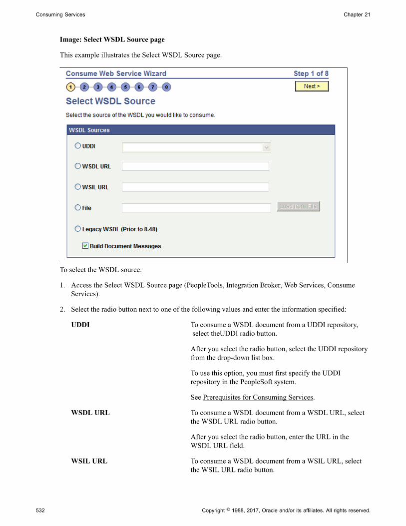
Consuming Services Chapter 21
Image: Select WSDL Source page
This example illustrates the Select WSDL Source page.
To select the WSDL source:
1. Access the Select WSDL Source page (PeopleTools, Integration Broker, Web Services, ConsumeServices).
2. Select the radio button next to one of the following values and enter the information specified:
UDDI To consume a WSDL document from a UDDI repository, select theUDDI radio button.
After you select the radio button, select the UDDI repositoryfrom the drop-down list box.
To use this option, you must first specify the UDDIrepository in the PeopleSoft system.
See Prerequisites for Consuming Services.
WSDL URL To consume a WSDL document from a WSDL URL, selectthe WSDL URL radio button.
After you select the radio button, enter the URL in theWSDL URL field.
WSIL URL To consume a WSDL document from a WSIL URL, selectthe WSIL URL radio button.
532 Copyright © 1988, 2017, Oracle and/or its affiliates. All rights reserved.

Chapter 21 Consuming Services
After you select the radio button, enter a URL in the WSILURL field.
File To consume a WSDL document from a file enter a file namein the File field or browse for the file.
To enter the file name, in the File field, enter the path andfile name. For example: c:\temp\sample.wsdl
To browse for the file:
1. Click the Load from File button.
A file upload page appears.
2. Click the Browse button to search for and select the filelocation and name.
3. Click the Upload button.
The Select WSDL Source page appears with the filelocation and name populated in the File field.
The Select WSDL Source page appears with the filelocation and name populated in the File field.
Legacy WSDL (Prior to 8.48) Select this option to consume a PeopleSoft WSDLdocument generated from releases prior to PeopleTools 8.48.
3. At the Build Document Messages check box:
• Select the check box to build document type messages for the consumed service. (Default.)
• Deselect the check box to build nonrowset-based messages for the consumed service.
4. Click the Next button to proceed to the next step in the wizard.
Step 2: Select ServiceUse the Select Service page (IB_WSDL_IMP_SVC) to select the services to consume.
Copyright © 1988, 2017, Oracle and/or its affiliates. All rights reserved. 533

Consuming Services Chapter 21
Image: Select Service page
This example illustrates the Select Service page.
Before selecting services to consume, you can click the View WSDL link to view the WSDL for eachservice. The WSDL document opens in a browser. Close the browser when you have finished viewing theWSDL document.
WSDL documents that the PeopleSoft system consumes from pre-PeopleTools 8.48 systems display in anedit box.
To select services to consume:
1. Select the check box next to each service to consume.
To clear a selection, select the box again.
2. Click the Next button to proceed to the next step in the wizard.
Step 3: Select Service PortsIf a service you select has more than one port, the Select Service Ports page (IB_WSDL_IMP_SVC2)appears.
Image: Select Service Ports page
This example illustrates the Select Service Ports page.
Multiple port options only appear when you are working with asynchronous request/response operationsin a WSDL document or the service has multiple bindings. Typically, when working with this operationtype, you select both options.
534 Copyright © 1988, 2017, Oracle and/or its affiliates. All rights reserved.
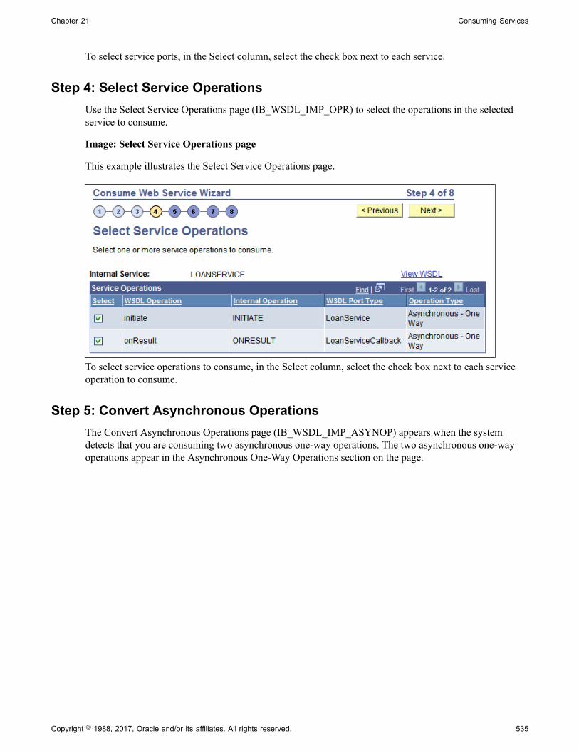
Chapter 21 Consuming Services
To select service ports, in the Select column, select the check box next to each service.
Step 4: Select Service OperationsUse the Select Service Operations page (IB_WSDL_IMP_OPR) to select the operations in the selectedservice to consume.
Image: Select Service Operations page
This example illustrates the Select Service Operations page.
To select service operations to consume, in the Select column, select the check box next to each serviceoperation to consume.
Step 5: Convert Asynchronous OperationsThe Convert Asynchronous Operations page (IB_WSDL_IMP_ASYNOP) appears when the systemdetects that you are consuming two asynchronous one-way operations. The two asynchronous one-wayoperations appear in the Asynchronous One-Way Operations section on the page.
Copyright © 1988, 2017, Oracle and/or its affiliates. All rights reserved. 535

Consuming Services Chapter 21
Image: Convert Asynchronous Operations
This example illustrates the Convert Asynchronous Operations page.
This page enables you to convert the two operations into a single asynchronous request/responseoperation type.
WSDL specification 1.1 has no standards for specifying an asynchronous request/response operation.Hence, the Consume Web Service wizard is not able to automatically detect such operations in a WSDL1.1 document.
To make this conversion, you must specify the request operation and the callback operation, using theRequest Operation and Callback Operation fields on the page. The system populates the possible values toselect in each field from the operation selected.
After you make the conversion the new asynchronous request/response operation appears in theAsynchronous Request/Response Operations section of the page.
536 Copyright © 1988, 2017, Oracle and/or its affiliates. All rights reserved.

Chapter 21 Consuming Services
Image: Convert Asynchronous Operations page after the operation conversion
This example illustrates the Convert Asynchronous Operations page. The example shows the page afterconverting an asynchronous one-way service operation into an asynchronous request/response serviceoperation.
To convert two one-way asynchronous operations into one asynchronous request/response operation:
1. From the Request Operation drop-down list box, select the request operation.
2. From the Callback Operation drop-down list box, select the callback operation.
3. Click the Convert button.
The single operation appears in the Asynchronous Request/Response Operations grid at the bottom of thepage.
To undo a conversion, in the Asynchronous Request/Response grid click the Delete a Row button (-) atthe end of a data row.
Step 6: Rename Operation MessagesThe Consume Web Service Wizard auto-generates message names. Use the Rename Operation Messagespage (IB_WSDL_IMP_MSGS) to rename auto-generated message names.:
Copyright © 1988, 2017, Oracle and/or its affiliates. All rights reserved. 537

Consuming Services Chapter 21
Image: Rename Operation Messages page
The example illustrates the Rename Operation Messages page.
When the system creates request, response and fault messages from the consumed service, it providesthem with system-generated names. The previous example shows system-generated names appearing forall messages.
Use the page to rename the messages to more meaningful names.
538 Copyright © 1988, 2017, Oracle and/or its affiliates. All rights reserved.

Chapter 21 Consuming Services
Image: Rename Operation Messages page
This example illustrates the Rename Operation Messages page. The example shows all messagesrenamed.
To rename operation messages:
1. Clear the system-generated name from a message name field.
2. Enter a new name in the field.
3. Click the Next button to proceed to the next step in the wizard.
The system checks whether the user-entered message name already exists in the database and displays anerror if the name exists.
Step 7: Select a Queue for Asynchronous OperationsThe Select a Queue for Asynchronous Operations page (IB_WSDL_IMP_QUEUE) appears only whenyou are consuming asynchronous one-way and asynchronous request/response operations.
Copyright © 1988, 2017, Oracle and/or its affiliates. All rights reserved. 539

Consuming Services Chapter 21
Image: Select a Queue for Asynchronous Operations page
This example illustrates the Select a Queue for Asynchronous Operations page.
Note: This page appears only when asynchronous operations are being consumed from the WSDLdocument.
Use the Select a Queue for Asynchronous Operations page to select a service operation queue for anasynchronous service operation.
PeopleSoft delivers a queue, WSDL_QUEUE, to which it assigns asynchronous service operations bydefault. However, you can select a different queue to use.
To select a queue for asynchronous operations:
1. Click the Use Existing Queue radio button.
2. From the Use Existing Queue drop-down list box, select the queue to use for the service operation.
3. Click the Next button to proceed to the next step in the wizard.
Step 8: Select the Receiver NodeUse the Select the Receiver Node page (IB_WSDL_IMP_NODE) to select the receiving node for theservice.
540 Copyright © 1988, 2017, Oracle and/or its affiliates. All rights reserved.
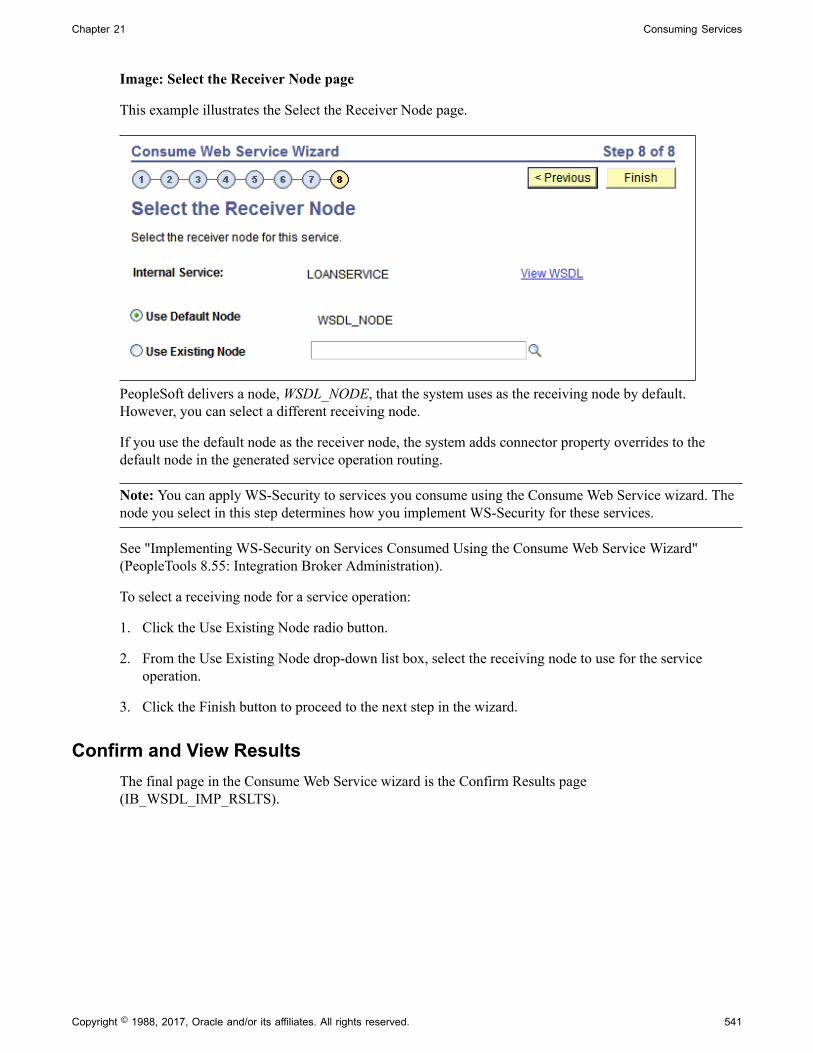
Chapter 21 Consuming Services
Image: Select the Receiver Node page
This example illustrates the Select the Receiver Node page.
PeopleSoft delivers a node, WSDL_NODE, that the system uses as the receiving node by default.However, you can select a different receiving node.
If you use the default node as the receiver node, the system adds connector property overrides to thedefault node in the generated service operation routing.
Note: You can apply WS-Security to services you consume using the Consume Web Service wizard. Thenode you select in this step determines how you implement WS-Security for these services.
See "Implementing WS-Security on Services Consumed Using the Consume Web Service Wizard"(PeopleTools 8.55: Integration Broker Administration).
To select a receiving node for a service operation:
1. Click the Use Existing Node radio button.
2. From the Use Existing Node drop-down list box, select the receiving node to use for the serviceoperation.
3. Click the Finish button to proceed to the next step in the wizard.
Confirm and View ResultsThe final page in the Consume Web Service wizard is the Confirm Results page(IB_WSDL_IMP_RSLTS).
Copyright © 1988, 2017, Oracle and/or its affiliates. All rights reserved. 541
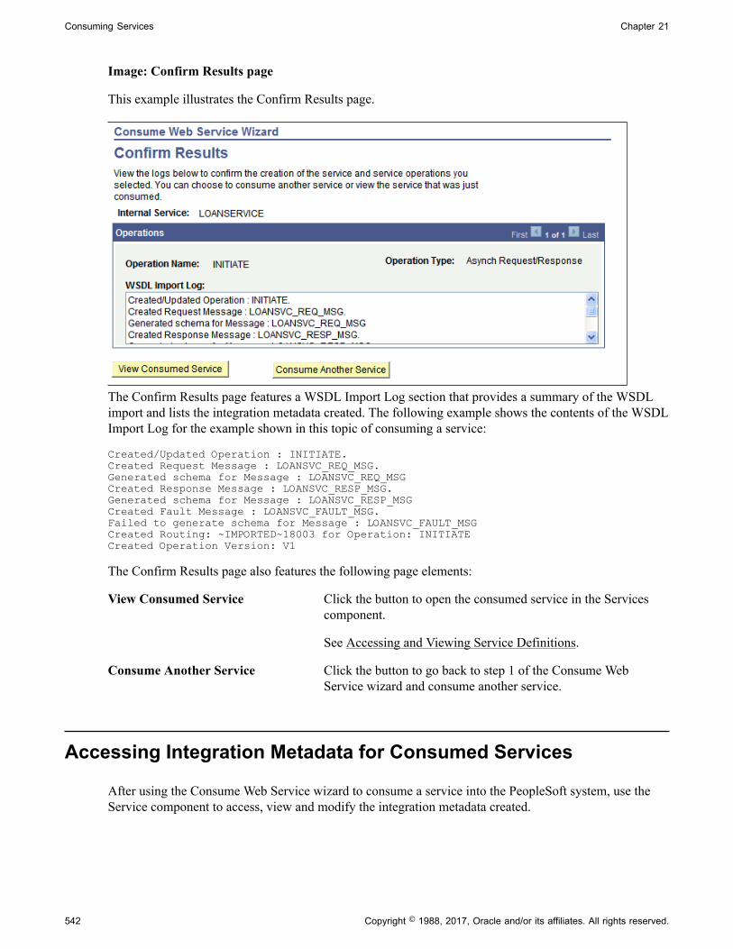
Consuming Services Chapter 21
Image: Confirm Results page
This example illustrates the Confirm Results page.
The Confirm Results page features a WSDL Import Log section that provides a summary of the WSDLimport and lists the integration metadata created. The following example shows the contents of the WSDLImport Log for the example shown in this topic of consuming a service:
Created/Updated Operation : INITIATE.Created Request Message : LOANSVC_REQ_MSG.Generated schema for Message : LOANSVC_REQ_MSGCreated Response Message : LOANSVC_RESP_MSG.Generated schema for Message : LOANSVC_RESP_MSGCreated Fault Message : LOANSVC_FAULT_MSG.Failed to generate schema for Message : LOANSVC_FAULT_MSGCreated Routing: ~IMPORTED~18003 for Operation: INITIATECreated Operation Version: V1
The Confirm Results page also features the following page elements:
View Consumed Service Click the button to open the consumed service in the Servicescomponent.
See Accessing and Viewing Service Definitions.
Consume Another Service Click the button to go back to step 1 of the Consume WebService wizard and consume another service.
Accessing Integration Metadata for Consumed Services
After using the Consume Web Service wizard to consume a service into the PeopleSoft system, use theService component to access, view and modify the integration metadata created.
542 Copyright © 1988, 2017, Oracle and/or its affiliates. All rights reserved.
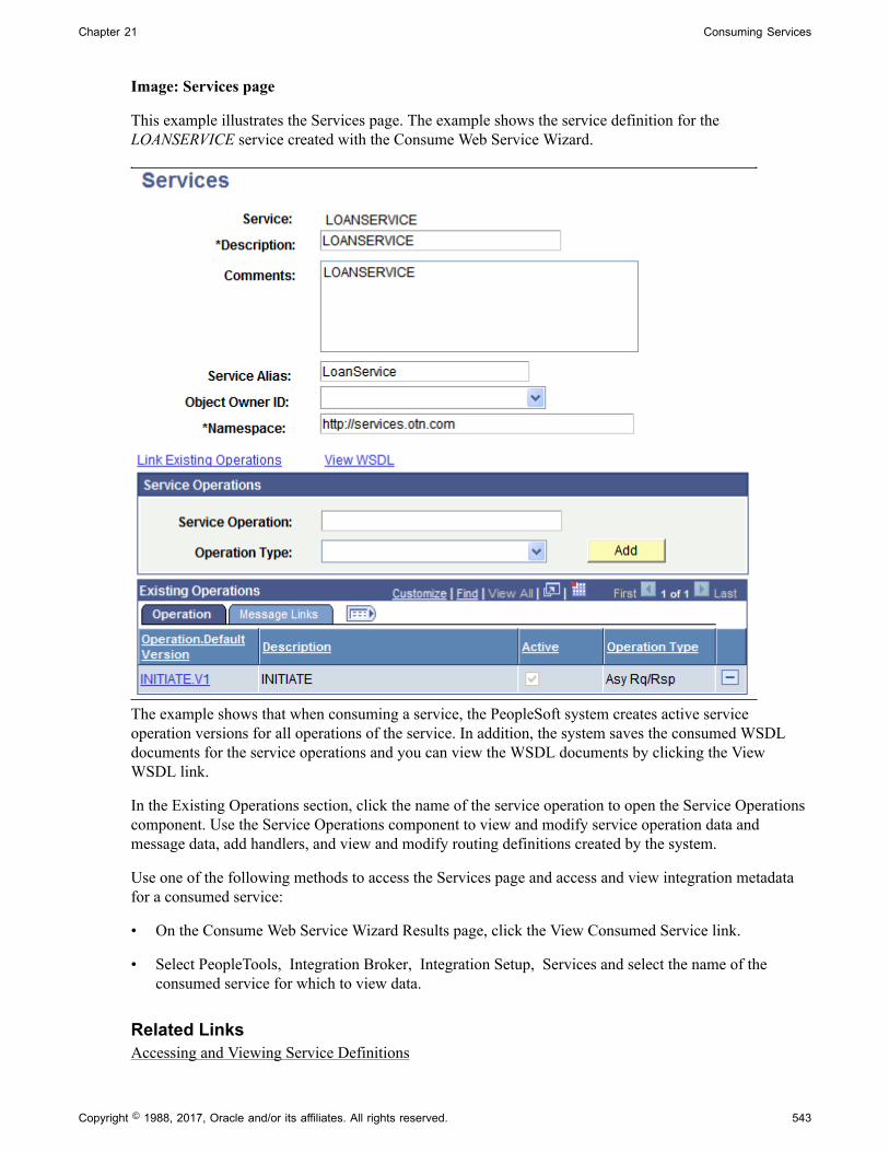
Chapter 21 Consuming Services
Image: Services page
This example illustrates the Services page. The example shows the service definition for theLOANSERVICE service created with the Consume Web Service Wizard.
The example shows that when consuming a service, the PeopleSoft system creates active serviceoperation versions for all operations of the service. In addition, the system saves the consumed WSDLdocuments for the service operations and you can view the WSDL documents by clicking the ViewWSDL link.
In the Existing Operations section, click the name of the service operation to open the Service Operationscomponent. Use the Service Operations component to view and modify service operation data andmessage data, add handlers, and view and modify routing definitions created by the system.
Use one of the following methods to access the Services page and access and view integration metadatafor a consumed service:
• On the Consume Web Service Wizard Results page, click the View Consumed Service link.
• Select PeopleTools, Integration Broker, Integration Setup, Services and select the name of theconsumed service for which to view data.
Related LinksAccessing and Viewing Service Definitions
Copyright © 1988, 2017, Oracle and/or its affiliates. All rights reserved. 543

Consuming Services Chapter 21
544 Copyright © 1988, 2017, Oracle and/or its affiliates. All rights reserved.

Chapter 22
Integrating with BPEL Process-BasedServices
Understanding Integrating with BPEL Processes
This topic provides an overview of integrating with Business Process Execution Language (BPEL)processes, lists prerequisites for integrating with BPEL processes, and discusses consuming and providingBPEL processes. This topic also features code examples to help illustrate consuming and providing BPELprocesses.
Note: The code examples in this topic are for illustrative purposes only and are not intended to be used ina production environment.
Oracle BPEL Process ManagerYou can use any BPEL runtime engine for integrations with BPEL processes. The developer version ofOracle BPEL Process Manager is the BPEL engine that is referenced in this topic.
See the following resources for related information:
• http://www.oracle.com/technology/index.html
• Oracle JDeveloper Installation Guide.
• PeopleTools Installation for your database platform.
• Oracle BPEL Process Manager Quick Start Guide.
• Oracle BPEL Process Manager Developer's Guide.
PeopleSoft-Delivered Application Classes for BPEL IntegrationsPeopleSoft provides several application classes for launching and controlling BPEL process instances.The following application classes are located in the PT_BPEL application package and are accessible inPeopleSoft Application Designer:
These classes are for use only when you use Oracle BPEL Process Manager as the BPEL runtime engine.
• AsyncFFSend
This class provides the onSend handler implementation when calling a BPEL web service in anasynchronous fire and forget fashion.
• BPELUtil
This class provides utility methods for interacting with BPEL processes from PeopleSoft systems.
Copyright © 1988, 2017, Oracle and/or its affiliates. All rights reserved. 545

Integrating with BPEL Process-Based Services Chapter 22
• IBUtil
This class provides utility methods to access PeopleSoft Integration Broker metadata.
Related Links"Understanding the BPEL Classes" (PeopleTools 8.55: PeopleCode API Reference)
Monitoring BPEL Process-Based IntegrationsPeopleTools provides the following tools and logs for monitoring, tracing, and debugging integrations onPeopleSoft systems:
• Service Operations Monitor.
• Integration gateway logs.
• PeopleSoft application server logs.
In addition, your BPEL runtime engine may provide additional tools for monitoring integrations. Forexample, Oracle BPEL Process Manager provides the Oracle BPEL Process Manager Console formanaging, administering, and debugging processes that are deployed on the BPEL server. In addition, theBPEL server logs may also provide additional details. Check your BPEL runtime engine documentationfor additional information about monitoring tools that are provided.
Related LinksUnderstanding Error Handling, Logging, Tracing and DebuggingIntegration Broker Service Operations Monitor
Securing BPEL Process-Based IntegrationsPeopleSoft Integration Broker provides a number of options that you can use to secure integrations. Theseinclude securing integrations at one or more of the following levels:
• Web server.
• Gateway level.
• Application server level.
• Node level.
• User level.
• Service operation level.
• And so on.
It is important to fully investigate these security options and implement those that best suit your businessneeds.
It is also important that you investigate the security options available for the BPEL runtime engine thatyou are using and to implement those security options that fulfill your security requirements. Refer to thesecurity documentation for your BPEL runtime engine.
546 Copyright © 1988, 2017, Oracle and/or its affiliates. All rights reserved.

Chapter 22 Integrating with BPEL Process-Based Services
Related Links"Understanding Securing Integration Environments" (PeopleTools 8.55: Integration BrokerAdministration)
Prerequisites for Integrating with BPEL Processes
For creating integrations with BPEL processes, you must have PeopleSoft Integration Broker configuredand running.
Note: This section discusses prerequisite configuration steps on the PeopleSoft system for creatingintegrations with BPEL processes. Check your BPEL runtime engine software documentation for setupand configuration steps that you must perform on the runtime engine prior to performing integrations.
The following list is a partial checklist of items to configure:
• When configuring the integrationGateway.properties file, be sure to set the ig.isc.serverURL propertyequal to the name of the machine running the integration engine.
• When configuring the PeopleTools application server, set the PUB/SUB option to Yes. This value isrequired for asynchronous integrations.
• Activate the application server domain by setting the Domain Status to Active.
• Set the service namespace, the schema namespace, and the target location.
• To load files into PeopleTools from the file system, set PS_FILEDIR and PS_SERVDIR in the systemvariables on your machine.
• PeopleSoft delivers a node, BPEL, specifically for BPEL integrations when you are using OracleBPEL Process Manager as the runtime engine. If you are using Oracle BPEL Process Manager, youmust configure this node. Steps to configure the BPEL node are provided elsewhere in this topic.
Related LinksPeopleSoft Integration Broker MetadataOrder of Precedence for Creating Integration MetadataUnderstanding Setting PS_FILEDIR and PS_SERVDIR Environment Variables
Configuring the PeopleSoft-Delivered BPEL Node
PeopleTools delivers a node called BPEL for use for BPEL integrations when you are using Oracle BPELProcess Manager as the runtime engine.
Note: You must configure the BPEL node only if you are using Oracle BPEL Process Manager as theBPEL runtime engine.
To configure BPEL node properties:
1. Select PeopleTools, Integration Broker, Integration Setup, Nodes.
Copyright © 1988, 2017, Oracle and/or its affiliates. All rights reserved. 547

Integrating with BPEL Process-Based Services Chapter 22
2. Search for and open the node BPEL.
The Node Definitions page appears.
3. Modify any other fields on the Node Definitions page as required.
See "Configuring Nodes" (PeopleTools 8.55: Integration Broker Administration).
4. Click the Properties link at the bottom of the page.
The Node Properties page appears.
Note: To view the complete BPEL property name in any of the Property Name fields, insert yourcursor in a field and use your keyboard arrow keys to scroll through and view the complete fieldname.
5. Set the value of the BPELCONSOLEURL property to the URL of the BPEL console.
6. Set the BPELDOMAIN property to the name of the domain that you are using for the BPEL server.
7. Click the OK button.
Note: Do not set any values for the BPELDOMAINPWD property. This property is reserved for futureuse.
Related Links"Understanding Nodes" (PeopleTools 8.55: Integration Broker Administration)
Consuming BPEL Process–Based Services
This section provides an overview of consuming BPEL process-based services and discusses how to:
• Deploy BPEL processes.
• Import WSDL documents from BPEL processes.
• Consume synchronous BPEL operations.
• Consume asynchronous request/response BPEL operations.
• Consume asynchronous one-way BPEL operations.
In addition, the end of this section provides development considerations for consuming BPEL webservices.
Understanding Consuming BPEL Process-Based ServicesThis section provides overview information about consuming BPEL process-based services.
Development ConsiderationsWhen consuming BPEL process-based services, consider that:
548 Copyright © 1988, 2017, Oracle and/or its affiliates. All rights reserved.
Chapter 22 Integrating with BPEL Process-Based Services
• XML content representing the payload must be constructed carefully and exactly.
• The XML namespace in the top-level element of the XML fragment representing the payload isobtained from the WSDL of the BPEL service operation.
• The LaunchSyncBPELProcess and LaunchASyncBPELProcess methods do not specify the actualendpoints to which a message is sent. This endpoint is inferred by PeopleSoft Integration Brokerat runtime based on the active routing that is associated with the service operation. An exception israised if no routing exists or if more than one active routing exists.
• When using the LaunchSyncBPELProcess and LaunchASyncBPELProcess methods, you mustconfigure the routings for the message so that exactly one active routing exists for a message. Failureto supply exactly one routing results in a runtime exception.
• PeopleSoft Integration Broker automatically maps an external service operation to an internalPeopleSoft operation. If you attempt to import an external operation that contains the same name asan internal operation that already exists, PeopleSoft Integration Broker provides the new operationwith a unique name and new metadata that maps the internal name to the external name. Make sureto use the unique internal name when calling any of the application class methods in the PT_BPELapplication package.
• For the asynchronous request/response operations, you must select the correct callback (response)operation for a given service request. This is achieved during the Convert step in the Consume WebService wizard.
Deploying BPEL Processes and Importing WSDL DocumentsThe first two steps for consuming any type of BPEL service are to deploy the BPEL process and importthe generated WSDL document into the PeopleSoft system.
The following two sections discuss performing these tasks and must be completed before consumingBPEL operations.
Deploying BPEL ProcessesThe first step in consuming a BPEL process-based service is to deploy the BPEL process in the BPELruntime engine, thereby generating a WSDL document. See the documentation for your BPEL runtimeengine for information about performing this task.
The PeopleSoft system can consume WSDL documents from a UDDI repository, WSDL URL, WSILURL, or file.
When deploying a BPEL process, note the URL of the WSDL document. You must provide the documentlocation when consuming the WSDL into the PeopleSoft system.
Consuming WSDL Documents from BPEL ProcessesTo consume WSDL from a BPEL process into the PeopleSoft system use the Consume Web Servicecomponent in the PeopleSoft Pure Internet Architecture.
During the consume WSDL process you are prompted to choose a receiving node. If Oracle BPELProcess Manager is your BPEL runtime engine, it is preferred to select the PeopleTools-delivered BPELnode as the receiving node. The BPEL node is delivered with BPEL-server related information, such as
Copyright © 1988, 2017, Oracle and/or its affiliates. All rights reserved. 549

Integrating with BPEL Process-Based Services Chapter 22
the BPEL console URL and BPEL domain, already added. However, during consumption you can use thedefault WSDL_NODE or any other external node.
Make a note of the web service operation for the process that you are importing as you will call thisoperation in PeopleCode.
Related LinksUnderstanding Consuming Services
Consuming Synchronous BPEL OperationsThis section provides an overview of consuming synchronous BPEL operations and discusses how to:
• Create synchronous BPEL requests.
• Invoke synchronous BPEL operations.
• Process synchronous BPEL responses.
Understanding Consuming Synchronous BPEL OperationsBefore consuming synchronous BPEL operations, you must deploy a BPEL process and import thegenerated WSDL document into the PeopleSoft system.
See Deploying BPEL Processes, Consuming WSDL Documents from BPEL Processes.
Creating Synchronous BPEL RequestsIn this step, you use the PeopleSoft-delivered BPEL application classes to create a request message andinitialize it with the message content, or payload. The payload is the content that will be sent as part of thesoap body to invoke the BPEL process.
The first step is to create a BPELUtil object.
&bpel = create PT_BPEL:BPELUtil();
Next, create the request message and specify the operation to invoke. In the following code example,PROCESS is the operation to be invoked.
&payload = "<?xml version='1.0'?> <SyncCalcProcessRequest xmlns='http://xmlns.oracle.com/SyncCalc'> <messageid>TestId::0123456789</messageid><op>+</op><input1>9</input1> <input2>3</input2></SyncCalcProcessRequest>";
&xml = CreateXmlDoc(&payload);&msg = CreateMessage(Operation.PROCESS, %IntBroker_Request);&msg.SetXmlDoc(&xml);
Invoking Synchronous BPEL OperationsTo invoke a synchronous BPEL operation, use the LaunchSyncBPELProcess method of the BPELUtilapplication class.
The following code example shows how to invoke a synchronous operation.
&reply = &bpel.LaunchSyncBPELProcess(&OP_NAME="PROCESS", &msg, "", "");
550 Copyright © 1988, 2017, Oracle and/or its affiliates. All rights reserved.

Chapter 22 Integrating with BPEL Process-Based Services
Processing Synchronous BPEL ResponsesThe following PeopleCode example shows sample shows code for processing a synchronous BPELresponse.
If All(&reply) Then &responseStr = &reply.GenXMLString(); End-If;
Example: Consuming Synchronous BPEL OperationsThe following code example demonstrates how to use all of the PeopleCode discussed earlier in thissection.
import PT_BPEL:*;
Local PT_BPEL:BPELUtil &bpel;Local string &url, &transactionId, &payload, &responseStr, &OP_NAME;Local Message &msg, &reply;Local XmlDoc &xml;
/* --- creating a BPELUtil object---*/&bpel = create PT_BPEL:BPELUtil();
/* --- setting operation name --- */&OP_NAME="PROCESS";&transactionId = "TestId::0123456789";
&payload = "<?xml version='1.0'?><SyncCalcProcessRequest xmlns='http://xmlns.oracle.com/SyncCalc'><messageid>TestId::0123456789</messageid><op>+</op><input1>9</input1><input2>3</input2></SyncCalcProcessRequest>";
&xml = CreateXmlDoc(&payload);&msg = CreateMessage(Operation.PROCESS, %IntBroker_Request);&msg.SetXmlDoc(&xml);
&reply = &bpel.LaunchSyncBPELProcess(&OP_NAME, &msg, "", "");If All(&reply) Then &responseStr = &reply.GenXMLString(); End-If;&url = &bpel.GetSyncBPELProcessInstanceUrl("BPEL", &transactionId);
Related Links"Understanding the BPEL Classes" (PeopleTools 8.55: PeopleCode API Reference)
Consuming Asynchronous Request/Response BPEL OperationsThis section provides an overview of consuming asynchronous request/response BPEL operations anddiscusses how to:
• Create an asynchronous request/response BPEL request.
• Invoke an asynchronous request/response BPEL operation.
• Create a handler to process the asynchronous request/response BPEL response.
• Add a handler to a service operation to process the asynchronous request/response BPEL response.
This section also features a comprehensive example of the PeopleCode discussed in this section.
Copyright © 1988, 2017, Oracle and/or its affiliates. All rights reserved. 551

Integrating with BPEL Process-Based Services Chapter 22
Understanding Consuming Asynchronous Request/Response BPEL OperationsBefore consuming asynchronous request/response BPEL operations, you must deploy a BPEL processand import the generated WSDL document into the PeopleSoft system.
When you consume an Asynchronous Request/Response WSDL, you must identify the request andcallback operations correctly in the Consume Web Service wizard.
See Deploying BPEL Processes, Consuming WSDL Documents from BPEL Processes.
Understanding Updating Asynchronous Request/Response WSDL for BPELCallback OperationsIf you are using Oracle BPEL Process Manager to generate WSDL for a PeopleSoft system to consume,you must modify the generated WSDL before attempting to consume it in the PeopleSoft system.
Note: This section applies only if you are using Oracle BPEL Process Manager 11g to generate WSDLfor consuming in the PeopleSoft system.If you are using earlier versions of Oracle BPEL Process Manager or another BPEL runtime engine, youmay disregard the information presented in this section.
The WSDL created by Oracle BPEL Process Manager for asynchronous request/response integrationsdoes not contain a service definition for the callback operation. The PeopleSoft system does not recognizethe callback until the service definition is defined. You must add the following code to the WSDLdocument prior to consuming it in the PeopleSoft system.
<wsdl:service name="asyncrrcalcbpelcallback_client_ep"> <wsdl:port name="AsyncRRCalcBPELCallback_pt" binding="client: AsyncRRCalcBPELCallbackBinding"> <soap:address xmlns:soap="http://schemas.xmlsoap.org/wsdl/soap/" location="http://Client.EndPoint.Set.By.Caller"/> </wsdl:port></wsdl:service>
Creating Asynchronous Request/Response BPEL RequestsIn this step, you use the PeopleSoft-delivered BPEL application classes to create a request message andinitialize it with the message content, or payload. The payload is the SOAP request (envelope) that will besent to the BPEL process as a service.
&bpel = create PT_BPEL:BPELUtil();
Next, create the request message and specify the operation to invoke. In the following code example,CALCULATE is the operation to be invoked:
&payload = "<?xml version='1.0'?><ASyncCalcProcessRequest xmlns='http://xmlns.oracle.com/ASyncCalc'><op>+</op><input1>9</input1><input2>3</input2></ASyncCalcProcessRequest>";
&xml = CreateXmlDoc(&payload);&msg = CreateMessage(Operation.CALCULATE, %IntBroker_Request);&msg.SetXmlDoc(&xml);
Invoking Asynchronous Request/Response BPEL OperationsTo invoke an asynchronous BPEL operation, use the LaunchASyncBPELProcess method of the BPELUtilapplication class.
552 Copyright © 1988, 2017, Oracle and/or its affiliates. All rights reserved.

Chapter 22 Integrating with BPEL Process-Based Services
The following example shows code for invoking an asynchronous operation.
&responseStr = &bpel.LaunchASyncBPELProcess(&OP_NAME="CALCULATE", &msg, "", "");
Creating Handlers to Process Asynchronous Request/Response BPELResponsesWhen you imported the asynchronous request/response BPEL WSDL document into the PeopleSoftsystem, the system automatically created a request message and response message for each serviceoperation that is contained in the WSDL document.
To process the response, you must create a handler and add it to the service operation definition.
To create a handler for the response to an asynchronous request/response operation, use PeopleSoftApplication Designer to extend the PS_PT:Integration:INotificationHandler application class and use theOnResponse method to code the response. When PeopleSoft Integration Broker receives the response forthe service operation, Integration Broker will use the handler code to process the response.
The following example shows a sample application class that is designed to handle the response:
import PS_PT:Integration:INotificationHandler;
class ASyncTestHandler implements PS_PT:Integration:INotificationHandler method ASyncTestHandler(); method OnNotify(&MSG As Message);end-class;
/* constructor */method ASyncTestHandlerend-method;
method OnNotify /+ &MSG as Message +/ /+ Extends/implements PS_PT:Integration:INotificationHandler.OnNotify +/ Local File &MYFILE; &MYFILE = GetFile("C:\temp\item.txt", "W", %FilePath_Absolute); If &MYFILE.IsOpen Then &MYFILE.WriteLine("--- Response Received ---"); &MYFILE.WriteLine(&MSG.GenXMLString()); &MYFILE.Close(); End-If; end-method;
Adding Handlers to Operations to Process Asynchronous Request/ResponseBPEL ResponsesAfter you create the response handler, you must add it to the service operation definition. To performthis task, use the Service Operations–Handlers page. To access this page, select PeopleTools, IntegrationBroker, Integration Setup, Service Operations and click the Handlers tab.
Example: Consuming Asynchronous Request/Response BPEL OperationsThe following code example provides a full example of all the PeopleCode discussed earlier for creatingthe asynchronous request and invoking the service operation.
import PT_BPEL:*;
Local PT_BPEL:IBUtil &ibutil;
Copyright © 1988, 2017, Oracle and/or its affiliates. All rights reserved. 553

Integrating with BPEL Process-Based Services Chapter 22
Local PT_BPEL:BPELUtil &bpel;Local string &url, &domain, &pwd, &opType, &asyncUrl, &transactionId, &payload, &responseStr, &OP_NAME;Local number &routings;Local Message &msg, &reply;Local XmlDoc &xml;
/* --- creating a BPELUtil object --- */&bpel = create PT_BPEL:BPELUtil();
/* --- setting operation name --- */&OP_NAME = "CALCULATE";
&payload = "<?xml version='1.0'?><ASyncCalcProcessRequest xmlns='http://xmlns.oracle.com/ASyncCalc'><op>+</op><input1>9</input1><input2>3</input2></ASyncCalcProcessRequest>";
&xml = CreateXmlDoc(&payload);&msg = CreateMessage(Operation.CALCULATE, %IntBroker_Request);&msg.SetXmlDoc(&xml);
&responseStr = &bpel.LaunchASyncBPELProcess(&OP_NAME, &msg, "", "");/*The Instance URL would be available only after the instance is created on the BPE⇒L engine. Programmatically wait for URL if needed*/&url = &bpel.GetASyncBPELProcessInstanceUrl(&responseStr);
Related LinksUnderstanding Service Operation Handlers"Understanding the BPEL Classes" (PeopleTools 8.55: PeopleCode API Reference)
Consuming Asynchronous Fire-and-Forget (One-Way) BPEL OperationsThis section provides an overview of consuming asynchronous fire-and-forget BPEL operations anddiscusses how to:
• Create an asynchronous fire-and-forget BPEL requests.
• Invoke an asynchronous fire-and-forget BPEL operation.
• Add handlers to assign correlation IDs to requests.
Note: BPEL asynchronous fire-and-forget operations correspond to asynchronous one-way operations inPeopleSoft systems.
This section also features a comprehensive example of the PeopleCode discussed in this section.
Understanding Consuming Asynchronous Fire-and-Forget BPEL OperationsBefore consuming asynchronous fire-and-forget BPEL operations, you must deploy a BPEL process andimport the generated WSDL document into the PeopleSoft system.
See Deploying BPEL Processes, Consuming WSDL Documents from BPEL Processes.
Creating Asynchronous Fire–and–Forget BPEL RequestsIn this step, you use the PeopleSoft-delivered BPEL application classes to create a request message andinitialize it with the message content, or payload. The payload is the SOAP request (envelope) that will besent to the BPEL process as a service.
554 Copyright © 1988, 2017, Oracle and/or its affiliates. All rights reserved.
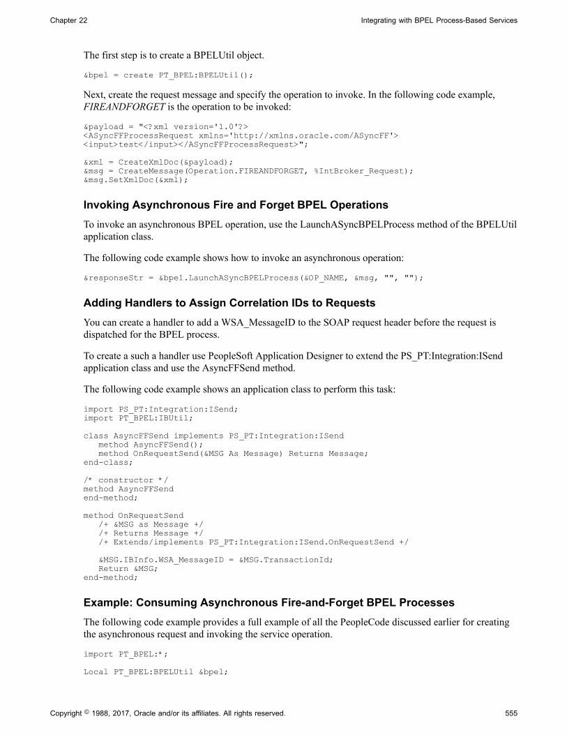
Chapter 22 Integrating with BPEL Process-Based Services
The first step is to create a BPELUtil object.
&bpel = create PT_BPEL:BPELUtil();
Next, create the request message and specify the operation to invoke. In the following code example,FIREANDFORGET is the operation to be invoked:
&payload = "<?xml version='1.0'?><ASyncFFProcessRequest xmlns='http://xmlns.oracle.com/ASyncFF'><input>test</input></ASyncFFProcessRequest>";
&xml = CreateXmlDoc(&payload);&msg = CreateMessage(Operation.FIREANDFORGET, %IntBroker_Request);&msg.SetXmlDoc(&xml);
Invoking Asynchronous Fire and Forget BPEL OperationsTo invoke an asynchronous BPEL operation, use the LaunchASyncBPELProcess method of the BPELUtilapplication class.
The following code example shows how to invoke an asynchronous operation:
&responseStr = &bpel.LaunchASyncBPELProcess(&OP_NAME, &msg, "", "");
Adding Handlers to Assign Correlation IDs to RequestsYou can create a handler to add a WSA_MessageID to the SOAP request header before the request isdispatched for the BPEL process.
To create a such a handler use PeopleSoft Application Designer to extend the PS_PT:Integration:ISendapplication class and use the AsyncFFSend method.
The following code example shows an application class to perform this task:
import PS_PT:Integration:ISend;import PT_BPEL:IBUtil;
class AsyncFFSend implements PS_PT:Integration:ISend method AsyncFFSend(); method OnRequestSend(&MSG As Message) Returns Message;end-class;
/* constructor */method AsyncFFSendend-method;
method OnRequestSend /+ &MSG as Message +/ /+ Returns Message +/ /+ Extends/implements PS_PT:Integration:ISend.OnRequestSend +/ &MSG.IBInfo.WSA_MessageID = &MSG.TransactionId; Return &MSG; end-method;
Example: Consuming Asynchronous Fire-and-Forget BPEL ProcessesThe following code example provides a full example of all the PeopleCode discussed earlier for creatingthe asynchronous request and invoking the service operation.
import PT_BPEL:*;
Local PT_BPEL:BPELUtil &bpel;
Copyright © 1988, 2017, Oracle and/or its affiliates. All rights reserved. 555

Integrating with BPEL Process-Based Services Chapter 22
Local string &url, &payload, &responseStr, &OP_NAME;Local Message &msg, &reply;Local XmlDoc &xml;
/* --- creating a BPELUtil object --- */&bpel = create PT_BPEL:BPELUtil();
/* --- setting operation name --- */&OP_NAME = "FIREANDFORGET";
&payload = "<?xml version='1.0'?><ASyncFFProcessRequest xmlns='http://xmlns.oracle.com/ASyncFF'><input>test</input></ASyncFFProcessRequest>";
&xml = CreateXmlDoc(&payload);&msg = CreateMessage(Operation.FIREANDFORGET, %IntBroker_Request);&msg.SetXmlDoc(&xml);
&responseStr = &bpel.LaunchASyncBPELProcess(&OP_NAME, &msg, "", "");
Example: Consuming Asynchronous Fire-and-Forget BPEL Processes/*The Instance URL would be available only after the instance is */ /*created on the BPEL engine. Programmatically wait for URL if needed */
&url = &bpel.GetASyncBPELProcessInstanceUrl(&responseStr);
Related LinksUnderstanding Service Operation Handlers"Understanding the BPEL Classes" (PeopleTools 8.55: PeopleCode API Reference)
Providing PeopleSoft Services to BPEL Processes
This section provides an overview of providing services to BPEL processes and discusses how to:
• Provide PeopleSoft synchronous operations to BPEL processes.
• Provide PeopleSoft asynchronous request/response operations to BPEL processes.
Understanding Providing PeopleSoft Services to BPEL ProcessesThis section provides overview information for providing services to BPEL processes.
Container Messages and Message PartsIf using container messages and message parts, create rowset-based parts in nonrowset-based containers.Doing so ensures that the XSchema that is generated for messages will not include PeopleTools-specificauditing information (PSCAMA). Typically, you do not want this auditing information to be included inthe generated XSchema when integrating with BPEL processes.
Provide Web Service WizardWhen providing services to systems using BPEL, consider the following guidelines:
• The providing web services step using the Provide Web Service wizard described in this section is forsynchronous and asynchronous request/response operations and is required only for an external clientto be able to consume a PeopleSoft service.
556 Copyright © 1988, 2017, Oracle and/or its affiliates. All rights reserved.

Chapter 22 Integrating with BPEL Process-Based Services
• When providing the service, the WSDL document is exported to the WSDL repository in thePeopleSoft Pure Internet Architecture. Optionally, you can select to export the WSDL to a UDDIrepository. PeopleSoft uses relative path URL for schemas referenced in the WSDL documents thesystem generates.
• After generating the WSDL document, carefully inspect the results using the WSDL Generation Log(the last page of the Provide Web Services wizard).
The WSDL Generation Log contains the Generated WSDL URL. Copy this URL and store itsomewhere carefully. You will need this WSDL URL later when calling the PeopleSoft-provided webservice operation from the BPEL process.
Related LinksManaging Container MessagesUnderstanding Providing Services
Providing Synchronous PeopleSoft Operations to BPEL ProcessesThis section discusses how to:
• Build synchronous PeopleSoft services.
• Provide synchronous PeopleSoft services as WSDL documents.
• Consume the service in a BPEL process and invoke the BPEL process.
Building Synchronous PeopleSoft ServicesThis section lists the steps for building synchronous PeopleSoft services. Detailed documentation foreach step is provided elsewhere the product documentation. See the end of this section for links to theappropriate documentation.
1. Define request and response messages to be associated with the service operation.
Use the appropriate XSchema for each message.
Schema for the messages are needed for generating the WSDL. If rowset-based messages are used inthe operation, simply save the message definition to generate the schema. If nonrowset messages areused in the operation, you must manually provide schema. These schema will determine the requestand response format during integration.
Examples of XSchema for request and response messages are provided at the end of this section.
2. Create a handler to process the request message.
Extend the PS_PT:Integration:IRequestHandler application class using the OnRequest method. Theoutput of the handler will be communicated back as the response to the received request.
An code example of an OnRequest handler is provided at the end of this section.
3. Create a new service.
4. Add a synchronous operation to the service.
• Generate an any-to-local routing definition for the operation.
Copyright © 1988, 2017, Oracle and/or its affiliates. All rights reserved. 557

Integrating with BPEL Process-Based Services Chapter 22
• Add permissions to the service operation.
• Add the OnRequest handler that you created in step 2 to the operation by referencing the packagename, path, and class ID of the handler that you created in step 2.
See Understanding Sending and Receiving Messages, Understanding Managing Services, UnderstandingManaging REST Services, Understanding Service Operation Handlers.
Providing Synchronous PeopleSoft Services as WSDL DocumentsUse the Provide Web Services wizard to export the service and generate a WSDL document.
See Understanding Providing Services.
Consuming Services in BPEL Processes and Invoking Services from BPELProcessesThe last step is to consume the PeopleSoft-provided service in a BPEL process and then invoke theconsumed service.
See the documentation that is provided with your BPEL runtime engine for the steps that are necessary toaccomplish this step.
Example 1: Providing Synchronous Operations – Sample Request MessageThe following code shows an example of a request message:
<?xml version="1.0"?> <xsd:schema targetNamespace="http://xmlns.oracle.com/Enterprise/Tools/schemas/PSFTCALCREQUESTMESSAGE.V1" xmlns="http://xmlns.oracle.com/Enterprise/Tools/schemas/PSFTCALCREQUESTMESSAGE.V1" xmlns:xsd="http://www.w3.org/2001/XMLSchema"> <xsd:element name="PSFTCalcRequestMessage" type= "PSFTCalcRequestMessage_Type Shape"/> <xsd:complexType name="PSFTCalcRequestMessage_TypeShape"> <xsd:sequence> <xsd:element name="op" type="xsd:string"/> <xsd:element name="input1" type="xsd:decimal"/> <xsd:element name="input2" type="xsd:decimal"/> </xsd:sequence> </xsd:complexType> </xsd:schema>
Example 2: Providing Synchronous Operations – Sample Response MessageThe following code shows an example of a response message:
<?xml version="1.0"?> <xsd:schema targetNamespace="http://xmlns.oracle.com/Enterprise/Tools/schemas/PSFTCALCRESPONSEMESSAGE.V1" xmlns="http://xmlns.oracle.com/Enterprise/Tools/schemas/PSFTCALCRESPONSEMESSAGE.V1" xmlns:xsd="http://www.w3.org/2001/XMLSchema"> <xsd:element name="PSFTCalcResponseMessage" type="PSFTCalcResponseMessage_TypeShape"/> <xsd:complexType name="PSFTCalcResponseMessage_TypeShape"> <xsd:sequence> <xsd:element name="result" type="xsd:decimal"/> </xsd:sequence> </xsd:complexType> </xsd:schema>
558 Copyright © 1988, 2017, Oracle and/or its affiliates. All rights reserved.
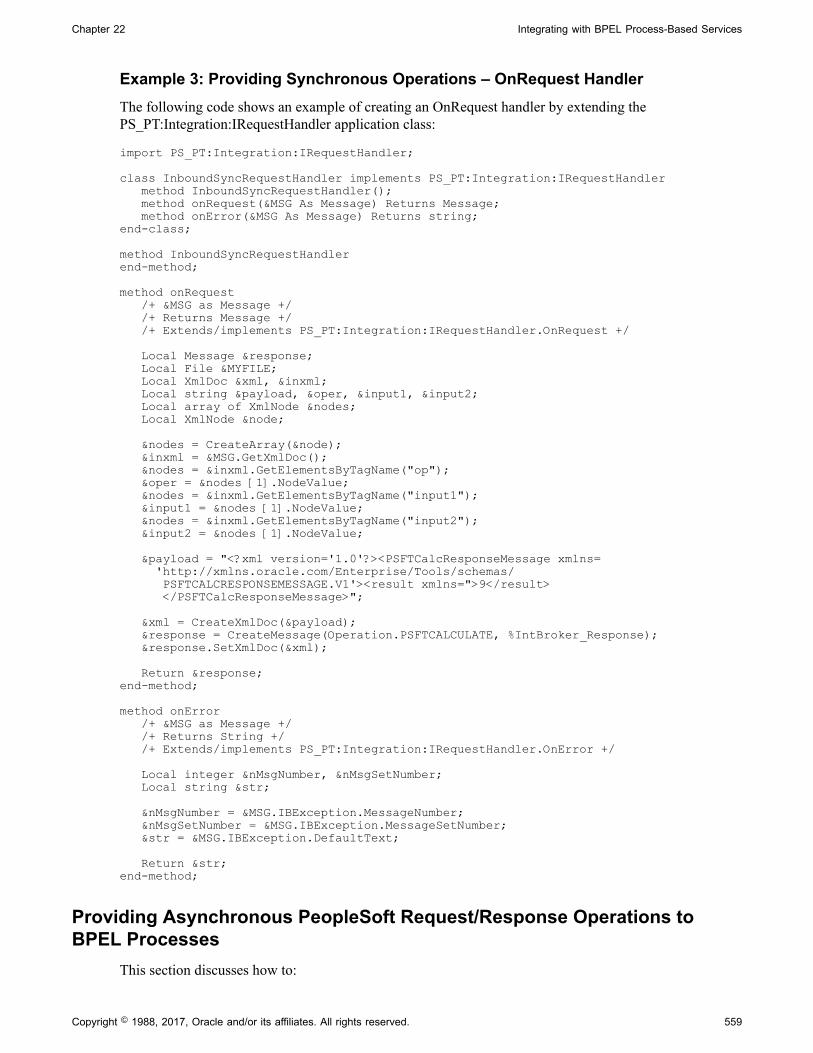
Chapter 22 Integrating with BPEL Process-Based Services
Example 3: Providing Synchronous Operations – OnRequest HandlerThe following code shows an example of creating an OnRequest handler by extending thePS_PT:Integration:IRequestHandler application class:
import PS_PT:Integration:IRequestHandler;
class InboundSyncRequestHandler implements PS_PT:Integration:IRequestHandler method InboundSyncRequestHandler(); method onRequest(&MSG As Message) Returns Message; method onError(&MSG As Message) Returns string;end-class;
method InboundSyncRequestHandlerend-method;
method onRequest /+ &MSG as Message +/ /+ Returns Message +/ /+ Extends/implements PS_PT:Integration:IRequestHandler.OnRequest +/ Local Message &response; Local File &MYFILE; Local XmlDoc &xml, &inxml; Local string &payload, &oper, &input1, &input2; Local array of XmlNode &nodes; Local XmlNode &node; &nodes = CreateArray(&node); &inxml = &MSG.GetXmlDoc(); &nodes = &inxml.GetElementsByTagName("op"); &oper = &nodes [1].NodeValue; &nodes = &inxml.GetElementsByTagName("input1"); &input1 = &nodes [1].NodeValue; &nodes = &inxml.GetElementsByTagName("input2"); &input2 = &nodes [1].NodeValue; &payload = "<?xml version='1.0'?><PSFTCalcResponseMessage xmlns= 'http://xmlns.oracle.com/Enterprise/Tools/schemas/ PSFTCALCRESPONSEMESSAGE.V1'><result xmlns=">9</result> </PSFTCalcResponseMessage>"; &xml = CreateXmlDoc(&payload); &response = CreateMessage(Operation.PSFTCALCULATE, %IntBroker_Response); &response.SetXmlDoc(&xml); Return &response;end-method;
method onError /+ &MSG as Message +/ /+ Returns String +/ /+ Extends/implements PS_PT:Integration:IRequestHandler.OnError +/ Local integer &nMsgNumber, &nMsgSetNumber; Local string &str; &nMsgNumber = &MSG.IBException.MessageNumber; &nMsgSetNumber = &MSG.IBException.MessageSetNumber; &str = &MSG.IBException.DefaultText; Return &str;end-method;
Providing Asynchronous PeopleSoft Request/Response Operations toBPEL Processes
This section discusses how to:
Copyright © 1988, 2017, Oracle and/or its affiliates. All rights reserved. 559
Integrating with BPEL Process-Based Services Chapter 22
• Build asynchronous request/response PeopleSoft services.
• Provide an asynchronous request/response PeopleSoft service as a WSDL document.
• Consume the service in a BPEL process and invoke the BPEL process.
Building Asynchronous Request/Response PeopleSoft ServicesThis section lists the steps for building asynchronous request/response PeopleSoft services. Detaileddocumentation for each step is provided elsewhere in the product documentation. See the end of thissection for links to the appropriate documentation.
1. Define request and response messages to be associated with the service operation.
Use the appropriate XSchema for each message.
Examples of XSchema for request and response messages are provided at the end of this section.
2. Create a handler to process the request message.
Extend the PS_PT:Integration:INotificationHandler application class using the OnNotify method. Theoutput of the handler will be communicated back as the response to the received request.
A code example of an OnNotify handler is provided at the end of this section.
3. Create a new service.
4. Add an Asynch Request/Response operation to the service.
• Generate an any-to-local routing definition for the operation.
• Add permissions to the service operation.
• Add the OnNotify handler that you created in step 2 to the operation by referencing the packagename, path, and class ID of the handler.
For Asynchronous Request/Response PeopleSoft services, you must invoke theUpdateConnectorResponseProperty method of the BPELUtil class in OnNotify before sending theasynchronous response to BPEL. This will override the default content-type from text/plain to text/xml asexpected by BPEL. If this is not done, BPEL will return an HTTP 415 Unknown Media-Type error.
See Understanding Sending and Receiving Messages, Understanding Managing Services, UnderstandingManaging REST Services, Understanding Service Operation Handlers.
Providing Asynchronous PeopleSoft Services as WSDL DocumentsUse the Provide Web Services wizard to export the service and generate a WSDL document.
See Understanding Providing Services.
Consuming Services in BPEL Processes and Invoking Services from BPELProcessesThe last step is to consume the PeopleSoft-provided service in a BPEL process and then invoke theconsumed service.
560 Copyright © 1988, 2017, Oracle and/or its affiliates. All rights reserved.
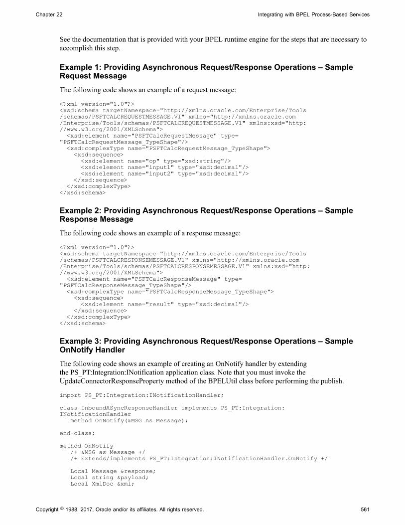
Chapter 22 Integrating with BPEL Process-Based Services
See the documentation that is provided with your BPEL runtime engine for the steps that are necessary toaccomplish this step.
Example 1: Providing Asynchronous Request/Response Operations – SampleRequest MessageThe following code shows an example of a request message:
<?xml version="1.0"?> <xsd:schema targetNamespace="http://xmlns.oracle.com/Enterprise/Tools/schemas/PSFTCALCREQUESTMESSAGE.V1" xmlns="http://xmlns.oracle.com/Enterprise/Tools/schemas/PSFTCALCREQUESTMESSAGE.V1" xmlns:xsd="http://www.w3.org/2001/XMLSchema"> <xsd:element name="PSFTCalcRequestMessage" type="PSFTCalcRequestMessage_TypeShape"/> <xsd:complexType name="PSFTCalcRequestMessage_TypeShape"> <xsd:sequence> <xsd:element name="op" type="xsd:string"/> <xsd:element name="input1" type="xsd:decimal"/> <xsd:element name="input2" type="xsd:decimal"/> </xsd:sequence> </xsd:complexType> </xsd:schema>
Example 2: Providing Asynchronous Request/Response Operations – SampleResponse MessageThe following code shows an example of a response message:
<?xml version="1.0"?> <xsd:schema targetNamespace="http://xmlns.oracle.com/Enterprise/Tools/schemas/PSFTCALCRESPONSEMESSAGE.V1" xmlns="http://xmlns.oracle.com/Enterprise/Tools/schemas/PSFTCALCRESPONSEMESSAGE.V1" xmlns:xsd="http://www.w3.org/2001/XMLSchema"> <xsd:element name="PSFTCalcResponseMessage" type="PSFTCalcResponseMessage_TypeShape"/> <xsd:complexType name="PSFTCalcResponseMessage_TypeShape"> <xsd:sequence> <xsd:element name="result" type="xsd:decimal"/> </xsd:sequence> </xsd:complexType> </xsd:schema>
Example 3: Providing Asynchronous Request/Response Operations – SampleOnNotify HandlerThe following code shows an example of creating an OnNotify handler by extendingthe PS_PT:Integration:INotification application class. Note that you must invoke theUpdateConnectorResponseProperty method of the BPELUtil class before performing the publish.
import PS_PT:Integration:INotificationHandler;
class InboundASyncResponseHandler implements PS_PT:Integration:INotificationHandler method OnNotify(&MSG As Message); end-class;
method OnNotify /+ &MSG as Message +/ /+ Extends/implements PS_PT:Integration:INotificationHandler.OnNotify +/ Local Message &response; Local string &payload; Local XmlDoc &xml;
Copyright © 1988, 2017, Oracle and/or its affiliates. All rights reserved. 561

Integrating with BPEL Process-Based Services Chapter 22
Local File &MYFILE; &payload = "<?xml version='1.0'?><PSFTCalcResponseMessage xmlns='http://xmlns.oracle.com/Enterprise/Tools/schemas/PSFTCALCRESPONSEMESSAGE.V1'><result xmlns=">9</result></PSFTCalcResponseMessage>"; &xml = CreateXmlDoc(&payload); &response = CreateMessage(Operation.PSFTASYNCCALCULATE, %IntBroker_Response); &response.SetXmlDoc(&xml); &response.IBInfo.WSA_MessageID = &MSG.IBInfo.WSA_MessageID; &response.IBInfo.WSA_ReplyTo = &MSG.IBInfo.WSA_ReplyTo; &bpel.UpdateConnectorResponseProperties(&response); %IntBroker.Publish(&response);end-method;
562 Copyright © 1988, 2017, Oracle and/or its affiliates. All rights reserved.

Chapter 23
Integrating with Oracle Mediator and OracleESB-Based Services
Understanding Integrating with Oracle Mediator and Oracle ESB-Based Services
This topic discusses how to consume and provide Oracle Mediator and Oracle ESB-based services. Thistopic also features code examples to help illustrate consuming and providing Oracle Mediator and OracleESB-based services.
Note: The code examples in this topic are for illustrative purposes only and are not intended to be used ina production environment.
Oracle Mediator and Oracle ESBOracle Mediator is a component of Oracle Fusion Middleware 11g. Oracle Mediator separates integrationconcerns from applications and business logic. It moves data among disparate applications, both withinand outside of an enterprise. It provides a messaging infrastructure and uses open standards to connect,transform, and route business documents. Oracle Mediator cannot provide services. Instead, it virtualizesendpoints and mediates between a client and a provider of a service.
In Oracle releases earlier than 11g, Oracle Mediator was named Oracle Enterprise Service Bus (ESB)
PeopleSoft supports integrations Oracle Mediator and Oracle ESB-based services. From a PeopleSoftperspective, the main differences between Oracle Mediator and Oracle ESB are:
• Oracle Mediator supports asynchronous request/response integrations. You cannot performasynchronous request/response integrations using Oracle ESB.
• PeopleSoft supports integrations with Oracle ESB nested WSDL documents. Note that OracleMediator does not support nested WSDL documents.
For more information about Oracle ESB or Oracle Mediator, visit the Oracle Technology Network onlineand enter the keywords Oracle ESB or Oracle Mediator.
Software ComponentsYou must install the following software components to perform integrations using Oracle ESB or OracleMediator:
Copyright © 1988, 2017, Oracle and/or its affiliates. All rights reserved. 563

Integrating with Oracle Mediator and Oracle ESB-Based Services Chapter 23
Software Component Description
PeopleTools Installs the PeopleSoft application server and the web. Alsoinstalls PeopleSoft Integration Broker and the PeopleSoftSOA, including the integration gateway, publication/subscription system, Provide Services Wizard, ConsumeServices Wizard, and so on.
Oracle Fusion Middleware Required for integrations with Oracle Mediator 11g.
Oracle SOA Suite Installs the Oracle services-oriented architecture, includingOracle Enterprise Manager.
Required only for Oracle 10.1.3g ESB-based integrations.
Oracle JDeveloper Studio Oracle JDeveloper Studio 11g features the Oracle BPELDesigner and the Oracle Mediator used to develop BPEL andMediator projects.
Oracle JDeveloper Studio 10.1.3g and earlier releases featuresthe Oracle BPEL Designer and the ESB Designer used todevelop BPEL and ESB projects.
Check the My Oracle Support website for the currently certified versions of Oracle SOA and OracleJDeveloper Studio for use with PeopleTools.
Check PeopleSoft document for installation tips and other information.
See PeopleTools Installation for your database platform.
Check the following Oracle documentation for installation tips and other useful information:
• Oracle SOA Suite Quick Start Guide.
• Oracle SOA Suite Installation Guide.
• Oracle JDeveloper Installation Guide.
• Oracle BPEL Process Manager Quick Start Guide.
• Oracle Mediator Quick Start Guide.
• Oracle Enterprise Service Bus Quick Start Guide.
• Oracle Enterprise Service Bus Installation Guide.
Securing Oracle Mediator and Oracle ESB-Based ServicesPeopleSoft Integration Broker provides a number of options that you can use to secure integrations. Theseinclude securing integrations at one or more of the following levels:
• Web server.
• Gateway level.
• Application server level.
564 Copyright © 1988, 2017, Oracle and/or its affiliates. All rights reserved.
Chapter 23 Integrating with Oracle Mediator and Oracle ESB-Based Services
• Node level.
• User level.
• Service operation level.
• And so on.
It is important to fully investigate these security options and implement those that best suit your businessneeds.
It is also important that you investigate the security options available for the Oracle SOA Suite and OracleJDeveloper and to implement those security options that fulfill your security requirements.
Related Links"Understanding Setting Up Secure Integration Environments" (PeopleTools 8.55: Integration BrokerAdministration)
Prerequisites for Integrating with Oracle Mediator/ESB–BasedServices
For creating integrations with Oracle Mediator and Oracle ESB services you must have PeopleSoftIntegration Broker configured and running.
Note: This section discusses prerequisite configuration steps on the PeopleSoft system for integratingwith Oracle Mediator and Oracle ESB-based services. Check your Oracle documentation for setup andconfiguration steps that you must perform on Oracle JDeveloper, Oracle BPEL Process Manager, andOracle Mediator or Oracle ESB.
The following list is a partial checklist of items to configure on the PeopleSoft system:
• In PeopleTools ensure that the application server and web server are installed and running.
• On the Nodes-Node Definitions page, create a node to represent Oracle ESB. Set the Node Type fieldto External for this node.
• When configuring the integrationGateway.properties file, be sure to set the ig.isc.serverURL propertyequal to the name of the machine running the integration engine.
• When configuring the PeopleTools application server, set the PUB/SUB option to Yes. This value isrequired for asynchronous integrations.
• Activate the application server domain by setting the Domain Status to Active.
• Set the service namespace, the schema namespace, and the target location.
• To load files into PeopleTools from the file system, set PS_FILEDIR and PS_SERVDIR in the systemvariables on your machine.
Related LinksPeopleSoft Integration Broker Metadata
Copyright © 1988, 2017, Oracle and/or its affiliates. All rights reserved. 565

Integrating with Oracle Mediator and Oracle ESB-Based Services Chapter 23
Order of Precedence for Creating Integration MetadataUnderstanding Setting PS_FILEDIR and PS_SERVDIR Environment Variables
Consuming and Invoking Oracle Mediator/ESB-Based Services
This section discusses how to:
• Provide Oracle Mediator/ESB-based services for consuming in PeopleSoft.
• Consume Oracle Mediator/ESB-based services.
• Invoke synchronous Oracle Mediator/ESB-based services.
• Invoke asynchronous Oracle Mediator/ESB-based services.
• Invoke asynchronous request/request Oracle Mediator services.
Understanding Consuming and Invoking Oracle Mediator/ESB-BasedServices
This section provides information about consuming Oracle Mediator/ESB-Based services.
Oracle Mediator/ESB Projects When PeopleSoft is a ConsumerOracle Mediator/ESB cannot provide a service. It can only mediate between a client and the provider ofthe service.
Hence, if PeopleSoft is the consumer of a Mediator or ESB service, the Mediator/ESB project will containa SOAP service (like BPEL) that will implement the business logic. Further there will be a routing servicethat will route the SOAP request message from PeopleSoft to the underlying web service implementation.
Service Routing TypesThere are three types of routing services: synchronous, asynchronous, and asynchronous request/response.
Note: Oracle Mediator provides the ability to consume asynchronous request/response services. Youcannot consume these types of services uses Oracle ESB.
The type of routing service determines the type of Mediator or ESB project. A Mediator or ESB projectwith a synchronous routing service defined is a synchronous Mediator/ESB project; and a Mediator/ESBproject with an asynchronous routing service defined is an asynchronous Mediator/ESB project. Mediatorprojects with an asynchronous request/response service defined is an asynchronous request/responseservice.
Oracle ESB Nested and Non-Nested WSDLPeopleSoft systems can consume WSDL documents that are nested or not nested. This section providesadditional information on each type.
Note: PeopleSoft supports integrations with Oracle ESB nested WSDL documents. This feature is notavailable with Oracle Mediator.
566 Copyright © 1988, 2017, Oracle and/or its affiliates. All rights reserved.

Chapter 23 Integrating with Oracle Mediator and Oracle ESB-Based Services
Using nested WSDL documents allows you to separate the different elements of a service definition intoindependent documents that you can consume as needed.
Using nested WSDL helps you to write clearer definitions by enabling you to separate the definitionsaccording to their level of abstraction. It also maximizes the ability to reuse service definitions.
The following example shows a nested WSDL document. The document is separated into three smallerdocuments: data type definitions, abstract definitions, and specific service bindings.
The following example shows a data type definition WSDL document:
//data type definitions WSDL//<schema attributeFormDefault="unqualified" elementFormDefault="qualified" targetNamespace="http://xmlns.oracle.com/SynchAdd_BPEL" xmlns="http://www.w3.org/2001/XMLSchema"> <element name="SynchAdd_BPELProcessRequest"> <complexType> <sequence> <element name="input1" type="integer"/> <element name="input2" type="integer"/> </sequence> </complexType> </element></schema>
The following example show an abstract definition WSDL document:
<?xml version="1.0" encoding="UTF-8" ?><definitions name="NestedAsyncFFAdd_RS" targetNamespace="http://oracle.com/esb/namespaces/NestedAsyncFFAdd_ESB" xmlns="http://schemas.xmlsoap.org/wsdl/" xmlns:tns="http://oracle.com/esb/namespaces/NestedAsyncFFAdd_ESB" xmlns:inp1="http://xmlns.oracle.com/SynchAdd_BPEL"> <types> <schema xmlns="http://www.w3.org/2001/XMLSchema"><import namespace="http://xmlns.oracle.com/SynchAdd_BPEL"schemaLocation="SyncAdd_Req.xsd" /></schema></types><message name="SynchAdd_BPELProcessRequest_request"><part name="SynchAdd_BPELProcessRequest"element="inp1:SynchAdd_BPELProcessRequest" /></message><portType name="NestedESBAsyncFFAdd_ppt"><operation name="NestedESBAsyncFFAdd"><input message="tns:SynchAdd_BPELProcessRequest_request" /></operation></portType></definitions>
The following example shows a service bindings WSDL document:
<?xml version="1.0" encoding="UTF-8" ?><definitions targetNamespace="http://oracle.com/esb/namespaces/ NestedAsyncFFAdd_ESB/concrete"xmlns="http://schemas.xmlsoap.org/wsdl/"xmlns:tns="http://oracle.com/esb/namespaces/NestedAsyncFFAdd_ESB/concrete"xmlns:ws="http://www.example.com/webservice" xmlns:http="http://schemas.xmlsoap.org/wsdl/http/"xmlns:plt="http://schemas.xmlsoap.org/ws/2003/05/partner-link/"xmlns:esb="http://www.oracle.com/esb/" xmlns:xs="http://www.w3.org/2001/XMLSchema"xmlns:soap="http://schemas.xmlsoap.org/wsdl/" xmlns:wsdl="http://schemas.xmlsoap.org/wsdl/"xmlns:import="http://oracle.com/esb/namespaces/NestedAsyncFFAdd_ESB"><import namespace="http://oracle.com/esb/namespaces/NestedAsyncFFAdd_ESB"location="http://bng-psft-0100:8888/esb/slide/ESB_Projects/PS_Consumer_NestedAsyncFFAdd_ESB/NestedAsyncFFAdd_
Copyright © 1988, 2017, Oracle and/or its affiliates. All rights reserved. 567

Integrating with Oracle Mediator and Oracle ESB-Based Services Chapter 23
ESB_NestedAsyncFFAdd_RS.wsdl" /><binding name="__soap_NestedAsyncFFAdd_RS_NestedESBAsyncFFAdd_ppt"type="import:NestedESBAsyncFFAdd_ppt"><soap:binding xmlns:soap="http://schemas.xmlsoap.org/wsdl/soap/" style="document"transport="http://schemas.xmlsoap.org/soap/http" /><operation name="NestedESBAsyncFFAdd"><soap:operation xmlns:soap="http://schemas.xmlsoap.org/wsdl/soap/" style="document"soapAction="NestedESBAsyncFFAdd" /><input><soap:body xmlns:soap="http://schemas.xmlsoap.org/wsdl/soap/" use="literal" /></input></operation></binding><binding name="__esb_NestedAsyncFFAdd_RS_NestedESBAsyncFFAdd_ppt"type="import:NestedESBAsyncFFAdd_ppt"><esb:binding /><operation name="NestedESBAsyncFFAdd"><esb:operation eventname="NestedAsyncFFAdd_ESB.NestedAsyncFFAdd_RS.NestedESBAsyncFFAdd" /><input /></operation></binding><service name="ESB_NestedAsyncFFAdd_RS_Service"><port name="__soap_NestedAsyncFFAdd_RS_NestedESBAsyncFFAdd_ppt"binding="tns:__soap_NestedAsyncFFAdd_RS_NestedESBAsyncFFAdd_ppt"><soap:address xmlns:soap="http://schemas.xmlsoap.org/wsdl/soap/" location="http://bng-psft-0100:8888/event/NestedAsyncFFAdd_ESB/ NestedAsyncFFAdd_RS" /></port><port name="__esb_NestedAsyncFFAdd_RS_NestedESBAsyncFFAdd_ppt"binding="tns:__esb_NestedAsyncFFAdd_RS_NestedESBAsyncFFAdd_ppt"/></service><plt:partnerLinkType name="NestedESBAsyncFFAdd_pptLT"><plt:role name="NestedESBAsyncFFAdd_pptProvider"><plt:portType name="tns:NestedESBAsyncFFAdd_ppt" /></plt:role></plt:partnerLinkType>
Oracle Mediator/ESB WSDL BindingsA WSDL document binding provides the protocol and data format specification for a particular port type.
Oracle Mediator/ESB WSDL documents can have SOAP bindings or Oracle Mediator/ESB nativebindings.
Note: Oracle Mediator/ESB WSDL documents to be consumed by PeopleSoft systems must be of theSOAP type. SOAP binding adhere to the SOAP protocol. Choosing the Oracle Mediator/ESB nativebinding type may result in unpredictable behavior in PeopleSoft systems.
Asynchronous Request/Response Callback OperationsThe WSDL created by Oracle Mediator for asynchronous request/response integrations does not contain aservice definition for the callback operation. The PeopleSoft system does not recognize the callback untilthe service definition is defined.
As a result, save the WSDL document to the file system and add the following section to the WSDLdocument. Then consume the WSDL document in the Consume Web Services Wizard, selecting the Fileoption when specifying the WSDL source.
<wsdl:service name="asyncrrcalcbpelcallback_client_ep"> <wsdl:port name="AsyncRRCalcBPELCallback_pt" binding="client: AsyncRRCalcBPELCallbackBinding"> <soap:address xmlns:soap="http://schemas.xmlsoap.org/wsdl/soap/" location="http://Client.EndPoint.Set.By.Caller"/>
568 Copyright © 1988, 2017, Oracle and/or its affiliates. All rights reserved.
Chapter 23 Integrating with Oracle Mediator and Oracle ESB-Based Services
</wsdl:port></wsdl:service>
PeopleSoft Integration Broker Consume Services WizardTo consume Oracle Mediator/ESB-based services use the PeopleSoft Integration Broker ConsumeServices Wizard. The wizard enables you to consume WSDL provided by integration partners. In turn,the wizard creates PeopleSoft service, service operation, message, and routing definitions for the WSDL,thereby enabling you to manage and invoke the service in PeopleSoft.
See Understanding the Consume Web Service Wizard.
Providing Oracle Mediator/ESB–Based Services for Consuming inPeopleSoft
This section lists the general steps for providing Oracle Mediator/ESB–based services for consuming inPeopleSoft systems. All steps are performed in Oracle Mediator/ESB except where otherwise noted:
1. Create the Mediator/ESB project.
Remember that the type of routing service (synchronous, asynchronous, or asynchronous request/response) you associate to the project determines the project type (synchronous, asynchronous,asynchronous request/response).
2. Register the project with the Oracle Mediator/ESB server.
Use the Oracle Mediator/ESB Console to verify that you successfully registered the project.
3. On the machine on which Oracle Mediator/ESB is deployed, verify that the virtual host and portvalues are set.
By default the virtual host is set to localhost. You must set the virtual host to the IP address or hostname.
4. On the Definitions tab, note the WSDL URL of the routing service.
Note: Write down the WSDL URL of the routing service. You must enter this URL in the PeopleSoftsystem to consume the service.
Consuming Oracle Mediator/ESB-Based ServicesTo consume WSDL from a Mediator/ESB-based service into the PeopleSoft system, use the ConsumeWeb Service component in the PeopleSoft Pure Internet Architecture.
As you use the Consume Services Wizard keep the following points in mind:
• The source of the WSDL is a WSDL URL. Enter the URL of the routing service that you noted on theDefinitions tab in Oracle Mediator/ESB.
• When prompted to select service ports select the service(s) who's name start with “SOAP.” Thisensures that the PeopleSoft system uses the correct binding type to create the routing metadata.
• Make a note of the service operations that you consume. You need these names when you createPeopleCode to create the request message and invoke the service.
Copyright © 1988, 2017, Oracle and/or its affiliates. All rights reserved. 569

Integrating with Oracle Mediator and Oracle ESB-Based Services Chapter 23
• When prompted to select a receiving node select the Use Exiting Node option. Next, enter or searchfor the external node that you created to represent the Mediator/ESB system.
• When consuming asynchronous services you can use the default queue option or select a differentqueue.
Related LinksUnderstanding the Consume Web Service Wizard
Invoking Synchronous Oracle Mediator/ESB-Based ServicesThis section discusses how to:
• Manage routing definitions for invoking synchronous Oracle Mediator/ESB-based services.
• Set message and error logging for invoking synchronous Oracle Mediator/ESB-based services.
• Invoke a synchronous Oracle Mediator/ESB-based service.
Prerequisites for Invoking Synchronous Oracle Mediator/ESB-Based ServicesBefore you can invoke a synchronous Oracle Mediator/ESB-based service, you must first consume it.Consuming Oracle Mediator/ESB-based services is described elsewhere in this section.
See Consuming Oracle Mediator/ESB-Based Services.
Managing Routing Definitions for Invoking Synchronous Oracle Mediator/ESB-Based ServicesThe PeopleSoft Integration Broker Consume Services Wizard creates an outbound routing definition forthe consumed service.
Before you invoke a synchronous Oracle Mediator/ESB-based service in the PeopleSoft system, performthese tasks:
1. Access the Routings – Connector Properties page (PeopleTools, Integration Broker, Integration Setup,Routings. and click the Connector Properties tab).
2. Ensure that the Connector ID field is set to HTTPTARGET.
3. Ensure that the value in the Primary URL field is set to the endpoint URL.
4. Set any other HTTP target connector properties as desired.
Setting Message and Error Logging for Invoking Synchronous Oracle Mediator/ESB-Based ServicesTo capture the maximum amount to message and error logging and information when you invoke theservice, set the following options:
• On the Routings – Routing Definitions page (PeopleTools, Integration Broker, Integration Setup,Routings.) set the value in the Log Detail field to Header and Detail.
570 Copyright © 1988, 2017, Oracle and/or its affiliates. All rights reserved.

Chapter 23 Integrating with Oracle Mediator and Oracle ESB-Based Services
• In the integrationGateway.properties file set the ig.log.level property equal to 5.
Invoking a Synchronous Oracle Mediator/ESB-Based ServiceThe following sample PeopleCode demonstrates one way to invoke a synchronous Mediator/ESB-basedservice:
Local string &payload, &responseStr;Local Message &msg, &reply;Local XmlDoc &xml;
/* --- set input request message--- */&payload = "<?xml version='1.0' encoding='UTF-8'?><SynchAdd_BPELProcessRequestxmlns='http://xmlns.oracle.com/SynchAdd_BPEL'><input1>1234</input1><input2>1234</input2></SynchAdd_BPELProcessRequest>";MessageBox(0, "Request Message", 0, 0, &payload);
&xml = CreateXmlDoc(&payload);&msg = CreateMessage(Operation.ESBSYNCADD, %IntBroker_Request);&msg.SetXmlDoc(&xml);
&reply = %IntBroker.SyncRequest(&msg);
If All(&reply) Then &responseStr = &reply.GenXMLString(); MessageBox(0, "Request Message", 0, 0, (&responseStr)); Else WinMessage("Error. No reply (or NULL) from LaunchSyncBPELProcess");End-If;
On execution the system displays the request message that the system sends to Oracle Mediator/ESB.If the invocation is successful, the system displays another box that shows the response from OracleMediator/ESB.
Use the PeopleSoft Integration Broker message logs to view the flow of the messages. You can also usethe Integration Broker Service Operations Monitor to view information about the outbound transaction.
See Managing Integration Gateway Message and Error Logging"Viewing Monitor Output forSynchronous Service Operations Data" (PeopleTools 8.55: Integration Broker Service OperationsMonitor).
Use the Oracle Mediator/ESB Console to check for the Mediator/ESB instance and for the successfulinvocation of the Mediator/ESB service.
Invoking Asynchronous Oracle Mediator/ESB-Based ServicesThis section discusses how to:
• Create acknowledgements for invoking asynchronous Oracle Mediator/ESB-based services.
• Manage routing definitions for invoking asynchronous Oracle Mediator/ESB-based services.
• Set message and error logging for invoking asynchronous Oracle Mediator/ESB-based services.
• Invoke an asynchronous Oracle Mediator/ESB-based service.
Understanding Invoking Asynchronous Oracle Mediator/ESB-Based ServicesAn asynchronous service is also referred to as a fire-and-forget service.
Copyright © 1988, 2017, Oracle and/or its affiliates. All rights reserved. 571
Integrating with Oracle Mediator and Oracle ESB-Based Services Chapter 23
Prerequisites for Invoking Asynchronous Oracle Mediator/ESB-Based ServicesBefore you can invoke an asynchronous Oracle Mediator/ESB-based service, you must first consume it.Consuming Oracle Mediator/ESB-based services is described elsewhere in this section.
See Consuming Oracle Mediator/ESB-Based Services.
Creating Acknowledgments for Invoking Asynchronous Oracle Mediator/ESB-Based ServicesTo handle acknowledgement data for an asynchronous service operation, create an OnReceive handlerthat uses the OnAckReceive method that is implemented as an application class. After doing so, you mustregister the application class with the PeopleSoft service operation.
The following code example shows sample code to create the handler:
import PS_PT:Integration:IReceiver;
class AsynchFF_AckReceive implements PS_PT:Integration:IReceiver method AsynchFF_AckReceive(); method OnAckReceive(&MSG As Message) Returns integer;end-class;
/* constructor */method AsynchFF_AckReceiveend-method;
method OnAckReceive /+ &MSG as Message +/ /+ Returns Integer +/ /+ Extends/implements PS_PT:Integration:IReceiver.OnAckReceive +/ /* Variable Declaration */
If &MSG.IsStructure Then
/* if message is rowset-based */ Local string &str = &MSG.GenXMLString();
Else /* if message is nonrowset-based */ Local XmlDoc &xmldoc = &MSG.GetXmlDoc(); Local string &str1 = &xmldoc.GenXmlString(); Local File &MYFILE;
&MYFILE = GetFile("C:\Temp\ESB\PS_Consume\ESBasynchffack.txt", "W",%FilePath_Absolute); If &MYFILE.IsOpen Then &MYFILE.WriteString(&str1); &MYFILE.WriteLine(""); &MYFILE.WriteString(String(%Operation_Done)); &MYFILE.Close(); End-If; End-If;
Return (%Operation__Done);end-method;
To create an acknowledgement for consumed asynchronous Oracle Mediator/ESB-based services:
1. Create an OnReceive handler that uses the OnAckReceive method that is implemented as anapplication class.
See Implementing Handlers Using Application Classes.
2. Open the service operation definitions for the consumed service operation.
572 Copyright © 1988, 2017, Oracle and/or its affiliates. All rights reserved.

Chapter 23 Integrating with Oracle Mediator and Oracle ESB-Based Services
3. Click the Handlers tab.
The Service Operations-Handlers page appears.
4. Add a handler with the following characteristics:
Name Enter any name. For example: AckReceive.
Type From the drop-down list select OnReceive.
Implementation From the drop-down list select Application Class.
Status From the status drop-down list select Active.
5. Click the Details link.
The Handler Details page appears.
6. At a minimum enter the following details about the application class:
Package Name Enter the package name that contains the class that you wantto specify.
Path Enter a colon ( : ).
Class ID Enter the name of the application class that contains themethod that you want to specify.
Method From the drop-down list select OnAckReceive.
Managing Routing Definitions for Invoking Asynchronous Oracle Mediator/ESB-Based ServicesThe PeopleSoft Integration Broker Consume Services Wizard creates an outbound routing definition forthe consumed service.
Before proceeding to invoke the service, ensure the following on the routing definition:
• On the Routings-Routing Definitions page (PeopleTools, Integration Broker, Integration Setup,Routings.) in the OnReceive Handler field, enter or select OnAckReceive.
This is the acknowledgement.
• On the Routings-Connector Properties page (PeopleTools, Integration Broker, Integration Setup,Routings. Click the Connector Properties tab):
• Ensure that the Connector ID field is set to HTTPTARGET.
• Ensure that the value in the Primary URL field is set to the endpoint URL.
• Set any other HTTP target connector properties as desired.
Copyright © 1988, 2017, Oracle and/or its affiliates. All rights reserved. 573
Integrating with Oracle Mediator and Oracle ESB-Based Services Chapter 23
Setting Message and Error Logging for Invoking Asynchronous Oracle Mediator/ESB-Based ServicesTo capture the maximum amount of message and error logging and information when you invoke theservice, in the integrationGateway.properties file, set the ig.log.level property equal to 5.
A setting of 5 is the default value.
Invoking an Asynchronous Oracle Mediator/ESB-Based ServiceThe following sample PeopleCode demonstrates one way to invoke the asynchronous Oracle Mediator/ESB-based service:
Local string &payload, &responseStr;Local Message &msg, &reply;Local XmlDoc &xml;
/* --- setting the input request message --- */
&payload = "<?xml version='1.0' encoding='UTF-8'?><SynchAdd_BPELProcessRequestxmlns='http://xmlns.oracle.com/SynchAdd_BPEL'><input1>6789</input1><input2>6789</input2></SynchAdd_BPELProcessRequest>";MessageBox(0, "Request Message", 0, 0, &payload);
&xml = CreateXmlDoc(&payload);
&msg = CreateMessage(Operation.ESBASYNCFFADD, %IntBroker_Request);
&msg.SetXmlDoc(&xml);
%IntBroker.Publish(&msg);&responseStr = &msg.TransactionId;
MessageBox(0, "Message Transaction ID-Response from LaunchAsyncBPELProcess", 0, 0, &responseStr);
MessageBox(0, "Acknowledgement from ESB", 0, 0, "For Ack Msg from ESB , go look at the file C:\temp\ESB\PS_Consume\ESBasynchffack.txt");
When you execute the PeopleCode the PeopleSoft system the following information in consecutivemessage boxes:
1. The request message that it sends to Oracle Mediator/ESB.
2. The transaction ID for the asynchronous request.
3. The file location of the acknowledgement it received from Oracle Mediator/ESB
You can use the PeopleSoft Integration Broker message logs to view the flow of the messages. You canalso use the Integration Broker Service Operations Monitor to view information about the outboundtransaction.
You can also use the Oracle Mediator/ESB Console to check for the message instance and for thesuccessful invocation of the Mediator/ESB service.
See Managing Integration Gateway Message and Error Logging"Monitoring Asynchronous ServiceOperation Transactions" (PeopleTools 8.55: Integration Broker Service Operations Monitor).
574 Copyright © 1988, 2017, Oracle and/or its affiliates. All rights reserved.
Chapter 23 Integrating with Oracle Mediator and Oracle ESB-Based Services
Invoking Asynchronous Request/Response Oracle Mediator-BasedServices
This section discusses invoking asynchronous request/response Oracle Mediator-based services.
Prerequisites for Invoking Asynchronous Request/Response Oracle Mediator-Based ServicesBefore you can invoke an asynchronous Oracle Mediator/ESB-based service, you must first consume it.Consuming Oracle Mediator/ESB-based services is described elsewhere in this section.
See Consuming Oracle Mediator/ESB-Based Services.
Invoking an Asynchronous Request/Response Oracle Mediator-Based ServiceTo invoke an asynchronous request/response Oracle Mediator-based service, you must use anOnResponse handler. The following code shows a sample OnResponse handler:
import PS_PT:Integration:INotificationHandler;import PT_BPEL:BPELUtil;
class Esb_AsyncRR implements PS_PT:Integration:INotificationHandler method Esb_AsyncRR(); method OnResponse(&MSG As Message);end-class;
/* constructor */method Esb_AsyncRRend-method;
method OnResponse /+ &MSG as Message +/ Local Message &request, &response; Local File &MYFILE; Local XmlDoc &xml, &inxml; Local string &payload, &oper, &input1, &input2, &result_st; Local integer &result_no; Local array of XmlNode &nodes; Local XmlNode &node; Local PT_BPEL:BPELUtil &obj = create PT_BPEL:BPELUtil(); &nodes = CreateArray(&node); &request = &MSG; &inxml = &request.GetXmlDoc(); &nodes = &inxml.GetElementsByTagName("input1"); &input1 = &nodes [1].NodeValue; &nodes = &inxml.GetElementsByTagName("input2"); &input2 = &nodes [1].NodeValue; &result_no = Integer(&input1) * Integer(&input2); &result_st = String(&result_no); &payload = "<?xml version='1.0'?><PSFTCalcResponseMessage xmlns=' http://xmlns.oracle.com/Enterprise/Tools/schemas/PSFTCALCRESPONSEMESSAGE.V1'> <result>" | &result_st | "</result></PSFTCalcResponseMessage>"; &xml = CreateXmlDoc(&payload); &response = CreateMessage(Operation.ESBASYNCRR, %IntBroker_Response); &response.SetXmlDoc(&xml); &response.IBInfo.WSA_MessageID = &request.IBInfo.WSA_MessageID; &response.IBInfo.WSA_ReplyTo = &request.IBInfo.WSA_ReplyTo; &obj.UpdateConnectorResponseProperties(&response); %IntBroker.Publish(&response); end-method;
Copyright © 1988, 2017, Oracle and/or its affiliates. All rights reserved. 575

Integrating with Oracle Mediator and Oracle ESB-Based Services Chapter 23
Providing and Invoking PeopleSoft Services in Oracle Mediator/ESB
This section discusses how to:
• Provide PeopleSoft services to Oracle Mediator/ESB.
• Invoke PeopleSoft services in Oracle Mediator/ESB.
Understanding Providing and Invoking PeopleSoft Services in OracleMediator/ESB
This section provides an overview of providing and invoking PeopleSoft services in Oracle Mediator/ESB.
Oracle Mediator/ESB Projects When PeopleSoft is a ProviderTo invoke a PeopleSoft service in Oracle Mediator/ESB, you must create a project in Oracle Mediator/ESB.
See Oracle Mediator Quick Start Guide.
See Oracle Enterprise Service Bus Quick Start Guide.
PeopleSoft Integration Broker Provide Services WizardTo provide PeopleSoft services to Oracle Mediator/ESB you use the PeopleSoft Integration BrokerProvide Services Wizard. The wizard enables you to generate WSDL documents based on services youcreate in PeopleSoft Integration Broker. You then provide the generated WSDL to Oracle Mediator/ESB.
Prerequisites for Providing and Invoking PeopleSoft Services in OracleMediator/ESB
You must create the PeopleSoft services you wish to provide, prior to using generating WSDL andproviding the WSDL to Oracle Mediator/ESB.
Other prerequisites may exist in Oracle JDeveloper or Oracle Mediator/ESB. Refer to the Oracledocumentation for more information.
Providing PeopleSoft ServicesUse the PeopleSoft Integration Broker Provide Web Service Wizard to generate a WSDL document forthe service you wish to provide to Oracle Mediator/ESB.
The wizard provides you the option to publish the WSDL to a UDDI repository that you define, or to theWSDL repository in PeopleSoft Integration Broker. You can choose either publishing option.
The last page is the WSDL Generation Log which provides the name of the services and URL for eachWSDL document generated. You will use this information when you invoke the services in OracleMediator/ESB.
576 Copyright © 1988, 2017, Oracle and/or its affiliates. All rights reserved.

Chapter 23 Integrating with Oracle Mediator and Oracle ESB-Based Services
Related LinksProviding Services
Invoking PeopleSoft Services in Oracle Mediator/ESBThis section describes how to invoke synchronous and asynchronous services in Oracle ESB.
Creating a Mediator/ESB Project to Invoke PeopleSoft ServicesAfter you use the PeopleSoft Integration Broker Provide Web Service wizard to generate WSDL, the nextstep is to invoke the services in Oracle Mediator/ESB, To do so, you must create a Mediator/ESB projecttype in Oracle JDeveloper.
See Oracle Mediator Quick Start Guide.
See Oracle Enterprise Service Bus Quick Start Guide.
The following are general steps to follow to configure the Oracle Mediator/ESB project after you initiallycreate it. Refer to the Oracle documentation for detailed information and instructions:
1. Modify the project so that the SOAP service points to the PeopleSoft WSDL URL generated whenyou provided the service in PeopleSoft,
2. Use the Make option to build the project.
3. Use the Register with Mediator/ESB option to register the project with Oracle Mediator/ESB.
This command allows you to register the services created using Oracle JDeveloper to Oracle Mediatoror the Oracle Enterprise Service Bus.
A message appears that indicates you successfully registered the services with the Oracle Mediator/ESBserver.
To view, monitor or make runtime adjustments to the Mediator/ESB configuration, use the OracleMediator/ESB Console.
When you have successfully registered the services on the Oracle Mediator/ESB Server, you can viewthem in the Services Panel in Oracle JDeveloper. Click the Mediator/ESB system to view the Mediator/ESB system flow in the Configuration Area on the right side.
Invoking a Service in OracleAs of the publication date of this product documentation Oracle Mediator/ESB does not feature a testpage. To test and invoke Mediator/ESB web services, use the Oracle SOA Suite’s Oracle EnterpriseManager.
See the product documentation for Oracle Enterprise Manager.
Copyright © 1988, 2017, Oracle and/or its affiliates. All rights reserved. 577

Integrating with Oracle Mediator and Oracle ESB-Based Services Chapter 23
578 Copyright © 1988, 2017, Oracle and/or its affiliates. All rights reserved.

Chapter 24
Using the Inbound File Loader Utility
Understanding the Inbound File Loader Utility
When external systems send inbound transactions consisting of flat files, you can use the Inbound FileLoader utility to translate the incoming files into service operations and process them.
The Inbound File Loader utility provides two options for translating and processing files:
• Use PeopleSoft Integration Broker to convert file data into service operations and publish themlocally. Then, subscribe to the service operations and insert the data into the tables.
• Write an application class that will read the contents of files and insert the data directly into the tables
Note: You can only use one processing method at any given time. Application class processing alwaysoverrides PeopleSoft Integration Broker processing.
File ProcessingThis section discusses the processing flow for the Inbound File Loader utility.
Image: Inbound File Loader utility processing flow
This diagram illustrates the processing of index files and flat files in the Inbound File Loader utility.
The flow for inbound file processing using the Inbound File Loader utility is:
1. The utility receives a flat file in the form of a file layout object from an external system.
Copyright © 1988, 2017, Oracle and/or its affiliates. All rights reserved. 579
Using the Inbound File Loader Utility Chapter 24
The flat file consists of either:
• A data file that contains the relevant data.
• An index file that contains pointers to the data.
Each index file lists the names of a set of data files to be processed. Each line of the indexfile must be a plain text file that contains only one field: a file name with full directory pathinformation.
These files contain the application data, which is in one of the following formats: fixed record,Comma Separated Values (CSV), or XML.
Note: The wildcards “*” and “?” may only be used in the filename and not in the directory path.
2. The utility reads the file that is submitted for processing:
• If the file is an index file, the Inbound File Loader utility loads the list of data files that areassociated with each index file to be processed into a parameter table.
• If it is a single data file, the utility inserts the single data file into a parameter table.
Note: If additional fields in the file layout are not in the message definition, the additional fieldsare ignored during the copying of the flat file data to the message and are not included in themessage.
3. The utility loops through the list of data files to be processed and reads each data file.
4. The utility uses either PeopleSoft Integration Broker or application class processing logic to read thefile contents and process the data.
• PeopleSoft Integration Broker processing.
When using Integration Broker processing logic, the Inbound File Loader utility copies therowsets of the data files into the message, publishes the service operation locally, and then thereceiving system receives the service operation and initiates normal inbound data processing.
• Application class processing.
You can build an application class to read the contents of the inbound file as rowsets andimplement the necessary processing logic to write to the underlying tables.
5. To add file archiving, delete logic to prevent files from processing again, and so on, when definingprocessing rules, you can optionally specify an application engine program name and section. Ifspecified, the utility calls the program and section as a final step to the inbound file process.
Understanding Development Activities
This section discusses development activities for using the Inbound File Loader utility and describes:
580 Copyright © 1988, 2017, Oracle and/or its affiliates. All rights reserved.

Chapter 24 Using the Inbound File Loader Utility
• General development activities
• Development activities for PeopleSoft Integration Broker processing.
• Creating file layout definitions.
• Development activities for application class processing.
General Development ActivitiesThis section discusses general development activities for using the Inbound File Loader utility usingeither PeopleSoft Integration Broker processing or application class processing.
Determining the Format for Inbound DataDetermine the necessary format of the inbound data. If there is an industry standard, use it for your filedefinition. If there is no industry standard, create a file layout object.
Development Activities for PeopleSoft Integration Broker ProcessingThis section discusses development activities for using the PeopleSoft Integration Broker processing inconjunction with the Inbound File Loader utility.
1. Create a message definition in the PeopleSoft Pure Internet Architecture.
The structure of the message definition must be similar to the structure of the file layout definitionthat you created.
2. Create a service.
3. Create an asynchronous one-way service operation for the service.
4. Create a local-to-local routing definition for the service operation.
5. Create an OnNotification handler and call the functional library IB_FILE_SUBCODE.
PeopleTools delivers this functional library and it can be used for any generic notification.
The following example shows code an OnNotification handler calling the functional library:
import PS_PT:Integration:INotificationHandler; class QUSubscribe implements PS_PT:Integration:INotificationHandler method QUSubscribe(); method OnNotify(&_MSG As Message);end-class; Declare Function Subscribe PeopleCode FUNCLIB_IBFILE.IB_FILE_SUBCODE FieldForm⇒ula; /* constructor */method QUSubscribeend-method; method OnNotify /+ &_MSG as Message +/ /+ Extends/implements PS_PT:Integration:INotificationHandler.OnNotify +/ /* Variable Declaration */
Copyright © 1988, 2017, Oracle and/or its affiliates. All rights reserved. 581

Using the Inbound File Loader Utility Chapter 24
Local Message &MSG; Local Rowset &MSG_ROWSET; &MSG = &_MSG; Subscribe(&MSG); end-method;
6. Define processing rules in the Inbound File Loader Rules page in the PeopleSoft Pure InternetArchitecture.
7. Initiate flat file processing using the Inbound File Processing page.
8. Test the inbound flat file processing.
Creating File Layout DefinitionsWhen you use the Inbound File Loader utility, you use file layout definitions to read and write data fromflat files. Use the following guidelines when creating file layout definitions:
• Create a file layout definition with the same structure as the message definition to support the vendorfile format.
• The hierarchical structure of the data in the file layout definition must match that of the messagedefinition. For example, suppose a message has three levels:
• Level 0, containing record A.
• Level 1, containing records B and C.
• Level 2, containing record D.
All file layouts that are associated with this message must also have record A in level 0, record B andC in level 1, and record D in level 2.
Note: The file layout does not need to contain the exact same fields as the message definition
• For every record in a file layout definition, add a new file field, AUDIT_ACTN, as the first field inthe record (except when the field already exists in the application table).
• You can associate more than one file layout to a single message. For example, vendor A may have adifferent number of fields than vendor B, so you may have two file layouts: one for vendor A and onefor vendor B.
• Specify the file ID uniquely to include a row in a file, which is necessary in mapping the data to itsproper record. Include start and end points when dealing with more than one record in a file layout.
• Each record in the file layout has a file record ID attribute. Do not confuse this with the file layout ID.The file layout ID determines whether a new layout is encountered for multiple file layout processing.
Development Activities for Application Class ProcessingThis section discusses development activities for application class processing using the Inbound FileLoader utility. This section discusses how to:
582 Copyright © 1988, 2017, Oracle and/or its affiliates. All rights reserved.
Chapter 24 Using the Inbound File Loader Utility
1. Create an application class.
2. Specify processing rules.
Creating Application ClassesThis section discusses creating an application class for processing flat files in conjunction with theInbound File Loader utility.
The application class you create must implement the IProcessFile interface. The signature of the interfaceis shown here:
interface IProcessFile /* Any initialization is done in this function*/method Init (&fldDefName As string, &msgName As string) Returns boolean; /* Contains processing logic that stores the Rowset data into the respective tables⇒ */method Process(&fldDefName As string, &msgName As string, &rs As Rowset) Returns bo⇒olean; /* This method shall contain logic for cleanup operations */method Finish(&fldDefName As string, &msgName As string) Returns boolean;end-interface;
The application class you create must implement the following three methods:
• Init
• Process
• Finish
If the Replace Data check box is selected in the Inbound File Loader Rule page, the Init method will becalled. The Finish method is the last method to be invoked by the utility. Any post-processing clean upcode can be implemented with this function.
The logic in the Process method stores the file contents in staging tables. You can add logic in the Finishmethod to move the data from staging tables to the actual transaction tables as a final process.
The Init, Process and Finish methods must return a boolean value of True for successful completion of thefile processing. If methods Init and Finish are not used, return a default value of True.
The following example shows an application class implementing the IProcessFile interface:
import PTIB:Interfaces:IProcessFile;
class InboundFileProcess implements PTIB:Interfaces:IProcessFile
method Init(&fldDefName As string, &msgName As string) Returns boolean;
method Process(&fldDefName As string, &msgName As string, &rs As Rowset) Returns bo⇒olean;
method Finish(&fldDefName As string, &msgName As string) Returns boolean;
end-class;
method Init /+ &fldDefName as String, +/ /+ &msgName as String +/ /+ Returns Boolean +//+ Extends/implements PTIB:Interfaces:IProcessFile.Init +/
Copyright © 1988, 2017, Oracle and/or its affiliates. All rights reserved. 583
Using the Inbound File Loader Utility Chapter 24
//This function will be called when the Replace Data flag is //enabled//add initialization code, such as cleaning up the table before //reading in the data from the file
Return True;end-method;
method Process /+ &fldDefName as String, +/ /+ &msgName as String, +/ /+ &rs as Rowset +/ /+ Returns Boolean +//+ Extends/implements PTIB:Interfaces:IProcessFile.Process +/
//Add the code that inserts/updates/delete data in the table
Return True;end-method;
method Finish /+ &fldDefName as String, +/ /+ &msgName as String +/ /+ Returns Boolean +/ /+ Extends/implements PTIB:Interfaces:IProcessFile.Finish +/
//This function will be called when the Replace Data flag is //enabled// Clean up logic goes here (if any)
Return True;end-method;
Specifying Processing RulesAfter you create an application class, you must access the Inbound File Loader Rules page and specify thefollowing information:
• Root Package ID.
• Path.
• Class name.
Prerequisites for Using the Inbound File Loader Utility
The prerequisites for using the Inbound File Loader utility are:
• PeopleSoft Integration Broker must be configured and running.
• PeopleSoft Process Scheduler must be configured in PSAdmin.
• Create a file definition layout as described previously in this topic.
See Creating File Layout Definitions.
• If using PeopleSoft Integration Broker processing, complete the development activities for PeopleSoftIntegration Broker processing described previously in this topic.
584 Copyright © 1988, 2017, Oracle and/or its affiliates. All rights reserved.
Chapter 24 Using the Inbound File Loader Utility
See Development Activities for PeopleSoft Integration Broker Processing.
• If using application class processing develop an application class that implements the IProcessFileinterface and specify the processing rules as described previously in this topic.
See Development Activities for Application Class Processing.
Setting Up Inbound File Loader Processing Rules
This section discusses how to set up inbound flat file processing rules.
Understanding Setting Up Inbound File Loader Processing RulesThe Inbound File Loader utility uses information you define in the Inbound File Loader Rules pageto determine the file layout and message combination, as well as other file attributes necessary forprocessing files.
Setting Up Inbound File Loader Processing RulesUse the Inbound File Loader Rules page (PSIBINFILERULE) to specify the file layout and messageto process, as well as define the parameters for processing. To access the page, select PeopleTools, Integration Broker, File Utilities, Inbound File Loader Rules.
Copyright © 1988, 2017, Oracle and/or its affiliates. All rights reserved. 585

Using the Inbound File Loader Utility Chapter 24
Image: Inbound File Loader Rules page
This example illustrates the fields and controls on the Inbound File Loader Rules page. You can finddefinitions for the fields and controls later on this page.
Note: You can process multiple inbound flat files at one time. By specifying an inbound index file as partof the Inbound File Loader utility parameters. The system reads all input files within the index file anduses the associated file layout object and message to convert the data. Similarly, specify a wildcard in thefilename in the inbound file rule component, but make sure that all files that meet the wildcard criteriacorrespond to the file layout and message mapping that are defined.
File Identifier Displays the inbound file that you are associating with the rule.
586 Copyright © 1988, 2017, Oracle and/or its affiliates. All rights reserved.

Chapter 24 Using the Inbound File Loader Utility
Inbound File Enter the index file name or the data file name of the inboundfile to process. Specify the full path information. ThePeopleCode program uses the %filepath_absolute variable whenopening the file.
File Type In the File Type section, select the type of inbound file. Theoptions are:
• Data File.
• Index File.
File Layout ID (Optional.) Enter a file layout ID to associate with the file. Thefile layout ID is used in a multiple file layout processing. Thisidentifier indicates that the data that follows belongs in a newfile layout.
Status From the Status drop-down list, select whether this inbound filerule is active. The valid options are:
• Active.
• Inactive. (Default.)
Replace Data Select the check box to indicate that the inbound file processingis a destructive load process.
A destructive load process involves replacing the contentsof the tables with new data from the file being processed. In a destructive load process, the service operations must besubscribed in the same order as they are published to ensuretransactional integrity.
If this check box is selected, the utility publishes a headermessage. The header message is a trigger in the subscriptionprocess to initialize tables before receiving the data messages. The subscription PeopleCode logic must check for the headermessage and perform any cleanup operation .
The utility then publishes data messages containing the datafollowed by a Trailer Message. The trailer message is used asa trigger in the subscription process to indicate that all the datamessages have been received.
If the Replace Data check box is not selected, only datamessages are published.
When used in the context of application class processing, if theReplace Data flag is selected, the Init() and Finish() methods ofthe specified application class are invoked.
Publish From Select the name of the publishing node.
Use this option to simulate an inbound asynchronous transactionfrom an external node.
Copyright © 1988, 2017, Oracle and/or its affiliates. All rights reserved. 587

Using the Inbound File Loader Utility Chapter 24
While using this feature, you must create an inboundasynchronous transaction on the node from where the messageis published.
Root Package ID Select the root package ID of the application class.
Path Select the qualifying path of the application class.
Class Name Select the application class name that contains the fileprocessing logic.
Program Name andSection Select a PeopleSoft Application Engine program and section toinvoke when the utility finishes processing data.
Definition Name Specify the file layout definition for the file(s) being processed.
If the File Layout ID field is blank, this field should containonly one entry.
If the File Layout ID field is not blank, this scroll area mustcontain an entry for each file layout definition name that isspecified in the inbound file.
Service Operation For every row in this scroll area, specify a service operation. The utility uses the message(s) defined within the serviceoperation to copy the file rowsets into message rowsets
Note: Use the wildcards “*” and “?” for the file name but not for the directory path. The file layout andservice operation must be valid for all files that meet the wildcard criteria.
Initiating File Processing
This section discusses how to initiate inbound flat file processing.
Understanding Initiating File ProcessingThe Inbound File Processing page runs the Application Engine process PTIB_INFILE that initiates thefile-to-message processing. The file-to-message processing function reads the file rowset and publishes itas a message.
If an index file exists when the inbound conversion process runs, the application engine program loadsthe list of files to be converted into a parameter table and completes a commit. The application engineprogram uses the list of files within the parameter table to restart the processing if a particular flat filefails. If a single data file is provided, then the rowset processing immediately begins.
The file publish process goes through each of the rowsets of the file layout and copies them into themessage row sets.
If the audit action (AUDIT_ACTN) exists in the file, it is copied to the PSCAMA record. If the auditaction does not exist in the file, the publishing process uses the default value that is specified in the filelayout field property.
588 Copyright © 1988, 2017, Oracle and/or its affiliates. All rights reserved.
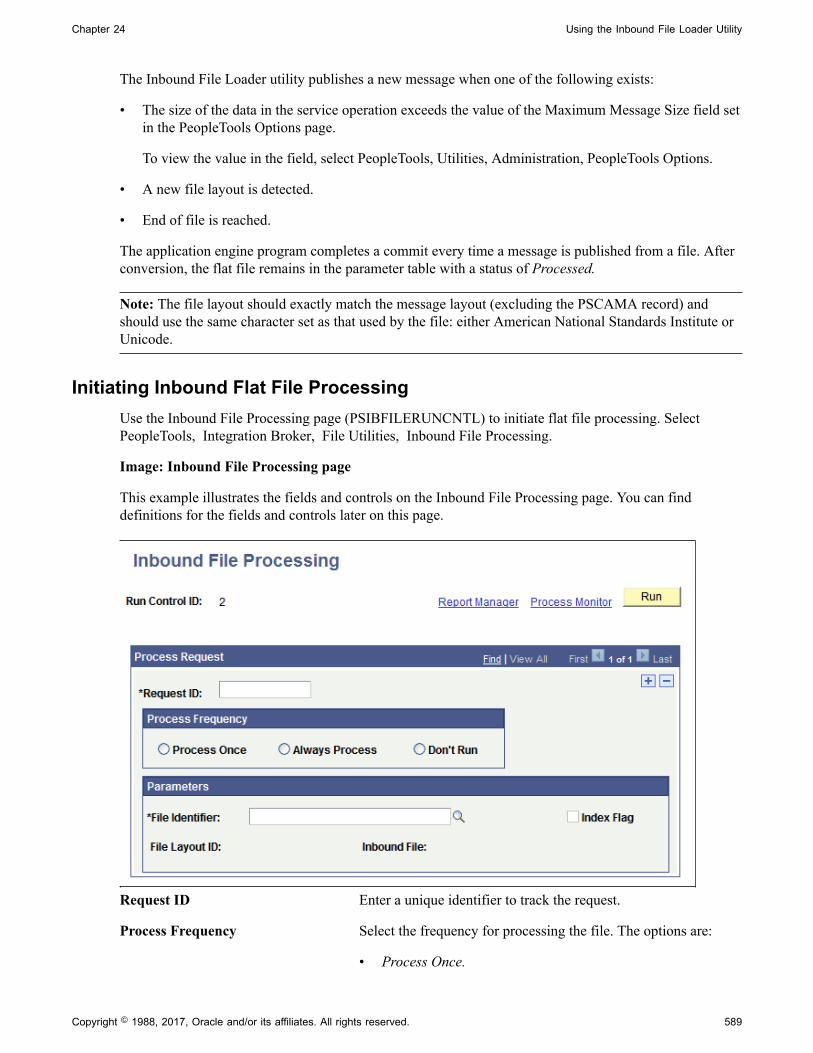
Chapter 24 Using the Inbound File Loader Utility
The Inbound File Loader utility publishes a new message when one of the following exists:
• The size of the data in the service operation exceeds the value of the Maximum Message Size field setin the PeopleTools Options page.
To view the value in the field, select PeopleTools, Utilities, Administration, PeopleTools Options.
• A new file layout is detected.
• End of file is reached.
The application engine program completes a commit every time a message is published from a file. Afterconversion, the flat file remains in the parameter table with a status of Processed.
Note: The file layout should exactly match the message layout (excluding the PSCAMA record) andshould use the same character set as that used by the file: either American National Standards Institute orUnicode.
Initiating Inbound Flat File ProcessingUse the Inbound File Processing page (PSIBFILERUNCNTL) to initiate flat file processing. SelectPeopleTools, Integration Broker, File Utilities, Inbound File Processing.
Image: Inbound File Processing page
This example illustrates the fields and controls on the Inbound File Processing page. You can finddefinitions for the fields and controls later on this page.
Request ID Enter a unique identifier to track the request.
Process Frequency Select the frequency for processing the file. The options are:
• Process Once.
Copyright © 1988, 2017, Oracle and/or its affiliates. All rights reserved. 589

Using the Inbound File Loader Utility Chapter 24
• Always.
• Don't Run.
File Identifier Select or enter the name of the file identifier that you set up inthe Inbound File Loader Rules. page. The file identifier is tied tothe publish rules.
Index Flag A read-only field that indicates if the file being processed is anindex file or a data file. When checked, the Inbound File Loaderutility is processing an index file.
File Layout ID A read-only field that displays the file layout ID associated withthe file in the Inbound File Loader Rules page.
Inbound File A read-only field that displays the name of the file beingprocessed.
Testing Inbound Flat File Processing
To test inbound files:
1. Create a sample flat file, or ask the third-party vendor for a sample flat file.
2. Set up processing rules for the test.
Select PeopleTools, Integration Broker, File Utilities, Inbound File Loader Rules to access theInbound File Loader Rules page.
See Setting Up Inbound File Loader Processing Rules.
3. Initiate file processing.
Select PeopleTools, Integration Broker, File Utilities, Inbound File Processing to access the InboundFile Processing page.
See Initiating Inbound Flat File Processing.
4. Verify the inbound processing created a message that contains the sample flat file data.
a. If you used application class processing, verify if the production or staging tables are loadedwith the correct field values. For production tables, look in the PeopleSoft application pages. Forstaging tables, use either the PeopleSoft application pages or run a query by using PeopleSoftQuery.
b. If you used PeopleSoft Integration Broker for file processing, use the Service Operations Monitorto ensure the inbound file processing created a service operation that contains the sample flat filedata.
Verify that the standard inbound notification process received the message and processed it intothe application tables.
590 Copyright © 1988, 2017, Oracle and/or its affiliates. All rights reserved.

Chapter 24 Using the Inbound File Loader Utility
Determine whether the values become the inherited values (if you used the inherited value featurein file layout).
Validate that the production or staging tables loaded with the correct field values. For productiontables, look in the PeopleSoft application pages. For staging tables, use either the PeopleSoftapplication pages or run a query by using PeopleSoft Query.
Ensure that the date formats conform.
Copyright © 1988, 2017, Oracle and/or its affiliates. All rights reserved. 591

Using the Inbound File Loader Utility Chapter 24
592 Copyright © 1988, 2017, Oracle and/or its affiliates. All rights reserved.

Chapter 25
Copying Integration Metadata betweenPeopleSoft Databases
Copying Integration Metadata Between PeopleSoft Databases
This section provides an overview of copying metadata between PeopleSoft 8.55 databases and discussesdata dependences and relationships when copying data.
Understanding Copying Integration Metadata Between PeopleSoftDatabases
You can use PeopleSoft Application Designer's Project Copy functionality to copy integration metadatabetween PeopleSoft databases.
Message schema and WSDL became managed objects beginning with the PeopleTools 8.50 release. As aresult, you can use Project Copy to copy message schemas and WSDL documents between PeopleTools8.50 and higher databases. However, to copy schema and WSDL between PeopleTools 8.50 and higherdatabases and PeopleTools 8.49 or PeopleTools 8.48 databases, you must use the provided data moverscripts. These data mover scripts are discussed elsewhere in this topic.
See Using Data Mover Scripts to Copy Message Schema and WSDL Data.
Related Links"Copying Projects" (PeopleTools 8.55: Lifecycle Management Guide)
Understanding Data Dependencies and Relationships for Copying DataWhen copying data between databases, you must be aware of data dependencies and relationships toensure that no errors occur and to lessen the chance of encountering orphaned data.
Note: References to 'Project Copy' in the following table are references to the Project Copy feature inPeopleSoft Application Designer.
Object Name Comments
Services. You can use Project Copy to copy services between databases.
WSDL documents that exist for a service are not automaticallycopied with a service. You must include them in the copyproject.
Copyright © 1988, 2017, Oracle and/or its affiliates. All rights reserved. 593

Copying Integration Metadata between PeopleSoft Databases Chapter 25
Object Name Comments
WSDL documents. To copy WSDL to another PeopleTools 8.55 system, use Project Copy. To copy WSDL to earlier releases ofPeopleTools, you must use data mover scripts to copy the datato the target database.
Service operations. A service operation is tied to a service. If you copy a serviceoperation in a project, the target database must alreadycontain the service to which the service operation is tied in thedatabase. If it does not, you must include that service in thecopy project.
Service operations cannot exist in a database without at leastone service operation version - the default version. So whencopying a service operation between databases, you need to beaware what the default service operation is and that you maypossibly have to copy it to the target database as well.
In addition, keep in mind that the relationship betweenservices and service operations is stored as part of the Serviceobject. So for example, if a service contains three operationsand you delete one of the three operations, you must includethe service in the project. After the operation delete, theservice is now linked to the remaining two operations andso it has changed and would need to be copied to the targetdatabase. It is not be enough to only copy the deleted operationin a Delete project; Deleting just the service operationdoesn't delete the link to the service. If you don't follow thisrecommendation, you'll have orphaned data.
Service operation versions. A service operation version refers to a specific serviceoperation. If you copy a service operation version, the targetdatabase must already contain the service operation. If itdoes not, you must include that service operation in the copyproject.
In addition, service operation versions refer to messages. Ifyou copy a service operation version, the messages that arereferenced for that service operation version must exist on thetarget database. If they do not, you must include them in thecopy project.
If WSDL documents have been generated for a serviceoperation version, they are not automatically copied duringthe Project Copy process. Further, once you have copied aservice operation version to the target database, it may appearthat WSDL documents exist for a service operation version, when they do not. To avoid this situation, after you copya service operation version to the target database, open theservice definition to which the service operation belongs.
If the View WSDL link appears, and when you click itWSDL appears, go back to the source database and export thegenerated WSDL documents to the target database. Anotheroption is to delete the WSDL documents associated with aservice operation before the Project Copy, and regenerate themon the target database.
594 Copyright © 1988, 2017, Oracle and/or its affiliates. All rights reserved.

Chapter 25 Copying Integration Metadata between PeopleSoft Databases
Object Name Comments
Service operation handlers. A service operation handler refers to a specific serviceoperation. If you copy a service operation handler, the targetdatabase must already contain the service operation to whichthe handler refers. If it does not, you must include that serviceoperation in the copy project.
Service operation routings. Routing names are keys in the system.
If you copy a routing, the sending and receiving nodes mustdefined on the target database. If they are not defined on thetarget database, you must include them in your copy project.
Routings reference a specific service operation version. If youcopy a routing, the target database must already contain theservice operation version to which the routing refers. If it doesnot, you must include that service operation version in theproject.
Routings also reference nodes. If you copy a routing, the targetdatabase must already contain the nodes being referenced. Anexception to this is the local default node. During project copy,any routing referencing the local default node will be modifiedto reference the default local node of the target system.
If the system detects a duplicate routing definition during theproject copy process, the routing definition in the project beingcopied overwrites the routing definition in the database. Thisinternal check occurs only when you use the Copy from Fileoption during project copy. If during the copy process thesystem overwrites a duplicate service operation routing onthe target system, you may receive a system message that theservice operation routing was deleted. The service operationrouting deleted is the service operation routing that resided onthe target system before the project copy process. To identifyduplicate routings when using the Database to Database optionduring project copy, or to detect and delete any duplicateroutings in the database outside the project copy process, run the duplicate routings check using the Delete DuplicateRoutings section of the Service Administration–Routingspage.
See Deleting Duplicate Routing Definitions.
Messages. Container messages and message parts must have messageschemas to function properly. You should also move messageschemas along with your messages.
Service operation queues. NA
Message schemas. To copy message schemas to another PeopleTools 8.55 system, use Project Copy. To copy message schemas to earlier releasesof PeopleTools, you must use data mover scripts to copy thedata to the target database.
You should copy message schema along with all messages youcopy from one database to another.
Copyright © 1988, 2017, Oracle and/or its affiliates. All rights reserved. 595

Copying Integration Metadata between PeopleSoft Databases Chapter 25
Object Name Comments
Documents When you include a document in a copy project, the systeminserts the document and all related definitions into the project.
To copy a document message type, when you specify themessage, you must also include the document as a relateddefinition.
Integration Groups NA
Related LinksUsing Data Mover Scripts to Copy Message Schema and WSDL Data
Using Data Mover Scripts to Copy Message Schema and WSDLData
In PeopleTools 8.50 message schema and WSDL documents became managed objects.
To move message schema and WSDL documents from PeopleTools 8.50 and later databases toPeopleTools 8.48 databases or PeopleTools 8.49 databases, use the data mover scripts described in thefollowing table. These scripts are located in the <PS_HOME>\scripts directory.
Object Script Name Description
Message schema. PSIBMSGSCHEMA_EXP.DMS Export a message schema from aPeopleTools 8.55 database.
Message schema. PSIBMSGSCHEMA_IMP.DMS Import a message schema into aPeopleTools 8.55 database.
WSDL document. PSIBWSDL_EXP.DMS Export a WSDL document from aPeopleTools 8.55 database.
WSDL document. PSIBWSDL_IMP.DMS Import a WSDL document into aPeopleTools 8.55 database.
The WSDL data mover scripts move WSDL by WSDL name, not service name. Therefore it is possible toselect specific WSDL for importing/exporting for a given service.
You may encounter errors while moving large WSDL documents and schemas from a Microsoft SQL,Oracle or Informix platform to a Sybase or DB2 (UNIX or OS/390) platform because of size restrictionsin Sybase and DB2. The maximum size of WSDL documents from Microsoft SQL, Oracle or Informixplatforms to DB2 or Sybase platforms is described in the following table:
Note: Beginning in PeopleTools 8.55 Informix and Sybase are no longer supported.
596 Copyright © 1988, 2017, Oracle and/or its affiliates. All rights reserved.

Chapter 25 Copying Integration Metadata between PeopleSoft Databases
Source Platforms
(PeopleTools 8.50 and later)
Target Platform
(PeopleTools 8.48 or PeopleTools8.49)
Maximum WSDL/Schema Size (Bytes)
DB2 – UNIX 32700
DB2 – OS/390 31744
• Microsoft SQL
• Oracle
• Informix
(Not supported beginning inPeopleTools 8.55.)
Sybase
(Not supported beginning in PeopleTools8.55.)
32000
Converting WSDL Documents and Message Schemas to ManagedObjects
This section discusses how to:
• Use the Metadata WSDL/Schema Convert page.
• Convert WSDL documents and message schemas to managed objects.
• Convert message schemas to managed objects.
• Delete data from the deprecated data repository.
Understanding Converting WSDL Documents and Message Schema toManaged Objects
This section discusses converting WSDL documents and XML message schema to managed objects. Italso discusses the deprecated data repository.
WSDL Documents and Message Schema as Managed ObjectsBeginning in PeopleTools 8.50, WSDL documents and XML message schema became managed objects.
After you copy WSDL and schema from earlier releases, PeopleSoft Integration Broker enables you toconvert the data to managed objects. To copy WSDL and XML message schema from earlier versions ofPeopleTools, use the data mover scripts described previously in this topic.
See Using Data Mover Scripts to Copy Message Schema and WSDL Data.
In addition, during the PeopleTools upgrade process the system automatically attempts to convert WSDLand schema metadata into managed objects. However, if the system is unable to convert the copied orupgraded data, you can convert it in the PeopleTools 8.55 system.
Deprecated Data RepositoryWSDL documents and XML message schema data that you copy from earlier PeopleTools releasesto a PeopleTools 8.55 database is stored in a deprecated data repository in the database. WSDL and
Copyright © 1988, 2017, Oracle and/or its affiliates. All rights reserved. 597

Copying Integration Metadata between PeopleSoft Databases Chapter 25
schema that do not property convert to managed objects during the upgrade process are also stored in thisrepository.
After you convert WSDL and schema to managed objects, the system moves the data to the metadatarepository.
You can leave data that you do not convert in the deprecated data repository, or you can delete if from thesystem.
Using the Metadata Convert/Schema Convert PageUse the Service Administration – Metadata Convert/Schema Convert page (IB_META_CONV)to convert WSDL documents and message schemas to managed objects. To access the page selectPeopleTools, Integration Broker, Service Utilities, Service Administration and click the Metadata WSDL/Schema Convert tab.
Image: Service Administration – Metadata WSDL/Schema Convert page
This page illustrates the Service Administration – Metadata WSDL/Schema Convert page.
Use the top portion of the page to convert WSDL documents to managed objects. Use the bottom portionof the page to convert XML message schemas to managed objects. The page enables you to work withone WSDL document or message schema at a time, or you can work with all data in the deprecated datarepository at once.
When working with message schema, you can also use the provided View Schema link on the page toview schemas before converting them.
This page also enables you to delete data from the deprecated data repository that you do not want toconvert to managed objects or that you no longer need.
The following sections describe how to accomplish these tasks in greater detail.
Converting WSDL Documents to Managed ObjectsThis section discusses how to convert WSDL documents to managed objects.
598 Copyright © 1988, 2017, Oracle and/or its affiliates. All rights reserved.

Chapter 25 Copying Integration Metadata between PeopleSoft Databases
To convert a WSDL document to a managed object:
1. Access the Service Administration – MetadataWSDL/Schema Convert page (PeopleTools, IntegrationBroker, Service Utilities, Service Administration and click the Metadata WSDL/Schema Convert tab.
2. Select the WSDL document(s) to convert:
• To select a specific service for which to convert WSDL, in the Service field, enter the servicename.
• To select from all services in the deprecated data repository, click the Search button under theService field.
Search results appear in the Non-Metadata WSDL grid.
3. In the Non-Metadata WSDL grid, select the check box next to each service name for which to convertWSDL.
If a check appears in the WSDL Exists check box, WSDL already exists as a managed object for theservice. You can choose to use the existing WSDL, or select the check box in the Select column toconvert the WSDL again and overwrite the existing WSDL.
4. Click the Convert button under the Non-Metadata WSDL grid.
5. The status of the conversion for each service you selected appears in the Results field.
Converting Message Schemas to Managed ObjectsThis section discusses how to convert XML message schema to managed objects.
To convert message schemas to managed objects:
1. Access the Service Administration – Metadata WSDL/Schema Convert page (PeopleTools,Integration Broker, Service Utilities, Service Administration and click the Metadata WSDL/SchemaConvert tab).
2. Select the XML message schema(s) to convert:
• To select a specific schema to convert, in the Message Name field, enter the message name.
• To select from all schema in the deprecated data repository, click the Search button under theMessage Name field.
Search results appear in the Non-Metadata Schemas grid.
3. In the Non-Metadata Schemas grid, select the check box next to each message name that contains theschema to convert.
If a check appears in the Schema Exists box, XML message schema already exists as a managedobject for the message. You can choose to use the existing managed object schema, or select the checkbox in the Select column to convert the schema again and overwrite the existing schema.
4. Click the Convert button under the Non-Metadata Schemas grid.
5. The status of the conversion for each message schema that you converted appears in the Results field.
Copyright © 1988, 2017, Oracle and/or its affiliates. All rights reserved. 599
Copying Integration Metadata between PeopleSoft Databases Chapter 25
If you are unable to convert a schema to a managed object, rebuild the schema:
• For rowset-based messages, open the message in the Messages-Message Definition page and save themessage. Upon Save, PeopleSoft Integration Broker automatically builds the schema for the message.
• For nonrowset-based messages use one of the following options to rebuild the schema:
• Access the schema using the View Schema link on the Metadata Convert/Schema Convert pageand copy it to the Messages-Schema page and correct and save the schema.
• Access the schema using the View Schema link on the Metadata Convert/Schema Convert pageand copy it into an XML editor and correct the schema. Then upload it into the system using theMessages-Schema page.
• Upload or create a new schema using the Messages-Schema page.
Related LinksManaging XML Message Schemas for Rowset-Based MessagesAdding XML Message Schemas to Nonrowset-Based Messages
Deleting Data from the Deprecated Data RepositoryThis section discusses how to delete WSDL documents and XML message schemas from the deprecateddata repository.
To delete data from the deprecated data repository:
1. Access the Service Administration – Metadata WSDL/Schema Convert page (PeopleTools,Integration Broker, Service Utilities, Service Administration and click the Metadata WSDL/SchemaConvert tab).
2. Select the WSDL document(s) or XML message schema(s) to delete:
• To select a specific WSDL document to delete, in the Service field, enter the service name.
• To select from all services in the deprecated data repository, click the Search button under theService field.
• To select a specific schema to delete, in the Message Name field, enter the message name.
• To select from all schema in the deprecated data repository, click the Search button under theMessage Name field.
Search results appear in the appropriate WSDL or schema grid.
3. In the WSDL or schema grid, select the Select check box next to the data to delete.
4. Click the Delete button under the grid in which the data to delete appears.
600 Copyright © 1988, 2017, Oracle and/or its affiliates. All rights reserved.
Chapter 25 Copying Integration Metadata between PeopleSoft Databases
Managing Nodes Copied Between Databases and Upgraded fromEarlier PeopleTools Releases
The user ID on any nodes that you copy to a database using Project Copy or that you upgrade from earlierPeopleTools releases must be:
• Valid in the target database.
• Assigned to the permission lists of any service operation that you intend to use.
Copyright © 1988, 2017, Oracle and/or its affiliates. All rights reserved. 601

Copying Integration Metadata between PeopleSoft Databases Chapter 25
602 Copyright © 1988, 2017, Oracle and/or its affiliates. All rights reserved.

Appendix A
Integration Scenarios
Understanding the Integration Scenarios
This section lists several basic integration scenarios that you can implement using PeopleSoftIntegration Broker. Overviews of each of these scenarios are provided in this topic. Other scenarios andconfigurations may exist that better suit your business requirements.
• Integrating with PeopleSoft Integration Broker Systems
• Integrating with PeopleSoft Integration Broker Systems Through Firewalls
• Integrating with PeopleSoft Integration Broker Systems by Using Hubs
• Integrating with Third-Party Systems
• Integrating with Third-Party Systems by Using Remote Gateways
• Integrating with PeopleTools 8.47 and Earlier PeopleTools 8.4x Systems
• Integrating with PeopleTools 8.1x Systems
Understanding Integration Setup for the Integration Scenarios
An integration engine is automatically installed as part of your PeopleSoft application, and an integrationgateway is installed as part of the PeopleSoft Pure Internet Architecture. However, there's no requirementthat your integration gateway be on the same machine as the integration engine.
In general, the high-level tasks that you perform to configure any of the integration scenarios are:
• Define a local integration gateway.
• Define a remote integration gateway.
• Set integration gateway properties.
• Set up a local node.
• Set up a remote node.
• Create service operations with inbound and outbound routing definitions.
You may not need to perform all of these tasks. For example, if you don't need to communicate through afirewall, you probably don't need to define a remote gateway.
Application messaging, the precursor to PeopleSoft Integration Broker, employed content-based routing—each message had to provide its own routing information, which was defined in the message header.
Copyright © 1988, 2017, Oracle and/or its affiliates. All rights reserved. 603

Integration Scenarios Appendix A
With PeopleSoft Integration Broker, you define the routing information separately. You can applymultiple routings to a message and change the routings independent of the message definition.
Defining Local and Remote Integration GatewaysOn each PeopleSoft Integration Broker system in your configuration, you must specify a local integrationgateway. The local gateway is the application’s first point of contact with other PeopleSoft applications,third-party systems, PeopleSoft Integration Broker hubs, and remote gateways. You must define exactlyone local gateway for each integration engine, but a single installed gateway can serve multiple engines.The web server where the integration gateway resides can be any machine on which you've installed thePeopleSoft Pure Internet Architecture.
To define the local gateway, use the Gateways component (IB_GATEWAY) to:
• Add the gateway that the application will use to communicate with other systems.
• Specify the uniform resource locator (URL) of the gateway's PeopleSoft listening connector.
This is the connector that receives messages from an integration engine (including the default localnode) or another integration gateway.
• Register the target connectors that are delivered with PeopleSoft Integration Broker.
These target connectors are automatically installed during the PeopleSoft Pure Internet Architectureinstallation process. When you subsequently define local and remote nodes, you specify—from thelist of installed target connectors—which connector the local gateway should use to send messages toeach node.
Note: The remote gateway default connector setting in the integrationGateway.properties file,ig.connector.defaultremoteconnector, determines through which connector the gateway routes messagesthat are bound for other gateways. By default, this property is set to the HTTP target connector,HTTPTARGET. Never change this setting unless you develop a custom connector to handle this routing.
An integration gateway also includes a set of listening connectors, which are likewise installed with thePeopleSoft Pure Internet Architecture. You don't to need to specify these connectors directly; third-partysystems send messages to the gateway by specifying the URL of an appropriate listening connector.
Setting Integration Gateway PropertiesYou set integration gateway properties by using the gateway's primary configuration file, calledintegrationGateway.properties. You must set an Oracle Jolt connect string in this file to enablecommunication with each PeopleSoft Integration Broker node that will be involved in an integration thatuses this gateway.
The following example shows the required Oracle Jolt connect string setting:
ig.isc.<nodename>.serverURL=//<machine_name>:<jolt_port>ig.isc.<nodename>.userid=<database_user_id>ig.isc.<nodename>.password=<database_password>ig.isc.<nodename>.toolsRel=<peopletools_release_version>
604 Copyright © 1988, 2017, Oracle and/or its affiliates. All rights reserved.
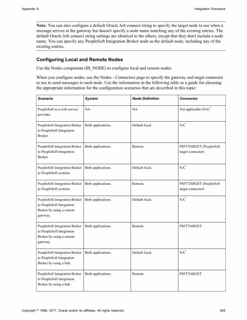
Appendix A Integration Scenarios
Note: You can also configure a default Oracle Jolt connect string to specify the target node to use when amessage arrives at the gateway but doesn't specify a node name matching any of the existing entries. Thedefault Oracle Jolt connect string settings are identical to the others, except that they don't include a nodename. You can specify any PeopleSoft Integration Broker node as the default node, including any of theexisting entries.
Configuring Local and Remote NodesUse the Nodes component (IB_NODE) to configure local and remote nodes.
When you configure nodes, use the Nodes - Connectors page to specify the gateway and target connectorto use to send messages to each node. Use the information in the following table as a guide for choosingthe appropriate information for the configuration scenarios that are described in this topic:
Scenario System Node Definition Connector
PeopleSoft as a web serviceprovider.
NA NA. Not applicable (NA)*
PeopleSoft Integration Brokerto PeopleSoft IntegrationBroker.
Both applications. Default local. NA*
PeopleSoft Integration Brokerto PeopleSoft IntegrationBroker.
Both applications. Remote. PSFTTARGET (PeopleSofttarget connector)
PeopleSoft Integration Brokerto PeopleSoft systems.
Both applications. Default local. NA*
PeopleSoft Integration Brokerto PeopleSoft systems.
Both applications. Remote. PSFTTARGET (PeopleSofttarget connector)
PeopleSoft Integration Brokerto PeopleSoft IntegrationBroker by using a remotegateway.
Both applications. Default local. NA*
PeopleSoft Integration Brokerto PeopleSoft IntegrationBroker by using a remotegateway.
Both applications. Remote. PSFTTARGET
PeopleSoft Integration Brokerto PeopleSoft IntegrationBroker by using a hub.
Both applications. Default local. NA*
PeopleSoft Integration Brokerto PeopleSoft IntegrationBroker by using a hub.
Both applications. Remote. PSFTTARGET
Copyright © 1988, 2017, Oracle and/or its affiliates. All rights reserved. 605
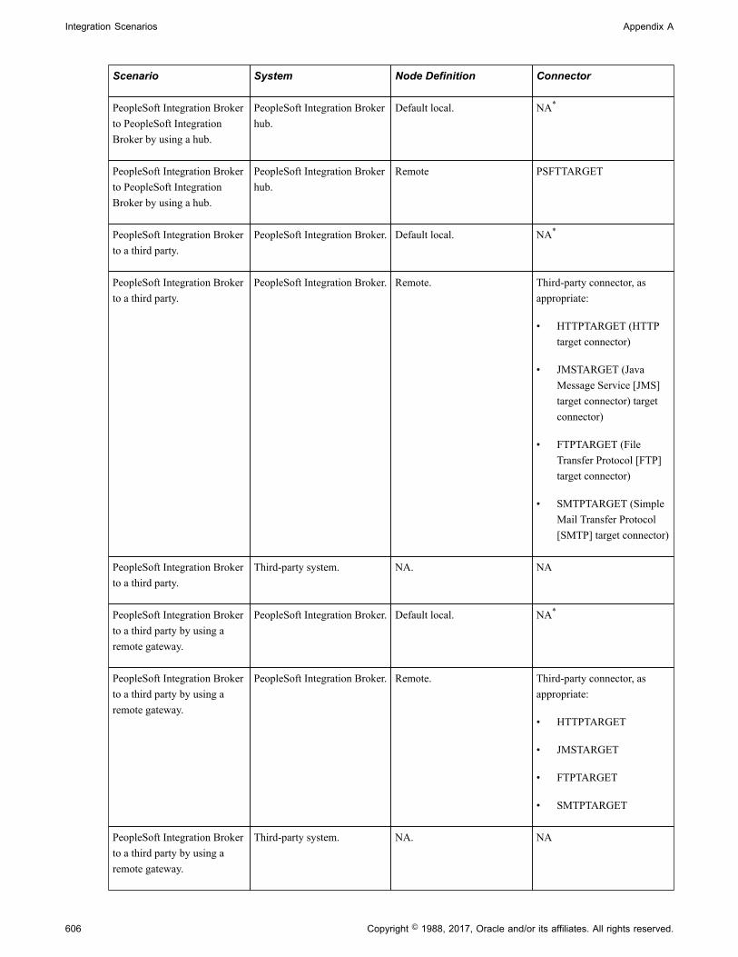
Integration Scenarios Appendix A
Scenario System Node Definition Connector
PeopleSoft Integration Brokerto PeopleSoft IntegrationBroker by using a hub.
PeopleSoft Integration Brokerhub.
Default local. NA*
PeopleSoft Integration Brokerto PeopleSoft IntegrationBroker by using a hub.
PeopleSoft Integration Brokerhub.
Remote PSFTTARGET
PeopleSoft Integration Brokerto a third party.
PeopleSoft Integration Broker. Default local. NA*
PeopleSoft Integration Brokerto a third party.
PeopleSoft Integration Broker. Remote. Third-party connector, asappropriate:
• HTTPTARGET (HTTPtarget connector)
• JMSTARGET (JavaMessage Service [JMS]target connector) targetconnector)
• FTPTARGET (FileTransfer Protocol [FTP]target connector)
• SMTPTARGET (SimpleMail Transfer Protocol[SMTP] target connector)
PeopleSoft Integration Brokerto a third party.
Third-party system. NA. NA
PeopleSoft Integration Brokerto a third party by using aremote gateway.
PeopleSoft Integration Broker. Default local. NA*
PeopleSoft Integration Brokerto a third party by using aremote gateway.
PeopleSoft Integration Broker. Remote. Third-party connector, asappropriate:
• HTTPTARGET
• JMSTARGET
• FTPTARGET
• SMTPTARGET
PeopleSoft Integration Brokerto a third party by using aremote gateway.
Third-party system. NA. NA
606 Copyright © 1988, 2017, Oracle and/or its affiliates. All rights reserved.

Appendix A Integration Scenarios
Scenario System Node Definition Connector
PeopleSoft Integration Brokerto PeopleSoft IntegrationBroker on PeopleTools 8.47and earlier PeopleTools 8.4xsystems.
Both applications. Default local. NA
PeopleSoft Integration Brokerto PeopleSoft IntegrationBroker on PeopleTools 8.47and earlier PeopleTools 8.4xsystems.
Both applications. Remote. PSFTTARGET (PeopleSofttarget connector)
PeopleSoft Integration Brokerto PeopleTools 8.1x systems.
PeopleSoft Integration Broker. Default local. NA*
PeopleSoft Integration Brokerto PeopleTools 8.1x systems.
PeopleSoft Integration Broker. Remote. PSFT81TARGET (PeopleSoft8.1 target connector)
PeopleSoft Integration Brokerto PeopleTools 8.1x systems.
PeopleSoft 8.1x system. NA.
Set up message nodes, message channels, messages, and so on.
NA
* The default connector is PSFTTARGET, but it is not used.
Related Links"Using the integrationGateway.properties File" (PeopleTools 8.55: Integration Broker Administration)"Administering Integration Gateways" (PeopleTools 8.55: Integration Broker Administration)"Adding Node Definitions" (PeopleTools 8.55: Integration Broker Administration)"Configuring Nodes" (PeopleTools 8.55: Integration Broker Administration)
Integrating with PeopleSoft Integration Broker Systems
This section provides an overview of this scenario and discusses how to configure the system for thisscenario.
Understanding This ScenarioIn this scenario a PeopleSoft Human Resources system is integrating with a PeopleSoft CustomerRelationship Management system on PeopleTools. Both systems are on the same PeopleTools release.
Copyright © 1988, 2017, Oracle and/or its affiliates. All rights reserved. 607

Integration Scenarios Appendix A
Image: Integrations with PeopleSoft Integration Broker Systems
This diagram illustrates a PeopleSoft Human Resources (HR) system communicating with a PeopleSoftCustomer Relationship Management (CRM) system and shows the configuration and interaction ofPeopleSoft Integration Broker components
This communication can be synchronous or asynchronous.
Configuring the System for This ScenarioThis section describes the source and destination system configuration tasks, based on the scenario shownin the previous diagram. In this example, the PeopleSoft Human Resources system is the source systemand the PeopleSoft CRM system is the destination system.
This section discusses how to configure:
• The integration gateway.
• The PeopleSoft Human Resources system.
• The PeopleSoft CRM system.
Configuring the Integration GatewayThe only required property that you must set for the local gateway is the Oracle Jolt connectstrings that enable the gateway to find the PeopleSoft CRM system. Set this property in theintegrationGateway.properties file.
608 Copyright © 1988, 2017, Oracle and/or its affiliates. All rights reserved.

Appendix A Integration Scenarios
Configuring the PeopleSoft Human Resources SystemPerform the following tasks on the PeopleSoft Human Resources system:
1. Define the local integration gateway for the PeopleSoft Human Resources system by using theGateways component.
Any integration gateway that you've installed and configured to find the PeopleSoft CRM system canserve this role. Specify the gateway's PeopleSoft listening connector as the gateway's URL.
2. Configure the default local node definition that represents the PeopleSoft system by using the Nodescomponent.
This node is delivered predefined on the system.
3. Define a remote node to represent the PeopleSoft CRM system.
Because the PeopleSoft CRM system uses PeopleSoft Integration Broker, specify the local gatewayfor the PeopleSoft Human Resources system and its PeopleSoft target connector on the NodeDefinitions - Connectors page.
4. Define a service operation that specifies the request message, the service operation handler definitionand routing definition.
The routing is a point-to-point routing where the PeopleSoft CRM node is the receiving node and thePeopleSoft HR system is the sending node.
Configuring the PeopleSoft CRM SystemPerform the following tasks on the PeopleSoft CRM system:
1. Define the local integration gateway for the PeopleSoft CRM system by using the Gatewayscomponent.
Any integration gateway that you've installed and configured can serve this role, including the localgateway for the PeopleSoft Human Resources system. Specify the gateway's PeopleSoft listeningconnector as the gateway's URL.
2. Configure the default local node definition that represents the PeopleSoft CRM system by using theNodes component.
This node is delivered predefined on the system.
3. Define a remote node to represent the PeopleSoft Human Resources system.
Because the PeopleSoft Human Resources system uses PeopleSoft Integration Broker, specify thelocal gateway for the PeopleSoft CRM system and its PeopleSoft target connector on the NodeDefinitions - Connectors page.
4. Define a service operation that specifies the request message, the service operation handler definitionand routing definition.
The routing is a point-to-point routing where the PeopleSoft CRM node is the receiving node and thePeopleSoft HR system is the sending node.
Copyright © 1988, 2017, Oracle and/or its affiliates. All rights reserved. 609

Integration Scenarios Appendix A
Related LinksUnderstanding Integration Setup for the Integration ScenariosAdding Service Operation DefinitionsConfiguring Service Operation Definitions"Administering Integration Gateways" (PeopleTools 8.55: Integration Broker Administration)"Adding Node Definitions" (PeopleTools 8.55: Integration Broker Administration)"Configuring Nodes" (PeopleTools 8.55: Integration Broker Administration)
Integrating with PeopleSoft Integration Broker Systems ThroughFirewalls
This section provides an overview of this scenario and discusses how to configure the system for thisscenario.
Understanding This ScenarioIn this scenario a PeopleSoft Human Resources system is integrating with a PeopleSoft CustomerRelationship Management system on PeopleTools. Both systems are on the same PeopleTools release.
Use a remote gateway configuration when connections with an integration participant are not possiblethrough the internet. This type of implementation enables you to communicate with wide area networks(WANs) and local area networks (LANs) where a firewall is present.
610 Copyright © 1988, 2017, Oracle and/or its affiliates. All rights reserved.

Appendix A Integration Scenarios
Image: Integrations with PeopleSoft Integration Broker Systems by Using Firewalls
This diagram shows the configuration of PeopleSoft Integration Broker components for integrations withother PeopleSoft Integration Broker systems by using firewall.
For this configuration scenario, one PeopleSoft application and one integration gateway reside on eachside of the firewall. The integration gateway can reside on the same physical machine on which you haveinstalled the PeopleSoft application, or it can reside on its own machine.
In this configuration scenario, PeopleSoft Integration Broker uses the default remote gateway connector,the HTTP target connector, on the local gateway to send messages to the PeopleSoft listening connectoron the remote gateway. Routing all messages through the local gateway enables each PeopleSoftIntegration Broker system to keep its own centralized log of all integration messages.
Because this example shows two-way communication and assumes that the same service operationis being exchanged, the PeopleSoft Human Resources (USA) system and the PeopleSoft CRM (UK)
Copyright © 1988, 2017, Oracle and/or its affiliates. All rights reserved. 611

Integration Scenarios Appendix A
system are source systems when they send messages, and they're destination systems when they receivemessages.
Keep in mind the following as you review these configuration tasks:
• You should use a single integration gateway for all applications that reside on the same side of afirewall.
• The local integration gateway for one application is the remote integration gateway for the otherapplication.
Configuring the System for This ScenarioThis section describes the configuration tasks for each of the components that are shown in the previousdiagram.
This section discusses how to configure:
• The PeopleSoft Human Resources (USA) system.
• The PeopleSoft Human Resources (USA) integration gateway.
• The PeopleSoft CRM (UK) system.
• The PeopleSoft CRM (UK) integration gateway.
Configuring the PeopleSoft Human Resources (USA) SystemOn the PeopleSoft Human Resources (USA) system:
1. Define a local integration gateway.
Use the Gateways component to define the local PeopleSoft Human Resources (USA) gateway.
2. Define a remote integration gateway.
The remote integration gateway for the PeopleSoft Human Resources (USA) system is the PeopleSoftCRM (UK) gateway. Use the Gateways component to define a new gateway, and for the gatewayURL, specify the PeopleSoft listening connector of the PeopleSoft CRM (UK) gateway.
3. Define the default local node.
Use the Nodes component to define the default local node, which represents the PeopleSoft HumanResources (USA) system.
4. Define a remote node.
The remote node that you define represents the PeopleSoft CRM (UK) system. When you set up theremote node, specify the PeopleSoft CRM (remote) integration gateway and the PeopleSoft targetconnector on that gateway.
5. For the outbound integration, define a service operation that specifies the request and responsemessages, the service operation handler definition, and the outbound routing definition.
The outbound routing is a point-to-point routing where the PeopleSoft HR node is the sending nodeand the PeopleSoft CRM node is the receiving node.
612 Copyright © 1988, 2017, Oracle and/or its affiliates. All rights reserved.
Appendix A Integration Scenarios
6. For the inbound integration, on the same service operation create a routing definition where thePeopleSoft HR system is the receiving node and the PeopleSoft CRM system is the sending node.
Note: The external alias you specify on the inbound routing definition must match the external aliason the outbound routing definition you created in the previous step.
Configuring the PeopleSoft Human Resources (USA) Integration GatewayThe only required integration gateway property that you must set for the PeopleSoft Human Resources(USA) integration gateway is the Oracle Jolt connect strings that enable communication with theintegration engine on the PeopleSoft Human Resources (USA) system. Set this property in theintegrationGateway.properties file.
Configuring the PeopleSoft CRM (UK) SystemOn the PeopleSoft CRM (UK) system:
1. Define a local integration gateway.
Use the Gateways component to define the local PeopleSoft CRM (UK) gateway.
2. Define a remote integration gateway.
The remote integration gateway for the PeopleSoft CRM (UK) system is the PeopleSoft HumanResources (USA) gateway. Use the Gateways component to define a new gateway, and for thegateway URL, specify the PeopleSoft listening connector of the PeopleSoft Human Resources (USA)gateway.
3. Define the default local node.
Use the Nodes component to define the default local node, which represents the PeopleSoft CRM(UK) system.
4. Define a remote node.
The remote node that you define represents the PeopleSoft Human Resources (USA) system. Whenyou set up the remote node, specify the PeopleSoft Human Resources (remote) integration gatewayand the PeopleSoft target connector on that gateway.
5. For the outbound integration, define a service operation that specifies the request and responsemessages, the service operation handler definition, and the outbound routing definition.
The outbound routing is a point-to-point routing where the PeopleSoft HR node is the receiving nodeand the PeopleSoft CRM node is the sending node.
6. For the inbound integration, on the same service operation create a routing definition where thePeopleSoft HR system is the sending node and the PeopleSoft CRM system is the receiving node.
Note: The external alias you specify on the inbound routing definition must match the external aliason the outbound routing definition you created in the previous step.
Copyright © 1988, 2017, Oracle and/or its affiliates. All rights reserved. 613

Integration Scenarios Appendix A
Configuring the PeopleSoft CRM (UK) Integration GatewayThe only required integration gateway property that you must set for the PeopleSoft CRM (UK)integration gateway is the Oracle Jolt connect strings that enable communication with the integrationengine on the PeopleSoft CRM (UK) system. Set this property in the integrationGateway.properties file.
Related LinksUnderstanding Integration Setup for the Integration Scenarios"Administering Integration Gateways" (PeopleTools 8.55: Integration Broker Administration)Adding Service Operation DefinitionsConfiguring Service Operation Definitions"Understanding Nodes" (PeopleTools 8.55: Integration Broker Administration)
Integrating with PeopleSoft Integration Broker Systems by UsingHubs
This section provides overviews of this scenario and hub routing types and discusses how to configure:
• Generic routing hubs.
• Sender-specified routing hubs.
Understanding This ScenarioA PeopleSoft Integration Broker hub configuration includes an integration engine that houses routingrules and transformations. All integrations are routed through the hub, which enables you to centralizerouting rules and offload the transformation process.
614 Copyright © 1988, 2017, Oracle and/or its affiliates. All rights reserved.

Appendix A Integration Scenarios
Image: Integrations with PeopleSoft Integration Broker systems using a hub.
This diagram shows a one-way hub configuration scenario that involves a PeopleSoft Human Resources(HR) system and a PeopleSoft Customer Relationship Management (CRM) system.
In this scenario, all of the routing rules and transformations are located on the hub.
To implement integrations between the two systems without a hub, you must set up a complete set ofcomplementary routing rules and transformations on each node.
Understanding Hub Routing TypesThere are two hub routing types: generic routing and sender-specified routing. The configuration steps fora hub vary, depending on which routing type you choose.
With generic routing, all transactions from the participating systems are sent directly to a hub for routingand transformation.
Copyright © 1988, 2017, Oracle and/or its affiliates. All rights reserved. 615
Integration Scenarios Appendix A
With sender-specified routing, a destination node name is passed as a parameter to a PeopleCode Publishor SyncRequest method, such as %intBrokerPublish or %intBroker.SynchRequest, to explicitly routethe outbound transactions to the necessary node. Using sender-specified routing requires that you definethe explicit destination nodes on the sending system. However, you can configure the system so thatPeopleSoft Integration Broker passes these outbound transactions to the hub for possible rerouting andtransformation.
Note: You must use sender-specific routing when you're using PublishXMLDoc to asynchronouslypublish an XML object.
Regardless of which hub routing you use, you must configure each PeopleSoft application's integrationengine, the integration gateway, and the PeopleSoft Integration Broker hub. A PeopleSoft IntegrationBroker hub can be an installed PeopleSoft application, or it can have only a stand-alone PeopleToolsdatabase installed, which includes the integration engine.
Configuring Generic-Routing HubsBy using the elements in the previous diagram as an example, this section provides an overview of how toconfigure a generic-routing hub. In the scenario, the PeopleSoft Human Resources system, the PeopleSoftCRM system, and the hub must all point to the same integration gateway and use the same gateway URL.
This section discusses how to configure:
• The PeopleSoft Human Resources system.
• The PeopleSoft CRM system.
• The PeopleSoft hub.
• The integration gateway.
• The generic-routing hub.
Configuring the PeopleSoft Human Resources SystemOn the PeopleSoft Human Resources system:
1. Define a local integration gateway.
Use the Gateways component to set up a local integration gateway for sending messages.
2. Set up a local node.
Use the Nodes component to set up the local node, which represents the PeopleSoft Human Resourcessystem.
3. Set up a remote node.
Use the Nodes component to set up the remote node, which represents the hub system.
4. Create a service operation.
Use the Service Operations component to set up a service operation. Define the request message,service operation handler definition, and routing definition.
616 Copyright © 1988, 2017, Oracle and/or its affiliates. All rights reserved.

Appendix A Integration Scenarios
Create a point-to-point routing definition where the PeopleSoft HR system is the sending node and thehub system is the receiving node.
Configuring the PeopleSoft CRM SystemOn the PeopleSoft CRM system:
1. Define a local integration gateway.
Use the Gateways component to set up a local integration gateway for sending messages.
2. Set up a local node.
Use the Node Definition component to set up the local node, which represents the PeopleSoft CRMsystem.
3. Set up a remote node.
Use the Node Definition component to set up the remote node, which represents the hub system.
4. Create a service operation.
Use the Service Operations component to set up a service operation.
Create an inbound point-to-point routing definition where the sending node is the hub system and thereceiving node is the PeopleSoft CRM system.
Configuring the PeopleSoft HubOn the PeopleSoft hub:
1. Define a local integration gateway.
Use the Gateways component to set up a local integration gateway for sending messages.
2. Set up a local node.
Use the Node Definition component to set up the local node, which represents the hub system.
3. Set up remote nodes.
Set up two remote nodes: one that represents the PeopleSoft Human Resources system and anotherthat represents the PeopleSoft CRM system.
4. Create a service operation.
Use the Service Operations component to set up a service operation.
Create an outbound point-to-point routing definition where the sending node is the PeopleSoft HRsystem and the receiving node is the PeopleSoft CRM system.
Configuring the Integration GatewayYou must set integration gateway properties for the local gateway. The only required properties are theOracle Jolt connect string properties that enable communication with the integration engines on the
Copyright © 1988, 2017, Oracle and/or its affiliates. All rights reserved. 617
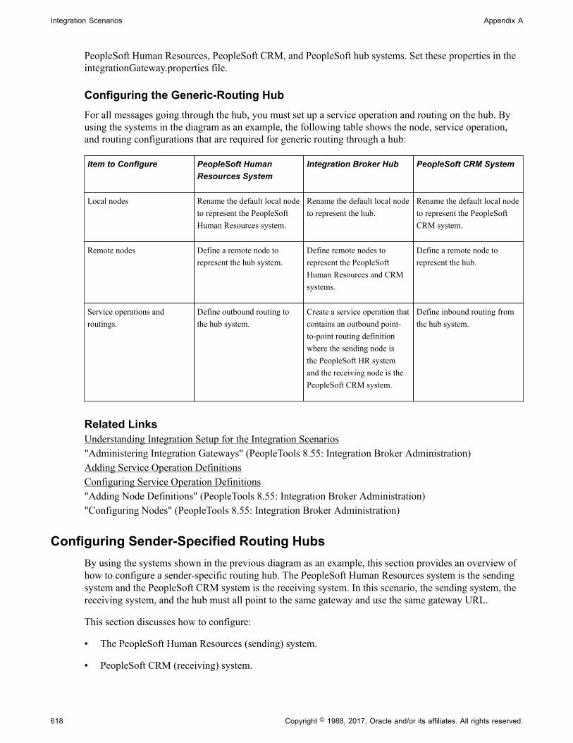
Integration Scenarios Appendix A
PeopleSoft Human Resources, PeopleSoft CRM, and PeopleSoft hub systems. Set these properties in theintegrationGateway.properties file.
Configuring the Generic-Routing HubFor all messages going through the hub, you must set up a service operation and routing on the hub. Byusing the systems in the diagram as an example, the following table shows the node, service operation,and routing configurations that are required for generic routing through a hub:
Item to Configure PeopleSoft HumanResources System
Integration Broker Hub PeopleSoft CRM System
Local nodes Rename the default local nodeto represent the PeopleSoftHuman Resources system.
Rename the default local nodeto represent the hub.
Rename the default local nodeto represent the PeopleSoftCRM system.
Remote nodes Define a remote node torepresent the hub system.
Define remote nodes torepresent the PeopleSoftHuman Resources and CRMsystems.
Define a remote node torepresent the hub.
Service operations androutings.
Define outbound routing tothe hub system.
Create a service operation thatcontains an outbound point-to-point routing definitionwhere the sending node isthe PeopleSoft HR systemand the receiving node is thePeopleSoft CRM system.
Define inbound routing fromthe hub system.
Related LinksUnderstanding Integration Setup for the Integration Scenarios"Administering Integration Gateways" (PeopleTools 8.55: Integration Broker Administration)Adding Service Operation DefinitionsConfiguring Service Operation Definitions"Adding Node Definitions" (PeopleTools 8.55: Integration Broker Administration)"Configuring Nodes" (PeopleTools 8.55: Integration Broker Administration)
Configuring Sender-Specified Routing HubsBy using the systems shown in the previous diagram as an example, this section provides an overview ofhow to configure a sender-specific routing hub. The PeopleSoft Human Resources system is the sendingsystem and the PeopleSoft CRM system is the receiving system. In this scenario, the sending system, thereceiving system, and the hub must all point to the same gateway and use the same gateway URL.
This section discusses how to configure:
• The PeopleSoft Human Resources (sending) system.
• PeopleSoft CRM (receiving) system.
618 Copyright © 1988, 2017, Oracle and/or its affiliates. All rights reserved.

Appendix A Integration Scenarios
• The PeopleSoft hub.
• The integration gateway.
• The sender-specified routing hub.
Configuring PeopleSoft Human Resources (Sending) SystemOn the PeopleSoft Human Resources system:
1. Define a local integration gateway.
Use the Gateways component to set up a local integration gateway for sending messages.
2. Set up a local node.
Use the Nodes component to set up the local node, which represents the PeopleSoft Human Resourcessystem.
3. Set up remote nodes.
Set up two remote nodes: one for the receiving system (PeopleSoft CRM in the example) and one forthe hub. When setting up the PeopleSoft CRM remote node, on the Nodes-Node Definitions page inthe Hub Node field, enter the node name of the hub system.
4. Create a service operation.
Use the Service Operations component to create a service operation that contains an outbound point-to-point routing definition where the sending node is the PeopleSoft HR system and the receivingnode is the PeopleSoft CRM system.
Configuring PeopleSoft CRM (Receiving System)On the PeopleSoft CRM system:
1. Define a local integration gateway.
Use the Gateways component to set up a local integration gateway for sending messages.
2. Set up a local node.
Use the Nodes component to set up the local node, which represents the PeopleSoft CRM system.
3. Set up a remote node.
Use the Nodes component to set up a node that represents the hub.
4. Create a service operation.
Use the Service Operations component to create a service operation that contains an inbound point-to-point routing definition where the sending node is the hub system and the receiving node is thePeopleSoft CRM system.
5. Create a service operation.
Copyright © 1988, 2017, Oracle and/or its affiliates. All rights reserved. 619

Integration Scenarios Appendix A
Use the Service Operations component to create a service operation that contains an inbound point-to-point routing definition where the sending node is the hub system and the receiving node is thePeopleSoft CRM system.
Configuring the PeopleSoft HubOn the PeopleSoft hub:
1. Define a local integration gateway.
Use the Gateways component to set up a local integration gateway for sending messages.
2. Set up a local node.
Use the Nodes component to set up the local node, which represents the hub system.
3. Set up remote nodes.
Use the Nodes component to set up two remote nodes: one for the PeopleSoft Human Resourcessystem and one for the PeopleSoft CRM system.
4. Create a service operation.
Use the Service Operations component to create a service operation that contains a point-to-pointrouting where the sending node is the PeopleSoft HR node and the receiving node is the CRM node.
Configuring the Integration GatewayThe only required integration gateway properties for the local integration gateway are the Oracle Joltconnect string properties that enable communication with the integration engines on the target PeopleSoftIntegration Broker systems. Set these properties in the integrationGateway.properties file.
Configuring the Sender-Specified Routing HubFor all messages going through the hub, you must set up transactions and relationships on the hub. Byusing the systems in the previous diagram as example, the following table shows the node, transaction,and relationship configurations that are required for sender-specified routing through a hub from thePeopleSoft Human Resources system:
Item to Configure PeopleSoft HumanResources System
PeopleSoft IntegrationBroker Hub
PeopleSoft CRM System
Local nodes Rename the default local nodeto represent the PeopleSoftHuman Resources system.
Rename the default local nodeto represent the hub.
Rename the default local nodeto represent the PeopleSoftCRM system.
Remote nodes Define remote nodes torepresent the PeopleSoft CRMand hub systems.
Define remote nodes torepresent the PeopleSoftHuman Resources and CRMsystems.
Define a remote node torepresent the hub.
620 Copyright © 1988, 2017, Oracle and/or its affiliates. All rights reserved.

Appendix A Integration Scenarios
Item to Configure PeopleSoft HumanResources System
PeopleSoft IntegrationBroker Hub
PeopleSoft CRM System
Service operations androutings.
Create a service operation thatcontains an outbound point-to-point routing definition thatspecifies the receiving node isthe PeopleSoft CRM system.
Create a service operationthat contains a point-to-pointrouting where the sendingnode is the PeopleSoft HRnode and the receiving node isthe CRM node.
Create a service operation thatcontains an inbound point-to-point routing definitionwhere the sending node is thehub system and the receivingnode is the PeopleSoft CRMsystem.
All messages to the PeopleSoft CRM node are the result of publish statements, which include these targetnode parameters:
• msg.Publish(Node.CRM)
• SyncRequest(Node.CRM)
• %intBroker.publish(&MyDoc, Message.MyMessage, Node.CRM)
• %intBroker.SyncRequest(&MyDoc, Message.MyMessage, Node.CRM)
Related LinksUnderstanding Integration Setup for the Integration Scenarios"Administering Integration Gateways" (PeopleTools 8.55: Integration Broker Administration)Adding Service Operation DefinitionsConfiguring Service Operation Definitions"Adding Node Definitions" (PeopleTools 8.55: Integration Broker Administration)"Configuring Nodes" (PeopleTools 8.55: Integration Broker Administration)
Integrating with Third-Party Systems
This section provides an overview of this scenario and discusses how to configure the system for thisscenario.
Understanding This ScenarioFor communications with third-party systems, messages can go through local or remote gateways.
Sending a message to a third-party system is the same as sending a message to a PeopleSoft IntegrationBroker node, except that the target connector that you select depends on the third-party system with whichyou are communicating.
Messages from third-party systems can enter the gateway through any of the listening connectors that aredelivered with PeopleSoft Integration Broker or through a listening connector that you build. You cannotuse the PeopleSoft listening connector for integrations with third-party systems, because it can acceptmessages only in the PeopleSoft internal format.
Copyright © 1988, 2017, Oracle and/or its affiliates. All rights reserved. 621
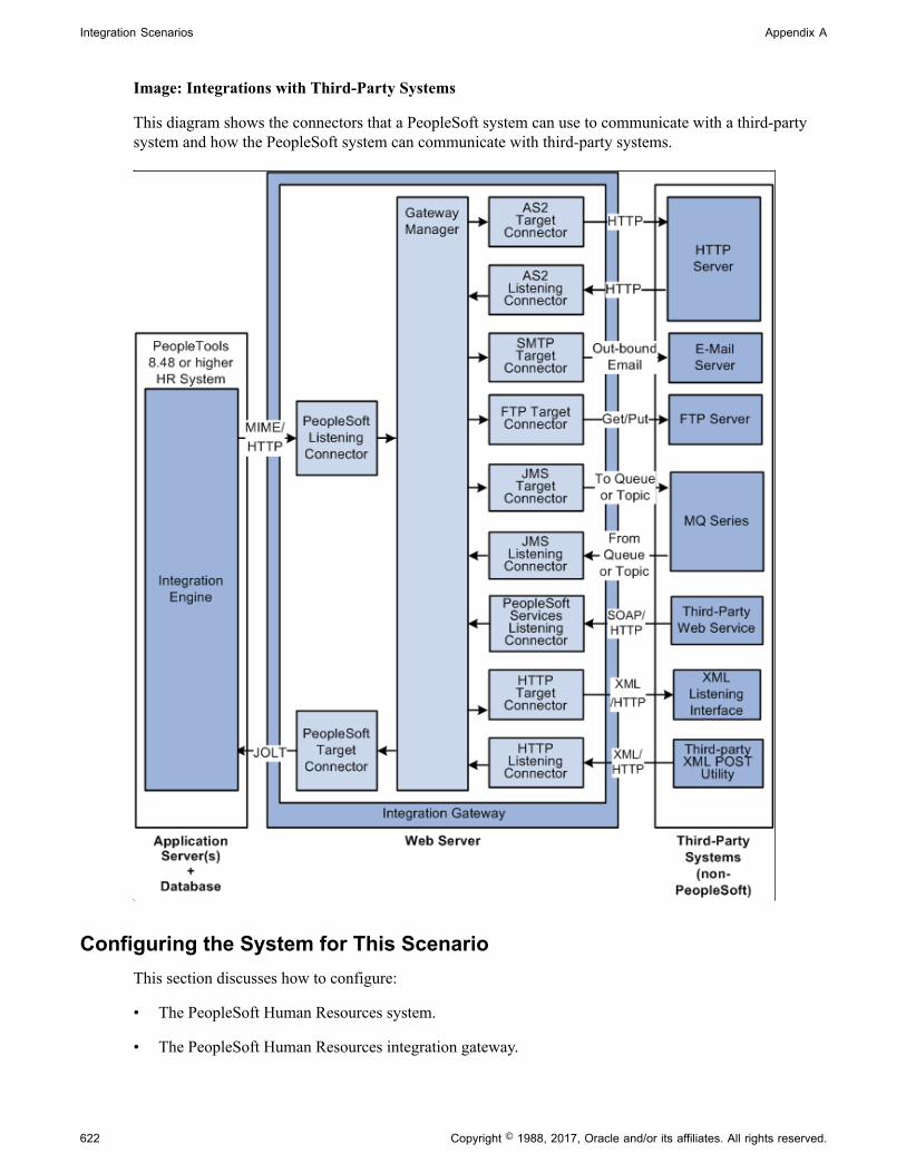
Integration Scenarios Appendix A
Image: Integrations with Third-Party Systems
This diagram shows the connectors that a PeopleSoft system can use to communicate with a third-partysystem and how the PeopleSoft system can communicate with third-party systems.
Configuring the System for This ScenarioThis section discusses how to configure:
• The PeopleSoft Human Resources system.
• The PeopleSoft Human Resources integration gateway.
622 Copyright © 1988, 2017, Oracle and/or its affiliates. All rights reserved.

Appendix A Integration Scenarios
Configuring the PeopleSoft Human Resources SystemOn the PeopleSoft Human Resources system:
1. Define a local integration gateway.
Use the Gateways component to set up a local integration gateway for sending messages.
2. Create a service operation.
Use the Service Operations component to create a service operation that contains an inbound point-to-point routing definition where the sending node is the hub system and the receiving node is thePeopleSoft CRM system.
3. Set up a remote node.
Set up a remote node that represents the third-party system. When you define this node, you select theappropriate connector (for example, JMS target connector, SMTP target connector, and so forth) forcommunicating with the third-party system.
4. Create a service operation with an inbound routing definition where the sending node is the third-party system and the receiving node is the PeopleSoft HR system.
5. In the service operation definition you created in the previous step, create an outbound routingdefinition where the sending node is the PeopleSoft HR system and the receiving node is the third-party system.
Configuring the PeopleSoft Human Resources Integration GatewayThe only required integration gateway properties for the local integration gateway are the default OracleJolt connect string properties that enable communication with integration engines on the PeopleSoftHuman Resources system. Set these properties in the integrationGateway.properties file.
Related LinksUnderstanding Integration Setup for the Integration Scenarios"Administering Integration Gateways" (PeopleTools 8.55: Integration Broker Administration)Adding Service Operation DefinitionsConfiguring Service Operation Definitions"Adding Node Definitions" (PeopleTools 8.55: Integration Broker Administration)"Configuring Nodes" (PeopleTools 8.55: Integration Broker Administration)
Integrating with Third-Party Systems by Using Remote Gateways
This section provides an overview of this scenario and discusses how to:
• Send messages to third-party systems.
• Receive messages from third-party systems.
Copyright © 1988, 2017, Oracle and/or its affiliates. All rights reserved. 623
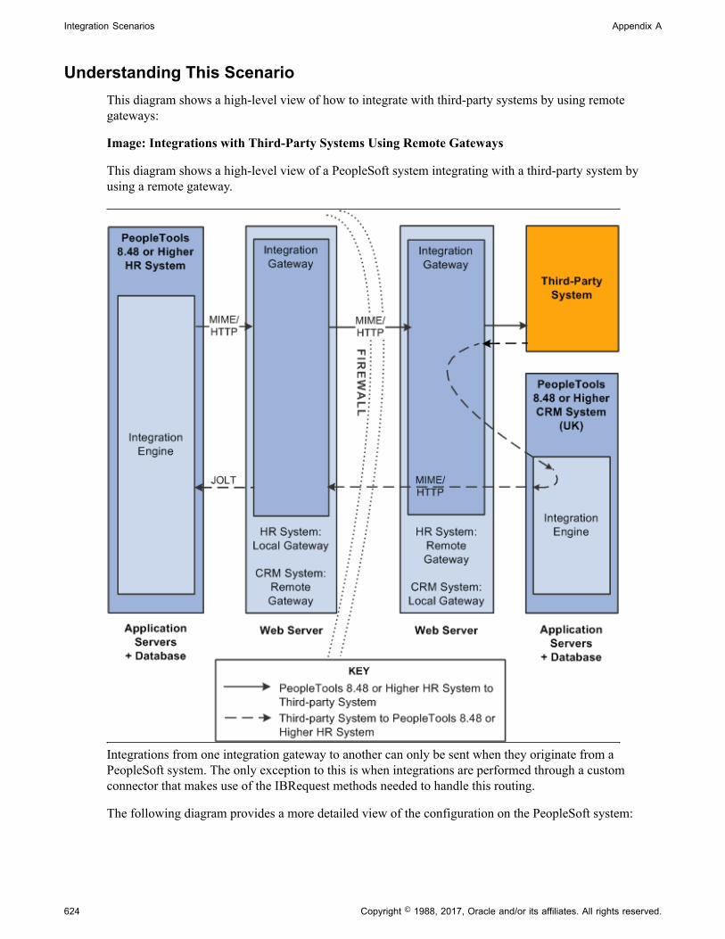
Integration Scenarios Appendix A
Understanding This ScenarioThis diagram shows a high-level view of how to integrate with third-party systems by using remotegateways:
Image: Integrations with Third-Party Systems Using Remote Gateways
This diagram shows a high-level view of a PeopleSoft system integrating with a third-party system byusing a remote gateway.
Integrations from one integration gateway to another can only be sent when they originate from aPeopleSoft system. The only exception to this is when integrations are performed through a customconnector that makes use of the IBRequest methods needed to handle this routing.
The following diagram provides a more detailed view of the configuration on the PeopleSoft system:
624 Copyright © 1988, 2017, Oracle and/or its affiliates. All rights reserved.

Appendix A Integration Scenarios
Image: Local PeopleSoft System Configuration
This diagram illustrates the configuration on the local PeopleSoft system for integrations with third-partysystems using remote gateways.
The following diagram provides a more detailed view of the configuration on the remote PeopleSoftsystem and the third-party system.
Copyright © 1988, 2017, Oracle and/or its affiliates. All rights reserved. 625
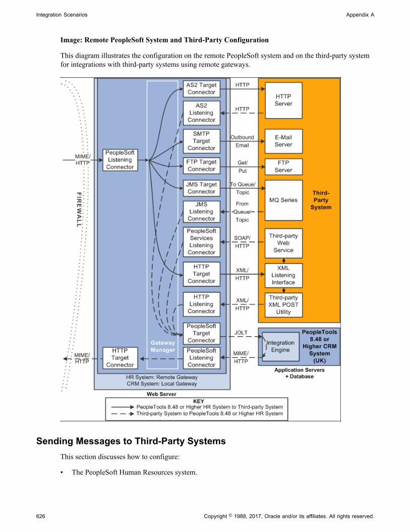
Integration Scenarios Appendix A
Image: Remote PeopleSoft System and Third-Party Configuration
This diagram illustrates the configuration on the remote PeopleSoft system and on the third-party systemfor integrations with third-party systems using remote gateways.
Sending Messages to Third-Party SystemsThis section discusses how to configure:
• The PeopleSoft Human Resources system.
626 Copyright © 1988, 2017, Oracle and/or its affiliates. All rights reserved.

Appendix A Integration Scenarios
• The PeopleSoft Human Resources integration gateway.
The setup for this scenario is similar to the configuration for integrations with Integration Broker systems.The only difference is the target connector you use.
However, instead of using the PeopleSoft target connector for the remote node you must select the targetconnector based on the third-party system with which the PeopleSoft system is communicating. The targetconnector you select must reside on the remote gateway.
In the previous diagram, the PeopleSoft Human Resources system is the source system and the selectedtarget connector is shown on the other side of the firewall, on the remote integration gateway.
As you review the configuration tasks for this scenario, keep in mind the following points:
• PeopleSoft recommends using a single gateway for all applications that reside on one side of afirewall.
• The local gateway for one PeopleSoft application can be the remote gateway for the other PeopleSoftapplication.
Configuring the PeopleSoft Human Resources SystemOn the PeopleSoft Human Resources system:
1. Define a local integration gateway.
Use the Gateways component to define the local PeopleSoft Human Resources (USA) gateway.
2. Define a remote integration gateway on the local system.
Use the Gateways component to define the gateway for the PeopleSoft Human Resources (USA)system (which is the PeopleSoft CRM [UK] gateway) and to specify the URL of the PeopleSoft CRM(UK) gateway.
3. Set up a local node.
Use the Nodes component to set up the local node, which represents the PeopleSoft Human Resources(USA) system.
4. Set up a remote node.
Use the Nodes component to set up the remote node, which represents the third-party system. Whenyou define the remote node, use the Node Definitions-Connectors page to specify the gateway ID onthe remote integration gateway. In addition, select the appropriate target connector, for example JMStarget connector, SMTP target connector, POP 3 target connector, and so forth.
5. Create a service operation that includes an outbound routing definition where the sending node is thePeopleSoft HR system and the receiving node is the third-party system.
Configuring the PeopleSoft Human Resources Integration GatewayThe only required integration gateway properties are the Oracle Jolt connect string properties that enablecommunication with integration engines on PeopleSoft Integration Broker systems. Set these properties inthe integrationGateway.properties file.
Copyright © 1988, 2017, Oracle and/or its affiliates. All rights reserved. 627

Integration Scenarios Appendix A
Related LinksUnderstanding Integration Setup for the Integration Scenarios"Administering Integration Gateways" (PeopleTools 8.55: Integration Broker Administration)Adding Service Operation DefinitionsConfiguring Service Operation Definitions"Adding Node Definitions" (PeopleTools 8.55: Integration Broker Administration)"Configuring Nodes" (PeopleTools 8.55: Integration Broker Administration)
Receiving Messages from Third-Party SystemsThe previous diagram shows a second configuration scenario where a third-party system is performing aninbound HTTP Post to a PeopleSoft Human Resources/USA system via a UK gateway. In this scenario,the message goes through the PeopleSoft CRM/UK system only to get routing information, before it issent to the remote integration gateway (the gateway on the USA side of the firewall. Therefore, in thisscenario, the PeopleSoft CRM/UK system serves as a hub.
This section discusses how to configure:
• The PeopleSoft Human Resources (USA) system.
• The PeopleSoft Human Resources integration gateway.
• The PeopleSoft CRM (UK) system and hub.
• The PeopleSoft CRM (UK) integration gateway.
• The third-party system and PeopleSoft system.
Message FlowIn this scenario, a message originating from a third-party system is posted to the HTTP listeningconnector, JMS listening connector or a custom-built listening connector on the PeopleSoft CRM/UKintegration gateway. Since the message does not contain the required routing information for the remotegateway, the listening connector hands it off to the PeopleSoft target connector. The PeopleSoft targetconnector sends the message to the default PeopleSoft node (the PeopleSoft CRM/UK) as determined bythe default Jolt settings in the integrationGateway.properties file.
When the message reaches Integration Broker on the PeopleSoft CRM/UK system, the system appliestransaction information to reroute the message to the remote gateway (the gateway on the USA side of thefirewall), and thereby serves as a hub.
Message Processing on the Remote GatewayWhenever you publish a message bound for a remote gateway, PeopleSoft Integration Broker reads it,determines that the target connector is not on its local gateway, places the remote gateway URL insidethe IBInfo message wrapper and posts it to the PeopleSoft listening connector on the local gateway. Thelocal gateway manager finds a remote gateway URL in the message wrapper and routes it to the remotegateway default connector, the HTTP target connector. The HTTP target connector on the local gatewaythen posts the message to the remote gateway URL (the PeopleSoft listening connector on the remotegateway) in MIME format, and removes the URL from the IBInfo message wrapper. On arrival at theremote gateway, the message is processed like any other incoming PeopleSoft message.
628 Copyright © 1988, 2017, Oracle and/or its affiliates. All rights reserved.
Appendix A Integration Scenarios
An exception to this message flow is if on the UK integration gateway side you created and loaded acustom listening connector that allows for the required routing information to be populated in the IBInfomessage wrapper. The message would no longer need to be sent via the hub.
Keep in mind the following points:
• PeopleSoft recommends that you use a single gateway for all applications that reside on one side of afirewall.
• The local gateway for one PeopleSoft application can be a remote gateway for another PeopleSoftapplication.
• A message coming from a third-party system (local gateway or remote gateway) system can enter theintegration gateway from any of the delivered listening connectors or from a custom-built listeningconnector. It cannot, however, use the PeopleSoft listening connector. PeopleSoft has designed thePeopleSoft listening connector to accept messages in the PeopleSoft internal message format only.Note that the diagram shows the message entering the integration gateway via the HTTP listeningconnector.
Configuring the PeopleSoft Human Resources (USA) SystemOn the PeopleSoft Human Resources system:
1. Set up a local node.
Use the Node Definition component to set up the local node, which represents the Human Resourcessystem.
2. Set up a remote node.
The remote node that you set up represents the PeopleSoft CRM system. When you set up the remotenode, specify the PeopleSoft target connector.
3. Create a service operation that contains an outbound routing definition where the sending node is thePeopleSoft CRM system and the receiving node is the PeopleSoft HR system.
Configuring the PeopleSoft Human Resources Integration GatewayThe only required integration gateway properties are the Oracle Jolt connect string properties thatenable communication with the PeopleSoft Human Resources system. Set these properties in theintegrationGateway.properties file.
Configuring the PeopleSoft CRM (UK) System and HubOn the PeopleSoft CRM (UK) system:
• Define a local integration gateway.
Use the Gateways component to set up the local gateway for the sending system.
• Define a remote integration gateway.
The remote gateway for the PeopleSoft CRM (UK) system is the PeopleSoft Human Resources(USA) gateway.
• Set up a local node.
Copyright © 1988, 2017, Oracle and/or its affiliates. All rights reserved. 629

Integration Scenarios Appendix A
Use the Node Definition component to set up the local node, which represents the PeopleSoft CRMsystem.
• Set up remote nodes.
Use the Node Definition component to define two remote nodes: one remote node that representsthe third-party system and another to represent the PeopleSoft Human Resources (USA) system.When you define the remote node that represents the third-party system, you specify the HTTP targetconnector, HTTPTARGET. When you define the remote node that represents the PeopleSoft HumanResources (USA) system, set it to use the PeopleSoft target connector on the remote (USA) gateway.
• Create a service operation that contains an outbound routing definition where the sending node is thethird-party system and the receiving node is the PeopleSoft HR system.
• In the service operation definition that you created in the previous step, create an inbound routingdefinition if the third-party system will be sending you requests.
Configuring the PeopleSoft CRM (UK) Integration GatewayThe only required properties are the Oracle Jolt connect string properties that enable communicationwith integration engines on the PeopleSoft CRM systems. Set these properties in theintegrationGateway.properties file.
Configuring the Third-Party System and PeopleSoft SystemBecause the PeopleSoft CRM (UK) system serves as a hub in this scenario, you must set up transactionsand relationships for all messages from the third-party system that are routed through it. By using thesystems in the diagram as an example, the following table shows the required node, transaction andrelationship configurations:
Item to Configure PeopleSoft Human ResourcesSystem
PeopleSoft CRM System (Hub)
Local nodes Rename the default local node torepresent the PeopleSoft HumanResources system.
Rename the default local node torepresent the PeopleSoft CRM system.
Remote nodes Define a remote node to represent thePeopleSoft CRM system.
Define remote nodes to represent thethird-party system and the PeopleSoft Human Resources system.
Service operations and routingdefinitions
Define a service operation with aninbound routing definition where thePeopleSoft CRM system is the sendingnode and the PeopleSoft HR system isthe receiving node.
Define a service operation with anoutbound routing definition where thesending node is the third-party systemand the receiving node is the PeopleSoftHR system.
Related LinksUnderstanding Integration Setup for the Integration Scenarios"Administering Integration Gateways" (PeopleTools 8.55: Integration Broker Administration)Adding Service Operation Definitions
630 Copyright © 1988, 2017, Oracle and/or its affiliates. All rights reserved.

Appendix A Integration Scenarios
Configuring Service Operation Definitions"Adding Node Definitions" (PeopleTools 8.55: Integration Broker Administration)"Configuring Nodes" (PeopleTools 8.55: Integration Broker Administration)
Integrating with PeopleTools 8.47 and Earlier PeopleTools 8.4xSystems
This section provides and overview of this scenario and discusses how to configure the system for thisscenario.
Understanding This ScenarioThis diagram shows the PeopleSoft Integration Broker components and configuration for communicationsbetween PeopleSoft Integration Broker system and a PeopleSoft system running on PeopleTools 8.47:
Image: Integrations with PeopleTools 8.47 and earlier systems.
This example illustrates the PeopleSoft Integration Broker components and configuration forcommunications between a PeopleSoft Integration Broker system on PeopleTools 8.48 or later release anda PeopleSoft system running on PeopleTools 8.47.
While this diagram depicts a PeopleSoft 8.47 system, the information provided in this section applies toany PeopleTools 8.47 or earlier system.
In this example, the PeopleSoft Human Resources is the sending system and the PeopleSoft CRM systemis the receiving system.
Copyright © 1988, 2017, Oracle and/or its affiliates. All rights reserved. 631

Integration Scenarios Appendix A
The remainder of this section highlights the integration tasks by using the systems and components shownin the diagram as examples.
Configuring the System for This ScenarioThis section discusses how to configure:
• The PeopleSoft Human Resources system.
• The PeopleSoft CRM system.
Configuring the PeopleSoft Human Resources SystemIn this scenario, the PeopleSoft Human Resource system is running on PeopleTools 8.55.
On the PeopleSoft Human Resources system:
• Define a local integration gateway.
Use the Gateways component to set up a local gateway for the PeopleSoft Human Resources system.
The only required properties are the Oracle Jolt connect string properties that enablecommunication with the PeopleSoft Human Resources systems. Set these properties in theintegrationGateway.properties file
• Set up a local node.
Use the Node Definition component to set up the local node, which represents the PeopleSoft 8.55Human Resources system.
• Set up a remote node.
The remote node that you set up represents the PeopleSoft 8.47 or earlier Human Resources system.When you set up the remote node, specify the PeopleSoft target connector (PSFTTARGET) on theConnectors tab.
Note: If you have upgraded from a PeopleSoft system, all nodes that existed for the system have beenpreserved as remote nodes in the PeopleSoft Integration Broker system. However, you must thenassociate each of these nodes to the PeopleSoft target connector for the remote note.
• Create a service operation with an inbound routing definition.
Use the Service Operations component to create a service operation that contains an inbound routingdefinition where the receiving node is the PeopleSoft 8.55 system and the sending node is thePeopleSoft 8.47 or earlier system.
• Set up an outbound routing definition.
In the service operation definition that you created in the previous step, create and outbound routingdefinition where the sending node is the PeopleSoft 8.55 system and the receiving node is the 8.47 orearlier system.
Configuring the PeopleSoft 8.47 or Earlier Human Resources SystemIn this scenario, the PeopleSoft CRM system is running on PeopleTools 8.47.
632 Copyright © 1988, 2017, Oracle and/or its affiliates. All rights reserved.

Appendix A Integration Scenarios
On the PeopleSoft CRM system:
1. Define the local integration gateway for the PeopleSoft CRM system by using the Gatewayscomponent. Specify the gateway’s PeopleSoft listening connector as the gateway’s URL.
2. Set up a local node.
Use the Node Definition component to set up the local node, which represents the PeopleSoft CRMsystem.
3. Set up a remote node.
The remote node that you set up represents the PeopleSoft 8.55 system. When you set up the remotenode, specify the PeopleSoft target connector (PSFTTARGET) on the Connectors tab.
Because the PeopleSoft Human Resources system uses PeopleSoft Integration Broker, specify thelocal gateway for the PeopleSoft CRM system and its PeopleSoft target connector on the NodeDefinitions - Connectors page.
Integrating with PeopleTools 8.1x Systems
This section provides an overview of this scenario and discusses how to configure the system for thisscenario.
Understanding This ScenarioThis diagram shows the PeopleSoft Integration Broker components and configuration for communicationsbetween PeopleSoft Integration Broker systems and PeopleSoft systems running on PeopleTools 8.1x:
Copyright © 1988, 2017, Oracle and/or its affiliates. All rights reserved. 633

Integration Scenarios Appendix A
Image: Integrating with PeopleSoft 8.1x systems
This example illustrates the PeopleSoft Integration Broker components and configuration forcommunications between PeopleSoft Integration Broker systems on PeopleTools 8.48 and later systemsand PeopleSoft systems running PeopleTools 8.1x.
In this scenario, you must configure the PeopleSoft Integration Broker system, the integration gateway,and the PeopleTools 8.1x system. The remainder of this section highlights these tasks by using thesystems and components shown in the diagram as examples.
Configuring the System for This ScenarioThis section discusses how to configure:
• The PeopleSoft Human Resources system.
• The PeopleSoft Human Resources integration gateway.
• The PeopleTools 8.1x Human Resources system.
634 Copyright © 1988, 2017, Oracle and/or its affiliates. All rights reserved.

Appendix A Integration Scenarios
Configuring the PeopleSoft Human Resources SystemOn the PeopleSoft Human Resources system:
• Define a local integration gateway.
Use the Gateways component to set up a local gateway for the PeopleSoft Human Resources system.
• Set up a local node.
Use the Node Definition component to set up the local node, which represents the PeopleSoft HumanResources system.
• Set up a remote node.
The remote node that you set up represents the PeopleSoft 8.1x Human Resources system. Whenyou set up the remote node, specify the PeopleSoft 8.1 target connector (PSFT81TARGET) on theConnectors tab.
Note: If you have upgraded from a PeopleSoft 8.1x system, all nodes that existed for the system havebeen preserved as remote nodes in the PeopleSoft Integration Broker system. However, you must thenassociate each of these nodes to the PeopleSoft 8.1 target connector.
• Create a service operation with an inbound routing definition.
Use the Service Operations component to create a service operation that contains an inbound routingdefinition where the receiving node is the PeopleSoft 8.55 system and the sending node is thePeopleSoft 8.1x system.
• Set up an outbound routing definition.
In the service operation definition that you created in the previous step, create and outbound routingdefinition where the sending node is the PeopleSoft 8.55 system and the receiving node is the 8.1xsystem.
Configuring the PeopleSoft Human Resources Integration GatewayYou must set integration gateway properties for the local gateway. The only required properties are theOracle Jolt connect string properties that enable communication with the PeopleSoft Human Resourcessystems. Set these properties in the integrationGateway.properties file.
Configuring the PeopleSoft 8.1x Human Resources SystemOn the PeopleSoft 8.1x Human Resources system, locate the PeopleSoft 8.1x Human Resources messagenode and change the URL (location) to the PeopleSoft listening connector. The format is http://webserver/PSIGW.war/PS81ListeningConnector.
Related LinksUnderstanding Integration Setup for the Integration Scenarios"Administering Integration Gateways" (PeopleTools 8.55: Integration Broker Administration)Adding Service Operation DefinitionsConfiguring Service Operation Definitions"Adding Node Definitions" (PeopleTools 8.55: Integration Broker Administration)
Copyright © 1988, 2017, Oracle and/or its affiliates. All rights reserved. 635

Integration Scenarios Appendix A
"Configuring Nodes" (PeopleTools 8.55: Integration Broker Administration)
636 Copyright © 1988, 2017, Oracle and/or its affiliates. All rights reserved.

Appendix B
Transformation Example: IntegrationBetween Two PeopleSoft Nodes
Understanding the Transformation Example
This topic presents an in-depth example of how to use transformations to alter the messages sent betweentwo systems.
Note: The code examples in this topic are for illustrative purposes only and are not intended to be used ina production environment.
Using the ExampleThe purpose of this topic is to present a more in depth example of how transformations can be used toalter the messages sent between two systems.
The following example describes an integration between a PeopleSoft Supply Chain Management node(PeopleSoft SCM) and a PeopleSoft Customer Relationship Management node (PeopleSoft CRM).This example demonstrates taking a PeopleSoft SCM purchase order message and transforming it into asimilar PeopleSoft CRM purchase order message format.
Two aspects of transformations will be examined in this example:
• How XSL can be used to modify the structure of a message.
• How codesets can be used to map values between messages.
The example will focus on the PeopleSoft SCM system. This is the node where the XSL will be executedto transform the message from the SCM specified format to that of CRM. When the SCM system sendsthe message to CRM, the message will be in the CRM native format.
Integration Metadata for This ExampleThe example does not go into detail about setting up the all infrastructure necessary to actuallysend messages between the two nodes. It assumes that the systems have been configured and theservice operations and services have been defined. Please refer to the topics elsewhere in the productdocumentation for setting up integration metadata.
Related LinksPeopleSoft Integration Broker Metadata
Copyright © 1988, 2017, Oracle and/or its affiliates. All rights reserved. 637

Transformation Example: Integration Between Two PeopleSoft Nodes Appendix B
Creating Message Definitions
This section discusses the structure of the message definitions used in this example.
Message Definition: PeopleSoft SCM NodeThe structure of a message appears on the Messages – Message Definitions page. To access the pageselect PeopleTools, Integration Broker, Integration Setup, Messages.
The following example shows the format of the purchase order on the PeopleSoft SCM node.
Image: PURCHASEORDERMSG message definition
This example illustrates a partial view of the Messages – Message Definition page. The example showsthe message structure for the purchase order message PURCHASEORDERMSG on the SCM node.
The following is a sample message that corresponds to the message structure:
<?xml version="1.0"?><PURCHASEORDERMSG> <FieldTypes> <PURCHASEORDER class="R"> <PURCHASEORDERNUM type="CHAR"/> <PURCHASEORDERDATE type="DATE"/> </PURCHASEORDER> <SHIPPINGDETAILS class="R"> <NAME type="CHAR"/> <ADDRESS type="CHAR"/> <CITY type="CHAR"/> <STATE type="CHAR"/> <CARRIER_ID type="CHAR"/> </SHIPPINGDETAILS> <PURCHASEDITEMS class="R"> <ITEM type="CHAR"/> </PURCHASEDITEMS> <PSCAMA class="R"> <LANGUAGE_CD type="CHAR"/> <AUDIT_ACTN type="CHAR"/> <BASE_LANGUAGE_CD type="CHAR"/> <MSG_SEQ_FLG type="CHAR"/> <PROCESS_INSTANCE type="NUMBER"/> <PUBLISH_RULE_ID type="CHAR"/> <MSGNODENAME type="CHAR"/> </PSCAMA> </FieldTypes> <MsgData>
638 Copyright © 1988, 2017, Oracle and/or its affiliates. All rights reserved.

Appendix B Transformation Example: Integration Between Two PeopleSoft Nodes
<Transaction> <PURCHASEORDER class="R"> <PURCHASEORDERNUM IsChanged="Y">19908</PURCHASEORDERNUM> <PURCHASEORDERDATE IsChanged="Y">2006-04-03</PURCHASEORDERDATE> <SHIPPINGDETAILS class="R"> <NAME IsChanged="Y">Smith,Bill</NAME> <ADDRESS IsChanged="Y">123 Anywhere St</ADDRESS> <CITY IsChanged="Y">Fresno</CITY> <STATE IsChanged="Y">CA</STATE> <CARRIER_ID IsChanged="Y">USPS</CARRIER_ID> </SHIPPINGDETAILS> <PURCHASEDITEMS class="R"> <ITEM IsChanged="Y">AAS5536</ITEM> </PURCHASEDITEMS> <PURCHASEDITEMS class="R"> <ITEM IsChanged="Y">POB332Q</ITEM> </PURCHASEDITEMS> </PURCHASEORDER> <PSCAMA class="R"> <LANGUAGE_CD>ENG</LANGUAGE_CD> <AUDIT_ACTN/> <BASE_LANGUAGE_CD>ENG</BASE_LANGUAGE_CD> <MSG_SEQ_FLG/> <PROCESS_INSTANCE>0</PROCESS_INSTANCE> <PUBLISH_RULE_ID/> <MSGNODENAME/> </PSCAMA> </Transaction> </MsgData></PURCHASEORDERMSG>
Message Definition: PeopleSoft CRM NodeThe structure of a message appears on the Messages – Message Definitions page. To access the pageselect PeopleTools, Integration Broker, Integration Setup, Messages.
The following example shows the format of the purchase order on the PeopleSoft CRM node.
Image: PO_MSG message definition
This example illustrates a partial view of the Messages – Message Definition page. The example showsthe message structure for the purchase order message PO_MSG on the CRM node.
This is a sample message that corresponds to the message structure:
<?xml version="1.0"?><PO_MSG> <FieldTypes> <PO_HEADER class="R"> <PO_NUMBER type="CHAR"/>
Copyright © 1988, 2017, Oracle and/or its affiliates. All rights reserved. 639
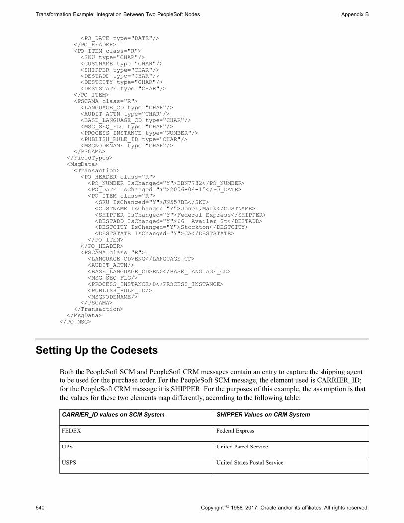
Transformation Example: Integration Between Two PeopleSoft Nodes Appendix B
<PO_DATE type="DATE"/> </PO_HEADER> <PO_ITEM class="R"> <SKU type="CHAR"/> <CUSTNAME type="CHAR"/> <SHIPPER type="CHAR"/> <DESTADD type="CHAR"/> <DESTCITY type="CHAR"/> <DESTSTATE type="CHAR"/> </PO_ITEM> <PSCAMA class="R"> <LANGUAGE_CD type="CHAR"/> <AUDIT_ACTN type="CHAR"/> <BASE_LANGUAGE_CD type="CHAR"/> <MSG_SEQ_FLG type="CHAR"/> <PROCESS_INSTANCE type="NUMBER"/> <PUBLISH_RULE_ID type="CHAR"/> <MSGNODENAME type="CHAR"/> </PSCAMA> </FieldTypes> <MsgData> <Transaction> <PO_HEADER class="R"> <PO_NUMBER IsChanged="Y">BBN7782</PO_NUMBER> <PO_DATE IsChanged="Y">2006-04-15</PO_DATE> <PO_ITEM class="R"> <SKU IsChanged="Y">JN557BB</SKU> <CUSTNAME IsChanged="Y">Jones,Mark</CUSTNAME> <SHIPPER IsChanged="Y">Federal Express</SHIPPER> <DESTADD IsChanged="Y">66 Availer St</DESTADD> <DESTCITY IsChanged="Y">Stockton</DESTCITY> <DESTSTATE IsChanged="Y">CA</DESTSTATE> </PO_ITEM> </PO_HEADER> <PSCAMA class="R"> <LANGUAGE_CD>ENG</LANGUAGE_CD> <AUDIT_ACTN/> <BASE_LANGUAGE_CD>ENG</BASE_LANGUAGE_CD> <MSG_SEQ_FLG/> <PROCESS_INSTANCE>0</PROCESS_INSTANCE> <PUBLISH_RULE_ID/> <MSGNODENAME/> </PSCAMA> </Transaction> </MsgData></PO_MSG>
Setting Up the Codesets
Both the PeopleSoft SCM and PeopleSoft CRM messages contain an entry to capture the shipping agentto be used for the purchase order. For the PeopleSoft SCM message, the element used is CARRIER_ID;for the PeopleSoft CRM message it is SHIPPER. For the purposes of this example, the assumption is thatthe values for these two elements map differently, according to the following table:
CARRIER_ID values on SCM System SHIPPER Values on CRM System
FEDEX Federal Express
UPS United Parcel Service
USPS United States Postal Service
640 Copyright © 1988, 2017, Oracle and/or its affiliates. All rights reserved.

Appendix B Transformation Example: Integration Between Two PeopleSoft Nodes
An SCM message containing the following XML:
<CARRIER_ID>UPS</CARRIER_ID>
would logically map to:
<SHIPPER>United Parcel Service</SHIPPER>
in the corresponding CRM message.
In order to enable such mapping in this example, you must create codeset metadata.
Create codeset metadata:
1. Create a codeset group called SCM_GROUP. Add the following entries:
Match Name Match Value
CARRIER_ID FEDEX
CARRIER_ID UPS
CARRIER_ID USPS
CARRIER_ID Blank
Note that the final match value entry is blank: this will be used for the default value.
2. Create a codeset called SCM_CODESET, using the codeset group defined in the prior step. Add thefollowing entries to this codeset:
Match Name Match Value
CARRIER_ID FEDEX
CARRIER_ID UPS
CARRIER_ID USPS
CARRIER_ID Blank
3. Create a codeset group called CRM_GROUP. There is no need to define any entries for this group.
4. Add codeset values from the SCM_GROUP to the CRM_GROUP, using the SCM_CODESET. Fourentries will need to be defined:
• Select CARRIER_ID and <blank>, and add a return name of SHIPPER and the value Unknown.
• Select CARRIER_ID and FEDEX, and add a return name of SHIPPER and the value FederalExpress.
• Select CARRIER_ID and UPS, and add a return name of SHIPPER and the value United ParcelService.
Copyright © 1988, 2017, Oracle and/or its affiliates. All rights reserved. 641

Transformation Example: Integration Between Two PeopleSoft Nodes Appendix B
• Select CARRIER_ID and USPS, and add a return name of SHIPPER and the value United StatesPostal Service.
5. Go to the node definition for the SCM node and add the codeset group SCM_CODESET to the node.
6. Go to the node definition for the CRM node and add the codeset group CRM_CODESET to the node.
Setting Up the Transformation
The PeopleSoft SCM and PeopleSoft CRM purchase order messages share what are essentially thesame first two elements: a purchase order number and the purchase order date. However, from there thestructures differ. The PeopleSoft SCM message has a small section containing shipping information,followed by the list of items purchased. The PeopleSoft CRM message has the shipping informationmerged with the list of items purchased.
The following XSL transforms the PeopleSoft SCM purchase order message into the PeopleSoft CRMformat:
<?xml version="1.0"?>
<xsl:stylesheet xmlns:xsl="http://www.w3.org/1999/XSL/Transform" version="1.0">
<xsl:template match="PURCHASEORDERMSG"> <PO_MSG> <xsl:apply-templates select="FieldTypes"/> <xsl:apply-templates select="MsgData"/> </PO_MSG> </xsl:template>
<xsl:template match="MsgData"> <MsgData> <xsl:apply-templates select="Transaction"/> </MsgData> </xsl:template>
<xsl:template match="Transaction"> <Transaction> <xsl:apply-templates select="PURCHASEORDER"/> <PSCAMA class="R"> <LANGUAGE_CD>ENG</LANGUAGE_CD> <AUDIT_ACTN/> <BASE_LANGUAGE_CD>ENG</BASE_LANGUAGE_CD> <MSG_SEQ_FLG/> <PROCESS_INSTANCE>0</PROCESS_INSTANCE> <PUBLISH_RULE_ID/> <MSGNODENAME/> </PSCAMA> </Transaction> </xsl:template>
<xsl:template match="PURCHASEORDER"> <PO_HEADER class="R"> <PO_NUMBER IsChanged="Y"><xsl:value-of select="PURCHASEORDERNUM"/> </PO_NUMBER> <PO_DATE IsChanged="Y"><xsl:value-of select="PURCHASEORDERDATE"/> </PO_DATE> <xsl:apply-templates select="PURCHASEDITEMS"/> </PO_HEADER> </xsl:template>
642 Copyright © 1988, 2017, Oracle and/or its affiliates. All rights reserved.

Appendix B Transformation Example: Integration Between Two PeopleSoft Nodes
<xsl:template match="PURCHASEDITEMS"> <PO_ITEM class="R"> <SKU IsChanged="Y"><xsl:value-of select="ITEM"/></SKU> <CUSTNAME IsChanged="Y"> <xsl:value-of select="../SHIPPINGDETAILS/NAME"/> </CUSTNAME> <SHIPPER IsChanged="Y"> <psft_function name="codeset" codesetname="SCM_CODESET"> <parm name="CARRIER_ID"> <xsl:value-of select="../SHIPPINGDETAILS/CARRIER_ID"/> </parm> <value name="SHIPPER" select="."/> </psft_function> </SHIPPER> <DESTADD IsChanged="Y"> <xsl:value-of select="../SHIPPINGDETAILS/ADDRESS"/> </DESTADD> <DESTCITY IsChanged="Y"> <xsl:value-of select="../SHIPPINGDETAILS/CITY"/> </DESTCITY> <DESTSTATE IsChanged="Y"> <xsl:value-of select="../SHIPPINGDETAILS/STATE"/> </DESTSTATE> </PO_ITEM> </xsl:template>
<xsl:template match="FieldTypes"> <FieldTypes> <PO_HEADER class="R"> <PO_NUMBER type="CHAR"/> <PO_DATE type="DATE"/> </PO_HEADER> <PO_ITEM class="R"> <SKU type="CHAR"/> <CUSTNAME type="CHAR"/> <SHIPPER type="CHAR"/> <DESTADD type="CHAR"/> <DESTCITY type="CHAR"/> <DESTSTATE type="CHAR"/> </PO_ITEM> <PSCAMA class="R"> <LANGUAGE_CD type="CHAR"/> <AUDIT_ACTN type="CHAR"/> <BASE_LANGUAGE_CD type="CHAR"/> <MSG_SEQ_FLG type="CHAR"/> <PROCESS_INSTANCE type="NUMBER"/> <PUBLISH_RULE_ID type="CHAR"/> <MSGNODENAME type="CHAR"/> </PSCAMA> </FieldTypes> </xsl:template></xsl:stylesheet>
Note that this XSL contains a reference to the psft_function, which will resolve codeset mapping after thetransform has been run.
This XSL should be placed into an Application Engine program, and this program associated with therouting definitions for the service operation.
XSL Walkthrough
This section discusses the process flow through the XSL when the PeopleSoft SCM purchase ordermessage is transformed.
Copyright © 1988, 2017, Oracle and/or its affiliates. All rights reserved. 643

Transformation Example: Integration Between Two PeopleSoft Nodes Appendix B
XSL is composed of templates. An XSLT template is an instruction of what to do when a particularXML node or condition is encountered. During a transform, the XSL processing engine starts at the rootelement of the XML message and then attempts to find matching templates in the XSL. When a matchingtemplate is found, the instructions in that template are used in the building of the output XML document.
The processing of a transform is actually a two pass process. In the first pass, the XSL is executed againstthe input XML, and an output XML document is generated. In the second pass, the psft_function calls areresolved and the codeset values are placed into the document.
Transformation Processing: First PassThis section discusses the first pass of transform processing, during which the XSL code runs against theinput XML and the system generates an output XML document. The steps listed below mimic the actionstaken by the transformation engine in processing the input XML.
1. The first element in the input message is PURCHASEORDERMESSAGE. The transformation enginefinds the following matching template in the XSL:
<xsl:template match="PURCHASEORDERMSG"> <PO_MSG> <xsl:apply-templates select="FieldTypes"/> <xsl:apply-templates select="MsgData"/> </PO_MSG> </xsl:template>
Here we see the root element of the output document being created. This template instructs thetransformation engine to:
• Output the start tag for PO_MSG.
It is important to note that template processing is a recursive process. In the sequence above, thetransformation engine outputs the start tag, then applies templates to all FieldType nodes. This isessentially a callout to the template that handles those nodes (and potentially any children). Theoutput of this call is then placed into the output document. Then the transformation engine selectsall the MsgData nodes, and applies templates to them. Again, the output from the processing ofthose nodes is then place into the output document. Finally, the closing PO_MSG tag is writteninto the output, and the first pass is finished. Of course, documenting a recursive process is notalways straightforward. In this example bear in mind that while it is presented as a numberedsequence of steps, the actual process is not sequential.
• Select the FieldTypes nodes under the current node in the input document, and process them.
• Select the MsgData nodes under the current node in the input document, and process them.
• Output the end tag for PO_MSG.
2. The transform engine selects the FieldTypes node, and finds the following template:
<xsl:template match="FieldTypes"> <FieldTypes> <PO_HEADER class="R"> <PO_NUMBER type="CHAR"/> <PO_DATE type="DATE"/> </PO_HEADER> <PO_ITEM class="R"> <SKU type="CHAR"/> <CUSTNAME type="CHAR"/>
644 Copyright © 1988, 2017, Oracle and/or its affiliates. All rights reserved.
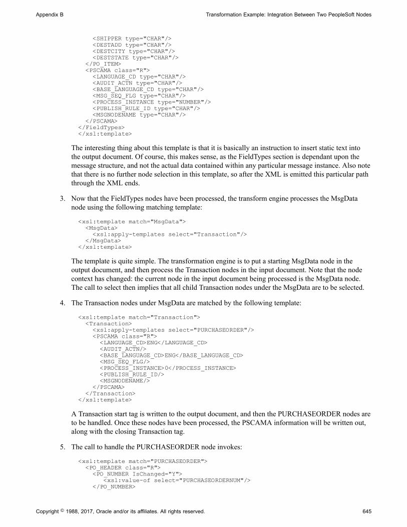
Appendix B Transformation Example: Integration Between Two PeopleSoft Nodes
<SHIPPER type="CHAR"/> <DESTADD type="CHAR"/> <DESTCITY type="CHAR"/> <DESTSTATE type="CHAR"/> </PO_ITEM> <PSCAMA class="R"> <LANGUAGE_CD type="CHAR"/> <AUDIT_ACTN type="CHAR"/> <BASE_LANGUAGE_CD type="CHAR"/> <MSG_SEQ_FLG type="CHAR"/> <PROCESS_INSTANCE type="NUMBER"/> <PUBLISH_RULE_ID type="CHAR"/> <MSGNODENAME type="CHAR"/> </PSCAMA> </FieldTypes> </xsl:template>
The interesting thing about this template is that it is basically an instruction to insert static text intothe output document. Of course, this makes sense, as the FieldTypes section is dependant upon themessage structure, and not the actual data contained within any particular message instance. Also notethat there is no further node selection in this template, so after the XML is emitted this particular paththrough the XML ends.
3. Now that the FieldTypes nodes have been processed, the transform engine processes the MsgDatanode using the following matching template:
<xsl:template match="MsgData"> <MsgData> <xsl:apply-templates select="Transaction"/> </MsgData> </xsl:template>
The template is quite simple. The transformation engine is to put a starting MsgData node in theoutput document, and then process the Transaction nodes in the input document. Note that the nodecontext has changed: the current node in the input document being processed is the MsgData node.The call to select then implies that all child Transaction nodes under the MsgData are to be selected.
4. The Transaction nodes under MsgData are matched by the following template:
<xsl:template match="Transaction"> <Transaction> <xsl:apply-templates select="PURCHASEORDER"/> <PSCAMA class="R"> <LANGUAGE_CD>ENG</LANGUAGE_CD> <AUDIT_ACTN/> <BASE_LANGUAGE_CD>ENG</BASE_LANGUAGE_CD> <MSG_SEQ_FLG/> <PROCESS_INSTANCE>0</PROCESS_INSTANCE> <PUBLISH_RULE_ID/> <MSGNODENAME/> </PSCAMA> </Transaction> </xsl:template>
A Transaction start tag is written to the output document, and then the PURCHASEORDER nodes areto be handled. Once these nodes have been processed, the PSCAMA information will be written out,along with the closing Transaction tag.
5. The call to handle the PURCHASEORDER node invokes:
<xsl:template match="PURCHASEORDER"> <PO_HEADER class="R"> <PO_NUMBER IsChanged="Y"> <xsl:value-of select="PURCHASEORDERNUM"/> </PO_NUMBER>
Copyright © 1988, 2017, Oracle and/or its affiliates. All rights reserved. 645

Transformation Example: Integration Between Two PeopleSoft Nodes Appendix B
<PO_DATE IsChanged="Y"> <xsl:value-of select="PURCHASEORDERDATE"/> </PO_DATE> <xsl:apply-templates select="PURCHASEDITEMS"/> </PO_HEADER> </xsl:template>
The PO_HEADER start tag is emitted as well as the child PO_NUMBER and PO_DATEelements. The call out to xs:value-of means that node values from the input message are copiedto the output message. In this case, the node PO_NUMBER in the output message is given thevalue from PURCHASEORDERNUM in the input message. PO_DATE is given the value fromPURCHASEORDERDATE. Once these two elements have been written out, the transformationengine is then told to process the PURCHASEDITEMS nodes in the input document.
6. Each PURCHASEDITEMS node in the input message causes the following template to be executed:
<xsl:template match="PURCHASEDITEMS"> <PO_ITEM class="R"> <SKU IsChanged="Y"><xsl:value-of select="ITEM"/></SKU> <CUSTNAME IsChanged="Y"> <xsl:value-of select="../SHIPPINGDETAILS/NAME"/> </CUSTNAME> <SHIPPER IsChanged="Y"> <psft_function name="codeset" codesetname="SCM_CODESET"> <parm name="CARRIER_ID"> <xsl:value-of select="../SHIPPINGDETAILS/CARRIER_ID"/> </parm> <value name="SHIPPER" select="."/> </psft_function> </SHIPPER> <DESTADD IsChanged="Y"> <xsl:value-of select="../SHIPPINGDETAILS/ADDRESS"/> </DESTADD> <DESTCITY IsChanged="Y"> <xsl:value-of select="../SHIPPINGDETAILS/CITY"/> </DESTCITY> <DESTSTATE IsChanged="Y"> <xsl:value-of select="../SHIPPINGDETAILS/STATE"/> </DESTSTATE> </PO_ITEM> </xsl:template>
This is where the bulk of the building of the output message is performed. For eachPURCHASEDITEMS node in the input document, this template will be run once. The template isresponsible for building out the PO_ITEM element and children in the output message. As in thetemplate for PURCHASEORDER, this template uses the values from the input message and copiesthem across to the output message. For example, the SKU element in the output is given the valuefrom the ITEM node in the input. Also note that the SHIPPER node contains a reference to psft-function and the SCM_CODESET. At this stage in the transformation, this text is static except forthe value-of call to “../SHIPPINGDETAILS/CARRIER_ID”, which will be resolved to “USPS”. Theactual codeset lookup will not be done at this point; this will occur in the second pass.
7. After the PURCHASEDITEMS template completes, the transformation jumps back to step 5, andoutputs the closing PO_HEADER template.
8. Once the PURCHASEORDER template in step 5 completes, the transformation jumps back to step4, and the Transaction template is completed. At this point the PSCAMA section in the template iswritten to the output message.
9. After the Transaction template in step 4 completes, the transformation jumps back to step 3, and theMsgData template. At this point the closing MsgData tag is written to the output message.
646 Copyright © 1988, 2017, Oracle and/or its affiliates. All rights reserved.
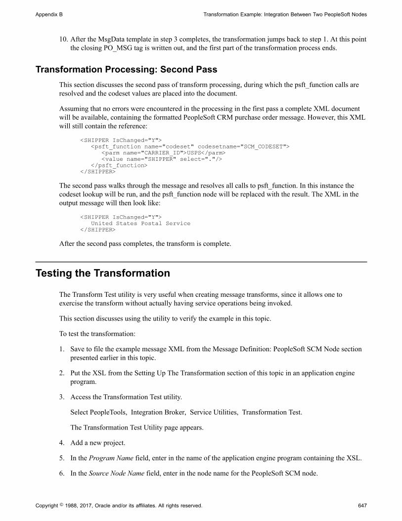
Appendix B Transformation Example: Integration Between Two PeopleSoft Nodes
10. After the MsgData template in step 3 completes, the transformation jumps back to step 1. At this pointthe closing PO_MSG tag is written out, and the first part of the transformation process ends.
Transformation Processing: Second PassThis section discusses the second pass of transform processing, during which the psft_function calls areresolved and the codeset values are placed into the document.
Assuming that no errors were encountered in the processing in the first pass a complete XML documentwill be available, containing the formatted PeopleSoft CRM purchase order message. However, this XMLwill still contain the reference:
<SHIPPER IsChanged="Y"> <psft_function name="codeset" codesetname="SCM_CODESET"> <parm name="CARRIER_ID">USPS</parm> <value name="SHIPPER" select="."/> </psft_function> </SHIPPER>
The second pass walks through the message and resolves all calls to psft_function. In this instance thecodeset lookup will be run, and the psft_function node will be replaced with the result. The XML in theoutput message will then look like:
<SHIPPER IsChanged="Y"> United States Postal Service </SHIPPER>
After the second pass completes, the transform is complete.
Testing the Transformation
The Transform Test utility is very useful when creating message transforms, since it allows one toexercise the transform without actually having service operations being invoked.
This section discusses using the utility to verify the example in this topic.
To test the transformation:
1. Save to file the example message XML from the Message Definition: PeopleSoft SCM Node sectionpresented earlier in this topic.
2. Put the XSL from the Setting Up The Transformation section of this topic in an application engineprogram.
3. Access the Transformation Test utility.
Select PeopleTools, Integration Broker, Service Utilities, Transformation Test.
The Transformation Test Utility page appears.
4. Add a new project.
5. In the Program Name field, enter in the name of the application engine program containing the XSL.
6. In the Source Node Name field, enter in the node name for the PeopleSoft SCM node.
Copyright © 1988, 2017, Oracle and/or its affiliates. All rights reserved. 647

Transformation Example: Integration Between Two PeopleSoft Nodes Appendix B
7. In the Destination Node Name field enter in the node name for the CRM node.
8. In the File Name field, enter in the fully qualified path name of the file containing the input message.
9. Click the Transform button.
The transformed XML appears in the Message Text text box.
648 Copyright © 1988, 2017, Oracle and/or its affiliates. All rights reserved.

Appendix C
Understanding Migrated IntegrationMetadata
Understanding Migrated Integration Metadata
These topics provide an overview of metadata migrated from PeopleSoft 8.47 and earlier database toPeopleSoft 8.48 and later databases.
The following table summarizes how objects are migrated between PeopleTools 8.47 and earlier releasesand PeopleTools 8.48 and later releases:
PeopleTools 8.4x Objects
( PeopleTools 8.47 and Earlier)
PeopleTools 8.48 and Higher Objects
Node. Node.
Channel. Queue.
Message. Message.
Node transactions and relationships. Service, Service Operations, Service Operation Versions, andRoutings.
Message and Subscription PeopleCode. Application classes and service operation handlers.
Note: All objects migrated to PeopleTools 8.48 and higher releases have the Owner ID of the messagefrom which they were created. Any invalid Owner IDs are deleted at the time of upgrade. If no Owner IDexists for an object, you must manually define one in the PeopleTools 8.48 or higher database.
Node ObjectsUpgraded node objects are assigned a Default User ID as defined in the upgrade script.
In PeopleTools 8.48 and higher releases security is implemented at the user ID level. The default user IDis used in conjunction with securing service operations.
Channel ObjectsChannels have been converted to queues.
The new queue name should be the same as the old channel name.
As part of the upgrade/conversion, any related language data associated with the channel should also bebrought over to the newly created queue definition.
Copyright © 1988, 2017, Oracle and/or its affiliates. All rights reserved. 649

Understanding Migrated Integration Metadata Appendix C
Message ObjectsMessages are shapes that provide the physical description of the contents of a service operationtransaction, and describe the data being sent, including fields, field types, and field lengths.
Unlike PeopleTools 8.47 and earlier releases, beginning with PeopleTools 8.48 messages do not containany processing logic, such as PeopleCode events or subscriptions. All processing logic is created byextending a set of delivered application classes, and associating those application classes to serviceoperations using service operation handlers.
Node Transaction and Relationship ObjectsNode transactions and relationships are migrated to services, service operations and routing definitions.
Service ObjectsDuring the upgrade process, a service definition is created for each distinct message referenced in thenode transaction table.
A service inherit most of its properties from the message, including description, long description, OwnerID, language code, and so on.
The service name in PeopleTools 8.48 and higher releases is the same as the message name in thePeopleTools 8.47 or earlier system.
Any related language data associated with the message is inherited by the service.
Service Operation ObjectsService operations have the same name as the service to which they are associated.
Complex transactions like asynchronous or synchronous transactions with transformations, hubtransactions or async-to-sync are defined by grouping a set of node transactions and relationshipstogether. As the complex cases are upgraded, the system separates node transactions that were createdfor these complex cases (for example an asynchronous hub case) from the simple cases (for example,outbound asynchronous requests with no transformation). Asynchronous and synchronous nodetransactions that do not participate in a relationship (for example, those that are left over after we settledthe complex cases) in PeopleTools 8.47 and earlier releases become service operations in PeopleTools8.48 and higher releases.
Warning! If there is no node transaction on the PeopleTools 8.47 or earlier system, no service operation iscreated on the PeopleTools 8.48 or higher system during upgrade.
In cases where a PeopleTools 8.47 or earlier node has both synchronous and asynchronous transactions,the first transaction defined on the node is migrated as a service operation; the second message cannot becreated and an error is generated to the output log at the time of upgrade.
For asynchronous-to-synchronous transactions on a PeopleTools 8.47 or earlier system, the followingoccurs during the upgrade process to PeopleTools 8.48 or higher system:
• The service operation is named after the outbound message name.
• The request message is named after the outbound asynchronous message.
650 Copyright © 1988, 2017, Oracle and/or its affiliates. All rights reserved.

Appendix C Understanding Migrated Integration Metadata
• The response message is named after the asynchronous response message specified in therelationship.
In PeopleTools 8.47 and earlier systems the IsActive property of the Message class was used to check theactive property on the message. In PeopleTools 8.48 and higher systems it checks the service operation.In cases where a service operation is not created for a message, the IsActive property returns False.Therefore there may be a behavioral change from previous releases. In cases where there is no serviceoperation created, and you want the previous behavior preserved, you must create a service operation andset the operation state to match that which was on the message.
Routing ObjectsThe upgrade process creates point-to-point routing definitions in the PeopleTools 8.48 or higher systembased on node transactions and relationships defined in the PeopleTools 8.47 or earlier system.
Only current relationships in the PeopleTools 8.47 or earlier system are migrated.
The Active/Inactive flag on the transaction in the PeopleTools 8.47 or earlier system determines whetherthe routing definition is active or inactive in the PeopleTools 8.48 or later system.
The connector information defined on the outbound transaction is used in the routing definition. You mustmanually update aliases on routing definitions that use custom connectors.
When the system creates routing definitions during the upgrade process, the external message name fromthe transaction is used as the routing alias, if one was defined. If there is no value in the external messagename, messages on nodes that are marked as External use the PeopleTools 8.47 or earlier system aliasmessage name. PeopleTools 8.47 and earlier system nodes marked as anything other then External use thePeopleTools 8.48 alias format of serviceoperation.version.
All routing definitions created during the upgrade process are point-to-point routings, with oneexception. In cases where on the PeopleTools 8.47 or earlier system there is an inbound synchronous orasynchronous node transaction on the default local node without a corresponding outbound synchronousor asynchronous node transaction (via relationship) on the default local node, an any-to-local routingdefinition is created during the upgrade.
Understanding Migrated Integration PeopleCode
The following table summarized how PeopleCode has been migrated between PeopleTools 8.4x releasesand PeopleTools 8.48:
PeopleTools 8.4x PeopleCode
(PeopleTools 8.47 and Earlier)
PeopleTools 8.48 and Higher PeopleCode
Message and subscription PeopleCode. Application classes.
PeopleCode events. Service operation handlers.
All PeopleCode referenced in a message is converted to an application class, which is in turn thenreferenced by a handler that is created in the service operation generated by the converted message.
Copyright © 1988, 2017, Oracle and/or its affiliates. All rights reserved. 651

Understanding Migrated Integration Metadata Appendix C
Application ClassesPeopleCode defined on messages in PeopleTools 8.47 and earlier releases is migrated into applicationclasses in PeopleTools 8.48 and higher releases.
Application classes have to belong to an application package. The message name becomes the applicationpackage name and description. The exception for this naming convention is when an application packagealready exists on the PeopleTools 8.48 or higher system that matches the message name. In this case theapplication package is stripped of all underscores and the number 1 is appended to the end of the name.
For every subscription event associated with a message, an application class is created in the PeopleTools8.48 or higher system with a similar name as the subscription event. Since application class namescannot contain special characters, those found in the subscription event name are simply replaced with anunderscore.
Default values for application class names are used for the other message events.
If a PeopleTools 8.47 or earlier message has no PeopleCode defined on it, no application package isgenerated for it in the PeopleTools 8.48 or higher system.
Application classes that fail to compile are saved and commented out. In these cases, a deprecatedhandler is created to invoke the old message or subscription event, to behave, runtime-wise, as it did inPeopleTools 8.47 and earlier systems. The user, however, is responsible for correcting any applicationclasses that failed to compile and modifying any service operation definition that makes use of thedeprecated handler.
See Correcting Integration PeopleCode That Did Not Migrate.
PeopleCode MethodsThe following table describes how PeopleCode events from PeopleTools 8.47 and earlier releases map toPeopleTools 8.48 and higher methods.
PeopleTools 8.4x Integration PeopleCode Events
(PeopleTools 8.47 and Earlier)
PeopleTools 8.48 Integration PeopleCode BaseClasses and Methods
(PeopleTools 8.48 and Higher)
OnRequest IRequestHandler:OnRequest
OnAckReceive IReceiver:OnAckReceive
OnRouteReceive IRouter: OnRouteReceive
OnRouteSend IRouter:OnRouteSend
OnSend ISend:OnRequestSend
Subscription INotification:OnNotify
652 Copyright © 1988, 2017, Oracle and/or its affiliates. All rights reserved.

Appendix C Understanding Migrated Integration Metadata
Built-In FunctionsMany PeopleCode built-in functions have been deprecated for the new PeopleSoft Integration Brokermodel. Most of the PeopleTools 8.47 and earlier built-in functions have been internally redirected to workwith the PeopleTools 8.48 and later equivalent. When compiling PeopleCode that uses the PeopleTools8.47 and earlier built-in functions, an informational message appears that explains that the given built-inhas been deprecated.
Other Migrated ConstructsThe following constructs are also migrated during the upgrade process:
• Import statements.
• Function libraries.
• Variables not explicitly declared.
Special CharactersDuring the upgrade process, any special characters that used in the name of PeopleCode constructs in thePeopleTools 8.47 or earlier PeopleCode, such as slashes (“/”), single quotation marks “ ' ' “, and periods( . ) are replaced with underscores ( _ ).
Correcting Integration PeopleCode That Did Not Migrate
This section provides an overview of integration PeopleCode that did not migrate and how to correct it.
Understanding Integration PeopleCode That Did Not MigrateThis section discusses the reasons why integration events and subscriptions might not successfullymigrate to application classes during the upgrade from PeopleTools 8.47 and earlier systems toPeopleTools 8.48 and higher systems and the Deprecated type service operation handler used to managesuch PeopleCode.
Reasons Why Integration PeopleCode Does Not MigrateIntegration events and subscriptions might not successfully migrate to application classes for thefollowing reasons:
• Use of global variables.
• Use of component variables.
• Use of constants.
• Use of local functions.
• Inability to determine the return type or the return type is incorrect.
Copyright © 1988, 2017, Oracle and/or its affiliates. All rights reserved. 653

Understanding Migrated Integration Metadata Appendix C
Deprecated PeopleCode HandlerThe PeopleSoft system creates a deprecated PeopleCode handler for any integration PeopleCode thatcannot be migrated to the PeopleTools 8.48 or higher system.
Deprecated handlers enable you to run PeopleTools 8.47 and earlier PeopleCode (subscription orOnRequest). However, PeopleSoft recommends that you correct the PeopleCode and migrate the codeinto an Application Class type handler for use in the PeopleTools 8.48 or higher system.
See Correcting Non-Migrated Integration PeopleCode.
Correcting Non-Migrated Integration PeopleCodeThis section discusses correcting non-migrated PeopleCode and creating an Application Class typehandler.
The following example shows an application class created for the PeopleTools 8.47 or earlier messagePT_CDB_SECURITY. During the upgrade process, the system was unable to migrate the integrationPeopleCode defined on the message.
Image: PeopleSoft Application Designer
This example illustates a PeopleTools 8.48 application class created for the PeopleTools 8.4x messagePT_CDB_SECURITY.
To correct non-migrated integration PeopleCode:
1. In PeopleSoft Application Designer, open the migrated application package.
The package name is generally the same as the message name in the PeopleTools 8.47 or earliersystem.
2. Remove the “<*” and “*>” symbols, as well as the comments from the code.
3. Compile the code.
654 Copyright © 1988, 2017, Oracle and/or its affiliates. All rights reserved.
Appendix C Understanding Migrated Integration Metadata
If the code did not migrate for one of the following reasons, the system displays a meaningful errormessage to assist you in correcting the problem:
• Use of component scope variables.
• Use of global variables or constant variables
• Incorrect return type for handler.
If the reason for the failure is due to the use of a local function, modify the PeopleCode to ensure thatthe function is passing appropriate types for the context in the application package.
4. Correct the PeopleCode and save the changes.
5. Delete the deprecated handler.
a. Select PeopleTools, Integration Broker, Service Utilities, Service Administration. Click theDeprecated PeopleCode tab.
The Deprecated PeopleCode page appears.
b. In the Service Operation field, enter the name of the service operation that contains the deprecatedhandler to delete and click the Search button.
c. In the Select column, select the check box next to the service operation name that contains thedeprecated handler to delete.
d. Click the Delete button.
6. Add an Application Class type handler to the service operation definition that references the modifiedPeopleCode.
See Adding Handlers to Service Operations.
7. In the message definition that was migrated to the PeopleTools 8.48 or higher system, delete thePeopleCode event or Subscription that is defined on the message.
Open the PeopleCode editor for the respective event and null out the program that exists there.Several warnings appear when saving the program, but your changes will be committed.
Copyright © 1988, 2017, Oracle and/or its affiliates. All rights reserved. 655

Understanding Migrated Integration Metadata Appendix C
656 Copyright © 1988, 2017, Oracle and/or its affiliates. All rights reserved.
Appendix D
Setting PS_FILEDIR and PS_SERVDIREnvironment Variables
Understanding Setting PS_FILEDIR and PS_SERVDIREnvironment Variables
Some features of PeopleSoft Integration Broker enable you or require that you upload, import or consumedata from files. For example, the system enables you to upload XML data from files to populate messagesor consume WSDL from files.
In these and most other situations where you upload, import, or consume data from files, you must set thePS_FILEDIR environment variable on the machine on which the application server resides before youcan successfully perform these actions.
Some features require that you also set the PS_SERVDIR environment variables
The procedure for setting the PS_FILEDIR and PS_SERVDIR environment variables is identical.
Setting PS_FILEDIR and PS_SERVDIR in Microsoft WindowsEnvironments
Use the following procedure to set the PS_FILEDIR or PS_SERVDIR environment variable in Windows.
To set the PS_FILEDIR or PS_SERVDIR environment variable in Microsoft Windows environments:
1. Close any open DOS windows.
2. On your desktop, right-click the My Computer icon and click Properties.
The System Properties dialog appears.
3. Click the Advanced tab.
4. In the Environment Variables section, click the Environment Variables button.
The Environment Variables dialog box appears.
5. In the User variables for <user name> section, click New.
A New User Variable dialog box displays.
a. In the Variable Name field enter PS_FILEDIR or PS_SERVDIR.
b. In the Variable Value field, enter c:\temp.
Copyright © 1988, 2017, Oracle and/or its affiliates. All rights reserved. 657

Setting PS_FILEDIR and PS_SERVDIR Environment Variables Appendix D
c. Click the OK button to close the dialog box.
6. In the System variables section, click New. The New System Variable dialog box appears.
a. In the Variable Name field enter PS_FILEDIR or PS_SERVDIR.
b. In the Variable Value field, enter c:\temp, unless the documentation for the feature with which youare working states that you should enter a different value.
c. Click the OK button to close the dialog box.
7. Click the OK button again to exit the System Properties dialog box.
Setting PS_FILEDIR and PS_SERVDIR in UNIX Environments
To set the PS_FILEDIR or PS_SERVDIR variable in UNIX use one of the following commands asappropriate for your UNIX environment.
Note that the path you specify in either command is the location from where the system will upload files.The documentation for the feature with which you are working may state a specific path to enter.
To set PS_FILEDIR:
• export PS_FILEDIR = <PS_HOME>/file
• setenv PS_FILEDIR = <PS_HOME>/file
To set PS_SERVDIR:
• export PS_SERVDIR = <PS_HOME>/file
• setenv PS_SERVDIR = <PS_HOME>/file
658 Copyright © 1988, 2017, Oracle and/or its affiliates. All rights reserved.