PD12C PARTS LIST - Arch Oil Tools
28
PD12C PARTS LIST } First 2 numbers indicate year manufactured WRITE HOIST SERIAL NUMBER BELOW For serial number location see page 3 ©2016 PACCAR Inc. All rights reserved LIT2299 Rev 10 October 2016 Printed in USA Visit our Web site at www.paccarwinch.com for the most comprehensive collection of winch, hoist, and drive information on the Internet. Most publications and specification sheets are available for downloading.
-
Upload
khangminh22 -
Category
Documents
-
view
0 -
download
0
Transcript of PD12C PARTS LIST - Arch Oil Tools

PD12C
PARTS LIST
}
First 2 numbers indicate year manufactured
WRITE HOIST SERIAL NUMBER BELOW
For serial number location see page 3
©2016 PACCAR Inc. All rights reserved
LIT2299 Rev 10October 2016Printed in USA
Visit our Web site at www.paccarwinch.com for the most comprehensive collection of winch, hoist, and drive information on the Internet. Most publications and specification sheets are available for downloading.
Administrator
Arch Oil Tools logo

2
TABLE OF CONTENTS
MODEL IDENTIFICATION ......................................................................3LUBRICATION ........................................................................................4MAIN ASSEMBLY COMPONENTS .....................................................6-7BASE CONFIGURATION ....................................................................8-9DRUM ROTATION ................................................................................10OVERRUNNING CLUTCH COMPONENTS ...................................10-11BRAKE CYLINDER ASSEMBLY ..........................................................12PLANETARY CARRIER ASSEMBLIES ................................................13MOTOR GROUPS ...........................................................................14-19BRAKE VALVE ASSEMBLY .................................................................20FASTENERS, ADAPTERS, AND HOSE ASSEMBLIES .......................21RECOMMENDED FASTENER TORQUE ............................................23METRIC CONVERSION CHART .........................................................24
FOREWORD
Read this entire publication and retain it for future reference.
If you have any questions regarding your Braden PD12C Winch or this publication, call the Braden Service Department at 1-918-251-8511, 08:00-16:30 hours Central Time Zone, Monday through Friday.
Some illustrations in this manual may show details or attachments that are different from your winch. Also, some components have been removed for illustrative purposes. Illustrations and pic-tures in this manual are of a “typical” unit sold through our distribution channels. Some winches, particularly those sold to original equipment manufacturers, may differ slightly in appearance.
Whenever a question arises regarding your Braden Winch, please contact the Braden Service Department for the latest available information.
PACCAR Winch DivisionService DepartmentP.O. Box 547Broken Arrow, Oklahoma 74013-0547 United States of Americawww.paccarwinch.com

3
PD DESIGNATES POWER DRUM12 DESIGNATES 12,000 LB. FIRST LAYER LINE PULLC DESIGNATES THE MODEL SERIES RELATING TO DESIGN CHANGES41 DESIGNATES TOTAL GEAR REDUCTION, 41 = 41.62:1051 DESIGNATES HYDRAULIC MOTOR DISPLACEMENT IN CU IN/REV (DECIMAL POINT ELIMINATED. EXAMPLE: 051 = 5.1 CU IN/REV)04X DESIGNATES THE DRUM (X OPTIONS: “U” DESIGNATES UNDERWIND, “L” DESIGNATES LEFT HAND BASE, “P” DESIGNATES RATCHET & PAWL)1 PERMITS TESTING AND INSPECTION PER API 2C FOR OFFSHORE CRANES
TO ORDER:
(1) List model and serial numbers of the winch. (2) Refer to exploded view and select the component(s) needed and note item number. (3) Find item number on material list, show part number, description and quantity required on your order. (4) Refer to Parts List and show price for each component or assembly.
Serial Numbers and Model Numbers are located to the left- hand side of the hydraulic motor, stamped into the base.
Always refer to the Serial Number and Model Number when requesting information or service parts.
EXPLANATION OF MODEL NUMBER
PD 12 C 41 051 - 04X - 1POWERDRUM
MAXRATING
DESIGNMODEL
GEARRATIO
MOTOR SIZE
DRUMSIZE
OPTION
IDENTIFICATION

4
LUBRICATIONRECOMMENDED PLANETARY GEAR OIL
Field experience, supported by engineering endurance tests, indicates the use of the proper gear oil and a program of regular preventive maintenance will help provide extended gear train life and reliable hoist brake performance. For this reason, BRADEN has published the following specifications to assist in determining which lubricant is best suited to your application.For simplicity, BRADEN has listed available products in each temperature range that have been tested and found to meet our specifications. This is not to say that other lubricant brands would not perform equally as well.If the following lubricant brands are not available in your area, make certain your lubricant vendor supplies you with oil equivalent to those products listed below.
Failure to use the proper type and viscosity of planetary gear oil may contribute to intermittent brake clutch slippage, which could result in property damage, severe personal injury, or death. Some gear lubricants contain large amounts of EP (Extreme Pressure) and anti-friction additives, which may contribute to brake clutch slippage or damage to brake friction discs or seals. NOTE: DO NOT use oil that is labeled as meeting "API Service GL-5." Oil viscosity, affected by ambient temperature, is also critical to reliable brake clutch operation. Our tests indicate excessively heavy or thick gear oil may contribute to intermittent brake clutch slippage. Make certain the gear oil viscosity used in your hoist is correct for your prevailing ambient temperature.
PREVAILING AMBIENT TEMPERATUREoF -40 -30 -20 -10 0 10 20 30 40 50 60 70 80 90 100 110 120 130 oF
oC -40 -30 -20 -10 0 10 20 30 40 50 oC
SHADED TEMPERATURE RANGE IN THE CHART ABOVE NOT RECOMMENDED FOR SEVERE APPLICATIONS SUCH AS SUSTAINED FAST DUTY CYCLES OR FREQUENT WINCHING.
TexacoShell
Meropa 220
Meropa 150
Omala S2 G 220
Omala S2 G 150
Chevron
Gear Compounds EP 220
Gear Compounds EP 150
PREVAILING AMBIENT TEMPERATUREoF -40 -30 -20 -10 0 10 20 30 40 50 60 70 80 90 100 110 120 130 oF
oC -40 -30 -20 -10 0 10 20 30 40 50 oC
SHADED TEMPERATURE RANGE IN THE CHART ABOVE NOT RECOMMENDED FOR SEVERE APPLICATIONS SUCH AS
Mobil
Mobilgear 600 XP 220
Mobilgear 600 XP 150
Winches are factory filled with Mobilgear 600 XP 150 or equivalent. Consult your oil supplier for other equivalentoils if required.
RECOMMENDED GEAR OIL
Omala S4 GX 150Mobilgear SHC 150
Use gear oil detailed in Range A
Range A
Range B
Range C
Use gear oil detailed in Range B
Use gear oil detailed in Range C
Failure to properly warm up the winch, particularly under low ambient temperature conditions, may result in temporary brake slippage due to high back pressures attempting to release the brake, which could result in property damage, severe personal injury or death.
If you have any questions regarding this bulletin or your BRADEN planetary winch, please contact the BRADEN Product Support Department at 1-918-251-8511, Monday through Friday
from 08:00 to 16:30 hours CST, or by fax at 1-918-259-1575.
5
SERVICE KITS
61715 - SEAL KITDESCRIPTION PART NO. QTYO-RING 13838 1O-RING 12465 2O-RING 25366 2O-RING 78312 2O-RING 22586 1O-RING 21150 1O-RING 21063 1O-RING 76208 1O-RING 23950 1O-RING 24186 1O-RING 72117 1SEAL 25642 1OIL SEAL 24109 1O-RING 21033 1SEAL-OIL 22818 1O-RING 10330 1O-RING 24981 1BACK-UP RING 25643 1
61567 - BRAKE VALVE O-RING KITDESCRIPTION PART NO. QTY.O-RING 24186 1O-RING 23601 2O-RING 24193 1O-RING 24194 1BACK-UP RING 24195 1BACK-UP RING 24196 1O-RING 21150 2O-RING 13838 2
64586- BEARING KITDESCRIPTION PART NO. QTY.
BALL BEARING 24110 2THRUST WASHER 40129 1THRUST WASHER 40128 1BEARING RACE 25361 6ROLLER BEARING 24175 3SPIROL PIN 24113 3PRIMARY PLANET GEAR SHAFT 25614 3THRUST WASHER 24306 6ROLLER BEARING 25292 6BEARING SPACER 25443 3SPIROL PIN 23584 3PLANET GEAR SHAFT 25613 3
64335 - BRAKE SERVICE KITDESCRIPTION PART NO. QTY.SEAL 25642 1DIE SPRING 25644 12850170 DISC-FRICTION 21036 7BRAKE DISK 100027 8O-RING 24981 1BACK-UP RING 25643 1O-RING 22586 1

6
BRADEN PD12C MAIN ASSEMBLY COMPONENTS
29
35
31
34 43
200
22
57
45
26
2730
23
39
24
2528
26
40
41
100
300
4644

7
BRADEN PD12C MAIN ASSSEMBLY COMPONENTS
ITEM DESCRIPTION PART NO. QTY22 BASE CONFIGURATIONS (SEE PGS 8-9) -- 1
24
CABLE DRUM (01 DRUM) 26757 1CABLE DRUM (02 DRUM) 25518 1CABLE DRUM (04 DRUM) FROM S/N 9102358 28831 1CABLE DRUM (05 DRUM) 25901 1
25CABLE DRUM CLOSURE (CONSULT FACTORY) 26763 1CABLE DRUM CLOSURE (CONSULT FACTORY) 25561 1
26 BALL BEARING 24110 227 OIL SEAL (SUPPORT END) 24109 128 O-RING 21033 129 OIL SEAL (DRUM CLOSURE) 22818 131 PRIMARY THRUST RACE 40128 134 OUTPUT SUN GEAR 135 PRIMARY SUN GEAR 1
40CAPSCREW (02 & 05 DRUM), HEX HEAD (1/2-13 X 1-1/2 GD8 Z) 104322 8CAPSCREW (01 & 04 DRUM), HEX HEAD (1/2 13 X 1-1/4 GD8 Z) 104174 8
41 LOCKWASHER (1/2) 11026 843 OUTPUT THRUST RACE 40129 145 DRAIN PLUG 32411 1
45a O-RING 23950 1
57
CABLE WEDGE STANDARD (7/16 - 5/8 IN) 40130 1CABLE WEDGE (3/8 IN. 10 MM) 24494 1CABLE WEDGE (3/4 IN. 19 MM) 24492 1CABLE WEDGE (POLY ROPE 1- 1 1/8 IN) 24413 1
100 PRIMARY PLANET CARRIER ASSEMBLY -- 1200 OUTPUT PLANET CARRIER ASSEMBLY -- 1300 BRAKE CYLINDER ASSEMBLY -- 1
ITEM DESCRIPTIONPART NO.
QTYGEAR REDUCTIONSUN GEARS 21:1 29:1 41:1 59:1
34 OUTPUT SUN GEAR 25608 25608 25610 25610 135 PRIMARY SUN GEAR 25714 25652 25652 25640 1

8
BASE CONFIGURATIONS
ITEM DESCRIPTION PART NO. QTY.30 RETAINING RING 70575 1
44PLUG HEX (STANDARD WINCHES) 31386 1PLUG FLUSH 24420 1SIGHT GLASS (-1 OPTION) 25958 1
44a O-RING FOR ITEM 44 PLUGS* 24186 146 RELIEF VALVE 18062 1
COMMON BASE PARTS
ITEM DESCRIPTION PART NO. QTY
22BASE (RIGHT HAND) 25615 1BASE (LEFT HAND) 101074 1
23BEARING SUPPORT (01 DRUM) 106459 1BEARING SUPPORT (02 & 05 DRUM) 101644 1
39 CAPSCREW, HEX HEAD (1/2-13 X 1-1/2 GD8 Z) 104322 841 LOCKWASHER (05 DRUM) 11026 8
CAST BASE
22

9
44
46 39 41
23
30
91
95
92
9796
90
9493
ITEM DESCRIPTIONDRUM OPTION CODE
QTY-01 -02 / -05 -02 (LH) -04PART NO.
23 BEARING SUPPORT 106459 106459 106459 106459 139 CAPSCREW, HEX HEAD (1/2-13 X 1-1/4 GD8 Z) 104174 104174 104174 104174 890 BASE 26344 26344 26344 26344 191 SIDE PLATE, BEARING SUPPORT END 26764 106466 106466 27212 192 SIDE PLATE, MOTOR END 26765 106465 106537 27213 1
93 CAPSCREW, HEX HEAD (1/2-13 X 1-1/2 GD8 Z) (SPECIAL)
103314 103314 103314 103314 16
94 LOCKWASHER 1/2 Z EXTERNAL TOOTH 12781 12781 12781 12781 16
95TIE BAR 26223 26223 26223 -- 1TIE BAR -- -- -- 26223 2
96CAPSCREW, HEX HEAD (1/2-13 X 1-1/4 GD8 Z) 104174 104174 104174 -- 2CAPSCREW, HEX HEAD (1/2-13 X 1-1/4 GD8 Z) -- -- -- 104174 4
97LOCKWASHER (1/2 Z) 11026 11026 11026 -- 2LOCKWASHER (1/2 Z) -- -- -- 11026 4
BASE CONFIGURATIONS
FABRICATED BASE

10
5352
5155
50
54
49
5152
53
ITEM DESCRIPTIONPART NO. PART NO.
QTY.SAE C SAE B
49 OUTER BRAKE RACE NSS NSS 150 INNER BRAKE RACE NSS NSS 151 SPRAG BEARING 27684 27684 252 THRUST BEARING 24581 24581 253 RETAINING RING 12034 12034 254 SPRAG CLUTCH NSS NSS 155 RETAINING RING 24506 24031 1
NSS – NOT SERVICED SEPARATELYORDER ENTIRE BRAKE CLUTCH ASSEMBLY
DRUM ROTATION TO HOIST (04 & 05 DRUM/BASE SHOWN)
* U N D E R WIND
OVERWIND STD.
*U N D E R WIND
OVERWIND STD.
RH BASE (Standard) LH BASE (Optional)
Underwound will have “U” inmodel number
* U N D E R WIND
OVERWIND STD.
*U N D E R WIND
OVERWIND STD.
RH BASE (Standard) LH BASE (Optional)
Underwound will have “U” inmodel number
UNDERWOUND MODELS DESIGNATED BY “–U”
(EXAMPLE: PD12C-41051-04U)
OVERRUNNING CLUTCH COMPONENTS

11
Note: Designation of cable drum rotation is determined by viewing winch from hydraulic motor end while hoisting.
On the BRADEN PD12C the inner race of the brake clutch sprag assembly, when viewed from the motor side, must freewheel in the direction opposite as the cable drum during hoisting
COMPLETE BRAKE CLUTCH ASSEMBLIES
Inner Race Freewheels Clockwise when Viewed
From Motor End
PART #81716 & #81774
Inner Race Freewheels CounterClockwise when Viewed From Motor End
PART #81776 & #81777
Motor Side ofBrake Clutch assembly
BRAKE CLUTCH ROTATION
DESCRIPTION APPLICATION PART NO.
SAE C 14TRH BASE OVERWIND, LH BASE UNDERWIND 81716RH BASE UNDERWIND, LH BASE OVERWIND 81776
SAE B 13TRH OVERWIND, LH UNDERWIND 81774RH UNDERWIND, LH OVERWIND 81777

12
BRAKE CYLINDER ASSEMBLY
NOTE: MOTOR ADAPTOR MAY BE SPLINED FOR USE IN EARLY MODEL BRAKE ASSEMBLIES. IF ITEM #23 IS SPLINED, USE SPLINED DISCS PN#21029
IF MAJOR REBUILD OF BRAKE ASSEMBLY IS RE-QUIRED, THE SPLINED MOTOR ADAPTOR IS RE-PLACED BY THE LOBED MOTOR ADAPTOR AND 8 LOBED DISKS
ITEM DESCRIPTION PART NO. QTY.1 BRAKE CYLINDER (LOBED DISC) 100035 12 BRAKE PISTON SEAL 25642 13 PRESSURE PLATE 25635 14 PISTON BACKUP RING 25636 1
5 DIE SPRING 25644 12
6 FRICTION DISC 21036 7
7BRAKE DISC, STEEL, LOBED 100027
8BRAKE DISC, STEEL, SPLINED 21029
23MOTOR ADAPTER (4 BOLT C) 051, 064, 049/024, 064/032 100028
1MOTOR ADAPTER (2 BOLT B) 029, 034, 039 100458MOTOR ADAPTER (2 BOLT A) 080 100097
36 SPACER 25637 1
41LOCKWASHER (4 BOLT C, 2 BOLT A) 11026
4LOCKWASHER (2 BOLT B) 12781
42 CAPSCREW, HEX HEAD (1/2-13 X 2 GD8 Z) 29855 447 O-RING 24981 148 BACKUP RING 25643 199 SPRING SPACER 100200 1
* ITEMS 1 AND 99 REPLACE PART NO 25564, BRAKE CYLINDER W/CAST IRON SPRING POCKETS
4142
2348
47
67
362
43
5 99
1

13
PLANET CARRIER ASSEMBLIES
15
38
17 21 19
20
19
21
18
16
15
10
14
131411
37
12
PRIMARY PLANET CARRIER ASSEMBLY
OUTPUT PLANET CARRIER ASSEMBLY
21:1 29:1 41:1 59:1ITEM DESCRIPTION PART NO. QTY
OUTPUT CARRIER ASSEMBLY 81804 81804 81802 81802 115 ROLL PIN (OUTPUT PLANET CARRIER) 23584 23584 23584 23584 316 OUTPUT PLANET CARRIER 25602 25602 25562 25562 117 OUTPUT PLANET GEAR 26279 26279 26277 26277 318 OUTPUT PLANET GEAR SHAFT 25613 25613 25613 25613 319 BEARING 25292 25292 25292 25292 620 BEARING SPACER 25443 25443 25443 25443 321 THRUST WASHER 24306 24306 24306 24306 638 OUTPUT THRUST PLATE 25638 25638 25638 25638 1
21:1 29:1 41:1 59:1ITEM DESCRIPTION PART NO. QTY.
PRIMARY PLANET CARRIER ASSEMBLY 81805 81806 81807 81801 110 PRIMARY PLANET CARRIER 25715 25730 25606 25604 111 PRIMARY PLANET GEAR 26280 2278 26278 26276 312 PRIMARY PLANET GEAR SHAFT 25614 25614 25614 25614 313 BEARING 24175 24175 24175 24175 314 THRUST WASHER 25361 25361 25361 25361 615 ROLLPIN (PRIMARY PLANET CARRIER) 24113 24113 24113 24113 337 PRIMARY THRUST PLATE 25729 25729 25729 25729 1
14
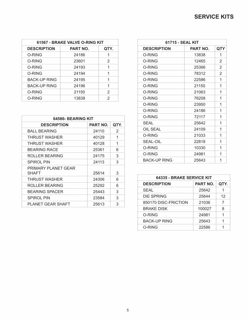
MOTOR GROUPS (STANDARD)
6162a
59
63
60
83 58
66 65
68
60
V-33/20TWO-SPEED, BRAKE VALVE 29576
59
6663
62
6865
70
6658
8360
65
61
V-33/20TWO-SPEED, BRAKE VALVE 81719
6859
6469
40 41
66
7065
6785
63
62
61
049/024 & 064/032 MOTORTWO-SPEED

15
59 61 687262
64
69
40 41
668360 58
7065
67
63
051 & 064 MOTORSINGLE-SPEED
62b61
66
70
62a
68
65
72
59
080 MOTORSINGLE-SPEED
6663
62b62a
60
40 41
6865
59
071 & 062 MOTORSINGLE-SPEED
MOTOR GROUPS (STANDARD)
16
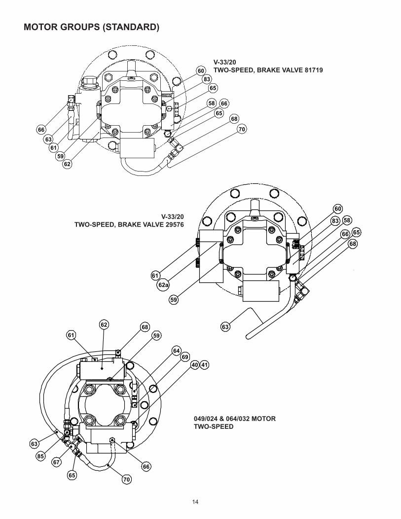
MOTOR GROUPS (STANDARD)
5860
66
69
83
5968 61 68
63
64
6765 70
029, 034, & 039 MOTORSINGLE-SPEED
NOTE: These drawings are standard configura-tions. Verify hoses, fittings, and capscrews using tables found on pages 21 and 22.
ITEM DESCRIPTION PART NO. QTY PILOT O-RING
5
029 (2 BOLT B) 25385 1 21063034 (2 BOLT B) 25912 1 21063034 (2 BOLT B) UNDERWOUND 103887 1 21063039 (2 BOLT B) 25515 1 21063039 (4 BOLTC) CT WINCHES 25896 1 10330051 (4 BOLT C) 25897 1 10330064 (4 BOLT C) 25777 1 10330049/024 (4 BOLT C) 26182 1 10330V33/20 (4 BOLT C) 100714 1 10330064/032 (4 BOLT C) 28956 1 10330071 REPLACED BY 062 (2 BOLT B) 106079 1 21063080 (2 BOLT A) 26124 1 22586

17
039, 051, 064 049/024064/032 029, 034, 039 080 071/062 V33/20
4 BOLT-C 4 BOLT-C 2 BOLT-B 2 BOLT-A 2 BOLT-B 4 BOLT-CITEM QTY DESCRIPTION PART NO.
40 4CAPSCREW 1/2-13 X 1-1/2 GD8 Z HX HD 104322 104322 104322 104322 104322CAPSCREW 1/2-13 X 1-1/2 ASTM A574 SKT HD -- -- -- 21908 -- --
41 4 LOCKWASHER (1/2 Z) 11026 11026 11026 11026 11026 1102658 1 MANIFOLD 24779 -- 25539 -- -- 2566459 1 O-RING 13838 13838 25366 78312 12273 12465
604 CAPSCREW 7/16 - 14 X 2 ASTM A574 SKT HD 21144 -- -- -- 29631 --4 CAPSCREW (EARLY) 3/8 - 16 X 1-1/2 ASTM A574 SKT HD 13544 135444 CAPSCREW (CURRENT) 3/8 - 16 X 1-1/4 ASTM A574 SKT HD -- -- 13827 -- -- 13827
61 4
CAPSCREW 7/16-14 X 3 ASTM A574 Z SKT HD 21134 21134 -- --CAPSCREW 3/8-16 X 2-3/4 ASTM A574 SKT HD -- -- 25622 -- -- --CAPSCREW 3/8-16 x 4 ASTM A574 SKT HD -- -- -- 29630 -- --CAPSCREW 3/8-16 x 3 ASTM A574 SKT HD 13587
62 1 BRAKE VALVE ASSY 81712 81984 81715 -- 8171962A 1 BRAKE VALVE BLOCK -- -- -- 26125 27403 2957662B 1 BRAKE VALVE CARTRIDGE -- -- -- 26126 27258 2959863 1 HOSE ASSY 25749 25749 25749 -- 25952 2595264 1 HOSE ASSY 13704 13707 13704 -- -- --65 1 ADAPTER 25864 25864 25864 25864 25864 2586466 1 FITTING 21163 25864 25131 31284 25302 2530267 1 SWIVEL TEE 25748 25748 25748 -- -- --68 1 CONNECTOR 25302 25302 25302 26140 26140 2614069 1 REDUCER ELBOW 24236 24236 24236 -- -- --70 1 HOSE ASSY 25750 25750 25750 25750 -- 2595272 1 HYD. MOTOR -- -- -- -- -- --73 1 NEEDLE VALVE -- -- -- -- -- --74 1 TEE-MALE BRANCH -- -- -- -- -- --75 1 CAP NUT -- -- -- -- -- --76 1 WARNING TAG -- -- -- -- -- --83 1 O-RING 21150 -- 25366 -- -- 12465
85 1 TEE, -4 ORB -- 29078 -- -- -- --
MOTOR GROUPS (STANDARD)

18
MOTOR GROUPS (– 1 OPTION, PERSONNEL HANDLING)
7461 73 68 6362
59
64
69
40
66
41
70 67758564
65
049/024 & 064/032 MOTORTWO-SPEED PERSONNEL HANDLING
59 61 73 7468 62
6440
60 8358
66 63 69757067 65
41
5961 73
6874 63
64
6775
6570
83
66
60
62
051 & 064 MOTORTWO-SPEED PERSONNEL HANLDING
029, 034 & 039 MOTORSINGLE-SPEED PERSONNEL HANDLING

19
051 & 64
064/032049/024 029/034/039
ITEM DESCRIPTION PART NO. QTY40 CAPSCREW 1/2-13 X 1-1/2 GD8 Z HX HD 104322 104322 104322 441 LOCKWASHER 1/2 Z 11026 11026 11026 458 MANIFOLD 24779 -- 25539 159 O-RING 13838 13838 25366 1
60CAPSCREW 7/16-14 X 2 GD5 SKT HD ASTM A574 Z 21144 -- --
4CAPSCREW 3/8-16 x 1-1/2 ASTM A574 SKT HD (EARLY) -- -- 13544CAPSCREW 3/8-16 X 1-1/4 ASTM A574 SKT HD (CURRENT) -- -- 13827
61CAPSCREW 7/16-14 X 3 ASTM A574 Z SKT HD 21134 21134 --
4CAPSCREW 3/8-16 X 2-3/4 ASTM A574 SKT HD -- -- 25622
62 BRAKE VALVE ASSY 81712 81984 81715 162A BRAKE VALVE BLOCK -- -- -- 162B BRAKE VALVE CARTRIDGE -- -- -- 163 HOSE ASSY 13707 13707 13707 164 HOSE ASSY 13704 13704 13704 165 ADAPTER 25864 25864 25864 166 FITTING 21165 25302 25131 167 SWIVEL TEE 25748 25748 25748 168 CONNECTOR 24784 24784 24784 169 REDUCER ELBOW 24236 24236 24236 170 HOSE ASSY 13731 13731 13731 172 HYD MOTOR -- -- -- 173 NEEDLE VALVE 25258 25258 25258 174 TEE-MALE BRANCH 22934 22934 22934 175 CAP NUT -4 70182 70182 70182 176 WARNING TAG 25257 25257 25257 183 O-RING 21150 -- 25366 185 TEE, -4 ORB -- 29078 -- 1
NOTE: These drawings are standard configurations. Verify hoses, fittings, and capscrews using tables found on pages 21 and 22.
MOTOR GROUPS (– 1 OPTION, PERSONNEL HANDLING)

20
BRAKE VALVE ASSEMBLY
ITEM DESCRIPTION PART NO. QTY1 BRAKE VALVE HOUSING NSS 12 VALVE SPRING RETAINER 24424 1
RELIEF RETAINER (81719 VALVE) 29609 13 SPRING RETAINER 24183 14 PLUG 22450 15 SPOOL NSS 16 DAMPER PISTON NSS 17 O-RING 24186 28 CHECK VALVE POPPET 24423 1
RELIEF ASSEMBLY (81719 VALVE) 82132 19 PILOT ORIFICE 24200 1
10 CHECK VALVE SPRING 24190 111 SPOOL SPRING 24192 112 O-RING 23601 213 O-RING 24193 114 O-RING 24194 115 BACK-UP RING 24195 116 BACK-UP RING 24196 117 BALL, STEEL 21158 118 COMPRESSION SPRING 25480 119 ELBOW FITTING 25302 119 PLUG, -4 ORB (81984 & 81719) 25663 122 SHIM, VALVE SPRING 25661 -59 O-RING 13838 1
BRAKE VALVESFLANGE PART NO.1-1/4 IN. CODE 61 817121 IN. CODE 61 817153/4 IN. CODE 62 817191-1/4 IN. CODE 61 81984
7 1 22
3
12
11
6
14
16
13
15
512
471028
18 17
19
59
9
SEAL KIT 61567

21
FASTENERS, ADAPTERS, AND HOSE ASSEMBLIES
SPLIT FLANGE ADAPTER
EARLY - Use socket head capscrews 13544.
CURRENT - Use socket head capscrews 13827.
NSS - NOT SERVICED SEPARATELY* = INCLUDED IN BRAKE O-RING KIT #61567
CAPSCREWS AND LOCKWASHERSPART NO. DESCRIPTION
29631 5/16 NC X 3 G8, SOCKET HEAD21654 3/8 NC X 3 1/2 G8, SOCKET HEAD25622 3/8 NC X 2 3/4 G8, SOCKET HEAD29630 3/8 NC X 4 G8, SOCKET HEAD13587 3/8 NC X 3 G8, SOCKET HEAD13544 3/8 NC X 1 1/2 G8, SOCKET HEAD (EARLY)13827 3/8 NC X 1 1/4 G8, SOCKET HEAD (CURRENT)21135 7/16 NC X 1 1/2 G8 Z SOCKET HEAD
104318 7/16 NC X 1 3/4 G8 Z HEX HEAD21144 7/16 NC X 2 G8 Z SOCKET HEAD21134 7/16 NC X 3 G8 Z SOCKET HEAD
101150 7/16 NC X 3 3/4 G8 Z SOCKET HEAD104174 1/2 NC X 1 1/4 G8 Z HEX HEAD104322 1/2 NC X 1 1/2 G8 Z HEX HEAD21908 1/2 NC X 1 1/2 G8 Z SOCKET HEAD29855 1/2 NC X 2 G8 Z HEX HEAD
103249 5/8 NC X 1 3/4 G8 Z HEX HEAD11026 LOCKWASHER 1/2 SPLIT, Z
102423 LOCKWASHER 5/8 SPLIT, Z
PART NO. DESCRIPTION25539 SPLIT FLANGE ADAPTER
HOSE ASSEMBLIESPART NO. LENGTH
13710 8 IN. NPT -2 TO JIC -413711 10 IN. NPT -2 TO JIC -413704 12 IN. NPT -2 TO JIC -413706 16 IN. NPT -2 TO JIC -413707 17 IN. NPT -2 TO JIC -413731 22 IN. NPT -2 TO JIC -424948 30 IN. NPT -2 TO JIC -425750 17 IN. JIC -4 BOTH ENDS25952 20 IN. JIC -4 BOTH ENDS25749 22.5 IN. JIC -4 BOTH ENDS
106269 14 IN. ORFS SWIVEL -8106270 17 IN. ORFS SWIVEL -8

22
FITTINGS
A B
E F
I J
M N
C D
G H
K L
O P
PART NO. DESCRIPTION ID25302 ELBOW -4 JIC TO -4 ORB A25131 ELBOW -4 JIC TO -6 ORB A22934 TEE, 1/8-27 NPT-F RUN TO 1/8-27 NPT-M BRANCH B24236 STREET ELBOW, REDUCER, 1/4-18 M TO 1/8-27F C13708 STREET ELBOW, 1/8-27 D24784 ADAPTER, -4 ORB TO -2 NPT-F E25748 SWIVEL TEE, -4 JIC M RUN X -4 JIC F SWIVEL BRANCH F25864 ADAPTER, -4 JIC TO -4 ORB G31284 ADAPTER, -4 JIC TO -6 ORB G25258 NEEDLE VALVE H21165 ELBOW (45°) -2 NPT TO -4 JIC I21163 ELBOW (90°) -2 NPT TO -4 JIC I29078 TEE, -4 ORB TO -4 JIC J
100945 ELBOW, ORFS SWIVEL K100946 ADAPTER, -4 ORB TO -6 ORFS L102632 TEE, -4 ORFS TO -6 ORB M69325 PLUG, -4 ORB N70182 CAP, -4 JIC O22934 TEE, FEMALE PIPE TO MALE PIPE -2 P23508 REDUCER PIPE -4 TO -2 -26140 ELBOW JIC SWIVEL -4/4 -

23
RECOMMENDED FASTENER TORQUE

24
Product: PD12C/PD15B with the 01 and 04 Style DrumTitle: PD12C/PD15B Bearing Support Product ImprovementPurpose: Product Improvement
If drum bearing support, part no. 101645, requires replacement in PD12C and PD15B model hoists with the 01 and 04 style drum, an upgraded bearing support must be purchased. The upgraded bearing support uses Hex Head Cap-screws (p/n 11174) and Lockwashers (p/n 12781) to provide easier servicing. The previous designs using Flathead Capscrews (p/n 25096) and Bearing Support (p/n 101645) were sometimes difficult to remove from the hoist when servicing.
NOTE:Refer to Service Manual LIT2103 for instructions on how to disassemble hoist & LIT2601 for complete instructions.
DESCRIPTION PART NO QTYA PREVIOUS FLATHEAD CAPSCREWS 25096 8B PREVIOUS BEARING SUPPORT 101645 1C NEW HEX HEAD CAPSCREWS 104174 8D NEW LOCKWASHERS 12781 8E NEW BEARING SUPPORT 106459 1F RETAINING RING 70575 1
GPLUG HEX (STANDARD WINCHES) 31386 1PLUG FLUSH 24420 1SIGHT GLASS (-1 OPTION) 25958 1
G1 O-RING FOR ITEM 44 PLUGS 24186 1H RELIEF VALVE 18062 1
PREVIOUS DESIGN UPDATED DESIGN
A
B
C
D
E
F
GH
D
B E
C

25
THIS PAGE INTENTIONALLY LEFT BLANK

26
THIS PAGE INTENTIONALLY LEFT BLANK

27
inches (in.) X 25.4 = millimeters (mm) millimeters (mm) X 0. 03937 = inches (in.)
feet (ft.) X 0.3048 = meters (m) meters (m) X 3.281 = feet (ft.)
miles (mi.) X 1.6093 = kilometers (km) kilometers (km) X 0.6214 = miles (mi.)
inches 2 (sq.in.) X 645.15 = millimeters 2 (mm 2) millimeters 2 (mm 2) X 0.000155 = inches 2 (sq.in.)
feet2 (sq.ft.) X 0.0929 = meters 2 (m 2) meters 2 (m 2) X 10.764 = feet 2 (sq.ft.)
inches 3 (cu.in.) X 0.01639 = liters (l) liters (l) X 61.024 = inches 3 (cu.in.)
quarts (qts.) X 0.94635 = liters (l) liters (l) X 1.0567 = quarts (qts.)
gallons (gal.) X 3.7854 = liters (l) liters (l) X 0.2642 = gallon (gal.)
inches 3 (cu.in.) X 16.39 = centimeters 3 (cc) centimeters3 (cc) X 0.06102 = inches 3 (cu.in.)
feet3 (cu.ft.) X 28.317 = liters (l) liters (l) X 0.03531 = feet 3 (cu.ft.)
feet3 (cu.ft.) X 0.02832 = meters 3 (m 3) meters3 (m3) X 35.315 = feet 3 (cu.ft.)
fluid ounce (fl.oz.) X 29.57 = millileters (ml) milliliters (ml) X 0.03381 = fluid ounce (fl.oz.)
ounces (oz.) X 28.35 = grams (g) grams (g) X 0.03527 = ounces (oz.)
pounds (lbs.) X 0.4536 = kilograms (kg) kilograms (kg) X 2.2046 = pounds (lbs.)
tons (2000 lbs.) X 907.18 = kilograms (kg) kilograms (kg) X 0.001102 = tons (2000 lbs.)
tons (2000 lbs.) X 0.90718 = metric tons (t) metric tons (t) X 1.1023 = tons (2000 lbs.)
tons (long) (2240 lbs.) X 1013.05 = kilograms (kg) kilograms (kg) X 0.000984 = tons (long) (2240 lbs.)
inches Hg (60 oF) X 3600 = kilopascals (kPa) kilopascals (kPa) X 0.2961 = inches Hg (60 oF)
pounds/sq.in. (PSI) X 6.895 = kilopascals (kPa) kilopascals (kPa) X 0.145 = pounds/sq.in. (PSI)
pounds/sq.in. (PSI) X 0.0703 = kilograms/sq.cm. (kg/cm 2) kilograms/sq.cm. (kg/cm2) X 14.22 = pounds/sq.in. (PSI)
pounds/sq.in. (PSI) X 0.069 = bars bars X 14.5 = pounds/sq.in. (PSI)
inches H 2O (60oF) X 0.2488 = kilopascals (kPa) kilopascals (kPa) X 4.0193 = inches H 2O (60
oF)
bars X 100 = kilopascals (kPa) kilopascals (kPa) X 0.01 = bars
horsepower (hp) X 0.746 = kilowatts (kW) kilowatts (kW) X 1.34 = horsepower (hp)
ft.-lbs./min. X 0.0226 = watts (W) watts (W) X 44.25 = ft.-lbs./min.
pound-inches (in.-lbs.) X 0.11298 = newton-meters (N-m) newton-meters (N-m) X 8.851 = pound-inches (in.lbs.)
pound-feet (ft.-lbs.) X 1.3558 = newton-meters (N-m) newton-meters (N-m) X 0.7376 = pound-feet (ft.-lbs.)
pound-feet (ft.-lbs.) X .1383 = kilograms/meter (kg-m) kilogram/meter (kg-m) X 7.233 = pound-feet (ft.-lbs.)
miles/hour (m/h) X 0.11298 = kilometers/hour (km/hr) kilometers/hour (km/hr) X 0.6214 = miles/hour (m/h)
feet/second (ft./sec.) X 0.3048 = meter/second (m/s) meters/second (m/s) X 3.281 = feet/second (ft./sec.)
feet/minute (ft./min.) X 0.3048 = meter/minute (m/min) meters/minute (m/min) X 3.281 = feet/minute (ft./min.)
mega (M) = 1,000,000 or 106 deci (d) = 0.1 or 10 -1
kilo (k) = 1,000 or 10 3 centi (c) = 0.01 or 10 -2
hecto (h) = 100 or 10 2 milli (m) = 0.001 or 10 -3
deka (da) = 10 or 10 1 micro (m) = 0.000.001 or 10 -6
oCelsius = 0.556 ( oF - 32) oFahrenheit = (1.8 oC) + 32
COMMON METRIC PREFIXES
TEMPERATURE
POWER
TORQUE
VELOCITY
VOLUME
MASS
PRESSURE
METRIC CONVERSION TABLE
LINEAR
AREA
English to Metric Metric to English

©2016 PACCAR Inc. All rights reserved
LIT2299 Rev 10October 2016Printed in USA
Administrator
Arch Oil Tools logo