
PCI EXPRESS BACKPLANES USER GUIDE
19
PCI EXPRESS BACKPLANES USER GUIDE Express7-G3 Express9 Express9-G3 Express11-G3 Version 1.0.0
-
Upload
khangminh22 -
Category
Documents
-
view
2 -
download
0
Transcript of PCI EXPRESS BACKPLANES USER GUIDE

PCI EXPRESS BACKPLANES
USER GUIDE
Express7-G3 Express9 Express9-G3 Express11-G3
Version 1.0.0

Contents
Unpacking.................................................................................................................................4
Models Available...........................................................................................................................................................4
Overview.......................................................................................................................................................................4
Installing the Backplane.............................................................................................................4
Backplane Layout......................................................................................................................5
Express7-G3...................................................................................................................................................................5
Express7-G3 PCIe Port Width.........................................................................................................................................6
Express7-G3 LED’s.........................................................................................................................................................6
Express7-G3 Connectors................................................................................................................................................7
Express7-G3 Specifications............................................................................................................................................7
Express9........................................................................................................................................................................8
Express9 LED’s..............................................................................................................................................................9
Express9 Connectors...................................................................................................................................................10
Express9 Specifications...............................................................................................................................................10
Express9-G3.................................................................................................................................................................11
Express9-G3 LED’s ......................................................................................................................................................12
Express9-G3 Connectors..............................................................................................................................................13
Express9-G3 Specifications..........................................................................................................................................13
Express11-G3...............................................................................................................................................................14
Express11-G3 LED’s.....................................................................................................................................................15
Express11-G3 Connectors............................................................................................................................................16
Express11-G3 Specifications ........................................................................................................................................16
Warranty Statement................................................................................................................17
RMA Returns Policy......................................................................................................................................................17
Certification and Compliances...................................................................................................18
CE...............................................................................................................................................................................18
FCC .............................................................................................................................................................................18
Technical Support....................................................................................................................19
Index.......................................................................................................................................20
Preliminary

Unpacking
Your packing box will contain one or more of the following Datapath backplanes:
• The Express7-G3 Backplane
• The Express9 Backplane
• The Express9-G3 Backplane
• The Express11-G3 Backplane
Installing the Backplane
The Express backplanes are fixed into the chassis by screwing down on the mounts located in the host chassis. Ensure the rear of the backplane is facing the rear of the chassis.
The chassis will have a number of mount locations not used by the backplane, it is important that mounts are not fitted to locations which are not utilised by the backplane.
4
Code Description
Express7-G3 7 Slot PCI Express Gen.3 Expansion backplane PCIe 3.0 Switch
Express9 9 Slot PCI Express Gen.2 Expansion backplane PCIe 2.0 Switch
Express9-G3 9 Slot PCI Express Gen.3 Expansion backplane PCIe 3.0 Switch
Express11-G3 11 slot PCI Express Gen.3 Expansion backplane PCIe 3.0 Switch
Models Available
Overview
The Datapath range of Express backplanes each provide multiple PCI Express slots. The backplanes can be used with standard PICMG single board computers (SBC) as a stand alone system or in combination with multiple backplanes providing a PCI Express expansion system for a standard PC.

Backplane LayoutExpress7-G3
Connector DescriptionJ8,J9, J10 Auxiliary power out for PCIe graphics card auxiliary power.
J17 Power on switch.
J18 Reset switch.
J19 Power on LED.
J23 ATX Power in from PSU.
J25 Auxiliary power out for SBC.
J26 Auxiliary in from PSU.
J30, J31 SATA3 connector.
J38 USB 2 header.
J50 GPIO header.
Fan 1, 2, 3 Chassis fan connectors.
TR1, TR2 Temperature sensors.
5

6
Express7-G3 LED’s
The Express7-G3 has an LED for each PCI Express slot and the PICMG1.3 SBC slot. The LED’s indicate the following:
D1 ON = +12V supply present
D2 ON = +3.3V supply present
D3 ON = +5V supply present
D4 ON = +5V Standby supply present
D5 ON = PICMG link speed = G3, FLASH-FAST = G2, FLASH-SLOW = G1
D8 ON = PCIe Slot 1 link speed = G3, FLASH-FAST = G2, FLASH-SLOW = G1
D7 ON = PCIe Slot 2 link speed = G3, FLASH-FAST = G2, FLASH-SLOW = G1
D12 ON = PCIe Slot 3 link speed = G3, FLASH-FAST = G2, FLASH-SLOW = G1
D11 ON = PCIe Slot 4 link speed = G3, FLASH-FAST = G2, FLASH-SLOW = G1
D10 ON = PCIe Slot 5 link speed = G3, FLASH-FAST = G2, FLASH-SLOW = G1
D13 ON = PCIe Slot 6 link speed = G3, FLASH-FAST = G2, FLASH-SLOW = G1
D9 ON = PCIe Slot 7 link speed = G3, FLASH-FAST = G2, FLASH-SLOW = G1
D17 ON= PLX Fatal Error
If an LED is not illuminated, this indicates that a link has not been established. The LED’s will not flash on slots where no cards are installed.
Express7-G3 PCIe Port Width
Slot Description BandwithSBC PICMG 1.3 Slot for SBC x16 Gen 3
Slot 1 PCIe Slot 1 x8 Gen3
Slot 2 PCIe Slot 2 x8 Gen3
Slot 3 PCIe Slot 3 x8 Gen3
Slot 4 PCIe Slot 4 x8 Gen3
Slot 5 PCIe Slot 5 x16 Gen 3
Slot 6 PCIe Slot 6 x16 Gen 3
Slot 7 PCIe Slot 7 x16 Gen 3
All PCIe slots use a physical x16 connector and therefore accepts any PCIe board type.

Express7-G3 Connectors
7
Max Power (without SBC) 25W
Power requirements Max current at +3.3V < 0.5A Max current at +12V < 0.5A Max current at +5V <4A
Form Factor PICMG1.3 Host SBC interface (x16 PCIe) 3 x PCI Express (x16) expansion slots 4 x PCI Express (x8) expansion slots
ATX/PSU 1 x 24 pin power connector 3 x 8 pin AUX Power out. 1 x AUX Power out for SBC 1 x AUX Power in for PSU
SATA Ports 2 x ports via PICMG1.3 interface
USB Port (2.0) 2 x ports via PICMG1.3 interface
Operating Temperature 0 to 35 deg C/32 to 95 deg F
Storage Temperature -20 to 70 deg C/-4 to 158 deg F
Relative Humidity 5% to 90% non-condensing
Express7-G3 Specifications

8
Express9
Connector DescriptionJ1 ATX Power in from PSU.
J2 ATX Power in from PSU.
J3 ATX Power in from PSU.
J4 ATX Power in from PSU.
J5 Auxiliary power in from PSU.
J6 Auxiliary power in from PSU.
J7 Power on switch.
J8 Reset switch
J9 GPIO header.
J11, J12 SATA2 connector.
J14, J15 USB 2 header.
J16 Power on LED.
J18 Auxiliary power out for SBC.
Fan 1, 2, 3, 4, 7, 8 Chassis fan connectors.
TR1, TR2 Temperature sensors.

9
Express9 LED’s
The Express9 has an LED for each PCI Express slot and the PICMG1.3 SBC slot. The LED’s indicate the following:
LED01 ON = +5V Standby supply present
LED02 ON = +5V supply present
LED03 ON = +12V supply present
LED04 ON = +3.3V supply present
LED05 ON = PICMG link speed = Link established, FLASH-FAST = G2, FLASH-SLOW = G1
LED07 ON = PCIe Slot 1 link speed = Link established, FLASH-FAST = G2, FLASH-SLOW = G1
LED09 ON = PCIe Slot 2 link speed = Link established, FLASH-FAST = G2, FLASH-SLOW = G1
LED10 ON = PCIe Slot 3 link speed = Link established, FLASH-FAST = G2, FLASH-SLOW = G1
LED11 ON = PCIe Slot 4 link speed = Link established, FLASH-FAST = G2, FLASH-SLOW = G1
LED12 ON = PCIe Slot 5 link speed = Link established, FLASH-FAST = G2, FLASH-SLOW = G1
LED13 ON = PCIe Slot 6 link speed = Link established, FLASH-FAST = G2, FLASH-SLOW = G1
LED14 ON = PCIe Slot 7 link speed = Link established, FLASH-FAST = G2, FLASH-SLOW = G1
LED15 ON = PCIe Slot 8 link speed = Link established, FLASH-FAST = G2, FLASH-SLOW = G1
LED16 ON = PCIe Slot 9 link speed = Link established, FLASH-FAST = G2, FLASH-SLOW = G1
LED17 ON= PLX Fatal Error
If an LED is not illuminated, this indicates that a link has not been established. The LED’s will not flash on slots where no cards are installed.
Slot Description BandwithSBC PICMG 1.3 Slot for SBC x16 Gen 2
Slot 1 PCIe Slot 1 x8 Gen2
Slot 2 PCIe Slot 2 x4 Gen2
Slot 3 PCIe Slot 3 x4 Gen2
Slot 4 PCIe Slot 4 x4 Gen2
Slot 5 PCIe Slot 5 x4 Gen2
Slot 6 PCIe Slot 6 x4 Gen2
Slot 7 PCIe Slot 7 x4 Gen2
Slot 8 PCIe Slot 8 x4 Gen2
Slot 9 PCIe Slot 9 x4 Gen2
All PCIe slots use a physical x16 connector and therefore accepts any PCIe board type.

10
Express9 Connectors
Max Power (without SBC) 16W
Power requirements Max current at +3.3V < 0.5A Max current at +12V < 0.5A Max current at +5V –<1.0A
Form Factor PICMG1.3 Host SBC interface 1 x PCI Express (x8) expansion slot 8 x PCI Express (x4) expansion slots
ATX PSU 4 x 24 pin power connectors 1 x 8 pin AUX Power in from PSU 1 x 8 pin AUX Power out for SBC
SATA Ports 2 x ports via PICMG1.3 interface
USB Port 2 x ports via PICMG1.3 interface
Operating Temperature 0 to 35 deg C/32 to 95 deg F
Storage Temperature -20 to 70 deg C/-4 to 158 deg F
Relative Humidity 5% to 90% non-condensing
Express9 Specifications

11
Express9-G3
Connector DescriptionJ1 ATX Power in from PSU.
J2 ATX Power in from PSU.
J6 Auxiliary power in from PSU.
J7 Power on switch.
J8 Reset switch
J9 GPIO header.
J11, J12 SATA connector.
J14, J15 USB 2 header.
J16 Power on LED.
J18 Auxiliary power out for SBC.
Fan 1, 2, 3, 7, 8 Chassis fan connectors.
TR1, TR2 Temperature sensors.

12
Express9-G3 LED’s
The Express9-G3 has an LED for each PCI Express slot and the PICMG1.3 SBC slot. The LED’s indicate the following:
LED01 ON = +5V Standby supply present
LED02 ON = +5V supply present
LED03 ON = +12V supply present
LED04 ON = +3.3V supply present
LED07 ON = PCIe Slot 1 link speed = G3, FLASH-FAST = G2, FLASH-SLOW = G1
LED09 ON = PCIe Slot 2 link speed = G3, FLASH-FAST = G2, FLASH-SLOW = G1
LED10 ON = PCIe Slot 3 link speed = G3, FLASH-FAST = G2, FLASH-SLOW = G1
LED11 ON = PCIe Slot 4 link speed = G3, FLASH-FAST = G2, FLASH-SLOW = G1
LED12 ON = PCIe Slot 5 link speed = G3, FLASH-FAST = G2, FLASH-SLOW = G1
LED16 ON = PCIe Slot 6 link speed = G3, FLASH-FAST = G2, FLASH-SLOW = G1
LED15 ON = PCIe Slot 7 link speed = G3, FLASH-FAST = G2, FLASH-SLOW = G1
LED14 ON = PCIe Slot 8 link speed = G3, FLASH-FAST = G2, FLASH-SLOW = G1
LED13 ON = PCIe Slot 9 link speed = G3, FLASH-FAST = G2, FLASH-SLOW = G1
LED17 ON= PLX Fatal Error
If an LED is not illuminated, this indicates that a link has not been established. The LED’s will not flash on slots where no cards are installed.
Slot Description BandwithSBC PICMG 1.3 Slot for SBC x16 Gen 3
Slot 1 PCIe Slot 1 x8 Gen3
Slot 2 PCIe Slot 2 x4 Gen3
Slot 3 PCIe Slot 3 x4 Gen3
Slot 4 PCIe Slot 4 x4 Gen3
Slot 5 PCIe Slot 5 x4 Gen3
Slot 6 PCIe Slot 6 x4 Gen3
Slot 7 PCIe Slot 7 x4 Gen3
Slot 8 PCIe Slot 8 x4 Gen3
Slot 9 PCIe Slot 9 x4 Gen3
All PCIe slots use a physical x16 connector and therefore accepts any PCIe board type.

13
Express9-G3 Connectors
Max Power (without SBC) 16W
Power requirements Max current at +3.3V < 0.5A Max current at +12V < 0.5A Max current at +5V –<1.5A
Form Factor PICMG1.3 Host SBC interface 1 x PCI Express (x8) expansion slot 8 x PCI Express (x4) expansion slots
ATX PSU 2 x 24 pin power connectors 1 x 8 pin AUX Power in from PSU 1 x 8 pin AUX Power out for SBC
SATA Ports 2 x ports via PICMG1.3 interface
USB Port 2 x ports via PICMG1.3 interface
Operating Temperature 0 to 35 deg C/32 to 95 deg F
Storage Temperature -20 to 70 deg C/-4 to 158 deg F
Relative Humidity 5% to 90% non-condensing
Express9-G3 Specifications

14
Express11-G3
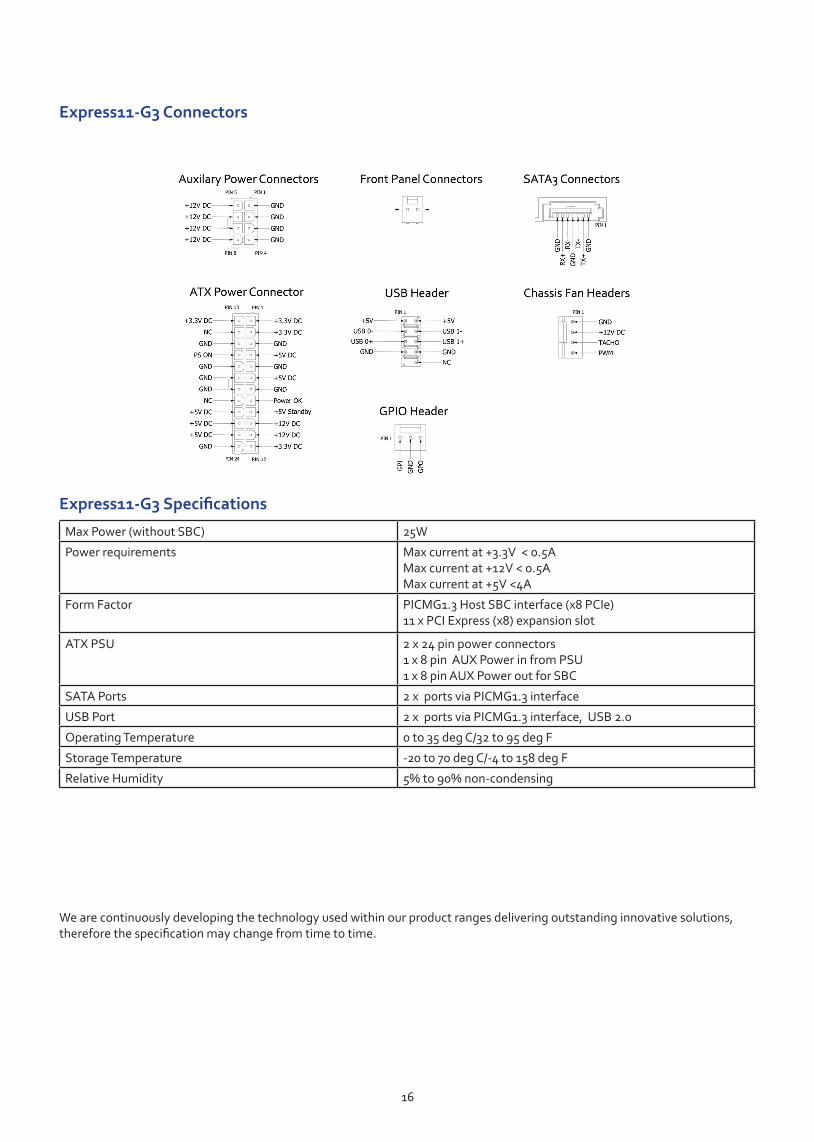
Connector DescriptionJ23 ATX Power in from PSU.
J24 ATX Power in from PSU.
J26 Auxiliary power in from PSU.
J25 Auxiliary power out for SBC
J17 Power on switch
J18 Reset switch
J19 Power on LED
J30,31 SATA3 connector.
J38 USB 2 header.
J50 GPIO header.
Fan 1, 2, 3 Chassis fan connectors.
TR1, TR2 Temperature sensors.

Express11-G3 LED’s
The Express11-G3 has an LED for each PCI Express slot and the PICMG1.3 SBC slot. The LED’s indicate the following:
Slot Description BandwithSBC PICMG 1.3 Slot for SBC x8 Gen 3
Slot 1 PCIe Slot 1 x8 Gen3
Slot 2 PCIe Slot 2 x8 Gen 3
Slot 3 PCIe Slot 3 x8 Gen 3
Slot 4 PCIe Slot 4 x8 Gen 3
Slot 5 PCIe Slot 5 x8 Gen 3
Slot 6 PCIe Slot 6 x8 Gen 3
Slot 7 PCIe Slot 7 x8 Gen 3
Slot 8 PCIe Slot 8 x8 Gen 3
Slot 9 PCIe Slot 9 x8 Gen 3
Slot 10 PCIe Slot 10 x8 Gen 3
Slot 11 PCIe Slot 11 x8 Gen 3
All PCIe slots use a physical x16 connector and therefore accepts any PCIe board type.
D1 ON = +12V supply present
D2 ON = +3.3V supply present
D3 ON = +5V supply present
D4 ON = +5V Standby supply present
D5 ON = PICMG link speed = G3, FLASH-FAST = G2, FLASH-SLOW = G1
D8 ON = PCIe Slot 1 link speed = G3, FLASH-FAST = G2, FLASH-SLOW = G1
D7 ON = PCIe Slot 2 link speed = G3, FLASH-FAST = G2, FLASH-SLOW = G1
D12 ON = PCIe Slot 3 link speed = G3, FLASH-FAST = G2, FLASH-SLOW = G1
D11 ON = PCIe Slot 4 link speed = G3, FLASH-FAST = G2, FLASH-SLOW = G1
D16 ON = PCIe Slot 5 link speed = G3, FLASH-FAST = G2, FLASH-SLOW = G1
D15 ON = PCIe Slot 6 link speed = G3, FLASH-FAST = G2, FLASH-SLOW = G1
D14 ON = PCIe Slot 7 link speed = G3, FLASH-FAST = G2, FLASH-SLOW = G1
D13 ON = PCIe Slot 8 link speed = G3, FLASH-FAST = G2, FLASH-SLOW = G1
D10 ON = PCIe Slot 9 link speed = G3, FLASH-FAST = G2, FLASH-SLOW = G1
D9 ON = PCIe Slot10 link speed = G3, FLASH-FAST = G2, FLASH-SLOW = G1
D6 ON = PCIe Slot11 link speed = G3, FLASH-FAST = G2, FLASH-SLOW = G1
D17 ON= PLX Fatal Error
If an LED is not illuminated, this indicates that a link has not been established, The LED’s will not flash on slots where no cards are installed.
15
16
Express11-G3 Connectors
We are continuously developing the technology used within our product ranges delivering outstanding innovative solutions, therefore the specification may change from time to time.
Max Power (without SBC) 25W
Power requirements Max current at +3.3V < 0.5A Max current at +12V < 0.5A Max current at +5V <4A
Form Factor PICMG1.3 Host SBC interface (x8 PCIe) 11 x PCI Express (x8) expansion slot
ATX PSU 2 x 24 pin power connectors 1 x 8 pin AUX Power in from PSU 1 x 8 pin AUX Power out for SBC
SATA Ports 2 x ports via PICMG1.3 interface
USB Port 2 x ports via PICMG1.3 interface, USB 2.0
Operating Temperature 0 to 35 deg C/32 to 95 deg F
Storage Temperature -20 to 70 deg C/-4 to 158 deg F
Relative Humidity 5% to 90% non-condensing
Express11-G3 Specifications

Warranty Statement
Datapath provides a return to manufacturer warranty on all its products for a standard 36 month period. It is important that RMA procedures are followed prior to products being returned as often issues can be resolved quickly without the need for products being returned.
RMA Returns Policy
If your Datapath product is not working as you expect, we recommend that you contact Datapath Ltd in the first instance for support, since many issues that may first appear as hardware faults, are actually installation or set-up problems and can normally be resolved without having to ship any hardware back to us. This route is therefore often the quickest, easiest and cheapest way of solving the problems that you are experiencing. Please email [email protected] including as much detail regarding the failure as possible (for example: system description, signal types, input or output resolutions and any other relevant background information).
It is essential for you to know the serial number of the product(s) when contacting us.
If it appears that the fault is most likely to be hardware related, please email [email protected] stating the serial number and as much additional information regarding the nature of the failure as possible. Detailed explanation of the fault will help us to better identify the problem and will direct additional focused testing if necessary. We will then issue an “RMA Number” to you.
At the time that the “RMA Number” is issued we will inform you of the warranty status of the product and the cost of the repair, if appropriate - see paragraph (b) below. The product should then be returned, at your cost, too Datapath Ltd following the steps below.
There are 4 possible scenarios when a product is returned to us:
(a) The product is in warranty and is either found to be genuinely faulty or no fault is found. In these cases, the product will be repaired as necessary, or replaced by a new or previously repaired product, and returned to you at our cost.
(b) The product is out of warranty and is found to be faulty. The product if possible will be repaired or replaced at fixed cost, as stated in the RMA authorisation email. To cover this payment, you will be required to either provide a Purchase Order or Credit Card details, when the product is returned to us. (However, we will not issue an invoice or charge the credit card until the repair has been completed and is about to be returned to you)
(c) The product is in warranty but is found to be damaged by mis-use. This will be treated as (b) above.
(d) The product is out of warranty and is obsolete. In the unlikely situation that the product can be neither repaired nor replaced, because some of it’s components are obsolete and we have no swap-out stock left, then the product will either be returned to you, or disposed of at your request, with no charge.
PLEASE NOTE: Datapath will not accept responsibility for the safety, integrity or security of any programmes, data or other content held on hard drives or any other type of rewritable media which is sent to us either separately or as part of any equipment returned to us for repair or for any other purpose. Customers are advised to take back-ups of anything that they deem to be valuable or important before returning the equipment to us and anything which is confidential should be erased from the media before it’s returned.
Once the RMA Number has been issued, you need to raise your Purchase Order, or supply your credit card details, and return the product to: Datapath Ltd, Bemrose House, Bemrose Park, Derby DE21 6XQ, United Kingdom - securely packed and with the RMA Number clearly displayed on the outside of the box. To prevent unnecessary carriage and handling please only send back products or accessory items you believe to be faulty.
In the case of paragraph (c) , the fixed charge will be levied after we have seen the product and identified the misuse. In this case we will request you to issue a purchase order or provide credit card details before any repairs are completed.
Our policy is to return the repair (or swap-out) to you within 10 UK business days of receipt.
17

Certification and Compliances
EU- Class A Declaration of Conformity
Datapath Ltd declares that he Express9, Expres9-G3 and the Express11-G3 complies with the essential requirements and other relevant provisions of Directives 2014/30/EU, 2014/35/EU and 2011/65/EU.
A copy of our Declaration of Conformity is available on request:
Datapath Ltd Bemrose House Bemrose Park Wayzgoose Drive Derby, DE21 6XQ United Kingdom
FCC
These devices comply with part 15 of the FCC Rules. Operation is subject to the following two conditions: (1) These devices may not cause harmful interference, and (2) these devices must accept any interference received, including interference that may cause undesired operation.
This equipment has been tested and found to comply with the limits for a Class A digital device, pursuant to part 15 of the FCC Rules. These limits are designed to provide reasonable protection against harmful interference when the equipment is oper-ated in a commercial environment. This equipment generates, uses and can radiate radio frequency energy and, if not installed and used in accordance with the instruction manual, may cause harmful interference to radio communications. Operation of this equipment in a residential area is likely to cause harmful interference in which case the user will be required to correct the interference at their own expense.
Caution. Changes or modifications to the equipment not expressly approved by the party responsible for compliance could void the user’s authority to operate the equipment
Disposal
At the end of life all Datapath products should be disposed of as per local laws and regulations dictate. In the UK contact Datapath to arrange disposal. Our WEE registration number is WEEE/AA0005ZR.
18
CE

Disclaimer/Copyright Statement
© Datapath Ltd, England 2018
Datapath Limited claims copyright on this User Guide. No part of this User Guide may be reproduced, released, disclosed, stored in any electronic format, or used in whole or in part for any purpose other than stated herein without the express permission of Datapath Limited.
Whilst every effort is made to ensure that the information contained in this User Guide is correct, Datapath Limited make no representations or warranties with respect to the contents thereof, and do not accept liability for any errors or omissions.
Datapath reserves the right to change specification without prior notice and cannot assume responsibility for the use made of the information supplied. Datapath Limited acknowledges all registered trademarks used within this User Guide.
Technical Support
Registered users can access our technical support using email and the Support Enquiry Form on our website, usually with a response within 24 hours (excluding weekends).
Send an email to [email protected] with as much information about your system as possible. To enable a swift response our support team will need to know the following details:
• Serial number of your backplane.
• Details of any SBC including any installed PCIe devices
• The exact nature of the problem - please be as specific as possible.
19

20
Index
A
ATX PSU 16
C
Class A Declaration of Conformity 18
Compliances 18
D
Datapath Ltd 18
Declaration of Conformity 18
Disposal 18
F
FCC Rules 18
Form Factor 16
M
Manufacturer Warranty 17
O
Operating Temperature 7
P
Physical x16 connector 6, 9, 12, 15
Power requirements 7
Product End of Life 18
R
Returns Policy 17
RMA Number 17
RMA Returns 17
S
SATA Ports 7
Support Enquiry Form 19
Swap-out 17
T
Temperature sensors. 8, 11, 14
U
USB Port 10, 13
W
WEE registration number 18