PBC Linear Catalog
260
LINEAR MOTION SOLUTIONS Simplicity ® Self-lubricated Bearings, Guides, Systems & Slides 1 (800) 962-8979 www.pbclinear.com
-
Upload
khangminh22 -
Category
Documents
-
view
1 -
download
0
Transcript of PBC Linear Catalog

LINEAR MOTION SOLUTIONSSimplicity® Self-lubricated Bearings, Guides, Systems & Slides
1 (800) 962-8979 www.pbclinear.com

800.962.8979 • www.pbc l inear.com2
The data and specifi cations in this publication have been carefully compiled and are believed to be accurate and correct. However, it is the responsibility of the user to determine and ensure the suitability of PBC Linear™ products for a specifi c application. PBC Linear’s only obligation will be to repair or replace without charge, any defective components if returned promptly. No liability is assumed beyond such replacement. Specifi cations are subject to change without notice. Consult www.pbclinear.com for the latest technical updates.
Table of Contents
SIMPLICITY® SELF-LUBRICATING BEARINGS - INCH SERIES
Ordering Information ..........................................8-9
FL & FLN ..........................................................10-11Open & Closed Linear Plane Bearings
P & PN ................................................................... 12Open & Closed Pillow Blocks
PW & PWN ............................................................ 13Open & Closed Twin Pillow Blocks
SIMPLICITY® SELF-LUBRICATING BEARINGS - ISO METRIC
SFPM ..................................................................... 25Flange Bearings
DFPM ..................................................................... 26Flange Bearings
CFPM ..................................................................... 27 Flange Bearings
SFP & DFP ............................................................. 14Flange Mounts
SDS & DDS ............................................................ 15Flange Mount Die Sets
PAC ........................................................................ 16Flange Mount Die Sets
Accessories ........................................................... 17Retaining Rings, Seals & O-Rings
FM & FMN ........................................................18-19Open & Closed Linear Plane Bearings
PM & PMN ........................................................20-21Closed & Open Pillow Blocks
FMT & FG .........................................................22-23Compact Thin Wall Bearings
PACM ..................................................................... 24Die Set Bushings
SIMPLICITY® SELF-LUBRICATING BEARINGS - JIS METRIC
FJH, FJ & FJN ..................................................28-29Open & Closed Linear Plane Bearings
SFPJ ...................................................................... 30Flange Bearings
Product Overview .................................................. 33
APN Bearing Plug .................................................. 33
Square Bearings ...............................................35-361.0" Specifications .................................................. 351.5" Specifications .................................................. 36
SIMPLICITY® SQUARE BEARINGS
DFPJ ...................................................................... 31Flange Bearings
CFPJ ...................................................................... 32Flange Bearings
Square Shafting & Accessories ............................ 37

800.962.8979 • www.pbc l inear.com 3
Table of Contents
SIMPLICITY® LINEAR SHAFTING - INCH SERIES
NIL ......................................................................... 63RC60 Steel - Solid
NILPDL .................................................................. 63RC60 Steel - Pre-Drilled & Tapped
NILXXSS ................................................................ 64440 Stainless Steel - Solid
SR .......................................................................... 64Aluminum - Non-Drilled Support Rail
SRXXPD ................................................................. 64Aluminum - Pre-Drilled Support Rail
SRA ........................................................................ 65Steel Shaft - Rail Assembly
NSB ........................................................................ 65Aluminum - End Support Blocks
CC .......................................................................... 66Ceramic Coated Aluminum - Solid
CCPDL ................................................................... 66Ceramic Coated Aluminum - Pre-Drilled & Tapped
CCR ........................................................................ 67Ceramic Coated Aluminum - Rail Assembly
SIMPLICITY® LINEAR SHAFTING - ISO METRIC
NIM ........................................................................ 68RC60 Steel - Solid
NIPDM ................................................................... 68RC60 Steel - Pre-Drilled & Tapped
NIMXXSS ............................................................... 69 440 Stainless Steel
CCM ..................................................... 69Ceramic Coated Aluminum - Solid
CCMDL................................................................... 69Ceramic Coated Aluminum - Pre-Drilled & Tapped
SIMPLICITY® TECHNICAL INFORMATION
Simplicity Advantages .......................................................................38
Bearing Liner Material .......................................................................39
Running Clearance ............................................................................40
Bearing Shell .....................................................................................40
Self-Alignment Feature ......................................................................41
Pillow Blocks .....................................................................................42
O-Rings & Seals ................................................................................42
Lubrication System ...........................................................................43
Load Capacity of Liner ......................................................................44
Speed Characteristics .......................................................................44
Performance Ratings (for Linear Motion) .........................................44
Wear Rate/Life Expectancy ................................................................45
Factors Affecting Wear Rate/Life .......................................................45
Transfer Process of Liner to Shaft ....................................................46
Lubrication ........................................................................................46
Temperature ......................................................................................47
Thermal Expansion ...........................................................................47
Rotary Applications ...........................................................................47
Open Bearings Orientation ................................................................48
Cantilevered Loads ............................................................................48
Severe Misalignment Solutions .........................................................50
Chemical Resistance .........................................................................50
Submerged Applications ...................................................................50
Vacuums/Outgassing/Clean Rooms ..................................................50
Classes of Plane Bearings .................................................................51
Rating a Plane Bearing ......................................................................51
Simplicity Maximum Perimeter .........................................................51
Formulas for Ratings ........................................................................51
PV Equivalents ..................................................................................51
Wear Rate VS. Life Expectancy .........................................................52
Coeffi cient of Friction ........................................................................53
Load Capacity (Pressure) ..................................................................54
Linear Surface Speeds (Velocity) ......................................................54
Factors that Contribute to Wear Life .................................................54
Types & Effects of Lubrication ..........................................................54
Using Oils with Simplicity .................................................................55
Grease Products ...............................................................................55
Proper use of Greases .......................................................................55
Effects of Lubrication ........................................................................55
Application Information .....................................................................56
Defl ection ..........................................................................................57
Displacement Angle ..........................................................................57
Installation of Simplicity Bearings ............................................... 58-61
Chemical Reaction Chart ...................................................................62

800.962.8979 • www.pbc l inear.com4
Table of Contents
SIMPLICITY® BALL BEARING TECHNICAL INFORMATION
SIMPLICITY® BALL BEARINGS - ISO METRIC
EP Series ..........................................................88-89Closed & Open
EP-W Series .....................................................90-91Double Wide
EPF Series ........................................................92-93Round Flange Mount
EPF-W Series ...................................................94-95Round Flange Mount - Double Wide
EPK Series ........................................................96-97Square Flange Mount
EPK-W Series ...................................................98-99Square Flange Mount - Double Wide
EPFC Series ..................................................100-101Round Flange Center Mount
EPKC Series .................................................102-103Square Flange Center Mount
EPPM & EPPMN .................................................. 104Closed & Open Pillow Blocks
KHP ...................................................................... 105Compact Thin Wall Bearings
SIMPLICITY® BALL BEARINGS - JIS METRIC
JP Series ......................................................106-107Ball Bearings
JP-W Series .................................................108-109Double Wide
JPF Series ....................................................110-111Round Flange Mount
JPF-W Series ...............................................112-113Round Flange Mount - Double Wide
JPK Series ....................................................114-115Square Flange Mount
JPK-W Series ...............................................116-117Square Flange Mount - Double Wide
JPFC Series ..................................................118-119Round Flange Center Mount
JPKC Series ..................................................120-121Square Flange Center Mount
SIMPLICITY® BALL BEARINGS - INCH SERIES
IP Series ............................................................... 70Closed & Open
IPS Series.............................................................. 71Closed & Open Super Ball Bearing
IP-W Series ......................................................72-73Double Wide
IPF Series .........................................................74-75Round Flange Mount
IPF-W Series ....................................................76-77Round Flange Mount - Double Wide
IPK Series.........................................................78-79Square Flange Mount
IPK-W Series ...................................................80-81Square Flange Mount - Double Wide
IPFC Series.......................................................82-83Round Flange - Center Mount
IPKC Series ......................................................84-85Square Flange - Center Mount
IPP & IPPN ............................................................ 86Closed & Open Pillow Blocks
IPPW & IPPWN ...................................................... 87Closed & Open Twin Pillow Blocks
Product Overview ............................................................... 122Load Rating and Life Expectancy ....................................... 123Relation Between Ball Circuits & Load Rating .................... 123Clearance & Fit ................................................................... 124Shaft & Housing ................................................................. 124Mounting ........................................................................... 124
Rating Life ................................................................... 125-126Sample Calculations ............................................................125Frictional Resistance ...........................................................127Ambient Working Temperature ...........................................127Lubrication and Dust Prevention .........................................127

SIMPLICITY® PLANE BEARINGS - POLYMER SERIES
Product Overview .........................................128-130
Technical Data Standard Compounds ................ 131
Chemical Resistance .......................................... 132
Compounds A & E................................................ 133
Compounds B & C ............................................... 134
Compounds D & F ............................................... 135
Compound G ........................................................ 136
E....................................................................137-141
Flanged E .....................................................142-145
Thrust Washers ................................................... 146
With Seals E ........................................................ 147
Ultra High Temperature Resistant - A .........148-150
Design Notes ....................................................... 151From Calculation to Trial Run
Technical Data .................................................... 152
Calculation Basics ............................................... 153
SIMPLICITY® PLANE BEARINGS - INCH SERIES
PS & PSF Sleeve ..........................................154-155
SIMPLICITY® PLANE BEARINGS - ISO METRIC
PSM & PSFM Sleeve ....................................156-157
SIMPLICITY® LINEAR SLIDES - INCH SERIES
Product Overview ................................................ 158
Technical Information ......................................... 159
Load Capacities ...........................................160-161
SRB ...................................................................... 162Preassembled Shaft, Rail & Bearing
RS ........................................................................ 163Rail Mounted Slide Assembly
RPS ...............................................................164-165Rail Mounted & Plate Supported Slide Assembly
1RPS .............................................................166-167Rail Mounted & Plate Supported Ball Screw Driven Slide Assembly
2RPS ............................................................168-169Rail Mounted Plate Supported Ball Screw Driven Slide Assembly
LRPS .............................................................170-171Low Profi le Rail Mounted & Plate Supported Slide Assembly
2LRPS ...........................................................172-173Low Profi le Rail Mounted & Plate Supported Ball Screw Drive Slide Assembly
SC2RPS ........................................................174-175Self-Centering Slide Assembly
2HCR/2HWL .................................................176-177Slide Assembly with Handcrank & Ball Screw Rotational Lock
2N42, 56, 143 ..............................................178-179Slide Assembly/NEMA Drive Kit
2N23 & 2N24 ...............................................180-181Slide Assembly/NEMA Drive Kit
Column Load Chart ............................................. 182
Critical Speed Chart ............................................ 183
800.962.8979 • www.pbc l inear.com 5
Table of Contents

800.962.8979 • www.pbc l inear.com6
Table of Contents
REDI-RAIL® LINEAR GUIDES
Product Overview ................................................ 200
Technical Information ..................................200-201Adjusting Slider Preload ....................................... 200Slider Orientation ................................................. 200Lubrication - Rails & Bearings ............................. 200Mounting Slider ................................................... 200Life Calculations ................................................... 201Reduction Factor .................................................. 201Load Comparison Graphs .................................... 201
Redi-Rail® Linear Guides - Inch SeriesRRS14 Slide ........................................................ 202RR14 Rail ............................................................ 203
RRS18 Slide ........................................................ 204RR18 Rail ............................................................ 205
Redi-Rail® Linear Guides - ISO MetricRRS30 Slide ........................................................ 206RR30 Rail ............................................................ 207
RRS45 Slide ........................................................ 208RR45 Rail ............................................................ 209
RRS65 Slide ........................................................ 210RR65 Slide .......................................................... 211
DRAWER SLIDES
Drawer Slides - RD ............................................. 212Inch Series
STEEL LINEAR GUIDES
Product Overview ................................................ 214
Technical Information ..................................216-217System Life .......................................................... 216Linear Precision ................................................... 216Sizing Control ...................................................... 217Maintenance ......................................................... 217Corrosion Resistance ........................................... 217
Steel Linear Guides - ISO MetricRSS Slide & RRT Rail - 18 .................................. 218RSS Slide & RRT Rail - 28 ................................. 219RSS Slide & RRT Rail - 43 ................................. 220
Applications ........................................................ 221
MINI-RAIL® MINIATURE LINEAR GUIDES
Product Overview ................................................ 184
Technical Information ......................................... 186
Mini-Rail® Sigma - MRS ..................................... 187
Low Profi le Mini-Rail® - LPM ............................. 188
Mini-Rail® Roller Carriage - MRR ...................... 189
Mini-Rail® Miniature Lead Screw - Driven SlideLS ......................................................190MS......................................................191
Technical Information ......................................... 192
Product Overview ................................................ 193
Technical & Ordering Information ...................... 194
Uni-Guide ............................................................ 195D075 (Small) ....................................................... 196D100 (Medium) ................................................... 197D125 (Large) ....................................................... 198
DFG Series* ........................................................ 194Modular Guides*NOTE: not for resale or distribution inside the European Union.
UNI-GUIDE - SLIDES, TABLES & STAGES
Drawer Slides - RRD ........................................... 213ISO Metric
800.962.8979 • www.pbc l inear.com 7
Table of Contents
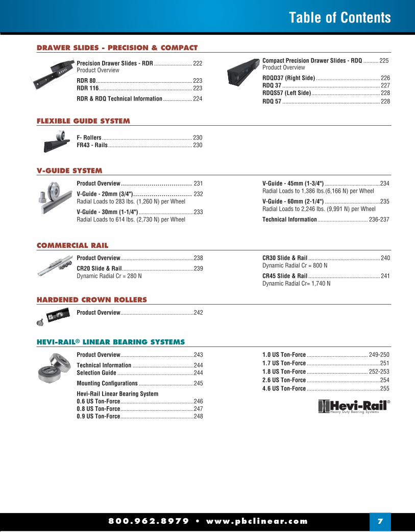
DRAWER SLIDES - PRECISION & COMPACT
Precision Drawer Slides - RDR ......................... 222Product Overview
RDR 80 ............................................................... 223RDR 116 ............................................................. 223
RDR & RDQ Technical Information ................... 224
Compact Precision Drawer Slides - RDQ .......... 225Product Overview
RDQD37 (Right Side) .......................................... 226RDQ 37 ................................................................ 227RDQS57 (Left Side) ............................................. 228RDQ 57 ................................................................ 228
FLEXIBLE GUIDE SYSTEM
F- Rollers ........................................................... 230FR43 - Rails ....................................................... 230
V-GUIDE SYSTEM
Product Overview ................................... 231
V-Guide - 20mm (3/4") ............................. 232Radial Loads to 283 lbs. (1,260 N) per Wheel
V-Guide - 30mm (1-1/4") ....................................233Radial Loads to 614 lbs. (2,730 N) per Wheel
V-Guide - 45mm (1-3/4") ....................................234Radial Loads to 1,386 lbs.(6,166 N) per Wheel
V-Guide - 60mm (2-1/4") ....................................235Radial Loads to 2,246 lbs. (9,991 N) per Wheel
Technical Information ................................. 236-237
COMMERCIAL RAIL
Product Overview ................................................238
CR20 Slide & Rail ...............................................239Dynamic Radial Cr = 280 N
CR30 Slide & Rail ............................................... 240Dynamic Radial Cr = 800 N
CR45 Slide & Rail ............................................... 241Dynamic Radial Cr= 1,740 N
HARDENED CROWN ROLLERS
Product Overview ................................................242
HEVI-RAIL® LINEAR BEARING SYSTEMS
Product Overview ................................................243
Technical Information ........................................244Selection Guide ..................................................244
Mounting Confi gurations ....................................245
Hevi-Rail Linear Bearing System0.6 US Ton-Force ................................................2460.8 US Ton-Force ................................................2470.9 US Ton-Force ................................................248
1.0 US Ton-Force ........................................ 249-2501.7 US Ton-Force ................................................2511.8 US Ton-Force ........................................ 252-2532.6 US Ton-Force ................................................2544.6 US Ton-Force ................................................255
8
The data and specifi cations in this publication have been carefully compiled and are believed to be accurate and correct. However, it is the responsibility of the user to determine and ensure the suitability of PBC Linear™ products for a specifi c application. PBC Linear™ only obligation will be to repair or replace without charge, any defective components if returned promptly. No liability is assumed beyond such replacement. *Visit www.pbclinear.com for the latest technical updates.
Orde
ring
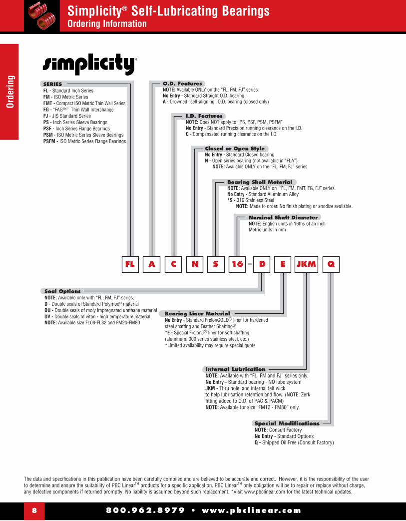
Simplicity® Self-Lubricating BearingsOrdering Information
FL A C N S 16 D E JKM Q
O.D. FeaturesNOTE: Available ONLY on the “FL, FM, FJ” seriesNo Entry - Standard Straight O.D. bearingA - Crowned “self-aligning” O.D. bearing (closed only)
I.D. FeaturesNOTE: Does NOT apply to “PS, PSF, PSM, PSFM”No Entry - Standard Precision running clearance on the I.D.C - Compensated running clearance on the I.D.
Bearing Shell MaterialNOTE: Available ONLY on “FL, FM, FMT, FG, FJ” seriesNo Entry - Standard Aluminum Alloy*S - 316 Stainless Steel NOTE: Made to order. No finish plating or anodize available.
Nominal Shaft DiameterNOTE: English units in 16ths of an inch Metric units in mm
Closed or Open StyleNo Entry - Standard Closed bearingN - Open series bearing (not available in “FLA”) NOTE: Available ONLY on the “FL, FM, FJ” series
Special ModificationsNOTE: Consult FactoryNo Entry - Standard OptionsQ - Shipped Oil Free (Consult Factory)
Internal LubricationNOTE: Available with “FL, FM and FJ” series only.No Entry - Standard bearing - NO lube systemJKM - Thru hole, and internal felt wick to help lubrication retention and flow. (NOTE: Zerk fitting added to O.D. of PAC & PACM)NOTE: Available for size “FM12 - FM80” only.
Seal OptionsNOTE: Available only with “FL, FM, FJ” series.D - Double seals of Standard Polymod® materialDU - Double seals of moly impregnated urethane materialDV - Double seals of viton - high temperature materialNOTE: Available size FL08-FL32 and FM20-FM80
Bearing Liner MaterialNo Entry - Standard FrelonGOLD® liner for hardened steel shafting and Feather Shafting®
*E - Special FrelonJ® liner for soft shafting (aluminum, 300 series stainless steel, etc.)*Limited availability may require special quote
–
SERIESFL - Standard Inch SeriesFM - ISO Metric SeriesFMT - Compact ISO Metric Thin Wall SeriesFG - “FAG™” Thin Wall InterchangeFJ - JIS Standard SeriesPS - Inch Series Sleeve BearingsPSF - Inch Series Flange BearingsPSM - ISO Metric Series Sleeve BearingsPSFM - ISO Metric Series Flange Bearings
800.962.8979 • www.pbc l inear.com

800.962.8979 • www.pbc l inear.com 9
OrderingSimplicity® Self-Lubricating Bearings
Ordering Information
Bearing I.D. FeaturesNo Entry - Standard Precision running clearance on the I.D.C - Compensated running clearance on the I.D.
P N B E 16 C D E JKM Q
Housing I.D. FeaturesNo Entry - Standard Spherical “self-aligning” I.D. in the housing.(Uses standard straight O.D. bearings)B - Straight I.D. housing. (For rigid fit use standard bearing.For self-alignment use “FLA” bearings.)NOTE: Available ONLY on “SFPM, DFPM, CFPM, SFPJ, DFPJ, CFPJ” seriesNo Entry - Standard Square FlangeR - Available Round Flange
Closed or Open Style NOTE: Available ONLY on “P, PW, PM” seriesNo Entry - Standard Closed SeriesN - Open Series
Housings OnlyNo Entry - Housings with bearing includedE - Empty Housings with NO bearing included
Nominal Shaft DiameterNOTE: English units in 16ths of an inchMetric units in mm
Special ModificationsNOTE: Consult FactoryNo Entry - Standard OptionsQ - Shipped Oil Free (Consult Factory)
Internal LubricationNo Entry - Standard pillowblock assembly with NO lubrication systemJKM - Thru holes, and internal felt wick to help lubrication retention and flow 1/4-28 Zerk.
Seal OptionsNOTE: “PAC” and “PACM” available ONLY as “S, SU, or SV”D - Double seals of Standard Polymod® materialDU - Double seals of moly impregnated urethane materialDV - Double seals of viton - high temperature material Bearing Liner Material
No Entry - Standard FrelonGOLD® liner for hardened steel or ceramic coated aluminumE - Special FrelonJ® liner for soft shafting(aluminum, 300 series stainless steel, 440 stainless steel shafting)
–
SERIES
NOTE: Standard Simplicity bearings are installed in housings
P - Standard Inch Pillow Blocks (FL)PW - Inch Twin Pillow Blocks (FL)PM - ISO Metric Pillow Blocks (FM)SDS - Single Flange Mount Die Set (FLA)SDSB - Single Flange Mount Die Set (FL)DDS - Double Flange Mount Die Set (FLA)DDSB - Double Flange Mount Die Set (FL)SFP - Inch Single Flange Mounts (FL)DFP - Inch Double Flange Mounts (FL)PAC - Inch Die Set BushingsPACM - ISO Metric Die Set BushingsSFPM - ISO Metric Single Flange MountsDFPM - ISO MetricDouble Flange MountsCFPM - ISO Metric Double Center Flange MountsSFPJ - JIS Metric Single Flange MountsDFPJ - JIS Metric Double Flange MountsCFPJ - JIS Metric Double Center Flange Mounts
PLEASE NOTE: The catalog is designed to represent all posssiblities, however may not all be standard parts. *These are options only - combination could lead to unavailable options.
800.962.8979 • www.pbc l inear.com10
Self-
Lubr
icat
ing
Bear
ing
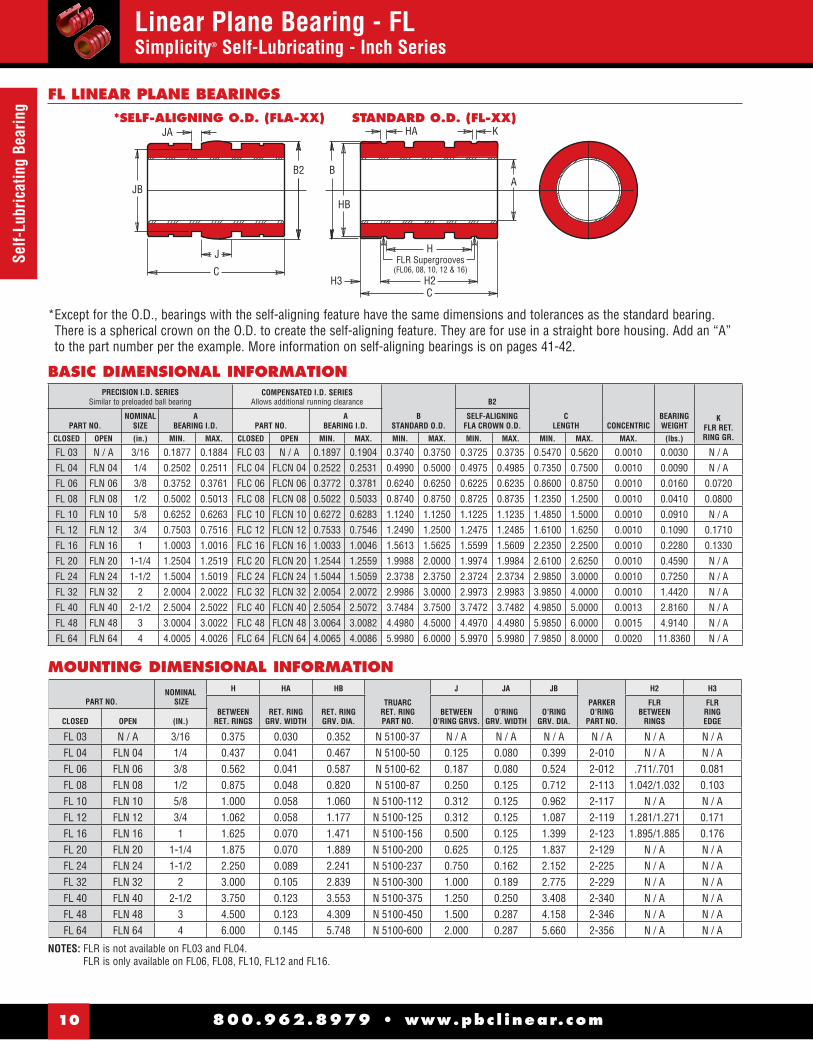
Linear Plane Bearing - FLSimplicity® Self-Lubricating - Inch Series
HB
AJB
B2 B
C
J
JA
HFLR Supergrooves
(FL06, 08, 10, 12 & 16)H2C
H3
HA K*SELF-ALIGNING O.D. (FLA-XX) STANDARD O.D. (FL-XX)
* Except for the O.D., bearings with the self-aligning feature have the same dimensions and tolerances as the standard bearing.There is a spherical crown on the O.D. to create the self-aligning feature. They are for use in a straight bore housing. Add an “A” to the part number per the example. More information on self-aligning bearings is on pages 41-42.
PRECISION I.D. SERIESSimilar to preloaded ball bearing
COMPENSATED I.D. SERIESAllows additional running clearance
BSTANDARD O.D.
B2
CLENGTH CONCENTRIC
BEARINGWEIGHT
KFLR RET. RING GR.
PART NO.NOMINAL
SIZEA
BEARING I.D. PART NO.A
BEARING I.D.SELF-ALIGNING
FLA CROWN O.D.
CLOSED OPEN (in.) MIN. MAX. CLOSED OPEN MIN. MAX. MIN. MAX. MIN. MAX. MIN. MAX. MAX. (lbs.)
FL 03 N / A 3/16 0.1877 0.1884 FLC 03 N / A 0.1897 0.1904 0.3740 0.3750 0.3725 0.3735 0.5470 0.5620 0.0010 0.0030 N / A
FL 04 FLN 04 1/4 0.2502 0.2511 FLC 04 FLCN 04 0.2522 0.2531 0.4990 0.5000 0.4975 0.4985 0.7350 0.7500 0.0010 0.0090 N / A
FL 06 FLN 06 3/8 0.3752 0.3761 FLC 06 FLCN 06 0.3772 0.3781 0.6240 0.6250 0.6225 0.6235 0.8600 0.8750 0.0010 0.0160 0.0720
FL 08 FLN 08 1/2 0.5002 0.5013 FLC 08 FLCN 08 0.5022 0.5033 0.8740 0.8750 0.8725 0.8735 1.2350 1.2500 0.0010 0.0410 0.0800
FL 10 FLN 10 5/8 0.6252 0.6263 FLC 10 FLCN 10 0.6272 0.6283 1.1240 1.1250 1.1225 1.1235 1.4850 1.5000 0.0010 0.0910 N / A
FL 12 FLN 12 3/4 0.7503 0.7516 FLC 12 FLCN 12 0.7533 0.7546 1.2490 1.2500 1.2475 1.2485 1.6100 1.6250 0.0010 0.1090 0.1710
FL 16 FLN 16 1 1.0003 1.0016 FLC 16 FLCN 16 1.0033 1.0046 1.5613 1.5625 1.5599 1.5609 2.2350 2.2500 0.0010 0.2280 0.1330
FL 20 FLN 20 1-1/4 1.2504 1.2519 FLC 20 FLCN 20 1.2544 1.2559 1.9988 2.0000 1.9974 1.9984 2.6100 2.6250 0.0010 0.4590 N / A
FL 24 FLN 24 1-1/2 1.5004 1.5019 FLC 24 FLCN 24 1.5044 1.5059 2.3738 2.3750 2.3724 2.3734 2.9850 3.0000 0.0010 0.7250 N / A
FL 32 FLN 32 2 2.0004 2.0022 FLC 32 FLCN 32 2.0054 2.0072 2.9986 3.0000 2.9973 2.9983 3.9850 4.0000 0.0010 1.4420 N / A
FL 40 FLN 40 2-1/2 2.5004 2.5022 FLC 40 FLCN 40 2.5054 2.5072 3.7484 3.7500 3.7472 3.7482 4.9850 5.0000 0.0013 2.8160 N / A
FL 48 FLN 48 3 3.0004 3.0022 FLC 48 FLCN 48 3.0064 3.0082 4.4980 4.5000 4.4970 4.4980 5.9850 6.0000 0.0015 4.9140 N / A
FL 64 FLN 64 4 4.0005 4.0026 FLC 64 FLCN 64 4.0065 4.0086 5.9980 6.0000 5.9970 5.9980 7.9850 8.0000 0.0020 11.8360 N / A
BASIC DIMENSIONAL INFORMATION
NOTES: FLR is not available on FL03 and FL04.FLR is only available on FL06, FL08, FL10, FL12 and FL16.
MOUNTING DIMENSIONAL INFORMATION
PART NO. NOMINAL
SIZE
H HA HB
TRUARCRET. RINGPART NO.
J JA JB
PARKERO’RING
PART NO.
H2 H3
BETWEENRET. RINGS
RET. RING GRV. WIDTH
RET. RING GRV. DIA.
BETWEENO’RING GRVS.
O’RINGGRV. WIDTH
O’RINGGRV. DIA.
FLRBETWEEN
RINGS
FLRRINGEDGECLOSED OPEN (IN.)
FL 03 N / A 3/16 0.375 0.030 0.352 N 5100-37 N / A N / A N / A N / A N / A N / AFL 04 FLN 04 1/4 0.437 0.041 0.467 N 5100-50 0.125 0.080 0.399 2-010 N / A N / AFL 06 FLN 06 3/8 0.562 0.041 0.587 N 5100-62 0.187 0.080 0.524 2-012 .711/.701 0.081FL 08 FLN 08 1/2 0.875 0.048 0.820 N 5100-87 0.250 0.125 0.712 2-113 1.042/1.032 0.103FL 10 FLN 10 5/8 1.000 0.058 1.060 N 5100-112 0.312 0.125 0.962 2-117 N / A N / AFL 12 FLN 12 3/4 1.062 0.058 1.177 N 5100-125 0.312 0.125 1.087 2-119 1.281/1.271 0.171FL 16 FLN 16 1 1.625 0.070 1.471 N 5100-156 0.500 0.125 1.399 2-123 1.895/1.885 0.176FL 20 FLN 20 1-1/4 1.875 0.070 1.889 N 5100-200 0.625 0.125 1.837 2-129 N / A N / AFL 24 FLN 24 1-1/2 2.250 0.089 2.241 N 5100-237 0.750 0.162 2.152 2-225 N / A N / AFL 32 FLN 32 2 3.000 0.105 2.839 N 5100-300 1.000 0.189 2.775 2-229 N / A N / AFL 40 FLN 40 2-1/2 3.750 0.123 3.553 N 5100-375 1.250 0.250 3.408 2-340 N / A N / AFL 48 FLN 48 3 4.500 0.123 4.309 N 5100-450 1.500 0.287 4.158 2-346 N / A N / AFL 64 FLN 64 4 6.000 0.145 5.748 N 5100-600 2.000 0.287 5.660 2-356 N / A N / A
FL LINEAR PLANE BEARINGS

800.962.8979 • www.pbc l inear.com 11
Self-Lubricating BearingLinear Plane Bearing - FL & FLN
Simplicity® Self-Lubricating
FLN 04 - FLN 06 FLN 08
FLN 10 FLN 12 THRU FLN 64
LOAD & SPEED DATA
FrelonGOLD® and FrelonJ® are registered trademarks of Pacifi c Bearing. NOTE: All other dimensions same as closed bearing.
PART NO.
EFFECTIVE SURFACE AREA
MAX. STATIC LOAD FRELON
GOLD J
(sq. In.) (lbs.) (lbs.)
FL 03 0.110 220 100
FL 04 0.200 600 300
FL 06 0.340 1020 510
FL 08 0.650 1950 975
FL 10 0.980 2940 1470
FL 12 1.270 3810 1905
FL 16 2.350 7050 3525
FL 20 3.430 10830 5415
FL 24 4.700 14100 7050
FL 32 8.350 25050 12525
FL40 13.000 39000 19500
FL 48 18.800 56400 28200
FL 64 33.500 100500 50250
MAX. PV (ft./min. * psi)FrelonGold = 20000 PVFrelonJ = 10000 PV
MAX. Speed Running Dry (ft./min.)FrelonGold = 300 sfmFrelonJ = 140 sfm
MAX. Speed Running with Lubrication (ft./min.)FrelonGold = 825 sfmFrelonJ = 400 sfm
OPEN DIMENSIONAL INFORMATION
PART NO.NOMINAL
SIZE
DSLOTWIDEMIN.
ESLOT
ANGLE
FRETAINING
HOLEDIA.
GRETAINING
HOLELOCATE
BEARINGWEIGHTS
(in.)PRECISION COMPENSATED (in.) (lbs.)
FLN 04 FLCN 04 1/4 0.188 60° 0.094 3/8 0.008FLN 06 FLCN 06 3/8 0.250 60° 0.094 7/16 0.013FLN 08 FLCN 08 1/2 0.313 60° 0.136 5/8 0.034FLN 10 FLCN 10 5/8 0.375 60° 0.136 1/8 0.072FLN 12 FLCN 12 3/4 0.438 60° 0.136 1/8 0.091FLN 16 FLCN 16 1 0.563 60° 0.136 1/8 0.184FLN 20 FLCN 20 1-1/4 0.625 60° 0.201 3/16 0.381FLN 24 FLCN 24 1-1/2 0.750 60° 0.201 3/16 0.603FLN 32 FLCN 32 2 1.000 60° 0.265 5/16 1.192FLN 40 FLCN 40 2-1/2 1.250 60° 0.265 5/16 2.334FLN 48 FLCN 48 3 1.500 60° 0.265 5/16 4.080FLN 64 FLCN 64 4 2.000 60° 0.265 5/16 9.870
ED
F
G
ED
F
G
1/8"
E
DF
G
15°
E
DF
G
FL & FLN LINEAR BEARINGS
ACCESSORIES
Retaining Rings (Internal & External) ..................................17
Seals, O-Rings, Zerk Fittings ...............................................17
Shafting (Steel, Ceramic Coated, Stainless Steel) ........... 63-66
Support Rails ..............................................................................67

800.962.8979 • www.pbc l inear.com12
Pillo
w B
lock
sPillow Blocks - P & PNSimplicity® Self-Lubricating
GS
BE
JA
K
MO
H
P
CF
R
MINGAP
G
BE
K
JA
D
MO
H
P
CF
NOTES: (1) Standard, pre-assembled pillow blocks include self-aligning housing and precision bearing.(2) All standard pillow blocks use standard “FL” series bearings found on page 10.(3) Straight bore, pre-assembled pillow blocks use standard “FL” series bearing.
See Page 162 for SRB Series – Pre-assembled Pillow Block, Shaft and Support Rail.
NOTES: (1) Standard, pre-assembled pillow blocks include self-aligning housing and precision bearing.(2) All standard pillow blocks use standard “FL” series bearings found on page 10.(3) All open pillow blocks have “notch”.
FrelonGOLD® and FrelonJ® are registered trademarks of Pacifi c Bearing.
P & PN PILLOW BLOCKS
CLOSED PILLOW BLOCKS
OPEN PILLOW BLOCKS
PART NO. CLOSED
NOM.BRG. I.D.
ACENTERLINE B C D E F
GBODY H
JFLNG.
K
MGRV.
OGRV.
PGRV.
SMALLEYRET.RING
PART NO.
MAX. STATIC LOAD (lbs.)
FRELONASSEM.
WT.
PRECISION COMPEN. MIN. +/- .001 WIDTH LENGTH HEIGHT +/- .010 +/-.010 WIDTH BOLT HOLE THICK SPACE WIDTH DIA. GOLD J (lbs.)
P 04 P 04C 1/4" 0.437 1.625 1.19 0.813 1.312 0.750 1.000 #6 5/32" 0.188 0.750 0.750 0.039 0.532 WH-51 600 300 0.099
P 06 P 06C 3/8" 0.500 1.750 1.31 0.938 1.437 0.875 1.125 #6 5/32" 0.188 0.875 0.875 0.039 0.665 WH-65 1020 510 0.129
P 08 P 08C 1/2" 0.687 2.000 1.69 1.250 1.688 1.000 1.375 #6 5/32" 0.250 1.125 1.250 0.046 0.931 WH-90 1950 975 0.250
P 10 P 10C 5/8" 0.875 2.500 1.94 1.625 2.125 1.125 1.750 #8 3/16" 0.281 1.438 1.500 0.056 1.197 WH-115 2940 1470 0.500
P 12 P 12C 3/4" 0.937 2.750 2.06 1.750 2.375 1.250 1.875 #8 3/16" 0.313 1.563 1.625 0.056 1.330 WH-128 3710 1905 0.580
P 16 P 16C 1" 1.187 3.250 2.81 2.188 2.875 1.750 2.375 #10 7/32" 0.375 1.938 2.250 0.068 1.671 WH-156 7050 3525 1.000
P 20 P 20C 1-1/4" 1.500 4.000 3.63 2.813 3.500 2.000 3.000 #10 7/32" 0.438 2.500 2.625 0.068 2.122 WH-200 10290 5145 2.000
P 24 P 24C 1-1/2" 1.750 4.750 4.00 3.250 4.125 2.500 3.500 1/4" 9/32" 0.500 2.875 3.000 0.086 2.519 WH-237 14100 7050 3.000
P 32 P 32C 2" 2.125 6.000 5.00 4.063 5.250 3.250 4.500 3/8" 13/32" 0.625 3.625 4.000 0.103 3.182 WH-300 25050 12525 6.500
PART NO. CLOSED
NOM. BRG.I.D.
ACENTERLINE B C E F
GBODY H
JFLNG. K
MGRV.
OGRV.
PGRV.
RMIN.
EATONRET.RING
PART NO.
MAX. STATIC LOAD (lbs.)
FRELONASSEM.
WT.S
OVERALL
PRECISION COMPEN. MIN. +/-.001 WIDTH LENGTH +/-.010 +/-.010 WIDTH BOLT HOLE THICK HEIGHT SPACE WIDTH DIA. OPEN GOLD J (lbs.) WIDTH
PN 08 PN 08C 1/2" 0.687 2.000 1.50 1.688 1.000 1.375 #6 5/32" 0.250 1.125 1.250 0.046 0.931 0.313 MNAN-87 1950 975 0.250 1.438
PN 10 PN 10C 5/8" 0.875 2.500 1.75 2.125 1.125 1.750 #8 3/16" 0.281 1.438 1.500 0.056 1.197 0.375 MNAN-112 2940 1470 0.500 1.813
PN 12 PN 12C 3/4" 0.937 2.750 1.88 2.375 1.250 1.875 #8 3/16" 0.313 1.563 1.625 0.056 1.330 0.438 MNAN-125 3710 1905 0.580 1.938
PN 16 PN 16C 1" 1.187 3.250 2.63 2.875 1.750 2.375 #10 7/32" 0.375 1.938 2.250 0.068 1.671 0.563 MNAN-156 7050 3525 1.000 2.438
PN 20 PN 20C 1-1/4" 1.500 4.000 3.38 3.500 2.000 3.000 #10 7/32" 0.438 2.500 2.625 0.068 2.122 0.625 MNAN-200 10290 5145 2.000 3.125
PN 24 PN 24C 1-1/2" 1.750 4.750 3.75 4.125 2.500 3.500 1/4" 9/32" 0.500 2.875 3.000 0.086 2.519 0.750 MNAN-237 14100 7050 3.000 3.625
PN 32 PN 32C 2" 2.125 6.000 4.75 5.250 3.250 4.500 3/8" 13/32" 0.625 3.625 4.000 0.103 3.182 1.000 MNAN-300 25050 12525 6.500 4.688
800.962.8979 • www.pbc l inear.com 13
Twin Pillow
BlocksTwin Pillow Blocks - PW & PWN
Simplicity® Self-Lubricating
DPA
G
EB
J
K
FF1 F1
C
H
GR
K
JEB
AH
F
S
F1 F1
C
P
MO
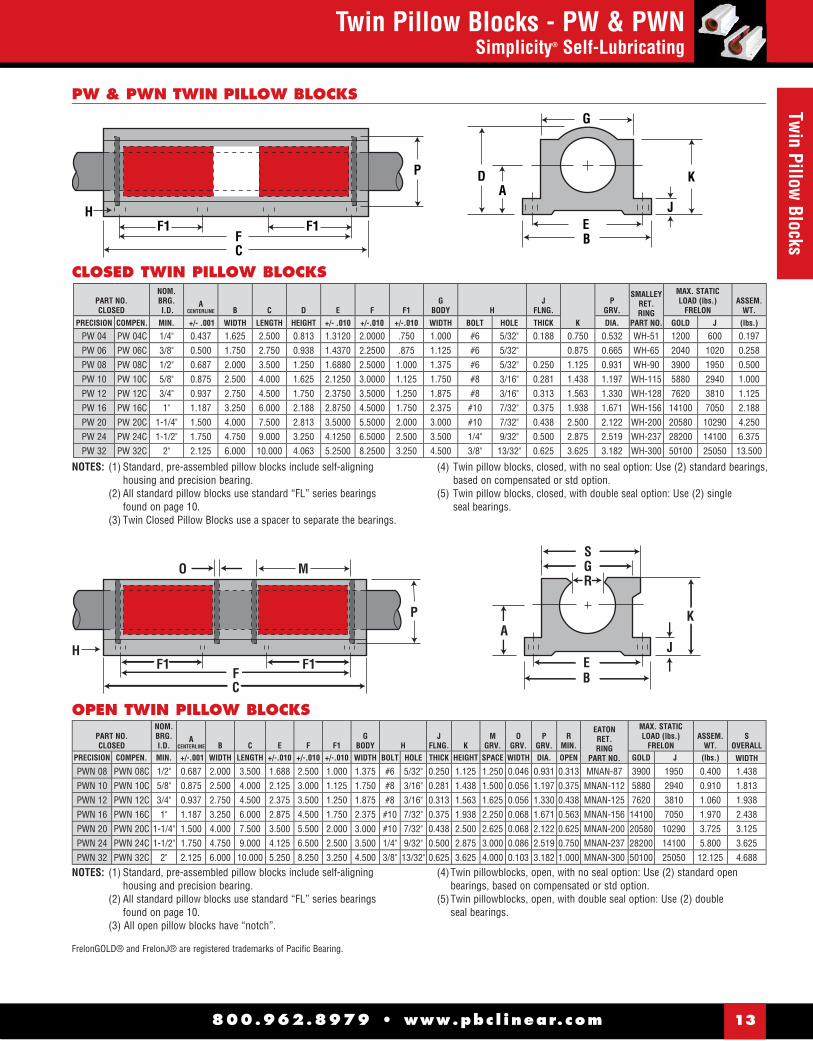
NOTES: (1) Standard, pre-assembled pillow blocks include self-aligning housing and precision bearing.
(2) All standard pillow blocks use standard “FL” series bearings found on page 10.
(3) Twin Closed Pillow Blocks use a spacer to separate the bearings.
(4) Twin pillow blocks, closed, with no seal option: Use (2) standard bearings, based on compensated or std option.
(5) Twin pillow blocks, closed, with double seal option: Use (2) single seal bearings.
FrelonGOLD® and FrelonJ® are registered trademarks of Pacifi c Bearing.
CLOSED TWIN PILLOW BLOCKS
PW & PWN TWIN PILLOW BLOCKS
PART NO. CLOSED
NOM.BRG. I.D.
ACENTERLINE B C D E F F1
GBODY H
JFLNG.
K
PGRV.
SMALLEYRET.RING
PART NO.
MAX. STATIC LOAD (lbs.)
FRELONASSEM.
WT.
PRECISION COMPEN. MIN. +/- .001 WIDTH LENGTH HEIGHT +/- .010 +/-.010 +/-.010 WIDTH BOLT HOLE THICK DIA. GOLD J (lbs.)
PW 04 PW 04C 1/4" 0.437 1.625 2.500 0.813 1.3120 2.0000 .750 1.000 #6 5/32" 0.188 0.750 0.532 WH-51 1200 600 0.197PW 06 PW 06C 3/8" 0.500 1.750 2.750 0.938 1.4370 2.2500 .875 1.125 #6 5/32" 0.875 0.665 WH-65 2040 1020 0.258PW 08 PW 08C 1/2" 0.687 2.000 3.500 1.250 1.6880 2.5000 1.000 1.375 #6 5/32" 0.250 1.125 0.931 WH-90 3900 1950 0.500PW 10 PW 10C 5/8" 0.875 2.500 4.000 1.625 2.1250 3.0000 1.125 1.750 #8 3/16" 0.281 1.438 1.197 WH-115 5880 2940 1.000PW 12 PW 12C 3/4" 0.937 2.750 4.500 1.750 2.3750 3.5000 1.250 1.875 #8 3/16" 0.313 1.563 1.330 WH-128 7620 3810 1.125PW 16 PW 16C 1" 1.187 3.250 6.000 2.188 2.8750 4.5000 1.750 2.375 #10 7/32" 0.375 1.938 1.671 WH-156 14100 7050 2.188PW 20 PW 20C 1-1/4" 1.500 4.000 7.500 2.813 3.5000 5.5000 2.000 3.000 #10 7/32" 0.438 2.500 2.122 WH-200 20580 10290 4.250PW 24 PW 24C 1-1/2" 1.750 4.750 9.000 3.250 4.1250 6.5000 2.500 3.500 1/4" 9/32" 0.500 2.875 2.519 WH-237 28200 14100 6.375PW 32 PW 32C 2" 2.125 6.000 10.000 4.063 5.2500 8.2500 3.250 4.500 3/8" 13/32" 0.625 3.625 3.182 WH-300 50100 25050 13.500
NOTES: (1) Standard, pre-assembled pillow blocks include self-aligning housing and precision bearing.
(2) All standard pillow blocks use standard “FL” series bearings found on page 10.
(3) All open pillow blocks have “notch”.
(4) Twin pillowblocks, open, with no seal option: Use (2) standard open bearings, based on compensated or std option.
(5) Twin pillowblocks, open, with double seal option: Use (2) double seal bearings.
OPEN TWIN PILLOW BLOCKS
PART NO. CLOSED
NOM. BRG.I.D.
ACENTERLINE B C E F F1
GBODY H
JFLNG. K
MGRV.
OGRV.
PGRV.
RMIN.
EATONRET.RING
PART NO.
MAX. STATIC LOAD (lbs.)
FRELONASSEM.
WT.S
OVERALLPRECISION COMPEN. MIN. +/-.001 WIDTH LENGTH +/-.010 +/-.010 +/-.010 WIDTH BOLT HOLE THICK HEIGHT SPACE WIDTH DIA. OPEN GOLD J (lbs.) WIDTH
PWN 08 PWN 08C 1/2" 0.687 2.000 3.500 1.688 2.500 1.000 1.375 #6 5/32" 0.250 1.125 1.250 0.046 0.931 0.313 MNAN-87 3900 1950 0.400 1.438PWN 10 PWN 10C 5/8" 0.875 2.500 4.000 2.125 3.000 1.125 1.750 #8 3/16" 0.281 1.438 1.500 0.056 1.197 0.375 MNAN-112 5880 2940 0.910 1.813PWN 12 PWN 12C 3/4" 0.937 2.750 4.500 2.375 3.500 1.250 1.875 #8 3/16" 0.313 1.563 1.625 0.056 1.330 0.438 MNAN-125 7620 3810 1.060 1.938PWN 16 PWN 16C 1" 1.187 3.250 6.000 2.875 4.500 1.750 2.375 #10 7/32" 0.375 1.938 2.250 0.068 1.671 0.563 MNAN-156 14100 7050 1.970 2.438PWN 20 PWN 20C 1-1/4" 1.500 4.000 7.500 3.500 5.500 2.000 3.000 #10 7/32" 0.438 2.500 2.625 0.068 2.122 0.625 MNAN-200 20580 10290 3.725 3.125PWN 24 PWN 24C 1-1/2" 1.750 4.750 9.000 4.125 6.500 2.500 3.500 1/4" 9/32" 0.500 2.875 3.000 0.086 2.519 0.750 MNAN-237 28200 14100 5.800 3.625PWN 32 PWN 32C 2" 2.125 6.000 10.000 5.250 8.250 3.250 4.500 3/8" 13/32" 0.625 3.625 4.000 0.103 3.182 1.000 MNAN-300 50100 25050 12.125 4.688
800.962.8979 • www.pbc l inear.com14
Flan
ge M
ount
sFlange Mount - SFP & DFPSimplicity® Self-Lubricating
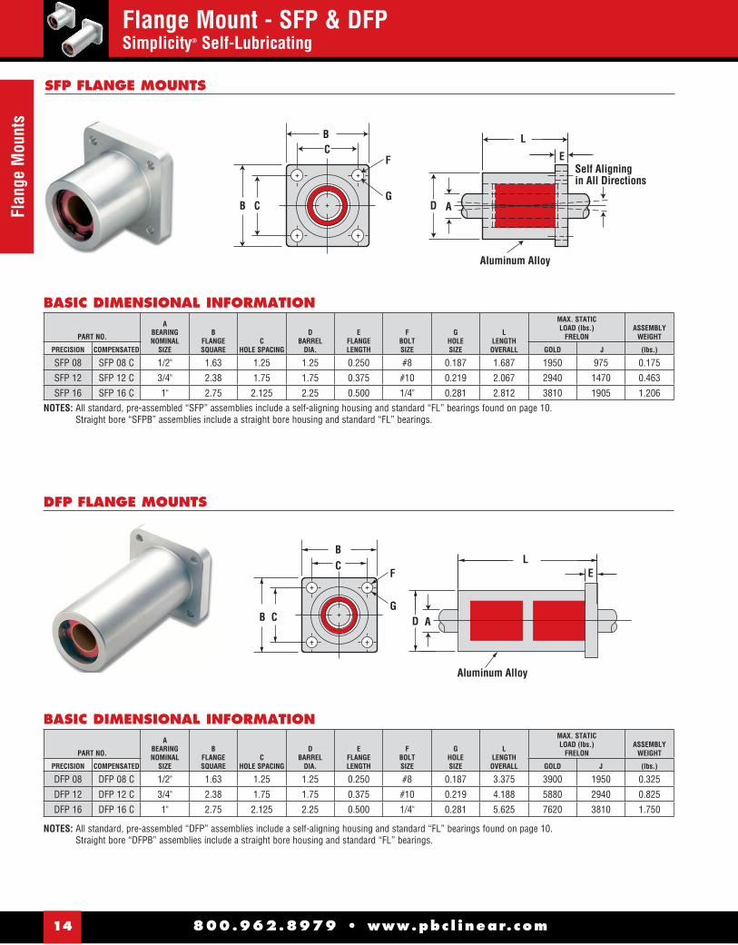
SFP FLANGE MOUNTS
NOTES: All standard, pre-assembled “SFP” assemblies include a self-aligning housing and standard “FL” bearings found on page 10.Straight bore “SFPB” assemblies include a straight bore housing and standard “FL” bearings.
NOTES: All standard, pre-assembled “DFP” assemblies include a self-aligning housing and standard “FL” bearings found on page 10.Straight bore “DFPB” assemblies include a straight bore housing and standard “FL” bearings.
PART NO.
ABEARINGNOMINAL
SIZE
BFLANGESQUARE
CHOLE SPACING
DBARREL
DIA.
EFLANGELENGTH
FBOLTSIZE
GHOLESIZE
LLENGTH
OVERALL
MAX. STATIC LOAD (lbs.)
FRELONASSEMBLY
WEIGHT
PRECISION COMPENSATED GOLD J (lbs.)
SFP 08 SFP 08 C 1/2" 1.63 1.25 1.25 0.250 #8 0.187 1.687 1950 975 0.175
SFP 12 SFP 12 C 3/4" 2.38 1.75 1.75 0.375 #10 0.219 2.067 2940 1470 0.463
SFP 16 SFP 16 C 1" 2.75 2.125 2.25 0.500 1/4" 0.281 2.812 3810 1905 1.206
BASIC DIMENSIONAL INFORMATION
PART NO.
ABEARINGNOMINAL
SIZE
BFLANGESQUARE
CHOLE SPACING
DBARREL
DIA.
EFLANGELENGTH
FBOLTSIZE
GHOLESIZE
LLENGTH
OVERALL
MAX. STATIC LOAD (lbs.)
FRELONASSEMBLY
WEIGHT
PRECISION COMPENSATED GOLD J (lbs.)
DFP 08 DFP 08 C 1/2" 1.63 1.25 1.25 0.250 #8 0.187 3.375 3900 1950 0.325
DFP 12 DFP 12 C 3/4" 2.38 1.75 1.75 0.375 #10 0.219 4.188 5880 2940 0.825
DFP 16 DFP 16 C 1" 2.75 2.125 2.25 0.500 1/4" 0.281 5.625 7620 3810 1.750
BASIC DIMENSIONAL INFORMATION
BC
F
B C
L
ESelf Aligningin All Directions
Aluminum Alloy
GA
DFP FLANGE MOUNTS
BC
F
B C
L
D
E
G
Aluminum Alloy
A
D

B A
I
D E FG
CA
Aluminum Shell with Black Anodize fi nish
SDS FLANGE MOUNTS
800.962.8979 • www.pbc l inear.com 15
Flange Mount Die Sets
Flange Mount Die Sets - SDS & DDSSimplicity® Self-Lubricating
NOTES: All standard, pre-assembled “SDS” assemblies include a straight bore housing and standard “FLA” bearings found on page 10.All straight bore, pre-assembled “SDSB” assemblies include a straight bore housing and standard “FL” bearings found on page 10.
NOTES: All standard, pre-assembled “DDS” assemblies include a straight bore housing and standard “FLA” bearings found on page 10.All straight bore, pre-assembled “DDSB” assemblies include a straight bore housing and standard “FL” bearings found on page 10.
DDS FLANGE MOUNTS
PART NO.A
BEARINGNOMINAL
SIZE
BFLANGE
CBARREL DIA.
DPILOT DIA. E
PILOTLENGTH
FFLANGELENGTH
GHEAD
LENGTH
HOVERALLLENGTH
IMOUNTING HOLES
(4 PLACES)
MAX. STATIC LOAD (lbs.)
FRELONASSEMBLY
WEIGHT
PRECISION COMPEN. O.D. MIN. MAX. MIN. MAX.BOLTSIZE
HOLESIZE CIRCLE GOLD J (lbs.)
SDS 16 SDS 16 C 1" 3.00 2.098 2.100 1.4995 1.500 0.875 0.562 2.500 3.927 1/4" 0.281 2.550 7050 3525 0.941
SDS 20 SDS 20 C 1-1/4" 3.50 2.598 2.600 1.7495 1.750 1.125 0.750 3.000 4.875 1/4" 0.281 3.050 10290 5145 1.852
SDS 24 SDS 24 C 1-1/2" 4.25 2.998 3.000 1.9990 2.000 1.375 1.000 3.500 5.875 3/8" 0.406 3.650 14100 7050 2.983
SDS 32 SDS 32 C 2" 5.00 3.748 3.750 2.4990 2.500 1.625 1.000 4.500 7.125 3/8" 0.406 4.400 25050 12525 5.032
BASIC DIMENSIONAL INFORMATION
PART NO.A
BEARINGNOMINAL
SIZE
BFLANGE
CBARREL DIA.
DLENGTH
EFLANGELENGTH
FLENGTH
gOVERALLLENGTH
IMOUNTING HOLES
(4 PLACES)
MAX. STATIC LOAD (lbs.)
FRELONASSEMBLY
WEIGHT
PRECISION COMPEN. O.D. MIN. MAX.BOLTSIZE
HOLESIZE CIRCLE GOLD J (lbs.)
DDS 16 DDS 16 C 1" 3.00 2.098 2.100 2.5 0.562 3.500 6.563 1/4" 0.281 2.550 14100 7050 1.785
DDS 20 DDS 20 C 1-1/4" 3.50 2.598 2.600 3 0.750 4.250 8.000 1/4" 0.281 3.050 20580 10290 3.203
DDS 24 DDS 24 C 1-1/2" 4.25 2.998 3.000 3.5 1.000 5.000 9.500 3/8" 0.406 3.650 28200 14100 5.128
DDS 32 DDS 32 C 2" 5.00 3.748 3.750 4.5 1.000 6.500 12.000 3/8" 0.406 4.400 50100 25050 9.015
BASIC DIMENSIONAL INFORMATION
Lube System OptionalOrder as JKM See pg. 8 for information
1˚ Misalignment
E F GH
C B A
I
A
Lube System OptionalOrder as JKM See pg. 8 for information
D
Aluminum Shell with Black Anodize fi nish

800.962.8979 • www.pbc l inear.com16
Flan
ge D
ie S
ets
Flange Mount Die Sets - PACSimplicity® Self-Lubricating
.300"
J 9/32
For5/16" - 18 SCR
3/16
9/32
NOTE: DIMENSION FOR CALCULATING BOLT CIRCLE
PAC FLANGE MOUNT DIE SETS
PART NO.NOMINAL
SIZEA
BEARING I.D. PART NO.A
BEARING I.D.
BFLANGE &
BARREL O.D.
CCLAMP
DIA.D
PILOT O.D. EPILOT
LENGTH
FFLANGELENGTH
GRECESSLENGTH
HHEAD
LENGTH
IOVERALLLENGTH
EFFECTIVESURFACE
AREA
MAX STATIC LOAD (lbs.)
FRELONBEARINGWEIGHT
PRECISION (in.) MIN. MAX. COMPENSATED MIN. MAX. MIN. MAX. MIN. MIN. MAX. (sq. in.) GOLD J (lbs.)
PAC 750 3/4" 0.750 0.7510 PAC 750 C 0.7530 0.7540 1.285 1.300 1.012 1.1245 1.1250 0.812 0.188 0.712 2.000 2.812 2.209 6626 3313 0.625
PAC 100 1" 1.000 1.0010 PAC 100 C 1.0030 1.0040 1.723 1.738 1.450 1.4995 1.5000 0.875 0.188 0.812 2.250 3.125 3.272 9817 4909 1.000
PAC 125 1-1/4" 1.250 1.2510 PAC 125 C 1.2540 1.2550 2.097 2.112 1.825 1.7495 1.7500 1.125 0.188 0.812 2.375 3.500 4.581 13744 6872 1.500
PAC 150 1-1/2" 1.500 1.5012 PAC 150 C 1.5040 1.5050 2.346 2.361 2.075 1.9995 2.0000 1.375 0.188 1.112 2.750 4.125 6.480 19439 9719 2.000
PAC 200 2" 2.000 2.0014 PAC 200 C 2.0050 2.0064 3.095 3.110 2.825 2.4995 2.5000 1.625 0.188 1.112 3.000 4.625 9.687 29060 14530 4.188
PAC 250 2-1/2" 2.500 2.5016 PAC 250 C 2.5050 2.5065 3.595 3.610 3.325 2.9995 3.0000 1.875 0.188 1.112 3.500 5.375 14.072 42215 21108 6.000
PAC 300 3" 3.000 3.0020 PAC 300 C 3.0060 3.0080 4.345 4.360 4.075 3.6245 3.6250 1.875 0.188 1.112 4.000 5.875 18.457 55371 27685 10.000
BASIC DIMENSIONAL INFORMATION
I
B C A
Frelon® LinerEF
G
H
D
Steel Shell with Black Oxide Finish
I
B C A
EF
G
H
D
OptionalFelt Wick
1/4 - 28
4 PAC CLAMPS ARE SHIPPED WITH EACH DIESET
EXTRAS CAN BE ORDERED USING PART #: PACCLAMP
Zerk Fitting
J = C + .600"
NOTES: Formula used for effective surface area is (pi * ID * L)/3Max Static load is effective surface area times max load for FrelonGOLD®
- 3000 psi is the rating for FrelonGOLD®
- 1500 psi is the rating for FrelonJ®
Lube System OptionalOrder as JKM See pg. 8 for information

800.962.8979 • www.pbc l inear.com 17
AccessoriesAccessories
O-RINGSSEALSRETAINING RINGS (EXTERNAL)
RETAINING RINGS (INTERNAL)
ZERK FITTINGS
ROLL PIN
FL SERIES PART NO.
FL03 6010001FL04 6010002FL06 6010003FL08 6010004FL10 6010005FL12 6010006FL16 6010007FL20 6010008FL24 6010009FL32 6010010FL40 6010011FL48 6010012FL64 6010013
FM SERIES PART NO.
FM05 6010014FM08 6010015FM10 6010016FM12 6010017FM16 6010018FM20 6010019FM25 6010020FM30 6010021FM40 6010022FM50 6010023FM60 6010024FM80 6010025
FL SERIES PART NO.
OPEN POLYMOD VITON URETHANE
FL08 6030001 6030009 6030017FL10 6030002 6030010 6030018FL12 6030003 6030011 6030019FL16 6030004 6030012 6030020FL20 6030005 6030013 6030021FL24 6030006 6030014 6030022FL32 6030007 6030015 6030023FL40 6030008 6030016 6030024FL48 * * 6030025FL64 * * 6030026
FM SERIES PART NO.
FM20 * * 6030027FM25 * * 6030028FM30 * * 6030029FM35 * * 6030030FM40 * * 6030031FM50 * * 6030032FM60 * * 6030033FM80 * * 6030034
FL SERIES PART NO.
OPEN URETHANE VITON
FL04 6000001 *
FL06 6000002 6000037
FL08 6000003 6000038
FL10 6000004 6000039
FL12 6000005 6000040
FL16 6000006 6000041
FL20 6000007 6000042
FL24 6000008 6000043
FL32 6000009 6000044
FL40 6000010 6000045
FL48 6000011 6000046
FL64 6000012 6000047
FM/FJ SERIES PART NO.
FM05 6000013 *
FM08 6000014 *
FM10 6000015 *
FM12 6000016 *
FM16 6000017 *
FM20 6000018 *
FM25 6000019 *
FM30 6000020 *
FM40 6000021 *
FM50 6000022 *
FM60 6000023 *
FM80 6000024 *
INCH PART NO.
1/4-28" Steel 6050002
1/4-28" Stainless 6050003
METRIC PART NO.
M8x1.0 Steel 6050001
M8X1.0 Stainless *
INCH OPEN PART NO.
PN08 6060001
PN10 6060002
PN12 6060003
PN16 6060004
PN20 6060005
PN24 6060006
PN32 6060007
METRIC OPEN PART NO.
PMN12 6060010
PMN16 6060009
PMN20 6060009
PMN25 6060010
PMN30 6060010
PMN40 6060012
PMN50 6060012
INCH OPENPART NO.
METRIC OPENPART NO.
STEEL STAINLESS STEEL STEEL STAINLESS STEEL
PN08 6010035 6010064 PMN12 6010044 *PN10 6010036 6010066 PMN16 6010045 *PN12 6010037 6010068 PMN20 6010046 *PN16 6010038 6010070 PMN25 6010047 *PN20 6010039 6010072 PMN30 6010048 6010083PN24 6010040 6010074 PMN40 6010049 *PN32 6010041 6010076 PMN50 6010050 *
CLOSED PART NO. CLOSED PART NO.
P04 6010026 6010052 PM08 6010042 *P06 6010027 6010053 PM10 6010043 *P08 6010028 6010054 PM12 6010044 *P10 6010029 6010055 PM16 6010045 *P12 6010030 6010056 PM20 6010046 *P16 6010031 6010057 PM25 6010047 *P20 6010032 6010058 PM30 6010048 *P24 6010033 6010059 PM40 6010049 *P32 6010034 6010060 PM50 6010050 *
See page 42 for technical information.
FM LINEAR BEARINGS
800.962.8979 • www.pbc l inear.com18
Self-
Lubr
icat
ing
Bear
ing
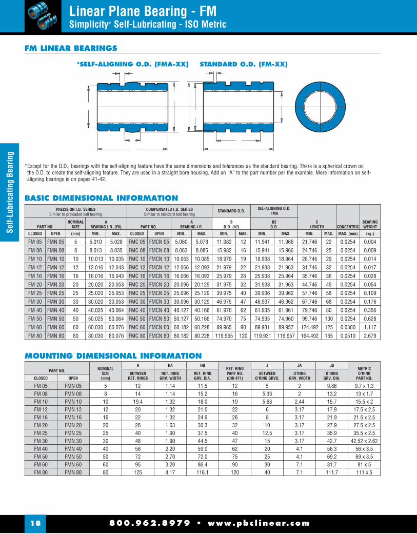
Linear Plane Bearing - FMSimplicity® Self-Lubricating - ISO Metric
* Except for the O.D., bearings with the self-aligning feature have the same dimensions and tolerances as the standard bearing. There is a spherical crown on the O.D. to create the self-aligning feature. They are used in a straight bore housing. Add an “A” to the part number per the example. More information on self-aligning bearings is on pages 41-42.
PRECISION I.D. SERIESSimilar to preloaded ball bearing
COMPENSATED I.D. SERIESSimilar to standard ball bearing
STANDARD O.D. SEL-ALIGNING O.D.FMA
CLENGTH CONCENTRIC
BEARINGWEIGHTPART NO.
NOMINALSIZE
ABEARING I.D. (F8) PART NO.
ABEARING I.D.
BO.D. (h7)
B2O.D.
CLOSED OPEN (mm) MIN. MAX. CLOSED OPEN MIN. MAX. MIN. MAX. MIN. MAX. MIN. MAX. MAX. (mm) (kg.)
FM 05 FMN 05 5 5.010 5.028 FMC 05 FMCN 05 5.060 5.078 11.982 12 11.941 11.966 21.746 22 0.0254 0.004
FM 08 FMN 08 8 8.013 8.035 FMC 08 FMCN 08 8.063 8.085 15.982 16 15.941 15.966 24.746 25 0.0254 0.009
FM 10 FMN 10 10 10.013 10.035 FMC 10 FMCN 10 10.063 10.085 18.979 19 18.938 18.964 28.746 29 0.0254 0.014
FM 12 FMN 12 12 12.016 12.043 FMC 12 FMCN 12 12.066 12.093 21.979 22 21.938 21.963 31.746 32 0.0254 0.017
FM 16 FMN 16 16 16.016 16.043 FMC 16 FMCN 16 16.066 16.093 25.979 26 25.938 25.964 35.746 36 0.0254 0.028
FM 20 FMN 20 20 20.020 20.053 FMC 20 FMCN 20 20.096 20.129 31.975 32 31.938 31.963 44.746 45 0.0254 0.054
FM 25 FMN 25 25 25.020 25.053 FMC 25 FMCN 25 25.096 25.129 39.975 40 39.936 39.962 57.746 58 0.0254 0.109
FM 30 FMN 30 30 30.020 30.053 FMC 30 FMCN 30 30.096 30.129 46.975 47 46.937 46.962 67.746 68 0.0254 0.176
FM 40 FMN 40 40 40.025 40.064 FMC 40 FMCN 40 40.127 40.166 61.970 62 61.935 61.961 79.746 80 0.0254 0.356
FM 50 FMN 50 50 50.025 50.064 FMC 50 FMCN 50 50.127 50.166 74.970 75 74.935 74.960 99.746 100 0.0254 0.628
FM 60 FMN 60 60 60.030 60.076 FMC 60 FMCN 60 60.182 60.228 89.965 90 89.931 89.957 124.492 125 0.0380 1.117
FM 80 FMN 80 80 80.030 80.076 FMC 80 FMCN 80 80.182 80.228 119.965 120 119.931 119.957 164.492 165 0.0510 2.679
BASIC DIMENSIONAL INFORMATION
MOUNTING DIMENSIONAL INFORMATION
PART NO. NOMINALSIZE(mm)
H HA HBRET. RINGPART NO. (DIN 471)
J JA JBMETRICO’RING
PART NO.BETWEEN
RET. RINGSRET. RING
GRV. WIDTHRET. RING GRV. DIA.
BETWEENO’RING GRVS.
O’RINGGRV. WIDTH
O’RINGGRV. DIA.CLOSED OPEN
FM 05 FMN 05 5 12 1.14 11.5 12 5 2 9.86 9.7 x 1.3FM 08 FMN 08 8 14 1.14 15.2 16 5.33 2 13.2 13 x 1.7FM 10 FMN 10 10 19.4 1.32 18.0 19 5.63 2.44 15.7 15.5 x 2FM 12 FMN 12 12 20 1.32 21.0 22 6 3.17 17.9 17.5 x 2.5FM 16 FMN 16 16 22 1.32 24.9 26 8 3.17 21.9 21.5 x 2.5FM 20 FMN 20 20 28 1.63 30.3 32 10 3.17 27.9 27.5 x 2.5 FM 25 FMN 25 25 40 1.90 37.5 40 12.5 3.17 35.9 35.5 x 2.5FM 30 FMN 30 30 48 1.90 44.5 47 15 3.17 42.7 42.52 x 2.62FM 40 FMN 40 40 56 2.20 59.0 62 20 4.1 56.3 56 x 3.5 FM 50 FMN 50 50 72 2.70 72.0 75 25 4.1 69.2 69 x 3.5FM 60 FMN 60 60 95 3.20 86.4 90 30 7.1 81.7 81 x 5FM 80 FMN 80 80 125 4.17 116.1 120 40 7.1 111.7 111 x 5
*SELF-ALIGNING O.D. (FMA-XX) STANDARD O.D. (FM-XX)

800.962.8979 • www.pbc l inear.com 19
Self-lubricating BearingLinear Plane Bearing - FM & FMN
Simplicity® Self-Lubricating
OPEN DIMENSIONAL INFORMATION
PART NO.NOMINAL
SIZE
DSLOTWIDEMIN.
ESLOT
ANGLE
XRET.HOLEDIA.
YRET.HOLEDIA.
YZRET.HOLE
LOCATE
BEARINGWT.
CLOSED (mm) (kg.)
FMN 05 5 3.2 60 2.2 N / A N / A 0.0034
FMN 08 8 5.1 60 3.0 N / A N / A 0.0077
FMN 10 10 6.4 60 3.0 N / A N / A 0.0119
FMN 12 12 7.6 78 3.0 3.0 7.0 0.0156
FMN 16 16 10.4 78 2.2 3.0 0 0.0213
FMN 20 20 10.8 60 2.2 3.0 0 0.0439
FMN 25 25 13.2 60 3.0 3.0 1.5 0.0893
FMN 30 30 14.2 72 3.0 3.0 2.0 0.1460
FMN 40 40 19.5 72 3.0 3.0 1.5 0.2948
FMN 50 50 24.0 72 3.0 5.0 2.5 0.5202
FMN 60 60 29.6 72 N / A 6.0 0 0.9199
FMN 80 80 39.0 72 N / A 8.0 0 2.2269
LOAD & SPEED DATA
PART NO.
EFFECTIVESURFACE
AREA
MAX.STATIC LOAD FRELON EFFECTIVE
SURFACEAREA
MAX.STATIC LOAD FRELON
GOLD J GOLD J
(sq. in.) (lbs.) (lbs.) (mm2) (N) (N)
FMN 05 1.1 232 116 110 2276 1138
FMN 08 2 420 210 200 4120 2060
FMN 10 2.9 610 305 290 5984 2992
FMN 12 3.8 806 403 380 7907 3953
FMN 16 5.8 1210 605 580 11870 5935
FMN 20 9 1890 945 900 18541 9270
FMN 25 14.5 3046 1523 1450 29881 14941
FMN 30 20.4 4284 2142 2040 42026 21013
FMN 40 32 6720 3360 3200 65923 32962
FMN 50 50 10500 5250 5000 103005 51503
FMN 60 75 15750 7875 7500 154508 77254
FMN 80 132 27720 13860 13200 271933 135967
MAX. PV (m/min. * kg/sq. cm)FrelonGold = 430 PVFrelonJ = 215 PV
MAX. PV (m/s. * N/mm2)FrelonGold = 0.70 PVFrelonJ = 0.35 PV
MAX. Speed Running Dry (m/min.)FrelonGold = 91.4FrelonJ = 42.6
MAX. Speed Running Dry (m/s.)FrelonGold = 1.52FrelonJ = 0.71
MAX. Speed Running with Lubrication (m/min.)FrelonGold = 251.5FrelonJ = 122
MAX. Speed Running with Lubrication (m/s.)FrelonGold = 4.19FrelonJ = 2.03
FMN 12 ONLY
FMN 05 THRU FMN 10 & FMN 80
FMN 16 THRU FMN 20
FMN 25 ONLY FMN 30 THRU FMN 50
FMN 60 ONLY
= =
FMN 60 ONLY
7°
ED
Y
1.35X
ED
ED
E
D
ED
ED
YZY
X X
XYX
YZY
YZY
FM & FMN LINEAR BEARINGS
ACCESSORIES
Retaining Rings (Internal & External) ..................................17
Seals, O-Rings, Zerk Fittings ...............................................17
Metric Shafting (Steel, Ceramic Coated, Stainless Steel) ......68
800.962.8979 • www.pbc l inear.com20
Pillo
w B
lock
sPillow Blocks - PMSimplicity® Self-Lubricating
A
N2 S2
N3
S3
H1
H
N
N5N4
A1
S
L
d
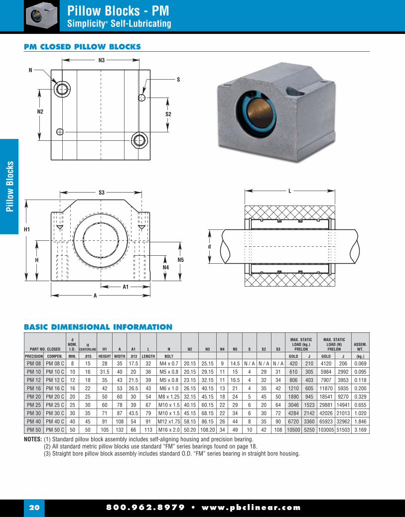
NOTES: (1) Standard pillow block assembly includes self-aligning housing and precision bearing.(2) All standard metric pillow blocks use standard “FM” series bearings found on page 18.(3) Straight bore pillow block assembly includes standard O.D. “FM” series bearing in straight bore housing.
PM CLOSED PILLOW BLOCKS
PART NO. CLOSED
dNOM.I.D.
HCENTERLINE H1 A A1 L N N2 N3 N4 N5 S S2 S3
MAX. STATIC LOAD (kg.)
FRELON
MAX. STATIC LOAD (N)FRELON
ASSEM.WT.
PRECISION COMPEN. MIN. .015 HEIGHT WIDTH .013 LENGTH BOLT GOLD J GOLD J (kg.)
PM 08 PM 08 C 8 15 28 35 17.5 32 M4 x 0.7 20.15 25.15 9 14.5 N / A N / A N / A 420 210 4120 206 0.069
PM 10 PM 10 C 10 16 31.5 40 20 36 M5 x 0.8 20.15 29.15 11 15 4 29 31 610 305 5984 2992 0.095
PM 12 PM 12 C 12 18 35 43 21.5 39 M5 x 0.8 23.15 32.15 11 16.5 4 32 34 806 403 7907 3953 0.118
PM 16 PM 16 C 16 22 42 53 26.5 43 M6 x 1.0 26.15 40.15 13 21 4 35 42 1210 605 11870 5935 0.200
PM 20 PM 20 C 20 25 50 60 30 54 M8 x 1.25 32.15 45.15 18 24 5 45 50 1890 945 18541 9270 0.329
PM 25 PM 25 C 25 30 60 78 39 67 M10 x 1.5 40.15 60.15 22 29 6 20 64 3046 1523 29881 14941 0.655
PM 30 PM 30 C 30 35 71 87 43.5 79 M10 x 1.5 45.15 68.15 22 34 6 30 72 4284 2142 42026 21013 1.020
PM 40 PM 40 C 40 45 91 108 54 91 M12 x1.75 58.15 86.15 26 44 8 35 90 6720 3360 65923 32962 1.846
PM 50 PM 50 C 50 50 105 132 66 113 M16 x 2.0 50.20 108.20 34 49 10 42 108 10500 5250 103005 51503 3.169
BASIC DIMENSIONAL INFORMATION

800.962.8979 • www.pbc l inear.com 21
Pillow Blocks
Pillow Blocks - PMNSimplicity® Self-Lubricating
PMN OPEN PILLOW BLOCKS
PART NO. CLOSED
dNOM.I.D.
HCENTERLINE H1 A
A1CENTERLINE L N N2 N3 N4 N5 S S2 S3 a
MAX. STATIC LOAD (kg.)
FRELON
MAX. STATIC LOAD (N)FRELON
ASSEM.WT.
PRECISION COMPEN. MIN. .015 HEIGHT WIDTH .013 LENGTH BOLT GOLD J GOLD J (kg.)
PMN 12 PMN 12C 12 18 28 43 21.5 39 M5 x 0.8 23.15 32.15 11 16.5 4 32 34 66 806 403 7907 3953 0.096
PMN 16 PMN 16C 16 22 35 53 26.5 43 M6 x 1.0 26.15 40.15 13 21 4 35 42 68 1210 605 11870 5935 0.162
PMN 20 PMN 20C 20 25 42 60 30 54 M8 x 1.25 32.15 45.15 18 24 5 45 50 60 1890 945 18541 9270 0.267
PMN 25 PMN 25C 25 30 51 78 39 67 M10 x 1.5 40.15 60.15 22 29 6 20 64 60 3046 1523 29881 14941 0.536
PMN 30 PMN 30C 30 35 60 87 43.5 79 M10 x 1.5 45.15 68.15 34 6 30 72 60 4284 2142 42026 21013 0.831
PMN 40 PMN 40C 40 45 77 108 54 91 M12 x 1.75 58.15 86.15 26 44 8 35 90 60 6720 3360 65923 32962 1.499
PMN 50 PMN 50C 50 50 88 132 66 113 M16 x 2.0 50.20 108.20 34 49 10 42 108 60 10500 5250 103005 51503 2.539
NOTES: (1) Standard pillow block assembly includes self-aligning housing and precision bearing.(2) All standard metric pillow blocks use standard “FM” series bearings found on page 18.
BASIC DIMENSIONAL INFORMATION

Com
pact
Thi
n W
all
800.962.8979 • www.pbc l inear.com22
Compact Thin Wall Bearing - FMTSimplicity® Self-Lubricating
FrelonGOLD® and FrelonJ® are registered trademarks of Pacifi c Bearing.
LOAD & SPEED DATA
PART NO.
EFFECTIVESURFACE
AREA
MAX. STATIC LOAD FRELON EFFECTIVESURFACE
AREA
MAX. STATIC LOAD FRELON
GOLD J GOLD J
(sq. cm.) (lbs.) (lbs.) (mm2) (N) (N)
FMT 06 1.3 278 139 130 2727 1364
FMT 08 1.9 404 202 190 3963 1982
FMT 10 2.6 546 273 260 5356 2678
FMT 12 3.4 706 353 340 6926 3463
FMT 14 3.9 824 412 390 8083 4042
FMT 16 4.8 1008 504 480 9888 4944
FMT 20 6.0 1260 630 600 12361 6180
FMT 25 10.0 2100 1050 1000 20601 10301
FMT 30 15.0 3150 1575 1500 30902 15451
FMT 40 24.0 5040 2520 2400 49442 24721
FMT 50 35.0 7350 3675 3500 72104 36052
MAX. PV (m/min. * kg/sq. cm)FrelonGold = 430 PVFrelonJ = 215 PV
MAX. PV (m/s. * N/mm2)FrelonGold = 0.70 PVFrelonJ = 0.35 PV
MAX. Speed Running Dry (m/min.)FrelonGold = 91.4FrelonJ = 42.6
MAX. Speed Running Dry (m/s.)FrelonGold = 1.52FrelonJ = 0.71
MAX. Speed Running with Lubrication (m/min.)FrelonGold = 251.5FrelonJ = 122
MAX. Speed Running with Lubrication (m/s.)FrelonGold = 4.19FrelonJ = 2.03
PRECISION I.D. SERIESSimilar to preloaded ball bearing
COMPENSATED I.D. SERIESSimilar to standard ball bearing
BO.D. (h7)
CLENGTH (h13) CONCENTRIC
BEARINGWEIGHTPART NO.
NOMINALSIZE
ABEARING I.D. (F8) PART NO.
ABEARING I.D.
CLOSED (mm) MIN. MAX. CLOSED MIN. MAX. MIN. MAX. MIN. MAX. MAX. (mm) (kg.)
FMT 06 6 6.010 6.028 FMTC 06 6.060 6.078 11.982 12 21.746 22 0.0254 0.0057
FMT 08 8 8.013 8.035 FMTC 08 8.063 8.085 14.982 15 23.746 24 0.0254 0.0071
FMT 10 10 10.013 10.035 FMTC 10 10.063 10.085 16.982 17 25.746 26 0.0254 0.0085
FMT 12 12 12.016 12.043 FMTC 12 12.066 12.093 18.979 19 27.746 28 0.0254 0.0113
FMT 14 14 14.016 14.043 FMTC 14 14.066 14.093 20.979 21 27.746 28 0.0254 0.0128
FMT 16 16 16.016 16.043 FMTC 16 16.066 16.093 23.979 24 29.746 30 0.0254 0.0184
FMT 20 20 20.020 20.053 FMTC 20 20.096 20.129 27.979 28 29.746 30 0.0254 0.0227
FMT 25 25 25.020 25.053 FMTC 25 25.096 25.129 34.975 35 39.746 40 0.0254 0.0439
FMT 30 30 30.020 30.053 FMTC 30 30.090 30.129 39.975 40 49.746 50 0.0254 0.0652
FMT 40 40 40.025 40.064 FMTC 40 40.127 40.166 51.970 52 59.746 60 0.0254 0.1233
FMT 50 50 50.025 50.064 FMTC 50 50.127 50.166 61.970 62 69.746 70 0.0254 0.1772
BASIC DIMENSIONAL INFORMATION
MOUNTING DIMENSIONS
PART NO.NOMINAL
SIZE
JBETWEENO-RINGGRVS.
JA0-RINGGRV.
WIDTH
JBO-RING
GRV. DIA.
METRICO-RING
PART NO.PRECISION COMPENSATED
FMT 06 FMTC 06 6 N / A N / A N / A N / A
FMT 08 FMTC 08 8 10.0 2.000 12.200 12 x 1.7
FMT 10 FMTC 10 10 12.0 2.000 14.400 14 x 1.6
FMT 12 FMTC 12 12 14.0 2.000 16.600 16 x 1.5
FMT 14 FMTC 14 14 14.0 2.000 18.500 18 x 1.5
FMT 16 FMTC 16 16 14.0 2.000 21.300 21.1 x 1.6
FMT 20 FMTC 20 20 14.0 2.000 25.500 25 x 1.5
FMT 25 FMTC 25 25 22.0 3.200 30.900 30.5 x 2.5
FMT 30 FMTC 30 30 30.0 3.200 35.900 35.5 x 2.5
FMT 40 FMTC 40 40 40.0 4.100 46.200 46 x 3.5
FMT 50 FMTC 50 50 50.0 4.100 56.300 26 x 3.5
FMT COMPACT THIN WALL BEARINGS
ACCESSORIES
Retaining Rings (Internal & External) ..................................17
Seals, O-Rings, Zerk Fittings ...............................................17
Metric Shafting (Steel, Ceramic Coated, Stainless Steel) ......68

800.962.8979 • www.pbc l inear.com 23
Compact Thin W
allCompact Thin Wall Bearing - FG
Simplicity® Self-Lubricating
FG COMPACT THIN WALL BEARINGS
LOAD & SPEED DATA
PART NO.
EFFECTIVESURFACE
AREA
MAX. STATIC LOAD FRELON EFFECTIVESURFACE
AREA
MAX. STATIC LOAD FRELON
GOLD J GOLD J
(sq. cm.) (lbs.) (lbs.) (mm2) (N) (N)
FG 06 1.1 226 113 110 2217 1109FG 08 1.6 336 168 160 3296 1648FG 10 2.2 462 231 220 4532 2266FG 12 3.2 680 340 320 6671 3335FG 15 4.2 882 441 420 8652 4326FG 16 4.8 1008 504 480 9888 4944FG 18 5.4 1134 567 540 11125 5562FG 20 7.0 1470 735 700 14421 7210FG 25 11.3 2362 1181 1130 23171 11586FG 30 16.2 3402 1701 1620 33374 16687FG 35 21.7 4558 2279 2170 44714 22357FG 40 28.8 6048 3024 2880 59331 29665FG 50 45.0 9450 4725 4500 92705 46352
MAX. PV (m/min. * kg/sq. cm)FrelonGold = 430 PVFrelonJ = 215 PV
MAX. PV (m/s. * N/mm2)FrelonGold = 0.70 PVFrelonJ = 0.35 PV
MAX. Speed Running Dry (m/min.)FrelonGold = 91.4FrelonJ = 42.6
MAX. Speed Running Dry (m/s.)FrelonGold = 1.52FrelonJ = 0.71
MAX. Speed Running with Lubrication (m/min.)FrelonGold = 251.5FrelonJ = 122
MAX. Speed Running with Lubrication(m/s.)FrelonGold = 4.19FrelonJ = 2.03
PRECISION I.D. SERIESSimilar to preloaded ball bearing
COMPENSATED I.D. SERIESSimilar to standard ball bearing
BO.D. (h7)
CLENGTH (h13) CONCENTRIC
BEARINGWEIGHTPART NO.
NOMINALSIZE
ABEARING I.D. (F8) PART NO.
ABEARING I.D.
CLOSED (mm) MIN. MAX. CLOSED MIN. MAX. MIN. MAX. MIN. MAX. MAX. mm (kg.)
FG 06 6 6.010 6.028 FGC 06 6.060 6.078 11.98 12 17.8 18 0.0254 0.004FG 08 8 8.013 8.035 FGC 08 8.063 8.085 14.98 15 19.8 20 0.0254 0.006FG 10 10 10.013 10.035 FGC 10 10.063 10.085 16.98 17 21.8 22 0.0254 0.008FG 12 12 12.016 12.043 FGC 12 12.066 12.093 21.98 22 26.8 27 0.0254 0.018FG 15 15 15.016 15.043 FGC 15 15.066 15.093 24.98 25 27.8 28 0.0254 0.022FG 16 16 16.016 16.043 FGC 16 16.066 16.093 25.98 26 29.8 30 0.0254 0.025FG 18 18 18.020 18.053 FGC 18 18.096 18.129 27.98 28 29.8 30 0.0254 0.027FG 20 20 20.020 20.053 FGC 20 20.096 20.129 31.98 32 34.8 35 0.0254 0.044FG 25 25 25.020 25.053 FGC 25 25.096 25.129 39.98 40 44.8 45 0.0254 0.091FG 30 30 30.020 30.053 FGC 30 30.096 30.129 44.98 45 53.8 54 0.0254 0.127FG 35 35 35.025 35.064 FGC 35 35.127 35.166 51.98 52 61.7 62 0.0254 0.189FG 40 40 40.025 40.064 FGC 40 40.127 40.166 59.98 60 71.7 72 0.0254 0.301FG 50 50 50.025 50.064 FGC 50 50.127 50.166 74.98 75 89.7 90 0.0254 0.596
BASIC DIMENSIONAL INFORMATION
MOUNTING DIMENSIONS
PART NO.NOMINAL
SIZE
JBETWEENO-RINGGRVS.
JA0-RINGGRV.
WIDTH
JBO-RINGGRV.DIA.
METRICO-RING
PART NO.PRECISION COMPENSATED
FG 06 FGC 06 6 N / A N / A N / A N / AFG 08 FGC 08 8 8.0 2.032 12.201 12 x 1.7FG 10 FGC 10 10 8.3 2.032 14.415 14 x 1.6FG 12 FGC 12 12 12.0 3.175 17.907 17.5 x 2.5FG 15 FGC 15 15 12.7 3.175 20.671 20 x 2.65FG 16 FGC 16 16 12.7 3.175 21.882 21.5 x 2.5FG 18 FGC 08 18 14.0 3.175 23.885 23.5 x 2.5FG 20 FGC 20 20 17.0 3.175 27.864 27.5 x 2.5FG 25 FGC 25 25 24.0 3.175 35.865 35.5 x 2.5FG 30 FGC 30 30 30.0 3.175 40.895 40 x 2.5FG 35 FGC 35 35 36.0 4.115 46.200 46 x 3.5FG 40 FGC 40 40 37.3 4.115 54.255 53 x 3.5FG 50 FGC 50 50 50 4.115 69.215 69 x 3.5
FrelonGOLD® and FrelonJ® are registered trademarks of Pacifi c Bearing.
ACCESSORIES
Retaining Rings (Internal & External) ..................................17
Seals, O-Rings, Zerk Fittings ...............................................17
Metric Shafting (Steel, Ceramic Coated, Stainless Steel) ......68

800.962.8979 • www.pbc l inear.com24
Die
Set B
ushi
ngDie Set Bushing - PACMSimplicity® Self-Lubricating
I
B C A
Frelon®LinerE
FG
H
D
Steel Shell withBlack Oxide Finish
I
B C A
EF
G
H
D
Frelon®Liner
OptionalFelt Wick
Zerk Fitting
Lube System OptionalOrder as JKM See pg. 8 for information
PACM DIE SET BUSHINGS
PART NO.NOMINAL
SIZEA
BEARING I.D. PART NO.A
BEARING I.D.
BFLANGE & BARREL
O.D. (H7)
CCLAMP
DIA.
DPILOT O.D.
(H7)E
PILOTLENGTH
FFLANGELENGTH
GRECESSLENGTH
HHEAD
LENGTH
IOVERALLLENGTH
EFFECTIVESURFACE
AREA
MAX. STATIC LOAD (kg.)
FRELONBEARINGWEIGHT
PRECISION (mm) MIN. MAX. COMPENSATED MIN. MAX. MIN. MAX. MIN. MIN. MAX. (sq. cm) GOLD J (kg.)
PACM 19 19 19.020 19.053 PACM 19 C 19.096 19.129 33.975 34 29 27.979 28 18
5
18 52 70 13.928 2925 1469 0.282
PACM 25 25 25.020 25.053 PACM 25 C 25.096 25.129 43.975 44 39 37.975 38 2320
57 80 20.944 4398 2209 0.551
PACM 32 32 32.020 32.053 PACM 32 C 32.096 32.129 52.970 53 48 44.975 45 26 64 90 30.159 6333 3180 0.834
PACM 40 40 40.025 40.064 PACM 40 C 40.127 40.166 62.970 63 58 53.970 54 30
25
70 100 41.888 8796 4417 1.229
PACM 50 50 50.025 50.064 PACM 50 C 50.127 50.166 78.970 79 74 64.970 65 35 75 110 57.596 12095 6073 2.055
PACM 63 63 63.030 63.076 PACM 63 C 63.182 63.228 91.965 92 87 80.970 81 48 82 130 85.765 10811 9044 2.984
PACM 80 80 80.030 80.076 PACM 80 C 80.182 80.228 110.965 111 106 99.965 100 48 102 150 125.664 26389 13251 4.772
J 7.6
FOR M8 X 1.25 SCREW
4 PAC CLAMPS ARE SHIPPED WITH EACH DIESET
EXTRAS CAN BE ORDERED USING PART #: PACCLAMP
NOTE: DIMENSION FOR CALCULATING BOLT CIRCLE
PAC CLAMP
4.67.0
7.0
J = C + 15.8mm
NOTES: Formula used for effective surface area is (pi * ID * L)/3Max static load is effective surface area times max load for FrelonGOLD®
- 210 kgf/cm2 is the rating for FrelonGOLD®
- 105.45 kgf/cm2 is the rating for FrelonJ®
BASIC DIMENSIONAL INFORMATION

800.962.8979 • www.pbc l inear.com 25
Flange BearingFlange Bearing - SFPM
Simplicity® Self-Lubricating
SFPMR Series (Round Flange)
SFPM Series (Square Flange)
DP
K
X
AnodizedAluminum Alloy
Frelon® Liner
DFDP
Y
Z
AB
C
T
SFPM FLANGE BEARINGS
PRECISION I.D. SERIESSimilar to preloaded ball bearing
COMPENSATED I.D. SERIESSimilar to standard ball bearing
BBODY O.D. (h7)
CLENGTH (h13)
EFFECTIVESURFACE
AREA
MAX. STATIC LOAD (kg.)
FRELONPART NO.NOMINAL
SIZEA
BEARING I.D. (F8) PART NO.A
BEARING I.D.
SQUARE ROUND (mm) MIN. MAX. SQUARE ROUND MIN. MAX. MIN. MAX. MIN. MAX. (sq. cm) GOLD J
SFPM 08 SFPMR 08 8 8.013 8.035 SFPM 08C SFPMR 08C 8.063 8.085 15.982 16 24.8 25 2.094 440 221
SFPM 12 SFPMR 12 12 12.016 12.043 SFPM 12C SFPMR 12C 12.066 12.093 21.979 22 31.8 32 4.021 844 424
SFPM 16 SFPMR 16 16 16.016 16.043 SFPM 16C SFPMR 16C 16.066 16.093 25.979 26 35.8 36 6.032 1267 636
SFPM 20 SFPMR 20 20 20.020 20.053 SFPM 20C SFPMR 20C 20.096 20.129 31.975 32 44.8 45 9.425 1979 994
SFPM 25 SFPMR 25 25 25.020 25.053 SFPM 25C SFPMR 25C 25.096 25.129 39.975 40 57.7 58 15.184 3189 1601
SFPM 30 SFPMR 30 30 30.020 30.053 SFPM 30C SFPMR 30C 30.096 30.129 46.975 47 67.7 68 21.363 4486 2253
SFPM 40 SFPMR 40 40 40.025 40.064 SFPM 40C SFPMR 40C 40.127 40.166 61.970 62 79.7 80 33.510 7037 3534
SFPM 50 SFPMR 50 50 50.025 50.064 SFPM 50C SFPMR 50C 50.127 50.166 74.970 75 99.7 100 52.360 10996 5521
SFPM 60 SFPMR 60 60 60.030 60.076 SFPM 60C SFPMR 60C 60.182 60.228 89.965 90 124.6 125 78.540 16493 8282
SFPM 80 SFPMR 80 80 80.030 80.076 SFPM 80C SFPMR 80C 80.182 80.228 119.965 120 164.6 165 138.230 29028 14576
BASIC DIMENSIONAL INFORMATION
PART NO.K
SQUAREDf
O.D.T
LENGTH DpBOLT
CIRCLEX
HOLE
YC’BOREDEPTH
ZC’BOREDEPTH
CLAMPINGBOLT CONCENTRICITY SQUARENESS
SFPMWEIGHTS
SFPMRWEIGHTS
SQUARE ROUND MAX. MAX. MAX. (kg.) (kg.)
SFPM 08 SFPMR 08 25 32 8 24 3.5 6 3.1 M 3
0.012 0.012
0.018 0.022
SFPM 12 SFPMR 12 32 429
324.5 7.5 4.1 M 4
0.037 0.046
SFPM 16 SFPMR 16 35 46 36 0.047 0.058
SFPM 20 SFPMR 20 42 5411
435.5 9 5.1 M 5
0.015 0.015
0.085 0.101
SFPM 25 SFPMR 25 50 62 51 0.156 0.172
SFPM 30 SFPMR 30 60 76 14 62 6.6 11 6.1 M 6 0.257 0.293
SFPM 40 SFPMR 40 75 9818
809.0 14 8.1 M 8 0.017 0.017
0.500 0.595 SFPM 50 SFPMR 50 88 112 94 0.825 0.930 SFPM 60 SFPMR 60 106 134
24112
11.0 17 11.1 M 10 0.020 0.0201.506 1.697
SFPM 80 SFPMR 80 136 164 142 3.308 3.483
MOUNTING DIMENSIONAL INFORMATION
NOTES: Formula used for effective surface area is (pi * ID * L)/3 Max static load is effective surface area times max load for FrelonGOLD®
- 210 kgf/cm2 is the rating for FrelonGOLD®
- 105.45 kgf/cm2 is the rating for FrelonJ®

800.962.8979 • www.pbc l inear.com26
Flan
ge B
earin
gFlange Bearing - DFPMSimplicity® Self-Lubricating
Y
B
DFPMR Series (Round Flange)
DFPM Series (Square Flange)
DP
K
FFT
X
DFDP
Z
A
C
AnodizedAluminumAlloy
Frelon® Liner
DFPM FLANGE BEARING
PRECISION I.D. SERIESSimilar to preloaded ball bearing
COMPENSATED I.D. SERIESSimilar to standard ball bearing
BBODY O.D. (h7)
CLENGTH F
LENGTHEACH END
EFFECTIVESURFACE
AREA
MAX. STATIC LOAD (kg.)
FRELONPART NO.NOMINAL
SIZEA
BEARING I.D. (F8) PART NO.A
BEARING I.D.
SQUARE ROUND (mm) MIN. MAX. SQUARE ROUND MIN. MAX. MIN. MAX. MIN. MAX. (sq. cm) GOLD J
DFPM 08 DFPMR 08 8 8.013 8.035 DFPM 08C DFPMR 08C 8.063 8.085 15.982 16 44.7 45 12.1 2.027 426 214
DFPM 12 DFPMR 12 12 12.016 12.043 DFPM 12C DFPMR 12C 12.066 12.093 21.979 22 56.7 57 15.4 3.870 813 408
DFPM 16 DFPMR 16 16 16.016 16.043 DFPM 16C DFPMR 16C 16.066 16.093 25.979 26 69.7 70 20.4 6.836 1436 721
DFPM 20 DFPMR 20 20 20.020 20.053 DFPM 20C DFPMR 20C 20.096 20.129 31.975 32 79.7 80 22.1 9.257 1944 976
DFPM 25 DFPMR 25 25 25.020 25.053 DFPM 25C DFPMR 25C 25.096 25.129 39.975 40 111.6 112 33.1 17.331 3640 1828
DFPM 30 DFPMR 30 30 30.020 30.053 DFPM 30C DFPMR 30C 30.096 30.129 46.975 47 122.6 123 35 21.991 4618 2319
DFPM 40 DFPMR 40 40 40.025 40.064 DFPM 40C DFPMR 40C 40.127 40.166 61.970 62 150.6 151 44 36.861 7741 3887
DFPM 50 DFPMR 50 50 50.025 50.064 DFPM 50C DFPMR 50C 50.127 50.166 74.970 75 191.6 192 69.5 72.780 15284 7675
DFPM 60 DFPMR 60 60 60.030 60.076 DFPM 60C DFPMR 60C 60.182 60.228 89.965 90 208.6 209 73 91.735 19264 9673
BASIC DIMENSIONAL INFORMATION
PART NO.K
SQUAREDf
O.D.T
LENGTH DpBOLT
CIRCLEX
HOLE
YC’BOREDEPTH
ZC’BOREDEPTH
CLAMPINGBOLT CONCENTRICITY SQUARENESS
DFPMWEIGHTS
DFPMRWEIGHTS
SQUARE ROUND MAX. MAX. MAX. (kg.) (kg.)
DFPM 08 DFPMR 08 25 32 8 24 3.5 6 3.1 M 3
0.015 0.015
0.027 0.031
DFPM 12 DFPMR 12 32 429
324.5 7.5 4.1 M 4
0.055 0.064
DFPM 16 DFPMR 16 35 46 36 0.078 0.089
DFPM 20 DFPMR 20 42 5411
435.5 9 5.1 M 5
0.017 0.017
0.133 0.149
DFPM 25 DFPMR 25 50 62 51 0.270 0.286
DFPM 30 DFPMR 30 60 76 14 62 6.6 11 6.1 M 6 0.413 0.450
DFPM 40 DFPMR 40 75 9818
809.0 14 8.1 M 8 0.020 0.020
0.846 0.942
DFPM 50 DFPMR 50 88 112 94 1.450 1.556
DFPM 60 DFPMR 60 106 134 24 112 11.0 17 11.1 M 10 0.025 0.025 2.329 2.519
MOUNTING DIMENSIONAL INFORMATION
NOTES: Formula used for effective surface area is (pi * ID * L)/3 Max static load is effective surface area times max load for FrelonGOLD®
- 210 kgf/cm2 is the rating for FrelonGOLD®
- 105.45 kgf/cm2 is the rating for FrelonJ®
Frelon pads in each end (F dimension)

800.962.8979 • www.pbc l inear.com 27
Flange BearingFlange Bearing - CFPM
Simplicity® Self-Lubricating
CFPMR Series (Round Flange)
CFPM Series (Square Flange)
DP
K F
DP DF
Y
F
I
Z
AB
C
T
X
AnodizedAluminumAlloy
Frelon® Liner
CFPM FLANGE BEARING
PRECISION I.D. SERIESSimilar to preloaded ball bearing
COMPENSATED I.D. SERIESSimilar to standard ball bearing
BBODY O.D. (h7)
CLENGTH
ILENGTH
TOFLNG.
FLENGTH
EACHEND
EFFECTIVESURFACE
AREA
MAX. STATIC LOAD (kg.)
FRELONPART NO.NOMINAL
SIZEA
BEARING I.D. (F8) PART NO.A
BEARING I.D.
SQUARE ROUND (mm) MIN. MAX. SQUARE ROUND MIN. MAX. MIN. MAX. MIN. MAX. (sq. cm) GOLD J
CFPM 08 CFPMR 08 8 8.013 8.035 CFPM 08C CFPMR 08C 8.063 8.085 15.982 16 45.7 46.3 20.5 12.1 2.027 426 214
CFPM 12 CFPMR 12 12 12.016 12.043 CFPM 12C CFPMR 12C 12.066 12.093 21.979 22 60.7 61.3 27.5 15.4 3.870 813 408
CFPM 16 CFPMR 16 16 16.016 16.043 CFPM 16C CFPMR 16C 16.066 16.093 25.979 26 67.7 68.3 31 20.4 6.836 1436 721
CFPM 20 CFPMR 20 20 20.020 20.053 CFPM 20C CFPMR 20C 20.096 20.129 31.975 32 79.7 80.3 36 22.1 9.257 1944 976
CFPM 25 CFPMR 25 25 25.020 25.053 CFPM 25C CFPMR 25C 25.096 25.129 39.975 40 111.7 112.3 52 33.1 17.331 3640 1828
CFPM 30 CFPMR 30 30 30.020 30.053 CFPM 30C CFPMR 30C 30.096 30.129 46.975 47 122.7 123.3 56.5 35 21.991 4618 2319
CFPM 40 CFPMR 40 40 40.025 40.064 CFPM 40C CFPMR 40C 40.127 40.166 61.970 62 150.7 151.3 69 44 36.861 7741 3887
CFPM 50 CFPMR 50 50 50.025 50.064 CFPM 50C CFPMR 50C 50.127 50.166 74.970 75 191.7 192.3 89.5 69.5 72.780 15284 7675
CFPM 60 CFPMR 60 60 60.030 60.076 CFPM 60C CFPMR 60C 60.182 60.228 89.965 90 208.7 209.3 95.5 73 91.735 19264 9673
BASIC DIMENSIONAL INFORMATION
PART NO.K
SQUAREDf
O.D.T
LENGTH DpBOLT
CIRCLEX
HOLE
YC’BOREDEPTH
ZC’BOREDEPTH
CLAMPINGBOLT CONCENTRICITY SQUARENESS
CFPMWEIGHTS
CFPMRWEIGHTS
SQUARE ROUND MAX. MAX. MAX. (kg.) (kg.)
CFPM 08 CFPMR 08 25 32 8 24 3.5 6 3.1 M 3
0.015 0.015
0.027 0.031
CFPM 12 CFPMR 12 32 429
324.5 7.5 4.1 M 4
0.058 0.067
CFPM 16 CFPMR 16 35 46 36 0.077 0.088
CFPM 20 CFPMR 20 42 5411
435.5 9 5.1 M 5
0.017 0.017
0.133 0.149
CFPM 25 CFPMR 25 50 62 51 0.270 0.286
CFPM 30 CFPMR 30 60 76 14 62 6.6 11 6.1 M 6 0.413 0.450
CFPM 40 CFPMR 40 75 9818
809.0 14 8.1 M 8 0.020 0.020
0.846 0.942
CFPM 50 CFPMR 50 88 112 94 1.450 1.556
CFPM 60 CFPMR 60 106 134 24 112 11.0 17 11.1 M 10 0.025 0.025 2.329 2.519
MOUNTING DIMENSIONAL INFORMATION
NOTES: Formula used for effective surface area is (pi * ID * L)/3 Max static load is effective surface area times max load for FrelonGOLD®
- 210 kgf/cm2 is the rating for FrelonGOLD®
- 105.45 kgf/cm2 is the rating for FrelonJ®
Frelon pads in each end (F dimension)

800.962.8979 • www.pbc l inear.com28
Self-
Lubr
icat
ing
Bear
ing
Linear Plane Bearing - FJSimplicity® Self-Lubricating - JIS Metric
* Except for the O.D. bearings with the self-aligning feature have the same dimensions and tolerances as the standard bearing. There is a spherical crown on the O.D. to create the self-aligning feature. They are for use in a straight bore housing. Add an “A” to the part number per the example. More information on self-aligning bearings is on page 41-42.
PRECISION I.D. SERIESSimilar to preloaded ball bearing
COMPENSATED I.D. SERIESAllows additional running clearance STANDARD O.D. SELF-ALIGNING O.D.
FJA
CLENGTH CONCENTRIC
BEARINGWEIGHTPART NO.
NOMINALSIZE
ABEARING I.D. PART NO.
ABEARING I.D.
BBEARING O.D.
B2BEARING O.D.
CLOSED OPEN (mm) MIN. MAX. CLOSED OPEN MIN. MAX. MIN. MAX. MIN. MAX. MIN. MAX. MAX. (kg.)
FJ06 N / A 6 6.010 6.028 FJC 06 FJCN 06 6.06 6.078 11.989 12 11.943 11.968 18.8 19 0.0254 0.004FJH 08 FJHN 08 8 8.013 8.035 FJCH 08 FJCHN 08 8.063 8.085 14.989 15 14.943 14.968 16.8 17 0.0254 0.005FJ 08 FJN 08 8 8.013 8.035 FJC 08 FJCN 08 8.063 8.085 14.989 15 14.943 14.968 23.8 24 0.0254 0.008FJ 10 FJN 10 10 10.013 10.035 FJC 10 FJCN 10 10.063 10.086 18.987 19 18.936 18.969 28.8 29 0.0254 0.015FJ 12 FJN 12 12 12.016 12.043 FJC 12 FJCN 12 12.066 12.093 20.987 21 20.942 20.968 29.8 30 0.0254 0.018FJ 13 FJN 13 13 13.016 13.043 FJC 13 FJCN 13 13.066 13.093 22.987 23 22.944 22.969 31.8 32 0.0254 0.024FJ 16 FJN 16 16 16.016 16.043 FJC 16 FJCN 16 16.066 16.093 27.988 28 27.943 27.968 36.8 37 0.0254 0.039FJ 20 FJN 20 20 20.020 20.053 FJC 20 FJCN 20 20.096 20.129 31.984 32 31.941 31.966 418 42 0.0254 0.052FJ 25 FJN 25 25 25.020 25.053 FJC 25 FJCN 25 25.096 25.129 39.984 40 39.942 39.967 58.7 59 0.0254 0.119FJ 30 FJN 30 30 30.020 30.053 FJC 30 FJCN 30 30.096 30.129 44.984 45 44.940 44.966 63.7 64 0.0254 0.149FJ 35 FJN 35 35 35.020 35.053 FJC 35 FJCN 35 35.100 35.136 51.981 52 51.940 51.966 69.7 70 0.0254 0.212FJ 38 FJN 38 38 38.025 38.064 FJC 38 FJCN 38 38.127 38.166 56.981 57 56.940 56.966 75.7 76 0.0254 0.284FJ 40 FJN 40 40 40.025 40.064 FJC 40 FJCN 40 40.127 40.166 59.981 60 59.939 59.964 79.7 80 0.0254 0.333FJ 50 FJN 50 50 50.025 50.064 FJC 50 FJCN 50 50.127 50.166 79.981 80 79.939 79.964 99.7 100 0.0254 0.823FJ 60 FJN 60 60 60.030 60.076 FJC 60 FJCN 60 60.182 60.228 89.978 90 89.939 89.964 109.7 110 0.0254 1.024FJ 80 FJN 80 80 80.030 80.076 FJC 80 FJCN 80 80.182 80.228 119.978 120 119.939 119.964 139.6 140 0.0380 2.359FJ 100 FJN 100 100 100.030 100.076 FJC 100 FJCN 100 100.182 100.228 149.975 150 149.936 149.962 174.6 175 0.0510 4.651FJ 120 FJN 120 120 120.035 120.089 FJC 120 FJCN 120 120.190 120.236 179.975 180 179.936 179.962 199.6 200 0.0510 7.706FJ 150 FJN 150 150 150.035 150.089 FJC 150 FJCN 150 150.190 150.236 209.971 210 209.934 209.959 239.6 240 0.0510 11.104
BASIC DIMENSIONAL INFORMATION
MOUNTING DIMENSIONAL INFORMATIONPART NO. NOMINAL SIZE H HA HB RET. RING
PART NO.(JIS B 2904)
J JA JB METRICO'RING
PART NO.CLOSED OPEN (mm)BETWEEN
RET. RINGSRET. RING
GRV. WIDTHRET. RINGGRV. DIA.
BETWEEN O'RING GRVS.
O'RINGGRV. WIDTH
O'RINGGRV. DIA.
FJ06 N / A 6 11.3 1.15 11.5 STW - 12 4.293 2.032 9.859 9.7 x 1.3FJH 08 FJHN08 8 9.2 1.15 14.3 STW - 15 2.540 2.362 12.243 12 x 1.7FJ 08 FJN08 8 15.2 1.15 14.3 STW - 15 7.493 2.362 12.243 12 x 1.7FJ 10 FJN 10 10 19.3 1.35 18.0 STW - 19 9.500 2.362 15.700 15.5 x 2FJ 12 FJN 12 12 20.3 1.35 20.0 STW - 20 10.490 2.362 18.546 18 x 1.5FJ 13 FJN 13 13 20.3 1.35 22.0 STW - 23 11.481 2.362 20.544 20 x 1.5FJ 16 FJN 16 16 23.2 1.65 26.6 STW - 28 11.100 3.556 23.978 23.5 x 2.5FJ 20 FJN 20 20 27.2 1.65 30.3 STW - 32 15.977 3.556 27.864 27.5 x 2.5FJ 25 FJN 25 25 37.2 1.85 38.0 STW - 40 19.990 3.556 35.865 35.5 x 2.5FJ 30 FJN 30 30 40.7 1.85 42.5 STW - 45 22.479 3.556 40.843 40 x 2.5FJ 35 FJN 35 35 44.8 2.20 49.0 STW - 52 25.984 4.115 46.200 46 x 3.5FJ 38 FJN 38 38 54.3 2.20 54.5 STW - 58 28.499 4.115 51.200 51 x 3.5FJ 40 FJN 40 40 56.1 2.20 57.0 STW - 60 29.997 4.115 54.225 53 x 3.5FJ 50 FJN 50 50 68.6 2.70 76.5 STW - 80 39.980 4.750 74.193 73 x 3.5FJ 60 FJN 60 60 78.7 3.15 86.5 STW - 90 44.983 7.036 81.738 81 x 5FJ 80 FJN 80 80 97.2 4.15 116.0 STW - 120 59.995 7.137 111.727 111 x 5FJ 100 FJN 100 100 117.2 4.15 145.0 STW - 150 74.981 7.137 141.199 140 x 5.3FJ 120 FJN 120 120 150.3 4.15 175.0 STW - 180 89.992 7.137 171.740 170 x 5FJ 150 FJN 150 150 160.3 5.15 204.0 STW - 210 104.978 7.137 201.193 200 x 5.3
FJ LINEAR BEARING*SELF-ALIGNING O.D. (FJA-XX) STANDARD O.D. (FJ-XX)
HB
AJBB
CJ
JA
HC
HA
B2

800.962.8979 • www.pbc l inear.com 29
Self-Lubricating BearingLinear Plane Bearing - FJ & FJN
Simplicity® Self-Lubricating
D
F
G
E
LOAD & SPEED DATA
PART NO.
EFFECTIVESURFACE
AREA
MAX.STATIC LOAD
FRELON EFFECTIVESURFACE
AREA
MAX.STATIC LOAD
FRELON
GOLD J GOLD J
(sq.cm.) (kg.) (kg.) (mm2) (N) (N)
FJ 06 1.1 239 119.7 114 2348 1174
FJH 08 1.4 286 143 140 2805 1402
FJ 08 1.9 404 202 190 3962 1981
FJ 10 2.9 610 305 290 5982 2991
FJ 12 3.6 756 378 360 7413 3707
FJ 13 4.0 874 437 400 8570 4285
FJ 16 5.9 1244 622 590 12199 6099
FJ 20 8.4 1764 882 840 17298 8649
FJ 25 15.0 3098 1549 1500 30379 15189
FJ 30 19.0 4032 2016 1900 39538 19769
FJ 35 25.0 5146 2573 2500 50462 25231
FJ 38 29.0 6064 3032 2900 59464 29732
FJ 40 32.0 6720 3360 3200 65896 32948
FJ 50 50.0 10500 5250 5000 102963 51482
FJ 60 66.0 13860 6930 6600 135911 67956
FJ 80 112.0 23520 11760 11200 230637 115319
FJ 100 175.0 36750 18375 17500 360371 180185
FJ 120 240.0 50400 25200 24000 494222 247111
FJ 150 360.0 75600 37800 36000 741334 370667MAX. PV (m/min. * kg/sq. cm)FrelonGold = 430 PVFrelonJ = 215 PV
MAX. PV (m/s. * N/mm2)FrelonGold = 0.70 PVFrelonJ = 0.35 PV
MAX. Speed Running Dry (m/min.)FrelonGold = 91.4FrelonJ = 42.6
MAX. Speed Running Dry (m/s.)FrelonGold = 1.52FrelonJ = 0.71
MAX. Speed Running with Lubrication (m/min.)FrelonGold = 251.5FrelonJ = 122
MAX. Speed Running with Lubrication (m/s.)FrelonGold = 4.19FrelonJ = 2.03
OPEN DIMENSIONAL INFORMATION
PART NO.NOMINAL
SIZE
DSLOT
WIDTHMIN.
ESLOT
ANGLE
FRET.HOLEDIA.
GRET.HOLELOC.
BEARINGWEIGHTS
CLOSED OPEN (mm) (kg.)
FJHN 08 FJHCN 088 5.1 60 2.200
8.460 0.004FJN 08 FJCN 08 11.940 0.006FJN 10 FJCN 10 10 7.0
803.454
1.9410.012
FJN 12 FJCN 12 12 8.0 0.014FJN 13 FJCN 13 13 9.0 2.441 0.018FJN 16 FJCN 16 16
11.03.019 0.030
FJN 20 FJCN 20 20 603.175
0.044FJN 25 FJCN 25 25 12.0
50
0.102FJN 30 FJCN 30 30 15.0
5.105 4.763
0.128FJN 35 FJCN 35 35 17.0 0.182FJN 38 FJCN 38 38 18.0 0.245FJN 40 FJCN 40 40 20.0 0.286FJN 50 FJCN 50 50 25.0
6.731
7.9380.709
FJN 60 FJCN 60 60 30.0 0.882FJN 80 FJCN 80 80 40.0 13.181 2.031FJN 100 FJCN 100 100 50.0 14.500 4.005FJN 120 FJCN 120 120 85.0
8016.103 5.994
FJN 150 FJCN 150 150 105.0 17.350 8.637
FJ & FJN LINEAR BEARING
ACCESSORIES
Retaining Rings (Internal & External) ................................... 17
Seals, O-Rings, Zerk Fittings ................................................ 17
Retaining Ring Groove Dimension ........................................ 28

800.962.8979 • www.pbc l inear.com30
Flan
ge B
earin
gFlange Bearing - SFPJSimplicity® Self-Lubricating
K
B
SFPJR Series (Round Flange)
SFPJ Series (Square Flange)
DPX
DFDP
Y
Z
A
C
T
AnodizedAluminumAlloy
Frelon® Liner
SFPJ FLANGE BEARING
PRECISION I.D. SERIESSimilar to preloaded ball bearing
COMPENSATED I.D. SERIESSimilar to standard ball bearing
BBODY O.D. (h7)
CLENGTH (h13)
EFFECTIVESURFACE
AREA
MAX. STATIC LOAD (kg.)
FRELONPART NO.NOMINAL
SIZEA
BEARING I.D. (F8) PART NO.A
BEARING I.D.
SQUARE ROUND (mm) MIN. MAX. SQUARE ROUND MIN. MAX. MIN. MAX. MIN. MAX. (sq. cm) GOLD J
SFPJ 06 SFPJR 06 6 6.010 6.028 SFPJ 06C SFPJR 06C 6.060 6.078 11.982 12 18.8 19 1.194 251 126SFPJ 08 SFPJR 08 8 8.013 8.035 SFPJ 08C SFPJR 08C 8.063 8.085 14.982 15 23.8 24 2.011 422 212SFPJ 10 SFPJR 10 10 10.013 10.035 SFPJ 10C SFPJR 10C 10.063 10.085 18.979 19 28.8 29 3.037 638 320SFPJ 12 SFPJR 12 12 12.016 12.043 SFPJ 12C SFPJR 12C 12.066 12.093 20.979 21 29.8 30 3.770 792 398SFPJ 13 SFPJR 13 13 13.016 13.043 SFPJ 13C SFPJR 13C 13.066 13.093 22.979 23 31.8 32 4.356 915 459SFPJ 16 SFPJR 16 16 16.016 16.043 SFPJ 16C SFPJR 16C 16.066 16.093 27.979 28 36.8 37 6.199 1302 654SFPJ 20 SFPJR 20 20 20.020 20.053 SFPJ 20C SFPJR 20C 20.096 20.129 31.975 32 41.8 42 8.796 1847 928SFPJ 25 SFPJR 25 25 25.020 25.053 SFPJ 25C SFPJR 25C 25.096 25.129 39.975 40 58.7 59 15.446 3244 1629SFPJ 30 SFPJR 30 30 30.020 30.053 SFPJ 30C SFPJR 30C 30.096 30.129 44.975 45 63.7 64 20.106 4222 2120SFPJ 35 SFPJR 35 35 35.020 35.053 SFPJ 35C SFPJR 35C 35.096 35.129 51.970 52 69.7 70 25.656 5388 2705SFPJ 40 SFPJR 40 40 40.025 40.064 SFPJ 40C SFPJR 40C 40.127 40.166 59.970 60 79.7 80 33.510 7037 3534SFPJ 50 SFPJR 50 50 50.025 50.064 SFPJ 50C SFPJR 50C 50.127 50.166 79.965 80 99.7 100 52.360 10996 5521SFPJ 60 SFPJR 60 60 60.030 60.076 SFPJ 60C SFPJR 60C 60.182 60.228 89.965 90 109.6 110 69.115 14514 7288SFPJ 80 SFPJR 80 80 80.030 80.076 SFPJ 80C SFPJR 80C 80.182 80.228 119.965 120 139.6 140 117.286 24630 12368
BASIC DIMENSIONAL INFORMATION
MOUNTING DIMENSIONAL INFORMATIONPART NO. K Df T Dp X Y Z
CLAMPINGBOLT CONCENTRICITY SQUARENESS
SFPJ SFPJR
SQUARE ROUNDSQUARE
MAX.O.D.MAX.
LENGTHMAX.
BOLTCIRCLE HOLE
C’BOREDIA.
C’BOREDEPTH
WEIGHTS(kg.)
WEIGHTS(kg.)
SFPJ 06 SFPJR 06 22 28 8 20 3.5 6 3.1 M 3 0.012 0.012 0.011 0.014SFPJ 08 SFPJR 08 25 32 8 24 3.5 6 3.1 M 3 0.012 0.012 0.017 0.021SFPJ 10 SFPJR 10 30 40 9 29 4.5 7.5 4.1 M 4 0.012 0.012 0.029 0.038SFPJ 12 SFPJR 12 32 42 9 32 4.5 7.5 4.1 M 4 0.012 0.012 0.033 0.042SFPJ 13 SFPJR 13 34 43 9 33 4.5 7.5 4.1 M 4 0.012 0.012 0.041 0.048SFPJ 16 SFPJR 16 37 48 9 38 4.5 7.5 4.1 M 4 0.012 0.012 0.058 0.069SFPJ 20 SFPJR 20 42 54 11 43 5.5 9 5.1 M 5 0.015 0.015 0.081 0.097SFPJ 25 SFPJR 25 50 62 11 51 5.5 9 5.1 M 5 0.015 0.015 0.158 0.174SFPJ 30 SFPJR 30 58 74 14 60 6.6 11 6.1 M 6 0.015 0.015 0.216 0.252SFPJ 35 SFPJR 35 64 82 14 67 6.6 11 6.1 M 6 0.017 0.017 0.292 0.338SFPJ 40 SFPJR 40 75 96 18 78 9.0 14 8.1 M 8 0.017 0.017 0.467 0.547SFPJ 50 SFPJR 50 92 116 18 98 9.0 14 8.1 M 8 0.017 0.017 0.999 1.104SFPJ 60 SFPJR 60 106 134 24 112 11.0 17 11.1 M 10 0.020 0.020 1.359 1.550SFPJ 80 SFPJR 80 136 164 24 142 11.0 17 11.1 M 10 0.020 0.020 2.873 3.048
NOTES: Formula used for effective surface area is (pi * ID * L)/3 Max static load is effective surface area times max load for FrelonGOLD®
- 210 kgf/cm2 is the rating for FrelonGOLD®
- 105.45 kgf/cm2 is the rating for FrelonJ®

800.962.8979 • www.pbc l inear.com 31
Flange BearingFlange Bearing - DFPJ
Simplicity® Self-Lubricating
DFPJR Series(Round Flange)
DFPJ Series(Square Flange)
DP
K
FF
Y
T
X
DFDP
Z
AB
C
AnodizedAluminumAlloy
Frelon® Liner
DFPJ FLANGE BEA RING
PRECISION I.D. SERIESSimilar to preloaded ball bearing
COMPENSATED I.D. SERIESSimilar to standard ball bearing
BBODY O.D. (h7)
CLENGTH F
LENGTHEACH END
EFFECTIVESURFACE
AREA
MAX. STATIC LOAD (kg.)
FRELONPART NO.NOMINAL
SIZEA
BEARING I.D. (F8) PART NO.A
BEARING I.D.
SQUARE ROUND (mm) MIN. MAX. SQUARE ROUND MIN. MAX. MIN. MAX. MIN. MAX. (sq. cm) GOLD J
DFPJ 06 DFPJR 06 6 6.010 6.028 DFPJ 06C DFPJR 06C 6.060 6.078 11.982 12 34.7 35 12 1.508 317 159DFPJ 08 DFPJR 08 8 8.013 8.035 DFPJ 08C DFPJR 08C 8.063 8.085 14.982 15 44.7 45 12 2.011 422 212DFPJ 10 DFPJR 10 10 10.013 10.035 DFPJ 10C DFPJR 10C 10.063 10.085 18.979 19 54.7 55 14 2.932 616 309DFPJ 12 DFPJR 12 12 12.016 12.043 DFPJ 12C DFPJR 12C 12.066 12.093 20.979 21 56.7 57 15 3.770 792 398DFPJ 13 DFPJR 13 13 13.016 13.043 DFPJ 13C DFPJR 13C 13.066 13.093 22.979 23 60.7 61 16 4.356 915 459DFPJ 16 DFPJR 16 16 16.016 16.043 DFPJ 16C DFPJR 16C 16.066 16.093 27.979 28 69.7 70 20 6.702 1407 707DFPJ 20 DFPJR 20 20 20.020 20.053 DFPJ 20C DFPJR 20C 20.096 20.129 31.975 32 79.7 80 22 9.215 1935 972DFPJ 25 DFPJR 25 25 25.020 25.053 DFPJ 25C DFPJR 25C 25.096 25.129 39.975 40 111.6 112 33 17.279 3629 1822DFPJ 30 DFPJR 30 30 30.020 30.053 DFPJ 30C DFPJR 30C 30.096 30.129 44.975 45 122.6 123 35 21.991 4618 2319DFPJ 35 DFPJR 35 35 35.020 35.053 DFPJ 35C DFPJR 35C 35.096 35.129 51.970 52 134.6 135 40 29.322 6158 3092DFPJ 40 DFPJR 40 40 40.025 40.064 DFPJ 40C DFPJR 40C 40.127 40.166 59.970 60 150.6 151 44 36.861 7741 3887DFPJ 50 DFPJR 50 50 50.025 50.064 DFPJ 50C DFPJR 50C 50.127 50.166 79.965 80 191.6 192 70 73.304 15394 7730DFPJ 60 DFPJR 60 60 60.030 60.076 DFPJ 60C DFPJR 60C 60.182 60.228 89.965 90 208.6 209 73 91.735 19264 9673
BASIC DIMENSIONAL INFORMATION
PART NO.K
SQUAREDf
O.D.T
LENGTH DpBOLT
CIRCLEX
HOLE
YC’BORE
DIA.
ZC’BOREDEPTH
CLAMPINGBOLT CONCENTRICITY SQUARENESS
DFPJWEIGHTS
DFPJRWEIGHTS
SQUARE ROUND MAX. MAX. MAX. (kg.) (kg.)
DFPJ 06 DFPJR 06 22 288
203.5 6 3.1 M 3
0.015 0.015
0.015 0.018DFPJ 08 DFPJR 08 25 32 24 0.024 0.028DFPJ 10 DFPJR 10 30 40
9
29
4.5 7.5 4.1 M 4
0.044 0.053DFPJ 12 DFPJR 12 32 42 32 0.051 0.060DFPJ 13 DFPJR 13 34 43 33 0.063 0.071DFPJ 16 DFPJR 16 37 48 38 0.096 0.107DFPJ 20 DFPJR 20 42 54
1143
5.5 9 5.1 M 50.017 0.017
0.133 0.149DFPJ 25 DFPJR 25 50 62 51 0.270 0.286DFPJ 30 DFPJR 30 58 74
1460
6.6 11 6.1 M 60.360 0.397
DFPJ 35 DFPJR 35 64 82 670.020 0.020
0.501 0.547DFPJ 40 DFPJR 40 75 96
1878
9.0 14 8.1 M 80.776 0.856
DFPJ 50 DFPJR 50 92 116 98 1.780 1.885DFPJ 60 DFPJR 60 106 134 24 112 11.0 17 11.1 M 10 0.025 0.025 2.329 2.519
MOUNTING DIMENSIONAL INFORMATION
NOTES: Formula used for effective surface area is (pi * ID * L)/3 Max static load is effective surface area times max load for FrelonGOLD®
- 210 kgf/cm2 is the rating for FrelonGOLD®
- 105.45 kgf/cm2 is the rating for FrelonJ®
Frelon pads in each end (F dimension)

800.962.8979 • www.pbc l inear.com32
Flan
ge B
earin
gsFlange Bearings - CFPJSimplicity® Self-Lubricating
CFPJR Series(Round Flange)
CFPJ Series(Square Flange)
DP
K F
DP DF
Y
F
l
Z
AB
C
T
X
AnodizedAluminumAlloy
Frelon® Liner
CFPJ FLANGE BEARING
PRECISION I.D. SERIESSimilar to preloaded ball bearing
COMPENSATED I.D. SERIESSimilar to standard ball bearing
BBODY O.D. (h7)
CLENGTH
ILENGTH
TOFLNG.
FLENGTH
EACHEND
EFFECTIVESURFACE
AREA
MAX. STATIC LOAD (kg.)
FRELONPART NO.NOMINAL
SIZEA
BEARING I.D. (F8) PART NO.A
BEARING I.D.
SQUARE ROUND (mm) MIN. MAX. SQUARE ROUND MIN. MAX. MIN. MAX. MIN. MAX. (sq. cm) GOLD J
CFPJ 06 CFPJR 06 6 6.010 6.028 CFPJ 06C CFPJR 06C 6.060 6.078 11.982 12 34.7 35.3 15 12 1.508 317 159CFPJ 08 CFPJR 08 8 8.013 8.035 CFPJ 08C CFPJR 08C 8.063 8.085 14.982 15 44.7 45.3 20 12 2.011 422 212CFPJ 10 CFPJR 10 10 10.013 10.035 CFPJ 10C CFPJR 10C 10.063 10.085 18.979 19 54.7 55.3 24.5 14 2.932 616 309CFPJ 12 CFPJR 12 12 12.016 12.043 CFPJ 12C CFPJR 12C 12.066 12.093 20.979 21 56.7 57.3 25.5 15 3.770 792 398CFPJ 13 CFPJR 13 13 13.016 13.043 CFPJ 13C CFPJR 13C 13.066 13.093 22.979 23 60.7 61.3 27.5 16 4.356 915 459CFPJ 16 CFPJR 16 16 16.016 16.043 CFPJ 16C CFPJR 16C 16.066 16.093 27.979 28 69.7 70.3 32 20 6.702 1407 707CFPJ 20 CFPJR 20 20 20.020 20.053 CFPJ 20C CFPJR 20C 20.096 20.129 31.975 32 79.7 80.3 36 22 9.215 1935 972CFPJ 25 CFPJR 25 25 25.020 25.053 CFPJ 25C CFPJR 25C 25.096 25.129 39.975 40 111.7 112.3 52 33 17.279 3629 1822CFPJ 30 CFPJR 30 30 30.020 30.053 CFPJ 30C CFPJR 30C 30.096 30.129 44.975 45 122.7 123.3 56.5 35 21.991 4618 2319CFPJ 35 CFPJR 35 35 35.020 35.053 CFPJ 35C CFPJR 35C 35.096 35.129 51.970 52 134.7 135.3 62.5 40 29.322 6158 3092CFPJ 40 CFPJR 40 40 40.025 40.064 CFPJ 40C CFPJR 40C 40.127 40.166 59.970 60 150.7 151.3 69 44 36.861 7741 3887CFPJ 50 CFPJR 50 50 50.025 50.064 CFPJ 50C CFPJR 50C 50.127 50.166 79.965 80 191.7 192.3 89.5 70 73.304 15394 7730CFPJ 60 CFPJR 60 60 60.030 60.076 CFPJ 60C CFPJR 60C 60.182 60.228 89.965 90 208.7 209.3 95.5 73 91.735 19264 9673
BASIC DIMENSIONAL INFORMATION
PART NO.K
SQUAREDf
O.D.T
LENGTH DpBOLT
CIRCLEX
HOLE
YC’BORE
DIA.
ZC’BOREDEPTH
CLAMPINGBOLT CONCENTRICITY SQUARENESS
CFPJWEIGHTS
CFPJRWEIGHTS
SQUARE ROUND MAX. MAX. MAX. (kg.) (kg.)
CFPJ 06 CFPJR 06 22 288
203.5 6 3.1 M 3
0.015 0.015
0.015 0.018CFPJ 08 CFPJR 08 25 32 24 0.024 0.028CFPJ 10 CFPJR 10 30 40
9
29
4.5 7.5 4.1 M 4
0.044 0.053CFPJ 12 CFPJR 12 32 42 32 0.051 0.060CFPJ 13 CFPJR 13 34 43 33 0.063 0.071CFPJ 16 CFPJR 16 37 48 38 0.096 0.107CFPJ 20 CFPJR 20 42 54
1143
5.5 9 5.1 M 50.017 0.017
0.133 0.149CFPJ 25 CFPJR 25 50 62 51 0.270 0.286CFPJ 30 CFPJR 30 58 74
1460
6.6 11 6.1 M 60.360 0.397
CFPJ 35 CFPJR 35 64 82 670.020 0.020
0.501 0.547CFPJ 40 CFPJR 40 75 96
1878
9.0 14 8.1 M 80.776 0.856
CFPJ 50 CFPJR 50 92 116 98 1.780 1.885CFPJ 60 CFPJR 60 106 134 24 112 11.0 17 11.1 M 10 0.025 0.025 2.329 2.519
MOUNTING DIMENSIONAL INFORMATION
NOTES: Formula used for effective surface area is (pi * ID * L)/3 Max static load is effective surface area times max load for FrelonGOLD®
- 210 kgf/cm2 is the rating for FrelonGOLD®
- 105.45 kgf/cm2 is the rating for FrelonJ®
Frelon pads in each end (F dimension)

800.962.8979 • www.pbc l inear.com 33
Square BearingsSimplicity® Square Bearings & Plugs
Product Overview
PRODUCT OVERVIEW
• Runs on a single, square shaft eliminating costly components
• Maintains radial integrity and can eliminate the need for parallel shafting
• Can be mounted in any orientation
• Housings are aluminum alloy with a standard anodized fi nish
• Utilizes standard bearing plugs
• Adjustable to maintain tight running clearances, contingent upon shafting
• Bearing plugs are easily replaced
SAME CHARACTERISTICS OF THE STANDARD ROUND-WAY SIMPLICITY® BEARINGS:• Self-lubricating• High load capacity• Wide temperature range (-400°F/+400°F)
(-240°C/+204°C)• Excel in contaminated environments• High shock loading abilities• Low wear rates
ADJUSTABLE BEARING PLUGS
Plug material is 316 stainless steel.
BEARING MATERIAL: FrelonJ® is standard for stainless square steel shafting (APN16 - E). FrelonGold® is also available for applications to be run on steel.
• Bearing plugs can be purchased separately
• Ideal for use in many applications as a wear pad
• Bearing surface area = .300 in2
• MAX Static Load Capacity per plug = 450 lbs.
• The use of green Loctite is recommended to hold the adjustable bearing plugs in positionFRELON® BEARING SURFACE
(Approx. .025 thick)
FRELON® BEARING SURFACEhas Angled Slot
3/4 - 20CLASS #2 THREAD
.090
.332.090
PART NO. DESCRIPTION
APN16EStandard - Adjustable bearing plug with FrelonJ® bearing liner. Use with 300 series stainless or soft shafting.
APN16Optional - Adjustable bearing plug with FrelonGOLD® bearing liner. Use with steel shafting.
ORDERING INFORMATION
FrelonGOLD®
APN16EFrelonJ®
APN16

800.962.8979 • www.pbc l inear.com34
Tech
nica
l Inf
orm
atio
nSquare Bearings & PlugsTechnical Information
APPLICATION NOTE
Use green Loctite to hold the adjustable bearing plugs in position.
Two parameters must be met in the design and use of square bearings:
1. The 2:1 ratio for cantilevered loads applies to square bearings in the same way as roundway Simplicity® bearings. Binding will occur if the ratio is not met! NOTE: if only one bearing is used, the 2:1 applies from plug centers.
2. The maximum load and moment load must be met.To calculate the acceptable cantilever or lever arm, multiply the length (from center of the bearing to the center of the load) times the weight. The result must be less than the moment load for that orientation.
EXAMPLE: Distance of cantilever = 3" Amount of load = 40 lbs. 3" x 80 lbs. = 240 in-lbs.
1X
2XMAX
LOAD OR FORCE
MxF
My
2-SIDEDADJUSTABLE
4-SIDEDADJUSTABLE
Adjustable bearing plugs inserted on 2 opposite sides
Adjustable bearing plugs inserted on 4 opposite sides
Adjustable bearing plugs inserted on 4 opposite sides
Frelon® bearing liner fixed on 2 sides
80 lbs.
80 lbs.
My
Mx
3"
3"
CUT-AWAY VIEW
SQUARE BEARING LOAD INFORMATION
PART NO.
MAXIMUM MOMENTS(TORSIONAL CAPACITIES)
(in.-lbs.)
MAXIMUMFORCE(lbs.)
Mx My F
SB1674
165920
SBL16 475SB24
416402
1840SBL24 1413
2-SIDED ADJUSTABLE
4-SIDED ADJUSTABLE
NOTE: Square Shafting on page 37.

800.962.8979 • www.pbc l inear.com 35
Square BearingSquare Bearings - 1.0"
Simplicity® Self-Lubricating
8-32 TAP THRU (32 TOTAL)8 EACH SIDE
STANDARD APN16E BEARING PLUGS (2 SIDES)
NOTE: SBL16-4 DO NOT HAVE THE .625 FRELON LINER. ADJUSTABLE PLUGS ARE INSTALLED ON THESE TWO SIDES.
"SBL16-2" 1.0" Extended length 2-sided adjustable square bearing
"SBL16-4" 1.0" Extended length 4-sided adjustable square bearing
FRELONLINER
.625 WIDE1.7221.718
.594 TYP
1.375 TYP
1.375 TYP
.219 TYP
.125
.125
1.7221.718
1.062
1.375 TYP
1.375 TYP
.594 TYP
.219 TYP
1.125
.625 .625 2.750
4.000
.001B
.001 A-B-
.001 A-A-
NOTE: SB16-4 DO NOT HAVE THE .625 FRELON® LINER. ADJUSTABLE PLUGS ARE INSTALLED ON THESE TWO SIDES.
STANDARD APN16EBEARING PLUGS
(2 SIDES)
8-32 TAP THRU (16 TOTAL)4 EACH SIDE
"SB16-2" 1.0" 2-Sided adjustable square bearing"SB16-4" 1.0" 4-Sided adjustable square bearing
FRELONLINER
.625 WIDE1.7221.718
.625 TYP
1.375 TYP
1.7221.718
1.062 .125
.125
.625 TYP.
1.375 TYP.
1.125
1.125
2.250
.001 B
.001A
.001A-B-
-A-
PART NO. DESCRIPTION
BEARINGWEIGHT
(lbs.)
SB16-2EStandard 1.0" two-sided adjustable square bearing with FrelonJ® plugs for stainless steel shafting
.48
SB16-2Optional 1.0" two-sided adjustable square bearing with FrelonGOLD® plugs for steel shafting
SB16-4EStandard 1.0" four-sided adjustable square bearing with FrelonJ plugs for stainless steel shafting
.56
SB16-4Optional 1.0" four-sided adjustable square bearing with FrelonGOLD plugs for steel shafting
SBL16-2EStandard 1.0" extended length, two-sided adjustable square bearing with FrelonJ plugs for stainless steel shafting
.77
SBL16-2Optional 1.0" extended length, two-sided adjustable square bearing with FrelonGOLD plugs for steel shafting
SBL16-4EStandard 1.0" extended length, four-sided adjustable square bearing with FrelonJ plugs for stainless steel shafting .85
SBL16-4Optional 1.0" extended length, four-sided adjustable square bearing with FrelonGOLD plugs for steel shafting
ORDERING INFORMATION
NOTE: Square Shafting on page 37.

800.962.8979 • www.pbc l inear.com36
Squa
re B
earin
gSquare Bearings - 1.5"Simplicity® Self-Lubricating
"SBL24-2"
"SBL24-4"
1/4-20 TAP THRU (32 TOTAL) 8 EACH SIDE
Extended length 1.5" 2-sided adjustable square bearing
Extended length 1.5" 4-sided adjustable square bearing
STANDARD APN16E BEARING PLUGS
FRELONLINER1.312"WIDE
NOTE: SBL24-4 DO NOT HAVE THE 1.312 FRELON® LINER. ADJUSTABLE PLUGS ARE INSTALLED ON THESE TWO SIDES.
1.438 TYP
2.3152.309
1.438 TYP
1.187 TYP
1.438 TYP
1.438 TYP
1.438 TYP
1.625
2.3152.309
.375
.375
6.000
4.312
4.312
1.187 TYP
1.438 TYP
1.625
.0015 A -B-
.0015 A -A-
.0015 B
"SB24-2" 1.5" 2-Sided adjustable square bearing"SB24-4" 1.5" 4-Sided adjustable square bearing
1/4-20 TAP THRU (16 TOTAL)4 EACH SIDE
STANDARD APN16E BEARING PLUGS
FRELONLINER1.312"WIDE
NOTE: SB24-4 DO NOT HAVE THE 1.312 FRELON® LINER. ADJUSTABLE PLUGS ARE INSTALLED ON THESE TWO SIDES.
1.187 TYP
2.3152.309
1.438 TYP
1.187 TYP
1.625
1.438
1.438
3.125
.375
.375
1.438 TYP
1.625
2.3152.309
.0015 A-B-
.0015 A
.0015 B
-A-
PART NO. DESCRIPTION
BEARINGWEIGHT
(lbs.)
SB24-2EStandard 1.5" two-sided adjustable square bearing with FrelonJ® plugs for stainless steel shafting
.96
SB24-2Optional 1.5" two-sided adjustable square bearing with FrelonGOLD® plugs for steel shafting
SB24-4EStandard 1.5" four-sided adjustable square bearing with FrelonJ plugs for stainless steel shafting
1.12
SB24-4Optional 1.5" four-sided adjustable square bearing with FrelonGOLD plugs for steel shafting
SBL24-2EStandard 1.5" extended length, two-sided adjustable square bearing with FrelonJ plugs for stainless steel shafting
1.71
SBL24-2Optional 1.5" extended length, two-sided adjustable square bearing with FrelonGOLD plugs for steel shafting
SBL24-4EStandard 1.5" extended length, four-sided adjustable square bearing with FrelonJ plugs for stainless steel shafting 1.84
SBL24-4Optional 1.5" extended length, four-sided adjustable square bearing with FrelonGOLD plugs for steel shafting
ORDERING INFORMATION
NOTE: Square shafting on page 37.

F
G
E
1.75
D
H
CB
A
800.962.8979 • www.pbc l inear.com 37
Square ShaftingSquare Shafting & Accessories
MOUNTING ACCESSORIES
All mounting accessories are made from cast 356-T6 aluminum for good strength and corrosion resistance.
PFL
PBH
ANGLE BRACKET – 1-1/2" onlyPART NO. PAN1515
CROSS MOUNT - 1-1/2" onlyPART NO. PXK1515
CROSS MOUNT ROUND & SQUARE - 1-1/2" only
PART NO. PXM1515
xx - Specify length in inches. Cut charge applied.
SQUARE SHAFTING
• 304 Stainless steel (standard) is highly corrosion resistant
• Buffed and polished to provide an excellent running surface for FrelonJ®
• Both 1" and 1.5" available cut to any length up to 10 feet
• Wall thickness is .120"
ORDERING INFORMATION
SQUARE CLAMP (PFL)Includes: 2 M6 x 1 Hex head bolts
PART NO. DESCRIPTION WT. (lbs./in.)
PST16-xx Standard 1.0" 304 stainless steel square shafting 0.12
PST24-xx Standard 1.5" 304 stainless steel square shafting 0.18
PART NO. A B C D E F G H J
PFL1000 1.00 0.984 1.968 0.630 2.362 0.197 0.200 0.787 -
PFL1500 1.50 1.338 2.677 0.787 2.953 0.276 0.256 1.024 -
PBH1000 1.00 0.984 1.890 2.362 2.520 0.472 0.256 3.228 2.874
PBH1500 1.50 1.338 2.440 2.756 2.992 0.551 0.256 3.740 3.347
Other housing confi gurations are also available. Size specifi cations are available upon request.
FLANGED BASE (PBH)
ORDERING INFORMATION
STEEL SHAFTING (PST)xx - Specify length in inches.

Plane bearing applications represent 25% of total worldwide bearing usage.
Why? Good engineering principles dictate the best bearing design for the application. Often ball bearings are asked to perform beyond their design capabilities. The rolling element industry has not helped users understand the limitations of their technology.
In 1983, linear ball bearing users came to PBC Linear's™ founding company Pacifi c Bearing® and asked for a linear bearing that simply would not fail. Dirt, vibration, shock loading, water washdowns, etc. were causing premature failure, often within days. After testing many material combinations, we chose the Simplicity design as the best solution.
In 1997, three years of rigorous development and testing resulted in the release of the next generation of plane bearing material – FrelonGOLD®. The original Simplicity bearings were improved with additional performance advantages. These are the advantages you will gain with Simplicity:
LINER
• Self-lubricating – requires no external lubricant• Embeddability of hard particulate eliminates galling and shaft
damage• Dampens vibration for quiet and smooth operation
LOAD CAPACITY
• FrelonGOLD® supplies an average of 20x more load capacity than a standard linear ball bearing allowing the Design Engineer to use a more compact package
• Shock loads are absorbed without damage to components
PERFORMANCE
• Simultaneous linear, oscillating, and rotary motions expand possibilities
• Reliable friction characteristics that do not increase over the life of the bearing
• Liner material similar to energized Tefl on® seals• Close fi t & wiping action - cleans shafting - eliminating the
need for seals
LOW COST
• Average purchase price 15-30% less than competitive rolling element linear bearings
• Operates maintenance free • Reliable, predictable life
ROLLINGELEMENTBEARINGS
SIMPLICITYBEARINGS
• Machine Tool Accuracies • Preloaded - zero play • Very high speeds
• Water washdowns • Foundry & welding environments • Shock loads & vibration • Extreme temperatures
ALL OTHERAPPLICATIONS
Fines embed in Frelon® - eliminates shaft damage
Wiping action cleans shaft
Lubrication optional - smooth and quiet
SIMPLICITY BEARING
Excessive preload fatigues balls
Counter rotation creates stick-slip
Scored shafting destroys accuracy
Fines cause balls to slide
BALL BEARING
800.962.8979 • www.pbc l inear.com38
Tech
nica
l Inf
orm
atio
nSimplicity® AdvantagesTechnical Information

800.962.8979 • www.pbc l inear.com 39
Technical Information
Simplicity® AdvantagesTechnical Information
FRELON® BEARING LINER MATERIALS
FrelonGOLD® and FrelonJ® are a compound of Tefl on® and fi llers developed for improved performance over other bearings. They provide low wear, low friction, self-lubrication, and high strength.
TEFLON FEATURES:• Self-lubricating (runs without added lubricant)• Embeddability of hard particulate• Wide temperature range (-400°F/+400°F)
(-240°C/+204°C)• Chemically inert• Vibration dampening (NO metal-to-metal contact)
FILLER BENEFITS:• High load capacity• High strength• Low wear rate vs. other materials
FrelonGOLD is a dark gold colored high performance material with gold-colored fi llers and is compatible with standard RC60 hardened steel shafting, RC70 ceramic coated ™ and 440 stainless steel shafting.
Frelon J is a yellow colored material specially formulated to provide the optimum performance with 300 series stainless steel and softer shafting like bare aluminum.
COMBINED FRELON® WITH PRECISION BEARING TECHNOLOGY TO CREATE SIMPLICITY®
• The Frelon liner is bonded to the bearing shell at the molecular level, which transfers the load and dissipates heat buildup throughout the bearing
• Will not rust or corrode due to anodized aluminum or stainless steel shell
• Patented self-aligning capabilities are standard (See pages 41-42 for information)
• Provides both linear, oscillating, rotary, or any combination of motions
• Maintenance free operation
• Will not damage shafting
• Smooth, quiet operation
• Highly accurate – all critical surfaces are ground on precision bearing grinders
• WILL NOT CATASTROPHICALLY FAIL!
• Longer life over competition
• 1.5 to 2 million inches of travel
Anodized AluminumBodyBonding AgentFrelon
FrelonGOLDFrelonJ
Teflon
Filler
s
Tefl on® is a registered trademark of Dupont Corporation
FrelonGOLD®
Bearing Plug Shown - See Page 33.
FrelonJ®

800.962.8979 • www.pbc l inear.com40
Tech
nica
l Inf
orm
atio
nRunning ClearanceTechnical Information
RUNNING CLEARANCE
Simplicity bearings are available with two classes of running clearance.
PRECISION–“FL”:
• Performs like a preloaded ball bearing
• Tightest running clearance approximately .001" (.025mm)
• Use in applications that require high precision
CAUTION: Not recommended for all parallel shaft applications. Any misalignment can cause binding on the shaft. See recommended “FLC”.COMPENSATED–“FLC”:
• Performs like a standard ball bearing
• Additional clearance built into the I.D. (all other dimensions are the same as the precision bearings)
• Ideally suited for parallel shaft applications
NOTE: Many parallel shaft applications will run “FL” precision on one rail and “FLC” compensation on the opposite rail to accommodate slight misalignments.
BEARING SHELL
Simplicity bearings are available in a variety of confi gurations to help meet specifi c application needs.
• Standard is aluminum alloy with anodized fi nish (standard)
• Special 316 stainless steel (no plating) (optional)
MATERIALS:Aluminum Alloy – Is a heat treated and artifi cially aged aluminum with good strength and corrosion resistance.
316 Stainless Steel – Has an excellent corrosion resistance and is widely used by the paper, food, and other industries.
FINISHES: Standard Anodized – A sulfuric bath anodizing with a nickel acetate seal that will stand up to 14 days exposure in a 5% salt spray solution at 96°F. It is applied at a .0002" thickness.
NOTE: See page 62 for details on chemical resistance.
RUNNING CLEARANCE
Standard “FL”Performs like a preloaded linear ball bearing
.0005" per side clearance average(.0127 mm)
Shaft
Compensated “FLC”Performs like a standard linear ball bearing
.0015" + per side clearance average(.0381 + mm)
Shaft
OPTIONAL
Inch Series ISO Metric Series JIS Metric Series
STANDARD
316 Stainless Steel
Standard Anodize.0002" thick

800.962.8979 • www.pbc l inear.com 41
Technical Information
Self-AlignmentTechnical Information
TOLERANCES
• All bearings are precision ground both I.D. and O.D. to provide the highest quality.
• Statistical Process Control (SPC) capabilities also increase fi nal quality.
SELF-ALIGNMENT FEATURE
Simplicity bearings are available with a standard straight O.D. or a crowned self-aligning O.D.
“FL” – (Standard): • Straight O.D.
• Standard pillow blocks have the self-aligning capability designed into the block using standard “FL” bearings for the fi nal assembly
“FLA” – (Self-aligning O.D.):• Has a crown on the O.D. allowing the bearing to re-align
itself in binding situations
• Specifi cally designed to easily retrofi t straight bore housings
• The bearing will allow 1/2° of misalignment capability from centerline (1° overall).
• O-rings are used on either side of the crown. This cushions and eliminaes clatter in operation.
FL = Straight O.D.*
FLA = Spherical O.D.** 1/2°
*NOTE: Standard pillow blocks use “FL” bearing with the self-alignment built into the I.D. of the block.
**Use in straight bore housings. 1/2°

800.962.8979 • www.pbc l inear.com42
Tech
nica
l Inf
orm
atio
n PILLOW BLOCKS
• Made of aluminum alloy
• Pillow blocks are interchangeable with industry standard ball bearing pillow blocks
• Critical centerline dimensions hold accuracy within ±.001" on inch sizes and ±.015 mm on metric sizes
FINISHES:• Clear anodized fi nish (Standard)
Standard pillow blocks have built-in self-alignment in all directions.
• Standard pillow blocks have 1/2° misalignmentfrom centerline.
• This feature is built into the housing with a patented spherical radius at the midpoint of the block.
• This self-aligning capability will allow for some shaft defl ection and misalignment.
Rigid or straight bore housings are available.
• This does not allow for any self-alignment and provides a very rigid assembly.
• They are typically used in single shaft applications.
0-RINGS
Used in standard pillow blocks and with self-aligning bearings.
Nitrile Buna 70 (standard) – A good general purpose rubber that is used in 98% of applications. -65°F to 275°F (-50°C to 135°C)
Viton (special – designate with “V”) – Used only in high temperature applications up to 400°F (up to 204°C).
SEALS
Use only in the most contaminated environments.
Polymod® (standard) – A high performance polymer modifi ed material that reduces friction of a standard buna material by 50% and increases wear life® Polymod is a registered trademark of Polymod Technologies, Inc.
Temperature – -40 – +400°F
Urethane (special - designate with “U”) – A moly-impregnated urethane scraper that is only for the severest applications - friction is greatly increased!
Temperature – -40 – +180 °F
Viton™ (special - designate with “V”) – Used only in high temperature applications up to 400°F (up to 204°C).
.001" .015 mm
.003"
INDUSTRY STANDARD
SIMPLICITY = TIGHTER TOLERANCES
Pillow BlocksTechnical Information

800.962.8979 • www.pbc l inear.com 43
Technical Information
ATTENTION: 90% of applications do not require seals when using Simplicity bearings. The liner has a natural ability to wipe particles from the shafting. Any particulate (metal, sand, etc.) that does enter the bearing will embed itself into the soft liner not scoring the shafting or locking mechanical parts.
When ordering a bearing with any internal features (seals or internal lubrication), the bearing may or may not be shipped with extra internal grooves in addition to those needed for the ordered option. Low volume orders are more likely to have additional grooves. The extra grooves will not negatively impact the performance of the bearing.
Also, internal grooves are typically an anodized surface; however, in the interest of the quickest possible delivery, the internal grooves may not be anodized.
LUBRICATION SYSTEM
Order with “JKM” modifi er
• Recommended for high speed, high load, and rotary or oscillating applications
LUBRICATION SYSTEM CONSISTS OF:
Felt wick – Retains oil lubricants (remove when using grease lubrication) Open glued / Closed are not
Zerk fi tting – Installed into pillow block, other housing, or directly into die sets PAC, PACM
• One seal available / two is standard
• Smaller than clearance uses seals
Lubcrication SystemTechnical Information
WICK
ZERK FITTING IN HOUSING WICK
1/4-28 HOLE
ZERKFITTING
PILLOW BLOCK HOUSING
O-RINGS
FELT WICK
RETAINING RINGSExternal
RETAINING RINGS Internal
ROLLPINS

800.962.8979 • www.pbc l inear.com44
Tech
nica
l Inf
orm
atio
n LOAD CAPACITY OF LINER
Simplicity bearings can carry from 4 to 20 times the load of a linear ball bearing.
• Allows the engineer to maintain performance in a smaller designed package
Example: Simplicity 1/2" I.D. = 1" I.D. linear ball bearing
• Shock loads and vibration are absorbed
• Metal to metal contact is eliminated providing a smoother, quieter running assembly
SPEED CHARACTERISTICS
Exceeding these speeds causes frictional heat and accelerates liner wear.
* Depending on the lubrication used, loads, and frequency of continuous or intermittent motion, speeds can be in excess of the numbers shown.
PERFORMANCE RATINGS (for Linear Motion)
Plane bearings are rated by their limiting PV which is a combination of load over a given surface area and the velocity.
PV = The performance measurement of plane bearings
PV = P x V where P = pressure (load) in psi (kgf/cm2)
V = velocity (speed) in sfm (m/min.)
NOTE: All 3 parameters must be met by an application for the bearing to perform properly.
1000#
5000#
5000#5000#
5000#
LINEAR BALL BEARING
(1 x LOAD)
SIMPLICITY(20 x LOAD)
MAX - FrelonJ = 140 sfm / FrelonGOLD = 300 sfm
CONTINUOUS MOTION
MAX - FrelonJ = 400 sfm / FrelonGOLD = 825 sfm
INTERMITTENT MOTION
STOPSTOP
STOP
In Excess of - FrelonJ = 400 sfm / FrelonGOLD = 825 sfm
WITH LUBRICATION
LOAD
(PSI
)
00 10 20 30 40 50 60 70 80 90 100 110 120 130
3.04 6.09 9.14 12.19 15.24 18.29 21.34 24.38 27.43 30.48 33.53 36.58 39.62
50
100
150
200
250
300
350
400
3.52
7.03
10.55
14.06
17.58
21.09
24.61
28.12
PV CHART (Dry Running)
SPEED (ft/min)
New FrelonGOLD
FrelonJ
SPEED (m/min)
LOAD
(kgf
/cm
)2
BEARING MATERIAL STATIC LOAD CAPACITY
FrelonGOLD® 20.68 N/mm2
FrelonJ® 10.34 N/mm2
BEARINGMATERIAL
NO LUBECONTINUOUS
MOTION
NO LUBEINTERMITTENT
MOTIONWITH
LUBRICATION*
FrelonGOLD
300 sfm 825 sfm 825 sfm
60 in/sec. 165 in./sec. 165 in./sec.
1.524 m/sec. 4.19m/sec. 4.19 m/sec.
FrelonJ
140 sfm 400 sfm 400 sfm
28 in./sec. 80 in./sec. 80 in./sec.
.711 m/sec. 2.03 m/sec. 2.03 m/sec.
BEARINGMATERIAL MAX. “PV” MAX. “P”
MAX. “V”(NO LUBRICATION)
FrelonGOLD20,000 (psi) x ft./min.)
or430 (kgf/cm2 x m/min.)
3000 psi or
210.9 kgf/cm2
300 sfm or
91.44 m/min.
FrelonJ10,000 (psi x ft./min.)
or215 (kgf/cm2 x m/min.)
1500 psi or
105.45 kgf/cm2
140 sfm or
42.66 m/min.
Load CapacityTechnical Information

800.962.8979 • www.pbc l inear.com 45
Technical Information
WEAR RATE/LIFE EXPECTANCY
The life expectancy of a Simplicity bearing is dependent on application parameters.
Factors that will affect life:• Shaft hardness, surface fi nish, and preparation• Length of travel • Temperature• Contamination • Running clearance• Lubrication • Speed
The Radial Wear chart gives a guideline for a typical application at 10 psi (.703 kgf/cm2) traveling at 100 ft./min. (30.48 m/min.).
FACTORS AFFECTING WEAR RATE/LIFE
Shafting requirements for Frelon® bearing materials.
BEST PERFORMANCE:• Finish of 8 - 12 RMS (Roughness Measurement System)• Hardness of Rc 60
ACCEPTABLE PERFORMANCE:• Finish of 8 - 16 RMS• Hardness of Rc 35 • Surface fi nish requirements apply to all three Frelon bearing
materials.• Rougher shafting can be used, but both bearing and shafting
will wear at accelerated rates and binding may occur.
NOTE: Consult factory if using chrome plated shafting Polished < 8 RMS
.0025
.0020
.0015
.0010
.0005
.0635
.0508
.0381
.0254
.0127
250 50 75 100
FrelonGOLD®Running Dry
125
635 1,270 1,905 2,540 3,175
Millions of Inches of Travel
Radi
al W
ear I
n In
ches
Radi
al W
ear i
n m
m
RADIAL WEAR Meters of Travel (100,000)
TEST DATA: Operating conditions of 10 psi (.703 kgf/cm2) 100 ft/min (30.48 m/min), 3/4" RC60 shafting
> 16 + RMSor
.40 + m
= 8 - 16 RMSor
.20 -.40 m
< 8 - RMSor
.20 - m
Wear RateTechnical Information
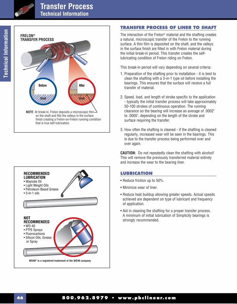
800.962.8979 • www.pbc l inear.com46
Tech
nica
l Inf
orm
atio
n TRANSFER PROCESS OF LINER TO SHAFT
The interaction of the Frelon® material and the shafting creates a natural, microscopic transfer of the Frelon to the running surface. A thin fi lm is deposited on the shaft, and the valleys in the surface fi nish are fi lled in with Frelon material during the initial break-in period. This transfer creates the self-lubricating condition of Frelon riding on Frelon.
This break-in period will vary depending on several criteria:
1. Preparation of the shafting prior to installation - it is best to clean the shafting with a 3-in-1 type oil before installing the bearings. This ensures that the surface will receive a full transfer of material.
2. Speed, load, and length of stroke specifi c to the application - typically the initial transfer process will take approximately 50-100 strokes of continuous operation. The running clearance on the bearing will increase an average of .0002" to .0005", depending on the length of the stroke and surface requiring the transfer.
3. How often the shafting is cleaned - if the shafting is cleaned regularly, increased wear will be seen in the bearings. This is due to the transfer process being performed over and over again.
CAUTION: Do not repeatedly clean the shafting with alcohol! This will remove the previously transferred material entirely and increase the wear to the bearing liner.
LUBRICATION
• Reduce friction up to 50%.
• Minimize wear of liner.
• Reduce heat buildup allowing greater speeds. Actual speeds achieved are dependent on type of lubricant and frequency of application.
• Aid in cleaning the shafting for a proper transfer process. A minimum of initial lubrication of Simplicity bearings is strongly recommended.
After
FRELONTRANSFER PROCESS
®
Before
NOTE: At break-in, Frelon deposits a microscopic film on the shaft and fills the valleys in the surface finish creating a Frelon-on-Frelon running condition that is true self-lubrication.
ShaftShaftShaft
RECOMMENDEDLUBRICATION• Waylube Oil• Light Weight Oils• Petroleum Based Grease• 3-in-1 oils
NOTRECOMMENDED• WD-40• PTFE Sprays• Fluorocarbons• Silicon Oils, Grease or Spray
WD40® is a registered trademark of the WD40 company
Transfer ProcessTechnical Information
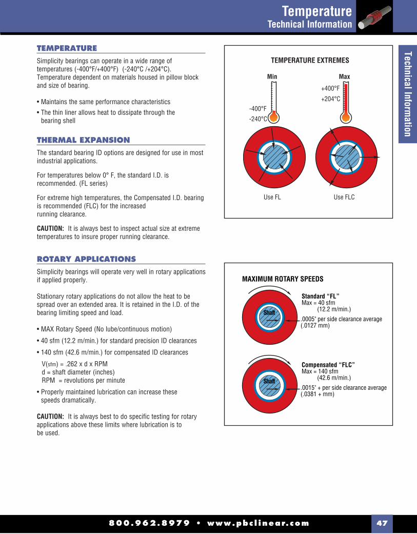
800.962.8979 • www.pbc l inear.com 47
Technical Information
TEMPERATURE
Simplicity bearings can operate in a wide range of temperatures (-400°F/+400°F) (-240°C /+204°C). Temperature dependent on materials housed in pillow block and size of bearing.
• Maintains the same performance characteristics
• The thin liner allows heat to dissipate through the bearing shell
THERMAL EXPANSION
The standard bearing ID options are designed for use in most industrial applications.
For temperatures below 0° F, the standard I.D. is recommended. (FL series)
For extreme high temperatures, the Compensated I.D. bearing is recommended (FLC) for the increased running clearance.
CAUTION: It is always best to inspect actual size at extreme temperatures to insure proper running clearance.
ROTARY APPLICATIONS
Simplicity bearings will operate very well in rotary applications if applied properly.
Stationary rotary applications do not allow the heat to be spread over an extended area. It is retained in the I.D. of the bearing limiting speed and load.
• MAX Rotary Speed (No lube/continuous motion)
• 40 sfm (12.2 m/min.) for standard precision ID clearances
• 140 sfm (42.6 m/min.) for compensated ID clearances
V(sfm) = .262 x d x RPM d = shaft diameter (inches) RPM = revolutions per minute
• Properly maintained lubrication can increase these speeds dramatically.
CAUTION: It is always best to do specifi c testing for rotary applications above these limits where lubrication is to be used.
TEMPERATURE EXTREMES
Use FL
Min
-400°F
-240°C
Use FLC
Max
+400°F
+204°C
MAXIMUM ROTARY SPEEDS
Standard “FL”Max = 40 sfm (12.2 m/min.)
.0005" per side clearance average(.0127 mm)
Shaft
Compensated “FLC”Max = 140 sfm (42.6 m/min.)
.0015" + per side clearance average(.0381 + mm)
Shaft
TemperatureTechnical Information

800.962.8979 • www.pbc l inear.com48
Tech
nica
l Inf
orm
atio
n OPEN BEARINGS ORIENTATION
Simplicity bearings can operate in any orientation.
Load capacities will vary on open bearings depending on the orientation in which they are being used.
CANTILEVERED LOADS
• Maximum 2:1 ratio• 1x = bearing separation on same shaft• 2x = distance from shaft to load or force
EXAMPLE: If 2x equals 10" then 1x must be at least 5"
CAUTION: BINDING will occur if the 2:1 ratio is exceeded!!
This principle is NOT load dependent! It is NOT due to edge loading. It is also NOT dependent on the driving force used! The bearings will bind whether hand or mechanically driven. This principle is a product of friction.
WORKING THROUGH THE FOLLOWING EQUATION WILL EXPLAIN WHY THIS IS A PRODUCT OF FRICTION:P = force being appliedL = distance out from shaft that P is being applieds = center to center spacing of bearingsf = resultant force on bearings by shaftF = friction force on each bearingμ = coeffi cient of friction (about .25 when not moving)
BALANCE THE MOMENTS: f * s = L * P L / s = f / P
COMPUTE FRICTION FORCE: F = f * μ
NOTE: Total friction force pushing up is 2 * F. To lock up the slide, the total friction force must be equal to (or greater than) P.
P = 2 * F = 2 * f * μ
SUBSTITUTE FOR P: L / s = f / ( 2 * f * μ) = 1 / ( 2 * μ ) = > L / s = 1 / ( 2 * μ )
NOTE: The forces drop out of the equation
Assume static coeffi cient of friction is .25 (μ = .25) then L / s = 2 That is the 2:1 ratio.
There may be other factors that add to the braking effect, but the coeffi cient of friction is the main cause. NOTE: Proper lubrication can help to drop friction and extend the 2:1 ratio.
100% Capacity 70% Capacity 40% Capacity
Load
Load
Load
Cantilevered LoadsTechnical Information

800.962.8979 • www.pbc l inear.com 49
Technical Information
Cantilevered LoadsTechnical Information
COUNTERBALANCE
If holding the 2:1 ratio is not possible, one method of preventing binding problems is using a counter balance.
For effi cient counter balances in horizontal applications, use this formula: M * Y = W * Z
NOTES: To avoid problems when running without mass: (M) Z = 1-1/2 s
W can be calculated - load on bearing will be:
M + W # of bearings
EXAMPLE: 50 * 24 = W * Z (Z = 1-1/2 * 6 = 9)
W = 50 * 24 = 133 lbs. 9
Load per bearing = 50 + 133 = 45.75 lbs. / bearing 4
CANTILEVER LOADS AND DRIVE FORCE LOCATION WITHOUT COUNTERBALANCEd = distance from shaft to Drive Force
l = distance from shaft to the load center of gravity
s = center to center spacing of the bearings on the shaft (If non-self-aligning, then outside to outside distance should be used.)
L = l / s = Load Force Ratio
D = d / s = Drive Force Ratio
GENERAL RULES:Drive Force Ratio (D) should never be larger than 2. A Drive Force Ratio (D) larger than 2 can cause the slide to lock up.
Load Force Ratio (L) can be larger than 2, but as this ratio increases, the drive force required to move the slide increases dramatically. A Load Force Ratio (L) larger than 4 is not recommended.
If the slide is occasionally operated unloaded, use the distance to the slide’s center of gravity as the distance to the load ( l ).
VERTICAL APPLICATIONS:If L is between 0 and 2, the lowest drive forces occur when the value of D is about 90% of L (D = .9 x L). However, D values between 0 and L will work fi ne.
If L is between 2 and 4, use this equation: D = 4 - L
HORIZONTAL APPLICATIONS:For best results, the drive force should be applied as close to the shaft as possible no matter what the value of the Load Force Ratio (L) is.
HANGING OR “TOP HEAVY” HORIZONTAL APPLICATIONS WITH HIGH ACCELERATION RATES:If your application will have high acceleration forces, use this formula for the value of the Drive Force Ratio: D = 0.8 x L x a where a is acceleration in g’s.

800.962.8979 • www.pbc l inear.com50
Tech
nica
l Inf
orm
atio
n
SEVERE MISALIGNMENT SOLUTIONS
Linear ball bearings will continue to operate in a misaligned condition, but will cause damage to shafting and catastrophically fail.
Simplicity bearings DO NOT tolerate misalignment. They simply will stop moving without any damage to the shafting. Self-aligning housings will aid in misalignment - up to 1/2° from centerline.
POSSIBLE SOLUTIONS for use with Standard “FL”: Undersize the bearing O.D. (see chart) and install o-rings. See product pages for o-ring numbers.
Oversize the housing I.D. (see chart) and install the standard bearing with o-rings. See product pages for o-ring part numbers.
The additional clearance created by either method will allow the bearing to fl oat in the housing and match the non-parallelism of the shafting.
CAUTION: This solution is only for SEVERE cases that the standard self-aligning will not accommodate.
NOTE: Maximum additional clearance and o-ring information for severe misalignment solutions on page 61. For complete installation instructions, see pages 58-61 in the Technical Section.
Misalignment & Chemical ResistanceTechnical Information
SUBMERGED APPLICATIONS
Simplicity bearings will provide excellent performance in a submerged condition.
The bearings will employ the fl uid as a lubricant showing increased velocities and wear life. Oils and non-salt water are especially effective.
NOTE: Please contact manufacturer before specifying FrelonGOLD for submerged applications.
VACUUMS/OUTGASSING/CLEANROOMS
Due to self-lubrication, low outgassing, and a minimum of particulate (buildup), Simplicity bearings are excellent in clean rooms and vacuums.
Testing has been done on the Frelon® materials in accordance with ASTM E-595-90 with acceptable maximums of 1.00% TML and .10% CVCM.
MATERIAL % TML % CVCM Frelon 0.00 0.00 FrelonJ 0.18 0.01
TML = Total Mass LossCVCM = Collected Volatile Condensible Materials
ADDITIONALDIAMETRICALCLEARANCE
O-rings act as a cushion allowing the bearig to fl oat
HOUSING
CHEMICAL RESISTANCE
Simplicity bearings stand up to harsh environments.
FrelonJ® – almost universal chemical inertness. Only molten sodium and fl ourine at elevated temperatures and pressures show any signs of attack.
FrelonGOLD® – the fi llers in the material can be attacked by deionized water and other harsh chemicals.
Anodized Aluminum Shell (Standard) – good chemical resistance in most industrial applications.
316 Stainless Steel Shell (Optional) – excellent chemical and corrosion resistance in harsh environments. (See page 62 for complete chemical interaction listing.)

800.962.8979 • www.pbc l inear.com 51
Technical Information
CLASSES OF PLANE BEARINGS
Simplicity bearings are in a class of bearings known as plane bearings, which means that they have no rolling elements. There are three classes of plane bearings:
Class I - Require an outside source of lubrication (oil, grease, etc.).
Class II - Lubrication is impregnated within the walls of the bearing. (Bronze, powder metal, etc.) Typically these bearings require an added lubricant also.
Class III - Self-lubricating bearings, which do not require added lubricants.
Simplicity bearings are Class III plane bearings and are self-lubricating.
RATING A PLANE BEARING
Plane bearing performance capacity is rated by PV.
P - pressure or load in pounds per square inch (psi) or kilograms per square centimeter (kg/cm2).
V - velocity or surface speed in feet per minute (fpm or sfm) or meters per minute (m/min.).
PV - pressure velocity value. (Pressure x Velocity)
SIMPLICITY MAXIMUM PERIMETER
NOTE: All three parameters must be met in order for the bearing to operate properly.
FORMULAS FOR RATINGS
PRESSURE IS OVER THE PROJECTED AREA OF LOAD:A = L x d
P = w psi (or kg/cm2)A
VELOCITY:Linear = total distance traveled in one minute
ROTATIONAL VELOCITY:V = � x d x n fpm (or m/min.)
12
PRESSURE VELOCITY VALUE (PV):PV = P x V psi x fpm (or kg/cm2 x m/min.)
n
W
L
dW = max. load
L = bearing length
d = shaft diameter
A = projected contact area
n = rotational speed (rpm)
PROJECTED AREA:
A = L x d(Approx. 1/3 or total liner surface area)
MAXIMUMPARAMETERS P
V(RUNNING DRY) PV
FrelonJ®
1500 psi or
105.45 kgf/cm2
140 sfm or
42.67 m/min.
10,000 psi x ft./min.or
215 kgf/cm2 x m/min.
FrelonGOLD®
3000 psi or
210.9 kgf/cm2
300 sfmor
91.44 m/min.
20,000 psi x ft./min.or
430 kgf/cm2 x m/min.
PV EQUIVALENTSINCH TECHNICAL
METRICINT’L METRIC
(SI)
LOAD 1 psi .0703 kgf/cm2 .0069 N/mm2
VELOCITY 1 ft./min. .3048 m/min. .00508 m/sec.
PV 1 PV .0214 PV .000036 PV
FrelonJ®
MAX PV 10,000 215 .36
FrelonGOLD®
MAX PV 20,000 430 .72
RatingsTechnical Information

800.962.8979 • www.pbc l inear.com52
Tech
nica
l Inf
orm
atio
n WEAR RATE VS. LIFE EXPECTANCY
FrelonGOLD® LINEAR WEAR TEST
WEAR in INCHES
INCHES of TRAVEL
HOURSOPERATED
FrelonGOLD®
.005
.004
.003
.002
.0010
30
3,02
4,00
0
6,04
8,00
0
9,07
2,00
0
12,0
96,0
00
15,1
20,0
00
18,1
44,0
00
21,1
68,0
00
24,1
92,0
00
27,2
16,0
00
30,2
40,0
00
33,2
64,0
00
36,2
88,0
00
39,3
12,0
00
42,3
36,0
00
45,3
60,0
00
48,3
84,0
00
51,4
08,0
00
54,4
32,0
00
57,4
56,0
00
60,4
80,0
00
63,5
04,0
00
66,5
28,0
00
69,5
52,0
00
72,5
76,0
00
75,6
00,0
00
78,6
24,0
00
81,6
48,0
00
84,6
72,0
00
87,6
96,0
00
90,7
20,0
00
93,7
44,0
00
96,7
68,0
00
99,7
92,0
00
102,
816,
000
105,
840,
000
60 90 120 150 180 210 240 270 300 330 360 390 420 450 480 510 540 570 600 630 660 690 720 750 780 810 840 870 900 930 960 990 1020 1050
.006
#4
B53 lbs.
#2
#3 #1
BOTTOM
MIDDLE
TOP
BOTTOM
MIDDLE
TOP
#4
A53 lbs.
CONNECTIONTO DRIVE
#2
#3 #1
BOTTOM
BOTTOM
MIDDLE
TOP
MIDDLE
TOP
5
19
5
4.5
CONDUCTED BY: Pacifi c Bearing® CompanyBEARING MATERIAL: FrelonGOLD®
SHAFT MATERIAL: Standard RC60 steel shaftingSURFACE FINISH: 8-12 RMSSPEED: 140 fpm (70 cycles/min; 1,680"/min; 100,800"/hour; 2,419,200"/day)STROKE: 12"
LOAD: 10.87 psi (53 lbs.)BEARINGS USED: FLN12 (3/4" open style bearings)LUBRICATION: NoneTOTAL WEAR TO BEARING MATERIAL:FrelonGOLD® = .00042"NOTE: Wear is an average of totals taken from 4 bearings per carriage.
A rolling element linear bearing’s life expectancy is usually expressed in total inches or meters. A rolling element rotary bearing’slife expectancy is expressed in hours of operation. Both are also rated for average (L-50) and minimum (L-10) life. L-50 life isthe average life that can be expected from 50% of rolling element bearings. In other words, 50% will not reach the average lifeexpectancy. L-10 life is the minimum life (1/5 the average life) expected from 90% of rolling element bearings. In other words,10% will not reach the minimum life expectancy. Theoretically they could fail upon installation.
Plane bearings are not rated by a life expectancy but by the wear rate of the bearing material. Wear is greatly dependent upon the proper application of the bearing and material used. If it is not properly applied, it will fail. Failure, however, is subjective and dependent upon specifi c application requirements. 0.002" running clearance may not be acceptable in one application while another may be able to run a bearing until the liner is completely worn through. The user may then rotate it 30 degrees and continue torun it. This broad range of acceptability makes it diffi cult to determine life expectancy.
The fi rst step is to determine what wear is acceptable for your application. Then utilizing the test data below, you can estimate thewear expected for your given application.
WEAR TEST SAMPLE
Wear RateTechnical Information

800.962.8979 • www.pbc l inear.com 53
Technical Information
COEFFICIENT OF FRICTION
FRICTION TEST SAMPLE #2
CONDUCTED BY: FrelonGOLD® material processorBEARING MATERIAL: FrelonGOLD®
SHAFT MATERIAL: CRS 1018SPEED: 100 fpmLOAD: 100 psiDURATION: 25.68 hoursLUBRICATION: None
SURFACE FINISH: 8 RMSAVERAGE COF: 0.10MAX. COF: 0.15MIN. COF: 0.08AVG. RUNNING TEMP.: 95.40° F
A frequent misconception of plane bearings is that wear and friction are basically synonymous, in that, high friction equals highwear or that low friction equals low wear. While there can be a relation between the two, they should be addressed as separate issues in the design process.
For example, dry running virgin (unfi lled) Tefl on® on steel’s coeffi cient of friction (c.o.f.) is approximately .1 while fi lled Tefl on’s c.o.f. can range from .125 to .4 depending on the fi llers used. By comparison, however, the virgin Tefl on will wear at a much greater rate.
.30
.25
.35
.20
.15
.10
.5
.0DRY
FRIC
TION
COE
FFIC
IENT
FrelonGOLD®
TEST PARAMETERSSPEED: 50 mm/sLOAD: 6 NHUMIDITY: 10%TEMP.: 25 CRunning on Steel210mm/s for 3 min.
CONDUCTED BY: Dr. Tillwich GmbH
MANAGING DIRECTOR: Mr. Werner Stehr (World leading tribologist with a seat on the ISOTC123 Committee establishing standards for tribological testing.)
BEARING MATERIAL: FrelonGOLD®
SHAFT MATERIAL: Standard RC60 steel shafting
SURFACE FINISH: 8-12 RMS
SPEED: 50 mm/sec
LOAD: 6 N
TEMP.: 25° C
LUBRICATION: None
AVG. COEFFICIENT OF FRICTION: FrelonGOLD® = .125
FRICTION TEST SAMPLE #1
COEFFICIENT of FRICTION.12
.11
.1
.09
.080 2 4 6 8 10 12 14 16 18 20 22 24 25.68
Coeffi cient of FrictionTechnical Information

800.962.8979 • www.pbc l inear.com54
Tech
nica
l Inf
orm
atio
n LOAD CAPACITY (Pressure)
Depending upon the material used, a plane bearing’s load capacity can greatly exceed a rolling element bearing. There are three basic reasons for this:
1. The area of surface contact with the shaft is far greater than rolling element bearings, which have point-to-point contact with a given number of balls.
2. A rolling element bearing must be oriented properly for the ball tracks to carry the load adequately, while a plane bearing can be mounted in any orientation.
3. Only one or two of the tracks in a rolling element bearing will actually carry any of the load applied.
Simplicity bearings have a thin liner that is bonded to a metal shell at the molecular level, allowing the load to be transferred throughout the bearing. This gives it an advantage over other plane bearings of solid plastic or polymer materials. These other materials will tend to “cold fl ow” under pressure. “Cold fl ow” means to deform or lose shape. The idea is similar to pressing your fi nger into a bar of soap - material will move or deform as pressure is applied.
LINEAR SURFACE SPEEDS (Velocity)
In typical applications, speed is a known quantity and easily converted. Typically feet per minute or meters per minute are used. The most important factor that speed (along with friction) produces is heat buildup. This is not a critical factor in most linear applications because the heat is dissipated over the length of travel, and it does not affect the bearing. Short stroke or extremely high speed applications may see the effects of heat buildup in thermal expansion and the bearing ID locking on the shaft. A compensated ID bearing (FLC) is recommended in these applications.
FACTORS THAT CONTRIBUTE TO WEAR LIFE
Proper mating of shaft and liner materials.
Surface fi nish 8-16 RMS (.20-.40mm) is required. Peaks in the surface that are polished to a radius provide the best running surface. Sharp peaks in the fi nish will be like a fi ne lapping compound wearing the I.D. of the bearing.
NOTE: Shafting damaged by use with ball bearings can be salvaged and used with Simplicity bearings. Spin in a lathe and polish with sand papers in this order: 120 grit, 180 grit, and 300 grit. This will also remove sharp peaks in the surface fi nish.
Surface speed - at high speeds, heat buildup will affect liner wear.
Break-in transfer - proper transfer process of the liner to the shaft. (pg. 46)
Lubrication - proper lubrication can greatly improve the wear rate of a bearing. At the same time, improper lubrication can increase wear and failure.
Load & Wear Relationship - Wear rate is proportional to load to the third power. (wear rate x (load)3.
If load is reduced to 1/2, wear will be reduced to (1/2)3.
Contamination - while migrating into the bearing and embedding into the liner, certain types of contamination may, over time, cause increased wear to the liner.
NOTE: This is not an all inclusive list. There are many, many more factors within an application that can affect wear to different degrees. These are the major issues and the fi rst things to address in a design.
Load CapacityTechnical Information

800.962.8979 • www.pbc l inear.com 55
Technical Information
TYPES AND EFFECTS OF LUBRICATION
Lubrication is any outside technique used for reducing the friction, wear, or both of a bearing. Proper lubrication of Simplicity bearings is critical. Evaluate lubrication needs on an application by application basis to determine whether or not it should be used at all, what type is needed, and how it is applied. Below are some criteria on which to base the lubricant decision:
DO NOT USE WD40™, PTFE sprays, or other oils, greases, or sprays that contain fl uorocarbons or silicone. In testing, these lubricants have proven to cause long-term stick-slip problems with the Frelon lined bearings. They tend to become a gummy substance that ultimately increases friction.
RECOMMENDED LUBRICANTS:
• Waylube oils
• Lightweight oils
• 3-in-1 type oils
• Lightweight petroleum based greases
WD40™ is a registered trademark of the WD40 Corporation.
USING OILS WITH SIMPLICITY
DO NOT USE ANY TYPE OF MOTOR OIL OR OILS WITH ADDITIVES! These types of oils work well short term, but quickly become ineffective, and will cause stick-slip reactions in the bearing. As a rule of thumb, the less additives in the oil, the better the performance. Recommended oils are Mobil Vactra #2 (a way lube oil) and any standard 3-in-1 oil. The 3-in-1 oils are tremendous cleaning oils and are the best in preparing for a proper transfer of tefl on to the shafting.
GREASE PRODUCTS
DO NOT USE A MOLY FILLED OR OTHER TYPE FILLED GREASES! They become like a lapping compound on the ID of the bearing and increase wear dramatically.
PROPER USE OF GREASES
Proper use of grease is critical for trouble-free operation.
Be sure the felt wick is removed from a “FL-xx-JKM” bearing because grease inserted through the zerk will cause the wick to act like a brake.
Do not fi ll all of the running clearance with grease! Thetemptation is to treat it like a rolling element bearing and fi ll it until it weeps from the end. This will cause greater friction and binding.
The rule of thumb for the bearing liner that “thin is better” applies to the use of grease also.
If grease is used and does not work in the application, it is possible to salvage the bearing with minimal work and to continue to operate. Follow the steps below:
1. If possible, remove the bearing from the housing, wipe the grease from the liner, use a 3-in-1 type oil to clean the excess remaining grease, and reinstall.
2. If it is not possible to remove the bearing, wipe as much grease as possible away from the ends of the bearing, then start to fi ll with a 3-in-1 type oil for cleaning the liner. To speed the cleaning process, apply forced air to the bearing through the zerk hole and continue using oil lubrication.
EFFECTS OF LUBRICATION
Lubrication can greatly increase the performance of a bearing when applied properly as noted earlier. Actual performance results for specifi c applications are diffi cult to predict due to the number of elements involved (temperature change with lube, useable life or aging of lubricant, etc.). Specifi c application testing is recommended to establish specifi c performance parameters. Below are charts with guidelines of performances.
Types & Effects of LubricationTechnical Information
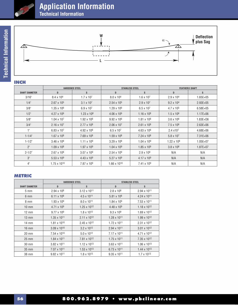
800.962.8979 • www.pbc l inear.com56
Tech
nica
l Inf
orm
atio
n
Deflectionplus Sag
W
L
α
INCH
METRIC
SHAFT DIAMETER
HARDENED STEEL STAINLESS STEEL FEATHER® SHAFT
D S D S D S
3/16" 8.4 x 10⁴ 1.7 x 10⁷ 8.0 x 10⁴ 1.6 x 10⁷ 2.9 x 10⁴ 1.65E+05
1/4" 2.67 x 10⁵ 3.1 x 10⁷ 2.54 x 10⁵ 2.9 x 10⁷ 9.2 x 10⁴ 2.93E+05
3/8" 1.35 x 10⁶ 6.9 x 10⁷ 1.29 x 10⁶ 6.5 x 10⁷ 4.7 x 10⁵ 6.58E+05
1/2" 4.27 x 10⁶ 1.23 x 10⁸ 4.06 x 10⁶ 1.16 x 10⁸ 1.5 x 10⁶ 1.17E+06
5/8" 1.04 x 10⁷ 1.92 x 10⁸ 9.92 x 10⁶ 1.81 x 10⁸ 3.6 x 10⁶ 1.83E+O6
3/4" 2.16 x 10⁷ 2.77 x 10⁸ 2.06 x 10⁷ 2.61 x 10⁸ 7.5 x 10⁶ 2.63E+06
1" 6.83 x 10⁷ 4.92 x 10⁸ 6.5 x 10⁷ 4.63 x 10⁸ 2.4 x10⁷ 4.68E+06
1-1/4" 1.67 x 10⁸ 7.69 x 10⁸ 1.59 x 10⁸ 7.24 x 10⁸ 5.8 x 10⁷ 7.31E+06
1-1/2" 3.46 x 10⁸ 1.11 x 10⁹ 3.29 x 10⁸ 1.04 x 10⁹ 1.22 x 10⁸ 1.05E+07
2" 1.09 x 10⁸ 1.97 x 10⁹ 1.04 x 10⁹ 1.85 x 10⁹ 3.8 x 10⁸ 1.87E+07
2-1/2" 2.67 x 10⁸ 3.07 x 10⁹ 2.54 x 10⁹ 2.9 x 10⁹ N/A N/A
3" 5.53 x 10⁹ 4.43 x 10⁹ 5.27 x 10⁹ 4.17 x 10⁹ N/A N/A
4" 1.75 x 10¹⁰ 7.87 x 10⁹ 1.66 x 10¹⁰ 7.41 x 10⁹ N/A N/A
SHAFT DIAMETER
HARDENED STEEL STAINLESS STEEL
D S D S
5 mm 2.94 x 10⁸ 3.12 x 10¹¹ 2.8 x 10⁸ 2.94 x 10¹¹
6 mm 6.11 x 10⁸ 4.5 x 10¹¹ 5.81 x 10⁸ 4.24 x 10¹¹
8 mm 1.93 x 10⁹ 8.0 x 10¹¹ 1.84 x 10⁹ 7.53 x 10¹¹
10 mm 4.71 x 10⁹ 1.25 x 10¹² 4.48 x 10⁹ 1.18 x 10¹²
12 mm 9.77 x 10⁹ 1.8 x 10¹² 9.3 x 10⁹ 1.69 x 10¹²
13 mm 1.35 x 10¹¹ 2.11 x 10¹² 1.28 x 10¹¹ 1.99 x 10¹²
14 mm 1.81 x 10¹⁰ 2.45 x 10¹² 1.72 x 10¹¹ 2.31 x 10¹²
16 mm 3.09 x 10¹⁰ 3.2 x 10¹² 2.94 x 10¹¹ 3.01 x 10¹²
20 mm 7.54 x 10¹⁰ 5.0 x 10¹² 7.17 x 10¹¹ 4.71 x 10¹²
25 mm 1.84 x 10¹¹ 7.81 x 10¹² 1.75 x 10¹¹ 7.35 x 10¹²
30 mm 3.82 x 10¹¹ 1.12 x 10¹³ 3.63 x 10¹¹ 1.06 x 10¹³
35 mm 7.07 x 10¹¹ 1.53 x 10¹³ 6.73 x 10¹¹ 1.44 x 10¹³
38 mm 9.82 x 10¹¹ 1.8 x 10¹³ 9.35 x 10¹¹ 1.7 x 10¹³
Application InformationTechnical Information

12"
α0.0513"
800.962.8979 • www.pbc l inear.com 57
Technical Information
SHAFT DEFLECTION
In applications where a support rail is not used, shaft defl ection can become critical in the function of the bearing. If defl ection is greater than the misalignment capabilities of a standard pillow block, binding can occur. Solutions would be to increase shaft and bearing size (to lessen the amount of defl ection) or to use an open bearing confi guration with a support rail. Follow the formulas below to check shaft defl ection and sag.
FORMULA FOR INCH AND METRIC SHAFTING DEFLECTIONTotal shaft defl ection in horizontal applications:
Tot. Def = Def + Sag
Def = w x L3 / D
Sag = L4 / S
Def = Pure defl ection due to load at center of shaft (inches or mm)
Sag = Defl ection of shaft due to its own weight (inches or mm)
L = Shaft unsupported length (inches or mm)
w = load being applied at center of shaft (lbs. or N)
D = Defl ection coeffi cient (D = 48 x E x I)
S = Sag coeffi cient (S = E x I x 384 / (5 x sw))
NOTES: I = � x diam4 / 64
sw = � x diam2 / 4 x density
E = Modulus of Elasticity (Young’s modulus)
TOTAL DEFLECTION
ø1 in. Shaft
24 in. Length (L)
250 lbs. load (W)
Defl ection = W x L3
D (from table)
= 250 lbs. x (24 in.)3
6.83 x 107
= 3,456,000 in.3 lbs. 68,300,000 in.2 lbs.
Defl ection = 0.0506 in.
SAG = L4
S (from table)
= (24)4
4.92 x 10⁸
SAG = 331,776 in.4 492,000,000 in.3
SAG = .000674 in.
Total Defl ection = Defl ection + SAG
= 0.0506 in. + .000674 in.
Total Defl ection = 0.0513 in.
� = tan-1 0 A
� = tan-1 0.0153 in. 12 in.
� = 0.2449° Displacement Angle
0.2449° < 1/2° Allowable = Good Design
DISPLACEMENT ANGLE
Defl ectionTechnical Information

800.962.8979 • www.pbc l inear.com58
Tech
nica
l Inf
orm
atio
n INSTALLING SIMPLICITY® BEARINGSApplies to standard linear bearing series.
For sleeve and fl ange bearings, see product pages in the catalog.
PS - Page 154, PSM - Page 156, PSF - Page 155, PSFM - Page 157
STRAIGHT BORE HOUSING - PRESS FIT BEARINGThis type of confi guration is NOT recommended for the vast majority of applications using Simplicity bearings.
It does NOT allow for any misalignment or shaft defl ection.
Misalignment or shaft defl ection will cause the bearing to bind on the shafting.
Extremely high precision applications may be able to employ this type of mounting. Typically the shafting has been aligned with a laser or some other highly precise equipment.
Due to bore closure in the pressing process, use a “C” series (compensated I.D.) bearing. EXAMPLE: FLC24, FMC30, FJC30
The recommended installation procedure is to freeze the bearings at 0°F (-17.75°C) for 30-45 minutes. Using gloves, remove the bearings from the freezer and slip them into the housing. As they heat to room temperature, full contact between bearing and housing will be achieved. The greatest advantage to this technique over traditional pressing is greater accuracy in alignment.
This type of mounting will not allow for misalignment or shaft defl ection. Both are very critical in the smooth operation of Simplicity bearings. A rolling element bearing may appear to initially operate in this condition, but it is operating in an extremely preloaded condition and will prematurely fail and in most cases destroy the shafting. Simplicity bearings will indicate the problem immediately upon installation by failing to move due to the binding condition. There are alternative mounting options that work extremely well.
NOTE: Use “C” (compensated I.D.) series bearings.
PART NO.
MIN.HOUSING
I.D.
MAX.HOUSING
I.D. PART NO.
MIN.HOUSING
I.D.
MAX.HOUSING
I.D. PART NO.
MIN.HOUSING
I.D.
MAX.HOUSING
I.D. PART NO.
MIN.HOUSING
I.D.
MAX.HOUSING
I.D. PART NO.
MIN.HOUSING
I.D.
MAX.HOUSING
I.D.
(inches) (inches) (mm) (mm) (mm) (mm) (mm) (mm) (mm) (mm)
FLC03 0.3729 0.3737 FMC05 11.972 11.995 FMTC06 11.954 11.972 FGC06 11.952 11.970 FJC06 11.961 11.979
FLC04 0.4978 0.4986 FMC08 15.954 15.972 FMTC08 14.954 14.972 FGC08 14.952 14.970 FJHC08 14.961 14.979
FLC06 0.6228 0.6236 FMC10 18.948 18.969 FMTC10 16.954 16.972 FGC10 16.952 16.970 FJC08 14.961 14.979
FLC08 0.8725 0.8734 FMC12 21.944 21.965 FMTC12 18.948 18.969 FGC12 21.945 21.966 FJC10 18.952 18.973
FLC10 1.1224 1.1234 FMC16 25.944 25.965 FMTC14 20.944 20.965 FGC15 24.945 24.966 FJC12 20.952 20.997
FLC12 1.2474 1.2484 FMC20 31.940 31.961 FMTC16 23.944 23.965 FGC16 25.945 25.966 FJC13 22.952 22.973
FLC16 1.5596 1.5607 FMC25 39.932 39.957 FMTC20 27.944 27.965 FGC18 27.945 27.966 FJC16 27.952 27.973
FLC20 1.9970 1.9981 FMC30 46.932 46.957 FMTC25 34.940 34.961 FGC20 31.945 31.966 FJC20 31.950 31.971
FLC24 2.3717 2.3729 FMC40 61.917 61.947 FMTC30 39.932 39.957 FGC25 39.937 39.962 FJC25 39.941 39.966
FLC32 2.9965 2.9977 FMC50 74.917 74.947 FMTC40 51.932 51.957 FGC30 44.937 44.962 FJC30 44.941 44.966
FLC40 3.7461 3.7473 FMC60 89.906 89.936 FMTC50 61.917 61.947 FGC35 51.937 51.962 FJC35 51.938 51.963
FLC48 4.4953 4.4966 FMC80 119.886 119.921 FGC40 59.927 59.957 FJC38 56.938 56.963
FLC64 5.9949 5.9963 FGC50 74.927 74.957 FJC40 59.928 59.958
FJC50 79.922 79.952
FJC60 89.919 89.949
FJC80 119.899 119.934
FJC100 149.896 149.931
FJC120 179.875 179.915
FJC150 209.849 209.895
InstallationTechnical Information

800.962.8979 • www.pbc l inear.com 59
Technical Information
STRAIGHT BORE HOUSING - SLIP FIT BEARING
There are three basic confi gurations that work well, depending on the misalignment and shaft defl ection in the application:
1. VIRTUALLY NO MISALIGNMENT
This method allows for NO or very little shaft defl ection and misalignment. Standard I.D. bearings will need tighter alignment than a“C” series (compensated I.D.) bearing. Standard retention methods are acceptable. EXAMPLE: snap rings, epoxy, etc.
NOTE: If using epoxy, do not touch the bearing liner with the bonding agent!This type of mounting will allow for minimum misalignment or shaft defl ection. Both are very critical in the smooth operation of Simplicity bearings. A rolling element bearing may appear to initially operate in this condition, but it is operating in an extremelypreloaded condition and will prematurely fail and in most cases destroy the shafting. Simplicity bearings will indicate the problemimmediately upon installation by failing to move due to the binding condition.
PART NO.
MIN.HOUSING
I.D.
MAX.HOUSING
I.D.
PART NO.
MIN.HOUSING
I.D.
MAX.HOUSING
I.D.
PART NO.
MIN.HOUSING
I.D.
MAX.HOUSING
I.D.
PART NO.
MIN.HOUSING
I.D.
MAX.HOUSING
I.D.
PART NO.
MIN.HOUSING
I.D.
MAX.HOUSING
I.D.
(inches) (inches) (mm) (mm) (mm) (mm) (mm) (mm) (mm) (mm)
FL03 0.3755 0.3764 FM05 12.016 12.043 FMT06 12.016 12.043 FG06 12.016 12.043 FJ06 12.016 12.043
FL04 0.5006 0.5017 FM08 16.016 16.043 FMT08 15.016 15.043 FG08 15.016 15.043 FJH08 15.016 15.043
FL06 0.6256 0.6267 FM10 19.020 19.053 FMT10 17.016 17.043 FG10 17.016 17.043 FJ08 15.016 15.043
FL08 0.8758 0.8771 FM12 22.020 22.053 FMT12 19.020 19.053 FG12 22.020 22.053 FJ10 19.020 19.053
FL10 1.1258 1.1271 FM16 26.020 26.053 FMT14 21.020 21.053 FG15 25.020 25.053 FJ12 21.020 21.053
FL12 1.2510 1.2525 FM20 32.025 32.064 FMT16 24.020 24.053 FG16 26.020 26.053 FJ13 23.020 23.053
FL16 1.5635 1.5650 FM25 40.025 40.064 FMT20 28.020 28.053 FG18 28.020 28.053 FJ16 28.020 28.053
FL20 2.0012 2.0030 FM30 47.025 47.064 FMT25 35.025 35.064 FG20 32.025 32.064 FJ20 32.025 32.064
FL24 2.3762 2.3780 FM40 62.030 60.076 FMT30 40.025 40.064 FG25 40.025 40.064 FJ25 40.025 40.064
FL32 3.0012 3.0030 FM50 75.030 75.076 FMT40 52.030 52.076 FG30 45.025 45.064 FJ30 45.025 45.064
FL40 3.7514 3.7535 FM60 90.036 90.090 FMT50 62.030 62.076 FG35 52.030 52.076 FJ35 52.030 52.076
FL48 4.5014 4.5035 FM80 120.036 120.090 FG40 60.030 60.076 FJ38 57.030 57.076
FL64 6.0017 6.0042 FG50 75.030 75.076 FJ40 60.030 60.076
FJ50 80.030 80.076
FJ60 90.036 90.090
FJ80 120.036 120.090
FJ100 150.043 150.106
FJ120 180.043 180.106
FJ150 210.050 210.122
InstallationTechnical Information
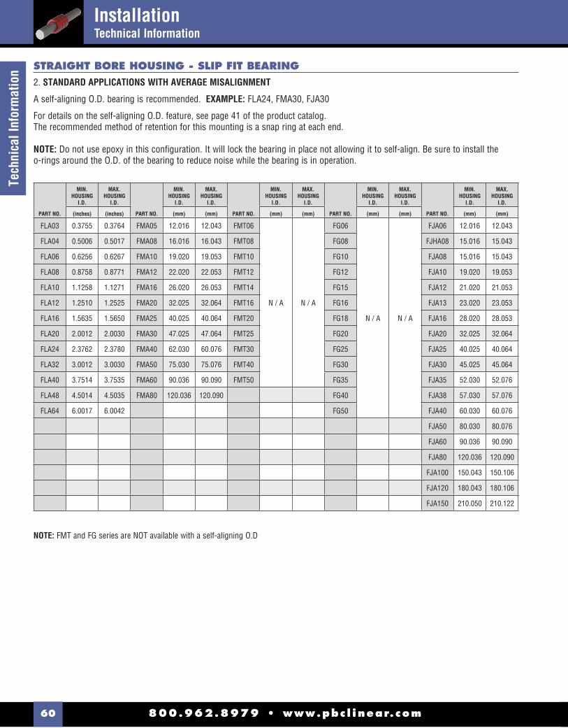
800.962.8979 • www.pbc l inear.com60
Tech
nica
l Inf
orm
atio
n
NOTE: FMT and FG series are NOT available with a self-aligning O.D
STRAIGHT BORE HOUSING - SLIP FIT BEARING2. STANDARD APPLICATIONS WITH AVERAGE MISALIGNMENT
A self-aligning O.D. bearing is recommended. EXAMPLE: FLA24, FMA30, FJA30
For details on the self-aligning O.D. feature, see page 41 of the product catalog.The recommended method of retention for this mounting is a snap ring at each end.
NOTE: Do not use epoxy in this confi guration. It will lock the bearing in place not allowing it to self-align. Be sure to install theo-rings around the O.D. of the bearing to reduce noise while the bearing is in operation.
PART NO.
MIN.HOUSING
I.D.
MAX.HOUSING
I.D.
PART NO.
MIN.HOUSING
I.D.
MAX.HOUSING
I.D.
PART NO.
MIN.HOUSING
I.D.
MAX.HOUSING
I.D.
PART NO.
MIN.HOUSING
I.D.
MAX.HOUSING
I.D.
PART NO.
MIN.HOUSING
I.D.
MAX.HOUSING
I.D.
(inches) (inches) (mm) (mm) (mm) (mm) (mm) (mm) (mm) (mm)
FLA03 0.3755 0.3764 FMA05 12.016 12.043 FMT06
N / A N / A
FG06
N / A N / A
FJA06 12.016 12.043
FLA04 0.5006 0.5017 FMA08 16.016 16.043 FMT08 FG08 FJHA08 15.016 15.043
FLA06 0.6256 0.6267 FMA10 19.020 19.053 FMT10 FG10 FJA08 15.016 15.043
FLA08 0.8758 0.8771 FMA12 22.020 22.053 FMT12 FG12 FJA10 19.020 19.053
FLA10 1.1258 1.1271 FMA16 26.020 26.053 FMT14 FG15 FJA12 21.020 21.053
FLA12 1.2510 1.2525 FMA20 32.025 32.064 FMT16 FG16 FJA13 23.020 23.053
FLA16 1.5635 1.5650 FMA25 40.025 40.064 FMT20 FG18 FJA16 28.020 28.053
FLA20 2.0012 2.0030 FMA30 47.025 47.064 FMT25 FG20 FJA20 32.025 32.064
FLA24 2.3762 2.3780 FMA40 62.030 60.076 FMT30 FG25 FJA25 40.025 40.064
FLA32 3.0012 3.0030 FMA50 75.030 75.076 FMT40 FG30 FJA30 45.025 45.064
FLA40 3.7514 3.7535 FMA60 90.036 90.090 FMT50 FG35 FJA35 52.030 52.076
FLA48 4.5014 4.5035 FMA80 120.036 120.090 FG40 FJA38 57.030 57.076
FLA64 6.0017 6.0042 FG50 FJA40 60.030 60.076
FJA50 80.030 80.076
FJA60 90.036 90.090
FJA80 120.036 120.090
FJA100 150.043 150.106
FJA120 180.043 180.106
FJA150 210.050 210.122
InstallationTechnical Information

800.962.8979 • www.pbc l inear.com 61
Technical Information
STRAIGHT BORE HOUSING - SLIP FIT BEARING3. SEVERE MISALIGNMENT
A standard O.D. bearing is recommended. EXAMPLE: FL24, FM30, FJ30
Oversize the I.D. of the housing and install the bearing with o-rings. This will allow the bearing to “fl oat” in the housing and match the misalignment or non-parallelism of the shafting.
The recommended method of retention for this mounting is a snap ring at each end.
NOTE: Do not use epoxy in this confi guration. It will lock the bearing in place, not allowing it to self-align.
See page 50 of the product catalog for more details on this solution.
PART NO.
MAX. ADDITIONAL CLEARANCE
PART NO.
MAX. ADDITIONAL CLEARANCE
PART NO.
MAX. ADDITIONAL CLEARANCE
PART NO.
MAX. ADDITIONAL CLEARANCE
PART NO.
MAX. ADDITIONAL CLEARANCE
(inches) (mm) (mm) (mm) (mm)
FL03 0.0070 FM05
0.203
FMT06
0.203
FG06
0.203
FJ06
0.203
FL04
0.0080
FM08 FMT08 FG08 FJH08
FL06 FM10 FMT10 FG10 FJ08
FL08 FM12 FMT12 FG12 FJ10
FL100.0100
FM160.254
FMT14 FG15
0.254
FJ12
FL12 FM20 FMT16
0.254
FG16 FJ13
FL16
0.0120
FM25
0.305
FMT20 FG18 FJ160.254
FL20 FM30 FMT25 FG20 FJ20
FL24 FM40 FMT30
0.305
FG25
0.305
FJ25
0.305
FL32 FM50 FMT40 FG30 FJ30
FL400.0160
FM60 0.406 FMT50 FG35 FJ35
FL48 FM80 0.508 FG40 FJ38
FL64 0.0200 FG50 FJ40
FJ500.406
FJ60
FJ80 0.508
FJ100
0.610FJ120
FJ150
InstallationTechnical Information
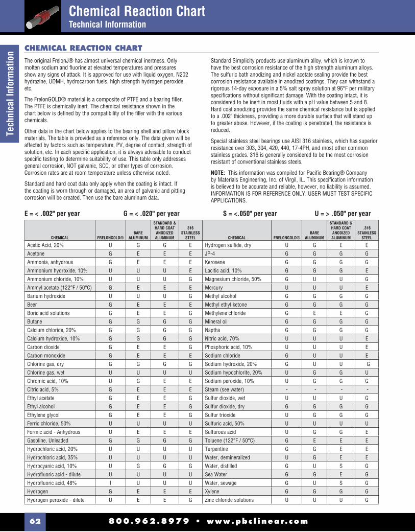
800.962.8979 • www.pbc l inear.com62
Tech
nica
l Inf
orm
atio
n
The original FrelonJ® has almost universal chemical inertness. Only molten sodium and fl uorine at elevated temperatures and pressures show any signs of attack. It is approved for use with liquid oxygen, N202 hydrazine, UDMH, hydrocarbon fuels, high strength hydrogen peroxide, etc.
The FrelonGOLD® material is a composite of PTFE and a bearing fi ller. The PTFE is chemically inert. The chemical resistance shown in the chart below is defi ned by the compatibility of the fi ller with the various chemicals.
Other data in the chart below applies to the bearing shell and pillow block materials. The table is provided as a reference only. The data given will be affected by factors such as temperature, PV, degree of contact, strength of solution, etc. In each specifi c application, it is always advisable to conduct specifi c testing to determine suitability of use. This table only addresses general corrosion, NOT galvanic, SCC, or other types of corrosion. Corrosion rates are at room temperature unless otherwise noted.
Standard and hard coat data only apply when the coating is intact. If the coating is worn through or damaged, an area of galvanic and pitting corrosion will be created. Then use the bare aluminum data.
Standard Simplicity products use aluminum alloy, which is known to have the best corrosion resistance of the high strength aluminum alloys. The sulfuric bath anodizing and nickel acetate sealing provide the best corrosion resistance available in anodized coatings. They can withstand a rigorous 14-day exposure in a 5% salt spray solution at 96°F per military specifi cations without signifi cant damage. With the coating intact, it is considered to be inert in most fl uids with a pH value between 5 and 8. Hard coat anodizing provides the same chemical resistance but is applied to a .002" thickness, providing a more durable surface that will stand up to greater abuse. However, if the coating is penetrated, the resistance is reduced.
Special stainless steel bearings use AISI 316 stainless, which has superior resistance over 303, 304, 420, 440, 17-4PH, and most other common stainless grades. 316 is generally considered to be the most corrosion resistant of conventional stainless steels.
NOTE: This information was compiled for Pacifi c Bearing® Company by Materials Engineering, Inc. of Virgil, IL. This specifi cation information is believed to be accurate and reliable, however, no liability is assumed. INFORMATION IS FOR REFERENCE ONLY. USER MUST TEST SPECIFIC APPLICATIONS.
E = < .002" per year G = < .020" per year S = <.050" per year U = > .050" per year
CHEMICAL REACTION CHART
CHEMICAL FRELONGOLD®BARE
ALUMINUM
STANDARD &HARD COATANODIZEDALUMINUM
316STAINLESS
STEEL CHEMICAL FRELONGOLD®BARE
ALUMINUM
STANDARD &HARD COATANODIZEDALUMINUM
.316STAINLESS
STEEL
Acetic Acid, 20% U G G E Hydrogen sulfi de, dry U G E E
Acetone G E E E JP-4 G G G G
Ammonia, anhydrous G E E E Kerosene G G G G
Ammonium hydroxide, 10% U U U E Lacitic acid, 10% G G G E
Ammonium chloride, 10% U U U G Magnesium chloride, 50% G U U G
Ammyl acetate (122°F / 50°C) G E E E Mercury U U U E
Barium hydroxide U U U G Methyl alcohol G G G G
Beer G E E E Methyl ethyl ketone G G G G
Boric acid solutions G E E G Methylene chloride G E E G
Butane G G G G Mineral oil G G G G
Calcium chloride, 20% G G G G Naptha G G G G
Calcium hydroxide, 10% G G G G Nitric acid, 70% U U U E
Carbon dioxide G E E G Phosphoric acid, 10% U U U E
Carbon monoxide G E E E Sodium chloride G U U E
Chlorine gas, dry G G G G Sodium hydroxide, 20% G U U G
Chlorine gas, wet U U U U Sodium hypochlorite, 20% U G G U
Chromic acid, 10% U G E E Sodium peroxide, 10% U G G G
Citric acid, 5% G E E E Steam (see water) - - - -
Ethyl acetate G E E G Sulfur dioxide, wet U U U G
Ethyl alcohol G E E G Sulfur dioxide, dry G G G G
Ethylene glycol G E E G Sulfur trioxide U G G G
Ferric chloride, 50% U U U U Sulfuric acid, 50% U U U U
Formic acid - Anhydrous U E E E Sulfurous acid U G G E
Gasoline, Unleaded G G G G Toluene (122°F / 50°C) G E E E
Hydrochloric acid, 20% U U U U Turpentine G G E E
Hydrochloric acid, 35% U U U U Water, demineralized U G E E
Hydrocyanic acid, 10% U G G G Water, distilled G U S G
Hydrofl uoric acid - dilute U U U U Sea Water G G E G
Hydrofl uoric acid, 48% I U U U Water, sewage G U S G
Hydrogen G E E E Xylene G G G G
Hydrogen peroxide - dilute U E E G Zinc chloride solutions U U U G
Chemical Reaction ChartTechnical Information

800.962.8979 • www.pbc l inear.com 63
Shafting - NIL & NIPDLRC60 Steel - Inch Series
Shafting - RC60 Steel
NIL - RC60 STEEL - SOLID
• RC60 case hardened steel shafting, small diameter, pre-drilled and tapped shafting
• Class "L" Shaft fi nish - polished for optimum surface fi nish• Suitable for Simplicity® bearings and linear ball bearings • Available cut-to-length (±0.0307) or in full random lengths • Joinable for longer lengths
PARTNUMBER
NOMINALSIZE
DIAMETER TOLERANCE CLASS “L”
MAX.LENGTH
MIN.HARDNESS
DEPTHWEIGHT
PER INCH
(inches) MIN. MAX. (in.) MIN. (lbs.)
NIL02-xx 1/8" 0.1240 0.1245 252 N / A 0.004
NIL03-xx 3/16" 0.1865 0.1870 252 N / A 0.008
NIL04-xx 1/4" 0.2490 0.2495 252 0.030 0.014
NIL06-xx 3/8" 0.3740 0.3745 252 0.030 0.031
NIL08-xx 1/2" 0.4990 0.4995 180 0.060 0.055
NIL10-xx 5/8" 0.6240 0.6245 180 0.060 0.086
NIL12-xx 3/4" 0.7490 0.7495 180 0.060 0.125
NIL16-xx 1" 0.9990 0.9995 204 0.080 0.222
NIL20-xx 1-1/4" 1.2490 1.2495 204 0.080 0.348
NIL24-xx 1-1/2" 1.4989 1.4994 204 0.080 0.500
NIL32-xx 2" 1.9987 1.9994 204 0.100 0.890
NIL40-xx 2-1/2" 2.4985 2.4993 204 0.100 1.391
NIL48-xx 3" 2.9983 2.9992 204 0.100 2.003
NIL64-xx 4" 3.9976 3.9988 204 0.100 3.560
NOTES: Specify length in part number using inches. For random lengths, add “R” to the part number. Example: for 1/2" shafting total length 13" = NIPDL08-13Customer specifi es “y” dimension.
y x
PARTNUMBER
NOMINALSIZE
DIAMETER TOLERANCE CLASS “L”
HOLESPACING
THREAD
MAX.LENGTH
WEIGHTPER INCH
(inches) MIN. MAX. X y (in.) (lbs.)
NIPDL08-xx 1/2" 0.4990 0.49954.00 2.00
6-32
156
0.055
NIPDL10-xx 5/8" 0.6240 0.6245 8-32 0.086
NIPDL12-xx 3/4" 0.7490 0.7495
6.00 3.00
10-32 0.125
NIPDL16-xx 1" 0.9990 0.9995 1/4-20
192
0.222
NIPDL20-xx 1-1/4" 1.2490 1.2495 5/16-18 0.348
NIPDL24-xx 1-1/2" 1.4989 1.49948.00 4.00
3/8-16 0.500
NIPDL32-xx 2" 1.9987 1.9994 1/2-13 0.890
NIPDL - RC60- PRE-DRILLED & TAPPED
NIL - RC60 - SMALL DIAMETER
PARTNUMBER
NOMINALSIZE
DIAMETER TOLERANCE CLASS “L”
MAX.LENGTH
MIN.HARDNESS
DEPTHWEIGHT
PER INCH
(inches) MIN. MAX. (in.) MIN. (lbs.)
NIL02-xx 1/8" 0.1240 0.1245 252 N / A 0.004
NIL03-xx 3/16" 0.1865 0.1870 252 N / A 0.008
NIL04-xx 1/4" 0.2490 0.2495 252 N / A 0.014
NIL06-xx 3/8" 0.3740 0.3745 252 0.040 0.031
SMALL DIAMETERSHAFTING1/8" - 3/8"
RC60 STEEL SHAFTING, SOLID, PRE-DRILLED AND TAPPED
*NOTES: Specify length in part number using inches. Example: for 1/2" shafting total length 15" = NIL08-15 Surface fi nish 8 - 12 RMS.

800.962.8979 • www.pbc l inear.com64
Shaf
ting
& S
uppo
rt Ra
ilShafting & Support Rail - NILXXSS, SR & SRXXPD440 Stainless Steel & Aluminum
• 440 stainless steel (Rc 52/55)• Suitable for linear ball bearings• Available in random lengths or cut-to-lengths• Length tolerance of +/- 1/32"• Available in pre-drilled see NIPDL (page 63)
PART NO.
NOMINALSIZE
DIAMETER TOLERANCE CLASS “L”
LENGTH(in.)
HARDNESSDEPTH WEIGHT
(in.) MIN. MAX. MAX. MIN. (lbs./in.)
NIL02SS-xx 1/8" 0.1240 0.1245
210 N/A
0.003
NIL03SS-xx 3/16" 0.1865 0.1870 0.008
NIL04SS-xx 1/4" 0.2490 0.2495 0.014
NIL06SS-xx 3/8" 0.3740 0.3745 252 0.040 0.031
NIL08SS-xx 1/2" 0.4990 0.4995
180 0.060
0.055
NIL10SS-xx 5/8" 0.6240 0.6245 0.087
NIL12SS-xx 3/4" 0.7490 0.7495 0.125
NIL16SS-xx 1" 0.9990 0.9995
2040.080
0.222
NIL20SS-xx 1-1/4" 1.2490 1.2495 0.348
NIL24SS-xx 1-1/2" 1.4989 1.4994 0.498
NIL32SS-xx 2" 1.9987 1.9994 0.100 0.886
GB
A D
B2
C
y XE
F
SR & SRXXPD - ALUMINUM - SUPPORT RAIL
GB
A D
B2
C
E
NOTES: Specify length in part number. Example: for 1/2" shafting support rail to 24" length = SR08-24 (Aluminum alloy construction)Shafts & support rails sold separately. Maximum length = 4ft.Customer specifi es “y” dimension.
Shaft rails and assemblies are available in long lengths, consult factory.
PART NO. NOMINALSIZE A
B C D E
RECOMMENDED HOLE SIZEG WEIGHT
NON-DRILLED PRE-DRILLED (in.) +/-.002 SCREW HOLE (lbs./in.)
SR08-xx SR08PD-xx 1/2" 1.125 1.500 0.250 0.188 1.000 6-32 x 7/8" 0.169 0.045
SR10-xx SR10PD-xx 5/8" 1.125 1.625 0.313 0.250 1.125 8-32 x 7/8" 0.193 0.058
SR12-xx SR12PD-xx 3/4" 1.500 1.750 0.375 0.250 1.250 10-32 x 7/8" 0.221 0.077
SR16-xx SR16PD-xx 1" 1.750 2.125 0.500 0.250 1.500 1/4-20 x 1-1/2" 0.281 0.104
SR20-xx SR20PD-xx 1-1/4" 2.125 2.500 0.563 0.313 1.875 5/16-18 x 1-3/4" 0.343 0.145
SR24-xx SR24PD-xx 1-1/2" 2.500 3.000 0.688 0.375 2.250 3/8-16 x 2" 0.406 0.210
SR32-xx SR32PD-xx 2" 3.250 3.750 0.875 0.500 2.750 1/2-13 x 2-1/2" 0.531 0.342
NILXXSS - 440 STAINLESS STEEL - SOLID
SRXXPDPRE-DRILLED
SRNON-DRILLED

800.962.8979 • www.pbc l inear.com 65
Rail Assembly - Alum
inumRail Assembly - SRA
Aluminum
GB
A D
B2
C
y XE
F
SRA - ALUMINUM - RAIL ASSEMBLY
NOTE: Specify length in part number using inches. Example: for 1/2" shafting total length 36" long = SRA08-36. Customer specifi es “y” dimension.
PART NO.
NOMINALSHAFTSIZE DIAMETER TOLERANCE A B C D E F HOLE SPACING
MAX.LENGTH WEIGHT
(in.) MIN. MAX. +/-.002 BOLT HOLE X y *(ft.) (lbs./in.)
SRA08-xx 1/2 0.4988 0.49961.125
1.500 0.250 0.188 1.000 #6 0.1694 2
4
0.101
SRA10-xx 5/8 0.6238 0.6246 1.625 0.313
0.250
1.125 #8 0.193 0.145
SRA12-xx 3/4 0.7488 0.7496 1.500 1.750 0.375 1.250 #10 0.221
6 3
0.202
SRA16-xx 1 0.9988 0.9996 1.750 2.125 0.500 1.500 1/4" 0.281 0.328
SRA20-xx 1-1/4 1.2488 1.2496 2.125 2.500 0.563 0.313 1.875 5/16" 0.343 0.493
SRA24-xx 1-1/2 1.4987 1.4995 2.500 3.000 0.688 0.375 2.250 5/16" 0.3438 4
0.711
SRA32-xx 2 1.9985 1.9995 3.250 3.750 0.875 0.500 2.750 3/8" 0.406 1.231
PART NO.
NOMINALSIZE A B C D E F G H I WEIGHT
(in.) +/-.001 +/-.001 BOLT HOLE +/-.001 (lb.)
NSB04 1/4" 0.687 1.500 0.500 1.050 1.125
0.250
0.625#6 5/32"
0.750 0.038
NSB06 3/8" 0.750 1.625 0.563 1.175 1.250 0.688 0.800 0.044
NSB08 1/2"1.000
2.000 0.625 1.625 1.500 0.750 #8 3/16" 1.000 0.079
NSB10 5/8" 2.500 0.688 1.750 1.8750.313
0.875#10 7/32"
1.250 0.112
NSB12 3/4" 1.250 2.500 0.750 2.055 2.000 1.000 1.375 0.148
NSB16 1" 1.500 3.055 1.000 2.500 2.500 0.375 1.375 1/4" 9/32" 1.625 0.313
NSB20 1-1/4" 1.750 3.750 1.125 3.000 3.000 0.438 1.7505/16" 11/32"
2.000 0.527
NSB24 1-1/2" 2.000 4.375 1.250 3.435 3.500 0.500 2.000 2.375 0.755
NSB32 2" 2.500 5.500 1.500 4.375 4.500 0.625 2.625 3/8" 13/32" 3.000 1.464
NSB - ALUMINUM - END SUPPORT BLOCK
D
AH
FE
B
G
C
I
• (2) piece assembly RC60 steel shaft and aluminum support rail
• Cut-to-length or longer lengths available
• Shafting also available in 440 stainless steel & ceramic coated aluminum)

800.962.8979 • www.pbc l inear.com66
Shaf
ting
- Cer
amic
Coa
ted
Shafting - CC & CCPDLCeramic Coated Aluminum
• Aluminum alloy base material• RC70 ceramic coated fi nish• Designed to run with Simplicity FrelonGOLD® lined bearings • Non-magnetic and vibration resistant • Weld splatter, paints, contaminants will not stick
y x
NOTES: Specify length in part number using inches. Example: for 1/2" shafting total length 36" long = CC08-36.Ends of cut-to-length shafting are not coated.Fully coated shafting is available on special request.
NOTES: Specify length in part number using inches. Example: for 1/2" shafting total length 36" long = CCPDL08-36. Ends of cut-to-length shafting are not coated.Fully coated shafting is available on special request.Counterbore .063" from top.Customer specifi es “y” dimension.
CC - CERAMIC COATED - SOLID
CCPDL - CERAMIC COATED - PRE-DRILLED & TAPPED
• Aluminum alloy base material• RC70 ceramic coated fi nish• Designed to run with Simplicity FrelonGOLD® lined bearings • Interchanges with standard pre-drilled shafting • Non-magnetic and vibration resistant • Weld splatter, paints, contaminants will not stick
PART NO.
NOMINALSHAFTSIZE
DIAMETERTOLERANCE
MAX. LENGTH WEIGHT
(in.) MIN. MAX. (in.) (lbs./in.)
CC03-xx 3/16 0.1863 0.1871
144
0.003
CC04-xx 1/4 0.2488 0.2496 0.005
CC06-xx 3/8 0.3738 0.3746 0.010
CC08-xx 1/2 0.4988 0.4996 0.019
CC10-xx 5/8 0.6238 0.6246 0.030
CC12-xx 3/4 0.7488 0.7496 0.043
CC16-xx 1 0.9988 0.9996 0.077
CC20-xx 1-1/4 1.2488 1.2496 0.120
CC24-xx 1-1/2 1.4987 1.4995 0.173
CC32-xx 2 1.9985 1.9995 0.308
PART NO.
NOMINALSHAFTSIZE
DIAMETERTOLERANCE
HOLESPACING THREAD
MAX.LENGTH WEIGHT
(in.) MIN. MAX. x y (in.) (lbs./in.)
CCPDL08-xx 1/2 0.4988 0.49964 2
6-32
144
0.019
CCPDL10-xx 5/8 0.6238 0.6246 8-32 0.030
CCPDL12-xx 3/4 0.7488 0.7496
6 3
10-32 0.043
CCPDL16-xx 1 0.9988 0.9996 1/4-20 0.077
CCPDL20-xx 1-1/4 1.2488 1.2496 5/16-18 0.120
CCPDL24-xx 1-1/2 1.4987 1.49958 4
3/8-16 0.173
CCPDL32-xx 2 1.9985 1.9995 1/2-13 0.308
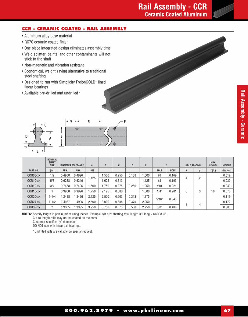
800.962.8979 • www.pbc l inear.com 67
Rail Assembly - Ceram
icRail Assembly - CCR
Ceramic Coated Aluminum
E
AD
C
B
y X F
NOTES: Specify length in part number using inches. Example: for 1/2" shafting total length 36" long = CCR08-36. Cut-to-length rails may not be coated on the ends. Customer specifi es “y” dimension. DO NOT use with linear ball bearings.
*Undrilled rails are vailable on special request.
CCR - CERAMIC COATED - RAIL ASSEMBLY
PART NO.
NOMINALSHAFTSIZE DIAMETER TOLERANCE A B C D E F HOLE SPACING
MAX.LENGTH WEIGHT
(in.) MIN. MAX. .002 BOLT HOLE X y *(ft.) (lbs./in.)
CCR08-xx 1/2 0.4988 0.49961.125
1.500 0.250 0.188 1.000 #6 0.1694 2
10'
0.019
CCR10-xx 5/8 0.6238 0.6246 1.625 0.313
0.250
1.125 #8 0.193 0.030
CCR12-xx 3/4 0.7488 0.7496 1.500 1.750 0.375 1.250 #10 0.221
6 3
0.043
CCR16-xx 1 0.9988 0.9996 1.750 2.125 0.500 1.500 1/4" 0.281 0.076
CCR20-xx 1-1/4 1.2488 1.2496 2.125 2.500 0.563 0.313 1.8755/16" 0.343
0.119
CCR24-xx 1-1/2 1.4987 1.4995 2.500 3.000 0.688 0.375 2.2508 4
0.172
CCR32-xx 2 1.9985 1.9995 3.250 3.750 0.875 0.500 2.750 3/8" 0.406 0.305
• Aluminum alloy base material• RC70 ceramic coated fi nish• One piece integrated design eliminates assembly time• Weld splatter, paints, and other contaminants will not
stick to the shaft• Non-magnetic and vibration resistant • Economical, weight saving alternative to traditional
steel shafting• Designed to run with Simplicity FrelonGOLD® lined
linear bearings• Available pre-drilled and undrilled*

800.962.8979 • www.pbc l inear.com68
Shafting - NIM & NIPDMRC60 Steel - ISO Metric
*NOTES: Specify length in part number using millimeters.Example: for 25 mm shafting total length 900mm = NIM25-900
PART NO.
NOMINALSIZE
DIAMETER TOLERANCE CLASS “M”
LENGTHin m*
HARDNESSDEPTH WEIGHT
(mm) MIN. MAX. MAX. MIN. (mm) (kg/m)
NIM03-xx 3 2.991 3 6.4 1.0 0.06
NIM04-xx 4 3.991 4 6.4 1.0 0.1
NIM05-xx 5 4.991 5 6.4 1.0 0.15
NIM06-xx 6 5.991 6 6.4 1.0 0.23
NIM08-xx 8 7.991 8 6.4 1.0 0.39
NIM10-xx 10 9.991 10 6.4 1.0 0.62
NIM12-xx 12 11.989 12 4.6 1.0 0.89
NIM16-xx 16 15.989 16 4.6 1.7 1.57
NIM20-xx 20 19.987 20 4.6 1.7 2.45
NIM25-xx 25 24.987 25 5.2 2.7 3.8
NIM30-xx 30 29.987 30 5.2 2.7 5.5
NIM40-xx 40 39.984 40 5.2 2.7 9.8
NIM50-xx 50 49.984 50 5.2 3.7 15.3
NIM60-xx 60 59.981 60 5.2 3.7 22.2
NIM80-xx 80 79.981 80 5.2 3.7 39.5
PART NO.
NOMINALSIZE
DIAMETER TOLERANCE CLASS “M”
LENGTHin m*
HARDNESSDEPTH WEIGHT
(mm) MIN. MAX. MAX. MIN. (mm) (kg/m)
NIM03-xx 3 2.991 3 6.4 1.0 0.06 NIM04-xx 4 3.991 4 6.4 1.0 0.1 NIM05-xx 5 4.991 5 6.4 1.0 0.15 NIM06-xx 6 5.991 6 6.4 1.0 0.23 NIM08-xx 8 7.991 8 6.4 1.0 0.39 NIM10-xx 10 9.991 10 6.4 1.0 0.62
NOTES: Specify length in part number using mm. For random lengths, add “R” to the part number. Example: for 12mm shafting total length 97mm = NIPDM12-97Customer specifi es “y” dimension.
y x
PART NO.
NOMINALSIZE
DIAMETERTOLERANCECLASS “M”
HOLESPACING
THREAD
MAX.LENGTH WEIGHT
(mm) (μm) X y (m) (kg/m)
NIPDM08-xx 8 +0/-9 101.6 50.8 M2 x .4 5.0 0.39
NIPDM10-xx 10 +0/-9 101.6 50.8 M3 x .5 5.0 0.62
NIPDM12-xx 12 +0/-11 120 60 M4 x .7 5.7 0.89
NIPDM16-xx 16 +0/-11 150 75 M5 x .8 5.7 1.57
NIPDM20-xx 20 +0/-13 150 75 M6 x 1.0 5.7 2.45
NIPDM25-xx 25 +0/-13 200 100 M8 x 1.25 5.7 3.80
NIPDM30-xx 30 +0/-13 200 100 M10 x 1.5 5.7 5.50
Shaf
tng
- RC6
0 St
eel
NIM - RC60 STEEL - SOLID• RC60 case hardened steel shafting, small diameter,
pre-drilled and tapped shafting• Polished for optimum surface fi nish • Suitable for Simplicity® bearings and linear ball bearings • Available cut-to-length or in full random lengths • Joinable for even longer lengths
NIM - RC60 - SMALL DIAMETER
NIPDM - RC60 - PRE-DRILLED & TAPPED
SMALL DIAMETERSHAFTING
3MM - 10MM
RC60 STEEL SHAFTING, SOLID, PRE-DRILLED AND TAPPED
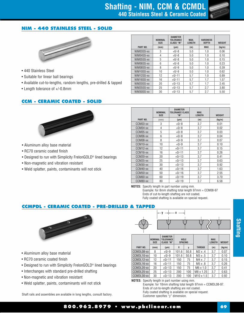
800.962.8979 • www.pbc l inear.com 69
Shafting - NIM, CCM & CCMDL440 Stainless Steel & Ceramic Coated
• 440 Stainless Steel• Suitable for linear ball bearings• Available cut-to-lengths, random lengths, pre-drilled & tapped• Length tolerance of +/-0.8mm
PART NO.
NOMINALSIZE
DIAMETERTOLERANCECLASS “M”
MAX.LENGTH
HARDNESSDEPTH WEIGHT
(mm) (μm) (m) MAX. (kg/m)
NIM03SS-xx 3 +0/-8 5.0 1.0 0.06NIM04SS-xx 4 +0/-8 5.0 1.0 0.10NIM05SS-xx 5 +0/-8 5.0 1.0 0.15NIM06SS-xx 6 +0/-8 5.0 1.0 0.23NIM08SS-xx 8 +0/-9 5.0 1.0 0.39NIM10SS-xx 10 +0/-9 5.0 1.0 0.62NIM12SS-xx 12 +0/-11 5.7 1.0 0.89NIM16SS-xx 16 +0/-11 5.7 1.7 1.57NIM20SS-xx 20 +0/-13 5.7 1.7 2.45NIM25SS-xx 25 +0/-13 5.7 2.7 3.80NIM30SS-xx 30 +0/-13 5.7 2.7 5.50
NIM - 440 STAINLESS STEEL - SOLID
y x
CCMPDL - CERAMIC COATED - PRE-DRILLED & TAPPED
• Aluminum alloy base material• RC70 ceramic coated fi nish• Designed to run with Simplicity FrelonGOLD® lined bearings • Interchanges with standard pre-drilled shafting • Non-magnetic and vibration resistant • Weld splatter, paints, contaminants will not stick
• Aluminum alloy base material• RC70 ceramic coated fi nish• Designed to run with Simplicity FrelonGOLD® lined bearings • Non-magnetic and vibration resistant • Weld splatter, paints, contaminants will not stick
CCM - CERAMIC COATED - SOLID
NOTES: Specify length in part number using mm. Example: for 8mm shafting total length 97mm = CCM08-97Ends of cut-to-length shafting are not coated.Fully coated shafting is available on special request.
PART NO.
NOMINALSIZE
DIAMETERTOLERANCE CLASS
“M”MAX.
LENGTH WEIGHT
(mm) (μm) (m) (kg/m)
CCM03-xx 3 +0/-8 3.7 0.01CCM04-xx 4 +0/-8 3.7 0.02CCM05-xx 5 +0/-8 3.7 0.03CCM06-xx 6 +0/-8 3.7 0.04CCM08-xx 8 +0/-9 3.7 0.07CCM10-xx 10 +0/-9 3.7 0.10CCM12-xx 12 +0/-11 3.7 0.15CCM16-xx 16 +0/-11 3.7 0.26CCM20-xx 20 +0/-13 3.7 0.41CCM25-xx 25 +0/-13 3.7 0.63CCM30-xx 30 +0/-13 3.7 0.92CCM40-xx 40 +0/-16 3.7 1.63CCM50-xx 50 +0/-16 3.7 2.55CCM60-xx 60 +0/-19 3.7 3.70CCM80-xx 80 +0/-19 3.7 6.58
NOTES: Specify length in part number using mm. Example: for 10mm shafting total length 97mm = CCMDL08-97. Ends of cut-to-length shafting are not coated.Fully coated shafting is available on special request.Customer specifi es “y” dimension.
PART NO.
NOMINALSIZE
DIAMETERTOLERANCECLASS “M”
HOLESPACING
THREAD
MAX.LENGTH WEIGHT
(mm) (μm) X y (m) (kg/m)
CCMDL08-xx 8 +0/-9 101.6 50.8 M2 x .4 3.7 0.07CCMDL10-xx 10 +0/-9 101.6 50.8 M3 x .5 3.7 0.10CCMDL12-xx 12 +0/-11 150 75 M4 x .7 3.7 0.15CCMDL16-xx 16 +0/-11 150 75 M5 x .8 3.7 0.26CCMDL20-xx 20 +0/-13 150 75 M6 x 1.0 3.7 0.41CCMDL25-xx 25 +0/-13 200 100 M8 x 1.25 3.7 0.63CCMDL30-xx 30 +0/-13 200 100 M10 x 1.5 3.7 0.92
Shaft rails and assemblies are available in long lengths, consult factory.
Shafting

h
IP IP-AJ IP-OP
dr
L
B
W W
D D1h1
800.962.8979 • www.pbc l inear.com70
Ball
Bear
ings
- IP
Linear Ball Bearings - IPInch Series
IP - DIMENSIONAL INFORMATION
MAJOR DIMENSIONS & TOLERANCES LOAD RATING
NOMINALSHAFT
DIAMETER
BMAX/MIN
(inch/mm)
WMIN
(inch/mm)
D1(inch/mm)
h(inch/mm)
h1(inch/mm)
TOL(inch/μm)
ECCENTRICITY(inch/μm)
MAX RADIALCLEARANCE
(inch/μm)
DYNAMICC
(N)
DYNAMICC
(lbs.)
STATICCo(N)
STATICCo
(lbs.)
1/46.350
.515/.49913.091/12.675
.03900.992
0.468711.906 .04
1
- -
0/-.0080/-0.2
.000512
-.0001 -3
206 46 265 60
3/8 9.525
.640/.62416.256/15.850
.03900.992
0.588014.935 - - 225 51 314 71
1/2 9.525
.967/.95124.562/24.155
.04591.168
0.820920.853
.061.5
0.34007.937
80 -.0001 -4
510 115 784 176
5/8 15.875
1.108/1.09228.143/27.737
.05591.422
1.059026.899
0.37509.525 774 174 1,180 265
3/4 19.050
1.170/1.15429.718/29.312
.05591.422
1.176029.870
0.437511.112 60
.0006 15
-.0002 -6
862 194 1,370 308
1 25.400
1.759/1.74144.679/44.421
.06791.727
1.468737.306
0.562514.287
50
0/-.0100/-0.25 980 220 1,570 353
1-1/4 31.750
2.009/1.99151.029/50.571
.06791.727
1.885947.904
.102.5
0.625015.875
0/-.0120/-0.3
.000820
-.0003 -8
1,570 353 2,740 616
1-1/2 38.100
2.415/2.39761.341/60.884
.08592.184
2.238956.870 .12
3
0.750019.050 2,180 490 4,020 904
2 50.800
3.195/3.17781.153/80.696
.10292.616
2.837972.085
1.00025.400
.001025
-.0005-13 3,820 859 7,940 1,785
PART NUMBER MAJOR DIMENSIONS & TOLERANCES
NOMINALSHAFT
DIAMETER(Inch/mm)
STANDARDCLOSE
BALLCIRCUIT
WEIGHT(g)
ADJUSTABLEPOLYMER
CAGE
WEIGHT(g)
STANDARDOPEN
WEIGHT(g)
dr(inch/mm)
TOLERANCE(inch/μm)
D(inch/mm)
TOLERANCE(inch/μm)
L(inch/mm)
TOLERANCE(inch/mm)
1/46.350 IP4G
4
10 - 10 - 10 0.25006.350
0/-.00040/-9
0.500012.700
0/-.00045 0/-11
0.750019.050
0/-.0080/-0.2
3/8 9.525 IP6G 15 - 15 - 15 0.3750
9.5250.625015.875
0/-.000500/-13
0.875022.225
1/2 9.525 IP8G 42 IP8G-AJ 41 IP8G-OP 32 0.5000
12.7000.875022.225
1.250031.750
5/8 15.875 IP10G
585 IP10G-AJ 83 IP10G-OP 64 0.6250
15.8751.125028.575
1.500038.100
3/4 19.050 IP12G 104 IP12G-AJ 102 IP12G-OP 86 0.7500
19.050 0/-.00040/-10
1.250031.750 0/-.00065
0/-16
1.62541.275
1 25.400 IP16G
6
200 IP16G-AJ 218 IP16G-OP 190 1.000025.400
1.562539.688
2.250057.150
0/-.0120/-0.3
1-1/4 31.750 IP20G 465 IP20G-AJ 455 IP20G-OP 390 1.2500
31.750
0/-.00050/-12
2.000050.800 0/-.00075
0/-19
2.625066.675
1-1/2 38.100 IP24G 720 IP24G-AJ 710 IP24G-OP 610 1.5000
38.1002.375060.325
3.000076.200
2 50.800 IP32G 1,310 IP32G-AJ 1,290 IP32G-OP 1,120 2.0000
50.8003.000076.200
0/-.000900/-22
4.0000101.600
(Standard Steel Finish)

800.962.8979 • www.pbc l inear.com 71
Ball Bearings - IPSLinear Ball Bearings - IPS & IPS-OP
Inch Series
IPS - DIMENSIONAL INFORMATIONPART NUMBER MAJOR DIMENSIONS & TOLERANCES LOAD RATING
NOMINALSHAFT DIA.
(Inch/mm)
STANDARDCLOSE
BALLCIRCUIT
WEIGHT(lbf)
dr(inch/mm)
TOLERANCED
(inch/μm)
L(inch/mm)
B W D1 DynamicC lbf
StaticCo lbf
1/46.350 IPS04
4
0.0080.009
0.25006.350
0/-.0005(0/-12)
0.500012.700
0.750019.050 0.515 0.0390 0.4687 60 80
3/8 9.525 IPS06 0.013
0.0140.37509.525
0.625015.875
0.875022.225 0.703 0.0390 0.5880 95 120
1/2 9.525 IPS08 0.042
0.0430.500012.700
0.875022.225
1.250031.750 1.032 0.0459 0.8209 230 290
5/8 15.875 IPS10 5 0.101
0.1030.625015.875
1.125028.575
1.500038.100 1.112 0.0559 1.0590 400 500
3/4 19.050 IPS12 6 0.123
0.1230.750019.050
1.250031.750
1.62541.275 1.272 0.0559 1.1760 470 590
1 25.400 IPS16
6
0.2650.265
1.000025.400
1.562539.688
2.250057.150 1.886 0.0679 1.4687 850 1060
1-1/4 31.750 IPS20 0.485
0.4851.250031.750
0/-.00060/-15
2.000050.800
2.625066.675 2.011 0.0679 1.8859 1230 1530
1-1/2 38.100 IPS24 0.750
0.7501.500038.100 0/-0008
0/-20
2.375060.325
3.000076.200 2.422 0.0859 2.2389 1480 1850
2 50.800 IPS32 1.389
1.4112.000050.800
3.000076.200
4.0000101.600 3.206 0.1029 2.8379 2430 3040
PART NUMBER MAJOR DIMENSIONS & TOLERANCES LOAD RATINGSHAFT DIA.
(Inch/mm)
STANDARDOPEN
BALLCIRCUIT
WEIGHT(lbf)
dr(inch/mm)
D(inch/μm)
L(inch/mm)
F G B W D1 h1(inch/
DynamicC (lbf)
StaticCo (bf)
1/2 9.525 IPS08-0P 3 0.030 0.500 0.8750 1.250 0.140 0.630 1.032 0.050 0.320 0.320 30 210 190
5/8 15.875 IPS10-OP 4 0.060 0.625 1.1250 1.500 0.110 0.130 1.105 0.056 0.380 0.380 30 320 340
3/4 19.050 IPS12-OP
5
0.110 0.750 1.2500 1.625 0.140 0.130 1.270 0.056 0.430 0.430 30 510 430
1 25.400 IPS16-OP 0.210 1.000 1.5625 2.250 0.140 0.130 1.884 0.070 0.560 0.560 30 830 780
1-1/4 31.750 IPS20-OP 0.350 1.250 2.0000 2.625 0.200 0.190 2.004 0.068 0.630 0.630 30 1250 1270
1-1/2 38.100 IPS24-OP 0.670 1.500 2.3750 3.000 0.200 0.190 2.410 0.086 0.750 0.750 30 1520 1540
2 50.800 IPS32-OP 1.10 1.500 3.0000 4.000 0.270 0.310 3.193 0.105 1.000 1.000 30 2250 2580
IPS-OP - DIMENSIONAL INFORMATION
D
LB
W W
1°
dr
h130°
G
F
1.3
IPS10-OP
IPS08-OP IPS12-OP thru IPS32-OP
30°h1
J
15°
G
F
30°h1
J
G
F
IP

800.962.8979 • www.pbc l inear.com72
Doub
le W
ide
- IP-
WDouble Wide - IP-WLinear Ball Bearings
L
Mo
B
dr
W W
D D1
IP-W - DIMENSIONAL INFORMATION
PART NUMBER MAJOR DIMENSIONS & TOLERANCES
NOMINALSHAFT
DIAMETER(Inch/mm)
POLYMERCAGE
BALLCIRCUIT
WEIGHT(g)
dr(inch/mm)
TOLERANCE(inch/mm)
D(inch/mm)
TOLERANCE(inch/μm)
L(inch/mm)
TOLERANCE(inch/mm)
1/4 6.350 IP4GW
4
18 0.25006.350
0/-.00040/-10
0.5000 12.700
0/-.00050/-13
1.375034.925
0/-0.012 0/-0.3
3/8 9.525 IP6GW 28 0.3750
9.5250.625015.875
0/-.000650/-16
1.593840.481
1/2 12.700 IP8GW 80 0.5000
12.7000.8750 22.225
2.375060.235
5/8 15.875 IP10GW
5
160 0.625015.875
1.125028.575
2.812571.438
3/4 19.050 IP12GW 195 0.7500
19.050 0/-.00050/-12
1.250031.750 0/-.00075
0/-19
3.0937 78.581
1 25.400 IP16GW
6
410 1.000025.400
1.562539.688
4.2813108.744
0/-0.016 0/-0.4
1-1/431.750 IP20GW 820 1.2500
31.750
0/-.00060/-15
2.000050.800 0/-.0009
0/-22
5.0000127.000
1-1/238.100 IP24GW 1,250 1.5000
38.1002.375060.325
5.6875144.463
2 50.800 IP32GW 2,350 2.0000
50.8003.000076.200
0/-.00100 0/-25
7.7500196.850

800.962.8979 • www.pbc l inear.com 73
Double Wide - IP-W
Double Wide - IP-WLinear Ball Bearings
IP-W - DIMENSIONAL INFORMATION (cont.)
MAJOR DIMENSIONS & TOLERANCES LOAD RATING
B(inch/mm)
TOLERANCE(inch/mm)
WMIN
(inch/mm)
D1(inch/mm)
ECCENTRICITY(inch/μm)
DYNAMICC
(N)
DYNAMICC
(lbs.)
STATICCo(N)
STATICCo
(lbs.)
ALLOWABLESTATIC
MOMENTMo
(N-m)
NOMINALSHAFT
DIAMETER(inch/mm)
1.022025.959
0/-.012 0/-0.3
.03900.992
0.468711.906
.0006 15
323 73 530 119 2 1/4 6.350
1.271632.298
.03900.992
0.588014.935 353 79 630 142 2.7 3/8
9.525
1.925048.895
.04591.168
0.820920.853 813 183 1,570 353 11.5 1/2
12.700
2.207956.080 .0559
1.422
1.059026.899 1,230 277 2,350 528 20 5/8
15.875
2.331459.218
1.176029.870 .0008
20
1,370 308 2,740 616 26.5 3/4 19.050
3.509489.139
0/-0.16 0/-0.4
.06791.727
1.4687 37.306 1,570 353 3,140 706 41.2 1
25.400
4.0094101.839
1.885947.904 .0010
25
2,500 562 5,490 1,234 84.8 1-1/431.750
4.8236122.519
.08592.184
2.238956.870 3,430 771 8,040 1,807 143 1-1/2
38.100
6.3834162.138
.10292.616
2.837972.085
.0012 30 6,080 1,367 15,900 3,574 399 2
50.800
(Standard Steel Finish)
L
Mo
B
dr
W W
D D1
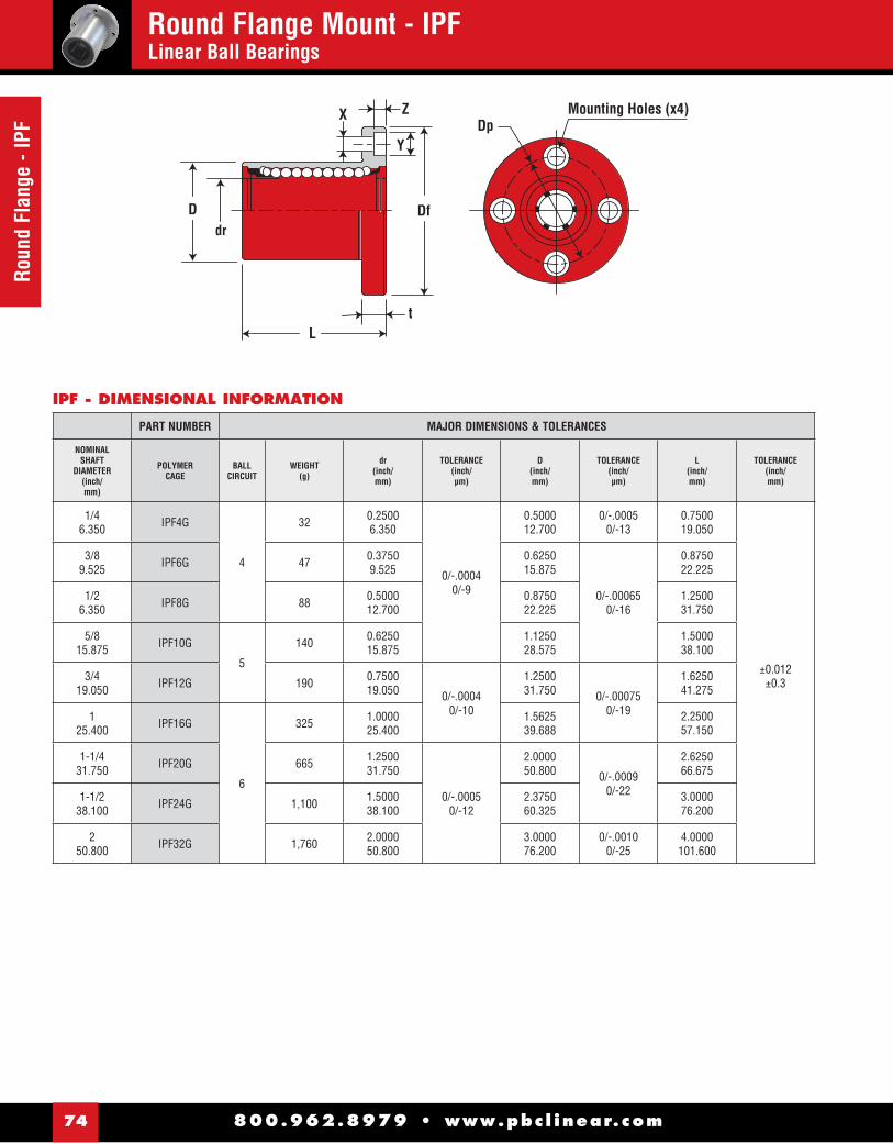
800.962.8979 • www.pbc l inear.com74
Roun
d Fl
ange
- IP
FRound Flange Mount - IPFLinear Ball Bearings
Dp
Df
Mounting Holes (x4)
dr
X Z
Y
tL
D
IPF - DIMENSIONAL INFORMATION
PART NUMBER MAJOR DIMENSIONS & TOLERANCES
NOMINALSHAFT
DIAMETER(inch/mm)
POLYMERCAGE
BALLCIRCUIT
WEIGHT(g)
dr(inch/mm)
TOLERANCE(inch/μm)
D(inch/mm)
TOLERANCE(inch/μm)
L(inch/mm)
TOLERANCE(inch/mm)
1/4 6.350 IPF4G
4
32 0.25006.350
0/-.00040/-9
0.500012.700
0/-.0005 0/-13
0.750019.050
±0.012±0.3
3/8 9.525 IPF6G 47 0.3750
9.5250.625015.875
0/-.000650/-16
0.875022.225
1/26.350 IPF8G 88 0.5000
12.7000.875022.225
1.250031.750
5/815.875 IPF10G
5
140 0.625015.875
1.125028.575
1.500038.100
3/419.050 IPF12G 190 0.7500
19.050 0/-.00040/-10
1.250031.750 0/-.00075
0/-19
1.625041.275
125.400 IPF16G
6
325 1.000025.400
1.562539.688
2.250057.150
1-1/431.750 IPF20G 665 1.2500
31.750
0/-.00050/-12
2.000050.800 0/-.0009
0/-22
2.625066.675
1-1/238.100 IPF24G 1,100 1.5000
38.1002.375060.325
3.000076.200
250.800 IPF32G 1,760 2.0000
50.8003.000076.200
0/-.00100/-25
4.0000101.600

800.962.8979 • www.pbc l inear.com 75
Round Flange - IPFRound Flange Mount - IPF
Linear Ball Bearings
IPF - DIMENSIONAL INFORMATION (cont.)
Dp
Df
Mounting Holes (x4)
dr
X Z
Y
tL
D
MAJOR DIMENSIONS & TOLERANCES LOAD RATING
Df(inch/mm)
t(inch/mm)
Dp(inch/mm)
X x Y x Z(inch/mm)
ECCENTRICITYID to OD
(inch/μm)
PERPENDICULARITYFLANGE FACE to ID
(inch/μm)
DYNAMICC
(N)
DYNAMICC
(lbs.)
STATICCo(N)
STATICCo
(lbs.)
NOMINALSHAFT
DIAMETER(inch/mm)
1.250031.750
.21905.556
0.875022.225
.156 x .250 x .1413.969 x 6.350 x 3.572
.000512
.000512
206 46 265 60 1/4 6.350
1.500038.100
.25006.350
1.062026.988
.1875 x .297 x .1724.763 x 7.541 x 4.366 225 51 314 71 3/8
9.525
1.750044.450
.25006.350
1.312033.338
.1875 x .297 x .1724.763 x 7.541 x 4.366 510 115 784 176 1/2
6.350
2.000050.800
.25006.350
1.562039.688
.1875 x .297 x .1724.763 x 7.541 x 4.366 774 174 1,180 265 5/8
15.875
2.187555.563
.31257.938
1.718043.660
.219 x .344 x .2035.556 x 8.731 x 5.159 .0006
15.0006
15
862 194 1,370 308 3/419.050
2.500063.500
.31257.938
2.031051.594
.219 x .344 x .2035.556 x 8.731 x 5.159 980 220 1,570 353 1
25.400
3.125079.375
.37509.525
2.562565.088
.281 x .406 x .2667.144 x 10.312 x 6.747
.000820
.000820 1,570 353 2,740 616 1-1/4
31.750
3.750095.250
.500012.700
3.062577.788
.344 x .500 x .3288.731 x 12.700 x 8.334 .0010
25.0010
25
2,180 490 4,020 904 1-1/238.100
4.3750111.125
.500012.700
3.687593.662
.344 x .500 x .3288.731 x 12.700 x 8.334 3,820 859 7,940 1,785 2
50.800
(Standard Steel Finish)

800.962.8979 • www.pbc l inear.com76
Roun
d Fl
ange
- IP
F-W
Round Flange - Double Mount - IPF-WLinear Ball Bearings
Df
DpMounting Holes (x4)X Z
Y
tL
Ddr
Mo
IPF-W - DIMENSIONAL INFORMATION
PART NUMBER MAJOR DIMENSIONS & TOLERANCES
NOMINALSHAFT
DIAMETER(inch/mm)
POLYMERCAGE
BALLCIRCUIT
WEIGHT(g)
dr(inch/mm)
TOLERANCE(inch/μm)
D(inch/mm)
TOLERANCE(inch/μm)
L(inch/mm)
TOLERANCE(inch/mm)
Df(inch/mm)
1/46.350 IPF4GW
4
40 0.25006.350
0/-.00040/-10
0.500012.700
0/-.0005 0/-13
1.37534.925
±0.012±0.3
1.250031.750
3/89.525 IPF6GW 60 0.3750
9.5250.625015.875
0/-.000650/-16
1.593840.481
1.500038.100
1/212.700 IPF8GW 126 0.5000
12.7000.875022.225
2.375060.325
1.750044.450
5/815.875 IPF10GW 215 0.6250
15.8751.125028.575
2.812571.438
2.000050.800
3/419.050 IPF12GW 5 280 0.7500
19.050 0/-.00050/-12
1.250031.750 0/-.00075
0/-19
3.093778.581
2.187555.563
125.400 IPF16GW
6
515 1.000025.400
1.562539.688
4.2813108.744
2.250063.500
1-1/431.750 IPF20GW 1,020 1.2500
31.750
0/-.00060/-15
2.000050.800 0/-.0009
0/-22
5.000127.000
3.125079.375
1-1/238.100 IPF24GW 1,630 1.5000
38.1002.375060.325
5.6875144.463
3.750095.250
250.800 IPF32GW 2,800 2.0000
50.8003.000076.200
0/-.00100/-25
7.7500196.850
4.3750111.125

800.962.8979 • www.pbc l inear.com 77
Round Flange - IPF-WRound Flange - Double Mount - IPF-W
Linear Ball Bearings
IPF-W - DIMENSIONAL INFORMATION (cont.)
Df
DpMounting Holes (x4)X Z
Y
tL
Ddr
Mo
MAJOR DIMENSIONS & TOLERANCES LOAD RATING
t(inch/mm)
Dp(inch/mm)
X x Y x Z(inch/mm)
ECCENTRICITYID to OD
(inch/μm)
PERPENDICULARITYFLANGE FACE to ID
(inch/μm)
DYNAMICC
(N)
DYNAMICC
(lbs.)
STATICCo(N)
STATICCo
(lbs.)
ALLOWABLESTATIC
MOMENTMo
(N-m)
NOMINALSHAFT
DIAMETER(inch/mm)
0.2195.556
0.875022.225
.156 x .250 x .1413.969 x 6.350 x 3.572
.0006 15
.0006 15
323 73 530 119 2 1/46.350
.25006.350
1.062026.988
.1875 x .297 x .1724.763 x 7.541 x 4.366 353 79 630 142 2.7 3/8
9.525
.25006.350
1.31233.338
.1875 x .297 x .1724.763 x 7.541 x 4.366 813 183 1,570 353 11.5 1/2
12.700
.25006.350
1.562539.688
.1875 x .297 x .1724.763 x 7.541 x 4.366 1,230 277 2,350 528 20 5/8
15.875
.31257.938
1.718843.656
.219 x .344 x .2035.556 x 8.731 x 5.159 .0008
20.0008
20
1,370 308 2,740 616 26.5 3/4 19.050
.31257.938
2.031351.594
.219 x .344 x .2035.556 x 8.731 x 5.159 1,570 353 3,140 706 41.2 1
25.400
.37509.525
2.562565.088
.281 x .406 x .2667.144 x 10.312 x 6.747 .0010
25.0010
25
2,500 562 5,490 1,234 84.8 1-1/431.750
.500012.700
3.062577.788
.344 x .500 x .3288.731 x 12.700 x 8.334 3,430 771 8,040 1,807 143 1-1/2
38.100
.500012.700
3.687593.662
.344 x .500 x .3288.731 x 12.700 x 8.334
.0012 30
.0012 30 6,080 1,367 15,900 3,574 399 2
50.800
(Standard Steel Finish)

800.962.8979 • www.pbc l inear.com78
Squa
re F
lang
e - I
PKSquare Flange Mount - IPKLinear Ball Bearings
Mounting Holes (x4)Dp
Df
X Z
Y
tL
Ddr
K
IPK - DIMENSIONAL INFORMATION
PART NUMBER MAJOR DIMENSIONS & TOLERANCES
NOMINALSHAFT
DIAMETER(inch/mm)
POLYMERCAGE
BALLCIRCUIT
WEIGHT(g)
dr(inch/mm)
TOLERANCE(inch/μm)
D(inch/mm)
TOLERANCE(inch/μm)
L(inch/mm)
TOLERANCE(inch/mm)
Df(inch/mm)
1/4 6.350 IPK4G
4
25 0.25006.350
0/-.00040/-9
0.500012.700
0/-.0005 0/-13
0.750019.050
±0.012±0.3
1.250031.750
3/8 9.525 IPK6G 32 0.3750
9.5250.625015.875
0/-.000650/-16
0.875022.225
1.500038.100
1/2 12.700 IPK8G 68 0.5000
12.7000.875022.225
1.250031.750
1.750044.450
5/8 15.875 IPK10G 124 0.6250
15.8751.125028.575
1.500038.100
2.000050.800
3/4 19.050 IPK12G 5 150 0.7500
19.050 0/-.00040/-10
1.250031.750 0/-.00075
0/-19
1.625041.275
2.187555.563
1 25.400 IPK16G
6
280 1.000025.400
1.562539.688
2.250057.150
2.500063.500
1-1/431.750 IPK20G 580 1.2500
31.750
0/-.00050/-12
2.0000 50.800 0/-.0009
0/-22
2.625066.675
3.125079.375
1-1/238.100 IPK24G 930 1.5000
38.1002.375060.325
3.000076.200
3.750095.250
2 50.800 IPK32G 1,580 2.0000
50.8003.000076.200
0/-.00100/-25
4.0000101.600
4.3750111.125
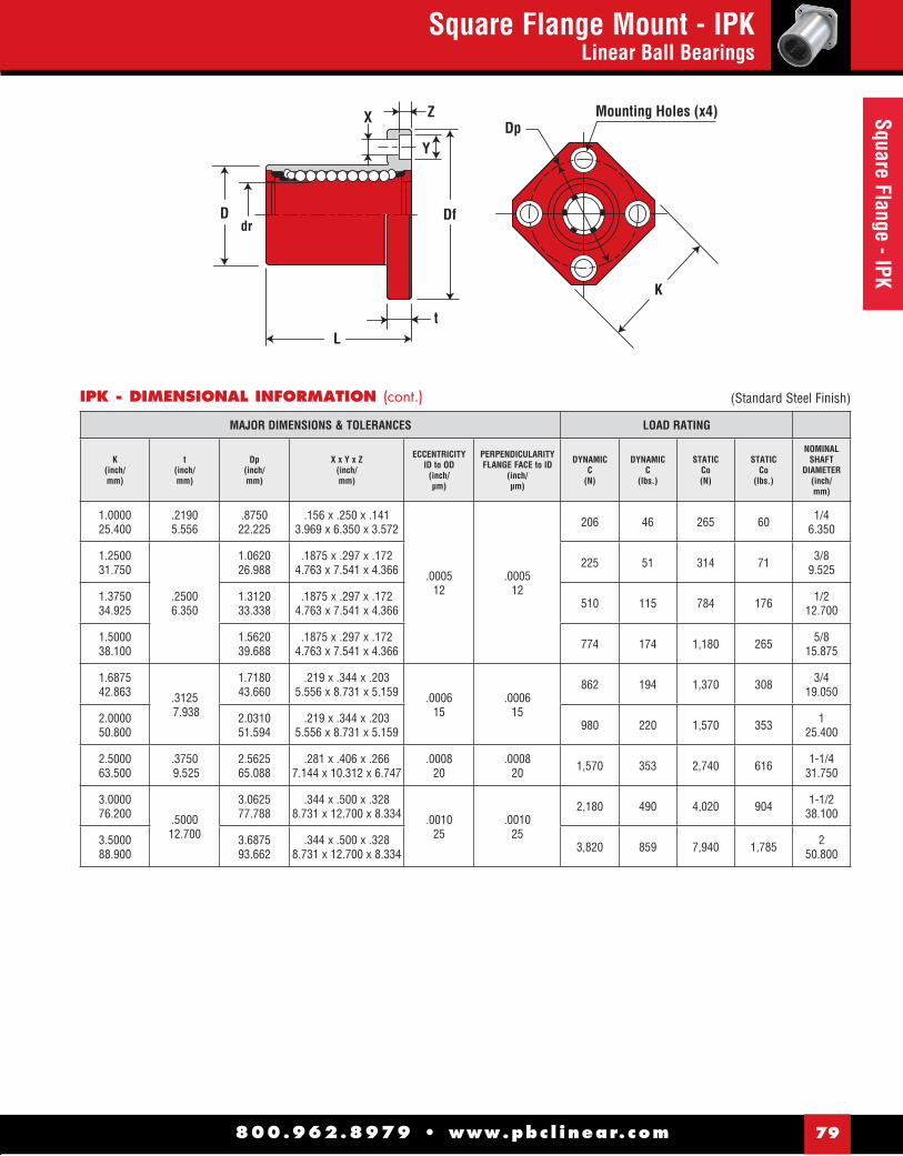
800.962.8979 • www.pbc l inear.com 79
Square Flange - IPKSquare Flange Mount - IPK
Linear Ball Bearings
IPK - DIMENSIONAL INFORMATION (cont.)
Mounting Holes (x4)Dp
Df
X Z
Y
tL
Ddr
K
MAJOR DIMENSIONS & TOLERANCES LOAD RATING
K(inch/mm)
t(inch/mm)
Dp(inch/mm)
X x Y x Z(inch/mm)
ECCENTRICITYID to OD
(inch/μm)
PERPENDICULARITYFLANGE FACE to ID
(inch/μm)
DYNAMICC
(N)
DYNAMICC
(lbs.)
STATICCo(N)
STATICCo
(lbs.)
NOMINALSHAFT
DIAMETER(inch/mm)
1.000025.400
.21905.556
.875022.225
.156 x .250 x .1413.969 x 6.350 x 3.572
.0005 12
.0005 12
206 46 265 60 1/4 6.350
1.250031.750
.25006.350
1.062026.988
.1875 x .297 x .1724.763 x 7.541 x 4.366 225 51 314 71 3/8
9.525
1.375034.925
1.312033.338
.1875 x .297 x .1724.763 x 7.541 x 4.366 510 115 784 176 1/2
12.700
1.500038.100
1.562039.688
.1875 x .297 x .1724.763 x 7.541 x 4.366 774 174 1,180 265 5/8
15.875
1.687542.863 .3125
7.938
1.718043.660
.219 x .344 x .2035.556 x 8.731 x 5.159 .0006
15.0006
15
862 194 1,370 308 3/4 19.050
2.000050.800
2.031051.594
.219 x .344 x .2035.556 x 8.731 x 5.159 980 220 1,570 353 1
25.400
2.500063.500
.3750 9.525
2.562565.088
.281 x .406 x .2667.144 x 10.312 x 6.747
.0008 20
.0008 20 1,570 353 2,740 616 1-1/4
31.750
3.000076.200 .5000
12.700
3.062577.788
.344 x .500 x .3288.731 x 12.700 x 8.334 .0010
25.0010
25
2,180 490 4,020 904 1-1/238.100
3.500088.900
3.687593.662
.344 x .500 x .3288.731 x 12.700 x 8.334 3,820 859 7,940 1,785 2
50.800
(Standard Steel Finish)

800.962.8979 • www.pbc l inear.com80
Squa
re F
lang
e - I
PK-W
Square Flange Mount - Double Wide - IPK-WLinear Ball Bearings
Df
X Z
Y
tL
Ddr
MoMounting Holes (x4)
K
Dp
IPK-W DIMENSIONAL INFORMATION
PART NUMBER MAJOR DIMENSIONS & TOLERANCES
NOMINALSHAFT
DIAMETER(inch/mm)
POLYMERCAGE
BALLCIRCUIT
WEIGHT(g)
dr(inch/mm)
TOLERANCE(inch/μm)
D(inch/mm)
TOLERANCE(inch/μm)
L(inch/mm)
TOLERANCE(inch/mm)
Df(inch/mm)
1/4 6.350 IPK4GW
4
33 0.25006.350
0/-.00040/-10
0.500012.700
0/-.0005 0/-13
1.375034.925
±0.012±0.3
1.250031.750
3/8 9.525 IPK6GW 45 0.3750
9.5250.625015.875
0/-.000650/-16
1.593840.481
1.500038.100
1/2 12.700 IPK8GW 106 0.5000
12.7000.875022.225
2.375060.325
1.750044.450
5/8 15.875 IPK10GW 200 0.6250
15.8751.125028.575
2.812571.438
2.000050.800
3/4 19.050 IPK12GW 5 240 0.7500
19.050 0/-.00050/-12
1.250031.750 0/-.00075
0/-19
3.093778.581
2.187555.563
1 25.400 IPK16GW
6
470 1.000025.400
1.562539.688
4.2813108.744
2.500063.500
1-1/431.750 IPK20GW 935 1.2500
31.750
0/-.00060/-15
2.000050.800 0/-.0009
0/-22
5.0000127.000
3.125079.375
1-1/238.100 IPK24GW 1,460 1.5000
38.1002.375060.325
5.6875144.463
3.750095.250
2 50.800 IPK32GW 2,620 2.0000
50.8003.000076.200
0/-.00100/-25
7.7500196.850
4.3750111.125
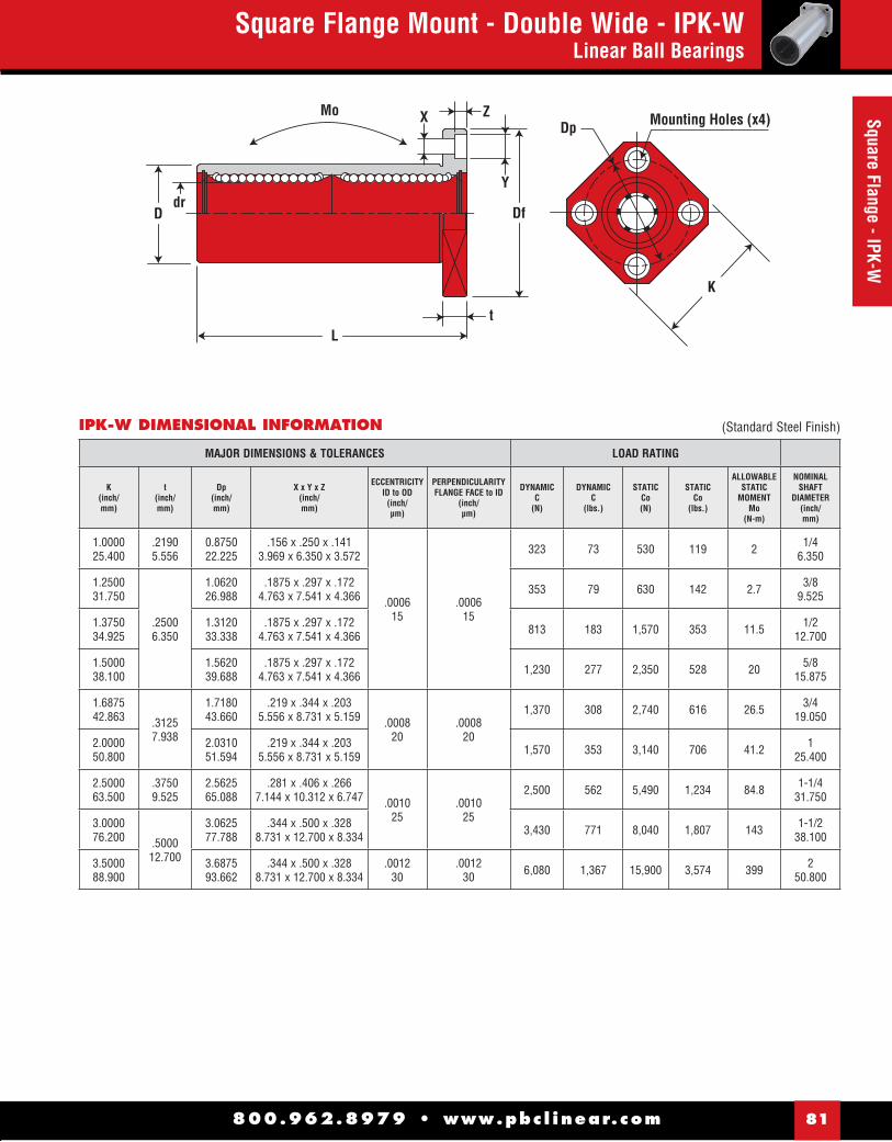
800.962.8979 • www.pbc l inear.com 81
Square Flange - IPK-WSquare Flange Mount - Double Wide - IPK-W
Linear Ball Bearings
IPK-W DIMENSIONAL INFORMATION
Df
X Z
Y
tL
Ddr
MoMounting Holes (x4)
K
Dp
MAJOR DIMENSIONS & TOLERANCES LOAD RATING
K(inch/mm)
t(inch/mm)
Dp(inch/mm)
X x Y x Z(inch/mm)
ECCENTRICITYID to OD
(inch/μm)
PERPENDICULARITYFLANGE FACE to ID
(inch/μm)
DYNAMICC
(N)
DYNAMICC
(lbs.)
STATICCo(N)
STATICCo
(lbs.)
ALLOWABLESTATIC
MOMENTMo
(N-m)
NOMINALSHAFT
DIAMETER(inch/mm)
1.000025.400
.21905.556
0.875022.225
.156 x .250 x .1413.969 x 6.350 x 3.572
.0006 15
.0006 15
323 73 530 119 2 1/4 6.350
1.250031.750
.25006.350
1.062026.988
.1875 x .297 x .1724.763 x 7.541 x 4.366 353 79 630 142 2.7 3/8
9.525
1.375034.925
1.312033.338
.1875 x .297 x .1724.763 x 7.541 x 4.366 813 183 1,570 353 11.5 1/2
12.700
1.500038.100
1.562039.688
.1875 x .297 x .1724.763 x 7.541 x 4.366 1,230 277 2,350 528 20 5/8
15.875
1.687542.863 .3125
7.938
1.718043.660
.219 x .344 x .2035.556 x 8.731 x 5.159 .0008
20.0008
20
1,370 308 2,740 616 26.5 3/4 19.050
2.000050.800
2.031051.594
.219 x .344 x .2035.556 x 8.731 x 5.159 1,570 353 3,140 706 41.2 1
25.400
2.500063.500
.37509.525
2.562565.088
.281 x .406 x .2667.144 x 10.312 x 6.747 .0010
25.0010
25
2,500 562 5,490 1,234 84.8 1-1/431.750
3.000076.200 .5000
12.700
3.062577.788
.344 x .500 x .3288.731 x 12.700 x 8.334 3,430 771 8,040 1,807 143 1-1/2
38.100
3.500088.900
3.687593.662
.344 x .500 x .3288.731 x 12.700 x 8.334
.0012 30
.0012 30 6,080 1,367 15,900 3,574 399 2
50.800
(Standard Steel Finish)
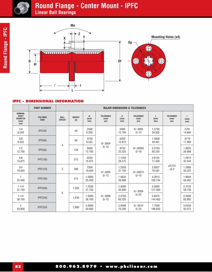
800.962.8979 • www.pbc l inear.com82
Roun
d Fl
ange
- IP
FCRound Flange - Center Mount - IPFCLinear Ball Bearings
Dp
Df
Mounting Holes (x4)XZ
Y
tlL
Ddr
Mo
IPFC - DIMENSIONAL INFORMATION
PART NUMBER MAJOR DIMENSIONS & TOLERANCES
NOMINALSHAFT
DIAMETER(inch/mm)
POLYMERCAGE
BALLCIRCUIT
WEIGHT(g)
dr(inch/mm)
TOLERANCE(inch/μm)
D(inch/mm)
TOLERANCE(inch/μm)
L(inch/mm)
TOLERANCE(inch/μm)
�(inch/mm)
1/46.350 IPFC4G
4
40 .25006.350
0/-.00040/-10
.500012.700
0/-.0005 0/-13
1.375034.925
±0.012±0.3
.578114.684
3/89.525 IPFC6G 60 .3750
9.525.625015.875
0/-.000650/-16
1.593840.481
.671917.066
1/212.700 IPFC8G 126 .5000
12.700.875022.225
2.375060.235
1.062526.988
5/815.875 IPFC10G 215 .6250
15.8751.125028.575
2.812571.438
1.281332.544
3/419.050 IPFC12G 5 280 .7500
19.050 0/-.00050/-12
1.250031.750 0/-.00075
0/-19
3.093778.581
1.390635.322
125.400 IPFC16G
6
515 1.000025.400
1.562539.688
4.2813108.744
1.984450.403
1-1/431.750 IPFC20G 1,020 1.2500
31.750
0/-.00060/-15
2.000050.800 0/-.0009
0/-22
5.0000127.000
2.312558.738
1-1/238.100 IPFC24G 1,630 1.5000
38.1002.375060.325
5.6875144.463
2.593865.882
250.800 IPFC32G 2,800 2.0000
50.8003.000076.200
0/-.00100/-25
7.7500196.850
3.625092.075
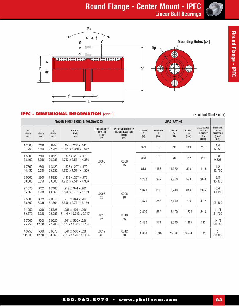
800.962.8979 • www.pbc l inear.com 83
Round Flange - IPFCRound Flange - Center Mount - IPFC
Linear Ball Bearings
IPFC - DIMENSIONAL INFORMATION (cont.)
Dp
Df
Mounting Holes (x4)XZ
Y
tlL
Ddr
Mo
MAJOR DIMENSIONS & TOLERANCES LOAD RATING
Df(inch/mm)
t(inch/mm)
Dp(inch/mm)
X x Y x Z(inch/mm)
ECCENTRICITYID to OD
(inch/μm)
PERPENDICULARITYFLANGE FACE to ID
(inch/μm)
DYNAMICC
(N)
DYNAMICC
(lbs.)
STATICCo(N)
STATICCo
(lbs.)
ALLOWABLESTATIC
MOMENTMo
(N-m)
NOMINALSHAFT
DIAMETER(inch/mm)
1.250031.750
.21905.556
0.875022.225
.156 x .250 x .1413.969 x 6.350 x 3.572
.0006 15
.0006 15
323 73 530 119 2.0 1/46.350
1.500038.100
.25006.350
1.062026.988
.1875 x .297 x .1724.763 x 7.541 x 4.366 353 79 630 142 2.7 3/8
9.525
1.750044.450
.25006.350
1.312033.338
.1875 x .297 x .1724.763 x 7.541 x 4.366 813 183 1,570 353 11.5 1/2
12.700
2.000050.800
.25006.350
1.562039.688
.1875 x .297 x .1724.763 x 7.541 x 4.366 1,230 277 2,350 528 20.0 5/8
15.875
2.187555.563
.31257.938
1.718043.660
.219 x .344 x .2035.556 x 8.731 x 5.159 .0008
20.0008
20
1,370 308 2,740 616 26.5 3/419.050
2.500063.500
.31257.938
2.031051.594
.219 x .344 x .2035.556 x 8.731 x 5.159 1,570 353 3,140 706 41.2 1
25.400
3.125079.375
.37509.525
2.562565.088
.281 x .406 x .2667.144 x 10.312 x 6.747 .0010
25.0010
25
2,500 562 5,490 1,234 84.8 1-1/431.750
3.750095.250
.500012.700
3.062577.788
.344 x .500 x .3288.731 x 12.700 x 8.334 3,430 771 8,040 1,807 143 1-1/2
38.100
4.3750111.125
.500012.700
3.687593.662
.344 x .500 x .3288.731 x 12.700 x 8.334
.0012 30
.0012 30 6,080 1,367 15,900 3,574 399 2
50.800
(Standard Steel Finish)
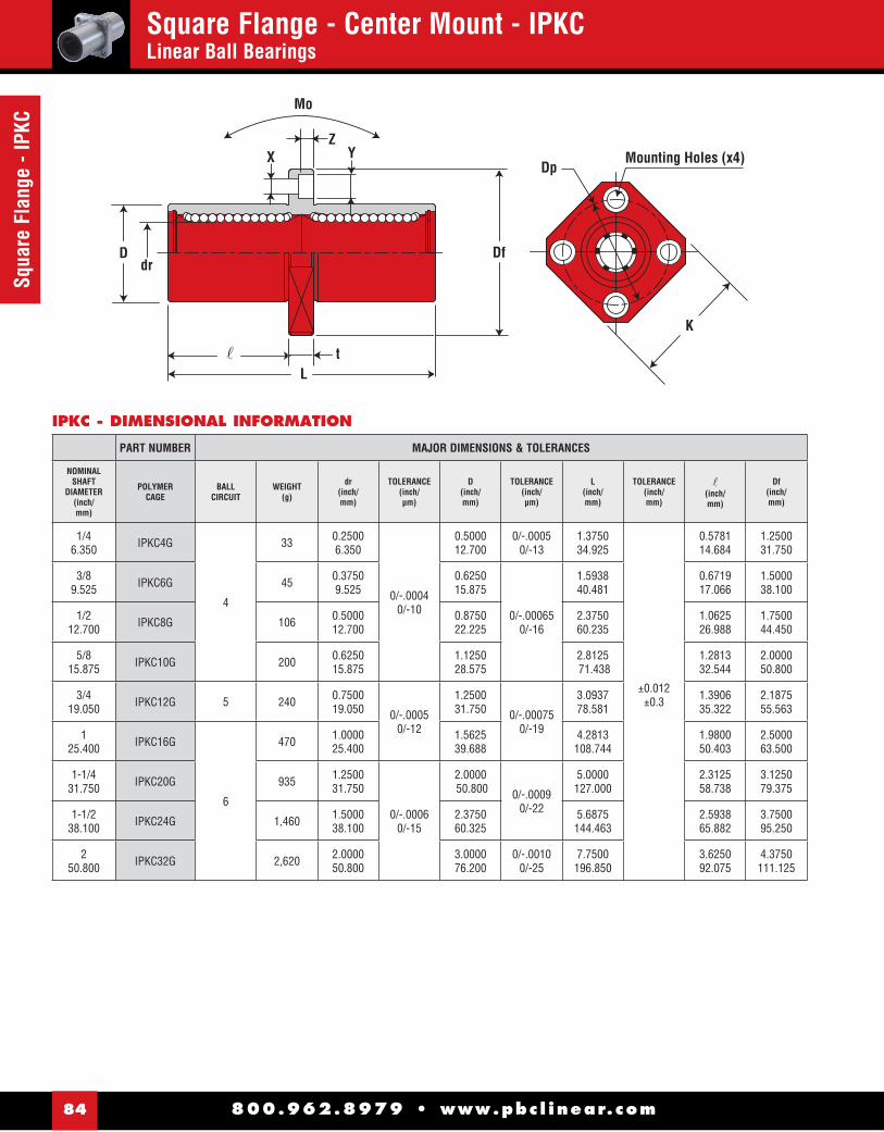
800.962.8979 • www.pbc l inear.com84
Squa
re F
lang
e - I
PKC
Square Flange - Center Mount - IPKCLinear Ball Bearings
Dp
Df
Mounting Holes (x4)XZ
Y
tlL
Ddr
Mo
K
IPKC - DIMENSIONAL INFORMATION
PART NUMBER MAJOR DIMENSIONS & TOLERANCES
NOMINALSHAFT
DIAMETER(inch/mm)
POLYMERCAGE
BALLCIRCUIT
WEIGHT(g)
dr(inch/mm)
TOLERANCE(inch/μm)
D(inch/mm)
TOLERANCE(inch/μm)
L(inch/mm)
TOLERANCE(inch/mm)
�(inch/mm)
Df(inch/mm)
1/4 6.350 IPKC4G
4
33 0.25006.350
0/-.00040/-10
0.500012.700
0/-.0005 0/-13
1.375034.925
±0.012±0.3
0.578114.684
1.250031.750
3/8 9.525 IPKC6G 45 0.3750
9.5250.625015.875
0/-.000650/-16
1.593840.481
0.671917.066
1.500038.100
1/2 12.700 IPKC8G 106 0.5000
12.7000.875022.225
2.375060.235
1.062526.988
1.750044.450
5/8 15.875 IPKC10G 200 0.6250
15.8751.125028.575
2.8125 71.438
1.281332.544
2.000050.800
3/4 19.050 IPKC12G 5 240 0.7500
19.050 0/-.00050/-12
1.250031.750 0/-.00075
0/-19
3.093778.581
1.390635.322
2.187555.563
1 25.400 IPKC16G
6
470 1.000025.400
1.562539.688
4.2813108.744
1.980050.403
2.500063.500
1-1/431.750 IPKC20G 935 1.2500
31.750
0/-.00060/-15
2.0000 50.800 0/-.0009
0/-22
5.0000127.000
2.312558.738
3.125079.375
1-1/238.100 IPKC24G 1,460 1.5000
38.1002.375060.325
5.6875144.463
2.593865.882
3.750095.250
2 50.800 IPKC32G 2,620 2.0000
50.8003.000076.200
0/-.00100/-25
7.7500196.850
3.625092.075
4.3750111.125
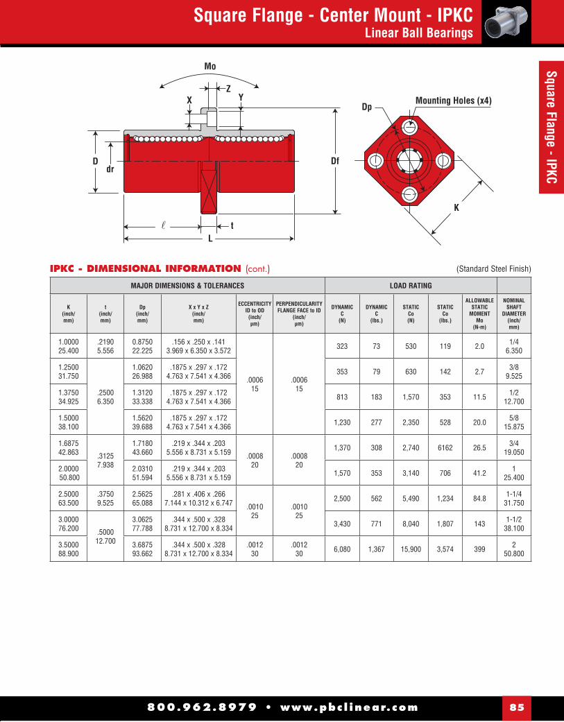
800.962.8979 • www.pbc l inear.com 85
Square Flange - IPKCSquare Flange - Center Mount - IPKC
Linear Ball Bearings
IPKC - DIMENSIONAL INFORMATION (cont.)
Dp
Df
Mounting Holes (x4)XZ
Y
tlL
Ddr
Mo
K
MAJOR DIMENSIONS & TOLERANCES LOAD RATING
K(inch/mm)
t(inch/mm)
Dp(inch/mm)
X x Y x Z(inch/mm)
ECCENTRICITYID to OD
(inch/μm)
PERPENDICULARITYFLANGE FACE to ID
(inch/μm)
DYNAMICC
(N)
DYNAMICC
(lbs.)
STATICCo(N)
STATICCo
(lbs.)
ALLOWABLESTATIC
MOMENTMo
(N-m)
NOMINALSHAFT
DIAMETER(inch/mm)
1.000025.400
.21905.556
0.8750 22.225
.156 x .250 x .1413.969 x 6.350 x 3.572
.0006 15
.0006 15
323 73 530 119 2.0 1/4 6.350
1.250031.750
.25006.350
1.062026.988
.1875 x .297 x .1724.763 x 7.541 x 4.366 353 79 630 142 2.7 3/8
9.525
1.375034.925
1.312033.338
.1875 x .297 x .1724.763 x 7.541 x 4.366 813 183 1,570 353 11.5 1/2
12.700
1.500038.100
1.562039.688
.1875 x .297 x .1724.763 x 7.541 x 4.366 1,230 277 2,350 528 20.0 5/8
15.875
1.687542.863 .3125
7.938
1.718043.660
.219 x .344 x .2035.556 x 8.731 x 5.159 .0008
20.0008
20
1,370 308 2,740 6162 26.5 3/4 19.050
2.0000 50.800
2.031051.594
.219 x .344 x .2035.556 x 8.731 x 5.159 1,570 353 3,140 706 41.2 1
25.400
2.500063.500
.37509.525
2.562565.088
.281 x .406 x .2667.144 x 10.312 x 6.747 .0010
25.0010
25
2,500 562 5,490 1,234 84.8 1-1/431.750
3.000076.200 .5000
12.700
3.062577.788
.344 x .500 x .3288.731 x 12.700 x 8.334 3,430 771 8,040 1,807 143 1-1/2
38.100
3.500088.900
3.687593.662
.344 x .500 x .3288.731 x 12.700 x 8.334
.0012 30
.0012 30 6,080 1,367 15,900 3,574 399 2
50.800
(Standard Steel Finish)

800.962.8979 • www.pbc l inear.com86
Pillo
w B
lock
s - I
PP &
IPNN
Pillow Block - IPP & IPPNLinear Ball Bearings
GS
BE
JA
K
MO
H
P
CF
R
MINGAP
G
BE
K
JA
D
MO
H
P
CF
NOTES: (1) Standard, pre-assembled pillow blocks include self-aligning housing and precision bearing.(2) All standard pillow blocks use standard “IP” series bearings found on page 70.(3) All open pillow blocks have “notch”.
NOTES: (1) Standard, pre-assembled pillow blocks include self-aligning housing and precision bearing.(2) All standard pillow blocks use standard “IP” series bearings found on page 70.(3) Straight bore, pre-assembled pillow blocks use standard “IP” series bearing.
PART NO.CLOSED
NOM.BRG. I.D. A B C D E F G H J K M O P
SMALLEYRET.RING
PART NO.
ASSEM.WT.
PRECISION MIN.CENTERLINE
+/-.001 WIDTH LENGTH HEIGHT +/-.010 +/-.010BODYWIDTH BOLT HOLE
FLNG.THICK
GRV.SPACE
GRV.WIDTH
GRV.DIA. (lbs.)
IPP04G 1/4" 0.437 1.625 1.19 0.813 1.3120 0.7500 1.000
#6 5/32"
0.188 0.750 0.750 0.039 0.532 WH-51 0.099
IPP06G 3/8" 0.500 1.750 1.31 0.938 1.4370 0.8750 1.125 0.188 0.875 0.875 0.039 0.665 WH-65 0.129
IPP08G 1/2" 0.687 2.000 1.69 1.250 1.6880 1.0000 1.375 0.250 1.125 1.250 0.046 0.931 WH-90 0.250
IPP10G 5/8" 0.875 2.500 1.94 1.625 2.1250 1.1250 1.750#8 3/16"
0.281 1.438 1.500 0.056 1.197 WH-115 0.500
IPP12G 3/4" 0.937 2.750 2.06 1.750 2.3750 1.2500 1.875 0.313 1.563 1.625 0.056 1.330 WH-128 0.580
IPP16G 1" 1.187 3.250 2.81 2.188 2.8750 1.7500 2.375#10 7/32"
0.375 1.938 2.250 0.068 1.671 WH-156 1.000
IPP20G 1-1/4" 1.500 4.000 3.63 2.813 3.5000 2.0000 3.000 0.438 2.500 2.625 0.068 2.122 WH-200 2.000
IPP24G 1-1/2" 1.750 4.750 4.00 3.250 4.1250 2.5000 3.500 1/4" 9/32" 0.500 2.875 3.000 0.086 2.519 WH-237 3.000
IPP - CLOSED PILLOW BLOCKS
IPPN - OPEN PILLOW BLOCKSPART NO.CLOSED
NOM.BRG. I.D. A B C E F G H J K M O P R
EATONRET.RING
PART NO.
ASSEM.WT. S
PRECISION MIN.CENTERLINE
+/-.001WIDTH+/-.010 LENGTH +/-.010 +/-.010
BODYWIDTH BOLT HOLE
FLNGTHICK HEIGHT
GRV.SPACE
GRV.WIDTH
GRV.DIA.
MIN.OPEN (lbs.)
OVERALLWIDTH
IPPN08G 1/2" 0.687 2.000 1.50 1.6880 1.0000 1.375 #6 5/32" 0.250 1.125 1.250 0.046 0.931 0.313 MNAN-87 0.250 1.438
IPPN10G 5/8" 0.875 2.500 1.75 2.1250 1.1250 1.750#8 3/16"
0.281 1.438 1.500 0.056 1.197 0.375 MNAN-112 0.500 1.813
IPPN12G 3/4" 0.937 2.750 1.88 2.3750 1.2500 1.875 0.313 1.563 1.625 0.056 1.330 0.438 MNAN-125 0.580 1.938
IPPN16G 1" 1.187 3.250 2.63 2.8750 1.7500 2.375#10 7/32"
0.375 1.938 2.250 0.068 1.671 0.563 MNAN-156 1.000 2.438
IPPN20G 1-1/4" 1.500 4.000 3.38 3.5000 2.0000 3.000 0.438 2.500 2.625 0.068 2.122 0.625 MNAN-200 2.000 3.125
IPPN24G 1-1/2" 1.750 4.750 3.75 4.1250 2.5000 3.500 1/4" 9/32" 0.500 2.875 3.000 0.086 2.519 0.750 MNAN-237 3.000 3.625
IPPN32G 2" 2.125 6.000 4.75 5.2500 3.2500 4.500 3/8" 13/32" 0.625 3.625 4.000 0.103 3.182 1.000 MNAN-300 6.500 4.688
IPP32G 2" 2.125 6.000 5.00 4.063 5.2500 3.2500 4.500 3/8" 13/32" 0.625 3.625 4.000 0.103 3.182 WH-300 6.500

800.962.8979 • www.pbc l inear.com 87
Twin - IPPW
& IPPW
NTwin Pillow Block - IPPW & IPPWN
Linear Ball Bearings
DPA
G
EB
J
K
FF1 F1
C
H
GR
K
JEB
AH
F
S
F1 F1
C
P
MO
NOTES: (1) All standard pillow blocks use standard “IP” series bearings found on page 70.
(2) All open pillow blocks have “notch”.
PART NO.CLOSED
NOM.BRG. I.D.
ACENTERLINE B C D E F F1 G H J K P
SMALLEYRET.RING
PART NO.
ASSEM.WT.
PRECISION MIN. +/-.001 WIDTH LENGTH HEIGHT +/-.010 +/-.010 +/-.010BODYWIDTH BOLT HOLE THICK HEIGHT
GRV.DIA (lbs.)
IPPW04G 1/4" 0.437 1.625 2.500 0.813 1.3120 2.0000 .750 1.000
#6 5/32"
0.188 0.750 0.532 WH-51 0.197
IPPW06G 3/8" 0.500 1.750 2.750 0.938 1.4370 2.2500 .875 1.125 0.188 0.875 0.665 WH-65 0.258
IPPW08G 1/2" 0.687 2.000 3.500 1.250 1.6880 2.5000 1.000 1.375 0.250 1.125 0.931 WH-90 0.500
IPPW10G 5/8" 0.875 2.500 4.000 1.625 2.1250 3.0000 1.125 1.750#8 3/16"
0.281 1.438 1.197 WH-115 1.000
IPPW12G 3/4" 0.937 2.750 4.500 1.750 2.3750 3.5000 1.250 1.875 0.313 1.563 1.330 WH-128 1.125
IPPW16G 1" 1.187 3.250 6.000 2.188 2.8750 4.5000 1.750 2.375#10 7/32"
0.375 1.938 1.671 WH-156 2.188
IPPW20G 1-1/4" 1.500 4.000 7.500 2.813 3.5000 5.5000 2.000 3.000 0.438 2.500 2.122 WH-200 4.250
IPPW24G 1-1/2" 1.750 4.750 9.000 3.250 4.1250 6.5000 2.500 3.500 1/4" 9/32" 0.500 2.875 2.519 WH-237 6.375
IPPW32G 2" 2.125 6.000 10.000 4.063 5.2500 8.2500 3.250 4.500 3/8" 13/32" 0.625 3.625 3.182 WH-300 13.500
NOTES: (1) All standard pillow blocks use standard “IP” series bearings found on page 70.
(2) Twin Closed Pillow Blocks arae non-self-aligning
IPPW - TWIN CLOSED PILLOW BLOCKS
PART NO.OPEN
NOM.BRG.I.D. A B C E F F1 G H J K M O P R
EATONRET.RING
PART NO.
ASSEM.WT. S
PRECISION MIN.CENTERLINE
+/-/001 WIDTH LENGTH +/-.010 +/-.010 +/-.010BODYWIDTH BOLT HOLE
FLNG.THICK HEIGHT
GRV.SPACE
GRV.WIDE
GRV.DIA.
MIN.OPEN (lbs.)
OVERALLWIDTH
IPPWN08G 1/2" 0.687 2.000 3.500 1.6880 2.5000 1.000 1.375 #6 5/32" 0.250 1.125 1.250 0.046 0.931 0.313 MNAN-87 0.400 1.438
IPPWN10G 5/8" 0.875 2.500 4.000 2.1250 3.0000 1.125 1.750#8 3/16"
0.281 1.438 1.500 0.056 1.197 0.375 MNAN-112 0.910 1.813
IPPWN12G 3/4" 0.937 2.750 4.500 2.3750 3.5000 1.250 1.875 0.313 1.563 1.625 0.056 1.330 0.438 MNAN-125 1.060 1.938
IPPWN16G 1" 1.187 3.250 6.000 2.8750 4.5000 1.750 2.375#10 7/32"
0.375 1.938 2.250 0.068 1.671 0.563 MNAN-156 1.970 2.438
IPPWN20G 1-1/4" 1.500 4.000 7.500 3.5000 5.5000 2.000 3.000 0.438 2.500 2.625 0.068 2.122 0.625 MNAN-200 3.725 3.125
IPPWN24G 1-1/2" 1.750 4.750 9.000 4.1250 6.5000 2.500 3.500 1/4" 9/32" 0.500 2.875 3.000 0.086 2.519 0.750 MNAN-237 5.800 3.625
IPPWN32G 2" 2.125 6.000 10.000 5.2500 8.2500 3.250 4.500 3/8" 13/32" 0.625 3.625 4.000 0.103 3.182 1.000 MNAN-300 12.125 4.688
IPPWN - TWIN OPEN PILLOW BLOCKS
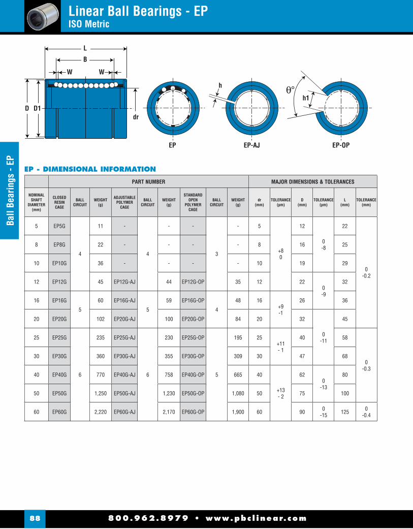
800.962.8979 • www.pbc l inear.com88
Ball
Bear
ings
- EP
Linear Ball Bearings - EPISO Metric
EP - DIMENSIONAL INFORMATION
PART NUMBER MAJOR DIMENSIONS & TOLERANCES
NOMINALSHAFT
DIAMETER(mm)
CLOSEDRESINCAGE
BALLCIRCUIT
WEIGHT(g)
ADJUSTABLEPOLYMER
CAGE
BALLCIRCUIT
WEIGHT(g)
STANDARDOPEN
POLYMERCAGE
BALLCIRCUIT
WEIGHT(g)
dr(mm)
TOLERANCE(μm)
D(mm)
TOLERANCE(μm)
L(mm)
TOLERANCE(mm)
5 EP5G
4
11 -
4
- -
3
- 5
+80
12
0-8
22
0-0.2
8 EP8G 22 - - - - 8 16 25
10 EP10G 36 - - - - 10 19 29
12 EP12G 45 EP12G-AJ 44 EP12G-OP 35 12 220-9
32
16 EP16G
5
60 EP16G-AJ
5
59 EP16G-OP
4
48 16+9-1
26 36
20 EP20G 102 EP20G-AJ 100 EP20G-OP 84 20 32
0-11
45
25 EP25G
6
235 EP25G-AJ
6
230 EP25G-OP
5
195 25+11- 1
40 58
0-0.3
30 EP30G 360 EP30G-AJ 355 EP30G-OP 309 30 47 68
40 EP40G 770 EP40G-AJ 758 EP40G-OP 665 40
+13- 2
620
-13
80
50 EP50G 1,250 EP50G-AJ 1,230 EP50G-OP 1,080 50 75 100
60 EP60G 2,220 EP60G-AJ 2,170 EP60G-OP 1,900 60 90 0-15 125 0
-0.4
h
EP EP-AJ EP-OP
dr
L
B
W W
D D1h1

800.962.8979 • www.pbc l inear.com 89
Ball Bearings - EPLinear Ball Bearings - EP
ISO Metric
EP - DIMENSIONAL INFORMATION (cont.)
h
EP EP-AJ EP-OP
dr
L
B
W W
D D1h1
MAJOR DIMENSIONS & TOLERANCES LOAD RATING
B(mm)
TOLERANCE(mm)
W(mm)
TOLERANCE(mm)
D1(mm)
TOLERANCE(mm)
h(mm)
h1(mm)
ECCENTRICITY(μm)
MAXRADIAL
CLEARANCE ( μm)
DYNAMICC
(N)
STATICCo(N)
NOMINALSHAFT
DIAMETER(mm)
14.5
0 -0.3
1.1
+.140
11.5
0-.11 1
- -
12
-5
206 265 5
16.5 1.1 15.2 - - 265 402 8
22 1.3 18 - - 372 549 10
22.9 1.3 21 0-.13
1.5
7.5
80 -7
510 784 12
24.9 1.3 24.90
-.21
10 774 1,180 16
31.5 1.6 30.3
2
10
60
15 -9
882 1,370 20
44.1
0 -0.4
1.85 37.50
-.25
12.5 980 1,570 25
52.1 1.85 44.5 12.5
50
1,570 2,740 30
60.6 2.15 590
-.303
16.8
17 -13
2,160 4,020 40
77.6 2.65 72 21 3,820 7,940 50
101.7 3.15 86.5 0-.35 27.2 54 20 -16 4,700 10,000 60
(Standard Steel Finish)

800.962.8979 • www.pbc l inear.com90
Doub
le W
ide
- EP-
WDouble Wide - EP-WLinear Ball Bearings
L
Mo
B
dr
W W
D D1
EP-W - DIMENSIONAL INFORMATION
PART NUMBER MAJOR DIMENSIONS & TOLERANCES
NOMINALSHAFT
DIAMETER(mm)
STANDARDPOLYMER
CAGE
BALLCIRCUIT
WEIGHT(g)
dr(mm)
TOLERANCE(μm)
D(mm)
TOLERANCE(μm)
L(mm)
TOLERANCE(mm)
8 EP8GW
4
40 8+9-1
16 0-9 45
0-0.3
12 EP12GW 80 12 220
-11
57
16 EP16GW
5
115 16+11- 1
26 68
20 EP20GW 180 20 32
0-13
80
25 EP25GW
6
430 25+13- 2
40 112
0-0.4
30 EP30GW 615 30 47 123
40 EP40GW 1,400 40
+16- 4
62 0-15 151
50 EP50GW 2,320 50 750
-20
192
60 EP60GW 3,920 60 90 209

800.962.8979 • www.pbc l inear.com 91
Double Wide - EP-W
Double Wide - EP-WLinear Ball Bearings
EP-W - DIMENSIONAL INFORMATION (cont.)
L
Mo
B
dr
W W
D D1
MAJOR DIMENSIONS & TOLERANCES LOAD RATING
B(mm)
TOLERANCE(mm)
W(mm)
TOLERANCE(mm)
D1(mm)
TOLERANCE(mm)
ECCENTRICITY(μm)
DYNAMICC
(N)
STATICCo(N)
ALLOWABLE STATIC
MOMENT Mo
(N-m)
NOMINALSHAFT
DIAMETER(mm)
33
0-0.3
1.1
+.140
15.2 0-.11
15
421 804 4.3 8
45.8 1.3 21 0-.13 813 1,570 11.7 12
49.8 1.3 24.90
-.21
921 1,780 14.2 16
61 1.6 30.3
17
1,370 2,740 25 20
82
0-0.4
1.85 37.50
-.25
1,570 3,140 44 25
104.2 1.85 44.5 2,500 5,490 78.9 30
121.2 2.15 590
-.30 20
3,430 8,040 147 40
155.2 2.65 72 6,080 15,900 396 50
170 3.15 86.5 0-.35 25 7,550 20,000 487 60
(Standard Steel Finish)

800.962.8979 • www.pbc l inear.com92
Roun
d Fl
ange
- E
PFRound Flange Mount - EPFLinear Ball Bearings
EPF - DIMENSIONAL INFORMATION
PART NUMBER MAJOR DIMENSIONS & TOLERANCES
NOMINALSHAFT
DIAMETER(mm)
STANDARDPOLYMER
CAGE
BALLCIRCUIT
WEIGHT(g)
dr(mm)
TOLERANCE(μm)
D(mm)
TOLERANCE(μm)
L(mm)
TOLERANCE(mm)
8 EPF8G
4
41 8+80
16 0-13 25
± 0.3
12 EPF12G 80 12 220
-16
32
16 EPF16G
5
103 16+9-1
26 36
20 EPF20G 182 20 32
0-19
45
25 EPF25G
6
335 25+11-1
40 58
30 EPF30G 560 30 47 68
40 EPF40G 1,175 40
+13-2
620
-22
80
50 EPF50G 1,745 50 75 100
60 EPF60G 3,220 60 90 0-25 125
Dp
Df
Mounting Holes (x4)
dr
X Z
Y
tL
D

800.962.8979 • www.pbc l inear.com 93
Round Flange - EPFRound Flange Mount - EPF
Linear Ball Bearings
EPF - DIMENSIONAL INFORMATION (cont.)
MAJOR DIMENSIONS & TOLERANCES LOAD RATING
Df(mm)
t(mm)
Dp(mm)
X x Y x Z(mm)
ECCENTRICITYID to OD
(inch/μm)
PERPENDICULARITYFLANGE FACE to ID
(inch/μm)
DYNAMICC
(N)
STATICCo(N)
NOMINALSHAFT
DIAMETER(mm)
32 5 24 3.5 x 6.0 x 3.1
12 12
265 402 8
42
6
32 4.5 x 8.0 x 4.1 510 784 12
46 36 4.5 x 8.0 x 4.1 578 892 16
54
8
43 5.5 x 9.3 x 5.1
15 15
862 1,370 20
62 51 5.5 x 9.3 x 5.1 980 1,570 25
76 10 62 6.6 x 11.0 x 6.1 1,570 2,740 30
98
13
80 9.0 x 14.0 x 8.1
17 17
2,160 4,020 40
112 94 9.0 x 14.0 x 8.1 3,820 7,940 50
134 18 112 11.0 x 17.5 x 11.1 20 20 4,700 9,800 60
Dp
Df
Mounting Holes (x4)
dr
X Z
Y
tL
D
(Standard Steel Finish)
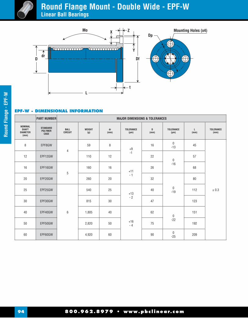
800.962.8979 • www.pbc l inear.com94
Roun
d Fl
ange
- EP
F-W
Round Flange Mount - Double Wide - EPF-WLinear Ball Bearings
Df
DpMounting Holes (x4)X Z
Y
tL
Ddr
Mo
EPF-W - DIMENSIONAL INFORMATION
PART NUMBER MAJOR DIMENSIONS & TOLERANCES
NOMINALSHAFT
DIAMETER(mm)
STANDARDPOLYMER
CAGE
BALLCIRCUIT
WEIGHT(g)
dr(mm)
TOLERANCE(μm)
D(mm)
TOLERANCE(μm)
L(mm)
TOLERANCE(mm)
8 EPF8GW
4
59 8+9-1
16 0-13 45
± 0.3
12 EPF12GW 110 12 220
-16
57
16 EPF16GW
5
160 16+11- 1
26 68
20 EPF20GW 260 20 32
0-19
80
25 EPF25GW
6
540 25+13- 2
40 112
30 EPF30GW 815 30 47 123
40 EPF40GW 1,805 40
+16- 4
620
-22
151
50 EPF50GW 2,820 50 75 192
60 EPF60GW 4,920 60 90 0-25 209
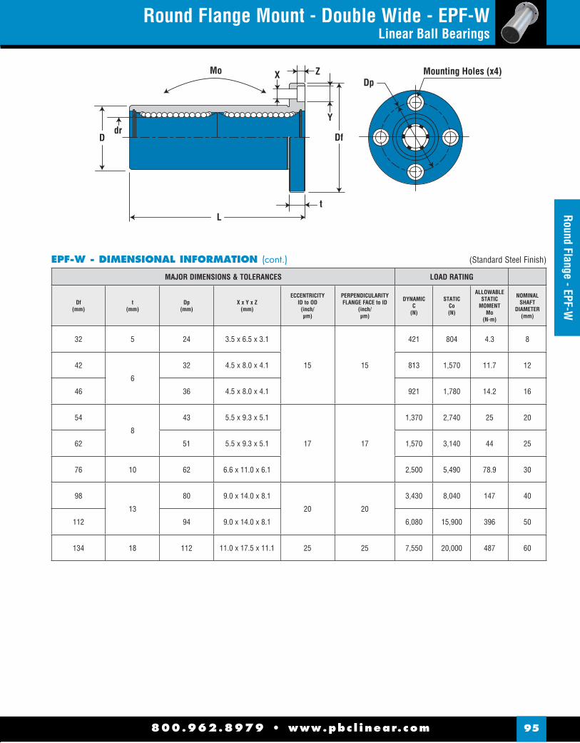
800.962.8979 • www.pbc l inear.com 95
Round Flange - EPF-WRound Flange Mount - Double Wide - EPF-W
Linear Ball Bearings
EPF-W - DIMENSIONAL INFORMATION (cont.)
Df
DpMounting Holes (x4)X Z
Y
tL
Ddr
Mo
MAJOR DIMENSIONS & TOLERANCES LOAD RATING
Df(mm)
t(mm)
Dp(mm)
X x Y x Z(mm)
ECCENTRICITYID to OD
(inch/μm)
PERPENDICULARITYFLANGE FACE to ID
(inch/μm)
DYNAMICC
(N)
STATICCo(N)
ALLOWABLESTATIC
MOMENTMo
(N-m)
NOMINALSHAFT
DIAMETER(mm)
32 5 24 3.5 x 6.5 x 3.1
15 15
421 804 4.3 8
42
6
32 4.5 x 8.0 x 4.1 813 1,570 11.7 12
46 36 4.5 x 8.0 x 4.1 921 1,780 14.2 16
54
8
43 5.5 x 9.3 x 5.1
17 17
1,370 2,740 25 20
62 51 5.5 x 9.3 x 5.1 1,570 3,140 44 25
76 10 62 6.6 x 11.0 x 6.1 2,500 5,490 78.9 30
98
13
80 9.0 x 14.0 x 8.1
20 20
3,430 8,040 147 40
112 94 9.0 x 14.0 x 8.1 6,080 15,900 396 50
134 18 112 11.0 x 17.5 x 11.1 25 25 7,550 20,000 487 60
(Standard Steel Finish)

800.962.8979 • www.pbc l inear.com96
Squa
re F
lang
e - E
PKSquare Flange Mount - EPKLinear Ball Bearings
Mounting Holes (x4)Dp
Df
X Z
Y
tL
Ddr
K
EPK - DIMENSIONAL INFORMATION
PART NUMBER MAJOR DIMENSIONS & TOLERANCES
NOMINALSHAFT
DIAMETER(mm)
STANDARDPOLYMER
CAGE
BALLCIRCUIT
WEIGHT(g)
dr(mm)
TOLERANCE(μm)
D(mm)
TOLERANCE(μm)
L(mm)
TOLERANCE(mm)
8 EPK8G
4
41 8+80
16 0-13 25
± 0.3
12 EPK12G 80 12 220
-16
32
16 EPK16G
5
103 16+9-1
26 36
20 EPK20G 182 20 32
0-19
45
25 EPK25G
6
335 25+11-1
40 58
30 EPK30G 560 30 47 68
40 EPK40G 1,175 40
+13-2
620
-22
80
50 EPK50G 1,745 50 75 100
60 EPK60G 3,220 60 90 0-25 125

800.962.8979 • www.pbc l inear.com 97
Square Flange - EPKSquare Flange Mount - EPK
Linear Ball Bearings
EPK - DIMENSIONAL INFORMATION (cont.)
MAJOR DIMENSIONS & TOLERANCES LOAD RATING
Df(mm)
K(mm)
t(mm)
Dp(mm)
X x Y x Z(mm)
ECCENTRICITYID to OD
(inch/μm)
PERPENDICULARITYFLANGE FACE to ID
(inch/μm)
DYNAMICC
(N)
STATICCo(N)
NOMINALSHAFT
DIAMETER(mm)
32 25 5 24 3.5 x 6.5 x 3.1
12 12
265 402 8
42 32
6
32 4.5 x 8.0 x 4.1 510 784 12
46 35 36 4.5 x 8.0 x 4.1 578 892 16
54 42
8
43 5.5 x 9.3 x 5.1
15 15
862 1,370 20
62 50 51 5.5 x 9.3 x 5.1 980 1,570 25
76 60 10 62 6.6 x 11.0 x 6.1 1,570 2,740 30
98 75
13
80 9.0 x 14.0 x 8.1
17 17
2,160 4,020 40
112 88 94 9.0 x 14.0 x 8.1 3,820 7,940 50
134 106 18 112 11.0 x 17.5 x 11.1 20 20 4,700 9,800 60
Mounting Holes (x4)Dp
Df
X Z
Y
tL
Ddr
K
(Standard Steel Finish)

800.962.8979 • www.pbc l inear.com98
Squa
re F
lang
e - E
PK-W
Square Flange Mount - Double Wide - EPK-WLinear Ball Bearings
Df
X Z
Y
tL
Ddr
MoMounting Holes (x4)
K
Dp
EPK-W - DIMENSIONAL INFORMATION
PART NUMBER MAJOR DIMENSIONS & TOLERANCES
NOMINALSHAFT
DIAMETER(mm)
STANDARDPOLYMER
CAGE
BALLCIRCUIT
WEIGHT(g)
dr(mm)
TOLERANCE(μm)
D(mm)
TOLERANCE(μm)
L(mm)
TOLERANCE(mm)
8 EPK8GW
4
51 8+9-1
16 0-13 45
± 0.3
12 EPK12GW 90 12 220
-16
57
16 EPK16GW
5
135 16+11-1
26 68
20 EPK20GW 225 20 32
0-19
80
25 EPK25GW
6
500 25+13-2
40 112
30 EPK30GW 720 30 47 123
40 EPK40GW 1,600 40
+16-4
620
-22
151
50 EPK50GW 2,620 50 75 192
60 EPK60GW 4,480 60 90 0-25 209

800.962.8979 • www.pbc l inear.com 99
Square Flange - EPK-WSquare Flange Mount - Double Wide - EPK-W
Linear Ball Bearings
EPK-W - DIMENSIONAL INFORMATION (cont.)
Df
X Z
Y
tL
Ddr
MoMounting Holes (x4)
K
Dp
MAJOR DIMENSIONS & TOLERANCES LOAD RATING
Df(mm)
K(mm)
t(mm)
Dp(mm)
X x Y x Z(mm)
ECCENTRICITYID to OD
(inch/μm)
PERPENDICULARITYFLANGE FACE to ID
(inch/μm)
DYNAMICC
(N)
STATICCo(N)
ALLOWABLE STATIC
MOMENT Mo
(N-m)
NOMINALSHAFT
DIAMETER(mm)
32 25 5 24 3.5 x 6.5 x 3.1
15 15
421 804 4.3 8
42 32
6
32 4.5 x 8.0 x 4.1 813 1,570 11.7 12
46 35 36 4.5 x 8.0 x 4.1 921 1,780 14.2 16
54 42
8
43 5.5 x 9.3 x 5.1
17 17
1,370 2,740 25 20
62 50 51 5.5 x 9.3 x 5.1 1,570 3,140 44 25
76 60 10 62 6.6 x 11.0 x 6.1 2,500 5,490 78.9 30
98 75
13
80 9.0 x 14.0 x 8.1
20 20
3,430 8,040 147 40
112 88 94 9.0 x 14.0 x 8.1 6,080 15,900 396 50
134 106 18 112 11.0 x 17.5 x 11.1 25 25 7,550 20,000 487 60
(Standard Steel Finish)

800.962.8979 • www.pbc l inear.com100
Roun
d Fl
ange
- EP
FCRound Flange - Center Mount - EPFCLinear Ball Bearings
Dp
Df
Mounting Holes (x4)XZ
Y
tlL
Ddr
Mo
EPFC - DIMENSIONAL INFORMATION
PART NUMBER MAJOR DIMENSIONS & TOLERANCES
NOMINALSHAFT
DIAMETER(mm)
STANDARDPOLYMER
CAGE
BALLCIRCUIT
WEIGHT(g)
dr(mm)
TOLERANCE(μm)
D(mm)
TOLERANCE(μm)
L(mm)
TOLERANCE(mm) (mm)
8 EPFC8G
4
59 8+9-1
16 0-13 45
± 0.3
20
12 EPFC12G 110 12 220
-16
57 25.5
16 EPFC16G
5
160 16+11-1
26 68 31
20 EPFC20G 260 20 32
0-19
80 36
25 EPFC25G
6
540 25+13-2
40 112 52
30 EPFC30G 815 30 47 123 56.5
40 EPFC40G 1,805 40
+16-4
620
-22
151 69
50 EPFC50G 2,820 50 75 192 89.5
60 EPFC60G 4,920 60 90 0-25 209 95.5

800.962.8979 • www.pbc l inear.com 101
Round Flange - EPFC
EPFC - DIMENSIONAL INFORMATION (cont.)
Dp
Df
Mounting Holes (x4)XZ
Y
tlL
Ddr
Mo
MAJOR DIMENSIONS & TOLERANCES LOAD RATING
Df(mm)
t(mm)
Dp(mm)
X x Y x Z(mm)
ECCENTRICITYID to OD
(inch/μm)
PERPENDICULARITYFLANGE FACE to ID
(inch/μm)
DYNAMICC
(N)
STATICCo(N)
ALLOWABLE STATIC
MOMENT Mo
(N-m)
NOMINALSHAFT
DIAMETER(mm)
32 5 24 3.5 x 6.5x 3.1
15 15
421 804 4.3 8
42
6
32 4.5 x 8.0 x 4.1 913 1,570 11.7 12
46 36 4.5 x 8.0 x 4.1 921 1,780 14.2 16
54
8
43 5.5 x 9.3 x 5.1
17 17
1,370 2,740 25 20
62 51 5.5 x 9.3 x 5.1 1,570 3,140 44 25
76 10 62 6.6 x 11.0 x 6.1 2,500 5,490 78.9 30
98
13
80 9.0 x 14.0 x 8.1
20 20
3,430 8,040 147 40
112 94 9.0 x 14.0 x 8.1 6,080 15,900 396 50
134 18 112 11.0 x 17.5 x 11.1 25 25 7,550 20,000 487 60
(Standard Steel Finish)
Round Flange - Center Mount - EPFCLinear Ball Bearings
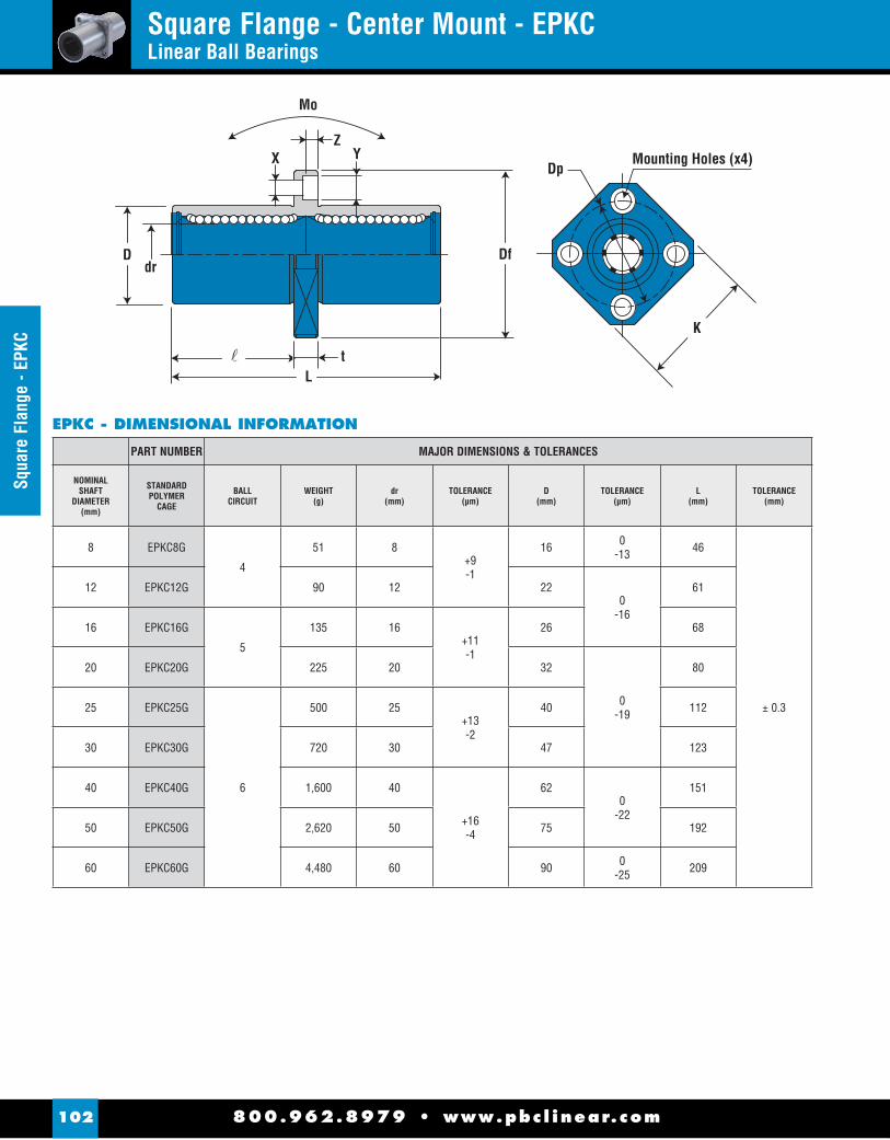
800.962.8979 • www.pbc l inear.com102
Squa
re F
lang
e - E
PKC
Square Flange - Center Mount - EPKCLinear Ball Bearings
Dp
Df
Mounting Holes (x4)XZ
Y
tlL
Ddr
Mo
K
EPKC - DIMENSIONAL INFORMATION
PART NUMBER MAJOR DIMENSIONS & TOLERANCES
NOMINALSHAFT
DIAMETER(mm)
STANDARDPOLYMER
CAGE
BALLCIRCUIT
WEIGHT(g)
dr(mm)
TOLERANCE(μm)
D(mm)
TOLERANCE(μm)
L(mm)
TOLERANCE(mm)
8 EPKC8G
4
51 8+9-1
16 0-13 46
± 0.3
12 EPKC12G 90 12 220
-16
61
16 EPKC16G
5
135 16+11-1
26 68
20 EPKC20G 225 20 32
0-19
80
25 EPKC25G
6
500 25+13-2
40 112
30 EPKC30G 720 30 47 123
40 EPKC40G 1,600 40
+16-4
620
-22
151
50 EPKC50G 2,620 50 75 192
60 EPKC60G 4,480 60 90 0-25 209

800.962.8979 • www.pbc l inear.com 103
Square Flange - EPKCSquare Flange - Center Mount - EPKC
Linear Ball Bearings
EPKC - DIMENSIONAL INFORMATION (cont.)
Dp
Df
Mounting Holes (x4)XZ
Y
tlL
Ddr
Mo
K
MAJOR DIMENSIONS & TOLERANCES LOAD RATING
(mm)
Df(mm)
K(mm)
t(mm)
Dp(mm)
X x Y x Z(mm)
ECCENTRICITYID to OD
(inch/μm)
PERPENDICULARITYFLANGE FACE to ID
(inch/μm)
DYNAMICC
(N)
STATICCo(N)
ALLOWABLE STATIC
MOMENT Mo
(N-m)
NOMINALSHAFT
DIAMETER(mm)
20.5 32 25 5 24 3.5 x 6.5 x 3.1
15 15
421 804 4.3 8
27.5 42 32
6
32 4.5 x 8.0 x 4.1 913 1,570 11.7 12
31 46 35 36 4.5 x 8.0 x 4.1 921 1,780 14.2 16
36 54 42
8
43 5.5 x 9.3 x 5.1
17 17
1,370 2,740 25 20
52 62 50 51 5.5 x 9.3 x 5.1 1,570 3,140 44 25
56.5 76 60 10 62 6.6 x 11.0 x 6.1 2,500 5,490 78.9 30
69 98 75
13
80 9.0 x 14.0 x 8.1
20 20
3,430 8,040 147 40
89.5 112 88 94 9.0 x 14.0 x 8.1 6,080 15,900 396 50
95.5 134 106 18 112 11.0 x 17.5 x 11.1 25 25 7,550 20,000 487 60
(Standard Steel Finish)

800.962.8979 • www.pbc l inear.com104
Pillo
w B
lock
s - E
PPN
& E
PPM
N Pillow Block - EPPN & EPPMNLinear Ball Bearings
NOTES: (1) Standard pillow block assembly includes self-aligning housing (2) All standard metric pillow blocks use standard “EP” series bearings found on page 88-89.
(For empty pillow block with no bearings included add LBB after the part number.)
PART NO.
dNOM.I.D.
HH1 A A1 L N
N2 N3 N4 N5 S S2 S3
ASSEM.WT.
PRECISION MIN.CENTERLINE
.015 HEIGHT WIDTH .013 LENGTH BOLT (Kg.)
EPPM08G 8 15 28 35 17.5 32 M4 x 0.720.15
25.15 9 14.5 N / A N / A N / A 0.069
EPPM10G 10 16 31.5 40 20 36 M5 x 0.8 29.1511
15
4
29 31 0.095
EPPM12G 12 18 35 43 21.5 39 M5 x 0.8 23.15 3 .15 16.5 32 34 0.118
EPPM16G 16 22 42 53 26.5 43 M6 x 1.0 26.15 40.15 13 21 35 42 0.200
EPPM20G 20 25 50 60 30 54 M8 x 1.25 32.15 45.15 18 24 5 45 50 0.329
EPPM25G 25 30 60 78 39 67 M10 x 1.5 40.15 60.1522
296
20 64 0.655
EPPM30G 30 35 71 87 43.5 79 M10 x 1.5 45.15 68.15 34 30 72 1.020
EPPM40G 40 45 91 108 54 91 M12 x1.75 58.15 86.15 26 44 8 35 90 1.846
EPPM50G 50 50 105 132 66 113 M16 x 2.0 50.20 108.2 34 49 10 42 108 3.169
EPPM - CLOSED PILLOW BLOCKS
PART NO.
dNOM.I.D. H H1 A A1 L N
N2 N3 N4 N5 S S2 S3 a
ASSEM.WT.
PRECISION MIN.CENTERLINE
.015 HEIGHT WIDTHCENTERLINE
.013 LENGTH BOLT (kg.)
EPPMN12G 12 18 28 43 21.5 39 M5 x 0.8 23.15 32.15 11 16.54
32 34 66 0.096
EPPMN16G 16 22 35 53 26.5 43 M6 x 1.0 26.15 40.15 13 21 35 42 68 0.162
EPPMN20G 20 25 42 60 30 54 M8 x 1.25 32.15 45.15 18 24 5 45 50 60 0.267
EPPMN25G 25 30 51 78 39 67 M10 x 1.5 40.15 60.1522
296
20 64 60 0.536
EPPMN30G 30 35 60 87 43.5 79 M10 x 1.5 45.15 68.15 34 30 72 60 0.831
EPPMN40G 40 45 77 108 54 91 M12 x 1.75 58.15 86.15 26 44 8 35 90 60 1.499
EPPMN50G 50 50 88 132 66 113 M16 x 2.0 50.20 108.2 34 49 10 42 108 60 2.539
EPPMN - OPEN PILLOW BLOCKS
L
A
N2 S2
N3 S3
H1
H
N
N5
N4A1
d
S
ANTI-ROTATION PIN
N
A
a
N2 S2
N3
S3
S
L
H1
H
d
A1 N4
N5
NOTES: (1) Standard pillow block assembly includes self-aligning housing. (2) All standard metric pillow blocks use standard “EP” series bearings found on page 88-89. (3) Straight bore pillow block assembly includes standard O.D. “EP” series bearing in straight bore housing.

800.962.8979 • www.pbc l inear.com 105
Compact Thin W
all - KHPCompact Thin Wall - KHP
Linear Ball Bearings
ØD Ød
C
KHP - BASIC DIMENSIONAL INFORMATION
PART NO.
DIMENSIONS (mm) LOAD RATING
Ød TOLERANCES ØD C TOLERANCES WEIGHT DYNAMIC C STATIC Co
mm Max (μm) Min (μm) mm mm Max (μm) Min (μm) (g) (N) (N)
KHP6 6 12 0 12 22 0 -520 7.0 400 239
KHP8 8 15 0 15 24 0 -520 12.0 435 280
KHP10 10 15 0 17 26 0 -520 14.5 500 370
KHP12 12 18 0 19 28 0 -520 18.5 620 510
KHP14 14 18 0 21 28 0 -520 20.5 620 520
KHP16 16 18 0 24 30 0 -520 27.5 800 620
KHP20 20 21 0 28 30 0 -520 32.5 950 790
KHP25 25 21 0 35 40 0 -620 66.0 1,990 1,670
KHP30 30 21 0 40 50 0 -620 95.0 2,880 2,700
KHP40 40 25 0 40 60 0 -740 182.0 4,400 4,450
KHP50 50 25 0 52 70 0 -740 252.0 5,500 6,300
(Standard Steel Finish)

800.962.8979 • www.pbc l inear.com106
Ball
Bear
ings
- JP
Linear Ball Bearings - JPJIS Metric
JP - DIMENSIONAL INFORMATION
PART NUMBER MAJOR DIMENSIONS & TOLERANCES
NOMINALSHAFT
DIAMETER(mm)
STANDARDCLOSE
POLYMERCAGE
BALLCIRCUIT
WEIGHT(g)
ADJUSTABLEPOLYMER
CAGE
BALLCIRCUIT
WEIGHT(g)
STANDARDOPEN
POLYMERCAGE
BALLCIRCUIT
WEIGHT(g)
dr(mm)
TOLERANCE(μm)
D(mm)
TOLERANCE(μm)
L(mm)
TOLERANCE(mm)
8 JP8G
4
17 -
4
- -
3
- 8
0-9
15 0-11 24
0-0.2
10 JP10G 36 - - - - 10 19
0-13
29
12 JP12G 42 JP12G-AJ 42 JP12G-OP 32 12 21 30
13 JP13G 49 JP13G-AJ 48 JP13G-OP 37 13 23 32
16 JP16G
5
76 JP16G-AJ
5
75 JP16G-OP 58 16 28 37
20 JP20G 100 JP20G-AJ 98 JP20G-OP 4 79 20
0-10
32
0-16
42
25 JP25G
6
240 JP25G-AJ
6
237 JP25G-OP
5
203 25 40 59
0-0.3
30 JP30G 270 JP30G-AJ 262 JP30G-OP 228 30 45 64
35 JP35G 425 JP35G-AJ 420 JP35G-OP 355 35
0-12
52
0-19
70
40 JP40G 654 JP40G-AJ 640 JP40G-OP 546 40 60 80
50 JP50G 1,700 JP50G-AJ 1,680 JP50G-OP 1,420 50 80 100
60 JP60G 2,000 JP60G-AJ 1,980 JP60G-OP 1,650 60 0-15 90 0
-22 110
h
JP JP-AJ JP-OP
dr
L
B
W W
D D1h1
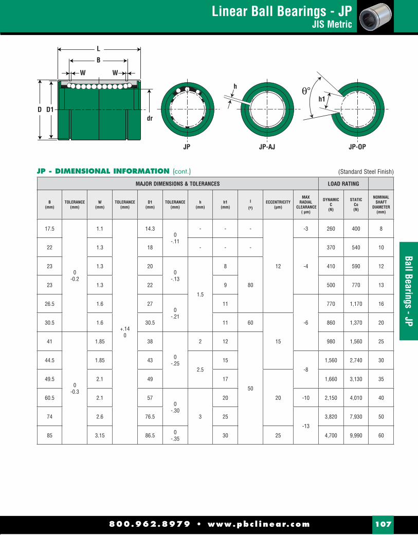
800.962.8979 • www.pbc l inear.com 107
Ball Bearings - JP
JP - DIMENSIONAL INFORMATION (cont.)
MAJOR DIMENSIONS & TOLERANCES LOAD RATING
B(mm)
TOLERANCE(mm)
W(mm)
TOLERANCE(mm)
D1(mm)
TOLERANCE(mm)
h(mm)
h1(mm)
I
(º)ECCENTRICITY
(μm)
MAXRADIAL
CLEARANCE ( μm)
DYNAMICC
(N)
STATICCo(N)
NOMINALSHAFT
DIAMETER(mm)
17.5
0-0.2
1.1
+.140
14.30
-.11
- - -
12
-3 260 400 8
22 1.3 18 - - -
-4
370 540 10
23 1.3 200
-.13
1.5
8
80
410 590 12
23 1.3 22 9 500 770 13
26.5 1.6 270
-.21
11
-6
770 1,170 16
30.5 1.6 30.5 11 60
15
860 1,370 20
41
0-0.3
1.85 38
0-.25
2 12
50
980 1,560 25
44.5 1.85 43
2.5
15
-8
1,560 2,740 30
49.5 2.1 49 17
20
1,660 3,130 35
60.5 2.1 570
-.303
20 -10 2,150 4,010 40
74 2.6 76.5 25
-13
3,820 7,930 50
85 3.15 86.5 0-.35 30 25 4,700 9,990 60
h
JP JP-AJ JP-OP
dr
L
B
W W
D D1h1
(Standard Steel Finish)
Linear Ball Bearings - JPJIS Metric

Double Wide - JP-WLinear Ball Bearings
800.962.8979 • www.pbc l inear.com108
Doub
le W
ide
- JP-
W
L
Mo
B
dr
W W
D D1
JP-W - DIMENSIONAL INFORMATION
PART NUMBER MAJOR DIMENSIONS & TOLERANCES
NOMINALSHAFT
DIAMETER(mm)
STANDARDPOLYMER
CAGE
BALLCIRCUIT
WEIGHT(g)
dr(mm)
TOLERANCE(μm)
D(mm)
TOLERANCE(μm)
L(mm)
TOLERANCE(mm)
8 JP8GW
4
31 8
0-10
15 0-13 45
0-0.3
12 JP12GW 80 12 210
-16
57
16 JP16GW
5
145 16 28 70
20 JP20GW 180 20
0-12
32
0-19
80
25 JP25GW
6
440 25 40 112
0-0.4
30 JP30GW 580 30 45 123
40 JP40GW 1,170 400
-15
600
-22
151
50 JP50GW 3,100 50 80 192
60 JP60GW 3,500 60 0-20 90 0
-25 209

Double Wide - JP-WLinear Ball Bearings
800.962.8979 • www.pbc l inear.com 109
Double Wide - JP-W
JP-W - DIMENSIONAL INFORMATION (cont.)
L
Mo
B
dr
W W
D D1
MAJOR DIMENSIONS & TOLERANCES LOAD RATING
B(mm)
TOLERANCE(mm)
W(mm)
TOLERANCE(mm)
D1(mm)
TOLERANCE(mm)
ECCENTRICITY(μm)
DYNAMICC
(N)
STATICCo(N)
ALLOWABLE STATIC
MOMENT Mo
(N-m)
NOMINALSHAFT
DIAMETER(mm)
35
0-0.3
1.1
+.140
14.3 0-.11
15
431 784 4.3 8
46 1.3 20 0-.13 657 1,200 10.9 12
53 1.6 270
-.21
1,230 2,350 19.7 16
61 1.6 30.5
20
1,400 2,750 26.8 20
82
0-0.4
1.85 380
-.25
1,560 3,140 43.4 25
89 1.85 43 2,490 5,490 82.8 30
121 2.1 570
-.30 25
3,430 8,040 147 40
148 2.6 76.5 6,080 15,900 397 50
170 3.15 86.5 0-.35 30 7,650 20,000 530 60
(Standard Steel Finish)

800.962.8979 • www.pbc l inear.com110
Roun
d Fl
ange
- JP
FRound Flange Mount - JPFLinear Ball Bearings
Dp
Df
Mounting Holes (x4)
dr
X Z
Y
tL
D
JPF - DIMENSIONAL INFORMATION
PART NUMBER MAJOR DIMENSIONS & TOLERANCES
NOMINALSHAFT
DIAMETER(mm)
STANDARDPOLYMER
CAGE
BALLCIRCUIT
WEIGHT(g)
dr(mm)
TOLERANCE(μm)
D(mm)
TOLERANCE(μm)
L(mm)
TOLERANCE(mm)
8 JPF8G
4
37 8
0-9
15 0-13 24
± 0.3
12 JPF12G 76 12 210
-16
30
16 JPF16G
5
120 16 28 37
20 JPF20G 180 20
0-10
32
0-19
42
25 JPF25G
6
340 25 40 59
30 JPF30G 470 30 45 64
40 JPF40G 1,060 400
-12
600
-22
80
50 JPF50G 2,200 50 80 100
60 JPF60G 3,000 60 0-15 90 0
-25 110

800.962.8979 • www.pbc l inear.com 111
Round Flange - JPFRound Flange Mount - JPF
Linear Ball Bearings
JPF - DIMENSIONAL INFORMATION (cont.)
MAJOR DIMENSIONS & TOLERANCES LOAD RATING
Df(mm)
t(mm)
Dp(mm)
X x Y x Z(mm)
ECCENTRICITYID to OD
(inch/μm)
PERPENDICULARITYFLANGE FACE to ID
(inch/μm)
DYNAMICC
(N)
STATICCo(N)
NOMINALSHAFT
DIAMETER(mm)
32 5 24 3.5 x 6 x 3.1
12 12
274 392 8
42
6
32
4.5 x 7.5 x 4.1
510 784 12
48 38 774 1,180 16
54
8
43
5.5 x 9 x 5.1
15 15
882 1,370 20
62 51 980 1,570 25
74 10 60 6.6 x 11 x 6.1 1,570 2,740 30
96
13
78
9 x 14 x 8.1 20 20
2,160 4,020 40
116 98 3,820 7,940 50
134 18 112 11 x 17 x 11.1 25 25 4,700 10,000 60
(Standard Steel Finish)
Dp
Df
Mounting Holes (x4)
dr
X Z
Y
tL
D

800.962.8979 • www.pbc l inear.com112
Roun
d Fl
ange
- JP
F-W
Round Flange Mount - Double Wide - JPF-WLinear Ball Bearings
Df
DpMounting Holes (x4)X Z
Y
tL
Ddr
Mo
JPF-W - DIMENSIONAL INFORMATION
PART NUMBER MAJOR DIMENSIONS & TOLERANCES
NOMINALSHAFT
DIAMETER(mm)
STANDARDPOLYMER
CAGE
BALLCIRCUIT
WEIGHT(g)
dr(mm)
TOLERANCE(μm)
D(mm)
TOLERANCE(μm)
L(mm)
TOLERANCE(mm)
8 JPF8GW
4
51 8
0-10
15 0-13 45
± 0.3
12 JPF12GW 110 12 210
-16
57
16 JPF16GW
5
190 16 28 70
20 JPF20GW 260 20
0-12
32
0-19
80
25 JPF25GW
6
540 25 40 112
30 JPF30GW 680 30 45 123
40 JPF40GW 1,570 400
-15
600
-22
151
50 JPF50GW 3,600 50 80 192
60 JPF60GW 4,500 60 0-20 90 0
-25 209

800.962.8979 • www.pbc l inear.com 113
Round Flange - JPF-WRound Flange Mount - Double Wide - JPF-W
Linear Ball Bearings
JPF-W - DIMENSIONAL INFORMATION (cont.)
Df
DpMounting Holes (x4)X Z
Y
tL
Ddr
Mo
MAJOR DIMENSIONS & TOLERANCES LOAD RATING
Df(mm)
t(mm)
Dp(mm)
X x Y x Z(mm)
ECCENTRICITYID to OD
(inch/μm)
PERPENDICULARITYFLANGE FACE to ID
(inch/μm)
DYNAMICC
(N)
STATICCo(N)
ALLOWABLESTATIC
MOMENTMo
(N-m)
NOMINALSHAFT
DIAMETER(mm)
32 5 24 3.5 x 6 x 3.1
15 15
431 784 4.3 8
42 6 32
4.5 x 7.5 x 4.1
813 1,570 10.9 12
48 6 38 1,230 2,350 19.7 16
54 8 43
5.5 x 9 x 5.1
20 20
1,400 2,740 26.8 20
62 8 51 1,560 3,140 43.4 25
74 10 60 6.6 x 11 x 6.1 2,490 5,490 82.8 30
96 13 78
9 x 14 x 8.1 25 25
3,430 8,040 147 40
116 13 98 6,080 15,900 397 50
134 18 112 11 x 17 x 11.1 30 30 7,550 20,000 530 60
(Standard Steel Finish)
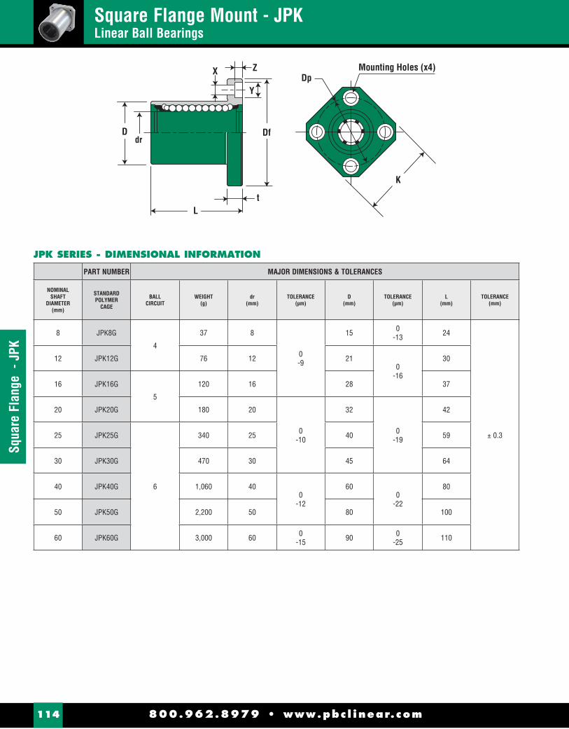
800.962.8979 • www.pbc l inear.com114
Squa
re F
lang
e -
JPK
Square Flange Mount - JPKLinear Ball Bearings
Mounting Holes (x4)Dp
Df
X Z
Y
tL
Ddr
K
JPK SERIES - DIMENSIONAL INFORMATION
PART NUMBER MAJOR DIMENSIONS & TOLERANCES
NOMINALSHAFT
DIAMETER(mm)
STANDARDPOLYMER
CAGE
BALLCIRCUIT
WEIGHT(g)
dr(mm)
TOLERANCE(μm)
D(mm)
TOLERANCE(μm)
L(mm)
TOLERANCE(mm)
8 JPK8G
4
37 8
0-9
15 0-13 24
± 0.3
12 JPK12G 76 12 210
-16
30
16 JPK16G
5
120 16 28 37
20 JPK20G 180 20
0-10
32
0-19
42
25 JPK25G
6
340 25 40 59
30 JPK30G 470 30 45 64
40 JPK40G 1,060 400
-12
600
-22
80
50 JPK50G 2,200 50 80 100
60 JPK60G 3,000 60 0-15 90 0
-25 110

Square Flange Mount - JPKLinear Ball Bearings
800.962.8979 • www.pbc l inear.com 115
Square Flange - JPK
JPK - DIMENSIONAL INFORMATION (cont.)
MAJOR DIMENSIONS & TOLERANCE LOAD RATING
Df(mm)
K(mm)
t(mm)
Dp(mm)
X x Y x Z(mm)
ECCENTRICITYID to OD
(inch/μm)
PERPENDICULARITYFLANGE FACE to ID
(inch/μm)
DYNAMICC
(N)
STATICCo(N)
NOMINALSHAFT
DIAMETER(mm)
32 25 5 24 3.5 x 6 x 3.1
12 12
274 392 8
42 32
6
32
4.5 x 7.5 x 4.1
510 784 12
48 37 38 774 1,180 16
54 42
8
43
5.5 x 9 x 5.1
15 15
882 1,370 20
62 50 51 980 1,570 25
74 58 10 60 6.6 x 11 x 6.1 1,570 2,740 30
96 75
13
78
9 x 14 x 8.1 20 20
2,160 4,020 40
116 92 98 3,820 7,940 50
134 106 18 112 11 x 17 x 11.1 25 25 4,700 10,000 60
Mounting Holes (x4)Dp
Df
X Z
Y
tL
Ddr
K
(Standard Steel Finish)
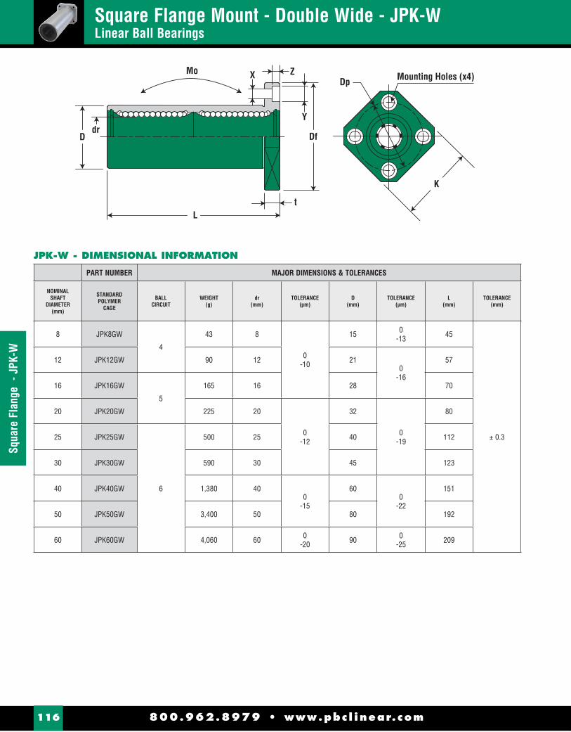
800.962.8979 • www.pbc l inear.com116
Squa
re F
lang
e -
JPK-
WSquare Flange Mount - Double Wide - JPK-WLinear Ball Bearings
Df
X Z
Y
tL
Ddr
MoMounting Holes (x4)
K
Dp
JPK-W - DIMENSIONAL INFORMATION
PART NUMBER MAJOR DIMENSIONS & TOLERANCES
NOMINALSHAFT
DIAMETER(mm)
STANDARDPOLYMER
CAGE
BALLCIRCUIT
WEIGHT(g)
dr(mm)
TOLERANCE(μm)
D(mm)
TOLERANCE(μm)
L(mm)
TOLERANCE(mm)
8 JPK8GW
4
43 8
0-10
15 0-13 45
± 0.3
12 JPK12GW 90 12 210
-16
57
16 JPK16GW
5
165 16 28 70
20 JPK20GW 225 20
0-12
32
0-19
80
25 JPK25GW
6
500 25 40 112
30 JPK30GW 590 30 45 123
40 JPK40GW 1,380 400
-15
600
-22
151
50 JPK50GW 3,400 50 80 192
60 JPK60GW 4,060 60 0-20 90 0
-25 209

800.962.8979 • www.pbc l inear.com 117
Square Flange - JPK-WSquare Flange Mount - Double Wide - JPK-W
Linear Ball Bearings
JPK-W - DIMENSIONAL INFORMATION (cont.)
Df
X Z
Y
tL
Ddr
MoMounting Holes (x4)
K
Dp
MAJOR DIMENSIONS & TOLERANCE LOAD RATING
Df(mm)
K(mm)
t(mm)
Dp(mm)
X x Y x Z(mm)
ECCENTRICITYID to OD
(inch/μm)
PERPENDICULARITYFLANGE FACE to ID
(inch/μm)
DYNAMICC
(N)
STATICCo(N)
ALLOWABLE STATIC
MOMENT Mo
(N-m)
NOMINALSHAFT
DIAMETER(mm)
32 25 5 24 3.5 x 6 x 3.1
15 15
431 784 4.3 8
42 32
6
32
4.5 x 7.5 x 4.1
813 1,570 10.9 12
48 37 38 1,230 2,350 19.7 16
54 42
8
43
5.5 x 9 x 5.1
20 20
1,400 2,740 26.8 20
62 50 51 1,560 3,140 43.4 25
74 58 10 60 6.6 x 11 x 6.1 2,490 5,490 82.8 30
96 75
13
78
9 x 14 x 8.1 25 25
3,430 8,040 147 40
116 92 98 6,080 15,900 397 50
134 106 18 112 11 x 17 x 11.1 30 30 7,550 20,000 530 60
(Standard Steel Finish)

800.962.8979 • www.pbc l inear.com118
Roun
d Fl
ange
- JP
FCRound Flange - Center Mount - JPFCLinear Ball Bearings
Dp
Df
Mounting Holes (x4)XZ
Y
tlL
Ddr
Mo
JPFC - DIMENSIONAL INFORMATION
PART NUMBER MAJOR DIMENSIONS & TOLERANCES
NOMINALSHAFT
DIAMETER(mm)
STANDARDPOLYMER
CAGE
BALLCIRCUIT
WEIGHT(g)
dr(mm)
TOLERANCE(μm)
D(mm)
TOLERANCE(μm)
L(mm)
TOLERANCE(mm) (mm)
8 JPFC8G
4
51 8
0-10
15 0-13 45
± 0.3
20.0
12 JPFC12G 110 12 210
-16
57 25.5
16 JPFC16G
5
190 16 28 70 32.0
20 JPFC20G 260 20
0-12
32
0-19
80 36.0
25 JPFC25G
6
540 25 40 112 52.0
30 JPFC30G 680 30 45 123 56.5
40 JPFC40G 1,570 400
-15
600
-22
151 69.0
50 JPFC50G 3,600 50 80 192 89.5
60 JPFC60G 4,500 60 0-20 90 0
-25 209 95.5

800.962.8979 • www.pbc l inear.com 119
Round Flange - JPFCRound Flange - Center Mount - JPFC
Linear Ball Bearings
JPFC - DIMENSIONAL INFORMATION (cont.)
Dp
Df
Mounting Holes (x4)XZ
Y
tlL
Ddr
Mo
MAJOR DIMENSIONS & TOLERANCES LOAD RATING
Df(mm)
t(mm)
Dp(mm)
X x Y x Z(mm)
ECCENTRICITYID to OD
(inch/μm)
PERPENDICULARITYFLANGE FACE to ID
(inch/μm)
DYNAMICC
(N)
STATICCo(N)
ALLOWABLE STATIC
MOMENT Mo
(N-m)
NOMINALSHAFT
DIAMETER(mm)
32 5 24 3.5 x 6 x 3.1
15 15
431 784 4.3 8
42
6
32
4.5 x 7.5 x 4.1
813 1,570 10.9 12
48 38 1,230 2,350 19.7 16
54
8
43
5.5 x 9 x 5.1
20 20
1,400 2,740 26.8 20
62 51 1,560 3,140 43.4 25
74 10 60 6.6 x 11 x 6.1 2,490 5,490 82.8 30
96
13
78
9 x 14 x 8.1 25 25
3,430 8,040 147 40
116 98 6,080 15,900 397 50
134 18 112 11 x 17 x 11.1 30 30 7,550 20,000 530 60
(Standard Steel Finish)

800.962.8979 • www.pbc l inear.com120
Squa
re F
lang
e - J
PKC
Square Flange - Center Mount - JPKCLinear Ball Bearings
Dp
Df
Mounting Holes (x4)XZ
Y
tlL
Ddr
Mo
K
JPKC - DIMENSIONAL INFORMATION
PART NUMBER MAJOR DIMENSIONS & TOLERANCES
NOMINALSHAFT
DIAMETER(mm)
STANDARDPOLYMER
CAGE
BALLCIRCUIT
WEIGHT(g)
dr(mm)
TOLERANCE(μm)
D(mm)
TOLERANCE(μm)
L(mm)
TOLERANCE(mm) (mm)
8 JPKC8G
4
43 8
0-10
15 0-13 45
± 0.3
20
12 JPKC12G 90 12 210
-16
57 25.5
16 JPKC16G
5
165 16 28 70 32
20 JPKC20G 225 20
0-12
32
0-19
80 36
25 JPKC25G
6
500 25 40 112 52
30 JPKC30G 590 30 45 123 56.5
40 JPKC40G 1,380 400
-15
600
-22
151 69
50 JPKC50G 3,400 50 80 192 89.5
60 JPKC60G 4,060 60 0-20 90 0
-25 209 95.5

800.962.8979 • www.pbc l inear.com 121
Square Flange - JPKC
JPKC - DIMENSIONAL INFORMATION (cont.)
Dp
Df
Mounting Holes (x4)XZ
Y
tlL
Ddr
Mo
K
MAJOR DIMENSIONS & TOLERANCE LOAD RATING
Df(mm)
K(mm)
t(mm)
Dp(mm)
X x Y x Z(mm)
ECCENTRICITYID to OD
(inch/μm)
PERPENDICULARITYFLANGE FACE to ID
(inch/μm)
DYNAMICC
(N)
STATICCo(N)
ALLOWABLE STATIC
MOMENT Mo
(N-m)
NOMINALSHAFT
DIAMETER(mm)
32 25 5 24 3.5 x 6 x 3.1
15 15
431 784 4.3 8
42 32
6
32
4.5 x 7.5 x 4.1
813 1,570 10.9 12
48 37 38 1,230 2,350 19.7 16
54 42
8
43
5.5 x 9 x 5.1
20 20
1,400 2,740 26.8 20
62 50 51 1,560 3,140 43.4 25
74 58 10 60 6.6 x 11 x 6.1 2,490 5,490 82.8 30
96 75
13
78
9 x 14 x 8.1 25 25
3,430 8,040 147 40
116 92 98 6,080 15,900 397 50
134 106 18 112 11 x 17 x 11.1 30 30 7,550 20,000 530 60
(Standard Steel Finish)
Square Flange - Center Mount - JPKCLinear Ball Bearings

800.962.8979 • www.pbc l inear.com122
Ball
Bear
ings
Linear Ball BearingsProduct Overview
ORDERING INFORMATION
ModificationSymbol Specification No Entry...... Standard TypeAJ ............... Adustable TypeOP............... Open Type
OPIP C 10 G
Retainer MaterialSymbol Specification G.......... Polymer Cage
W
Symbol Specification W ......... Double wide
Nominal Shaft Diameter
TypeIP: Inch dimension seriesEP: ISO metric dimension seriesJP: JIS metric dimension seriesKHP: ISO metric thin wall dimension series
Flange Type CenterFC - Round flange center mountKC - Square flange center mount
F
Flange TypeF - Round flangeK - Square flange
• Simplicity® ball bearing consists of an outer cylinder, ball retainer, balls and two end rings. The ball retainer which holds the balls in the recirculating tracks is held inside the outer cylinder by end rings.
• Those parts are assembled to optimize their required functions.
• The outer shell is heat treated to ensure long life.
• The ball retainer is molded from a durable polymer to ensure smooth and quiet motion.
PRODUCT OVERVIEW
High Precision and Rigidity The Simplicity® ball bearing is produced from a solid steel outer cylinder and incorporates an industrial strength polymer retainer.
Ease of Assembly The standard type of Simplicity® ball bearing can be loaded from any direction. Precision control is possible using only the shaft supporter, and the mounting surface can be machined easily.
Ease of Replacement Simplicity® ball bearing of each type are completely interchangeable because of their standardized dimensions and strict precision control. Replacement because of wear or damage is therefore easy and accurate.
Variety of Types PBC offers a full line of Simplicity® ball bearings: the standard, integral single-retainer closed type, the clearance adjustable type and the open types. The user can choose from among these according to the application requirements to be met.
NOTE: Precision of inscribed circle diameters and outside diameters for the clearance adjustable type (…-AJ) and the open type (…-OP) indicates the value obtained before the corresponding type is subjected to cutting process.

800.962.8979 • www.pbc l inear.com 123
Technical Information
Load RatingLinear Ball Bearings
LOAD RATING AND LIFE EXPECTANCY
The life (L) of a linear bushing can be obtained from the following equation with the basic dynamic load rating and the load applied to the bush:
L : Rated life (km) C : Basic dynamic load rating (N/lbf)P : Working load (N/lbf)fw : Load coeffi cientfH : Hardness factor (see page 126)fT : Temperature coeffi cient (see page 126)fC : Contact coeffi cient (see page 126)
The lifespan (Lh) of a linear ball bushing in hours can be obtained by calculating the traveling distance per unit time. The lifespan can be obtained from the following equation if the stroke length and the number of strokes are constant:
Lh : Lifespan (hr)L : Rated life (km)s : Stroke length (m)n1 : Number of strokes per minute (cpm)50: Constant base line (km)
RELATION BETWEEN BALL CIRCUITS AND LOAD RATING
The Simplicity® linear ball bearings are constructed so that the ball circuits are spaced equally. The load rating varies according to the loaded position. The load ratings of the linear ball bearings from the dimensional tables are per track and increased loading can be achieved by equally sharing the load between the tracks.
The following table shows the increased value by the number of ball circuits in such cases:
Co
Comax
Co
Comax
Co
Comax
Numberof Rows
Co
Load Rating Specified on
Comax
MaximumLoad Rating
4 65
Load RatioComax/Co 1.2801.4631.414
NOTES: 3 track bearing is equal. Open bearing load is de-rated by 50% if going against the opening.
Basic Dynamic Load Rating (C) -This term is arrived at based on an evaluation of a number of identical linear systems individually run in the same conditions, if 90% of them can run with the load (with a constant value in a constant direction) for a distance of 50 km without damage caused by rolling fatigue. This is the basis of the rating.
Allowable Static Moment (M) - This term defi nes the allowable limit value of static moment load, with reference to the amount of permanent deformation similar to that used for evaluation of basic rated load (Co).
Static Safety Factor (fs) -This factor is used based on the application condition as shown in Table 1.
Basic Static Load Rating (Co) -This term defi nes a static load such that, at the contacting position where the maximum stress is exercised, the sum of the permanent deformation of the rolling elements and that of the rolling plane is 0.0001 times of the diameter of the rolling elements.
LOAD RATING
CONDITION OF USE LOW LIMIT OF fs
When the shaft has less defl ection and shock 1 to 2
When elastic deformation should be considered with respect to cantilever load
2 to 4
When the equipment is subject to vibration and impacts 3 to 5
TABLE 1 - STATIC SAFETY FACTORS
the Tables
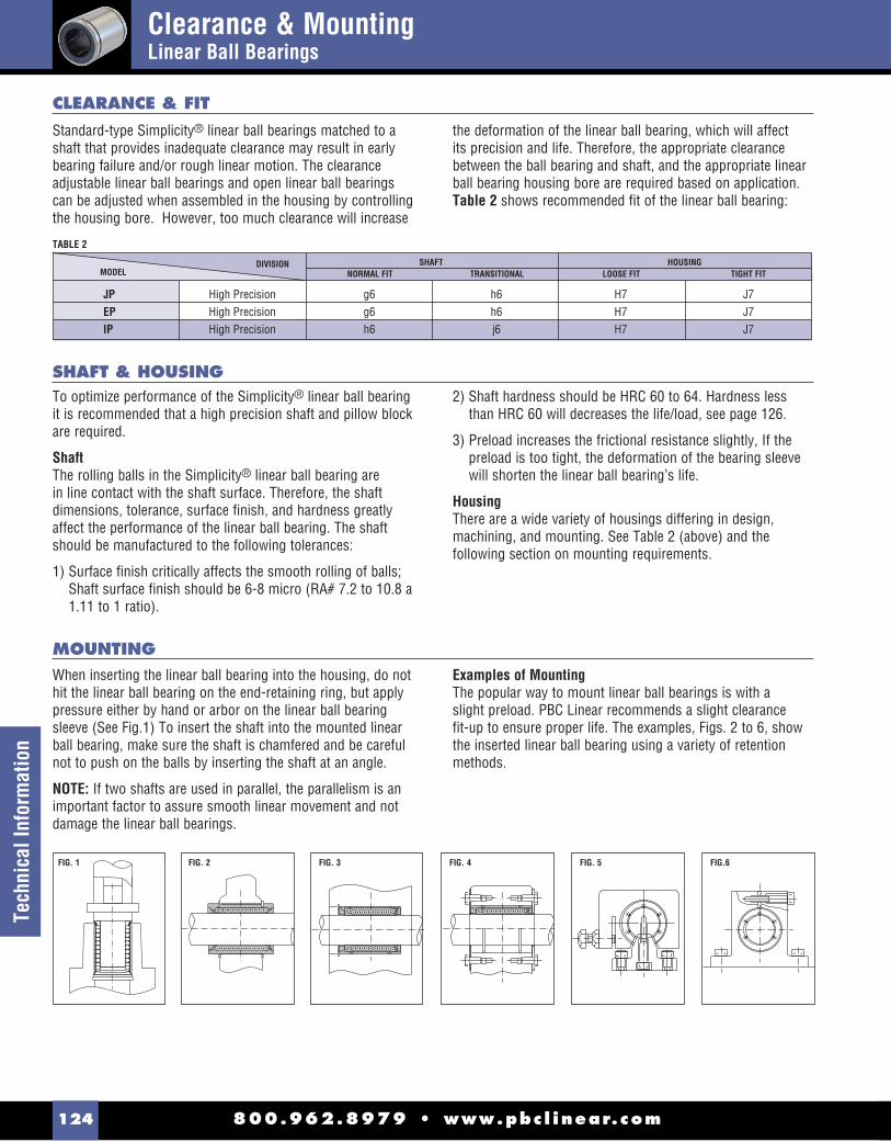
Clearance & MountingLinear Ball Bearings
800.962.8979 • www.pbc l inear.com124
Tech
nica
l Inf
orm
atio
n
Standard-type Simplicity® linear ball bearings matched to a shaft that provides inadequate clearance may result in early bearing failure and/or rough linear motion. The clearance adjustable linear ball bearings and open linear ball bearings can be adjusted when assembled in the housing by controlling the housing bore. However, too much clearance will increase
the deformation of the linear ball bearing, which will affect its precision and life. Therefore, the appropriate clearance between the ball bearing and shaft, and the appropriate linear ball bearing housing bore are required based on application. Table 2 shows recommended fi t of the linear ball bearing:
To optimize performance of the Simplicity® linear ball bearing it is recommended that a high precision shaft and pillow block are required.
ShaftThe rolling balls in the Simplicity® linear ball bearing are in line contact with the shaft surface. Therefore, the shaft dimensions, tolerance, surface fi nish, and hardness greatly affect the performance of the linear ball bearing. The shaft should be manufactured to the following tolerances:
1) Surface fi nish critically affects the smooth rolling of balls; Shaft surface fi nish should be 6-8 micro (RA# 7.2 to 10.8 a 1.11 to 1 ratio).
2) Shaft hardness should be HRC 60 to 64. Hardness less than HRC 60 will decreases the life/load, see page 126.
3) Preload increases the frictional resistance slightly, If the preload is too tight, the deformation of the bearing sleeve will shorten the linear ball bearing’s life.
HousingThere are a wide variety of housings differing in design, machining, and mounting. See Table 2 (above) and the following section on mounting requirements.
CLEARANCE & FIT
SHAFT & HOUSING
When inserting the linear ball bearing into the housing, do not hit the linear ball bearing on the end-retaining ring, but apply pressure either by hand or arbor on the linear ball bearing sleeve (See Fig.1) To insert the shaft into the mounted linear ball bearing, make sure the shaft is chamfered and be careful not to push on the balls by inserting the shaft at an angle.
NOTE: If two shafts are used in parallel, the parallelism is an important factor to assure smooth linear movement and not damage the linear ball bearings.
Examples of MountingThe popular way to mount linear ball bearings is with a slight preload. PBC Linear recommends a slight clearance fi t-up to ensure proper life. The examples, Figs. 2 to 6, show the inserted linear ball bearing using a variety of retention methods.
MOUNTING
TABLE 2
FIG. 1 FIG. 2 FIG. 3 FIG. 4 FIG. 5 FIG.6

Rating LifeLinear Ball Bearings
800.962.8979 • www.pbc l inear.com 125
Technical Information
Rating Life of the Linear System -As long as the linear system reciprocates while being loaded, continuous stress acts on the linear system to cause fl aking on the rolling bodies and planes because of material fatigue. The traveling distance of linear system until the fi rst fl aking occurs is called the life of the systems. The life of the system varies even for the systems of the same dimensions, structure, material, heat treatment and processing method, when used in the same conditions. This variation is brought about from the essential variations in the material fatigue itself. The rating life defi ned bellow is used as an index for the life expectancy of the linear system.
Rating Life (L) -Rating life is the total travelling distance that 90% of a group of systems of the same size can reach without causing any fl aking when they operate under the same conditions. The rating life can be obtained from the following equation with the basic dynamic load rating and the load on the linear system:
For ball type: L = (C)3 • 50 ________ (1)p
L : Rating life (km) C: Basic dynamic load rating (N)P : load (N)
Consideration and infl uence of vibration impact loads and distribution of load should be taken into account when designing a linear motion system. It is diffi cult to calculate
the actual load. The rating life is also affected by the operating temperature. In these conditions, the expression (1) is arranged as follows:
For ball type:
L : Rating life (km)
fh : Hardness factor (See Fig.1) C : Basic dynamic load rating (N)fr : Temperature coeffi cient (See Fig.2) P : Load (N) fc : Contact coeffi cient (See Table 2)fw : Load coeffi cient (See Table 3)
The rating life in hours can be calculated by obtaining the travelling distance per unit time. The rating life in hours can be obtained from the following expression when the stroke length and the number of strokes are constant:
Lh : Rating life in hours (hr)
ls : Stroke length (m) L : Rating life (km)n1 : No. of strokes per minute (cpm)
RATING LIFE
1. Obtaining the rated life L and lifespan Lh of the Simplicity®
linear ball bearing used in the following conditions:
Linear ball bearing . . . . . . . . . . . . . . . . . . . . .EP20GStroke length . . . . . . . . . . . . . . . . . . . . . . . . .50mmNumber of strokes per minute . . . . . . . . . . . .50cpmLoad per bush . . . . . . . . . . . . . . . . . . . . . . . .490N
The basic dynamic load rating of the linear ball bearing is 882N from the dimension tables. From equation (1), therefore, the rated life L is obtained as follows:
From equation (2), the lifespan Lh is obtained as follows:
2. Select the linear ball bearing type by satisfying the following conditions:
Number of linear bushing used ......................4Stroke length ..................................................1mTraveling speed ..............................................10m/min.Number of strokes per minute .......................5cpmLifespan ..........................................................10,000hrTotal load .......................................................980N
From equation (2), the traveling distance within the lifespan is obtained as follows:
From equation (1), the basic dynamic load rating is obtained as follows:
Assume the following with a pair of shafts each with two linear ball bearings: fC = 0.81 fW = fT = fH = 1
As a result, EP20G is selected from the dimension table as the Simplicity® linear ball bearing type satisfying the value of C.
SAMPLE CALCULATIONS

800.962.8979 • www.pbc l inear.com126
Tech
nica
l Inf
orm
atio
nRating LifeLinear Ball Bearings
Hardness Factor (fH)The shaft must be suffi ciently hardened when a linear bushing is used. If not properly hardened, permissible load is lowered and the life of the linear ball bearings will be shortened.
Temperature Coeffi cient (fT)If the temperature of the linear system exceeds 100°C, hardness of the linear system and the shaft lowers to decrease the permissible load compared to that of the linear system used at room temperature. As a result, the abnormal temperature rise shortens the rating life.
Contact Coeffi cient (fc) Generally two or more linear bearings are used on one shaft. Thus, the load on each linear system differs depending on each processing accuracy. Because the linear bushings are not loaded equally, the number of linear bushings per shaft changes the permissible load off the system.
Load Coeffi cient (fw) When calculating the load on the linear system, it is necessary to accurately obtain object weight, inertial force based on motion speed, moment load, and each transition as time passes. However, it is diffi cult to calculate those values accurately because reciprocating motion involves the repetition of start and stop as well as vibration and impact. A more practical approach is to obtain the load coeffi cient by taking the actual operating conditions into account.
RATING LIFE (cont.)
60
1.0
0.9
0.8
0.7
0.6
0.5
0.4
0.3
0.2
0.1
50 40
Hard
ness
Fac
tor f
H
2030 10
FIG. 1 - HARDNESS FACTOR
OPERATING CONDITIONS fw
Operation at low speed (15m/min.or less) without impulsive shock from outside
1.0 to 01.5
Operation at intermediate speed (60m/min.or less) without impulsive shock
1.5 to 2.0
Operation at high speed (over 60m/min.) with impulsive shock from outside
2.0 to 3.5
TABLE 3 - LOAD COEFFICIENT
1.0
0.9
0.8
0.7
0.6
0.5
Temperature of Linear System (°C)
Tem
pera
ture
Coe
ffici
ent f
T
100 150 200 250
FIG. 2 - TEMPERATURE COEFFICIENT
TABLE 2 - CONTACT COEFFICIENT
NUMBER OF LINEAR SYSTEMS PER SHAFT CONTACT COEFFICIENT fc
1 1.00
2 0.81
3 0.72
4 0.66
5 0.61
NOTES: Maximum temperature of plastic retainer 212°F or 100°C. Maximum temperature 176° per Table 6.

Frictional ResistanceLinear Ball Bearings
800.962.8979 • www.pbc l inear.com 127
Technical Information
FRICTIONAL RESISTANCE
The static frictional resistance of the Simplicity® linear system is so low that it is only slightly different from the kinetic frictional resistance, enabling smooth linear movement from low to high speeds. In general, the frictional resistance is expressed by the following equation.
F = μ • W + f
F : Frictional resistance μ : Coeffi cient of frictionW : Load weight f : Sealing resistance
The frictional resistance of each PBC linear system depends on the model, load weight, speed, and lubricant. The sealing resistance depends on the lip interference and lubricant, regardless of the load weight. The sealing resistance of one linear system is about 200 to 500 gf. The coeffi cient of friction depends on the load weight, moment load, and preload.
AMBIENT WORKING TEMPERATURE
The ambient working temperature range for each PBC linear system depends on the model. Consult PBC on use outside the recommended temperature range.
Temperature conversion equation:
C = 5 (F - 32) F = 32 + 9 C 9 5
LUBRICATION AND DUST PREVENTION
Using PBC linear systems without lubrication increases the abrasion of the rolling elements, shortening the life span. The PBC linear systems therefore require appropriate lubrication. For lubrication PBC recommends turbine oil conforming to ISO Standards G32 to G68 or lithium base soap grease No.2.Some PBC linear systems are sealed to block dust out and seal lubricant in. If used in a harsh or corrosive environmenta protective cover should be used.
TABLE 5 - COEFFICIENT OF LINEAR SYSTEM FRICTIONS (μ)
LINEAR SYSTEM TYPE MODELS COEFFICIENT OF FRICTION (μ)
Linear Bearing JP, EP, IP 0.002 to 0.003
TABLE 6 - AMBIENT WORKING TEMPERATURE
LINEAR SYSTEM TYPE MODELS AMBIENT WORKING TEMPERATURE
Linear Ball Bearing JP, EP, IP -20 to 80°C, -4 to 176°F

PRODUCT OVERVIEW
PBC Linear’s light-weight polymer sleeve are used in a variety of applications with specially formulated compounds with the following advantages:
• Absorb vibrations
• Anti-corrosive
• Chemically resistant
• Lightweight
• Provide additional functions (integral seals, grease retention pockets etc.)
• Highly economic- Lower unit costs
- Fewer components - N o maintenance costs
Additional advantages of compound plane bearings:
• Modifi ed for various applications
• Low density
• Adjustability with electric insulation and conductivity
• Suitable for dry runs
• Friendly to edge loading
• Can show magnetic properties
• Resistant to ionizing radiation
FEATURES & BENEFITS
Maintenance-Free Self-LubricatedPBC compounds lubricants in balanced ratios into the polymer matrix and ensure through fi berate mi cro-wear during running in for clean and continuous auto lubrication. During micro-wear a transfer coating is built enabling optimal sliding performance. The basic polymers and their additives already own good tribological properties.
Long Service LifeThe homogeneous structure of the compound plane bearings prevent thin run or wear layers which would shorten service life right from the beginning. The basic polymer with its mainly synthetic reinforcement additives forms an intimate matrix for other additives. There is no abrasive wear of the shafts because the commonly used glass fi bers have been removed.
Low FrictionStatic and dynamic coeffi cients of friction are close to each other due to the high amount of PTFE and other special additives in the compounds. Thus, we ensure stick-slip-free running at lower speeds. The plane bearing also runs with much less noise. The frictional behavior of the compound plane bearings depends mainly on tempe rature, sliding
speeds, types of movement and loads. Surface structure and the circumstances of dry running or greasing standards substantially infl uence frictional behavior. Through the appropriate lubrication the coeffi cient of friction can be reduced even further.
High Dimensional StabilityAll compound plane bearings take in virtually no water, which can be disregarded to dimensional accuracy in connection with the installation. Fiber strengthening reduces thermal expansion/contraction and improves the press-fi t at higher temperatures.
Minimal WearCompound plane bearings are extremely wear resistant in rotating and axial bearings as well as in hinge move mentsunder high loads.
High Loading CapacityOur compound plane bearings can withstand immense forces and pressures. As well as edge loads, which do not cause problems in contrast to common plane bearings made of non-fer rous metals or composite materials. Depending on the compound chosen, high pressures are also permissible.
Broad Temperature RangeDepending on the material temperatures of -200°C/-328°F up to +250 °C can be withstood during application. Always check the compound specifi cations in each application with regard to temperature tolerances.
Improved Thermal ConductivityPolymer compound plane bearings show an improved thermal conductivity. Higher rpm/sfm during continuous operation are possible thanks to a better press-fi t of the plane bearing in its housing. This is achieved through fi ber strengthening.
800.962.8979 • www.pbc l inear.com128
Poly
mer
Bea
rings
Polymer Plane BearingsProduct Overview

PLANE BEARINGS FOR ALL APPLICATIONS
PBC Linear™ produces compound plane bearings through an injection molding process.
We can help you select a suitable material for a specifi c application from our wide range of materials. Our technical staff will support you at every step of the way. PBC will fi nd the best compound for your application – with regard to costs as well as effectiveness/performance.
Whether you are looking for standard parts or custom/proprietary components we can provide standard plane bearings. Special components and seals are available as well.
Standard Plane Bearings Standard bearings are stocked in compounds A and E:
• Bushings• Flanged bushings • Thrust washers • Bushings with integral seals
Plane Bearings with Integral SealsPlane bearings with integral seals have proven superior in sustaining the basic advantages of our compound plane bearings even in tough environments.
• Integral seals keep away dirt and water from the bearing • Initial lubrication is suggested • Safe from corrosion
As a standard we provide bearings with double-sided integral seals.
HIGH PERFORMANCE SPECIALITY
High performance plane bearings are a specialty of PBC Linear™, which is distinguished by a quality-analytic separation of the bearing function. We manufacture them by multi cavity injection molding process. These are high fi lled and form a stable basic body and a sliding layer with the most favorable wear and friction values. Additionally, we include specially arrayed grease retention pockets. Integrated elastomer integral seals complement these bearings.
They show the particular qualities of:
• Increased application possibilities
• Corrosion resistance
• Low weight
• Optimized performance
• Optimal adaptation to your requirements through suitable combinations of materials and design
The layers of our high performance plane bea rings are built up as follows:
• Outer layer: A high-fi lled basic body guarantees press-fi t and pressure capacity with high temperatures as well as with high stress
• Inner layer: Tribologically modifi ed sliding layer for optimal wear and friction characteristics
SPECIALITY PARTS
We can deliver special forms and dimensions of parts under wear and friction demands, which we design, and manufacture individually along your requirements. Our service covers the material side as well as dimensional interpretation of the component.
Other special components examples:
• Gearwheels, tooth racks
• Plane bearings with integrated grease retention pockets and integral seals
• Slide ring seals
• Half sockets, ball sockets
• Spherical plane bearings/components
• Split bushings
• High performance plane bearings
• Thrust washers
• Multi-component parts
Polymer Bearings
Polymer Plane BearingsProduct Overview
800.962.8979 • www.pbc l inear.com 129

HOW TO CHOOSE THE BEST MATERIAL
The optimal application of a plane bearing in a system essentially depends on temperature, sliding speed, the occurring loads and environmental infl uences. We offer a wide spectrum of materials for the most varied applications. The technical data should give you an orientation and simplify the choice. In general, testing is advised.
With only few exceptions we incorporate the use of glass fi bers, which considerably enhances sliding performance and increases service life. Nevertheless, with synthetic fi ber reinforcement the press-fi t in housings show increased temperature dependence. As a rule, the temperature in continuous use should not exceed 60% of the maximum sliding surface temperature or the safety in the system may be compromised.
Our technical staff not only offer you a wide choice of materials but we can provide additional detailed technical data. Apart from the material offered we also have access to all the other commonly used polymers or we can use some suitable material from our own Value Added Polymer series of compounds. Furthermore, we can design the optimal material for your demands in our in-house developing department and then produce the new material to meet your requirements.
COMPOUND BEARING MARKETS• Automotive• Agricultural machinery• Mechanical engineering• Hydraulics• Light engineering• Valves• Chemical apparatus • Pneumatics• Oven construction• Semiconductor production lines• Electric motors• Textile machinery• Medical and laboratory technology• Pumps• Printing presses• Paper making machines• Household appliances• Food industry
800.962.8979 • www.pbc l inear.com130
Poly
mer
Bea
rings
Polymer Plane BearingsProduct Overview

COMPOUND A E B C D F G
BASIS POLYMER PEEK PBT PAI PBT PBT POM PPS
Additives
carbonfi bers,
graphite,PTFE
bronze,PTFE
graphite,PTFE,
additives
aramidefi bers, bronze,PTFE
long glass fi bers, PTFE
bronze,MoS2
PTFE glass fi bers, PTFE
Color black brown dark grey olive grey white light brown
Density g/cm3 1.48 1.65 1.5 1.48 1.60 1.52 1.73
Water vapor RT/50% rF % 0.10 0.10 0.3 0.15 0.30 0.2 0.05
MECHANICAL PROPERTIES
Tensile strength MPa 150 40 164 100 100 50 155
Modulus of elasticity GPa 6.5 2.8 6.6 4.2 6.4 2.5 13
Specifi c load, static MPa 150 70 150 80 90 60 120
THERMAL PROPERTIES
Thermal conductivity W/mK 0.60 0.26 0.53 0.27 0.26 0.32 0.34
Coeffi cient of thermal expansion 10-6 1/K 30 14 25 13 25 120 30
Max. sliding surface temperature °C -100
+250-40
+100-120+240
-40+120
-50+130
-40+80
-40+200
Max. temperature, unloaded °C +300 +120 +280 +150 +200 +140 +250
TRIBOLOGICAL PROPERTIES
Max. sliding speed, rotating m/s 1.5 1.0 2.5 1.0 1.2 1.0 1.2
Max. sliding speed. linear m/s 5.0 3.0 4.5 4.0 4.5 4.0 4.5
Max. pv-value MPa • m/s 3.5 0.8 4.0 1.0 1.1 0.6 2.6
Abstract 0.10 - 0.20 0.10 - 0.20 0.10 - 0.40 0.10 - 0.20 0.10 - 0.20 0.07 - 0.20 0.15 - 0.30
Description Suitable for heavy loads
Universalchemicalresistance
Hightemperatures
High loads
Strong
Machineable
Inexpensivematerial
Hightemperature
Specialadditives to improve the tribologicalproperties
High loads
Strong
High loads
Strong
Stable at high temperatures
This material is suitable mainlyfor the contactwith food or applicationsin medical technology.TheCompoundis safe, correspondsto appropriate BGA/FDA
High loads
Strong
Press-fi t
Hightemperatures
STOCKED PRODUCED TO ORDER
Polymer - Com
poundsCompounds
Polymer Plane Bearings
800.962.8979 • www.pbc l inear.com 131
COMPOUNDS

CHEMICAL A E B C D F G
Acetic acid, 5 % + + + + + + +
Acetone + + - + + +
Ammonia, 10 % - - - - - + +
Carbon tetrachloride + + + + + + +
Caustic soda, 5 % + + + + + + -
Diesel + + + + + + +
Formic acid, 5 % + + + - + + +
Gas + + + + + + +
HFC-Water-Glycol, 70 °C + + + + + + +
Hydrochloric acid, 5 % + - + - - - -
Kerosene + + + + + + +
Mineral oil, 70 °C + + + + + + +
Nitric acid, 5 % + - + - - - -
Paraffi n + + + + + + +
Seawater + + + + + + +
Sulfuric acid, 5 % + + + + + - +
Water + + + + + + +
STOCKED PRODUCED TO ORDER
+ Usage trouble-free, no corrosion expected- Usage not recommended (chemical pit the compound and it is expected to react in a negative way)
On inquiry we will give you a detailed chemicals resistance list.
800.962.8979 • www.pbc l inear.com132
Poly
mer
Bea
rings
Chemical ResistancePolymer Plane Bearings
CHEMICAL RESISTANCE (Cont.)

COMPOUND A
Characteristics:• Thermoplastic compound made of PEEK polymer matrix
reinforced with synthetic fi bers and modifi ed with triboadditives
• Highly effi cient high temperature material with high chemical and good wear resistance
• Recommended tolerance for press fi t bushings: housing H7, shaft h7 - h9
• Color: black
Applications:Industry – textile and knitting machinery, baking machinery, relay and control valves, powder coating equipment, chemical plants, armatures
Availability:In stock – bearings, fl anged bearings. Production to order – thrust washers, special parts of all kinds
Material structure:PEEK + carbon fi bers + PTFE + graphite
Grinding pattern A
Operation conditions:Dry . . . . . . . . . . . . . . . . . . goodOil lubricated. . . . . . . . . . . optimumGrease lubricated . . . . . . . optimumWater lubricated . . . . . . . . optimumMedium lubricated . . . . . . optimum
These PBC materials (maintenance free) are standardized compounds for our plane bearings. Upon request we can also provide other standard and special bearings and sliding elements made of different materials or with divergent dimensions.
We solve a variety of problems and produce special forms as well as special dimensions according to your application needs evenif they are not included in our tables.
133
Polymer - Com
pound A & E
Compound A & E Polymer Plane Bearings
COMPOUND E
Characteristics:• Filled thermoplastic compound made of PBT polymer matrix
and triboadditives• Good sliding performance under moderate operational
conditions• The E standard program is interchangeable with bushings
according to DIN1494/ISO3547• Very cost-effective sliding material• Recommended tolerance for press fi t bushings: housing H7,
shaft h7 - h9• Color: brown
Applications:Industry – medical equipment, textile machinery, trans portdevices, apparatus engineering, furniture, materials handling technology, electronics, valve technology, agricultural machinery
Availability:In stock - bushings, fl anged bushings, bushings with integrated sealings, thrust washers.
Production to order - special parts of all kinds
Material structure: PBT + powdered bronze + PTFE
Grinding pattern E
Operational conditions:Dry good ............................goodOil lubricated .....................goodGrease lubricated ...............goodWater lubricated ...............less goodMedium lubricated ............less good
800.962.8979 • www.pbc l inear.com

COMPOUND C
Characteristics:• Thermoplastic compound made of PBT polymer matrix
reinforced with long glass fi bers and modifi ed with triboadditives
• Improved performance compared to E, as well as lower wear rate and less shrinkage
• Excellent press-fi t by long glass fi bers • Recommended tolerance for press fi t bushings: housing H7,
shaft h7 - h9 • Color: olive
Applications:Industry – medical equipment, textile machinery, transport devices, apparatus engineering, furniture, materials handling technology, electronics, valve technology, agricultural machinery
Availability:Production to order – bushings, fl anged bushings, bushings with integrated sealings, thrust washers special parts of all kinds.
Material structure:PBT + powdered bronze + PTFE + aramid fi bers
Grinding pattern C
Operational conditions:Dry .....................................goodOil lubricated ......................goodGrease lubricated ...............goodWater lubricated .................goodMedium lubricated ............less good
800.962.8979 • www.pbc l inear.com134
Poly
mer
- Co
mpo
und
B &
CCompound B & C Polymer Plane Bearings
COMPOUND B
Characteristics:• Injection-molded polyamidimide modifi ed with special
additives• Irreversible cross-linking through by thermal treatment• High temperature material for demanding components with
low thermal expansion• High toughness and mechanical consistency• High wear resistance against vibrating oscillations• Good chemical resistance• Recommended tolerance for press fi t bushings: housing H7,
shaft h7 - h9• Color: dark grey
Applications:Automobile industry – automatic transmission, pumps, labyrinth seal in turbo blowers, piston rings, valve seats, integral seals
Industry – continuous furnace, cockles for coating, textile machinery
Other – aviation and astronautics, extreme high- and low-level temperature operations
Availability:Production to order – bearings and special parts of all kinds
Material structure:PAI + graphite + PTFE + additive
Grinding pattern B
Operational conditions:Dry .....................................goodOil lubricated .....................very goodGrease lubricated ...............goodWater lubricated .................goodMedium ..............................good

COMPOUND D
Characteristics:• Thermoplastic compound made of PBT polymer matrix
reinforced with long glass fi bers and modifi ed with triboadditives
• Good sliding performance under moderate operational conditions
• Recommended tolerance for press fi t bushings: housing H7, shaft h7 - h9
• Color: grey
Applications:Automobile industry – hinges, guides for sliding and lifting covers
Industry – formed parts for machinery and apparatus engineering, adjustment devices
Availability:Production to order – bushings, fl anged bushings, thrust washers, special parts of all kinds
Material structure: PBT + long glass fi bers + powdered bronze + PTFE
Grinding pattern D
Operational conditions:Dry .....................................goodOil lubricated .....................goodGrease lubricated ...............goodWater lubricated ...............less goodM edium lubricated ............less good
COMPOUND F
Characteristics:• Thermoplastic compound made of made of POM polymer
matrix with PTFE • Corresponds to BGA/FDA recommendations. Suitable for
contact with food.• Recommended tolerance for press fi t bushings: housing H7,
shaft h7 - h9• Color: white
Applications:Industry – racks and packaging machines, pumps, butcher’s shop equipment, medical equipment
Availability:Production to order – bushings, fl anged bushings, thrust washers, bushings with integrated seals, special parts of all kinds
Material structure: POM + PTFE
Grinding pattern F
Operational conditions:Dry good ............................good Oil lubricated .....................goodGrease lubricated ...............goodWater lubricated ...............less goodMedium lubricated ............less good
Polymer - Com
pound D & F
Compound D & F Polymer Plane Bearings
800.962.8979 • www.pbc l inear.com 135

COMPOUND G
Characteristics:• Thermoplastic compound made of PPS polymer matrix
reinforced with glass fi bers and triboadditives • High hydrolysis and temperature resistance• Good sliding performance under moderate operational
conditions• Recommended tolerance for press fi t bushings: housing H7,
shaft h7 - h9• Color: beige
Applications:Industry – various outdoor applications
Automobile industry – rear windscreen wiper, pump bearing
Availability:Production to order – bushings, fl anged bushings, thrust washer, special parts of all kinds
Material structure: PPS + glass fi bers + PTFE
Grinding pattern G
Operational conditions:Dry .....................................less good Oil lubricated .....................goodGrease lubricated ...............goodWater lubricated ...............goodMedium lubricated ............good
800.962.8979 • www.pbc l inear.com136
Poly
mer
- Co
mpo
und
GCompound G Polymer Plane Bearings

30°30°
L
T
OD ID
ø IT 9
PART NUMBERDIMENSIONS WEIGHT FITTING TOLERANCE
ID[mm]
OD[mm]
L[mm] [g] HOUSING H7
[mm]ID AFTER FITTING: F10
[mm]
B-002.0-003.5-003.0-E 2.0 3.5 3.0 0.03+0.012
0+0.046+0.006B-003.0-004.5-004.0-E 3.0 4.5 4.0 0.06
B-003.0-004.5-006.0-E 3.0 4.5 6.0 0.09
B-003.5-007.8-005.0-E 3.5 7.8 5.0 0.31 +0.0150
+0.058+0.010
B-004.0-005.5-004.0-E 4.0 5.5 4.0 0.07 +0.0120B-004.0-005.5-006.0-E 4.0 5.5 6.0 0.11
B-005.0-007.0-004.8-E 5.0 7.0 4.8 0.15
+0.0150
B-005.0-007.0-005.0-E 5.0 7.0 5.0 0.16
B-005.0-007.0-008.0-E 5.0 7.0 8.0 0.25
B-005.0-007.0-010.0-E 5.0 7.0 10.0 0.31
B-006.0-008.0-006.0-E 6.0 8.0 6.0 0.22
B-006.0-008.0-008.0-E 6.0 8.0 8.0 0.29
B-006.0-008.0-010.0-E 6.0 8.0 10.0 0.36
B-008.0-010.0-005.0-E 8.0 10.0 5.0 0.23
+0.071+0.013
B-008.0-010.0-006.0-E 8.0 10.0 6.0 0.28
B-008.0-010.0-008.0-E 8.0 10.0 8.0 0.37
B-008.0-010.0-010.0-E 8.0 10.0 10.0 0.47
B-008.0-010.0-012.0-E 8.0 10.0 12.0 0.56
B-008.0-010.0-015.0-E 8.0 10.0 15.0 0.70
B-008.0-012.0-007.0-E 8.0 12.0 7.0 0.73
+0.0180
B-008.0-012.0-010.0-E 8.0 12.0 10.0 1.04
B-010.0-012.0-008.0-E 10.0 12.0 8.0 0.46
B-010.0-012.0-009.0-E 10.0 12.0 9.0 0.51
B-010.0-012.0-010.0-E 10.0 12.0 10.0 0.57
B-010.0-012.0-012.1-E 10.0 12.0 12.1 0.69
B-010.0-012.0-015.0-E 10.0 12.0 15.0 0.86
B-010.0-012.0-020.0-E 10.0 12.0 20.0 1.14
B-010.0-012.0-025.0-E 10.0 12.0 25.0 1.43
B-010.0-014.0-008.0-E 10.0 14.0 8.0 1.00
B-010.0-014.0-010.0-E 10.0 14.0 10.0 1.24
B-010.0-014.0-012.0-E 10.0 14.0 12.0 1.49
B-010.0-014.0-028.0-E 10.0 14.0 28.0 3.48
B-012.0-014.0-008.0-E 12.0 14.0 8.0 0.54
+0.086+0.016
B-012.0-014.0-010.0-E 12.0 14.0 10.0 0.67
B-012.0-014.0-012.0-E 12.0 14.0 12.0 0.81
B-012.0-014.0-014.0-E 12.0 14.0 14.0 0.94
B-012.0-014.0-015.0-E 12.0 14.0 15.0 1.01
B-012.0-014.0-020.0-E 12.0 14.0 20.0 1.35
B-012.0-014.0-030.0-E 12.0 14.0 30.0 2.02
800.962.8979 • www.pbc l inear.com 137
Polymer - Com
pound ECompound E
Polymer Plane Bearings

30°30°
L
T
OD ID
ø IT 9
PART NUMBERDIMENSIONS WEIGHT FITTING TOLERANCE
ID[mm]
OD[mm]
L[mm] [g] HOUSING H7
[mm]ID AFTER FITTING: F10
[mm]
B-012.0-016.0-012.0-E 12.0 16.0 12.0 1.74
+0.0180
+0.086+0.016
B-012.0-016.0-020.0-E 12.0 16.0 20.0 2.90
B-012.0-017.0-020.0-E 12.0 17.0 20.0 3.76
B-012.0-018.0-010.0-E 12.0 18.0 10.0 2.33
B-013.0-015.0-010.0-E 13.0 15.0 10.0 0.73B-013.0-015.0-020.0-E 13.0 15.0 20.0 1.45B-014.0-016.0-010.0-E 14.0 16.0 10.0 0.78
B-014.0-016.0-015.0-E 14.0 16.0 15.0 1.17
B-014.0-016.0-020.0-E 14.0 16.0 20.0 1.56
B-014.0-016.0-025.0-E 14.0 16.0 25.0 1.94
B-014.0-018.0-014.0-E 14.0 18.0 14.0 2.32
B-014.0-018.0-020.0-E 14.0 18.0 20.0 3.32
B-015.0-017.0-010.0-E 15.0 17.0 10.0 0.83
B-015.0-017.0-015.0-E 15.0 17.0 15.0 1.24
B-015.0-017.0-020.0-E 15.0 17.0 20.0 1.66
B-015.0-017.0-025.0-E 15.0 17.0 25.0 2.07
B-016.0-018.0-007.0-E 16.0 18.0 7.0 0.62
B-016.0-018.0-010.0-E 16.0 18.0 10.0 0.88
B-016.0-018.0-012.0-E 16.0 18.0 12.0 1.06
B-016.0-018.0-015.0-E 16.0 18.0 15.0 1.32
B-016.0-018.0-020.0-E 16.0 18.0 20.0 1.76
B-016.0-018.0-025.0-E 16.0 18.0 25.0 2.20
B-016.0-020.0-020.0-E 16.0 20.0 20.0 3.73
+0.0210
B-018.0-020.0-015.0-E 18.0 20.0 15.0 1.48
B-018.0-020.0-020.0-E 18.0 20.0 20.0 1.97
B-018.0-020.0-025.0-E 18.0 20.0 25.0 2.46
B-018.0-021.0-020.0-E 18.0 21.0 20.0 3.03
B-018.0-022.0-018.0-E 18.0 22.0 18.0 3.73
B-018.0-024.0-018.0-E 18.0 24.0 18.0 5.88
B-018.0-024.0-028.0-E 18.0 24.0 28.0 9.14
B-020.0-023.0-010.0-E 20.0 23.0 10.0 1.67
+0.104+0.020
B-020.0-023.0-015.0-E 20.0 23.0 15.0 2.51
B-020.0-023.0-020.0-E 20.0 23.0 20.0 3.34
B-020.0-023.0-025.0-E 20.0 23.0 25.0 4.18
B-020.0-023.0-030.0-E 20.0 23.0 30.0 5.02
B-020.0-024.0-020.0-E 20.0 24.0 20.0 4.56
B-020.0-025.0-015.0-E 20.0 25.0 15.0 4.37
B-020.0-025.0-020.0-E 20.0 25.0 20.0 5.83
B-020.0-029.0-030.0-E 20.0 29.0 30.0 17.14
B-022.0-024.0-010.0-E 22.0 24.0 10.0 1.19
800.962.8979 • www.pbc l inear.com138
Poly
mer
- Co
mpo
und
ECompound E Polymer Plane Bearings
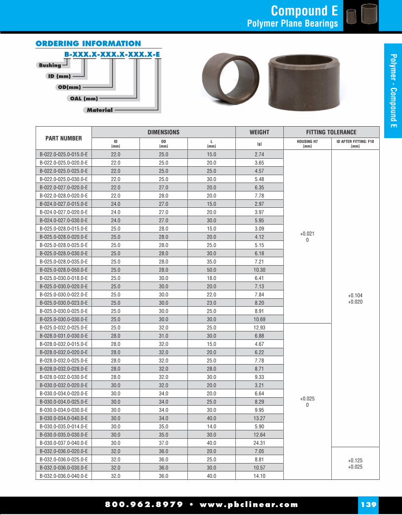
Material
OAL (mm)
Bushing
OD(mm)
ID (mm)
B-XXX.X-XXX.X-XXX.X-E
ORDERING INFORMATION
PART NUMBERDIMENSIONS WEIGHT FITTING TOLERANCE
ID[mm]
OD[mm]
L[mm] [g] HOUSING H7
[mm]ID AFTER FITTING: F10
[mm]
B-022.0-025.0-015.0-E 22.0 25.0 15.0 2.74
+0.0210
+0.104+0.020
B-022.0-025.0-020.0-E 22.0 25.0 20.0 3.65
B-022.0-025.0-025.0-E 22.0 25.0 25.0 4.57
B-022.0-025.0-030.0-E 22.0 25.0 30.0 5.48
B-022.0-027.0-020.0-E 22.0 27.0 20.0 6.35
B-022.0-028.0-020.0-E 22.0 28.0 20.0 7.78
B-024.0-027.0-015.0-E 24.0 27.0 15.0 2.97
B-024.0-027.0-020.0-E 24.0 27.0 20.0 3.97
B-024.0-027.0-030.0-E 24.0 27.0 30.0 5.95
B-025.0-028.0-015.0-E 25.0 28.0 15.0 3.09
B-025.0-028.0-020.0-E 25.0 28.0 20.0 4.12
B-025.0-028.0-025.0-E 25.0 28.0 25.0 5.15
B-025.0-028.0-030.0-E 25.0 28.0 30.0 6.18
B-025.0-028.0-035.0-E 25.0 28.0 35.0 7.21
B-025.0-028.0-050.0-E 25.0 28.0 50.0 10.30
B-025.0-030.0-018.0-E 25.0 30.0 18.0 6.41
B-025.0-030.0-020.0-E 25.0 30.0 20.0 7.13
B-025.0-030.0-022.0-E 25.0 30.0 22.0 7.84
B-025.0-030.0-023.0-E 25.0 30.0 23.0 8.20
B-025.0-030.0-025.0-E 25.0 30.0 25.0 8.91
B-025.0-030.0-030.0-E 25.0 30.0 30.0 10.69
B-025.0-032.0-025.0-E 25.0 32.0 25.0 12.93
+0.0250
B-028.0-031.0-030.0-E 28.0 31.0 30.0 6.88
B-028.0-032.0-015.0-E 28.0 32.0 15.0 4.67
B-028.0-032.0-020.0-E 28.0 32.0 20.0 6.22
B-028.0-032.0-025.0-E 28.0 32.0 25.0 7.78
B-028.0-032.0-028.0-E 28.0 32.0 28.0 8.71
B-028.0-032.0-030.0-E 28.0 32.0 30.0 9.33
B-030.0-032.0-020.0-E 30.0 32.0 20.0 3.21
B-030.0-034.0-020.0-E 30.0 34.0 20.0 6.64
B-030.0-034.0-025.0-E 30.0 34.0 25.0 8.29
B-030.0-034.0-030.0-E 30.0 34.0 30.0 9.95
B-030.0-034.0-040.0-E 30.0 34.0 40.0 13.27
B-030.0-035.0-014.0-E 30.0 35.0 14.0 5.90
B-030.0-035.0-030.0-E 30.0 35.0 30.0 12.64
B-030.0-037.0-040.0-E 30.0 37.0 40.0 24.31
B-032.0-036.0-020.0-E 32.0 36.0 20.0 7.05
+0.125+0.025
B-032.0-036.0-025.0-E 32.0 36.0 25.0 8.81
B-032.0-036.0-030.0-E 32.0 36.0 30.0 10.57
B-032.0-036.0-040.0-E 32.0 36.0 40.0 14.10
800.962.8979 • www.pbc l inear.com 139
Polymer - Com
pound ECompound E
Polymer Plane Bearings

Compound E Polymer Plane Bearings
30°30°
L
T
OD ID
ø IT 9
PART NUMBERDIMENSION WEIGHT FITTING TOLERANCE
ID[mm]
OD[mm]
L[mm] [g] HOUSING H7
[mm]ID AFTER FITTING: F10
[mm]
B-032.0-036.0-050.0-E 32.0 36.0 50.0 17.62
+0.0250
+0.125+0.025
B-032.0-036.0-054.0-E 32.0 36.0 54.0 19.03
B-032.0-038.0-042.0-E 32.0 38.0 42.0 22.86
B-032.0-040.0-025.0-E 32.0 40.0 25.0 18.66
B-035.0-039.0-010.0-E 35.0 39.0 10.0 3.84
B-035.0-039.0-020.0-E 35.0 39.0 20.0 7.67
B-035.0-039.0-025.0-E 35.0 39.0 25.0 9.59
B-035.0-039.0-030.0-E 35.0 39.0 30.0 11.51
B-035.0-039.0-040.0-E 35.0 39.0 40.0 15.34
B-035.0-039.0-050.0-E 35.0 39.0 50.0 19.18
B-036.0-040.0-025.0-E 36.0 40.0 25.0 9.85
B-036.0-040.0-040.0-E 36.0 40.0 40.0 15.76
B-036.0-040.0-050.0-E 36.0 40.0 50.0 19.70
B-036.0-042.0-030.0-E 36.0 42.0 30.0 18.19
B-038.0-042.0-025.0-E 38.0 42.0 25.0 10.37
B-040.0-042.0-025.0-E 40.0 42.0 25.0 5.31
B-040.0-044.0-020.0-E 40.0 44.0 20.0 8.71
B-040.0-044.0-025.0-E 40.0 44.0 25.0 10.89
B-040.0-044.0-030.0-E 40.0 44.0 30.0 13.06
B-040.0-044.0-040.0-E 40.0 44.0 40.0 17.42
B-040.0-044.0-050.0-E 40.0 44.0 50.0 21.77
B-040.0-045.0-040.0-E 40.0 45.0 40.0 22.03
B-043.0-046.0-030.0-E 43.0 46.0 30.0 10.38
B-045.0-050.0-020.0-E 45.0 50.0 20.0 12.31
B-045.0-050.0-025.0-E 45.0 50.0 25.0 15.39
B-045.0-050.0-030.0-E 45.0 50.0 30.0 18.47
B-045.0-050.0-040.0-E 45.0 50.0 40.0 24.62
B-045.0-050.0-045.0-E 45.0 50.0 45.0 27.70
B-045.0-050.0-050.0-E 45.0 50.0 50.0 30.78
B-045.0-050.0-060.0-E 45.0 50.0 60.0 36.93
B-050.0-055.0-020.0-E 50.0 55.0 20.0 13.61
+0.0300
B-050.0-055.0-025.0-E 50.0 55.0 25.0 17.01
B-050.0-055.0-030.0-E 50.0 55.0 30.0 20.41
B-050.0-055.0-040.0-E 50.0 55.0 40.0 27.21
B-050.0-055.0-050.0-E 50.0 55.0 50.0 34.02
B-050.0-055.0-060.0-E 50.0 55.0 60.0 40.82
B-050.0-055.0-070.0-E 50.0 55.0 70.0 47.62
B-050.0-058.0-040.0-E 50.0 58.0 40.0 44.79
B-055.0-060.0-040.0-E 55.0 60.0 40.0 29.81 +0.150+0.030B-055.0-060.0-060.0-E 55.0 60.0 60.0 44.71
800.962.8979 • www.pbc l inear.com140
Poly
mer
- Co
mpo
und
E

Compound E Polymer Plane Bearings
Material
OAL (mm)
Bushing
OD(mm)
ID (mm)
B-XXX.X-XXX.X-XXX.X-E
ORDERING INFORMATION
PART NUMBERDIMENSION WEIGHT FITTING TOLERANCE
ID[mm]
OD[mm]
L[mm] [g] HOUSING H7
[mm]ID AFTER FITTING: F10
[mm]
B-055.0-065.0-040.0-E 55.0 65.0 40.0 62.20
+0.0300
+0.150+0.030
B-060.0-065.0-030.0-E 60.0 65.0 30.0 24.30
B-060.0-065.0-040.0-E 60.0 65.0 40.0 32.40
B-060.0-065.0-060.0-E 60.0 65.0 60.0 48.60
B-060.0-065.0-070.0-E 60.0 65.0 70.0 56.70
B-064.0-068.0-052.5-E 64.0 68.0 52.5 35.92
B-065.0-070.0-040.0-E 65.0 70.0 40.0 34.99
B-065.0-070.0-060.0-E 65.0 70.0 60.0 52.48
B-068.0-072.0-010.0-E 68.0 72.0 10.0 7.26
B-070.0-075.0-040.0-E 70.0 75.0 40.0 37.58
B-070.0-075.0-060.0-E 70.0 75.0 60.0 56.37
B-070.0-075.0-070.0-E 70.0 75.0 70.0 65.77
B-070.0-075.0-080.0-E 70.0 75.0 80.0 75.16
B-075.0-080.0-025.0-E 75.0 80.0 25.0 25.11
B-075.0-080.0-032.0-E 75.0 80.0 32.0 32.14
B-075.0-080.0-040.0-E 75.0 80.0 40.0 40.17
B-080.0-085.0-040.0-E 80.0 85.0 40.0 42.76
+0.0350
B-080.0-085.0-050.0-E 80.0 85.0 50.0 53.46
B-080.0-085.0-060.0-E 80.0 85.0 60.0 64.15
B-080.0-085.0-080.0-E 80.0 85.0 80.0 85.53
B-080.0-085.0-100.0-E 80.0 85.0 100.0 106.91
B-085.0-090.0-040.0-E 85.0 90.0 40.0 45.36
+0.176+0.036
B-085.0-090.0-080.0-E 85.0 90.0 80.0 90.71
B-089.0-094.0-020.0-E 89.0 94.0 20.0 23.72
B-090.0-095.0-050.0-E 90.0 95.0 50.0 59.94
B-090.0-095.0-090.0-E 90.0 95.0 90.0 107.88
B-100.0-105.0-050.0-E 100.0 105.0 50.0 66.42
B-100.0-105.0-095.0-E 100.0 105.0 95.0 126.19
B-100.0-105.0-100.0-E 100.0 105.0 100.0 132.83
B-120.0-125.0-050.0-E 120.0 125.0 50.0 79.37
+0.0400
B-120.0-125.0-150.0-E 120.0 125.0 150.0 238.12
B-125.0-130.0-030.0-E 125.0 130.0 30.0 49.57
+0.203+0.043
B-125.0-130.0-060.0-E 125.0 130.0 60.0 99.14
B-130.0-135.0-050.0-E 130.0 135.0 50.0 85.85
B-130.0-135.0-060.0-E 130.0 135.0 60.0 103.02
B-150.0-155.0-060.0-E 150.0 155.0 60.0 118.58
B-195.0-200.0-014.0-E 195.0 200.0 14.0 35.83 +0.0460
+0.235+0.050
800.962.8979 • www.pbc l inear.com 141
Polymer - Com
pound E

PART NUMBERDIMENSION WEIGHT FITTING TOLERANCE
ID[mm]
OD[mm]
FD[mm]
L1[mm]
L[mm] [g] HOUSING H7
[mm]ID AFTER FITTING: F10
[mm]
F-003-004.5-007.0-0.75-003.0-E 3.0 4.5 7.0 0.75 3.0 0.07
+0.0120
+0.046+0.006F-003-004.5-007.0-0.75-005.0-E 3.0 4.5 7.0 0.75 5.0 0.10
F-004-005.5-009.0-0.75-003.0-E 4.0 5.5 9.0 0.75 3.0 0.10
+0.058+0.010
F-004-005.5-009.0-0.75-004.0-E 4.0 5.5 9.0 0.75 4.0 0.12
F-004-005.5-009.0-0.75-006.0-E 4.0 5.5 9.0 0.75 6.0 0.16
F-005-007.0-010.0-1.00-004.0-E 5.0 7.0 10.0 1.00 4.0 0.19
+0.0150
F-005-007.0-010.0-1.00-006.0-E 5.0 7.0 10.0 1.00 6.0 0.25
F-006-008.0-012.0-1.00-004.0-E 6.0 8.0 12.0 1.00 4.0 0.25
F-006-008.0-012.0-2.50-005.5-E 6.0 8.0 12.0 2.50 5.5 0.46
F-006-008.0-012.0-1.00-006.0-E 6.0 8.0 12.0 1.00 6.0 0.32
F-006-008.0-012.0-1.00-008.0-E 6.0 8.0 12.0 1.00 8.0 0.39
F-006-008.0-012.0-1.00-010.0-E 6.0 8.0 12.0 1.00 10.0 0.47
F-006-019.5-025.0-2.00-005.0-E 6.0 19.5 25.0 2.00 5.0 2.86 +0.0210
F-008-010.0-015.0-1.00-004.5-E 8.0 10.0 15.0 1.00 4.5 0.37
+0.0150
+0.071+0.013
F-008-010.0-015.0-1.00-005.5-E 8.0 10.0 15.0 1.00 5.5 0.42
F-008-010.0-014.0-1.00-008.0-E 8.0 10.0 14.0 1.00 8.0 0.50
F-008-010.0-015.0-1.00-009.5-E 8.0 10.0 15.0 1.00 9.5 0.61
F-008-010.0-014.0-1.00-010.0-E 8.0 10.0 14.0 1.00 10.0 0.59
F-008-010.0-014.0-2.00-012.0-E 8.0 10.0 14.0 2.00 12.0 0.81
F-008-012.0-018.0-2.00-008.0-E 8.0 12.0 18.0 2.00 8.0 1.30
+0.0180
F-008-012.0-021.0-2.00-008.0-E 8.0 12.0 21.0 2.00 8.0 1.60
F-008-012.0-016.0-2.00-010.0-E 8.0 12.0 16.0 2.00 10.0 1.33
F-010-012.0-016.0-1.00-006.0-E 10.0 12.0 16.0 1.00 6.0 0.49
F-010-012.0-018.0-1.00-007.0-E 10.0 12.0 18.0 1.00 7.0 0.63
F-010-012.0-022.0-1.00-007.0-E 10.0 12.0 22.0 1.00 7.0 0.84
F-010-012.0-016.0-2.00-012.0-E 10.0 12.0 16.0 2.00 12.0 0.97
F-010-012.0-019.0-2.00-016.0-E 10.0 12.0 19.0 2.00 16.0 1.47
F-010-012.0-018.0-1.00-017.0-E 10.0 12.0 18.0 1.00 17.0 1.20
F-010-014.0-018.0-2.00-010.0-E 10.0 14.0 18.0 2.00 10.0 1.58
F-010-016.0-020.5-2.00-011.0-E 10.0 16.0 20.5 2.00 11.0 2.65
F-010-017.0-031.0-2.00-025.0-E 10.0 17.0 31.0 2.00 25.0 7.86
F-011-014.0-017.0-1.50-006.5-E 11.0 14.0 17.0 1.50 6.5 0.81
+0.086+0.016
F-012-014.0-018.0-1.00-010.0-E 12.0 14.0 18.0 1.00 10.0 0.84
F-012-014.0-018.0-1.00-012.0-E 12.0 14.0 18.0 1.00 12.0 0.97
F-012-014.0-018.0-2.00-012.0-E 12.0 14.0 18.0 2.00 12.0 1.14
F-012-014.0-017.0-0.50-004.0-E 12.0 14.0 17.0 0.50 4.0 1.68
30°30°
L
T
OD ID
R 0,5
FD
L1
A
A
800.962.8979 • www.pbc l inear.com142
Flan
ge -
Com
poun
d E
Flange - Compound EPolymer Plane Bearings

PART NUMBERDIMENSION WEIGHT FITTING TOLERANCE
ID[mm]
OD[mm]
FD[mm]
L1[mm]
L[mm] [g] HOUSING H7
[mm]ID AFTER FITTING: F10
[mm]
F-012-015.0-022.0-1.00-006.0-E 12.0 15.0 22.0 1.00 6.0 0.97
+0.0180
+0.086+0.016
F-012-016.0-020.0-2.00-008.0-E 12.0 16.0 20.0 2.00 8.0 1.53
F-012-016.0-020.0-2.00-010.0-E 12.0 16.0 20.0 2.00 10.0 1.82
F-012-016.0-020.0-2.00-012.0-E 12.0 16.0 20.0 2.00 12.0 2.11
F-012-016.0-020.0-2.00-015.0-E 12.0 16.0 20.0 2.00 15.0 2.55
F-012-016.0-020.0-2.00-019.0-E 12.0 16.0 20.0 2.00 19.0 3.13
F-014-016.0-020.0-1.00-009.0-E 14.0 16.0 20.0 1.00 9.0 0.89
F-014-016.0-022.0-1.00-012.0-E 14.0 16.0 22.0 1.00 12.0 1.23
F-014-016.0-020.0-2.00-014.0-E 14.0 16.0 20.0 2.00 14.0 1.46
F-014-016.0-020.0-2.00-015.0-E 14.0 16.0 20.0 2.00 15.0 1.54
F-014-018.0-022.0-2.00-009.5-E 14.0 18.0 22.0 2.00 9.5 1.99
F-014-018.0-022.0-2.00-014.0-E 14.0 18.0 22.0 2.00 14.0 2.74
F-015-017.0-023.0-1.00-017.0-E 15.0 17.0 23.0 1.00 17.0 1.72
F-016-018.0-024.0-1.00-012.0-E 16.0 18.0 24.0 1.00 12.0 1.38
F-016-018.0-024.0-1.00-017.0-E 16.0 18.0 24.0 1.00 17.0 1.82
F-016-018.0-032.0-1.50-021.0-E 16.0 18.0 32.0 1.50 21.0 3.21
F-016-018.0-022.0-2.00-022.0-E 16.0 18.0 22.0 2.00 22.0 2.35
F-016-020.0-028.0-2.00-015.0-E 16.0 20.0 28.0 2.00 15.0 3.79
+0.0210
F-016-020.0-024.0-2.00-016.0-E 16.0 20.0 24.0 2.00 16.0 3.44
F-016-020.0-024.0-2.00-022.0-E 16.0 20.0 24.0 2.00 22.0 4.56
F-017-021.0-025.0-2.00-022.0-E 17.0 21.0 25.0 2.00 22.0 4.81
F-018-020.0-026.0-1.00-012.0-E 18.0 20.0 26.0 1.00 12.0 1.54
F-018-020.0-026.0-1.00-017.0-E 18.0 20.0 26.0 1.00 17.0 2.03
F-018-020.0-024.0-2.00-022.0-E 18.0 20.0 24.0 2.00 22.0 2.62
F-018-020.0-026.0-1.00-022.0-E 18.0 20.0 26.0 1.00 22.0 2.52
F-018-022.0-026.0-2.00-006.8-E 18.0 22.0 26.0 2.00 6.8 1.91
F-018-022.0-026.0-2.00-018.0-E 18.0 22.0 26.0 2.00 18.0 4.23
F-019-021.0-024.0-0.50-015.0-E 19.0 21.0 24.0 0.50 15.0 1.64
F-020-023.0-030.0-1.50-012.0-E 20.0 23.0 30.0 1.50 12.0 2.73
+0.104+0.020
F-020-023.0-030.0-2.00-012.0-E 20.0 23.0 30.0 2.00 12.0 2.97
F-020-023.0-030.0-2.00-015.0-E 20.0 23.0 30.0 2.00 15.0 3.47
F-020-023.0-030.0-2.00-020.0-E 20.0 23.0 30.0 2.00 20.0 4.30
F-020-023.0-030.0-2.00-022.0-E 20.0 23.0 30.0 2.00 22.0 4.64
F-020-023.0-030.0-2.00-025.0-E 20.0 23.0 30.0 2.00 25.0 5.14
F-020-023.0-035.0-2.00-025.0-E 20.0 23.0 35.0 2.00 25.0 5.98
F-020-024.0-030.0-2.00-015.0-E 20.0 24.0 30.0 2.00 15.0 4.26
F-020-024.0-024.6-3.00-020.0-E 20.0 24.0 24.6 3.00 20.0 4.67
800.962.8979 • www.pbc l inear.com 143
Flange - Compound E
Flange - Compound EPolymer Plane Bearings
Length (mm)
FLG (mm)
Material
FLG OD (mm)
Bushing
OD (mm)
ID (mm)
F-XXX-XXX.X-XXX.X-X.XX-XXX.X-E
ORDERING INFORMATION

Flange - Compound EPolymer Plane Bearings
PART NUMBERDIMENSION WEIGHT FITTING TOLERANCE
ID[mm]
OD[mm]
FD[mm]
L1[mm]
L[mm] [g] HOUSING H7
[mm]ID AFTER FITTING: F10
[mm]
F-020-024.0-030.0-2.00-020.0-E 20.0 24.0 30.0 2.00 20.0 5.40
+0.0210
+0.104+0.020
F-020-025.0-030.0-2.00-015.0-E 20.0 25.0 30.0 2.00 15.0 5.09
F-022-025.0-033.0-1.50-023.5-E 22.0 25.0 33.0 1.50 23.5 5.20
F-022-028.0-033.0-2.00-020.0-E 22.0 28.0 33.0 2.00 20.0 8.57
F-024-027.0-032.5-2.00-022.0-E 24.0 27.0 32.5 2.00 22.0 5.21
F-025-028.0-035.0-2.00-022.0-E 25.0 28.0 35.0 2.00 22.0 5.68
F-025-028.0-035.0-2.00-025.0-E 25.0 28.0 35.0 2.00 25.0 6.29
F-025-028.0-035.0-2.00-032.0-E 25.0 28.0 35.0 2.00 32.0 7.74
F-025-030.0-035.0-2.50-020.0-E 25.0 30.0 35.0 2.50 20.0 8.18
F-025-030.0-033.0-2.00-023.0-E 25.0 30.0 33.0 2.00 23.0 8.69
F-025-030.0-035.0-2.50-025.0-E 25.0 30.0 35.0 2.50 25.0 9.96
F-025-030.0-033.0-2.00-027.0-E 25.0 30.0 33.0 2.00 27.0 10.11
F-025-030.0-033.0-2.00-032.0-E 25.0 30.0 33.0 2.00 32.0 11.89
F-025-032.0-038.0-2.50-018.5-E 25.0 32.0 38.0 2.50 18.5 10.93 +0.0250F-025-034.0-040.0-3.50-040.0-E 25.0 34.0 40.0 3.50 40.0 29.54
F-026-029.0-031.0-2.00-007.0-E 26.0 29.0 31.0 2.00 7.0 1.81 +0.0210
F-028-032.0-038.0-2.00-017.0-E 28.0 32.0 38.0 2.00 17.0 6.38
+0.0250
F-028-032.0-038.0-2.00-028.0-E 28.0 32.0 38.0 2.00 28.0 9.80
F-030-034.0-045.0-2.00-018.0-E 30.0 34.0 45.0 2.00 18.0 8.22
F-030-034.0-045.0-2.00-022.0-E 30.0 34.0 45.0 2.00 22.0 9.55
F-030-034.0-045.0-2.00-032.0-E 30.0 34.0 45.0 2.00 32.0 12.87
F-030-035.0-038.0-2.00-015.5-E 30.0 35.0 38.0 2.00 15.5 7.10
F-030-035.0-042.0-2.50-030.0-E 30.0 35.0 42.0 2.50 30.0 14.38
F-030-036.0-050.0-3.00-020.0-E 30.0 36.0 50.0 3.00 20.0 14.94
F-030-038.0-042.0-5.00-025.0-E 30.0 38.0 42.0 5.00 25.0 19.70
F-032-036.0-036.8-3.00-025.0-E 32.0 36.0 36.8 3.00 25.0 9.04
+0.125+0.025
F-032-036.0-042.0-2.00-032.0-E 32.0 36.0 42.0 2.00 32.0 12.49
F-035-039.0-048.0-2.00-010.0-E 35.0 39.0 48.0 2.00 10.0 5.87
F-035-039.0-050.0-2.00-012.0-E 35.0 39.0 50.0 2.00 12.0 7.14
F-035-039.0-048.0-2.00-013.0-E 35.0 39.0 48.0 2.00 13.0 7.02
F-035-039.0-047.0-2.00-016.0-E 35.0 39.0 47.0 2.00 16.0 7.92
F-035-039.0-050.0-2.00-022.0-E 35.0 39.0 50.0 2.00 22.0 10.98
F-035-039.0-050.0-2.00-032.0-E 35.0 39.0 50.0 2.00 32.0 14.81
F-035-039.0-050.0-2.00-040.0-E 35.0 39.0 50.0 2.00 40.0 17.88
F-035-039.0-050.0-2.00-050.0-E 35.0 39.0 50.0 2.00 50.0 21.72
F-040-044.0-055.0-2.00-025.0-E 40.0 44.0 55.0 2.00 25.0 13.71
800.962.8979 • www.pbc l inear.com144
Flan
ge -
Com
poun
d E
30°30°
L
T
OD ID
R 0,5
FD
L1
A
A

Flange - Compound EPolymer Plane Bearings
PART NUMBERDIMENSION WEIGHT FITTING TOLERANCE
ID[mm]
OD[mm]
FD[mm]
L1[mm]
L[mm] [g] HOUSING H7
[mm]ID AFTER FITTING: F10
[mm]
F-040-044.0-052.0-2.50-040.0-E 40.0 44.0 52.0 2.50 40.0 19.91
+0.0250
+0.125+0.025
F-040-044.0-055.0-2.00-040.0-E 40.0 44.0 55.0 2.00 40.0 20.24
F-040-045.0-052.0-2.50-040.0-E 40.0 45.0 52.0 2.50 40.0 24.23
F-045-050.0-060.0-2.50-032.0-E 45.0 50.0 60.0 2.50 32.0 23.26
F-045-050.0-060.0-2.50-038.0-E 45.0 50.0 60.0 2.50 38.0 26.95
F-045-050.0-062.0-2.00-038.0-E 45.0 50.0 62.0 2.00 38.0 26.87
F-045-050.0-060.0-2.50-045.0-E 45.0 50.0 60.0 2.50 45.0 31.26
F-045-050.0-060.0-2.50-050.0-E 45.0 50.0 60.0 2.50 50.0 34.34
F-050-055.0-063.0-2.00-010.0-E 50.0 55.0 63.0 2.00 10.0 9.25
+0.0300
F-050-055.0-065.0-2.00-020.0-E 50.0 55.0 65.0 2.00 20.0 16.72
F-050-055.0-065.0-2.50-020.5-E 50.0 55.0 65.0 2.50 20.5 17.83
F-050-055.0-065.0-2.50-024.0-E 50.0 55.0 65.0 2.50 24.0 20.22
F-050-055.0-065.0-2.50-032.0-E 50.0 55.0 65.0 2.50 32.0 25.66
F-050-055.0-065.0-2.50-050.0-E 50.0 55.0 65.0 2.50 50.0 37.91
F-050-056.0-070.0-3.00-025.0-E 50.0 56.0 70.0 3.00 25.0 27.46
F-055-060.0-070.0-2.50-040.0-E 55.0 60.0 70.0 2.50 40.0 34.02
+0.150+0.030
F-055-060.0-070.0-2.50-060.0-E 55.0 60.0 70.0 2.50 60.0 48.92
F-060-064.0-075.0-2.50-060.0-E 60.0 64.0 75.0 2.50 60.0 43.52
F-060-065.0-075.0-2.50-040.0-E 60.0 65.0 75.0 2.50 40.0 36.93
F-060-065.0-075.0-2.50-060.0-E 60.0 65.0 75.0 2.50 60.0 53.13
F-065-070.0-080.0-2.50-040.0-E 65.0 70.0 80.0 2.50 40.0 39.85
F-065-070.0-080.0-2.50-060.0-E 65.0 70.0 80.0 2.50 60.0 57.34
F-070-075.0-085.0-2.50-040.0-E 70.0 75.0 85.0 2.50 40.0 42.76
F-070-075.0-085.0-2.50-070.0-E 70.0 75.0 85.0 2.50 70.0 70.95
F-075-080.0-090.0-2.50-040.0-E 75.0 80.0 90.0 2.50 40.0 45.68
F-075-080.0-090.0-2.50-070.0-E 75.0 80.0 90.0 2.50 70.0 75.81
F-080-085.0-095.0-2.50-040.0-E 80.0 85.0 95.0 2.50 40.0 48.60
+0.0350
F-080-085.0-095.0-2.50-080.0-E 80.0 85.0 95.0 2.50 80.0 91.36
F-090-095.0-110.0-2.50-050.0-E 90.0 95.0 110.0 2.50 50.0 69.90
+0.176+0.036
F-090-095.0-110.0-2.50-090.0-E 90.0 95.0 110.0 2.50 90.0 117.85
F-100-105.0-120.0-2.50-050.0-E 100.0 105.0 120.0 2.50 50.0 77.35
F-100-105.0-120.0-2.50-090.0-E 100.0 105.0 120.0 2.50 90.0 130.48
F-110-115.0-130.0-2.50-090.0-E 110.0 115.0 130.0 2.50 90.0 143.12
F-140-145.0-160.0-2.50-040.0-E 140.0 145.0 160.0 2.50 40.0 88.69 +0.0400
+0.203+0.043F-140-145.0-165.0-2.50-060.0-E 140.0 145.0 165.0 2.50 60.0 130.89
800.962.8979 • www.pbc l inear.com 145
Flange - Compound ELength (mm)
FLG (mm)
Material
FLG OD (mm)
Bushing
OD (mm)
ID (mm)
F-XXX-XXX.X-XXX.X-X.XX-XXX.X-E
ORDERING INFORMATION

PART NUMBER ID[mm]
OD[mm]
T[mm]
FITTING DEPTH [mm]
WEIGHT[g]
T-010.0-020.0-01.5-E 10.0 20.0 1.5 0.95 - 1.20 0.58T-010.0-022.0-01.5-E 10.0 22.0 1.5 0.95 - 1.20 0.75T-011.2-015.0-01.5-E 11.2 15.0 1.5 0.95 - 1.20 0.19T-012.0-020.0-02.0-E 12.0 20.0 2.0 1.25 - 1.60 0.66T-015.0-030.0-02.0-E 15.0 30.0 2.0 1.25 - 1.60 1.75T-016.0-032.0-02.5-E 16.0 32.0 2.5 1.60 - 2.00 2.49T-018.5-031.8-01.5-E 18.5 31.8 1.5 0.95 - 1.20 1.30T-026.0-044.0-01.5-E 26.0 44.0 1.5 0.95 - 1.20 2.45T-028.5-042.0-01.5-E 28.5 42.0 1.5 0.95 - 1.20 1.85T-037.0-052.0-02.0-E 37.0 52.0 2.0 1.25 - 1.60 3.46T-038.0-062.0-01.5-E 38.0 62.0 1.5 0.95 - 1.20 4.67T-068.0-080.0-02.0-E 68.0 80.0 2.0 1.25 - 1.60 4.60T-075.0-093.0-01.0-E 75.0 93.0 1.0 0.60 - 0.80 3.92T-080.5-093.0-01.5-E 80.5 93.0 1.5 0.95 - 1.20 4.22T-080.5-114.0-01.5-E 80.5 114.0 1.5 0.95 - 1.20 12.67T-104.0-126.0-01.5-E 104.0 126.0 1.5 0.95 - 1.20 9.84T-120.0-140.0-02.5-E 120.0 140.0 2.5 1.60 - 2.00 16.85T-140.0-160.0-03.0-E 140.0 160.0 3.0 1.90 - 2.40 23.33T-141.0-164.0-03.0-E 141.0 164.0 3.0 1.90 - 2.40 27.27T-160.0-190.0-02.0-E 160.0 190.0 2.0 1.25 - 1.60 27.21T-160.0-200.0-02.0-E 160.0 200.0 2.0 1.25 - 1.60 37.32
800.962.8979 • www.pbc l inear.com146
Thru
st W
ashe
rs -
Com
poun
d E
Thrust Washers - Compound EPolymer Plane Bearings
THRUST WASHERS WITHOUT MOUNTING HOLE
OD
ID
T
FITTING DEPTH
Material
T (mm)
Type
OD (mm)
ID (mm)
T-XXX.X-XXX.X-XX.X-E
ORDERING INFORMATION
ODT
IDHCD
ØD FITTING DEPTH
PART NUMBER ID[mm]
OD[mm]
T[mm]
FITTING DEPTH [mm]
HOLE CIRCLE D [mm]
PIN HOLE D [mm]
WEIGHT[g]
T-012.0-024.0-01.5-18.0-1.75-E 12.0 24.0 1.5 0.95 - 1.20 18.0 1.75 1.75T-014.0-026.0-01.5-20.0-2.25-E 14.0 26.0 1.5 0.95 - 1.20 20.0 2.25 2.25T-016.0-030.0-01.5-22.0-2.25-E 16.0 30.0 1.5 0.95 - 1.20 22.0 2.25 1.24T-018.0-032.0-01.5-25.0-2.25-E 18.0 32.0 1.5 0.95 - 1.20 25.0 2.25 1.35T-020.0-036.0-01.5-28.0-3.25-E 20.0 36.0 1.5 0.95 - 1.20 28.0 3.25 1.73T-022.0-038.0-01.5-30.0-3.25-E 22.0 38.0 1.5 0.95 - 1.20 30.0 3.25 1.85
THRUST WASHERS WITH MOUNTING HOLE
Hole Ø
Hole Circle Ø
Material
T (mm)
Type
OD (mm)
ID (mm)
T-XXX.X-XXX.X-XX.X-XX.X-X.XX-E
ORDERING INFORMATION

25°25°
L
T
xx
OD ID
10°
0.75SD
R 0.6
IT 9
PART NUMBERDIMENSION WEIGHT FITTING TOLERANCE
ID[mm]
OD[mm]
L[mm] [g] HOUSING H7
[mm]ID AFTER FITTING: F10
[mm]
S-040.0-044.0-025.0-E 40.0 44.0 25.0 10.9
+0.0250
+0.125+0.025
S-040.0-044.0-040.0-E 40.0 44.0 40.0 17.4
S-045.0-050.0-030.0-E 45.0 50.0 30.0 18.5
S-045.0-050.0-050.0-E 45.0 50.0 50.0 30.8
S-045.0-050.0-060.0-E 45.0 50.0 60.0 36.9
S-050.0-055.0-040.0-E 50.0 55.0 40.0 27.2
+0.0300
S-050.0-055.0-050.0-E 50.0 55.0 50.0 34.0
S-050.0-055.0-060.0-E 50.0 55.0 60.0 40.8
S-050.0-058.0-040.0-E 50.0 58.0 40.0 44.8
S-050.0-066.0-060.0-E 50.0 66.0 60.0 144.3
S-060.0-065.0-050.0-E 60.0 65.0 50.0 40.5
+0.150+0.030
S-060.0-065.0-060.0-E 60.0 65.0 60.0 48.6
S-070.0-075.0-050.0-E 70.0 75.0 50.0 47.0
S-070.0-075.0-060.0-E 70.0 75.0 60.0 56.4
S-072.0-077.0-065.0-E 72.0 77.0 65.0 62.8
S-075.0-080.0-080.0-E 75.0 80.0 80.0 80.3
S-080.0-085.0-060.0-E 80.0 85.0 60.0 64.1 +0.0350S-080.0-085.0-095.0-E 80.0 85.0 95.0 101.6
800.962.8979 • www.pbc l inear.com 147
Seal - Compound E
Seal - Compound EPolymer Plane Bearings
Material
Length (mm)
Type
OD (mm)
ID (mm)
S-XXX.X-XXX.X-XX.X-E
ORDERING INFORMATION

Material
OAL (mm)
Bushing
OD (mm)
ID (mm)
B-XXX.X-XXX.X-XXX.X-A
ORDERING INFORMATION
PART NUMBERDIMENSION WEIGHT FITTING TOLERANCE
ID[mm]
OD[mm]
L[mm] [g] HOUSING H7
[mm]ID AFTER FITTING: F10
[mm]
B-003.0-004.5-006.0-A 3.0 4.5 6.0 0.08 +0.0120
+0.046+0.006
B-004.0-005.5-008.0-A 4.0 5.5 8.0 0.13
+0.058+0.010
B-005.0-007.0-005.0-A 5.0 7.0 5.0 0.14
+0.0150
B-005.0-007.0-015.0-A 5.0 7.0 15.0 0.42
B-006.0-008.0-020.0-A 6.0 8.0 20.0 0.65
B-008.0-010.0-015.0-A 8.0 10.0 15.0 0.63
+0.071+0.013
B-008.0-012.0-012.0-A 8.0 12.0 12.0 1.12
+0.0180
B-010.0-012.0-012.0-A 10.0 12.0 12.0 0.61
B-010.0-012.0-020.0-A 10.0 12.0 20.0 1.02
B-012.0-014.0-020.0-A 12.0 14.0 20.0 1.21
+0.086+0.016
B-014.0-016.0-012.0-A 14.0 16.0 12.0 0.84
B-014.0-016.0-025.0-A 14.0 16.0 25.0 1.74
B-015.0-017.0-025.0-A 15.0 17.0 25.0 1.86
B-016.0-018.0-020.0-A 16.0 18.0 20.0 1.58
B-020.0-023.0-010.0-A 20.0 23.0 10.0 1.50
+0.0210 +0.104
+0.020
B-020.0-023.0-015.0-A 20.0 23.0 15.0 2.25
B-020.0-023.0-020.0-A 20.0 23.0 20.0 3.00
B-020.0-023.0-030.0-A 20.0 23.0 30.0 4.50
B-025.0-028.0-030.0-A 25.0 28.0 30.0 5.54
B-030.0-034.0-015.0-A 30.0 34.0 15.0 4.46
+0.0250
B-030.0-034.0-040.0-A 30.0 34.0 40.0 11.90
B-035.0-039.0-050.0-A 35.0 39.0 50.0 17.20
+0.125B-040.0-044.0-050.0-A 40.0 44.0 50.0 19.53
B-045.0-050.0-050.0-A 45.0 50.0 50.0 27.61
B-050.0-055.0-060.0-A 50.0 55.0 60.0 36.62
+0.0300
B-060.0-065.0-070.0-A 60.0 65.0 70.0 50.85
+0.150+0.030
B-070.0-075.0-040.0-A 70.0 75.0 40.0 33.71
B-070.0-075.0-080.0-A 70.0 75.0 80.0 67.42
B-075.0-080.0-060.0-A 75.0 80.0 60.0 54.05
B-080.0-085.0-080.0-A 80.0 85.0 80.0 76.72+0.035
0B-090.0-095.0-090.0-A 90.0 95.0 90.0 96.77 +0.176+0.036B-100.0-105.0-090.0-A 100.0 105.0 90.0 107.23
30°30°
L
T
OD ID
ø IT 9
148
Tem
p. R
esis
tant
- A
Ultra High Temperature Resistant - APolymer Plane Bearings
800.962.8979 • www.pbc l inear.com

PART NUMBERDIMENSION WEIGHT FITTING TOLERANCE
ID[mm]
OD[mm]
FD [MM][mm]
L1[mm]
L[mm] [g] HOUSING H7
[mm]ID AFTER FITTING: F10
[mm]
F-002-003.5-004.8-0.50-004.0-A 2.0 3.5 4.8 0.50 4.0 0.04 +0.0120
+0.046+0.006
F-004-005.5-009.5-0.75-004.0-A 4.0 5.5 9.5 0.75 4.0 0.12+0.058+0.010
F-005-007.0-011.0-1.00-005.0-A 5.0 7.0 11.0 1.00 5.0 0.22+0.015
0F-006-008.0-012.0-1.00-010.0-A 6.0 8.0 12.0 1.00 10.0 0.42F-008-010.0-015.0-1.00-009.5-A 8.0 10.0 15.0 1.00 9.5 0.54
+0.071+0.013
F-010-012.0-018.0-1.00-012.0-A 10.0 12.0 18.0 1.00 12.0 0.82
+0.0180
F-010-012.0-018.0-1.00-017.0-A 10.0 12.0 18.0 1.00 17.0 1.08F-010-012.0-018.0-1.00-020.0-A 10.0 12.0 18.0 1.00 20.0 1.23F-012-014.0-020.0-1.00-020.0-A 12.0 14.0 20.0 1.00 20.0 1.45
+0.086+0.016
F-014-016.0-022.0-1.00-017.0-A 14.0 16.0 22.0 1.00 17.0 1.45F-015-017.0-023.0-1.00-020.0-A 15.0 17.0 23.0 1.00 20.0 1.77F-016-018.0-024.0-1.00-012.0-A 16.0 18.0 24.0 1.00 12.0 1.24F-016-018.0-024.0-1.00-020.0-A 16.0 18.0 24.0 1.00 20.0 1.87F-018-020.0-026.0-1.00-014.0-A 18.0 20.0 26.0 1.00 14.0 1.56
+0.0210
F-018-020.0-026.0-1.00-020.0-A 18.0 20.0 26.0 1.00 20.0 2.09F-018-020.0-024.0-2.00-022.0-A 18.0 20.0 24.0 2.00 22.0 2.35F-020-023.0-030.0-1.50-016.5-A 20.0 23.0 30.0 1.50 16.5 3.12
+0.104+0.020
F-020-023.0-030.0-2.00-020.0-A 20.0 23.0 30.0 2.00 20.0 3.86F-020-023.0-030.0-1.50-021.5-A 20.0 23.0 30.0 1.50 21.5 3.87F-025-028.0-035.0-1.50-021.5-A 25.0 28.0 35.0 1.50 21.5 4.74F-028-030.0-034.0-1.00-006.0-A 28.0 30.0 34.0 1.00 6.0 1.11
30°30°
L
T
OD ID
R 0,5
FD
L1
A
A
800.962.8979 • www.pbc l inear.com 149
Temp. Resistant - A
Ultra High Temperature Resistant - APolymer Plane Bearings

PART NUMBERDIMENSION WEIGHT FITTING TOLERANCE
ID[mm]
OD[mm]
FD[mm]
L1[mm]
L[mm] [g] HOUSING H7
[mm]ID AFTER FITTING: F10
[mm]
F-030-034.0-042.0-2.00-026.0-A 30.0 34.0 42.0 2.00 26.0 9.15
+0.0250
+0.104+0.020F-030-034.0-045.0-2.00-037.0-A 30.0 34.0 45.0 2.00 37.0 13.03
F-035-039.0-050.0-2.00-040.0-A 35.0 39.0 50.0 2.00 40.0 16.04
+0.125+0.025
F-035-039.0-050.0-2.00-050.0-A 35.0 39.0 50.0 2.00 50.0 19.48
F-040-044.0-055.0-2.00-016.0-A 40.0 44.0 55.0 2.00 16.0 8.78
F-040-044.0-052.0-2.00-030.0-A 40.0 44.0 52.0 2.00 30.0 13.50
F-040-044.0-055.0-2.00-040.0-A 40.0 44.0 55.0 2.00 40.0 18.15
F-045-050.0-058.0-2.50-026.0-A 45.0 50.0 58.0 2.50 26.0 16.87
F-045-050.0-058.0-2.40-050.0-A 45.0 50.0 58.0 2.40 50.0 30.02
F-050-055.0-065.0-2.50-050.0-A 50.0 55.0 65.0 2.50 50.0 34.00
+0.0300
F-050-057.5-063.0-2.50-012.0-A 50.0 57.5 63.0 2.50 12.0 13.17
F-055-060.0-070.0-2.50-060.0-A 55.0 60.0 70.0 2.50 60.0 43.88
+0.150+0.030
F-060-065.0-075.0-2.50-040.0-A 60.0 65.0 75.0 2.50 40.0 33.13
F-060-065.0-075.0-2.50-070.0-A 60.0 65.0 75.0 2.50 70.0 54.92
F-065-070.0-080.0-2.50-060.0-A 65.0 70.0 80.0 2.50 60.0 51.44
F-070-075.0-085.0-2.50-070.0-A 70.0 75.0 85.0 2.50 70.0 63.64
F-070-075.0-085.0-2.50-080.0-A 70.0 75.0 85.0 2.50 80.0 72.07
F-080-085.0-095.0-2.50-080.0-A 80.0 85.0 95.0 2.50 80.0 81.95+0.035
0F-090-095.0-110.0-2.50-090.0-A 90.0 95.0 110.0 2.50 90.0 105.70 +0.176+0.036F-100-105.0-130.0-2.50-090.0-A 100.0 105.0 130.0 2.50 90.0 124.30
800.962.8979 • www.pbc l inear.com150
Tem
p. R
esis
tant
- A
Length (mm)
FLG (mm)
Material
FLG OD (mm)
Bushing
OD (mm)
ID (mm)
F-XXX-XXX.X-XXX.X-X.XX-XXX.X-A
ORDERING INFORMATION
30°30°
L
T
OD ID
R 0,5
FD
L1
A
A
Ultra High Temperature Resistant - APolymer Plane Bearings

TOLERANCE
Polymer plane bearings are suitable as press-in bu shing,preferably used in housings with tolerance H7. The press fi t oversize depends on the nominal diameter and the respective material. The press fi t oversize is about 0.5 - 1.5% according to the chosen diameter.
After assembly the inside diameter adjusts itself to the nominal value. A certain clearance in the bearing is necessary to guarantee faultless operation under all operational conditions. Inside diameter lies in the ran ge of tolerance F10 according to compound.
Shafts are mainly in tolerance h9 - h7. The ideal sliding counterpart is steel with a ground surface (surface roughness value with parameter Ra 0.4 to 0.8 m) and a minimum hardness of 50 HRC. Apart from hardened steel nearly all other common shaft materials can be used: stainless steel, carbon steel, non-ferrous metals and plastics. Special compounds are available for soft shafts made for example out of non-ferrous metals or alumi num alloys. Thus, we can achieve very low to no wear in the sliding counterpart.
For special applications please contact us. We are able to formulate service life on the basis of our tests for and experience from a huge number of applications.
MACHINING
Polymer plane bearings can be reworked without problem.
Milling, turning on a lathe, sawing or cutting can be done, however, please do not alter I.D.
LUBRICATION
Compound plane bearings are self-lubricating and maintenance-free. Nevertheless, initial lubrication during assembly or cooling by environmental media can multiply loading capacity and service life. The compounds are resistant against most of the common greases and oils. Detailed information can be obtained from the chemicals resistance list in this catalog or you can receive a detailed list on request.
ASSEMBLY
It is preferable to press polymer plane bearings into the housing with an arbor parallel to the axis. The one-sided chamfer on the bearing simplifi es assembly. A similar chamfer should also be part of the housing.
ROUNDED EDGE
Dhousing+2a
Dhousing
45°a
Dhousing
45°a
ID-0.2
L-1
L
ROUNDED EDGE
FD+1
OD
ID L
OD
ID
FD
ID-0.2
L-1
WIDTH OF CHAMFER
800.962.8979 • www.pbc l inear.com 151
Design NotesDesign Notes
Polymer Plane Bearings

Polymer plane bearings made of specially modifi ed compounds for the best operating results in maintenance-poor or maintenance-free surroundings. Through many years of experiences we have continuously improved our materials. Today, we are able to cover a large segment of applications with our products.
Many factors have an infl uence on the successful operationof plane bearings. Temperature is a determining factor. Polymers change their properties more radically at different temperatures than conventional metal-polymer bearings.
Approximate values and orientation cannot replace a test under real everyday conditions of a system. Check operational temperature, loads, life, safety and the insertion tolerance and lubrication edge pressures or unwanted inclusion of dirt particles.
TERM FORMULA TYPE UNIT
radial bearing load F N
inner diameter d mm
bushing width L mm
wall thickness s mm
sliding speed v m/s
coeffi cient of friction �
environment temperature �U °C
max. sliding surface temperature �max °C
specifi c load p MPa
revolutions per minute n U/min
rotation angle � °compensation constant PV-value k1, k2
thermal conductivity compound �C W/mK
thermal conductivity shaft �W W/mK
NOMENCLATURE
The following parameters and variables are being used:
HOW THE SURROUNDINGS INFLUENCE PLANE BEARINGS
800.962.8979 • www.pbc l inear.com152
Tech
nica
l Dat
aPolymer Plane BearingsTechnical Data

AVERAGE LOAD
The active radial force affecting the plane bearing and the projected supporting surface combine to the average load. The value results from this formula:
SLIDING SPEED
Sliding speed is either the direct result of the linear speed or with rotating movements results from the revs:
or with oscillator movements result in:
PERMISSIBLE PV VALUE
The permissible PV value is the product of sliding speed and the corresponding load allowance. With polymer plane bearings the PV value can be determined via the following formula:
and
The permissible PV value should be greater or equal to the PV value formulated from speed and load data for the fi nal application!
LIFE EXPECTANCY OF A PLANE BEARING
To calculate the service life the complete group of possible strains must be taken into consideration. If in doubt, talk to a member of our skilled and experienced technical staff. They will help you interpreting and calculating the length of service life.
BUSHING WALL THICKNESS s k1 k2
�2 mm 0.50 0.042
> 2 mm 0.75 0.058
MATERIAL SHAFT THERMAL CONDUCTIVITY [W/mK]
Aluminum bronze 120
Aluminum alloy 156
Brass 80
Bronze 46
Carbon Steel 46
Cast iron 60
Low alloy steel 55
Phosphor bronze 75
Stainless steel 15
The following correction factors apply:
The following thermal conductivities have to be applied to the shaft material:
800.962.8979 • www.pbc l inear.com 153
Calculation BasesCalculation Basics
Polymer Plane Bearings

Sleeve Bearings - PSInch Series
800.962.8979 • www.pbc l inear.com154
Slee
ve B
earin
gs -
PS
INSTALLATION INSTRUCTIONS
1. Slip the bearing sleeve into the housing and epoxy into place with Loctite® or similar type bonding agent. CAUTION: Do NOT let any of the adhesive touch the bearing liner. It will harden and interfere with the running clearance.
2. Freeze the bearings at 0°F (-17.75°C) for 30-45 minutes. Using gloves, remove the bearings from the freezer and slip them into the housing. As they heat to room temperature, full contact between the bearing and housing will be achieved. The greatest advantage to this technique over traditional pressing is greater accuracy in alignment.
ORDERING INFORMATION
Precision Sleeve - PS
I.D. in 1/16" Increments
O.D. in 1/16" Increments
Length in 1/8" Increments
FrelonGOLD® and FrelonJ® are registered trademarks of Pacifi c Bearing. NOTE: Lengths not listed above must be specially quoted.
PS SLEEVE BEARINGS
BASIC DIMENSIONAL INFORMATION
PART NO.
NOMINAL BEARING SIZEA
BEARING I.D.B
O.D.L
LENGTH
MAX. STATIC LOAD (lbs.)
FRELONBEARINGWEIGHT
RECOMMENED HOUSING BORE
SLIP FIT & EPOXY PRESS FIT
I.D. 0.D. LENGTH MIN. MAX. MIN. MAX. MIN. MAX. GOLD J (oz.) MIN. MAX. MIN. MAX.
PS0305-02 3/16" 5/16" 1/4" 0.1890 0.1900 0.3135 0.3145 0.230 0.250 130 65 0.02 0.3145 0.3155 0.3125 0.3130
PS0305-04 3/16" 5/16" 1/2" 0.1890 0.1900 0.3135 0.3145 0.480 0.500 272 136 0.04 0.3145 0.3155 0.3125 0.3130
PS0406-02 1/4" 3/8" 1/4" 0.2515 0.2525 0.3760 0.3770 0.230 0.250 174 87 0.03 0.3770 0.3780 0.3750 0.3755
PS0406-03 1/4" 3/8" 3/8" 0.2515 0.2525 0.3760 0.3770 0.355 0.375 268 134 0.04 0.3770 0.3780 0.3750 0.3755
PS0406-04 1/4" 3/8" 1/2" 0.2515 0.2525 0.3760 0.3770 0.480 0.500 362 181 0.05 0.3770 0.3780 0.3750 0.3755
PS0610-04 3/8" 5/8" 1/2" 0.3765 0.3775 0.6260 0.6270 0.480 0.500 542 271 0.14 0.6270 0.6280 0.6250 0.6255
PS0610-06 3/8" 5/8" 3/4" 0.3765 0.3775 0.6260 0.6270 0.730 0.750 824 412 0.20 0.6270 0.6280 0.6250 0.6255
PS0710-06 7/16" 5/8" 3/4" 0.4390 0.4400 0.6260 0.6270 0.730 0.750 962 481 0.23 0.6270 0.6280 0.6250 0.6255
PS0812-04 1/2" 3/4" 1/2" 0.5015 0.5025 0.7510 0.7520 0.480 0.500 722 361 0.15 0.7520 0.7530 0.7500 0.7505
PS0812-06 1/2" 3/4" 3/4" 0.5015 0.5025 0.7510 0.7520 0.730 0.750 1098 549 0.25 0.7520 0.7530 0.7500 0.7505
PS0812-08 1/2" 3/4" 1" 0.5015 0.5025 0.7510 0.7520 0.980 1.000 1474 737 0.35 0.7520 0.7530 0.7500 0.7505
PS1014-06 5/8" 7/8" 3/4" 0.6265 0.6275 0.8760 0.8770 0.730 0.750 1372 686 0.30 0.8770 0.8780 0.8750 0.8755
PS1014-08 5/8" 7/8" 1" 0.6265 0.6275 0.8760 0.8770 0.980 1.000 1842 921 0.45 0.8770 0.8780 0.8750 0.8755
PS1216-08 3/4" 1" 1" 0.7515 0.7525 1.0010 1.0020 0.980 1.000 2210 1105 0.50 1.0020 1.0030 0.9995 1.0000
PS1620-12 1" 1-1/4" 1-1/2" 1.0015 1.0025 1.2510 1.2520 1.480 1.500 4446 2223 0.95 1.2520 1.2530 1.2490 1.2500
PS2024-16 1-1/4" 1-1/2" 2" 1.2515 1.2525 1.5010 1.5020 1.980 2.000 7434 3717 1.55 1.5020 1.5030 1.4990 1.5000
PS2428-16 1-1/2" 1-3/4" 2" 1.5015 1.5025 1.7510 1.7520 1.980 2.000 8918 4459 1.80 1.7520 1.7530 1.7490 1.7500
PS2832-24 1-3/4" 2" 3" 1.7515 1.7525 2.0010 2.0020 2.980 3.000 15658 7829 3.15 2.0020 2.0030 1.9990 2.0000
PS3236-24 2" 2-1/4" 3" 2.0015 2.0025 2.2510 2.2520 2.980 3.000 17894 8947 3.55 2.2520 2.2530 2.2490 2.2500
PS4044-24 2-1/2" 2-3/4" 3" 2.5015 2.5025 2.7510 2.7520 2.980 3.000 22364 11182 4.85 2.7520 2.7530 2.7490 2.7500
PS4852-28 3" 3-1/4" 3-1/2" 3.0015 3.0025 3.2510 3.2520 3.480 3.500 31336 15668 6.10 3.2520 3.2530 3.2485 3.2495
L
B A
Aluminum Alloy Frelon® Liner

Sleeve Flange Bearings - PSFInch Series
800.962.8979 • www.pbc l inear.com 155
Sleeve Bearings - PSF
INSTALLATION INSTRUCTIONS
1. Slip the bearing sleeve into the housing and epoxy into place with Loctite® or similar type bonding agent. CAUTION: Do NOT let any of the adhesive touch the bearing liner. It will harden and interfere with the running clearance.
2. Freeze the bearings at 0°F (-17.75°C) for 30-45 minutes. Using gloves, remove the bearings from the freezer and slip them into the housing. As they heat to room temperature, full contact between the bearing and housing will be achieved. The greatest advantage to this technique over traditional pressing is greater accuracy in alignment.
ORDERING INFORMATION
Precision Sleeve Flange - PSF
I.D. in 1/16" Increments
O.D. in 1/16" Increments
Length in 1/8" Increments
FrelonGOLD® and FrelonJ® are registered trademarks of Pacifi c Bearing.
PSF SLEEVE BEARINGS
BASIC DIMENSIONAL INFORMATION
PART NO.
NOMINAL BEARING SIZEA
BEARING I.D.B
O.D.
CFLANGE
O.D.
DFLANGEWIDTH
LLENGTH
MAX. STATIC LOAD (lbs.)
FRELONBEARINGWEIGHT
RECOMMENED HOUSING BORE
SLIP FIT & EPOXY PRESS FIT
I.D. 0.D. LENGTH MIN. MAX. MIN. MAX. MIN. MAX. GOLD J (oz.) MIN. MAX. MIN. MAX.
PSF0305-02 3/16" 5/16" 1/4" 0.1890 0.1900 0.3135 0.3145 0.4370 0.0625 0.230 0.250 130 65 0.023 0.3145 0.3155 0.3125 0.3130
PSF0305-04 3/16" 5/16" 1/2" 0.1890 0.1900 0.3135 0.3145 0.4370 0.0625 0.480 0.500 272 136 0.044 0.3145 0.3155 0.3125 0.3130
PSF0406-02 1/4" 3/8" 1/4" 0.2515 0.2525 0.3760 0.3770 0.5000 0.0625 0.230 0.250 174 87 0.031 0.3770 0.3780 0.3750 0.3755
PSF0406-03 1/4" 3/8" 3/8" 0.2515 0.2525 0.3760 0.3770 0.5000 0.0625 0.355 0.375 268 134 0.044 0.3770 0.3780 0.3750 0.3755
PSF0406-04 1/4" 3/8" 1/2" 0.2515 0.2525 0.3760 0.3770 0.5000 0.0625 0.480 0.500 362 181 0.055 0.3770 0.3780 0.3750 0.3755
PSF0610-04 3/8" 5/8" 1/2" 0.3765 0.3775 0.6260 0.6270 0.8750 0.1250 0.480 0.500 542 271 0.20 0.6270 0.6280 0.6250 0.6255
PSF0610-06 3/8" 5/8" 3/4" 0.3765 0.3775 0.6260 0.6270 0.8750 0.1250 0.730 0.750 824 412 0.25 0.6270 0.6280 0.6250 0.6255
PSF0710-06 7/16" 5/8" 3/4" 0.4390 0.4400 0.6260 0.6270 0.9375 0.1250 0.730 0.750 962 481 0.20 0.6270 0.6280 0.6250 0.6255
PSF0812-04 1/2" 3/4" 1/2" 0.5015 0.5025 0.7510 0.7520 1.0000 0.1250 0.480 0.500 722 361 0.25 0.7520 0.7530 0.7500 0.7505
PSF0812-06 1/2" 3/4" 3/4" 0.5015 0.5025 0.7510 0.7520 1.0000 0.1250 0.730 0.750 1098 549 0.30 0.7520 0.7530 0.7500 0.7505
PSF0812-08 1/2" 3/4" 1" 0.5015 0.5025 0.7510 0.7520 1.0000 0.1250 0.980 1.000 1474 737 0.40 0.7520 0.7530 0.7500 0.7505
PSF1014-06 5/8" 7/8" 3/4" 0.6265 0.6275 0.8760 0.8770 1.0000 0.1250 0.730 0.750 1372 686 0.35 0.8770 0.8780 0.8750 0.8755
PSF1014-08 5/8" 7/8" 1" 0.6265 0.6275 0.8760 0.8770 1.0000 0.1250 0.980 1.000 1842 921 0.45 0.8770 0.8780 0.8750 0.8755
PSF1216-08 3/4" 1" 1" 0.7515 0.7525 1.0010 1.0020 1.2500 0.1250 0.980 1.000 2210 1105 0.55 1.0020 1.0030 0.9995 1.0000
PSF1620-12 1" 1-1/4" 1-1/2" 1.0015 1.0025 1.2510 1.2520 1.5000 0.1250 1.480 1.500 4446 2223 1.05 1.2520 1.2530 1.2490 1.2500
PSF2024-16 1-1/4" 1-1/2" 2" 1.2515 1.2525 1.5010 1.5020 1.7500 0.1250 1.980 2.000 7434 3717 1.80 1.5020 1.5030 1.4990 1.5000
PSF2428-16 1-1/2" 1-3/4" 2" 1.5015 1.5025 1.7510 1.7520 2.0000 0.1250 1.980 2.000 8918 4459 2.16 1.7520 1.7530 1.7490 1.7500
PSF2832-24 1-3/4" 2" 3" 1.7515 1.7525 2.0010 2.0020 2.2500 0.1250 2.980 3.000 15658 7829 3.30 2.0020 2.0030 1.9990 2.0000
PSF3236-24 2" 2-1/4" 3" 2.0015 2.0025 2.2510 2.2520 2.5000 0.1250 2.980 3.000 17894 8947 3.75 2.2520 2.2530 2.2490 2.2500
PSF4044-24 2-1/2" 2-3/4" 3" 2.5015 2.5025 2.7510 2.7520 3.0000 0.1250 2.980 3.000 22364 11182 4.60 2.7520 2.7530 2.7490 2.7500
PSF4852-28 3" 3-1/4" 3-1/2" 3.0015 3.0025 3.2510 3.2520 3.5000 0.1250 3.480 3.500 31336 15668 6.30 3.2520 3.2530 3.2485 3.2495
L
Frelon® Liner
D
C
Aluminum Alloy
B A
NOTE: Lengths not listed above must be specially quoted.

Precision Sleeve Metric - PSM
I.D. in mm
O.D. in mm
Length in mm
ORDERING INFORMATIONC
B A
Aluminum Alloy Frelon® Liner
FrelonGOLD® and FrelonJ® are registered trademarks of Pacifi c Bearing.
NOTE: Lengths not listed below must be quoted.
PSM SLEEVE BEARINGS
DIMENSIONAL INFORMATION
PART NO.
NOMINALBEARING SIZE
ABEARING I.D.
BO.D. (S7)
CLENGTH
MAX. STATIC LOAD (kg.)
FRELON
MAX. STATIC LOAD (N) FRELON
BEARINGWEIGHT
RECOMMENED HOUSING BORE
SLIP FIT & EPOXY PRESS FIT
I.D. 0.D. LENGTH MIN. MAX. MIN. MAX. MIN. MAX. GOLD J GOLD J (kg.) MIN. MAX. MIN. MAX.
PSM0610-06 6 10 6 6.028 6.058 10.023 10.038 5.75 6 76 38 745 373 0.00084 10.038 10.063 10.000 10.015PSM0610-10 6 10 10 6.028 6.058 10.023 10.038 9.75 10 126 63 1236 618 0.00140 10.038 10.063 10.000 10.015PSM0812-08 8 12 8 8.033 8.066 12.028 12.046 7.75 8 134 67 1314 657 0.00140 12.046 12.071 12.000 12.018PSM0812-12 8 12 12 8.033 8.066 12.028 12.046 11.75 12 202 101 1981 990 0.00210 12.046 12.071 12.000 12.018PSM0814-08 8 14 8 8.033 8.066 14.028 14.046 7.75 8 134 67 1314 657 0.00231 14.046 14.071 14.000 14.018PSM0814-12 8 14 12 8.033 8.066 14.028 14.046 11.75 12 202 101 1981 990 0.00347 14.046 14.071 14.000 14.018PSM1014-10 10 14 10 10.033 10.066 14.028 14.046 9.75 10 210 105 2059 1030 0.00210 14.046 14.071 14.000 14.018PSM1014-16 10 14 16 10.033 10.066 14.028 14.046 15.75 16 336 168 3295 1647 0.00336 14.046 14.071 14.000 14.018PSM1216-12 12 16 12 12.034 12.070 16.028 16.046 11.75 12 302 151 2961 1481 0.00294 16.046 16.071 16.000 16.018PSM1216-16 12 16 16 12.034 12.070 16.028 16.046 15.75 16 404 202 3962 1981 0.00392 16.046 16.071 16.000 16.018PSM1519-16 15 19 16 15.034 15.070 19.035 19.056 15.75 16 504 252 4942 2471 0.00476 19.046 19.071 19.000 19.018PSM1620-12 16 20 12 16.041 16.080 20.035 20.056 11.50 12 404 202 3962 1981 0.00378 20.056 20.081 20.000 20.021PSM1620-16 16 20 16 16.041 16.080 20.035 20.056 15.50 16 538 269 5276 2638 0.00505 20.056 20.081 20.000 20.021PSM1620-25 16 20 25 16.041 16.080 20.035 20.056 24.50 25 840 420 8237 4119 0.00788 20.056 20.081 20.000 20.021PSM2025-16 20 25 16 20.042 20.084 20.035 20.056 15.50 16 672 336 6590 3295 0.00787 20.056 25.081 25.000 25.021PSM2025-20 20 25 20 20.042 20.084 20.035 20.056 19.50 20 840 420 8237 4119 0.00984 20.056 25.081 25.000 25.021PSM2025-25 20 25 25 20.042 20.084 20.035 20.056 24.50 25 1050 525 10296 5148 0.01230 20.056 25.081 25.000 25.021PSM2025-30 20 25 30 20.042 20.084 20.035 20.056 29.50 30 1260 630 12356 6178 0.01476 20.056 25.081 25.000 25.021PSM2530-20 25 30 20 20.042 25.084 30.035 30.056 19.50 20 1050 525 10296 5148 0.01202 30.056 30.081 30.000 30.021PSM2530-25 25 30 25 20.042 25.084 30.035 30.056 24.50 25 1312 656 12865 6433 0.01503 30.056 30.081 30.000 30.021PSM2530-30 25 30 30 20.042 25.084 30.035 30.056 29.50 30 1576 788 15454 7727 0.01803 30.056 30.081 30.000 30.021PSM2535-25 25 35 25 25.050 25.096 35.043 35.068 24.50 25 1312 656 12865 6433 0.03276 35.068 35.093 35.000 30.021PSM2535-35 25 35 35 25.050 25.096 35.043 35.068 34.50 35 1838 919 18023 9012 0.04586 35.068 35.093 35.000 30.021PSM3035-25 30 35 25 30.050 30.096 35.043 35.068 24.50 25 1576 788 15454 7727 0.01777 35.068 35.093 35.000 30.021PSM3035-30 30 35 30 30.050 30.096 35.043 35.068 29.50 30 1890 945 18533 9267 0.02133 35.068 35.093 35.000 30.021PSM3040-35 30 40 35 30.050 30.096 40.043 40.068 34.50 35 2206 1103 21632 10816 0.05349 40.068 40.093 40.000 40.025PSM3040-50 30 40 50 30.050 30.096 40.043 40.068 49.50 50 3150 1575 30889 15444 0.07641 40.068 40.093 40.000 40.025PSM3545-25 35 45 25 35.052 35.102 40.043 40.068 24.50 25 1838 919 18023 9012 0.04365 45.068 45.093 45.000 45.025PSM3545-40 35 45 40 35.052 35.102 40.043 40.068 39.50 40 2940 1470 28830 14415 0.06983 45.068 45.093 45.000 45.025PSM3545-50 35 45 50 35.052 35.102 40.043 40.068 49.50 50 3676 1838 36047 18023 0.08729 45.068 45.093 45.000 45.025PSM4050-30 40 50 30 40.052 40.102 50.043 50.068 29.50 30 2520 1260 24711 12356 0.05891 50.068 50.093 50.000 50.025PSM4050-40 40 50 40 40.052 40.102 50.043 50.068 39.50 40 3360 1680 32948 16474 0.07855 50.068 50.093 50.000 50.025PSM5060-35 50 60 35 50.062 50.133 60.053 60.099 34.50 35 3676 1838 36047 18023 0.08419 60.099 60.124 60.000 60.030PSM5060-50 50 60 50 50.062 50.133 60.053 60.099 49.50 50 5250 2625 51482 25741 0.12027 60.099 60.124 60.000 60.030PSM6070-60 60 70 60 60.063 60.139 70.053 70.099 59.50 60 7560 3780 74133 37067 0.17052 70.099 70.124 70.000 70.030
800.962.8979 • www.pbc l inear.com156
Slee
ve B
earin
gs -
PSM
Sleeve Bearings - PSMISO Metric

Precision Sleeve Flange Metric - PSFM
I.D. in mm
O.D. in mm
Length in mm
PSFM 12 18 - 08
ORDERING INFORMATION
L
Frelon® Liner
D
C
Aluminum Alloy
B A
INSTALLATION INSTRUCTIONS
1. Slip the bearing sleeve into the housing and epoxy into place with Loctite™ or similar type bonding agent. CAUTION: Do NOT let any of the adhesive touch the bearing liner. It will harden and interfere with the running clearance.
2. Freeze the bearings at 0°F (-17.75°C) for 30-45 minutes. Using gloves, remove the bearings from the freezer and slip them into the housing. As they heat to room temperature, full contact between the bearing and housing will be achieved. The greatest advantage to this technique over traditional pressing is greater accuracy in alignment.
FrelonGOLD® and FrelonJ® are registered trademarks of Pacifi c Bearing.
NOTE: Lengths not listed above must be quoted.
PSFM SLEEVE BEARINGS
DIMENSIONAL INFORMATION
PART NO.
NOMINALBEARING SIZE
ABEARING I.D.
BO.D. (S7)
CFLANGE
O.D.
DFLANGEWIDTH
LLENGTH
MAX. STATIC LOAD (kg.)
FRELON
MAX. STATIC LOAD (N) FRELON
BEARINGWEIGHT
RECOMMENDED HOUSING BORE
SLIP FIT & EPOXY PRESS FIT
I.D. 0.D. LENGTH MIN. MAX. MIN. MAX. MIN. MAX. GOLD J GOLD J (kg.) MIN. MAX. MIN. MAX.
PSFM0610-06 6 10 6 6.028 6.058 10.023 10.038 14 2 5.75 6 76 38 745 373 0.00126 10.038 10.063 10.000 10.015PSFM0610-10 6 10 10 6.028 6.058 10.023 10.038 14 2 9.75 10 126 63 1236 618 0.00182 10.038 10.063 10.000 10.015PSFM0812-06 8 12 6 8.033 8.066 12.028 12.046 16 2 5.75 6 100 50 981 490 0.00153 12.046 12.071 12.000 12.018PSFM0812-08 8 12 8 8.033 8.066 12.028 12.046 16 2 7.75 8 134 67 1314 657 0.00189 12.046 12.071 12.000 12.018PSFM0812-12 8 12 12 8.033 8.066 12.028 12.046 16 2 11.75 12 202 101 1981 990 0.00259 12.046 12.071 12.000 12.018PSFM1016-08 10 16 8 10.033 10.066 16.028 16.046 22 3 7.75 8 168 84 1647 824 0.00421 16.046 16.071 16.000 16.018PSFM1016-10 10 16 10 10.033 10.066 16.028 16.046 22 3 9.75 10 210 105 2059 1030 0.00489 16.046 16.071 16.000 16.018PSFM1016-16 10 16 16 10.033 10.066 16.028 16.046 22 3 15.75 16 336 168 3295 1647 0.00694 16.046 16.071 16.000 16.018PSFM1218-08 12 18 8 12.034 12.070 18.028 18.046 24 3 7.75 8 202 101 1981 990 0.00478 18.046 18.071 18.000 18.018PSFM1218-12 12 18 12 12.034 12.070 18.028 18.046 24 3 11.75 12 302 151 2961 1481 0.00636 18.046 18.071 18.000 18.018PSFM1519-16 15 19 16 15.034 15.070 19.028 19.046 25 3 15.50 16 504 252 4942 2471 0.00647 19.046 19.071 19.000 19.018PSFM1620-16 16 20 16 16.041 16.080 20.035 20.056 27 3 15.55 16 538 269 5276 2638 0.00718 20.056 20.081 20.000 20.021PSFM1620-20 16 20 20 16.041 16.080 20.035 20.056 27 3 19.50 20 672 336 6590 3295 0.00844 20.056 20.081 20.000 20.021PSFM1620-25 16 20 25 16.041 16.080 20.035 20.056 27 3 24.50 25 840 420 8237 4119 0.01002 20.056 20.081 20.000 20.021PSFM2026-20 20 26 20 20.042 20.084 26.035 26.056 32 3 19.50 20 840 420 8237 4119 0.01432 26.056 26.081 26.000 26.021PSFM2026-30 20 26 30 20.042 20.084 26.035 26.056 32 3 29.50 30 1260 630 12356 6178 0.02035 26.056 26.081 26.000 26.021PSFM2530-20 25 30 20 25.042 25.084 30.035 30.056 39 3.5 19.50 20 1050 525 10296 5148 0.01672 30.056 30.081 30.000 30.021PSFM2530-25 25 30 25 25.042 25.084 30.035 30.056 39 3.5 24.50 25 1312 656 12865 6433 0.01973 30.056 30.081 30.000 30.021PSFM2530-32 25 30 32 25.042 25.084 30.035 30.056 39 3.5 31.50 32 1680 840 16474 8237 0.02394 30.056 30.081 30.000 30.021PSFM3038-30 30 38 30 30.050 30.096 38.043 38.068 46 4 29.50 30 1890 945 18533 9267 0.04145 38.068 38.093 38.000 38.021PSFM3545-35 35 45 35 35.052 35.102 45.043 45.068 55 5 34.50 35 2572 1286 25221 12611 0.07192 45.068 45.093 45.000 45.025PSFM4050-40 40 50 40 40.052 40.102 50.043 50.068 60 5 39.50 40 3360 1680 32948 16474 0.09044 50.068 50.093 50.000 50.025PSFM5060-50 50 60 50 50.062 50.133 60.053 60.099 70 5 49.50 50 5250 2625 51482 25741 0.13429 60.099 60.124 60.000 60.030
800.962.8979 • www.pbc l inear.com 157
Sleeve Bearings - PSFMSleeve Flange Bearings - PSFM
ISO Metric

800.962.8979 • www.pbc l inear.com158
Line
ar S
lides
Simplicity® Linear SlidesProduct Overview
PRODUCT OVERVIEW
Simplicity slides effectively today in some of the toughest environments industry has to offer:• Fiberglass manufacturing and processing plants• Stone cutters and other quarry applications• Auto manufacturing facilities• Welding and assembly lines• Foundries• Machine Tools
Standard components include:• Mounting plate • Four pillow block assemblies• Two (2) steel shafts with corrosion resistant fi nish• Two (2) aluminum support rails
MODULAR COMPONENTSSRB - pre-assembled shaft, rail and bearing
SRB2 - support rail, guide bar, and two standard Simplicity pillow blocks
SRBT - support rail, guide bar, and one standard Simplicity pillow block
HIGH PROFILERS - comes with standard components
RPS - comes with standard components and includes bottom support plate with precision alignment
1RPS - same as “RPS” with ball screw and one end supported with end plate
2RPS - same as “RPS” with ball screw and both ends with end plates
LOW PROFILE
LRPS - low profi le support rail version of a standard RPS
2LRPS - low profi le support rail version of a standard 2RPS
ACCESSORIES
• Hand crank with ball screw lock rotational lock
• Handwheel (Foldaway)
• Direct drive NEMA 23 & 34 motor bracket kit
Call for more information. Special quotation requests for your specifi c application are welcome!
Many of the toughest applications and environments do not use standard off-the-shelf components. We excel at these challenges. Call our application engineers for an evaluation and quotation on a slide for your needs.
2N342N42, 56, 143
2HCR-2HWLSC2RPS
2LRPSLRPS
SRB
2RPS1RPS
RPSRS
NOTE: Miniature and unitized stages and slides can be found on page 190-191.

800.962.8979 • www.pbc l inear.com 159
Linear SlidesSimplicity® Linear Slides
Technical Information
HORIZ. VERT. ANGLESADDLE
UP
Angle
HORIZ.
ANGLESADDLEDOWN
Angle
HORIZ.
MODEL NUMBER
Series Code Size Code Length Code––
Ball Screw Lead Code
–
MOUNTING ORIENTATION
Cycle Rate:
Max. Saddle Velocity:
Acceleration Rate:
Deceleration Rate:
Load:
Per Hour:
Inch/Second:
Inches/Second2:
Inches/Second2:
lbs.
Per Minute:
DRIVE
C.G.
*RESISTING
SLIDE FORCE (If Present)
LOCATION OF CENTER OF GRAVITY FROM SADDLE CENTER
Resisting Force:
Life Requirement:
lbs.
Strokes Hours
Please indicate the parameters of your application in the boxes below.
Please indicate the parameters of your application in the boxes below.
*Example of “Resisting Force” would be tool thrust for a drill head mounted on slide.
SLIDE SELECTION INFORMATION1. Determine the size and stroke of slide.
2. Is a lube system required?
3. Please furnish the following to the factory: a. Model designation b. Lube system requirements c. Mounting orientation, saddle position if mounted
at an angle d. Load to be carried and approximate center of gravity
from saddle center e. Location and magnitude of any force which resists the
motion of the slide f. Acceleration rate and maximum velocity of the saddle g. Deceleration rate h. Service life requirements i. Type of environment the slide will operate in

800.962.8979 • www.pbc l inear.com160
Line
ar S
lides
Load CapacitiesSimplicity® Linear Slides
STANDARD MOUNTING
SIDE MOUNTING
For non-lubricated slide applications where speeds are less than 90 feet/minute (18 inches/seconds). All slides are to be fullysupported and rigidly mounted.
SIZE FMAX. (lbs.)
My(in.-lbs.)
Mx(in.-lbs.)
FMAX. (N)
My(Nm)
Mx(Nm)
08 540 910 1500 2402 103 169 10 760 1680 2750 3381 190 311 12 840 1710 2875 3737 193 325 16 1050 3300 4430 4671 373 501 20 1750 6175 8750 7784 698 989 24 2100 9600 12600 9341 1085 1424 32 3300 19000 28050 14679 2147 3169
RECOMMENDED SAFE LOADING
SIZEF
MAX.(lbs.)
FMAX.(N)
X(in.)
Y(in.)
Z(in.)
08 1450 2402 4.00 2.37 3.0010 2200 3381 4.75 2.76 3.5012 2850 3737 5.00 2.85 4.0016 5275 4671 5.50 3.37 4.5020 7750 7784 6.75 4.05 5.5024 10600 9341 7.86 4.90 6.5032 18750 14679 10.75 6.00 9.00
RECOMMENDED SAFE LOADING
YC.G. MUSTFALL WITHINTHESE LIMITS
2Y2XX
F
Z
F F
My
of My of Mx
Mx

800.962.8979 • www.pbc l inear.com 161
Linear SlidesLoad Capacities
Simplicity® Linear Slides
INVERTED MOUNTING
VERTICAL MOUNTING
1 Applies only when using 2RPS & 2LRPS slides2 If “F” is exceeded consult factory.Footnote: w/RPS, FMAX is dependent upon customer’s method of moving the slide.
SIZE FMAX. (lbs.)1,2
My(in.-lbs.)
Mz(in.-lbs.)
FMAX. (N)
My(Nm)
Mz(Nm)
08 260 1445 1500 1157 163 169 10 300 2750 2750 1334 311 311 12 300 2875 2875 1334 325 325 16 600 5000 4430 2669 565 501 20 675 9500 8750 3003 1073 989 24 710 14400 12600 3158 1627 1424 32 900 32300 28050 4003 3649 3169
RECOMMENDED SAFE LOADING
SIZEF
MAX. (lbs.)
FMAX.(N)
X (in.)
Y(in.)
Z(in.)
08 195 867 4.85 2.91 3.0010 285 1268 5.69 3.33 3.5012 315 1401 6.52 3.75 4.0016 450 2002 7.31 4.58 4.5020 712 3167 8.84 5.42 5.5024 900 4003 10.50 6.67 6.5032 1425 6339 14.67 8.33 9.00
RECOMMENDED SAFE LOADING
YC.G. MUSTFALL WITHINTHESE LIMITS 2Y2X
X
F Z
FF
Mz
of Mz of My
My

800.962.8979 • www.pbc l inear.com162
Line
ar S
lides
- SR
BLinear Slides - SRBSimplicity®
SRB2A
A2
2FE 2
2FE
+.00*K -.06+.00*K -.06+.00L -.12
J TYP.
SHAFT DIAMETERVIEW A-A
MATERIAL:T-Rail supports - aluminum alloy*Shafting - Hardened steel alloy, SS 440 stainless steel and CR 303 SSTSimplicity Bearings - composite tefl on and aluminum alloySimplicity Pillow Blocks - aluminum alloyScrews, retaining rings, spring pins - steel alloy
NOTE: For lengths over 48" , guide bars will be continuous, but rail supports will have a minimum of one break every 48".
Substitute “L” from standard length table for “XXX”
00 = Alloy Steel SS = 440 Stainless Steel CR = Chrome Plated XX = 303 Stainless Steel CC = Ceramic Coated
Shaft diameter dimension in 1/16" increments
JKM=Thru hole and internal felt wickS = Single Seals D = Double Seals (Leave blank for no seals. Note seals are included with Simplicity FL and ball bearings)
Pillow Block Style 2 = Two single PN bearings T = One Twin PWN bearing for “Y” 3 = Three single PN bearings T2 = Two Twin PWN bearings for “Y”
C = Compensated X = Ball Bearing (Leave blank for Simplicity FL bearing)
08 008 012 016 020 024 028 032 036 040 044 048 10 008 012 016 020 024 028 032 036 040 044 048 12 012 018 024 030 036 042 048 16 012 018 024 030 036 042 048 20 012 018 024 030 036 042 048 24 016 024 032 040 048 32 024 032 040 048
STANDARD LENGTH TABLE (Inches) SIZE AVAILABLE LENGTHS - L* (in inches)
052 056 060 064 068 072 076 080 052 056 060 064 068 072 076 080 054 060 066 072 078 054 060 066 072 078 054 060 066 072 078 056 064 072 080 056 064 072 080
*Non-standard lengths are also available - see non-standard lengths ordering example.
NOTES: Longer lengths are available - Consult Factory.For Full Slide Assemblies, refer to www.pacifi c-bearing.com
SRB – Preassembled Shaft, Rail, & Bearing
SRBT
T
TA
A
FE
+.00*K -.06+.00*K -.06+.00L -.12
SHAFT DIAMETER
J TYP.
P Hole Dia.A
DR
S
GMN Hole Dia.
BC
H
*For standard length dimensions consult chart for “K” dimension.
*For non-standard length dimensions “K” can be calculated with the following formula (in all cases equal on both ends).
K(non-std) = (K(from chart) - (�L/2)).
Where �L = next longer standard length - desired length.
SERIES SIZE L SHAFTDIA. A B C D ET FT E2 F2 G H J K M N P R S
SRBXY X XXX - 08 XX - XXX .500 1.125 2.00 1.688 1.50 2.500 3.500 1.000 1.687 .250 1.812 4.000 2.00 1.125 .156 .169 1.000 .188SRBXY X XXX - 10 XX - XXX .625 1.125 2.50 2.125 1.62 3.000 4.000 1.125 1.937 .281 2.000 4.000 2.00 1.437 .188 .193 1.125 .250SRBXY X XXX - 12 XX - XXX .750 1.500 2.75 2.375 1.75 3.500 4.500 1.250 2.062 .312 2.438 6.000 3.00 1.562 .188 .221 1.250 .250SRBXY X XXX - 16 XX - XXX 1.000 1.750 3.25 2.875 2.12 4.500 6.000 1.750 2.812 .375 2.938 6.000 3.00 1.937 .219 .281 1.500 .250SRBXY X XXX - 20 XX - XXX 1.250 2.125 4.00 3.500 2.50 5.500 7.500 2.000 3.625 .437 3.625 6.000 3.00 2.500 .219 .343 1.875 .312SRBXY X XXX - 24 XX - XXX 1.500 2.500 4.75 4.125 3.00 6.500 9.000 2.500 4.000 .500 4.250 8.000 4.00 2.875 .281 .343 2.250 .375SRBXY X XXX - 32 XX - XXX 2.000 3.250 6.00 5.250 3.75 8.250 10.000 3.250 5.000 .625 5.375 8.000 4.00 3.625 .406 .406 2.750 .500
PART NUMBER DIMENSIONS
Dimensions are in inches
ORDERING EXAMPLE:To order an assembly with a .750 diameter shaft, support rail and one twin double sealed Simplicity bearing, with a length overall of 96.00", specify part number SRBTD-1200-096
To order an assembly with a .625 diameter shaft, support rail and two single open Simplicity bearings without seals, with a length overall of 73.25", specify part number SRB2-10-073.25.NOTE: Carry out all fractional lengths to two decimal places.

800.962.8979 • www.pbc l inear.com 163
Linear Slides - RSSimplicity®
Substitute “L” from standard length table for “XXX”00 = Alloy Steel SS = 440 Stainless Steel CR = Chrome Plated XX = 303 Stainless SteelShaft diameter dimension in 1/16" in incrementsX = Ball Bearings (Leave blank for Simplicity FL bearing)
VIEW A-A
MATERIAL:Aluminum Alloy - Top Plate, Rail Supports, Pillow Blocks*Shafting - Hardened steel alloy, SS 440 stainless steel and CR 303 SSTNOTE: For lengths over 48" , guide bars will be continuous, but rail supports will have a minimum of one break every 48". Lengths and mounting provisions to your specifi cations are available - consult factory.
ORDERING EXAMPLE:To order a slide with a .625 diameter shaft, and 28" travel, specify part number RS-10-028.
08 008 012 016 020 024 028 032 036 040 044 048 10 008 012 016 020 024 028 032 036 040 044 048 12 012 018 024 030 036 042 048 16 012 018 024 030 036 042 048 20 012 018 024 030 036 042 048 24 016 024 032 040 048 32 024 032 040 048
052 056 060 064 068 072 076 080 084 088 092 096052 056 060 064 068 072 076 080 084 088 092 096 054 060 066 072 078 084 090 096 054 060 066 072 078 084 090 096 054 060 066 072 078 084 090 096 056 064 072 080 088 096 056 064 072 080 088 096
STANDARD LENGTH TABLE (Inches) SIZE AVAILABLE LENGTHS - L* (in inches)
*NOTE: Longer lengths are available - consult factory.
A
A
J TYP.
HOLE DIAMETER
R (CENTRAL)
J/2 J/2
W
G (CENTRAL)
J (CENTRAL)
Simplicity® Linear BearingsTRAVEL = L - W
L
SHAFT DIAMETER
TAP (4)
D
AH
B E
C (CENTRAL)
W
R (CENTRAL)
SERIES SIZE L SHAFT DIA. W H A B C D E G J R TAP HOLE DIA.
RS X - 08 - XX - XXXRS X - 10 - XX - XXX RS X - 12 - XX - XXXRS X - 16 - XX - XXXRS X - 20 - XX - XXXRS X - 24 - XX - XXXRS X - 32 - XX - XXX
.500 6.000 2.188 1.125 2.00 3.500 1.500 .375 5.500 4.000 1.000 10-24 .17 .625 7.000 2.375 1.125 2.50 4.000 1.625 .375 6.312 4.000 1.125 1/4-20 .19 .750 8.000 2.938 1.500 2.75 4.500 1.750 .500 7.125 6.000 1.250 1/4-20 .22 1.000 9.000 3.438 1.750 3.25 5.500 2.125 .500 8.312 6.000 1.500 1/4-20 .28 1.250 11.000 4.375 2.125 4.00 6.500 2.500 .750 10.000 6.000 1.875 5/16-18 .34 1.500 13.000 5.000 2.500 4.75 8.000 3.000 .750 12.000 8.000 2.250 5/16-18 .34 2.000 18.000 6.375 3.250 6.00 10.000 3.750 1.000 15.880 8.000 2.750 3/8-16 .41
PART NUMBER DIMENSIONS
RS – Rail Mounted Slide Assembly
Linear Slides - RS

800.962.8979 • www.pbc l inear.com164
Line
ar S
lides
- RP
SLinear Slides - RPSSimplicity®
SERIES SIZE L SHAFT DIA. W H A B C D E F G J TAP HOLE
RPS X - 08 - XX - XXX RPS X - 10 - XX - XXX RPS X - 12 - XX - XXXRPS X - 16 - XX - XXXRPS X - 20 - XX - XXXRPS X - 24 - XX - XXXRPS X - 32 - XX - XXX
.500 6.000 2.562 1.125 2.00 3.500 1.500 .375 1.00 5.500 4.000 10-24 .22 .625 7.000 2.750 1.125 2.50 4.000 1.625 .375 1.00 6.312 4.000 1/4-20 .28 .750 8.000 3.438 1.500 2.75 4.500 1.750 .500 1.25 7.125 6.000 1/4-20 .28 1.000 9.000 3.938 1.750 3.25 5.500 2.125 .500 1.25 8.312 6.000 1/4-20 .28 1.250 11.000 5.125 2.125 4.00 6.500 2.500 .750 1.50 10.000 6.000 5/16-18 .34 1.500 13.000 5.750 2.500 4.75 8.000 3.000 .750 1.50 12.000 8.000 5/16-18 .34 2.000 18.000 7.375 3.250 6.00 10.000 3.750 1.000 1.75 15.875 8.000 3/8-16 .41
PART NUMBER DIMENSIONAL INFORMATION
Substitute “L” from standard length table for “XXX”
00 = Alloy Steel SS = 440 Stainless Steel CR = Chrome Plated XX = 303 Stainless SteelShaft diameter dimension in 1/16" increments
X = Ball Bearing (Leave blank for Simplicity FL bearing)
MATERIAL:Aluminum Alloy - Top Plate, Bottom Plate, Rail Supports, Pillow Blocks.
Steel Alloy - Shafts with proprietary low friction corrosion resistant surface treatment.
NOTE: Lengths and mounting provisions to your specifi cations are available - consult factory.
ORDERING EXAMPLE:To order a slide with a .625 diameter shaft, and 28" travel, specify part number RPS-10-028.
08 008 012 016 020 024 028 032 036 040 044 048 10 008 012 016 020 024 028 032 036 040 044 048 12 012 018 024 030 036 042 048 16 012 018 024 030 036 042 048 20 012 018 024 030 036 042 048 24 016 024 032 040 048 32 024 032 040 048
STANDARD LENGTH TABLE (Inches) SIZE AVAILABLE LENGTHS - L* (in inches)
052 056 060 064 068 072 076 080 084 088 092 096052 056 060 064 068 072 076 080 084 088 092 096 054 060 066 072 078 084 090 096 054 060 066 072 078 084 090 096 054 060 066 072 078 084 090 096 056 064 072 080 088 096 056 064 072 080 088 096
*NOTE: Longer lengths are available - consult factory.
RPS - Rail Mounted & Plate Supported Slide Assembly
Dimensions are in inches

800.962.8979 • www.pbc l inear.com 165
Linear Slides - RPSLinear Slides - RPS
Simplicity®
VIEW A-A
A
A
J (CENTRAL)G (CENTRAL)
H
Simplicity® Linear Bearings
W FF TRAVEL = L - W
C (CENTRAL)
W
L
SHAFT DIAMETER
TAP (4)
E
J TYP.
A
D
HOLE DIAMETER
J/2 J/2
G (CENTRAL)
B E
RPS - Rail Mounted & Plate Supported Slide Assembly

800.962.8979 • www.pbc l inear.com166
Line
ar S
lides
- 1R
PSLinear Slides - 1RPS Simplicity®
08 008 012 016 020 024 028 032 10 008 012 016 020 024 028 032 12 012 018 024 030 036 042 16 012 018 024 030 036 042 20 012 018 024 030 036 042 048 24 016 024 032 040 048 32 024 032 040 048
STANDARD LENGTH TABLE (Inches) SIZE AVAILABLE LENGTHS - L* (in inches)
*NOTE: Longer lengths are available - consult factory.
08 ARO ALO 10 ARO ALO 12 ARO ALO 16 BRO BLO CRO DRO 20 BRO BLO CRO DRO 24 BRO BLO CRO DRO DLO ERO 32 BRO BLO CRO DRO DLO ERO
ARO = .200 Right HandALO = .200 Left HandBRO = .250 Right HandBLO = .250 Left HandCRO = .500 Right HandDRO = 1.000 Right HandDLO = 1.000 Left HandERO = 1.875 Right Hand
STANDARD LEAD TABLE SIZE AVAILABLE LEAD CODES LEAD CODES
08 AR1 AL1 10 AR1 AL1 12 AR1 AL1 16 BR1 BL1 CR1 DR1 20 BR1 BL1 CR1 DR1 24 BR1 BL1 CR1 DR1 DL1 ER1 32 BR1 BL1 CR1 DR1 DL1 ER1
AR1 = .200 Right HandAL1 = .200 Left HandBR1 = .250 Right HandBL1 = .250 Left HandCR1 = .500 Right HandDR1 = 1.000 Right HandDL1 = 1.000 Left HandER1 = 1.875 Right Hand
SELECT LEAD TABLE SIZE AVAILABLE LEAD CODES LEAD CODES
MATERIAL:Aluminum Alloy - Top Plate, Bottom Plate, Rail Supports, Pillow Blocks.
Shafting - Alloy Steel, 440 Stainless Steel, 303 Stainless Steel and Chrome Plated
ORDERING EXAMPLE:To order a slide with a Ø.625 diameter shaft, 21.00" travel, .200" right hand select ball screw, specify part number 1RPS-10-SS-028-AR1.
Substitute standard or select lead code from table for “YYY”
Substitute “L” from standard length table for “XXX”
00 = Alloy Steel SS = 440 Stainless SteelCR = Chrome Plated XX = 303 Stainless SteelShaft diameter dimension in 1/16" increments
X = Ball Bearing (Leave blank for Simplicity FL bearing)
1RPS - Rail Mounted & Plate Supported - Ball Screw Driven (Supported on one end)
NOTE: Standard leads are accurate to less than .007" per foot accumulative. NOTE: Select leads are accurate to less than .003" per foot accumulative.
SERIES SIZE MATERIAL L LEAD
1RPS X - 08 - XX - XXX - YYY1RPS X - 10 - XX - XXX - YYY1RPS X - 12 - XX - XXX - YYY1RPS X - 16 - XX - XXX - YYY1RPS X - 20 - XX - XXX - YYY1RPS X - 24 - XX - XXX - YYY1RPS X - 32 - XX - XXX - YYY
PART NUMBER

800.962.8979 • www.pbc l inear.com 167
Linear Slides - 1RPS
1RPS - DIMENSIONAL INFORMATION
2.00 3.500 1.500 .375 1.00 5.500 4.000 1.375 .375 1.45 .63 10-24 .22 3/32 sq X 5/8 lg2.50 4.000 1.625 .375 1.00 6.312 4.000 1.375 .375 1.45 .63 1/4-20 .28 3/32 sq X 5/8 lg2.75 4.500 1.750 .500 1.25 7.125 6.000 1.500 .375 1.45 .63 1/4-20 .28 3/32 sq X 5/8 lg3.25 5.500 2.125 .500 1.25 8.312 6.000 2.125 .625 1.76 1.00 1/4-20 .28 3/16 sq X 1" lg4.00 6.500 2.500 .750 1.50 10.000 6.000 2.375 .625 1.76 1.00 5/16-18 .34 3/16 sq X 1" lg4.75 8.000 3.000 .750 1.50 12.000 8.000 2.875 1.000 2.31 1.50 5/16-18 .34 1/4 sq X 1.62 lg6.00 10.000 3.750 1.000 1.75 15.875 8.000 3.875 1.000 2.31 1.50 3/8-16 .41 1/4 sq X 1.62 lg
.500 6.000 2.562 1.125 .625 7.000 2.750 1.125 .750 8.000 3.438 1.500 1.000 9.000 3.938 1.750 1.250 11.000 5.125 2.125 1.500 13.000 5.750 2.500 2.000 18.000 7.375 3.250
B C D E F G J K M N O TAP HOLE KEY SHAFT DIA. W H A
A
SCREW MAJOR
DIAMETER
A
VIEW A-A
+.000-.001ØM
N
.062
F
W
C (CENTRAL)
TRAVEL = L - W
Simplicity® Linear Bearings
SHAFT DIAMETER
L
J/2
K
J/2
G (CENTRAL)
J (CENTRAL)
W/2 EB
HOLE DIAMETER
W
G (CENTRAL)
E
J TYP.
A
H
D
O
KEY
F
TAP (4)
.25
Linear Slides - 1RPSSimplicity®

800.962.8979 • www.pbc l inear.com168
Line
ar S
lides
- 2R
PSLinear Slides - 2RPSSimplicity®
MATERIAL:Aluminum Alloy - Top Plate, Bottom Plate, Rail Supports, Pillow Blocks.
Shafting - Alloy Steel, 440 Stainless Steel, 303 Stainless Steel and Chrome Plated
ORDERING EXAMPLE:To order a slide with a Ø.625 diameter shaft, 21.00" travel, .200" right hand select ball screw - specify part number, 2RPS-10-028-AR1.
Substitute standard or select lead code from table for “YYY”
Substitute “L” from standard length table for “XXX”
00 = Alloy Steel SS = 440 Stainless SteelCR = Chrome Plated XX = 303 Stainless SteelShaft diameter dimension in 1/16" increments
X = Ball Bearing (Leave blank for Simplicity FL bearing)
08 008 012 016 020 024 028 032 036 040 044 048 10 008 012 016 020 024 028 032 036 040 044 048 12 012 018 024 030 036 042 048 16 012 018 024 030 036 042 048 20 012 018 024 030 036 042 048 24 016 024 032 040 048 32 024 032 040 048
STANDARD LENGTH TABLE (Inches) SIZE AVAILABLE LENGTHS - L* (in inches)
052 056 060 064 068 072 076 080 084 088 092 096052 056 060 064 068 072 076 080 084 088 092 096 054 060 066 072 078 084 090 096 054 060 066 072 078 084 090 096 054 060 066 072 078 084 090 096 056 064 072 080 088 096 056 064 072 080 088 096
*NOTE: Longer lengths are available - consult factory.
08 ARO ALO 10 ARO ALO 12 ARO ALO 16 BRO BLO CRO DRO 20 BRO BLO CRO DRO 24 BRO BLO CRO DRO DLO ERO 32 BRO BLO CRO DRO DLO ERO
ARO = .200 Right HandALO = .200 Left HandBRO = .250 Right HandBLO = .250 Left HandCRO = .500 Right HandDRO = 1.000 Right HandDLO = 1.000 Left HandERO = 1.875 Right Hand
STANDARD LEAD TABLE SIZE AVAILABLE LEAD CODES LEAD CODES
08 AR1 AL1 10 AR1 AL1 12 AR1 AL1 16 BR1 BL1 CR1 DR1 20 BR1 BL1 CR1 DR1 24 BR1 BL1 CR1 DR1 DL1 ER1 32 BR1 BL1 CR1 DR1 DL1 ER1
AR1 = .200 Right HandAL1 = .200 Left HandBR1 = .250 Right HandBL1 = .250 Left HandCR1 = .500 Right HandDR1 = 1.000 Right HandDL1 = 1.000 Left HandER1 = 1.875 Right Hand
SELECT LEAD TABLESIZE AVAILABLE LEAD CODES LEAD CODES
PART NUMBER
2RPS X - 08 - XX - XXX - YYY2RPS X - 10 - XX - XXX - YYY2RPS X - 12 - XX - XXX - YYY2RPS X - 16 - XX - XXX - YYY2RPS X - 20 - XX - XXX - YYY2RPS X - 24 - XX - XXX - YYY2RPS X - 32 - XX - XXX - YYY
SERIES SIZE L LEAD
NOTE: Standard leads are accurate to less than .007" per foot accumulative. NOTE: Select leads are accurate to less than .003" per foot accumulative.
2RPS - Rail Mounted & Plate Supported - Ball Screw Driven (Supported on both ends)

2RPS - DIMENSIONAL INFORMATION
2.00 3.500 1.500 .375 1.00 5.500 4.000 1.375 .375 1.45 .63 10-24 .22 3/32 sq X 5/8 lg2.50 4.000 1.625 .375 1.00 6.312 4.000 1.375 .375 1.45 .63 1/4-20 .28 3/32 sq X 5/8 lg2.75 4.500 1.750 .500 1.25 7.125 6.000 1.500 .375 1.45 .63 1/4-20 .28 3/32 sq X 5/8 lg3.25 5.500 2.125 .500 1.25 8.312 6.000 2.125 .625 1.76 1.00 1/4-20 .28 3/16 sq X 1" lg4.00 6.500 2.500 .750 1.50 10.000 6.000 2.375 .625 1.76 1.00 5/16-18 .34 3/16 sq X 1" lg4.75 8.000 3.000 .750 1.50 12.000 8.000 2.875 1.000 2.31 1.50 5/16-18 .34 1/4 sq X 1.62 lg6.00 10.000 3.750 1.000 1.75 15.875 8.000 3.875 1.000 2.31 1.50 3/8-16 .41 1/4 sq X 1.62 lg
.500 6.000 2.562 1.125 .625 7.000 2.750 1.125 .750 8.000 3.438 1.500 1.000 9.000 3.938 1.750 1.250 11.000 5.125 2.125 1.500 13.000 5.750 2.500 2.000 18.000 7.375 3.250
B C D E F G J K M N O TAP DIA. KEY SHAFT DIA. W H A
800.962.8979 • www.pbc l inear.com 169
Linear Slides - 2RPSLinear Slides - 2RPS
Simplicity®
SCREW MAJOR
DIAMETER
A
A
VIEW A-A
+.000-.001øM
N
.062
Simplicity® Linear Bearings
J TYP.
W
L
C (CENTRAL)
EB
W
SHAFT DIAMETER
J/2
K
J/2
H
G (CENTRAL)
TAP (4)
W/2
FTRAVEL = L - WF
G (CENTRAL)
E
A
HOLE DIAMETER
D
O
J (CENTRAL)
KEY
.25 .25

800.962.8979 • www.pbc l inear.com170
Low
Pro
fi le
- LPR
SLow Profi le Linear Slides - LRPSSimplicity®
SERIES SIZE L SHAFT HOLE DIA. W H A B C D E F G J TAP DIA.
LRPS X - 08 - XX - XXXLRPS X - 10 - XX - XXXLRPS X - 12 - XX - XXXLRPS X - 16 - XX - XXXLRPS X - 20 - XX - XXXLRPS X - 24 - XX - XXXLRPS X - 32 - XX - XXX
.500 6.000 2.000 .563 2.00 3.500 .37 .375 1.00 5.500 4.000 10-24 .22 .625 7.000 2.313 .688 2.50 4.000 .45 .375 1.00 6.312 4.000 1/4-20 .28 .750 8.000 2.688 .750 2.75 4.500 .51 .500 1.25 7.125 6.000 1/4-20 .28 1.000 9.000 3.188 1.000 3.25 5.500 .69 .500 1.25 8.312 6.000 1/4-20 .28 1.250 11.000 4.188 1.188 4.00 6.500 .78 .750 1.50 10.000 6.000 5/16-18 .34 1.500 13.000 4.625 1.375 4.75 8.000 .93 .750 1.50 12.000 8.000 5/16-18 .34 2.000 18.000 5.875 1.750 6.00 10.000 1.18 1.000 1.75 15.875 8.000 3/8-16 .41
PART NUMBER DIMENSIONAL INFORMATION
Substitute “L” from standard length table for “XXX”00 = Alloy Steel SS = 440 Stainless Steel CR = Chrome Plated XX = 303 Stainless SteelShaft diameter dimension in 1/16" incrementsX = Ball Bearing (Leave blank for Simplicity FL bearing)
MATERIAL:Aluminum Alloy - Top Plate, Bottom Plate, Rail Supports, Pillow Blocks.
Steel Alloy - Shafting with proprietary low friction corrosion resistant surface treatment.
NOTE: Lengths and mounting provisions to your specifi cations are available - consult factory.
ORDERING EXAMPLE:To order a slide with a .625 diameter shaft, and 28" travel, specify part number LRPS-10-028.
08 008 012 016 020 024 028 032 036 040 044 048 10 008 012 016 020 024 028 032 036 040 044 048 12 012 018 024 030 036 042 048 16 012 018 024 030 036 042 048 20 012 018 024 030 036 042 048 24 016 024 032 040 048 32 024 032 040 048
STANDARD LENGTH TABLE (Inches) SIZE AVAILABLE LENGTHS - L* (in inches)
052 056 060 064 068 072 076 080 084 088 092 096052 056 060 064 068 072 076 080 084 088 092 096 054 060 066 072 078 084 090 096 054 060 066 072 078 084 090 096 054 060 066 072 078 084 090 096 056 064 072 080 088 096 056 064 072 080 088 096
*NOTE: Longer lengths are available - consult factory.
LOW PROFILE RAIL - Rail Mounted & Plate Supported Slide Assembly
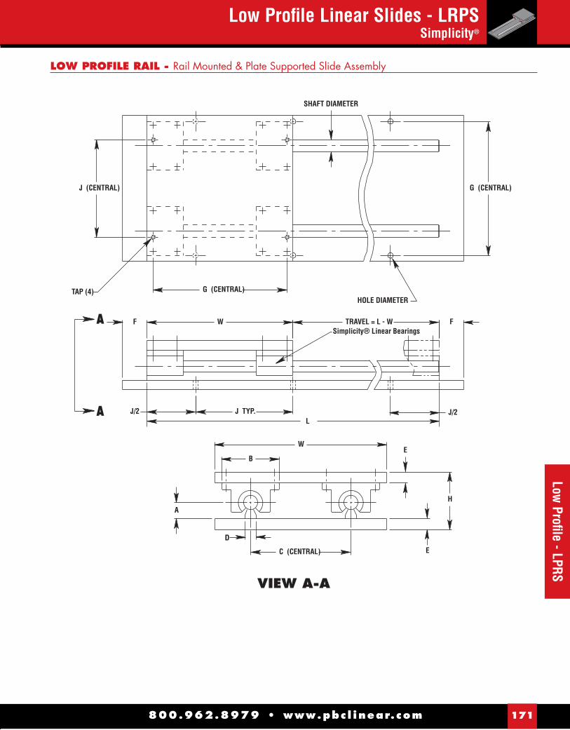
800.962.8979 • www.pbc l inear.com 171
Low Profi le - LPRS
D
A
A
E
J/2
HOLE DIAMETER
E
H
G (CENTRAL)
TRAVEL = L - WSimplicity® Linear Bearings
SHAFT DIAMETER
TAP (4)
J TYP.L
B
J/2
G (CENTRAL)
J (CENTRAL)
A
WF
W
C (CENTRAL)
F
VIEW A-A
Low Profi le Linear Slides - LRPSSimplicity®
LOW PROFILE RAIL - Rail Mounted & Plate Supported Slide Assembly

Low Profi le Linear Slides - 2LRPSSimplicity®
800.962.8979 • www.pbc l inear.com172
Low
Pro
fi le
- 2LP
RS
08 008 012 016 020 024 028 032 036 040 044 048 10 008 012 016 020 024 028 032 036 040 044 048 12 012 018 024 030 036 042 048 16 012 018 024 030 036 042 048 20 012 018 024 030 036 042 048 24 016 024 032 040 048 32 024 032 040 048
STANDARD LENGTH TABLE (Inches) SIZE AVAILABLE LENGTHS - L* (in inches)
052 056 060 064 068 072 076 080 084 088 092 096052 056 060 064 068 072 076 080 084 088 092 096 054 060 066 072 078 084 090 096 054 060 066 072 078 084 090 096 054 060 066 072 078 084 090 096 056 064 072 080 088 096 056 064 072 080 088 096
* Longer lengths are available - consult factory.
08 ARO ALO 10 ARO ALO 12 ARO ALO 16 BRO BLO CRO DRO 20 BRO BLO CRO DRO 24 BRO BLO CRO DRO DLO ERO 32 BRO BLO CRO DRO DLO ERO
ARO = .200 Right HandALO = .200 Left HandBRO = .250 Right HandBLO = .250 Left HandCRO = .500 Right HandDRO = 1.000 Right HandDLO = 1.000 Left HandERO = 1.875 Right Hand
STANDARD LEAD TABLE SIZE AVAILABLE LEAD CODES LEAD CODES
08 AR1 AL1 10 AR1 AL1 12 AR1 AL1 16 BR1 BL1 CR1 DR1 20 BR1 BL1 CR1 DR1 24 BR1 BL1 CR1 DR1 DL1 ER1 32 BR1 BL1 CR1 DR1 DL1 ER1
AR1 = .200 Right HandAL1 = .200 Left HandBR1 = .250 Right HandBL1 = .250 Left HandCR1 = .500 Right HandDR1 = 1.000 Right HandDL1 = 1.000 Left HandER1 = 1.875 Right Hand
SELECT LEAD TABLESIZE AVAILABLE LEAD CODES LEAD CODES
MATERIAL:Aluminum Alloy - Top Plate, Bottom Plate, Rail Supports, Pillow Blocks.
Shafting - Alloy Steel, 440 Stainless Steel, 303 Stainless Steel and Chrome Plated
ORDERING EXAMPLE:To order a slide with a Ø.625 diameter shaft, 28" travel, .200" right hand select ball screw - specify part number, 2LRPS-10-028-AR1.
Substitute standard or select lead code from table for “YYY”
Substitute “L” from standard length table for “XXX”
00 = Alloy Steel SS = 440 Stainless SteelCR = Chrome Plated XX = 303 Stainless Steel
Shaft diameter dimension in 1/16" increments
X = Ball Bearing (Leave blank for Simplicity FL bearing)
PART NUMBER
2LRPS X - 08 - XX - XXX - YYY2LRPS X - 10 - XX - XXX - YYY2LRPS X - 12 - XX - XXX - YYY2LRPS X - 16 - XX - XXX - YYY2LRPS X - 20 - XX - XXX - YYY2LRPS X - 24 - XX - XXX - YYY2LRPS X - 32 - XX - XXX - YYY
SERIES SIZE L LEAD
LOW PROFILE RAIL - Mounted & Plate Supported - Ball Screw Driven (Supported on Both Ends)
NOTE: Standard leads are accurate to less than .007" per foot accumulative. NOTE: Select leads are accurate to less than .003" per foot accumulative.

Low Profi le Linear Slides - 2LRPSSimplicity®
800.962.8979 • www.pbc l inear.com 173
Low Profi le - 2LPRS
A
A
SCREWMAJOR
DIAMETER
VIEW A-A
C (CENTRAL)
W
FWL
N FSimplicity® Linear Bearings
TRAVEL = L - W
J/2
G (CENTRAL)
J (CENTRAL)
EW/2B
HOLE DIAMETERG (CENTRAL)
J/2
K
A
H
O
SHAFT DIAMETER
KEY
TAP (4)
E
J TYP.
+.000-.001øM
D
.062
.25 .25
2LRPS - DIMENSIONAL INFORMATION
2.00 3.5 0.37 0.375 1.00 5.50 4.0 1.000 0.38 1.45 0.63 0.031 10-24 .22 3/32 sq X 5/8 lg2.50 4.0 0.45 0.375 1.00 6.31 4.0 1.156 0.38 1.45 0.63 0.031 1/4-20 .28 3/32 sq X 5/8 lg2.75 4.5 0.51 0.500 1.25 7.13 6.0 1.344 0.38 1.45 0.63 0.031 1/4-20 .28 3/32 sq X 5/8 lg3.25 5.5 0.69 0.500 1.25 8.31 6.0 1.594 0.63 1.76 1.00 0.062 1/4-20 .28 3/16 sq X 1" lg 4.00 6.5 0.78 0.750 1.50 10.00 6.0 2.094 0.63 1.76 1.00 0.062 5/16-18 .34 3/16 sq X 1" lg4.75 8.0 0.93 0.750 1.50 12.00 8.0 2.312 1.00 2.31 1.50 0.062 5/16-18 .34 1/4 sq X 1.62 lg6.00 10.0 1.18 1.000 1.75 15.88 8.0 2.937 1.00 2.31 1.50 0.062 3/8-16 .41 1/4 sq X 1.62 lg
.500 6.0 2.000 0.563 .625 7.0 2.313 0.688 .750 8.0 2.688 0.7501.000 9.0 3.188 1.0001.250 11.0 4.188 1.1881.500 13.0 4.625 1.3752.000 18.0 5.875 1.750
B C D E F G J K M N O P TAP DIA. KEY SHAFT DIA. W H A

Self Centering Linear Slides - SC2RPSSimplicity®
800.962.8979 • www.pbc l inear.com174
Self
Cent
erin
g - S
C2RP
S
*NOTE: Longer lengths are available - consult factory.
LEAD CODE TABLESTANDARD & SELECT BALL SCREW
SIZE AVAILABLE LEAD CODE
08 ALR? 10 ALR?12 ALR?16 BLR? 20 BLR? 24 BLR? DLR?32 BLR? DLR?
LEAD CODES
ALR? = .200 LeadsBLR? = .250 LeadsDLR? = 1.000 Leads
One left and one right hand lead ballscrew on each self-centering slide assembly.
Replace ? with 0 for standard lead accurate to less than .007" per foot accumulativeReplace ? with 1 for standard lead accurate to less than .003" per foot accumulative
ORDERING EXAMPLE: SC2RPS-10-056-ALR1
Shaft diameter in 1/16" increments (10/16 = .625")
MATERIAL:Aluminum Alloy - Top and bottom plates, rail supports, and pillow blocks.Shafting - Alloy Steel, 440 Stainless Steel, 303 Stainless Steel and Chrome Plate. Rolled ball screw, ball nut assembly, and rigid coupling.
00 = Alloy Steel SS = 440 Stainless SteelCR = Chrome Plated XX = 303 Stainless Steel
PART NUMBERSERIES SIZE L LEAD
SC2RPS X - 08 - XX - XXX - XXXSC2RPS X - 10 - XX - XXX - XXXSC2RPS X - 12 - XX - XXX - XXXSC2RPS X - 16 - XX - XXX - XXXSC2RPS X - 20 - XX - XXX - XXXSC2RPS X - 24 - XX - XXX - XXXSC2RPS X - 32 - XX - XXX - XXX
EXTENDED (TOGETHER)
RETURNED (APART)
S2RPS - Self-Centering Slide Assembly
X = Ball Bearing (Leave blank for FL bearing)
W
W
SIZES AVAILABLE LENGTHS - L* (in inches)
08 016 020 024 028 032 036 040 044 048 052 056 060 064 068 072 076 080 084 088 092 096
10 016 020 024 028 032 036 040 044 048 052 056 060 064 068 072 076 080 084 088 092 096
12 018 024 030 036 042 048 054 060 066 072 078 084 090 096
16 024 030 036 042 048 054 060 066 072 078 084 090 096
20 024 030 036 042 048 054 060 066 072 078 084 090 096
24 032 040 048 056 064 072 080 088 096
32 040 048 056 064 072 080 088 096
STANDARD LENGTH TABLE (Inches)

Self Centering Linear Slides - SC2RPSSimplicity®
800.962.8979 • www.pbc l inear.com 175
Self Centering - SC2RPS
F/2
KEY
J(CENTRAL)
TAP (8)G (CENTRAL)
G(CENTRAL)
W.25
.062 (2)
F
CLOCKWISE ROTATION BRINGSCARRIAGES TOGETHER
SHAFTDIAMETER
OSCREW NOMINAL
DIAMETER
.25F
HOLE DIAMETER (FOR CUST. MTG.)
C'BORE & HOLE(FOR CUST. MTG.)
TRAVEL = (L/2)-W
RIGID COUPLING
A
A
N
K
J/2 JL
B
DC (CENTRAL)
H
E
E
A
W
+.000-.001øM
VIEW A-A
SC2RPS - DIMENSIONAL INFORMATION
2.00 3.500 1.500 .375 1.00 5.500 4.000 1.375 .375 1.45 .63 10-24 .22 3/32 sq X 5/8 lg2.50 4.000 1.625 .375 1.00 6.312 4.000 1.375 .375 1.45 .63 1/4-20 .28 3/32 sq X 5/8 lg2.75 4.500 1.750 .500 1.25 7.125 6.000 1.500 .375 1.45 .63 1/4-20 .28 3/32 sq X 5/8 lg3.25 5.500 2.125 .500 1.25 8.312 6.000 2.125 .625 1.76 1.00 1/4-20 .28 3/16 sq X 1" lg4.00 6.500 2.500 .750 1.50 10.000 6.000 2.375 .625 1.76 1.00 5/16-18 .34 3/16 sq X 1" lg4.75 8.000 3.000 .750 1.50 12.000 8.000 2.875 1.000 2.31 1.50 5/16-18 .34 1/4 sq X 1.62 lg6.00 10.000 3.750 1.000 1.75 15.875 8.000 3.875 1.000 2.31 1.50 3/8-16 .41 1/4 sq X 1.62 lg
.500 6.000 2.562 1.125 .625 7.000 2.750 1.125 .750 8.000 3.438 1.500 1.000 9.000 3.938 1.750 1.250 11.000 5.125 2.125 1.500 13.000 5.750 2.500 2.000 18.000 7.375 3.250
B C D E F G J K M N O TAP HOLE KEY SHAFT DIA. W H A

800.962.8979 • www.pbc l inear.com176
Hand
cran
k - 2
HCR
/ 2HW
LHandcrank & Ball Screw Rotational Lock - 2HCR / 2HWLSimplicity® Linear Slides
2HCR-16-018-BRO REF.
SERIES HANDLE DESCRIPTION Standard Model Cast Aluminum Counterbalanced Hand Crank 24 and 32 (ONLY) Spoked Cast Iron Handwheel with Rigid, Revolving Crank Handle
Deluxe Model Aluminum Handwheel with Fold-Away Composite Handle
CR
WL
LEAD CODE TABLESTANDARD & SELECT BALL SCREWS
SIZE AVAILABLE LEAD CODE
08 ARX ALX 10 ARX ALX12 ARX ALX16 BRX BLX CRX DRX 20 BRX BLX CRX DRX 24 BRX BLX CRX DRX DLX ERX32 BRX BLX CRX DRX DLX ERX
LEAD CODES
ARX = .200 Right HandALX = .200 Left HandBRX = .250 Right HandBLX = .250 Left HandCRX = .500 Right HandDRX = 1.000 Right HandDLX = 1.000 Left HandERX = 1.875 Right HandReplace X with 0 for standard lead accurate to
less than .007" per foot accumulativeReplace X with 1 for standard lead accurate toless than .003" per foot accumulative
08 008 012 016 020 024 028 032 036 040 044 048 10 008 012 016 020 024 028 032 036 040 044 048 12 012 018 024 030 036 042 048 16 012 018 024 030 036 042 048 20 012 018 024 030 036 042 048 24 016 024 032 040 048 32 024 032 040 048
STANDARD LENGTH TABLE (Inches) SIZE AVAILABLE LENGTHS - L* (in inches)
052 056 060 064 068 072 076 080 084 088 092 096052 056 060 064 068 072 076 080 084 088 092 096 054 060 066 072 078 084 090 096 054 060 066 072 078 084 090 096 054 060 066 072 078 084 090 096 056 064 072 080 088 096 056 064 072 080 088 096
PART NUMBER DIMENSIONAL INFORMATIONSERIES SIZE L LEAD SHAFT DIA. W H A B C D E F G J
2HXXX - 08 - XXX - YYY .500 6.000 2.562 1.125 2.00 3.500 1.50 .375 2HXXX - 10 - XXX - YYY .625 7.000 2.750 1.125 2.50 4.000 1.62 .375 2HXXX - 12 - XXX - YYY .750 8.000 3.438 1.500 2.75 4.500 1.75 .500 2HXXX - 16 - XXX - YYY 1.000 9.000 3.938 1.750 3.25 5.500 2.12 .500 2HXXX - 20 - XXX - YYY 1.250 11.000 5.125 2.125 4.00 6.500 2.50 .750 2HXXX - 24 - XXX - YYY 1.500 13.000 5.750 2.500 4.75 8.000 3.00 .750 2HXXX - 32 - XXX - YYY 2.000 18.000 7.375 3.250 6.00 10.000 3.75 1.000
.75 5.500 4.000 .75 6.312 4.000 1.00 7.125 6.000 1.00 8.312 6.000 1.25 10.000 6.000 1.25 12.000 8.000 1.50 15.875 8.000
ORDERING EXAMPLE: 2HWL-10-056-AR1
Shaft diameter in 1/16" increments (10/16 = .625")
MATERIAL:Aluminum Alloy -Top and bottom plates, rail supports, and pillow blocks.Alloy Steel - Shafting with proprietary low friction corrosion resistant surface treatment. Rolled ball screw and ball nut assembly.
2HWL-16-018-BRO REF.
2HCR/2HWL – Slide Assembly with Handcrank & Ball Screw Rotational Lock
X = Ball Bearing (Leave blank for FL bearing)
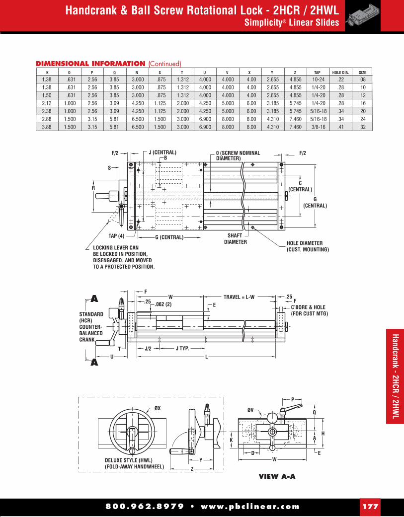
F/2
S
R
TAP (4) G (CENTRAL) SHAFTDIAMETER
G(CENTRAL)
C(CENTRAL)
HOLE DIAMETER(CUST. MOUNTING)
.25F
FW
.062 (2)
J TYP.TU
ØX
Y
Z
DELUXE STYLE (HWL)(FOLD-AWAY HANDWHEEL)
K
DW
E
VIEW A-A
A
A
H
Q
A
P
ØV
STANDARD (HCR)COUNTER-BALANCEDCRANK
L
J/2
.25C’BORE & HOLE(FOR CUST MTG)
TRAVEL = L-WE
B
LOCKING LEVER CAN BE LOCKED IN POSITION,DISENGAGED, AND MOVED TO A PROTECTED POSITION.
F/2J (CENTRAL) 0 (SCREW NOMINAL DIAMETER)
800.962.8979 • www.pbc l inear.com 177
Handcrank - 2HCR / 2HWL
Handcrank & Ball Screw Rotational Lock - 2HCR / 2HWLSimplicity® Linear Slides
K O P Q R S T U V X Y Z TAP HOLE DIA. SIZE
1.38 .631 2.56 3.85 3.000 .875 1.312 4.000 4.000 4.00 2.655 4.855 10-24 .22 081.38 .631 2.56 3.85 3.000 .875 1.312 4.000 4.000 4.00 2.655 4.855 1/4-20 .28 101.50 .631 2.56 3.85 3.000 .875 1.312 4.000 4.000 4.00 2.655 4.855 1/4-20 .28 122.12 1.000 2.56 3.69 4.250 1.125 2.000 4.250 5.000 6.00 3.185 5.745 1/4-20 .28 162.38 1.000 2.56 3.69 4.250 1.125 2.000 4.250 5.000 6.00 3.185 5.745 5/16-18 .34 202.88 1.500 3.15 5.81 6.500 1.500 3.000 6.900 8.000 8.00 4.310 7.460 5/16-18 .34 243.88 1.500 3.15 5.81 6.500 1.500 3.000 6.900 8.000 8.00 4.310 7.460 3/8-16 .41 32
DIMENSIONAL INFORMATION (Continued)

800.962.8979 • www.pbc l inear.com178
Driv
e Ki
t - 2
N42,
56,
143
NEMA Drive Kit - 2N42, 56, 143Simplicity® Linear Slides
16 012 018 024 030 036 042 048 20 012 018 024 030 036 042 048 24 016 024 032 040 048 32 024 032 040 048
STANDARD LENGTH TABLE (Inches) SIZE AVAILABLE LENGTHS - L* (in inches)
054 060 066 072 078 084 090 096 054 060 066 072 078 084 090 096 056 064 072 080 088 096 056 064 072 080 088 096
SIZE AVAILABLE LEAD CODE
16 BR? BL? CR? DR? 20 BR? BL? CR? DR? 24 BR? BL? CR? DR? DL? ER?32 BR? BL? CR? DR? DL? ER?
LEAD CODES
BR? = .250 Right HandBL? = .250 Left HandCR? = .500 Right HandDR? = 1.000 Right HandDL? = 1.000 Left HandER? = 1.875 Right Hand
Replace ? with 0 for standard lead accurate toless than .007" per foot accumulative
Replace ? with 1 for standard lead accurate toless than .003" per foot accumulative
LEAD CODE TABLESTANDARD & SELECT BALL SCREWS
PART NUMBER DIMENSIONAL INFORMATIONSERIES SIZE L LEAD SHAFT DIA. W H A B C D E
2NXXX - 16 - XXX - XXX 1.000 9.000 3.938 1.750 3.25 5.500 2.12 .5002NXXX - 20 - XXX - XXX 1.250 11.000 5.125 2.125 4.00 6.500 2.50 .7502NXXX - 24 - XXX - XXX 1.500 13.000 5.750 2.500 4.75 8.000 3.00 .7502NXXX - 32 - XXX - XXX 2.000 18.000 7.375 3.250 6.00 10.000 3.75 1.000
ORDERING EXAMPLE: 2N56-16-054-BR1
MATERIAL:Aluminum Alloy - Top and bottom plates, rail supports, pillow blocks, and coupling.Alloy Steel - Shafting with proprietary low friction corrosion resistant surface treatment. Rolled ball screw and ball nut assembly.
MOTOR MOUNTING DIMENSIONS COUPLING2
MAX DYNAMIC SERIES DRIVE R S V X Y Z TORQUE CAPACITY
42A NEMA 42 3.000 .375 5.000 .28 3.750 2.652 200 in-lbs 42B NEMA 42 2.188 .625 5.000 5/16-18 4.950 3.500 200 in-lbs 56 NEMA 56 4.500 .625 7.000 .41 5.875 4.154 200 in-lbs 143 NEMA 143 or 145 4.500 .875 7.000 .41 5.875 4.154 200 in-lbs
NOTE: International drives and low profi le slide assemblies are available - consult factory. 2 Due to ball screw and nut life/torque capacities for 16 and 20 size slides, do not exceed 100 in-lbs. of input torque without consulting factory.
*NOTE: Longer lengths are available - consult factory.
2N56-16-018-BRO REF.
Shaft diameter in 1/16" increments (12/16 = .750")
2N42, 56, 143 – Slide Assembly/NEMA Drive Kit
X = Ball Bearing (Leave blank for FL bearing)

800.962.8979 • www.pbc l inear.com 179
Drive Kit - 2N42, 56, 143NEMA Drive Kit - 2N42, 56, 143
Simplicity® Linear Slides
LOW BACKLASHSHAFT CLAMPINGSTYLE COUPLING2
F/2
7.000
J (CENTRAL)O (SCREW NOMINAL DIAMETER)
F/2
C(CENTRAL)
G(CENTRAL)
.25F
HOLE & C’BORE (4)(FOR CUST MTG.)
HOLE DIAMETER(FOR CUST MTG.)
L
J TYP
REF MOTOR
MOTOR MTG PLATE
RISER
2.00G (CENTRAL)
W.25F
5.254.37
.062 (2)
SHAFTDIAMETER
TRAVEL = L-W
E
TAP (4)
WB
AH
K
DE
Z (CENTRAL)Z (CENTRAL)
V
V/2
øX (on Y BC)
øR (PILOT BORE)+.001+.004
ø2.25
øM+.000-.001
(BALL SCR)
Q (MAX) N
J/2
AB
B
A
VIEW A-A VIEW B-B
DIMENSIONAL INFORMATION (Continued) F G J K M N O Q TAP HOLE SIZE
1.00 8.312 6.000 2.125 .625 1.76 1.000 3.00 1/4-20 .28 16 1.25 10.000 6.000 2.375 .625 1.76 1.000 3.00 5/16-18 .34 20 1.25 12.000 8.000 2.875 1.000 2.31 1.500 2.62 5/16-18 .34 24 1.50 15.875 8.000 3.875 1.000 2.31 1.500 2.62 3/8-16 .41 32

800.962.8979 • www.pbc l inear.com180
NEM
A Dr
ive
- 2N2
3 &
2N3
4NEMA Drive Kit - 2N23 & 2N34Simplicity® Linear Slides
LEAD CODE TABLESTANDARD & SELECT BALL SCREWSIZE AVAILABLE LEAD CODE
08 AR? AL? 10 AR? AL? 12 AR? AL? 16 BR? BL? CR? DR? 20 BR? BL? CR? DR?
LEAD CODES
AR? = .200 Right HandAL? = .200 Left HandBR? = .250 Right HandBL? = .250 Left HandCR? = .500 Right HandDR? = 1.000 Right HandReplace ? with 0 for standard lead accurate to
less than .007" per foot accumulative
Replace ? with 1 for standard lead accurate toless than .003" per foot accumulative
08 008 012 016 020 024 028 032 036 040 044 048 10 008 012 016 020 024 028 032 036 040 044 048 12 012 018 024 030 036 042 048 16 012 018 024 030 036 042 048 20 012 018 024 030 036 042 048
STANDARD LENGTH TABLE (Inches) SIZE AVAILABLE LENGTHS - L* (in inches)
052 056 060 064 068 072 076 080 084 088 092 096052 056 060 064 068 072 076 080 084 088 092 096 054 060 066 072 078 084 090 096 054 060 066 072 078 084 090 096 054 060 066 072 078 084 090 096
PART NUMBER DIMENSIONAL INFORMATIONSERIES SIZE L LEAD SHAFT DIA. W H A B C D E
2NXXX - 08 - XXX - XXX .500 6.000 2.562 1.125 2.00 3.500 1.50 .375 2NXXX - 10 - XXX - XXX .625 7.000 2.750 1.125 2.50 4.000 1.62 .375 2NXXX - 12 - XXX - XXX .750 8.000 3.438 1.500 2.75 4.500 1.75 .500 2NXXX - 16 - XXX - XXX 1.000 9.000 3.938 1.750 3.25 5.500 2.12 .500 2NXXX - 20 - XXX - XXX 1.250 11.000 5.125 2.125 4.00 6.500 2.50 .750
ORDERING EXAMPLE: 2N23A-10-056-AR1
Shaft diameter in 1/16" increments (10/16 = .625")
MATERIAL:Aluminum Alloy - Top & bottom plates, rail supports, and pillow blocks, coupling, and motor mounts.Alloy Steel - Shafting with proprietary low friction corrosion resistant surface treatment. Rolled ball screw & ball nut assembly.
*NOTE: Longer lengths are available - consult factory
MOTOR MOUNTING DIMENSIONS COUPLING2
MAX DYNAMIC SERIES DRIVE R S V X Y Z TORQUE CAPACITY
23A NEMA 23 1.502 .250 2.500 10-32 2.625 1.856 50 in-lbs 23B NEMA 23 1.502 .375 2.500 10-32 2.625 1.856 50 in-lbs 34A NEMA 34 1.880 .375 3.500 10-32 3.875 2.740 50 in-lbs 34B NEMA 34 1.880 .500 3.500 10-32 3.875 2.740 50 in-lbs
NOTE: International drive confi gurations and low profi le slide assemblies are available - consult factory 2Due to ball screw & nut life/torque capacities for sizes 08, 10, or 12 do not exceed 30 in-lbs. of input torque.
2N23A-08-012-ARO REF.
2N34A-20-018-BRO REF.
2N23 & 2N34 – Slide Assembly/NEMA Drive Kit
X = Ball Bearing (Leave blank for FL bearing)

S
EA
A
V
+.001+.004
VIEW A-A
LOW BACKLASHSHAFT CLAMPINGSTYLE COUPLING
3.250 F/2
3.500
J (CENTRAL)B
(MOTOR SHAFT)
2.38(COUPLING)
MOTOR
MOTOR MTG PLATERISER
TAP (4)
.062 (2)F
.25 W TRAVEL = L-W
G (CENTRAL)
.25
HOLE DIAMETER(CUST. MOUNTING)
FHOLE & C'BORE (4)(CUST. MOUNTING)
OSCREW NOMINAL
DIAMETER F/2
C(CENTRAL)
G(CENTRAL)
ø1.50
øM+.000-.001
(BALL SCR.)
Q MAX N
E
A
J/2 J TYP
L
W
Z (CENTRAL)
Z (CENTRAL)V/2
K
X TAPS (ON Y B.C.)
R (PILOT BORE)D
SHAFTDIAMETER
H
800.962.8979 • www.pbc l inear.com 181
Drive Kit - 2N23 & 2N34
NEMA Drive Kit - 2N23 & 2N34Simplicity® Linear Slides
DIMENSIONAL INFORMATION (Continued) F G J K M N O Q TAP HOLE SIZE
.75 5.500 4.000 1.375 .375 1.45 .631 1.31 10-24 .22 08 .75 6.312 4.000 1.375 .375 1.45 .631 1.31 1/4-20 .28 10 1.00 7.125 6.000 1.500 .375 1.45 .631 1.31 1/4-20 .28 12 1.00 8.312 6.000 2.125 .625 1.76 1.000 1.19 1/4-20 .28 16 1.25 10.000 6.000 2.375 .625 1.76 1.000 1.19 5/16-18 .34 20
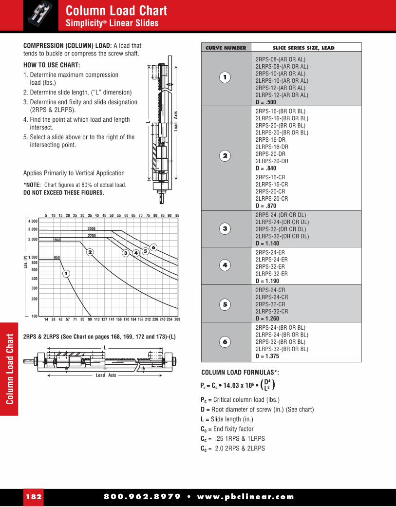
800.962.8979 • www.pbc l inear.com182
Colu
mn
Load
Cha
rtColumn Load ChartSimplicity® Linear Slides
L
Load Axis
Applies Primarily to Vertical Application
*NOTE: Chart fi gures at 80% of actual load. DO NOT EXCEED THESE FIGURES.
COMPRESSION (COLUMN) LOAD: A load that tends to buckle or compress the screw shaft.
HOW TO USE CHART:1. Determine maximum compression
load (lbs.)2. Determine slide length. (“L” dimension)3. Determine end fi xity and slide designation
(2RPS & 2LRPS).4. Find the point at which load and length
intersect.5. Select a slide above or to the right of the
intersecting point.L
Load
Ax
is
4,000
3,000
2,000
1,000800
600
400
300
200
100
5 15 25 35 45 55 65 75 85 9510 20 40 5030 60 70 80 90
Lbs.
(P)
14 42 71 99 127 156 184 212 240 26928 57 113 14185 170 198 226 254
1
2 436
5950
19402200
3000
2RPS & 2LRPS (See Chart on pages 168, 169, 172 and 173)-(L)
CURVE NUMBER SLICE SERIES SIZE, LEAD
1
2
3
4
6
2RPS-08-(AR OR AL)2LRPS-08-(AR OR AL)2RPS-10-(AR OR AL)2LRPS-10-(AR OR AL)2RPS-12-(AR OR AL)2LRPS-12-(AR OR AL)D = .500
2RPS-16-(BR OR BL)2LRPS-16-(BR OR BL)2RPS-20-(BR OR BL)2LRPS-20-(BR OR BL)2RPS-16-DR2LRPS-16-DR2RPS-20-DR2LRPS-20-DRD = .840
2RPS-16-CR2LRPS-16-CR2RPS-20-CR2LRPS-20-CRD = .870
2RPS-24-(DR OR DL)2LRPS-24-(DR OR DL)2RPS-32-(DR OR DL)2LRPS-32-(DR OR DL)D = 1.140
2RPS-24-ER2LRPS-24-ER2RPS-32-ER2LRPS-32-ERD = 1.190
2RPS-24-CR2LRPS-24-CR2RPS-32-CR2LRPS-32-CRD = 1.260
2RPS-24-(BR OR BL)2LRPS-24-(BR OR BL)2RPS-32-(BR OR BL)2LRPS-32-(BR OR BL)D = 1.375
COLUMN LOAD FORMULAS*:
Pc = Critical column load (lbs.)D = Root diameter of screw (in.) (See chart)L = Slide length (in.)Cc = End fi xity factor Cc = .25 1RPS & 1LRPSCc = 2.0 2RPS & 2LRPS
5

800.962.8979 • www.pbc l inear.com 183
Critical Speed ChartCritical Speed Chart
Simplicity® Linear Slides
CRITICAL SPEED: The maximum speed at which a ball screw or ball nut can rotate without producing destructive resonant vibrations. The critical speed is a function of the ball screw diameter, the unsupported length of screw, rigidity of bearing supports, and RPM.
HOW TO USE CHART:1. Determine end fi xity. How many ends are fi xed?
(Slide designation, 2RPS & 2LRPS)2. Determine slide length. (“L” dimension)3. Find the length – fi xity vertical line, read up to fi nd the
intersecting, at the required travel rate.4. Select a slide above or to the right of the intersection point.5. Higher speeds and/or longer lengths are available as cost
effective specials, having a larger ball screw and bearings. (Consult Pacifi c Bearing)
L
Load Axis
L
Load Axis
12
3 45 6
7
8
150
100
50
30
20
10
5
2
1
.5
10 20 30 40 50 60 70 80 90 100 110 120 130 140 150 160 170 180 190 200
6 12 18 24 30 36 42 48 54 60 66 72 78 84 90 96 102 108 114 120
Trav
el R
ate
(N)
(inch
es/s
ec.)
Lube
Req
’dLu
be O
ptio
nal
*NOTE: Chart fi gures at 80% of actual load. DO NOT EXCEED THESE FIGURES.
2RPS & 2LRPS (See Chart on pages 168, 169, 172 and 173)-(L)
2RPS-08-(AR or AL) 2RPS-12-(AR or AL)2LPS-08-(AR or AL) 2LPS-12-(AR or AL)2RPS-10-(AR or AL)2LPS-10-(AR or AL)D = .500H = .200
2RPS-16-(BR or BL) 2RPS-20-(BR or BL)2LPS-16-(BR or BL) 2LPS-20-(BR or BL)D = .840H = .250
2RPS-24-(BR or BL) 2RPS-32-(BR or BL)2LPS-24-(BR or BL) 2LPS-32-(BR or BL)D = 1.375H = .250
2RPS-16-(CR) 2RPS-20-(CR)2LPS-16-(CR) 2LPS-20-(CR)D = .870H = .500
2RPS-24-(CR) 2RPS-32-(CR)2LPS-24-(CR) 2LPS-32-(CR)D = 1.260H = .500
2RPS-16-(DR) 2RPS-20-(DR)2LPS-16-(DR) 2LPS-20-(DR)D = .840H = 1.000
2RPS-24-(DR or DL) 2RPS-32-(DR or DL)2LPS-24-(DR or DL) 2LPS-32-(DR or DL)D = 1.140H = 1.000
2RPS-24-(ER) 2RPS-32-(ER)2LPS-24-(ER) 2LPS-32-(ER)D = 1.190H = 1.875
1
2
3
4
5
6
7
8
CURVE NUMBER SLICE SERIES SIZE, LEAD
CRITICAL SPEED FORMULAS*:
N = Critical speed (Maximum) (expressed in inches/sec.)D = Root diameter of screw (in./Rev.) (See chart)H = Lead of screw (in.) (See chart)L = Slide length (in.)Cs = End fi xity factorCs = .36 1RPS & 1LRPSCs = 1.47 2RPS & 2LRPS

800.962.8979 • www.pbc l inear.com184
Min
i-Rai
l®Mini-Rail® Miniature Linear GuidesProduct Overview
An economical alternative to conventional miniature linear guides, Mini-Rail requires no maintenance, is fully interchangeable with industry standard sizes and is maintained in stock for quick delivery.
Mini-Rail miniature linear guides are available in fi ve sizes: 7, 9, 12, 15 and 20mm - in lengths up to 3600mm, meaning no cumbersome butt joints. These guides are precision manufactured out of lightweight aluminum alloys to ensure long life and corrosion resistance.
• No rolling elements • Self-lubricating FrelonGOLD® Liner • Withstands vibration and shock• Corrosion-resistant - ideal in harsh environments• Ceramic coated, aluminum rail • Compact design- small footprint
CARRIAGE CONFIGURATIONS
Precision Series: Ceramic coated rails and carriages are corrosion resistant. FrelonGold® self-lubricating liner delivers the best overall performance, the highest loads, the best wear life, and speeds. Most precise running clearance for high precision applications.
Compensated Precision Series: Same as Precision Series except with additional clearance provided to tolerate misalignment.
APPLICATIONS
• Medical Precision • Packaging• Food Processing • Product Movement• Automation • Printing• Electronics • Semi-conductor• Mobile Home Components
PRODUCT OVERVIEW
FrelonGOLD® and FrelonJ are Tefl on® based materials that are truly self-lubricating. Frelon® materials are bonded to the carriage creating a one-piece unit.
Rail
MR XXCARRIAGE
Mini-RailMiniature Linear Guide
MRRAIL XX
Nominal Sizes(7, 9, 12, 15, 20mm)
Mini-RailMiniature Linear Guide
Nominal Sizes(7, 9, 12, 15, 20mm)
SeriesBlank = Precision Series C= Compensated Precision Series
Carriage
C R
ORDERING INFORMATION EXAMPLE: MRC20C
MR20R
See following page for Mini-Rail full assembly ordering.

800.962.8979 • www.pbc l inear.com 185
Mini-Rail® - MRMiniature Linear Guide
NOTES: Cut-to-length rails are available up to 3600mm. Standard and cut-to-length rail ends are NOT coated. Fully coated rails are available upon request. All carriage mounting holes are through tapped except MR20 12.5mm of thread. The “Y” dimension will remain constant at one end unless requested otherwise. Add the overall length of the rail to the part number (EX:“MR12-0220” for a Precision Series assembly with a 220mm rail)
ORDERING INFORMATION
Mini-RailMiniature Linear Guide
MR XXXX
Length of Rail in mmEX: 50mm = 0050
XX
# of Carriages
XX
Nominal Sizes(7, 9, 12, 15, 20mm)
SeriesBlank = Precision Series C= Compensated Precision Series
FrelonGOLD® bearing material on RC70 ceramic-coated rail
– –ASSEMBLY
B
MA
K
B1H2
[MAX LENGTH 3600mm]"L" .010
Y X
H1
H
EF
D
GC
DETAIL A (SCALE 2:1)
QUALIFIEDEDGE
(Maximum Length 3600mm)
Materials: 6061-T6 aluminum rail and carriage, FrelonGOLD or FrelonJ liner
Mini-Rail ® - M
R
MINI-RAIL - MR
EXAMPLE: MR12-0220-2
PART NUMBER RUNNING CLEARANCE
A B B1 C D E F G H H1 H2 K M Y X
RAILWT.
(gram/mm)
CARRIAGEWT.
(gram)
BASE WIDTH(mm)
OVERALLHEIGHT
RAILHEIGHT
CARRIAGEWIDTH
CARRIAGELENGTH
CARRIAGEMTG. HOLE
SIZE
CARRIAGEMTG. HOLE
DEPTH
CARRIAGEMTG. HOLE
CTR. TO CTR. RAIL HOLE SIZE
CARRIAGEHEIGHT
RAIL MTG. HOLE TO
QUALIFIEDEDGE
RAILHOLE
TOEND
RAILHOLECTR.TO
CTR
MR7-XXX .025 - .0517 8 6.1 17 24 M2 x 0.4
THRU
8 12 4.2 2.4 2.3 6.2 3.5 5 15 0.10 5.7MRC7-XXX .064 - .089
MR9-XXX .025 - .0519 10 7.1 20 30
M3 x 0.5
13 15 4.5 2.6 3 8.0 4.5 7.5 20 0.16 8.5MRC9-XXX .064 - .089
MR12-XXX .025 - .05112 13 8.0 27 34 15 20
6 3.5
3.5 10.7 6 10 25 0.22 20.0MRC12-XXX .064 - .089
MR15-XXX .025 - .05115 16 9.2 32 42 20 25 4.5 14.1 7.5 15 40 0.38 34.0
MRC15-XXX .064 - .089
MR20-XXX .025 - .05120 25 13.4 46 62 M4 x 0.7 12.5 38 38 9.5 6 8.5 21.2 10 20 60 0.48 127.9
MRC20-XXX .064 - .089
Max V: 300 sfm for FrelonGold, 140 sfm for FelonJMax P: 3000 psi for FrelonGold, 1500 psi for FrelonJ

800.962.8979 • www.pbc l inear.com186
Tech
nica
l Inf
orm
atio
nMini-Rail® - MRTechnical Information
CANTILEVERED LOADS
Binding of the carriage will occur if the 2:1 ratio for cantilevered loads and drive forces is exceeded. This principle is not load or force dependent. It is a product of the coeffi cient of frictions associated with plane bearings. Contact factory or website for additional information.
LOAD/MOMENT CONVERSION
N = 4.45 x (lbs.)
N-m = 0.113 x (in.-lbs.)
x
Load or Force
2xMAX
STATIC LOAD DATA
The numbers below are for rails in a static condition. Refer to the calculations below to establish dynamic parameters.
F F
F F
MyMx
F
C of MxC of My
My
F
Mz
F
C of My
C of Mz
L
PERFORMANCE RATINGS FOR LINEAR MOTION
Plane bearings are rated by their limiting PV, which is a combination of load over a given surface area and the velocity.
PV = The performance measurement of plane bearings.
PV = P x V, where P = pressure (load) in psi (kgf/cm2)
V = velocity (speed) in sfm (m/min.)
NOTE: All three parameters must be met by an application for the bearing to perform properly.
SIZE F (N) MSL (N)*
7 445 7349 667 155712 1334 195715 2224 311420 3559 6005
*Max static load in Newtons.
SIZE F (N)
7 899 12512 22215 35620 578
SIZE My(N-m)
Mx(N-m)
Mz(N-m)
7 2.3 1.8 1.89 5.0 3.2 3.212 9.0 5.6 5.615 15.1 9.0 9.020 24.9 14.7 14.7
SIZE F(N)
My(N-m)
Mx(N-m)
Mz(N-m)
7 133 2.3 1.8 1.89 222 5.0 3.2 3.212 400 9.0 5.6 5.615 667 15.1 9.0 9.020 1112 24.9 14.7 14.7
BEARINGMATERIAL MAX. “PV” MAX. “P”
MAX. “V”(NO LUBRICATION)
FrelonGold®
20,000 (psi x ft./min.) or
0.7 N/m2 x m/s
3000 psi or
20.68 N/mm2
300 sfm or
1.524 m/s
FrelonJ®
10,000 (psi x ft./min.) or
0.35 N/m2 x m/s
1500 psi or
10.34 N/mm2
140 sfm or
0.711 m/s

800.962.8979 • www.pbc l inear.com 187
Sigma - M
RSMini-Rail® Sigma - MRS
Miniature Linear Guide
MINI-RAIL SIGMA - MRS
ORDERING INFORMATION
PART NO.
A B B1 C D E F G H H1 H2 K M X YCARRIAGE
WT.
RAILUNITWT.
LOAD CAPACITY
Fy Fz Mx My Mz
(mm) (mm) (mm) (mm) (mm) (mm) (mm) (mm) (mm) (mm) (mm) (mm) (mm) (mm) (mm) (g) (g/mm) (N) (lbs.) (N) (lbs.) (N-m) (lbs.-in.) (N-m) (lbs.-in.) (N-m) (lbs.-in.)
MRS09 9 10 6.3 20 29 M2 X 0.4 13 15 4.4 2.4 1.7 8.3 4.5 20 5 17.6 0.11 590 130 295 65 2.4 21 1.2 11 1.2 11
MRS12 12 13 8.6 27 34 M3 X 0.5 15 20 6.5 3.4 2.7 11 6 25 5 37.3 0.19 995 225 500 110 5 50 2.5 24 2.5 24
MRS15 15 16 10.8 32 42 M3 X 0.5 20 25 6.5 3.4 3.9 13 7.5 40 10 64.9 0.32 1620 360 810 180 11 100 6 50 6 50
NOTE: Apply a load reduction factor 0.25 on Fy rating if the system is used inverted.
Materials:POM based polymer insertsAnodized aluminum railsChrome plated die cast carriages
Working Temperatures: -40C to 90C (-40F to 195F) Coeffi cient of Friction: 0.1- 0.2Maximum Velocity: 10 m/s (2000 fpm) for intermediate application and 8 m/s (1600 fpm) for continuous applicationMaximum PV Value: 10,000 psi - fpm
My
Fyy
Mx
x
Mzz Fz
• Easy alignment slot - quick assembly
• Cast zinc carriages with engineered polymer inserts
• Size interchangeable with miniature profi le rails
• Flat surface - easy mount with pop rivets, screws or
double-sided
EXAMPLE: MRS09R-0500-R5 MRS0C-XC25

800.962.8979 • www.pbc l inear.com188
Tech
nica
l Dat
aMini Rail® LS/MS SeriesMiniature Lead Screw - Driven Slides
800.962.8979 • www.pbc l inear.com188
Low
Pro
fi le
Min
i-Rai
l®Low Profi le Mini-Rail® - LPMMiniature Guide/Slide Motion Systems
• Low profi le for small spaces• Low cost polymer slider• Molded SS threaded Inserts• Double rail track• Ideal in harsh environments• Five sizes
Low Profile Mini-Rail®
LPM XX XXXX–
# of Carriages
Length of Rail in mm
– X
Nominal Size17mm27mm40mm80mm
ORDERING INFORMATION
EXAMPLE: LPMXX-XXXX-X
PART NUMBER
A B C D E FH
(C’BORE) L1 L2 L3 Y X
CAR-RIAGEWT.
RAILUNITWT.
LOAD CAPACITY
Fy Fz Mx My Mz
(mm) (mm) (mm) (mm) (mm) (mm) (mm) (mm) (mm) (mm) (mm) (mm) (g) (g/mm) (N) (lbs.) (N) (lbs.) (N-m)(lbs.-in.) (N-m)
(lbs.-in.) (N-m)
(lbs.-in.)
LPM17 17 6 9.6 20 M3 x 0.5 14 M3 SBHCS 8.5 N/A N/A 20 60 1.1 0.15 35 8 10 2.5 0.2 1.5 0.3 2.5 0.2 1.5
LPM27 27 9.5 14 40 M4 x 0.7 20 M4 SBHCS 13.5 N/A N/A 20 60 4.8 0.33 130 30 85 20 1 10 2.5 20 1 10
LPM40 40 9.5 23 50 M4 x 0.7 20 M4 SBHCS 20 N/A N/A 20 60 9.8 0.38 270 60 150 35 2.5 25 5 50 2.5 25
LPM80 80 12.0 57 80 M4 x 0.7 56 M4 SBHCS 20 40 45 25 150 32.3 1.07 515 120 250 55 7 60 14 125 7 60
NOTE: Apply a load reduction factor 0.25 on Fy rating if the system is used inverted.
Materials: SimGlide™-J Polymer slider (UL 94 HB fl ammability rating)Molded-in stainless steel thread insertsAnodized aluminum rails
Operating Temperatures: -35C to 65C (-30F to 150F)Chemical Resistance: Resistant to lubricants, fuels, dyes, weak acidsMaximum Velocity: 10 m/s Load Reduction Factor: 0.7-1.0 for low speed application; 0.4-0.7 for medium speed application; 0.1-0.4 for high speed application
Max Length=3048mmDF
L1C A
B
H E
L3
L1
L2
LOW PROFILE MINI-RAIL® - LPM
Y X
LPM 17, 27, 40, 80
LPM 80
My
Fyy
Mx
x
Mz z Fz
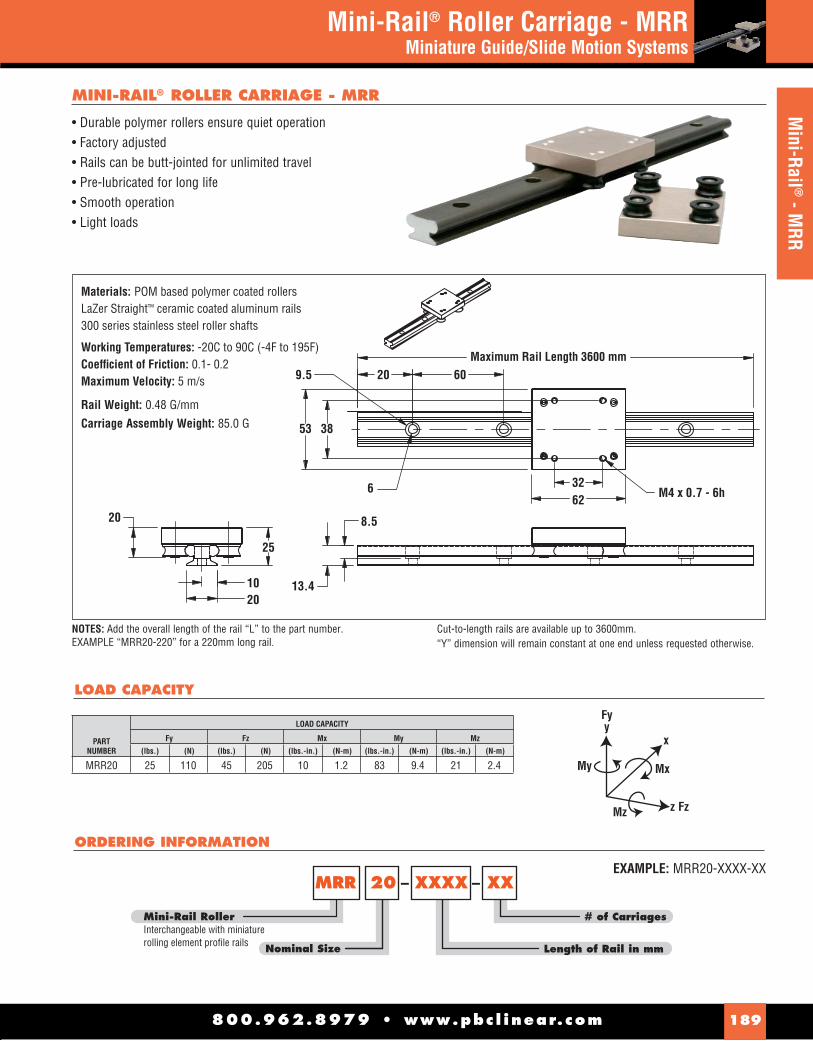
800.962.8979 • www.pbc l inear.com 189
Technical DataMini Rail® LS/MS Series
Miniature Lead Screw - Driven Slides
800.962.8979 • www.pbc l inear.com 189
Mini-Rail ® - M
RRMini-Rail® Roller Carriage - MRR
Miniature Guide/Slide Motion Systems
• Durable polymer rollers ensure quiet operation• Factory adjusted• Rails can be butt-jointed for unlimited travel• Pre-lubricated for long life• Smooth operation• Light loads
MINI-RAIL® ROLLER CARRIAGE - MRR
53 38
9.5
6
8.5
32M4 x 0.7 - 6h62
20
25
1020
13.4
6020
Rail Weight: 0.48 G/mm
Carriage Assembly Weight: 85.0 G
Materials: POM based polymer coated rollersLaZer Straight™ ceramic coated aluminum rails300 series stainless steel roller shafts
Working Temperatures: -20C to 90C (-4F to 195F)Coeffi cient of Friction: 0.1- 0.2Maximum Velocity: 5 m/s
NOTES: Add the overall length of the rail “L” to the part number.EXAMPLE “MRR20-220” for a 220mm long rail.
Cut-to-length rails are available up to 3600mm. “Y” dimension will remain constant at one end unless requested otherwise.
Mini-Rail Roller Interchangeable with miniaturerolling element profile rails
MRR XXXX
Length of Rail in mm
XX
# of Carriages
20
Nominal Size
– –
ORDERING INFORMATION
EXAMPLE: MRR20-XXXX-XX
LOAD CAPACITY
PART NUMBER
LOAD CAPACITY
Fy Fz Mx My Mz
(lbs.) (N) (lbs.) (N) (lbs.-in.) (N-m) (lbs.-in.) (N-m) (lbs.-in.) (N-m)
MRR20 25 110 45 205 10 1.2 83 9.4 21 2.4
Maximum Rail Length 3600 mm
My
Fyy
Mx
x
Mz z Fz

800.962.8979 • www.paci f i c -bear ing.com190
• Right hand rolled thread• 303 stainless steel screw with TFE coating• Self-lubricating Polyacetal, anti-backlash nut• Lengths up to 640mm• Three (3) leads available• Optional hand brake
MINI-RAIL® LS - LEAD SCREW DRIVEN
Mini-Rail
MR XX LS
Nominal Size of Base in mm15mm20mm
Lead Screw
Length of Rail in mmCut to length (Max. of 64Ø mm)
Screw Lead Option P = 1.27 mm (Ø.Ø5Ø in.)K = 4.75 mm (Ø.187 in.)T = 9.52 mm (Ø.375 in.)
Driving Mechanism ØØ = No knobSK = With screw knob17 = NEMA 17 motor mount
Mechanical Brake ØØ = No brakeBL = With brake lever mounted on carriage
XXXX XX XX
ORDERING INFORMATION
NOTES: Maximum length for lead screw driven MR is 640mm.Standard and cut-to-length rail ends are NOT coated. Fully coated rails are available upon request.
800.962.8979 • www.pbc l inear.com190
Min
i-Rai
l® -
LSMini-Rail® - LS Miniature Lead Screw - Driven Slides
46.0
16.0
6.4
640mm MAX
6.4
3.2
40.042.020.0 25.0
14.9
MR15LS
MOUNTING HOLESFOR M3 SCREWS.
M4x0.7 TAPPED HOLES
MR20LS
25.0
45.8
6.4 6.4
640mm MAX
3.2
60.0
15.1
62.038.0 38.0
MOUNTING HOLESFOR M5 SCREWS.
M4x0.7 TAPPED HOLES

800.962.8979 • www.paci f i c -bear ing.com 191800.962.8979 • www.pbc l inear.com 191
Mini-Rail ® - M
SMini-Rail® - MS
Miniature Lead Screw - Driven Slides
6.47.9
640mm MAX33.8
25.3
60.0
62.038.0
38.0 45.9
MOUNTING HOLESFOR M5 SCREWS
M4X0.7 TAPPED HOLES
55.5
43.0
42.2TYP
MR20MS
Mini-Rail
MR XX MS
Lead Screw
Length of Rail in mmCut to length (Max. of 64Ø mm)
Screw Lead Option AA = Ø.61 mm (Ø.Ø24 in.)AB = 2.44 mm (Ø.Ø96 in.)AC = 9.75 mm (Ø.384 in.)
Nominal Size of Stepper Motor N17 = NEMA 17
XXXXX N17
Nominal Size of Base in mm15mm20mm
ORDERING INFORMATION
MINI-RAIL® MS - LEAD SCREW DRIVEN
NOTES: Maximum length for lead screw driven MR is 640mm.Standard and cut-to-length rail ends are NOT coated. Fully coated rails are available upon request.
• Robust design - outstanding reliability• Fewer parts - less maintenance• Preloaded drive nut - eliminates backlash• High torque stepper motor (NEMA 17)• Low cost• Lengths up to 640 mm• Ball bearing supports• Integral screw• Three (3) leads available

800.962.8979 • www.paci f i c -bear ing.com192 800.962.8979 • www.pbc l inear.com192
Tech
nica
l Inf
orm
atio
nMini-Rail® LS/MSTechnical Information
400
350
300
250
200
150
100
50
0
10090807060
THRU
ST(lb
s.)
THRU
ST(N
)
50403020100
0 200
.00192
.00096
.00048
.00024
.00012
RECOMMENDED LOAD LIMIT
SPEED (full steps/sec.)400 600 800 1000 1200 1400 1600 1800
Size 17 Stepper Motor with 5.54mm (0.218") Screw LINEAR TRAVEL PER STEP
.001524 mm (.00006")
.003048 mm (.00012")
.006096 mm (.00024")
.012192 mm (.00048")
.024384 mm (.00096")
.048768 mm (.00192")
NOTES: Rail ends are NOT coated. Fully coated rails are available upon request.
F F
F F
F (N) MSL(N)*
3559 6005
F(N)
Mx(N-m)
My(N-m)
Mz(N-m)
1112 24.9 14.7 14.7
PV = The performance measurement of plane bearingsPV = P x V where P = pressure (load) in psi (kgf/cm2)V = velocity (speed) in sfm (m/min.)NOTE: All three parameters must be met by an application for
the bearing to perform properly.
PERFORMANCE RATINGS FOR LINEAR MOTION
Plane bearings are rated by their limiting PV, which is a combination of load over a given surface area and the velocity.
BEARINGMATERIAL MAX. “PV” MAX. “P”
MAX. “V”(NO LUBRICATION)
FrelonGold®
20,000 (psi x ft./min.) or
0.7 N/m2 x m/s
3000 psi or
20.68 N/mm2
300 sfm or
1.524 m/s
CANTILEVERED LOADS
Binding of the carriage will occur if the 2:1 ratio for cantilevered loads and drive forces is exceeded. This principle is not load or force dependent. It is a product of the coeffi cient of frictions associated with plane bearings. Contact factory or website for additional information.
LOAD/MOMENT CONVERSION
N = 4.45 x (lbs.)N-m = 0.113 x (in-lbs.)
x
Load or Force
2xMAXF
CL of Mz
Mz
F
Mx MxMy
F
CL of Mx CL of My
STATIC LOAD DATA
The numbers below are for rails in a static condition. Refer to the calculations below to establish dynamic parameters.
F (N)
578

Based on proven Simplicity® linear bearing technology, the Uni-Guide contain FrelonGOLD® self-lubricating bearing material. This material results in no metal to metal contact, while dampening vibrations and shock loads. The Uni-Guide unique two-piece assembly eliminates tolerance stack up and the integrated lightweight packages can drop into existing applications making installation easy. Ideal for low cost automation, positioning tables and packaging equipment.
FEATURES & BENEFITS
• Two-piece assembly - lightweight and eliminates tolerance stack
• Self-lubricating - FrelonGold® provides low wear, low friction, and high strength
• Lengths up to 10’ - butt-joinable for longer lenghts
• Mounting Flexibility - Pre-drilled rails - T-slots & mounting holes on carriages- Side or top mounting
• Easy drop in unit - no alignment needed
• Drive options - Ball- Lead screw (includes motor and drive)- Belt Driven
• Corrosion-Resistant - ideal in washdown environments
• Pre-engineered - ready to use
ACCESSORIES*
• Hand Brake & Crank • Motor Mount • Vise Block • End Block • Ratchet Pin • Pin Lock Clamp
APPLICATION EXAMPLES
800.962.8979 • www.pbc l inear.com 193
Uni-GuideProduct Overview
Uni-Guide
* Optional confi gurations and special carriages are available. Contact manfuracturer for availability.
Uni-Guide Ratchet
PRODUCT OVERVIEW
Two-piece linear guide
Flexible t-slot mounting system
FrelonGold® Liner
60% less frictionCeramic coated rail
Self- Centering Vice Pin-Lock Quick
Positioning Clamp
(Application examples require accessories. Contact manufacturer for availability)
UNLIMITED DESIGN OPTIONSAND VERSATILITY.

800.962.8979 • www.pbc l inear.com194
Tech
nica
l Inf
orm
atio
nUni-GuideTechnical & Ordering Information
F
Fz
F
CL of My CL of Mx CL of Mz
F
F
MxMz
F
F
My
CL of My
Mz
STATIC LOADS WITH NO DRIVE MECHANISM
The numbers below are for guides only in a static condition. The drive mechanism selected (lead screw, ball screw, cylinder, etc.)becomes the limiting factor when calculating maximum load and speed capacities. The user is responsible for determining the maximum capacity for the complete system based on the manufacturer’s data for their drive confi guration.
2X max.
X
Load orForce
If the drive mechanism (lead screw, ball screw, cylinder, etc.) is centered on the carriage, the load may not exceed a 2:1 ratio to the length of the bearings or binding will occur.
Designs must also operate within the following dynamic parameters:• Maximum Loads (P) = from charts above• Maximum Speed Dry (V) = 300 ft./min. (1.524 m/s)• Maximum PV (pressure x velocity) = 20,000 (0.70 N/mm2 x m/s)• PV Example: Load = 85 psi Speed = 180 ft./min. PV = 85 x 180 = 15,300 PVNOTE: FrelonGold® bearing material coeffi cient of friction is 0.125.
SIZE
FMAX LOAD
(lbs.)
FMAX LOAD
(N)
D075 500 2,224D100 750 3,336D125 1,000 4,448
SIZE
FMAX LOAD
(lbs.)
FMAX LOAD
(N)
D075 125 556D100 190 845D125 250 1,112
SIZE
FMAX LOAD
(lbs.)My
(in./lbs.)Mz
(in./lbs.)
FMAX LOAD
(N)My
(Nm)Mz
(Nm)
D075 250 340 350 1,112 38 40D100 375 650 730 1,668 73 82D125 500 1,200 1,225 2,224 136 138
SIZEMy
(in./lbs.)Mx
(in./lbs.)My
(Nm)Mx
(Nm)
D075 340 350 38 40D100 650 730 73 82D125 1,200 1,225 136 138
D L M 100 A CHB xxx P M
Mounting Hole OptionsNo Entry - Standard Inch SizesM - Metric Size Mounting Holes
Carriage OptionsNo Entry - Standard CarriageL - Extended Length Carriage
Nominal Size75mm, 100mm, 125mmBased on mm from shaft center-to-center
Drive Mounting OptionsNo Entry - No Drive Mounting OptionsH - Hand CrankN - NEMA Standard Motor Mount (See pages 196-198 for specifications.)HB - Handbrake (requires handcrank and screw)CHB - Carriage Handbrake (not offered with screw driven options)
Drive OptionsNo Entry - No Drive MechanismA - Right Hand Lead Screw with Standard PitchA1 - Right Hand Lead Screw with Optional Pitch (See pages 196-198 for specifications.)Notes: Screw options require attaching collar.Call the factory for other optional drive mechanisms.
Data Entry OptionNo Entry - No OptionsM - Optional MMI Keypad (Man-to-Machine Interface)
X # of Carriages
Overall Rail Length“D” Series - enter length of rail in inches xxx.xxx (EX: 6” = 006.000)“DM” Series - enter length of rail in mm xxxx (EX: 3500mm = 0350
Power and Control OptionsNo Entry - No Power OptionsP - Standard Motor with Motor Mount, Programmable Drive, Cables and Software (must have “N” in Drive Mounting Option)Note: Kits available for NEMA motor
– –
SeriesD - Standard Uni-Guides
ORDERING INFORMATION
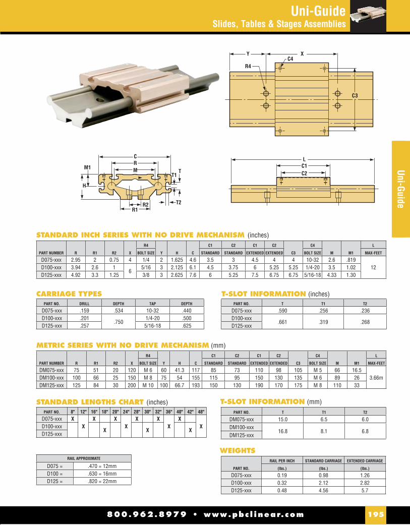
800.962.8979 • www.pbc l inear.com 195
Uni-Guide
XYC4
R4
C3
CRM
H
M1
R1T2
T1T
R2
LC1C2
PART NUMBER R R1 R2 X
R4
Y H C
C1 C2 C1 C2
C3
C4
M M1
L
BOLT SIZE STANDARD STANDARD EXTENDED EXTENDED BOLT SIZE MAX-FEET
D075-xxx 2.95 2 0.75 4 1/4 2 1.625 4.6 3.5 3 4.5 4 4 10-32 2.6 .81912D100-xxx 3.94 2.6 1
65/16 3 2.125 6.1 4.5 3.75 6 5.25 5.25 1/4-20 3.5 1.02
D125-xxx 4.92 3.3 1.25 3/8 3 2.625 7.6 6 5.25 7.5 6.75 6.75 5/16-18 4.33 1.30
STANDARD INCH SERIES WITH NO DRIVE MECHANISM (inches)
PART NUMBER R R1 R2 X
R4
Y H C
C1 C2 C1 C2
C3
C4
M M1
L
BOLT SIZE STANDARD STANDARD EXTENDED EXTENDED BOLT SIZE MAX-FEET
DM075-xxx 75 51 20 120 M 6 60 41.3 117 85 73 110 98 105 M 5 66 16.53.66mDM100-xxx 100 66 25 150 M 8 75 54 155 115 95 150 130 135 M 6 89 26
DM125-xxx 125 84 30 200 M 10 100 66.7 193 150 130 190 170 175 M 8 110 33
METRIC SERIES WITH NO DRIVE MECHANISM (mm)
PART NO. T T1 T2
D075-xxx .590 .256 .236D100-xxx
.661 .319 .268D125-xxx
T-SLOT INFORMATION (inches)
PART NO. T T1 T2
DM075-xxx 15.0 6.5 6.0DM100-xxx
16.8 8.1 6.8DM125-xxx
T-SLOT INFORMATION (mm)PART NO. 8" 12" 16" 18" 20" 24" 28" 30" 32" 36" 40" 42" 48"
D075-xxx XX
X XX
X XX
XXD100-xxx
X X XD125-xxx
STANDARD LENGTHS CHART (inches)
PART NO. DRILL DEPTH TAP DEPTH
D075-xxx .159 .534 10-32 .440D100-xxx .201
.7501/4-20 .500
D125-xxx .257 5/16-18 .625
CARRIAGE TYPES
PART NO.
RAIL PER INCH STANDARD CARRIAGE EXTENDED CARRIAGE
(lbs.) (lbs.) (lbs.)
D075-xxx 0.19 0.98 1.26D100-xxx 0.32 2.12 2.82D125-xxx 0.48 4.56 5.7
WEIGHTS
Uni-GuideSlides, Tables & Stages Assemblies
RAIL APPROXIMATE
D075 = .470 = 12mmD100 = .630 = 16mmD125 = .820 = 22mm
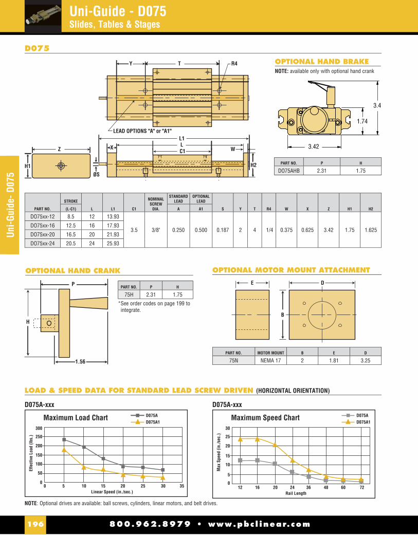
800.962.8979 • www.pbc l inear.com196
Uni-Guide - D075Slides, Tables & Stages
Uni-G
uide
- D07
5
PART NO.
STROKE
L L1 C1
NOMINALSCREW
DIA.
STANDARDLEAD
OPTIONALLEAD
S Y T R4 W X Z H1 H2(L-C1) A A1
DO75xx-12 8.5 12 13.93
3.5 3/8" 0.250 0.500 0.187 2 4 1/4 0.375 0.625 3.42 1.75 1.625DO75xx-16 12.5 16 17.93
DO75xx-20 16.5 20 21.93
DO75xx-24 20.5 24 25.93
LEAD OPTIONS "A" or "A1"
T R4Y
C1Z WLX
ØS
L1
H2H1
DE
B
OPTIONAL MOTOR MOUNT ATTACHMENT
H
1.56
P
OPTIONAL HAND CRANK
Maximum Load Chart
Effe
ctiv
e Lo
ad (l
bs.)
Linear Speed (in./sec.)
300
250
200
150
100
50
050 10 15 20 25 30 35
D075AD075A1
Maximum Speed Chart
Max
Spe
ed (i
n./s
ec.)
Rail Length
30
25
20
15
10
5
012 16 20 24 36 48 60 72
D075AD075A1
D075A-xxx D075A-xxx
D075
PART NO. MOTOR MOUNT B E D
75N NEMA 17 2 1.81 3.25
PART NO. P H
75H 2.31 1.75
PART NO. P H
DO75AHB 2.31 1.75
3.42
1.74
3.4
OPTIONAL HAND BRAKE
NOTE: Optional drives are available: ball screws, cylinders, linear motors, and belt drives.
NOTE: available only with optional hand crank
* See order codes on page 199 to integrate.
LOAD & SPEED DATA FOR STANDARD LEAD SCREW DRIVEN (HORIZONTAL ORIENTATION)

800.962.8979 • www.pbc l inear.com 197
Uni-Guide- D100Uni-Guide - D100
Slides, Tables & Stages
PART NO.
STROKE
L L1 C1
NOMINALSCREW
DIA.
STANDARDLEAD
OPTIONALLEAD
S Y T R4 W X Z H1 H2(L-C1) A A1
D100xx-12 7.5 12 14.61
4.5 1/2 0.250 0.500 0.314 3 6 5/16 0.5 1 4.56 2.5 2.500
D100xx-18 13.5 18 20.61
D100xx-24 19.5 24 26.61
D100x x-30 25.5 30 32.61
D100x x-48 25.5 30 32.61
LEAD OPTIONS "A" or "A1"
T R4Y
C1Z WLX
ØS
L1
H2H1
DE
B
OPTIONAL MOTOR MOUNT ATTACHMENT
H
1.56
P
OPTIONAL HAND CRANK
D100
Maximum Load Chart
Effe
ctiv
e Lo
ad (l
bs.)
Linear Speed (in./sec.)
600
500
400
300
200
100
050 10 15 20 25 30 35
D100AD100A1
D100A-xxx
Maximum Speed Chart
Max
Spe
ed (i
n./s
ec.)
Rail Length
30
25
20
15
10
5
012 18 24 30 36 48 60 72
D100AD100A1
D100A-xxx
LOAD & SPEED DATA FOR STANDARD LEAD SCREW DRIVEN (HORIZONTAL ORIENTATION)
PART NO. MOTOR MOUNT B E D
100N NEMA 23 2.5 1.81 3.25
PART NO. P H
100H 2.31 2.25
OPTIONAL HAND BRAKE
PART NO. P H
DO100AHB 2.31 1.75
NOTE: Optional drives are available: ball screws, cylinders, linear motors, and belt drives.
4.57
2.50
4.3
NOTE: available only with optional hand crank
* See order codes on page 199 to integrate.

Uni-Guide - D125Slides, Tables & Stages
800.962.8979 • www.pbc l inear.com198
Uni-G
uide
- D12
5
LEAD OPTIONS "A" or "A1"
T R4Y
C1Z WLX
ØS
L1
H2H1
DE
B
OPTIONAL MOTOR MOUNT ATTACHMENT
H
1.56
P
OPTIONAL HAND CRANK
D125
PART NO. MOTOR MOUNT B E D
125N NEMA 34 3.5 2.3 4.25
PART NO. P H
125H 2.31 3.25
PART NO.
STROKE
L L1 C1
NOMINALSCREW
DIA.
STANDARDLEAD
OPTIONALLEAD
S Y T R4 W X Z H1 H2(L-C1) A A1
D125xx-12 6 12 14.85
6 5/8 0.200 0.500 0.314 3 6 3/8 0.5 1 5.78 3.5 2.500
D125xx-18 12 18 20.85
D125xx-24 18 24 26.85
D125xx-30 24 30 32.85
D125xx-36 30 36 38.85
D125xx-48 30 48 50.85
D125xx-60 30 60 62.85
PART NO. P H
DO125AHB 2.31 1.75
OPTIONAL HAND BRAKE
Maximum Load Chart
Effe
ctiv
e Lo
ad (l
bs.)
Linear Speed (in./sec.)
600
500
400
300
200
100
050 10 15 20 25 30 35
D125AD125A1
Maximum Speed Chart
Max
Spe
ed (i
n./s
ec.)
Rail Length
30
25
20
15
10
5
012 18 24 30 36 48 60 72
D125AD125A1
D125A-xxx D125A-xxx
LOAD & SPEED DATA FOR STANDARD LEAD SCREW (HORIZONTAL ORIENTATION)
NOTE: Optional drives are available: ball screws, cylinders, linear motors, and belt drives.
5.79
3.47
4.7
NOTE: available only with optional hand crank
* See order codes on page 199 to integrate.

800.962.8979 • www.pbc l inear.com 199
Uni-Guide - DFGUni-Guide - DFG
Modular Guide
# of Carriages
Carriage LengthA =100B = 150C = 200
Rail Width 40/80
DFG10 XXXXXX
Length of Rail (in.)
X– – – X
DFG Series10mm System
ORDERING INFORMATION
PART NUMBER
DIMENSIONAL INFORMATION LOAD DATA
C C1 C2 C3 C4 H L1 R1 R3 R4 YCARRIAGEWEIGHT
RAILWEIGHT Fy Fz Mx My Mz
(mm) (mm) (mm) (mm) (mm) (mm) (mm) (mm) (mm) (mm) (mm) (G) (G/mm) (N) (lbs.) (N) (lbs.) (N-m) (lbs.-in.) (N-m) (lbs.-in.) (N-m) (lbs.-in.)
DFG10CA-40A 73 100 87 60 M6 24 36.5 40 120 6.6 20 310 1.0 5039 1133 4031 1020 100 74 180 133 180 133DFG10CA-40B 73 150 137 60 M6 24 36.5 40 120 6.6 20 370 1.0 5039 1133 4031 1020 100 74 305 225 305 225DFG10CA-40C 107 200 187 60 M6 24 36.5 40 120 6.6 20 430 1.0 5039 1133 4031 1020 100 74 430 320 430 320DFG10CA-80A 107 100 87 94 M6 24 53.5 80 120 6.6 20 360 1.4 5039 1133 4031 1020 184 136 180 132 180 132DFG10CA-80B 107 150 137 94 M6 24 53.5 80 120 6.6 20 450 1.4 5039 1133 4031 1020 184 136 305 225 305 225DFG10CA-80C 107 200 187 94 M6 24 53.5 80 120 6.6 20 530 1.4 5039 1133 4031 1020 184 136 430 320 430 320
NOTE: Apply a load reduction factor 0.25 on Fy rating if the system is used inverted.
• Self-lubricating- maintenance free• Polymer inserts - smooth, replaceable, low cost• Modular construction allow for multiple confi gurations • Multiple carriage and rail sizes• Industry standard interchangeable
*Not for resale or distribution inside the European Union.
EXAMPLE: DFG10-40A-0500-1
Materials:POM polymer insertAnodized aluminum railsChromate plated die cast carriageAnodized aluminum carriage plate
Working Temperatures: -40C to 90C (-40F to 195F) Coeffi cient of Friction: 0.1- 0.2Maximum Velocity: 10 m/s (2000 fpm) for intermediate application and 8 m/s (1600 fpm) for continuous applicationMaximum PV Value: 10,000 psi - fpm
DFG MODULAR GUIDE
My
Fyy
Mx
x
Mz z Fz

PRODUCT OVERVIEW
• Sealed double row bearings provide maintenance free, smooth linear guidance
• Side adjusted preload makes greatly simplifi es assembly and installation
• Withstands temperatures up to 180°F
• Butt-joinable for longer length applications
• Available in Inch or ISO Metric
ADJUSTING SLIDE PRELOAD
The preload of a slide should be properly set from the factory, but if you must adjust it yourself, here are some simple steps to follow.
Metric Series1. To loosen the eccentric (center) roller, use an Allen wrench
to loosen the screw that is on the side of the mounting block. Be sure to loosen the screw that is on the side of the direction you want the roller to move.
2. When it is loose, tighten the set screw on the opposite side of the block. This will move the roller and mounting stud.
3. Make a very small change, retighten the fi rst set screw, and try it out. If the preload is too loose, you will feel the slider rock and you will hear a slight “clunk.” If it is too tight, the slider will roll rough, like riding a bicycle on a gravel road.
4. Move the slide along the length of the rail by hand. Adjust it so that it does not feel loose anywhere. It may take you several times to get the proper adjustment.
5. Make sure the rollers are tightened with the proper adjustment prior to operation.
Inch Series1. To loosen the eccentric (center) roller, use an allen wrench to
turn the roller stud CLOCKWISE.2. When it is loose enough, the stud bushing (hex nut) can be
turned with a small wrench or by hand.3. Make a very small change, tighten the stud and try it out. If
the preload is too loose, you will feel the slider rock and you will hear a slight “clunk.” If it is too tight, the slider will roll rough, like riding a bicycle on a gravel road.
4. Move the slider along the length of the rail by hand. Adjust it so that it does not feel loose anywhere. It may take you several times to get the proper adjustment.
5. Make sure the rollers are tightened with the proper adjustment prior to operation.
LUBRICATION - RAILS & BEARINGS
The rollers are internally lubricated for life, but the rails must always have a layer of grease. As a guideline, reapply fresh grease every 50,000 cycles.
SLIDER ORIENTATION
The 3-Roller slide should be installed in the rail so the load is shared on the two outside rollers. The orientation marks indicate how to align the slider with the load direction.
MOUNTING SLIDER BODY & MAX CAPACITY
Below are recommended bolt tightening torques for mounting to the slide body. Be sure to use bolts that are long enough to obtain full thread engagement.
MOUNTING TORQUE
800.962.8979 • www.pbc l inear.com200
Redi-Rail® Linear GuidesProduct Overview
Tech
nica
l Inf
orm
atio
n
PART NUMBER IN-LBS. TORQUE NM TORQUE
RRS14RRS30 25 3
RRS18RRS45 70 8
RRS65 150 24
LOAD
Metric Series Inch Series

PART NUMBER MAX SPEED (m/min) MAX SPEED (m/s) Cd (N)
RR30 300 5.0 1,440
RR45 420 7.0 4,404
RR65 480 8.0 10,200
LRR = 107• /(LoadEquiv • RF))3.0
Ca
LoadAxial
Mx Max
Mx+My Max
My+Mz Max
Mz+
(inches)
LCRRS = Slider Life Capacity which is found in the table
LoadEquiv = Equivalent Radial Load found from the following equation:
LoadEquiv = Cr • ( ) + LoadRadial
(Cd
To calculate an approximate life for redi-rail sliders, use the following equation.
Inch SeriesThe value of LRR is in meters
Metric SeriesThe value of LRR is in meters
NOTE: Reduction factors apply to both inch and metric seriesRF = Reduction Factor of the Application or Environment = 1.0 to 1.5 for very clean, low speed (<30% Max), low
shocks = 1.5 to 2.0 for some dirtiness, moderate speed
(30% Max to 75% Max), medium shocks and vibration = 2.0 to 3.0 for heavy dirt & dust, high speeds (>75% Max)
and heavy shocks & vibrations
800.962.8979 • www.pbc l inear.com 201
Redi-Rail® Linear GuidesTechnical Information
Technical Information
LOAD COMPARISON GRAPHS
INCHPART NO.
C r(lbs.)
Ca(lbs.)
Mx (in-lbs.)
My(in-lbs.)
Mz(in-lbs.)
RRS14 336 79 21 54 201
RRS18 847 168 67 153 677METRIC (N) (N) (Nm) (Nm) (Nm)
RRS30 1,002 330 1.8 5.5 12.5
RRS45 2,660 827 6.6 19.9 47.9
RRS65 5,950 1,678 19.0 58.2 154.7
Cd = Dynamic capacity (LC)Cr = Radial capacityCa = Axial capacityMx, My, Mz = Moment capacities
Conversionsnewton (N) x 0.2248 = lbs. (lbf) meter x 0.0397 = inchnewton - meter (Nm) x 8.851 = in.-lbs.
LIFE CALCULATIONS
Cr My Mx
Mz
Ca
PART NO. MAX SPEED (fpm) MAX SPEED (ipm) Cd
RRS14 500 6000 421
RRS18 800 9,600 1,032
Ca
LoadAxial
Mx Max
Mx+My Max
My+Mz Max
Mz+LoadEquiv = Cr • ( ) + LoadRadial
LRR = (Cd/LoadEquiv • RF)3.0 x 100,000 meters
Cd = Slider Life Capacity which is found in the table
LoadEquiv = Equivalent Radial Load found from the following equation:

800.962.8979 • www.pbc l inear.com202
RRS14 SlideRedi-Rail® Linear Guides - Inch Series
ORDER INFORMATION
EXAMPLE:Slider size 14
0.702 0.959
0.62
1.25
3.25
TAPPED MOUNTING HOLES 1/4-28
1.25 1.33
LOAD
NOTE: Slide weight 0.25 lbs./ea.
RRS 14
Nominal Size14 = Dimension18 = Dimension (page 204)
Redi-Rail Slide
Redi
-Rai
i® 1
4
RRS14 SLIDE
• Low Cost Precision
• Factory Adjusted
• Sealed Bearings
• Solid Bearing Mounting System
• 5.79m Lengths
• Gothic Arch Rollers
• Off the Shelf Delivery
• Aluminum alloy boyd
• Rollers are 52100 steel, sealed against contamination, and are mounted with hardened steel mounting accessories.
• Not available with seals.
• Maximum temperature approximately 180°F.

800.962.8979 • www.pbc l inear.com 203
RR14 RailLoad Capacity to 340 lbs.
RR 14 XX
Nominal Size14 = Dimension18 = Dimension (page 205)
LengthsSuggested lengths cut up to 19'
CR
Corrosion Resistance Rail type with 440 SST rods
_
Redi-Rail
ORDER INFORMATION
EXAMPLE: RR14-36 Rail size 14 cut to 36" long
PARTNUMBER LENGTH HOLES Y
WT.(lbs./ft.)
RR14-12 12 4 0.75
0.64
RR14-24 24 7 1.50
RR14-36 36 11 0.50
RR14-48 48 14 1.25
RR14-60 60 17 2.00
RR14-72 72 21 1.00
RR14-84 84 24 1.75
RR14-96 96 28 0.75
NOTE: Suggested lengths can be cut and are available up to 19' (6m).
SUGGESTED RAIL LENGTHS & DIMENSIONS (Inches)
RR14 RAIL
3.500#10 COUNTERBORE MOUNTING HOLES
Y
1.33
Cd = Dynamic capacity (LC)Cr = Radial capacityCa = Axial capacityMx, My, Mz = Moment capacities
Conversionsnewton (N) x 0.2248 = lbs. (lbf) meter x 0.0397 = inchnewton - meter (Nm) x 8.851 = in.-lbs.
LIFE CALCULATIONS
PART NUMBERCd
(lbs.)C r
(lbs.)Ca
(lbs.)Mx
(in-lbs.) My
(in-lbs.) Mz
(in-lbs.)
RRS14 421 340 79 21 54 201
Cr My Mx
Mz
Ca
Customer specifi es ”Y“ dimension
Redi-Raii ® 14
Aluminum alloy with hardened steel raceways inserted.
NOTE: Rail weight 0.56 lb/ft

• Low Cost Precision
• Factory Adjusted
• Sealed Bearings
• Solid Bearing Mounting System
• 5.79m Lengths
• Gothic Arch Rollers
• Off the Shelf Delivery
• Body is aluminum alloy.
• Rollers are 52100 steel, sealed against contamination, and are mounted with hardened steel mounting accessories.
• Not available with seals.
• Maximum temperature approximately 180°F.
800.962.8979 • www.pbc l inear.com204
RRS18 SlideRedi-Rail® Linear Guides
ORDER INFORMATION
0.823 1.134
0.76
1.625
4.50
1.50 1.921
LOAD
TAPPED MOUNTING HOLES 5/16-24
NOTE: Slide weight 0.50 lbs./ea.
RRS18 SLIDE
EXAMPLE: RRS18
RRS 18
Nominal Size14 = Dimension (page 202)18 = Dimension
Redi-Rail Slide
Redi
-Rai
i® 1
8

800.962.8979 • www.pbc l inear.com 205
RR18 RailLoad Capacity to 850 lbs.
ORDER INFORMATION
PARTNUMBER LENGTH HOLES Y
WT.(lbs./ft.)
RR18-12 12 4 0.75
1.11
RR18-24 24 7 1.50
RR18-36 36 11 0.50
RR18-48 48 14 1.25
RR18-60 60 17 2.00
RR18-72 72 21 1.00
RR18-84 84 24 1.75
RR18-96 96 28 0.75
NOTE: Suggested lengths can be cut and are available up to 19' (6m).
SUGGESTED RAIL LENGTHS & DIMENSIONS (Inches)
RR18 RAIL
3.5001/4" COUNTERBORE MOUNTING HOLES
LENGTH
Y
1.91
Cd = Dynamic capacity (LC)Cr = Radial capacityCa = Axial capacityMx, My, Mz = Moment capacities
Conversionsnewton (N) x 0.2248 = lbs. (lbf) meter x 0.0397 = inchnewton - meter (Nm) x 8.851 = in.-lbs.
LIFE CALCULATIONSCr My Mx
Mz
Ca
PART NUMBERCd
(lbs.)C r
(lbs.)Ca
(lbs.)Mx
(in-lbs.) My
(in-lbs.) Mz
(in-lbs.)
RRS18 1,032 850 168 67 153 677
Customer specifi es ”Y“ dimension
Redi-Rail ® 18
RR 18 XX
Nominal Size14 = Dimension (page 203)18 = Dimension
LengthsSuggested lengths cut up to 19'
CR
Corrosion Resistance Rail type with 440 SST rods
_
Redi-Rail
EXAMPLE: RR18-36Rail size 18 cut to 36” long
Aluminum alloy with hardened steel raceways inserted.
NOTE: Rail weight 0.85 lb/ft

206
RRS30 SlideRedi-Rail® Linear Guides - ISO Metric
Redi
-Rai
l® 3
0
RRS 30 U
Nominal Size30 = Dimension45 = Dimension (page 208)65 = Dimension (page 210)
Wiper OptionsNo Entry - Oil filled plastic (Standard)U = UHMW
Redi-Rail Slide
ORDER INFORMATION
EXAMPLE: RRS30USlide size 30 with UHMW seals
Gothic contact for smooth, high speed performance
Shaft Roller
ROLLER/SHAFT INTERFACE
RRS30 SLIDE
NOTE: Slide weight .09 Kg
22.6
25.4 30
2886.926
LOAD
15.9
TAPPED MOUNTING HOLES M5 X 0.8
• 5.79 Meter Lengths
• Sealed Bearings
• Integral Seals
• Easy Adjusting
• Gothic Arch Rollers
• Solid Roller Mounting
• Slider body is aluminum alloy.
• Maximum temperature approximately 80°C.
• Gothic rollers are 52100 steel, hardened and ground, lubricated for life and sealed against contamination.
• Oil-fi lled plastic or UHMW spring loaded seals keep contamination clear of the rollers.
• Custom roller confi gurations can be designed, engineered, and manufactured to meet your specifi c requirements.
• Patented pre-load adjustment eliminates eccentrics.
APPLICATIONS
• Automation • Material Handling• Assembly • Packaging
800.962.8979 • www.pbc l inear.com
NOTES: Felt wipers have been replaced by low friction oil impregnated plastic wipers.No entry in the part # results in use of oil impregnated wiper.

800.962.8979 • www.pbc l inear.com 207
RR30 RailLoad Capacity to 1000 N
Redi-Rail ® 30
ORDER INFORMATION
RR 30 XXXX
Nominal Size30 = Dimension45 = Dimension (page 209)65 = Dimension (page 211)
Lengths (mm)Note: Specify Rail Length & Carriage
CR
Corrosion Resistanc Rail type with 440 SST rods
Redi-Rail
–EXAMPLE: RR30-1200
Rail size 30 cut to 1200mm long
Cd = Dynamic capacity (LC)Cr = Radial capacityCa = Axial capacityMx, My, Mz = Moment capacities
Conversionsnewton (N) x 0.2248 = lbs. (lbf) meter x 0.0397 = inchnewton - meter (Nm) x 8.851 = in.-lbs.
LIFE CALCULATIONSCr My Mx
Mz
Ca
PART NUMBERC d(N)
C r(N)
Ca(N)
Mx (Nm)
My (Nm)
Mz (Nm)
RRS30 1,440 1,000 330 1.8 5.5 12.5
NOTE: Rail weight 0.868 kg/m
30
M5 COUNTERBORE MOUNTING HOLES 60.0
LENGTH
Customer specifi es ”Y“ dimension
Y
RR30 RAIL
• Rail is aluminum alloy with hardened and ground steel raceways inserted.
• Custom solutions can be designed, engineered, and manufactured to meet your specifi c requirements.
• Maximum lengths up to 5800mm are available.
• Patented preload adjustment
• Joinable for even longer runs.
• Cut-to-length

800.962.8979 • www.pbc l inear.com208
RRS45 SlideRedi-Rail® Linear Guides
Redi
-Rai
l® 4
5
RRS 45 U
Nominal Size30 = Dimension45 = Dimension65 = Dimension
Wiper OptionsNo Entry - Oil filled plastic (Standard)U = UHMW
Redi-Rail Slide
ORDER INFORMATIONEXAMPLE: RRS45U
Slider size 45 with UHMW seals
RRS45 SLIDE
25.8
38.1 45
3311736
LOAD
20.4
TAPPED MOUNTING HOLES M8 x 1.25
NOTE: Slide weight .23 Kg
NOTES: Felt wipers have been replaced by low friction oil impregnated plastic wipers.No entry in the part # results in use of oil impregnated wiper.
• 5.79 Meter Lengths
• Sealed Bearings
• Integral Seals
• Easy Adjusting
• Gothic Arch Rollers
• Solid Roller Mounting• Slider body is aluminum alloy.
• Maximum temperature approximately 80°C.
• Gothic rollers are 52100 steel, hardened and ground, lubricated for life and sealed against contamination.
• Oil-fi lled plastic or UHMW spring loaded seals keep contamination clear of the rollers.
• Custom roller confi gurations can be designed, engineered, and manufactured to meet your specifi c requirements.
• Patented pre-load adjustment eliminates eccentrics.
APPLICATIONS• Automation • Material Handling• Assembly • Packaging
Gothic contact for smooth, high speed performance
Shaft Roller
ROLLER/SHAFT INTERFACE

800.962.8979 • www.pbc l inear.com 209
RR45 RailLoad Capacity to 2660 N
Redi-Rail ® 45
RR 45 XXXX
Nominal Size30 = Dimension45 = Dimension65 = Dimension
Lengths (mm)Note: Specify Rail Length & Carriage
CR
Corrosion Resistance Rail type with 440 SAT rods
–
Redi-Rail
ORDER INFORMATIONEXAMPLE: RR45-1200
Rail size 45 cut to 1200mm long
RR45 RAIL
Cd = Dynamic capacity (LC)Cr = Radial capacityCa = Axial capacityMx, My, Mz = Moment capacities
Conversionsnewton (N) x 0.2248 = lbs. (lbf) meter x 0.0397 = inchnewton - meter (Nm) x 8.851 = in.-lbs.
LIFE CALCULATIONSCr My Mx
Mz
Ca
PART NUMBERC d(N)
C r(N)
Ca(N)
Mx (Nm)
My (Nm)
Mz (Nm)
RRS45 4404 2660 827 6.6 19.9 47.9
NOTE: Rail weight 1.718 kg/m
45
M6 COUNTERBORE MOUNTING HOLES 60.0
LENGTH
Customer specifi es ”Y“ dimension
Y
• Rail is aluminum alloy with hardened and ground steel raceways inserted.
• Custom solutions can be designed, engineered, and manufactured to meet your specifi c requirements.
• Maximum lengths up to 5800mm are available.
• Patented preload adjustment
• Joinable for even longer runs.
• Cut-to-length

800.962.8979 • www.pbc l inear.com210
RRS65 SlideRedi-Rail® Linear Guide
Redi
-Rai
l® 6
5
RRS 65 U
Nominal Size30 = Dimension45 = Dimension65 = Dimension
Wiper OptionsNo Entry - Oil filled plastic (Standard)U = UHMW
Redi-Rail Slide
ORDER INFORMATION
EXAMPLE: RRS65USlider size 65 with UHMW seals
NOTES: Felt wipers have been replaced by low friction oil impregnated plastic wipers.No entry in the part # results in use of oil impregnated wiper.
RRS65 SLIDE
NOTE: Slide weight .54 Kg
32.3
50.8 65
4216252
LOAD
28.6
TAPPED MOUNTING HOLES M8 x 1.25
• 5.79 Meter Lengths
• Sealed Bearings
• Integral Seals
• Easy Adjusting
• Gothic Arch Rollers
• Solid Roller Mounting• Slider body is aluminum alloy.
• Maximum temperature approximately 80°C.
• Gothic rollers are 52100 steel, hardened and ground, lubricated for life and sealed against contamination.
• Oil-fi lled plastic or UHMW spring loaded seals keep contamination clear of the rollers.
• Custom roller confi gurations can be designed, engineered, and manufactured to meet your specifi c requirements.
• Patented pre-load adjustment eliminates eccentrics.
APPLICATIONS• Automation • Material Handling• Assembly • Packaging
Gothic contact for smooth, high speed performance
Shaft Roller
ROLLER/SHAFT INTERFACE

800.962.8979 • www.pbc l inear.com 211
RR65 RailLoad Capacity up to 5,950 N
Redi-Rail ® 65
Cd = Dynamic capacity (LC)Cr = Radial capacityCa = Axial capacityMx, My, Mz = Moment capacities
Conversionsnewton (N) x 0.2248 = lbs. (lbf) meter x 0.0397 = inchnewton - meter (Nm) x 8.851 = in.-lbs.
LIFE CALCULATIONSCr My Mx
Mz
Ca
PART NUMBERC d(N)
C r(N)
Ca(N)
Mx (Nm)
My (Nm)
Mz (Nm)
RRS65 10200 5950 1678 19.0 58.2 154.7
RR 65 XXXX
Nominal Size30 = Dimension45 = Dimension65 = Dimension
Lengths (mm)Note: Specify Rail Length & Carriage
CR
Corrosion Resistance Rail type with 440 SST rods
–
Redi-Rail
ORDER INFORMATION
EXAMPLE: RR65-1200Rail size 65 cut to 1200mm long
65
M6 COUNTERBORE MOUNTING HOLES 80.0
LENGTHNOTE: Rail weight 3.758kg/m
Customer specifi es ”Y“ dimension
Y
RR65 RAIL
• Rail is aluminum alloy with hardened and ground steel raceways inserted.
• Custom solutions can be designed, engineered, and manufactured to meet your specifi c requirements.
• Maximum lengths up to 5800mm are available.
• Patented preload adjustment
• Joinable for even longer runs.
• Cut-to-length

800.962.8979 • www.pbc l inear.com212
Drawer Slides - RDInch Series
RD DRAWER SLIDES
RD XX XXXX
Size30, 45, 65
Lengths (in.)0016 (RD30), 0018, 0024, 0036, 0048
X
L = Left HandR = Right Hand
_ _
Redi-Rail Drawer Slide
ORDER INFORMATIONEXAMPLE: RDXX-XXXX-X
PART NUMBERLENGTH STROKE CAPACITY PER PAIR
MOUNTING DATASCREW SIZE
FORMOUNTING
H W M WEIGHTA B C QTY
(in.) (in.) (N) (lbs.) (in.) (in.) (in.) (in.) (in.) (in.) (lbs.)
RD30-0016 16.00 16.00 1,150 259 1.25 2.36 0.59 7 (#10) M5 3.1 .83 1.39 4.16RD30-0018 18.00 18.00 1,265 285 1.10 2.36 0.38 8 (#10) M5 3.1 .83 1.39 5.32RD30-0024 24.00 24.00 1,391 313 1.25 2.36 1.51 10 (#10) M5 3.1 .83 1.39 6.08RD30-0036 36.00 36.00 1,489 335 1.25 2.36 1.71 15 (#10) M5 3.1 .83 1.39 8.95RD30-0048 48.00 48.00 1,542 347 1.25 2.36 1.91 20 (#10) M5 3.1 .83 1.39 11.83RD45-0018 18.00 18.00 3,158 710 1.75 2.36 2.08 7 (1/4") M6 4.3 1.12 2.05 7.7RD45-0024 24.00 24.00 3,673 826 1.38 2.36 1.36 10 (1/4") M6 4.3 1.12 2.05 9.92RD45-0036 36.00 36.00 3,919 881 1.38 2.36 1.55 15 (1/4") M6 4.3 1.12 2.05 14.36RD45-0048 48.00 48.00 4,061 913 1.38 2.36 1.74 20 (1/4") M6 4.3 1.12 2.05 18.8RD65-0024 24.00 24.00 6,585 1480 2.5 3.15 2.6 7 1/4") M6 5.9 1.46 2.56 18.8RD65-0036 36.00 36.00 8,145 1831 2.5 3.15 2 11 1/4") M6 5.9 1.46 2.56 27.1RD65-0048 48.00 48.00 8,765 1970 2.5 3.15 1.4 15 1/4") M6 5.9 1.46 2.56 35.4
MH
W
1.2
1
0.8
0.6
0.4
0.2
00 0.2 0.4 0.6 0.8 1
LOAD REDUCTION FACTOR VS. LOAD POSITION
LOAD
RED
UCTI
ON F
ACTO
R
LOAD POSITION ON DRAWER BEAM
LENGTH STROKE/2STROKE/2
A BC CB LOAD
Materials: Carbon steel rollers300 series stainless steel roller shafts300 series stainless steel frameSantoprene bumpersAnodized aluminum railStainless steel hardware
Working Temperatures: -20C to 120C (-4F to 248F)• Oil impregnated wipers not only prevents the system from dust and particle intrusion, but also provide lubrication and extend life cycles.• Elastomer end stops are not intended as stroke terminus; hard stops must be provided to limit the stroke • Load rated for a pair of slides when the load is applied on the middle of drawer beams. A load reduction factor shall be used if the load is
applied toward the front of drawers.
NOTE: Load rated for a pair of slides when the load is applied on the middle of drawer beams. A load reduction factor shall be used if the load is applied toward the front of drawers.
300 STAINLESS
SEALED BEARINGS
AIRCRAFT ALUMINUM
HARDENED SHAFTING
Draw
er S
lides
- In
ch
• S-shape stainless steel frame • Aluminum rail with embedded hardened steel raceway• Sealed steel bearings• Strokes range from 16" to 48"

800.962.8979 • www.pbc l inear.com 213
Drawer Slides - M
etricDrawer Slides - RRD
ISO Metric
RRD - DRAWER SLIDES
Lengths (mm)Size30, 45, 65
Redi-Rail Drawer Slide
ORDER INFORMATIONEXAMPLE: RRDXX-XXXX-X
• Strokes range from 500mm to 1250mm• S shape stainless steel frame ensures heavy duty telescoping
application• Preloaded Redi-Rail assures precision movement• Follow instructions on how to mount left-handed or right-
handed section
PART NUMBERLENGTH STROKE CAPACITY PER PAIR
MOUNTING DATASCREW SIZE
FORMOUNTING
H W M .WEIGHTA B C QTY.
(mm) (mm) (N) (lbs.) (mm) (mm) (mm) (mm) (mm) (mm) (kg)
RRD30-0500 500 500 1,150 259 50 60 30 8 M5 73 21.1 34 2.2RRD30-0750 750 750 1,391 313 40 60 50 12 M5 73 21.1 34 3.3RRD30-1000 1,000 1,000 1,489 335 30 60 10 17 M5 73 21.1 34 4.4RRD30-1250 1,250 1,250 1,542 347 30 60 20 21 M5 73 21.1 34 5.5RRD45-0500 500 500 2,871 645 50 60 30 8 M6 103 28.4 49 4.0RRD45-0750 750 750 3,673 826 40 60 50 12 M6 103 28.4 49 6.0RRD45-1000 1,000 1,000 3,919 881 30 60 10 17 M6 103 28.4 49 8.0RRD45-1250 1,250 1,250 4,061 913 30 60 20 21 M6 103 28.4 49 10.0RRD65-0750 750 750 7,521 1,391 63.5 80 46.5 9 M6 149.1 37 64 10.3RRD65-1000 1,000 1,000 8,368 1,881 63.5 80 56.5 12 M6 149.1 37 64 13.4RRD65-1250 1,250 1,250 8,808 1,980 63.5 80 66.5 15 M6 149.1 37 64 16.5
MH
W
1.2
1
0.8
0.6
0.4
0.2
00 0.2 0.4 0.6 0.8 1
LOAD REDUCTION FACTOR VS. LOAD POSITION
LOAD
RED
UCTI
ON F
ACTO
RLOAD POSITION ON DRAWER BEAM
LENGTH STROKE/2STROKE/2
A BC CB LOAD
Materials: Carbon steel rollers300 series stainless steel roller shafts300 series stainless steel frameSantoprene bumpersAnodized aluminum railStainless steel hardware
Working Temperatures: -20C to 120C (-4F to 248F)• Oil impregnated wipers not only prevents the system from dust and particle intrusion, but also provide lubrication and extend life cycles.• Elastomer end stops are not intended as stroke terminus; hard stops must be provided to limit the stroke• Load rated for a pair of slides when the load is applied on the middle of drawer beams. A load reduction factor shall be used if the load is
applied toward the front of drawers.
NOTE: Load rated for a pair of slides when the load is applied on the middle of drawer beams. A load reduction factor shall be used if the load is applied toward the front of drawers.
300 STAINLESS
SEALED BEARINGS
AIRCRAFT ALUMINUM
HARDENED SHAFTING

GREAT DESIGN
• Innovative and attractive look• Unique black fi nish
IMPROVED LOAD CAPACITY
• Double row precision ball-bearing rollers• High load capacity, both radial and axial• Hardened and honed raceways
IMPROVED STIFFNESS
• Optimized rail design• Roller bearings preloaded for stiffness
INCREASED SPEED AND LOWER NOISE
• High precision rollers• Super fi nished raceways• Low noise
EASY ASSEMBLY
• Self-aligning and self-adjusting components, compensating for assembly/structural errors
800.962.8979 • www.pbc l inear.com214
Steel Linear Guides Product Overview
Stee
l Lin
ear G
uide
s

800.962.8979 • www.pbc l inear.com 215
Steel Linear GuidesSteel Linear Guides
Product Overview
IMPROVED LIFE TIME OF ALL COMPONENTS
• Innovative materials• Innovative black surface hardening technology• Innovative wear resistance
IMPROVED CORROSION-RESISTANCE
• Overall corrosion resistance, due to surface treatment, including raceways
• Improved corrosion resistance compared traditional zinc plating
IMPROVED PROTECTION
• Dust protection for the entire product range
LOW MAINTENANCE REQUIREMENTS
• Self-lubricating system on all sliders and telescopic rails• Rollers lubricated for life

800.962.8979 • www.pbc l inear.com216
Tech
nica
l Inf
orm
atio
nSteel Linear GuidesTechnical Information
160
140
120
100
80
60
40
20
0
μm
B
A
500 1000 1500 2000 2500 3000 3500 4000Stroke
mm
SYSTEM LIFE
LINEAR PRECISION
The actual lifetime of the system (rails, slides, and rollers) depends on the applied load, but is also infl uenced by factors such as: correct lubrication, environmental conditions, assembly precision to avoid uncalculated component stress/wear and total cycle length.In order to estimate the expected system lifetime in km of operation, the following equation must be solved:L(Km) = 100 x (Co/P)3 x fc/n x faWhere:Co = dynamic load coeffi cient of roller or slideP = is the equivalent load applied on the heaviest loaded roller or slide.For each single roller: P = P rad + (Pax / Co ax) x Co radFor the slide: P = P rad + (Pax / Coax + Mx / Mox + My / Moy + Mz / Moz) x Co rad
Fc = coeffi cient depending on the actual length of the stroke. This is an important factor in the case of applications with short stroke and high frequency. In these cases total lifetime in km is much shorter, than if application with long strokes. The factor is equal to 1 for stroke longer than 2 meter, while for shorter than 2 meter, the value is derived from the graph shown below:
n = number of slides running on the same railfa = coeffi cient depending on lubrication and environmental conditions. Recommended values are shown in the table below:
The linear precision of the running slide depends on the rail and, specifi cally, on the longitudinal parallelism between the raceways and precision of the surface to which they are mounted.As a result, two slide precision values are determined, one referring to the surface the rails are fi xed to (A) and the other (B) to the precision of supporting rail. Precision is achieved when the surfaces are aligned.When all screws are correctly tightened, the RRT rail aligns with the fi xing surface, and this adds up to the construction linear precision of the same rail. When the RRT rail is loose, it may result slightly curved. However, this does not give rise to any problem of alignment, once the rail is properly fi xed.
1
0.75
0.5
0.25
0
fc
250 500 750 1000 1250 1500 1750 2000Stroke
mm
AA
B
fa APPLICATION CONDITIONS
0.7 - 1 Good lubrication, availability of self-lubricating rail wiper system, no dust accumulation and no pollutants, precise assembly
0.5 - 0.7 Random lubrication, environmental dust, thermal fl uctuations, vibrations
0.5 - 0.1 Low lubrication, high environmental pollution, strong thermal fl uctuations, high vibrations

800.962.8979 • www.pbc l inear.com 217
Technical Information
Steel Linear GuidesTechnical Information
SIZING CONTROL
Where:Pax = axial load componentPrad = radial load componentMx, My, Mz = applied momentsCo ax = axial load capacityCo rad = radial load capacityMox, Moy, Moz = resistance capacity to momentsZ = safety coeffi cient 1
It is recommended to apply the following values to safety coeffi cient Z:
Z APPLICATION CONDITIONS
1 -1.5 Accurate determination of static and dynamic loads. Precise assembly, tight structure.
1.5 - 2 Average conditions
2 - 3.5 Insuffi cient determination of applied loads. Vibrations, loose structure. Imprecise assembly. Unfavorable environmental conditions.
When the positioning and confi guration of rails and slides or rollers is determined, it is necessary to verify the correct sizing of system components, for both static and dynamic function. With regard to the static verifi cation, it is necessary to determine the load applied onto each single slide. When the heaviest loaded slide is identifi ed, the safety coeffi cient must be calculated on that slide and the result must be compared with the maximum static load capacity. When the load applied is the result of a sum of radial and axial loads as well as moments, it is necessary to calculate the value of each component and verify the following:
Mx
Co ax
Co rad
For system sizing of Steel Linear Slides, only the axial (Pax) and radial (Prad) load components must be taken into consideration. As a result, it is suffi cient to calculate the following:
Pax
PPrad
MAINTENANCE
The roller’s internal elements are lubricated and protected by double lip seals (2RS). As a result, they are maintenance free. The sliders of the Steel Linear Guide systems are equipped with lateral seals and a system of strong rail wipers, which incorporate a lubrication system, assuring a release of lubricating oil on the raceways overtime. This gives a maintenance free system for the entire lifetime, under normal clean operational environment.
A similar rail wiper and lubrication system is also standard assembled on the entire system of Drawer Slides of the Precision/RDR series.
In case the wipers with integrated lubrication system is disassembled, it is necessary to provide a periodic manual lubrication of the raceways, to assure a suffi cient lubrication on the contact areas. In addition, it is also necessary to regularly clean the raceways for impurities or other residues. For lubrication we recommend to apply standard lithium grease lubrication, specifi c for ball bearings.
CORROSION RESISTANCE
All Steel and Flexible rails have a surface treatment, which ensures the hardness and offers a high resistance to corrosion. As the surface treatment is carried out after working the raceways, the complete surface has a high corrosion protection also on the raceways. The treatment gives the rails an overall black fi nish.
In comparison to traditional electrolytic galvanization zinc plating, this surface treatment offer a much better corrosion resistance protection of the rails, which usually are more exposed to corrosion than the sliders.
All sliders and intermediate plate in RDR drawer slides have an electrolytic zinc platting surface treatment.
�
<

800.962.8979 • www.pbc l inear.com218
Stee
l Lin
ear G
uide
s - 1
8RSS Slide & RRT Rail - 18Steel Linear Guides
80
L
18
40
120112
20 20 20
M5 1618
18
7.14.8
16.5
9.5
16.5
7770
2052
Mz
Co
CoaxMx
My
RAIL RRT18 LENGTHS
160 240 320 400 480 560 640 720 800 880 960 1040 1120 1200 1280 1360
1440 1520 1600 1680 1760 1840 1920 2000 2080 2160 2240 2320 2400 2480 2560 2640
2720 2800 2880 2960
Slides RSSV18-3 Slides RSSV18-5
RSS18 & RRT18
18
Load TypeV = GuidingP = FloatingA = Rotating
Rail Size (mm)
3
# of Cam Rollers3 = 3 Cam Rollers5 = 5 Cam Rollers
RSS X
Slide
–RAIL
ORDER INFORMATION
Rail RRT18
RRT
Steel Rail
18 160
Rail Length160 - 2960mm
Rail Size18 = 18mm28 = 28mm (page 219)43 = 43mm (page 220)
–CARRIAGE
EXAMPLE: RSSV18-3RRT18-160
SLIDE TYPE C(N)
RADIALCo (N)
AXIALCo (N)
Mx(Nm)
My(Nm)
Mz(Nm)
RSSX18-3 4,000 1,600 1,000 5.2 16.5 20
RSSX18-5 6,000 2,400 1,500 9.3 46.1 50.3
RAIL SIZE TORX DIAMETER LENGTH (MM)
RRT18 T20 M4 x 0.7 8
Screw Mounts

148140
25 25 25
M5 2528
28
89.7
24
12
24
800.962.8979 • www.pbc l inear.com 219
Steel Linear Guides - 28RSS Slide & RRT Rail - 28
Steel Linear Guides
Mz
Co
CoaxMx
My
10294
3578
Slides RSSV28-3 Slides RSSV28-5
80
L
28
40
RAIL RRT28 LENGTHS
240 320 400 480 560 640 720 800 880 960 1040 1120 1200 1280 1360 1440
1520 1600 1680 1760 1840 1920 2000 2080 2160 2240 2320 2400 2480 2560 2640 2720
2800 2880 2960 3040 3120 3200 3280 3360 3440 3520 3600 3680 3760 3840 3920 4000
RSS28 & RRT28
Rail RRT28
28
Load TypeV = GuidingP = FloatingA = Rotating
Rail Size (mm)
3
# of Cam Rollers3 = 3 Cam Rollers5 = 5 Cam Rollers
RSS X
Slide
–RAIL RRT
Steel Rail
28 240
Rail Length240 - 4,000mm
Rail Size18 = 18mm28 = 28mm (page 218)43 = 43mm (page 220)
–CARRIAGE
EXAMPLE: RSSV28-3RRT28-240
SLIDE TYPE C(N)
RADIALCo (N)
AXIALCo (N)
Mx(Nm)
My(Nm)
Mz(Nm)
RSSX28-3 6,600 3,200 2,000 15.3 43.5 48
RSSX28-5 9,900 4,800 3,000 31.1 115.2 120
RAIL SIZE TORX DIAMETER LENGTH (MM)
RRT28 T25 M5 x 0.8 10
Screw Mounts
ORDER INFORMATION

800.962.8979 • www.pbc l inear.com220
Stee
l Lin
ear G
uide
s - 4
3RSS Slide & RRT Rail - 43Steel Linear Guides
Slides RSSV43-3
RAIL RRT43 LENGTHS
400 480 560 640 720 800 880 960 1040 1120 1200 1280 1360 1440 1520 1600
1680 1760 1840 1920 2000 2080 2160 2240 2320 2400 2480 2560 2640 2720 2800 2880
2960 3040 3120 3200 3280 3360 3440 3520 3600 3680 3760 3840 3920 4000
RSS43 & RRT43
Rail RRT43
216207
40 40 40
M8 4043
43
13.214.8
37
18
37
146136
55114
SLIDE TYPE C(N)
RADIALCo (N)
AXIALCo (N)
Mx(Nm)
My(Nm)
Mz(Nm)
RSSX43-3 18,000 7,200 4,500 50.1 157.3 165
RSSX43-5 27,000 10,800 6,700 107.2 394 410
Slides RSSV43-5
Mz
Co
CoaxMx
My
43
Load TypeV = GuidingP = FloatingA = Rotating
Rail Size (mm)
3
# of Cam Rollers3 = 3 Cam Rollers5 = 5 Cam Rollers
RSS X
Slide
–RAIL RRT
Steel Rail
43 240
Rail Length400 - 4,000mm
Rail Size18 = 18mm28 = 28mm (page 218)43 = 43mm (page 219)
–CARRIAGE
EXAMPLE: RSSV43-3 RRT43-160
RAIL SIZE TORX DIAMETER LENGTH (MM)
RRT43 T40 M8 x 1.25 16
Screw Mounts
ORDER INFORMATION

800.962.8979 • www.pbc l inear.com 221
ApplicationsApplications
Steel Linear Guides
Floating Rollers
Floating Roller
Guiding Rollers
Floating Roller
FLOATING SLIDE RP SERIES
ROTATING SLIDE RAIL SERIES
LONGITUDINAL PARALLELISM ERROR
RAIL WITH FLOATING SLIDE RP SERIES
a
SIZE a
18 1mm
28 1.2mm
43 2mm
HORIZONTAL NON-ALIGNMENT ERROR
HORIZONTAL PARALLELISM ERROR
b
c
SIZE b
18 2°
28 2°
43 2°
SIZE c
18 3°
28 3°
43 3°
Rotating Slide RA
Rail RRT
Floating Slide RP
The “Floating” slides contain only fl oating rollers, three or fi ve in total. The contact areas with the raceways only provide for radial load and Mz capacities, thus allowing for axial movement and a simultaneous slight rotation of the slide to offer axial and longitudinal compensation, while maintaining original preload and same precise and smooth straight-line movement.
The “Rotating” slides are mounted with two or three guiding V-rollers (depending if slide has 3 or 5 rollers in total), which are aligned against the same lower raceway for max. radial load capacity. While one or two (depending if slide has three or fi ve rollers in total) fl oating P rollers are mounted against the upper raceway. This confi guration allows the A slide a minor rotation, around the contact points of the lower raceway. This compensates for axial misalignment, while maintaining its original preload and same straight, precision motion.
APPLICATIONS
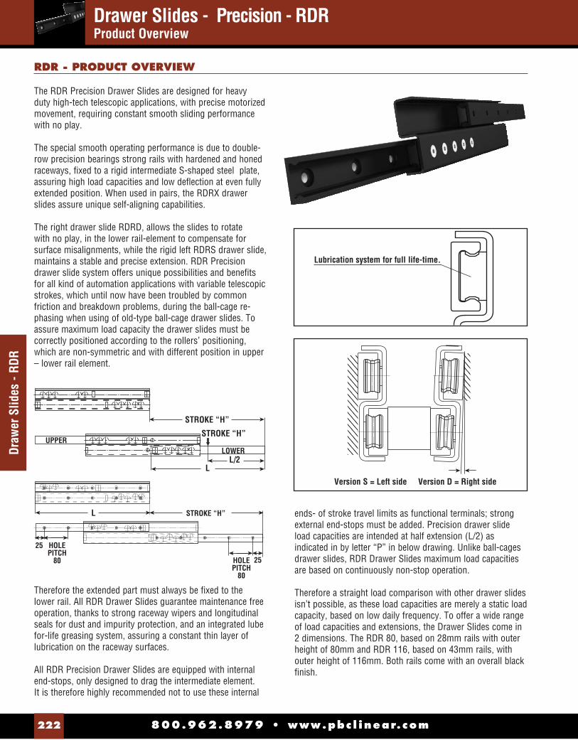
Drawer Slides - Precision - RDR Product Overview
800.962.8979 • www.pbc l inear.com222
Draw
er S
lides
- RD
R
The RDR Precision Drawer Slides are designed for heavy duty high-tech telescopic applications, with precise motorized movement, requiring constant smooth sliding performance with no play.
The special smooth operating performance is due to double-row precision bearings strong rails with hardened and honed raceways, fi xed to a rigid intermediate S-shaped steel plate, assuring high load capacities and low defl ection at even fully extended position. When used in pairs, the RDRX drawer slides assure unique self-aligning capabilities.
The right drawer slide RDRD, allows the slides to rotate with no play, in the lower rail-element to compensate for surface misalignments, while the rigid left RDRS drawer slide, maintains a stable and precise extension. RDR Precision drawer slide system offers unique possibilities and benefi ts for all kind of automation applications with variable telescopic strokes, which until now have been troubled by common friction and breakdown problems, during the ball-cage re-phasing when using of old-type ball-cage drawer slides. To assure maximum load capacity the drawer slides must be correctly positioned according to the rollers’ positioning, which are non-symmetric and with different position in upper – lower rail element.
Therefore the extended part must always be fi xed to the lower rail. All RDR Drawer Slides guarantee maintenance free operation, thanks to strong raceway wipers and longitudinal seals for dust and impurity protection, and an integrated lube for-life greasing system, assuring a constant thin layer of lubrication on the raceway surfaces.
All RDR Precision Drawer Slides are equipped with internal end-stops, only designed to drag the intermediate element. It is therefore highly recommended not to use these internal
STROKE “H”
STROKE “H”
LOWERUPPER
L/2L
STROKE “H”L
25
HOLEPITCH
80 HOLEPITCH
80
25
Version S = Left side Version D = Right side
Lubrication system for full life-time.
RDR - PRODUCT OVERVIEW
ends- of stroke travel limits as functional terminals; strong external end-stops must be added. Precision drawer slide load capacities are intended at half extension (L/2) as indicated in by letter “P” in below drawing. Unlike ball-cages drawer slides, RDR Drawer Slides maximum load capacities are based on continuously non-stop operation.
Therefore a straight load comparison with other drawer slides isn’t possible, as these load capacities are merely a static load capacity, based on low daily frequency. To offer a wide range of load capacities and extensions, the Drawer Slides come in 2 dimensions. The RDR 80, based on 28mm rails with outer height of 80mm and RDR 116, based on 43mm rails, with outer height of 116mm. Both rails come with an overall black fi nish.

800.962.8979 • www.pbc l inear.com 223
Drawer Slides - RDR
18.6
28
35 80
2
05.5
RDR 80
Guiding Version RDRS Loading Version RDRD TYPE STROKE H LENGTH L CO RAD (N) (kg.)
RDRX80-0370 380 0370 753 2.1
RDRX80-0470 460 0450 817 2.5
RDRX80-0570 540 0530 1207 2.9
RDRX80-0670 620 0610 1495 3.3
RDRX80-0690 700 0690 1673 3.7
RDRX80-0770 780 0770 1771 4.1
RDRX80-0850 860 0850 1755 4.5
RDRX80-0930 940 0930 1623 4.9
RDRX80-1010 1020 1010 1510 5.3
RDRX80-1170 1180 1170 1325 6.1
RDRX80-1330 1340 1330 1180 6.9
RDRX80-1490 1500 1490 1064 7.7
RDR X 80
SideS = LeftD = Right
Rail Size80 = 80mm116 = 166mm
0370
Rail Length0370 - 1490mm
–
Precision Drawer Slide
ORDER INFORMATIONEXAMPLE: RDRS80-0370
NOTE: S = Left Side D = Right Side
28
43
52 116
3
08.5
RDR 116
TYPE STROKE H LENGTH L CO RAD (N) (kg.)
RDRX116-0530 540 0530 1829 6.4
RDRX116-0610 620 0610 2040 7.3
RDRX116-0690 700 0690 2870 8.2
RDRX116-0770 780 0770 3033 9.1
RDRX116-0850 860 0850 3780 10.1
RDRX116-0930 940 0930 3978 11
RDRX116-1010 1020 1010 4122 11.8
RDRX116-1170 1180 1170 4080 13.6
RDRX116-1330 1340 1330 3648 15.4
RDRX116-1490 1500 1490 3298 17.1
RDRX116-1650 1660 1650 3010 18.9
RDRX116-1810 1820 1810 2768 20.7
RDRX116-1970 1980 1970 2562 22.4
ORDER INFORMATION
RDR X 116
SideS = LeftD = Right
Rail Size80 = 80mm116 = 166mm
0530
Rail Length0530 - 1970mm
–
Precision Drawer Slide
EXAMPLE: RDRS116-0530
NOTE: S = Left Side D = Right Side
Guiding Version RDRS Loading Version RDRD
RDR 80 & RDR 116Drawer Slides - Precision

800.962.8979 • www.pbc l inear.com224
Tech
nica
l Ove
rvie
wDrawer Slides - RDR / RDQTechnical Overview
The RDR Precision Drawer Slides & RDQ Compact Precision Drawer Slides systems are the world’s only telescopic rail system for complete extension, based on precision rollers and hardened raceways and with incorporate self-aligning feature (RDR series).
The system offers unique possibilities for all kinds of automation applications, where smooth and precise telescopic movement is required. Optimal movement with no play for High-Tech telescopic applications, or for even heavy load and high frequency applications.
These systems are composed of exactly the same components as the Redi-Rail® Steel Rail system, except that the slider bodies are different, as longer and with more rollers. All drawer slides feature strong raceway wipers and greasing system for low maintenance.
The RDR drawer slides offer unique self-aligning capability, when used in pairs. As the right telescopic rail RDRD, allows the sliders to rotate in the lower rail-element it compensates assembling or surface misalignment errors, while maintaining the same precise, preloaded extension.
To guarantee high load capacities and low defl ection, the RDR drawer slides are fi xed to an intermediate S-shaped steel plate.The RDQ drawer slides have the RRT-rails functioning as the intermediate element, offering good radial and axial load capacities, with very compact overall dimensions.
RDR and RDQ rails are the only drawer slide system which incorporates a self-aligning feature to absorb parallelism errors of the mounting surfaces.
RDR /RDQ DRAWER SLIDES
P
TLR
TLQ
P

800.962.8979 • www.pbc l inear.com 225
Drawer Slide - RDQ
Drawer Slide - RDQCompact Precision
RDQ Compact Precision Drawer Slides are designed for high-tech telescopic applications with precise motorized movement, requiring constant smooth sliding performance with no play.
The square design is obtained by using two RRT-rails with hardened honed raceways, as the rigid intermediate element, into which the slides are assembled. The RDQ drawer slides offer both high radial and axial load capacities.
The rail/slide confi guration allows the RDQ drawer slides to be mounted not only at the side, but also underneath the moving part, when there are space limitations at the sides, or to be used in typical vertical applications. See below tables and fi gures.
In the case of horizontal panel extension, we recommend the use of a pair of RDR and RDQ, as the RDR can absorb some lateral structural misalignments on the vertical axis.
RDQ system assures smooth extension for all kinds of automation applications with variable telescopic strokes, which until now have been troubled by common friction breakdown problems typical drawer slides during the ball-cage re-phasing.Same re-phase problem or even deformation of the ball-cages, occurs for all vertical applications, as the ball-cage in such drawer slides, constantly tend to move downwards, so extra friction is generated with each stroke during the repositioning of the ball-cages.
To assure maximum load capacity the drawer slides must be correctly orientation during assembly. The extended part must always be fi xed to the shortest slide.
RDQ Compact Precision Drawer Slides are equipped with internal end-stops, only designed to drag the intermediate element. It is therefore highly recommended not to use these internal end of stroke travel limits as functional hardstops; strong external end-stops must be added. Similarly to the RDR series, the RDQ’s stroke goes slightly beyond the overall length of the rail in closed position. The rails come with an overall black fi nish.
Corad
RDQ - PRODUCT OVERVIEW
Coax
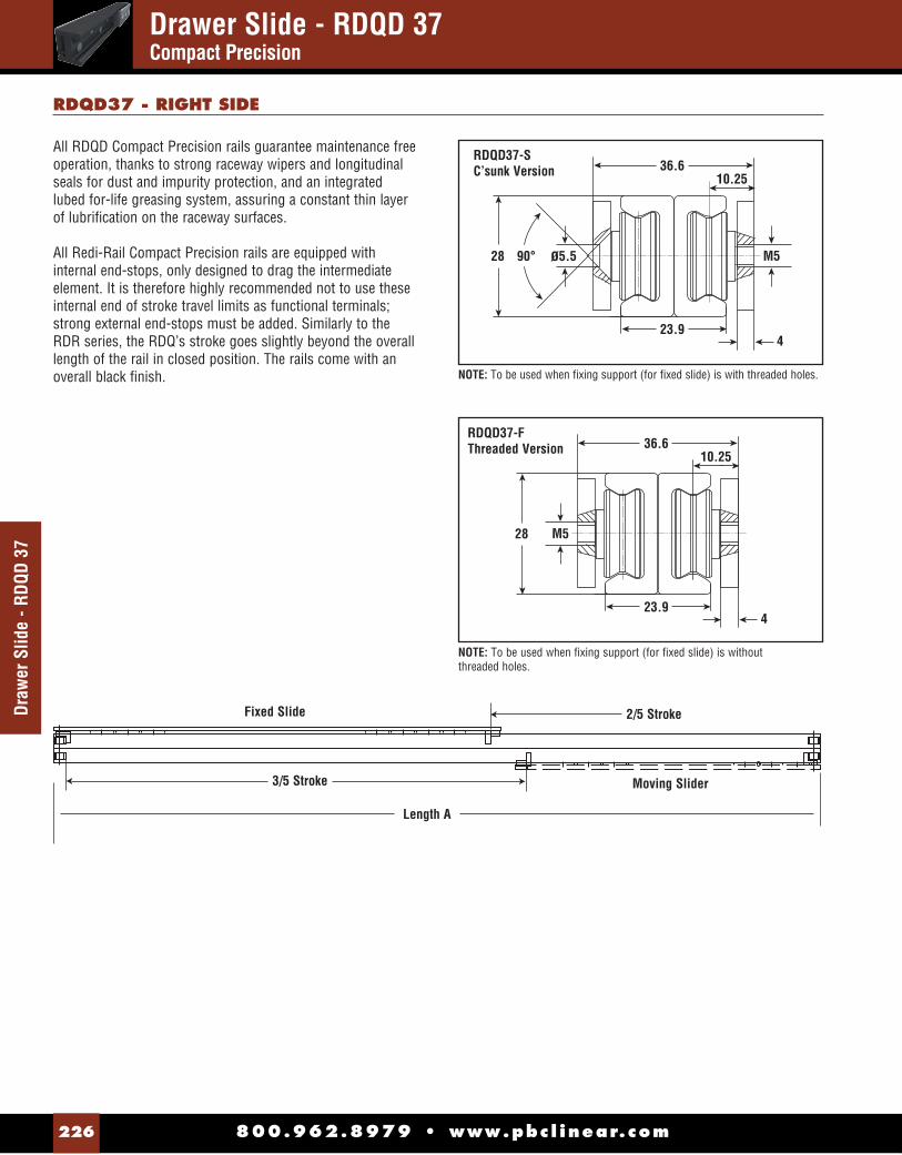
800.962.8979 • www.pbc l inear.com226
Draw
er S
lide
- RDQ
D 37
Drawer Slide - RDQD 37Compact Precision
All RDQD Compact Precision rails guarantee maintenance free operation, thanks to strong raceway wipers and longitudinal seals for dust and impurity protection, and an integrated lubed for-life greasing system, assuring a constant thin layer of lubrifi cation on the raceway surfaces.
All Redi-Rail Compact Precision rails are equipped with internal end-stops, only designed to drag the intermediate element. It is therefore highly recommended not to use these internal end of stroke travel limits as functional terminals; strong external end-stops must be added. Similarly to the RDR series, the RDQ’s stroke goes slightly beyond the overall length of the rail in closed position. The rails come with an overall black fi nish.
RDQD37 - RIGHT SIDE
2/5 Stroke
Moving Slider
Length A
3/5 Stroke
Fixed Slide
ø5.590°28
36.610.25
M5
423.9
RDQD37-SC’sunk Version
NOTE: To be used when fi xing support (for fi xed slide) is with threaded holes.
28
36.610.25
M5
423.9
RDQD37-FThreaded Version
NOTE: To be used when fi xing support (for fi xed slide) is without threaded holes.

800.962.8979 • www.pbc l inear.com 227
Roller Positions: Ex. RDQX37 - 0370
NOTE: S = Left Side D = Right Side
Drawer Slide - RDQ 37
Drawer Slide - RDQ 37Compact Precision
TYPE STROKE A B C X M N P R Q K T Y F H S L Z CORAD(N)
COAX(N) (kg.)
RDQX37-0370 380 370 170 201
53
70 70 x
xx
x
x
25 70 50
x
x
50 707 441 1.5
RDQX37-0450 460 450 175 276 72 72 72 25 70 55 55 1003 655 1.7
RDQX37-0530 540 530 207 324 88 88 88 23.5 80 80 80 1128 721 2.0
RDQX37-0610 620 610 239 372 104 104 104 24.5 95 95 95 1116 689 2.3
RDQX37-0690 700 690 271 420 120 120 120 25,5 110 110 110 1012 623 2.6
RDQX37-0770 780 770 303 468 102 102 102 102 24 85 85 85 85 926 569 2.8
RDQX37-0850 860 850 335 516 90 90 90 90 96 25 95 95 95 95 853 523 3.1
RDQX37-0930 940 930 367 564 100 100 100 100 100 26 105 105 105 106 791 484 3.4
RDQX37-1010 1020 1010 399 612 110 110 110 110 110 x 25.5 87 87 87 87 87 738 451 3.6
RDQX37-1170 1180 1170 463 708 108 108 108 108 108 108 25.5 103 103 103 103 103 650 396 4.2
RDQX37-1330 1340 1330 527 804 124 124 124 124 124 124 23.5 120 120 120 120 120 580 353 4.7
RDQX37-1490 1500 1490 591 900 120 120 120 120 120 120 120 25.5 108 108 108 108 108 524 319 5.2
RDQ 37
X
Rail Length0370-1500mm
ORDER INFORMATION
EXAMPLE: RDQS37-0370
M N
C BA/2
R Q K T V X Y F H S L G Z Y
P
X

800.962.8979 • www.pbc l inear.com228
Draw
er S
lide
- RDQ
S 57
Drawer Slide - RDQS 57Compact Precision
RDQS 57 - LEFT SIDE
All RDQS Compact Precision rails guarantee maintenance free operation, thanks to strong raceway wipers and longitudinal seals for dust and impurity protection, and an integrated lubed for-life greasing system, assuring a constant thin layer of lubrifi cation on the raceway surfaces.
All RDQ Compact Precision rails are equipped with internal end-stops, only designed to drag the intermediate element. It is therefore highly recommended not to use these internal end of stroke travel limits as functional terminals; strong external end-stops must be added. Similarly to the RDR series, the RDQ’s stroke goes slightly beyond the overall length of the rail in closed position. The rails come with an overall black fi nish.
2/5 Stroke
Moving Slider
Length A
3/5 Stroke
Fixed Slide
NOTE: To be used when fi xing support (for fi xed slide) is with threaded holes
RDQS57-S C’sunk Version
50.4
36
43 90° Ø6.5
15
M6
6
NOTE: To be used when fi xing support (for fi xed slide) is without threaded holes
RDQS57-F Threaded Version
36
43 M6
56.415
6

800.962.8979 • www.pbc l inear.com 229
Drawer Slide - RDQ 57
Drawer Slide - RDQ 57Compact Precision
TYPE STROKE A B C X M P N R Q K T Y F H S L Z CORAD(N)
COAX(N) (kg.)
RDQX57-0530 540 530 227 306
61
118 x 118
x
x x
x
28,5 100 70
x
x
70 2160 1728 4.8
RDQX57-0610 620 610 238 375 105 100 100 28 102 80 80 2610 2138 5.4
RDQX57-0690 700 690 270 423 118 118 118 28 107 107 107 2799 2280 6.0
RDQX57-0770 780 770 302 471 100 100 100 100 28 123 123 123 2943 2390 6.7
RDQX57-0850 860 850 334 519 116 116 116 102 28 102 88 88 88 2647 2173 7.4
RDQX57-0930 940 930 366 567 120 120 120 136 28,5 103 103 103 103 2460 2016 8.1
RDQX57-1010 1020 1010 398 615 102 102 102 136 28 114 114 114 114 2297 1912 8.7
RDQX57-1170 1180 1170 462 711 126 126 126 126 136 x 28 102 102 102 100 100 2028 1655 10.0
RDQX57-1330 1340 1330 526 807 120 120 120 120 120 136 28 120 120 120 110 110 1816 1478 11.3
RDQX57-1490 1500 1490 590 903 116 116 116 116 116 116 136 27,5 107 107 107 107 107 1644 1336 12.5
RDQX57-1650 1660 1650 654 999 132 132 132 132 132 132 136 27,5 120 120 120 120 119 1501 1219 13.8
RDQX57-1810 1820 1810 718 1095 137 125 125 125 125 125 125 28 112 110 110 110 110 1382 1120 15.0
RDQX57-1970 1980 1970 782 1191 140 140 140 140 140 140 140 28 121 121 121 121 121 1280 1036 16.4
X
Rail Length0530-1980mm
ORDER INFORMATION
EXAMPLE: RDQX57-0530
Roller Positions: Ex. RDQX57 - 0530
NOTE: S = Left Side D = Right Side
M N
C BA/2
R Q K T V X Y F H S L G Z Y
P
X
RDQ 57

800.962.8979 • www.pbc l inear.com230
Flex
ible
Gui
deFlexible Guide System 43 Roller & Rail - Radial Loads to 3,600 N
F C P
Load TypeP = FloatingV = Guiding
43
Rail Size43 = 43mm
C = ConcentricE = Eccentric
Flexible Roller
RAIL
L1
D
S H FLUSH FOR HEXAGON KEY
dM1
L1
D
S H FLUSH FOR HEXAGON KEY
dM1
GUIDING ROLLER FCV-FEV
FLOATING ROLLER FEP-FCP LATERAL DISPLACEMENT
GUIDING ROLLER / CONCENTRIC PIVOT - FEV
FLOATING ROLLER / CONCENTRIC PIVOT-FCP
LATERALDISPLACEMENT
ROLLERTYPE D S H L1 d M1 Ch C C
(N)CORAD
(N)COAX
(N)WEIGHT
(G)
2
FCV4330.8
14 2 9 15 M8 6
0
9,000 3,600 2,160 50FEV43 0.8FCP43
30.40
FEP43 0.8
F - ROLLER
FLOATING ROLLER / ECCENTRIC PIVOT - FEP
GUIDING ROLLER / ECCENTRIC PIVOT - FCVL1
DC
S H FLUSH FOR HEXAGON KEY
dM1
L1
DC
S H FLUSH FOR HEXAGON KEY
dM1
Flexible rails have a unique design as its rail offers three protruding raceways, angled at 90° intervals.
Providing an extremely versatile linear system. The stronger fl exible rails have a 160mm hole pitch for easy assembling.
RAIL TYPE Kg/m A B C D d E F G H S L SCREW TYPE
FR43 2.09 19.36 25 18.3 10.5 6.5 13.2 12.3 12.2 4.4 5.6 400 - 3,920 M6 DIN 6912
Note: Tolerance for fi rst-last hole +/-0.5
FR
Flexible Rail
43 0400
Rail Length400 - 3920mm
Rail Size43 = 43mm
–CARRIAGEEXAMPLE: FCP43
FR43-XXXX
FR43 - RAILS
F
A E
G C B
HS
dD
40 40PITCH 160
L = 400 - 3920
ORDER INFORMATION

800.962.8979 • www.pbc l inear.com 231
V-Guide SystemV-Guide System
Product Overview
V-Guide System components provide an excellent alternative for linear motion applications in harsh environments with medium accuracy requirements, and high speed capabilities.
FEATURES & BENEFITSV-Guide systems are an industry standard for linear motion, and offer features that make them an ideal solution for a wide range of motion control applications.
V-Guide Rail:• Has shoulder for simple mounting and alignment• Available in long lengths• Induction hardened way surface• 1045 Carbon Steel or 400 Series Stainless Steel• Optional black oxide fi nish• Choose predrilled rail from stock, or custom cut and drilled
to your specifi cation
V-Guide Wheels:• Four (4) sizes• Permanently lubricated• Precision dual row bearing construction• Available in 52100 Bearing Steel or
420 Stainless Steel construction• 304 Stainless Steel shields, or nitrile rubber seals
Wheel Bushings:• 303 Stainless Steel • Inch or metric hardware• Adjustable bushings allow adjustable fi t and preload• Fixed bushings are used in the primary radial
load direction• Stainless Steel construction
APPLICATIONS• Machine tool doors
• Vending machines
• Woodworking machinery
• Carpet and textile machinery
• Laboratory automation
• Paper converting equipment
• Packaging machinery
PRODUCT OVERVIEW
TECHNICAL SPECIFICATIONS
V-Guide Wheels:V-Guide Wheels are precision ground dual row angular contact ball bearings with hardened outer way surfaces that provide low friction guidance for linear motion applications. V-Guide wheels can be used with internal or external 90-degree ways, or used with round shafts.
V-Guide Rails:The rail V-Ways are induction or fl ame hardened, ground and polished. The track body is left soft for easy drilling of mounting holes. Available in (4) four sizes, which are designed for the corresponding size wheels.
Wheel Bushings:Bushings allow for the wheels to be mounted with the appropriate fastener for the specifi c application.

800.962.8979 • www.pbc l inear.com232
V-Gu
ide
- 20
mm
(3/4
")V-Guide System - 20 mm (3/4”)Radial Loads to 283 lbs. (1,260 N) per Wheel
PART NUMBER LENGTH NO. OF HOLES
CARBON STEEL
VRD1-1250 12.5" (317.5 mm) 7
VRD1-2450 24.5" (622.3 mm) 13
VRD1-3650 36.5" (927.1 mm) 19
VRD1-4850 48.5" (1231.9 mm) 25
VRD1-6050 60.5" (1536.7 mm) 31
VRD1-7250 72.5" (1841.5 mm) 37
STAINLESS STEEL
VRSD1-1250 12.5" (317.5 mm) 7
VRSD1-2450 24.5" (622.3 mm) 13
VRSD1-3650 36.5" (927.1 mm) 19
VRSD1-4850 48.5" (1231.9 mm) 25
VRSD1-6050 60.5" (1536.7 mm) 31
VRSD1-7250 72.5" (1841.5 mm) 37
MVB1 Metric Fixed Bushing
MVBA1 Metric Adjustable Bushing
VB1 Fixed Bushing
VBA1 Adjustable Bushing
VW1 Shielded Bearing
VWS1 Sealed Bearing
VWSS1 Sealed Stainless Bearing
V-GUIDE WHEELS
WEIGHT: .42 oz. (12 g)
Carbon Steel
VR1-xxx undrilled rail max. length 21' (6400 mm)
VRD1-xxx drilled rail, see table
Stainless Steel
VRS1-xxx undrilled rail, max. length 21' (6400 mm)
VRSD1-xxx drilled rail, see table
(4.8)Ø.1875
(19.6) .771
(7.9) .310
(8.0) .313
(11.9) .468
90°
.125 (3.2)
.062 (1.6)
.032 (0.8)
.437 (11.1)
90°
.187 (4.7)
ECCENTRICCONCENTRIC
Ø.1873 Ø.1873
Ø.438 .438.250
.550 REF
.550 REF
.300 .250 .300
Ø.138 Ø.138
.012
ECCENTRICCONCENTRIC
Ø4.76 Ø4.76
Ø11.2 12.06.2
13.8 REF
13.8 REF
7.6 6.2 7.6
Ø3.96 Ø3.96
0.25
WHEEL BUSHINGS
METRIC WHEEL BUSHINGS
STANDARD DRILLED RAILS
V-GUIDE RAIL
.156 (4.0)
.25 (6.4)
.25 (6.4)
2.000 (50.8)
TYP
Ø.156 (4.0) THRU TYP L
Rated for:Radial loads to 283 lbs. (1,260 N) per wheelAxial loads to 67 lbs. (297 N) per wheel
NOTE: Non-heat treated rails available in all sizes, contact factory.

800.962.8979 • www.pbc l inear.com 233
V-Guide System - 30 mm (1-1/4”)Radial Loads to 614 lbs. (2,730 N) per Wheel
V-Guide 30 mm
(1-1/4")
.219 (5.6)
.32 (8.0) .32
(8.0)3.000
(76.2)TYP
Ø.203 (5.2) THRU TYP L
PART NUMBER LENGTH # OF HOLES
Carbon Steel
VRD2-1263 12.63" (320.8 mm) 5
VRD2-2463 24.63" (625.6 mm) 9
VRD2-3663 36.63" (930.4 mm) 13
VRD2-4863 48.63" (1235.2 mm) 17
VRD2-6063 60.63" (1540 mm) 21
VRD2-7263 72.63" (1844.8 mm) 25
Stainless Steel
VRSD2-1263 12.63" (320.8 mm) 5
VRSD2-2463 24.63" (625.6 mm) 9
VRSD2-3663 36.63" (930.4 mm) 13
VRSD2-4863 48.63" (1235.2 mm) 17
VRSD2-6063 60.63" (1540 mm) 21
VRSD2-7263 72.63" (1844.8 mm) 25
MVB2 Metric Fixed Bushing
MVBA2 Metric Adjustable Bushing
VB2 Fixed Bushing
VBA2 Adjustable Bushing
VW2 Shielded Bearing
VWS2 Sealed Bearing
VWSS2 Sealed Stainless Bearing
V-GUIDE WHEELS
WEIGHT: 1.41 oz. (40 g)
Carbon Steel
VR2-xxx undrilled rail max. length 21' (6400 mm)
VRD2-xxx drilled rail, see table
Stainless Steel
VRS2-xxx undrilled rail, max. length 21' (6400 mm)
VRSD2-xxx drilled rail, see table
(9.5)Ø.3750
(30.7) 1.210
(11.1) .438
(12.7) .500
(18.3) .719
90°
.187 (4.7)
.094 (2.4)
.031 (0.8)
.625 (15.9)
90°
.250 (6.4)
Ø.250 Ø.250
.024
.563Ø.563
Ø.3748
.706 REF
.706 REF
Ø.3748
.425.425.281 .281
ECCENTRICCONCENTRIC
Ø6.00 Ø6.00
0.6114.0Ø14.2
Ø9.52
17.5 REF
17.5 REF
Ø9.52
10.810.86.7 6.7
ECCENTRICCONCENTRIC
WHEEL BUSHINGS
METRIC WHEEL BUSHINGS
STANDARD DRILLED RAILS
V-GUIDE RAIL
Rated for:Radial loads to 614 lbs. (2,730 N) per wheelAxial loads to 142 lbs. (632 N) per wheel
NOTE: Non-heat treated rails available in all sizes, contact factory.
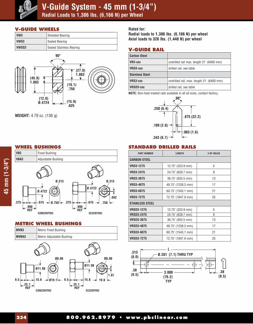
800.962.8979 • www.pbc l inear.com234
V-Guide System - 45 mm (1-3/4”)Radial Loads to 1,386 lbs. (6,166 N) per Wheel
45 m
m (1
-3/4
")
PART NUMBER LENGTH # OF HOLES
CARBON STEEL
VRD3-1275 12.75" (323.9 mm) 5
VRD3-2475 24.75" (628.7 mm) 9
VRD3-3675 36.75" (933.5 mm) 13
VRD3-4875 48.75" (1238.3 mm) 17
VRD3-6075 60.75" (1543.1 mm) 21
VRD3-7275 72.75" (1847.9 mm) 25
STAINLESS STEEL
VRSD3-1275 12.75" (323.9 mm) 5 VRSD3-2475 24.75" (628.7 mm) 9 VRSD3-3675 36.75" (933.5 mm) 13
VRSD3-4875 48.75" (1238.3 mm) 17
VRSD3-6075 60.75" (1543.1 mm) 21
VRSD3-7275 72.75" (1847.9 mm) 25
MVB3 Metric Fixed Bushing
MVBA3 Metric Adjustable Bushing
VB3 Fixed Bushing
VBA3 Adjustable Bushing
VW3 Shielded Bearing
VWS3 Sealed Bearing
VWSS3 Sealed Stainless Bearing
V-GUIDE WHEELS
WEIGHT: 4.79 oz. (136 g)
Carbon Steel
VR3-xxx undrilled rail max. length 21' (6400 mm)
VRD3-xxx drilled rail, see table
Stainless Steel
VRS3-xxx undrilled rail, max. length 21' (6400 mm)
VRSD3-xxx drilled rail, see table
(12.0)Ø.4724
(45.8) 1.803
(15.9) .625
(19.1) .750
(27.0) 1.063
90°
.250 (6.4)
.109 (2.8)
.063 (1.6)
.875 (22.2)
90°
.343 (8.7)
Ø.313 Ø.313
.042
.750Ø.750
Ø.4722
.990 REF
.990 REF
Ø.4722
.615.615.375 .375
ECCENTRICCONCENTRIC
Ø8.00 Ø8.00
1.0719.0Ø19.1
Ø11.99
25.1 REF
25.1 REF
Ø11.99
15.615.69.5 9.5
ECCENTRICCONCENTRIC
WHEEL BUSHINGS
METRIC WHEEL BUSHINGS
STANDARD DRILLED RAILS
V-GUIDE RAIL
.313 (8.0)
.38 (9.5)
.38 (9.5)
3.000(76.2)
TYP
Ø.281 (7.1) THRU TYP L
Rated for:Radial loads to 1,386 lbs. (6,166 N) per wheelAxial loads to 326 lbs. (1,448 N) per wheel
NOTE: Non-heat treated rails available in all all sizes, contact factory.

800.962.8979 • www.pbc l inear.com 235
V-Guide System - 60 mm (2-1/4”)Radial Loads to 2,246 lbs. (9,991 N) per Wheel
60 mm
(2-1/4")
VB4 Fixed Bushing
VBA4 Adjustable Bushing
V-GUIDE WHEELS
WEIGHT: 10 oz. (285 g)
Carbon Steel
VR4-xxx undrilled rail max. length 21' (6400 mm)
VRD4-xxx drilled rail, see table
Stainless Steel
VRS4-xxx undrilled rail, max. length 21' (6400 mm)
VRSD4-xxx drilled rail, see table
(15.0)Ø.5906
(59.9) 2.360
(19.1) .750
(25.4) 1.000
(34.9) 1.375
90°
.312 (7.9)
.125 (3.2)
.094 (2.4)
1.062 (27.0)
90°
.437 (11.1)
Ø.375 Ø.375
.060
.875Ø.875
Ø.5904
1.177 REF
1.177 REF
Ø.5904
.740.740.437 .437
ECCENTRICCONCENTRIC
Ø10.00 Ø10.00
1.52
22.0Ø22.4
Ø15.00
29.9 REF
29.9 REF
Ø15.00
18.818.811.1 11.1
ECCENTRICCONCENTRIC
WHEEL BUSHINGS
METRIC WHEEL BUSHINGS
STANDARD DRILLED RAILS
V-GUIDE RAIL
VW4 Shielded Bearing
VWS4 Sealed Bearing
VWSS4 Sealed Stainless Bearing
MVB4 Metric Fixed Bushing
MVBA4 Metric Adjustable Bushing .375 (9.5)
.50 (12.7)
.50 (12.7)
4.000 (101.6)
TYP
Ø.344 (8.7) THRU TYP L
PART NUMBER LENGTH # OF HOLES
CARBON STEEL
VRD4-1300 13.00" (330.2 mm) 4
VRD4-2500 25.00" (635 mm) 7
VRD4-3700 37.00" (939.8 mm) 10
VRD4-4900 49.00" (1244.6 mm) 13
VRD4-6100 61.00" (1549.4 mm) 16
Stainless Steel
VRSD4-1300 13.00" (330.2 mm) 4
VRSD4-2500 25.00" (635 mm) 7
VRSD4-3700 37.00" (939.8 mm) 10
VRSD4-4900 49.00" (1244.6 mm) 13
VRSD4-6100 61.00" (1549.4 mm) 16
Rated for:Radial loads to 2,246 lbs. (9,991 N) per wheelAxial loads to 520 lbs. (2,313 N) per wheel
NOTE: Non-heat treated rails available in all sizes, contact factory.

800.962.8979 • www.pbc l inear.com236
V-Guide SystemTechnical Information
Tech
nica
l Inf
orm
atio
n
LOAD CALCULATIONS
L = applied load / number of wheel pairs
LR = wheel radial load
Lo = wheel load from moment
A = load offset dimension
B = track width dimension
FA = .5 for light duty, well lubricated use
FA = 1 for normal lubricated use
FA = 2 for dry, or harsh environments
LOAD CONDITION A
Lo1 = L x (B - A) x FA
B
Lo2 = (L x FA) - Lo1
Compare the greater of these loads to the rated moment and radial load capacities.
Example:
Load is 100 lbs on 4 wheel carriage,
L = 100 / 2 pair wheels = 50 lbs.
A = 4", B = 10", FA = 1
Lo1 = 50 x (10 - 4) x 1 = 30 lbs. 10
Lo2 = 50 - 30 = 20 lbs.
LOAD CONDITION B
Lo1 = L x A x FA
B
Lo2 = (L x FA) + Lo1
Compare the greater of these loads to the rated moment and radial load capacities.
Example:
Load is 100 lbs. on 4 wheel carriage,
L = 100 / 2 pair wheels = 50 lbs.
A = 4", B = 6", FA = 1
Lo1 = 50 x 4 x 1 = 33 lbs. 6
Lo2 = 50 + 33 = 83 lbs.
LOAD CONDITION C
Lo1 = L x A x FA
B
LR = (L x FA) + Lo1
Lo1 = Lo2
Compare the greater of these loads to the rated moment and radial load capacities.
Example:
Load is 100 lbs. on 4 wheel carriage,
L = 100 / 2 pair wheels = 50 lbs.
A = 4", B = 6", FA = 1
Lo1 = 50 x 4 x 1 = 33 lbs. 6
LR = (50 x 1) + 33 = 83 lbs.
Lo1
Lo2
L
BA
Lo1
Lo2
L
B
A
Lo1 Lo2
L
B
A

800.962.8979 • www.pbc l inear.com 237
V-Guide SystemTechnical Information
Technical Information
MOUNTING AND ADJUSTMENT
Use the recommended fasteners for the specifi ed track and wheel bushings.
Use the following table, and the center distance formulas in the next column, to confi gure the appropriate wheel mounting dimensions.
The fi xed bushing should be used to carry the heaviest loading. Preload the adjustable bushing so that the wheel can just be turned by hand. Over-tightening the preload will cause premature wear of the components.
LUBRICATION
The V-Guide wheels are grease lubricated, and will not require any additional lube. The track should be lubricated for optimum performance and service life. Suggested lubricants are Mobil Vactra #2 Way Oil, or Mobil Polyrex EP 2 Extreme Pressure Grease.
SUGGESTED FASTENERS
V-RAIL SIZE IV(in.)
OV(in.)
IV(mm)
OV(mm)
1 0.874 0.934 22.2 23.7
2 1.374 1.436 34.9 36.5
3 2 2.124 50.8 53.9
4 2.624 2.75 66.6 69.9
WHEEL / BUSHING ASSEMBLY
Use SAE series N fl at washers and lock washers to secure the wheel bushing assemblies.
A
BA = B + IV
A
C
A = C - IV
A
D
A = D – OV
CENTER DISTANCE FORMULA
BUSHINGS
INCH METRIC
VB1 #6 MVB1 M4
VB2 1/4" MVB2 M6
VB3 5/16" MVB3 M8
VB4 3/8" MVB4 M10
V-RAIL
VR1 #6, M3 VR3 1/4", M6
VR2 #10, M6 VR4 5/16", M8

800.962.8979 • www.pbc l inear.com238
Commercial RailProduct Overview
Com
mer
cial
Rai
l
PRODUCT OVERVIEW
Commercial Rail is a simple and cost effective linear motion solution with high load capacity and corrosion resistance.
- Roll formed rails made of steel/stainless steel sheet for low cost and corrosion resistance application
- Zinc plated rail length up to 6000mm
- Machined slider body made of aluminum alloy and anodized for corrosion resistance
- Steel rollers are made of 52100 chrome steel, hardened and ground, lubricated for life and sealed against contamination
- Stainless steel rollers made of 440C stainless steel for better corrosion resistance, lubricated for life and sealed against contamination
- Rollers made with thread integrated inner ring for ease of assembly and adjustment of pre-load
- Custom polymer wipers can be designed and manufactured to improve the smoothness of motion and service life
- Maximum operating temperature 100°C or 212°F
- Consult with factory for special hole spacing
- Speed up to 1.5 m/s
- Moment loads should be carried by two slides or two parallel rollers
SLIDE ORIENTATION
The 3-roller slide should be installed in the rail so that the load is shared among the two outside rollers. The orientation marks indicate how to align the slider with the load direction
LUBRICATION – RAILS & BEARINGS
The rollers are internally lubricated for life, but the rails must always have a layer of grease. As a guideline, reapply fresh grease every 50,000 cycles.
PRELOAD ADJUSTMENT
- To loosen the center roller, use an Allen wrench to un-tighten the screw while holding the roller still with an open-end wrench
- Turn the center roller to a position to achieve the desired pre-load
- Move the slide along the length of the rail by hand. Adjust it so that it does not feel loose anywhere.
- Tighten the screw while holding the roller fl at with an open-end wrench
PRELOAD ADJUSTMENT CR20/CRSS20 CR30/CRSS30 CR45/CRSS45
Wrench fl at sq. (mm) 6 10 14
CR SERIES SS SERIES
Rail Carbon steel sheet, Zinc plated Stainless steel 304 sheet
Slide Aluminum alloy anodized Aluminum alloy anodized
Rollers Chrome steel Stainless steel
Hardware Steel zinc plated Stainless steel 18-8
RAIL MOUNT CR20/CRSS20 CR30/CRSS30 CR45/CRSS45
Slide mount screws (Socket head cap) M5 M6 M8
Tightening torque (lbs-in) 25 43 103
Tightening torque (N-m) 3 5 12
SLIDES CR20/SS20 CR30/SS30 CR45/SS45
Rail mount screw (Button head cap) M4 M5 M8
MATERIAL & FINISH SPECIFICATIONS
APPLICATIONS
- Automation- Packaging, material handling, etc- Environmental, energy, HVAC, etc. - Medical- Offi ce equipment

800.962.8979 • www.pbc l inear.com 239
Commercial Rail - CR20Dynamic Radial Cr = 280 N
Comm
ercial Rail - CR20
60
204.5 2
40
20
8010 M5
CR20 SLIDE
CR20 RAIL
17.8
10.25
6.9
6
12.7
12.7
M5 20 60
6
20 R
MaterialBlank = SteelSS = Stainless Rail Size
20 = 20mm30 = 30mm (page 240)45 = 45mm (page 241)
XXXX
Rail Length160 - 6000mm
Rail
Commercial Rail
CR _RAILCR 20
MaterialBlank = SteelSS = Stainless SteelP = Polymer
Rail Size20 = 20mm30 = 30mm (page 240)45 = 45mm (page 241)
MCA
Type of BodyMCA = Machined BodySCA = Stamped
Commercial Rail Slide
SLIDE
ORDER INFORMATIONEXAMPLE: CR20MCA / CR20R-XXXX
DIMS
LOAD RATINGS
STATIC RADIALCor. (N)
STATIC RADIAL Coa. (N)
DYNAMIC RADIAL Cr (N)
CR20CRSS20 210 160 280
CRP20 30 20 40
Unit Weight = 0.31 lbs./ft.

800.962.8979 • www.pbc l inear.com240
Com
mer
cial
Rai
l - C
R30
Commercial Rail - CR30Dynamic Radial Cr = 800 N
80
35 5.5 2
40
30
8015 M6
CR30 SLIDE
CR30 RAIL
26.5
15
10
8.5
19.1
19.10
M6 35 80
8.5
30 R
MaterialBlank = SteelSS = Stainless Rail Size
20 = 20mm (page 239)30 = 30mm 45 = 45mm (page 241)
XXXX
Rail Length160 - 6000mm
Rail
Commercial Rail
CR _RAIL
Unit Weight = 0.64 lbs./ft.
DIMS
LOAD RATINGS
STATIC RADIALCor. (N)
STATIC RADIAL Coa. (N)
DYNAMIC RADIAL Cr (N)
CR30CRSS30 610 420 800
CRP30 90 60 120
ORDER INFORMATIONEXAMPLE: CR30MCA / CR30R-XXXX
CR 30
MaterialBlank = SteelSS = Stainless SteelP = Polymer
Rail Size20 = 20mm (page 239)30 = 30mm 45 = 45mm (page 241)
MCA
Type of BodyMCA = Machined BodySCA = Stamped
Commercial Rail Slide
SLIDE

800.962.8979 • www.pbc l inear.com 241
Comm
ercial Rail - CR45Commercial Rail - CR45
Dynamic Radial Cr = 1,740 N
120
50 9 2
40
45.7
8022.9 M8
CR45 SLIDE
CR45 RAIL
41.5
24
15.5
15
31.80
31.80
M8 50 120
15
Unit Weight = 1.31 lbs./ft.
DIMS
LOAD RATINGS
STATIC RADIALCor. (N)
STATIC RADIAL Coa. (N)
DYNAMIC RADIAL Cr (N)
CR45CRSS45 1330 930 1740
CRP45 190 150 260
ORDER INFORMATIONEXAMPLE: CR45MCA / CR45R-XXXX
45 R
MaterialBlank = SteelSS = Stainless Rail Size
20 = 20mm (page 239)30 = 30mm (page 240)45 = 45mm
XXXX
Rail Length160 - 6000mm
Rail
Commercial Rail
CR _RAILCR 45
MaterialBlank = SteelSS = Stainless SteelP = Polymer
Rail Size20 = 20mm (page 239)30 = 30mm (page 240)45 = 45mm
MCA
Type of BodyMCA = Machined BodySCA = Stamped
Commercial Rail Slide
SLIDE

FEATURES & BENEFITS
• Low cost linear motion solution
• Precision rolling element bearing riding in a *Unistrut™ type rail
• 9/16" Hex head for easier mounting
• Simple solution and setup for point-to-point applications
• Rollers provide self-alignment, durability and longevity
• MAX. bearing load - 399 lbs.
• MAX. bearing speed - 150 ft./ min. (30 in./sec.)
• Rails lengths available up to 10 ft. Contact manufacturer for longer lengths.
RAILS FINISHES: • Bare steel• Powder coated
ACCESSORIES AVAILABLE:• Angle brackets (for welding to mounting rail)• End stops*Unistrut is a trademark of Unistrut, Inc.
ORDERING INFORMATION
PART NUMBER DESCRIPTION
PAC3016 Hardened Crown Roller Bearing
PAC3016M Hardened Crown Roller Bearing with metric thread
PAC2245 Rail System - unpainted (specify length - priced per foot)
PAC2247 Rail System - black powder coat fi nish (specify length- price per foot)
PAC2244 Angle Brackets - 1" Steel
PAC2246 End Stops for Rail System (bolt included)
800.962.8979 • www.pbc l inear.com242
Hardened Crown RollersInch & ISO Metric Series
Hard
ened
Cro
wn
Rolle
rs
14.3mm HEX
M8 - 1.0
36mm.9.6mm
ANGLE BRACKETS CAN BE WELDED IN ANY POSITION ALONG THE LENGTH OF THE TRACK
11.5mm
11mm35mm
R 9mm
BEARING
RAIL
ANGLE BRACKET
END STOP
23mm
42mm
22mm
9.5
32mm38mm
32mm
35mm
19mm
INCH
METRIC
NOTE: All metric dimensions are conversions from inch dimensions all parts are manufactured to inch standards.
.075
.375

800.962.8979 • www.pbc l inear.com 243
Hevi-Rail ®Hevi-Rail® Linear Bearing Systems
Product Overview
PRODUCT OVERVIEW
The economical Hevi-Rail® guide systems offer a lifetime of durability under continuous use. The easily interchangeable bearing components provide even dispersion of forces in the profi le rails for longer system life and stability.
Linear Bearings:• Outer ring made of case-hardened steel• Handles very high axial and radial loads• Easily interchangeable components for less down-time
Profi le Rails:• Standard length up to 6 meters• Sand blasted or lightly oiled• U-channel or I-channel available
Flange Plates:• Simple mounting for bearings• Can be ordered pre-welded to bearingOrdering example: HVB-054/HVPO-1
Clamp Flanges:• Adjustable• Eliminates need for welding and straightening• Easily adjustable parallelism
APPLICATIONS
• Telescoping applications (ex. overhead extending jib crane)
• Warehouse handling systems / other material handling
• Custom and standard lift units
• Large Shrink-wrap machinery
• Steel and coil handling
• Large variety of material handling
ProfileRails
CombinedBearings
Clamp Flanges

800.962.8979 • www.pbc l inear.com244
Hevi-Rail® Linear Bearing SystemsTechnical Information & Selection Guide
Tech
nica
l Inf
orm
atio
n
NOTE: For cantilevered loads, static verifi cation calculations can be found on page 245. * All dimensions in mm.
SELECTION GUIDE (when used with Profi le Rails HVR-S to HVR-6)
Use the following chart to select the bearings (fi xed or adjustable), rails, fl ange plates and clamp fl anges according to your system’s maximum static radial and axial loading. A “system” is defi ned as a bearing in the corresponding rail. For dimensional and detailed specifi cations for the system selected, simply refer to the corresponding pages.
F (KN) MAX STAT RADIAL
F (KN) MAX STAT AXIAL
COMBINED BEARING AXIAL BEARING FIXED
COMBINED BEARNG AXIAL BEARING ADJUSTABLE PROFILE RAILS CLAMP FLANGE FLANGE PLATE PAGE NO.
5.2 1.7 HVB-053 – HVR-S – HVPS-1 246
7.2 2.4 HVB-054 HVBEA-454 HVR-0 HVC-0 HVP0-1 244
8.6 2.8 HVB-055 HVBEA-455 HVR-1, HVRI-07 HVC-1 HVP1-1 248
8.9 3.0 HVB-056 HVBEA-456 HVR-2 HVC-2 HVP2-1 249
8.9 3.0 HVB-057 HVBEA-457 HVRI-08 – HVP2-1 250
15.6 5.2 HVB-058 HVBEA-458 HVR-3, HVRI-09 HVC-3 HVP3-1 251
15.5 5.1 HVB-059 HVBEA-459 HVRI-10 – – 252
16.5 5.5 HVB-060 HVBEA-460 HVRI-11 – – 252
16.5 5.5 HVB-061 HVBEA-461 HVR-4 HVC-4 HVP4-1 253
23.5 7.8 HVB-062 - HVR-5 – HVP4-1 254
41.1 13.7 HVB-063 HVBEA-463 HVR-6 – HVP6-1 255
TECHNICAL SPECIFICATIONS
Linear Bearing for Axial & Radial LoadsPrior to welding, disassemble bearing components. To avoid cracks in welded joints, please use welding electrodes and core weld for unalloyed steel.
Materials:
Outer ring - Case-hardened steel UNI 20 MnCr 5 hardened at 60+2 HRc
Inner ring - Hardened steel En 31 - SAE 52100 hardened at 62-2 HRc
Cylindrical rollers - Flat ground heads are hardened steel, En 31 - SAE 52100, hardened at 59-64 HRC
Welding bolts - Low carbon steel
Bolt tolerance = 0.05 mm
Profi le Rails: High quality steel, UNI FE 510.C with maximum contact pressure of 750 MPa (N/mm2). Optional sand blasted and/or lighty oiled. Rails are not hardened but have a Brinell hardness of 145-185. The guide ways in the rails should be lightly greased and not painted.
Clamp Flange: Low carbon steel, Adjustable clamp
Flange Plate: Low carbon steel. Special designs available, call manufacturer.
Seals: Bearings with fi xed axial bearing (HVB-053 to HVB-063) - radial bearing has steel labyrinth and side guide roller with rubber seals
Bearings with eccentric adjustable axial bearing (HVBEA-454 to HVBEA-463) - Both radial and axial bearings utilize rubber seals (RS type)
Lubrication: Bearings are supplied lubricated with grease grade 3. Bearings from HVB-057 to HVB-063 can be re-lubricated with grease zerk. Adjustable bearings are not available with zerk.
Temperature: Resistant from -10°C to 80°C (14°F to 176°F)
Bearing Life Calculations:
L10 = ( )( ) 10/3 (Hours)C = Dynamic load rating (KN)P = Automatic dynamic load (KN)n = Revolutions per minute (rpm)
NOTE: Above calculation formula is for predicting life expectance with 90% reliability level. Customers shall use their discretion to determine the reduction factor based on the actual operation needs and conditions such as reliability level, load, speed, impact and environments.
Adjusting Axial Bearing (HVBEA-454 to HVBEA-463)1. Remove front screws.2. Rotate axial bearing shaft3. Check dimension A
(repeat step 2, if needed)4. Re-install front screws
14
23
A

Fmax stat.axial
Profile Rail
Linear Bearing
Fmax stat.radial
P
P
A
P
P
Q
L
= Q • L 2 • A
Formula: Fmax[N] stat radial
Q = Load capacity (N)L = Load distance to suspension point (mm)P = Suspension pointA = Bearing distance (mm) recommended 500–1000 mm
CALCULATION OF FMAX FOR CANTILEVERED LOADS
Pzul = 860 N/mm2 for Profi le Rails HVB-0 to HVB-6.
Pzul = 750 N/mm2 for all profi le rails. Indicated here are Fmax stat radial + axial for each bearing.
800.962.8979 • www.pbc l inear.com 245
Hevi-Rail® Linear Bearing SystemsMounting Confi gurations
Inner Rail Distance = Saddle Width + (1.524 mm to 3.048 mm)
2. Verify that the Axial bearing is aligned parallel to the rail; especially in vertical operations.
Inner Rail DistanceSaddle Width
SYSTEM DESIGN SUGGESTIONS1. The overall system clearance should be 1.524 mm to 3.048 mm
HANDLING UNITS ADJUSTABLE CLAMP SYSTEM
ALIFTING UNITS
MOUNTING CONFIGURATIONS
HORIZONTIAL TELESCOPE
Mounting Confi gurations

800.962.8979 • www.pbc l inear.com246
Hevi-Rail® Linear Bearing System0.6 US Ton-Force
52.5 40 30 15
33
17 5
27
R2
AXIAL BEARING - FIXED HVB-053
89
M8 x 1.25 thru
40
8.5
30 51
6
703011
27
65
FLANGE PLATE HVPS-1
System Max. Static Radial Load = 5.2 KN / 0.6 US Ton-ForceSystem Max. Static Axial Load = 1.7 KN / 0.2 US Ton-Force
WHEN USED WITH SHOWN PROFILE RAILS,
WEIGHT = 0.36 KgBEARING RADIAL LOADMax. dynamic load = 24 KNMax. static load = 33 KNBEARING AXIAL LOADMax. dynamic load = 10 KNMax. static load = 14 KN
NOTE: Above loads achievable when used with a hardened rail 55 RC minimum 2.54mm deep.
0.6
US T
on-F
orce
53 ±0.4 6y
x R4
65
ey
30
6
ex
WEIGHT = 5.3 Kg/mMOMENT OF INERTIAIx = 5.2 cm4, ly = 38.8 cm4
MOMENT OF RESISTANCEWx = 2.50 cm3, Wy = 11.90 cm3
PROFILE RAIL U-CHANNEL HVR-S
RADIUS OF INERTIAix = 0.80 cm, iy = 2.40 cmDIST. TO CENTER OF GRAVITYey = 0.94 cm, ex = 32.50 cm

800.962.8979 • www.pbc l inear.com 247
Hevi-Rail® Linear Bearing Systems0.8 US Ton-Force
AXIAL BEARING - FIXED HVB-05462 42 30 20
37.5
20 2.5
30.5
R3
ECCENTRIC ADJUSTABLE HVBEA-454
62 42 30
37.530.5 - 32
20Rubber Seals
20
4.0 ~ 5.5
R3
102
M10 x 1.5 thru
40
10.5
40 63.5
86.5
6
8030
h*11
FLANGE PLATE HVP0-1 CLAMP FLANGE HVC-0
15 y
x3
86.5
ey
R6
R4
ex
62.5+1
12±0.5
7± 0.5
36± 0
.8
90°±
1°
R6 R2-3
PROFILE RAIL U-CHANNEL HVR-0
WEIGHT = 10.5 Kg/mMOMENT OF INERTIAIx = 15.35 cm4, Iy = 137.05 cm4
DIST. TO CENTER OF GRAVITYey = 1.29 cm, ex = 4.33 cm
RADIUS OF INERTIAix = 1.07 cm, iy = 3.20 cmMOMENT OF RESISTANCEWxmin = 6.64 cm3
Wxmax = 11.93 cm3
Wy = 31.69 cm3
* “h” refers to the depth of the axial bearing, so “h” depends on choice of HVB-054 or HVBEA-454.
WEIGHT = 0.53 KgBEARING RADIAL LOADMax. dynamic load = 39 KNMax. static load = 65 KNBEARING AXIAL LOADMax. dynamic load = 16 KNMax. static load = 25 KN
WEIGHT = 0.53 KgBEARING RADIAL LOADMax. dynamic load = 39 KNMax. static load = 65 KNBEARING AXIAL LOADMax. dynamic load = 15 KNMax. static load = 22 KN
121.
311
88.5
10.8
Rail
44.5 41.0
M10 X 30
6100
20.5
M10 x 30
13018
40
1160
NOTE: Above loads achievable when used with a hardened rail 55 RC minimum 2.54mm deep.
NOTE: Above loads achievable when used with a hardened rail 55 RC minimum 2.54mm deep.
0.8 US Ton-Force
System Max. Static Radial Load = 7.2 KN / 0.8 US Ton-ForceSystem Max. Static Axial Load = 2.4 KN / 0.3 US Ton-Force
WHEN USED WITH SHOWN PROFILE RAILS,

800.962.8979 • www.pbc l inear.com248
Hevi-Rail® Linear Bearing Systems0.9 US Ton-Force
AXIAL BEARING - FIXED HVB-055
70.1 48 35 M
6 22
44
23 2.5
36R4
ECCENTRIC ADJUSTABLE HVBEA-455
70.1 48 35
4436-37.5
23Rubber Seals
20
4.0 ~ 5.5
R4
15
y
x3
103.2
ey
R6
R5
ex
70.8±0.516±0.5
7.7± 0
.5
40± 0
.8
90°+
1°
R6 R2-3
121
M12 x 1.75 thru
50
12.5
50 76
103.
2
6
9035
h*16
PROFILE RAIL U-CHANNEL HVR-1
FLANGE PLATE HVP1-1
PROFILE RAIL I-CHANNEL HVRI-07
WEIGHT = 19.4 Kg/mMOMENT OF INERTIAIx = 344.29 cm4, Iy = 57.63 cm3
DIST. TO CENTER OF GRAVITYey = 4.90 cm. ex = 3.25 cmRADIUS OF INERTIAix = 3.73 cm, iy = 1.52 cmMOMENT OF RESISTANCEWx = 70.26 cm3, Wy = 17.73 cm3
311.5
R4-7
9±0.5
ex
65±1
91° +1°
R3±1
R4-1
10°
90°
98
70+1
14± 0
.5ey14
± 0.5
15
y
x
CLAMP FLANGE HVC-1
135.
411
105.
0
12.7
Rail
38.5 53.0
M10 X 30
6100
26.5
M10 x 30
13018
40
1160
* “h” refers to the depth of the axial bearing, so “h” depends on choice of HVB-055 or HVBEA-455.
WEIGHT = 14.8 Kg/mMOMENT OF INERTIAIx = 27.29 cm4, Iy = 273.50 cm4
DIST. TO CENTER OF GRAVITYey = 1.50 cm, ex = 5.16 cm
RADIUS OF INERTIAix = 1.20 cm, iy = 3.81 cmMOMENT OF RESISTANCEWxmin = 10.91 cm3
Wxmax = 18.20 cm3
Wy = 53.00 cm3
WEIGHT = 0.80 KgBEARING AXIAL LOADMax. dynamic load = 18 KNMax. static load = 26 KN
WEIGHT = 0.80 KgBEARING RADIAL LOADMax. dynamic load = 56 KNMax. static load = 93 KNBEARING AXIAL LOADMax. dynamic load = 16 KNMax. static load = 25 KNNOTE: Above loads achievable when used with a hardened rail 55 RC minimum 2.54mm deep.
NOTE: Above loads achievable when used with a hardened rail 55 RC minimum 2.54mm deep.
0.9
US T
on-F
orce
System Max. Static Radial Load = 8.6 KN / 0.9 US Ton-ForceSystem Max. Static Axial Load = 2.8 KN / 0.3 US Ton-Force
WHEN USED WITH SHOWN PROFILE RAILS,

800.962.8979 • www.pbc l inear.com 249
Hevi-Rail® Linear Bearing Systems1.0 US Ton-Force
77.7 54 40
4837 - 38.5
23RubberSeals
26
3.5 ~ 5.0
R4
AXIAL BEARING - FIXED HVB-056
WEIGHT = 1.00 KgBEARING RADIAL LOADMax. dynamic load = 59 KNMax. static load = 102 KNBEARING AXIAL LOADMax. dynamic load = 20 KNMax. static load = 32 KN77
.7 54 40 M6 24
48
23 3
36.5
R4
CLAMP FLANGE HVC-2
157.
216
123.
0
14
Rail
49.5 61.2
M12 X 356
13030.6
M12 x 35
16018
60
1380
15 y
x
5
121.3
ey
�R6
R5
ex
78.7±0.52
10.8
± 0.5
90°+
1°
�R6 R2-3
PROFILE RAIL U-CHANNEL HVR-2
121
M12 x 1.75 thru
50
12.5
50 76
121.
3
6
9040
h*16
FLANGE PLATE HVP2-1
* “h” refers to the depth of the axial bearing, so “h” depends on choice of HVB-056 or HVBEA-456.
WEIGHT = 20.9 Kg/mMOMENT OF INERTIAIx = 37.92 cm4, Iy = 493.58 cm4
DIST. TO CENTER OF GRAVITYey = 1.54 cm, ex = 6.07 cm
ECCENTRIC ADJUSTABLE HVBEA-456
WEIGHT = 1.00 KgBEARING RADIAL LOADMax. dynamic load = 59 KNMax. static load = 102 KNBEARING AXIAL LOADMax. dynamic load = 23 KNMax. static load = 36 KNNOTE: Above loads achievable when used with a hardened rail 55 RC minimum 2.54mm deep.
NOTE: Above loads achievable when used with a hardened rail 55 RC minimum 2.54mm deep.
1.0 US Ton-Force
System Max. Static Radial Load = 8.9 KN / 1.0 US Ton-ForceSystem Max. Static Axial Load = 3.0 KN / 0.3 US Ton-Force
WHEN USED WITH SHOWN PROFILE RAILS,
RADIUS OF INERTIAix = 1.19 cm, iy = 4.30 cmMOMENT OF RESISTANCEWxmin = 14.83 cm3, Wxmax = 24.58 cm3, Wy = 81.38 cm3

800.962.8979 • www.pbc l inear.com250
Hevi-Rail® Linear Bearing Systems1.0 US Ton-Force
AXIAL BEARING - FIXED HVB-057
PROFILE RAIL I-CHANNEL HVRI-08
77.7 54 40
M6 24
40.7
23 3
29R4
77.7 54 40
4029 - 30.5
23RubberSeals
26
3.5 ~ 5.0
R4
310°14.5
11±0.5
ex R4-7
66±1
91° +1°
R3±1
R4-1
90°
113.
9
77.9
+118
± 0.5ey
18± 0
.5
15
y
x
ECCENTRIC ADJUSTABLE HVBEA-457
121
M12 x 1.75 thru
50
12.5
50 76
121.
3
6
9040
h*16
FLANGE PLATE HVP2-1
* “h” refers to the depth of the axial bearing, so “h” depends on choice of HVB-057 or HVBEA-457.
WEIGHT = 25.3 Kg/mMOMENT OF INERTIAIx = 597.54 cm4, Iy = 76.79 cm4
DIST. TO CENTER OF GRAVITYey = 5.70 cm, ex = 3.30 cmRADIUS OF INERTIAix = 4.24 cm, iy = 1.54 cmMOMENT OF RESISTANCEWx = 104.92 cm3,Wy = 23.27 cm3
WEIGHT = 0.87 KgBEARING RADIAL LOADMax. dynamic load = 59 KNMax. static load = 102 KNBEARING AXIAL LOADMax. dynamic load = 23 KNMax. static load = 36 KN
WEIGHT = 0.90 KgBEARING RADIAL LOADMax. dynamic load = 59 KNMax. static load = 102 KNBEARING AXIAL LOADMax. dynamic load = 20 KNMax. static load = 32 KN
NOTE: Above loads achievable when used with a hardened rail 55 RC minimum 2.54mm deep.
NOTE: Above loads achievable when used with a hardened rail 55 RC minimum 2.54mm deep.
1.0
US T
on-F
orce
System Max. Static Radial Load = 8.9 KN / 1.0 US Ton-ForceSystem Max. Static Axial Load = 3.0 KN / 0.3 US Ton-Force
WHEN USED WITH SHOWN PROFILE RAILS,

800.962.8979 • www.pbc l inear.com 251
Hevi-Rail® Linear Bearing Systems1.7 US Ton-Force
PROFILE RAIL I-CHANNEL HVRI-09
12±0.5R3±
1
R4-7
R4-1
81±1.2512
9.6
15
88.6
+120
.5± 0
.520
.5± 0
.5
3
90°
91° +1°
1510°
ex
ey
y
x
15y
x5
135.4
ey
R6
R5
ex
89.4±0.523.0±0.5
12.7
± 0.5
53± 0
.8
90°±
1°
R6 R2-3
135.
4
h* 199045
121
M16 x 2 thru
127
AXIAL BEARING - FIXED HVB-058
PROFILE RAIL U-CHANNEL HVR-3
175.
016
137.
5
16.2
Rail
46.9 66.2
M12 X 35
6130
33.1
M12 x 35160
18
60
1380
CLAMP FLANGE HVC-3
88.4 59 45 M
6 26
57
30 3.5
44
R4
88.4 59 45
5744 - 45.5
30Rubber Seals
26
4.0 ~ 5.5
R4
FLANGE PLATE HVP3-1
* “h” refers to the depth of the axial bearing, so “h” depends on choice of HVB-058 or HVBEA-458.
ECCENTRIC ADJUSTABLE HVBEA-458
WEIGHT = 34.1 Kg/mMOMENT OF INERTIAIx = 1037.22 cm4, Iy = 161.89 cm4
DIST. TO CENTER OF GRAVITYey = 6.48 cm, ex = 4.05 cm RADIUS OF INERTIAix = 4.89 cm, iy = 1.93 cmMOMENT OF RESISTANCEWx = 160.07 cm3,Wy = 39.97 cm3
WEIGHT = 28.6 Kg/mMOMENT OF INERTIAIx = 89.47 cm4, Iy = 865.23 cm4
DIST. TO CENTER OF GRAVITYey = 1.99 cm, ex = 6.77 cm
RADIUS OF INERTIAix = 1.57 cm, iy = 4.87 cmMOMENT OF RESISTANCEWxmin = 27.03 cm3
Wxmax = 44.96 cm3
Wy = 127.80 cm3
WEIGHT = 1.62 KgBEARING RADIAL LOADMax. dynamic load = 85 KNMax. static load = 134 KNBEARING AXIAL LOADMax. dynamic load = 27 KNMax. static load = 44 KN
WEIGHT = 1.62 KgBEARING RADIAL LOADMax. dynamic load = 85 KNMax. static load = 134 KNBEARING AXIAL LOADMax. dynamic load = 23 KNMax. static load = 36 KNNOTE: Above loads achievable when used with a hardened rail 55 RC minimum 2.54mm deep.
NOTE: Above loads achievable when used with a hardened rail 55 RC minimum 2.54mm deep.
1.7 US Ton-Force
System Max. Static Radial Load = 15.6 KN / 1.7 US Ton-ForceSystem Max. Static Axial Load = 5.2 KN / 0.6 US Ton-Force
WHEN USED WITH SHOWN PROFILE RAILS,

800.962.8979 • www.pbc l inear.com252
Hevi-Rail® Linear Bearing Systems1.8 US Ton-Force
AXIAL BEARING - FIXED HVB-059
WEIGHT = 1.80 KgBEARING RADIAL LOAD Max. dynamic load = 92 KNMax. static load = 153 KNBEARING AXIAL LOADMax. dynamic load = 32 KNMax. static load = 50 KN
101.
267 50 M6 30
46
28 3
33R5
WEIGHT = 1.74 KgBEARING RADIAL LOAD Max. dynamic load = 91 KNMax. static load = 140 KNBEARING AXIAL LOADMax. dynamic load = 32 KNMax. static load = 50 KN
101.
269 50
4633 - 35
26Rubber Seals
30
4.5 ~ 6.5
R3
ECCENTRIC ADJUSTABLE HVBEA-459
AXIAL BEARING - FIXED HVB-060
WEIGHT = 2.30 KgBEARING RADIAL LOADMax. dynamic load = 100 KNMax. static load = 174 KNBEARING AXIAL LOADMax. dynamic load = 39 KNMax. static load = 66 KN
107.
771 55 M6 34
53
31 4
39
R5
WEIGHT = 2.27 KgBEARING RADIAL LOADMax. dynamic load = 100 KNMax. static load = 174 KNBEARING AXIAL LOADMax. dynamic load = 32 KNMax. static load = 50 KN
107.
769 55
5440 - 42
31Rubber Seals
30
4 (Ax. Adj.)
R5
ECCENTRIC ADJUSTABLE HVBEA-460
PROFILE RAIL I-CHANNEL HVRI-10
R3R8
R4-7
101.
9+0.
818
.9± 0
.8
19.0
519
.05
101.
6
18.9
± 0.8
12.7±0.5
91° +1°
69.9+1.6ex
ey
x
y
9
WEIGHT = 30.9 Kg/mMOMENT OF INERTIAIx = 1078.01 cm4, Iy = 104.38 cm4
DIST. TO CENTER OF GRAVITYey = 6.99 cm, ex = 3.49 cmMOMENT OF RESISTANCEWx = 154.33 cm3, Wy = 29.89 cm3
PROFILE RAIL I-CHANNEL HVRI-11
R3
108.
4± 0.5
22± 0
.522
± 0.5
20
14±0.5
91°+
1°
15
12°
12°
152.
4
ey
83±1
ex
R5
R4 -7
y
x
WEIGHT = 40.5 Kg/mMOMENT OF INERTIAIx = 1670.08 cm4, Iy = 184.52 cm4
DIST. TO CENTER OF GRAVITYey = 7.62 cm, ex = 4.15 cmRADIUS OF INERTIAix = 5.69 cm, iy = 1.91 cmMOMENT OF RESISTANCEWx = 219.17 cm3, Wy = 44.46 cm3
NOTE: Above loads achievable when used with a hardened rail 55 RC minimum 2.54mm deep.
NOTE: Above loads achievable when used with a hardened rail 55 RC minimum 2.54mm deep.
1.8
US T
on-F
orce
System Max. Static Radial Load = 15.5 KN / 1.7 US Ton-ForceSystem Max. Static Axial Load = 5.1 KN / 0.6 US Ton-Force
WHEN USED WITH SHOWN PROFILE RAILS,
System Max. Static Radial Load = 16.5 KN / 1.8 US Ton-ForceSystem Max. Static Axial Load = 5.5 KN / 0.6 US Ton-Force
WHEN USED WITH SHOWN PROFILE RAILS,

800.962.8979 • www.pbc l inear.com 253
Hevi-Rail® Linear Bearing Systems1.8 US Ton-Force
AXIAL BEARING - FIXED HVB-06110
7.7
71 60 M6 34
69
31 4
55
R5
ECCENTRIC ADJUSTABLE HVBEA-461
180
M16 x 2 thru80
17
80 127
157.
2
6
14060
h*19
107.
769 60
6955 - 57
31Rubber Seals
30
4.0 ~ 6.0
R5
FLANGE PLATE HVP4-1 CLAMP FLANGE HVC-4
201.
516
159.
0
19.4
Rail
44.4 71.2
M12 X 356
130
35.6
M12 x 35
16018
60
1380
PROFILE RAIL U-CHANNEL HVR-4
* “h” refers to the depth of the axial bearing, so “h” depends on choice of HVB-061 or HVBEA-461.
WEIGHT = 35.9 Kg/mMOMENT OF INERTIAIx = 150.98 cm4,Iy = 1,494.32 cm4
DIST. TO CENTER OF GRAVITYey = 2.25 cm, ex = 7.86 cmRADIUS OF INERTIAix = 1.82 cm, iy = 5.72 cmMOMENT OF RESISTANCEWxmin = 39.00 cm3
Wxmax = 67.13 cm3
Wy = 190.12 cm3
WEIGHT = 2.82 KgBEARING RADIAL LOADMax. dynamic load = 100 KNMax. static load = 174 KNBEARING AXIAL LOADMax. dynamic load = 39 KNMax. static load = 66 KN
WEIGHT = 2.82 KgBEARING RADIAL LOADMax. dynamic load = 100 KNMax. static load = 174 KNBEARING AXIAL LOADMax. dynamic load = 32 KNMax. static load = 50 KN
NOTE: Above loads achievable when used with a hardened rail 55 RC minimum 2.54mm deep.
NOTE: Above loads achievable when used with a hardened rail 55 RC minimum 2.54mm deep.
1.8 US Ton-Force
System Max. Static Radial Load = 16.5 KN / 1.8 US Ton-ForceSystem Max. Static Axial Load = 5.5 KN / 0.6 US Ton-Force
WHEN USED WITH SHOWN PROFILE RAILS,

800.962.8979 • www.pbc l inear.com254
Hevi-Rail® Linear Bearing Systems2.6 US Ton-Force
123
80 60 M6 40
72.3
37 5
56R5
AXIAL BEARING - FIXED HVB-062
180
M16 x 2 thru80
17
80 127
175
6
14060
h*19
FLANGE PLATE HVP4-1
PROFILE RAIL U-CHANNEL HVR-5
* “h” refers to the depth of the axial bearing, so “h” depends on choice of HVB-062 or HVBEA-462.
WEIGHT = 42.9 Kg/mMOMENT OF INERTIAIx = 205.84 cm4,Iy = 2,185.32 cm4
DIST. TO CENTER OF GRAVITYey = 2.37 cm, ex = 8.75 cmRADIUS OF INERTIAix = 1.94 cm, iy = 6.32 cmMOMENT OF RESISTANCEWxmin = 48.42 cm3
Wxmax = 86.89 cm3
Wy = 249.75 cm3
WEIGHT = 4.50 KgBEARING RADIAL LOADMax. dynamic load = 135 KNMax. static load = 242 KNBEARING AXIAL LOADMax. dynamic load = 47 KNMax. static load = 90 KNNOTE: Above loads achievable when used with a hardened rail 55 RC minimum 2.54mm deep.
2.6
US T
on-F
orce
ECCENTRIC ADJUSTABLE HVBEA-462
WEIGHT = 3.90 KgBEARING RADIAL LOADMax. dynamic load = 135 KNMax. static load = 242 KNBEARING AXIAL LOADMax. dynamic load = 41 KNMax. static load = 72 KN
4.5 ~ 8.5
System Max. Static Radial Load = 23.5 KN / 2.6 US Ton-ForceSystem Max. Static Axial Load = 7.8 KN / 0.9 US Ton-Force
WHEN USED WITH SHOWN PROFILE RAILS,

800.962.8979 • www.pbc l inear.com 255
Hevi-Rail® Linear Bearing Systems4.6 US Ton-Force
149
108
60
76.558.5 - 62.5
45Rubber Seals
34
6.0 ~ 10.0
R3
149
60 M6 50
78.5
45 5.5
58.5
R3
108
ECCENTRIC ADJUSTABLE HVBEA-463AXIAL BEARING - FIXED HVB-063
20
y
x
5
201.5
ey
R3-8
R6
ex
150.1±0.5
25.7±0.5
19.4
±0.5
71.2
±0.8
90°±
1°
R3-6 R2-3
200
M16 x 2 thru100
17
100
153
201.
5
6
16060
h*19
FLANGE PLATE HVP6-1
PROFILE RAILHVR-6
* “h” refers to the depth of the axial bearing, so “h” depends on choice of HVB-063 or HVBEA-463.
WEIGHT = 52.3 Kg/mMOMENT OF INERTIAIx = 269.52 cm4,Iy = 3,423.08 cm4
DIST. TO CENTER OF GRAVITYey = 2.40 cm, ex = 10.08 cm
RADIUS OF INERTIAix = 2.01 cm, iy = 7.17 cmMOMENT OF RESISTANCEWxmin = 57.15 cm3
Wxmax = 112.11 cm3
Wy = 339.76 cm3
WEIGHT = 6.52 KgBEARING RADIAL LOADMax. dynamic load = 183 KNMax. static load = 353 KNBEARING AXIAL LOADMax. dynamic load = 82 KNMax. static load = 131 KN
WEIGHT = 6.50 KgBEARING RADIAL LOADMax. dynamic load = 183 KNMax. static load = 353 KNBEARING AXIAL LOADMax. dynamic load = 41 KNMax. static load = 72 KN
NOTE: Above loads achievable when used with a hardened rail 55 RC minimum 2.54mm deep.
NOTE: Above loads achievable when used with a hardened rail 55 RC minimum 2.54mm deep.
4.6 US Ton-Force
System Max. Static Radial Load = 41.1 KN / 4.6 US Ton-ForceSystem Max. Static Axial Load = 13.7 KN / 1.5 US Ton-Force
WHEN USED WITH SHOWN PROFILE RAILS,

800.962.8979 • www.pbc l inear.com256
Notes

800.962.8979 • www.pbc l inear.com 257
Notes

800.962.8979 • www.pbc l inear.com258
Notes

800.962.8979 • www.pbc l inear.com 259
World Distributor Map
LOCATE YOUR CLOSEST DISTRIBUTOR LOCATION AT www.pbclinear.com
■ Australia■ Austria■ Belgium■ Brazil■ Canada■ China■ Czech Republic■ Denmark■ Finland■ France■ Germany
■ Greece■ Israel■ Italy■ Japan■ Korea■ Lithuania■ Malaysia■ Mexico■ Norway■ Puerto Rico■ Poland
■ Russia■ Singapore■ Spain■ Sweden■ Switzerland■ Taiwan■ Turkey■ United Kingdom■ United States
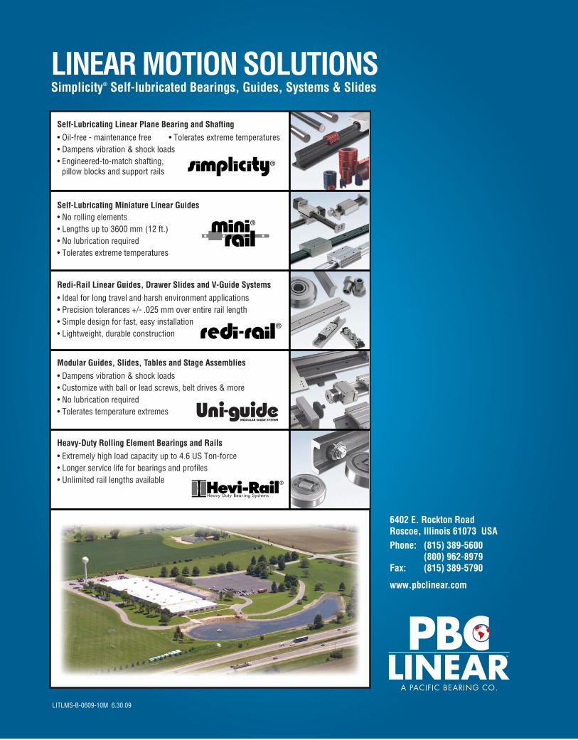
6402 E. Rockton Road Roscoe, Illinois 61073 USAPhone: (815) 389-5600 (800) 962-8979 Fax: (815) 389-5790
www.pbclinear.com
LITLMS-B-0609-10M 6.30.09
LINEAR MOTION SOLUTIONS Simplicity® Self-lubricated Bearings, Guides, Systems & Slides
Heavy-Duty Rolling Element Bearings and Rails• Extremely high load capacity up to 4.6 US Ton-force• Longer service life for bearings and profiles• Unlimited rail lengths available
Self-Lubricating Miniature Linear Guides• No rolling elements• Lengths up to 3600 mm (12 ft.)• No lubrication required• Tolerates extreme temperatures
Self-Lubricating Linear Plane Bearing and Shafting • Oil-free - maintenance free • Tolerates extreme temperatures• Dampens vibration & shock loads • Engineered-to-match shafting, pillow blocks and support rails
Modular Guides, Slides, Tables and Stage Assemblies• Dampens vibration & shock loads• Customize with ball or lead screws, belt drives & more• No lubrication required• Tolerates temperature extremes
Redi-Rail Linear Guides, Drawer Slides and V-Guide Systems • Ideal for long travel and harsh environment applications• Precision tolerances +/- .025 mm over entire rail length• Simple design for fast, easy installation• Lightweight, durable construction