
Pavement Design Manual Revised July 2004 © 2003-4 Texas Department of Transportation All rights...
70
Pavement Design Manual Revised July 2004 © 2003-4 Texas Department of Transportation All rights reserved
-
Upload
independent -
Category
Documents
-
view
2 -
download
0
Transcript of Pavement Design Manual Revised July 2004 © 2003-4 Texas Department of Transportation All rights...

Pavement Design
Manual
Revised July 2004
© 2003-4 Texas Department of Transportation All rights reserved

Pavement Design Manual
July 2004
Manual Notices

Manual Notice 2004-1
To: Users of the Pavement Design Manual
From: Thomas R. Bohuslav, P. E., Director, Construction Division
Subject: Pavement Design Manual
Date: July 1, 2004
Purpose
This manual notice is intended to transmit changes to the content of the Pavement Design Manual.
Overview of Changes
Revisions made to Chapter 3, Section 4, “Recommended Input Design Values”:
♦ subhead, “28-day Concrete Modulus of Rupture, Mr” changed 650 psi to 620 psi
♦ subhead, “Load Transfer Coefficient” added column header text
♦ subhead, “Design Traffic 18-kip ESAL” added text to table for 8 lanes
Revisions made to Chapter 3, Section 6, “Concrete Pavement Design Standards”:
♦ bulleted list under subhead, “Design Standards” updated the information in the second and third bullets from current: • CPCR (1)-94, Concrete Pavement Details for CRCP, One-Layer Steel Placement -
applies to CRCP that is from 8 to 13 inches thick. • CPCR (2)-94, Concrete Pavement Details for CRCP, Two-Layer Steel Placement -
used for CRCP that is from 13 to 15 inches thick. to new:
• CRCP (1)-03, Continuously Reinforced Concrete Pavement, One-Layer Steel Bar Placement - applies to CRCP that is from 8 to 13 inches thick.
• CRCP (2)-03, Continuously Reinforced Concrete Pavement, Two-Layer Steel Bar Placement – applies to CRCP that is from 14 to 15 inches thick.
Contents
The manual change issues the above changes and additions online.
Instructions
Access the new version through the TxDOT Online Manual System.

Contact
For more information or questions regarding the revised section above, please contact:
♦ Materials and Pavements Section—512/467-5926.

Manual Notice 2003-1
To: Users of the Pavement Design Manual
From: Thomas R. Bohuslav, P. E., Director, Construction Division
Subject: Pavement Design Manual
Date: December 1, 2003
Purpose
This manual notice is intended to transmit changes to the content of the Pavement Design Manual.
Overview of Changes
♦ Various revisions made to chapters 1, 2, and 3.
♦ Divided Chapter 4 into the following new chapters: • Chapter 4 describes the procedure for changing load zones on highways (including
county roads and bridges). • Chapter 5 provides the guidelines on the Wet Weather Accident Reduction
Program (WWARP). • Chapter 6 provides information about other pavement-related activities such as
super heavy load analysis and how to create a pavement forensic team.
Contents
The manual change issues the above changes and additions online.
Instructions
Access the new version through the TxDOT Online Manual System.
Contact
For more information or questions regarding the revised section above, please contact:
Materials and Pavements Section — 512/467-5926.

Manual Notice 2001-1
To: All Districts, Divisions, and Special Offices
From: Thomas R. Bohuslav, P. E., Director, Construction Division
Subject: Pavement Design Manual
Date: March 1, 2001
Purpose
The purpose of this manual is to provide the Texas Department of Transportation (TxDOT) and consultant pavement designers with a uniform, streamlined process for designing pavements on TxDOT-approved projects. The manual also addresses related topics that a pavement designer needs for effective pavement management.
Contents
This manual is organized into four chapters.
♦ Chapter 1 – Introduction. This chapter explains the purpose of the manual and discusses how it may be used, describes the pavement design process, and discusses pavement documentation requirements, signature, and approval authority. This chapter also describes the information needed for pavement design.
♦ Chapter 2 – Flexible Pavement Design. This chapter describes acceptable procedures to be used for flexible pavement design.
♦ Chapter 3 – Rigid Pavement Design. This chapter describes acceptable procedures for rigid pavement design (Portland Cement Concrete).
♦ Chapter 4 – Other Pavement Related Issues. This chapter provides information about other pavement-related issues such as load zoning and forensic studies.
This manual also contains online links to other project development procedural manuals currently available online as well as those under development.
Action Required
This manual is the department policy for pavement design. A pavement design needs to be performed during the early phase of project development. The pavement section needs to be established in order to facilitate the further design of the project. This step also ensures that pavement design is used to calculate the project cost rather than project cost dictating the pavement design.

Contact
Contact the Pavements Section of the Construction Division at (512) 465-3674 for general comments and suggestions for future revisions of this manual.

Pavement Design Manual 1-1 TxDOT 12/2003
Chapter 1
Introduction
Contents: Section 1 — Manual Overview ............................................................................................ 1-2
Section 2 — Pavement Design Process ................................................................................ 1-4
Section 3 — Information Needed for Pavement Design ...................................................... 1-9

Chapter 1 — Introduction Section 1 — Manual Overview
Pavement Design Manual 1-2 TxDOT 12/2003
Section 1 Manual Overview
Purpose of Manual
The purpose of this manual is to provide the Texas Department of Transportation (TxDOT) and consultant pavement designers with a uniform, streamlined process for designing pavements on TxDOT-approved projects. The manual also addresses related topics that a pavement designer needs for effective pavement management.
Organization of the Manual
This manual is organized into six chapters.
♦ Chapter 1 explains the purpose of the manual and discusses how it may be used, describes the pavement design process, and discusses pavement documentation requirements, signature, and approval authority. The chapter also describes the information needed for pavement design.
♦ Chapter 2 describes acceptable procedures to be used for flexible pavement design.
♦ Chapter 3 describes acceptable procedures for rigid pavement design (Portland Cement Concrete).
♦ Chapter 4 describes the procedure for changing load zones on highways (including county roads and bridges).
♦ Chapter 5 provides the guidelines on the Wet Weather Accident Reduction Program (WWARP).
♦ Chapter 6 provides information about other pavement-related activities such as super heavy load analysis and how to create a pavement forensic team.
The TxDOT Glossary has a list of other pavement-related terms that may not be described in this manual.

Chapter 1 — Introduction Section 1 — Manual Overview
Pavement Design Manual 1-3 TxDOT 12/2003
Importance of Pavement Design
TxDOT spends more than 50 percent of the annual construction and maintenance budget on pavements. Nevertheless, with current funding, only 40 percent of pavement-related needs can be addressed. Therefore pavements need to be properly designed using an analytical process with accurate design inputs.
A pavement design needs to be performed during the early phase of project development. This step ensures that pavement design is used to calculate project cost rather than project cost dictating the pavement design.
Training
This manual provides general information about pavement design processes and procedures. Information on more comprehensive training courses and materials is available through the district pavement engineer, the Construction Division — Materials & Pavements Section (CST/M&P) and other sources. A partial list of available training courses is as follows:
♦ American Association of State Highway and Transportation Officials (AASHTO) Design Procedures for New Pavements
♦ Techniques for Pavement Rehabilitation
♦ Flexible Pavement System — Version 19 (FPS-19W) and MODULUS 5.1
♦ Basic Geotechnical Engineering for Roadways
♦ Flexible Pavement Rehabilitation Training CD-ROM.
A more comprehensive list is available from your TxDOT training coordinator.
Pavement Design Policy
The department has communicated its procedures and policies through various memoranda such as Executive Orders (EOs), Administrative Circulars (ACs), and Stand-alone Manual (SAM) notices. The original intent of these documents was to get information out quickly for the districts to implement in their daily duties. The documents were to be incorporated in the appropriate manual. Hence, all pavement design policy statements have been updated and incorporated into the text of this manual making this document TxDOT’s policy for pavement design.
Contacts for Questions and Comments
Contact the director of CST/M&P for questions or comments about this manual.

Chapter 1 — Introduction Section 2 — Pavement Design Process
Pavement Design Manual 1-4 TxDOT 12/2003
Section 2 Pavement Design Process
Pavement Type Definitions
For the purposes of this manual, flexible and rigid pavements are defined as follows:
♦ flexible pavement - a structure with an asphalt surface
♦ rigid pavement - a structure with a Portland Cement Concrete (PCC) surface.
An exception to these definitions would be an asphalt surface on a PCC pavement, which would be considered a type of rigid pavement.
Approved Pavement Design Methods
Use one of the following for flexible pavements:
♦ FPS-19W
♦ AASHTO design procedure
♦ Modified Texas Triaxial design method.
Use the AASHTO design procedure for rigid pavements.
Coordinating with Other Agencies
Other agencies should contact the district engineer concerning TxDOT and district policies relating to pavement issues.

Chapter 1 — Introduction Section 2 — Pavement Design Process
Pavement Design Manual 1-5 TxDOT 12/2003
Pavement Design Categories
There are three pavement structure design categories. They are:
♦ "New" pavement design
♦ Pavement reconstruction design
♦ Pavement rehabilitation design.
It is very important that the pavement designer make an early investigation to determine which category applies to the project.
The following table lists the definitions for each pavement structure design category.
Pavement Structure Design Category Definitions Term Definition
New Pavement Structure A combination of a subbase and surface course placed on a subgrade to support the traffic load and distribute it to the roadbed.
Pavement Reconstruction Construction of the equivalent of a new pavement structure, which usually involves complete removal and replacement of the existing pavement structure including new and/or recycled materials
Pavement Rehabilitation Resurfacing, restoration, and rehabilitation (3R) work undertaken to restore serviceability and to extend the service life of an existing facility. This may include partial recycling of the existing pavement, placement of additional surface materials, or other work necessary to return an existing pavement, including shoulders, to a condition of structural or functional adequacy.
NOTE: These definitions do not necessarily coincide with program definitions.

Chapter 1 — Introduction Section 2 — Pavement Design Process
Pavement Design Manual 1-6 TxDOT 12/2003
Example of When to Use Each Category
"New" Pavement Design. The "new" pavement design category assumes that a pavement is to be constructed from point "A" to point "B" and that there is no existing pavement along the proposed route.
Pavement Reconstruction Design. Pavement reconstruction design assumes that there is an existing pavement along the project route. It is further assumed that the structural condition of the existing pavement is in such deteriorated condition that removal of all or part of the existing pavement is necessary. Also, there is the possibility that adjustments to the vertical and/or horizontal alignment make reconstruction necessary.
Pavement Rehabilitation Design. Pavement rehabilitation design assumes that there is an existing pavement structure along the project route. The vertical and/or horizontal alignment will not change. Also, it is assumed that the existing pavement structure possesses a degree of remaining life.
Data Collection
The data collected for each of the categories are considerably different. The pavement rehabilitation category will take the largest data collection effort. In many instances it will be necessary to design for both pavement reconstruction and pavement rehabilitation. The final selection between the two will involve a study of costs, traffic handling, and other re-lated items. It is easy to determine when a project is in the "new" pavement design category. When it is established that a project is in the "new" pavement category, the other categories do not need consideration. See 'Information Needed for Pavement Design' for a description of the information needed for pavement design.

Chapter 1 — Introduction Section 2 — Pavement Design Process
Pavement Design Manual 1-7 TxDOT 12/2003
Projects Needing a Pavement Design Report
A pavement design report will be required for the following projects that are over 500 feet long:
♦ New location projects (flexible and rigid)
♦ Reconstruction projects (flexible and rigid)
♦ Rehabilitation 2R and 3R projects (flexible and rigid)
♦ PCC overlays
♦ Asphalt Concrete Pavement (ACP) overlays greater than 2 inches thick.
Special cases address pavement designs for which there are no formal design procedures currently available. The pavement design for special cases will typically be based on engineering judgment, historical performance, district policy, and other guidelines. The following list gives examples of special cases that require documentation of the criteria and rationale for the strategy selected:
♦ approaches on a bridge replacement
♦ addition of shoulders
♦ detours
♦ addition of a travel lane
♦ match to the existing section.
ACP overlays 2 inches thick and less are considered a preventive maintenance treatment, and therefore a pavement design report is not required. Nevertheless, considering the significant investment that thin overlays represent, these treatments should be considered in an overall pavement preservation program.
For design categories not covered above, contact the district pavement engineer for guidance about recommended design procedures and documentation requirements.
Pavement Design Report and Other Documentation
A pavement design report is a formal engineering document that presents all analyses, data, policies and other considerations used to design a pavement. Guidelines for the information that needs to be included in a pavement design report are discussed in"Guidelines for the Development of a Pavement Design Report."
For the special cases identified above that do not require a pavement design report, the documentation should include a brief description of the criteria, engineering considerations, and/or district policy used in the decision process. For other reporting requirements, contact the district pavement engineer for guidance.

Chapter 1 — Introduction Section 2 — Pavement Design Process
Pavement Design Manual 1-8 TxDOT 12/2003
Responsibility, Approval, and Signature Authority
Pavement design and documentation is the responsibility of the engineer of record and must be reviewed and approved by the district pavement engineer. In the event that the district pavement engineer position is vacant, or the district pavement engineer is not certified by the Construction Division, the pavement designs shall be forwarded to the director of CST/M&P for review and approval.
The pavement design report shall be signed and dated by the district pavement engineer and shall include his serial number ("Procedures for Sealing Engineering Documents," Project Development Policy Manual). A copy of the pavement design report shall be sent to the director of CST/M&P.

Chapter 1 — Introduction Section 3 — Information Needed for Pavement
Design
Pavement Design Manual 1-9 TxDOT 12/2003
Section 3 Information Needed for Pavement Design
Overview
Specific and accurate information is needed for effective pavement design and to create a pavement design report, if needed. This section discusses the following pavement design information:
♦ Traffic Projections
♦ Project Files/Records
♦ Pavement Management Information System (PMIS) Data
♦ Construction and Maintenance Experience
♦ Site Investigation
♦ Material Sampling and Testing
♦ Deflection Testing of Pavements.

Chapter 1 — Introduction Section 3 — Information Needed for Pavement
Design
Pavement Design Manual 1-10 TxDOT 12/2003
Traffic Projections
The Transportation Planning and Programming (TPP) Division provides traffic projections ("Single Source Traffic Data Operating Procedures," Project Development Policy Manual). The designer must request a 20-year traffic projection for flexible pavements and a 30-year traffic projection for rigid pavements from the Traffic Section of TPP. Requests for traffic projections should be coordinated with the district director of Transportation Planning and Development.
The pavement designer can help ensure that accurate traffic projections are provided by documenting local conditions and planned economic development that may affect future traffic loads and volumes.
TPP should be notified of special traffic situations when traffic data are requested. Some special situations may be a:
♦ street that is or will be a major arterial route for city buses
♦ roadway that will carry truck traffic to and from heavily used distribution or freight centers
♦ highway that will experience an increase in traffic due to a connecting major, high-traffic highway that will be constructed in the near future
♦ roadway that will experience a decrease in traffic due to the future opening of a parallel roadway facility.
For more information on traffic projection refer to "1430: Obtain traffic data" in the Project Development Process Manual.

Chapter 1 — Introduction Section 3 — Information Needed for Pavement
Design
Pavement Design Manual 1-11 TxDOT 12/2003
Project Files/Records
A review of project files and/or records will reveal to the pavement designer many things related to the current status of project development. Reviewing the project files and/or records will be the most beneficial to the pavement designer who has not been with the project since its conception. In reviewing the project files and/or records, the pavement designer should especially be on the alert for any information relating to pavement design category.
"Old" Construction Plans. When the proposed project has an existing pavement structure, district and area offices usually have copies of “old” plans for the project under consideration. These plans are sometimes referred to as "as built" plans. This means they have been corrected or revised to reflect actual dimensions, quantities, elevations, and station locations of various features, specifications, and other items of this nature.
Project Construction Records. In addition to the copies of "old" plans, district and area offices will usually have project construction records relating to an existing project. These records will contain information on concrete pavement strengths, base materials gradations, thickness measurements, and related items.
Pavement Management Information System (PMIS) Data
The Texas PMIS is an automated system for storing, retrieving, analyzing, and reporting information to help with pavement-related decision-making processes.
PMIS provides network-level pavement condition information for planning and programming purposes. PMIS data are used to help select rehabilitation and preventive maintenance projects and evaluate performance trends. They also provide pavement condition information that is useful for performing a preliminary evaluation of a project location. Refer to the Pavement Management Information System (PMIS) User’s Manual or contact CST/M&P for more information about PMIS and PMIS data.

Chapter 1 — Introduction Section 3 — Information Needed for Pavement
Design
Pavement Design Manual 1-12 TxDOT 12/2003
Construction and Maintenance Experience
On any given project, there are always construction and maintenance experiences with pavement structures that were never entered into the permanent records relating to the project. Usually, it was not realized that information such as this would be useful in the future. The area engineer, construction inspectors, district construction engineer, and other personnel involved with the project may have useful information if interviewed.
The district maintenance engineer and county maintenance supervisors may have pavement performance data that do not appear elsewhere in the records. Frequently, maintenance forces have repaired substantial sections of the project and this information is not always readily available in the records.
Site Investigation
It may be beneficial to visit the project site several times during the development of a pavement or rehabilitation design. Most likely the pavement designer may find it desirable to make a brief visit to the project site as the first step in the investigative process. As the investigation proceeds, events may develop which will make it desirable to revisit the project site.
During site visits, the following are some of the items that should be viewed or determined:
♦ Visual Pavement Condition Survey
♦ Abutting Land Usage
♦ Existing Project Geometrics
♦ Geotechnical Investigations
♦ Drainage Characteristics.
Visual Pavement Condition Survey. The preliminary visual condition survey should provide an overview of project conditions. It may be necessary to subdivide the project by mileposts if pavement condition varies along the length of the project. Detailed pavement condition data can be taken at a later date if needed. The preliminary visual condition survey should consider all or part of those visual distresses outlined in the PMIS User’s Manual.
It is important to differentiate between load and environmentally induced distress. The mechanism that caused each distress type should be identified based on knowledge of the materials and site conditions.
Detailed pavement condition data are a must if rehabilitation of the existing pavement is contemplated. There will be instances when detailed pavement data will be needed to make the decision on reconstruction or rehabilitation of the existing pavement structure.

Chapter 1 — Introduction Section 3 — Information Needed for Pavement
Design
Pavement Design Manual 1-13 TxDOT 12/2003
Abutting Land Usage. The abutting land usage will be a needed item of design information. Land usage will have an effect on the selection of a pavement type or the selection of a rehabilitation design procedure. If the abutting land is rural, then note should be made of its use such as farming, ranching, or other, with descriptive details as needed. If the property is urban, a record of usage in terms of residential or commercial is helpful. Additional details on type of residences or type of commercial usage are also helpful.
Existing Project Geometrics. Note should be made as to vertical and horizontal alignment characteristics and type of typical section. Data concerning the typical section should indicate the average and maximum "cut" and "fill" heights and the extent of these over the project. Items such as number of travel lanes and shoulders should be noted. Notes on type and extent of curb and gutter should be made. Vertical clearances at structures should be recorded.
Geotechnical Investigations. Geotechnical investigations are performed to determine the subgrade soil properties needed for pavement structural design considerations and to determine if subgrade stabilization/modification is needed. While pavement design is based on the response of the soil to short-term loads, long-term soil response may dramatically affect the roadway. For example, roadways constructed over soft soils may experience long-term settlements.
Important subgrade parameters obtained through a geotechnical investigation include the soil classification, Atterberg Limits, Texas Triaxial Classification, sulfate content, stabilization requirements, Potential Vertical Rise (PVR) for expansive soils, and other design considerations.
Geotechnical investigations are typically required for new construction and reconstruction projects. Contact the district laboratory to request a geotechnical investigation. Refer to the County Soil Survey manuals and maps for general information about soil type and extent. Refer to the Geologic Atlas of Texas for more information on surface conditions. Further information is available in the Texas Triaxial Classification Manual and the FHWA Subsurface Investigation Manual. Information on the availability of these and similar resources is available from CST-M&P, Soils and Aggregates Branch.
Drainage Characteristics. Drainage characteristics should be noted during the visit to the project. Items such as the general terrain drainage, the highway drainage, and the existing pavement drainage need to be noted. Another drainage item is bridge size drainage structures. The number of bridges and how the existing pavement terminates at the bridge ends is important to note. Also, note if the bridges have bridge approach slabs. The condition of the bridge end/approach slab and the approach slab/pavement interface conditions are of special interest when concrete pavement exists.

Chapter 1 — Introduction Section 3 — Information Needed for Pavement
Design
Pavement Design Manual 1-14 TxDOT 12/2003
Material Sampling and Testing
Sampling involves coring the existing pavement to determine layer thicknesses, to permit visual inspection of the subsurface condition, and to obtain material samples of unbound layers for further testing. For an existing pavement, the types of tests performed on the extracted materials should depend on the type of distress observed. Contact the district laboratory for information on recommended sampling intervals and further guidance on available material test methods.
Deflection Testing of Pavements
The purpose of collecting deflection data is to determine pavement and subgrade layer stiffness values (elastic moduli) used in FPS-19W. Additionally, deflections may provide a good indication of overall pavement and subgrade structural condition. The stiffness and condition of the existing pavement layers are also used to estimate the pavement’s remaining life.
Deflection testing is typically not used for rigid pavement in new construction, reconstruction, or unbonded concrete overlays. However, deflection testing may be required for bonded PCC or ACP overlays of existing concrete pavement. Contact the district pavement engineer or CST/M&P if further information is needed.
Falling Weight Deflectometer (FWD). The FWD provides deflection information at different load levels designed to simulate actual vehicle loadings. FWD deflection data can be used directly to evaluate pavement and subgrade conditions or can be further analyzed to provide back-calculated layer moduli, which are needed for FPS-19. The MODULUS computer program is used to compute layer moduli based on FWD deflections, pavement layer thicknesses, and other inputs. For more information on modulus back-calculation, refer to TTI Report 1987-1, MODULUS 5.0 User’s Manual.
FWD test intervals depend on a number of factors including the type of analysis being performed, project length, variability of the pavement and subgrade conditions along the route, and other factors. The pavement designer should ensure that a sufficient number of tests are obtained to properly characterize the route. As a general guide, testing should be performed at least every tenth of a mile in the outside wheel path. For more information on FWD test protocols, consult with the district pavement engineer or CST/M&P.
For information on FWD deflection analysis refer to TTI Report 409-3F, Incorporating a Structural Strength Index into the Texas Pavement Evaluation System. Contact CST/M&P for additional information on FWD data analysis.

Pavement Design Manual 2-1 TxDOT 12/2003
Chapter 2
Flexible Pavement Design
Contents: Section 1 — Overview.......................................................................................................... 2-2
Section 2 — Types of Asphalt Pavements ........................................................................... 2-3
Section 3 — Approved Design Methods .............................................................................. 2-5

Chapter 2 — Flexible Pavement Design Section 1 — Overview
Pavement Design Manual 2-2 TxDOT 12/2003
Section 1 Overview
Background
TxDOT’s flexible pavement design procedure uses a systems approach. The design system is centered upon deflection measurements from the Falling Weight Deflectometer (FWD). These measurements are then used by a computer program to determine the material properties of the pavement layers and to compute alternative structural designs.
What is in This Chapter?
This chapter discusses the following:
♦ Types of asphalt pavements
♦ Approved design methods.

Chapter 2 — Flexible Pavement Design Section 2 — Types of Asphalt Pavements
Pavement Design Manual 2-3 TxDOT 12/2003
Section 2 Types of Asphalt Pavements
Definition of Flexible Pavement
A flexible pavement is a relatively thin surface of Asphalt Concrete Pavement (ACP) over a base and subbase resting on a subgrade
Asphalt concrete surfaced pavements are categorized as being flexible or semi-rigid. The fundamental difference between a flexible, semi-rigid, and rigid pavement is the load distribution over the subgrade. The semi-rigid pavement has a higher modulus of elasticity than a flexible pavement. The elements contributing to the higher modulus may be:
1. Increased thickness in asphalt concrete
2. Chemical stabilization of the base, subbase, and/or subgrade layers
3. Asphalt stabilization of the base course.
The higher modulus adds to the structural capacity of the pavement layers. The load is thereby distributed over a wider area of the subgrade.
Six Types of Pavements
The six types of pavements defined as asphalt surfaced pavements are:
♦ Thin hot mix asphalt concrete (< 2 inches) above granular base
♦ Intermediate hot mix asphalt concrete (2 - 5 inches) above granular base
♦ Thick hot mix asphalt concrete (> 5 inches) (semi-rigid)
♦ Surface treated above granular base
♦ Thin hot mix asphalt concrete above chemically stabilized base or subbase (semi-rigid)
♦ Thin hot mix asphalt above asphaltic bound base (semi-rigid).
Stabilization of the subgrade layer can apply to any of the above pavement types. Typical stabilizers include asphalt cement (for base only), lime, and fly ash.

Chapter 2 — Flexible Pavement Design Section 2 — Types of Asphalt Pavements
Pavement Design Manual 2-4 TxDOT 12/2003
Asphalt Concrete Mix Selection
Generally, the type of asphalt mix ultimately selected for use on a proposed pavement structure is left to the district’s discretion. As a result of the Flexible Pavement Design Task Force (FPDTF) recommendations, department guidelines were established on April 23, 2001 to address the increased structural demands on heavy truck traffic facilities. For facilities with a projected 20-year one direction cumulative loading of more than 30 million ESALs, "heavy duty" mixes with improved aggregate properties must be used in lieu of conventional QC/QA dense graded specifications. In addition, when new or "bottom up" reconstruction is anticipated, the use of a Superpave Rich Bottom Layer (RBL) is required. Exceptions to the use of these improved performance mixes must be granted by the executive director or designated representative. These mixes are designated as performance or stone matrix asphalt (SMA) mixes under the 2003 Specifications. A pavement structure composed of an RBL with multiple lifts of performance and/or SMA mixes is commonly referred to as a perpetual pavement structure that is not subject to traditional bottom-up fatigue damage but will eventually experience surface distresses and will require surface renewal.
A listing of high use truck routes and conceptual perpetual pavement design are given below. Districts desiring to use these improved performance mixes on routes with less than 30 million ESALs must gain approval from CST/M&P.
♦ High Use Truck Routes
♦ Conceptual Perpetual Pavement Design.

Chapter 2 — Flexible Pavement Design Section 3 — Approved Design Methods
Pavement Design Manual 2-5 TxDOT 12/2003
Section 3 Approved Design Methods
Introduction
The Flexible Pavement System ( FPS-19W ) is the preferred method for designing flexible pavements.
FPS-19W provides a methodology for selecting a complete pavement design strategy. Such a strategy calls for action now (initial construction) and for future action (maintenance, overlays, or reconstruction). For a given design analysis, initial construction costs as well as future costs are computed for various design strategies.
FPS-19W does not consider frost heave or strength of materials. The FPS-19W program assumes that a smaller deflection means smaller stresses or strains and, therefore, longer life. The system can generate designs that may fail under occasional heavy wheel loads. For this reason, designs obtained with the FPS-19W program should be checked with the Modified Texas Triaxial design method.
Although FPS-19W is the preferred method, the AASHTO design procedure is also acceptable.
FPS-19
FPS-19W uses back-calculated modulus to characterize the pavement layer strength (stiffness) based on Falling Weight Deflectometer (FWD) deflection measurements. Note that back-calculated modulus used in FPS-19 is not the same as the resilient modulus used in the AASHTO design procedure.
For more information, refer to the Flexible Pavement Design System (FPS) 19: User’s Manual (TTI Research Report). Contact the district pavement engineer or the Construction Division, Materials & Pavements Section to get a copy of the latest version of the FPS-19 computer program.

Chapter 2 — Flexible Pavement Design Section 3 — Approved Design Methods
Pavement Design Manual 2-6 TxDOT 12/2003
AASHTO Design Procedure
The AASHTO (originally AASHO) pavement design guide was first published as an interim guide in 1972. Updates to the guide were subsequently published in 1986 and 1993; a new mechanistic-based design guide is currently planned for completion in 2004. The AASHTO design procedure is based on the results of the AASHO Road Test that was conducted in 1959–1960 in Ottawa, Illinois. Approximately 1.2 million axle load repetitions were applied to specially designed test tracks in the largest road test ever conducted.
For more information on using the AASHTO flexible pavement design procedure, refer to the AASHTO Guide for Design of Pavement Structures (1993). DARWin® 3.10 is the latest automated version of the AASHTO design process. TxDOT has an unlimited license for this software for internal use only. The license cannot be shared with outside agencies.
Modified Texas Triaxial Design Method
The Modified Texas Triaxial design method was developed in the late 1940s and early 1950s by the department. The triaxial design method is used to determine the required pavement thickness to ensure against subgrade shear failure due to heavy wheel loads. The triaxial procedure characterizes the subgrade and base layers using the triaxial classification from laboratory test results.
For more information on the Modified Texas Triaxial design method refer to the Triaxial Compression Test for Disturbed Soils and Base Materials or Appendix D of the Flexible Pavement Designer’s Manual (1994).
Geosynthetics in HMA Applications
Geosynthetic products, defined herein as fabrics, grids, composites, or membranes, have been used by TxDOT since the mid 1980's. The primary purpose of incorporating the use of geosynthetics in the pavement design process is to reduce reflective cracking in HMA overlays and to resist moisture intrusion into the underlying pavement structure. TxDOT investigated these products in 2001 as part of research project 0-1777. One of the products from this research was the publication of "Geosynthetic Guidelines." This document discusses the advantages of using geosynthetics in HMA applications, guidance on the selection of materials, cost considerations, pavement design, as well as construction considerations.
Performance Period
For flexible pavements, the selected design strategy shall provide a minimum initial performance period of eight years before an overlay is required. Normally a 20-year analysis period is used in flexible pavement design. A 30-year analysis period is possible but the designer must use the 20-year cumulative traffic in the FPS-19W computer program. Adjustments to the traffic are then made internally by the computer program.

Chapter 2 — Flexible Pavement Design Section 3 — Approved Design Methods
Pavement Design Manual 2-7 TxDOT 12/2003
Design Process
The flexible pavement design process for FPS-19W for new/reconstruction and overlay design modes is a four-part process that includes:
1. Obtaining inputs for the FPS program
2. Computing results with the FPS program
3. Selecting the best pavement design strategy
4. Documenting and securing approval.
Figure 2-1 summarizes the flexible pavement design process.

Chapter 2 — Flexible Pavement Design Section 3 — Approved Design Methods
Pavement Design Manual 2-8 TxDOT 12/2003
Figure 2-1. Flexible Pavement Design Process

Chapter 2 — Flexible Pavement Design Section 3 — Approved Design Methods
Pavement Design Manual 2-9 TxDOT 12/2003

Pavement Design Manual 3-1 TxDOT 7/2004
Chapter 3
Rigid Pavement Design
Contents: Section 1 — Overview.......................................................................................................... 3-2
Section 2 — Approved Design Method................................................................................ 3-4
Section 3 — Rigid Pavement Design Process ...................................................................... 3-5
Section 4 — Recommended Input Design Values ............................................................... 3-6
Section 5 — Concrete Pavement Thickness Determination............................................... 3-11
Section 6 — Concrete Pavement Design Standards ........................................................... 3-12

Chapter 3 — Rigid Pavement Design Section 1 — Overview
Pavement Design Manual 3-2 TxDOT 7/2004
Section 1 Overview
Definition
Portland Cement Concrete (PCC) pavements are commonly referred to as rigid pavements. Rigid pavements respond to a wheel load as a very stiff material (concrete) over softer materials ( subbase and subgrade ). The concrete layer in the rigid pavement develops bending moments from loading and acts as a slab to spread the wheel load over a large area of the subbase and subgrade, thus reducing stresses and strains in subbase and subgrade.
Rigid Pavement Types
There are two types of concrete pavements commonly used in Texas.
Continuously Reinforced Concrete Pavement (CRCP). CRCP contains both longitudinal and transverse steel. CRCP does not contain transverse joints except at construction joints. The function of the longitudinal steel is not to strengthen the concrete slab, but to control concrete volume changes due to temperature and moisture variations and to keep transverse cracks tightly closed. The function of the transverse steel is to keep longitudinal joints and cracks closed. If the steel serves its proper function and keeps cracks from widening, aggregate interlock is preserved and concrete stresses in the concrete slab due to traffic loading are reduced. Steel reinforcement and other design details are governed by the CRCP standards that can be obtained from TxDOT’s Internet web site at the following address: http://www.dot.state.tx.us/insdtdot/orgchart/cmd/cserve/standard/rdwylse.htm.
Jointed Concrete Pavement. Jointed concrete pavement has transverse joints spaced at regular intervals. The transverse joints are used to control temperature induced contraction and expansion in the concrete. Smooth dowels are used at the transverse joints for load transfer. The transverse joints are spaced at 15 feet. Longitudinal joints are used to control random longitudinal cracking. Longitudinal joints are tied together with tie-bars. Design details are governed by the Concrete Pavement Contraction Design (CPCD) standards that can be obtained from the Department's Internet web site at the following address: http://www.dot.state.tx.us/insdtdot/orgchart/cmd/cserve/standard/rdwylse.htm.
Department policy as of October 17, 2000 is to utilize CRCP for rigid pavements in Texas. There are situations where jointed pavement may be desirable. If jointed pavement is to be utilized, its use must meet one of the following criteria:
♦ For roadways controlled and maintained by another government entity.
♦ For aesthetic reasons where pedestrian traffic might interpret the randomly spaced cracks of CRCP with premature failure.
♦ For parking areas or roadways with crosswalks, adjacent parking, or sidewalks.
♦ For railroad crossings, approaches to structures or to widen existing jointed pavement.

Chapter 3 — Rigid Pavement Design Section 1 — Overview
Pavement Design Manual 3-3 TxDOT 7/2004
♦ For intersections and approaches in flexible pavement roadways that are associated with vehicle braking and acceleration which could cause shoving and rutting of an asphalt pavement.
♦ For other situations approved by the Administration, after submittal of request and justification to the Materials and Pavements Section of the Construction Division.
Performance Period
For rigid pavements, the initial pavement structure shall be designed and analyzed for a performance period of 30 years. A performance period other than 30 years may be utilized with justifications. For example, an existing pavement to be widened will be completely reconstructed within 15 years. In this case, a selection of 15 year performance period is more reasonable and justifiable for the widening.

Chapter 3 — Rigid Pavement Design Section 2 — Approved Design Method
Pavement Design Manual 3-4 TxDOT 7/2004
Section 2 Approved Design Method
AASHTO Rigid Pavement Design Procedure
The AASHTO Guide for Design of Pavement Structures (AASHTO Guide for Design of Pavement Structures – 1993, American Association of State Highway and Transportation Officials. Washington, D.C. 2001) is the only approved design method for rigid pavements for TxDOT. This design procedure is available in automated form. Automated procedures include the AASHTO DARWin® program and the TxDOT’s TSLAB86 program. These programs are available to TxDOT personnel through the district pavement engineer. Consultants may obtain the TSLAB86 program from the district pavement engineer or the Construction Division, Materials and Pavements Section (CST/M&P).
The AASHTO Guide also contains design procedures for rehabilitation of rigid pavements, including asphalt concrete overlays or PCC overlays of existing rigid pavements. Contact the district pavement engineer or CST/M&P for further assistance.

Chapter 3 — Rigid Pavement Design Section 3 — Rigid Pavement Design Process
Pavement Design Manual 3-5 TxDOT 7/2004
Section 3 Rigid Pavement Design Process
Design Process
The following figure summarizes the rigid pavement design process.
Figure 3-1. Rigid Pavement Design Process

Chapter 3 — Rigid Pavement Design Section 4 — Recommended Input Design Values
Pavement Design Manual 3-6 TxDOT 7/2004
Section 4 Recommended Input Design Values
Input Values
The following input variables are needed for the AASHTO rigid pavement design procedure:
♦ 28-day Concrete Modulus of Rupture, psi
♦ 28-day Concrete Elastic Modulus, psi
♦ Effective Modulus of Subbase/Subgrade Reaction, pci
♦ Serviceability Indices
♦ Load Transfer Coefficient
♦ Drainage Coefficient
♦ Overall Standard Deviation
♦ Reliability, %
♦ Design Traffic, 18-kip Equivalanet Single Axle Load (SEAL).
28-day Concrete Modulus of Rupture, Mr
The Mr of concrete is a measure of the flexural strength of the concrete as determined by breaking concrete beam test specimens. A Mr of 620 psi at 28 days should be used with the current statewide specification for concrete pavement design. If the Engineer selects an alternate value for Mr, then it must be documented with an explanation.
28-day Concrete Elastic Modulus
Elastic modulus of concrete is an indication of concrete stiffness. It varies depending on the coarse aggregate type used in the concrete. Although the value selected for pavement design could be different from the actual values, the elastic modulus does not have a significant effect on the computed slab thickness. A modulus of 5,000,000 psi should be used for pavement design. The use of a different value must be documented with an explanation.
Chapter 3 — Rigid Pavement Design Section 4 — Recommended Input Design Values
Pavement Design Manual 3-7 TxDOT 7/2004
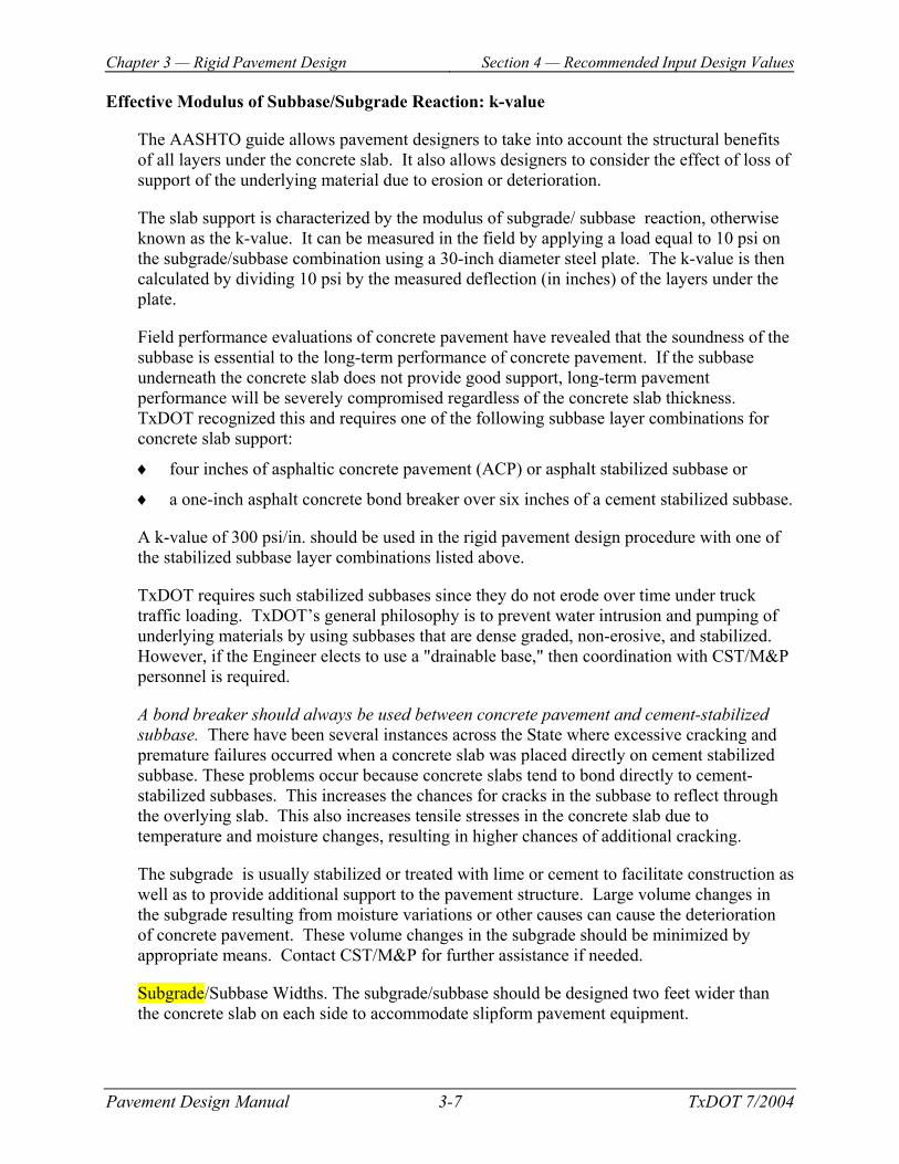
Effective Modulus of Subbase/Subgrade Reaction: k-value
The AASHTO guide allows pavement designers to take into account the structural benefits of all layers under the concrete slab. It also allows designers to consider the effect of loss of support of the underlying material due to erosion or deterioration.
The slab support is characterized by the modulus of subgrade/ subbase reaction, otherwise known as the k-value. It can be measured in the field by applying a load equal to 10 psi on the subgrade/subbase combination using a 30-inch diameter steel plate. The k-value is then calculated by dividing 10 psi by the measured deflection (in inches) of the layers under the plate.
Field performance evaluations of concrete pavement have revealed that the soundness of the subbase is essential to the long-term performance of concrete pavement. If the subbase underneath the concrete slab does not provide good support, long-term pavement performance will be severely compromised regardless of the concrete slab thickness. TxDOT recognized this and requires one of the following subbase layer combinations for concrete slab support:
♦ four inches of asphaltic concrete pavement (ACP) or asphalt stabilized subbase or
♦ a one-inch asphalt concrete bond breaker over six inches of a cement stabilized subbase.
A k-value of 300 psi/in. should be used in the rigid pavement design procedure with one of the stabilized subbase layer combinations listed above.
TxDOT requires such stabilized subbases since they do not erode over time under truck traffic loading. TxDOT’s general philosophy is to prevent water intrusion and pumping of underlying materials by using subbases that are dense graded, non-erosive, and stabilized. However, if the Engineer elects to use a "drainable base," then coordination with CST/M&P personnel is required.
A bond breaker should always be used between concrete pavement and cement-stabilized subbase. There have been several instances across the State where excessive cracking and premature failures occurred when a concrete slab was placed directly on cement stabilized subbase. These problems occur because concrete slabs tend to bond directly to cement-stabilized subbases. This increases the chances for cracks in the subbase to reflect through the overlying slab. This also increases tensile stresses in the concrete slab due to temperature and moisture changes, resulting in higher chances of additional cracking.
The subgrade is usually stabilized or treated with lime or cement to facilitate construction as well as to provide additional support to the pavement structure. Large volume changes in the subgrade resulting from moisture variations or other causes can cause the deterioration of concrete pavement. These volume changes in the subgrade should be minimized by appropriate means. Contact CST/M&P for further assistance if needed.
Subgrade/Subbase Widths. The subgrade/subbase should be designed two feet wider than the concrete slab on each side to accommodate slipform pavement equipment.

Chapter 3 — Rigid Pavement Design Section 4 — Recommended Input Design Values
Pavement Design Manual 3-8 TxDOT 7/2004
Serviceability Indices
For concrete pavement design, the difference between the initial and terminal serviceability is an important factor. An initial serviceability value of 4.5 and a terminal serviceability value of 2.5 are to be used in the procedure, which results in a difference of 2.0. Different values, if used, must be documented and justified.
Load Transfer Coefficient
The load transfer coefficient is used to incorporate the effect of dowels, reinforcing steel, tied shoulders, and tied curb and gutter on reducing the stress in the concrete slab due to traffic loading. The coefficients recommended in the AASHTO Guide were based on findings from the AASHO Road Test.
The use of load transfer devices, tied shoulders, and tied curb and gutter would result in lower stresses in the concrete slab. The AASHTO procedure recognizes this by requiring a lower concrete pavement thickness when load transfer systems (as described above) are provided. The following table lists the load transfer coefficient values to be used for rigid pavement design.
Load Transfer Coefficients CRCP or Load transfer devices
at transverse joints Tied PCC shoulders, curb and gutter, or greater than two lanes in
one direction Yes No
Yes 2.9 3.2 No 3.7 4.2
There is substantial evidence that tied PCC shoulders improve PCC pavement performance significantly. Therefore, it is strongly recommended that tied PCC shoulders be provided, if possible. In case it is not feasible to provide tied PCC shoulders, the use of a minimum 2-ft wider outside lane should be considered.

Chapter 3 — Rigid Pavement Design Section 4 — Recommended Input Design Values
Pavement Design Manual 3-9 TxDOT 7/2004
Drainage Coefficient
The drainage coefficient characterizes the quality of drainage of the subbase layers under the concrete slab. Good draining pavement structures do not give water the chance to saturate the subbase and subgrade; thus, pumping is not as likely to occur.
The AASHTO Guide provides a table of drainage coefficients based on the anticipated exposure of the pavement structure to moisture and on the quality of drainage of the subbase layers. Higher drainage coefficients represent better drainage. The most credit is given to permeable subbases with edge drains.
TxDOT has not had much experience with positive drainage systems. As stated earlier, TxDOT's philosophy on this issue is to prevent water intrusion and pumping by using subbases that are dense graded, non-erosive, and stabilized. TxDOT has had good performance with such subbases and it is believed that the subbases recommended earlier in this section provide performance equivalent to a fair level of drainage.
Currently, drainage coefficients in Texas for non-erosive stabilized subbases are based on the anticipated exposure of the pavement structure to water. The 'Drainage Coefficients' table shows the recommended drainage coefficients for Texas. The coefficients are selected based on the annual rainfall in the project area.
Drainage Coefficients Annual Rainfall (inches) Drainage Coefficient
58 – 50 0.91 - 0.95 48 – 40 0.96 - 1.00 38 – 30 1.01 - 1.05 28 – 20 1.06 - 1.10 18 – 8 1.11 - 1.16
NOTE: Higher drainage coefficients decrease the pavement thickness in the AASHTO procedure.
Overall Standard Deviation
Overall standard deviation accounts for both chance variation in the traffic prediction and normal variation in pavement performance prediction for a given traffic. The AASHTO Guide recommends values in the range of 0.30 to 0.40, with 0.35 being the overall standard deviation from the AASHO Road Test. Higher values represent more variability; thus, the pavement thickness increases with higher overall standard deviations. A value on the high end of the range is considered reasonable for Texas since it is believed that the inputs recommended for Texas are less accurate than the inputs determined at the AASHO Road Test. A value of 0.39 is to be used for rigid pavement design.

Chapter 3 — Rigid Pavement Design Section 4 — Recommended Input Design Values
Pavement Design Manual 3-10 TxDOT 7/2004
Reliability, %
The reliability value represents a "safety factor," with higher reliabilities representing pavement structures with less chance of failure. The AASHTO Guide recommends values ranging from 50% to 99.9%, depending on the functional classification and the location (urban vs. rural) of the roadway. Based on TxDOT's experience, a reliability of 95% should be used for rigid pavement design on most projects. If the Engineer decides to use a different value, then it must be documented and justified.
Design Traffic 18-kip ESAL
The AASHTO Guide requires a prediction of the number of 18-kip ESALs that the pavement will experience over its design life.
The traffic projections for a highway project (in terms of ADT and one-way total 18-kip ESALs) are obtained from the traffic analysis report provided by the Transportation Planning and Programming (TPP) Division. This report is requested during the design phase of a project and upon receipt, should be evaluated for reasonableness.
The predicted 18-kip ESALs is multiplied by a lane distribution factor (LDF). This factor represents the percentage of the total one-way 18-kip ESALs that could be expected in the design lane. The design lane is the lane that will carry the most traffic. Usually, it is assumed that the outer lane of a highway with two lanes in each direction carries the most traffic. For a three-lane facility, the middle lane is assumed to carry the most traffic. Traffic distribution in urban areas is somewhat more complex due to merging and exiting operations, but the same assumptions could apply.
Lane Distribution Factors Total Number of Lanes in Both Directions LDF
≤ 4 1.0 6 0.7
≥ 8* 0.6 *Unless field observations show otherwise
The LDF decreases with an increase in the number of lanes of a facility. So, a highway with two lanes in each direction would have a higher LDF than a highway with three or more lanes in each direction. This is because traffic tends to spread out over the available lanes.
The traffic analysis report also lists a directional distribution of traffic, which indicates the percent distribution of the design hourly volume in each direction of a highway facility. This value is used for capacity analysis and applies to all vehicles in the design hourly volume. However, TPP assumes that the directional distribution of heavy vehicles on any project is evenly split in both directions. Therefore, the directional distribution factor listed in the TPP report should not be used to modify the design 18-kip ESALs. However, the local conditions may cause the directional distribution of heavy vehicles unequal. If this is the case, adjust the reported 18-kip ESALs for pavement design and document the reasons and methods used to make the adjustment.

Chapter 3 — Rigid Pavement Design Section 5 — Concrete Pavement Thickness
Determination
Pavement Design Manual 3-11 TxDOT 7/2004
Section 5 Concrete Pavement Thickness Determination
Determining Concrete Pavement Thickness
The concrete slab thickness determined with the inputs from the "Recommended Input Design Values" section should be used for the proposed pavement structure, except if the computed thickness contains fractions of inches, round the thickness up to the next higher whole inch.
♦ Use 8 inches for slab thickness if the computed thickness is less than 8 inches.
♦ Use 15 inches for slab thickness if the computed thickness is greater than 15 inches.
The reasoning behind this is that slabs less than 8 inches have substantially higher deflections and stresses than an 8-inch slab, which makes using an 8-inch slab cost-effective. Additionally, slabs over 15 inches do not reduce deflections and stresses appreciably, making any further increase in thickness above 15 inches less cost-effective.

Chapter 3 — Rigid Pavement Design Section 6 — Concrete Pavement Design Standards
Pavement Design Manual 3-12 TxDOT 7/2004
Section 6 Concrete Pavement Design Standards
Design Standards
The following TxDOT pavement-related standards should be included in the pavement design report where applicable. These standards are available from TxDOT's internet web site at http://www.dot.state.tx.us/insdtdot/orgchart/cmd/cserve/standard/rdwylse.htm. For more detailed information about these standards, contact the district pavement engineer or the Construction Division, Materials & Pavements Section (CST/M&P).
♦ BAS-94, Bridge Approach Slab (2 Sheets) - apply to approaches to bridge structures.
♦ CRCP (1)-03, Continuously Reinforced Concrete Pavement, One-Layer Steel Bar Placement - applies to CRCP that is from 8 to 13 inches thick.
♦ CRCP (2)-03, Continuously Reinforced Concrete Pavement, Two-Layer Steel Bar Placement – applies to CRCP that is from 14 to 15 inches thick.
♦ FDRCP-94, Full-Depth Repair of Concrete Pavement - used for repairing existing concrete pavement.
♦ CPCD-94, Concrete Pavement Details, Contraction Design (CPCD) – standard for plain jointed concrete pavement and covers pavement thickness from 8 to 15 inches.
♦ TA (CP)-99, Terminal Anchorage for Concrete Pavement - shows a terminal anchorage system usually constructed near bridge ends to restrain the movement at the joint between the bridge approach slab and the end of the pavement. Restraining the slab movement will hopefully reduce the chance of damaging adjacent structures. Such anchors are mainly used for CRCP, but they can also be used for CPCD as well.
♦ JS-94, Concrete Paving Details, Joint Seals - specifies joint sealing requirements for concrete pavement.

Pavement Design Manual 4-1 TxDOT 12/2003
Chapter 4
Load Zoning
Contents: Section 1 — Overview.......................................................................................................... 4-2
Section 2 — Changing Load Zones on Roads...................................................................... 4-3
Section 3 — Emergency Load Zones on Roads ................................................................... 4-5
Section 4 — Changing Load Zones on County Roads and Bridges..................................... 4-6

Chapter 4 — Load Zoning Section 1 — Overview
Pavement Design Manual 4-2 TxDOT 12/2003
Section 1 Overview
Background
There are more than 17,000 miles of load-restricted highways and more than 600 on-system load-restricted bridge structures in Texas. These facilities were generally constructed prior to the late 1950s, and were designed for lighter wheel loads and axle configurations than are currently allowed by law. In addition, environmental effects have weakened some structures.
The Construction Division, Materials & Pavements Section (CST/M&P) manages a database for load-restricted highways. This database is currently not accessible to anyone outside of CST/M&P. However, efforts are underway to update the Texas Reference Marker (TRM) database on the department’s mainframe with load zone restriction information comparable to what is retained within CST/M&P. Once this update is complete, outside agencies will be able to access this information. One drawback is that a geographic description of the limits may not be available in the TRM database – just the TRM limits.
The Bridge Division manages a database for load-restricted bridge structures. Refer to http://www.dot.state.tx.us/brg/lrbm/lrbm.htm for the load restricted bridge application that includes both on and off-system load restricted bridges.
Minute Orders
In an effort to protect facilities that were originally designed for lighter wheel loads from accelerated deterioration, a provision exists in the state law (Texas Transportation Code, §621.102). The law authorizes the Transportation Commission to set load limits. The Commission must accomplish all actions to revise, post, or remove postings from restricted facilities by issuing a legal document called a Minute Order. CST/M&P is responsible for preparing and submitting, to the Commission, proposed Minute Orders involving load zoning. Minute Orders are approved by the Commission on a monthly basis.
What is in This Chapter?
This chapter discusses the following:
♦ Changing Load Zones on Roads
♦ Emergency Load Zones on Roads
♦ Changing Load Zones on County Roads and Bridges.
For information on adding, removing, or posting an emergency load zone on bridges, refer to "Legal Loads and Load Posting" in the Bridge Inspection Manual.

Chapter 4 — Load Zoning Section 2 — Changing Load Zones on Roads
Pavement Design Manual 4-3 TxDOT 12/2003
Section 2 Changing Load Zones on Roads
Adding
New restrictions may be required for a number of reasons. Highways undergo periodic evaluations and, during the course of these evaluations, highways may be discovered to be structurally deficient. If the deficiency is severe enough to cause potential for accident or injury, then an emergency posting of restrictions under Minute Order 51070 or 84587 may be required. These Minute Orders authorize temporary load posting up to 60 or 120 days, respectively. In addition, if repairs or upgrades are not anticipated for more than 120 days, restrictions must be authorized and promulgated by a subsequent "permanent" Minute Order. See 'Emergency Load Zones on Roads' for more information on emergency postings.
Refer to the step-by-step instructions in the 'Changing Load Zones on Roads' table for adding a load zone.
Removing
Removing a load zone may be requested if rehabilitation or reconstruction has been performed or the load-zoned roadwaycan carry the traffic until the next scheduled rehabilitation without premature failure. If the highway was upgraded by using an approved design process that accounts for future projected traffic, then no further analysis is necessary and recommendation for removal of restrictions by Minute Order should be made. However, if an upgrade was accomplished by means of a maintenance effort (or 2R program), then the district must perform a deflection survey of the upgraded highway using the load zone setup on the Falling Weight Deflectometer (FWD).
Refer to the step-by-step instructions in the 'Changing Load Zones on Roads' table for removing a load zone.
Chapter 4 — Load Zoning Section 2 — Changing Load Zones on Roads
Pavement Design Manual 4-4 TxDOT 12/2003
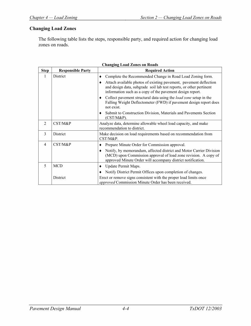
Changing Load Zones
The following table lists the steps, responsible party, and required action for changing load zones on roads.
Changing Load Zones on Roads Step Responsible Party Required Action
1 District ♦ Complete the Recommended Change in Road Load Zoning form. ♦ Attach available photos of existing pavement, pavement deflection
and design data, subgrade soil lab test reports, or other pertinent information such as a copy of the pavement design report.
♦ Collect pavement structural data using the load zone setup in the Falling Weight Deflectometer (FWD) if pavement design report does not exist.
♦ Submit to Construction Division, Materials and Pavements Section (CST/M&P).
2 CST/M&P Analyze data, determine allowable wheel load capacity, and make recommendation to district.
3 District Make decision on load requirements based on recommendation from CST/M&P.
4 CST/M&P ♦ Prepare Minute Order for Commission approval. ♦ Notify, by memorandum, affected district and Motor Carrier Division
(MCD) upon Commission approval of load zone revision. A copy of approved Minute Order will accompany district notification.
5 MCD
♦ Update Permit Maps. ♦ Notify District Permit Offices upon completion of changes.
District Erect or remove signs consistent with the proper load limits once approved Commission Minute Order has been received.

Chapter 4 — Load Zoning Section 3 — Emergency Load Zones on Roads
Pavement Design Manual 4-5 TxDOT 12/2003
Section 3 Emergency Load Zones on Roads
Setting Emergency Load Zones on Roads
The district shall notify the Construction Division, Materials and Pavements Section (CST/M&P), by telephone or fax, that an emergency load restriction is required. The following table lists the steps, responsible party, and required action for establishing emergency load zones on roads.
Table Title Step Responsible Party Required Action
1 District ♦ Provide a map showing location of road and alternate routes for legally loaded vehicles to use.
♦ Recommend gross load or axle load limits. ♦ Document deficiencies justifying the placement of emergency load
limits. ♦ Submit a request for a 60-day extension of the emergency load
restriction if the load restriction is needed for more than 60 days. ♦ Request a permanent load restriction by memorandum and submittal
of the Recommended Change in Road Load Zoning form prior to the expiration of the emergency load restriction, if necessary.
2 CST/M&P ♦ Evaluate information received from district. ♦ Prepare letter for the director of the Construction Division
authorizing the emergency load restriction for 60 days (director can also authorize 60-day extension of emergency load zone restriction, if necessary).
♦ Verbally notify district of approval. 3 Motor Carrier Division
(MCD) ♦ Update Permit Maps. ♦ Notify District Permit Offices upon completion of changes.
District Erect signs indicating the emergency load limits once approval from the director of the Construction Division has been received.
Chapter 4 — Load Zoning Section 4 — Changing Load Zones on County Roads
and Bridges
Pavement Design Manual 4-6 TxDOT 12/2003
Section 4 Changing Load Zones on County Roads and Bridges
Law Ruling
In 2001, Texas Senate Bill 220 amended the Texas Transportation Code (§621.301) requiring counties to obtain TxDOT concurrence for proposed county road and bridge load limits. Counties will petition TxDOT for concurrence with a load limit by submitting a request to the district engineer. The county’s request must include an engineer’s evaluation of the proposed change along with supporting documentation.
The procedure outlined in this section will help expedite review of county requests that involve emergency or other temporary situations that pose a risk to the public or potential damage to a road or bridge. The department is not responsible for monitoring county compliance with this amendment of the Transportation Code. Also, a change in a county road limit does not require an approved Commission Minute Order.

Chapter 4 — Load Zoning Section 4 — Changing Load Zones on County Roads
and Bridges
Pavement Design Manual 4-7 TxDOT 12/2003
Coordination Between County and District
Each district will be responsible for communicating the requirements of the statute and providing information to the counties. The following table lists the steps that the district should take when a county submits a proposed change in load limits to the district engineer.
Changing Load Zones on County Roads and Bridges Step Required Action
1 Determine if TxDOT concurrence is necessary. A county must always obtain TxDOT concurrence for a proposed change in: ♦ road load limits, or for a proposed road load limit on a county road built on a new location, if the
proposed load limit is less than the legal load limit permissible under the Texas Transportation Code.
♦ bridge load limits not supported by TxDOT inspections. 2 Check the completeness of the request.
If TxDOT concurrence is required for the proposed change, the request must include the information and supporting documentation listed in "Required Information and Supporting Documentation."
3 Evaluate the request. If the district does not have the resources or expertise to perform the review, contact the Construction Division for roads and Bridge Division for bridges to assist in evaluating the proposed change.
4 Provide written concurrence to the county. ♦ If the submitted documentation and calculations accord with accepted engineering principles and
practice, the district engineer should provide written concurrence to the county within 30 calendar days of receiving the complete request, including all supporting documentation.
♦ If the district engineer does not respond within 30 calendar days, the county may consider the proposed limit to have TxDOT concurrence.
5 Provide district pavement engineer with copies of concurrence correspondence. If concurrence is given for changes in: ♦ road load limits, provide the district pavement engineer with a copy of the county request,
supporting documentation, and district concurrence letter for record purposes. ♦ bridge load limits, provide the district bridge inspection office with the new load ratings and a
copy of the documentation for updating the database. 6 Provide written notification withdrawing concurrence.
The district engineer may review a changed load limit and withdraw concurrence at any time by providing written notification to the county.
7 Review request for appeal. ♦ The county may appeal a decision of the district engineer by submitting a written request along
with the required documentation to the executive director of TxDOT. ♦ The executive director will review the request to determine if department concurrence will be
granted. ♦ The executive director’s decision is final.

Chapter 4 — Load Zoning Section 4 — Changing Load Zones on County Roads
and Bridges
Pavement Design Manual 4-8 TxDOT 12/2003
Required Information and Supporting Documentation
The following table lists the required information and documentation that must be included in the request for changing load limits on county roads and bridges.
Required Information and Supporting Documentation Roads Bridges
♦ Name, phone number, email address for a county contact person.
♦ Route name/number, location, and length (in feet) of the section to be load zoned.
♦ Reason for the proposed change. ♦ The current and proposed limits. The Gross
Vehicle Weight (GVW) and allowable axle weights should be specified.
♦ Evaluation of traffic loads based on a recommended 10-year analysis period.
♦ Description of pavement typical sections and section limits, including layer thickness, material types, lane and shoulder widths, and curb and gutter locations, if applicable.
♦ Pavement visual distress condition evaluation, including an engineering description of the pavement distress type and extent.
♦ Date of the last rehabilitation or reconstruction performed on the road.
♦ Engineering Analysis - Supporting documentation that has been sealed by a professional engineer and includes a visual evaluation of the pavement, a full-depth structural analysis, and calculations supporting the proposed load limit.
♦ For a surfaced county road comparable to a state FM road or higher type pavement: an assessment of the pavement and subgrade layers is required within the project limits based on one of the following methods: • Manual field tests using the Dynamic Cone
Penetrometer or similar device; • Laboratory test results; • Deflection analysis based on the Falling
Weight Deflectometer or similar device; • Other test methods based on accepted
engineering practice. • For an unsurfaced county road or a county
road constructed to a lower standard than is typical for the state maintained system: an assessment of the pavement and subgrade layers is required based on engineering judgment including a visual inspection.
♦ Name, phone number, email address for a county contact person.
♦ Route name/number, location, feature crossed, and structure number (if known).
♦ Reason for the proposed change. ♦ Supporting documentation that has been sealed by
a professional engineer and includes a structural evaluation report documenting the condition of the bridge and calculations supporting the proposed limits. Calculations should include the inventory and operating ratings for the bridge as defined by the AASHTO Manual for Condition Evaluation of Bridges, Chapter 6.

Pavement Design Manual 5-1 TxDOT 12/2003
Chapter 5
Wet Weather Accident Reduction Program
Contents: Section 1 — Overview.......................................................................................................... 5-2
Section 2 — Wet Weather Accident Analysis (Phase I) ...................................................... 5-4
Section 3 — Aggregate Selection (Phase II) ........................................................................ 5-7
Section 4 — Skid Testing (Phase III) ................................................................................. 5-10

Chapter 5 — Wet Weather Accident Reduction Program Section 1 — Overview
Pavement Design Manual 5-2 TxDOT 12/2003
Section 1 Overview
Background
Texas has been and continues to be a leader in research, development, and implementation of skid resistant pavement surfacing. Over the last 30 years, there has been extensive research regarding pavement friction requirements. For example, macro-texture (texture provided by the size and spacing of surfacing aggregate) provides a much higher degree of skid resistance in wet weather than micro-texture (texture of the aggregate particle) which relates mainly to the aggregate polish value.
Roadway characteristics like speed, traffic, number and weight of trucks, vertical and horizontal grades, number and location of driveways, and intersecting roadways have a significant impact on the frictional demand for a specific section of pavement. Also, dry pavements provide adequate skid resistance and therefore different regions of the state have different requirements. Several paving methods are available to meet the frictional demands of the roadway. These methods include the use of macro- and micro-texture aggregates, pavement surface drainage, and surface treatments.
The Texas Wet Weather Accident Reduction Program (WWARP) addresses three separate but interrelated aspects or phases of pavement friction safety. They are accident analysis, aggregate selection, and skid testing. Each phase is described in more detail in the following sections.
Federal Mandate
On June 27, 1967, the Federal Highway Administration (FHWA) issued Highway Safety Program Standard 12, which states in part that "every State shall have a program of design, construction and maintenance to improve highway safety." On July 19, 1973, the FHWA issued IM 21-2-73, which provided basic guidelines for a Skid Accident Reduction Program. The most recent FHWA document relating to skid safety is Technical Advisory (TA) 5040.17 dated December 23, 1980. It provides that "the State’s program shall provide that there are standards for pavement design and construction with specific provision for high skid resistant qualities."

Chapter 5 — Wet Weather Accident Reduction Program Section 1 — Overview
Pavement Design Manual 5-3 TxDOT 12/2003
Department Responsibilities
TxDOT implemented WWARP in order to take advantage of the increased knowledge gained through our research efforts and to more effectively and efficiently address the various regional demands of Texas pavements.
As part of this implementation, the department will:
♦ establish and maintain programs to ensure that pavements with good skid resistant characteristics are used
♦ develop and implement methodologies for the detection and improvement of locations with a significant incident of wet weather accidents using accident record systems and countermeasures to address those locations
♦ implement methods for analysis of the skid resistant characteristics of selected roadway sections to: • ensure pavements that are being constructed provide adequate skid resistance • develop an overview of the skid resistant properties of the highway system • provide information for use in developing safety improvement projects and
implementation of cost effective treatments at appropriate locations.
The Construction Division, Materials & Pavements Section (CST/M&P) is responsible for developing, implementing, and maintaining WWARP. Other divisions charged with responsible support include Traffic Operations, Transportation Planning and Programming, and Maintenance. However, it is the district’s responsibility to ensure safe and adequate frictional properties for their pavements through sound engineering judgement and applying the concepts described in this chapter. A singular mark of success for this program will be a reduction in the rate of wet weather accidents.
Effective Date for Implementation
Change to an aggregate classification system (from polish value and skid exception) became effective on all projects let on or after October 1, 1999. The requirement for collection of mandatory skid testing began May 1, 1999.
What is In This Chapter?
This chapter discusses the following:
♦ Wet Weather Accident Analysis (Phase I)
♦ Aggregate Selection (Phase II)
♦ Skid Testing (Phase III).

Chapter 5 — Wet Weather Accident Reduction Program
Section 2 — Wet Weather Accident Analysis (Phase I)
Pavement Design Manual 5-4 TxDOT 12/2003
Section 2 Wet Weather Accident Analysis (Phase I)
Objectives
Accident analysis is the first phase and it consists of identifying, evaluating, and improving (as needed) all wet weather accident locations. This information is contained in the Motor Vehicle Traffic Accident data file.
The objectives of a wet weather accident analysis are to:
♦ identify locations with wet weather accidents
♦ evaluate and determine the cause or causes of high accident incidents during wet weather
♦ determine corrective measures and take appropriate actions in a timely and systematic manner
♦ ensure that new surfaces have adequate, durable friction properties
♦ ensure those available resources, including high quality aggregates and local materials, are properly used to enhance accident reduction in a cost-effective manner.
Identification of Wet Weather Accident Sites
Total accidents, wet surface condition accidents, and the ratio of wet surface/dry surface condition accidents should be reviewed from the accident records. The Traffic Operations Division will perform an annual search using the accident records to identify sites that have continued occurrence of wet surface condition accidents. Locations identified by local law enforcement personnel, maintenance supervisors, or other field personnel will also be included. Each year the Traffic Operations Division will send reports to CST/M&P for distribution to the districts.

Chapter 5 — Wet Weather Accident Reduction Program
Section 2 — Wet Weather Accident Analysis (Phase I)
Pavement Design Manual 5-5 TxDOT 12/2003
District Review
For evaluation purposes, the district may hold informal meetings to analyze the accident data with the various staff sections. The district’s pavement engineer, maintenance engineer and traffic engineer should review the list of wet surface condition accidents and skid test information together. Additional or supplemental traffic accident information may be needed to fully analyze the collisions. This information is available through the TxDOT mainframe computer system. The district should contact the Traffic Operations Division for help in getting additional traffic accident information.
District pavement and maintenance personnel are familiar with the history of the pavement surface. The district’s Maintenance and Transportation Planning and Development personnel should know of proposed modifications and projects that have been scheduled. Information on the history of the location and the schedule of proposed improvements to the location is essential to designing cost-effective countermeasures.
At a minimum, the district should consider the following in their evaluation of the data:
♦ The selected locations should be compared to the previous three years maintenance program to track changes to the pavement over the reporting period.
♦ The Pavement Engineer should consult the schematics or other sources to determine the geometric layout of the area. It is at this point that the engineer might consult a more detailed list of the location’s accidents to determine the most probable causes.
♦ A site visit should be made to the location to visually assess the condition of the pavement surface, the roadway drainage and the traffic characteristics. Any of these conditions could contribute to a high demand for friction.
♦ The Pavement, Traffic, and/or Maintenance Engineer will determine if the site warrants modification based on the site information, detailed accident data, historical records of the pavement, and skid data.

Chapter 5 — Wet Weather Accident Reduction Program
Section 2 — Wet Weather Accident Analysis (Phase I)
Pavement Design Manual 5-6 TxDOT 12/2003
Field Review
The selected locations should be inspected and evaluated. A review group consisting of materials, design, construction, maintenance, traffic, and safety experts is an effective way of accomplishing a comprehensive field review. The review group should analyze accidents at each location and use all areas of expertise to propose corrective actions.
Visual inspections for elements that could result in wet weather accidents should be considered. Some of these areas include:
♦ rutting or wheel path channelization
♦ build up on shoulder edges that cause ponding on the road surface
♦ bleeding of pavements
♦ drainage issues that result in water on the pavement
♦ geometrics (grade and curvature).
The visual inspection will help to determine the need for additional information such as skid testing and texture measurement.
Report
Once the field review has been completed the district pavement engineer will be responsible for drafting and submitting a report to CST/M&P documenting the site location, evaluation of the site, and any actions taken or recommended.
Actions taken may include drainage improvements, surface preparations (remove mud, restore cross slope), signage (such as Mud on Roadway and Slow Down in Wet Weather), and programming for future surfacing improvements (such as Safety Program, Rehabilitation Program, and Preventive Maintenance).

Chapter 5 — Wet Weather Accident Reduction Program Section 3 — Aggregate Selection (Phase II)
Pavement Design Manual 5-7 TxDOT 12/2003
Section 3 Aggregate Selection (Phase II)
Objective
The second phase of the program is aggregate selection. The objective of aggregate selection is to provide friction and/or texture to satisfy the frictional demands of the roadway.
The aggregate selection program described in this section is for bituminous coarse aggregate and will not apply to concrete pavements. Frictional demand for concrete pavements is provided through the fine aggregate matrix and the quality is controlled primarily through the acid insoluble test. Surface texturing of concrete pavement also provides skid resistant properties.
Selection Process
The following table lists the steps for selecting pavement aggregate.
Selecting Pavement Aggregate Step Action
1 Determine overall frictional demand on road surface. 2 Match overall frictional demand with appropriate surface aggregate classification. 3 Document the process used to determine overall frictional requirements.
Each step is discussed in more detail below.
Determine Overall Frictional Demand
The first step in aggregate selection is to determine the overall frictional demand (Low, Moderate, or High) of the roadway surface. Using engineering judgment, the designer should consider the factors and guidelines provided below to determine the overall frictional demand of the roadway surface. Some of the major factors that influence the overall frictional demand include:
♦ Precipitation (wet days per year and inches per year)
♦ Traffic volume (such as ADT and vehicles per lane)
♦ Speed (such as speed limits and operational speed)
♦ Geometrics (such as number and severity of horizontal and vertical curves and superelevation)
♦ Frequency of vehicle stops (such as driveways and crossroads)
♦ Amount of cross traffic
♦ Amount of truck traffic (percent, number ESAL’s)

Chapter 5 — Wet Weather Accident Reduction Program Section 3 — Aggregate Selection (Phase II)
Pavement Design Manual 5-8 TxDOT 12/2003
♦ Surface Texture (such as rough and smooth)
♦ Drainage characteristics (such as cross slope, ponding, and rutting)
♦ Visibility restrictions (sight distance)
♦ Accident history
♦ Skid performance
♦ Material availability
The following table shows how the factors listed above are categorized to determine the overall frictional demand of the roadway.
Determining Overall Frictional Demand Attribute Low Moderate High
Rain Fall (inches/year) ≤20 >20≤40 >40 Traffic (ADT) ≤5000 >5000≤15,000 >15,000 Speed (mph) ≤35 >35≤60 >60 Trucks (%) ≤8 >8≤15 >15 Vertical Grade (%) ≤2 >2≤5 >5 Horizontal Curve (°) ≤3 >3≤7 >7 Driveways (per mile) ≤5 >5≤10 >10 Intersecting Rdwys (ADT) ≤500 >500≤750 >750
Parameters set by the designer that affect pavement
friction
Low Moderate High
Cross Slope (inches/foot) 3/8 - 1/2 1/4 - 3/8 ≤ 1/4 Surface Design Life (years) ≤ 3 >3 ≤ 7 > 7 Macro Texture (of proposed surface)
Coarse (Such as: Seal Coat Surface Treatment, OGFC)
Medium (Such as: HMAC Type "C" & "D,"
CMHB, SuperPave)
Fine (Such as: Micro Surface, Type "F"
HMAC)
The last three parameters listed in the table have a great influence on the overall frictional demand of the pavement. For example, a pavement with a relatively high cross slope (3/8 - 1/2 inches per foot) should drain well. As a result, there should be a relatively low frictional demand on the aggregate. Conversely, a pavement surface that is designed to last 10 years places a relatively high frictional demand on the aggregate since pavement friction generally decreases with time.

Chapter 5 — Wet Weather Accident Reduction Program Section 3 — Aggregate Selection (Phase II)
Pavement Design Manual 5-9 TxDOT 12/2003
Match Frictional Demand with Aggregate Classification
The second step in selecting an aggregate is to match the overall frictional demand with an appropriate surface aggregate classification. Again, the designer should use engineering judgment to select a surface aggregate classification (for bituminous surfaces only) that will accommodate the friction demand of the roadway.
The following table lists the recommended surface aggregate classification.
Recommended Surface Aggregate Classification Overall Frictional Demand
Attribute Low Moderate High Recommended Surface Aggregate Classification C B A
Each bituminous coarse aggregate source is classified into one of four categories (A, B, C, or D) based on a combination of the frictional and durability properties of the aggregate. Frictional and durability indicator tests (such as polish value, soundness, acid insolubility, and micro deval) are used to classify the aggregates. For example, a surface aggregate classification of "A" is assigned to an aggregate that has high frictional and durability properties. CST/M&P (Soils and Aggregates Branch) is responsible for setting the aggregate classification criteria and listing them in the Concrete Rated Source Quality Catalog and the Bituminous Rated Source Quality Catalog every six months.
Document Process
The last step is to document the entire process used to determine the overall frictional requirements for the project, and specify the minimum surface aggregate classification to be used. The designer must complete the Surface Aggregate Selection Form (2088) and submit it to the district pavement engineer for review. This form must be included in the pavement design report.

Chapter 5 — Wet Weather Accident Reduction Program Section 4 — Skid Testing (Phase III)
Pavement Design Manual 5-10 TxDOT 12/2003
Section 4 Skid Testing (Phase III)
Objectives
The third and final phase of the program concludes with analysis of the skid data. This includes a mandatory collection of skid data that will be stored in the Pavement Management Information System (PMIS).
Skid data will be stored in PMIS and reports will be generated for district review, evaluation, and programming of projects as needed. CST/M&P will oversee the skid testing program, provide the districts with adequate skid testing equipment, assign vehicles to the various districts, and provide training for skid operators in each district. However, the districts will be responsible for collecting, inputting, and analyzing the data.
Frequency and Performance
Skid testing will be performed on an annual basis from May through August. Skid data will be collected on 0.5-mile increments set by CST/M&P. This data will be reviewed annually by CST/M&P to determine if WWARP is working effectively and if the surface aggregate classifications are indicative of field performance.

Pavement Design Manual 6-1 TxDOT 12/2003
Chapter 6
Other Pavement-Related Activities
Contents: Section 1 — Overview.......................................................................................................... 6-2
Section 2 — Pavement Forensics Team ............................................................................... 6-3
Section 3 — Super Heavy Load Analysis ............................................................................ 6-6
Section 4 — Brick Roadway Surfacing................................................................................ 6-7
Section 5 — Additional Pavement Evaluation Equipment................................................... 6-8

Chapter 6 — Other Pavement-Related Activities Section 1 — Overview
Pavement Design Manual 6-2 TxDOT 12/2003
Section 1 Overview
Background
There are many other factors that influence the design of pavements. Sometimes pavements do not meet the designed performance criteria and a special team must be gathered to determine the cause(s) of failure. Or, an industrial plant may need to transport an extremely heavy piece of machinery to its site. As a result, a pavement analysis of the current road condition may need to be done to assess the load limits and any potential damage that may be done to the road. In performing these evaluations, special equipment is used to collect the pavement thickness, profile, and other pavement characteristics. This chapter discusses these factors and how they are used in the design process.
What is in This Chapter?
This chapter discusses the following:
♦ Pavement Forensics Team
♦ Super Heavy Load Analysis
♦ Brick Roadway Surfacing
♦ Additional Pavement Evaluation Equipment.

Chapter 6 — Other Pavement-Related Activities Section 2 — Pavement Forensics Team
Pavement Design Manual 6-3 TxDOT 12/2003
Section 2 Pavement Forensics Team
Objectives
A Pavement Forensics Team has been established to provide technical assistance to the districts and divisions to determine the causes of, and recommend solutions to, premature pavement failures or chronic pavement distresses. The Pavement Forensic Team’s involvement in pavement projects is strictly by request. The team will act as a consultant to the districts and divisions.
The Pavement Forensics Team’s objectives are to:
♦ enhance the district/division’s pavement problem solving capabilities
♦ identify, document, and communicate causes of premature pavement failures so that they may be avoided in the future.
The team represents a step forward in the implementation of pavement management concepts and practices within the department.
Team’s Composition and Specialization
The team is composed of members from the Construction and Bridge Divisions. Members of the team from the Construction Division, Materials and Pavements Section (CST/M&P) specialize in any one (or more) of the following areas:
♦ Pavement Design
♦ Pavement Structural Analysis
♦ Pavement Evaluation
♦ Asphalt Concrete Pavements
♦ Portland Cement Concrete Pavements
♦ Asphalt Cement
♦ Soils and Aggregates
♦ Construction Practices.
Members of the team from the Bridge Division specialize in Foundations and Subsurface Investigations. The director of CST/M&P will serve as the Pavement Forensics Team Coordinator. The director is responsible for:
♦ assigning project leaders to specific projects
♦ reviewing progress on individual projects and ensuring timely completion.

Chapter 6 — Other Pavement-Related Activities Section 2 — Pavement Forensics Team
Pavement Design Manual 6-4 TxDOT 12/2003
Requesting Team’s Assistance
The following table lists the necessary steps for requesting the assistance of a forensics team.
Requesting Pavement Forensics Team Assistance Step Responsible Party Required Action
1 Requesting District/Division ♦ Assign district/division person to serve on team ♦ Request assistance by memorandum from the district engineer
or division director to the director of the Construction Division. Include the following information in the memorandum: • District/Division Coordinator for Pavement Forensics Team
to contact • Pavement history (such as date of initial construction,
overlays, and widening) • Pavement structure and materials information • Traffic information • Description of the predominant distress or failure modes • Construction records relevant to the problem (including
weather conditions) • Soil and geologic information.
2 Director of CST/M&P Assign project leader 3 Pavement Forensic Team
Project Leader Contact district/division coordinator within one week of the date of receipt of request to schedule initial meeting and preliminary on-site investigation.
Pavement Forensics Team Investigation Procedures
The following table lists the investigation procedures for the forensics team.
Pavement Forensics Team Investigation Procedures Step Responsible Party Required Action
1 Pavement Forensics Team and District/Division Coordinator
Conduct preliminary project meeting and perform on-site investigation
2 Pavement Forensics Team and District/Division Coordinator
Formulate action plan for detailed investigation based on preliminary meeting and on-site investigation. Detailed condition survey may include: ♦ Detailed visual evaluation ♦ Automatic Road Analyzer (ARAN) ♦ Ground Penetrating Radar ♦ Spectral Analysis of Surface Waves ♦ Falling Weight Deflectometer (FWD) ♦ Core Rig ♦ Materials sampling and testing ♦ Other testing as required.

Chapter 6 — Other Pavement-Related Activities Section 2 — Pavement Forensics Team
Pavement Design Manual 6-5 TxDOT 12/2003
Pavement Forensics Team Investigation Procedures Step Responsible Party Required Action
3 Pavement Forensics Team and requesting District or Division
♦ Perform materials sampling and laboratory testing to the extent possible and as recommended by the Forensics Team
♦ Provide necessary traffic control ♦ Provide equipment and personnel to acquire material samples ♦ Provide equipment and personnel for repair of cored or
trenched sections. 4 Pavement Forensics Team and
requesting District or Division Analyze data and identify most likely cause of problem
5 Pavement Forensics Team and requesting District or Division
Produce following reports: ♦ Detailed, confidential report for district circulation ♦ Generic report (non-specific location) for statewide distribution ♦ Reports should contain the following items: ♦ Project history and background ♦ Description of pavement structure and material types ♦ Detailed description of pavement condition, distress types and
failure modes ♦ Summary of environmental and soil conditions ♦ Traffic history and projections ♦ Summary of evaluation/testing strategies employed and
findings ♦ Summary of prioritized corrective strategies and associated
costs. 6 Pavement Forensics Team and
requesting District or Division Present findings/recommendations to district engineer
7 Requesting District or Division ♦ Monitor project subsequent to corrective measures to assess effectiveness
♦ Provide periodic feedback to Pavement Forensics Team regarding the effectiveness of the repair strategy. This feedback should be in the form of a technical memorandum.
♦ At the end of the project life (reconstruction or rehabilitation) the district/division coordinator shall produce a final summary analysis report of the performance (effectiveness) of the selected strategy.
If you have any questions or need additional information on the Pavement Forensics Team, contact the director of CST/M&P.

Chapter 6 — Other Pavement-Related Activities Section 3 — Super Heavy Load Analysis
Pavement Design Manual 6-6 TxDOT 12/2003
Section 3 Super Heavy Load Analysis
Guidelines
Super heavy loads are defined as loads that exceed 250,000-lbs. gross vehicle weight. However, these loads may approach 2,000,000 lbs. Due to the magnitude of these loads, there is a risk of causing severe damage in one pass. All loads of this magnitude must be permitted through the Motor Carrier Division (MCD). MCD will notify the Construction Division, Materials and Pavements Section (CST/M&P) of all proposed super heavy load moves. Notification includes proposed movement dates, routes, and load configuration diagrams.
CST/M&P will perform analyses associated with super heavy load moves with input data supplied by the affected districts. The data provided by the districts may include pavement typical section, visual distress evaluation, and FWD deflections. CST/M&P may conduct additional testing as needed. Contact the director of CST/M&P for additional information on super heavy load analysis.
The Bridge Division’s Field Operations Section conducts all bridge-related analyses.

Chapter 6 — Other Pavement-Related Activities Section 4 — Brick Roadway Surfacing
Pavement Design Manual 6-7 TxDOT 12/2003
Section 4 Brick Roadway Surfacing
Guidelines
Prior to initiating detailed design on any facility that proposes the rehabilitation and/or reconstruction of an existing brick roadway, an engineering study, based on the requirements of the Wet Weather Accident Reduction Program (WWARP), must be performed. This study shall consider factors such as operational speed, current and future traffic, number and weight of trucks, vertical and horizontal grades, sight distance, number and location of driveways and intersecting roadways, and accident data. The study should include an engineering analysis of the brick pavement’s skid resistant characteristics, proposed methodologies considered, and recommended action to be taken.
The engineering study shall be signed, sealed, and dated by the district pavement engineer for all projects. The study shall be sent to the Construction Division at the time of typical section submittal. It is recommended that the engineering study be prepared as early as practical, preferably prior to submitting the requested project for funding.
Some suggested methodologies to consider for mitigating the frictional demands of brick roadway surfacing may include one or a combination of the following:
♦ Reduction in posted speed
♦ Advanced warning signs (Slow Down on Wet Road Sign [W8-5])
♦ Limit the length of the brick roadway section.
As with any other pavement surface, it is the district’s responsibility to ensure safe and adequate frictional properties for all their respective pavements through sound engineering judgment and application of the WWARP guidelines.
TxDOT will not participate in any new construction utilizing fired-clay brick (brick roadway surfacing) as the roadway surface where none currently exist. When fired-clay brick roadway surfacing is not feasible for use in the rehabilitation or reconstruction of existing brick facilities, the use of simulated brick roadway surfacing (concrete pavers, stamped concrete) may be considered.

Chapter 6 — Other Pavement-Related Activities Section 5 — Additional Pavement Evaluation
Equipment
Pavement Design Manual 6-8 TxDOT 12/2003
Section 5 Additional Pavement Evaluation Equipment
Contact Information
Contact CST/M&P for information on the following:
♦ Obtaining pavement data collection equipment capabilities
♦ Scheduling equipment training
♦ Scheduling data collection in your district
♦ Scheduling equipment maintenance or repairs.
Evaluation Equipment
Below is a partial list of the types of equipment used to evaluate pavement condition. They include:
♦ Ground Penetrating Radar (GPR)
♦ Profiler/Rut Bar
♦ Multi-Functional Vehicle (MFV)
♦ Skid System
♦ Dynamic Cone Penetrometer (DCP)
♦ Texas Mobile Load Simulator (TxMLS).
Ground Penetrating Radar
The GPR provides a non-destructive means for determining pavement layer thicknesses, subsurface moisture conditions, and pavement defects. For more information on GPR, refer to TTI Research Report 1341-1 COLORMAP – User’s Manual with Case Studies. TxDOT reports are available through Technology Transfer System (http://crossroads/org/rti/tts/) of the Research and Technology Implementation Office.

Chapter 6 — Other Pavement-Related Activities Section 5 — Additional Pavement Evaluation
Equipment
Pavement Design Manual 6-9 TxDOT 12/2003
Profiler/Rut Bar
The TxDOT profiler/rut bar system collects longitudinal and transverse profile measurements in real time and at highway speeds by using non-contact laser and ultrasonic sensors. The longitudinal profile measurements are collected in the left and right wheel paths. The data are summarized every 0.1-mile and are used in calculating the Present Serviceability Index (PSI) and the International Roughness Index (IRI).
The transverse profile measurements are made every four feet in five locations across the rut bar for a total width of seven feet. These measurements are summarized for both the left and right side into percentage of 0.1-mile wheel path having ruts from 0.25 – 0.499 inch (shallow) and 0.5 – 0.99 inch (deep). The average rut depth in each wheel path for every 0.1-mile is calculated, in addition to the maximum, minimum, and standard deviation for both wheel paths. However, the maximum, minimum, and standard deviation values are not currently stored in PMIS.
Multi-Functional Vehicle
The MFV combines the profiler/rut bar technology described above with right-of-way and pavement view video and Global Positioning System (GPS) capability. This system is used in high-traffic urban areas where visual distress surveys are too dangerous to be performed manually and on special projects for documenting before and after results. Three cameras are mounted on the vehicle to provide the video. The videotapes are brought into an office workstation and the pavement view is rated for visual distress. The ride and rut summaries and the visual distress survey results are formatted for uploading into PMIS.
Skid System
The TxDOT skid system collects pavement skid resistance information. The system spreads water in front of a trailer tire. The brake is applied to lock the trailer tire, and a transducer measures the resulting torque. The torque measurements are converted into a skid number from 0 to 100. This system is used for both project and network level data collection efforts.
Dynamic Cone Penetrometer
The DCP is a manual test device that is used to determine the relative stiffness of the base, subbase, and subgrade layers as a function of the number of blows per inch of penetration. It should be noted that DCP test results are not directly used in any of the flexible pavement design procedures approved by the department. Rather, the DCP may provide verification of other structural test results and can also be used to validate pavement layer thickness information. Contact CST/M&P for more information.
Chapter 6 — Other Pavement-Related Activities Section 5 — Additional Pavement Evaluation
Equipment
Pavement Design Manual 6-10 TxDOT 12/2003
Texas Mobile Load Simulator
The TxMLS is a state-of-the-art, accelerated pavement testing machine that applies traffic loads to a 40-foot long pavement test section using six tandem-axle truck bogies.
The TxMLS is approximately 102 feet long, 19.6 feet wide, 22.5 feet high, and weighs approximately 260,000 lbs. It can be disassembled and transported to any location in the state for testing on existing highway segments or specially constructed, full-scale pavement test sections.
The TxMLS typically applies legal tandem-axle loads (34,000 lbs.) at the rate of 4,000 axle loads per hour. Non-destructive test equipment and in-situ instrumentation is used to evaluate the condition of the pavement at set intervals during testing. The TxMLS has been used to evaluate the rate of deterioration of new and rehabilitated pavements in the Yoakum and Fort Worth Districts. Tests have also been performed to evaluate damage due to increased tire pressure and axle overloads. Contact CST/M&P for more information.