Patterns: SOA with an Enterprise Service Bus in WebSphere Application Server V6
410
ibm.com/redbooks Patterns: SOA with an Enterprise Service Bus in WebSphere Application Server V6 Martin Keen Oscar Adinolfi Sarah Hemmings Andrew Humphreys Hanumanth Kanthi Alasdair Nottingham Design and implement an ESB using WebSphere V6 technologies Service-oriented architecture and Web services Learn by example with practical scenarios
Transcript of Patterns: SOA with an Enterprise Service Bus in WebSphere Application Server V6

ibm.com/redbooks
Patterns: SOA with an Enterprise Service Busin WebSphere Application Server V6
Martin KeenOscar Adinolfi
Sarah HemmingsAndrew HumphreysHanumanth Kanthi
Alasdair Nottingham
Design and implement an ESB using WebSphere V6 technologies
Service-oriented architecture and Web services
Learn by example with practical scenarios
Front cover


Patterns: SOA with an Enterprise Service Bus in WebSphere Application Server V6
May 2005
International Technical Support Organization
SG24-6494-00

© Copyright International Business Machines Corporation 2005. All rights reserved.Note to U.S. Government Users Restricted Rights -- Use, duplication or disclosure restricted by GSA ADPSchedule Contract with IBM Corp.
First Edition (May 2005)
This edition applies to Version 6 of WebSphere Application Server and Rational Application Developer.
Note: Before using this information and the product it supports, read the information in “Notices” on page ix.
Contents
Notices . . . . . . . . . . . . . . . . . . . . . . . . . . . . . . . . . . . . . . . . . . . . . . . . . . . . . . . ixTrademarks . . . . . . . . . . . . . . . . . . . . . . . . . . . . . . . . . . . . . . . . . . . . . . . . . . . . x
Preface . . . . . . . . . . . . . . . . . . . . . . . . . . . . . . . . . . . . . . . . . . . . . . . . . . . . . . . xiHow to read this redbook . . . . . . . . . . . . . . . . . . . . . . . . . . . . . . . . . . . . . . . . . . xiThe team that wrote this redbook. . . . . . . . . . . . . . . . . . . . . . . . . . . . . . . . . . . xivBecome a published author . . . . . . . . . . . . . . . . . . . . . . . . . . . . . . . . . . . . . . . xviComments welcome. . . . . . . . . . . . . . . . . . . . . . . . . . . . . . . . . . . . . . . . . . . . xvii
Part 1. Patterns for e-business and SOA . . . . . . . . . . . . . . . . . . . . . . . . . . . . . . . . . . . . . . . . 1
Chapter 1. Introduction to Patterns for e-business . . . . . . . . . . . . . . . . . . . 31.1 The Patterns for e-business layered asset model . . . . . . . . . . . . . . . . . . . . 41.2 How to use the Patterns for e-business . . . . . . . . . . . . . . . . . . . . . . . . . . . 6
1.2.1 Selecting a Business, Integration, or Composite pattern, or a Custom design . . . . . . . . . . . . . . . . . . . . . . . . . . . . . . . . . . . . . . . . . . . . . . . . . 6
1.2.2 Selecting Application patterns. . . . . . . . . . . . . . . . . . . . . . . . . . . . . . 111.2.3 Review Runtime patterns . . . . . . . . . . . . . . . . . . . . . . . . . . . . . . . . . 131.2.4 Reviewing Product mappings . . . . . . . . . . . . . . . . . . . . . . . . . . . . . . 151.2.5 Reviewing guidelines and related links . . . . . . . . . . . . . . . . . . . . . . . 16
1.3 Summary . . . . . . . . . . . . . . . . . . . . . . . . . . . . . . . . . . . . . . . . . . . . . . . . . . 17
Chapter 2. SOA and the Enterprise Service Bus . . . . . . . . . . . . . . . . . . . . 192.1 Overview of SOA. . . . . . . . . . . . . . . . . . . . . . . . . . . . . . . . . . . . . . . . . . . . 20
2.1.1 Definition of a service . . . . . . . . . . . . . . . . . . . . . . . . . . . . . . . . . . . . 232.1.2 Web services and SOA . . . . . . . . . . . . . . . . . . . . . . . . . . . . . . . . . . . 272.1.3 The advantages of SOA . . . . . . . . . . . . . . . . . . . . . . . . . . . . . . . . . . 292.1.4 SOA summary. . . . . . . . . . . . . . . . . . . . . . . . . . . . . . . . . . . . . . . . . . 30
2.2 Overview of Enterprise Service Bus . . . . . . . . . . . . . . . . . . . . . . . . . . . . . 312.2.1 SOA infrastructure requirements. . . . . . . . . . . . . . . . . . . . . . . . . . . . 312.2.2 Definition of an ESB . . . . . . . . . . . . . . . . . . . . . . . . . . . . . . . . . . . . . 322.2.3 Enterprise requirements for an ESB . . . . . . . . . . . . . . . . . . . . . . . . . 342.2.4 Minimum ESB capabilities. . . . . . . . . . . . . . . . . . . . . . . . . . . . . . . . . 372.2.5 ESB and Web services technologies . . . . . . . . . . . . . . . . . . . . . . . . 382.2.6 Extended ESB capabilities . . . . . . . . . . . . . . . . . . . . . . . . . . . . . . . . 392.2.7 The ESB and other SOA components . . . . . . . . . . . . . . . . . . . . . . . 44
Chapter 3. Application Integration and Extended Enterprise patterns . . 453.1 Application Integration pattern. . . . . . . . . . . . . . . . . . . . . . . . . . . . . . . . . . 46
© Copyright IBM Corp. 2005. All rights reserved. iii
3.1.1 Direct Connection . . . . . . . . . . . . . . . . . . . . . . . . . . . . . . . . . . . . . . . 483.1.2 Direct Connection=Message Connection variation . . . . . . . . . . . . . . 493.1.3 Direct Connection=Call Connection variation . . . . . . . . . . . . . . . . . . 503.1.4 Broker . . . . . . . . . . . . . . . . . . . . . . . . . . . . . . . . . . . . . . . . . . . . . . . . 513.1.5 Broker=Router variation . . . . . . . . . . . . . . . . . . . . . . . . . . . . . . . . . . 523.1.6 Serial Process . . . . . . . . . . . . . . . . . . . . . . . . . . . . . . . . . . . . . . . . . . 543.1.7 Serial Process=Workflow variation . . . . . . . . . . . . . . . . . . . . . . . . . . 553.1.8 Parallel Process . . . . . . . . . . . . . . . . . . . . . . . . . . . . . . . . . . . . . . . . 563.1.9 Parallel Process=Workflow variation. . . . . . . . . . . . . . . . . . . . . . . . . 58
3.2 Extended Enterprise pattern . . . . . . . . . . . . . . . . . . . . . . . . . . . . . . . . . . . 593.2.1 Exposed Direct Connection. . . . . . . . . . . . . . . . . . . . . . . . . . . . . . . . 613.2.2 Exposed Direct Connection=Message Connection variation . . . . . . 623.2.3 Exposed Direct Connection=Call Connection variation. . . . . . . . . . . 633.2.4 Exposed Broker. . . . . . . . . . . . . . . . . . . . . . . . . . . . . . . . . . . . . . . . . 643.2.5 Exposed Broker=Router variation . . . . . . . . . . . . . . . . . . . . . . . . . . . 653.2.6 Exposed Serial Process . . . . . . . . . . . . . . . . . . . . . . . . . . . . . . . . . . 673.2.7 Exposed Serial Process=Workflow variation. . . . . . . . . . . . . . . . . . . 68
Chapter 4. Product descriptions and ESB capabilities . . . . . . . . . . . . . . . 714.1 Runtime product descriptions . . . . . . . . . . . . . . . . . . . . . . . . . . . . . . . . . . 72
4.1.1 IBM WebSphere Application Server V6 . . . . . . . . . . . . . . . . . . . . . . 724.1.2 IBM DB2 Universal Database Enterprise Server Edition V8.2 . . . . . 764.1.3 IBM Cloudscape . . . . . . . . . . . . . . . . . . . . . . . . . . . . . . . . . . . . . . . . 764.1.4 IBM WebSphere MQ V5.3. . . . . . . . . . . . . . . . . . . . . . . . . . . . . . . . . 774.1.5 IBM WebSphere Business Integration Message Broker V5 . . . . . . . 784.1.6 IBM WebSphere Business Integration Server Foundation V5.1 . . . . 79
4.2 Development product descriptions . . . . . . . . . . . . . . . . . . . . . . . . . . . . . . 804.2.1 IBM Rational Application Developer V6 . . . . . . . . . . . . . . . . . . . . . . 80
4.3 Product capabilities for the Enterprise Service Bus . . . . . . . . . . . . . . . . . 814.3.1 Assessment of ESB capabilities by product . . . . . . . . . . . . . . . . . . . 824.3.2 IIBM WebSphere Application Server V6 . . . . . . . . . . . . . . . . . . . . . . 834.3.3 IBM WebSphere Business Integration Message Broker V5 . . . . . . . 874.3.4 Conclusion . . . . . . . . . . . . . . . . . . . . . . . . . . . . . . . . . . . . . . . . . . . . 91
Chapter 5. SOA runtime patterns and Product mappings . . . . . . . . . . . . . 955.1 Runtime patterns . . . . . . . . . . . . . . . . . . . . . . . . . . . . . . . . . . . . . . . . . . . . 96
5.1.1 Direct Connection using a service bus . . . . . . . . . . . . . . . . . . . . . . . 965.1.2 ESB runtime pattern . . . . . . . . . . . . . . . . . . . . . . . . . . . . . . . . . . . . . 985.1.3 ESB Gateway runtime pattern. . . . . . . . . . . . . . . . . . . . . . . . . . . . . 1065.1.4 BSC runtime pattern . . . . . . . . . . . . . . . . . . . . . . . . . . . . . . . . . . . . 1085.1.5 ESB, BSC composite pattern . . . . . . . . . . . . . . . . . . . . . . . . . . . . . 1115.1.6 Exposed ESB Gateway runtime pattern . . . . . . . . . . . . . . . . . . . . . 1135.1.7 Exposed ESB Gateway, BSC composite pattern . . . . . . . . . . . . . . 115
iv Patterns: SOA with an Enterprise Service Bus in WebSphere Application Server V6
5.2 Product mappings . . . . . . . . . . . . . . . . . . . . . . . . . . . . . . . . . . . . . . . . . . 1165.2.1 ESB runtime pattern::Product mappings. . . . . . . . . . . . . . . . . . . . . 1175.2.2 ESB Gateway runtime pattern::Product mapping . . . . . . . . . . . . . . 1185.2.3 BSC runtime pattern::Product mapping . . . . . . . . . . . . . . . . . . . . . 1195.2.4 Exposed ESB Gateway Product mapping. . . . . . . . . . . . . . . . . . . . 120
Part 2. Business scenario and guidelines . . . . . . . . . . . . . . . . . . . . . . . . . . . . . . . . . . . . . 123
Chapter 6. The business scenario that this book uses . . . . . . . . . . . . . . 1256.1 WS-I sample application . . . . . . . . . . . . . . . . . . . . . . . . . . . . . . . . . . . . . 1266.2 Stages of the business scenario . . . . . . . . . . . . . . . . . . . . . . . . . . . . . . . 126
6.2.1 Stage 1: Internal supply chain management on demand . . . . . . . . 1266.2.2 Stage 2: Additional warehouses . . . . . . . . . . . . . . . . . . . . . . . . . . . 1286.2.3 Stage 3: Divested inter-enterprise manufacturers. . . . . . . . . . . . . . 129
Chapter 7. Technology options . . . . . . . . . . . . . . . . . . . . . . . . . . . . . . . . . 1317.1 Web services. . . . . . . . . . . . . . . . . . . . . . . . . . . . . . . . . . . . . . . . . . . . . . 132
7.1.1 Web services interoperability . . . . . . . . . . . . . . . . . . . . . . . . . . . . . 1357.1.2 Advanced and future Web services standards . . . . . . . . . . . . . . . . 137
7.2 Java Message Service . . . . . . . . . . . . . . . . . . . . . . . . . . . . . . . . . . . . . . 1417.2.1 Understanding messaging . . . . . . . . . . . . . . . . . . . . . . . . . . . . . . . 1417.2.2 JMS messages . . . . . . . . . . . . . . . . . . . . . . . . . . . . . . . . . . . . . . . . 1427.2.3 Advantages of JMS . . . . . . . . . . . . . . . . . . . . . . . . . . . . . . . . . . . . . 1437.2.4 Disadvantages of JMS . . . . . . . . . . . . . . . . . . . . . . . . . . . . . . . . . . 143
7.3 J2EE Connector Architecture . . . . . . . . . . . . . . . . . . . . . . . . . . . . . . . . . 1447.3.1 Advantages of the J2EE Connector Architecture . . . . . . . . . . . . . . 1447.3.2 Disadvantages of the J2EE Connector Architecture . . . . . . . . . . . . 145
7.4 Service integration bus in WebSphere Application Server . . . . . . . . . . . 1457.4.1 Concepts and architecture . . . . . . . . . . . . . . . . . . . . . . . . . . . . . . . 1457.4.2 Further information . . . . . . . . . . . . . . . . . . . . . . . . . . . . . . . . . . . . . 149
Part 3. Scenario implementation . . . . . . . . . . . . . . . . . . . . . . . . . . . . . . . . . . . . . . . . . . . . . 151
Chapter 8. SOA Direct Connection pattern . . . . . . . . . . . . . . . . . . . . . . . . 1538.1 Design guidelines . . . . . . . . . . . . . . . . . . . . . . . . . . . . . . . . . . . . . . . . . . 154
8.1.1 Business scenario . . . . . . . . . . . . . . . . . . . . . . . . . . . . . . . . . . . . . . 1548.1.2 Selecting an SOA pattern . . . . . . . . . . . . . . . . . . . . . . . . . . . . . . . . 1558.1.3 Products . . . . . . . . . . . . . . . . . . . . . . . . . . . . . . . . . . . . . . . . . . . . . 156
8.2 Development guidelines . . . . . . . . . . . . . . . . . . . . . . . . . . . . . . . . . . . . . 1578.2.1 Scenario implementation: Direct Connection interaction . . . . . . . . 157
8.3 Runtime guidelines . . . . . . . . . . . . . . . . . . . . . . . . . . . . . . . . . . . . . . . . . 1608.3.1 Using the service integration bus for messaging . . . . . . . . . . . . . . 1608.3.2 Creating a bus. . . . . . . . . . . . . . . . . . . . . . . . . . . . . . . . . . . . . . . . . 1628.3.3 Adding a bus member . . . . . . . . . . . . . . . . . . . . . . . . . . . . . . . . . . . 163
Contents v
8.3.4 Creating the destinations . . . . . . . . . . . . . . . . . . . . . . . . . . . . . . . . 1648.3.5 Creating a JMS connection factory . . . . . . . . . . . . . . . . . . . . . . . . . 1658.3.6 Creating the JMS queues . . . . . . . . . . . . . . . . . . . . . . . . . . . . . . . . 1678.3.7 Creating the JMS activation specifications . . . . . . . . . . . . . . . . . . . 1698.3.8 Hosting the WSDL files . . . . . . . . . . . . . . . . . . . . . . . . . . . . . . . . . . 1718.3.9 Installing the applications . . . . . . . . . . . . . . . . . . . . . . . . . . . . . . . . 1728.3.10 Running and using the sample application . . . . . . . . . . . . . . . . . . 174
Chapter 9. Enterprise Service Bus pattern: router scenario . . . . . . . . . . 1799.1 Design guidelines . . . . . . . . . . . . . . . . . . . . . . . . . . . . . . . . . . . . . . . . . . 180
9.1.1 Business scenario . . . . . . . . . . . . . . . . . . . . . . . . . . . . . . . . . . . . . . 1809.1.2 Selecting an SOA pattern . . . . . . . . . . . . . . . . . . . . . . . . . . . . . . . . 1829.1.3 Router interaction design . . . . . . . . . . . . . . . . . . . . . . . . . . . . . . . . 1849.1.4 Products . . . . . . . . . . . . . . . . . . . . . . . . . . . . . . . . . . . . . . . . . . . . . 200
9.2 Development guidelines . . . . . . . . . . . . . . . . . . . . . . . . . . . . . . . . . . . . . 2029.2.1 Scenario implementation: ESB router interaction . . . . . . . . . . . . . . 2039.2.2 Creating a SOAP over JMS Web service . . . . . . . . . . . . . . . . . . . . 2059.2.3 Updating Web service clients to use the ESB. . . . . . . . . . . . . . . . . 219
9.3 Runtime guidelines . . . . . . . . . . . . . . . . . . . . . . . . . . . . . . . . . . . . . . . . . 2319.3.1 Using the service integration bus to route Web service requests . . 2339.3.2 Removing the existing enterprise applications . . . . . . . . . . . . . . . . 2369.3.3 Installing the SDO repository . . . . . . . . . . . . . . . . . . . . . . . . . . . . . 2379.3.4 Installing the Web services support . . . . . . . . . . . . . . . . . . . . . . . . 2389.3.5 Creating the endpoint listeners . . . . . . . . . . . . . . . . . . . . . . . . . . . . 2419.3.6 Creating the JMS resources for the Retailer Web service . . . . . . . 2439.3.7 Creating the outbound services . . . . . . . . . . . . . . . . . . . . . . . . . . . 2449.3.8 Creating the inbound services. . . . . . . . . . . . . . . . . . . . . . . . . . . . . 2479.3.9 Exporting the service integration bus WSDL for development . . . . 2539.3.10 Importing the schemas into the SDO repository . . . . . . . . . . . . . . 2549.3.11 Installing and testing the new enterprise applications. . . . . . . . . . 2559.3.12 Runtime alternatives . . . . . . . . . . . . . . . . . . . . . . . . . . . . . . . . . . . 256
Chapter 10. Enterprise Service Bus pattern: broker scenario . . . . . . . . 25910.1 Design guidelines . . . . . . . . . . . . . . . . . . . . . . . . . . . . . . . . . . . . . . . . . 260
10.1.1 Business scenario . . . . . . . . . . . . . . . . . . . . . . . . . . . . . . . . . . . . . 26010.1.2 Selecting an SOA pattern . . . . . . . . . . . . . . . . . . . . . . . . . . . . . . . 26210.1.3 Broker interaction design . . . . . . . . . . . . . . . . . . . . . . . . . . . . . . . 26410.1.4 Products . . . . . . . . . . . . . . . . . . . . . . . . . . . . . . . . . . . . . . . . . . . . 271
10.2 Development guidelines . . . . . . . . . . . . . . . . . . . . . . . . . . . . . . . . . . . . 27410.2.1 Scenario implementation: ESB broker interaction. . . . . . . . . . . . . 27410.2.2 Mediations. . . . . . . . . . . . . . . . . . . . . . . . . . . . . . . . . . . . . . . . . . . 27510.2.3 Creating a mediation handler class. . . . . . . . . . . . . . . . . . . . . . . . 27610.2.4 Working with messages in mediations . . . . . . . . . . . . . . . . . . . . . 279
vi Patterns: SOA with an Enterprise Service Bus in WebSphere Application Server V6

10.2.5 Coding the mediations . . . . . . . . . . . . . . . . . . . . . . . . . . . . . . . . . 28210.2.6 Assigning and exporting the mediation handlers . . . . . . . . . . . . . 295
10.3 Runtime guidelines . . . . . . . . . . . . . . . . . . . . . . . . . . . . . . . . . . . . . . . . 29710.3.1 Externalizing service lookup . . . . . . . . . . . . . . . . . . . . . . . . . . . . . 29810.3.2 Configuration of additional resources . . . . . . . . . . . . . . . . . . . . . . 30410.3.3 Mediation configuration . . . . . . . . . . . . . . . . . . . . . . . . . . . . . . . . . 30510.3.4 Installing the additional Warehouses . . . . . . . . . . . . . . . . . . . . . . 31110.3.5 Testing the sample application . . . . . . . . . . . . . . . . . . . . . . . . . . . 311
Chapter 11. Exposed ESB Gateway pattern . . . . . . . . . . . . . . . . . . . . . . . 31511.1 Design guidelines . . . . . . . . . . . . . . . . . . . . . . . . . . . . . . . . . . . . . . . . . 316
11.1.1 Business scenario . . . . . . . . . . . . . . . . . . . . . . . . . . . . . . . . . . . . . 31611.1.2 Selecting an SOA pattern . . . . . . . . . . . . . . . . . . . . . . . . . . . . . . . 31711.1.3 Exposed ESB Gateway design . . . . . . . . . . . . . . . . . . . . . . . . . . . 32111.1.4 Products . . . . . . . . . . . . . . . . . . . . . . . . . . . . . . . . . . . . . . . . . . . . 333
11.2 Development guidelines . . . . . . . . . . . . . . . . . . . . . . . . . . . . . . . . . . . . 33511.3 Runtime guidelines . . . . . . . . . . . . . . . . . . . . . . . . . . . . . . . . . . . . . . . . 337
11.3.1 Removing Web services from the ESB . . . . . . . . . . . . . . . . . . . . . 33811.3.2 Migrating the SDO repository to use Network Cloudscape. . . . . . 34211.3.3 Setting up the Exposed Gateway . . . . . . . . . . . . . . . . . . . . . . . . . 34911.3.4 Configuring the service integration bus link . . . . . . . . . . . . . . . . . 35411.3.5 Routing Web service requests between buses . . . . . . . . . . . . . . . 35711.3.6 Testing the sample application . . . . . . . . . . . . . . . . . . . . . . . . . . . 361
Part 4. Appendixes . . . . . . . . . . . . . . . . . . . . . . . . . . . . . . . . . . . . . . . . . . . . . . . . . . . . . . . . 363
Appendix A. Additional material . . . . . . . . . . . . . . . . . . . . . . . . . . . . . . . . 365Locating the Web material . . . . . . . . . . . . . . . . . . . . . . . . . . . . . . . . . . . . . . . 365Using the Web material . . . . . . . . . . . . . . . . . . . . . . . . . . . . . . . . . . . . . . . . . 366
System requirements for downloading the Web material . . . . . . . . . . . . . 366How to use the Web material . . . . . . . . . . . . . . . . . . . . . . . . . . . . . . . . . . 366
Appendix B. Configuring the scenario environment . . . . . . . . . . . . . . . . 367Working with the WS-I sample scenario enterprise applications . . . . . . . . . . 368Configuring the Direct Connection scenario. . . . . . . . . . . . . . . . . . . . . . . . . . 368Configuring the ESB router scenario . . . . . . . . . . . . . . . . . . . . . . . . . . . . . . . 370
Abbreviations and acronyms . . . . . . . . . . . . . . . . . . . . . . . . . . . . . . . . . . . 373
Related publications . . . . . . . . . . . . . . . . . . . . . . . . . . . . . . . . . . . . . . . . . . 375IBM Redbooks . . . . . . . . . . . . . . . . . . . . . . . . . . . . . . . . . . . . . . . . . . . . . . . . 375Other publications . . . . . . . . . . . . . . . . . . . . . . . . . . . . . . . . . . . . . . . . . . . . . 375Online resources . . . . . . . . . . . . . . . . . . . . . . . . . . . . . . . . . . . . . . . . . . . . . . 376How to get IBM Redbooks . . . . . . . . . . . . . . . . . . . . . . . . . . . . . . . . . . . . . . . 378
Contents vii
Help from IBM . . . . . . . . . . . . . . . . . . . . . . . . . . . . . . . . . . . . . . . . . . . . . . . . 378
Index . . . . . . . . . . . . . . . . . . . . . . . . . . . . . . . . . . . . . . . . . . . . . . . . . . . . . . . 379
viii Patterns: SOA with an Enterprise Service Bus in WebSphere Application Server V6

Notices
This information was developed for products and services offered in the U.S.A.
IBM may not offer the products, services, or features discussed in this document in other countries. Consult your local IBM representative for information on the products and services currently available in your area. Any reference to an IBM product, program, or service is not intended to state or imply that only that IBM product, program, or service may be used. Any functionally equivalent product, program, or service that does not infringe any IBM intellectual property right may be used instead. However, it is the user's responsibility to evaluate and verify the operation of any non-IBM product, program, or service.
IBM may have patents or pending patent applications covering subject matter described in this document. The furnishing of this document does not give you any license to these patents. You can send license inquiries, in writing, to: IBM Director of Licensing, IBM Corporation, North Castle Drive Armonk, NY 10504-1785 U.S.A.
The following paragraph does not apply to the United Kingdom or any other country where such provisions are inconsistent with local law: INTERNATIONAL BUSINESS MACHINES CORPORATION PROVIDES THIS PUBLICATION "AS IS" WITHOUT WARRANTY OF ANY KIND, EITHER EXPRESS OR IMPLIED, INCLUDING, BUT NOT LIMITED TO, THE IMPLIED WARRANTIES OF NON-INFRINGEMENT, MERCHANTABILITY OR FITNESS FOR A PARTICULAR PURPOSE. Some states do not allow disclaimer of express or implied warranties in certain transactions, therefore, this statement may not apply to you.
This information could include technical inaccuracies or typographical errors. Changes are periodically made to the information herein; these changes will be incorporated in new editions of the publication. IBM may make improvements and/or changes in the product(s) and/or the program(s) described in this publication at any time without notice.
Any references in this information to non-IBM Web sites are provided for convenience only and do not in any manner serve as an endorsement of those Web sites. The materials at those Web sites are not part of the materials for this IBM product and use of those Web sites is at your own risk.
IBM may use or distribute any of the information you supply in any way it believes appropriate without incurring any obligation to you.
Information concerning non-IBM products was obtained from the suppliers of those products, their published announcements or other publicly available sources. IBM has not tested those products and cannot confirm the accuracy of performance, compatibility or any other claims related to non-IBM products. Questions on the capabilities of non-IBM products should be addressed to the suppliers of those products.
This information contains examples of data and reports used in daily business operations. To illustrate them as completely as possible, the examples include the names of individuals, companies, brands, and products. All of these names are fictitious and any similarity to the names and addresses used by an actual business enterprise is entirely coincidental.
COPYRIGHT LICENSE: This information contains sample application programs in source language, which illustrates programming techniques on various operating platforms. You may copy, modify, and distribute these sample programs in any form without payment to IBM, for the purposes of developing, using, marketing or distributing application programs conforming to the application programming interface for the operating platform for which the sample programs are written. These examples have not been thoroughly tested under all conditions. IBM, therefore, cannot guarantee or imply reliability, serviceability, or function of these programs. You may copy, modify, and distribute these sample programs in any form without payment to IBM for the purposes of developing, using, marketing, or distributing application programs conforming to IBM's application programming interfaces.
© Copyright IBM Corp. 2005. All rights reserved. ix

TrademarksThe following terms are trademarks of the International Business Machines Corporation in the United States, other countries, or both:
Eserver®Redbooks (logo) ™developerWorks®e-business on demand™ibm.com®iSeries™xSeries®z/OS®
AIX®Cloudscape™CICS®Domino®DB2 Connect™DB2 Universal Database™DB2®Everyplace®
IBM®IMS™Lotus®Rational®Redbooks™SupportPac™Tivoli®WebSphere®
The following terms are trademarks of other companies:
Java and all Java-based trademarks and logos are trademarks or registered trademarks of Sun Microsystems, Inc. in the United States, other countries, or both.
Microsoft, Windows, Windows NT, and the Windows logo are trademarks of Microsoft Corporation in the United States, other countries, or both.
UNIX is a registered trademark of The Open Group in the United States and other countries.
Linux is a trademark of Linus Torvalds in the United States, other countries, or both.
Other company, product, and service names may be trademarks or service marks of others.
x Patterns: SOA with an Enterprise Service Bus in WebSphere Application Server V6
Preface
The Patterns for e-business are a group of proven, reusable assets that can be used to increase the speed of developing and deploying e-business applications. This IBM Redbook focuses on how you can use the service-oriented architecture (SOA) profile of the Patterns for e-business to implement an Enterprise Service Bus in WebSphere® Application Server V6.
Part 1 presents a description of service-oriented architecture and the Enterprise Service Bus. It introduces the Application Integration and Extended Enterprise patterns, and describes the service-oriented architecture Runtime patterns and Product mappings.
Part 2 describes the business scenario used throughout this book and explains the key technologies that you can use to build an Enterprise Service Bus in WebSphere Application Server V6, including Web services and the service integration bus.
Part 3 guides you through the process of architecting and implementing various Enterprise Service Bus configurations using WebSphere Application Server V6 and Rational Application Developer V6. It discusses router and broker scenarios within an Enterprise Service Bus, along with a gateway to enable interaction in an inter-enterprise environment.
How to read this redbookWe designed this book primarily with IT architects and IT specialists in mind. You can also find information here for application developers and system administrators.
This book is the third in a series that covers service-oriented architecture and the Patterns for e-business. The other books in the series are:
� Patterns: Service-Oriented Architecture and Web Services, SG24-6303
This book introduces SOA concepts and the rudimentary SOA profile of the Patterns for e-business. Scenario chapters are provided, offering design, development, and runtime guidelines for building SOA implementations in WebSphere Application Server V5.
© Copyright IBM Corp. 2005. All rights reserved. xi
� Patterns: Implementing an SOA Using an Enterprise Service Bus, SG24-6346
This book provides a more in-depth description of SOA and Web services technologies and introduces the SOA concept of the Enterprise Service Bus. It expands the Patterns for e-business SOA profile to provide Enterprise Service Bus guidelines. This book also provides scenario chapters to show Enterprise Service Bus implementations that are created in WebSphere Application Server V5 and WebSphere Business Integration Message Broker V5. An additional scenario chapter describes how WebSphere Business Integration Server Foundation V5.1 can interact with an Enterprise Service Bus.
In this book, Part 1, “Patterns for e-business and SOA” on page 1 introduces the concepts used throughout the rest of the book:
� Chapter 1, “Introduction to Patterns for e-business” on page 3
Patterns for e-business are a group of proven, reusable assets that can be used to increase the speed of developing and deploying e-business applications. This book uses the Patterns for e-business to indicate how to develop and deploy SOA solutions. This chapter provides an introduction to what the Patterns for e-business are at a general level.
� Chapter 2, “SOA and the Enterprise Service Bus” on page 19
This chapter provides an introduction to SOA and the Enterprise Service Bus. It is essential reading if you are new to SOA.
� Chapter 3, “Application Integration and Extended Enterprise patterns” on page 45
The Patterns for e-business define relevant patterns for intra-enterprise (Application Integration) and inter-enterprise (Extended Enterprise) solutions. This chapter introduces the Application patterns for each of these solutions, and the SOA profile that is associated with them. You need a basic understanding of this chapter to make sense of the Patterns for e-business chapters in the remainder of this book.
� Chapter 4, “Product descriptions and ESB capabilities” on page 71
An Enterprise Service Bus is usually implemented using a combination of products. This chapter provides a short introduction to each of the IBM products discussed in the book. It also lists common capabilities of an Enterprise Service Bus and rates WebSphere Application Server V6 and WebSphere Business Integration Message Broker V5 against these capabilities.
xii Patterns: SOA with an Enterprise Service Bus in WebSphere Application Server V6
� Chapter 5, “SOA runtime patterns and Product mappings” on page 95
For information about how to architect an Enterprise Service Bus solution, you should study this chapter closely. It describes the Runtime patterns for the complete Patterns for e-business SOA profile. Product mappings are also provided for each Runtime pattern, showing how WebSphere Application Server V6 and other IBM products can be combined to create an Enterprise Service Bus.
Part 2, “Business scenario and guidelines” on page 123 provides an introduction to the scenario chapters that are included in Part 3. You can skip Part 2 if you are familiar with the business scenario and technologies that are related to WebSphere Application Server. Part 2 contains:
� Chapter 6, “The business scenario that this book uses” on page 125
All three of the IBM Redbooks™ in this series use the same business scenario: the WS-I supply chain management scenario. This scenario is used as the sample application throughout the scenario chapters of the book.
� Chapter 7, “Technology options” on page 131
This chapter introduces the key technologies that are used with an Enterprise Service Bus, including Web services and the service integration bus feature of WebSphere Application Server V6.
Part 3, “Scenario implementation” on page 151 consists of what we term scenario chapters. Each chapter takes a Runtime pattern from the SOA profile of the Patterns for e-business and describes how to design, development, and deploy this Pattern using WebSphere Application Server V6. The scenario chapters that are included are:
� Chapter 8, “SOA Direct Connection pattern” on page 153� Chapter 9, “Enterprise Service Bus pattern: router scenario” on page 179� Chapter 10, “Enterprise Service Bus pattern: broker scenario” on page 259� Chapter 11, “Exposed ESB Gateway pattern” on page 315
Each scenario chapter is divided into three distinct parts:
� Design guidelines
Primarily intended for architects. This section describes the design alternatives that you should consider when designing a particular scenario.
� Development guidelines
Primarily intended for application developers. This section describes the application development changes that are required when implementing a particular scenario.
Preface xiii
� Runtime guidelines
Primarily intended for system administrators. This section describes how to deploy a particular scenario, and the runtime alternatives that are available.
Part 4, “Appendixes” on page 363 includes the appendixes for this book, information about abbreviations and acronyms that are used in the book, and a bibliography of related publications.
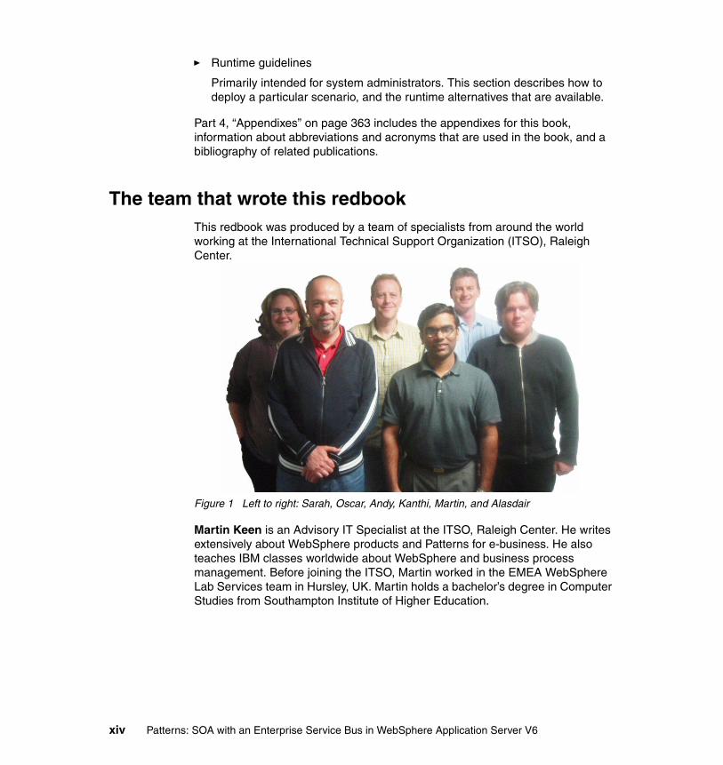
The team that wrote this redbookThis redbook was produced by a team of specialists from around the world working at the International Technical Support Organization (ITSO), Raleigh Center.
Figure 1 Left to right: Sarah, Oscar, Andy, Kanthi, Martin, and Alasdair
Martin Keen is an Advisory IT Specialist at the ITSO, Raleigh Center. He writes extensively about WebSphere products and Patterns for e-business. He also teaches IBM classes worldwide about WebSphere and business process management. Before joining the ITSO, Martin worked in the EMEA WebSphere Lab Services team in Hursley, UK. Martin holds a bachelor’s degree in Computer Studies from Southampton Institute of Higher Education.
xiv Patterns: SOA with an Enterprise Service Bus in WebSphere Application Server V6
Oscar Adinolfi is a Certified Senior IT Architect with Global Services in Melbourne, Australia. He has 25 years of experience in the IT industry. He has a product and application software development background and has been working as an IT Architect for the last 10 years, designing and implementing solutions for large clients in the Telecommunications and Finance industries. His areas of expertise include systems integration and middleware. He has designed and developed middleware products, network management products, and applications for large clients. He holds a degree in Computer Science from Belgrano University in Argentina.
Sarah Hemmings is a Software Engineer with WebSphere Messaging and Transactions Technologies in IBM Hursley, UK. She has six years of experience in testing technologies that are related to messaging. Her areas of expertise include the WebSphere platform, particularly network deployment, and WebSphere messaging. Sarah has an Master of Science in Bioengineering from the University of Stathclyde in the UK.
Andrew Humphreys is a Senior IT Specialist in IBM Software Group Services in Hursley, UK. He has 10 years of experience in IT. He is a specialist on WebSphere Business Integration products and has extensive experience in architecting ESB-style solutions. His customer facing work has lead to an understanding of the problems customers face and the requirements that they have for implementing ESBs. He holds a Bachelor of Science in Economics from City University, London, and a Master of Science in Information Systems from the University of Huddersfield. He is also a Chartered IT professional member of the British Computer Society.
Hanumanth Kanthi is a Senior IT Specialist with IBM Software Services for WebSphere, part of the IBM Software Group. Kanthi’s diverse roles include providing consulting services, education, and mentoring on J2EE technologies, specifically WebSphere Application Server, to federal and commercial clients. He holds a Master of Computer Science from Victoria University of Technology, Melbourne, Australia.
Alasdair Nottingham is a Software Engineer with the IBM WebSphere Messaging and Transactions Technologies group based in the UK. He has three years of experience in the fields of J2EE, messaging, and Web services technologies, specifically with WebSphere Application Server and WebSphere MQ. He has a Bachelor of Science degree in Computer Science from University of Southampton.
Preface xv

Thanks to the following people for their contributions to this project:
Jonathan Adams and Paul VerschuerenPatterns for e-business leadership and architecture, IBM UK
Carla Sadtler, Linda RobinsonITSO, Raleigh Center
Phil AdamsWebSphere Application Server Web services development, Austin, USA
Jonathan BondService integration bus, Web services development, Hursley, UK
David CurrieIBM Software Services for WebSphere, Hursley, UK
Peter LambrosSenior Technical Staff Member, ESB mediation and integration, Hursley, UK
Craig HurstTechnology Architect, Mincom
M. R. WokSenior Provisioning Consultant, Research Triangle Park, USA
Become a published authorJoin us for a two- to six-week residency program! Help write an IBM Redbook dealing with specific products or solutions, while getting hands-on experience with leading-edge technologies. You'll team with IBM technical professionals, Business Partners, or customers.
Your efforts will help increase product acceptance and customer satisfaction. As a bonus, you'll develop a network of contacts in IBM development labs, and increase your productivity and marketability.
Find out more about the residency program, browse the residency index, and apply online at:
ibm.com/redbooks/residencies.html
xvi Patterns: SOA with an Enterprise Service Bus in WebSphere Application Server V6

Comments welcomeYour comments are important to us!
We want our Redbooks to be as helpful as possible. Send us your comments about this or other Redbooks in one of the following ways:
� Use the online Contact us review redbook form found at:
ibm.com/redbooks
� Send your comments in an email to:
� Mail your comments to:
IBM® Corporation, International Technical Support OrganizationDept. HZ8 Building 662P.O. Box 12195Research Triangle Park, NC 27709-2195
Preface xvii

xviii Patterns: SOA with an Enterprise Service Bus in WebSphere Application Server V6

Part 1 Patterns for e-business and SOA
This part of the book introduces the concepts that are used throughout the rest of the book. It contains the following chapters:
� Chapter 1, “Introduction to Patterns for e-business” on page 3
� Chapter 2, “SOA and the Enterprise Service Bus” on page 19
� Chapter 3, “Application Integration and Extended Enterprise patterns” on page 45
� Chapter 4, “Product descriptions and ESB capabilities” on page 71
� Chapter 5, “SOA runtime patterns and Product mappings” on page 95
Part 1
© Copyright IBM Corp. 2005. All rights reserved. 1

2 Patterns: SOA with an Enterprise Service Bus in WebSphere Application Server V6
Chapter 1. Introduction to Patterns for e-business
The role of the IT architect is to evaluate business problems and build solutions to solve them. The architect begins by gathering input on the problem, developing an outline of the desired solution, and considering any special requirements that need to be factored into that solution. The architect then takes this input and designs the solution, which can include one or more computer applications that address the business problems by supplying the necessary business functions.
To improve the process over time, we need to capture and reuse the experience of the IT architects in such a way that future engagements can be made simpler and faster. We do this by capturing knowledge gained from each engagement and using it to build a repository of assets. IT architects can then build future solutions based on these proven assets. This reuse saves time, money, and effort and helps ensure delivery of a solid, properly architected solution.
The IBM Patterns for e-business help facilitate this reuse of assets. Their purpose is to capture and publish e-business artifacts that have been used, tested, and proven to be successful. The information captured by them is assumed to fit the majority, or 80/20, situation. The IBM Patterns for e-business are further augmented with guidelines and related links for their better use.
1
© Copyright IBM Corp. 2005. All rights reserved. 3

1.1 The Patterns for e-business layered asset modelThe Patterns for e-business approach enables architects to implement successful e-business solutions through the reuse of components and solution elements from proven successful experiences. The Patterns approach is based on a set of layered assets that can be exploited by any existing development methodology. These layered assets are structured in a way that each level of detail builds on the last and include:
� Business patterns that identify the interaction between users, businesses, and data.
� Integration patterns that tie multiple Business patterns together when a solution cannot be provided based on a single Business pattern.
� Composite patterns that represent commonly occurring combinations of Business patterns and Integration patterns.
� Application patterns that provide a conceptual layout that describe how the application components and data within a Business pattern or Integration pattern interact.
� Runtime patterns that define the logical middleware structure that supports an Application pattern. Runtime patterns depict the major middleware nodes, their roles, and the interfaces between these nodes.
� Product mappings that identify proven and tested software implementations for each Runtime pattern.
� Best-practice guidelines for design, development, deployment, and management of e-business applications.
Figure 1-1 on page 5 shows these assets and their relationships to each other.
4 Patterns: SOA with an Enterprise Service Bus in WebSphere Application Server V6

Figure 1-1 The Patterns for e-business layered asset model
Patterns for e-business Web siteThe layers of patterns, along with their associated links and guidelines, allow the architect to start with a problem and a vision for the solution and then find a pattern that fits that vision. Then, by drilling down using the patterns process, the architect can further define the additional functional pieces that the application need to succeed. Finally, the architect can build the application using coding techniques that are outlined in the associated guidelines.
The Patterns Web site provides an easy way of navigating through the layered Patterns assets to determine the most appropriate assets for a particular engagement.
For easy reference, see the Patterns for e-business Web site at:
http://www.ibm.com/developerWorks/patterns/
Best-Practice GuidelinesApplication DesignSystems ManagementPerformanceApplication DevelopmentTechnology Choices
Customer requirements
Productmappings
Any Methodology
Runtimepatterns
Applicationpatterns
Compositepatterns
Businesspatterns
Integrationpatterns
Chapter 1. Introduction to Patterns for e-business 5

1.2 How to use the Patterns for e-businessAs described in the previous section, the Patterns for e-business have a layered structure where each layer builds detail on the last. At the highest layer are Business patterns. These describe the entities involved in the e-business solution.
Composite patterns appear in the hierarchy shown in Figure 1-1 on page 5 above the Business patterns. However, Composite patterns are made up of a number of individual Business patterns and at least one Integration pattern. This section discusses how to use the layered structure of Patterns for e-business assets.
1.2.1 Selecting a Business, Integration, or Composite pattern, or a Custom design
When faced with the challenge of designing a solution for a business problem, the first step is to get a high-level view of the goals that you are trying to achieve. You need to describe a proposed business scenario and match each element to an appropriate IBM Pattern for e-business. You might find, for example, that the total solution requires multiple Business and Integration patterns or that it fits into a Composite pattern or Custom design.
For example, suppose an insurance company wants to reduce the amount of time and money spent on call centers that handle client inquiries. By allowing customers to view their policy information and request changes online, the company can cut back significantly on the resources that are spent handling this type of request by phone. The objective allows policy holders to view policy information that is stored in existing databases.
The Self-Service business pattern fits this scenario perfectly. You can use it in situations where users need direct access to business applications and data. The following sections discuss the available Business patterns.
6 Patterns: SOA with an Enterprise Service Bus in WebSphere Application Server V6
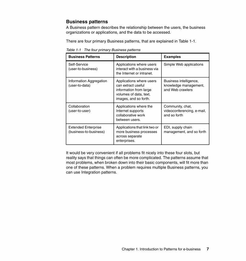
Business patternsA Business pattern describes the relationship between the users, the business organizations or applications, and the data to be accessed.
There are four primary Business patterns, that are explained in Table 1-1.
Table 1-1 The four primary Business patterns
It would be very convenient if all problems fit nicely into these four slots, but reality says that things can often be more complicated. The patterns assume that most problems, when broken down into their basic components, will fit more than one of these patterns. When a problem requires multiple Business patterns, you can use Integration patterns.
Business Patterns Description Examples
Self-Service (user-to-business)
Applications where users interact with a business via the Internet or intranet.
Simple Web applications
Information Aggregation (user-to-data)
Applications where users can extract useful information from large volumes of data, text, images, and so forth.
Business intelligence, knowledge management, and Web crawlers
Collaboration(user-to-user)
Applications where the Internet supports collaborative work between users.
Community, chat, videoconferencing, e-mail, and so forth
Extended Enterprise (business-to-business)
Applications that link two or more business processes across separate enterprises.
EDI, supply chain management, and so forth
Chapter 1. Introduction to Patterns for e-business 7
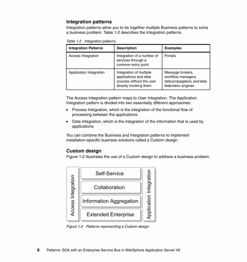
Integration patternsIntegration patterns allow you to tie together multiple Business patterns to solve a business problem. Table 1-2 describes the Integration patterns.
Table 1-2 Integration patterns
The Access Integration pattern maps to User Integration. The Application Integration pattern is divided into two essentially different approaches:
� Process Integration, which is the integration of the functional flow of processing between the applications.
� Data Integration, which is the integration of the information that is used by applications.
You can combine the Business and Integration patterns to implement installation-specific business solutions called a Custom design.
Custom designFigure 1-2 illustrates the use of a Custom design to address a business problem.
Figure 1-2 Patterns representing a Custom design
Integration Patterns Description Examples
Access Integration Integration of a number of services through a common entry point
Portals
Application Integration Integration of multiple applications and data sources without the user directly invoking them
Message brokers, workflow managers,data propagators, and data federation engines
Acc
ess
Inte
grat
ion Self-Service
Collaboration
Information Aggregation
Extended Enterprise App
licat
ion
Inte
grat
ion
8 Patterns: SOA with an Enterprise Service Bus in WebSphere Application Server V6

If you do not use any of the Business or Integration patterns in a Custom design, you can show the unused patterns as lighter blocks than those patterns that you do use. For example, Figure 1-3 shows a Custom design that does not have a Collaboration or an Extended Enterprise business pattern for a business problem.
Figure 1-3 Custom design showing unused patterns
If a Custom design recurs many times across domains that have similar business problems, then it can also be a Composite pattern. For example, the Custom design in Figure 1-3 can also describe a Sell-Side Hub Composite pattern.
Composite patternsSeveral common uses of Business and Integration patterns have been identified and formalized into Composite patterns. Table 1-3 on page 10 shows the identified Composite patterns.
Acc
ess
Inte
grat
ion Self-Service
Collaboration
Information Aggregation
Extended Enterprise App
licat
ion
Inte
grat
ion
Chapter 1. Introduction to Patterns for e-business 9

Table 1-3 Composite patterns
Composite Patterns Description Examples
Electronic Commerce User-to-online-buying • www.macys.com• www.amazon.com
Portal Typically designed to aggregate multiple information sources and applications to provide uniform, seamless, and personalized access for its users.
• Enterprise intranet portal providing self-service functions such as payroll, benefits, and travel expenses.
• Collaboration providers who provide services such as e-mail or instant messaging.
Account Access Provide customers with around-the-clock account access to their account information.
• Online brokerage trading applications.
• Telephone company account manager functions.
• Bank, credit card and insurance company online applications.
Trading Exchange Allows buyers and sellers to trade goods and services on a public site.
• Buyer's side - interaction between buyer's procurement system and commerce functions of e-Marketplace.
• Seller's side - interaction between the procurement functions of the e-Marketplace and its suppliers.
Sell-Side Hub(supplier)
The seller owns the e-Marketplace and uses it as a vehicle to sell goods and services on the Web.
www.carmax.com (car purchase)
Buy-Side Hub(purchaser)
The buyer of the goods owns the e-Marketplace and uses it as a vehicle to leverage the buying or procurement budget in soliciting the best deals for goods and services from prospective sellers across the Web.
www.wre.org(WorldWide Retail Exchange)
10 Patterns: SOA with an Enterprise Service Bus in WebSphere Application Server V6
The makeup of these patterns is variable in that there will be basic patterns present for each type. However, you can extend the Composite to meet additional criteria. For more information about Composite patterns, refer to Patterns for e-business: A Strategy for Reuse by Jonathan Adams, Srinivas Koushik, Guru Vasudeva, and George Galambos.
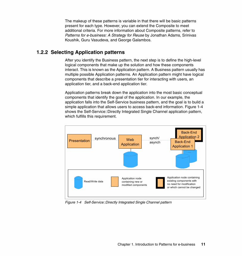
1.2.2 Selecting Application patternsAfter you identify the Business pattern, the next step is to define the high-level logical components that make up the solution and how these components interact. This is known as the Application pattern. A Business pattern usually has multiple possible Application patterns. An Application pattern might have logical components that describe a presentation tier for interacting with users, an application tier, and a back-end application tier.
Application patterns break down the application into the most basic conceptual components that identify the goal of the application. In our example, the application falls into the Self-Service business pattern, and the goal is to build a simple application that allows users to access back-end information. Figure 1-4 shows the Self-Service::Directly Integrated Single Channel application pattern, which fulfills this requirement.
Figure 1-4 Self-Service::Directly Integrated Single Channel pattern
Presentation synchronous WebApplication
synch/asynch Back-End
Application 1
Application node containing new or modified components
Application node containing existing components with no need for modification or which cannot be changed
Read/Write data
Back-EndApplication 2
Chapter 1. Introduction to Patterns for e-business 11
This Application pattern consists of a presentation tier that handles the request and response to the user. The application tier represents the component that handles access to the back-end applications and data. The multiple application boxes on the right represent the back-end applications that contain the business data. The type of communication is specified as synchronous (one request/one response, then next request/response) or asynchronous (multiple requests and responses intermixed).
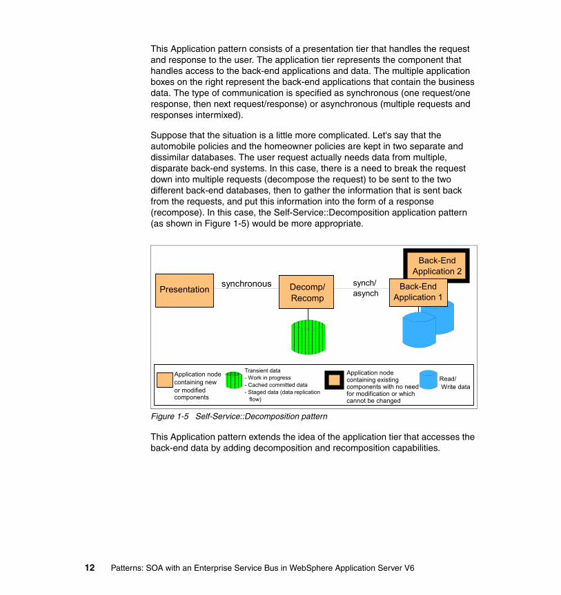
Suppose that the situation is a little more complicated. Let's say that the automobile policies and the homeowner policies are kept in two separate and dissimilar databases. The user request actually needs data from multiple, disparate back-end systems. In this case, there is a need to break the request down into multiple requests (decompose the request) to be sent to the two different back-end databases, then to gather the information that is sent back from the requests, and put this information into the form of a response (recompose). In this case, the Self-Service::Decomposition application pattern (as shown in Figure 1-5) would be more appropriate.
Figure 1-5 Self-Service::Decomposition pattern
This Application pattern extends the idea of the application tier that accesses the back-end data by adding decomposition and recomposition capabilities.
Presentation synchronous Decomp/Recomp
synch/asynch
Application node containing new or modified components
Application node containing existing components with no need for modification or which cannot be changed
Read/ Write data
Transient data- Work in progress- Cached committed data- Staged data (data replication flow)
Back-EndApplication 1
Back-EndApplication 2
12 Patterns: SOA with an Enterprise Service Bus in WebSphere Application Server V6
1.2.3 Review Runtime patternsYou can refine the Application pattern further with more explicit functions. Each function is associated with a runtime node. In reality, these functions, or nodes, can exist on separate physical machines or can coexist on the same machine. In the Runtime pattern the physical location of the function is not relevant. The focus is on the logical nodes that are required and their placement in the overall network structure.
As an example, let's say that our client has determined that their solution fits into the Self-Service business pattern and that the Directly Integrated Single Channel pattern is the most descriptive of the situation. The next step is to determine the Runtime pattern that is most appropriate for the situation.
They know that they will have users on the Internet what are accessing their business data, Therefore, they require a measure of security. You can implement security at various layers of the application, but the first line of defense is almost always one or more firewalls that define who and what can cross the physical network boundaries into the company network.
The client also needs to determine the functional nodes that are required to implement the application and security measures. Figure 1-6 on page 14 shows the Runtime pattern that is one option.
Chapter 1. Introduction to Patterns for e-business 13
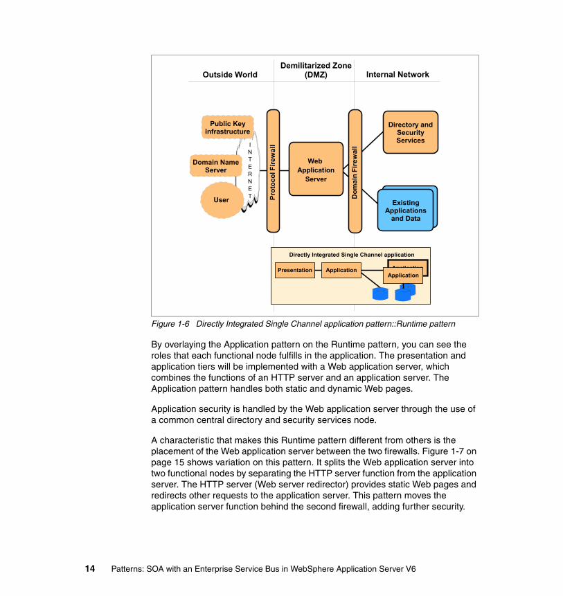
Figure 1-6 Directly Integrated Single Channel application pattern::Runtime pattern
By overlaying the Application pattern on the Runtime pattern, you can see the roles that each functional node fulfills in the application. The presentation and application tiers will be implemented with a Web application server, which combines the functions of an HTTP server and an application server. The Application pattern handles both static and dynamic Web pages.
Application security is handled by the Web application server through the use of a common central directory and security services node.
A characteristic that makes this Runtime pattern different from others is the placement of the Web application server between the two firewalls. Figure 1-7 on page 15 shows variation on this pattern. It splits the Web application server into two functional nodes by separating the HTTP server function from the application server. The HTTP server (Web server redirector) provides static Web pages and redirects other requests to the application server. This pattern moves the application server function behind the second firewall, adding further security.
Internal NetworkDemilitarized Zone
(DMZ)Outside World
Prot
ocol
Fire
wal
l
Existing Applications
and Data
Dom
ain
Fire
wal
lINTERNET
Public Key Infrastructure
User
Web Application
Server
Domain Name Server
Directory and SecurityServices
Presentation Application Application
Directly Integrated Single Channel application
Application
Existing Applications
and Data
14 Patterns: SOA with an Enterprise Service Bus in WebSphere Application Server V6

Figure 1-7 Directly Integrated Single Channel application pattern::Runtime pattern
These are just two examples of the possible Runtime patterns that are available. Each Application pattern will have one or more Runtime patterns defined. You can modify these Runtime patterns to suit the client’s needs. For example, the client might want to add a load-balancing function and multiple application servers.
1.2.4 Reviewing Product mappingsThe last step in defining the network structure for the application is to correlate real products with one or more runtime nodes. The Patterns Web site shows each Runtime pattern with products that have been tested in that capacity. The Product mappings are oriented toward a particular platform. However, it is more likely that the client will have a variety of platforms involved in the network. In this case, you can mix and match product mappings.
Internal NetworkDemilitarized Zone
(DMZ)Outside World
Prot
ocol
Fire
wal
l
Dom
ain
Fire
wal
lINTERNET
Public Key Infrastructure
User
WebServer
Redirector
Domain Name Server
Presentation Application Application
Directly Integrated Single Channel application
Application
Existing Applications
and Data
ApplicationServer
Directory and SecurityServices
Existing Applications
and Data
Chapter 1. Introduction to Patterns for e-business 15

For example, you could implement the runtime variation in Figure 1-7 on page 15 using the product set that is depicted in Figure 1-8.
Figure 1-8 Directly Integrated Single Channel application pattern: Windows® 2000 Product mapping
1.2.5 Reviewing guidelines and related linksThe Application patterns, Runtime patterns, and Product mappings can guide you in defining the application requirements and the network layout. The actual application development has not been addressed yet. The Patterns Web site provides guidelines for each Application pattern, including techniques for developing, implementing, and managing the application, based on the following guidelines:
� Design guidelines provide tips and techniques for designing the applications.
� Development guidelines take you through the process of building the application, from the requirements phase all the way through the testing and rollout phases.
� System management guidelines address the day-to-day operational concerns, including security, backup and recovery, application management, and so forth.
� Performance guidelines give information about how to improve the application and system performance.
Internal networkDemilitarized zone O
utsi
de w
orld
Prot
ocol
Fire
wal
l
Dom
ain
Fire
wal
lWeb ServerRedirector
Windows 2000 + SP3IBM WebSphere Application Server V5.0 HTTP Plug-inIBM HTTP Server 1.3.26
Directory and SecurityServices
LDAP
Application Server
Windows 2000 + SP3IBM SecureWay Directory V3.2.1IBM HTTP Server 1.3.19.1IBM GSKit 5.0.3IBM DB2 UDB EE V7.2 + FP5
Database
Existing Applications
and Data
Windows 2000 + SP3IBM DB2 UDB ESE V8.1
JMS Option:Windows 2000 + SP3IBM WebSphere Application Server V5.0IBM WebSphere MQ 5.3Message-driven bean application
Web Services Option:Windows 2000 + SP3IBM WebSphere Application Server V5.0IBM HTTP Server 1.3.26IBM DB2 UDB ESE 8.1Web service EJB application
JCA Option:z/OS Release 1.3IBM CICS Transaction Gateway V5.0IBM CICS Transaction Server V2.2CICS C-application
Windows 2000 + SP3IBM WebSphere Application Server V5.0
JMS Option add:IBM WebSphere MQ 5.3
16 Patterns: SOA with an Enterprise Service Bus in WebSphere Application Server V6

1.3 SummaryThe IBM Patterns for e-business are a collected set of proven architectures. You can use this repository of assets to facilitate the development of Web-based applications. Patterns for e-business help you understand and analyze complex business problems and break them down into smaller, more manageable functions that you can then implement.
Chapter 1. Introduction to Patterns for e-business 17

18 Patterns: SOA with an Enterprise Service Bus in WebSphere Application Server V6

Chapter 2. SOA and the Enterprise Service Bus
This chapter provides an introduction to service-oriented architecture (SOA). It also defines the Enterprise Service Bus (ESB) and describes the ESB in terms of the role that it plays in the implementation of an SOA.
2
© Copyright IBM Corp. 2005. All rights reserved. 19

2.1 Overview of SOASOA defines integration architectures based on the concept of a service. Applications collaborate by invoking each others services, and services are composed into larger sequences to implement business processes.
Drivers for SOAThe main driver for SOA is to define an architectural approach that assists in the flexible integration of IT systems. Organizations spend a considerable amount of time and money trying to achieve rapid, flexible integration of IT systems across all elements of the business cycle. The drivers behind this objective include:
� Increasing the speed at which businesses can implement new products and processes, can change existing ones, or can recombine them in new ways
� Reducing implementation and ownership costs of IT systems and the integration between them
� Enabling flexible pricing models by outsourcing more fine-grained elements of the business than were previously possible or by moving from fixed to variable pricing, based on transaction volumes
� Simplifying the integration work that is required by mergers and acquisitions
� Achieving better IT use and return on investment
� Achieving implementation of business processes at a level that is independent from the applications and platforms that are used to support the processes
SOA prescribes a set of design principles and an architectural approach to achieve this rapid flexible integration.
Definition of SOASOA is an integration architecture approach that is based on the concept of a service. The business and infrastructure functions that are required to build distributed systems are provided as services that collectively, or individually, deliver application functionality to either user applications or other services.
SOA specifies that within any given architecture, there should be a consistent mechanism by which services communicate. That mechanism should be loosely coupled and should support the use of explicit interfaces.
SOA brings the benefits of loose coupling and encapsulation to integration at an enterprise level. It applies successful concepts that are proven by Object-Oriented development, Component-Based Design, and Enterprise
20 Patterns: SOA with an Enterprise Service Bus in WebSphere Application Server V6

Application Integration technology to an architectural approach for IT system integration.
Services are the building blocks to SOA. They provide the function out of which you can build distributed systems. Services can be invoked independently by either external or internal service consumers to process simple functions or can be chained together to form more complex functionality and to quickly devise new functionality.
By adopting an SOA approach and implementing it using supporting technologies, you can build flexible systems that implement changing business processes quickly and make extensive use of reusable components.
Figure 2-1 illustrates a company that wants to implement a new business process to support customers who are placing orders from a Web site.
Figure 2-1 A service-oriented approach to building systems
The company already has existing retail, warehouse, and billing systems. It would like to build the new process by reusing the functionality that is provided by those systems rather than having to write new applications or new interfaces to the existing systems.
If the company has already adopted an SOA approach, it will have defined the interfaces to its existing systems in terms of the functions or services that they can offer to support the building of business processes. The defined interfaces makes building the new Web front end to the system very simple. All the company needs to do is to develop an application that makes calls to the services to complete the new business process.
BusinessProcess
BillCustomer
DefinedServices
ReceiveOrder
Service
CustomerBilling
Service
FulfillOrder
Service
RestockService
ITSystems
WebApplication
RetailSystem
CRMWarehouse
System
ReceiveOrder
FulfillOrder Restock
Chapter 2. SOA and the Enterprise Service Bus 21
The SOA approach means companies are able to build horizontal business processes that integrate systems, people, and processes from across the enterprise quickly and easily in response to changing business needs.
As shown in Figure 2-1 on page 21, the company can use existing systems to implement new business processes that extend the use of the system beyond the processes that they were originally written to support. The company can maximize the previous IT investment by reusing existing IT systems without having to invest extensively to build new interfaces to the systems.
e-business on demand™ and SOASOA plays a crucial role for companies who are trying to implement the IBM vision of e-business on demand. The IBM on demand vision is to enable customers to succeed in an environment with an unprecedented rate of change.
In an on demand world, companies need to respond quickly and easily to any client requirement, opportunity, or threat. To succeed in this environment, a company must be able to implement new processes quickly while leveraging existing investment. From a business perspective, e-business on demand provides a way for companies to realign their business and technology environment to match the need for reusable business functionality. For a fuller discussion about the e-business on demand vision from IBM and how it relates to SOA refer to Chapter 2 of Patterns: Implementing an SOA Using an Enterprise Service Bus, SG24-6346.
SOA can be an architectural enabler for e-business on demand. SOA touches on the four key elements of e-business on demand, namely:
� Open standards
SOA provides a standard method of invoking services (business logic and functionality) for disparate organizations to share across network boundaries.
� Integration
– SOA provides interfaces to wrap service endpoints for a system-independent architecture that promotes cross-industry communication and integrates end-to-end solutions both in and out of the enterprise.
– SOAs provide dynamic service discovery and binding, which means that service integration can occur on demand.
– SOA provides an approach to integrate heterogeneous technologies inside an enterprise.
22 Patterns: SOA with an Enterprise Service Bus in WebSphere Application Server V6

� Virtualization
A key principle of SOA is that consumers who invoke the services are oblivious to implementation details, including location, platform, and if appropriate to the business scenario, even the identity of the service provider.
� Automation
Technologies, such as grid technologies, can apply SOA principles to implementing infrastructure services that provide an evolutionary approach to increased automation.
2.1.1 Definition of a serviceSOA is an architectural approach to defining integration architectures that are based on services. Now, it is important to define what is meant by a service in this context in order to fully describe SOA and to understand what you can achieve by using it.
A service can be defined as any discrete function that can be offered to an external consumer. The function can be an individual business function or a collection of functions that together form a process.
There are many additional aspects to a service that must also be considered in the definition of a service within an SOA. The most commonly agreed-on aspects of a service are that:
� Services encapsulate a reusable business function
� Services are defined by explicit, implementation-independent interfaces
� Services are invoked through communication protocols that stress location transparency and interoperability
This book uses these commonly agreed aspects to define SOA.
Reusable functionAny business function can be a service. SOA often focusses on business functions. However, many technical functions can also be exposed as services. When defining function, there are several levels of granularity that you can consider. Many descriptions of SOA refer to the use of large-grained services; however, some powerful counter-examples of successful, reusable, fine-grained services exist. For example, getBalance is a very useful service but is not large-grained.
Chapter 2. SOA and the Enterprise Service Bus 23

More realistically, there are many useful levels of service granularity in most SOAs. For example, all of the following are services that each have a different granularity:
� Technical Function Services (for example auditEvent, checkUserPassword, and checkUserAuthorization)
� Business Function Services (for example calculateDollarValueFromYen and getStockPrice)
� Business Transaction Services (for example checkOrderAvailability and createBillingRecord)
� Business Process Services (for example openAccount, createStockOrder, reconcileAccount, and renewPolicy)
Some degree of choreography or aggregation is required between each granularity level for them to be integrated in an SOA.
A service can be any business function. In an SOA, however, it is preferable that the function is genuinely reusable. In an SOA, the service can be used and reused by one or more systems that participate in the architecture. For example, while the reuse of a Java™ logging API could be described as design time (when a decision is made to reuse an available package and bind it into application code), the intention of SOA is to achieve the reuse of services at:
� Runtime
Each service is deployed in one place and one place only and is invoked remotely by anything that must use it. The advantage of this approach is that changes to the service (for example, to the calculation algorithm or the reference data it depends on) need only be applied in a single place.
� Deployment time
Each service is built once but redeployed locally to each system or set of systems that must use it. The advantage of this approach is increased flexibility to achieve performance targets or to customize the service (perhaps according to geography).
The service definition should encapsulate the function well enough to make the reuse possible. The encapsulation of functions as services and their definition using interfaces enables the substitution of one service implementation for another. For example, the same service might be provided by multiple providers (such as a car insurance quote service, which might be provided by multiple insurance companies) and individual service consumers might be routed to individual service providers through some intermediary agent.
24 Patterns: SOA with an Enterprise Service Bus in WebSphere Application Server V6
Granularity in SOAThe concept of granularity is used to mean several things in SOA, each of which is actually quite separate:
� Level of abstraction of services
Is the service a high-level business process, a lower-level business sub-process or activity, or a very low-level technical function?
� Granularity of service operations
How many operations are in the service? One, a few, or many? What factors determine which operations are collected together in a service?
� Granularity of service parameters
How are the input and output data of service operations expressed? SOA prefers a small number of large, structured parameters rather than a small number of primitive types.
Explicit implementation independent interfacesThe use of explicit interfaces to define and encapsulate service function is of particular importance in making services genuinely reusable. The interface should encapsulate only those aspects of process and behavior that are used in the interaction between the service consumer and the service provider. An explicit interface definition, or contract, is used to bind a service consumer and a service provider. It should specify only the mutual behavior that is required for the interaction and nothing about the implementation of the consumer or the provider.
By explicitly defining the interaction in this way, those aspects of either system (for example, the platform on which they are based) that are not part of the interaction are free to change without affecting the other system. This flexibility allows either system to change implementation or identity freely.
Chapter 2. SOA and the Enterprise Service Bus 25

Figure 2-2 illustrates the use of explicit interfaces to define and encapsulate services function.
Figure 2-2 Service implementation in SOA
Communication protocols that stress location transparencyCompanies have a variety of choices when deciding how to connect applications. HTTP, HTTPS, JMS, CORBA, and SMTP are all examples of protocols that can be used to connect applications. There are also many middleware products, for example WebSphere MQ, that provide application-to-application connectivity. Typically, even within a single company, a variety of techniques, products, and protocols are used to address different integration requirements. This variety of techniques can create problems when trying to extend the integration to connect to applications that do not use the same protocols.
SOA does not specify that any specific protocol should be used to provide access to a service. A key principle in SOA is that a service is not defined by the communication protocol that it uses but instead is protocol-independent so that different protocols can be used to access the same service.
SYSTEM 1
Internal codeand process
Service definition of reusablebusiness function
SYSTEM 2
Internal codeand process
Code definition of reusablebusiness function
INTERFACE
26 Patterns: SOA with an Enterprise Service Bus in WebSphere Application Server V6

Ideally, a service should be defined only once, through a service interface, and should have many implementations with different access protocols. This definition increases the reusability of any service definition. Also, services should be invoked, published, and discovered in a way that is abstracted away from the actual implementation using a single, standards-based form of interface. Thus, there is a complimentary nature between SOA and Web services.
2.1.2 Web services and SOAThis section discusses the advantages of using Web services to implement SOA. (You can find a description of Web services in 7.1, “Web services” on page 132.)
An appropriate combination of both Web services technology and the SOA approach addresses many of the issues of building an SOA-enabled environment. That is not to say that Web services and SOA are intrinsically linked, because they can be implemented separately. In fact, many significant SOAs are proprietary or customized implementations that based on reliable messaging and Enterprise Application Integration middleware (for example WebSphere MQ and WebSphere Business Integration Message Broker) and do not use Web services technologies. Also, most existing Web services implementations consist of point-to-point integrations that address a limited set of business functions between a defined set of cooperating partners.
However, existing SOA implementations have demonstrated the benefits of SOA, usually within a single enterprise, and the existing uses of Web services have demonstrated the benefits of the Web services technologies in integrating heterogeneous systems both within and among organizations. A custom approach gives an organization the problem of supporting heterogenity; a proprietary approach gives it to one IT vendor. Adopting a standards-based approach, such as Web services, offers a solution to these issues.
There are logical links between Web services and SOA that suggest that they are complimentary:
� Web services provide an open-standard and machine-readable model for creating explicit, implementation-independent descriptions of service interfaces.
� Web services provide communication mechanisms that are location-transparent and interoperable.
� Web services are evolving, through Business Process Execution Language for Web Services (BPEL4WS), document-style SOAP, Web services Definition Language (WSDL), and emerging technologies (such as WS-ResourceFramework), to support the technical implementation of well-designed services that encapsulate and model reusable function in a flexible manner.
Chapter 2. SOA and the Enterprise Service Bus 27
Working together, Web services and SOA have the potential to address many of the technical issues that are faced when trying to build an on demand environment. For example:
� A multitude of technologies and platforms are used to support business systems, all which need to be integrated into an SOA.
Web services are a set of open-standard technologies that are supported by most of the IT industry and by the Web Services Interoperability (WS-I) organization. Their basis is in simple, text-based, and open-standard technologies such as XML and HTTP, and the fact that they can leverage more sophisticated interoperable technologies, such as asynchronous messaging, means that they can be supported in the vast majority of IT environments. Increasing ubiquity and maturity of product support means that implementing and integrating Web services will become increasingly efficient.
� Business process models are a mixture of people practices, application code, and interactions among people and systems or systems and systems.
Although SOA is an approach to architecture that must be applied to systems and integrations, it specifies a set of principles and techniques that encourage the encapsulation and modeling of reusable business functions and processes. Recent and emerging trends in Web services, such as BPEL4WS and WS-ResourceFramework, will increasingly support the modeling concepts of SOA. In this way, process management can be centralized rather than being part of multiple applications.
� Changes to one system tend to imply ripples of change at many levels to many other systems.
SOA specifies several principles and techniques for achieving the encapsulation of service function and the loose coupling of service interactions. These techniques minimize the cases where change to one part of a system implies changes to other parts.
� In a true SOA the integration solution should be able to invoke services offered outside the enterprise by partners and should be extendable to support future partners.
The Web services technologies have proven effective in many business-to-business integrations, where their open standards basis and use of simple, existing infrastructure and protocols makes them particularly effective. Recent and emerging standards, such as WS-Security, add to the sophistication of interaction that is possible when using Web services in this model.
28 Patterns: SOA with an Enterprise Service Bus in WebSphere Application Server V6

� There is no single data, business, or process model across, or beyond, the enterprise.
Although they are not a magic solution to this issue, the SOA principles define an approach that enables organizations to progressively expose functions across their business as services and to combine those services into processes. SOA encourages processes to be centrally managed and explicitly defined and modelled. Over time, businesses that take this approach will improve the consistency of their business and process models and will leverage the use of business process modeling and automation technology to more explicitly control and monitor their execution of processes.
� Not all integration technologies work as well across a wide area network or the Internet as they do across a local area network.
The Web services technologies support multiple protocols, so they can use the simplest protocols available, such as HTTP when that offers an advantage, or leverage other infrastructures such as WebSphere MQ when that is more appropriate.
For these reasons, SOA and Web services are often seen together as the future direction for system integration. However, note that in Web services that WSDL does not specify all that is implied by what SOA means by an interface. It does not specify service levels, and it does not specify pre- and post- conditions. BPEL4WS can do something equivalent but only for a subset of requirements, for example in process models. All SOA projects have to make up this shortfall in standard project documentation, custom service descriptions, or some other means.
2.1.3 The advantages of SOAUse of SOA has the following advantages to achieving loosely coupled flexible integration of IT systems:
� Heterogeneous systems can be integrated because of implementation-independent interfaces that describe services.
� The description of service interfaces in terms of a common business process and data model minimizes any interdependencies to only what matters to the business.
� The encapsulation of services with standard interfaces enables reuse and flexibility. Each service is defined and implemented in only one place, so changing it is straightforward.
There are benefits in development and maintenance costs, but flexibility is the primary goal in SOA.
Chapter 2. SOA and the Enterprise Service Bus 29

With clearly defined interfaces between all business systems, it is possible to model and change the business process that are captured by them at a level above individual systems. Thus, SOA is an enabler for process modelling and automation at an enterprise scale.
Currently, and for some time to come, many of the technologies that are used to implement SOAs are evolving rather than mature and stable. Therefore, individual SOA solutions must make carefully balanced decisions among customized, proprietary, and open-standard technologies, which characteristics and components of SOA to implement, and which areas of business function and process to which to apply them. Of course, you should balance these decisions between business benefits, technology maturity, and implementation or maintenance efforts.
2.1.4 SOA summarySOA and Web services enable new opportunities for more flexible, rapid, and widespread integration in a model that is consistent with the exposure of business function as services. SOA and Web services offer the choreography of those services into processes that can be modeled, executed, and monitored with features such as:
� SOA defines concepts and general techniques for designing, encapsulating, and invoking reusable business functions through loosely bound service interactions. Most of the techniques have been proven individually in previous technologies or design styles. SOA unites them in an approach that is intended to bring encapsulation and reuse to the enterprise level.
� Web services provide an emerging set of open-standard technologies that can be combined with proven existing technologies to implement the concepts and techniques of SOA.
� Industry support for Web services standards, interoperability among different implementations of Web services, and the infrastructure technology that is required to support an SOA give technology customers increasingly mature and sophisticated technologies that are suitable for SOA implementation.
These techniques and technologies give you the tools that are required to implement flexible SOAs and to evolve toward an on demand business model. However, SOA is an architectural approach, not a technology or a product. In order to implement an SOA, you must have the infrastructure to support the architecture, such as an Enterprise Service Bus.
30 Patterns: SOA with an Enterprise Service Bus in WebSphere Application Server V6

2.2 Overview of Enterprise Service BusSuccessfully implementing an SOA requires applications and infrastructure that can support the SOA principles. Applications can be enabled by creating service interfaces to existing or new functions that are hosted by the applications. The service interfaces should be accessed using an infrastructure that can route and transport service requests to the correct service provider. As organizations expose more and more functions as services, it is vitally important that this infrastructure should support the management of SOA on an enterprise scale.
2.2.1 SOA infrastructure requirementsThe Enterprise Service Bus (ESB) is emerging as a middleware infrastructure component that supports the implementation of SOA within an enterprise. The need for an ESB can be seen by considering how it supports the concepts of SOA implementation by:
� Decoupling the consumer’s view of a service from the actual implementation of the service
� Decoupling technical aspects of service interactions
� Integrating and managing services in the enterprise
Decoupling the consumer’s view of a service from the actual implementation greatly increases the flexibility of the architecture. It allows the substitution of one service provider for another (for example, because another provider offers the same services for lower cost or with higher standards) without the consumer being aware of the change or without the need to alter the architecture to support the substitution.
This decoupling is better achieved by having the consumers and providers interact via an intermediary. Intermediaries publish services to consumers. The consumer binds to the intermediary to access the service, with no direct coupling to the actual provider of the service. The intermediary maps the request to the location of the real service implementation.
In an SOA, services are described as being loosely coupled. However, at implementation time, there is no way to loosely couple a service or any other interaction between systems. The systems must have some common understanding to conduct an interaction. Instead, to achieve the benefits of loose coupling, consideration should be given to how to couple or decouple various aspects of service interactions, such as the platform and language in which services are implemented, the communication protocols used to invoke services, the data formats used to exchange input and output data between service consumers and providers.
Chapter 2. SOA and the Enterprise Service Bus 31

Further decoupling can be achieved by handling some of the technical aspects of transactions outside of applications. This could apply aspects of interactions such as:
� How service interactions are secured
� How the integrity of business transactions and data are maintained (for example, through reliable messaging, the use of transaction monitors, or compensation techniques)
� How the invocation of alternative service providers is handled in the event that the default provider is unavailable
These aspects imply a need for middleware to support an SOA implementation. Some of the functions that might be provided by the middleware are:
� Map service requests from one protocol and address to another
� Transform data formats
� Support a variety of security and transactional models between service consumers and service providers and recognize that consumers and providers might support or require different models
� Aggregate or disaggregate service requests and responses
� Support communication protocols between multiple platforms with appropriate qualities of service
� Provide messaging capabilities such as message correlation and publish/subscribe, to support different messaging models such as events and asynchronous request/response
This middleware support is the role of an ESB.
2.2.2 Definition of an ESBAn ESB provides an infrastructure that removes any direct connection between service consumers and providers. Consumers connect to the bus and not the provider that actually implements the service. This type of connection further decouples the consumer from the provider. A bus also implements further value add capabilities. For example, security and delivery assurance can be implemented centrally within the bus instead of having this buried within the applications.
Integrating and managing services in the enterprise outside of the actual implementation of the services in this way helps to increase the flexibility and manageability of SOA.
32 Patterns: SOA with an Enterprise Service Bus in WebSphere Application Server V6
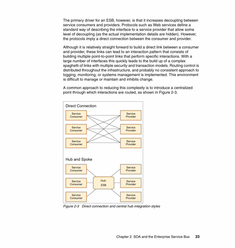
The primary driver for an ESB, however, is that it increases decoupling between service consumers and providers. Protocols such as Web services define a standard way of describing the interface to a service provider that allow some level of decoupling (as the actual implementation details are hidden). However, the protocols imply a direct connection between the consumer and provider.
Although it is relatively straight forward to build a direct link between a consumer and provider, these links can lead to an interaction pattern that consists of building multiple point-to-point links that perform specific interactions. With a large number of interfaces this quickly leads to the build up of a complex spaghetti of links with multiple security and transaction models. Routing control is distributed throughout the infrastructure, and probably no consistent approach to logging, monitoring, or systems management is implemented. This environment is difficult to manage or maintain and inhibits change.
A common approach to reducing this complexity is to introduce a centralized point through which interactions are routed, as shown in Figure 2-3.
Figure 2-3 Direct connection and central hub integration styles
Direct Connection
Hub and Spoke
Service Consumer
Service Consumer
Service Consumer
Service Provider
Service Provider
Service Provider
Service Consumer
Service Consumer
Service Consumer
Service Provider
Service Provider
Service Provider
Hub:ESB
Chapter 2. SOA and the Enterprise Service Bus 33

A hub and spoke architecture is a common approach that is used in application integration architectures. In a hub, the distribution rules are separated from applications. The applications connect to the hub and not directly to any other application. This type of connection allows a single interaction from an application to be distributed to multiple target applications without the consumer being aware that multiple providers are involved in servicing the request. This connection can reduce the proliferation of point-to-point connections.
Note that the benefit of reducing the number of connections only truly emerges if the application interfaces and connections are genuinely reusable. For example, consider the case where one application needs to send data to three other applications. If this is implemented in a hub, the sending application must define a link to the hub, and the hub must have links that are defined to the three receiving applications, giving a total of four interfaces that need to be defined. If the same scenario was implemented using multiple point-to-point links, the sending application would need to define links to each of the three receiving applications, giving a total of just three links. A hub only offers the benefit of reduced links if another application also needs to send data to the receiving applications and can make use of the same links as those that are already defined for the first application. In this scenario, the new application only needs to define a connection between itself and the hub, which can then send the data correctly formatted to the receiving applications.
Hubs can be federated together to form what is logically a single entity that provides a single point of control but is actually a collection of physically distributed components. This is commonly termed a bus. A bus provides a consistent management and administration approach to a distributed integration infrastructure.
2.2.3 Enterprise requirements for an ESBUsing a bus to implement an SOA has a number of advantages. In an SOA services should, by definition, be reusable by a number of different consumers, so that the benefits of reduced connections are achieved. In addition, the ESB:
� Supports high volumes of individual interactions.
� Supports more established integration styles, such as message-oriented and event-driven integration, to extend the reach of the SOA. The ESB should allow applications to be SOA enabled either directly or through the use of adapters.
� Support centralization of enterprise-level qualities of service and manageability requirements into the hub.
34 Patterns: SOA with an Enterprise Service Bus in WebSphere Application Server V6
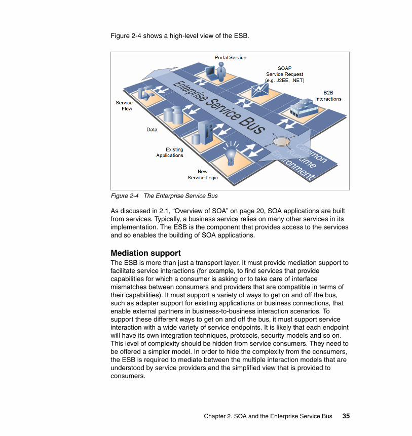
Figure 2-4 shows a high-level view of the ESB.
Figure 2-4 The Enterprise Service Bus
As discussed in 2.1, “Overview of SOA” on page 20, SOA applications are built from services. Typically, a business service relies on many other services in its implementation. The ESB is the component that provides access to the services and so enables the building of SOA applications.
Mediation supportThe ESB is more than just a transport layer. It must provide mediation support to facilitate service interactions (for example, to find services that provide capabilities for which a consumer is asking or to take care of interface mismatches between consumers and providers that are compatible in terms of their capabilities). It must support a variety of ways to get on and off the bus, such as adapter support for existing applications or business connections, that enable external partners in business-to-business interaction scenarios. To support these different ways to get on and off the bus, it must support service interaction with a wide variety of service endpoints. It is likely that each endpoint will have its own integration techniques, protocols, security models and so on. This level of complexity should be hidden from service consumers. They need to be offered a simpler model. In order to hide the complexity from the consumers, the ESB is required to mediate between the multiple interaction models that are understood by service providers and the simplified view that is provided to consumers.
Chapter 2. SOA and the Enterprise Service Bus 35
Protocol independenceAs shown in Figure 2-4 on page 35, services can be offered by a variety of sources. Without an ESB infrastructure, any service consumer that needs to invoke a service needs to connect directly to a service provider using the protocol, transport, and interaction pattern that is used by the provider. With an ESB, the infrastructure shields the consumer from the details of how to connect to the provider.
In an ESB, there is no direct connection between the consumer and provider. Consumers access the ESB to invoke services, and the ESB acts as an intermediary by passing the request to the provider using the appropriate protocol, transport, and interaction pattern for the provider. This intermediary connection enables the ESB to shield the consumer from the infrastructure details of how to connect to the provider. The ESB should support several integration mechanisms, all of which can be described as invoking services through specific addresses and protocols, even if in some cases the address is the name of a CICS® transaction and the protocol is a J2EE resource adapter integrating with the CICS Transaction Gateway. By using the ESB, the consumers are unaware of how the service is invoked on the provider.
Because the ESB removes the direct connection between service consumer and providers, an ESB enables the substitution of one service implementation by another with no effect to the consumers of that service. Thus, an ESB allows the reach of an SOA to extend to non-SOA enabled service providers. It can also be used to support migration of the non-SOA providers to using an SOA approach without impacting the consumers of the service.
Support for multiple interaction patternsTo fully support the variety of interaction patterns that are required in a comprehensive SOA (for example, request/response, publish/subscribe, and events), the ESB must support in one infrastructure the following major styles of enterprise integration:
� SOAs in which applications communicate through reusable services with well-defined, explicit interfaces. Service-oriented interactions leverage underlying messaging and event communication models.
� Message-driven architectures in which applications send messages through the ESB to receiving applications.
� Event-driven architectures in which applications generate and consume messages independently of one another.
The ESB support the enterprise integration while providing additional capabilities to mediate or transform service messages and interactions, enabling a wide variety of behaviors and supporting the various models of coupling interaction.
36 Patterns: SOA with an Enterprise Service Bus in WebSphere Application Server V6
2.2.4 Minimum ESB capabilitiesThis section discusses the minimum capabilities an ESB must have to support the requirements of an SOA enabling infrastructure component. Understanding the minimum capabilities allows you to assess the suitability of individual technologies or products for implementing an ESB by analyzing the functionality that they offer to support the minimum ESB capabilities.
In discussions on ESB, the most commonly agreed elements for defining an ESB are:
� The ESB is a logical architectural component that provides an integration infrastructure that is consistent with the principles of SOA.
� The ESB can be implemented as a distributed, heterogeneous infrastructure.
� The ESB provides the means to manage the service infrastructure and the capability to operate in a distributed, heterogeneous environment.
Table 2-1 summarizes the minimum capabilities that an ESB should have in order to provide an infrastructure consistent with these elements, and thus consistent with the benefits of SOA. The sections that follow discusses these capabilities in more detail.
Table 2-1 Minimum capabilities of an ESB
Category Capabilities Reasons
Communications • Routing• Addressing• At least one messaging style
(request/response, publish/subscribe)
• At least one transport protocol that is or can be made widely available
Provides location transparency and supports service substitution
Integration • Several integration styles or adapters
• Protocol transformation
Supports integration in heterogeneous environments and supports service substitution
Service interaction • Service interface definition• Service messaging model• Substitution of service
implementation
Supports SOA principles, separating application code from specific service protocols and implementations
Management Administration capability A point of control over service addressing and naming
Chapter 2. SOA and the Enterprise Service Bus 37
CommunicationThe ESB needs to supply a communication layer to support service interactions. It should support communication through a variety of protocols. It should provide underlying support for message and event oriented middleware and integrate with existing HTTP infrastructure and other enterprise application integration (EAI) technologies. As a minimum capability, the ESB should support at least the protocols that make sense given the requirements of a specific situation. The ESB should be able to route between all these communication technologies through a consistent naming and administration model.
IntegrationThe ESB should support linking to a variety of systems that do not directly support service-style interactions so that a variety of services can be offered in a heterogeneous environment. This includes existing systems, packaged applications, and other EAI technologies. Integration technologies might be protocols (for example JDBC, FTP, or EDI) or adapters such as the J2EE Connector Architecture resource adapters or WebSphere Business Integration Adapters. It also includes service client invocation through client APIs for various languages (Java, C+, or C#) and platforms (J2EE or .Net), CORBA, and RMI.
Service interactionThe ESB needs to support SOA concepts for the use of interfaces and support declaration service operations and quality of service requirements. The ESB should also support service messaging models consistent with those interfaces, and be capable of transmitting the required interaction context, such as security, transaction or message correlation information.
ManagementAs with any other infrastructure component, the ESB needs to have administration capabilities so that it can be managed and monitored to provide a point of control over service addressing and naming. In addition, it should be capable of integration into systems management software.
2.2.5 ESB and Web services technologiesGiven the prominence of Web services technologies in current discussions of SOA and the fact that many successful implementations of Web services technologies exist, it is interesting to analyze what the use of basic Web services technologies (WSDL and SOAP/HTTP) achieves against the minimum ESB
38 Patterns: SOA with an Enterprise Service Bus in WebSphere Application Server V6
capabilities that are described in 2.2.4, “Minimum ESB capabilities” on page 37. Using basic Web services technologies achieves:
� URL addressing and the existing HTTP and DNS infrastructure provide a bus with routing services and location transparency.
� SOAP/HTTP supports the request/response messaging paradigm.
� The HTTP transport protocol is widely available.
� SOAP and WSDL are an open, implementation-independent messaging and interfacing model.
Although the use of SOAP/HTTP and WSDL in this way has many advantages, this scenario falls short of the minimum capabilities of the ESB in the following ways:
� The scenario relies on the provision of interoperable SOAP/HTTP enablement of each participating system. Because the Web services standards are continuing to mature, there are many systems for which this will not be feasible. An ESB should provide some form of support for alternative integration techniques.
� Control over service addressing and routing is dispersed between client invocation code, adapter configurations, and the DNS infrastructure. There is no single point of infrastructure control. In other words, this is a point-to-point integration style.
Vitally, there is no capability to substitute one implementation of a service provider for another without changing the service consumers. Clients and provider code tend to be bound to service invocations over specific protocols and to specific addresses.
So, in conclusion, the use of basic Web services technologies on their own is not sufficient to build an ESB. This technology only supports a subset of the minimum capabilities that an ESB needs to provide. That said, support of the Web services technologies is highly desirable within the ESB, as is support for other technologies that are required in combination to fully implement an ESB infrastructure.
2.2.6 Extended ESB capabilitiesThe minimum capabilities described in 2.2.4, “Minimum ESB capabilities” on page 37 can help assess the suitability of individual technologies or products for implementing an ESB. However it will establish only those technologies that are candidates. The detailed requirements of any particular scenario drive additional ESB capabilities that can then be used to select specific, appropriate products.
Chapter 2. SOA and the Enterprise Service Bus 39

In particular, the following types of requirements are likely to lead to the use of more sophisticated technologies, either now or over time:
� Non-functional requirements such quality of service demands and service-level capabilities
� Higher-level SOA concepts, such as a service directory, and transformations
� Advanced management capabilities, such as system management, and autonomic and intelligent capabilities
� Truly heterogeneous operation across multiple networks, multiple protocols, and multiple domains of disparate ownership
Figure 2-5 shows the vision of the IBM On Demand Operating Environment based on SOA.
Figure 2-5 On Demand Operating Environment architecture
Figure 2-5 shows the capabilities that the ESB requires to facilitate the interactions between the levels in the On Demand Operating Environment. These capabilities include service level, service interface, quality of service, intelligence, communication, security, message management, modeling, management/automation, and integration capabilities.
If we consider the requirements for an ESB in light of both the minimum requirements described in 2.2.4, “Minimum ESB capabilities” on page 37 and the IBM On Demand Operating Environment requirements, then several additional capability requirements can be identified, as shown in Table 2-2 on page 41.
Service Level Automation and Orchestration
Integration ServicesInformationManagement
Services
CommonServices
BusinessFunctionServices
BusinessProcess
ChoreographyServices
UserAccessServices
Security Message Processing Modeling
Integration Mgmt & Autonomic Service Level Intelligence Communication
Enterprise Service Bus
Utility Business Services
Resource Virtualization
Infrastructure Services
BusinessPerformanceManagement
BusinessService
BusinessService
USER
BUSINESS
BusinessServices
Quality of ServiceService Interaction
UserInteractionServices
40 Patterns: SOA with an Enterprise Service Bus in WebSphere Application Server V6

Note that many situations not in the On Demand Operating Environment can also require some of these capabilities in addition to the minimum requirements.
Table 2-2 Categorized ESB capabilities
Communication Service interaction
• Routing• Addressing• Protocols and standards (HTTP,
HTTPS)• Publish/subscribe• Response/request• Fire and forget, events• Synchronous and asynchronous
messaging
• Service interface definition (WSDL)• Substitution of service implementation• Service messaging models required for
communication and integration (SOAP, XML, or proprietary Enterprise Application Integration models)
• Service directory and discovery
Integration Quality of service
• Database• Existing and application adapters• Connectivity to enterprise application
integration middleware• Service mapping• Protocol transformation• Data enrichment• Application server environments (J2EE
and .Net)• Language interfaces for service
invocation (Java, C/C++, or C#)
• Transactions (atomic transactions, compensation, WS-Transaction)
• Various assured delivery paradigms (WS-ReliableMessaging or support for Enterprise Application Integration middleware)
Security Service level
• Authentication• Authorization• Non-repudiation• Confidentiality• Security standards (Kerberos,
WS-Security)
• Performance (response time, throughput and capacity)
• Availability• Other continuous measures that might
form the basis of contracts or agreements
Chapter 2. SOA and the Enterprise Service Bus 41

IntegrationBecause additional integration capabilities could be supported, the ESB should be capable of connectivity to a wide range of different service providers, using adapters and EAI middleware. It should be capable of data enrichment to alter the service request content and destination on route, and map an incoming service request to a one or more service providers.
Quality of serviceThe ESB might be required to support service interactions that require different qualities of service to protect the integrity of data mediated through those interactions. This support can involve transactional support, compensation, and levels of delivery assurance. These features should be variable and driven by service interface definitions. Other quality of service considerations for an ESB might include:
� Support qualities of service on top of communication protocols that are fundamentally more brittle.
� Business transactions that span several systems that need to be monitored as a whole.
� Support for exception and error handling.
Message processing Management and autonomic
• Encoded logic• Content-based logic• Message and data transformations• Message / service aggregation and
correlation• Validation• Intermediaries• Object identity mapping• Service / message aggregation• Store and forward
• Administration capability• Service provisioning and registration• Logging• Metering• Monitoring• Integration to systems management
and administration tooling• Self-monitoring and self-management
Modeling Infrastructure Intelligence
• Object modeling• Common business object models• Data format libraries• Public versus private models for
business-to-business integration• Development and deployment tooling
• Business rules• Policy-driven behavior, particularly for
service level, security and quality of service capabilities (WS-Policy)
• Pattern recognition
42 Patterns: SOA with an Enterprise Service Bus in WebSphere Application Server V6
SecurityThe ESB should ensure the integrity and confidentiality of the services that it carries is maintained. It should integrate with the existing security infrastructures to address the essential security functions, such as:
� Identification and authentication� Access controls� Confidentiality� Data integrity� Security management and administration� Disaster recovery and contingency planning� Incident reporting
Additionally, the ESB should integrate with the overall management and monitoring of the security infrastructure. The ESB can either provide security directly or can integrate with other security components, such as authentication, authorization, and directory components.
Service levelThe ESB should mediate interactions between systems supporting specific performance, availability and other requirements. It should offer a variety of techniques and capabilities to meet these requirements. The ESB should provide support that allows technical and business service level agreements to be monitored and enforced.
Message processingThe ESB needs to be capable of integrating message, object, and data models between the application components of an SOA. It should also be able to make decisions, such as routing, based on content of service messages. The ESB needs a mediation model that allows message processing to be customized. The model should also allow sequencing of infrastructure services (for example, security logging and monitoring) around business services invocations. Mediations can be located close to consumers, providers, or anywhere in the ESB infrastructure that is transparent to consumers and providers. Mediations can also be chained. The ESB should be able to validate content and format.
Management and autonomicIn addition to basic management capabilities, the ESB should also support the migration to autonomic and On Demand infrastructure by supporting metering and billing, self-healing and dynamic routing, and it should be able to react to events to self-configure, heal, and optimize.
Chapter 2. SOA and the Enterprise Service Bus 43

ModelingThe ESB should support the increasing array of cross-industry and vertical standards in both the XML and Web services spaces. It should support custom message and data models. The ESB should also support the use of development tooling and be capable of identifying different models for internal and external services and processes.
Infrastructure intelligenceThe ESB should be capable of evolving towards a more autonomic, On Demand infrastructure. It should allow business rules and policies to affect ESB function, and it should support pattern recognition.
2.2.7 The ESB and other SOA componentsThe ESB is not the only infrastructure component in an SOA. Although individual scenarios vary, other commonly occurring components are:
� Business Service Directory, which provides details of available services to systems that participate in the SOA.
� Business Service Choreography, which is used to orchestrate sequences of service interactions into short or long-lived business processes.
� ESB Gateway, which is used to provide a controlled point of external access to services where the ESB does not provide this natively. Larger organizations are likely to keep the ESB Gateway as a separate component. An ESB Gateway can also be used to federate ESBs within an enterprise.
These ESB and SOA components are described in detail in 5.1, “Runtime patterns” on page 96.
44 Patterns: SOA with an Enterprise Service Bus in WebSphere Application Server V6
Chapter 3. Application Integration and Extended Enterprise patterns
This chapter covers Application patterns that are relevant to a service-oriented architecture (SOA). These Application patterns describe commonly observed and proven solution alternatives for integrating applications within an enterprise as well as for inter-enterprise integration.
It discusses the Application Integration pattern and, more specifically, the Process Integration patterns subset. These patterns bring together multiple applications that integrate the functional flow of processes. This chapter discusses the following Application Integration patterns (including variations):
� Direct Connection� Broker� Serial Process� Parallel Process
The chapter also discusses the Extended Enterprise pattern (also know as business-to-business) which addresses interactions and collaborations between business processes in different enterprises. The patterns covered are the exposed version of the Application Integration patterns.
3
© Copyright IBM Corp. 2005. All rights reserved. 45

3.1 Application Integration patternThe Application Integration pattern serves to integrate multiple Business patterns or to integrate applications and data within an individual Business pattern. At its highest level, application integration can be divided into two essentially different approaches:
� Process integration, which is the integration of the functional flow of processing between applications.
� Data integration, which is the integration of the information that is used by applications.
This section covers the Process Integration subset of the Application Integration pattern, because this is the most relevant pattern to an SOA. Figure 3-1 shows the patterns that this section discusses.
Figure 3-1 Process Integration::Interaction patterns
Direct ConnectionVariations: Message/Call Connection
No Yes
No
Yes
Parallel Interaction
Seria
l Int
erac
tion
SourceApplication
TargetApplication
BrokerVariation: Router
Serial ProcessVariation: Serial Workflow
ConnectionRules
TargetApplicationSource
ApplicationBrokerRules
TargetApplicationTarget
Application
TargetApplicationSource
Application
SerialProcessRulesTier
TargetApplicationTarget
Application
Parallel ProcessVariation: Parallel Workflow
TargetApplication
Parallel Process
Rules TierSourceApplication
TargetApplicationTarget
Application
46 Patterns: SOA with an Enterprise Service Bus in WebSphere Application Server V6
These patterns describe four styles of interaction (and several variations). The following lists these styles in order of increasing flexibility and sophistication:
� Direct Connection
This pattern is the simplest interaction style that is based on a one-to-one topology, enabling a pair of applications within an organization to talk directly to each other. The variations of this pattern are Message Connection and Call Connection, which apply to one-way request and request/reply interactions, respectively.
� Broker
This pattern is based on a one-to-N topology which separates distribution rules from the applications and enables a single interaction from the source application to be distributed to multiple target applications concurrently. The variation is Router, which applies to solutions where the source application initiates an interaction that is forwarded to, at most, one of multiple target applications. In addition, a Publish/Subscribe runtime variation exists for the Broker application pattern.
� Serial Process
This pattern extends the one-to-N topology of the Broker pattern by facilitating sequential execution of business services hosted by target applications based on a defined set of process rules. A Workflow variation extends these capabilities by supporting human interaction to complete specific process steps.
� Parallel Process
This pattern extends the one-to-N topology of the Broker pattern by facilitating parallel (concurrent) execution of processes. A Workflow variation extends these capabilities by supporting human interaction to complete specific process steps.
The remainder of this section provides an overview of these four styles of interaction. You can find more details at:
http://www.ibm.com/developerworks/patterns
Chapter 3. Application Integration and Extended Enterprise patterns 47

3.1.1 Direct ConnectionThe Direct Connection application pattern allows a pair of applications within an organization to directly communicate with each other. Complex connections have associated connection rules, as shown in Figure 3-2.
Connection rules can be used to control the mode of operation of a connector, depending on external factors. Examples of connection rules are:
� Business data mapping rules� Infrastructure intelligence rules (such as policy-driven behavior)� Security rules� Service level rules (such as response time, throughput, capacity, availability)� Management rules (such as logging, monitoring, metering)
Figure 3-2 Direct Connection application pattern
The Direct Connection application pattern has two variations:
� Message Connection variation� Call Connection variation
The variations that are required depend on whether the initiating source application needs a response from the target application in order to continue with execution. Both variations can be used with either synchronous or asynchronous communication protocols. However, synchronous protocols are a better fit for the Call Connection variation, while asynchronous protocols are a better fit for the Message Connection variation.
When you should use this patternYou should use this pattern for applications that have simple integration requirements with a small number of interfaces which are not likely to be reused by other applications.
Note: Unlike other patterns, all applications of this pattern must be an instance of one of the two variations. That is, the Direct Connection application pattern must be either the Message Connection or Call Connection variation.
TargetApplication
SourceApplication
ConnectionRules
48 Patterns: SOA with an Enterprise Service Bus in WebSphere Application Server V6

When you should not use this patternConversely, you should not use this pattern for applications with complex integration requirements with interfaces that are likely to be reused. This pattern cannot be used for intelligent routing of requests, for decomposition and recomposition of requests, and for invoking complex business process flows. If some of these capabilities are required, you should consider more advanced patterns, such as Broker or Serial/Parallel Process.
SOA profileIn an SOA environment, you can implement the Direct Connection application pattern using the Service Bus runtime pattern as described in 5.1.1, “Direct Connection using a service bus” on page 96. This Runtime pattern provides some minimum SOA capabilities.
3.1.2 Direct Connection=Message Connection variationThe Message Connection variation, shown in Figure 3-3, applies to solutions in which the business process does not require a response from the target application within the scope of the interaction.
Figure 3-3 Direct Connection=Message Connection variation
This pattern supports real-time, one-way message flows and best suits message-oriented middleware, such as IBM WebSphere MQ.
Note: Figure 3-3 does not show the connection rules box that appears in Figure 3-2 on page 48 in order to focus on the nature of the connection.
TargetApplication
SourceApplication
Chapter 3. Application Integration and Extended Enterprise patterns 49

3.1.3 Direct Connection=Call Connection variationThe Call Connection variation, shown in Figure 3-4, applies to solutions in which the business process depends on the target application to process a request and return a response within the scope of the interaction.
Figure 3-4 Direct Connection=Call Connection variation
This pattern supports real-time, request/response interactions. You should use this pattern variation only if a response from the target application is required to fulfil the business process. Otherwise, the Message Connection variation is the preferred option because it provides a more loosely coupled interface with better performance characteristics.
You can also implement this pattern using federated adapter connectors to improve reuse potential in multiple point-to-point scenarios. It supports conversion of the request and response into a common protocol between the adapters.
Note: Figure 3-4 does not show the connection rules box that appear in Figure 3-2 on page 48 in order to focus on the nature of the connection.
TargetApplication
SourceApplication
50 Patterns: SOA with an Enterprise Service Bus in WebSphere Application Server V6
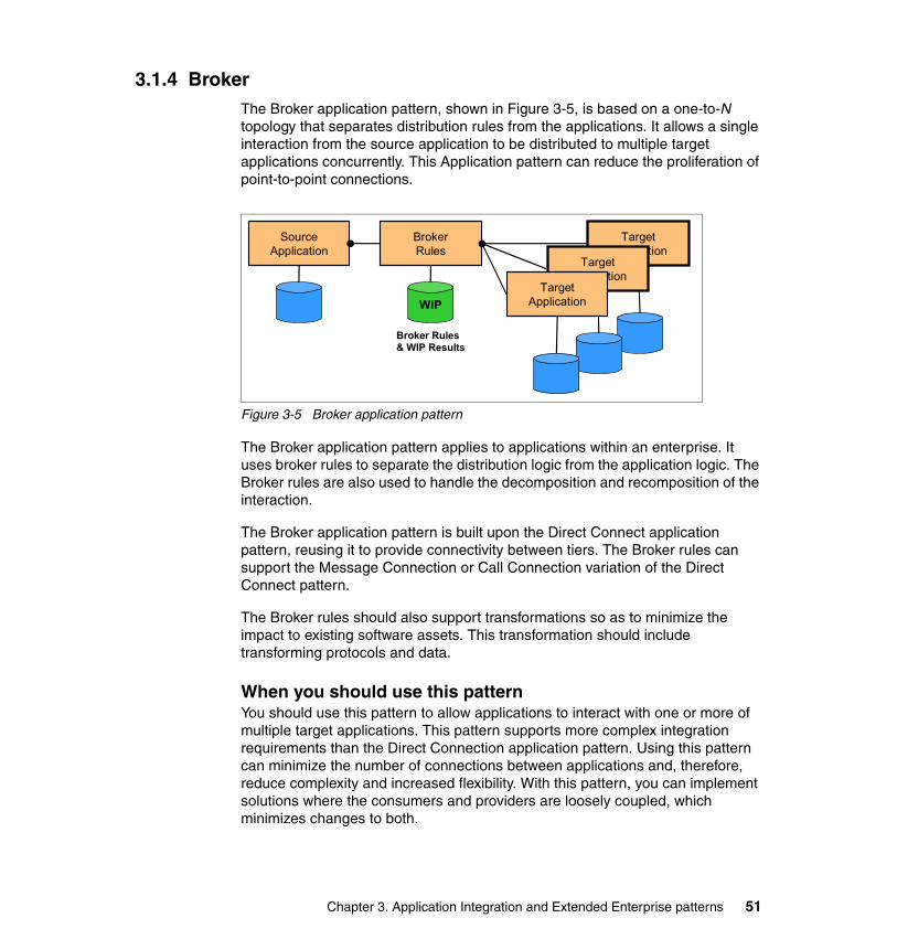
3.1.4 BrokerThe Broker application pattern, shown in Figure 3-5, is based on a one-to-N topology that separates distribution rules from the applications. It allows a single interaction from the source application to be distributed to multiple target applications concurrently. This Application pattern can reduce the proliferation of point-to-point connections.
Figure 3-5 Broker application pattern
The Broker application pattern applies to applications within an enterprise. It uses broker rules to separate the distribution logic from the application logic. The Broker rules are also used to handle the decomposition and recomposition of the interaction.
The Broker application pattern is built upon the Direct Connect application pattern, reusing it to provide connectivity between tiers. The Broker rules can support the Message Connection or Call Connection variation of the Direct Connect pattern.
The Broker rules should also support transformations so as to minimize the impact to existing software assets. This transformation should include transforming protocols and data.
When you should use this patternYou should use this pattern to allow applications to interact with one or more of multiple target applications. This pattern supports more complex integration requirements than the Direct Connection application pattern. Using this pattern can minimize the number of connections between applications and, therefore, reduce complexity and increased flexibility. With this pattern, you can implement solutions where the consumers and providers are loosely coupled, which minimizes changes to both.
TargetApplication
SourceApplication
BrokerRules
TargetApplication
TargetApplicationWIP
Broker Rules& WIP Results
Chapter 3. Application Integration and Extended Enterprise patterns 51
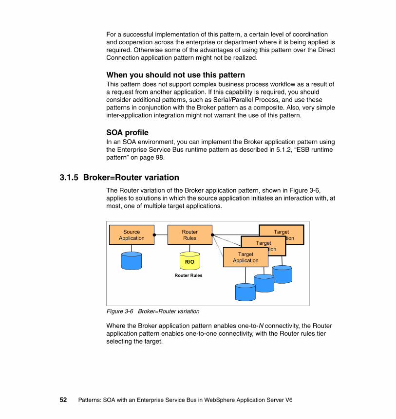
For a successful implementation of this pattern, a certain level of coordination and cooperation across the enterprise or department where it is being applied is required. Otherwise some of the advantages of using this pattern over the Direct Connection application pattern might not be realized.
When you should not use this patternThis pattern does not support complex business process workflow as a result of a request from another application. If this capability is required, you should consider additional patterns, such as Serial/Parallel Process, and use these patterns in conjunction with the Broker pattern as a composite. Also, very simple inter-application integration might not warrant the use of this pattern.
SOA profileIn an SOA environment, you can implement the Broker application pattern using the Enterprise Service Bus runtime pattern as described in 5.1.2, “ESB runtime pattern” on page 98.
3.1.5 Broker=Router variationThe Router variation of the Broker application pattern, shown in Figure 3-6, applies to solutions in which the source application initiates an interaction with, at most, one of multiple target applications.
Figure 3-6 Broker=Router variation
Where the Broker application pattern enables one-to-N connectivity, the Router application pattern enables one-to-one connectivity, with the Router rules tier selecting the target.
TargetApplication
SourceApplication
RouterRules
TargetApplication
TargetApplicationR/O
Router Rules
52 Patterns: SOA with an Enterprise Service Bus in WebSphere Application Server V6
When you should use this patternThe reasons for selecting this pattern are similar to those for selecting the Broker application pattern. The difference is that the Router application pattern routes requests to only one of multiple target applications. Otherwise, as with the Broker application pattern, this pattern removes the need for an application to hold routing rules, provides loose coupling between consumers and providers, and can minimize the number of connections between applications and therefore reduce complexity and increase flexibility. The Router application pattern should also support protocol and data transformation.
As with the Broker application pattern, this pattern requires a certain level of coordination and cooperation across the enterprise or department where it is being applied.
When you should not use this patternIf a one-to-N topology is required, then, you should use the Broker application pattern. As with the Broker application pattern, this pattern does not support complex business process flows. If this capability is required, you should consider additional patterns, such as Serial/Parallel Process, and use these patterns in conjunction with the Router pattern as a composite. Also, very simple inter-application integration might not warrant the use of this pattern.
SOA profileIn an SOA environment, you can implement the Router application pattern using the Enterprise Service Bus runtime pattern as described in 5.1.2, “ESB runtime pattern” on page 98. In this case, fewer ESB capabilities are required as compared to the Broker application pattern.
Chapter 3. Application Integration and Extended Enterprise patterns 53

3.1.6 Serial ProcessThe Serial Process application pattern, shown in Figure 3-7, extends the one-to-N topology that is provided by the Broker application pattern by facilitating the sequential execution of business services hosted by target applications.
Figure 3-7 Serial Process application pattern
This pattern enables the orchestration of a serial business process in response to an interaction that a source application initiates.
When you should use this patternYou should use this pattern for solutions that require the composition of end-to-end business process flows that leverage business services that are implemented by target applications. This pattern supports business process flows that are composed of sequential steps. This pattern allows organizations to externalize process flow logic. This means that process flow logic, which is otherwise typically embedded in applications and in the interaction between applications, can be centrally modelled and defined. This provides more flexibility and the ability for an organization to respond to change more promptly. It also provides a much easier way to manage the processes, to measure and analyze process effectiveness, and to take corrective actions.
When you should not use this patternAlthough this might seem obvious, this pattern is only suited for solutions that are process driven. The pattern is not suited if there is a requirement for parallel process execution and is not suited for inter-enterprise process flows.
SOA profileIn an SOA environment, you can implement the Serial Process application pattern using the Business Service Choreography runtime pattern as described in 5.1.4, “BSC runtime pattern” on page 108.
TargetApplication
SourceApplication
Serial ProcessRules Tier
WIP
IntermediateResults
R/O
Process ExecutionRules
TargetApplication
TargetApplication
54 Patterns: SOA with an Enterprise Service Bus in WebSphere Application Server V6

You should also consider combining this pattern with the Enterprise Service Bus pattern to leverage the integration capabilities of the ESB. See 5.1.5, “ESB, BSC composite pattern” on page 111 for more information.
3.1.7 Serial Process=Workflow variationThe Serial Workflow variation of the Serial Process application pattern, shown in Figure 3-8, extends the basic serial process orchestration capability by supporting human interaction for completing certain process steps.
Figure 3-8 Serial Process=Workflow variation
When you should use this patternYou should use this pattern for solutions that require the composition of end-to-end business process flows that leverage business services that are implemented by target applications. This pattern supports business process flows that are composed of sequential steps. These sequential steps can include one or more steps that are performed by a human. This pattern also supports requirements for long running transactions, given that it must support this requirement to provide for human interaction capability. As with the Serial Process application pattern, organizations using this pattern can benefit from externalizing process flow logic.
TargetApplication
SourceApplication
Serial WorkflowRules Tier
WIP
IntermediateResults
R/O
Process ExecutionRules including
task-resource relationship
Human InteractionResolution
TargetApplication
TargetApplication
Chapter 3. Application Integration and Extended Enterprise patterns 55

When you should not use this patternThis pattern is only suited for solutions that are process driven and that require human interaction. The pattern is not suited if there is a requirement for parallel process execution and is not suited for inter-enterprise process flows.
SOA profileIn an SOA environment, you can implement the Serial Workflow variation using the Business Service Choreography runtime pattern as described in 5.1.4, “BSC runtime pattern” on page 108.
You should consider combining this pattern with the Enterprise Service Bus pattern to leverage from the integration capabilities of the ESB. See 5.1.5, “ESB, BSC composite pattern” on page 111 for more information.
3.1.8 Parallel ProcessThe Parallel Process application pattern, shown in Figure 3-9, extends the basic serial process orchestration capability provided by the Serial Process application pattern by supporting parallel (concurrent) execution of the process.
Figure 3-9 Parallel Process application pattern
This pattern enables the orchestration of a parallel business process in response to an interaction initiated by a source application.
SourceApplication
Parallel ProcessRules Tier
WIP
IntermediateResults
R/O
Process ExecutionRules
TargetApplication
TargetApplication
TargetApplication
56 Patterns: SOA with an Enterprise Service Bus in WebSphere Application Server V6
When you should use this patternYou should use this pattern for solutions that require the composition of end-to-end business process flows that leverage business services that are implemented by target applications.
This pattern supports parallel steps, which support requirements to reduce the process cycle execution time. Therefore, you should use this patter in preference to the Serial Process application pattern when improved process performance is required. As always, there is a trade-off between improved performance and increased complexity of the solution. This is particularly so if the middleware that is used to implement the pattern does not fully support the pattern’s capability requirements.
As with the Serial Process application pattern, organizations that use this pattern can benefit from externalizing process flow logic.
When you should not use this patternThis pattern is only suited for solutions that are process driven. If execution of parallel process steps is not required, you should use the Serial Process application pattern. This pattern does not support inter-enterprise process flows.
SOA profileIn an SOA environment, you can implement the Parallel Process application pattern using the Business Service Choreography runtime pattern as described in 5.1.4, “BSC runtime pattern” on page 108.
You should consider combining this pattern with the Enterprise Service Bus pattern to leverage from the integration capabilities of the ESB. See 5.1.5, “ESB, BSC composite pattern” on page 111 for more information.
Chapter 3. Application Integration and Extended Enterprise patterns 57
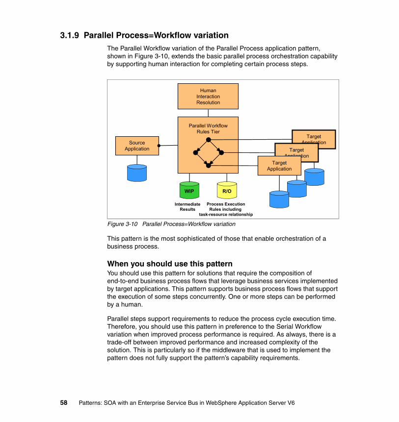
3.1.9 Parallel Process=Workflow variationThe Parallel Workflow variation of the Parallel Process application pattern, shown in Figure 3-10, extends the basic parallel process orchestration capability by supporting human interaction for completing certain process steps.
Figure 3-10 Parallel Process=Workflow variation
This pattern is the most sophisticated of those that enable orchestration of a business process.
When you should use this patternYou should use this pattern for solutions that require the composition of end-to-end business process flows that leverage business services implemented by target applications. This pattern supports business process flows that support the execution of some steps concurrently. One or more steps can be performed by a human.
Parallel steps support requirements to reduce the process cycle execution time. Therefore, you should use this pattern in preference to the Serial Workflow variation when improved process performance is required. As always, there is a trade-off between improved performance and increased complexity of the solution. This is particularly so if the middleware that is used to implement the pattern does not fully support the pattern’s capability requirements.
SourceApplication
Parallel WorkflowRules Tier
WIP
IntermediateResults
R/O
Process ExecutionRules including
task-resource relationship
TargetApplication
TargetApplication
TargetApplication
Human InteractionResolution
58 Patterns: SOA with an Enterprise Service Bus in WebSphere Application Server V6

This pattern supports requirements for long running transactions, given that it must support this requirement to provide for human interaction capability. As with the Serial Process application pattern, organizations that use this pattern can benefit from externalizing process flow logic.
When you should not use this patternThis pattern is only suited for solutions that are process driven and that require human interaction. The pattern is not suited for inter-enterprise process flows.
SOA profileIn an SOA environment, you can implement the Serial Workflow variation using the Business Service Choreography runtime pattern as described in 5.1.4, “BSC runtime pattern” on page 108.
You should consider combining this pattern with the Enterprise Service Bus pattern to leverage from the integration capabilities of the ESB. See 5.1.5, “ESB, BSC composite pattern” on page 111 for more information.
3.2 Extended Enterprise patternThe Extended Enterprise pattern addresses interactions and collaborations between business processes in separate enterprises. This pattern can be observed in solutions that implement programmatic interfaces to connect inter-enterprise applications. In other words, it does not cover applications that are directly invoked via a user interface by business partners across organizational boundaries.
This section discusses the Extended Enterprise application pattern and its variations. Figure 3-11 on page 60 shows the patterns that this section covers.
Chapter 3. Application Integration and Extended Enterprise patterns 59

Figure 3-11 Extended Enterprise application patterns
These patterns describe three styles of interaction (and several variations). The following lists these styles in order of increasing flexibility and sophistication:
� Exposed Direct Connection
This is the simplest interaction style that is based on a one-to-one topology, enabling a pair of applications in different organizations to directly talk to each other. The variations of this pattern are Message Connection and Call Connection, which apply to one-way request and request/response interactions, respectively.
� Exposed Broker
This pattern is based on a one-to-N topology which separates distribution rules from the applications and enables a single interaction from the source application to be distributed to multiple target applications concurrently, where the source application belongs to a different enterprise than that of the target applications. The variation is Router, which applies to solutions where the source application initiates an interaction that is forwarded to at most one of multiple target applications.
� Exposed Serial Process
This pattern extends the one-to-N topology of the Broker by facilitating sequential execution of business services hosted by target applications based on a defined set of process rules. A Workflow variation extends these capabilities by supporting human interaction to complete specific process
Exposed Direct ConnectionVariations: Message/Call Connection
No Yes
No
Yes
Parallel Interaction
Seria
l Int
erac
tion
SourceApplication
TargetApplication
Exposed BrokerVariation: Exposed Router
Exposed Serial ProcessVariation: Exposed Serial Workflow
ConnectionRules
TargetApplicationSource
ApplicationBrokerRules
TargetApplicationTarget
Application
TargetApplicationSource
Application
SerialProcessRulesTier
TargetApplicationTarget
Application
60 Patterns: SOA with an Enterprise Service Bus in WebSphere Application Server V6

steps. The source application, which starts the process, belongs to a different enterprise than that of the target applications.
For more details about this pattern, consult the IBM Patterns for e-business Web site at:
http://www.ibm.com/developerworks/patterns
3.2.1 Exposed Direct ConnectionThe Exposed Direct Connection application pattern allows a pair of applications from different enterprises to directly communicate with each other. Complex connections will have associated connection rules, as shown in Figure 3-12.
Figure 3-12 Exposed Direct Connection application pattern
This pattern is equivalent to the Direct Connection application pattern. For a more detailed description, refer to 3.1.1, “Direct Connection” on page 48.
When should you use this patternYou should use this pattern for very simple integration with a partner where a small number of interfaces are not likely to be reused with other partners.
Note: An Exposed Parallel Process (with associated Parallel Workflow variation) is not described in this section because this pattern is not yet proven in the industry. This pattern will be described in the future when inter-enterprise parallel process implementations are proven in production.
Inter-enterprise
Zone
EnterpriseDemilitarized
Zone Enterprise Secure ZonePartner Zone
TargetApplication
SourceApplication
ConnectionRules
Chapter 3. Application Integration and Extended Enterprise patterns 61

When should you not use this patternConversely, do not use this pattern for applications with complex integration requirements with interfaces that are likely to be reused. This pattern is not suited for interacting with multiple partners. This pattern cannot be used for intelligent routing requests, for decomposition and recomposition of requests, and for invoking complex business process flow. If some of these capabilities are required, you should consider more advanced patterns, such as Exposed Broker or Exposed Serial Process.
SOA profileThere is no specific SOA Runtime pattern that supports this Application pattern. In an SOA environment, accessing external applications would require the Exposed ESB Gateway runtime pattern that is described in 5.1.6, “Exposed ESB Gateway runtime pattern” on page 113.
3.2.2 Exposed Direct Connection=Message Connection variationThe Message Connection variation, shown in Figure 3-13, applies to solutions in which the business process does not require a response from the target application within the scope of the interaction.
Figure 3-13 Exposed Direct Connection=Message Connection variation
Note: Figure 3-13 does not show the connection rules box that appears in Figure 3-12 on page 61 in order to focus on the nature of the connection.
Inter-enterprise
Zone
EnterpriseDemilitarized
Zone Enterprise Secure ZonePartner Zone
TargetApplication
SourceApplication
62 Patterns: SOA with an Enterprise Service Bus in WebSphere Application Server V6

3.2.3 Exposed Direct Connection=Call Connection variationThe Call Connection variation, shown in Figure 3-14, applies to solutions in which the business process depends on the target application to process a request and return a response within the scope of the interaction.
Figure 3-14 Exposed Direct Connection=Call Connection variation
This pattern supports real-time, request/response interactions. You should only use this pattern variation if a response from the target application is required to fulfill the business process. Otherwise, the Message Connection variation is the preferred option because it provides a more loosely coupled interface with better performance characteristics.
Note: Figure 3-14 does not show the connection rules box that appears in Figure 3-12 on page 61 in order to focus on the nature of the connection.
Inter-enterprise
Zone
EnterpriseDemilitarized
Zone Enterprise Secure ZonePartner Zone
TargetApplication
SourceApplication
Chapter 3. Application Integration and Extended Enterprise patterns 63

3.2.4 Exposed BrokerThe Exposed Broker application pattern, shown in Figure 3-15, is based on a one-to-N topology that separates distribution rules from the applications. It allows a single interaction from the source application to be distributed to multiple target applications from one or more partners concurrently. This Application pattern can reduce the proliferation of point-to-point connections.
Figure 3-15 Exposed Broker application pattern
This pattern is equivalent to the Broker application pattern. For a more detailed description of this pattern, see 3.1.4, “Broker” on page 51 .
When you should use this patternYou should use this pattern to allow applications to interact with one or more of multiple target applications from one or more partners. This pattern supports more complex integration requirements than the Exposed Direct Connection Application pattern supports. Using this pattern can minimize the number of connections between applications and, therefore, reduce complexity and increase flexibility. With this pattern, you can implement solutions where the consumers and providers are loosely coupled, which minimizes changes to both.
This pattern should support protocol and data transformation. This pattern supports the most likely scenario where the enterprise needs to interact with multiple partners.
Partner B
Partner A
Inter-enterprise
Zone
EnterpriseDemilitarized
Zone Enterprise Secure ZonePartner Zones
SourceApplication
BrokerRules
TargetApplication
TargetApplication
WIP
Broker Rules& WIP Results
Partner C
TargetApplication
64 Patterns: SOA with an Enterprise Service Bus in WebSphere Application Server V6

When you should not use this patternThis pattern does not support complex business process workflow. If this capability is required, you should consider additional patterns, such as Exposed Serial Process, and use these patterns in conjunction with the Exposed Broker pattern as a composite. Also, very simple inter-application integration with one partner might not warrant the use of this pattern.
SOA profileIn an SOA environment, you can implement the Exposed Broker application pattern using the Exposed ESB Gateway runtime pattern as described in 5.1.6, “Exposed ESB Gateway runtime pattern” on page 113.
3.2.5 Exposed Broker=Router variationThe Exposed Router variation of the Exposed Broker application pattern, shown in Figure 3-16, applies to solutions in which the source application initiates an interaction with, at most, one of multiple target applications that are hosted by one partner company.
Figure 3-16 Exposed Broker=Router variation
Where the Broker application pattern enables one-to-N connectivity, the Router application pattern enables one-to-one connectivity, with the router rules tier selecting the target.
Partner B
Partner A
Inter-enterprise
Zone
EnterpriseDemilitarized
Zone Enterprise Secure ZonePartner Zones
SourceApplication
RouterRules
TargetApplication
TargetApplication
Partner C
TargetApplication
R/O
Router Rules
Chapter 3. Application Integration and Extended Enterprise patterns 65
When you should use this patternThe reasons for selecting this pattern are similar to those for selecting the Exposed Broker Application pattern. The difference is that the Exposed Router Application pattern routes requests to only one of multiple partner target applications. Otherwise, as with the Exposed Broker application pattern, this pattern removes the need for application to hold routing rules and provides loose coupling between consumers and providers. It also minimizes the number of connections between applications and, therefore, reduces complexity and increases flexibility. The Exposed Router Application pattern should also support protocol and data transformation. As with the Exposed Broker pattern, this pattern supports the most likely scenario where the enterprise needs to interact with multiple partners.
When you should not use this patternIf a one-to-N topology is required, then you should use the Exposed Broker application pattern. As with the Exposed Broker application pattern, this pattern does not support complex business process flows. If this capability is required, you should consider additional patterns, such as Exposed Serial Process, and use these patterns in conjunction with the Router pattern as a composite. Also, very simple inter-application integration with one partner might not warrant the use of this pattern.
SOA profileIn an SOA environment, you can implement the Exposed Router variation using the Exposed ESB Gateway runtime pattern as described in 5.1.6, “Exposed ESB Gateway runtime pattern” on page 113.
66 Patterns: SOA with an Enterprise Service Bus in WebSphere Application Server V6
3.2.6 Exposed Serial ProcessThe Exposed Serial Process application pattern, shown in Figure 3-17, extends the one-to-N topology that is provided by the Exposed Broker application pattern by facilitating the sequential execution of business services that are hosted by target applications.
Figure 3-17 Exposed Serial Process application pattern
This pattern enables a partner application to initiate the orchestration of a serial business process. This pattern is equivalent to the Serial Process application pattern that is described in Figure 3.1.6 on page 54.
When you should use this patternYou should use this pattern for solutions that require the composition of end-to-end business process flows to be initiated by a partner application. This pattern supports business process flows that are composed of sequential steps.
This pattern allows organizations to externalize process flow logic. This means that process flow logic, that is otherwise typically embedded in applications and in the interaction between applications, can be centrally modelled and defined. This provides more flexibility and the ability for an organization to respond to change more promptly. It also provides an easier way to manage the processes, to measure and analyze process effectiveness, and to take corrective actions.
The advantages outlined become even more important with process flows that are able to be initiated by partners, as the ability to control and manage the process is more critical in order to provide agreed levels of service and possibly meet contractual obligations. Ideally, the process flows can be reused between
Inter-enterprise
Zone
EnterpriseDemilitarized
Zone Enterprise Secure ZonePartner Zone
SourceApplication
Serial Process
Rules Tier
WIP
IntermediateResults
R/O
Process Execution
Rules
TargetApplicationTarget
ApplicationTarget
Application
Chapter 3. Application Integration and Extended Enterprise patterns 67

external and internal source applications by using this pattern in conjunction with the Serial Process Application pattern.
When you should not use this patternThis pattern is only suited for solutions that are process driven. The pattern is not suited if there is a requirement for parallel process execution.
SOA profileIn an SOA environment, you can implement the Exposed Serial Process application pattern using the Exposed ESB Gateway, Business Service Choreography composite pattern as described in 5.1.7, “Exposed ESB Gateway, BSC composite pattern” on page 115.
3.2.7 Exposed Serial Process=Workflow variationThe Exposed Serial Workflow variation of the Exposed Serial Process application pattern, shown in Figure 3-18, extends the basic serial process orchestration capability by supporting human interaction for completing certain process steps.
Figure 3-18 Exposed Serial Process=Workflow variation
Inter-enterprise
Zone
EnterpriseDemilitarized
Zone Enterprise Secure ZonePartner Zone
SourceApplication
Serial WorkflowRules Tier
WIP
IntermediateResults
R/O
Process Execution
Rules includingTask-resource relationship
TargetApplicationTarget
ApplicationTarget
Application
Human InteractionResolution
68 Patterns: SOA with an Enterprise Service Bus in WebSphere Application Server V6
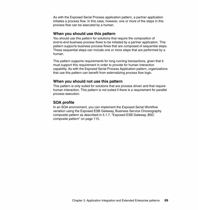
As with the Exposed Serial Process application pattern, a partner application initiates a process flow. In this case, however, one or more of the steps in this process flow can be executed by a human.
When you should use this patternYou should use this pattern for solutions that require the composition of end-to-end business process flows to be initiated by a partner application. This pattern supports business process flows that are composed of sequential steps. These sequential steps can include one or more steps that are performed by a human.
This pattern supports requirements for long running transactions, given that it must support this requirement in order to provide for human interaction capability. As with the Exposed Serial Process Application pattern, organizations that use this pattern can benefit from externalizing process flow logic.
When you should not use this patternThis pattern is only suited for solutions that are process driven and that require human interaction. This pattern is not suited if there is a requirement for parallel process execution.
SOA profileIn an SOA environment, you can implement the Exposed Serial Workflow variation using the Exposed ESB Gateway, Business Service Choreography composite pattern as described in 5.1.7, “Exposed ESB Gateway, BSC composite pattern” on page 115.
Chapter 3. Application Integration and Extended Enterprise patterns 69

70 Patterns: SOA with an Enterprise Service Bus in WebSphere Application Server V6
Chapter 4. Product descriptions and ESB capabilities
This chapter describes products that are discussed and used throughout this book for both development and runtime activities. The products described are:
� IBM WebSphere Application Server V6� IBM DB2® Universal Database™� IBM Cloudscape™� IBM WebSphere MQ V5.3� IBM WebSphere Business Integration Message Broker V5� IBM WebSphere Business Integration Server Foundation V5.1� IBM Rational® Application Developer V6.0
Additionally, this chapter compares two of these products, WebSphere Application Server V6 and WebSphere Business Integration Message Broker V5, against the ESB capabilities that are discussed in 2.2.4, “Minimum ESB capabilities” on page 37 and 2.2.6, “Extended ESB capabilities” on page 39.
4
© Copyright IBM Corp. 2005. All rights reserved. 71
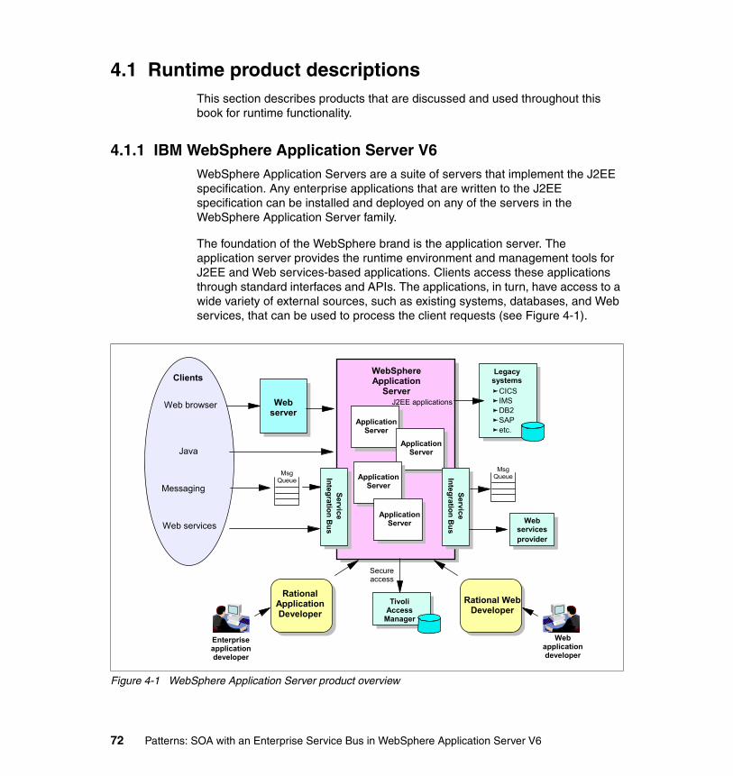
4.1 Runtime product descriptionsThis section describes products that are discussed and used throughout this book for runtime functionality.
4.1.1 IBM WebSphere Application Server V6WebSphere Application Servers are a suite of servers that implement the J2EE specification. Any enterprise applications that are written to the J2EE specification can be installed and deployed on any of the servers in the WebSphere Application Server family.
The foundation of the WebSphere brand is the application server. The application server provides the runtime environment and management tools for J2EE and Web services-based applications. Clients access these applications through standard interfaces and APIs. The applications, in turn, have access to a wide variety of external sources, such as existing systems, databases, and Web services, that can be used to process the client requests (see Figure 4-1).
Figure 4-1 WebSphere Application Server product overview
Web server
WebSphere Application
Server
Application Server
Application Server
Clients
Web browser
Java
Msg Queue
Msg Queue
Legacy systems
CICSIMSDB2SAPetc.
Application Server
J2EE applications
Messaging
Web servicesprovider
Enterprise application developer
Rational Application Developer
Rational Web Developer
Web application developer
Secure access
Tivoli Access
Manager
Web servicesApplication
Server
ServiceIntegration B
us
ServiceIntegration B
us
72 Patterns: SOA with an Enterprise Service Bus in WebSphere Application Server V6
WebSphere Application Servers are available in multiple packages to meet specific business needs. They are also available on a wide range of platforms, including UNIX® platforms, Microsoft® operating systems, IBM z/OS®, and iSeries™. Although branded for iSeries, the WebSphere Application Server products for iSeries are functionally equivalent to those for the UNIX and Microsoft platforms.
Highlights and benefitsWebSphere Application Server provides the environment to run your Web-enabled e-business applications. You might think of an application server as Web middleware or a middle tier in a three-tier e-business environment. The first tier is the HTTP server that handles requests from the browser client. The third tier is the business database (for example, DB2 UDB for iSeries) and the business logic (for example, traditional business applications such as order processing). The middle tier is IBM WebSphere Application Server, which provides a framework for consistent, architected linkage between the HTTP requests and the business data and logic.
IBM WebSphere Application Server is intended for organizations that want to take advantage of the productivity, performance advantages, and portability that Java provides for dynamic Web sites. It includes:
� J2EE V1.4 support.
� High performance connectors to many common back-end systems to reduce the coding effort required to link dynamic Web pages to real line-of-business data.
� Application services for session and state management.
� Web services that enable businesses to connect applications to other business applications, to deliver business functions to a broader set of customers and partners, to interact with marketplaces more efficiently, and to create new business models dynamically.
� The service integration bus infrastructure to complement and extend WebSphere MQ and the application server. It is suitable for those that are currently using the WebSphere Application Server V5 embedded messaging and for those that need to provide messaging capability between WebSphere Application Server and an existing WebSphere MQ backbone.
The service integration bus features include:
– Multiple messaging patterns (APIs) and protocols for message-oriented and service-oriented applications.
– A J2EE V1.4 compliant JMS provider that is the default messaging provider.
– The relevant Web services standards that support JAX-RPC APIs.
Chapter 4. Product descriptions and ESB capabilities 73

– Reliable message transport capability.
– Tightly and loosely coupled communications options.
– Intermediary logic (mediations) to intelligently adapt message flow in the network.
– Support for clustering to provide scalability and high availability.
– Quality of service options.
– Support for the WebSphere Business Integration programming model which converges functions from workflow, message brokering, collaborations, adaptors, and the application server.
– Fully integrated within WebSphere Application Server, including security, installation, administration console, performance monitoring, trace, and problem determination.
– Support for connectivity into a WebSphere MQ network.
Packaging for distributed platformsBecause different levels of application server capabilities are required at different times as varying e-business application scenarios are pursued, WebSphere Application Server is available in multiple packaging options. Although they share a common foundation, each provides unique benefits to meet the needs of applications and the infrastructure that supports them. So, at least one WebSphere Application Server product package will fulfill the requirements of any particular project and the prerequisites of the infrastructure that supports it. As your business grows, the WebSphere Application Server family provides a migration path to higher configurations.
You can find more information about the WebSphere Application Server packages at:
http://www.ibm.com/software/webservers/appserv/was/
You can find more information about using IBM WebSphere Application Server V6 in WebSphere Application Server V6 System Management and Configuration Handbook, SG24-6451.
WebSphere Application Server - Express V6The Express package is geared to those who need to “get started quickly” with e-business. It is specifically targeted at medium-sized businesses or departments of a large corporation, and is focused on providing ease of use and ease of application development. It contains full J2EE V1.4 support but is limited to a single server environment.
74 Patterns: SOA with an Enterprise Service Bus in WebSphere Application Server V6
The WebSphere Application Server - Express offering is unique from the other packages in that it is bundled with an application development tool. Although there are WebSphere Studio and Rational Developer products designed to support each WebSphere Application Server package, they are normally ordered independently of the server. WebSphere Application Server - Express includes the Rational Web Developer application development tool. It provides a development environment geared toward Web developers and includes support for most J2EE V1.4 features with the exception of EJB and J2EE Connector Architecture development environments.
However, keep in mind that WebSphere Application Server - Express does contain full support for EJB and the J2EE Connector Architecture, so you can deploy applications with them.
WebSphere Application Server V6The WebSphere Application Server package is the next level of server infrastructure in the WebSphere Application Server family. Though the WebSphere Application Server is functionally equivalent to that shipped with Express, this package differs slightly in packaging and licensing. The development tool included is a trial version of Rational Application Developer, the full J2EE V1.4 compliant development tool.
WebSphere Application Server Network Deployment V6WebSphere Application Server Network Deployment is an even higher level of server infrastructure in the WebSphere Application Server family. It extends the WebSphere Application Server base package to include clustering capabilities, edge components, and high availability for distributed configurations. These features become more important at larger enterprises, where applications tend to service a larger client base and more elaborate performance and availability requirements are in place.
Application servers in a cluster can reside on the same or multiple machines. A Web server plug-in installed in the Web server can distribute work among clustered application servers. In turn, Web containers running servlets and JSPs can distribute requests for EJBs among EJB containers in a cluster.
Chapter 4. Product descriptions and ESB capabilities 75

4.1.2 IBM DB2 Universal Database Enterprise Server Edition V8.2IBM DB2 Universal Database Enterprise Server Edition is a multi-user version of DB2 Universal Database that allows you to create and manage single partitioned or partitioned database environments. Partitioned database systems can manage high volumes of data and provide benefits such as high availability and increased performance. Other features include:
� A data warehouse server and related components
� DB2 Connect™ functionality for accessing data stored on midrange and mainframe database systems
� Satellite administration capabilities
DB2 Universal Database V8.2 delivers new features to address the ever increasing demands and requirements on important data, which include:
� Broadened autonomic computing solutions that automate and simplify potentially time consuming and complex database tasks.
� A significant amount of new capabilities as well as further integration of DB2 tooling into the Microsoft .NET and WebSphere Java environments. These new capabilities simplify the development and deployment of DB2 applications and allow application developers to take advantage of the openness, performance, and scalability of DB2, without regard to the back-end database or the chosen application architecture
� Integration of industry proven high availability disaster recovery technology allow line-of-business managers and the enterprise itself to benefit because applications face less risk of downtime.
You can find more information about the IBM DB2 Universal Database Enterprise Server Edition at :
http://www.ibm.com/software/data/db2/udb
4.1.3 IBM CloudscapeIBM Cloudscape is an open source Java relational database management system that can be embedded in Java programs and used for online transaction processing. IBM Cloudscape features include:
� Rapid application development through the Java-based relational database management system (RDBMS) that is built from the ground up for the embedded environment. This platform independent, small footprint database integrates tightly with any Java based solution, allowing shortened development cycles.
76 Patterns: SOA with an Enterprise Service Bus in WebSphere Application Server V6

� Supports Java technology standards. Single application versions can be created that run on any standard Java Virtual Machine (JVM).
� Does not require database administration or resource management and is invisible to non-technical users, thus eliminating the need for database administration at each client installation site. IBM Cloudscape can also be deployed anywhere, from notebook or desktop applications to robust server solutions.
� Tuned for high performance as well as efficient use of resources, with a straightforward migration path to various IBMDB2 versions.
� Supports international characters and formats as well as a rich set of RDBMS features that are based on SQL-92E, including row locking, triggers, and stored procedures.
� Available access to IBM Cloudscape from inside Java programs using JDBC and the ability to embed the IBM Cloudscape database inside Java applications on the server.
Cloudscape Network server comes as part of the IBM Cloudscape package. This provides multi-user connectivity to IBM Cloudscape databases within a single system or over a network using Standard Distributed Relational Database Architecture protocol.
You can find more information about IBM Cloudscape at:
http://www.ibm.com/software/data/cloudscape
4.1.4 IBM WebSphere MQ V5.3IBM WebSphere MQ provides assured once-only delivery of messages across more than 35 industry platforms using a variety of communications protocols. The transportation of message data through a network is made possible through the use of a network of WebSphere MQ queue managers. Each queue manager hosts local queues that are containers used to store messages. Through remote queue definitions and message channels, data can be transported to its destination queue manager.
To use the services of a WebSphere MQ transport layer, an application must make a connection to a WebSphere MQ queue manager, the services of which enable it to receive (get) messages from local queues or send (put) messages to any queue on any queue manager. The application’s connection can be made directly (where the queue manager runs locally to the application) or as a client (to a queue manager that is accessible over a network).
Chapter 4. Product descriptions and ESB capabilities 77

Dynamic workload distribution is another important feature of WebSphere MQ. This feature shares the workload among a group of queue managers that are part of the same cluster. This enables WebSphere MQ to balance the workload across available resources automatically and provide hot standby capabilities if a system component fails. This is a critical feature for companies that need to maintain round-the-clock availability.
WebSphere MQ supports a variety of application programming interfaces (including MQI, AMI, and JMS), which provide support for several programming languages as well as point-to-point and publish/subscribe communication models. In addition to support for application programming, WebSphere MQ provides several connectors and gateways to a variety of other products, such as Microsoft Exchange, Lotus® Domino®, SAP/R3, CICS, and IMS™, to name just a few.
You can find more information about IBM WebSphere MQ at:
http://www.ibm.com/software/ts/mqseries
4.1.5 IBM WebSphere Business Integration Message Broker V5WebSphere Business Integration Message Broker V5 extends the messaging capabilities of WebSphere MQ by adding message routing, transformation, and publish/subscribe features. WebSphere Business Integration Message Broker provides a runtime environment that executes message flows, which consist of a graph of nodes that represent the processing that is needed for integrating applications. The message flows can be designed to perform a wide variety of functions, including:
� Routing of messages to zero or more destinations based on the contents of the message or message header. (Both one-to-many and many-to-one messaging topologies are supported.)
� Transformation of messages into different formats so that diverse applications can exchange messages that each of them can understand.
� Processing message content in several message domains, including the XML domain that handles self-defining (or generic) XML messages, the Message Repository Manager (MRM), which handles predefined message sets, and unstructured data (BLOB domain).
WebSphere Business Integration Message Broker also provides these features:
� Simplified integration of existing applications with Web services through the transformation and routing of SOAP messages, as well as logging of Web services transactions.
� Mediation between Web services and other integration models as both a service consumer and a service provider.
78 Patterns: SOA with an Enterprise Service Bus in WebSphere Application Server V6

� Compliance with standards such as Web Services Definition Language (WSDL), Simple Object Access Protocol (SOAP), and Hypertext Transfer Protocol (HTTP).
� Integrated WebSphere MQ transports for enterprise, mobile, real-time, multicast, and telemetry endpoints.
� Standards-based metadata including XML schema and WSDL.
You can find more information about IBM WebSphere Business Integration Message Broker V5 at:
http://www.ibm.com/software/integration/wbimessagebroker
4.1.6 IBM WebSphere Business Integration Server Foundation V5.1WebSphere Business Integration Server Foundation V5.1 builds on WebSphere Application Server to provide a premier J2EE and Web services technology-based application platform for deploying enterprise Web services solutions for dynamic e-business on demand.
It includes WebSphere Process Choreographer, which provides WebSphere Application Server with the ability to choreograph intra-enterprise and inter-enterprise services into business processes that are described using the open-standard Business Process Execution Language for Web Services (BPEL4WS).
The business processes that are implemented in an enterprise typically require a mixture of human and IT resources, and these processes are supported by Process Choreographer. A process is a directed graph that starts with an input node and ends with an output node. A process itself is described in WSDL. Its input and output are described as WSDL messages.
A process can contain many activities. An activity can be the invocation of an EJB, a Java class, a service, or another process. A process can also be event driven. For example, it can be paused to wait for an event and then resumed when a message arrives.
WebSphere Process Choreographer supports processes that can be:
� Long-running and interruptible, requiring human intervention� Short-running and part of a one-business transaction
You can find more information about IBM WebSphere Business Integration Server Foundation V5.1 at:
http://www.ibm.com/software/integration/wbisf/
Chapter 4. Product descriptions and ESB capabilities 79

4.2 Development product descriptionsThis section describes products that are discussed and used throughout this book for development.
4.2.1 IBM Rational Application Developer V6Rational Application Developer is an integrated development environment with full support for the J2EE programming model including EJB development, Web services, Web applications and Java. In previous releases this product was known as WebSphere Studio Application Developer. This tool includes integrated portal development, UML editing, code analysis, automated test and deployment tools, built in version control, and team tools. Everything you need to be productive and to make sure written code is well designed, scalable, and ready for production is included in Rational Application Developer. Additionally, everything is provided for version control and protection when developers work in large teams or on complex projects. Rational Application Developer is optimized for IBM WebSphere software.
Rational Application Developer V6.0 is part of the Rational Software Development Platform used to develop applications to be deployed to IBM WebSphere Application Server V6.0, V5.0.x, and IBM WebSphere Portal V5.0.2.2 and V5.1. The Rational Software Development Platform provides an integrated development environment (IDE) and tooling used to design, develop, test, debug, and deploy applications in support of the application development life cycle.
The IBM Rational Software Development Platform is built upon the IBM Eclipse SDK 3.0, which is an IBM supported version of the Eclipse V3.0 Workbench containing many new features, and a new look and feel. When used with the IBM Software Development Platform, you can access a broad range of requirements directly from Rational Application Developer for WebSphere Software with features such as the following:
� Rational Web Developer tools allow accelerated use of portal, SOA, and J2EE.
� You can shorten the Java learning curve by using drag-and-drop components and point-and-click database connectivity.
� You can improve code quality by using automated tools for applying coding standard reviews, component, and Web service unit testing and multi-tier runtime analysis.
� Business applications can be integrated with Web services and SOA.
80 Patterns: SOA with an Enterprise Service Bus in WebSphere Application Server V6
You can find more information about IBM Rational Application Developer at:
http://www.ibm.com/software/awdtools/developer/application
4.3 Product capabilities for the Enterprise Service BusThis section discusses the features the products that are described in 4.1, “Runtime product descriptions” on page 72 and that support the ESB capabilities that are identified in 2.2.4, “Minimum ESB capabilities” on page 37 and 2.2.6, “Extended ESB capabilities” on page 39. Using the product descriptions and ESB capabilities as a guide, we can make an assessment of the products suitability for implementing an ESB.
You should select appropriate products to support an ESB implementation based on the current and likely future requirements for that specific ESB implementation. These is likely to be a subset of the extended capabilities that should include all the minimum capabilities and might also include additional functional and non-functional requirements that are applicable only to that ESB and are not included in our capability model.
Note that no single product currently provides strong support in all of the capabilities that we have defined. If the aim is to build a fully functional ESB that addresses all the capabilities, then you need to use multiple products in combination. For this reason, it is important to ensure not only that all current functional and non-functional requirements are met but that the products selected can be integrated together to form a logically single ESB infrastructure. Customized coding effort might also be required in an ESB implementation, either to implement a customized ESB or to support service interaction characteristics that are not supported by standards or product features.
The rapidly changing and emerging nature of the standards that an ESB needs to support (for example Web services standards) means that it is conceivable that the chosen technologies do not provide support for a particular standard, as that standard is too recent. If there is a desire to use such an emerging standard to implement some aspect of service interactions, it needs to be possible to use features of the ESB technology runtime to provide a customized implementation of an open standard, rather than using product features. Although a development and maintenance cost is involved in doing a customized implementation, the use of an open standard reduces the eventual migration cost to a product-supported solution.
Chapter 4. Product descriptions and ESB capabilities 81

In light of these requirements, you should analyze the suitability of products for building an ESB by considering:
� The ability of product(s) to meet minimum ESB capabilities
� The ability of product(s) to address additional, specific ESB implementation functional and non-functional requirements
� The ease of integration between multiple products in the ESB
� Support for customized development
4.3.1 Assessment of ESB capabilities by productTable 4-1 on page 83 rates the products that are candidates for implementing an ESB against the ESB capabilities that we have defined. The table include only those products that meet the minimum ESB capabilities.
IBM DB2 Universal Database V8.2 and IBM Cloudscape are not discussed, because they are not products that are aimed at implementing an ESB and do not meet our minimum capabilities.
WebSphere Business Integration Server Foundation 5,1 is not discussed, because it is an extension of WebSphere Application Server with additional components to support business integration. Of particular relevance to SOA is the WebSphere Process Choreographer component that provides a BPEL4WS process management engine. You can use this component to implement the business service choreography support that is required in an SOA. However, while this is an important component in an SOA, it is not actually a part of the ESB. In terms of ESB capabilities, WebSphere Business Integration Server Foundation V5.1 provides the same support as WebSphere Application Server, so is not assessed separately.
WebSphere MQ and WebSphere Business Integration Message Broker are not discussed separately as products for building an ESB. In the assessment, WebSphere MQ and WebSphere Business Integration Message Broker V5.0 are considered to be components of a messaging-based ESB.
82 Patterns: SOA with an Enterprise Service Bus in WebSphere Application Server V6

Table 4-1 ESB capabilities by product
4.3.2 IIBM WebSphere Application Server V6WebSphere Application Server V6 provides several runtime features that support ESB capabilities. It has support for Web services standards and for programming models that enable data and message manipulation. Development tooling for WebSphere Application Server, such as Rational Application Developer, includes tools and wizards that simplify the development of application, framework, or infrastructure code to leverage those runtime features.
WebSphere Application Server provides, through the service integration bus component, communication infrastructure for messaging and Web services applications that enables it to support the communication and message processing requirements of an ESB. WebSphere Application Server and tooling also provide support for a wide variety of integration methods, either directly (databases, J2EE connectors, and so forth) or through support for Enterprise Application Integration middleware (such as WebSphere MQ).
Enterprise Service Bus capability
WebSphere Application Server V6.0
WebSphere Business Integration Message Broker V5.0 and WebSphere MQ V5.3
Communication Strong Strong
Integration Strong Strong
Security Strong Medium
Message processing Limited Strong
Modeling Limited Fairly Strong
Service interaction Strong Strong
Quality of service Strong Strong
Service level Fairly Strong Strong
Management and autonomic
Medium Medium
Infrastructure intelligence
Limited Limited
Chapter 4. Product descriptions and ESB capabilities 83

WebSphere Application Server V6 meets the ESB capabilities that the following sections describe.
CommunicationWebSphere Application Server supports all of the minimum and extended capabilites that we have defined for communication, including support for:
� SOAP-based Web service hosting and invocation.
� Asynchronous messaging. The support is provided by the service integration bus component that provides a JMS V1.1 compliant JMS provider for reliable message transport.
� Synchronous messaging via HTTP and HTTPS transports.
� Point-to-point, request/response, fire and forget, events, and publish/subscribe styles of messaging.
� Routing support that allows dynamic service and port selection, that allows Web service requests to be converted from one WSDL definition to another, and that supports internet routing with proxy.
� WSDL as the service interface definition and the service implementation definition. Can publish services to a UDDI directory.
IntegrationWebSphere Application Server supports all of the minimum and extended capabilites that we have defined for integration, including support for:
� JDBC for connectivity to external data sources (for example, a relational database).
� Protocol transformation. The service integration bus supports transformation from SOAP/HTTP to SOAP/JMS and vice versa.
� Existing and application adapters by implementing the J2EE Connector Architecture support for connecting the J2EE platform to heterogeneous Enterprise Information Systems (EIS), for example ERP, mainframe transaction processing, database systems, and existing applications not written in the Java programming language.
� Connectivity to enterprise application middleware. The service integration bus is tightly integrated with WebSphere MQ. Connections an be defined so that WebSphere MQ queue managers view a service integration bus as a queue manager, and so the service integration bus views queue managers as another bus. The JMS support means messages can be exchanged with any other JMS V1.1 compliant provider.
� Data enrichment of services messages within the ESB. The service integration bus provides mediation support that allows processing of in-flight
84 Patterns: SOA with an Enterprise Service Bus in WebSphere Application Server V6
messages. Examples of the processing that can be performed by a mediation are transforming a message from one format into another, routing messages to one or more target destinations that were not specified by the sending application, augmenting messages by adding data from a data source, and distributing messages to multiple target destinations.
� WebSphere Application Server is a fully J2EE V1.4 compliant application server.
� Language interfaces for service invocation. WebSphere Application Server supports Java interfaces. It provides Web service support so that it can act as both a Web service provider and as a consumer. As a provider, it hosts Web services that are published for use by clients. As a consumer, it hosts applications that invoke Web services from other locations
SecurityWebSphere Application Server supports some of the extended capabilites that we have defined for security, including support for:
� Tokens, keys, signatures, and encryption according to the WS-Security specification can be applied to every deployed Web service.
� Authentication and authorization as part of J2EE.
� HTTPS.
� Proxy authentication can be enabled.
� Message-level security, as part of the WS-Security specification, is implemented using JAX-RPC.
Message processingWebSphere Application Server supports some of the extended capabilites that we have defined for message processing. It provides:
� Content based logic support. The mediation support in the service integration bus allows messages to be routed and altered based on content.
� Message and data transformation support (via mediations in the service integration bus).
� Message aggregation and correlation support. The mediation framework requires custom Java coding to perform aggregation and correlation.
� Validation is supported, but only through mediation support so it must be coded instead of configured.
� Intermediary support. The service integration bus allows WebSphere Application server to act as an intermediary.
� Store and forward support.
Chapter 4. Product descriptions and ESB capabilities 85
ModelingWebSphere Application Server has limited support for the extended capabilites that we have defined for modeling.
Service interactionWebSphere Application Server supports all of the minimum and some of the extended capabilites that we have defined for service interaction. It provides:
� WSDL support for the service interface definition and the service implementation definition.
� Service directory and discovery support.
� Substitution of service implementation. Using WebSphere Application Server as an ESB means service implementations can be substituted without the service consumer needing to be aware of the change.
Quality of serviceWebSphere Application Server supports some of the extended capabilites that we have defined for quality of service. It provides:
� Assured delivery support. The service integration bus supports five levels of message reliability and persistence. The integration with WebSphere MQ means that it can also use the assured delivery features of WebSphere MQ.
� Transaction support. WebSphere Application Server can act as an XA compliant transaction manager or as a participant in transactions controlled by another transaction controller.
Service levelWebSphere Application Server supports some of the extended capabilites that we have defined for service level. It provides:
� Performance tuning and monitoring tools. In particular Web service performance can be monitored through the Performance Monitoring Infrastructure (PMI), including the number of asynchronous and synchronous requests and responses.
� WebSphere Application Server Network Deployment provides a number of facilities for provide high availability across all components of the WebSphere Application Server environment.
86 Patterns: SOA with an Enterprise Service Bus in WebSphere Application Server V6
Management and autonomicWebSphere Application Server supports all of the minimum and some of the extended capabilites that we have defined for management and autonomic. It provides:
� Administration tools and support.
� Provision for service provision and registration.
� Integration to system management and administration tooling, in particular IBM Tivoli® products.
Infrastructure intelligenceWebSphere Application Server has limited support for the extended capabilites that we have defined for infrastructure intelligence.
4.3.3 IBM WebSphere Business Integration Message Broker V5WebSphere Business Integration Message Broker V5, in combination with WebSphere MQ, can support all the minimum ESB capabilities that we have defined. It provides proven support for routing, addressing, and service directory features and is well suited for building an environment that connects to multiple service interfaces using different protocols and transports.
The following sections provide details on the capabilities of the WebSphere Business Integration Message Broker as it relates to an ESB.
CommunicationWebSphere Business Integration Message Broker supports all of the minimum and extended capabilites that we have defined for communication, including support for:
� Asynchronous messaging. The support is provided by WebSphere MQ, which is a JMS provider in addition to supporting mature MQ messaging standards.
� Synchronous messaging via HTTP transports.
� Request/response, fire and forget, events, and publish/subscribe messaging styles.
� Routing support that allows dynamic service and port selection and allows Web service requests to be converted from one WSDL definition to another.
� Native WSDL for the service interface definition.
� Transaction management and assured once-only delivery of persistent WebSphere MQ messages.
Chapter 4. Product descriptions and ESB capabilities 87

IntegrationWebSphere Business Integration Message Broker supports all of the minimum and most of the extended capabilities that we have defined for integration, including support for:
� Integration with relational databases, which can also be under transactional control. This access can be used for data enrichment to provide additional information that is required for service provider processing.
� Protocol transformation from SOAP/HTTP to SOAP/JMS and vice versa. Can also be used to translate from SOAP to other service interface style (for example, a CICS transaction).
� Extensive and mature existing and application adapter for connectivity to applications, such as commercial off the shelf packages and bespoke systems, using WebSphere Business Integration Adapters and WebSphere MQ bridges.
� Connectivity to enterprise application middleware. WebSphere Business Integration Message Broker is tightly integrated with WebSphere MQ.
� Extensive data enrichment. Support is provided for routing messages to one or more target destinations that were not specified by the sending application, augmenting messages by adding data from an external data source, and distributing messages to multiple target destinations. All of this can be achieved by setting configuration options without needing to write code.
� Hand-held and embedded devices (including WebSphere MQ Everyplace® and SCADA support).
� A non-application server environment. However, integration with WebSphere Application Server is supported via WebSphere MQ. Connections can be defined so that WebSphere MQ queue managers view a service integration bus on WebSphere Application Server as a queue manager and so that the service integration bus views queue managers as another bus.
SecurityWebSphere Business Integration Message Broker supports most of the extended capabilities that we have defined for security, including support for:
� WebSphere MQ infrastructure to provide authentication and authorization for access over JMS and WebSphere MQ.
� Authentication and authorization for access over HTTP provided by an external HTTP server. Custom security can be implemented within WebSphere Business Integration Message Broker. This implementation could make a call out to an LDAP directory using a plug-in node that is provided as a SupportPac™.
� Supports non-repudiation using WebSphere MQ.
88 Patterns: SOA with an Enterprise Service Bus in WebSphere Application Server V6

� Confidentiality using WebSphere MQ, which has built in SSL support and provides exit support for encryption.
Message processingWebSphere Business Integration Message Broker supports most of the extended capabilites that we have defined for message processing. It provides:
� Encoded logic support.
� Content based logic support.
� Comprehensive message and data transformation facilities. Stylesheet transformation can also be used.
� Native aggregation support for the processing of a single service request from a client by fanning out several requests to service providers and aggregating the results into a single response without coding.
� Message validation. The Message Repository provides support for defining message and data structures and validation against the definitions. Importers are provided to easily build structures based on XSDs and DTDs as well as COBOL and C structures.
� Ability to act as an intermediary between a service consumer and service provider, with independence between the two.
� Object identity support can be built into message flows, however this support is not provided and must be coded.
� Store and forward support.
ModelingWebSphere Business Integration Message Broker supports some of the extended capabilites that we have defined for modeling, including support for:
� Common business objects. However, they are not provided natively and must be defined in a message repository or in message flows developed manually.
� Extensive data format libraries are provided through the message repository. There is also support for multiple data formats, including SOAP and business entity support through XSDs.
� Ability to have public versus private models for business-to-business integration, however they are not provided natively and must be defined in message flows developed manually.
� Development and deployment tooling for modeling data structures.
Chapter 4. Product descriptions and ESB capabilities 89

Service interactionWebSphere Business Integration Message Broker supports all of the minimum and most of the extended capabilites that we have defined for service interaction, including support for:
� Service interface definition via WSDL.
� The substitution of service implementation. The implementation of a service as a message flow can be changed without affecting the service consumer and a service provider’s implementation can change without affecting its access from a message flow.
� Extensive support for service messaging models including SOAP, XML, and enterprise integration models. A message flow can handle a service request with no, partial, or complete SOAP (or any other message structure) validation and processing.
� Service directory and discovery. Services that are created from message flows could be published in an external directory such as UDDI. A client could then use UDDI to discover the services. Basic message flow functionality provides database lookup facilities and can be extended via plug ins to support service discovery from within a message flow.
Quality of serviceWebSphere Business Integration Message Broker supports most of the extended capabilites that we have defined for quality of service, including support for:
� Transaction support. Message flows under transaction control and WebSphere MQ as an XA compliant transaction manager or as a participant in transactions that are controlled by another transaction controller.
� Use of WebSphere MQ assures the once-only delivery of persistent messages.
Service levelWebSphere Business Integration Message Broker supports all of the extended capabilites that we have defined for service level, including support for:
� Has high performance and throughput characteristics, as documented on the IBM SupportPac Web site. Numerous options are available for performance tuning, for example, partial parsing is automatically supported so the SOAP header could be parsed and the body transported to increase throughput.
� High levels of availability can be achieved using multiple brokers and execution groups underpinned with WebSphere MQ clustering.
90 Patterns: SOA with an Enterprise Service Bus in WebSphere Application Server V6
Management and autonomicWebSphere Business Integration Message Broker supports all of the minimum and some of the extended capabilites that we have defined for management and autonomic. It provides:
� Administration and development support.
� Messages can be logged in whole or in part. Such information can be used to input into metering and monitoring.
� Integration to system management and administration tooling, in particular IBM Tivoli products.
Infrastructure intelligenceWebSphere Business Integration Message Broker has limited support for the extended capabilites that we have defined for infrastructure intelligence. You can:
� Adapt message flow processing according to business rules.� Adapt message flow processing according to policies.
4.3.4 ConclusionBoth WebSphere Application Server V6 and WebSphere Business Integration Message Broker V5 are suitable products for building an ESB.
WebSphere Application Server as an ESBBuilding an ESB that is based entirely on WebSphere Application Server is an option when Web services support is critical and the service provider and consumer environment is predominantly built on J2EE. WebSphere Application Server is most suitable for implementing ESBs that are based on Web services standards. It also provides facilities to integrate services that are offered via enterprise application integration messaging and other sources. However, if integration with these non-Web service standards-based services is a major requirement for the ESB, then you should consider WebSphere Application Server in combination with products that provide more sophisticated support, such as WebSphere Business Integration Message Broker.
Additionally, if the ESB needs to support high volume and complex data transformations, routing decisions and data validation, then again, you should consider it in combination with products that provide more sophisticated support for this, again, such as WebSphere Business Integration Message Broker.
Chapter 4. Product descriptions and ESB capabilities 91
WebSphere Business Integration Message Broker as an ESBBuilding an ESB that is based entirely on WebSphere Business Integration Message Broker is an option when Web services support is not critical and quality-of-service requirements demand the use of mature middleware. WebSphere Business Integration Message Broker V5 can support all the minimum ESB capabilities that we have defined. However, in comparison with WebSphere Application Server, it lacks the sophistication of Web services support that might be required in an ESB implementation which makes extensive use of these standards.
An ESB is for more than Web servicesThere are a spectrum of approaches to the use of messaging middleware to support SOA. There is no reason why the same infrastructure should not support a variety of other message-based and event-based interactions that are part of an overall SOA but that, for various reasons, do not use the Web services standards.
However, where Web services standards are not used, either for specific interactions or for all interactions within an SOA, several decisions must be made:
� In order to fulfill the criteria for service interactions, some form of explicit interface definition is required. This definition is usually, but not always, machine-readable (for example, WSDL can be read by application development tools or ESB middleware). Machine-readable interface specifications increase the options that are available to loosely couple service interactions. In some cases, a proprietary interface definition might be provided by the messaging middleware, in other cases a customized model might be used.
� Some form of service messaging model is also required, such as to provide a message body using some format for application data and message headers and describing other aspects of the interaction such as security or transactional context. Again, these features can be provided by middleware, or a customized approach could be used. It is important to note that there are many choices of non-Web services messaging models that nevertheless provide inter operability and conform to open standards. XML or industry formats that are based on it, such as ebXML, are good examples.
� Service consumers invoke and receive service requests that are defined by an interface definition and that use a service messaging model. When the interface definition or messaging model is proprietary, applications will either have to construct appropriate messages themselves, or a framework will have to be provided to assist them.
92 Patterns: SOA with an Enterprise Service Bus in WebSphere Application Server V6

Given the rapid emergence and maturity of Web services standards, the amount of effort that should be put into customized implementations is questionable, unless the implementation is to provide support for an open standard that is not directly supported by the product. Preferably, as a starting position, service interactions should use open standards or supported features of product technologies in order to minimize development, maintenance, and migration cost.
You can combine approaches that are based on messaging middleware with approaches that are based on Web services in an overall ESB infrastructure. In these situations, a combination of WebSphere Application Server with WebSphere Business Integration Message Broker is a good fit.
SummaryIn conclusion, both WebSphere Application Server and WebSphere Business Integration Message Broker are suitable products for implementing an ESB. In some cases, you could use WebSphere Business Integration Message Broker or WebSphere Application Server alone. However, in more sophisticated ESBs, these products are more likely to be combined to provide additional features.
Chapter 4. Product descriptions and ESB capabilities 93

94 Patterns: SOA with an Enterprise Service Bus in WebSphere Application Server V6
Chapter 5. SOA runtime patterns and Product mappings
This section describes the Runtime patterns and Product mappings that are relevant to a Service Oriented Architecture (SOA) with specific focus on the Enterprise Service Bus (ESB).
This chapter describes the following SOA runtime patterns:
� Direct Connection using a Service Bus runtime pattern� ESB runtime pattern� ESB Gateway runtime pattern� BSC runtime pattern� ESB, BSC composite pattern� Exposed ESB Gateway runtime pattern (for inter-enterprise)� Exposed ESB Gateway, BSC composite pattern (for inter-enterprise)
This chapter also provides product mappings for the following Runtime patterns:
� ESB runtime pattern� ESB Gateway runtime pattern� BSC runtime pattern� Exposed ESB Gateway runtime pattern (for inter-enterprise)
You can find an overview of the products mapped in 4.1, “Runtime product descriptions” on page 72.
5
© Copyright IBM Corp. 2005. All rights reserved. 95

5.1 Runtime patternsRuntime patterns are used to define the logical middleware structure that supports the Application patterns that are described in Chapter 3, “Application Integration and Extended Enterprise patterns” on page 45. In other words, Runtime patterns describe the logical architecture that is required to implement an Application pattern. Runtime patterns depict the major middleware nodes, their roles, and the interfaces between these nodes.
The Runtime patterns that are illustrated in this chapter give some typical examples of possible solutions. However, these examples should not be considered exhaustive.
5.1.1 Direct Connection using a service busFigure 5-1 shows a service consumer that is connected to two other service providers via a simple service bus. The Application pattern overlays in this figure show that multiple Direct Connection application patterns can be deployed using the service bus.
Figure 5-1 Direct Connection using a simple service bus
Direct Connection
SourceApplication
TargetApplication 2
Internal network
Direct Connection
SourceApplication
TargetApplication 1
App Server/Services
App Server/Services
App Server/Services
<Service Bus>
<Service Provider><Service Consumer> <Service Provider>
96 Patterns: SOA with an Enterprise Service Bus in WebSphere Application Server V6
The service consumer (or source application) can use the service bus to initiate direct connections to two service providers — one to Target Application 1 and the other to Target Application 2.
In order to focus on the service bus concept, we do not explicitly model adapter connectors or connection rules in Figure 5-1 on page 96. The service bus concept is, however, an extension of the Direct Connection with federated adapter connectors runtime pattern that enables a set of connected Direct Connections. The service bus approach:
� Minimizes the number of adapters required for each point-to-point connection to link service consumers to service providers.
� Improves reuse in multiple point-to-point scenarios.
� Addresses any technical and information model discrepancies amongst services.
The service bus can span across multiple system/application tiers, and can extend beyond the enterprise boundary. A rules repository node can also be included to model a service directory, allowing services to be discovered within and outside of the enterprise.
Note: The figure shows the relationship between the Application and Runtime patterns as an example. For clarity, the remainder of this section concentrates on the Runtime patterns and does not show the associated Application patterns. Chapter 3, “Application Integration and Extended Enterprise patterns” on page 45 describes the Application patterns that are relevant to an SOA. Each pattern description contains an SOA Profile section that maps the Application pattern to one of the Runtime patterns that are described in this section. In addition, you can find full mapping between Application and Runtime patterns at:
http://www.ibm.com/developerworks/patterns
Note: The very simple service bus described here provides just a small subset of the integration capabilities of a true ESB as described in the remainder of this chapter.
Chapter 5. SOA runtime patterns and Product mappings 97

5.1.2 ESB runtime patternFigure 5-2 shows the runtime pattern that provides the highest level view of the ESB.
Figure 5-2 ESB runtime pattern - Level 0
The ESB is a key enabler for an SOA because it provides the capability to route and transport service requests from the service consumer to the correct service provider. The ESB controls routing within the scope of a service namespace, indicated symbolically by the ellipse on the ESB node representation.
The true value of the ESB concept, however, is to enable the infrastructure for SOA in a way that reflects the needs of today’s enterprise: to provide suitable service levels and manageability and to operate and integrate in a heterogeneous environment. Furthermore, the ESB needs to be centrally managed and administered and have the ability to be physically distributed.
The Runtime pattern shown in Figure 5-3 on page 99 represents a first level decomposition of the major components that make up an ESB.
Enterprise
ESB
App Server/Services
App Server/Services
App Server/Services
<Service Consumer>
<Service Consumer>
<Service Consumer>
App Server/Services
App Server/Services
App Server/Services
<Service Provider>
<Service Provider>
<Service Provider>
98 Patterns: SOA with an Enterprise Service Bus in WebSphere Application Server V6

Figure 5-3 ESB runtime pattern - Level 1
This basic topology leverages the nodes with their associated responsibilities as described in the following sections.
App server/services nodeThese nodes represent applications that request a service from the ESB or provide a service to the ESB. These applications can be implemented in any technology as long as they are able to interact using one of the protocols and messaging models that is supported by the ESB.
Services can be implemented in a variety of technologies and can be custom-developed, enterprise applications, such as those typically implemented in CICS Transaction Server, IMS Transaction Manager, and software packages.
Hub nodeThis node supports the key ESB functions and, therefore, fulfills a large part of the ESB capabilities. The hub has a fundamental service integration role and should be able to support various styles of interaction. There are two interaction styles (that are covered in detail in Part 3) that the hub supports. Those styles are the Router and Broker interaction patterns. The Router interaction pattern is where a request is routed to a single provider. The Broker interaction pattern supports requests that are routed to multiple providers, including aggregation and disaggregation of messages. The hub must contain rules for routing messages, and in the case of hubs that support the Broker interaction pattern,
Enterprise
Business Service Directory
Zone: Enterprise Service Bus
NamespaceDirectory
Administration & Security Services
HubApp Server/
Services
<Service Consumer>
App Server/Services
<Service Consumer>
App Server/Services
App Server/Services
<Service Provider>
<Service Provider>
Chapter 5. SOA runtime patterns and Product mappings 99
the rules must also describe how messages should be disaggregated or aggregated.
The following are the minimum set of functions that this node should support:
� Routing
This function removes the need for applications to know anything about the bus topology or its traversal. The interaction that a requester initiates is sent to one provider.
� Addressing
Addressing complements routing to provide location transparency and support service substitution. Service addresses are transparent to the service consumer and can be transformed by the hub. The hub obtains the service address from the namespace directory.
� Messaging styles
The hub should support at least one or more messaging styles. The most common are request/response, fire and forget, events, publish/subscribe, and synchronous and asynchronous messaging.
� Transport protocols
The hub should support at least one transport that is or can be made widely available, such as HTTP/S. The hub can provide protocol transformation. If a protocol transformation is required that is not supported by the hub, then a specific connector can be used to perform the transformation (see “Connectors” on page 103).
� Service interface definition
Services should have a formal definition, ideally in an industry-standard format, such as WSDL.
� Service messaging model
The hub should support at least one model such as SOAP, XML, or a proprietary EAI model.
100 Patterns: SOA with an Enterprise Service Bus in WebSphere Application Server V6

In addition to these capabilities, the hub can support more advanced capabilities, such as:
� Integration
Additional integration services that can be provided include service mapping and data enrichment.
� Quality of service
These services can include transaction management (for example, ACID properties, compensation, or WS-Transaction), various assured delivery paradigms (such as WS-ReliableMessaging), or support for Enterprise Application Integration middleware.
� Message processing
The hub can support more advanced message processing capabilities such as encoded logic, content-based logic, message and data transformations, message/service aggregation and correlation, validation, intermediaries, object identity mapping, service/message aggregation, and store and forward.
� Modelling
The hub can support more advanced modelling capabilities such as object modeling, common business object models, data format libraries, public versus private models for business-to-business integration, and development and deployment tooling.
� Service level
Service level indicators might need to be measured, particularly in an enterprise mission critical environment. The key indicators are availability and performance, which includes response time, throughput, and capacity.
� Infrastructure intelligence
More advanced infrastructure capabilities can be provided. These include:
– Business rules– Policy-driven behavior, particularly for service levels– Security and quality of service capabilities (WS-Policy).
Namespace directoryThis node provides routing information in order for the hub to perform routing of service interactions. This node could be implemented as a routing table in the more simple implementations of an ESB.
Chapter 5. SOA runtime patterns and Product mappings 101
Administration and security servicesThis section covers both administration and security services.
AdministrationAn ESB should be controlled by a single administration infrastructure. This node provides these administration services which, at a minimum, should support service addressing and naming.
The key services that need to be provided by this node are:
� ESB configuration� Service provisioning and registration� Logging� Metering� Monitoring� Integration with systems management and administration tooling
More advanced administration features that can be provided by this node include self-monitoring and self-management.
SecurityIn a mission critical environment and, depending on the confidentiality, integrity, and availability requirements of the applications, the hub should support security capabilities such as authentication, authorization, non-repudiation, confidentiality, and security standards, such as Kerberos and WS-Security.
Business service directoryThe role of the business service directory is to provide details of services that are available to perform business functions identified within a taxonomy. The business service directory can be implemented as an open-standard UDDI registry. More basic implementations can make use of an HTTP server as described in Chapter 9, “Enterprise Service Bus pattern: router scenario” on page 179. Catalogs, such as a UDDI registry, can achieve one of the primary goals of a business service directory: to publish the availability of services and encourage their reuse across the development activity of an enterprise.
The vision of Web services defines an open-standard UDDI registry that enables the dynamic discovery and invocation of business services. However, although technologies mature toward that vision, more basic solutions are likely to be implemented in the near term.
102 Patterns: SOA with an Enterprise Service Bus in WebSphere Application Server V6

ConnectorsIf we model the connectors that facilitate the interactions between service consumer/service providers and the ESB, as shown in Figure 5-4, we find that we might require that some of these are both adapter connectors and path connectors, while other service consumer/service providers only need a path connector to the ESB.
An adapter connector is concerned with enabling logical connectivity by bridging the gap between the context schema and protocols used by the source and target applications. In this case, between the service consumer/providers and the ESB.
A path connector is concerned with providing physical connectivity between source and target applications. It can be very complex (for example, the Internet) or very simple (an area of shared storage).
Figure 5-4 ESB Level 2 with adapter connectors
Adapter connectors facilitate integration in a heterogeneous environment with diverse technology, protocols, application types, and integration styles. The following are the key types of function that Adapters perform:
� Technology adaptation
This type of adapter handles service consumers and providers that are built using technologies that are not natively supported by the hub. Examples of technologies that can be supported via adapters are CORBA, COM, JDBC,
Enterprise
Business Service Directory
Zone: Enterprise Service Bus
NamespaceDirectory
Administration & Security Services
HubApp Server/
Services
<Service Consumer>
App Server/Services
<Service Consumer>
App Server/Services
App Server/Services
<Service Provider>
<Service Provider>
Connector
Connector
Chapter 5. SOA runtime patterns and Product mappings 103

JMS, and EJB. Some of these technology adapters can use data handlers for particular data formats such as EDI, SOAP, XML, and various text formats.
These adapters can also support different application server environments such as J2EE and .Net and different language interfaces such as Java, C, C++, and C#.
� Application adaptation
This type of adapter facilitates integration with package solutions. There are many examples of package solutions that provide application adapters, such as Siebel, PeopleSoft, and SAP among others.
� Legacy adaptation
This type of adapter facilitates exposing valuable enterprise applications as services. These enterprise applications can be implemented using technologies such as CICS Transaction Server, IMS Transaction Manager and ADABAS amongst others.
Development-time support can also be provided in order to develop custom adapters.
As an example, the connectors in Figure 5-4 on page 103 that are modeled (that is that are represented as a connector node) can support a Siebel Customer Service application that acts as a service consumer to the ESB and requests a service that is provided by an enterprise application running under CICS Transaction Server. In this scenario, the connector might be a Siebel application adaptation adapter connector and a legacy adaptation adapter connector that supports CICS Transaction Server. The connectors that are not modelled (that is, that are only represented by a line) in this example, could support the interaction between applications that use a SOAP/JMS to interface with the ESB and, therefore, only require a path connector.
Not all connectors are necessarily within the ESB Zone. Figure 5-5 on page 105 shows the possible placement options for connectors that support interaction between application server and services and the ESB. These application server and services can be service consumers or service providers.
104 Patterns: SOA with an Enterprise Service Bus in WebSphere Application Server V6

Figure 5-5 Placement of adapter connectors
The following are the placement options for connectors:
� Inside the ESB Zone.� On the boundary of the ESB Zone.� Outside the ESB Zone.
In general, IT artifacts (such as nodes, connectors, and client APIs) have some configuration that determine their behavior. If this configuration is managed by the ESB management infrastructure, the artifact is inside the ESB Zone.
In some instances, an artifact such as a connector can be either outside or on the boundary of the ESB Zone, depending on whether it is managed or partly managed by the ESB infrastructure. An example of a partly managed connector could be an ESB that is built on WebSphere V6 with J2C Adapter to CICS Transaction Server using CICS Transaction Gateway in Server or Client Mode. CICS Transaction Gateway runs as a separate process, or at least with its own configuration and management, but the J2C end is within WebSphere control.
In the scenario described previously, if we build the ESB using WebSphere Business Integration Message Broker, linking to the J2C adaptor that is running in WebSphere Application Server, the J2C adaptor is outside the WebSphere
Enterprise
Connector
Zone: Enterprise Service Bus
Hub
Connector
Connector
App Server/Services
App Server/Services
App Server/Services
App Server/Services
Chapter 5. SOA runtime patterns and Product mappings 105
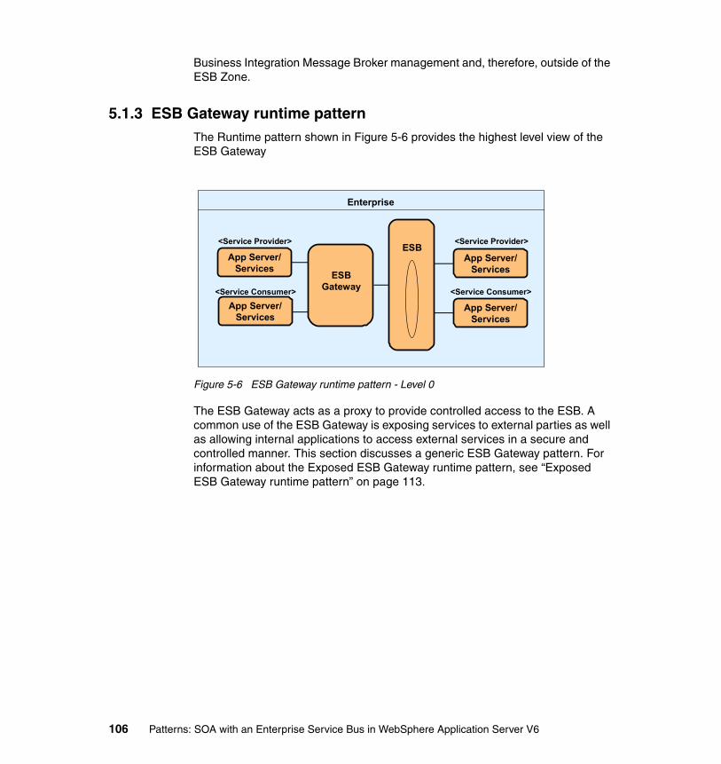
Business Integration Message Broker management and, therefore, outside of the ESB Zone.
5.1.3 ESB Gateway runtime patternThe Runtime pattern shown in Figure 5-6 provides the highest level view of the ESB Gateway
Figure 5-6 ESB Gateway runtime pattern - Level 0
The ESB Gateway acts as a proxy to provide controlled access to the ESB. A common use of the ESB Gateway is exposing services to external parties as well as allowing internal applications to access external services in a secure and controlled manner. This section discusses a generic ESB Gateway pattern. For information about the Exposed ESB Gateway runtime pattern, see “Exposed ESB Gateway runtime pattern” on page 113.
Enterprise
ESB Gateway
ESBApp Server/
Services
App Server/Services
App Server/Services
App Server/Services
<Service Provider>
<Service Consumer>
<Service Provider>
<Service Consumer>
106 Patterns: SOA with an Enterprise Service Bus in WebSphere Application Server V6
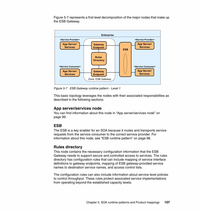
Figure 5-7 represents a first level decomposition of the major nodes that make up the ESB Gateway.
Figure 5-7 ESB Gateway runtime pattern - Level 1
This basic topology leverages the nodes with their associated responsibilities as described in the following sections.
App server/services nodeYou can find information about this node in “App server/services node” on page 99.
ESBThe ESB is a key enabler for an SOA because it routes and transports service requests from the service consumer to the correct service provider. For information about this node, see “ESB runtime pattern” on page 98.
Rules directoryThis node contains the necessary configuration information that the ESB Gateway needs to support secure and controlled access to services. The rules directory has configuration rules that can include mapping of service interface definitions to gateway endpoints, mapping of ESB gateway-provided service names to destination service names, and access control lists.
The configuration rules can also include information about service level policies to control throughput. These rules protect associated service implementations from operating beyond the established capacity levels.
Enterprise
Zone: ESB Gateway
GatewayEndpoint
GatewayEndpoint
ESB
Rules Directory
App Server/Services
App Server/Services
App Server/Services
App Server/Services
<Service Provider>
<Service Consumer>
<Service Provider>
<Service Consumer>
Chapter 5. SOA runtime patterns and Product mappings 107

Gateway endpointThis node is the entry point into services that the ESB provides or that are external to the ESB. It provides the address where messages are received, and it is mapped to particular protocols that the ESB Gateway supports, for example HTTP/S. The gateway endpoint controls access to and from the ESB based on configuration rules that include access control lists and service level policies. It maps requests to the appropriate service and facilitates the interaction.
5.1.4 BSC runtime patternThe Runtime pattern shown in Figure 5-8 provides the highest level view of this pattern.
Figure 5-8 BSC runtime pattern – Level 0
With the Business Service Choreography (BSC) runtime pattern, you can develop and execute business process flow logic which governs the sequence and control of service invocations. The business process is controlled centrally and is not part of the program logic in individual applications. Therefore, rather than having the business process defined in multiple applications and within the interactions between these multiple applications, the business process can be modelled and implemented by a central function. The Business Service Choreography facilitates the implementation of changes to the business process and monitoring and analysis of business process execution.
Enterprise
App Server/ Services
Business Service
Choreography App Server/ Services
App Server/ Services<Service Consumer>
<Service Provider>
<Service Provider>
108 Patterns: SOA with an Enterprise Service Bus in WebSphere Application Server V6
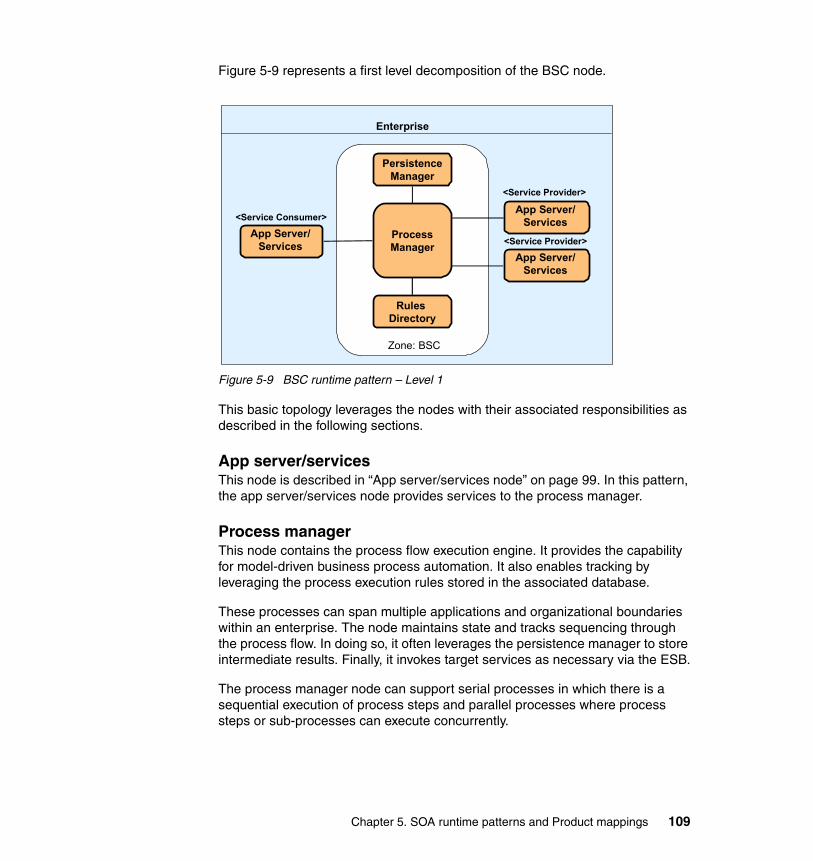
Figure 5-9 represents a first level decomposition of the BSC node.
Figure 5-9 BSC runtime pattern – Level 1
This basic topology leverages the nodes with their associated responsibilities as described in the following sections.
App server/servicesThis node is described in “App server/services node” on page 99. In this pattern, the app server/services node provides services to the process manager.
Process managerThis node contains the process flow execution engine. It provides the capability for model-driven business process automation. It also enables tracking by leveraging the process execution rules stored in the associated database.
These processes can span multiple applications and organizational boundaries within an enterprise. The node maintains state and tracks sequencing through the process flow. In doing so, it often leverages the persistence manager to store intermediate results. Finally, it invokes target services as necessary via the ESB.
The process manager node can support serial processes in which there is a sequential execution of process steps and parallel processes where process steps or sub-processes can execute concurrently.
Enterprise
ProcessManager
Rules Directory
Zone: BSC
PersistenceManager
App Server/ Services
<Service Consumer>
App Server/ Services
App Server/ Services
<Service Provider>
<Service Provider>
Chapter 5. SOA runtime patterns and Product mappings 109

The process manager should support the following key capabilities:
� Process definition standards, such as BPEL4WS, and the ability to execute process definitions that have been defined and exported from a modelling tool.
� Monitoring and analysis of processes by capturing information about process execution for historical analysis. It should also support integration with system management and administration tools.
� Ability to meet non-functional requirements such as performance, availability and scalability will be important for mission critical enterprise applications. Other key non-functional requirements are security and transaction management particularly supporting the integrity and recovery of long running business processes.
� Multiple levels of process abstractions.
� Correlation of events or incoming messages with existing process instances.
� Support for branching, parallel branch execution and recomposing if the process manager supports parallel process execution.
Persistence managerThis node provides a persistent data storage service in support of the process flow execution. It holds results from the execution of certain activities within the context of an end-to-end process flow. These can be intermediate results valid within the context of a particular process flow and process data for the purpose of process monitoring and analysis. The intermediate results are necessary to support state management.
The implementation of this node typically involves a persistent data technology, such as a DBMS. In some cases, you can use non-persistent storage to store the intermediate results.
Rules directoryThis node holds the read-only process execution rules in support of the process flow execution. These rules control the sequencing of activities and, therefore, support flow control within the context of an end-to-end process flow. The implementation of this node involves persistent data technologies, such as a flat file or a DBMS.
110 Patterns: SOA with an Enterprise Service Bus in WebSphere Application Server V6

5.1.5 ESB, BSC composite patternThe Runtime pattern shown in Figure 5-10 provides the highest level view of this Composite pattern.
Figure 5-10 ESB with BSC composite pattern – Level 0
The BSC node is implemented as a service consumer or service provider of the ESB. The BSC node is focused on process management function, and the ESB node provides the integration capabilities with other services. This pattern generally provides a loosely coupled and more functionally cohesive architecture where functional responsibility of nodes is clearly defined. The business process governs the sequence and control of service invocations which are mediated through the ESB.
Figure 5-11 on page 112 represents a first level decomposition of the major nodes that make up this pattern.
The BSC has two core components, the process manager and repository nodes, that support the development and execution of business process flow logic. This logic is controlled centrally outside the application logic. Shielding the applications from the business process flow facilitates the implementation of changes to the business process and the monitoring and analysis of business process execution.
Enterprise
ESB
Business Service
Choreography
App Server/Services
App Server/Services
<Service Consumer>
<Service Consumer>
App Server/Services
App Server/Services
<Service Provider>
<Service Provider>
Chapter 5. SOA runtime patterns and Product mappings 111

Figure 5-11 ESB with BSC composite pattern – Level 1
The BSC and ESB nodes are described in “ESB runtime pattern” on page 98. Therefore, this section provides only a brief description of these nodes.
BSCThis node is limited to process management and contains only the process manager, rules directory, and persistent manager nodes. The BSC relies on the ESB for integration and security functionality and both receives requests from the ESB and sends requests to the ESB via the hub node. The ESB can issue a request to the BSC to start execution of a process. The process execution will in
Note: Only a connector to the ESB is required as opposed to a connector to each app server/services node that is involved in the process flows as described in “BSC runtime pattern” on page 108. The service integration function is subsumed by the ESB, leaving the BSC to perform its core process management function.
p g p y p
Enterprise
Zone: BSC
ProcessManager
Rules Directory
PersistenceManager Business Service
Directory
Zone: Enterprise Service Bus
NamespaceDirectory
Administration & Security Services
App Server/Services
<Service Consumer>
App Server/Services
<Service Consumer>
App Server/Services
App Server/Services
<Service Provider>
<Service Provider>Hub
112 Patterns: SOA with an Enterprise Service Bus in WebSphere Application Server V6

turn most likely require services to be invoked as part of the process flow. Therefore, the BSC will request services from the ESB.
For a description of the BSC nodes, see “BSC runtime pattern” on page 108.
ESBThe ESB nodes are described in “ESB runtime pattern” on page 98. As far as the ESB is concerned, the BSC is another application which can both request and provide services.
5.1.6 Exposed ESB Gateway runtime pattern
Figure 5-12 shows a runtime pattern that supports secured and controlled access to enterprise services from outside of the enterprise and that allows enterprise applications to access external services. The two major nodes in this pattern, the Exposed ESB Gateway and ESB, are described in “ESB Gateway runtime pattern” on page 106 and “ESB runtime pattern” on page 98.
Figure 5-12 Exposed ESB Gateway runtime pattern – Level 0
The connection between the app service/services node in the partner zone and the network infrastructure in the inter-enterprise zone could be an HTTP server, an ESB, an Exposed ESB Gateway, or a firewall. Therefore, depending on security requirements, the Exposed ESB Gateway node can be inside or outside of the Enterprise Demilitarized Zone.
This basic topology leverages the nodes with their associated responsibilities as described in the following sections.
Note: This pattern applies to inter-enterprise solutions.
Enterprise Secure ZoneInter-enterprise
ZoneEnterprise
Demilitarized ZonePartner Zone
App Server/Services
NetworkInfrastructure
ESBD
omai
n Fi
rew
all
ExposedESB
Gateway
Prot
ocol
Fire
wal
l
Connector
App Server/Services
App Server/Services
<Service Provider>
<Service Consumer>
App Server/Services
<Service Provider>
<Service Consumer>
Enterprise Secure Zone
Chapter 5. SOA runtime patterns and Product mappings 113

App server/servicesThis node is described in “App server/services node” on page 99.
ConnectorThis node, which is deployed in the demilitarized zone (DMZ) between two firewalls, provides a communication link over the internet for incoming requests from external applications as well as outgoing requests to external services.
Exposed ESB GatewayAn Exposed ESB Gateway makes the services of one organization available to others, and vice versa, in a controlled and secure manner. Although this might require capabilities such as partner provisioning and management, which are distinct from ESB capabilities, the intent of this component is different from the intent of the ESB, which is to provide a service infrastructure within an organization. For both of these reasons, the Exposed ESB Gateway is likely to be integrated to, but not be a part of, the Enterprise Service Bus.
This node is described in “ESB Gateway runtime pattern” on page 106.
ESBThe ESB is a key enabler for an SOA as it provides the capability to route and transport service requests from the service consumer to the correct service provider.
This node is described in “ESB runtime pattern” on page 98.
Note: The app server/services node that interacts directly with the ESB Gateway could be an ESB in the other enterprise.
114 Patterns: SOA with an Enterprise Service Bus in WebSphere Application Server V6
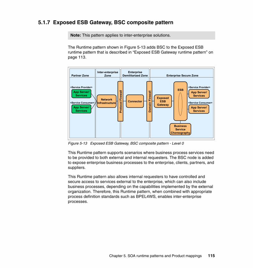
5.1.7 Exposed ESB Gateway, BSC composite pattern
The Runtime pattern shown in Figure 5-13 adds BSC to the Exposed ESB runtime pattern that is described in “Exposed ESB Gateway runtime pattern” on page 113.
Figure 5-13 Exposed ESB Gateway, BSC composite pattern - Level 0
This Runtime pattern supports scenarios where business process services need to be provided to both external and internal requesters. The BSC node is added to expose enterprise business processes to the enterprise, clients, partners, and suppliers.
This Runtime pattern also allows internal requesters to have controlled and secure access to services external to the enterprise, which can also include business processes, depending on the capabilities implemented by the external organization. Therefore, this Runtime pattern, when combined with appropriate process definition standards such as BPEL4WS, enables inter-enterprise processes.
Note: This pattern applies to inter-enterprise solutions.
Inter-enterprise Zone
EnterpriseDemilitarized ZonePartner Zone
App Server/Services
NetworkInfrastructure
ESB
Dom
ain
Fire
wal
l
ExposedESB
Gateway
Prot
ocol
Fire
wal
l
Connector
App Server/Services
App Server/Services
<Service Provider>
<Service Consumer>
BusinessService
Choreography
App Server/Services
<Service Provider>
<Service Consumer>
Enterprise Secure Zone
Chapter 5. SOA runtime patterns and Product mappings 115
5.2 Product mappingsAfter choosing a Runtime pattern, you need to determine the actual products and platforms that you will use. The Product mappings in this section are suggested mappings and address both the scenario implementations that Part 3 of this book discusses. These Product mappings are also typical product mappings that are used for production systems.
We suggest that you make the final product selection decisions based on your particular non-functional requirements, such as volumetric data, performance, availability, scalability, security, manageability, and supportability. These non-functional requirements typically are defined during the solution analysis process.
Other considerations that influence the product selection include:
� Specific technology and product standards� Existing systems and platform investments� Existing development skills
Note: The product mappings in this section do not include hardware nodes and operating systems. The sample scenarios in Part 3 of this book were implemented on xSeries® Servers running the Windows 2000 Operating System.
116 Patterns: SOA with an Enterprise Service Bus in WebSphere Application Server V6
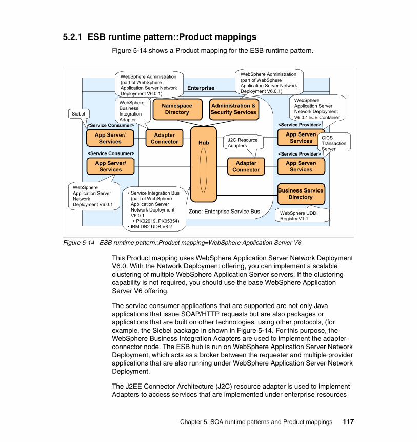
5.2.1 ESB runtime pattern::Product mappingsFigure 5-14 shows a Product mapping for the ESB runtime pattern.
Figure 5-14 ESB runtime pattern::Product mapping=WebSphere Application Server V6
This Product mapping uses WebSphere Application Server Network Deployment V6.0. With the Network Deployment offering, you can implement a scalable clustering of multiple WebSphere Application Server servers. If the clustering capability is not required, you should use the base WebSphere Application Server V6 offering.
The service consumer applications that are supported are not only Java applications that issue SOAP/HTTP requests but are also packages or applications that are built on other technologies, using other protocols, (for example, the Siebel package in shown in Figure 5-14. For this purpose, the WebSphere Business Integration Adapters are used to implement the adapter connector node. The ESB hub is run on WebSphere Application Server Network Deployment, which acts as a broker between the requester and multiple provider applications that are also running under WebSphere Application Server Network Deployment.
The J2EE Connector Architecture (J2C) resource adapter is used to implement Adapters to access services that are implemented under enterprise resources
Enterprise
Business Service Directory
Zone: Enterprise Service Bus
NamespaceDirectory
Administration & Security Services
HubApp Server/
Services
<Service Consumer>
App Server/Services
<Service Consumer>
App Server/Services
App Server/Services
<Service Provider>
<Service Provider>
• Service Integration Bus (part of WebSphere Application Server Network Deployment V6.0.1+ PK02919, PK05354)
• IBM DB2 UDB V8.2
WebSphere UDDI Registry V1.1
WebSphere Application Server Network Deployment V6.0.1 EJB Container
WebSphere Application Server Network Deployment V6.0.1
J2C Resource Adapters
WebSphere Business Integration Adapter
WebSphere Administration (part of WebSphere Application Server Network Deployment V6.0.1)
WebSphere Administration (part of WebSphere Application Server Network Deployment V6.0.1)
Siebel
CICS Transaction Server
AdapterConnector
AdapterConnector
Chapter 5. SOA runtime patterns and Product mappings 117

such as CICS Transaction Server. The WebSphere UDDI Registry is used to implement the business service directory. The advantage of using a UDDI registry is that there is a central location where all available services are published which should encourage reuse of services within an enterprise. The Administration Services and namespace directory are provided by WebSphere Application Server Network Deployment. A local DB2 database is used to store the SDO repository.
5.2.2 ESB Gateway runtime pattern::Product mappingFigure 5-15 shows the Product mapping for the ESB Gateway runtime pattern.
Figure 5-15 ESB Gateway::Product mappings
The service consumer application in this scenario is implemented using WebSphere Application Server V6. However, it could be implemented in other technologies and, in fact, could be another ESB. The service consumer initiates a service via the Gateway using either SOAP over HTTP or SOAP over JMS. The gateway endpoint node in the gateway is implemented using WebSphere Application Server and the rules directory is implemented using the file system.
Enterprise
Zone: ESB Gateway
GatewayEndpoint
GatewayEndpoint
ESB
Rules Directory
App Server/Services
<Service Consumer>
App Server/Services
<Service Provider>
App Server/Services
App Server/Services
<Service Provider>
<Service Consumer>
WebSphere Application Server V6.0.1
Service Integration Bus (part of WebSphere Application Server V6.0.1 + PK02919, PK05354)
• Service Integration Bus & WebSphere Administration (part of WebSphere Application Server V6.0.1 + PK02919, PK05354)
• Network Cloudscape
WebSphere Application Server V6.0.1
WebSphere Administration (part of WebSphere Application Server V6.0.1 + PK02919, PK05354)
118 Patterns: SOA with an Enterprise Service Bus in WebSphere Application Server V6
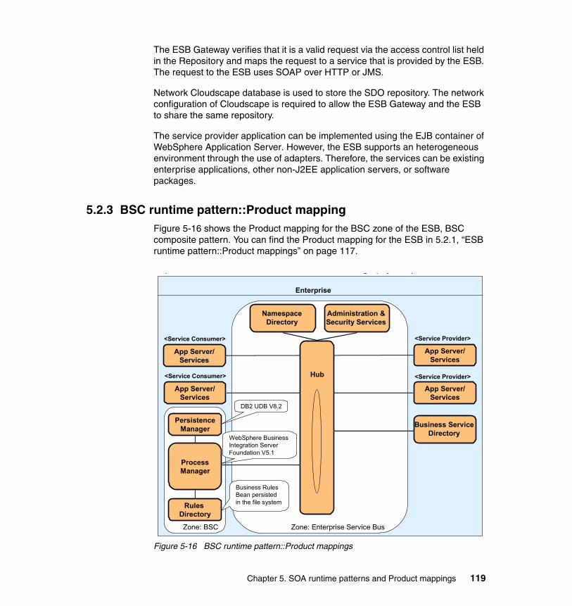
The ESB Gateway verifies that it is a valid request via the access control list held in the Repository and maps the request to a service that is provided by the ESB. The request to the ESB uses SOAP over HTTP or JMS.
Network Cloudscape database is used to store the SDO repository. The network configuration of Cloudscape is required to allow the ESB Gateway and the ESB to share the same repository.
The service provider application can be implemented using the EJB container of WebSphere Application Server. However, the ESB supports an heterogeneous environment through the use of adapters. Therefore, the services can be existing enterprise applications, other non-J2EE application servers, or software packages.
5.2.3 BSC runtime pattern::Product mappingFigure 5-16 shows the Product mapping for the BSC zone of the ESB, BSC composite pattern. You can find the Product mapping for the ESB in 5.2.1, “ESB runtime pattern::Product mappings” on page 117.
Figure 5-16 BSC runtime pattern::Product mappings
Enterprise
Zone: BSC
ProcessManager
Rules Directory
PersistenceManager Business Service
Directory
Zone: Enterprise Service Bus
NamespaceDirectory
Administration & Security Services
App Server/Services
<Service Consumer>
App Server/Services
<Service Consumer>
App Server/Services
App Server/Services
<Service Provider>
<Service Provider>Hub
p g p y p
WebSphere Business Integration Server Foundation V5.1
DB2 UDB V8.2
Business Rules Bean persisted in the file system
Chapter 5. SOA runtime patterns and Product mappings 119

The process manager is implemented using the Business Process Choreography component that is part of the WebSphere Business Integration Server Foundation product. The process manager controls the process execution and invokes services from the ESB via the hub using SOAP over HTTP or JMS.
The process manager uses the persistence manager implemented using the DB2 database to store process results and a business rules bean persisted in the file system to implement the business process flow rules as part of the rules directory node.
For more information about BSC, refer to Patterns: Serial and Parallel Processes for Process Choreography and Workflow, SG24-6306 and to Patterns: Using Business Service Choreography In Conjunction With An Enterprise Service Bus, REDP-3908.
5.2.4 Exposed ESB Gateway Product mappingFigure 5-17 shows the Product mapping for the Exposed ESB Gateway runtime pattern. This Product mapping is used to implement the scenario that is described in Chapter 11, “Exposed ESB Gateway pattern” on page 315.
Figure 5-17 Exposed ESB Gateway::Product mappings
Inter-enterprise Zone
EnterpriseDemilitarized Zone Enterprise Secure ZonePartner Zone
App Server/Services
App Server/Services
NetworkInfrastructure
ESB
Dom
ain
Fire
wal
l
ExposedESB
Gateway
Prot
ocol
Fire
wal
l
Connector
<Service Provider>
<Service Consumer>
App Server/Services
App Server/Services
<Service Consumer>
IBM HTTP Server V2
WebSphere Application Server V6.0.1
Service Integration Bus (part of WebSphere Application Server V6.0.1 + PK02919, PK05354)
• Service Integration Bus & WebSphere Administration (part of WebSphere Application Server V6.0.1 + + PK02919, PK05354)
• Network Cloudscape
WebSphere Application Server V6.0.1
<Service Provider>Internet
120 Patterns: SOA with an Enterprise Service Bus in WebSphere Application Server V6

This scenario represents an external service consumer accessing services from an Enterprise over the Internet. The service consumer in this scenario is implemented using WebSphere Application Server V6. However, it could be implemented in any technology capable of issuing HTTPS requests. The figure also shows an external service provider that is implemented using WebSphere Application Server V6 and provides Web Services that use SOAP/HTTPS.
The requests are received by an HTTP server that is located in the DMZ, which receives all incoming requests and sends them to the Exposed ESB Gateway. The Exposed ESB Gateway is implemented using WebSphere Application Server, as described in “Exposed ESB Gateway” on page 114.
The Exposed ESB Gateway verifies and maps the request to a service that is provided by the ESB. The ESB is implemented using WebSphere Application Server using a network setup for the Cloudscape database which holds the SDO repository. Finally, the internal service provider application is implemented using WebSphere Application Server.
Chapter 5. SOA runtime patterns and Product mappings 121

122 Patterns: SOA with an Enterprise Service Bus in WebSphere Application Server V6

Part 2 Business scenario and guidelines
This part of the book provides an introduction to the scenario chapters in Part 3, “Scenario implementation” on page 151. The chapters in this part are:
� Chapter 6, “The business scenario that this book uses” on page 125� Chapter 7, “Technology options” on page 131
You can skip this part of the book if you are familiar with the business scenario and WebSphere Application Server related technologies.
Part 2
© Copyright IBM Corp. 2005. All rights reserved. 123

124 Patterns: SOA with an Enterprise Service Bus in WebSphere Application Server V6

Chapter 6. The business scenario that this book uses
Part 3, “Scenario implementation” on page 151 uses a common business scenario: the WS-I Supply Chain Management sample application. This chapter describes the sample scenario, the three stages of the scenario, and the relevant chapter in which each stage is described.
6
© Copyright IBM Corp. 2005. All rights reserved. 125
6.1 WS-I sample applicationThe Web Services Interoperability Organization (WS-I) has developed a supply chain management business scenario that demonstrates the features of the WS-I Basic Profile V1.0. The following documents describe the WS-I sample business scenario and the technical solution overview:
� WS-I Supply Chain Management Use Cases V1.0� WS-I Usage Scenarios V1.0� WS-I Supply Chain Management Technical Architecture V1.0
For full details, see the Web Services Interoperability Organization Web site:
http://www.ws-i.org
This book uses this business scenario to show how you can use the Patterns for e-business, service-oriented architecture (SOA), and Enterprise Service Bus approach to develop solutions with real-world business requirements that are based on interoperability principles as defined in the WS-I Basic Profile.
This business scenario is a simplified supply chain for a consumer electronics retailer. This chapter describes the evolution of scenarios as the supply chain management organization moves from a directly connected intra-enterprise environment to an expanded organization that has divested its business and operates in an inter-enterprise environment.
6.2 Stages of the business scenarioThis section describes the stages of the business scenario. Each stage builds a layer of complexity onto the previous stage.
6.2.1 Stage 1: Internal supply chain management on demandIn a typical B2C model, customers can access the retailer’s Web site, review the catalog, and place orders for products, such as televisions, DVD players, and video cameras. The retailer system requests fulfilment of a consumer’s order from the internal company warehouse, which responds as to whether line items from the order can be filled. If stock for any line item falls below a minimum threshold in the warehouse, a replenishment order is sent to an external manufacturer using the business-to-business model.
The manufacturer does not immediately fulfill replenishment orders, but completes the order at some later time (possibly after completing a manufacturing run).
126 Patterns: SOA with an Enterprise Service Bus in WebSphere Application Server V6
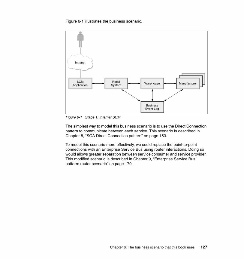
Figure 6-1 illustrates the business scenario.
Figure 6-1 Stage 1: Internal SCM
The simplest way to model this business scenario is to use the Direct Connection pattern to communicate between each service. This scenario is described in Chapter 8, “SOA Direct Connection pattern” on page 153.
To model this scenario more effectively, we could replace the point-to-point connections with an Enterprise Service Bus using router interactions. Doing so would allows greater separation between service consumer and service provider. This modified scenario is described in Chapter 9, “Enterprise Service Bus pattern: router scenario” on page 179.
Intranet
ManufacturerManufacturer
Manufacturer
BusinessEvent Log
WarehouseRetailSystem
SCMApplication
Chapter 6. The business scenario that this book uses 127

6.2.2 Stage 2: Additional warehousesThe company has a requirement to stock the parts that it offers to customers in more than one warehouse. However, the client must see the order as a single transaction with the company, as shown in Figure 6-2.
Figure 6-2 Stage 2: Additional warehouses
An Enterprise Service Bus using router interactions is no longer sufficient to model this business scenario because a single message from the retail system needs to be broken apart into multiple messages and sent to each of the warehouse systems. This scenario requires an Enterprise Service Bus with broker interactions. This stage is discussed in chapter Chapter 10, “Enterprise Service Bus pattern: broker scenario” on page 259.
Intranet
ManufacturerManufacturer
Manufacturer
BusinessEvent Log
RetailSystem
SCMApplication
ManufacturerManufacturer
ManufacturerManufacturer
ManufacturerWarehouse
128 Patterns: SOA with an Enterprise Service Bus in WebSphere Application Server V6

6.2.3 Stage 3: Divested inter-enterprise manufacturersThe company has decided to divest itself of the three manufacturers. Each manufacturer will be sold off to another company or be established as a new company in its own right. Various interactions must now take place securely over the Internet as shown in Figure 6-3.
Figure 6-3 Stage 3: Divested manufacturers
Each manufacturer runs within its own Enterprise Service Bus. Communication between two Enterprise Services Bus implementations is represented by the Exposed ESB Gateway pattern. This stage is discussed in chapter Chapter 11, “Exposed ESB Gateway pattern” on page 315.
Intranet
LoggingFacility
RetailSystem
SCMApplication
ManufacturerManufacturer
ManufacturerWarehouse
Intranet
Inte
rnet
Chapter 6. The business scenario that this book uses 129

130 Patterns: SOA with an Enterprise Service Bus in WebSphere Application Server V6

Chapter 7. Technology options
This chapter discusses the technologies that this book uses to implement the SOA patterns. The following standards are of particular importance to an SOA implementation:
� Web services� Java Message Service (JMS)� J2EE Connector Architecture
This book describes SOA implementations in WebSphere Application Server V6. The key technology to implementing SOA in WebSphere Application Server V6 is the service integration bus.
7
© Copyright IBM Corp. 2005. All rights reserved. 131
7.1 Web servicesWeb services is a recent re-invention of concepts that have been around for sometime. They introduce many new advantages and capabilities. In a sense, none of the function that Web services provide is new; CORBA has provided much of this function for many years. Web services, however, builds upon existing open Web technologies, such as XML, URL, and HTTP. Web services are defined in several different standards, such as SOAP and WSDL which build upon general Web and other Web services standards. These standards are defined by the World Wide Web Consortium, the Organization for the Advancement of Structured Information Standards (OASIS), and Web Services Interoperability Organization (WS-I).
The basic Web services support provides for three simple usage models:
� One-way usage scenario
A Web services message is sent from a consumer to a provider and no response message is expected.
� Synchronous request/response usage scenario
A Web services message is sent from a consumer to a provider and a response message is expected.
� Basic callback usage scenario
A Web service message is sent from a consumer to a provider using the 2-way invocation model, but the response is just treated as an acknowledgement that the request has been received. The provider then responds by calling making use of a Web service callback to the consumer.
Other Web service standards are built upon these basic standards and invocation models to provide higher level functions and qualities of service. Examples of these standards are WS-Transaction, WS-Security, and WS-ResourceFramework.
One of the main aims of Web services is to provide a loose coupling between service consumer and service providers. While this is limited to a certain extent by a requirement for the consumers and providers to agree on a WSDL interface definition, Web services have been created with significant flexibility with regard to the location of these Web services. Figure 7-1 on page 133 shows how the Web services interaction model has been designed with this form of loose coupling.
132 Patterns: SOA with an Enterprise Service Bus in WebSphere Application Server V6

Figure 7-1 Basic Web service interaction model
The interactions work as follows:
1. The service provider publishes some WSDL defining its interface and location to a service registry.
2. The service consumer contacts the service registry in order to obtain a reference to a service provider.
3. The service consumer, having obtained the location of the service provider, makes calls on the service provider.
Note: Although this model is regularly discussed, the service registry is often removed from the cycle in real implementations in the interests of simplicity and lack of trust of the services in the service registry. This has the drawback that if the service provider is relocated, the service consumer needs to be changed to refer to the new location of the service provider.
ServiceConsumer
ServiceRegistry
ServiceProvider
Find Publish
Use
12
3
Exposes business functions as Web servicesPublishes functions to registryListens to and accepts requests
Requires business functionsSearches registry for matching functionsBinds and make requests
Maintains repository of business functionsAccessed via UDDI
Business functions described in WSDL using UDDI
Business functions described in WSDL using UDDI
Business functions using SOAP
UDDI: Service RegistryWSDL: Service DescriptionSOAP: Service Invocation
Chapter 7. Technology options 133

SOAPSOAP is an XML-based format for constructing messages in a transport independent way and a standard on how the message should be handled. SOAP messages consist of an envelope that contains a header and a body. It also defines a mechanism for indicating and communicating problems that occurred while processing the message, which are known as SOAP faults.
The headers section of a SOAP message is extensible and can contain many different headers that are defined by different schemas. The extra headers can be used to modify the behavior of the middleware infrastructure. For example, the headers can include information about transactions that can be used to ensure that actions performed by the service consumer and service provider are coordinated.
The body section contains the content of the SOAP message. When used by Web services, the SOAP body contains XML-formatted data. This data is specified in the WSDL that describes the Web service.
When talking about SOAP, it is common to talk about SOAP in combination with the transport protocol that is used to communicate the SOAP message. For example, SOAP that is transported using HTTP is referred to as SOAP over HTTP or SOAP/HTTP.
The most common transport that is used to communicate SOAP messages is HTTP. This is expected because Web services are designed to make use of Web technologies. However, SOAP can also be communicated using JMS as a transport. When using JMS, the address of the Web service is expressed in terms of a JMS connection factory and a JMS destination. Although using JMS provides a more reliable transport mechanism, it is not an open standard, requires extra and potential expensive investment, and does not interoperate as easily as SOAP over HTTP.
The SOAP version 1.1 and 1.2 specifications are available from the World Wide Web Consortium at:
http://www.w3.org/TR/soaap/
Web Services Description LanguageWeb Services Description Language (WSDL) is an XML-based interface definition language that separates function from implementation and enables design by contract as recommended by SOA. WSDL descriptions contain a port type (the functional and data description of the operations that are available in a Web service), a binding (providing instructions for interacting with the Web service through specific protocols, such as SOAP over HTTP), and a port (providing a specific address through which a Web service can be invoked using a specific protocol binding).
134 Patterns: SOA with an Enterprise Service Bus in WebSphere Application Server V6

It is common for these aspects to be defined in three separate WSDL files, each importing the others.
The value of WSDL is that it enables development tooling and middleware for any platform and language to understand service operations and invocation mechanisms. For example, given the WSDL interface to a service that is implemented in Java, running in a WebSphere environment, and offering invocation through HTTP, a developer working in the Microsoft .Net platform can import the WSDL and easily generate application code to invoke the service.
As with SOAP, the WSDL specification is extensible and provides for additional aspects of service interactions to be specified, such as security and transactionality.
Universal Description, Discovery, IntegrationUniversal Description, Discovery, Integration (UDDI) servers act as a directory of available services and service providers. SOAP can be used to query UDDI to find the locations of WSDL definitions of services, or the search can be performed through a user interface at design or development time. The original UDDI classification was based on a U.S. government taxonomy of businesses and recent versions of the UDDI specification have added support for custom taxonomies.
A public UDDI directory is provided by IBM, Microsoft, and SAP, each of whom runs a mirror of the same directory of public services. However, there are many patterns of use that involve private registries. For more information, see the following articles:
� The role of private UDDI nodes in Web services, Part 1: Six species of UDDI
http://www.ibm.com/developerworks/webservices/library/ws-rpu1.html
� The role of private UDDI nodes, Part 2: Private nodes and operator nodes
http://www.ibm.com/developerworks/webservices/library/ws-rpu2.html
7.1.1 Web services interoperabilityIn order to facilitate the development of truly interoperable Web services, the Web Services Interoperability Organization (often referred to as the WS-I) was formed in February 2002. The WS-I aims to promote interoperability of Web services implementations by publishing profiles, which are descriptions of conventions and practices for the use of specific combinations of Web services standards through which systems can interact. Technology vendors can then produce compliant implementations and publicize that compliance, offering some level of assurance to technology customers as to the level of Web services interoperability that can be achieved with different implementations.
Chapter 7. Technology options 135
The WS-I published the first profile for interaction, the Basic Profile V1.0, in July 2003, and many technology vendors provide product implementations of Web services that are compliant with this profile. This is described further in the next section.
In August 2004, the WS-I published the Basic Profile V1.1, splitting the original profile in two: the Basic Profile V1.1 and the Simple SOAP Binding Profile V1.0. The idea is that the combination is equivalent to Basic Profile V1.0. Combining the two profiles aids in the incorporation of different binding mechanisms, such as SOAP with Attachments. This allows a implementation to make the claim that it is Basic Profile V1.1 and Attachments Profile V1.0 compliant without needing to implement the Simple SOAP Binding Profile V1.0.
The Web Services Interoperability Organization Web site contains links to published, draft, and planned interoperability profiles and information about vendor compliance:
http://www.ws-i.org/
WS-I Basic Profile V1.0The WS-I Basic Profile V1.0 specifies a set of usage scenarios and Web services standards that can be used to integrate systems. It focuses on the core foundation technologies upon which Web services are based. Basic Profile V1.0 was approved unanimously on July 22, 2003, by the WS-I board of directors and members.
The WS-I Basic Profile V1.0 - Profile Specification consists of the following non-proprietary Web services related specifications:
� SOAP V1.1� WSDL V1.1� UDDI V2.0� XML V1.0 (Second Edition)� XML Schema Part 1: Structures� XML Schema Part 2: Datatypes� RFC2246: The Transport Layer Security Protocol Version V1.0� RFC2459: Internet X.509 Public Key Infrastructure Certificate and CRL
Profile� RFC2616: HyperText Transfer Protocol V1.1� RFC2818: HTTP over TLS� RFC2965: HTTP State Management Mechanism� The Secure Sockets Layer Protocol Version V3.0
136 Patterns: SOA with an Enterprise Service Bus in WebSphere Application Server V6
The WS-I Supply Chain Management sample application depicts an application for a fictitious consumer electronics retailer. This sample application is the basis of the scenarios in this book and is described in Chapter 6, “The business scenario that this book uses” on page 125.
See also the following IBM developerWorks® articles:
� First look at the WS-I Basic Profile V1.0
http://www.ibm.com/developerworks/webservices/library/ws-basicprof.html
� First look at the WS-I Usage Scenarios
http://www.ibm.com/developerworks/webservices/library/ws-iuse/
� Preview of WS-I sample application
http://www.ibm.com/developerworks/webservices/library/ws-wsisamp/
WS-I Basic Profile V1.1The WS-I Basic Profile V1.1 removes the SOAP binding requirements and moves them to the Simple SOAP Binding Profile V1.0. This means that being WS-I Basic Profile V1.1 compliant by itself is not very interesting. It is not until a binding is applied that the Web services can interact. Two bindings have been created. The Simple SOAP Binding Profile V1.0 which together with the WS-I Basic Profile V1.1 allows equivalent function to the Basic Profile V1.0, and the Attachments Profile V1.0 which allows SOAP with attachments as a binding option.
7.1.2 Advanced and future Web services standardsThere are many successful implementations of the basic Web services standards, particularly SOAP and WSDL but many aspects of service interaction and integration are not directly supported by those basic standards, such as security, transactionality, delivery assurance, and process modeling.
The Web services standards are evolving and maturing to address these aspects of interaction and integration, increasing their value to SOA. This section discusses some of the recent and emerging Web services standards that support more sophisticated aspects of service interactions and SOA.
Production-level product support for some of these standards is not yet available, but early implementations exist. The IBM Emerging Technologies Toolkit (ETTK), for example, provides an implementation of WS-ReliableMessaging. You can download the toolkit from:
http://www.alphaworks.ibm.com/tech/ettk
Chapter 7. Technology options 137

Web services securityIn theory, Web services can leverage any security model that is appropriate to the underlying communication technologies. (SOAP/HTTP can use basic HTTP authentication or SSL authentication and encryption.) However, such simple point-to-point models are insufficient for the widespread integration needs of SOA. For example:
� Communication security does not recognize the difference between SOAP message headers and the SOAP message body.
� Credentials can be technology-specific to the communication mechanism, but inappropriate to communication mechanisms that are used farther down the interaction chain.
� Combining many interactions in a secure overall chain involves trust models between the participants in the chain. Such models are often customized or proprietary, and are not consistent with flexibly changing the participants in the chain as they imply a technology barrier to participation.
In 2002, IBM and Microsoft proposed an architecture and road map for Web services security (WS-Security). This set out a framework consisting of several Web services specifications, including WS-Security, WS-Trust, WS-Privacy, and WS-Policy. It also accommodated existing security technologies such as Kerberos, XML Digital Signatures, and XML Encryption.
Support for the basic WS-Security standards is available in existing products and can be used to implement secure Web services solutions. Understanding the security requirements of specific SOA situations and selecting appropriate technologies, include those compliant with the WS-Security standards, is a key decision in SOA implementation.
For further information, see:
� Security in a Web Services World: a Proposed Architecture and Road map
http://www.ibm.com/developerworks/library/ws-secmap/
� Web Services Security: Moving up the stack
http://www.ibm.com/developerworks/webservices/library/ws-secroad/
WS-ReliableMessaging and SOAP/JMSThe HTTP protocol is used widely in SOAP interactions and is specified in the WS-I Basic Profile. However, it offers relatively poor reliability in contrast to communication protocols that are often associated with valuable business transactions, such as WebSphere MQ. Many SOA scenarios involve interactions that require a level of delivery assurance beyond that provided by HTTP.
138 Patterns: SOA with an Enterprise Service Bus in WebSphere Application Server V6

The WS-ReliableMessaging specification defines a protocol for reliable communication (including SOAP messages) that use a variety of communication technologies, which themselves might be less reliable. An updated specification was published in March 2004.
Until WS-ReliableMessaging is widely available, alternative approaches are possible using implementations of SOAP over more reliable communication infrastructures. For example, SOAP messaging is supported through the JMS API to WebSphere MQ by WebSphere MQ, the Web Services Gateway, and WebSphere Business Integration Server Foundation. However, such approaches tend to be implementations by specific technology vendors so, although they are useful in particular SOA implementations, they do not have all of the potential benefits of a fully open-standard implementation.
For further information, see:
� Updated: Web Services Reliable Messaging: A new protocol for reliable delivery between distributed applications
http://www.ibm.com/developerworks/webservices/library/ws-rm/
� Implementation Strategies for WS-ReliableMessaging: How WS-ReliableMessaging can interact with other middleware communication systems
http://www.ibm.com/developerworks/webservices/library/ws-rmimp/
Business Process Execution Language for Web ServicesThe encapsulation and exposure of business functions as services in an SOA enables the definition of processes consisting of those services. The Business Process Execution Language for Web Services (BPEL4WS) provides a standard, XML language for expressing business processes consisting of functions that are defined through WSDL interfaces. BPEL4WS supports both short-lived processes and long-lived processes (processes that must wait at certain points until some event occurs, such as the receipt of an event).
As with WSDL, BPEL4WS has both design time and runtime uses. At design time, development or modeling tools can use, import, or export BPEL4WS to enable business analysts to specify processes and developers to refine them and bind process steps to specific service implementations. The runtime choreography and workflow engines can use BPEL4WS to control the execution of processes and invoke the services that are required to implement them.
Although BPEL4WS is a relatively new standard, product support such as WebSphere Business Integration Server Foundation V5.1 is available. This support provides additional facilities to compensate failed processes (a proprietary equivalent to the WS-BusinessActivity standard described in the next
Chapter 7. Technology options 139

section, “Web services transactions”) and provide a user workflow interface to enable human actions to fulfill WSDL-defined steps in a BPEL4WS process.
For further information, see:
� BPEL4WS Specification
http://www.ibm.com/developerworks/library/ws-bpel/
� Business Process with BPEL4WS, a series of introductory articles and references
http://www.ibm.com/developerworks/webservices/library/ws-bpelcol1/
� BPEL4WS support in WebSphere Business Integration Server Foundation
http://www.ibm.com/software/integration/wbisf/features/
� BPEL4WS support in WebSphere Studio Application Developer Integration Edition
http://www.ibm.com/software/integration/wsadie/features/
Web services transactionsAlthough WS-ReliableMessaging provides a means to assure the delivery of individual communications in a Web services interaction, a means is also required to control the integrity of business transactions in an SOA that consist of one or more Web services invocations or interactions.
Within the framework of the Web services coordination (WS-Coordination) specification, both synchronous (WS-AtomicTransaction) and long-lived (WS-BusinessActivity) transaction models have been defined. These replace the previous WS-Transaction specification.
The WS-AtomicTransaction specifies a model for synchronous, two-phase committal of distributed transactions using Web services protocols. WS-BusinessActivity defines an asynchronous model for compensating failed processes using undo actions to reverse the effects of individual steps of the process. Neither specification has mature product support to date.
For further information, see:
� WS-AtomicTransaction Specification
http://www.ibm.com/developerworks/library/ws-atomtran/
� WS-BusinessActivity Specification
http://www.ibm.com/developerworks/webservices/library/ws-busact/
� Transactions in the world of Web Services, part 1 and part 2
http://www.ibm.com/developerworks/webservices/library/ws-wstx1/http://www.ibm.com/developerworks/webservices/library/ws-wstx2/
140 Patterns: SOA with an Enterprise Service Bus in WebSphere Application Server V6

� WS-Coordination Specification
http://www.ibm.com/developerworks/library/ws-coor/
Web Services Policy Framework (WS-Policy)The Web Services Policy Framework is intended to provide a set of languages by which service consumers and providers can express their requirements and capabilities concerning qualities of service of service interactions, such as security, transactionality, and communication reliability. Eventually, a framework of such languages, supported by Enterprise Service Bus middleware, enables open-standard implementations of negotiated coupling between various aspects of service interactions.
A WS-Policy specification is available, although specific policy languages for quality of service aspects such as security are still required, and product support has yet to emerge.
For further information, see:
� WS-Policy Framework Specification
http://www.ibm.com/developerworks/library/ws-polfram/
� Web Services Policy Framework: New specifications improve WS-Security
http://www.ibm.com/developerworks/webservices/library/ws-polfram/summary.html
7.2 Java Message ServiceThe Java Message Service (JMS) is a cross platform Java API for accessing message oriented middleware.
7.2.1 Understanding messagingMessaging is a form of communication between two or more software applications or components. Messaging is commonly used for application integration where the application does not need an immediate answer to progress. In messaging, the requester sends a message to a destination. At some point the provider receives the message and does some processing. It does not require that the two applications be up at the same time. The power of messaging lies in this disconnect. Messaging is often referred to as loosely coupled, but to get the full advantage of this, advanced broker functionality is
Chapter 7. Technology options 141
required. Without this broker functionality the requester and provider must agree on a format and location for the messages. The addition of broker functionality allows for routing of messages between destinations and for code to be inserted into the messaging middleware in order to transform message formats.
7.2.2 JMS messagesThe JMS specification defines a set of message types and APIs for sending and receiving those messages to and from destinations. In JMS, messages are split into the following sections:
� Header
The JMS header contains information about where the message was sent to and where responses should be sent. These properties are typically for use by the JMS provider.
� Properties
JMS properties are application level properties. JMS properties can be strings, numbers, or booleans and are named. The JMS properties are intended as an extensible form of application level header.
� Body
The body of the message contains the data being transported. It is intended for the payload of the message.
JMS defines the following interaction styles for messaging:
� Point-to-point
A single message sent to a destination is received by a single client.
� Publish subscribe
A single message sent, or published, to a destination is received by all clients.
Messages can be persisted at the destinations. The intent is that persistent messages are guaranteed to be delivered and not duplicated. Messages can also be sent as a part of an externally coordinated two phase commit transaction.
The J2EE V1.3 specification integrates support for JMS V1.0.2b and requires that J2EE V1.3 compliant application servers include an integral JMS provider. It also introduces the concept of message-driven beans (MDBs), which allow message to be delivered to an EJB allowing the asynchronous invocation of business logic.
With J2EE V1.4 the JMS specification is upgraded to the V1.1 level which includes support for domain neutral messaging. In JMS 1.0.2b the application writer has to decide which of the two messaging model, point-to-point or publish
142 Patterns: SOA with an Enterprise Service Bus in WebSphere Application Server V6

subscribe, the program should use. In JMS V1.1 the programming model is the same for both interactions models. It is type of the destination that is used to determine which model that maps to. Destinations in JMS are considered administrative objects which get bound into a JNDI namespace and looked up later. J2EE V1.4 also makes the concept of an MDB more generic, providing a framework for anyone wishing to trigger work asynchronously into an enterprise application.
The JMS provider in WebSphere Application Server V6 is the service integration bus. See 7.4, “Service integration bus in WebSphere Application Server” on page 145
7.2.3 Advantages of JMSThe following are some of the advantages of using JMS:
� It is the first enterprise messaging API that has achieved wide cross-industry support.
� It simplifies the development of enterprise applications by providing standard messaging concepts and conventions that apply across a wide range of enterprise messaging systems.
� It leverages existing, enterprise-proven, messaging systems.
� It allows you to extend existing message-based applications by adding new JMS clients that are integrated fully with their existing non-JMS clients.
� Developers have to learn only one common interface for accessing diverse messaging systems.
7.2.4 Disadvantages of JMSThe following are some of the disadvantages of using JMS:
� In common with messaging, in general it does not easily support the concepts of synchronous request-response.
� It is not a protocol, so all your JMS applications need to access the same JMS provider.
� JMS resources require an extra level of administration.
Chapter 7. Technology options 143
7.3 J2EE Connector ArchitectureThe J2EE Connector Architecture is aimed at providing a standard way to access enterprise applications from a J2EE-based Java application. It defines a set of Java interfaces through which application developers can access Enterprise Information Systems (EIS), for example, CICS, and Enterprise Resource Planning (ERP) applications.
J2EE Connector Architecture V1.5 support is a requirement of the J2EE V1.4 specification. Resource adapters allow J2EE applications to connect to a particular EIS. The J2EE Connector Architecture specification defines the following types of resource adapters:
� Outbound adapters, which are used by application initiated requests to an EIS.
� Inbound adapters, which are used by the EIS making calls to a message-driven bean.
The J2EE Connector Architecture provides a Common Client Interface API (CCI) with both common and resource adapter specific interfaces. Application programmers code to this single API rather than using different interfaces for each proprietary system. However, it is common for a resource adapter to make use of its own, or an existing API, such as JDBC or JMS.
The J2EE Connector Architecture specification provides support for transactions, security and sharing of connections between different clients.
7.3.1 Advantages of the J2EE Connector ArchitectureThe following are some of the advantages of using J2EE Connector Architecture resource adapters:
� The CCI simplifies application integration with diverse EISs. This common interface makes it easy to plug third-party or home-grown resource adapters into your applications.
� Inbound adapters provide a way to get a message-driven bean invoked when an event occurs in the EIS (for example, a message arrives at a JMS destination).
� Outbound adapters that are XA capable automatically participate in any transactions in effect without requiring action by an application.
� Outbound adapters can pick up security credentials from the container where they are executing.
� Connections to the EIS can be shared to reduce resource overhead.
144 Patterns: SOA with an Enterprise Service Bus in WebSphere Application Server V6
7.3.2 Disadvantages of the J2EE Connector ArchitectureAlthough the CCI provides a common interface definition, some resource adapter specific interfaces still need to be used. The usage of these interfaces varies depending on the EIS the resource adapter used.
7.4 Service integration bus in WebSphere Application Server
The service integration bus provides advanced support for application integration. It combines support for applications connecting via native JMS, WebSphere MQ JMS, WebSphere MQ, and Web services. It supports the message-oriented middleware and request-response interaction models. As a part of this, the service integration bus supports multiple message distribution models, reliability options, and transactional messaging.
7.4.1 Concepts and architectureThis section discusses the new concepts that service integration bus technology introduces.
BusA service integration bus, or bus, provides a conceptual connection point and a namespace for destinations and services. The application integration capabilities of the service integration bus are provided by a number of connected messaging engines.
Messaging engineA messaging engine provides the messaging capabilities of the service integration bus. Messaging engines provide two functions:
� Message management
A messaging engine manages messages by routing them to the appropriate endpoint (via additional messaging engines if required). These messages can be persisted to a database and managed within a transactional scope.
� Connection management
While the conceptual entity clients connect to is the bus, the physical connection is to a messaging engine. Clients can connect into any messaging engine in the bus and send messages to it. If the destination is assigned to a different messaging engine the messaging engine will route it to the correct messaging engine. A messaging engine is assigned to a bus member.
Chapter 7. Technology options 145
Bus memberA bus member is an application server or cluster that is a member of a bus and, therefore, is hosting a messaging engine.
DestinationA destination is an addressing point within a bus. A destination is assigned to one bus member and, therefore, one or more messaging engines. Clients send messages to a destination and the bus ensures that it is routed to the correct localization on the bus. The following destination types are supported by the service integration bus:
� Web service destinations
Web service destinations are a representation of an outbound Web service in the bus. They are used as a placeholder for a port selection mediation.
� Port destinations
Port destinations are a representation of an outbound Web service port. Sending a Web service request to a port destination will result in the target Web service being invoked.
� Queue destinations
Queue destinations are destinations that are configured for point-to-point messaging.
� Topic space destinations
Topic space destinations are destinations that are configured for publish/subscribe messaging.
� Alias destinations
Alias destinations are destinations that are configured to refer to another destination. They provide an extra level of indirection for messaging applications. An alias destination can also be used to override some of the values specified on the target destination, such as default reliability and maximum reliability. An alias destination can also refer to a destination on a foreign bus. Foreign buses are discussed in “Foreign bus” on page 148.
� Foreign destinations
Foreign destinations are not actual destinations within a service integration bus, but they can be used override the default reliability and maximum reliability properties of a destination that exists on a foreign bus. Foreign buses are discussed in “Foreign bus” on page 148.
Destinations can be mediated to provide advanced message formatting and routing function.
146 Patterns: SOA with an Enterprise Service Bus in WebSphere Application Server V6

Inbound serviceAn inbound service is defined to allow Web service clients to connect into the bus. An inbound service converts an incoming Web service request into a message and places it on a destination. The message can then be routed, transformed, and processed. Inbound services can be invoked using SOAP over JMS or SOAP over HTTP by associating the service with the relevant endpoint listener.
Outbound serviceAn outbound service allows a Web service request in the bus to exit and invoke a Web service. The Web service can be invoked by SOAP over JMS or SOAP over HTTP. Creating an outbound service causes Web service and port type destinations to be created. Sending a Web service message to the Web service destination causes the Web service to be invoked. By routing a request from an inbound service to an outbound service, the service integration bus can be inserted in the Web service flow providing some Enterprise Service Bus capabilities.
Endpoint listenerAn endpoint listener listens for incoming Web service requests via HTTP or JMS and passes them onto the relevant inbound service. An endpoint listener can be thought of as a localization point for an inbound service.
Message pointWhen a destination is assigned to a bus member, a message point is created. The messages are stored on the message point.
The following are the types of message point that can be contained with a messaging engine:
� Queue point, which is the message point for a queue destination.
� Publication points, which is the message point for a topic space. Creating a topic space destination automatically defines a publication point for each messaging engine within the bus.
� Mediation points, which is where messages are stored while they wait to be mediated. A mediated destination also has mediation points.
Chapter 7. Technology options 147

MediationA mediation processes in-flight messages between the production of a message by one application and the consumption of a message by another application. Mediations enable the messaging behavior of a bus to be customized. Examples of the processing that can be performed by a mediation are:
� Transforming a message from one format into another.
� Dynamically routing messages to one or more target destinations that were not specified by the sending application.
� Augmenting messages by adding data from a data source.
� Disaggregation of a request into several requests and then aggregation of the responses.
A mediation is defined within a bus. This mediation can then be associated with a destination on the bus. A destination with which the mediation is associated is referred to as a mediated destination.
Foreign busA bus can be configured to connect to and exchange messages with other messaging networks. A foreign bus is how the service integration bus refers to one of these networks.
A foreign bus encapsulates information related to the remote messaging network, such as the type of the foreign bus and whether messaging applications are allowed to send messages to the foreign bus. When buses are interconnected, applications can send messages to destinations that are defined on other buses.
Foreign bus linkWhen a foreign bus is configured on a bus, it simply names a foreign bus. It does not define a link between the two. In order for the two buses to be able to communicate with each other at runtime, links must be configured between a specific messaging engine within the local bus and a specific messaging engine, or queue manager, within the foreign bus. When configuring a direct service integration bus link, these links must be configured in both directions in order for the two buses to be able to communicate. At runtime, messages that are routed to a foreign bus will flow across the corresponding link.
Exception destinationsIf a message cannot be delivered to the target destination or client, the message is placed on an exception destination. Thus, messages are not lost in the event of delivery failure and allows applications to continue in the event of a corrupt or poisoned message.
148 Patterns: SOA with an Enterprise Service Bus in WebSphere Application Server V6

7.4.2 Further informationYou can find more information about the service integration bus in WebSphere Application Server V6 System Management and Configuration Handbook, SG24-6451.
Chapter 7. Technology options 149

150 Patterns: SOA with an Enterprise Service Bus in WebSphere Application Server V6

Part 3 Scenario implementation
This part of the book consists of what we term scenario chapters. Each chapter takes a Runtime pattern from the SOA profile of the Patterns for e-business and describes how to design, development, and deploy this pattern using WebSphere Application Server V6. Each chapter is divided into design guidelines, development guidelines, and runtime guidelines.
This part contains the following chapters:
� Chapter 8, “SOA Direct Connection pattern” on page 153� Chapter 9, “Enterprise Service Bus pattern: router scenario” on page 179� Chapter 10, “Enterprise Service Bus pattern: broker scenario” on page 259� Chapter 11, “Exposed ESB Gateway pattern” on page 315
Part 3
© Copyright IBM Corp. 2005. All rights reserved. 151

152 Patterns: SOA with an Enterprise Service Bus in WebSphere Application Server V6

Chapter 8. SOA Direct Connection pattern
The simplest form of SOA implementation is to use the Direct Connection runtime pattern, where service consumers and providers communicate through direct point-to-point interactions. Although simple to implement, this pattern does not incorporate an Enterprise Service Bus (ESB) design and, thus, does not inherit any of the advantages of using an ESB.
This chapter discusses how to construct the simplest form of SOA and also introduces the basic runtime guidelines for administering WebSphere Application Server V6. We have, however, deliberately kept this chapter as short and simple as possible. For more advanced information about SOA design decisions, development guidelines, and runtime guidelines, consult the Enterprise Service Bus scenario chapters which follow this chapter.
8
© Copyright IBM Corp. 2005. All rights reserved. 153

8.1 Design guidelinesThis section discusses the business needs that are addressed by the sample scenario, and the appropriate SOA pattern and WebSphere products that meet the requirements of this solution. The business scenario that is implemented in this chapter is Stage 1 of the WS-I sample application business scenario that is defined in Chapter 6, “The business scenario that this book uses” on page 125.
8.1.1 Business scenarioThe business scenario that is implemented in this chapter represents the internal supply chain management on demand scenario as defined in 6.2.1, “Stage 1: Internal supply chain management on demand” on page 126. This scenario illustrates how you can develop solutions to real-world business requirements within an single enterprise by applying an SOA that uses simple point-to-point interactions.
The Supply Chain Management application makes requests to the Retail system to help customers buy electronics goods online. The Retailer receives stock from the Warehouse, and the Warehouse replenishes stock from the Manufacturers, on a one-to-one basis, as shown in Figure 8-1.
Figure 8-1 High-level business context showing the existing infrastructure
Intranet
ManufacturerManufacturer
Manufacturer
Logging Facility
WarehouseRetailSystem
SCMApplication
154 Patterns: SOA with an Enterprise Service Bus in WebSphere Application Server V6
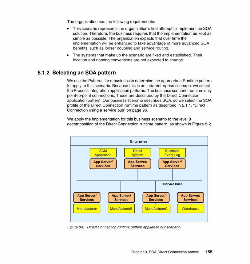
The organization has the following requirements:
� This scenario represents the organization’s first attempt to implement an SOA solution. Therefore, the business requires that the implementation be kept as simple as possible. The organization expects that over time the implementation will be enhanced to take advantage of more advanced SOA benefits, such as looser coupling and service routing.
� The systems that make up the scenario are fixed and established. Their location and naming conventions are not expected to change.
8.1.2 Selecting an SOA patternWe use the Patterns for e-business to determine the appropriate Runtime pattern to apply to this scenario. Because this is an intra-enterprise scenario, we select the Process Integration application patterns. The business scenario requires only point-to-point connections. These are described by the Direct Connection application pattern. Our business scenario describes SOA, so we select the SOA profile of the Direct Connection runtime pattern as described in 5.1.1, “Direct Connection using a service bus” on page 96.
We apply the implementation for this business scenario to the level 0 decomposition of the Direct Connection runtime pattern, as shown in Figure 8-2.
Figure 8-2 Direct Connection runtime pattern applied to our scenario
Enterprise
<Service Bus>
App Server/Services
App Server/Services
App Server/Services
App Server/Services
App Server/Services
App Server/Services
App Server/Services
SCM Application
Retail System
Business Event Log
Manufacturer ManufacturerB ManufacturerC Warehouse
Chapter 8. SOA Direct Connection pattern 155
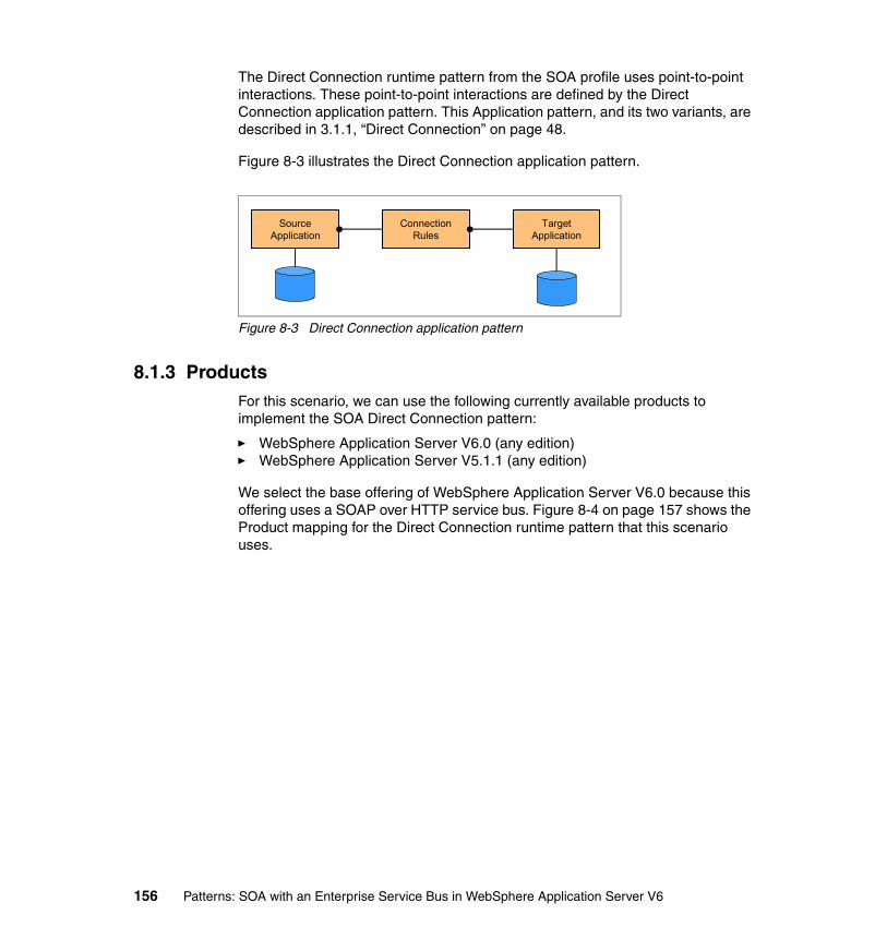
The Direct Connection runtime pattern from the SOA profile uses point-to-point interactions. These point-to-point interactions are defined by the Direct Connection application pattern. This Application pattern, and its two variants, are described in 3.1.1, “Direct Connection” on page 48.
Figure 8-3 illustrates the Direct Connection application pattern.
Figure 8-3 Direct Connection application pattern
8.1.3 ProductsFor this scenario, we can use the following currently available products to implement the SOA Direct Connection pattern:
� WebSphere Application Server V6.0 (any edition)� WebSphere Application Server V5.1.1 (any edition)
We select the base offering of WebSphere Application Server V6.0 because this offering uses a SOAP over HTTP service bus. Figure 8-4 on page 157 shows the Product mapping for the Direct Connection runtime pattern that this scenario uses.
TargetApplication
SourceApplication
ConnectionRules
156 Patterns: SOA with an Enterprise Service Bus in WebSphere Application Server V6

Figure 8-4 Product mapping=WebSphere Application Server V6
The sample application internally uses JMS messaging to communicate to its components. Therefore, a JMS-capable messaging engine is required. We use the default JMS messaging capability that is provided by the WebSphere Application Server V6.0 service integration bus.
8.2 Development guidelinesThe scenario that this book uses is based on the WS-I sample application. This section discusses how the scenario makes use of the SOA Direct Connection runtime pattern.
8.2.1 Scenario implementation: Direct Connection interactionFigure 8-5 on page 158 shows the WS-I sample application. Each scenario has a similar diagram that shows the interactions that are made by each component in the sample application.
Enterprise
App Server/Services
AdapterConnector
App Server/Services
AdapterConnector
App Server/Services
AdapterConnector
<Service Bus>SOAP V1.1 /HTTP V1.1
WebSphere Application Server V6.0
SOAP provider
Web service
Chapter 8. SOA Direct Connection pattern 157

Figure 8-5 Scenario implementation using the Direct Connection pattern
Figure 8-5 shows how the application has been written and how it interacts with other components. Shown are the enterprise applications (the blue boxes), the Web services (the white boxes), and the operations (the small white boxes that come out of the larger white boxes). Also shown is whether the operation in question is a one-way or two-way Web service request or a JMS operation. All arrows that connect the cogs to operations indicate a Web service invocation. Lines that are decorated by an envelope designate a SOAP over JMS invocation. All other invocations are SOAP over HTTP.
LoggingFacility
logEvent
getEvents
LoggingFacility
Retailer
getCatalog
submitOrder
Retailer
Warehouse
shipGoodsWarehouse
submitSN
errorPO
WarehouseCallback
SCMSampleUI
SCMSampleUI
Key:
Operation name A Web service operation or onMessage
Indicates a one-way operation Indicates a Web service request
Indicates a JMS related operation
Indicates a request/response operation
shipGoods
logEvent
logEvent
submitPO
logEvent
getEvents
getCatalog
submitOrder
submitPOManufacturer
ManufacturerMDB
logEvent
onMessage
submitSN
errorPO
Manufacturer
158 Patterns: SOA with an Enterprise Service Bus in WebSphere Application Server V6
The application interacts as follows:
1. The SCMSampleUI application:
a. Provides a Web user interface.
b. Invokes the Retailer Web service to obtain a list of all the items that can be purchased.
c. Invokes the Retailer Web service to order an item.
d. Invokes the LoggingFacility to track an order.
2. When an order is submitted, the Retailer Web service:
a. Invokes the LoggingFacility to log events that occur in the order.
b. Invokes the Warehouse to obtain whether the order can be shipped and, if so, has it shipped.
3. When a request to ship goods is made, the Warehouse Web service:
a. Determines if there is enough of the goods in stock to ship the order.
• If there is not enough goods in stock, it refuses to ship the order.
• If there is enough goods in stock, it ships the order.
b. Determines if more goods need to be ordered:
• If more goods need to be ordered, it submits a purchase order to the relevant manufacturer.
• If there is enough goods in stock, it does nothing.
4. When a purchase order is submitted, the Manufacturer Web service sends a JMS message to a queue.
5. When triggered, Manufacturer message-driven bean:
a. If the purchase order can be filled:
• Invokes submitSN on the WarehouseCallback.
• Invokes LoggingFacility to log that the item has been shipped.
b. If the purchase order cannot be filled:
• Invokes errorPO on the WarehouseCallback.
• Invokes LoggingFacility to indicate that the item cannot be shipped.
6. When invoked, the WarehouseCallback Web service calls the LoggingFacility to indicate whether the purchase order was filled.
Chapter 8. SOA Direct Connection pattern 159

8.3 Runtime guidelinesThis section takes you through the steps that are involved for configuring the sample application using the SOA Direct Connection pattern. It assumes that you have a running application server.
This section describes the following activities:
� Using the service integration bus for messaging� Creating a bus� Adding a bus member� Creating the destinations� Creating a JMS connection factory� Creating the JMS queues� Creating the JMS activation specifications� Hosting the WSDL files� Installing the applications� Running and using the sample application
8.3.1 Using the service integration bus for messagingThe sample scenario that is used in this chapter uses JMS messaging to pass messages within the three Manufacturer enterprise applications, as shown in Figure 8-6 on page 161.
160 Patterns: SOA with an Enterprise Service Bus in WebSphere Application Server V6
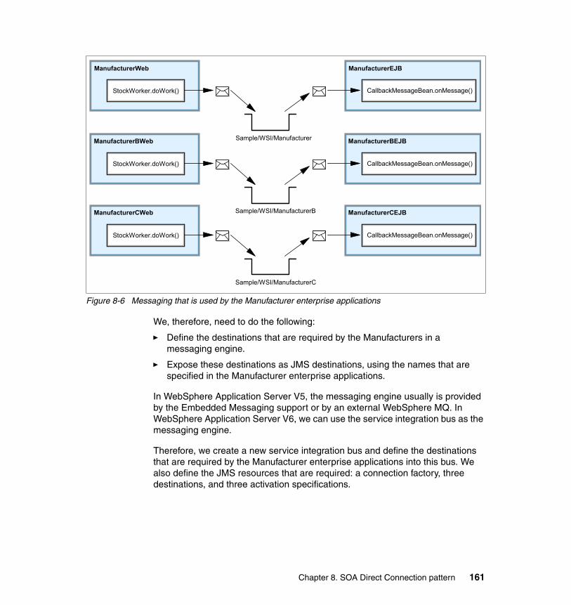
Figure 8-6 Messaging that is used by the Manufacturer enterprise applications
We, therefore, need to do the following:
� Define the destinations that are required by the Manufacturers in a messaging engine.
� Expose these destinations as JMS destinations, using the names that are specified in the Manufacturer enterprise applications.
In WebSphere Application Server V5, the messaging engine usually is provided by the Embedded Messaging support or by an external WebSphere MQ. In WebSphere Application Server V6, we can use the service integration bus as the messaging engine.
Therefore, we create a new service integration bus and define the destinations that are required by the Manufacturer enterprise applications into this bus. We also define the JMS resources that are required: a connection factory, three destinations, and three activation specifications.
ManufacturerWeb
StockWorker.doWork()
Sample/WSI/Manufacturer
ManufacturerEJB
CallbackMessageBean.onMessage()
ManufacturerBWeb
StockWorker.doWork()
Sample/WSI/ManufacturerB
ManufacturerBEJB
CallbackMessageBean.onMessage()
ManufacturerCWeb
StockWorker.doWork()
Sample/WSI/ManufacturerC
ManufacturerCEJB
CallbackMessageBean.onMessage()
Chapter 8. SOA Direct Connection pattern 161

8.3.2 Creating a busThe first step in the process is to create a new service integration bus. To create a bus:
1. Access and log in to the WebSphere Application Server administrative console at:
http://localhost:9060/ibm/console
2. Expand Service integration and click Buses.
3. Click New.
4. In the field labeled Name, enter TESTBUS, as shown in Figure 8-7. For the other values, accept the defaults.
Figure 8-7 New Bus details entry page
5. Click Apply, and the bus is created. Save the changes.
Note: In this chapter, we simply use the service integration bus as a messaging engine. If our sample application did not use messaging, we would not have needed the service integration bus to implement the SOA Direct Connection pattern. The Web services support of the service integration bus was not required, because all our Web service interactions are point-to-point and require no redirection or mediation.
In the following chapters, we use the Web services support of the service integration bus to act as an intermediary between Web service invocations. In those chapters, we use the service integration bus as a component of an Enterprise Service Bus.
162 Patterns: SOA with an Enterprise Service Bus in WebSphere Application Server V6
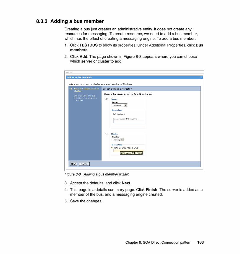
8.3.3 Adding a bus memberCreating a bus just creates an administrative entity. It does not create any resources for messaging. To create resource, we need to add a bus member, which has the effect of creating a messaging engine. To add a bus member:
1. Click TESTBUS to show its properties. Under Additional Properties, click Bus members.
2. Click Add. The page shown in Figure 8-8 appears where you can choose which server or cluster to add.
Figure 8-8 Adding a bus member wizard
3. Accept the defaults, and click Next.
4. This page is a details summary page. Click Finish. The server is added as a member of the bus, and a messaging engine created.
5. Save the changes.
Chapter 8. SOA Direct Connection pattern 163

8.3.4 Creating the destinationsThe Manufacturer enterprise application uses a JMS to trigger some work to occur asynchronously. The use of JMS requires you to create some destinations. To create these destinations:
1. From the bus details page for TESTBUS under Additional Properties, click Destinations.
2. Click New.
3. In the page that appears, as shown in Figure 8-9, you can select the type of destination to be created. Accept the default of Queue, and click Next. This launches the Queue creation wizard.
Figure 8-9 Destination type selection page
4. The first page of the wizard, as shown in Figure 8-10, asks for an identifier and description. The identifier is the name by which the destination will be exposed to applications. Enter ManufacturerSIBQ, and click Next.
Figure 8-10 New Destination wizard
164 Patterns: SOA with an Enterprise Service Bus in WebSphere Application Server V6
5. The next page allows you to specify to which bus member to assign the destination. There is only one bus member in this scenario, so accept the default. Click Next.
6. The final page is just a summary. Click Finish, and the destination is created.
7. We need to create an additional two queue type destinations. So, repeat steps 2 on page 164 to 6 and specify ManufacturerBSIBQ and ManufacturerCSIBQ instead of ManufacturerSIBQ.
8. Save the changes.
8.3.5 Creating a JMS connection factoryThe next step is to create a JMS connection factory so that the Manufacturers can connect to the service integration bus to send a JMS message. To create a JMS connection factory:
1. From the administrative console, expand Resources → JMS Providers, and click Default messaging.
2. Under Connection Factories, click JMS connection factory.
3. Click New.
The page that appears, as shown in Figure 8-11 on page 166, allows you to specify the properties for the JMS connection factory.
Chapter 8. SOA Direct Connection pattern 165
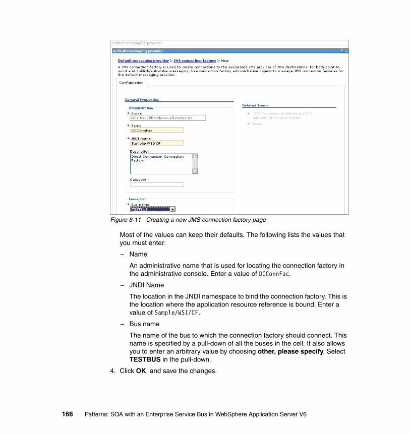
Figure 8-11 Creating a new JMS connection factory page
Most of the values can keep their defaults. The following lists the values that you must enter:
– Name
An administrative name that is used for locating the connection factory in the administrative console. Enter a value of DCConnFac.
– JNDI Name
The location in the JNDI namespace to bind the connection factory. This is the location where the application resource reference is bound. Enter a value of Sample/WSI/CF.
– Bus name
The name of the bus to which the connection factory should connect. This name is specified by a pull-down of all the buses in the cell. It also allows you to enter an arbitrary value by choosing other, please specify. Select TESTBUS in the pull-down.
4. Click OK, and save the changes.
166 Patterns: SOA with an Enterprise Service Bus in WebSphere Application Server V6
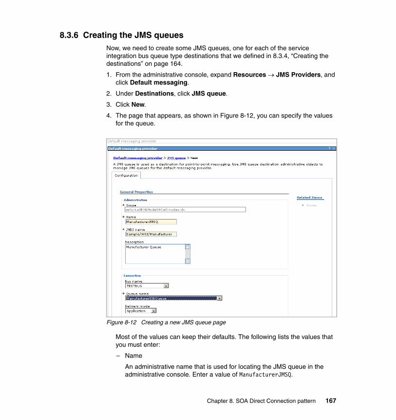
8.3.6 Creating the JMS queuesNow, we need to create some JMS queues, one for each of the service integration bus queue type destinations that we defined in 8.3.4, “Creating the destinations” on page 164.
1. From the administrative console, expand Resources → JMS Providers, and click Default messaging.
2. Under Destinations, click JMS queue.
3. Click New.
4. The page that appears, as shown in Figure 8-12, you can specify the values for the queue.
Figure 8-12 Creating a new JMS queue page
Most of the values can keep their defaults. The following lists the values that you must enter:
– Name
An administrative name that is used for locating the JMS queue in the administrative console. Enter a value of ManufacturerJMSQ.
Chapter 8. SOA Direct Connection pattern 167

– JNDI Name
The location in the JNDI namespace to bind the JMS queue. This is the location where applications message reference is bound. Enter a value of Sample/WSI/Manufacturer.
– Bus name
The name of the bus to which you are connecting. While this name is not strictly necessary, specifying the bus name allows the administrative console to fill in the Queue names with the queue type destinations that are defined on the bus. Select the value of TESTBUS. The page is reloaded with the Queue names list.
– Queue name
This field specifies the service integration bus queue type destination that is used to store the messages that are sent to this JMS queue. Select the value of ManufacturerSIBQ.
5. Click OK.
6. You need to repeat steps 3 on page 167 to 5 to create two other JMS queues. Table 8-1 and Table 8-2 provide the configuration for these queues.
Table 8-1 JMS queue settings for Manufacturer B
Table 8-2 JMS queue settings for Manufacturer C
7. Save the changes.
Field Value
Name ManufacturerBJMSQ
JNDI Name Sample/WSI/ManufacturerB
Bus name TESTBUS
Queue name ManufacturerBSIBQ
Field Value
Name ManufacturerCJMSQ
JNDI Name Sample/WSI/ManufacturerC
Bus name TESTBUS
Queue name ManufacturerCSIBQ
168 Patterns: SOA with an Enterprise Service Bus in WebSphere Application Server V6
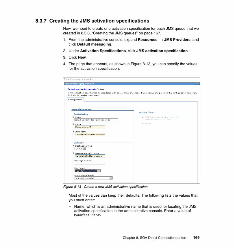
8.3.7 Creating the JMS activation specificationsNow, we need to create one activation specification for each JMS queue that we created in 8.3.6, “Creating the JMS queues” on page 167.
1. From the administrative console, expand Resources → JMS Providers, and click Default messaging.
2. Under Activation Specifications, click JMS activation specification.
3. Click New.
4. The page that appears, as shown in Figure 8-13, you can specify the values for the activation specification.
Figure 8-13 Create a new JMS activation specification
Most of the values can keep their defaults. The following lists the values that you must enter:
– Name, which is an administrative name that is used for locating the JMS activation specification in the administrative console. Enter a value of ManufacturerAS.
Chapter 8. SOA Direct Connection pattern 169

– JNDI name, which is the location in the JNDI namespace to bind the JMS activation specification. This location is where the applications message-driven beans are bound for message delivery. Enter a value of Sample/WSI/ManufacturerAS.
– Destination type, which is the type of the JMS destination that is used to deliver messages to the message-driven bean. Accept the default of Queue.
– Destination JNDI name, which is the location in JNDI of the JMS destination from which messages are received. Enter a value of Sample/WSI/Manufacturer.
– Bus name, which is the name of the bus from which the JMS destination receives messages. This name is not required, but for consistency, select the value of TESTBUS.
5. Click OK.
6. You need to repeat steps 3 on page 169 to 5 to create two other activation specifications. Table 8-3, and Table 8-4 give the configuration for these specifications.
7. Save the changes.
Table 8-3 JMS activation specification settings for Manufacturer B
Table 8-4 JMS activation specification settings for Manufacturer C
Field Value
Name ManufacturerBAS
JNDI name Sample/WSI/ManufacturerBAS
Destination type Queue
Destination JNDI name Sample/WSI/ManufacturerB
Bus name TESTBUS
Field Value
Name ManufacturerCAS
JNDI name Sample/WSI/ManufacturerCAS
Destination type Queue
Destination JNDI name Sample/WSI/ManufacturerC
Bus name TESTBUS
170 Patterns: SOA with an Enterprise Service Bus in WebSphere Application Server V6

8.3.8 Hosting the WSDL filesEach Web service client in the WS-I sample application attempts to retrieve WSDL files that contain port type and binding information. Import statements dictate the location of these files. For example, the SCMSampleUI enterprise application contains a WSDL file that tries to retrieve the Retailer port type and binding by using the following import:
<wsdl:import location="http://appsrv1a.itso.ral.ibm.com/wsdl/Retailer.wsdl" namespace="http://www.ws-i.org/SampleApplications/SupplyChainManagement/2002-08/Retailer.wsdl"/>
Thus, it is necessary to host an HTTP server where these files can be retrieved. Furthermore, this HTTP server must be assigned the address of appsrv1a.itso.ral.ibm.com. The address assignment can easily be achieved on a Windows machine by modifying the hosts file located at:
<Windows_home>\system32\drivers\etc\hosts
And adding the following statement to the hosts file:
127.0.0.1 appsrv1a.itso.ral.ibm.com
We installed IBM HTTP Server V6, which is shipped with WebSphere Application Server V6. The WSDL files to be hosted on this HTTP server are provided with the additional materials that are supplied with this book. For information about how to obtain the additional materials, see Appendix A, “Additional material” on page 365.
From the additional material, copy the contents of the \DirectConnection\wsdl directory to the following directory in the HTTP server:
<HTTP_Server_home>\htdocs\en_US\wsdl
Make sure that the HTTP server is started, then test that the WSDL is available by entering the following URL into a Web browser:
http://appsrv1a.itso.ral.ibm.com/wsdl/Retailer.wsdl
It should show the WSDL for the Retailer Web service.
Chapter 8. SOA Direct Connection pattern 171
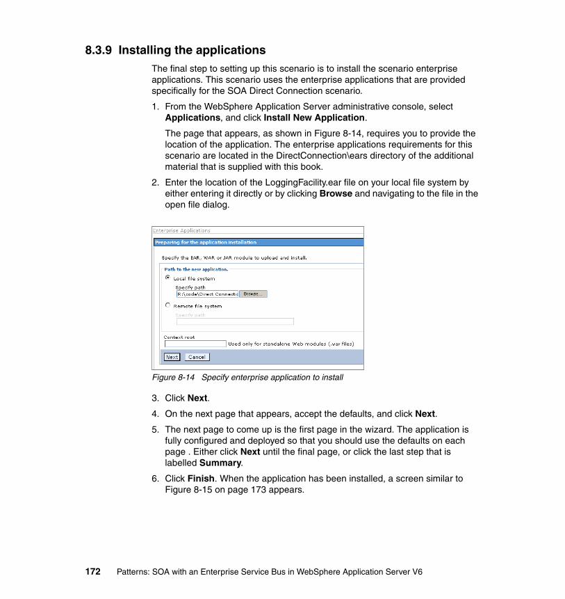
8.3.9 Installing the applicationsThe final step to setting up this scenario is to install the scenario enterprise applications. This scenario uses the enterprise applications that are provided specifically for the SOA Direct Connection scenario.
1. From the WebSphere Application Server administrative console, select Applications, and click Install New Application.
The page that appears, as shown in Figure 8-14, requires you to provide the location of the application. The enterprise applications requirements for this scenario are located in the DirectConnection\ears directory of the additional material that is supplied with this book.
2. Enter the location of the LoggingFacility.ear file on your local file system by either entering it directly or by clicking Browse and navigating to the file in the open file dialog.
Figure 8-14 Specify enterprise application to install
3. Click Next.
4. On the next page that appears, accept the defaults, and click Next.
5. The next page to come up is the first page in the wizard. The application is fully configured and deployed so that you should use the defaults on each page . Either click Next until the final page, or click the last step that is labelled Summary.
6. Click Finish. When the application has been installed, a screen similar to Figure 8-15 on page 173 appears.
172 Patterns: SOA with an Enterprise Service Bus in WebSphere Application Server V6
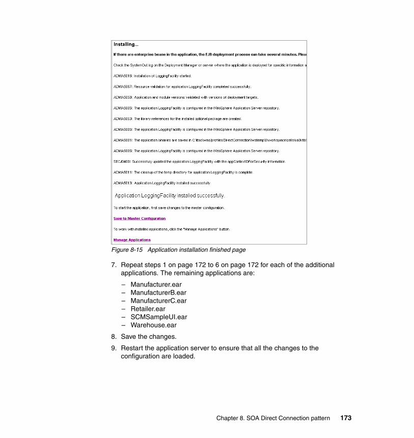
Figure 8-15 Application installation finished page
7. Repeat steps 1 on page 172 to 6 on page 172 for each of the additional applications. The remaining applications are:
– Manufacturer.ear– ManufacturerB.ear– ManufacturerC.ear– Retailer.ear– SCMSampleUI.ear– Warehouse.ear
8. Save the changes.
9. Restart the application server to ensure that all the changes to the configuration are loaded.
Chapter 8. SOA Direct Connection pattern 173

8.3.10 Running and using the sample applicationYou can test the WS-I sample application by entering the following URL in a Web browser on the machine that is hosting the application server:
http://localhost:9080/SCMSampleUI/
The Supply Chain Management Sample Application should start, as shown in Figure 8-16.
Figure 8-16 SCM Sample application
174 Patterns: SOA with an Enterprise Service Bus in WebSphere Application Server V6

To use the application:
1. To retrieve a list of products, select Place New Order to displays a list of 10 products, as shown in Figure 8-17.
Figure 8-17 SCM Sample product listing
You can order multiple quantities of each product. If the warehouse has sufficient stock for the product, an order will be placed.
If the placement of the order causes the warehouse’s stock level of that product to drop below a certain threshold, then an reorder request is sent to the manufacturer of the product.
The warehouse stock level is stored in the org.ws_i.www.Impl.WarehouseImpl class in the WarehouseEJB project. For example, the stock level for the first three products is shown in Table 8-5 on page 176.
Chapter 8. SOA Direct Connection pattern 175
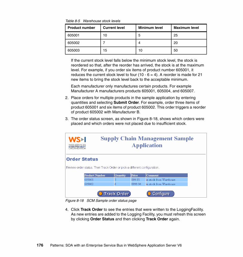
Table 8-5 Warehouse stock levels
If the current stock level falls below the minimum stock level, the stock is reordered so that, after the reorder has arrived, the stock is at the maximum level. For example, if you order six items of product number 605001, it reduces the current stock level to four (10 - 6 = 4). A reorder is made for 21 new items to bring the stock level back to the acceptable minimum.
Each manufacturer only manufactures certain products. For example Manufacturer A manufacturers products 605001, 605004, and 605007.
2. Place orders for multiple products in the sample application by entering quantities and selecting Submit Order. For example, order three items of product 605001 and six items of product 605002. This order triggers a reorder of product 605002 with Manufacturer B.
3. The order status screen, as shown in Figure 8-18, shows which orders were placed and which orders were not placed due to insufficient stock.
Figure 8-18 SCM Sample order status page
4. Click Track Order to see the entries that were written to the LoggingFacility. As new entries are added to the Logging Facility, you must refresh this screen by clicking Order Status and then clicking Track Order again.
Product number Current level Minimum level Maximum level
605001 10 5 25
605002 7 4 20
605003 15 10 50
176 Patterns: SOA with an Enterprise Service Bus in WebSphere Application Server V6
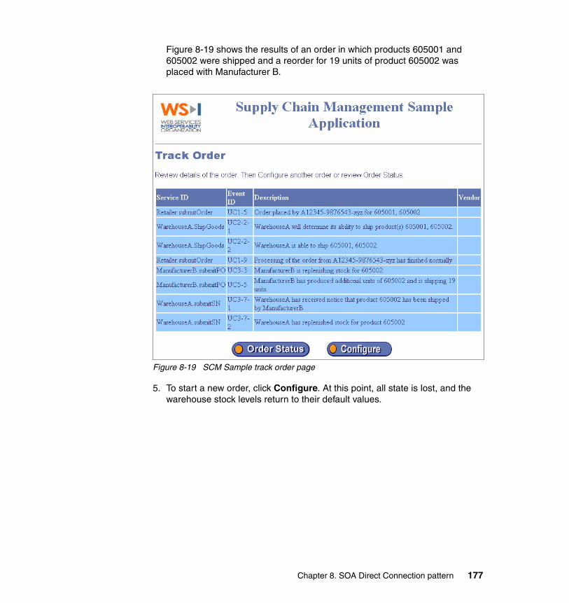
Figure 8-19 shows the results of an order in which products 605001 and 605002 were shipped and a reorder for 19 units of product 605002 was placed with Manufacturer B.
Figure 8-19 SCM Sample track order page
5. To start a new order, click Configure. At this point, all state is lost, and the warehouse stock levels return to their default values.
Chapter 8. SOA Direct Connection pattern 177

178 Patterns: SOA with an Enterprise Service Bus in WebSphere Application Server V6
Chapter 9. Enterprise Service Bus pattern: router scenario
In this chapter, the Enterprise Service Bus (ESB) is moved from concept to practical implementation by applying the service-oriented architecture (SOA) ESB runtime pattern with router interactions. Using a simple scenario (as described in Chapter 6, “The business scenario that this book uses” on page 125), this chapter demonstrates how you can use an ESB runtime pattern to implement this pattern.
9
© Copyright IBM Corp. 2005. All rights reserved. 179
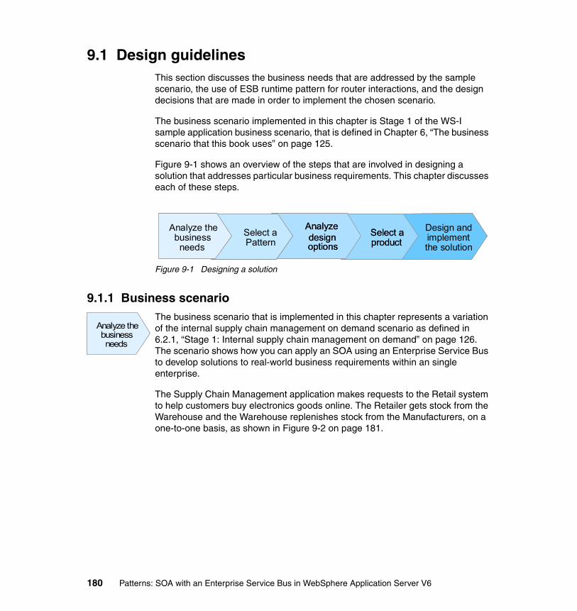
9.1 Design guidelinesThis section discusses the business needs that are addressed by the sample scenario, the use of ESB runtime pattern for router interactions, and the design decisions that are made in order to implement the chosen scenario.
The business scenario implemented in this chapter is Stage 1 of the WS-I sample application business scenario, that is defined in Chapter 6, “The business scenario that this book uses” on page 125.
Figure 9-1 shows an overview of the steps that are involved in designing a solution that addresses particular business requirements. This chapter discusses each of these steps.
Figure 9-1 Designing a solution
9.1.1 Business scenarioThe business scenario that is implemented in this chapter represents a variation of the internal supply chain management on demand scenario as defined in 6.2.1, “Stage 1: Internal supply chain management on demand” on page 126. The scenario shows how you can apply an SOA using an Enterprise Service Bus to develop solutions to real-world business requirements within an single enterprise.
The Supply Chain Management application makes requests to the Retail system to help customers buy electronics goods online. The Retailer gets stock from the Warehouse and the Warehouse replenishes stock from the Manufacturers, on a one-to-one basis, as shown in Figure 9-2 on page 181.
Design andimplementthe solution
Select aproduct
Analyzedesignoptions
Select aPattern
Analyze thebusinessneeds
Design andimplementthe solution
Select aproductSelect aproduct
Analyzedesignoptions
Analyzedesignoptions
Select aPatternSelect aPattern
Analyze thebusinessneeds
Analyze thebusinessneeds
Analyze thebusinessneeds
Analyze thebusinessneeds
180 Patterns: SOA with an Enterprise Service Bus in WebSphere Application Server V6

Figure 9-2 High-level business context showing the existing infrastructure
The organization has a few concerns with their current ability to meet market demands. Competition is increasing, customers have more options and opportunities, and the enterprise is under management pressure to do more for less. Consequently, the proposed solution must focus on solving the following business issues:
� Quicker response to change:
– Improve the ability to respond to changes including both business requirements and changes in technology.
– Implement changes quickly in a central location because service providers often change due to mergers and acquisitions.
– Rapidly grow the business without constant infrastructure change.
� Reduce costs:
– Suppliers throughout the supply chain have different infrastructures. Managing all of these differences can be costly due to increases in resources, time, and training.
– Reuse of existing code by combining independent business requirements in an innovative way.
– Use existing resources more efficiently.
– Make use of industry open standards in all possible locations of the solution.
Intranet
ManufacturerManufacturer
Manufacturer
Logging Facility
WarehouseRetailSystem
SCMApplication
Chapter 9. Enterprise Service Bus pattern: router scenario 181

9.1.2 Selecting an SOA patternThe business scenario states that the Retailer gets stock from the Warehouse and the Warehouse replenishes stock from the Manufacturers on a one-to-one basis. From this description, we can conclude that there are two interaction requirements:
� Only one Warehouse provider is used.
� The Warehouse calls each Manufacturer in isolation. Interactions with more than one manufacturer require multiple calls.
Choosing and applying the relevant SOA patternWe used the Patterns for e-business to determine the appropriate Runtime pattern to apply to this scenario. Because this is an intra-enterprise scenario, we selected the Process Integration application patterns. The business scenario requires routing of requests to one of multiple providers. This routing interaction is described by the Router variation of the Broker application pattern. Our business scenario describes SOA. So, we selected the SOA profile of the Router runtime pattern, which is the ESB runtime pattern. This pattern is described in 5.1.2, “ESB runtime pattern” on page 98.
The ESB implementation for this business scenario is applied to the level 0 decomposition of the ESB runtime pattern, as shown in Figure 9-3.
Figure 9-3 ESB runtime pattern applied to our scenario
Select aPatternSelect aPattern
Enterprise
ESBApp Server/
Services Manufacturer
App Server/ Services ManufacturerB
App Server/ Services ManufacturerC
App Server/ Services
SCM Application
App Server/ Services
Business Event Log
App Server/ ServicesRetail System
App Server/ Services Warehouse
182 Patterns: SOA with an Enterprise Service Bus in WebSphere Application Server V6
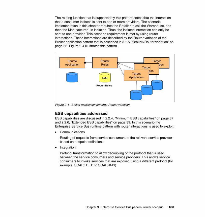
The routing function that is supported by this pattern states that the interaction that a consumer initiates is sent to one or more providers. The scenario implementation in this chapter requires the Retailer to call the Warehouse, and then the Manufacturer , in isolation. Thus, the initiated interaction can only be sent to one provider. This scenario requirement is met by using router interactions. These interactions are described by the Router variation of the Broker application pattern that is described in 3.1.5, “Broker=Router variation” on page 52. Figure 9-4 illustrates this pattern.
Figure 9-4 Broker application pattern= Router variation
ESB capabilities addressedESB capabilities are discussed in 2.2.4, “Minimum ESB capabilities” on page 37 and 2.2.6, “Extended ESB capabilities” on page 39. In this scenario the Enterprise Service Bus runtime pattern with router interactions is used to exploit:
� Communications
Routing of requests from service consumers to the relevant service provider based on endpoint definitions.
� Integration
Protocol transformation to allow decoupling of the protocol that is used between the service consumers and service providers. This allows service consumers to invoke services that are exposed using a different protocol (for example, SOAP/HTTP, to SOAP/JMS).
TargetApplication
SourceApplication
RouterRules
TargetApplication
TargetApplicationR/O
Router Rules
Chapter 9. Enterprise Service Bus pattern: router scenario 183

Managing communications and integration through the ESB provides many benefits:
� Decoupling of service consumers and service providers.
� Centralized control of service namespace.
� Logging of service requests and responses.
� Transformation of service requests and responses.
� Centralized security for Web service invocations, for example all service consumers can be authenticated centrally.
� Common access point for service consumers that need access to service providers. The ESB intercepts and routes requests to the relevant service provider. A change in location of the service provider only affects the ESB routing; the service provider location remains transparent to the service consumer.
9.1.3 Router interaction designThis section discusses the architectural decisions made, and their options, for implementation of this scenario using router interactions in the Enterprise Service Bus.
Location of service definitionsTable 9-1 summarizes the design alternatives that are available when deciding where to locate service definitions. Following the table, each design alternative is discussed in detail.
Table 9-1 Location of service definitions
Decision title Where to locate service definitions
Problem statement The interface, binding, and service endpoint of a Web service are defined in Web Services Definition Language (WSDL) files. The ESB must have access to these service definitions so a decision has to be made on where to put the WSDL files so that they can be accessed as needed.
Alternative 1 Copy the WSDL files to a local directory.
Alternative 2 Publish WSDL files on an HTTP server.
Analyzedesignoptions
Analyzedesignoptions
Analyzedesignoptions
184 Patterns: SOA with an Enterprise Service Bus in WebSphere Application Server V6
Alternative 1: Local directory copy of WSDLThe WSDL files can be copied into a local directory and the ESB can be given access to the local directory.
� Reasons for using this option include:
– Easy configuration.
– Fast and simple configuration for prototypes.
� Reasons for not using this option include:
– For a large system having local copies of WSDL files will require high maintenance.
– In a production environment it might not be sensible to give access to local directories, especially if the WSDL files are accessed by multiple consumers.
Alternative 3 Publish the WSDL files to a Universal Description and Integration (UDDI) registry.
Decision Publish WSDL files on an HTTP server so they can be accessed by the ESB.
Justification The WSDL files used in this scenario are published on an HTTP server. The scenario is a prototype, so a local directory copy of the WSDL could be used, but multiple scenarios and ESB implementations need to access the WSDL files. UDDI publication could offer advantages for multiple users but technical features are not exploited and can be more difficult to set up than HTTP. So, HTTP publication seemed to be a sensible choice for this scenario because it is easy to set up and organize for multiple users.
Decision title Where to locate service definitions
Chapter 9. Enterprise Service Bus pattern: router scenario 185
Alternative 2: HTTP server publication of WSDLThe WSDL files can be published on an HTTP server which the ESB can access using a specific URL.
� Reasons for using this option include:
– Simple implementation.
– The WSDL files used can be organized sensibly and accessed easily on an HTTP server.
� Reasons for not using this option include:
– Providers of Web services within an enterprise could change frequently because of organizational changes or business needs. In this environment HTTP published WSDL files could have a high maintenance overhead.
Alternative 3: UDDI registry publication of WSDLThe UDDI specification defines a way to publish and discover information about Web services. In this specification:
� Each Web service is owned by one business, and each business (and Web service it owns) is maintained by one authorized name.
� One authorized name can own many businesses, and one business can own many Web services.
The UDDI specification also associates Web services with technical models. Using these models or generic categories, a UDDI registry user can search for a type of service, rather than needing to know the access details for a specific service.
� Reasons for using this option include:
– UDDI registries allow a fine degree of classification for Web services in an organization, which enables service consumers to quickly find the Web services to fit particular needs.
– Due to frequent changes of Web service providers, from an administrative point of view, it might be easier for each service provider to keep published data up to date using UDDI.
� Reasons for not using this option include:
– In this scenario most UDDI features are not used and not needed.
– UDDI publication should be used for production ready systems.
– UDDI is more complicated to set up in comparison with an HTTP server.
186 Patterns: SOA with an Enterprise Service Bus in WebSphere Application Server V6
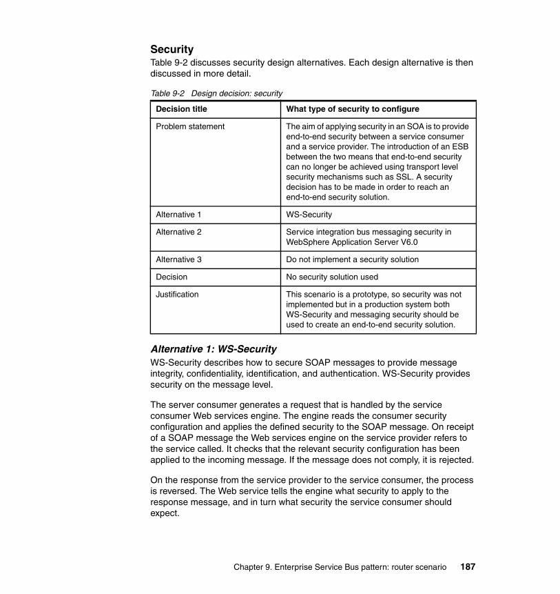
SecurityTable 9-2 discusses security design alternatives. Each design alternative is then discussed in more detail.
Table 9-2 Design decision: security
Alternative 1: WS-SecurityWS-Security describes how to secure SOAP messages to provide message integrity, confidentiality, identification, and authentication. WS-Security provides security on the message level.
The server consumer generates a request that is handled by the service consumer Web services engine. The engine reads the consumer security configuration and applies the defined security to the SOAP message. On receipt of a SOAP message the Web services engine on the service provider refers to the service called. It checks that the relevant security configuration has been applied to the incoming message. If the message does not comply, it is rejected.
On the response from the service provider to the service consumer, the process is reversed. The Web service tells the engine what security to apply to the response message, and in turn what security the service consumer should expect.
Decision title What type of security to configure
Problem statement The aim of applying security in an SOA is to provide end-to-end security between a service consumer and a service provider. The introduction of an ESB between the two means that end-to-end security can no longer be achieved using transport level security mechanisms such as SSL. A security decision has to be made in order to reach an end-to-end security solution.
Alternative 1 WS-Security
Alternative 2 Service integration bus messaging security in WebSphere Application Server V6.0
Alternative 3 Do not implement a security solution
Decision No security solution used
Justification This scenario is a prototype, so security was not implemented but in a production system both WS-Security and messaging security should be used to create an end-to-end security solution.
Chapter 9. Enterprise Service Bus pattern: router scenario 187
To secure an inbound or outbound service, the following types of WS-Security resources need to be applied to the ports that the relevant services use:
� WS-Security configurations� WS-Security bindings
The configurations type specifies the level of security that is required (for example, the body must be signed) and the bindings type that provides the information that the runtime needs to implement the configuration (for example, to sign the body, use this key).
WS-Security resources are administered separately from any Web service that uses them. So, one or more WS-Security configurations and bindings can be configured, all of which can then be applied to multiple Web services.
� Reasons for using this option include:
– You can easily enforce different security constraints on messages.
– You can enforce message confidentiality by encrypting the SOAP body or parts of it. The ESB can process a message without affecting end-to-end security by decrypting and encrypting data. Selective SOAP parsing is automatically applied to all Web services that are configured for a service integration bus in WebSphere Application Server V6.0. This means only message headers are parsed and confidentiality is not breached.
– You can separate resource administration from the Web services that uses them, providing flexibility, reuse, and low maintenance.
– When used with messaging security, you can provide an end-to-end security solution between consumers and providers.
– This option stops unauthorized users from changing message content and sending unauthorized requests.
� Reasons for not using this option include:
– It is not quick to configure. Therefore, it is unsuitable when implementing prototypes within set time constraints.
Alternative 2: Messaging securityIn WebSphere Application Server V6.0, messaging security is provided by a number of components that can be used together to ensure that users are authenticated, that resources are protected by security checks, and that messages are secure when they are in transit from a sending application to a receiving application.
When a connection to the messaging system is created, a user name and password can be specified. These are authenticated through the WebSphere Application Server user registry. If the authentication is successful, an access
188 Patterns: SOA with an Enterprise Service Bus in WebSphere Application Server V6
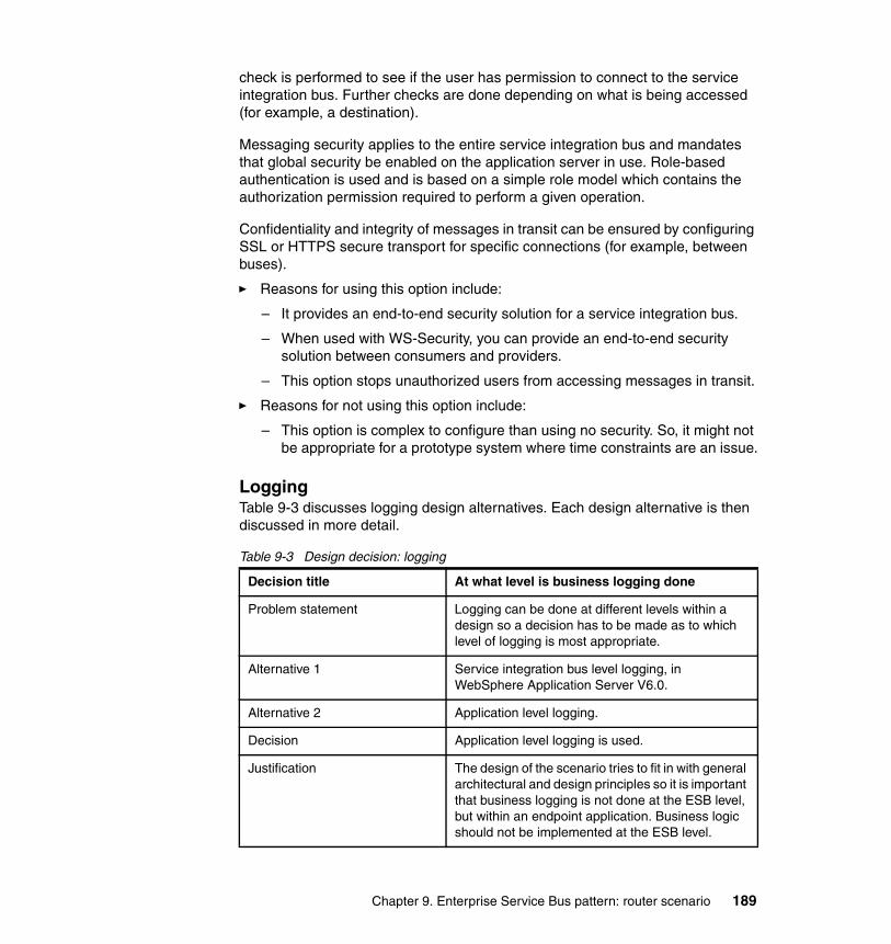
check is performed to see if the user has permission to connect to the service integration bus. Further checks are done depending on what is being accessed (for example, a destination).
Messaging security applies to the entire service integration bus and mandates that global security be enabled on the application server in use. Role-based authentication is used and is based on a simple role model which contains the authorization permission required to perform a given operation.
Confidentiality and integrity of messages in transit can be ensured by configuring SSL or HTTPS secure transport for specific connections (for example, between buses).
� Reasons for using this option include:
– It provides an end-to-end security solution for a service integration bus.
– When used with WS-Security, you can provide an end-to-end security solution between consumers and providers.
– This option stops unauthorized users from accessing messages in transit.
� Reasons for not using this option include:
– This option is complex to configure than using no security. So, it might not be appropriate for a prototype system where time constraints are an issue.
LoggingTable 9-3 discusses logging design alternatives. Each design alternative is then discussed in more detail.
Table 9-3 Design decision: logging
Decision title At what level is business logging done
Problem statement Logging can be done at different levels within a design so a decision has to be made as to which level of logging is most appropriate.
Alternative 1 Service integration bus level logging, in WebSphere Application Server V6.0.
Alternative 2 Application level logging.
Decision Application level logging is used.
Justification The design of the scenario tries to fit in with general architectural and design principles so it is important that business logging is not done at the ESB level, but within an endpoint application. Business logic should not be implemented at the ESB level.
Chapter 9. Enterprise Service Bus pattern: router scenario 189
Alternative 1: Service integration bus level loggingLogging can be turned on at the ESB level, in WebSphere Application Server V6.0, by using a logging mediation on destinations of choice:
� Reasons for using this option include:
– Logic is centralized in the ESB, which facilitates reuse, allows a single point of maintenance, and enables it to be provided as a service.
– A logging mediation is simple to implement.
� Reasons for not using this option include:
– Most business logic events should not be modeled through the ESB. Business logic events are better served by embedding them into the application logic. The ESB is not a place to store business logic. However, an architecture that sent interaction level events through the ESB could provide benefits in interaction diagnostics.
Alternative 2: Application level loggingLogging can be turned on at the application level by including logging logic inside an application.
� Reasons for using this option include:
– Business decisions are logged outside of the ESB, which fits general architectural and design principles.
– Services should allow changes to business logic by a business division without the need for other service providers to change their WSDL definitions. Putting business logic at the application level facilitates flexibility within a business division.
� Reasons for not using this option include:
– This option requires high maintenance and difficult change implementation in large production systems. If logging is done at an application level with multiple applications, implementing change would mean a lot of work and maintenance will be high.
190 Patterns: SOA with an Enterprise Service Bus in WebSphere Application Server V6

Communication protocolsTable 9-4 discusses design alternatives for communication protocols over which SOAP messages can be sent. Each design alternative is then discussed in more detail.
Table 9-4 Design decision: SOAP message transportation.
Alternative 1: HTTP service busHTTP is the protocol by which servers and clients communicate. An HTTP interaction consists of a request sent by a client to a server and (in a request-response interaction) a response sent from the server to the client. HTTP defines how messages are formatted and transmitted and what actions should be taken in response to various commands.
HTTP is the most familiar way to send requests and responses between service consumers and providers. Organizations are already well equipped to handle HTTP security requirements and have put in measures to ensure that only valid HTTP requests are received through farewells, proxy servers, demilitarized zones, HTTP servers, authorization, authentication procedures, and so forth. As a result, HTTP is usually one of the first transport layers an organization would use when thinking about inter-enterprise solutions.
Decision title Communication protocol used for SOAP message transportation
Problem statement Web services can communicate using SOAP messages over a variety of protocols. Each protocol effectively provides a service bus between multiple endpoints. So a decision has to be made about which service bus implementation to use. Two primary options for transporting SOAP messages are Hyper Text Transfer Protocol (HTTP) and Java Message Service (JMS).
Alternative 1 HTTP service bus
Alternative 2 JMS service bus
Decision Both alternatives are implemented.
Justification In this scenario, one of the exploited ESB capabilities is integration, in particular protocol transformation. Using the ESB capabilities enables a service provider to receive a JMS message that is sent from a service consumer that originated the call using HTTP. Both alternatives are implemented to show the protocol transformation capabilities of the ESB.
Chapter 9. Enterprise Service Bus pattern: router scenario 191

Use of an ESB extends the use of HTTP. It enables a service consumer to communicate using HTTP and permits a service provider to receive the request using a different transport mechanism.
� Reasons for using this alternative include:
– HTTP is a widely adopted protocol, and so the HTTP infrastructure is widely available.
– The HTTP protocol is open and deployed on many different system types.
– Most enterprises allow HTTP to travel through protocol firewalls. Therefore, there are fewer barriers to extended enterprise use of HTTP as a transport for Web services.
� Reasons for not using this alternative include:
– There is no single point of control over the namespace with HTTP. This differs from the scope of an ESB that is defined by a group of services that are accessible through one or more protocols whose addressing and naming is controlled at a single point.
– HTTP is a lightweight and stateless protocol that was not originally designed to carry application data. If any state data is required to maintain an application session, the applications must create and manage the state data.
– HTTP is not a reliable protocol.
Alternative 2: JMS service busJMS defines the standard for reliable enterprise messaging. JMS, part of the J2EE standard, provides a conventional way to create, send and receive messages. A JMS service bus can provide asynchronous and reliable messaging to Web service invocations. The use of a JMS service bus means that the service consumer can receive acknowledgement of assured delivery and communicate with services that might not be available.
The use of an ESB extends the use of JMS, enabling service consumers and providers to communicate using different protocols.
� Reasons for using this alternative include:
– JMS provides a more reliable transport than alternatives such as HTTP.
– Asynchronous requests can be deployed readily.
– JMS is an open Java based standard and is readily available to Java based systems.
192 Patterns: SOA with an Enterprise Service Bus in WebSphere Application Server V6
� Reasons for not using this alternative include:
– JMS does not provide the level of interoperability that HTTP does.
– JMS is a Java based standard and is not as readily accessible to systems that are not Java based.
– The actual transport system must be provided by a software product. So the communicating Web services must have access to JMS providers that can communicate with each other.
Service provider routingTable 9-5 discusses service provider routing design alternatives. Each design alternative is then discussed in more detail.
Table 9-5 Design decision: service provider routing
Alternative 1: Static routingRouting can be done statically by looking up the endpoint for a given Web service from within the ESB, or from an external routing table.
� Reasons for using this option include:
– This option is easy to configure, with no programming required.
– It ensures that all requests for a particular Web service operation are forwarded to the same service provider.
– It is easily changeable in the ESB or in the external routing table without making any change to the service consumer.
Decision title Determining the route to a service provider
Problem statement When multiple services are configured there are multiple providers to which a request can be routed. The ESB has to determine which service provider to send a request to so that the correct service can be invoked for that particular request. A decision has to be made as to which method of routing to use.
Alternative 1 Static routing
Alternative 2 Dynamic routing
Decision Static routing based on a routing table.
Justification In this scenario one-to-one relationships between service consumers and providers are of interest. The benefits of dynamic routing would not be exploited in this situation so static routing is applied.
Chapter 9. Enterprise Service Bus pattern: router scenario 193

� Reasons for not using this option include:
– The service providers in an organization are subject to change over time. These changes would lead to ESB configuration changes and so higher maintenance.
Alternative 2: Dynamic routingRouting can be done dynamically by examining a SOAP message and determining the endpoint based on the content of the message. This dynamic routing can be achieved by designing and configuring a mediation or using the Web Services Gateway as a proxy for a service. You can use a JAX-RPC handler list to set the endpoints for incoming request messages for the service. Mediations and JAX-RPC handler lists are discussed in more detail in 10.1.3, “Broker interaction design” on page 264.
� Reasons for using this option include:
– The service providers in an organization are subject to change over time. Provided that a service provider keeps its routing directory entry up to date, dynamic routing leads to little or no ESB administration after initial set up.
– You configure this option only once and future maintenance is minimal.
� Reasons for not using this option include:
– It can be complicated to configure.
– Programming is required for this option.
Topology considerationsThis section discusses different topology options for the scenarios that are used in this book for WebSphere Application Server V6.0.
Figure 9-5 on page 195 shows three alterative operational topologies. The topologies are conceptual but map to what can be implemented using WebSphere Application Server V6. Some of the terminology that is used in the diagram is as follows:
� Servers, which are instances of the WebSphere Application Server runtime that are running one or more applications. That is, a server in this context equates to a WebSphere Application Server instance. The servers run the application services and also the ESB.
� Nodes, which are a logical grouping of servers. Nodes usually correspond to hardware (that is, computers to where servers are deployed and where these deployed servers execute).
� Bus, which equates to the service integration bus that is part of WebSphere Application Server V6. The service integration bus provides a common
194 Patterns: SOA with an Enterprise Service Bus in WebSphere Application Server V6

messaging component for the WebSphere Application Server platform providing point-to-point, publish/subscribe, persistent, and non-persistent messaging. The service integration bus is a key component for building an ESB in WebSphere Application Server V6. However, it is not purely the ESB itself.
� Cell, which is an administrative domain in WebSphere Application Server V6. All servers within a cell can be administered from a central console.
Figure 9-5 General topology implementations
The three alternatives shown in Figure 9-5 represent different WebSphere Application Server V6 configurations. These configurations essentially differ in the number of nodes that are deployed, whether single or multiple buses are used, and how the administration domain (cell) is configured.
Alternative 2: Multiple nodes, single bus
Node 1 Node 2
Alternative 1: Single node, single bus
Cell
Node
Server: ESB & Application Services
Bus
Server: ESB &Application Services
Cell
Alternative 3: Multiple nodes, multiple buses
Node 1 Node 2
Server: ESB &Application Services
Cell 1
BusInter-Bus
Link
Cell 2
Server: ESB &Application Services
Bus
Server: ESB &Application Services
Bus
Chapter 9. Enterprise Service Bus pattern: router scenario 195

The remainder of this section summarizes the alternatives and the decision that was applied to this scenario. It then discusses the pros and cons of each of these alternatives.
Table 9-6 summarizes the problem and various operational topology alternatives.
Table 9-6 Design decision: topology considerations
Note: These topologies are not an exhaustive list of possible topologies. Mission critical production environments most likely have variations of these topologies where nodes are replicated to provide high availability and high performance. ESB design for high availability solutions is not the focus of this book.
Decision title Which topology is most suitable
Problem statement Different ESB topologies can be used depending on enterprise requirements.
Alternative 1 Single node topology with single bus.
Alternative 2 Multi node topology with single bus.
Alternative 3 Multi node topology with multiple buses.
Decision A single node topology is used.
Justification This scenario is a prototype, so a simple topology is used.
196 Patterns: SOA with an Enterprise Service Bus in WebSphere Application Server V6

Alternative 1: Single node topology with a single busIn this alternative, as shown in Figure 9-6, there would be one node with one bus. This alternative is equivalent to a small start-up enterprise or a prototype set up.
Figure 9-6 Single node, single bus topology
� Reasons for using this alternative include:
– It is very simple to set up and configure.
� Reasons for not using this alternative include:
– There is a single point of failure.
– This alternative does not provide scalability.
– Message throughput cannot be increased easily.
– There is a limitation on the number of client connections that can be handled.
Alternative 1: Single node, single bus
Cell
Node
Server: ESB & Application Services
Bus
Chapter 9. Enterprise Service Bus pattern: router scenario 197
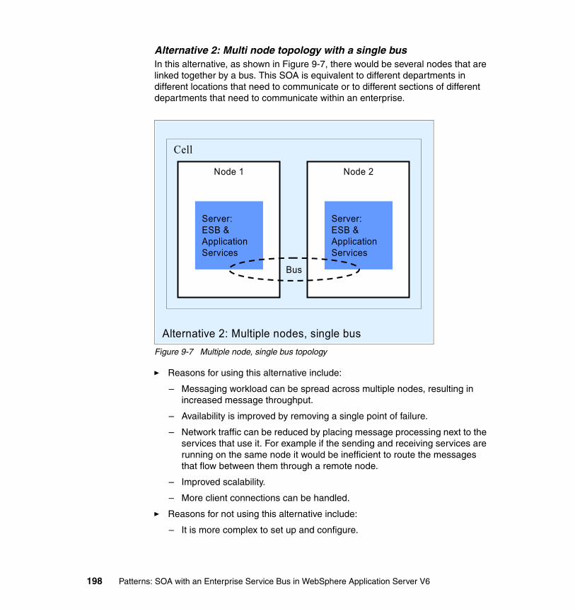
Alternative 2: Multi node topology with a single busIn this alternative, as shown in Figure 9-7, there would be several nodes that are linked together by a bus. This SOA is equivalent to different departments in different locations that need to communicate or to different sections of different departments that need to communicate within an enterprise.
Figure 9-7 Multiple node, single bus topology
� Reasons for using this alternative include:
– Messaging workload can be spread across multiple nodes, resulting in increased message throughput.
– Availability is improved by removing a single point of failure.
– Network traffic can be reduced by placing message processing next to the services that use it. For example if the sending and receiving services are running on the same node it would be inefficient to route the messages that flow between them through a remote node.
– Improved scalability.
– More client connections can be handled.
� Reasons for not using this alternative include:
– It is more complex to set up and configure.
Alternative 2: Multiple nodes, single bus
Node 1 Node 2
Server: ESB &Application Services
Cell
Server: ESB &Application Services
Bus
198 Patterns: SOA with an Enterprise Service Bus in WebSphere Application Server V6

Alternative 3: Multi node topology with multiple busesIn this alternative, as shown in Figure 9-8, there would be several inter-connected buses. This alternative is equivalent to several enterprises that need to communicate with each other or to different departments in different locations that need to communicate.
Figure 9-8 Multiple nodes, multiple buses topology
� Reasons for using this alternative include:
– You can easily apply different security zones.
– This alternative provides improved scalability.
– Services on other buses can be accessed and messages can be sent to other bus services.
– Resources provided by other buses can be accessed.
� Reasons for not using this alternative:
– This alternative is complicated to set up and configure.
Alternative 3: Multiple nodes, multiple buses
Node 1 Node 2
Server: ESB &Application Services
Cell 1
BusInter-Bus
Link
Cell 2
Server: ESB &Application Services
Bus
Chapter 9. Enterprise Service Bus pattern: router scenario 199
9.1.4 ProductsSeveral design decisions were discussed which influence product choice in 9.1.3, “Router interaction design” on page 184. This section looks at the products that you can use to implement these design decisions and the product choices that were made for this particular implementation.
Product implementation optionsProduct choices for this scenario are based on:
� Exploiting the ESB capabilities, as discussed in “ESB capabilities addressed” on page 183.
� Making the design decisions, as discussed in “Router interaction design” on page 184.
� Using products that are currently available.
For this scenario, we can use the following currently available products to implement Enterprise Service Bus with router interactions:
� WebSphere Application Server V6.0
� WebSphere Application Server Network Deployment V6.0
� WebSphere Application Server Network Deployment V5.1.1 Web Services Gateway
� WebSphere Business Integration Message Broker V5.0
� WebSphere Business Integration Connect V4.2
You can find a comparison between available products and ESB capabilities in 4.3.1, “Assessment of ESB capabilities by product” on page 82.
WebSphere Application Server V6.0 meets all of the requirements of this scenario. Thus, this is the product of choice.
Select aproductSelect aproduct
200 Patterns: SOA with an Enterprise Service Bus in WebSphere Application Server V6

Product mappingsFigure 9-9 shows the Product mappings that were selected for the Router scenario.
Figure 9-9 ESB runtime pattern::Product mapping=WebSphere Application Server V6, Router scenario
In this Product mapping, the WebSphere Application Server V6.0 base product is used across the board. The service consumer application provides a user interface which is executed in WebSphere Application Server initiating a SOAP/HTTP service requests to the ESB. Other service consumers can use SOAP/JMS to communicate with the ESB. The ESB hub is run on WebSphere Application Server and routes the requests to provider applications which are also running under WebSphere Application Server.
The Administration Services and namespace directory are provided by WebSphere Application Server. The business service directory is supported by the IBM HTTP server.
A local Cloudscape database, which is shipped with WebSphere Application Server V6, is used to store the Service Data Objects (SDO) repository.
Enterprise
Business Service Directory
Zone: Enterprise Service Bus
NamespaceDirectory
Administration & Security Services
HubApp Server/
Services
<Service Consumer>
App Server/Services
<Service Consumer>
App Server/Services
App Server/Services
<Service Provider>
<Service Provider>
• Service Integration Bus (part of WebSphere Application Server V6.0.1 + PK02919, PK05354)
• Cloudscape
WebSphere Application Server V6.0.1
WebSphere Administration (part of WebSphere Application Server V6.0.1)
WebSphere Administration (part of WebSphere Application Server V6.0.1)
WebSphere Application Server V6.0.1
IBM HTTP server V2
Chapter 9. Enterprise Service Bus pattern: router scenario 201

9.2 Development guidelines
This section describes how to modify the WS-I sample scenario that was used in Chapter 8, “SOA Direct Connection pattern” on page 153 to make use of an ESB. For more information about how this scenario worked using point-to-point connections instead of an ESB, see 8.2, “Development guidelines” on page 157.
This section works with Rational Application Developer V6.0.0.1 to modify the enterprise application that is used in Chapter 8, “SOA Direct Connection pattern” on page 153.
To complete the steps in this section, you need to import the \ProjectInterchange\DirectConnection.zip file into a Rational Application Developer workspace. For instructions on how to import these necessary files, see “Working with the WS-I sample scenario enterprise applications” on page 368.
Note: We used WebSphere Application Server V6.0.1 with the i-fixes PK02919 and PK05354 for this scenario. Versions of WebSphere Application Server beyond V6.0.1 will not require the i-fix.
Note: This section requires the use of Rational Application Developer V6.0.0.1 or later.
Note: You need to have completed the steps in 8.3.8, “Hosting the WSDL files” on page 171 (to configure an HTTP server with the relevant WSDL definitions) before completing any of the steps in this section. You also need to ensure that the machine on which you are running Rational Application Developer has access to this HTTP server.
To verify that Rational Application Developer is running, enter the following URL in a Web browser on the machine where Rational Application Developer is installed.
http://appsrv1a.itso.ral.ibm.com/wsdl/Retailer.wsdl
If the URL returns a WSDL document, then you are ready to follow the steps in this section.
202 Patterns: SOA with an Enterprise Service Bus in WebSphere Application Server V6
9.2.1 Scenario implementation: ESB router interactionIn the scenario, each of the Web services calls are made through the ESB rather than have the service consumer directly interact with the service provider. In addition, the Retailer Web service is invoked by SOAP over JMS and invokes the Warehouse Web service by SOAP over JMS. The SCMSampleUI enterprise application continues to call the Retailer by SOAP over HTTP and the Warehouse is ultimately invoked by SOAP over HTTP. The ESB transforms the protocols from HTTP to JMS or vice versa as and when necessary.
Figure 9-10 on page 204 illustrates this scenario.
Chapter 9. Enterprise Service Bus pattern: router scenario 203

Figure 9-10 Scenario implemented with ESB router interactions
As shown in Figure 9-10, there are few changes with regard to the enterprise applications and the Web services, other than the Retailer is using SOAP over JMS instead of SOAP over HTTP.
LoggingFacility
logEvent
getEvents
LoggingFacility
Retailer
getCatalog
submitOrder
Retailer
Warehouse
shipGoodsWarehouse
submitSN
errorPO
WarehouseCallback
SCMSampleUI
SCMSampleUI
Key:
Operation name A Web service operation or onMessage
Indicates a one-way operation Indicates a Web service request
Indicates a JMS related operation
Indicates a request/response operation
shipGoods
logEvent
logEvent
submitPO
logEvent
getEvents
getCatalog
submitOrder
submitPOManufacturer
ManufacturerMDB
logEvent
onMessage
submitSN
errorPO
Manufacturer
ESB
204 Patterns: SOA with an Enterprise Service Bus in WebSphere Application Server V6
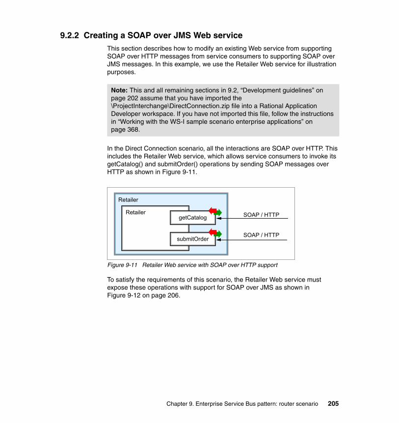
9.2.2 Creating a SOAP over JMS Web serviceThis section describes how to modify an existing Web service from supporting SOAP over HTTP messages from service consumers to supporting SOAP over JMS messages. In this example, we use the Retailer Web service for illustration purposes.
In the Direct Connection scenario, all the interactions are SOAP over HTTP. This includes the Retailer Web service, which allows service consumers to invoke its getCatalog() and submitOrder() operations by sending SOAP messages over HTTP as shown in Figure 9-11.
Figure 9-11 Retailer Web service with SOAP over HTTP support
To satisfy the requirements of this scenario, the Retailer Web service must expose these operations with support for SOAP over JMS as shown in Figure 9-12 on page 206.
Note: This and all remaining sections in 9.2, “Development guidelines” on page 202 assume that you have imported the \ProjectInterchange\DirectConnection.zip file into a Rational Application Developer workspace. If you have not imported this file, follow the instructions in “Working with the WS-I sample scenario enterprise applications” on page 368.
Retailer
getCatalog
submitOrder
Retailer
Retailer
getCatalog
submitOrder
Retailer SOAP / HTTP
SOAP / HTTP
Chapter 9. Enterprise Service Bus pattern: router scenario 205

Figure 9-12 Retailer Web service with SOAP over JMS support
The remainder of this section provides step-by-step instructions on how to convert the SOAP/HTTP Retailer Web service to a SOAP/JMS Web service. The following steps are described:
� Creating an EJB project.
The EJB project is used to store the generated message-driven bean which processes the SOAP/JMS messages and the EJB Web service implementation.
� Configuring Rational Application Developer for Web services
The Web services support in Rational Application Developer should be enabled before creating Web services clients.
� Creating a skeleton EJB Web service.
The EJB Web service is the only Web service type that is supported for SOAP/JMS messages. The Retailer Web service is initially created as a Java Web service. Therefore, a new EJB Web service must be created.
� Removing the dummy EJB and assigning a JNDI name.
Remove the temporary EJB and assign a JNDI name to the skeleton EJB Web service.
� Copying the business logic into the generated EJB.
The business logic defined in the Java Web service must be copied to the generated EJB Web service.
� Removing the Web project.
The EJB Web service and the message-driven bean which processes the SOAP/JMS messages are both stored in the EJB project. Because we no longer require support for SOAP/HTTP, we need to remove this support by deleting the relevant Web project.
Retailer
getCatalog
submitOrder
Retailer SOAP / JMS
SOAP / JMS
Retailer
getCatalog
submitOrder
Retailer
206 Patterns: SOA with an Enterprise Service Bus in WebSphere Application Server V6

Creating an EJB projectWebSphere Application Server V6 only supports SOAP over JMS when the enterprise bean implementation type is used. In the Direct Connection scenario, the Retailer uses the Java bean implementation type. Therefore, in this scenario, the Retailer must be ported to an enterprise bean. Porting the Retailer is simple because the generated Web service binding code delegates to another class that provides the business logic.
To port the Retailer:
1. Create an EJB project. Select File → New → EJB project. The window shown in Figure 9-13 appears.
Figure 9-13 Creating a new EJB project
2. Within this dialog box:
a. Enter a Name of RetailerEJB.b. Click Show Advanced.c. Select the EAR project called Retailer.d. Deselect Create an EJB Client JAR Project to hold the client interfaces
and classes. You do not need this facility because the client is a Web service client rather than an EJB client.
e. Click Finish.
Chapter 9. Enterprise Service Bus pattern: router scenario 207
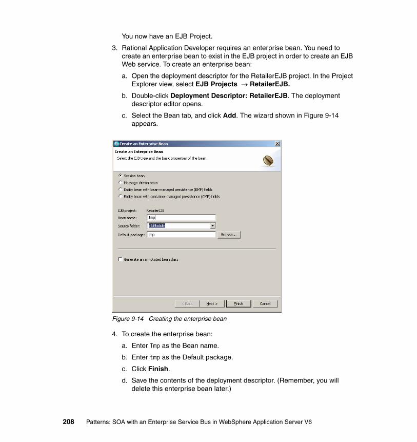
You now have an EJB Project.
3. Rational Application Developer requires an enterprise bean. You need to create an enterprise bean to exist in the EJB project in order to create an EJB Web service. To create an enterprise bean:
a. Open the deployment descriptor for the RetailerEJB project. In the Project Explorer view, select EJB Projects → RetailerEJB.
b. Double-click Deployment Descriptor: RetailerEJB. The deployment descriptor editor opens.
c. Select the Bean tab, and click Add. The wizard shown in Figure 9-14 appears.
Figure 9-14 Creating the enterprise bean
4. To create the enterprise bean:
a. Enter Tmp as the Bean name.
b. Enter tmp as the Default package.
c. Click Finish.
d. Save the contents of the deployment descriptor. (Remember, you will delete this enterprise bean later.)
208 Patterns: SOA with an Enterprise Service Bus in WebSphere Application Server V6

Configuring Rational Application Developer for Web servicesTo help in the development of Web services in Rational Application Developer, you can turn on the Web services development support and turn off the automatic publishing of projects. After you configure Rational Application Developer, you can then start the unit test environment server.
To configure Rational Application Developer:
1. Enable the full Web services development environment on Rational Application Developer as shown in Figure 9-15.
a. Click Window → Preferences.b. In the Preferences window, select Workbench → Capabilities.c. Turn on the Web services development support by expanding Web
Service Developer and then selecting Web Services Development.d. Click OK.
Figure 9-15 Preferences window
2. Turn off the automatic publishing.
a. Locate the Servers view and double-click the server configuration called WebSphere Application Server V6.0.
b. In the Server Overview screen, deselect Enable automatic publishing.
c. Save your changes and close the editor.
3. Start the server by right-clicking WebSphere Application Server V6.0 and selecting Start.
Although you will not use the unit test environment to test the Web services, a running server instance is required by the Web service wizards. If you do not start the server, the relevant Web service wizard would start it when required.
Chapter 9. Enterprise Service Bus pattern: router scenario 209

Creating a skeleton EJB Web serviceNow that you have a pre-existing EJB project containing a dummy enterprise bean, you can create a skeleton EJB Web service. The skeleton service allows you to build a Web service with an EJB implementation that is based on existing WSDL.
To create a skeleton EJB Web service:
1. Select File → New → Other. The New dialog box opens.
2. Inside this dialog box, expand Web Services, select Web Service, and click Next. If this is the first time that you have used Web services in this Rational Application Developer workspace, you are prompted to enable Web service deployment support.
3. The next page (shown in Figure 9-16 on page 211) allows you to specify the type of Web service to create. The most common types are:
– Java bean Web Service – EJB Web Service– Skeleton Java bean Web Service– Skeleton EJB Web Service
The first two types are used when an implementation has been written and the implementation now needs to be exposed an a Web service. The latter two (which are the options in which we are interested) are for when the WSDL exists and some skeleton code needs to be created. In this scenario, you want you Web service to be invokable via SOAP over JMS. Thus, you can choose Skeleton EJB Web Service.
210 Patterns: SOA with an Enterprise Service Bus in WebSphere Application Server V6
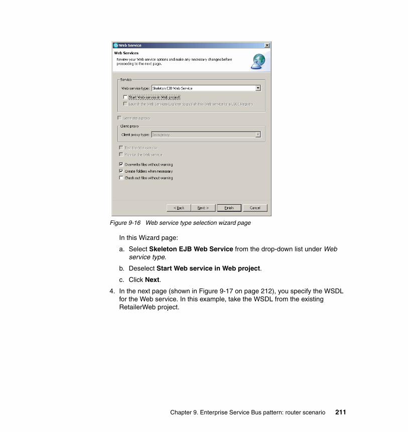
Figure 9-16 Web service type selection wizard page
In this Wizard page:
a. Select Skeleton EJB Web Service from the drop-down list under Web service type.
b. Deselect Start Web service in Web project.
c. Click Next.
4. In the next page (shown in Figure 9-17 on page 212), you specify the WSDL for the Web service. In this example, take the WSDL from the existing RetailerWeb project.
Chapter 9. Enterprise Service Bus pattern: router scenario 211

Figure 9-17 Web service WSDL selection page
The WSDL file is Retailer_Impl.wsdl, which is located in the RetailerWeb project. There are two ways of locating the WSDL file. You can either enter the name in the text box or click Browse and browse to the file.
/RetailerWeb/WebContent/wsdl/org/ws_i/www/Retailer_Impl.wsdl
5. Click Next.
6. In the next page (shown in Figure 9-18), select the EJB project and EAR project in which the Web service will be created.
Figure 9-18 Selecting the EJB project
In this Wizard page:
a. Select or enter RetailerEJB in the Service project pull-down list.
b. Select the Retailer project in the EAR project pull-down box.
c. Click Next. A WebSphere Application Server unit test server will start if one is not already running.
212 Patterns: SOA with an Enterprise Service Bus in WebSphere Application Server V6

7. Specify how the Web service will be invoked (Figure 9-19).
Figure 9-19 Options for creating a SOAP over JMS Web service
In this Wizard page:
a. In the Select Router Project pull-down list, select RetailerEJB.
b. Select the option Define custom mapping for namespace to package.
Chapter 9. Enterprise Service Bus pattern: router scenario 213
c. In the Select transports group of radio buttons, select SOAP over JMS. This will present some new options that are required in order to invoke the Web service via JMS. These options are:
• Queue kind
Which specialization of JMS destination to use. The choices are queue or topic. It only makes sense to use a topic with one way request interaction. Requests sent to a topic will be distributed to all subscribers to that topic, in a request response interaction this would result in multiple responses to a single request which is unlikely to be the desired behavior.
Select queue in the pull-down list.
• WSDL service name
The name of the Web service port to be invoked. Specify a value of Retailer.
• Connection factory
The JNDI name of a JMS connection factory. Specify a value of Sample/WSI/RetailerCF.
• Destination
The JNDI name of a JMS destination where messages to that Web service will be sent. Specify a value of Sample/WSI/RetailerQueue.
• MDB deployment mechanism
This property specifies what mechanism will be used to deliver messages to the Web service. The valid values are:
JMS ActivationSpec: used for JMS providers that have a J2EE Connector Architecture V1.5 compliant inbound resource adapter.
Listener Port: used for JMS providers that do not have a J2EE Connector Architecture V1.5 compliant inbound resource adapter, but do support the JMS Application Server Facilities part of the JMS specification.
Select JMS ActivationSpec from the pull-down list.
Tip: When using SOAP over JMS each WSDL service should have a unique JMS destination for requests. That is to say that when looking at messages on a destination they will all be destined for the same Web service.
214 Patterns: SOA with an Enterprise Service Bus in WebSphere Application Server V6
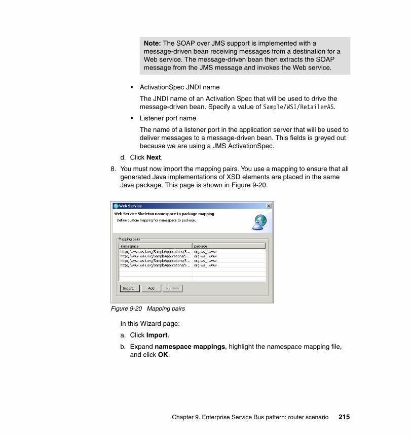
• ActivationSpec JNDI name
The JNDI name of an Activation Spec that will be used to drive the message-driven bean. Specify a value of Sample/WSI/RetailerAS.
• Listener port name
The name of a listener port in the application server that will be used to deliver messages to a message-driven bean. This fields is greyed out because we are using a JMS ActivationSpec.
d. Click Next.
8. You must now import the mapping pairs. You use a mapping to ensure that all generated Java implementations of XSD elements are placed in the same Java package. This page is shown in Figure 9-20.
Figure 9-20 Mapping pairs
In this Wizard page:
a. Click Import.
b. Expand namespace mappings, highlight the namespace mapping file, and click OK.
Note: The SOAP over JMS support is implemented with a message-driven bean receiving messages from a destination for a Web service. The message-driven bean then extracts the SOAP message from the JMS message and invokes the Web service.
Chapter 9. Enterprise Service Bus pattern: router scenario 215

c. Click Finish. At this point a warning message box appears that is similar to the one shown in Figure 9-21. These warnings are generated because some types defined in XML Schema and SOAP cannot be directly mapped to Java types. This message is warning that some types have been mapped to the javax.xml.soap.SOAPElement class instead. As a result the message can safely be ignored.
Figure 9-21 Warning issued when generating a Web service
Removing the dummy EJB and assigning a JNDI nameEarlier, you created a temporary enterprise bean. Now, you need to delete it. You also need to assign a JNDI name to the RetailerSOAPBindingImpl EJB. Setting the JNDI name in Rational Application Developer means you will not need to set it manually at deployment time.
To remove the dummy EJB and assign a JNDI name:
1. Open the deployment descriptor for the RetailerEJB project using the deployment descriptor editor.
2. Select the Bean tab.
3. Select the bean named Tmp.
4. Click Remove.
5. A window appears asking for confirmation. Accept the defaults and click OK.
6. Highlight the RetailerSOAPBindingImpl EJB.
7. In the WebSphere Bindings section, enter a JNDI name of Sample/WSI/RetailerEJB.
8. Save the deployment descriptor.
216 Patterns: SOA with an Enterprise Service Bus in WebSphere Application Server V6

Copying the business logic into the generated EJBNow, you have generated a skeleton EJB Web service, you need to add business logic to that skeleton. You will reuse the business logic from the RetailerWeb project by copying the relevant business logic class and adding code to the skeleton EJB:
1. Copy the Retailer business logic class from the RetailerWeb project into the RetailerEJB project:
a. From the Project Explorer, select Dynamic Web Projects → RetailerWeb → Java Resources → JavaSource.
b. Right-click the package org.ws_i.www.Impl and select Copy.
c. Select EJB Projects → RetailerEJB.
d. Right-click ejbModule and select Paste. The org.ws_i.www.Impl package, and the RetailerLogic.java class within it, will be copied into the RetailerEJB project.
2. Modify the skeleton EJB (class RetailerSOAPBindingImpl.java) so that it contains useful business logic. You will find the Java class in the package org.ws_i.www in the RetailerEJB project. Make the changes that are shown in bold in Example 9-1.
Example 9-1 Content of RetailerSOAPBindingImpl.java
private org.ws_i.www.Impl.RetailerLogic rl = null;
public void ejbCreate() {rl = new org.ws_i.www.Impl.RetailerLogic();
}
public CatalogItem[] getCatalog() {return rl.getCatalog();
}
public PartsOrderResponseItem[] submitOrder(PartsOrderItem partsOrder,CustomerDetailsType customerDetailsConfigurationType configurationHeader)
throws InvalidProductCode, BadOrderFault, ConfigurationFaultType {return rl.submitOrder(partsOrder, customerDetails, configurationHeader);
}
Note: At this point, you will get some compile errors because you have not generated the Web service clients that the EJB uses. Do not worry about these errors for now. We will discuss these errors later in 9.2.3, “Updating Web service clients to use the ESB” on page 219.
Chapter 9. Enterprise Service Bus pattern: router scenario 217

Removing the Web projectNow that you have created a EJB Web service for Retailer, you can delete the Java Web service in the RetailerWeb project:
1. Expand Dynamic Web Projects.
2. Right-click the RetailerWeb project.
3. Select Delete. The dialog box that is shown in Figure 9-22 appears.
Figure 9-22 Deleting the module options dialog
4. Select Also delete references to selected project(s) and click OK. The dialog box that is shown in Figure 9-23 appears.
Figure 9-23 Confirm project delete dialog
5. Select the option to delete the contents and click OK.
The Retailer Web service has now been converted to be an enterprise bean based Web service.
218 Patterns: SOA with an Enterprise Service Bus in WebSphere Application Server V6
9.2.3 Updating Web service clients to use the ESB
This section describes how to modify existing Web service clients to point to the WebSphere Application Server service integration bus rather than directly to a service provider. This modification changes the following:
� The Endpoint address that is used by Web service consumers to invoke a Web service provider changes to invoke the service integration bus inbound service rather than the provider directly.
� By going through the service integration bus, the WSDL definitions namespace changes. This requires that you regenerate the Web service client stubs and the service references in your J2EE applications. It does not affect the in transit SOAP message.
When an inbound service is exported from WebSphere Application Server, it is packaged in a zipped file. The zipped file contains four WSDL files. Each WSDL file describes a portion of the service.
Assuming that our sample bus is called TESTBUS and that the service we are looking at is called LoggingFacilityService, these files are called:
� TESTBUS.LoggingFacilityServiceBindings.wsdl
Defines the binding and transport for each operation in the service.
� TESTBUS.LoggingFacilityServicePortTypes.wsdl
Defines the port type, operations, and messages for the service.
� TESTBUS.LoggingFacilityServiceService.wsdl
Defines the service and port for the service.
� TESTBUS.LoggingFacilityServiceNonBound.wsdl
Imports a port type and defines a non-specific binding and service. Not used in this scenario.
Note: Before you can attempt this section, you must configure the service integration bus in WebSphere Application Server, and you must define the WS-I sample application Web services as inbound services to this service integration bus. To do this, follow the steps in the 9.3, “Runtime guidelines” on page 231. You need to complete all the steps up to and including 9.3.9, “Exporting the service integration bus WSDL for development” on page 253. After you have exported the service integration bus WSDL files, return to this section in the development guidelines to generate the Web service clients.
Chapter 9. Enterprise Service Bus pattern: router scenario 219

This section describes how to regenerate the Web service client code using the RetailerEJB that is generated in the previous section and the LoggingFacilityService. The procedure is the same for regenerating all the stubs.
Removing existing Web service clientsThis step is only required when updating Web service consumers. It is not required for the RetailerEJB project as it does not have any existing Web service references. Therefore, you can skip this step for the RetailerEJB project.
If you already have service references, you need to remove these references before continuing by doing the following:
1. Open the Deployment Descriptor in the deployment descriptor editor
2. Click the Reference tab (or References if you are editing a Web project).
3. Each bean in the project is listed. Expand the bean you are interested and all the references will be shown as in Figure 9-24. Select the service reference for the service you are about to regenerate the Web service for and click Remove then save the deployment descriptor.
Figure 9-24 Service references in deployment descriptor
Importing the generated WSDLThe WSDL files that are generated by WebSphere Application Server for an inbound service should now be imported into your Rational Application Developer workspace. To import the LoggingFacility service WSDL:
1. In Rational Application Developer select File → Import
2. The import dialog box is shown. Scroll down and select Zip file and click Next.
Note: Ensure that the Rational Application Developer unit test environment is started prior to completing these steps. You can check to see if it is running by examining the status of the server in the Servers view of the J2EE perspective.
220 Patterns: SOA with an Enterprise Service Bus in WebSphere Application Server V6

3. From the dialog box that appears, you import the service integration bus WSDL.
a. Specify the location of the zipped file that contains the WSDL by either entering the path or by clicking Browse and selecting the file.
b. In the right panel, deselect TESTBUS.LoggingFacilityBindingNotFound.wsdl. You will import only the port type, binding, and service WSDL files.
c. Select the project to import the WSDL files into. Click Browse and expand RetailerEJB → ejbModule → META-INF. Select wsdl, and click OK.
d. Click Finish. The files are imported into the RetailerEJB project in the ejbModule/META-INF/wsdl folder.
4. The port types WSDL file contains an XSD import statement. The WSDL assumes the XSD file is local to the WSDL file. In our scenario, all XSD files are located on an HTTP server, so the import statement should be adjusted accordingly:
a. Double-click TESTBUS.LoggingFacilityServicePortTypes.wsdl to open it in the WSDL editor.
b. Click the Source tab.
c. Locate the line that imports the LoggingFacility.xsd file:
<xs:import namespace="http://www.ws-i.org/SampleApplications/SupplyChainManagement/2002-08/LoggingFacility.xsd" schemaLocation="LoggingFacility.xsd"/>
d. Change the schemaLocation attribute to point to the HTTP server:
schemaLocation="http://appsrv1a.itso.ral.ibm.com/wsdl/LoggingFacility.xsd"
e. Save and close the WSDL file.
Creating a namespace mapping fileWhen you generate a Web service client, Rational Application Developer creates Java class implementations of all the XSD components defined by the Web service. The name of each Java class is derived from the name of the XSD component. The package name of each Java class is derived from the namespace of the XSD component.
The Java package name is based on the host part of the namespace name. For example, an XSD component that belongs to the following package would be stored in a Java package called org.ws_i.www:
http://www.ws-i.org/SampleApplications/SupplyChainManagement/2002-08/LoggingFacility.wsdl
Chapter 9. Enterprise Service Bus pattern: router scenario 221
It is common to have multiple namespaces defined with a common host part. Examples include www.ws-i.org, www.w3c.org, and schemas.xmlsoap.org. It is possible in these cases that some schemas will define elements with the same name. Without namespace mapping these elements will generate classes with the same name and in the same package. This would result in one of the generated classes overwriting the other. Namespace mapping allows a namespace to be mapped to an arbitrary package name allowing the problem to be removed.
Additionally, namespace mapping is useful to map XSD components from multiple namespaces into a single Java package. This is useful for the service integration bus generated WSDL, which is in a namespace with of host name of www.ibm.com and the generated code to be in the package org.ws_i.www.
There are three namespaces that you need to map:
� The targetNamespace, which is the same for all service definitions generated by the service integration bus.
� The sibusbinding namespaces, which are unique to each Web service we are working with.
� The other namespaces used by the XSD components.
To map the namespaces:
1. Determine the namespaces that are defined by the Web service. Open the service WSDL file TESTBUS.LoggingFacilityServiceService.wsdl and examine the namespace definitions defined in the <definitions> tag (Example 9-2 on page 223).
Note: Certain characters that are valid in a host part of a URI are not valid in a package name, such as a hyphen (-). In these cases, those characters are mapped to a different character. In the example, the hyphen is converted to an underline character (_).
222 Patterns: SOA with an Enterprise Service Bus in WebSphere Application Server V6

Example 9-2 Definitions attribute of a service WSDL file
<wsdl:definitions targetNamespace=
"http://www.ibm.com/websphere/sib/webservices/w2kssp4Node01Cell/TESTBUS/Service" xmlns:sibusbinding=
"http://www.ibm.com/websphere/sib/webservices/w2kssp4Node01Cell/TESTBUS/LoggingFacilityService/Binding"
xmlns:tns="http://www.ws-i.org/SampleApplications/SupplyChainManagement/2002-08/
LoggingFacility.wsdl" xmlns:intf=
"http://www.ws-i.org/SampleApplications/SupplyChainManagement/2002-08/LoggingFacility.wsdl"
2. From this file, you can determine that the value of the targetNamespace is:
http://www.ibm.com/websphere/sib/webservices/w2kssp4Node01Cell/TESTBUS/Service
You can also determine the value of the sibusbinding namespace is:
http://www.ibm.com/websphere/sib/webservices/w2kssp4Node01Cell/TESTBUS/LoggingFacilityService/Binding
Notice that these namespaces incorporate the cell and name of the service integration bus used.
3. Create a namespace mapping file to map these two namespaces to the Java package org.ws_i.www:
a. Select File → New → Other from the main menu.
b. In the New dialog select Simple → File then click Next.
c. Set the parent folder to namespace mappings. Then, enter nsmappings.properties in the File name text field, and click Finish. This creates the file and opens an editor for it.
d. The file is formatted so that the namespace comes first followed by equals and then the package name, all on one line. You can specify multiple lines. The namespace mappings are e unique to your system, so you must determine the namespace names yourself by examining the WSDL file TESTBUS.LoggingFacilityServiceService.wsdl. For this example, use the mappings as shown in Example 9-3.
Example 9-3 Namespace mapping file - part one
http\://www.ibm.com/websphere/sib/webservices/w2kssp4Node01Cell/TESTBUS/Service=org.ws_i.wwwhttp\://www.ibm.com/websphere/sib/webservices/w2kssp4Node01Cell/TESTBUS/LoggingFacilityService/Binding=org.ws_i.www
Chapter 9. Enterprise Service Bus pattern: router scenario 223

e. You need to create mappings for the namespaces that assigned to the sibusbinding attribute in each of the other Web services for which you will create clients. You can determine these namespaces by opening the relevant service WSDL file of each Web service. Example 9-4 shows all of the namespace mappings (including LoggingFacility). Copy this into the nsmappings.properties file. Be sure to change all occurrences of w2kssp4Node01Cell in the namespace name to the cell name of your installation.
Example 9-4 Namespace mapping file - part two
http\://www.ibm.com/websphere/sib/webservices/w2kssp4Node01Cell/TESTBUS/Service=org.ws_i.wwwhttp\://www.ibm.com/websphere/sib/webservices/w2kssp4Node01Cell/TESTBUS/LoggingFacilityService/Binding=org.ws_i.wwwhttp\://www.ibm.com/websphere/sib/webservices/w2kssp4Node01Cell/TESTBUS/ManufacturerService/Binding=org.ws_i.wwwhttp\://www.ibm.com/websphere/sib/webservices/w2kssp4Node01Cell/TESTBUS/ManufacturerBService/Binding=org.ws_i.wwwhttp\://www.ibm.com/websphere/sib/webservices/w2kssp4Node01Cell/TESTBUS/ManufacturerCService/Binding=org.ws_i.wwwhttp\://www.ibm.com/websphere/sib/webservices/w2kssp4Node01Cell/TESTBUS/RetailerService/Binding=org.ws_i.wwwhttp\://www.ibm.com/websphere/sib/webservices/w2kssp4Node01Cell/TESTBUS/WarehouseCallBackService/Binding=org.ws_i.wwwhttp\://www.ibm.com/websphere/sib/webservices/w2kssp4Node01Cell/TESTBUS/WarehouseService/Binding=org.ws_i.www
Note: Although one of the namespace mappings shown in Example 9-3 spans multiple lines, it should each be entered on a single line in the namespace mapping file. This convention also applies to Example 9-4 and Example 9-5 on page 225. Also note that the namespace must be modified from using http:// to using http\:// in the namespace mapping file.
224 Patterns: SOA with an Enterprise Service Bus in WebSphere Application Server V6

f. You need to add mappings for the other XSD components. These namespaces are not system-specific so copy the declarations shown in Example 9-5 into nsmappings.properties.
Example 9-5 Namespace mapping file - part three
http\://www.ws-i.org/SampleApplications/SupplyChainManagement/2002-10/ManufacturerPO.xsd=org.ws_i.www.pohttp\://www.ws-i.org/SampleApplications/SupplyChainManagement/2002-10/ManufacturerSN.xsd=org.ws_i.www.snhttp\://www.ws-i.org/SampleApplications/SupplyChainManagement/2002-08/Configuration.xsd=org.ws_i.wwwhttp\://www.ws-i.org/SampleApplications/SupplyChainManagement/2002-08/RetailCatalog.xsd=org.ws_i.wwwhttp\://www.ws-i.org/SampleApplications/SupplyChainManagement/2002-08/RetailOrder.xsd=org.ws_i.wwwhttp\://www.ws-i.org/SampleApplications/SupplyChainManagement/2002-08/Retailer.wsdl=org.ws_i.wwwhttp\://www.ws-i.org/SampleApplications/SupplyChainManagement/2002-08/Warehouse.wsdl=org.ws_i.wwwhttp\://www.ws-i.org/SampleApplications/SupplyChainManagement/2002-08/Manufacturer.CallBack=org.ws_i.wwwhttp\://www.ws-i.org/SampleApplications/SupplyChainManagement/2002-08/Manufacturer.wsdl=org.ws_i.www
g. Save the changes to nsmapping.properties.
Generating a Web service clientYou are now ready to generate a Web service client for the LoggingFacility service. This client points to the LoggingFacility inbound service on the service integration bus. To generate a Web service client, do the following:
1. Select File → New → Other. Then select Web Services → Web Service Client and click Next.
2. You want to create a Java proxy client, so ensure that Client proxy type is set to Java proxy and then click Next.
3. Use the browse button to locate the WSDL file RetailerEJB/ejbModule/META-INF/wsdl/TESTBUS.LoggingFacilityServiceService.wsdl and click Next.
Chapter 9. Enterprise Service Bus pattern: router scenario 225

4. On the page shown in Figure 9-25, specify the information about how the application the Web service client will be generated.
– Client type, which specifies the type of the Web service client to generate. Select EJB. The other options are Web, Application client, and Java.
– Client Project, which specifies the project where the Web service client will be generated. Select RetailerEJB.
– EAR Project, which specifies the EAR project with which the Web service client will be associated. Select Retailer.
Figure 9-25 Specify Web service client type
5. Click Next to move to the next page
6. You specify security information in the next page. Select Define custom mappings for namespace to package and click Next.
7. Import the namespace mappings file. Click Import, expand namespace mapping, highlight nsmappings.properties, and click OK. This will fill in the Mapping pairs table with the relevant information as shown in Figure 9-26 on page 227.
226 Patterns: SOA with an Enterprise Service Bus in WebSphere Application Server V6
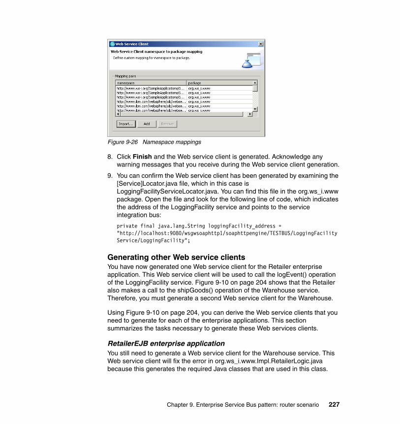
Figure 9-26 Namespace mappings
8. Click Finish and the Web service client is generated. Acknowledge any warning messages that you receive during the Web service client generation.
9. You can confirm the Web service client has been generated by examining the [Service]Locator.java file, which in this case is LoggingFacilityServiceLocator.java. You can find this file in the org.ws_i.www package. Open the file and look for the following line of code, which indicates the address of the LoggingFacility service and points to the service integration bus:
private final java.lang.String loggingFacility_address = "http://localhost:9080/wsgwsoaphttp1/soaphttpengine/TESTBUS/LoggingFacilityService/LoggingFacility";
Generating other Web service clientsYou have now generated one Web service client for the Retailer enterprise application. This Web service client will be used to call the logEvent() operation of the LoggingFacility service. Figure 9-10 on page 204 shows that the Retailer also makes a call to the shipGoods() operation of the Warehouse service. Therefore, you must generate a second Web service client for the Warehouse.
Using Figure 9-10 on page 204, you can derive the Web service clients that you need to generate for each of the enterprise applications. This section summarizes the tasks necessary to generate these Web services clients.
RetailerEJB enterprise applicationYou still need to generate a Web service client for the Warehouse service. This Web service client will fix the error in org.ws_i.www.Impl.RetailerLogic.java because this generates the required Java classes that are used in this class.
Chapter 9. Enterprise Service Bus pattern: router scenario 227

To generate this Web service client:
1. Import the Warehouse WSDL files into the RetailerEJB/ejbModule/META-INF/wsdl folder as described in “Importing the generated WSDL” on page 220. Remember to import only three files: the ones ending in PortTypes.wsdl, Service.wsdl, and Binding.wsdl.
2. Modify the PortTypes.wsdl file import statements to ensure that the XSD files are retrieved from the HTTP server.
3. Generate a new Web service client as described in “Generating a Web service client” on page 225. Be sure to specify the TESTBUS.WarehouseServiceService.wsdl file when working through the wizard.
When the Web service client for Warehouse is complete, the RetailerEJB project should contain no errors.
SampleSCMUIWeb enterprise applicationThis is the first enterprise application that contains existing Web service clients. You will re-create these clients so that they point to the service integration bus inbound service instead of pointing directly to the service provider. The service integration bus inbound service uses a different namespace and location URL.
Generate Web service clients for the LoggingFacility and Retailer services:
1. Delete the existing Web service client references as described in “Removing existing Web service clients” on page 220.
2. Import the LoggingFacility WSDL files into the SampleSCMUIWeb/WebContent/WEB-INF/wsdl folder as described in “Importing the generated WSDL” on page 220. Alternatively, copy the three WSDL files from the RetailerEJB project. Copying will save you from fixing the WSDL files in the next step.
3. If you imported the WSDL files, modify the PortTypes.wsdl file import statements to ensure that the XSD files are retrieved from the HTTP server.
4. Generate a new Web service client as described in “Generating a Web service client” on page 225.
After the LoggingFacility Web service client has been generated, repeat the steps to generate a Retailer Web service client.
228 Patterns: SOA with an Enterprise Service Bus in WebSphere Application Server V6
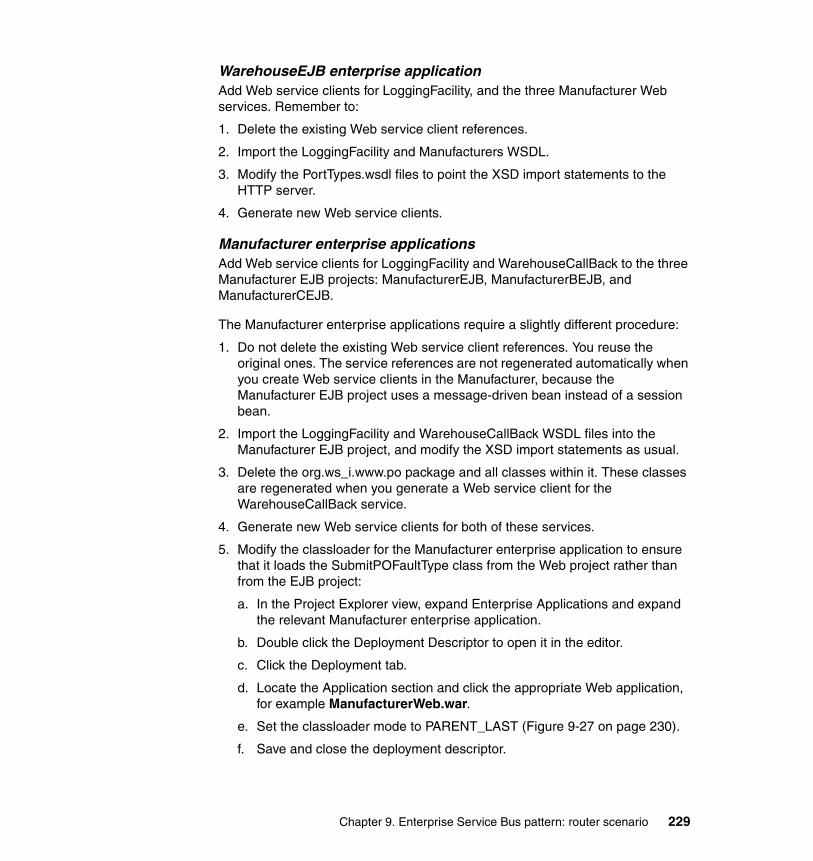
WarehouseEJB enterprise applicationAdd Web service clients for LoggingFacility, and the three Manufacturer Web services. Remember to:
1. Delete the existing Web service client references.
2. Import the LoggingFacility and Manufacturers WSDL.
3. Modify the PortTypes.wsdl files to point the XSD import statements to the HTTP server.
4. Generate new Web service clients.
Manufacturer enterprise applicationsAdd Web service clients for LoggingFacility and WarehouseCallBack to the three Manufacturer EJB projects: ManufacturerEJB, ManufacturerBEJB, and ManufacturerCEJB.
The Manufacturer enterprise applications require a slightly different procedure:
1. Do not delete the existing Web service client references. You reuse the original ones. The service references are not regenerated automatically when you create Web service clients in the Manufacturer, because the Manufacturer EJB project uses a message-driven bean instead of a session bean.
2. Import the LoggingFacility and WarehouseCallBack WSDL files into the Manufacturer EJB project, and modify the XSD import statements as usual.
3. Delete the org.ws_i.www.po package and all classes within it. These classes are regenerated when you generate a Web service client for the WarehouseCallBack service.
4. Generate new Web service clients for both of these services.
5. Modify the classloader for the Manufacturer enterprise application to ensure that it loads the SubmitPOFaultType class from the Web project rather than from the EJB project:
a. In the Project Explorer view, expand Enterprise Applications and expand the relevant Manufacturer enterprise application.
b. Double click the Deployment Descriptor to open it in the editor.
c. Click the Deployment tab.
d. Locate the Application section and click the appropriate Web application, for example ManufacturerWeb.war.
e. Set the classloader mode to PARENT_LAST (Figure 9-27 on page 230).
f. Save and close the deployment descriptor.
Chapter 9. Enterprise Service Bus pattern: router scenario 229
Figure 9-27 Setting the classloader for the Manufacturer
Exporting the enterprise applicationsEach enterprise application must be exported from the Rational Application Developer workspace to an EAR file, so that hey can be deployed to WebSphere Application Server.
To export the LoggingFacility enterprise application:
1. Click File → Export.
2. In the Export wizard, highlight EAR file and click Next.
3. In the EAR project pull-down, select LoggingFacility. Click Browse and locate a directory to where you want to store the enterprise application. Click Save. The enterprise application is called LoggingFacility.ear by default.
4. Click Finish to generate LoggingFacility.ear.
Export the remaining enterprise applications using these same steps:
� SCMSampleUI� Retailer� Warehouse� Manfacturer� ManufacturerB� ManufacturerC
Note: After you have exported the enterprise applications, you can import and test them in WebSphere Application Server, as described in 9.3.11, “Installing and testing the new enterprise applications” on page 255. You must have completed all the remaining steps in 9.3, “Runtime guidelines” on page 231 before installing the enterprise applications into WebSphere Application Server.
230 Patterns: SOA with an Enterprise Service Bus in WebSphere Application Server V6
Development alternative: Using the command line toolsWebSphere Application Server provides a set of command line tools that you can use to generate the client and server stubs. You can use these tools instead of Rational Application Developer or similar graphical tools. These tools are:
� WSDL2Java, which is used to generate the Web service consumer and provider artifacts from a WSDL file. You can then use the output from this tool to write the Web service function. This tool allows top-down development where the interface has already been defined.
� Java2WSDL, which is used to generate the Web service artifacts from a Java bean or enterprise bean. The output includes the WSDL interface definition. This tool allows bottom-up development where some function has been created and needs to be converted into a Web service where no WSDL interface definition exists.
� wsdeploy, which can be used to regenerate the generated Web service code in an ear file based on an updated WSDL. A typical example of when this would be used is when all that has changed about the WSDL is the address. In this case replacing the WSDL and running wsdeploy will update the EAR file to use the new address.
� endptenabler, which takes an EAR file and adds in the routing project required to deliver the message to the deployed Web service. For SOAP over HTTP a routing WAR file will be created. For SOAP over JMS an EJB JAR file will be added containing a message-driven bean.
9.3 Runtime guidelines
This section describes how to configure the Enterprise Service Bus runtime pattern with router interactions using WebSphere Application Server.
Note: This section assumes that you have installed and are using WebSphere Application Server V6.0.1 with the i-fixes PK02919 and PK05354 applied. You can download PK02919 at:
http://www.ibm.com/search?en=utf&v=11&lang=en&cc=us&q=PK02919
You can download PK05354 at:
http://www.ibm.com/support/docview.wss?rs=180&uid=swg24009729
Versions of WebSphere Application Server beyond V6.0.1 will not require these i-fixes.
Chapter 9. Enterprise Service Bus pattern: router scenario 231

This section describes how to perform the following tasks:
� Using the service integration bus to route Web service requests
In this chapter we will send all Web service consumer requests to the service integration bus. The service integration bus will then route these requests to the relevant Web service provider, and perform any necessary transformation.
� Installing the SDO repository
The Web service support in the service integration bus requires an SDO repository to store WSDL and XSD schema files.
� Installing the Web services support
The service integration bus Web service support is installed through running a number of Jacl scripts.
� Creating the endpoint listeners
Endpoint listeners are used to receive requests from Web service consumers. HTTP and JMS endpoint listeners are created.
� Creating the JMS resources for the Retailer Web service
As the Retailer Web service provides support for JMS, the relevant JMS resources need to be defined for it in the service integration bus.
� Creating the outbound services and Creating the inbound services
Inbound services define how Web service consumers communicate with the service integration bus. Outbound services define how the service integration bus communicates with the Web service providers. An inbound and outbound service needs to be defined for each Web service routed through the service integration bus.
� Exporting the service integration bus WSDL for development
WSDL files are created for each inbound service describing how a Web service consumer should invoke the service integration bus. This WSDL must be exported from the service integration bus and used to generate a Web service client in the service consumer.
Note: These instructions assume that you have configured the SOA Direct Connection scenario as described in Chapter 8, “SOA Direct Connection pattern” on page 153. This section describes the required modifications to convert that configuration into this one. You can quickly import the Direct Connection configuration into WebSphere Application Server using a set of Jacl scripts. For information about how to do this, see “Configuring the Direct Connection scenario” on page 368.
232 Patterns: SOA with an Enterprise Service Bus in WebSphere Application Server V6
� Importing the schemas into the SDO repository
� Installing and testing the new enterprise applications
� Runtime alternatives
9.3.1 Using the service integration bus to route Web service requestsIn this scenario, we use the service integration bus to act as a Web services intermediary between services consumers and service providers. We use the service integration bus Web services support to:
� Route Web service consumer requests to the correct Web service provider, using a simple one-to-one mapping (meaning a request for a particular Web service is always sent to the same Web service provider).
� Transform the protocol that is used by the Web service consumer (HTTP or JMS) to the protocol supported by the Web service provider.
This scenario represents three protocol interaction styles where Web service consumer requests are sent through the service integration bus. These interactions can be seen by studying Figure 9-10 on page 204. The three types of protocol interaction styles are:
� SOAP over HTTP requests with no transformation.� SOAP over JMS requests transformed to SOAP over HTTP.� SOAP over HTTP requests transformed to SOAP over JMS.
SOAP over HTTP requests with no transformationIn this instance, a Web service consumer sends a SOAP over HTTP request, which is illustrated in Figure 9-28 on page 234. This request is received by the HTTP endpoint listener and routed to the relevant inbound service defined for this Web service. The relevant outbound service is then called, which forwards a new SOAP over HTTP message to the relevant Web service provider. The message body of the original SOAP over HTTP message is preserved in the new SOAP over HTTP message.
Two Web service consumers send SOAP over HTTP requests to invoke an operation on the LoggingFacility Web service. These requests are routed through the service integration bus. In the case of the getEvents operation, a response is returned to the Web service consumer because it is a request-response operation.
Note: Chapter 10, “Enterprise Service Bus pattern: broker scenario” on page 259 uses a more complex mapping to route Web service requests with mediation handlers.
Chapter 9. Enterprise Service Bus pattern: router scenario 233

Figure 9-28 SOAP over HTTP messages sent to the LoggingFacility service
The LoggingFacilityService inbound service defines where the Web service consumers should send their SOAP over HTTP requests to for the LoggingFacility service. This inbound service points to the HTTP endpoint listener. The LoggingFacility outbound service defines where the real LoggingFacility Web service implementation is located.
SOAP over JMS requests transformed to SOAP over HTTPThe service integration bus can be used to transform the protocol used to transport a SOAP message, which is illustrated in Figure 9-29 on page 235. This becomes necessary if the Web service consumer and Web service provider use different protocols.
The Retailer Web service consumer sends a request to the shipGoods operation of the Warehouse service using SOAP over JMS. However the Warehouse service only supports SOAP over HTTP requests. The Warehouse inbound service defines a SOAP over JMS interaction and the Warehouse outbound service defines a SOAP over HTTP interaction. The service integration bus automatically performs the protocol transformation, preserving the message body of the SOAP request.
InboundServices
Retailer
logEvent
SCMSampleUI
getEvents
HTT
P en
dpoi
nt
liste
ner
Logg
ingF
acilit
ySer
vice
SOAP/HTTP
SOAP/HTTP
OutboundServices
Logg
ingF
acilit
ySer
vice
LoggingFacility
getEvents
logEvent
SOAP/HTTP
SOAP/HTTP
234 Patterns: SOA with an Enterprise Service Bus in WebSphere Application Server V6
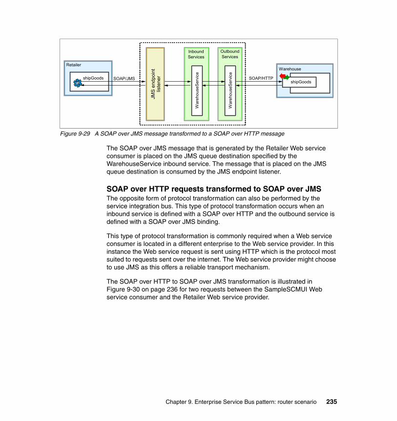
Figure 9-29 A SOAP over JMS message transformed to a SOAP over HTTP message
The SOAP over JMS message that is generated by the Retailer Web service consumer is placed on the JMS queue destination specified by the WarehouseService inbound service. The message that is placed on the JMS queue destination is consumed by the JMS endpoint listener.
SOAP over HTTP requests transformed to SOAP over JMSThe opposite form of protocol transformation can also be performed by the service integration bus. This type of protocol transformation occurs when an inbound service is defined with a SOAP over HTTP and the outbound service is defined with a SOAP over JMS binding.
This type of protocol transformation is commonly required when a Web service consumer is located in a different enterprise to the Web service provider. In this instance the Web service request is sent using HTTP which is the protocol most suited to requests sent over the internet. The Web service provider might choose to use JMS as this offers a reliable transport mechanism.
The SOAP over HTTP to SOAP over JMS transformation is illustrated in Figure 9-30 on page 236 for two requests between the SampleSCMUI Web service consumer and the Retailer Web service provider.
InboundServices
Retailer
shipGoods
JMS
end
poin
t lis
tene
r
War
ehou
seS
ervi
ce
SOAP/JMS
OutboundServices
Warehouse
shipGoodsSOAP/HTTP
War
ehou
seS
ervi
ce
Chapter 9. Enterprise Service Bus pattern: router scenario 235

Figure 9-30 SOAP over HTTP messages transformed to SOAP over JMS messages
The Retailer Web service waits for a JMS message to be placed on a predefined queue. Once a message is received, the Retailer service consumes it and executes the Web service business logic. When the Web service completes, a response message is placed on a reply-to queue, which is consumed by the service integration bus and used to construct a SOAP over HTTP response to send back to the Web service consumer.
9.3.2 Removing the existing enterprise applicationsThe first task to perform is the enterprise applications that is deployed in the SOA Direct Connection scenario. These enterprise applications use point-to-point connections. We ultimately will replace these applications with a new set of enterprise applications that make use of the ESB.
To remove the existing enterprise applications:
1. Access the WebSphere Application Server administrative console at http://localhost:9060/ibm/console and log in.
2. Expand Applications and click Enterprise Applications.
3. Select the applications LoggingFacility, Manufacturer, ManufacturerB, ManufacturerC, Retailer, SCMSampleUI and Warehouse (as shown in Figure 9-31 on page 237), and click Stop.
InboundServices
SCMSampleUI
getCatalog
HTT
P en
dpoi
nt
liste
ner
Ret
aile
rSer
viceSOAP/HTTP
OutboundServices
Retailer
getCatalog
submitOrder
SOAP/JMS
SOAP/JMSsubmitOrder SOAP/HTTP
Ret
aile
rSer
vice
236 Patterns: SOA with an Enterprise Service Bus in WebSphere Application Server V6

Figure 9-31 Selecting the applications before stopping them
4. Select the applications LoggingFacility, Manufacturer, ManufacturerB.ear, ManufacturerC, Retailer, SCMSampleUI, and Warehouse and click Uninstall.
5. Confirm the uninstallation of the applications by clicking OK.
6. Save the changes. The enterprise applications have now been removed from the server.
9.3.3 Installing the SDO repositoryThe service integration bus Web services support stores the WSDL and schemas for the Web services in the SDO repository. When WebSphere Application Server is installed it does not install the SDO repository, so this step must be performed manually.
The SDO repository uses a database to store its information. The SDO repository supports a wide variety of databases. In this scenario we will use embedded Cloudscape database. The SDO repository installation script will automatically setup the relevant resources for the database configuration.
Chapter 9. Enterprise Service Bus pattern: router scenario 237
To install the SDO repository:
1. In a command prompt window, navigate to the WAS_HOME/bin directory, where WAS_HOME is the directory where you installed WebSphere Application Server.
2. Run the following command:
wsadmin -f installSdoRepository.jacl -createDb
3. After the script completes successfully, the SDO repository has been installed. You can confirm the install by examining the installed enterprise applications. You should see a new enterprise application added and started that is called SDO Repository. Before you can use the SDO repository, you must restart the application server. However, you can wait to restart the application and proceed to the next steps.
9.3.4 Installing the Web services supportThe service integration bus Web services support is not installed by default when you install WebSphere Application Server, so this need to be performed manually. There are several steps involved in setting up this support.
Creating the JMS resourcesIn order to support inbound Web service requests via SOAP over JMS, some JMS resources need to be created. These resources are used by the JMS endpoint listener, which you will create later. To create the JMS resources:
1. Create two service integration bus queue type destinations. For instructions on how to create queue type destinations, see 8.3.4, “Creating the destinations” on page 164.
The queue type destinations should be called wsqmjmsQ1 and wsqmjmsQ2.
2. Create two JMS queue connection factories. For instructions on how to create JMS connection factories, see 8.3.5, “Creating a JMS connection factory” on page 165. However, instead of selecting JMS connection factory, select JMS queue connection factory. Use the settings that are specified in Table 9-7 on page 239 and Table 9-8 on page 239.
238 Patterns: SOA with an Enterprise Service Bus in WebSphere Application Server V6

Table 9-7 JMS queue connection factory settings
Table 9-8 JMS queue connection factory settings
3. Create two JMS queues that point to the service integration bus queue type destinations that you created in step 1 on page 238. For instructions on how to create JMS queues, see 8.3.6, “Creating the JMS queues” on page 167. Use the settings that are specified in Table 9-9 and Table 9-10.
Table 9-9 JMS queue settings
Table 9-10 JMS queue settings
4. Create two activation specifications. For instructions on how to create activation specifications, see 8.3.7, “Creating the JMS activation specifications” on page 169. Use the settings that are specified in Table 9-11 on page 240 and Table 9-12 on page 240.
Field Value
Name SOAPJMSConnFac1
JNDI name jms/SOAPJMSFactory1
Bus name TESTBUS
Field Value
Name SOAPJMSConnFac2
JNDI name jms/SOAPJMSFactory2
Bus name TESTBUS
Field Value
Name SOAPJMSQueue1
JNDI Name jms/SOAPJMSQueue1
Bus name TESTBUS
Queue name wsqmjmsQ1
Field Value
Name SOAPJMSQueue2
JNDI Name jms/SOAPJMSQueue2
Bus name TESTBUS
Queue name wsqmjmsQ2
Chapter 9. Enterprise Service Bus pattern: router scenario 239
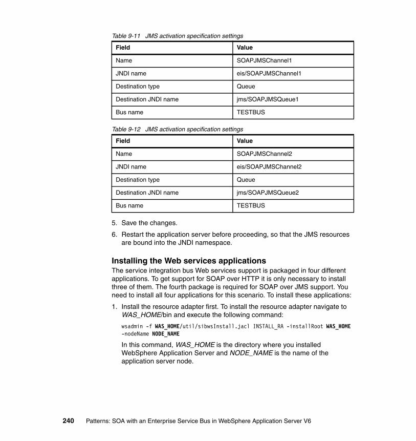
Table 9-11 JMS activation specification settings
Table 9-12 JMS activation specification settings
5. Save the changes.
6. Restart the application server before proceeding, so that the JMS resources are bound into the JNDI namespace.
Installing the Web services applicationsThe service integration bus Web services support is packaged in four different applications. To get support for SOAP over HTTP it is only necessary to install three of them. The fourth package is required for SOAP over JMS support. You need to install all four applications for this scenario. To install these applications:
1. Install the resource adapter first. To install the resource adapter navigate to WAS_HOME/bin and execute the following command:
wsadmin -f WAS_HOME/util/sibwsInstall.jacl INSTALL_RA -installRoot WAS_HOME -nodeName NODE_NAME
In this command, WAS_HOME is the directory where you installed WebSphere Application Server and NODE_NAME is the name of the application server node.
Field Value
Name SOAPJMSChannel1
JNDI name eis/SOAPJMSChannel1
Destination type Queue
Destination JNDI name jms/SOAPJMSQueue1
Bus name TESTBUS
Field Value
Name SOAPJMSChannel2
JNDI name eis/SOAPJMSChannel2
Destination type Queue
Destination JNDI name jms/SOAPJMSQueue2
Bus name TESTBUS
240 Patterns: SOA with an Enterprise Service Bus in WebSphere Application Server V6

2. Install the Web services support application from the WAS_HOME/bin directory by executing the following command:
wsadmin -f WAS_HOME/util/sibwsInstall.jacl INSTALL -installRoot WAS_HOME -nodeName NODE_NAME -serverName server1
In this command WAS_HOME is the directory where you installed WebSphere Application Server, and NODE_NAME is the name of the application server node.
3. Although the Web services support has now been installed, you cannot use it until at least one endpoint listener application is installed. There are two endpoint listener applications: one for SOAP over HTTP and one for SOAP over JMS. For this scenario, you need to install both of them. Install these applications by running the following command to install the HTTP endpoint listener application:
wsadmin -f WAS_HOME/util/sibwsInstall.jacl INSTALL_HTTP -installRoot WAS_HOME -nodeName NODE_NAME -serverName server1
Then, run the following command to install the JMS endpoint listener application:
wsadmin -f WAS_HOME/util/sibwsInstall.jacl INSTALL_JMS -installRoot WAS_HOME -nodeName NODE_NAME -serverName server1
In these commands, where WAS_HOME is the directory where you installed WebSphere Application Server, and NODE_NAME is the name of the application server node.
9.3.5 Creating the endpoint listenersNext, you need to create some endpoint listeners (which will use the endpoint listener applications at runtime). Endpoint listeners listen for incoming Web service requests and forward them onto the relevant inbound service. Inbound services get bound to an endpoint listener when they are created.
The process is similar for creating both the JMS and an HTTP endpoint listener:
1. Access the administrative console at http://localhost:9060/ibm/console and log in.
2. Expand Servers and click Application Servers.
3. Click server1.
Important: The second WAS_HOME must have elements in the path separated by a forward slash (/) even on Windows system. So a path of c:\WebSphere\AppServer becomes c:/WebSphere/AppServer.
Chapter 9. Enterprise Service Bus pattern: router scenario 241

4. Under Additional Properties, click Endpoint Listeners.
5. Click New.
6. Create an endpoint listener using the dialog box as shown in Figure 9-32.
Figure 9-32 Creating an endpoint listener
In this dialog box, enter the following information:
– Name, which is the name of the endpoint listener. It must have the name SOAPHTTPChannel1.
– URL root, which is the base URL for Web service requests into this endpoint listener. The URLs that are used for making Web service requests to the service integration bus will have this root at the beginning. Set this to:
http://localhost:9080/wsgwsoaphttp1
You can replace localhost with the server’s host name and 9080 with the correct port number for your server.
– WSDL serving HTTP URL root, which is the location of the HTTP URL that is serving your Web service WSDL. Enter a value of http://appsrv1a.itso.ral.ibm.com/wsdl, which corresponds to the HTTP server configuration that you completed in 8.3.8, “Hosting the WSDL files” on page 171.
7. Click OK.
8. Repeat steps 5 through 7 for the JMS endpoint listener. Use the settings shown in Table 9-13 on page 243.
242 Patterns: SOA with an Enterprise Service Bus in WebSphere Application Server V6

Table 9-13 SOAP over JMS endpoint listener settings
9. Save the changes.
9.3.6 Creating the JMS resources for the Retailer Web serviceThe Retailer Web service is invoked using SOAP over JMS, so you must create some JMS resources. To create the necessary resources:
1. Create a service integration bus queue type destination. The queue type destination should be called wsqmjmsQ3.
2. Create two JMS queue connection factories. Use the settings that are specified in Table 9-14 and Table 9-15.
Table 9-14 JMS queue connection factory settings
Table 9-15 JMS queue connection factory settings
Field Value
Name SOAPJMSChannel1
URL root jms:/queue?destination=jms/SOAPJMSQueue1&connectionFactory=jms/SOAPJMSFactory1&
WSDL serving HTTP URL root http://appsrv1a.itso.ral.ibm.com/wsdl
Field Value
Name RetailerCF
JNDI name Sample/WSI/RetailerCF
Bus name TESTBUS
Field Value
Name WebServicesCF
JNDI name jms/WebServicesReplyQCF
Bus name TESTBUS
Chapter 9. Enterprise Service Bus pattern: router scenario 243
3. Create a JMS queue that points to the service integration bus queue type destination that you created in step 1 on page 238. Use the settings that are specified in Table 9-16.
Table 9-16 JMS queue settings
4. Create an activation specification. Use the settings that are specified in Table 9-17.
Table 9-17 JMS activation specification settings
5. Finally save the changes.
9.3.7 Creating the outbound servicesOutbound services define Web service requests that leave the service integration bus and are received by a service provider. To define an outbound service for the LoggingFacilityService Web service:
1. From the administrative console, expand Service integration and click Buses.
2. Click TESTBUS.
3. Under Additional Properties, click Outbound Services.
4. Click New.
5. The first page of the wizard (Figure 9-33 on page 245) requires you to specify a URL or UDDI repository where a WSDL definition of the service can be
Field Value
Name SOAPJMSQueue3
JNDI Name Sample/WSI/RetailerQueue
Bus name TESTBUS
Queue name wsqmjmsQ3
Field Value
Name RetailerAS
JNDI name Sample/WSI/RetailerAS
Destination type Queue
Destination JNDI name Sample/WSI/RetailerQueue
Bus name TESTBUS
244 Patterns: SOA with an Enterprise Service Bus in WebSphere Application Server V6

found. In this case, use a URL. The URL option allows you to specify an HTTP URL or a file system path. Enter the following URL and click Next.
http://appsrv1a.itso.ral.ibm.com/wsdl/LoggingFacility_Impl.wsdl
Figure 9-33 Web service definition selection
6. The next page displays the available services that are defined in the WSDL file. You can select the service for which you want to create an outbound service. In this case, there is only one service to select (LoggingFacilityService). Click Next.
7. The next page (Figure 9-34 on page 246) displays the ports that are defined for the selected service. There is only one port in our service, so select LoggingFacility and click Next.
Chapter 9. Enterprise Service Bus pattern: router scenario 245

Figure 9-34 Port selection page
8. You change the name of the outbound service, service destination name, and port destination name. You also specify a port selection mediation. Accept the defaults and click Next.
9. You to select the bus member to which to assign the outbound service. Accept the defaults and click Finish. The outbound service is created.
10.Repeat steps 4 on page 244 to 9 for each of the additional Web services, using the URL locations that are specified in Table 9-18 on page 247.
246 Patterns: SOA with an Enterprise Service Bus in WebSphere Application Server V6

Table 9-18 Outbound service settings
11.Save the changes.
12.A Web service destination and port destination are created for each inbound service. You can see these destinations by selecting Destinations in the bus details page.
9.3.8 Creating the inbound servicesInbound services define Web service requests that are received by the service integration bus. These requests are then routed to the appropriate outbound service. To define an inbound service for the LoggingFacilityService Web service:
1. From the bus details page under Additional Properties, click Inbound Services.
2. Click New.
3. Select the service destination name and supply the template WSDL service definition, as shown in Figure 9-35 on page 248.
Web service WSDL location
ManufacturerService http://appsrv1a.itso.ral.ibm.com/wsdl/Manufacturer_Impl.wsdl
ManufacturerBService http://appsrv1a.itso.ral.ibm.com/wsdl/ManufacturerB_Impl.wsdl
ManufacturerCService http://appsrv1a.itso.ral.ibm.com/wsdl/ManufacturerC_Impl.wsdl
RetailerService http://appsrv1a.itso.ral.ibm.com/wsdl/RetailerJMS_Impl.wsdl
WarehouseService http://appsrv1a.itso.ral.ibm.com/wsdl/Warehouse_Impl.wsdl
WarehouseCallBackService http://appsrv1a.itso.ral.ibm.com/wsdl/WarehouseCallBack_Impl.wsdl
Chapter 9. Enterprise Service Bus pattern: router scenario 247

Figure 9-35 Service destination and template WSDL settings page
– Service destination name, which is the destination on which the inbound service requests should be placed. In this case, you want to specify the Web service destination that was created for the LoggingFacility outbound service.
Select the following:
http://www.ws-i.org/SampleApplications/SupplyChainManagement/2002-08/LoggingFacility.wsdl:LoggingFacilityService
– Template WSDL location, which specifies the WSDL definition of the Web service to be invoked. While the WSDL that is used by client applications will be slightly different, it is based on this WSDL. In this scenario, you specify the WSDL of the Web service endpoint that will ultimately be invoked after the request has been routed through the bus:
Enter the following:
http://appsrv1a.itso.ral.ibm.com/wsdl/LoggingFacility_Impl.wsdl
4. Click Next.
5. Enter the template WSDL that should be used. Our WSDL has only one entry, so accept the default, and click Next.
6. Rename the inbound service and specify which endpoint listener is to be used, as shown in Figure 9-36 on page 249.
248 Patterns: SOA with an Enterprise Service Bus in WebSphere Application Server V6

Figure 9-36 Specify inbound service name and endpoint listener
– Inbound Service name, which is the service in the WSDL. It affects the code that is generated by the application development tooling. By default, the name is based on the service destination name with InboundService at the end. Enter LoggingFacilityService.
– Endpoint listener, which defines what mechanism is used to get Web service requests into the inbound service. Listed will be the endpoint listeners that you created in 9.3.5, “Creating the endpoint listeners” on page 241. It is possible to choose multiple endpoint listeners.
Select the endpoint that ends in SOAPHTTPChannel1.
7. Click Next.
8. Specify UDDI specific properties. Because you are not using UDDI, you can accept the defaults and click Finish.
9. The default port name for the inbound service is based on the endpoint listener name followed by the phrase InboundPort. In this case, the inbound port name is SOAPHTTPChannel1InboundPort. Because our clients are calling a port called LoggingFacility, the clients are unable to invoke the service. To fix this issue:
a. From the Inbound service listing page, click LoggingFacilityService.
b. Under Additional Properties, click Inbound Ports.
c. Click the port named SOAPHTTPChannel1InboundPort.
Note: In order to see the Additional Properties, you probably will need to scroll to the right using the horizontal scroll bar.
Chapter 9. Enterprise Service Bus pattern: router scenario 249
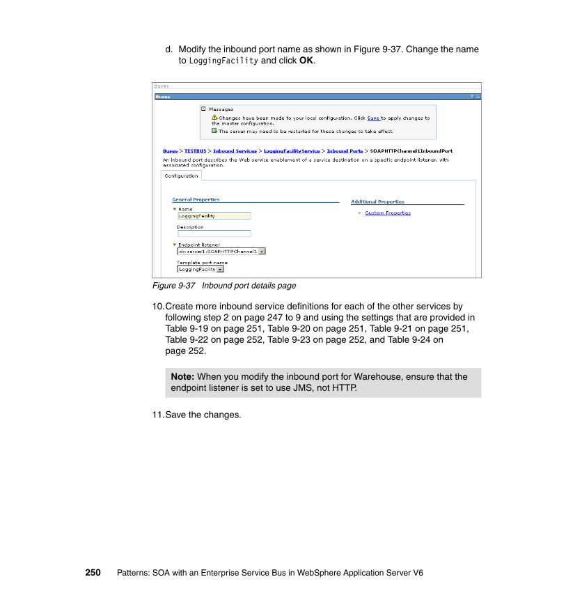
d. Modify the inbound port name as shown in Figure 9-37. Change the name to LoggingFacility and click OK.
Figure 9-37 Inbound port details page
10.Create more inbound service definitions for each of the other services by following step 2 on page 247 to 9 and using the settings that are provided in Table 9-19 on page 251, Table 9-20 on page 251, Table 9-21 on page 251, Table 9-22 on page 252, Table 9-23 on page 252, and Table 9-24 on page 252.
11.Save the changes.
Note: When you modify the inbound port for Warehouse, ensure that the endpoint listener is set to use JMS, not HTTP.
250 Patterns: SOA with an Enterprise Service Bus in WebSphere Application Server V6

Table 9-19 Inbound service settings for ManufacturerService
Table 9-20 Inbound service settings for ManufacturerBService
Table 9-21 Inbound service settings for ManufacturerCService
Field Value
Service destination name http://www.ws-i.org/SampleApplications/SupplyChainManagement/2002-10/Manufacturer.wsdl:ManufacturerService
Template WSDL location http://appsrv1a.itso.ral.ibm.com/wsdl/Manufacturer_Impl.wsdl
Inbound service name ManufacturerService
Endpoint listener SOAPHTTPChannel1
Inbound port name Manufacturer
Field Value
Service destination name http://www.ws-i.org/SampleApplications/SupplyChainManagement/2002-10/Manufacturer.wsdl:ManufacturerBService
Template WSDL location http://appsrv1a.itso.ral.ibm.com/wsdl/ManufacturerB_Impl.wsdl
Inbound service name ManufacturerBService
Endpoint listener SOAPHTTPChannel1
Inbound port name ManufacturerB
Field Value
Service destination name http://www.ws-i.org/SampleApplications/SupplyChainManagement/2002-10/Manufacturer.wsdl:ManufacturerCService
Template WSDL location http://appsrv1a.itso.ral.ibm.com/wsdl/ManufacturerC_Impl.wsdl
Inbound service name ManufacturerCService
Endpoint listener SOAPHTTPChannel1
Inbound port name ManufacturerC
Chapter 9. Enterprise Service Bus pattern: router scenario 251

Table 9-22 Inbound service settings for RetailerService
Table 9-23 Inbound service settings for WarehouseService
Table 9-24 Inbound service settings for WarehouseCallBackService
Field Value
Service destination name http://www.ws-i.org/SampleApplications/SupplyChainManagement/2002-08/Retailer.wsdl:RetailerService
Template WSDL location http://appsrv1a.itso.ral.ibm.com/wsdl/RetailerJMS_Impl.wsdl
Inbound service name RetailerService
Endpoint listener SOAPHTTPChannel1
Inbound port name Retailer
Field Value
Service destination name http://www.ws-i.org/SampleApplications/SupplyChainManagement/2002-08/Warehouse.wsdl:WarehouseService
Template WSDL location http://appsrv1a.itso.ral.ibm.com/wsdl/Warehouse_Impl.wsdl
Inbound service name WarehouseService
Endpoint listener SOAPJMSChannel1
Inbound port name Warehouse
Note: WarehouseService uses an endpoint listener of SOAPJMSChannel1.
Field Value
Service destination name http://www.ws-i.org/SampleApplications/SupplyChainManagement/2002-08/Warehouse.wsdl:WarehouseCallBackService
Template WSDL location http://appsrv1a.itso.ral.ibm.com/wsdl/WarehouseCallBack_Impl.wsdl
Inbound service name WarehouseCallBackService
Endpoint listener SOAPHTTPChannel1
Inbound port name WarehouseCallBack
252 Patterns: SOA with an Enterprise Service Bus in WebSphere Application Server V6

9.3.9 Exporting the service integration bus WSDL for developmentThe enterprise applications that are used in the Direct Connection scenario cannot be used with this scenario, because these applications all contain Web service clients which point directly to a service provider rather than to the service integration bus that you have defined. Therefore, you need to modify the enterprise applications to point to your service integration bus inbound services.
To do this, you must create new WSDL files for each Web service and export these WSDL files from WebSphere Application Server into zipped files. You can then give the zipped files to an application developer, who can import them into Rational Application Developer and change the enterprise applications accordingly.
To download a zipped file for each inbound service.:
1. In the administrative console, locate the inbound services list. Click LoggingFacilityService.
2. Under Additional Properties, click Publish WSDL files to ZIP file.
3. Click LoggingFacilityService.zip and save the file to disk.
4. Repeat steps 1 to 3 for each of the other inbound services as follows:
– ManufacturerService– ManufacturerBService– ManufacturerCService– RetailerService– WarehouseService– WarehouseCallBackService
The zipped files can now be provided to the application developers to regenerate the Web service clients.
Note: In order to see the Additional Properties, you probably will need to scroll to the right using the horizontal scroll bar.
Chapter 9. Enterprise Service Bus pattern: router scenario 253

9.3.10 Importing the schemas into the SDO repositoryWhen the inbound and outbound services are created, the WSDL is imported automatically into the SDO repository. Unfortunately, any schemas that were used are not similarly imported. Therefore, you will need to import the schemas manually, as follows:
1. Download the following files from http://appsrv1a.itso.ral.ibm.com/wsdl into the directory c:\tmp\xsd:
– Configuration.xsd– LoggingFacility.xsd– ManufacturerPO.xsd– ManufacturerSN.xsd– RetailCatalog.xsd– RetailOrder.xsd– Warehouse.xsd– envelope.xsd
2. From the WAS_HOME/bin directory run the following command to load the WebSphere Application Server command line administrative console:
wsadmin
In this command, WAS_HOME is the directory where you installed WebSphere Application Server.
3. Obtain a reference to the SDO Repository MBean by entering:
set sdo [$AdminControl queryNames type=SdoRepository,*]
4. Import the schema by entering the following:
$AdminControl invoke $sdo importResource {http://appsrv1a.itso.ral.ibm.com/wsdl/Configuration.xsd c:/tmp/xsd/Configuration.xsd}
This command imports the Configuration.xsd file into the SDO repository so that it can be accessed at runtime by the service integration bus Web services support.
5. Repeat step 4 for each of the XSD files, replacing both occurrences of Configuration.xsd with the relevant file name.
6. Type exit to leave the command line administrative console.
Note: This command only works on a single server setup. In a network deployment environment, there might be multiple instances of the SDO repository, in which case the sdo command would contain a list of MBean references rather than a single MBean reference.
254 Patterns: SOA with an Enterprise Service Bus in WebSphere Application Server V6

9.3.11 Installing and testing the new enterprise applications
Installing the new enterprise applicationsThe final configuration task is to take the applications that you created in the 9.2, “Development guidelines” on page 202 and install them into the application server.
You need to install the following enterprise applications:
� SCMSampleUI� LoggingFacility� Retailer� Warehouse� Manufacturer� ManufacturerB� ManufacturerC
For more information about how to install enterprise applications into WebSphere Application Server, see 8.3.9, “Installing the applications” on page 172. Be sure to use the EAR files that you exported from Rational Application Developer in 9.2.3, “Updating Web service clients to use the ESB” on page 219.
When all the enterprise applications are installed, restart the application server.
Testing the sample applicationYou can test the sample application by opening a Web browser and entering:
http://localhost:9080/SCMSampleUI/
Note: In order to complete this scenario, you must now complete section 9.2.3, “Updating Web service clients to use the ESB” on page 219. In this section, you use the zipped files that were exported by the service integration bus to modify the Web service clients that is defined in each enterprise application.
This task requires the use of Rational Application Developer and is considered a development task. Thus, this step is described in the development guidelines of this chapter.
Note: You cannot complete this section until you have regenerated the Web service clients as described in 9.2.3, “Updating Web service clients to use the ESB” on page 219.
Chapter 9. Enterprise Service Bus pattern: router scenario 255

You can find full instructions on how to test the application in 8.3.10, “Running and using the sample application” on page 174.
9.3.12 Runtime alternativesThis section discusses some alternative runtime guidelines.
Runtime alternative: multiple services in a single WSDL fileSome Web services might define multiple services in a single WSDL service implementation file. For example, the LoggingFacility Web service can define two services, one for a SOAP/HTTP service and another for a SOAP/JMS service as shown in Example 9-6.
Example 9-6 LoggingFacility with multiple services
<wsdl:service name="LoggingFacilityService"> <wsdl:port binding="intf:LoggingFacilitySoapBinding" name="LoggingFacility">
<wsdlsoap:address location="http://localhost:9080/LoggingFacility/services/LoggingFacility" /> </wsdl:port></wsdl:service>
<wsdl:service name="LoggingFacilityJMSService"> <wsdl:port binding="intf:LoggingFacilitySoapJMSBinding" name="LoggingFacility"> <wsdlsoap:address location="jms:/queue?destination=jms/LoggingFacilityQ&
connectionFactory=jms/LoggingFacilityQCF&targetService=LoggingFacility"/> </wsdl:port></wsdl:service>
When deploying such services to the service integration bus, it is not sufficient to simply supply the WSDL location, as the service integration bus is unable to determine which service is intended to be deployed. Therefore, you must also specify the correct target service name and the target service namespace.
For example, to define the LoggingFacility service which uses SOAP/HTTP, we specified:
� Inbound service name set to LoggingFacilityHTTPService
� Endpoint Listener set to SOAPHTTPChannel1
256 Patterns: SOA with an Enterprise Service Bus in WebSphere Application Server V6

� WSDL location set to:
http://appsrv1a.itso.ral.ibm.com/wsdl/LoggingFacility_Impl.wsdl
� WSDL target service name set to LoggingFacilityService
� WSDL target service Namespace set to:
http://www.ws-i.org/SampleApplications/SupplyChainManagement/2002-08/LoggingFacility.wsdl
Similarly, we defined a second LoggingFacility inbound service (which uses SOAP/JMS) called LoggingFacilityJMSService with the same settings, except with endpoint listener set to SOAPJMSChannel1 and the WSDL target service name set to LoggingFacilityJMSService.
Runtime alternative: multiple target portsInstead of defining two service definitions in a single WSDL file, you can define multiple WSDL ports with a single WSDL service, as shown in Example 9-7.
Example 9-7 Multiple ports in a single service definition
<wsdl:service name="LoggingFacilityService"> <wsdl:port name="LoggingFacilityHTTP" binding="intf:LoggingFacilitySoapBinding">
<wsdlsoap:address location="http://appsrv1a:9080/LoggingFacility/services/LoggingFacility"/> </wsdl:port> <wsdl:port name="LoggingFacilityJMS" binding="intf:LoggingFacilitySoapJMSBinding"> <wsdlsoap:address location="jms:/queue?destination=jms/LoggingFacilityQ& connectionFactory=jms/LoggingFacilityQCF&targetService=LoggingFacility"/> </wsdl:port></wsdl:service>
In this instance, you would deploy a single Web service for both ports. The service integration bus detects that multiple ports are defined in the service and creates target service ports for each of them.
You must define a JAX-RPC handler to select the appropriate target port for the target service. Failure to do so will mean that service integration bus always selects the first target service port in the list.
Chapter 9. Enterprise Service Bus pattern: router scenario 257

258 Patterns: SOA with an Enterprise Service Bus in WebSphere Application Server V6

Chapter 10. Enterprise Service Bus pattern: broker scenario
This chapter expands on the capability of the Enterprise Service Bus (ESB) using the service-oriented architecture (SOA). Chapter 9, “Enterprise Service Bus pattern: router scenario” on page 179 discussed the implementation of the router pattern to replace point-to-point connections. This chapter describes an ESB implementation that reduces the number of service invocations by using the ESB runtime pattern with broker interactions.
10
© Copyright IBM Corp. 2005. All rights reserved. 259

10.1 Design guidelinesThis section discusses the business needs that are addressed by the sample scenario, the use of ESB runtime pattern for broker interactions, and the design decisions that were made in order to implement the chosen scenario.
The business scenario that is implemented in this chapter is one of the interactions of the WS-I SCM sample scenario that is defined in Chapter 6, “The business scenario that this book uses” on page 125.
Figure 10-1 shows an overview how to design a solution that addresses particular business requirements. This chapter discusses each of these steps.
Figure 10-1 Design approach
10.1.1 Business scenarioThe business scenario represents a variation of the internal supply chain management on demand scenario as defined in 6.2.2, “Stage 2: Additional warehouses” on page 128. The scenario shows how you can develop solutions to real-world business requirements within an single enterprise by applying an SOA using an Enterprise Service Bus .
The Supply Chain Management application makes requests to the Retail system to help customers buy electronics goods online. The Retailer gets stock from the Warehouses and the Warehouses replenishes stock from the Manufacturers, on a one-to-one basis, as seen in Figure 10-2 on page 261.
Design andimplementthe solution
Select aproduct
Analyzedesignoptions
Select aPattern
Analyze thebusinessneeds
Design andimplementthe solution
Select aproductSelect aproduct
Analyzedesignoptions
Analyzedesignoptions
Select aPatternSelect aPattern
Analyze thebusinessneeds
Analyze thebusinessneeds
Analyze thebusinessneeds
Analyze thebusinessneeds
260 Patterns: SOA with an Enterprise Service Bus in WebSphere Application Server V6

Figure 10-2 High-level business context showing the existing infrastructure
The company is facing several issues with the existing infrastructure, which it is looking to overcome. In addition to those discussed in 9.1.1, “Business scenario” on page 180 there are additional issues as follows:
� The parts that are offered to customers are now stocked in multiple Warehouses, where each part is held in only one Warehouse. However, the client must see the order as a single transaction through the company. Therefore, an order must be split within the company so that requests for shipment by a Warehouse are only made for the parts stocked at that particular Warehouse. The responses from the Warehouses must be merged to provide a single response to the client.
� The company is looking to grow its product line through acquisition. Thus, they want to bring additional Warehouses online and also broaden the supply chain by allowing more manufacturing facilities to make the company’s goods.
Intranet
ManufacturerManufacturer
Manufacturer
LoggingFacility
RetailSystem
SCMApplication
ManufacturerManufacturer
ManufacturerManufacturer
ManufacturerWarehouse
Intranet
ManufacturerManufacturer
Manufacturer
LoggingFacility
RetailSystem
SCMApplication
ManufacturerManufacturer
ManufacturerManufacturer
ManufacturerWarehouse
Chapter 10. Enterprise Service Bus pattern: broker scenario 261

10.1.2 Selecting an SOA patternThe business scenario states that the Retailer gets stock from multiple Warehouses, where each part is held in only one Warehouse. Additionally, acquired companies need to be easily integrated into the organization’s infrastructure.
From this description, there are three interaction requirements:
� Requests must be distributed between multiple service providers and must return a single response.
� Additional Warehouses must be added in order to support the client request from the Retailer.
� Additional Manufacturers could be accessed to provide goods to the Warehouses
Choosing and applying the relevant SOA patternWe used the Patterns for e-business to determine the appropriate Runtime pattern to apply to this scenario. Because this is an intra-enterprise scenario, we selected the Process Integration application patterns. The business scenario requires routing of a single request to multiple providers, which is described by the Broker application pattern. Our business scenario describes SOA, so we selected the SOA profile of the Broker runtime pattern, which is the ESB runtime pattern (described in 5.1.2, “ESB runtime pattern” on page 98).
The ESB implementation for this business scenario is applied to the level 0 decompostion of the ESB runtime pattern, as shown in Figure 10-3 on page 263.
Select aPatternSelect aPattern
262 Patterns: SOA with an Enterprise Service Bus in WebSphere Application Server V6
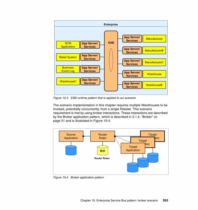
Figure 10-3 ESB runtime pattern that is applied to our scenario
The scenario implementation in this chapter requires multiple Warehouses to be invoked, potentially concurrently, from a single Retailer. This scenario requirement is met by using broker interactions. These interactions are described by the Broker application pattern, which is described in 3.1.4, “Broker” on page 51 and is illustrated in Figure 10-4.
Figure 10-4 Broker application pattern
Enterprise
ESB
App Server/ Services Manufacturer
App Server/ Services ManufacturerB
App Server/ Services ManufacturerC
App Server/ Services
SCM Application
App Server/ Services
Business Event Log
App Server/ ServicesRetail System
App Server/ Services Warehouse
App Server/ Services WarehouseB
App Server/ ServicesWarehouseC
TargetApplication
SourceApplication
RouterRules
TargetApplication
TargetApplicationR/O
Router Rules
Chapter 10. Enterprise Service Bus pattern: broker scenario 263
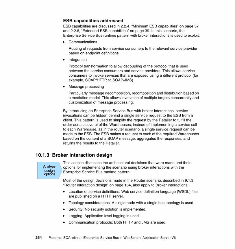
ESB capabilities addressedESB capabilities are discussed in 2.2.4, “Minimum ESB capabilities” on page 37 and 2.2.6, “Extended ESB capabilities” on page 39. In this scenario, the Enterprise Service Bus runtime pattern with broker interactions is used to exploit:
� Communications
Routing of requests from service consumers to the relevant service provider based on endpoint definitions.
� Integration
Protocol transformation to allow decoupling of the protocol that is used between the service consumers and service providers. This allows service consumers to invoke services that are exposed using a different protocol (for example, SOAP/HTTP, to SOAP/JMS).
� Message processing
Particularly message decomposition, recomposition and distribution based on a mediation model. This allows invocation of multiple targets concurrently and customization of message processing.
By introducing an Enterprise Service Bus with broker interactions, service invocations can be hidden behind a single service request to the ESB from a client. This pattern is used to simplify the request by the Retailer to fulfill the order across several of the Warehouses; instead of implementing a service call to each Warehouse, as in the router scenario, a single service request can be made to the ESB. The ESB makes a request to each of the required Warehouses based on the content of a SOAP message, aggregates the responses, and returns the results to the Retailer.
10.1.3 Broker interaction designThis section discusses the architectural decisions that were made and their options for implementing the scenario using broker interactions with the Enterprise Service Bus runtime pattern.
Most of the design decisions made in the Router scenario, described in 9.1.3, “Router interaction design” on page 184, also apply to Broker interactions:
� Location of service definitions: Web service definition language (WSDL) files are published on a HTTP server.
� Topology considerations: A single node with a single bus topology is used.
� Security: No security solution is implemented.
� Logging: Application level logging is used.
� Communication protocols: Both HTTP and JMS are used.
Analyzedesignoptions
Analyzedesignoptions
Analyzedesignoptions
264 Patterns: SOA with an Enterprise Service Bus in WebSphere Application Server V6
One design decision that has to change to meet the requirements of the scenario is the routing method. Static routing is no longer appropriate. An order has to be divided between several Warehouses that have specific parts in stock. The SOAP message has to be split apart in order to invoke the Warehouse services concurrently and has to be merged in order to return one response to the client. In this case, we need to use dynamic routing.
There are also additional design decisions that are specific to this scenario, which are discussed in the following sections.
Service invocationTable 10-1 summarizes the design alternatives that are available when deciding how to invoke multiple services. Each design alternative is then discussed in more detail in the sections that follow.
Table 10-1 Design decision: service invocation
Decision title Multiple service invocation implementation
Problem statement In this scenario, multiple requests are made concurrently to multiple service providers by the ESB on behalf of a single request by a service consumer. The responses from each service provider also have to be combined into a single response to the service consumer.A decision has to be made on how this is going to be implemented.
Alternative 1 Aggregation and disaggregation of SOAP messages.
Alternative 2 Serial invocations.
Decision Aggregation and disaggregation of SOAP messages through implementation of mediations.
Justification This scenario requires splitting and merging of messages so aggregation and disaggregation is the most appropriate choice.
Chapter 10. Enterprise Service Bus pattern: broker scenario 265

Alternative 1: Aggregation and disaggregationDisaggregation can be done by parsing the body of SOAP messages that flow through the system and by breaking down the information into multiple messages that can be sent to the relevant service providers. Aggregation can be done by merging and transforming responses to create a single response to the original request.
� Reasons for using this alternative include:
– The duration of an aggregated or diaggregated process is the duration of the longest individual call so performance is greatly improved. This is particularly relevant when there are many requests being made to service providers for each consumer request
– This alternative reduces the number of service invocations. This improves the performance of the system and allows for greater throughput
� Reasons for not using this alternative include:
– Programming is required in order to do the disaggregation or aggregation. For example a mediation can be implemented.
– Product choice might not be capable of disaggregation and aggregation.
Alternative 2: Serial invocationsNot all products are capable of disaggregation and aggregation, and it is not always the most suited method of implementation. In these cases, you should consider serial calls from the ESB to the service provider.
� Reasons for using this alternative include:
– Product choice might dictate use of serial invocations.
� Reasons for not using this alternative include:
– Performance is low because the duration of a serial process implementation is the sum of the duration of all the steps.
– Number of service invocations is increased. This reduces system performance and reduces overall throughput.
266 Patterns: SOA with an Enterprise Service Bus in WebSphere Application Server V6
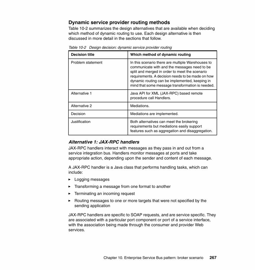
Dynamic service provider routing methodsTable 10-2 summarizes the design alternatives that are available when deciding which method of dynamic routing to use. Each design alternative is then discussed in more detail in the sections that follow.
Table 10-2 Design decision: dynamic service provider routing
Alternative 1: JAX-RPC handlersJAX-RPC handlers interact with messages as they pass in and out from a service integration bus. Handlers monitor messages at ports and take appropriate action, depending upon the sender and content of each message.
A JAX-RPC handler is a Java class that performs handling tasks, which can include:
� Logging messages
� Transforming a message from one format to another
� Terminating an incoming request
� Routing messages to one or more targets that were not specified by the sending application
JAX-RPC handlers are specific to SOAP requests, and are service specific. They are associated with a particular port component or port of a service interface, with the association being made through the consumer and provider Web services.
Decision title Which method of dynamic routing
Problem statement In this scenario there are multiple Warehouses to communicate with and the messages need to be split and merged in order to meet the scenario requirements. A decision needs to be made on how dynamic routing can be implemented, keeping in mind that some message transformation is needed.
Alternative 1 Java API for XML (JAX-RPC) based remote procedure call Handlers.
Alternative 2 Mediations.
Decision Mediations are implemented.
Justification Both alternatives can meet the brokering requirements but mediations easily support features such as aggregation and disaggregation.
Chapter 10. Enterprise Service Bus pattern: broker scenario 267
To enable JAX-RPC handlers to perform more complex operations, they can be chained together into a handler list. Each handler list is then associated with one or more ports, so that the handler list can monitor the activity at the port and take appropriate action depending on the sender and content of each message that passes through the port.
If a proxy configuration is created a JAX-RPC handler must also be created that can set the target endpoint for the proxy service. When a proxy is configured, a single proxy Web service is defined without any target services. Any SOAP request can be made to this service but as a consequence of not defining target services another mechanism is needed to provide routing. A JAX-RPC handler can be used to select the appropriate target service and set the necessary message property.
� Reasons for using this alternative include:
– JAX-RPC handlers are widely implemented
– Any JAX-RPC handlers written for use in other systems can also be configured for use with a service integration bus
– Already accepted as standard approach to message-level security in Java
– Good support for request/response messages
� Reasons for not using this alternative include:
– Programming is required
– Not intended for dealing with cloning or aggregation and disaggregation
Alternative 2: MediationsA mediation, in WebSphere Application Server V6.0, processes messages that are between production by one application and consumption by another application. Mediations provide functionality that allows customization of the messaging behavior of the service integration bus, which can include processing such as:
� Transforming a message from one format to another
� Routing messages to one or more targets that were not specified by the sending application
� Augmenting messages by adding data from a data source
� Distributing messages to multiple target destinations
A mediation is associated with a destination. A destination is a virtual location within a service integration bus, which can be used to exchange messages by the applications connected to the service integration bus. When a mediation is applied to a destination it becomes a mediated destination that has two parts: pre-mediated and post-mediated. Applications send messages to the
268 Patterns: SOA with an Enterprise Service Bus in WebSphere Application Server V6
pre-mediated part and receive them from the post-mediated part. The mediation receives messages from the pre-mediated part, transforms them in some way and then places them on the post-mediated part. In this way the mediation controls the progress of the messages to their intended target destination.
The behavior of a mediation is defined by a mediation handler list which contains mediation handlers and can be identified by:
� A unique name� A description of the message processing provided by the mediation� A set of properties that control behavior during message processing
A mediation handler list is a collection of mediation handlers that are invoked in sequence. A mediation handler is a Java program that performs the function of a mediation and can be deployed in a mediation handler list. The unique name for a mediation handler list is determined by the programmer who deployed the mediatiion.
A mediation is configured for a particular destination within a service integration bus whose physical location is referred to as a mediation point. The message processing by the mediation is started when the mediation point receives a messages from the messaging runtime.
� Reasons for using this alternative include:
– Several mediations can operate at the same time to improve the throughput of messages at destinations.
– A mediation can operate within a global unit of work to ensure transactional integrity.
– Messages can be routed to one or more targets.
– Better support for cloning messages or aggregation and disaggregation.
� Reasons for not using this alternative include:
– Programming is required.
– Poor support for request/response processing.
Chapter 10. Enterprise Service Bus pattern: broker scenario 269

Externalizing service lookupTable 10-3 summarizes the design alternatives that are available when deciding how to externalize service lookup. Each design alternative is then discussed in more detail in the sections that follow. This applies to the WebSphere Application Server SDO repository which is used by the service integration bus to lookup service definitions.
Table 10-3 Design decision: externalizing service lookup
Alternative 1: UDDI registry implementationThe UDDI specification defines a way to publish and discover information about Web services. For more information about UDDI registries, see 9.1.3, “Router interaction design” on page 184. UDDI is oriented towards information that is accessed by one or more service clients.
� Reasons for using this alternative include:
– A single point of control over routing irrespective of the transport mechanism.
– The address information can be maintained in the directory without having to maintain the logic that is defined in the ESB. For example, the services might change physical location over time.
– Dynamic discovery of service interfaces at runtime.
– Allows the use of different providers of the same service.
Decision title Performing externalization of service lookup
Problem statement In any particular situation, there might be multiple namespaces, but one of particular importance to an ESB is that which contains the service names. The use of an external directory creates a manageable namespace but a decision needs to be made about the external directory implementation.
Alternative 1 UDDI registry implementation.
Alternative 2 Database implementation.
Decision Database implementation.
Justification In this case, it is only the ESB that needs access to information so a database seems most suitable. Also a prototype setup is being implemented and not a production ready system so a UDDI implementation would be over kill.
270 Patterns: SOA with an Enterprise Service Bus in WebSphere Application Server V6
� Reasons for not using this alternative include:
– In this scenario, the only client that would use a UDDI is the ESB. In this case most UDDI features are not used and not needed.
– UDDI publication should be used for production ready systems.
– UDDI is more complicated to set up.
Alternative 2: Database implementationA database table can be used to store service location and namespace information.
� Reasons for using this alternative include:
– Allows a single point of control over routing irrespective of the transport mechanism.
– The address information can be maintained in the directory without having to maintain the logic that is defined in the ESB.
– Simple implementation of directory for ESB use only.
– A number of database products can be used.
� Reasons for not using this alternative include:
– Only set up for use by ESB. Multiple clients cannot access service information.
10.1.4 ProductsIn 10.1.3, “Broker interaction design” on page 264 several design decisions are made which influence product choice. This section looks at the products that you can use to implement these design decisions and the product choices that were made for this particular implementation.
Product implementation optionsThis section discusses the products that were used to implement this scenario. Product choice is based on:
� The ESB capabilities being exploited, as discussed in “ESB capabilities addressed” on page 264.
� The design decisions made, as discussed in 10.1.3, “Broker interaction design” on page 264.
� Products that are currently available.
Select aProductSelect aProduct
Chapter 10. Enterprise Service Bus pattern: broker scenario 271
You can use the following currently available products to implement an Enterprise Service Bus with broker interactions:
� WebSphere Application Server V6.0
� WebSphere Application Server Network Deployment V6.0
� WebSphere Application Server Network Deployment V5.1.1 Web Services Gateway
� WebSphere Business Integration Message Broker V5.0
� WebSphere Business Integration Connect V4.2
A comparison between available products and ESB capabilities is made in 4.3.1, “Assessment of ESB capabilities by product” on page 82. WebSphere Application Server V6.0 meets all of the requirements of the broker interactions scenario. Thus, this is the product of choice.
This scenario is o concerned with service lookup externalization. For this, a database is needed so that the second product of choice is IBM DB2 Universal Database V8.2. In the ESB router scenario, IBM Cloudscape is used by default because it comes with WebSphere Application Server V6.0. You could use IBM Cloudscape instead of IBM DB2 UDB in this scenario. However, this example would not show product interaction.
272 Patterns: SOA with an Enterprise Service Bus in WebSphere Application Server V6

Product mappingsFigure 10-5 shows the Product mappings for the Broker scenario.
Figure 10-5 ESB runtime pattern::Product mapping=WebSphere Application Server V6, Broker scenario
In this Product mapping, we use the base offering of WebSphere Application Server V6.0 across the board. The service consumer provides a user interface which is executed in WebSphere Application Server initiating a SOAP/HTTP service requests to the ESB. Other service consumers can use SOAP/JMS to communicate with the ESB. The ESB hub is run on WebSphere Application Server and routes the requests to multiple service provider applications which are also running under WebSphere Application Server. The hub also exploits the mediation capabilities in WebSphere Application Server V6 to disaggregate and aggregate messages.
The Administration Services and namespace directory are provided by WebSphere Application Server. The business service directory is supported by the IBM HTTP server.
A local DB2 database is used to store the SDO repository.
Enterprise
Business Service Directory
Zone: Enterprise Service Bus
NamespaceDirectory
Administration & Security Services
HubApp Server/
Services
<Service Consumer>
App Server/Services
<Service Consumer>
App Server/Services
App Server/Services
<Service Provider>
<Service Provider>
• Service Integration Bus (part of WebSphere Application Server V6.0.1 + PK02919, PK05354)
• Cloudscape
WebSphere Application Server V6.0.1
WebSphere Administration (part of WebSphere Application Server V6.0.1)
WebSphere Administration (part of WebSphere Application Server V6.0.1)
WebSphere Application Server V6.0.1
IBM HTTP server V2
Chapter 10. Enterprise Service Bus pattern: broker scenario 273

10.2 Development guidelines
This section describes how to modify the scenario built in Chapter 9, “Enterprise Service Bus pattern: router scenario” on page 179 to use mediation. It presents a detailed description of the development steps that are taken to implement the broker scenario. It describes how to develop the artifacts required to implement mediation support in the service integration bus component of WebSphere Application Server V6.
To follow the steps in this section, you need import the \ProjectInterchange\Router.zip file into a Rational Application Developer workspace. For instructions on how to do import these files, see “Working with the WS-I sample scenario enterprise applications” on page 368.
10.2.1 Scenario implementation: ESB broker interactionIn the ESB broker scenario, the WS-I sample application requirements are extended to illustrate how the company stocks the parts that it offers to customers in more than one Warehouse. The client must see the order as a single transaction with the company. If the client makes a request ordering multiple parts that are stocked in different Warehouses, the ESB is responsible for disaggregation of the request, meaning it must split the request into separate orders and route each to the correct Warehouse. It must also aggregate the responses back from the Warehouses into a single reply to send back to the consumer.
Figure 10-6 on page 275 illustrates this scenario.
Note: This section requires the use of Rational Application Developer V6.0.0.1 or later.
274 Patterns: SOA with an Enterprise Service Bus in WebSphere Application Server V6
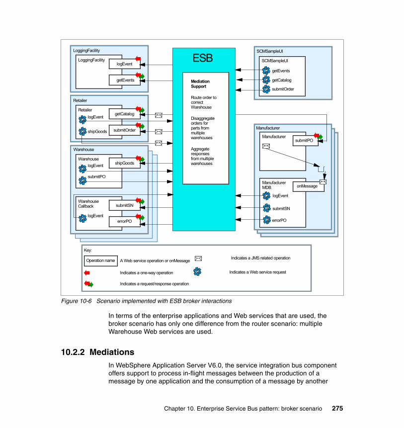
Figure 10-6 Scenario implemented with ESB broker interactions
In terms of the enterprise applications and Web services that are used, the broker scenario has only one difference from the router scenario: multiple Warehouse Web services are used.
10.2.2 MediationsIn WebSphere Application Server V6.0, the service integration bus component offers support to process in-flight messages between the production of a message by one application and the consumption of a message by another
LoggingFacility
logEvent
getEvents
LoggingFacility
Retailer
getCatalog
submitOrder
Retailer
Warehouse
shipGoodsWarehouse
submitSN
errorPO
WarehouseCallback
SCMSampleUI
SCMSampleUI
Key:
Operation name A Web service operation or onMessage
Indicates a one-way operation Indicates a Web service request
Indicates a JMS related operation
Indicates a request/response operation
shipGoods
logEvent
logEvent
submitPO
logEvent
getEvents
getCatalog
submitOrder
submitPOManufacturer
ManufacturerMDB
logEvent
onMessage
submitSN
errorPO
Manufacturer
ESB
Mediation Support
Route order to correct Warehouse
Disaggregate orders for parts from multiple warehouses
Aggregate responses from multiple warehouses
Chapter 10. Enterprise Service Bus pattern: broker scenario 275
application. The support is provided through mediations. Mediations enable the messaging behavior of a service integration bus to be customized. Examples of the processing that mediations perform are:
� Transforming a message from one format into another.
� Routing messages to one or more target destinations that were not specified by the sending application.
� Augmenting messages by adding data from a data source.
� Distributing messages to multiple target destinations.
The mediation support allows WebSphere Application Server V6.0 to provide the functionality that is required to support our broker scenario.
10.2.3 Creating a mediation handler classIn WebSphere Application Server V6.0, mediations are implemented as mediation handlers. A mediation handler can be deployed, and each mediation handler executes some specific message processing at runtime (for example, transforming a message format or routing a message to a particular destination). A mediation handler is a Java program framework to which you add the code that performs the mediation function.
This section describes how to use IBM Rational Application Developer V6.0 to create the mediation handler. This product provides support for developing mediation handler code and adding mediation handlers to the J2EE deployment descriptors. The Application Server Toolkit that is provided with WebSphere Application Server also provides support for developing mediation handlers.
In Rational Application Developer, a mediation handler class can be defined either in a Java project or an EJB project. This section describes how to create mediation handlers in an EJB project. However, the steps are very similar if you want to create a Java project, because you simply define a target server for either a Java project or an EJB project and the server runtime plug-in sets the classpath correctly.
To create a mediation handler, do the following in a Rational Application Developer workspace:
1. Create a new EJB project:
a. In Rational Application Developer, switch to the J2EE perspective to work with J2EE projects. Click Window → Open Perspective → Other → J2EE.
b. From the File menu, select New → Project.
276 Patterns: SOA with an Enterprise Service Bus in WebSphere Application Server V6

c. Expand the J2EE folder, and select Enterprise Application Project. Click Next. The window shown in Figure 10-7 is displayed.
Figure 10-7 New Enterprise Application Project wizard
d. Enter a name for the project, such as WarehouseAggregator, and set the target server to WebSphere Application Server V6.0.
e. Click Next to take you to the EAR Module Projects window.
f. Click New Module.
g. Create a new EJB module project by selecting only EJB Project and entering a name for the mediation handler EJB project. We used WarehouseAggregatorEJB.
h. Click Finish. You are returned to the EAR Module Projects window.
i. Click Finish to create the new enterprise and EJB projects.
2. Create a mediation handler class by implementing the com.ibm.websphere.sib.mediation.handler.MediationHandler interface.
a. In the Project Explorer window expand EJB Projects.
b. Right-click the EJB project that you just created and select New → Class (as shown in Figure 10-8 on page 278).
c. Specify a package name of com.ibm.itso.broker.
d. Specify a name for your mediation handler of RequestDisaggregator.
Chapter 10. Enterprise Service Bus pattern: broker scenario 277
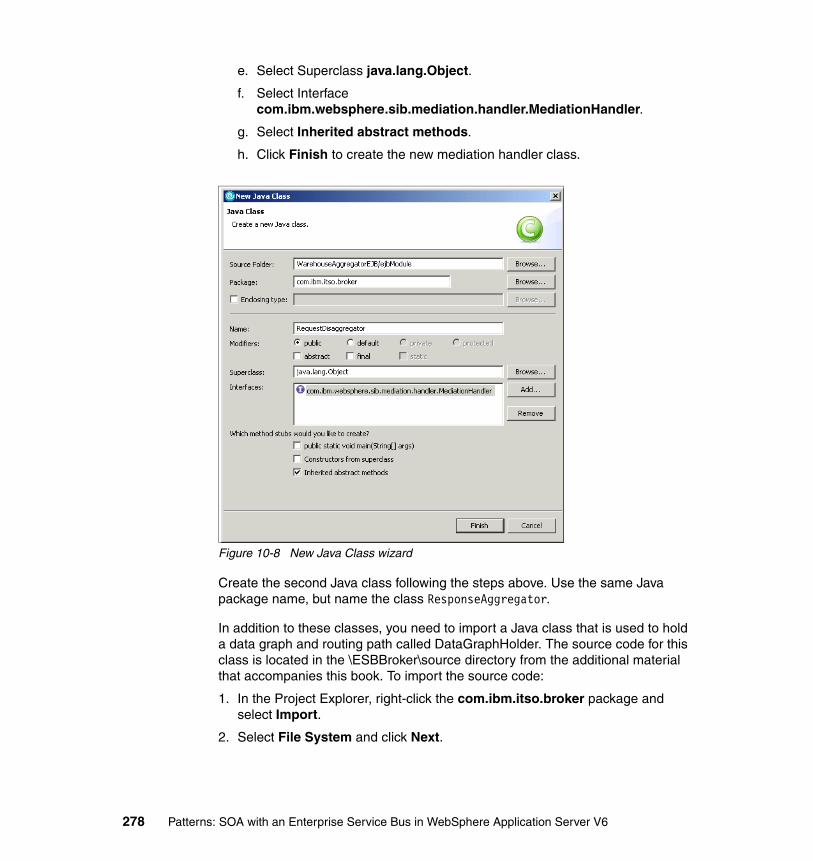
e. Select Superclass java.lang.Object.
f. Select Interface com.ibm.websphere.sib.mediation.handler.MediationHandler.
g. Select Inherited abstract methods.
h. Click Finish to create the new mediation handler class.
Figure 10-8 New Java Class wizard
Create the second Java class following the steps above. Use the same Java package name, but name the class ResponseAggregator.
In addition to these classes, you need to import a Java class that is used to hold a data graph and routing path called DataGraphHolder. The source code for this class is located in the \ESBBroker\source directory from the additional material that accompanies this book. To import the source code:
1. In the Project Explorer, right-click the com.ibm.itso.broker package and select Import.
2. Select File System and click Next.
278 Patterns: SOA with an Enterprise Service Bus in WebSphere Application Server V6
3. Browse to the directory where you downloaded the additional material, select DataGraphHolder.java, and click Finish.
10.2.4 Working with messages in mediationsThis section describes some concepts you need to understand to work with messages in mediations.
Mediation APIsSeveral application programming interfaces (APIs) are provided to allow you to work with the message context and code mediations.
� MediationHandler
This interface defines the method which is invoked by the mediation runtime. The method returns boolean true if the message passed into this method should continue along the handler list. Otherwise, it returns false. The API has just one method handle, handle(), which is used by the runtime to invoke a mediation.
In addition to the context information that is passed from one handler to another, it can return a reference to an SIMessage and an SIMediationSession. The SIMessage is the service integration bus representation of the message that is processed by the MediationHandler. The SIMediationSession is a handle to the runtime resources.
� MessageContext
This interface abstracts the message context that is processed by a handler in the handle method. The MessageContext interface provides methods to manage a property set. The API has two methods:
– getSIMessage(), which is a method to get the service integration bus representation of the message being mediated
– getSession(), which is a method to get an SIMediationSession object, which is a handle to the core runtime.
� SIMessage
This interface is the public interface to a service integration bus message for use by mediations. The SIMessage interface has many methods which allow you to work with the message properties, header contents, routing path, metadata, and others.
In particular, the method getDataGraph() returns the SDO data graph which contains the SIMessage content in a tree representation. This method allows you to work directly with the individual fields in the message payload.
Chapter 10. Enterprise Service Bus pattern: broker scenario 279

Forward and reverse routing paths define a sequential list of intermediary bus destinations that messages must pass through to reach a target bus destination. A routing path is used to apply the mediations configured on several destinations to messages sent along the path. The methods getForwardRoutingPath(), setForwardRoutingPath(), getReverseRoutingPath(), and getReverseRoutingPath() allow you to get and set the contents of the forward routing path and reverse routing path for this SIMessage.
� SIMediationSession
This interface defines the methods for querying and interacting with the service integration bus. and also includes methods that provide information about where the mediation is invoked from, and the criteria that are applied before the message is mediated.
The API has these methods:
– getBusName(), which returns the name of the bus upon which the mediation is associated
– getDestinationName(), which returns the name of the destination with which the mediation is associated
– getDiscriminator(), which returns the discriminator that is defined in the mediation definition
– getMediationName(), which returns the name of the mediation that is being executed
– getMessageSelector(), which returns the message selector that is defined in the mediation definition
– getMessagingEngineName(), which returns the name of the messaging engine from which the mediation was invoked
– getSIDestinationConfiguration(), which returns the SIDestinationConfiguration object associated with the destination that is specified by destinationName or destinationAddress.
– receive(), which receives an SIMessage from the service integration bus
– send(), which sends a copy of an SIMessage to the service integration bus in addition to the message that is returned by the message interface
SDO DataGraphsA message published in one format (for instance, a Web services SOAP message) can be routed to a service provider that requires another format, such as Java beans, using the Java API for XML-based RPC (JAX-RPC). Equally, the routing could be in the other direction. If the message is operated on by a mediation as it passes through the bus, in either direction, the mediation must be
280 Patterns: SOA with an Enterprise Service Bus in WebSphere Application Server V6

able to operate on the message regardless of the underlying format. This is achieved by using a common message model for the data mediators to use. The model is called SDO DataGraph and it gives an abstract view of the message, allowing you to concentrate on the information being conveyed (such as the parameters of the request, the data of the response) without having to worry about the packaging of that information.
SDO is based on the concept of data graphs. In the data graphs architecture, a mediation retrieves a data graph (that is, a collection of tree-structured or graph-structured data objects) from a message, transforms the data graph, and applies the data graph changes back to the data source.
In general, graphs that are generated from messages is a tree structure. The service presents a standard SDO data graph representation of the message payload, whatever the format of the incoming message‘s payload. A data object holds a set of named properties, each of which contains either a primitive-type value or a reference to another Data Object. The Data Object API provides a dynamic data API for manipulating these properties.
Routing pathsA routing path defines a sequential list of intermediary bus destinations that messages must pass through to reach a target bus destination. A routing path is used to apply the mediations configured on several destinations to messages sent along the path.
A forward routing path identifies a list of bus destinations that a message should be sent to from the producer to the last destination from which receivers retrieve messages. The reverse routing path is constructed automatically for request/reply messages, and identifies the list of destinations that any reply message should be sent to from the receiver back to the producer. Use of reverse routing path enables a reply message to take a different route back to the producer, and therefore have more mediations applied.
When a message arrives at a destination in the path, mediations can manipulate the entries in the forward routing path, to change the sequence of destinations through which messages pass. If a mediation manipulates the forward routing path, and the reverse routing path has been set (for a request message that expects a reply), then the mediation is responsible for making any corresponding changes to the reverse routing path.
A destination without mediations can be included in a routing path to provide a future option to apply a mediation assigned to that destination.
Chapter 10. Enterprise Service Bus pattern: broker scenario 281
10.2.5 Coding the mediationsThere are two mediations that are used to implement this scenario:
� The first mediation performs disaggregation of an order message into multiple order messages to send to the Warehouses. It receives a Web service SOAP request message the Retailer service that contains an order for one or more parts. It parses the message and determines which Warehouse each part contained in the order is stocked by. It creates a new Web service SOAP request message for each Warehouse that is required to fulfil the order and routes each new request message to the appropriate Warehouse service.
� The second mediation performs aggregation of the responses from the Warehouses. It receives the Web service SOAP response message from each Warehouse and aggregates them to a single response to send back to the Retailer service.
This section describes how to code these two mediations.
Disaggregation mediationWe implemented the disaggregation mediation by coding it as two Java methods: the handle() method and the disaggregate() method.
We chose to implement it as two methods to separate the logic to disaggregate a message in a mediation from the logic that determines how the message should be disaggregated. Thus, the handle() method could be used unchanged in another mediation that has different requirements for how the specific message itself should be disaggregated.
This mediation:
1. Receives the message (SOAP request message from Retailer).
2. Gets the name of the log queue, which is defined as a property of the mediation within WebSphere Application Server V6.0. The log queue is used to hold the updated original message and is updated to contain control data that indicates how many messages were sent out in the disaggregation. This information is used by the aggregation mediation to indicate how many responses it should expect.
3. Parses the request message and builds new messages to send to appropriate Warehouses.
4. Sends these messages to the Warehouse services. Sends a control message to the log queue that shows how many messages were sent to Warehouses.
282 Patterns: SOA with an Enterprise Service Bus in WebSphere Application Server V6
The handle() methodThe handle() method provides access to the service integration bus in WebSphere Application Server V6.0 to send and receive messages. It is invoked by the arrival of a message on the queue that it has been configured to mediate. This configuration is described in 10.3.3, “Mediation configuration” on page 305.
When the mediation is invoked, the method gets a handle to the MessageContext interface. The mediation abstracts the message context that is processed by a handler in the handle() method. The MessageContext interface provides methods to manage a property set. Message context properties enable handlers in a handler chain to share processing related state.
In Rational Application Developer, perform the following to modify the handle() method:
1. Open the RequestDisaggregator.java class in the Java editor.
2. The handle() method is generated automatically and, by default, returns false. Modify this method to catch java.lang.Exception, as shown in Example 10-1.
Example 10-1 Modified method to catch all exceptions
public boolean handle(MessageContext arg0) throws MessageContextException {try{
//enter all code here} catch (Exception e) {
throw new MessageContextException(e.getMessage());}return true;
}
3. The handle() method first casts the message context to SIMessageContext. This is the object that is required on the interface of a mediation handler. In addition to the context information that can be passed from one handler to another, it can return a reference to an SIMessage and an SIMediationSession. The SIMessage is the service integration bus representation of the message being processed by the MediationHandler. An SIMessage contains message properties, header contents, routing path, and the message body. The SIMediationSession is a handle to the runtime resources. The RequestDisaggregator then gets handles to SIMessage and SIMediationSession so that it can use these APIs.
Note: Enter all the remaining code for this method in the try-catch block. This section currently only contains a comment which reads:
//enter all code here
Chapter 10. Enterprise Service Bus pattern: broker scenario 283

Add the code that is shown in Example 10-2 to the handle() method in the try-catch block.
Example 10-2 Retrieving SIMediationSession and SIMessage
// Convert to an SIMessageContextSIMessageContext ctx = (SIMessageContext)arg0;
// Get the SIMediationSessionSIMediationSession session = ctx.getSession();
// Get the messageSIMessage msg = ctx.getSIMessage();
4. Next, the method retrieves the log queue name. This is set as a property of the mediation in WebSphere Application Server V6.0. These properties are included in the MessageContext object passed to the mediation. Add the code that is shown in Example 10-3 to retrieve this property:
Example 10-3 Retrieving the log queue name
String logQueueName = (String)arg0.getProperty("logQueueName");
5. The handle() method then passes the message object to the disaggregate() method. The disaggregate() method is responsible for building an array of type DataGraphHolder. This structure consists of a datagraph, which is used as the message body that is sent to the appropriate Warehouse and destination, which is the address of the Warehouse to which to send the message.
When the DataGraphHolder array is returned the handle() method creates a new message for each entry in the DataGraphHolder array. It copies the headers from the original message, sets the message body from the appropriate datagraph in the array, and sets the ForwardRoutingPath property, which is the address to which to send the message. It then sends the message.
Add the code that is shown in Example 10-4 to the handle() method.
Example 10-4 Working with the DataGraphHolder array
DataGraphHolder bodyToSplit = new DataGraphHolder(msg);
DataGraphHolder[] disaggregatedMessages = disaggregate(ctx, bodyToSplit);
int messageCount = disaggregatedMessages.length;for (int i = 0; i < messageCount; i++){
// Clone the message to copy the headers, only really good as we have// a simple message body. If it were a complex graph this would be bad.
284 Patterns: SOA with an Enterprise Service Bus in WebSphere Application Server V6
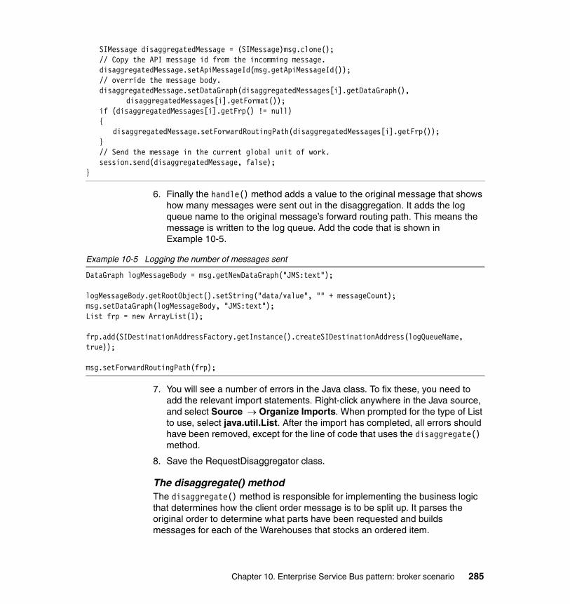
SIMessage disaggregatedMessage = (SIMessage)msg.clone();// Copy the API message id from the incomming message.disaggregatedMessage.setApiMessageId(msg.getApiMessageId());// override the message body.disaggregatedMessage.setDataGraph(disaggregatedMessages[i].getDataGraph(),
disaggregatedMessages[i].getFormat());if (disaggregatedMessages[i].getFrp() != null){
disaggregatedMessage.setForwardRoutingPath(disaggregatedMessages[i].getFrp());}// Send the message in the current global unit of work.session.send(disaggregatedMessage, false);
}
6. Finally the handle() method adds a value to the original message that shows how many messages were sent out in the disaggregation. It adds the log queue name to the original message’s forward routing path. This means the message is written to the log queue. Add the code that is shown in Example 10-5.
Example 10-5 Logging the number of messages sent
DataGraph logMessageBody = msg.getNewDataGraph("JMS:text");
logMessageBody.getRootObject().setString("data/value", "" + messageCount);msg.setDataGraph(logMessageBody, "JMS:text");List frp = new ArrayList(1); frp.add(SIDestinationAddressFactory.getInstance().createSIDestinationAddress(logQueueName, true));
msg.setForwardRoutingPath(frp);
7. You will see a number of errors in the Java class. To fix these, you need to add the relevant import statements. Right-click anywhere in the Java source, and select Source → Organize Imports. When prompted for the type of List to use, select java.util.List. After the import has completed, all errors should have been removed, except for the line of code that uses the disaggregate() method.
8. Save the RequestDisaggregator class.
The disaggregate() methodThe disaggregate() method is responsible for implementing the business logic that determines how the client order message is to be split up. It parses the original order to determine what parts have been requested and builds messages for each of the Warehouses that stocks an ordered item.
Chapter 10. Enterprise Service Bus pattern: broker scenario 285

The disaggregate() method receives the message context and a DatagraphHolder object, which contains the original request order message body and forward routing path. The method returns an array of DatagraphHolders.
Example 10-6 illustrates the SOAP input message body that is processed by the mediation. It contains an ItemList structure. Within this structure are the Items that are to be ordered from the Warehouse.
Example 10-6 Example of a SOAP body message
<s:Envelope xmlns:s="http://schemas.xmlsoap.org/envelope/"><s:Body><ns1:ShipGoods xmlns:ns1="http://www,ws-i.org/SampleApplications/SupplyChainManagement/2002-08/Warehouse.wsdl"xmlns:ns2="http://www,ws-i.org/SampleApplications/SupplyChainManagement/2002-08/Warehouse.xsd"><ItemList>
<ns2:Item><ns2:ProductNumber>605006</ns2:ProductNumber><ns2:Quantity>23</ns2:Quantity>
</ns2:Item><ns2:Item>
<ns2:ProductNumber>605007</ns2:ProductNumber> <ns2:Quantity>22</ns2:Quantity>
</ns2:Item></ItemList><Customer>D22845-W8N349Y-tky</Customer></ns1:ShipGoods></s:Body></s:Envelope>
Note: Although not implemented in this scenario, there could be a requirement for the number of different items that are ordered, the number of Warehouses that are used, and the list of items that are stocked in each Warehouse to be changed dynamically without needing to alter the mediation handler code. If this were the case, it would be necessary to store the details of which items are stocked in which Warehouse externally, for example in a database.
We have assumed that there is no requirement for adding new Warehouses or items dynamically. So, we have hard coded this information in the method.
286 Patterns: SOA with an Enterprise Service Bus in WebSphere Application Server V6

In Rational Application Developer, perform the following to modify the disaggregate() method:
1. The disaggregate() method needs to create copies of the original request message datagraph for each of the three Warehouses. You can copy the original message instead of creating new messages because the message contains more data than just the items that are ordered. This is data that is required by each Warehouse. Enter the code that is shown in Example 10-7 into the disaggregate() method.
Example 10-7 Create three datagraphs using the original datagraph
DataGraph WarehouseA = inDataGraphHolder.getNewDataGraph();DataGraph WarehouseB = inDataGraphHolder.getNewDataGraph();DataGraph WarehouseC = inDataGraphHolder.getNewDataGraph();
2. The disaggregate() method parses the SOAP body and alters the copies of each new Warehouse message so that only the items that are stocked by that particular Warehouse are included in the ItemList structure.
Because we have created a copy of the input message for each Warehouse, the first step in constructing the Warehouse messages is to remove the ItemList structure from each Warehouse message. Add the code that is shown in Example 10-8.
Example 10-8 Removing the ItemList object
//Delete ItemList from copied datagraphsDataObject warehouseArootNode = WarehouseA.getRootObject();DataObject warehouseAbodyNode = warehouseArootNode.getDataObject("Info/body");DataObject warehouseAitemListNode = warehouseArootNode.getDataObject("Info/body/ItemList");warehouseAitemListNode.delete();
DataObject warehouseBrootNode = WarehouseB.getRootObject();DataObject warehouseBbodyNode = warehouseBrootNode.getDataObject("Info/body");DataObject warehouseBitemListNode = warehouseBrootNode.getDataObject("Info/body/ItemList");warehouseBitemListNode.delete();
DataObject warehouseCrootNode = WarehouseC.getRootObject();DataObject warehouseCbodyNode = warehouseCrootNode.getDataObject("Info/body");DataObject warehouseCitemListNode = warehouseCrootNode.getDataObject("Info/body/ItemList");warehouseCitemListNode.delete();
3. Create an empty ItemList structure that you can use to add the items to be ordered for each Warehouse. Add the code that is shown in Example 10-9 on page 288.
Chapter 10. Enterprise Service Bus pattern: broker scenario 287
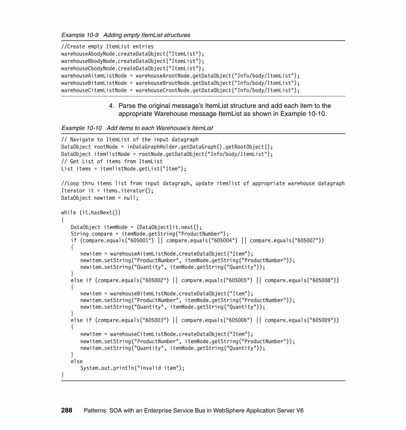
Example 10-9 Adding empty ItemList structures
//Create empty ItemList entrieswarehouseAbodyNode.createDataObject("ItemList");warehouseBbodyNode.createDataObject("ItemList");warehouseCbodyNode.createDataObject("ItemList");warehouseAitemListNode = warehouseArootNode.getDataObject("Info/body/ItemList");warehouseBitemListNode = warehouseBrootNode.getDataObject("Info/body/ItemList");warehouseCitemListNode = warehouseCrootNode.getDataObject("Info/body/ItemList");
4. Parse the original message’s ItemList structure and add each item to the appropriate Warehouse message ItemList as shown in Example 10-10.
Example 10-10 Add items to each Warehouse’s ItemList
// Navigate to ItemList of the input datagraphDataObject rootNode = inDataGraphHolder.getDataGraph().getRootObject();DataObject itemlistNode = rootNode.getDataObject("Info/body/ItemList");// Get List of items from ItemListList items = itemlistNode.getList("Item");
//Loop thru items list from input datagraph, update itemlist of appropriate warehouse datagraphIterator it = items.iterator();DataObject newitem = null;
while (it.hasNext()){
DataObject itemNode = (DataObject)it.next();String compare = itemNode.getString("ProductNumber");if (compare.equals("605001") || compare.equals("605004") || compare.equals("605007")){
newitem = warehouseAitemListNode.createDataObject("Item");newitem.setString("ProductNumber", itemNode.getString("ProductNumber"));newitem.setString("Quantity", itemNode.getString("Quantity"));
}else if (compare.equals("605002") || compare.equals("605005") || compare.equals("605008")){
newitem = warehouseBitemListNode.createDataObject("Item");newitem.setString("ProductNumber", itemNode.getString("ProductNumber"));newitem.setString("Quantity", itemNode.getString("Quantity"));
}else if (compare.equals("605003") || compare.equals("605006") || compare.equals("605009")){
newitem = warehouseCitemListNode.createDataObject("Item");newitem.setString("ProductNumber", itemNode.getString("ProductNumber"));newitem.setString("Quantity", itemNode.getString("Quantity"));
}else
System.out.println("invalid item");}
288 Patterns: SOA with an Enterprise Service Bus in WebSphere Application Server V6

5. Check whether any items were added to each Warehouse. For each Warehouse that has items to process we add that Warehouse datagraph and the forward routing path to the DataGraphHolder array that is returned by this method. Enter the code that is shown in Example 10-11.
Example 10-11 Adding Warehouse datagraphs to the DataGraphHolder array
//If warehouse has items in ItemList add it to datagraph holderList graphs = new ArrayList(3);
List newitems = warehouseAitemListNode.getList("Item");if (newitems.size() > 0){
List frp = new ArrayList(1);frp.add(SIDestinationAddressFactory.getInstance().
createSIDestinationAddress((String) ctx.getProperty("WarehouseA"), false));graphs.add(new DataGraphHolder(WarehouseA, inDataGraphHolder.getFormat(), frp));
}
newitems = warehouseBitemListNode.getList("Item");if (newitems.size() > 0){
List frp = new ArrayList(1);frp.add(SIDestinationAddressFactory.getInstance().
createSIDestinationAddress((String) ctx.getProperty("WarehouseB"), false));graphs.add(new DataGraphHolder(WarehouseB, inDataGraphHolder.getFormat(), frp));
}
newitems = warehouseCitemListNode.getList("Item");if (newitems.size() > 0){
List frp = new ArrayList(1);frp.add(SIDestinationAddressFactory.getInstance().
createSIDestinationAddress((String) ctx.getProperty("WarehouseC"), false));graphs.add(new DataGraphHolder(WarehouseC, inDataGraphHolder.getFormat(), frp));
}
return (DataGraphHolder[])graphs.toArray(new DataGraphHolder[0]);
6. Right-click in the Java editor, and select Source → Organize Imports. When prompted for the type of Iterator to use, select java.util.Iterator.
7. Save RequestDisaggregator.java. You should see no errors. The class is now complete.
Chapter 10. Enterprise Service Bus pattern: broker scenario 289

Aggregation mediationThe aggregation mediation is coded as two Java methods: the handle() and the aggregate() methods. We used two methods to separate the logic to aggregate messages in a mediation from the logic that determines how the messages should be aggregated. Thus, the handle() method could be used unchanged in another mediation that has different requirements for how the message should be aggregated.
For this aggregation, the mediation must:
� Receive a message (SOAP response message from a Warehouse).
� Get the names of the log queue and the temporary storage queue. These names are defined as properties of the mediation within WebSphere Application Server V6.0.
� Read the control message from log queue.
� If messages count on a log queue that is greater than one, then:
– Decrement count field on the control message, rewrite the control message to the log queue and put a SOAP response message from the Warehouse on a temporary storage queue.
� If message count on a log queue is equal to one, then:
– Read messages from the temporary storage queue and add them to an array.
– Build a single SOAP response message for the Retailer service.
– Send the response message back to the Retailer service.
The handle() methodThe handle() method is responsible for the message handling and aggregation of the response messages, and sending the aggregated response back to the original requester. It provides the interface to the service integration bus and calls the aggregate() method to implement the business logic that describes the Warehouse message aggregation.
The handle() method provides access to the service integration bus to send and receive messages. It is invoked by the arrival of a message on the queue that it has been configured to mediate, as described in 10.3.3, “Mediation configuration” on page 305. This message is a response from one of the Warehouse services.
When the mediation is invoked the handle() method gets a handle to the MessageContext interface. This abstracts the message context that is processed by a handler in the handle method. The MessageContext interface provides
290 Patterns: SOA with an Enterprise Service Bus in WebSphere Application Server V6
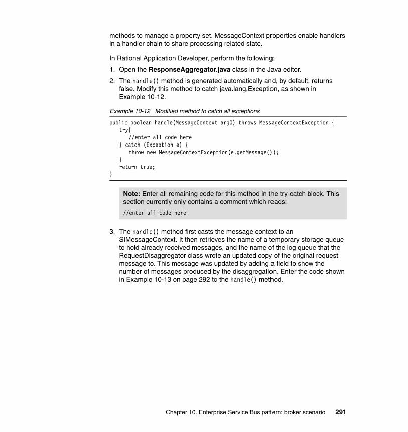
methods to manage a property set. MessageContext properties enable handlers in a handler chain to share processing related state.
In Rational Application Developer, perform the following:
1. Open the ResponseAggregator.java class in the Java editor.
2. The handle() method is generated automatically and, by default, returns false. Modify this method to catch java.lang.Exception, as shown in Example 10-12.
Example 10-12 Modified method to catch all exceptions
public boolean handle(MessageContext arg0) throws MessageContextException {try{
//enter all code here} catch (Exception e) {
throw new MessageContextException(e.getMessage());}return true;
}
3. The handle() method first casts the message context to an SIMessageContext. It then retrieves the name of a temporary storage queue to hold already received messages, and the name of the log queue that the RequestDisaggregator class wrote an updated copy of the original request message to. This message was updated by adding a field to show the number of messages produced by the disaggregation. Enter the code shown in Example 10-13 on page 292 to the handle() method.
Note: Enter all remaining code for this method in the try-catch block. This section currently only contains a comment which reads:
//enter all code here
Chapter 10. Enterprise Service Bus pattern: broker scenario 291

Example 10-13 Retrieving the message and log
// Convert to an SIMessageContextSIMessageContext ctx = (SIMessageContext)arg0;
// Get the SIMediationSessionSIMediationSession session = ctx.getSession();
// Get the messageSIMessage msg = ctx.getSIMessage();
// Get the name of the log queueString logQueueName = (String)arg0.getProperty("logQueueName");
// Get the name of the queue used to store already received messagesString tempStorageQueueName = (String)arg0.getProperty("tmpStorageQueueName");
4. The handle() method must then parse the message that is read from the log queue to see how many response messages from the Warehouses it is still waiting for. Add the code as shown in Example 10-14.
Example 10-14 Determine the number of responses
// Get the message count log message.SIMessage logMessage = session.receive(logQueueName, 0, null, "SI_MessageID='" +
msg.getCorrelationId() + "'", false);
// Get the message body as a datagraph, changes to the datagraph affect message body.DataGraph dg = logMessage.getDataGraph();
// Get the body of the messageString body = dg.getRootObject().getString("data/value");int number = Integer.parseInt(body);
5. If the message count is one, then all required responses from the Warehouses have been received. The handle() method aggregates the messages and sends the aggregated messages back to the requester.
The method processes all the messages on the temporary storage queue and adds them to an array for datagraphs that it passes to the aggregate() method to aggregate to a single response to the Retailer service.
Note: This example does not include any logic to cater for the aggregation having a time limit to receive replies from the Warehouses. In a more realistic scenario, it is likely that you would need to add the code to define what should happen if not all responses have been received in a specific time. In this example, the mediation continues to wait for all replies indefinitely.
292 Patterns: SOA with an Enterprise Service Bus in WebSphere Application Server V6
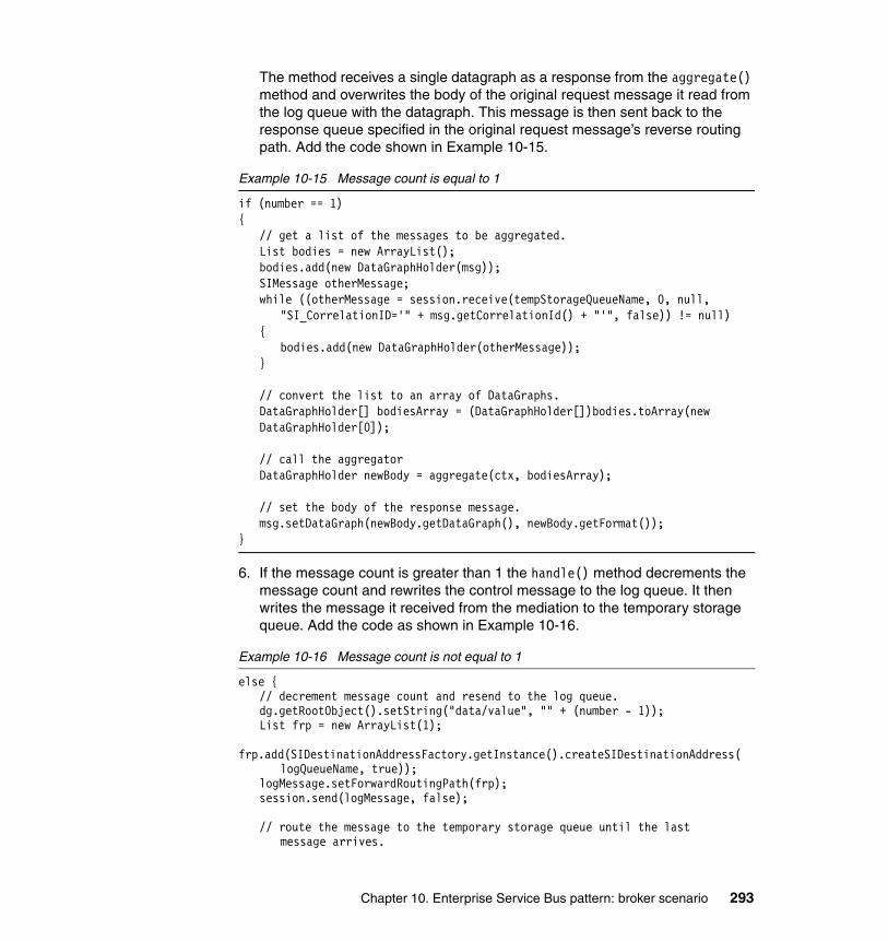
The method receives a single datagraph as a response from the aggregate() method and overwrites the body of the original request message it read from the log queue with the datagraph. This message is then sent back to the response queue specified in the original request message’s reverse routing path. Add the code shown in Example 10-15.
Example 10-15 Message count is equal to 1
if (number == 1){
// get a list of the messages to be aggregated.List bodies = new ArrayList();bodies.add(new DataGraphHolder(msg));SIMessage otherMessage;while ((otherMessage = session.receive(tempStorageQueueName, 0, null,
"SI_CorrelationID='" + msg.getCorrelationId() + "'", false)) != null){
bodies.add(new DataGraphHolder(otherMessage));}
// convert the list to an array of DataGraphs.DataGraphHolder[] bodiesArray = (DataGraphHolder[])bodies.toArray(newDataGraphHolder[0]);
// call the aggregatorDataGraphHolder newBody = aggregate(ctx, bodiesArray);
// set the body of the response message.msg.setDataGraph(newBody.getDataGraph(), newBody.getFormat());
}
6. If the message count is greater than 1 the handle() method decrements the message count and rewrites the control message to the log queue. It then writes the message it received from the mediation to the temporary storage queue. Add the code as shown in Example 10-16.
Example 10-16 Message count is not equal to 1
else {// decrement message count and resend to the log queue.dg.getRootObject().setString("data/value", "" + (number - 1));List frp = new ArrayList(1);
frp.add(SIDestinationAddressFactory.getInstance().createSIDestinationAddress(logQueueName, true));
logMessage.setForwardRoutingPath(frp);session.send(logMessage, false);
// route the message to the temporary storage queue until the last message arrives.
Chapter 10. Enterprise Service Bus pattern: broker scenario 293

frp = new ArrayList(1);
frp.add(SIDestinationAddressFactory.getInstance().createSIDestinationAddress(tempStorageQueueName, true));
msg.setForwardRoutingPath(frp);}
7. You will see a number of errors in the Java class. To fix these, you need to add the relevant import statements. Right-click anywhere in the Java source, and select Source → Organize Imports. When prompted for the type of List to use, select java.util.List. After the import has completed, all errors should have been removed, except for the line of code that uses the aggregate() method. You will create that method later.
8. Save the ResponseAggregator class.
The aggregate() methodThe aggregate() method receives an array of datagraphs and returns a datagraph. It navigates to the Response structure in the first datagraph in the array. It then loops through each subsequent datagraph in the array and copies the ItemStatus structure from each datagraph to the ItemStatus structure of the first datagraph. It then returns the updated first datagraph.
In Rational Application Developer:
1. Create a new method in the ResponseAggregator class with the following method signature:
public DataGraphHolder aggregate(MessageContext ctx, DataGraphHolder[] responses) throws Exception{}
2. Enter the code that is shown in Example 10-17 into the aggregate() method.
Example 10-17 The aggregate() method
if (responses.length >= 1){
// Get ItemList from first messageDataObject firstRootNode = responses[0].getDataGraph().getRootObject();DataObject firstitemlistNode = firstRootNode.getDataObject("Info/body/Response");
// Loop through all other datagrams, and add items to first datagramfor (int i = 1; i < responses.length; i++){
DataObject currentroot = responses[i].getDataGraph().getRootObject();DataObject currentitemlist = currentroot.getDataObject("Info/body/Response");
// Get List of items from ItemListList currentitems = currentitemlist.getList("ItemStatus");
294 Patterns: SOA with an Enterprise Service Bus in WebSphere Application Server V6

Iterator it = currentitems.iterator();DataObject newitem = null;
while (it.hasNext()){
DataObject currentitem = (DataObject)it.next();newitem = firstitemlistNode.createDataObject("ItemStatus");newitem.setString("ProductNumber", currentitem.getString("ProductNumber"));newitem.setString("Status", currentitem.getString("Status"));
}}
}
return responses[0];
3. Right-click in the Java editor and select Source → Organize Imports. When prompted for which Iterator to use, select java.util.Iterator.
4. Save ResponseAggregator.java. You should see no errors.
10.2.6 Assigning and exporting the mediation handlersNext, you need to assign the two mediation handlers that you have created to two mediation enterprise beans. You will then export the entire mediation application from Rational Application Developer to an EAR file.
Assigning the mediation handlersCreate two mediation handler entries in the EJB deployment descriptor of the EJB project containing the mediation handlers by following these steps:
1. In the Package Explorer expand EJB Projects → WarehouseAggregatorEJB, and double-click the Deployment Descriptor to open it in the editor.
2. Click the Mediation Handlers tab of the deployment descriptor editor. This section allows you to define your two mediation handlers. To define the aggregator mediation handler:
a. Click Add to add a new mediation handler.
b. In the Define Mediation Handler window (Figure 10-9 on page 296), set the Name to Aggregator, and use the Browse button to set the Handler class to com.ibm.itso.broker.ResponseAggregator.
Chapter 10. Enterprise Service Bus pattern: broker scenario 295
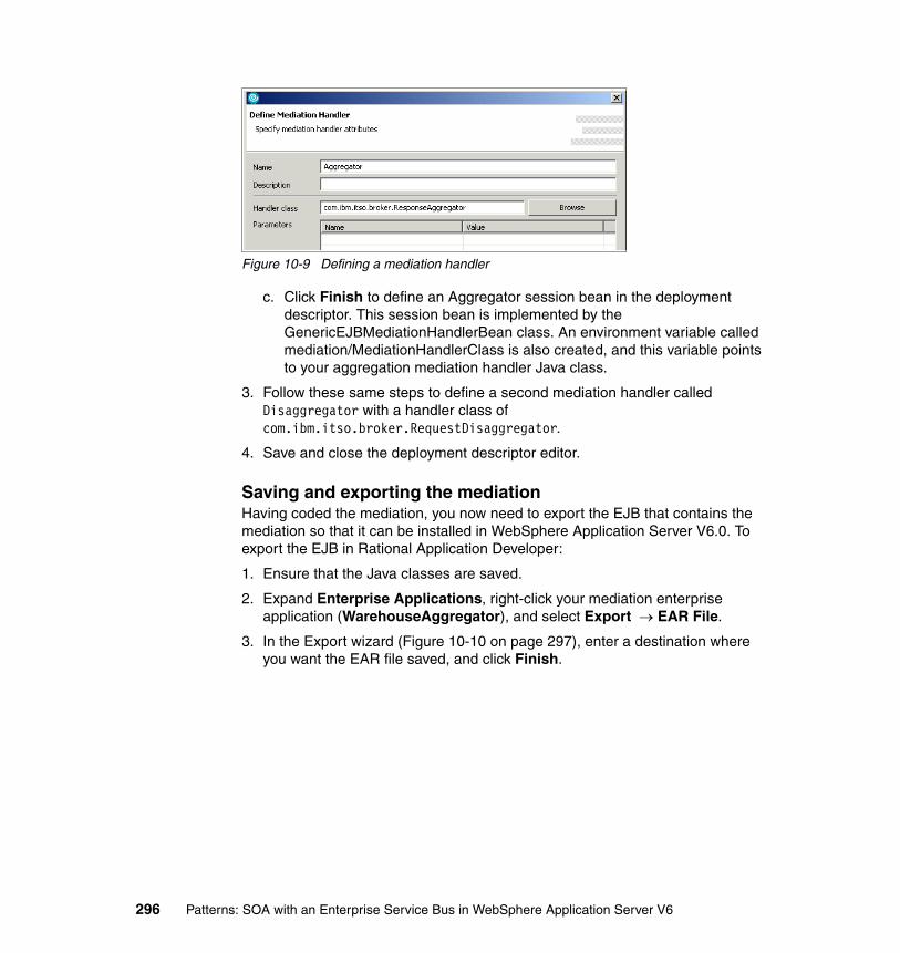
Figure 10-9 Defining a mediation handler
c. Click Finish to define an Aggregator session bean in the deployment descriptor. This session bean is implemented by the GenericEJBMediationHandlerBean class. An environment variable called mediation/MediationHandlerClass is also created, and this variable points to your aggregation mediation handler Java class.
3. Follow these same steps to define a second mediation handler called Disaggregator with a handler class of com.ibm.itso.broker.RequestDisaggregator.
4. Save and close the deployment descriptor editor.
Saving and exporting the mediationHaving coded the mediation, you now need to export the EJB that contains the mediation so that it can be installed in WebSphere Application Server V6.0. To export the EJB in Rational Application Developer:
1. Ensure that the Java classes are saved.
2. Expand Enterprise Applications, right-click your mediation enterprise application (WarehouseAggregator), and select Export → EAR File.
3. In the Export wizard (Figure 10-10 on page 297), enter a destination where you want the EAR file saved, and click Finish.
296 Patterns: SOA with an Enterprise Service Bus in WebSphere Application Server V6

Figure 10-10 Export wizard
Steps for installing this enterprise application into WebSphere Application Server are described in 10.3.3, “Mediation configuration” on page 305.
10.3 Runtime guidelines
This section describes how to configure the Enterprise Service Bus runtime pattern with broker interactions using WebSphere Application Server.
Note: This section assumes that you have installed and are using WebSphere Application Server V6.0.1 with the i-fixes PK02919 and PK05354 applied. You can download PK02919 at:
http://www.ibm.com/search?en=utf&v=11&lang=en&cc=us&q=PK02919
You can download PK05354 at:
http://www.ibm.com/support/docview.wss?rs=180&uid=swg24009729
Versions of WebSphere Application Server beyond V6.0.1 will not require these i-fixes.
Chapter 10. Enterprise Service Bus pattern: broker scenario 297

This section describes how to perform the following tasks:
� Setting up an IBM DB2 UDB database for the SDO repository to externalize service lookup.
� Adjusting some of the existing WebSphere Application Server configuration and creating some new resources to accommodate the broker scenario.
� Configuring and deploying mediations to allow aggregation and disaggregation.
� Installing the new applications, which provide two additional Warehouses.
� Testing the sample application.
10.3.1 Externalizing service lookupIn Chapter 9, “Enterprise Service Bus pattern: router scenario” on page 179, we used IBM Cloudscape for service lookup. Cloudscape is embedded in WebSphere Application Server V6.0 as the default database. For the router scenario, Cloudscape was used as a persistent data store for the service integration bus and also for the SDO repository. For the broker scenario, we replaced embedded Cloudscape with IBM DB2 Universal Database V8.2 for the SDO repository. For a discussion on this design decision, see “Externalizing service lookup” on page 270.
To implement a database other than embedded Cloudscape, you need to:
� Install the database product.� Remove existing resources.� Configure J2C Authentication data.� Create a JDBC provider.� Create a JDBC data source.� Provide current database drivers.
The following sections describe each of these steps are described in detail.
Note: These instructions assume that you have configured the Enterprise Service Bus router scenario (Chapter 9, “Enterprise Service Bus pattern: router scenario” on page 179). This section describes the required modifications to convert that configuration into this one.
You can quickly import the Enterprise Service Bus router configuration into WebSphere Application Server using a set of Jacl scripts. For more information, see “Configuring the ESB router scenario” on page 370.
298 Patterns: SOA with an Enterprise Service Bus in WebSphere Application Server V6

Installing IBM DB2 Universal Database V8.2After DB2 is installed, you need to create a new database for the SDO repository called SDOREPOS using the First Steps wizard.
The tables for the SDO repository are not created automatically on start-up, so you need to do some manual steps. The SDO repository application contains container-managed persistence (CMP) enterprise beans. When the WebSphere Application Server deployment tooling deploys an EJB jar file that contains CMP enterprise beans, it selects the target database and creates a corresponding Table.ddl file. This file contains the SQL statement necessary to generate the database table for your CMP beans. You need to run the DDL file on the DB2 server to create the tables. To run the file:
1. Copy the Table.ddl file to a directory of your choice. You can find the relevant Table.ddl file in the WAS_HOME/util/SdoRepository/DB2UDB_V82 directory, where WAS_HOME is the WebSphere Application Server install directory.
2. From the directory into which you copied the Table.ddl file, enter db2cmd. A new command window appears, in which you enter the following commands:
– db2 connect to SDOREPOS (to connect to the database that you created)– db2 -tf Table.ddl (to create tables for your CMP enterprise bean)– db2 disconnect all
All of the DB2 databases that are needed for broker interactions should now be ready for use.
Recreating the SDO repositoryYou next need to remove the old database resources and SDO repository and then create a new one. To recreate the SDO repository:
1. The original resources are configured for embedded Cloudscape and will not work with DB2. Thus, you need to remove them. Run the following command from the WebSphere Application Server bin directory:
wsadmin -f uninstallSdoRepository.jacl -removeDb
2. Reinstall the SDO repository:
wsadmin -f installSdoRepository.jacl
3. Set the database type of the SDO repository:
wsadmin -f installSdoRepository.jacl -editBackendId DB2UDB_V82
Note: In this scenario, we set the database type to DB2UDB_V82. However, this setting is dependant on the exact database type and version that you have selected to use.
Chapter 10. Enterprise Service Bus pattern: broker scenario 299
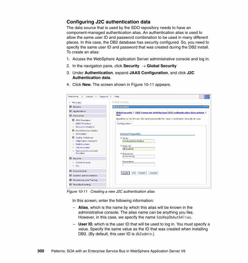
Configuring J2C authentication dataThe data source that is used by the SDO repository needs to have an component-managed authentication alias. An authentication alias is used to allow the same user ID and password combination to be used in many different places. In this case, the DB2 database has security configured. So, you need to specify the same user ID and password that was created during the DB2 install. To create an alias:
1. Access the WebSphere Application Server administrative console and log in.
2. In the navigation pane, click Security → Global Security
3. Under Authentication, expand JAAS Configuration, and click J2C Authentication data.
4. Click New. The screen shown in Figure 10-11 appears.
Figure 10-11 Creating a new J2C authentication alias
In this screen, enter the following information:
– Alias, which is the name by which this alias will be known in the administrative console. The alias name can be anything you like. However, in this case, we specify the name SdoRepDbAuthAlias.
– User ID, which is the user ID that will be used to log in. You must specify a value. Specify the same value as the ID that was created when installing DB2. (By default, this user ID is db2admin.)
300 Patterns: SOA with an Enterprise Service Bus in WebSphere Application Server V6

– Password, which is the password that is associated with the user ID. You must specify a value. Specify the same value as the password that was created when installing DB2.
5. Click OK and save the changes to the master configuration by clicking Save.
Creating a JDBC provider for DB2You next configure WebSphere Application Server to access the SDO repository database using DB2. To do this, you need to define a new JDBC provider. In the administrative console, complete the following steps to create a JDBC provider:
1. In the navigation pane, click Resources → JDBC Providers.
2. You need to create a new JDBC provider. For simplicity, you will create one at the node scope, the scope that is automatically shown, for this scenario. Click New.
3. You need to supply some general information about the type of database and the connection mechanism, as shown in Figure 10-12. Note that the pull-down boxes are disabled until you have completed the values in the preceding boxes.
Figure 10-12 Specifying properties for DB2 JDBC provider
In this screen, enter the following information:
– Select the database type, which is used to specify the type of database to which the JDBC provider will connect. In this case, choose DB2.
– Select the provider type, which is used to specify how the database will be accessed. In this case choose, DB2 Universal JDBC Driver Provider.
Chapter 10. Enterprise Service Bus pattern: broker scenario 301

– Select the implementation type, which is used to specify how the provider will be implemented. In this case, choose XA Data source.
4. Click Next, accept the defaults, and click OK.
5. Save the changes to the master configuration by clicking Save.
Creating the JDBC data sourceYou next need to create the JDBC data source for accessing DB2. From the JDBC providers page in the administrative console, complete the following:
1. Click DB2 Universal JDBC Driver Provider (XA).
2. Click Data sources, then click New.
3. You need to configure this data source for the SDO repository as shown in Figure 10-13.
Figure 10-13 Specifying the data source settings
Use default settings, except for the following:
– Name, which is an administrative entity that only has meaning within the administrative console. You can specify as anything you like. For this example, we used Sdo Repository DB2 data source.
– JNDI Name, which is the JNDI name from where applications pick up the data source. Specify jdbc/com.ibm.ws.sdo.config/SdoRepository.
302 Patterns: SOA with an Enterprise Service Bus in WebSphere Application Server V6
– Component-managed authentication alias, which is the alias that is used when making connections to the database where the application managed authentication is being used by the application. Select the value that ends in SdoRepDbAuthAlias.
– Database name, which is the name of the database that you created in DB2. Specify SDOREPOS.
– Server name, which is the host name where the DB2 server is running. You can use localhost.
4. Click OK and save the changes to the master configuration by clicking Save.
DB2 driversFinally, you need to verify that the current DB2 drivers are accessible by WebSphere Application Server. You need two .jar files: db2jcc.jar and db2jcc_license_cu.jar. You can find these files in DB2_HOME\java, where DB2_HOME is the DB2 installation directory.
Copy these jar files to WAS_HOME\lib, where WAS_HOME is the WebSphere Application Server installation directory.
The new SDO repository should now be configured and ready to use. Restart the server to get it all working.
Moving data to the new SDO repositoryBecause you have now created a new SDO repository, you need to add the reload the WSDL and XSD files into this repository:
1. Reload the XSD schemas into the SDO repository by following the steps in 9.3.10, “Importing the schemas into the SDO repository” on page 254.
2. Reload the WSDL files for all the inbound services. To change the LoggingFacility inbound service:
a. In the WebSphere Application Server administrative console select Service integration → Buses.
b. Click TESTBUS, then click Inbound Services.
c. Select the LoggingFacilityService inbound service.
d. Click Reload template WSDL.
e. Execute the same function for all other inbound services, and save the configuration.
Note: You must restart the server before you can test the connection to the data source using the Test Connection button.
Chapter 10. Enterprise Service Bus pattern: broker scenario 303

3. Reload the WSDL files for all the outbound services, using the same technique. This time, click Reload WSDL. When complete, save the changes.
Testing the new SDO repositoryBefore adding the mediation support, you can test that the new SDO repository is working. Open a Web browser, and start the SCM sample application with the following URL:
http://localhost:9080/SCMSampleUI
For a reminder of how to test the application, see 8.3.10, “Running and using the sample application” on page 174.
10.3.2 Configuration of additional resourcesThis scenario introduces a number of additional WebSphere Application Server resources that were not defined in the router scenario. These resources are required for the two additional Warehouse services and for the mediations.
You need to define the following resources:
1. Define the queue destinations that are shown in Table 10-4 into the TESTBUS service integration bus. For information about how to define destinations in WebSphere Application Server, see 8.3.4, “Creating the destinations” on page 164.
Table 10-4 Queue destinations
2. Set the reply destination of WarehouseService to WarehouseReply as follows:
a. In the destinations list of the administrative console, click the WarehouseService destination.
b. Locate the Reply destination field, and set it to WarehouseReply.
c. Click OK.
Name Description
WarehouseReply Destination for aggregator mediation
WarehouseService Destination for disaggregator mediation
logQ Log destination for mediations
tmpStorageQ Temporary storage destination for mediations
304 Patterns: SOA with an Enterprise Service Bus in WebSphere Application Server V6
3. Define two additional outbound services for WarehouseB and WarehouseC, as defined in Table 10-5. For information about how to define outbound services, see 9.3.7, “Creating the outbound services” on page 244.
Table 10-5 Outbound services
4. Modify the WarehouseService inbound service to use the WarehouseService destination name. This action is required for the mediation, so that messages are sent to the disaggregator rather than directly to the Warehouse Web service. To modify the inbound service:
a. In the TESTBUS properties screen, click Inbound Services, then WarehouseService.
b. Set the Service destination name to WarehouseService using the drop-down list.
c. Click OK.
5. Save all of the changes to the master configuration by clicking Save.
10.3.3 Mediation configurationSection 10.2, “Development guidelines” on page 274 describes how to create an enterprise application (EAR file) containing a mediation handler that can be deployed in WebSphere Application Server. This section describes how to install the application and configure WebSphere Application Server to use the mediation. To set up working mediations, you need to:
� Install the mediation application� Create a mediation� Localize the mediation to a destination� Configure context properties for the mediation
The following sections describe these steps in detail.
Name WSDL Location Description
WarehouseBService http://appsrv1a.itso.ral.ibm.com/wsdl/WarehouseB_Impl.wsdl
Outbound service for the warehouse WarehouseB
WarehouseCService http://appsrv1a.itso.ral.ibm.com/wsdl/WarehouseC_Impl.wsdl
Outbound service for the warehouse WarehouseC
Chapter 10. Enterprise Service Bus pattern: broker scenario 305

Installing a mediation application
Use the WebSphere Application Server administrative console to install the mediation EAR file as follows:
1. Click Applications → Install New Application. In the screen that appears, browse to the location where you exported the mediation handler EAR file. In this case, locate the WarehouseAggregation.ear file that you exported from Rational Application Developer in “Saving and exporting the mediation” on page 296. Click Next.
2. Click Next again.
3. Work your way through the wizard, then click Finish to install the enterprise application.
4. When the enterprise application is installed, save it, and then start it.
Defining mediationsAfter the mediation application has been installed, you need to define a mediation to the deployed handler list. To define the mediations for the aggregator and disaggregator, use the WebSphere Application Server administrative console to complete the following steps:
1. Navigate to the mediations pane. Click Service integration → Buses → TESTBUS → Mediations.
2. Click New to add a new mediation.
3. In the new mediation page (Figure 10-14 on page 307), specify the relevant properties for the mediation.
Note: The mediation application must be installed on every server where you intend to use the deployed mediation handler to mediate a destination.
306 Patterns: SOA with an Enterprise Service Bus in WebSphere Application Server V6

Figure 10-14 Defining a new destination mediation
a. Set the following properties:
• Mediation name, which is a name for the mediation that is unique to the service integration bus. This name is used to identify the mediation for administrative purposes. Set this to Aggregator.
• Handler list name, which was determined by the programmer who deployed the mediation handler. Set this to Aggregator.
• Global transaction, which if selected, starts a global transaction for each message mediated by the mediation. Select this box.
b. Other properties that you can set are:
• Description, which is a description of the behavior of the mediation.
• Allow concurrent mediation, which mediates multiple messages at the mediated destination.
• Selector, which controls which messages are mediated.
c. Click OK.
4. Create a second mediation called Disaggregator, specifying a handler list of Disaggregator, and selecting Global transaction.
� Click Save to save the changes to the master configuration.
Chapter 10. Enterprise Service Bus pattern: broker scenario 307
Follow these steps for both mediations so that there are two mediations that are defined for the deployed handler list.
Mediating a destinationMediating a destination associates a mediation with a selected service integration bus destination. At run-time, the mediation applies some message processing to the messages handled by the service integration bus destination.
You need to mediate two destinations, as listed in Table 10-6.
Table 10-6 Mediations and associated destinations
To mediate a destination, use the administrative console to complete the following steps:
1. Click Service integration → Buses → TESTBUS. Then, under additional properties, click Destinations.
2. Check the bus destination that you want to mediate (in our case, WarehouseReply), and click Mediate.
3. In the Select mediation wizard, set the mediation to apply to this destination. In our case, select Aggregator. Click Next.
4. Select the bus member where the mediation is installed (by default there is only one), and click Next.
5. Click Finish to mediate the destination.
Repeat these steps to assign the Disaggregator mediation to the WarehouseService destination. When complete, you should see two mediations that defined in the destinations list, as shown in Figure 10-15 on page 309. Save the changes to the configuration.
Note: You can only mediate a destination with a single mediation at a time. You can mediate more than one destination with the same mediation
Mediation Destination to be mediated
Aggregator WarehouseReply
Disaggregator WarehouseService
308 Patterns: SOA with an Enterprise Service Bus in WebSphere Application Server V6
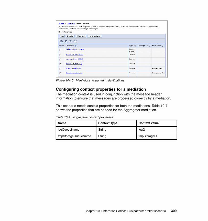
Figure 10-15 Mediations assigned to destinations
Configuring context properties for a mediationThe mediation context is used in conjunction with the message header information to ensure that messages are processed correctly by a mediation.
This scenario needs context properties for both the mediations. Table 10-7 shows the properties that are needed for the Aggregator mediation.
Table 10-7 Aggregator context properties
Name Context Type Context Value
logQueueName String logQ
tmpStorageQueueName String tmpStorageQ
Chapter 10. Enterprise Service Bus pattern: broker scenario 309
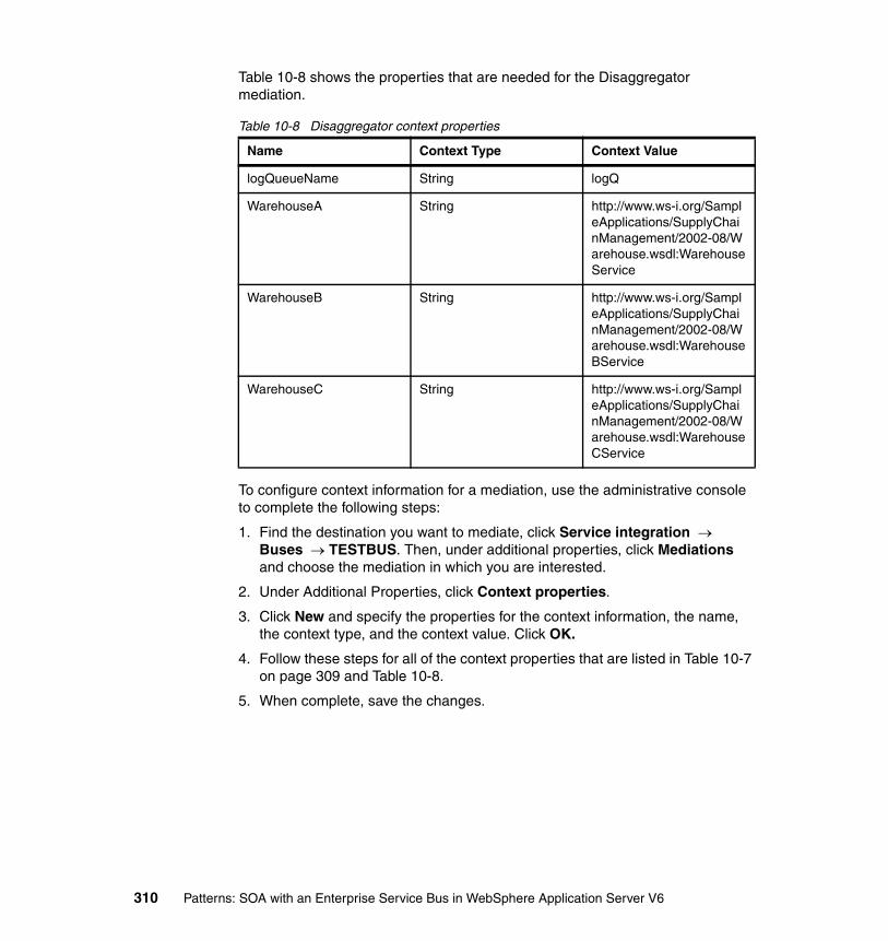
Table 10-8 shows the properties that are needed for the Disaggregator mediation.
Table 10-8 Disaggregator context properties
To configure context information for a mediation, use the administrative console to complete the following steps:
1. Find the destination you want to mediate, click Service integration → Buses → TESTBUS. Then, under additional properties, click Mediations and choose the mediation in which you are interested.
2. Under Additional Properties, click Context properties.
3. Click New and specify the properties for the context information, the name, the context type, and the context value. Click OK.
4. Follow these steps for all of the context properties that are listed in Table 10-7 on page 309 and Table 10-8.
5. When complete, save the changes.
Name Context Type Context Value
logQueueName String logQ
WarehouseA String http://www.ws-i.org/SampleApplications/SupplyChainManagement/2002-08/Warehouse.wsdl:WarehouseService
WarehouseB String http://www.ws-i.org/SampleApplications/SupplyChainManagement/2002-08/Warehouse.wsdl:WarehouseBService
WarehouseC String http://www.ws-i.org/SampleApplications/SupplyChainManagement/2002-08/Warehouse.wsdl:WarehouseCService
310 Patterns: SOA with an Enterprise Service Bus in WebSphere Application Server V6

10.3.4 Installing the additional WarehousesYou must install the two additional Warehouse enterprise applications, WarehouseB and WarehouseC, before you can test the mediation. These enterprise applications are shipped as WarehouseB.ear and WarehouseC.ear in the \ESBBroker\ears directory of the additional material that accompanies this book. For information about how to obtain this additional material, see Appendix B, “Configuring the scenario environment” on page 367.
Use the WebSphere Application Server administrative console to install WarehouseB.ear as follows:
1. Click Applications → Install New Application. In this pane, browse to the WarehouseB.ear file. Click Next.
2. Click Next again.
3. Work your way through the wizard, then click Finish to install the enterprise application.
4. When the enterprise application is installed, save it, and then start it.
Repeat this process for WarehouseC.ear. When WarehouseC is installed and started, you are ready to test the sample application.
10.3.5 Testing the sample applicationTo test that the mediation is working correctly in the sample application:
1. Open a Web browser and enter the following URL:
http://localhost:9080/SCMSampleUI
2. Select Place New Order to make a call from the SCMSampleUI enterprise application to the Retailer Web service. This action does not test the mediation.
3. In the next screen, enter a quantity of one (1) for the first three products, and then click Submit Order, as shown in Figure 10-16 on page 312. This action invokes the mediation and disaggregates the request from the Retailer to all three Warehouses. It also aggregates the response.
Chapter 10. Enterprise Service Bus pattern: broker scenario 311

Figure 10-16 Ordering three products
4. If the mediation is successful, you will see the response that is shown in Figure 10-17. Note that this only reports that the orders were fulfilled. It does not state which Warehouse fulfilled the order. Click Track Order to determine which Warehouse supplied each product.
Figure 10-17 Successful completion of the mediation
312 Patterns: SOA with an Enterprise Service Bus in WebSphere Application Server V6
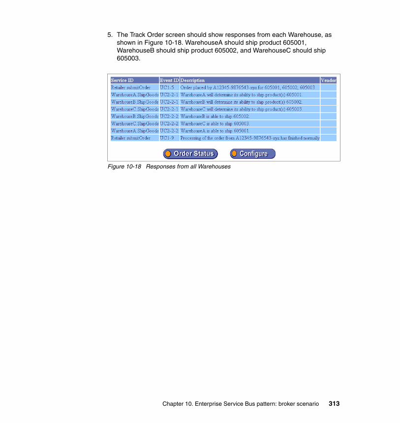
5. The Track Order screen should show responses from each Warehouse, as shown in Figure 10-18. WarehouseA should ship product 605001, WarehouseB should ship product 605002, and WarehouseC should ship 605003.
Figure 10-18 Responses from all Warehouses
Chapter 10. Enterprise Service Bus pattern: broker scenario 313

314 Patterns: SOA with an Enterprise Service Bus in WebSphere Application Server V6
Chapter 11. Exposed ESB Gateway pattern
This chapter discusses how to expose services outside the enterprise. This chapter builds on the scenario that is described in Chapter 9, “Enterprise Service Bus pattern: router scenario” on page 179. The scenario in this chapter adds a gateway which supports interactions with services that located outside the enterprise. The Manufacturers are placed outside of the enterprise and communicate with the ESB using a gateway.
11
© Copyright IBM Corp. 2005. All rights reserved. 315

11.1 Design guidelinesThis section discusses the business needs that are addressed by the sample scenario and the design decisions that were made in order to implement the chosen scenario using the Exposed ESB Gateway runtime pattern.
The business scenario that is implemented in this chapter is one of the interactions of the WS-I SCM sample scenario that is defined in Chapter 6, “The business scenario that this book uses” on page 125.
Figure 11-1 shows an overview of the steps that you can follow when designing a solution that addresses particular business requirements. This chapter discusses each of these steps.
Figure 11-1 Design approach
11.1.1 Business scenarioThe business scenario is a simplified supply chain for a consumer electronics retailer as defined in 6.2.3, “Stage 3: Divested inter-enterprise manufacturers” on page 129. The company has implemented the Enterprise Service Bus pattern to meet the business requirements.
The company has decided to divest itself of the three Manufacturers. Each will be sold off to other companies or established as new companies in their own right. Various interactions must now take place securely over the Internet. These are:
� The functionality that enables a Warehouse to replenish stock from a Manufacturer.
� The notification of shipment to a Warehouse of replenishment stock by a Manufacturer.
� The logging of business tracking information by a Manufacturer.
Figure 11-2 on page 317 shows the business infrastructure.
Design andimplementthe solution
Select aproduct
Analyzedesignoptions
Select aPattern
Analyze thebusinessneeds
Design andimplementthe solution
Select aproductSelect aproduct
Analyzedesignoptions
Analyzedesignoptions
Select aPatternSelect aPattern
Analyze thebusinessneeds
Analyze thebusinessneeds
Analyze thebusinessneeds
Analyze thebusinessneeds
316 Patterns: SOA with an Enterprise Service Bus in WebSphere Application Server V6
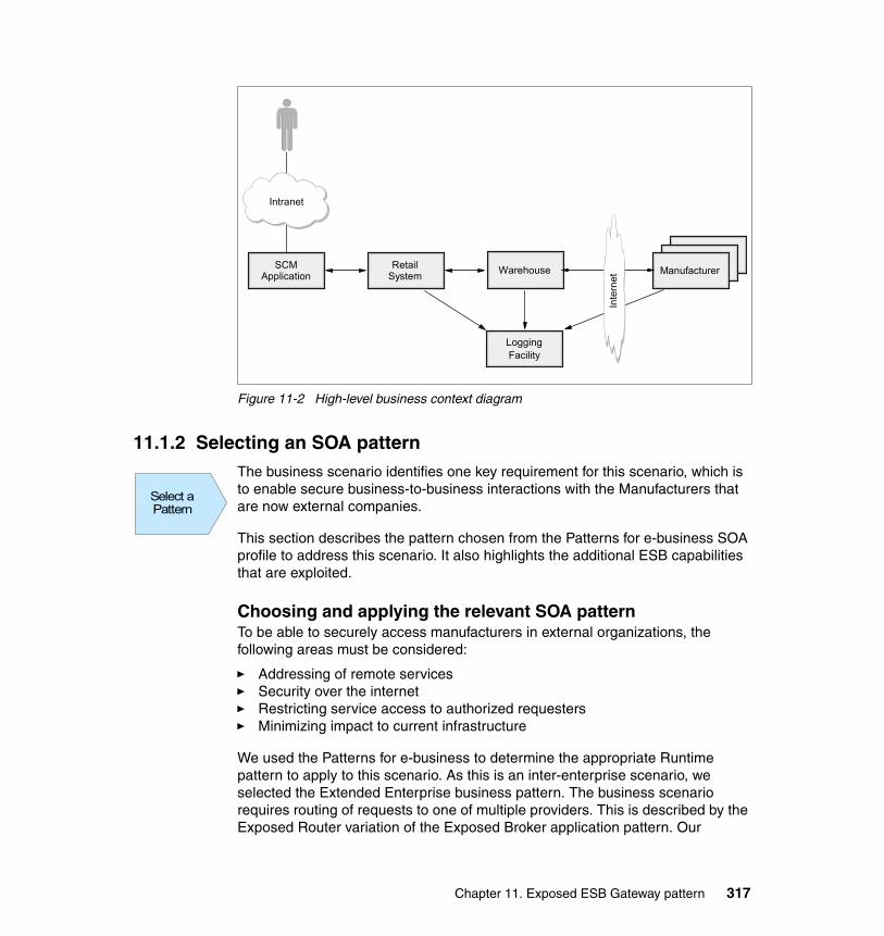
Figure 11-2 High-level business context diagram
11.1.2 Selecting an SOA patternThe business scenario identifies one key requirement for this scenario, which is to enable secure business-to-business interactions with the Manufacturers that are now external companies.
This section describes the pattern chosen from the Patterns for e-business SOA profile to address this scenario. It also highlights the additional ESB capabilities that are exploited.
Choosing and applying the relevant SOA patternTo be able to securely access manufacturers in external organizations, the following areas must be considered:
� Addressing of remote services� Security over the internet� Restricting service access to authorized requesters� Minimizing impact to current infrastructure
We used the Patterns for e-business to determine the appropriate Runtime pattern to apply to this scenario. As this is an inter-enterprise scenario, we selected the Extended Enterprise business pattern. The business scenario requires routing of requests to one of multiple providers. This is described by the Exposed Router variation of the Exposed Broker application pattern. Our
Intranet
LoggingFacility
RetailSystem
SCMApplication
ManufacturerManufacturer
ManufacturerWarehouse
Intranet
Inte
rnet
Select aPatternSelect aPattern
Chapter 11. Exposed ESB Gateway pattern 317

business scenario describes SOA, so we selected the SOA profile of the Exposed Router runtime pattern, which is the Exposed ESB Gateway runtime pattern. This pattern is described in 5.1.6, “Exposed ESB Gateway runtime pattern” on page 113. Figure 11-3 illustrates the application of this pattern to the scenario.
Figure 11-3 Exposed ESB Gateway pattern applied to this scenario
The three Manufacturers are deployed in the Partner Zone that is outside of the enterprise. The Manufacturers are able to access only the appropriate Web services that are provided by the Exposed ESB Gateway. Conversely, the internal applications are also able to securely access the external services provided by the Manufacturer via the Exposed ESB Gateway. The Exposed ESB Gateway provides a restricted view of services and only allows authorized requesters access.
Inter-enterprise Zone
EnterpriseDemilitarized Zone Enterprise Secure ZonePartner Zone
App Server /Services
App Server /Services
NetworkInfrastructure
Dom
ain
Fire
wal
lD
omai
n Fi
rew
all
ESBGateway
Prot
ocol
Fire
wal
lPr
otoc
ol F
irew
all
WebServer
App Server / Services
SCM Application
App Server / Services
Retail System
App Server / Services
LoggingFacility
App Server / Services
Warehouse
ESBESBESB
Manufacturer
ManufacturerB
ManufacturerC
App Server /Services
318 Patterns: SOA with an Enterprise Service Bus in WebSphere Application Server V6
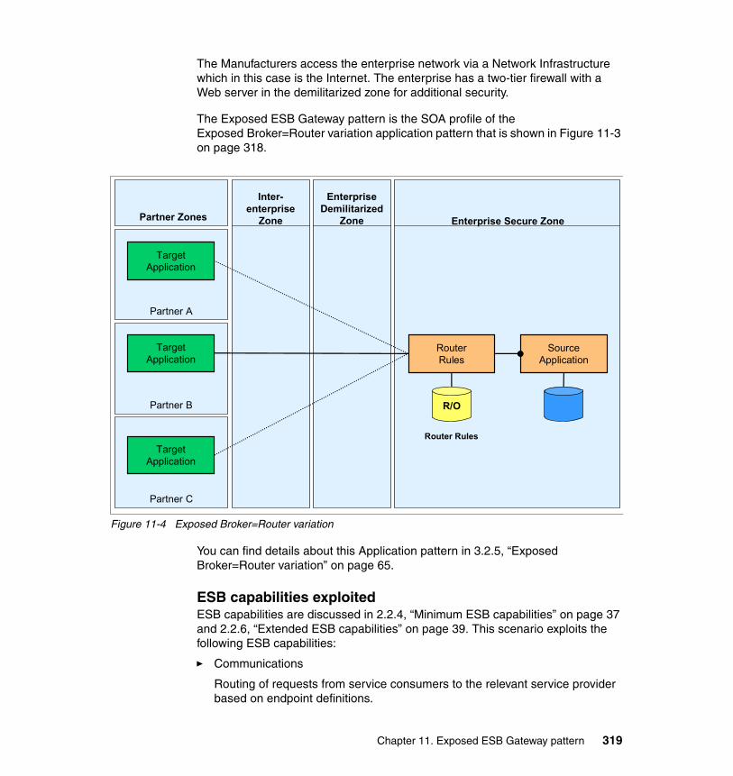
The Manufacturers access the enterprise network via a Network Infrastructure which in this case is the Internet. The enterprise has a two-tier firewall with a Web server in the demilitarized zone for additional security.
The Exposed ESB Gateway pattern is the SOA profile of the Exposed Broker=Router variation application pattern that is shown in Figure 11-3 on page 318.
Figure 11-4 Exposed Broker=Router variation
You can find details about this Application pattern in 3.2.5, “Exposed Broker=Router variation” on page 65.
ESB capabilities exploitedESB capabilities are discussed in 2.2.4, “Minimum ESB capabilities” on page 37 and 2.2.6, “Extended ESB capabilities” on page 39. This scenario exploits the following ESB capabilities:
� Communications
Routing of requests from service consumers to the relevant service provider based on endpoint definitions.
Partner B
Partner A
Inter-enterprise
Zone
EnterpriseDemilitarized
Zone Enterprise Secure ZonePartner Zones
SourceApplication
RouterRules
TargetApplication
TargetApplication
Partner C
TargetApplication
R/O
Router Rules
Chapter 11. Exposed ESB Gateway pattern 319
� Integration
Protocol transformation to allow de-coupling of the protocol that is used between the service consumers and service providers. This allows service consumers to invoke services that are exposed using a different protocol (for example, SOAP/HTTP to SOAP/JMS).
� Security
The layering of the solution and deployment into a two tier firewall allows the Web services to be secured from unauthorized access. Security services such as confidentiality, authentication and authorization are provided by a combination of secure protocols such as HTTP/S, and central control by the Exposed ESB Gateway and the ESB.
� Service interaction
The services are defined using WSDL and made available across enterprises.
Extending the ESB with the Exposed ESB Gateway for this business-to-business scenario fulfils the following requirements:
� Addressing of remote services
Remote services are defined in WSDL and the definitions are made available across enterprises.
� Security over the internet
The layering of the solution into a Web server, Exposed ESB Gateway, ESB and applications allows for a robust security environment to be configured.
� Restricting service access to authorized consumers
External service consumers can only access services that are provided by the Exposed ESB Gateway. Furthermore, the Exposed ESB Gateway could be configured to only allow external service providers to access only a subset of the services advertised.
� Minimizing impact to current infrastructure
The requirement to support external manufacturers was implemented reusing the Enterprise Service Bus Pattern: Router interactions scenario. Providing support for external manufacturers did not impact any of the other services provided by the ESB and was achieved largely by applying configuration changes, as opposed to software development.
320 Patterns: SOA with an Enterprise Service Bus in WebSphere Application Server V6

11.1.3 Exposed ESB Gateway designThis section discusses the architectural decisions that were made and their options for implementation of the scenario using the Exposed ESB Gateway runtime pattern.
Topology considerationsThis section discusses the different operational topology options that could be used to implement the Exposed ESB Gateway scenario. Figure 11-5 on page 322 shows four alterative operational topologies. The topologies are conceptual but map to what can be implemented using WebSphere Application Server V6.
You can find a description of the terminology that this diagram uses in “Topology considerations” on page 194. In addition, we define inter-bus link as a secure connection between service integration buses.
Analyzedesignoptions
Analyzedesignoptions
Analyzedesignoptions
Chapter 11. Exposed ESB Gateway pattern 321
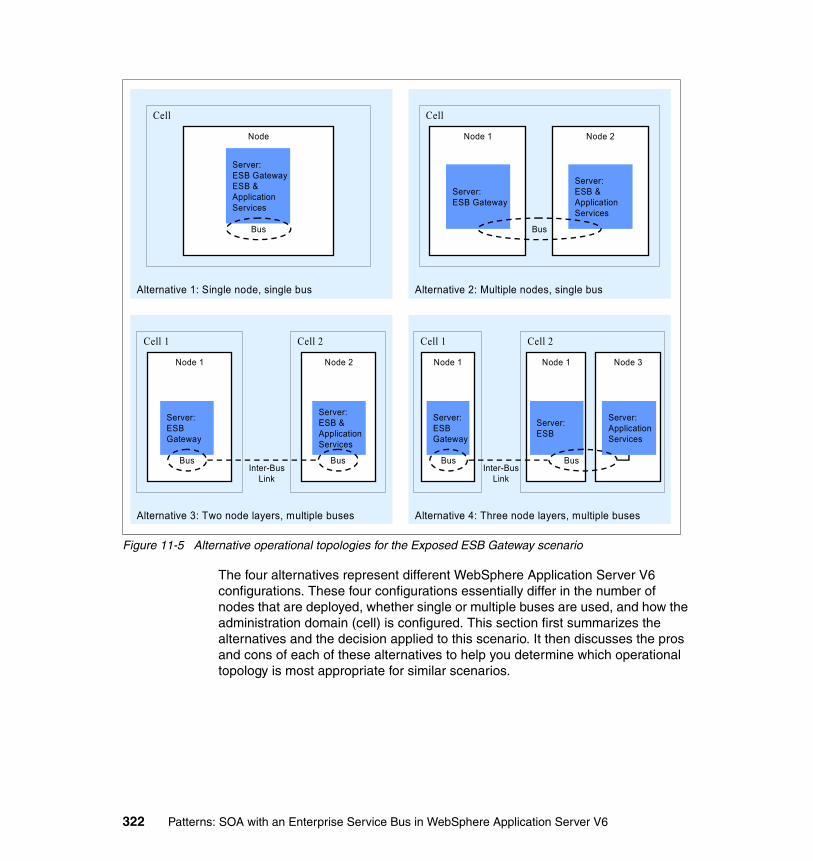
Figure 11-5 Alternative operational topologies for the Exposed ESB Gateway scenario
The four alternatives represent different WebSphere Application Server V6 configurations. These four configurations essentially differ in the number of nodes that are deployed, whether single or multiple buses are used, and how the administration domain (cell) is configured. This section first summarizes the alternatives and the decision applied to this scenario. It then discusses the pros and cons of each of these alternatives to help you determine which operational topology is most appropriate for similar scenarios.
Alternative 2: Multiple nodes, single bus
Node 1 Node 2
Alternative 1: Single node, single bus
Cell
Node
Server: ESB GatewayESB & Application Services
Bus
Server: ESB Gateway
Server: ESB &Application Services
Bus
Cell
Alternative 3: Two node layers, multiple buses
Node 1 Node 2
Server: ESB Gateway
Server: ESB &Application Services
Bus
Cell 1
BusInter-Bus
Link
Cell 2
Alternative 4: Three node layers, multiple buses
Node 1
Server: ESB Gateway
Cell 1
Bus
Node 1
Server: ESB
Node 3
Cell 2
Inter-BusLink
Server: Application Services
Bus
322 Patterns: SOA with an Enterprise Service Bus in WebSphere Application Server V6
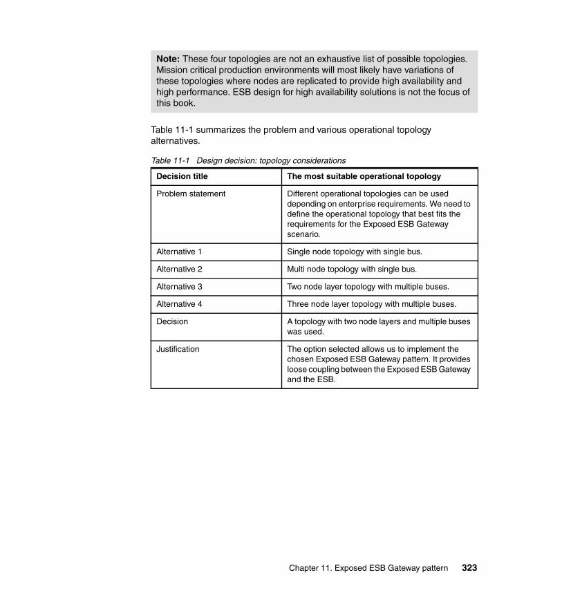
Table 11-1 summarizes the problem and various operational topology alternatives.
Table 11-1 Design decision: topology considerations
Note: These four topologies are not an exhaustive list of possible topologies. Mission critical production environments will most likely have variations of these topologies where nodes are replicated to provide high availability and high performance. ESB design for high availability solutions is not the focus of this book.
Decision title The most suitable operational topology
Problem statement Different operational topologies can be used depending on enterprise requirements. We need to define the operational topology that best fits the requirements for the Exposed ESB Gateway scenario.
Alternative 1 Single node topology with single bus.
Alternative 2 Multi node topology with single bus.
Alternative 3 Two node layer topology with multiple buses.
Alternative 4 Three node layer topology with multiple buses.
Decision A topology with two node layers and multiple buses was used.
Justification The option selected allows us to implement the chosen Exposed ESB Gateway pattern. It provides loose coupling between the Exposed ESB Gateway and the ESB.
Chapter 11. Exposed ESB Gateway pattern 323

Alternative 1: Single node topology with a single busIn this alternative, shown in Figure 11-6, we have a server on one node with one bus. The server runs the Exposed ESB Gateway, the ESB and the applications services.
Figure 11-6 Single node, single bus topology
This alternative was not selected as an implementation option for this scenario, because it does not meet some of the architectural principles that are inherent in the Exposed ESB Gateway runtime pattern that we are trying to implement. In particular, the Runtime pattern defines the Exposed ESB Gateway as a service external to the ESB. This implementation tightly couples the ESB and the Exposed ESB Gateway by implementing them on the same bus. Furthermore, although the pattern does not explicitly specify that the Exposed ESB Gateway and the ESB should be deployed in separate nodes, the implication of being part of the same node and cell is that the Exposed ESB Gateway is part of the same administration domain as the ESB. In addition to this, a single node would not provide the qualities of service required for this application, in particular availability and scalability.
� Reasons for using this alternative include:
– Very simple to set-up and configure for a prototype.
� Reasons for not using this alternative include:
– Tightly couples the Exposed ESB Gateway to the ESB.– Single point of failure.– Difficulty scaling.– Message throughput cannot be increased easily.– Limitation on number of client connections that can be handled.
Alternative 1: Single node, single bus
Cell
Node
Server: ESB GatewayESB & Application Services
Bus
324 Patterns: SOA with an Enterprise Service Bus in WebSphere Application Server V6

– The Exposed ESB Gateway and ESB cannot be deployed in different security zones if required.
Alternative 2: Multiple node topology with a single busThis alternative, shown in Figure 11-7, is similar to Alternative 1, but here we deploy two servers in two separate nodes. Node 1 has a server that executes the Exposed ESB Gateway, and node 2 has a server that executes the ESB and the application services.
Figure 11-7 Multiple nodes, single bus topology
This alternative expands the first option because it improves the qualities of service that can be provided. However, it still has the limitations that are described with respect to having only one bus administered as one cell. Therefore, this alternative is again not selected.
� Reasons for using this alternative include:
– Valid for a prototype or small production environment.
– Availability is improved although there are still single points of failure.
– Improved scalability.
– More client connections can be handled.
� Reasons for not using this alternative include:
– Tightly couples the Exposed ESB Gateway to the ESB.
– Single points of failure.
– Availability and performance improvements are not significant.
– Might be difficult to deploy the Exposed ESB Gateway and ESB in different security zones if required.
Alternative 2: Multiple nodes, single bus
Node 1 Node 2
Server: ESB Gateway
Server: ESB &Application Services
Bus
Cell
Chapter 11. Exposed ESB Gateway pattern 325

Alternative 3: Two node layers with multiple busesThis alternative, shown in Figure 11-8, extends the previous option by implementing two buses: one on the server that runs the Exposed ESB Gateway and one in the server that runs the ESB and application services. The two buses are connected via an inter-bus link. In addition, each node in this topology is within a different cell.
Figure 11-8 Two node layers, multiple buses topology
This alternative overcomes the issues discussed in the previous examples with respect to the tight coupling between the Exposed ESB Gateway and ESB, providing a controlled and secure link between the two in the form of the inter-bus link. Also, in this implementation, the Exposed ESB Gateway and the ESB can be implemented using different technologies, or the Exposed ESB Gateway might service more than one ESB. The inter-bus link implemented in WebSphere Application Server V6 is able to integrate with other buses, for example buses that are built on WebSphere MQ or WebSphere Business Integration Message Broker.
This alternative is the operational topology that was selected for this scenario. In a production environment, the ESB is likely to have dedicated nodes. Therefore, the application services would be deployed on a separate node, which is discussed in “Alternative 4: Three node layers with multiple buses” on page 327. However, for the purpose of this book, it was not necessary to go to that extent.
Alternative 3: Two node layers, multiple buses
Node 1 Node 2
Server: ESB Gateway
Server: ESB &Application Services
Bus
Cell 1
BusInter-Bus
Link
Cell 2
326 Patterns: SOA with an Enterprise Service Bus in WebSphere Application Server V6

� Reasons for using this alternative include:
– Loosely couples the Exposed ESB Gateway and the ESB.
– Improved scalability.
– Services on other buses can be accessed and messages sent to other bus services.
– Resources provided by other buses can be accessed.
– Different security zones can easily be applied.
� Reasons for not using this alternative include:
– Complicated to set-up and configure.
– In some cases, you might want to deploy application services on a separate node to the ESB (see alternative 4).
Alternative 4: Three node layers with multiple busesThis alternative, shown in Figure 11-9, is virtually identical to the topology for Alternative 3 but extends that alternative by deploying the Application Services on a separate node from the ESB. The server in Node 3 has outbound and inbound services defined so that the Application Services can be invoked as well as for Application Services to invoke other provided services.
Figure 11-9 Three node layers, multiple buses topology
Alternative 4: Three node layers, multiple buses
Node 1
Server: ESB Gateway
Cell 1
Bus
Node 1
Server: ESB
Node 3
Cell 2
Inter-BusLink
Server: Application Services
Bus
Chapter 11. Exposed ESB Gateway pattern 327

This alternative is a likely scenario where the application services are being reused from services provided by other departments or are implemented in other technologies (for example, .Net services). Specific non-functional requirements can also dictate the need to separate the ESB node from application services node to provide higher qualities of service in the areas of availability, security, performance or scalability. In a production environment the ESB infrastructure would typically be deployed in its own node.
� Reasons for using this alternative include:
– Loosely couples the Exposed ESB Gateway and the ESB
– Improved scalability.
– Improved availability.
– Services on other buses can be accessed and messages sent to other bus services.
– Resources provided by other buses can be accessed.
– Different security zones can easily be applied.
� Reasons for not using this alternative include:
– Complicated to set-up and configure.
Sharing service definitions across enterprisesThe following section discusses options for sharing service definitions across enterprises. The design consideration is an extension of the architectural decision made in “Location of service definitions” on page 184 for the Enterprise Service Bus pattern. Table 11-2 on page 329 summarizes the problem and various service definition alternatives.
328 Patterns: SOA with an Enterprise Service Bus in WebSphere Application Server V6

Table 11-2 Design decision: service definition location
Alternative 1: Local copy of WSDLThe WSDL definition files can be provided to partners, in this case, to the Manufacturers. Thus, the WSDL definitions are common and static across organizations. Partners can chose where to store the service definitions.
� Reasons for using this option include:
– Can provide higher performance.
– Easy configuration for provider of service.
– Additional security.
� Reasons for not using this option include:
– This approach is generally less flexible.
– More difficult to maintain and administer across enterprises.
– Prone to errors as definitions need to be deployed in multiple places by multiple organizations.
– New definitions take time to roll out.
Decision title Sharing service definitions across enterprises
Problem statement Invocation of inter-enterprise services implicitly requires the sharing of service definitions in the form of WSDL definition files, which define the interface, binding, and service endpoint.
Alternative 1 Provide service definitions to the partners, who maintain a local copy.
Alternative 2 Centrally publish WSDL service definitions. WSDL files can be published either to a UDDI registry or on an HTTP server.
Decision Centrally publish WSDL files on an HTTP server.
Justification Having one centrally managed copy of the service definitions is a better option from a management point of view and is less likely to produce errors from using wrong or out of date service definitions. The scenario is a prototype and for simplicity an HTTP publication is chosen ahead of UDDI as it is easy to set-up and organize.
Chapter 11. Exposed ESB Gateway pattern 329
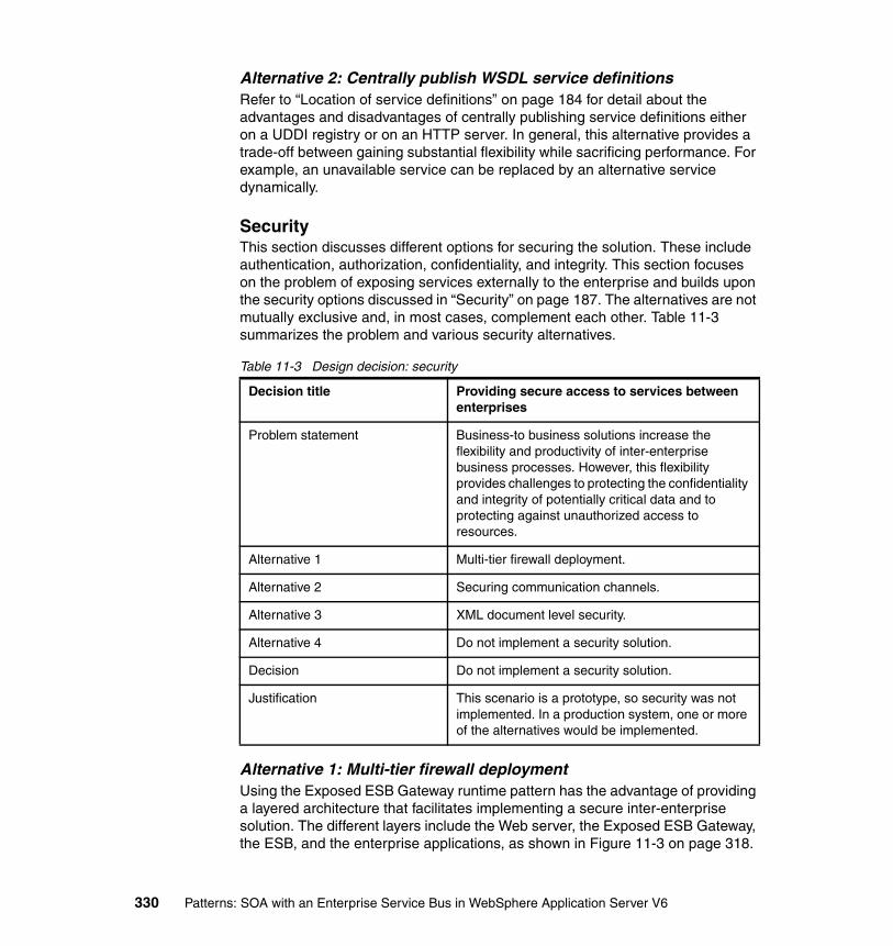
Alternative 2: Centrally publish WSDL service definitionsRefer to “Location of service definitions” on page 184 for detail about the advantages and disadvantages of centrally publishing service definitions either on a UDDI registry or on an HTTP server. In general, this alternative provides a trade-off between gaining substantial flexibility while sacrificing performance. For example, an unavailable service can be replaced by an alternative service dynamically.
SecurityThis section discusses different options for securing the solution. These include authentication, authorization, confidentiality, and integrity. This section focuses on the problem of exposing services externally to the enterprise and builds upon the security options discussed in “Security” on page 187. The alternatives are not mutually exclusive and, in most cases, complement each other. Table 11-3 summarizes the problem and various security alternatives.
Table 11-3 Design decision: security
Alternative 1: Multi-tier firewall deploymentUsing the Exposed ESB Gateway runtime pattern has the advantage of providing a layered architecture that facilitates implementing a secure inter-enterprise solution. The different layers include the Web server, the Exposed ESB Gateway, the ESB, and the enterprise applications, as shown in Figure 11-3 on page 318.
Decision title Providing secure access to services between enterprises
Problem statement Business-to business solutions increase the flexibility and productivity of inter-enterprise business processes. However, this flexibility provides challenges to protecting the confidentiality and integrity of potentially critical data and to protecting against unauthorized access to resources.
Alternative 1 Multi-tier firewall deployment.
Alternative 2 Securing communication channels.
Alternative 3 XML document level security.
Alternative 4 Do not implement a security solution.
Decision Do not implement a security solution.
Justification This scenario is a prototype, so security was not implemented. In a production system, one or more of the alternatives would be implemented.
330 Patterns: SOA with an Enterprise Service Bus in WebSphere Application Server V6

The Web server deployed in the demilitarized zone receives the external requests. The Web server can be configured to authenticate the consumer and if successful forward the request together with the credentials to the Exposed ESB Gateway, which is in the Enterprise Zone. In the case of this scenario, the Exposed ESB Gateway is configured to only accept the two valid requests that Manufacturers are allowed to invoke, these are: the LoggingFaclity and WarehouseCallBack Web services. The Exposed ESB Gateway then invokes the services using the ESB.
� Reasons for using this option include:
– Protects the availability, integrity, and confidentiality of enterprise data.
– Protects against attacks from external parties.
� Reasons for not using this option include:
– When implementing prototypes within set time constraints.
Alternative 2: Securing communication channelsConfidentiality and integrity of a message as it makes its way from the service consumer to the service provider, particularly over the internet, can be provided by Secure Socket Layer (SSL). HTTP over SSL (HTTPS) is widely used for secure communication over the Internet. The entire message payload is encrypted and so there will be a trade-off between security and performance. If performance is a concern, dedicated hardware can be deployed which is purpose built to accelerate the encrypting and decrypting of messages. With a federated ESB implementation, it might make sense to only secure the communications between the intermediaries on either side of the internet, that is, between the Exposed ESB Gateways.
The use of SSL allows either or both the client and server to prove identity to the other. This can be achieved using certificates and provides an authentication mechanism. Securing the communications channel in conjunction with J2EE security and JSR 109 can additionally address authorization requirements. The J2EE role-based authorization model can be assigned to operations of services exposed by the Exposed ESB Gateway.
An alternative to HTTPS is to use HTTP basic authentication. HTTP basic authentication uses the HTTP header to carry user ID and password information.
Note: The layered architecture allows for further zones to be defined within the enterprise if the confidentiality and integrity requirements warrant this design. For example, critical enterprise applications might be further restricted in an additional enterprise zone behind a firewall.
Chapter 11. Exposed ESB Gateway pattern 331

This information is sent over an SSL connection (HTTPS) but everything else is sent over HTTP in clear text.
� Reasons for using this option include:
– To protect from unauthorized inspection of the content of messages.
– To protect against message tampering.
– To prevent unauthorized users from accessing enterprise services.
� Reasons for not using this option include:
– When implementing prototypes within set time constraints.
– When the messages flowing through the communication channel are public and integrity is not an issue.
Alternative 3: XML document level securityIntegrity and confidentiality requirements can also be addressed at the document level through the W3C recommendations to use XML Encryption and XML Signature, as follows:
� XML Encryption
This provides the ability to encrypt certain portions of an XML document, such as part or all of the SOAP body. An XML syntax is used to represent the encrypted content and information that enables a service provider to decrypt it.
� XML Signature
Algorithms are available to sign XML documents, such as a SOAP envelope. XML Signature provides a mechanism for securely verifying the origin of such a message by using an XML-compliant syntax for representing the signature.
For more information, see:
http://www.w3c.org
The use of the Structure Assertion Markup Language (SAML) standard allows the exchange of authentication and authorization information with XML between business partners. You can find further information at:
http://www.oasis-open.org
The use of these capabilities has several drawbacks:
� Performance might be affected adversely.� Current tooling might hide the XML layer from service developers.� A PKI infrastructure is required.
WS-Security is also a consideration and can be implemented between Exposed ESB Gateways over the Internet to allow encryption of part or all of the SOAP
332 Patterns: SOA with an Enterprise Service Bus in WebSphere Application Server V6

body only. WS-Security can be used to provide a high degree of flexibility for addressing security requirements for services, including the authentication of a service request from one Exposed ESB Gateway by another. Further information about WS-Security can be found at:
http://www.ibm.com/developerworks/webservices/library/ws-secure
� Reasons for using this option include:
– Similar to alternative 2, but when requiring finer granularity over what data is secured and at a higher level of abstraction closer to the application. This as opposed to HTTPS, where security is implemented at the transport level.
� Reasons for not using this option include:
– When implementing prototypes within set time constraints– When the messages flowing through the communication channel are
public and integrity is not an issue
11.1.4 ProductsIn 11.1.3, “Exposed ESB Gateway design” on page 321, several design decisions were made which influenced product choice. This section looks at the products that you can use to implement these design decisions and the product choices that were made for this particular implementation.
Product implementation optionsThis section discusses the products used to implement this scenario. Product choice is based on the following:
� The ESB capabilities being exploited, as discussed in “ESB capabilities exploited” on page 319.
� The design decisions made, as discussed in 11.1.3, “Exposed ESB Gateway design” on page 321.
� Products that are currently available.
You can use the following currently available products to implement the Exposed ESB Gateway:
� WebSphere Application Server V6.0
� WebSphere Application Server Network Deployment V6.0
� WebSphere Application Server Network Deployment V5.1.1 Web Services Gateway
� WebSphere Business Integration Message Broker V5.0
� WebSphere Business Integration Connect V4.2
Select aproductSelect aproduct
Chapter 11. Exposed ESB Gateway pattern 333
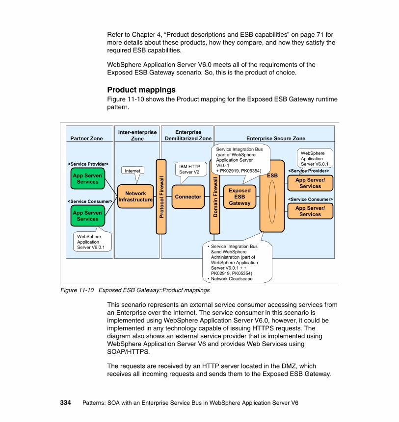
Refer to Chapter 4, “Product descriptions and ESB capabilities” on page 71 for more details about these products, how they compare, and how they satisfy the required ESB capabilities.
WebSphere Application Server V6.0 meets all of the requirements of the Exposed ESB Gateway scenario. So, this is the product of choice.
Product mappingsFigure 11-10 shows the Product mapping for the Exposed ESB Gateway runtime pattern.
Figure 11-10 Exposed ESB Gateway::Product mappings
This scenario represents an external service consumer accessing services from an Enterprise over the Internet. The service consumer in this scenario is implemented using WebSphere Application Server V6.0, however, it could be implemented in any technology capable of issuing HTTPS requests. The diagram also shows an external service provider that is implemented using WebSphere Application Server V6 and provides Web Services using SOAP/HTTPS.
The requests are received by an HTTP server located in the DMZ, which receives all incoming requests and sends them to the Exposed ESB Gateway.
Inter-enterprise Zone
EnterpriseDemilitarized Zone Enterprise Secure ZonePartner Zone
App Server/Services
App Server/Services
NetworkInfrastructure
ESB
Dom
ain
Fire
wal
l
ExposedESB
Gateway
Prot
ocol
Fire
wal
l
Connector
<Service Provider>
<Service Consumer>
App Server/Services
App Server/Services
<Service Consumer>
IBM HTTP Server V2
WebSphere Application Server V6.0.1
Service Integration Bus (part of WebSphere Application Server V6.0.1 + PK02919, PK05354)
• Service Integration Bus &and WebSphereAdministration (part of WebSphere Application Server V6.0.1 + + PK02919, PK05354)
• Network Cloudscape
WebSphere Application Server V6.0.1
<Service Provider>Internet
334 Patterns: SOA with an Enterprise Service Bus in WebSphere Application Server V6
The Exposed ESB Gateway is implemented using WebSphere Application Server. The Exposed ESB Gateway verifies and maps the request to a service provided by the ESB. The ESB is implemented using WebSphere Application Server using a network setup for the Cloudscape database which holds the SDO repository. Finally, the internal service provider application is implemented using WebSphere Application Server.
11.2 Development guidelines
In the ESB Exposed Gateway scenario, the Manufacturers are connected to the ESB via an Exposed Gateway, rather than directly. The ESB is aware of this connection and any calls to the Manufacturer by the ESB are then forwarded to the Exposed Gateway. Calls made by the Manufacturers to services that are defined on the ESB are made via the Exposed Gateway, and it decides whether to forward the requests to the ESB. Figure 11-11 on page 336 illustrates this scenario.
Note: This section requires the use of Rational Application Developer V6.0.0.1 or later.
Chapter 11. Exposed ESB Gateway pattern 335
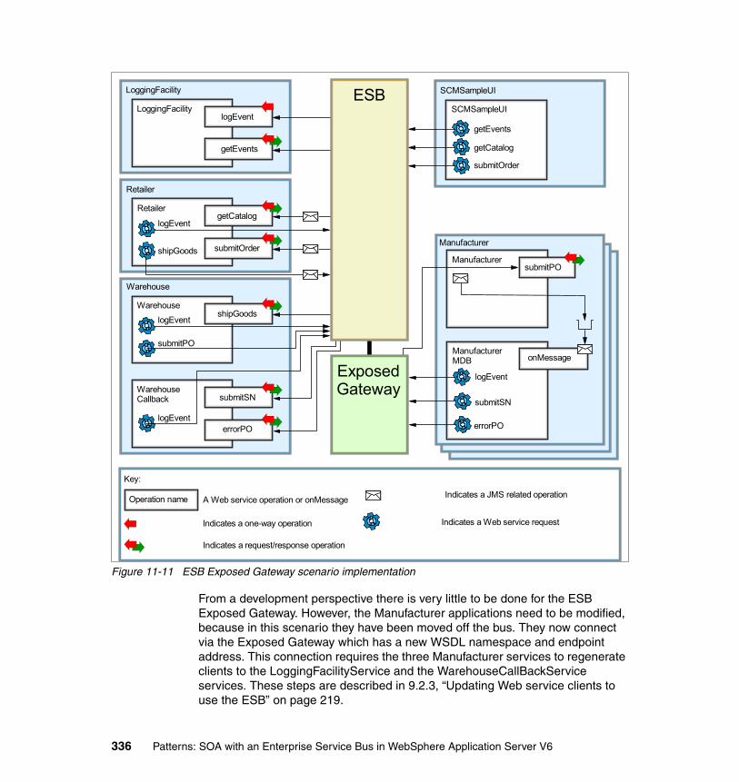
Figure 11-11 ESB Exposed Gateway scenario implementation
From a development perspective there is very little to be done for the ESB Exposed Gateway. However, the Manufacturer applications need to be modified, because in this scenario they have been moved off the bus. They now connect via the Exposed Gateway which has a new WSDL namespace and endpoint address. This connection requires the three Manufacturer services to regenerate clients to the LoggingFacilityService and the WarehouseCallBackService services. These steps are described in 9.2.3, “Updating Web service clients to use the ESB” on page 219.
LoggingFacility
logEvent
getEvents
LoggingFacility
Retailer
getCatalog
submitOrder
Retailer
Warehouse
shipGoodsWarehouse
submitSN
errorPO
WarehouseCallback
SCMSampleUI
SCMSampleUI
Key:
Operation name A Web service operation or onMessage
Indicates a one-way operation Indicates a Web service request
Indicates a JMS related operation
Indicates a request/response operation
shipGoods
logEvent
logEvent
submitPO
logEvent
getEvents
getCatalog
submitOrder
submitPOManufacturer
ManufacturerMDB
logEvent
onMessage
submitSN
errorPO
Manufacturer
ESB
ExposedGateway
336 Patterns: SOA with an Enterprise Service Bus in WebSphere Application Server V6
It is not strictly necessary to regenerate these Manufacturer services, because sample Manufacturer enterprise applications are provided for you, as described in the runtime guidelines. Therefore, you can skip this step if you wish.
11.3 Runtime guidelines
This section describes how to get the ESB Exposed Gateway scenario up and running in WebSphere Application Server V6.
This section discusses the following tasks:
� Removing Web services from the ESB� Migrating the SDO repository to use Network Cloudscape� Setting up the Exposed Gateway� Configuring the service integration bus link� Routing Web service requests between buses� Testing the sample application
Note: This section assumes that you have installed and are using WebSphere Application Server V6.0.1 with the i-fixes PK02919 and PK05354 applied. You can download PK02919 at:
http://www.ibm.com/search?en=utf&v=11&lang=en&cc=us&q=PK02919
You can download PK05354 at:
http://www.ibm.com/support/docview.wss?rs=180&uid=swg24009729
Versions of WebSphere Application Server beyond V6.0.1 will not require the i-fixes.
Note: These instructions assume that you have configured the Enterprise Service Bus router scenario (Chapter 9, “Enterprise Service Bus pattern: router scenario” on page 179). This section describes the required modifications to convert that configuration into this one.
You can quickly import the Enterprise Service Bus router configuration into WebSphere Application Server using a set of Jacl scripts. For information, see “Configuring the ESB router scenario” on page 370.
Chapter 11. Exposed ESB Gateway pattern 337

11.3.1 Removing Web services from the ESBFirst, you need to remove the Manufacturers from the ESB and remove the WarehouseCallBack inbound service. These Web services now are exposed via the Exposed Gateway.
Uninstalling the Manufacturer applicationsTo uninstall the Manufacturer applications:
1. Access the administrative console at http://localhost:9060/ibm/console and log in.
2. Expand Applications and click Enterprise Applications.
3. Select the applications Manufacturer, ManufacturerB, and ManufacturerC, as shown in Figure 11-12, and click Stop.
Figure 11-12 Selecting the Manufacturer applications before stopping them
4. Select the applications Manufacturer.ear, ManufacturerB.ear, and ManufacturerC.ear, and this time, click Uninstall.
5. Confirm the uninstallation of the applications by clicking OK.
6. Save the changes to the master configuration.
338 Patterns: SOA with an Enterprise Service Bus in WebSphere Application Server V6
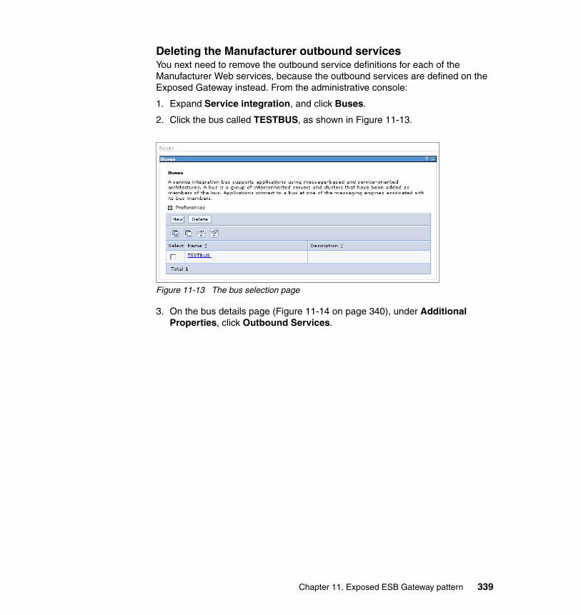
Deleting the Manufacturer outbound servicesYou next need to remove the outbound service definitions for each of the Manufacturer Web services, because the outbound services are defined on the Exposed Gateway instead. From the administrative console:
1. Expand Service integration, and click Buses.
2. Click the bus called TESTBUS, as shown in Figure 11-13.
Figure 11-13 The bus selection page
3. On the bus details page (Figure 11-14 on page 340), under Additional Properties, click Outbound Services.
Chapter 11. Exposed ESB Gateway pattern 339
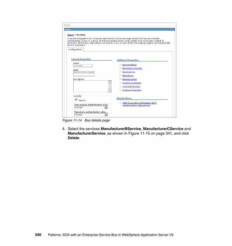
Figure 11-14 Bus details page
4. Select the services ManufacturerBService, ManufacturerCService and ManufacturerService, as shown in Figure 11-15 on page 341, and click Delete.
340 Patterns: SOA with an Enterprise Service Bus in WebSphere Application Server V6

Figure 11-15 Selecting the outbound service definitions
5. Save the changes.
Deleting the WarehouseCallBack inbound serviceNext, you need to remove the inbound service definition for the Warehouse Callback Web service, because the inbound services is defined on the Exposed Gateway instead. From the administrative console:
1. On the bus details page (Figure 11-14 on page 340), under Additional Properties, click Inbound Services.
2. Select the service WarehouseCallBackService, and click Delete. Save the changes.
Chapter 11. Exposed ESB Gateway pattern 341

11.3.2 Migrating the SDO repository to use Network CloudscapeThis section covers the changes that are required for converting the SDO repository from using Cloudscape as an embedded database to using Cloudscape as a network database. The network database is required because both the ESB and the Exposed Gateway need access to the same SDO database, which is not supported by Embedded Cloudscape.
Starting the Cloudscape network serverTo start the Cloudscape network server:
1. Navigate to the WAS_HOME/cloudscape/bin/networkServer directory, where WAS_HOME is the directory where you installed WebSphere Application Server.
2. Execute the file named startNetworkServer.bat on Windows or startNetworkServer.sh on UNIX platforms. This batch file starts the network server and, if executed from a command prompt, blocks further usage of that command prompt. If you wish to stop the network server, execute stopNetworkServer.bat on Windows or stopNetworkServer.sh on UNIX platforms.
Removing the existing resourcesYou next need to remove the old database resources. The original resources are configured for Embedded Cloudscape and will not work with Network Cloudscape.
You should remove the resources by running uninstallSdoRepository.jacl with the -removeDb option. Then, run installSdoRepository.jacl without any options. The -removeDb option removes the WebSphere Application Server references to the database, but it does not delete the database itself. You will reuse the database content in the Network Cloudscape implementation.
To run these commands, go to the WebSphere Application Server bin directory and enter:
wsadmin -f uninstallSdoRepository.jacl -removeDb
Then, enter:
wsadmin -f installSdoRepository.jacl
Configuring J2C authentication dataThe data source that the SDO repository uses needs to have a component-managed authentication alias. An authentication alias is used to allow the same user ID and password combination to be used in many different places. In this scenario, the Cloudscape database does not have security
342 Patterns: SOA with an Enterprise Service Bus in WebSphere Application Server V6
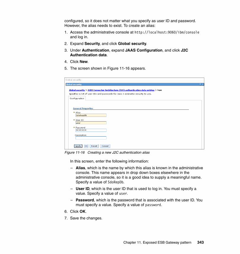
configured, so it does not matter what you specify as user ID and password. However, the alias needs to exist. To create an alias:
1. Access the administrative console at http://localhost:9060/ibm/console and log in.
2. Expand Security, and click Global security.
3. Under Authentication, expand JAAS Configuration, and click J2C Authentication data.
4. Click New.
5. The screen shown in Figure 11-16 appears.
Figure 11-16 Creating a new J2C authentication alias
In this screen, enter the following information:
– Alias, which is the name by which this alias is known in the administrative console. This name appears in drop down boxes elsewhere in the administrative console, so it is a good idea to supply a meaningful name. Specify a value of SdoRepDb.
– User ID, which is the user ID that is used to log in. You must specify a value. Specify a value of user.
– Password, which is the password that is associated with the user ID. You must specify a value. Specify a value of password.
6. Click OK.
7. Save the changes.
Chapter 11. Exposed ESB Gateway pattern 343

Creating the JDBC provider for Network CloudscapeThe next step is to configure the ESB to access the SDO repository database using Network Cloudscape. To define a JDBC provider:
1. Access the administrative console at http://localhost:9060/ibm/console and log in.
2. Expand Resources, and click JDBC Providers.
3. You need to create a new JDBC provider. For simplicity, you will create one at the node scope, the scope that is automatically shown (see Figure 11-17). Click New.
Figure 11-17 JDBC provider panel at node scope
4. The next page, shown in Figure 11-18 on page 345, asks for some general information about the type of database and the connection mechanism to be used. Note that the pull-down boxes are disabled until you have completed the values in the preceding boxes.
344 Patterns: SOA with an Enterprise Service Bus in WebSphere Application Server V6

Figure 11-18 Specifying properties for the Network Cloudscape JDBC provider
Enter the following information:
– Select the database type, which specifies the type of database to which the JDBC provider connects. In this case select Cloudscape.
– Select the provider type. which specifies how the database is accessed. The options are:
• Cloudscape Network Server Using Universal JDBC Driver, which is used for accessing Network Cloudscape
• Cloudscape JDBC Provider, which is used for accessing Embedded Cloudscape
In this case, select Cloudscape Network Server Using Universal JDBC Driver.
– Select the implementation type, which is determined by the two previous selections. There is only one option allowed, and it is selected by default.
5. Click Next.
6. On the following page, accept the defaults and click OK.
7. Save the changes.
Chapter 11. Exposed ESB Gateway pattern 345

Creating the JDBC data sourceYou next create the JDBC data source for accessing the Network Cloudscape database. From the JDBC providers page:
1. Click the JDBC provider that is named Cloudscape Network Server Using Universal JDBC Driver.
2. On the next page, shown in Figure 11-19, select Data sources.
Figure 11-19 JDBC provider details page
3. On the Data source details page, click New.
4. In the next page, you enter the details for this data source. Except where specified, you should keep the defaults. Figure 11-20 on page 347 shows the first two settings.
Note: The Cloudscape Network Server JDBC provider does not support Data sources (Version 4).
346 Patterns: SOA with an Enterprise Service Bus in WebSphere Application Server V6

Figure 11-20 Specifying the data source name, JNDI name and description
Enter the following information:
– Name, which is an administrative entity that only has meaning within the administrative console. Specify a value of SDO Repository Data source.
– JNDI Name, which is where applications pick up the data source. Specify a value of jdbc/com.ibm.ws.sdo.config/SdoRepository.
– Description, which is another administrative entity. You can leave this as is. In this example, as shown in Figure 11-20, we have copied the name into the description. This step is optional. Specify a value of SDO Repository Data source.
The options that are different from the defaults are shown in Figure 11-21 on page 348.
Chapter 11. Exposed ESB Gateway pattern 347

Figure 11-21 Specifying the Cloudscape database properties
In this screen, enter the following information:
– Component-managed authentication alias, which is the alias that is used when making connections to the database where the application managed authentication is used by the application and it does not specify a user ID and password. Select the value that ends in SdoRepDb.
– Database name, which is the path on the database server to the cloudscape database. Specify WAS_HOME/profiles/PROFILE_NAME/databases/SdoRepDb, where WAS_HOME is the WebSphere Application Server install directory and PROFILE_NAME is the name of the profile in which your ESB is defined.
– Server name, which is the name of the host where the Network Cloudscape server is running. Accept the default of localhost.
5. Click OK and save the changes.
6. There is an option to test a connection to a database to check that the configuration is valid. After defining the data source, attempting to test the connection will fail because the database is being accessed by the SDO repository that is running currently in the application server. Therefore, restart the application server now.
348 Patterns: SOA with an Enterprise Service Bus in WebSphere Application Server V6
11.3.3 Setting up the Exposed GatewayThe Exposed Gateway is implemented by a separate application server. In implementing the Exposed Gateway, we are running two application servers on a single computer. However, this scenario could equally be implemented using two machines.
Runtime alternative: Separate profilesAs stated, two application servers can run on a single machine, where each server is in a different profile. This configuration has several advantages:
� Test environment
For a test environment where a more limited number of computers are available and checking that the function executes correctly is more important than checking out how the solution scales or performs, using multiple profiles is simpler and less expensive.
� Total cost of ownership
Using multiple profiles requires a single licence for WebSphere Application Server, rather than multiple ones for each installation.
It also has several disadvantages:
� Performance
Having two application servers on a single computer introduces the chance that the two servers will need to compete for access to the same resources, for example processor, RAM, hard disc access.
� Availability
Because both servers are running on a single computer, if that computer goes down, both servers are unavailable.
Note: This section assumes that you have configured a second WebSphere Application Server profile on your machine. If you have not yet done this, use the Profile creation wizard that is supplied with WebSphere Application Server to create a second profile. Ensure that the second profile uses a unique set of ports. We refer to this second profile as the Exposed Gateway server.
Chapter 11. Exposed ESB Gateway pattern 349
� Complexity
The two profiles are isolated from each other. So, it would be possible to configure both servers to use resources which only allow a single connection, for example:
– Configuring both servers to listen on the same port.
– Configuring both servers to access the same Embedded Cloudscape database.
Setting up the Exposed Gateway server
To configure the Web services on the Exposed Gateway server:
1. Install the SDO repository without specifying the -createDb option. To run this command, go to the bin directory of the WebSphere Application Server Exposed Gateway profile and enter:
wsadmin -f WAS_HOME/bin/installSdoRepository.jacl
In this command, WAS_HOME is the directory where WebSphere Application Server is installed.
2. Install the Web services support into the Exposed Gateway server. Enter all commands from the bin directory of the WebSphere Application Server Exposed Gateway profile:
a. To install the resource adapter, execute the following command:
wsadmin -f WAS_HOME/util/sibwsInstall.jacl INSTALL_RA -installRoot WAS_HOME -nodeName NODE_NAME
In this command, WAS_HOME is the directory you installed WebSphere Application Server, and NODE_NAME is the name of the application server node.
b. Install the Web services support application:
wsadmin -f WAS_HOME/util/sibwsInstall.jacl INSTALL -installRoot WAS_HOME -nodeName NODE_NAME -serverName server1
Note: This section applies to the configuration that is required on the Exposed Gateway server.
Important: The second WAS_HOME must have elements in the path separated by a forward slash (/) even on a Windows system. So, a path of c:\WebSphere\AppServer, becomes c:/WebSphere/AppServer.
350 Patterns: SOA with an Enterprise Service Bus in WebSphere Application Server V6

c. Install the SOAP over HTTP endpoint listener application:
wsadmin -f WAS_HOME/util/sibwsInstall.jacl INSTALL_HTTP -installRoot WAS_HOME -nodeName NODE_NAME -serverName server1
3. Configure the HTTP endpoint listener in the administrative console of the Exposed Gateway server by doing the following:
a. Expand Servers, and click Application Servers.
b. Click server1.
c. Under Additional Properties, click Endpoint Listeners.
d. Click New.
e. Enter the following parameters:
i. Set Name to SOAPHTTPChannel1.
ii. Set URL root to http://localhost:9081/wsgwsoaphttp1.
iii. Set WSDL serving HTTP URL root to http://appsrv1a.itso.ral.ibm.com/wsdl.
f. Click OK, and then save the changes.
4. To create the JDBC provider and data source for the SDO repository, follow the steps in the following sections. Be sure to use the administrative console of the Exposed Gateway server.
a. “Configuring J2C authentication data” on page 342.
b. “Creating the JDBC provider for Network Cloudscape” on page 344.
c. “Creating the JDBC data source” on page 346. In this section, set the Database name field to point the Cloudscape database that is installed in the ESB server profile.
5. If you have not already done so, restart the application server so that the SDO repository can connect to the database.
6. Create a bus called TESTBUS1. From the administrative console:
a. Click Service integration → Buses.
b. Click New.
c. Enter TESTBUS1 in the Name field, and then click OK.
d. Save the changes.
Note: This setting assumes that the Exposed Gateway server is assigned port 9081 for HTTP.
Chapter 11. Exposed ESB Gateway pattern 351
7. Add the server as a bus member. From the administrative console:
a. Click Service integration → Buses → TESTBUS1. Under Additional Properties, click Bus members.
b. Click Add.
c. Accept the defaults by clicking Next and then Finish.
d. Save the changes.
8. Define the queue destinations that required by the Manufacturer services:
a. Click Service integration → Buses → TESTBUS1. Under Additional Properties, click Destinations.
b. Click New.
c. Select Queue, and click Next.
d. In the Identifier field, enter a queue name of ManufacturerSIBQ. Click Next, Next again, and then Finish.
e. Using the same steps, create four other queue destinations called ManufacturerBSIBQ, ManufacturerCSIBQ, LoggingFacilityService, and WarehouseCallBackService.
f. Save the changes.
9. Define the following JMS resources for TESTBUS1:
a. Create a JMS connection factory, as described in 8.3.5, “Creating a JMS connection factory” on page 165.
b. Create JMS queues for the Manufacturer destinations, as described in 8.3.6, “Creating the JMS queues” on page 167.
c. Create the JMS activation specifications, as described in 8.3.7, “Creating the JMS activation specifications” on page 169.
10.In 8.3.8, “Hosting the WSDL files” on page 171, you configured an HTTP server to host the WSDL files of the Web services. Each of the Manufacturer WSDL files on this HTTP server assumes an HTTP port of 9080. You need to change these Manufacturer WSDL files to use the HTTP port defined for the Exposed Gateway server by doing the following:
a. Locate the Manufacturer_Impl.wsdl file in the <HTTP_Server_home>\htdocs\en_US\wsdl directory.
b. Open the Manufacturer_Impl.wsdl file in a text editor, and locate the following line:
<wsdlsoap:address location="http://localhost:9080/Manufacturer/services/Manufacturer"/>
352 Patterns: SOA with an Enterprise Service Bus in WebSphere Application Server V6

c. Modify the 9080 port to reflect the HTTP port that is used by your Exposed Gateway server. We used port 9081:
<wsdlsoap:address location="http://localhost:9081/Manufacturer/services/Manufacturer"/>
d. Save and close file.
e. Make the same change to the ManufacturerB_Impl.wsdl and ManufacturerC_Impl.wsdl files.
11.Create an outbound service for each of the Manufacturers. The outbound services allow the service integration bus to interact with the Manufacturer Web service providers. For instructions on how to do this see 9.3.7, “Creating the outbound services” on page 244. This creates three outbound services: ManufacturerService, ManufacturerBService, and ManufacturerCService. Save your changes.
12.Create inbound services for LoggingFacilityService and WarehouseCallBackService. The inbound services receive requests from service consumers. We forward these requests to the ESB service integration bus to be processed.
Follow the instructions in 9.3.8, “Creating the inbound services” on page 247 to create these two inbound services.
Table 11-4 Inbound Service mappings to destinations
13.New Manufacturer enterprise applications need to be installed that use the new LoggingFacility and WarehouseCallBack inbound services. This is part of the development guidelines at 11.2, “Development guidelines” on page 335.
For convenience, the three Manufacturer enterprise applications that are designed to work with a service integration bus called TESTBUS1 listening on HTTP port 8081 have been pre-built and are supplied with the additional material accompanying this book. For information about how to get this code, see Appendix A, “Additional material” on page 365. The three Manufacturer EAR files are supplied in the \ExposedGateway\ears directory.
Important: There is one important difference from the given instructions. The given instructions use a Web service destination as the inbound service destination. In this case, each of the inbound services should be mapped to the appropriate queue destinations, as shown in Table 11-4.
Inbound service name Destination name
WarehouseCallBackService WarehouseCallBackService
LoggingFacilityService LoggingFacilityService
Chapter 11. Exposed ESB Gateway pattern 353
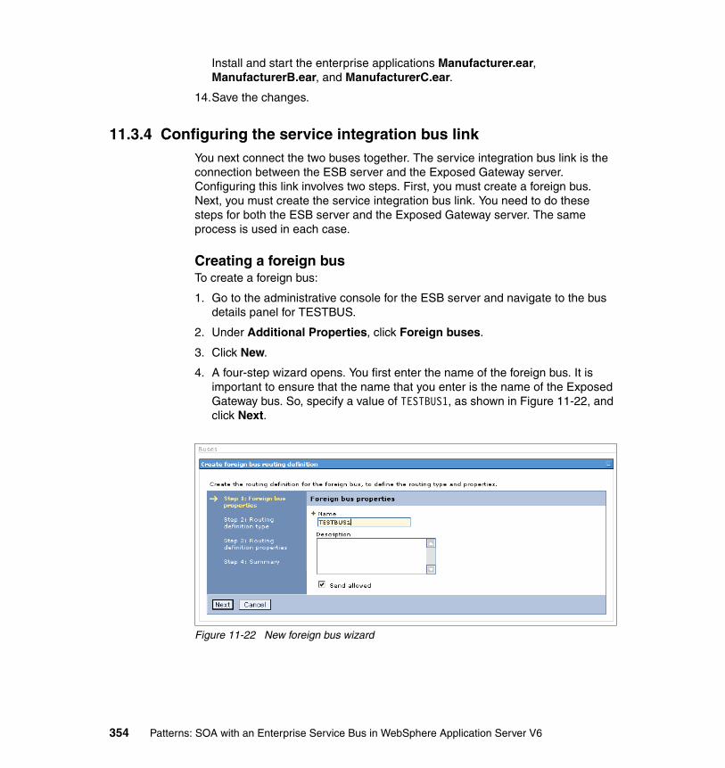
Install and start the enterprise applications Manufacturer.ear, ManufacturerB.ear, and ManufacturerC.ear.
14.Save the changes.
11.3.4 Configuring the service integration bus linkYou next connect the two buses together. The service integration bus link is the connection between the ESB server and the Exposed Gateway server. Configuring this link involves two steps. First, you must create a foreign bus. Next, you must create the service integration bus link. You need to do these steps for both the ESB server and the Exposed Gateway server. The same process is used in each case.
Creating a foreign busTo create a foreign bus:
1. Go to the administrative console for the ESB server and navigate to the bus details panel for TESTBUS.
2. Under Additional Properties, click Foreign buses.
3. Click New.
4. A four-step wizard opens. You first enter the name of the foreign bus. It is important to ensure that the name that you enter is the name of the Exposed Gateway bus. So, specify a value of TESTBUS1, as shown in Figure 11-22, and click Next.
Figure 11-22 New foreign bus wizard
354 Patterns: SOA with an Enterprise Service Bus in WebSphere Application Server V6

5. In the next page, you select the routing type. There are three options:
– Direct, service integration bus link– Direct, WebSphere MQ link– Indirect
The default is Direct, service integration bus link, which is the option we need. So, just click Next.
6. In the next page, you specify the user ID to be used for inbound and outbound message authentication. These setting are not needed for this scenario, so click Next.
7. The last page is a summary page. Click Finish, and the foreign bus is created.
8. Save the changes.
You should repeat this process for the Exposed Gateway server. When running through for the Exposed Gateway server, the bus names are swapped round. So, where you would have entered TESTBUS1 you now enter TESTBUS, and vice versa.
Creating the service integration bus linkThe next step is creating the service integration bus link. You must create a service integration bus link for each bus. This link connects a messaging engine on one bus to a messaging engine on another. To create this link:
1. Go to the administrative console for the ESB and navigate to the bus details panel for TESTBUS.
2. Under Additional Properties, click Messaging engines.
3. Click the messaging engine name.
4. Under Additional Properties, click Service integration bus link.
5. Click New.
6. In the next page, shown in Figure 11-23 on page 356, you set up the service integration bus link.
Chapter 11. Exposed ESB Gateway pattern 355
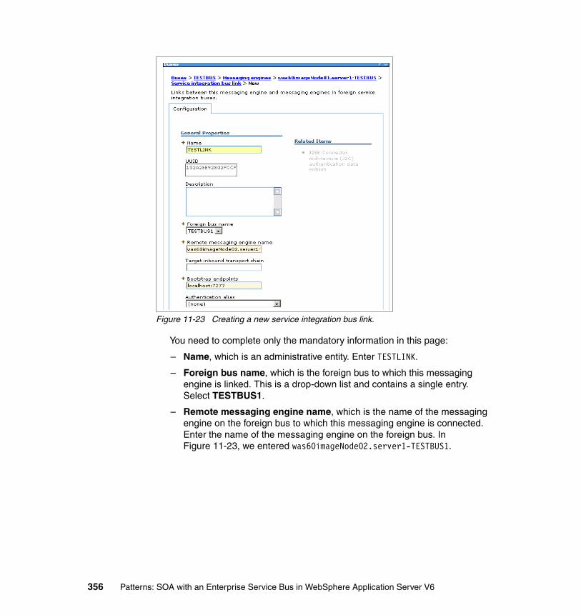
Figure 11-23 Creating a new service integration bus link.
You need to complete only the mandatory information in this page:
– Name, which is an administrative entity. Enter TESTLINK.
– Foreign bus name, which is the foreign bus to which this messaging engine is linked. This is a drop-down list and contains a single entry. Select TESTBUS1.
– Remote messaging engine name, which is the name of the messaging engine on the foreign bus to which this messaging engine is connected. Enter the name of the messaging engine on the foreign bus. In Figure 11-23, we entered was60imageNode02.server1-TESTBUS1.
356 Patterns: SOA with an Enterprise Service Bus in WebSphere Application Server V6

– Bootstrap endpoints, which specify where to find the messaging engine. It is a comma separated list of entries. Each entry consists of up to three parts. If one part is missing, that part assumes a default value. The parts are separated with a colon:
• Host name, which is the name of the host.
• Port number, which is the port number on which the remote messaging engine is listening. This setting defaults to 7276. You can determine the port number of a messaging engine by clicking Servers → Application Servers → server1 → Ports and by noting the value of the SIB_ENDPOINT_ADDRESS port name.
• Protocol name, which is the symbolic name of the messaging protocol that is used. There are currently two: BootstrapBasicMessaging and BootstrapSecureMessaging. The default is BootstrapBasicMessaging.
In this case, simply enter the host name and messaging engine port that the Exposed Gateway are using. In Figure 11-23 on page 356, we entered localhost:7277.
7. Click OK. The service integration bus link has been configured.
8. Save the changes.
You should repeat this process should for the Exposed Gateway server to create a service integration bus link, also called TESTLINK, to TESTBUS on the ESB server.
11.3.5 Routing Web service requests between busesThe final step is to route the Web service from the ESB to the Exposed Gateway and vice versa. Currently, we have inbound services on the ESB for each of the Manufacturers, and the Exposed Gateway has inbound services for the LoggingFacility and the WarehouseCallBack.
Configuring inbound service destinations To configure inbound service destinations, do the following in the ESB server:
1. Create three queue type destinations, one for each Manufacturer inbound service called:
– ManufacturerService– ManufacturerBService– ManufacturerCService
2. From the bus details panel under Additional Properties, click Inbound Services.
3. Click ManufacturerService.
Chapter 11. Exposed ESB Gateway pattern 357
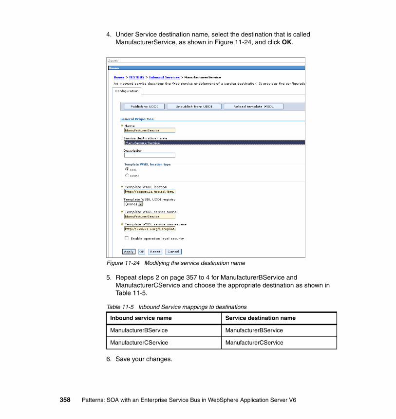
4. Under Service destination name, select the destination that is called ManufacturerService, as shown in Figure 11-24, and click OK.
Figure 11-24 Modifying the service destination name
5. Repeat steps 2 on page 357 to 4 for ManufacturerBService and ManufacturerCService and choose the appropriate destination as shown in Table 11-5.
Table 11-5 Inbound Service mappings to destinations
6. Save your changes.
Inbound service name Service destination name
ManufacturerBService ManufacturerBService
ManufacturerCService ManufacturerCService
358 Patterns: SOA with an Enterprise Service Bus in WebSphere Application Server V6

Configuring destinations to route to the other busAfter you configure inbound service destinations, you modify the queue definitions to route to the outbound service destinations on the Exposed Gateway bus by doing the following on the ESB server:
1. From the bus details panel under Additional Properties, click Destinations.
2. Click ManufacturerService.
3. On the page that appears, as shown in Table 11-25, set up a default forward routing path.
Figure 11-25 Configuring the forward routing path
A default forward routing path is applied to messages sent to a destination if the forward routing path of that message is available. Thus, messages that are sent to the ManufacturerService destination can be routed elsewhere, which in our case is the Exposed Gateway bus. The format of this box is a comma separated list of qualified destination names. A qualified destination name consists of a bus name and a destination name separated by a colon. The bus name is optional if the destination is on the current bus.
Enter the following in the Default forward routing path:
TESTBUS1:http://www.ws-i.org/SampleApplications/SupplyChainManagement/2002-10/Manufacturer.wsdl:ManufacturerService.
4. Click OK. Requests to the ManufacturerService are forwarded to the Exposed Gateway.
5. Repeat steps 3 and 4 for each of ManufacturerBService and ManufacturerCService and choose the appropriate qualified destination names as shown in Table 11-6 on page 360.
Chapter 11. Exposed ESB Gateway pattern 359
Table 11-6 Inbound service destination default forward routing paths
6. Save your changes.
7. Configure the Exposed Gateway inbound services to forward to the other bus. The configuration settings are shown in Figure 11-7.
Table 11-7 Inbound service destination default forward routing paths
8. Save your changes.
Starting the service integration bus linkTo start the service integration bus link, restart both application servers. You can confirm the status of the service integration bus link by checking the SystemOut.log file for each application server. The ESB server SystemOut.log file should contain an entry similar to the one below if the service integration bus link was successful:
CWSIT0032I: The inter-bus connection TESTLINK from messaging engine was60imageNode01.server1-TESTBUS in bus TESTBUS to messaging engine was60imageNode02.server1-TESTBUS1 in bus TESTBUS1 started.
Destination Default forward routing path
ManufacturerBService TESTBUS1:http://www.ws-i.org/SampleApplications/SupplyChainManagement/2002-10/Manufacturer.wsdl:ManufacturerBService
ManufacturerCService TESTBUS1:http://www.ws-i.org/SampleApplications/SupplyChainManagement/2002-10/Manufacturer.wsdl:ManufacturerCService
Destination Default forward routing path
LoggingFacilityService TESTBUS:http://www.ws-i.org/SampleApplications/SupplyChainManagement/2002-08/LoggingFacility.wsdl:LoggingFacilityService
WarehouseCallBackService TESTBUS:http://www.ws-i.org/SampleApplications/SupplyChainManagement/2002-08/Warehouse.wsdl:WarehouseCallBackService
360 Patterns: SOA with an Enterprise Service Bus in WebSphere Application Server V6

11.3.6 Testing the sample applicationTo test that the service integration bus link is working correctly in the sample application:
1. Open a Web browser and enter the following URL:
http://localhost:9080/SCMSampleUI
2. Click Place New Order to make a call from the SCMSampleUI enterprise application to the Retailer Web service.
3. On the next screen, enter a quantity of six (6) for the first three products, as shown in Figure 11-26, then click Submit Order. This action triggers the Warehouse to send orders to all three Manufacturers to replenish stock
Figure 11-26 Submitting three orders
4. On the next screen, the Warehouse should report that it was able to fulfill all three orders, as shown in Figure 11-27. Click Track Order.
Figure 11-27 Order successfully completed
Chapter 11. Exposed ESB Gateway pattern 361
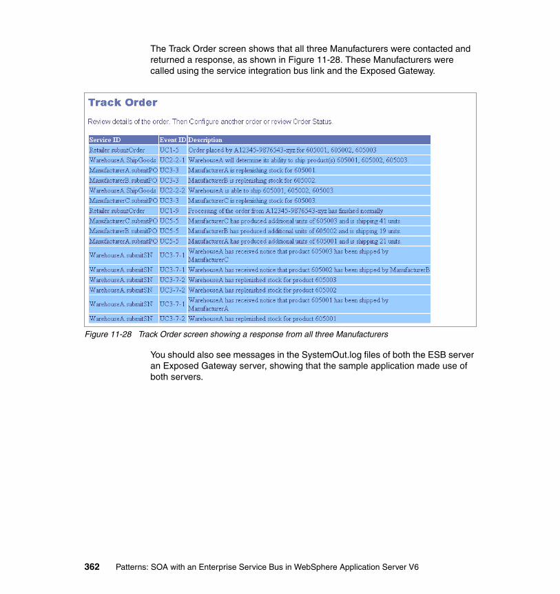
The Track Order screen shows that all three Manufacturers were contacted and returned a response, as shown in Figure 11-28. These Manufacturers were called using the service integration bus link and the Exposed Gateway.
Figure 11-28 Track Order screen showing a response from all three Manufacturers
You should also see messages in the SystemOut.log files of both the ESB server an Exposed Gateway server, showing that the sample application made use of both servers.
362 Patterns: SOA with an Enterprise Service Bus in WebSphere Application Server V6
Part 4 Appendixes
Part 4
© Copyright IBM Corp. 2005. All rights reserved. 363

364 Patterns: SOA with an Enterprise Service Bus in WebSphere Application Server V6

Appendix A. Additional material
This redbook refers to additional material that you can download from the Internet as described in the following sections.
Locating the Web materialThe Web material that is associated with this redbook is available in softcopy on the Internet from the IBM Redbooks Web server. Point your Web browser to:
ftp://www.redbooks.ibm.com/redbooks/SG246494
Alternatively, you can go to the IBM Redbooks Web site at:
ibm.com/redbooks
Select Additional materials and open the directory that corresponds with the redbook form number, SG246494.
A
© Copyright IBM Corp. 2005. All rights reserved. 365

Using the Web materialThe additional Web material that accompanies this redbook includes the following files:
File name DescriptionSG246494.zip Zipped additional materials for this redbook.
System requirements for downloading the Web materialThe following system configuration is recommended:
Hard disk space: 10 GB recommendedOperating System: A Windows, AIX®, or Linux® platformMemory: 1 GB minimum, 2 GB recommended
How to use the Web materialCreate a subdirectory (folder) on your workstation, and unzip the contents of the Web material zipped file into this folder.
366 Patterns: SOA with an Enterprise Service Bus in WebSphere Application Server V6

Appendix B. Configuring the scenario environment
This appendix describes how to configure the scenario environment without following the detailed step-by-step instructions within each scenario chapter in the book. It enables you to build an working environment quickly for the Direct Connection and ESB Router scenarios, both of which are pre-requisite configurations for other scenarios.
This appendix makes use of resources that are provided in the additional material that is supplied with this book. To obtain this additional material, see Appendix A, “Additional material” on page 365.
B
© Copyright IBM Corp. 2005. All rights reserved. 367
Working with the WS-I sample scenario enterprise applications
The WS-I sample application enterprise applications can be examined and modified by importing them into Rational Application Developer.
The enterprise applications should be imported into Rational Application Developer using the Project Interchange feature. A number of Project Interchange project files are provided in the additional material supplied with this book. These project files are also located in the \ProjectInterchange directory. They are:
� DirectConnection.zip
Contains a set of WS-I sample scenario enterprise applications that are configured to use point-to-point connections. Use this project file to examine the enterprise applications that are used in Chapter 8, “SOA Direct Connection pattern” on page 153 and as the starting point for Chapter 9, “Enterprise Service Bus pattern: router scenario” on page 179.
� Router.zip
Contains a set of WS-I sample scenario enterprise applications that are used by the ESB router scenario. Use this project file to examine the enterprise applications that are built in Chapter 9, “Enterprise Service Bus pattern: router scenario” on page 179.
To install a project file into Rational Application Developer, perform the following:
1. Select File → Import → Project Interchange and click Next.
2. Click Browse and locate the relevant project zipped file to import it. For example, select \ProjectInterchange\DirectConnection.zip.
3. A list of the enterprise projects contained within this project file is displayed. Click Select All and then click Finish. The enterprise projects are imported into your workspace.
Configuring the Direct Connection scenarioThis section describes how to work with the materials that are supplied for the Direct Connection scenario that is described in Chapter 8, “SOA Direct Connection pattern” on page 153. It describes how to use Jacl scripts to create a working version of the WS-I sample application, using the SOA Direct Connection pattern. This section assumes you have a working WebSphere Application Server server running.
368 Patterns: SOA with an Enterprise Service Bus in WebSphere Application Server V6

To configure the Direct Connection scenario:
1. Complete the steps that are described in 8.3.8, “Hosting the WSDL files” on page 171 to ensure that you have an HTTP server that is configured for this scenario.
2. Jacl scripts are provided to create the necessary configurations with your WebSphere Application Server environment. You can find these Jacl scripts in the \DirectConnection\jacl directory of the additional material that are supplied with this book.
Issue the following command from the WAS_HOME\bin directory of WebSphere Application Server:
wsadmin -f DirectConnectionConfig.jacl
This Jacl script modifies the application server configuration to define a service integration bus, queues, and JMS resources.
3. A second Jacl script is used to install the WS-I sample application enterprise applications to the application server. You can find these enterprise applications in the \DirectConnection\ears directory of the additional material that are supplied with this book.
Issue the following command from the WAS_HOME\bin of WebSphere Application Server:
wsadmin -f AppInstall.jacl <ear_file_location>
In this command, <ear_file_location> is the location of the enterprise applications directory. This path must consist of forward slashes, even on a Windows system. You will also need to qualify AppInstall.jacl with the path where this file can be found. For example, the complete command might read:
wsadmin -f C:\DirectConnection\jacl\AppInstall.jacl C:/DirectConnection/ears/
4. Restart the server so that the new configuration settings take affect and so that the installed enterprise applications are started.
5. After the server restart, you are ready to test the server. Access the application using the following URL:
http://localhost:9080/SCMSampleUI
You can find more information about how to test the scenario in 8.3.10, “Running and using the sample application” on page 174.
Note: DirectConnectionConfig.jacl needs to be qualified with the path where this file is found.
Appendix B. Configuring the scenario environment 369

Configuring the ESB router scenarioThis section describes how to configure the materials that are supplied for the ESB router scenario that is described in Chapter 9, “Enterprise Service Bus pattern: router scenario” on page 179.
To configure the ESB router scenario:
1. Complete all the steps as described in “Configuring the Direct Connection scenario” on page 368. This ESB router scenario uses resources that are defined in the Direct Connection scenario.
2. Jacl scripts are provided to create the necessary configurations with your WebSphere Application Server environment. You can find these Jacl scripts in the \ESB Router\jacl directory of the additional material supplied with this book. Run these from the WAS_HOME\bin of WebSphere Application Server:
a. Issue the following command to run the Jacl script to uninstall the existing enterprise applications that are used in the Direct Connection scenario:
wsadmin -f AppUninstall.jacl
b. Create an SDO repository with Cloudscape.
wsadmin.bat -f [install_root]\bin\installSdoRepository.jacl -createDb
c. Install a resource adapter.
wsadmin.bat -f [install_root]\util\sibwsInstall.jacl INSTALL_RA -installRoot "[install_root]" -nodeName [nodeName]
d. Install the service integration bus Web service application.
wsadmin.bat -f [install_root]/util/sibwsInstall.jacl INSTALL -installRoot "[install_root]" -nodeName [nodeName] -serverName server1
e. Install the HTTP endpoint application.
wsadmin.bat -f [install_root]/util/sibwsInstall.jacl INSTALL_HTTP -installRoot "[install_root]" -nodeName [nodeName] -serverName server1
f. Create the SOAP HTTP resources.
wsadmin -f RouterSOAPHTTPConfig.jacl
Note: AppUninstall.jacl needs to be qualified with the path where this file can be found.
Note: RouterSOAPHTTPConfig.jacl needs to be qualified with the path where this file can be found.
370 Patterns: SOA with an Enterprise Service Bus in WebSphere Application Server V6
g. Create the SOAP JMS resources.
wsadmin -f RouterSOAPJMSConfig.jacl
h. Install the JMS endpoint application.
wsadmin.bat -f [install_root]/util/sibwsInstall.jacl INSTALL_JMS -installRoot "[install_root]" -nodeName [nodeName] -serverName server1
i. Create the SOAP JMS endpoint listener.
wsadmin -f SOAPJMSEndpointListenerConfig.jacl
j. Install the enterprise applications built for this scenario. Replace <earfile_location> with the directory path where the \ESBRouter\ears\ directory (supplied with the additional material) can be found. Remember to use forward slashes in the path.
wsadmin -f AppInstall.jacl <earfile_location>
3. Download the following files from http://appsrv1a.itso.ral.ibm.com/wsdl into the directory c:\tmp\xsd:
– Configuration.xsd– LoggingFacility.xsd– ManufacturerPO.xsd– ManufacturerSN.xsd– RetailCatalog.xsd– RetailOrder.xsd– Warehouse.xsd– envelope.xsd
4. From the WAS_HOME/bin directory, run the following command to load the WebSphere Application Server command line administrative console:
wsadmin
In this command, WAS_HOME is the directory where WebSphere Application Server was installed.
Note: RouterSOAPJMSConfig.jacl needs to be qualified with the path where this file can be found.
Note: SOAPJMSEndpointListenerConfig.jacl needs to be qualified with the path where this file can be found.
Note: AppInstall.jacl needs to be qualified with the path where this file can be found.
Appendix B. Configuring the scenario environment 371

5. Obtain a reference to the SDO Repository MBean by entering:
set sdo [$AdminControl queryNames type=SdoRepository,*]
6. Import the schema by entering in the following:
$AdminControl invoke $sdo importResource {http://appsrv1a.itso.ral.ibm.com/wsdl/Configuration.xsd c:/tmp/xsd/Configuration.xsd}
This command imports the Configuration.xsd file into the SDO repository so that it can be accessed at runtime by the service integration bus Web services support.
7. Repeat step 6 for each of the XSD files, replacing both occurrences of Configuration.xsd with the relevant file name.
8. Type exit to leave the command line administrative console.
9. Restart the application server.
10.After the server restart, you are ready to test the server. Access the application using the following URL:
http://localhost:9080/SCMSampleUI
You can find more information about how to test the scenario in 8.3.10, “Running and using the sample application” on page 174.
Note: This command only works on a single server setup. In a network deployment environment, there might be multiple instances of the SDO repository in which case the sdo command would contain a list of MBean references rather than a single MBean reference.
372 Patterns: SOA with an Enterprise Service Bus in WebSphere Application Server V6
acronyms
API Application Programming Interface
BLOB Binary Large Object
BPEL4WS Business Process Execution Language for Web Services
CCI Common Client Interface
CICS Customer Information Control System
CORBA Common Object Request Broker Architecture
COTS Commercial-Off-The-Shelf
DBMS Database Management System
DMZ Demilitarized zone
DNS Domain Name System
DOS Disk Operating System
DTD Document Type Definition
DVD Digital Video Disc
EAI Enterprise Application Integration
EAR Enterprise Archive
ebXML Electronic Business using XML
EDI Electronic Data Interchange
EIS Enterprise Information System
EJB Enterprise JavaBean
EPI External Presentation Interface
ERP Enterprise Resource Planning
ESB Enterprise Service Bus
FTP File Transfer Protocol
HTML Hypertext Markup Language
HTTP Hypertext Transfer Protocol
Abbreviations and
© Copyright IBM Corp. 2005. All rights reserved.
HTTPS Hypertext Transfer Protocol Secure
IBM International Business Machines Corporation
IDE Integrated Development Environments
IIOP Internet Inter-ORB Protocol
ITSO International Technical Support Organization
J2C J2EE Connector Architecture
J2EE Java 2 Platform, Enterprise Edition
JAAS Java Authentication and Authorization Service
JAR Java archive
JAX-RPC Java API for XML-based Remote Procedure Calls
JDBC Java database connectivity
JMS Java Message Service
JNDI Java Naming and Directory Interface
JSP JavaServer Pages
JVM Java Virtual Machine
LAN Local Area Network
LDAP Lightweight Directory Access Protocol
MDB Message Driven Bean
OASIS Organization for the Advancement of Structured Information Standards
OGSA Open Grid Services Architecture
PKI Public-Key Infrastructure
QoS Quality of Service
RAR Resource Adapter Archive
373
RMI Remote Method Invocation
SAML Security Assertion Markup Language
SCM Supply Chain Management
SOA Service-Oriented Architecture
SOAP Simple Object Access Protocol
SQL Structured Query Language
SSL Secure Sockets Layer
TCP/IP Transmission Control Protocol / Internet Protocol‘
UDDI Universal Description Discovery and Integration
UML Unified Modeling Language
URL Uniform Resource Locator
WAR Web Archive
WSDL Web Services Description Language
WS-I Web Services Interoperability Organization
WSIF Web Services Invocation Framework
WSIL Web Services Inspection Language
XML Extensible Markup Language
XSD XML Schema Definition
XSL Extensible Stylesheet Language
XSLT Extensible Stylesheet Language Transformations
374 Patterns: SOA with an Enterprise Service Bus in WebSphere Application Server V6
Related publications
The publications listed in this section are considered particularly suitable for a more detailed discussion of the topics covered in this redbook.
IBM RedbooksFor information about ordering these publications, see “How to get IBM Redbooks” on page 378. Note that some of the documents referenced here might be available in softcopy only.
� Patterns: Service-Oriented Architecture and Web Services, SG24-6303
� Patterns: Implementing an SOA Using an Enterprise Service Bus, SG24-6346
� WebSphere Application Server V6 System Management and Configuration Handbook, SG24-6451
� Patterns: Serial and Parallel Processes for Process Choreography and Workflow, SG24-6306
� WebSphere Application Server V6 System Management and Configuration Handbook, SG24-6451
� Patterns: Using Business Service Choreography In Conjunction With An Enterprise Service Bus, REDP-3908
Other publicationsThese publications are also relevant as further information sources:
� Jonathan Adams, Srinivas Koushik, Guru Vasudeva, George Galambos, Patterns for e-business: A Strategy for Reuse, IBM Press, 2001, ISBN 1-931182-02-7
� Olaf Zimmermann, Mark Tomlinson, Stefan Peuser, Perspectives on Web Services, Springer, 2003, ISBN 3-540-00914-0
© Copyright IBM Corp. 2005. All rights reserved. 375
Online resourcesThese Web sites and URLs are also relevant as further information sources:
� Patterns for e-business Web site
http://www.ibm.com/developerWorks/patterns/
� IBM WebSphere Application Server
http://www.ibm.com/software/webservers/appserv/was/
� IBM DB2 Universal Database Enterprise Server Edition
http://www.ibm.com/software/data/db2/udb
� IBM Cloudscape
http://www.ibm.com/software/data/cloudscape
� IBM WebSphere MQ
http://www.ibm.com/software/ts/mqseries
� IBM WebSphere Business Integration Message Broker
http://www.ibm.com/software/integration/wbimessagebroker
� IBM WebSphere Business Integration Server Foundation
http://www.ibm.com/software/integration/wbisf/
� IBM Rational Application Developer
http://www.ibm.com/software/awdtools/developer/application
� The role of private UDDI nodes in Web services, Part 1: Six species of UDDI
http://www.ibm.com/developerworks/webservices/library/ws-rpu1.html
� The role of private UDDI nodes, Part 2: Private nodes and operator nodes
http://www.ibm.com/developerworks/webservices/library/ws-rpu2.html
� Web Services Interoperability Organization
http://www.ws-i.org
� WS-I Basic Profile V1.0
http://www.ibm.com/developerworks/webservices/library/ws-basicprof.html
� WS-I Usage Scenarios
http://www.ibm.com/developerworks/webservices/library/ws-iuse/
� Preview of WS-I sample application
http://www.ibm.com/developerworks/webservices/library/ws-wsisamp/
� IBM Emerging Technologies Toolkit
http://www.alphaworks.ibm.com/tech/ettk
376 Patterns: SOA with an Enterprise Service Bus in WebSphere Application Server V6

� Security in a Web Services World: a Proposed Architecture and Road map
http://www.ibm.com/developerworks/library/ws-secmap/
� Web Services Security: Moving up the stack
http://www.ibm.com/developerworks/webservices/library/ws-secroad/
� Updated: Web Services Reliable Messaging: A new protocol for reliable delivery between distributed applications
http://www.ibm.com/developerworks/webservices/library/ws-rm/
� Implementation Strategies for WS-ReliableMessaging: How WS-ReliableMessaging can interact with other middleware communication systems
http://www.ibm.com/developerworks/webservices/library/ws-rmimp/
� BPEL4WS specification
http://www.ibm.com/developerworks/library/ws-bpel/
� Business Process with BPEL4WS, a series of introductory articles and references
http://www.ibm.com/developerworks/webservices/library/ws-bpelcol1/
� BPEL4WS support in WebSphere Business Integration Server Foundation
http://www.ibm.com/software/integration/wbisf/features/
� BPEL4WS support in WebSphere Studio Application Developer Integration Edition
http://www.ibm.com/software/integration/wsadie/features/
� WS-AtomicTransaction specification
http://www.ibm.com/developerworks/library/ws-atomtran/
� WS-BusinessActivity specification
http://www.ibm.com/developerworks/webservices/library/ws-busact/
� Transactions in the world of Web Services, part 1 and part 2
http://www.ibm.com/developerworks/webservices/library/ws-wstx1/http://www.ibm.com/developerworks/webservices/library/ws-wstx2/
� WS-Coordination specification
http://www.ibm.com/developerworks/library/ws-coor/
� WS-Policy framework specification
http://www.ibm.com/developerworks/library/ws-polfram/
� Web Services Policy Framework: New specifications improve WS-Security
http://www.ibm.com/developerworks/webservices/library/ws-polfram/summary.html
Related publications 377
How to get IBM RedbooksYou can search for, view, or download IBM Redbooks, Redpapers, Hints and Tips, draft publications and Additional materials, as well as order hardcopy IBM Redbooks or CD-ROMs, at this Web site:
ibm.com/redbooks
Help from IBMIBM Support and downloads
ibm.com/support
IBM Global Services
ibm.com/services
378 Patterns: SOA with an Enterprise Service Bus in WebSphere Application Server V6

Index
Numerics80/20 situation 3
AAccess control lists 108Adapter connectors 103Advanced and future Web services standards 137
Business Process Execution Language for Web Services 139Web services security 138
WS-Policy 138WS-Privacy 138WS-Security 138WS-Trust 138
Web services transactions 140Web Services Policy Framework 141
WS-Policy 141WS-AtomicTransaction 140WS-BusinessActivity 140WS-Coordination 140
WS-ReliableMessaging 138Alias destinations 146Application Integration 46
Broker 51Router 52
Data integration 46Direct Connection 48
Call Connection 50Message Connection 49
Parallel Process 56Parallel Workflow 58
Process integration 46Serial Process 54
Serial Workflow 55Application patterns 4, 11
Broker 51Router 52
Direct Connection 48Call Connection 50Message Connection variation 49
Exposed Broker 64Exposed Router 65
Exposed Direct Connection 61
© Copyright IBM Corp. 2005. All rights reserved.
Call Connection 63Message Connection 62
Exposed Serial Process 67Exposed Serial Workflow 68
Parallel Process 56Parallel Workflow 58
Serial Process 54Serial Workflow 55
ArchitectureService-oriented 19
Autonomic computing 76
BBasic Profile 136Basic Profile V1.0 136Basic Profile V1.1 136Best practices 4, 16BLOB 78BPEL4WS 79Broker application pattern
51Router variation 52
Broker scenario 259, 281Design
Dynamic service provider routing methods 267
JAX-RPC handlers 267Mediations 268
Externalizing service lookup 270Database implementation 271UDDI registry implementation 270
Service invocation 265Aggregation and disaggregation 266Serial invocations 266
Development 274Mediations 275
Aggregation mediation 290Assigning mediation handlers 295Coding the mediations 282Creating a mediation handler class 276Disaggregation mediation 282Mediation APIs 279MediationHandler 279
379
MessageContext 279Saving and exporting mediations 296SDO DataGraphs 280SIMediationSession 280SIMessage 279Working with messages in mediations 279
ESB capabilities 264Message processing 264
Product mappings 273Runtime 297
Configuring context properties for a media-tion 309Configuring J2C authentication data 300Creating a JDBC data source 302Creating a JDBC provider for DB2 301DB2 drivers 303Defining mediations 306Externalizing service lookup 298Installing a mediation application 306Installing IBM DB2 Universal Database V8.2 299Mediating a destination 308Mediation configuration 305Moving data to a new SDO repository 303Recreating the SDO repository 299Testing a new SDO repository 304
BSC runtime pattern 108App server / services 109Persistence manager 110Process manager 109
Branching 110Correlation 110Monitoring 110Non-functional requirements 110Process abstractions 110Process definition standards 110
Product mappings 119Rules directory 110
Business patterns 4, 7Business Service Choreography 44, 108Business Service Directory 44
UDDI directory 102
CCall Connection 50Centrally publish WSDL service definitions 330CICS Transaction Server 99
Cloudscape 76Cloudscape Network server 77Communication 41Composite patterns 4, 9Creating a mediation handler class 281
DData integration 46Data warehouse 76DB2 Connect 76DB2 Universal Database Enterprise Server Edition V8.2 76Development
Mediations 281Direct Connection 48Direct Connection application pattern 48
Call Connection variation 50Message Connection variation 49
Direct Connection runtime pattern 96
Ee-business on demand 22
business driversvariable 22
Service-oriented architectureAutomation 23Integration 22Open standards 22Virtualization 23
Eclipse 80Endptenabler 231Enterprise Information Systems 144Enterprise Resource Planning 144Enterprise Service Bus
Business Service Choreography 44Business Service Directory 44Capabilities
Communication 41Infrastructure Intelligence 42Integration 41Management and Autonomic 42Message Processing 42Modeling 42Quality of Service 41Security 41Service Interaction 41Service Level 41
ESB Gateway 44
380 Patterns: SOA with an Enterprise Service Bus in WebSphere Application Server V6

Mediate 36Minimum capability
Heterogeneous infrastructure 37Integration 37Integration techniques 39Logical architectural component 37Manage the service infrastructure 37Management and Autonomic 37Service Interaction 37
Product capabilitiesWebSphere Application Server Network De-ployment 83WebSphere Business Integration Message Broker 87
Substitution 36Transform 36
ESB capabilities 82WebSphere Application Server V6 83
Communication 84Infrastructure intelligence 87Integration 84Management and autonomic 87Message processing 85Modeling 86Quality of service 86Security 85Service interaction 86Service level 86
WebSphere Business Integration Message Bro-ker V5 87
Communication 87Infrastructure intelligence 91Integration 88Management and autonomic 91Message processing 89Modeling 89Quality of service 90Security 88Service interaction 90Service level 90
ESB Gateway 44App server / services 107ESB 107Gateway endpoint 108Rules directory 107
ESB Gateway runtime pattern 106Product mappings 118
ESB runtime pattern 98Administration and security services 102
Administration 102Security 102
App server / services 99Business service directory 102Connectors 103
Adapter connectors 103Application adaptation 104Legacy adaptation 104Path connectors 103Technology adaptation 103
Hub node 99Addressing 100Infrastructure intelligence 101Integration 101Message processing 101Messaging styles 100Modelling 101Quality of service 101Routing 100Service interface definition 100Service level 101Service messaging model 100Transport protocols 100
Namespace directory 101Product mappings 117
ESB, BSC composite pattern 111BSC 112ESB 113Process manager 111Repository nodes 111
Event driven architectures 36Exposed Broker application pattern 64
Exposed Router 65Exposed Direct Connection application pattern 61
Call Connection 63Message Connection 62
Exposed ESB Gateway runtime patternApp server / services 114Connector 114ESB 114ESB Gateway 114Product mappings 120
Exposed ESB Gateway scenarioDesign
Security 330Multi-tier firewall deployment 330Securing communication channels 331XML document level security 332
Service definitions across enterprises 328,
Index 381

330Sharing service definitions across enterpris-es
Local copy of WSDL 329Topology considerations 321
Multiple node topology with a single bus 325Single node topology with a single bus 324Three nodes layers with multiple buses 327Two node layers with multiple buses 326
ESB capabilities 319Addressing 320Communications 319Integration 320Minimizing impact to current infrastructure 320Restricting service access 320Security 320Service interaction 320
Product mappings 334Runtime 337
Configuring destinations to route to another bus 359Configuring inbound service destinations 357Creating a foreign bus 354Creating a service integration bus link 355Migrating an SDO repository to use Network Cloudscape 342Removing Web services from an ESB 338Routing Web service requests between bus-es 357Separate profiles 349Starting a service integration bus link 360
Exposed ESB Gateway, BSC composite pattern 115Exposed Serial Process application pattern 67
Exposed Serial Workflow 68Extended Enterprise 59
Exposed Broker 64Exposed Router 65
Exposed Direct Connection 61Call Connection 63Message Connection 62
Exposed Serial Process 67Exposed Serial Workflow 68
FForeign destinations 146
GGuidelines 4, 16
HHTTP authentication 138HTTP over TLS 136HTTP State Management Mechanism 136Hub node 99HyperText Transfer Protocol 136
IIBM Emerging Technologies Toolkit 137IMS Transaction Manager 99Industry support 30Infrastructure Intelligence 42Integration 41Integration patterns 4, 8Internet X.509 Public Key Infrastructure Certificate 136
JJ2EE Connector Architecture 144
Common Client Interface 144Disadvantages 145Inbound adapters 144Outbound adapters 144XA capable 144
Java Message Service 141Advantages 143Disadvantages 143Enterprise messaging API 143JMS messages 142
Body 142Header 142Point-to-point 142Properties 142Publish subscribe 142
Java2WSDL 231JDBC 77
LLegacy adaptation 104Location transparency 100
382 Patterns: SOA with an Enterprise Service Bus in WebSphere Application Server V6

Long-running 79
MManagement and Autonomic 42Mediate 36Mediation handler 276Mediation points 147Message channels 77Message Connection variation 49Message driven architectures 36Message oriented middleware 141Message Processing 42Message Repository Manager 78Messaging 141Messaging patterns 73Messaging provider 73Microsoft .NET 76Modeling 42
NNamespace directory 101
PParallel Process application pattern 56
Parallel Workflow variation 58Parallel Workflow 58Path connectors 103Patterns for e-business
Application patterns 4, 11Best practices 4, 16Business patterns 4, 7Composite patterns 4, 9Guidelines 4, 16Integration patterns 4, 8Product mappings 4, 15Runtime patterns 4, 13Web site 5
Point-to-point 78Port destinations 146Process integration 46Process management 112Process Manager 109Product 116Product mappings 4, 15, 116
BSC runtime pattern 119ESB Gateway runtime pattern 118ESB runtime pattern 117
Exposed ESB Gateway runtime pattern 120Publication points 147Publish/subscribe 78
QQuality of Service 41Queue definitions 77Queue destinations 146Queue manager 77Queue points 147
RRational Application Developer 75Rational Application Developer V6 80Rational Software Development Platform 80Rational Web Developer 75RDBMS 77Redbooks Web site 378
Contact us xviiReliable message transport 74Router 52Router scenario 179
Design 184Communication protocols 191
HTTP service bus 191JMS service bus 192
Location of service definitions 184HTTP server publication of WSDL 186Local directory copy of WSDL 185UDDI registry publication of WSDL 186
Logging 189Application level logging 190Service integration bus level logging 190
Security 187Messaging security 188WS-Security 187
Service provider routing 193Dynamic routing 194Static routing 193
Topology considerations 194Bus 194Cell 195Multi node topology with a single bus 198Multi node topology with multiple buses 199Nodes 194
Index 383

Servers 194Single node topology with a single bus 197
Development 202Configuring Rational Application Developer for Web services 209Creating a skeleton EJB Web service 210Creating a SOAP over JMS Web service 205Creating an EJB project 207Updating Web service clients to use an ESB 219
Creating a namespace mapping file 221Exporting enterprise applications 230Generating a Web service client 225Importing generated WSDL 220Removing Web service clients 220
ESB capabilities 183Centralized control 184Centralized security 184Common access point 184Communications 183, 264ecoupling 184Integration 183, 264Logging 184Transformation 184
Product mappings 201Runtime 231
Creating endpoint listeners 241Creating outbound services 244Creating the inbound services 247Exporting the service integration bus WSDL 253Importing schemas into the SDO repository 254Installing the SDO repository 237Installing the Web services support 238Multiple services in a single WSDL file 256SOAP over HTTP requests transformed to SOAP over JMS 235SOAP over HTTP requests with no transfor-mation 233SOAP over JMS requests transformed to SOAP over HTTP 234Using the service integration bus to route Web service requests 233
Routing paths 281Rules repository 97Runtime patterns 4, 13, 96
BSC 108Direct Connection 96ESB 98ESB Gateway 106ESB, BSC composite 111Exposed ESB Gateway, BSC composite 115
SScenarios 126
Stage I 126Stage II 128Stage III 129
Secure Sockets Layer Protocol 136Security 41Serial Process application pattern 54
Serial Workflow variation 55Serial Workflow 55Service bus
Simple 96Service integration bus 145
Adding a bus member 163Bus 145Bus member 146Creating a bus 162Creating a JMS connection factory 165Creating destinations 164Creating JMS activation specifications 169Creating JMS queues 167Destination 146Destinations
Alias destinations 146Foreign destinations 146Port destinations 146Queue destinations 146Topic space destinations 146Web service destinations 146
Endpoint listener 147Exception destinations 148Foreign bus 148Foreign bus link 148Inbound service 147Mediation 148
Augmenting messages 148Disaggregation 148Dynamically routing messages 148Transforming a message 148
Message point 147Mediation points 147
384 Patterns: SOA with an Enterprise Service Bus in WebSphere Application Server V6

Publication points 147Queue points 147
Messaging engine 145Connection management 145Message management 145
Outbound service 147Using for messaging 160
Service Interaction 41Service Level 41Service level policies 108Service provisioning 102Service substitution 100Service-oriented architecture 19, 36
Component Based Design 20Customized 27Drivers
Flexible pricing 20Increasing speed 20Reducing costs 20Return on investment 20Simplifying integration 20
Object Oriented development 20Proprietary 27Service
Deployment time 24Implementation-independent 23Loosely bound 23Reusable 23Runtime 24Substitution 24
Short-running 79Siebel 104SOA profile
BSC 108Direct Connection 96ESB 98ESB Gateway 106ESB, BSC composite 111Exposed ESB Gateway, BSC composite 115
SOAP 134Envelope 134Messages 134
SOAP with Attachments 136SSL authentication 138SSL encryption 138
TTopic space destinations 146
Transform 36Transport Layer Security Protocol 136
UU.S. government taxonomy 135UDDI 135UDDI directory 102UML editing 80
WWeb service destinations 146Web services 132
Loose coupling 132SOAP
Body 134Header 134
UDDI 135Usage models 132
Basic callback 132One-way 132Synchronous request/response 132
Web services standards 137Business Process Execution Language for Web Services 139Web Services Policy Framework 141Web services security 138Web services transactions 140WS-ReliableMessaging and SOAP/JMS 138
WSDL 134Web services architecture
SOAP 134Universal Description, Discovery, Integration 135Web Services Description Language 134Web services interoperability 135
Web Services Interoperability Organization 135
Basic Profile 136Web Services Gateway 139Web services interoperability 135Web Services Interoperability Organization 126, 135Web services security 138WebSphere Application Server 75WebSphere Application Server - Express 74WebSphere Application Server Network Deploy-ment 75
Index 385

WebSphere Application Server Network Deploy-ment V6 75WebSphere Application Server V6 72
Highlights and benefits 73Packaging for distributed platforms 74
WebSphere Application Server - Express V6 74WebSphere Application Server Network De-ployment V6 75WebSphere Application Server V6 75
WebSphere Business Integration Message Broker V5 78WebSphere Business Integration Server Founda-tion V5.1 79WebSphere MQ V5.3 77WebSphere Process Choreographer 79Working with messages in mediations 281Workload management 78WS-AtomicTransaction 140WS-BusinessActivity 140WS-Coordination 140wsdeploy 231WSDL 134WSDL2Java 231WS-I sample application 126WS-I Supply Chain Management Technical Archi-tecture 126WS-I Supply Chain Management Use Cases 126WS-I Usage Scenarios 126WS-Policy 101, 138, 141WS-Privacy 138WS-ReliableMessaging 137–138WS-Security 138WS-Trust 138
XXML Encryption 332XML Signature 332
386 Patterns: SOA with an Enterprise Service Bus in WebSphere Application Server V6
(0.5” spine)0.475”<
->0.875”
250 <->
459 pages
Patterns: SOA with an Enterprise Service Bus in W
ebSphere Application Server V6


®
SG24-6494-00 ISBN 073849058X
INTERNATIONAL TECHNICALSUPPORTORGANIZATION
BUILDING TECHNICALINFORMATION BASED ONPRACTICAL EXPERIENCE
IBM Redbooks are developed by the IBM International Technical Support Organization. Experts from IBM, Customers and Partners from around the world create timely technical information based on realistic scenarios. Specific recommendations are provided to help you implement IT solutions more effectively in your environment.
For more information:ibm.com/redbooks
Patterns: SOA with an Enterprise Service Bus in WebSphere Application Server V6Design and implement an ESB using WebSphere V6 technologies
Service-oriented architecture and Web services
Learn by example with practical scenarios
The Patterns for e-business are a group of proven, reusable assets that can be used to increase the speed of developing and deploying e-business applications. This IBM Redbook focuses on how you can use the service-oriented architecture (SOA) profile of the Patterns for e-business to implement an Enterprise Service Bus in WebSphere Application Server V6.
Part 1 presents a description of service-oriented architecture and the Enterprise Service Bus.
Part 2 describes the business scenario used throughout this book and explains the key technologies that you can use to build an Enterprise Service Bus in WebSphere Application Server V6, including Web services and the service integration bus.
Part 3 guides you through the process of architecting and implementing various Enterprise Service Bus configurations using WebSphere Application Server V6 and Rational Application Developer V6. It discusses router and broker scenarios within an Enterprise Service Bus, along with a gateway to enable interaction in an inter-enterprise environment.
Back cover