
Path Accumulation Extensions for the LOADng Routing Protocol in Sensor Networks
10
Path Accumulation Extensions for the LOADng Routing Protocol in Sensor Networks Thomas Clausen and Jiazi Yi Laboratoire d’Informatique (LIX), Ecole Polytechnique, France Abstract. The “Light-weight On-demand Ad-hoc Distance-vector Rout- ing Protocol – Next Generation” (LOADng) is a simple, yet efficient and flexible routing protocol, specifically designed for use in lossy networks with constrained devices. A reactive protocol, LOADng – as a basic mode of operation – offers discovery and maintenance of hop-by-hop routes and imposes a state in intermediate routers proportional to the number of traffic paths served by that intermediate router. This paper offers an extension to LOADng, denoted LOADng-PA (Path Accumulation). LOADng-PA is designed with the motivation of requiring even less state in each intermediate router, and with that state being independent on the number of concurrent traffic flows carried. Another motivation the design of LOADng-PA is one of monitoring and managing networks: providing more detailed topological visibility of traffic paths through the network, for either traffic or network engineering purposes. 1 Introduction Since the late 90s, the Internet Engineering Task Force (IETF) 1 has embarked upon a path of developing routing protocols for networks with increasingly more fragile and low-capacity links, with less pre-determined connectivity properties and with increasingly constrained router resources. In ’97, by chartering the MANET (Mobile Ad hoc Networks) working group, then subsequently in 2006 and 2008 by chartering the 6LoWPAN (IPv6 over Low power WPAN) and ROLL (Routing Over Low power and Lossy networks) working groups. The MANET working group converged on the development of two protocol families: reactive protocols, including AODV (Ad hoc On-demand Distance Vec- tor routing [1]), and proactive protocols, including Optimized Link State Routing (OLSR) [2,3]. A distance vector protocol, AODV operates in an on-demand fash- ion, acquiring and maintaining paths only while needed for carrying data, by way of a Route Request/Route Reply exchange. A link state protocol, OLSR is based on periodic control messages exchanges, and each router proactively maintaining a routing table with entries for all destinations in the network, which provides low delays but constant control overhead. LOAD [4] is a protocol derived from AODV [1], simplified for LLNs, and standardised by the ITU-T as part of the G3-PLC standard [5] for mesh-under 1 http://www.ietf.org
-
Upload
polytechnique -
Category
Documents
-
view
0 -
download
0
Transcript of Path Accumulation Extensions for the LOADng Routing Protocol in Sensor Networks
Path Accumulation Extensions for the LOADngRouting Protocol in Sensor Networks
Thomas Clausen and Jiazi Yi
Laboratoire d’Informatique (LIX), Ecole Polytechnique, France
Abstract. The “Light-weight On-demand Ad-hoc Distance-vector Rout-ing Protocol – Next Generation” (LOADng) is a simple, yet efficient andflexible routing protocol, specifically designed for use in lossy networkswith constrained devices. A reactive protocol, LOADng – as a basic modeof operation – offers discovery and maintenance of hop-by-hop routes andimposes a state in intermediate routers proportional to the number oftraffic paths served by that intermediate router.This paper offers an extension to LOADng, denoted LOADng-PA (PathAccumulation). LOADng-PA is designed with the motivation of requiringeven less state in each intermediate router, and with that state beingindependent on the number of concurrent traffic flows carried. Anothermotivation the design of LOADng-PA is one of monitoring and managingnetworks: providing more detailed topological visibility of traffic pathsthrough the network, for either traffic or network engineering purposes.
1 Introduction
Since the late 90s, the Internet Engineering Task Force (IETF)1 has embarkedupon a path of developing routing protocols for networks with increasingly morefragile and low-capacity links, with less pre-determined connectivity propertiesand with increasingly constrained router resources. In ’97, by chartering theMANET (Mobile Ad hoc Networks) working group, then subsequently in 2006and 2008 by chartering the 6LoWPAN (IPv6 over Low power WPAN) and ROLL(Routing Over Low power and Lossy networks) working groups.
The MANET working group converged on the development of two protocolfamilies: reactive protocols, including AODV (Ad hoc On-demand Distance Vec-tor routing [1]), and proactive protocols, including Optimized Link State Routing(OLSR) [2,3]. A distance vector protocol, AODV operates in an on-demand fash-ion, acquiring and maintaining paths only while needed for carrying data, by wayof a Route Request/Route Reply exchange. A link state protocol, OLSR is basedon periodic control messages exchanges, and each router proactively maintaininga routing table with entries for all destinations in the network, which provideslow delays but constant control overhead.
LOAD [4] is a protocol derived from AODV [1], simplified for LLNs, andstandardised by the ITU-T as part of the G3-PLC standard [5] for mesh-under
1 http://www.ietf.org

routing for utility (electricity) metering networks. The emergence of LLNs thustriggered a renewed interest in AODV-derived protocols for specific scenarios,resulting in continued work within the IETF [6] and [7] for the purpose of stan-dardisation of a successor to LOAD – denoted LOADng (the Lightweight On-demand Ad hoc Distance-vector Routing Protocol – Next Generation). LOADngincorporates the experiences from deploying LOAD – including, but not only,in LLNs – and has been accepted as part of an update to the G3-PLC ITU-Tstandard for communication in the “smart grid” [8].
1.1 The Lightweight On-demand Ad hoc Distance vector RoutingProtocol - Next Generation (LOADng) Overview
A reactive protocol, the basic operations of LOADng [16,6] include generationof Route Requests (RREQs) by a LOADng Router (originator) and floodedthrough the network when discovering a route to a destination, and RouteReplies (RREPs) generated by the sought destination ad transmitted to theoriginator by way of unicasts. When an intermediate router forwards a RREQ,it installs temporary routing table information towards the originator of theRREQs – the “reverse route” from the destination to the originator. When thesought destination receives a RREQ, it will respond by an unicast RREP, whichis forwarded along this installed reverse route – and the forwarding of whichwill serve to install a “forward route” from the originator to the destination.Thus, for each bidirectional path through a LOADng router, four entries arethus maintained in the routing table: for directions, an entry is recorded for the“next hop” and for the “destination” via that “next hop”.
One of the key features of LOADng is, that it combines simplicity with exten-sibility: the core protocol provides mechanisms for discovering and maintainingbi-directional routes between pairs of routers, but offers the ability to developfunctional extensions, optimising its behaviour and performance for specific de-ployments, topologies and traffic patterns.
LOADng provides the information required for hop-by-hop routing of datapackets: a router will know the next hop towards the destination, for a datapacket, but not the full path that the packet will take. To this end, the headerof a data packet contains only the destination address, relying on intermediaterouters to be able to make forwarding decisions based on their local knowledge ofthe routing topology. This provides agility for each router to make a local decision(e.g., if local connectivity changes more frequently than routing updates can bepropagated globally through the network) and, e.g., enables “fast re-routing”mechanisms to engage and improve data packet delivery when a data packetarrives at a router without, or with outdated, topological information [12,13].
The LOADng Collection Tree Protocol (LOADng-CTP) is of the pro-tocol extensions, developed for LOADng [9]. This extension permits efficientconstruction of a bi-directional collection tree, rooted in one router and cover-ing the entire network. LOADng-CTP permits reducing the number of RREQ

flooding operations from (n-1) to 2 in order to construct bi-directional pathsbetween the root and all other routers in the network, but otherwise incursthe same state requirements as described above. This extension is applicablefor deployments where a central controller, or monitoring entity is present andoperating the network, e.g., as is the case in a smart grid management, or forhome/building/factory automation.
1.2 The Case for Source Routing and Path Accumulation
There are, however, potential downsides to hop-by-hop routing combined with areactive protocol: by their very nature, reactive protocols acquires and maintainsonly topological information about actively used paths – and, at that – at theirbasic form only “next hops” along those paths. Thus, no router has access to a“global view” of the network topology, or even of which destinations are reach-able through which paths. This may be unfortunate in some scenarios, e.g., formanagement purposes: paths from a central unit (e.g., a monitoring station) toa set of devices (e.g., sensor devices) may, all pass through a faulty intermediaterouter rendering the network inoperative – and absence of a topological viewof the paths actually used, this faulty router may be difficult to identify. Also,lack of such global information renders establishing path-diversity, i.e., that datapackets (as far as possible) are not concentrated across a few unfortunate routers(which may, if battery-driven, see their energy depleted prematurely, or expe-rience congestion) or across a few unfortunate links (which may incur highermedia contention and losses) hard to accomplish.
(a) Simple network topology with choke-point.
0
1
43
2
65
..........
...... ......
h=0
h=1
h=2
h=H-1
(b) Bi-directional traffic in a collec-tion tree network.
Fig. 1. Example network topologies.
A final downside is, and probably the most critical issue for memory-constraineddevices, of hop-by-hop routing is, that with hop-by-hop routing and a reactiveprotocol, the state required in each router is proportional to the number of activepaths passing through that router. Thus, any individual device in the network

may, worst case, be required to maintain a routing table with entries to many(or all) destinations, as illustrated in figure 1(a): each of the white routers ontop establishes a (bi-directional) path to each of the white routers in the bot-tom, requiring the two intermediate black routers to, each, maintain entries foreach of the white routers in the network (plus, for each other, of course). Inlarge networks with a topology in which a router finds itself an intermediaryof a large number of active paths, this may put undue requirements on somerouters. Figure 1(b) shows an example of such a network topology: if the root(0) is a network controller or monitoring station, and as such needs establishingbi-directional paths to all destinations in the network for command-and-control,then the two routers immediately below it (1 and 2), each, will need to maintainrouting table entries for all destinations in their respective sub-trees. While, insuch a case, the root (0) typically can be provisioned with sufficient resources, inan unplanned network, or a network evolving over time, it may not be possible todetermine which non-root routers will thus become “choke-points” and thereforewill also need to be provisioned to be able to maintain this much routing state.
The alternative to hop-by-hop routing is source-routing: the router, by whicha data packet enters a routing domain, inserts the complete path information(for transversing that routing domain — which may be the complete path, upto and including the destination) into the data packet header. Consequently,intermediate routers need only inspect this information when making forwardingdecisions. In order for a router to be able to insert complete path informationinto data packet headers, sufficient topological information must be available toconstruct the complete path – the task of acquiring this topological informationis denoted path accumulation.
Literature contains a few examples of such path accumulation mechanism forreactive protocols: Dynamic Source Routing [14] and AODV-PA [15], both, useaggressive caching mechanisms to reduce the cost of route discovery. Because therouters need not only keep the routing tuples to the destinations of the routediscovery, but also the routing tuples of the intermediate routers, those protocolsrequires maintaining more state in all routers, possibly exceeding the memorycapacity of devices in a sensor network.
1.3 Paper Outline
This paper explores path accumulation extensions to LOADng, intended to –in topologies and with traffic patterns where it is appropriate – alleviate thesedifficulties, and (i) eliminate the requirements of routers in a strangulation point,(ii) provide visibility of the paths used and (iii) enable traffic engineering, e.g., forpath diversity. Consequently, the remainder of this paper is organised as follows:section 2 specifies the the path accumulation extension. The performance ofLOADng with this path accumulation is, then, studied, and compared with coreLOADng, by way of network simulations, and results are presented in section 3.This paper is concluded in section 4.
2 LOADng Path Accumulation
Each of the two message types used for route discovery by LOADng – RREQand RREP – provide an option for doing path accumulation, by way of inclusionof appropriate TLVs and addresses, as the message is forwarded. While doingpath accumulation in either message will result in the source learning the fullpath used, and while the same TLVs and general mechanism can be applied toeither RREQ or RREP, the two approaches are not equivalent, and are thereforediscussed independently in sections 2.1 and 2.2 below. Either way, once a pathis established by way of Path Accumulation, user data is forwarded by wayof source routing, carrying the complete path in each data packet: essentially,trading off router state for channel occupation.
2.1 RREQ Path Accumulation (RREQ-PA)
As indicated in section 1.1, a router seeking a path to a destination initiatesRoute Discovery by generating an RREQ, flooded through the network. Aug-menting the RREQ so as to support Path Accumulation (RREQ-PA) requiresincluding a flag, requesting that intermediate routers include path informationwhen receiving the RREQ and prior to either forwarding or replying (by way ofan RREP).
The regular LOADng processing of RREQs, specified in [6], can be modifiedslightly, so as to reduce the amount to state is required in each intermediaterouter: LOADng [6] stipulates that while forwarding RREQs, temporary “reversepath information” towards the source is installed in each intermediate router soas to facilitate forwarding of RREPs. The destination for an RREQ extend withRREQ-PA, will know the exact path that the RREQ took, and will be able touse this path for source-routing the RREP back to the initiator of the RouteDiscovery process. Figure 2(a) gives an example of RREQ-PA route discoveryfrom A to D.
If the initiator of the Route Discovery process conveys additional requests –such as multiple disjoint paths, or paths avoiding/passing specific routers, thedestination for a RREQ extended with RREQ Path Accumulation will be ableto make intelligent decisions as to which RREQs to respond to.
The benefits of this operation are that (i) either end of the path will know thefull path, all intermediaries – although only the initiator of the Route Discoveryprocess will know if the path is actually bi-directional; (ii) traffic engineering ispossible – the destination router can wait and receive multiple RREQs, and electto send RREPs in response to multiple RREQs, for example so as to ensure thatmultiple non-overlapping paths are made available for carrying traffic, and (iii)no intermediate routers are required to maintain any state.
The downside to RREQ-PA is, that the over-the-channel overhead can getlarge: RREQs are flooded through the network, and each additional octet addedis amplified by the number of routers which are participating in the network,consuming channel capacity and energy, both.

Either way, once a path is established by way of RREQ-PA, user data isforwarded by way of source routing, carrying the complete path in each datapacket: essentially, trading off router state for channel occupation.
A B C D
RREQ[A]
RREQ[A,B]
RREQ[A,B,C]
RREP[A,B,C,D]
RREP[A,B,C,D]
RREP[A,B,C,D]
source destination
(a) RREQ Path Accumulation
A B C D
RREQ[A]
RREQ[A]
RREQ[A]
RREP[D]
RREP[D,C]
RREP[B,C,D]
source destination
(b) RREP Path Accumuation
Fig. 2. RREQ-PA and RREP-PA examples. A is the source and D is the destination
2.2 RREP Path Accumulation (RREP-PA)
An alternative, somewhat lighter, approach is to do path accumulation by wayof RREPs: a router, seeing a path to a destination generates an RREQ, which isaugmented by way of a flag requesting only the destination router to process theRREQ differently: The regular LOADng processing of RREQs, specified in [6],is maintained, reverse paths installed, etc., by all intermediate routers.
When the destination router receives an RREQ indicating “path accumu-lation requested”, it will generate an RREP – which, also, will contain that“path accumulation requested” flag – and send it in unicast along the reversepath installed when forwarding the RREQ. Then all the intermediate routers areaccumulated in RREP messages. Figure 2(b) depicts an example of RREP-PAfrom A to D. Processing of an RREP in intermediate routers is changed, in afashion similar to that of RREQ processing in section 2.1: on receiving a RREP,add the address of the router, and a distance to the source of the RREP. Whenthe router, which initiated the Route Discovery process, receives this RREP, itwill have acquired the complete path traveled between itself and the destination.
The benefits results of this operation are that (i) the source – but not thedestination – acquires a full path, (ii) intermediate routers need only one entrytowards the source – which, in case of path accumulation being used for providinga topological view of the network to a root means, that each intermediate routerwill maintain exactly one entry for the “upwards route” towards that root, and(iii) the size of RREQs, which are flooded through the network, does not changeas compared to LOADng – which was otherwise the case for RREQ-PA.
The potential downside to RREP-PA is, that neither traffic engineering norpath diversity is enabled: (i) the destination router, responding to an RREQ, isnot able to, in any meaningful way, select to respond to one RREQ over another(except for, that is, the metrics contained in the RREQ [6], since the RREQs donot carry any detailed path information, and (ii) when generating the RREP,this is forwarded in unicast and by way of the (unique) “reverse path” installedas part of RREQ processing.

3 Performance Evaluation
In order to understand the performance impact of the path accumulation ex-tension to LOADng, this section presents a set of ns2 simulations, compar-ing LOADng with and without path accumulation. Of particular interest is,of course, the size of routing table required, as well as the increase in controlmessage size.
3.1 Simulation Settings
Simulations were made with static scenarios of 63 to 500 routers, randomlyplaced in a square field, but maintaining a constant density of routers. Fromamong the routers, one is designated as “root” and the network is subject to traf-fic between the root and each other router in the network: sensor-to-root traffic,emulating a smart meeter sending its reading to a “controller”, and SCADA-likebidirectional data exchange every 5 seconds, lasting for 80 seconds each. Thesimulations were undertaken using the TwoRayGround propagation model andthe IEEE 802.11 MAC2.
As discussed in section 1.2, path accumulation is proposed, in part, to reducememory requirements in intermediate routers, and in part to provide a topolog-ical view of the network to a central management station in the network. As aconsequence, the performance LOADng-CTP alone, as described in section 1.1,is compared with LOADng-CTP combined with RREQ-PA and RREP-PA.
3.2 Simulation Results and Discussions
For packet delivery ratio and end-to-end delay, all three protocols combinationsexhibit similar performance, depicted in [9].
Figure 3(a) shows the average number of routing table entries required for thethree protocol combinations. As expected, with path accumulation, the averagenumber of routing table entries is (almost) constant – opposed to LOADng-CTP, where each router maintains state for its entire sub-tree. For the samereason, LOADng-CTP exhibits significant variance on the number of routingtable entries, as shown in figure 3(b).
The overhead of RREQ messages (each RREQ retransmission is counted)is presented in figure 4. The number of RREQs retransmitted is generally thesame, however as expected, RREQ-PA incurs larger RREQ messages, with asconsequence up to twice as many bytes sent across the network as the LOADng-CTP and RREP-PA.
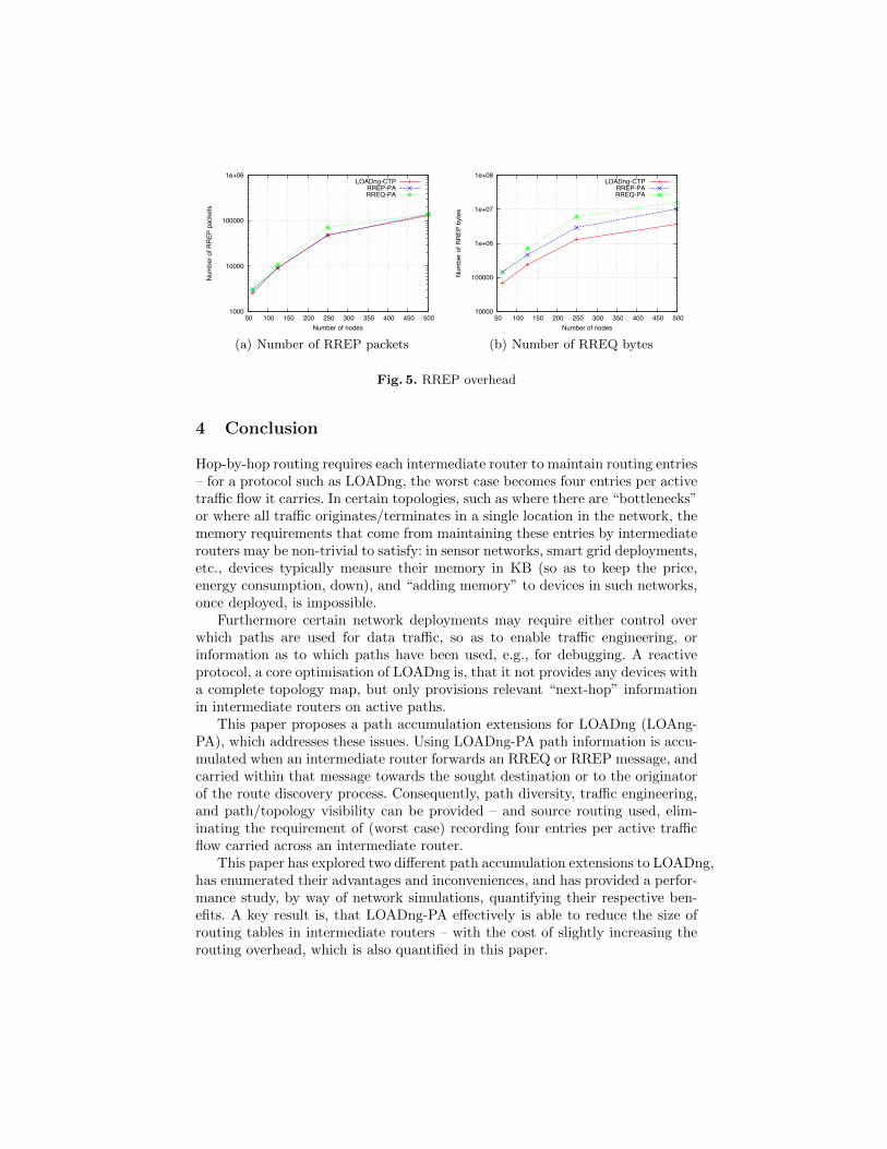
The overhead of RREP message transmission is given in figure 5, with RREQ-PA as expected exhibiting larger RREP messages and, thus, the most bytes sentacross the network.
Based on the simulation results and the discussion in section 1, the charac-teristics of three protocol settings are summarised qualitatively in table 1.
2 IEEE 802.11b is, of course, not suggested as a viable interface for LLNs, but servesto illustrate general protocol behaviours

0
5
10
15
20
25
30
35
40
45
50 100 150 200 250 300 350 400 450 500
Num
ber a
vera
ge ro
utin
g en
try
Number of nodes
LOADng-CTPRREP-PARREQ-PA
(a) Average routing table entries
0
5
10
15
20
25
30
35
40
45
50 100 150 200 250 300 350 400 450 500
Stan
dard
dev
iatio
n of
rout
ing
entry
Number of nodes
LOADng-CTPRREP-PARREQ-PA
(b) Standard deviation
Fig. 3. Routing table information
1000
10000
100000
1e+06
1e+07
50 100 150 200 250 300 350 400 450 500
Num
ber o
f RR
EQ p
acke
ts
Number of nodes
LOADng-CTPRREP-PARREQ-PA
(a) Number of RREQ packets
10000
100000
1e+06
1e+07
1e+08
1e+09
50 100 150 200 250 300 350 400 450 500
Num
ber o
f RR
EQ b
ytes
Number of nodes
LOADng-CTPRREP-PARREQ-PA
(b) Number of RREQ bytes
Fig. 4. RREQ overhead.
LOADng-CTP RREQ-PA RREP-PA
Source routing no yes yes
Network topology at the root no yes yes
Traffic engineering no yes yes
Path diversity no yes no
RREQ overhead low high low
RREP overhead low high medium
Sensor memory requirement high low lowTable 1. Characteristics of LOADng path accumulation
1000
10000
100000
1e+06
50 100 150 200 250 300 350 400 450 500
Num
ber o
f RR
EP p
acke
ts
Number of nodes
LOADng-CTPRREP-PARREQ-PA
(a) Number of RREP packets
10000
100000
1e+06
1e+07
1e+08
50 100 150 200 250 300 350 400 450 500
Num
ber o
f RR
EP b
ytes
Number of nodes
LOADng-CTPRREP-PARREQ-PA
(b) Number of RREQ bytes
Fig. 5. RREP overhead
4 Conclusion
Hop-by-hop routing requires each intermediate router to maintain routing entries– for a protocol such as LOADng, the worst case becomes four entries per activetraffic flow it carries. In certain topologies, such as where there are “bottlenecks”or where all traffic originates/terminates in a single location in the network, thememory requirements that come from maintaining these entries by intermediaterouters may be non-trivial to satisfy: in sensor networks, smart grid deployments,etc., devices typically measure their memory in KB (so as to keep the price,energy consumption, down), and “adding memory” to devices in such networks,once deployed, is impossible.
Furthermore certain network deployments may require either control overwhich paths are used for data traffic, so as to enable traffic engineering, orinformation as to which paths have been used, e.g., for debugging. A reactiveprotocol, a core optimisation of LOADng is, that it not provides any devices witha complete topology map, but only provisions relevant “next-hop” informationin intermediate routers on active paths.
This paper proposes a path accumulation extensions for LOADng (LOAng-PA), which addresses these issues. Using LOADng-PA path information is accu-mulated when an intermediate router forwards an RREQ or RREP message, andcarried within that message towards the sought destination or to the originatorof the route discovery process. Consequently, path diversity, traffic engineering,and path/topology visibility can be provided – and source routing used, elim-inating the requirement of (worst case) recording four entries per active trafficflow carried across an intermediate router.
This paper has explored two different path accumulation extensions to LOADng,has enumerated their advantages and inconveniences, and has provided a perfor-mance study, by way of network simulations, quantifying their respective ben-efits. A key result is, that LOADng-PA effectively is able to reduce the size ofrouting tables in intermediate routers – with the cost of slightly increasing therouting overhead, which is also quantified in this paper.

References
1. C. Perkins, E. Belding-Royer, and S. Das, “Ad hoc On-Demand Distance Vector(AODV) Routing,” Experimental RFC 3561, July 2003.
2. T. Clausen and P. Jacquet, “Optimized Link State Routing Protocol (OLSR),”RFC 3626, IETF, October 2003.
3. T. Clausen, C. Dearlove, and P. Jacquet, “Optimized Link State Routing Protocol(OLSR) Version 2,” Standard Track RFC 7181, April 2014.
4. K. Kim, S. D. Park, G. Montenegro, S. Yoo, and N. Kushalnagar, “6LoWPAN AdHoc On-Demand Distance Vector Routing,” June 2007, Internet Draft, work inprogress, draft-daniel-6lowpan-load-adhoc-routing-03.
5. “ITU-T G.9956: Narrow-Band OFDM power line communication transceivers -Data link layer specification,” November 2011.
6. T. Clausen, A. C. de Verdiere, J. Yi, A. Niktash, Y. Igarashi, H. Satoh, and U. Her-berg, “The lln on-demand ad hoc distance-vector routing protocol - next genera-tion,” The Internet Engineering Task Force, October 2011, internet Draft, work inprogress, draft-clausen-lln-loadng.
7. T. Clausen, A. Camacho, J. Yi, A. C. de Verdiere, Y. Igarashi, H. Satoh, andY. Morii, “Experience with the loadng routing protocol for llns,” The InternetEngineering Task Force, October 2011, internet Draft, work in progress, draft-lavenu-lln-loadng-interoperability-report.
8. ITU, “ITU-T G.9903: Narrow-band orthogonal frequency division multiplexingpower line communication transceivers for G3-PLC networks: Amendment 1,” May2013.
9. J. Yi, T. Clausen, and A. C. de Verdiere, “Collection Tree Extension of ReactiveRouting Protocol for Low-Power and Lossy Networks,” International Journal ofDistributed Sensor Networks, 2014.
10. J. Yi, T. Clausen, and A. Bas, “Smart Route Request for On-demand Route Dis-covery in Constrained Environments.” Proceedings of the IEEE InternationalConference on Wireless Information Technology and Systems, September 2012.
11. A. Bas, J. Yi, and T. Clausen, “Expanding Ring Search for Route Discovery inLOADng Routing Protocol.” Proceedings of The 1st International Workshop onSmart Technologies for Energy, Information and Communication, September 2012.
12. T. Clausen, J. Yi, A. Bas, and U. Herberg, “A depth first forwarding (dff) extensionfor the loadng routing protocol.” ASON 2013 Sixth International Workshop onAutonomous Self-Organizing Networks, December 2013.
13. J. Yi, T. Clausen, and U. Herberg, “Depth first forwarding for low power and lossynetworks: Application and extension.” Proceedings of IEEE World Forum onInternet of Things WF-IoT 2014, March 2014.
14. D. Johnson, Y. Hu, and D. Maltz, “The Dynamic Source Routing Protocol forMobile Ad Hoc Networks for IPv4,” IETF Std. RFC 4728, February 2007.
15. S. Gwalani, E. Belding-Royer, and C. Perkins, “Aodv-pa: Aodv with path accu-mulation,” in Communications, 2003. ICC ’03. IEEE International Conference on,vol. 1, May 2003, pp. 527–531 vol.1.
16. T. Clausen, J. Yi, and A. C. de Verdiere, “LOADng: Towards AODV Version 2,”in VTC Fall. IEEE, 2012, pp. 1–5.
17. T. Clausen, C. Dearlove, J. Dean, and C. Adjih, “Generalized MANETPacket/Message Format,” Std. Track RFC 5444, February 2009.