Passive building energy savings: A review of building envelope components
15
Renewable and Sustainable Energy Reviews 15 (2011) 3617–3631 Contents lists available at ScienceDirect Renewable and Sustainable Energy Reviews journal homepage: www.elsevier.com/locate/rser Passive building energy savings: A review of building envelope components Suresh B. Sadineni ∗ , Srikanth Madala, Robert F. Boehm Center for Energy Research, Howard R. Hughes College of Engineering, University of Nevada Las Vegas, 4505 Maryland Parkway, Las Vegas 89154-4027, United States article info Article history: Received 7 June 2011 Accepted 5 July 2011 Available online 30 July 2011 Keywords: Passive techniques Building envelope Building energy savings Windows Doors Glazing Fenestration Walls Thermal insulation Thermal mass Roofs Green roofs Infiltration abstract A significant portion of the total primary energy is consumed by today’s buildings in developed countries. In many of these buildings, the energy consumption can be significantly reduced by adopting energy efficiency strategies. Due to environmental concerns and the high cost of energy in recent years there has been a renewed interest in building energy efficiency. This article strives to make an exhaustive technical review of the building envelope components and respective improvements from an energy efficiency perspective. Different types of energy efficient walls such as Trombe walls, ventilated walls, and glazed walls are discussed. Performance of different fenestration technologies including aerogel, vacuum glazing and frames are presented. Advances in energy efficient roofs including the contemporary green roofs, photovoltaic roofs, radiant-transmittive barrier and evaporative roof cooling systems are discussed. Various types of thermal insulation materials are enumerated along with selection criteria of these materials. The effects of thermal mass and phase change material on building cooling/heating loads and peak loads are discussed. Application of thermal mass as an energy saving method is more effective in places where the outside ambient air temperature differences between the days and nights are high. Air tightness and infiltration of building envelopes are discussed as they play a crucial role in the energy consumption of a building. Energy efficiency approaches sometimes might not require additional capital investment. For example, a holistic energy efficient building design approach can reduce the size of mechanical systems compensating the additional cost of energy efficiency features. Published by Elsevier Ltd. Contents 1. Introduction ........................................................................................................................................ 3618 2. Walls ............................................................................................................................................... 3619 2.1. Passive solar walls .......................................................................................................................... 3619 2.2. Lightweight concrete (LWC) walls ......................................................................................................... 3620 2.3. Ventilated or double skin walls ............................................................................................................ 3620 2.4. Walls with latent heat storage ............................................................................................................. 3621 3. Fenestration (windows and doors) ................................................................................................................ 3621 3.1. Types of glazing materials and technologies .............................................................................................. 3621 3.1.1. Aerogel glazing ................................................................................................................... 3621 3.1.2. Vacuum glazing ................................................................................................................... 3621 3.1.3. Switchable reflective glazing ..................................................................................................... 3621 3.1.4. Suspended particle devices (SPD) film ........................................................................................... 3622 3.1.5. Holographic optical elements .................................................................................................... 3622 3.2. Frames ...................................................................................................................................... 3622 4. Roofs ............................................................................................................................................... 3622 4.1. Types of roofs ............................................................................................................................... 3622 4.1.1. Masonry roofs .................................................................................................................... 3622 4.1.2. Lightweight roofs ................................................................................................................. 3622 4.1.3. Ventilated and micro-ventilated roofs .......................................................................................... 3623 ∗ Corresponding author. E-mail address: [email protected] (S.B. Sadineni). 1364-0321/$ – see front matter. Published by Elsevier Ltd. doi:10.1016/j.rser.2011.07.014
Transcript of Passive building energy savings: A review of building envelope components

P
SC
a
ARAA
KPBBWDGFWTTRGI
C
1d
Renewable and Sustainable Energy Reviews 15 (2011) 3617–3631
Contents lists available at ScienceDirect
Renewable and Sustainable Energy Reviews
journa l homepage: www.e lsev ier .com/ locate / rser
assive building energy savings: A review of building envelope components
uresh B. Sadineni ∗, Srikanth Madala, Robert F. Boehmenter for Energy Research, Howard R. Hughes College of Engineering, University of Nevada Las Vegas, 4505 Maryland Parkway, Las Vegas 89154-4027, United States
r t i c l e i n f o
rticle history:eceived 7 June 2011ccepted 5 July 2011vailable online 30 July 2011
eywords:assive techniquesuilding envelopeuilding energy savingsindows
oorslazing
a b s t r a c t
A significant portion of the total primary energy is consumed by today’s buildings in developed countries.In many of these buildings, the energy consumption can be significantly reduced by adopting energyefficiency strategies. Due to environmental concerns and the high cost of energy in recent years therehas been a renewed interest in building energy efficiency. This article strives to make an exhaustivetechnical review of the building envelope components and respective improvements from an energyefficiency perspective. Different types of energy efficient walls such as Trombe walls, ventilated walls,and glazed walls are discussed. Performance of different fenestration technologies including aerogel,vacuum glazing and frames are presented. Advances in energy efficient roofs including the contemporarygreen roofs, photovoltaic roofs, radiant-transmittive barrier and evaporative roof cooling systems arediscussed. Various types of thermal insulation materials are enumerated along with selection criteriaof these materials. The effects of thermal mass and phase change material on building cooling/heating
enestrationalls
hermal insulationhermal massoofsreen roofs
loads and peak loads are discussed. Application of thermal mass as an energy saving method is moreeffective in places where the outside ambient air temperature differences between the days and nightsare high. Air tightness and infiltration of building envelopes are discussed as they play a crucial role in theenergy consumption of a building. Energy efficiency approaches sometimes might not require additionalcapital investment. For example, a holistic energy efficient building design approach can reduce the sizeof mechanical systems compensating the additional cost of energy efficiency features.
nfiltrationPublished by Elsevier Ltd.
ontents
1. Introduction . . . . . . . . . . . . . . . . . . . . . . . . . . . . . . . . . . . . . . . . . . . . . . . . . . . . . . . . . . . . . . . . . . . . . . . . . . . . . . . . . . . . . . . . . . . . . . . . . . . . . . . . . . . . . . . . . . . . . . . . . . . . . . . . . . . . . . . . 36182. Walls . . . . . . . . . . . . . . . . . . . . . . . . . . . . . . . . . . . . . . . . . . . . . . . . . . . . . . . . . . . . . . . . . . . . . . . . . . . . . . . . . . . . . . . . . . . . . . . . . . . . . . . . . . . . . . . . . . . . . . . . . . . . . . . . . . . . . . . . . . . . . . . 3619
2.1. Passive solar walls . . . . . . . . . . . . . . . . . . . . . . . . . . . . . . . . . . . . . . . . . . . . . . . . . . . . . . . . . . . . . . . . . . . . . . . . . . . . . . . . . . . . . . . . . . . . . . . . . . . . . . . . . . . . . . . . . . . . . . . . . . 36192.2. Lightweight concrete (LWC) walls . . . . . . . . . . . . . . . . . . . . . . . . . . . . . . . . . . . . . . . . . . . . . . . . . . . . . . . . . . . . . . . . . . . . . . . . . . . . . . . . . . . . . . . . . . . . . . . . . . . . . . . . . 36202.3. Ventilated or double skin walls . . . . . . . . . . . . . . . . . . . . . . . . . . . . . . . . . . . . . . . . . . . . . . . . . . . . . . . . . . . . . . . . . . . . . . . . . . . . . . . . . . . . . . . . . . . . . . . . . . . . . . . . . . . . 36202.4. Walls with latent heat storage . . . . . . . . . . . . . . . . . . . . . . . . . . . . . . . . . . . . . . . . . . . . . . . . . . . . . . . . . . . . . . . . . . . . . . . . . . . . . . . . . . . . . . . . . . . . . . . . . . . . . . . . . . . . . 3621
3. Fenestration (windows and doors) . . . . . . . . . . . . . . . . . . . . . . . . . . . . . . . . . . . . . . . . . . . . . . . . . . . . . . . . . . . . . . . . . . . . . . . . . . . . . . . . . . . . . . . . . . . . . . . . . . . . . . . . . . . . . . . . 36213.1. Types of glazing materials and technologies . . . . . . . . . . . . . . . . . . . . . . . . . . . . . . . . . . . . . . . . . . . . . . . . . . . . . . . . . . . . . . . . . . . . . . . . . . . . . . . . . . . . . . . . . . . . . . 3621
3.1.1. Aerogel glazing . . . . . . . . . . . . . . . . . . . . . . . . . . . . . . . . . . . . . . . . . . . . . . . . . . . . . . . . . . . . . . . . . . . . . . . . . . . . . . . . . . . . . . . . . . . . . . . . . . . . . . . . . . . . . . . . . . . 36213.1.2. Vacuum glazing. . . . . . . . . . . . . . . . . . . . . . . . . . . . . . . . . . . . . . . . . . . . . . . . . . . . . . . . . . . . . . . . . . . . . . . . . . . . . . . . . . . . . . . . . . . . . . . . . . . . . . . . . . . . . . . . . . . 36213.1.3. Switchable reflective glazing . . . . . . . . . . . . . . . . . . . . . . . . . . . . . . . . . . . . . . . . . . . . . . . . . . . . . . . . . . . . . . . . . . . . . . . . . . . . . . . . . . . . . . . . . . . . . . . . . . . . . 36213.1.4. Suspended particle devices (SPD) film . . . . . . . . . . . . . . . . . . . . . . . . . . . . . . . . . . . . . . . . . . . . . . . . . . . . . . . . . . . . . . . . . . . . . . . . . . . . . . . . . . . . . . . . . . . 36223.1.5. Holographic optical elements . . . . . . . . . . . . . . . . . . . . . . . . . . . . . . . . . . . . . . . . . . . . . . . . . . . . . . . . . . . . . . . . . . . . . . . . . . . . . . . . . . . . . . . . . . . . . . . . . . . . 3622
3.2. Frames . . . . . . . . . . . . . . . . . . . . . . . . . . . . . . . . . . . . . . . . . . . . . . . . . . . . . . . . . . . . . . . . . . . . . . . . . . . . . . . . . . . . . . . . . . . . . . . . . . . . . . . . . . . . . . . . . . . . . . . . . . . . . . . . . . . . . . 36224. Roofs . . . . . . . . . . . . . . . . . . . . . . . . . . . . . . . . . . . . . . . . . . . . . . . . . . . . . . . . . . . . . . . . . . . . . . . . . . . . . . . . . . . . . . . . . . . . . . . . . . . . . . . . . . . . . . . . . . . . . . . . . . . . . . . . . . . . . . . . . . . . . . . 3622
4.1. Types of roofs . . . . . . . . . . . . . . . . . . . . . . . . . . . . . . . . . . . . . . . . . . . . . . . . . . . . . . .4.1.1. Masonry roofs . . . . . . . . . . . . . . . . . . . . . . . . . . . . . . . . . . . . . . . . . . . . .4.1.2. Lightweight roofs . . . . . . . . . . . . . . . . . . . . . . . . . . . . . . . . . . . . . . . . .4.1.3. Ventilated and micro-ventilated roofs . . . . . . . . . . . . . . . . . . .
∗ Corresponding author.E-mail address: [email protected] (S.B. Sadineni).
364-0321/$ – see front matter. Published by Elsevier Ltd.oi:10.1016/j.rser.2011.07.014
. . . . . . . . . . . . . . . . . . . . . . . . . . . . . . . . . . . . . . . . . . . . . . . . . . . . . . . . . . . . . . . . . . . . . . . . 3622. . . . . . . . . . . . . . . . . . . . . . . . . . . . . . . . . . . . . . . . . . . . . . . . . . . . . . . . . . . . . . . . . . . . . . . 3622
. . . . . . . . . . . . . . . . . . . . . . . . . . . . . . . . . . . . . . . . . . . . . . . . . . . . . . . . . . . . . . . . . . . . . . . . 3622
. . . . . . . . . . . . . . . . . . . . . . . . . . . . . . . . . . . . . . . . . . . . . . . . . . . . . . . . . . . . . . . . . . . . . . . 3623

3
618 S.B. Sadineni et al. / Renewable and Sustainable Energy Reviews 15 (2011) 3617–36314.1.4. Vaulted and domed roofs . . . . . . . . . . . . . . . . . . . . . . . . . . . . . . . . . . . . . . . . . . . . . . . . . . . . . . . . . . . . . . . . . . . . . . . . . . . . . . . . . . . . . . . . . . . . . . . . . . . . . . . . . 36234.1.5. Solar-reflective/cool roofs . . . . . . . . . . . . . . . . . . . . . . . . . . . . . . . . . . . . . . . . . . . . . . . . . . . . . . . . . . . . . . . . . . . . . . . . . . . . . . . . . . . . . . . . . . . . . . . . . . . . . . . . 36234.1.6. Green roofs . . . . . . . . . . . . . . . . . . . . . . . . . . . . . . . . . . . . . . . . . . . . . . . . . . . . . . . . . . . . . . . . . . . . . . . . . . . . . . . . . . . . . . . . . . . . . . . . . . . . . . . . . . . . . . . . . . . . . . . 36234.1.7. Photovoltaic roofs . . . . . . . . . . . . . . . . . . . . . . . . . . . . . . . . . . . . . . . . . . . . . . . . . . . . . . . . . . . . . . . . . . . . . . . . . . . . . . . . . . . . . . . . . . . . . . . . . . . . . . . . . . . . . . . . 36244.1.8. Thermal roof insulation systems . . . . . . . . . . . . . . . . . . . . . . . . . . . . . . . . . . . . . . . . . . . . . . . . . . . . . . . . . . . . . . . . . . . . . . . . . . . . . . . . . . . . . . . . . . . . . . . . . 3624
4.2. Evaporative roof cooling . . . . . . . . . . . . . . . . . . . . . . . . . . . . . . . . . . . . . . . . . . . . . . . . . . . . . . . . . . . . . . . . . . . . . . . . . . . . . . . . . . . . . . . . . . . . . . . . . . . . . . . . . . . . . . . . . . . 36255. Thermal insulation, thermal mass and phase change materials . . . . . . . . . . . . . . . . . . . . . . . . . . . . . . . . . . . . . . . . . . . . . . . . . . . . . . . . . . . . . . . . . . . . . . . . . . . . . . . . . . 3625
5.1. Thermal Insulation . . . . . . . . . . . . . . . . . . . . . . . . . . . . . . . . . . . . . . . . . . . . . . . . . . . . . . . . . . . . . . . . . . . . . . . . . . . . . . . . . . . . . . . . . . . . . . . . . . . . . . . . . . . . . . . . . . . . . . . . . 36255.1.1. Selection of insulation . . . . . . . . . . . . . . . . . . . . . . . . . . . . . . . . . . . . . . . . . . . . . . . . . . . . . . . . . . . . . . . . . . . . . . . . . . . . . . . . . . . . . . . . . . . . . . . . . . . . . . . . . . . . 36255.1.2. Types of insulation . . . . . . . . . . . . . . . . . . . . . . . . . . . . . . . . . . . . . . . . . . . . . . . . . . . . . . . . . . . . . . . . . . . . . . . . . . . . . . . . . . . . . . . . . . . . . . . . . . . . . . . . . . . . . . . 36265.1.3. Vacuum insulation panels . . . . . . . . . . . . . . . . . . . . . . . . . . . . . . . . . . . . . . . . . . . . . . . . . . . . . . . . . . . . . . . . . . . . . . . . . . . . . . . . . . . . . . . . . . . . . . . . . . . . . . . . 36265.1.4. Structurally insulated panels (SIPs) . . . . . . . . . . . . . . . . . . . . . . . . . . . . . . . . . . . . . . . . . . . . . . . . . . . . . . . . . . . . . . . . . . . . . . . . . . . . . . . . . . . . . . . . . . . . . . 3626
5.2. Thermal mass. . . . . . . . . . . . . . . . . . . . . . . . . . . . . . . . . . . . . . . . . . . . . . . . . . . . . . . . . . . . . . . . . . . . . . . . . . . . . . . . . . . . . . . . . . . . . . . . . . . . . . . . . . . . . . . . . . . . . . . . . . . . . . . 36265.3. Phase change materials (PCM) . . . . . . . . . . . . . . . . . . . . . . . . . . . . . . . . . . . . . . . . . . . . . . . . . . . . . . . . . . . . . . . . . . . . . . . . . . . . . . . . . . . . . . . . . . . . . . . . . . . . . . . . . . . . . 3626
6. Infiltration and airtightness . . . . . . . . . . . . . . . . . . . . . . . . . . . . . . . . . . . . . . . . . . . . . . . . . . . . . . . . . . . . . . . . . . . . . . . . . . . . . . . . . . . . . . . . . . . . . . . . . . . . . . . . . . . . . . . . . . . . . . . 36266.1. Factors affecting infiltration. . . . . . . . . . . . . . . . . . . . . . . . . . . . . . . . . . . . . . . . . . . . . . . . . . . . . . . . . . . . . . . . . . . . . . . . . . . . . . . . . . . . . . . . . . . . . . . . . . . . . . . . . . . . . . . . 36276.2. Mathematical formulation of infiltration . . . . . . . . . . . . . . . . . . . . . . . . . . . . . . . . . . . . . . . . . . . . . . . . . . . . . . . . . . . . . . . . . . . . . . . . . . . . . . . . . . . . . . . . . . . . . . . . . . 36276.3. Pollutant infiltration . . . . . . . . . . . . . . . . . . . . . . . . . . . . . . . . . . . . . . . . . . . . . . . . . . . . . . . . . . . . . . . . . . . . . . . . . . . . . . . . . . . . . . . . . . . . . . . . . . . . . . . . . . . . . . . . . . . . . . . 36276.4. Infiltration and air tightness case studies . . . . . . . . . . . . . . . . . . . . . . . . . . . . . . . . . . . . . . . . . . . . . . . . . . . . . . . . . . . . . . . . . . . . . . . . . . . . . . . . . . . . . . . . . . . . . . . . . . 3627
7. Building simulation software/programs. . . . . . . . . . . . . . . . . . . . . . . . . . . . . . . . . . . . . . . . . . . . . . . . . . . . . . . . . . . . . . . . . . . . . . . . . . . . . . . . . . . . . . . . . . . . . . . . . . . . . . . . . . . 36288. Building envelope diagnostics . . . . . . . . . . . . . . . . . . . . . . . . . . . . . . . . . . . . . . . . . . . . . . . . . . . . . . . . . . . . . . . . . . . . . . . . . . . . . . . . . . . . . . . . . . . . . . . . . . . . . . . . . . . . . . . . . . . . . 3628
8.1. Infrared thermography . . . . . . . . . . . . . . . . . . . . . . . . . . . . . . . . . . . . . . . . . . . . . . . . . . . . . . . . . . . . . . . . . . . . . . . . . . . . . . . . . . . . . . . . . . . . . . . . . . . . . . . . . . . . . . . . . . . . . 36288.2. Fenestration diagnostics . . . . . . . . . . . . . . . . . . . . . . . . . . . . . . . . . . . . . . . . . . . . . . . . . . . . . . . . . . . . . . . . . . . . . . . . . . . . . . . . . . . . . . . . . . . . . . . . . . . . . . . . . . . . . . . . . . . 36288.3. Infiltration and airtightness diagnostics . . . . . . . . . . . . . . . . . . . . . . . . . . . . . . . . . . . . . . . . . . . . . . . . . . . . . . . . . . . . . . . . . . . . . . . . . . . . . . . . . . . . . . . . . . . . . . . . . . . 36288.4. Envelope moisture diagnostics . . . . . . . . . . . . . . . . . . . . . . . . . . . . . . . . . . . . . . . . . . . . . . . . . . . . . . . . . . . . . . . . . . . . . . . . . . . . . . . . . . . . . . . . . . . . . . . . . . . . . . . . . . . . . 3629
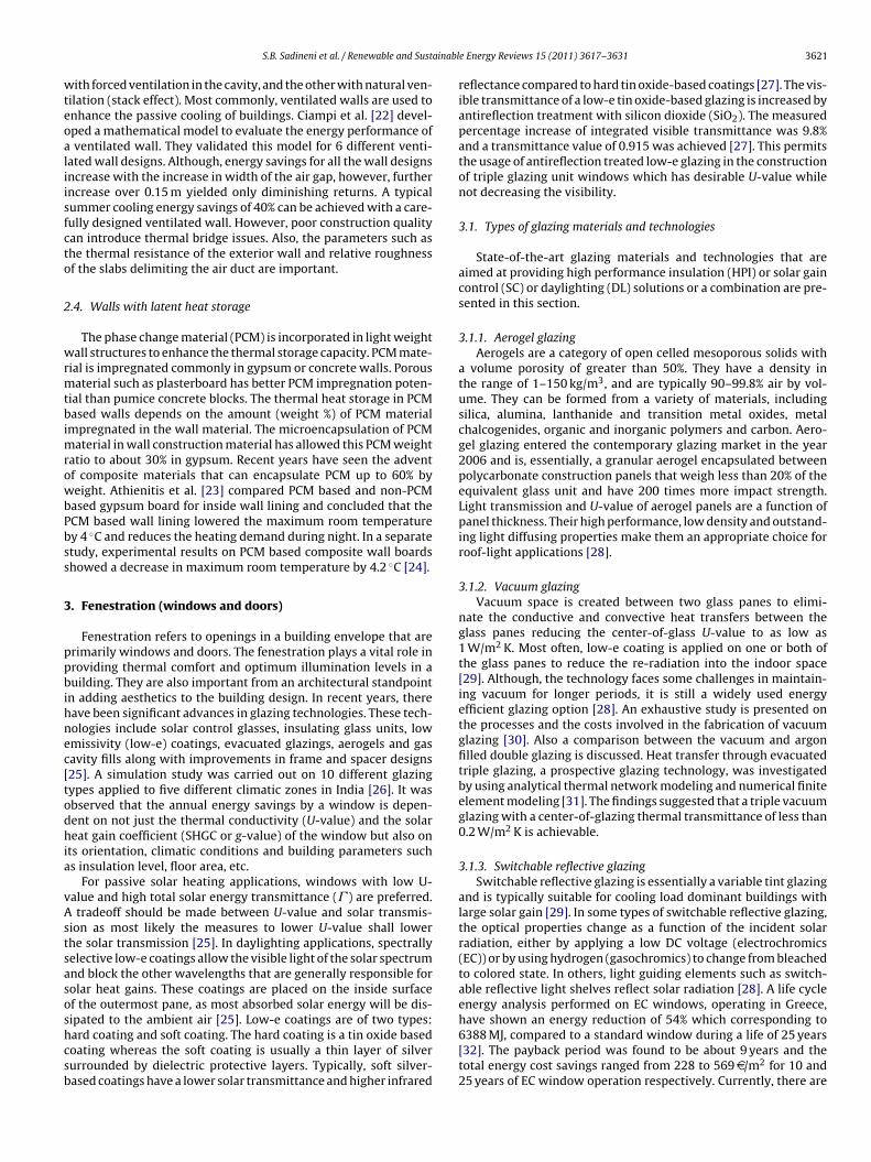
9. Building envelope maintenance . . . . . . . . . . . . . . . . . . . . . . . . . . . . . . . . . . . . . . . . . . . . . . . . . . . . . . . . . . . . . . . . . . . . . . . . . . . . . . . . . . . . . . . . . . . . . . . . . . . . . . . . . . . . . . . . . . . 362910. Conclusion . . . . . . . . . . . . . . . . . . . . . . . . . . . . . . . . . . . . . . . . . . . . . . . . . . . . . . . . . . . . . . . . . . . . . . . . . . . . . . . . . . . . . . . . . . . . . . . . . . . . . . . . . . . . . . . . . . . . . . . . . . . . . . . . . . . . . . . . 3629
Acknowledgements . . . . . . . . . . . . . . . . . . . . . . . . . . . . . . . . . . . . . . . . . . . . . . . . . . . . . . . . . . . . . . . . . . . . . . . . . . . . . . . . . . . . . . . . . . . . . . . . . . . . . . . . . . . . . . . . . . . . . . . . . . . . . . 3630References . . . . . . . . . . . . . . . . . . . . . . . . . . . . . . . . . . . . . . . . . . . . . . . . . . . . . . . . . . . . . . . . . . . . . . . . . . . . . . . . . . . . . . . . . . . . . . . . . . . . . . . . . . . . . . . . . . . . . . . . . . . . . . . . . . . . . . . . 3630
Nomenclature
AAC Autoclaved aerated concreteACH Air changes per hourAPS Arizona public serviceASHRAE American society of heating, refrigerating and air-
conditioning engineersASTM American society for testing and materialsBIPV Building integrated photovoltaicsBUR Built-up roofC Dimensionless constantCFCs Chlorofluoro carbonsd Gap thickness of the crackDL DaylightingEC ElectrochromicsEPDM Ethylene propylene diene monomerEPS Extruded polystyreneESP-r Environmental systems performance-researchFRP Fiber-reinforced plasticHCFCs HydrochlorofluorocarbonsHOE Holographic optical elementsHPI High performance insulationHTF Heat transfer fluidHVAC Heating, ventilation and air conditioningIECC International energy conservation codeIR InfraredISO The International Standards OrganizationL Breadth of the crackLASRS Lightweight aluminum standing seam roofing sys-
temsLEED Leadership in energy and environmental designLWC Lightweight concrete
Q Flow rateRCC Reinforced cement concreteSC Solar gain controlSCE Solar collection envelopeSPD film Suspended particle devices filmSR Solar reflectanceTPO Thermoplastic polyolefinU Thermal transmittance (in W/m2 K)UK United KingdomUS United States of AmericaVR Vaulted roofWGBC World green building councilz Length in the direction of flow� Density� Dynamic viscosity� Energy transmittance˛, ˇ Constants�P Pressure difference
1. Introduction
A significant portion of the energy is consumed by today’s build-ings in developed countries. For example, about 39% of the total USprimary energy is consumed by buildings today [1], this fact empha-sizes on the imperative need for energy savings in buildings. Bothgovernments and scientific communities across the world haveidentified the potential and need for energy efficiency in the build-ings, and initiated significant efforts in this direction. As of date,the WGBC (world green building council) has involved 82 nationsall across the globe in taking up green building initiatives to some
PCES Phase change energy solutionsPCM Phase change materialPIR Polyisocyanurate
degree. LEED (Leadership in Energy and Environmental Design),an internationally recognized green building certification system,also identifies energy efficiency as an important attribute of greenbuildings.

S.B. Sadineni et al. / Renewable and Sustainabl
Table 1Code standard U-values (in W/m2 K) for UK buildings.
Envelopeelement
1995 StandardU-values (W/m2 K)
2000 StandardU-values (W/m2 K)
Percentagereduction inU-value (%)
Walls 0.45 0.35 22Roofs 0.25 0.16 36Floors 0.45 0.25 44
S
eallteoc
ettiuesp
eqotsiii3tepnaatDiptetr2onbta
iTcdfs
Windows 3.3 2.2 33
ource: John et al. [6].
The buildings we find today are expected to achieve both energyfficient and environmental-friendly design. This idea of sustain-ble buildings encompasses various issues regarding energy, water,and and material conservation, together with environmental pol-ution and the quality of indoor and outdoor environments. Aechnical review on the recent developments in various buildingnvelope components and their effects on the energy efficiencyf a building is, therefore, highly relevant given the presentontext.
Building energy efficiency can be improved by implementingither active or passive energy efficient strategies. Improvementso heating, ventilation and air conditioning (HVAC) systems, elec-rical lighting, etc. can be categorized as active strategies, whereas,mprovements to building envelope elements can be classifiednder passive strategies. Recent years have seen a renewed inter-st in environmental-friendly passive building energy efficiencytrategies. They are being envisioned as a viable solution to theroblems of energy crisis and environmental pollution.
A building envelope is what separates the indoor and outdoornvironments of a building. It is the key factor that determines theuality and controls the indoor conditions irrespective of transientutdoor conditions. Various components such as walls, fenestra-ion, roof, foundation, thermal insulation, thermal mass, externalhading devices etc. make up this important part of any build-ng. Several researchers around the world carried out studies onmprovements in the building envelope and their impact on build-ng energy usage. Energy savings of 31.4% and peak load savings of6.8% from the base case were recorded for high-rise apartments inhe hot and humid climate of Hong Kong by implementing passivenergy efficient strategies. The strategies include adding extrudedolystyrene (EPS) thermal insulation in walls, white washing exter-al walls, reflective coated glass window glazings, 1.5 m overhangsnd wing wall to all windows [2]. In a different study, the thermalnd heat transfer performance of a building envelope in sub-ropical climatic conditions of Hong Kong was studied using theOE-2 building energy simulation tool. An energy effective build-
ng envelope design saved as much as 35% and 47% of total andeak cooling demands respectively [3]. In Greece, thermal insula-ion (in walls, roof and floor) and low infiltration strategies reducednergy consumption by 20–40% and 20% respectively. According tohe same study, external shadings (e.g. awnings) and light-coloredoof and external walls reduced the space cooling load by 30% and–4%, respectively [4]. Several numerical studies were also carriedut on building envelopes and individual building envelope compo-ents. A detailed model of transient heat transfer through a typicaluilding envelope developed by Price et al. [5] takes into accounthe convection and thermal radiation heat exchange at the interiornd exterior surfaces of the building.
Over the years, code requirements on building envelopes havemproved significantly, and continue to increase in performance.able 1 shows how building envelope standards in the UK have
hanged over time. With each revision, the building envelope stan-ards were upgraded substantially, emphasizing the growing needor energy conservation. In the United States, although differenttates implement different code standards, they are all derivativese Energy Reviews 15 (2011) 3617–3631 3619
from various versions of American society of heating refrigera-tion and air-conditioning engineers (ASHRAE) and InternationalEnergy Conservation Code (IECC) standards. The latest version ofASHRAE standard is ASHRAE 90.1-2007 and the IECC standard isIECC 2009.
Advanced and sustainable materials research for building enve-lope applications has seen significant progress in recent years.Fiber-reinforced plastic (FRP) is one such advanced compositematerial that can be used in wall and roof applications [7]. Sustain-able earth material such as unfired clay bricks, a straw–clay mixtureand straw bales were investigated for use in new or upgrading his-torical earth wall constructions [8]. These earth wall constructionscan comply with the UK building regulations for thermal transmit-tance of less than 0.35 W/m2 K.
A proper architectural design of a building envelope can signifi-cantly lower the energy usage through daylighting, reduced HVACloads, etc. Innovations such as the self-shading envelopes are beingexplored by researchers. A nomogram simulation of a solar collec-tion envelope (SCE) was discussed by using a computer modelingtool called SustArc [9]. The SCE concept is used to generate self-shading envelopes. In efficient self-shading envelope designs, thesummer sun is blocked while the winter sun is permitted.
The most important building envelope components and theirlatest developments are discussed in the following sections.
2. Walls
Walls are a predominant fraction of a building envelope andare expected to provide thermal and acoustic comfort within abuilding, without compromising the aesthetics of the building. Thethermal resistance (R-value) of the wall is crucial as it influencesthe building energy consumption heavily, especially, in high risebuildings where the ratio between wall and total envelope area ishigh. The market available center-of-cavity R-values and clear wallR-values consider the effect of thermal insulation. However, theinfluence of framing factor and interface connections is not takeninto consideration [10].
Walls with thermal insulation have a higher chance of surfacecondensation when the relative humidity of ambient air is greaterthan 80%, provided the convective and radiative heat transfer coef-ficients of the exterior wall are small. This problem is more severeduring winter months and in colder climatic regions with higherhumidity levels [11]. This moisture condensation on building exte-rior walls promotes undesirable microbial growth which mightreduce the wall life and lead to other undesirable conditions in thebuilding. Conventionally, based on the materials used in construc-tion, walls can be classified as wood-based walls, metal-based wallsand masonry-based walls. There are other types of advanced build-ing wall designs that are applied to improve the energy efficiencyand comfort levels in buildings. The following sections describesuch advanced wall technologies.
2.1. Passive solar walls
Typically used in cold climates, the walls that trap and transmitthe solar energy efficiently into the building are called passive solarwalls. This type of walls were first developed by E.S. Morse in the19th century and later redesigned by Trombe et al. In these walls,typically, a 12-inch-thick concrete wall is used as a south (for geo-graphical northern hemisphere) facade to absorb solar radiation.A glazing is used as an outer covering of the wall to provide the
greenhouse effect. Several developments resulted from the basicdesigns of classical Trombe wall and composite Trombe–Michellwall [12–17]. One such Trombe wall system design proposed forcold climatic conditions has a steel panel backed with polystyrene
3620 S.B. Sadineni et al. / Renewable and Sustainable Energy Reviews 15 (2011) 3617–3631
S
itAsicwatbwhWwiosoowbAo(cwrbwAwi[tfifi(p
t
Fig. 1. A cross-sectional view of fluidized Trombe wall system with part details.ource: Tunc and Uysal [19].
nsulation mounted on the south facade. This design improvedhe operating efficiency of the classical Trombe wall by 56% [15].
comparative study was conducted on four different kinds ofolar wall configurations—unventilated solar wall, Trombe wall,nsulated Trombe wall and composite solar wall—using numeri-al simulations. All of these walls, except the unventilated solarall, transfer heat to the indoors both by conduction through wall
nd convection through circulating air. The unventilated solar wallransfers heat exclusively through conduction. A more convection-ased type (controllable) of solar wall such as composite solarall or insulated Trombe wall is preferable in regions with shortereating seasons in order to avoid overheating in cooling season.hereas a more conduction-based type (uncontrollable) of solarall such as Trombe wall or unventilated solar wall is preferable
n regions with longer heating seasons. However, the problem ofverheating in summer can be prevented through the use of solarhields [14]. Jie et al. [17] have proposed an innovative designf PV integrated Trombe wall. In this design, PV cells are affixedn the back of the transparent glass cover of a normal Trombeall. Both the heat rejected by the PV cells and the heat absorbed
y the thermal mass of Trombe wall are used for space heating.theoretical analysis on a Trombe wall with fin-type structured
uter wall surface design suppresses the convective and infraredIR) radiation heat losses from the wall’s outer face to the glassover thereby encouraging the conduction through the wall alongith convective and radiative heat exchange to the inside of the
oom [16]. Phase change material (PCM) based Trombe walls haveeen reviewed [18]. Experimental results suggest that PCM Trombealls were thinner and also performed better than concrete walls.novel concept of fluidized Trombe wall system (as shown in Fig. 1)here the gap between the Trombe wall and the glass cover is flu-
dized with highly absorbing, low-density particles is introduced19]. The solar energy absorbed by these highly absorptive par-icles is transferred to the indoors through fan-circulated air. Alter at the top of the air channel checks the fluidized particles
rom entering the indoor space. The overall efficiency of this designs higher compared to a classical Trombe wall design as the airheat transfer fluid (HTF)) is in direct contact with the fluidized
articles.A Transwall (as shown in Fig. 2) is a transparent modular wallhat provides both heating and illumination of the dwelling space.
Fig. 2. A cross-sectional view of Transwall system with part details.Source: Nayak [20].
These walls are comprised of water enclosed between two par-allel glass panes supported in a metal frame. A semi-transparentglass absorbing plate is at the center of the parallel glass panes. Theincident solar radiation is partially absorbed by the water and semi-transparent glass plate, the rest of the transmitted radiation causesboth heating and illumination that are required by the indoors [20].
2.2. Lightweight concrete (LWC) walls
Lightweight concrete (LWC) refers to any concrete producedwith a density of less than 2000 kg/m3. For structural purposes,the LWC density often ranges between 1600 and 2000 kg/m3 alongwith a strength grade of 15 MPa. Whereas for thermal insulationpurposes the density is often less than 1450 kg/m3 along withstrength grade as low as 0.5 MPa. The thermal resistance of lightweight concrete can be improved by mixing with light weightaggregates. These aggregates can come from natural material (suchas pumice, diatomite, expanded clay or expanded shale, etc.), pro-cessed by-products (such as foamed slag, sintered pulverized fuelash) or unprocessed materials. The low-conductivity aggregatessuch as polystyrene beads, vermiculite and leca have been focusof research in recent years [21]. Autoclaved aerated concrete (AAC)is a type of LWC produced by introducing aluminum powder togenerate miniscule air bubbles. It has superior thermal resistancethan other types of LWC. AAC is first introduced in the early 20thcentury in Europe, and it is gaining popularity as exterior and inte-rior wall material as an alternative to clay bricks in recent yearsin developing countries. The density of AAC ranges between 600and 800 kg/m3. All kinds of LWC walls are particularly useful incountries where concrete construction is predominant and the useof insulation in walls is not a common practice. Also, they can beconstructed faster using less skilled labor.
2.3. Ventilated or double skin walls
An air gap between two layers of masonry wall braced withmetal ties constitutes a ventilated or double skin wall. They are alsocalled cavity walls. There are two basic kinds of ventilated walls, one
ainabl
wteoaliisfcto
2
wrmtbimrowbPbss
3
ppbihnec[todhia
vAstsasoshcsb
S.B. Sadineni et al. / Renewable and Sust
ith forced ventilation in the cavity, and the other with natural ven-ilation (stack effect). Most commonly, ventilated walls are used tonhance the passive cooling of buildings. Ciampi et al. [22] devel-ped a mathematical model to evaluate the energy performance ofventilated wall. They validated this model for 6 different venti-
ated wall designs. Although, energy savings for all the wall designsncrease with the increase in width of the air gap, however, furtherncrease over 0.15 m yielded only diminishing returns. A typicalummer cooling energy savings of 40% can be achieved with a care-ully designed ventilated wall. However, poor construction qualityan introduce thermal bridge issues. Also, the parameters such ashe thermal resistance of the exterior wall and relative roughnessf the slabs delimiting the air duct are important.
.4. Walls with latent heat storage
The phase change material (PCM) is incorporated in light weightall structures to enhance the thermal storage capacity. PCM mate-
ial is impregnated commonly in gypsum or concrete walls. Porousaterial such as plasterboard has better PCM impregnation poten-
ial than pumice concrete blocks. The thermal heat storage in PCMased walls depends on the amount (weight %) of PCM material
mpregnated in the wall material. The microencapsulation of PCMaterial in wall construction material has allowed this PCM weight
atio to about 30% in gypsum. Recent years have seen the adventf composite materials that can encapsulate PCM up to 60% byeight. Athienitis et al. [23] compared PCM based and non-PCM
ased gypsum board for inside wall lining and concluded that theCM based wall lining lowered the maximum room temperaturey 4 ◦C and reduces the heating demand during night. In a separatetudy, experimental results on PCM based composite wall boardshowed a decrease in maximum room temperature by 4.2 ◦C [24].
. Fenestration (windows and doors)
Fenestration refers to openings in a building envelope that arerimarily windows and doors. The fenestration plays a vital role inroviding thermal comfort and optimum illumination levels in auilding. They are also important from an architectural standpoint
n adding aesthetics to the building design. In recent years, thereave been significant advances in glazing technologies. These tech-ologies include solar control glasses, insulating glass units, lowmissivity (low-e) coatings, evacuated glazings, aerogels and gasavity fills along with improvements in frame and spacer designs25]. A simulation study was carried out on 10 different glazingypes applied to five different climatic zones in India [26]. It wasbserved that the annual energy savings by a window is depen-ent on not just the thermal conductivity (U-value) and the solareat gain coefficient (SHGC or g-value) of the window but also on
ts orientation, climatic conditions and building parameters suchs insulation level, floor area, etc.
For passive solar heating applications, windows with low U-alue and high total solar energy transmittance (� ) are preferred.tradeoff should be made between U-value and solar transmis-
ion as most likely the measures to lower U-value shall lowerhe solar transmission [25]. In daylighting applications, spectrallyelective low-e coatings allow the visible light of the solar spectrumnd block the other wavelengths that are generally responsible forolar heat gains. These coatings are placed on the inside surfacef the outermost pane, as most absorbed solar energy will be dis-ipated to the ambient air [25]. Low-e coatings are of two types:
ard coating and soft coating. The hard coating is a tin oxide basedoating whereas the soft coating is usually a thin layer of silverurrounded by dielectric protective layers. Typically, soft silver-ased coatings have a lower solar transmittance and higher infrarede Energy Reviews 15 (2011) 3617–3631 3621
reflectance compared to hard tin oxide-based coatings [27]. The vis-ible transmittance of a low-e tin oxide-based glazing is increased byantireflection treatment with silicon dioxide (SiO2). The measuredpercentage increase of integrated visible transmittance was 9.8%and a transmittance value of 0.915 was achieved [27]. This permitsthe usage of antireflection treated low-e glazing in the constructionof triple glazing unit windows which has desirable U-value whilenot decreasing the visibility.
3.1. Types of glazing materials and technologies
State-of-the-art glazing materials and technologies that areaimed at providing high performance insulation (HPI) or solar gaincontrol (SC) or daylighting (DL) solutions or a combination are pre-sented in this section.
3.1.1. Aerogel glazingAerogels are a category of open celled mesoporous solids with
a volume porosity of greater than 50%. They have a density inthe range of 1–150 kg/m3, and are typically 90–99.8% air by vol-ume. They can be formed from a variety of materials, includingsilica, alumina, lanthanide and transition metal oxides, metalchalcogenides, organic and inorganic polymers and carbon. Aero-gel glazing entered the contemporary glazing market in the year2006 and is, essentially, a granular aerogel encapsulated betweenpolycarbonate construction panels that weigh less than 20% of theequivalent glass unit and have 200 times more impact strength.Light transmission and U-value of aerogel panels are a function ofpanel thickness. Their high performance, low density and outstand-ing light diffusing properties make them an appropriate choice forroof-light applications [28].
3.1.2. Vacuum glazingVacuum space is created between two glass panes to elimi-
nate the conductive and convective heat transfers between theglass panes reducing the center-of-glass U-value to as low as1 W/m2 K. Most often, low-e coating is applied on one or both ofthe glass panes to reduce the re-radiation into the indoor space[29]. Although, the technology faces some challenges in maintain-ing vacuum for longer periods, it is still a widely used energyefficient glazing option [28]. An exhaustive study is presented onthe processes and the costs involved in the fabrication of vacuumglazing [30]. Also a comparison between the vacuum and argonfilled double glazing is discussed. Heat transfer through evacuatedtriple glazing, a prospective glazing technology, was investigatedby using analytical thermal network modeling and numerical finiteelement modeling [31]. The findings suggested that a triple vacuumglazing with a center-of-glazing thermal transmittance of less than0.2 W/m2 K is achievable.
3.1.3. Switchable reflective glazingSwitchable reflective glazing is essentially a variable tint glazing
and is typically suitable for cooling load dominant buildings withlarge solar gain [29]. In some types of switchable reflective glazing,the optical properties change as a function of the incident solarradiation, either by applying a low DC voltage (electrochromics(EC)) or by using hydrogen (gasochromics) to change from bleachedto colored state. In others, light guiding elements such as switch-able reflective light shelves reflect solar radiation [28]. A life cycleenergy analysis performed on EC windows, operating in Greece,have shown an energy reduction of 54% which corresponding to
6388 MJ, compared to a standard window during a life of 25 years[32]. The payback period was found to be about 9 years and thetotal energy cost savings ranged from 228 to 569D/m2 for 10 and25 years of EC window operation respectively. Currently, there are
3 ainabl
ct
3
fintaEt
3
cpatdeac
3
tTUaifl
4
stpitr1rntrb
iisrmsicRowidtsa
622 S.B. Sadineni et al. / Renewable and Sust
ost, warranty, switching time, glare and color rendering issueshwarting the marketability of this glazing technology.
.1.4. Suspended particle devices (SPD) filmAn SPD film is laminated between two glass panes. The SPD
lm has light absorbing particles that are randomly aligned in theirormal state forming an opaque barrier. When voltage is applied,he particles align perpendicular to the plane of the glazing cre-ting a transparent glass. The switching time (∼1 s) is faster thanC glazing. This technology suffers from drawbacks such as radiantemperature, glare, color rendering, clearness and lifetime [28].
.1.5. Holographic optical elementsHolographic optical elements (HOE) are light guiding elements
omprising a holographic film sandwiched between two glassanes. The incident solar radiation is redirected, at a predefinedngle through diffraction at the holographic film layer, usually ontohe ceiling of the building interior. This can be used as a possibleaylighting application. It suffers from some setbacks such as glareffects, light dispersion, milky clearness, limited exposure range ofzimuth and zenith angles, etc. This technology is not yet commer-ialized [28].
.2. Frames
The edge components (frame and spacer) of advanced fenes-rations should minimize thermal bridging and infiltration losses.he effect of various combinations of frames and spacers on the-value of different types of windows is described by Robinsonnd Hutchins [25]. Also, these edge effects are more pronouncedn case of smaller size windows. The emphasis of low conductancerames was reiterated by Gustavsen et al. [33] in their review onow conductance window frames.
. Roofs
Roofs are a critical part of the building envelopes that are highlyusceptible to solar radiation and other environmental changes,hereby, influencing the indoor comfort conditions for the occu-ants. Roofs account for large amounts of heat gain/loss, especially,
n buildings with large roof area such as sports complexes, audi-oriums, exhibition halls etc. In accordance with the UK buildingegulations, the upper limits of U-value for flat roofs in 1965,976 and 1985 were 1.42 W/m2 K, 0.6 W/m2 K and 0.35 W/m2 K,espectively. Currently, 0.25 W/m2 K or less is required for allew buildings in the UK [34]. This reduction in the U-value overhe years emphasizes the significance of thermal performance ofoofs in the effort to increase the overall thermal performance ofuildings.
Some passive cooling techniques could be implemented in trop-cal climates as result of modification in roof architecture. Thesenclude a compact cellular roof layout with minimum solar expo-ure, domed and vaulted roofs, naturally or mechanically ventilatedoofs, micro ventilated roofs, high roofs and double roofs. Otherethods such as white-washed external roof surfaces to reduce
olar absorptivity, roofs covered with vegetation to provide humid-ty and shade, and usage of high thermal capacity materials such asoncrete to minimize peak load demand are also gaining popularity.oof shading is one way of reducing the impact of solar radiationn the roof surface. Economical roof shading is usually achievedith local material such as terracotta tiles, hay, date palm branches,
nverted earthen pots, etc. which can usually contribute to a 6 ◦C
rop in the indoor temperature [35]. Roof coatings are another wayo mitigate the impact of solar radiation on the roof surface. Higholar reflectance and high emissivity are the respective daytimend nighttime factors that govern the selection of a roof coating.e Energy Reviews 15 (2011) 3617–3631
Aluminum-pigmented coatings are less desirable because of theirlow infrared emittance. A cool coating can reduce a white concreteroof’s surface temperature by 4 ◦C during a hot summer day and by2 ◦C during night [35]. Most often, compound roofing systems areused to bring about the desired roof characteristics depending onthe climatic conditions of the building location. A wide variety ofroofing systems has emerged, and several of these are discussed inthe following section.
4.1. Types of roofs
Roofs can be classified into different categories based on the typeof construction. The following sections present some of the com-monly used roofing structures along with recent developments.
4.1.1. Masonry roofsIn the developing countries of South Asia and the Middle East,
masonry houses with reinforced cement concrete (RCC) roofs arepopular owing to their pest (termite) resistance, natural calamity(cyclones) resistance, availability and cost effectiveness of concreteingredients [36]. During tropical summers, they tend to exhibitunfavorable thermal characteristics such as higher soffit temper-ature and longer heat retaining capacity that affect the indoor aircomfort conditions and increase energy costs. The indoor temper-atures exceed 40 ◦C due to high roof temperatures of about 65 ◦C[35]. Higher soffit temperatures make them emit long wavelengthinfrared radiation towards the occupants. Even worse is that itmight continue into the night due to the heat capacity of the slab.Also, the absorbed heat may lead to cracks in the supporting struc-ture mainly made up of brick work or block work. This problem ofhigh roof temperatures can be mitigated by employing roof shad-ing, cool roof coatings or compound roof systems. A compound roofsystem developed with a combination of radiation reflectors andthermal insulation demonstrated substantial lowering of the heatconducted through a concrete roof [37]. An insulated concrete roofsystem with an antisolar coating proved successful in the tropicalclimatic conditions of Pakistan [38]. By lowering the roof temper-ature using this system, it was observed that the roof heat gainin summer was reduced by 45 kWh/day for a roof area of 208 m2.Also, the overall heat transfer coefficient of the roof is reduced from3.3 W/m2 K to 0.54 W/m2 K.
4.1.2. Lightweight roofsLightweight aluminum standing seam roofing systems (LASRS)
are popularly used on commercial and government buildings asthey are economical. However, they are wind sensitive due to weakseam-clip connection and also have bad thermal characteristics.Two easy ways to improve thermal characteristics of these roofsare by adding thermal insulation and using light colored roof paint.It was determined that the lighter colored surfaces such as white,off-white, brown and green yielded 9.3%, 8.8%, 2.5% and 1.3% reduc-tion in cooling loads compared to an black-painted LASRS surface[39]. Recent investigations have revealed that the LASRS with glassfiber insulation does not suit well for hot and humid climates dueto the interstitial condensation in the glass fiber layer. Alternativethermal insulation materials such as polyurethane, polystyrene ora combination of these have been evaluated [39]. These roofingsystems, modeled and tested on an indoor stadium with a largeroof surface area of 51 m × 41 m, indicated that roof structure withpolyurethane insulation and white painted top surface performedbetter and saved 53.8% of the peak cooling load compared to a dark
painted roof with glass wool insulation [39]. This can be attributedto the low thermal conductivity and thermal diffusivity of thepolyurethane material and higher reflectivity of light colored roofsurface.
ainabl
4
ahbaiaodcbDafs
4
ahepaomsct[rrrhiuT[
4
htsrihttlaatritc0pcwsfotb
S.B. Sadineni et al. / Renewable and Sust
.1.3. Ventilated and micro-ventilated roofsThe ventilated roof systems are essentially two slabs delimiting
duct through which air flows. This air gap/air flow diminishes theeat transfer across the roof into the building. Ventilated roofs cane either a passive type, with stack effect driving the air flow, or anctive type, with fan induced ventilation. They are more popularn hot climatic conditions and are particularly useful in moder-te height and wide roof area buildings. Depending on the sizef the duct, the flow through it is either laminar or turbulent. Aetailed energy analysis conducted on ventilated roof buildingsonfirmed that an energy savings of 30%, during Italian summer, cane achieved when compared to non-ventilated roof buildings [40].uring cold winters, it is advisable to close the air duct using suit-ble dampers from an energy savings standpoint. These dampersavor only a very small ventilation to drain off any possible conden-ate in the duct.
.1.4. Vaulted and domed roofsVaulted and domed roofs are quite popular in the vernacular
rchitecture of the Middle East where the climatic conditions areot and arid. Tang et al. [41] performed detailed finite element mod-ling of both vaulted roof (VR) and flat roof to compare their thermalerformance in various climatic conditions. The half rim angle ofVR should be greater than 50◦ for it to show favorable influencen the indoor thermal conditions. South–north orientation of VR isore advantageous than east–west orientation. Also, they are only
uitable for hot and dry climates, due to the presence of larger beamomponent of the solar radiation which is effectively reflected byhe curved roof surface, and not so much for hot and humid climates41]. Although VRs absorb more heat during the daytime than flatoofs, they also dissipate more heat through natural convection ande-radiation. Also, during night times, typical desert climate expe-iences colder ambient temperatures causing the VRs to dissipateeat even faster. High thermal stratification occurs inside VR build-
ngs, with almost 75% of the stratification taking place in the volumender the vault, keeping the lower part of the building space cool.he hot air can be exhausted near the top of the gable walls of vaults41].
.1.5. Solar-reflective/cool roofsSolar-reflective roofs or cool roofs are high solar reflectance and
igh infrared emittance roofs. They maintain lower roof surfaceemperature and inhibit the heat conduction into the building. Twourface properties that affect the thermal performance of theseoof surfaces are solar reflectance (SR) (reflectivity or albedo) andnfrared emittance (or emissivity). Conventional roofing materialsave a SR of 0.05–0.25. Reflective roof coatings can increase the SRo more than 0.60. Most roofing materials have an infrared emit-ance of 0.85 or higher, with the exception of metals, which have aow infrared emittance of about 0.25. Therefore, even though met-ls are very reflective (i.e. SR greater than 0.60), bare metal roofsnd metallic roof coatings tend to get hot since they cannot emithe absorbed heat effectively as radiation. Special roof coatings canaise the infrared emittance of bare metal roofs [42]. As shownn some cases in Table 2, by increasing SR or infrared emittance,he roof surface temperature can be lowered. A white elastomericoating or aluminum coating can raise the SR value more than.50. Additionally, the SR increases with coating thickness for someroducts [42]. To find the influence of highly reflective roofs onooling and peak load variations, six different types of buildingsere retrofitted with high reflectance white coatings or white PVC
ingle-ply membrane at three different geographical sites in Cali-
ornia (USA) [43]. It was concluded that the daily peak temperaturef the roof surface for all the buildings was lowered by 33–42 K. Theests performed on these single-storey commercial/institutionaluildings proved that high reflective roofs are economical for thesee Energy Reviews 15 (2011) 3617–3631 3623
buildings achieving cooling load savings of 5–40% and the peakdemand savings of 5–10%.
4.1.6. Green roofsA building roof that is either fully or partly covered with a
layer of vegetation is called a green roof. It is a layered com-posite system consisting of a waterproofing membrane, growingmedium and the vegetation layer itself. Often, green roofs alsoinclude a root barrier layer, drainage layer and, where the cli-mate demands, an irrigation system. There are two types of greenroofs: intensive and extensive, the former has a deeper substratelayer and allows to cultivate deep rooting plants such as shrubsand trees; while the latter with thinner substrate layer allows togrow low level planting such as lawn or sedum. Extensive typeis more commonly used as it can be retrofitted easily on exist-ing roofs without modifications to the roof structure and alsorequires minimum maintenance. They have been proven to befairly successful in cold climates, but needs more research on sub-strate material in hot and dry climates. The green roofs not onlyreflect the solar radiation, but also act as an extra thermal insu-lation layer. They are only meant to improve thermal protectionof a building and should not replace the roof insulation layer. Thetypical additional load associated with an extensive green roof isabout 120–150 kg/m2 [45]. This is in the acceptable range of mostbuildings. A green roof system incurs higher annual savings wheninstalled on a poorly insulated roof rather than a well-insulatedroof.
The moisture content in growing media of the green roofinfluences its insulating properties. A 100 mm increase in thethickness of dry clay soil led to an increase in resistance by0.4 m2K/W, whereas for 40% moisture clay soil the increase wasonly 0.063 m2K/W [46]. The wetter the medium, the poorer theinsulating behavior compared to the dry growing media. The equiv-alent albedo of green roofs is about 0.7–0.85 as against an albedoof 0.1–0.2 for bitumen/tar/gravel roof [34]. Therefore, green roofsreflect solar radiation more efficiently than most conventionalroofs. The building energy savings and the retrofit potential of greenroofs in UK have been evaluated [62]. The field measurements car-ried out on low-rise commercial building, in the tropical climaticconditions of Singapore, reported that green roofs helped reducethe thermal reradiation effect experienced with bare roofs [47].Average heat gain (summer) and heat loss (winter) reductions of70–90% and 10–30%, respectively, were measured using green roofsystems in Toronto, Canada [48]. The performance of green roofs onoffice buildings in Athens (Greece) is simulated and validated [49].It is observed through simulations using the DOE-2 computer codethat for a turf-type extensive green roof system installed on a non-insulated roof yielded 10.5% annual savings compared to only 0.6%annual savings when installed on an insulated roof [46]. The sameconclusions are mathematically validated for Greek climatic con-ditions [50]. A thermal simulation package ESP-r (EnvironmentalSystems Performance-research) was used to evaluate the perfor-mance of a green roof on a multi-storey residential building inMadrid (Spain). The building energy reduction is found to be max-imum for the floor immediately below the roof surface and thesavings were negligible/none for more than three floors below theroof [51].
Fig. 3 enumerates the various phenomena involved in the energybalance of the solar radiation received by a dry green roof, awet green roof, and a traditional roof. Although wet soil greenroofs disadvantageous as they are poor thermal insulators, theyare advantageous in hot and dry climates where evapotranspira-
tion is high. The wet green roofs have almost double the amountof evapotranspiration compared to dry green roofs making themactually remove heat from the building acting as a passive cooler[52].
3624 S.B. Sadineni et al. / Renewable and Sustainable Energy Reviews 15 (2011) 3617–3631
Table 2Solar reflectance and infrared emittance properties of typical roof types along with temperature rise [44].
Roof surface type Solar reflectance Infrared emittance Roof surface temperature rise (◦C)
Ethylene propylene diene monomer (EPDM)–black 0.06 0.86 46.1EPDM–white 0.69 0.87 13.9Thermoplastic polyolefin (TPO)–white 0.83 0.92 6.11Bitumen–smooth surface 0.06 0.86 46.1Bitumen–white granules 0.26 0.92 35Built-up roof (BUR)–dark gravel 0.12 0.90 42.2BUR–light gravel 0.34 0.90 31.7Asphalt shingles–generic black granules 0.05 0.91 45.6Asphalt shingles–generic white granules 0.25 0.91 35.6Shingles–white elastomeric coating 0.71 0.91 12.2Shingles–aluminum coating 0.54 0.42 28.3Steel–new, bare, galvanized 0.61 0.04 30.6
4
pw(awicomahOml
ioita7idt
S
Aluminum 0.61Siliconized polyester–white 0.59
.1.7. Photovoltaic roofsThere have been significant efforts in recent years in integrating
hotovoltaics (PV) into building envelope. Especially, in countrieshere land-use is an important constraint, building integrated PV
BIPV) offer an effective solution by the use of building surfacerea while facilitating energy production and building envelopeeather protection. PV roof tiles replace roofing material and are
nstalled directly on to the roof structure. Ceramic tiles or fiber-ement roof slates have crystalline silicon solar cells glued directlyn them. Another type of roof-integrated system has a PV ele-ent (glass-glass laminate) positioned in a plastic supporting tray
nchored to the roof. Due to low cost and physical flexibility thereas been growing interest in thin film PV for BIPV applications.ther types of PV roofs include sandwich PV roofing which offersulti-functionality such as electricity generation and thermal insu-
ation [53].Photovoltaic module based roof systems are still widely
nstalled on sloped or flat roofs. They are either fixed directlyn a weather-proof membrane with the help of aluminum fram-ng system with drain trays or retrofit on top of the existingiles. The generally guaranteed life span of these structures isround 30 years. An average retrofit cost of such system is around400D/kWp as per the year 2003 prices [53]. The bulk of this cost
s attributed to the price of PV modules. The cost of PV has goneown substantially since 2003, which would mean a lower price ofhese systems.
Fig. 3. Comparison of the energy exchanges of the dry or wource: Lazzarin et al. [52].
0.25 26.70.85 20.6
4.1.8. Thermal roof insulation systemsThe thermal insulation for roofs has been of growing importance
lately, because on an average as much as 60% of the thermal energyleakage occurs through the roofs. Roof insulation has the potentialfor saving both cooling and heating loads. The transmittive barrieris a term often used to refer thermal insulation. When accompa-nied by a reflective surface (viz. an aluminum foil backing), it isreferred to as radiant-transmittive barrier (as shown in Fig. 4) asit can also reflect infrared radiation. Polystyrene, fiberglass, rock-wool/mineral-wool are commonly used as roof insulation in thearid climates of Middle-East and Asia. Polystyrene or polyurethaneinsulation layers have the capability of reducing the load by morethan 50% when compared to an identical building roof withoutinsulation [35].
Laboratory experiments have been carried out on different con-figurations of roofing systems fabricated from five different kindsof insulating materials – polyurethane, polystyrene, polyethylene,sand and rubber along with two different reflector material – alu-minum 1100-H14 and galvanized steel sheets [37]. Substantialreduction of heat flux through the roof, as high as up to 88%,is recorded for a combination of flat aluminum 1100 reflectorand polyurethane insulator type concrete roof. The general resultssuggest that aluminum 1100-H14 is a better reflector than galva-
nized steel. Polyurethane and polystyrene performed better thanother insulating materials. The geometry of the reflector seemedto have negligible effect unless there is forced convection [37]. Aet green roof with a traditional roof, summer season.

S.B. Sadineni et al. / Renewable and Sustainable Energy Reviews 15 (2011) 3617–3631 3625
Fig. 4. Radiant-transmittive barrier.Source: Alvarado et al. [37].
S
rpu–2[
4
tccimttdperbvwaSc(wta
and polyisocyanurate (PIR) prove detrimental to the environment
Fig. 5. Roof insulation system.ource: Halwatura and Jayasinghe [36].
oof insulation system (as shown in Fig. 5) was tested on an occu-ied building in the tropical climate of Sri Lanka. The insulationsed was expanded cellular polyethylene (thermal conductivity0.034 W/m2 K). It was observed that an insulation thickness of
5 mm resulted in a soffit temperature reduction of at least 10 ◦C36].
.2. Evaporative roof cooling
In evaporative roof cooling, latent heat of evaporation is usedo cool a building roof. There are different types of evaporativeooling methods. The techniques that are appropriate for tropicallimates are roof ponds and wetted burlap bag covers. A roof ponds a shallow pool of water over a flat roof top with fixed side ther-
al insulations and a movable top thermal insulation. In summer,he top movable insulation covers the pond during daytime pro-ecting it from solar radiation and exposes it to the environmenturing the night for nocturnal cooling of the water. In winters, therocess happens vice versa, i.e. closed pond during the night andxposed pond during the day. The use of roof pond can lower theoom temperature by about 20 ◦C in summer [35]. Wetted burlapags are water soaked jute bags that are laid on roof tops to pro-ide evaporative cooling, especially in regions with hot and arideather. Although the roof temperature can be lowered by as much
s 15 ◦C [35], these methods suffer from non-availability of water.kytherm or evapo-reflective methods are more preferable in suchlimatic conditions [37]. A proposed evapo-reflective roof systemas shown in Fig. 6) consists of high thermal capacity rock bed in
ater over the concrete roof ceiling, a reflective aluminum sheethat encloses on the top and an air gap between the water surfacend the aluminum reflector. A simulated comparison suggests that
Fig. 6. Evapo-reflective roof cooling system.Source: Ben Cheikh and Bouchair [54].
this evapo-reflective roof can reduce the indoor temperature by upto 8 ◦C in comparison to a bare concrete roof [54].
5. Thermal insulation, thermal mass and phase changematerials
5.1. Thermal Insulation
Thermal insulation is a material or combination of materials,that, when properly applied, retard the rate of heat flow by con-duction, convection, and radiation. It retards heat flow into or outof a building due to its high thermal resistance. The proper use ofthermal insulation in buildings reduces not only the energy usagebut also downsizes the HVAC system during design. A simple andeffective way to improve the energy efficiency of a building is byimproving the thermal insulation of the envelope. The thickness ofinsulation in building has increased since the early 1970s, almostdoubling in northern Europe [55]. The best performance of ther-mal insulation is achieved by placing it closest to the surface ofheat entry; i.e. in space heating load dominant regions, insulationshould be placed close to the inner surface of the building envelopewhile in cooling load dominant regions it should be closer to theouter surface. Typically, the thickness of the insulation material ina 50 cm thick wall is around 25–30 mm depending on the buildingcodes and regulations across various countries. An economic modelto determine the optimum insulation thickness for external wallsof a building for various locations in Turkey was developed [56].Seasonal load savings were estimated using the model.
5.1.1. Selection of insulationThe thermal conductivity and thermal inertia are practically
the most important factors that affect the selection. The increasein temperature and moisture content of the thermal insulationincreases its thermal conductivity, thereby degrading its perfor-mance. In fact, studies have shown that water in the form of vaporor liquid has a detrimental effect on the material characteristics ofslag-rock wool fibers and fiberglass [57]. Environmental and healthimpacts are also important factors in selecting an appropriateinsulation. The chlorofluorocarbons (CFCs) and hydrochlorofluo-rocarbons (HCFCs) gradually emitted over the life cycle of somefoam type insulation materials such as extruded polystyrene (EPS)
due to their large ozone depletion and global warming potentials.Insulating foam which contains isocyanates acts as a powerful irri-tant on eyes and skin. Often times, glass-fiber batt type insulation

3626 S.B. Sadineni et al. / Renewable and Sustainabl
Thermal Insula�on
Inorganic
Cellular materials
calcium silicate, bonded perlite, vermiculite, and ceramic products.
Fibrous materials glass wool, rock wool, and slag wool.
Organic
Fibrous materials
cellulose, co�on, sheep wool, wood, pulp, cane, or synthe�c fibers.
Cellular materials
cork, foamed rubber,polystyrene, polyethylene, polyurethane,
polyisocyanurate, and other polymers.
Metallic/Metalized reflec�ve
membranes
rolled foil (usually aluminum), reflec�ve paint, reflec�ve metal shingles, or foil-
faced plywood sheathing
Advanced material
transparent materials (Aerogel), phase change materials
mpaflcp(ttfg
5
s
123
4
5
678
as
5
tsFoctt
5
icTp
Fig. 7. Different types of thermal insulation.
aterial is known to cause health related problems, especially res-iratory ailments, to the personnel handling it. Flammability islso an important factor in material selection. Rigorous tests checkare spread, fuel contribution, and smoke development rates tolassify the flammability of the insulators accordingly. For exam-le, the mixture of flame/glow-retardant chemicals with cellulosean inherently flammable material) diminishes the fire propaga-ion ability [58]. However, the addition of flame-retardants reduceshe thermal resistance of the insulator thus diminishing its per-ormance. Benefit to cost ratio is another important factor that isenerally considered in the selection of insulation.
.1.2. Types of insulationThe thermal insulation is available in different physical forms
uch as
. Mineral fiber blankets: batts and rolls (fiberglass and rock wool).
. Loose fill that can be blown-in (fiberglass, rock wool),
. Poured-in, or mixed with concrete (cellulose, perlite, vermi-culite).
. Rigid boards (polystyrene, polyurethane, polyisocyanurate, andfiberglass).
. Foamed or sprayed in-place (polyurethane and polyisocyanu-rate).
. Boards or blocks (perlite and vermiculite).
. Insulated concrete blocks and insulated concrete form.
. Reflective materials (aluminum foil, ceramic coatings).
The types of insulation can be classified into 4 categoriesnd respective subcategories depending on their material type ashown in Fig. 7 [55,59].
.1.3. Vacuum insulation panelsVacuum insulation panels are high performance thermal insula-
ors made up of evacuated foil-encapsulated porous material. Theelection of core material that can maintain vacuum is a challenge.umed silica (SiOx) is one such material that suits the requirementsf core material. Pressed boards made out of fumed silica has a lowonductivity (close to 0.003 W/m K at 50 mbar) and has a conduc-ivity of 0.020 W/m K at ambient pressure in dry conditions, halfhe thermal conductivity of traditional insulation materials [60].
.1.4. Structurally insulated panels (SIPs)Structurally insulated panels (SIPs) are pre-fabricated compos-
te building elements used as walls, roofs, ceilings and floors. SIPsonsist of insulation sandwiched between two structural boards.he commonly used insulation materials in SIPs are expandedolystyrene foam and polyurethane foam. In some cases, straw
e Energy Reviews 15 (2011) 3617–3631
bales are also used as sustainable insulation material. The SIPs aremanufactured in factories and shipped to job site allowing quickerinstallation, a major advantage of SIPs.
5.2. Thermal mass
Thermal mass refers to the high heat capacity materials that canabsorb heat, store it and release it later. They include building com-ponents such as walls, partitions, ceilings, floors and furniture of abuilding that can store thermal energy. It helps in the regulationof indoor temperature by absorbing and progressively releasingthe heat gained through both external and internal means. Thisleads to delaying/reducing the peak indoor loads and decreasingthe mean radiant temperature [61,62]. For thermal storage to beeffective, the diurnal ambient temperature variation should exceed10 K. The thermal mass optimization is effected by the thermo-physical properties of the building material, building orientation,thermal insulation, ventilation, auxiliary cooling systems and occu-pancy patterns. This passive building energy efficiency technique ismore effective to buildings such as offices that are unoccupied dur-ing the night when the thermal mass can be cooled with nighttimeventilation [62]. The effects of thermal mass and night ventilationon building cooling load are mathematically modeled [63]. In acase study on a 27,000 ft2 commercial building in northern NewYork, energy savings of 18–20% (12.2–16.0 kBtu/ft2) were achievedthrough addition of thermal mass. Reduction in both peak heat-ing and cooling loads led to the downsizing of the HVAC system,offsetting the capital investment spent on thermal mass addition[64]. In a study, six different envelope configurations were com-pared through computational simulations. It was concluded thatthe position and distribution of thermal mass in the building enve-lope does not influence energy savings for high rise buildings incold climates [65].
5.3. Phase change materials (PCM)
Phase change materials store and release heat to reduce thecooling and heating loads of a building. They basically function asa thermal mass and accomplish that by liquefying as they absorbheat, preventing the heat from reaching the conditioned spaceand releasing the heat when the outside temperature decreases(typically at night). A recent experimental work carried out byArizona Public Service (APS) in collaboration with Phase ChangeEnergy Solutions (PCES) Inc. with a new class of organic-basedPCM (BioPCM) showed maximum energy savings of about 30%, amaximum peak load shift of about 60 min, and a maximum costsavings of about 30% over conventional non-PCM base-case. Also,unlike other organic based PCMs which are highly flammable, theBioPCM used in this case is less flammable and safer to use [66].Feldman et al. [67] used differential calorimetry technique to deter-mine the transition temperatures and latent heats of transition offatty acids (capric, lauric, palmitic and stearic) and their binary mix-tures, which are all attractive candidates for latent heat thermalstorage. The PCM absorption capacity of 10 different building enve-lope materials was presented [68]. The PCM used in this case wasa mixture of 50% butyl stearate and 48% palmitic acid.
6. Infiltration and airtightness
The movement of air into the conditioned space of a build-ing through cracks, leaks, or other building envelope openings isreferred as infiltration, and out of the building is called exfiltra-
tion. Infiltration affects the air conditioning load, temperature andmoisture levels of indoor air in buildings. Also, when infiltrated airencounters colder regions of the building envelope, water vaporcondenses which is not desirable due to various reasons such as
ainabl
poc
bnecaq
6
iamTrDthdshee(Teor
6
rfl�gbemlBTfaeavtsli[bt
6
cttt
S.B. Sadineni et al. / Renewable and Sust
romotion of mold and mildew growth, etc. [69]. Caulking/sealingf air leakage cracks and penetrations can improve the energy effi-iency of a building by minimizing infiltration.
Unlike infiltration which depends on the pressures across theuilding envelope, airtightness of a building is independent of theseaturally induced pressures. That is why it is an important param-ter in building stock characterization, modeling assumptions oronstruction quality control. The measure of both infiltration andirtightness of a building are important from energy and indoor airuality (pollutant and moisture transports) standpoints.
.1. Factors affecting infiltration
Infiltration is driven by a pressure difference across the build-ng envelope caused due to temperature difference between indoornd outdoor air (stack effect), wind movement and operation ofechanical ventilation equipment and vented combustion devices.
he rate of infiltration is affected by climatic factors, building sur-oundings, building age and building construction characteristics.uring indoor heating, air tends to infiltrate the building through
he leaks low in the building envelope and exfiltrate from the leaksigh in the building envelope. The airflow patterns are reverseduring indoor cooling. Ignoring the internal airflow resistance, thetack pressure difference is around 0.02 Pa per meter of buildingeight and degree Celsius of indoor–outdoor temperature differ-nce. Generally, lower wind speeds (2.5 m/s or less) generate anxterior wind pressure of 1 or 2 Pa; whereas higher wind speeds10 m/s or more) can generate pressure of 25 Pa or more [70].he operation of mechanical equipment, ventilation systems, localxhaust fans, and vented combustion appliances causes a net flowf air into the building or out of the building, thereby causing aespective raise or fall of the interior building pressure.
.2. Mathematical formulation of infiltration
Generally, the power laws of the form �P = ˛Qˇ establish aelation between pressure drop (�P) and volume flow rate (Q) inow through cracks. Other laws, such as the square law (whereP = ˛Q2) are also applicable to some types of leakage or crack
eometries and pressure differences where fully developed tur-ulent flow is encountered. Here ‘�’ is a constant dependent onffective leakage area of the crack. In a different study, experi-ents on pressurization testing of windows resulted in quadratic
aw of the form: �P = AQ + BQ2. The coefficients A = 12 �z/Ld3 and= �C/2d2L2 in this equation are independent of the flow rate.his law described experimental data better than the power lawor window pressurization test [71]. Although the quadratic formddresses a wide range of laminar and turbulent flow rates, thequation inherently assumes a fully developed flow through leaksnd cracks. However, this fully developed flow assumption is notalid as flow through the cracks is mostly developing, and also theransient pressure difference across the building envelope in realituation worsens the likelihood of a fully developed flow. A poweraw of the flow equation has been proven to better represent thenfiltration across a building envelope [72]. ASHRAE crack method73] and empirical equations derived from air tightness test resultsy Persily [74] for air leakages and infiltration appear to endorsehe use of the power law form.
.3. Pollutant infiltration
Buildings are ventilated by three means, namely: mechani-
al ventilation (induced by fans, blowers etc.), natural ventilationhrough fenestration (due to wind and buoyancy force) and infiltra-ion through cracks and leaks. In mechanically ventilated buildings,he effectiveness of the filters influences the penetration of ambiente Energy Reviews 15 (2011) 3617–3631 3627
particles. While in naturally ventilated buildings, particle pene-tration approaches unity because of the air exchange openingsare large. In infiltration governed air change, particle penetrationdepends on geometry of air leakage path, pressure difference thatdrives the flow and particle transport properties. Although filtersand other cleaning equipment minimize the pollutant levels inbuildings, different particles and reactive gases enter through infil-tration. Diesel soot, constituents of photochemical smog, industrialparticulate emissions, aerosols, airborne pollen, spores and micro-bial volatile organic compounds from molds in building envelopeare some examples of such urban pollutants [75]. Higher particleconcentrations in the indoor air lead to adverse effects on humanhealth. These concentrations depend primarily on the degree ofpenetration of these particles through the building envelope [76].
Rectangular/regular geometry surrogates of the real infiltra-tion paths were developed using seven commonly-used buildingmaterials: aluminum, brick, concrete, plywood, redwood lum-ber, pine lumber and strand board. The crack heights wereselected to be 0.25 and 1 mm to closely represent those ina real building. The length of the crack in direction of air-flow was 4.3 and 9.9 mm for aluminum cracks and 4.5 mm forother materials. Also, the pressure difference across the crackwas maintained similar to that of a normal building envelope4 or 10 Pa. Particle penetration is almost 100% for particles of diam-eter 0.02–7 �m when the crack height is ≥1 mm. It is almost 95% forparticles of diameter 0.1–1 �m when the crack height is ≥0.25 mm,assuming the pressure difference is at least 4 Pa. It was experi-mentally proven that the surface roughness and irregular crackgeometries has a bearing on the particle penetration [76].
6.4. Infiltration and air tightness case studies
Persily et al. [69], collected air leakage data from over 70,000U.S. homes. The average air leakage of these homes was about 20air changes per hour at 50 Pa pressure difference, although con-ventional new houses constructed since 1993 seem to have anaverage value of 10 air changes per hour. Energy efficiency con-struction programs have reportedly reduced this value to 5 airchanges per hour (ACH) for new houses. Also, against the popu-lar belief in the U.S. that commercial and institutional buildings arerelatively airtight, it was proven that they are more conducive toincreased leakage than conventional new houses in the U.S. TheU.S. commercial and institutional building data also proves thattaller commercial/institutional buildings are tighter than shorterones and, so did the buildings in colder climates than in warmerclimates. It appears that the type of construction practices in tallerbuildings lend themselves more to airtight envelopes. The gen-eral residential building data obtained in USA suggests that 2 airchanges per hour at 50 Pa could be considered a very tight house.A value of 5 air changes per hour could be considered moderatelytight, while 10 air changes per hour could be considered typical and20 air changes per hour can be classified leaky [74]. The data from139 commercial and institutional buildings analyzed by Persily [74]have shown that taller buildings are more airtight than shorterbuildings. The more careful design and construction to meet thestructural demands of tall buildings may have yielded to their betterair-tightness.
Experimental studies have been conducted to measure the infil-tration on 20 residential buildings in Greece, a representative ofMediterranean/southern European type of climate [70]. These nat-urally ventilated building envelopes (with more than one exposedfacade) are classified into three categories based on their air tight-
ness and infiltration under natural conditions. This classificationcomplies with the standard EN ISO 13790 that defines three cate-gories of building air tightness levels: high, medium and low. Theair tightness measured from a blower door test (at 50 Pa pressure
3 ainabl
dfalA4
7
tbfcittrcauso
fcEITlAsattsebuil
cmsSpSfft
Sddq
prome
8
i
628 S.B. Sadineni et al. / Renewable and Sust
ifference) should be less than 4 ACH or infiltration rate measuredrom tracer gas decay should be less than 0.5 ACH to be classifieds ‘high’ level of envelope tightness. Similarly, a ‘low’ level of enve-ope tightness indicates 10 ACH (or higher) or infiltration rate of 1.5CH (or higher). A ‘medium’ level of envelope tightness designates–10 ACH or infiltration rate of 0.8 ACH.
. Building simulation software/programs
The building energy modeling codes can be used to estimatehe energy performance of a building envelope, energy used in theuilding, HVAC sizing, estimate lighting requirements, economiceasibility estimates for building energy efficiency components,omparison of a building performance with a code standard build-ng, etc. These codes can be used by building designers as guidingools to develop an optimal energy efficient building. The modelingools can also be used to predict a cost effective energy efficiencyetrofit to an existing building. Several building energy modelingodes have been developed by different groups over the years. Theccuracy of the building energy simulations heavily depends on theser input data such as building geometry and orientation, con-truction details, geographic location, mechanical equipment, typef building (residential or commercial), etc.
Crawley et al. [77] performed an up-to-date comparison of theeatures and capabilities of 20 major building energy simulationodes. The codes include BLAST, BSim,DeST, DOE-2.1E, ECOTECT,ner-Win, Energy Express, Energy-10, EnergyPlus, eQUEST, ESP-r,DA ICE, IES/VES, HAP, HEED, PowerDomus, SUNREL, Tas, TRACE andRNSYS. The capabilities of these codes to model building enve-ope, daylighting and infiltration in buildings are also discussed.ntinucci et al. [62] identified 128 models with building energyimulation capabilities. Of those programs 54 can evaluate the vari-tion in indoor air temperature, 45 can also consider the impact ofhermal mass and shading, 48 tools include daylighting subrou-ines, whereas only 23 programs can simulate natural ventilationtrategies. Most of these programs are compiled for architects andngineers, although some of them can be useful to technicians,uilders and researchers. The majority of these programs can besed for simulation of residential and small-size commercial build-
ngs, while only 47 of them have some capability of simulatingarge-size commercial buildings.
Apart from above mentioned software, there are certain specificomputer programs that deal with simulation of the perfor-ance characteristics of certain envelope components. Programs
uch as Window, VISION4, FRAME4, FRAMEPlus, FENSIZE, Frameimulator, RESFEN, SPACER etc. are used to simulate thermalerformance characteristics of fenestration. GLASTRUCT and FEN-TRUCT are used to simulate the structural performance ofenestration. Fenspec and Catalogue are multi-vendor databasesor windows/fenestration products that can be searched for optionshat meet a designer’s physical and performance criteria.
AWNSHADE, LESO-Shade, ParaSol, ShadowFX, Solar-2, Solarch,un Chart, SunCast, Sundi and SunPath are some shading/solaresign tools that assist in analyzing the qualitative aspect of solaresign (such as building appearance, lighting, glare) rather thanuantitative energy issues.
CONTAM is a multi-zone indoor air quality and air flow analysisrogram that helps determine infiltration, exfiltration, room-to-oom air flows, induced pressure differences due to indoor andutdoor temperature difference, wind movement and mechanicaleans, contaminant concentrations, occupant exposure patterns,
tc. [78].
. Building envelope diagnostics
Building envelopes, like any other components of the build-ng, should receive regular and thorough inspection. The inspection
e Energy Reviews 15 (2011) 3617–3631
techniques may vary from simple visual inspection through binoc-ulars to sophisticated IR thermography.
8.1. Infrared thermography
The thermal infrared (IR) imaging is a handy diagnostic toolused for detecting building envelope defects. IR inspections areuseful in detecting building energy problems such as heat losses,missing or damaged thermal insulation in walls and roofs, thermalbridges, air leakage and moisture sources. It is non-destructive andnon-contact in operation and can be used to easily inspect remoteregions of the envelope. The accuracy of the leakage measurementis dependent on various factors such as emissivity of the mea-sured surface, air particles, ambient temperature, wind speed anddistance from the target [79]. Most non-metallic surfaces such aspaint, wood and plastics have high emissivity values greater than0.8. For clean, well-polished, shiny metal surfaces, the emissivityis typically between 0.05 and 0.2, though oxide layer impuritiescan increase the emissivity values. Generally, a high emissivity sur-face (such as paper stickers, water soluble black paint, electrician’stape) can be affixed on a low emissivity surface (less than 0.5)while executing the measurement. A vivid description of emissiv-ity measurement technique and the details of error corrections aredescribed [80]. Atmospheric particles between the source and thelens of the IR camera cause transmission attenuation of IR radiationand the ambient air temperature affects the temperature of the IRradiation sensing equipment. IR equipment, usually have an inter-nal compensation system that will correct these variations. Windspeed of 5 m/s or higher can influence the measurements due toconvective heat losses. The distance of the target and the angle ofvision influence the resolution and quality of the IR image. Far-ther distances and higher oblique angles of vision can lead to poorresolution and quality of the picture [79].
8.2. Fenestration diagnostics
Portable spectrometer or solar transmission meter is used tomeasure the emissivity of fenestration glazing. A portable hand-held spectrometer is a surface-contact tool that uses an infraredemitter and detector to estimate the aggregate normal reflectanceof a multi-pane glazing assembly. It is more convenient to use thansolar transmission meter. The use of solar transmission meter on afixed (non-opening) fenestration is impractical because it requiresmeasuring irradiance with and without the glazing in the irradi-ance path. Neither of these devices can differentiate a low-e panefrom a non-low-e pane nor can they determine the thickness ofinter-pane gap. A handheld laser thickness gauge is used for suchmeasurements [81].
8.3. Infiltration and airtightness diagnostics
Tracer gas measurements are used to calculate infiltration ratesin buildings. The tracer gas released in the buildings is usuallynitrous oxide (N2O) whose concentration decays as it mixes withthe indoor air. The N2O concentration is traced to determine theinfiltration rate in air changes per hour (ACH or h−1). ASTM stan-dard E741 details various tracer gas methods applicable to singlezone buildings.
The airtightness of a building is measured by blower door testor fan pressurization test. The blower door test is generally usedfor low rise residential buildings and is carried out at variousinduced pressures (generally at 50 Pa). ASTM standard E1827
describes the blower door test that employs an orifice approach tomeasure air flow rate. In commercial buildings, fan pressurizationtest, which is analogous to blower door test, is conducted todetermine airtightness. The fan pressurization test method is
S.B. Sadineni et al. / Renewable and Sustainable Energy Reviews 15 (2011) 3617–3631 3629
ault trS
da[cfpr
8
tsubtmbotTm
9
etacifesloocttstof
Fig. 8. Fource: Genge [83].
escribed comprehensively by ASTM standard E779. EN ISO 13829lso elucidates the fan pressurization test procedure in detail82]. Elevated pressure differences in the range of 10 to 75 Pa arereated between the interior and exterior of a building using aan or a blower to override any weather factors influencing theressure difference. The airtightness is calculated from the airflowates required to maintain these induced pressure differences.
.4. Envelope moisture diagnostics
The areas of moisture anomalies in building envelopes are iden-ified using in situ moisture measurement procedures. Surfacecanning dielectric meters and penetrating conductance meters aresed to quantify the presence of moisture in non-conductive porousuilding material. Since both these devices are electrical based,hey are susceptible to presence of static electricity and conductive
aterials. Of these, surface scanning techniques are advantageousecause they do not damage the envelope surface and can be usedn large surfaces. On the other hand, the penetrating conductanceechnique damages the envelope surface due to insertion of probes.he penetration method is often used after the surface scanningethod to get accurate measurements.
. Building envelope maintenance
Since building envelopes separate the indoor and outdoornvironments, they are subjected to environmental effects ofemperature, humidity, air movement, rain, snow, solar radi-tion and various other natural factors. It is important toarry out building envelope maintenance to ensure quality liv-ng/working/industrial environments and to avoid prematureailure of the building structure. There are two types of buildingnvelope maintenance—‘Routine’ maintenance involves regularlycheduled inspections, repairs or replacement of building enve-ope components and ‘Response’ maintenance involves emergencyr immediate maintenance where failed components are repairedr replaced. Generally, building envelope repair and replacementosts contribute 20–30% of the overall building repair and main-enance life cycle costs [83]. The building envelope repair calls arehe most frequent of all building repair calls, especially in high-rise
tructures and extreme climates [84]. Investment on annual main-enance audits and professional review of the general performancef building envelope components can prevent premature and costlyailures.ee tool.
One of the commonly encountered building envelope mainte-nance issues is water run-off damage. Whenever water runs downover building envelope components, it can leave behind contam-inants that react with or adhere to the surface of the exposedenvelope components, thus causing a temporary or permanentdamage to the building envelope [84]. Building envelopes alsoneed to be designed and protected from two wind storm effects:windborne debris and fluctuating pressures. This is an importantconsideration in hurricane/tropical cyclone/typhoon prone areas.A review of the wind storm effects on building envelopes concludethat the fenestration of high rise buildings are most affected due tothe hurricane winds [85]. Some of the building codes and standardsconcerning the windborne debris and fluctuating pressures impacton the building envelope are also discussed in this review.
Commonly, considerable effort may be spent on examining, cat-egorizing and documenting the symptoms of fault (distress) ratherthan the fault itself. For instance water leaks, efflorescence, spalledbrick, etc., are often classified as fault when they actually are thesymptoms of fault (distress). The fault tree tool that is useful ininspecting the building envelope performance is shown in Fig. 8.This tool helps the investigator identify the fault(s) causing the dis-tress rather than the distress (symptom of fault). The fault treeis divided into two main divisions—the left branch is concernedwith faults encountered during the creation of a building while theright branch is concerned with faults encountered during the oper-ation of a building. Any identified building envelope distress maybe related to one or more faults shown in the fault tree. Once thosefaults are identified, the necessary repair or replacement action canbe initiated depending on the operational, financial and technicalconstraints to minimize or eradicate the distress [83].
10. Conclusion
This article reviewed various building envelope componentsfrom an energy efficiency and savings perspective. Improvementsto building envelope elements are generally referred as passiveenergy efficiency strategies. Passive energy efficiency strategies arehighly sensitive to meteorological factors and, therefore, require abroader understanding of the climatic factors by a designer. Forexample, application of thermal mass as an energy saving method
is more effective in places where the atmospheric air tempera-ture differences between the days and nights are high. Buildingenergy modeling computer codes play an important role in choos-ing the best energy efficiency options for a given location. In order to
3 ainabl
elbb
nrbfCfaacstwo
A
tsFca
R
[[
[
[
[
[
[
[
[
[
[
[
[
[
[
[
[
[
[
[
[
[
[
[
[
[
[
[
[
[
[
[
[
[
[[
[
[
[
[
[
[
[
[
[
630 S.B. Sadineni et al. / Renewable and Sust
nsure proper operation of the designed envelope, building enve-ope commissioning is essential. Periodic energy auditing of theuilding envelopes and maintenance are important to achieve theest energy performance and extended life for a building envelope.
Currently, while some of these advances in envelope compo-ent technologies are easy and cost effective to adopt, others stillemain in the research and development phase for future applica-ility. Several studies have been performed to find the economiceasibility of various building energy efficiency strategies [86–88].ost-benefit analysis of some of these energy efficiency strategies
or a cooling dominated desert climate is presented by Sadineni etl. [89]. Energy efficiency approaches sometimes might not requiredditional capital investment. For example, a holistic energy effi-ient building design approach can reduce the size of mechanicalystems compensating the additional cost of energy efficiency fea-ures. Government incentives and rebates in many parts of theorld are promoting the market penetration and social awareness
f these technologies.
cknowledgements
The authors would like to acknowledge the Public Land Insti-ute (PLI) at the University of Nevada, Las Vegas for their financialupport of this project. Additionally, support provided by Mr.ady Atallah, a graduate student in the Department of Mechani-al Engineering at the University of Nevada, Las Vegas (UNLV), isppreciated.
eferences
[1] D&R International. Buildings energy data book, buildings technologies pro-gram, energy efficiency and renewable energy, U.S. Department of Energy;2009.
[2] Cheung CK, Fuller RJ, Luther MB. Energy-efficient envelope design for high-riseapartments. Energy and Buildings 2005;37(1):37–48.
[3] Chan KT, Chow WK. Energy impact of commercial-building envelopes in thesub-tropical climate. Applied Energy 1998;60(1):21–39.
[4] Balaras CA, Droutsa K, Argiriou AA, Asimakopoulos DN. Potential for energyconservation in apartment buildings. Energy and Buildings 2000;31(2):143–54.
[5] Price BA, Smith TF. Thermal response of composite building envelopesaccounting for thermal radiation. Energy Conversion and Management1995;36(1):23–33.
[6] John G, Clements-Croome D, Jeronimidis G. Sustainable building solutions:a review of lessons from the natural world. Building and Environment2005;40(3):319–28.
[7] Abdou OA, Murali K, Morsi A. Thermal performance evaluation of a prefabri-cated fiber-reinforced plastic building envelope system. Energy and Buildings1996;24(1):77–83.
[8] Goodhew S, Griffiths R. Sustainable earth walls to meet the building regulations.Energy and Buildings 2005;37(5):451–9.
[9] Capeluto IG. Energy performance of the self-shading building envelope. Energyand Buildings 2003;35(3):327–36.
10] Christian JE, Kosny J. Thermal Performance and wall ratings; 2006.11] Aelenei D, Henriques FMA. Analysis of the condensation risk on exterior surface
of building envelopes. Energy and Buildings 2008;40(10):1866–71.12] Zalewski L, Chantant M, Lassue S, Duthoit B. Experimental thermal study of a
solar wall of composite type. Energy and Buildings 1997;25(1):7–18.13] Sharma AK, Bansal NK, Sodha MS, Gupta V. Vary-therm wall for cooling/heating
of buildings in composite climate. International Journal of Energy Research1989;13(6):733–9.
14] Zalewski L, Lassue S, Duthoit B, Butez M. Study of solar walls—validating asimulation model. Building and Environment 2002;37(1):109–21.
15] Ji J, Luo C, Sun W, Yu H, He W, Pei G. An improved approach for the application ofTrombe wall system to building construction with selective thermo-insulationfacades. Chinese Science Bulletin 2009;54(11):1949–56.
16] Zrikem Z, Bilgen E. Theoretical study of a non-convective trombe wall collectorwith honeycomb structure. Solar & Wind Technology 1986;3(1):33–44.
17] Jie J, Hua Y, Wei H, Gang P, Jianping L, Bin J. Modeling of a novel Trombe wallwith PV cells. Building and Environment 2007;42(3):1544–52.
18] Tyagi VV, Buddhi D. PCM thermal storage in buildings: a state of art. Renewableand Sustainable Energy Reviews 2007;11(6):1146–66.
19] Tunc M, Uysal M. Passive solar heating of buildings using a fluidized bed plus
Trombe wall system. Applied Energy 1991;38(3):199–213.20] Nayak JK. Transwall versus Trombe wall: relative performance studies. EnergyConversion and Management 1987;27(4):389–93.
21] Al-Jabri KS, Hago AW, Al-Nuaimi AS, Al-Saidy AH. Concrete blocks for thermalinsulation in hot climate. Cement and Concrete Research 2005;35(8):1472–9.
[
[
e Energy Reviews 15 (2011) 3617–3631
22] Ciampi M, Leccese F, Tuoni G. Ventilated facades energy performance in sum-mer cooling of buildings. Solar Energy 2003;75(6):491–502.
23] Athienitis AK, Liu C, Hawes D, Banu D, Feldman D. Investigation of the thermalperformance of a passive solar test-room with wall latent heat storage. Buildingand Environment 1997;32(5):405–10.
24] Kuznik F, Virgone J. Experimental assessment of a phase change material forwall building use. Applied Energy 2009;86(10):2038–46.
25] Robinson PD, Hutchins M. G. Advanced glazing technology for low energy build-ings in the UK. Renewable Energy 1994;5(1–4):298–309.
26] Singh MC, Garg SN. Energy rating of different glazings for Indian climates.Energy 2009;34(11):1986–92.
27] Hammarberg E, Roos A. Antireflection treatment of low-emitting glazings forenergy efficient windows with high visible transmittance. Thin Solid Films2003;442(1–2):222–6.
28] Bahaj AS, James PAB, Jentsch MF. Potential of emerging glazing technolo-gies for highly glazed buildings in hot arid climates. Energy and Buildings2008;40(5):720–31.
29] Sullivan R, Beck FA, Arasteh DK, Selkowitz SE. Energy performance of evacuatedglazings in residential buildings. Transactions—American Society of HeatingRefrigerating and Air Conditioning Engineers 1996;102:220–7.
30] Garrison JD, Collins RE. Manufacture and cost of vacuum glazing. Solar Energy1995;55(3):151–61.
31] Manz H, Brunner S, Wullschleger L. Triple vacuum glazing: heat transfer andbasic mechanical design constraints. Solar Energy 2006;80(12):1632–42.
32] Papaefthimiou S, Syrrakou E, Yianoulis P. Energy performance assessment ofan electrochromic window. Thin Solid Films 2006;502(1–2):257–64.
33] Gustavsen A, Arasteh D, Jelle BP, Curcija C, Kohler C. Developing low-conductance window frames: capabilities and limitations of current windowheat transfer design tools—state-of-the-art review. Journal of Building Physics2008;32(2):131–53.
34] Gaffin S, Rosenzweig C, Parshall L, Beattie D, Berghage R, O’Keefe G, BramanD. Energy balance modeling applied to a comparison of white and green roofcooling efficiency. In: Presentation at greening rooftops for sustainable com-munities. 2005.
35] Sanjay M, Prabha Chand. Passive cooling techniques of buildings: past andpresent—a review. ARISER 2008;4(1):37–46.
36] Halwatura RU, Jayasinghe MTR. Thermal performance of insulated roof slabs intropical climates. Energy and Buildings 2008;40(7):1153–60.
37] Alvarado JL, Terrell Jr W, Johnson MD. Passive cooling systems for cement-basedroofs. Building and Environment 2009;44(9):1869–75.
38] Ahmad I. Performance of antisolar insulated roof system. Renewable Energy2010;35(1):36–41.
39] Han J, Lu L, Yang H. Investigation on the thermal performance of differentlightweight roofing structures and its effect on space cooling load. AppliedThermal Engineering 2009;29(11–12):2491–9.
40] Ciampi M, Leccese F, Tuoni G. Energy analysis of ventilated and microventilatedroofs. Solar Energy 2005;79(2):183–92.
41] Tang R, Meir IA, Wu T. Thermal performance of non air-conditioned buildingswith vaulted roofs in comparison with flat roofs. Building and Environment2006;41(3):268–76.
42] Liu KKY. Green, reflective, and photovoltaic roofs. Construction Canada2006;48(5):44.
43] Akbari H, Levinson R, Rainer L. Monitoring the energy-use effects ofcool roofs on California commercial buildings. Energy and Buildings2005;37(10):1007–16.
44] LBNL’s cool roofing materials database. http://eetd.lbl.gov/coolroofs/.45] Castleton HF, Stovin V, Beck SBM, Davison JB. Green roofs: building energy
savings and the potential for retrofit. Energy and Buildings 2010;42(10):1582–91.
46] Wong NH, Cheong DKW, Yan H, Soh J, Ong CL, Sia A. The effects of rooftopgarden on energy consumption of a commercial building in Singapore. Energyand Buildings 2003;35(4):353–64.
47] Wong NH, Chen Y, Ong CL, Sia A. Investigation of thermal benefits ofrooftop garden in the tropical environment. Building and Environment2003;38(2):261–70.
48] Liu K, Minor J. Performance evaluation of an extensive green roof. Presentationat Green Rooftops for Sustainable Communities, Washington DC, pp. 1–11.
49] Niachou A, Papakonstantinou K, Santamouris M, Tsangrassoulis A, MihalakakouG. Analysis of the green roof thermal properties and investigation of its energyperformance. Energy and Buildings 2001;33(7):719–29.
50] Eumorfopoulou E, Aravantinos D. The contribution of a planted roof to the ther-mal protection of buildings in Greece. Energy and Buildings 1998;27(1):29–36.
51] Alcazar SS, Bass B. Energy performance of green roofs in a multi-storey resi-dential building in Madrid. Proceedings of 3rd annual conference on greeningrooftops for sustainable communities.
52] Lazzarin RM, Castellotti F, Busato F. Experimental measurements and numericalmodelling of a green roof. Energy and Buildings 2005;37(12):1260–7.
53] Bahaj AS. Photovoltaic roofing: issues of design and integration into buildings.Renewable Energy 2003;28(14):2195–204.
54] Ben Cheikh H, Bouchair A. Passive cooling by evapo-reflective roof for hot dryclimates. Renewable Energy 2004;29(11):1877–86.
55] Papadopoulos AM. State of the art in thermal insulation materials and aims forfuture developments. Energy and Buildings 2005;37(1):77–86.
56] Bolattürk A. Optimum insulation thicknesses for building walls with respect tocooling and heating degree-hours in the warmest zone of Turkey. Building andEnvironment 2008;43(6):1055–64.

ainabl
[
[
[
[
[
[
[
[
[
[
[
[
[
[
[
[
[
[[
[
[
[
[
[
[
[
[
[
[
[
[
S.B. Sadineni et al. / Renewable and Sust
57] Low NMP. The Degradation of thermal insulating mineral fibers. Journal ofBuilding Physics 1984;8(2):116–26.
58] Kandola BK, Horrocks AR, Price D, Coleman GV. Flame-retardant treatments ofcellulose and their influence on the mechanism of cellulose pyrolysis. Journalof Macromolecular Science Part C Polymer Review 1996;36(4):721.
59] Al-Homoud DMS. Performance characteristics and practical applications ofcommon building thermal insulation materials. Building and Environment2005;40(3):353–66.
60] Baetens R, Jelle BP, Thue JV, Tenpierik MJ, Grynning S, Uvsløkk S, GustavsenA. Vacuum insulation panels for building applications: a review and beyond.Energy and Buildings 2010;42(2):147–72.
61] Antinucci M, Asiain D, Fleury B, Lopez J, Maldonado E, Santamouris M, TombazisA, Yannas S. Passive and hybrid cooling of buildings – state of the art – PB –Taylor & Francis. International Journal of Solar Energy 1992;11(3):251.
62] Balaras CA. The role of thermal mass on the cooling load of buildings. Anoverview of computational methods. Energy and Buildings 1996;24(1):1–10.
63] Yang L, Li Y. Cooling load reduction by using thermal mass and night ventilation.Energy and Buildings 2008;40(11):2052–8.
64] Brown MJ. Optimization of thermal mass in commercial building applications.Journal of Solar Energy Engineering 1990;112(4):273–9.
65] Wong ESW, Zaiyi Liao. Investigating the impact of thermal mass on buildingperformance using computational simulation. 2010 IEEE international confer-ence on advanced management science (ICAMS) 2010:11–5.
66] Muruganantham K, Phelan P, Horwath P, Ludlam D, McDonald T. Experimentalinvestigation of a bio-based phase change material to improve building energyperformance. In: Proceedings of ASME 2010 4th international conference onenergy sustainability, 2010, 43949. 2010. p. 979–84.
67] Feldman D, Shapiro MM, Banu D, Fuks CJ. Fatty acids and their mixtures asphase-change materials for thermal energy storage. Solar Energy Materials1989;18(3–4):201–16.
68] Feldman D, Khan MA, Banu D. Energy storage composite with an organic PCM.Solar Energy Materials 1989;18(6):333–41.
69] Persily AK, Emmerich SJ, Trechsel HR, Bomberg MT. Effects of air infiltrationand ventilation, moisture control in buildings. In: Bomberg MT, Trechsel HR,editors. The key factor in mold prevention. West Conshohocken, PA: ASTMInternational; 2009. pp. 110-110-7.
70] Sfakianaki A, Pavlou K, Santamouris M, Livada I, Assimakopoulos M-N, Man-tas P, Christakopoulos A. Air tightness measurements of residential houses inAthens, Greece. Building and Environment 2008;43(4):398–405.
71] Baker PH, Sharples S, Ward IC. Air flow through cracks. Building and Environ-ment 1987;22(4):293–304.
[
[
e Energy Reviews 15 (2011) 3617–3631 3631
72] Walker IS, Wilson DJ, Sherman MH. A comparison of the power law toquadratic formulations for air infiltration calculations. Energy and Buildings1998;27(3):293–9.
73] Klems JH. Methods of estimating air infiltration through windows. Energy andBuildings 1983;5(4):243–52.
74] Persily AK. Myths about building envelopes. ASHRAE Journal 1999;41:39–48.75] Liu DL, Nazaroff WW. Modeling pollutant penetration across building
envelopes. Atmospheric Environment 2001;35(26):4451–62.76] Liu D-L, Nazaroff WW. Particle penetration through building cracks. Aerosol
Science and Technology 2003;37(7):565.77] Crawley DB, Hand JW, Kummert M, Griffith BT. Contrasting the capabilities of
building energy performance simulation programs. Building and Environment2008;43(4):661–73.
78] Dols WS. A tool for modeling airflow & contaminant transport. ASHRAE Journal2001;43(3):35–43.
79] Balaras CA, Argiriou AA. Infrared thermography for building diagnostics. Energyand Buildings 2002;34(2):171–83.
80] Madding RP. Emissivity measurement and temperature correction accuracyconsiderations. Proceedings of SPIE 1999:393.
81] Wray C, Walker I, Siegel J, Sherman M. Practical diagnostics for evaluatingresidential commissioning metrics. Lawrence Berkeley National Labora-tory: Lawrence Berkeley National Laboratory. LBNL paper LBNL-45959;2002.
82] EN 13829. Hellenic Standard. Thermal performance of buildings—determination of air permeability of buildings—fan pressurization method.
83] Genge GR. Repair of faults in building envelopes. Journal of Building Physics1994;18(1):81–8.
84] Burton B. The Building envelope: a maintenance challenge. Journal of BuildingPhysics 1992;16(2):134–9.
85] Minor JE. Windborne debris and the building envelope. Journal of Wind Engi-neering and Industrial Aerodynamics 1994;53(1–2):207–27.
86] Lam JC, Tsang CL, Li DHW, Cheung SO. Residential building envelope heat gainand cooling energy requirements. Energy 2005;30(7):933–51.
87] Florides GA, Tassou SA, Kalogirou SA, Wrobel LC. Measures used to lowerbuilding energy consumption and their cost effectiveness. Applied Energy2002;73(3–4 (November)):299–328.
88] Gieseler UDJ, Heidt FD, Bier W. Evaluation of the cost efficiency of an energyefficient building. Renewable Energy 2004;29:369–76.
89] Sadineni SB, France TM, Boehm RF. Economic feasibility of energy effi-ciency measures in residential buildings. Renewable Energy 2011;36(11):2925–31.