Part Design Guide - Eurotec
48
Part Design Guide
-
Upload
khangminh22 -
Category
Documents
-
view
0 -
download
0
Transcript of Part Design Guide - Eurotec

PartDesign
Guide

PartDesign
Guide

ContentsGeneral Part Design Principles
Uniform Walls, Fillets and Radii 6
Draft Angle 8
Bosses 9
Ribbing 10
Holes and Coring 11
Shrinkage & Warpage 11
Secondary Operations: Assembly
Mechanical Fasteners 14
Bolts 15
Molded-in Threads 16

Finishing & Decoration
Painting 32
Metallization 34
Printing 38
Machining 41
Self-Tapping Screws 17
Threaded Metal Inserts 18
Riveted Assembly 20
Press Fit 21
Snap Fit 22
Welding 24

General Part Design
Principles
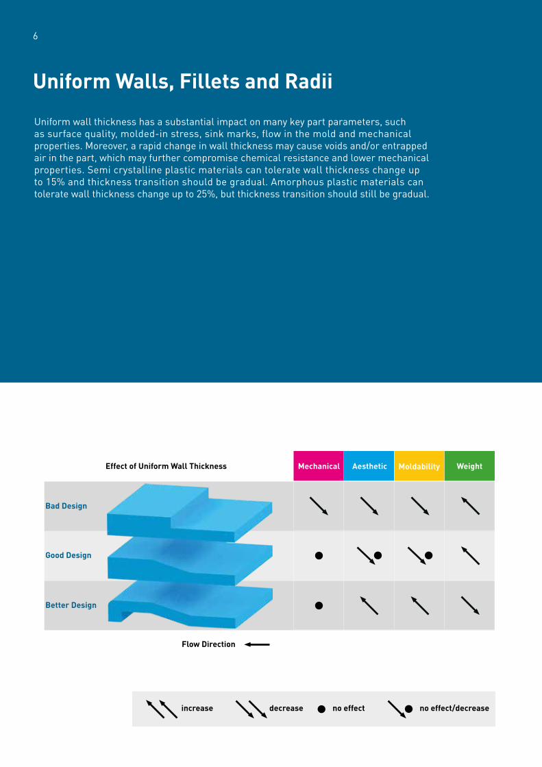
Uniform wall thickness has a substantial impact on many key part parameters, such as surface quality, molded-in stress, sink marks, flow in the mold and mechanical properties. Moreover, a rapid change in wall thickness may cause voids and/or entrapped air in the part, which may further compromise chemical resistance and lower mechanical properties. Semi crystalline plastic materials can tolerate wall thickness change up to 15% and thickness transition should be gradual. Amorphous plastic materials can tolerate wall thickness change up to 25%, but thickness transition should still be gradual.
Uniform Walls, Fillets and Radii
6
Bad Design
Effect of Uniform Wall Thickness WeightMoldabilityAestheticMechanical
Flow Direction
Good Design
Better Design
increase decrease no effect no effect/decrease

Additionally, the attention to detail must be exercised to avoid sharp corners in part design. The part corners should maintain uniform wall thickness and should be designed with a minimum inner fillet radius of 50% of the wall thickness and outer fillet radius of 150% of the wall thickness. In addition, fillets should be co-centric to maintain a uniform wall thickness. Another important function of fillets and radii is to prevent stress concentration and to eliminate the “notch effect” which could cause part failures. Moreover, smooth radii and fillets included in the design of a part provide easy plastic flow in the mold and enable easy demolding.
7
X
R=1,5X
R=X/2
R=1.5X
4X
2X
X
X/2
X/2 - X/3
R=X/2Gusset
Rib
ConnectionRib
Hole
Boss
R=X/4
>2X
>2X

XIncorrect
Correct
Draft is indispensable for the smooth ejection of parts from the mold. Draft should essentially be applied on all surfaces, including ribs and holes of the part. Normally, the recommended minimum draft angle is 1° with 1/2° on ribs. If a minimum draft is desired, a good polishing process would be needed to help clean ejection and the depth of the form should not exceed 15 mm. If, however, the mold surface has textures, then draft angle should be increased. When the draft is applied on the part walls, they should be kept at the same angle to generate uniform wall thickness.
Draft Angle
8
min. 0.5

Bosses are generally designed to accommodate inserts, self-tapping screws, drive pins or other types of fastening elements. These features are used to reinforce holes. As a general rule, bosses should not stand alone, and their outer diameter should be 2.0 to 2.4 times larger than the hole diameter. If, however, the wall thickness of bosses is higher than 50% of the part wall thickness, then visible sink marks will occur. In that case, a sink recess can be used to prevent or minimize visible sink marks. Bosses should not merge with side walls, because they will form thick sections which will lead to voids or sink marks. Instead, they should be reinforced with ribs and gussets. If sink mark is a concern, thickness of the ribs and gussets should not be higher than 50% of the wall thickness. Inner and outer walls of bosses should have 1/2° draft angle for smooth demolding.
Bosses
9
Cutaway
B
2.0-2.4 B
<0.5 A
A
0.3 A max

Ribs are an effective means of enhancing stiffness and strength of the part. In addition, ribs can make savings on material and weight, shorten molding cycle and assist in filling difficult areas, if properly used. However, the unnecessary and inappropriate use may cause warpage and stress on the part. The use of ribs just for safety purposes should be avoided. General rules for rib design are as follows:• Rib thickness will affect the sink mark that occurs on the adjacent wall. If sink marks are concern, the recommendations given in table X should be considered. If the wall thickness is less than 1.5 mm, thicker ribs are tolerable.• Rib height should be between 2.5 to 3 times for an effective support. • Multiple ribs should be spaced at least 2 times the wall thickness.• Draft angle should be 0.5° on each side.• Fillets at the base of the ribs should be minimum 0.5 mm.
Ribbing
10
X
X/2-X/3
R>1/2mm
2X
>1/2”
>2.5-3.0 X
Rib Thickness as a Percentage of Wall Thickness
Resin Type
Amorphous 0.40X 0.60X
Semi Crystalline (unfilled) 0.30X 0.40X
Semi Crystalline (filled) 0.35X 0.50X
Minimal Sink Mark Slight Sink Mark

Cores are used to form the features, such as holes, pockets and recesses. While designing through-holes, one of the mating cores should be slightly larger than the corresponding core to prevent any mismatch whenever possible. If, however, if cores are used to form tight tolerance through holes, they cannot be stepped. So, two sides of the core should interlock each other to provide enough stiffness against the molten plastic flow. Additionally,the length to diameter ratio for these types of cores should be kept around 6:1 to provide enough support against injection process. The flow of molten plastic could be an issue for blind holes. If the core is too thin and long, the flow of the molten plastic could result in the misalignment of the core due to lack of support from the other half of the mold. Therefore, the depth to diameter ratio of the blind holes should not exceed 3:1. If, however, the flow is symmetrical around the unsupported core, then 5:1 is possible. If a higher hole depth is needed, then the core can be stepped with a shorter diameter extension. Bottom thickness of the blind hole should be at least 1/6 of the diameter of the hole to prevent any bulging.
Holes and Coring
Shrinkage is a general characteristic of thermoplastic material that occurs during the cooling phase. Although the amount of shrinkage of a thermoplastic material depends on its chemical structure and formulation, the final shrinkage of a component is also affected by processing conditions, geometry of the part, and mold design. Shrinkage is usually anisotropic, and depends on flow direction especially for glass fiber reinforced materials. Moreover, different wall thicknesses may also lead to difference in shrinkage, which causes internal stress on the part. Furthermore, the rate of cooling in a mold is generally very high and non-uniform, generating additional internal stress. All these generated stresses will be released after ejection from the cavity, and this relief of stress is called post-mold shrinkage which is the main contributor to warpage on the part. For the considerations described above, shrinkage is very complex phenomenon; therefore, it should be analyzed with computer simulations before finalizing the final part design. Yet, final shrinkage could still easily be affected by the mold and injection machine design. Therefore, the final part geometry should be validated by production trials.
Shrinkage & Warpage
11

Secondary Operations:
Assembly

Mechanical fasteners (bolts, screws, rivets, pins, etc.) are the most common assembly method. Although conventional mechanical fasteners can be used for plastic parts, care must be taken in design to avoid failures.
Mechanical Fasteners
14
No Frequent Dissassembly Need
Moulded in threads Bolts
Push-on fasteners Nuts
Press-fits
Rivets Threaded metal inserts
Self tapping screws
Frequent Dissassembly Need
Snap-fits

15
When assembling and disassembling a component frequently, bolts and nuts can be used. These connectors need tightening, but overstressing the plastic part must be avoided. If two hollow plastic components are assembled with bolts, bosses should support the part walls and prevent them from buckling. Moreover, assembly must be limited to a prescribed torque level and rate of torque application must be controlled. Rapid application of torque should be avoided.
The use of conical head bolts should be avoided. These fasteners result in a wedging action that can lead to part failure. Instead, stress under the bolt head has be to be dispersed over a wide area with washer. If spring washers are used, the stress relaxation and loosening of the assembly can additionally be prevented.
If parts from metals are assembled with plastic parts, the difference in the coefficient of thermal expansion must be considered. Elastomeric grommets and/or oversized holes should be used to handle thermal expansion mismatches. If this issue is not handled properly, compressive strengths in the assembly may exceed the yield strength of the plastic part and will result in cracking.
Bolts
Deflection
Compression
X Incorrect
Correct
Elastomeric Grommet
Spring Washer
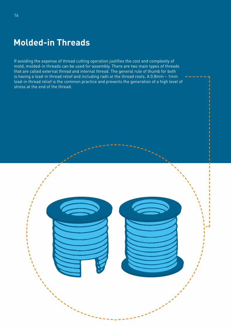
If avoiding the expense of thread cutting operation justifies the cost and complexity of mold, molded-in threads can be used for assembly. There are two main types of threads that are called external thread and internal thread. The general rule of thumb for both is having a lead-in thread relief and including radii at the thread roots. A 0.8mm – 1mm lead-in thread relief is the common practice and prevents the generation of a high level of stress at the end of the thread.
Molded-in Threads
16

17
Self-tapping screws are different from traditional screws as they cut or form their own threads while screwing. Although they eliminate the use of nuts and have better aesthetics, the number of repeated assembly and disassembly is limited.
The method of generating threads divides these screws in two types: thread forming screws and thread cutting screws.
Thread forming screws generate threads by removing material out of the way. Therefore, they need to be used in low filled to unfilled materials. Also because of the deformation, they have a limited repeated assembly and disassembly performance.
Thread cutting screws cut the material while generating threads. During the process, chips are also produced. These screws should not be retightened and a chip reservoir should be included in the part design.
For both screw types, the boss diameter should be 2 – 2.5 times larger than the pilot hole diameter and the thread engagement length should be 2.5 times the screw diameter.
Self-Tapping Screws

A metal component is inserted, if the connecting part will be assembled and disassembled repeatedly throughout its lifetime. There are different insertion techniques that can be used as listed below;
Ultrasonic InsertsDuring ultrasonic installation, a small amount of force is generated by a pneumatic cylinder. This cylinder also acts as a horn and presses the insert into a predrilled or molded hole, while vibrating at an ultrasonic frequency. These vibrations deliver energy to the insert-plastic interface through direct contact and melts the plastic around the insert.
Heated InsertsInserts are heated by a special press. When the desired temperature is achieved, the press pushes the insert to pre-drilled hole. Temperature melts the plastic, and the molten plastic flows into the undercuts and secures the component. Although the heated insertion has a longer cycle time than ultrasonic insertion, it generates low stress on the plastic part and has low equipment cost.
Threaded Metal Inserts
18

19
Cold InsertsThese inserts can be pressed as cold, but this is not recommended since they generate too much stress.
Molded-In InsertsThe insert is placed in the mold cavity before the injection cycle and thus creates a strong bond with minimal internal stress. This process also minimizes the secondary time, but it is important to heat the insert to the mold temperature before molding. Heating the insert will eliminate post internal stresses by reducing the difference in thermal expansion.
Self-Tapping InsertsSelf-tapping screws have an external thread which enables the insert screw itself to a molded or drilled hole via its cutting edge.
Expansion Inserts Like cold inserts, expansion inserts are pressed into the plastic and expand when the assembly screw is tightened. This method also generates high stress and is not recommended for stiff plastic materials consequently.
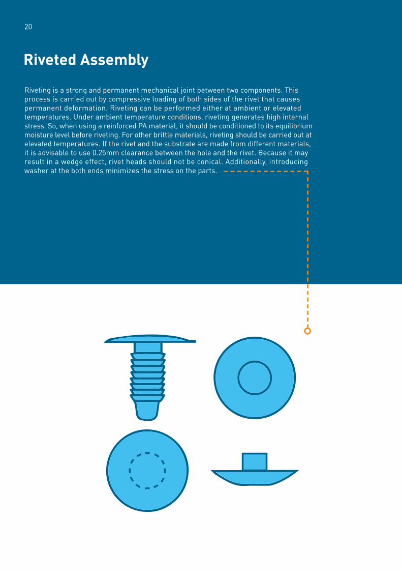
Riveting is a strong and permanent mechanical joint between two components. This process is carried out by compressive loading of both sides of the rivet that causes permanent deformation. Riveting can be performed either at ambient or elevated temperatures. Under ambient temperature conditions, riveting generates high internal stress. So, when using a reinforced PA material, it should be conditioned to its equilibrium moisture level before riveting. For other brittle materials, riveting should be carried out at elevated temperatures. If the rivet and the substrate are made from different materials, it is advisable to use 0.25mm clearance between the hole and the rivet. Because it may result in a wedge effect, rivet heads should not be conical. Additionally, introducing washer at the both ends minimizes the stress on the parts.
Riveted Assembly
20
21
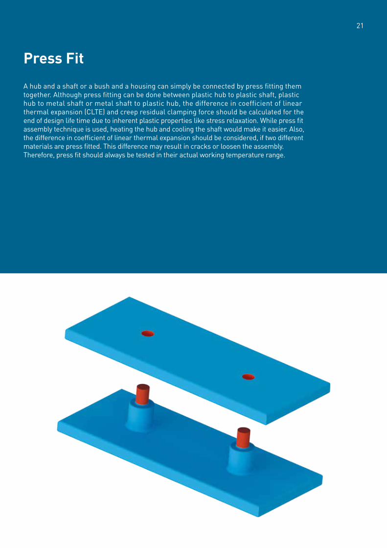
A hub and a shaft or a bush and a housing can simply be connected by press fitting them together. Although press fitting can be done between plastic hub to plastic shaft, plastic hub to metal shaft or metal shaft to plastic hub, the difference in coefficient of linear thermal expansion (CLTE) and creep residual clamping force should be calculated for the end of design life time due to inherent plastic properties like stress relaxation. While press fit assembly technique is used, heating the hub and cooling the shaft would make it easier. Also, the difference in coefficient of linear thermal expansion should be considered, if two different materials are press fitted. This difference may result in cracks or loosen the assembly. Therefore, press fit should always be tested in their actual working temperature range.
Press Fit

Snap fits are economical and effective elements that can be integrated into the design to eliminate additional fasteners. They can be designed for repeated use or permanent assembly according to the need. In general terms, snap fits can be divided in two categories;
A. Cantilever snap fits can be used for either filled or unfilled materials.
B. Cylindrical snap fits can be used for only unfilled materials.
Snap Fit
22
A. Cantilever (Filled & Unfilled Materials)
B. Cylindrical (Unfilled Materials)
Beam Cross Section
rectangular
one third round
half round
one quarter round
Permissible Deflection
h
t
L
h = x x23 100
Lt
2
h = x xLt
2
h = x xLt
2
h = x xLt
2
0.576
0.580
0.555

23
The key points for designing snap fits are as follows; • Their permissible strain should not exceed the allowable strain of the material.• If repeated use is needed, snap fit undercut should be drafted.• Flexing cantilever should not continue to deflect after assembly.• Sharp corners should be avoided and a minimum radius of 0.5 mm should be used.• While removing sharp corners, uniform wall thickness should be kept to avoid sink marks and voids.• Snap arms should not exceed 50% to 60% of the attached wall thickness.
The allowable strain is determined by yield strain for unfilled materials and by maximum strain for filled/reinforced materials. It is also affected depending on if there will be a single snap or repeated use.
Material Destription
PA (dry as molded) 2.50 80 4.0
PA GF30 (dry as molded) 1.50 190 3.0
3.0
2.5
PBT
PBT GF20
PBT GF30
2.00
1.50
1.25
50
115
135
3.5
Allowable Strain - ! (%) Yield Strength (Mpa) Yield Strain (%)

Welding permanently joins two plastic components through the phase change from solid to liquid and then re-solidification. There are several welding techniques that are described below.
Ultrasonic WeldingUltrasonic welding process is the conversion of electrical energy into high frequency mechanical motion. This rapid motion coupled with applied pressure generates heat due to friction in the joint area of plastic components. Heat melts the plastic in the mating area and creates a bond during re-solidification.
Semi-crystalline materials are more difficult to ultrasonically weld than amorphous materials for two reasons. First, they require extra energy for dissolving the crystalline part of the polymer. Second, their orderly molecular structure absorbs vibrational energy, making it more difficult to transmit motion from the horn contact point, through the plastic, to the joint interface of the parts being welded. With amorphous materials, the random arrangement of molecules allows the vibrational energy to pass through them smoothly with little attenuation. Properly designed energy directors or shear weld features are needed for consistent and strong welds. In general, shear weld features are used for semi-crystalline plastics.
Welding
24
Polymer Type Range of Vibration Amplitude at 20 kHz ("m)
PA
PBT
PP, PE
PPS
PEEK
POM
PC
ABS
PS
60-80
60-125
70-90
Fixture
80-125
60-125
75-125
50-70
40-60
20-40

25
Vibration / Spin WeldingVibration / spin welding is a preferable practical method for assembling large structural parts. This welding technique is most suitable between same or similar thermoplastics and especially useful for rigid material welding. In vibration / spin welding, parts are to be joined, vibrated or spun against each other at a chosen frequency, amplitude and pressure. This results in frictional heating and melting at the interface. When vibration stops, the molten polymer cools down and generates a strong hermetic bond.
Hot Plate WeldingHot plate welding generates a non-cosmetic, cost-effective and single plane bond. In this method, a heated plate contacts two joint areas and slightly melts them. Then the heated plate is removed, and joint areas are pressed against each other. During this process, the molten plastic is subjected to air which makes the material prone to thermal oxidation.
Material Combination Exemples for Vibration Welding
ABS
ABS
ABS
PC
PC
PC
PPO+PS
PPO+PA
PE
PMMA
PC
PC+ABS
PMMA
PC+ABS
PC+PBT
PC+ABS
PA
PP
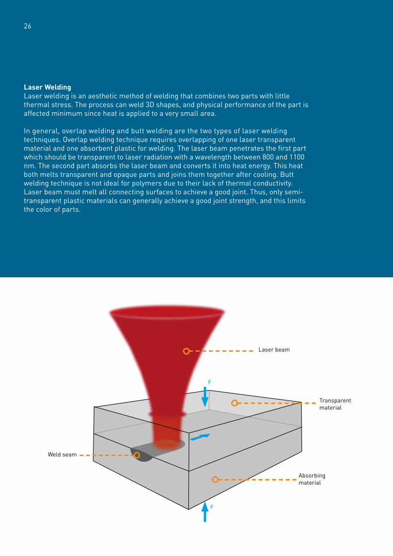
Laser WeldingLaser welding is an aesthetic method of welding that combines two parts with little thermal stress. The process can weld 3D shapes, and physical performance of the part is affected minimum since heat is applied to a very small area.
In general, overlap welding and butt welding are the two types of laser welding techniques. Overlap welding technique requires overlapping of one laser transparent material and one absorbent plastic for welding. The laser beam penetrates the first part which should be transparent to laser radiation with a wavelength between 800 and 1100 nm. The second part absorbs the laser beam and converts it into heat energy. This heat both melts transparent and opaque parts and joins them together after cooling. Butt welding technique is not ideal for polymers due to their lack of thermal conductivity. Laser beam must melt all connecting surfaces to achieve a good joint. Thus, only semi-transparent plastic materials can generally achieve a good joint strength, and this limits the color of parts.
26
F
F
Laser beam
Transparent material
Absorbing material
Weld seam
27
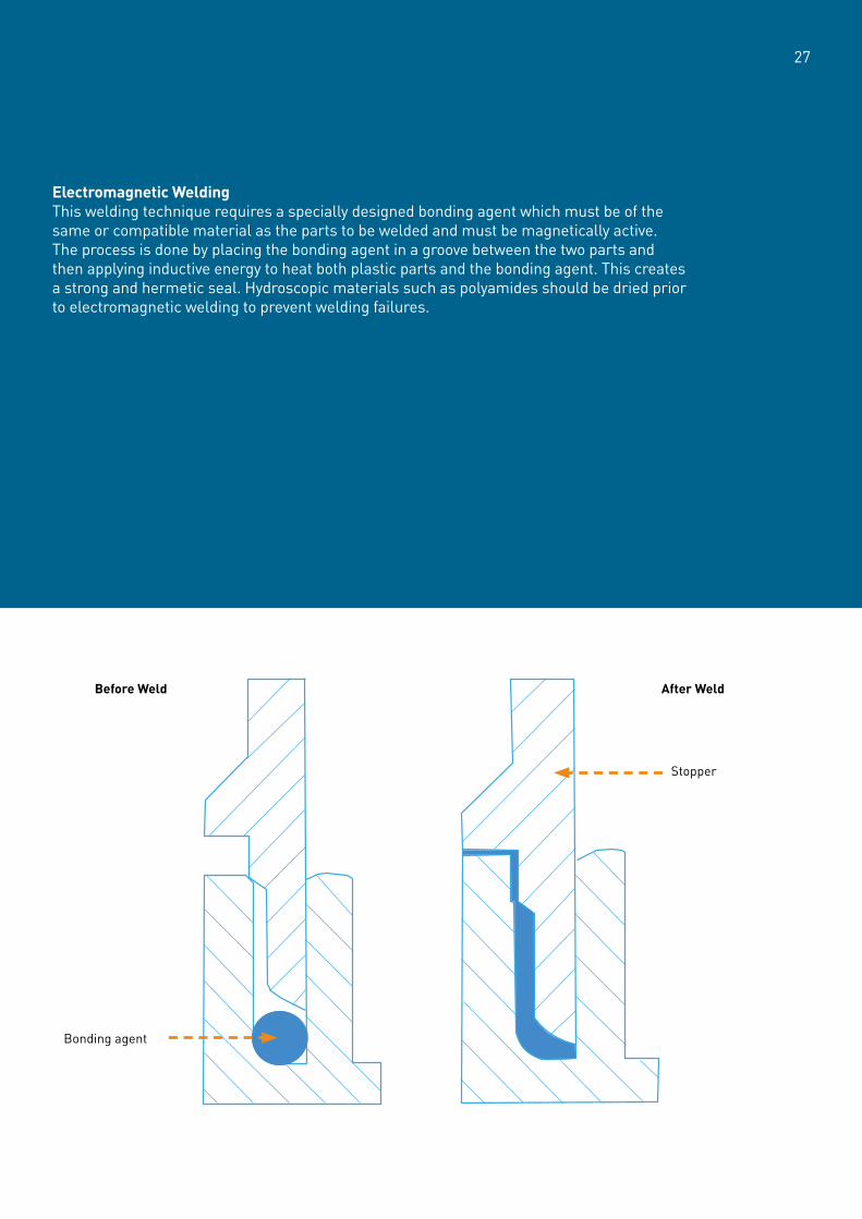
Electromagnetic WeldingThis welding technique requires a specially designed bonding agent which must be of the same or compatible material as the parts to be welded and must be magnetically active. The process is done by placing the bonding agent in a groove between the two parts and then applying inductive energy to heat both plastic parts and the bonding agent. This creates a strong and hermetic seal. Hydroscopic materials such as polyamides should be dried prior to electromagnetic welding to prevent welding failures.
Before Weld
Bonding agent
Stopper
After Weld

Solvent Bonding (Welding)The solvent bonding process is done by applying suitable solvent to the joint interface to swell the interface and then join the parts by applying pressure until curing finishes.
Suitable solvents for Polyamide and PA blends are concentrated formic acid, alcoholic calcium chloride, concentrated aqueous chloral hydrate, or concentrated alcoholic phenol and resorcinol. A slurry made from five to ten percent by weight of unreinforced PA with the solvent makes it easier to use and creates a smooth filling.
Polyester materials and their blends, such as PBT, PET and PBT+PET, are not suitable for solvent bonding due to the high chemical resistance. Aggressive solvents must be used for bonding for these resins which can cause low bond strength.
Polycarbonate and Polycarbonate+ABS blends can be used in solvent bonding. Methylene chloride or ethylene dichloride are the suitable solvents than can be used to bond parts made from them. Methylene chloride has a faster evaporation rate than ethylene dichloride, which prevents solvent vapor entrapment. If, however, the assembly is complex and requires longer curing time, ethylene dichloride should be used. Therefore, the mixture of both solvents is used for efficient bonding in general. When solvent bonding is used with these materials, parts can show some embrittlement and lose their impact strength at the bonding joint. A five to ten percentage solution of polycarbonate in methylene chloride can be used to fill the joint when parts do not fit perfectly, but it should not be used for aligning severely mismatched joints. If the slurry concentration rises by more than ten percent, it can create bubbles at the joint.
Styrenic materials like ABS, SAN and ASA can be solvent bonded typically with methylethylketone (MEK), acetone or a mixture of these two. Furthermore, a paste made of MEK and the base resin can be used to fill small gaps in a part or assembly.
Adhesive BondingParts can also be joined by using adhesives. With adhesives, two similar or dissimilar materials can be joined together by a strong and leak tight bond. However, it is easier to achieve a good adhesion with amorphous polymers than semi-crystalline polymers since molecular interdiffusion is limited in polymer crystallites. The adhesion of non-polar polymers like polyolefins can considerably be improved in the surface, if treated with corona, UV, plasma or flame. Additionally, poor bonding can occur, if the adhesive layer is not in contact with the substrate properly. Therefore, pretreatments like cleaning, degreasing and sanding will improve the bond strength considerably. The choice of adhesives depends on the application and operating conditions of the part. The information about some of the adhesives can be found below.
Polyurethanes; these adhesives are usually two parts with high strength and good impact resistance and good low temperature flexibility. These resins have a limited moisture resistance and long curing times, which usually creates a need for a fixture.
Epoxies; these adhesives also consist of two parts and they provide a high thermal resistance with high strength values. However, they do not have a good impact strength. Due to long curing times, they also need to be fixtured.
Cyanoacrylates; this is a one-part, highly strong and fast curing adhesive with limited service temperature generally around 95°C and poor impact resistance and low moisture temperature. Silicones; they are generally two-part adhesives with high temperature resistance, good low temperature resistivity, good impact strength and good sealing capability. They also require long curing times and they need to be fixtured during curing.
28
29
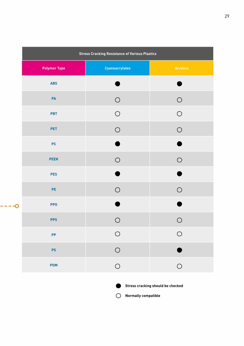
Polymer Type Cyanoacrylates Acrylics
ABS
PA
PBT
PET
PC
PEEK
PES
PE
PPO
PPS
PP
PS
POM
Stress Cracking Resistance of Various Plastics
Stress cracking should be checked
Normally compatible


Finishing & Decoration

32
Parts made from pre-colored thermoplastics can be made in vast variety of colors but there are certain reasons for the performance of paintwork as a secondary operation, such as;• Color matching adjacent assembled parts that are made from different materials and/or by different processes• Hiding irregularities in the substrate• Improving chemical, abrasion or UV resistancea
On the other hand, if a brittle paint and/or primer is used on a ductile plastic, crack in the paint would propagate through the plastics and reduce its impact strength. Furthermore, solvents in the paint could cause stress cracking especially near gates, weld lines and wall thickness transition points.
Pretreatment of the surface is very important, and the parts to be painted must be clean and free of any contaminants. Therefore, cleaning is necessary in most cases, and painting should be done in a dust free environment. There are several other pretreatments to enhance the adhesion of the paint, such as flaming, low pressure plasma treatment, corona treatment, priming and sanding.
There are basically four components in paints and these are base resin that forms the coating; pigments and/or dyes for coloring; a solvent for thinning and delivery; and some additives to modify the paint. Although there is a vast variety of paints in the market, the common types of paint used on plastics are;• Polyurethane paints do not require heat for curing and provide a flexible and tough finish. They are not only compatible with most plastics, but also a good choice for amorphous substrates.• Epoxy paints provide a hard and durable finish with a good gloss.• Vinyl paints provide a soft and rubbery finishes. • Acrylic paints deliver hard and scratch-resistant surface and are resistant to most common oils.• Polysiloxane paints provide scratch- and chemically resistant finish which can be also transparent.
Different solvents can be used for paint systems, but they are generally divided in two groups, such as;• Organic solvents swell the substrate to form strong coatings that have a very good adhesion. But if the solvent used is very aggressive, they can damage the substrate.• Water as a solvent is generally less aggressive, but it provides a weak adhesion to the part. The most important advantage of water-based systems is that they prevent most health and safety issues and have very low emissions.
Painting

Semi-crystalline plastics like polyamides have a high chemical resistance to many solvents and therefore, they require special pretreatments or especially primers. The allowable moisture level should be determined especially for polyamides. Amorphous plastics have a lower chemical resistance and thus provide a better adhesion. If, however, the solvent system in the paint is too aggressive, it can cause stress cracking.
The most common method for applying the paint is spraying, because it can be easily automated to improve consistency. There are three type of spraying process, such as;• Conventional spray painting; high pressure air generates and delivers small paint droplets.• Airless systems; paint is forced through the nozzle at a high speed.• Electrostatic system; the part and the paint are oppositely charged so that droplets are attracted to the part surface.
In practice, the surface tension of wet paint must be higher than the substrate surface tension for good wetting. If the paintwork ambient is too hot or dry, the solvent in the paint system could evaporate quickly which can cause irregular paint thickness distribution known as dry spray.
Plastic Surface Painting Steps
Surface Pretreament Adhesion Promoting Paint Application Curing
Claning Flaming Spray painting Air curing
Low pressure plasma Airless systems Heat curing
Corona Electrostatic systems Two component systems
Priming
Sanding
33

Plastic parts are metallized for a variety of functions, such as aesthetics, conductivity and/or EMI/RF shielding. These parts can be an economical and lightweight alternative to metals and improve component’s visuality and texture. Functional coatings can also provide electrically conductive surface and provide EMI/RF shielding. The process can be carried out with several techniques, but the primary ones are electroplating, electroless plating, vacuum metallizing and sputter coating.
Electroless PlatingBy electroless plating process, a metallic coating can be deposited on electrically nonconductive plastic. The process requires a series of pretreatment parts which should clean, etch and surface activate the plastic part prior to plating. This process is generally used for either creating a conductive layer for electroplating or providing EMI/RF shielding. The common plating combination is nickel over copper.
Metallization
34

35
For this process, the following items should be considered regarding special part design;• All plated edges should have a radius of 0.25 mm minimum,• All outer edges of the part should have a radius of 1.60 mm minimum,• Flashes on the part should be minimized,
To prevent variation in coating thickness, the design of the part should prevent air entrapment during immersion in baths and clamping points should be designed so that they can secure the part on the rack without flexing it.
Additionally, the molding process directly affects the coating quality. High molded-in stresses should be minimized by using high mold temperatures and slow filling speeds. The design should allow for demolding without using mold release agents. Ejector pins should be self-lubricating to prevent any oil contamination on the part surface. Another key point in mold design is the gate position which must be in a non-visible position. In addition, a satin-finish on the mold surface improves adhesion of the coating.
Electroless Plating Steps
Surface Cleaning Etching Surface Activation Metal Plating (thin layer)

ElectroplatingThis process requires either electrically conductive plastic part or electroless plated plastic part to provide a durable coating on the part. Same design and molding considerations as electroless plating are also valid for electroplating.
36
Electroplating Steps
A- Electrically Insulative Plastic
B- Electrically Conductive Plastic
Surface Cleaning Etching Surface Activation Metal Plating(thin layer)
Metal Plating (final layer)
Surface Cleaning Metal Plating(final layer)

37
Vacuum MetallizationVacuum metallization is widely used to deposit a thin layer of metal onto plastic parts in a vacuum chamber. During the process, tungsten filaments or electron beams evaporate metal, commonly aluminum, and then these metal particles condense onto the plastic part. After the process, another top coat is often applied to protect the coating. The key point in part design for vacuum metallization is keeping in mind that the process only coats in a line of sight pattern. Therefore, shadowed or undercut features will not be coated. Moreover, the part must be rotated for two side coating.
Sputter DepositionSputtering is also a vacuum coating process in which the evaporated metal is deposited via an inert gas plasma. Sputtering provides thicker layer of metal coating and offers more metal choices like chromium, copper, gold, tungsten, stainless steel and brass. Because sputtering is also a vacuum deposition, the process only coats in a line of sight patterns, but in general provides better adhesion than standard vacuum metallization.
Wire Oxygen fuel gas mixture
Compressed atomising air
Spray stream of molten atomised particles
Coating

Pad PrintingPad printing is an efficient process for single color printing which can be carried out by two methods. In the first method, the patterned ink pad picks up a layer of ink which is deposited onto a transfer plate by a roller. In the second method, a smooth pad picks up a pattern of ink from an etched imprinted plate which is filled with ink. In both processes, the pad transfers ink to the part by pressing on it.
Screen PrintingIn this process, ink is pushed through a mesh or a stencil made from silk, polyester or stainless steel to print a specific pattern on the plastic part. Multi-color printing is only possible with sequential overprinting.
Sublimation PrintingIn this process, ink sublimes (goes directly from solid phase to gas phase) with a pattern to a transfer film. Then the film is placed on the plastic part with heat and pressure application. Dye penetrates the plastic surface and is sealed as the part cools down.
Printing
38
1
Silicone StampPad Printing
Process
Mold
PastePaddle
3
5
2
3
6

39
FlexographyThis is a high-speed printing technique which is commonly used in plastic film printing. Multi-color printing is possible with successive printing stations.
For all the printing techniques above, it is most important that surface energy of the wet ink should be lower than that of the substrate. Printing on polyamides is easy thanks to their high chemical resistance and strong polar characteristics. However, acceptable mold release agents and moisture levels should be determined during test runs. For PBT and PET materials, a primer is needed for a good printing quality. Because inks contain various solvents, solvent compatibility should be checked when printing amorphous materials.
Flexography
Ink Tray
Ink
Fountain Cylinder
Doctor Blade
Flexible Plate
Plate Cylinder
Impression Cylinder
Anilox Cyinder Substrate

5 7 9 11 13 15 20 25 30
300 423 593 762 931 1101 1270 1693 2117 2540
400 318 445 572 699 826 953 1270 1588 1905
500 254 356 457 559 660 762 1016 1270 1524
600 212 296 381 466 550 635 847 1058 1270
700 181 254 327 399 472 544 726 907 1088
800 159 222 286 349 413 476 635 794 952
900 141 198 254 310 367 423 564 705 847
Laser Printing & Marking Laser marking is a flexible way of marking plastic parts either by direct contact or selective evaporation of a coating which should be applied prior to marking. In direct contact, various colors of marking are achieved with a specially formulated compound.
The combination of wavelength, power, spot size, frequency and the marking speed parameters has a strong effect on produced mark quality in laser printing.
Wavelength (#): Plastic materials absorb different wavelengths and therefore different wavelengths interact differently with the plastic substrate. Power (p): Laser beams are generally not continuous and sent as pulses. Power defines the energy per pulse.
Frequency (q): Pulses per second is defined as frequency. A higher frequency represents a higher energy release on the plastic substrate.
Marking speed (v): The speed of beam travel on the plastic substrate is defined as marking speed.
Spot size of the laser beam also plays a major role in laser printing, which determines line width of the mark and power density of the pulse.
Dpi (image resolution) number of the laser printing is a function of pulse frequency and marking speed of the process. A table is given below to show the correlation between them.
40
dpi
v (mm/s)
Pulse frequency (Hz) as a function of laser marking speed and dpi

41
In general, machining is often used for the products which are produced by extrusion and blow molding processes. Plastic machining techniques require extra precautions and the following points should be considered;• Although HSS (high-speed steel) tools or carbide tools can be used, the tools specially designed for plastic machining would yield higher production rates. If machining will be carried out on a filled/reinforced plastic material, carbide or diamond tipped tools should be used.• Especially for reinforced resins, tool sharpness is critical.• Plastics are thermally insulative materials. So, cooling the work piece is critical to avoid local melting and gumming. Because reinforced semi-crystalline materials are more resistant to gumming, they are generally easier to machine. Cutting oils and cooling liquids used in the metal industry should be avoided as they might not be compatible with the plastic. Forced air stream or a compatible cooling liquid should be used.• Plastic materials have a high coefficient of linear thermal expansion. Therefore, the final part dimension should be checked after cooling.• Cutting force should be minimal to avoid stress accumulation.
Machining
Carbide or diamond tippe tools should be used.
Cooling the work piece is critical.
The final part dimension should be checked.
Cutting force should be minimal.
Tool sharpness is critical.

Notes


Karamehmet Mah. European Free Zone Avrasya Bulvari No:8 TR 59930Ergene, Tekirdag - TurkeyT: +90 282 265 12 00F: +90 282 691 12 18www.eurotec-ep.com