Part B – Health Facility Briefing & Design
718
Part B – Health Facility Briefing & Design including Functional Planning Units International Health Facility Guidelines Version 5 Sep 2017
-
Upload
khangminh22 -
Category
Documents
-
view
0 -
download
0
Transcript of Part B – Health Facility Briefing & Design

Part B – Health Facility Briefing & Design including Functional Planning Units
International Health Facility Guidelines
Version 5 Sep 2017

International
Health Facility Guidelines © TAHPI
Part B: Version 5 2017
Page 2
Table of Contents
1 Planning Preliminary Information .......................................................................................................... 3 1 Structure of these Guidelines...................................................................................................................................... 3 2 Levels of Recommendation ......................................................................................................................................... 3 3 Health planning ............................................................................................................................................................. 3
2 Role Delineation Guide ........................................................................................................................... 5 1 Role delineation level (RDL) ........................................................................................................................................ 5 2 Role delineation guide ................................................................................................................................................. 5
3 Standard Components ............................................................................................................................ 6 1 Room Data Sheets (RDS) ............................................................................................................................................. 6 2 Room Layout Sheets (RLS) ......................................................................................................................................... 6
4 Planning ................................................................................................................................................... 7 1 Site Development .......................................................................................................................................................... 7 2 Masterplan Development ............................................................................................................................................. 7 3 Local Design Regulations .......................................................................................................................................... 13 4 Floor Area Measurement Methodology, Definitions and Diagrams ...................................................................... 14 5 Parking and Vehicular Access .................................................................................................................................. 18
5 Acceptable Standards and Guidelines ................................................................................................ 31
6 Functional Planning Units .................................................................................................................... 32
7 Appendix A – Role Delineation Level Guide ....................................................................................... 33

Planning Preliminary Information
International
Health Facility Guidelines © TAHPI
Part B: Version 5 2017
Page 3
1 Planning Preliminary Information 1 Structure of these Guidelines Part B of the International Health Facility Guidelines covers the subject of Health Facility Design and the factors which influence the outcome. Health Facility Design requires knowledge, skill and experience. These guidelines alone may not be sufficient to ensure good design, however, using these guidelines, a reasonably skilled designer should be able to focus on the required functionality quickly and deliver a product which meets the minimum Local Health Authority requirements. The administrative requirements for health facility applications have been covered in Part A of the International Health Facility Guidelines. This part focuses on the Architectural and Health Planning Aspects. This part may include aspects of service health service provision and facility design which are not part of the Local Health Authority approval but required as part of the process of delivering a competent health facility. Part C addresses issues related to Access, Mobility and Occupational Health and Safety requirements. Part D details the Infection Control requirements of healthy facilities. Part E will focus on the Engineering aspects. All parts must be taken into consideration in the design of health facilities. 2 Levels of Recommendation Mandatory Requirements Within these Guidelines, all paragraphs by default are mandatory. In situations where the text has the potential for misunderstanding, the note "mandatory" may be used to clarify any aspect which is absolutely required without re-interpretation. Even if the word "Mandatory" does not appear in the text, it does not indicate that the paragraph is optional. This principle also applies to Schedules of Accommodation, Room Data Sheets and Room Layout Sheets. Items listed are required and only optional if indicated. Recommended Requirements On some occasions a standard is mandatory but a higher standard is recommended. The intention is to guide designers who wish to voluntarily upgrade the facility to a higher standard and wish to know what the higher standard is. Optional Requirements The text, Schedules of Accommodation and Room Data Sheets will indicate “Optional” for all items that that are not mandatory requirements. 3 Health planning Health Service Provision is determined by the discipline known as Health Planning. There are two branches to this discipline; Health Service Planning and Health Facility Planning. Health service planning This discipline relates to the research, analysis and calculation of demand and supply for a given population catchment. Every competent proposal for a health service starts with a Service Plan.

Planning Preliminary Information
International
Health Facility Guidelines © TAHPI
Part B: Version 5 2017
Page 4
Demand
A Health Service Planner uses various statistical tools as well as benchmarks and localised information to determine the raw demand. This may be represented by Occasions of Service (OOS), Average Length of Stay (ALS), Presentations Per Annum (PPA), etc. The service planner will consider inflows of patients from other catchment areas as well as outflows to other catchment areas. The calculations will include level of self-sufficiency desired or anticipated. The demand is typically calculated for a period of time into the future known as the Time Horizon of the Study. This may be 10 to 20 years into the future. The starting point will be known as the Base Point or Base Year. The characteristics of the population in terms of age, gender and predisposition to various diseases and socio-economic class have the greatest influence on the on the demand of each population catchment. A Service Planner finally converts raw demand into facility units known as Key Planning Units (KPUs). KPUs may vary greatly depending on the nature of the facility. They include: ▪ Bed numbers of a variety of types ▪ Operating Room Numbers ▪ Birthing Room Numbers ▪ Emergency Treatment Cubicles ▪ Consultation Rooms ▪ Diagnostic modes of a variety of types. These KPUs are later used by Health Facility Planners to prepare a full brief for the proposed facilities.
Supply
This refers to the current supply of health facilities and the service they provide to the same population catchment. This may or may not meet the needs of that population catchment now or in the future.
Service Gap
The difference between the Demand and Supply is the Service Gap which needs to be met by the provision of health facilities. The process of determining this gap and proposing solutions for meeting it is described as: ▪ Needs Analysis, ▪ Feasibility Study; or ▪ Business Case. A proposal for a facility, therefore, should not commence with a block of land and design. Health Facilities are too important to be treated purely as a real-estate development. A competent Service Plan resulting in a Needs Analysis, Feasibility Study or Business Case must be at the core of any proposal.
Health facility planning
This is the discipline which aims to design facilities and meet the health service gap. The outcome of this discipline is design and specifications for the construction of facilities or refurbishment and expansion of existing ones. Design does not start from a blank sheet of paper. Prior to design a great deal of preparation is required. These are briefly described in the following sections.

Role Delineation Guide
International
Health Facility Guidelines © TAHPI
Part B: Version 5 2017
Page 5
2 Role Delineation Guide The health service requirements can be classified under broad categories such as Emergency, Inpatients, Surgery, and Intensive Care etc. Each of these may be designed for a particular level or standard of service. These are known as Role Delineation Level or RDL and numbered from 1 to 6 (including in-between numbers such as 4-5); level 1 representing uncomplicated health facilities, ascending to level 6 representing complex specialist services and hospitals. 1 Role delineation level (RDL) To illustrate the difference in RDL, an Intensive Care Service provided by a major Metropolitan hospital which also incorporates Teaching and Research will be at RDL 6. The same service provided at a small General hospital without Teaching and Research facilities will be at RDL 4. At higher RDLs the service provision will require access to higher levels of skill and additional, complementary services. For example Surgery at RDL 5 will require Intensive Care services also at RDL 5 plus many more supporting services. The relationships between all the services and the inter-dependence of the services at each RDL results in a large matrix with services one side and 6 RDLs on the other side. The operators of health facilities and/or the designers need to decide what services they wish to provide as well as the RDL for those services. Only then, the facility requirements can be determined and verified. For example, the number, type and size of rooms for an ICU service at RDL 6 will be different to one at RDL 4. International Health Facility Guidelines provide a Role Delineation Guide which sets out the most common health services under each RDL. Under each category the requirements and dependencies are stated. The Role Delineation Guide is enclosed at the end of this section. A blank version of the Role Delineation Guide is available in electronic spreadsheet format to allow the proposed services and RDLs to be listed. This is known as the Role Delineation Matrix. This RDL Matrix can be used by the Health Facility Planning team to prepare the Facility Brief. It is also used by the Local Health Authority to assess applications for health facilities (refer to Part A of the International Health Facility Guidelines) 2 Role delineation guide The Role Delineation Guide is described in Part B, Volume 1, Appendix A of this document.

Standard Components
International
Health Facility Guidelines © TAHPI
Part B: Version 5 2017
Page 6
3 Standard Components The FPU Schedules of Accommodation by RDL includes listings of Standard Room Types required. In order to assist designers to better understand the requirements of each room type, the International Health Facility Guidelines includes a comprehensive set of Standard Components. These Standard Components are represented by two sets of documents: 1 Room Data Sheets (RDS) These are written descriptions of each room type, described under various categories: ▪ Room Primary Information; includes Briefed Area, Occupancy, Room Description and
relationships, and special room requirements) ▪ Building Fabric and Finishes; identifies the fabric and finish required for the room ceiling,
floor, walls, doors, and glazing requirements ▪ Furniture and Fittings; lists all the fittings and furniture typically located in the room ▪ Fixtures and Equipment; includes all the serviced equipment typically located in the room
along with the services required such as power, data, hydraulics ▪ Building Services; indicates the requirement for communications, power, Heating, Ventilation
and Air conditioning (HVAC), medical gases, nurse/ emergency call and lighting along with quantities and types as relevant.
Refer to Volume 2 and Volume 3 of Part B for the full set of Room Data Sheets. 2 Room Layout Sheets (RLS) These are individual sheets incorporating typical design of rooms at 1:50 scale with abbreviations, dimensions etc. Each Room Layout Sheet includes a Plan as well as 4 or more elevations showing the installation height of elements. Note: These Room Layouts are indicative plan layouts and elevations illustrating an example of minimum acceptable design standard. The Room Layouts shown are deemed to satisfy these Guidelines. Alternative layouts and innovative planning shall be deemed to comply with these Guidelines provided that the following criteria are met: ▪ Compliance with the text of these Guidelines ▪ Minimum floor areas as shown in the schedule of accommodation ▪ Additional 2m2 added for each additional door above the minimum required area ▪ Heights and dimensions where shown ▪ Any Clean/ Dirty separations shown or implied ▪ Accessibility to and around various objects as shown or implied. Room Layout Sheets must indicate relative location and empirical dimensions of: ▪ Hand rails and Grab rails ▪ Call points, Power, Light Switch, Data and Gas outlets ▪ Bed Screens ▪ Sanitary Fixtures. Refer to Volume 4, Volume 5 and Volume 6 of Part B for the full set of Room Layout Sheets.

Planning
International
Health Facility Guidelines © TAHPI
Part B: Version 5 2017
Page 7
4 Planning 1 Site Development The location and development of the site shall be in accordance with the requirements of the Urban Planning Council and the local Municipality. Below we have summarised the main criteria to be considered when developing a site, accommodating a health facility. Environmental Impact The aesthetics and form of a health facility shall be sympathetic with its immediate environment, either built or natural; for example domestic scale and treatments where built in a residential area. The building should enhance the streetscape. Note: This is not a mandatory requirement but is highly recommended. Consideration should also be given to the siting of a health facility to ensure that it is accepted as an asset by the community, and not thought of as an imposition and inconvenience on the neighbourhood. Landscaping A suitable landscaping scheme shall be provided to ensure that the outdoor spaces are pleasant areas in which patients, visitors and staff may relax. The scheme should also ensure that the buildings blend into the surrounding environment, built or natural. Water conservation should be a consideration when designing layouts and selecting plants. The use of mains water for reticulation is restricted. The local authority on water supply should be consulted for current regulations. Site Grading The balance of a health facility site not covered by buildings should be graded to facilitate safe movement of the public and staff. Where this is not possible, access should be restricted. Public Utilities Impact on existing local service networks may be substantial. In establishing a health facility on any site, the requirements and regulations of authorities regulating water, electricity, gas, telephones, sewerage and any other responsible statutory or local authority must be complied with. Structural requirements If the site is low lying, on the side of a hill, or partly consists of rock then structural engineering advice should be sought at an early stage to minimise future drainage or settlement problems. 2 Masterplan Development Planning relationships and the use of planning models The planning of health facilities requires general knowledge of the appropriate relationships between the various components. Certain components (also referred to as Functional Planning Units or FPUs) need to be adjacent or close to other components. Most components must be accessible independently without having to go through other components. In short, the planning of a health facility requires a certain logic which is derived from the way the facility functions. Good Planning Relationships: ▪ Increase the efficiency of operation ▪ Promote good practice and safe health care delivery

Planning
International
Health Facility Guidelines © TAHPI
Part B: Version 5 2017
Page 8
▪ Minimise recurrent costs ▪ Improve privacy, dignity and comfort ▪ Minimise travel distances ▪ Support a variety of good operational policy models ▪ Allow for growth and change over time. Inappropriate Planning Relationships: ▪ Result in duplication and inefficiency ▪ May result in unsafe practices ▪ Increase running costs ▪ May result in reduced privacy, dignity and comfort ▪ Increases travel distance or force un-necessary travel ▪ Result in lack of flexibility to respond to future growth and change ▪ May limit the range of operational possibilities. Planning Models: The planning of a complex health facility is based on applying commonly recognised "good relationships" as well as taking into consideration site constraints and conformity with various codes and guidelines. In theory it is possible to go back to the basics every time. In practice however, designers soon discover that this is an inefficient way of arriving at appropriate planning solutions. Just as in other buildings types e.g. hotels and shopping centres, health facilities have over time evolved around a number of workable Planning Models. These can be seen as templates, modules, prototypes or patterns for the design of new facilities. These Guidelines include a number of flow diagrams, also referred to as Functional Relationship Diagrams which represent Planning Models for various Functional Planning Units (FPUs). The flow diagrams are referred to in the appropriate sections of these Guidelines. They cover not only internal planning and relationships within the FPUs, but also relationships between FPUs. Designers may use these diagrams to set out the various components and then manipulate them into the appropriate shapes to suit the site constraints. Designers are encouraged to see the overall design as a model. A good health facility plan usually can be reduced to a basic flow diagram. If the diagram has clarity, is simple and logical, as demonstrated in the FPUs in these Guidelines, it probably has good potential for development. A skilled designer will use these planning models to assemble the requirements of a health facility on the site without compromising functionality. If on the other hand the model is too hard to reduce to a simple, clear and logical flow diagram, it should be critically examined. It is not sufficient to satisfy immediate or one-to-one relationships. Similarly, it may not be sufficient to satisfy only a limited, unusual or temporary operational policy. It is more important to incorporate planning relationships that can satisfy multiple operational policies due to their inherent simplicity and logic. Masterplanning In the health care industry, the term “Masterplan” has different meanings in different contexts. The most common use of the term “Masterplan” refers to words, diagrams and drawings describing the "global arrangement of activities" in a health facility with particular emphasis on land use, indicating growth and change over time. Under the above definition, a Masterplan is a fundamental planning tool to identify options for the current needs as well as projected future needs. Its purpose is to guide decision making for clients and designers. Health facility owners and designers are encouraged to prepare a Masterplan before any detailed design is undertaken. A Masterplan can be prepared in parallel with detailed briefing, so that valuable feedback can be obtained regarding real world opportunities and constraints. Ideally, a successful Masterplan will avoid wrong long term strategic decisions, minimise abortive work,

Planning
International
Health Facility Guidelines © TAHPI
Part B: Version 5 2017
Page 9
prevent future bottlenecks and minimise expectations that cannot be met in the given circumstances. A Masterplan diagram is typically a simplified plan showing the following: ▪ The overall site or section of the site relating to the development ▪ Departmental boundaries for each level related to the development ▪ Major entry and exit points to the site and the relevant departments ▪ Vertical transportation including stairs and lifts ▪ Main inter-departmental corridors (arterial corridors) ▪ Location of critical activity zones within departments but without full detail ▪ Likely future site development ▪ Areas (if any) set aside for future growth and change ▪ Arrows and notes indicating major paths of travel for vehicles, pedestrians, goods and beds ▪ Services masterplan showing the engineering impact, plant locations, availability of services
and future demand. Masterplan diagrams and drawings should be prepared for several options (typically 3) to an equal level of resolution and presentation so that each option reaches its maximum potential. Only then a decision maker is in a position to compare options on equal terms. The above diagrams and drawings are typically accompanied by a report covering the following headings as a minimum: ▪ Project description ▪ Outline brief ▪ Opportunities and constraints ▪ Options considered ▪ Evaluation criteria ▪ Evaluation of the options including cost impact (if any) ▪ Recommended option ▪ Executive summary and recommendation. The exact deliverables for a Masterplan can adapted to the nature of the project. The most typical additional deliverables are listed below, allowing clients to refer to them by name and by reference to these Guidelines: ▪ Stacking Plans- This is typically used for locating departments in major multistorey
developments where the shell is already well defined. ▪ Master Concept plan - This is typically used as a further development of the preferred
Masterplan option so that the design implications can be further tested and priced. ▪ Staging Plan - A staging plan shows a complete Masterplan defined for each stage of the
development rather than simply a zone allocation for future works. ▪ Strategic Plan - A Strategic Plan refers to higher level "what if" studies, providing a range of
development scenarios. These may include the use of alternate sites, private-public collocation, purchase versus lease, alternative operational policies etc.
Planning Policies Planning policies refer to a collection of non-mandatory guidelines that may be adopted by health facility designers or owners. These policies generally promote good planning, efficiency and flexibility. The planning policies below are included in these Guidelines so that in the process of briefing, designers or clients can simply refer to them by name or require compliance from others.
Loose Fit
Loose Fit is the opposite of Tight Fit. This policy refers to a type of plan which is not so tightly configured around only one operational policy that it is incapable of adapting to another. In Health Care, operational policies change frequently. The average cycle seems to be around 5 years. It may be a result of management change, government policy change, turn-over of key staff
Planning
International
Health Facility Guidelines © TAHPI
Part B: Version 5 2017
Page 10
or change in the market place. On the other hand, major health facilities are typically designed for 30 years but tend to last more than 50 years. This immediately presents a conflict. If, for example, a major hospital is designed very tightly around the operational policies of the day or the opinion of a few individuals that may leave at any time, then a significant investment may be at risk of early obsolescence. The Loose Fit Planning Policy refers to planning models which can not only adequately respond to today's operational policy but have the inherent flexibility to adapt to a range of alternative, proven and forward looking policies. At macro Level, many of the commonly adopted health facility planning models, including those in the enclosures to these Guidelines, have proven flexible in dealing with multiple operational policies. At micro level, designers should consider simple, well proportioned, regular shaped rooms with good access to simple circulation networks that are uncomplicated by a desire to create interest. Interior features should not be achieved by creating unnecessary complexity.
Change by Management
This concept refers to plans which allow for changes in operating mode as a function of management rather than physical building change. For example, two Inpatient Units can be designed back to back so that a range of rooms can be shared. The shared section may be capable of isolation from one or the other Inpatient Unit by a set of doors. This type of sharing is commonly referred to as Swing Beds. It represents a change to the size of one Inpatient Unit without any need to expand the unit or make any physical changes. The same concept can be applied to a range of planning models to achieve greater flexibility for the management. Also see other planning policies in this section.
Overflow Design
Some functions can be designed to serve as overflow for other areas that are subject to fluctuating demand. For example, a waiting area for an Emergency Unit may be designed so that it can overflow into the hospital’s main entrance waiting area. An Emergency Unit Procedure Room or a Birthing Room may be designed specifically to provide an emergency operating room for caesarean sections in case the standard allocated operating room is not available. Any area that includes bed bays such as an Emergency Unit may be designed to absorb the available open space and provide room for additional beds in case of natural disasters.
Progressive Shutdown
Even large facilities may be subject to fluctuating demand. It is desirable to implement a Progressive Shutdown policy to close off certain sections when they are not in use. This allows for savings in energy, maintenance and staff costs. It also concentrates the staff around patients and improves communication and security. In designing for progressive shutdown, designers must ensure: ▪ None of the requirements of these Guidelines are compromised in the remaining open
sections ▪ The open sections comply with other statutory requirements such as fire egress ▪ The open patient care sections maintain the level of observation required by these guidelines ▪ In the closed sections, lights and air-conditioning can be shut off independently of other
areas ▪ The closed sections are not required as a thoroughfare for access to other functions ▪ Nurse Call and other communication systems can adapt to the shut-down mode appropriately ▪ The shut-down strategy allows access to items requiring routine maintenance.

Planning
International
Health Facility Guidelines © TAHPI
Part B: Version 5 2017
Page 11
Open Ended Planning
A health facility designed within a ‘finite’ shape, where various departments and functions are located with correct internal relationships may look and function very well at first; however, any expansion will be difficult. Some expansion requirements can be accommodated in new external buildings with covered links; but over time the site will become complicated with random buildings and long walkways. The opposite of this scenario is to use “Open Ended Planning”: planning models and architectural shapes that have the capability to grow, change and develop additional wings (horizontally or vertically) in a controlled way. As an example, a typical health facility flow diagram which promotes open ended planning is represented below.
Below are some of the concepts involved in Open Ended Planning Policies: ▪ Major corridors should be located so that they can be extended outside the building. ▪ As far as possible, FPUs should have one side exposed to the outside to permit possible
expansion. ▪ If a critical FPU must be internal, it should be adjacent to other areas that can be relocated,
such as large stores or administration areas. ▪ External shapes should not be finite. ▪ External shapes should be capable of expansion. ▪ Finite shapes may be reserved for one-off feature elements such as a Main Entrance Foyer. ▪ Roof design should consider expansion in a variety of directions.

Planning
International
Health Facility Guidelines © TAHPI
Part B: Version 5 2017
Page 12
▪ Avoid FPUs that are totally land-locked between major corridors. ▪ Stairs should not be designed to block the end of major corridors. ▪ The overall facility flow diagram should be capable of linear or radial expansion whilst
keeping all the desirable relationships intact. ▪ Fixed internal services such as plant rooms, risers, service cupboards should be placed
along major corridors rather than in the centre of FPUs. Open Ended Planning Policies can be applied to entire facilities as well as individual FPUs.
Modular Design
This is the concept of designing a facility by combining perfectly designed standard components. For example a designer may create a range of Patient Bedrooms, a range of utility rooms and other common rooms that are based on a regular grid such as 600 mm. These rooms can then be combined to create larger planning units such as an Inpatient Unit. The Inpatient Unit can then be used as a module and repeated a number of times as required. This approach, in the hands of a skilled designer has many benefits. Modules can be designed only once to perfection and repeated throughout the facility. No redesign is necessary to adjust to different planning configurations. Instead the plan is assembled to adapt to the modules. Errors in both design and construction can therefore be minimised. The opposite to this approach is to start from a different architectural shape for each FPU, divide it into various shapes for the rooms, then design the interior of each room independently. This approach, in the hands of a skilled designer can also result in satisfactory solutions, but at a higher risk of errors and at a greater cost. For example, in a typical health facility, one might find 10 Dirty Utility Rooms which are entirely different. Modular Design should not necessarily be seen as a limitation to the designer's creativity, but a tool to achieve better results. Designers are encouraged to consult with clients and user groups to agree on perfect modules, and then adopt them across all FPUs.
Universal Design
This concept is similar to Modular Design. Universal Design refers to Modules (or standard components) designed to perform multiple functions by management choice. For example, a typical patient single bedroom can be designed to suit a variety of disciplines including Medical/ Surgical/ Maternity and Orthopaedics. Such a room can be standardised across all compatible Inpatient Units. This will permit a change of use between departments if the need arises. Such Universal Design must take into account the requirements of all compatible uses and allow for all of them. The opposite of this policy is to "specialise" the design of each component to the point of inflexibility. Other examples of Universal Design are as follows: ▪ Universal Operating Rooms which suit a range of operations ▪ Bed cubicles in Day Surgery which suit both Pre-op and Post-op ▪ Offices which are standardised into only a limited number of types for example 9 m2 and 12
m2 ▪ Toilets may all be designed for disabled access or as unisex. The main point of Universal Design is to resist unnecessary variation in similar components, where the change in functionality can be accommodated in one standard design.
Single Handing
It is common design practice to design identical and adjoining planning modules in mirror image. This is most common in the assembly of Patient Bedrooms with Ensuites. It is commonly believed that this is also more economical.

Planning
International
Health Facility Guidelines © TAHPI
Part B: Version 5 2017
Page 13
The concept of Single Handing is the exact opposite. Single Handing refers to situations where mirror image (Handing) may not be necessary. In areas requiring a high level of staff training, such as in operating suites, it may be more appropriate to "hand" all key rooms in identical manner. This makes the task of staff training easier and may also reduce the possibility of mistakes. In a hypothetical example, a staff member entering any operating room, regardless of its location and approach from corridor will find the service panel on the left, X-ray viewer on the right and the door to the Sterile Stock Room in the front. In another example, at micro level, medical gases may always be located to the left side of patient’s bedhead regardless of the direction of approach. Note: Single Handing is a matter of individual choice and may not suit all conditions.
Natural Disaster
All health facilities should be capable of continued operation during and after a natural disaster, except in instances where a facility sustains primary impact. This means that special design consideration is needed to protect essential services such as emergency power generation, heating and/or cooling systems, water supply (if applicable), etc. Typical problems such as disruption to public utilities such as water or sewer mains and energy supplies, may affect the operation of onsite services. Appropriate construction detailing and structural provision shall be made to protect occupants and to ensure continuity of essential services in areas where there is a history of earthquakes, cyclones, flooding, bushfires or other natural disasters. Consideration shall be given to possible flood effects when selecting and developing a site. Where possible, facilities shall NOT be located on designated flood plains. Where this is unavoidable, take extra care when selecting structural and construction methodology, and incorporate protective measures against flooding into the design. Facilities shall be designed and constructed to withstand the minimum earthquake design loads on structures. In cyclonic areas, special attention shall be given, not only to protection against the effects of the direct force of wind (structural detailing, special cladding fixings, cyclonic glazing etc.), but also against such things as wind generated projectiles (trees, cladding, fencing etc.) and localised flooding. In all cases, effective long range communications systems, which do not rely on ground lines to function, are essential. Consultation with Emergency Services is recommended to ensure arrangements are in place for emergency long range communications assistance in the event of emergency situations or a major disaster. 3 Local Design Regulations Typical Design factors for Health facilities depending on local customs and traditions may include the following ▪ Access to Recovery areas for relatives ▪ Separation of male and female recovery areas ▪ Separation of male and female waiting areas ▪ Larger family waiting areas ▪ Prayer room on each floor ▪ Independent male and female Inpatient Unit accommodation.

Planning
International
Health Facility Guidelines © TAHPI
Part B: Version 5 2017
Page 14
Prayer Rooms
The typical hospital facility should respect the local customs of the population. Prayer rooms on each floor may be required. Separate prayer rooms for male and female may be required. The following consideration should be given to prayer rooms. ▪ Location of the prayer room should be in an accessible area but away from noise, distraction
and heavy clinical traffic. ▪ Orientation of the prayer room is important; appropriate location of entry into the prayer room
is essential. ▪ Airlock to the prayer room is desirable; this may accommodate hand basin for ablution, shoe
racks, bag lockers and coat hooks as deemed necessary. ▪ Appropriate finish on the floor and walls is desirable ▪ Windows are desirable. 4 Floor Area Measurement Methodology, Definitions and Diagrams Within these Guidelines, Room areas, Departmental boundaries, Travel and Engineering are defined and calculated according to the following standards. How to measure floor areas To measure drawings, the following measurement technique will apply.
Rooms
Room areas are measured as follows: ▪ To the inside face of outside walls ▪ To centre of walls to adjoining rooms ▪ To the full thickness of corridor walls facing rooms ▪ To the centre of departmental boundary walls (except where boundary wall adjoins a
corridor). Areas not included are: ▪ Circulation % (represented by Departmental corridors) ▪ Service risers, Service cupboards and Plant Rooms ▪ Fire Hose Reels, Fire Stairs, Lift Shafts.
Departments
The gross FPU (Departmental) area is the sum of the room areas within the FPU plus circulation – internal corridors, measured as follows: ▪ FPU areas are measured to the face of corridor walls ▪ To the inside face of outside walls. Areas not included are: ▪ Service Risers, Service Cupboards and Plant Rooms ▪ Fire Hose Reels, Fire Stairs ▪ Lift Shafts.
Travel
Travel includes: ▪ Corridors between Departments (FPUs), measured as follows: ▪ To the face of corridor walls ▪ To the inside face of outside walls ▪ Stairs including Fire Stairs ▪ Internal Fire Stairs and ramps. Areas not included are: ▪ Service risers and cupboards

Planning
International
Health Facility Guidelines © TAHPI
Part B: Version 5 2017
Page 15
▪ Fire Hose Reels, Lift Shafts ▪ Plant Rooms.
Engineering
Engineering includes: ▪ Plant Rooms, Fire Hose Reels and Service Cupboards measured as follows: ▪ To the centre of adjoining walls ▪ To the inside face of outside walls ▪ To the full thickness of riser walls. Areas not included are Lift Shafts (the void area). Impact of wall thickness The minimum room sizes in these Guidelines assume wall thicknesses of 100 mm. For wall thicknesses of more than 120 mm, the minimum area of the room (as measured in accordance with these Guidelines) shall be increased to compensate for the greater wall thickness. Refer to Area Measurement Diagrams attached below for a visual representation of these area measurements. Gross Floor Area Gross Floor Area (GFA) represents the sum of the Departmental areas on the floor, measured as described in Departments above plus Travel (measured as described in Travel above) plus Engineering areas (measured as described in Engineering above). Area Measurement Diagrams The above measurement descriptions are represented below diagrammatically
Measurement of Departments, Travel
Plan of Departmental Area

Planning
International
Health Facility Guidelines © TAHPI
Part B: Version 5 2017
Page 16
Detail of Typical Department
Measurement of Rooms, Corridors, Travel
A – Typical Room adjoining Departmental Corridor

Planning
International
Health Facility Guidelines © TAHPI
Part B: Version 5 2017
Page 17
B – Typical Room adjoining Departmental Corridor with adjacent Travel Area
C – Typical Room adjoining Circulation and Travel Corridors

Planning
International
Health Facility Guidelines © TAHPI
Part B: Version 5 2017
Page 18
D – Typical Room between Circulation and Travel Corridors
5 Parking and Vehicular Access Introduction In a new health facility development, planned parking and vehicular access is essential and should be provided based on health facility functions, available staff, community needs and space available. The parking should provide an adequate number of spaces for vehicles including cars, commercial vehicles, emergency vehicles and 2-wheelers such as motorcycles, scooters and bicycles. Access to and from parking areas should meet applicable disability standards and other relevant local and safety standards. General Design Guidelines
Physical Location
Various circumstances may dictate the location of the parking such as ▪ Location of the Emergency department ▪ Location of the Main Waiting area ▪ Proximity to Staff, patients and other users. ▪ Practicality of consolidated parking versus spread out parking. ▪ Transport policy objectives determined by the local Road Transportation Authority. ▪ Any other specific services offered at the health facility.
Physical Characteristics
The physical characteristics of a car park must meet the needs of the different types of vehicles in use or expected to be in use.

Planning
International
Health Facility Guidelines © TAHPI
Part B: Version 5 2017
Page 19
For private and emergency vehicles, the car park or drop off areas should adhere to local building authority guidelines. For emergency areas, designated ambulance drop-off and parking is essential for the safety and well-being of patients and staff. Clear access ways and designated parking spots shall be demarcated to avoid misuse. For commercial and service vehicles such as delivery and waste management trucks, loading docks should be designed compatible with the type of vehicles to be used or expected to be used in the future. Traffic controls may need to be provided to segregate vehicles according to their use. For example loading/ unloading areas for a ‘Clean’ delivery truck and a ‘Dirty’ waste management truck. Similarly access points and access ways through the site need to be designed such that patient access does not interfere with emergency and service vehicle access.
Disabled Access Parking
All access to and from the car park will need to adhere to applicable disability guidelines. Parking spaces for use by people with disabilities should be in accordance with such guidelines. A parking space for a person with disability should consist of an unobstructed area having a firm and level surface with a fall not exceeding minimum requirements of the local disability code. Space width and overlap allowances also need to be in accordance with such codes. A continuous, accessible path of travel should be provided between each parking space to an accessible entrance/lift. Parking spaces should be identified by a sign incorporating the international symbol of access for people with disabilities.
Community Safety
Car parking and vehicular access ways should provide a safe environment for its users. Clear sightlines should be provided throughout the car parking areas to enhance safety and avoid confusion. Car parks should be directly linked to accessible pedestrian pathways linking directly to the main building or reception areas. Adequate lighting is essential after hours for patients and staff to access their vehicles. Communication and security systems may be installed in large car parks depending on the location, function and layout. Adequate traffic controls may be required to safely navigate pedestrian and vehicular traffic through the parking area. This could be achieved through signage or other electronic controls. Access ways and parking spots for emergency vehicles should kept clear of any public interference for the well-being of both patients and the general public. Loading and unloading areas should follow minimum applicable standards for Occupation and Health Safety. This shall include adequate lighting, clear access ways and designated parking spots. Communications and security systems may be installed to monitor such areas that have low frequency of visitors or vehicular access.
Landscaping and Signage
Car parks should generally be attractive and pleasant spaces that are aesthetically designed for public and private use. To avoid unattractive expanses of paving, vegetation may be used to soften the visual impact. The landscaping should generally respect the terrain of the land. Trees may be utilised to provide greenery as well as shade during summer months. Plants should be selected that have vigorous growth, longevity, minimal maintenance and ample shade. Care should be taken that sub-soil drainage is provided for all trees and adequate drainage is provided for surface water run-off from paved areas. Way finding and signage are important elements that safely guide patients and staff to and from the health facility. Signage should prominently highlight pedestrian/disabled access ways. Clear directions to the nearest stairwell or lift well should be posted at prominent locations or at proper intervals. Proper signage also helps visitors to identify a particular location so that they are able to access their vehicles in an easy and timely manner. Care should be taken that exit and direction signs are clearly visible to avoid incidents. Security systems may be installed to discourage miscreants.

Planning
International
Health Facility Guidelines © TAHPI
Part B: Version 5 2017
Page 20
Maintenance
The design of car parks and vehicular access ways should aim to achieve minimum maintenance. Elements such as signs, landscape, barriers, etc. should be designed to ensure minimal maintenance and discourage vandalism. For example sealed pavement may be used instead of gravel that requires constant maintenance. Healthcare Facility and Community Land Use Policies Travel associated with community and health facilities land use covers a range of purposes including the journey to work, personal business and recreation. Modes of travel vary depending on the prevalent functions associated with the health facility. For example, the local authority may require a drop-off/ pick up area for public transportation. Some communities encourage sustainable lifestyles and may require bicycle parking or direct pedestrian access from main arterial roads. Ready access to public transport is often particularly important because of the absence of viable alternatives for the community. The design of the health facility should ensure that due consideration is given to policies laid by the applicable authority with regard to community land use and the amenities required for such land use. The safety of all users at all times is essential and care should be taken that no safety hazards are created by the provision of access and parking facilities for a development. Car Parking Calculations Designers of health facilities should refer to local guidelines for calculating the number of parking spaces required for the facility.
HFBS Carparking Calculator
Alternatively, the Health Facility Briefing System (HFBS) provides a tool that designers can rapidly and accurately estimate the number of parking required for cars, trucks and other vehicles. The tool is based on algorithms devised by transportation experts. Based on a set of 9 questions related to the numbers of staff and beds, the tool is able to accurately predict the estimated car parking load for the health facility. HFBS can be accessed on the website: www.healthdesign.com.au .

Planning
International
Health Facility Guidelines © TAHPI
Part B: Version 5 2017
Page 21
Above: Car Parking Calculator – Health Facility Briefing System (HFBS)

Planning
International
Health Facility Guidelines © TAHPI
Part B: Version 5 2017
Page 22
Carparking Design Parking bays may be organised in a variety of arrangements including 300, 450, 600 and 900 with single or two way aisles. The preferred parking angle is 900 which allows for the flexibility of two way aisles. Allow an area of 35 m2 for a typical carparking space; this allowance includes the aisle space required.
Carpark Bay Dimensions
Provide the following minimum car parking bay dimensions:
Bays at 30º
Classification
Dimension A mm Bay Width
Dimension B mm Bay Width
Dimension C mm Bay Length to wall or high kerb with no overhang
Dimension C mm Bay Length to low kerb which allows 600 mm overhang
Dimension C mm Bay Length with wheelstops*
Aisle Width mm
Employee & Commuter parking; staff only(all day)
2100 4200 4400 4100 4500 3100
Hospital and Medical Centres (mix of patient and staff parking)
2500 5000 4400 4100 4900 2900
Above: Typical Carparking Bays at 30º

Planning
International
Health Facility Guidelines © TAHPI
Part B: Version 5 2017
Page 23
Bays at 45º
Classification
Dimension A Mm Bay Width
Dimension B Mm Bay Width
Dimension C Mm Bay Length to wall or high kerb with no overhang
Dimension C Mm Bay Length to low kerb which allows 600 mm overhang
Dimension C Mm Bay Length with wheelstops*
Aisle Width mm
Employee & Commuter parking; staff only(all day)
2400 3400 5200 4800 5500 3900
Hospital and Medical Centres (mix of patient and staff parking )
2600 3700 5200 4800 5700 3500
Above: Typical Carparking Bays at 45º

Planning
International
Health Facility Guidelines © TAHPI
Part B: Version 5 2017
Page 24
Bays at 60º
Classification
Dimension A mm Bay Width
Dimension B mm Bay Width
Dimension C mm Bay Length to wall or high kerb with no overhang
Dimension C mm Bay Length to low kerb which allows 600 mm overhang
Dimension C mm Bay Length with wheelstops*
Aisle Width mm
Employee & Commuter parking; staff only(all day)
2400 2750 5700 5100 5900 4900
Hospital and Medical Centres (mix of patient and staff parking )
2600 3000 5700 5100 6000 4300
Above: Typical Carparking Bays at 60 º
Planning
International
Health Facility Guidelines © TAHPI
Part B: Version 5 2017
Page 25
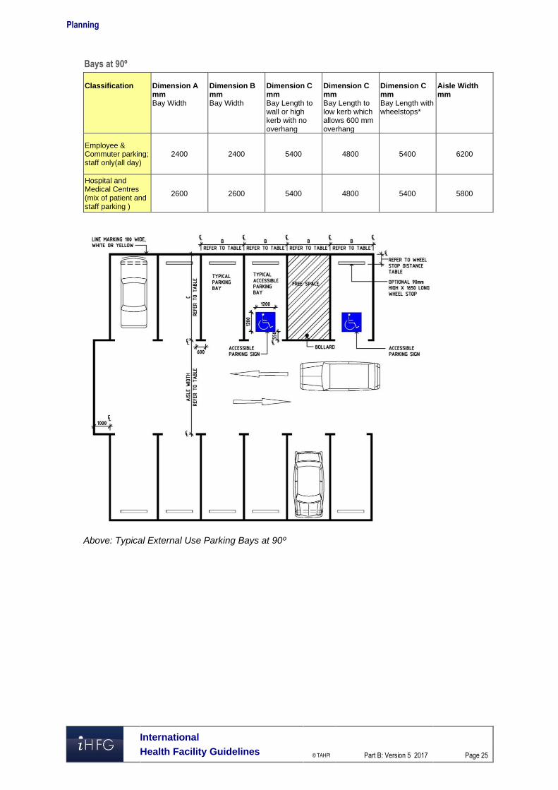
Bays at 90º
Classification
Dimension A mm Bay Width
Dimension B mm Bay Width
Dimension C mm Bay Length to wall or high kerb with no overhang
Dimension C mm Bay Length to low kerb which allows 600 mm overhang
Dimension C mm Bay Length with wheelstops*
Aisle Width mm
Employee & Commuter parking; staff only(all day)
2400 2400 5400 4800 5400 6200
Hospital and Medical Centres (mix of patient and staff parking )
2600 2600 5400 4800 5400 5800
Above: Typical External Use Parking Bays at 90º

Planning
International
Health Facility Guidelines © TAHPI
Part B: Version 5 2017
Page 26
Below: Typical Internal Use Parking Bays at 90º showing clearances for obstructions
Parallel Parking Bays
Provide the following minimum dimensions for parallel parking with a one way aisle:
Aisle Width
One way W
Space Length
L
Space Length
Obstructed end spaces L0
Space Length
Unobstructed end spaces Lu
3000 6300 6600 5400
3300 6100 6400 5400
3600 5900 6200 5400
Parallel spaces shall be located at least 300 mm clear of obstructions higher than 150 mm such as walls, fences and columns. If the opposite side of the aisle is bounded by obstructions higher than 150 mm then the aisle width (W) should be increased by at least 300 mm. If a single space is obstructed at both ends the dimensions of the space shall be increased by 300 mm. For parallel parking on both sides with a two way aisle, the aisle width identified for one way traffic (W) above, shall be doubled.

Planning
International
Health Facility Guidelines © TAHPI
Part B: Version 5 2017
Page 27
Below: Parallel parking on both sides of a one way aisle
Below: Parallel parking on both sides of a two way aisle

Planning
International
Health Facility Guidelines © TAHPI
Part B: Version 5 2017
Page 28
Design Envelope for Internal Parking Bay
Use the template below to ensure clearance around columns, walls and obstructions This template must fit into any internal parking bay without obstruction for columns, walls and bollards.
Above: template for clearances within parking bay
Parking Aisles
Aisles for 90º bays need to allow for two way traffic. Aisles for 30º, 45º or 60º angled bays shall be one way traffic. Parallel parking bay aisles may be either one way or two way traffic. The width of aisles for angled parking bays will vary according to the width of the parking bays, wider bays require less aisle width. Where there are blind aisles, the aisle shall extend 1 metre beyond the last parking bay. If the last parking bay is bounded by a wall or a fence, it should be widened by 300 mm.
Wheel Stops
Wheel stops may be provided if necessary to limit the travel of a vehicle. Wheel stops should not be used in situations where they are in the path of pedestrians moving to and from parked vehicles or where pedestrians cross a car park. If required, wheelstops are installed at right angles to the direction of parking or where the ends of angled parking form a sawtooth pattern If wheel stops are required, install according to the front of the carparking space according to the following dimensions:
Parking Direction
Wheel stop distance to front of parking space Parking to Kerb < 150 mm high Parking to Kerb > 150 mm high or
wall 90 mm high wheel stop
100 mm high wheel stop
90 mm high wheel stop
100 mm high wheel stop
Front in parking 630 mm 620 mm 830 mm 820 mm Rear in parking 910 mm 900 mm 1110 mm 1100 mm

Planning
International
Health Facility Guidelines © TAHPI
Part B: Version 5 2017
Page 29
Accessible Parking Bays
Accessible parking bays shall have the following minimum dimensions with a clearance height of 2500 mm from the entry/exit to the bay:
Description Width mm Length mm Angled Bays (45-900) 2600 5400 Parallel Bays 3200 7800
A shared area should be provided to the side of the accessible parking bay for loading and unloading; two accessible bays may be located either side of a single shared space.
Ambulance Bays
Provide the following minimum drive through area for ambulances:
Minimum width is 5200 mm; minimum depth is 5500 mm. The ambulance bay requires a covered space with a minimum length of 8000 mm and height of 3600 mm:

Planning
International
Health Facility Guidelines © TAHPI
Part B: Version 5 2017
Page 30
Ambulance Turning Circle:
Ambulances will require the following minimum radius for turning:
For additional information on ambulance unit and requirements refer to Emergency Unit FPU, in these Guidelines.

Acceptable Standards and Guidelines
International
Health Facility Guidelines © TAHPI
Part B: Version 5 2017
Page 31
5 Acceptable Standards and Guidelines The design requirements of each FPU as well as various room types are also described in a number of International guidelines. For additional reference, three other international guidelines may be considered: ▪ Guidelines for Design and Construction of Health Care Facilities, The Facility Guidelines
Institute, 2010 Edition, American Institute of Architects (AIA) www.fgiguidelines.org ▪ Australasian Health Facility Guidelines. (AusHFG Version 3.0), Australasian Health
Infrastructure Alliance, 2009 refer to website www.healthfacilitydesign.com.au ▪ DH (Department of Health) (UK) NHS Estates Health Building Notes, refer to
www.estatesknowledge.dh.gov.uk Where one guideline is deemed to be inadequate in the coverage of certain facility types, another guideline may be consulted.
Functional Planning Units
International
Health Facility Guidelines © TAHPI
Part B: Version 5 2017
Page 32
6 Functional Planning Units Refer overleaf for the following FPUs 10 Administration Unit 15 Admissions Unit & Discharge 20 Birthing Unit 35 Cardiac Investigation Unit 40 Catering Unit 45 Clinical Information Unit 50 Community Health Unit 52 Complementary and Alternative Medicine Centre 55 Coronary Care Unit 56 Day Surgery/ Procedure Unit 65 Dental Surgery Unit 75 Emergency Unit 80 Endoscopy Unit 85 Engineering & Maintenance Unit 95 Housekeeping Unit 105 Inpatient Unit - Bariatric 110 Inpatient Unit - General 130 Intensive Care Unit - General 140 IVF Unit (Fertilization Centers) 145 Laboratory Unit 150 Linen Handling Unit 155 Main Entrance Unit 157 Maternity Unit 160 Medical Imaging Unit - General 170 Medical Imaging - Nuclear Medicine Unit 175 Medical Imaging - Nuclear Medicine Unit - PET 180 Mental Health Unit - Adult 185 Mental Health Unit - Child & Adolescent 200 Mental Health Unit - Older Persons 205 Mobile Healthcare Unit 215 Mortuary - General 225 Oncology Unit - Medical (Chemotherapy) 230 Oncology Unit - Radiation 235 Operating Unit 245 Outpatients Unit 255 Pharmacy Unit 260 Public & Staff Amenities 265 Rehabilitation - Allied Health 270 Renal Dialysis Unit 280 Sterile Supply Unit (SSU) 285 Supply Unit 290 Waste Management Unit

Part B – Health Facility Briefing & Design 10 Administration Unit
International Health Facility Guidelines Version 5 May 2016

Part B: Health Facility Briefing & Design
International
Health Facility Guidelines © TAHPI
Part B: Version 5 May 2016
Page 2
Table of Contents
10 Administration Unit ................................................................................................................... 3
1 Introduction ............................................................................................................................................... 3 Description .................................................................................................................................................. 3
2 Functional and Planning Considerations ............................................................................................... 3 Operational Models ..................................................................................................................................... 3 Planning Models .......................................................................................................................................... 3 Functional Areas ......................................................................................................................................... 4 Functional Relationships ............................................................................................................................. 5
3 Design ........................................................................................................................................................ 7 Environmental Considerations .................................................................................................................... 7 Space Standards and Components ............................................................................................................ 7 Safety and Security ..................................................................................................................................... 8 Finishes ....................................................................................................................................................... 8 Fixtures, Fittings and Equipment ................................................................................................................. 8 Building Service Requirements ................................................................................................................... 8 Infection Control .......................................................................................................................................... 9
4 Components of the Unit ............................................................................................................................ 9 Standard Components ................................................................................................................................ 9
5 Schedule of Accommodation – Administration Unit ........................................................................... 10 Administration Unit located within a health facility ..................................................................................... 10
6 Future Trends .......................................................................................................................................... 12
7 Further Reading ....................................................................................................................................... 12

Part B: Health Facility Briefing & Design Administration Unit
International
Health Facility Guidelines © TAHPI
Part B: Version 5 May 2016
Page 3
10 Administration Unit
1 Introduction
Description The Administration Unit provides an area of offices, workspaces and associated facilities for supporting the management of the facility and may include both clinical and non-clinical support staff to oversee the management of a hospital or unit. This may include administrative tasks, interviews and meetings by a range of executive, medical, nursing and support personnel. The level and range of facilities provided for general office and executive administration functions will vary depending on the size and level of the service being delivered in the proposed health facility and as described in the endorsed Service Plan. The Administration Unit may include the following administrative positions or services:
Main Reception and Enquiries
Chief Executive Officer (CEO), Senior Managers and support staff
Nursing Executive and Senior Nurse Managers
Human Resources and Payroll staff
Finance and Accounting Managers and support staff
Facility Management
Public Relations
Legal Services
Quality Management
Training, Education and Research, this may be a separate area in large healthcare facilities
Disaster Management coordination
Clinical Administration, including medical, clinical, professional staff with support staff; this may be a separate unit in large healthcare facilities.
2 Functional and Planning Considerations
Operational Models Depending on the size of the facility, Administration Unit may be provided as a single unit for small facilities, or as separate functional units grouped according to services (medical, nursing, finance, education, etc.) in multiple locations for larger facilities. The operational model will be determined by the size, Operational Policies and the Service Plan of the facility.
Hours of Operation
The Administration Unit will generally operate during business hours, Monday to Friday. Some functions such as Nursing Management, Clinical Management and Staff Allocation may be provided on an extended or 24-hours basis. Meetings and functions being held after-hours will require safe and planned access for both staff and visitors.
Planning Models The Administration Unit may be located in an area easily accessed by staff in the organisation and visitors. It is recommended that a separate secure entry be provided for staff. The Administration Unit may be provided as:
A distinct unit within the health facility
A Unit located in a non-clinical zone of a health facility
A unit within a separate building on the campus.

Part B: Health Facility Briefing & Design Administration Unit
International
Health Facility Guidelines © TAHPI
Part B: Version 5 May 2016
Page 4
Functional Areas The Administration Unit functional areas include:
Entry Area: - Reception - Waiting areas with amenities for visitors
Administration Areas; Office/s and workstations for the following functions: - General Administration including:
Executive Suite (CEO, Divisional Directors and secretarial support) Public Relations Legal Services Ancillary support staff which may include Occupational Health and Safety,
Infection Control, Quality Assurance, Disaster Coordinator, Complaints Management/ Patient Advocate, PABX/ operator/s/ telecommunications
- Nursing Administration - Finance and Accounts - Human Resources that may include Payroll - Information Technology and Communications - Clinical and Medical Services Unit
General Support Areas: - Beverage Bay for staff access - Cleaner’s room - Disposal room - Mail Room - Pantry - Stores for files, stationery
Staff Areas - Meeting Room/s; may be designated as a disaster coordination room or Board Room - Staff Room, may be shared - Staff toilets, may be shared
For facilities where space is not sufficient to include all functions required, some of the above components may be provided as separate units.
Entry Area
Reception and Waiting The Reception is the first point of contact with the Administration Unit for visitors and may act as an access control point to restrict access and direct visitors to the area required. Waiting areas should be located nearby and be suitable for a range of occupants including those in wheelchairs. Smaller Waiting areas may be provided close to offices as required.
Administration Areas
Administration areas may be provided as offices and workstations within in one Unit to promote collaboration between divisions. The number of offices provided will be according to the endorsed full time positions required for the Administration Unit, dependent on the size of the facility and the Operational Policies. Consideration should be given to provision of the following:
Separate offices, shared offices and workstations where possible for executive, finance and clinical staff that are required to be situated in the Administration Unit according to the facility’s Service Plan
Specialised administration functions such as Quality Management, Public Relations, etc. as required according to the Service Plan

Part B: Health Facility Briefing & Design Administration Unit
International
Health Facility Guidelines © TAHPI
Part B: Version 5 May 2016
Page 5
Offices for roster management, staff allocation and bed allocation staff that may require access after-hours.
Support Areas
Support areas for the Administration Unit, including stores for files and stationery, should be located convenient to staff requiring frequent access. Secured storage should be provided for confidential records including administration, finance and human resources records. Meeting rooms with tele-conference or video-conference facilities provide for meeting flexibility with remote staff. A large Meeting Room may be used for disaster management and Board meetings. If multipurpose meeting rooms are provided, they may be located to enable sharing by several services or Units. Meeting Room/s should have access to a pantry for food and beverages as necessary
Staff Areas
Staff Room/s and dining areas should include a beverage bay or access to a pantry for use during meal breaks. Staff Room/s and toilets may be shared with adjacent units where possible.
Functional Relationships
External
The Administration Unit should be located to provide ease of access to visitors arriving from the Main Entrance of the facility. A ground level location is not required. The Administration Unit should be well sign posted and easily identifiable by staff and visitors.
Internal
The Executive Suite, Nursing Administration and the Finance Unit should ideally be located together in one zone to enhance staff communication and collaboration Clinical Administration functions including the Division of Medicine, the Division of Surgery and Clinical Research Unit may be located within or in close proximity to the Administration Unit. Alternatively, these areas may be located close to the relevant clinical area or collocated with the Education Unit, according to the Operational Policy of the facility.
Functional Relationship Diagram
Administration Unit located within a health facility The Functional Relationship Diagram below applies to a typical Administration unit, centrally located in a non-clinical zone within a health facility and including with sub units located together. The key functional relationships are demonstrated in the diagram below.

Part B: Health Facility Briefing & Design Administration Unit
International
Health Facility Guidelines © TAHPI
Part B: Version 5 May 2016
Page 6
Figure 1 Functional Relationship Diagram: Administration Unit

Part B: Health Facility Briefing & Design Administration Unit
International
Health Facility Guidelines © TAHPI
Part B: Version 5 May 2016
Page 7
The following represents preferred external functional relationships:
Visitors access from a main circulation corridor from the Main Entrance
Separate entry and access for staff
Service corridor access for service units such as Supply and Housekeeping. The optimum internal relationships include the following:
Reception at the entrance that may act as an access control point and an interview area in close proximity
Access to administrative sub units such as Public Relations, Human Resources, Finance, and Clinical Administration etc. via internal circulation corridors
Administration sub units that are more frequently visited, such as Public Relations and Human Resources are located closer to the Entry and Reception
Support areas located centrally for ease of staff access
Interview rooms located close to sub units requiring frequent access. 3 Design
Environmental Considerations
Acoustics
Acoustic performance and sounds levels should be designed and documented to meet the function of spaces being provided. Acoustic consideration should be given to the following during the design process: Acoustic separation of Meeting and Interview rooms to reduce the noise between rooms,
particularly if used for tele-conferencing, video-conferencing and large meetings Acoustic separation should be provided between Offices, Meeting Rooms, Interview Rooms
and adjacent corridors to reduce transfer of noise between rooms, particularly private conversations which should not be audible outside the room
Location of waiting areas away from Offices, Meeting and Interview rooms Location of staff rooms away from public areas, Offices and Meeting rooms
Natural Light/ Lighting
Maximise the provision of natural light to areas where staff offices and workstations are located. Artificial lighting should be arranged to avoid glare on computer screens. Refer to Part C Access, Mobility, OH&S in these Guidelines for further information.
Privacy
Visual privacy must be considered where confidential conversations are likely to take place in offices, meeting and interview rooms
Space Standards and Components
Accessibility
Reception, Offices, Meeting rooms and Waiting areas should be design to provided access for people in wheelchairs. Refer to Part C in these Guidelines - Access, Mobility, OH&S for further information and local Accessibility Guidelines.
Ergonomics/ Occupational Health and Safety (OH&S)
The design process and selection of furniture, fittings, fixtures and equipment must consider ergonomics and Occupational Health and Safety (OH&S) aspects to avoid injuries to staff and visitors. Particular attention should be made to design of workstations and storage areas. Adjustable height workstations may be considered. Shelving in storage areas should be placed at suitable reach heights.

Part B: Health Facility Briefing & Design Administration Unit
International
Health Facility Guidelines © TAHPI
Part B: Version 5 May 2016
Page 8
Refer to Part C in these Guidelines - Access, Mobility, OH&S and local Occupational Health and Safety standards for further information.
Size of the Unit
The size of the Administration unit will be dependent on the size and level of service of the health facility, as determined by the facility’s Service Plan and Operational Policies. Schedules of Accommodation have been provided for an Administration Unit in a typical hospital at Role Delineation Levels 2 to 6.
Safety and Security The Administration Unit should include the following security considerations:
Entry to the Administration Unit, Reception and Waiting may require restricted access such as electronic card reader; with an intercom/ phone, CCTV and remote door release from Reception
All Offices require lockable doors
Rooms located on the perimeter of the Unit should be locked when they are not in use
All Store rooms for files, records and equipment should be lockable
After-hours access which may be required to some Offices and Meeting Rooms and may also involve security personnel.
Finishes The Administration Unit décor should be pleasant and professional in character. Finishes should be selected with consideration of the following:
Acoustic properties of the materials; the use of carpet and acoustic panels will assist in absorption of sound
Durability, replacement and cleaning of materials
Fire safety of the materials. Refer also to Part C – Access, Mobility, OH&S in these Guidelines for further information on internal finishes.
Fixtures, Fittings and Equipment All furniture, fittings and equipment selections for the Administration Unit should be made with consideration to ergonomic and Occupational Health and Safety (OH& S) aspects. Refer to Part C of these Guidelines - Access, Mobility, OH&S, the Room Layout Sheets (RLS) and Room Data Sheets (RDS) for more information.
Building Service Requirements
Communications
The Administration Unit has a managing role in the facility and requires reliable and effective IT / Communications service for efficient operation of the service. The IT design should address:
Hospital networking requirements including wireless networks
Video-conferencing and tele-conferencing
Communications and Server Room/s
Telephone systems including cordless and mobile phones
Computers, mainframes, laptops and hand-held devices
Duress alarms and paging master system for staff and emergencies

Part B: Health Facility Briefing & Design Administration Unit
International
Health Facility Guidelines © TAHPI
Part B: Version 5 May 2016
Page 9
Heating, Ventilation and Air conditioning (HVAC)
Offices, open plan workstation areas, Meeting Rooms, Interview Rooms and Staff Rooms should be air-conditioned for the benefit of staff and visitors to the Unit. The local or country specific mechanical requirements should be consulted.
Infection Control Infection Control measures applicable to the Administration Unit will involve prevention of cross infection between staff and visitors. Hand hygiene is an essential element and provision of medicated hand gel dispensers or hand wipes at the Reception and in circulation corridors is recommended. For further information refer to Part D – Infection Control in these Guidelines. 4 Components of the Unit
Standard Components The Administration Unit will contain Standard Components to comply with details in the Standard Components Room Data Sheets and Room Layout Sheets in these Guidelines.

Part B: Health Facility Briefing & Design Administration Unit
International
Health Facility Guidelines © TAHPI
Part B: Version 5 May 2016
Page 10
5 Schedule of Accommodation – Administration Unit
Administration Unit located within a health facility
ROOM/ SPACE Standard Component RDL 1/2 RDL 3 RDL 4 RDL 5 RDL 6 Remarks Room Codes Qty x m2 Qty x m2 Qty x m2 Qty x m2 Qty x m2
Entry Area Reception/ Clerical RECL-9-I RECL-10-I RECL-12-I 1 x 9 1 x 9 1 x 10 1 x 12 1 x 12 1 - 2 staff. May be replaced by a workstation.
Waiting WAIT-SUB-I WAIT-10-I WAIT-15-I 1 x 5 1 x 5 1 x 10 1 x 15 1 x 15 May be divided by gender; 1.2 m2 per person
Waiting - Sub WAIT-SUB-I 1 x 5 1 x 5 2 x 5 Areas for visitors to wait close to Offices.
Toilet - Accessible WCAC-I 1 x 6 1 x 6 1 x 6 1 x 6 1 x 6 If not available nearby. May require separate family/female facilities
Toilet – Public, 3 m2 WCPU-3-I 1 x 3 1 x 3 2 x 3 2 x 3 2 x 3 If not available nearby
General Administration Note 1
Office - CEO OFF-CEO-I 1 x 18 1 x 18 1 x 18 1 x 18 1 x 18
Office – Directors (Divisional) OFF-CEO-I 1 x 15 2 x 15 3 x 15 5 x 15 Nursing, Medical, Finance, HR, Operations, Disaster Coordinator
Office – Deputy Directors/Manager (Divisional) OFF-S12-I 1 x 12 2 12 3 x 12 5 x 12 Nursing, Medical, Finance, HR, Operations
Office – Workstation (Secretarial) OFF-WS-I 1 x 5 1 x 5 2 x 5 4 x 5 6 x 5 Executive support; Note 1
Office – PABX/Operator OFF-2P-I 1 x 12 1 x 12 1 x 12 PABX workstation & mainframe modules
Office – Single Person OFF-S9-I 1 x 9 2 x 9 Public Relations, Legal Services, Complaints, Patient Advocate
Office – 2 Person Shared OFF-2P-I 1 x 12 1 x 12 1 x 12 OH&S staff
Nursing Administration Note 1
Office – Supervisors (Nursing) OFF-S9-I 1 x 9 1 x 9 1 x 9 2 x 9 4 x 9
Office - Workstation (Nursing) OFF-WS-I 1 x 5 1 x 5 2 x 5 4 x 5 Infection Control, QM, Education etc.
Finance & Accounts Note 1
Office – Managers (Finance) OFF-S9-I 1 x 9 1 x 9 1 x 9 1 x 9 2 x 9 Finance and Accounts
Office - Workstation OFF-WS-I 4 x 5 6 x 5 8 x 5 Accounts support
Human Resources Note 1
Office Managers (HR) OFF-S9-I 1 x 9 1 x 9 1 x 9 2 x 9 2 x 9
Office – 2 Person Shared OFF-S12-I 1 x 12 1 x 12 2 x 12 2 x 12 HR clerical support
Office - Workstation OFF-WS-I 1 x 5 1 x 5 2 x 5 2 x 5 HR administrative staff.
Interview Room (s) OFF-S9-I 1 x 9 1 x 9 2 x 9 2 x 9 For interviews of 2-3 people
IT/ Communications Note 1

Part B: Health Facility Briefing & Design Administration Unit
International
Health Facility Guidelines © TAHPI
Part B: Version 5 May 2016
Page 11
ROOM/ SPACE Standard Component RDL 1/2 RDL 3 RDL 4 RDL 5 RDL 6 Remarks Room Codes Qty x m2 Qty x m2 Qty x m2 Qty x m2 Qty x m2
Office Managers (IT/Communications)) OFF-S9-I 1 x 9 1 x 9 1 x 9 2 x 9 2 x 9
Office – 4 Person Shared OFF-4P-I 1 x 20 1 x 20 IT support/Technical staff
Server Room COMM-I (similar) 1 x 20 1 x 20 1 x 20 1 x 30 1 x 30 Size dependent on IT operational system.
Support Areas
Bay – Beverage, Open Plan BBEV-OP-I 1 x 4 1 x 4 1 x 4 1 x 4 1 x 4 If no Staff Room
Cleaners Room CLRM-6-I 1 x 6 1 x 6 4 x 6 5 x 6 6 x 6 With storage of cleaning materials.
Communications Room COMM-12-I 1 x 12 1 x 12 1 x 12 1 x 12 1 x 12 Area as required, part of Engineering
Disposal DISP-8 DISP-10 1 x 8 1 x 8 1 x 10 1 x 10 1 x 10 With locked confidential paper waste bins
Mail Room SECR-10-I 1 x 10 1 x 10 Lockable
Pantry PTRY-I 1 x 8 1 x 8 Optional for functions
Store - Files STFS-8-I STFS-10-I STFS-20-I 1 x 8 1 x 10 1 x 20 1 x 20 Documents & minutes
Store - Files STFS-8-I STFS-10-I 1 x 8 1 x 8 1 x 10 1 x 10 1 x 10 Personnel files
Store - Photocopy/ Stationery STPS-8-I or similar 1 x 8 1 x 8 1 x 8 1 x 8 1 x 8 Storage of paper and stationery supplies.
Staff Areas Meeting Room - Large, 55 m2 MEET-L-55-I 1 x 55 1 x 55 Up to 45 persons; disaster coordination
Meeting Room – Medium/Large 30 m2 MEET-L-30-I 1 x 30 1 x 30 Up to 20 persons; may be Board Room
Meeting Room - Medium/ Large, 20 m2 MEET-L-20-I 1 x 20 1 x 20 1 x 20 Up to 16 persons
Meeting Room - Small, 12 m2 MEET-12-I 1 x 12 1 x 12 2 x 12 4 x 12 Interviews
Meeting Room - Small, 9 m2 MEET-9-I 1 x 9 1 x 9 2 x 9 2 x 9 2 x 9 Interview/ small meeting functions
Staff Room SRM-12-I SRM-18-I SRM-25-I 1 x 12 1 x 18 1 x 18 1 x 25 Optional; includes Beverage Bay
Toilet - Staff M/F WCST-I 2 x 3 2 x 3 2 x 3 2 x 3 2 x 3
Sub Total 183 253 412 654 846
Circulation % 20 20 20 25 25
Area Total 219.6 303.6 494.4 817.5 1057.5
Note 1: Offices to be provided according to the number of approved full time positions within the Unit Please also note the following: Areas noted in Schedules of Accommodation take precedence over all other areas noted in the FPU. Rooms indicated in the schedule reflect the typical arrangement according to the Role Delineation. Exact requirements for room quantities and sizes will reflect Key Planning Units identified in the Service Plan and the Operational Policies of the Unit. Room sizes indicated should be viewed as a minimum requirement; variations are acceptable to reflect the needs of individual Unit. Office areas are to be provided according to the Unit role delineation and number of endorsed full time positions in the unit. Staff and support rooms may be shared between Functional Planning Units dependent on location and may provide scope to reduce duplication of facilities.

Part B: Health Facility Briefing & Design Administration Unit
International
Health Facility Guidelines © TAHPI
Part B: Version 5 May 2016
Page 12
6 Future Trends Future trends that may affect the Administration Unit include:
Management innovation that focuses on new ways of allocating scarce resources as the workforce becomes more adaptable, creative and mobile, requiring more flexibility
Increased focus on developing talent of individuals in the workforce while robots perform the routine tasks; this may require fundamental organisational redesign
An increased pressure on hospital management to reduce costs while increasing productivity and service, supporting an increasing population
A greater use of technology and improved software to support managing the service, particularly portable devices which enables administrative staff to be more mobile with instant information sources available to make decisions
7 Further Reading
Australasian Health Facility Guidelines (Aus). ‘Part B - Health Facility Briefing and Planning 0120 Administration Unit Revision 5, 2016, refer to website www.healthfacilitydesign.com.au
European Union Program for Employment and Social Solidarity PROGRESS (2007-2013) Occupational Health and Safety Risks in the Healthcare Sector - Guide to Prevention and Good Practice, Refer to: www.acoem.org%2FuploadedFiles%2FPublic_Affairs%2FPolicies_And_Position_Statements%2FGuidelines%2FGuidelines%2FMCOH%2520Guidance.pdf&usg=AFQjCNFlXlZ5lmE_aazYC-Mcj6p9lrCCNw
Facility Guidelines Institute, Guidelines for Design and Construction of Health Care Facilities; 2014 Edition; refer to website www.fgiguidelines.org
Gov.UK: Department of Health, Building Notes, Designing health and community care buildings (HBN 00- 01), refer to: https://www.gov.uk/government/uploads/system/uploads/attachment_data/file/316247/HBN_00-01-2.pdf
Gov.UK Department of Health, Building Notes, Designing Generic Clinical and Support Spaces (HBN 00-03), Refer to: https://www.gov.uk/government/uploads/system/uploads/attachment_data/file/147845/HBN_00-03_Final.pdf
Health and Building Executive, UK. The law on VDUs: An easy guide: Making sure your office complies with the Health and Safety (Display Screen Equipment) Regulations 1992 (as amended in 2002), refer to: http://www.hse.gov.uk
Health Building Note 00-01 Health Facilities Scotland, Core elements: General design guidance for healthcare buildings, refer to www.hfs.scot.nhs.uk%2Fpublications%2F1413797038-HBN_00-01%2520General%2520design%2520guidance%2520for%2520healthcare%2520buildings_cover.pdf&usg=AFQjCNEN2QU5IauE4vr7cdLU0wybA_HfPw
U.S. Department of Veterans Affairs, Office of Construction & Facilities Management, Technical Information Library, Refer to: http://www.cfm.va.gov/til/index.asp
Part B – Health Facility Briefing & Design 15 Admissions Unit & Discharge
International Health Facility Guidelines Version 5 October 2016

Part B: Health Facility Briefing & Design
International
Health Facility Guidelines © TAHPI
Part B: Version 5 Oct 2016
Page 2
Table of Contents
15 Admissions Unit & Discharge .................................................................................................. 3
1 Introduction ............................................................................................................................................... 3 Description .................................................................................................................................................. 3
2 Functional and Planning Considerations ............................................................................................... 4 Operational Models ..................................................................................................................................... 4 Planning Models .......................................................................................................................................... 5 Functional Areas ......................................................................................................................................... 5 Functional Relationships ............................................................................................................................. 7
3 Design ...................................................................................................................................................... 10 General...................................................................................................................................................... 10 Environmental Considerations .................................................................................................................. 10 Space Standards and Components .......................................................................................................... 10 Safety & Security ....................................................................................................................................... 11 Finishes ..................................................................................................................................................... 12 Fixtures, Fittings & Equipment .................................................................................................................. 12 Building Service Requirements ................................................................................................................. 12 Infection Control ........................................................................................................................................ 13
4 Components of the Unit .......................................................................................................................... 14 Standard Components .............................................................................................................................. 14 Non-Standard Components ....................................................................................................................... 14
5 Schedule of Accommodation – Admissions Unit, Pre-admissions Unit & Discharge ...................... 15 Admissions Unit......................................................................................................................................... 15 Pre-admissions Unit .................................................................................................................................. 16 Discharge Unit ........................................................................................................................................... 17
6 Future Trends .......................................................................................................................................... 18
7 Further Reading ....................................................................................................................................... 18

Part B: Health Facility Briefing & Design Admissions Unit & Discharge
International
Health Facility Guidelines © TAHPI
Part B: Version 5 Oct 2016
Page 3
15 Admissions Unit & Discharge
1 Introduction
Description
Admissions Unit
The Admissions Unit is a central administrative service that co-ordinates and processes information to support a patient’s admission and discharge to/ from a healthcare facility. The admission of patients to a healthcare facility may be through an emergency department (unplanned) or as a booked admission (planned). The majority of patients who require admission into hospital are pre-planned booked admissions and are admitted as either a day patient (same day) or to an inpatient unit upon receipt of a request for admission by a medical practitioner/ specialist. The Admissions Unit is often a patient’s primary contact so planning should minimize institutional imagery and provide the patient and family members with finishes and furnishings that are familiar and comforting to reduce stress and promote privacy. The type of facilities required for the Admission unit may vary and would be dependent on the range of services to be provided in the organisations Clinical Operational Policies and Service Guidelines. Admission Units undertake two processes: administrative and clinical assessment which is often provided in a Pre-admission Clinic. Provisions for the following Admission Unit services and functions should be considered early in planning process. Administrative processes: Coordination, review and management of electronically and hard copy admission referral
documentation Provision of assistance to patients in the completion of admission information requirements,
in person or by phone Provision of a mobile service to a service or department to complete admission
documentation at the point of the patients arrival Assistance with inter hospital transfers Administrative functions related to the preparation and maintenance of the admission records Assistance with the bed management/ allocation in a healthcare facility Assistance with the co-ordination of patient arrival and admission to a healthcare unit Assistance with the co-ordination of operating theatre list management Assistance with the co-ordination of appointments for attendance to a pre admissions
outpatient clinic Collection of financial information for the finance unit. Clinical Assessment processes: Completion of admission documentation and consent forms Organisation of patient referrals to anaesthetists or other health professionals Organisation of patient diagnostic tests (pathology, imaging, cardiac) Organisation of patient health records, assessments and diagnostic results Commencement of discharge planning.
Discharge Lounge
A Discharge Lounge may be provided according to Operational Policy. The purpose of the Discharge Lounge which is sometimes referred to as Transit Lounge or Departure Lounge, is for patients who have planned discharge to be transferred to an area to complete the discharge

Part B: Health Facility Briefing & Design Admissions Unit & Discharge
International
Health Facility Guidelines © TAHPI
Part B: Version 5 Oct 2016
Page 4
process to assist the facility in bed capacity management. It provides stable patients a safe and comfortable waiting area with nursing supervision and assistance on the day of their discharge. In this area, patients may, await transport and carers, be issued discharge summaries, future care plans, medications and medical certificates, arrange Allied Health consultations and/or community health services and finalise hospital accounts. Some activities undertaken in the Discharge Lounge include: Completion of discharge paperwork such as discharge summary, care plans, medical
certificate and medication prescription Waiting for specialist nurse/ allied health consultation Meeting transportation from family, friends, carers or patient transport services Receiving prescription medication from pharmacy Waiting for loaned equipment required by patient at home Settlement of hospital accounts if applicable.
Pre-admission Clinic
The pre-admission clinic undertakes a clinical assessment of patients prior to the hospital visit in order to streamline the admission process. The Pre-admission clinic may be collocated with the Outpatients clinics but may be a stand-alone unit. The pre-admission process will typically include: Medical assessment and history Anaesthetic assessment Diagnostic test such as pathology, imaging, ECG Patient education on the medical procedures to be undertaken and the likely course of
recovery Financial aspects of the intended hospital stay Discharge planning. 2 Functional and Planning Considerations
Operational Models For planned admissions there are usually four stages in the admission process: The receipt, completion and confirmation of the admission request received The interview either by phone or in person with the patient, family or carer to be admitted The confirmation of the admission date and to where the patient should present to The arrival and admission of the patient to the service on the date provided to finalise the
admission to a unit or service. These functions may be completed in the Admissions Unit, a Peri-operative Unit or decentralised to the specific clinical Unit the patient will be attending. The preferred model will be dependent on the hospital’s Operational Policies. Currently, the provision of a Pre-admissions Clinic is becoming common in many health facilities. This can streamline the admission process for all pre-booked admissions where clinical pre-assessment is required. The Discharge Lounge is used for planned discharge only. Patients are transferred from the ward level, Day Surgery or Endoscopy Procedure area to the Discharge Lounge on the day of discharge typically between 9 am to 6pm Monday to Friday. Larger facilities may provide longer operating hours or seven days a week service.
Hours of Operation
The Admission Unit services operating hours will be dependent on the organisation’s Operational Policies and service profile. However the Admissions Unit generally operates from 8am to 5pm daily for planned admissions. Many services are provided on a 24 hour per day basis with the admission documentation being completed by staff from the Admissions Unit.

Part B: Health Facility Briefing & Design Admissions Unit & Discharge
International
Health Facility Guidelines © TAHPI
Part B: Version 5 Oct 2016
Page 5
In larger facilities unplanned/ emergency admissions may occur via the facility’s Emergency Unit or Obstetric Unit operating 24 hours a day. In these Unit, generally there will be administrative staff trained to undertake and complete the admission documentation.
Models of Care
Contemporary models of care reveal increased demand for day only procedures, day of surgery admissions and pre-admission clinics requiring multi-disciplined staffing profiles to ensure streamlined services. Pre-admission clinics provide an efficient admission process prior to the appointment and are generally provided as an outpatient service. Pre-admission clinics will undertake a clinical patient assessment by nursing or specialist staff. The Discharge Lounge provides are area where patients may be discharged from the clinical unit and await transportation in a separate area. This model of care frees up inpatient facilities for planned admissions and transfers releasing patients to the comfort of the discharge lounge with their carers during the discharge process.
Medical Record Management The Admissions Unit will assist to enter patient data and track patients from pre-admission to discharge using electronic patient information systems or traditional paper based records. Operational policies determine storage and retrieval systems of medical records but hard-copy secured storage space may be required unless all documents are stored and accessible electronically.
Planning Models
Location
The Admission Unit may be provided as: A single stand-alone unit A Unit collocated with the Main Reception A satellite unit located either in or near to the Outpatient service or in the Operating Unit/ Day
Surgery reception area A mobile service to a healthcare facility’s Inpatient or Emergency Units A combination of the above. Admission Units are generally located at the main entry to the facility or with ease of access from main circulation routes, public transport and parking areas. The clearly defined description of the service model or models to be provided should assist with the early design of the Unit within the healthcare facility. Where Pre-admission Clinics are provided, they may be located in the Unit where the procedure will occur such as Day Surgery or Endoscopy Units. An alternate option is to locate this unit with other outpatient clinics. The Discharge Unit may be a stand-alone Unit but is often co-located with Admissions Unit near the Main Entrance. An alternative location for the Discharge Unit is an area accessible from a secondary hospital entrance with easy access to the patient pick-up zone.
Functional Areas The Admissions Unit may include the following functional areas, arranged together or separately as directed by the health facility’s Operational Policies.

Part B: Health Facility Briefing & Design Admissions Unit & Discharge
International
Health Facility Guidelines © TAHPI
Part B: Version 5 Oct 2016
Page 6
Admissions Unit
Entry/ Reception including: - Patient waiting areas (gender segregated areas if required) - Reception desk, that may have discussion booths incorporated - Public Amenities (may be located in adjoining areas)
Patient Areas: - Interview rooms and cubicles for patient admissions, interviews and private
discussions - Access to a Cashier (this may be a centralised or decentralised service provision)
Staff and Support Areas including: - Offices and workstations to provide administrative area and for receiving and making
phone calls - Storage for files, wheelchairs, stationery, photocopier/ printer
Pre-admissions Clinic
Entry/ Reception including: - Reception desk - Waiting which may be gender segregated
Patient Areas: - Office/ Consult rooms - Interview rooms - Vital signs room (optional) - Blood collection bay (optional)
Support Areas - Handwashing bays - Clean Utility - Dirty Utility - Storage for linen, stationery, files, consumable supplies and equipment
Staff Areas: - Workstations for staff write-up and administrative functions - Staff room, which may be shared - Property Bay - Staff toilets, which may be shared
Discharge Lounge
Patient Areas - Discharge Lounge with recliner and lounge chairs - Patient Bays, for patients requiring bed waiting - Property bay for luggage - Patient toilets
Staff and Support Areas - Staff Station - Handwashing bays - Clean and Dirty Utilities - Beverage Bay for patient refreshments - Storage for linen, supplies and equipment used in the unit.
Patient Waiting Areas
Gender segregated areas may be provided and sized accordingly to the predicted patient profile on a daily basis. Space for wheelchairs, prams, trolleys, mobility equipment, and wheelchair storage should be considered when designing this space. A separate waiting area for families including a play space for children may also be appropriate. Facilities to display reading materials, information pamphlets, and entertainment system (TV, speakers for music) should be considered. A queuing management system (electric or manual) should be provided in the waiting area to assist with the order and management of arriving patients in this area.

Part B: Health Facility Briefing & Design Admissions Unit & Discharge
International
Health Facility Guidelines © TAHPI
Part B: Version 5 Oct 2016
Page 7
A satellite unit providing access by patients from the Outpatients Unit would require interview rooms, (the number dependent on the assessed volume of patients requiring access for admission) and a waiting area.
Patient Interview Cubicle/ Rooms
Configuration and design of Interview cubicles/ rooms shall provide a high level of visibility from outside without compromising privacy. The rooms will require acoustic privacy, for confidential discussion between the admission staff, patients and accompanying family or carers.
Vital Signs Room
The Vital Signs Room if provided will include an interview space with facilities for measurement of patient vital signs such as weight, height, blood pressure, pulse and temperature.
Cashier
A Cashier may be incorporated within Admission Units & Discharge Lounges if required by the healthcare facilities operational policies. If provided, the following factors should be considered during planning: Accessibility during normal business hours and after-hours Safety provisions for Staff Secured storage where money is handled Safe routes of delivery and collection of money to and from the cashiers area Secure electronic payment systems, e.g. EFTPOS.
Staff and Support Areas
Staff will require: Offices and workstations for the Unit Manager, Supervisors and administrative staff Access to toilets, showers, change rooms and lockers Access to a staff room with beverage and food storage facilities Access to shared Meeting room/s for education, training and meetings. Support areas will include: Bays for linen, resuscitation trolley, mobile equipment and wheelchairs Beverage Bay for patient refreshments in Discharge areas Cleaners room Clean Utility with provision for drug storage Dirty Utility room including facilities for urine testing and waste holding Storage areas for stationery, records, general stock, equipment used in patient areas and
patient luggage in Discharge Lounge areas.
Functional Relationships
External
The Admissions Unit is ideally be located adjacent to the Main Reception area with close access to public amenities and waiting areas. The Pre-admissions Clinic, where provided, may be located in the Outpatients Unit (Peri-operative clinics) or other Units where procedures will be performed such as Day Surgery Unit. Pre-Admissions or Peri-operative outpatient clinic services will require access to diagnostic units including Pathology and Medical Imaging. The Discharge Unit is often located in close proximity to the Main Reception with ready access to external patient transport pick-up zones.
Internal
Decentralised admission areas and pre-admission areas should be configured to be visible and prominent for easy of way-finding by patients, family, carers and visitors. If the Cashier is to be located with an Admissions Unit, access to security is recommended

Part B: Health Facility Briefing & Design Admissions Unit & Discharge
International
Health Facility Guidelines © TAHPI
Part B: Version 5 Oct 2016
Page 8
Functional Relationship Diagram
Figure 1 Functional Relationship Diagram:

Part B: Health Facility Briefing & Design Admissions Unit & Discharge
International
Health Facility Guidelines © TAHPI
Part B: Version 5 Oct 2016
Page 9
External Relationships
The optimum external functional relationships are demonstrated in the diagram above including the following:
Admissions Unit A direct relationship between Admissions Unit, the Main Entry and car parking A direct relationship between Admissions Unit and Pre-admissions Clinic Indirect relationship to related hospital Units including Day Surgery Unit, Emergency Unit,
Inpatient Units and Diagnostic units Access for service units such as Supply, Housekeeping and Clinical Information via a service
corridor.
Discharge A direct relationship between Discharge area and the Main Entry and car parking Indirect relationship to related hospital Units including Day Surgery Unit, Inpatient Units and
Pharmacy Access for service units such as Supply, Housekeeping and Clinical Information via a service
corridor.
Pre-admissions A direct relationship between Pre-admissions clinic and Outpatients Units Convenient access to Diagnostic Units including Medical Imaging and Clinical Laboratories.
Internal Relationships
Correct internal relationships creating efficient design include the following:
Admissions Unit Reception, Cashier, Waiting and Interview areas at the entry to the Unit Ready access to Interview room/s from waiting areas Ready access to public amenities Support rooms located with convenient access to staff areas.
Discharge Ready access to patient amenities from the lounge area Support and staff areas located for ease of staff access.
Preadmissions Ready access to Consult rooms from patient Waiting areas Ready access to public amenities.

Part B: Health Facility Briefing & Design Admissions Unit & Discharge
International
Health Facility Guidelines © TAHPI
Part B: Version 5 Oct 2016
Page 10
3 Design
General The Admissions Unit, Pre-admissions and Discharge Lounge should be located with easy access to a vehicle drop-off and pick-up zones. The Admission unit and Discharge area should be designed to accommodate all types of patients including the elderly, disabled, carers with prams and young children and bariatric patients.
Environmental Considerations
Acoustics
Facility design shall ensure appropriate levels of patient acoustic privacy throughout the care process by installing measures to control ambient noise e.g. sound absorbing (drapes, carpets & ceiling tiles) sound blocking (panels, walls, & floors) and sound masking. Acoustic privacy is required in Interview rooms and area where confidential information will be discussed, to ensure confidential conversations are not audible in adjoining rooms or spaces. Provision of an augmented hearing loop service for patients and visitors with hearing impairment should be considered.
Natural Light/ Lighting
Natural light is recommended to promote a pleasant environment for patients, visitors and staff. . Windows are particularly desirable in waiting and lounge areas.
Privacy
Careful consideration of privacy and patient comfort is required to reduce discomfort and stress for patients. Interview rooms should be located away from public corridors and layout designed to ensure maximum privacy when doors open. The Discharge Lounge must be designed to permit good staff visibility whilst maintaining privacy between patients.
Interior Décor
The Admission Unit and Discharge Lounge interior design should reflect patient, carers and staff needs. Entry and waiting areas should be welcoming, comfortable and well-illuminated with natural light where possible. Colours, finishes and furniture should be chosen to avoid a clinical appearance. Access control limits and differentiates public space and prohibited/staff only areas.
Space Standards and Components
Accessibility
Design must provide ease of access for disabled patients to all patient areas including Consult and Interview rooms/ cubicles. Seating in waiting areas shall be provided at a range of heights to cater for the different mobility levels of patients. Consideration should be given to selection of seating offering bariatric support. An accessible height counter should be provided for patients/ visitors with disabilities that need to sit on a chair or in a wheelchair during the interview process.
Doors
Entry points, doors and openings to the Admission Unit and Discharge Lounge should be a minimum of 1200 mm wide, unobstructed. Doors used for bed transfers should be a minimum of 1400mm wide, unobstructed.

Part B: Health Facility Briefing & Design Admissions Unit & Discharge
International
Health Facility Guidelines © TAHPI
Part B: Version 5 Oct 2016
Page 11
Doors must provide acoustic privacy. Door openings must allow risk free passage of patients, carers, staff and manoeuvring room for equipment, wheelchairs and trolleys where necessary. Also refer to Part C – Access, Mobility, OH&S of these Guidelines.
Ergonomics/ OH&S
Design and dimensions of counters and workstations shall ensure privacy and security for patients, visitors and staff. Counter heights should be made identical for patients/ visitors and staff to enhance communication and minimise aggressive behaviour. Refer to Part C – Access, Mobility, OH&S of these Guidelines for more information.
Size of the Unit
The size of the Admission Unit and Discharge Lounge is dependent on facility location, service complexity, patient flow and model of care. Schedules of Accommodation provided in this guidelines provide typical units sized for a range of role delineation levels.
Safety & Security A stakeholder initiated risk assessment should form part of the early planning phase to design secure environments meeting the needs of patients and staff. Factors for consideration include: Demographics of the planned services population. Capacity, location, type and level of service to be provided. Security staff planning including staffing levels, base of operation and response teams. Disaster and critical event planning including staff training for security incidents e.g.
aggression and poor behaviour of patients, visitors or carers or the management of an intended robbery with force
The following security issues shall be addressed when designing Admission Units, Discharge Lounges and Pre-admissions clinics: Unobstructed waiting room viewpoints for staff from counters and staff stations Duress alarms and emergency exit points to all counters Controlled after-hours access to prevent unauthorized entry and exit; external doors locked
(preferably electronically) and monitored CCTV to Waiting areas and Cashier - if culturally acceptable. Provision of emergency and safety lighting to patient drop off/ pick up transport zones for
after-hours use Restricted access from Waiting areas to staff and administrative areas for patients and
visitors Security provisions for a Cashier may include: Security glazing to secure the Cashier counter Fire proof safe sized to accommodate sufficient cash and concealed visually from patients,
visitors and others; a pneumatic tube system or after-hours hatch may be provided Electronically locked external doors with alarms linked to Security Unit.
Emergency Response Plan
Safety and security is enhanced through development of an emergency response plan to potential hazards. With ready access to transport pick up and drop off areas and open space Admission Units and Discharge Lounges have potential as designated communications or walking wounded bases, controlled access points, or stockpile area for emergency supplies.

Part B: Health Facility Briefing & Design Admissions Unit & Discharge
International
Health Facility Guidelines © TAHPI
Part B: Version 5 Oct 2016
Page 12
Finishes Selection of materials in the Unit shall ensure durability particularly for heavy pedestrian utilisation. Finishes should be selected with consideration for not only aesthetic appearance but also acoustic properties, fire safety, life span and ability to easily clean and maintain infection control standards. Refer to Part C – Access, Mobility, OH&S of these Guidelines and Standard Components for more information on wall protection, floor finishes and ceiling finishes.
Fixtures, Fittings & Equipment All furniture, fittings and equipment selections for the Admissions, Discharge and Pre-admissions areas should be made with consideration to ergonomic and Occupational Health and Safety (OH&S) aspects.
Counters
If the Cashier is located within the Admissions Unit, then an appropriate barrier should be provided to the Cashier’s counter. Depth of counters is recommended to be between 900 mm to 1200 mm. The counter height shall be suitable for standing interactions; high stools may be provided for staff. If a seated position is required, there shall be a section to be reduced to 720 mm, with standard height chairs for staff and patients. Counters should be provided with disabled access by patients compliant with relevant codes and guidelines. Refer also to Part C – Access, Mobility, OH&S of these Guidelines.
Window Treatments
Window treatments should be durable and easy to clean. Consideration may be given to tinted glass, reflective glass, exterior overhangs or louvers to control the level of lighting.
Building Service Requirements
Communications
The following IT/ Communications systems shall be provided within an Admission Unit and/ or Discharge Lounge: Voice and data points for telephones and computers/ internet Data provision for electronic medical records and patient management systems as required
(optional) Access to a Picture Archival Communications System (PACS) (if applicable in the Pre-
admission Clinic only) EFTPOS connections to payment areas Queuing management system.
Nurse and Emergency Call Systems Nurse and emergency call systems to assist staff and patients shall be installed in all clinical areas including patient lounge areas and patient toilets.
Duress Alarms A duress alarm system should be designed into Reception, Interview rooms and Cashier positions.
Heating, Ventilation and Air conditioning
Admissions Unit, Discharge areas and Pre-admissions should be provided with air-conditioning for temperature and humidity control, ensuring patient and staff comfort.
Medical Gases
Medical gases may be provided within selected discharge recliner/ bed bays as required by the facility’s operational policy.

Part B: Health Facility Briefing & Design Admissions Unit & Discharge
International
Health Facility Guidelines © TAHPI
Part B: Version 5 Oct 2016
Page 13
Infection Control Infection control measures for the Admissions, Discharge and Pre-admissions areas will include handwashing and standard precautions. In addition to handwashing it is recommended that medicated hand gel dispensers be located at the entry/ exits and in circulation corridors.
Hand Basins
Hand washing facilities for staff shall be readily available in the Discharge lounge and Pre-admissions clinics. Disposable paper towels, hand washing liquids and garbage bins for waste should always be provided at hand washing facilities. For further information refer to Part D – Infection Control in these Guidelines.
Waste Management
In terms of Waste Management, common clinical waste management shall be provided within the Pre-admission Clinic and Discharge areas according to the facility’s operational policies. Provision of sharps containers shall be in compliance with the Hospital’s Infection Control Policy. Refer also to Part D – Infection Control for further information.

Part B: Health Facility Briefing & Design Admissions Unit & Discharge
International
Health Facility Guidelines © TAHPI
Part B: Version 5 Oct 2016
Page 14
4 Components of the Unit
Standard Components The Admission Unit, Discharge areas and Pre-admissions Unit will contain Standard Components to comply with details in these Guidelines. Refer also to Standard Components Room Data Sheets and Room Layout Sheets.
Non-Standard Components Non Standard rooms are identified in the Schedules of Accommodation as NS and are described below.
Cubicle - Interview
The Interview cubicle will provide a small booth type area for private discussion between patients and staff. Acoustic privacy will be required. The cubicle will include: Desk or counter for completion of paperwork Computer and telephone Chairs for staff, patient and support person
Vital Signs Room
The Vital Sign room is a room for measurement and recording of patient vital signs. The room will include: Desk and chair for staff Chairs for staff, patient and support person Handbasin with paper towel and soap dispensers Clinical measurement equipment:
- Weighing scales - Stadiometer - height measurement device - Vital signs monitoring equipment, electronic
Discharge Lounge
The discharge lounge will provide a comfortable environment for patient to wait for transport following discharge from a clinical unit. As the length of waiting may vary and in some cases be prolonged, the lounge should have provision for patient refreshments, patient entertainment and access to amenities. The lounge should include: Recliner chairs and lounge chairs for patients and accompanying support persons Bed bays for patients being transferred to other health facilities in beds, with privacy
screening Lockers for secure storage of patient property Beverage bay for patient refreshments Patient toilets Support Areas:
- Staff station - Handwashing bays - Storage for linen, resus trolley, equipment and supplies used in the unit.
Staff areas such as staff rooms, toilets and property bays may be shared with adjacent units where possible. All patient areas will require patient and emergency call systems to enable patients and staff to call for urgent assistance.

Part B: Health Facility Briefing & Design Admissions Unit & Discharge
International
Health Facility Guidelines © TAHPI
Part B: Version 5 May 2016
Page 15
5 Schedule of Accommodation – Admissions Unit, Pre-admissions Unit & Discharge
Admissions Unit ROOM/ SPACE Standard Component RDL 1 & 2 RDL 3 & 4 RDL 5 RDL 6 Remarks Room Codes N/A Qty x m2 Qty x m2 Qty x m2
Entry / Reception Waiting WAIT-10-I WAIT-20-I WAIT-30-I 1 x 10 1 x 20 1 x 30 May be divided into Female/ Family areas
Waiting - Family WAIT-30-I WAIT-50-I 1 x 30 1 x 50 2 x 30 May include play area
Reception/ Clerical RECL-9-I RECL-12-I RECL-15-I 1 x 9 1 x 12 1 x 15 Space for 2 - 3 staff
Bay - Wheelchair Park BWC-I 1 x 4 1 x 4 1 x 4 Locate in Entrance Area
Toilet - Accessible WCAC-I 1 x 6 2 x 6 2 x 6 Optional; May share with another collocated FPU
Toilet - Public, M/F WCPU-3-I 2 x 3 4 x 3 6 x 3 Optional; May share with another collocated FPU
Patient Areas Cubicle - Interview NS 2 x 5 3 x 5 5 x 5 For one-on-one discussions/interviews
Cashier CASH-I 1 x 9 1 x 9 1 x 9 Optional
Interview/ Multipurpose Room MEET-9-I 1 x 9 1 x 9 1 x 9 For private one-on-one discussions/interviews
Interview Room - Family/ Large INTF-I 1 x 12 1 x 12 Optional; Dependent on operational policies
Staff and Support Areas Office - Single Person, 9 m2 OFF-S9-I 1 x 9 1 x 9 1 x 9 Unit Manager; refer to Note 1
Office - Workstation OFF-WS-I 1 x 5.5 1 x 5.5 2 x 5.5 Refer to Note 1
Office - Billing OFF-S9-I 1 x 9 1 x 9 1 x 9 Refer to Note 1
Bay - Storage BS-2-I BS-3-I 1 x 2 1 x 2 1 x 3 Optional; may be added to Cashier for safe
Cleaner's Room CLRM-5-I 1 x 5 1 x 5 1 x 5
IT/ Communications Room COMM-I 1 x 12 1 x 12 1 x 12 Size dependant on IT service
Store - Equipment STEQ-6-I STEQ-10-I 1 x 6 1 x 10 1 x 10 Optional
Store - Files STFS-8-I STFS-10-I 1 x 8 1 x 10 1 x 10
Store - Photocopy/ Stationery STPS-4-I STPS-8-I 1 x 4 1 x 8 1 x 8
Sub Total 153.5 225.5 271.0
Circulation % 20 20 20
Area Total 184.2 270.6 325.2
Note 1: Offices to be provided according to the number of approved full time positions within the Unit

Part B: Health Facility Briefing & Design Admissions Unit & Discharge
International
Health Facility Guidelines © TAHPI
Part B: Version 5 May 2016
Page 16
Pre-admissions Unit ROOM/ SPACE Standard Component RDL 1 & 2 RDL 3 & 4 RDL 5 RDL 6 Remarks Room Codes N/A Qty x m2 Qty x m2 Qty x m2
Entry / Reception Waiting WAIT-10-I WAIT-20-I WAIT-30-I 1 x 10 1 x 20 1 x 30 May be divided into Female/ Family areas
Waiting - Family WAIT-15-I WAIT-25-I WAIT-50-I 1 x 15 1 x 25 1 x 50 May include play area
Reception/ Clerical RECL-9-I RECL-10-I RECL-12-I 1 x 9 1 x 10 1 x 12 Space for up to 2 staff
Patient Areas Office - Consult OFF-CONS-I 1 x 14 2 x 14 2 x 14
Interview Room - Family/ Large INTF-I 1 x 12 2 x 12 2 x 12 Optional
Toilet - Accessible, Patient WCAC-I 1 x 6 2 x 6 2 x 6
Vital Signs Room NS 1 x 8 1 x 8 1 x 8 Optional
Blood Collection Bay BLDC-I 1 x 5 1 x 5 Optional
Support Areas Bay - Handwashing, Type B BHWS-B-I 1 x 1 1 x 1 1 x 1 Locate in staff zone
Bay - Linen BLIN-I 1 x 2 1 x 2 1 x 2
Cleaner's Room CLRM-5-I 1 x 5 1 x 5 1 x 5
Clean Utility - Sub CLUR-8-I 1 x 8 1 x 8 1 x 8
Dirty Utility - Sub DTUR-S-I 1 x 8 1 x 8 1 x 8
Store - Equipment STEQ-6-I STEQ-10-I 1 x 6 1 x 10 1 x 14 Optional; May share with another collocated FPU
Staff Areas May share with a collocated unit Office - Workstation OFF-WS-I 1 x 5.5 2 x 5.5 4 x 5.5 Workstations to be provided according to the number of admin staff
Property Bay - Staff PROP-2-I PROP-3-I 1 x 2 1 x 2 1 x 3
Staff Room SRM-12-I SRM-15-I 1 x 12 1 x 15 1 x 18
Store - Photocopy/ Stationery STPS-4-I STPS-8-I 1 x 4 1 x 8 1 x 8 Optional
Store - Files STFS-8-I STFS-10-I 1 x 8 1 x 10 1 x 10
Toilet - Staff, M/F WCST-I 2 x 3 2 x 3 2 x 3
Sub Total 141.5 218 274
Circulation % 20 20 20
Area Total 169.8 261.6 328.8

Part B: Health Facility Briefing & Design Admissions Unit & Discharge
International
Health Facility Guidelines © TAHPI
Part B: Version 5 May 2016
Page 17
Discharge Unit ROOM/ SPACE Standard Component RDL 1 & 2 RDL 3 & 4 RDL 5 RDL 6 Remarks Room Codes N/A Qty x m2 Qty x m2 Qty x m2
Patient Areas
Discharge Lounge NS 1 x 32 1 x 45 1 x 65 5 m2 per recliner bay plus circulation space; no. dependent on operational policy
Patient Bay - Bed holding PBTR-H-9-I 1 x 9 1 x 9 2 x 9 No. dependent on operational policy
Property Bay - Patient PROP-2-I 2 x 2 2 x 2 2 x 2 Optional if bedside locker not provided in bays
Toilet - Accessible, Patient WCAC-I 1 x 6 1 x 6 1 x 6
Toilet - Patient WCPT-I 1 x 4 1 x 4 2 x 4
Staff and Support Areas Bay - Beverage, Open Plan BBEV-OP-I 1 x 4 1 x 4 1 x 4
Bay - Handwashing, Type B BHWS-B-I 2 x 1 3 x 1 4 x 1
Bay - Linen BLIN-I 1 x 2 1 x 2 1 x 2
Bay - Resuscitation Trolley BRES-I 1 x 1.5 1 x 1.5 1 x 1.5
Clean Utility - Sub CLUR-8-I 1 x 8 1 x 8
Dirty Utility - Sub DTUR-S-I 1 x 8 1 x 8 1 x 8
Staff Station/ Clean Utility SSCU-I 1 x 9
Staff Station SSTN-5-I SSTN-10-I 1 x 5 1 x 10
Store - Equipment STEQ-6-I STEQ-10-I 1 x 6 1 x 10 1 x 10 May share with another collocated FPU
Store - Photocopy/ Stationery STPS-4-I STPS-8-I 1 x 4 1 x 8 1 x 8
Sub Total 91.5 117.5 156.5
Circulation % 20 20 20
Area Total 109.8 141.0 187.8
The following notes apply to all Schedules of Accommodation identified above: Areas noted in Schedules of Accommodation take precedence over all other areas noted in the FPU. Rooms indicated in the schedule reflect the typical arrangement according to the Role Delineation. Exact requirements for room quantities and sizes will reflect Key Planning Units identified in the Service Plan and the Operational Policies of the Unit. Room sizes indicated should be viewed as a minimum requirement; variations are acceptable to reflect the needs of individual Unit. Office areas are to be provided according to the Unit role delineation and number of endorsed full time positions in the unit. Staff and support rooms may be shared between Functional Planning Units dependent on location and accessibility to each unit and may provide scope to reduce duplication of
facilities.
.

Part B: Health Facility Briefing & Design Admissions Unit & Discharge
International
Health Facility Guidelines © TAHPI
Part B: Version 5 May 2016
Page 18
6 Future Trends Future trends related to Admissions are expected to include: The introduction of designated care co-ordinators to improve patient flow by better managing
admission and discharge processes A greater use of patient queueing systems, improving logistics and automation of workplace
flows. The latest technology now being applied to mobile wayfinding apps and blue tooth low
energy technology to communicate with patients and staff throughout the facility campus; when a patient arrives for an appointment a personalised push notification would greet them and simultaneously notify staff of their arrival. The greeting can include wait times, direction or advice regarding how they should proceed.
The increased introduction of integrated communication system platforms enabling access, receipt and utilisation of information from disparate sources e.g. easier access to pathology and radiology results by clinicians, which streamlines administration processes for Admission Units.
The future may anticipate a reduction in patient presentations through unplanned admissions by: Community, social service and allied health programs targeting co-ordinated care for people
with chronic conditions and long term needs to be effectively managed within the community Extended healthcare roles to maximise patient engagement through patient centred
pathways e.g. physiotherapist triage in outpatient departments for patients with back pain rather than presenting as unplanned admission
Primary and allied health providers coaching of patients on medication use, exercise, diet, and the management of their condition to prevent acute episodes.
Hospital-In-The-Home (HITH) as a viable alternative to hospital-based care by managing acute care at home.
7 Further Reading Australasian Health Facility Guidelines, Part B: Health Facility Briefing and Planning, Clinical
Investigation Unit, 2016, refer to website: https://healthfacilityguidelines.com.au/health-planning-units
Day Surgery Centres in Australia, Planning and Design (March 2005), Lindsay Roberts FRACS, Chairman Australian Day Surgery Council 1990-2000, refer to website: http://www.aams.org.au/contents.php?subdir=library/history/day_surgery/&filename=mar_05
Guidelines for Design and Construction of Health Care Facilities; The Facility Guidelines Institute, 2014 Edition refer to website www.fgiguidelines.org
UK Department of Health, Health Building Note 26: Facilities for surgical procedures in acute general hospitals refer to website: https://www.gov.uk/government/collections/health-building-notes-core-elements
Model of Care for Pre-Admission Units, National Clinical Program for Anaesthesia, Health Service Executive of Ireland; https://www.hse.ie/eng/about/Who/clinical/natclinprog/anaesthesia/modelofcare.pdf
Wales/NHS UK, Health Building Note 51 Accommodation at the main entrance of a district general hospital, 1991; refer to website http://www.wales.nhs.uk/sites3/Documents/254/HBN%2051.pdf

Part B – Health Facility Briefing & Design 20 Birthing Unit
International Health Facility Guidelines Version 5 May 2016

Part B: Health Facility Briefing & Design
International
Health Facility Guidelines © TAHPI
Part B: Version 5 May 2016
Page 2
Table of Contents
20 Birthing Unit .............................................................................................................................. 3
1 Introduction ............................................................................................................................................... 3 Description .................................................................................................................................................. 3
2 Functional and Planning Considerations ............................................................................................... 3 Operational Models ..................................................................................................................................... 3 Planning Models .......................................................................................................................................... 4 Functional Areas ......................................................................................................................................... 5 Functional Relationships ............................................................................................................................. 8
3 Design ...................................................................................................................................................... 10 Patient Treatment Areas ........................................................................................................................... 10 Environmental Considerations .................................................................................................................. 10 Space Standards and Components .......................................................................................................... 11 Safety and Security ................................................................................................................................... 12 Finishes ..................................................................................................................................................... 12 Fixtures and Fittings .................................................................................................................................. 12 Building Service Requirements ................................................................................................................. 13 Infection Control ........................................................................................................................................ 13
4 Components of the Unit .......................................................................................................................... 14 Standard Components .............................................................................................................................. 14 Non-Standard Components ....................................................................................................................... 14
5 Schedule of Accommodation – Birthing Unit ....................................................................................... 15 Birthing Unit located within a health facility ............................................................................................... 15 Stand-alone Birthing Unit .......................................................................................................................... 17 Operating Rooms Area (Optional) ............................................................................................................. 19 Nursery Areas (Special Care Nursery Optional) ....................................................................................... 19
6 Future Trends .......................................................................................................................................... 21
7 References and Further Reading ........................................................................................................... 22
Part B: Health Facility Briefing & Design Birthing Unit
International
Health Facility Guidelines © TAHPI
Part B: Version 5 May 2016
Page 3
20 Birthing Unit
1 Introduction
Description The Birthing Unit is a discreet Unit providing facilities for the safe prenatal care, delivery and immediate postnatal care of mothers and their newborn babies. The number of birthing rooms and the size of the associated service areas shall be as required by the proposed obstetrical workload outlined in the Service Plan. The Birthing Unit will form a component of the Obstetric or Maternity Unit. Within this unit, patients with specific needs will be taken into consideration through the creation of dedicated zones:
Mothers having normal deliveries
Mothers suffering from antenatal or postnatal complications, requiring acute care
Newborn babies requiring minimal care
Newborn babies requiring care for complications arising from medium risk factors
Newborn babies requiring care for severe complications, in anticipation of a transfer to a Neonatal Unit of a higher delineation.
It is expected the Birthing Unit, including the nursery, will be managed as one unit. 2 Functional and Planning Considerations
Operational Models
Hours of Operation
The Unit will operate on a 24 hour per day basis, with admissions at any time of the day or night.
Models of Care
Maternity care including antenatal care, delivery and postnatal care may be provided in a number of different ways that will impact on the organisation and provision of facilities including:
Midwife-managed or midwife case load care, where care is delivered by a single midwife or by a group/team of midwives, from both hospital and community settings
Obstetrician-led care, where an Obstetrician is the main provider of antenatal care and is present for the birth. Nurses provide postnatal and sometimes intrapartum care.
General practitioner-led care, where a medical doctor provides the majority of the antenatal care with referral to specialist obstetric care as needed. Obstetric nurses or midwives perform intrapartum and immediate postnatal care but not at a decision making level as the Medical doctor is present during the birth.
Shared Care, which may include General Practitioners, Midwives, Obstetrician and/or Consultants (such as Neonatal Specialists).
Woman Centred Care where women have the choice of delivery method, practitioner and location, whether in hospital, in a Birthing Centre or at home.
A traditional Obstetrical model of care is based on the patient being moved between areas dedicated to the individual processes. The preferred design for a Birthing Unit however, particularly for smaller birthing centres, includes a number of self-contained rooms fitted out to perform several of the processes, without the patient having to move. These models are explained in greater detail below.
Labour, Delivery, Recovery Model (LDR) LDR design model accommodates the birthing process from labour through delivery and recovery of mother and baby within the one room. The room is equipped to handle most small complications. The patient is only moved from this room in the case of complications requiring

Part B: Health Facility Briefing & Design Birthing Unit
International
Health Facility Guidelines © TAHPI
Part B: Version 5 May 2016
Page 4
surgery (e.g. to the Caesarean section delivery room) or after recovery, to an in-patient room. LDR rooms are for single occupancy.
Labour, Delivery, Recovery, Postpartum Model (LDRP) Room design and capability to handle emergencies are similar to LDR rooms. The LDRP model eliminates an additional move to postpartum care. Equipment is moved to the room as needed, rather than moving the patient to the equipped room. This model is particularly relevant in the increasing demand for early discharge, within 24 hours. The models selected may depend on the risk factors of the pregnancy. Other factors contributing to the models of care provided include the size of the birthing unit. Larger birthing centres may adopt a more traditional model where a separate Birthing Suite is provided along with dedicated maternity in-patient beds. The design preferred by smaller birthing centres includes a number of self-contained rooms provided by the LDR and LDRP models. If the Birthing Unit does not provide a standalone Special Care Nursery or Neonatal Intensive Care Unit, a Level 1 (General Care) nursery may be provided.
General Practice Shared Care Model (GPSC) GPSC is a collaborative model that combines the skills of midwives, GPs and Obstetricians to varying degrees. It is generally only applicable to low risk pregnancies, as women with moderate to high risk pregnancy require more tailored care (note: pregnancy risk can alter during the course of the pregnancy). A General Practitioner provides most of the antenatal and postnatal care, while inpatient and outpatient obstetric care is performed by hospital staff. This traditional Obstetrical model is based on the patient being moved between areas dedicated to the individual processes. Facilities enabling the successful collaboration between caregivers should be considered.
Pregnancy Centred Programs for Antenatal Care Often used in conjunction with GPSC, pregnancy centred care is concerned with group antenatal care and combines regular health assessment with educational and support programs. The purpose of this type of program is to offer a support network and increase continuity of care within the GPSC Model. Group antenatal care requires access to a room that is large enough for 8-10 women seated, plus space for examination (possibly an adjoining room).
Planning Models The Birthing Unit may be provided as a:
Unit within a Hospital facility
Stand-alone facility in a community setting; which may also be referred to as a Birth Centre. For ease of access for patients in labour, a ground floor location for the Birthing Unit is recommended; however, ready access via lifts is acceptable. The Unit will require easy 24 hour access for patients arriving by private vehicles, taxi cabs and ambulances. A ground floor location or directed lift access is therefore preferable. The Birthing Unit will require rapid access to an operating unit for emergency Caesarean Section deliveries and this may be achieved by incorporation of an Operating Room within the Unit. Inclusion of operating facilities within the Unit will be determined by the Service Plan and Operational Policy. The Birthing Unit shall be located and designed to prohibit non-related traffic through the unit. When Birthing and Operating Rooms are in close proximity, access and service arrangements shall be such that neither staff nor patients need to travel through one area to reach the other. Access to an outdoor area is also desirable for patient recreation; this may be provided as a courtyard in a multi-storey facility. The functional needs of the unit should take priority over location requirements. However, some consideration should be given to reducing disturbing sounds (from on-site and off-site) such as sirens and traffic, and avoiding disturbing views, such as cemeteries and mortuaries.

Part B: Health Facility Briefing & Design Birthing Unit
International
Health Facility Guidelines © TAHPI
Part B: Version 5 May 2016
Page 5
The hours of operation of other units should be considered when planning the location of the Birthing Unit. Staff should not be working in an isolated area and the spatial organisation should enable staff to observe and assist each other. Staff should not have to travel through unoccupied areas at night. Access by women and their supporters to food and retail facilities that may be provided within a hospital setting may also be a consideration of the location of the birthing unit within the spatial plan.
Functional Areas The Birthing Unit consists of the following functional areas:
Entry/ Reception area including: - Waiting areas for families and provisions for children - Public amenities including parenting facilities and play area - Consult/ Interview room for discussions with patients and family members - Storage for wheelchairs
Birthing Suite with: - Assessment/ examination rooms - Birthing rooms - Associated Ensuites and Bathrooms - Waiting areas within the Birthing Unit for support persons and families
Support Areas including: - Beverage making facilities - Bays for storage, Linen, blanket warmer as required, Resuscitation Trolley and mobile
equipment - Cleaner’s room - Clean Utility/ Medication Room - Dirty Utility - Disposal Room - Handwashing facilities at entries and exits - Staff Station - Storerooms for sterile stock, equipment and general supplies
Staff Areas including: - Change Rooms with lockers, toilets and showers - Meeting Rooms - Offices and write-up/ handover rooms - Overnight On-call rooms - Staff Room including beverage making facilities
Optional Operating Rooms area for emergency Caesarean sections
Nurseries – General care with optional Neonatal Special Care Nursery area
Inpatient Area
Entry/ Reception Area
The Reception is the receiving hub of the unit and should therefore ensure the security of the entire Unit through access control. The Reception may be used for the registration of expectant mothers; alternatively this can occur at the Staff Station within the Birthing Suite, according to Operational Policy. Good access from Reception to the nursing administration offices and education areas is beneficial. Patients, their supporters and members of the public will need to have good access to amenities including separate male/female toilet facilities, prayer rooms (a minimum of 1 prayer room per sex,

Part B: Health Facility Briefing & Design Birthing Unit
International
Health Facility Guidelines © TAHPI
Part B: Version 5 May 2016
Page 6
per floor) and waiting areas. A separate waiting area for families should be provided, preferably with a small play area for children. A Consult/ Interview room may be included for private discussions with patients and families.
Birthing Suite
The Birthing Suite caters for all the processes surrounding the birth of a newborn: assessment, labour, delivery (with/ without intervention), bonding between mother and baby (and the greater family), resting and recovery and finally, the transfer to an inpatient unit or a discharge in case of a community midwifery programme. Most of these processes will take place in one dedicated room in the LDRP model of care. A Birthing Suite shall include:
Birthing rooms, typically LDR type, each with an Ensuite containing shower and toilet facilities; provision of a bath is optional. Birthing units require acoustic privacy from other parts of the unit.
An Examination/ Assessment Room; a multi-purpose room for consultations, examinations and if required, for delivery
Family/supporters facilities, allowing them to take part in the entire birthing process, including provision for partners to stay overnight; this may be provided within the LDR Birthing Rooms
Staff and support areas including Beverage Bay, Storage, Utilities, Staff Change areas and Staff Rooms.
Birthing Rooms and Ensuites are to comply with Standard Components particularly for essential inclusions which contain provisions for maternal and baby resuscitation equipment and services. Refer to Standard Components Birthing Room, Ensuite – Birthing Room and Bathroom for details.
Water Birthing If water birthing is included in the Operational Policy, the Birthing Room will require direct access to a water pool area; this may be integrated within the Birthing Room. Water pools may be a fixed item or removable and will need to be installed to manufacturer’s specifications. Additional considerations include:
Provision of non-slip surfaces to the area
Provision of grab rails for patients
Provision of conveniently located emergency call and patient/nurse call buttons
Provision of medical gases including nitrous oxide and oxygen used for pain relief to the pool area
Provision of sufficient space to enable a patient lifter and staff to access the pool in the event of a patient needing to be lifted out of the pool
Ongoing cleaning and disinfection of the pool. Note: These Guidelines do not suggest or recommend water birthing as a safe or appropriate birthing option.
Support and Staff Areas
Support Areas will include Bays for linen, resuscitation trolley, mobile equipment, Cleaners Room, Clean and Dirty Utilities, Disposal Room, Staff Station and Store Rooms for consumable stock, sterile stock and equipment. Like elsewhere in the facility, sharing space, equipment and staffing should be promoted, both within the Unit and with other units. Within the unit, sharing of staff stations, support and waiting areas may be possible between the different zones. Toilet facilities, prayer rooms and educational spaces could be shared with other units. Where spaces are shared, the size should be modified proportionally to suit the number of occupants.

Part B: Health Facility Briefing & Design Birthing Unit
International
Health Facility Guidelines © TAHPI
Part B: Version 5 May 2016
Page 7
Operating Room/s and Support Facilities
If provided within the Obstetric Unit, emergency Operating Rooms shall have:
Operating Room to comply with Standard Components – Operating Room, General; provision should be made for twin baby resuscitation areas within the Operating Room
Scrub-up/ Gowning Bay to comply with Standard Components Scrub-up/ Gowning, 6 m2
Clean-up Room
Two patient bed bays for recovery for each Operating Room, to comply with Standard Components Patient Bay, Recovery Stage 1.
An Anaesthetic Room is optional as anaesthetics are generally administered in the Operating Room in urgent cases, however the room may be used for patient preparation and administration of spinal /epidural anaesthetics. The time taken to travel to the Operating Room from the Birthing Room ideally should not exceed three minutes. An assessment of the distance between the Birthing Room and the Operating Rooms should be done taking into consideration the average speed of travel and whether lifts are involved including any delays associated with lift travel.
Nursery Areas
The General Care Nursery will accommodate well newborn babies as required for short term care. The Nursery will include:
A bathing/ examination area where newborn babies may be examined, weighed and bathed
An area for mothers to feed under the supervision of staff
A formula room for holding milk supplies
A Staff Station with direct observation of all cots in the Nursery and a resuscitation trolley in close proximity; sterile stock and medications may be co-located with the Staff Station
Support rooms including utilities, linen holding and storage areas. A Special Care Nursery will provide facilities for:
Short term care, including the provision of assisted ventilation, for babies who suffer from complications and while they are waiting to be transferred to a neonatal intensive care unit/facility
Isolation room as required
Resuscitation facilities
Feeding, bathing, changing and weighing the baby
Allowing the baby to sleep during the day in darkened conditions
Education of staff and parents
Phototherapy
Care for premature newborns who are ill or who are simply recovering – due to their prematurity and/or low weight, they will be cared for in humidicribs and bassinettes.
Inpatient Area
Refer to Inpatient Unit – General for standard inpatient accommodation requirements. The inpatient area shall cater for both antenatal and postnatal patients. Patient rooms may be grouped together in zones corresponding to their different levels of dependency. The more relaxed environment of mother care rooms, where women can gather breastfeed and participate in informal education groups, can be located further away from the staff observation posts and the support areas, whereas the more clinical acute care rooms shall be located to allow for effective staff observation and ease of access from the support areas.
Part B: Health Facility Briefing & Design Birthing Unit
International
Health Facility Guidelines © TAHPI
Part B: Version 5 May 2016
Page 8
A small, discreet group of rooms should be provided for women who have lost their baby or have given their baby up for adoption. These women require ongoing psychological care, post-natal medical care and support which is best provided within the maternity inpatient unit. A number of larger postnatal rooms should be available to cope with multiple births, bariatric patients and people with disabilities that require additional equipment such as a wheelchair. With regards to the different type of rooms:
Due to requirement for a high level of privacy, the use of two bed rooms should be avoided unless specifically requested by the operator. Single bed rooms assist with infection control and better accommodate growing equipment requirements.
Subject to the level of service provided and the likelihood of contagious diseases in the population, a negative pressure isolation room with anteroom may be required.
Functional Relationships
External
The unit should be in close proximity to:
Short term parking/drop off bay for dropping off expectant mothers
Hospital car parking and public transport access points
Outpatients/Women’s’ Health Units.
Flower delivery drop off and parking bay
Ambulance transport parking bay
Helipad Obstetric emergencies can rapidly result in life threatening situations for the mother or neonate; The Birthing Unit requires rapid access to:
Operating Unit
Anaesthetic Services
Intensive Care Unit – General and Neonatal
Emergency Unit (for urgent admissions from Emergency Unit). Other departments that may relate to the Birthing Unit include Outpatient Clinics, Community Maternity services, Day Only Units, Inpatient Units, Imaging (particularly obstetric ultrasound), Pathology, and Pharmacy services.
Internal
The entrance to the unit shall provide direct access to the Reception area. Adjacent to Reception separate Waiting areas may be provided for females and families. From the Reception, direct access to assessment/ consultation/ examination, and birthing areas shall be provided. Direct access to a climate controlled internal garden or courtyard for mothers and their supporters would be beneficial. These relationships are demonstrated in the Functional Relationship Diagram below.

Part B: Health Facility Briefing & Design Birthing Unit
International
Health Facility Guidelines © TAHPI
Part B: Version 5 May 2016
Page 9
Functional Relationship Diagram
Birthing Unit (All Models)
Important external Relationships identified in the diagram above include:
External access and entry for arriving patients, directly from an access corridor, via a lift
Close access for emergency patients from a helipad or Emergency Unit
Close access to Operating Unit
Access to service Units via a service corridor
Ready access to Neonatal ICU/ Special Care Nursery and Maternity Inpatient Units.

Part B: Health Facility Briefing & Design Birthing Unit
International
Health Facility Guidelines © TAHPI
Part B: Version 5 May 2016
Page 10
The optimal internal relationships are demonstrated in the diagram above:
Reception located with control of access for visitors
Waiting area at the Unit entry and within the Unit for families
Ready access between Birthing Suite, Nurseries and Maternity Inpatient Units
Separate entrances to the Unit for staff and visitors
Staff Station located centrally to Birthing Rooms
Support areas decentralised, located close to treatment areas for staff convenience. 3 Design
Patient Treatment Areas
Birthing Unit design involves recognizing and respecting the diverse needs, values and circumstances of each patient.
As 24 hour access is required to the Unit, a dedicated drop off zone and entry with rapid access to the Birthing Unit or lifts that transport patients directly to the Birthing Unit is required. After-hours access requires careful consideration, it should be well sign- posted and conveniently located.
Birthing Rooms The trend in Birthing Room design is to provide a home-like environment with concealed services and procedural lighting. Additional considerations include:
Privacy screening from the corridor
Temperature control within the room for mother and baby’
Space for patients to walk around the room with sufficient supports
Provisions within the room to support a variety of pain relief methods such as bean bags, alternative seating areas and shelves for patients to lean on at standing and sitting heights
Provision of soothing music or aromas. Current research indicates the bed should not be the focal point in the room, indicating to the patient that the bed is the centre of attention. Consideration should be given to location of comfortable seating as the focal point and the Ensuite and bathing areas within the room to create privacy.
Ensuite Bathrooms and Showers The Birthing Room will require an Ensuite Bathroom or Ensuite Shower with toilet. The shower should have dual shower sprays in opposing directions. If a Bathroom is provided, it will require an island bath with access around the bath for patient lifting, as well as steps and rails for safe patient access.
Environmental Considerations
Acoustics
The unit in general should be isolated from disturbing sounds of traffic and sirens of ambulances, either through its strategic location or through applying sound absorption and insulation techniques. The following areas require careful consideration of acoustic privacy:
Noisy spaces such as Waiting and play areas shall be located further away from the treatment spaces and staff areas
Loud speakers, paging systems and music in common areas
Interview areas with patients where confidential information is discussed must not be overheard in adjacent areas
Birthing sounds must not be audible outside confines of space

Part B: Health Facility Briefing & Design Birthing Unit
International
Health Facility Guidelines © TAHPI
Part B: Version 5 May 2016
Page 11
Within the nursery, sound absorption and insulation techniques should be applied to soften the noise created by crying babies and their support equipment. This however should not reduce the observation of babies or the access between staff and support areas. Refer to Part C of these Guidelines for more information
Natural Light
Natural light and views by means of a window is essential and shall be available in all Birthing Rooms, Nurseries, patient bedrooms, and is desirable in patient lounge areas and staff rooms. Windows are an important aspect of sensory orientation and psychological well-being of patients.
Lighting
All high acuity care areas such as Birthing Rooms (including Bathrooms/ Ensuites), assessment rooms, nurseries, examination/ resuscitation areas and baby bathing areas require dimmable colour-corrected lighting.
Privacy
Privacy is essential for both the Assessment and Birthing Rooms. Avoid direct views into the room from the outside, through the windows and through the door – i.e. do not provide door viewing panels and a privacy curtain should be allowed for. Furthermore, the foot end of the bed should be facing away from the door or the access point.
Interior Décor
Interior decor includes furnishings, style, colour, textures and ambience, influenced by perception and culture. The décor of the Unit should be of a standard that meets the expectations of people using the services and make every effort to reduce an institutional atmosphere. Patient treatment and reception areas should be open and inviting, of domestic scale and décor rather than institutional. Access to outdoor areas is desirable.
Space Standards and Components
Accessibility
Design should provide ease of access for wheelchair bound patients in all patient areas including Assessment Rooms, Birthing Rooms and Nurseries. Waiting areas should include spaces for wheelchairs (with power outlets for charging electric mobility equipment) and suitable seating for patients with disabilities or mobility aids. The Unit will require provision for bariatric patients.
Doors
Door used for emergency bed transfer to the Birthing or Operating Units must be appropriately positioned and sized. A minimum of 1400mm clear opening is recommended for doors requiring bed/trolley access. Also refer to Part C of these Guidelines.
Ergonomics/ OH&S
Design of clinical spaces including Birthing Rooms and Nurseries must consider Ergonomics and OH&S issues for patient, visitor and safety welfare. Refer to Part C of these Guidelines for more information.
Size of the Unit
The number of Birthing Rooms required will be dependent on:
The size of the population served by the Unit and demographic trends
The average length of stay
The number of booked Caesarean section deliveries
Early discharge programmes
Transfers from other units or hospitals.

Part B: Health Facility Briefing & Design Birthing Unit
International
Health Facility Guidelines © TAHPI
Part B: Version 5 May 2016
Page 12
Assuming an LDR model where Birthing rooms may be occupied for 24 hours after admission, the following can be used as a guide:
3 Birthing Rooms with 1 Assessment room for up to 1,000 births
4 Birthing Rooms with 1 Assessment room for up to 1,500 births
5 Birthing Rooms with 1 Assessment room for up to 2,000 births
8 Birthing Rooms with 1 to 2 Assessment rooms for up to 3,000 births.
Safety and Security The number of access points to the unit should be minimised. All entries should be under direct control of staff and daytime access is to be via the Reception area. After-hours access should provide direct access to the Birthing Suite. As a minimum, this entry point should be fitted out with video intercom and remote access hardware, allowing for 24 hours access for expectant mothers, support persons of patients in the Unit or parents of neonates. All entry points should also be controlled through an Access Control System – a combination of reed switches, electric strike/ magnetic locks and card readers. Card readers should be provided on both sides of these entry points and these only should be deactivated in case of an emergency. CCTV surveillance of Entry/ exit points is also recommended and if provided, should be monitored at a central control point. To increase the safety of newborns even further, the use of electronic tagging should be promoted. This involves a combination of the infant wearing a tag around the ankle and sensor panels located at every access point to the unit (and perhaps the entire hospital or facility). All reception areas and staff stations are to have duress alarm buttons in obscure but easily accessible locations. To promote OH&S safety of staff, where lifting devices are used for baths or pools within the birthing rooms, special attention should be given to the storage and handling of this equipment. To ensure the correct milk is provided to the right infant, breast milk storage freezers and fridges should be lockable or located within a lockable formula room with access restricted to staff only or to mothers under staff supervision.
Finishes A homely, non-clinical ambience is preferred for birthing rooms and the nursery. Medical equipment and services should be easily accessible but concealed behind built in joinery or screens. Colours should be chosen carefully to avoid an adverse impact on the skin colour of patients and neonates, particularly of jaundiced babies. Refer to Part C of these Guidelines for more information on wall protection, floor finishes and ceiling finishes.
Fixtures and Fittings Patient and foetal monitoring such as cardiotocograph (CTG) monitors should be located to provide ready access to the patient and the monitor. For specific information on fittings, fixtures and equipment typically included in the Unit refer to Part C of these Guidelines, the Room Layout Sheets (RLS) and Room Data Sheets (RDS).

Part B: Health Facility Briefing & Design Birthing Unit
International
Health Facility Guidelines © TAHPI
Part B: Version 5 May 2016
Page 13
Building Service Requirements
Communications
The Birthing Unit will require efficient and reliable IT/ Communications services for effective operation of the Unit. The following items relating to IT/ Communication shall be addressed in the design of the Unit:
Electronic patient records and patient information systems
Electronic forms and requests for investigations, pharmacy, catering, supplies
Picture archiving communications systems (PACS)
Telephones including cordless and mobile phones
Computers, laptops and tablets
Patient call, nurse assist call, emergency call systems
Paging for staff and emergencies
Duress systems, personal mobile duress systems may be considered
Supply and records management systems including bar coding for supplies
Wireless network requirements
Videoconferencing requirements
Communications rooms and server requirements.
Staff/ Emergency Call Patient call, staff assist and emergency call facilities shall be provided in all patient areas including Assessment rooms, Birthing rooms, Lounges, Toilets, Ensuites and Bathrooms for patients and staff to request urgent assistance. The individual call buttons shall alert to an annunciator system. Annunciator panels should be located in strategic points within the circulation area, particularly in Staff Stations, Staff Rooms, and Meeting Rooms, and should be of the “non-scrolling” type, allowing all calls to be displayed at the same time. The audible signal of these call systems should be controllable to ensure minimal disturbance to patients at night. The alert to staff members shall be done in a discreet manner at all times.
Heating Ventilation and Air Conditioning (HVAC)
The Birthing Rooms and Nurseries should be serviced by individual HVAC systems, allowing the temperature to be raised quickly to 25-27 degrees Celsius when a baby is born. The temperature control devices should be located within the room and should only be accessible to the staff. To ensure confidentiality and reduce noise the ventilation ductwork should minimise transmission of sounds throughout the Unit. Ventilation and proprietary scavenging systems should be designed to control occupational exposures to medical analgesic gases, used in birthing and recovery rooms.
Medical Gases
Oxygen, medical air and suction will be required to each Birthing Room for mother and baby resuscitation, and Nurseries. Consideration should be given to provision of additional medical gases in Birthing Rooms for twin deliveries. Oxygen/ Nitrous oxide used in the Birthing Suite will require scavenging suction. For stand-alone Birthing Units a gas bottle store and manifold room will be required located within an external enclosure, adjacent to road access.
Infection Control
General
The placenta is considered contaminated/ clinical waste and should be disposed of according to the hospital waste management policy. Disposal using placental macerators is not appropriate and should be avoided. Freezer storage should be provided within the unit to allow for collection by the

Part B: Health Facility Briefing & Design Birthing Unit
International
Health Facility Guidelines © TAHPI
Part B: Version 5 May 2016
Page 14
family, for cultural reasons. Placenta disposal using cultural methods should also be accommodated.
Hand Basins
Each Birthing Room will include a scrub basin. Handwashing basins will be required at the Unit entry and exit, Staff Stations and in corridors. Each nursery should have a hand basin at the point of entry for staff and parents. Within the nursery, a minimum 1 hand basin should be provided per 4 cots and the distance between any point in the nursery to the closest basin should not exceed 6 metres. Refer to Part D Infection Control in these Guidelines for additional information.
Isolation Rooms
The need for Negative Pressure Birthing Isolation rooms is to be evaluated by an infection control risk assessment and will reflect the requirements of the Service Plan. Negative Pressure Isolation cot spaces may be required according to the Service Plan. 4 Components of the Unit
Standard Components The Obstetric Unit will contain Standard Components to comply with details in the Standard Components described in these Guidelines. Refer to Standard Components Room Data Sheets and Room Layout Sheets.
Non-Standard Components Non Standard rooms are identified in the Schedules of Accommodation as NS and are described below.
Bathing/ Examination
The Bathing / Examination area will be used for baby bathing, baby examinations, weighing and baby bathing demonstrations for parents. The area may be located within or adjacent to the neonatal general care or special care nursery. The Bathing/ Examination area will include a bench with a baby examination area and baby weighing scales and a sink for baby bathing. Storage will be required for clean baby linen, towels and dirty baby linen. A staff handwashing basin should be located within easily access. Special considerations include:
Provision of heating over the examination / bathing area
Provision of temperature controlled warm water
Provision of good lighting levels; lighting should permit the accurate assessment of skin colour
The baby bathing sink should be manufactured from a material that will not retain heat or cold, (stainless steel is not recommended)
Staff will require access to an emergency call button for use in emergencies.

Part B: Health Facility Briefing & Design Birthing Unit
International
Health Facility Guidelines © TAHPI
Part B: Version 5 May 2016
Page 15
5 Schedule of Accommodation – Birthing Unit
Birthing Unit located within a health facility ROOM/ SPACE Standard Component RDL 2 RDL 3 RDL 4 RDL 5/6 Remarks Room Codes Qty x m2 Qty x m2 Qty x m2 Qty x m2
Entry / Reception 2 Rooms 4 Rooms 8 Rooms 12 Rooms Reception/ Clerical RECL-10-I RECL-12-I 1 x 10 1 x 12 1 x 12
Waiting WAIT-15-I WAIT-20-I WAIT-30-I 1 x 15 1 x 15 1 x 20 1 x 30 May be divided into female/ family areas as applicable
Waiting - Family WAIT-15-I WAIT-20-I WAIT-30-I 1 x 15 1 x 15 1 x 20 1 x 30 May be divided into female/ family areas as applicable
Play Area PLAP-8-I PLAP-10-I 1 x 8 1 x 8 1 x 10 1 x 10 Adjacent to family waiting
Parenting Room PAR-I 1 x 6 1 x 6 1 x 6 May share with Main facility if located close
Bay - Wheelchair Park BWC-I 1 x 4 1 x 4 1 x 4 1 x 4 May share with Main facility if located close
Consult/ Interview CONS-I 1 x 14 1 X 14 1 x 14 Optional
Store - Files STFS-8-I STFS-10-I 1 x 8 1 x 10 1 x 10 For clinical records; optional if electronic records used
Toilet - Accessible WCAC-I 2 x 6 2 x 6 May share with Main facility if located close
Toilet - Public WCPU-3-I 2 x 3 2 x 3 2 x 3 2 x 3 May share with Main facility if located close
Birthing Suite Patient Areas 2 Rooms 4 Rooms 8 Rooms 12 Rooms
Examination/ Assessment (Birthing LDR Room) BIRM-I 1 x 31 1 x 31 2 x 31 In addition to Birthing Rooms; includes 3 m2 store within the room; also used as a Birthing room
Birthing Room - LDR BIRM-I 2 x 31 4 x 31 8 x 31 12 x 31 includes 3 m2 store within the room
Ensuite – Shower, Birthing Room ENS-BR-I-B 1 x 8 3 x 8 5 x 8 7 x 8 double Sh & WC only; alternatively provide ensuites with bath
Ensuite - Bathroom, Birthing Room ENS-BR-I-A 1 x 15 2 x 15 4 x 15 6 x 15 bath, shower and toilet; alternatively provide ensuites with sh/wc
Waiting WAIT-10-I WAIT-15-I WAIT-25-I 1 x 10 1 x 15 1 x 25 Within Birthing Suite, for support persons
Support Areas Bay - Beverage BBEV-OP-I BBEV-ENC-I 1 x 4 1 x 4 1 x 5 1 x 5
Bay - Blanket Warmer BBW-I 1 x 1 1 x 1 1 x 1 1 x 1 optional
Bay - Handwashing, Type B BHWS-B-I 1 x 1 1 x 1 2 x 1 3 x 1 at entry to the Suite and in Corridors
Bay - Linen BLIN-I 1 x 2 1 x 2 2 x 2 2 x 2
Bay - Mobile Equipment BMEQ-4-I 1 x 4 1 x 4 2 x 4 2 x 4
Bay - Resuscitation Trolley BRES-I 1 x 1.5 1 x 1.5 1 x 1.5 1 x 1.5 Adult resuscitation trolley
Cleaners Room CLRM-5-I 1 x 5 1 x 5 1 x 5 1 x 5
Clean Utility/ Medication CLUR-8-I CLUR-12-I CLUR-14-I 1 x 8 1 x 8 1 x 12 1 x 14 Medication room may be separate
Dirty Utility DTUR-10-I DTUR-12-I 1 x 10 1 x 10 1 x 12 1 x 12
Disposal Room DISP-8-I DISP-10-I 1 x 8 1 x 10 1 x 10

Part B: Health Facility Briefing & Design Birthing Unit
International
Health Facility Guidelines © TAHPI
Part B: Version 5 May 2016
Page 16
ROOM/ SPACE Standard Component RDL 2 RDL 3 RDL 4 RDL 5/6 Remarks Room Codes Qty x m2 Qty x m2 Qty x m2 Qty x m2 Staff Station SSTN-10-I SSTN-14-I SSTN-20-I 1 x 10 1 x 10 1 x 14 1 x 20 May be provided as small sub stations to a group of rooms
Store - Equipment STEQ-10-I STEQ-14-I 1 x 10 1 x 10 1 x 14 2 x 14 May be subdivided and located near Birthing rooms as required
Store - General STGN-10-I STGN-14-I 1 x 10 1 x 10 1 x 10 2 x 14
Store - Sterile Stock STSS-12-I (sim) 1 x 6 1 x 12 1 x 12 2 x 12
Waiting/ Lounge - Visitors WAIT-10-I WAIT-15-I 1 x 10 1 x 15 1 x 15 Within the Unit ; may be shared with Entry area if convenient
Staff Areas Bay - Beverage BBEV-OP-I BBEV-ENC-I 1 x 4 1 x 5 1 x 5 Optional, near Meeting Room
Change - Staff (Male/Female) CHST-10-I CHST-14-I CHST-20-I 2 x 10 2 x 14 2 x 14 2 x 20 Toilets, Shower and Lockers; size dependent on staffing numbers
Meeting Room MEET-L-15-I MEET-L-25-I shared 1 x 15 1 x 15 1 x 25 Quantity and size dependent on Service Plan
Office - Clinical/ Handover OFF-CLN-I 1 x 15 1 x 15 1 x 15 Locate near staff station
Office - Single Person, 12 m2 OFF-S12-I 1 x 12 1 x 12 1 x 12 1 x 12 Note 1; Service Manager
Office - Single Person, 9 m2 OFF-S9-I 1 x 9 1 x 9 1 x 9 2 x 9 Note 1; Unit Manager
Office - 2 Person, Shared OFF-2P-I 1 x 12 1 x 12 Note 1; Nurse Educators, Specialists, Clinicians
Overnight Stay - Bedroom OVBR-I 1 x 10 1 x 10 1 x 10 1 x 10 Optional
Overnight Stay - Ensuite OVES-I 1 x 4 1 x 4 1 x 4 1 x 4
Staff Room SRM-15-I SRM-20-I SRM-25-I shared 1 x 15 1 x 20 1 x 25 May divide into Male & Female areas
Sub Total 260.5 513.5 763.5 1083.5
Circulation % 35 35 35 35
Area Total 351.7 693.2 1030.7 1462.7
Note 1: Offices to be provided according to the number of approved full time positions within the Unit Please also note the following:
Refer to Inpatient Unit for Maternity Inpatient accommodation requirements Areas noted in Schedules of Accommodation take precedence over all other areas noted in the FPU. Rooms indicated in the schedule reflect the typical arrangement according to the Role Delineation. Exact requirements for room quantities and sizes will reflect Key Planning Units identified in the service plan and the policies of the Unit. Room sizes indicated should be viewed as a minimum requirement; variations are acceptable to reflect the needs of individual Unit. Staff and support rooms may be shared between Functional Planning Units dependent on location and accessibility to each unit and may provide scope to reduce duplication of
facilities.
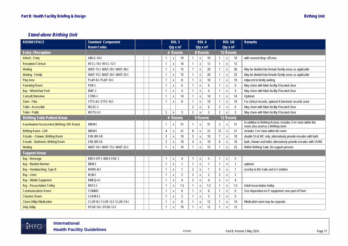
Part B: Health Facility Briefing & Design Birthing Unit
International
Health Facility Guidelines © TAHPI
Part B: Version 5 May 2016
Page 17
Stand-alone Birthing Unit ROOM/ SPACE Standard Component RDL 3 RDL 4 RDL 5/6 Remarks Room Codes Qty x m2 Qty x m2 Qty x m2
Entry / Reception 4 Rooms 8 Rooms 12 Rooms Airlock - Entry AIRLE-10-I 1 x 10 1 x 10 1 x 10 with covered drop -off area
Reception/ Clerical RECL-10-I RECL-12-I 1 x 10 1 x 12 1 x 12
Waiting WAIT-15-I WAIT-20-I WAIT-30-I 1 x 15 1 x 20 1 x 30 May be divided into female/ family areas as applicable
Waiting - Family WAIT-15-I WAIT-20-I WAIT-25-I 1 x 15 1 x 20 1 x 25 May be divided into female/ family areas as applicable
Play Area PLAP-8-I PLAP-10-I 1 x 8 1 x 10 1 x 10 Adjacent to family waiting
Parenting Room PAR-I 1 x 6 1 x 6 1 x 6 May share with Main facility if located close
Bay - Wheelchair Park BWC-I 1 x 4 1 x 4 1 x 4 May share with Main facility if located close
Consult/ Interview CONS-I 1 x 14 1 x 14 1 x 14 Optional
Store - Files STFS-8-I STFS-10-I 1 x 8 1 x 10 1 x 10 For clinical records; optional if electronic records used
Toilet - Accessible WCAC-I 2 x 6 2 x 6 May share with Main facility if located close
Toilet - Public WCPU-3-I 2 x 3 2 x 3 2 x 3 May share with Main facility if located close
Birthing Suite Patient Areas 4 Rooms 8 Rooms 12 Rooms
Examination/ Assessment (Birthing LDR Room) BIRM-I 1 x 31 1 x 31 2 x 31 In addition to Birthing Rooms; includes 3 m2 store within the room; also used as a Birthing room
Birthing Room - LDR BIRM-I 4 x 31 8 x 31 12 x 31 includes 3 m2 store within the room
Ensuite – Shower, Birthing Room ENS-BR-I-B 3 x 10 5 x 10 7 x 10 double Sh & WC only; alternatively provide ensuites with bath
Ensuite - Bathroom, Birthing Room ENS-BR-I-A 2 x 10 4 x 10 6 x 10 bath, shower and toilet; alternatively provide ensuites with Sh/WC
Waiting WAIT-10-I WAIT-15-I WAIT-25-I 1 x 10 1 x 15 1 x 25 Within Birthing Suite, for support persons
Support Areas Bay - Beverage BBEV-OP-I BBEV-ENC-I 1 x 4 1 x 5 1 x 5
Bay - Blanket Warmer BBW-I 1 x 1 1 x 1 1 x 1 optional
Bay - Handwashing, Type B BHWS-B-I 1 x 1 2 x 1 3 x 1 at entry to the Suite and in Corridors
Bay - Linen BLIN-I 1 x 2 2 x 2 2 x 2
Bay - Mobile Equipment BMEQ-4-I 1 x 4 2 x 4 2 x 4
Bay - Resuscitation Trolley BRES-I 1 x 1.5 1 x 1.5 1 x 1.5 Adult resuscitation trolley
Communications Room COMM-I 1 x 0 1 x 0 1 x 0 Size dependant on IT equipment; area part of Plant
Cleaners Room CLRM-5-I 1 x 5 1 x 5 1 x 5
Clean Utility/ Medication CLUR-8-I CLUR-12-I CLUR-14-I 1 x 8 1 x 12 1 x 14 Medication room may be separate
Dirty Utility DTUR-10-I DTUR-12-I 1 x 10 1 x 12 1 x 12

Part B: Health Facility Briefing & Design Birthing Unit
International
Health Facility Guidelines © TAHPI
Part B: Version 5 May 2016
Page 18
ROOM/ SPACE Standard Component RDL 3 RDL 4 RDL 5/6 Remarks Room Codes Qty x m2 Qty x m2 Qty x m2 Disposal Room DISP-8-I DISP-10-I 1 x 8 1 x 10 1 x 10
Loading Dock LODK-I (sim) 1 x 10 1 x 15 1 x 20
Linen Holding - Clean DISP-8-I DISP-10-I 1 x 8 1 x 10 1 x 10
Staff Station SSTN-10-I SSTN-14-I SSTN-20-I 1 x 10 1 x 14 1 x 20 May be provided as small sub stations to a group of rooms
Store - Bulk STBK-20-I similar 1 x 10 1 x 15 1 x 20 Consumable and general stock
Store - Equipment STEQ-10-I STEQ-14-I 1 x 10 1 x 14 2 x 14 May be subdivided and located near Birthing rooms as required
Store - Gas Bottles STGB-F-I similar 1 x 8 1 x 10 1 x 15
Store - General STGN-10-I STGN-14-I 1 x 10 1 x 10 2 x 14
Store - Records STFS-10-I STFS-20-I 1 x 10 1 x 20 1 x 20
Store - Sterile Stock STSS-12-I (sim) 1 x 12 1 x 12 2 x 12
Waiting/ Lounge - Visitors WAIT-10-I WAIT-15-I 1 x 10 1 x 15 1 x 15 Within the Unit ; may be shared with Entry area if convenient
Waste Holding/ Recyclables WACO-I (similar) 1 x 15 1 x 20 1 x 30
Staff Areas Bay - Beverage BBEV-OP-I BBEV-ENC-I 1 x 4 1 x 5 1 x 5 Optional, near Meeting Room
Change - Staff (Male/Female) CHST-14-I CHST-20-I 2 x 14 2 x 14 2 x 20 Toilets, Shower and Lockers; size dependent on staffing numbers
Meeting Room MEET-L-15-I MEET-L-25-I 1 x 15 1 x 15 1 x 25
Office - Clinical/ Handover OFF-CLN-I 1 x 15 1 x 15 1 x 15 Locate near staff station
Office - Single Person, 12 m2 OFF-S12-I 1 x 12 1 x 12 1 x 12 Note 1; Service Manager
Office - Single Person, 9 m2 OFF-S9-I 1 x 9 1 x 9 2 x 9 Note 1; Unit Manager
Office - 2 Person, Shared OFF-2P-I 1 x 12 1 x 12 Note 1; Nurse Educators, Specialists, Clinicians
Overnight Stay - Bedroom OVBR-I 1 x 10 1 x 10 1 x 10 Optional
Overnight Stay - Ensuite OVES-I 1 x 4 1 x 4 1 x 4
Staff Room SRM-15-I SRM-20-I SRM-25-I 1 x 15 1 x 20 1 x 25 May divide into Male & Female areas
Sub Total 584.5 863.5 1203.5
Circulation % 35 35 35
Area Total 789.1 1165.7 1624.7
Note 1: Offices to be provided according to the number of approved full time positions within the Unit Please also note the following:
Refer to Inpatient Unit for Maternity Inpatient accommodation requirements
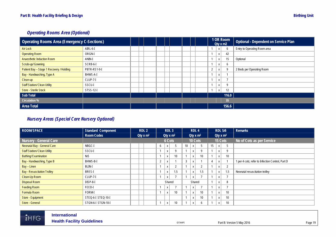
Part B: Health Facility Briefing & Design Birthing Unit
International
Health Facility Guidelines © TAHPI
Part B: Version 5 May 2016
Page 19
Operating Rooms Area (Optional)
Operating Rooms Area (Emergency C-Sections) 1 OR Room Qty x m2
Optional - Dependent on Service Plan
Air Lock AIRL-6-I 1 x 6 Entry to Operating Room area
Operating Room ORGN-I 1 x 42
Anaesthetic Induction Room ANIN-I 1 x 15 Optional
Scrub-up/ Gowning SCRB-6-I 1 x 6
Patient Bay – Stage 1 Recovery / Holding PBTR-RS1-9-I 2 x 9 2 Beds per Operating Room
Bay - Handwashing, Type A BHWS-A-I 1 x 1
Clean-up CLUP-7-I 1 x 7
Staff Station/ Clean Utility SSCU-I 1 x 9
Store - Sterile Stock STSS-12-I 1 x 12
Sub Total 116.0 Circulation % 35
Area Total 156.6
Nursery Areas (Special Care Nursery Optional)
ROOM/ SPACE Standard Component RDL 2 RDL 3 RDL 4 RDL 5/6 Remarks Room Codes Qty x m2 Qty x m2 Qty x m2 Qty x m2
Nursery - General Care 6 Cots 10 Cots 15 Cots No of Cots as per Service Neonatal Bay - General Care NBGC-I 6 x 5 10 x 5 15 x 5
Staff Station/ Clean Utility SSCU-I 1 x 9 1 x 9 1 x 9
Bathing/ Examination N/S 1 x 10 1 x 10 1 x 10
Bay - Handwashing, Type B BHWS-B-I 2 x 1 3 x 1 4 x 1 1 per 4 cots; refer to Infection Control, Part D
Bay – Linen BLIN-I 1 x 2 1 x 2 1 x 2
Bay - Resuscitation Trolley BRES-I 1 x 1.5 1 x 1.5 1 x 1.5 Neonatal resuscitation trolley
Clean-Up Room CLUP-7-I 1 x 7 1 x 7 1 x 7
Disposal Room DISP-8-I Shared Shared 1 x 8
Feeding Room FEED-I 1 x 7 1 x 7 1 x 7
Formula Room FORM-I 1 x 10 1 x 10 1 x 10
Store - Equipment STEQ-6-I STEQ-10-I 1 x 10 1 x 10
Store - General STGN-6-I STGN-10-I 1 x 10 1 x 6 1 x 10

Part B: Health Facility Briefing & Design Birthing Unit
International
Health Facility Guidelines © TAHPI
Part B: Version 5 May 2016
Page 20
ROOM/ SPACE Standard Component RDL 2 RDL 3 RDL 4 RDL 5/6 Remarks Room Codes Qty x m2 Qty x m2 Qty x m2 Qty x m2
Nursery- Special Care 8 Cots Refer to NICU Optional Neonatal Bay - Special Care NBSC-I 7 x 10 Qty will depend on No. of Birthing Rooms, beds and service plan
Neonatal Bay - Resuscitation NBICU-I 1 x 14 for resuscitation and transfer preparation, in addition to neonatal bays
Neonatal Room - Special Care - Isolation Class N NBSC-I (similar) 1 x 14 provide according to Service Plan
Anteroom ANRM-I 1 x 6 for Isolation Room, Negative Pressure
Nursery - Special Care Staff & Support Areas
Bathing/ Examination NS 1 x 10
Bay - Handwashing, Type A BHWS-A-I 5 x 1 1 per 2 cots + 1 at entry
Bay - Linen BLIN-I 1 x 2
Bay - Mobile Equipment BMEQ-4-I 1 x 4
Bay - Pathology BPATH-I 1 x 1
Bay - Resuscitation Trolley BRES-I 1 x 1.5 Neonatal resuscitation trolley
Clean-up CLUP-12-I 1 x 12
Disposal Room DISP-8-I 1 x 8 May be shared
Feeding Room FEED-I 1 x 7
Formula Room FORM-I (sim) 1 x 10 Milk storage
Meeting Room, 9m2 MEET-9-I 1 x 9 Meetings, Tutorials & Education
Office - Single Person, 9 m2 OFF-S9-I 1 x 9 Note 1; SCN Manager
Procedure Room TRMT-I 1 x 14 Optional
Staff Station SSTN-10-I 1 x 10
Store - Equipment STEQ-16-I 1 x 16 Based on a minimum of 2 m2 per cot
Store - General STGN-9-I 1 x 9 Consumable stock and sterile packs
Toilet – Public (Parent) WCPU-3-I 1 x 3 May be shared with general public amenities
Toilet - Staff, (M/F) WCST-I 2 x 3 May be shared with general staff amenities
Sub Total 88.5 356.0 153.5 Circulation % 35 35 35
Total Area 119.5 480.6 207.2
Note 1: Offices to be provided according to the number of approved full time positions within the Unit Please also note the following:
Special care Nursery of RDL5/6 will likely be located in a Neonatal ICU.

Part B: Health Facility Briefing & Design Birthing Unit
International
Health Facility Guidelines © TAHPI
Part B: Version 5 May 2016
Page 21
6 Future Trends When planning for future developments the following trends should be considered:
Increased prevalence of obesity in teenage and adult women
Steep rise in caesarean births
Increasing survival of pre-term babies
Demand for midwife led care throughout the pregnancy, birth and post-natal period.
Recognition that the physical and sensory surroundings, including access to the outdoors, significantly impacts upon patients and their carers during birthing.
Recognition that flexible patient rooms, where medical equipment is discreetly stored and the patient bed is not the focal point, enhances birthing experiences
Demand for deep tubs/baths to facilitate immersion in all positions, enhanced by ledges for support persons. Showerheads with pulsing features, fixed support rails, hammocks and resting ledges improve patient experience.
Expectation by families/carers that live-in accommodation can be provided.
Strong preferences for one patient room to facilitate birthing and post-natal period.
Patient demand for control over heating, lighting and visitor access.
Early discharge into community support programs
Ongoing development in support, monitoring, diagnostic, security and treatment technology.
Ongoing development in electronic medical records and information technology.
Infant and facility security systems developments.
Recognition that midwives and birth attendants require a retreat space within the room to complete documentation and provide separation from birthing patient and carers.

Part B: Health Facility Briefing & Design Birthing Unit
International
Health Facility Guidelines © TAHPI
Part B: Version 5 May 2016
Page 22
7 References and Further Reading
Annabelle, S., Maralyn, F., Christine, C. and Caroline, H. (2010). Examining the content validity of the Birthing Unit Design Spatial Evaluation Tool (BUDSET) within a woman-centred framework. Elsevier Inc. http://www.ncbi.nlm.nih.gov/pubmed/?term=Foureur%20M%5BAuthor%5D&cauthor=true&cauthor_uid=23181648
Australia and New Zealand College of Anaesthetists (ANZCA) Recommendations for Minimum Facilities for Safe Administration of Anaesthesia in Operating Suites and Other Anaesthetising Locations. http://www.anzca.edu.au/resources/professional-documents/pdfs/ps55-2012-recommendations-on-minimum-facilities-for-safe-administration-of-anaesthesia-in-operating-suites-and-other-anaesthetising-locations.pdf
Australasian Health Facility Guidelines, Part B Health Facility Briefing and Planning, 0510 - Maternity Unit, 2016 https://aushfg-prod-com-au.s3.amazonaws.com/HPU_B.0510_6_0.pdf
Davis, D., Homer, C., Leap, N., Forbes, I. and Foureur, M. (2011). Testing the birth unit design spatial evaluation tool (BUDSET) in Australia: a Pilot Study. Vendome Group, LLC. https://www.researchgate.net/publication/51000564_Testing_the_Birth_Unit_Design_Spatial_Evaluation_Tool_BUDSET_in_Australia_a_pilot_study
Gov.UK DH (Department of Health) Children young people and maternity services. Health Building Note 09-02: Maternity care facilities, 2008, refer https://www.gov.uk/government/uploads/system/uploads/attachment_data/file/147876/HBN_09-02_Final.pdf
Foureur, M., Davis, D., Fenwick, J., Leap, N., Iedema, R., Forbes, I. and Homer, C. (2010). The relationship between birth unit design and safe, satisfying birth: Developing a hypothetical model. Midwifery, 26(5), pp.520--525. http://www.midwiferyjournal.com/article/S0266-6138(10)00090-2/abstract
Guidelines for Design and Construction of Health Care Facilities; The Facility Guidelines Institute, Freestanding Birth Centres, 2014 Edition http://www.fgiguidelines.org/
NSW Department of Health, (2008). Primary Maternity Services in Australia. Australian Health Ministers' Advisory Council. http://www.ahmac.gov.au/cms_documents/Primary%20Maternity%20Services%20in%20Australia.pdf
Sandall, J., Soltani, H., Gates, S., Shennan, A. and Devane, D. (2013). Midwife-led continuity models versus other models of care for childbearing women. Cochrane Database of Systematic Reviews, 8. http://www.cochrane.org/CD004667/PREG_midwife-led-continuity-models-versus-other-models-care-childbearing-women
Stenglin, M. and Foureur, M. (2013). Designing out the Fear Cascade to increase the likelihood of normal birth (Journal article). Midwifery. http://www.midwiferyjournal.com/article/S0266-6138(13)00123-X/abstract
University of Technology Sydney (AUS). ‘Birthing Unit Design Guideline’ 2013. Retrieved from: http://www.worldhealthdesign.com/birthing-Unit-design-researching-newprinciples.aspx February 2014
Part B – Health Facility Briefing & Design 35 Cardiac Investigation Unit
International Health Facility Guidelines Version 5 May 2016
Part B: Health Facility Briefing & Design
International
Health Facility Guidelines © TAHPI
Part B: Version 5 May 2016
Page 2
Table of Contents
35 Cardiac Investigation Unit ........................................................................................................ 3
1 Introduction ............................................................................................................................................... 3 Description .................................................................................................................................................. 3
2 Operational and Planning Considerations .............................................................................................. 3 Operational Models ..................................................................................................................................... 3 Planning Models .......................................................................................................................................... 4 Functional Areas ......................................................................................................................................... 4 Functional Relationships ............................................................................................................................. 8
3 Design ...................................................................................................................................................... 10 Patient Treatment Areas ........................................................................................................................... 10 Environmental Considerations .................................................................................................................. 10 Space Standards and Components .......................................................................................................... 11 Safety & Security ....................................................................................................................................... 12 Finishes ..................................................................................................................................................... 12 Fixtures, Fittings & Equipment .................................................................................................................. 12 Building Service Requirements ................................................................................................................. 12 Infection Control ........................................................................................................................................ 13
4 Components of the Unit .......................................................................................................................... 14 Standard Components .............................................................................................................................. 14 Non-Standard Components ....................................................................................................................... 14
5 Schedule of Accommodation – Cardiac Investigation Unit ................................................................ 15 Cardiac Investigation Unit located within a health facility – Non-Interventional ........................................ 15 Cardiac Catheter Suite – Interventional .................................................................................................... 17
6 Future Trends .......................................................................................................................................... 19
7 Further Reading ....................................................................................................................................... 19

Part B: Health Facility Briefing & Design Cardiac Investigation Unit
International
Health Facility Guidelines © TAHPI
Part B: Version 5 May 2016
Page 3
35 Cardiac Investigation Unit
1 Introduction
Description The Cardiac Investigation Unit provides diagnostic procedures, interventional treatments and consultation for patients with cardiac conditions. The Unit consists of three major components: Cardiac Catheter Suite Cardiac Diagnostic Unit Outpatient Clinics This Functional Planning Unit will address the following components of a cardiac investigation service primarily for secondary and tertiary healthcare facilities: Cardiac Catheter Laboratories – diagnostic and interventional Electrophysiology (EP) laboratory Echocardiography – trans-thoracic (TTE), trans-oesophageal (TOE) and stress
echocardiography Exercise stress testing Electrocardiography (ECG) Holter monitoring Ambulatory blood pressure monitoring Pacemaker and defibrillator implantation and follow-up Outpatient clinics. 2 Operational and Planning Considerations
Operational Models
Hours of Operation
The Cardiac Investigation outpatients area will generally operate up to 8 hours a day, five-days a week. The diagnostic and interventional areas of Cardiac Investigations Unit may operate up to 12-hours a day, seven-days a week, depending on the Operational Policy.
Models of Care
The Cardiac Investigation Unit may incorporate the following Models of Care for specific components:
Cardiac Catheter Laboratories Catheter laboratories, depending on their role within the service plan, may be: Integrated into an interventional imaging suite in a Medical Imaging Unit A component of a Cardiac Precinct A component of an interventional floor that incorporates operating theatres and cardiac
investigations with access to a 23 hour or short stay ward. The number of laboratories will be determined by the service plan, but laboratories should operate at near-optimum capacity to justify the expense of operation, maintain the skills and teamwork of the operators and staff, and provide maximum patient and operator safety.
Cardiac Diagnostic Unit Cardiac diagnostic services may be provided: Within a fully integrated Cardiac Investigation Unit As a part of a general Clinical Measurement Unit that can include diagnostic facilities for
other units such as neurology and respiratory function testing Within an outpatient clinic (depending on the range of tests to be provided by the unit).

Part B: Health Facility Briefing & Design Cardiac Investigation Unit
International
Health Facility Guidelines © TAHPI
Part B: Version 5 May 2016
Page 4
Cardiac Outpatient Clinics Cardiac Outpatient Clinics can be conducted through: A general Outpatient Unit Consulting rooms provided within a Clinical Measurement Unit that can be shared with other
disciplines Dedicated consulting rooms within a Cardiac Precinct. The provision of dedicated cardiac
clinics should be based on throughput requirements and service planning. Access to ECG testing is required as a minimum in all forms of cardiac outpatients clinics. The Cardiac Outpatients Clinics will generally work closely with the Cardiac Rehabilitation Service with patient referrals for ongoing therapy.
Planning Models
Location
The relationships required between the Cardiac Investigation Unit and other units within the health facility will determine the most appropriate location for the unit. The models of care, described above, will impact on the location of the unit in relation to other units, particularly if areas such as diagnostic units, are shared. If the Unit is not on the ground floor, consideration should be given to outpatient volumes in regard to vertical access to clinics.
Configuration
Staff, patients and the general public should not need to use the Cardiac Investigation Unit as a thoroughfare to other units of the healthcare facility as it could adversely impact on issues relating to security, privacy and stock control. The diagnostic and clinic rooms that are less complex and more frequently used should be located closer to reception/ waiting areas, while the catheterisation suite should located in a more private zone. It would be preferable if staff and patient paths are separate and a discreet access for inpatients is provided.
Functional Areas The Cardiac Investigation Unit can include the following functional zones, arranged in relation to each other depending on operational policies, service delineation and relationships to other services:
Outpatient/ Diagnostic Facilities – Non-interventional
Cardiac Outpatient/ Diagnostic facilities will generally comprise: Entry Reception including:
- Waiting with beverage bay and drinking water facilities if required - Public amenities, if not located in close proximity - Interview room - Patient bed bays, for holding pre-procedure and recovery following procedures - Storage for files and stationery
Outpatient/ Diagnostic areas that may incorporate the following rooms or diagnostic testing
specialties according to the Service Plan: - Consult rooms - ECG cubicles - Stress testing - Echocardiography - Holter monitoring application room - Tilt table testing - Reporting areas with workstations

Part B: Health Facility Briefing & Design Cardiac Investigation Unit
International
Health Facility Guidelines © TAHPI
Part B: Version 5 May 2016
Page 5
Support areas including - Patient amenities with showers for post exercise hygiene - Patient change rooms, that may be located within the diagnostic rooms - Storage for linen, equipment, consumables, mobile equipment, resuscitation trolley - Clean-up room.
Procedural Areas (Cardiac Catheter Laboratories)
The service plan, capability (secondary, tertiary) and anticipated caseload will determine the number and type of laboratories required. The Cardiac Catheterisation Suite requires the following functional areas as a minimum: Entry/ Reception, which may be shared with an adjacent unit along with:
- Patient /visitor waiting area - Change cubicles - Interview room for patient/ family discussions - Patient bed Bays for holding and post-procedure - Patient amenities
Treatment Area:
- Catheter Laboratory/s (diagnostic, interventional) - Electrophysiology Laboratory (EP) rooms as required - Computer equipment rooms (generators, computer modules for imaging equipment) - Control room/s (Note: it is not recommended that control rooms are shared; refer to
Design: Environmental Considerations: Acoustics in this FPU) - Scrub bay/s for catheter laboratories (should be located external to laboratories)
Support Areas will include:
- Beverage bay for patient refreshments as required - Clean-up and Dirty Utility rooms - Clean Utility area that may be collocated with the staff station for ease of staff access - Handwashing bays with close access to bed bays - Staff station with observation of holding and recovery bed bays - Storage for linen, blanket warmer, sterile stock, equipment, consumables, lead
aprons, resuscitation trolley and files - Set-up area for procedure set-up as required - Viewing/ reporting room
Staff Area:
- Change rooms with showers, toilet and lockers - Offices/ workstations, according to the service plan - Staff Room and amenities
Depending on the model of care, every opportunity should be taken to share facilities such as: Public waiting areas and amenities Reception Support areas Staff offices and amenities.
Reception/ Waiting
The Reception/ Waiting area of the Cardiac Investigation Unit may be shared by all sections of the unit and should provide convenient access to both the diagnostic areas and procedural areas such as cardiac catheter laboratories, as well as allowing access to public and disabled amenities for patients and visitors. The Reception area may include patient registration, a patient queuing system and cashier facilities where appropriate. Waiting areas may be designed with separation to meet cultural requirements where appropriate. Waiting areas should accommodate a range of occupants including children, those less mobile or in wheelchairs.

Part B: Health Facility Briefing & Design Cardiac Investigation Unit
International
Health Facility Guidelines © TAHPI
Part B: Version 5 May 2016
Page 6
A separate Reception/ waiting area may be provided for the Catheterisation Suite in order to offer discreet access to patients.
Cardiology Outpatient Clinics
Multi-function consultation rooms can sufficiently serve cardiology outpatient clinics. They may be scheduled for use by other disciplines and the number and size of rooms provided will be determined by throughput and relationships to other units as outlined in the service plan. If a pacemaker clinic is included in the service plan, there should be access to a room for testing equipment and access to an external defibrillator. If the consulting rooms are part of a general outpatient area that is shared with other disciplines, the location/ layout of the rooms should allow ready access to ECG facilities.
ECG Cubicles
A room or bay for undertaking resting electrocardiograms is required, with ready access from the waiting area and outpatient area as ECGs are routinely performed in a cardiac clinic. This may be provided as a single room/ cubicle or may be designed as two patient bays. If two bays are designed, curtain tracks and screens will be required for patients’ privacy. Patients may change in the room/ bay or an adjacent change cubicle. A handwashing basin will be required in close proximity.
Stress Testing
Stress testing rooms should be located with ready access to change facilities and a shower for patients following the test. Stress Testing Rooms should comply with the Standard Component for Stress Testing.
Echocardiography
Echocardiography Rooms should comply with the Standard Component for Echocardiography. Room size may be adjusted according to equipment to be used.
Holter Monitoring/ Ambulatory Monitoring/ BP Application Room
A room for attaching Holter monitors or blood pressure cuffs for ambulatory monitoring of patients may be required. Note that a multi-disciplinary Consult room may be suitable for this purpose. Patients may change in the room or in an adjacent change cubicle. The room should be located with ready access to the Waiting Area. The Room will require Body Protected power in accordance with local authority requirements. Furniture, Fittings and Equipment within the room will include: Examination Couch/ table Holter monitoring equipment (ECG leads and monitors) and blood pressure equipment Small desk and technician chair or stool Patient chair Hand basin Clothes hook/s for patient clothing Storage for leads, equipment parts and consumable stock.
Cardiac Catheter Laboratory/s
The Cardiac Catheter Laboratory is to comply with Standard Components Catheter Laboratory. Rooms may be resized according to equipment to be installed. Cardiac Catheter Laboratories should be located in close proximity to holding and recovery bed bays.

Part B: Health Facility Briefing & Design Cardiac Investigation Unit
International
Health Facility Guidelines © TAHPI
Part B: Version 5 May 2016
Page 7
Electrophysiology (EP) Laboratory
The Electrophysiology Laboratory is a room for undertaking electrophysiology studies and radiofrequency ablation if indicated and will be similar to the Cardiac Catheter Laboratory. The room needs to be located away from external electrical interference i.e. plant rooms or other equipment requiring high voltage, and properly shielded; an electro-magnetic shielding cage may be necessary. The room will require direct access to Patient Holding bays. Note that patients may become unstable during a procedure and therefore more support equipment is required. Allow for circulation space for four (4) staff plus equipment in room. The Control Room should be located at head or foot of bed not at the side for optimum patient visibility. Equipment required may include: Anaesthetic pendant at head of table Anaesthetic machine Resuscitation trolley and defibrillators Set-up and stock trolleys 3 dimensional mapping equipment Echocardiography (TOE) machine. Provide services pendants or power points co-located with the patient table to reduce trip hazards from electrical cables across the room. Increasingly equipment is becoming cordless e.g. foot pedals, echo machines. The room should include a bench or trolley for preparation of emergency drugs. The room will require storage space, drawers and shelves for consumable equipment required during procedures.
Staff Offices and Amenities
Offices and workstations may be required for senior staff managing the various zones of the unit to undertake administrative functions, or to facilitate educational and research activities. Offices / workstations may be located within the functional zone or may be provided as a combined general office complex in a cardiac precinct. Staff will need access to the following: Toilets, showers, change rooms and lockers Staff room with beverage and food storage facilities Meeting room/s
Teaching and Research
An assessment to gain an understanding of the extent of the teaching and research to be undertaken within the Cardiac Investigation Unit will need to be conducted in order to allow for sufficient office space and teaching facilities. The assessment should consider applicable guidelines for staff training and competence, particularly as new procedures and technologies are developed. The assessment will determine the type, size, and number of facilities provided in the service plan as well as whether they are located within the unit or easily are accessible from the unit. At a minimum, adequate access to facilities for meetings and staff education should be provided. Clinical research needs should be assessed for provision of offices for senior coordinators, research fellows, research staff and assistants. Facilities may include consulting and diagnostic rooms if required for patient consultation, drug storage and monitoring, records storage and research laboratories.

Part B: Health Facility Briefing & Design Cardiac Investigation Unit
International
Health Facility Guidelines © TAHPI
Part B: Version 5 May 2016
Page 8
Functional Relationships
External
The rapid transfer of emergency patients requires direct access from the Emergency Unit to the Catheter Laboratory. The Cardiac Investigation Unit should also be well-situated for easy access to: The Chest Pain Assessment Unit Medical Imaging (chest x-rays and CT scanning) Nuclear Medicine (stress testing) Positron Emission Tomography Unit (in tertiary facilities) Operating Unit for cardiac surgery Short stay unit/ 23 hour unit for patient observation and investigations Pathology Services Biomedical Engineering for equipment support and maintenance Community Health Services. The Cardiac Investigation Unit will have a strong relationship with cardiac surgical specialties including Operating Unit and cardiac Inpatient Units and should be located to enable effective communication and collaboration between staff of these areas. Links with cardiac surgery occur at several levels including clinical decision making concerning patients who require cardiac surgery, cardiac management of patients in the post-operative phase including rehabilitation and cardiac research projects.
Internal
Radiofrequency interference should be considered when planning the Cardiac Investigation Unit. The Electrophysiology (EP) laboratories, as well as Pacemaker and ICD (Implantable Cardiac Defibrillator) clinics should not be located close to any high voltage electronic equipment (such as a sub-station or lift plant room) as interruption by auxiliary radiofrequency will distort the assessment of the patient and affect new devices that use wireless technology. Expert advice should be obtained. If Stress Echocardiography is undertaken within the unit, the Echo room may include a dedicated treadmill. Alternatively the Echo room may be located adjacent to the Stress Testing room to allow for efficient staff and patient access.
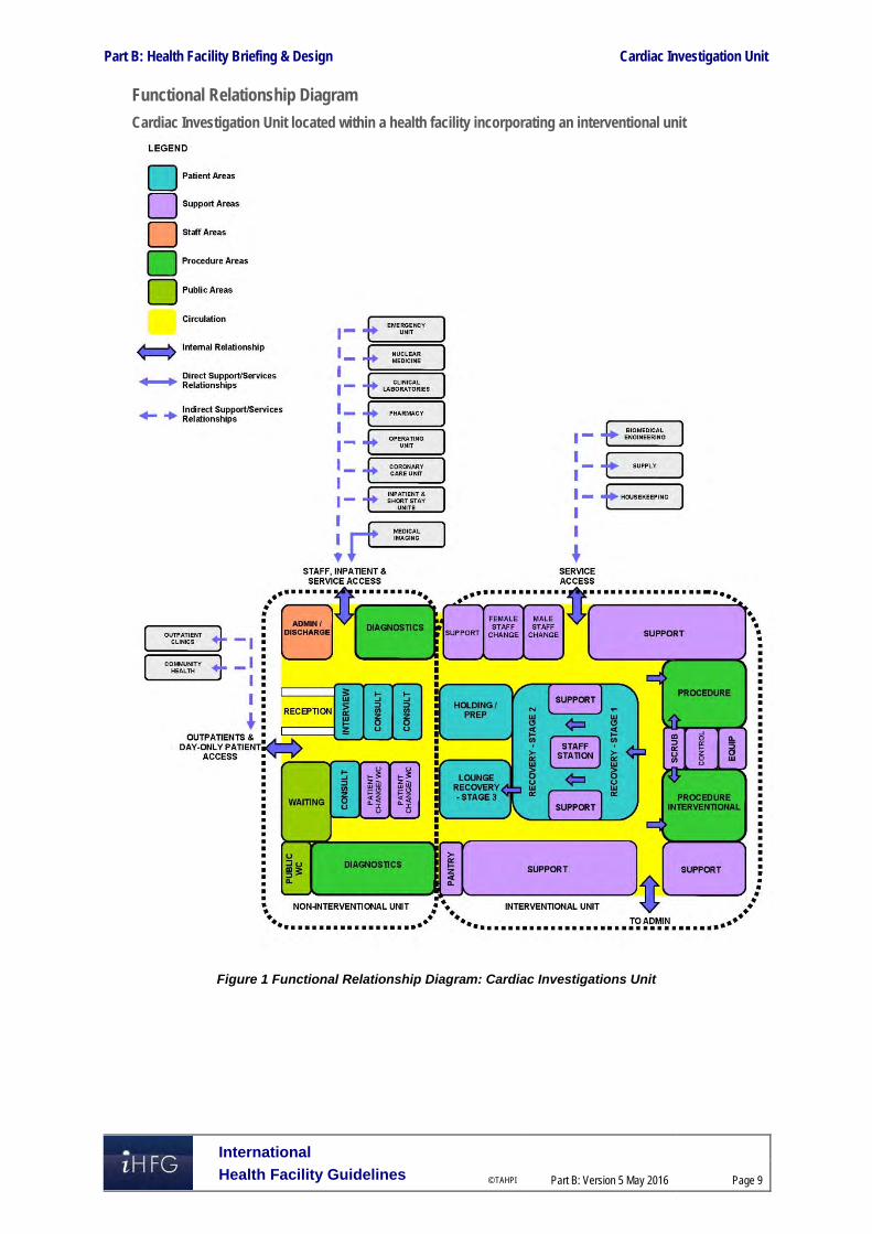
Part B: Health Facility Briefing & Design Cardiac Investigation Unit
International
Health Facility Guidelines © TAHPI
Part B: Version 5 May 2016
Page 9
Functional Relationship Diagram
Cardiac Investigation Unit located within a health facility incorporating an interventional unit
Figure 1 Functional Relationship Diagram: Cardiac Investigations Unit

Part B: Health Facility Briefing & Design Cardiac Investigation Unit
International
Health Facility Guidelines © TAHPI
Part B: Version 5 May 2016
Page 10
The optimum external relationships include: Visitors access from a main circulation corridor with a relationship to the Main Entrance Separate entry and access for staff from hospital units to Administration Access for service units such as Supply and Housekeeping via a service corridor. Internal relationships should include the following: Reception at the entrance with access to an interview area Access to administrative sub units such as Public Relations, Human Resources, Finance,
and Clinical Administration etc. via staff corridors with link to Reception Areas of administration that are more frequently visited, such as Public Relations and Human
Resources, located closer to Reception and entry Support areas located centrally for ease of staff access. 3 Design
Patient Treatment Areas Direct visualisation, or indirect by video monitoring, of patients is essential at all times. This approach permits the monitoring of patient status under both routine and emergency circumstances. The preferred design is to allow a direct line of vision between the patient and the Staff Station. Weight-bearing surfaces that support the monitoring and imaging equipment should be sturdy enough to withstand high levels of strain over time. Design should allow for a future increase in monitoring equipment requirements, particularly mobile monitoring.
Environmental Considerations
Acoustics
Acoustic privacy is required in consulting/ testing rooms and any rooms where confidential information will be discussed. The transfer of sound between clinical spaces should be minimised to reduce the potential of staff error from disruptions and miscommunication and to increase patient safety and privacy. Shared Control Rooms to cardiac laboratories are not recommended. The staff working in the control room are responsible for scheduling and coordinating all investigations and treatments. Acoustic difficulties may occur when several staff occupy the same space creating the potential for instructions to be misinterpreted and mistakes to be made.
Natural Light/ Lighting
Natural light and views should be available from the Unit for the benefit of staff and patients. Windows are an important aspect of sensory orientation, and as many rooms as possible should have windows to reinforce day/ night orientation. If windows cannot be provided in each room, an alternate option is to allow a remote view of an outside window or skylight. Windows are particularly desirable in waiting areas, holding and recovery areas and staff lounges. Diagnostic rooms are an exception where it is not needed or recommended to have windows. Variable lighting levels should be provided in Control/ Reporting rooms, Procedure rooms, Cardiac Catheterisation Laboratories, Ultrasound / Echo rooms and Holter reading rooms, where screen visibility is required.
Privacy
Change rooms should be located adjacent to testing rooms so that a patient is not required to cross public areas to access them. Patients should not be in view when a door to a change room is open; therefore entry should be discrete and controlled.

Part B: Health Facility Briefing & Design Cardiac Investigation Unit
International
Health Facility Guidelines © TAHPI
Part B: Version 5 May 2016
Page 11
Additional privacy considerations will include: Privacy screening to all Patient Bed Bays Discreet and non-public access to medical records Location of doors to avoid patient exposure in Consult, Diagnostic and treatment rooms.
Interior Decor
Interior décor refers to colour, textures, surface finishes, fixtures, fittings, furnishings, artworks and atmosphere. It is desirable that these elements are combined to create a calming, non-threatening environment. Colours should be used in combination with lighting to ensure that they do not mask skin colours as this can be a problem in areas where clinical observation takes place. Bold primary colours and greens are colours to be aware of e.g. yellow could mask a main symptom of jaundice.
Space Standards and Components
Patient Bays
Where an open plan arrangement is provided in patient holding and treatment bay areas, bed spaces shall be arranged so that there is a clearance of at least 1200 mm from the side of the bed to the nearest fixed obstruction or wall. At the head of the bed, at least 900 mm clearance shall be allowed between the bed and any fixed obstruction or wall.
Catheter Laboratories
Catheter laboratories should have ceilings that are at least 3 metres high and are capable of supporting the weight of the various pieces of ceiling-mounted imaging equipment required. This may include the gantry for catheter equipment, theatre light, room lighting, air conditioning, medical gas booms etc. The co-ordination of all ceiling fixed services is vital to the functioning of the laboratories.
Accessibility
Design should provide ease of access for wheelchair bound patients in all patient areas including Consult, Diagnostic rooms and Catheter Laboratories. Waiting areas should include spaces for wheelchairs (with power outlets for charging electric mobility equipment) and suitable seating for patients with disabilities or mobility aids. The Unit will require provision for bariatric patients.
Doors
All entry points, doors or openings, shall be a minimum of 1200 mm wide, unobstructed. Larger openings may be required for special equipment, as determined by the Operational Policy, to allow the manoeuvring of beds, trolleys, equipment and wheelchairs without manual handling risks and risk of damage. Doors used for emergency bed transfer to the Operating Units must be appropriately positioned and sized. A minimum of 1400mm clear opening is recommended for doors requiring bed/trolley access. Also refer to Part C – Access, Mobility, OH&S of these Guidelines.
Ergonomics/ OH&S
Design of clinical spaces including Diagnostic rooms, Catheter Laboratories, EP laboratories must consider Ergonomics and OH&S issues for patient and staff safety and welfare. Refer to Part C – Access, Mobility, OH&S of these Guidelines for more information.
Size of the Unit
The size of the Clinical Information Unit will be determined by a Clinical Services Plan and will take into consideration:
The size of the population served by the Unit and demographic trends
The average length of consultation, diagnostic procedure or stay
The number of referrals and transfers from other local regions or hospitals.

Part B: Health Facility Briefing & Design Cardiac Investigation Unit
International
Health Facility Guidelines © TAHPI
Part B: Version 5 May 2016
Page 12
Safety & Security The Cardiac Investigation Unit should include the following security considerations:
The Reception may act as a control point for the unit
Entry to the Cardiac Catheter Suite may require restricted access such as electronic card reader
All Offices require lockable doors
All Store rooms for files, records and equipment should be lockable
After-hours access which may be required to some diagnostic and procedural areas for emergency procedures
Finishes In all areas where patient observation is critical, colours shall be chosen that do not alter the observer's perception of skin colour. The following aspects should always be considered when specifying internal finishes: Cleaning and infection control Fire safety of the materials Patient care and comfort Staff safety, particularly for floor finishes Cultural/ social perceptions of a professional healthcare environment. Refer to Part C of these Guidelines and Standard Components for more information on wall protection, floor finishes and ceiling finishes.
Fixtures, Fittings & Equipment All furniture, fittings and equipment selections for the Cardiac Investigations Unit should be made with consideration to ergonomic and Occupational Health and Safety (OH& S) aspects. Refer to Part C of these Guidelines - Access, Mobility, OH&S, the Room Layout Sheets (RLS) and Room Data Sheets (RDS) for more information.
Clocks
An analogue clock/s with a second sweep hand shall be provided and conveniently located for easy reference from all diagnostic areas, bed positions and the Staff Station.
Window Treatments
Window treatments should be durable and easy to clean. Consideration may be given to use double glazing with integral blinds, tinted glass, reflective glass, exterior overhangs or louvers to control the level of lighting.
Building Service Requirements
Communications
The Cardiac Investigation Unit requires a wide range of systems to ensure the storage of patient information and image management is efficient and effective. These systems include but are not limited to: Picture archiving communications systems (PACS) and storage for digital archives Voice/ data cabling and outlets for phones, fax and computers Network data requirements and wireless network requirements to support remote reporting Video and teleconferencing capability CCTV surveillance if indicated Patient, staff, emergency call, duress alarms and paging systems

Part B: Health Facility Briefing & Design Cardiac Investigation Unit
International
Health Facility Guidelines © TAHPI
Part B: Version 5 May 2016
Page 13
Communications rooms and server rooms. Patient, staff assist and emergency call facilities shall be provided in all Diagnostic, Procedure, Treatment rooms and patient areas (e.g. Catheter Laboratories, Echo rooms, ECG rooms and toilets) in order for patients and staff to request for urgent assistance. Close collaboration with the IT Unit and obtaining advice from consultants early in the design phase is recommended.
Heating, Ventilation and Air conditioning
The unit shall have appropriate air conditioning that allows control of temperature, humidity and air change. Cardiac Catheterisation Suites will require specialised air-conditioning and filtration requirements, refer to Standard Components Catheter Laboratory Room Data Sheets and Room Layout Sheets.
Medical Gases
The Unit will require: oxygen and suction in all patient investigation rooms, treatment rooms and procedure rooms provision of medical air to patient recovery bays and interventional rooms is optional Full anaesthetic capability is required within the catheter laboratories, including systems for
the delivery of nitrous oxide and the ‘scavenging’ of gases that have been exhaled by the patient that should not be breathed in by any medical personnel.
Refer to Part E of these guidelines and to the Standard Components, RDS and RLS.
Radiation Shielding and Radiation Safety
The Catheter Laboratories require radiation shielding. A certified physicist or qualified expert will need to assess the plans and specifications for radiation protection as required by the relevant local radiation/nuclear safety authorities. A radiation protection assessment will specify the type, location and amount of radiation protection required for an area according to the final equipment selections, the layout of the space and the relationship between the space and other occupied areas. Incorporate all radiation protection requirements into the final specifications and building plans and re-evaluate radiation protection if the intended use of a room changes, equipment is upgraded or surrounding room occupancy is altered. Consideration should be given to the provision of floor and ceiling shielding when rooms immediately above and below are occupied.
Infection Control Standard precautions apply to the Cardiac Investigation Unit areas to prevent cross infection between patients, staff and visitors. Hand hygiene is important and it is recommended that in addition to hand basins, medicated hand gel dispensers be located strategically in staff circulation corridors.
Hand Basins
Basins suitable for surgical scrubbing procedures shall be provided for each Procedure and Treatment room (refer to Standard Components Room Layout and Room Data Sheets). Clinical hand-washing facilities shall be provided within the diagnostic testing rooms, convenient to the Staff Stations and patient areas. The ratio of provision shall be one clinical hand-washing facility for every four patient bays in open-plan areas. For further information refer to Part D – Infection Control in these Guidelines.

Part B: Health Facility Briefing & Design Cardiac Investigation Unit
International
Health Facility Guidelines © TAHPI
Part B: Version 5 May 2016
Page 14
4 Components of the Unit
Standard Components The Cardiac Investigation Unit will contain Standard Components to comply with details in the Standard Components described in these Guidelines. Refer to Standard Components Room Data Sheets and Room Layout Sheets.
Non-Standard Components Non Standard rooms are identified in the Schedules of Accommodation as NS and are described below.
ECG Cubicle/s
The ECG Cubicle is similar to a Patient Bay – Holding with the following inclusions: Cubicle partitions, optional Body protected power to protect patients from electric shock in accordance with local
authority requirements. Examination couch/ table ECG machine, mobile, with storage for leads and consumable stock Small desk and technician chair or stool, Patient chair Hand basin located in close proximity Clothes hook/s for patient use. Multiple cubicles will require screening for patient privacy.
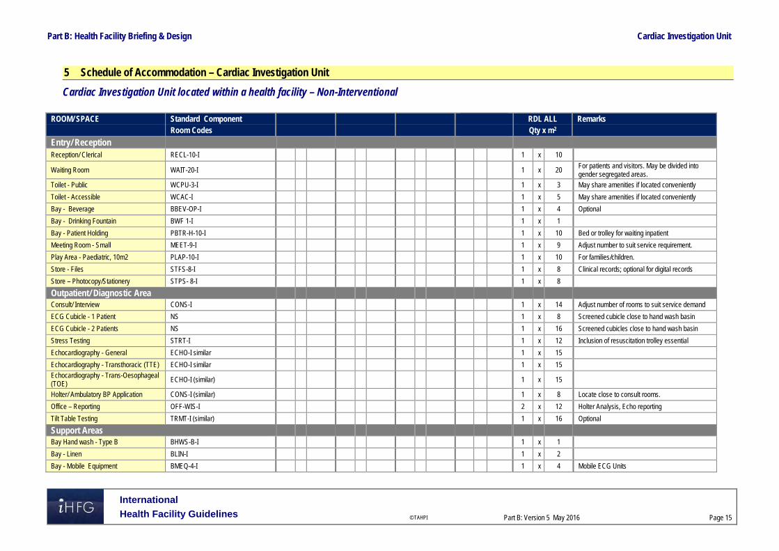
Part B: Health Facility Briefing & Design Cardiac Investigation Unit
International
Health Facility Guidelines © TAHPI
Part B: Version 5 May 2016
Page 15
5 Schedule of Accommodation – Cardiac Investigation Unit
Cardiac Investigation Unit located within a health facility – Non-Interventional
ROOM/ SPACE Standard Component RDL ALL Remarks Room Codes Qty x m2
Entry/ Reception Reception/ Clerical RECL-10-I 1 x 10
Waiting Room WAIT-20-I 1 x 20 For patients and visitors. May be divided into gender segregated areas.
Toilet - Public WCPU-3-I 1 x 3 May share amenities if located conveniently
Toilet - Accessible WCAC-I 1 x 5 May share amenities if located conveniently
Bay - Beverage BBEV-OP-I 1 x 4 Optional
Bay - Drinking Fountain BWF 1-I 1 x 1
Bay - Patient Holding PBTR-H-10-I 1 x 10 Bed or trolley for waiting inpatient
Meeting Room - Small MEET-9-I 1 x 9 Adjust number to suit service requirement.
Play Area - Paediatric, 10m2 PLAP-10-I 1 x 10 For families/children.
Store - Files STFS-8-I 1 x 8 Clinical records; optional for digital records
Store – Photocopy/Stationery STPS- 8-I 1 x 8
Outpatient/ Diagnostic Area Consult/ Interview CONS-I 1 x 14 Adjust number of rooms to suit service demand
ECG Cubicle - 1 Patient NS 1 x 8 Screened cubicle close to hand wash basin
ECG Cubicle - 2 Patients NS 1 x 16 Screened cubicles close to hand wash basin
Stress Testing STRT-I 1 x 12 Inclusion of resuscitation trolley essential
Echocardiography - General ECHO-I similar 1 x 15
Echocardiography - Transthoracic (TTE) ECHO-I similar 1 x 15
Echocardiography - Trans-Oesophageal (TOE) ECHO-I (similar) 1 x 15
Holter/ Ambulatory BP Application CONS-I (similar) 1 x 8 Locate close to consult rooms.
Office – Reporting OFF-WIS-I 2 x 12 Holter Analysis, Echo reporting
Tilt Table Testing TRMT-I (similar) 1 x 16 Optional
Support Areas
Bay Hand wash - Type B BHWS-B-I 1 x 1
Bay - Linen BLIN-I 1 x 2
Bay - Mobile Equipment BMEQ-4-I 1 x 4 Mobile ECG Units

Part B: Health Facility Briefing & Design Cardiac Investigation Unit
International
Health Facility Guidelines © TAHPI
Part B: Version 5 May 2016
Page 16
ROOM/ SPACE Standard Component RDL ALL Remarks Room Codes Qty x m2 Bay - Resuscitation Trolley BRES-I 1 x 1.5 May be stored in ECG Stress Testing Room
Change - Patient (Male/Female) CHPT-12-I 2 x 12 Shower, Toilet, Lockers
Clean – Up Room CLUP-7-I 1 x 7 For clean-up of echo probes.
Store - Equipment STEQ-20-I 1 x 20
Toilet - Accessible WCAC-I 1 x 6 As required
Staff Areas
Staff Room SRM-15-I 1 x 15 Includes beverage making facilities
Office – Single Person OFF–S9-1 1 x 9 Unit Manager, Note 1
Office – 2 Person Shared OFF-2P-I 1 x 12 General Administration; , Note 1
Office- Write – Up (Shared) OFF-WIS-U 1 x 12 Note 1
Office – Workstation (Technicians) OFF-WS-I 1 x 5.5 Work-stations numbers will depend on staffing.
Toilet - Staff WCST-I 2 x 3
Sub Total 356.0
Circulation % 35
Area Total 480.6
Note 1: Offices to be provided according to the number of approved full time positions within the Unit
Also note the following: Areas noted in Schedules of Accommodation take precedence over all other areas noted in the FPU. Rooms indicated in the schedule reflect the typical arrangement according to the Role Delineation. Exact requirements for room quantities and sizes will reflect Key Planning Units identified in the Service Plan and the Operational Policies of the Unit. Room sizes indicated should be viewed as a minimum requirement; variations are acceptable to reflect the needs of individual Unit. Office areas are to be provided according to the Unit role delineation and number of endorsed full time positions in the unit. Staff and support rooms may be shared between Functional Planning Units dependent on location and accessibility to each unit and may provide scope to reduce duplication of
facilities.

Part B: Health Facility Briefing & Design Cardiac Investigation Unit
International
Health Facility Guidelines © TAHPI
Part B: Version 5 May 2016
Page 17
Cardiac Catheter Suite – Interventional Note: If the Cardiac Catheter Suite is collocated with a non-interventional Cardiac Investigations Unit, Entry / Reception, Support Areas and Staff Areas may be shared between the two Units.
ROOM/ SPACE Standard Component RDL 6 Remarks Room Codes Qty x m2
Entry / Reception 2 Cath Labs Reception/ Clerical RECL-I0-I 1 x 10
Waiting WAIT-15-I 1 x 15 May be divided into gender segregated areas.
Change Cubicle - Accessible CHPT-D-I 2 x 4 May be divided into gender segregated areas.
Meeting Room - Small MEET-9-I 1 x 9 For pre-admission interviews, post angiography reviews, etc.
Patient Bay- Holding /Recovery PBTR-H-10-II 14 x 10 6 bays per laboratory, plus 1-2 for TOE
Toilet - Accessible WCAC-I 1 x 4
Procedural Area
Consult Rom CONS-I 1 x 14
Catheter Laboratory Procedure Room CLAB-I 2 x 55 For Single Plane or Bi-plane procedures
Catheter Laboratory Control/Reporting Room CLCRT-I 2 x 14
Computer Equipment Room COEQ-I 2 x 10 Computer & technical equipment modules
Electrophysiology Laboratory CLAB-I (similar) 1 x 55
Electrophysiology Lab -Control Room CLCRT-I 1 x 14
Scrub up/ Gowning SCRB-6-I 2 x 6
Support Areas
Bay - Beverage, Open Plan BBEV-OP-I 1 x 4
Bay - Blanket Warmer BBW-I 1 x 1
Bay - Handwashing Type B BHWS-B-I 2 x 1
Bay - Linen BLIN-I 1 x 2
Bay - Pathology BPATH-I 1 x 1 Point of care testing units
Bay - PPE BPPE-I 1 x 1.5 Lead aprons
Bay - Resuscitation Trolley BRES-I 1 x 1.5
Clean-Up Room CLUP-7-I 1 x 7 For processing echo transfers
Dirty Utility Room DTUR-10-I 1 x 10
Disposal Room DISP-10-I 1 x 10
Set-Up Room SETUP-8-I 1 x 8

Part B: Health Facility Briefing & Design Cardiac Investigation Unit
International
Health Facility Guidelines © TAHPI
Part B: Version 5 May 2016
Page 18
ROOM/ SPACE Standard Component RDL 6 Remarks Room Codes Qty x m2 Staff Station/ Clean Utility SSCU-I 1 x 9
Store - Sterile Stock STSS-12-I 2 x 12 Provide 12m2 per Procedure room
Store - Equipment STEQ-16-I 1 x 16
Store - Files STFS-8-I 1 x 8 Files, stationery
Store - General STGN-12-I 1 x 12
X-Ray Viewing & Reporting XRRR-I 1 x 12
Staff Areas
Change Room - Staff CHST-12-I 2 x 12 Shower, Toilet & lockers, may be shared
Office – Single Person OFF-S9-I 1 x 9 Unit Manager; Note 1
Office – 2 Person Shared OFF-2P-I 1 x 12 Cardiac technicians; Note 1
Staff Room SRM-15-I 1 x 15 May share with an adjacent unit
Staff Toilet WCST-I 1 x 3 May share with an adjacent unit
Sub Total 631.0
Circulation % 35
Area Total 851.9
Note 1: Offices to be provided according to the number of approved full time positions within the Unit
Also note the following:
Areas noted in Schedules of Accommodation take precedence over all other areas noted in the FPU. Rooms indicated in the schedule reflect the typical arrangement according to the Role Delineation. Exact requirements for room quantities and sizes will reflect Key Planning Units identified in the Service Plan and the Operational Policies of the Unit. Room sizes indicated should be viewed as a minimum requirement; variations are acceptable to reflect the needs of individual Unit. Office areas are to be provided according to the Unit role delineation and number of endorsed full time positions in the unit. Staff and support rooms may be shared between Functional Planning Units dependent on location and accessibility to each unit and may provide scope to reduce duplication of
facilities.

Part B: Health Facility Briefing & Design Cardiac Investigation Unit
International
Health Facility Guidelines © TAHPI
Part B: Version 5 May 2016
Page 19
6 Future Trends Technological advances are continuing to make investigative and diagnostic cardiac procedures safer and more effective in a wider range of patients. The development of new technology, such as multiplanar systems will impact the design, spatial requirements and functioning of Cardiac Investigation Units. There is a general movement towards the use and development of technology for remote monitoring of cardiovascular implantable electronic devices. Remote monitoring is proving to be a safe alternative to in-office evaluation of cardiac function, improves discovery of clinically important events, and reduces clinical response time and follow up contact visits. Facilities for the provision of this service will be increasingly required in the near future. The disciplines of cardiology and cardiac surgery are increasingly converging with the development of interventional electrophysiology. Interventional electrophysiology therapies include endovascular mitral valve repair, permanent pacing for Brady arrhythmias, surgery for arrhythmias, percutaneous catheter ablation for atrial fibrillation, cardiac brachytherapy for restenosis, and implantable devices for tachyarrhythmias. The need for interventional electrophysiology is increasing with complex conditions now able to be treated with three-dimensional mapping and endovascular surgery. Mapping technology is constantly improving and able to accurately replicate the cardiac anatomy underlying an arrhythmia, to provide a plausible representation of the activation of the chambers, allowing for planning and implementation of appropriate interventions. The distinction between the two disciplines of cardiology and cardiac surgery is becoming blurred and the spatial relationships and facilities provided should reflect this interconnection. Other emerging technologies associated with interventional electrophysiology include remote magnetic navigation techniques where catheters with magnetic tips are steered within the patient, without the need for an electrophysiologist to manoeuvre the catheter manually. Catheter ablations for complex arrhythmias can be long procedures with additional risks such as X-ray exposure. Magnetic navigation is well suited to the treatment of complex arrhythmias, because of its efficacy and reliability, the significant reduction in X-ray exposure for both patient and operator, and the very low risk of perforation. Ongoing developments will likely improve results and procedure times. The proliferation of magnetic navigation technologies will result in a drastic change in the size and amount of equipment required for various procedures. Infarct angioplasty is likely to become more widely practiced, predominantly in those patients with large infarcts who have a high mortality rate. This procedure is becoming more widely accepted as evidence has established it to be highly effective. It has been shown that the rapid transfer of patients from general hospitals to acute revascularisation units is safe and effective. Compared to current thrombolytic treatment, angioplasty achieves a much higher rate of normal flow, a lower re-infarction rate, a lower mortality rate, improved ventricular function and a lower rate of stroke. Few centres worldwide are equipped or staffed for the routine application of primary angioplasty but this is set to change as the procedure becomes more widely accepted and practiced. The introduction of facilities for infarct angioplasty will result in an increase the amount of catheter laboratories required and will again require an interconnected cardiac investigation and cardiac surgery unit. 7 Further Reading A. Alyson and W. G. Stevenson. (2006) "Catheter Ablation of Atrial Fibrillation." Circulation:
American Heart Association. Refer to website: http://circ.ahajournals.org/content/113/13/e666.full
A. Da Costa, P. Lafond, C. Romeyer-Bouchard, A. Gate-Martinet, L. Bisch, A. Nadrouss, and K. Isaaz. "Remote Magnetic Navigation and Arrhythmia Ablation. (2012) “Archives of Cardiovascular Diseases. Refer to website: http://www.sciencedirect.com/science/article/pii/S1875213612000940
Australasian Health Facility Guidelines, Part B: Health Facility Briefing and Planning, Clinical Investigation Unit, 2016, refer to website: https://healthfacilityguidelines.com.au/health-planning-units
The Cardiac Society of Australia and New Zealand (2013). Guidelines: Clinical Practice. CSANZ; refer to website http://www.csanz.edu.au/guidelines/clinical-practice.

Part B: Health Facility Briefing & Design Cardiac Investigation Unit
International
Health Facility Guidelines © TAHPI
Part B: Version 5 May 2016
Page 20
DaCosta, Antoine, Patrick Lafond, Cécile Romeyer-Bouchard, Alexie Gate-Martinet, Laurence Bisch, Abdallah Nadrouss, and Karl Isaaz. "Remote magnetic navigation and arrhythmia ablation." Archives of Cardiovascular Diseases 105 (2012): 446-53. Science Direct. 2012. Elsevier. http://www.sciencedirect.com/science/article/pii/S1875213612000940 .
D. E. Belder and J. A. Hall. (1999)_"Infarct Angioplasty." Heart 82: 399-401. Refer to website: http://www.ncbi.nlm.nih.gov/pmc/articles/PMC1760302/pdf/v082p00399.pdf.
Dixon, S. R. (2005) "Infarct Angioplasty: Beyond Stents and Glycoprotein IIb/IIIa Inhibitors." Heart 91. Refer to website: http://heart.bmj.com/content/91/suppl_3/iii2.full.pdf+html
D. L. Packer, "Three-Dimensional Mapping in Interventional Electrophysiology: Techniques and Technology." Medscape. Journal of Cardiovascular Electrophysiology, 2005. Refer to website: http://www.medscape.com/viewarticle/514067_2
G. L. Kaluza,., and A. E. Raizner. "Brachytherapy for Restenosis after Stenting for Coronary Artery Disease: Its Role in the Drug-eluting Stent Era." Current Opinion in Cardiology 19.6 (2004): 601-07. Print.
Guidelines for Design and Construction of Health Care Facilities; The Facility Guidelines Institute, 2014 Edition refer to website www.fgiguidelines.org
Teo, W. S., R. Kam, and A. Tan. (1998) "Remote Interventional Electrophysiology and Its Role in the Treatment of Cardiac Arrhythmia." Pubmed; refer to website: http://www.ncbi.nlm.nih.gov/pubmed/9663319.
Left Ventricular Assist Device: Guidelines, Complications. MedicineNet, 2014. Refer to website: http://www.medicinenet.com/left_ventricular_assist_device_lvad/article.htm
UK Department of Health, Health Building Note 01-01: Cardiac Facilities , refer to website: https://www.gov.uk/government/collections/health-building-notes-core-elements
US Department of Veteran Affairs: Office of Construction & Facilities Management, Design Guides, refer to website: http://www.cfm.va.gov/til/dGuide.asp

Part B – Health Facility Briefing & Design 40 Catering Unit
International Health Facility Guidelines Version 5 June 2017

Part B: Health Facility Briefing & Design
International
Health Facility Guidelines © TAHPI Part B: Version 5 June 2017
Page 2
Table of Contents
40 Catering Unit ............................................................................................................................. 3
1 Introduction ............................................................................................................................................... 3 Description .................................................................................................................................................. 3
2 Functional and Planning Considerations ............................................................................................... 3 Operational Models ..................................................................................................................................... 3 Planning Models .......................................................................................................................................... 3 Functional Areas ......................................................................................................................................... 4 Functional Relationships ............................................................................................................................. 8
3 Design ...................................................................................................................................................... 10 Construction Standards ............................................................................................................................. 10 Environmental Considerations .................................................................................................................. 10 Space Standards and Components .......................................................................................................... 10 Safety & Security ....................................................................................................................................... 11 Finishes ..................................................................................................................................................... 11 Fixtures, Fittings & Equipment .................................................................................................................. 11 Building Service Requirements ................................................................................................................. 12 Infection Control ........................................................................................................................................ 12
4 Components of the Unit .......................................................................................................................... 13 Standard Components .............................................................................................................................. 13 Non-Standard Components ....................................................................................................................... 13
5 Schedule of Accommodation ................................................................................................................. 16 Catering Unit located within a health facility .............................................................................................. 16
6 Future Trends .......................................................................................................................................... 18
7 Further Reading ....................................................................................................................................... 18

Part B: Health Facility Briefing & Design Catering Unit
International
Health Facility Guidelines © TAHPI Part B: Version 5 June 2017
Page 3
40 Catering Unit
1 Introduction
Description The Catering Unit provides food service for inpatients, outpatients, ambulatory patients and staff as appropriate and according to the Service Plan of the facility. The food service may also include catering for meetings and functions, such as board meetings, seminars, conferences and special occasions. Catering Units, in healthcare facilities, deliver food to a highly susceptible population who are more likely than other populations to experience foodborne disease as they may be immunocompromised, frail, medically ill or very young. As a result, providing nutrition is challenging due to the diverse dietary needs of the population. Food must be familiar, tasty and appealing to patients from all age groups, religious, cultural and social backgrounds and those nutritionally vulnerable due to illness. Organisational structures, policies, procedures and practices must treat ethnic minorities fairly and equally. Special diets must meet cultural or religious needs, while personal diets are those meeting personal preferences. Assessment of the patients’ dietary needs should also consider preferences for timings of meals and provision for snack or composite dish style meals instead of full meals for those with reduced appetite. Provision of food services may include cafeterias, kiosks, or vending machine dispensing areas, particularly for after-hours access. The Food Service Model will determine the space and equipment requirement for the preparation and service of various food items including: The proposed receiving and delivery areas Storage areas Preparation and handling areas Cooking, reheating and thawing areas Serving and delivery of meals. Food service facilities and equipment must comply with these Guidelines and relevant Food Standards Codes. 2 Functional and Planning Considerations
Operational Models
Hours of Operation
The Catering Unit will generally operate on a long day basis, providing a service between 6am and 9pm daily for inpatients, covering all meals during the day with preparation and storage of meals for night staff.
Planning Models
Location, Configuration
The Catering Unit may be located on-site within the health facility or off-site, remote from the health facility.
On-site Preparation The Catering Unit may be designed to accommodate a Cook-Chill or a Cook-Serve food preparation system. Cook-Chill refers to the process where food (fresh or frozen) is prepared, cooked and then chilled for up to five days. Food may be chilled in bulk or cold plated and then chilled. Plated, chilled food

Part B: Health Facility Briefing & Design Catering Unit
International
Health Facility Guidelines © TAHPI Part B: Version 5 June 2017
Page 4
may then be re-thermalised and served. Alternatively, bulk chilled food may be reconstituted and then plated and served. Variations on Cook-Chill preparation include: Extended Shelf Life Cook-Chill, where food is processed according to the Cook-Chill method
and stored chilled at a controlled temperature for up to 28 days Cook-Freeze, where food is prepared, portioned or left in bulk form and frozen for up to 12
months; following thawing, food is processed the same way as conventional Cook-Chill. Cook-Serve refers to the process where food, fresh or frozen is prepared, cooked, plated and served immediately. Variations of the Cook-Serve process include: Hot plating, delivery and serving Delivery of hot bulk food, then plating and serving. Food preparation systems require space and equipment for receipt, storage, preparing, cooking and baking. Convenience food service systems such as frozen prepared meals, bulk packaged entrees, individual packaged portions, or systems using contractual commissioned services, require space and equipment for refrigeration, holding, thawing, portioning, cooking and/or baking.
Off Site Preparation If food is prepared off site or in a remote location on the hospital campus, then the following will apply: Briefed requirements under this section (Catering Unit) may be reduced as appropriate Provide protection for food delivered to ensure it maintains freshness, retains temperature and
avoids contamination. If delivery is from outside sources, provide protection against the weather. Provisions must be made for thorough cleaning and sanitising of equipment to avoid mixing soiled and clean items. If food is brought in from a remote part of the hospital site, all connections must be under cover and reasonably weather protected.
Functional Areas The Catering Unit may include the following Functional Areas dependent on the planning model adopted: Entry:
- Receipt area for supplies with access to the Clean Loading Dock - Airlock Entry
Cleaning/ Washing Areas: - Trolley return/ stripping for returned food delivery trolleys - Trolley/ cart washing area - Dishwashing - Pot washing
Food preparation and Distribution areas: - Separate preparation areas for food types including meat, dairy, vegetables, pastry,
special diets, special requirements such as kosher or halal foods - Cooking facilities - Blast chillers for cook-chill processing - Reheating facilities and/ or re-thermalisation facilities if cook-chill food is processed - Plating areas - Cart holding area including provision for re-thermalisation of pre-plated chilled food for
cook-chill service, or hot/ cold trolleys for fresh-cook service - Trolley parking for food distribution trolleys
Storage Areas - Refrigerator/s, cool rooms and freezers of adequate size to store perishable foodstuffs - Storage areas for dry goods - Fruit/ Vegetable storage - Storage for tableware, linen, crockery and utensils

Part B: Health Facility Briefing & Design Catering Unit
International
Health Facility Guidelines © TAHPI Part B: Version 5 June 2017
Page 5
- Storage for equipment used in functions – tables and chairs - Chemicals used in cleaning, dish and pot washing equipment
Dining Areas
- Servery - Staff Dining room - Vending Machine area (optional)
Staff and Support Areas including: - Cleaner’s room - Disposal of waste - Offices and workstations for Manager, Dieticians - Staff Change with Toilets, showers and lockers - Staff Toilets in addition to Change areas depending on location of facilities.
Entry
Supplies Receipt An area shall be provided for the receiving and control of incoming food supplies with access to a Clean Loading Dock. This area shall be separated from the general loading dock areas used for access to waste areas and body holding rooms. Supplies are received by Catering staff and storage organised immediately particularly for chilled or frozen foods.
Air-lock Entry An Air-Lock Entry is required and to prevent external air, insects or contaminants such as dust entering the Catering unit and to control access to the Unit.
Cleaning/ Washing Areas
Trolley Return/ Stripping The Trolley Return area will hold used meal delivery trolleys, returned from Inpatient Units or Operating Unit. Trolleys will then be taken into the Trolley Stripping area where they will be dismantled, dishes, trays and waste removed and the trolley cleaned in the Trolley/ Cart Washing area.
Trolley/ Cart Wash An area shall be provided for washing/ disinfecting and drying of trolleys and carts, with ready access to the trolley return and parking areas. There must be a clear flow from dirty to clean to prevent cross flow of dirty with clean items. Automated trolley/ cart washing equipment may be fitted; if provided install according to manufacturer’s specifications.
Dishwashing The Catering Unit will require separate stainless steel sinks and drainers or equipment for washing of dishes, utensils and cutlery. Commercial type washing equipment is recommended. The area shall also provide space for receiving, scraping, rinsing, sorting and stacking of soiled tableware. Dedicated crockery, utensil and cutlery washing (ware washing) facilities shall be located as far as practical from the food preparation and serving area. It is recommended that where possible, a ware washing space be located in a separate room or alcove. Ware washing facilities shall be designed to prevent contamination of clean wares with soiled wares through cross-traffic. The clean wares shall be transferred for storage or use in plating, serving or dining areas without having to pass through food preparation areas.
Pot Washing The Catering Unit shall provide separate stainless steel sinks and drainers or automated equipment for washing of pots. If automated Pot scrubbing facilities are installed then sinks shall also be provided for emergency manual pot washing in the event of equipment failure.

Part B: Health Facility Briefing & Design Catering Unit
International
Health Facility Guidelines © TAHPI Part B: Version 5 June 2017
Page 6
Food Preparation and Distribution
Preparation Areas Food Preparation areas do not necessarily involve cooking on site. Food may be prepared off site, then reheated and served on site. Food preparation areas are provided as discrete areas for separation of food types. Vegetarian, religious and cultural practices demand the preparation and serving of food with strict storage, preparation and serving requirements. Vegetarian and vegan food may need to be prepared, cooked and stored separately. Foods for particular health issues may include diabetes, food sensitivities or allergies such as lactose and glucose intolerance or nut, shellfish or egg protein allergies.
Cooking & Re-thermalising areas Cooking and re-thermalising equipment will be selected to suit the menu and may use convection or conduction heating. Cooking equipment must be commercial quality and will require installation according to manufacturer’s specifications particularly with attention to services required which may include power, gas, water or steam. Equipment should include temperature control and monitoring devices and safety features such as electricity cut-off switches in the event of emergencies.
Blast Chillers Blast Chillers are required for the Cook-Chill process and are used for rapid chilling of cooked food in order to store food until ready for plating. In Cook-Chill food production, the Blast Chillers will be located with ready access to the cooking and food preparation areas.
Plating /Tray Preparation Cooked food may be plated: Cold (as in cook-chill food service) and then chilled for future reconstitution and delivery Hot (as in cook-serve food service) followed by hot transport and immediate delivery. The plating area equipment will be dependent on the number of meals to be plated and delivered to ensure meals are delivered at the correct time and a suitable temperature. The Plating area may include automated plating conveyor systems supported by food serving trolleys, table ware and utensil trolleys. The process of plating includes tray setting and plating of food using a multiple station process line for efficiency, each station adding an item to the food tray to end with a completed meal.
Food Distribution A trolley/ cart distribution system shall be provided with spaces for storage, loading, distribution, receiving, and sanitising of the food service carts. The meal trolley/ cart delivery traffic and the cleaning, sanitising process shall be designed to eliminate any danger of cross-circulation between outgoing food carts and incoming, soiled carts. Trolley/ cart traffic shall not be through food processing areas. The distribution service must ensure food is delivered to the patient hot or cold as required. Cook-Chill food systems require insulated carts for food re-thermalisation; the carts will have separate heating and chilled food compartments. Patient meals may be re-thermalised in the Catering unit or in the Inpatient Unit Pantries, depending on operational policy. Cook-Serve meals will require an enclosed tray trolley delivery system with insulated plate covers to keep hot food hot during delivery. Consideration should be given to parking of trolleys in Inpatient Units when not in use, awaiting collection of used meal trays.
Storage Areas
Refrigeration, Cool rooms, Freezers Cool rooms and freezers should be commercial quality and temperature monitored for optimal operation. Alternatively, refrigerators may be installed in smaller facilities. Sufficient quantities of refrigerators/ freezers and cool rooms will be required for separation of stored food types

Part B: Health Facility Briefing & Design Catering Unit
International
Health Facility Guidelines © TAHPI Part B: Version 5 June 2017
Page 7
Storage Areas will be required for: Perishable food such as fruit and vegetables, in a temperature and humidity controlled
environment Dry goods such as spices, dry ingredients and cooking condiments, stored in a moisture
controlled environment Utensils, crockery, cutlery, glassware and table linen, stored as close to the point of use as
possible Equipment items such as stored tables, chairs for special dining functions as required Cleaning agents and chemicals used in dish/pot washing equipment. Food storage components should be grouped for convenient access from receiving areas to the food preparation areas. All food shall be stored clear of the floor. The lowest shelf shall be not less than 300 mm above the floor or shall be closed in and sealed tight for ease of cleaning. Storage space for at least a four day supply of food shall be provided. Catering facilities in remote areas may require proportionally more food storage facilities than needed for the four days recommended depending on the frequency and reliability of deliveries. Consideration should be given to storage of food for emergencies or disasters.
Dining Areas
Servery The Servery provides an area for plating and serving food with facilities for keeping food warm or cool. The Servery may be located with close access to the Catering Unit and adjacent to Staff Dining Areas.
Dining Room A Staff Dining Room may be provided for staff dining and relaxation. If provided, the Dining Room should be sized to accommodate all staff potentially requiring dining space during any single shift. The minimum area for a Staff Dining Room shall be 1.25 m2 per person dining at any one time. Note: Staggered dining sessions is an acceptable way of reducing the size of this room. Depending on Operational Policy of the hospital, a combined public/ staff Dining Area may be provided located close to the entrance area. Alternatively, Cafeteria and commercial food areas may be available for staff and visitor meals.
Vending Machine Area A vending machine area may be provided for after-hours access to prepared food and snacks. The vending machines maybe located within the Dining Room with security considerations to prevent access to the Catering Unit after hours.
Staff and Support Areas
Cleaner’s Room The Catering Unit will require a dedicated Cleaner’s room, not shared with clinical patient areas.
Waste Disposal Provision shall be made for regular wet and dry waste storage, removal and disposal in accordance with Waste Management guidelines and policies. All garbage, and in particular wet waste, shall be stored in sealed bins. Provision shall be made for the storage and cleaning of bins. In large Hospitals or catering facilities, the following are highly recommended: Refrigerated wet waste storage. Special equipment to reduce the water content of wet waste.
Staff Amenities Staff Change Rooms with toilets, showers and locker spaces should be provided for the catering staff within the Unit unless available in close proximity. These shall not open directly into the food preparation areas, but must be in close proximity to them. Staff will require access to a Staff Room that may be shared with other Units.

Part B: Health Facility Briefing & Design Catering Unit
International
Health Facility Guidelines © TAHPI Part B: Version 5 June 2017
Page 8
Offices will be required for the Manager/ Supervisors and key senior staff within the Unit including Dieticians. Offices for the Manager/ Supervisor and should have oversight of the operational areas within the Unit. The provision of offices will depend upon the size of the Unit. Workstations may be available for Dietetics staff. Storage should be provided for records, resource materials for dieticians and menus, as required. Access to a Meeting Room will be required for staff meetings and training purposes, which may be shared with an adjacent Unit.
Functional Relationships
External
The Catering Unit has a functional relationship with: Loading dock for deliveries of clean supplies Waste disposal area Inpatient and clinical Units Operating Unit for staff meals Staff Dining areas if provided (these may be centrally located or dispersed throughout the
complex) Visitor food service areas if provided by the hospital. External relationships outlined in the diagram below include: Entrance for staff, supplies from a Staff/Service corridor Entry for supplies from Clean Loading dock or external area through an Airlock Access to Offices and staff areas via service corridor Access to/ from clinical units and areas requiring a catering service via a service corridor with
a uni-directional traffic flow from delivery of food trolley/ carts to return of soiled food trolley/ carts
Access to the dirty loading dock for Waste Holding via a service corridor Entry for staff or public to a Dining area via the public corridor.
Internal
Within the Catering Unit the food preparation areas and food cooking areas are central to the operation of the Unit and have a strong functional link to all support areas required including dry stores, cold storage, freezer storage, plating, dishwashing and pot washing. Optimum internal relationships outlined in the diagram below include: Controlled access at entry points from a Staff/ Service corridor Flow of food processing from receipt to Stores, Preparation, Cooking, Plating and delivery in
one direction Separate entry for supplies and exit for removal of waste demonstrating separation of clean
and dirty work flows Cooking area located centrally to Preparation and Plating areas Dishwashing and Pot Washing located conveniently to Preparation, Cooking, and Soiled
Trolley return Support areas located at the perimeter, away from operational areas Staff Offices and Amenities located on a perimeter in a staff accessible zone.

Part B: Health Facility Briefing & Design Catering Unit
International
Health Facility Guidelines © TAHPI Part B: Version 5 June 2017
Page 9
Functional Relationship Diagram
Figure 1 Functional Relationship Diagram:

Part B: Health Facility Briefing & Design Catering Unit
International
Health Facility Guidelines © TAHPI Part B: Version 5 June 2017
Page 10
3 Design
Construction Standards Food service areas must: Be easy to clean and maintain Be provided with potable water, effective sewage disposal, sufficient light and ventilation for
effective operation Include facilities for staff personal hygiene Provide facilities to permit equipment cleaning and decontamination Be protected against entry or harbourage by pests Have a uni-directional work flow from receipt of produce and supplies to storage, food
preparation, cooking, plating and food delivery and on to inpatient units and servery areas. Be compliant with the return of used food carts and equipment to a receiving area, before
proceeding to dishwashing and storage areas.
Environmental Considerations
Acoustics
Catering Units have high levels of ambient noise due to mechanical equipment, extraction units, and materials with high reverberation scales. Dining areas tend to be noisy and will require acoustic treatment, particularly to walls adjoining other departments. Provide acoustic treatment to dishwashing areas.
Natural Light/ Lighting
Natural light should be maximised to provide a pleasant work environment where possible. Artificial lighting should be sufficient to enable people to work, use facilities and move from place to place safely and without experiencing eye-strain. Lights should not be allowed to become obscured, for example by stacked goods.
Space Standards and Components
Accessibility
Dining areas should be designed to provide ease of access for persons in wheelchairs.
Doors
Adequately sized automatic/ semi-automatic doors are recommended for ease of passage of food distribution trolleys. Also refer to Part C – Access, Mobility, OH&S of these Guidelines.
Ergonomics/ OH&S
Consideration should be given to ergonomic functionality in the Unit. Benches, storage shelves, sinks and preparation areas should be provided as suitable working heights. Adjustable height equipment is recommended where possible. The following occupational health and safety issues should be addressed during planning and design for staff safety and welfare: Manual handling of heavy supplies that may require lifting equipment Chemical agents used in Cleaning/ Decontamination processes may require specific chemical
handling requirements (refer to local regulations) Electrical and fire hazards related to equipment in use. Refer to Part C – Access, Mobility and OH&S of these guidelines for further information

Part B: Health Facility Briefing & Design Catering Unit
International
Health Facility Guidelines © TAHPI Part B: Version 5 June 2017
Page 11
Size of the Unit
The size of the Unit will be dependent on the size of the facility, the number of meals to be served daily, the Service Plan and Operational Model adopted for the facility. Schedules of Accommodation have been provided for typical Catering Units servicing RDL 4 to 6 hospital facilities.
Safety & Security
Safety
To prevent accidents, all internal kitchen doors shall have clear glazing to the top half. All electrical equipment should have emergency shut off switches to prevent overheating. Mobile food trolleys and catering equipment on casters must have locking brakes. The Catering Unit will have a food safety program in place which is a written document indicating how the Catering Unit will control the food safety hazards including: Identification of the suppliers and sources of received food Recall of unsafe food, which includes records of production and food distribution Contingency arrangements for loss of power to refrigeration, freezing and cooking equipment.
Security
The Catering Unit will require controlled access to prevent unauthorised entry and the Unit should be isolated from general hospital traffic. Visitors to the Unit should be directed to the Main Reception of the facility for directions. Door signs should be installed on restricted access doors.
Finishes All tables, benches and other surfaces on which food is prepared or handled shall be covered in a smooth impervious material.
Ceilings
All exposed ceilings and ceiling structures in food preparation or food storage areas should be finished to ensure they can be readily cleaned with equipment used routinely in daily housekeeping activities. In food preparation and other areas where dust fallout would present a potential problem, a monolithic ceiling should be provided that covers all conduits, piping, duct work and open construction.
Floors & Walls
In areas used for food preparation or assembly, floors should be non-slip, water resistant and greaseproof to comply with relevant standards. Floor finish must be easily cleaned with no crevices. Floor and wall construction, finishes and trims in dietary and food preparation areas should be free of gaps/ spaces that can harbour rodents and insects. Compliance with relevant public health regulations is required. Wall finishes are to be smooth, impervious to moisture, easily cleaned and able to withstand repeated washing. Hollow wall constructions are vulnerable to trolley damage and risk pest infestation. Solid, rendered, smooth walls, epoxy coated or spray painted withstand heavy treatment and allow ease of repair. Refer to Part C - Access, Mobility and OH&S of these Guidelines and Standard Components for more information on wall protection, floor finishes and ceiling finishes.
Fixtures, Fittings & Equipment Refrigerators, freezers, ovens and other equipment that is thermostatically controlled will require temperature monitoring to maintain desired temperatures and alarms when temperature is not reached or exceeded. Alarms should be automatically recorded. Movable equipment including food service delivery trolleys will require heavy duty locking castors.

Part B: Health Facility Briefing & Design Catering Unit
International
Health Facility Guidelines © TAHPI Part B: Version 5 June 2017
Page 12
Shelving systems installed should be constructed of non-porous materials, dust resistant, easily cleaned and avoid inaccessible corners. Equipment installed in the Unit including sinks, dishwashing/ ware washing equipment, cooking equipment and exhaust hoods will require mechanical, hydraulics, or electrical services in accordance with manufacturers’ recommendations and local regulations.
Building Service Requirements
Communications
The following IT/ Communications systems shall be provided within the Catering Unit: Voice and data points for telephones and computers with internet access Wireless internet provision for Offices, Meeting rooms Data provision for management and quality systems as required EFTPOS connections to payment areas such as Dining Rooms.
Heating, Ventilation and Air conditioning
The Catering Unit should be provided with air-conditioning for temperature and humidity control, ensuring food preparation integrity and staff comfort.
Hydraulics
Provide hot water to sinks used for food preparation and dishwashing, ware washing and pot washing within the Catering area. Provide hot water to all automatic dishwashing and utensil washing machines as specified by the manufacturer. Under-counter conduits, piping, and drains shall be arranged to not interfere with cleaning of the equipment or of the floor below the counter.
Infection Control
Hand Basins
Staff Hand washing basins shall be provided in all clean-up, preparation, cooking, serving areas of the Unit. Staff in food preparation and serving areas should not be more than 6 metres from a handwashing basin. Basins should be hands-free operation with paper towel and soap dispensers. Mirrors should not be installed over basins in food preparation areas where contamination from touching hair may occur.
Insect Control
In new hospitals the kitchen should not open directly to the outside; an air lock shall be provided between the kitchen and external areas. A section of hospital corridor may be used as an air lock. In existing kitchens being refurbished, any door leading directly from the kitchen to the outside shall be fitted with a fly screen door with a self-closer. For further information refer to Part D – Infection Control in these Guidelines.

Part B: Health Facility Briefing & Design Catering Unit
International
Health Facility Guidelines © TAHPI Part B: Version 5 June 2017
Page 13
4 Components of the Unit
Standard Components The Cardiac Investigation Unit will contain Standard Components to comply with details in the Standard Components described in these Guidelines. Refer to Standard Components Room Data Sheets and Room Layout Sheets.
Non-Standard Components Non Standard rooms are identified in the Schedules of Accommodation as NS and are described below.
Supplies Receipt
The Supplies Receipt area should be located with close access to the Clean Loading Dock and with ready access to the Catering unit entry for prompt deliveries. The receiving area shall contain the following: A control station An area for loading, un-crating, and weighing supplies These areas may be shared with clean dock areas.
Trolley Return/ Stripping
The Trolley Return/ Stripping area will be located adjacent to the Dishwashing and the Trolley/ Cart Washing area, with direct access from the Entry Airlock. There should also be convenient access to Waste Disposal area. The Trolley Return/ Stripping area will require: Wall and corner protection for trolley impact zones A hand washing basin should be located in close proximity.
Trolley/ Cart Washing
The Trolley Wash area should be located remotely from the food preparation and storage areas with convenient access from the Trolley Return/ Stripping area. The Trolley/ Cart washing area will require: Smooth, impervious and easily cleanable surfaces to walls and ceiling Impervious and non-slip finishes to the floor Hot and cold water outlets with a high pressure hose spray A trolley/cart drying area. If automated trolley washing equipment is installed, provide services and power according to manufacturer’s specifications.
Dishwashing
The Dishwashing Area should be located in close proximity to Trolley/Cart Stripping and away from food preparation/ cooking areas. Dishwashing areas will generally include automated dishwashing equipment. Sinks may also be provided for items that cannot be automatically processed. Dishwashing equipment and sinks will require: Hot and cold water with a flexible hose spray Services according to manufacturer’s specifications Provision for automated cleaning chemical dosing. The Dishwashing area requires the following finishes: Walls and ceiling that are smooth, impervious and easily cleanable Floors that are impervious and non-slip

Part B: Health Facility Briefing & Design Catering Unit
International
Health Facility Guidelines © TAHPI Part B: Version 5 June 2017
Page 14
Pot Washing
Pot washing sinks or equipment shall be located with ready access to preparation and cooking areas and may be co-located with dishwashing areas. The Pot washing area may include automated equipment or sinks for manual washing. Automated Pot washing equipment should be installed to manufacturer’s specifications. Sinks will require hot and cold water. The Pot washing area requires the following finishes: Walls and ceiling that are smooth, impervious and easily cleanable Floors that are impervious and non-slip.
Food Preparation Areas
Food preparation areas will be located with ready access to storage areas, refrigeration for food supplies, cooking areas, boiling water units and ice dispensing machines. The areas will include benches, sinks, shelving and mobile trolleys for utensils. Equipment may include food processors, slicers, mixers and cutters. All equipment must be installed according to manufacturer’s specifications. Items of equipment may require special power and safety considerations such as power cut-off. Food Preparation areas require: A temperature controlled environment Handwashing basin with paper towel and soap fittings Surfaces that are smooth, impervious, easily cleaned and resistant to scratches and cleaning
chemicals.
Cooking Areas
Cooking areas will be located in close proximity to food preparation areas and with convenient access to plating areas. Cooking equipment must be installed to manufacturers’ specifications and may include a range of services including gas, electricity, steam, water and drainage. Cooking areas must be properly ventilated with an exhaust hood covering the entire area. Exhaust hoods must be designed and installed to prevent grease or condensation from collecting on walls, ceilings and from dripping into food or onto food contact surfaces. Cooking areas will require the following finishes: Walls and ceiling that are smooth, impervious and easily cleanable Floors that are impervious and highly non-slip, particularly for grease spills.
Blast Chiller/s (Optional)
Blast Chillers are required in cook-chill food delivery systems. If installed, they should be located with ready access to cooking areas. Blast Chillers will require direct power, temperature monitoring and should be installed according to manufacturer’s specifications.
Plating/ Tray Preparation Areas
The Plating area will be located with ready access to food delivery trolley/ cat holding area for efficient distribution. The Plating/ Tray preparation area will consist of: Plating conveyor or bench for tray preparation and meal serving Mobile bulk food serving trolleys for plating Supplies of trays, plates, utensils and items for tray setting Plating/ Tray Preparation areas will require power to heated/ chilled food serving trolleys and food delivery trolley/ carts

Part B: Health Facility Briefing & Design Catering Unit
International
Health Facility Guidelines © TAHPI Part B: Version 5 June 2017
Page 15
Meal Trolley/ Cart Holding
Meal Trolley/ Cart Holding parking space will be required in the Catering Unit and should be located adjacent to Plating/Tray Preparation area with convenient access to the exit doors. The size of the area will be dependent on the number of trolleys to be accommodated. Trolley/Carts that keep food hot and cold will require power according to manufacturer’s specifications.
Cool Rooms, Refrigerators, Freezers
Cool Rooms, refrigerators and Freezers should be located with ready access to food preparation, cooking and re-thermalisation areas. Refrigeration units should generally not be located directly adjacent to cooking equipment or other high heat producing equipment which may interfere with the temperature control within the refrigerator or freezer. Cool Rooms, refrigerators and freezers will require installation and services according to manufacturers’ specifications.
Dining Areas:
Servery The Servery will be located in close association with a Dining area. The Servery may be located in close proximity to the food preparation and cooking area or food may be prepared remotely and transported to the Servery. The Servery will require the following fittings and fixtures: Workbenches with an impervious top and splashback Single or double bowl stainless steel sink set in the bench top supplied with hot and cold
reticulated water, lever action or automatically activated taps Heated and chilled food display cabinets and serving Bain Maries Provision for plates, food trays and utensils Disposable glove dispenser Handbasin, with liquid soap and paper towel dispensers Cash register and EFTPOS outlets for sale of food items, according to operational policy. The Servery will require the following finishes: Walls and ceiling that are smooth, impervious and easily cleanable Floors that are impervious and non-slip
Staff Dining The Staff Dining Room should be located in a staff only, discreet area of the facility with direct access to a circulation corridor. It should have ready access to the Catering Unit. Access to an external dining area is desirable. Acoustic privacy may be required to adjoining areas. The Dining Room should incorporate the following: External windows Dining tables and chairs Telephone within or adjacent to the room for staff use Provision for dirty plates and trays for return to cleaning areas Food waste and recyclables area.

Part B: Health Facility Briefing & Design Catering Unit
International
Health Facility Guidelines © TAHPI
Part B: Version 5 June 2017
Page 16
5 Schedule of Accommodation
Catering Unit located within a health facility
ROOM/ SPACE Standard Component RDL 4 RDL 5/ 6 Remarks Room Codes Qty x m2 Qty x m2
Entry Supplies Receipt area NS 1 x 6 1 x 10 with access to Clean Loading Dock
Airlock Entry airle-6-i 1 x 6 1 x 6 Required if Unit is accessed directly from outside
Cleaning/ Washing Area
Trolley Return NS 1 x 15 1 x 20
Trolley Stripping NS 1 x 15 1 x 25
Trolley / Cart Washing NS 1 x 15 1 x 20
Dishwashing NS 1 x 30 1 x 55
Pot Washing NS 1 x 15 1 x 25
Food Preparation and Distribution Preparation - Cold Food NS 1 x 8 1 x 20 May be reduced if preparation / cooking is off-site
Preparation - Diets / VIP NS 1 x 8 1 x 20 May be reduced if preparation / cooking is off-site
Preparation - Meat NS 1 x 8 2 x 10 May be reduced if preparation / cooking is off-site
Preparation - Pastry NS 1 x 8 1 x 25 May be reduced if preparation / cooking is off-site
Preparation - Vegetable NS 1 x 8 1 x 20 May be reduced if preparation / cooking is off-site
Cooking NS 1 x 35 1 x 110 May be reduced if preparation / cooking is off-site
Blast Chillers NS 1 x 20 1 x 40 Optional, additional area for Cook-chill system
Plating / Tray Preparation NS 1 x 35 1 x 50
Meal Trolley Holding NS 1 x 10 1 x 20 Parking, ready for distribution to patient areas
Storage Areas
Cool Room - Dairy / Vegetable corm-i similar 2 x 6 4 x 10 Separate cool rooms for dairy/produce.
Cool Room - Meat corm-i similar 2 x 6 3 x 10 Allow for separation of food storage
Cool Room - Freezer corm-i similar 2 x 6 3 x 10 Allow for separation of food storage
Dry Store stgn-8-i stgn-16-i 2 x 8 2 x 16
Fruit/ Vegetable Store stgn-8-i stgn-16-i 2 x 8 1 x 16
Store - Chemical stcm-i 1 x 4 1 x 4 dishwashing/ cleaning chemicals
Store - Tableware stgn-6-i stgn-16-i 1 x 6 1 x 16 Crockery, utensils, linen.

Part B: Health Facility Briefing & Design Catering Unit
International
Health Facility Guidelines © TAHPI
Part B: Version 5 June 2017
Page 17
ROOM/ SPACE Standard Component RDL 4 RDL 5/ 6 Remarks Room Codes Qty x m2 Qty x m2
Store - Equipment steq-10-i steq-25-i 1 x 10 1 x 25 Optional; for stored tables, chairs used in functions
Dining Areas Optional Servery NS 1 x 12 1 x 20
Staff Dining NS 1 x 50 1 x 100 Allows 40/ 80 persons, may be located remotely
Vending Machine Area bvm-3-i bvm-5-i 1 x 3 2 x 5 After hours service
Staff & Support Areas
Cleaners Room clrm-5-i 1 x 5 1 x 5
Disposal Room disp-8-i disp-10-i 1 x 8 1 x 10
Office - Single Person off-s9-i 1 x 9 1 x 9 Note 1; Manager
Office/ Workstations - Dieticians off-ws 2 x 5.5 6 x 5.5
Store - Photocopy/ Stationery stps-8-i stps-10-i 1 x 8 1 x 10 Dieticians storage – menus etc.
Change Room - Staff chst-12-i chst-20-i 1 x 12 1 x 20 Toilet. Shower & Lockers
Property Bay - Staff prop-2-i prop-6-i 1 x 2 1 x 6
Toilet - Staff wcst-i 1 x 3 2 x 3 as required, in addition to Staff Change
453.0 908.0
Circulation % 25 25
Area Total 566.3 1135.0
Note 1: Offices to be provided according to the number of approved full time positions within the Unit
Also note the following: Areas noted in Schedules of Accommodation take precedence over all other areas noted in the FPU. Rooms indicated in the schedule reflect the typical arrangement according to the Role Delineation. Exact requirements for room quantities and sizes will reflect Key Planning Units identified in the Service Plan and the Operational Policies of the Unit. Room sizes indicated should be viewed as a minimum requirement; variations are acceptable to reflect the needs of individual Unit. Office areas are to be provided according to the Unit role delineation and number of endorsed full time positions in the unit. Staff and support rooms may be shared between Functional Planning Units dependent on location and accessibility to each unit and may provide scope to reduce duplication of
facilities.
.

Part B: Health Facility Briefing & Design Catering Unit
International
Health Facility Guidelines © TAHPI
Part B: Version 5 June 2017
Page 18
6 Future Trends Future trends in Catering for hospitals includes: Technological advances particularly in software to manage the food production process, to
manage cost, quality and nutritional content Software to integrate with the patient’s medical records to manage special diets and food
allergies Provision of room service to patients with flexible, customised menus, ordered electronically Provision of flexible meal times for patients with improved cooking and delivery systems Improved menu options for patients and faster food processing with a greater use of pre-
prepared food products. Automated robotic delivery systems to transport meal carts to inpatient units, reducing manual
handling, allowing catering staff more time with the patients. 7 Further Reading FDA (US Food & Drug Administration) Food Establishment Plan Review Guideline, 2000
http://www.fda.gov/Food/GuidanceRegulation/RetailFoodProtection/IndustryandRegulatoryAssistanceandTrainingResources/ucm101639.htm
Food and Medicine Regulation, Food Standards Australia and New Zealand, refer to website: http://www.foodstandards.gov.au/industry/food-medicine-regulation/Pages/default.aspx
Guidelines for Design and Construction of Health Care Facilities; The Facility Guidelines Institute, 2014 Edition; refer to website www.fgiguidelines.org
Monash University (Aust) - The Office of Environmental Sustainability; Greening Up Our Catering: Sustainable Catering Guide, 2009, refer to https://www.monash.edu/__data/assets/pdf_file/0009/238995/Sustainable-Catering-Guide.pdf
NSW Dept. of Primary Industries, Food Authority, 2015; Guidelines for food service for vulnerable persons, refer to: http://www.foodauthority.nsw.gov.au/_Documents/industry/guidelines_vulnerable_persons.pdf
Nutrient Needs of the Hospital Population: National Catering and Nutrition Specification for Food and Fluid Provision in Hospitals in Scotland (2008) http://www.gov.scot/Resource/Doc/229423/0062185.pdf
That’s Progress - Advancements in Hospital Foodservice, 2009, Maura Keller, Today’s Dietitian, Vol. 11 No. 8 P. 28, refer to http://www.todaysdietitian.com/newarchives/072709p28.shtml

Part B – Health Facility Briefing & Design 45 Clinical Information Unit
International Health Facility Guidelines Version 5 June 2017

Part B: Health Facility Briefing & Design
International
Health Facility Guidelines © TAHPI
Part B: Version 5 June 2017
Page 2
Table of Contents
45 Clinical Information Unit ........................................................................................................... 3
1 Introduction ............................................................................................................................................... 3 Description .................................................................................................................................................. 3
2 Functional and Planning Considerations ............................................................................................... 3 Operational Models ..................................................................................................................................... 3 Planning Models .......................................................................................................................................... 4 Functional Areas ......................................................................................................................................... 5 Functional Relationships ............................................................................................................................. 7
3 Design ........................................................................................................................................................ 9 Construction Standards ............................................................................................................................... 9 Environmental Considerations .................................................................................................................... 9 Space Standards and Components ............................................................................................................ 9 Safety & Security ....................................................................................................................................... 10 Finishes ..................................................................................................................................................... 10 Fixtures, Fittings & Equipment .................................................................................................................. 11 Building Service Requirements ................................................................................................................. 11 Infection Control ........................................................................................................................................ 11
4 Components of the Unit .......................................................................................................................... 12 Standard Components .............................................................................................................................. 12 Non-Standard Components ....................................................................................................................... 12
5 Schedule of Accommodation ................................................................................................................. 13 Clinical Information Unit ............................................................................................................................ 13
6 Future Trends .......................................................................................................................................... 15
7 Further Reading ....................................................................................................................................... 15

Part B: Health Facility Briefing & Design Clinical Information Unit
International
Health Facility Guidelines © TAHPI
Part B: Version 5 June 2017
Page 3
45 Clinical Information Unit 1 Introduction
Description The Clinical Information Unit provides secure maintenance, storage and retrieval of confidential clinical records. Provision should be made for 24 hour availability of clinical records either by a computerised or manual system. The functions involved in the development and maintenance of health information systems include the following: Collection, assembly, sorting and circulation of records for all inpatient and outpatient units Transcription / typing service for outpatient letters, discharge summaries and operation
reports Classification of diseases and procedures for inpatient admissions using an International
Classification of Diseases, i.e. clinical coding Provision of information to management and other authorised staff for purposes such as
planning, utilisation review, Quality Assurance, case mix studies and research Quality assurance of the medical record to ensure standards are met Storage of current and archived records for the prescribed time period in a secure, moisture
resistant environment. All patient related administrative, historical and medical records must be stored in a fire rated construction as indicated in local regulations. 2 Functional and Planning Considerations
Operational Models The Clinical Information Unit will generally be provided under the direction and supervision of the Administration Unit.
Hours of Operation
The Clinical Information Unit typically will operate during business hours, Monday to Friday although larger facilities may offer a 7 days per week service. The Unit will organise provision for record retrieval after hours.
Service Delivery Models
The Clinical Information service model is dependent on a number of Operational Policies, to be addressed in the Service Plan of the facility as discussed below.
Operational Policies Operational Policies that may have an impact on the planning of the Clinical Information Unit and may require decisions by policy makers include the following: How records are to be managed and identified; essential elements include:
- Provision of a centralised record system for all inpatient, emergency and outpatient/ day patient attendances or decentralized systems; where decentralized systems are in operation, the existence of sub-files will require registration, allowing retrieval of the sub-file for patient care or medico-legal purposes
- Provision of a unit numbering system providing a unique identification number for every patient who presents to the Hospital i.e. the Medical Record Number (MRN); the MRN issued at the time of first admission or attendance is then used for all subsequent admissions and treatment
Provision of Patient Administration Systems with information relating to patient movements, with electronic updating for rapid record location
The use of terminal digit filing systems in both active storage and secondary storage Tracking of each medical record leaving the Unit using request forms (which may be
electronic); tracking may be facilitated by the use of bar code labels on the record folder

Part B: Health Facility Briefing & Design Clinical Information Unit
International
Health Facility Guidelines © TAHPI
Part B: Version 5 June 2017
Page 4
Maintenance of record confidentiality, including authorized access to the record and release of information to other parties
Preparation of Medico-legal reports and subpoenas in accordance with the local statutory requirements
Retrieval of medical records from secondary storage within a set time if deemed clinically necessary; the location of secondary storage to be considered
Provision of a centralised dictating system utilising the telephone system for clinical staff to compile discharge reports and summaries
Transcription of discharge summaries, medical reports from operations and procedures and outpatient letters to be completed in the Unit.
The record management system chosen will also require consideration of operational policies and specific details related to implementation of new technologies including: Cabling and network requirements to all related hospital units Integration with existing communications systems Location of workstations Space and security requirements Air conditioning, temperature and humidity control requirements for workstations and paper
record storage The transition process to be utilised when moving from one system to another.
Paper Medical Records The traditional paper medical record is gradually being replaced by electronic and digitised records. While paper medical records still exist, storage space will be required within the health facility.
Electronic Medical Records The Electronic Medical Record (EMR) is a computerised online record, which tracks and details a patient’s care during the time spent in hospital. The EMR enables staff to enter patient data at the point of care and allows authorised clinicians and access a patient’s records from any online location, at any time, to make rapid assessments and coordinate care. In the future, as electronic systems are implemented, the EMR will begin to replace paper-based records by integrating patient information in a central system. As a result, the provisions for paper based systems may not be required or may be reduced if an EMR is provided. An EMR system may require scanning of miscellaneous paper records that may be sourced from outside the facility or brought in by the patient.
Digitised (Scanned) Medical Records Records may be scanned to create a digital record and filed on a centralised server. The advantages of record scanning include: Improved access to records for staff, particularly for clinical staff completing summaries, for
quality assurance and availability of patient admission information as needed Reduced space for storage of records.
Storage Medical records must be kept for at least 7 to or 15 years after last attendance, official contact or access by or on behalf of a patient, or until the patient attains the age of 21 to 25 years, depending on local statutory requirements. If a commercial company is used to dispose of the records they should provide certification to confirm confidentiality. Records must be stored in a fire-rated construction as indicated in the local building bylaws. Note that sprinklers should NOT be installed.
Planning Models
Location
It is often not possible to locate medical records in a key clinical area, and consideration should be given to providing space in a low activity area of the hospital.

Part B: Health Facility Briefing & Design Clinical Information Unit
International
Health Facility Guidelines © TAHPI
Part B: Version 5 June 2017
Page 5
Location will be influenced by the type of records system adopted (paper, EMR) and whether or not a pneumatic or mechanical automated records transport system is to be installed and the departments to which it is linked. The decision to include such a system will strongly influence the external functional relationships of the Unit with the Outpatients Clinic area in particular, and may reduce the importance of direct access to the Emergency Unit. It may also useful to locate the Unit to encourage access for medical staff to complete unwritten discharge summaries and provide convenient record review. The Clinical Information Unit should be located so as to provide natural light and, if possible, views for staff who occupy the area during the working day.
Layout, Configuration
Planners must consider possible future uses of the unit envelope for such time as an electronic record system has further evolved with consequent reduction in staff and diminishing storage needs. The Unit should be considered as “soft” space into which an adjoining unit could expand or a new unit established. Secondary storage ideally will be readily accessible to minimise time wasted in retrieving records.
Functional Areas The Clinical Information Unit will consist of the following functional areas: Entry/ Reception/ Administration area with
- Waiting - Dictation cubicles for medical staff - Meeting/ Interview room for authorised staff, patients or external personnel to view
records without entering the Unit Record Processing Area
- Assembly/ Sorting area - Transcription area - Clinical Coding area - Photocopy/ Printing area - Record Scanning area, if applicable - Waste Holding area for secure document waste bins
Record Storage area for active and archived records Offices for Manager, Coders, Quality Assurance, Medico-legal personnel Staff Amenities:
- Staff Room, lockers and toilets that may be shared with an adjacent unit.
Entry / Reception / Administration
The Reception is the first point of contact with the Clinical Information Unit for visitors and will act as an access control point to restrict access and receive visitors. A small waiting area should be located nearby for visitors. Entry doors should have a buzzer with key card or electronic access for authorised staff. For units that provide a 24 hour service, a peep hole in the door and/or a camera /intercom is required for after-hours access. Access will be required within this area to a Meeting/Interview room and Dictation Cubicles so that visiting staff do not need to enter the Unit.
Dictation Cubicles The dictating area will be used by medical staff and others to view and research medical records as well as dictating and completing the discharge summaries. The cubicles should be located on the perimeter of the unit adjacent to but inside the reception area. The number of cubicles will depend on usage and the cubicles may be self-contained or in an open plan office in which case cubicle partitions will be required. The auditory separation of personnel is preferred as extraneous noise will be distracting to the person dictating.
Part B: Health Facility Briefing & Design Clinical Information Unit
International
Health Facility Guidelines © TAHPI
Part B: Version 5 June 2017
Page 6
Record Processing Area
Assembly & Sorting Record assembly and sorting involves filing and arrangement of paper based documents comprising the medical records for outpatients’ areas, admissions and discharges and will generally be undertaken in an open plan area. This area may have “zones” for assembled files ready for issue and records waiting to be re-filed. The record assembly area should have direct access to the filing storage areas, photocopy area and consumable stores for supplies of filing covers and stationery. The area will include workstations and sorting tables sized to accommodate records in progress and records awaiting sorting and assembly. Each records officer will need a records storage bay and a trolley at or in close proximity to their workstation. Completed records awaiting filing will be held in a designated area prior to filing. A temporary storage area will also be required for returned files or files awaiting delivery to departments. Note that records awaiting medico-legal attention will generally be stored in the Medico-Legal Office.
Transcription This area will provide the medical transcription service. Staff should be located in a quieter area of the unit but within close proximity to the dictating and general assembly/ sorting area. Consideration should be given to the acoustic treatment of this area as staff need to listen to transcription machines, however staff should not be totally separated from the other department activities.
Clinical Coding Clinical Coding of medical records is an activity that involves a high level of attention to avoid errors and is best performed in a quiet area of the Unit. Each coder will need a computer workstation and storage for incoming files and coding and reference manuals if these are not available on a centralised server.
Photocopying / Printing A dedicated, acoustically-treated and ventilated space is required. This space may also be used for generating bar code labels and stationery storage. Locate with ready access to the medico-legal offices that generate a large amount of photocopying.
Record Scanning Scanning of medical records will provide a digital copy of a paper based record, available on a central server. The advantages of record scanning include: Improved access to records Reduction of the amount of record storage space required. The number of records that may be scanned per day will be dependent on the number of staff assigned and the speed and capacity of the scanning equipment. The paper copy of the records is generally kept for a predetermined short amount of time prior to destruction.
Waste Holding An area for holding secure confidential document waste bins will be required. Discarded confidential documents in this unit should be destroyed by shredding. Location near a service exit is recommended as access will be required for removal and replacement of bins.
Record Storage All medical records requiring storage should meet the statutory requirements beyond the 5 year active storage period.

Part B: Health Facility Briefing & Design Clinical Information Unit
International
Health Facility Guidelines © TAHPI
Part B: Version 5 June 2017
Page 7
Active medical records in constant use are typically stored in open metal shelving units, to provide easy access. Standard shelving bays are usually 900 mm wide and 300-400 mm deep. Compactus units may be used to store non-active or archived files which is space efficient but are not recommended for active files where multiple staff may require access to bays at the same time. There are a number of advantages for keeping non-active medical records readily accessible and available including: Time saving for staff needing to retrieve records and for staff awaiting receipt of records for
clinical reasons Easy access for re-filing. Fire sprinklers should NOT be installed. Records storage areas must be temperature and humidity controlled for preservation of records.
Offices Offices should be located to allow easy access to the Unit for the Health Information Manager, staff and visitors. Offices for medico-legal staff will optimally be located near the Reception area with dual access from the Waiting Area and from inside the Unit.
Functional Relationships
External
In a traditional, paper based record environment, the critical relationship is with the Emergency Department for urgent record retrieval. Outpatient Unit/s have an indirect relationship with the Clinical Information Unit where record retrieval can be scheduled to coincide with Outpatient sessions. Transport of files to remote Units would be enhanced by a mechanical transportation system. In a paperless environment, there will probably be no critical relationships except for staff wanting to access records still in hard copy for research purposes etc. The ideal external Relationships are demonstrated in the diagram below:
Visitors access from a public circulation corridor
Single entry and access for staff, visitors
Indirect but important relationship to external units including Emergency, Outpatients, Day Patients, Inpatients and Critical Care units
Indirect relationship with service units including supply and housekeeping.
Internal
A planned and organised workflow is important for efficient functioning of the Unit. Internal spaces should be organised from receipt of records, to processing, coding, scanning if appropriate and storage. Medico-legal and Quality Assurance areas should be located with convenient access to records and printing areas. The archival store is ideally located within the Clinical Information Unit but may be located remotely with convenient access. The optimum internal relationships include the following:
Reception at the entrance that acts as an receiving point and an interview area in close proximity
Access control to the entry and functional areas within the Unit, to maintain the security of records at all times
Dictation cubicles located near the entry to the unit, so medical staff do not need to traverse the unit for reporting or research

Part B: Health Facility Briefing & Design Clinical Information Unit
International
Health Facility Guidelines © TAHPI
Part B: Version 5 June 2017
Page 8
Support areas located centrally for ease of staff access
Staff Amenities located at the Unit perimeter and may be shared with adjacent units
Process of work from Assembly/Sorting, to Coding to Active Stores; Transcription and Scanning areas are additional to the primary work flow.
Functional Relationship Diagram
Figure 1 Functional Relationship Diagram:

Part B: Health Facility Briefing & Design Clinical Information Unit
International
Health Facility Guidelines © TAHPI
Part B: Version 5 June 2017
Page 9
3 Design
Construction Standards Records storage areas will require structural engineering assessment to calculate the load requirements of the records and ensure adequate floor structure. Records must be held in a secure, dry environment free from vermin, silverfish and other insects likely to attack the paper.
Environmental Considerations
Acoustics
Acoustic privacy will be required to Offices, Meetings Rooms, Interview rooms, Dictation cubicles, Coding workstations and all areas where confidential patient information may be discussed. Refer to Part C - Access, Mobility, OH&S of these Guidelines for further information.
Natural Light/ Lighting
Wherever possible, the use of natural light is to be maximised for the benefit of staff working in the Unit. Record processing areas will be the major activity area of the Unit and should have access to natural daylight. Records and archive storage areas should not be provided with natural light which may enhance deterioration of paper records. Overhead lighting in the records store must run parallel to the direction of the filing bays to ensure adequate lighting of each aisle. General lighting in staff work areas should be even, sufficient for illumination of the work area and non-reflective. Refer to Part C - Access, Mobility, OH&S of these Guidelines for further information.
Privacy
Visual and acoustic privacy must be considered where confidential conversations are likely to take place in offices, meeting and interview rooms.
Interior Décor
The décor of the Unit should be of a standard that meets the expectations of staff and visitors using the service. The design of the unit should create a pleasant, professional atmosphere without appearing institutional.
Space Standards and Components
Accessibility
Reception, Offices, Meeting/Interview rooms and Waiting areas should be design to provided access for people in wheelchairs that may include staff or visitors. Refer to Part C in these Guidelines - Access, Mobility, OH&S and local Accessibility Guidelines for further information.
Ergonomics/ OH&S
The Clinical Information Unit should be designed with consideration to ergonomics to ensure an optimal working environment. Aspects for consideration will include height of benches and height of equipment in constant use, particularly photocopiers and scanners. Particular attention should be made to design of workstations and storage areas. Adjustable height workstations may be considered.

Part B: Health Facility Briefing & Design Clinical Information Unit
International
Health Facility Guidelines © TAHPI
Part B: Version 5 June 2017
Page 10
Storage Areas The number of shelves in each bay should be six or up to a maximum of seven. The highest shelf should not exceed 2175mm and be reachable by staff using a library step stool. The highest shelf for staff reach without a step stool should not be higher than 1700 mm. Step ladders should not be used for safety purposes. Aisles between bays of shelving should have a minimum width of 750 mm, however 900 mm is recommended to allow space for records trolleys, library stools and staff transit. Access aisles used as a thoroughfare should be a minimum of 1500 mm wide to allow for trolley access and must comply with fire egress requirements. Refer to Part C – Access, Mobility, OH&S of these Guidelines for more information.
Size of the Unit
The size of the Clinical Information Unit will be dependent on the service to be provided by the Unit, the type and quantity of physical records to be stored and the number of staff. In addition to records processing and storage areas, accommodation will be required for: Health Information Manager Medico-legal and Quality Assurance staff Clinical coders Medical typists Administrative staff. Schedules of Accommodation have been provided for typical units serving RDL3-4 and 5-6 hospitals.
Safety & Security Security of the Unit must be carefully considered due to the confidential nature of the documents being handled in the Unit and to prevent record loss or damage. Department entry and exit points should be limited and fitted with access control – manual or electronic. All other egress points should be locked and/ or locally alarmed and well sign posted to deter unauthorised egress. Locking on all egress doors is to comply with relevant fire regulations. Operational policy may require a security officer to accompany non departmental staff in the department to retrieve records after- hours. Security issues to be addressed include: Adequate security for staff that may be working in an isolated area of the campus Visitors should only be able to access the department via the Reception Reception counters should be designed so that it would be difficult/ impossible to climb over Motion sensors to storage areas to be considered to identify unauthorized access.
Security for Scanned and Electronic Records
Scanned and electronic medical records including server storage devices will be subject to data security considerations to prevent loss of data and ensure authorised access. Refer to relevant local and international standards related to data security for further information.
Finishes Finishes should be selected with consideration of the following: Acoustic properties of the materials; the use of carpet and acoustic panels will assist in
absorption of sound Durability, replacement and cleaning of materials Fire safety of the materials Promote an efficient and pleasant working environment for staff and visitors. Provide wall protection to all areas where trolleys are in use.

Part B: Health Facility Briefing & Design Clinical Information Unit
International
Health Facility Guidelines © TAHPI
Part B: Version 5 June 2017
Page 11
Refer to Part C - Access, Mobility, OH&S of these Guidelines and Standard Components for more information on wall protection, floor finishes and ceiling finishes.
Fixtures, Fittings & Equipment All furniture, fittings and equipment selections for the Clinical Information Unit should be made with consideration to ergonomic and Occupational Health and Safety (OH& S) aspects. Shelving, workstations and work benches must meet Occupational Health & Safety standards. Refer to Part C of these Guidelines - Access, Mobility, OH&S, the Room Layout Sheets (RLS) and Room Data Sheets (RDS) for more information
Window Treatments
Window treatment should be installed to external windows to control sunlight and glare to working areas of the Unit and for staff privacy from outside observation.
Building Service Requirements
Information Technology/ Communications
The Clinical Information Unit will require the following Information Technology/ Communications considerations: The provision for remote dictating from the administrative and clinical areas to a central
dictating unit as required by the Operational Policy of the Unit Telephones to Offices, Dictation cubicles, Interview rooms, Meeting Rooms and Records
Storage areas (active and archive) Computer networking and servers associated with patient administration systems, electronic
records systems, scanned records Duress alarm system, to be located at Reception and in Meeting rooms.
Heating, Ventilation and Air conditioning
The unit shall have appropriate air conditioning that allows control of temperature and humidity for the proper storage of paper records as applicable. Offices, open plan workstation areas, Meeting Rooms, Interview Rooms and Staff Rooms should be air-conditioned for the benefit of staff and visitors to the Unit. The local or country specific mechanical requirements should be consulted.
Electrical Services
If an Electronic Medical Record system is implemented, components of the system such as terminal and servers may require an uninterruptible power supply.
Pneumatic Tube Systems
The Clinical Information Unit may include a pneumatic tube station, connecting key clinical units with the main support units as determined by the facility Operational Policy. If provided the station should be located in close proximity to the Reception under direct staff supervision with record security maintained at all times.
Infection Control Infection Control measures applicable to the Clinical Information Unit will involve prevention of cross infection between staff and visitors. Hand hygiene is an essential element and provision of medicated hand gel dispensers or hand wipes at the Reception and in circulation corridors is recommended. For further information refer to Part D – Infection Control in these Guidelines.

Part B: Health Facility Briefing & Design Clinical Information Unit
International
Health Facility Guidelines © TAHPI
Part B: Version 5 June 2017
Page 12
4 Components of the Unit
Standard Components The Clinical Information Unit will contain Standard Components to comply with details in the Standard Components described in these Guidelines. Refer to Standard Components Room Data Sheets and Room Layout Sheets.
Non-Standard Components Non Standard rooms are identified in the Schedules of Accommodation as NS and are described below.
Dictation Cubicles
Dictation Cubicles will be located close to the Unit entry area for ease of access for medical personnel. The cubicles will provide a single work station of 3 - 4m2 and may be partially enclosed with partitions. Requirements for each cubicle will include: Acoustic treatment to partitions Desk or workstation with ergonomic height adjustable chair Workstation shelf unit Computer and telephone access with power and data provision.
Records Transcription
Records transcription should be located between the Entry area and Record Assembly area. Transcription services will require single quiet workstations of 4 - 5.5m2 each, to listen to recorded notes and type reports. Requirements include Workstation with acoustic treatment to partitions Ergonomic height adjustable chair Dictation system connections Computer and telephone access with data and power provision
Records Scanning
Records scanning should be located with ready access to the Records Assembly and Sorting Area. The Records Scanning area will require: Benches for checking and organising each file Scanning unit/s – bench top or desk top Quality control workstations of 4 - 5.5.m2 Storage area for holding the scanned documents prior to destruction.
Secure Confidential Waste Holding
A Bay is required for holding secure confidential waste bins and should be located close to an external exit for bin retrieval and replacement. The area should also have convenient access from record processing, printing and photocopying areas. The bay will require: Wall protection to protect from damage Secure confidential waste holding bins, 240 litre; the quantity will be dependent on the scale
of the service and whether scanning and destruction of records is undertaken.

Part B: Health Facility Briefing & Design Clinical Information Unit
International
Health Facility Guidelines © TAHPI
Part B: Version 5 June 2017
Page 13
5 Schedule of Accommodation
Clinical Information Unit
ROOM/ SPACE Standard Component RDL 3/4L RDL 5/6L Remarks Room Codes Qty x m2 Qty x m2
Entry/ Reception Reception recl-10-i recl-15-i 1 x 10 1 x 15 may include a Pneumatic Tube station
Waiting wait-sub-i 1 x 4 1 x 6
Meeting/ Interview Room meet-9-i 1 x 9 1 x 9
Dictation Cubicles NS 3 x 4 5 x 4 Medical Staff reporting, research
Record Processing
Bay- Mobile Equipment bmeq-4-i 1 x 4 3 x 4 Medical records trolleys
Records Transcription NS 1 x 15 1 x 25 Workstations for 3, 5 persons respectively, as required
Assembly/ Sorting assco-i similar 1 x 20 1 x 40 reduce for an EMR system
Clinical Coding off-ws-i 4 x 5.5 8 x 5.5 Quiet zone
Records Scanning NS 1 x 20 1 x 40 Optional
Photocopy/ Printing stps-10-i similar 1 x 10 1 x 10
Bay - Secure Waste Holding NS 1 x 2 1 x 4 Secure confidential waste bins
Storage
Records Store - Active strs-60-i similar 1 x 80 1 x 200 May be reduced for an electronic records system
Records Store - Archived strs-60-i strs-80-i 1 x 60 1 x 80 Project specific, may be located off-site; may be reduced if scanning is implemented
Store - General stgn-9-i stgn-12-i 1 x 9 1 x 12 Stationery and supplies used in records processing e.g., folders etc.
Staff Offices/ Amenities
Office - Single Person, 12m2 off-12-i x 12 x 12 Manager
Office - Single Person, 9m2 off-9-i x x 9 Note 1; Deputy Manager/ Supervisor
Office – 2 Person Shared off-2p-i 1 x 12 2 x 12 Note 1; Medico-legal, Quality Assurance
Office - Workstations off-ws-i 2 x 5.5 4 x 5.5 Note 1; Administrative support
Meeting Room – Medium/Large meet-l-20-i shared 1 x 20 Meetings, Training
Property Bay - Staff prop-2-i 1 x 2 2 x 2
Bay – Beverage, Open plan bbev-op-i 1 x 4 Staff & meeting room beverages

Part B: Health Facility Briefing & Design Clinical Information Unit
International
Health Facility Guidelines © TAHPI
Part B: Version 5 June 2017
Page 14
ROOM/ SPACE Standard Component RDL 3/4L RDL 5/6L Remarks Room Codes Qty x m2 Qty x m2 Staff Room srm-15-i shared 1 x 15 May be shared
Toilet - Staff wcst-i 1 x 3 2 x 3 may be shared with an adjacent unit
Sub Total 321.0 629.0
Circulation % 15 15
Area Total 369.2 723.4
Note 1: Offices and workstations to be provided according to the number of approved full time positions within the Unit
Also note the following:
Areas noted in Schedules of Accommodation take precedence over all other areas noted in the FPU. Rooms indicated in the schedule reflect the typical arrangement according to the Role Delineation. Exact requirements for room quantities and sizes will reflect Key Planning Units identified in the Service Plan and the Operational Policies of the Unit. Room sizes indicated should be viewed as a minimum requirement; variations are acceptable to reflect the needs of individual Unit. Office areas are to be provided according to the Unit role delineation and number of endorsed full time positions in the unit. Staff and support rooms may be shared between Functional Planning Units dependent on location and accessibility to each unit and may provide scope to reduce duplication of
facilities.
.

Part B: Health Facility Briefing & Design Clinical Information Unit
International
Health Facility Guidelines © TAHPI
Part B: Version 5 June 2017
Page 15
6 Future Trends Future trends for health records include: Further uptake of Electronic Medical Records within healthcare facilities, globally. This will
require significant investment in healthcare information technology Intercommunication between EMR systems may be developed; currently many health
facilities develop their own systems which do not have connectivity with other hospitals and medical clinics systems
Centralised or personal health records, allowing patients to be more involved with their care Improvements to EMRs will be aimed at speeding up documentation and making it simpler
and easier for clinicians and other healthcare workers to enter data Customised reporting from data supplied in health records The EMR data will provide a valuable source of information for researches to enhance
research activities and improve diagnostic accuracy. 7 Further Reading Australasian Health Facility Guidelines, Part B Health Facility Briefing and Planning, 0240 –
Health Information Unit, Rev 6, 2016; refer to website www.healthfacilitydesign.com.au Guidelines for Design and Construction of Hospitals and Outpatient Facilities; The Facility
Guidelines Institute (US), 2014 Edition; refer to website www.fgiguidelines.org Healthcare IT News, What will EHRs look like in 2020, May 2015, refer to:
http://www.healthcareitnews.com/news/what-will-ehrs-look-2020 International Organisation for Standardization ISO 15489-1:2016 Information and
documentation - Records Management – Part 1: Concepts and principles, refer to https://www.iso.org/standard/62542.html
NHS Estates (UK) HBN 00-03 Clinical and Clinical Support Spaces, 2013 refer to https://www.gov.uk/government/publications/design-and-layout-of-generic-clinical-and-clinical-support-spaces
NHS Estates (UK) HBN 12 Outpatients Department, 2004, refer to https://www.gov.uk/government/publications/guidance-on-the-design-of-an-out-patients-department

Part B – Health Facility Briefing & Design 50 Community Health Unit
International Health Facility Guidelines Version 5, May 2016

Part B: Health Facility Briefing & Design
International
Health Facility Guidelines © TAHPI
Part B: Version 5,May 2016
Page 2
Table of Contents
50 Community Health Unit ............................................................................................................ 3
1 Introduction ............................................................................................................................................... 3 Description .................................................................................................................................................. 3 Services Provided ....................................................................................................................................... 3
2 Planning ..................................................................................................................................................... 4 Operational Models ..................................................................................................................................... 4 Operational Policies .................................................................................................................................... 4 Planning Models .......................................................................................................................................... 4 Functional Areas ......................................................................................................................................... 5 Functional Relationships ............................................................................................................................. 8
3 Design ...................................................................................................................................................... 10 Parking ...................................................................................................................................................... 10 Disaster Management ............................................................................................................................... 10 Environmental Considerations .................................................................................................................. 10 Space Standards and Components .......................................................................................................... 10 Safety and Security ................................................................................................................................... 11 Finishes ..................................................................................................................................................... 11 Building Services Requirements ............................................................................................................... 11 Heating, Ventilation and Air-conditioning (HVAC) ..................................................................................... 12 Infection Control ........................................................................................................................................ 12
4 Components of the Unit .......................................................................................................................... 12 Standard Components .............................................................................................................................. 12 Non-Standard Components ....................................................................................................................... 12
5 Schedule of Accommodation – Community Health Unit ..................................................................... 13 Community Health Unit (Stand-alone Facility) .......................................................................................... 13 Specialist Areas......................................................................................................................................... 15
6 References and Further Reading ........................................................................................................... 17

Part B: Health Facility Briefing & Design Community Health Unit
International
Health Facility Guidelines © TAHPI
Part B: Version 5,May 2016
Page 3
50 Community Health Unit 1 Introduction
Description
The purpose of the Community Health Unit (CHU) is to provide assessment, counselling, therapy, treatments, health education, community support and group programmes for outpatients. Community Health facilities can range from single rooms to multi-functional clinics and can either be integrated within a hospital campus or located in a stand-alone building. Community Health Services are typically delivered in a community based rather than hospital based setting. Specific requirements for the facility are determined by the range of services to be provided and may include primary health services, mental health services, health promotion and education. Mental Health services delivered on an outpatient basis may require specialist facilities; refer to Mental Health Unit – Outpatient for specific details. Staff may be based in the Unit or may be field workers visiting patients at home or other community locations. Some Community Health Services could also be provided in an Outpatient Unit or facility. This will be dictated by the Services plan for the facility.
Services Provided
Services within a Community Health Unit are aimed at health promotion and education while providing therapy services and minimally or non-invasive treatments. Services that may be included in a Community Health Unit include (but are not limited to) the following:
Aged Care Services
Antenatal / Postnatal Services
Carer Support Services
Child Protection Services
Child, Youth and Family Health Services
Chronic Disease Management Services
Continence Services
Counselling Services
Dietetics & Nutrition
Dental Services (Refer also to Dental Surgery Unit)
Early Childhood Intervention Services
Family Planning & Sexual Health
HIV/AIDS Services
Home Nursing Services
Men’s Health Services
Multicultural Health Services
Outpatients Care and Post-Acute Care Services (refer also to Outpatients Unit)
Outreach Medical Clinics
Palliative Care Services
Pharmacotherapy (Methadone) Clinic
Primary Medical Services (GP and Nurse Practitioners)
Rehabilitation and Allied Health Services Including Physiotherapy; Occupational Therapy; Podiatry; Chiropractic; Social Work; Speech Pathology; Psychology; Audiology (refer also to Rehabilitation/ Allied Health Unit)
Sexual Assault Services
Women’s Health Services

Part B: Health Facility Briefing & Design Community Health Unit
International
Health Facility Guidelines © TAHPI
Part B: Version 5,May 2016
Page 4
The Community Health Unit may contain facilities that are addressed by other specific Functional Planning Units. For details and further information on specialists units refer to the relevant Functional Planning Units identified above. 2 Planning
Operational Models
Hours of Operation
The Community Health Unit will generally operate up to eight hours per day, 5 days per week with some services available 24 Hours a day. However, extended hours services may be provided. Some services, such as community nursing, may be provided over weekends and public holidays. The facility may also be used by other community groups and voluntary organisations for meetings, education sessions or other activities on a booked basis and may require access after-hours and weekends.
Flexibility
The Community Health Unit may experience fluctuations in service provision, therefore a flexible accommodation model is recommended to provide for expansion and adaptation for future use. Opportunities for sharing resources and facilities within the unit should also be examined e.g. Reception and Waiting Areas, Interview Rooms and Treatment Rooms. Use of shared spaces and multi-purpose rooms reduce the need for potentially under-utilised special purpose rooms and may avoid duplication of equipment requirements.
Operational Policies
Because the services that can be delivered by a community health unit are so diverse operational policies will vary greatly. Operational policies have a major impact on facility design, management, capital cost and recurrent costs of health facilities. It is recommended that users of the unit develop Operational Policies to suit the individual facility based on the services to be provided and the clientele to be served.
Staffing
Staffing mix and numbers will vary for each CHU, depending on Operational Policies, services provided, availability of staff, case mix, and role delineation of the facility. Staff may be located in the Unit or be mobile, using the Unit as a base and consult with patients in their homes, at their workplace or schools, or in other community facilities, such as home nursing services and community occupational therapy.
Planning Models
Location
The location of the CHU will vary, depending on the needs of the local area that it will serve. Options for locating units include:
Free standing in a community location
Attached or included in the development of commercial facilities e.g. shopping centre
On the grounds of a hospital facility.
Configuration
The configuration of the CHU will depend on:
Population profile
Service mix
Staff profile providing the services
Relationship of the CHU with any adjacent hospital facilities

Part B: Health Facility Briefing & Design Community Health Unit
International
Health Facility Guidelines © TAHPI
Part B: Version 5,May 2016
Page 5
Functional Areas
The Community Health Unit will consist of individual spaces that combine to form areas, zones or groups of spaces with a similar purpose. The relationship between areas/ zones is considered important to ensure that the CHU operates efficiently and effectively. A Community Health Unit will consist of the following Functional Areas/ Zones:
Entry / Reception including: - Covered canopy in stand-alone facilities for patient and ambulance transport - Waiting, with provision for gender segregated family waiting, play area for children - Storage for wheelchairs - Amenities including toilets and parenting room for baby changing and feeding
Client Areas comprising: - Consult rooms - Meeting and interview rooms of varying sizes to accommodate families or larger
groups; a beverage bay may be located in close proximity to meeting rooms - Treatment room/s
Support Areas including: - Handwashing bays - Storage for linen, resuscitation trolley, consumables, equipment, medical records,
stationery and gas bottles if medical gases are required - Clean and Dirty Utility rooms - Disposal and waste holding rooms - Loading dock for delivery of supplies in stand-alone facilities
Office / Administration areas with offices and workstations for the management, administration and clinical staff
Staff Areas including: - Change rooms with toilets, showers and lockers - Staff room, that may be shared
Specialist Areas which will depend on the Service Plan of the facility and may include: - Physiotherapy with Consult rooms, Gymnasiums, Treatment Bays and support rooms - Occupational Therapy with ADL facilities, Gymnasiums, and support rooms - Speech Pathology including office/consult rooms, observation rooms and storage - Audiology with office/ consult and audiology testing rooms - Podiatry including podiatry treatment rooms with office/ consult facilities - Dental Surgery with dental treatment rooms, clean-up, sterilising and support rooms - Pharmacotherapy (opioid replacement therapy) with waiting, dispensing and dosing
areas.
Entry/ Reception
The Entry to the facility should be clearly identified through appropriate signage informing visitors where to proceed. The Entry may incorporate an airlock space and should have suitable weather protection. Entry doors should cater for disabled access and may require automatic doors. The Entry should be located adjacent to a vehicle set down point and readily accessible from the street and parking areas. Reception and waiting areas should be adjacent. The Reception area should be highly visible with good directional signposting. If the Reception is also used for Cashier functions, then security cash handling should be considered. Patients will generally register on arrival at the Reception desk and facilities may be included for patient self-registration.

Part B: Health Facility Briefing & Design Community Health Unit
International
Health Facility Guidelines © TAHPI
Part B: Version 5,May 2016
Page 6
Waiting areas must cater for disabled access, and make allowances for family groups, prams and play areas for children. Waiting areas, where appropriate, may be designed with separate enclosures to meet cultural requirements In large Units a patient booking/ queuing system will be essential for efficient operation and patient management.
Client Areas
The Community Health Unit may include a number of Consult Rooms, Interview Rooms, Meeting Rooms and Treatment Rooms for use by Medical Practitioners, Nurses, Psychologists, Social workers, Counsellors and other staff. If multiple services are provided from the one unit then these rooms may be shared between services. The quantity of rooms required will be dependent on the Service Plan for the combinations of services provided in the unit as well as operational policies regarding space sharing. For example, a Community Health Unit may contain a Chronic Disease Management service that employs a variety professionals including occupational therapists, physiotherapists, dietitians, social workers, counsellors and community nursing workers. The unit may simultaneously house a family planning and sexual health service that offers consultations with general practitioners and counsellors, as well as holding education evenings. Both services require office space for staff, meeting rooms, seminar rooms, consult rooms and staff facilities and these may be shared, with one service using a certain rooms at certain times.
Specialist Areas
Services and specialties such as Dental Surgery, Podiatry Clinics, Occupational Therapy, Physiotherapy, Prosthetists and Orthotists require specialist clinical areas. Occupational Therapy and Physiotherapy treatment areas will require access to an outdoor area for exercises and patient training. The CHU provides a base for therapists to work from, store equipment and complete documentation. Refer to Standard Components Room Data Sheets and Room Layout Sheets for specific room sizes and details.
Physiotherapy Physiotherapy will require an open treatment area with a number of bays to assist with evaluation, therapeutic exercise and ambulation training. The treatment area needs to accommodate equipment such as plinths, gym equipment, mats, treatment tables, parallel bars and steps. The Physiotherapy area should include a specifically designated area for electro-medical patient treatment. Treatment areas may include curtained bays or enclosed rooms if additional privacy is required. Treatment bays and rooms should be located with close access to waiting areas for patient access and plaster rooms and other treatment spaces for staff access. Plinths should be adjustable height, some may be double size. Treatment bays may include mesh and pulleys for exercises to sides and ceiling space over the plinth. Physiotherapists also may provide care through home visits, particularly if part of a service for a specific population such as those for chronic disease management, and neuromuscular disorders.
Occupational Therapy Occupational therapy may require an open treatment / activities area for individual or group activities or evaluation of patient equipment needs. Specialist rooms or areas will be required for activities of daily living (ADL) training and may include an ADL Kitchen, Laundry, Bathroom and Bedroom. Refer to Standard Components for specific ADL room requirements. Paediatric occupational therapy services may require a sensory play room to provide play therapies to children. Paediatric occupational therapy may be provided by a specific occupational
Part B: Health Facility Briefing & Design Community Health Unit
International
Health Facility Guidelines © TAHPI
Part B: Version 5,May 2016
Page 7
therapy service or by occupational therapy professionals within an early childhood intervention service in conjunction with other services such as speech pathology and physiotherapy. Occupational therapists may also require smaller consult rooms and a plaster/ splinting room if hand therapy or lymphedema services are provided. Some community occupational therapy services, including aged care, chronic illness and paediatric services are provided predominantly through home visitation. For this mode of service delivery the community health unit would provide a base for equipment storage, team meetings and undertaking documentation.
Allied Health Specialties Allied Health services including Podiatry, Speech Therapy, Audiology will generally accommodated in specialised treatment and diagnostic spaces. General consultation and interviews may occur in multipurpose interview and consult rooms that are shared with other disciplines in the Unit. Speech therapy consultation may be associated with an adjacent observation room with one-way glazing. The observation room provides discreet observation to assist in diagnosis and also may be used for education and training purposes. For specialist rooms including Podiatry Treatment, Observation Room, and Audiology Testing refer to Standard Components Room Data Sheets and Room Layout Sheets. Other Allied Health specialties including Psychology and Social Work and Dietetics may use shared multipurpose consult, interview and group rooms. An efficient booking system will be beneficial.
Dental Facilities Depending on the services to be included in the CHU, there may be a requirement for Dental Surgery rooms for sessional dentist and dental nurse consultation with patients. If Dental facilities are included, there will be a need for space for sterilising equipment, portable X-Ray and X-Ray developing equipment. Design of the area for decontamination and sterilising must comply with the relevant local statutory standards and guidelines. Refer to Standard Components Dental Surgery, Dental Clean-up/ Sterilising and Dental Laboratory for additional details and room sizes to accommodate specialised dental functions and equipment. If provided, Dental facilities should be located with close access to the Entry and Waiting Areas. Dental facilities must be acoustically isolated. Refer to Dental Surgery FPU in these Guidelines for additional information on Dental Units.
Staff and Support Areas
Staff and Support areas for the Community Health Unit will include:
Bays for linen, resuscitation trolley, mobile equipment
Cleaners room
Clean Utility with provision for drug storage
Dirty Utility room including facilities for urine testing and waste holding
Store Rooms for general stock and equipment; storage for sterile stock may be required for treatment areas, if physiotherapy and occupational therapy areas are included storage may be required for bulky equipment such as crutches, walking frames and other mobility equipment
Offices for Unit Manager and clinical staff
Offices for administrative staff
Staff amenities including Staff Room, Toilets, Shower and Lockers.

Part B: Health Facility Briefing & Design Community Health Unit
International
Health Facility Guidelines © TAHPI
Part B: Version 5,May 2016
Page 8
Functional Relationships
External
The Community Health Unit should be carefully positioned to be:
Easily accessible to the community with private and public transport connections in close proximity
Close to other local resources such as a shopping centre or other public amenities. The Community Health Unit will require convenient access to:
Car parking areas
Ambulance entry with ambulance trolley access; a discreet entry for ambulance entry is recommended
Covered entry and vehicle set down for clients
Service entry for deliveries and removal of waste
Main entrance and other health care facilities on the site such as Medical Imaging, Laboratories and Pharmacy if co-located with a hospital.
Internal
The internal plan of the CHU must allow clients to easily move to and from treatment and activity areas, and enable efficient staffing. Optimum internal relationships include:
Reception/ Clerical Areas should have a direct view of the entry and waiting areas and be visible from adjacent staff areas for optimal security.
Medical records should be conveniently located for staff access or available as digital files. Access to consultation and treatment areas by clients should be controlled by the Reception area.
Consult, interview, and treatment rooms should be easily accessible from the Unit entry and waiting areas for patients
Meeting/ Activity Rooms should be adjacent to the entry/ waiting area so they can be accessed after hours and security maintained to the remainder of the Unit.
Staff areas should be located with ready access entry, reception and client areas.
Staff offices and amenities should be separate from client and public areas to provide privacy and security.

Part B: Health Facility Briefing & Design Community Health Unit
International
Health Facility Guidelines © TAHPI
Part B: Version 5,May 2016
Page 9
Functional Relationship Diagram
Community Health Unit – all models
Figure 1: Functional Relationship Diagram – Community Health Unit The ideal external functional relationships are demonstrated in the diagram above including:
A distinct relationship between public transport, car parking and external community facilities with a covered drop off zone which has a direct relationship to the public Entry
Staff entrance and access to and from service units via a service entry
Access to related hospital and diagnostic units via a public corridor. Correct internal relationships creating efficient design include the following:
Reception, administration, waiting and interview areas at the entry to the Unit, where Reception may act as a control point
Ready access to Consult and Meeting/ Group room/s from waiting areas
Interview, Meeting/ Group rooms located at the front of the Unit to permit after hours access
Centrally located support rooms with ready access to patient consult and therapy areas.

Part B: Health Facility Briefing & Design Community Health Unit
International
Health Facility Guidelines © TAHPI
Part B: Version 5,May 2016
Page 10
3 Design
Parking
Car parking will be required for clients, patient transport vehicles, hire taxi cab vehicles, staff and health service vehicles that may be stationed at the Unit. Car parking areas should have good access to the Unit entrance and amenities.
Disaster Management
The role of Community Health Unit in a disaster management situation should be considered as the unit will have the location and facilities which make it potentially useful in a disaster situation including:
Focal point in the community with convenient transport access
Reception, waiting rooms, large meeting rooms that may be used for disaster coordination or emergency accommodation
Consult / Interview Rooms that may be used for triage
Environmental Considerations
Acoustics
The following functions require careful consideration of acoustic privacy:
Waiting and play areas should be located further away from the consult rooms, treatment spaces and staff areas
Interview areas with clients require acoustic treatment in order to maintain the confidentiality of conversations between clients and clinicians
Meeting rooms and discussion areas for staff where confidential patient information will be shared require acoustic treatment
Consultation/ treatment areas where loud equipment may be used or noise producing treatments are likely to take place should be treated to minimise the transmittal of noise to other areas of the CHU.
Natural Light/ Lighting
Windows are an important aspect of sensory orientation and psychological well-being of patients and staff. Windows should be provided to all patient and staff spaces wherever possible. External lighting must be addressed for stand-alone units, including car parking areas, particularly if the Unit is accessed after-hours parking, according to Local Authority requirements.
Privacy
Staff observation of patients and patient privacy must be well-balanced within the Unit. Areas should be designed to avoid direct views into patient consult and treatment spaces from the outside, through the windows and through the doors. Privacy curtains should be provided where necessary. Decentralised waiting areas may be included for segregation of patients into smaller clusters.
Space Standards and Components
Accessibility
Design should provide disabled access to all patient areas including Consult, Interview, Treatment and specialist clinical areas. Charging points for mobility equipment is useful and seating must accommodate a wide range of occupants including patients with mobility aids children and bariatric patients.

Part B: Health Facility Briefing & Design Community Health Unit
International
Health Facility Guidelines © TAHPI
Part B: Version 5,May 2016
Page 11
Ergonomics/ OH&S
Furniture, fittings, fixtures and equipment selections should consider ergonomics and occupational health and safety issues for patients, visitors and staff welfare. Refer to Part C – Access, Mobility, OH&S in these Guidelines for further information
Size of the Unit
The size of the Unit will be influenced by:
The size of the population served by the unit and the expected numbers of patients
The clinical service plan that will determine the range of specialty services and programs to be included
The community services available in the local district
Referrals and transfers from other local districts. A Schedule of Accommodation has been provided for a typical stand-alone CHU with optional specialist areas indicated.
Safety and Security
The Community Health Unit, either stand-alone or located within a hospital precinct will require good external security which may include CCTV surveillance. The perimeter of the Unit must be lockable. Internal areas should be planned with a high level of security including:
Zoning areas and grouping similar functions together with electronic access to areas
Provide access and egress control which may use the Reception as the control point
Provide good visibility to waiting and patient areas for staff
Use of shutters and screens to provide additional security to public access points. As community programs may be offered after-hours and weekends, security provisions allowing access to zones within the Unit will need to be considered.
Finishes
Internal finishes including floor, walls, joinery, and ceilings should be suitable for the function of the unit while promoting a pleasant environment for patients, visitors and staff. The following factors shall be considered:
Aesthetic appearance
Acoustic properties
Durability
Fire safety
Ease of cleaning and compliant with infection control standards
Suitable floor finishes with respect to slip resistance, movement of equipment and impermeable to fluids in treatment areas.
Refer also to Part C – Access, Mobility and OH&S and Part D – Infection Control of these Guidelines for additional information.
Building Services Requirements
Communications
Unit design should address the following Information Technology/ Communications issues for optimal operation of the Unit:
Electronic health records, prescriptions and investigation requests

Part B: Health Facility Briefing & Design Community Health Unit
International
Health Facility Guidelines © TAHPI
Part B: Version 5,May 2016
Page 12
Patient Administration Systems (PAS), including patient booking systems
Computers including mobile and handheld units, email and paging systems
Picture Archiving Communication System (PACS)
Bar coding of supplies, records and X-Rays
Data and voice communication outlets, telephones and mobile telephones, servers and communication room requirements
Network and wireless network requirements
Video-conferencing teleconferencing and telemedicine requirements.
Nurse Call & Duress Alarm Systems Nurse and Emergency Call facilities shall be provided in all patient areas (e.g. Consult/ exam rooms, toilets) and clinical areas (treatment and therapy rooms) in order for patients and staff to request urgent assistance. The individual call buttons shall activate a central module situated at or adjacent to the Staff Station, Staff Room and Meeting Rooms within the Unit. The alert to staff members shall be done in a discreet manner at all times. Provision of a Duress Alarm system is required for the safety of staff members who may occasionally face threats imposed by clients/ visitors. Duress call buttons will be required at all Reception/ Staff Stations, Consult rooms and Treatment rooms where staff may spend time with a client in isolation or alone. The combination of fixed and personal duress units should be considered as part of the safety review during planning for the unit.
Heating, Ventilation and Air-conditioning (HVAC)
The air conditioning system in the unit should be designed to maintain a comfortable temperature range, not exceeding 25 degrees Celsius in patient areas including waiting areas, meeting rooms, therapy areas and consult rooms.
Infection Control
Standard precautions should be implemented in the Unit to prevent cross infection between potentially infectious patients. It is recommended that antiseptic hand gel dispensers be available at the Unit entry/ exits and in corridors in all patient zones. Handwashing facilities for staff within the Unit must be readily available in all patient areas including Consult rooms, and treatment spaces. Where a hand wash basin is provided there shall be liquid soap, disposable paper towels, a garbage bin and PPE provided. For further details refer to Part D - Infection Control of these Guidelines. 4 Components of the Unit
Standard Components
The Community Health Unit will contain Standard Components to comply with details described in these Guidelines. Refer to Standard Components Room Data Sheets and Room Layout Sheets.
Non-Standard Components
Non Standard rooms are identified in the Schedule of Accommodation as NS and are described below.
Entry Canopy.
A stand-alone facility will require a canopy at the Entry to provide undercover access to the building for vehicles. The Canopy should be sized to accommodate the type of vehicles expected at the facility including ambulances, taxi cabs, patient transport vehicles and private vehicles.

Part B: Health Facility Briefing & Design Community Health Unit
International
Health Facility Guidelines © TAHPI
Part B: Version 5 May 2016
Page 13
5 Schedule of Accommodation – Community Health Unit The content and size of a Community Health Unit varies depending on the location, services provided and throughput. The Schedule of Accommodation that follows lists generic spaces that can be combined to form a Community Health Unit. Sizes and quantities of each space will need to be determined on a case by case basis.
Community Health Unit (Stand-alone Facility)
ROOM/ SPACE Standard Component All RDLs Remarks Room Codes Qty x m2
Entry / Reception All room areas depend on size of service Entry Canopy NS 1 x 0 External area; allow for patient transport and ambulances
Airlock - Entry AIRLE-10-I 1 x 10 Main Entry. Directly adjacent to reception and waiting areas.
Bay - Wheelchair Park BWC-I 1 x 4 May also be used for prams.
Parenting Room PAR-I 1 x 6
Play Area - Paediatric PLAP-15-I 1 x 15 Optional. Provide if paediatric / family services are provided. Close to main waiting for unit or to sub-waiting areas for paediatrics
Reception / Clerical RECL 1 x 20 Up to 4 staff. May connect with clerical / administration areas.
Toilet - Accessible WCAC-I 2 x 6 May be divided into gender segregated areas. Adjacent to waiting
Toilet- Public WCPU-3-I 2 x 3 May be divided into gender segregated areas. Adjacent to waiting
Waiting WAIT-50-I 1 x 50 May be divided into gender segregated areas. Size for client numbers and service mix. May be provided as sub waiting areas
Waiting - Family WAIT-50-I 1 x 50 Optional. Provide if paediatric / family services are provided. Adjacent to play area. Include space for prams.
Client Areas May be shared between services Bay - Beverage (Enclosed) BBEV-ENC-I 1 x 5 For large meeting rooms.
Consult / Exam Room CONS-I 4 x 14 Multifunctional, programmed use.
Meeting Room - Small MEET-9-I 2 x 9 Interview function. Suitable for mental health, drug and alcohol, counselling, etc. services.
Meeting Room - Small MEET-12-I 2 x 12 Interview function. Suitable for paediatric / family services.
Meeting Room - Medium / Large MEET-L-20-I 2 x 20 May include telehealth / videoconference facilities.
Meeting Room - Medium / Large MEET-L-30-I 2 x 30 Group therapy / education function. External access for after-hours use. May include audio-visual / videoconference facilities.
Meeting Room - Large MEET-L-55-I 1 x 55 Conference function. External access for after-hours use. May include audio-visual and videoconference facilities.
Observation Room OBS-I 2 x 9 Optional. One-way window to small meeting rooms.
Treatment Room TRMT-I 1 x 14 Multi-functional, programmed use.
Support Areas
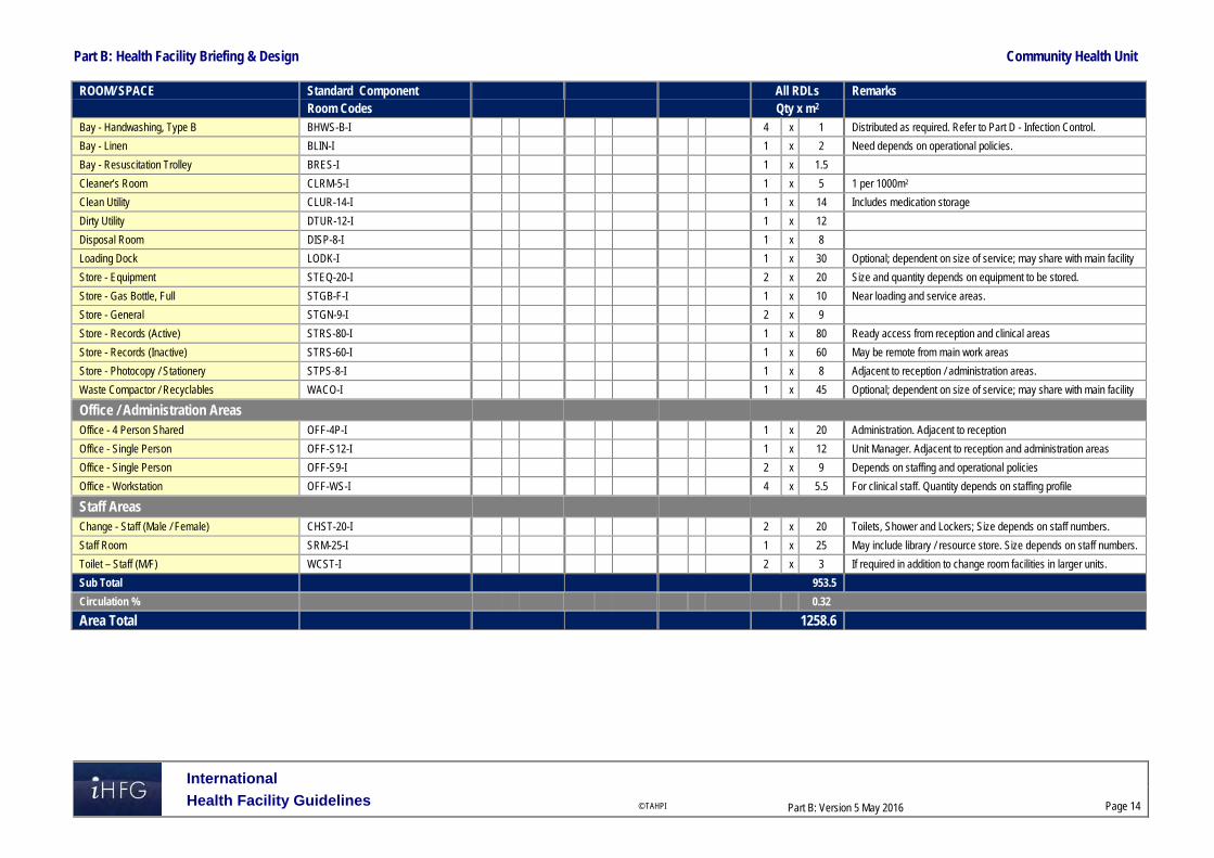
Part B: Health Facility Briefing & Design Community Health Unit
International
Health Facility Guidelines © TAHPI
Part B: Version 5 May 2016
Page 14
ROOM/ SPACE Standard Component All RDLs Remarks Room Codes Qty x m2 Bay - Handwashing, Type B BHWS-B-I 4 x 1 Distributed as required. Refer to Part D - Infection Control.
Bay - Linen BLIN-I 1 x 2 Need depends on operational policies.
Bay - Resuscitation Trolley BRES-I 1 x 1.5
Cleaner’s Room CLRM-5-I 1 x 5 1 per 1000m2
Clean Utility CLUR-14-I 1 x 14 Includes medication storage
Dirty Utility DTUR-12-I 1 x 12
Disposal Room DISP-8-I 1 x 8
Loading Dock LODK-I 1 x 30 Optional; dependent on size of service; may share with main facility
Store - Equipment STEQ-20-I 2 x 20 Size and quantity depends on equipment to be stored.
Store - Gas Bottle, Full STGB-F-I 1 x 10 Near loading and service areas.
Store - General STGN-9-I 2 x 9
Store - Records (Active) STRS-80-I 1 x 80 Ready access from reception and clinical areas
Store - Records (Inactive) STRS-60-I 1 x 60 May be remote from main work areas
Store - Photocopy / Stationery STPS-8-I 1 x 8 Adjacent to reception / administration areas.
Waste Compactor / Recyclables WACO-I 1 x 45 Optional; dependent on size of service; may share with main facility
Office / Administration Areas Office - 4 Person Shared OFF-4P-I 1 x 20 Administration. Adjacent to reception
Office - Single Person OFF-S12-I 1 x 12 Unit Manager. Adjacent to reception and administration areas
Office - Single Person OFF-S9-I 2 x 9 Depends on staffing and operational policies
Office - Workstation OFF-WS-I 4 x 5.5 For clinical staff. Quantity depends on staffing profile
Staff Areas Change - Staff (Male / Female) CHST-20-I 2 x 20 Toilets, Shower and Lockers; Size depends on staff numbers.
Staff Room SRM-25-I 1 x 25 May include library / resource store. Size depends on staff numbers.
Toilet – Staff (M/F) WCST-I 2 x 3 If required in addition to change room facilities in larger units.
Sub Total 953.5
Circulation % 0.32
Area Total 1258.6

Part B: Health Facility Briefing & Design Community Health Unit
International
Health Facility Guidelines © TAHPI
Part B: Version 5 May 2016
Page 15
Specialist Areas
ROOM/ SPACE Standard Component All RDLs Remarks Room Codes Qty x m2
Physiotherapy Area Optional Bay - Resuscitation Trolley BRES-I 1 x 1.5
Consult / Exam Room CONS-I 1 x 14 For assessment and treatment. May share consult rooms in general client area.
Change Cubicle - Patient CHPT-I 2 x 2 Mix of large and small change cubicles depending on anticipated clientele.
Change Cubicle - Accessible CHPT-D-I 2 x 4 Mix of large and small change cubicles depending on anticipated clientele.
Gymnasium GYAH-60-I 1 x 60 For up to 6 patient per hour. Includes write-up. May be split into 2 x 30m2 spaces to allow gender separated areas
Office - Write-Up OFF-WI-3-1 2 x 3 Adjacent to treatment cubicles.
Plaster Room PLST-I 1 x 14
Shower - Patient SHPT-I 2 x 4 Gender separated areas
Store - Equipment STEQ-14-I 1 x 14
Toilet - Accessible WCAC-I 2 x 6 Gender separated areas
Treatment Bay PBTR-H-10-I 4 x 10 May be divided into gender segregated areas. Open bay with privacy screen.
Treatment Bay (Enclosed) PBTR-H-E-12-I 2 x 12 May be divided into gender segregated areas.
Occupational Therapy Area Optional ADL Bathroom ADLB-I 1 x 12 Optional; assessment may be conducted in patient’s home
ADL Kitchen ADLK-OP-I or ADLK-ENC-I 1 x 12 Optional; assessment may be conducted in patient’s home
ADL Laundry ADLL-I 1 x 8 Optional; assessment may be conducted in patient’s home
Consult / Exam Room CONS-I 1 x 14 For assessment and treatment. May share consult rooms in general client area.
Equipment Clean-Up ECL-12-I 1 x 12
Gymnasium - Paediatric GYAH-P-I 1 x 45 Size depends on service demand.
Observation Room OBS-I 1 x 9 Optional. To consult room and / or play gymnasium.
Office - Write-Up OFF-WI-3-1 1 x 3 Adjacent to ADL training areas.
Plaster Room PLST-I 1 x 14 For hand splinting and lymphedema services. May be shared with physiotherapy.
Store - Equipment STEQ-14-I 1 x 14
Speech Pathology Area Optional
Office / Consult Room CONS-I (similar) 1 x 14 Combined office and consultation room depends on unit policies. May share consult rooms in general client area.
Observation Room OBS-I 1 x 9 Optional.
Office - Write-Up OFF-WI-3-1 1 x 3 Optional. Provide if consult room and office not combined.

Part B: Health Facility Briefing & Design Community Health Unit
International
Health Facility Guidelines © TAHPI
Part B: Version 5 May 2016
Page 16
ROOM/ SPACE Standard Component All RDLs Remarks Room Codes Qty x m2 Store - General STGN-10-I 1 x 10 Includes resource storage.
Audiology Area Optional Audiology Testing Room AUDIO-I 1 x 14
Office / Consult Room CONS-I (similar) 1 x 14 Combined office and consultation room depends on unit policies. May share consult rooms in general client area.
Podiatry Area Optional
Office / Consult Room CONS-I (similar) 1 x 14 Combined office and consultation room depends on unit policies. May share consult rooms in general client area.
Podiatry Treatment PODTR-14-I 2 x 14
Equipment Clean-Up ECL-10-I 1 x 10
Dental Area Optional Dental Clean-Up / Sterilising DENCU-8-I 1 x 8
Dental Surgery DENSR-14-I 2 x 14
Dental Workroom DENW-I 1 x 12
Dental X-Ray DENXR-I 1 x 6 Storage and developing.
Office - Write-Up Bay OFFWI-6-I 1 x 6
Pharmacotherapy Area (Opioid Replacement Therapy) Optional Pharmacotherapy Unit - Dispensing PHCO-DISP-I 1 x 14
Pharmacotherapy Unit - Dosing PHCO-DOS-I 1 x 4
Pharmacotherapy Unit - Waiting PHCO-WAIT-I 2 x 15 6-10 people per room. May be gender segregated.
Office - 3 Person Shared OFF-3P-I 1 x 15
Toilet - Patient WCPT-I 2 x 4 Specimen collection.
Sub Total 595.5 Circulation % 0.32
Total Areas 786.1 Please note the following:
Areas noted in Schedules of Accommodation take precedence over all other areas noted in the FPU.
Rooms indicated in the schedule reflect the typical arrangement according to the Role Delineation.
Exact requirements for room quantities and sizes will reflect Key Planning Units identified in the Service Plan and the Operational Policies of the Unit.
Room sizes indicated should be viewed as a minimum requirement; variations are acceptable to reflect the needs of individual Unit.
Offices and workstations to be provided according to the Operational Policy and the number of endorsed full time positions within the Unit
Staff and support rooms may be shared between Functional Planning Units dependant on location and accessibility to each unit and may provide scope to reduce duplication of facilities.

Part B: Health Facility Briefing & Design Community Health Unit
International
Health Facility Guidelines © TAHPI
Part B: Version 5, May 2016
Page 17
6 References and Further Reading
Australasian Health Facility Guidelines (AusHFG), Part B ‘Health Facility Briefing and Planning-Community Health, 2016, refer to website: https://aushfg-prod-com-au.s3.amazonaws.com/HPU_B.0255_6_0.pdf
Facility Guidelines Institute, Guidelines for Design and Construction of Health Care Facilities; 2014 Edition; refer to website www.fgiguidelines.org
U.S. Department of Veterans Affairs, Office of Construction & Facilities Management: ‘Prototype for Standardized Design and Construction of Community Based Outpatient Clinics’ http://www.cfm.va.gov/til/spclRqmts.asp#SIGN
Gov.UK DH Health Building Notes (HBN 00-01) ‘Designing Health and Community Care Buildings’ (2014) https://www.gov.uk/government/collections/health-building-notes-core-elements

Part B – Health Facility Briefing & Design 52 Complementary and Alternative Medicine Centre
International Health Facility Guidelines Version 4 May 2014

International Health Facility Guidelines © TAHPI
Part B: Version 4 2014
Page 2
Table of Contents 52 Complementary and Alternative Medicine Centre .................................................................. 3
1 Introduction ............................................................................................................................................... 3 2 Planning ..................................................................................................................................................... 4 3 Design ........................................................................................................................................................ 8 4 Components of the Unit .......................................................................................................................... 10 5 Schedule of Accommodation – Complementary and Alternative Medicine Centre .......................... 11 6 Functional Relationship Diagram - Complementary and Alternative Medicine Centre .................... 12 7 Further Reading....................................................................................................................................... 13

Complementary and Alternative Medicine Centre
International Health Facility Guidelines © TAHPI
Part B: Version 4 2014
Page 3
52 Complementary and Alternative Medicine Centre 1 Introduction Description Complementary and Alternative Medicine (CAM) is a wide reaching term that is usually used to describe a range of health approaches that have their history or origins outside of conventional, mainstream or ‘Western’ medicine. Other terms used include alternative therapy, holistic therapy, and traditional medicine. Whilst generally used interchangeably, the two terms ‘complementary’ and ‘alternative’ refer to different concepts: ‘Complementary’ refers to using a non-mainstream approach that is integrated with
conventional medicine. ‘Alternative’ refers to using a non-mainstream approach to in place of conventional medicine. Initially there was scepticism regarding the use and effect of complementary and alternative medicines, but recent scientific research into some complementary treatments has produced scientific evidence supporting their use, safety and efficacy. CAM is usually provided on an outpatient basis within the context of the broader health system. An integrative approach of combining CAM with conventional treatment is more frequently being offered by healthcare providers in regard to: Health promotion The management and relief of symptoms/side effects of conventional treatments General improvement in health or well-being. CAM services are generally classified into two subgroups: Natural products e.g. dietary, vitamin and mineral supplements Mind and body practices, which include a wide range of procedures and techniques
administered by trained practitioners, e.g. yoga, massage therapy, acupuncture and meditation.
There are also CAM approaches which do not fit into either of these groups including homeopathy, naturopathy, traditional Chinese medicine and traditional healing practices. Some common Complementary and Alternative therapies/medicine include: Acupuncture Aromatherapy Biofeedback Chiropractic and osteopathic Chinese herbal medicine Electromagnetic therapy Homeopathy Hypnosis Iridology Kinesiology Massage therapy Meditation Movement therapies including Feldenkrais method, Alexander technique, Pilates, Rolfing
Structural Integration, Trager Psychophysical Integration Naturopathy Qi gong Reflexology Reiki Tai chi Yoga

Complementary and Alternative Medicine Centre
International Health Facility Guidelines © TAHPI
Part B: Version 4 2014
Page 4
The size, design, functional requirements (facilities and equipment), and internal/external relationships will be determined by the type, range and scope of services offered by the unit. These elements should be outlined and described in the Services and Operational Policy of the Unit/Centre. The CAM Center can be incorporated as part of another health facility or as a freestanding and independently-operated center. Applicable local authority statutory requirements and guidelines are to be complied with. 2 Planning Planning Models
Dedicated CAM Centre
It is recommended that the facilities of a CAM Center be contained within a dedicated space. If it is incorporated as a unit within a health facility, a CAM Center should be easily accessed by ambulatory patients and should have a functional relationship with outpatient clinic rooms. By confining the CAM Centre within a dedicated space the environment and ambience of the centre can be maintained and operational flow is optimised.
Unit/Department-Based CAM Treatment and Consultation Spaces
CAM Treatment and consultation spaces may be located within particular departments throughout a hospital and can be collocated with Allied Health services and spaces. This is not a commonly adopted model and may result in the duplication of resources, labour and equipment. However, in specialty areas such as Cancer Day Care Units and Fertility and Women’s Clinics, CAM treatments are becoming more popular and common place. Therefore it may be feasible, depending on the service profile of the centre/hospital, to provide dedicated CAM units adjacent to these units. Operational Models The service plan and operational model will determine the specific requirements for manufacture, storage and dispatch of products, and the provision/delivery of treatment and services. The CAM Center may extend its service from a single healthcare facility to outlying facilities.
Integrated CAM Centre
If the CAM center is collocated with a hospital, medical clinic or other health facility it is seen to be operating under an integrated model. The attached facility’s operational policy shall determine, in part, the products and services to be supplied by the Center, with the aim of complementing the conventional/mainstream medicine that is provided in the healthcare facility. An integrated model of operation will require the creation of referral pathways between the Center and the health facility. Products and services beyond the scope of the facility’s requirements shall be negotiated and predefined.
Private CAM Centre
A private CAM Center may be separate to any health facility and its operational model will resemble a private business. The success of the private CAM center relies on: Market demand The products and services supplied The availability of trained and qualified practitioners. Depending on the scope of services and products provided, a private Centre may choose to establish formal relationships with nearby health facilities or independent medical practitioners to optimize business operations.
Treatment and Procedural Services
For the delivery of treatment and procedural services offered by CAM Centers a sufficient amount of space and equipment is required. This may range from large studios for yoga, Pilates and meditation practices to small treatment spaces for massage therapy, chiropractic therapy and acupuncture. In some cases outdoor space may be required for classes such as tai chi.

Complementary and Alternative Medicine Centre
International Health Facility Guidelines © TAHPI
Part B: Version 4 2014
Page 5
Product Manufacture
Any dietary supplements or natural products manufactured onsite must comply with local and international regulatory requirements. Manufacturing practices and products should also be aligned and negotiated with the hospital’s pharmacy procedures and products if the Center is collocated with such a health facility. The safe manufacture of products for ingestion requires sterile handling and manufacturing techniques and extemporaneous manufacturing will require sufficient space for compounding products. The Center must include specialized space and equipment for the refinement, testing, compounding, packaging, labelling and storage of manufactured products.
Hours of Operation
A CAM centre will commonly provide services up to 12 hours per day, five-days a week. Hours of operation generally complement outpatient clinics and services. CAM centers coordinate multiple practitioners and services and generally create a weekly/monthly timetable which is updated as client demand changes. Functional Areas There are both ‘accessible’ and ‘restricted’ functional areas of a CAM Center:
Accessible Areas
Reception counter Waiting areas; it is possible to share waiting areas with an adjacent unit if CAM is within a
hospital/healthcare facility Patient counselling and consult areas (access is controlled to ensure privacy) Patient treatment and consultation spaces (accessed in the company or with the guidance of
a staff member to ensure safety)
Restricted/Staff Areas
Dispensing area for products Preparation and manufacturing areas of non-sterile products Active store for stock storage Bulk stores including an unpacking area Secured storage for refrigerated items and flammable goods as required Staff Areas which may include: Offices, Workstations, File Stores, Meeting Rooms, Staff
Room, Change Rooms and Toilets.
Optional Areas
The operational policy and scope of services plan will determine additional areas that may be required in a CAM. These optional areas may include: Sterile manufacturing suites with support facilities including Anterooms, Change Rooms and
Sterile Storage Rooms Facilities for clinical trials, which may include dedicated dispensing areas, additional
treatment spaces, secured storage for records and workstations; clinical trials in CAM Centres may include trials of both products and therapies
An Extemporaneous or ‘practitioner dispensed product’ manufacturing area which requires extra space for compounding products.
CAM Counter/Reception
The Reception counter should be prominent, clearly signposted, and have a clear functional relationship with the entry and the waiting area. If used for cashier functions, appropriate security measures should be taken to allow safe cash handling. Patients will present at the counter for products or services and wait for a practitioner to dispense and counsel on the product or lead them to a treatment/consultation space for services. Waiting Areas A range of patients with varying mobility will need access to the waiting areas of a CAM unit. With this in mind, the waiting areas should be designed for easy accessibility. Waiting areas should

Complementary and Alternative Medicine Centre
International Health Facility Guidelines © TAHPI
Part B: Version 4 2014
Page 6
have a functional relationship with the reception counter, public amenities, baby change and feeding areas, refreshments, play facilities (optional) and public telephones. There should be ready access to counselling, consult and treatment areas
Patient Counselling and Consult Areas
The patient counselling and consult areas of a CAM Unit should be spatially related to the Counter/Reception and Waiting areas. Privacy is important and, if it is not possible to entirely enclose these areas, they should be designed to create perceived privacy using a confined space and barricades. There should still be adequate acoustic and visual privacy for spaces in which confidential information is being discussed.
Treatment/Consultation Space
Treatment or Consultation spaces should have controlled access, being accessible to a patient only when accompanied by a staff member or practitioner. The number and size of treatment spaces will be determined by the service plan and they can be located interior or exterior to the central CAM Center. The equipment required will be dependent on the number and type of services to be provided within that space. Equipment may include, but is not limited to: Hand-washing facilities Appropriate means for disposal of waste Patient treatment bench, table and/or chair for therapies such as acupuncture and massage Movement therapy machines and equipment for manipulative therapies such as Pilates Flashlight, magnifying glass, cameras and slit-lamp microscopes for iridology Adequate lighting and ventilation Storage for equipment used in therapies such as aromatherapy and acupuncture. Durable, comfortable and stain-resistant flooring, particularly for the delivery of yoga and
other floor-based therapies.
Dispensing Area
An effectively designed area dedicated to the dispensing of products should enable practitioners to prepare, pack and label products in a safe and efficient manner. The dispensing area should have the following equipment nearby to facilitate its operations: Adequate lighting including both task and ambient lighting Shelving and reference texts Hand-washing facilities Adequate bench space adjacent to dispensing units for product preparation.
Manufacturing Area
The manufacturing of products involves the preparation of oral or topical dosage forms, often requiring little manipulation of the main ingredients. If manufacturing is performed onsite the following elements shall be required: A confined, dedicated room with HEPA filtered air Hand-washing facilities located near the entry/exit point of the room Impervious surfaces with minimal joins and easy to clean walls and flooring Bulk compounding area Adequate space for packaging and labelling Quality control area.
Storage
Storage in the form of cabinets, cupboards, shelves, and/or separate rooms or closets, shall be included as required: Bulk storage Active storage Refrigerated storage (See Below) Storage for volatile fluids and alcohol with construction determined by the relevant
regulations for substances involved Storage for general supplies and equipment not in use.

Complementary and Alternative Medicine Centre
International Health Facility Guidelines © TAHPI
Part B: Version 4 2014
Page 7
Store – Refrigerated
The refrigerated store can be a room/bay containing refrigerators to store specific ingredients and products. A commercial grade cool room may be used as an alternative if the service plan requires it. Refrigerated storage should be located close to assembly and preparation areas, packaging areas, manufacturing areas and other storage areas. All access doors of to the Refrigerated storage areas should be lockable and it is recommended that a temperature monitoring system connected to a warning system should be installed.
Clinical Trials Area
Clinical trials in Complementary and Alternative Medicine must adhere to the same stringent policies and regulations as clinical trials in conventional medicine. Policies regarding safety monitoring, data collection and management, privacy and confidentiality, and the protection of human and animal subjects are particularly important considerations when designing a space for clinical trials. The treatment modes in CAM related clinical trials are varied; therefore the spatial requirements will be determined by the area of expertise, context, interests and focus of the CAM Center and its staff. Some examples of recent research areas in CAM include: The efficacy of Yoga practice for back pain Mind and body approaches to smoking cessation Spinal manipulation for chronic back pain Fish oil effects on immunity in mice The impact of acupuncture for IVF success The use of hypnosis to treat postmenopausal hot flashes Brain effects of meditation Mindfulness Based Stress Reduction techniques on psychological distress in cancer patients Using melatonin supplements for sleep problems in people with high blood pressure How milk thistle extract effects chronic hepatitis C. An area for Clinical Trials should include adequate storage, dispensing, packaging, labeling and records holding for clinical trial therapies and treatments. If a CAM treatment that is being trialled incorporates the performance of therapies and procedures on/with patients then adequate space and equipment should be allocated. Facilities for Clinical Trials may be located within a separate area of the main CAM Center.
Staff Areas
Both administrative and clinical functions will require offices and workstations to facilitate educational/research activities. The approved staffing levels will determine the number of offices provided. Additional educational areas can include Meeting/Tutorial Room/s and the inclusion of technology facilities will provide additional capacity for educational activities. Administration, education and staff welfare areas, including Staff Room/s, Toilets and Meeting Room/s may be shared with nearby adjacent units if the CAM Centre is within another facility. Functional Relationship
External
The CAM Center shall be located for convenient access, staff control, and security. The CAM Center should be readily accessible from the Main Entry of the health facility and outpatient clinics for patient convenience. It should be well-signposted and it should have ready access to a loading dock for deliveries. Depending on the scope of its services and Operational Policy, it may be appropriate to situate the CAM Centre adjacent to the Inpatient Pharmacy Unit. Various types of access points for visitors to the centre, patients, practitioners, centre staff, and professionals conducting maintenance and delivering supplies should be carefully considered.
Internal
The public should have access to the Reception area, Waiting Areas, Amenities, Counselling and Consult Areas, and subsequent Treatment and Consultation Spaces. These spaces should have a

Complementary and Alternative Medicine Centre
International Health Facility Guidelines © TAHPI
Part B: Version 4 2014
Page 8
coherent functional relationship. The CAM Center must provide secure, discrete access for delivery of supplies to storage areas and access to these storage areas, as well as Offices and Operational Support Areas will be restricted to staff only. Assembly, Preparation, Dispensing Areas and Manufacturing Areas should be in proximity to drug storage areas. Manufacturing areas should be located in a discrete, low traffic zone within the CAM Center. 3 Design General The design of the CAM Center will be largely dependent on the scope of services and Operational Policy of the Center and the facility it is incorporated into, if relevant. If integrated into a health facility the Operational Policy will determine the degree of integration, including access and entries, types of treatments and services provided, and the dispersion of CAM services throughout the facility or the containment of all CAM services in a distinct space. The provision of shared or exclusive entry points will have implications for controlled access, preventing unauthorized entry and the maintenance of privacy of the centre’s operations. It is considered best practice for comprehensive care that all treatments and products prescribed by practitioners in the CAM Centre should be recorded into the patient clinical records and integrated with the health facility’s information technology and data systems. Extensive information and communication technology capabilities will be needed to facilitate this. Environmental Considerations
Natural Light
Natural light and windows permitting outside views are highly desirable within a CAM Center in order to create a natural ambience. If necessary, windows can be frosted, tinted or treated to prevent views from any adjacent public thoroughfare while still permitting natural light to enter the space.
Privacy
Privacy should be provided for in all patient treatment, consultation and counseling areas. The following features should be considered to facilitate privacy in the design: Location of doors, windows, examination equipment and furniture to ensure patient privacy
and promote staff security Appropriate window treatments to offer privacy from external and internal viewing security of patient records and confidentiality of patient discussion
Acoustics
Patient interview and counseling rooms will require acoustic treatment to maintain privacy. Consultation/Treatment spaces should be acoustically treated to reduce the transmission of noise to adjacent spaces. Waiting areas and other noisy areas should be located away from treatment spaces and staff areas to facilitate effective treatment and rest. Space Standards and Components
Ergonomics
Ergonomics and Occupational Safety and Health (OSH) requirements must be considered in the design process particularly in regard to the selection and placement of fittings and equipment. These considerations ensure the health and safety of the staff, patients and visitors and the optimal operation of the Center. This can be achieved by paying particular attention to the placement of equipment and the heights and dimensions of counters and work areas. Refer also to Part C of these Guidelines.

Complementary and Alternative Medicine Centre
International Health Facility Guidelines © TAHPI
Part B: Version 4 2014
Page 9
Size of the Centre
The approved Service Plan will determine the size of the CAM Center taking into consideration the needs of an associated health facility, if applicable, and other external facilities. A Schedule of Accommodation is provided below for a CAM Center servicing a tertiary level hospital with the capacity to undertake product manufacture onsite. Safety and Security The CAM Center and any external Treatment and Consultation Spaces must be secured to prevent unauthorized access through doors, windows, wall and ceilings. Security measures for consideration include: A security intrusion detector alarm be fitted to monitor the Center 24-hours a day Duress alarms at Center counter/reception and in treatment/consultation spaces Electronic door controls and alarms to perimeter doors Movement sensors Solid ceilings to prevent access Finishes The desired ambience of a CAM centre is relaxing and calm therefore finishes, including fabrics, floors, walls and ceilings, should be as non-institutional as is possible while still facilitating cleanliness and infection control. The following factors should be considered when selecting finishes: Purpose of the rooms Movement of equipment Acoustic properties Durability Ease of cleaning and infection control Fire safety Aesthetic appearance Refer also to Part C of these Guidelines. Fixtures and Fittings Equipment, furniture and fittings should be safe, robust and suitable for heavy use. Refer also to Part C of these Guidelines. Building Services Requirements
Heating, Ventilation, Air-Conditioning (HVAC)
Internal room temperature shall be kept below 25°C unless otherwise specified. All ingredients and product storage areas require temperature and humidity controls.
Communications
Information technology/communications systems should provide for: Sufficient data and power outlets for computers and laptops Electronic records and computerized ordering systems Integration of CAMS records with attached healthcare facility’s clinical records to ensure
comprehensive care. Video-conferencing/tele-medicine in Meeting Room/s.

Complementary and Alternative Medicine Centre
International Health Facility Guidelines © TAHPI
Part B: Version 4 2014
Page 10
Infection Control The quantity and ratio of hand basins to work areas will be determined by the size of the individual areas, the services provided and the operating policies and standard guidelines relating to the Center’s services. It is recommended that hand-washing facilities are provided in each area where ingredients and products are handled including Preparation Rooms, Assembly/Dispensing Areas and Manufacturing Areas. Facilities should also be provided in all support areas. All hand basins in the Center should permit clinical hand-washing with hands-free activation. Taps may be wall-mounted, lever operated or sensor operated and should include dispensers for soap, antiseptic soap and paper towels. Hand basins in non-clinical areas should permit routine hand washing and taps may be basin -mounted and lever operated. Refer also to Part D of these Guidelines. 4 Components of the Unit The CAM Center will contain Standard Components to comply with details described in these Guidelines. Refer also to Standard Components Room Data Sheets and Room Layout Sheets.

Complementary and Alternative Medicine Centre
International Health Facility Guidelines © TAHPI
Part B: Version 4 2014
Page 11
5 Schedule of Accommodation – Complementary and Alternative Medicine Centre Typical Complementary and Alternative Medicine Unit at levels 4 to 6 Public Areas
ROOM/SPACE Standard Level 4 Level 5 Level 6
Remarks Component Qty x m2 Qty x m2 Qty x m2
COUNTER CAM-CO-SJ 1 x 9 1 x 9 1 x 20
MEETING ROOM – SMALL MEET-9-SJ 1 x 9 1 x 9 1 x 9 Interview function, small meetings
Staff Areas
ROOM/SPACE Standard Level 4 Level 5 Level 6
Remarks Component Qty x m2 Qty x m2 Qty x m2
OFFICE – SINGLE PERSON OFF-9-SJ OFF-12-SJ
1 x 9 1 x 12 1 x 12 Director
OFFICE WORKSTATION OFF-WS-SJ 2 x 5.5 4 x 5.5 6 x 5.5 Qty depends on staffing
ASSEMBLY/PREPARATION ASPR-20-SJ 1 x 10 1 x 20 1 x 30
BAY – HANDWASHING TYPE B BHWS-B-SJ 3 x 1 4 x 1 5 x 1 Unit entrance and corridor recesses, as required.
CLEANER’S ROOM CLRM-5-SJ 1 x 5 1 x 5 1 x 5 Include cupboard for dry goods
COOL ROOM CORM-SJ 2 x 10 2 x 10 Optional, or refrigerators and freezers
CLINICAL TRIALS 1 x 12 1 x 12 Optional
MANUFACTURE ROOM PREP-SJ 1 x 18 2 x 12 3 X 12 Based on 3 m2 per person
STORE – BLUK STBK-20-SJ 1 x 40 1 x 100 1 x 150 May include pallets
STORE – FILES STFS-8-SJ 1 x 8 1 x 10 1 x 20 Collocate with Ward Clerk
STORE – GENERAL STGN-6-SJ 1 x 6 1 x 8 1 x 10 Size in accordance with service demand and operational policies
STORE – INGREDIENTS STBK-5-SJ STBK-10-SJ
1 x 5 1 x 10 1 x 10
STORE – PHOTOCOPY/STATIONARY
STPS-8-SJ 1 x 8 1 x 8 1 x 8 Collocate with Clerk
STORE – REFRIGERATION STRF-8-SJ 1 x 6 1 x 6 1 x 6 Bay with fridges
MEETING ROOM - LARGE MEET-15-SJ 1 x 15 1 x 20 1 x 25
PROPERTY BAY – STAFF PROP-3-SJ 2 x 2 3 x 3 4 x 3 Number of lockers depends on staff complement per shift
STAFF ROOM SRM-15-SJ 2 x 15 2 x 20 2 x 20 Unit-specific space, with beverage bay
TOILET - STAFF WCST-SJ 2 x 3 4 x 3 4 x 3
Shared Areas
ROOM/SPACE Standard Level 4 Level 5 Level 6
Remarks Component Qty x m2 Qty x m2 Qty x m2
WAITING WAIT-SUB-I 2 x 5 2 x 10 2 x 10 Separate male/female areas
TREATMENT ROOM/SPACES TRMT-SJ 1 x 14 1 x 14 1 x 14 For specialist units, or shared; Depends on operational policy

Complementary and Alternative Medicine Centre
International Health Facility Guidelines © TAHPI
Part B: Version 4 2014
Page 12
Notes: Areas noted in Schedules of Accommodation take precedence over all other areas noted in
the FPU Rooms indicated in the schedule reflect the typical arrangement according to the Role
Delineation Exact requirements for room quantities and sizes will reflect Key Planning Units identified in
the Service Plan and the Operational Policies of the Unit Room sizes indicated should be viewed as a minimum requirement; variations are acceptable
to reflect the needs of individual Unit Office areas are to be provided according to the Unit role delineation and staffing
establishment; Executives and Managers may be responsible for more than one area but should have only one office assigned within the campus
Staff and support rooms may be shared between Functional Planning Units dependent on location and accessibility to each unit and may provide scope to reduce duplication of facilities.
6 Functional Relationship Diagram - Complementary and Alternative Medicine Centre
The external and internal functional relationships are demonstrated in the diagram above, including: Entry for patients and visitors directly from public corridor Access to key clinical units associated with the CAM Center via staff corridor Entry of good via loading dock directly into stores areas Service access required for materials and housekeeping via service corridor. The optimum internal relationships include the following: Reception and waiting areas at the entrance of the CAM Center Restricted access to operational areas Treatment and Consultation rooms located between accessible and staff-only areas Support rooms located on the perimeter for ease of access Administration and office areas easily accessible to staff.

Complementary and Alternative Medicine Centre
International Health Facility Guidelines © TAHPI
Part B: Version 4 2014
Page 13
7 Further Reading Australasian Health Facility Guidelines (Aus.). ‘Part B Health Facility Briefing and Planning,
Rev 4’, 2012. Retrieved from website: x3o;/ 2014 Melbourne IVF (Aus.). ‘Adoption of Complementary Therapies’ 2014. Retrieved from website:
http://mivf. com. au/about-fertility/how-to-get-pregnant/complementary-therapies-for-pregnancy 2014
National Cancer Institute (US). ‘Recommendations for use of CAM’ 2014. Retrieved from website: http://www. cancer. gov/cancertopics/cam 2014
National Center for Complementary and Alternative Medicine (NCCAM) (US) 2014 for general research information. Retrieved from website: http://nccam. nih. gov/research/results 2014
Refer to DHA website for local licensing requirements www. dha. gov. ae and MOH website www. moh. gov. ae for local approval procedures
The Facility Guidelines Institute (US). ‘Guidelines for Design and Construction of Health Care Facilities’ 2010 Edition. Retrieved from website: www. fgiguidelines. org 2014.
Part B – Health Facility Briefing & Design 55 Coronary Care Unit
International Health Facility Guidelines Version 4 May 2014

International Health Facility Guidelines © TAHPI
Part B: Version 4 2014
Page 2
Table of Contents 55 Coronary Care Unit ................................................................................................................... 3
1 Introduction ............................................................................................................................................... 3 2 Planning ..................................................................................................................................................... 3 3 Design ........................................................................................................................................................ 6 4 Components of the Unit .......................................................................................................................... 10 5 Schedule of Accommodation – Coronary Care Unit ............................................................................ 11 6 Functional Relationship Diagram – Coronary Care Unit ..................................................................... 13 7 References and Further Reading ........................................................................................................... 14
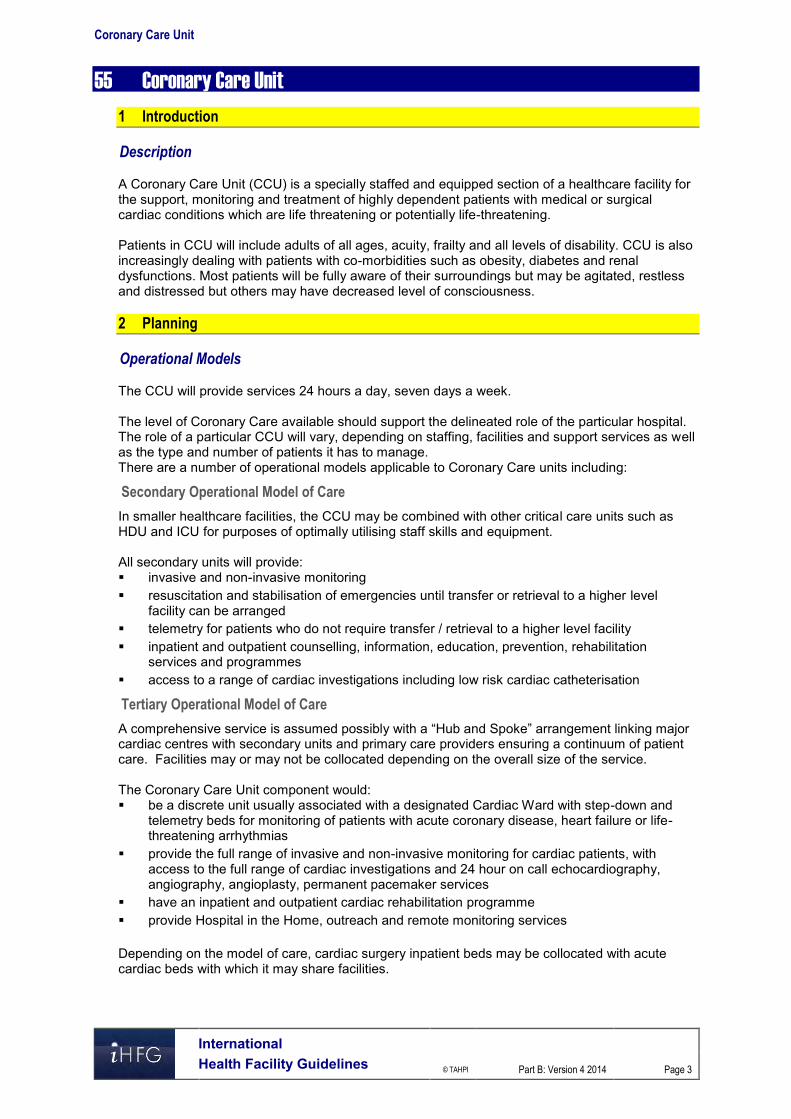
Coronary Care Unit
International Health Facility Guidelines © TAHPI
Part B: Version 4 2014
Page 3
55 Coronary Care Unit 1 Introduction Description A Coronary Care Unit (CCU) is a specially staffed and equipped section of a healthcare facility for the support, monitoring and treatment of highly dependent patients with medical or surgical cardiac conditions which are life threatening or potentially life-threatening. Patients in CCU will include adults of all ages, acuity, frailty and all levels of disability. CCU is also increasingly dealing with patients with co-morbidities such as obesity, diabetes and renal dysfunctions. Most patients will be fully aware of their surroundings but may be agitated, restless and distressed but others may have decreased level of consciousness. 2 Planning Operational Models The CCU will provide services 24 hours a day, seven days a week. The level of Coronary Care available should support the delineated role of the particular hospital. The role of a particular CCU will vary, depending on staffing, facilities and support services as well as the type and number of patients it has to manage. There are a number of operational models applicable to Coronary Care units including:
Secondary Operational Model of Care
In smaller healthcare facilities, the CCU may be combined with other critical care units such as HDU and ICU for purposes of optimally utilising staff skills and equipment. All secondary units will provide: invasive and non-invasive monitoring resuscitation and stabilisation of emergencies until transfer or retrieval to a higher level
facility can be arranged telemetry for patients who do not require transfer / retrieval to a higher level facility inpatient and outpatient counselling, information, education, prevention, rehabilitation
services and programmes access to a range of cardiac investigations including low risk cardiac catheterisation
Tertiary Operational Model of Care
A comprehensive service is assumed possibly with a “Hub and Spoke” arrangement linking major cardiac centres with secondary units and primary care providers ensuring a continuum of patient care. Facilities may or may not be collocated depending on the overall size of the service. The Coronary Care Unit component would: be a discrete unit usually associated with a designated Cardiac Ward with step-down and
telemetry beds for monitoring of patients with acute coronary disease, heart failure or life-threatening arrhythmias
provide the full range of invasive and non-invasive monitoring for cardiac patients, with access to the full range of cardiac investigations and 24 hour on call echocardiography, angiography, angioplasty, permanent pacemaker services
have an inpatient and outpatient cardiac rehabilitation programme provide Hospital in the Home, outreach and remote monitoring services Depending on the model of care, cardiac surgery inpatient beds may be collocated with acute cardiac beds with which it may share facilities.
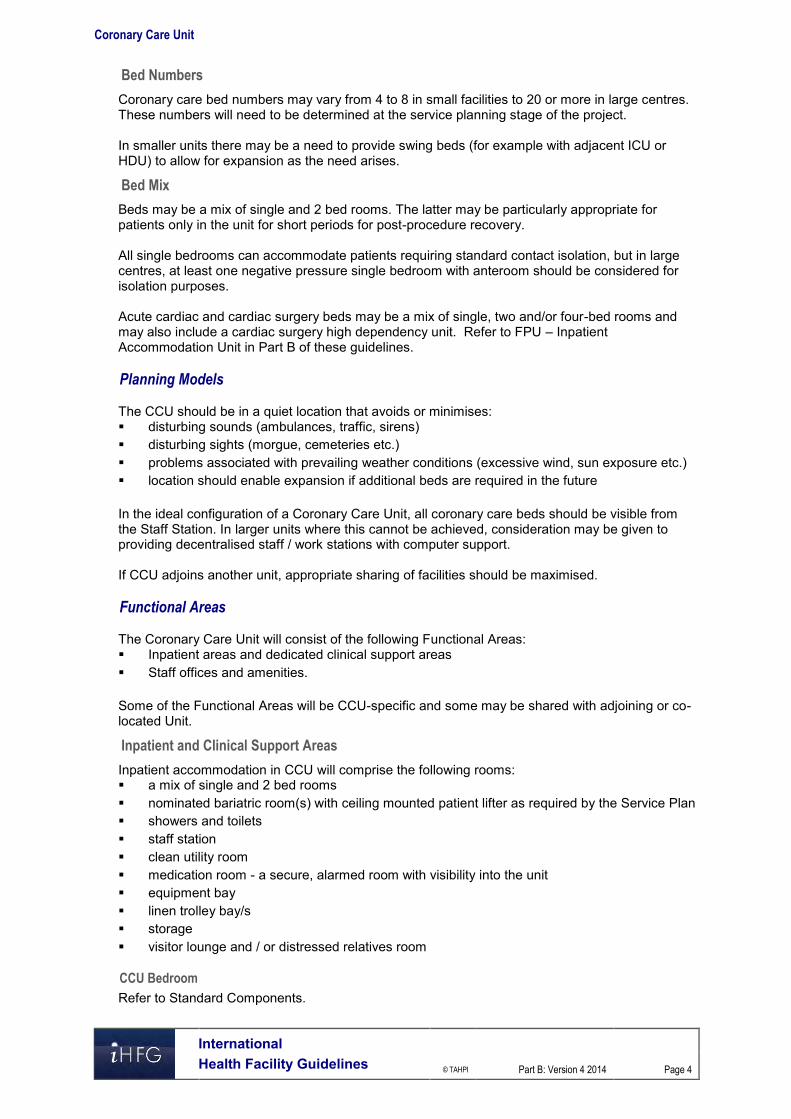
Coronary Care Unit
International Health Facility Guidelines © TAHPI
Part B: Version 4 2014
Page 4
Bed Numbers
Coronary care bed numbers may vary from 4 to 8 in small facilities to 20 or more in large centres. These numbers will need to be determined at the service planning stage of the project. In smaller units there may be a need to provide swing beds (for example with adjacent ICU or HDU) to allow for expansion as the need arises.
Bed Mix
Beds may be a mix of single and 2 bed rooms. The latter may be particularly appropriate for patients only in the unit for short periods for post-procedure recovery. All single bedrooms can accommodate patients requiring standard contact isolation, but in large centres, at least one negative pressure single bedroom with anteroom should be considered for isolation purposes. Acute cardiac and cardiac surgery beds may be a mix of single, two and/or four-bed rooms and may also include a cardiac surgery high dependency unit. Refer to FPU – Inpatient Accommodation Unit in Part B of these guidelines. Planning Models The CCU should be in a quiet location that avoids or minimises: disturbing sounds (ambulances, traffic, sirens) disturbing sights (morgue, cemeteries etc.) problems associated with prevailing weather conditions (excessive wind, sun exposure etc.) location should enable expansion if additional beds are required in the future In the ideal configuration of a Coronary Care Unit, all coronary care beds should be visible from the Staff Station. In larger units where this cannot be achieved, consideration may be given to providing decentralised staff / work stations with computer support. If CCU adjoins another unit, appropriate sharing of facilities should be maximised. Functional Areas The Coronary Care Unit will consist of the following Functional Areas: Inpatient areas and dedicated clinical support areas Staff offices and amenities. Some of the Functional Areas will be CCU-specific and some may be shared with adjoining or co-located Unit.
Inpatient and Clinical Support Areas
Inpatient accommodation in CCU will comprise the following rooms: a mix of single and 2 bed rooms nominated bariatric room(s) with ceiling mounted patient lifter as required by the Service Plan showers and toilets staff station clean utility room medication room - a secure, alarmed room with visibility into the unit equipment bay linen trolley bay/s storage visitor lounge and / or distressed relatives room
CCU Bedroom
Refer to Standard Components.

Coronary Care Unit
International Health Facility Guidelines © TAHPI
Part B: Version 4 2014
Page 5
Provide cardiac protection and electrical installations to comply with local standards.
Ensuite Showers and Toilets
Provision of individual en suite showers / toilets to patient bedrooms should be carefully considered for the following reasons; Many patients are transferred out of the unit as soon as they are past the critical phase and
are ambulant. Patients may only be in the unit for a few hours recovering from a procedure but may require
access to a toilet and shower before discharge. En suites increase the overall size of the unit and subsequent capital costs.
Shared Areas
The extent of room/s spaces that may be shared between CCU and an adjoining Inpatient Unit or ICU will be determined by the size of the overall CCU itself. Large units may be entirely self-contained with regard to clinical spaces but may still share some staff amenities and teaching spaces. However, the following should be considered with regard to potential for sharing: Clean and dirty utility rooms Central equipment storage Beverage pantry / kitchen Reception / ward clerk Cleaner’s room Disposal room Visitor waiting Public toilets Staff education / training room Staff amenities (shower, toilets, locker room and rest area)
Acute Cardiac and Cardiac Surgery Inpatient Unit
In most respects, an acute cardiac and cardiac surgery inpatient unit will be the same as a general medical or surgical inpatient unit with the following additions: Procedure Room with access for a bed and image intensifier if required; this room is optional. Telemetry equipment and antenna with monitoring at a Staff Station that may be in the CCU
or in the main ward staff station. Patient education facilities.
Day Procedure Holding / Recovery Beds
Unless beds in the Catheter laboratory or a Day Procedure or 23 hour unit are utilised, the CCU or the acute ward may cater for the recovery of patients following cardiac procedures such as echocardiography, cardiac angiography, transoesophageal echo (TOE), percutaneous coronary intervention and temporary and permanent pacemaker insertion.
Staff Offices and Amenities
Staff offices and amenities will be dictated by staff establishment and may include: Offices Workstations Meeting / teaching room/s Staff room with beverage bay Showers and toilets Property storage In large centres, there should be access to adequate facilities for staff education and meetings. Teaching facilities should allow staff to access simulation training and competency assessment within the unit. This room may be used by the multidisciplinary team.
Teaching and Clinical Research

Coronary Care Unit
International Health Facility Guidelines © TAHPI
Part B: Version 4 2014
Page 6
Central monitor connected to patient cardiac monitors is usually located at the central staff station. Easy viewing of cardiac rhythms of all patients will encourage discussion between staff and assist with in-house education. In larger Units, simulation training and competency assessment facilities may also be provided. Associated with the provision of all cardiac services for CCU and cardiac inpatient unit, research may be undertaken. Spatial provision for research may be justified by service needs and role delineation. The following facilities may be required for clinical trials: shared offices for senior coordinator/s and research fellow/s shared offices / workstations for other clinical trial research staff shared offices / workstations for registrars and research assistants patient consulting room/s (if the unit is accessed by patient) drug monitors room drugs and research files storage research laboratories Functional Relationships
External
The CCU will have working relationships with many other units & services including: Cardiac investigation and cardiac catheterisation unit Cardiac rehabilitation services Emergency Unit Nuclear Medicine / PET Intensive Care Unit Operating Suite Unit Medical Imaging Pathology Biomedical Engineering Cardiac Surgery:
Linkages occur at several levels including clinical decision making about patients requiring cardiac surgery, joint research projects and joint management of patients in the post-operative phase including rehabilitation. The Units need to be well-linked, but not necessarily co-located.
Hospital in the Home services for chronic cardiac disease such as heart failure.
Internal
Optimal internal relationships to be achieved include those between: patient occupied areas forming the core of the unit staff station(s) and associated areas that need direct access and observation of patient areas utility and storage areas that need to be readily accessible to both patient and staff work
areas public areas located on the perimeter of the unit shared areas that should be easily accessible from the units served 3 Design Access
External
The Unit should be located where emergency medical team can respond rapidly and efficiently to emergency calls with minimum travel time. Through traffic to other parts of the healthcare facility should be avoided for efficient access of emergency team and equipment and to maintain patient privacy.

Coronary Care Unit
International Health Facility Guidelines © TAHPI
Part B: Version 4 2014
Page 7
Ideally there should be a separate and discrete entry or entries for staff, goods and supplies with swipe card or similar electronic access to authorised personnel. Discrete entry for patients on beds or trolleys may also be considered as this should provide: Easy access from lifts from Emergency Unit and Chest Pain Assessment Unit Ready access to and from Cardiac Catheter Laboratory
Internal
There should be one only point of public entry overseen by a ward clerk / receptionist during extended daytime hours to: monitor and / or prevent access by visitors depending on the patients’ condition advise visitors if patients have been moved or are out of the unit for any reason monitor visiting staff and direct them to the appropriate staff member or patient monitor patient movements in and out of the unit Patient Treatment Areas Patients should be situated so that healthcare providers have direct or indirect visualisation, with cardiac monitoring at all times. This approach permits the monitoring of patient status under both routine and emergency circumstances. The preferred design is to allow a direct line of vision between the patient and the central Staff Station. In CCUs with a modular design, patients should be visible from their respective nursing substations. Sliding glass doors and partitions facilitate this arrangement and provide speedy access to the room in emergency situations.
Renal Dialysis
Planning considerations for the provision of dialysis outlets which would include water and drainage to a specific number of CCU beds should be considered as part of the planning for this unit.
Bedside Monitoring
Each coronary care bed should have the capacity for individual monitoring. Bedside monitoring equipment should be located to permit ease of access and viewing, but should not interfere with the visualisation of, or access to the patient. The bedside nurse and/or monitor technician should be able to observe the monitored status of each patient at a glance. This goal can be achieved either by a central monitoring at staff stations, or by bedside monitors that permit the observation of more than one patient simultaneously. Neither of these methods is intended to replace bedside observation. Weight-bearing surfaces that support the monitoring equipment should be sturdy enough to withstand high levels of strain over time. It should be assumed that monitoring equipment will increase in volume over time. Therefore, space and electrical facilities should be designed accordingly. Environmental Considerations
Acoustics
Signals from patient call systems, alarms from monitoring equipment, and telephones add to the sensory overload in critical care units. Without reducing their importance or sense of urgency, such signals should be modulated to a level that will alert staff members, yet be rendered less intrusive. For these reasons, floor coverings that absorb sound should be used while keeping infection control, maintenance, and equipment movement needs under consideration. Walls and ceilings should be constructed of materials with high sound absorption capabilities. Ceiling soffits and baffles help reduce echoed sounds. Doorways should be offset, rather than being placed in symmetrically opposed positions, to reduce sound transmission. Counters, partitions, and glass doors are also effective in reducing noise levels.

Coronary Care Unit
International Health Facility Guidelines © TAHPI
Part B: Version 4 2014
Page 8
Natural Light
Natural light and views should be available from the Unit for the benefit of staff and patients. Natural light to all bedrooms by means of a window is essential and desirable in patient lounge areas and staff rooms. Windows are an important aspect of sensory orientation and psychological well-being of patients.
Privacy
Visual and acoustic privacy is required but high staff visibility is essential. Each patient bed and toilet/shower area should have provisions for visual privacy from casual observation by other patients and visitors.
Interior Decor
Interior decor includes furnishings, style, colour, textures and ambience, influenced by perception and culture. This can help prevent an institutional atmosphere. However, cleaning, infection control, fire safety, patient care and the patients' perceptions of a professional environment should always be considered. Some colours, particularly the bold primaries and green should be avoided in areas where clinical observation occurs such as bedrooms, treatment areas and corridors. Such colours may prevent the accurate assessment of skin tones e.g. yellow / jaundice, blue / cyanosis, red / flushing. Space Standards and Components Where an open plan arrangement is provided, bed spaces shall be arranged so that there is a clearance of at least 1200 mm from the side of the bed to the nearest fixed obstruction (including bed screens) or wall. At the head of the bed, at least 900 mm clearance shall be allowed between the bed and any fixed obstruction or wall. Single Patient Bedrooms including Isolation Rooms, shall have minimum dimensions of 3900 mm x 3900 mm. Finishes Wall protection should be provided where bed or trolley movement occurs such as corridors, patients’ bedrooms, equipment and linen storage and treatment areas. Floor finishes should provide qualities such as acoustic performance, slip resistance, infection control, ease of cleaning and resistance to marring and shearing by wheeled equipment. In all areas where patient observation is critical, colours shall be chosen that do not alter the observer's perception of skin colour. Fixtures and Fittings
Clocks
A clock shall be provided and conveniently located for easy reference from all bed positions and the Staff Station.
Bedside Storage
Each patient bed space shall include storage and writing provision for staff use.
Window Treatments
Window treatments should be durable and easy to clean. Consideration may be given to use of double glazing with integral blinds, tinted glass, reflective glass, exterior overhangs or louvers to control the level of lighting. Rooms may require complete darkness to enable cardiac ultrasound being undertaken.
Patient Lifting Hoist
Allowance for ceiling mounted patient lifters should be provided to a nominated number of beds for lifting bariatric CCU patients who have to be kept in supine position or complete bed rest. The

Coronary Care Unit
International Health Facility Guidelines © TAHPI
Part B: Version 4 2014
Page 9
hoist is also beneficial for repositioning bariatric patients who are connected to multiple medical equipment including balloon pump and haemodialysis machine. Infection Control The infectious status of many patients accessing or admitted to the CCU may be unknown. All body fluids should be treated as potentially infectious and standard precautions should be taken as a minimum. Refer to Part D of these Guidelines – Infection Prevention and Control - for further information.
Hand Basins
Hand basins should be located in all clinical areas – bedrooms, treatment rooms, procedure rooms (unless a scrub bay), clean and dirty utility rooms, entry to the ward, medication room and Staff Station if used for any medication preparation purposes.
Isolation Rooms
The need for a negative pressure isolation room should be determined on a project by project basis. However depending on the size of the unit and its location (regional setting) an isolation room for large (tertiary) and special needs units should be provided. All entry points, doors or openings, shall be a minimum of 1200 mm wide, unobstructed. Larger openings may be required for special equipment, as determined by the Operational Policy. Safety and Security Aspects of safety and security within CCU to be considered include: Emergency call in all patient areas Monitoring of patient’s movement Staff access control Control and monitoring of visitors Duress call provision as required Emergency escape pathways during threats which may necessitate evacuation of the facility Building Service Requirements
Mechanical Services
The unit shall have appropriate air conditioning that allows control of temperature, humidity and air change. Refer to Part E of these Guidelines for the specific requirements for Mechanical and Electrical provision.
Communications
The following communication systems should be provided in the Unit; Telephone, facsimile and computer access Intranet and internet access Access to all ordering and recording systems utilised by the Health Facility to supply and
collect data Health Facility Briefing and Planning Teleconferencing and videoconferencing amenities Closed Circuit Television (CCTV) may be required to ensure staff can oversee entry and
egress points Patient, staff and emergency call systems to comply with standards. Telemetry Central cardiac monitoring A ceiling mounted TV should be provided in patient bedrooms for education, therapy and relaxation purposes.

Coronary Care Unit
International Health Facility Guidelines © TAHPI
Part B: Version 4 2014
Page 10
A decision about the need for other Telehealth technology (these would normally be standard provision/service provided e.g. just a computer is required) such as access to digital radiology or pathology systems) should be made early in the planning process. 4 Components of the Unit The Coronary Care Unit will consist of Standard Components to comply with details described in these Guidelines. Refer to Standard Components Room Data Sheets and Room Layout Sheets.

Coronary Care Unit
International Health Facility Guidelines © TAHPI
Part B: Version 4 2014
Page 11
5 Schedule of Accommodation – Coronary Care Unit The Coronary Care Unit may be co-located with an Inpatient Unit or ICU in order to efficiently share facilities
ROOM/ SPACE Standard Component RDL 2 & 3 RDL 4 RDL 5 RDL 6 Remarks
Room Codes N/A Qty x m2 Qty x m2 Qty x m2
Patient Areas 6 Rooms 8 Rooms 12 Rooms
1 Bedroom - Special, CCU, 20 m2 1 BR-SP-20-I 6 x 20 7 x 20 11 x 20 Provide ceiling mounted lifter in designated bariatric room(s)
1 Bedroom - Special, CCU (Negative Pressure) 1 BR-SP-20-I 1 x 20 1 x 20 Optional dependent on Service Demand
Anteroom ANRM-I 1 x 6 1 x 6 To negative pressure isolation room if provided
Ensuite - Standard ENS-ST-I 6 x 5 8 x 5 12 x 5 6 m2 for designated bariatric ensuite(s)
Sub Total 150.0 206.0 306.0
Circulation % 35 35 35
Area Total 202.5 278.1 413.1
Support Areas
Bay - Beverage, Enclosed BBEV-ENC-I 1 x 5 1 x 5 1 x 5
Bay - Meal Trolley BMT-4-I 1 x 4 1 x 4
Bay - Handwashing, Type B BHWS-B-I 2 x 1 2 x 1 3 x 1
Bay - Linen BLIN-I 1 x 2 1 x 2 1 x 2
Bay - Mobile Equipment BMEQ-4-I 1 x 4 1 x 4 2 x 4 For mobile patient lifter, ECG machine, mobile X-ray, etc.
Bay - Resuscitation Trolley BRES-I 1 x 2 1 x 2 1 x 2
Clean Utility CLUR-12-I 1 x 12 1 x 12 1 x 12
Cleaner's Room CLRM-5-I 1 x 5 1 x 5 1 x 5 May be shared with an adjacent unit in smaller CCUs
Communications Room COMM-I 1 x 0 1 x 0 1 x 0
Dirty Utility DTUR-10-I 1 x 10 1 x 10 1 x 10 May be co-located with Disposal Room
Disposal Room DISP-8-I DISP-10-I 1 x 8 1 x 10 1 x 10
Office - Clinical/ Handover OFF-CLN-I 1 x 15 1 x 15 1 x 15
Staff Station SSTN-10-I SSTN-14-I SSTN-20-I 1 x 10 1 x 14 1 x 20
Store - General STGN-9-I STGN-12-I STGN-15-I 1 x 9 1 x 12 1 x 15
Waiting WAIT-10-I WAIT-15-I 1 x 10 1 x 15 1 x 15 Optional. Maybe shared with an adjacent Unit
Sub Total 94.0 112.0 124.0
Circulation % 35 35 35
Area Total 126.9 151.2 167.4
Staff Areas
Meeting Room MEET-12-I MEET-L-15-I 1 x 12 1 x 15 1 x 15 For Meetings, Tutorials
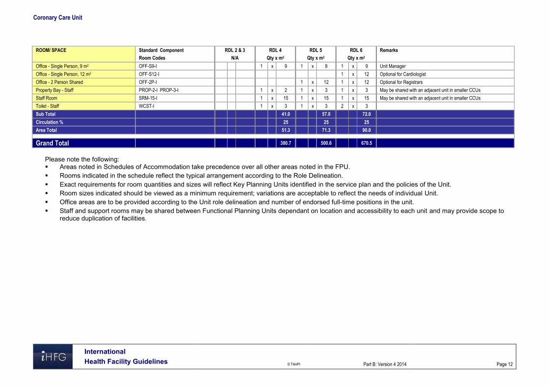
Coronary Care Unit
International Health Facility Guidelines © TAHPI
Part B: Version 4 2014
Page 12
ROOM/ SPACE Standard Component RDL 2 & 3 RDL 4 RDL 5 RDL 6 Remarks
Room Codes N/A Qty x m2 Qty x m2 Qty x m2
Office - Single Person, 9 m2 OFF-S9-I 1 x 9 1 x 9 1 x 9 Unit Manager
Office - Single Person, 12 m2 OFF-S12-I 1 x 12 Optional for Cardiologist
Office - 2 Person Shared OFF-2P-I 1 x 12 1 x 12 Optional for Registrars
Property Bay - Staff PROP-2-I PROP-3-I 1 x 2 1 x 3 1 x 3 May be shared with an adjacent unit in smaller CCUs
Staff Room SRM-15-I 1 x 15 1 x 15 1 x 15 May be shared with an adjacent unit in smaller CCUs
Toilet - Staff WCST-I 1 x 3 1 x 3 2 x 3
Sub Total 41.0 57.0 72.0
Circulation % 25 25 25
Area Total 51.3 71.3 90.0
Grand Total 380.7 500.6 670.5
Please note the following: Areas noted in Schedules of Accommodation take precedence over all other areas noted in the FPU. Rooms indicated in the schedule reflect the typical arrangement according to the Role Delineation. Exact requirements for room quantities and sizes will reflect Key Planning Units identified in the service plan and the policies of the Unit. Room sizes indicated should be viewed as a minimum requirement; variations are acceptable to reflect the needs of individual Unit. Office areas are to be provided according to the Unit role delineation and number of endorsed full-time positions in the unit. Staff and support rooms may be shared between Functional Planning Units dependant on location and accessibility to each unit and may provide scope to
reduce duplication of facilities.

Coronary Care Unit
International Health Facility Guidelines © TAHPI
Part B: Version 4 2014
Page 13
6 Functional Relationship Diagram – Coronary Care Unit

Coronary Care Unit
International Health Facility Guidelines © TAHPI
Part B: Version 4 2014
Page 14
7 References and Further Reading Australasian Health Facility Guidelines. (AusHFG Version 4.0), 2012; refer to website
www.healthfacilitydesign.com.au Guidelines for Design and Construction of Health Care Facilities; The Facility Guidelines
Institute, 2010 Edition; refer to website www.fgiguidelines.org .

Part B – Health Facility Briefing & Design 60 Day Surgery/Procedure Unit
International Health Facility Guidelines Version 4 May 2014

International Health Facility Guidelines © TAHPI
Part B: Version 4 2014
Page 2
Table of Contents 60 Day Surgery/ Procedure Unit ................................................................................................... 3
1 Introduction ............................................................................................................................................... 3 2 Planning ..................................................................................................................................................... 3 3 Design ........................................................................................................................................................ 6 4 Components of the Unit ............................................................................................................................ 8 5 Schedule of Accommodation – Day Surgery/ Procedure Unit .............................................................. 9 6 Functional Relationship Diagram – Day Surgery/ Procedure Unit ..................................................... 12 7 References and Further Reading ........................................................................................................... 13

Day Surgery/ Procedure Unit
International Health Facility Guidelines © TAHPI
Part B: Version 4 2014
Page 3
60 Day Surgery/ Procedure Unit 1 Introduction Description A Day Surgery/ Procedure Unit is where operative or endoscopic procedures are performed and admission, procedure and discharge occurs on the same date. The Unit will have access to or include one or more Operating Rooms, with provision to deliver anaesthesia and accommodation for the immediate post-operative recovery of day patients. The range of procedures that may be undertaken in a Day Surgery/Procedures Unit may include: Surgical procedures, particularly ENT, Dental, Plastic Surgery, Ophthalmology Endoscopy - gastrointestinal, respiratory, urology; Electroconvulsive Therapy (ECT) for mental health inpatients Day Medical Procedures including intravenous infusions and minor treatments For specific details on provisions for Endoscopy, refer to Endoscopy Unit, in these Guidelines. 2 Planning Operational Models The range of options for a Day Surgery/ Procedure Unit may include: a standalone centre, fully self-contained a dedicated fully self-contained unit within a hospital a Unit collocated with a specialist clinical service such as Gastroenterology or Respiratory
Medicine , within an acute hospital a Unit collocated with the Operating Unit with shared facilities. If the facility is part of an Acute Care Hospital or other Medical Facility, services can be shared, as appropriate to minimise duplication. Functional Areas The Day Surgery/ Procedure Unit may consist of a number of Functional Areas/ Zones: Entry/ Reception/ Administration and Waiting areas Pre-operative examination and preparation, including Consult rooms, patient change areas,
holding areas, Preparation rooms, toilet and lockers Procedural Area Recovery Area ( this may also include extended recovery areas where patients are
discharged within 24 hours) Perioperative Area (provides for admission on the day of surgery and short term
accommodation following procedure Discharge Lounge Staff Amenities Day Medical Unit (if collocated).
Entry / Reception/ Administration and Waiting Areas
A covered entrance for dropping off and collection of patients after surgery shall be provided. The Entry may be a shared facility and shall include: Reception and information counter or desk Waiting areas that allows for the separation of paediatric and adult patients, if organised
Paediatric Services are provided convenient access to wheelchair storage convenient access to public toilet facilities

Day Surgery/ Procedure Unit
International Health Facility Guidelines © TAHPI
Part B: Version 4 2014
Page 4
convenient access to public telephones
Ambulance Access
A discreet pick-up point, preferably under cover, shall be provided for the transfer of patients to and from the Day Surgery/ Procedure Unit.
Car Parking
Adequate car parking facilities with convenient access needs to be provided.
Administration Areas
General and individual offices shall be provided as required for business transactions, records, administrative and professional staff. These shall be separate from public and patient areas with provision for confidentiality of records. Enclosed office spaces shall be provided for: Administration and consultation Manager / Nurse Unit Manager as required Offices are to comply with Standard Components.
Clinical Records
A secure room shall be provided with provision for storage, recording and retrieval of clinical records. If geographically appropriate, and if the Day Procedures Unit is part of, or attached to, an acute hospital, the general clinical records facility might be used in lieu of a dedicated and separate room.
Pre-operative Examination/ Preparation Areas
Consult/ Examination Rooms
A number of rooms will be required for patient consultation and Interview prior to Procedures. The number of rooms will be determined by the Service Plan and Operational Policy of the Unit. Provide Consult and Interview rooms to comply with Standard Components.
Patient Change Areas
Separate areas shall be provided where outpatients can change from street clothing into hospital gowns and be prepared for surgery, convenient to the Waiting Area. The patient change areas shall include Waiting Rooms and lockers. Design of Change Areas is to facilitate management of patient lockers, patient property and keys.
Holding Area
A Holding Area may be provided where gowned patients enter after changing and wait for their procedure. Additional holding areas may be provided for seated patients before an operation or procedure. Such an area must have access to nurse call services. The Pre-operative Holding area shall be provided with the following minimum requirements as appropriate to the proposed service: A patient trolley or patient seating Privacy screening Handbasins with liquid soap and paper towel fittings Patient nurse call/ emergency call buttons with pendant handsets and indicators Medical gases including oxygen and suction and power outlets to each bed
Preparation Room
A Preparation Room may be required for patients undergoing certain procedures such as Endoscopy or Ophthalmology. If included, the Preparation Room should include: Handbasin - Clinical Bench, and cupboards for setting up of procedures

Day Surgery/ Procedure Unit
International Health Facility Guidelines © TAHPI
Part B: Version 4 2014
Page 5
Adequate space for procedures equipment trolleys Examination couch Patient privacy screening
Procedural Areas
Operating/ Procedures Rooms
The design of the Operating / Procedure Rooms must allow for adequate space, ready access, free movement and demarcation of sterile and non-sterile zones. Operating Rooms are to comply with Standard Components.
Operating Room/s for Endoscopy
The number and operation of Operating Rooms for Endoscopy shall be as determined by the Service Plan. Room size may vary, dependent upon: The use of video equipment Electrosurgical laser treatment Fluoroscopy equipment installed Multiple endoscope activity Multiple observers The use of X-ray (image intensifying) Where basic endoscopy is to be performed, the room size shall be no smaller than 36 m2. Where video equipment is used the room size should be 42 m2. Larger sizes, where possible, are recommended for flexibility and future developments. The ceiling height shall be 3000 mm. Operating Rooms for Endoscopy shall be fitted out as for a Minor Operating Room, for example, it will be suitable for general anaesthetic with appropriate medical gases, power, lighting, air-conditioning and ventilation. Staff assistance call shall be provided. Consideration shall also be given to the special requirements of laser equipment. A clinical scrub up basin shall be provided outside the entrance to the Operating Room/s for Endoscopy. Direct access to the Clean-Up Room is recommended. Impervious wall, floor and ceiling treatments are essential for ease of cleaning.
Recovery Areas
In larger facilities it is often considered desirable to have a three stage recovery area. The first stage involves intensive supervision, the second stage has flexible facilities in more casual surroundings, and in the third stage the patient is fully mobile and is awaiting discharge. Supervision of the patient is vital at each stage. If Paediatric Surgery is part of the function, the Recovery Room shall provide for the needs of parents/attendants.
Stage 1 Recovery
The number of bed/trolley spaces in the Stage 1 Recovery Area will be dependent upon the nature of surgery or procedures performed as outlined in the Operational Policy and the proposed throughput. As a minimum, 1.5 bed/trolley spaces per Operating Room shall be provided. The Stage 1 Recovery area will require the following support facilities: Staff station with a centrally located resuscitation trolley Bays for Linen, Resuscitation Trolley and mobile equipment Clean Utility Dirty Utility Store room.

Day Surgery/ Procedure Unit
International Health Facility Guidelines © TAHPI
Part B: Version 4 2014
Page 6
Stage 2 Recovery
Stage 2 Recovery Room may be provided as required to accommodate: Patients who have regained consciousness after anaesthesia but require further observation Patients who have undergone procedures with local anaesthetic. The patient is required to remain under observation until ready for discharge. Patients in this area may recover in trolleys or recliner chairs; each recovery bay should be able to accommodate either trolley or chair. External windows are to be provided in Stage 2 Recovery. A ratio of three Trolley/ Chair Bays to each Operating/ Procedure room, is considered appropriate.
Stage 3 Recovery Lounge
The Stage 3 Recovery Lounge is also referred to as a Discharge Lounge. Patients are ambulant, dressed and may await discharge in comfortable chairs. The lounge will require access to patient refreshment facilities and patient toilets. Seating should be comfortable recliner lounges. A ratio of three Chair Bays to each Operating/ Procedure room is considered appropriate.
Peri-Operative Area
Where Day Procedures (day only surgical service) are provided within the same area as Inpatient Acute Surgery (shared facility), the design shall consider the need to separate the two distinct functions at the incoming side. The design shall also preclude unrelated traffic from the Day Procedures Unit and the Operating Unit. Provide patient accommodation to comply with Standard Components. Refer also to Inpatient Unit – General in these Guidelines. Functional Relationships
External
The Day Surgery/ Procedure Unit will have functional relationships with the following units: Operating Suite Pre-Admission Clinic Transit Lounge.
Internal
Within the Unit, key functional relationships will include: Unidirectional patient flow from arrival at Reception, through holding, Procedure Rooms,
Recovery rooms, then to the Peri-operative Unit or Inpatient Unit or Lounge areas and then discharge to home
Separation of clean and dirty traffic flows Staff visibility of patient areas for patient supervision and safety 3 Design General The design will need to accommodate all types of patients using the Unit as determined by the endorsed clinical service plan; this may include paediatric patients. Provision should also be made for the management of disabled patients and bariatric patients. The design should also be able to accommodate changes in equipment technology as well as changing workload and variability to throughputs. Use of modular components and standard rooms sizes are recommended to provide flexibility of design. Pre-operative and post-operative patient facilities can be co-located to share resources such as staff stations, utilities and storage, if required. Patient areas may require gender separation, according to local customs.

Day Surgery/ Procedure Unit
International Health Facility Guidelines © TAHPI
Part B: Version 4 2014
Page 7
Environmental Considerations
Acoustics
Design should consider reduction of the ambient noise level within the unit, particularly waiting areas. Acoustic privacy treatment will be required to: Consulting / interview rooms Preparation rooms where patient pre-treatments may be undertaken Operating/ Procedure Rooms
Natural Light
The design of the unit should incorporate external views and natural light as far as possible, particularly to Waiting Areas, Pre-operative and Recovery areas. It is recommended that external views and natural light are provided in staff areas such as Staff Rooms and Offices and areas where staff are confined to one location e.g. Reception, Clean-up Rooms. When external views and natural light are provided in patient areas, care must be taken to minimise glare and ensure privacy is not compromised. Sun penetration should be controlled to exclude glare and heat gain or loss. In Operating and Procedure Rooms, provision of controlled level of lighting during procedures should be considered
Privacy
Staff observation of patients and patient privacy must be well-balanced within the Unit. The following features shall be integrated to the design of the Unit: doors and windows to be located appropriately to ensure patient privacy and not comprise
staff security discreet spaces to enable confidentiality of discussions related to a patient and storage of
patients medical records privacy screening to bed and chair bays Consultation, Interview and Preparation rooms should not be visible from public or waiting
areas; examination couches should not face the door location of patient change areas to provide direct access to waiting areas to prevent patients
in gowns travelling through public areas when changed before and after procedures. separation of male, female and paediatric changing rooms and waiting areas. Finishes The aesthetics of the Unit should be warm, relaxing and non-clinical as far as possible. The following additional factors should be considered in the selection of finishes: acoustic properties durability ease of cleaning infection control fire safety movement of equipment, floor finishes should be resistant to marring and shearing by
wheeled equipment. In all areas where patient observation is critical, colours shall be chosen that do not alter the observer's perception of skin colour. Wall protection should be provided where bed or trolley movement occurs, such as corridors, patients’ bedrooms, equipment and linen storage and treatment areas.

Day Surgery/ Procedure Unit
International Health Facility Guidelines © TAHPI
Part B: Version 4 2014
Page 8
Safety and Security Internal spaces and zones should offer a high standard of security through grouping functions, controlling access and egress from the Unit and providing optimum observation for staff. Patient holding, procedural and recovery areas will require restricted access to prevent unauthorised entry by visitors or others. Building Services Requirements
Radiation Shielding
If the Unit is undertaking procedures involving imaging, plans and specifications will require assessment for radiation protection by a certified physicist or other qualified expert as required by the relevant Radiation and Nuclear Safety Agency. The radiation protection assessment will specify the type, location and amount of radiation protection required according to the final equipment selections and layout. Radiation protection requirements must be incorporated into the final specifications and building plans.
Information Technology (IT) and Communications
It is vital to provide reliable and effective IT/ Communications service for efficient operation of the Unit. The following items relating to IT/ Communication should be addressed in the design: Appointment systems Patient Administration System (PAS) including clinical records, pathology results, Picture Archiving Communications Systems (PACS) Scheduling systems to manage Procedure or operating room sessions Procedure recording and printing of reports within the Procedure room Materials management including bar coding for supplies, x-rays and records Management and statistical information required for administration and quality assurance. Education and training utilisation of video and camera equipment
Nurse/ Emergency Call
Nurse Call and Emergency Call facilities must be provided in all patient areas (e.g. bed/chair spaces, toilets, showers) and procedure areas in order for patients and staff to request urgent assistance. The individual call buttons will alert to a central module situated at or adjacent to the Staff Station. Calls must be audible in Utilities, Staff Room and Meeting Rooms within the Unit. The alert to staff members should be done in a discreet manner at all times. Infection Control Consideration of Infection Control is important in the design of this Unit. Separation of clean and dirty workflows in treatment and clean-up areas and separation of patient care areas and contaminated spaces and equipment is critical to the function of the Unit and to prevent cross infection. Procedure/ Operating rooms will be used for a variety of clients whose infection status may be unknown. Standard precautions must be taken for all clients regardless of their diagnosis or presumed infectious status. Staff hand washing facilities, including disposable paper towels, must be readily available. Refer to Part D of these Guidelines for further information. 4 Components of the Unit The Day Surgery/ Procedure Unit will contain Standard Components to comply with details in the Standard Components described in these Guidelines. Refer to Standard Components Room Data Sheets and Room Layout Sheets.

Day Surgery/ Procedure Unit
International Health Facility Guidelines © TAHPI
Part B: Version 4 2014
Page 9
5 Schedule of Accommodation – Day Surgery/ Procedure Unit Schedule of Accommodation follows and assumes a 2 room and a 4 room suite that may incorporate day surgery. The schedule will need to be amended in accordance with the requirements of the Service Plan. Provision of Offices, Workstations and support areas will be dependent on the Operational Policy and service demand and may vary from the Schedule of Accommodation Entry/Waiting/Reception/Administration
ROOM / SPACE Standard 2 rooms 4 rooms Remarks
Component Qty x m2 Qty x m2
PATIENT WAITING - MALE / FEMALE WAIT-10-I 2 x 10 2 x 15 Separate areas for Male &
WAIT-15-I Female; seating for 8-12
PATIENT WAITING - FAMILY WAIT-25-I 1 x 25 1 x 50
WAIT-50-I
TOILET - PUBLIC WCPU-3-I 2 x 3 2 x 3 Separate for Male and Female
TOILET - ACCESSIBLE WCAC-I 2 x 6 2 x 6 Add baby change table as
(MALE/ FEMALE) necessary
RECEPTION RECL-10-I 1 x 10 1 x 10
OFFICE – 2 PERSON SHARED OFF-2P-I 1 x 12 1 x 12 Clerical Workroom
STORE - PHOTOCOPY / STATIONERY STPS-8-I 1 x 8 1 x 10 1 and 2 staff respectively
STPS-10-I
STORE - FILES STFS-8-I 1 x 8 1 x 8 Include stationery recycle bin
OFFICE – SINGLE PERSON OFF-S9-I 1 x 9 1 x 9 Unit Manager
OFFICE - SINGLE PERSON OFF-S9-I 1 x 9 Day Procedure Unit Clinical
Nurse Specialist
OFFICE - SHARED (MEDICAL AND) OFF-2P-I 1 x 12 1 x 20 2 and 4 workstations for
NURSING WRITE-IP ROOM OFF-4P-I Medical/ Nursing staff
MEETING / GROUP MEET-12-I 1 x 12 1 x 15
ROOM MEET-L-15-I
Patient Exam/ Prep/ Waiting
ROOM / SPACE Standard 2 rooms 4 rooms Remarks
Component Qty x m2 Qty x m2
CONSULT ROOM CONS-I 1 x 14 2 x 14 May also be used for medical
student training
SUB – WAITING (ENDOSCOPY) WAIT-SUB-I 1 x 5 1 x 5 For bowel preps
TREATMENT/ PREPARATION ROOM TRMT-I 2 x 14 2 x 14 Bowel preps (Male/ Female)
(GASTRO) optional optional
ENSUITE – PATIENT (TO PREP ROOM) ENS-ST-I 2 x 5 2 x 5 (Male/ Female)
(TOILET / SHOWER)
CHANGE - PATIENT CHPT-12-I 2 x 12 2 x 15 Includes Toilet, Shower &
MALE / FEMALE Lockers
TOILET - PATIENT WCPT-I 2 x 4 2 x 4 (Male/ Female)
TOILET - ACCESSIBLE WCAC-I 2 x 6 2 x 6 (Male/ Female)
SHOWER - ACCESSIBLE SHD-I 1 x 4 1 x 4 May be combined with Toilet-
optional optional Accessible
BAY - LINEN TROLLEY BLIN-I 1 x 2 1 x 2 Gowns etc.
WAITING - "CHANGED" PATIENTS WAIT-SUB-I WAIT-10-I
2 x 5 2 x 10 Separate areas for Male & Female
PATIENT BAY - HOLDING PBTR-H-10-I 2 x 10 2 x 10 Separate Male/ Female
Trolley waiting
STAFF STATION SSTN-10-I 1 x 10 1 x 14 To oversight changed waiting;
SSTN-14-I

Day Surgery/ Procedure Unit
International Health Facility Guidelines © TAHPI
Part B: Version 4 2014
Page 10
Procedures Area ROOM / SPACE Standard 2 rooms 4 rooms Remarks
Component Qty x m2 Qty x m2
OPERATING ROOM - GENERAL ORGN-I 2 x 42 4 x 42 Able to rotate bed through 360
degrees
OPERATING ROOM - MINOR ORMS-I 2 x 36 4 x 36 Able to rotate bed through 360
optional optional degrees
CLEAN-IP ROOM - SHARED CLUP-15-I 1 x 15 1 x 15 If possible, direct access from
(SCOPE REPROCESSING) Endoscopy Rooms
ENDOSCOPE STORE 1 x 4 1 x 6 Special cupboards
SCRUB-IP /GOWNING SCRB-6-I 1 x 6 2 x 6 Shared between rooms
CLEAN-IP ROOM CLUP-7-I 1 x 7 for surgical instruments
processing
BAY - MOBILE EQUIPMENT BMEQ-2.5-I 2 x 2.5 4 x 2.5 X-ray units etc.
BAY - LINEN BLIN-I 1 x 2 1 x 2
Recovery
ROOM / SPACE Standard 10 bays 20 bays
Component Qty x m2 Qty x m2
STAFF STATION SSTN-10-I 1 x 10 1 x 14
SSTN-14-I
CLEAN UTILITY CLUR-12-I 1 x 12 1 x 12
DIRTY UTILITY ROOM DTUR-12-I 1 x 12 1 x 14 Incorporates Disposal
DTUR-14-I
RESUSCITATION TROLLEY BAY BRES-I 1 x 1.5 1 x 1.5
BAY - LINEN TROLLEY BLIN-I 1 x 2 1 x 2
PATIENT BAY - RECOVERY STAGE 1 PBTR-RS1-I 1 x 12 1 x 12 Children; Neg/neutral air
ENCLOSED similar pressure for Bronchoscopy.
PATIENT BAY - RECOVERY STAGE 1 PBTR-RS1-I 7 x 12 14 x 12
PATIENT BAY – HOLDING PBTR-H-10-I 6 x 10 12 x 10 May use recliner chairs
(RECOVERY STAGE 2)
BEVERAGE BAY BBEV-OP-I 1 x 4 1 x 4
DISCHARGE LOUNGE (3RD STAGE LNPT-20-I 1 x 20 1 x 30 Patient Lounge; screened
RECOVERY) LNPT-30-I chairs; 3 m2 per chair
MEETING ROOM - SMALL MEET-9-I 1 x 9 1 x 9
STORE - EQUIPMENT STEQ-15-I STEQ-20-I
1 x 15 1 x 20 With power points for recharging pumps etc.
TOILET - ACCESSIBLE WCAC-I 1 x 6 1 x 6
TOILET - PATIENT WCPT-I 1 x 4 2 x 4 May be shared with Exam/
Prep/ Entry as design permits
CIRCULATION ALLOWANCE % 35% 35%
Staff Amenities
ROOM / SPACE Standard 2 rooms 4 rooms Remarks
Component Qty x m2 Qty x m2
STAFF ROOM SRM-15-I 2 x 15 2 x 15 Male/ Female
CHANGE - STAFF - MALE CHST-10-I 1 x 10 1 x 14 Full lockers - adjust mix as
CHST-14-I required
CHANGE - STAFF - FEMALE CHST-10-I 1 x 10 1 x 14 Full lockers - adjust mix as
CHST-14-I required
CIRCULATION ALLOWANCE % 35% 35%

Day Surgery/ Procedure Unit
International Health Facility Guidelines © TAHPI
Part B: Version 4 2014
Page 11
Please note the following: Areas noted in Schedules of Accommodation take precedence over all other areas noted in
the FPU. Rooms indicated in the schedule reflect the typical arrangement according to the Role
Delineation. Exact requirements for room quantities and sizes will reflect Key Planning Units identified in
the Service Plan and the Operational Policies of the Unit. Room sizes indicated should be viewed as a minimum requirement; variations are acceptable
to reflect the needs of individual Unit. Office areas are to be provided according to the Unit role delineation and the number of
approved full time positions within the Unit Staff and support rooms may be shared between Functional Planning Units dependant on
location and accessibility to each unit and may provide scope to reduce duplication of facilities.

Day Surgery/ Procedure Unit
International Health Facility Guidelines © TAHPI
Part B: Version 4 2014
Page 12
6 Functional Relationship Diagram – Day Surgery/ Procedure Unit

Day Surgery/ Procedure Unit
International Health Facility Guidelines © TAHPI
Part B: Version 4 2014
Page 13
7 References and Further Reading Australasian Health Facility Guidelines, Part B Health Facility Briefing and Planning, Day
Surgery/ Procedure Unit, Rev 4, 2012; refer to website www.healthfacilitydesign.com.au Guidelines for Design and Construction of Health Care Facilities; The Facility Guidelines
Institute, 2010 Edition; refer to website www.fgiguidelines.org NHS Estates, Department of Health Estates and Facilities Division, HBN 10-02 Day Surgery
facilities, London, 2007 refer to website www.estatesknowledge.dh.gov.uk NHS Estates, Department of Health Estates and Facilities Division, HBN 52 Accommodation
for day care Endoscopy unit, London, HMSO 1994 refer to website www.estatesknowledge.dh.gov.uk

Part B – Health Facility Briefing & Design 65 Dental Surgery Unit
International Health Facility Guidelines Version 4 May 2014

International Health Facility Guidelines © TAHPI
Part B: Version 4 2014
Page 2
Table of Contents 65 Dental Surgery Unit................................................................................................................... 3
1 Introduction ............................................................................................................................................... 3 2 Planning ..................................................................................................................................................... 3 3 Design ........................................................................................................................................................ 5 4 Components of the unit ............................................................................................................................ 7 5 Schedule of Accommodation – Dental Surgery Unit ............................................................................. 8 6 Functional Relationship Diagram – Dental Surgery Unit ..................................................................... 10 7 References and Further Reading ........................................................................................................... 11

Dental Surgery Unit
International Health Facility Guidelines © TAHPI
Part B: Version 4 2014
Page 3
65 Dental Surgery Unit 1 Introduction Description The Dental Surgery Unit provides facilities for the delivery of dental services which may include: Dental consult and procedures including cosmetic dental procedures Orthodontic treatments Dental imaging, generally using digital processing Dental Prosthetics, (dentures, crowns, veneers, bridges etc.) Dental hygiene education Dental services will be provided according to a Service Plan and Operational Policy, determined for each unit. This FPU will address Dental Surgery provided as a free-standing unit located in a community setting. Refer to Oral Health Unit for dental services provided within a hospital facility. 2 Planning Operational Models
Hours of Operation
The Dental Surgery Unit will generally operate up to 12 hours per day, 5 days per week. However, extended hours services involving after-hours and weekends may be provided by individual units.
Location
The location of the Dental Surgery Unit will vary, depending on the needs of the local area that it will serve. Options for locating units include: free standing in a community location attached or included in the development of commercial facilities e.g. shopping centre or
medical suite. Functional Areas The Dental Surgery Unit will consist of the following Functional Areas/ Zones: Entry / Reception and Waiting Client/ Treatment Areas – including Dental Surgery Rooms, Dental Imaging Rooms, dental
education areas Dental Support areas including Clean-up, Sterilising, Laboratories, dental plant room. Staff and Support Areas; Utilities, Storage, Drug storage, Staff Room, Toilets and Locker
facilities.
Entry/ Reception and Waiting
The Entry to the Unit should be clearly identified through appropriate signage informing people where to proceed. The Entry may incorporate an airlock space and should have suitable weather protection. Entry doors should cater to the physically handicapped and may require automatic doors for easy access. The Entry should have access to a vehicle set down area and be readily accessible from the street and parking areas. Reception and Waiting Areas should be adjacent.

Dental Surgery Unit
International Health Facility Guidelines © TAHPI
Part B: Version 4 2014
Page 4
The Reception area should be prominent and well signposted. If the Reception is also used for Cashier functions, then appropriate security may be added for cash handling. Patient registration is generally undertaken at the Reception desk. Waiting areas need to accommodate a range of occupants of varying mobility and should be designed for accessibility. As many patients may be accompanied by family members, provisions should be made for prams and play areas should be provided for children.
Client/ Treatment Areas
Dental Surgery Rooms
Dental Surgery Rooms should be located with ready access to/from Waiting Areas. The rooms will require access for clients with disabilities. Provide Dental Surgery Rooms to comply with Standard Components, refer to details in Standard Components Room Data Sheets and Room Layout Sheets
Dental Education Area
A Dental Education area may be provided to teach children teeth care and brushing techniques. The education area will consist of basins at child height and a mirror. The area may include more than one basin according to service requirements. The child education area may be incorporated into a dental surgery room or may be a separate room within the Unit, with ready access to the Waiting areas. Provide warm water to the basins.
Dental Support Areas
Dental Support Areas will consist of: Dental Clean-up Room Dental Sterilising area Dental Laboratory, according to the service plan and requirement for dental prosthetics. Dental Plant room, for plant equipment servicing dental chairs. Dental Service area should be located in a staff only zone with ready access to Dental Surgery Rooms and storage areas. Provide Dental Clean-up, Dental Sterilising and Dental Laboratory Rooms to comply with Standard Components, refer to details in Standard Components Room Data Sheets and Room Layout Sheets
Dental Plant Room
The Dental Plant Room will accommodate equipment including water filtration equipment, silver water treatment system, dental suction plant and air compressors. The Plant Room shall be a minimum of six m2. The size will be dependent on the amount of equipment to be accommodated and the layout. The Plant Room should be located to minimise the impact of noise and heat generated by equipment accommodated within the room on adjacent areas. Access to the Plant Room though an external door is recommended as internal access may present noise issues. Services required for equipment may include compressed air, cold water and both single and three phase power. Additional requirements include floor wastes and tundishes for waste water, external exhausting for suction system air discharge and room ventilation. There may be a requirement to include a pit in the plant room floor to accommodate an air venturi for the suction system. Remote isolation switches for plant should be considered (the sterilizing room or reception are ideal locations) so plant can be easily shut down at the end of the day.

Dental Surgery Unit
International Health Facility Guidelines © TAHPI
Part B: Version 4 2014
Page 5
Staff and Support Areas
Staff and Support areas for the Community Health Unit will include: Bays for Linen, Resuscitation trolley, mobile equipment Cleaners room Clean Utility with provision for drug storage Store Rooms for general stock and equipment; storage for sterile stock may be required for
Dental Surgery rooms Offices for Unit Manager, Dentists and Orthodontists Staff amenities including Staff Room, Toilets, Shower, Lockers. Functional Relationships
External
The Dental Surgery Unit will have a close functional relationship with the following: Car parking areas Ambulance access for emergency use Main Entry Services entry for delivery of supplies and removal of waste.
Internal
Within the Unit, key functional relationships will include: Reception should have a direct view of Entry / Waiting Areas and be visible from adjacent
staff areas for optimal security; stationery and patient records should be conveniently located for staff access. Access to Dental Treatment areas by clients should be controlled by the Reception area.
Dental Surgery and treatment rooms should be easily accessible from the Entry / Waiting Area for patients
Separation of clean and dirty traffic flows particularly in Surgery rooms and Clean-up/ sterilising areas
Staff areas should be located with ready access to Entry / Reception and Client/ Treatment areas. Staff offices and amenities should be separate from client and Waiting areas to provide privacy and security.
3 Design General Design needs to accommodate all types of patients using the Unit. Provision shall be made for wheelchairs, mobility aids, and families with children and prams within the Unit. Environmental Considerations
Natural Light
Where possible, the use of natural light shall be maximised within the Unit. Sufficient levels of natural lighting can provide a sense of wellbeing for both staff and patients, reduce patient discomfort and stress and is more likely to lead to better service outcomes Maximise provision of natural light to areas where staff spend a large proportion of their working day such as Clean-up Rooms and Laboratories.
Privacy
Privacy is an important consideration in this Unit. The following features shall be integrated to the design of the Unit to support privacy: Doors and windows to be located appropriately to guarantee patient privacy and promote
staff security Window treatments should provide patient privacy from external and internal viewing Confidentiality of patient discussions and patient records.

Dental Surgery Unit
International Health Facility Guidelines © TAHPI
Part B: Version 4 2014
Page 6
Acoustics
The following functions require careful consideration of acoustic privacy: noisy areas such as Waiting and play areas shall be located further away from the Surgery/
treatment spaces and staff areas interview areas with clients discussion areas for staff where confidential patient information will be shared Surgery/ treatment areas and Dental Laboratories where equipment noise and noise
producing treatments are likely to be transmitted. Space Standards and Components
Ergonomics
The Dental Surgery Unit should be designed with consideration to ergonomics to ensure an optimal working environment, particularly with respect to heights of benches, working height of equipment and location of equipment within rooms. Refer also to Part C of these Guidelines. Safety and Security Equipment, furniture, fittings and the facility itself shall be designed and constructed to be safe, robust and meet the needs of the intended range of users. The Dental Unit requires the following security considerations: The perimeter of the Unit shall be lockable Zones within the Unit such as service areas may need to be lockable when not in use Doors to all offices shall be lockable Rooms used for storing equipment and files must be lockable Provision of after-hours access and security for staff may be required. Finishes Floor and ceiling finishes shall be selected to suit the function of the space and promote a pleasant environment for patients, visitors and staff. The following factors shall be considered: aesthetic appearance acoustic properties durability ease of cleaning infection control movement of equipment and mobility equipment through the Unit. Refer to Part C and Part D of these Guidelines. Fixtures and Fittings Specialised dental equipment will require services and installation according to manufacturer’s specifications. Refer to Part C of these Guidelines and Standard Components for information of fixtures and fittings.

Dental Surgery Unit
International Health Facility Guidelines © TAHPI
Part B: Version 4 2014
Page 7
Building Service Requirements
Radiation Safety and Shielding
The Unit will undertake dental imaging procedures; plans and specifications will require assessment for radiation protection by a certified physicist or other qualified expert as required by the relevant Radiation and Nuclear Safety Agency. The radiation protection assessment will specify the type, location and amount of radiation protection required according to the final equipment selections and layout. Radiation protection requirements must be incorporated into the final specifications and building plans.
Information Technology (IT) and Communications
It is vital to provide reliable and effective IT/ Communications service for efficient operation of the Unit. The following items relating to IT/ Communication should be addressed in the design: Appointment systems Electronic records, pathology results Scheduling systems to manage Dental surgery room bookings, if applicable Materials management including bar coding for supplies, x-rays and records, as required Emergency and duress call systems Telephones, computers, servers and communications room requirements. Infection Control Consideration of Infection Control is important in the design of this Unit. Separation of clean and dirty workflows in Dental Surgery rooms and clean-up areas is critical to the function of the Unit and to prevent cross infection. Dental Surgery rooms will be used for a variety of clients whose infection status may be unknown. Standard precautions must be taken for all clients regardless of their diagnosis or presumed infectious status. Staff hand washing facilities, including disposable paper towels, must be readily available. 4 Components of the unit The Dental Unit will consist of Standard Components to comply with details described in these Guidelines. Refer to Standard Components Room Data Sheets.

Dental Surgery Unit
International Health Facility Guidelines © TAHPI
Part B: Version 4 2014
Page 8
5 Schedule of Accommodation – Dental Surgery Unit Dental Unit with 2, 4 & 6+ chairs Entry/Reception
ROOM / SPACE Standard 2 Chairs 4 Chairs 6+ Chairs Remarks
Component Qty x m2 Qty x m2 Qty x m2
AIRLOCK – ENTRY AIRLE-6-I 1 x 6 1 x 6 1 x 6 Optional depending on location
RECEPTION RECL-10-I 1 x 10 1 x 12 1 x 20
RECL-20-I
STORE – FILES STFS-8-I 1 x 8 1 x 8 1 x 10 Compactus or fixed shelving
STFS-10-I
STORE - PHOTOCOPIER / STATIONERY STPS-8-I Share 1 x 8 1 x 8
OFFICE – 2 PERSON, SHARED OFF-2P-I 1 x 12 1 x 12
WAITING - MALE / FEMALE WAIT-10-I 2 x 10 2 x 15 2 x 20 Cold water dispenser;
WAIT-20-I separate for Male & Female
WAITING – FAMILY WAIT-10-I 1 x 10 1 x 15 1 x 20 Cold water dispenser
WAIT-20-I
PLAY AREA- PAEDIATRIC PLAP-10-I Included in 1 x 10 1 x 15 Optional
PLAP-15-I Waiting
BAY - WHEELCHAIR PARK BWC-I Share 1 x 4 1 x 4 1 – 2 wheelchairs
TOILET – PUBLIC WCPU-3-I Share 2 x 3 2 x 3 Separate for Male & Female
TOILET – ACCESSIBLE WCAC-I 2 x 6 2 x 6 2 x 6
MALE/ FEMALE
Treatment Areas
ROOM / SPACE Standard 2 Chairs 4 Chairs 6+ Chairs Remarks
Component Qty x m2 Qty x m2 Qty x m2
DENTAL SURGERY – SINGLE DENSR-14-I 2 x 14 2 x 14 3 x 14
DENTAL SURGERY – SINGLE DENSR-16-I 1 x 16 1 x 16 For Bed access
As required
DENTAL SURGERY - 2 CHAIRS DENSR-14-I 1 x 40 1 x 40 Similar to Dental Surgery -
similar Single
CHILD EDUCATION AREA 1 x 2 1 x 3 1 x 4 Optional; may be incorporated
into an open plan surgery
PATIENT BAY – HOLDING PBTR-H-10-I 2 x 10 2 x 10 2 x 10 Separate Male & Female
(RECOVERY)
BAY - HANDWASHING, TYPE B BHWS-B-I 1 x 1 1 x 1 1 x 1 Collocate with recovery
BAY - RESUSCITATION TROLLEY BRES-I Share 1 x 1.5 1 x 1.5
Support Areas ROOM / SPACE Standard 2 Chairs 4 Chairs 6+ Chairs Remarks
Component Qty x m2 Qty x m2 Qty x m2
DENTAL X-RAY PROCESSING DIGITAL DENXR-I 1 x 6 1 x 6 1 x 6
DENTAL X-RAY , OPG DENXR-I 1 x 6 1 x 6
DENTAL LABORATORY DENL-8-I 1 x 8 1 x 20 1 x 30
similar
DENTAL CLEAN-UP / DCLUP-I 1 x 8 1 x 12 1 x 30
STERILISING similar
STORE - STERILE STOCK STSS-12-I 1 x 8 1 x 10 1 x 12 May be incorporated into
instrument Processing
DIRTY UTILITY - SUB DTUR-S-I 1 x 8 1 x 10 1 x 12 Including Disposal; for fluids
DTUR-12-I disposal, soiled linen etc.
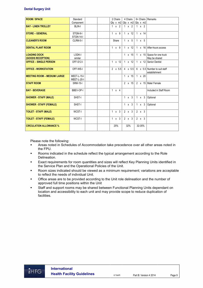
Dental Surgery Unit
International Health Facility Guidelines © TAHPI
Part B: Version 4 2014
Page 9
ROOM / SPACE Standard 2 Chairs 4 Chairs 6+ Chairs Remarks
Component Qty x m2 Qty x m2 Qty x m2
BAY - LINEN TROLLEY BLIN-I 1 x 2 1 x 2 1 x 2
STORE – GENERAL STGN-9-I 1 x 9 1 x 12 1 x 14
STGN-14-I
CLEANER'S ROOM CLRM-5-I Share 1 x 5 1 x 5
DENTAL PLANT ROOM 1 x 9 1 x 12 1 x 16 After-hours access
LOADING DOCK LODK-I 1 x 15 1 x 15 Space for one truck
(GOODS RECEPTION) similar May be shared
OFFICE – SINGLE PERSON OFF-S12-I 1 x 12 1 x 12 1 x 12 Senior Dentist
OFFICE - WORKSTATION OFF-WS-I 2 x 5.5 4 x 5.5 6 x 5.5 Number to suit staff
establishment
MEETING ROOM – MEDIUM/ LARGE MEET-L-15-I 1 x 15 1 x 20
MEET-L-20-I
STAFF ROOM SRM-15-I 2 x 15 2 x 15 Male/ Female
BAY - BEVERAGE BBEV-OP-I 1 x 4 Included in Staff Room
SHOWER - STAFF (MALE) SHST-I 1 x 3 1 x 3 Optional
SHOWER - STAFF (FEMALE) SHST-I 1 x 3 1 x 3 Optional
TOILET - STAFF (MALE) WCST-I 1 x 3 2 x 3 2 x 3
TOILET - STAFF (FEMALE) WCST-I 1 x 3 2 x 3 2 x 3
CIRCULATION ALLOWANCE % 25% 32% 32-35%
Please note the following: Areas noted in Schedules of Accommodation take precedence over all other areas noted in
the FPU. Rooms indicated in the schedule reflect the typical arrangement according to the Role
Delineation. Exact requirements for room quantities and sizes will reflect Key Planning Units identified in
the Service Plan and the Operational Policies of the Unit. Room sizes indicated should be viewed as a minimum requirement; variations are acceptable
to reflect the needs of individual Unit. Office areas are to be provided according to the Unit role delineation and the number of
approved full time positions within the Unit Staff and support rooms may be shared between Functional Planning Units dependant on
location and accessibility to each unit and may provide scope to reduce duplication of facilities.

Dental Surgery Unit
International Health Facility Guidelines © TAHPI
Part B: Version 4 2014
Page 10
6 Functional Relationship Diagram – Dental Surgery Unit

Dental Surgery Unit
International Health Facility Guidelines © TAHPI
Part B: Version 4 2014
Page 11
7 References and Further Reading Australasian Health Facility Guidelines, Part B Health Facility Briefing and Planning, Oral
Health Unit, Rev 4, 2012; refer to website www.healthfacilitydesign.com.au Guidelines for Design and Construction of Health Care Facilities, The Facilities Guidelines
Institute, 2010; refer to website www.fgiguidelines.org HBN12 Out-patients Department, NHS Estates, UK Department of Health, 2004 refer to
website www.tso.co.uk/bookshop .

Part B – Health Facility Briefing & Design 75 Emergency Unit
International Health Facility Guidelines Version 5 September 2017

Part B: Health Facility Briefing & Design
International
Health Facility Guidelines © TAHPI
Part B: Version 5 2017
Page 2
Table of Contents
75 Emergency Unit ......................................................................................................................... 3
1 Introduction ............................................................................................................................................... 3 Description .................................................................................................................................................. 3
2 Functional and Planning Considerations ............................................................................................... 3 Operational Models ..................................................................................................................................... 3 Planning Models .......................................................................................................................................... 4 Functional Areas ......................................................................................................................................... 5 Functional Relationships ........................................................................................................................... 11
3 Design ...................................................................................................................................................... 16 General...................................................................................................................................................... 16 Car Parking ............................................................................................................................................... 16 Patient Treatment Areas ........................................................................................................................... 16 Environmental Considerations .................................................................................................................. 16 Space Standards and Components .......................................................................................................... 17 Safety and Security ................................................................................................................................... 18 Finishes ..................................................................................................................................................... 18 Fixtures, Fittings and Equipment ............................................................................................................... 19 Building Service Requirements ................................................................................................................. 19 Infection Control ........................................................................................................................................ 20
4 Components of the Unit .......................................................................................................................... 21 Standard Components .............................................................................................................................. 21 Non-Standard Components ....................................................................................................................... 21
5 Schedule of Accommodation – Emergency Unit ................................................................................. 22 Emergency Unit located within a health facility ......................................................................................... 22 Short Stay Unit/ Medical Assessment Unit/ Clinical Decision Unit ............................................................ 26 Ambulance Base ....................................................................................................................................... 27
6 References and Further Reading ........................................................................................................... 28

Part B: Health Facility Briefing & Design Emergency Unit
International
Health Facility Guidelines © TAHPI
Part B: Version 5 2017
Page 3
75 Emergency Unit
1 Introduction
Description The function of the Emergency Unit is to receive, stabilise and manage patients (adults and children) who present with a large variety of urgent and non-urgent conditions whether self or otherwise referred. The Emergency Unit also provides for the reception and management of disaster patients as part of the Unit's role within each region. It is recommended that Hospitals not providing an Emergency Service display a prominent exterior sign at the main entrance stating this and giving the location of the nearest Hospital with an Emergency Service. 2 Functional and Planning Considerations
Operational Models The Emergency Unit may be configured in a number of models that are aimed at improving efficiency of treatment and may influence facility design. The majority of Emergency Units will have a number of these models in operation.
Triage and Registration
Patient assessment in Triage occurs first followed by initial registration by clerical staff. In this model, the Reception and Triage are collocated. The patient is rapidly assessed and assigned to the appropriate care zone. A variation of this model includes a senior Nurse to manage patients in the Waiting room to continually review patients who have been triaged and are awaiting treatment. This initiative may be implemented to improve patient safety and quality of care as the Nurse can escalate access to care as needed.
Patient Streaming
In this model the patient is first triaged and registered in a rapid triage model and transferred to a streaming zone for assessment by a senior Emergency Physician. A Streaming zone Nurse coordinates patients through the streaming area into an Early Treatment Zone.
Early Treatment Zone The Early Treatment zone is a separate clinical area where patients are managed for a short time and then moved to another area of the EU such as Acute Care or Waiting area for patients waiting on results before discharge. This model works in conjunction with other models such as Acute Care, Non-Acute Observation, Fast Track, Short Stay Units and Mental Health assessment.
Fast-Track
Specific patient groups may be assessed and treated via a separate ‘fast’ track to other EU presentations. This may occur at the triage point, or immediately after triage but in a separate zone. Patient types suitable for this area are ambulant with non-complex conditions such as contagious diseases, minor injuries, and paediatric illnesses. Assessment and treatment may be carried out in Consult / Examination rooms and the majority of patients discharged to home.
Grouping by Patient Acuity
Patients of similar acuity (urgency) or staff intensity may be treated in the same zone. Facilities for this model will include separate areas for resuscitation, acute monitored beds, acute non monitored beds and ambulatory treatment spaces. There may be separate entry-points (or triage points) for the different areas. Staff may be separately allocated to different areas for each shift, and may require separate Staff Stations and private workspace.

Part B: Health Facility Briefing & Design Emergency Unit
International
Health Facility Guidelines © TAHPI
Part B: Version 5 2017
Page 4
Examples of Grouping by Patient Acuity include:
Resuscitation and Trauma This model sets out how resuscitation and trauma patients will be assessed and managed in order to streamline the process and ensure the correct team and diagnostic services are available. This model ensures that when emergency or trauma patients arrive, trained staff are available to attend.
Acute Care The Acute Care model is aimed at assessment and treatment of patients that are acute or unstable with complex illnesses. Acute Care may be provided in a separate zone or allocated beds that require a higher level of care and endeavours to improve the patient’s access to specialist care and minimise delays. The acute care environment will typically use a standardised clinical environment for each treatment space, using the principles of lean thinking.
Non-Acute Care Non-acute care involves assessment of the patient to determine their need for monitoring or interventional care. Patients in this category do not require acute care or monitoring but have complex conditions that require observation, investigation, discharge planning, or follow up and are not suitable for Fast Track care. Non-Acute care patients are allocated to a separate treatment area or a Short Stay area.
Grouping by Specialty
Patients may be managed in different areas according to the specialty of service they require e.g. paediatric assessment and observation or mental health assessment and emergency care Patients may be triaged from a central arrival point, or from separate ambulance and ambulant entry points. Within each Functional Area, patients would be prioritised according to acuity. In this model, separate specialist staffing for each area is required, which would also include workspaces for staff.
Short Stay Unit
The Short Stay Unit is also known as Emergency Medical Unit or Clinical Decision Unit and is a separate unit located adjacent or incorporated into the Emergency Unit. This may allow sharing of administrative, staff and support facilities. Patients suitable for the Short Stay Unit will require observation, diagnostic services, therapy or follow-up that may take up to 24 hours. These patients will typically be discharged home or admitted to an Inpatient Unit if their condition remained unresolved. Short Stay Units provide efficiency by improving the patient flow through the EU and improving bed management in the hospital by avoiding short term inpatient admissions.
Urgent Primary Care/ Urgent Care Centre
Hospitals with a Role Delineation Level of 1 to 3 may provide an Urgent Primary Care Unit also known as an Urgent Care Centre instead of an Emergency Unit is able to undertake basic resuscitation, stabilisation and minor procedures with medical services provided by local General Practitioners supported by Registered Nurses. The Urgent Care Centre generally operates on a long day basis and some operate 24 hours per day, providing an extended late hour GP service. The Urgent Care Centre would have links to a network of local health services in order that patients requiring more specialised care would be transferred to a higher level emergency unit.
Hours of Operation
The Emergency Unit will typically operate 24 Hours per day, 7 days per week.
Planning Models The Emergency Unit will generally be located for efficient ambulant and ambulance access at ground level, with good access to public transport. Planning of the Emergency Unit will depend on the Operational Model/ Model of Care adopted, the patient mix and the Service plan which establishes the role delineation and size of the service.

Part B: Health Facility Briefing & Design Emergency Unit
International
Health Facility Guidelines © TAHPI
Part B: Version 5 2017
Page 5
Planning should provide maximum flexibility of patient spaces to allow adaption to alternative models of care easily. Where patients are grouped by acuity or by specialty distinct zones may be provided with good functional relationships to key areas of the unit and external units as noted in Functional Relationships. Planning should provide a clear path of travel for each zone with a minimum of cross traffic, for maximum unit efficiency. Reception and Triage areas should be located to allow maximum visibility for incoming ambulances, incoming ambulant patients and waiting areas.
Functional Areas An Emergency Unit may include the following Functional Areas, according to the facility’s agreed Service Plan: Entrance / Reception/ Waiting
- Receiving of patients and visitors and administration - Patient waiting with areas for refreshments and amenities - Security room
Triage - Triage Assessment for ambulant patients - Triage Assessment for ambulance patients
Patient Resuscitation/ Treatment Areas - Decontamination Shower - Resuscitation Bays - Acute Treatment bays/ rooms for assessment and treatment of severe conditions - Non-Acute treatment bays- for patients awaiting test results or requiring observation
prior to admission or discharge. - Treatment & Procedure Rooms
Fast Track/ Primary Care/ Consulting Area - Consult/ Examination rooms - Patient Bed / Chair Bays - Vital signs room - Staff Station - Access to patient amenities
Support Areas - Bays for Handwashing basins, Linen, Mobile Equipment and resuscitation trolleys - Clean Utility and Medication rooms - Cleaners Room - Dirty Utility and Disposal Rooms - Meeting/ Grieving Room. - Store rooms
Staff Areas: - Change Rooms with toilets, shower and lockers - Staff Room - Offices and Workstations - Meeting rooms that may be used for education and teaching functions.
Optional Areas include: Paediatric Assessment/ Short Stay Mental Health Assessment Rooms, Short-Stay Unit/ Emergency Medical Unit for extended observation and management of
patients Ambulance Base and facilities. In addition to standard treatment areas, depending on the service plan and models of care, some functions may require additional, specifically designed areas to fulfil special roles, such as: Streaming of patients to improve throughput and access to care which may require specialist
areas such as Early Treatment Zone Management of paediatric patients Management of major trauma patients Management of mental health patients

Part B: Health Facility Briefing & Design Emergency Unit
International
Health Facility Guidelines © TAHPI
Part B: Version 5 2017
Page 6
Management of patients following sexual assault Undergraduate and postgraduate teaching Transport and retrieval services Tele-medical referral/ consultation service. The inclusion of the above functional areas or specialist treatment zones will be dependent on the size of the unit and the Service Plan of the facility.
Entrance / Reception/ Waiting Areas
Entrance The Emergency Unit should be accessible by two separate entrances: one for ambulance patients and the other for ambulant patients. It is recommended that each entrance area contains a separate foyer that can be sealed by remotely activating the security doors. Access to Treatment Areas should also be restricted by the use of security doors. The Ambulance Entrance should be screened as much as possible for sight and sound from the ambulant patient entrance. Both entrances should direct patient flow towards the Reception/Triage Area. The entrances to the Emergency Unit must be at grade-level, well-marked, illuminated, and covered. It shall provide direct access from public roads for ambulance and vehicle traffic, with the entrance and driveway clearly marked. A ramp shall be provided for pedestrian and wheelchair access. The ambulant entrance to the Emergency Unit should be paved to allow discharge of patients from cars and ambulances. Temporary parking should be provided close to the entrance.
Waiting Areas The Waiting Area should provide sufficient space for waiting patients as well as relatives/ escorts. The area should be open and easily observed from the Triage and Reception areas. Seating should be comfortable and adequate. Space should be allowed for wheelchairs, prams, walking aids and patients being assisted. There should be an area where children may play. Support facilities such as a television should also be available. Fittings must not provide the opportunity for self-harm or harm towards staff. From the Waiting Area there must be access to: Triage and Reception Areas Toilets Baby Change Room Light refreshment facilities which may include automatic beverage dispensing machines Telephone and change machines Health literature It is desirable to have a separate Waiting Areas particularly for children. Child play areas will provide equipment suitable for safe play activities, including a television. It shall be separated for sound from the general Waiting Rooms and must be visible to the Triage Nurse. The area should be monitored to safeguard security and patient well-being. Consideration should be given to provision of a separate, negatively pressured Waiting area for use by patients presenting with suspected pandemic infections.
Reception / Clerical Areas The Reception Area is required to accommodate: Reception of patients and visitors Registration interviews of patients Clinical records Printing of identification labels.

Part B: Health Facility Briefing & Design Emergency Unit
International
Health Facility Guidelines © TAHPI
Part B: Version 5 2017
Page 7
The counter should provide seating and be partitioned for privacy at the interview area. There should be direct communication with the Reception / Triage area and the Staff Station in the Acute Treatment / Observation Area. The Reception/Clerical Area should be designed with due consideration for the safety of staff. This area requires a duress alarm. The Reception desk should be located where staff can observe and control access to treatment areas, pedestrian and ambulance entrances, and public waiting areas. This area requires a duress alarm. The Reception should have direct observation of Waiting areas and Paediatric play areas if provided.
Triage
The Triage may be collocated with the Reception desk and should have clear a vision to the Waiting Room, the ambulant entry and the ambulance entrance. The Triage nurse may interview patients, perform observations and provide first aid in relative privacy in a bed bay or triage cubicle.
Patient Resuscitation/ Treatment Areas
Decontamination Area Emergency Units will require a Decontamination area for patients who are contaminated with toxic substances. This area may be integrated with the Ambulance bay/s or directly accessible from the ambulance bay/s without entering any other part of the unit. The Decontamination area may consist of shower heads in a section of the Ambulance bay ceiling or a dedicated internal room with a shower hose spray. Additional requirements include: A retractable plastic screen to contain the water flow if located in an external area A flexible water hose, floor drain and contaminated water trap; all water flowing out of such a
decontamination area shall be treated as contaminated water and treated accordingly.
Resuscitation Area The Resuscitation Room/ Bay is used for the resuscitation and treatment of critically ill or injured patients. The Resuscitation Room/ Bay requires: Space to fit a specialised resuscitation bed Space to ensure 360 degree access to all parts of the patient for uninterrupted procedures Circulation space to allow movement of staff and equipment around the work area Maximum possible visual and auditory privacy for the occupants of the room and other
patients and relatives Easy access from the ambulance entrance and separate from patient circulation areas Easy access to the Acute Treatment/Observation area from the Staff Station A full range of physiological monitoring and resuscitation equipment Workbenches, storage cupboards, X-ray viewing facilities (or digital electronic imaging
system) and computer access Access to dirty utility and disposal facilities Solid partitions between this and other areas are recommended. Each Resuscitation Bay should be equipped with: Service panel, service pendants or pods to maximise access to patients Physiological monitor with facility for ECG, printing, NIBP, SpO2, temperature probe, invasive
pressure, CO2 monitor A procedure light similar to a small, single arm operating light Equipment to hang IV fluids and attach infusion pumps Resuscitation patient trolley Wall mounted diagnostic set (ophthalmoscope/ auroscope) Clinical scrub basin with paper towel and soap fittings Imaging facilities should include: Overhead X-ray or mobile digital x-ray X-ray screening (lead lining) of walls and partitions between beds
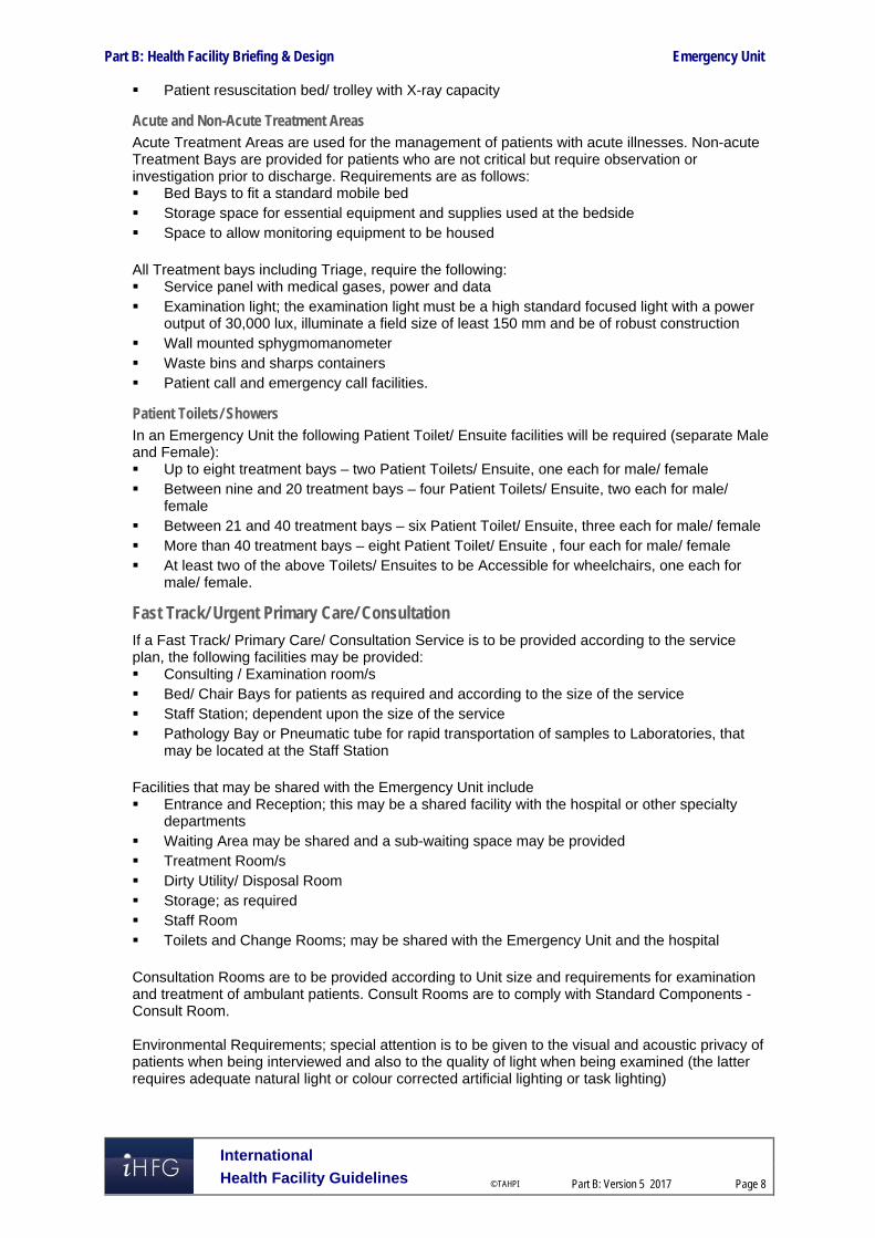
Part B: Health Facility Briefing & Design Emergency Unit
International
Health Facility Guidelines © TAHPI
Part B: Version 5 2017
Page 8
Patient resuscitation bed/ trolley with X-ray capacity
Acute and Non-Acute Treatment Areas Acute Treatment Areas are used for the management of patients with acute illnesses. Non-acute Treatment Bays are provided for patients who are not critical but require observation or investigation prior to discharge. Requirements are as follows: Bed Bays to fit a standard mobile bed Storage space for essential equipment and supplies used at the bedside Space to allow monitoring equipment to be housed All Treatment bays including Triage, require the following: Service panel with medical gases, power and data Examination light; the examination light must be a high standard focused light with a power
output of 30,000 lux, illuminate a field size of least 150 mm and be of robust construction Wall mounted sphygmomanometer Waste bins and sharps containers Patient call and emergency call facilities.
Patient Toilets/ Showers In an Emergency Unit the following Patient Toilet/ Ensuite facilities will be required (separate Male and Female): Up to eight treatment bays – two Patient Toilets/ Ensuite, one each for male/ female Between nine and 20 treatment bays – four Patient Toilets/ Ensuite, two each for male/
female Between 21 and 40 treatment bays – six Patient Toilet/ Ensuite, three each for male/ female More than 40 treatment bays – eight Patient Toilet/ Ensuite , four each for male/ female At least two of the above Toilets/ Ensuites to be Accessible for wheelchairs, one each for
male/ female.
Fast Track/ Urgent Primary Care/ Consultation
If a Fast Track/ Primary Care/ Consultation Service is to be provided according to the service plan, the following facilities may be provided: Consulting / Examination room/s Bed/ Chair Bays for patients as required and according to the size of the service Staff Station; dependent upon the size of the service Pathology Bay or Pneumatic tube for rapid transportation of samples to Laboratories, that
may be located at the Staff Station Facilities that may be shared with the Emergency Unit include Entrance and Reception; this may be a shared facility with the hospital or other specialty
departments Waiting Area may be shared and a sub-waiting space may be provided Treatment Room/s Dirty Utility/ Disposal Room Storage; as required Staff Room Toilets and Change Rooms; may be shared with the Emergency Unit and the hospital Consultation Rooms are to be provided according to Unit size and requirements for examination and treatment of ambulant patients. Consult Rooms are to comply with Standard Components - Consult Room. Environmental Requirements; special attention is to be given to the visual and acoustic privacy of patients when being interviewed and also to the quality of light when being examined (the latter requires adequate natural light or colour corrected artificial lighting or task lighting)

Part B: Health Facility Briefing & Design Emergency Unit
International
Health Facility Guidelines © TAHPI
Part B: Version 5 2017
Page 9
Construction, finishes, design for disabled access, parking, signposting, etc. shall be in accordance with the other relevant sections of these Guidelines.
Support Areas
Support areas include Clean and Dirty utilities, Disposal room, Bays for linen, handwashing, mobile equipment and resuscitation trolley and Store Rooms to comply with Standard Components as identified in the Schedule of Accommodation.
Staff Station/s The Staff Station/s should have an uninterrupted vision of the patients. It should be centrally located and may be constructed with an enclosed area to ensure confidential information can be conveyed without breach of privacy and to provide security to staff, information and privacy. The use of sliding windows and adjustable blinds can be used to modulate external stimuli and a separate write-up area may be considered.
Pathology Bay A designated area for performing immediate laboratory investigations such as arterial blood gas analysis and microscopy should be considered in Units of Role Delineation Levels 4 to 6. Mechanical or pneumatic tube transport systems for specimens and electronic reporting of results are recommended.
Medication Room A Medication Room is required for the storage of medications used within the Emergency Department. Entry should be secure with a self-closing door. The area should be accessible to all clinical areas and have sufficient space to house a drug refrigerator for the storage of heat sensitive drugs. The drug refrigerator should be temperature monitored and alarmed.
Optional Areas
Inclusion of the following optional areas is dependent on the clinical services plan.
Paediatric Assessment / Short Stay A separate zone may be provided, customised for paediatric patients with Controlled access for the safety and security of paediatric patients Paediatric play area, within the zone Paediatric Consult rooms Bed/ cot bays and chair bays for nebuliser therapy Staff Station with direct visibility to all treatment bays and areas Support areas contained within the zone for staff convenience.
Acute Mental Health & Behavioural Assessment Area The patient who is suffering from an acute psychological or psychiatric crisis has unique and often complex requirements. An Emergency Unit should have adequate facilities for the reception, assessment, stabilisation and initial treatment of patients presenting with acute mental health problems. It is not intended that this be used for prolonged observation of uncontrolled patients. The main purpose of such an area is to provide a safe and appropriate space to interview and stabilise patients. Acute mental health presentations have the potential to disrupt the normal operation of an Emergency Unit. Conversely, the busy environment of an Emergency Unit may not be conductive to the care of patients with acute mental health crises. Patient flows should be separated where possible to maximise privacy and minimise disruption. A separate secure entrance for use by community emergency mental health teams and police may be desirable. Patients should be continuously observable by staff either directly or via closed circuit television The designated area should be within close proximity of other continuously staffed areas of the department, with ready access to assistance when required. As far as possible, the facility should not contain objects that could be thrown at staff. There should be two separate exits to allow the

Part B: Health Facility Briefing & Design Emergency Unit
International
Health Facility Guidelines © TAHPI
Part B: Version 5 2017
Page 10
exit of staff if one exit is blocked. The exit doors should open outwards, and should be lockable from the outside but not from the inside. If a window is incorporated, any drapes or blinds shading the window should be operable from outside. All areas should have easily accessible duress alarms. As far as possible, the area should be free of heavy or breakable furniture, sharp or hard surfaces which could injure an uncontrolled patient, and should incorporate tamper resistant electrical fittings. It should also incorporate interior design features that promote calmness, such as muted colours and soft furnishings and appropriate lighting. Patient tracking devices may enhance security. The Acute Mental Health & Behavioural Assessment Area should be separate enough from adjacent patient care areas to allow privacy for the mental health patient and protection of other patients from potential disturbance or violence. There should be acoustic and visual separation from adjacent clinical areas, but ready access for staff in the event of an urgent need for intervention. The incorporation of sound-insulating material is recommended. Ideally the area should contain at least two separate but adjacent areas: Interview Room (Mental Health) with
- Two exit doors, swinging outward and lockable from outside, to allow for the escape of staff members when one exit is blocked; one door should be large enough to allow a patient to be carried through it; consideration should be given to solid core doors with safety viewing glass
- Design that permits observation of the patient by staff outside the room at all times; this may be backed up with closed circuit television for the safety of staff
- Acoustic shielding from external noise - Soft furnishings with no hard edges - No patient access to air vents or hanging points - Smoke detectors fitted - Duress alarm at each exit.
Treatment room (Mental Health) with the following features: - The room should be immediately adjacent to the Interview room and should contain
adequate facilities for physical examination of the patient; however the inclusion of unnecessary and easily dislodged equipment should be avoided; a lockable retractable door or panel to services is recommended.
- If operational policy dictates that intravenous sedation is to occur in this area, the room should include appropriate facilities and monitoring equipment, mounted out of reach of a potentially violent patient. The room should contain the minimum of additional fittings or hard furnishings that could be used to harm an uncontrolled patient. It should be of sufficient size to allow a restraint team of five people to surround a patient on a standard Emergency Unit bed and should be at least 14 m2 in floor area.
Short Stay Unit (SSU) / Emergency Medical Unit (EMU)/ Clinical Decision Unit This facility may be provided either within or adjacent to the Emergency Unit for the prolonged observation and ongoing treatment of patients who are planned for subsequent discharge (directly from the EU). Patients may be kept in this Unit for diagnosis, treatment, testing or for medical stabilisation. The length of stay in the Unit is generally between 4 and 24 hours, although Unit policy may allow require longer stays. The Unit may also be situated separately to the Emergency Unit, although functionally linked. According to the service plan, dedicated beds for short stay are separately designated and staffed. The types of patients planned to be admitted to this Unit will determine the number and type of beds provided, and the design of associated monitoring and equipment. Staff Stations, work and storage and other support areas will need to be available and may be shared if the unit is located physically close to other treatment areas.
Ambulance Service Requirements Specific requirements of the Ambulance Service(s) serving the area shall be obtained and complied with. These requirements will be in relation to areas such as ramp gradients, ambulance parking/ unloading area gradients, height clearance and ambulance bay dimensions.

Part B: Health Facility Briefing & Design Emergency Unit
International
Health Facility Guidelines © TAHPI
Part B: Version 5 2017
Page 11
Specific information about emergency vehicles and ambulances that will be used for the facility should be acquired from local public and private Ambulance Services. The following consideration shall be given while designing the Ambulance areas: Access for Ambulances shall not conflict with other vehicular or pedestrian traffic The Ambulance access shall be located away from public entrances and shall be reasonably
screened from public view; a separate entrance is required and cannot be shared with the Main Public Entrance
The Ambulance access is to be directly connected to the Emergency Unit; an air lock shall be provided between the inside and the outside; Ambulance access to the Emergency Unit shall not be via hospital corridors that are open for public access.
The Ambulance collection/ drop off points must be discreet and shall be covered A lockable storage cupboard or room no less than 2 m2 shall be provided for Ambulance
supplies. The cupboard or room shall have adjustable shelves and be lockable with a separate key or keypad lock.
A hose cock with attached hose shall be located close to an Ambulance bay for washing down the vehicle or trolleys; it is recommended that the hose cock and hose be located in a discrete cabinet or recessed bay.
An intercom system shall be provided between the Ambulance door and the Emergency Unit Reception/Clerical Area, Triage Area or Staff Station; the Intercom system shall be integrated with a security CCTV system located to clearly show those requesting entry
All Ambulance Bays shall be clearly marked and sign-posted; the external signage system shall direct ambulances and vehicles carrying emergency cases to the Ambulance Bays. These signs shall be clearly visible at the entrance to the Hospital and/or any major change of direction. Signs directed to ambulance bays intended for emergency units or birthing units shall be permanently lit during the night. In order to avoid confusion, the signage system shall be designed in such a way that ambulant patients, including ambulant access to an emergency unit are not to be directed to the ambulance bay or ambulance door.
A Communications Room is required, for up to three ambulance officers to communicate between major hospital centres and the ambulance service for coordination of Ambulance movements; the communications base is also a critical co-ordination centre in the event of a disaster. - The room should be immediately adjacent to the Ambulance entry of the Emergency
Unit with direct line of sight to incoming ambulance vehicles and the parking bays - The room will include workstation benches and chairs for 3 persons, telephones,
computer and radio communications systems.
Functional Relationships
External
The Emergency Unit will require close and efficient access to the following units: Medical Imaging Unit; The Medical Imaging Unit is to provide general X-Ray diagnostic
investigations and other diagnostic screening services such as fluoroscopy, ultrasound, mammography, computed tomography (CT), magnetic resonance imaging (MRI) and other interventional radiographic procedures and immediate access to those modalities are highly recommended for effective Emergency Unit’s operational procedure; - Medical Imaging may be provided as a satellite facility within the Emergency Unit; the
requirement for film processing is dependent upon close proximity to the Medical Imaging Department and the use of digital radiology;
- A system of electronic display of imaging is desirable. Clinical Information Unit – Patients’ previous medical records are required to provide holistic
care in Emergency Department. In order to minimise delays and labour costs, a mechanical or electronic record transfer system is recommended. 24 hours per day access to Clinical Information Unit is essential.
Birthing Unit - for labour, deliveries and care for patients with antepartum complications Operating Unit – to transfer patients requiring emergency surgical procedures Cardiac Investigation Unit (particularly Cardiac Catheter Laboratories) – for patients who
require further cardiac services consultation, diagnostic procedures, and interventional treatments

Part B: Health Facility Briefing & Design Emergency Unit
International
Health Facility Guidelines © TAHPI
Part B: Version 5 2017
Page 12
Intensive Care Unit / High Dependency Unit/ Coronary Care Unit - for admission of patients with severe conditions requiring close monitoring or life support.
Ready access is required to the following: Inpatient Accommodation Units – for admissions of medical and surgical patients Outpatients Unit - for patient follow-up and referrals for further investigation and ongoing
review for non-admitted patients Service Units including:
- Catering Unit – for providing meals, beverages, and snacks for patients - Mortuary – to transfer deceased patients for storage and undertaking post mortems
examination / autopsies - Laboratory Unit – for sending patient specimen for testing and examination, this may
be an automated link such as pneumatic tube system - Pharmacy Unit – pharmacy services for dispensing medications for discharged patient
and enabling prescriptions to be filled by patients - Sterile Supply Unit – to obtain sterile equipment for surgical emergencies in
Emergency Department These key external functional relationships are demonstrated in the diagrams below including the following: Separate entries are provided for ambulant and ambulance patients Public entry is in close proximity to urgent short-term parking Rapid and ready access to key clinical units such as Operating Unit, Birthing Unit, Cardiac
Catheter Labs, ICU/ HDU/ CCU for patient treatment and transfers via service corridor Ready access to Inpatient Units for patient transfer via service corridor Access to Outpatients Units via a public corridor Access to support untis including Clinical Information Unit, Supply, Sterile Supply
Housekeeping, Catering Waste managmenent and Mortuary should be readily accessible for staff via a service corridor
Access to diagnostic units such asLaboratory and Pharmacy via a service corridor and may be via a pneumatic tube or automated transport system.
Internal
Within the Unit, key functional relationships include the following: The design should allow for rapid access to every space with a minimum of cross traffic There must be close proximity between the Resuscitation / Acute Treatment areas for non-
ambulant patients, other treatment areas for ambulant and non-ambulant patients, so that staff may be relocated at times of high workload
Visitor and patient access to all areas should not traverse clinical areas Protection of visual, auditory and olfactory privacy is important whilst recognising the need for
observation of patients by staff.
The optimal internal relationships are outlined in the diagrams below include the following: Triage and Waiting located at the Public Entry of the Unit; Ambulance Triage located at the
Ambulance Entry Direct link from Ambulance Entry, to Ambulance Triage and Resuscitation areas Close proximity of Resuscitation and Patient Treatment Areas Patient treatment areas divided into Fast Track, Acute/ Non-acute Care/ Observation, with
the addition of specialist areas such as Paediatrics, Mental Health and Short Stay Unit in larger Emergency Units
Staff Station/s located centrally within Treatment Areas, with direct oversight of Resuscitation, Acute Treatment and Non-acute Treatment bays
Access from all Patient Treament and Consult areas to the Integrated Medical Imaging facilities
Support areas for Treatment zones located adjacent to the zones for ready access Staff amenities and Administration may be accessed externally from staff/ service corridors
and located on the perimeter of the Unit
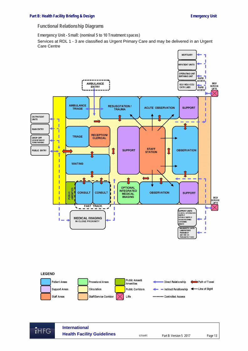
Part B: Health Facility Briefing & Design Emergency Unit
International
Health Facility Guidelines © TAHPI
Part B: Version 5 2017
Page 13
Functional Relationship Diagrams
Emergency Unit - Small: (nominal 5 to 10 Treatment spaces) Services at RDL 1 - 3 are classified as Urgent Primary Care and may be delivered in an Urgent Care Centre

Part B: Health Facility Briefing & Design Emergency Unit
International
Health Facility Guidelines © TAHPI
Part B: Version 5 2017
Page 14
Emergency Unit - Medium: (nominal 11 to 30 Treatment spaces)

Part B: Health Facility Briefing & Design Emergency Unit
International
Health Facility Guidelines © TAHPI
Part B: Version 5 2017
Page 15
Emergency Unit - Large: (nominal 31 to 100 or more Treatment spaces)

Part B: Health Facility Briefing & Design Emergency Unit
International
Health Facility Guidelines © TAHPI
Part B: Version 5 2017
Page 16
3 Design
General
Location
Decisions regarding the site location have a major influence on the eventual cost and operational efficiency of the Emergency Unit staff. The site of the Emergency Unit should, as much as possible, maximise the choices of layout. In particular, sites of access points must be carefully considered. The Emergency Unit should be located on the ground floor for easy access by ambulant patients and ambulances. The entrances must be covered and provide shelter for ambulances and crew unloading and loaf-ding patients.
External Signposting The emergency unit should be clearly identified from all approaches. Signposting that is illuminated is desirable to allow visibility at night. The use of graphic and character displays such as a white cross on a red background is encouraged.
Car Parking Car parking should be close to the Entrance, well lit and available exclusively for patients, their relatives and staff. Parking areas should be available close to the Emergency Unit for urgent call in staff. Undercover car parking should be available for: Appropriate number of ambulances which will be determined by the case load and the
availability of ambulance access to other parts of the hospital for non-emergency patients Taxis and private vehicles that drop off/pick up patients adjacent to the ambulance entrance.
Patient Treatment Areas Patients must be situated so that healthcare providers have direct visualization, as far as possible. This permits the monitoring of patient status under both routine and emergency circumstances. The preferred design is to allow a direct line of vision between the patient and the Staff Station. In large Emergency Units, treatment bed areas may be designed in clusters with a centralised staff station with maximum direct visibility of patients. Treatment spaces may be fully or partially enclosed to ensure that confidential information can be conveyed without breach of privacy and to provide security to staff. Treatment bed spaces should be designed as acuity adaptable - to suit any patient acuity in order to provide maximum flexibility for patient placement within the Emergency Unit.
Paediatric Treatment Zone Paediatric assessment and treatment should be designed as a separate zone and have restricted access for safety and security of paediatric patients. Paediatric Bed Bays should be provided at the same size as adult bed bays in order to provide future flexibility.
Environmental Considerations
Acoustics
Clinical Areas should be designed to minimise the transmission of sound between adjacent treatment areas. The following areas will require acoustic consideration: Consult/ Interview and triage areas for discussions / interviews with clients; Seclusion and psychiatric assessment rooms Treatment and Procedure Rooms Waiting areas Staff Stations

Part B: Health Facility Briefing & Design Emergency Unit
International
Health Facility Guidelines © TAHPI
Part B: Version 5 2017
Page 17
Natural Light
The use of natural light should be maximised throughout the Unit. Natural lighting contributes to a sense of wellbeing and assists orientation of patients and visitors and minimises staff disorientation.
Privacy
Staff observation of patients and patient privacy must be well-balanced within the Unit. The following features shall be integrated to the design of the Unit: Doors and windows to be located appropriately to ensure patient privacy and not comprise
staff security Discreet spaces to enable confidentiality of discussions related to a patient and storage of
patients medical records Privacy screening to bed and chair bays Consultation, Interview bays, Resuscitation bays and Patient bed bays should not be visible
from public or waiting areas; examination couches should not face the door.
Space Standards and Components
Accessibility
Design should provide ease of access for wheelchair bound patients to Reception desks, Staff Stations, Consult Rooms and Interview/ Meeting Rooms. Waiting areas should include spaces for wheelchairs and suitable seating for patients with disabilities or mobility aids.
Doors
Doors used for bed transfer to Operating Unit, Medical Imaging Unit, Critical Care Units and Inpatient Units, must be appropriately positioned and sized. A minimum of 1400mm clear opening is recommended for doors requiring bed/trolley access. Also refer to Part C - Access, Mobility and OH&S of these Guidelines.
Ergonomics/ OH&S
Consideration should be given to ergonomic functionality in the Unit. Benches and recording workstations should be provided at suitable working heights. Refer to Part C – Access, Mobility, OH&S of these Guidelines for more information.
Size of the Unit
The size of the Emergency Unit will be determined by the Clinical Services Plan establishing the intended services scope and complexity. Schedules of Accommodation have been provided for typical small, medium and large facilities along with the typical Role Delineation that may apply to that size. Small, medium and large facilities are nominally defined as follows: Small: 5 to 10 treatment spaces (not including Procedure and Treatment Rooms) Medium: 11 to 30 treatment spaces Large: 31 to 100 or more treatment spaces.
Bed Spacing
In open plan Treatment bed areas there should be at least 2.4 metres of clear floor space between the centres of each bed and a minimum of 900mm clear space at the sides and foot of each bed.
Corridors
Corridor width in the Emergency Unit must allow the passage of two hospital beds without difficulty. There should be adequate space for trolleys to enter or exit Treatment, Procedure and Consult Rooms. Corridors should not be used for storage of equipment and bays provided for storage should not impede Corridor access.

Part B: Health Facility Briefing & Design Emergency Unit
International
Health Facility Guidelines © TAHPI
Part B: Version 5 2017
Page 18
Note: Refer to Part C - Access, Mobility and OH&S in these Guidelines - Space Standards & Dimensions for further information on corridor standards.
Safety and Security The Emergency Unit receives a large number of patients and their visitors, many of whom may be distressed, intoxicated or involved in violence. The hospital has a duty of care to provide for the safety and security of employees, patients and visitors. Both policies and structures should be in place to minimise injury, psychological trauma and damage or loss of property. The precise details of security features should be designed in conjunction with a security risk assessment for the specific site. The location of an office for security personnel near the entrance should be considered. This room should be positioned so that it allows Security Staff a clear view of the Waiting Room, Triage and Reception Areas. Immediate access to these areas is essential. Remote monitoring of other areas in the department by CCTV and of staff duress/personal alarms should also occur from this area.
Perimeter Access Control
Ambulatory and Ambulance entrances should be separate, with electronically operated locks. Access from the Waiting Areas to the treatment areas should be controlled. There should be restricted access from the remainder of the hospital into the Emergency Unit.
Reception / Triage Areas
The interface between the Waiting Areas and the Reception / Triage Areas should be carefully designed so as to permit communication and reassurance to distressed patients or visitors, yet provide safety and security for staff. Counters should be of sufficient height and depth to minimise the possibility of them being jumped over or reached over. The Reception Area should be designed so that staff may sit at eye level with standing patients or visitors. The Reception / Triage area should have an unobstructed view of the entire Waiting Area. Fixed and/or personal duress alarms should be positioned in suitable areas as suggested by the security risk assessment, particularly Reception and Staff stations. Uniformed security personnel may be required at very short notice to assist with a safety or security issue. Relatively secluded or isolated areas should be monitored electronically (for example, by closed circuit television), with monitors in easily visible and continuously staffed areas.
Finishes In all areas where patient observation is critical, colours shall be chosen that do not alter the observer's perception of skin colour. The following additional factors should be considered in the selection of finishes: Acoustic properties Durability Ease of cleaning Infection control Fire safety Movement of equipment.
Floor Finishes
The floor finishes in all patient care areas and corridors should have the following characteristics: Non-slip surface Impermeable to water, body fluids Durable Easy to clean Acoustic properties that reduce sound transmission Shock absorption to optimise staff comfort but facilitate movement of beds
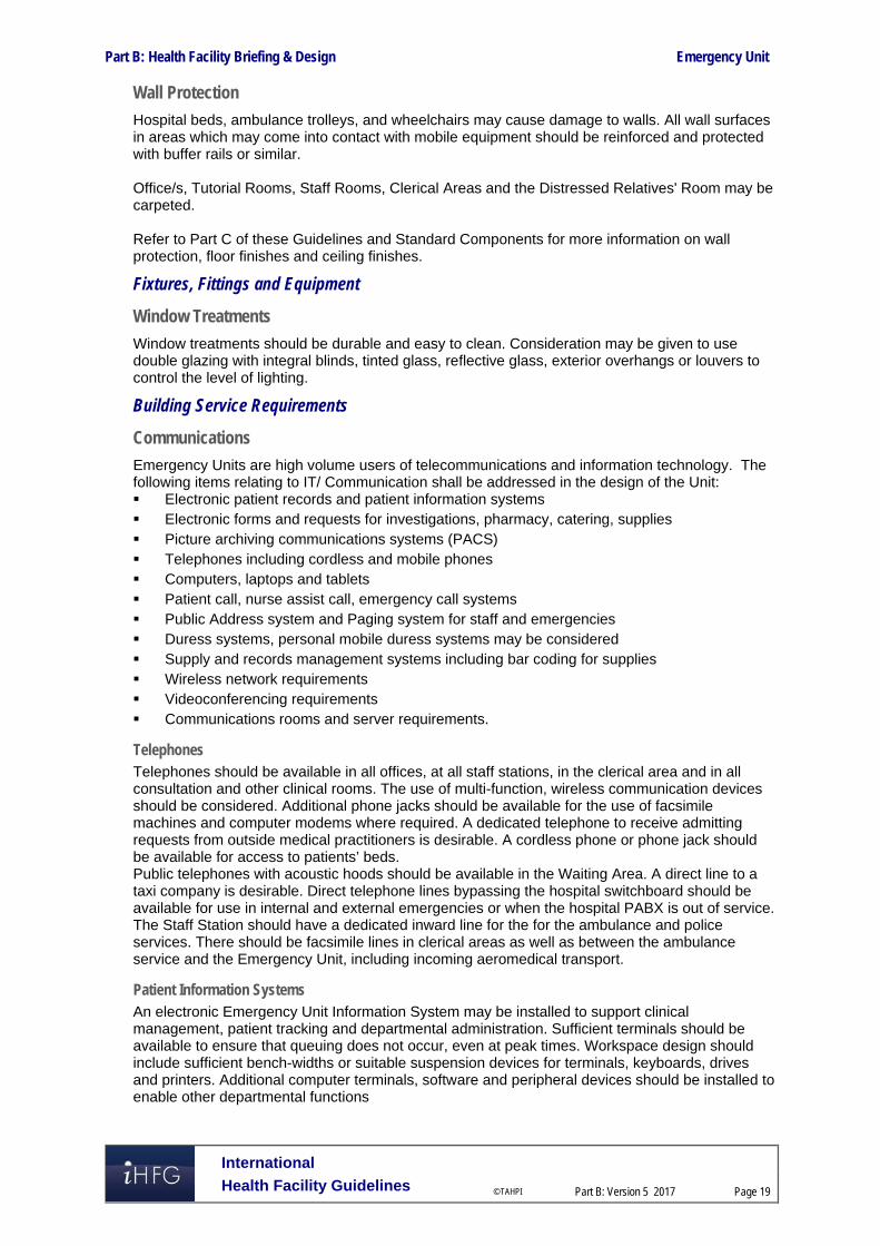
Part B: Health Facility Briefing & Design Emergency Unit
International
Health Facility Guidelines © TAHPI
Part B: Version 5 2017
Page 19
Wall Protection
Hospital beds, ambulance trolleys, and wheelchairs may cause damage to walls. All wall surfaces in areas which may come into contact with mobile equipment should be reinforced and protected with buffer rails or similar. Office/s, Tutorial Rooms, Staff Rooms, Clerical Areas and the Distressed Relatives' Room may be carpeted. Refer to Part C of these Guidelines and Standard Components for more information on wall protection, floor finishes and ceiling finishes.
Fixtures, Fittings and Equipment
Window Treatments
Window treatments should be durable and easy to clean. Consideration may be given to use double glazing with integral blinds, tinted glass, reflective glass, exterior overhangs or louvers to control the level of lighting.
Building Service Requirements
Communications
Emergency Units are high volume users of telecommunications and information technology. The following items relating to IT/ Communication shall be addressed in the design of the Unit: Electronic patient records and patient information systems Electronic forms and requests for investigations, pharmacy, catering, supplies Picture archiving communications systems (PACS) Telephones including cordless and mobile phones Computers, laptops and tablets Patient call, nurse assist call, emergency call systems Public Address system and Paging system for staff and emergencies Duress systems, personal mobile duress systems may be considered Supply and records management systems including bar coding for supplies Wireless network requirements Videoconferencing requirements Communications rooms and server requirements.
Telephones Telephones should be available in all offices, at all staff stations, in the clerical area and in all consultation and other clinical rooms. The use of multi-function, wireless communication devices should be considered. Additional phone jacks should be available for the use of facsimile machines and computer modems where required. A dedicated telephone to receive admitting requests from outside medical practitioners is desirable. A cordless phone or phone jack should be available for access to patients’ beds. Public telephones with acoustic hoods should be available in the Waiting Area. A direct line to a taxi company is desirable. Direct telephone lines bypassing the hospital switchboard should be available for use in internal and external emergencies or when the hospital PABX is out of service. The Staff Station should have a dedicated inward line for the for the ambulance and police services. There should be facsimile lines in clerical areas as well as between the ambulance service and the Emergency Unit, including incoming aeromedical transport.
Patient Information Systems An electronic Emergency Unit Information System may be installed to support clinical management, patient tracking and departmental administration. Sufficient terminals should be available to ensure that queuing does not occur, even at peak times. Workspace design should include sufficient bench-widths or suitable suspension devices for terminals, keyboards, drives and printers. Additional computer terminals, software and peripheral devices should be installed to enable other departmental functions

Part B: Health Facility Briefing & Design Emergency Unit
International
Health Facility Guidelines © TAHPI
Part B: Version 5 2017
Page 20
Public Address System An intercom or public address system that can reach all areas of the Emergency Unit should be considered.
Telemedicine Emergency Units using telemedicine facilities should have a dedicated, fully enclosed room with appropriate power and communications cabling provided. This room should be of suitable size to allow simultaneous viewing by members of multiple service teams and should be close to the Staff Station.
Nurse/ Emergency Call
All patient spaces and clinical areas, including beds, toilets, bathrooms, treatment areas, patient day areas and lounges should have access to an emergency call facility so staff can summon urgent assistance. The emergency call facility should alert to a central module situated adjacent to the Staff Station, as well as to the Staff and Tutorial rooms.
Heating, Ventilation, Air-conditioning
The Emergency Unit shall have appropriate air conditioning that allows control of temperature and humidity within each functional zone.
Medical Gases
Oxygen, medical air and suction will be required to each Acute Bed Bay, Non-acute bed Bay, Resuscitation Bay, Triage Bays, Procedure Rooms, Treatment Rooms, Consult Rooms for treatment and resuscitation. Oxygen/ nitrous oxide used in the Birthing Suite will require scavenging suction.
Pneumatic Tube Systems
The Emergency Unit may include a pneumatic tube station system, as determined by the facility Operational Policy. If provided the station/s should be located in close proximity to the Staff Stations within the treatment clusters or under direct staff supervision.
Radiation Shielding
The Unit may undertake procedures involving imaging; plans and specifications will require assessment for radiation protection by a certified physicist or other qualified expert as required by the relevant Radiation and Nuclear Safety Agency. The radiation protection assessment will specify the type, location and amount of radiation protection required according to the final equipment selections and layout. Radiation protection requirements must be incorporated into the final specifications and building plans.
Infection Control Handbasins for hand-washing should be located in close proximity to each treatment bay and must be included in each enclosed bay or treatment room. Han basins should be accessible without traversing any other clinical area. All handbasins in clinical areas should be of surgical type with hands-free activation (Type A). Dispensers for non-sterile latex gloves should be available in the vicinity of each handbasin and each treatment area. Refer to Part D- Infection Control for ratios of basins required in clinical areas.
Isolation Rooms
At least one negative pressure Isolation Room should be provided in Units in Level 5 & 6. The need for additional negative pressure Isolation Rooms shall be determined by the infection control risk assessment. Refer to iHFG Part D - Infection Control.

Part B: Health Facility Briefing & Design Emergency Unit
International
Health Facility Guidelines © TAHPI
Part B: Version 5 2017
Page 21
4 Components of the Unit
Standard Components The Emergency Unit will consist of Standard Components to comply with details described in these Guidelines. Refer to Standard Components Room Data Sheets and Room Layout Sheets.
Non-Standard Components Non Standard rooms are identified in the Schedules of Accommodation as NS and are described below.
Triage Cubicles (ambulant patients)
The Triage Cubicles are used for patient interview, observation and initial assessment, located adjacent to the Triage Desk or station. The cubicle may be enclosed or partly enclosed and include: Desk Chairs for patients and support person Exam couch with privacy screen curtains Equipment for measuring vital signs Handbasin with paper towel and soap fittings. The cubicle will require bed/ trolley access for patients requiring trolley transfer to other EU areas.
Holding Room (Bodies)
The holding Room for bodies is a secure room for deceased patients on trolleys awaiting transfer to the Mortuary. The room will contain a handbasin with paper towel and soap fittings. The room should be located in a staff only, quiet area of the Unit and sized to accommodate a single trolley.
Pneumatic Tube Station
The Pneumatic Tube Station should be located at the Staff Station/s under the direct supervision of staff for urgent arrivals. The location should not be accessible by external staff or visitors. Requirements include: The bay should not impede access within staff station areas Racks should be provided for pneumatic tube canisters Wall protection should be installed to prevent wall damage from canisters.
Vital Signs Room
The Vital Signs room is a room for measurement and recording of patient vital signs. The room will include: Desk and chair for staff Chairs for staff, patient and support person Handbasin with paper towel and soap dispensers Clinical measurement equipment:
- Weighing scales - Stadiometer - height measurement device - Vital signs monitoring equipment, electronic.

Part B: Health Facility Briefing & Design Emergency Unit
International
Health Facility Guidelines © TAHPI
Part B: Version 5 2017
Page 22
5 Schedule of Accommodation – Emergency Unit
Emergency Unit located within a health facility Note: Services at RDL 1-3 are classified as Urgent Primary Care
ROOM/ SPACE iHFG Standard Component RDL 1-2 RDL 3-4 RDL 3-4 RDL 5-6 Remarks Room Codes Qty x m2 Qty x m2 Qty x m2 Qty x m2
Unit Size Small-10 spaces Medium-15 spaces Medium-30 spaces Large-60 spaces (spaces only, not including procedure rooms)
Entry/ Reception/ Waiting Urgent Primary Care
Airlock - Entry airle-10-i 1 x 10 1 x 10 1 x 10 1 x 10 Optional; May be shared with Main Entry; Ambulance entry may require separate Airlock
Reception rece-i I 1 x 10 1 x 15 1 x 20 1 x 20 Staff to observe & control access
Waiting wait-10-i 2 x 10 2 x 20 May be separate Male/ Female/ Family
Waiting - Family wait-20-i 1 x 20 1 x 25 1 x 25 1 x 25
Play Area - Paediatric plap-10-i similar 1 x 8 1 x 8 1 x 10 1 x 10 Adjoining Waiting area
Bay - Vending Machines bvm-3-i bvm-5-i 1 x 3 1 x 5 Optional
Bay - Wheelchair Park bwc-i similar 1 x 2 1 x 4 1 x 4 1 x 6 Wheelchairs & trolley holding
Parenting Room par-i 1 x 6 1 x 6 May be shared with Main Entry
Police/ Security Room secr-10-i similar 1 x 10 * 1 x 12 1 x 12 * Optional
Toilet- Accessible wcac-i 1 x 6 1 x 6 1 x 6 1 x 6 May also include facilities for baby change
Toilet - Public & Patient wcpt-i 1 x 4 2 x 4 2 x 4 For waiting patients and support persons
Triage
Triage - Nurse rece-i similar 1 x 5 1 x 5 2 x 5 2 x 5 May include with Reception
Triage Cubicle/s NS 1 x 10 2 x 10 4 x 10 Includes exam couch and write-up desk
Ambulance Triage ambtr-i 1 x 10 1 x 12 2 x 12 1, 2 & 4 bays respectively
Resuscitation/ Treatment Areas 8 spaces 12 spaces 20 spaces 40 spaces
Decontamination Shower shdec-i 1 x 8 1 x 8 1 x 8 1 x 8 May be external with ambulance bays
Patient Bay - Resuscitation pbtr-r-i similar 1 x 35 1 x 35 3 x 28 4 x 28 35m2 room has 2 bays, includes handbasin within
Patient Bay - Acute Treatment pbtr-a-12-i 2 x 12 5 x 12 8 x 12 18 x 12 Qty according to service plan; arranged in clusters of up to 12 beds
Patient Bay - Non Acute Treatment pbtr-na-i 3 x 10 4 x 10 8 x 10 16 x 10 Qty according to service plan; arranged in clusters of up to 12 beds
Patient Bay - Enclosed, Isolation Negative Pressure pbtr-h-e-12-i similar 1 x 12
Acute/ Non-acute; includes hand basin within Qty according to service plan
Patient Bay - Enclosed, Isolation - Standard / Positive Pressure
pbtr-h-e-12-i similar 1 x 12 1 x 12 1 x 12 1 x 12 Acute/ Non-acute; includes hand basin within Qty according to service plan

Part B: Health Facility Briefing & Design Emergency Unit
International
Health Facility Guidelines © TAHPI
Part B: Version 5 2017
Page 23
ROOM/ SPACE iHFG Standard Component RDL 1-2 RDL 3-4 RDL 3-4 RDL 5-6 Remarks Room Codes Qty x m2 Qty x m2 Qty x m2 Qty x m2
Unit Size Small-10 spaces Medium-15 spaces Medium-30 spaces Large-60 spaces (spaces only, not including procedure rooms)
General X-ray Room genxr-i 1 x 30 2 x 30 Optional; for CT scanning & Control room additional area will be required
Procedure Room proc-20-i 1 x 20 2 x 20 May include plaster/splint facilities
Plaster Room plst-i 1 x 14 1 x 14 Optional
Treatment Room trmt-14-i 1 x 14 1 x 14 1 x 14
Anteroom anrm-i 1 x 5 For negative pressure isolation room
Ensuite - Standard enst-st-i 1 x 5 1 x 5 1 x 5 2 x 5 For Isolation room/s
Meeting Room - Small meet-9-i 1 x 9 2 x 9 May be used as Interview, Grieving room or as Telemedicine consult
Shower - Patient shpt-i 1 x 4 1 x 4 1 x 4 2 x 4 May be combined with Toilet-Patient
Toilet - Accessible, Patient wcac-i shared 1 x 6 2 x 6 2 x 6
Toilet - Patient wcpt-iI 1 x 4 2 x 4 2 x 4 4 x 4
Fast Track/ Primary Care/ Consulting 2 spaces 3 spaces 5 spaces 10 spaces
Consult Room cons-i 2 x 14 3 x 14 3 x 14 4 x 14
Consult - ENT/ Ophthalmology cons-ento-i 1 x 14 1 x 14
Patient Bay - Non Acute Treatment pbtr-na-i 1 x 10 5 x 10
Vital Signs Room NS 1 x 8 1 x 8 1 x 8 Optional
Bay - Handwashing, Type A bhws-a-i 1 x 1 2 x 1 for bed bay area
Staff Station sstn-5-i sstn-12-i similar 1 x 5 1 x 8 1 x 12
Toilet - Patient wcpt-i 1 x 4 2 x 4
Support Areas May be shared between zones
Bay - Beverage, Open Plan bbev-op-i 1 x 4 1 x 4 1 x 4 1 x 4
Bay - Handwashing, Type A bhws-a-i 2 x 1 3 x 1 4 x 1 9 x 1 1 per 4 open treatment bays, minimum
Bay - Linen blin-i 1 x 2 1 x 2 2 x 2 2 x 2
Bay - Mobile Equipment bmeq-4-i bmeq-6-i 1 x 6 1 x 6 2 x 4 2 x 4
Bay - Pathology bpath-1-i bpath-3-i 1 x 1 1 x 1 1 x 1 1 x 3
Bay - Pneumatic Tube NS 1 x 1 1 x 1 1 x 1 1 x 1 Optional
Bay - Resuscitation Trolley bres-i 1 x 1.5 1 x 1.5 1 x 1.5 1 x 1.5 Adult and paediatric trolleys
Clean Utility clur-8-i clur-12-i 1 x 8 1 x 8 1 x 12 2 x 12
Cleaner’s Room clrm-i 1 x 5 1 x 5 1 x 5 1 x 5
Dirty Utility dtur-s-i dtur-10-i dtur-12-i 1 x 8 1 x 8 1 x 10 2 x 12
Disposal Room disp-8-i shared shared 1 x 8 1 x 8

Part B: Health Facility Briefing & Design Emergency Unit
International
Health Facility Guidelines © TAHPI
Part B: Version 5 2017
Page 24
ROOM/ SPACE iHFG Standard Component RDL 1-2 RDL 3-4 RDL 3-4 RDL 5-6 Remarks Room Codes Qty x m2 Qty x m2 Qty x m2 Qty x m2
Unit Size Small-10 spaces Medium-15 spaces Medium-30 spaces Large-60 spaces (spaces only, not including procedure rooms)
Holding Room - Bodies NS 1 x 12 Optional; also used as ‘Brought in Dead’ room
Medication Room stdr-10-i similar 1 x 8 1 x 10 1 x 12
Office - Write-up, Shared off-wis-i 1 x 10 1 x 12 1 x 12
Staff Station sstn-10-i sstn-20-i similar 1 x 10 1 x 12 1 x 20 1 x 30 2m2 per staff; may be divided for clusters
Store - Crutches stcr-i 1 x 2 1 x 2 1 x 2
Store - Disaster Equipment stde-i 1 x 8 1 x 8
Store - Equipment steq-10-i steq-15-i similar 1 x 8 1 x 10 1 x 12 1 x 15
Store - General stgn-8-i stgn-10-i stgn-12-i 1 x 8 1 x 10 1 x 12 2 x 12
Paediatric Assessment / Short Stay 5 spaces 8 spaces Optional dedicated zone
Patient Bay - Non Acute Treatment pbtr-na-i 4 x 10 6 x 10 bed or cot
Patient Bay - Enclosed, Isolation Negative Pressure pbtr-h-e-12-i similar 1 x 12 1 x 12
includes handbasin within; Qty according to service need
Patient Bay - Enclosed, Isolation - Standard / Positive Pressure
pbtr-h-e-12-i similar 1 x 12 includes handbasin within; Qty according to service need
Treatment Room - Paediatric trmt-p-i 1 x 14 1 x 14 may include plaster/ splinting facilities
Play Area – Paediatric play-10-i 1 x 8 1 x 8
Anteroom anrm-i 1 x 5 1 x 5 For Isolation Room/s - Negative Pressure
Bay - Handwashing, Type A bhws-a-i 1 x 1 2 x 1
Bay - Linen blin-iI 1 x 2 1 x 2
Bay - Resuscitation Trolley, Paediatric bres-i 1 x 1.5 1 x 1.5
Clean Utility -Sub, 8m2 clur-8-i 1 x 8 1 x 8
Dirty Utility - Sub, 8m2 dtur-8-i 1 x 8 1 x 8
Ensuite - Standard ens-st-i 1 x 5 1 x 5 For Isolation Room/s
Toilet - Patient wcpt-i 1 x 4 1 x 4
Shower - Patient shpt-i 1 x 4 1 x 4 May be included with Toilet
Staff Station sstn-12-i sstn-14-i 1 x 12 1 x 14
Store - Equipment/ General steq-10-i steq-15-i 1 x 10 1 x 15 may include recharging of equipment
Mental Health/ Behavioural Assessment 2 spaces Optional dedicated zone
Treatment Room - Secure Assessment (Mental Health)
trsa-i 1 x 14
Exam/ Assessment - Mental Health exas-mh-i 1 x 15
Staff Station sstn-5-i 1 x 5

Part B: Health Facility Briefing & Design Emergency Unit
International
Health Facility Guidelines © TAHPI
Part B: Version 5 2017
Page 25
ROOM/ SPACE iHFG Standard Component RDL 1-2 RDL 3-4 RDL 3-4 RDL 5-6 Remarks Room Codes Qty x m2 Qty x m2 Qty x m2 Qty x m2
Unit Size Small-10 spaces Medium-15 spaces Medium-30 spaces Large-60 spaces (spaces only, not including procedure rooms)
Staff Areas
Staff Room srm-15-i srm-20-i srm-30-i shared 1 x 10 1 x 20 1 x 30 1.5m2 per staff member
Change – Staff (Male/ Female) chst-14-i chst-20-i shared 2 x 14 2 x 20 Size for maximum staff per shift
Office- Single Person, 12m2 off-s12-i 1 x 12 1 x 12 Note 1; Director
Office- Single Person, 9m2 off-s9-i 1 x 9 2 x 9 3 x 9 5 x 9 Note 1; Unit Manager, Staff Specialists
Office - Workstations off-ws-i 4 x 5.5 8 x 5.5 Medical, Allied Health, Nursing, as required
Meeting Room - Medium/ Large meet-15-i meet-30-i 1 x 15 1 x 30
Meeting Room - Small meet-9-i meet-12-i 1 x 9 1 x 12 1 x 12
Store - Photocopy/ Stationery stps-8-i 1 x 8 1 x 8
Property Bay- Staff prop-2-i 1 x 2
Toilet - Staff wcst-i 1 x 3 2 x 3 with close access to treatment areas
Sub Total 285.5 488.5 1069.0 1743.0
Circulation % 40 40 40 40
Area Total 399.7 683.9 1496.6 2440.2
Note 1: Offices to be provided according to the number of approved full time positions within the Unit
Please note the following:
Areas noted in Schedules of Accommodation take precedence over all other areas noted in the FPU. Rooms indicated in the schedule reflect the typical arrangement according to the Role Delineation. Exact requirements for room quantities and sizes will reflect Key Planning Units identified in the Service Plan and the Operational Policies of the Unit. Room sizes indicated should be viewed as a minimum requirement; variations are acceptable to reflect the needs of individual Unit. Office areas are to be provided according to the Unit role delineation and number of endorsed full time positions in the unit. Staff and support rooms may be shared between Functional Planning Units dependent on location and accessibility to each unit and may provide scope to reduce duplication of
facilities

Part B: Health Facility Briefing & Design Emergency Unit
International
Health Facility Guidelines © TAHPI
Part B: Version 5 2017
Page 26
Short Stay Unit/ Medical Assessment Unit/ Clinical Decision Unit May be located within the Emergency Unit or located adjacent; support facilities may be shared for small units
ROOM/ SPACE Standard Component RDL ALL RDL ALL Remarks Room Codes Qty x m2 Qty x m2
Size 5 spaces 10 spaces Optional Patient Bay - Non Acute Treatment pbtr-na-i 4 x 12 8 x 12 Qty according to service plan
Patient Bay - Enclosed, Isolation Negative Pressure
pbtr-h-e-12-i similar 1 x 12 Includes handbasin within; Qty according to service need
Patient Bay - Enclosed, Isolation - Standard / Positive Pressure pbtr-h-e-12-i similar 1 x 12 1 x 12
Includes handbasin within; Qty according to service need
Anteroom anrm-i 1 x 5 For Negative Pressure Isolation Room/s
Ensuite - Standard ens-st-i 1 x 5 1 x 5 For Isolation Room/s
Bay - Handwashing, Type A bhws-a-i 1 x 1 2 x 1 1 per 4 open treatment bays, minimum
Bay - Linen blin-iI 1 x 2 1 x 2
Bay - Resuscitation Trolley bres-i 1 x 1.5 1 x 1.5
Clean Utility -Sub, 8m2 clur-8-i 1 x 8 1 x 8
Dirty Utility - Sub, 8m2 dtur-8-i shared 1 x 8
Toilet - Patient wcpt-i 1 x 4 2 x 4
Shower - Patient shpt-i 1 x 4 2 x 4 May be combined with Patient Toilet
Staff Station sstn-5-i sstn-12-i 1 x 5 1 x 12
Store - Equipment/ General steq-10-i shared 1 x 10
Sub Total 90.5 194.5
Circulation % 32 32
Area Total 119.5 256.7
Please note the following:
Areas noted in Schedules of Accommodation take precedence over all other areas noted in the FPU. Rooms indicated in the schedule reflect the typical arrangement according to the Role Delineation. Exact requirements for room quantities and sizes will reflect Key Planning Units identified in the Service Plan and the Operational Policies of the Unit. Room sizes indicated should be viewed as a minimum requirement; variations are acceptable to reflect the needs of individual Unit. Office areas are to be provided according to the Unit role delineation and number of endorsed full time positions in the unit. Staff and support rooms may be shared between Functional Planning Units dependent on location and accessibility to each unit and may provide scope to reduce duplication of
facilities
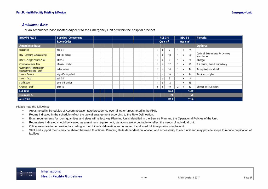
Part B: Health Facility Briefing & Design Emergency Unit
International
Health Facility Guidelines © TAHPI
Part B: Version 5 2017
Page 27
Ambulance Base For an Ambulance base located adjacent to the Emergency Unit or within the hospital precinct
ROOM/ SPACE Standard Component RDL 3-4 RDL 5-6 Remarks Room Codes Qty x m2 Qty x m2
Ambulance Base Optional Reception recl-9-i 1 x 9 1 x 9
Bay - Cleaning (Ambulances) bcl-18-i similar 1 x 18 1 x 36 Optional, External area for cleaning ambulances
Office – Single Person, 9m2 off-s9-i 1 x 9 1 x 9 Manager
Communications Base off-wis-i similar 1 x 12 1 x 20 2, 4 person, shared, respectively
Overnight Accommodation Bedroom/ Ensuite - Staff
ovbr-i oves-i 1 x 14 1 x 14 As required, on-call staff
Store – General stgn-10-i stgn-14-i 1 x 10 1 x 14 Stock and supplies
Store – Drug stdr-5-i 1 x 5 1 x 5
Staff Room srm-15-i similar 1 x 12 1 x 15
Change – Staff chst-10-i 2 x 10 2 x 10 Shower, Toilet, Lockers
Sub Total 109.0 143.0
Circulation % 20 20
Area Total 130.8 171.6
Please note the following:
Areas noted in Schedules of Accommodation take precedence over all other areas noted in the FPU. Rooms indicated in the schedule reflect the typical arrangement according to the Role Delineation. Exact requirements for room quantities and sizes will reflect Key Planning Units identified in the Service Plan and the Operational Policies of the Unit. Room sizes indicated should be viewed as a minimum requirement; variations are acceptable to reflect the needs of individual Unit. Office areas are to be provided according to the Unit role delineation and number of endorsed full time positions in the unit. Staff and support rooms may be shared between Functional Planning Units dependent on location and accessibility to each unit and may provide scope to reduce duplication of
facilities

Part B: Health Facility Briefing & Design Emergency Unit
International
Health Facility Guidelines © TAHPI
Part B: Version 5 2017
Page 28
6 References and Further Reading In addition to the iHFG parts referred to in this document: i.e. Part C - Access, Mobility and OH&S and Part D - Infection Control, readers may find the following useful: Australasian Health Facility Guidelines, Part B Health Facility Briefing and Planning, 0300-
Emergency Unit, Revision 6 2016, refer to website https://healthfacilityguidelines.com.au/health-planning-units
CENA (College of Emergency Nursing Australasia Ltd) Innovative models of emergency care delivery, refer to website http://2016.icen.com.au/category/innovative-models-of-emergency-care-delivery
CDC (Center for Disease Control) US. Guidelines for Environmental Infection Control in Health-Care Facilities, US, refer to website https://www.cdc.gov/infectioncontrol/guidelines/index.html
(Department of Health) (UK) HBN 22; Accident and emergency facilities for adults and children; 2005, refer to website http://www.wales.nhs.uk/sites3/Documents/254/HBN%2022%20v2%20ed2005.pdf
NSW Health, Emergency Department Models of Care, July 2012; refer to website: https://www.aci.health.nsw.gov.au/__data/assets/pdf_file/0005/273794/emergency-department-models-of-care-july-2012.pdf
The Facility Guidelines Institute (US), Guidelines for Design and Construction of Hospitals and Outpatient Facilities, 2014. Refer to website www.fgiguidelines.org

Part B – Health Facility Briefing & Design 80 Endoscopy Unit
International Health Facility Guidelines Version 4 May 2014

International Health Facility Guidelines © TAHPI
Part B: Version 4 2014
Page 2
Table of Contents 80 Endoscopy Unit ......................................................................................................................... 3
1 Introduction ............................................................................................................................................... 3 2 Planning ..................................................................................................................................................... 3 3 Design ........................................................................................................................................................ 7 4 Components of the Unit .......................................................................................................................... 10 5 Schedule of Accommodation – Endoscopy Unit ................................................................................. 11 6 Functional Relationship Diagram – Endoscopy Unit ........................................................................... 18 7 References and Further Reading ........................................................................................................... 19

Endoscopy Unit
International Health Facility Guidelines © TAHPI
Part B: Version 4 2014
Page 3
80 Endoscopy Unit 1 Introduction Description The Endoscopy Unit is a dedicated unit for Endoscopy procedures, a minimally invasive surgical or medical procedure utilising an instrument called an endoscope which is a long flexible tube that has a lens at one end and a fibre optic camera at the other. This allows for the magnification of an image to be projected onto a video screen for viewing and recording. Endoscopy can be used to examine organs or tissue for diagnostic or therapeutic purposes. Endoscopy procedures may involve the taking of biopsies, dilations, retrieval of foreign objects and removal of stones from the bile duct. Procedures undertaken in an Endoscopy Unit may include gastrointestinal endoscopy (such as gastroscopy, colonoscopy, ERCP (Endoscopic Retrograde Cholangiopancreatography), endoscopic ultrasound, bronchoscopy, cystoscopy or ureteroscopy, duodenoscopy, hysteroscopy or other specialties. Endoscopy procedures are generally performed in a controlled aseptic procedure room environment or in an Operating room, using sedation or short acting anaesthetic medication. Some procedures, such as ERCP may also involve diagnostic imaging equipment. Most endoscopy procedures are performed on a same-day basis. Endoscopy procedures have advantages for both the facility and the patient including: reduced demand on operating rooms increased patient throughput as procedures are faster procedures are less invasive (the endoscope is inserted through a natural opening) resulting
in reduced scarring, quick recovery time and rapid discharge. 2 Planning Operational Models The range of options for an Endoscopy Unit may include: a dedicated fully self-contained unit within a hospital a Unit collocated with the Operating Unit with shared facilities a Unit collocated with a specialist clinical service such as Gastroenterology or Respiratory
Medicine, within a hospital a stand-alone centre/ Day Surgery centres, fully self-contained Rural and Remote endoscopy services. Patients undergoing endoscopy procedures may be admitted and discharged on the same day, or transferred from and to a referring unit. The Endoscopy Unit will generally operate on a long day basis, with admissions from early morning. Procedures undertaken on a sessional basis and discharges / transfers into the evening. Planning Models The configuration of the Endoscopy Unit will be dependent on: The procedures performed and the equipment and expertise available The patient population the unit will serve The location of the Unit – within a hospital, attached to another Unit or stand-alone and the
ability to share support services. The Endoscopy Unit should be located with easy access to and from the entry area for patients, visitors, staff and supplies; a ground floor location is desirable. The location within the complex shall permit free access for outpatients and for the transport of inpatients by bed, trolley or

Endoscopy Unit
International Health Facility Guidelines © TAHPI
Part B: Version 4 2014
Page 4
wheelchair. The planning of the Unit should create an efficient flow of patients, staff and supplies through the Unit while maintaining separation of procedure and contaminated areas. Where the endoscopy unit is not located within the main hospital complex, consideration of the provision for enclosed transfer of patients is advisable. Functional Areas The Endoscopy Unit will consist of the following Functional Areas: Entry/ Reception including Waiting area for patients and relatives and access for admission
of patients Assessment/ Preparation area which may include consultation, interview, toilet facilities,
patient changing and preparation rooms for pre-procedure treatments Procedure area Recovery areas including first and second stage recovery Discharge lounge with interview space for consultation and access to toilet facilities Reprocessing area including Clean-up/ Decontamination, Sterilising and scope storage and
bulk storage areas Staff and support areas; including Equipment (mobile II or X-ray machines) and linen bays; in
stand-alone Units this will include supply areas and waste holding.
Entry/ Reception Areas
A covered entrance for patient drop-off and collection after surgery shall be provided. The Entry may be a shared facility providing: a reception/ information counter or desk waiting areas that allow for the separation of paediatric and female patients as appropriate convenient access to wheelchair storage, public toilets and amenities including public
telephones. The reception desk should be located to have a view of the entry and must provide for privacy of patient information and records. Waiting areas should be sized according to the expected numbers of patients and support persons and provide for family waiting and patients in wheelchairs or with limited mobility. If paediatric patients are treated in the Unit, play areas should be included. Assessment/ Preparation Areas Interview and Consultation rooms are required, located with convenient access to the entry and waiting areas to provide for private discussion with patients, review with medical practitioners and anaesthetic consultation prior to endoscopy procedures as required. A patient holding area is required with access to patient changing and toilet facilities. Patients are generally ambulant and may await procedures on a bed or in chairs. Holding areas must provide for male and female separation and patient privacy; screen curtains to bed and chairs spaces is recommended. Storage will be required for patient clothing and valuables. Lockers may be provided or patient clothing and personal items may travel with the patient through each stage of the procedure, recovery and discharge in sealed containers according to the Unit Operational Policy and procedures. A Staff Station should be located to provide close supervision of the holding and Preparation areas. A Preparation room may be required for patients undergoing endoscopy procedures, where patients may change and undergo preparation procedures. If provided, the Preparation room should include: handbasin - clinical bench and cupboards for setting up of procedures adequate space for procedures equipment trolleys examination couch and comfortable chair desk and a computer terminal for review of test results privacy screening.

Endoscopy Unit
International Health Facility Guidelines © TAHPI
Part B: Version 4 2014
Page 5
Patient holding and Preparation room must have close access to patient toilets. At least one accessible toilet must be provided.
Procedure Areas:
In Procedure rooms a clean to dirty workflow must be maintained. The clean area will include sterile supplies and a write-up space with computer and printer to generate endoscopy reports. The room may be purpose designed to accommodate the following: endoscopy 'stack' and video monitor(s) – this equipment contains the light source and video
processor required for the endoscopes to produce images endoscope cabinet with clean endoscopes and accessory equipment such as endoscopy
biopsy forceps, snares, injectors monitoring equipment to allow continuous monitoring of patient condition during procedures anaesthetic equipment and medication used to provide procedural sedation or short acting
anaesthetics diathermy and/or Argon plasma coagulation equipment imaging equipment such as Image Intensifier or C- arm X-ray screening unit depending on
procedures to be performed; imaging equipment may be portable or installed in the room. Procedure rooms may be sized to accommodate the equipment required; the minimum room area recommended for basic endoscopy is 36 m2. Rooms to accommodate ERCP or video equipment will require a larger space for sterile set-up, general anaesthesia and fluoroscopy equipment; a minimum of 42 m2 is recommended. Operating Rooms for Endoscopy shall be fitted out as for a Minor Operating Room, for example, it will be suitable for general anaesthetic with appropriate medical gases, power, lighting, air-conditioning and ventilation. Staff assistance call must be provided. Consideration also needs to be given to the special requirements of imaging and laser equipment if required. A clinical scrub up basin shall be provided outside the entrance to the Procedure/ Operating Room/s for Endoscopy. Procedure/ Operating rooms will require direct access to clean-up and decontamination area for rapid processing of endoscopes and their storage
Recovery Areas
The Stage 1 Recovery should be located with close access from the Procedure rooms. Recovery beds will be under direct observation of staff and provide for close supervision and observation of patients including monitoring and medical gases for patient resuscitation in emergencies. The recommended number of Stage 1 Recovery spaces is 2 bed/trolley spaces per Operating/ Procedure room. A Stage 2 Recovery area will be provided to accommodate patients who have regained consciousness after sedation/ anaesthesia but require further observation. Patients will remain under staff observation until ready for discharge. Patients in this area may recover in trolleys or recliner chairs; each recovery bay should be able to accommodate either trolley or chair. External windows are to be provided in Stage 2 Recovery. Patients in this area may change into street clothes, and close access to private changing rooms or cubicles is required. Provision should be made in the Stage 2 Recovery area for patient refreshments/ beverage bay and access to toilets. Patients may progress to a lounge area to await discharge as required or be discharged directly from the Stage 2 Recovery. The recommended number of Stage 2 Recovery spaces is 3 bed/ chair bays to each Operating/ Procedure room.
Reprocessing Areas
The ability to efficiently and safely process endoscopes is critical to the functioning of the Endoscopy Unit. Endoscope and instrument processing is a multi-step procedure involving decontaminating dirty scopes/ instruments, sterilising of scopes and packaging/ storing of clean scopes. Processing of the endoscopes commences as soon as the procedure is complete – the

Endoscopy Unit
International Health Facility Guidelines © TAHPI
Part B: Version 4 2014
Page 6
scope is wiped down and placed in a closed container and transported to the clean-up area; if any delay in processing is expected the scopes are soaked in an enzyme detergent solution. Decontamination includes leak testing, manual pre-cleaning followed by high level disinfection with a disinfectant solution. Endoscope reprocessing areas should be separate to Procedure/ Operating rooms and a unidirectional dirty to clean workflow must be maintained. A centralised reprocessing area is recommended for efficient handling of endoscopes and appropriate air pressurisation and ventilation. Cleaning and Disinfection areas must be negatively pressured and ventilated to remove vapours of chemicals used in the process. The Cleaning and Disinfection of equipment area will include: sinks for soaking and rinsing sufficiently sized to prevent tight coiling of the endoscope which
may damage the fibre-optic cables in the instrument ultrasonic cleaner for accessory equipment used in procedures Automated endoscope cleaning/ disinfecting machines compressed air to aid drying of endoscopic equipment after cleaning handwashing basin safety eyewash facility stainless steel benches with space to accommodate the length of the endoscopes storage for disinfected scopes on a bench or shelf. The Sterilising/Disinfection area will include an autoclave to sterilise accessory instruments if a sterile supply service is not available. Storage provisions will include adequately sized areas for drugs, sterile stock, consumables, linen, resuscitation trolley and mobile equipment which may include mobile imaging equipment. Storage of sterile items and scopes close to the point of use is recommended. Scope storage areas must be positively pressured and HEPA filtered to prevent contamination of clean endoscopes. Scopes may be stored in properly ventilated and temperature controlled cabinets, preferably a pass-through type, located between reprocessing/ sterilising/disinfection areas and the Operating/ Procedure room. Endoscope cabinets should allow for endoscopes to hang without coiling preventing damage to either end of the scope.
Staff Amenities
Staff amenities will include change rooms with showers, toilets and lockers and a staff lounge, providing a respite area for staff away from patient and procedural areas. Staff amenities areas may be shared with adjacent areas if appropriate. Functional Relationships
External
The Endoscopy Unit will have a close functional relationship with the following: Car parking areas Emergency services Main Entry Outpatients Unit Transit Lounge The stand-alone Unit will also require an area for ambulance access for emergency use and ready access to supply services and waste holding areas.
Internal
Within the Unit, key functional relationships will include: Unidirectional patient flow from arrival at Reception, through Holding, Procedure Rooms,
Recovery rooms, then to the Lounge areas and discharge to home or transfer to other Units Separation of clean and dirty traffic flows particularly in Procedures rooms and
disinfection/sterilising areas

Endoscopy Unit
International Health Facility Guidelines © TAHPI
Part B: Version 4 2014
Page 7
Visibility of patient areas by staff for patient supervision and safety. 3 Design General The design will need to accommodate all types of patients using the Unit as determined by the endorsed clinical service plan; this may include paediatric patients. Provision should also be made for the management of disabled patients and bariatric patients. The design should also be able to accommodate changes in equipment technology as well as changing workload and variability to throughputs. Use of modular components and standard rooms sizes are recommended to provide flexibility of design. Future trends in advanced endoscopy include: highly specialised and more invasive procedures that may require facilities similar to an
operating suite access to overnight inpatient beds or extended stay wards education and training of medical personnel using simulators that may require space
provision or camera and video transmittal from the procedure rooms linked to a remote Meeting/ Tutorial room.
Environmental Considerations
Natural Light
The design of the unit should incorporate external views and natural light as far as possible, particularly to Waiting Areas, pre-operative Holding and Recovery areas. It is recommended that external views and natural light are provided in staff areas such as Staff Rooms, Offices and areas where staff are confined to one location e.g. Reception and Clean-up Rooms. When external views and natural light are provided in patient areas, care must be taken to minimise glare and ensure privacy is not compromised. Sun penetration should be controlled to exclude glare and heat gain or loss. In Procedure Rooms, provision of controlled level of lighting during procedures should be considered.
Privacy
Staff observation of patients and patient privacy must be well-balanced within the Unit. The following features shall be integrated to the design of the Unit: doors and windows to be located appropriately to ensure patient privacy and not comprise
staff security Discreet spaces to enable confidentiality of discussions related to a patient and storage of
patients medical records. privacy screening to bed and chair bays Consultation, Interview and Preparation rooms should not be visible from public or waiting
areas; examination couches should not face the door location of patient change areas to provide direct access to waiting areas to prevent patients
in gowns travelling through public areas when changed before and after procedures separation of male, female and paediatric changing rooms and waiting areas.
Acoustics
The design should reduce the intrusive ambient noise level in the Unit particularly in waiting areas. Acoustic privacy will be required in the following areas: Consultation/ Interview rooms where confidential patient information will be discussed Preparation rooms where patient pre-treatments may be undertaken
Endoscopy Unit
International Health Facility Guidelines © TAHPI
Part B: Version 4 2014
Page 8
Procedure/ Operating rooms. Space Standards
Accessibility
External
The Unit will require a weatherproof vehicle drop-off area with easy access for less-mobile and wheelchair bound patients. Drop off areas may be shared in Units located within a hospital. Access to other units in the facility should be convenient, covered and not through public thoroughfares.
Internal
All patient areas should be wheelchair accessible and designed to comply with relevant accessibility standards. Reception desks and Staff stations should provide wheelchair accessible counters.
Ergonomics
The Endoscopy Unit should be designed with consideration to ergonomics to ensure an optimal working environment. Design and dimensions of Staff Stations and work areas must ensure privacy and security for patients, visitors and staff. Refer also to Part C of these Guidelines.
Size of Unit:
The number of endoscopy rooms required in the Unit can be calculated using the workload per annum (number of procedures per year according to local population data) divided by the workload per Endoscopy room (the average number of cases per working day). Generally, larger endoscopy units should contain one procedure room per 1,000 to 1,500 procedures performed annually. Safety and Security Internal spaces and zones should offer a high standard of security through grouping functions, controlling access and egress from the Unit and providing optimum observation for staff. Patient holding, procedural and recovery areas will require restricted access to prevent unauthorised entry by visitors or others. Protective clothing and safety equipment including an emergency eye wash station must be available for staff undertaking cleaning/ disinfection due to the use of chemicals in the disinfection process. Finishes The aesthetics of the Unit should be warm and non-institutional as far as possible. The following additional factors should be considered in the selection of finishes: acoustic properties durability ease of cleaning infection control fire safety movement of equipment. The floor finishes in all patient care and treatment areas should have a non-slip surface and be impermeable to water and body fluids. Refer also to Part C and Part D of these Guidelines Equipment, Fixtures and Fittings

Endoscopy Unit
International Health Facility Guidelines © TAHPI
Part B: Version 4 2014
Page 9
The Unit should have sufficient endoscopes and accessory equipment to allow for proper cleaning, disinfection and sterilising to be performed. The quantities of equipment and instruments should also allow for some equipment to be unavailable when awaiting repair or replacement. It is recommended that only fully immersible endoscopes are used. Automated endoscopic cleaning/ disinfection equipment will require consideration regarding optimum location and services requirements such as water, power and drainage; equipment will be installed according to manufacturers’ specifications. Refer also to Standard Components Room Data Sheets and Room Layout Sheets for Furniture, Fittings Fixtures and Equipment requirements. Building Services Requirements
Water Treatment
Water filtration is required for cleaning of endoscopes and to supply automated endoscope cleaning/ disinfection machines. Water with a high mineral content is unsuitable for rinsing flexible endoscopes and accessory equipment due to mineral deposits that may permanently damage the equipment. Provide water filtration to sinks and automated endoscope cleaning machines according to equipment manufacturers’ specifications.
Air Filtration
Ventilation and exhaust is required to extract toxic vapours in Clean-up/ disinfection areas. Hazardous chemicals such as gluteraldehyde, OPA or paracetic acid should be used in a closed system with air extraction such as a fume cabinet
Radiation Safety and Shielding
If the Unit is undertaking procedures involving imaging, plans and specifications will require assessment for radiation protection by a certified physicist or other qualified expert as required by the relevant Radiation and Nuclear Safety Agency. The radiation protection assessment will specify the type, location and amount of radiation protection required according to the final equipment selections and layout. Radiation protection requirements must be incorporated into the final specifications and building plans.
Information Technology (IT) and Communications
It is vital to provide reliable and effective IT/ Communications service for efficient operation of the Unit. The following items relating to IT/ Communication should be addressed in the design: Appointment systems Patient Administration System (PAS) including clinical records, pathology results, PACS Scheduling systems to manage Procedure or operating room sessions Endoscopy procedure recording and printing of reports within the Procedure room Materials management including bar coding for supplies, x-rays and records Management and statistical information required for administration and quality assurance. Education and training utilisation of video and camera equipment
Nurse/ Emergency Call
Nurse Call and Emergency Call facilities must be provided in all patient areas (e.g. bed/chair spaces, toilets, showers) and procedure areas in order for patients and staff to request urgent assistance. The individual call buttons will alert to a central module situated at or adjacent to the Staff Station. Calls must be audible in Utilities, Staff Room and Meeting Rooms within the Unit. The alert to staff members should be done in a discreet manner at all times. Infection Control Consideration of Infection Control is important in the design of this Unit. Separation of clean and dirty workflows in treatment and clean-up areas and separation of patient care areas and contaminated spaces and equipment is critical to the function of the Unit and to prevent cross infection. Procedure/ Operating rooms will be used for a variety of clients whose infection status may be unknown. Standard precautions must be taken for all clients regardless of their diagnosis

Endoscopy Unit
International Health Facility Guidelines © TAHPI
Part B: Version 4 2014
Page 10
or presumed infectious status. Staff hand washing facilities, including disposable paper towels, must be readily available. Refer to Part D of these Guidelines for further information. 4 Components of the Unit The Endoscopy Unit will consist of Standard Components to comply with details described in these Guidelines. Refer to Standard Components Room Data Sheets and Room Layout Sheets as identified in the Schedule of Accommodation.

Endoscopy Unit
International Health Facility Guidelines © TAHPI
Part B: Version 4 2014
Page 11
5 Schedule of Accommodation – Endoscopy Unit Endoscopy Unit within a hospital complex with 2, 4 & 6 Rooms
ROOM/ SPACE Standard Component RDL 2 & 3 RDL 4 RDL 5 RDL 6 Remarks
Room Codes N/A Qty x m2 Qty x m2 Qty x m2
Entry/ Reception 2 Rooms 4 Rooms 6 Rooms
Reception/ Clerical RECL-9-I RECL-15-I RECL-20-I 1 x 9 1 x 15 1 x 20
Waiting WAIT-10-I WAIT-15-I WAIT-25-I 1 x 10 1 x 15 1 x 25 May be divided for separate Female areas as applicable
Waiting - Family WAIT-10-I WAIT-15-I WAIT-25-I 1 x 10 1 x 15 1 x 25
Play Area PLAP-8-I PLAP-10-I 1 x 8 1 x 10 1 x 10 Optional; if Paediatric patients included
Bay - Wheelchair Park BWC-I 1 x 4 1 x 4 1 x 4 May share with Main facility if located close
Office - Single Person OFF-S9-I 1 x 9 1 x 9 1 x 9 Manager; Note 1
Interview Room - Family INTF-I 1 x 12 1 x 12 1 x 12 May be co-located with Assessment area
Parenting Room PAR-I 1 x 6 1 x 6 1 x 6 May share with Main facility if located close
Store - Files STFS-8-I STFS-10-I 1 x 8 1 x 10 1 x 10 For stationery/ clinical records, fax, photocopier
Toilet - Accessible WCAC-I 1 x 6 1 x 6 1 x 6 May share with Main facility if located close
Toilet - Public WCPU-3-I 2 x 3 2 x 3 2 x 3 May share with Main facility if located close
Sub Total 88.0 108.0 133.0
Circulation % 35 35 35
Area Total 118.8 145.8 179.6
Assessment/ Preparation Areas
Consult Room CONS-I 1 x 14 2 x 14 3 x 14 Combined Consult/ Examination Room
Meeting Room - Small MEET-9-I 1 x 9 1 x 9 2 x 9 Optional Interviews, private discussions
Treatment/ Preparation Room TRMT-I CONS-I 1 x 14 2 x 14 2 x 14 Optional; locate near Patient Ensuite
Change - Patient (Male/ Female) CHPT-12-I 2 x 12 2 x 12 2 x 15
Patient Bay - Holding PBTR-H-10-I 2 x 10 2 x 10 4 x 10
Waiting - Changed Patients (M/F) WAIT-SUB-I WAIT-10-I WAIT-15-I 2 x 5 2 x 10 2 x 15 comfortable seating
Bay - Handwasing/PPE BHWS-PPE-I 1 x 1.5 1 x 1.5 1 x 1.5
Bay - Linen BLIN-I 1 x 2 1 x 2 1 x 2
Dirty Utility DTUR-S-I 1 x 8 1 x 8 1 x 8
Ensuite - Toilet/ Shower ENS-ST-I 1 x 5 1 x 5 1 x 5 Locate adjacent to Treatment/ Preparation

Endoscopy Unit
International Health Facility Guidelines © TAHPI
Part B: Version 4 2014
Page 12
ROOM/ SPACE Standard Component RDL 2 & 3 RDL 4 RDL 5 RDL 6 Remarks
Room Codes N/A Qty x m2 Qty x m2 Qty x m2
Staff Station/ Clean Utility SSCU-I 1 x 9 1 x 9 1 x 9 to oversight holding and changed waiting areas; review size if Clean Utility is shared
Store - General STGN-6-I 1 x 6 1 x 6 1 x 6
Toilet - Accessible, Patient (M/F) WCAC-I 1 x 6 1 x 6 1 x 6
Toilet - Patient (M/F) WCPT-I 1 x 4 1 x 4 1 x 4 May share with Recovery if close
Sub Total 132.5 170.5 229.5
Circulation % 35 35 35
Area Total 178.9 230.2 309.8
Procedure Areas 2
Rooms
4 Rooms
6
Rooms
Procedure/ Operating Room ORMS-I 2 x 36 2 x 36 2 x 36 general Endoscopy
Operating Room ORGN-I 2 x 42 4 x 42 specialised Endoscopy, as required
Clean-up, Shared CLUP-15-I 1 x 15 2 x 15 3 x 15 Shared between rooms, for immediate post procedure
Scrub-up SCRB-6-I 2 x 6 4 x 6 6 x 6
Bay - Linen BLIN-I 1 x 2 1 x 2 1 x 2
Bay - Mobile Equipment BMEQ-2.5-I 2 x 2.5 4 x 2.5 6 x 2.5 also for imaging equipment
Store - Sterile Stock STSS-12-I 1 x 12 2 x 12 3 x 12
Store - Equipment STEQ-6-I STEQ-10-I 1 x 6 1 x 10 2 x 10 Additional specialist equipment
Sub Total 72.0 72.0 394.0
Circulation % 35 35 35
Area Total 97.2 97.2 531.9
Recovery Areas
Patient Bay - Recovery Stage 1 PBTR-RS1-12-I 4 x 12 8 x 12 12 x 12 2 Beds per Procedure/ OR; Separate M/ F as required
Patient Bay - Recovery Stage 2 PBTR-H-10-I 6 x 10 12 x 10 18 x 10 3 Beds/Chairs per Procedure/OR; Separate M/ F as required
Recovery Lounge LNPT-RS2-I 4 x 6 6 x 6 8 x 6 Optional; according to service plan; screened bays
Bay - Beverage BBEV-OP-I 1 x 4 1 x 4 1 x 4
Bay - Handwashing/PPE BHWS-PPE-I 3 x 1.5 7 x 1.5 10 x 1.5
Bay - Linen BLIN-I 1 x 2 2 x 2 2 x 2
Bay - Resuscitation Trolley BRES-I 1 x 1.5 1 x 1.5 1 x 1.5
Clean Utility CLUR-8-I CLUR-12-I 1 x 8 1 x 12
Dirty Utility DTUR-S-I DTUR-10-I 1 x 8 1 x 8 1 x 10
Property Bay - Patient PROP-2-I 1 x 2 2 x 2 2 x 2 separate M/F areas

Endoscopy Unit
International Health Facility Guidelines © TAHPI
Part B: Version 4 2014
Page 13
ROOM/ SPACE Standard Component RDL 2 & 3 RDL 4 RDL 5 RDL 6 Remarks
Room Codes N/A Qty x m2 Qty x m2 Qty x m2
Staff Station SSTN-10-I SSTN-20-I 1 x 10 1 x 20
Staff Station/ Clean Utility SSCU-I 1 x 9
Store - General STGN-6-I STGN-8-I 1 x 6 1 x 8 1 x 8
Store - Equipment STEQ-10-I STEQ-15-I 1 x 10 1 x 10 1 x 15 with power for equipment recharging
Toilet - Accessible WCAC-I 1 x 6 1 x 6 2 x 6
Toilet - Patient (M/F) WCPT-I 1 x 4 2 x 4 2 x 4
Sub Total 189.0 334.0 485.5
Circulation % 35 35 35
Area Total 255.2 450.9 655.4
Reprocessing Areas
Bay - Handwashing BHWS-B-I 1 1 1 1 1 1
Clean-up/ Decontamination 1 x 15 1 x 30 1 x 30 Endoscopes and instruments
Sterilising 1 x 6 1 x 10 1 x 20 Low temp sterilisers and autoclave as required
Store - Endoscope 2 x 2 4 x 2 6 x 2 1 endo store/cupboard per Procedure room/ OR – or stored in single area next to disinfection area
Sub Total 26.0 49.0 63.0
Circulation % 35 35 35
Area Total 35.1 66.2 85.1
Staff and Support Areas
Change - Staff (M/F) CHST-10-I CHST-14-I CHST-20-I 2 x 10 2 x 14 2 x 20 Toilets, Shower and Lockers
Cleaner's Room CLRM-5-I 1 x 5 1 x 5 1 x 5
Disposal Room DISP-5-I DISP-8-I 1 x 5 1 x 8 1 x 8 May be shared with adjacent Unit
Meeting Room MEET-12-I MEET-L-15-I 1 x 12 1 x 12 1 x 15 Optional; may be shared
Office - Single Person, 9m2 OFF-S9-I 1 x 9 1 x 9 2 x 9 Note 1; Nursing/ Medical
Office - 2 Person, Shared OFF-2P-I 1 12 1 12 Note 1; Clerical support
Property Bay - Staff PROP-2-I 1 x 2 2 x 2 2 x 2 May be shared with adjacent Unit
Staff Room SRM-15-I SRM-20-I SRM-25-I 1 x 15 1 x 25 1 x 30 May be shared with adjacent Unit
Sub Total 419.4 735.2 1020.5
Circulation % 25 25 25
Area Total 85.0 128.75 165.0

Endoscopy Unit
International Health Facility Guidelines © TAHPI
Part B: Version 4 2014
Page 14
ROOM/ SPACE Standard Component RDL 2 & 3 RDL 4 RDL 5 RDL 6 Remarks
Room Codes N/A Qty x m2 Qty x m2 Qty x m2
Grand Total 770.1 1119.0 1926.8
Note 1: Offices and workstation to be provided according to the number of approved full time positions within the Unit requiring access to this space Stand-alone Endoscopy Unit with 2, 4 & 6 rooms
ROOM/ SPACE Standard Component RDL 2 & 3 RDL 4 RDL 5 RDL 6 Remarks
Room Codes N/A Qty x m2 Qty x m2 Qty x m2
Entry/ Reception 2
Rooms
4 Rooms
6
Rooms
Airlock - Entry AIRLE-10-I 1 x 10 1 x 10 1 x 10 with covered drop -off area
Reception/ Clerical RECL-9-I RECL-15-I RECL-20-I 1 x 9 1 x 15 1 x 20
Waiting WAIT-10-I WAIT-15-I WAIT-25-I 1 x 10 1 x 15 1 x 25 May be divided for separate Female areas as applicable
Waiting - Family WAIT-10-I WAIT-15-I WAIT-25-I 1 x 10 1 x 15 1 x 25
Play Area PLAP-8-I PLAP-10-I 1 x 8 1 x 10 1 x 10 Optional; if Paediatric patients included
Bay - Wheelchair Park BWC-I 1 x 4 1 x 4 1 x 4
Office - Single Person OFF-S9-I 1 x 9 1 x 9 1 x 9 Manager; Note 1
Interview Room - Family INTF-I 1 x 12 1 x 12 1 x 12 May be co-located with Assessment area
Parenting Room PAR-I 1 x 6 1 x 6 1 x 6
Store - Files STFS-8-I STFS-10-I 1 x 8 1 x 10 1 x 10 For stationery/ clinical records, fax, photocopier
Toilet - Accessible WCAC-I 1 x 6 1 x 6 1 x 6
Toilet - Public WCPU-3-I 2 x 3 2 x 3 2 x 3
Sub Total 98.0 118.0 143.0
Circulation % 35 35 35
Area Total 132.3 159.3 193.1
Assessment/ Preparation Areas
Consult Room CONS-I 1 x 14 2 x 14 3 x 14 Combined Consult/ Examination Room
Meeting Room - Small MEET-9-I 1 x 9 1 x 9 2 x 9 Optional Interviews, private discussions
Treatment/ Preparation Room TRMT-I CONS-I 1 x 14 2 x 14 2 x 14 Optional; locate near Patient Ensuite
Change - Patient (Male/ Female) CHPT-12-I 2 x 12 2 x 12 2 x 15
Patient Bay - Holding PBTR-H-10-I 2 x 10 2 x 10 4 x 10
Waiting - Changed Patients (M/F) WAIT-SUB-I WAIT-10-I WAIT-15-I 2 x 5 2 x 10 2 x 15 comfortable seating

Endoscopy Unit
International Health Facility Guidelines © TAHPI
Part B: Version 4 2014
Page 15
ROOM/ SPACE Standard Component RDL 2 & 3 RDL 4 RDL 5 RDL 6 Remarks
Room Codes N/A Qty x m2 Qty x m2 Qty x m2
Bay - Handwasing/PPE BHWS-PPE-I 1 x 1.5 1 x 1.5 1 x 1.5
Bay - Linen BLIN-I 1 x 2 1 x 2 1 x 2
Dirty Utility DTUR-S-I 1 x 8 1 x 8 1 x 8
Ensuite - Toilet/ Shower ENS-ST-I 1 x 5 1 x 5 1 x 5 Locate adjacent to Treatment/ Preparation
Staff Station/ Clean Utility SSCU-I 1 x 9 1 x 9 1 x 9 to oversight holding and changed waiting areas
Store - General STGN-6-I 1 x 6 1 x 6 1 x 6
Toilet - Accessible, Patient (M/F) WCAC-I 1 x 6 1 x 6 1 x 6
Toilet - Patient (M/F) WCPT-I 1 x 4 1 x 4 1 x 4 May share with Recovery if close
Sub Total 132.5 170.5 229.5
Circulation % 35 35 35
Area Total 178.9 230.2 309.8
Procedure Areas 2 Rooms 4 Rooms 6 Rooms
Procedure/ Operating Room ORMS-I 2 x 36 2 x 36 2 x 36 general Endoscopy
Operating Room ORGN-I 2 x 42 4 x 42 specialised Endoscopy
Clean-up, Shared CLUP-15-I 1 x 15 2 x 15 3 x 15 Shared between rooms, for immediate post procedure
Scrub-up SCRB-6-I SCRB-8-I 2 x 6 4 x 6 6 x 6 May be shared between Operating/ Procedure rooms
Bay - Linen BLIN-I 1 x 2 1 x 2 1 x 2
Bay - Mobile Equipment BMEQ-2.5-I 2 x 2.5 4 x 2.5 6 x 2.5 also for imaging equipment
Store - Sterile Stock STSS-12-I 1 x 12 2 x 12 3 x 12
Store - Equipment STEQ-6-I STEQ-10-I 1 x 6 1 x 10 2 x 10 Additional specialist equipment
Sub Total 72.0 72.0 394.0
Circulation % 35 35 35
Area Total 97.2 97.2 531.9
Recovery Areas
Patient Bay - Recovery Stage 1 PBTR-RS1-12-I 4 x 12 8 x 12 12 x 12 2 Beds per Procedure/ OR; Separate M/ F as required
Patient Bay - Recovery Stage 2 PBTR-H-10-I 6 x 10 12 x 10 18 x 10 3 Beds/Chairs per Procedure/OR; Separate M/ F as required
Recovery Lounge LNPT-RS2-I 4 x 6 6 x 6 8 x 6 Optional; according to service plan; screened bays
Bay - Beverage BBEV-OP-I 1 x 4 1 x 4 1 x 4
Bay Handwashing/PPE BHWS-PPE-I 3 x 1.5 7 x 1.5 10 x 1.5
Bay - Linen BLIN-I 1 x 2 2 x 2 2 x 2
Bay - Resuscitation Trolley BRES-I 1 x 1.5 1 x 1.5 1 x 1.5

Endoscopy Unit
International Health Facility Guidelines © TAHPI
Part B: Version 4 2014
Page 16
ROOM/ SPACE Standard Component RDL 2 & 3 RDL 4 RDL 5 RDL 6 Remarks
Room Codes N/A Qty x m2 Qty x m2 Qty x m2
Clean Utility CLUR-8-I CLUR-12-I 1 x 8 1 x 12
Dirty Utility DTUR-S-I DTUR-10-I 1 x 8 1 x 8 1 x 10
Property Bay - Patient PROP-2-I 1 x 2 2 x 2 2 x 2 separate M/F areas
Staff Station SSTN-10-I SSTN-20-I 1 x 10 1 x 20
Staff Station/ Clean Utility SSCU-I 1 x 9 Suitable for small procedures areas
Store - General STGN-6-I STGN-8-I 1 x 6 1 x 8 1 x 8
Store - Equipment STEQ-10-I STEQ-15-I 1 x 10 1 x 10 1 x 15 with power for equipment recharging
Toilet - Accessible WCAC-I 1 x 6 1 x 6 2 x 6
Toilet - Patient (M/F) WCPT-I 1 x 4 2 x 4 2 x 4
Sub Total 189.0 334.0 485.5
Circulation % 35 35 35
Area Total 255.2 450.9 655.4
Reprocessing Areas
Bay - Handwashing BHWS-B-I 1 x 1 1 x 1 1 x 1
Clean-up/ Decontamination 1 x 15 1 x 30 1 x 30 Endoscopes and instruments
Sterilising 1 x 6 1 x 10 1 x 20 Low temp sterilisers and autoclave as required
Endoscope Store 2 x 2 4 x 2 6 x 2 1 endo store/cupboard per Procedure room/ OR – or stored in single area next to disinfection area
Sub Total 26.0 49.0 63.0
Circulation % 35 35 35
Area Total 35.1 66.2 85.1
Staff and Support Areas
Change - Staff (M/F) CHST-10-I CHST-14-I CHST-20-I 2 x 10 2 x 14 2 x 20 Toilets, Shower and Lockers
Communications Room COMM-I 1 x 0 1 x 0 1 x 0 Size dependant on IT equipment; area part of Plant
Cleaner's Room CLRM-5-I 1 x 5 1 x 5 1 x 5
Disposal Room DISP-5-I DISP-8-I 1 x 5 1 x 8 1 x 8 includes dirty Linen Holding
Loading Dock LODK-I (sim) 1 x 10 1 x 15 1 x 20 May share common facilities if applicable
Linen Holding - Clean DISP-8-I DISP-10-I 1 x 8 1 x 10 1 x 10
Meeting Room MEET-12-I MEET-L-15-I 1 x 12 1 x 12 1 x 15 Optional; may be shared
Office - Single Person, 9m2 OFF-S9-I 1 x 9 1 x 9 2 x 9 Note 1; Nursing/ Medical
Office - 2 Person, Shared OFF-2P-I x 1 x 12 1 x 12 Note 1; Clerical support

Endoscopy Unit
International Health Facility Guidelines © TAHPI
Part B: Version 4 2014
Page 17
ROOM/ SPACE Standard Component RDL 2 & 3 RDL 4 RDL 5 RDL 6 Remarks
Room Codes N/A Qty x m2 Qty x m2 Qty x m2
Property Bay - Staff PROP-2-I 1 x 2 2 x 2 2 x 2
Staff Room SRM-15-I SRM-20-I SRM-25-I 1 x 15 1 x 25 1 x 30
Store - Gas Bottles STGB-F-I (sim) 1 x 8 1 x 10 1 x 10
Store - Main STGN-10-I STGN-15-I STGN-20-I 1 x 10 1 x 15 1 x 20 Consumables
Store - Medical Records STFS-10-I STFS-20-I 1 x 10 1 x 20 1 x 20
Waste Holding/ Recyclables WACO-I 1 x 15 1 x 20 1 x 30 General, Contaminated, Sharps & Recyclables
Sub Total 480.4 825.2 1130.5
Circulation % 25 25 25
Area Total 161.3 241.25 302.5
Grand Total 859.9 1245.0 2077.8
Note 1: Offices and workstation to be provided according to the number of approved full time positions within the Unit requiring access to this space Please note the following: Areas noted in Schedules of Accommodation take precedence over all other areas noted in the FPU. Rooms indicated in the schedule reflect the typical arrangement according to the Role Delineation. Exact requirements for room quantities and sizes will reflect Key Planning Units identified in the Service Plan and the Operational Policies of the Unit. Room sizes indicated should be viewed as a minimum requirement; variations are acceptable to reflect the needs of individual Unit. Staff and support rooms may be shared between Functional Planning Units dependent on location and accessibility to each unit and may provide scope to
reduce duplication of facilities.

Endoscopy Unit
International Health Facility Guidelines © TAHPI
Part B: Version 4 2014
Page 18
6 Functional Relationship Diagram – Endoscopy Unit Unit located within a hospital
Stand-alone Unit

Endoscopy Unit
International Health Facility Guidelines © TAHPI
Part B: Version 4 2014
Page 19
7 References and Further Reading Australasian Health Facility Guidelines, Part B Health Facility Briefing and Planning, Day
Surgery/ Procedure Unit, Rev 4, 2012; refer to website www.healthfacilitydesign.com.au Design and Management of gastrointestinal endoscopy units, Peter B Cotton, ed, 2012;
Gastrohep ebook refer to www.gastrohep.com Digestive Diseases - Endoscopy Service. Design Guide, Department of Veteran Affairs,
Office of Construction & Facilities Management, USA, 2011 Endoscopy, Standards for Endoscopy Facilities and Services, GESA Gastroenterological
Society of Australia, 2011 Endoscopy Unit Design, Infection Prevention & Control Guidelines, Public Health Agency of
Canada; www.phac-aspc.gc.ca Guidelines for Design and Construction of Health Care Facilities; The Facility Guidelines
Institute, 2010 Edition; www.fgiguidelines.org DH (Department of Health) (UK) Health Building Note HBN 52 Accommodation for day care
Endoscopy unit, 2008, refer to www.estatesknowledge.dh.gov.uk

Part B – Health Facility Briefing & Design 85 Engineering & Maintenance Unit
International Health Facility Guidelines Version 4 May 2014
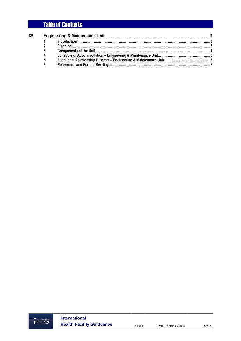
International Health Facility Guidelines © TAHPI
Part B: Version 4 2014
Page 2
Table of Contents 85 Engineering & Maintenance Unit ............................................................................................. 3
1 Introduction ............................................................................................................................................... 3 2 Planning ..................................................................................................................................................... 3 3 Components of the Unit ............................................................................................................................ 4 4 Schedule of Accommodation – Engineering & Maintenance Unit ........................................................ 5 5 Functional Relationship Diagram – Engineering & Maintenance Unit ................................................. 6 6 References and Further Reading ............................................................................................................. 7

Engineering & Maintenance Unit
International Health Facility Guidelines © TAHPI
Part B: Version 4 2014
Page 3
85 Engineering & Maintenance Unit 1 Introduction General All facilities, no matter how large or small, will require environmental support services in the form of: Maintenance services Engineering services Cleaning services, - external areas, windows & building fabric (refer to Housekeeping Unit for
Cleaning of internal areas) Waste disposal (refer to Waste Management Unit for specific details) Gardening services Storage. Description A Maintenance Service shall be provided. It may be in-house or contracted, with an on-call repair service. The complexity of the services provided by the facility will dictate the nature and extent of the Maintenance Service required. The Maintenance Service is provided to effect preventative maintenance and repairs to all elements of the facility, from the building fabric to items of specialist equipment. Areas that require a 24 hour per day, 7 day per week 'on-call' maintenance service are: Medical gases and suction systems Lifts Fire systems Bio-electronic equipment Any life-support systems Emergency power systems Boiler plant Telecommunications systems including public address, fire warning alarm systems, Nurse/
Emergency Call, Duress call systems The potential life threatening nature of the failure of any of the above systems justifies a 24 hour service. 2 Planning Functional Areas The Engineering and Maintenance Unit may consist of the following Functional Areas dependent on the Operational Policy and service demand: Workshop areas, which may include separate areas for carpentry, mechanical, plumbing and
electrical services Storage areas for all specialty services/trades including paint, gardening and flammable
liquids Office area for administrative and clerical activities Staff amenities which may be shared
Workshop Areas
Maintenance Workshop

Engineering & Maintenance Unit
International Health Facility Guidelines © TAHPI
Part B: Version 4 2014
Page 4
A general maintenance Workshop shall be provided for repair and maintenance. Sufficient space is required for a workbench, drill press, angle grinder, stainless steel trough, tool peg board, storage cabinets. Floor space is also required for the standing of equipment during repairs. Adequate lighting, power and ventilation are required. Note: If Maintenance Services are externally contracted, then a Workshop is not required. Maintenance workshops incorporating carpentry, metal fabrication, plumbing, refrigeration or other noise generating trades shall be acoustically isolated from non-maintenance areas.
Electronics Workshop
A separate workshop may be provided specifically for the storage, repair and testing of electronic and other medical equipment. The amount of space and type of utilities will vary with the type of equipment involved and types of service and maintenance contracts used.
Storage Areas
A storage room shall be provided for the storage of building maintenance supplies. Storage for solvents and flammable liquids shall comply with relevant statutory requirements.
Gardener's Facilities
A room or shed shall be provided for the storage of all the necessary gardening equipment and material.
Staff Areas
Offices
Offices are required for full time management staff including: Engineer/ Head of Department, with file space and provision for protected storage of facility
drawings, records and manuals Head Gardener, depending on the size of the facility.
Staff Facilities
Staff Facilities will include: Hand washing facilities located close to all workshop area Toilet, Shower and lockers, that may be shared with the main hospital Staff Room that may be shared with the main hospital Functional Relationships The Engineering & Maintenance Unit should be located on the ground floor to facilitate delivery and dispatch of heavy items of equipment. Access to a loading dock is desirable. The Unit will require ready access to all areas of the hospital and in particular, to plant rooms and areas. Depending on the size of the Unit and the Operational Policy, considerable noise and fumes may be generated by the Unit and care should be taken in locating the Unit relative to other units such as Inpatient Accommodation Units. 3 Components of the Unit Standard Components The Engineering and Maintenance Unit will consist of Standard Components to comply with details in these Guidelines. Refer also to Standard Components Room Data Sheets and Room Layout Sheets.

Engineering & Maintenance Unit
International Health Facility Guidelines © TAHPI
Part B: Version 4 2014
Page 5
4 Schedule of Accommodation – Engineering & Maintenance Unit The following Generic Schedule of Accommodation is for a typical Engineering & Maintenance Unit in a Level 4 Hospital with 120 Beds and a range of diagnostic and treatment facilities. This schedule assumes that all services are provided in-house. Note: For maximum functionality, some of the workshop areas should be combined into one large area.
ROOM / SPACE Standard Level 4 Remarks
Component Qty x m2
OFFICE - SINGLE PERSON 12 m2 OFF-S12-I 1 x 12 If Engineer on staff
STORE - PLAN FILE STGN-12-I 1 x 12
Optional
STORE - FLAMMABLE LIQUID STFL-I 1 x 9 Or Steel Cupboard
WORKSHOP/STORE - GARDENING WSS-GAR-I 1 x 12
PAINTER'S STORE STFL-I 1 x 9 Store flammable liquids in
STGN-9-I optional appropriate cabinets
WORKSHOP - CARPENTRY WK-CA-I 1 x 30 Including storage
optional
WORKSHOP - MECHANICAL WK-MC-I 1 x 30 Including storage
optional
WORKSHOP - PLUMBING WK-PL-I 1 x 30 Including storage
optional
CIRCULATION ALLOWANCE % 15%
Shared Areas
ROOM / SPACE Standard Level 4 Remarks
Component Qty x m2
BAY - CLEAN-IP BCL-1.5-I 1 x 1.5
STAFF ROOM SRM-15-I 1 x 15
TOILET - STAFF WCST-I 2 x 3 Separate Male/ Female
where applicable
Please note the following: Areas noted in Schedules of Accommodation take precedence over all other areas noted in
the FPU. Rooms indicated in the schedule reflect the typical arrangement according to the Role
Delineation. Exact requirements for room quantities and sizes will reflect Key Planning Units identified in
the Service Plan and the Operational Policies of the Unit. Room sizes indicated should be viewed as a minimum requirement; variations are acceptable
to reflect the needs of individual Unit. Office areas are to be provided according to the Unit role delineation and endorsed full time
positions in the Unit Staff and support rooms may be shared between Functional Planning Units dependant on
location and accessibility to each unit and may provide scope to reduce duplication of facilities.

Engineering & Maintenance Unit
International Health Facility Guidelines © TAHPI
Part B: Version 4 2014
Page 6
5 Functional Relationship Diagram – Engineering & Maintenance Unit

Engineering & Maintenance Unit
International Health Facility Guidelines © TAHPI
Part B: Version 4 2014
Page 7
6 References and Further Reading Australasian Health Facility Guidelines, Part B Health Facility Briefing and Planning, Rev 4,
2012; refer to website www.healthfacilitydesign.com.au Guidelines for Design and Construction of Health Care Facilities; The Facility Guidelines
Institute, 2010 Edition; refer to website www.fgiguidelines.org .

Part B – Health Facility Briefing & Design 95 Housekeeping Unit
International Health Facility Guidelines Version 4 May 2014

International Health Facility Guidelines © TAHPI
Part B: Version 4 2014
Page 2
Table of Contents 95 Housekeeping Unit ................................................................................................................... 3
1 Introduction ............................................................................................................................................... 3 2 Planning ..................................................................................................................................................... 3 3 Design ........................................................................................................................................................ 4 4 Components of the Unit ............................................................................................................................ 4 5 Schedule of Accommodation – Housekeeping Unit .............................................................................. 5 6 Functional Relationship Diagram – Housekeeping Unit ........................................................................ 6 7 References and Further Reading ............................................................................................................. 7

Housekeeping Unit
International Health Facility Guidelines © TAHPI
Part B: Version 4 2014
Page 3
95 Housekeeping Unit 1 Introduction Description The Housekeeping Unit is responsible for maintaining the cleanliness of the facility in all areas including Inpatient Units and all public areas. The cleaning service may be contracted or in-house. In addition to the Cleaner's Rooms provided in the specialist Units, others may be required throughout the facility to maintain a clean and sanitary environment. 2 Planning Operational Models
Hours of Operation
The Housekeeping Unit will generally operate up to 12 hours per day, 7 days per week with some specific cleaning services operating 24 Hours a day. Some Hospital Units may be cleaned at night to avoid disruption to the Unit during the day.
Location
The Unit will be located in the service area of the facility. Functional Areas A typical hospital Housekeeping Unit comprises the following: Staff Areas including:
Manager's Office Meeting room for Briefing, Training and staff meetings Sign-on bay for Cleaning staff, optional depending on the Unit Operational Policy
Storage Areas for: Cleaner's Equipment, such as trolleys, buckets, mops, brooms Bulk cleaning materials, consumable supplies including soap and paper towel
supplies for handbasins Trolley wash area that may be shared with other service units. The above facilities are not mandatory. These facilities may be centralised or departmentalised. When provided, these should be sized adequately for the number of staff and the amount of equipment stored. Storage areas may be shared with the Supply Unit
Staff Areas
Offices and Meeting Rooms
Provide Offices for senior Full time staff such as Manager and Supervisors according to Standard Components. Meeting Rooms are to comply with Standard Components.
Sign-On Bay
A recessed area may be required for staff to sign-on, check and record rosters. The Sign-on Bay shall be a minimum of four m2. The Sign-on Bay should be located in a discreet area with ready access to staff entry area and circulation corridor. It may also be located close to the Unit Manager's Office. The Sign-on Bay will require the following fittings and services:

Housekeeping Unit
International Health Facility Guidelines © TAHPI
Part B: Version 4 2014
Page 4
bench at standing height pin board for display of rosters (or computer for computerised rosters) computer terminal (optional) power and data outlets for computers as required
Trolley Wash
An area shall be provided for washing of trolleys and cleaners equipment and may be shared with other service unit. The Trolley Wash area should be located in the service area. The trolley washing area will require: Smooth, impervious and easily cleanable surfaces to walls and ceiling Impervious and non-slip finishes to the floor Hot and cold water outlets. Functional Relationships The Housekeeping Unit will require ready access to: the Waste Management Area the Loading Dock Laundry/ Linen Handling areas Storage areas for cleaning supplies. 3 Design Equipment The Housekeeping Unit will require sufficient cleaning equipment for cleaning and maintaining all type of finishes installed in the facility including vinyl, floors, carpeted floors and other finishes. This may include polishers, scrubbers, vacuum cleaners, steam carpet cleaners. Infection Control Cleaning staff will require ready access to staff handwashing basins. Hand basins may be located within the Cleaner’s Rooms or in adjacent corridor areas. Safety and Security All electrical cleaning equipment should have prominent shut off switches for staff safety. Storage areas for equipment and supplies must be locked with access restricted to authorised staff. 4 Components of the Unit The Cleaning/ Housekeeping Unit will consist of Standard Components to comply with details described in these Guidelines. Refer to Standard Components Room Data Sheets and Room Layout Sheets.

Housekeeping Unit
International Health Facility Guidelines © TAHPI
Part B: Version 4 2014
Page 5
5 Schedule of Accommodation – Housekeeping Unit
ROOM / SPACE Standard Level 1/2 Level 3 Level 4 Level 5 Level 6 Remarks
Component Qty x m2 Qty x m2 Qty x m2 Qty x m2 Qty x m2
BAY - MOBILE EQUIPMENT BMEQ-10-I 1 x 10 1 x 10 1 x 10
optional optional optional
BAY - SIGN ON 1 x 4 1 x 4 1 x 4 May be collocated with Office
optional optional optional – Single Person
OFFICE - SINGLE PERSON 12 m2 OFF-S12-I 1 x 12 1 x 12 For Manager
optional optional
STORE – CLEANERS STCL-I 1 x 12 1 x 12 1 x 12 2 x 12 2 x 12 Room may be re-sized
STGN-20-I optional optional optional according to storage needs
STORE - CHEMICAL STCM-I 1 x 4 1 x 4 1 x 6 1 x 6 1 x 8 For cleaning chemicals
similar optional optional optional optional optional as needed
CIRCULATION ALLOWANCE % 10% 10% 10% 10% 10%
Please note the following: Areas noted in Schedules of Accommodation take precedence over all other areas noted in
the FPU. Rooms indicated in the schedule reflect the typical arrangement according to the Role
Delineation. Exact requirements for room quantities and sizes will reflect Key Planning Units identified in
the Service Plan and the Operational Policies of the Unit. Room sizes indicated should be viewed as a minimum requirement; variations are acceptable
to reflect the needs of individual Unit. Office areas are to be provided according to the Unit role delineation and endorsed full time
positions in the Unit. Staff and support rooms may be shared between Functional Planning Units dependant on
location and accessibility to each unit and may provide scope to reduce duplication of facilities.

Housekeeping Unit
International Health Facility Guidelines © TAHPI
Part B: Version 4 2014
Page 6
6 Functional Relationship Diagram – Housekeeping Unit

Housekeeping Unit
International Health Facility Guidelines © TAHPI
Part B: Version 4 2014
Page 7
7 References and Further Reading Australasian Health Facility Guidelines, Part B Health Facility Briefing and Planning, Rev 4,
2012; refer to website www.healthfacilitydesign.com.au Guidelines for Design and Construction of Health Care Facilities; The Facility Guidelines
Institute, 2010 Edition; refer to website www.fgiguidelines.org

Part B – Health Facility Briefing & Design 105 Inpatient Unit - Bariatric
International Health Facility Guidelines Version 4 May 2014

International Health Facility Guidelines © TAHPI
Part B: Version 4 2014
Page 2
Table of Contents 105 Inpatient Unit - Bariatric ........................................................................................................... 3
1 Introduction ............................................................................................................................................... 3 2 Planning ..................................................................................................................................................... 3 3 Design ........................................................................................................................................................ 6 4 Components of the Unit .......................................................................................................................... 11 5 Schedule of Accommodation - Bariatric Inpatient Unit ....................................................................... 12 6 Functional Relationship Diagram – Bariatric Inpatient Unit ................................................................ 15 7 References and Further Reading ........................................................................................................... 16

Inpatient Unit - Bariatric
International Health Facility Guidelines © TAHPI
Part B: Version 4 2014
Page 3
105 Inpatient Unit - Bariatric 1 Introduction Description The Bariatric Inpatient Unit is a specially designed, staffed and equipped service of a healthcare facility to provide support, rehabilitation, monitoring and treatment of the obese patient(s) in a controlled multi-disciplined inpatient environment. 2 Planning Operational Models The Bariatric Inpatient Unit can be operated as a stand-alone Unit or as a designated area of an inpatient unit. A stand - alone Bariatric Inpatient Unit may accommodate the obese pre and post-surgical patient(s) or patients with chronic disease and related co-morbidities. Some examples of a stand-alone Bariatric Inpatient Unit may include: Bariatric Surgery Unit which provides care for obese patients undergoing weight loss surgery
such as gastric banding or gastric bypass Bariatric Rehabilitation Unit to assist obese individuals who are committed to weight loss
through a variety of supported service e.g. education, exercise planning and support, counselling, dietician consultation.
Levels of Care
The levels of care in the Unit will range from high acute and special care such as High Dependency with a progression to intermediate care while working towards discharge. Bariatric patients requiring 24 hour medical intervention should be transferred to a critical care unit such as ICU or CCU. Planning Models
Bed Numbers
The preferred maximum number of patients in a stand-alone Bariatric Inpatient Unit is 12 for intermediate and more dependent patients to 20 patient beds for mostly ambulant/ self-caring patients. The smaller number of patients would support a higher staff to patient ratio. More patient bedroom accommodation may be provided as required by the Clinical Service Planning document supported by the operational policies and guidelines for the proposed service. The number of patient beds in a Bariatric Inpatient Unit if integrated in an Inpatient Unit should be determined by the endorsed clinical service plan, operational policies and guidelines. This Guideline discusses the requirements of an integrated 6 single bedroom Bariatric Inpatient Unit. The clustering of bariatric patient bedrooms is preferred for ease of patient management, their comfort and adjacency to bariatric equipment storage and physical therapy spaces. Single bedrooms are recommended to allow for gender separation, support patient dignity, as well as provide patients and their visitors with personal individual private space. This Guideline discusses the requirements of a Bariatric Inpatient Unit with single bedroom provisions. Where shared bedrooms are provided, the room spatial allowance should be sized accordingly. Each shared patient bedroom should be provided with adjacent separate shower and well anchored toilet and adequate space for bariatric equipment as well as manoeuvring space for patient lifters and staff. Supporting a patient’s privacy and dignity is a critical consideration when designing a shared bedroom space. Functional Areas The Bariatric Inpatient Unit will consist of the following Functional Areas:

Inpatient Unit - Bariatric
International Health Facility Guidelines © TAHPI
Part B: Version 4 2014
Page 4
Entry/ Reception with: Waiting Areas (may be shared) Meeting Room
Inpatient areas: Patient Bedrooms Ensuites Lounge Sitting Alcoves Gymnasium
Clinical Support areas: Cleaner’s Room Clean Utility Dirty Utility Disposal Store rooms
Staff offices and amenities: Offices and Workstations Meeting Room Staff Room Toilets and lockers.
Entry/ Reception
Waiting Area
Patient and visitor waiting areas should be located close to the Bariatric Inpatient Unit. Obese and morbidly obese patients may also have obese family members and this should be taken into consideration when designing waiting areas to support a Bariatric Inpatient Unit. The waiting area should be provided with general seating and a minimum of suitable 20% bariatric seating to accommodate up to a seating weight of 270 kg, bariatric furniture width, height and depth are larger and will impact on the space and volume of seating that will fit into a space. Wheelchair spaces should be allocated to accommodate the width and depth of bariatric wheelchairs, and provided with power outlets for charging of mobility equipment. For smaller units, the waiting area may be shared with a co-located FPU. If shared, the obese only sections in the waiting area should be avoided. Discretely incorporated bariatric rated two-seaters or built-in double seats which can also be used by the general public may be included in the design of the waiting area.
Meeting/Multi-purpose Room
A Meeting Room is used for staff and patient/family conference and case conferences. This room may also be used as a Group Room for specific patient education such as health, lifestyle and nutrition education. This room should be located close to the main entrance of the unit with a second access from the unit. This will allow easy access for family and visitors without entering the unit and ease of access by patients during individual or group meetings.
Inpatient Areas
Patient Bedroom
All bedroom accommodations shall comply with the Standard Components. The bedroom should allow for more than one carer at any one time as well as equipment movement. Patient equipment for lifting and mobility support equipment requires adequate space for safe movement of patients and assisting staff. Manual handling is a major cause of injury to staff and patients in Bariatric Inpatient Units. Overhead lifters such as ceiling mounted patient lifters is recommended for all patient bedrooms. Where all bedrooms cannot be provided with ceiling mounted lifters, 50% of the bedrooms are to have ceiling mounted lifters and mobile lifters are to be used for other bedrooms and patients. The maximum weight capacity of the bariatric ceiling mounted lifters will be determined by the facility’s

Inpatient Unit - Bariatric
International Health Facility Guidelines © TAHPI
Part B: Version 4 2014
Page 5
operational policies and guidelines. It would be recommended that at least one ceiling mounted lifter in a bedroom has the capacity to support a maximum weight of 450 kg
Patient Ensuite
The patient ensuite is to be directly accessible from the bedrooms. Ceiling mounted lifter connected to the bedroom lifter track is recommended for all patient ensuites. Where all ensuites cannot be provided with ceiling mounted lifters from the bedroom to the ensuite, 50% of the ensuites are to have ceiling mounted lifters from the bedroom to the ensuite. At least one bedroom to the ensuite is to be provided with a ceiling mounted lifter track with a maximum weight capacity of 450 kilograms.
Lounge Room
The lounge room should be provided within the patient area of the unit. Television and other entertainment and reading materials may be provided. Bariatric seating and space for bariatric wheelchairs with power outlets for charging of equipment is essential.
Sitting Alcove
Patient sitting alcoves along the corridor may be provided to allow patients to rest while mobilising around the unit. This alcove may also function as a space for informal conversation between patients and staff, support staff or between patients. The alcove is an alternative patient sitting area to the Lounge Room. The nook may be provided with bariatric chairs or bariatric rated built-in seating.
Gymnasium
A gymnasium specifically designed for obese patients may be provided within the Unit depending on operational policies or guidelines. The gymnasium will be equipped with gym equipment which can support weights between 250 to 500 kg. The patients will be assessed and a program developed that is able to support increased planned and supervised activities supported as part of the overall clinical multi-disciplined team management plan for the patient(s). The gym may be equipped with wider plinth examination couches, stationary bikes, row machines, arm ergometers, elliptical machines, treadmills, and strength training equipment depending on the services provided by the facility. Group education may also be undertaken in this area. Ceiling mounted lifters may be installed in this area to support the weight of obese patients to assist them with transfer or self-rising from sitting position as well as support the patient during assisted mobilisation The gymnasium should include additional space for holding mobile lifting equipment, mobility equipment and bariatric wheelchairs.
Clinical Support Areas
Storage
Bariatric equipment should be stored as close as possible to patient areas to encourage their utilisation regularly. The locating of patient manual handling equipment close to or in a patients bedroom should assist with staff utilisation to support the patient and provide a safer environment. Bariatric equipment tends to be larger and subsequently requires more space both in depth and width for each item, larger storage areas or additional smaller storage bays should be considered in a Bariatric Inpatient Unit. Where built-in overhead lifters are not provided in all patient bedrooms, the location and number of storage bays for lifting equipment should be determined early in the design phase of the project. Functional Relationships
External
For Bariatric Inpatient Units, the principal concept of external planning should be to integrate the planning of the facility to create a safe and dignified entry and exit to the unit.

Inpatient Unit - Bariatric
International Health Facility Guidelines © TAHPI
Part B: Version 4 2014
Page 6
The Unit should have discreet patient access from Emergency Unit, Operating Unit, Critical Care areas and Imaging Department away from public traffic. Easy access to public lifts and shorter walking travel distances from the lift to the Unit is important to assist ambulant bariatric patients who have planned admission and discharge to walk to/from the Unit independently. The provision of seating areas for short resting breaks on the walking route should be considered. Internal The Bariatric Inpatient Unit should be designed so that the patient occupied areas form the core of the unit with direct access and observation of staff. Utility and storage areas should be accessible from both patient and staff work areas. Where a Bariatric Inpatient Unit is a designated as part of another unit, these shared areas should be easily accessible and functional to both units. 3 Design General The facility design, layout, access, finishes, furniture, fitting and building services may potentially influence the management of bariatric patient. The design of the Unit should respond to a variety of health care requirements of the obese patient. Some of these requirements include: Larger space requirement to accommodate special bariatric equipment Structural and other architectural design consideration to accommodate ceiling mounted
equipment e.g. patient lifters, toilet bowl fixation, vanity anchoring, grab rail support etc. Positioning of patient handling and mobilising equipment in patient spaces such as bedrooms
bathrooms, ensuites and lounge areas Climate control requirements – individual room sensors Modified care practices to suit patient needs OHS&S of patients and staff evacuation path plans Ingress and egress requirements for doorways, corridors and lifts Infection prevention and Control Environmental Considerations
Natural Light
Natural light and views should be available from the Unit for the benefit of staff and patients. Windows are an important aspect of sensory orientation, and all bedrooms should have windows to reinforce day/ night orientation.
Privacy
The design of the Unit should be able to support the privacy of patients. The functional design should consider the potential physical exposure of patients bodies when utilising mobility and lifting equipment.
Acoustics
The Bariatric Inpatient Unit should be designed to minimise the ambient noise level within the unit and transmission of sound between patient areas, staff areas and public areas. Consideration should be given to location of noisy areas or activity away from quiet areas including patient bedrooms and selection of sound absorbing materials and finishes. Space Standards and Components
Accessibility - External
Ramps and handrails should be available at entrances of the facility to assist bariatric and other less ambulant patients to access the facility. The access path from the car park to the hospital entrance should accommodate the turning radius of bariatric wheelchairs.

Inpatient Unit - Bariatric
International Health Facility Guidelines © TAHPI
Part B: Version 4 2014
Page 7
Where bariatric beds with built-in weighing scales are not utilised or available bariatric bed weighing scale should be located in close proximity to areas of initial admission if not directly to the Bariatric Inpatient Unit e.g. Emergency Departments.
Accessibility – Internal
At least one facility lift should accommodate a patient on a bariatric bed with attending staff. Lifts should be designed with increased door clearance and weight capacity to accommodate the larger size of the transport equipment and the patient’s weight. In new facilities without existing building restrictions, bariatric rated lifts should be located with other patient lifts and not in the service zone where its primary function is for transport of large and heavy medical equipment. Review of access points to other areas of the facility such as inpatient rooms, treatment rooms, operating suites and other areas where bariatric patients may be treated. Diagnostic equipment purchases should consider the imaging needs of bariatric patients e.g. ray table weight limits, MRI and CT table weight limits and diameter of the CT bore.
Ergonomics
Occupational Health and Safety (OH&S) requirements must be adhered to in the design process to ensure the health and safety of the end users.
Patient Bedrooms
A minimum clear dimension of 1500 mm is required between the sides and the foot of the bed from any wall or any fixed obstructions. Two configurations for Bariatric Bedrooms are shown below: 1 Bedroom – Bariatric

Inpatient Unit - Bariatric
International Health Facility Guidelines © TAHPI
Part B: Version 4 2014
Page 8
1 Bedroom – Bariatric (Isolation)
Ensuite
Ensuites should be sized to allow for staff assistance on two sides of the patient at the toilet and shower areas. The toilet pan should be floor fixed with bolts to the floor to support weights of up to 450 kg and to be mounted a minimum of 700 mm from the finished wall or any fixed obstruction to the centreline of the toilet. A clear space of 1100 mm should be provided on the opposite side of the toilet for wheelchair and commode access. Handrails, support rails and vanity basins should be fixed robustly to support the weight of the patients. The dimension of the shower should be a minimum of 1200 mm by 1800 mm to allow for staff assistance. A Bariatric Ensuite configuration is shown below:

Inpatient Unit - Bariatric
International Health Facility Guidelines © TAHPI
Part B: Version 4 2014
Page 9
Safety and Security Design of the facility and selection of furniture, fittings and equipment should ensure that users are not exposed to avoidable risks of injury. Patient and visitor movements into and out of the Unit should be monitored to ensure safety of all users. Emergency call, staff assist call buttons and duress alarms should be installed in appropriate locations to alert other staff in the event of emergency. Emergency evacuation path in the event of a bomb threat or fire should be established during the planning of the Bariatric Inpatient Unit. Evacuation routes should be established and the Bariatric Inpatient Unit should be designed as close as possible to appropriate exits. Finishes Floor surfaces that reduce or absorb impact if a patient falls may not be function or sufficiently robust with moving wheeled bariatric equipment as this may result in indentations, marring and shearing of material and should be considered when specifying floor finish. Carpeted or padded vinyl floors may also contribute to excessive shear forces of push and pull on staff as a result of pulling/pushing bariatric patients on wheeled equipment. Floor transitions must be designed to prevent tripping hazards, bumps and strain on staff pushing/pulling wheeled equipment. Furniture and Equipment All furniture and equipment for patient use must be bariatric rated to avoid incidences of breakage and injury to patient and staff.
Bariatric Bed
Some bariatric beds now come with built-in scales to accurately weigh bed bound patients without transferring the patient to a weighing scale. Pressure relieving mattresses can prevent pressure points which may arise in the obese patients who have with difficulty in repositioning when either sitting in a chair or laying in bed.
Seating
Bariatric rated reinforced chairs should be used in Bariatric Inpatient Units to avoid injury from broken furniture. Some patient chairs should have armrests and built-in seats should be provided with wall mounted reinforced handrails to assist in self-rising. Patient Lifters Bariatric Inpatient Units aim to maintain, support, educate and improve mobility, independence and the strength of patients while in the Unit. To assist patients and staff, patient handling equipment should be incorporated as a critical design component of the facility.

Inpatient Unit - Bariatric
International Health Facility Guidelines © TAHPI
Part B: Version 4 2014
Page 10
The provision of an appropriate lifting system is critical to the safe movement and supported mobility of patients and ensures safety of staff and support staff environment. Ceiling mounted lifters are recommended for all patient bedrooms. Where ceiling mounted lifters are provided, the traverse lifter is preferred as they generally have higher weight capacity and allows for wider area coverage of the room. A combination of different types and weight requirements of patient lifters and transferring equipment should be considered in this unit. Standing aids maybe adequate for independent patients but passive patient lifters may be required for less ambulant bariatric patients. Passive patient lifters are also utilised to lift a patients from floor if a patient has a fall and required assistance to stand or be transferred to a bed.
Fixtures and Fittings
All fixtures must be bariatric compliant. Handrails along corridors should be reinforced to support mobilising patients. It is recommended that toilet seats be floor mounted unless contraindicated by requirements of Accessibility Standards. Toilet and toilet seats should be able to withstand weight of up to 450 kg. Hand washing basin in ensuites should withstand downward static force of 450 kg at the edge of the sink. Wall reinforcements and additional wall fixings may be required for all sanitary grab rails as well as towel rails to efficiently support obese patient in self-rising. Where drop down grab rail is used, heavy duty rails are to be utilised with reinforced wall support to maintain the robustness and integrity of the rails. Handheld shower heads are essential in the shower area with sufficient shower hose length to adequately reach areas for washing and be hung on a wall hook after use. Structural Requirements Structural engineers must be consulted to calculate the static and dynamic load limit of equipment and persons in order to ensure appropriate floor and ceiling reinforcement. Ceiling reinforcements will be required in areas with ceiling mounted lifters such as in patient bedrooms, ensuites and gymnasium. Building Service Requirements
Air-conditioning
Air-conditioning with temperature control is important in the nursing care of obese patients. Adjustable temperature control may be required to prevent patient overheating and reduce excessive perspiration.
Exhaust System
Storage areas for floor based patient lifters may require air-conditioning or exhaust system depending on the type of batteries to be charged to prevent noxious fumes accumulation in the room.
Nurse Call/ Emergency Call
Nurse Call and Emergency Call facilities must be provided in all patient areas (e.g. bedrooms, toilets, showers, lounge room) and procedure areas in order for patients and staff to request urgent assistance. The individual call buttons will alert to a central module situated at or adjacent to the Staff Station. Infection Control Standard precautions must be taken for all clients regardless of their diagnosis or presumed infectious status. Patient lifter slings and transferring devices can be a source of infection from

Inpatient Unit - Bariatric
International Health Facility Guidelines © TAHPI
Part B: Version 4 2014
Page 11
general use. Selected equipment should be easy to clean and comply with infection control requirements Hand washing facilities for staff within the Unit should be readily available. Where a hand wash basin is provided, there shall also be liquid soap and disposable paper towel dispenser, garbage bin and PPE equipment provided. For further details relating to the Infection control refer to PART D of these Guidelines. 4 Components of the Unit The Bariatric Inpatient Unit will contain Standard Components to comply with details described in these Guidelines. Refer also to Standard Components Room Data Sheets and Room Layout Sheets.

Inpatient Unit - Bariatric
International Health Facility Guidelines © TAHPI
Part B: Version 4 2014
Page 12
5 Schedule of Accommodation - Bariatric Inpatient Unit The Schedule of Accommodation described below is for Roles Delineation Level (RDL) 3 & 4 where the Bariatric Unit may be attached to another Inpatient Unit and RDL 5 & 6 where the Bariatric Unit functions a self-contained stand-alone unit. The 6 Bed Bariatric Unit may share entrance/reception, support and staff facilities with a co-located FPU.
ROOM/ SPACE Standard Component RDL 1 & 2 RDL 3 & 4 RDL 5/6 RDL 5/6 Remarks
Room Codes Qty x m2 Qty x m2 Qty x m2 Qty x m2
Entrance/ Reception Area 6 Beds 12 Beds 20 Beds Required for stand-alone Unit only
Waiting WAIT-10-I WAIT-15-I 1 x 10 1 x 15
Waiting - Family WAIT-20-I WAIT-30-I 1 x 20 1 x 30
Toilet - Public WCPU-3-I 2 x 3 2 x 3
Toilet - Accessible WCAC-I 1 x 6 1 x 6
Consult Room - Special CONS-SP-I 1 x 16 1 x 16
Meeting/ Multi-purpose Room MEET-L-15-I MEET-L-18-I 1 x 15 1 x 18 May be used as a Group Room
Sub Total 73.0 91.0
Circulation % 32 32
Area Total 96.4 120.1
Patient Areas
1 Bedroom - Bariatric 1 BR-B-20-I 5 x 20 10 x 18 18 x 20 Provide at least one bedroom with 450 kg weight limit ceiling mounted patient lifter
1 Bedroom - Bariatric (Isolation) 1 BR-B-20-I 1 x 20 2 x 20 2 x 20 Provide ceiling mounted patient lifter
Anteroom ANRM-I 1 x 6 2 x 6 2 x 6
Ensuite - Bariatric ENS-B-7-I 6 x 7 12 x 7 20 x 7 Provide at least one Ensuite with built-in patient lifter track
Bay - Handwashing, Type B BHWS-B-I 1 x 1 1 x 1 3 x 1 To Unit entry
Bay - Handwashing, PPE BHWS-PPE-I 2 x 1.5 3 x 1.5 5 x 1.5 Refer Part D - Infection Prevention and Control.
Lounge - Patient LNPT-15-I LNPT-20-I LNPT-30-I 1 x 15 1 x 20 1 x 30
Sitting Alcove SA-2-I 1 x 2 2 x 2 Locate along corridors.
Gymnasium GYAH-45-I 1 x 45 1 x 45 Optional. Dependent on operational policy.
Bay - Resuscitation Trolley BRES-I 1 x 1.5 1 x 1.5 1 x 1.5
Bay - Linen BLIN-I 1 x 2 1 x 2 2 x 2
Procedure Room PROC-20-I 1 x 20 1 x 20 Optional. Dependent on operational policy and number of single room s
Bay - Beverage BBEV-OP-I 1 x 4 1 x 4 1 x 4 Open bay. 5 m2 if enclosed.

Inpatient Unit - Bariatric
International Health Facility Guidelines © TAHPI
Part B: Version 4 2014
Page 13
ROOM/ SPACE Standard Component RDL 1 & 2 RDL 3 & 4 RDL 5/6 RDL 5/6 Remarks
Room Codes Qty x m2 Qty x m2 Qty x m2 Qty x m2
Sub Total 194.5 416.0 671.0
Circulation % 32 32 32
Area Total 256.7 258.7 357.7
Support Areas
Staff Station (Main) SSTN-12-I SSTN-14-I SSTN-18-I 1 x 12 1 x 18 1 x 20
Staff Station SSTN-5-I 1 x 5 2 x 5 Optional. If decentralised Staff Station are required.
Clean Utility CLUR-12-I CLUR-14-I 1 x 12 1 x 12 1 x 14
Bay - Meal Trolley BMT-4-I 1 x 4 1 x 4 1 x 4
Dirty Utility DTUR-10-I DTUR-12-I DTUR-14-I 1 x 10 1 x 12 1 x 14
Disposal DISP-8-I DISP-10-I 1 x 8 1 x 10
Bay - Mobile Equipment BMEQ-4-I 1 x 2 2 x 2 2 x 2 Sized to accommodate mobile patient lifter
Store - General STGN-8-I STGN-12-I STGN-16-I 1 x 8 1 x 12 1 x 16
Store - Equipment STEQ-10-I STEQ-20-I STEQ-30-I 1 x 10 1 x 20 1 x 30 Sized to accommodate bariatric equipment
Cleaner's Room CLRN-5-I 1 x 5 1 x 5 1 x 5
Sub Total 63.0 100.0 127.0
Circulation % 32 32 32
Area Total 83.2 132.0 167.6
Staff Areas
Office - Clinical/ Handover OFF-CLN-12--I OFF-CLN-I 1 x 15 1 x 15 1 x 15 Locate near Staff Station
Store - Photocopy/ Stationery STPS-6-I STPS-8-I 1 x 6 1 x 8
Store - Files STFS-8-I 1 x 8 1 x 8 Optional
Office - Single Person, 9 m2 OFF-S9-I 1 x 9 1 x 9 NUM
Office - 3 Person Shared OFF-2P-I 1 x 12 1 x 12 Allied Health or Medical staff.
Office - Workstation OFF-WS-I 1 x 5.5 2 x 5.5 2 x 5.5 CNC, CNE. Shared office may also be provided.
Meeting Room MEET-L-15-I MEET-L-20-I 1 x 15 1 x 20 For meetings, staff education, case discussion, teleconferencing etc.
Staff Room SRM-15-I SRM-18-I 1 x 15 1 x 18
Toilet - Staff WCST-I 2 x 3 2 x 3
Property Bay - Staff PROP-2-I 2 x 2 2 x 2 Separate male/female locker areas
Sub Total 17.5 101.0 111.0
Circulation % 25 25 25

Inpatient Unit - Bariatric
International Health Facility Guidelines © TAHPI
Part B: Version 4 2014
Page 14
ROOM/ SPACE Standard Component RDL 1 & 2 RDL 3 & 4 RDL 5/6 RDL 5/6 Remarks
Room Codes Qty x m2 Qty x m2 Qty x m2 Qty x m2
Area Total 21.9 126.3 138.8
Grand Total 361.8 613.3 784.2
Please note the following: Areas noted in Schedules of Accommodation take precedence over all other areas noted in the FPU. Rooms indicated in the schedule reflect the typical arrangement according to the Role Delineation. Exact requirements for room quantities and sizes will reflect Key Planning Units identified in the Service Plan and the Operational Policies of the Unit. Room sizes indicated should be viewed as a minimum requirement; variations are acceptable to reflect the needs of individual Unit. Office areas are to be provided according to the Unit role delineation and number of endorsed full time positions in the unit. Staff and support rooms may be shared between Functional Planning Units dependent on location and accessibility to each unit and may provide scope to
reduce duplication of facilities.

Inpatient Unit - Bariatric
International Health Facility Guidelines © TAHPI
Part B: Version 4 2014
Page 15
6 Functional Relationship Diagram – Bariatric Inpatient Unit

Inpatient Unit - Bariatric
International Health Facility Guidelines © TAHPI
Part B: Version 4 2014
Page 16
7 References and Further Reading ARJO. Guidebook for Architects and Planners, 2nd ed. ARJO Hospital Equipment A B
(2005). Australasian Health Facility Guidelines. (AusHFG Version 4.0), 2012; refer to website
www.healthfacilitydesign.com.au Australian Safety and Compensation Council (2009) Manual Handling Risks Associated with
the Care, Treatment and Transportation of Bariatric (Severely Obese) Patients in Australia Cohen, M.H., Nelson, G.G., Green D.A., Leib, R., Matz, M.W., Thomas, P.A., et al and
Borden, CA (ed) (2010) Patient Handling and Movement Assessments: A White Paper, The Facility Guidelines Institute.
Guidelines for Design and Construction of Health Care Facilities, The Facility Guidelines Institute, 2010 Edition, refer to website www.fgiguidelines.org .
NSW Health (2005) Guidelines for the Management of Occupational Health and Safety (OHS) Issues Associated with the Management of Bariatric (Severely Obese) Patients, NSW Australia
Wignall, D. (2008), ‘Design as a Critical Tool in Bariatric Care’, Journal of Diabetes Science and Technology, vol 2, issue 2, March, pp. 263-267.
Victorian WorkCover Authority.3rd Edition (September 2007) Worksafe Victoria: A Guide to Designing Workplaces

Part B – Health Facility Briefing & Design 110 Inpatient Unit - General
International Health Facility Guidelines Version 4.2 February 2015

International
Health Facility Guidelines © TAHPI
Part B: Version 4.2 2015
Page 2
Table of Contents
110 Inpatient Unit - General ............................................................................................................. 3
1 Introduction ............................................................................................................................................... 3 Description .................................................................................................................................................. 3
2 Planning ..................................................................................................................................................... 3 Models of Care ............................................................................................................................................ 3 Planning Models .......................................................................................................................................... 3 Functional Areas ......................................................................................................................................... 6 Functional Relationships ............................................................................................................................. 7 Functional Relationships Diagram............................................................................................................... 8
3 Design ...................................................................................................................................................... 10 Environmental Considerations .................................................................................................................. 10 Space Standards and Components .......................................................................................................... 10 Accessibility ............................................................................................................................................... 13 Infection Control ........................................................................................................................................ 13 Safety and Security ................................................................................................................................... 13 Finishes ..................................................................................................................................................... 13 Fixtures & Fittings ...................................................................................................................................... 14 Building Services Requirements ............................................................................................................... 14
4 Components of the Unit .......................................................................................................................... 15
5 Schedule of Accommodation ................................................................................................................. 16 Inpatient Unit - General ............................................................................................................................. 16 Super VIP Suite (Optional) ........................................................................................................................ 18
6 References and Further Reading ........................................................................................................... 19

Inpatient Unit - General
International
Health Facility Guidelines © TAHPI
Part B: Version 4.2 2015
Page 3
110 Inpatient Unit - General
1 Introduction The prime function of the Inpatient Unit is to provide appropriate accommodation for the delivery of health care services including diagnosis, care and treatment to inpatients. The Unit must also provide facilities and conditions to meet the needs of patients and visitors as well as the workplace requirements of staff.
Description
The Inpatient Unit is for general medical and surgical patients. In larger health facilities this Unit includes specialist medical and surgical patients, for example, cardiac, neurology/ neurosurgery, integrated palliative care and obstetric patients. Patients awaiting placement elsewhere may also be accommodated in this type of Unit. 2 Planning
Models of Care
Models of Care for an Inpatient Unit may vary dependent upon the patients’ acuity and numbers of, and skill level of the nursing staff available. Examples of the models of care that could be implemented include:
patient allocation
task assignment
team nursing
case management
primary care (comprehensive range of generalist services by multidisciplinary teams that include not only GPs and nurses but also allied health professionals and other health workers) or
a combination of the above. The physical environment should permit of a range of models of care to be implemented, allowing flexibility for future change.
Levels of Care
The levels of care will range from highly acute nursing and specialist care (high dependency), with a progression to intermediate care prior to discharge or transfer (self-care). Patients requiring 24 hour medical intervention or cover will generally not be nursed or managed within a general inpatient unit.
Planning Models
Bed Numbers and Complement
Each Inpatient Unit may contain up to 32 patient beds and shall have Bedroom accommodation complying with the Standard Components. Additional beds up to 16 as an extension of a standard 32 bed Unit may be permitted with additional support facilities in proportion to the number of beds, for example 1 extra Sub Clean Utility, Sub Dirty Utility and storage. For additional beds of more than 16, additional support facilities for a full unit (32 beds) will be required, located to serve the additional beds.

Inpatient Unit - General
International
Health Facility Guidelines © TAHPI
Part B: Version 4.2 2015
Page 4
The preferred maximum number of beds in an acute Inpatient Unit in Maternity or Paediatric Units is 20-25 beds. A minimum of 20 % of the total bed complement shall be provided as Single Bedrooms in an Inpatient Unit used for overnight stay; the current trend is to provide a greater proportion of single bed rooms largely for infection control reasons.
Swing Beds For flexibility and added options for utilisation it may be desirable to include provisions for Swing Beds. This may be a single bed or a group of beds that may be quickly converted from one category of use to another. An example might be long-stay beds which may be converted to acute beds. At any given time, swing beds are part of an Inpatient Unit in terms of the total number of beds and the components of the unit. For example:
Unit A + Swing Beds = One Inpatient Unit as per these Guidelines.
Alternatively: Unit B + the same Swing Beds = One Inpatient Unit as per these Guidelines. Facility design for swing beds will often require additional corridor doors and provision for switching patient/ nurse call operation from one Staff Station to another. Security is also an issue, for example, converting General/Medical beds to Paediatric beds.
Unit Planning Options
There are a number of acceptable planning options for Inpatient Units including:
Single Corridor; Patient and support rooms are clustered along a single corridor
Double Corridor – racetrack; patient rooms are located on the external aspects of the space and support rooms are clustered in the central areas in a racetrack configuration
Combinations: - L, T & Y shaped corridors, patient rooms are located along external aspects, support areas may be located in a central core area – refer to examples below.
Double Corridor - Racetrack Model

Inpatient Unit - General
International
Health Facility Guidelines © TAHPI
Part B: Version 4.2 2015
Page 5
L Shaped Corridor Model
T Shaped Corridor Model

Inpatient Unit - General
International
Health Facility Guidelines © TAHPI
Part B: Version 4.2 2015
Page 6
Functional Areas
The Inpatient Accommodation Unit will comprise the following Functional Areas or zones:
Entry/ Reception area ( may be a shared area or provided at the Main Entry)
Patient Areas - areas where patients are accommodated or facilities specifically serve patients
Support Areas - areas, including utility and storage, that support the functions of the unit
Staff Areas - areas accessed by staff, including administration and rest areas
Shared Areas – public and clinical areas that may be shared by two or more Inpatient Units
Reception Area
The Reception is the receiving hub of the unit and may be used to control the security of the Unit. A Waiting area for visitors may be provided with access to separate male/female toilet facilities and prayer rooms. If immediately adjacent to the Unit, visitor and staff gowning and protective equipment may also be located here for infection control during ward isolation.
Patient Areas
Patient Areas will include:
Bedrooms
Ensuites
Lounge areas
Patient Laundry in some Units. All Patient areas are to comply with Standard Components.
Support Areas
Support Areas include:
Handwashing, Linen and Equipment bays
Clean Utility, Dirty Utility and Disposal Rooms
Beverage Bays and Pantries
Meeting Room/s and Interview rooms for education sessions, interviews with staff, patients and families and other meetings.
Staff Areas
Staff Areas will consist of:
Offices and workstations
Staff Room
Staff Station and handover room
Toilets, Shower and Lockers. Note 1: The Offices / workstations will be required for administrative as well as clinical functions to facilitate educational / research activities Note 2: Staff Areas, particularly Staff Rooms, Toilets, Showers and Lockers may be shared with adjacent Units as far as possible.
Shared Areas
In addition to the shared Staff areas above, Shared Areas include:
Patient Bathroom
Treatment Room
Public Toilets
Visitor Lounge

Inpatient Unit - General
International
Health Facility Guidelines © TAHPI
Part B: Version 4.2 2015
Page 7
Functional Relationships
The Inpatient Unit is a key functional component of the hospital, connected with many clinical and operational support units. Correct functional relationships will promote delivery of services that are efficient in terms of management, cost and human resources.
External
Principal relationships with other Units include:
Ready access to diagnostic facilities such as Medical Imaging and Pathology
Ready access from the Emergency Unit
Ready access to Critical Care Units
Ready access to Clinical Laboratories and Pharmacy
Ready access to Material Management, Housekeeping and Catering Units
Inpatient Surgical Units require ready access to Operating/ Day Procedures Units Principal relationships with public areas include:
Easy access from the Main Entrance of a facility
Easy access to public amenities
Easy access to parking
Principal relationships with Staff Areas
Ready access to staff amenities.
Note: Inpatient Units must not be located so that access to one Unit is via another
Internal
Optimum internal relationships include:
Patient occupied areas as the core of the unit
The Staff Station and associated areas need direct access and observation of Patient Areas
Utility and storage areas need ready access to both patient and staff work areas
Public Areas should be on the outer edge of the Unit
Shared Areas should be easily accessible from the Units served

Inpatient Unit - General
International
Health Facility Guidelines © TAHPI
Part B: Version 4.2 2015
Page 8
Functional Relationships Diagram
The functional relationships of the Inpatient Unit are demonstrated in the diagram below.
External relationships outlined in the diagram include:
Clear Goods/Service/Staff Entrance - Access to/ from key clinical units associated with patient arrivals/ transfers via service
corridor - Access to/ from key diagnositc facilities via service corridor - Entry for staff via the public or service corridor - Access to shared staff break and property areas via service corridor - Acces to/ from Materials, Catering and Housekeeping Units via service corridor.
Clear Public Entrance - Entry for ambulant patients and visitors directly from dedicated lift and public corridor - Access to / from key public areas, such as the main entrance, parking and cafeteria
from the public corridor and lift

Inpatient Unit - General
International
Health Facility Guidelines © TAHPI
Part B: Version 4.2 2015
Page 9
Internal relationships outlined in the diagram include:
Bed Room(s) on the perimeter arranged in a racetrack model (although other models are also suitable)
Staff Station is centralised for maximum patient visibility and access
Clinical support areas located close to Staff Station(s) and centralised for ease of staff access
Administrative areas located at the Unit entry and adjacent to Staff Station
The Patient Lounge located close to the Unit entry allowing relatives to visit patients without traversing the entire Unit.
Reception located at Unit entry for control over entry corridor
Personal Protective Equipment Bays located at entry for both Staff and Visitors for infection control during ward isolation.

Inpatient Unit - General
International
Health Facility Guidelines © TAHPI
Part B: Version 4.2 2015
Page 10
3 Design
Environmental Considerations
Acoustics
The Inpatient Unit should be designed to minimise the ambient noise level within the unit and transmission of sound between patient areas, staff areas and public areas. Consideration should be given to the location of noisy areas or activity, preferably placing them away from quiet areas including patient bedrooms. Acoustic treatment will be required to the following:
patient bedrooms,
interview and meeting rooms
treatment rooms
staff rooms
toilets and showers. Refer also to Part C of these Guidelines.
Natural Light
The use of natural light should be maximised throughout the Unit. Windows are an important aspect of sensory orientation and psychological well-being of patients. Natural light must be available in all bedrooms and is desirable in patient areas such as lounge rooms.
Observation and Privacy
The design of the Inpatient Unit needs to consider the contradictory requirement for staff visibility of patients while maintaining patient privacy. Unit design and location of staff stations will offer varying degrees of visibility and privacy. The patient acuity including high dependency, elderly or intermediate care will be a major influence. Factors for consideration include:
use of windows in internal walls and/or doors
location of beds that may affect direct staff visibility
provision of bed screens to ensure privacy of patients undergoing treatment;
location of sanitary facilities to provide privacy for patients while not preventing observation by staff.
Space Standards and Components
Room Capacity and Dimensions
Maximum room capacity shall be four patients. Minimum dimensions, excluding such items as ensuites, built-in robes, alcoves, entrance lobbies and floor mounted mechanical equipment shall be as follows:
ROOM TYPE WIDTH LENGTH SINGLE BED ROOM 3450 mm 3600 mm TWO BED ROOM 3450 mm 5600 mm FOUR BED ROOM 6100 mm 5600 mm
Minimum room dimensions are based on overall bed dimensions (buffer to buffer) of 2250 mm long x 1050 mm wide. Minor encroachments including columns and hand basins that do not interfere with functions may be ignored when determining space requirements

Inpatient Unit - General
International
Health Facility Guidelines © TAHPI
Part B: Version 4.2 2015
Page 11
Bed Spacing / Clearances
Bed dimensions become a critical consideration in ascertaining final room sizes. The dimensions noted in these Guidelines are intended as minimums and do not prohibit the use of larger rooms where required. In bed rooms there shall be a clearance of 1200 mm available at the foot of each bed to allow for easy movement of equipment and beds. This is represented diagrammatically below:
Single Bed Rooms

Inpatient Unit - General
International
Health Facility Guidelines © TAHPI
Part B: Version 4.2 2015
Page 12
Multiple Bed Rooms In multiple-bed rooms, the minimum distance between bed centre lines shall be 2400 mm. Paediatric bedrooms that contain cots may have reduced bed centres, but consideration must be given to the spatial needs of visiting relatives. To allow for more flexible use of the room the 2400 mm centre line is still recommended. Consider allowing additional floor area within the room for the children to play. The clearance required around beds in multiple-bed rooms and chair spaces is represented diagrammatically below:
Bariatric Patient Facilities
In each Inpatient Unit provide facilities for bariatric patients according to the facility Operational Policy. Provisions will include:
Large single Bedroom; Bedrooms will require additional space for a bariatric bed and lifter access

Inpatient Unit - General
International
Health Facility Guidelines © TAHPI
Part B: Version 4.2 2015
Page 13
Large single Ensuite, with access door to permit lifter access with staff assisting patient transfers
Refer to Inpatient Unit - Bariatric in these Guidelines for specific additional requirements. All fixtures and fittings for bariatric patients will need to accommodate up to 350 kg weight Ceiling suspended lifting system may be considered between the Bedroom bed area and the adjacent Ensuite.
Accessibility
A Bedroom and Ensuite should be provided with full accessibility compliance; the quantity of accessible rooms to be determined by the service plan. Accessible bedrooms and ensuites should enable normal activity for wheelchair dependant patients, as opposed to patients who are in a wheelchair as a result of their hospitalisation.
Infection Control
Hand Basins
Hand-washing facilities shall not impact on minimum clear corridor widths. At least one is to be conveniently accessible to the Staff Station. Handbasins are to comply with Standard Components - Bay - Hand-washing and Part D - Infection Control.
Isolation Rooms
At least one 'Class S - Standard' Isolation Room shall be provided for each 32 bed Inpatient Unit. At least one 'Class N - Negative Pressure' Isolation Room shall be provided for each 100 beds in facilities of level 4 and above. These beds may be used for normal acute care when not required for isolation.
Safety and Security
An Inpatient Unit shall provide a safe and secure environment for patients, staff and visitors, while remaining a non-threatening and supportive atmosphere conducive to recovery. The facility, furniture, fittings and equipment must be designed and constructed in such a way that all users of the facility are not exposed to avoidable risks of injury. Security issues are important due to the increasing prevalence of violence and theft in health care facilities. The arrangement of spaces and zones shall offer a high standard of security through the grouping of like functions, control over access and egress from the Unit and the provision of optimum observation for staff. The level of observation and visibility has security implications
Drug Storage
Each Inpatient Accommodation Unit shall have a lockable storage area or cupboard containing:
Benches and shelving
Lockable cupboards for the storage of restricted substances
A lockable steel cabinet for the storage of drugs of addiction
A refrigerator, as required; to store restricted substances, it must be lockable or housed within a lockable storage area
Space for medication trolley Note: Storage for dangerous drugs must be in accordance with the relevant legislation.
Finishes
Finishes including fabrics, floor, wall and ceiling finishes, should be relaxing and non-institutional as far as possible. The following additional factors should be considered in the selection of finishes:

Inpatient Unit - General
International
Health Facility Guidelines © TAHPI
Part B: Version 4.2 2015
Page 14
acoustic properties
durability
ease of cleaning
infection control
fire safety
movement of equipment. In areas where clinical observation is critical such as bedrooms and treatment areas, colour selected must not impede the accurate assessment of skin tones.
Fixtures & Fittings
Bed Screens
In multiple-bed rooms, visual privacy from casual observation by other patients and visitors shall be provided for each patient. The design for privacy shall not restrict patient access to the entrance, toilet or shower.
Curtains / Blinds
Each room shall have partial blackout facilities (blinds or lined curtains) to allow patients to rest during the daytime.
Building Services Requirements
Information Technology/ Communications
Unit design should address the following Information Technology/ Communications issues:
Electronic records
Hand-held computers
Picture Archiving Communication System (PACS)
Paging and personal telephones replacing some aspects of call systems
Data entry including scripts and investigation requests
Bar coding for supplies and X-rays / Records
Data and communication outlets, servers and communication room requirements.
Nurse Call
Hospitals must provide an electronic call system that allows patients and staff to alert nurses and other health care staff in a discreet manner at all times. Patient calls are to be registered at the Staff Stations and must be audible within the service areas of the Unit including Clean Utilities and Dirty Utilities. If calls are not answered the call system should escalate the call priority. The Nurse Call system may also use mobile paging systems or SMS to notify staff of a call.
Patient Entertainment Systems
Patients may be provided with the following entertainment/ communications systems according to the Operational Policy of the facility:
Television
Telephone
Radio
Internet
Dialysis Stations
The Inpatient Unit should provide one Bedroom with a dialysis drain for use with mobile dialysis equipment, as needed by the Unit Operational Policy.

Inpatient Unit - General
International
Health Facility Guidelines © TAHPI
Part B: Version 4.2 2015
Page 15
Pneumatic Tube Systems
The Inpatient Unit may include a pneumatic tube station, as determined by the facility Operational Policy. If provided the station should be located in close proximity to the Staff Station or under direct staff supervision.
Hydraulics
Warm water supplied to all areas accessed by patients within the Inpatient Unit must not exceed 43 degrees Celsius. This requirement included all staff handwash basins and sinks located within patient accessible areas. 4 Components of the Unit The Inpatient Unit will consist of Standard Components to comply with details described in these Guidelines. Refer also to Standard Components Room Data Sheets and Room Layout Sheets

Inpatient Unit - General
International
Health Facility Guidelines © TAHPI
Part B: Version 4.2 2015
Page 16
5 Schedule of Accommodation The Schedule of Accommodation for a 30 Bed Unit at all RDS Levels follows. Although categorised by level of service, this does not necessarily lead to different physical requirements. The Schedule of Accommodation lists generic spaces that form an Inpatient Unit. Quantities and sizes of some spaces will need to be determined in response to the service needs of each unit on a case by case basis.
Inpatient Unit - General
ROOM/ SPACE Standard Component All RDLs Remarks Room Codes Qty x m2
Patient Areas 30 Beds 1 Bed Room 1 BR-ST-18-I 6 x 18 Mix and number depend on service demand
1 Bed Room - Isolation 1 BR-IS-N-28-I, 1 BR-IS-P-28-I 1 x 28 Class N or P as required by service demand
1 Bed Room - Large 1 BR-LG-28-I 1 x 28 Minimum 1 per facility; may be used for bariatric / special needs patients
1 Bed Room - VIP 1 BR-VIP-30-I 2 x 30 Provide according to demand
2 Bed Room 2 BR-ST-28-I 2 x 28 Mix and number depend on service demand
4 Bed Room 4 BR-ST-49-I 2 x 49 Mix and number depend on service demand
Anteroom ANRM-I 1 x 6 For 1 Bed Room - Isolation
Ensuite - Standard ENS-ST-I 13 x 5 1 to be directly accessible from each 1 and 2 Bed Rooms, including isolation room. 2 to each 4 Bed Room
Ensuite - Super ENS-SP-I 1 x 6 For 1 Bed Room - Large. Special fittings required for bariatrics
Ensuite - VIP ENS-VIP-I 2 x 8 For 1 Bed Room - VIP
Lounge - Patient LNPT-20-I 1 x 20 1 per 60 beds or may be shared between 2 units
Laundry - Patient LAUN-PT-I 1 x 6 For specialist units e.g. rehabilitation; as required by service demand
Toilet - Patient WCPT-I 1 x 4 Optional; dependent on provision of communal areas
Support Areas Bay - Beverage, Enclosed BBEV-ENC-I 1 x 5
Bay - Handwashing, Type B BHWS-B-I 4 x 1 In addition to basins in patient rooms. Refer to Part D
Bay - Linen BLIN-I 2 x 2 Quantity and location to be determined for each facility
Bay - Meal Trolley BMT-4-I 1 x 4 Optional; dependent on catering and operational policies
Bay - Mobile Equipment BMEQ-4-I 1 x 4 Quantity, size and location dependent on equipment to be stored
Bay – Personal Protective Equipment BPPE-I 4 x 1.5 In addition to those required for isolation rooms. Refer to Part D
Bay - Resuscitation Trolley BRES-I 1 x 1.5

Inpatient Unit - General
International
Health Facility Guidelines © TAHPI
Part B: Version 4.2 2015
Page 17
ROOM/ SPACE Standard Component All RDLs Remarks Room Codes Qty x m2 Cleaner’s Room CLRM-5-I 1 x 5 Include separate cupboard for dry goods
Clean Utility / Medication CLUM-14-I 1 x 14
Dirty Utility DTUR-14-I 1 x 4 2 may be required to minimise travel distances
Disposal Room DISP-8-I 1 x 8
Meeting Room - Small MEET-12-I 1 x 12
Pantry PTRY-I 1 x 8 Optional if Beverage Bay provided.
Store - Equipment STEQ-20-I 1 x 20 Size dependent on equipment to be stored. Located for staff access only
Store - General STGN-10-I 1 x 10 Size as per service demand and operational policies
Staff Areas Office - Clinical / Handover OFF-CLN-I 1 x 15
Office - Single Person, 12m2 OFF-S12-I 2 x 12 NUM office and clinical personnel as needed
Staff Station SSTN-14-I 1 x 14 May include ward clerk. Size and location dependent on operational policies
Shared Areas Bathroom BATH-I 1 x 15 1 per 60 beds or may be shared between 2 units
Lounge - Visitor WAIT-20-I 1 x 20 Shared between 2 units
Meeting Room - Medium / Large MEET-L-20-I 1 x 20 Tutorial; shared between 2 units
Property Bay - Staff PROP-2-I 2 x 2 Separated for male and female. Number of lockers depends on staff complement per shift
Staff Room SRM-18-I 1 x 18 Include Beverage Bay
Toilet - Staff WCST-I 2 x 3 Separated for male and female
Toilet - Public WCPU-3-I 2 x 3 Separated for male and female. Minimum 1 pair per floor
Toilet - Accessible WCAC-I 1 x 6 Minimum 1 per floor
Treatment Room TRMT-14-I 1 x 14 Optional; provide according to service demand
Sub Total 772.5 Circulation % 32
Total Areas 1019.7

Inpatient Unit - General
International
Health Facility Guidelines © TAHPI
Part B: Version 4.2 2015
Page 18
Super VIP Suite (Optional)
ROOM/ SPACE Standard Component RDL 2 RDL 3 RDL 4 RDL 5/6 Remarks Room Codes Qty x m2 Qty x m2 Qty x m2 Qty x m2
1 Bed 1 Bed Room - Super VIP 1 BR-SVIP-50-I 1 x 50 Provide according to service demand
Ensuite - Super VIP ENS-SVIP-I 1 x 20 Provide according to service demand
Store - Equipment STEQ-10-I 1 x 10 Provide according to service demand
Pantry - Super VIP PTRY-SVIP-I 1 x 12 Provide according to service demand
Lounge / Dining - Super VIP LD-SVIP-I 1 x 37 Provide according to service demand
Family / Carer Room F-CR-SVIP-I 1 x 33 Provide according to service demand
Ensuite - Visitor ENS-VIS-I 1 x 5 Provide according to service demand
Sub Total 167.0 Circulation % 32
Total Areas 220.44
Please note the following:
Areas noted in Schedules of Accommodation take precedence over all other areas noted in the FPU.
Rooms indicated in the schedule reflect the typical arrangement according to the Role Delineation.
Exact requirements for room quantities and sizes will reflect Key Planning Units identified in the Service Plan and the Operational Policies of the Unit.

Inpatient Unit - General
International
Health Facility Guidelines © TAHPI
Part B: Version 4.2 2015
Page 19
6 References and Further Reading Australasian Health Facility Guidelines, Part B Health Facility Briefing and Planning,
Community Health, Rev 4, 2012; refer to website www.healthfacilitydesign.com.au
Guidelines for Design and Construction of Health Care Facilities; The Facility Guidelines Institute, 2010 Edition; refer to website www.fgiguidelines.org
DH (Department of Health) (UK) Health Building Note 04-01: Adult Inpatient Facilities, 2009, refer to website www.estatesknowledge.dh.gov.uk

Part B – Health Facility Briefing & Design 130 Intensive Care Unit - General
International Health Facility Guidelines Version 5 September 2017

Part B: Health Facility Briefing & Design
International
Health Facility Guidelines © TAHPI
Part B: Version 5 2017
Page 2
Table of Contents
20 Intensive Care Unit - General ................................................................................................... 3
1 Introduction ............................................................................................................................................... 3 Description .................................................................................................................................................. 3
2 Planning ..................................................................................................................................................... 3 Operational Models ..................................................................................................................................... 3 Planning Models .......................................................................................................................................... 4 Functional Areas ......................................................................................................................................... 4 Functional Relationships ............................................................................................................................. 6 Functional Relationships Diagram............................................................................................................... 7
3 Design ........................................................................................................................................................ 8 Access ......................................................................................................................................................... 8 Patient Treatment Areas ............................................................................................................................. 8 Environmental Considerations .................................................................................................................... 8 Space Standards and Components ............................................................................................................ 9 Finishes ....................................................................................................................................................... 9 Equipment ................................................................................................................................................... 9 Fixtures & Fittings ...................................................................................................................................... 10 Infection Control ........................................................................................................................................ 10 Building Service Requirements ................................................................................................................. 10
4 Components of the Unit .......................................................................................................................... 11 Standard Components .............................................................................................................................. 11
5 Schedule of Accommodation ................................................................................................................. 12 Intensive Care Unit – General at Role Delineation Levels 4 to 6 .............................................................. 12
6 References and Further Reading ........................................................................................................... 15

Part B: Health Facility Briefing & Design Intensive Care Unit - General
International
Health Facility Guidelines © TAHPI
Part B: Version 5 2017
Page 3
20 Intensive Care Unit - General
1 Introduction
Description
Intensive Care is a dedicated unit for critically ill patients who require invasive life support, high levels of medical and nursing care and complex treatment. The intensive care unit provides a concentration of clinical expertise, technological and therapeutic resources which are coordinated to care for the critically ill patient. 2 Planning
Operational Models
The level of Intensive Care available should support the delineated role of the particular hospital. The role of a particular ICU will vary, depending on staffing, facilities and support services as well as the type and number of patients it has to manage. There are a number of operational models applicable to intensive care units including:
Combined Critical Care
The Combined Critical Care may include a High Dependency Unit, Intensive Care and/or Coronary Care, often located in a rural or regional hospital where flexibility of bed utilisation is important. This will allow short and medium term intensive care patients to be managed appropriately when required, and at other times, the Unit may be used for the more common cardiology or high dependency patients. These Units have lower medical and nursing demands, and will usually be staffed on a nurse/patient ratio of significantly less than 'one to one'.
Combined General Intensive Care
In this model the Intensive Care consists of all patient specialties such as cardiothoracic surgery, orthopaedics, neurosurgery, and general medical patients. These Units will usually have a combination of intensive care and high dependency beds. This model may be adopted where there are limited numbers of sub-specialty critical patients. The disadvantage of this model is that if the general intensive care is fully occupied, critical sub specialty cases may need to remain in standard inpatient units for treatment.
Hot Floor
The 'Hot Floor' model of Intensive Care can be collocated with specialty Intensive Care Units such as cardiothoracic, neurosurgical and general intensive care and may include a high dependency unit. A comprehensive ‘Hot Floor’ model may include collocation of ICU with Operating Unit, Emergency, CCU and parts or all of Medical Imaging. The Hot Floor model has the principal advantage of collocating services, avoiding duplication and with a single management structure, allows a more efficient medical and nursing overview. Advantages of the Hot Floor model include:
enables standardisation of equipment across the Hot Floor avoiding duplication and minimises service costs
assists practitioners particularly medical and nursing to develop expertise in the specialties
prevents access blockage to general ICU beds optimising patient throughput The disadvantages of a Hot Floor involve:
the management of a large group of nurses and doctors
infection control risks including cross infection of patients in co-located units
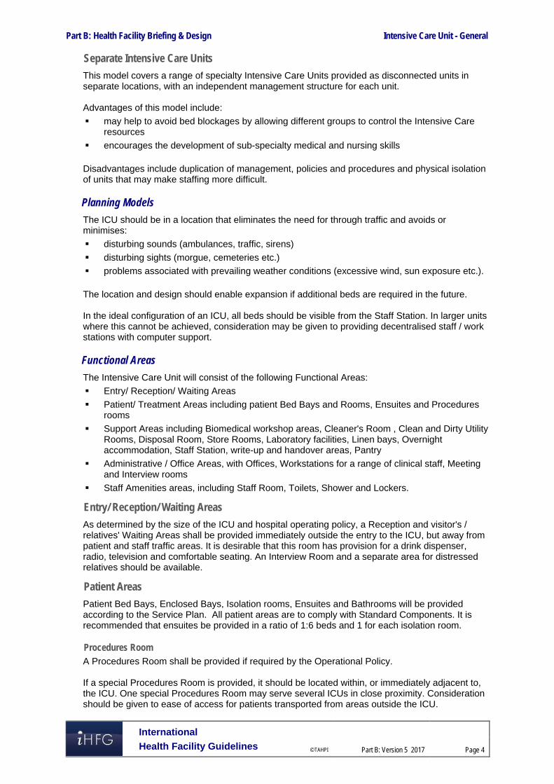
Part B: Health Facility Briefing & Design Intensive Care Unit - General
International
Health Facility Guidelines © TAHPI
Part B: Version 5 2017
Page 4
Separate Intensive Care Units
This model covers a range of specialty Intensive Care Units provided as disconnected units in separate locations, with an independent management structure for each unit. Advantages of this model include:
may help to avoid bed blockages by allowing different groups to control the Intensive Care resources
encourages the development of sub-specialty medical and nursing skills Disadvantages include duplication of management, policies and procedures and physical isolation of units that may make staffing more difficult.
Planning Models
The ICU should be in a location that eliminates the need for through traffic and avoids or minimises:
disturbing sounds (ambulances, traffic, sirens)
disturbing sights (morgue, cemeteries etc.)
problems associated with prevailing weather conditions (excessive wind, sun exposure etc.). The location and design should enable expansion if additional beds are required in the future. In the ideal configuration of an ICU, all beds should be visible from the Staff Station. In larger units where this cannot be achieved, consideration may be given to providing decentralised staff / work stations with computer support.
Functional Areas
The Intensive Care Unit will consist of the following Functional Areas:
Entry/ Reception/ Waiting Areas
Patient/ Treatment Areas including patient Bed Bays and Rooms, Ensuites and Procedures rooms
Support Areas including Biomedical workshop areas, Cleaner's Room , Clean and Dirty Utility Rooms, Disposal Room, Store Rooms, Laboratory facilities, Linen bays, Overnight accommodation, Staff Station, write-up and handover areas, Pantry
Administrative / Office Areas, with Offices, Workstations for a range of clinical staff, Meeting and Interview rooms
Staff Amenities areas, including Staff Room, Toilets, Shower and Lockers.
Entry/ Reception/ Waiting Areas
As determined by the size of the ICU and hospital operating policy, a Reception and visitor's / relatives' Waiting Areas shall be provided immediately outside the entry to the ICU, but away from patient and staff traffic areas. It is desirable that this room has provision for a drink dispenser, radio, television and comfortable seating. An Interview Room and a separate area for distressed relatives should be available.
Patient Areas
Patient Bed Bays, Enclosed Bays, Isolation rooms, Ensuites and Bathrooms will be provided according to the Service Plan. All patient areas are to comply with Standard Components. It is recommended that ensuites be provided in a ratio of 1:6 beds and 1 for each isolation room.
Procedures Room A Procedures Room shall be provided if required by the Operational Policy. If a special Procedures Room is provided, it should be located within, or immediately adjacent to, the ICU. One special Procedures Room may serve several ICUs in close proximity. Consideration should be given to ease of access for patients transported from areas outside the ICU.

Part B: Health Facility Briefing & Design Intensive Care Unit - General
International
Health Facility Guidelines © TAHPI
Part B: Version 5 2017
Page 5
Room size should be sufficient to accommodate the necessary equipment and personnel. Monitoring capabilities, equipment, support services, and safety considerations must be consistent with those services provided in the ICU proper. Work surfaces and storage areas must be adequate enough to maintain all necessary supplies and permit the performance of all desired procedures without the need for staff to leave the room. Procedures Rooms are to comply with Standard Components – Procedures Room.
Support Areas
Biomedical Workshop Dependent upon the size and intended use of the ICU, a dedicated electronic and pneumatic equipment maintenance service may have to be accommodated within the hospital or a 24 hour on-call emergency service made available. This same service would cover the Operating, Emergency and Medical Imaging Units. If a dedicated workshop is provided, its location should be in an area that is equally accessible to all of the above mentioned departments. The facility should have a degree of sound-proofing and be accessible from a non-sterile area.
Laboratory Facilities The ICU must have available 24-hour clinical laboratory services. When this service cannot be provided by the central hospital Laboratory, a satellite laboratory within or immediately adjacent to the ICU must serve this function. Satellite facilities must be able to provide minimum chemistry and haematology testing, including arterial blood gas analysis.
Overnight Accommodation Depending upon the availability of nearby commercial accommodation, consideration should be given to the provision of overnight accommodation for relatives and staff, preferably near the unit. This will be dependent upon the size and intended function of the ICU. A motel type bed-sitter level of provision is recommended.
Storage Areas Mobile equipment such as cardiopulmonary resuscitation trolleys and mobile X-ray, that are used and located within the ICU, shall have storage areas that are out of traffic paths but conveniently located for easy access by staff. Consideration should be given to the ever increasing amount of equipment used in the unit.
Staff Facilities
Offices / workstations will be required for senior staff in full time administrative roles according to the approved positions in the Unit. Offices / workstations for medical staff and some nursing staff (manager/ specialists/ registrars/ educators) may be located as part of the Intensive Care Unit where required for clinical functions or adjacent in an administrative area, to facilitate unit co-ordination, educational and research activities A Staff Lounge shall be provided within the unit for staff to relax and prepare beverages. Inclusion of a window to the outside is desirable. A Library/ Reference area with an appropriate range of bench manuals, textbooks and journals for rapid access 24 hours a day should be available within the Intensive Care Unit. Staff will need close access to the following:
Toilets and Shower
Lockers
Meeting room/s.
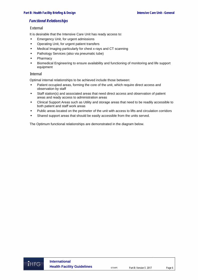
Part B: Health Facility Briefing & Design Intensive Care Unit - General
International
Health Facility Guidelines © TAHPI
Part B: Version 5 2017
Page 6
Functional Relationships
External
It is desirable that the Intensive Care Unit has ready access to:
Emergency Unit, for urgent admissions
Operating Unit, for urgent patient transfers
Medical Imaging particularly for chest x-rays and CT scanning
Pathology Services (also via pneumatic tube)
Pharmacy
Biomedical Engineering to ensure availability and functioning of monitoring and life support equipment
Internal
Optimal internal relationships to be achieved include those between:
Patient occupied areas, forming the core of the unit, which require direct access and observation by staff
Staff station(s) and associated areas that need direct access and observation of patient areas and ready access to administration areas
Clinical Support Areas such as Utility and storage areas that need to be readily accessible to both patient and staff work areas
Public areas located on the perimeter of the unit with access to lifts and circulation corridors
Shared support areas that should be easily accessible from the units served. The Optimum functional relationships are demonstrated in the diagram below.

Part B: Health Facility Briefing & Design Intensive Care Unit - General
International
Health Facility Guidelines © TAHPI
Part B: Version 5 2017
Page 7
Functional Relationships Diagram
The internal and external functional relationships are demonstrated in the diagram below.
External functional relationships outlined in the diagram include:
Entry for visitors directly from dedicated lifts and public corridor
Bed access to / from key clinical units associated with patient arrivals and transfers via service corridor
Ready access to Medical Imaging and Pharmacy Units
Entry for staff via public or service corridor
Separate service access for biomedical engineering, materials, catering and housekeeping.

Part B: Health Facility Briefing & Design Intensive Care Unit - General
International
Health Facility Guidelines © TAHPI
Part B: Version 5 2017
Page 8
Internal relationships outlined in the diagram include:
Bed Room(s) on the perimeter arranged in a linear model, although other models are also suitable
Staff Station(s) located close to the Unit entry with supervision and control over the entry corridor and the patient areas
Clinical support areas located close to Staff Station(s) and centralised for ease of staff access
Administrative areas located at the Unit entry and in staff accessible corridors
Good visibility and access from Staff Station to Patient Bedrooms. 3 Design
Access
External
Ideally there should be a separate and discrete entry or entries for staff, goods and supplies with swipe card or similar electronic access to authorised personnel. Discrete entry for patients on beds or trolleys may also be considered and this should provide:
Ready access from Emergency Unit, and Operating Unit that may involve transfers via lifts
Ready access to and from Diagnostic Imaging areas.
Internal
There should be one only point of public entry overseen by a ward clerk / receptionist during extended daytime hours to:
monitor and / or prevent access by visitors depending on the patients’ condition
advise visitors if patients have been moved or are out of the unit for any reason
monitor visiting staff and direct them to the appropriate staff member or patient
monitor patient movements in and out of the unit.
Patient Treatment Areas
Patients must be situated so that healthcare providers have direct or indirect visualization, such as by video monitoring, at all times. This approach permits the monitoring of patient status under both routine and emergency circumstances. The preferred design is to allow a direct line of vision between the patient and the central Staff Station. In ICUs with a modular design, patients should be visible from their respective nursing substations. Sliding glass doors and partitions facilitate this arrangement and increase access to the room in emergency situations
Renal Dialysis Facilities
Dialysis facilities including water and drainage should be provided to patient treatment areas according to the Unit’s Operational Policy. As a minimum, dialysis facilities should be provided in the Isolation Room/s.
Environmental Considerations
Acoustics
Signals from patient call systems, alarms from monitoring equipment, and telephones add to the sensory overload in critical care units. Without reducing their importance or sense of urgency, such signals should be modulated to a level that will alert staff members, yet be rendered less intrusive. For these reasons, floor coverings that absorb sound should be used while keeping infection control, maintenance, and equipment movement needs under consideration. Walls and ceilings

Part B: Health Facility Briefing & Design Intensive Care Unit - General
International
Health Facility Guidelines © TAHPI
Part B: Version 5 2017
Page 9
should be constructed of materials with high sound absorption capabilities. Ceiling soffits and baffles help reduce echoed sounds. Doorways should be offset, rather than being placed in symmetrically opposed positions, to reduce sound transmission. Counters, partitions, and glass doors are also effective in reducing noise levels.
Natural Light
Natural light and views should be available from the Unit for the benefit of staff and patients. Windows are an important aspect of sensory orientation, and as many rooms as possible should have windows to reinforce day/ night orientation. If windows cannot be provided in each room, an alternate option is to allow a remote view of an outside window or skylight.
Space Standards and Components
Where an open plan arrangement is provided, bed spaces shall be arranged so that there is a clearance of at least 1200 mm from the side of the bed to the nearest fixed obstruction (including bed screens) or wall. At the head of the bed, at least 900 mm clearance shall be allowed between the bed and any fixed obstruction or wall. When an open plan arrangement is provided, a circulation space of 2200 mm minimum clear width shall be provided beyond dedicated cubicle space. Separate cubicles and Single Patient Bedrooms including Isolation Rooms, shall have minimum dimensions of 3900 mm x 3900 mm.
Finishes
The aesthetics of the Unit should be warm, relaxing and non-clinical as far as possible. The following additional factors should be considered in the selection of finishes:
acoustic properties
durability
ease of cleaning
infection control
fire safety
movement of equipment, floor finishes should be resistant to marring and shearing by wheeled equipment.
In all areas where patient observation is critical, colours shall be chosen that do not alter the observer's perception of skin colour. Wall protection should be provided where bed or trolley movement occurs such as corridors, patients’ bedrooms, equipment and linen storage and treatment areas.
Equipment
Bedside monitoring equipment should be located to permit easy access and viewing, and should not interfere with the visualisation of, or access to the patient. The bedside nurse and/or monitor technician must be able to observe the monitored status of each patient at a glance. This goal can be achieved either by a central monitoring station, or by bedside monitors that permit the observation of more than one patient simultaneously. Neither of these methods are intended to replace bedside observation. Weight-bearing surfaces that support the monitoring equipment should be sturdy enough to withstand high levels of strain over time. It should be assumed that monitoring equipment will increase in volume over time. Therefore, space and electrical facilities should be designed accordingly.

Part B: Health Facility Briefing & Design Intensive Care Unit - General
International
Health Facility Guidelines © TAHPI
Part B: Version 5 2017
Page 10
Fixtures & Fittings
Clocks
An analogue clock/s with a second sweep hand shall be provided and conveniently located for easy reference from all bed positions and the Staff Station.
Bedside Storage
Each patient bed space shall include storage and writing provision for staff use.
Window Treatments
Window treatments should be durable and easy to clean. Consideration may be given to use of double glazing with integral blinds, tinted glass, reflective glass, exterior overhangs or louvers to control the level of lighting.
Infection Control
Handbasins
Clinical Hand-washing Facilities shall be provided convenient to the Staff Station and patient bed areas. The ratio of provision shall be one clinical hand-washing facility for every two patient beds in open-plan areas and one in each patient Bedroom or cubicle.
Isolation Rooms
At least one negative pressure Isolation Room per ICU shall be provided in Level 5 and 6 facilities. Entry shall be through an airlock. Clinical hand-washing, gown and mask storage, and waste disposal shall be provided within the airlock. An Ensuite - Special, directly accessible from the Isolation Room, shall also be provided. All entry points, doors or openings, shall be a minimum of 1200 mm wide, unobstructed. Larger openings may be required for special equipment, as determined by the Operational Policy.
Building Service Requirements
Mechanical Services
The unit shall have appropriate air conditioning that allows control of temperature, humidity and air change. Refer to Part E of these Guidelines for the specific requirements for Mechanical and Electrical provision.
Communications
It is vital to provide reliable and effective IT/ Communications service for efficient operation of the Unit. The following items relating to IT/ Communication shall be addressed in the design of the Unit:
electronic patient records – patient information systems
electronic forms and requests (e.g. scripts and investigative requests)
picture archiving communications systems (PACS)
telephones including cordless and mobile phones;
computers and hand-held computers
paging for staff and emergencies
duress systems
bar coding for supplies, x-rays and records
wireless network requirements
videoconferencing requirements
communications rooms and server requirements.

Part B: Health Facility Briefing & Design Intensive Care Unit - General
International
Health Facility Guidelines © TAHPI
Part B: Version 5 2017
Page 11
Nurse and Emergency Call facilities shall be provided in all patient and treatment areas in order for patients and staff to request for urgent assistance. The individual call buttons shall alert to an annunciator system. Annunciator panels should be located in strategic points within the circulation area, particularly Staff Stations, Staff Rooms, and Meeting Rooms and should be of the “non-scrolling” type, allowing all calls to be displayed at the same time. The audible signal of these call systems should be controllable to ensure minimal disturbance to patients at night. The alert to staff members shall be done in a discreet manner at all times.
Security
Entrance doors need to be secured to prevent unauthorised access. A video intercom with speech should be provided from entrance and exit door to main staff reception complete with door release button for staff access control. Security surveillance of the Unit may include CCTV cameras and monitors. 4 Components of the Unit
Standard Components
The Intensive Care Unit will consist of Standard Components to comply with details described in these Guidelines. Refer also to Standard Components Room Data Sheets and Room Layout Sheets.

Part B: Health Facility Briefing & Design Intensive Care Unit - General
International
Health Facility Guidelines © TAHPI
Part B: Version 5 2017
Page 12
5 Schedule of Accommodation
Intensive Care Unit – General at Role Delineation Levels 4 to 6
Note: Units at RDL 2/3 will be a High Dependency Unit and may be separate or collocated with an Intensive Care Unit or Inpatient Unit
ROOM/ SPACE Standard Component RDL 2/3 RDL 4 RDL 5 RDL 6 Remarks Room Codes Qty x m2 Qty x m2 Qty x m2 Qty x m2
4 Bed HDU 8 Beds 12 Beds 24 Beds
Entry / Reception Reception/ Clerical RECL-10-I RECL-12-I 1 x 10 1 x 12 1 x 12
Waiting WAIT-15-I WAIT-20-I WAIT-30-I 1 x 15 1 x 20 1 x 20 1 x 30 1.2 m2 per person; 1.5 m2 per wheelchair
Waiting - Family WAIT-20-I WAIT-25-I WAIT-50-I 1 x 20 1 x 20 1 x 25 1 x 50
Meeting Room MEET-12-I MEET-L-15-I 1 x 12 1 x 15 1 x 15
Toilet - Public WCPU-3-I 2 x 3 2 x 3 2 x 3 2 x 3 May share public amenities if located close
Patient Areas Patient Bay - Critical PBC-16-I 1 x 16 16m2 bed bays may be used for lower acuity units
Patient Bay - Critical PBC-24-I 1 x 24 4 x 24 5 x 24 10 x 24 Group of not more than 12, within observation of Staff Station
Patient Bay - Critical (Enclosed); Class S Isolation PBCE-25-I 1 x 25 3 x 25 6 x 25 12 x 25 Group of not more than 12, within observation of Staff Station
Patient Bay - Critical (Enclosed); Class N Isolation PBCE-25-I 1 x 25 1 x 25 1 x 25 2 x 25 Clustered, located away from Unit entrance
Anteroom ANRM-I 1 x 5 1 x 5 2 x 5 2 x 5 For Class N Isolation Rooms
Ensuite - Super ENS-SP-I 2 x 6 3 x 6 4 x 6 7 x 6 Size for 'full assistance', i.e. 2 staff plus equipment
Support Areas Bathroom BATH-I 1 x 16 1 x 16 1 x 16 1 x 16 Inclusion depends on operational policy of unit
Bay - Beverage BBEV-OP-I BBEV-ENC-I 1 x 4 1 x 4 1 x 5 1 x 5
Bay - Blanket Warmer BBW-I 1 x 1 1 x 1 1 x 1 1 x 1 Optional
Bay - Handwashing, Type A BHWS-A-I 1 x 1 2 x 1 3 x 1 4 x 1 At entry to the Unit and in Corridors
Bay - Linen BLIN-I 1 x 2 1 x 2 2 x 2 2 x 2
Bay - Mobile Equipment BMEQ-4-I 1 x 4 1 x 4 2 x 4 2 x 4
Bay - Pathology BPATH-I (similar) 1 x 1 1 x 2 1 x 4 1 x 4
Bay - PPE BPPE-I 1 x 1.5 1 x 1.5 1 x 1.5 4 x 1.5 As required, may be combined with Bay-Handwashing
Bay - Resuscitation Trolley BRES-I 1 x 1.5 1 x 1.5 1 x 1.5 1 x 1.5
Cleaners Room CLRM-5-I 1 x 5 1 x 5 1 x 5 1 x 5
Clean Utility/ Medication CLUR-12-I CLUM-14-I 1 x 12 1 x 12 1 x 14 2 x 14 Medication room may be separate
Dirty Utility DTUR-12-I DTUR-12-I DTUR-14-I 1 x 10 1 x 12 1 x 14 2 x 14

Part B: Health Facility Briefing & Design Intensive Care Unit - General
International
Health Facility Guidelines © TAHPI
Part B: Version 5 2017
Page 13
ROOM/ SPACE Standard Component RDL 2/3 RDL 4 RDL 5 RDL 6 Remarks Room Codes Qty x m2 Qty x m2 Qty x m2 Qty x m2
4 Bed HDU 8 Beds 12 Beds 24 Beds Disposal Room DISP-8-I DISP-10-I 1 x 8 1 x 8 1 x 10 1 x 10 Inclusion depends on unit size & waste operational policies
Equipment Clean-up ECL-8-I 1 x 8 1 x 8 1 x 8 1 x 8 Room size according to service requirements
Office - Clinical Workroom OFF-CLW-I (similar) 1 x 10 1 x 15 1 x 15 1 x 20 Locate near staff station
Office - Write-up Bay OFF-WI-1-U 2 x 1 4 1 7 x 1 14 x 1 1 per each enclosed bed room
Respiratory/ Biomedical Workroom REWM-I (similar) 1 x 20 1 x 20 Inclusion depends on operational policy of unit
Staff Station SSTN-12-I SSTN-18-I SSTN-20-I 1 x 12 1 x 18 1 x 20 2 x 20
Store - Drugs STDR-5-I STDR-10-I 1 x 5 1 x 10 1 x 10 1 x 10 Optional
Store - Equipment STEQ-10-I STEQ-15-I STEQ-30-I 1 x 10 1 x 15 1 x 15 1 x 30 May be subdivided and located near Birthing rooms as required
Store - General STGN-12-I STGN-16-I STGN-30-I 1 x 12 1 x 16 1 x 16 1 x 30
Store - Respiratory STEQ-20-I 1 x 20 Inclusion depends on operational policy of unit
Store - Sterile Stock STSS-12-I (sim) STSS-24-I 1 x 6 1 x 12 1 x 24 2 x 24
Staff Areas Bay - Beverage BBEV-OP-I BBEV-ENC-I 1 x 4 1 x 5 1 x 5 Optional, near Meeting Room/s
Change - Staff (Male/Female) CHST-10-I CHST-20-I CHST-25-I 2 x 10 2 x 14 2 x 20 2 x 25 Toilets, Shower and Lockers; size dependent on staffing numbers
Meeting Room MEET-L-15-I MEET-L-25-I shared 1 x 15 1 x 25 2 x 25 Quantity and size dependent on Service Plan
Office - Single Person, 12 m2 OFF-S12-I 1 x 12 1 x 12 Note 1; Director/ Service Manager
Office - Single Person, 9 m2 OFF-S9-I 1 x 9 1 x 9 1 x 9 2 x 9 Note 1; Unit Manager
Office - Single Person, 9 m2 OFF-S9-I 1 x 9 1 x 9 Note 1; Staff Specialists
Office - 2 Person, Shared OFF-2P-I x 1 x 12 1 x 12 Note 1; Nurse Educators, Staff Specialists, Clinicians
Office - Workstation/s OFF-WS-I 1 x 5.5 2 x 5.5 4 x 5.5 8 x 5.5 Note 1; Registrars, Nursing, Secretarial
Overnight Stay - Bedroom OVBR-I 1 x 10 1 x 10 Optional
Overnight Stay - Ensuite OVES-I 1 x 4 1 x 4 Optional
Staff Room SRM-15-I SRM-20-I SRM-35-I 1 x 15 1 x 15 1 x 20 1 x 35 May be shared
Store - Files STFS-10-I 1 x 10 Optional, depends on record storage operational policy
Store - Photocopy/ Stationery STPS-8-I STPS-10-I 1 x 8 1 x 8 1 x 10 1 x 10
Sub Total 346.5 555.0 798.0 1375.5
Circulation % 40 40 40 40
Area Total 485.1 777.0 1117.2 1925.7 Note 1: Offices to be provided according to the number of approved full time positions within the Unit

Part B: Health Facility Briefing & Design Intensive Care Unit - General
International
Health Facility Guidelines © TAHPI
Part B: Version 5 2017
Page 14
Please note the following: Areas noted in Schedules of Accommodation take precedence over all other areas noted in the FPU. Rooms indicated in the schedule reflect the typical arrangement according to the Role Delineation. Exact requirements for room quantities and sizes will reflect Key Planning Units identified in the Service Plan and the Operational Policies of the Unit. Room sizes indicated should be viewed as a minimum requirement; variations are acceptable to reflect the needs of individual Unit. Office areas are to be provided according to the Unit role delineation and the number of endorsed full time positions within the Unit Staff and support rooms may be shared between Functional Planning Units dependant on location and accessibility to each unit and may provide scope to
reduce duplication of facilities.

Part B: Health Facility Briefing & Design Intensive Care Unit - General
International
Health Facility Guidelines © TAHPI
Part B: Version 5 2017
Page 15
6 References and Further Reading In addition to iHFG Sections referenced in this FPU, i.e. Part C- Access, Mobility, OH&S and Part D - Infection Control, readers may find the following helpful:
AHIA, Australasian Health Facility Guidelines, Part B Health Facility Briefing and Planning, Intensive Care - General, Rev 6, 2016; refer to website: https://healthfacilityguidelines.com.au/health-planning-units
Guidelines for Design and Construction of Hospitals and Outpatient Facilities; The Facility Guidelines Institute, 2014, refer to website www.fgiguidelines.org
DH (Department of Health) (UK) Health Building Note 57: Facilities for critical care, 2003, refer to www.estatesknowledge.dh.gov.uk

Part B – Health Facility Briefing & Design 140 IVF Unit (Fertilisation Centres)
International Health Facility Guidelines Version 4 May 2014

International Health Facility Guidelines © TAHPI
Part B: Version 4 2014
Page 2
Table of Contents 140 IVF Unit (Fertilisation Centres) ................................................................................................ 3
1 Introduction ............................................................................................................................................... 3 2 Planning ..................................................................................................................................................... 3 3 Design ........................................................................................................................................................ 7 4 Components of the Unit ............................................................................................................................ 9 5 Schedule of Accommodation – IVF Unit ............................................................................................... 10 6 Functional Relationship Diagram – IVF Unit ......................................................................................... 13 7 References and Further Reading ........................................................................................................... 14

IVF Unit (Fertilisation Centres)
International Health Facility Guidelines © TAHPI
Part B: Version 4 2014
Page 3
140 IVF Unit (Fertilisation Centres) 1 Introduction Description The IVF Unit will provide facilities for In vitro fertilisation (IVF) procedures. IVF is one of several Assisted Reproductive Techniques (ART) used to help infertile couples to conceive a child. The procedure involves removal of eggs (mature Oocyte or Ovum) from the woman's ovary. Ova are then fertilised with sperm in a laboratory procedure (in vitro). If fertilisation occurs, a fertilised ovum, after undergoing several cell divisions, is transferred to the mother for normal development in the uterus, or frozen for later implantation. The IVF laboratory may use Intracytoplasmic Sperm Injection (ICSI) in the process of IVF. Services provided by the IVF Unit include: Patient consultation and interview on an outpatient basis Pre-treatment assessment Blood collection Semen collection Artificial insemination Ovarian stimulation therapy Ultrasound examination Oocyte (egg) collection Embryo culture In vitro / ICSI fertilisation Cryopreservation Embryo transfer Recovery Licensing Of Unit IVF Units (Fertilisation Centres) in the region may require licensing according to the requirements of pertaining laws of the land. Please refer to local licensing laws for additional information on the licensing process for IVF Units. 2 Planning Planning Models The IVF Unit may be developed as: a stand-alone unit a dedicated Unit within a general hospital Functional Areas The IVF Unit may consist of a number of Functional Areas or zones: Entry/ Consult Area
Entry/ Reception and waiting areas Administration/ Records Interview Room/s Consult/ Examination/ Treatment Room/s Ultrasound room/s Collection Room/s with Ensuite shower and Toilet Public Toilets

IVF Unit (Fertilisation Centres)
International Health Facility Guidelines © TAHPI
Part B: Version 4 2014
Page 4
Patient Procedural Area
Operating Room/s for oocyte (egg) collection and re-implantation Recovery areas Change areas and toilets for staff and patients
Laboratory Area
Laboratories (Embryology, IVF, ICSI, Andrology, Genetics) Cryopreservation facilities Gas Bottle Store
Staff and Support Area
Clean-Up and Disposal room Store rooms and Sterile store Offices, meeting rooms, staff room Sterilising area: if the IVF unit is a stand-alone building, dedicated sterilising facilities
will be required
Entry/ Reception and Waiting
The Entry and Reception provides the first point of contact for clients. Waiting areas should be calm, comforting and relaxing. They should be divided for gender separation.
Procedural Areas
Collection Room/ s
Collection room/s should be discreet and private, enclosed rooms for collection of sperm samples from patients. The Collection rooms have a close functional relationship with the Andrology laboratory; rapid delivery of specimens is required to prevent cell deterioration. The Collection rooms will require an Ensuite shower / toilet. The rooms should include: comfortable seating handbasin and fittings including soap and paper towel dispenser TV, DVD player acoustic treatment a pass-through hatch for specimens.
Operating Room/ s
Operating room/s) will include equipment and facilities for egg collection and embryo transfer, under local anaesthetic. Operating rooms will require adjacent Patient and Staff Change Rooms, scrub sink and patient toilet facilities.
Laboratory Areas
Strict protocols for handling and labelling patient specimens in all laboratory areas are required. Laboratory areas should be zoned in a restricted staff access only area.
Embryology/ IVF/ ICSI Laboratory
The embryology laboratory provides facilities for the handling, preparation, culture and storage of human gametes (sperm and oocytes). Due to the sensitive nature of its functions, the embryology laboratory should be located in a secure and sterile area away from the outpatient/ clinic facilities but in close proximity to the procedure room where the oocytes (eggs) are collected. The laboratory is responsible for identifying oocytes in ovarian fluid, culturing these eggs with the partner's sperm, and embryo examination prior to embryo implantation into the patient.
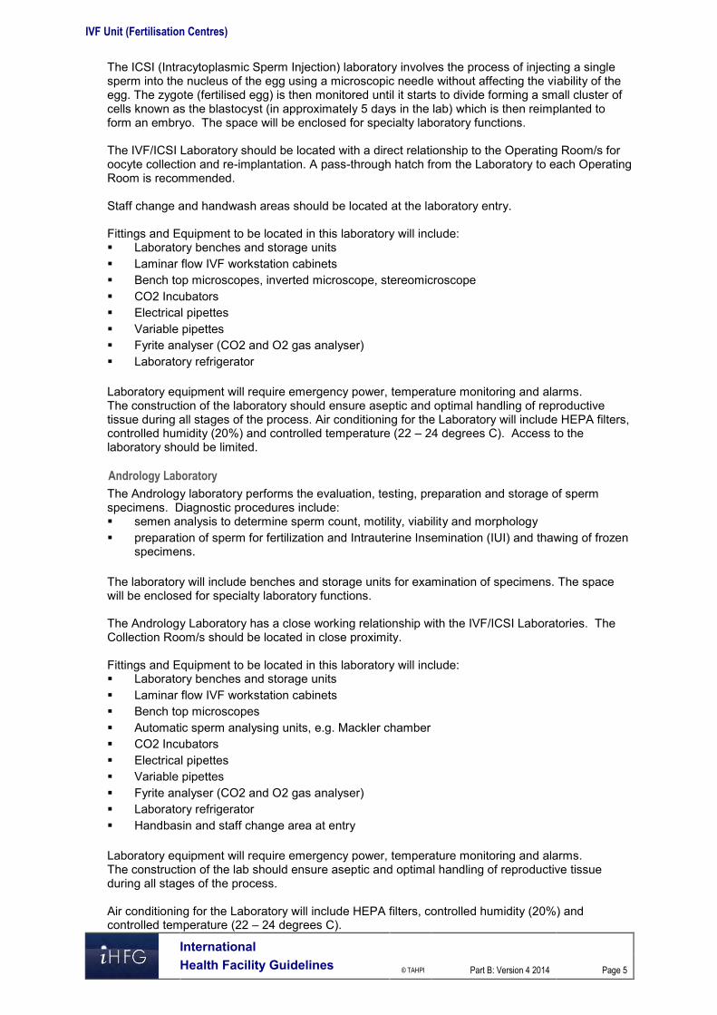
IVF Unit (Fertilisation Centres)
International Health Facility Guidelines © TAHPI
Part B: Version 4 2014
Page 5
The ICSI (Intracytoplasmic Sperm Injection) laboratory involves the process of injecting a single sperm into the nucleus of the egg using a microscopic needle without affecting the viability of the egg. The zygote (fertilised egg) is then monitored until it starts to divide forming a small cluster of cells known as the blastocyst (in approximately 5 days in the lab) which is then reimplanted to form an embryo. The space will be enclosed for specialty laboratory functions. The IVF/ICSI Laboratory should be located with a direct relationship to the Operating Room/s for oocyte collection and re-implantation. A pass-through hatch from the Laboratory to each Operating Room is recommended. Staff change and handwash areas should be located at the laboratory entry. Fittings and Equipment to be located in this laboratory will include: Laboratory benches and storage units Laminar flow IVF workstation cabinets Bench top microscopes, inverted microscope, stereomicroscope CO2 Incubators Electrical pipettes Variable pipettes Fyrite analyser (CO2 and O2 gas analyser) Laboratory refrigerator Laboratory equipment will require emergency power, temperature monitoring and alarms. The construction of the laboratory should ensure aseptic and optimal handling of reproductive tissue during all stages of the process. Air conditioning for the Laboratory will include HEPA filters, controlled humidity (20%) and controlled temperature (22 – 24 degrees C). Access to the laboratory should be limited.
Andrology Laboratory
The Andrology laboratory performs the evaluation, testing, preparation and storage of sperm specimens. Diagnostic procedures include: semen analysis to determine sperm count, motility, viability and morphology preparation of sperm for fertilization and Intrauterine Insemination (IUI) and thawing of frozen
specimens. The laboratory will include benches and storage units for examination of specimens. The space will be enclosed for specialty laboratory functions. The Andrology Laboratory has a close working relationship with the IVF/ICSI Laboratories. The Collection Room/s should be located in close proximity. Fittings and Equipment to be located in this laboratory will include: Laboratory benches and storage units Laminar flow IVF workstation cabinets Bench top microscopes Automatic sperm analysing units, e.g. Mackler chamber CO2 Incubators Electrical pipettes Variable pipettes Fyrite analyser (CO2 and O2 gas analyser) Laboratory refrigerator Handbasin and staff change area at entry Laboratory equipment will require emergency power, temperature monitoring and alarms. The construction of the lab should ensure aseptic and optimal handling of reproductive tissue during all stages of the process. Air conditioning for the Laboratory will include HEPA filters, controlled humidity (20%) and controlled temperature (22 – 24 degrees C).

IVF Unit (Fertilisation Centres)
International Health Facility Guidelines © TAHPI
Part B: Version 4 2014
Page 6
Access to the laboratory should be limited.
Genetics Laboratory
The Genetics Laboratory undertakes cytogenetics studies of the embryo cells, particularly the nucleus which contains the chromosomes that carry genes and their DNA to determine the status of the embryo after IVF and before re-implantation, also referred to as Pre-implantation Genetic Diagnosis (PGD). This process can also identify and diagnose abnormalities and genetic diseases that may accompany the pregnancy by the use of sophisticated techniques such as Fluorescence In-Situ Hybridization (FISH) or Polymerase Chain Reaction (PCR). The functions performed in the Genetics Laboratory may be included in the IVF/ ICSI Laboratory. The Genetics Laboratory has a close working relationship with the IVF/ ICSI Laboratory. Fittings and Equipment to be located in this laboratory will include: Laboratory benches and storage units Laminar flow IVF workstation cabinets Bench top microscopes Laboratory refrigerator Handbasin and staff change area at entry Laboratory equipment will require emergency power, temperature monitoring and alarms. The construction of the lab should ensure aseptic and optimal handling of reproductive tissue during all stages of the process. Air conditioning for the Laboratory will include HEPA filters, controlled humidity (20%) and controlled temperature (22 – 24 degrees C). Access to the laboratory should be limited.
Cryopreservation Facilities
Facilities for cryopreservation will include a separate room for storage of frozen reproductive cells (gametes, zygotes and embryos) in liquid nitrogen storage tanks. Nitrogen tanks should be stored in an enclosed space in case of nitrogen leakage. The Cryopreservation storage area should be located in close proximity to the Laboratory areas, in an area with controlled access. A monitoring system is required for low levels of liquid nitrogen in the storage tanks and for high levels of nitrogen in the air. Strict protocols on the method of storage and specimen labelling are required for this process (refer to local regulations and licensing laws) and will include: infection control (minimising the risk of cross contamination of frozen gametes, zygotes and
embryos) Labelling, packaging and documentation of tissue frozen Provide controlled access to the room.
Staff and Support Areas
Sterilising/ Packing
The Sterilising/ Packing room is an area where cleaned and dried instruments are sorted, assembled into sets, packaged, and then sterilised in an autoclave. The Sterilising/ Packing Room will be located adjacent to the Clean-up Room where the instruments are cleaned and decontaminated. Considerations: Fittings and Equipment located in this room will include:

IVF Unit (Fertilisation Centres)
International Health Facility Guidelines © TAHPI
Part B: Version 4 2014
Page 7
Handbasin Benches and cupboards Instrument packing table Heat sealing device Autoclave Cooling trolleys The room requires a defined unidirectional workflow for instruments from clean to sterile and then to sterile store. Sterile stock should not be stored in this room to avoid the potential for mixing unsterilized instrument sets with sterile sets. Functional Relationships
External
The IVF Unit may have a close working relationship with: Pathology Laboratories Pharmacy Medical Imaging The IVF Unit should be ideally located on the Ground floor. If located on an upper floor, there must be a stretcher carrying lift available.
Internal
Within the IVF Unit the following relationships are significant: Laboratory areas should be located with a direct adjacent relationship to the Operating
rooms for egg collection and re-implantation Laboratories should be located in a separate zone away from the outpatient/ consult area
and secured. Sperm Collection rooms have a close functional relationship with the Andrology Laboratory;
specimens require rapid transfer to the laboratory to avoid deterioration. Office areas should be separate from the treatment and laboratory zone 3 Design General The design of the unit should create a pleasant, reassuring atmosphere for patients whilst retaining the necessary functional requirements associated with clinical spaces and laboratories. Ideally, waiting areas should be divided into several small ‘Family Waiting’ zones or ‘nooks’ to allow partners or close relatives to wait in relative privacy. Consideration may be given to a private and discreet entry area for patients, away from general public view. Environmental Considerations
Natural Light
Natural light is highly desirable where achievable, particularly for laboratory areas where staff will spend a majority of their time.
Privacy
Privacy is essential for confidential conversations and interviews and will minimise stress and discomfort for patients. Patient privacy and confidentiality can be enhanced by provision of private interview rooms for personal discussions between staff and patients.

IVF Unit (Fertilisation Centres)
International Health Facility Guidelines © TAHPI
Part B: Version 4 2014
Page 8
Acoustics
Confidential patient information is exchanged between patients and staff, therefore the Interview, Consult, Collection and Treatment rooms should be acoustically treated to maximise privacy. In acoustically treated rooms, return air grilles should be acoustically treated to avoid transfer of conversations to adjacent areas. Door grilles and undercuts to these areas should be avoided. Space Standards and Components Laboratories and storage areas shall be sized to suit the design requirements of the equipment to be used, to provide a safe working environment and to allow the effective movement of staff.
Ergonomics
Laboratories should be designed with consideration to ergonomics to ensure an optimal working environment. Aspects for consideration will include height of benches and chairs, height of equipment in constant use such as microscopes and bio-safety cabinets. Refer also to Part C of these Guidelines. Safety and Security Zones within the Unit will require access control to prevent unauthorised access, particularly laboratory areas, cryopreservation areas and staff office areas. A separate room or a fume hood should be available for procedures requiring use of fixatives. Finishes Floor finishes should be appropriate to the function of the space. Consideration must be given to the appearance and quality of environment required e.g. non-institutional, acoustic performance, slip resistance, infection control, movement of trolleys and maintenance. Laboratory, Storage and Procedural areas should have vinyl or similar impervious floors; patient recovery areas and staff offices may be carpeted. Ceiling and wall finishes, laboratory cabinetry and bench tops must be easily cleaned. Refer also to Part C and D of these Guidelines. Fixtures and Fittings Critical items of equipment including incubators and liquid nitrogen storage should be temperature alarmed and monitored. Consideration should also be given to emergency and uninterruptible (UPS) power supplies to critical equipment. Building Service Requirements Laboratories will require air conditioning with controlled humidity and temperature to provide an environment that minimises staff distraction and fatigue. Procedure rooms will require temperature regulation to assist in maintaining patient temperature at 37 degrees C and prevent deterioration of oocytes. Power supplies to critical equipment such as incubators, refrigerators, biosafety cabinets should be on emergency supply with generator back-up. Infection Control

IVF Unit (Fertilisation Centres)
International Health Facility Guidelines © TAHPI
Part B: Version 4 2014
Page 9
All assisted reproductive techniques involve handling of biological material and therefore pose a potential infection control risk to staff and to other patients’ reproductive cells (gametes, zygotes, embryos). Strict infection control measures are required within the unit to protect laboratory staff from potentially contaminated body fluids (follicular fluid etc.) and to ensure aseptic environment for reproductive cells, preventing cross infection. Measures will include: Handbasins for staff handwashing in all patient areas and laboratories Use of laboratory clothing in laboratories Use of theatre clothing in procedure rooms Use of laminar flow biosafety cabinets in laboratories (a Class II cabinet should be available
for handling of contaminated samples) Sharps containers and clinical waste collection and removal. 4 Components of the Unit The IVF Unit will contain Standard Components to comply with details described in these Guidelines. Refer to Standard Components Room Data Sheets and Room Layout Sheets. Laboratories are to comply with applicable statutory requirements and international standards for clean rooms.

IVF Unit (Fertilisation Centres)
International Health Facility Guidelines © TAHPI
Part B: Version 4 2014
Page 10
5 Schedule of Accommodation – IVF Unit Entry/Consulting Areas
ROOM / SPACE Standard Level 5 Level 6 Remarks
Component Qty x m2 Qty x m2
RECEPTION / CLERICAL RECL-15-I 1 x 15 1 x 15
STORE - PHOTOCOPY / STATIONERY STPS-8-I 1 x 8 1 x 8
STORE - FILES STFS-8-I 1 x 8 1 x 8
WAITING MALE / FEMALE WAIT-10-I 2 x 10 2 x 15 Separate Waiting areas for
WAIT-15-I Male & Female
WAITING FAMILY WAIT-25-I 1 x 25 1 x 30
WAIT-30-I
TOILET- VISITORS, ACCESSIBLE WCAC-I 2 x 6 2 x 6 Located adjacent to Male &
Female Waiting
MEETING/ INTERVIEW ROOM - FAMILY MEET-12-I 2 x 12 3 x 12
CONSULT / EXAMINATION / CONS-I 3 x 14 4 x 14
COLLECTION ROOM 2 x 6 2 x 6 Semen samples
ENSUITE SHOWER/ TOILET ENS-ST-I 2 x 5 2 x 5 Adjacent to semen Collection
Rooms
BLOOD COLLECTION BAY BLDC-5-I 2 x 5 2 x 5
ULTRASOUND ROOM ULTR-I 1 x 14 1 x 14
Patient Procedural Area
ROOM / SPACE Standard Level 5 Level 6 Remarks
Component Qty x m2 Qty x m2
OPERATING ROOM - GENERAL ORGN-I 1 x 42 2 x 42
CHANGE CUBICLE – ACCESSIBLE CHPT-D-I 1 x 4 2 x 4 1 adjacent to each Procedure
PATIENT Room
TOILET - PATIENT WCPT-I 2 x 4 3 x 4 1 adjacent to each Procedure
Room; 1 adjacent to Recovery
CHANGE - STAFF (MALE / FEMALE) CHST-10-I 2 x 10 2 x 14
CHST-14-I
SCRUB UP / GOWNING SCRB-6-I 1 x 6 1 x 10 Maybe shared between 2
SCRBS-I procedure room
PATIENT BAY – HOLDING/ RECOVERY PBTR-H-10-I 2 x 10 4 x 10
BAY - HANDWASHING , TYPE B BHWS-B-I 1 x 1 2 x 1
BAY - BEVERAGE BBEV-ENC-I 1 x 5 1 x 5
BAY - LINEN BLIN-I 1 x 2 1 x 2
BAY - RESUSCITATION TROLLEY BRES-I 1 x 1.5 1 x 1.5
CLEAN UTILITY CLUR-8-I 1 x 8 1 x 12
CLUR-12-I
DIRTY UTILITY DTUR-S-I 1 x 8 1 x 10
DTUR-10-I
STAFF STATION SSTN-5-I 1 x 5 1 x 10
SSTN-10-I
STORE - GENERAL STGN-8-I 1 x 8 1 x 10
STGN-10U
CIRCULATION ALLOWANCE % 35% 35%
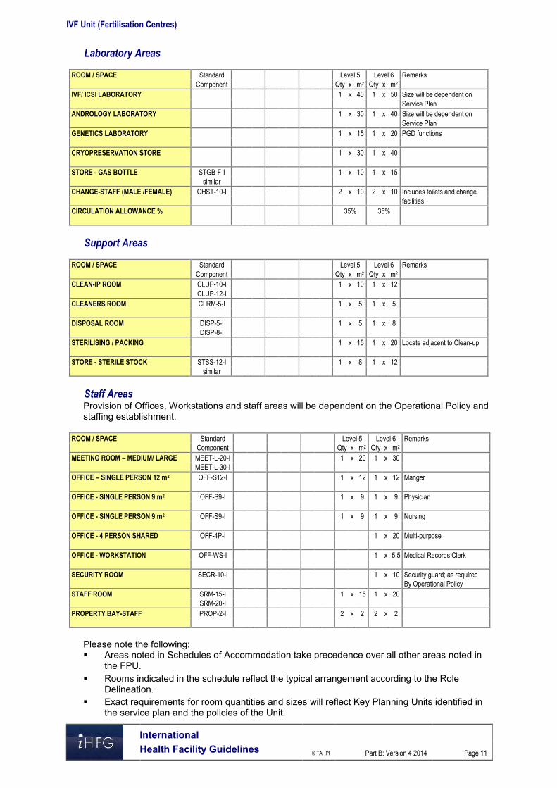
IVF Unit (Fertilisation Centres)
International Health Facility Guidelines © TAHPI
Part B: Version 4 2014
Page 11
Laboratory Areas
ROOM / SPACE Standard Level 5 Level 6 Remarks
Component Qty x m2 Qty x m2
IVF/ ICSI LABORATORY 1 x 40 1 x 50 Size will be dependent on
Service Plan
ANDROLOGY LABORATORY 1 x 30 1 x 40 Size will be dependent on
Service Plan
GENETICS LABORATORY 1 x 15 1 x 20 PGD functions
CRYOPRESERVATION STORE 1 x 30 1 x 40
STORE - GAS BOTTLE STGB-F-I 1 x 10 1 x 15
similar
CHANGE-STAFF (MALE /FEMALE) CHST-10-I 2 x 10 2 x 10 Includes toilets and change
facilities
CIRCULATION ALLOWANCE % 35% 35%
Support Areas
ROOM / SPACE Standard Level 5 Level 6 Remarks
Component Qty x m2 Qty x m2
CLEAN-IP ROOM CLUP-10-I 1 x 10 1 x 12
CLUP-12-I
CLEANERS ROOM CLRM-5-I 1 x 5 1 x 5
DISPOSAL ROOM DISP-5-I 1 x 5 1 x 8
DISP-8-I
STERILISING / PACKING 1 x 15 1 x 20 Locate adjacent to Clean-up
STORE - STERILE STOCK STSS-12-I 1 x 8 1 x 12
similar
Staff Areas Provision of Offices, Workstations and staff areas will be dependent on the Operational Policy and staffing establishment.
ROOM / SPACE Standard Level 5 Level 6 Remarks
Component Qty x m2 Qty x m2
MEETING ROOM – MEDIUM/ LARGE MEET-L-20-I 1 x 20 1 x 30
MEET-L-30-I
OFFICE – SINGLE PERSON 12 m2 OFF-S12-I 1 x 12 1 x 12 Manger
OFFICE - SINGLE PERSON 9 m2 OFF-S9-I 1 x 9 1 x 9 Physician
OFFICE - SINGLE PERSON 9 m2 OFF-S9-I 1 x 9 1 x 9 Nursing
OFFICE - 4 PERSON SHARED OFF-4P-I 1 x 20 Multi-purpose
OFFICE - WORKSTATION OFF-WS-I 1 x 5.5 Medical Records Clerk
SECURITY ROOM SECR-10-I 1 x 10 Security guard; as required
By Operational Policy
STAFF ROOM SRM-15-I 1 x 15 1 x 20
SRM-20-I
PROPERTY BAY-STAFF PROP-2-I 2 x 2 2 x 2
Please note the following: Areas noted in Schedules of Accommodation take precedence over all other areas noted in
the FPU. Rooms indicated in the schedule reflect the typical arrangement according to the Role
Delineation. Exact requirements for room quantities and sizes will reflect Key Planning Units identified in
the service plan and the policies of the Unit.

IVF Unit (Fertilisation Centres)
International Health Facility Guidelines © TAHPI
Part B: Version 4 2014
Page 12
Office areas are to be provided according to the Unit role delineation and the number of endorsed full time positions in the Unit
Room sizes indicated should be viewed as a minimum requirement; variations are acceptable to reflect the needs of individual Unit.
Staff and support rooms may be shared between Functional Planning Units dependant on location and accessibility to each unit and may provide scope to reduce duplication of facilities.

IVF Unit (Fertilisation Centres)
International Health Facility Guidelines © TAHPI
Part B: Version 4 2014
Page 13
6 Functional Relationship Diagram – IVF Unit

IVF Unit (Fertilisation Centres)
International Health Facility Guidelines © TAHPI
Part B: Version 4 2014
Page 14
7 References and Further Reading Revised Guidelines for good practice in IVF laboratories; Magli, M.C. et al, Human
Reproduction Vol 23, No 6, 1253-1262, 2008 Guidelines for Design and Construction of Health Care Facilities; The Facility Guidelines
Institute, 2010 Edition refer to website www.fgiguidelines.org . Clinical and Laboratory Standards Institute (CLSI) (www.clsi.org) “Laboratory Design;
Approved Guideline,” 2nd edition. GP18-A2. Vol 27, No.7. Wayne, PA:CLSI, 2007.

Part B – Health Facility Briefing & Design 145 Laboratory Unit
International Health Facility Guidelines Version 5 July 2017

Part B: Health Facility Briefing & Design
International
Health Facility Guidelines © TAHPI
Part B: Version 5 July 2017
Page 2
Table of Contents
145 Laboratory Unit ......................................................................................................................... 3
1 Introduction ............................................................................................................................................... 3 Description .................................................................................................................................................. 3
2 Functional and Planning Considerations ............................................................................................... 3 Operational Models ..................................................................................................................................... 3 Planning Models .......................................................................................................................................... 3 Functional Areas ......................................................................................................................................... 4 Functional Relationships ............................................................................................................................. 6
3 Design ........................................................................................................................................................ 8 Environmental Considerations .................................................................................................................... 8 Space Standards and Components ............................................................................................................ 8 Safety & Security ......................................................................................................................................... 9 Finishes ....................................................................................................................................................... 9 Fixtures, Fittings & Equipment .................................................................................................................... 9 Building Service Requirements ................................................................................................................. 10 Pneumatic Tube Systems ......................................................................................................................... 10 Infection Control ........................................................................................................................................ 10
4 Components of the Unit .......................................................................................................................... 11 Standard Components .............................................................................................................................. 11 Non-Standard Components ....................................................................................................................... 11
5 Schedule of Accommodation ................................................................................................................. 13 Laboratory Unit located within a health facility .......................................................................................... 13
6 Future Trends .......................................................................................................................................... 17
7 Further Reading ....................................................................................................................................... 17

Part B: Health Facility Briefing & Design Laboratory Unit
International
Health Facility Guidelines © TAHPI
Part B: Version 5 July 2017
Page 3
145 Laboratory Unit
1 Introduction
Description The Laboratory Unit provides facilities and equipment for the examination of body tissues and fluids, involving receipt of patient specimens, testing and issue of reports. The Laboratory Unit may be divided into specialist disciplines including (but not limited to): General Pathology - involves a mixture of anatomical and clinical pathology specialties in the
one Unit Anatomical Pathology – involves the diagnosis of disease based on the microscopic,
chemical, immunologic and molecular examination of organs, tissues, and whole bodies (autopsy); Anatomical pathology is itself divided in subspecialties including Surgical Pathology, Cytopathology and Forensic Pathology
Clinical/ Chemical Pathology involves diagnosis of disease through the laboratory analysis of blood and bodily fluids and/or tissues using the tools of Chemistry, Microbiology, Haematology and Molecular Pathology
Haematology is concerned with diseases that affect the blood and the management of blood transfusion services
Microbiology is concerned with diseases caused by organisms such as bacteria, viruses, fungi and parasites; clinical aspects involve control of infectious diseases and infections caused by antibiotic-resistant bacteria
Genetics/ Clinical Cytogenetics - a branch of genetics concerned with studying the structure and function of the cell, particularly the microscopic analysis of chromosomal abnormalities; molecular genetics uses DNA technology to analyse genetic mutations
Immunology - a broad discipline that deals with the physiological functioning of the immune system and malfunctions of the immune system such as autoimmune diseases, hypersensitivities, immune deficiency and transplant rejection
2 Functional and Planning Considerations
Operational Models Laboratory services may be provided according to the following service delivery models and will be dependent on the size, the Role Delineation and the Operational Policy of the facility: On-site laboratory providing a wide range of tests and services On-site provision limited to Point of Care Testing (POCT) for a limited range of urgent tests Off-site laboratory with services provided by an external laboratory on a contracted or other
basis; the external laboratory may be a separate private business unit Networking of hospital laboratories across an area or region with varying arrangements for
specialisation between laboratories.
Hours of Operation
The Laboratory Unit will generally operate seven days per week with core services available from 8am to 6pm daily and emergency or urgent services available on a 24 hour basis.
Planning Models
Location
The Laboratory Unit may be located in a service zone within the healthcare facility with consideration to: travel distances and the amount of time taken to receive specimens and for staff travelling
between various key departments Ease of access for patients attending the Unit for specimen collection.

Part B: Health Facility Briefing & Design Laboratory Unit
International
Health Facility Guidelines © TAHPI
Part B: Version 5 July 2017
Page 4
With automated delivery methods such as pneumatic tube systems and satellite specimen collection zones within the facility, the location of the Unit becomes less critical.
Configuration
The Laboratory Unit may be planned as a series of modular laboratories, providing flexibility for change of function and equipment as necessary. Each module may be sized to accommodate a specific specialty and the equipment required, with the ability to adapt and reconfigure modules.
Functional Areas The Laboratory Unit will consist of a number of Functional Areas according to the service plan of the unit: Specimen Reception including:
- Specimen registration, data entry - Specimen sorting and preliminary processing prior to delivery/despatch to various
specialty laboratories Laboratories, which may include:
- Automated laboratories that perform a range of tests across a variety of specialties - Specialist laboratories such as Clinical Chemistry, Anatomical Pathology,
Microbiology, Haematology, Immunology Blood Bank including
- Storage of blood and blood products in refrigerators and freezers - Testing laboratory
Support areas may be centralised to serve all sub specialty laboratories and may include: - Clean-up room/s - Sterilisation area - Storage areas for reagents, appropriate storage for flammable liquids, general
supplies, refrigerated storage for slides and reagents - Disposal facilities for contaminated waste
Specimen Collection area (this may be located remotely to the Laboratory Unit or in Outpatient areas): - Reception and Waiting area - Patient toilets - Specimen collection cubicles with a workbench, space for patient seating and hand
washing facilities Staff Areas including:
- Offices and workstations - Meeting Rooms - Staff Room - Change Rooms with Toilets, Shower and Lockers.
Specimen Reception
The Specimen Reception area is where specimens for analysis are received, sorted and held temporarily before despatch into laboratory areas. Specimens may be received through a pneumatic tube system, couriers or delivered by staff. The area will require specimen registration facilities which may include computerised/ barcode systems, sorting benches and a holding area for specimens including refrigerated holding if required. Following registration, specimens are transported to the relevant laboratory or area for processing and reporting.
Laboratories
Laboratories will be provided according to the service plan of the facility and may be open plan or enclosed specialist laboratories. Open plan laboratories are suitable for main stream processing such as Clinical Chemistry and Haematology. Laboratories are enclosed with walls and doors where work with hazardous material is undertaken requiring containment such as Microbiology, Anatomical Pathology or Virology/ Serology. These laboratories require special air-conditioning and exhaust arrangements from open plan areas.

Part B: Health Facility Briefing & Design Laboratory Unit
International
Health Facility Guidelines © TAHPI
Part B: Version 5 July 2017
Page 5
The specimen work flow proceeds in an orderly path from Specimen Reception, to Sorting and initial processing, and then to specific laboratories for testing, analysis and reporting. Results may be automated and matched to the patient’s electronic medical record, or printed and delivered to the various units by courier or automated delivery system. Laboratory planning will need to include the following: Laboratory workbenches with space for equipment such as microscopes, chemical analysers,
incubator/s and centrifuge/s Access to vacuum, gas and electrical services at the workbench Sinks with hot and cold water; may be used for the disposal of non-toxic fluids Hand basin with paper towel and soap fittings for staff hand-washing Emergency shower and eye flushing devices, with drainage to a separate holding area Note: The size of the laboratory needs to be appropriate to the function and provide a safe working environment.
Blood Bank
In general blood and blood products are produced in a dedicated facility by a separate service provider, delivered to health institutions as needed and stored in the Blood Bank area. The Blood Bank area should be located in close proximity to Haematology for convenient processing. Blood and blood products must be stored in a secure, strictly controlled environment according to local and international standards. The area will contain temperature controlled refrigerators and freezers under the supervision of laboratory staff.
Support Areas
Support areas may be located centrally to serve all laboratories and avoid duplication of support rooms. Support areas will include: Cleaner’s room Clean-up room/s for washing glassware, re-usable equipment and utensils used in
processing and analysing specimens Sterilisation area for sterilising dishes and glassware Storage areas for reagents, flammable liquids, general and consumable supplies,
refrigerated storage for slides and reagents Disposal facilities for contaminated waste that may include cytotoxic waste and radioactive
waste if radioactive reagents are used Emergency shower and eyewash station, located with ready access to all processing areas.
Specimen Collection
Specimen Collection is an area where patient specimens are taken for laboratory testing, generally for outpatients; inpatient specimens are typically collected at the bedside. The area should be located with ready access to Outpatient areas. Specimens may be transported to the Laboratory unit for processing by a mechanical transport system such as a Pneumatic Tube system or by internal hospital courier. There will typically be a large volume of specimens for processing.
Staff Areas
Offices or workstations will be required for routine clerical/ administrative procedures, located in the staff accessed areas. Offices for the Manager/ Supervisors should be located in a staff accessible area away from the operational areas within the Unit; visitors to offices should not transit through laboratory areas. The provision of offices will depend upon the size of the Unit. An area for storage of stationery and files should be provided. Access to a Meeting Room will be required for staff meetings and training purposes, which may be shared with an adjacent Unit.

Part B: Health Facility Briefing & Design Laboratory Unit
International
Health Facility Guidelines © TAHPI
Part B: Version 5 July 2017
Page 6
A staff room will be required for staff meals and refreshments, and also provide for staff on duty after-hours. Change areas for staff will include toilets, showers, handbasins and lockers. All technical staff working in this Unit must wear personal protective clothing and equipment, including laboratory coats, and eye protection in specimen processing areas.
Functional Relationships
External
The Laboratory Unit will have a close relationship with the following units for urgent tests and results unless point of care testing devices are installed within critical units or a rapid transport system is in place: Emergency Unit Intensive Care Unit/ Coronary Care Unit Operating Unit and Day Surgery/ Procedures Units Birthing Unit and Neonatal Nurseries Inpatient Units Outpatient Units Oncology Units including Radiotherapy and Chemotherapy Day Patient Units such as Renal Dialysis Unit and medical day chairs. The key external functional relationships are demonstrated in the diagram below including: Access from Outpatients and Day Patient units to Specimen Collection through a public
corridor Specimen Collection area may be located adjacent to Laboratories or in a remote location Indirect relationships between Laboratory Unit all Inpatient and Critical Care areas through
public corridors; specimen transit may be automated Access through a staff/ service corridor for Supplies and Housekeeping including waste
Internal
Internally, the Laboratory unit will be arranged in zones with a clear flow of processing from Specimen Reception to the various Laboratories required for specific specimen testing. Support areas will be ideally located with ready access from all laboratory areas. Staff areas may be located in a discreet staff accessible zone, away from processing areas. The preferred internal relationships are demonstrated in the diagram below and include: Specimen Reception at the Entry Controlled access at entry points to staff and Laboratory areas A specimen work flow from Specimen Reception, to Sorting/ Initial Processing, then to
Laboratories Support areas located centrally to Laboratories at the point of use, and also at the perimeter
for supplies and shared areas Staff areas including Offices and Meeting Room located in a staff zone accessible without
traversing laboratory areas. Staff Change Areas located closer to the entry to the Unit for staff to put on protective attire
on entry and remove on exit.

Part B: Health Facility Briefing & Design Laboratory Unit
International
Health Facility Guidelines © TAHPI
Part B: Version 5 July 2017
Page 7
Functional Relationship Diagram
Figure 1 Functional Relationship Diagram:

Part B: Health Facility Briefing & Design Laboratory Unit
International
Health Facility Guidelines © TAHPI
Part B: Version 5 July 2017
Page 8
3 Design
Environmental Considerations
Acoustics
Provide acoustic treatment for noise generating processing equipment including automated specimen analysers, washer/ decontaminators, sterilisers, refrigerators and freezers. Consideration should be given to acoustic privacy in Offices, Staff Rooms and Meeting Rooms. Acoustic provisions may include floor coverings, wall treatments, window coverings and ceilings selected for acoustic properties in addition to cleaning and maintenance attributes.
Natural Light/ Lighting
Natural lighting aids visual inspection and has positive morale on staff and is important in some laboratories and staff areas within the Unit. Where natural lighting is not possible, glazed panels should be considered. Automated specimen processing areas may be provided with glazed walls for open visibility. Internal and task lighting must be sufficient for safe operation of equipment, use of computer screens and provide good visibility for digital displays on equipment.
Privacy
Visual and acoustic privacy must be considered where confidential conversations are likely to take place in offices and meeting rooms. Specimen collection areas must provide privacy for patients in collection cubicles with screen curtains.
Interior Décor
The décor and design of the unit should create a pleasant, professional atmosphere without appearing institutional or industrial.
Space Standards and Components
Accessibility
Reception, Offices, Meeting rooms, Waiting areas and Specimen Collection areas should be designed to provide access for people in wheelchairs that may include staff or visitors. Refer to Part C in these Guidelines - Access, Mobility, OH&S and local Accessibility Guidelines for further information.
Doors
Doors to enclosed Laboratories must be adequately sized to accommodate equipment located in the laboratory such as fume hoods and automated processing analysers. Also refer to Part C – Access, Mobility, OH&S of these Guidelines.
Ergonomics/ OH&S
Consideration should be given to ergonomic functionality in the Unit. Laboratory benches, sinks and processing workstations should be provided at suitable working heights. Adjustable height work stations are recommended. The following occupational health and safety issues should be addressed during planning and design for staff safety and welfare: Chemical agents used in analysers and cleaning/ decontamination processes and flammable
liquids that involve specific chemical handling requirements (Refer to local regulations) Electrical and fire hazards related to equipment in use
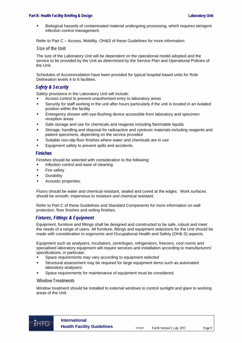
Part B: Health Facility Briefing & Design Laboratory Unit
International
Health Facility Guidelines © TAHPI
Part B: Version 5 July 2017
Page 9
Biological hazards of contaminated material undergoing processing, which requires stringent infection control management.
Refer to Part C – Access, Mobility, OH&S of these Guidelines for more information.
Size of the Unit
The size of the Laboratory Unit will be dependent on the operational model adopted and the service to be provided by the Unit as determined by the Service Plan and Operational Policies of the Unit. Schedules of Accommodation have been provided for typical hospital based units for Role Delineation levels 4 to 6 facilities.
Safety & Security Safety provisions in the Laboratory Unit will include: Access control to prevent unauthorised entry to laboratory areas Security for staff working in the unit after hours particularly if the unit is located in an isolated
position within the facility Emergency shower with eye-flushing device accessible from laboratory and specimen
reception areas Safe storage and use for chemicals and reagents including flammable liquids Storage, handling and disposal for radioactive and cytotoxic materials including reagents and
patient specimens, depending on the service provided Suitable non-slip floor finishes where water and chemicals are in use Equipment safety to prevent spills and accidents.
Finishes Finishes should be selected with consideration to the following: Infection control and ease of cleaning Fire safety Durability Acoustic properties. Floors should be water and chemical resistant, sealed and coved at the edges. Work surfaces should be smooth, impervious to moisture and chemical resistant. Refer to Part C of these Guidelines and Standard Components for more information on wall protection, floor finishes and ceiling finishes.
Fixtures, Fittings & Equipment Equipment, furniture and fittings shall be designed and constructed to be safe, robust and meet the needs of a range of users. All furniture, fittings and equipment selections for the Unit should be made with consideration to ergonomic and Occupational Health and Safety (OH& S) aspects. Equipment such as analysers, incubators, centrifuges, refrigerators, freezers, cool rooms and specialised laboratory equipment will require services and installation according to manufacturers’ specifications, in particular: Space requirements may vary according to equipment selected Structural assessment may be required for large equipment items such as automated
laboratory analysers Space requirements for maintenance of equipment must be considered.
Window Treatments
Window treatment should be installed to external windows to control sunlight and glare to working areas of the Unit.

Part B: Health Facility Briefing & Design Laboratory Unit
International
Health Facility Guidelines © TAHPI
Part B: Version 5 July 2017
Page 10
Building Service Requirements
Communications
Unit design should address the following Information Technology/ Communications issues: Telephones and video-conferencing capacity for meeting rooms Electronic Medical Records and inclusion of laboratory result reporting Data and communication outlets, wireless networks, servers and communication room
requirements.
Heating, Ventilation and Air conditioning
The Laboratory Unit shall have appropriate air conditioning that allows control of temperature and humidity for the proper handling of specimens and equipment functioning. Some laboratories will require special air-conditioning such as negative pressure or positive pressure. Anatomical Pathology land Microbiology laboratories will require negative pressure air-conditioning and exhaust to minimise odours and prevent aerosol contamination of adjacent areas. Offices, open plan workstation areas, Meeting Rooms and Staff Rooms should be air-conditioned for the benefit of staff and visitors to the Unit. The local or country specific mechanical requirements should be consulted.
Shielding and Radiation Safety
If radioactive reagents and materials are used they should be stored and disposal of in appropriately shielded containers and room. No special provisions will normally be required for waste specimens from most patients receiving low level isotope diagnostic material.
Pneumatic Tube Systems The Laboratory Unit may include a pneumatic tube station, connecting key clinical units with the main support units as determined by the facility Operational Policy. If provided the station should be located in the Specimen Reception under direct staff supervision.
Infection Control Infection Control measures applicable to the Laboratory Unit will involve proper handling of specimens to prevent contamination of staff. Standard precautions apply to the Laboratory Unit areas and personal protective equipment including protective clothing, gloves, masks, and eye protection will be available close to all processing areas. It is recommended that in addition to hand basins, medicated hand gel dispensers be located strategically at Specimen Reception and in staff circulation areas.
Hand Basins
Hand hygiene is an essential element of infection control and handbasins will be required in: Specimen Collection areas Each laboratory or automated processing area Clean-up rooms. For further information refer to Part D – Infection Control in these Guidelines.

Part B: Health Facility Briefing & Design Laboratory Unit
International
Health Facility Guidelines © TAHPI
Part B: Version 5 July 2017
Page 11
4 Components of the Unit
Standard Components The Laboratory will contain Standard Components to comply with details in the Standard Components described in these Guidelines. Refer to Standard Components Room Data Sheets and Room Layout Sheets.
Non-Standard Components Non Standard rooms are identified in the Schedules of Accommodation as NS and are described below.
Laboratory - High volume analyser
The High volume Laboratory analyser is an automated analyser, consisting of multiple modules, depending on the required function that may process hundreds of specimens per hour. The analyser may be located in a large open plan area within the Laboratory Unit; the space required will be determined by the equipment selected. The Processor should be located with convenient access to Specimen Reception for efficient sample processing. The equipment is automated and will require a temperature controlled environment along with services and data connections according to manufacturer’s specifications. Access for installation and servicing should be available.
Laboratory - Physical Containment, high risk
The Physical Containment Laboratory will be a fully enclosed, strongly negatively pressured, HEPA filtered laboratory with entry via a dedicated airlock. The Airlock is moderately negative pressured with air flow towards the Laboratory. Doors between the Airlock and Laboratory are interlocking - only one can be open at one time. The Physical Containment laboratory is used for handling infective organisms such as HIV viruses, viral hepatitis and other infective agents and genetically modified organisms. Work inside the Laboratory will be undertaken in a biological safety cabinet. Physical containment Laboratories are classified according to risk of the agents used in them from lowest biosafety level 1 to highest biosafety level 4. These laboratories must be constructed to standards and are certified by an appropriate authority. Requirements include: Air pressurisation to be monitored with a display and alarmed Walls, floors and ceiling finishes that are smooth, impervious to water chemical resistant and
easily cleaned A hand basin and PPE within the laboratory Eye wash equipment within the laboratory All fittings within the laboratory must be able to be decontaminated and fumigated An autoclave A fail-safe communication system within the laboratory.
Pneumatic Tube Station
The Pneumatic Tube Station should be located at the Specimen Reception under the direct supervision of staff for urgent arrivals. The location should not be accessible by external staff or visitors. Requirements include: The bay should not impede access within reception areas Racks should be provided for pneumatic tube canisters Wall protection should be installed to prevent wall damage from canisters.

Part B: Health Facility Briefing & Design Laboratory Unit
International
Health Facility Guidelines © TAHPI
Part B: Version 5 July 2017
Page 12
Sorting / Processing
The Sorting area within the Laboratory includes labelling of specimens, sorting by specialty and laboratories, initial scanning or copying of requests. Processing will include temporary holding in refrigeration, holding and packaging specimens for transfer to laboratories. The Sorting/ Processing area will be located adjacent to the Specimen Reception and with easy access to the laboratories The area will require: Workstations for data entry Holding areas for specimens awaiting transit to specialist internal laboratories or remote
laboratories Scanning equipment Refrigerators and freezers in close proximity Incubator for microbiology samples Hand basin and sink within the initial processing area Clinical waste disposal Extraction for odours and fumes may be required.

Part B: Health Facility Briefing & Design Laboratory Unit
International
Health Facility Guidelines © TAHPI
Part B: Version 5 July 2017
Page 13
5 Schedule of Accommodation
Laboratory Unit located within a health facility
ROOM/ SPACE Standard Component RDL 4 RDL 5/6 Remarks Room Codes Qty x m2 Qty x m2
Entry/ Reception Specimen Reception/ Registration sprec-i similar 1 x 12 1 x 20 Receiving, data entry for tracking
Pneumatic Tube Station NS 1 x 1 1 x 1
Sorting / Processing NS 1 x 10 1 x 15 Preliminary processing, Includes dispatch area
Laboratory - General
Laboratory - General pthlb-mod-i similar 1 x 50 Clinical Chemistry, Haematology, Blood bank processing combined; RDL 5/6 separate labs
Haematology
Specimen Reception sprec-i similar 1 x 15 Receiving, sorting & preliminary processing
Laboratory - High volume analyser NS 1 x 80
Laboratory - Manual Testing pthlb-mod- 1 x 25
Lab Workstations - Microscopy pthlb-mod-i similar 1 x 30
Store - General stgn-10-i 1 x 10
Clinical Chemistry
Specimen Reception sprec-i similar 1 x 15
Laboratory - High Volume Analyser NS 1 x 50
Lab Workstations - Chemistry pthlb-mod-i similar 1 x 25 May include manual processing stations
Bay - Storage bs-2-i 1 x 2 Equipment that needs to be located in the zone
Microbiology/ Serology Specimen Reception, sorting, set-up sprec-i similar 1 x 10 1 x 30 Receiving, sorting & preliminary processing
Laboratory - Blood Culture pthlb-mod- 1 x 15 1 x 15 Enclosed , Negative Pressure
Laboratory - Physical Containment NS 1 x 25 Negative Pressure, includes biological safety cabinet/s; to comply with standards
Anteroom - Physical Containment Laboratory
anrm-i 1 x 6 For air pressurisation, PPE
Cool Room/ Refrigerator/s corm-i 2 x 6 Separate clean and dirty cool storage
Laboratory - Incubators pthlb-mod- similar 1 x 15
Lab Workstations - Microscopy, Specimen reading
pthlb-mod-i similar 1 x 40 Enclosed, negative pressure
Laboratory - Mycology, Microscopy pthlb-mod-i similar 1 x 15 1 x 25 Enclosed, negative pressure

Part B: Health Facility Briefing & Design Laboratory Unit
International
Health Facility Guidelines © TAHPI
Part B: Version 5 July 2017
Page 14
ROOM/ SPACE Standard Component RDL 4 RDL 5/6 Remarks Room Codes Qty x m2 Qty x m2
Anatomical Pathology Specimen Reception sprec-i similar 1 x 15 Receiving, sorting & preliminary processing
Laboratory - Cytology pthlb-mod- similar 1 x 20
Laboratory - Immuno-histochemistry (IHC)
pthlb-mod- similar 1 x 15
Lab Workstations - Blocking & Embedding pthlb-mod- similar 1 x 15
Lab Workstations - Chemical Prep & Staining
pthlb-mod- similar 2 x 20
Lab Workstations - Microscopy pthlb-mod- similar 1 x 40
Laboratory - Cutting room pthlb-mod- similar 1 x 40
Laboratory - Tissue processing pthlb-mod- similar 1 x 15
Laboratory - Cryostat pthlb-mod- similar 1 x 10 1 x 15 Frozen sections
Store - Samples, Slides & Specimens stgn-20-i similar 1 x 20
Bay - Storage bs-2-i 1 x 2 Equipment that needs to be located in the zone
Clinical Immunology Specimen Reception sprec-i similar Shared 1 x 15 RDL 4 shared with main Specimen Reception
Laboratory - Antibody pthlb-mod- similar 1 x 25
Laboratory - Proteins, Allergy pthlb-mod- similar 1 x 25 1 x 25
Bay - Refrigerators - Freezers bmeq-4-i similar 1 x 6 temperature monitored, alarmed
Blood Bank
Specimen Reception sprec-i similar Shared 1 x 4 RDL 4 shared with main Specimen Reception
Laboratory - Processing Area pthlb-mod- similar 1 x 25 RDL 4 processing done in Lab-General
Blood Products Cool Room/ Refrigerators
corm-i similar 1 x 2 1 x 6
Blood Products Freezer/s corm-i similar 1 x 1 1 x 6
After-hours Blood Store ahbbf-i 1 x 3 1 x 3
Bay - Storage bs-2-i 1 x 2 Equipment that needs to be located in the zone
Specimen Collection
Reception recl-12-i recl-15-i 1 x 12 1 x 15
Waiting wait-10-i wait-25-i 2 x 10 2 x 25 Separate Male/ Female waiting
Specimen Collection Cubicles specc-i 2 x 9 4 x 9
Toilet - Patient wcpt-i 2 x 4 2 x 4 Separate Male/ Female
Toilet - Accessible wcac-i 1 x 6 1 x 6 Optional

Part B: Health Facility Briefing & Design Laboratory Unit
International
Health Facility Guidelines © TAHPI
Part B: Version 5 July 2017
Page 15
ROOM/ SPACE Standard Component RDL 4 RDL 5/6 Remarks Room Codes Qty x m2 Qty x m2 Bay - Pneumatic Tube Station NS 1 x 1 1 x 4 Optional, locate at Reception
Bay - Mobile Equipment bmeq 1 x 4 2 x 4 Phlebotomy trolleys
Dirty Utility dtur-s-i dtur-12-i 1 x 8 1 x 12
Store - General stgn- 1 x 6 1 x 12 Consumables, sterile stock
Support Areas Shared between Laboratories Bay - Emergency Shower and Eyewash bese-1-i 1 x 1 5 x 1 Locate in each separate laboratory
Cleaner’s Room clrm-5-i 1 x 5 2 x 5
Clean-up Room clup-7-i clup-12-i 1 x 7 1 x 12
Cool Room/s corm-i similar 1 x 6 2 x 10
Disposal Room disp-5-i disp-10-i 1 x 5 1 x 10
Freezers area NS 1 x 3 1 x 10
Sterilising Room NS 1 x 7 1 x 12 adjacent to Clean-up
Store - Bulk stbk-40-i similar 1 x 20 1 x 60
Store - Chemical stcm-i similar 1 x 4 1 x 9
Store - General stgn-8-i stgn-16-i 1 x 8 1 x 16 general supplies & consumables
Store - Photocopy/ Stationery stps-8-i stps-10-i 1 x 8 1 x 10 optional
Store - Files stfs-8-i stfs-10-i 1 x 8 1 x 10 optional
Offices & Staff Areas
Meeting Room - Medium/ Large meet-l-15-i meet-l-25-i 1 x 15 2 x 25
Office - Single Person, 12m2 off-s12-i 1 x 12 1 x 12 Head of Department
Office - Single Person, 9m2 off-s9-i 4 x 9 Pathologists, include microscope station
Office, 2 Person Shared off-2p-i 1 x 12 2 x 12 Clerical support
Office, 2 Person Shared off-2p-i 6 x 12 Lab Managers & Supervisors, senior technician
Office - Workstation/s off-ws-i 3 x 5.5 10 x 5.5 Technical staff for each specialty
Staff Room srm-25-i Shared 1 x 25
Property Bay - Staff prop-2-i 2 x 2 Lockers, separate M/F areas
Change Room - Staff, (M/F) chst-20-i 2 x 20 Includes Toilet, Shower and Lockers
Shower - Staff shst-3-i 2 x 3 Separate M/F
Toilet - Staff wcst-i 2 x 3 2 x 3 Separate M/F
Sub Total 390.5 1465.0
Circulation % 25 25
Area Total 488.1 1831.3

Part B: Health Facility Briefing & Design Laboratory Unit
International
Health Facility Guidelines © TAHPI
Part B: Version 5 July 2017
Page 16
Note 1: Offices to be provided according to the number of approved full time positions within the Unit
Also note the following: Areas noted in Schedules of Accommodation take precedence over all other areas noted in the FPU. Rooms indicated in the schedule reflect the typical arrangement according to the Role Delineation. Exact requirements for room quantities and sizes will reflect Key Planning Units identified in the Service Plan and the Operational Policies of the Unit. Room sizes indicated should be viewed as a minimum requirement; variations are acceptable to reflect the needs of individual Unit. Office areas are to be provided according to the Unit role delineation and number of endorsed full time positions in the unit. Staff and support rooms may be shared between Functional Planning Units dependent on location and accessibility to each unit and may provide scope to reduce duplication of
facilities.
.

Part B: Health Facility Briefing & Design Laboratory Unit
International
Health Facility Guidelines © TAHPI
Part B: Version 5 July 2017
Page 17
6 Future Trends Laboratory practise is rapidly changing with advances in technology affecting the service delivery. Future trends include the following: As software capabilities continue to develop, clinical chemistry analysers will be able to offer
increased testing speed and degree of automation Automation is progressing towards Total Laboratory Automation Software is becoming more sophisticated in linking analysers to laboratory information
systems, ordering and reporting are becoming more automated Continued improvements to sample turnaround and throughput speed Analysers with specimen storage and retrieval capabilities Increase used of genetic testing and biopsy testing Increased use and accuracy of point of care devices. All of the above may have a direct influence on the type of service to be offered and the amount of space required in future laboratories. 7 Further Reading Australasian Health Facility Guidelines, Part B Health Facility Briefing and Planning, 0550 -
Pathology Unit, Revision 6, 2016 refer to https://healthfacilityguidelines.com.au/health-planning-units
Building Type Basics for Research Laboratories, Daniel Watch. New York, NY: John Wiley & Sons, Inc., 2001.
CDC (Center for Disease Control) US. Guidelines for Environmental Infection Control in Health-Care Facilities, US, refer to website http://www.cdc.gov/hicpac/pubs.html
CRC Handbook of Laboratory Safety, 5th Edition, A. K. Furr. Boca Raton, FL: CRC Press, 2000 refer to https://www.crcpress.com/CRC-Handbook-of-Laboratory-Safety-5th-Edition/Furr/p/book/9780849325236
ISO/IEC 17025 General requirements for the competence of testing and calibration laboratories, 2005, refer to https://www.iso.org/standard/39883.html
Laboratory Design Guide, 3rd Edition; Brian Griffin, Architectural Press, Elsevier UK, 2005 The Clinical Biochemist Reviews, Clinical Chemistry Laboratory Automation in the 21st
Century, David A Armbruster, David R Overcash and Jaime Reyes, 2014 Aug; 35(3): 143–153, refer to https://www.ncbi.nlm.nih.gov/pmc/articles/PMC4204236/
The Facility Guidelines Institute (US), Guidelines for Design and Construction of Hospitals and Outpatient Facilities, 2014. Refer to website www.fgiguidelines.org

Part B – Health Facility Briefing & Design 150 Linen Handling Unit
International Health Facility Guidelines Version 5 Aug 2017

Part B: Health Facility Briefing & Design
International
Health Facility Guidelines © TAHPI
Part B: Version 5 Aug 2017
Page 2
Table of Contents
150 Linen Handling Unit .................................................................................................................. 3
1 Introduction ............................................................................................................................................... 3 Description .................................................................................................................................................. 3
2 Functional and Planning Considerations ............................................................................................... 3 Operational Models ..................................................................................................................................... 3 Planning Models .......................................................................................................................................... 3 Functional Areas ......................................................................................................................................... 3 Functional Relationships ............................................................................................................................. 5
3 Design ........................................................................................................................................................ 7 General........................................................................................................................................................ 7 Environmental Considerations .................................................................................................................... 7 Space Standards and Components ............................................................................................................ 7 Safety & Security ......................................................................................................................................... 7 Finishes ....................................................................................................................................................... 7 Fixtures, Fittings & Equipment .................................................................................................................... 8 Building Service Requirements ................................................................................................................... 8 Infection Control .......................................................................................................................................... 8
4 Components of the Unit ............................................................................................................................ 9 Standard Components ................................................................................................................................ 9 Non-Standard Components ......................................................................................................................... 9
5 Schedule of Accommodation ................................................................................................................. 11 Linen Handling Unit ................................................................................................................................... 11
6 Future Trends .......................................................................................................................................... 12
7 Further Reading ....................................................................................................................................... 12

Part B: Health Facility Briefing & Design Linen Handling Unit
International
Health Facility Guidelines © TAHPI
Part B: Version 5 Aug 2017
Page 3
150 Linen Handling Unit
1 Introduction
Description Linen handling involves: The collection of dirty linen on a regular basis Processing of dirty linen including sorting, washing, drying and folding Storage of clean linen and supply to inpatient and ambulatory care units on a regular basis. Linen processing may be done within the hospital facility or off-site in a commercial or shared laundry, depending on the Operational Policy. As a minimum, each facility shall have provisions for storage and exchange of clean and soiled linen for appropriate patient care. 2 Functional and Planning Considerations
Operational Models Linen processing may be performed on-site in a separate facility or within the hospital. Most commonly, linen processing is outsourced in a commercial arrangement with an external provider and delivered to the facility. The minimum service provided by the hospital will generally be a daily collection of dirty linen and daily delivery of clean linen to patient units.
Hours of Operation
The Linen Handling Unit will typically operate up to 12 hours per day, 7 days per week.
Planning Models
Location
The Linen Handling Unit will be located in the service area of the facility with close access to clean and dirty loading dock areas. An on-site laundry facility may be located in the hospital or remotely in a separate building with good connectivity to the hospital.
Functional Areas As a minimum, the following elements shall be provided: Service Areas:
- Clean Linen Holding room with an area for receipt of pre-loaded linen trolleys from an external supplier
- Dirty Linen Holding with an area for holding of dirty linen collection trolleys Support Areas
- Service entrance, protected from weather for loading and unloading clean and dirty linen
- Loading Dock, with clean and dirty zones, that may be shared with other service units - Trolley Washing area that may be shared with other service units - Equipment Parking Bay for holding of clean linen supply and collection trolleys.
Staff Areas including: - Manager or Supervisor's Office - Access to a meeting room for Training and staff meetings - Sign-on bay for staff, optional depending on the Unit Operational Policy and the
method used for staff attendance - Access to Staff Room, Toilets, Shower and Lockers; these may be shared with
general hospital staff.

Part B: Health Facility Briefing & Design Linen Handling Unit
International
Health Facility Guidelines © TAHPI
Part B: Version 5 Aug 2017
Page 4
Optional functional areas include: A clean linen inspection room or area, located on or off the site, as part of the main linen
service, as determined by the system identified in the hospital's Operational Policy Sewing/ Mending room, for linen repairs and alterations Uniform holding and issuing room with changing facilities Small commercial laundry room with washing and drying facility for processing small items
that are not handled by an external laundry Full scale Laundry on-site for bulk processing, if provided will include:
- Laundry processing rooms with commercial type equipment that can process at least a seven day supply within the regular scheduled work week
- Storage for laundry supplies and chemicals - Employee hand-washing facilities in each separate room where clean or soiled linen is
processed and handled - Arrangement of equipment that permits an orderly work flow and separation of dirty
and clean processes with no cross traffic - Convenient access to Staff Amenities, which may be shared - Compliance with all of the relevant statutory requirements and regulations for cleaning
and handling linen will be required. This FPU does not address the specific arrangement and requirements of an on-site full scale Laundry processing unit.
Clean Linen Holding
The Clean Linen Holding room receives the clean linen supply on trolleys from an external supplier. The Clean Linen Holding room should have capacity for several days’ supply of linen, sufficient for efficient operation of the hospital in emergencies. Clean linen is supplied to inpatient units on trolleys held in the clean linen holding room until delivery. The Clean Linen Holding Room should be located with ready access to the clean loading dock area for deliveries. The room may include a workstation for linen receipt and counting and shelving for stored items of linen such as curtains, blankets, bedspreads, as well as additional supplies of general linen articles. Refer to Standard Components - Linen Holding-Clean for additional information and specific room requirements.
Dirty Linen Holding
The Dirty Linen Holding room will hold bagged dirty linen on trolleys awaiting collection and removal to the laundry facilities. The room should be sized sufficient for holding several days of dirty linen awaiting collection, allowing for delays in the collection service in emergencies. Dirty Linen Holding should be located with ready access to the dirty loading dock area for waste removal. Refer to Standard Components - Linen Holding-Soiled for additional information and specific room requirements
Support Areas
Service Entry The service entry is an external area with access to the clean and dirty loading dock areas for delivery of clean supplies and removal of waste. Traffic and work flows for clean and dirty functions should not cross. The service entry may require secured access for vehicles. The loading dock area should be covered. Refer to Standard Components - Loading Dock for additional information and specific requirements.

Part B: Health Facility Briefing & Design Linen Handling Unit
International
Health Facility Guidelines © TAHPI
Part B: Version 5 Aug 2017
Page 5
Trolley Washing Trolley washing may be provided in the service area and shared by other service units. Where the linen supply is provided by an external enterprise, trolley washing may be undertaken off-site with trolleys delivered clean.
Optional Areas:
Linen Inspection and Mending The Linen Inspection and Mending room is an area where linen such as sheets, wraps and uniforms are examined for tears, holes and signs of wear. Linen suitable for repair may be mended in the sewing area, containing sewing machines and patching materials. An external linen provider may undertake this task off-site.
Uniform Holding Uniform holding will require a locked room containing uniform supplies for various hospital staff, sized to accommodate a multitude of uniform components in a range of sizes. Internally the room should include changing cubicles, for staff to check uniform sizing. The room may be located adjacent to the clean linen handling area or may be located remotely where there is convenient access for staff.
Hospital Laundry for Small Items The hospital may include a small scale laundry fitted with commercial washing and drying equipment for on-site washing of items not processed by an external laundry service. This may include mop heads, patient lifter slings and delicate linen items used for catered functions. The laundry will be located in the service area with convenient access for linen handling personnel. Refer to Standard Components - Laundry-Hospital for additional information and specific room requirements
Functional Relationships
External
The Linen Handling Unit will require ready access to: The service entry and clean Loading Dock for daily deliveries of clean linen on trolleys to the
Clean Linen Holding Waste Management area and Dirty Loading dock for daily collection of dirty linen on trolleys
from the Dirty Linen Holding room All hospital Units supplied with linen; good connectivity is required to service corridors and
service lifts for linen deliveries and collection services. The optimum external functional relationships are demonstrated in the diagram below.
Internal
Within the Linen Handling Unit, clean and dirty linen holding areas will generally be separated to prevent cross flow of clean and dirty traffic to the Loading Dock area Trolley storage and cleaning areas should be located with convenience for efficient linen handling. Staff and support areas will generally be shared with other service areas in the hospital. Key Internal Functional relationships are demonstrated in the diagram below.

Part B: Health Facility Briefing & Design Linen Handling Unit
International
Health Facility Guidelines © TAHPI
Part B: Version 5 Aug 2017
Page 6
Functional Relationship Diagram
Figure 1 Functional Relationship Diagram

Part B: Health Facility Briefing & Design Linen Handling Unit
International
Health Facility Guidelines © TAHPI
Part B: Version 5 Aug 2017
Page 7
3 Design
General Design of Linen Handling areas should ensure that clean and dirty work flows do not cross as far as possible and that holding rooms are free from insects and vermin.
Environmental Considerations
Acoustics
Consideration should be given to acoustic privacy in Offices particularly if located in noisy service areas of the hospital.
Natural Light/ Lighting
Natural light is not required in linen holding rooms, however, artificial lighting is required and should be sufficient to avoid shaded spots where accidents can occur.
Space Standards and Components
Doors
Doors to service corridors and Linen Holding areas must be adequately sized to accommodate the trolleys in use. Also refer to Part C – Access, Mobility, OH&S of these Guidelines.
Ergonomics/ OH&S
Consideration should be given to the manual handling of linen supply and collection trolleys. Where linen sorting, counting or examining activities are undertaken, benches and shelving should be provided at suitable working heights. Refer to Part C – Access, Mobility, OH&S of these Guidelines for more information.
Size of the Unit
The size of the Linen Handling areas will be dependent on the size of the facility and the amount of storage required for standard conditions. The Unit size should include an allowance for reserve clean linen and dirty holding in emergencies and take into consideration the frequency and reliability of linen supply and collection services. Schedules of Accommodation have been provided for typical Linen Handling Units with an out-sourced linen supply in a range of hospital role delineation levels.
Safety & Security Safety and Security provisions in the Linen Handling Unit will include: Locked linen holding rooms with access restricted to authorised staff Security for staff in isolated service zones of the facility, particularly if working after-hours Non-slip floor finishes to laundry rooms and trolley washing areas.
Finishes Finishes should be selected with consideration to the following: Infection control and ease of cleaning Ability to withstand heavy trolley traffic Fire safety Acoustic properties. Door and wall protection should be provided where linen trolley movement occurs such as service corridors, service lifts, trolley parking areas, linen holding rooms and linen storage bays. Floor finish is to be non-slip, impervious, easy to clean and durable, with frequent movement of bulky linen supply and collection trolleys.

Part B: Health Facility Briefing & Design Linen Handling Unit
International
Health Facility Guidelines © TAHPI
Part B: Version 5 Aug 2017
Page 8
Refer to Part C of these Guidelines and Standard Components for more information on wall protection, floor finishes and ceiling finishes.
Fixtures, Fittings & Equipment Shelving installed in clean linen areas should be constructed of non-porous materials, dust resistant, easily cleaned and avoid inaccessible corners. Washing and drying machines installed in the laundry room should be commercial quality and installed to manufacturer’s specifications.
Building Service Requirements
Communications
The following IT/ Communications systems may be provided within the Linen Handling Unit: Telephones in Linen Holding areas, Uniform rooms, Linen Inspection and Mending rooms,
Offices and workstations Data outlets for computers/ internet access to Offices, Workstations and Holding rooms Scanning systems for registering received supplies or despatches Wireless networks for computer access in receiving areas, which may include service
corridors and Loading Docks.
Heating, Ventilation and Air conditioning
Linen Handling areas such as inspection and folding areas will require air-conditioning with efficient lint filtration systems. Offices and Staff Rooms should be provided with air-conditioning with temperature and humidity control for staff comfort.
Infection Control Linen Handling staff will require ready access to staff handwashing basins. Hand basins will be located within the Clean Linen Holding Rooms and in Soiled Linen collection rooms, in linen inspection, mending and folding areas. It is recommended that in addition to hand basins, medicated hand gel dispensers be located strategically in staff circulation corridors. For further information refer to Part D – Infection Control in these Guidelines.
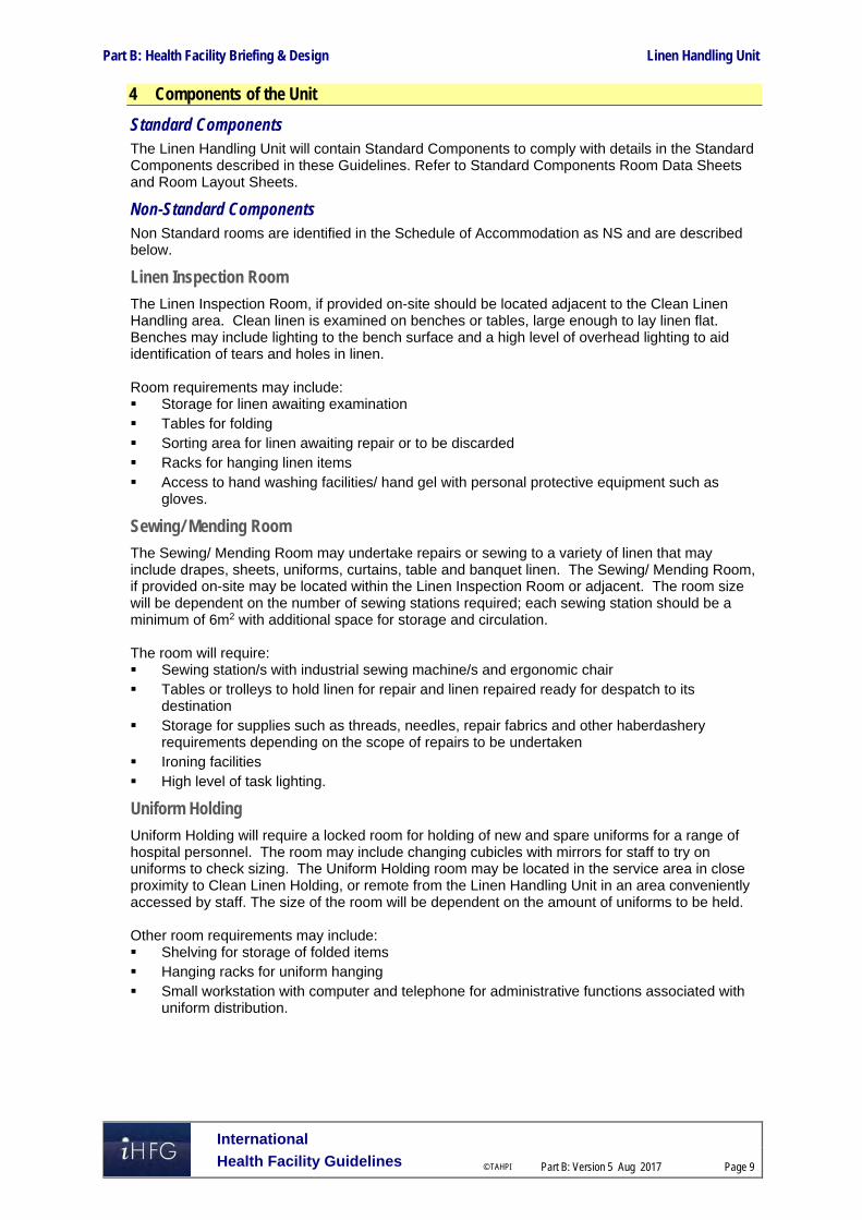
Part B: Health Facility Briefing & Design Linen Handling Unit
International
Health Facility Guidelines © TAHPI
Part B: Version 5 Aug 2017
Page 9
4 Components of the Unit
Standard Components The Linen Handling Unit will contain Standard Components to comply with details in the Standard Components described in these Guidelines. Refer to Standard Components Room Data Sheets and Room Layout Sheets.
Non-Standard Components Non Standard rooms are identified in the Schedule of Accommodation as NS and are described below.
Linen Inspection Room
The Linen Inspection Room, if provided on-site should be located adjacent to the Clean Linen Handling area. Clean linen is examined on benches or tables, large enough to lay linen flat. Benches may include lighting to the bench surface and a high level of overhead lighting to aid identification of tears and holes in linen. Room requirements may include: Storage for linen awaiting examination Tables for folding Sorting area for linen awaiting repair or to be discarded Racks for hanging linen items Access to hand washing facilities/ hand gel with personal protective equipment such as
gloves.
Sewing/ Mending Room
The Sewing/ Mending Room may undertake repairs or sewing to a variety of linen that may include drapes, sheets, uniforms, curtains, table and banquet linen. The Sewing/ Mending Room, if provided on-site may be located within the Linen Inspection Room or adjacent. The room size will be dependent on the number of sewing stations required; each sewing station should be a minimum of 6m2 with additional space for storage and circulation. The room will require: Sewing station/s with industrial sewing machine/s and ergonomic chair Tables or trolleys to hold linen for repair and linen repaired ready for despatch to its
destination Storage for supplies such as threads, needles, repair fabrics and other haberdashery
requirements depending on the scope of repairs to be undertaken Ironing facilities High level of task lighting.
Uniform Holding
Uniform Holding will require a locked room for holding of new and spare uniforms for a range of hospital personnel. The room may include changing cubicles with mirrors for staff to try on uniforms to check sizing. The Uniform Holding room may be located in the service area in close proximity to Clean Linen Holding, or remote from the Linen Handling Unit in an area conveniently accessed by staff. The size of the room will be dependent on the amount of uniforms to be held. Other room requirements may include: Shelving for storage of folded items Hanging racks for uniform hanging Small workstation with computer and telephone for administrative functions associated with
uniform distribution.

Part B: Health Facility Briefing & Design Linen Handling Unit
International
Health Facility Guidelines © TAHPI
Part B: Version 5 Aug 2017
Page 10
Trolley Washing
Trolley Washing is an area for manual washing of trolleys including linen handling and may be shared with a number of service units. The Trolley Wash area should be located in the service area. The trolley washing area will require: Smooth, waterproof and easily cleanable surfaces to walls and ceiling Non-slip, waterproof finishes to the floor Hot and cold water outlets with hoses Drainage to the floor An area for hand drying of trolleys and space for holding completed trolleys awaiting
transport to clean holding areas.
Staff Registration Bay
A recessed area may be required for staff to register presence and check or record rosters, depending on the system used for staff registration. The bay size will be dependent on the system used and operational policy; 4 m2 is recommended if accommodating a computer station. An electronic system or scanning device may be used for staff registration. The Staff Registration Bay should be located in a discreet area with ready access to staff entry area and circulation corridor/s. It may also be located close to the Unit Manager's Office. The Staff Registration Bay may include the following: Staff registration equipment, manual or electronic Bench at standing height (optional) Pin board for display of rosters or other staff information (or computer for computerised
rosters) Computer terminal (optional) Power and data outlets for computer or electronic staff presence equipment as required.

Part B: Health Facility Briefing & Design Linen Handling Unit
International
Health Facility Guidelines © TAHPI
Part B: Version 5 Aug 2017
Page 11
5 Schedule of Accommodation
Linen Handling Unit
ROOM/ SPACE Standard Component RDL 2 RDL 3 RDL 4 RDL 5 RDL 6 Remarks Room Codes Qty x m2 Qty x m2 Qty x m2 Qty x m2 Qty x m2
Service Areas Linen Holding - Clean lho-cl-i similar 1 x 15 1 x 30 1 x 45 1 x 80 1 x 100 Adjust size to meet service plan
Linen Holding - Soiled lho-so-i similar 1 x 15 1 x 20 1 x 30 1 x 40 1 x 60 Adjust size to meet service plan
Linen Inspection Room NS 1 x 10 1 x 15 1 x 20 Optional
Sewing/ Mending Room NS 1 x 10 1 x 15 1 x 15 Optional
Uniform Holding NS 1 x 15 1 x 20 1 x 20 Optional
Laundry - Hospital (Small Items) laun-ho-i similar 6 1 x 6 1 x 10 1 x 20 1 x 20 Optional
Support Areas
Loading Dock lodk-i similar 1 x 20 1 x 30 1 x 30 1 x 40 1 x 40 Shared between service units
Trolley Washing Area NS 1 x 6 1 x 6 1 x 6 1 x 10 1 x 10 Optional, may be shared
Bay - Equipment Park beqp-15-i beqp-20-i 1 15 1 15 1 20 1 20 Holding clean spare trolleys
Staff Areas
Office - Single Person off-s9-i 1 9 1 x 9 1 x 9 Manager
Office - Shared off-2p-i 1 x 12 1 x 12 Supervisors
Staff Registration Bay NS 1 x 4 1 x 4 1 x 4 1 x 4 1 x 4 Optional
Meeting Room meet-15-i Shared Shared Shared Shared Shared Optional, Shared with general staff facilities
Staff Room srm-15-i Shared Shared Shared Shared Shared Optional, May be shared
Change - Staff (M/F) chst-14-i Shared Shared Shared Shared Shared Shared, Toilets, Showers, Lockers
Toilet - Staff (M/F wcst-i Shared Shared Shared Shared Shared Shared with general staff facilities
Sub Total 67 110.0 184.0 285.0 330.0
Circulation % 10 10 10 10 10
Area Total 73.7 122.1 202.4 313.5 363.0
Also note the following: Areas noted in Schedules of Accommodation take precedence over all other areas noted in the FPU. Rooms indicated in the schedule reflect the typical arrangement according to the Role Delineation. Exact requirements for room quantities and sizes will reflect Key Planning Units identified in the Service Plan and the Operational Policies of the Unit. Room sizes indicated should be viewed as a minimum requirement; variations are acceptable to reflect the needs of individual Unit. Office areas are to be provided according to the Unit role delineation and number of endorsed full time positions in the unit. Staff and support rooms may be shared between Functional Planning Units dependent on location and provide scope to reduce duplication of facilities.

Part B: Health Facility Briefing & Design Linen Handling Unit
International
Health Facility Guidelines © TAHPI
Part B: Version 5 Aug 2017
Page 12
6 Future Trends Future trends that may affect the operation of Linen Handling Units include: Evolving service delivery models that provide more efficient off-site processing with collection
and delivery services Increased usage of automated delivery systems in hospitals such as automated guided
vehicles Improvements to technology and software that allow request of linen direct from the hospital
units that require this service, track usage, manage costs and reduce linen wastage. 7 Further Reading In addition to iHFG Sections referenced in this FPU, i.e. Part C- Access, Mobility, OH&S and Part D - Infection Control, readers may find the following helpful: Guidelines for Design and Construction of Hospitals and Outpatient Facilities; The Facility
Guidelines Institute (US), 2014 Edition; refer to website www.fgiguidelines.org Health Building Note 00-04 Circulation and communication spaces, Department of Health
(UK), 2013 refer to https://www.gov.uk/government/uploads/system/uploads/attachment_data/file/187026/Health_Building_Note_00-04_-_Circulation_and_communication_spaces_-_updated_April_2013.pdf

Part B – Health Facility Briefing & Design 155 Main Entrance Unit
International Health Facility Guidelines Version 5 July 2017

Part B: Health Facility Briefing & Design
International
Health Facility Guidelines © TAHPI
Part B: Version 5 July 2017
Page 2
Table of Contents
155 Main Entrance Unit ................................................................................................................... 3
1 Introduction ............................................................................................................................................... 3 Description .................................................................................................................................................. 3
2 Functional and Planning Considerations ............................................................................................... 3 Operational Models ..................................................................................................................................... 3 Planning Models .......................................................................................................................................... 3 Functional Areas ......................................................................................................................................... 3 Functional Relationships ............................................................................................................................. 5
3 Design ........................................................................................................................................................ 7 Entry Area ................................................................................................................................................... 7 Environmental Considerations .................................................................................................................... 7 Space Standards and Components ............................................................................................................ 7 Safety & Security ......................................................................................................................................... 8 Finishes ....................................................................................................................................................... 8 Fixtures, Fittings & Equipment .................................................................................................................... 8 Building Service Requirements ................................................................................................................... 9 Infection Control .......................................................................................................................................... 9
4 Components of the Unit .......................................................................................................................... 10 Standard Components .............................................................................................................................. 10 Non-Standard Components ....................................................................................................................... 10
5 Schedule of Accommodation ................................................................................................................. 11 Main Entrance Unit .................................................................................................................................... 11
6 Future Trends .......................................................................................................................................... 12
7 Further Reading ....................................................................................................................................... 12

Part B: Health Facility Briefing & Design Main Entrance Unit
International
Health Facility Guidelines © TAHPI
Part B: Version 5 July 2017
Page 3
155 Main Entrance Unit
1 Introduction
Description The Main Entrance Unit provides for the following functions: Entry to the hospital Drop off and collection area Patient reception Patient and visitor enquiries Way finding to hospital units Patient and visitor waiting. 2 Functional and Planning Considerations
Operational Models
Hours of Operation
The operating hours for the Main Entrance will be dependent on the role, size and Operational Policies of the facility. Generally, the Main Entrance will be open from early morning for arrival of admissions to evening, after closing of visiting hours, seven days per week. After-hours access may be arranged through Security or through the Emergency Unit, according to the Operational Policies of the facility.
Planning Models
Location
The Main Entrance Unit is generally located on ground level, in a location easily seen and accessible from car parking and public transport stations.
Configuration
The Reception desk may include an Admissions area or Cashier stations, depending on the Operational Policy of the facility. A security station may be located in close proximity to the Main Entrance in addition to security stations in other areas such as Emergency Unit. Retail areas may be included as determined by the size and the Service Plan of the facility. The Main Entrance area will have access to lifts, connecting corridors and public amenities including Public and Accessible Toilets, Parenting/ Baby Change facilities and Prayer Rooms if provided in the facility.
Functional Areas The Main Entrance will include the following functional areas: Entry Areas
- External drop-off and collection point, preferably under cover - Airlock, recommended but optional - Entrance Lobby - Storage for wheelchairs
Reception/ Enquiries Area - Reception desk, which may be shared with Admissions Unit - Office for administrative support functions, switchboard operators
Public Areas - Waiting Areas, which may be shared with Admissions and other adjacent hospital
units

Part B: Health Facility Briefing & Design Main Entrance Unit
International
Health Facility Guidelines © TAHPI
Part B: Version 5 July 2017
Page 4
- Internet Kiosk, an optional area for visitors to use computers, internet and recharge mobile phones while they wait
- Access to Public Amenities including toilets, baby change, telephone, public transport phones, vending machines, prayer rooms.
Retail Areas are optional and commonly include: - Florist - Kiosk / Coffee Shop - Gift Shop / Newsagent - Retail Pharmacy - ATM / Banks or agencies - Optical Shop - Other retail areas considered viable.
Entry Areas
Airlock (Optional) An Airlock connecting external areas with internal areas is recommended to: Maintain air-conditioning temperature and air pressurisation from internal to external areas Prevent outside air contaminants such as dust entering the building Provide a security barrier that can be locked in emergencies. The Airlock should be sized to accommodate the amount of people arriving and exiting, and cater for people with mobility aids. Refer to Standard Components Airlock-Entry for additional details.
External Drop-off and Collection Area The external drop off and collection areas, including public transport stations should be covered with direct access to the Main Entry doors. Size will be dependent on number of vehicles expected in the vicinity.
Entrance Lobby The Entrance lobby is the area through which patients and visitors arrive at the Main Entrance to the facility connecting the drop-off and collection areas with the Reception and circulation routes. The Lobby will direct visitors to the Reception area and provide waiting areas and public amenities. The size of the Lobby will be determined by the functions to be accommodated, the volume of persons through the area and the impact the arrival point has on the whole facility. The Lobby will have direct access to circulation corridors and lifts providing the thoroughfare to hospital units and will preferably be in close proximity to the vehicle drop off/ collection areas. Security features provided in this area may be discreet and not noticeable to the observer, including closed circuit television (CCTV), a security room, and controlled access points. Signage and wayfinding in this area needs to be clear and highly visible. This may include electronic directories.
Reception Areas
Reception Desk The Reception Desk should be highly visible from the entry with good signposting indicating the enquiry point for visitors and patients. The Reception Desk may be open plan, partially enclosed or fully enclosed, to be determined by a security risk assessment. Security features such as duress alarms should be included. The Reception Desk will need to accommodate Reception staff and a range of other personnel that may include cashiers, security staff and volunteers to assist with patients and public enquiries and way finding. Refer to Standard Components Reception/ Clerical for additional details.

Part B: Health Facility Briefing & Design Main Entrance Unit
International
Health Facility Guidelines © TAHPI
Part B: Version 5 July 2017
Page 5
Public Areas
Waiting Areas Waiting areas will require seating for a range of occupants including children, elderly and disabled patients and visitors. Seating may be arranged to provide a degree of privacy to groups of seats and may include separate family waiting areas. Waiting areas will require close access to public amenities. Refer to Standard Components Waiting provided in a range of sizes for additional information.
Public Amenities The Main Entry will include access to public amenities including Toilets, Parenting Rooms and Prayer rooms. The sign posting to public amenities should be highly visible and easily understood; use of pictograms is recommended. All public amenities will require access for people with disabilities. Refer to Part B - 260 - Public & Staff Amenities in these guidelines for further information.
Retail Areas
Retail areas may be included in the Main Entry area according to the Operational Policy of the facility providing services that will benefit patients, visitors and staff. The range of retail outlets available will be dependent on the business plan and commercial arrangements between the retail outlets and the facility and will be influenced by the location, the proximity to other retail areas. The size and requirements of each shop will be dependent on the service provided. Local authority regulations may apply to provision of services such as food/ drinks outlets and Pharmacy. Retail areas will require good public access, and ready access to public amenities.
Functional Relationships
External
The Main Entrance will have a strong functional relationship with: Vehicle set down and collection areas including public transport ranks Car parking areas The optimum external functional relationships are demonstrated in the diagram below including the following: Access from drop off, pick-up and transport stations to the Main Entrance Airlock at the entrance between the Main Entrance and Lobby Controlled access at the Airlock entry.
Internal
Within the Main Entry, the following relationships are important: The Reception Desk should have a direct view of Main Entry / Waiting Areas for patient /
visitor enquiries and security issues The Admissions Unit and Discharge Lounge areas may be located in adjacent areas for
patient and visitor convenience Public Amenities may be located in the area or in close proximity Lifts and corridors should be visible, well signposted and easily accessible Retail areas and Discharge Lounges may be located in adjacent areas for patient and visitor
convenience. These internal relationships are outlined in the diagram below, notably: Access to all inpatient outpatient and day patient areas through public corridors Access to service and diagnostic areas through a public access corridor Access to Admissions, Discharge Lounge and Emergency Unit, ideally located in adjacent
areas on the same level as the Main Entrance.

Part B: Health Facility Briefing & Design Main Entrance Unit
International
Health Facility Guidelines © TAHPI
Part B: Version 5 July 2017
Page 6
Functional Relationship Diagram
Figure 1 Functional Relationship Diagram:

Part B: Health Facility Briefing & Design Main Entrance Unit
International
Health Facility Guidelines © TAHPI
Part B: Version 5 July 2017
Page 7
3 Design
Entry Area The Main Entrance shall be at grade level, sheltered from inclement weather, and accessible to the disabled.
Environmental Considerations
Acoustics
The Main Entrance may have a high level of ambient noise from visitors, waiting areas and ambulant traffic. Acoustic measures to reduce sound reverberation may include: Installation of sound absorbing surface materials to walls, floors and ceilings Provision of acoustic fabrics to waiting chairs Acoustic screen panels to waiting areas Sound absorbing fabric drapes to windows. Provision of an augmented hearing loop service for patients and visitors with hearing impairment should be considered for enclosed Reception Desks.
Natural Light/ Lighting
Natural light is recommended to promote a pleasant environment for patients, visitors and staff entering the facility. Windows are highly desirable in waiting areas. Entry and waiting areas should be welcoming and well-illuminated with natural and artificial lighting. General lighting at the Reception Desk and in staff work areas should be even, sufficient for illumination of the work area, avoid glare to computer screens and non-reflective.
Privacy
Acoustic privacy must be considered if confidential patient information is discussed at the Reception desk.
Interior Décor
Interior decor includes furnishings, style, colour, textures and ambience, influenced by perception and culture. The décor of the Main Entrance should be of a high standard, as it is an area of first impressions that will influence the expectations of people using the services.
Signposting
Signposting in the Main Entrance is an important consideration for ease of access through the area. Particular attention must be given to key areas including: External signs identifying the Main Entrance Internal signposting the Reception Desk and Enquiries area Signposting public amenities including Accessible Toilets; relevant guideline requirements for
disability are to be applied Directional signs to major thoroughfare routes and lifts. For additional information on signposting, refer to iHFG Part W - Wayfinding Guidelines.
Space Standards and Components
Accessibility
Design should provide ease of access for wheelchair bound patients and visitors at pathways and external ramps, Airlocks, Reception Desk and in Waiting areas.

Part B: Health Facility Briefing & Design Main Entrance Unit
International
Health Facility Guidelines © TAHPI
Part B: Version 5 July 2017
Page 8
Doors
Entry doors should be automatic where possible and be sized to provide access for wheelchairs and people with mobility aides entering and exiting concurrently. Also refer to Part C – Access, Mobility, OH&S of these Guidelines.
Ergonomics/ OH&S
Design and dimensions of counters and workstations shall ensure privacy and security for patients, visitors and staff. Counter heights should enhance communication and minimise aggressive behaviour. Refer to Part C – Access, Mobility, OH&S of these Guidelines for more information.
Size of the Unit
The size of the Main Entrance Unit is influenced by the size of the facility, the service complexity, the expected volume of patients and visitors through the area and the required ambience of the space. Schedules of Accommodation have been provided in this guideline for a typical unit sized in a range of role delineation levels.
Safety & Security A safety risk assessment should be undertaken in early planning. Security issues that may need to be addressed in the Main Entrance include: Unobstructed viewpoints for staff from counters to Waiting areas and the Main Entrance Duress alarms and emergency exit points to all counters Security to the Reception Desk to prevent unauthorised access behind counter areas Controlled after-hours access to prevent unauthorized entry and exit; external doors locked
(preferably electronically) and monitored CCTV to Waiting areas and Cashier stations - if culturally acceptable Provision of emergency and safety lighting to drop-off and pick-up transport zones for after-
hours use.
Finishes Finishes should be selected with consideration for aesthetic appearance, acoustic properties, fire safety, life span and ability to easily clean and maintain infection control standards. Finishes selected should be able to withstand heavy traffic and sustained usage. Refer to Part C of these Guidelines and Standard Components for more information on wall protection, floor finishes and ceiling finishes.
Fixtures, Fittings & Equipment All furniture, fittings and equipment selections for the Main Entrance areas should be made with consideration to Ergonomic and Occupational Health and Safety (OH&S) aspects.
Counters
If a Cashier is located at the Reception Desk, an appropriate barrier should be provided to the Cashier’s counter. Refer to OH&S guidelines for appropriate depth of workstation counters suitable for staff working with computers. The counter top height shall be suitable for standing interactions with patients and visitors. Counters should be provided with disabled access by patients and visitors compliant with relevant codes and guidelines. Refer also to Part C – Access, Mobility, OH&S of these Guidelines.

Part B: Health Facility Briefing & Design Main Entrance Unit
International
Health Facility Guidelines © TAHPI
Part B: Version 5 July 2017
Page 9
Window Treatments
Window treatments should be durable and easy to clean. Consideration may be given to tinted glass, reflective glass, exterior overhangs or louvers to control the level of natural lighting.
Building Service Requirements
Communications
The following IT/ Communications systems may be provided within the Main Entrance: Voice and data points for telephones and computers/ internet Wireless network access, particularly for Waiting areas Data provision for patient management systems at the Reception Desk, for patient enquiries EFTPOS connections to payment areas CCTV for security monitoring systems at entries, exits and waiting areas.
Duress Alarms A duress alarm system should be designed into the Reception Desk, Enquiries stations and Cashier positions.
Heating, Ventilation and Air conditioning
The Main Entrance should be provided with air-conditioning for temperature and humidity control, ensuring patient, visitor and staff comfort.
Infection Control Infection Control measures applicable to the Main Entrance will involve prevention of cross infection between staff, patients and visitors. Hand hygiene is an essential element and provision of medicated hand gel dispensers or hand wipes at the Reception and in circulation corridors is recommended. For further information refer to Part D – Infection Control in these Guidelines.

Part B: Health Facility Briefing & Design Main Entrance Unit
International
Health Facility Guidelines © TAHPI
Part B: Version 5 July 2017
Page 10
4 Components of the Unit
Standard Components The Main Entrance Unit will contain Standard Components to comply with details in the Standard Components described in these Guidelines. Refer to Standard Components Room Data Sheets and Room Layout Sheets.
Non-Standard Components Non Standard rooms are identified in the Schedules of Accommodation as NS and are described below.
Entrance Lobby
The Entrance Lobby adjoins the Entry Airlock, Main Reception and Waiting areas. Convenient access to public amenities is required. Key consideration in the Entrance Lobby are: Selection of floor finish to reduce the risk of slips and falls to visitors, patients and staff Provision of handrails where appropriate Storage areas for wheelchairs close to the entry doors Provision of good internal lighting Sufficient signposting and directional signs to identify key areas within the zone including
Reception, Enquiries, Public Amenities, Lifts and circulation routes.
Internet Kiosk
Internet Kiosks may be included to provide persons waiting with facilities to use laptops, recharge mobile phones and access the internet. If provided, the internet Kiosks should be located conveniently to Waiting areas. Internet Kiosks will require: Bench with seating Power and USB connections to each seated station for charging mobile phones Internet connections or wireless internet to the entire zone
Retail Areas
Retail areas located within the Main Entrance may be provided as modular uniform areas or sized according to the retail outlet requirements and service provided. Retail areas should be located along circulation routes with good public access. Considerations for Retail areas include: Security features such as lockable perimeter doors, CCTV surveillance Signage to shop fronts Provision for display of wares Mechanical, Electrical and Hydraulic services to be provided according to type of retail store
and equipment located within the space.

Part B: Health Facility Briefing & Design Main Entrance Unit
International
Health Facility Guidelines © TAHPI
Part B: Version 5 July 2017
Page 11
5 Schedule of Accommodation
Main Entrance Unit
ROOM/ SPACE Standard Component RDL 3 RDL 4 RDL 5/6 Remarks Room Codes Qty x m2 Qty x m2 Qty x m2
Entry Areas Airlock - Entry airle-12-i similar 1 x 12 1 x 15 1 x 25 Size according to project requirements
Entrance Lobby NS 1 x 30 1 x 50 1 x 150 Size according to project requirements
Bay - Wheelchair Park bwc-i bwc-8-i 1 x 4 1 x 4 1 x 8
Reception Area
Reception/ Clerical recl-12-i recl-15-i recl-20-i 1 x 12 1 x 15 1 x 20
Office - Shared off-2p-i off-3p-i off-4p-i 1 x 12 1 x 15 1 x 20 Administrative support, switchboard
Public Areas
Waiting wait-10-i wait-25-i wait-50-i 1 x 10 1 x 25 1 x 50
Waiting - Family wait-25-i wait-50-i 1 x 25 1 x 50 2 x 50 May have separate Family/ Female Waiting
Internet Kiosk NS 1 x 2 1 x 5 2 x 5 Optional
Retail Areas Optional Bay-ATM batm-2-i batm-6-i 1 x 2 1 x 2 2 x 6
Coffee Kiosk NS 1 x 15 1 x 20 1 x 30
Florist NS 1 x 15 1 x 20 1 x 30
Gift Shop/ Newsagent NS 1 x 15 1 x 20 1 x 30
Optical Outlet NS 1 x 20 1 x 30
Retail Pharmacy NS 1 x 20 1 x 30
Sub Total 154.0 281.0 545.0 Sub Total includes Retail Areas
Circulation % 10 10 10
Area Total 169.4 309.1 599.5 Total includes Retail Areas
Note the following:
Areas noted in Schedules of Accommodation take precedence over all other areas noted in the FPU. Rooms indicated in the schedule reflect the typical arrangement according to the Role Delineation. Exact requirements for room quantities and sizes will reflect Key Planning Units identified in the Service Plan and the Operational Policies of the Unit. Room sizes indicated should be viewed as a minimum requirement; variations are acceptable to reflect the needs of individual Unit. Office areas are to be provided according to the Unit role delineation and number of endorsed full time positions in the unit.

Part B: Health Facility Briefing & Design Main Entrance Unit
International
Health Facility Guidelines © TAHPI
Part B: Version 5 July 2017
Page 12
6 Future Trends The future design of Main Entrance areas will be influenced by: Technological advances with wayfinding systems and signposting with provision of electronic
and interactive wayfinding systems; these may also have an impact on staffing levels at enquiry stations
Expansion strategies for the facility; as facilities expand the number of entry areas to the building may increase; connection to key functional areas must be maintained
Changes to security arrangements and enhancements to monitoring systems; an increasing demand for security may see the introduction of tighter controls at all entry and exit points.
7 Further Reading In addition to iHFG Sections referenced in this FPU, i.e. Part C- Access, Mobility, OH&S, Part D - Infection Control and Part W - Wayfinding Guidelines, readers may find the following helpful: ADA Standards for Accessible Design 2010 (US), refer to website
https://www.ada.gov/regs2010/2010ADAStandards/2010ADAStandards_prt.pdf Australasian Health Facility Guidelines, Part B Health Facility Briefing and Planning, 0430 -
Front of House Unit, Rev 6, 2016; refer to website www.healthfacilitydesign.com.au Guidelines for Design and Construction of Hospitals and Outpatient Facilities; The Facility
Guidelines Institute (US), 2014 Edition; refer to website www.fgiguidelines.org Health Building Note 00-04 Circulation and communication spaces, Department of Health
(UK), 2013 refer to https://www.gov.uk/government/uploads/system/uploads/attachment_data/file/187026/Health_Building_Note_00-04_-_Circulation_and_communication_spaces_-_updated_April_2013.pdf
Wales/NHS (UK), Health Building Note 51 Accommodation at the main entrance of a district general hospital, 1991; refer to website http://www.wales.nhs.uk/sites3/Documents/254/HBN%2051.pdf
Wales/NHS (UK) HTM 63 Wayfinding, DH (UK), 2005, refer to http://www.wales.nhs.uk/sites3/Documents/254/Wayfinding2nded2005.pdf

Part B – Health Facility Briefing & Design 157 Maternity Unit
International Health Facility Guidelines Version 5 Mar 2017

International
Health Facility Guidelines © TAHPI
Part B: Version 5 Mar 2017
Page 2
Table of Contents
157 Maternity Unit ............................................................................................................................ 3
1 Introduction ............................................................................................................................................... 3 Description .................................................................................................................................................. 3
2 Planning ..................................................................................................................................................... 3 Operational Models ..................................................................................................................................... 3 Models of Care ............................................................................................................................................ 4 Planning Models .......................................................................................................................................... 4 Functional Areas ......................................................................................................................................... 5 Functional Relationships ............................................................................................................................. 8
3 Design ...................................................................................................................................................... 13 Patient Treatment Areas ........................................................................................................................... 13 Environmental Considerations .................................................................................................................. 13 Space Standards and Components .......................................................................................................... 14 Accessibility ............................................................................................................................................... 14 Safety and Security ................................................................................................................................... 15 Finishes ..................................................................................................................................................... 16 Fixtures, Fittings and Equipment ............................................................................................................... 16 Building Services Requirements ............................................................................................................... 16 Infection Control ........................................................................................................................................ 17
4 Components of the Unit .......................................................................................................................... 18 Non-Standard Components ....................................................................................................................... 18
5 Schedule of Accommodation ................................................................................................................. 19 Inpatient Unit – Antenatal and Postnatal ................................................................................................... 19 Nursery – General Care ............................................................................................................................ 21 Nursery – Special Care (Optional) ............................................................................................................ 21
6 Future Trends .......................................................................................................................................... 23
7 References and Further Reading ........................................................................................................... 23

Part B: Health Facility Briefing & Design Maternity Unit
International
Health Facility Guidelines © TAHPI
Part B: Version 5 Mar 2017
Page 3
157 Maternity Unit
1 Introduction
Description
The Maternity Unit provides facilities for:
Antenatal care of mothers with complications during pregnancy
Assessment, management of labour, delivery and immediate post-delivery observation of mothers
Postnatal care of mothers following birth – complicated or uncomplicated deliveries
Neonatal care by mothers under supervision from nursing and midwifery trained staff
Neonatal care of newborns requiring special care from specialist neonatal medical and nursing staff.
The Maternity Unit incorporates:
Birthing Unit
Inpatient accommodation – Antenatal
Inpatient accommodation – Postnatal
Nurseries: - General care - Special Care (SCN)
This FPU will address Maternity inpatient accommodation and general care/ special care nursery areas. Facilities and requirements for assessment, delivery and immediate postnatal care of mothers are addressed in the separate Birthing Unit FPU in these Guidelines. Neonatal ICU (NICU) will be addressed in a separate FPU.
Terminology
In this FPU the following terminology may be used interchangeably: Title Alternative Titles Maternity Unit Obstetrical Unit Birthing Unit Birthing Suite, Birth Suite, Birth Center General Care Nursery (GCN) Well Baby Nursery
Newborn Nursery Baby Holding Nursery
Special Care Nursery (SCN) Special Care Unit (SCU) Special Care Baby Unit (SCBU) Neonatal High Dependency Unit (NHDU) Continuing Care Nursery
2 Planning
Operational Models
Hours of Operation
All components of the Maternity Unit will operate on a 24 hour per day basis, with admissions at any time of the day or night.

Part B: Health Facility Briefing & Design Maternity Unit
International
Health Facility Guidelines © TAHPI
Part B: Version 5 Mar 2017
Page 4
Models of Care
Maternity care including antenatal care, delivery and postnatal care may be provided in a number of different ways that will impact on the organisation and provision of facilities including:
Midwife-managed or midwife case load care, where care is delivered by a single midwife or by a group/team of midwives, from both hospital and community settings
Obstetrician-led care, where an Obstetrician is the main provider of antenatal care and is present for the birth. Nurses provide postnatal and sometimes intrapartum care.
General practitioner-led care, where a medical doctor provides the majority of the antenatal care with referral to specialist obstetric care as needed. Obstetric nurses or midwives perform intrapartum and immediate postnatal care but not at a decision making level as the Medical doctor is present during the birth.
Shared care, which may include General Practitioners, Midwives, Obstetrician and/or Consultants (such as Neonatal Specialists).
Woman Centred Care where women have the choice of delivery method, practitioner, support person and location whether in hospital, in a Birthing Centre or at home.
General Practice Shared Care Model (GPSC) is a collaborative model that combines the skills of midwives, GPs and Obstetricians to varying degrees. It is generally only applicable to low risk pregnancies, as women with moderate to high risk pregnancy require more tailored care (note: pregnancy risk can alter during the course of the pregnancy). A General Practitioner provides most of the antenatal and postnatal care, while inpatient and outpatient obstetric care is performed by hospital staff. This traditional Obstetrical model is based on the patient being moved between areas dedicated to the individual processes. Facilities enabling the successful collaboration between caregivers should be considered.
Pregnancy Centred Programs for Antenatal Care, often used in conjunction with GPSC, is a model where pregnancy centred care is concerned with group antenatal care and combines regular health assessment with educational and support programs. The purpose of this type of program is to offer a support network and increase continuity of care within the GPSC Model. Group antenatal care requires access to a room that is large enough for 8-10 women seated, plus space for examination (possibly an adjoining room).
Planning Models
There are several planning models applicable to the Maternity Unit providing for combinations of birthing suite, antenatal and postnatal inpatient accommodation, general care nursery, special care nursery and neonatal ICU. The different combinations demonstrate alternative management options for neonatal care depending on the level of service provided by the facility and are described below.
General Care Nursery Incorporated with Postnatal Unit
The Maternity Unit may be provided as a unit combining Birthing Unit, Antenatal / Postnatal Accommodation and General Care Nursery under one management. The General Care Nursery for well babies is located within the postnatal Inpatient Unit, allowing mothers quick access to the nursery for specialist nursing care as required. Antenatal inpatient beds are located within a quiet area of the inpatient unit away from babies and excessive noise. In this model, Special Care Nursery is provided as a component of a Neonatal ICU, providing intensive care and step down care for neonates and concentrating specialist neonatal trained staff in one area. Typically neonatal care may change between special care, high dependency and intensive care, so maintaining flexibility and a close relationship between these areas without transferring the baby is recommended. This model suits larger facilities where the numbers of sick and critical neonates warrant a separate NICU/ SCN.
Separate General & Special Care Nursery
This model combines antenatal / postnatal inpatient accommodation and Birthing Suite. The inpatient accommodation is similar to a general inpatient unit. The General Care Nursery is collocated with Special Care Nursery and situated separately to the postnatal inpatient accommodation, but with convenient access for mothers. Neonatal ICU is located with the adult

Part B: Health Facility Briefing & Design Maternity Unit
International
Health Facility Guidelines © TAHPI
Part B: Version 5 Mar 2017
Page 5
intensive care unit which may be remote. This model suits facilities with no on-site NICU, where critically ill neonates are transferred to a referral hospital for higher level care.
Fully Integrated General, Special Care Nursery & NICU
The fully integrated Maternity Unit includes Birthing Unit, Antenatal / Postnatal Inpatient accommodation with nursery areas all collocated, General Care Nursery adjacent to Special Care Nursery and NICU. Nursery areas are adjacent and physically linked to have close access to both the postnatal inpatient area and Birthing Unit. This model represents the ideal planning arrangement and relationships between the Birthing Suite, Inpatient accommodation and neonatal care.
Inpatient Accommodation Options
In all models Maternity inpatient accommodation should be provided with predominantly single bedrooms including a small number of two bed rooms. Inpatient Accommodation for maternity patients will be similar to general Inpatient accommodation and a number of suitable options include single corridor models, double corridor or racetrack units and combinations or L shaped, T shaped or Y shaped corridors. For further information on Unit Planning options refer to Part B - Inpatient Unit - General in these Guidelines. All these models are demonstrated in the Functional Relationship Diagrams that follow. The diagrams identify a typical racetrack model for Inpatient Unit accommodation. Planning models for Birthing Unit are addressed in the Birthing Unit FPU in these Guidelines.
Functional Areas
The Maternity Unit will comprise the following Functional Areas or zones:
Entry/ Reception area (may be shared with Birthing Unit or provided at the Main Entry)
Maternity Inpatient accommodation; bed areas for antenatal and postnatal patients including: - Bedrooms - Ensuites and bathrooms - Patient/ visitor lounge areas
Support Areas including: - Beverage making facilities - Bays for storage, Linen, blanket warmer as required, Resuscitation Trolley and mobile
equipment - Cleaner’s room - Clean Utility/ Medication Room - Dirty Utility - Disposal Room - Handwashing facilities in corridors, at entries and exits - Staff Station - Storerooms for equipment and general supplies
Nursery areas: - General Care Nursery for well babies - Special Care Nursery for babies requiring closer observation and care
Feeding Room for mothers to receive assistance with feeding from nursing staff
Formula Room for holding milk supplies
Staff Areas - areas accessed by staff, including administration and rest areas
Shared Areas, including Bathrooms, Treatment room, Visitors lounge and amenities that may be shared with an adjacent unit

Part B: Health Facility Briefing & Design Maternity Unit
International
Health Facility Guidelines © TAHPI
Part B: Version 5 Mar 2017
Page 6
Reception Area
The Reception is the receiving hub of the unit and may be used to control the security of the Unit. A Waiting area for visitors may be provided with access to separate male/female toilet facilities and prayer rooms. If immediately adjacent to the Unit, visitor and staff gowning and protective equipment may also be located here for infection control during ward isolation.
Patient Accommodation
Patient rooms may be grouped together in zones corresponding to different levels of dependency. Antenatal accommodation will preferably be separated from postnatal beds and be provided in single bed rooms. Postnatal accommodation may be arranged to provide a more relaxed environment of mother care rooms, where women can gather, breastfeed and participate in informal education groups, located further away from the staff observation posts and more clinical acute care rooms situated close to the staff station to allow for effective staff observation and ease of access from the support areas. A small, discreet group of rooms should be provided for women who have lost their baby or have given their baby up for adoption. These women require ongoing psychological care, post-natal medical care and support which is best provided within a quiet area of the maternity inpatient unit. A number of larger postnatal rooms should be available to cope with multiple births, bariatric patients and people with disabilities that require additional equipment such as a wheelchair. With regards to the different type of rooms:
Due to requirement for a high level of privacy, the use of two bed rooms should be avoided unless specifically requested by the operational policy of the facility.
Single bed rooms assist with infection control and patient privacy. Single Bedrooms are preferred particularly for antenatal patients that may require additional rest and postnatal patients that may disturb other patients with baby care.
Subject to the level of service provided and the likelihood of contagious diseases in the population, a negative pressure isolation room with anteroom may be required.
Bedrooms for postnatal patients with babies rooming in should consider provisions for baby bathing. Baby bathing may be undertaken within the room using a portable baby bath or a built-in bathing area. Alternatively baby bathing may be undertaken within the Nursery area, according to the operational policy of the Unit.
All patient areas are to comply with Standard Components.
Support Areas
Support Areas including Utility rooms, Disposal and Store rooms should be located conveniently for staff access. Meeting Room/s and Interview rooms for education sessions, interviews with staff, patients and families may be shared with adjacent areas where possible.
Staff Areas
Staff Areas will consist of:
Offices and workstations
Staff Room
Staff Station and handover room
Toilets, Shower and Lockers. Offices and workstations will be required for administrative as well as clinical functions to facilitate educational / research activities and will be provided according to approved staffing levels for the Unit. Staff Areas, particularly Staff Rooms, Toilets, Showers and Lockers may be shared with adjacent Units as far as possible.

Part B: Health Facility Briefing & Design Maternity Unit
International
Health Facility Guidelines © TAHPI
Part B: Version 5 Mar 2017
Page 7
Shared Areas
In addition to the shared Staff areas above, Shared Areas may include:
Patient Bathroom
Treatment Room
Public Toilets
Visitor Lounge
Nursery Areas
The General Care Nursery will accommodate well newborn babies as required for short term care. The Nursery will include:
A bathing/ examination area where newborn babies may be examined, weighed and bathed
A Staff Station with direct observation of all cots in the Nursery and a resuscitation trolley in close proximity; sterile stock and medications may be co-located with the Staff Station
Support rooms including Cleaner’s room, utilities, linen holding and storage areas. A Special Care Nursery will provide facilities for:
Short term care, including the provision of assisted ventilation, for babies who suffer from complications and while they are waiting to be transferred to a neonatal intensive care unit/facility
Isolation room as required
Resuscitation and transfer to a neonatal intensive care unit
Feeding, bathing, changing and weighing the baby
Darkening the area to allow babies to sleep during the day and dimmable lighting
Education of staff and parents
Phototherapy
Care for premature newborns who are ill or who are simply recovering – due to their prematurity and/or low weight, they will be cared for in humidicribs and bassinettes.
Nurseries will require access to public amenities for parents
Feeding and Formula Room/s
The Feeding Room provides an area close to Nurseries for mothers to feed under the supervision of staff. The Feeding room will include:
Comfortable chairs suitable for breast feeding
Provision for use of breast pumps
Privacy screening for patients
Space for assistance from nursing personnel
Access to a Formula room for milk storage. The Formula room should be located close to the Nurseries and include facilities for holding milk supplies, both breast milk and prepared formula milk. The formula room will include:
Bench with sink for rinsing equipment
Cupboards for storage
Refrigerator with freezer
Baby milk warmer or microwave oven. Refer to Standard Components Room Data Sheets and Room Layout Sheets for additional information.

Part B: Health Facility Briefing & Design Maternity Unit
International
Health Facility Guidelines © TAHPI
Part B: Version 5 Mar 2017
Page 8
Functional Relationships
External
Principal relationships with other Units include ready access to:
Short term parking/drop off bay for dropping off expectant mothers
Drop off and parking bays for florist deliveries
Emergency Unit
Birthing Unit
Operating Unit
Neonatal ICU and Special Care Nurseries
Intensive Care Unit and HDU for mothers requiring advanced care
Diagnostic facilities such as Medical Imaging, Laboratories and Pharmacy
Supply, Housekeeping, Catering and Waste Handling Units
Outpatients/ Women’s Health Units and Community support services. Principal relationships with public areas include:
Easy access from the Main Entrance of a facility
Easy access to public amenities
Easy access to parking
Principal relationships with Staff Areas
Ready access to staff amenities.
Notes:
The Maternity Unit must not be located so that access to one component is via another.
A Nursery must not open directly into another Nursery.
Internal
Optimum internal relationships in all models include:
Reception to supervise security to the entire unit with restricted access to Maternity Inpatient accommodation, Birthing Unit and NICU/ SCN Nursery areas
The Staff Station and associated areas need direct access and observation of Patient Areas
Utility and storage areas need ready access to both patient and staff work areas
Nursery areas to be accessible from postnatal inpatient areas particularly the General Care Nursery
Feeding and Formula rooms to be accessible to both Nursery and postnatal inpatient areas
Public Areas located in the entry area, prior to entry into restricted access zones
Shared support areas should be easily accessible from the Units served.
Functional Relationships Diagrams
The functional relationships of the Maternity Unit and options for neonatal care are demonstrated in the diagrams below.

Part B: Health Facility Briefing & Design Maternity Unit
International
Health Facility Guidelines © TAHPI
Part B: Version 5 Mar 2017
Page 9
General Care Nursery Incorporated with Postnatal Unit
In this model the postnatal inpatient unit and Birthing unit are located in close proximity with controlled access and entry from the public access areas. General Care Nursery is incorporated into the postnatal Inpatient Unit for maximum convenience of mothers. Special Care Nursery is collocated with NICU and located separately to the Maternity Unit. The advantage of this arrangement of neonatal care is that sick/ critical babies and specialist neonatal trained staff are concentrated in one area. A disadvantage is that the location may be less convenient for mothers who require frequent access for feeding and nursing sick babies.

Part B: Health Facility Briefing & Design Maternity Unit
International
Health Facility Guidelines © TAHPI
Part B: Version 5 Mar 2017
Page 10
Separate General Care Nursery / SCN
In the model above the postnatal inpatient unit is a standard configuration located in close relationship with Birthing Unit. The general care and special care nurseries are located together, separate from the inpatient unit. The key advantage of standard configuration inpatient units is flexibility of inpatient accommodation. Inpatient units that are suitable for any specialty allow reassignment of specialties throughout a facility without significant alterations. The major disadvantage of a separate general care nursery is lack of convenience for mothers who need to access nursery staff and facilities for neonatal care and feeding support and milk storage.

Part B: Health Facility Briefing & Design Maternity Unit
International
Health Facility Guidelines © TAHPI
Part B: Version 5 Mar 2017
Page 11
Fully Integrated General Care, Special Care Nursery and NICU
The fully integrated model provides for all components of Maternity unit located in close juxtaposition. The General Care Nursery, Special Care Nursery, NICU are accessible from the postnatal inpatient unit with close access to the Birthing Unit. Access to NICU is also available via a staff/ service corridor for admissions directly from Birthing or Emergency Units. The main advantage of this model is maximum convenience for patients and staff, where neonatal care is clustered in one area better utilising specially trained staff.

Part B: Health Facility Briefing & Design Maternity Unit
International
Health Facility Guidelines © TAHPI
Part B: Version 5 Mar 2017
Page 12
External relationships outlined in all the diagrams include:
Clear Goods/Service/Staff Entrance - Access to/ from key clinical units associated with patient arrivals/ transfers via service
corridor and lifts - Access to/ from key diagnositc facilities via service corridor and lifts - Entry for staff via the public or service corridor - Close access to staff support areas that may be shared with adjacent areas - Acces to/ from Supply, Housekeeping, Catering and Waste Units via service corridor
and lifts.
Clear Public Entrance - Entry for ambulant patients and visitors directly from dedicated lifts and public corridor - Access to / from key public areas, such as the main entrance, parking and Outpatients
Units from the public corridor and lifts Optimum internal relationships outlined in the diagrams include the following:
Bed Room(s) on the perimeter arranged in a racetrack model (although other models are also suitable)
Staff Station and staff support areas are centralised for maximum patient visibility and access; a sub staff station may be located close to the General Care Nursery for supervision and security of babies
Clinical support areas located close to Staff Station(s) and centralised for ease of staff access
Patient Lounge located conveniently to patient beds within the unit allowing communal space for patients
Reception located at Visitor Lifts and corridor for control over entry to all areas – Inpatient Unit, Birthing Unit, Nurseries
Personal Protective Equipment Bays located at entry for both Staff and Visitors for infection control during unit isolation.

Part B: Health Facility Briefing & Design Maternity Unit
International
Health Facility Guidelines © TAHPI
Part B: Version 5 Mar 2017
Page 13
3 Design
Patient Treatment Areas
Antenatal accommodation may be provided in a quiet zone within the postnatal Unit, preferably separated from postnatal patients. Single bedrooms are preferred for patients with high risk pregnancies that will require rest and quiet. Support areas may be shared with postnatal accommodation. Postnatal accommodation will generally include a combination of single and 2 Bed rooms and may include communal areas where mothers can gather to socialise or attend educational sessions. Nursery areas, Feeding Room and Formula rooms should be readily accessible to mothers in postnatal accommodation. Birthing Unit accommodation is addressed in the separate Birthing Unit FPU in these Guidelines.
Environmental Considerations
Acoustics
Inpatient Areas Inpatient accommodation should be designed to minimise the ambient noise level within the unit and transmission of sound between patient areas, staff areas and public areas. Consideration should be given to the location of noisy areas or activity, preferably placing them away from quiet areas including patient bedrooms. Acoustic treatment will be required to the following:
Patient bedrooms
Interview and Meeting rooms
Treatment rooms
Staff rooms
Toilets and Showers.
Nursery Areas Sound levels within Nursery areas should be minimised to prevent harm and stress to newborn and sick babies. Noise may be generated from air-conditioning, telephones, paging systems, emergency call system, water sources such as taps to sinks and basins, monitors and alarms. Sound levels for all services installed within the Nursery areas, particularly Special Care nurseries, should be controllable to provide minimal noise intrusion, ideally less than 40 dB. Within the nursery, sound absorption and insulation techniques should be applied to soften the noise created by crying babies and their support equipment. This however should not reduce the observation of babies or the access between staff and support areas. Refer also to Part C - Access, Mobility and OH&S of these Guidelines.
Natural Light/ Lighting
The use of natural light should be maximised throughout the Unit. Windows are an important aspect of sensory orientation and psychological well-being of patients. Natural light must be available in all bedrooms and is desirable in patient areas such as lounge rooms. Natural light should be available in Nursery areas. External windows will require shading and babies must be positioned away from windows to prevent excessive light and radiant heat gain. Artificial lighting must be colour corrected to allow staff to observe natural skin tones and dimmable for night lighting.
Observation and Privacy
The design of the Inpatient Unit needs to consider the contradictory requirement for staff visibility of patients while maintaining patient privacy. Unit design and location of staff stations will offer
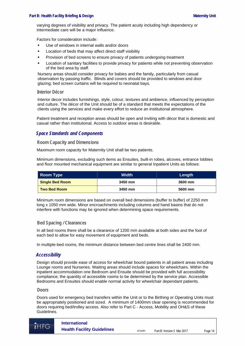
Part B: Health Facility Briefing & Design Maternity Unit
International
Health Facility Guidelines © TAHPI
Part B: Version 5 Mar 2017
Page 14
varying degrees of visibility and privacy. The patient acuity including high dependency or intermediate care will be a major influence. Factors for consideration include:
Use of windows in internal walls and/or doors
Location of beds that may affect direct staff visibility
Provision of bed screens to ensure privacy of patients undergoing treatment
Location of sanitary facilities to provide privacy for patients while not preventing observation of the bed area by staff.
Nursery areas should consider privacy for babies and the family, particularly from casual observation by passing traffic. Blinds and covers should be provided to windows and door glazing; bed screen curtains will be required to neonatal bays.
Interior Décor
Interior decor includes furnishings, style, colour, textures and ambience, influenced by perception and culture. The décor of the Unit should be of a standard that meets the expectations of the clients using the services and make every effort to reduce an institutional atmosphere. Patient treatment and reception areas should be open and inviting with décor that is domestic and casual rather than institutional. Access to outdoor areas is desirable.
Space Standards and Components
Room Capacity and Dimensions
Maximum room capacity for Maternity Unit shall be two patients. Minimum dimensions, excluding such items as Ensuites, built-in robes, alcoves, entrance lobbies and floor mounted mechanical equipment are similar to general Inpatient Units as follows:
Room Type Width Length
Single Bed Room 3450 mm 3600 mm
Two Bed Room 3450 mm 5600 mm
Minimum room dimensions are based on overall bed dimensions (buffer to buffer) of 2250 mm long x 1050 mm wide. Minor encroachments including columns and hand basins that do not interfere with functions may be ignored when determining space requirements.
Bed Spacing / Clearances
In all bed rooms there shall be a clearance of 1200 mm available at both sides and the foot of each bed to allow for easy movement of equipment and beds. In multiple-bed rooms, the minimum distance between bed centre lines shall be 2400 mm.
Accessibility
Design should provide ease of access for wheelchair bound patients in all patient areas including Lounge rooms and Nurseries. Waiting areas should include spaces for wheelchairs. Within the inpatient accommodation one Bedroom and Ensuite should be provided with full accessibility compliance; the quantity of accessible rooms to be determined by the service plan. Accessible Bedrooms and Ensuites should enable normal activity for wheelchair dependant patients.
Doors
Doors used for emergency bed transfers within the Unit or to the Birthing or Operating Units must be appropriately positioned and sized. A minimum of 1400mm clear opening is recommended for doors requiring bed/trolley access. Also refer to Part C - Access, Mobility and OH&S of these Guidelines.

Part B: Health Facility Briefing & Design Maternity Unit
International
Health Facility Guidelines © TAHPI
Part B: Version 5 Mar 2017
Page 15
Ergonomics/ OH&S
Design of clinical spaces including Bed Rooms, Treatment rooms, Feeding Rooms, Formula Rooms, Nurseries and Lounge areas must consider Ergonomics and OH&S issues for patient, visitor and staff welfare. Refer to Part C - Access, Mobility and OH&S of these Guidelines for more information.
Size of the Unit
The number of beds will be determined by the facility’s service plan. The preferred maximum number of beds in the Maternity Unit is 20-25 beds in order to accommodate additional rooms such as the General Care Nursery, Feeding Room, Formula room and communal activities areas. The number of cots in the Nursery areas will be determined by the service plan dependent on the number of beds in the Maternity inpatient areas and number of Birthing Rooms, expected numbers of births and expected numbers of complicated deliveries resulting in babies requiring special or intensive care. The number of cots in a newborn Nursery should not exceed 16 cots. Where the operational policy of the Maternity Unit includes rooming in of babies with mothers, then the number of cots in a general care nursery should accommodate the expected number of babies that are not rooming in with the mother.
Safety and Security
Security issues are important due to the increasing prevalence of infant abduction in addition to violence and theft in health care facilities. The arrangement of spaces and zones shall offer a high standard of security through the control over access and egress from the Unit, the provision of optimum observation for staff and grouping of like functions into zones. All Maternity Unit areas including inpatient areas, Nurseries and Birthing Unit must have restricted access, and appropriate staff identification systems. Maternity Units are increasingly adopting a baby tagging system. This involves a combination of the infant wearing a tag around the ankle and sensor panels located at every access point to the unit (and perhaps the entire hospital or facility). Maternity Unit design should endeavour to limit the access and egress points to one, supervised by staff with additional security measures including:
electronic access and egress
monitoring of all perimeter doors
CCTV monitoring of entries and exits
Duress alarms to all reception areas and staff stations in obscure but easily accessible locations.
It is also important that the security systems installed do not interfere with emergency response and transfer of patients and newborns for critical incidents.
Drug Storage
All components of the Maternity Unit will include lockable drug storage within the Clean Utility or Medication room/s. Refer to Standard Components Clean Utility/ Medication and Store-Drugs Data Sheets and Room Layout Sheets for further details. Note: Storage for dangerous drugs must be in accordance with the relevant legislation.

Part B: Health Facility Briefing & Design Maternity Unit
International
Health Facility Guidelines © TAHPI
Part B: Version 5 Mar 2017
Page 16
Milk Storage
To ensure the correct milk is provided to the right infant, breast milk storage freezers and fridges should be lockable or located within a lockable formula room with access restricted to staff only or to mothers under staff supervision.
Finishes
Finishes including fabrics, floor, wall and ceiling finishes, should be relaxing and non-institutional as far as possible. The following additional factors should be considered in the selection of finishes:
Acoustic properties
Durability
Ease of cleaning
Infection control
Fire safety
Movement of equipment. As clinical observation of patients and neonates is essential, colours should be chosen carefully to avoid an adverse impact on the skin colour, particularly for cyanosis and jaundiced babies. Refer to Part C - Access, Mobility and OH&S of these Guidelines for more information on wall protection, floor finishes and ceiling finishes.
Fixtures, Fittings and Equipment
Privacy Screens
In single and two bed rooms, visual privacy from casual observation by other patients and visitors shall be provided for each bed space. The design for privacy shall not restrict patient access to the Ensuite or room entrance in two bed rooms. Feeding areas will require privacy screening with sufficient space to allow a staff member to assist the mother.
Curtains / Blinds
Each Bed Room and the Nursery areas shall have partial blackout facilities (blinds or lined curtains) to allow patients and babies to rest during the daytime. For specific information on fittings, fixtures and equipment typically included in the Unit refer to Part C - Access, Mobility and OH&S of these Guidelines, the Room Layout Sheets (RLS) and Room Data Sheets (RDS).
Building Services Requirements
Communications
Unit design should address the following Information Technology/ Communications issues:
Electronic patient records and patient information systems
Electronic forms and requests for investigations, pharmacy, catering, supplies
Picture archiving communications systems (PACS)
Telephones including cordless and mobile phones
Computers, laptops and tablets
Patient call, nurse assist call, emergency call systems
Paging for staff and emergencies
Duress systems, personal mobile duress systems may be considered
Supply and records management systems including bar coding for supplies
Wireless network requirements
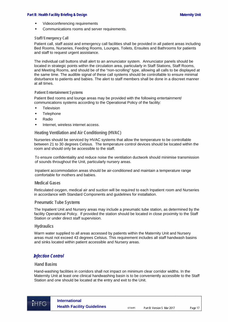
Part B: Health Facility Briefing & Design Maternity Unit
International
Health Facility Guidelines © TAHPI
Part B: Version 5 Mar 2017
Page 17
Videoconferencing requirements
Communications rooms and server requirements.
Staff/ Emergency Call Patient call, staff assist and emergency call facilities shall be provided in all patient areas including Bed Rooms, Nurseries, Feeding Rooms, Lounges, Toilets, Ensuites and Bathrooms for patients and staff to request urgent assistance. The individual call buttons shall alert to an annunciator system. Annunciator panels should be located in strategic points within the circulation area, particularly in Staff Stations, Staff Rooms, and Meeting Rooms, and should be of the “non-scrolling” type, allowing all calls to be displayed at the same time. The audible signal of these call systems should be controllable to ensure minimal disturbance to patients and babies. The alert to staff members shall be done in a discreet manner at all times.
Patient Entertainment Systems Patient Bed rooms and lounge areas may be provided with the following entertainment/ communications systems according to the Operational Policy of the facility:
Television
Telephone
Radio
Internet, wireless internet access.
Heating Ventilation and Air Conditioning (HVAC)
Nurseries should be serviced by HVAC systems that allow the temperature to be controllable between 21 to 30 degrees Celsius. The temperature control devices should be located within the room and should only be accessible to the staff. To ensure confidentiality and reduce noise the ventilation ductwork should minimise transmission of sounds throughout the Unit, particularly nursery areas. Inpatient accommodation areas should be air-conditioned and maintain a temperature range comfortable for mothers and babies.
Medical Gases
Reticulated oxygen, medical air and suction will be required to each Inpatient room and Nurseries in accordance with Standard Components and guidelines for installation.
Pneumatic Tube Systems
The Inpatient Unit and Nursery areas may include a pneumatic tube station, as determined by the facility Operational Policy. If provided the station should be located in close proximity to the Staff Station or under direct staff supervision.
Hydraulics
Warm water supplied to all areas accessed by patients within the Maternity Unit and Nursery areas must not exceed 43 degrees Celsius. This requirement includes all staff handwash basins and sinks located within patient accessible and Nursery areas.
Infection Control
Hand Basins
Hand-washing facilities in corridors shall not impact on minimum clear corridor widths. In the Maternity Unit at least one clinical handwashing basin is to be conveniently accessible to the Staff Station and one should be located at the entry and exit to the Unit.

Part B: Health Facility Briefing & Design Maternity Unit
International
Health Facility Guidelines © TAHPI
Part B: Version 5 Mar 2017
Page 18
Each nursery should have a hand basin at the point of entry for staff and parents. Within the nursery, a minimum 1 hand basin should be provided per 4 cots in general care nurseries and 1 per 2 cots in special care nurseries; the distance between any point in the nursery to the closest basin should not exceed 6 metres. Handbasins are to comply with Standard Components - Bay - Hand-washing and Part D - Infection Control in these Guidelines.
Isolation Rooms
At least one 'Class S - Standard' Isolation Room shall be provided for each Inpatient Unit. The need for Negative Pressure Isolation rooms is to be evaluated by an infection control risk assessment and will reflect the requirements of the Service Plan. Negative Pressure and Standard Pressure Isolation cot spaces may be required according to the Service Plan. 4 Components of the Unit The Maternity Unit Inpatient accommodation will consist of Standard Components to comply with details described in these Guidelines. Refer also to Standard Components Room Data Sheets and Room Layout Sheets
Non-Standard Components
Non Standard rooms are identified in the Schedules of Accommodation as NS and are described below.
Bathing/ Examination
The Bathing / Examination area will be used for baby bathing, baby examinations, weighing and baby bathing demonstrations for parents. The area may be located within or adjacent to the neonatal general care or special care nursery. The Bathing/ Examination area will include a bench with a baby examination area and baby weighing scales and a sink for baby bathing. Storage will be required for clean baby linen, towels and dirty baby linen. A staff handwashing basin should be located within easily access. Special considerations include:
Provision of heating over the examination / bathing area
Provision of temperature controlled warm water
Provision of good lighting levels; lighting should permit the accurate assessment of skin colour
The baby bathing sink should be manufactured from a material that will not retain heat or cold, (stainless steel is not recommended)
Staff will require access to an emergency call button for use in emergencies.

Part B: Health Facility Briefing & Design Maternity Unit
International
Health Facility Guidelines © TAHPI
Part B: Version 5 Mar 2017
Page 19
5 Schedule of Accommodation The Schedule of Accommodation for a 24 bed Maternity Inpatient Unit at all RDL levels follows. Quantities and sizes of some spaces will need to be determined in response to the service needs on a case by case basis.
Inpatient Unit – Antenatal and Postnatal
ROOM/ SPACE Standard Component All RDLs Remarks Room Codes Qty x m2
Patient Areas 24 Beds
1 Bed Room 1br-st-18-i 6 x 18 Antenatal; located in a quiet zone; Mix and number depend on service demand
1 Bed Room 1br-st-18-i 12 x 18 Postnatal; Mix and number depend on service demand
1 Bed Room - Isolation 1br-is-n-28-i, 1br-is-p-28-i 1 x 28 Class N or P as required by service demand
1 Bed Room - Large 1br-lg-28-i 1 x 28 May be used for multiple births / special needs patients
1 Bed Room - VIP 1br-vip-30-i 30 Provide according to service demand
2 Bed Room 2br-st-28-i 2 x 28 Postnatal; Mix and number depend on service demand
Lounge - Patient lnpt-15-i 1 x 15 Patient communal space
Anteroom anrm-i 1 x 6 For 1 Bed Room - Isolation
Ensuite - Standard ens-st-i 21 x 5 Directly accessible from each 1 Bed, 2 Bed and Isolation rooms
Ensuite - Super ens-sp-i 1 x 6 For 1 Bed Room - Large. Special fittings required for bariatrics
Ensuite - VIP ens-vip-i 8 For 1 Bed Room - VIP
Lounge - Patient lnpt-20-i 1 x 20 1 per 60 beds or may be shared between 2 units
Toilet - Patient wcpt-i 1 x 4 Optional; locate adjacent to communal areas
Support Areas Bay - Beverage, Enclosed bbev-enc-i 1 x 5
Bay - Handwashing, Type B bhws-b-i 4 x 3 In addition to basins in patient rooms; 1 at entry, 1 near staff station; Refer to Part D
Bay - Linen blin-i 2 x 2 Quantity and location to be determined for each facility
Bay - Meal Trolley bmt-4-i 1 x 4 Optional; dependent on catering and operational policies
Bay - Mobile Equipment bmeq-4-i 1 x 4 Quantity, size and location dependent on equipment to be stored
Bay - Personal Protective Equipment bppe-i 1 x 1.5 In addition to those required for isolation rooms. Refer to Part D
Bay - Resuscitation Trolley bres-i 1 x 1.5
Cleaner’s Room clrm-5-i 1 x 5 Include separate cupboard for dry goods
Clean Utility / Medication clum-14-i 1 x 14
Dirty Utility dtur-i 1 x 4 2 may be required to minimise travel distances

Part B: Health Facility Briefing & Design Maternity Unit
International
Health Facility Guidelines © TAHPI
Part B: Version 5 Mar 2017
Page 20
ROOM/ SPACE Standard Component All RDLs Remarks Room Codes Qty x m2 Disposal Room disp-8-i 1 x 8
Meeting Room - Small meet-12-i 1 x 12
Pantry ptry-i 1 x 8 Optional if Beverage Bay provided.
Store - Equipment steq-20-i 1 x 20 Size dependent on equipment to be stored. Located for staff access only
Store - General stgn-10-i 1 x 10 Size as per service demand and operational policies
Staff Areas Office - Clinical / Handover off-cln-i 1 x 15
Office - Single Person, 12m2 off-s12-i 2 x 12 NUM office and clinical personnel as needed
Staff Station sstn-14-i 1 x 14 May include ward clerk. Size and location dependent on operational policies
Shared Areas Bathroom bath-i 1 x 15 1 per 60 beds or may be shared between 2 units
Lounge - Visitor wait-20-i 1 x 20 Shared between 2 units
Meeting Room - Medium / Large meet-l-20-i 1 x 20 Tutorial; shared between 2 units
Property Bay - Staff prop-2-i 2 x 2 Separate Male and Female. Number of lockers depends on staff complement per shift
Staff Room srm-18-i 1 x 18 Includes food preparation area
Toilet - Staff wcst-i 2 x 3 Separate Male and Female
Toilet - Public wcpu-3-i 2 x 3 Separate Male and Female. Minimum 1 pair per floor
Toilet - Accessible wcac-i 1 x 6 Minimum 1 per floor
Treatment Room trmt-14-i 1 x 14 Optional; provide according to service demand
Sub Total 867.0 Circulation % 32
Total Areas 1144.4 Please note the following:
Areas noted in Schedules of Accommodation take precedence over all other areas noted in the FPU. Rooms indicated in the schedule reflect the typical arrangement according to the Role Delineation. Exact requirements for room quantities and sizes will reflect Key Planning Units identified in the Service Plan and the Operational Policies of the Unit. Room sizes indicated should be viewed as a minimum requirement; variations are acceptable to reflect the needs of individual Unit. Staff and support rooms may be shared between Functional Planning Units dependent on location and accessibility to each unit and may provide scope to reduce duplication of
facilities.

Part B: Health Facility Briefing & Design Maternity Unit
International
Health Facility Guidelines © TAHPI
Part B: Version 5 Mar 2017
Page 21
Nursery – General Care
ROOM/ SPACE Standard Component RDL 2 RDL 3 RDL 4 RDL 5/6 Remarks Room Codes Qty x m2 Qty x m2 Qty x m2 Qty x m2
Nursery - General Care 6 Cots 10 Cots 16 Cots No of Cots as per Service Plan Neonatal Bay - General Care nbgc-i 6 x 5 10 x 5 16 x 5
Staff Station/ Clean Utility sscu-i 1 x 9 1 x 9 1 x 9
Bathing/ Examination N/S 1 x 10 1 x 10 1 x 10
Bay - Handwashing, Type B bhws-b-i 2 x 1 3 x 1 4 x 1 1 per 4 cots; refer to Infection Control, Part D
Bay - Linen blin-i 1 x 2 1 x 2 1 x 2
Bay - Resuscitation Trolley bres-i 1 x 1.5 1 x 1.5 1 x 1.5 Neonatal resuscitation trolley
Clean-Up Room clup-7-i 1 x 7 1 x 7 1 x 7
Cleaner’s Room clrm-5-i 1 x 5 1 x 5 1 x 5
Disposal Room disp-8-i 1 x 8 May be shared
Feeding Room feed-i (sim) 1 x 7 1 x 7 1 x 12
Formula Room form-i (sim) 1 x 10 1 x 10 1 x 10 Milk storage
Sub Total 83.5 104.5 148.5 Circulation % 35 35 35
Total Area 112.7 141.1 200.5
Nursery – Special Care (Optional)
ROOM/ SPACE Standard Component RDL 2 RDL 3 RDL 4 RDL 5/6 Remarks Room Codes Qty x m2 Qty x m2 Qty x m2 Qty x m2
Nursery- Special Care N/A N/A 8 Cots Refer to NICU Optional Neonatal Bay - Special Care nbsc-i 7 x 12 Qty will depend on No. of Birthing Rooms, beds and service plan
Neonatal Bay - Resuscitation nbicu-i 1 x 14 for resuscitation and transfer prep; in addition to neonatal bays
Neonatal Room - Special Care - Isolation Class N nbsc-i(similar) 1 x 14 provide according to Service Plan
Anteroom anrm-i 1 x 6 for Isolation Room, Negative Pressure
Bathing/ Examination NS 1 x 10
Support Areas
Bay - Handwashing, Type A bhws-a-i 5 x 1 1 per 2 cots + 1 at entry

Part B: Health Facility Briefing & Design Maternity Unit
International
Health Facility Guidelines © TAHPI
Part B: Version 5 Mar 2017
Page 22
ROOM/ SPACE Standard Component RDL 2 RDL 3 RDL 4 RDL 5/6 Remarks Room Codes Qty x m2 Qty x m2 Qty x m2 Qty x m2 Bay - Linen blin-i 1 x 2
Bay - Mobile Equipment bmeq-4-i 1 x 4
Bay - Pathology bpath-i 1 x 1
Bay - Resuscitation Trolley bres-i 1 x 1.5 Neonatal resuscitation trolley
Clean-up clup-12-i 1 x 12
Cleaner’s Room clrm-5-i 1 x 5
Disposal Room disp-8-i 1 x 8 May be shared
Feeding Room feed-i (sim) 1 x 12
Formula Room form-i (sim) 1 x 10 Milk storage
Staff Station/ Clean Utility sscu-i (sim) 1 x 10
Store - Equipment steq-16-i 1 x 16 Based on a minimum of 2 m2 per cot
Store - General stgn-9-i 1 x 9 Consumable stock and sterile packs
Treatment Room trmt-i 1 x 14 Optional
Staff Areas
Meeting Room, 9 m2 meet-9-i 1 x 9 Meetings, Tutorials & Education
Office - Single Person, 9 m2 off-s9-im 1 x 9 Note 1; SCN Manager
Toilet - Staff, (M/F) wcst-i 2 x 3 May be shared with general staff amenities
Sub Total 261.5 Circulation % 35
Total Area 353.0 Note 1: Offices to be provided according to the number of approved full time positions within the Unit Please also note the following:
Please note the following:
Special Care Nursery of RDL5/6 will likely be located in a Neonatal ICU. Areas noted in Schedules of Accommodation take precedence over all other areas noted in the FPU. Rooms indicated in the schedule reflect the typical arrangement according to the Role Delineation. Exact requirements for room quantities and sizes will reflect Key Planning Units identified in the Service Plan and the Operational Policies of the Unit. Room sizes indicated should be viewed as a minimum requirement; variations are acceptable to reflect the needs of individual Unit. Staff and support rooms may be shared between Functional Planning Units dependent on location and accessibility to each unit and may provide scope to reduce duplication of
facilities.

Part B: Health Facility Briefing & Design Maternity Unit
International
Health Facility Guidelines © TAHPI
Part B: Version 5 Mar 2017
Page 23
6 Future Trends When planning for future developments the following trends should be considered:
Increased prevalence of obesity in society requiring bariatric facilities
Steep rise in caesarean births may result in more high dependency postnatal accommodation
Increasing numbers of multiple births
Increasing numbers of pre-term deliveries and survival of pre-term babies
Demand for midwife led care throughout the pregnancy, birth and post-natal period
Expectation by families/carers that patient rooms can accommodate partners and family to stay with the mother
Patient demand for control over heating, lighting and visitor access
Early discharge into community support programs
Ongoing development in electronic medical records and information technology
Infant and facility security systems developments. 7 References and Further Reading ACOG, American Congress of Obstetricians and Gynecologists Clinical Guidelines 2017;
refer to website, http://www.acog.org/Resources-And-Publications
AHIA, Australasian Health Facility Guidelines, Part B Health Facility Briefing and Planning, HPU 0510-Maternity Unit, 2016; refer to website https://aushfg-prod-com-au.s3.amazonaws.com/HPU_B.0510_6_0.pdf
AHIA, Australasian Health Facility Guidelines, Part B Health Facility Briefing and Planning, HPU 0390-Intensive Care- Neonatal Special Care Nursery, 2016; https://aushfg-prod-com-au.s3.amazonaws.com/HPU_B.0390_6_0.pdf
DH (Department of Health) (UK) Health Building Note 04-01: Adult Inpatient Facilities, 2009, refer to website; https://www.gov.uk/government/uploads/system/uploads/attachment_data/file/148502/HBN_04-01_Final.pdf
DH (Department of Health) (UK) Health Building Note 09-02: Maternity Care facilities, 2013, refer to website: https://www.gov.uk/government/uploads/system/uploads/attachment_data/file/147876/HBN_09-02_Final.pdf
DH (Department of Health) (UK) Health Building Note 09-03: Neonatal Units, 2013, refer to website: https://www.gov.uk/government/uploads/system/uploads/attachment_data/file/147879/HBN_09-03_Final.pdf
DH (Department of Health) (UK) Health Technical Memorandum 08-03: Bedhead Services, 2013, refer to website https://www.gov.uk/government/uploads/system/uploads/attachment_data/file/144247/HTM_08-03.pdf
Guidelines for Design and Construction of Health Care Facilities; The Facility Guidelines Institute, Section 2.2-2.2 Medical/Surgical Nursing Unit, Section 2.2-2.11 Obstetrical Unit, Section 2.2-2.12 Nursery Unit, 2014 Edition; refer to website www.fgiguidelines.org
Royal College of Obstetricians & Gynaecologists (UK) Guidelines, 2017, refer to website https://www.rcog.org.uk/guidelines

Part B – Health Facility Briefing & Design 160 Medical Imaging Unit - General
International Health Facility Guidelines Version 5 December 2016

International
Health Facility Guidelines © TAHPI
Part B: Version 5 Dec 2016
Page 2
Table of Contents
160 Medcial Imaging Unit – General ............................................................................................... 3
1 Introduction ............................................................................................................................................... 3 Description .................................................................................................................................................. 3
2 Functional and Planning Considerations ............................................................................................... 3 Operational Models ..................................................................................................................................... 3 Planning Models .......................................................................................................................................... 3 Functional Areas ......................................................................................................................................... 4 Functional Relationships ............................................................................................................................. 8
3 Design ...................................................................................................................................................... 11 Construction Standards ............................................................................................................................. 11 Environmental Considerations .................................................................................................................. 11 Space Standards and Components .......................................................................................................... 12 Safety and Security ................................................................................................................................... 13 Finishes ..................................................................................................................................................... 13 Fixtures, Fittings and Equipment ............................................................................................................... 13 Building Service Requirements ................................................................................................................. 13 Infection Control ........................................................................................................................................ 14
4 Components of the Unit .......................................................................................................................... 15 Standard Components .............................................................................................................................. 15 Non Standard Components ....................................................................................................................... 15
5 Schedule of Accommodation – Medical Imaging Unit - General ........................................................ 16 Medical Imaging Unit – General ................................................................................................................ 16
6 Future Trends .......................................................................................................................................... 22
7 Further Reading ....................................................................................................................................... 22

Medical Imaging Unit - General
International
Health Facility Guidelines © TAHPI
Part B: Version 5 Dec 2016
Page 3
160 Medical Imaging Unit – General
1 Introduction
Description
The general Medical Imaging Unit is a discrete facility of the hospital which provides radiology and diagnostic investigations. Depending on the level of service and the clinical service plan, the unit may also provide diagnostic screening (fluoroscopy), ultrasound, mammography, computed tomography (CT), magnetic resonance imaging (MRI) or interventional radiographic procedures such as angiography. The general Medical Imaging Unit may be co-located with or incorporate other specialties including Nuclear Medicine, PET and Oncology - Radiotherapy Units in a fully integrated imaging suite. 2 Functional and Planning Considerations
Operational Models
Hours of Operation
The Medical Imaging Unit will normally operate 24 hours per day, seven days per week. Smaller units may operate on a long day basis with an after-hours emergency service, depending on the hospital’s operational policy.
Models of Service Delivery
The Medical Imaging Unit may be provided as:
As a single unit managed and operated by the hospital
A main facility with satellite units located for ease of patient access under the management of the hospital
A privately owned and operated facility, providing a service to all hospital units and sharing support areas with the hospital. As this is a popular model of service delivery, this option needs to be identified early in the planning process in order to allow the associated space requirements, design issues and cost implications to be addressed
An off-site service; smaller hospitals that cannot justify a full Medical Imaging Unit, may consider access to off-site specialist services; this option needs to be identified during the planning phase, in particular, the location of the off-site services.
The general Medical Imaging Unit may be arranged in a variety of models, depending on the hospital’s clinical services plan that may include:
A comprehensive unit located adjacent to the Emergency Unit and with good functional links to Outpatient Units
A unit integrated with Nuclear Medicine & Radiotherapy
A centralised Unit with satellite imaging services for Emergency Unit, outpatient ultrasound, intraoperative imaging, cardiac angiography (Catheter Laboratories) or other interventional imaging specialties.
Planning Models
The planning of a Medical Imaging Unit will be dependent on the imaging specialties to be included and the operational model adopted.
Location
The location of Medical Imaging is important for easy access by emergency patients, ambulant patients and inpatients. The Medical Imaging Unit should ideally be located on the ground floor with direct access to the Emergency Unit (EU) unless satellite imaging is provided within the EU.

Medical Imaging Unit - General
International
Health Facility Guidelines © TAHPI
Part B: Version 5 Dec 2016
Page 4
The relative location of Outpatients Unit should be considered in the planning stage due to the volume of outpatient referrals to the Unit. Refer to Functional Relationships in this section for ideal internal relationships to be considered during the planning stages.
Functional Areas
The Medical Imaging Unit may consist of the following Functional Areas depending on the Clinical service plan of the Unit and the services to be provided:
Entry/ Reception areas incorporating: - Reception desk for patient registration and to act as an access control point - Waiting for a range of occupants including children, families, elderly, and patients with
limited mobility - Consult room for patient assessment and review - Amenities – toilets, vending areas for refreshments - Offices and workstations for Unit management and clerical functions
Imaging and screening areas: - General and digital X-ray rooms
General and digital X-ray rooms Screening (Fluoroscopy rooms) Patient Change cubicles associated with each x-ray room
- Access to patient amenities - Support areas including patient bed bays, handwashing bays, storage for linen, supplies
Dental/ Oral imaging: - OPG Room - Sub waiting facilities
CT Scanning including: - CT Scanning rooms
Control, reporting and computer module equipment rooms Patient Change cubicles associated with each scanning room
- Sub waiting areas - Access to patient amenities - Support Rooms including bays for linen, handwashing, utility room and store rooms
Ultrasound including specialty rooms such as paediatric and interventional
Mammography rooms including interventional rooms
Angiography/ Digital Subtraction Angiography (DSA) with: - Scanning, control, reporting and computer module equipment rooms - Anaesthetic induction rooms - Patient Change cubicles associated with each scanning room - Holding and recovery bed bays - Support areas including linen bays, utilities,
MRI suite with - Scanning, control, reporting and computer module equipment rooms - Patient Change cubicles associated with each scanning room - Sub-waiting area - Support facilities including bays for linen, handwashing, utility rooms and store rooms - Access to patient toilets
Shared Support Areas including - Cleaner’s room/s - Communications room - Dark Room, this room may not be required if a filmless digital imaging system is
implemented - Digital Processing areas - Film processing areas - daylight as required - Store rooms for film, files, stationery, general consumables
Staff Office and Reporting areas: - Offices for Unit Director, Senior Radiologist/s, Senior Radiographer/s, Nurse Manager/
Supervisor

Medical Imaging Unit - General
International
Health Facility Guidelines © TAHPI
Part B: Version 5 Dec 2016
Page 5
- Workstations for clerical staff, PACS technical staff, general imaging staff - Staff Amenities including Staff Room, Change Rooms with Showers, Toilets, Lockers - Meeting Rooms.
Entry/ Reception/ Waiting Areas
The Reception is the receiving hub of the unit where patients are first registered and should therefore ensure the security of the entire department through access control. Patient registration may include a booking and queuing system for effective management of patient bookings. Waiting areas may be divided into separate female/ family areas to meet cultural requirements and will require convenient access to public amenities. The Waiting areas should be designed for compliance with accessibility standards and be provided with a range of seating options for occupants of varying mobility including bariatric patients. Waiting areas should include provisions for prams and a play area for children. Bed waiting areas should be separated from the ambulatory patient waiting areas for patient privacy.
X-ray, Screening and Scanning Areas
General X-ray and Fluoroscopy (Screening) General X-ray rooms may be clustered with Fluoroscopy Screening rooms in order to share support facilities. The General X-ray room equipment will generally include an upright bucky stand for chest films. OPG and Mammography imaging equipment may be included in a General X-ray room where imaging equipment is not fully utilised. Additional equipment will require a slightly larger room. If satellite imaging rooms are not provided in the Emergency Unit (EU), a minimum of one General X-ray room must be sized and located with rapid access for transfer of patients from Emergency Unit. Fluoroscopic radiographic imaging procedures involve administration of contrast media to the patient and the timed use of a fluoroscopic imaging system along with sequential repositioning of the patient. The Fluoroscopy room will require a preparation room for barium mixtures and an adjacent toilet/ shower that may be accessed from inside the room and from the external corridor. Fluoroscopy Screening may be combined with an Angiography room, due to the decreasing incidence of barium usage. The room should include services for anaesthesia.
Orthopantomography (OPG) OPG is an orbital X-ray of the upper and lower jaws, displaying teeth on a single film, used in dental, trauma, and facio-maxillary services. This equipment may be incorporated into a General X-ray room, a separate bay or within the Dental Unit.
Computerised Tomography (CT Scanning) CT Scanning uses X-ray and computer technology to create detailed digital images, both two and three dimensional. CT scanning equipment consists of a rotating ring inside a gantry with a sliding table for the patient. Multiple images are taken in slices which are combined using computer technology. The CT Scanning room will have an associated Control Room and computer equipment room. Refer to the Standard Component for CT Scanning for detailed room requirements. A Control Room may service 2 rooms. The room should include services for general anaesthesia and be sized for interventional procedures. A bed/ trolley bay adjacent to each room is required for staff observation of waiting patients.
Angiography/ Digital Subtraction Angiography (DSA). Angiography involves x-ray imaging the inside of blood vessels using an injection of contrast media. Simple angiography procedures such as peripheral studies can be done on fluoroscopy equipment.

Medical Imaging Unit - General
International
Health Facility Guidelines © TAHPI
Part B: Version 5 Dec 2016
Page 6
Digital Subtraction Angiography (DSA) refers to a process where contrast media is injected into a vessel in the area being examined. Images are taken of the blood vessels before and after injection with contrast media. The pre-contrast images are subtracted from the post contrast images by computer resulting in clear blood vessel images. Procedures using this type of imaging include angiography, angioplasty, arterial and venous stents, biliary and renal artery imaging. DSA procedures are becoming less popular in favour of CT scanning due to the ability to produce 3D images of vessels using a less invasive procedure.
Endoscopic Retrograde Choleopancreatography (ERCP) ERCP is a procedure that uses endoscopy and fluoroscopy to diagnose and treat conditions of the biliary and pancreatic ductal systems including removal of gall stones, insertion of stents for strictures, repair of leaks and removal of cancer. These are gastrointestinal endoscopy procedures that may be performed in the Medical Imaging Unit or in an Endoscopy Unit.
Mammography Mammography imaging or breast screening may be included for diagnostic purposes according to the hospital’s operational policies. Mammography rooms should provide sufficient area for interventional procedures such as needle biopsy that may require bed access and prone positioning. Mammography should be located adjacent to an Ultrasound Room for fine needle biopsies. Change Rooms should be accessible directly from the Mammography room and an Interview Room will be required in close proximity.
Magnetic Resonance Imaging (MRI) MRI scanning is a non-invasive procedure using large magnets combined with radio waves and a computer to receive signals from atoms in body tissue creating detailed cross section images of organs and vessels. MRI does not use ionising radiation. The location of the MRI is important to restrict access, protect the magnetic field from interference and reduce the extent of electro-magnetic shielding required. Specifically the MRI should be located:
with good external access for installing and servicing the equipment; this may be achieved through an accessible side panel
distant to any moving metal objects that may cause interference such as lifts, passing cars, construction equipment.
The MRI should not be located below a helipad or next to a sub-station Facilities required in the MRI suite include:
Patient change rooms with lockers for personal property (personal property particularly items with a metallic content must not be taken into the MRI room including watches, credit cards and keys)
An Interview Room for patient discussion
Storage for equipment (non-metallic) Planning and design should consider the following:
Structural assessment is required to ensure the floor/ slab will accommodate the weight of the MRI
The MRI unit and the associated magnetic field must be fully contained within the room, according to the equipment selection and specifications, that will require liaison with the equipment supplier
The MRI room will require magnetic shielding and radiofrequency shielding, to be determined in conjunction with the equipment supplier, according to the machine specifications
Access control is required to the MRI suite, the MRI room and the support areas within the suite to ensure authorised entry. Recommended exclusion zones are divided into four stages including: - Zone 1: Entrance which may be shared with general radiology

Medical Imaging Unit - General
International
Health Facility Guidelines © TAHPI
Part B: Version 5 Dec 2016
Page 7
- Zone 2: Reception, Waiting which may be shared, patient screening, toilet and change room
- Zone 3: MRI waiting, patient preparation, recovery, control and equipment rooms - Zone 4: MRI Scanning room
Equipment and fittings in the room including emergency equipment such as fire extinguishers and gas bottles need to be constructed of non-ferrous material.
MRI rooms are to comply with Standard Components, refer to Standard Component – MRI Scanning Room, Room Data Sheet and Room Layout Sheet.
Ultrasound Ultrasound is a non-invasive procedure using high frequency sound waves for diagnostic purposes This permits the use of ultrasound for a various types of tissue and organs and is particularly useful in obstetrics, digestive system, renal, cardiac and vascular scanning. Ultrasound does not use ionising radiation and does not require radiation shielding. Ultrasound examinations may be done in the Medical Imaging unit, in specialist units or at the patient location, as the equipment is mobile. Ultrasound imaging may involve interventional procedures and room size may need to accommodate additional procedures and access for patients on a bed/ trolley. Ultrasound rooms may require close access to drinking water and a toilet for particular scanning procedures.
Support Areas
Preparation Room The Preparation Room is provided for preparation of contrast media solutions, storage of medications and sterile supplies. The room should be sized to accommodate the quantity of supplies required. The Preparation Room, if conveniently located, may serve several imaging rooms. The Preparation Room shall comply with requirements identified in Standard Components.
Film Processing Areas Film processing if required should be located convenient to the Imaging Rooms and to the quality control area and will normally involve daylight processing equipment .A Darkroom is rarely required, now replaced by digital/ computer processing. The Darkroom, if provided will require special provisions for lighting and ventilation. For digital imaging systems, processing areas are replaced by workrooms for viewing and checking of digital images. The workrooms should be located in close proximity to the imaging rooms and sized appropriately for the numbers of workstations required.
Film Storage For digital imaging applications, there will need to be an area for the PACS (Picture Archiving and Communications System) servers. The PACS server room should be located with ready access to the imaging rooms. A room for filing of patient films may be provided which may include the patient‘s own films and historic films for research purposes. The film store may be located close to the Reception/ administration areas. Secure storage areas for archived film may be remote to the Imaging Unit. Film storage areas must provide a suitable environment to protect films from deterioration and damage.
Staff Areas
Offices and Workstations Offices and workstations may be provided for the Unit Manager, Senior Radiographer, Senior Radiologist and Nurse Manager of the Unit, located in a discreet staff accessible area. The number of offices required will be determined by the clinical service plan, dependent on the role and size of the unit.

Medical Imaging Unit - General
International
Health Facility Guidelines © TAHPI
Part B: Version 5 Dec 2016
Page 8
Reporting Rooms Picture Archiving Communications Systems (PACS) reporting areas will include Radiologist workstations for viewing and reporting on procedures using high resolution (LCD) monitors on which images can be manipulated. A minimum of two linked monitors are required, occasionally four screens are provided. In addition to the reporting monitors, a dedicated computer will be required for access to the Patient Information System and a system for dictating reports. Locate reporting areas in a quiet area with ready access to the imaging rooms. Several workstations may be located in one room but will need to be visually and acoustically separated. The reporting area will require:
Ergonomic design of the workstation to accommodate multiple monitors
Adequate ventilation and temperature control to individual spaces to minimise risk of monitor failure
Individual cubicle lighting (dimmable)
Acoustic measures to ensure quality of voice recordings.
Staff Amenities Areas Staff will need access to the following:
Toilets, shower and lockers
Staff room with beverage facilities
Meeting room/s for meetings, education and training.
Functional Relationships
External
The Medical Imaging Unit should be located close to the Main Entrance of the facility and ideally situated at the ground level. Wayfinding to the Medical Imaging Unit should be easily identifiable by staff and visitors. The location of the Medical Imaging Unit is variable. Consideration must be given to its proximity to Accident and Emergency, to the Operating Unit for intra-operative imaging and Radiotherapy/ Oncology for regular patient investigations associated with treatment. The requirement for an Outpatient X-ray Service may also dictate where in the facility it is located. In most instances, a compromise between travelling distance for inpatients (minor role) and convenience for outpatients (major role) will be made.
Internal
Internally, the Medical Imaging Unit will be arranged in functional zones. The entrance to the unit will provide access control with a Reception. Imaging and scanning areas will be located in clusters along with related support facilities such as holding, sub-waiting areas and change rooms for patients. Support areas such as reporting and processing will be located conveniently to the imaging areas and may be shared. Staff areas may be located in a discreet and staff only accessible area. The Medical Imaging Unit should have a clear one-way flow of patients from entry, holding, imaging procedures, to recovery and then exit, for both ambulant and bed/trolley patients.

Medical Imaging Unit - General
International
Health Facility Guidelines © TAHPI
Part B: Version 5 Dec 2016
Page 9
Functional Relationship Diagram
Medical Imaging Unit - General The key functional relationships are demonstrated in the diagram below.
Figure 1 Functional Relationship Diagram: Medical Imaging Unit

Medical Imaging Unit - General
International
Health Facility Guidelines © TAHPI
Part B: Version 5 Dec 2016
Page 10
Medical Imaging Unit – General, Modular Option
Figure 2 Functional Relationship Diagram: Medical Imaging Unit – Modular Option with integrated Nuclear
Medicine
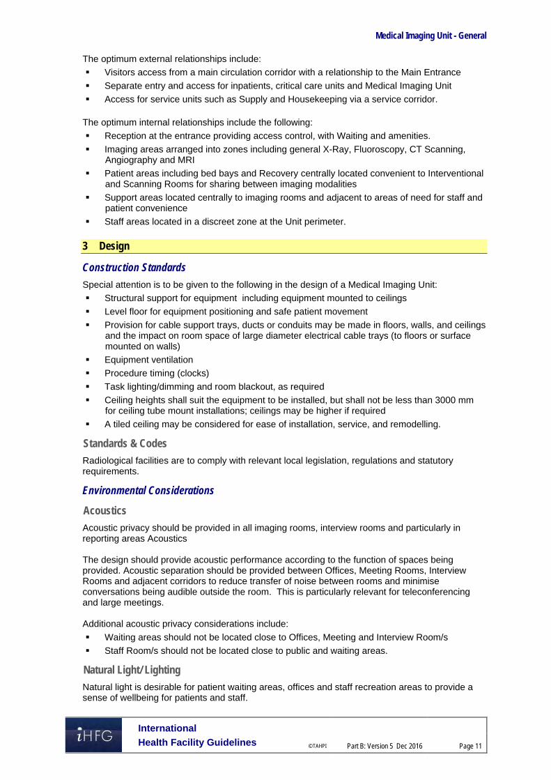
Medical Imaging Unit - General
International
Health Facility Guidelines © TAHPI
Part B: Version 5 Dec 2016
Page 11
The optimum external relationships include:
Visitors access from a main circulation corridor with a relationship to the Main Entrance
Separate entry and access for inpatients, critical care units and Medical Imaging Unit
Access for service units such as Supply and Housekeeping via a service corridor. The optimum internal relationships include the following:
Reception at the entrance providing access control, with Waiting and amenities.
Imaging areas arranged into zones including general X-Ray, Fluoroscopy, CT Scanning, Angiography and MRI
Patient areas including bed bays and Recovery centrally located convenient to Interventional and Scanning Rooms for sharing between imaging modalities
Support areas located centrally to imaging rooms and adjacent to areas of need for staff and patient convenience
Staff areas located in a discreet zone at the Unit perimeter. 3 Design
Construction Standards
Special attention is to be given to the following in the design of a Medical Imaging Unit:
Structural support for equipment including equipment mounted to ceilings
Level floor for equipment positioning and safe patient movement
Provision for cable support trays, ducts or conduits may be made in floors, walls, and ceilings and the impact on room space of large diameter electrical cable trays (to floors or surface mounted on walls)
Equipment ventilation
Procedure timing (clocks)
Task lighting/dimming and room blackout, as required
Ceiling heights shall suit the equipment to be installed, but shall not be less than 3000 mm for ceiling tube mount installations; ceilings may be higher if required
A tiled ceiling may be considered for ease of installation, service, and remodelling.
Standards & Codes
Radiological facilities are to comply with relevant local legislation, regulations and statutory requirements.
Environmental Considerations
Acoustics
Acoustic privacy should be provided in all imaging rooms, interview rooms and particularly in reporting areas Acoustics The design should provide acoustic performance according to the function of spaces being provided. Acoustic separation should be provided between Offices, Meeting Rooms, Interview Rooms and adjacent corridors to reduce transfer of noise between rooms and minimise conversations being audible outside the room. This is particularly relevant for teleconferencing and large meetings. Additional acoustic privacy considerations include:
Waiting areas should not be located close to Offices, Meeting and Interview Room/s
Staff Room/s should not be located close to public and waiting areas.
Natural Light/ Lighting
Natural light is desirable for patient waiting areas, offices and staff recreation areas to provide a sense of wellbeing for patients and staff.

Medical Imaging Unit - General
International
Health Facility Guidelines © TAHPI
Part B: Version 5 Dec 2016
Page 12
Provide indirect lighting in all examination rooms for patient comfort and dimmable lighting as required Ceiling mounted shadowless lighting is required in CT and Angiography imaging rooms.
Privacy
Visual patient privacy is an important consideration to be addressed in the design of imaging rooms and waiting spaces. Doors to imaging and screening rooms should be located to avoid patient exposure to circulation areas.
Interior Decor
Interior décor refers to colour, textures, surface finishes, fixtures, fittings, furnishings, artworks and atmosphere. It is desirable that these elements are combined to create a calming, non-threatening environment. Colours should be used in combination with lighting to ensure that they do not mask skin colours in procedure and scanning rooms where clinical observation takes place.
Space Standards and Components
Accessibility
Wheelchair access is required in all patient areas including Waiting, Consult and Imaging rooms. Waiting areas should also include space and power outlets for charging electric mobility equipment along with suitable seating for patients with disabilities or mobility aids. Waiting and sub-waiting areas should include suitable seating and provisions for bariatric patients.
Doors Special consideration should be given to the width and height of doorways to ensure delivery and removal of equipment is not impeded or prevented, and that patient trolley and bed movement is not hampered. Doors through which trolleys and beds must pass should be a minimum of 1200 mm wide.
Ergonomics/ OH&S
Design of clinical spaces including imaging rooms, bed bays and recovery areas must consider Ergonomics and OH&S issues for patient and staff safety and welfare. Refer to Part C – Access, Mobility, OH&S of these Guidelines for further information.
Size of the Unit
The size of the Medical Imaging Unit will be dependent on the level of service and will be determined by the facility’s Service Plan and Operational Policies. Schedules of Accommodation have been provided for typical Medical Imaging Units in a hospital at role delineation Levels 2 (less complex services) to 6 (teaching/ research facilities).
Imaging Room/s The size of imaging rooms will be influenced by the following:
ease of movement in and around the room for patients, staff and equipment; bed and trolley access to all imaging room will be required
the number of staff required in and around the room to operate the equipment and support the patient
the equipment to be installed; design will need to consider the manufacturer’s recommended room sizes, equipment placement and services requirements
potential future upgrading of equipment.

Medical Imaging Unit - General
International
Health Facility Guidelines © TAHPI
Part B: Version 5 Dec 2016
Page 13
Safety and Security
Design should consider the following issues:
Access control to the unit which may be provided at Reception
Zones within the unit should be organised to allow patients to access the intended area only and prevent patients and visitors entering unrelated areas
Doors to all offices and at the perimaters of the Unit should be lockable
Rooms used for storing equipment and files and records should be lockable
Meetings and functions scheduled after-hours requiring access by staff and visitors may involve special access arrangements.
Finishes
The Medical Imaging Unit ambience should provide a calm and inviting impression. Finishes should be selected with consideration of the following:
Infection control and cleaning
Acoustic properties of the materials
Durability, replacement of materials
Fire safety of the materials Wall protection should be provided where bed or equipment movement occurs including corridors, bed bays and imaging rooms. Refer also to Part C - Access Mobility, OH&S in these Guidelines for further information on floors and ceilings.
Fixtures, Fittings and Equipment
Equipment, furniture and fittings shall be designed and constructed to be safe, robust and meet the needs of a range of users. Imaging equipment and the necessary services will require installation to the manufacturer’s recommendations and specifications. Refer to Part C - Access Mobility, OH&S of these Guidelines, the Room Layout Sheets (RLS) and Room Data Sheets (RDS) for more information
Building Service Requirements
Communications
The Medical Imaging Unit requires reliable and effective IT / Communications service for efficient operation of the service. The IT design should address:
Booking, appointment and queuing systems
Patient/ clinical information systems and electronic records
Telephones including cordless and mobile phones
Computers, laptops and hand-held computers
Duress alarms and paging master system for staff and emergencies
Wireless and hospital network requirements, high capacity and speed for digital equipment
Video-conferencing and tele-conferencing requirements, including connection to imaging rooms for educational purposed
Communications and Server Room/s
Reporting and recording systems that may include dictation or voice recognition and include printing of reports
Picture Archiving Communications Systems (PACS).

Medical Imaging Unit - General
International
Health Facility Guidelines © TAHPI
Part B: Version 5 Dec 2016
Page 14
Emergency/ Nurse Call Patient and Emergency Call facilities shall be provided in all patient areas (e.g. Holding bays, Recovery bays, Preparation rooms, Change Rooms, Toilets and Imaging rooms) in order for patients and staff to request for urgent assistance. The individual call buttons shall alert to an annunciator system. Annunciator panels should be located in strategic points visible from Staff Stations and audible in Staff Rooms and Meeting Rooms.
Heating, Ventilation and Air conditioning (HVAC)
The Medical Imaging Unit should be air-conditioned to provide a comfortable working environment for staff and visitors. Interventional Imaging rooms may require air-conditioning equivalent to operating room conditions, i.e. filtered and positive pressured. Rooms with heat generating equipment may require special air-conditioning. The local or country specific mechanical provision requirements should be consulted.
Medical gases
Medical gases will be included in general and interventional imaging rooms in accordance with standards components or project specific requirements. Refer to the Standard Components, RDS and RLS of these guidelines and to Part E for additional information.
Radiation Shielding
All rooms that are used for undertaking imaging procedures require radiation shielding. A certified physicist or qualified expert will need to assess the plans and specifications for radiation protection as required by the relevant local radiation/nuclear safety authorities. A radiation protection assessment will specify the type, location and amount of radiation protection required for an area according to the final equipment selections, the layout of the space and the relationship between the space and other occupied areas. The radiation protection requirements are to be incorporated into the final specifications and building plans. Radiation requirements should be re-assessed if the intended use of a room changes during the planning stages, equipment is upgraded or surrounding room occupancy is altered. Consideration should be given to the provision of floor and ceiling shielding when rooms immediately above and below are occupied.
Infection Control
Standard precautions apply to the Medical Imaging Unit to prevent cross infection between patients, staff and visitors. Paths of travel for inpatients should be separated from outpatients as far as possible. Hand hygiene is important and it is recommended that in addition to hand basins, medicated hand gel dispensers be located strategically in staff areas and circulation corridors. Consideration should be given to separate clean and dirty workflows in all imaging/ procedure, preparation and clean-up rooms.
Hand Basins Hand basins will be located in each imaging/ procedure room, patient holding, recovery areas as well as clinical support rooms including clean and dirty utilities. In holding and recovery areas the minimum provision is one hand basin per 4 bed or chair bays. Interventional imaging rooms such as Angiography may have an adjoining scrub facility. Hand basins should comply with Standard Components for Bay - Handwashing. Refer to the Standard Components, RDS and RLS of these guidelines for additional information. For further information related to Infection Control refer to Part D – Infection Control in these Guidelines.

Medical Imaging Unit - General
International
Health Facility Guidelines © TAHPI
Part B: Version 5 Dec 2016
Page 15
4 Components of the Unit
Standard Components
The Medical Imaging Unit will contain Standard Components to comply with details in the Standard Components described in these Guidelines. Refer to Standard Components Room Data Sheets and Room Layout Sheets.
Non Standard Components
Non Standard rooms are identified in the Schedules of Accommodation as NS and are described below.
Orthopantomography (OPG) Room The OPG imaging unit may be located in a room or bay. The room size will be dependent on the equipment to be installed; circulation space will be required around the imaging unit. Access will be required for patients in wheelchairs. Room requirements will include:
Radiation shielding of the space with access to lead gowns for the patient and staff
Radiation warning light
Patient and emergency call system
A handbasin in close proximity.

Medical Imaging Unit – General
International
Health Facility Guidelines © TAHPI
Part B: Version 5 Dec 2016
Page 16
5 Schedule of Accommodation – Medical Imaging Unit - General
Medical Imaging Unit – General
The following Schedule of accommodation is provided for RDL 2 to 6 including typical imaging specialties; the inclusion of imaging specialties in health facilities will be dependent on the operational policy of the facility:
ROOM/ SPACE Standard Component RDL 2 RDL 3 RDL 4 RDL 5 RDL 6 Remarks Room Codes Qty x m2 Qty x m2 Qty x m2 Qty x m2 Qty x m2
Entry / Reception Reception/ Clerical RECL-9-I RECL-12-I RECL-15-I 1 x 9 1 x 12 1 x 15 1, 2 & 3 staff.
Waiting WAIT-10-I WAIT-15-I WAIT-20-I 2 x 15 2 x 20 2 x 25 Public. May be divided into gender segregated areas. 1.2sqm per seat, 1.5sqm w/chair.
Bay – Drinking Fountain, 1m2 BWF-1-I 2 x 1 2 x 1 Optional
Bay – Vending Machines BVM-3-I BVM-5-I 1 x 3 1 x 3 Optional
Bay – Wheelchair BWC-I 1 x 4 2 x 4 2 x 4 3 x 4
Consult/ Exam Room CONS 1 x 12 1 x 12 2 x 12 2 x 12 Number dependent on volumes and patient requirements
Office -Shared OFF-2P-I OFF-3P-I OFF-4P-I 1 x 9 1 x 15 1 x 20 1 x 20 Clerical/ bookings; 2, 3 or 4 person shared office.
Office – Workstation OFF-WS-I 1 x 5.5 1 x 5.5 1 x 5.5 Transport Staff. May be located adjacent to trolley parking
Play Area PLAP-10-I PLAP-15-I PLAP-20-I 1 X 10 1 x 10 1 x 10 Adjacent to Family waiting 4-5 places for children.
Toilet – Accessible, 6m2 WCAC-I 2 x 6 2 x 6 2 x 6 May be divided into gender segregated areas.
Toilet – Public, 3m2 WCPU-3-I 2 x 3 2 x 3 2 x 3 May be divided into gender segregated areas.
General X-ray & Fluoroscopy (Screening) General X-Ray GENXR-I 1 x 35 1 x 35 2 x 35 3 x 35 4 x 35
Screening Room (Fluoroscopy) SCRN-I 1 x 36 1 x 36 1 x 36 2 x 36 Includes control area; qty of rooms to suit service plan.
Interventional Screening Room (Fluoroscopy )
SCRN-I (similar) 1 x 45 1 x 45 1 x 45 2 x 45 Optional. For both vascular and Non-vascular procedures
Bay – Handwashing, Type B BHWS-B-I 1 x 1 1 x 1 1 x 1 2 x 1 For patient bed bay areas
Bay - PPE BPPE-I 1 x 1.5 1 x 1.5 1 x 1.5 1 x 1.5 2 x 1.5 For Lead Apron storage
Bay - Linen BLIN-1 1 x 2 1 x 2 1 x 2 1 x 2
Bay – Resuscitation Trolley BRES-I 1 x 1.5 1 x 1.5 1 x 1.5 1 x 1.5
Change Cubicle – Patient CHPT-I 2 x 2 3 x 2 4 x 2 4 x 2 May be divided into gender segregated areas.
Change Cubicle – Accessible CHPT-D-I 2 x 4 2 x 4 3 x 4 4 x 4 4 x 4 May be divided into gender segregated areas.
Clean Utility CLUR-8-I CLUR-12-I 1 x 8 1 x 12 1 x 12 May be shared
Dirty Utility DTUR-10-1 1 x 10 1 x 10 1 x 10 1 x 10 Disposal, clean-up, dirty linen storage; may be shared ,
Patient Bay – Holding, 10m2 PBTR-H-10-I 2 x 10 4 x 10 4 x 10 4 x 10 May be divided into gender segregated areas.

Medical Imaging Unit – General
International
Health Facility Guidelines © TAHPI
Part B: Version 5 Dec 2016
Page 17
ROOM/ SPACE Standard Component RDL 2 RDL 3 RDL 4 RDL 5 RDL 6 Remarks Room Codes Qty x m2 Qty x m2 Qty x m2 Qty x m2 Qty x m2 Preparation/ Set-up Room (Imaging) PREP-S-I 1 x 9 1 x 9 1 x 9 1 x 9 For contrast media storage and preparation
Property Bay PROP-2-I PROP-6-I similar 2 x 2 2 x 2 2 x 2 Optional; patient lockers. Separate Male/ Female areas.
Waiting WAIT-SUB-I WAIT-10-I 2 x 5 2 x 5 2 x 10 2 x 10 2 x 10 Optional for level-2 & 3. May be divided into gender segregated areas.
Shower – Patient - Accessible SHD-I 2 x 4 2 x 4 2 x 4 2 x 4 Optional May be divided into gender segregated areas.
Toilet – Patient WCPT-I 1 x 4 1 x 4 1 x 4 2 x 4 May be divided into gender segregated areas.
Toilet – Accessible WCAC-I 1 x 6 1 x 6 1 x 6 2 x 6 May be divided into gender segregated areas.
Dental/Oral Radiology
OPG Room N/S 1 x 7 Room area depends on equipment selected
Bay - PPE BPPE-I 1 x 1.5 Lead aprons, adjacent to imaging rooms
Waiting WAIT-SUB-I 1 x 5 May be shared with adjacent imaging areas.
C.T Scanning
C.T Scanning – Procedure Room CTPR-I 1 x 45 2 x 45 2 x 45 Room size is dependent on equipment selected
C.T Scanning – Control Room ANCRT-I similar 1 x 14 1 x 20 1 x 24 May be shared between 2
CT Computer Equipment Room COEQ-I 1 x 8 2 x 8 2 x 8 Room size dependant on equipment selected.
C.T Scanning – Reporting Room XRRR-I similar 1 x 9 1 x 9 1 x 9 One workstation/2 scanning rooms
Waiting WAIT-SUB-I WAIT-10-I 2 x 5 2 x 10 2 x 10 May be divided into gender segregated areas.
Patient Bay – Holding, 10m2 PBTR-H-10-I 2 x 10 2 x 10 2 x 10 1 outside each scanning room. May be divided into gender segregated areas.
Bay – Handwashing, Type B BHWS-B-I 1 x 1 1 x 1 1 x 1 1 per 4 bed bays; Refer to Part D Infection Control
Bay – Linen BLIN-I 1 x 2 1 x 2 1 x 2 May be shared
Bay - PPE BPPE-I 1 x 1.5 1 x 1.5 2 x 1.5 For Lead Apron storage
Bay – Resuscitation Trolley BRES-I 1 x 1.5 1 x 1.5 1 x 1.5 May be shared if located in close proximity to another unit
Change Cubicle – Accessible, 4m2 CHPT-D-I 1 x 4 1 x 4 1 x 4 May be divided into gender segregated areas. 1 cubicle per scanning room
Change Cubicle – Patient CHPT-I CHPT-12-I 1 x 2 1 x 2 1 x 2 May be divided into gender segregated areas. 1 cubicle per scanning room
Clean Utility CLUR-8-I CLUR-12-I 1 x 8 1 x 12 1 x 12 May be shared
Dirty Utility DTUR-S-I DTUR-12-I 1 x 8 1 x 12 1 x 12 May be shared
Office – Workstation OFF-WS-I 1 x 5.5 1 x 5.5 1 x 5.5 Optional, staff base
Property Bay, 2m2 PROP-2-I 1 x 2 1 x 2 1 x 2 May be shared
Scrub-up/ Gowning, 6m2 SCRB-6-I 1 x 6 1 x 6 2 x 6 May be shared
Toilet –Patient WCPT-I 2 x 4 2 x 4 2 x 4 May be divided into gender segregated areas; may share amenities with adjacent imaging areas.

Medical Imaging Unit – General
International
Health Facility Guidelines © TAHPI
Part B: Version 5 Dec 2016
Page 18
ROOM/ SPACE Standard Component RDL 2 RDL 3 RDL 4 RDL 5 RDL 6 Remarks Room Codes Qty x m2 Qty x m2 Qty x m2 Qty x m2 Qty x m2
Ultrasound & Mammography
Ultrasound ULTR-I 1 x 14 2 x 14 4 x 14 6 x 14 For general and obstetrics
Ultrasound – Paediatric ULTR-I similar 1 x 20 2 x 20 Optional. As required by service plan
Ultrasound - Interventional PROC-20-I similar 1 x 30 2 x 30 For Interventional ultrasonography procedures
Mammography MAMMO-I 1 x 16 2 x 16 3 x 16
Mammography - Interventional MAM-INT-I 1 x 16 2 x 16 3 x 16 For symptomatic and needle biopsy procedures
Patient Bay – Holding, 10m2 PBTR-H-10-I 2 x 10 4 x 10 4 x 10 May be shared. May be divided into gender segregated areas.
Bay – Handwashing, Type B BHWS-B-I 1 x 1 1 x 1 1 x 1 1 x 1 1 per 4 bed bays; Refer to Part D Infection Control
Bay – Linen BLIN-I 1 x 2 1 x 2 1 x 2 1 x 2 May be shared with adjacent area
Bay – Resuscitation Trolley BRES-I 1 x 1.5 1 x 1.5 1 x 1.5 1 x 1.5 May be shared if located in close proximity to another trolley
Change Cubicle – Patient CHPT-I CHPT-12-I 1 x 4 1 x 2 2 x 2 4 x 2 Total of 1 per U/S or Mammography room
Change Cubicle – Accessible CHPT-D-I 1 x 4 1 x 4 2 x 4 2 x 4 Total of 1 per U/S or Mammography room
Clean Utility CLUR-8-I 1 x 8 1 x 8 1 x 8 Optional
Dirty Utility DTUR-S-I 1 x 8 1 x 8 1 x 8 Optional
Office – Workstation OFF-WS-I 1 x 5.5 1 x 5.5 1 x 5.5 1 x 5.5 For Sonographers
Processing DPRO-I similar 1 x 6 1 x 6 1 x 10 For Mammography
Property Bay PROP-2-I PROP-6-I similar 2 x 4 2 x 8 2 x 8 For patient lockers. May be divided into gender segregated areas.
Toilet – Patient WCPT-I 1 x 4 3 x 4 4 x 4 For Ultrasound. Within ultrasound room
Toilet – Accessible WCAC-I 2 x 6 1 x 6 1 x 6 2 x 6 Patient. May be divided into gender segregated areas.
Waiting WAIT-SUB-I WAIT-10-I 2 x 5 2 x 5 2 x 10 2 x 10 May be divided into gender segregated areas.
Viewing and Reporting Room XRRR similar 1 x 12 1 x 12 1 x 12 1 12 Adjust size to suit service plan.
Angiography/ Digital Subtraction Angiography (DSA) Angiography Procedure Room ANPR-I similar 1 x 55 2 x 55 3 x 55 Number of rooms to suit service plan.
Angiography Control/ Reporting Room
ANCRT-I 1 x 14 1 x 14 1 x 14 May be shared between rooms
Computer Equipment Room COEQ-I 1 x 8 2 x 8 3 x 8 1 per Angiography room
Anaesthetic Induction Room ANIN-I 1 x 15 1 x 15 1 x 15 Optional
Bay – Linen BLIN-I 1 x 2 1 x 2 1 x 2 1 x 2 May be shared
Bay – PPE (Personal Protective Equipment) BPPE-I 1 x 1.5 1 x 1.5 1 x 1.5 For Lead Apron
Bay – Resuscitation Trolley BRES-I 1 x 1.5 1 x 1.5 1 x 1.5 May be shared if located in close proximity to another unit
Change Cubicle – Patient CHPT-I CHPT-12-I 1 x 2 2 x 2 4 x 2 May be divided into gender segregated areas.

Medical Imaging Unit – General
International
Health Facility Guidelines © TAHPI
Part B: Version 5 Dec 2016
Page 19
ROOM/ SPACE Standard Component RDL 2 RDL 3 RDL 4 RDL 5 RDL 6 Remarks Room Codes Qty x m2 Qty x m2 Qty x m2 Qty x m2 Qty x m2 Change Cubicle – Accessible CHPT-D-I 2 x 4 4 x 4 4 x 4 Patient. May be divided into gender segregated areas.
Clean Utility CLUR-8-I CLUR-12-I 1 x 8 1 x 12 1 x 12 May be shared
Dirty Utility DTUR-S-I DTUR-12-I 1 x 8 1 x 12 1 x 12 May be shared
Patient Bay – Holding, 10m2 PBTR-H-10-I Refer to Holding/Recovery Areas for patient bays.
Preparation/ Set-Up Room (Imaging) PREP-S-I 1 x 9 1 x 9 1 x 9
Property Bay PROP-2-I PROP-6-I similar 2 x 4 2 x 8 2 x 8 For patients; may be divided into gender segregated areas.
Scrub-Up/ Gowning SCRB-6-I 1 x 6 1 x 6 1 x 6 May be shared.
Store – Sterile Stock STSS-12-I STSS-24-I 1 x 12 1 x 18 1 x 24
Toilet – Patient WCPT-I 1 x 4 2 x 4 2 x 4 Within Angiography Suite
Toilet – Accessible WCAC-I 1 x 6 1 x 6 1 x 6 Patient May be divided into gender segregated areas.
Waiting WAIT-SUB-I WAIT-10-I 2 x 5 2 x 10 2 x 10 May be divided into gender segregated areas.
X-Ray Viewing and Reporting XRRR-I 1 x 12 1 x 12 1 x 12 May be combined with Control room
MRI MRI Scanning Room MRI-SC-42-I 2 x 42 Room size dependant on equipment selected
MRI Computer Equipment Room, COEQ-8-I similar 2 x 8 MRI. requirements as per manufacturers specifications
MRI Control/ Reporting Room, 14m2 ANCRT-14-I similar 2 x 14 Shared between 2 MRI rooms
Anaesthetic Induction Room ANIN-I 1 x 15 Optional
Viewing and Reporting Room XRRR-12-I similar 1 x 12 May be combined with Control Room.
Patient Bay - Holding, 10m2 PBTR-H-10-I 2 x 10 May be shared. May be divided into gender segregated areas.
Bay – Handwashing, Type A BHWS-A-I 2 x 1 1 per MRI room, in close proximity to MRI rooms
Bay – Linen BLIN-I 1 x 2 May be shared
Bay – Resuscitation Trolley BRES-I 1 x 1.5 May be shared if located in close proximity to another unit
Change Cubicle – Accessible CHPT- D-I 2 x 4 May be divided into gender segregated areas.
Clean Utility CLUR-8-I CLUR-12-I 1 x 12 May be shared
Dirty Utility DTUR-S-I DTUR-12-I 1 x 12 May be shared
Property Bay PROP-2-I 4 x 2 Patient lockers. May be divided into gender segregated areas.
Store - Dewar Tank N/S 1 x 6 As required, accessible to MRI rooms
Store – Files, 8m2 STFS-8-I 1 x 8 Optional
Toilet – Accessible WCAC-I 2 x 6 Patient. May be divided into gender segregated areas.
Waiting – Sub WAIT-SUB-I 2 x 5 May be divided into gender segregated areas.
Patient Holding/ Recovery Areas

Medical Imaging Unit – General
International
Health Facility Guidelines © TAHPI
Part B: Version 5 Dec 2016
Page 20
ROOM/ SPACE Standard Component RDL 2 RDL 3 RDL 4 RDL 5 RDL 6 Remarks Room Codes Qty x m2 Qty x m2 Qty x m2 Qty x m2 Qty x m2
Patient Bay – Holding, 10m2 PBTR-H-10-I 4 x 10 6 x 10 8 x 10 Holding/ recovery. 2 Bays per interventional imaging room; May be divided into gender segregated areas.
Staff Station SSTN-10-I SSTN-14-I 1 x 10 1 x 10 1 x 14
Bay – Beverage BBEV-OP-I 1 x 4 1 x 4 1 x 4 Optional
Bay – Handwashing, Type B BHWS-B-I 1 x 1 2 x 1 2 x 1
Bay – Linen BLIN-I 1 x 2 1 x 2 2 x 2
Bay – Resuscitation Trolley BRES-I 1 x 1.5 1 x 1.5 1 x 1.5 May be shared if located close to another trolley
Consult Room CONS-I 1 x 12 2 x 12 Optional
Clean Utility, 12m2 CLUR-S-I CLUR-10-I CLUR-12-I 1 x 8 1 x 10 1 x 12
Dirty Utility DTUR-S-I DTUR-10-I DTUR-12-I 1 x 8 1 x 10 1 x 12
Disposal Room, 8m2 DISP-8-I DISP-10-I 1 x 8 1 x 8 1 x 10
Store – Equipment, 10m2 STEQ-10-I 1 x 10 1 x 10 2 x 10
Support Areas - Shared
Bay – Mobile Equipment BMEQ-4-I BMEQ-6-I 1 x 4 1 x 6 2 x 6 2 x 6 Depends on facility requirement
Cleaner’s Room, 5m2 CLRM-5-I 1 x 5 1 x 5 2 x 5
Communications Room COMM-12-I COMM-20-I similar 1 x 10 1 x 12 1 x 20 1 x 30 For PACS Server. Size determined by Operational Policy
Dark Room DARK-I 1 x 6 1 x 6 1 x 6 1 x 6 1 x 6 Optional
Digital Processing DPRO-I similar 1 x 16 1 x 24 1 x 30 1 x 40 Digital processing/ printing. As required by service plan
Disposal Room, 8m2 DISP-8-I shared 1 x 8 1 x 8 1 x 8 1 x 8
Store – Current Film STFS-20-I similar 1 x 30 1 x 50 1 x 70 1 x 100 Optional. Depends on facility & digital imaging requirements
Store – Files STFS-8-I STFS-20-I 1 x 8 1 x 8 1 x 12 1 x 16 1 x 20 Films/ CDs/ Discs. Size determined by Operational Policy
Store – General STGN-9-I 1 x 9 1 x 9 1 x 12 1 x 12 1 x 16
Store – Photocopy/ Stationery, 8m2 STPS-8-I 1 x 8 1 x 8 1 x 8 Laser Printing/ Digitiser; may be included in work space for radiographers.
Staff Offices & Reporting Areas Office – Single Person, 12m2 OFF-S12-I 1 x 12 1 x 12 1 x 12 Director
Office – Single Person, 9m2 OFF-S9-I 1 x 9 1 x 9 2 x 9 Radiologists
Office – Single Person, 9m2 OFF-S9-I 1 x 9 1 x 9 2 x 9 Radiographers
Office – Single Person, 9m2 OFF-S9-I 1 x 9 1 x 9 2 x 9 Nurse Manager/ Supervisor
Office – Shared OFF-2P-I OFF-3P-I 1 x 12 1 x 15 1 x 15 PACS Operation/ Management. 2-3 person; see Notes
Office – Shared OFF-2P-I OFF-3P-I OFF-4P-I 1 x 12 1 x 16 1 x 20 2, 3 & 4 person shared areas. May be used as a film study/ library room; as required by operational policy
Office - Workstation OFF-WS-I 2 x 5.5 4 x 5.5 6 x 5.5 General imaging staff

Medical Imaging Unit – General
International
Health Facility Guidelines © TAHPI
Part B: Version 5 Dec 2016
Page 21
ROOM/ SPACE Standard Component RDL 2 RDL 3 RDL 4 RDL 5 RDL 6 Remarks Room Codes Qty x m2 Qty x m2 Qty x m2 Qty x m2 Qty x m2
Office - Workstation OFF-WS-I 2 x 5.5 4 x 5.5 6 x 5.5 Picture Archiving Comms Systems (PACS) Reporting. Qty will depend on service plan
Change – Staff (Male/ Female), 14m2 CHST-14-I 2 x 14 2 x 14 2 x 14 May be divided into gender segregated areas. Includes shower/ toilets/ lockers
Meeting Room MEET-9-I MEET-12-I 1 x 9 1 x 9 1 x 12
Meeting Room – Medium/ Large MEET-L-15-I MEET-L-20-I 1 x 15 1 x 15 2 x 20
Store – Photocopy/ Stationary STPS-8-I STPS-10-I 1 x 8 1 x 8 1 x 10
Staff Room SRM-15-I SRM-20-I 1 x 15 1 x 20 1 x 20 May be divided into gender segregated areas.
Sub Total 77.5 385.0 1290.5 1833.5 2661.5
Circulation % 35 35 35 40 40
Area Total 104.6 519.8 1742.2 2566.9 3726.1 Notes
Areas noted in Schedules of Accommodation take precedence over all other areas noted in the FPU.
Rooms indicated in the schedule reflect the typical arrangement according to the Role Delineation.
Exact requirements for room quantities and sizes will reflect Key Planning Units identified in the Service Plan and the Operational Policies of the Unit.
Room sizes indicated should be viewed as a minimum requirement; variations are acceptable to reflect the needs of individual Unit.
Office areas are to be provided according to the Unit role delineation and number of endorsed full time positions in the unit.
Staff and support rooms may be shared between Functional Planning Units dependent on location and accessibility to each unit and may provide scope to reduce duplication of facilities.

Medical Imaging Unit - General
International
Health Facility Guidelines © TAHPI
Part B: Version 5 Dec 2016
Page 22
6 Future Trends Imaging is widely used as an essential adjunct to clinical assessment for diagnosis and staging of human disease, and increasingly in the design of appropriate therapies and then monitoring response to these treatments and has been described as one of the fastest growing healthcare sectors in the developed world. Medical liability considerations also weigh heavily in many decisions by physicians to utilize medical imaging if clinically warranted. It is expected that radiation dosages will continue to drop and utilization of imaging services will become more efficient, with fewer healthcare resources wasted. With the Internet, borders have blurred between the concepts of information and communication systems, making access to data and distribution of information faster and more efficient. Mobile and wearable media will accelerate these trends. New energy sources—magnetic, radiofrequency, sonic, optical and nuclear—combined with fast, dynamic, digital methods of applying and recording them, will continue to add dozens of parameters to the imaging toolkit. Future images will be photo realistic; using all the sources of data combined, enhanced using interactive rendering with additional details, and available remotely at the desktop. Future new technologies (e.g., molecular imaging) could yield rapid utilization changes if these provide the clinical value that has been attributed to traditional advanced imaging during its recent boom 7 Further Reading
Agency for Science, Technology and Research, Clinical Imaging Research Centre, Singapore, Professor David W. Townsend, PhD, FRCR (Hon) Director, lecture: Future Trends in Medical Imaging refer to website: http://infieri-network.eu/sites/default/files/users/user270/DT_INFIERI_Lecture_Final.pdf
American College of Radiology (ACR) Medical Imaging: ‘Is the Growth Boom Over’ Neiman Report Oct 2012 http://www.acr.org/Research/Health-Policy-Institute/Neiman-Report-Index/Brief-01-Is-the-Medical-Imaging-Growth-Boom-Over
Australasian Health Facility Guidelines, Part B Health Facility Briefing and Planning, Medical Imaging - General, Rev 6 2016 refer to website
https://aushfg-prod-com-au.s3.amazonaws.com/HPU_B.0440_6_0.pdf
Department of Health, Queensland Government, Australia Medical Imaging Services; CSCFv3.2 Module Overview. Refe to website:
https://www.health.qld.gov.au/clinical-practice/guidelines-procedures/service-delivery/cscf/modules/default.asp
Department of Veterans Affairs (US) Office of Facilities Management, VA Design Guide Magnetic Resonance Imaging, 2008, refer to website: http://www.cfm.va.gov/til/dGuide/dgmri02.pdf
Government of Dubai, Dubai Health Authority, Health Regulation Department, “Diagnostic Imaging Services Regulation” 2012 https://www.dha.gov.ae/Documents/Regulations/Diagnostic%20Imaging%20Services%20Regulation.pdf
NHS Estates, Department of Health Estates and Facilities Division, HBN 6 Facilities for diagnostic imaging and interventional radiology, HMSO, London, 2001, https://www.gov.uk/government/organisations/department-of-health
RSNA Radiological Society of North America, James H. Thrall, M.D ‘Look Ahead The Future of Medical Imaging’ Aug 2015 http://www.rsna.org/News.aspx?id=17019
The Facilities Guidelines Institute, Guidelines for Design and Construction of Health Care Facilities, 2014 refer to website: https://www.fgiguidelines.org
University of Oxford, Department of Physics, Future Trends in Medical Imaging 2016; refer to website: https://www2.physics.ox.ac.uk/events/2013/07/10/future-trends-in-medical-imaging

Part B – Health Facility Briefing & Design 170 Medical Imaging Unit – Nuclear Medicine
International Health Facility Guidelines Version 4 May 2014

Medical Imaging Unit – Nuclear Medicine
International Health Facility Guidelines © TAHPI
Part B: Version 4 2014
Page 2
Table of Contents 170 Medical Imaging Unit - Nuclear Medicine ................................................................................ 3
1 Introduction ............................................................................................................................................... 3 2 Planning ..................................................................................................................................................... 3 3 Design ........................................................................................................................................................ 6 4 Components of the Unit ............................................................................................................................ 8 5 Schedule of Accommodation – Medical Imaging Unit – Nuclear Medicine ......................................... 9 6 Functional Relationship Diagram – Medical Imaging Unit – Nuclear Medicine ................................. 11 7 References and Further Reading ........................................................................................................... 12

Medical Imaging Unit – Nuclear Medicine
International Health Facility Guidelines © TAHPI
Part B: Version 4 2014
Page 3
170 Medical Imaging Unit - Nuclear Medicine 1 Introduction Description The Nuclear Medicine Unit provides facilities for the administration of radiopharmaceutical agents to patients and patient imaging for diagnostic purposes and for treatment. The Nuclear Medicine Unit may be provided within the Medical Imaging Unit or as a freestanding Unit. The Unit may or may not include a Radiopharmacy Laboratory. The size of a unit in terms of numbers and type of cameras will be determined by the service plan and clinical needs. 2 Planning Model of Care The model of care will depend on level of services provided as defined in the service plan and the presence or otherwise of PET as a sub-component of the Nuclear Medicine Unit. In large centres, it will be a discrete unit. If there are only one or two gamma cameras, it may be a discrete sub-Unit of Medical Imaging. All units will have a Hot Laboratory (Hot Lab). Large centres may or may not include a Radiopharmacy Laboratory that will prepare its own radiopharmaceuticals for general use. Planning Models
Location
A ground floor site is preferred but if this cannot be achieved, consideration should be given to units above, below and adjoining the proposed location with regards to radiation shielding requirements, the weight of equipment and associated shielding and access for equipment and radioactive isotopes. The Unit should not act as a thoroughfare to other units of the healthcare facility.
Unit Layout
Staff and patient flows in the Unit are critical to ensure that patients, staff and visitors are not exposed to radiation as a result of travel through or adjacent to areas occupied by dosed patients and scanning rooms. Effective layout can also reduce the need for costly radiation shielding. Layout should address the need for separation of areas particularly patient and staff corridors and entry areas for outpatients and inpatient on beds/ trolleys. If provided, the Bone Density Room should be located near the entry to the Nuclear Medicine Unit to ensure patients do not unnecessarily cross areas of radioactivity. The Bone Densitometry room should be located away from dosed patients by distance or shielding to avoid interference to the Bone Density Unit from high ambient radiation levels. Functional Areas The Nuclear Medicine Unit consists of the following functional areas: Reception/ Administration Waiting areas for outpatients and inpatients, including toilets Patient holding, observation and recovery area Treatment areas including gamma camera rooms, specialised scanning imaging rooms
(SPECT, PET, PET/CT, bone densitometry), stress testing facilities Support areas including utilities, staff station Hot Lab/ Radioactive Waste Store Staff areas including offices and amenities

Medical Imaging Unit – Nuclear Medicine
International Health Facility Guidelines © TAHPI
Part B: Version 4 2014
Page 4
Teaching and research facilities (Tertiary Centres)
Patient Waiting
Waiting areas should allow separation of dosed and undosed patients, particularly as some patients may need to wait for 45 minutes after dosing for uptake. It is also preferable to separate dosed patients from relatives and visitors to the unit which may include young adults, pregnant women and children. Dosed patients should have access to drinking water and toilet facilities without having to access general waiting areas. Outpatients should be separated from inpatients for privacy reasons with separate entrances.
Patient Holding, Observation and Recovery Area
An area will be required for patient holding, recovery and observation including the following: a dedicated inpatient entry curtained bed/ trolley bays for holding, observation and recovery; the configuration of the
overall space should permit both dosed and un-dosed patients to be held safely a small staff station with hand basin support rooms including Dirty Utility, Linen Bay, Sterile Stock Store Resuscitation trolley (trolley may be located near the Stress Testing Room).
Gamma Camera
The gamma camera is a device used in Nuclear Medicine to image gamma radiation emitting radioisotopes to view and analyse images of the human body or the distribution of medically injected, inhaled, or ingested radionuclides emitting gamma rays, producing a two dimensional image. The gamma camera consists of one or more flat crystal planes (detectors) optically coupled to an array of photomultiplier tubes, the assembly is known as a "head", mounted on a gantry. The gantry is connected to a computer system that both controls the operation of the camera as well as acquisition and storage of acquired images. The gamma camera room will require a control area and radiation screening as assessed by Radiation Consultants.
Single Photon Emission Computed Tomography (SPECT)
SPECT is a nuclear medicine tomographic imaging technique using gamma rays, similar to the conventional gamma camera planar imaging system that is able to provide true 3D information. This information is typically presented as cross-sectional slices through the patient, but can be freely reformatted or manipulated as required. To acquire SPECT images, the gamma camera is rotated around the patient. Projections are acquired at defined points during the rotation, typically every 3-6 degrees. In most cases, a full 360 degree rotation is used to obtain an optimal reconstruction. The time taken to obtain each projection is also variable, but 15-20 seconds is typical. This gives a total scan time of 15-20 minutes. A SPECT camera may be combined with a computerised tomography (CT) unit to form a hybrid system and fusion imaging of the physiology and anatomy of the area/s being scanned. SPECT/CT requires a separate control room and radiation screening in accordance with CT requirements.
Viewing and Reporting Area
A dedicated room with dimmable lighting will be required for viewing and reporting on scans. Each workstation should accommodate imaging screens, computers for access to imaging and patient information systems, writing and shelving space for reference materials. The number of reporting stations will depend on service level, number of scanning rooms and the staff establishment.
Hot Lab/ Dispensary and Radioactive Waste Store
Radioactive radiopharmaceuticals are stored and prepared ready for administration to the patient in the Hot Lab. A lead screen barrier is required for the dispensary area. The Dispensary should be located adjacent to the patient dosing room.

Medical Imaging Unit – Nuclear Medicine
International Health Facility Guidelines © TAHPI
Part B: Version 4 2014
Page 5
A radioactive waste storage area may also be incorporated into or adjacent to this space. Provide radiation shielding as advised by Radiation Consultants. The Waste Store will require a sink and basin with hands-free taps for hand washing and equipment decontamination.
Radiopharmacy
The Radiopharmacy is used for preparation, compounding, quality control and dispensing of radiopharmaceuticals for diagnosis and treatment. Radiopharmaceuticals are radioactive isotopes attached to pharmaceutical substances. Only designated units will have an in-house Radiopharmacy laboratory where cold kits are prepared; these may be used in-house or supplied to other Nuclear Medicine Units. Many nuclear medicine units (e.g. private practices) may receive a daily delivery of the radiopharmaceutical already prepared and dispensed as individual patient doses. Other isotopes/ radionuclides (e.g. gallium, thallium) are delivered weekly or monthly as required, pre-packaged into individual doses for dispensing.
Storage - Equipment & Supplies
Storage is required for: collimators and scanning phantoms, within the scanning rooms mobile equipment such as wheelchairs, trolleys, lifters and ultrasound scanners, may be
located in equipment bays Technegas unit and large argon cylinder/s that may be located in an equipment bay; the
Technegas unit and trolley is taken to patients in holding bays or in the camera rooms for patient to inhale Tc99m
medical consumables and smaller equipment items sterile stock stationery records/ files
SPECT and SPECT/ CT Scanning Room -
The SPECT and SPECT/CT Scanning rooms will be used for patient imaging procedures using a SPECT camera or combined SPECT/CT hybrid system. Installation of equipment should be in accordance with manufacturer's recommendations. Room size may vary according to the equipment selected Scanning rooms require ready access from dosing rooms and dosed patient waiting areas. Scanning rooms may be collocated with shared Control rooms to enable monitoring of two rooms simultaneously. Some special considerations for SPECT and SPECT/CT Rooms include: Floor structure should support the equipment weight. Uninterruptible power supply is required to the cameras and associated computer modules to
prevent data loss and/or damage during power surges or loss of supply Power to patient areas shall be body protected to protect against electric shock Individual room temperature and humidity control is required. Lighting should be placed to avoid lights shining directly into the patient’s eyes and should be
dimmable. Radiation shielding will be required according to assessment by the Radiation Consultant Bed/ trolley access is required to the room Fixtures, fittings and equipment within the room will include: Collimator rack/s for a range of collimator sizes should be included; the collimator is a
directional guide; the size and length of the collimator holes determine which gamma rays reach the detector in the camera; collimator racks vary according to the model / level of Gamma Camera.
Patient ECG monitoring may be required in the room CCTV camera may be included (optional in SPECT/CT room). Lead apron rack and aprons will be required in the room or immediately adjacent. hand basin - Type B with paper towel and soap fittings

Medical Imaging Unit – Nuclear Medicine
International Health Facility Guidelines © TAHPI
Part B: Version 4 2014
Page 6
Television, ceiling or wall mounted is optional. Bench and shelving for preparation and storage may be provided. Services will include: medical gases - oxygen, suction, medical air on service panel nurse and emergency call system power outlets for patient equipment on the medical services panel and additional power on all
walls computer data points on patient services panel, near gamma camera unit and in control
areas
Store - Radioactive Waste
This room will store radioactive waste materials. Ready access to the Hot Laboratory is required. Lead lining is required to ensure safe protection of radioactive materials.
Bone Densitometry Room
Bone densitometry is a non-invasive procedure using a special x-ray scanning machine to determine bone density or strength. It is used to identify those at risk of developing osteoporosis and to monitor change in bone density. The bone densitometry room maybe located within the radiology or nuclear medicine department. The room may have radiation shielding to walls and/or glazing as advised by a Radiation Consultant. Functional Relationships The Nuclear Medicine Unit should be located with ready access to the Medical Imaging Unit, PET Unit if provided, Emergency Unit, Operating Unit and Critical Care areas. It requires easy access for ambulant patients and beds/ stretchers. 3 Design Construction Standards Construction Standards for a Nuclear Medicine Unit include the following: Flooring shall be adequate to meet load requirements for equipment, patients, and
personnel. Floors and walls should be constructed of materials that are easily decontaminated in case of
radioactive spills. Walls should contain necessary support systems for either built-in or mobile oxygen and
vacuum and; vents for radioactive gases. Provision for cable trays, ducts or conduits should be made in floors, walls, and ceilings as
required. Ceiling height should be a minimum of 3 metres. Ceiling mounted equipment should have properly designed rigid support structures located
above the finished ceiling. A lay-in type ceiling should be considered for ease of installation, service and future
remodelling. Environmental Considerations
Acoustics
Acoustic treatment will be required to the following areas: SPECT/CT scanning rooms (hybrid units may be noisy) Viewing / reporting room Consulting rooms

Medical Imaging Unit – Nuclear Medicine
International Health Facility Guidelines © TAHPI
Part B: Version 4 2014
Page 7
Refer also to acoustic requirements identified in Standard Components Room Data Sheets.
Natural Light
Natural light is desirable in all patient areas, staff room and staff offices. Lighting level in reporting rooms needs to be adjustable. External windows provided in scanning and uptake rooms should be assessed by a Radiation Consultant for shielding requirements. Safety and Security The Nuclear Medicine Unit shall include a safety shower with an eyewash station for use in the event of radioactive spills. Finishes Floor finishes and junctions should be smooth, impervious and non-absorbent in case of radiation spills. Building Service Requirements
Radiation Protection
Plans and specifications will require assessment for radiation protection by a certified physicist or other qualified expert, as required by the appropriate state authorities. The radiation protection assessment will specify the type, location and amount of radiation protection required according to the final equipment selections and layout. Radiation protection requirements shall be incorporated into the final specifications and the building plans. Radiation shielding will be required to a number of areas as advised by Radiation Consultants including: Reception and rooms adjacent to dosed patient rooms Dosing/ Consult Exam rooms Hot Lab/ Dispensing room/ Radiopharmacy Pre-scan uptake rooms/ dosed waiting areas, patient toilets Cardiac Stress Testing Room Scanning Room/s Post scanning waiting areas Bone Densitometry Room
Hydraulic Services
Ceiling spaces above gamma cameras and specialty scanning units should not be used for hydraulic services or air-conditioning ducts, to avoid damage to equipment from leakages. The need for delayed holding tanks within the Nuclear Medicine Unit will require assessment by the Radiation Consultant.
Mechanical Services
Additional cooling and ventilation will be required to Scanning Rooms and associated computer equipment rooms as the equipment is sensitive to excessive ambient heat. Some scanners may require chilled water for cooling. Large temperature changes (greater than 400C per hour) within scanning rooms need to be avoided to reduce the risk of crystal fracture in gamma cameras. Additional air extraction or exhaust may be required to Camera Room/s where ventilation agents such as Technegas are administered. In the restricted areas of Patient Examination Room and Storage and Preparation areas, if radioactive gas Xenon is being used, special ventilation is required. Ventilation requirements would be in accordance with relevant Guidelines. The restricted area should be kept under negative pressure by exhausting at least 15 % more air than supply air. Recirculation of air from these spaces should not be permitted.

Medical Imaging Unit – Nuclear Medicine
International Health Facility Guidelines © TAHPI
Part B: Version 4 2014
Page 8
It is recommended that the Storage and Preparation areas be generally equipped with a special radioisotope fume hood. This system may need to be fabricated from non-ferrous materials. Exhaust registers should be located at floor and ceiling levels General air conditioning inpatient and staff areas needs to be adjustable for patient and staff comfort; the temperature of the Unit should not exceed 25°C. Smoke detectors in treatment rooms should be sensitive to radiation. Hot Lab room air should be negatively pressured and exhausted, not recirculated. The Hot Lab may include a fume cabinet which will require exhausting. Rooms in which Technegas is used should be negatively pressured to the rest of the Unit. 4 Components of the Unit The Nuclear Medicine Unit will contain to comply with details described in these Guidelines. Refer to Standard Components Room Data Sheets and Room Layout Sheets.

Medical Imaging Unit – Nuclear Medicine
International Health Facility Guidelines © TAHPI
Part B: Version 4 2014
Page 9
5 Schedule of Accommodation – Medical Imaging Unit – Nuclear Medicine Entry/Reception Area
ROOM/ SPACE Standard Level4 Level 5 Level 6 Remarks
Component Qty x m2 Qty x m2 Qty x m2
RECEPTION RECL-10-I 1 x 10 1 x 10 1 x 15
RECL-15-I
WAITING – MALE/FEMALE WAIT-10-I 2 x 10 2 x 15 2 x 20 Separate Male/female areas
WAIT-20-I
MEETING ROOM – SMALL MEET-9-I 1 x 9 1 x 9 1 x 12
MEET-12-I
OFFICE – SHARED OFF-2P-I 1 x 12 1 x 12 1 x 15 2/ 3 staff
OFF-3P-I
STORE – PHOTOCOPY/STATIONERY STPS-8-I 1 x 8 1 x 8 1 x 10
STPS-10-I
STORE - FILES STFS-8-I 1 x 8 1 x 8 1 x 10
STFS-10-I
Patient & Support Areas
ROOM/ SPACE Standard Level 4 Level 5 Level 6 Remarks
Component Qty x m2 Qty x m2 Qty x m2
WAITING – UNDOSED WAIT-SUB-I 2 x 5 2 x 5 2 x 5 Separate Male/female areas
(MALE/FEMALE) WAIT-10-I
PLAY AREA – PAEDIATRIC PLAP-10-I 1 x 10 1 x 10 1 x 10
optional
PATIENT BAY – HOLDING PBTR-H-10-I 2 x 10 3 x 10 8 x 10 Separate Male/female areas
(MALE/FEMALE)
BAY - BEVERAGE BBEV-OP-I 1 x 4 1 x 4 1 x 4
BAY – HANDWASHING BHWS-B-I 1 x 1 1 x 1 2 x 1
BAY – LINEN BLIN-I 1 x 2 1 x 2 2 x 2
BAY – RESUSCITATION TROLLEY BRES-I 1 x 1.5 1 x 1.5 1 x 1.5
CLEANER’S ROOM CLRM-5-I 1 x 5 1 x 5 1 x 5
CONSULT ROOM CONS-I 1 x 14 2 x 14 4 x 14 Qty dependent on Service
Plan
DIRTY UTILITY – SUB DTUR-S-I 1 x 8 1 x 8 1 x 10
DTUR-10-I
DISPOSAL ROOM DISP-5-I 1 x 5 1 x 8 1 x 10 May be shared at Level 4
DISP-8-I
STAFF STATION/ CLEAN UTILITY SSCU -I 1 x 9 1 x 9 1 x 9
STORE – STERILE STOCK STSS-12-I 1 x 6 1 x 12 1 x 12
TOILET - ACCESSIBLE WCAC-I 2 x 6 2 x 6 4 x 6
PATENT
SHOWER – PATIENT SHPT-I 2 x 4 2 x 4 4 x 4
MALE/FEMALE
CIRCULATION ALLOWANCE % 35% 35% 35%
Treatment Areas
ROOM/ SPACE Standard Level 4 Level 5 Level 6 Remarks
Component Qty x m2 Qty x m2 Qty x m2
GAMMA CAMERA ROOMS GCAM-I 1 x 38 1 x 38 1 x 38
(WITH INTERNAL CONTROL)
SPECT SCANNING ROOM GCAM-I 1 x 42 2 x 42 Size to suit equipment
(WITH CONTROL ROOM) similar
SPECT/C.T SCANNING ROOM 1 x 48 1 x 48
SPECT/C.T SCANNING ANCRT-I 1 x 14 1 x 14

Medical Imaging Unit – Nuclear Medicine
International Health Facility Guidelines © TAHPI
Part B: Version 4 2014
Page 10
CONTROL ROOM similar
COMPUTER EQUIPMENT ROOM COEQ-I 1 x 8 3 x 8 4 x 8
STRESS TESTING STRT-I 1 x 12 1 x 12 2 x 12
BONE DENSITOMETRY 1 x 16 1 x 16
BAY – MOBILE EQUIPMENT BMEQ-6-I 1 x 6 2 x 6 4 x 6 Qty according to equipment
to be accommodated
PROCEDURE ROOM PROC-20-I 1 x 20 Optional
VIEWING/REPORTING ROOM XRRR-I 1 x 12 1 x 12 1 x 12
CIRCULATION ALLOWANCE % 35% 35% 35%
Hot Laboratory Areas
ROOM/ SPACE Standard Level 4 Level 5 Level 6 Remarks
Component Qty x m2 Qty x m2 Qty x m2
ENTRY LOBBY ISOTOPE DELIVERY AIRL-6-I 1 x 6 1 x 6 1 x 6 Refer to Airlock
optional optional optional
HOT LABORATORY HTLB-I 1 x 10 1 x 12 1 x 12
(RADIOPHARMACY) similar
STORE – RADIOACTIVE WASTE 1 x 20 1 x 20
BAY – EMERGENCY SHOWER BES-I 2 x 1 2 x 1 2 x 1 Decontamination; privacy
screened
BAY – PPE (PERSONAL PROTECTIVE BPPE-I 1 x 1.5 1 x 1.5 1 x 1.5
EQUIPMENT)
Staff Support Areas
ROOM/ SPACE Standard Level 4 Level 5 Level 6 Remarks
Component Qty x m2 Qty x m2 Qty x m2
OFFICE – SINGLE PERSON 12M2 OFF-S12-I 1 x 12 1 x 12 Director
OFFICE – SINGLE PERSON, 9M2 OFF-S9-I 1 x 9 1 x 9 1 x 9 Nursing Personnel
OFFICE – SINGLE PERSON, 9M2 OFF-S9-I 1 x 9 2 x 9 4 x 9 Medical specialist etc.; Qty
depends on service plan
OFFICE – WORKSTATIONS OFF-WS-I 3 x 5.5 4 x 5.5 6 x 5.5 Qty depends on service plan
MEETING ROOM MEET-L-15-I 1 x 15 1 x 15 2 x 20 Qty depends on service plan
MEET-L-20-I
STAFF ROOM – MALE/FEMALE SRM-15-I 2 x 15 2 x 20 Separate Male/female areas
SRM-20-I
CHANGE - STAFF (MALE/FEMALE) CHST-10-I 2 x 10 2 x 14 2 x 20 Separate Male/female areas
CHST-20-I
Please note the following: Areas noted in Schedules of Accommodation take precedence over all other areas noted in
the FPU. Rooms indicated in the schedule reflect the typical arrangement according to the Role
Delineation. Exact requirements for room quantities and sizes will reflect Key Planning Units identified in
the service plan and the policies of the Unit. Room sizes indicated should be viewed as a minimum requirement; variations are acceptable
to reflect the needs of individual Unit. Office areas are to be provided according to the Unit role delineation and number of
endorsed full time positions in the unit. Staff and support rooms may be shared between Functional Planning Units dependant on
location and accessibility to each unit and may provide scope to reduce duplication of facilities.

Medical Imaging Unit – Nuclear Medicine
International Health Facility Guidelines © TAHPI
Part B: Version 4 2014
Page 11
6 Functional Relationship Diagram – Medical Imaging Unit – Nuclear Medicine

Medical Imaging Unit – Nuclear Medicine
International Health Facility Guidelines © TAHPI
Part B: Version 4 2014
Page 12
7 References and Further Reading Australasian Health Facility Guidelines, Part B Health Facility Briefing and Planning, Rev 5,
2012; refer to website www.healthfacilitydesign.com.au Guidelines for Design and Construction of Health Care Facilities; The Facility Guidelines
Institute, 2010 Edition; refer to website www.fgiguidelines.org NHS Estates, Department of Health Estates and Facilities Division, 14-01, Pharmacy and
Radiopharmacy, HMSO, London, 2008, refer to website www.estatesknowledge.dh.gov.uk NHS Estates, Department of Health Estates and Facilities Division, HBN 6 Facilities for
diagnostic imaging and interventional radiology, HMSO, London, 2001, refer to website www.estatesknowledge.dh.gov.uk
Part B – Health Facility Briefing & Design 175 Medical Imaging-Nuclear Medicine Unit - PET
International Health Facility Guidelines Version 5 Sep 2017

Part B: Health Facility Briefing & Design
International
Health Facility Guidelines © TAHPI
Part B: Version 5 Sep 2017
Page 2
Table of Contents
175 Medical Imaging-Nuclear Medicine Unit - PET ....................................................................... 3
1 Introduction ............................................................................................................................................... 3 Description .................................................................................................................................................. 3
2 Functional and Planning Considerations ............................................................................................... 4 Operational Models ..................................................................................................................................... 4 Planning Models .......................................................................................................................................... 4 Functional Areas ......................................................................................................................................... 5 Functional Relationships ............................................................................................................................. 8
3 Design ...................................................................................................................................................... 10 General...................................................................................................................................................... 10 Construction Standards ............................................................................................................................. 10 Patient Treatment Areas ........................................................................................................................... 10 Environmental Considerations .................................................................................................................. 10 Space Standards and Components .......................................................................................................... 11 Safety & Security ....................................................................................................................................... 12 Finishes ..................................................................................................................................................... 13 Fixtures, Fittings & Equipment .................................................................................................................. 13 Building Service Requirements ................................................................................................................. 13 Infection Control ........................................................................................................................................ 14
4 Components of the Unit .......................................................................................................................... 15 Standard Components .............................................................................................................................. 15 Non-Standard Components ....................................................................................................................... 15
5 Schedule of Accommodation ................................................................................................................. 17 PET facility located within a Nuclear Medicine/ Medical Imaging Unit ...................................................... 17 Cyclotron & Radiopharmacy (Optional) ..................................................................................................... 19
6 Future Trends .......................................................................................................................................... 20
7 Further Reading ....................................................................................................................................... 20
Part B: Health Facility Briefing & Design Medical Imaging-Nuclear Medicine Unit - PET
International
Health Facility Guidelines © TAHPI
Part B: Version 5 Sep 2017
Page 3
175 Medical Imaging-Nuclear Medicine Unit - PET
1 Introduction
Description Positron Emission Tomography (PET) is a nuclear medicine technology that uses short-lived radionuclides (tracers) injected into the body allowing non-invasive imaging of metabolic, biochemical and/or physiological function within the body. PET scanning now involves 3 dimensional images using CT or MRI scanning at the same time, which provides information about the body structure. Images from metabolic scanning and the CT/MRI are reconstructed using computer analysis. The function of a PET Unit is to provide a safe environment to enable the delivery of radiopharmaceutical agents and scanning under carefully controlled conditions. The Unit may be provided within the Nuclear Medicine Unit or Medical Imaging Unit. Inclusion of a radiopharmaceutical support laboratory is optional and dependent on the operational policy of the facility...
PET: Positron Emission Tomography
The primary radioactive isotopes used for clinical PET is FDG - Fluorine-18 (Fluoro deoxy glucose) and Ga-68 manufactured in a cyclotron, with a half-life of 110 minutes. These isotopes can only be transported relatively short distances before use. Because of the short half-life of the supplied isotopes careful planning is needed with respect to patient scheduling and isotope deliveries that may require more than one delivery per day.
PET/CT: Positron Emission Tomography/ Computed Tomography
Positron Emission Tomography (PET) with Computed Tomography (CT) technology is used extensively in cancer assessment and ongoing evaluation of treatment response. The CT scan may also be used for radiotherapy simulation with the addition of laser positioning lights in the scanning room.
PET/MRI: Positron Emission Tomography/ Magnetic Resonance Imaging
The PET/MRI is an emerging hybrid imaging technology incorporating PET scanning with MRI scanning in the one procedure. PET/MRI scanning is predominantly performed in oncology, and to a lesser extent in cardiac and neurology specialties and provides a superior anatomical information.
Cyclotron and Radiopharmacy
The Cyclotron is an accelerator that uses proton beams to manufacture radioisotopes used in PET scanning. The Cyclotron may be provided within the health facility or located off site and radioisotopes supplied by an external provider. Hospitals with a Cyclotron have Radiopharmacy Laboratories for their PET/CT use and may provide services to other hospitals. Design and specific requirements for a Cyclotron and Radiopharmacy are not included in this FPU. If a Cyclotron and Radiopharmacy are to be provided, the location and the spatial requirements will need to be assessed at a very early planning stage with particular emphasis on siting the facility in an access restricted area and structural requirements to support the weight of the equipment and radiation shielding needs. The shielding requirements for cyclotron and radiopharmacy facilities will need to be coordinated between the equipment manufacturers and a radiation physicist. The area required for the PET tracer production facility, including the cyclotron depends on the tracers to be produced and functional requirements of the facility and needs to be determined on an individual basis. The Cyclotron and Radiopharmacy facilities will require compliance with relevant local and national radiation authority standards, guidelines and licensing requirements.

Part B: Health Facility Briefing & Design Medical Imaging-Nuclear Medicine Unit - PET
International
Health Facility Guidelines © TAHPI
Part B: Version 5 Sep 2017
Page 4
2 Functional and Planning Considerations
Operational Models
Hours of Operation
The PET suite will generally operate during business hours from 8am to 5pm daily, dependent on the opening hours of the Unit it is located within, Nuclear Medicine or Medical Imaging. Urgent scans may be attended out of hours according to the Unit’s Operational Policy.
Models of Care
PET services are generally collocated with the Nuclear Medicine Unit or in smaller centres, with the Medical Imaging Unit, sharing support facilities. As PET is extensively used as an oncology diagnostic tool, it may be located in a comprehensive Cancer Centre. The majority of patients undergoing PET Studies are treated on an outpatient basis. Patient appointments are booked in advance in order to ensure supplies of radionuclides are available at the time needed. Appointments for paediatric patients will need to be coordinated with an anaesthetist as these patients require sedation or anaesthesia for PET studies in order to ensure images are not compromised by movement.
Planning Models
Location
The location of the unit requires careful consideration of the following: the weight of the equipment the weight and extent of shielding requirements access required for installation and servicing of equipment access for delivery of radioisotopes (for outsourced supplies) A ground floor location is preferred. The location of the Unit should be prevent access by persons such as lost visitors and wandering patients from other units and ensure the security of radioisotopes held within the unit.
Configuration
The layout and configuration of the PET suite should provide separation of dosed patients from un-dosed patients to ensure patients, staff and visitors are not exposed to radiation. The path of travel of dosed patients needs to be carefully planned including Uptake Rooms, Toilets, Scanning Rooms and Hot Laboratories. ‘Hot’ and ‘cold’ areas should be geographically separated whenever possible. Planning and design should consider separate patient and staff corridor systems and provide separate entries for outpatients and for inpatients on beds/ trolleys. The layout of the PET suite will need to address security of radioisotopes and radioactive waste and consolidate areas requiring costly radiation shielding. PET Scanning rooms should be planned in compliance with manufacturer’s recommendations, because area requirements may vary from machine to machine. Since technology changes frequently and from manufacturer to manufacturer, rooms should be sized larger to allow upgrading of equipment in the future.
Future Growth Planning should provide for future growth of PET services which will be dependent on population increase and advances in technology. In cases where it is expected that population growth will require enhanced service capacity within a five year period, the following issues need to be addressed with regard to future expansion of the Unit: Additional scanning rooms to allow for increased service demand Scanning rooms sized to provide sufficient space for upgrades to the equipment which may
also require additional shielding, increased load bearing capabilities and services requirements
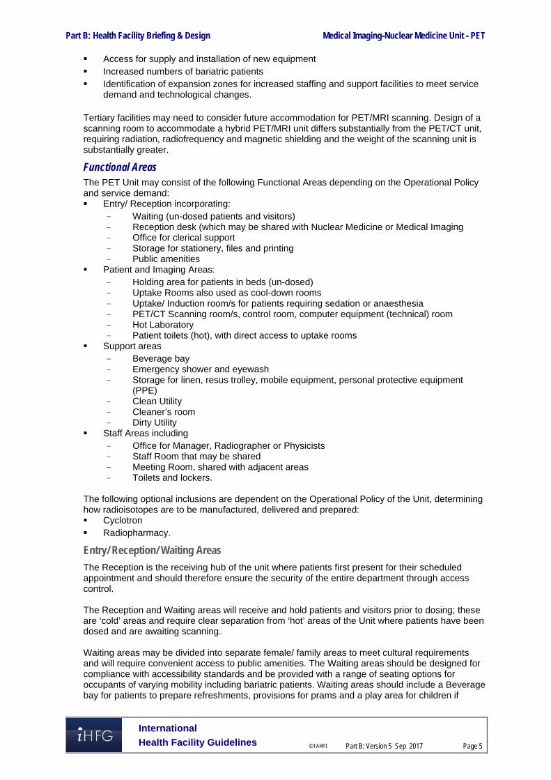
Part B: Health Facility Briefing & Design Medical Imaging-Nuclear Medicine Unit - PET
International
Health Facility Guidelines © TAHPI
Part B: Version 5 Sep 2017
Page 5
Access for supply and installation of new equipment Increased numbers of bariatric patients Identification of expansion zones for increased staffing and support facilities to meet service
demand and technological changes. Tertiary facilities may need to consider future accommodation for PET/MRI scanning. Design of a scanning room to accommodate a hybrid PET/MRI unit differs substantially from the PET/CT unit, requiring radiation, radiofrequency and magnetic shielding and the weight of the scanning unit is substantially greater.
Functional Areas The PET Unit may consist of the following Functional Areas depending on the Operational Policy and service demand: Entry/ Reception incorporating:
- Waiting (un-dosed patients and visitors) - Reception desk (which may be shared with Nuclear Medicine or Medical Imaging - Office for clerical support - Storage for stationery, files and printing - Public amenities
Patient and Imaging Areas: - Holding area for patients in beds (un-dosed) - Uptake Rooms also used as cool-down rooms - Uptake/ Induction room/s for patients requiring sedation or anaesthesia - PET/CT Scanning room/s, control room, computer equipment (technical) room - Hot Laboratory - Patient toilets (hot), with direct access to uptake rooms
Support areas - Beverage bay - Emergency shower and eyewash - Storage for linen, resus trolley, mobile equipment, personal protective equipment
(PPE) - Clean Utility - Cleaner’s room - Dirty Utility
Staff Areas including - Office for Manager, Radiographer or Physicists - Staff Room that may be shared - Meeting Room, shared with adjacent areas - Toilets and lockers.
The following optional inclusions are dependent on the Operational Policy of the Unit, determining how radioisotopes are to be manufactured, delivered and prepared: Cyclotron Radiopharmacy.
Entry/ Reception/ Waiting Areas
The Reception is the receiving hub of the unit where patients first present for their scheduled appointment and should therefore ensure the security of the entire department through access control. The Reception and Waiting areas will receive and hold patients and visitors prior to dosing; these are ‘cold’ areas and require clear separation from ‘hot’ areas of the Unit where patients have been dosed and are awaiting scanning. Waiting areas may be divided into separate female/ family areas to meet cultural requirements and will require convenient access to public amenities. The Waiting areas should be designed for compliance with accessibility standards and be provided with a range of seating options for occupants of varying mobility including bariatric patients. Waiting areas should include a Beverage bay for patients to prepare refreshments, provisions for prams and a play area for children if

Part B: Health Facility Briefing & Design Medical Imaging-Nuclear Medicine Unit - PET
International
Health Facility Guidelines © TAHPI
Part B: Version 5 Sep 2017
Page 6
paediatric services are included in the Operational Policy. Un-dosed patients may wait in the general waiting area with their family/ supporters outpatients prior to scanning procedures. Inpatients may be taken directly into a bed Holding area or Uptake room. Bed waiting areas should be separated from the ambulatory patient waiting areas for patient privacy; prior to injection with radionuclides, the bed holding area is a ‘cold’ zone.
Patient/ Imaging Areas
Uptake Room/s The Uptake room is a private, radiation shielded room where patients are injected with the radiopharmaceutical on a recliner chair or bed and rest until uptake has occurred before the scanning procedure. Uptake may typically take 45 to 60 minutes, during which time the patient must rest quietly. The Uptake room requires direct access to a ‘hot’ toilet, preferably without accessing a common corridor and exposing staff and passing traffic to radiation. Following scanning procedures patients will return to the Uptake room to ‘cool down’ prior to discharge from the Unit. The discharge route should not cross un-dosed patients or visitors. The recommended ratio of Uptake rooms to Scanning rooms is 2 Uptake rooms per 1 Scanning room, if the rooms are also used for ‘cool down’ additional Uptake rooms will be required. Refer to Non Standard Components in this FPU for additional information.
Uptake/ Induction Room/s The Uptake Induction room is provided for administering sedation or anaesthetic to patients on a bed prior to scanning procedures including paediatric patients. The room will include an anaesthetic machine, medical gases and patient monitoring. Patients may be returned to the Uptake/ Induction room to cool down prior to discharge. The Uptake room/s will require access for beds and trolleys. Refer to Non Standard Components in this FPU for additional information.
PET/ CT Scanning Room The PET/CT Scanning Room provides an enclosed, radiation shielded room with a hybrid PET camera and CT Scanning unit for non-invasive scanning procedures. Patients are usually fully awake for the procedure but may be sedated or occasionally under general anaesthesia (including paediatric patients). Scanning time varies between 10 and 25 minutes, following which patients are returned to an Uptake room or shielded private waiting space to ‘cool down’ prior to discharge home or transfer back to an inpatient unit. Bed and trolley access will be required to the PET/CT scanning room. Visibility to the PET scanner from the Control Room is preferred but not essential if patients are fully monitored via closed circuit television. Scanning equipment will be installed to manufacturer’s specifications and may require service links to the Computer Equipment (Technical) Room and Control Room.
Hot Laboratory and Hot Store The Hot Laboratory will be required for receipt, delivery, storage and dispensing/ preparation of radiopharmaceuticals. Radiopharmaceuticals may be supplied as unit doses from an external provider or from a Cyclotron facility within the campus and are drawn up or prepared ready for administration to the patient in the Hot Laboratory. The Hot Laboratory requires ready access from a service corridor for delivery of Fluorodeoxyglucose (FDG) and other PET radiopharmaceuticals and will need to be readily accessible to the Uptake and PET Scanning rooms. The room will be radiation shielded. Space and equipment is required for dose calibration, computerised record keeping and quality control activities. A lead glass screen may act as a barrier behind which dispensing and calibration occur.

Part B: Health Facility Briefing & Design Medical Imaging-Nuclear Medicine Unit - PET
International
Health Facility Guidelines © TAHPI
Part B: Version 5 Sep 2017
Page 7
The Hot Store is a secure, radiation shielded room for storage of sealed sources and radioactive waste, particularly sharps. The Hot Store should be located with convenient access from Uptake Rooms, Hot Laboratory and exit for removal of waste when it is safe for disposal. The Hot Laboratory and Hot Store will need to be accredited by the relevant jurisdictional authorities. Refer to Standard Components and Non Standard Components in this FPU for additional information.
Support Areas
Support areas include the following provisions: A beverage Bay as light refreshments are made available for patients undergoing PET and
myocardial perfusion studies, due to the length of time patients are required to fast An emergency Shower and eyewash facility is required for chemical spills Dirty Utility room may require radiation shielding if hot waste is held in this room; refer to local
radiation safety regulations Storage is required for linen, resuscitation trolley, wheelchairs, equipment used in the unit,
sterile supplies and consumable stock; provision for recharging of equipment should be available
A staff station with supervision of Uptake rooms and bed holding areas Viewing and reporting, is an optional area for reviewing images and reporting and may be
shared with an adjacent Unit.
Staff Areas
Staff will need access to the following:
Toilets, shower and lockers
Staff room with beverage facilities
Meeting room/s for meetings, education and training. Staff areas may be shared with a collocated Unit (Nuclear Medicine/ Medical Imaging). Teaching, research and student facilities may be required depending on the role delineation and service plan of the facility including offices, workstations, dry laboratories, wet laboratories, student discussion areas and meeting rooms.
Optional Areas
Radiopharmacy Laboratory The Radiopharmacy Laboratory is used for manufacturing a range of radiopharmaceuticals used in scanning procedures under strict controls and sterile manufacturing techniques or preparation of radiopharmaceuticals supplied from an adjacent Cyclotron. Inclusions in the Laboratory will be largely dependent on the range of radiopharmaceuticals to be produced. Details of this laboratory is not covered in detail by this FPU but an approximate square metre area is given in the Schedule of Accommodation to facilitate early planning where such a laboratory is proposed.
Cyclotron The Cyclotron accelerator manufactures radioisotopes and inclusion in the facility will be dependent on the service plan, operational policies and business case. Details of the Cyclotron are not covered in this FPU but an approximate square metre area is given in the Schedule of Accommodation to facilitate early planning where inclusion is proposed. Installations will require compliance and registration with the appropriate local or national radiation and nuclear authority.

Part B: Health Facility Briefing & Design Medical Imaging-Nuclear Medicine Unit - PET
International
Health Facility Guidelines © TAHPI
Part B: Version 5 Sep 2017
Page 8
Functional Relationships
External
The Nuclear Medicine PET suite ideally will be located on the ground level with easy access from the Main Entry area for patients, staff and visitors. Externally the PET suite should have good access to: The entry point of the Hot Laboratory for delivery of externally provided radioisotopes in a
route as direct as possible Radiation Oncology Unit and Chemotherapy Unit Inpatient Units particularly Oncology, Neurology and Cardiology Medical Imaging Unit Support Units including Clinical Information, Housekeeping, Linen, Laboratories, Pharmacy
and Supply. The optimum external functional relationships are demonstrated in the diagram below including:
Ambulant patients and outpatient access from a main circulation corridor with a relationship to the Main Entrance
Separate entry and access for inpatients on beds and Medical Imaging Unit
Access for service units via a service corridor with entry to the ‘cold’ area of the unit.
Internal
Internally, the PET suite will generally be a dedicated suite of rooms within a larger Unit typically Nuclear Medicine but also may be a component of an integrated Medical Imaging Unit. The Reception will provide an access control point and there will be clear separation of un-dosed - ‘cold’ and dosed - ‘hot’ areas of the Unit. There should be a clear path of travel for patients who arrive and wait in un-dosed waiting, then are transferred to Uptake rooms dosing, wait for uptake followed by scanning procedures, then return to Uptake rooms for a cool-down period waiting for radioactivity to dissipate prior to discharge, preferably through a separate exit, and not through areas where un-dosed patients and visitors are waiting. The ideal relationships are demonstrated in the diagram below including: Reception at the entrance providing access control, with direct view of Waiting areas Staff Station with direct view of bed holding areas for un-dosed patients Separation and access control between un-dosed areas and dosed areas of the unit Support rooms located centrally to the scanning and patient areas for maximum convenience Emergency Shower located with close access to all ‘hot’ areas.

Part B: Health Facility Briefing & Design Medical Imaging-Nuclear Medicine Unit - PET
International
Health Facility Guidelines © TAHPI
Part B: Version 5 Sep 2017
Page 9
Functional Relationship Diagram
The following diagram depicts a single PET suite within a Nuclear Medicine Unit.

Part B: Health Facility Briefing & Design Medical Imaging-Nuclear Medicine Unit - PET
International
Health Facility Guidelines © TAHPI
Part B: Version 5 Sep 2017
Page 10
3 Design
General Consideration needs to be given to the following during design: Rapid access and path of travel for isotope deliveries and disposal of radioactive waste Separation of outpatients’ and inpatients’ entries with entrances easily observed from the
Reception and Staff Station Separation of ‘cold’ areas from ‘hot’ areas within the Unit.
Car Parking
An identified parking area for vehicles delivering isotopes is required to enable rapid access to the Hot Lab. Patients and visitors will use the public parking facilities with access to drop-off areas and disabled parking.
Construction Standards Special attention is to be given to the following in the design of the PET suite:
Structural support for equipment; floors must be able to support the weight of equipment and shielding which is significant (the weight may range from approximately 3 tons (PET/CT) to approximately 9 tons (PET/MRI)
Level floor for equipment positioning and safe patient movement
Provision for cable support trays, ducts or conduits may be made in floors, walls, and ceilings and the impact on room space of large diameter electrical cable trays (to floors or surface mounted on walls)
Ventilation for heat generating equipment and extraction for Hot Labs
Procedure timing (clocks)
Task lighting/dimming and room blackout, as required
Ceiling heights shall suit the equipment to be installed, but shall not be less than 3000 mm for ceiling tube mount installations; ceilings may be higher if required
A tiled ceiling may be considered for ease of installation, service, and remodelling.
Standards & Codes
Radiological and radiopharmaceutical facilities are to comply with relevant local legislation, regulations, statutory and licensing requirements.
Patient Treatment Areas
Patient Monitoring
Dosed patients are alone in Uptake rooms and during the scanning process and should be under observation at all times in case of emergency via closed circuit TV cameras (CCTV) with monitors in the Control Room and / or Staff Station. Cameras should be located at both the head and foot of the PET scanner.
Environmental Considerations
Acoustics
Sound attenuation should be provided in the following areas: Uptake and Uptake/ Induction rooms Scanning rooms Viewing/ Reporting room In addition, acoustic separation should be provided between Offices, Meeting Rooms, Consult Rooms and adjacent corridors to reduce transfer of noise between rooms and minimise conversations being audible outside the room. For further information also refer to Acoustic Requirements noted on Standard Component Room Data Sheets.

Part B: Health Facility Briefing & Design Medical Imaging-Nuclear Medicine Unit - PET
International
Health Facility Guidelines © TAHPI
Part B: Version 5 Sep 2017
Page 11
Natural Light/ Lighting
Natural light is desirable in all patient areas, Offices and Staff Room to provide for patient and staff comfort. Lighting should be controllable in reporting rooms to allow for work with high resolution images on screens. External windows provided in scanning and uptake rooms will need assessment by a Radiation Consultant for shielding requirements. In practice, it may be difficult to shield windows equal to wall shielding levels.
Privacy
Visual privacy is required in all Consult, Uptake, PET Scanning rooms and patient holding bed bays. Doors to screening rooms should be located to avoid patient exposure to circulation areas. If patients change in the Uptake rooms, privacy from CCTV cameras while getting changed will be required.
Interior Décor
Interior décor refers to colour, textures, surface finishes, fixtures, fittings, furnishings, artworks and atmosphere. It is desirable that these elements are combined to create a calming, non-threatening environment. Colours should be used in combination with lighting to ensure that they do not mask skin colours in Scanning and Uptake rooms where patients are under direct observation and are compatible with CCTV monitoring of patients.
Space Standards and Components
Accessibility
Design should provide ease of access for wheelchair bound patients in all patient areas including Consult, Uptake rooms and PET Scanning rooms. Waiting areas should include spaces for wheelchairs (with power outlets for charging electric mobility equipment) and suitable seating for patients with disabilities or mobility aids. The Unit will require provision for bariatric patients.
Doors
Special consideration should be given to the width and height of doorways to ensure delivery and removal of PET/CT scanning equipment is not impeded or prevented, and that patient trolley, bed movement and wheelchair access is not hampered. Doors to Uptake rooms should permit trolley and bed access and should be a minimum of 1200 mm wide. Doors to PET Scanning rooms should be a minimum of 1500 mm wide or larger to permit equipment access. Where provided, vision panels in doors to Uptake, Scanning rooms and Hot Labs must have the same level of shielding as the adjoining walls. Also refer to Part C - Access, Mobility, OH&S of these Guidelines.
Ergonomics/ OH&S
Consideration should be given to ergonomic functionality in the PET suite. Workstations, sinks and Hot Laboratory benches should be provided at suitable working heights, whether seated or standing positions. Adjustable height work stations are recommended where possible. The following occupational health and safety issues should be addressed during planning and design for staff safety and welfare: Location and handing of radionuclides and provision of safety shower and eyewash facilities
for chemical spills (refer to local regulations); design should ensure patients, staff and visitors are not unnecessarily exposed to radiation hazards
Manual handling of heavy equipment; storage of heavy equipment close to point of use recommended
PET Scanning rooms must be sized to suit the design requirements of the equipment to be used, to provide a safe working environment and to allow the effective movement of staff and patients.

Part B: Health Facility Briefing & Design Medical Imaging-Nuclear Medicine Unit - PET
International
Health Facility Guidelines © TAHPI
Part B: Version 5 Sep 2017
Page 12
Refer to Part C – Access, Mobility, OH&S of these Guidelines for more information.
Size of the Unit
The size of the PET suite in terms of numbers of cameras will be determined by the clinical service plan that establishes the scope of the service. A Schedule of Accommodation has been provided for a single PET scanner that may be incorporated within a larger unit, typically a Nuclear Medicine Unit.
Safety & Security
Safety
Management of Radioactive substances spills is a key safety consideration within the PET suite and will include the following measures: All surfaces including floors, bench tops, walls and junctions should be impermeable and
easy to clean An emergency shower and eye wash for patients and staff should be readily accessible and
located in close proximity to all areas of potential exposure A decontamination kit should be stored in the Hot Lab for quick access to contain and clean
up radioactive spills
Radioactive Isotopes - Delivery PET Units will receive radioactive isotopes, delivered to a licensed person and will be required to handle and store these as described within the local Radiation Protection guidelines. Deliveries of isotopes for PET studies (FDG) with their short half-life will usually be once or twice daily depending on workload, direct to the Hot Laboratory in the Unit for dispensing by technologists. In some facilities, unit doses may be supplied from an on-site Radiopharmacy.
Radiation Protection and Monitoring - Personnel Staff should be monitored with an approved dosimeter badge attached to clothing. Electronic personal dosimeters may be worn to allow dosage received during the day from specific activities to be assessed and minimised. These are particularly useful during the training of new staff. In addition to fixed radiation shielding in walls, mobile lead screens may be provided for use in Uptake Rooms for administering radiopharmaceuticals and in the PET Scanning rooms for positioning the patient.
Radioactive Waste Management Radioactive waste is waste that contains radioactive substances and may be solid, liquid or gaseous. The radioactivity diminishes with time, so waste products may be held until considered safe for routine disposal. Radioactive waste is no longer deemed to be radioactive once lead shielded and allowed to decay to a safe level as set by the regulatory authority. Due to the rapid decay of radioisotopes used for PET studies, very little solid waste will need to be stored except for syringes, needles, cannula etc. Specially designed lead-lined sharps bins are commercially available and should be readily accessible for use by the clinicians and technicians in the PET suite as required by relevant authorities. Radioactive waste will be held in the Hot Store until decayed and removed to general waste holding areas. The requirement for delay holding tanks for effluent from patient toilets in the uptake areas will need to be assessed by the Radiation Safety Officer.
Security
Security of radioactive material is important and subject to radiation safety regulations. Security measures for the PET suite will include the following: Access control to the Unit and in particular the ‘Hot’ areas within the Unit, the Hot Lab and
Hot Store with a combination of reed switches, electric strike/ magnetic locks and card readers
Controlled staff access after hours CCTV camera surveillance of Scanning rooms, Hot Labs, access and exit points Reception area and staff station must have duress alarm buttons in obscure but easily
accessible locations; there should be a combination of fixed and personal duress alarms.

Part B: Health Facility Briefing & Design Medical Imaging-Nuclear Medicine Unit - PET
International
Health Facility Guidelines © TAHPI
Part B: Version 5 Sep 2017
Page 13
Finishes Finishes including floors, walls, ceilings, cornices, door protection, fittings and joinery should be selected with consideration to the following: Infection control and ease of cleaning Fire safety Durability Acoustic properties. All surface finishes are to be washable including walls and ceilings. Floor surfaces should be impervious, easy to clean, sealed and coved at the edges. Refer to Part C - Access, Mobility, OH&S of these Guidelines and Standard Components for more information on interior finishes.
Fixtures, Fittings & Equipment Due to the complexities of tendering for and purchasing significant items of high technology equipment, there can be a 12-18 month timeframe before the final equipment selection takes place. As the equipment is not generally known at the time of the initial design, a generic design should be undertaken whereby all major manufacturers’ equipment can be accommodated. This also allows for easy future replacement without major renovation costs. PET/CT and PET/MRI Scanning equipment will require services and installation according to manufacturers’ specifications, in particular: Space requirements may vary according to equipment selected Space requirements for maintenance of equipment must be considered Structural assessment will be required Doors will need to be sized to allow passage of equipment. All furniture, fittings and equipment selections for the Unit should be made with consideration to ergonomic and Occupational Health and Safety (OH& S) aspects. Refer to Part C - Access, Mobility, OH&S of these Guidelines for further information.
Building Service Requirements
Communications
Voice/ data installation may include: Patient booking and appointment systems Voice / data outlets and wireless networks, servers and communication room requirements Dictation or voice recognition system for reporting Picture Archiving Communications Systems (PACS) Patient or Clinical Information Systems Conferencing facilities for meeting rooms CCTV for patient viewing and security surveillance.
Nurse Call/ Emergency Call Nurse call, Staff Assist and Emergency call buttons are required in Uptake rooms, patient-use toilets, holding bed bays, Scanning rooms and Waiting areas. The individual call buttons shall alert to an annunciator system. Annunciator panels should be located in strategic points visible from Staff Stations, circulation corridors and audible in Staff Rooms, and Meeting Rooms. Annunciator panels in corridors must be located for optimum viewing.
Heating, Ventilation and Air conditioning
The PET suite should be air-conditioned to provide a comfortable working environment for staff and patients. General air conditioning needs to cool equipment but outlets should not be placed directly over partially undressed patients on beds or trolleys. The temperature of the unit should

Part B: Health Facility Briefing & Design Medical Imaging-Nuclear Medicine Unit - PET
International
Health Facility Guidelines © TAHPI
Part B: Version 5 Sep 2017
Page 14
be maintained within a comfortable range not exceeding 25 degrees Celsius for optimal operating efficiency and patient comfort.
Medical Gases
The PET suite will require: Oxygen and suction in all Patient Holding bays, Uptake Rooms and Scanning rooms Provision of medical air to Uptake Rooms and patient recovery bays is optional. Full anaesthetic capability is required within the Uptake/ Induction Room/s, including systems for the delivery of nitrous oxide and the ‘scavenging’ of gases that have been exhaled by the patient that should not be breathed in by any medical personnel. Refer to Non-Standard Components in this FPU, Standard Components Room Data Sheets and Room Layout Sheets for specific medical gases required.
Radiation Shielding and Radiation Safety
All rooms that are used for undertaking imaging procedures require radiation shielding including PET/CT scanning, Hot Labs, Hot Stores and any rooms holding patients injected with radionuclides. A certified physicist or qualified expert will need to assess the plans and specifications for radiation protection as required by the relevant local radiation/nuclear safety authorities. A radiation protection assessment will specify the type, location and amount of radiation protection required for an area according to the final equipment selections, the layout of the space and the relationship between the space and other occupied areas. The radiation protection requirements are to be incorporated into the final specifications and building plans. Radiation requirements should be re-assessed if the intended use of a room changes during the planning stages, equipment is upgraded or surrounding room occupancy is altered. Consideration should be given to the provision of floor and ceiling shielding when rooms immediately above and below are occupied. The PET suite may need to be registered or accredited by the relevant radiation or nuclear safety authority.
Infection Control Infection control measures include prevention of cross infection between patients, visitors and staff. Paths of travel for inpatients should be separated from outpatients as far as possible.
Hand Basins
Hand hygiene is an essential element of infection control and handbasins will be required in: PET/CT Scanning room/s Uptake and Uptake/Induction Room/s Clean and Dirty Utility rooms Bed Holding areas in a ratio of 1 basin per 4 bed bays Corridors and adjacent to Staff Station. It is recommended that in addition to hand basins, medicated hand gel dispensers be located strategically in staff circulation corridors. For further information refer to Part D – Infection Control in these Guidelines.

Part B: Health Facility Briefing & Design Medical Imaging-Nuclear Medicine Unit - PET
International
Health Facility Guidelines © TAHPI
Part B: Version 5 Sep 2017
Page 15
4 Components of the Unit
Standard Components The PET suite will contain Standard Components to comply with details in the Standard Components described in these Guidelines. Refer to Standard Components Room Data Sheets and Room Layout Sheets.
Non-Standard Components Non Standard rooms are identified in the Schedule of Accommodation as NS and are described below.
Uptake Room
The Uptake room is for patients to receive intravenous radiopharmaceuticals and rest until uptake has occurred before transfer from the scanning room or to ‘cool-down’ following scanning procedures waiting for the radiation to dissipate prior to discharge. Patients will change into a hospital gown for scanning procedures within this room. The room will be radiation shielded and a mobile lead screen may also be used by staff when attending patients. CCTV will be used to monitor patients who have been injected and are awaiting uptake. The Uptake room should have direct access to a shielded patient toilet to prevent injected patients accessing common corridors unnecessarily and exposing staff to radiation. A communications system between the Uptake Room/s and the Control room may be included as required. The Uptake room should be a minimum of 9 m2 and include: Privacy screening to the doorway allowing the patient to change in the room A recliner chair or bed; doors must allow bed access Handbasin with paper towel and soap fittings Services panel including
- Oxygen and suction outlets - Patient Call, Staff Assist call and Emergency call buttons - General power outlets including power for motorised beds/ chairs
Dimmable lighting to allow the patient to rest Ceiling mounted examination light Lead shielded sharps and waste containers for radioactive waste.
Uptake/ Induction Room
The Uptake/ Induction room is an Uptake Room that may also be used to administer anaesthetics or sedation to patients particularly paediatric patients. The Uptake/ Induction room should be a minimum of 15m2 with an adjoining shielded patient toilet and have close access to the Scanning room. In addition to requirements for an Uptake room the Uptake/ Induction room will include: Patient bed/ trolley Services for administering anaesthetics and sedation:
- Oxygen, Suction, Medical Air, Nitrous Oxide and anaesthetic gas scavenging outlets - Anaesthetic machine with patient monitor - Bench with cupboard and drawers for storing supplies and stock.
PET/CT Scanning Room
The PET/CT Room size will be dependent on equipment manufacturer and layout. A minimum size of 50m2 is recommended, however may be adjusted for increased complexity of procedures. The room will require radiation shielding assessment by a certified Physicist. The PET/CT scanning equipment will be installed to manufacturer’s specifications and room provisions will include the following considerations: Structural assessment will be required to ensure structural support for the equipment and the
weight of radiation shielding to the room Services to suit the equipment provided, according to manufacturer’s recommendations and
may include an uninterrupted power supply to camera and control equipment.

Part B: Health Facility Briefing & Design Medical Imaging-Nuclear Medicine Unit - PET
International
Health Facility Guidelines © TAHPI
Part B: Version 5 Sep 2017
Page 16
Patient Services panel with: - Oxygen, suction medical air, Nitrous oxide and gas scavenging outlets - Power outlets, a minimum of 6 for patient equipment and monitoring - Patient call, Nurse Assist and Emergency call buttons
CCTV cameras located to view the patients from several different directions, with monitors in the Control Room
A communication system between the PET/CT Scanning room and the Control room, intercom or speakers and microphones
Clock positioned to be viewed by the patient Scrub basin for staff use with paper towel and soap fittings Bench with cupboards and shelving for storage of items used in the room Manual handling devices for assisting with patient transfers; hoists are not recommended as
they may increase the time taken for patient transfer and expose staff to radiation Lighting should be colour corrected to ensure skin colour can be observed by staff and glare
free If the PET/CT room is also used for radiotherapy simulation, laser positioning lights will be required.
Hot Laboratory and Hot Store
The Hot Laboratory is a room for storage and preparation of radiopharmaceuticals while the Hot Store will hold waste radionuclides awaiting decay in order to return to general waste. The rooms will ideally be located with a direct entry from the corridor. The room may be sized to accommodate the scope of the service and space requirements for radionuclide holding, preparation and storage. Refer to requirements noted in Standard Components - Hot Laboratory Room Data Sheets and Room Layout Sheet. In addition the following may be provided: Doors with access control and radiation shielded glazing as required Radioactive warning signs on doors Lead-shielded sharps bins and a bin for general radioactive waste may be located under a
bench in shielded cupboards A wall or ceiling-mounted hoist for lifting heavy transport containers from floor to bench, if
required.
Radiopharmacy Laboratory
A Radiopharmacy Laboratory may be provided for the manufacturing of sterile radiopharmaceuticals that have been produced in a cyclotron, according to local authority standards. The room will be sized according to the scope of the service and the range of radiopharmaceuticals to be manufactured and may be located directly adjacent to a Cyclotron. The Laboratory will comprise: General work area with benches and shelving Sterile Manufacturing area incorporating a Clean Room for cell labelling and in-house
manufacture, including biosafety cabinets Class 2 or 3 Kit production area (PET Hot Lab) Quality Control Lab Radioactive supplies store Emergency shower and eyewash station and spill kit in the event of radioactive chemical
spills. Refer to local authority’s requirements and standards.

Part B: Health Facility Briefing & Design Medical Imaging-Nuclear Medicine Unit - PET
International
Health Facility Guidelines © TAHPI
Part B: Version 5 Sep 2017
Page 17
5 Schedule of Accommodation
PET facility located within a Nuclear Medicine/ Medical Imaging Unit
ROOM/ SPACE Standard Component RDL ALL Remarks Room Codes Qty x m2
1 PET/CT
Entry/ Reception Reception recl-10-i 1 x 10
Waiting wait-10-i 2 x 10 May provide separate Male/ Family waiting
Consult Room cons-i 1 x 14
Office - 2 Person Shared off-2p-i 1 x 12 Administrative support
Store - Stationery/ Photocopy stps-8-i 1 x 8 Printing, stationery storage
Toilet - Accessible wcac-i 1 x 6 May share with a collocated unit
Toilet - Public wcpu-3-i 2 x 3 May share with a collocated unit
Patient & Imaging Areas Patient Bay - Holding pbtr-h-10-i 2 x 10 Patients on beds, prior to injection
Uptake Room NS 3 x 9 Radiation shielded; with recliner chair
Uptake Induction Room NS 1 x 15 For administering anaesthetics or sedation to a patient on a bed or for recovery
PET/ CT scanning Room NS 1 x 50 Size according to manufacturer’s specifications
PET Control Room ctcr-i similar 1 x 8 2 persons
PET Computer Equipment room coeq-i similar 1 x 8 Size according to manufacturer’s specifications
Hot Laboratory htlb-i similar 1 x 8 Adjacent to Uptake rooms
Hot Store NS 1 x 6 With external entry, holding of waste
Office - Workstations, QC off-ws-i 2 x 5.5 Quality Control of radionuclides
Toilet - Patient, Hot wcpt-i similar 4 x 4 Radiation shielded, direct access to uptake rooms
Support Areas
Bay - Beverage bbev-op-i 1 x 4 Located close to Waiting and Holding areas
Bay - Emergency Shower & Eyewash bese-i 1 x 1
Bay - Handwashing, Type B bhws-b-i 1 x 1 For Bed Holding; 1 per 4 bays
Bay - Linen blin-i 1 x 2
Bay - Mobile Equipment bmeq-4-i 1 x 4
Bay - PPE bppe-i 1 x 1.5 Radiation protection equipment, (gloves, gowns)

Part B: Health Facility Briefing & Design Medical Imaging-Nuclear Medicine Unit - PET
International
Health Facility Guidelines © TAHPI
Part B: Version 5 Sep 2017
Page 18
ROOM/ SPACE Standard Component RDL ALL Remarks Room Codes Qty x m2
1 PET/CT Bay - Resuscitation Trolley bres-i 1 x 1.5
Bay - Wheelchair Park bwc-i 1 x 2 Optional
Cleaner’s Room clrm-6-i 1 x 6 May be shared with adjoining unit
Clean Utility/ Medication clur-s-i 1 x 8
Dirty Utility dtur-s-i 1 x 8 Radiation shielded if holding ‘hot’ waste
Staff Station sstn-10-i 1 x 10
Store - Equipment/ General steq-6-i 1 x 6 Equipment and supplies
Viewing and Reporting xrrr-i similar 1 x 12 Optional; 3 workstations
Staff Areas
Meeting Room meet-l-15-i 1 x 15 Shared with Nuclear Medicine/ Medical Imaging
Office, Single Person, 9m2 off-s9-i 1 x 9 Note 1; Manager/ Radiographer/ Physicist
Property Bay - Staff prop-2-i 2 x 2 Separate Male & Female
Staff Room srm-15-i 1 x 15 Shared with Nuclear Medicine/ Medical Imaging
Toilet - Staff wcst-i 2 x 3 Separate Male & Female, may be shared
361.0
Circulation % 35
Area Total 487.3
Note 1: Offices to be provided according to the number of approved full time positions within the Unit
.

Part B: Health Facility Briefing & Design Medical Imaging-Nuclear Medicine Unit - PET
International
Health Facility Guidelines © TAHPI
Part B: Version 5 Sep 2017
Page 19
Cyclotron & Radiopharmacy (Optional) Note: Inclusion and size will be dependent on the Service Plan of the facility.
ROOM/ SPACE Standard Component RDL 6 Remarks Room Codes Qty x m2
Radiopharmacy Laboratory NS 40
Cyclotron NS 80
Technical Support/ Staff 20 Will include staff amenities, PPE bays, Change rooms
Sub Total 140
Circulation % 35
Area Total 189.0
Note the following: Areas noted in Schedules of Accommodation take precedence over all other areas noted in the FPU. Rooms indicated in the schedule reflect the typical arrangement according to the Role Delineation. Exact requirements for room quantities and sizes will reflect Key Planning Units identified in the Service Plan and the Operational Policies of the Unit. Room sizes indicated should be viewed as a minimum requirement; variations are acceptable to reflect the needs of individual Unit. Office areas are to be provided according to the Unit role delineation and number of endorsed full time positions in the unit. Staff and support rooms may be shared between Functional Planning Units dependent on location and accessibility to each unit and may provide scope to reduce duplication of
facilities.

Part B: Health Facility Briefing & Design Medical Imaging-Nuclear Medicine Unit - PET
International
Health Facility Guidelines © TAHPI
Part B: Version 5 Sep 2017
Page 20
6 Future Trends Future trends for PET scanning are centred on advances in technology including: Increasing use of molecular imaging Improved tracer chemicals to allow more precise scanning of particular tissues and diseases Improved PET/CT scanning with better image quality, identifying smaller tumours and
monitoring the response to therapy. PET/MRI is an emerging technology that will increase in application and use in the future. This advance in technology offers a more precise diagnosis of diseases of the brain and organ cancers and can be used to study how drugs and tracers are taken up by tumours. The combination of PET and MRI enables imaging of organs in motion, not previously possible. This will contribute to major advances in cancer treatment in future. 7 Further Reading In addition to iHFG Sections referenced in this FPU, i.e. Part C- Access, Mobility, OH&S and Part D - Infection Control, readers may find the following helpful: AHIA, Australasian Health Facility Guidelines, Part B Health Facility Briefing and Planning,
HPU 0500-Nuclear Medicine / PET Unit, Revision 6, 2016, refer to website: https://healthfacilityguidelines.com.au/health-planning-units
Canadian Nuclear Safety Commission, Design Guide for Nuclear Substance Laboratories and Nuclear Medicine Rooms,(May 2010); Canadian Nuclear Safety Commission, May 2010, refer to website: http://nuclearsafety.gc.ca/pubs_catalogue/uploads/GD-52_Design_Guide_for_Nuclear_Substance_Laboratories_and_Nuclear_Medicine_Rooms.pdf
Department of Health UK, NHS Estates, HBN 14-01 Designing pharmacy and radiopharmacy facilities, 2013, Refer to website: https://www.gov.uk/government/publications/guidance-on-the-design-and-layout-of-pharmacy-and-radiopharmacy-facilities
Department of Health UK, NHS Estates, HBN 06 Facilities for diagnostic imaging and interventional radiology, 2001, Refer to website: https://www.gov.uk/government/uploads/system/uploads/attachment_data/file/149183/HBN_6_V1_DSSA.pdf
Department of Veteran Affairs, US, VA Design Guide Nuclear Medicine, 2008 refer to website https://www.cfm.va.gov/til/dGuide.asp
Guidelines for Design and Construction of Hospitals and Outpatient Facilities; The Facility Guidelines Institute, 2014, refer to website www.fgiguidelines.org
PET-MRI: Challenges and new directions, A Daftary, Indian Journal of Nuclear Medicine. 2010 Jan-Mar; 25(1): 3–5.

Part B – Health Facility Briefing & Design 180 Mental Health Unit - Adult
International Health Facility Guidelines Version 4 May 2014

International Health Facility Guidelines © TAHPI
Part B: Version 4 2014
Page 2
Table of Contents 180 Mental Health Unit - Adult ........................................................................................................ 3
1 Introduction ............................................................................................................................................... 3 2 Planning ..................................................................................................................................................... 3 3 Design ........................................................................................................................................................ 8 4 Components of the Unit .......................................................................................................................... 12 5 Schedule of Accommodation – Mental Health Unit - Adult ................................................................. 13 6 Functional Relationship Diagram – Mental Health Unit - Adult .......................................................... 21 7 References and Further Reading ........................................................................................................... 22

Mental Health Unit - Adult
International Health Facility Guidelines © TAHPI
Part B: Version 4 2014
Page 3
180 Mental Health Unit - Adult 1 Introduction Description The Adult Mental Health Unit provides assessment, admission, inpatient accommodation and treatment in a safe and therapeutic environment suitable for adult patients with mental health and behavioural conditions. The Adult Mental Health Unit will be suitable for patients with acute mental health symptoms that may be accommodated in a secure or high dependency area or patients with sub-acute conditions that can be cared for in an open, less secure unit. Patients in the unit may exhibit behaviour that is agitated, aggressive, violent or may pose a threat to themselves or others. This FPU is applicable to: A dedicated Adult Mental Health Unit within a general hospital campus A stand-alone Adult Mental Health Unit or group of units. Refer to the relevant FPUs for other mental health services including: Child & Adolescent unit Day Care Unit Forensic Mental Health Unit Intensive Care Unit Older Persons Unit Outpatients Unit Psychiatric Emergency Care. 2 Planning Operational Models The Adult Acute Mental health Unit will operate on a 24 hour per day basis. Specific Clinical Service Operational Models will be dependent on the endorsed clinical service plan, the patient mix, number of beds and the Model of Care to be adopted.
Models of Care
The Model of Care will reflect the number of beds planned for the unit, and identify the need for seclusion/de-escalation spaces and secure entry spaces of entry to the proposed units.
Custodial (Acute Care) model
In this model visibility of patients is critical; a direct line of sight between staff areas and patient areas should be maintained. Racetrack designs, long single corridors and ‘disjointed’ corridors are avoided due to the difficulty in maintaining patient visibility by staff. The Staff Station is a secured area, centrally located with patient recreation areas in direct view. Patient Bedrooms are provided along corridors visible from the staff base.
Collaborative Care Model
In this model, mental health care is a joint collaboration between clinical and non-clinical streams involving the patient, carers, community, consumers, carers, other professionals and clinicians. The Collaborative Unit will have patient/ ‘client’ care coordinators who work individually with the patient/ ‘client’ and their relatives or support persons. The Unit and staff will have strong links to Primary Care facilities and specialists support which may be external. Less emphasis is placed on visibility of patients/ ‘clients’ and more use is made of innovative technologies such as videoconferencing, teleconferencing, shared electronic health information, as well as direct consultation with patients/ ‘clients’ and carers.

Mental Health Unit - Adult
International Health Facility Guidelines © TAHPI
Part B: Version 4 2014
Page 4
Planning Models
Location
The Unit will commonly be located at ground level to provide access to outdoor recreational areas for patients. A Unit within a multi storey building will require the consideration of difficulties in patient movement into and out of the unit and the ability to provide sufficient functional external space for the clients.
External Planning
For stand-alone Units, the principal concept of planning should be to integrate the new facility with its surrounds and other buildings. Planning of external spaces must take into account the requirement for provision of secure gardens that have weather protection associated with the High Dependency area, and an open garden area with weather protection for general use. The area should be based on 10 m2 per person. Mental health patients may at times exhibit disturbed or high risk behaviour. Appropriate planning and use of materials (for example safety glass, low maintenance/ resilient surfaces etc.) can achieve an environment where all patients can co-exist with minimal disruption to each other. Access to toilet facilities and storage of equipment for activities would also be of a high priority. The unit should be able to accommodate patients of all levels of disturbance and distress without taking on the characteristics of a correctional institution.
Internal Planning
Single Bedrooms are recommended to support gender separation, to provide patients with safe personal space and reduce the risk of disturbance to other patients. Rooms may be grouped into clusters that can be defined for distinct patient groups or gender; each cluster of rooms should include a recreational and lounge space to allow for patient therapy/activities and flexibility for a variety of patient categories including access to outdoor areas with appropriate weather protection. Additional considerations include: clearly defined patient residential areas readily identifiable by patients who may be
disoriented or disturbed an effective balance between opportunities for patients' privacy and the need for staff to
observe patient behaviours provision of flexible use spaces that will accommodate a variety of activities the inclusion of amenities to support families, carers, official visitors and consumers. Functional Areas The Adult Acute Mental health Inpatient Unit will consist of a number of functional areas or zones as follows: Entrance/ Reception Assessment/ Consulting area including;
Interview - family room Assessment/ Consulting rooms
Inpatient/ Therapy Area with: Patient Bedrooms Treatment/examination rooms Medication storage and dispensing area Dining area which could also be used for therapy activities Servery, co-located with Dining facilities Activities and lounge areas Storage – patient belongings, activity materials, linen Support Areas - Clinical and non-clinical including Disposal Room and IT/
Communications facilities External space with protection from sun and rain
High Dependency secure area including Dining/ Activities and Lounge/ sitting areas with a secured courtyard; the high dependency area is optional depending on the service plan
Administration & Office Area

Mental Health Unit - Adult
International Health Facility Guidelines © TAHPI
Part B: Version 4 2014
Page 5
Staff Amenities.
Entrance/ Reception
The Entrance provides direct access to the unit for patients referred for admission arriving either with relatives, via police or ambulance and alternative access to the unit for patients arriving via the Emergency Unit of the main hospital. The Unit should have an emergency Entrance capable of direct approach by ambulance/ police vehicles that is secure and has shelter from the weather to allow transfer of patients to be protected from the elements. Provision should be made for a gun safe that allows Police to deposit firearms prior to entering the Mental Health Unit. A stand-alone unit should have an Entry with an airlock capable of accepting an ambulance trolley and support staff with ease. There should be provision for an intercom and CCTV that is viewable between the entrance, the Emergency entrance and the Reception/ Staff Station. Visitors to the Unit should not be able to access inpatient areas without passing a reception area. The Reception Area design must provide for staff safety with consideration given to security glazing, remote door releases, CCTV, intercoms and duress alarms.
Assessment/ Consulting Areas
The Assessment area will consist of Consult/ Interview Rooms and Exam/ Assessment Rooms, for use by nursing, allied health and medical staff to interview patients and relatives/ carers and examine patients as necessary. Duress alarms are required in Consult, Examination and Interview rooms. The Assessment/ Consulting area should be directly screened from the Waiting Area. Acoustic privacy in Consult and Examination rooms is essential; noise transmission between rooms should be reduced to a minimum to maintain patient confidentiality. The inpatient area should have access to Consult and Examination rooms for use by medical and allied health professionals for consultation and therapy.
Inpatient/ Therapy Areas
Single Bedrooms
Bedrooms should be designed to avoid a narrow corridor at the entry to the room. There should be no ‘blind spots’ in the rooms particularly those created by open doors. An external outlook coupled with high ceilings adds to the perception of light and space and creates a positive contribution to treatment and care. At least one larger patient Bedroom with Ensuite should be provided for bariatric or special needs patients. Doors should open fully outwards for staff access in emergencies or should a patient attempt to blockade themselves in the room. Door viewing panels are optional in general unit bedrooms and will be dependent on the Unit’s Operational Policy. Bedroom doors should be key lockable from the outside. Low wattage night lighting for use by staff when carrying out night time observations of patients should be provided. This may include wall inserted lighting to provide soft lighting to the floor. Acoustic treatment to bedrooms is required to minimise transference of noise between adjoining bedrooms. Whilst domestic-style beds may be preferred for ambience, consideration should be given to occupational health and safety issues of staff attending to low height beds.
Two Bed Rooms
Two bed rooms are not recommended due to difficulty in allocation of suitable patients and gender separation and may result in the disruptive movement of patients to other rooms in order to accommodate new admissions. Two bed rooms may be included in the Unit to provide an option

Mental Health Unit - Adult
International Health Facility Guidelines © TAHPI
Part B: Version 4 2014
Page 6
for sharing or accommodation of a mother and child, if required by the service plan or operational policy.
Ensuites
Each bedroom in the acute unit is to have access to an ensuite. There are a number of configurations possible including inboard, outboard and externally accessible from the corridor. The inboard option provides improved privacy and dignity, however, design should consider the following issues related to this option: a narrow passage may be created at the entrance to the bedroom that may limit observation
through the door vision panel and facilitate barricading blind spots may be created inside the bedroom staff attending any emergencies in the room must enter in single file position of inbuilt joinery that could limit access. Ensuite doors should open outwards, avoid creating a blind spot when open and be positioned prevent the ensuite door and bedroom door to be tied together to create a barricade. Ensuite doors are to be lockable by staff when needed and have a privacy latch that can be opened by staff in an emergency. Ensuites may require staff control of water supply and drainage or discreet observation panels, dependent on the Operational Policy of the Unit, the patient acuity and safety considerations.
Activities Rooms
At least two separate social spaces shall be provided, one for quiet activities and one appropriate for noisy activities. Activities rooms may be provided as multi-function spaces for flexibility of use. Access to an external area for all type of weather use from at least one Activities Room is desirable.
ECT Facilities
ECT procedures should be undertaken in the Day Procedures Unit, Operating Unit or fully accredited and equipped ECT Suite.
Group Therapy Rooms
Space for group therapy shall be provided. Group Rooms may be combined with the quiet Activities Room provided that an additional 0.7 m2 per patient is added and a minimum room area of 21 m2, enclosed for privacy, is available for therapy activities. Group rooms may include teleconferencing facilities for multipurpose use.
Occupational Therapy
Each Adult Acute Mental health Inpatient Unit shall contain 1.5 m2 of separate space per patient for Occupational Therapy with a minimum total area of 20.0 m2. The space shall include provisions for: Hand-washing Workbenches Storage and Displays Sink for wet activities such as art and pottery. Occupational Therapy Areas may be shared between adjacent mental health units as required.
Courtyards/ External areas
External areas for mental health patients must be provided. External furniture avoiding the risk of ligature points; bench seats and tables should be constructed of solid surface materials and securely fixed to the ground. External areas should provide some covered space for shade and patient use in inclement weather. A separate, secured Courtyard must be provided for High Dependency mental health patients. The Courtyard should be supervised by staff and enclosed with a secure perimeter of a height and type to prevent climbing; footholds and handholds. Outdoor furniture should be positioned to prevent climbing onto fences or building structure. Secure storage for activity equipment and access to toilet facilities near the courtyard should be considered.

Mental Health Unit - Adult
International Health Facility Guidelines © TAHPI
Part B: Version 4 2014
Page 7
Landscaping
Landscaping in areas accessed by patients should avoid plants that can be climbed, have ligature points and spiky, thorny or poisonous plants. Tall plants, trees or large pots should not be located near the perimeters of secured external areas. Surfaces suitable for outdoor sporting activities should be provided.
Lounge/ Dining/ Servery
Patients will generally have meals in a communal Dining Room. The room should be sized to accommodate all patients in the Unit and carers. The Dining Room may be used for other activities when not in use for meals. A secure Servery may be located adjacent, from which meals may be served. The Servery should be accessible only by staff. A Beverage Bay accessible by patients and controlled by staff may be provided in this area. The Lounge and Dining areas may be adjoining to provide a larger activities area. Access to an external area is desirable. A quiet lounge should be provided for patients to retreat. Lounge and Dining areas will require good visibility from the Staff Station. An accessible toilet should be provided close to Dining/ Activities areas for convenient patient use.
Medication/ Treatment Room
The Medication/ Treatment room will be used for storage of medication and medication trolleys it may also be utilised for the dispensing of medications to patients, patient injections and treatments. The room should be located near the Staff Station and be secured with patient access only under staff supervision. Space for a resuscitation trolley should also be included.
Patient Laundry
A patient laundry with domestic washing machine, dryer and ironing facilities should be provided for patients to launder small items of clothing. External ventilation for this area is essential to prevent moisture due to dryer heat. The room may also be used for activities of daily living (ADL) assessment. The room should be lockable with access under staff supervision.
Patient Property Store
A secure patient property store may be required for patient belongings not stored within the Bedroom such as additional clothing, bags and suitcases. Patient property should be stored in separate compartments within the room.
Staff Station
The staff station should be located with good visibility of the Unit entrance and patient recreational areas. The staff station design will be dependent on the Model of Care adopted for the Unit and the patient acuity. The Staff Station may be a fully enclosed room with glazed security screens if the custodial care model is implemented, or open and accessible to patients in the collaborative care model. Patient information should be secure, records may be electronic. The functions for this space may include: Staff handovers and case discussions Space for technology use e.g. computers, printers, phone charging and mobile duress
charging racks Storage of stationary and paper records
Support Areas
Support areas include Beverage Bays, Cleaner’s Room, Dirty Utility, Disposal Room, Linen Store or cupboard, Equipment Storage, Offices and Stores and should be located in staff only accessible areas. If located within the patient areas, the rooms or bays must be enclosed and lockable.

Mental Health Unit - Adult
International Health Facility Guidelines © TAHPI
Part B: Version 4 2014
Page 8
High Dependency / Seclusion
The High Dependency/ Unit should be located adjacent to the Staff Station to ensure good visibility by staff, security and enhanced safety of staff and patients, promote rapid staff response in patient emergencies and avoid transit of disturbed patients though the general unit. This area should be capable of secure separation from the remainder of the unit. There should be defined areas for male and female patients. Patients in this area will require access to a secured courtyard. The High Dependency bedrooms must be lockable and able to be opened from the corridor should a patient attempt to blockade themselves in the room. Doors require a viewing panel, positioned to ensure that should the glass be broken or removed, a patient cannot put an arm through and operate the door lock. High Dependency bedrooms may be accessible to both the low dependency and high dependency sections of the unit. The High Dependency Areas will require a separate Dining/ Lounge/ Activities room and access to a Seclusion Room. The High Dependency Area must have high impact resistant surfaces and finishes and tamper proof, anti-ligature fittings.
Administration and Office Areas
Administration and office areas will require controlled access to prevent unauthorised entry by patients or visitors. The Unit Manager’s Office should be located in, or directly adjacent to the patient area and the Staff Station. Access to workstations for allied health and medical staff should be considered in a discreet area of the staff station.
Staff Amenities Areas
Staff amenities will consist of a Staff Room, Locker areas and Toilets. Staff amenities areas should be located in a discreet area with restricted entry and able to be accessed 24 hours per day. Functional Relationships
External
The Adult Acute Mental health Unit will have a close functional relationship to: Other units of the Mental Health Service ECT Services Community Health support services External practitioners and mental health specialists Police A stand-alone Unit will also have strong functional links to outsourced supply services which will include the delivery of drugs, food, linen, general consumable supplies and waste handling for deliveries and collections.
Internal
The Adult Acute Mental health Inpatient Unit should be located with ready access to the Emergency Unit, Diagnostic Services, Day Surgery or Operating Unit, Main Entry and service and support areas including Catering Unit, Cleaning/ Housekeeping, Linen Handling, Pharmacy, Waste Management and Supply Unit. 3 Design General The design of the unit and external spaces should be domestic in nature rather than formal or monumental. The Mental Health Unit will need to provide a sufficient amount of space for patient

Mental Health Unit - Adult
International Health Facility Guidelines © TAHPI
Part B: Version 4 2014
Page 9
recreation, to reduce potential for aggressive behaviour and minimise claustrophobia while not being excessive. The design should: create a therapeutic environment for patients which provide opportunities for privacy,
recreation and self-expression keep entry points to a minimum with the focus being on the Main Entrance to the facility separate the points of entry for patients and staff for safety issues provide for patient movement/ ambulation both indoors and outdoors with unobtrusive
environmental boundaries provide staff with unobtrusive observation of patients incorporate appropriate safety provisions for patients and staff provide clear directional signage to the service both internally and externally. The Mental Health Unit will require building fabric that is resilient, impact resistant and able to withstand damage due to violent behaviour and prevent opportunities for self-harm, irrespective of whether the unit is accommodating acute or sub-acute patients. This will include floors, walls, ceiling, doors, glazing, all fittings, furniture and fixtures. Environmental Considerations
Acoustics
Acoustic treatment should be applied to the following areas: Patient lounge, dining and activities areas Bedrooms including high dependency, intensive care and seclusion rooms Consulting, Examination and Interview Rooms In rooms requiring acoustic privacy, return air grilles should be acoustically treated and door grilles avoided, minimising transfer of conversations to adjacent areas.
Windows and Glazing
Wherever possible, the use of natural light is to be maximised. All windows and observation panels shall be glazed with toughened laminated glass. Polycarbonate is not recommended due to surface scratching which may reduce visibility over time. Internal windows shall be double glazed in patient accessible areas; windows and frames are to be flush faced. For glazing, graduate the impact resistance of the glass from toughest at lower level to weakest at high level. Specifically, toughened laminated glass with a minimum nominal thickness of 10.38mm, or equivalent approved is recommended for patient areas at low level. In areas where damage to glass may be expected, avoid larger pane sizes. Smaller panes are inherently stronger for a given thickness than larger panes. The use of integral venetian in external windows should be considered to reduce the risk of self-harm. The addition of fly screens to windows that are able to be opened should be secured to reduce the risk of removal by patients but still be able to be cleaned. Where windows are operable, effective security features such as narrow windows that will not allow patient escape, shall be provided. Locks, under the control of staff, shall be fitted. Space Standards and Components
Size of Unit
The endorsed Clinical Service Plan and Operational Policy shall determine the size and function of the Adult Mental Health Unit.

Mental Health Unit - Adult
International Health Facility Guidelines © TAHPI
Part B: Version 4 2014
Page 10
The schedule of accommodation has been developed for typical 20 and 30 Bed Adult Mental Health Unit. For alternative configurations, allocate space for key areas according to the following guide: Lounge/dining/activity areas - General - 7.5 m2 per person Lounge/dining/activity areas - Secure HDU – 10 m2 per person Outdoor areas (courtyards and terraces) - General – 7.5 m2 per person with a minimum area
of 20 m2 Outdoor areas (courtyards and terraces) - Secure HDU – 10 m2 per person Consult/ Interview rooms - 1 per 5 beds ( which may also be used as family conference/
meeting rooms) Exam/assessment rooms - 1-2 per unit
Accessibility
Ensure all waiting areas, meeting rooms, interview rooms, consult and examination rooms will accommodate patients/ visitors in wheelchairs. The provision of at least one fully accessible Patient Bedroom with Ensuite in the general unit should be considered. Safety and Security Security within the facility and the surrounding outdoor area, related to patient movement requires careful consideration and may include use of video surveillance, motion sensors, electronic locking and movement sensor tracking systems. The safe and secure access by staff, community, domestic services and deliveries should also be considered. The design should assist staff to carry out their duties safely and to supervise patients by allowing or restricting access to areas in a manner which is consistent with patient needs/skills. Staff should be able to view patient movements and activities as naturally as possible, whenever necessary. Controlled and/or concealed access will be required as an option in a number of functional areas. Functionally the only difference between an open and a secured (locked) area in their design should be the provision of controls over the flow to, from and throughout the facility. Such controls should be as unobtrusive as possible. A communication system which enables staff to signal for assistance from other staff should be included.
Duress
The provision of both fixed and individual mobile duress equipment with location finders should be considered and planned for early in the project. Finishes The aesthetics are to be warm and user-friendly wherever possible. Surface finishes should be impact resistant and easily cleaned. Floor finishes are to be non-clinical where possible and easy to maintain.
Ceilings
Ceiling linings in patient areas within the Unit are to be solid sheet - not ceiling tiles. Provide secure, tamper resistant, solid sheet ceilings to all patient areas, Seclusion Rooms and High Dependency Units. Refer also to Part C of these Guidelines. Furniture, Fittings, Fixtures and Equipment Furniture should be selected to be robust, impact resistant, and not be able to be used as a weapon.

Mental Health Unit - Adult
International Health Facility Guidelines © TAHPI
Part B: Version 4 2014
Page 11
Fittings and fixtures should be safe and durable and should avoid the potential to be used either as a weapon or to inflict personal damage, there should be no ligature points. Fittings, including hooks, curtain tracks and bathroom fittings should have no sharp edges, no ligature points and a breaking strain of not more than 15kgs. Paintings, mirrors and signage should be rigidly fixed to walls with tamper proof fixings. Mirrors shall be of safety glass or other appropriate impact resistant and shatterproof construction and must not distort the patient’s image. Mirrors shall be fully glued to a backing to prevent availability of loose fragments of broken glass. Holland blinds, venetian blinds and curtains should be avoided in patient areas with the preference for integral venetian to external windows. Curtain tracks, pelmets and other fittings that provide potential for patients to hang themselves should be avoided or designed so that the potential is removed noting the breaking strain of 15kgs.. Generally, all fixings should be heavy duty, concealed, and where exposed, tamper proof.
Doors & Door Hardware
Doors and door frames should be impact resistant. All doors except Ensuites should be fitted with vision panels of a suitable impact resistant glass. Where privacy is required, vision panels are to be covered or obscured this can be achieved by the use of integral venetians or slide panels. The doors may also provide a ligature point which must be considered; doors are not required to patient wardrobes to minimise ligature points. Door hardware must not provide points for ligature. Building Service Requirements Avoid exposed services; for example, sink wastes which may be easily damaged or used as ligature points. Toilet cisterns enclosed behind the wall, Shower heads flush to the wall and downward facing and taps without ligature points. Light fittings, smoke detectors, thermal detectors and air-conditioning vents to higher dependent areas, particularly Seclusion Rooms, should be vandal proof and incapable of supporting a patient's weight.
Patient/ Staff/ Emergency Call System
An emergency call system must be provided and may include fixed and personal duress systems that are worn by staff; ceiling locators are installed to support mobile duress units with a 5m2 position locator. Fixed duress call buttons should be located strategically around the Unit for convenient access by staff. A Patient call system is recommended to be installed to patient Bedrooms and Ensuites. The Unit Operational Policies and guidelines will determine the need for inclusion of a patient/ nurse call system and the type required. Considerations include location of buttons that may not always be in easy reach of patients, patient abuse of systems and the type of patients in the Unit that are usually ambulant and able to seek assistance from staff independently. Patient and emergency call buttons must be tamper proof and covered. Mobile duress units for staff may also include telephone capabilities e.g. DECT phones and duress. Duress pendants are not supported due to risk of harm to the wearer. Infection Control Handbasins for staff hand washing must be provided in corridors and patient activities areas. Basins should have a shroud or cover to plumbing and tapware and outlets must not provide ligature points, sensor or push button operated tapware is recommended. Refer to Part D – Infection Control for additional details.

Mental Health Unit - Adult
International Health Facility Guidelines © TAHPI
Part B: Version 4 2014
Page 12
4 Components of the Unit The Adult Mental Health Unit will consist of Standard Components to comply with details described in these Guidelines. Refer also to Standard Components Room Data Sheets and Room Layout Sheets.

Mental Health Unit - Adult
International Health Facility Guidelines © TAHPI
Part B: Version 4 2014
Page 13
5 Schedule of Accommodation – Mental Health Unit - Adult Adult Mental Health Unit with 20 Beds and 30 Beds, located within a health facility
ROOM/ SPACE Standard Component RDL 2 RDL 3 RDL 4 & 5 RDL 6 Remarks
Room Codes N/A N/A Qty x m2 Qty x m2
Reception/ Consult 20 Beds (16+4) 30 Beds (24+6)
Airlock - Entry AIRLE-10-I 1 x 10 1 x 10
Reception/ Clerical RECL-10-I RECL-12-I 1 x 10 1 x 12
Waiting WAIT-15-I WAIT-20-I 1 x 15 1 x 20 May be divided into Female/ Family areas as applicable
Waiting - Family WAIT-15-I WAIT-20-I 1 x 15 1 x 20 May include a child Play Area
Parenting Room PAR-I 1 x 6 1 x 6 May share with Main facility if located close
Consult - Mental Health CONS-MH-I 4 x 14 6 x 14 Interview function, family meetings; 1 per 5 beds
Examination/ Assessment EXAS-MH-I 1 x 15 1 x 15 1 – 2 per unit depending on size of unit
Meeting Room, Medium/ Large MEET-L-20-I MEET-L-30-I 1 x 20 1 x 30 Also for Group Therapy & patient reviews
Store - Files STFS-10-I 1 x 10 1 x 10 For clinical records; optional if electronic records used
Store - Photocopy/ Stationery STPS-8-I 1 x 8 1 x 8
Toilet - Accessible WCAC-I 1 x 6 1 x 6 May share with Main facility if located close
Toilet - Public WCPU-3-I 2 x 3 2 x 3 May share with Main facility if located close
Sub Total 177.0 227.0
Circulation % 35 35
Area Total 239.0 306.5
Inpatient/Therapy Areas - General Open Unit 16 Beds 24 Beds
1 Bed Room - Mental Health 1 BR-MH-18-I 12 x 18 20 x 18
1 Bed Room - Mental Health, 28 m2 1 BR-MH-28-I 2 x 28 2 x 28 Special purpose room as required
2 Bed Room - Mental Health 2 BR-MH-28-I 1 x 28 1 x 28 Optional, dependent on Operational Policy
Ensuite - Mental Health ENS-MH-I 15 x 5 23 x 5
Dining Room (Mental Health) DINMH-30-I 1 x 40 1 x 60 See Note 1
Gymnasium GYAH-45-I (sim) 1 x 20 1 x 20 Optional in a 20 Bed Unit
Laundry - Mental Health LAUN-MH-I 1 x 6 1 x 6
Lounge/ Activities Room LNAC-55-I (sim) 1 x 40 1 x 60 See Note 1
Multifunction Activities Room MAC-20-I (sim) 1 x 40 1 x 40 See Note 1
Quiet Lounge LNPT-15-I 1 x 15 1 x 15
Seclusion Room SECL-I 1 x 14 1 x 14 Optional in a General Unit

Mental Health Unit - Adult
International Health Facility Guidelines © TAHPI
Part B: Version 4 2014
Page 14
ROOM/ SPACE Standard Component RDL 2 RDL 3 RDL 4 & 5 RDL 6 Remarks
Room Codes N/A N/A Qty x m2 Qty x m2
Courtyard CTSE-I 1 x 120 1 x 180 Based on 7.5 m2 per person
Bathroom BATH-I 1 x 16 1 x 16 Optional; locked
Bay - Handwashing BHWS-B-I (sim) 4 x 1 6 x 1 With anti-ligature tapware & basin fittings
Bay - Linen BLIN-I 1 x 2 2 x 2 Enclosed and locked
Bay - Resuscitation Trolley BRES-I 1 x 1.5 1 x 1.5 Locate in Staff Station or Medication/ Treatment
Cleaners Room CLRM-5-I 1 x 5 1 x 5
Communications Room COMM-I 1 x 0 1 x 0 Size dependant on IT specifications; area is a part of Plant
Dirty Utility DTUR-10-I 1 x 10 1 x 10
Disposal Room DISP-8-I 1 x 8 1 x 8
Medication/ Treatment Room MED-MH-I 1 x 12 1 x 12
Office - Clinical/ Handover OFF-CLN-I 1 x 15 1 x 15
Servery/ Trolley Holding (Mental Health) SERV-MH-I 1 x 15 1 x 15 Locate adjacent to Dining
Staff Station SSTN-14-I SSTN-20-I 1 x 14 1 x 20 May be re-sized or sub divided for surveillance
Store - Equipment STEQ-10-I STEQ-16-I 1 x 10 1 x 16
Store - General STGN-6-I STGN-12-I 1 x 6 1 x 12
Store - Patient Property STPP-I 1 x 8 1 x 8
Toilet - Accessible WCAC-I 1 x 6 1 x 6 May be located near Dining/ Activities areas
Toilet - Staff WCST-I 1 x 3 1 x 3 Located in a staff only accessed area
Sub Total 805.5 1111.5
Circulation % 35 35
Area Total 1087.4 1500.5
HDU - Secure Unit 4 Beds 6 Beds Optional - Dependent on Service Plan
Airlock - Entry AIRLE-10-I 1 x 10 1 x 10 Secure entry with weather protection
Waiting - Secure WAIT-SEC-I 1 x 6 1 x 6 May be shared between secure units
Exam/ Assessment Room EXAS-MH-I 1 x 15 1 x 15 May be shared between secure units
1 Bed Room - Mental Health 1 BR-MH-18-I 4 x 18 6 x 18 May be subdivided into pods, each with a Sitting room
Ensuite - Mental Health ENS-MH-I 3 x 5 4 x 5 Accessible from Corridor, 1 for Assessment room
Dining Room/ Beverage Bay (Mental Health) DINBEV-38-I (sim) 1 x 20 1 x 25 Used for Activities between meals; see Note 2
Lounge - Activities (Mental Health) LNAC-20-I 1 x 20 1 x 20 See Note 2
Multi-Function Activities Room (Mental Health) MAC-20-I 1 x 15 See Note 2
Seclusion Room SECL-I 1 x 14 2 x 14
Sitting Area SIT-3-I 4 x 3 6 x 3 Combine as appropriate depending on layout
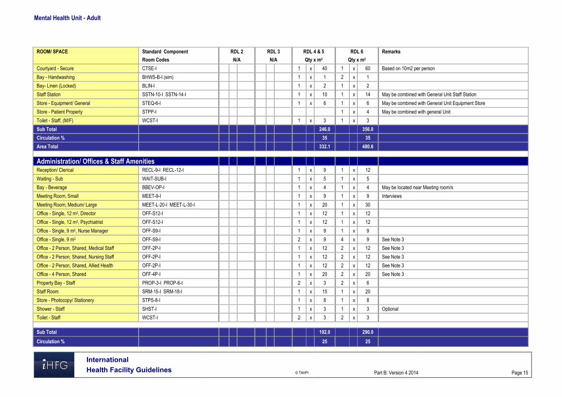
Mental Health Unit - Adult
International Health Facility Guidelines © TAHPI
Part B: Version 4 2014
Page 15
ROOM/ SPACE Standard Component RDL 2 RDL 3 RDL 4 & 5 RDL 6 Remarks
Room Codes N/A N/A Qty x m2 Qty x m2
Courtyard - Secure CTSE-I 1 x 40 1 x 60 Based on 10m2 per person
Bay - Handwashing BHWS-B-I (sim) 1 x 1 2 x 1
Bay- Linen (Locked) BLIN-I 1 x 2 1 x 2
Staff Station SSTN-10-I SSTN-14-I 1 x 10 1 x 14 May be combined with General Unit Staff Station
Store - Equipment/ General STEQ-6-I 1 x 6 1 x 6 May be combined with General Unit Equipment Store
Store - Patient Property STPP-I 1 x 4 May be combined with general Unit
Toilet - Staff, (M/F) WCST-I 1 x 3 1 x 3
Sub Total 246.0 356.0
Circulation % 35 35
Area Total 332.1 480.6
Administration/ Offices & Staff Amenities
Reception/ Clerical RECL-9-I RECL-12-I 1 x 9 1 x 12
Waiting - Sub WAIT-SUB-I 1 x 5 1 x 5
Bay - Beverage BBEV-OP-I 1 x 4 1 x 4 May be located near Meeting room/s
Meeting Room, Small MEET-9-I 1 x 9 1 x 9 Interviews
Meeting Room, Medium/ Large MEET-L-20-I MEET-L-30-I 1 x 20 1 x 30
Office - Single, 12 m2, Director OFF-S12-I 1 x 12 1 x 12
Office - Single, 12 m2, Psychiatrist OFF-S12-I 1 x 12 1 x 12
Office - Single, 9 m2, Nurse Manager OFF-S9-I 1 x 9 1 x 9
Office - Single, 9 m2 OFF-S9-I 2 x 9 4 x 9 See Note 3
Office - 2 Person, Shared, Medical Staff OFF-2P-I 1 x 12 2 x 12 See Note 3
Office - 2 Person, Shared, Nursing Staff OFF-2P-I 1 x 12 2 x 12 See Note 3
Office - 2 Person, Shared, Allied Health OFF-2P-I 1 x 12 2 x 12 See Note 3
Office - 4 Person, Shared OFF-4P-I 1 x 20 2 x 20 See Note 3
Property Bay - Staff PROP-3-I PROP-6-I 2 x 3 2 x 6
Staff Room SRM-15-I SRM-18-I 1 x 15 1 x 20
Store - Photocopy/ Stationery STPS-8-I 1 x 8 1 x 8
Shower - Staff SHST-I 1 x 3 1 x 3 Optional
Toilet - Staff WCST-I 2 x 3 2 x 3
Sub Total 192.0 290.0
Circulation % 25 25

Mental Health Unit - Adult
International Health Facility Guidelines © TAHPI
Part B: Version 4 2014
Page 16
ROOM/ SPACE Standard Component RDL 2 RDL 3 RDL 4 & 5 RDL 6 Remarks
Room Codes N/A N/A Qty x m2 Qty x m2
Area Total 240.0 362.5
Grand Total 1898.5 2650.1
Note 1: Overall size of recreational areas in the General Unit is based on 7.5 m2 per person; rooms may be re-sized according to numbers of persons to be accommodated. Note 2: Overall size of recreational areas in the HDU/ Secure areas are based 10 m2 per person; rooms may be re-sized according to numbers of persons to be accommodated. Note 3: Offices to be provided according to the number of approved full time positions within the Unit Note 4: Kitchen size and equipment will be dependent on Operational Policy - food prepared off site or on site; method of food preparation and delivery Please also note the following: Areas noted in Schedules of Accommodation take precedence over all other areas noted in the FPU. Rooms indicated in the schedule reflect the typical arrangement according to the Role Delineation. Exact requirements for room quantities and sizes will reflect Key Planning Units identified in the Service Plan and the Operational Policies of the Unit. Room sizes indicated should be viewed as a minimum requirement; variations are acceptable to reflect the needs of individual Unit. Staff and support rooms may be shared between Functional Planning Units dependant on location and accessibility to each unit and may provide scope to
reduce duplication of facilities.
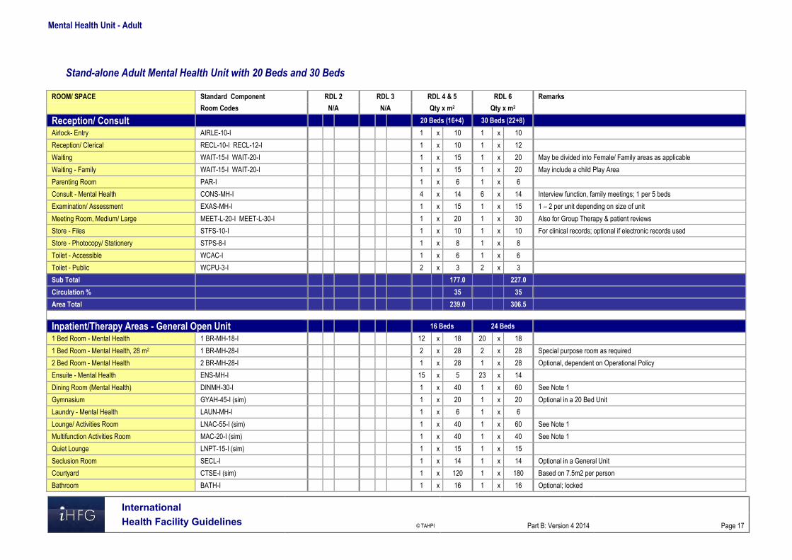
Mental Health Unit - Adult
International Health Facility Guidelines © TAHPI
Part B: Version 4 2014
Page 17
Stand-alone Adult Mental Health Unit with 20 Beds and 30 Beds
ROOM/ SPACE Standard Component RDL 2 RDL 3 RDL 4 & 5 RDL 6 Remarks
Room Codes N/A N/A Qty x m2 Qty x m2
Reception/ Consult 20 Beds (16+4) 30 Beds (22+8)
Airlock- Entry AIRLE-10-I 1 x 10 1 x 10
Reception/ Clerical RECL-10-I RECL-12-I 1 x 10 1 x 12
Waiting WAIT-15-I WAIT-20-I 1 x 15 1 x 20 May be divided into Female/ Family areas as applicable
Waiting - Family WAIT-15-I WAIT-20-I 1 x 15 1 x 20 May include a child Play Area
Parenting Room PAR-I 1 x 6 1 x 6
Consult - Mental Health CONS-MH-I 4 x 14 6 x 14 Interview function, family meetings; 1 per 5 beds
Examination/ Assessment EXAS-MH-I 1 x 15 1 x 15 1 – 2 per unit depending on size of unit
Meeting Room, Medium/ Large MEET-L-20-I MEET-L-30-I 1 x 20 1 x 30 Also for Group Therapy & patient reviews
Store - Files STFS-10-I 1 x 10 1 x 10 For clinical records; optional if electronic records used
Store - Photocopy/ Stationery STPS-8-I 1 x 8 1 x 8
Toilet - Accessible WCAC-I 1 x 6 1 x 6
Toilet - Public WCPU-3-I 2 x 3 2 x 3
Sub Total 177.0 227.0
Circulation % 35 35
Area Total 239.0 306.5
Inpatient/Therapy Areas - General Open Unit 16 Beds 24 Beds
1 Bed Room - Mental Health 1 BR-MH-18-I 12 x 18 20 x 18
1 Bed Room - Mental Health, 28 m2 1 BR-MH-28-I 2 x 28 2 x 28 Special purpose room as required
2 Bed Room - Mental Health 2 BR-MH-28-I 1 x 28 1 x 28 Optional, dependent on Operational Policy
Ensuite - Mental Health ENS-MH-I 15 x 5 23 x 14
Dining Room (Mental Health) DINMH-30-I 1 x 40 1 x 60 See Note 1
Gymnasium GYAH-45-I (sim) 1 x 20 1 x 20 Optional in a 20 Bed Unit
Laundry - Mental Health LAUN-MH-I 1 x 6 1 x 6
Lounge/ Activities Room LNAC-55-I (sim) 1 x 40 1 x 60 See Note 1
Multifunction Activities Room MAC-20-I (sim) 1 x 40 1 x 40 See Note 1
Quiet Lounge LNPT-15-I (sim) 1 x 15 1 x 15
Seclusion Room SECL-I 1 x 14 1 x 14 Optional in a General Unit
Courtyard CTSE-I (sim) 1 x 120 1 x 180 Based on 7.5m2 per person
Bathroom BATH-I 1 x 16 1 x 16 Optional; locked

Mental Health Unit - Adult
International Health Facility Guidelines © TAHPI
Part B: Version 4 2014
Page 18
ROOM/ SPACE Standard Component RDL 2 RDL 3 RDL 4 & 5 RDL 6 Remarks
Room Codes N/A N/A Qty x m2 Qty x m2
Bay - Handwashing BHWS-B-I (sim) 4 x 1 6 x 1 With anti-ligature tapware & basin fittings
Bay - Linen BLIN-I 1 x 2 2 x 2 Enclosed and locked
Bay - Resuscitation Trolley BRES-I 1 x 1.5 1 x 1.5 Locate in Staff Station or Medication/ Treatment
Cleaners Room CLRM-5-I 1 x 5 1 x 5
Dirty Utility DTUR-10-I 1 x 10 1 x 10
Disposal Room DISP-8-I 1 x 8 1 x 8
Medication/ Treatment Room MED-MH-I 1 x 12 1 x 12
Office - Clinical/ Handover OFF-CLN-I 1 x 15 1 x 15
Servery/ Trolley Holding (Mental Health) SERV-MH-I 1 x 15 1 x 15 Locate adjacent to Dining
Staff Station SSTN-14-I SSTN-20-I 1 x 14 1 x 20 May be re-sized or sub divided for surveillance
Store - Equipment STEQ-10-I STEQ-16-I 1 x 10 1 x 16
Store - General STGN-9-I STGN-12-I 1 x 9 1 x 12
Store - Patient Property STPP-I 1 x 8 1 x 8
Toilet - Accessible WCAC-I 1 x 6 1 x 6 May be located near Dining/ Activities areas
Toilet - Staff WCST-I 1 x 3 1 x 3 Located in a staff only accessed area
Sub Total 808.5 1318.5
Circulation % 35 35
Area Total 1091.5 1780.0
HDU - Secure Unit 4 Beds 6 Beds Optional - Dependent on Service Plan
Airlock - Entry AIRLE-10-I 1 x 10 1 x 10 Secure entry with weather protection
Waiting - Secure WAIT-SEC-I 1 x 6 1 x 6 May be shared between secure units
Exam/ Assessment Room EXAS-MH-I 1 x 15 1 x 15 May be shared between secure units
1 Bed Room - Mental Health 1 BR-MH-18-I 4 x 18 6 x 18 May be subdivided into pods, each with a Sitting room
Ensuite - Mental Health ENS-MH-I 3 x 5 4 x 5 Accessible from Corridor, 1 for Assessment room
Dining Room/ Beverage Bay (Mental Health) DINBEV-38-I (sim) 1 x 20 1 x 25 Used for Activities between meals; see Note 2
Lounge - Activities (Mental Health) LNAC-20-I 1 x 20 1 x 20 See Note 2
Multi-Function Activities Room (Mental Health) MAC-20-I 1 x 15 See Note 2
Seclusion Room SECL-I 1 x 14 2 x 14
Sitting Area SIT-3-I 4 x 3 6 x 3 Combine as appropriate depending on layout
Courtyard - Secure CTSE-I 1 x 40 1 x 60 Based on 10 m2 per person
Bay - Handwashing BHWS-B-I (sim) 1 x 1 2 x 1
Bay- Linen (Locked) BLIN-I 1 x 2 1 x 2

Mental Health Unit - Adult
International Health Facility Guidelines © TAHPI
Part B: Version 4 2014
Page 19
ROOM/ SPACE Standard Component RDL 2 RDL 3 RDL 4 & 5 RDL 6 Remarks
Room Codes N/A N/A Qty x m2 Qty x m2
Staff Station SSTN-10-I SSTN-14-I 1 x 10 1 x 14 May be combined with General Unit Staff Station
Store - Equipment/ General STEQ-6-I 1 x 6 1 x 6 May be combined with General Unit Equipment Store
Store - Patient Property STPP-I x 1 x 4 May be combined with general Unit
Toilet - Staff, (M/F) WCST-I 1 x 3 1 x 3
Sub Total 246.0 356.0
Circulation % 35 35
Area Total 332.1 480.6
Administration/ Office Areas
Reception/ Clerical RECL-9-I RECL-12-I 1 x 9 1 x 12
Waiting - Sub WAIT-SUB-I 1 x 5 1 x 5
Bay - Beverage BBEV-OP-I BBEV-ENC-I 1 x 4 1 x 5 May be located near Meeting room/s
Meeting Room, Small MEET-9-I 1 x 9 1 x 9 Interviews
Meeting Room, Medium/ Large MEET-L-20-I MEET-L-30-I 1 x 20 1 x 30
Office - Single, 12m2, Director OFF-S12-I 1 x 12 1 x 12
Office - Single, 12m2, Psychiatrist OFF-S12-I 1 x 12 1 x 12
Office - Single, 9m2, Nurse Manager OFF-S9-I 1 x 9 1 x 9
Office - Single, 9m2 OFF-S9-I 2 x 9 4 x 9 See Note 3
Office - 2 Person, Shared, Medical Staff OFF-2P-I 1 x 12 2 x 12 See Note 3
Office - 2 Person, Shared, Nursing Staff OFF-2P-I 1 x 12 2 x 12 See Note 3
Office - 2 Person, Shared, Allied Health OFF-2P-I 1 x 12 2 x 12 See Note 3
Office - 4 Person, Shared OFF-4P-I 1 x 20 2 x 20 See Note 3
Store - Files STFS-8-I STFS-10-I 1 x 8 1 x 10
Store - Photocopy/ Stationery STPS-8-I 1 x 8 1 x 8
Sub Total 170.0 260.0
Circulation % 25 25
Area Total 212.5 325.0
Staff & Support Areas
Cleaners Room CLRM-10-I 1 x 10 1 x 10 Includes storage of cleaning consumables
Communications Room COMM-I 1 x 0 1 x 0 Size dependant on IT specifications; area is a part of Plant
Disposal Room DISP-8-I 1 x 8 1 x 8
Kitchen NS 1 x 30 1 x 40 See Note 4 ; Dependent on Operational Policy
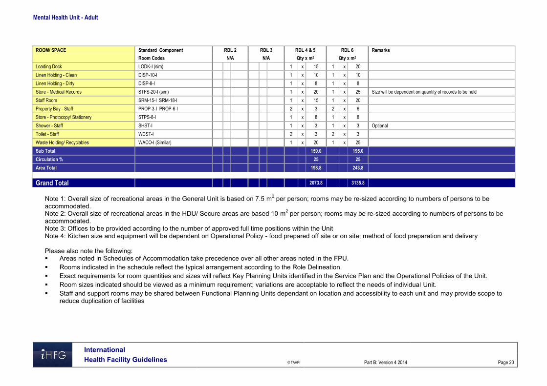
Mental Health Unit - Adult
International Health Facility Guidelines © TAHPI
Part B: Version 4 2014
Page 20
ROOM/ SPACE Standard Component RDL 2 RDL 3 RDL 4 & 5 RDL 6 Remarks
Room Codes N/A N/A Qty x m2 Qty x m2
Loading Dock LODK-I (sim) 1 x 15 1 x 20
Linen Holding - Clean DISP-10-I 1 x 10 1 x 10
Linen Holding - Dirty DISP-8-I 1 x 8 1 x 8
Store - Medical Records STFS-20-I (sim) 1 x 20 1 x 25 Size will be dependent on quantity of records to be held
Staff Room SRM-15-I SRM-18-I 1 x 15 1 x 20
Property Bay - Staff PROP-3-I PROP-6-I 2 x 3 2 x 6
Store - Photocopy/ Stationery STPS-8-I 1 x 8 1 x 8
Shower - Staff SHST-I 1 x 3 1 x 3 Optional
Toilet - Staff WCST-I 2 x 3 2 x 3
Waste Holding/ Recyclables WACO-I (Similar) 1 x 20 1 x 25
Sub Total 159.0 195.0
Circulation % 25 25
Area Total 198.8 243.8
Grand Total 2073.8 3135.8
Note 1: Overall size of recreational areas in the General Unit is based on 7.5 m2 per person; rooms may be re-sized according to numbers of persons to be accommodated. Note 2: Overall size of recreational areas in the HDU/ Secure areas are based 10 m2 per person; rooms may be re-sized according to numbers of persons to be accommodated. Note 3: Offices to be provided according to the number of approved full time positions within the Unit Note 4: Kitchen size and equipment will be dependent on Operational Policy - food prepared off site or on site; method of food preparation and delivery Please also note the following: Areas noted in Schedules of Accommodation take precedence over all other areas noted in the FPU. Rooms indicated in the schedule reflect the typical arrangement according to the Role Delineation. Exact requirements for room quantities and sizes will reflect Key Planning Units identified in the Service Plan and the Operational Policies of the Unit. Room sizes indicated should be viewed as a minimum requirement; variations are acceptable to reflect the needs of individual Unit. Staff and support rooms may be shared between Functional Planning Units dependant on location and accessibility to each unit and may provide scope to
reduce duplication of facilities

Mental Health Unit - Adult
International Health Facility Guidelines © TAHPI
Part B: Version 4 2014
Page 21
6 Functional Relationship Diagram – Mental Health Unit - Adult

Mental Health Unit - Adult
International Health Facility Guidelines © TAHPI
Part B: Version 4 2014
Page 22
7 References and Further Reading Australasian Health Facility Guidelines, Part B Health Facility Briefing and Planning, Adult
Acute Mental Health Unit, Rev 5, 2012; refer to website www.healthfacilitydesign.com.au National Advisory Council on Mental Health (Australia), December 2010, Fitting Together the
Pieces: Collaborative Care Models for Adults with Severe and Persistent Mental Illness. DH (Department of Health) NHS Estates (UK) Health Building Note 35 Accommodation for
people with Mental Illness, part 1 – The Acute Unit., 2006; refer to website www.estatesknowledge.dh.gov.uk
Royal College of Psychiatrists (UK), 2007, Standards for Medium Secure Units, Quality Network for medium secure units
The Facility Guidelines Institute (US), 2010 Edition. Guidelines for Design and Construction of Health Care Facilities; ) refer to website www.fgiguidelines.org .

Part B – Health Facility Briefing & Design 185 Mental Health Unit – Child & Adolescent
International Health Facility Guidelines Version 4 May 2014

International
Health Facility Guidelines © TAHPI
Part B: Version 4 2014
Page 2
Table of Contents
185 Mental Health Unit - Child & Adolescent ................................................................................. 3 1 Introduction ............................................................................................................................................... 3 2 Planning ..................................................................................................................................................... 3 3 Design ........................................................................................................................................................ 6 4 Components of the Unit ............................................................................................................................ 8 5 Schedule of Accommodation - Mental Health Unit - Child & Adolescent ............................................ 9 6 Functional Relationship Diagram - Mental Health Unit - Child & Adolescent ................................... 12 7 References and Further Reading ........................................................................................................... 13

Mental Health Unit – Child & Adolescent
International
Health Facility Guidelines © TAHPI
Part B: Version 4 2014
Page 3
185 Mental Health Unit - Child & Adolescent 1 Introduction Description The Child & Adolescent Mental Health Inpatient Unit provides short term acute inpatient mental health assessment and treatment of children up to 10 to 12 years of age and adolescents up to 16 -18 years where community approaches have proven (or are likely to prove) inadequate. The design, layout and functionality of Child and Adolescent Mental Health Units should meet the developmental needs of their age group. Notably, the Child and Adolescent Unit should enable active family involvement in daily care, treatment and program activities including family admission and residence where appropriate. The patients in each unit will have a broad range of mental health problems and disorders and challenging behaviours that must be managed safely and effectively. The layout and design of the Child and Adolescent units will need to accommodate children and young people at varying stages of social, emotional and intellectual development. Young people in the Adolescent Unit will have families and others involved in their care who should feel welcome in the unit. The unit may admit and treat patients who have: A risk of self-injury A risk of self-neglect A risk of injury to others A severe affective disorder Psychosis including early onset schizophrenia Pervasive developmental disorders Anorexia nervosa and related eating disorders Severe anxiety disorders Obsessive compulsive disorder Tourette's syndrome Co-morbid drug and alcohol problems Severe family relationship difficulties. 2 Planning Models of Care Models of care include: Children and adolescents together in a fully integrated unit, with separate programs and
activities for relevant age groups; this arrangement optimises staffing and enables efficient use of resources;
Children and adolescents in the same unit but separate “zones” designed to cater for their differing needs; they should operate as two discrete service types with separate functional areas, programs and activities although co-location allows sharing of facilities
Inclusion of a secured dedicated unit collocated with a paediatric precinct to allow children to participate in activities with other children such as school and play therapy
Collocation of a Day Unit to minimise the need for hospitalisation; the Day unit would provide for day activities and close down at night.
Functional Areas The Unit will cater for both male and female patient and family members as required. The Unit should provide Bedrooms that can accommodate family members in a bed sitting arrangement with a separate bedroom to the child, with a shared Ensuite.

Mental Health Unit – Child & Adolescent
International
Health Facility Guidelines © TAHPI
Part B: Version 4 2014
Page 4
Support areas required in Child/ Adolescent Units will include: Multipurpose Group Therapy/ Activity rooms that can also be used for education purposes Large Interview Rooms to accommodate families Outdoor space for recreation activities. Storage for general ward equipment, occupational therapy equipment and a range of age
appropriate, therapy, sport and recreation equipment in each setting. Office accommodation should be located in a non-patient area of the unit with secured access/ egress.
Assessment/ Medication Room (may be a Shared Facility)
The Unit will include a suitably equipped room for physical/ neurological examinations which will also contain locked cupboards for dressings, medications and emergency equipment in keeping with legislative requirements. The Room will require two entry/ exit doors.
External Relaxation/ Activities Areas
Each unit will require discrete and separate outdoor relaxation areas. These areas will not be locked but access to and from the units should be only from the respective unit and easily observed and monitored by staff. Staff should however be able to prevent access to these areas at night. A common external activity area may be shared if units are co-located.
High Dependency/ Intensive Care Unit (Adolescent Unit Only)
The Adolescent Unit will require a lockable high dependency unit consisting of at least one seclusion room and toilet/bath/ shower room opening onto a locked lounge area which has direct access to an external secure courtyard separate to other external recreation areas. Entry to this area directly from outside the unit will be required for police assisted admissions or where a young person is highly disturbed and at immediate risk of harm to themselves or others.
Patient Bedrooms
Single Patient Bedrooms shall be provided, each with an Ensuite. The patient bedroom doors must be able to be unlocked from the outside, even if locked on the inside. It is advisable to have the capacity to restrict the access to the Ensuite. The fittings and furniture include: Built-in wardrobe Built-in desk Pin board for photos and posters. Fittings must not provide opportunities for self-harm and are to have a breaking strain of less than 15 kg. Blinds to external windows are to be within double glazing. Chairs should be light weight and flexible. Services will include the following: Two power outlets - RCD protected Staff alarm system. Medical gases will not be required.
Patient Ensuites
An Ensuite shall be provided to each bedroom to comply with Standard Components Ensuite - Mental Health. The fittings must not provide opportunities for self-harm and are to have a breaking strain of less than 15 kg.
Parent/ Family/ Carer Bedrooms
Bedrooms for parents or other family members should include a double bed and a single bed and be of sufficient size to allow a fold away cot for very young children. A shared Ensuite to enable parents/ carers to look after their child accommodated in another room should be available to each parent/ family/ carer bedroom.
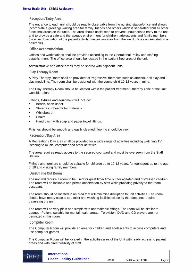
Mental Health Unit – Child & Adolescent
International
Health Facility Guidelines © TAHPI
Part B: Version 4 2014
Page 5
Reception/ Entry Area
The entrance to each unit should be readily observable from the nursing station/office and should incorporate a greeting/ waiting area for family, friends and others which is separated from all other functional areas on the units. The area should assist staff to prevent unauthorised entry to the unit and to provide a safe and therapeutic environment for children, adolescents and family members, (passive observation of the patient activity / recreation area from the ward office / nurses station is desirable).
Office Accommodation
Offices and workstations shall be provided according to the Operational Policy and staffing establishment. The office area should be located in the 'patient free' area of the unit. Administrative and office areas may be shared with adjacent units.
Play Therapy Room
A Play Therapy Room shall be provided for 'regressive' therapies such as artwork, doll play and clay modelling. The room shall be designed with the young child 10-12 years in mind. The Play Therapy Room should be located within the patient treatment / therapy zone of the Unit. Considerations Fittings, fixtures and equipment will include: Bench, open under Storage cupboards for materials Whiteboard Chairs Hand basin with soap and paper towel fittings. Finishes should be smooth and easily cleaned, flooring should be vinyl.
Recreation/ Day Area
A Recreation / Day area shall be provided for a wide range of activities including watching TV, listening to music, computer and other activities. The area requires ready access to the secured courtyard and must be overseen from the Staff Station. Fittings and furniture should be suitable for children up to 10-12 years, for teenagers up to the age of 18 and visiting family members.
Quiet/ Time Out Room:
The unit will require a room to be used for quiet time/ time out for agitated and distressed children. The room will be lockable and permit observation by staff while providing privacy to the room occupant. The room should be located in an area that will minimise disruption to unit activities. The room should have ready access to a toilet and washing facilities close by that does not require traversing the unit. The room will be very plain and simple with unbreakable fittings. The room will be similar to Lounge- Patient, suitable for mental health areas. Television, DVD and CD players are not permitted in this room.
Computer Room
The Computer Room will provide an area for children and adolescents to access computers and use computer games. The Computer Room will be located in the activities area of the Unit with ready access to patient areas and with direct visibility of staff.

Mental Health Unit – Child & Adolescent
International
Health Facility Guidelines © TAHPI
Part B: Version 4 2014
Page 6
The room will include the following furniture, fittings and equipment: Computer desks Computers Computer games consoles Chairs suitable for computer desks Whiteboard (optional) All furniture in the area will need to be sturdy, vandal resistant and suitable for mental health areas. Electrical outlets will require RCD protection. All cables will need to be secured and not accessible to patients. Functional Relationships The Child and Adolescent Mental Health Unit will have functional relationships with the following units, services and organizations: Emergency Unit Paediatric Inpatient Unit Paediatric Outpatient services Diagnostic Pathology Unit Allied Health Unit Early childhood services Child and family support services Community services including day programs Drug treatment services Adult Psychiatric Services Adolescent medical units. 3 Design General The Child and Adolescent Mental Health Unit should be located on the ground floor. The following design issues are mandatory requirements: Access to the Unit must not be through other units, also the unit must not form a
thoroughfare to any other unit Bedrooms should provide a comfortable domestic environment with comfortable, robust
furniture and furnishings All glazing must be a grade of safety glass suitable for mental health applications Where co-located, the Child and Adolescent Mental Health Unit should allow full independent
operation and separation while enabling common use of appropriate facilities Rooms and equipment need to meet the therapeutic and educational requirements of the
patient group, with provisions for video conferencing in at least one large family Meeting Room and video recording in at least one Interview Room or wet and dry Therapy/ Play Room.
The Entry areas to both Units require a Visitors’ Toilet - Disabled with baby change facilities and a Waiting Area in close proximity.
Design elements incorporating additional security measures should not be evident to the casual observer.
Environmental Considerations
Acoustics
Acoustic treatment should be applied to the following areas: Day Areas such as patient living, dining and activities areas Patient Bedrooms including high dependency, intensive care and seclusion rooms Consulting Rooms Admission Areas.
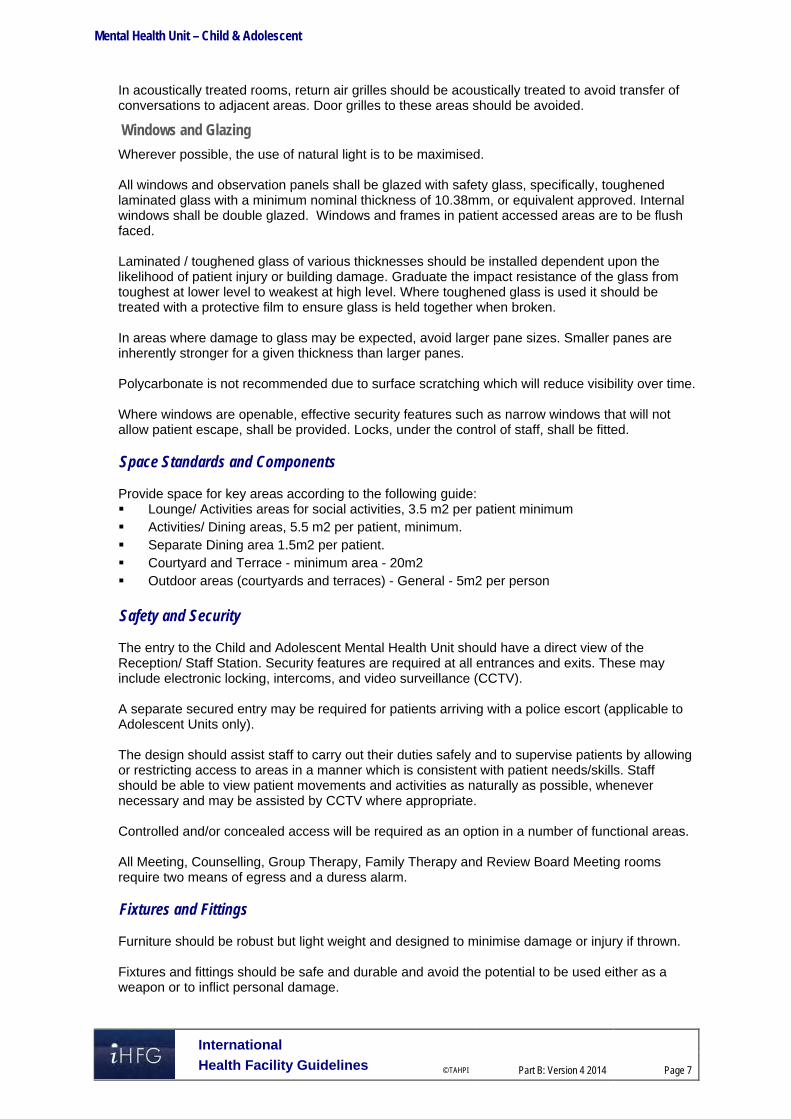
Mental Health Unit – Child & Adolescent
International
Health Facility Guidelines © TAHPI
Part B: Version 4 2014
Page 7
In acoustically treated rooms, return air grilles should be acoustically treated to avoid transfer of conversations to adjacent areas. Door grilles to these areas should be avoided.
Windows and Glazing
Wherever possible, the use of natural light is to be maximised. All windows and observation panels shall be glazed with safety glass, specifically, toughened laminated glass with a minimum nominal thickness of 10.38mm, or equivalent approved. Internal windows shall be double glazed. Windows and frames in patient accessed areas are to be flush faced. Laminated / toughened glass of various thicknesses should be installed dependent upon the likelihood of patient injury or building damage. Graduate the impact resistance of the glass from toughest at lower level to weakest at high level. Where toughened glass is used it should be treated with a protective film to ensure glass is held together when broken. In areas where damage to glass may be expected, avoid larger pane sizes. Smaller panes are inherently stronger for a given thickness than larger panes. Polycarbonate is not recommended due to surface scratching which will reduce visibility over time. Where windows are openable, effective security features such as narrow windows that will not allow patient escape, shall be provided. Locks, under the control of staff, shall be fitted. Space Standards and Components Provide space for key areas according to the following guide: Lounge/ Activities areas for social activities, 3.5 m2 per patient minimum Activities/ Dining areas, 5.5 m2 per patient, minimum. Separate Dining area 1.5m2 per patient. Courtyard and Terrace - minimum area - 20m2 Outdoor areas (courtyards and terraces) - General - 5m2 per person Safety and Security The entry to the Child and Adolescent Mental Health Unit should have a direct view of the Reception/ Staff Station. Security features are required at all entrances and exits. These may include electronic locking, intercoms, and video surveillance (CCTV). A separate secured entry may be required for patients arriving with a police escort (applicable to Adolescent Units only). The design should assist staff to carry out their duties safely and to supervise patients by allowing or restricting access to areas in a manner which is consistent with patient needs/skills. Staff should be able to view patient movements and activities as naturally as possible, whenever necessary and may be assisted by CCTV where appropriate. Controlled and/or concealed access will be required as an option in a number of functional areas. All Meeting, Counselling, Group Therapy, Family Therapy and Review Board Meeting rooms require two means of egress and a duress alarm. Fixtures and Fittings Furniture should be robust but light weight and designed to minimise damage or injury if thrown. Fixtures and fittings should be safe and durable and avoid the potential to be used either as a weapon or to inflict personal damage.

Mental Health Unit – Child & Adolescent
International
Health Facility Guidelines © TAHPI
Part B: Version 4 2014
Page 8
Generally, all fixings should be heavy duty, concealed, and where exposed, tamper proof. Fittings, including hooks, curtain tracks, bathroom fittings, should be plastic where possible, and have a breaking strain of not more than 15kgs. Paintings, mirrors and signage should be rigidly fixed to walls with tamper proof fixings. Mirrors shall be of safety glass or other appropriate impact resistant and shatterproof construction. They shall be fully glued to a backing to prevent availability of loose fragments of broken glass. Holland blinds, Venetian blinds and curtains should be avoided in patient areas. Curtain tracks, pelmets and other fittings that provide potential for patients to hang themselves should be avoided or designed so that the potential is removed. Building Services Requirements Avoid exposed services; for example, sink wastes which may be easily damaged. Refer to Part E of these Guidelines for further information. 4 Components of the Unit The Child and Adolescent Mental Health Unit will consist of Standard Components to comply with details described in these Guidelines. Refer also to Standard Components Room Data Sheets and Room Layout Sheets.
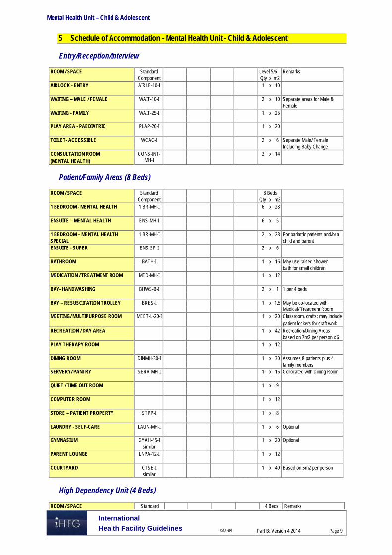
Mental Health Unit – Child & Adolescent
International
Health Facility Guidelines © TAHPI
Part B: Version 4 2014
Page 9
5 Schedule of Accommodation - Mental Health Unit - Child & Adolescent Entry/Reception/Interview
ROOM / SPACE Standard Level 5/6 Remarks Component Qty x m2 AIRLOCK - ENTRY AIRLE-10-I 1 x 10 WAITING – MALE / FEMALE WAIT-10-I 2 x 10 Separate areas for Male & Female WAITING - FAMILY WAIT-25-I 1 x 25 PLAY AREA - PAEDIATRIC PLAP-20-I 1 x 20 TOILET- ACCESSIBLE WCAC-I 2 x 6 Separate Male/ Female Including Baby Change CONSULTATION ROOM CONS-INT-
MH-I 2 x 14
(MENTAL HEALTH)
Patient/Family Areas (8 Beds)
ROOM / SPACE Standard 8 Beds Component Qty x m2 1 BEDROOM - MENTAL HEALTH 1 BR-MH-I 6 x 28 ENSUITE – MENTAL HEALTH ENS-MH-I 6 x 5 1 BEDROOM – MENTAL HEALTH 1 BR-MH-I 2 x 28 For bariatric patients and/or a SPECIAL child and parent ENSUITE - SUPER ENS-SP-I 2 x 6 BATHROOM BATH-I 1 x 16 May use raised shower bath for small children MEDICATION / TREATMENT ROOM MED-MH-I 1 x 12 BAY- HANDWASHING BHWS-B-I 2 x 1 1 per 4 beds BAY – RESUSCITATION TROLLEY BRES-I 1 x 1.5 May be co-located with Medical/ Treatment Room MEETING/ MULTIPURPOSE ROOM MEET-L-20-I 1 x 20 Classroom, crafts; may include patient lockers for craft work RECREATION / DAY AREA 1 x 42 Recreation/Dining Areas based on 7m2 per person x 6 PLAY THERAPY ROOM 1 x 12 DINING ROOM DINMH-30-I 1 x 30 Assumes 8 patients plus 4 family members SERVERY/ PANTRY SERV-MH-I 1 x 15 Collocated with Dining Room QUIET / TIME OUT ROOM 1 x 9 COMPUTER ROOM 1 x 12 STORE – PATIENT PROPERTY STPP-I 1 x 8 LAUNDRY - SELF-CARE LAUN-MH-I 1 x 6 Optional GYMNASIUM GYAH-45-I 1 x 20 Optional similar PARENT LOUNGE LNPA-12-I 1 x 12 COURTYARD CTSE-I 1 x 40 Based on 5m2 per person similar
High Dependency Unit (4 Beds)
ROOM / SPACE Standard 4 Beds Remarks

Mental Health Unit – Child & Adolescent
International
Health Facility Guidelines © TAHPI
Part B: Version 4 2014
Page 10
Component Qty x m2 WAITING - SECURE WAIT-SEC-I 1 x 6 Entry area EXAMINATION /ASSESSMENT EXAS-MH-I 1 x 15 STAFF STATION SSTN-10-I 1 x 10 Optional depending on planning layout SECLUSION ROOM SECL-I 1 x 12 1 BEDROOM – MENTAL HEALTH 1 BR-MH-I 4 x 28 PATIENT TOILET (MENTAL HEALTH) ENS-MH-I 2 x 4 similar PATIENT SHOWER (MENTAL HEALTH) ENS-MH-I 2 x 4 similar BAY HANDWASH BHWS-B-I 1 x 1 LOUNGE / DINING / ACTIVITY LDA-MH-20-I
similar 1 x 30 7.5m2 per person
COURTYARD CTSE-I 1 x 40 10m2 per person similar
Clinical Support Areas
ROOM / SPACE Standard Level 5/6 Remarks Component Qty x m2 BAY - LINEN BLIN-I 1 x 2 DIRTY UTILITY DTUR-10-I 1 x 10 STAFF STATION SSTN-14-I 1 x 14 OFFICE – CLINICAL / HANDOVER OFF-CLN-I 1 x 15 STORE - EQUIPMENT STEQ-14-I 1 x 14 STORE - GENERAL STGN-9-I 1 x 9 CLEANER'S ROOM CLRM-5-I 1 x 5 DISPOSAL ROOM DISP-8-I 1 x 8 CIRCULATION ALLOWANCE % 32%
Offices & Staff Amenities
ROOM / SPACE Standard Level 5/6 Remarks Component Qty x m2 OFFICE - CEO OFF-CEO-I 1 x 15 CLINICAL DIRECTOR OFFICE – SINGLE PERSON 12M2 OFF-S12-I 1 x 12 PSYCHIATRIST OFFICE – SINGLE PERSON, 9M2 OFF-S9-I 1 x 9 NURSE MANAGER OFFICE - WORKSTATION OFF-WS-I 4 x 5.5 NURSING STAFF OFFICE - WORKSTATION OFF-WS-I 4 x 5.5 ALLIED HEALTH OFFICE - WORKSTATION OFF-WS-I 1 x 5.5 CLERICAL OFFICE - WORKSTATION OFF-WS-I 2 x 5.5 VISITING PROFESSIONALS MEETING ROOM - LARGE MEET-L-25-I 1 x 25 STORE – PHOTOCOPY / STATIONERY STPS-8-I 1 x 8 STAFF ROOM SRM-20-I 1 x 20 With Beverage Bay

Mental Health Unit – Child & Adolescent
International
Health Facility Guidelines © TAHPI
Part B: Version 4 2014
Page 11
ROOM / SPACE Standard Level 5/6 Remarks Component Qty x m2 STAFF PROPERTY BAY PROP-2-I 2 x 2 Separate for Male & Female SHOWER - STAFF SHST-I 1 x 3 TOILET - STAFF WCST-I 2 x 3 Separate for Male & Female
Day Unit
ROOM / SPACE Standard Level 5/6 Remarks Component Qty x m2 RECEPTION RECL-12-I 1 x 12 STORE – PHOTOCOPY / STATIONERY STPS-8-I 1 x 8 STORE - FILES STFS-8-I 1 x 8 WAITING - MALE / FEMALE WAIT-20-I 2 x 20 Separate areas for Male & Female WAITING - FAMILY WAIT-25-I 1 x 25 PLAY AREA - PAEDIATRIC PLAP-15-I 1 x 15 TOILET - ACCESSIBLE WCAC-I 1 x 6 With Baby Change TOILET – PUBLIC WCPU-3-I 2 x 3 Separate for Male & Female CONSULT ROOM – MENTAL HEALTH CONS-INT-
MH-I 4 x 14 No. to be determined by
Service plan OBSERVATION ROOM OBS-I 1 x 9 One-way observation window STORE - GENERAL STGN-9-I 1 x 9 CIRCULATION ALLOWANCE % 35%
Please note the following: Areas noted in Schedules of Accommodation take precedence over all other areas noted in
the FPU. Rooms indicated in the schedule reflect the typical arrangement according to the Role
Delineation. Exact requirements for room quantities and sizes will reflect Key Planning Units identified in
the Service Plan and the Operational Policies of the Unit. Room sizes indicated should be viewed as a minimum requirement; variations are acceptable
to reflect the needs of individual Unit. Office areas are to be provided according to the Unit role delineation and number of
endorsed fulltime positions in the unit. Staff and support rooms may be shared between Functional Planning Units dependant on
location and accessibility to each unit and may provide scope to reduce duplication of facilities.
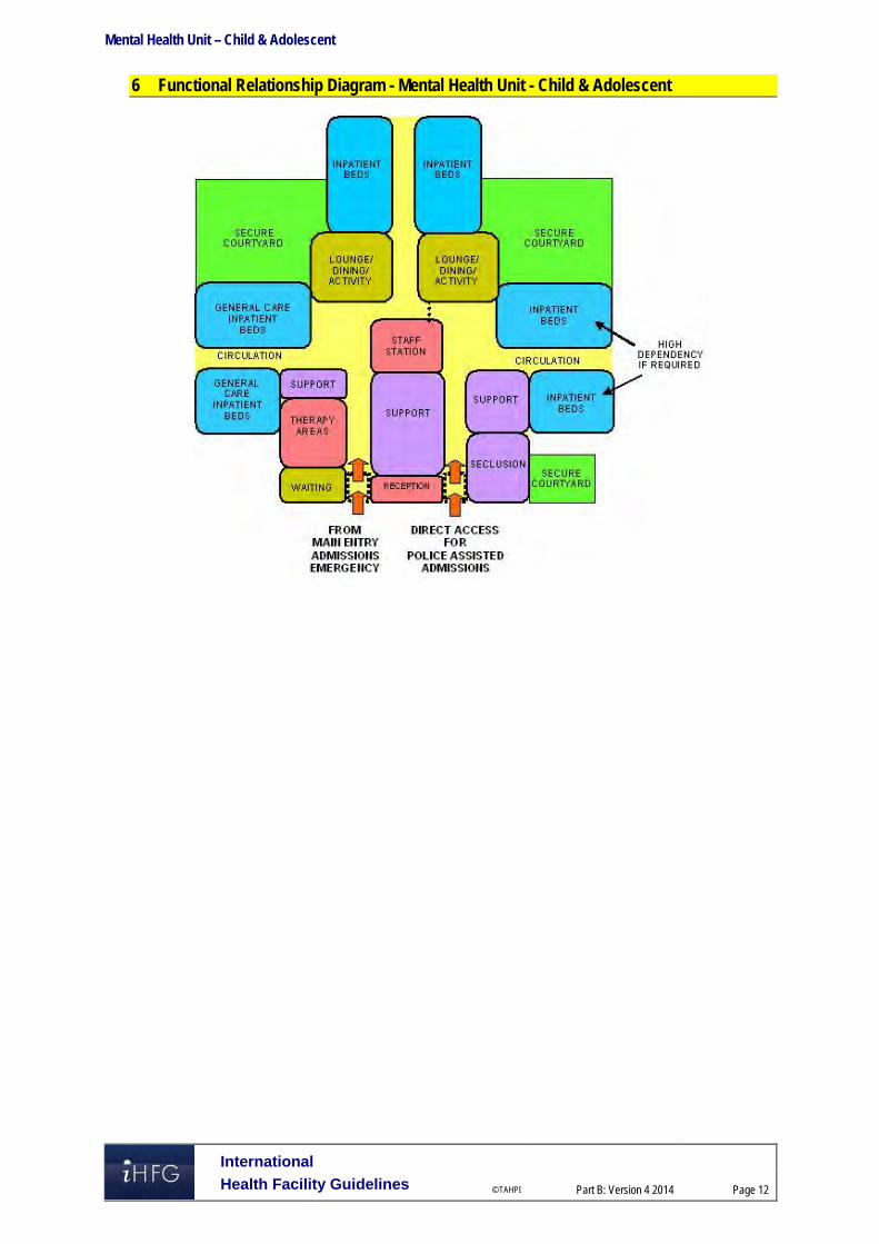
Mental Health Unit – Child & Adolescent
International
Health Facility Guidelines © TAHPI
Part B: Version 4 2014
Page 12
6 Functional Relationship Diagram - Mental Health Unit - Child & Adolescent

Mental Health Unit – Child & Adolescent
International
Health Facility Guidelines © TAHPI
Part B: Version 4 2014
Page 13
7 References and Further Reading Australasian Health Facility Guidelines, Part B Health Facility Briefing and Planning, Adult
Acute Mental Health Unit, Rev 5, 2012; refer to website www.healthfacilitydesign.com.au DH (Department of Health) NHS Estates (UK) Health Building Note 35 Accommodation for
people with Mental Illness, part 1 – The Acute Unit., 2006; refer to website www.estatesknowledge.dh.gov.uk
The Facility Guidelines Institute (US), 2010 Edition. Guidelines for Design and Construction of Health Care Facilities) refer to website www.fgiguidelines.org

Part B – Health Facility Briefing & Design 200 Mental Health Unit – Older Persons
International Health Facility Guidelines Version 4 May 2014

International
Health Facility Guidelines © TAHPI
Part B: Version 4 2014
Page 2
Table of Contents
200 Mental Health Unit - Older Persons ......................................................................................... 3 1 Introduction ............................................................................................................................................... 3 2 Planning ..................................................................................................................................................... 4 3 Design ........................................................................................................................................................ 7 4 Components of the Unit .......................................................................................................................... 13 5 Schedule of Accommodation - Mental Health Unit - Older Persons .................................................. 14 6 Functional Relationship Diagram - Mental Health Unit - Older Persons ............................................ 17 7 References and Further Reading ........................................................................................................... 18

Mental Health Unit – Older Persons
International
Health Facility Guidelines © TAHPI
Part B: Version 4 2014
Page 3
200 Mental Health Unit - Older Persons 1 Introduction Description The function of the Older Persons Mental Health Unit is to provide appropriate facilities for the reception, multidisciplinary assessment, admission, diagnosis and treatment of patients presenting with known or suspected psychiatric conditions and behavioural disorders along with assessment of physical health and psycho-social issues. Patients may be admitted on a voluntary or involuntary basis. Treatment is focused on clinical symptom reduction with a reasonable expectation of substantial improvement in the short term. The Unit must provide a safe, restorative environment. Optimal physical environments are associated with shorter lengths of stay, lower levels of aggression and critical incidents, better client outcomes and better staff conditions and satisfaction. Recurrent costs will be substantially reduced and client services and outcomes improved in such settings. Some patients may be agitated, aggressive and potentially a risk to themselves or others, including staff. The Unit must therefore provide a high level of security and the capacity for observation and even temporary containment. However, this should be achieved with a therapeutic focus so that while necessary measures for safety and security are in place, they are non-intrusive and do not convey a custodial ambience. It must be stressed that Older Persons Mental Health Units are not “dementia” units but they should be able to accommodate people with dementia, confusion and disturbed behaviour appropriately. Target Group The target group for these services will comprise of older people who: develop or are at high risk of developing a mental health disorder at the age of 65 years and
over, such as depression, psychosis, anxiety or a severe adjustment disorder have had a lifelong or recurring mental illness, and now experience age-related problems
causing significant functional disability (i.e. become ‘functionally old’) have had a prior mental health problem but have not seen a specialist mental health service
for at least five years and now have a recurrence of their illness or disorder that can be optimally managed by Older Persons Mental Health Unit
present with severe behavioural or psychiatric symptoms associated with dementia or other long-standing organic brain disorder and would be optimally managed with input from Older Persons Mental Health Units. This may include people who are deemed at risk of harm to themselves or to others. Symptoms may include:
- major depression - severe physical and/or verbal aggression - severe agitation - screaming - psychosis.
The families and carers of these older people are also part of the broader target group for Older Persons Mental Health Units.
Client Profile
Robust elderly (although an Adult Acute Unit may be more suitable in some cases); Frail elderly; Violent/ disturbed elderly. Patients may have; tendency to wander, become lost or abscond

Mental Health Unit – Older Persons
International
Health Facility Guidelines © TAHPI
Part B: Version 4 2014
Page 4
reduced personal and social skills and require assistance with personal hygiene, dressing, toileting and eating
disturbed or aggressive behaviours (verbal / physical) confusion, bewilderment, agitation, memory loss repetitive, persistent or noisy behaviour resistance to care withdrawn behaviour intentional self-harming behaviour physical co-morbidity Clinical conditions of patients; Schizophrenia and psychotic disorders; Dementia (incl. Alzheimer’ disease) with severe behavioural and psychological symptoms Depression, anxiety and mania Potential suicide Underlying co-morbidities Regardless of diagnosis, patients may be described as “hyperactive” or “hypoactive” and it is this description that may determine appropriate bed placement within the Unit. 2 Planning Planning Models
Location
It is highly desirable to locate the Older Persons Mental Health Units on ground floor, in order to provide necessary secure outdoor areas.
Configuration
The Older Persons Mental Health Units it may be developed as: A stand-alone Inpatient Unit - or group of units – usually as part of a Mental Health Complex. A dedicated Inpatient Unit within a general hospital. A number of dedicated Patient Bedrooms as an annexe to an Acute Inpatient Unit within a
general hospital.
Bed Numbers and Complement
The number of beds will be determined by the Service Plan but the larger a facility the more confusing it is likely to be for some patients. Bedrooms may be grouped into clusters that can be defined for distinct patient groups such as male and female patients who may feel threatened if in close proximity to the opposite sex or “hyperactive” and hypoactive” patients. Small groups of bedrooms with an adjacent recreational space will allow better management of changing patient needs and flexibility of use.
Unit Design
The following principles should be applied: Reduce the size of the patient groups Make the environment as familiar as possible Make the environment as domestic as possible Make the environment safe and secure Make the environment simple, with good visual access Reduce unnecessary stimulation Highlight helpful stimuli Provide for planned wandering Provide opportunities for both privacy and community, i.e. a variety of social spaces Provide for visitors, i.e. links to the community

Mental Health Unit – Older Persons
International
Health Facility Guidelines © TAHPI
Part B: Version 4 2014
Page 5
Layout
Consideration should also be given to the following issues when planning the layout of a mental health unit: Prevalence of violence and theft Availability of qualified staff Need for space, light and a functional layout Changes in the composition of the patient population Rapid changes in technology Maximising efficiencies in recurrent /operating costs The final layout of a mental health unit will reflect the interplay between the following factors; The interplay between inpatient and ambulatory care services in the Health Service model of
service delivery Special needs of potential patients The effect of mixing mental health and non-mental health clients Proximity to Emergency Unit Lines of sight – along corridors and across recreational and common areas into courtyard Dead-end corridors where patients may be unable to be seen must be avoided and
consideration must be given to safe and supervised access for housekeeping, catering, maintenance, security, contractors and other staff who may feel uncomfortable in the mental health environment.
Functional Areas The Older Persons Mental Health Units will comprise a number of zones as follows: Main Entry / Reception / Clerical area Admissions Area Inpatient bedrooms Recreation and family / carer areas including outdoor areas Clinical support areas – utilities, treatment rooms, storage etc. Staff offices, administrative and management area Staff amenities
Main Entry/ Reception/ Clerical Area
These areas are designated for the reception of all persons entering the Unit with the exception of involuntary admissions who will access the unit via a separate Secure Entry (if provided), and deliveries and staff from within the Hospital itself. A safe environment must be provided for staff in this workspace while providing a welcoming ambience for patients and others. Direct access for reception staff to a safe retreat in an adjacent secure area should be provided in the case of any threat to staff safety from persons arriving at the main entry.
Admissions Area
This zone may include Consult / Exam Rooms
Bedrooms
Generally single bedrooms are recommended but it may be appropriate to include one or two 2 bed rooms in order to assess a patient’s ability to socialise once discharged particularly if returning to shared accommodation in a Nursing Home or similar. Ideally adjustable hi-lo beds be selected for the unit; “hi” adjustable bed position to assist nursing staff in patient care and bed making; “lo” adjustable bed position when patients are resting/sleeping to minimise falls. A personal display board and lockable storage for personal clothes/ belongings should be provided in bedroom.

Mental Health Unit – Older Persons
International
Health Facility Guidelines © TAHPI
Part B: Version 4 2014
Page 6
One or two bedrooms acoustically treated and contained for very agitated “screaming” patients.
Bathrooms
Most bedrooms should have a dedicated ensuite shower/ toilet. However, consideration may be given to having a one or two fully accessible showers and toilets apart from the bedrooms for use by patients occupying recreational areas. Size and design of these rooms are crucial as it is a high risk area for both agitated patients and staff and as far as possible, design should be such as to make the showering experience safe and pleasant. Fixtures and fittings should be securely attached and designed so as to provide no possibility for self-harm or use as a weapon. Refer to Fixtures and Fittings Section for details.
Staff Station & Staff Handover
Ideally staff station & staff handover areas should be a single space oversighting all inpatient zones. Conflict of observation versus confidentiality should be reviewed.
Clean Utility/ Treatment Room
If appropriately sized and equipped, a single room can serve the following functions; Examination and procedures that may be best undertaken away from the bedside Visual acuity testing; storage & use of ophthalmoscope & auroscope X-ray viewing (screens or PACS monitor) Medication storage and distribution Storage of medical / surgical consumables and sterile supplies Storage of resuscitation trolley and defibrillator Provision of Hand basin is essential. Direct access from the Staff Station for access control and second locked access from the Unit corridor is recommended.
Courtyards/ Gardens
When designing courtyards and gardens the following requirements need to be considered; Oversighted by the Staff Station Controlled access for patients, preferably from recreation area/s Separate discreet access for gardeners and maintenance staff Weather-protection to allow use during inclement weather (agitation may increase if no
external access) Shade cloth and sun protection. No footholds on fences. (Fencing height to be addressed)
Occupational Therapy Room
The Occupational Therapy Room should be multi-purpose, in design and fit-out, to allow varied activities aimed at promoting independence in daily living. Functions and activities involve: A.D.L. assessment and retraining ergonomic assessment sensory, perceptual, cognitive and motor assessment and therapy group treatments leisure activities social interaction Ideally the occupational Therapy Room may be adjacent to the multifunction activity Room and may share a common movable wall. This would enable the potential for a large space if required. Fittings and furniture for this area should include; emergency call stainless steel sink
Mental Health Unit – Older Persons
International
Health Facility Guidelines © TAHPI
Part B: Version 4 2014
Page 7
clock domestic style furnishings that may include chairs, tables and plinth wall and door protection for chairs and wheelchairs Hand basin Functional Relationships
General
Acute mental illness in older people may be accompanied by co-morbid physical health or medical issues and is sometimes complicated by delirium. Therefore, acute episodes of illness frequently persist much longer than the four or five days common in adult mental health or general acute inpatient units, and patients require follow-up care. Older Persons Mental Health Units thus need to be supported by acute geriatric medical services and appropriate non-acute services, including non-acute mental health inpatient facilities, specialist residential aged care facilities with adequate mental health expertise or input and adequate acute and non-acute services for older people with medical issues, delirium and dementia.
External
Principal relationships with other Units include: Community Centres Residential Aged Care Facilities General Practitioners
Internal
Optimum internal relationships include: Emergency Unit / PECC Adult Acute Mental Health Unit Acute Geriatric Inpatient Unit Medical Imaging Outpatient clinics Pathology Linen, Catering, Stores etc. 3 Design Environmental Considerations
Access
External Discreet access for goods and services (linen, food, supplies etc.) that does not traverse patient-occupied areas.
Internal Access to and between zones needs to be restricted to authorised persons only (including access by patients to external areas).
Parking
The following will be required; Disabled access drop-off for patients and their visitors Ambulance (If appropriate) Police (if appropriate) General visitor parking including disabled access parking bays For staff parking, refer to Part C of these Guidelines for further information.

Mental Health Unit – Older Persons
International
Health Facility Guidelines © TAHPI
Part B: Version 4 2014
Page 8
Acoustics
The unit should be designed to minimise the ambient noise level within the unit and transmission of sound between patient areas, staff areas and public areas. Consideration should be given to location of noisy areas or activity away from quiet areas including patient bedrooms and selection of sound absorbing materials and finishes. Acoustic treatment will be required to the following: Day areas such as patient living, dining and activities areas Consulting Rooms Admission Area In acoustically treated rooms, return air grilles should be treated to avoid transfer of conversations to adjacent areas. Door grilles to these areas should be avoided. One or two bedrooms may be acoustically treated and contained for very agitated and noisy patients. Refer also to Part C of these Guidelines.
Natural Light
The provision of natural light is important particularly in the management of dementia. Natural Light has calming effect, affects sleeping patterns of patients.
Observation and Privacy
The design of the Inpatient Unit needs to consider the requirement for staff visibility of patients while maintaining patient privacy. Unit design and location of staff stations will offer varying degrees of visibility and privacy. The patient acuity including high dependency, elderly or intermediate care will be a major influence. Factors for consideration include: use of windows in internal walls and / or doors location of beds that may affect direct staff visibility provision of bed screens to ensure privacy of patients undergoing treatment; location of sanitary facilities to provide privacy for patients while not preventing observation
by staff.
Interior Design/ Décor
Decor is not just referring to colour. It refers to furnishings, style, textures, ambience, perception and taste and can be very personal and subjective. Decor can be used to prevent an institutional atmosphere. Cleaning, infection control, fire safety, patient care and the patient's perception of a professional, caring environment should always be considered when dealing with decor. Interpretations and "research" on the use and value of colour in the clinical area differ; some issues are obvious, others less so and often not backed up by empirical evidence. Consider the following: Some colours, particularly the bold primaries and green should be avoided as many people
find them disturbing. Extremes of colour and pattern such as geometric designs which may disturb perception
should be avoided. However, strong colours on floors may assist in orienting patients to their bedroom cluster etc.
Colours and interior design should also be chosen to reflect the tastes and age of patients who will use the facility.
Re-decoration is not a budgetary priority so care in selection of materials and colour is important in the first instance.
Wall colour should be different to floor colour to define floor plan. Consider use of colour and stepping of ceiling heights to provide node points along corridors
and to define seating alcoves.

Mental Health Unit – Older Persons
International
Health Facility Guidelines © TAHPI
Part B: Version 4 2014
Page 9
Space Standards and Components
Human Engineering
Human Engineering covers those aspects of design that permit effective, appropriate, safe and dignified use by all people, including those with disabilities. It includes occupational ergonomics, which aims to fit the work practices, furniture, fittings and equipment and the work environment to the physical and cognitive capabilities of all persons using the building. As the requirements of Occupational Health and Safety (OHS) and antidiscrimination legislation will apply, this section needs to be read in conjunction with the section on Safety and Security in these Guidelines in addition to OHS related guidelines.
Ergonomics
Units shall be designed and built in such a way that patients, staff, visitors and maintenance personnel are not exposed to avoidable risks of injury. Badly designed recurring elements such as height, depth and design of workstations and counters, shelving and the layout of critical rooms have a great impact on the Occupational Health and Safety (OHS) of staff as well as the welfare of patients. Refer to Part C of these Guidelines for more details.
Building Elements
Building elements include walls, floors, ceilings, doors, windows and corridors and are addressed in detail in Part C of these Guidelines - Space Standards and Dimensions.
Doors
All bedroom, bathroom and toilet doors should open outward in an emergency without the use of special tools. The seclusion room if provided needs to have at least one wide door that should open outwards. Door, hinges and locks to be sturdy and resist breakage. Door viewing panels to be resist breakage. Refer to Part C, of the Guidelines with specific reference to Secure Rooms.
Windows and Glazing
In areas where damage to glass may be anticipated, avoid larger pane sizes as smaller panes are inherently stronger for a given thickness than larger panes. Impact-resistant Grade A safety glass to comply with local Standards – Safety Glazing Materials in Buildings is the recommended choice. Polycarbonate is not recommended as it suffers from surface scratching and deteriorates thus reducing vision. Where windows are operable, effective security features such as narrow windows that will not allow patient escape, shall be provided. Locks, under the control of staff, shall be fitted. Also refer to Part C of the Guidelines. Infection Control The infectious status of many patients admitted to the Unit may be unknown. All body fluids should be treated as potentially infectious and adequate precautions taken accordingly. Patient hygiene may also at times give cause for concern and will need to be addressed.
Hand Basins
Hand-washing facilities shall not impact on minimum clear corridor widths. At least one is to be conveniently accessible to the Staff Station. Hand basins are to comply with Standard Components - Bay - Hand-washing and Part D - Infection Control.

Mental Health Unit – Older Persons
International
Health Facility Guidelines © TAHPI
Part B: Version 4 2014
Page 10
Safety and Security
General
Safety and security involves people and policies as well as physical aspects but the latter must be built in as part of overall design and not superimposed on a completed building and surrounding outdoor areas. A safety audit via a risk analysis of potential hazards should be undertaken during the design process. The Unit must not only be safe, it must feel safe. Security may be physical or psychological and barriers may be real or symbolic, but all must be unobtrusive. Within this context, the least restrictive environment that still provides a safe environment should be the goal. The following aspects need to be considered: Safety of patients, staff and visitors Patients' legal rights The status of the hospital or part thereof under the Mental Health Act Legislation in force at the time of development
Physical Security Aspects
Include the following; Access control Containment (if and when necessary) Good sight lines and avoidance of isolated spaces for both patient and staff safety (e.g. no
unsupervised blind corridors) Fittings that minimise the opportunity for patient self-harm or injury to staff Smooth finishes and rounded edges Use of impact-resistant glass Arrangement and design of rooms and furniture that prevents barricading A communication system which enables staff to signal for assistance from other staff as
required via personal and fixed duress alarms. Impact resistant wall materials Sound attenuation
Access Control
Design should assist staff to carry out their duties safely and to supervise patients by allowing or restricting access to areas in a manner which is consistent with patients' needs / skills. Staff should be able to view patient movements and activities as naturally as possible, whenever necessary. Security features are required at all entrances and exits. These may include electronic locking, intercoms, and video surveillance. Controlled and / or concealed access will be required as an option in a number of functional areas. Such controls should be as unobtrusive as possible. All Meeting, Counselling, Group Therapy, Family Therapy and Review Board Meeting rooms require two means of egress and a duress alarm. When the Unit is located within a multi-storey building, access to external spaces above ground level such as balconies or roof is to be prevented. The perimeter security of the outdoor area surrounding the building is important in reducing staff anxiety in relation to patients’ movement and safety and patient privacy.
Video Security
The use of video surveillance may be useful for monitoring areas such as stairways and blind spots, seclusion rooms, hallways and entrances. It is not an appropriate alternative to observation

Mental Health Unit – Older Persons
International
Health Facility Guidelines © TAHPI
Part B: Version 4 2014
Page 11
of patients by clinical staff and staffing levels should be sufficient to ensure that reliance is not placed on such electronic surveillance. When considering the use of video security, the following factors should be considered; NSW Health and Area Health Service policies The rights of patients to privacy balanced against the need to observe activities for safety
and security reasons The ability of the staff establishment to manage the level of observation required without
video security The maintenance costs involved Finishes Finishes including fabrics, floor, wall and ceiling finishes, should be selected with consideration to infection control, ease of cleaning and fire safety, while avoiding an institutional atmosphere. In areas where clinical observation is critical such as bedrooms and treatment areas, colour selected must not impede the accurate assessment of skin tones. Fixtures & Fittings
Safety Principles
A safe and secure environment in Mental Health Units may be achieved when good design is evident with respect to sight lines, lack of unobservable spaces and opportunities for self-harm, together with appropriate staffing levels and operational policies. Fittings and fixtures selected for Mental Health Units should also be assessed to ensure they do not create any additional safety hazards for staff. These guidelines in respect to Fixtures and Fittings do not negate the need for close observation of patients deemed as at risk, or for clinical care appropriate to the acuity of the patients. While these guidelines may refer to the provision of specific fittings or fixtures, they may not always be required. For example, coat hooks and towel rails are not necessary. Alternatives such as a bench or cupboard may be adequate to meet the patient's needs. The potential for suicide of patients is a special concern in Mental Health Units and hanging is the main method. Hanging may involve suspending the body from a high ligature point although many deaths also occur through asphyxiation or strangulation, without suspension of the body, using a ligature point below head height. Due to the impossibility of observing all patients at all times, in areas which patients occupy or to which they have access, utmost care must be taken in selection of fixtures and fittings and their potential to be used as ligature points. They must also be assessed for their potential to be used as a weapon or other means of self-harm. Any fitting or fixture capable of supporting a patient’s weight should be avoided unless it is an item of furniture intended to bear the patient’s weight. Fittings and fixtures should be safe, durable, tamperproof, and concealed where possible. They must be flush with the surfaces to which they are attached or designed in a way that prevents attachment of anything around them e.g. cords or belts. It is critical to ensure that if anything is or can be attached to the fitting or fixture; it will break away when weight of 15-20kg is applied.
Shower Curtains and Tracks
Where installed, shower tracks should be plastic and mounted flush to the ceiling to prevent the possibility of attaching anything such as cords, belts etc. If installed, it is critical to ensure that the entire track plus hooks has a 15-20kg breaking strain to ensure that if curtains are gathered into a single cluster the aggregate does not exceed 15-20kgs

Mental Health Unit – Older Persons
International
Health Facility Guidelines © TAHPI
Part B: Version 4 2014
Page 12
If curtain hooks are able to be "pushed" together then they should not be installed as this will increase the breaking strain far beyond the 20kg as outlined. If the fall-to-floor ratio of the floor drains in showers is adequate to prevent flooding, the provision of shower curtains may be avoided but consideration needs to then be given to dry storage for towels etc. Flooring in and around the cubicle must be non-slip.
Window Treatments
Curtains, Holland blinds or any type of blinds or curtains with cords should not be used in patient bedrooms. However, alternative means of providing privacy must be considered. Enclosed Venetians with flush controls or electronic controls in nurses’ station are a preferred option where privacy and sun shading are required. If curtains are selected for use in patient recreational areas, the tracks must be flush to the ceiling and have a breaking strain of 15-20 kg (as for shower curtains). Consideration should also be given to fabric type, with respect to weight/thickness and how easily it tears. Ideally external shading of windows (eaves, awnings etc.) addressing environmental considerations should be the preferred option while applying the same safety principles for fittings and fixtures.
Rails, Hooks and Handles
The use of horizontal grab rails in toilets and showers should be avoided; solid, vertical rails with moulded hand grip are preferred. Alternative provision of towel storage, such as a bench, can be considered to avoid use of towel rails or hooks. Where rails or hooks are provided, they must comply with a breaking strain of 15-20 kg. Door and cupboard handles / knobs should be of a design that does not provide ligature points. Fittings moulded to incorporate hand pulls should be investigated to avoid use of handles altogether.
Plumbing Fixtures
Consideration should be given to the following items; Shower heads should be flush with the wall Taps must not be able to be used as ligature points Exposed services such as sink wastes which may be easily damaged should be avoided Toilet cisterns should be enclosed behind the wall Toilet seats should resist breakage and removal
Heating/ Cooling
Consideration shall be given to the type of heating and cooling units, ventilation outlets, and equipment installed in patient-occupied areas of Mental Health Units. Special purpose equipment designed for psychiatric use shall be used to minimise opportunities for self-harm. The following shall apply; All air grilles and diffusers shall be of a type that prohibits the insertion of foreign objects All exposed fasteners shall be tamper-resistant All convector or HVAC enclosures exposed in the room shall be constructed with rounded
corners and shall have closures fastened with tamper-resistant screws HVAC equipment shall be of a type that minimises the need for maintenance within the room. Air conditioning vents should be fixed to the ceiling to prevent access to the roof cavity.
Artwork, Signage and Mirrors
Artwork and signage should be rigidly fixed to walls with concealed, flush, tamper-proof mountings. Artwork based on non-tearable fabric may be considered. Mirrors shall be of safety glass or other appropriate impact-resistant and shatterproof construction but free from distortion. They shall be fully glued to a backing to prevent availability of loose fragments of broken glass.
Mental Health Unit – Older Persons
International
Health Facility Guidelines © TAHPI
Part B: Version 4 2014
Page 13
Furniture
Loose furniture should be sturdy and heavy enough to prevent use as a weapon. Design of furniture – especially of beds - should minimise any risk of use as a low ligature point.
Ceiling Fittings
Light fittings, smoke and thermal detectors, CCTV cameras where used and air-conditioning vents to secure areas, particularly the seclusion rooms (if provided) should be vandal-proof and incapable of supporting a patient’s weight. Air conditioning vents should be fixed to the ceiling to prevent access to the roof cavity Building Services Requirements
Information Technology/ Communications
Unit design should address the following Information Technology/ Communications issues; Paperless records Hand-held computers PACS Paging and personal telephones replacing some aspects of call systems Data entry including scripts and investigation requests Email Bar coding for supplies and X-rays / Records.
Nurse Call
Hospitals must provide an electronic call system that allows patients and staff to alert nurses and other health care staff in a discreet manner at all times. The need for and type of patient call system should be reviewed. In bedrooms, it will need to be a call button that may not always be in easy reach, systems can be abused and most patients are ambulant and capable of asking for assistance. Staff assist and psychiatric emergencies call can be handled via personal duress alarms. Medical emergencies will need access to the hospital’s cardiac arrest system.
Lighting
Older people need three times as much light as a 20-30 year old. Abrupt changes in light can stop them cold as it takes up to seven minutes for the eye to adjust to the changed level of light. If they try to walk in that time, they can’t tell where the floor is and they can easily fall and lose their balance. Glare of any type is also blinding. An especially excellent and inexpensive aid: nightlights placed about 12” above the finished floor just outside the bathroom door and illuminated switches for the bathroom lights. Falls in a dim bathroom at night are especially dangerous. Care should be taken with sensor lights in – for example – bathrooms – as they have been known to confuse and frighten patients with dementia. 4 Components of the Unit The Older Persons Mental Health Units will consist of Standard Components to comply with details described in these Guidelines. Refer also to Standard Components Room Data Sheets and Room Layout Sheets.

Mental Health Unit – Older Persons
International
Health Facility Guidelines © TAHPI
Part B: Version 4 2014
Page 14
5 Schedule of Accommodation - Mental Health Unit - Older Persons Older Persons Mental Health Units with 16 Bed (2 x 8 bed modules). This SOA is applicable to Levels 4 to 6. Main/Entry Reception Areas
ROOM / SPACE Standard Remarks Component Qty x m2 16 Bed 2 x 8 Beds AIRLOCK - ENTRY AIRLE-10-I 1 x 10 RECEPTION RECL-9-I 1 x 9 OFFICE - 2 PERSON SHARED OFF-2P-I 1 x 12 For Administration staff STORE - PHOTOCOPY/ STATIONERY STPS-8-I 1 x 8 STORE - FILES STFS-10-I 1 x 10 WAITING - PUBLIC WAIT-10-I 1 x 10 TOILET - PUBLIC WCPU-3-I 2 x 3 TOILET - ACCESSIBLE WCAC-I 1 x 6 CONSULTATION/INTERVIEW ROOM CONS-MH-I 3 x 14 MEETING ROOM (& REVIEW BOARD) MEET-L-30-I 1 x 30 Also used for Group / Family Therapy
Inpatient Bed Area (8 Bed)
ROOM / SPACE Standard Component Qty x m2 16 Bed 2 x 8 Beds 1 BED ROOM - MENTAL HEALTH 1 BR-MH-I 6 x 18 2 BED ROOM - MENTAL HEALTH
2 BR-MH-I 1 x 28 Optional. May be 2 additional single rooms.
ENSUITE - MENTAL HEALTH ENS-MH-I 7 x 5 BAY - HANDWASHING BHWS-B-I 2 x 1 Recessed bays in corridors. 1
per 4 beds BAY - LINEN BLIN-I 1 x 2 Lockable
Inpatient Bed Area – Module B (8 Beds)
ROOM / SPACE Standard Component Qty x m2 16 Bed 2 x 8 Beds 1 BED ROOM - MENTAL HEALTH 1 BR-MH-I
6 x 18
2 BED ROOM - MENTAL HEALTH
2 BR-MH-I 1 x 28 Optional. May be 2 additional single rooms.
ENSUITE - MENTAL HEALTH ENS-MH-I 7 x 5
BAY - HANDWASHING BHWS-B-I 2 x 1 Recessed bays in corridors. 1 per 4 beds
BAY - LINEN BLIN-I 1 x 2 Lockable

Mental Health Unit – Older Persons
International
Health Facility Guidelines © TAHPI
Part B: Version 4 2014
Page 15
Shared Areas between Modules
ROOM / SPACE Standard Component Qty x m2 16 Bed 2 x 8 Beds DINING ROOM DINMH-30-I 1 x 50 similar PANTRY / SERVERY
PTRY-I 1 x 8 With servery counter
LOUNGE / ACTIVITY AREA LDA-MH-20-I 1 x 50 similar MULTIFUNCTION ACTIVITY AREA MAC-20-I 1 x 32 Shared by 2 units. Access to similar OCCUPATIONAL THERAPY ROOM - 1 x 20 Separated for Male & Female COURTYARD CTSE-I 1 x 100 similar LAUNDRY - MENTAL HEALTH LAUN-MH-I 1 x 6 SECLUSION ROOM SECL-I 1 x 12
Optional if location of Obs (secure) unit too remote
STORE - PATIENT PROPERTY STPP-I 1 x 8 BATHROOM BATH-I 1 x 16 Optional TOILET - STAFF WCST-I 1 x 3 Optional if location of main
amenities too remote
Clinical Support Areas
ROOM / SPACE Standard Component Qty x m2 16 Bed 2 x 8 Beds STAFF STATION SSTN-14-I 1 x 14 To oversee all sub-units. May sub-divide if necessary OFFICE - CLINICAL HANDOVER OFF-CLN-I 1 x 15 MEDICATION / TREATMENT ROOM MED-MH-I 1 x 12
BAY - RESUSCITATION TROLLEY BRES-I 1 x 1.5 Locate in Staff Station or Medication/ Treatment DIRTY UTILITY DTUR-10-I 1 x 10 CLEANER'S ROOM CLRM-5-I 1 x 5 DISPOSAL ROOM DISP-8-I 1 x 8 Includes recycling bins. STORE - EQUIPMENT STEQ-16-I 1 x 16 STORE - GENERAL STGN-9-I 1 x 9
Staff Areas
ROOM / SPACE Standard Component Qty x m2 16 Bed 2 x 8 Beds OFFICE - SINGLE 12 m2 (DIRECTOR) OFF-S12-I 1 x 12 OFFICE - SINGLE 9 m2 (NURSE OFF-S9-I 1 x 9 MANAGER) OFFICE - SINGLE 12 m2
(PSYCHIATRIST) OFF-S12-I 1 x 12 No. determined by Staff
Establishment OFFICE - SHARED - MEDICAL STAFF OFF-WS-I 5.5 No. determined by Staff

Mental Health Unit – Older Persons
International
Health Facility Guidelines © TAHPI
Part B: Version 4 2014
Page 16
Establishment OFFICE - SHARED - NURSING STAFF OFF-WS-I 5.5 No. determined by Staff Establishment OFFICE - SHARED - ALLIED HEALTH OFF-WS-I 5.5 No. determined by Staff Establishment STORE - PHOTOCOPY / STATIONERY STPS-8-I 1 x 8 MEETING ROOM MEET-L-30-I 1 x 30 STAFF ROOM SRM-20-I 1 x 20 PROPERTY BAY - STAFF PROP-2-I 1 x 2 TOILET - STAFF WCST-I 2 x 3 CIRCULATION ALLOWANCE 32 %
Please note the following: Areas noted in Schedules of Accommodation take precedence over all other areas noted in
the FPU. Rooms indicated in the schedule reflect the typical arrangement according to the Role
Delineation. Exact requirements for room quantities and sizes will reflect Key Planning Units identified in
the service plan and the policies of the Unit. Room sizes indicated should be viewed as a minimum requirement; variations are acceptable
to reflect the needs of individual Unit. Office areas are to be provided according to the Unit role delineation and number of
endorsed fulltime positions in the unit. Staff and support rooms may be shared between Functional Planning Units dependant on
location and accessibility to each unit and may provide scope to reduce duplication of facilities.

Mental Health Unit – Older Persons
International
Health Facility Guidelines © TAHPI
Part B: Version 4 2014
Page 17
6 Functional Relationship Diagram - Mental Health Unit - Older Persons

Mental Health Unit – Older Persons
International
Health Facility Guidelines © TAHPI
Part B: Version 4 2014
Page 18
7 References and Further Reading Australasian Health Facility Guidelines, Part B Health Facility Briefing and Planning, Adult
Acute Mental Health Unit, Rev 5, 2012; refer to website www.healthfacilitydesign.com.au DH (Department of Health) NHS Estates (UK) Health Building Note 35 Accommodation for
people with Mental Illness, part 1 – The Acute Unit., 2006; refer to website www.estatesknowledge.dh.gov.uk
The Facility Guidelines Institute (US), 2010 Edition. Guidelines for Design and Construction of Health Care Facilities) refer to website www.fgiguidelines.org

Part B – Health Facility Briefing & Design 205 Mobile Healthcare Unit
International Health Facility Guidelines Version 3 February 2013
Mobile Healthcare Unit
International
Health Facility Guidelines © TAHPI
Part B: Version 4 2014
Page 2
Table of Contents
205 Mobile Healthcare Unit ............................................................................................................. 3 1 Introduction ............................................................................................................................................... 3 2 Planning ..................................................................................................................................................... 3 3 Design ........................................................................................................................................................ 4 4 Components of the Unit ............................................................................................................................ 5 5 Schedule of Accommodation – Mobile Unit ........................................................................................... 6 6 References and Further Reading ............................................................................................................. 7

Mobile Healthcare Unit
International
Health Facility Guidelines © TAHPI
Part B: Version 4 2014
Page 3
205 Mobile Healthcare Unit 1 Introduction Description A mobile unit may be described as any mobile, transportable or re-locatable structure intended to provide shared medical services to the community on a permanent or temporary basis. Mobile units are usually pre-manufactured and equipped with services and transported to the desired location for operation. The size of the units is restricted by transportation guidelines and therefore usually low occupancy facilities. A mobile unit does not necessarily have to be on wheels as long as it can be de-mounted and transported easily. 2 Planning Planning Models Mobile units generally cater to low occurrence services that may complement services
already being provided by a hospital facility. It may also be a service that requires expensive capital investment and thus shared by a community, locality or region. The types of services provided by a mobile unit may depend on the level of services being provided at the main hospital or facility. Some examples of Mobile units are:
Mobile Hospital/ Dispensary Mobile Imaging unit Mobile Breast Screening unit Operational Policies Operational policies will largely depend on the Operational policies adapted by the related departments or the main hospital facility that the mobile unit is affiliated to. It is important that staff working in the mobile unit have input in its working. Functional Relationships
Location and Access
Access to and from the unit should be given proper consideration so as to take into account staff and patients. The location of the unit should preferably be in close proximity to its related department or its patient base. Proper consideration needs to be given with respect to turning radius, manoeuvrability of the unit, parking, delivery and service access to the mobile unit. The unit has to be located on a solid and levelled surface to prevent instability of the structure when in use. Access to the unit should be located where it does not interfere with emergency exits of an adjacent building unless the exits are specifically permitted to serve both buildings. For mobile MRI units, gauss fields of various strengths generated by the equipment shall be considered; both for the environmental and interference effects. Radio frequency interference shall be considered when planning a site. MRI mobile units shall consider providing adequate access for cryogen-servicing of the magnet. The location of the Mobile Unit should comply with relevant local environmental laws and regulations.
Parking and Drop-Off Zones
Sites shall provide hazard-free drop-off zones and adequate parking for patients. Wheelchair and stretcher access should be provided.

Mobile Healthcare Unit
International
Health Facility Guidelines © TAHPI
Part B: Version 4 2014
Page 4
Functional Areas
Entrance/ Reception
Protection from the elements during transport to and from the mobile unit shall be provided. This can be achieved by providing permanent or temporary patient/ staff walkways. The entrance to the unit is to be well-lit and well sign-posted.
Waiting Areas
The facility shall provide waiting space for patient privacy as close to the unit docking area as possible. The facility shall provide patient/staff toilets as close to the unit docking area as possible.
Clinical Areas
The clinical areas should have easy access to the relevant departments and other critical resources required to provide the services. The internal planning of the unit should provide patient and staff direct access to services located in the mobile unit. Patient access should adhere to disability, privacy and safety guidelines. Adequate hand wash basins should be provided according to infection control guidelines. 3 Design Environmental Considerations Mobile units should adhere to relevant local environment laws and regulations as may apply. Natural light may be desirable in patient areas depending on the type of services being provided. Exhaust from mobile units should be directed away from patient areas. Space Standards and Components Stairs and landings to and from mobile units should comply with local construction codes. Ramps are required for handicapped access and should comply with Disability guidelines. Depending on the planning of the unit, handrails should be provided for patient safety and comfort.
Construction Standards
The design and construction of mobile units will be according to the applicable construction codes and subject to approval and testing by the relevant authority. The mobile unit will adhere to all patient/ staff safety regulations relating to fire safety, Occupation health and safety and radiation protection. Safety and Security
Fire Protection
Manual fire extinguishers shall be provided in accordance Life safety codes. Fire detection, alarm, and communications capabilities shall be installed and connected to facility central alarm system on all new units in accordance with relevant Life safety codes. Finishes Interior finish materials should be fire retardant or non-combustible. Colours can be used to enhance patient experience. Refer to Part C of these guidelines for restrictions on use of specific colours for specific services. Building Services Requirements
Electrical & Heating Ventilation Air Conditioning
Main switchboards and panels should be located in accessible location for maintenance but away from high traffic areas. They should be located in dry ventilated areas free from explosive flames and corrosive elements. Receptacles should be water proof if they are located externally and should be sufficient for various tasks to be performed. Air-conditioning, heating, ventilating, ductwork, shall be installed in accordance with local construction codes.

Mobile Healthcare Unit
International
Health Facility Guidelines © TAHPI
Part B: Version 4 2014
Page 5
Telecommunication and Information Systems
Locations for terminating telecommunications and information system devices shall be located within easy access to authorized personnel. Special air conditioning and voltage regulation shall be provided when recommended by the manufacturer.
Lighting
Consideration shall be given to the special needs of the elderly. Excessive contrast in lighting levels that makes effective sight adaptation difficult shall be minimized. Approaches to buildings and parking lots and all occupied spaces shall have lighting fixtures that can be illuminated as necessary. 4 Components of the Unit The components of the Unit will be dependent on the type of mobile services to be provided.

Mobile Healthcare Unit
International
Health Facility Guidelines © TAHPI
Part B: Version 4 2014
Page 6
5 Schedule of Accommodation – Mobile Unit The Schedule of Accommodation for Mobile Unit will be determined by the type of mobile services to be provided. In general, the areas will include: Entrance, Reception & Waiting Clinical Areas which may include Procedure Room, Treatment Room, Imaging Room,
Handwashing/ Scrub Stations, Patient Bays and Recovery Area Support Areas which may include Staff Station, Clean Utility/ Drugs Store, Sterile Store,
Equipment/ General Store, Disposal Room, Change Rooms (Patient & Staff), Toilets (Patient & Staff) and Staff Areas

Mobile Healthcare Unit
International
Health Facility Guidelines © TAHPI
Part B: Version 4 2014
Page 7
6 References and Further Reading The Facility Guidelines Institute (US), 2010 Edition. Guidelines for Design and Construction
of Health Care Facilities) refer to website www.fgiguidelines.org

Part B – Health Facility Briefing & Design 215 Mortuary - General
International Health Facility Guidelines Version 4 May 2014

International
Health Facility Guidelines © TAHPI
Part B: Version 4 2014
Page 2
Table of Contents
215 Mortuary - General .................................................................................................................... 3 1 Introduction ............................................................................................................................................... 3 2 Planning ..................................................................................................................................................... 3 3 Design ........................................................................................................................................................ 5 4 Components of the Unit ............................................................................................................................ 7 5 Schedule of Accommodation – Mortuary - General ............................................................................... 8 6 Functional Relationship Diagram – Mortuary - General ........................................................................ 9 7 References and Further Reading ........................................................................................................... 10

Mortuary - General
International
Health Facility Guidelines © TAHPI
Part B: Version 4 2014
Page 3
215 Mortuary - General 1 Introduction Description The Hospital Morgue is a facility for the viewing and/or identification of a body and the temporary holding / storage of bodies prior to transfer to a Mortuary. The needs of hospital staff, relatives of the deceased and attendant authorised persons should be considered in the design, layout and functionality of the unit to provide a safe and private environment. The design must address the following: number of bodies to be stored; method of storage i.e. refrigerated cabinets, cool room, freezing capacity; separation of entries for families to view/identify bodies, and delivery of bodies from inside the hospital and external delivery (if applicable). It should be noted that the standard hospital Morgue facility should not be used for storage of a body associated with a criminal investigation. In this case the body is evidence and enhanced security should be provided. 2 Planning Operational Model
Hours of Operation
Working hours will be on a routine eight hours per day, five days per week. Work times are assumed 8.00am-5.00pm. The Hospital Morgue Unit will also be accessible to authorised personnel 24 hours per day, 7 days per week. Model of Care – Body Holding Two options are available as follows: Walk-in cool room for individual trolleys; or Bank of refrigerated cabinets. Consideration should be given to the following: security of bodies; isolation and bariatric needs; and expected length of time for retention of bodies. There are two types of morgue cold chambers: positive temperature +2/+4°C (the most common type), negative temperature -15°C/-25°C (used by forensic institutes for the storage of bodies that
have not yet been identified). Planning Models The Unit should be located in the same building as the main health facility away from any public area to ensure that is appropriately screened from visibility. It should be located at ground level to allow easy and discrete access to deliver and/or remove bodies via an exit lobby.

Mortuary - General
International
Health Facility Guidelines © TAHPI
Part B: Version 4 2014
Page 4
Functional Areas The Hospital Morgue Unit will consist of the following Functional Areas depending on the size of the facility and the Operational Policy: Entry Lobby / Administration / Exit Lobby; Body Holding Area; Waiting / Viewing Area; Staff Area.
Entry Lobby/ Administration/ Exit Lobby
The Entry and Exit Lobbies form part of a single space with direct access to the Body Holding Area. The area should include hand basin workstation for body registration and removal details parking space for the transport trolley parking space for a hoist / elevating trolley
Body Holding Area
The Body Holding Area provides refrigerated space for the temporary storage of bodies. The area should allow for the following: Separate spaces / cabinets should be allowed for isolation; Manoeuvring space in front of refrigerated cabinets to insert/withdraw the trays; 3 square metres is required for a body on a loose tray or trolley in a cool room.
Waiting / Viewing Area
The area should allow for the following: Discrete entrance away from the main hospital to the Waiting Area for relatives, police and
others; Direct visibility into the adjoining Viewing Area.
Storage
The area should allow for the following dedicated areas: Lockable storage area for the deceased’s personal effects; Clean linen area; Cleaning materials and agents; Used linen collection area; Plastic body bags and sealing machine area.
Staff Area
The area should allow for the following: Staff areas comprising of office, workstations, meeting / teaching rooms and amenities; Office for use by the pathologist and police. Functional Relationships
External
Mortuary / Holding facilities shall be accessible through an exterior entrance and shall be located to avoid the need for transporting bodies through public areas. It should also be located in close proximity to Anatomical Pathology laboratories and relevant clinical areas for transportation of laboratory specimens.
Internal
The Waiting Area and Viewing Area should be collocated however there should be no access to other sections of the Morgue for viewers. Entry Lobby, Exit Lobby and Administrative Area form part of a single area.

Mortuary - General
International
Health Facility Guidelines © TAHPI
Part B: Version 4 2014
Page 5
3 Design Accessibility
External
Morgue Unit is to have separate access as follows: direct access from the Hospital for delivery of the body; direct but separate and discreet access for relatives of the deceased from all relevant areas
of the hospital to Morgue waiting / viewing area; adequate access for funeral directors for vehicle parking and discrete, weather protected,
facilities for the collection of bodies; adequate access for ambulances delivering bodies; adequate access for police vehicles.
Internal
The Body Holding Room is to have direct access to/from: the hospital corridor for use by staff; Viewing Room; discreet access from body hold / cool room to hearse and ambulance parking bays. Infection Control Bodies stored in the Morgue which may contain infectious diseases that must be contained. Cleaned instruments and materials shall be re-circulated under normal procedures through the Sterile Supply Unit or autoclaved within the Morgue Unit. The unit shall be designed to control infection utilising the following: layout designed to minimise cross contamination in work areas; provision of a small wash-down / disposal / booting area; provision of an adequate number of hand wash facilities; provision of appropriate cleaning, waste storage and waste disposal; use of suitable materials and finishes; specimen storage facilities; first aid facilities; adequate isolation of space and ventilation systems which present potential hazard. Environmental Considerations
General
The Morgue Unit needs to be designed to provide staff with sufficient space, working surfaces and appropriate equipment to safely carry out their duties.
Interior Design
The interior design of the Morgue Unit shall have due consideration for the following as primary items of design: infection control; cooling and ventilation. The Viewing Room should be a pleasant space and consideration given to adjustable lighting and a music system in the room.
Acoustics
Acoustic design shall ensure that conversations in adjoining rooms cannot he overheard by relatives in the viewing area.

Mortuary - General
International
Health Facility Guidelines © TAHPI
Part B: Version 4 2014
Page 6
Space Standards and Components
Ergonomics
The Morgue Unit shall be ergonomically designed to any potential avoid injury to staff, patients, visitors or maintenance personnel.
Access and Mobility
Where necessary the layout shall comply with the requirements of the Americans with Disabilities Act (ADA) Accessibility Guidelines for Building Facilities. Safety and Security
Safety
The interior design of the Morgue Unit shall consider the impact of finishes, surfaces and fittings on safety including the following: floor covering selection adequate drainage protection from protrusions or sharp edges stability and height of equipment or fittings adequate protection against infection and any other hazards
Security
The security aspects of the Morgue Unit shall consider the following: deceased bodies valuables left on the body specimens removed during autopsy staff personal belongings and security access and egress, particularly after hours Finishes Refer also to Part C of these Guidelines.
Ceiling Finishes
Ceilings must be washable, impermeable and non-porous.
Floor Finishes
Floor finishes shall be non-slip for all wet areas or areas subject to water. It should be impervious, easy to clean, sealed with coving at the edges and have adequate drainage. Drains should be fitted with appropriately filtered traps for ease of hosing down.
Wall Finishes
Wall surfaces in the body holding area should be washable and/or scrubbable. Fixtures and Fittings Refer also to Part C of these Guidelines AND Standard Components for Fixtures and Fittings. The equipment layout of the Morgue Unit shall ensure: adequate provision for operation and maintenance; provision of services as required; door sized to allow for delivery and removal of the equipment; design for the required heat loads; Adequate provision for weight loads.
Safety Showers and Eye Washes
Provide safety shower and eye wash or eye / face wash equipment.

Mortuary - General
International
Health Facility Guidelines © TAHPI
Part B: Version 4 2014
Page 7
Building Service Requirements Refer also to Part E of these Guidelines.
Heating, Ventilation & Air-Conditioning
The temperature of the body holding area should be maintained within a comfortable range not exceeding 20-21°C. The ventilation system should be isolated from other ventilation systems by being designed to minimise the spread of odours and airborne pathogens.
Alarms
The operating temperatures of all cooled and freezing facilities should be continuously monitored and fitted with alarms which are activated when the temperature exceeds a predetermined level. The alarms should be transmitted to a permanently manned station.
Communications
It is recommended that an intercom be provided from the main / exit door to the to the body preparation room, to alert attendants.
Lighting
Provide adequate lighting in all areas.
Power Supply
Provide protective covers to power supply outlets to protect outlets from wetting. Provide an emergency back-up system for the power supply to the refrigeration, high priority equipment and illumination. 4 Components of the Unit The Hospital Morgue Unit will contain Standard Components to comply with details described in these Guidelines. Refer also to Standard Components Room Data Sheets and Room Layout Sheets.

Mortuary - General
International
Health Facility Guidelines © TAHPI
Part B: Version 4 2014
Page 8
5 Schedule of Accommodation – Mortuary - General
ROOM / SPACE Standard Level 4 Level 5/6 Remarks Component Qty x m2 WAITING MALE / FEMALE WAIT-10-I 2 x 10 5 persons; separate waiting areas for Male & Female WAITING FAMILY WAIT-25-I 1 x 25 VIEWING ROOM MOR-VR-I 1 x 8 1 morgue trolley plus 2 persons TOILET - ACCESSIBLE WCAC-I 2 x 6 Optional for relatives if (MALE / FEMALE) available nearby AIRLOCK - ENTRY AIRLE-6-I 1 x 6 OFFICE - WORKSTATION OFF-WS-I 1 x 5.5 May include lockable cupboard for valuables BAY – MOBILE EQUIPMENT BMEQ-4-I 1 x 4 Morgue trolley parking BAY - HANDWASH TYPE B BHWS-B-I 1 x 1 BAY - STORAGE 3 m2 BS-3-I 1 x 3 General and linen MORTUARY EXIT LOBBY MOR-EX-I 1 x 7 MORTUARY COOL STORE MOR-CS-I 1 x 25 Assumes 9 body hold refrig. BODY HOLDING ROOM cabinets 3x3 tiers TOILET - STAFF – MALE / FEMALE WCST-I 2 x 3 Separate for Male & Female CLEANERS ROOM CLRM-5-I 1 x 5 DISPOSAL ROOM DISP-8-I 1 x 8 SHOWER - STAFF SHST-I 2 x 3 Separate for Male & Female CIRCULATION ALLOWANCE % 20 %
Please note the following: Areas noted in Schedules of Accommodation take precedence over all other areas noted in
the FPU. Rooms indicated in the schedule reflect the typical arrangement according to the Role
Delineation. Exact requirements for room quantities and sizes will reflect Key Planning Units identified in
the Service Plan and the Operational Policies of the Unit. Room sizes indicated should be viewed as a minimum requirement; variations are acceptable
to reflect the needs of individual Unit. Office areas are to be provided according to the Unit role delineation and number of
endorsed fulltime positions in the unit. Staff and support rooms may be shared between Functional Planning Units dependent on
location and accessibility to each unit and may provide scope to reduce duplication of facilities.

Mortuary - General
International
Health Facility Guidelines © TAHPI
Part B: Version 4 2014
Page 9
6 Functional Relationship Diagram – Mortuary - General

Mortuary - General
International
Health Facility Guidelines © TAHPI
Part B: Version 4 2014
Page 10
7 References and Further Reading Australasian Health Facility Guidelines, Part B Health Facility Briefing and Planning, Rev 5,
2012; refer to website www.healthfacilitydesign.com.au Guidelines for Design and Construction of Health Care Facilities; The Facility Guidelines
Institute, 2010 Edition; refer to website www.fgiguidelines.org

Part B – Health Facility Briefing & Design 225 Oncology Unit – Medical (Chemotherapy)
International Health Facility Guidelines Version 5 May 2016

Part B: Health Facility Briefing & Design
International
Health Facility Guidelines © TAHPI
Part B: Version 5 May 2016
Page 2
Table of Contents
225 Oncology Unit - Medical (Chemotherapy] ............................................................................... 3
1 Introduction ............................................................................................................................................... 3 Description .................................................................................................................................................. 3
2 Planning ..................................................................................................................................................... 4 Operational Models ..................................................................................................................................... 4 Functional Areas ......................................................................................................................................... 4 Functional Relationships ............................................................................................................................. 7
3 Design ........................................................................................................................................................ 9 General........................................................................................................................................................ 9 Patient Treatment Areas ............................................................................................................................. 9 Environmental Considerations .................................................................................................................... 9 Space Standards and Components .......................................................................................................... 10 Safety and Security ................................................................................................................................... 11 Finishes ..................................................................................................................................................... 11 Fixtures and Fittings .................................................................................................................................. 11 Building Service Requirements ................................................................................................................. 11 Infection Control ........................................................................................................................................ 12
4 Components of the Unit .......................................................................................................................... 13
5 Schedule of Accommodation – Oncology Unit – Medical (Chemotherapy) ...................................... 14 Oncology – Chemotherapy (standalone unit with 12, 18, 24 & 30 spaces)............................................... 14 Imaging Suite (Optional. May be shared with collocated Radiation Oncology Unit) ................................. 17
6 Future Trends .......................................................................................................................................... 19
7 Further Reading ....................................................................................................................................... 19

Part B: Health Facility Briefing & Design Oncology Unit – Medical (Chemotherapy)
International
Health Facility Guidelines © TAHPI
Part B: Version 5 May 2016
Page 3
225 Oncology Unit - Medical (Chemotherapy]
1 Introduction
Description The treatment of cancer is complex, often involving a combination of treatment methods to be effective. The following methods may be provided, alone or in combination, as part of an individual’s management plan:
Surgical intervention
Chemotherapy
Radiation Therapy
Hormone Therapy Chemotherapy is prescribed for the treatment of diseases, especially cancers, using specific cytotoxic agents or drugs that are destructive to malignant cells and tissues. The Medical Oncology (Chemotherapy) Unit provides for the clinical treatment and management of patients undergoing Chemotherapy treatment for cancer. The function of the Unit may include:
Chemotherapy Administration
Administration of blood products and/or other supportive therapies
Blood collection
Clinical procedures and examination
Patient and family education and support
Clinical trial management
Coordination of care. Chemotherapy can be administered by various routes:
Intravenously – through a vein or artery e.g. PICC line, Central Venous Catheter, Porta-caths
Injection – intramuscularly or subcutaneously
Intrathecal – into the central nervous system via the cerebrospinal fluid
Intra-pleural – into the chest cavity
Intraperitoneal – into the abdominal cavity
Intra-vesical – into the bladder
Intra-lesional/ Intra-tumoral – directly into the tumour
Topically – either as a cream or lotion
Orally – as a capsule. Support services that are associated with the chemotherapy service may include:
Physiotherapy (including lymph oedema management)
Occupational therapy
Dietetic / Nutrition services
Clinical Psychology
Social work services
Community and outreach cancer services
Palliative Care
Complementary therapies (e.g. relaxation, stress management and massage)
Wig and prosthesis services. This document will utilise the term Chemotherapy and not Medical Oncology (Chemotherapy) throughout.

Part B: Health Facility Briefing & Design Oncology Unit – Medical (Chemotherapy)
International
Health Facility Guidelines © TAHPI
Part B: Version 5 May 2016
Page 4
2 Planning
Operational Models Operational models of care for a service will influence the functional planning components for the unit. Cancer service delivery is generally supported by a multidisciplinary team management approach. Chemotherapy treatment, within the multidiscipline treatment plan, is prescribed by an Oncologist and administered by nursing staff. The administration of treatments with blood products and the collection of specimens are also coordinated by nursing staff. Patient and family education may be undertaken by nurses, physicians and allied health professionals. The role delineation of a hospital and the community service need will determine the type and range of Chemotherapy services to be provided. An endorsed Clinical Service Plan for cancer services in the local area, including planning for support services and systems, should be well documented to assist with the design, development and planning, ensuring future functionality of the unit.
Hours of Operation
The hours and days of operation will depend on the level of service being provided. Units operate on a 5 to 7 day week, with 8 – 12 hour working days. Chemotherapy infusions administered in an outpatient facility may take from 15 minutes to 12 hours. Intensive and complex chemotherapy infusions that may take 1-4 days, often involving the sequential infusion of a variety of drugs, will require a short stay in an inpatient facility.
Service Delivery Models
This FPU is applicable to the following Operational Models
Hospital based unit – a unit within the hospital
Satellite Unit – on a hospital campus but not in a hospital
Stand-alone unit – positioned in a community setting
Integrated Cancer Care - Outpatients (Ambulatory Care) Unit - Radiotherapy/Radiation Service - Diagnostic Service as part of Radiotherapy Unit
Planning Models
Factors that should be taken into consideration when planning a Chemotherapy Unit include:
The operational model chosen as part of the planning model
Age and mix of the patient group
Acuity of the proposed or current patient group
Comorbidities of the patient group
Rate of infectious diseases to be expected in the patient group.
Functional Areas The Chemotherapy Unit may include the following Functional Areas:
Entry / Reception including: - Waiting areas with amenities such as beverage making facilities, telephones, vending
machines, play area for children and toilets - Interview room for patient/ family discussions and treatment planning - Storage for files, stationery, wheelchairs
Chemotherapy Treatment Areas including: - Treatment chair or bed bays - Isolation rooms as required - Ensuites, Patient Toilets - Treatment Room - Cytotoxic room
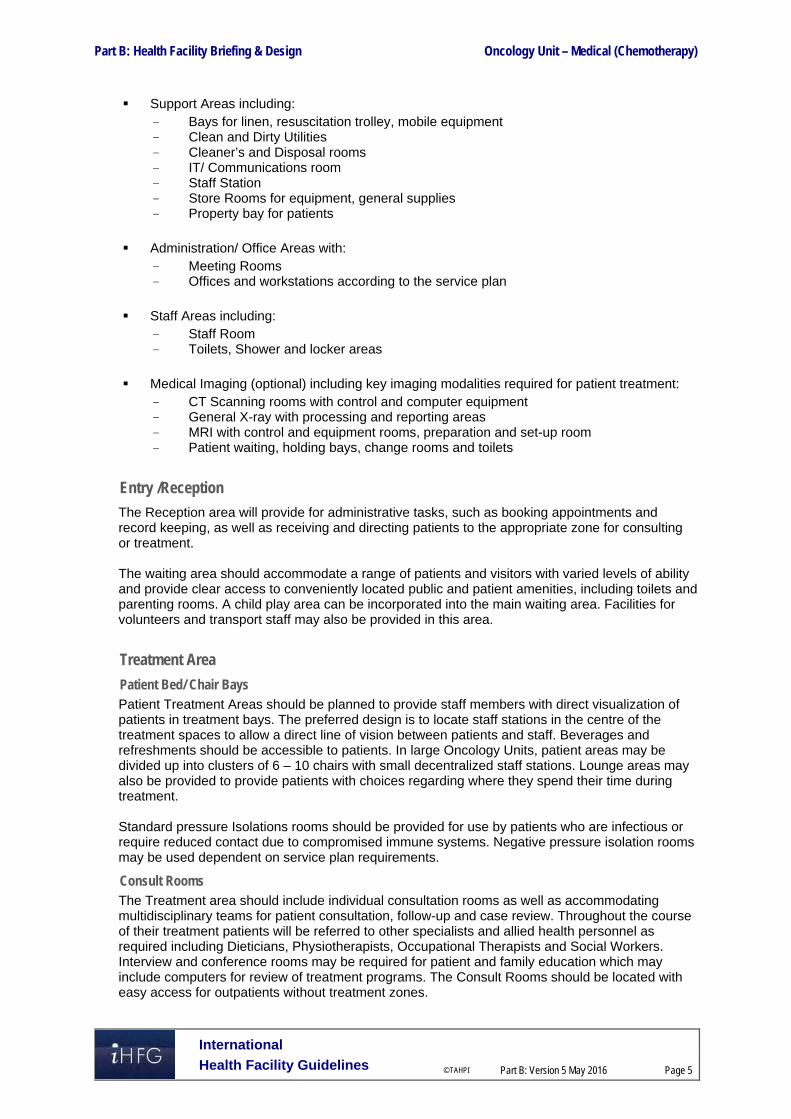
Part B: Health Facility Briefing & Design Oncology Unit – Medical (Chemotherapy)
International
Health Facility Guidelines © TAHPI
Part B: Version 5 May 2016
Page 5
Support Areas including: - Bays for linen, resuscitation trolley, mobile equipment - Clean and Dirty Utilities - Cleaner’s and Disposal rooms - IT/ Communications room - Staff Station - Store Rooms for equipment, general supplies - Property bay for patients
Administration/ Office Areas with: - Meeting Rooms - Offices and workstations according to the service plan
Staff Areas including: - Staff Room - Toilets, Shower and locker areas
Medical Imaging (optional) including key imaging modalities required for patient treatment: - CT Scanning rooms with control and computer equipment - General X-ray with processing and reporting areas - MRI with control and equipment rooms, preparation and set-up room - Patient waiting, holding bays, change rooms and toilets
Entry /Reception
The Reception area will provide for administrative tasks, such as booking appointments and record keeping, as well as receiving and directing patients to the appropriate zone for consulting or treatment. The waiting area should accommodate a range of patients and visitors with varied levels of ability and provide clear access to conveniently located public and patient amenities, including toilets and parenting rooms. A child play area can be incorporated into the main waiting area. Facilities for volunteers and transport staff may also be provided in this area.
Treatment Area
Patient Bed/ Chair Bays Patient Treatment Areas should be planned to provide staff members with direct visualization of patients in treatment bays. The preferred design is to locate staff stations in the centre of the treatment spaces to allow a direct line of vision between patients and staff. Beverages and refreshments should be accessible to patients. In large Oncology Units, patient areas may be divided up into clusters of 6 – 10 chairs with small decentralized staff stations. Lounge areas may also be provided to provide patients with choices regarding where they spend their time during treatment. Standard pressure Isolations rooms should be provided for use by patients who are infectious or require reduced contact due to compromised immune systems. Negative pressure isolation rooms may be used dependent on service plan requirements.
Consult Rooms The Treatment area should include individual consultation rooms as well as accommodating multidisciplinary teams for patient consultation, follow-up and case review. Throughout the course of their treatment patients will be referred to other specialists and allied health personnel as required including Dieticians, Physiotherapists, Occupational Therapists and Social Workers. Interview and conference rooms may be required for patient and family education which may include computers for review of treatment programs. The Consult Rooms should be located with easy access for outpatients without treatment zones.

Part B: Health Facility Briefing & Design Oncology Unit – Medical (Chemotherapy)
International
Health Facility Guidelines © TAHPI
Part B: Version 5 May 2016
Page 6
Treatment/ Procedure Rooms Treatment/ Procedure rooms are recommended for catheter insertion, lumbar puncture and intrathecal chemotherapy. The rooms should have access to a dedicated lockable refrigerator for storage of intrathecal chemotherapy for short periods prior to administration.
Support Areas
Support areas include clean and dirty utilities, storage, disposal rooms, linen bays, personal protective equipment bays and handwashing facilities. Emergency support, including resuscitation equipment should be located close to centrally located staff stations to ensure rapid access in emergency situations and emergency shower and eye washing facilities should be located close to patient areas for use in case of spills of cytotoxic chemicals. For a Stand-alone facility, support areas also include Back of House areas such as Loading Docks, Waste Compactors and Recyclables, Bulk Storage and Gas Bottle Storage (if medical gases are required).
Administration / Offices
Offices should be provided for the Clinical Director of the Unit, Radiation Oncologists, Radiation Therapy Managers, Nursing Managers, Allied Health professionals, Cancer Care Coordinators and Specialist Nurses. In a standalone facility additional offices / workstations may be required for Human Resources, Finance, Legal Services, Public Relations and Information Technology professionals. Quantities and configuration of offices is per staffing establishment.
Staff Areas
Staff Areas may be shared with adjacent Units if convenient and will consist of:
Meeting rooms
Staff Room
Toilets, Shower and Lockers.
Medical Imaging
Computed tomography (CT), magnetic resonance imaging (MRI), ultrasound (US), positron emission tomography (PET) and general x-ray imaging may be used for the visualization of bone or soft-tissue during planning and review of treatment. A stand-alone or satellite facility that does not have an efficient functional relationship with a medical imaging department may need to accommodate medical imaging facilities. CT and MRI are the most commonly used imaging facilities for treatment planning and review. The types of imaging facilities required will be determined by the service plan.

Part B: Health Facility Briefing & Design Oncology Unit – Medical (Chemotherapy)
International
Health Facility Guidelines © TAHPI
Part B: Version 5 May 2016
Page 7
Functional Relationships Planning should address the following key issues:
External
Ease of access to the unit where the majority of people will arrive by car on a daily basis.
separation of walking and stretcher/ambulance patient arrivals
Safe access to the units storerooms for the delivery of bulk items e.g. Bulk fluids which may arrive or be stored on a palette requiring mechanical lifting, moving and storage
Safe access for the delivery of food, clean linen, pharmacy, consumables, disposable items and the removal of bulk cytotoxic chemotherapy waste and soiled linen etc.
Internal
The internal planning of the Chemotherapy Unit should be planned by considering the units functional areas/zones. Some of the critical relationships to be considered include:
Staff station/s require an unobtrusive view of all patient treatment areas. The inclusion of decentralised staff stations may be considered in larger units that have multiple treatment spaces
Providing a number of treatment spaces and/or individual cubicles in groups or clusters
Inclusion of working spaces for visiting multidisciplinary team members.
Location of Reception to provide a clear view of entry and exit/egress points of the Unit
Easy access from the Waiting area to the patient treatment area for the convenient arrival and departure of patients and families
These functional relationships are represented diagrammatically below.

Part B: Health Facility Briefing & Design Oncology Unit – Medical (Chemotherapy)
International
Health Facility Guidelines © TAHPI
Part B: Version 5 May 2016
Page 8
Functional Relationship Diagram – Oncology Unit – Medical (Chemotherapy)
Figure 1 – Functional Relationship Diagram
The external and internal functional relationships are demonstrated in the diagram above including the following:
Separate entry for ambulant patients and visitors
Separate entry for patient on beds from staff corridor
Access to key clinical units associated with patient treatment, including the Radiotherapy Unit, Medical Imaging (if not provided within the unit), Pharmacy, sterile manufacturing and clinical laboratory units, via inpatient / staff access corridor
Access required for materials, clinical information and housekeeping via staff / service corridor
Access to main public amenities, including parking, outpatient pharmacy, and main hospital entry (if located on a health facility campus), via the public entry corridor.

Part B: Health Facility Briefing & Design Oncology Unit – Medical (Chemotherapy)
International
Health Facility Guidelines © TAHPI
Part B: Version 5 May 2016
Page 9
The optimum internal relationships include the following:
Reception and Waiting at the entrance to the Unit
Consult rooms at the entrance to the Unit
Administration and office areas located close to Reception and at the Unit perimeter in a staff accessible area
Patient treatment chair spaces arranged in a racetrack model with Staff Station(s) and clinical support facilities in the centre to allow clear visual access to all patient treatment bays from the Staff Stations
Support areas located in staff areas for ease of access and to be close to the point of use. 3 Design
General Design of the Unit should consider the following:
Ease of access for patients and their families, who may arrive either walking, using mobility equipment, by ambulance stretcher or patient transport trolley
Convenient access to public parking for frail patients, particularly those undergoing a scheduled period of chemotherapy on a regular basis
Service access for delivery of large amounts of intravenous fluids to the unit on a regular basis and suitably sized storage areas to hold supplies
Appropriate floor finishes for constant staff movement to/ from and between patients during chemotherapy treatments, such as cushioned vinyl.
Patient Treatment Areas Patients should be situated so that healthcare providers have good visual access to ensure safety and quality care. This approach enhances staff monitoring of patient condition during treatment. The optimal design is to allow a direct line of vision between the patient and staff. The type and number of chemotherapy spaces to be provided e.g. cubical, screened areas and isolation room numbers will be determined by the service plan, operational policies and cultural preferences of the population group using the services. Provision for dedicated chemotherapy areas for children and young people is recommended. Where facilities are shared, patient pathways should be kept as separate as possible. Cancers that develop in children and young people are complex and differ from those that develop in adults. Early diagnosis is challenging because cancers are rare and more diverse.
Environmental Considerations
Acoustics
Acoustic privacy is required for many functions in the Unit including:
Family/ case conference/ interview rooms
Isolation of noisy areas such as waiting rooms from clinical areas e.g. clean and dirty utilities
Staff discussions regarding confidential matters in meeting rooms
Noise sources arising both within and from outside the Unit such as: - Sanitary Facilities - Equipment - Patients/ Clients - Staff Activities - Traffic through the unit e.g. visitors, food, linen or other trolleys

Part B: Health Facility Briefing & Design Oncology Unit – Medical (Chemotherapy)
International
Health Facility Guidelines © TAHPI
Part B: Version 5 May 2016
Page 10
Solutions to be considered include:
Location of the unit away from noisy hospital areas
Use of sound isolating construction and selection of sound absorbing materials and finishes
Planning to separate quiet areas from noisy areas
Review of operational management and patient/client flows; this may include separate areas for patients with special needs
Provision of television systems with headphones to reduce ambient noise levels.
Natural Light/ Lighting
Natural light and views should be available from the Unit for the benefit of staff and patients. Every effort should be made to provide a view to all treatment areas either by locating treatment bays/ cubicles/ bedrooms adjacent to a window or by locating chairs and beds to have an external view from each patient space. High quality task lighting is essential to ensure complex medical and pharmacological tasks can be safely achieved. Colour corrected lighting is also essential to ensure patient assessment can be conducted effectively.
Privacy
Confidentiality and privacy when requested for persons receiving treatment and the area design should be considered as a critical element during the design process. The Unit should be designed to:
Ensure confidentiality of personal discussions and medical records;
Provide an adequate number of rooms for discreet discussions and treatments to occur when required
Provide suitably sized treatment spaces that permit screen curtains to be easily closed whenever required
Appropriately locate windows and doors to enhance visual and acoustic privacy.
Interior Décor
Interior decor includes furnishings, style, colour, textures and ambience, and is influenced by perception and culture. The décor of the Unit should provide an inviting and comfortable space with a non-institutional atmosphere. Cleaning, infection control, fire safety, patient care requirements and the patients’ perception of a professional environment should always be considered. Suggestions to achieve this balance include the following:
Use of design features such as colours and artworks to distract the sight from clinical areas
Inclusion of soft furnishings that act as a design feature such as screening, lounges in waiting areas and window treatments
Provision of corridors at the required widths for patient access and services deliveries
Provision of a beverage bay for people to use while waiting
Provision of background music through a piped system or a centralised unit that can contribute to Unit ambience.
Space Standards and Components
Accessibility - External
There should be a weatherproof vehicle drop-off zone with easy access for less-mobile and wheelchair bound patients. Design should consider separate access points for ambulant patients and those arriving on stretchers or inpatient beds for patient privacy. All patient areas should be designed for access by wheelchairs. Refer also to Part C of these Guidelines for additional information

Part B: Health Facility Briefing & Design Oncology Unit – Medical (Chemotherapy)
International
Health Facility Guidelines © TAHPI
Part B: Version 5 May 2016
Page 11
Ergonomics
Ergonomics must be considered in the internal design of the Unit for patient and staff health and safety. Heights and depths of benches and Staff Stations in the treatment area need to allow staff to efficiently work from standing and seated positions. Consideration must be given to storage of supplies at suitable working heights including cartons of intravenous fluids in constant use. Refer also to Part C of these Guidelines for additional information
Safety and Security A high standard of safety and security can be achieved by careful configuration of spaces and zones to include:
Controlled access/ egress to and from the unit
Optimal visual observation for staff to access points and patient/ visitor areas
Use of CCTV to entry and communication systems to enable contact after normal work hours
Colocation of similar functions for ease of staff management Access to public areas shall be considered with care so that the safety and security of staff areas within the Unit are not compromised. Refer also to Part C of these Guidelines.
Finishes Internal finishes including floor, walls, joinery, and ceilings should be suitable for the function of the unit while promoting a pleasant environment for patients, family, carers, visitors and staff. The following factors shall be considered:
Aesthetic appearance
Acoustic properties
Durability
Ease of cleaning and compliant with infection control standards
Suitable floor finishes with respect to slip resistance and movement of equipment. Refer also to Part C and Part D of these Guidelines for additional information.
Fixtures and Fittings Equipment, furniture, fittings should be selected to ensure that users are not exposed to avoidable risks or injury. A safety shower and eyewash should be provided close to patient treatment areas for cytotoxic spills. Refer to Part C of these Guidelines and Standard Components of individual rooms for specific information related to fixtures, fittings and equipment.
Building Service Requirements
Communications & IT
It is vital to provide reliable and effective Information Technology/ Communications service for efficient operation of the Unit. The following items should be considered during planning and will contribute to the operation of the unit:
Electronic medical records and medical record storage systems
Patient Administration Systems (PAS), including patient booking systems

Part B: Health Facility Briefing & Design Oncology Unit – Medical (Chemotherapy)
International
Health Facility Guidelines © TAHPI
Part B: Version 5 May 2016
Page 12
Electronic ordering and reporting systems e.g. prescriptions and pathology requests/ results
Bar coding for supplies, x-rays and records
Access to picture archiving communications systems (PACS)
BMS alarms systems including drug fridges
Videoconferencing, teleconferencing and telemedicine requirements
Wireless technology requirements
Paging, nurse call and duress alarm systems – fixed and mobile units
Communications rooms and server requirements.
Nurse Call, Emergency Call, Duress Alarms Nurse Call and Emergency Call facilities shall be provided in all patient areas such as bed/ chair spaces, toilets, bathrooms, consult rooms and treatment rooms for patients and staff to request urgent attention. The individual call buttons shall activate the annunciators and central module situated at or adjacent to the Staff Stations in a discreet manner. Provision of a Duress Alarm system is required for the safety of staff members who may occasionally face threats imposed by clients/ visitors. Call buttons will be required at all Reception/ Staff Stations, Consult rooms and Treatment rooms where a staff may spend time with a client in isolation or alone. The combination of fixed and mobile duress units should be considered as part of the safety review during planning for the unit.
Heating, Ventilation, Air-conditioning (HVAC)
Air conditioning systems should be designed with consideration to provision of appropriate air exchanges and exhaust for cytotoxic chemicals. The temperature of the unit should be maintained within a comfortable range not exceeding 25 degrees Celsius for optimal operating efficiency and patient comfort. General air conditioning outlets should not be placed directly over patients on chairs, beds or trolleys.
Medical Gases
Medical gases (oxygen and suction) outlets should be provided to the following for use in patient emergencies:
Bed spaces
Chair spaces, may be shared between two chair spaces
Treatment and Procedure rooms.
Infection Control Oncology patients are at increased infection risk due to immunosuppression and frequent exposure to healthcare settings. Flooring, walls, furniture and fittings should be carefully selected to ensure effective infection control measures. Infectious and immune-suppressed patients may occupy the same treatment space at the different times of the same day. The design of all aspects for the Unit should take into consideration the need to ensure a high level of infection control in all aspects of clinical and non-clinical practice.
Handbasins
Hand washing facilities for staff within the Unit should be readily available. Where a hand wash basin is provided, there shall also be liquid soap and disposable paper towels provided and PPE equipment. Handbasins should be provided in single bed rooms, isolation rooms and chair bays, a minimum of 1 per 4 chair spaces, according to Infection Control guidelines.
Isolation Room/s
Isolation room(s) numbers should be reviewed as part of the Infection control risk assessment during planning of the project, relevant to the proposed service needs.

Part B: Health Facility Briefing & Design Oncology Unit – Medical (Chemotherapy)
International
Health Facility Guidelines © TAHPI
Part B: Version 5 May 2016
Page 13
For further details relating to the Infection control refer to Part D of these Guidelines.
Chemotherapy Waste Disposal
Chemotherapy pharmaceuticals are highly toxic and designated as dangerous waste. All bulk chemotherapy waste is hazardous waste and must be disposed of at a dedicated waste facility. Chemotherapy wastes include:
Expired drugs and aborted dosages
All equipment used in preparing and delivering chemotherapy drugs to patients
Contaminated personal protective equipment (PPE) and other materials. 4 Components of the Unit The Chemotherapy Unit will contain Standard Components to comply with details described in these Guidelines. Refer to Standard Components Room Data Sheets and Room Layout Sheets.

Part B: Health Facility Briefing & Design Oncology Unit- Medical (Chemotherapy)
International
Health Facility Guidelines © TAHPI
Part B: Version 5 May 2016
Page 14
5 Schedule of Accommodation – Oncology Unit – Medical (Chemotherapy)
Oncology – Chemotherapy (standalone unit with 12, 18, 24 & 30 spaces)
ROOM/ SPACE Standard Component RDL 2 RDL 3 RDL 4 RDL 5/6 Remarks Room Codes Qty x m2 Qty x m2 Qty x m2 Qty x m2
Entry / Reception 12 spaces 18 spaces 24 spaces 30 spaces Airlock AIRLE-6-I AIRLE-10-I 1 x 6 1 x 6 1 x 6 1 x 10 For standalone facilities or units with direct access from outside
Bay - Beverage, Open Plan BBEV-OP-I 1 x 4 1 x 4 1 x 4 1 x 4 Optional. May be shared with a collocated unit
Bay - Mobile Equipment BMEQ-4-1 BMEQ-10-1 1 x 4 1 x 4 1 x 4 1 x 10 Optional. May be shared with a collocated unit
Bay - Public Telephone BPH-I 1 x 2 1 x 2 Optional. May be shared with a collocated unit
Bay - Vending Machines BVM-3-I BVM-5-I 1 x 3 1 x 5 Optional. May be shared with a collocated unit
Interview Room - Family / Large INTF-I 1 x 12 1 x 12 2 x 12 2 x 12 For up to 8 persons. For counselling, interviews & education
Play Area - Paediatric PLAP-10-I, PLAP-15-I, PLAP-20-I 1 x 10 1 x 10 1 x 15 1 x 20 Optional. Extra sound absorption may be required if located adjacent to patient treatment areas
Reception / Clerical RECL-9-I RECL-12-I REC-20-I 1 x 9 1 x 9 1 x 12 1 x 20
Store - Files STFS-8-I STFS-10-I 1 x 8 1 x 8 1 x 8 1 x 10
Store - Photocopy / Stationery STPS-8-I 1 x 8 1 x 8 1 x 8 1 x 8
Toilet - Public WCPU-4-I 2 x 4 2 x 4 2 x 4 2 x 4 Separate male / female. May be shared with a collocated unit
Toilet - Accessible WCAC-I 1 x 6 1 x 6 1 x 6 1 x 6 May be shared with a collocated unit
Waiting WAIT-10-I WAIT-15-I WAIT-20-I 1 x 10 1 x 15 1 x 15 1 x 20 Allow 1.2m2 per person and 1.5m2 for people in wheelchairs
Treatment Areas 1 Bed Room - Isolation - Standard Pressure 1 BR-IS-N-18-I similar 2 x 18 3 x 18 4 x 18 5 x 18 May be negative pressure as required by service plan
Bay - Beverage, Enclosed BBEV-ENC-I 1 x 5 1 x 5 1 x 5 1 x 5 Patient refreshments. Access to bench mounted ice dispenser. Size relevant to service provision.
Consult / Exam Room CONS-I 2 x 14 3 x 14 4 x 14 5 x 14
Cytotoxic Room CYT-I 1 x 8 1 x 8 1 x 8 1 x 8
En suite - Standard ENS-ST-I 2 x 5 3 x 5 4 x 5 5 x 5 1 per isolation room
Procedure Room PROC-20-I 1 x 20 1 x 20 May be used for intrathecal treatments
Shower - Accessible SHD-I 1 x 4 1 x 4 2 x 4 2 x 4 Patient use
Toilet - Patient WCPT-I 2 x 4 2 x 4 4 x 4 4 x 4 Separate male / female
Toilet - Accessible WCAC-I 1 x 6 1 x 6 2 x 6 2 x 6 Separate male / female
Treatment Bay - Chemotherapy TRMT-CHE-I 10 x 10 15 x 10 20 x 10 25 x 10 See Note 1. 10m2 per chair bay or increase to 12m2 for bed bays
Treatment Room TRMT-14-I similar 1 x 16 1 x 16 1 x 16 1 x 16 For lumbar puncture and venous catheter insertion procedures. Optional if procedures not part of service provision.

Part B: Health Facility Briefing & Design Oncology Unit- Medical (Chemotherapy)
International
Health Facility Guidelines © TAHPI
Part B: Version 5 May 2016
Page 15
ROOM/ SPACE Standard Component RDL 2 RDL 3 RDL 4 RDL 5/6 Remarks Room Codes Qty x m2 Qty x m2 Qty x m2 Qty x m2
Support Areas Bay - Emergency Shower BES-I 1 x 1 1 x 1 2 x 1 2 x 1
Bay - Handwashing, Type B BHWS-B-I 3 x 1 4 x 1 5 x 1 6 x 1 1 per 4 chairs/beds
Bay - Linen BLIN-I 1 x 2 1 x 2 2 x 2 2 x 2
Bay - Mobile Equipment BMEQ-4-I 1 x 4 1 x 4 2 x 4 2 x 4
Bay - Personal Protective Equipment BPPE-I 3 x 1.5 4 x 1.5 5 x 1.5 6 x 1.5 Collocated with handwashing bays
Bay - Resuscitation Trolley BRES-I 1 x 1.5 1 x 1.5 1 x 1.5 1 x 1.5 Adjacent to staff station
Bay - Wheelchair Park BWC-I 1 x 4 1 x 4 1 x 8 1 x 8 May be subdivided
Clean Utility CLUR-12-I CLUM-14-I similar 1 x 12 1 x 12 1 x 14 1 x 14 Increase to 20m2 if drug fridges are required to store IV fluids
Cleaner’s Room CLRM-5-I CLRM-5-I 1 x 5 1 x 5 1 x 10 1 x 10 Includes dry storage for cleaning consumables
Dirty Utility DTUR-10-I DTUR-12-I 1 x 10 1 x 10 1 x 12 1 x 12
Disposal Room DISP-8-I 1 x 8 1 x 8 1 x 8 1 x 8
IT Communications COMM-I 1 x 12 1 x 12 1 x 12 1 x 12 Sized to meet service provision
Loading dock LODK-I similar 1 x 10 1 x 10 1 x 15 1 x 20 Optional if attached to main facility
Property Bay PROP-2-I 2 x 2 3 x 2 4 x 2 5 x 2 Patient property. 1 per 6 chairs/beds. May be provided as individual lockers adjacent to chairs/beds.
Staff Station SSTN-5-I SSTN-10-I 1 x 12 2 x 10 2 x 10 2 x 12 May be subdivided in larger units
Store - Bulk STBK-20-I similar 1 x 15 1 x 20 1 x 30 1 x 30 To be located on the perimeter of the Unit and accessible by a palette lifter for delivery of bulk fluids and clinical stores.
Store - Equipment STEQ-10-I STEQ-14-I STEQ-20-I 1 x 10 1 x 10 1 x 14 1 x 20 Sized to meet service provision
Store - Gas Bottle STBD-F-I 1 x 10 1 x 10 1 x 10 1 x 10 Optional. Provide if medical gases are required to chair/bed bays
Store - General STGN-8-I STGN-10-I STGN-12-I 1 x 8 1 x 8 1 x 10 1 x 12 Sized to meet service provision
Waste disposal WACO-I similar 1 x 15 1 x 15 1 x 20 1 x 20 For chemotherapy cytotoxic waste
Waste Compactor / Recyclables WACO-I 1 x 15 1 x 15 1 x 20 1 x 20 Satellite units may share common facilities
Administration / Offices Quantity as per Service Plan Quantity aOffice - Single Person OFF-S9-I 1 x 9 1 x 9 1 x 9 1 x 9 Unit / Nurse manager. Located close to patient areas
Office - Single Person OFF-S9-I 1 x 9 1 x 9 2 x 9 2 x 9 Educator, Teaching Fellow, Quality Assurance manager, IT manager, etc.
Office - 2 Person Shared OFF-2P-I 1 x 12 1 x 12 1 x 12 1 x 12 Clinical trials monitor, nurse coordinator, biostatistician, data manager. Provided as per service plan
Office - Workstation OFF-WS-I 1 x 5.5 1 x 5.5 1 x 5.5 1 x 5.5 Nurse coordinator. Provided as per service plan
Office - Workstation OFF-WS-I 1 x 5.5 2 x 5.5 2 x 5.5 4 x 5.5 Cancer care coordinators, specialist cancer nurses and palliative care nurses. Provided as per service plan
Office - Workstation OFF-WS-I 2 x 5.5 2 x 5.5 4 x 5.5 4 x 5.5 For administration staff. Provided as per service plan

Part B: Health Facility Briefing & Design Oncology Unit- Medical (Chemotherapy)
International
Health Facility Guidelines © TAHPI
Part B: Version 5 May 2016
Page 16
ROOM/ SPACE Standard Component RDL 2 RDL 3 RDL 4 RDL 5/6 Remarks Room Codes Qty x m2 Qty x m2 Qty x m2 Qty x m2 Office - Write up (Shared) OFF-WIS-I 1 x 12 1 x 12 1 x 12 2 x 12 Clinical reviews. Located close to patient areas.
Meeting Room - Medium / Large MEET-L-15-I MEET-L-20-I 1 x 15 1 x 15 1 x 20
Staff Areas Property Bay - Staff PROP-3-I PROP-6-I 1 x 3 2 x 3 2 x 3 1 x 6 Discrete secure location, adjacent to staff room
Staff Room SRM-15-I SRM-20-I SRM-30-I 1 x 15 1 x 15 1 x 20 1 x 30
Shower - Staff SHST-I 2 x 3 2 x 3 4 x 3 4 x 3 Separate male / female
Toilet - Staff WCST-I 2 x 3 2 x 3 4 x 3 4 x 3 Separate male / female
Sub Total 566 699 941.5 1120
Circulation % 35 35 35 35
Area Total 764.1 943.7 1271.0 1512
Note 1: Treatment Bays; Bay size needs to be 9 square meters with a clear width of 3 meters along the back of the bay to ensure appropriate service placement, Infusion equipment and curtain track placement; spaces of 12m2 will need to be considered where more than 50% of patients are receiving chemotherapy infusions in a patient beds rather than chairs; bays should be able to accommodate beds or chairs
Also Note the following: Areas noted in Schedules of Accommodation take precedence over all other areas noted in the FPU. Rooms indicated in the schedule reflect the typical arrangement according to the Role Delineation. Exact requirements for room quantities and sizes will reflect Key Planning Units identified in the Service Plan and the Operational Policies of the Unit. Room sizes indicated should be viewed as a minimum requirement; variations are acceptable to reflect the needs of individual Unit. Office areas are to be provided according to the Unit role delineation and number of endorsed fulltime positions in the unit. Staff and support rooms may be shared between Functional Planning Units dependant on location and accessibility to each unit and may provide scope to reduce duplication of
facilities.

Part B: Health Facility Briefing & Design Oncology Unit- Medical (Chemotherapy)
International
Health Facility Guidelines © TAHPI
Part B: Version 5 May 2016
Page 17
Imaging Suite (Optional. May be shared with collocated Radiation Oncology Unit)
ROOM/ SPACE Standard Component RDL 2 RDL 3 RDL 4 RDL 5/6 Remarks Room Codes Qty x m2 Qty x m2 Qty x m2 Qty x m2
Computer Tomography - CT Scanning Change Cubicle - Accessible CHPT-D-I 1 x 4
Computer Equipment Room COEQ-I 1 x 8 Size and requirements as per manufacturers specifications
C.T Scanning - Procedure Room CTPR-I 1 x 45 Size and requirements as per manufacturers specifications
C.T Scanning - Control Room ANCRT-I similar 1 x 14
Preparation/ Set-Up Room (Imaging) PREP-S-I 1 x 9
Patient Bay - Holding PBTR-H-10-I 1 x 10
Viewing and Reporting Room XRRR-I similar 1 x 12 Optional. May be combined with control room
Waiting - Sub WAIT-SUB-I 1 x 5.5 Optional. Waiting may be shared between imaging rooms
General X-Ray Change Cubicle - Accessible CHPT-D-I 1 x 4
General X-Ray GENXR-I 1 x 30 Size and requirements as per manufacturers specifications
Day Light Processing DPRO-I similar 1 x 16 Digital processing/ printing. As required by service plan
Patient Bay - Holding PBTR-H-10-I 1 x 10
Viewing and Reporting Room XRRR-I similar 1 x 12 Optional. May be combined with processing room
Waiting - Sub WAIT-SUB-I 1 x 5.5 Optional. Waiting may be shared between imaging rooms
Magnetic Resonance Imaging - MRI Change Cubicle - Accessible CHPT-D-I 1 x 4
Computer Equipment Room COEQ-I 1 x 8 Size and requirements as per manufacturers specifications
MRI Scanning Room MRI-SC-42-I 1 x 42 Size and requirements as per manufacturers specifications
MRI - Control Room ANCRT-I similar 1 x 14
Preparation/ Set-Up Room (Imaging) PREP-S-I 1 x 9
Patient Bay - Holding PBTR-H-10-I 1 x 10
Viewing and Reporting Room XRRR-I similar 1 x 12 Optional. May be combined with control room
Waiting - Sub WAIT-SUB-I 1 x 5.5 Optional. Waiting may be shared between imaging rooms
Imaging Support Bay - Handwashing, Type B BHWS-B-I 1 x 1 To patient holding bays
Bay - Linen BLIN-I 2 x 2 1 per 2 imaging rooms
Bay - Personal Protective Equipment BPPE-I 2 x 1.5 1 per 2 imaging rooms
Bay - Resuscitation Trolley BRES-I 2 x 1.5 1 per 2 imaging rooms

Part B: Health Facility Briefing & Design Oncology Unit- Medical (Chemotherapy)
International
Health Facility Guidelines © TAHPI
Part B: Version 5 May 2016
Page 18
ROOM/ SPACE Standard Component RDL 2 RDL 3 RDL 4 RDL 5/6 Remarks Room Codes Qty x m2 Qty x m2 Qty x m2 Qty x m2 Bay - Wheelchair Park BWC-I 2 x 4 1 per 2 imaging rooms
Clean Utility CLUR-8-I 1 x 8
Cleaner’s Room CLRM-5-I 1 x 5
Dirty Utility DTUR-S-I 1 x 8
Disposal Room DISP-8-I 1 x 8
Property Bay PROP-2-I 2 x 2 Patient property. 1 per 2 imaging rooms
Shower - Patient SHPT-I 2 x 3 Separate male / female
Staff Station SSTN-5-I 1 x 5 To waiting / patient holding bays
Toilet - Patient WCPT-I 2 x 4 Separate male / female
Imaging Staff Areas Office - Single Person OFFIS9-I 2 x 9 Radiologist, Radiographer
Office - Workstation OFF-WS-I 4 x 5.5 Quantity dependent on service plan
Property Bay - Staff PROP-3-I 1 x 3
Staff Room SRM-15-I 1 x 15
Shower - Staff SHST-I 2 x 3 Separate male / female
Toilet - Staff WCST-I 2 x 3 Separate male / female
Sub Total 430.5 Circulation % 40
Total Areas 602.7
Grand Total 2114.7 including Optional Imaging Suite Note 1: Treatment Bays; Bay size needs to be 9 square meters with a clear width of 3 meters along the back of the bay to ensure appropriate service placement, Infusion equipment and curtain track placement; spaces of 12m2 will need to be considered where more than 50% of patients are receiving chemotherapy infusions in a patient beds rather than chairs; bays should be able to accommodate beds or chairs
Also Note the following: Areas noted in Schedules of Accommodation take precedence over all other areas noted in the FPU. Rooms indicated in the schedule reflect the typical arrangement according to the Role Delineation. Exact requirements for room quantities and sizes will reflect Key Planning Units identified in the Service Plan and the Operational Policies of the Unit. Room sizes indicated should be viewed as a minimum requirement; variations are acceptable to reflect the needs of individual Unit. Office areas are to be provided according to the Unit role delineation and number of endorsed fulltime positions in the unit. Staff and support rooms may be shared between Functional Planning Units dependant on location and accessibility to each unit and may provide scope to reduce duplication of
facilities.

Part B: Health Facility Briefing & Design Oncology Unit – Medical (Chemotherapy)
International
Health Facility Guidelines © TAHPI
Part B: Version 5 May 2016
Page 19
6 Future Trends Planning and design should consider the following developments in cancer care:
Survival of cancer continues to improve due to improved screening, diagnostic methods and treatment options leads to increased long-term care demands.
Leukaemia, lymphoma, germ cell tumours and early stage solid tumours once incurable have become curable malignancies and there is an increasing trend towards combination therapies involving surgery, chemotherapy and radiotherapy
Targeted therapies, aimed at specific pathways blocking tumour cells leading to fewer side effects and complications
Research and development into active chemotherapy combinations leading to new treatment options
Developing international trends for cancer services to be concentrated in centres that treat high volumes of patients and offer a full range of cancer services including surgery, oncology, radiotherapy, and specialised nursing and allied health services.
7 Further Reading
American Cancer Society. http://www.cancer.org/index
Australasian Health Facility Guidelines, Part B Health Facility Briefing and Planning, Rev 5, 2016; refer to website www.healthfacilitydesign.com.au
Cancer Council Australia, (2012). Understanding Chemotherapy: A guide for people with cancer, their families and friends. Sydney, Australia: Cancer Council Australia.
Department of Health (UK) HSC 2008/001 ‘Updated national guidance on the safe administration of intrathecal chemotherapy’ (2008) refer to: http://webarchive.nationalarchives.gov.uk/20130107105354/http:/www.dh.gov.uk/prod_consum_dh/groups/dh_digitalassets/documents/digitalasset/dh_086844.pdf
Department of Ecology, State of Washington, US: ‘Pharmaceutical Waste’. http://www.ecy.wa.gov/programs/hwtr/pharmaceuticals/pages/chemotherapy.html#RCRA
Guidelines for Design and Construction of Health Care Facilities; The Facility Guidelines Institute, 2014 Edition refer to website www.fgiguidelines.org
Health Building Note 02-01: Cancer treatment facilities. (2013). 1st ed. [pdf] London, UK: Department of Health. Available at: http://www.dhsspsni.gov.uk/hbn_02-01_cancer_treatment_facilities_final.pdf
NICE National Institute for Health and Care Excellence, UK ‘Cancer Services for Children and Young People’ (2014) https://www.nice.org.uk/guidance/qs55
State of Victoria, Department of Health, (2014). A guide to chemotherapy day unit redesign measures for improvement. Melbourne, Australia: State of Victoria, Department of Health.

Part B – Health Facility Briefing & Design 230 Oncology Unit - Radiation
International Health Facility Guidelines Version 5 June 2017

Part B: Health Facility Briefing & Design
International
Health Facility Guidelines © TAHPI
Part B: Version 5 June 2017
Page 2
Table of Contents
230 Oncology Unit - Radiation ........................................................................................................ 3
1 Introduction ............................................................................................................................................... 3 Description .................................................................................................................................................. 3
2 Functional and Planning Considerations ............................................................................................... 3 Operational Models ..................................................................................................................................... 3 Planning Models .......................................................................................................................................... 3 Functional Areas ......................................................................................................................................... 3 Functional Relationships ............................................................................................................................. 7
3 Design ........................................................................................................................................................ 9 Construction Standards ............................................................................................................................... 9 Patient Treatment Areas ............................................................................................................................. 9 Environmental Considerations .................................................................................................................... 9 Space Standards and Components ............................................................................................................ 9 Safety & Security ....................................................................................................................................... 10 Finishes ..................................................................................................................................................... 10 Fixtures, Fittings & Equipment .................................................................................................................. 10 Building Service Requirements ................................................................................................................. 10 Infection Control ........................................................................................................................................ 11
4 Components of the Unit .......................................................................................................................... 12 Standard Components .............................................................................................................................. 12
5 Schedule of Accommodation ................................................................................................................. 13 Oncology Unit – Radiation (with 2 & 4 bunkers) ........................................................................................ 13 Brachytherapy Suite (Optional) ................................................................................................................. 16 Imaging Suite (Optional)............................................................................................................................ 17
6 Future Trends .......................................................................................................................................... 19
7 Further Reading ....................................................................................................................................... 19

Part B: Health Facility Briefing & Design Oncology Unit - Radiation
International
Health Facility Guidelines © TAHPI
Part B: Version 5 June 2017
Page 3
230 Oncology Unit - Radiation
1 Introduction
Description The purpose of the Radiation Oncology Unit is to provide facilities and equipment for radiotherapy treatment. Mainly used for the treatment of cancer, radiotherapy is often used in conjunction with other treatments, including chemotherapy and surgery. The Radiation Oncology Unit contains spaces to support patient consultation, treatment simulation and planning, and the administration of treatment. The Radiation Oncology Unit may contain both external and internal radiotherapy (brachytherapy) treatment areas. Although not recommended, a Simulation Room may be omitted in small linear accelerator facilities where other positioning geometry is provided. Room sizes and specifications for a Radiation Oncology Unit should accommodate the equipment manufacturer's recommendations, as space requirements may vary from one machine to another and one manufacturer to another. 2 Functional and Planning Considerations
Operational Models
Hours of Operation
The Radiation Oncology Unit will typically operate from 8am to 6pm daily, week days; however, extended hours of operation may occur according to the unit operational policy.
Model of Care
The preferred model of care for Radiation Oncology is where cancer services are collocated and provided in a purpose-built facility. The benefits of this model are improved communications between all members of the team, resulting in optimal clinical management, efficiency and best outcomes for patients. Separation of planning and therapy is not recommended.
Planning Models
Location
Generally, the Radiation Oncology Unit should be located on ground level due to the weight of the equipment and shielding, for ease of installation/ replacement of specialised equipment. The Unit should be located with ready access for outpatients, including people with disabilities, people arriving by patient transfer services and ambulances, and for inpatients in wheelchairs and on beds or trolleys. If the Unit is located in a free-standing building on a hospital campus, careful consideration must be given to covered links between the Unit and the main hospital particularly for inpatients on beds/ trolleys, the delivery of goods and supplies, and access to other departments such as Medical Imaging or Pathology.
Functional Areas The Radiation Oncology Unit may include the following Functional Areas: Entry/ Reception including:
- Interview Room - Waiting areas with access to refreshments - Public amenities - Reception with storage for files and stationery
Patient Consult Area: - Consult rooms - Interview room - Specimen collection and access to patient toilets
Treatment Planning and Appliance areas: - Simulator rooms with Control and Equipment rooms - Mould fitting room

Part B: Health Facility Briefing & Design Oncology Unit - Radiation
International
Health Facility Guidelines © TAHPI
Part B: Version 5 June 2017
Page 4
- Mould workshop - Patient holding bay for patients on a bed or trolley - Support rooms including Change cubicles, stores for consumables and equipment,
patient toilets and sub-waiting areas Medical Physics:
- Offices and workstations for Physicists - Physics laboratory and storage for technical equipment
Radiation Therapy Treatment Areas: - Radiation bunkers with Control rooms - Change cubicles - Patient sub-waiting, locker area and access to toilets - Ready access to Interview rooms
Support Areas including: - Bays for Handwashing/PPE, Linen, Resuscitation trolley, holding of mobile equipment
and wheelchairs - Clean and Dirty Utilities with waste holding areas - Cleaners Room - Staff Station - Store rooms for equipment and consumables
Administration / Office Areas: - Offices and workstations for key personnel according to the approved service plan - Meeting room
Staff Areas: - Staff Room - Locker area - Toilets and Showers, gender separated
The Unit may incorporate the following Optional areas depending on the Service Plan: Brachytherapy Suite:
- Brachytherapy bunker with Control room - Anaesthetic room - Operating/ Procedure room (optional) - Scrub up room - Patient Bays for holding and recovery with access to patient toilets - Patient Waiting area - Support areas including Bays for handwashing basins/PPE, Linen and resuscitation
trolley - Radioactive seed and loading room - Store room for sterile stock and equipment - Shared utility rooms
Medical Imaging (optional satellite unit) including: - CT Scanning room with Control and Equipment rooms - General X-ray room - MRI imaging room with Preparation, Control, Equipment rooms - Patient facilities such as holding bays, property bays, waiting areas and toilets - Staff and support rooms including
Entry / Reception
Sufficient parking should be made available for ambulances, staff and patients. Ideally, patients should be allocated parking closest to the department, and it is important to take into account the fact that, although there would be a limited number of patients being actively attended to in the Unit at any given point in time, patients nevertheless spend many hours inside the department when undergoing imaging or planning, consulting with doctors or receiving brachytherapy. The Reception area will provide for administrative tasks, such as booking appointments and record keeping, as well as receiving and directing patients to the appropriate zone for consulting, treatment planning or radiotherapy treatment. The waiting area should accommodate a range of patients and visitors with varied levels of ability and provide clear access to conveniently located public and patient amenities.
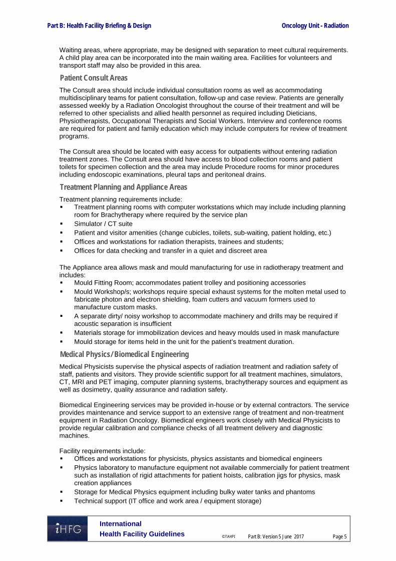
Part B: Health Facility Briefing & Design Oncology Unit - Radiation
International
Health Facility Guidelines © TAHPI
Part B: Version 5 June 2017
Page 5
Waiting areas, where appropriate, may be designed with separation to meet cultural requirements. A child play area can be incorporated into the main waiting area. Facilities for volunteers and transport staff may also be provided in this area.
Patient Consult Areas
The Consult area should include individual consultation rooms as well as accommodating multidisciplinary teams for patient consultation, follow-up and case review. Patients are generally assessed weekly by a Radiation Oncologist throughout the course of their treatment and will be referred to other specialists and allied health personnel as required including Dieticians, Physiotherapists, Occupational Therapists and Social Workers. Interview and conference rooms are required for patient and family education which may include computers for review of treatment programs. The Consult area should be located with easy access for outpatients without entering radiation treatment zones. The Consult area should have access to blood collection rooms and patient toilets for specimen collection and the area may include Procedure rooms for minor procedures including endoscopic examinations, pleural taps and peritoneal drains.
Treatment Planning and Appliance Areas
Treatment planning requirements include: Treatment planning rooms with computer workstations which may include including planning
room for Brachytherapy where required by the service plan Simulator / CT suite Patient and visitor amenities (change cubicles, toilets, sub-waiting, patient holding, etc.) Offices and workstations for radiation therapists, trainees and students; Offices for data checking and transfer in a quiet and discreet area The Appliance area allows mask and mould manufacturing for use in radiotherapy treatment and includes: Mould Fitting Room; accommodates patient trolley and positioning accessories Mould Workshop/s; workshops require special exhaust systems for the molten metal used to
fabricate photon and electron shielding, foam cutters and vacuum formers used to manufacture custom masks.
A separate dirty/ noisy workshop to accommodate machinery and drills may be required if acoustic separation is insufficient
Materials storage for immobilization devices and heavy moulds used in mask manufacture Mould storage for items held in the unit for the patient’s treatment duration.
Medical Physics/ Biomedical Engineering
Medical Physicists supervise the physical aspects of radiation treatment and radiation safety of staff, patients and visitors. They provide scientific support for all treatment machines, simulators, CT, MRI and PET imaging, computer planning systems, brachytherapy sources and equipment as well as dosimetry, quality assurance and radiation safety. Biomedical Engineering services may be provided in-house or by external contractors. The service provides maintenance and service support to an extensive range of treatment and non-treatment equipment in Radiation Oncology. Biomedical engineers work closely with Medical Physicists to provide regular calibration and compliance checks of all treatment delivery and diagnostic machines. Facility requirements include: Offices and workstations for physicists, physics assistants and biomedical engineers Physics laboratory to manufacture equipment not available commercially for patient treatment
such as installation of rigid attachments for patient hoists, calibration jigs for physics, mask creation appliances
Storage for Medical Physics equipment including bulky water tanks and phantoms Technical support (IT office and work area / equipment storage)

Part B: Health Facility Briefing & Design Oncology Unit - Radiation
International
Health Facility Guidelines © TAHPI
Part B: Version 5 June 2017
Page 6
Electronic / biomedical engineering workshop Dark room x-ray processor as required for machine commissioning and imaging of special
procedures.
Radiation Therapy Treatment Area
The radiation treatment zone includes: Bunkers with entry/ exit maze and Control rooms Change cubicles and patient toilets immediately adjacent to radiation treatment areas. Sub-Waiting areas located conveniently to each bunker and access to Interview rooms Support areas including patient bays, utilities, staff station, preparation and storage areas.
Support Areas
Support areas include clean and dirty utilities, storage, disposal rooms, linen bays and handwashing facilities. The following optional support areas may be required: Quality control area with illuminated X-ray viewing boxes Dosimetry equipment area Hypothermia Room (may be combined with an Examination Room)
Administration / Offices
Offices should be provided for the clinical director of the unit, radiation oncologists, and radiation therapy managers, nursing managers, allied health professionals, cancer care co-ordinators and specialist nurses. In a stand-alone facility additional offices/ workstations may be required for human resources, finance, legal services, public relations and information technology professionals. Quantities and configuration of offices is according to needs analysis. Adequate access to meeting rooms should be provided to facilitate education, training and research activities within the Unit.
Staff Areas
Staff Areas will consist of: Staff Room Toilets, Showers and Lockers. Staff areas may be shared with adjacent Units as far as possible.
Optional Areas
Brachytherapy Treatment Areas The Brachytherapy treatment room is used for delivery of a radiation source through a tube or applicator, implanted during surgery. The Brachytherapy room is similar to a radiation bunker and is equipped as an operating room with services to provide for anaesthesia. Support facilities include an anaesthetic induction room, scrub-up area, patient recovery bays, and sterile stock areas.
Medical Imaging Computed tomography (CT), magnetic resonance imaging (MRI), ultrasound (US), positron emission tomography (PET) and general x-ray imaging may be used for the visualization of bone or soft-tissues during planning and review of radiotherapy treatment. If a facility is a distinct entity or does not have an efficient functional relationship with a medical imaging department it may need to accommodate medical imaging facilities. CT and MRI are the most commonly used imaging facilities for treatment planning. However there are certain conditions under which ultrasound and PET may be used. The types of imaging facilities required will be determined by the service plan.

Part B: Health Facility Briefing & Design Oncology Unit - Radiation
International
Health Facility Guidelines © TAHPI
Part B: Version 5 June 2017
Page 7
Functional Relationships The Radiation Oncology Unit should be located with ready access for ambulant outpatients as well as inpatients arriving by wheelchairs and beds. The Unit may be co-located with Medical Imaging Units, Chemotherapy Units and related Inpatient Units to increase efficiency. If intra-operative therapy is proposed, the Radiation Oncology Unit should be located close to the Operating Unit or with a direct link. A ground level location is preferred due to the weight of the equipment and shielding requirements, and for ease of installation and replacement. There will also be a restriction on the type of departments located above the Radiation Oncology bunkers.
External
Principal relationships with other Units include ready access to: Diagnostic facilities such as Medical Imaging and Pathology Emergency and Critical Care Units Clinical Laboratories Pharmacy Outpatient Rehabilitation and Complementary Medicine facilities Material Management and Housekeeping Operating/ Day Procedures Units Public amenities and cafeteria Parking
Internal
Optimum internal relationships include: The Staff Station and associated areas need direct access and observation to patient holding
areas Utility and storage areas need ready access to both patient and staff work areas Planning and treatment areas should be collocated.
Functional Relationship Diagram - Oncology Unit - Radiation
External relationships outlined in the diagram include: Clear staff, goods and service entrance:
- Access to/from Housekeeping, Supply and Catering Units via service corridor. - Access to Offices and staff areas via service corridor - Access to/ from key clinical units associated with patient arrivals and transfers via a
service corridor - Entry for staff via the public or service corridor
Separate public entrance - Access to/ from key public areas, such as the main entrance, Outpatients Units and
parking from the public corridor - Entry for ambulant patients and visitors directly from public corridor - Access to/ from related treatment facilities via a public corridor
Optimum internal relationships outlined in the diagram include: Reception located with control of access for public and patients Waiting area at the Unit entry and sub-waiting within the Unit for patients Patient flow from Reception, to Consult, to Simulation and Planning then Radiotherapy
Treatment areas. Convenient access to Mould Fitting and Workshop from Planning areas Access to Medical Imaging from Consult, Planning and Radiotherapy Treatment stages Shared patient holding for both Simulation and Treatment stages Staff Station located with direct observation of patient bed holding Support areas decentralised, located close to treatment areas for staff convenience Staff Offices and Support areas located on a perimeter in a staff accessible zone.

Part B: Health Facility Briefing & Design Oncology Unit - Radiation
International
Health Facility Guidelines © TAHPI
Part B: Version 5 June 2017
Page 8
Functional Relationship Diagram
Figure 1 Functional Relationship Diagram:

Part B: Health Facility Briefing & Design Oncology Unit - Radiation
International
Health Facility Guidelines © TAHPI
Part B: Version 5 June 2017
Page 9
3 Design
Construction Standards The flooring for a Radiation Oncology Unit shall be adequate to meet the load requirements for equipment, patients and personnel. Provision for cable ducts or conduits should be made in the floors and ceilings as required. Ceiling mounted equipment should have properly designed rigid support structures located above the finished ceiling. The minimum recommended ceiling height is 3 metres. A lay-in type of ceiling should be considered for ease of installation and service. The linear accelerator installation may require an opening in a wall and co-ordination of the entry door size to also allow for future servicing of the equipment
Patient Treatment Areas Radiation Oncology Units should be designed to avoid exposing patients, staff and visitors to risks such as injury or radiation hazard.
Environmental Considerations
Acoustics
Acoustic treatment will be required to all examination, consult rooms and offices to ensure privacy for discussions with patients, families and staff. Provide acoustic treatment for the control of noise associated with machinery in the appliance fabrication workshop areas.
Natural Lighting/ Lighting
Radiation bunkers and simulators will require dimmable lighting with adjustable lighting levels for patient comfort. All patient areas in the Unit will require lighting with clinical colour rendering. General lighting in staff work areas should be even, sufficient for illumination of the work area and non-reflective. Refer also to Part C of these Guidelines.
Privacy
Careful consideration of privacy and patient comfort is required to reduce discomfort and stress for patients and privacy screening will be required to all patient bed bays.
Interior Décor
Interior decor includes furnishings, style, colour, textures and ambience, influenced by perception and culture. The décor of the Unit should be of a standard that meets the expectations of people using the services and make every effort to reduce an institutional atmosphere The design of the unit should create a pleasant, reassuring atmosphere for patients whilst retaining the necessary functional requirements associated with clinical spaces and radiation treatment areas.
Space Standards and Components
Accessibility
Design should provide ease of access for wheelchair bound patients in all patient areas including Reception desk, Consult, Interview, Mould fittings rooms and Radiation Treatment bunkers. Waiting areas should include spaces for wheelchairs and suitable seating for patients with disabilities or mobility aids.
Doors
All entry points, doors or openings requiring bed/trolley access including Radiation Therapy and Procedure Rooms are recommended to be a minimum of 1400 mm wide, unobstructed. Larger openings may be required for special equipment, as determined by the Operational Policy, to allow the manoeuvring of equipment without manual handling risks and risk of damage.

Part B: Health Facility Briefing & Design Oncology Unit - Radiation
International
Health Facility Guidelines © TAHPI
Part B: Version 5 June 2017
Page 10
Within workshop and appliance room areas, the number of doors should be kept to a minimum to facilitate the movement of equipment; double doors should be provided to all workshop areas. Also refer to Part C – Access, Mobility, OH&S of these Guidelines.
Ergonomics/ OH&S
Heights and depths of benches and workstations in the radiation treatment area need to allow staff to efficiently work from standing and seated positions. The emergency stop button should be placed within easy reach of attending staff. Refer to Part C – Access, Mobility, OH&S of these Guidelines for more information.
Size of the Unit
The size of the Radiation Oncology Unit will be determined by the Clinical Services Plan establishing the intended services scope and complexity. In a satellite facility, where cancer services are collocated, two Radiotherapy Treatment rooms (bunkers) is the minimum viable number. Schedules of Accommodation have been provided for typical units with 2 and 4 Radiotherapy Bunkers.
Safety & Security Access control is required to the patient areas, Radiation Therapy areas and staff areas of the Unit. Security measures may include: CCTV camera surveillance of bunkers, access and exit points Emergency “stop” buttons in treatment bunkers and control rooms Controlled staff access after hours Controlled access to equipment storage areas to protect sensitive equipment Fixed and personal duress alarms for staff.
Finishes All surface finishes are to be washable including walls and ceilings. Floor surfaces should be impervious, easy to clean, sealed and coved at the edges. Refer also to Part C of these Guidelines and Standard Components for more information on wall protection, floor finishes and ceiling finishes.
Fixtures, Fittings & Equipment Equipment such as the linear accelerator and control equipment must be installed to the manufacturer’s specifications and recommendations, in particular: Space requirements may vary according to equipment selection Doors will need to be sized to allow passage of equipment Structural assessment will be required for equipment weight loads Adequate space will be required for maintenance of major equipment ensuring adequate
access to cabinets and control units. Equipment, furniture, fittings and the facility itself shall be designed and constructed to be safe, robust and meet the needs of a range of users. All furniture, fittings and equipment selections for the Unit should be made with consideration to ergonomic and Occupational Health and Safety (OH& S) aspects. Refer to Part C of these Guidelines, the Room Layout Sheets (RLS) and Room Data Sheets (RDS) for more information.
Building Service Requirements
Communications
Communications and information systems installed in the unit may include: Voice / data outlets and wireless networks Telephone and video conferencing capacity for meeting rooms PACS imaging system, electronic records and radiotherapy information management
systems
Part B: Health Facility Briefing & Design Oncology Unit - Radiation
International
Health Facility Guidelines © TAHPI
Part B: Version 5 June 2017
Page 11
CCTV for patient viewing, treatment delivery computers and intercoms to allow the radiation therapist to monitor and communicate with the patient from the control area during treatment.
Nurse Call/ Emergency Call Patient and Emergency Call facilities shall be provided in all patient areas (e.g. Consult Room/s, Holding/ Recovery bays, Change Cubicles and Toilets) in order for patients and staff to request for urgent assistance. The individual call buttons shall alert to an annunciator system. Annunciator panels should be located in strategic points visible from Staff Stations Staff Stations and audible in Staff Rooms, and Meeting Rooms, and should be of the “non-scrolling” type, allowing all calls to be displayed at the same time.
Heating, Ventilation and Air conditioning
General air conditioning needs to cool equipment but outlets should not be placed directly over partially undressed patients on beds or trolleys. The temperature of the unit should be maintained within a comfortable range not exceeding 25 degrees Celsius for optimal operating efficiency and patient comfort. Air conditioning systems should be designed with consideration to the following: Appropriate air exchanges and exhaust for chemicals and dust in the appliance workshop Sufficient cooling for heat generating equipment in radiotherapy treatment and computer
equipment rooms. Smoke detectors in radiation treatment and simulator rooms must be of the type not sensitive to radiation (i.e. photoelectric) and require special consideration.
Medical Gases
The Unit will require: oxygen and suction in all patient bays and procedure rooms provision of medical air to patient recovery bays is optional Full anaesthetic capability is required within the Brachytherapy Room or adjacent Operating Room, including systems for the delivery of nitrous oxide and the ‘scavenging’ of gases that have been exhaled by the patient that should not be breathed in by any medical personnel. Refer to Part E of these guidelines and to the Standard Components, RDS and RLS.
Radiation Shielding and Radiation Safety
Linear accelerator bunkers require radiation protection that may include lead shielding and concrete walls, floors and ceilings to specified thicknesses. Design of the bunker rooms may incorporate a maze entry to assist with radiation protection; a neutron door may also be required depending on the type of linear accelerator used. The radiation protection needs of the unit shall be assessed by a certified physicist or appropriate agency. This assessment is to specify the type, location, and amount of protection to be installed in accordance with final approved department layout and equipment selection. The radiation protection requirements shall be incorporated into the final plans and specifications. Early consultation with the manufacturers of radiotherapy equipment is recommended. The lifespan of the facility and the need to upgrade technology should be considered when specifying the radiation shielding required. It is likely that the machines will be upgraded and newer machines may or may not emit stronger radiation. Therefore it is sensible to allow for the highest energy machine and widest beam that is likely to be used in the future.
Infection Control Infectious and immune-suppressed patients may be sharing the same treatment space at the different times of the same day. The design of all aspects for the Unit should take into consideration the need to ensure a high level of infection control in all aspects of clinical and non-clinical practice.

Part B: Health Facility Briefing & Design Oncology Unit - Radiation
International
Health Facility Guidelines © TAHPI
Part B: Version 5 June 2017
Page 12
Hand Basins
Hand washing facilities for staff within the Unit will be required in all patient treatment areas including bed bays for holding and recovery, Consult Rooms, Procedure Rooms and Radiation Therapy Bunkers, Imaging rooms, and located conveniently to Simulator Rooms and Staff Stations. Where a hand wash basin is provided, there shall also be liquid soap and disposable paper towels provided and PPE equipment. Hand hygiene is important and it is recommended that in addition to hand basins, medicated hand gel dispensers be located strategically in staff circulation corridors. For further information refer to Part D – Infection Control in these Guidelines. 4 Components of the Unit
Standard Components The Radiation Oncology Unit will contain Standard Components to comply with details in the Standard Components described in these Guidelines. Refer to Standard Components Room Data Sheets and Room Layout Sheets.

Part B: Health Facility Briefing & Design Oncology Unit - Radiation
International
Health Facility Guidelines © TAHPI
Part B: Version 5 June 2017
Page 13
5 Schedule of Accommodation
Oncology Unit – Radiation (with 2 & 4 bunkers) ROOM/ SPACE Standard Component RDL 4 RDL 5/6 Remarks Room Codes Qty x m2 Qty x m2
Entry/ Reception 2 Bunkers 4 Bunkers
Airlock airle-6-i airle-10-i 1 x 6 1 x 10 For standalone facilities or units with direct access from outside
Bay - Beverage, Open Plan bbev-op-i 1 x 4 1 x 4 Optional. May be shared with a collocated unit
Bay - Mobile Equipment bmeq-4-i bmeq-10-i 1 x 4 1 x 10 Optional. May be shared with a collocated unit
Bay - Vending Machines bvm-3-i bvm-5-i I 1 x 3 1 x 5 Optional. May be shared with a collocated unit
Reception/ Clerical recl-10-i recl-20-i 1 x 10 1 x 20
Store - Files stfs-8-i stfs-10-i 1 x 8 1 x 10
Store - Photocopy/ Stationery stps-8-i 1 x 8 1 x 8
Toilet - Public wcpu-4-i 2 x 4 2 x 4 Separate Male/ Female. May be shared
Toilet - Accessible wcac-i 1 x 6 1 x 6 May be shared
Waiting wait-20-i wait-30-i 1 x 20 1 x 30 Allow 1.2m2 per person and 1.5m2 for people in wheelchairs. May be gender segregated.
Consult Area
Consult/ Exam Room cons-i 2 x 14 4 x 14 Quantity according to service plan
Interview Room - Family/ Large intf-i 1 x 12 1 x 12 For up to 8 persons
Procedure Room proc-i 1 x 20 1 x 20
Specimen Collection Bay specc-i 1 x 9 1 x 9 As required
Toilet - Accessible wcac-i shared shared Access to patient toilets
Waiting wait-20-i Shared shared Shared with Entry/Reception
Treatment Planning, Appliance Areas
Bay - Resuscitation Trolley bres-i 1 x 1.5 1 x 1.5
Change Cubicle - Accessible chpt-d-i 1 x 4 2 x 4 1 per simulation room
Clean-up Room clup-7-i 1 x 7 1 x 7 Mould fitting/workshop clean up
Computer Equipment Room coeq-i 1 x 8 1 x 8 To simulator room. Size and requirements as per manufacturers specifications
Mould Room – Fitting mld-ft-i 1 x 10 1 x 10
Mould Room – Workshop mld-ws-i 1 x 20 1 x 20 Noise reduction required
Radiotherapy Simulator Room rad-sim-i 1 x 40 2 x 40 Sized to suit equipment
Radiotherapy Simulator Control Room rad-bctr-i similar 1 x 17 1 x 30 1 control room can be shared between 2 simulation rooms

Part B: Health Facility Briefing & Design Oncology Unit - Radiation
International
Health Facility Guidelines © TAHPI
Part B: Version 5 June 2017
Page 14
ROOM/ SPACE Standard Component RDL 4 RDL 5/6 Remarks Room Codes Qty x m2 Qty x m2 Radiotherapy Treatment Planning rad-trp-i 1 x 35 1 x 55 Workstations for 6 & 10 staff respectively
Patient Bay – Holding pbtr-h-10-i 1 x 10 2 x 10 1 per simulation room
Store – Equipment steq-20-i steq-30-i 1 x 20 1 x 30
Store – General stgn-9-i stgn-12-i 1 x 9 1 x 12 Patient mould storage during treatment program
Toilet - Accessible wcac-i 1 x 6 1 x 6
Waiting – Sub wait-sub-i 1 x 5 1 x 5 May be shared between 2 simulation rooms
X-Ray Viewing and Reporting xrrr-i 1 x 12 1 x 12 PACS room; may be combined with control room
Medical Physics
Office - Single Person off-s12-i 1 x 12 1 x 12 Chief Physicist.
Office - Workstation off-ws-i 1 x 5.5 2 x 5.5 Physicists. Quantity as per service plan
Office - Workstation off-ws-i 1 x 5.5 1 x 5.5 Biomedical Engineer
Physics Laboratory phlab-i 1 x 24 1 x 40
Store - Equipment steq-10-i steq-20-i 1 x 10 1 x 20 Physics equipment
Workshop - Biomedical ws-bm-i 1 x 40 1 x 50
Radiation Therapy Treatment Areas
Change Cubicle - Accessible chpt-d-i 2 x 4 4 x 4 1 per bunker
Clean up Room clup-15-i 1 x 15 2 x 15 1 per 2 bunkers
Interview Room – Family / Large intf-i 2 x 12 2 x 12 Optional. May be shared with adjacent zones
Patient Bay – Holding / Recovery pbtr-h-10-i similar 2 x 10 4 x 10 1 per bunker.
Property Bay prop-2-i 1 x 2 2 x 2 Optional; Patient property. 1 per 2 bunkers
Radiotherapy Bunker Room rad-bunk-i 2 x 128 4 x 128 See Note 1. Size and requirements as per manufacturers specifications
Radiotherapy Bunker Control Room rad-bctr-i 2 x 17 4 x 17 Size and requirements as per manufacturers specifications
Toilet - Patient wcpt-i 2 x 4 2 x 4 Separate male / female
Waiting - Sub wait-sub-i 2 x 5 4 x 5 1 per bunker
Support Areas
Bay - Handwashing, PPE, Type B bhws-ppe-i 1 x 1 2 x 1 To patient holding bays
Bay - Linen blin-i 1 x 2 2 x 2 1 per 2 bunkers
Bay - Mobile Equipment bmeq-4-i 1 x 4 2 x 4 1 per 2 bunkers, mobile equipment & wheelchairs
Bay - Resuscitation Trolley bres-i 1 x 1.5 2 x 1.5 1 per 2 bunkers
Clean Utility/ Medication clur-12-i clum-14-i similar 1 x 12 1 x 14
Cleaner’s Room clrm-5-i 1 x 5 1 x 5

Part B: Health Facility Briefing & Design Oncology Unit - Radiation
International
Health Facility Guidelines © TAHPI
Part B: Version 5 June 2017
Page 15
ROOM/ SPACE Standard Component RDL 4 RDL 5/6 Remarks Room Codes Qty x m2 Qty x m2 Dirty Utility dtur-12-i dtur-14-i 1 x 12 1 x 14
Disposal Room disp-8-i 1 x 8 1 x 8
Staff Station sstn-5-i sstn-10-i 1 x 5 1 x 10
Store - Equipment steq-10-i steq-14-i 1 x 10 1 x 14
Administration / Offices Note 2
Office - Single Person off-s12-i 1 x 12 1 x 12 Clinical Director
Office - Single Person off-s9-i off-s12-i 1 x 9 1 x 12 Radiation Oncologist.
Office - Single Person off-s9-i off-s12-i 1 x 9 1 x 12 Manager - Radiation Therapy.
Office - Single Person off-s9-i 1 x 9 2 x 9 Radiation Therapist - Head of Planning
Office - Single Person off-s9-i 1 x 9 1 x 9 Radiation Therapist - Head of
Office - Single Person off-s9-i 2 x 9 4 x 9 Educator, Teaching Fellow, Quality Assurance manager, IT manager, etc.
Office - Single Person off-s9-i 1 x 9 1 x 9 Nurse Manager. Located close to patient areas
Office - 2 Person Shared off-2p-i 1 x 12 1 x 12 Clinical trials monitor, nurse coordinator.
Office - 2 Person Shared off-2p-i 1 x 12 1 x 12 Biostatistician, data manager
Office - 3 Person Shared off-3p-i 1 x 16 1 x 16 Allied health
Office - Workstation off-ws-i 1 x 5.5 1 x 5.5 Nurse coordinator
Office - Workstation off-ws-i
2 x 5.5 4 x 5.5 Cancer care coordinators, specialist cancer nurses and palliative care nurses.
Office - Workstation off-ws-i 2 x 5.5 4 x 5.5 Administration staff
Office - Write up (Shared) off-ws-i 1 x 12 2 x 12 Clinical reviews. Located close to patient areas.
Meeting Room - Medium / Large meet-l-15-i meet-l-20-i 1 x 15 1 x 20
Staff Areas
Property Bay - Staff prop-3-l prop-6pil 1 x 3 1 x 6
Staff Room srm-20-i srm-30-il 1 x 20 1 x 30
Shower - Staff shst-i 2 x 3 4 x 3 Separate Male / Female
Toilet - Staff wcst-i 2 x 3 4 x 3 Separate Male / Female
Sub Total 1089.5 1756.5
Circulation % 40 40
Area Total 1525.3 2459.1
Note 1: Spatial allocation for one Linear Accelerator Bunker includes maze and radiation shielding wall. Bunker size depends on equipment selected and radiation shielding recommendation from radiation safety specialist Note 2: Offices to be provided according to the number of approved full time positions within the Unit

Part B: Health Facility Briefing & Design Oncology Unit - Radiation
International
Health Facility Guidelines © TAHPI
Part B: Version 5 June 2017
Page 16
Brachytherapy Suite (Optional) ROOM/ SPACE Standard Component RDL 5/6 Remarks Room Codes Qty x m2
Brachytherapy Suite Anaesthetic Induction Room anin-i 1 x 15
Brachytherapy Bunker rad-bunk-i similar 1 x 128 Size and requirements as per manufacturers specifications
Brachytherapy Bunker Control Room rad-bctr-i similar 1 x 17 Size and requirements as per manufacturers specifications
Change Cubicle – Accessible chpt-d-i 1 x 4
Clean up Room clup-10-i 1 x 10
Operating Room orgn-i similar 1 x 42 Optional. Provide if Brachytherapy Bunker is not equipped for surgical procedures
Patient Bay – Holding/ Recovery pbtr-h-10-i 2 x 10
Scrub up / Gowning scrb-6-iI 1 x 6
Store / Prep - Seed and Loading htlb-i similar 1 x 9 Radiation shielding as per specialist advice
Toilet – Accessible, Patient wcac-i 1 x 6
Waiting - Sub wait-sub-i 2 x 5 Separate Male/ Female
Brachytherapy Support
Bay - Handwashing, PPE, Type B bhws-ppe-i 1 x 1 Patient holding bay, combined with PPE storage
Bay - Linen blin-i 1 x 2
Bay - Resuscitation Trolley bres-i 1 x 1.5
Clean Utility clur-8-i shared Shared with main treatment/planning support
Cleaner’s Room clrm-5-i shared Shared with main treatment/planning support
Dirty Utility dtur-s-i shared Shared with main treatment/planning support
Disposal Room disp-8-i shared Shared with main treatment/planning support
Property Bay prop-2-i 1 x 2 Optional, Patient property
Store - Equipment steq-15-i 1 x 15 Sterile stock and consumables
Sub Total 288.5
Circulation % 40
Area Total 403.9

Part B: Health Facility Briefing & Design Oncology Unit - Radiation
International
Health Facility Guidelines © TAHPI
Part B: Version 5 June 2017
Page 17
Imaging Suite (Optional) For Stand-alone Facility. May be shared with collocated Chemotherapy Oncology Unit
ROOM/ SPACE Standard Component RDL 5/6 Remarks Room Codes Qty x m2
Computer Tomography - CT Scanning Change Cubicle - Accessible chpt-d-iI 1 x 4
Computer Equipment Room coeq-i 1 x 8 Size and requirements as per manufacturers specifications
C.T Scanning - Procedure Room ctpr-i 1 x 45 Size and requirements as per manufacturers specifications
C.T Scanning - Control Room ancrt-i similar 1 x 14
Preparation/ Set-Up Room (Imaging) prep-s-i 1 x 9
Patient Bay - Holding pbtr-h-10-i 1 x 10
Viewing and Reporting Room xrrr-i similar 1 x 12 Optional. May be combined with control room
Waiting - Sub wait-sub-i 1 x 5.5 Optional. Waiting may be shared
General X-Ray
Change Cubicle - Accessible chpt-d-i 1 x 4
General X-Ray genxr-i 1 x 30 Size and requirements as per manufacturers specifications
Day Light Processing dpro-i similar 1 x 16 Optional; Digital processing/ printing.
Patient Bay – Holding pbtr-h-10-i 1 x 10
Viewing and Reporting Room xrrr-i similar 1 x 12 Optional. May be combined with processing room
Waiting - Sub wait-sub-i 1 x 5.5 Optional. Waiting may be shared
Magnetic Resonance Imaging - MRI
Change Cubicle - Accessible chpt-d-i 1 x 4
Computer Equipment Room coeq-i 1 x 8 Size and requirements as per manufacturers specifications
MRI Scanning Room mri-sc-42-i 1 x 42 Size and requirements as per manufacturers specifications
MRI - Control Room ancrt-i similar 1 x 14
Preparation/ Set-Up Room (Imaging) prep-s-i 1 x 9
Patient Bay - Holding pbtr-h-10-i 1 x 10
Viewing and Reporting Room xrrr-i similar 1 x 12 Optional. May be combined with control room
Waiting - Sub wait-sub-i 1 x 5.5 Optional. Waiting may be shared between imaging rooms or with main facility entry
Imaging Support

Part B: Health Facility Briefing & Design Oncology Unit - Radiation
International
Health Facility Guidelines © TAHPI
Part B: Version 5 June 2017
Page 18
ROOM/ SPACE Standard Component RDL 5/6 Remarks Room Codes Qty x m2 Bay - Handwashing, PPE, Type B bhws-ppe-i 1 x 1 To patient holding bays
Bay - Linen blin-i 2 x 2 1 per 2 imaging rooms
Bay - Resuscitation Trolley bres-i 2 x 1.5 1 per 2 imaging rooms
Bay - Wheelchair Park bwc-i 2 x 4 1 per 2 imaging rooms
Clean Utility clur-8-i 1 x 8
Cleaner’s Room clrm-5-iI 1 x 5
Dirty Utility dtur-s-i 1 x 8
Disposal Room disp-8-i 1 x 8
Property Bay prop-2-i 2 x 2 Patient property. 1 per 2 imaging rooms
Shower - Patient shpt-i 2 x 3 Separate Male / Female
Staff Station sstn-5-i 1 x 5 To waiting / patient holding bays
Toilet - Patient wcpt-i 2 x 4 Separate male / female
Office - Single Person off-s9-i 1 x 9 Radiologist
Office - Single Person off-s9-i 1 x 9 Radiographer
Office - Workstation off-ws-i 1 x 5.5 Quantity dependent on service plan
Property Bay - Staff prop-3-i 1 x 3
Staff Room srm-15-i 1 x 15
Shower - Staff shst-i 2 x 3 Separate Male / Female
Toilet - Staff wcst-i 2 x 3 Separate Male / Female
Sub Total 411 Circulation % 40
Area Total 575.4
Also note the following:
Areas noted in Schedules of Accommodation take precedence over all other areas noted in the FPU. Rooms indicated in the schedule reflect the typical arrangement according to the Role Delineation. Exact requirements for room quantities and sizes will reflect Key Planning Units identified in the Service Plan and the Operational Policies of the Unit. Room sizes indicated should be viewed as a minimum requirement; variations are acceptable to reflect the needs of individual Unit. Office areas are to be provided according to the Unit role delineation and number of endorsed full time positions in the unit. Staff and support rooms may be shared between Units dependent on location and accessibility to each unit and may provide scope to reduce duplication of facilities. Rooms may be shared between Functional Planning Units dependent on location and accessibility to each unit and may provide scope to reduce duplication of facilities
.

Part B: Health Facility Briefing & Design Oncology Unit - Radiation
International
Health Facility Guidelines © TAHPI
Part B: Version 5 June 2017
Page 19
6 Future Trends Developing international trends for cancer services to be concentrated in centres that treat
high volumes of patients and offer a full range of cancer services including surgery, oncology, radiotherapy, and specialised nursing and allied health services.
Improved survivals (both long-term & short-term palliative) leading to increased care
demands. Ongoing technological developments e.g. the robotic ‘cyberknife’ which combines a linear
accelerator with a computerized tomography (CT) scanner, delivering radiotherapy from six different angles.
Biologically targeted radiation e.g. boron neutron capture which delivers radiation from within
a tumour. Ground-breaking new evidence that adrenaline, produced by muscles during exercise actives
Interleukin 6 which seeks out tumour cells directly, inhibiting further development while informing the body’s natural killer cells what to target. In future, this may lead to gymnasiums being an integral part of oncology units.
7 Further Reading American Institute of Architects, The Facility Guidelines Institute, Guidelines for Design and
Construction of Hospitals and Outpatient Facilities; Available from: http://www.fgiguidelines.org/
Australasian Health Facility Guidelines Part B-Health Facility Briefing and Planning 600 – Radiation Oncology (2016) https://aushfg-prod-com-au.s3.amazonaws.com/HPU_B.0600_6_0.pdf
Gov.UK Health Building Note 02-01: Cancer Treatment Facilities (2013) https://www.gov.uk/government/uploads/system/uploads/attachment_data/file/147860/HBN_02-01_Final.pdf
International Atomic Energy Agency (IAEA) Radiotherapy Facilities: Master planning & Concept Design Consideration (2014) http://www-pub.iaea.org/MTCD/Publications/PDF/Pub1645web-46536742.pdf
The Kings Fund; ‘Future Trends and Challenges for Cancer Services in England, a Review of Literature & Policy’. https://www.kingsfund.org.uk/publications/future-trends-and-challenges-cancer-services-england
The Royal Australian and New Zealand College of Radiologists. http://www.ranzcr.edu.au/ Exercise Medicine Research Institute. Edith Cowan University, WA, Australia
https://www.exercisemedicine.org.au/

Part B – Health Facility Briefing & Design 235 Operating Unit
International Health Facility Guidelines Version 5.1 May 2017

Part B: Health Facility Briefing & Design
International
Health Facility Guidelines © TAHPI
Part B: Version 5.1 May 2017
Page 2
Table of Contents
235 Operating Unit ........................................................................................................................... 3
1 Introduction ............................................................................................................................................... 3 Description .................................................................................................................................................. 3
2 Functional and Planning Considerations ............................................................................................... 3 Operational Models ..................................................................................................................................... 3 Planning Models .......................................................................................................................................... 5 Functional Areas ......................................................................................................................................... 6 Functional Relationships ............................................................................................................................. 9
3 Design ...................................................................................................................................................... 15 Environmental Considerations .................................................................................................................. 15 Space Standards and Components .......................................................................................................... 15 Safety and Security ................................................................................................................................... 16 Finishes ..................................................................................................................................................... 16 Fixtures, Fittings and Equipment ............................................................................................................... 16 Building Service Requirements ................................................................................................................. 16 Infection Control ........................................................................................................................................ 17
4 Components of the Unit .......................................................................................................................... 17 Standard Components .............................................................................................................................. 17 Non-Standard Components ....................................................................................................................... 17
5 Schedule of Accommodation – Operating Unit .................................................................................... 19 Operating Unit at RDL 2 to 6 ..................................................................................................................... 19 Peri-operative Unit (Optional – May be Collocated with Operating Unit) .................................................. 21
6 Future Trends .......................................................................................................................................... 24
7 Further Reading ....................................................................................................................................... 24

Part B: Health Facility Briefing & Design Operating Unit
International
Health Facility Guidelines © TAHPI
Part B: Version 5.1 May 2017
Page 3
235 Operating Unit
1 Introduction
Description
The Operating Unit provides a safe and controlled environment for the operative care of patients undergoing diagnostic/ surgical procedures under anaesthesia and peri-operative care including post procedure recovery. 2 Functional and Planning Considerations
Operational Models
There are 4 basic models of surgery:
Inpatient Surgery
Day Surgery (Outpatient or Ambulatory Care Surgery) which may include - Catheter Lab procedures - Endoscopy procedures
Same-day Surgery
23 Hour surgery. All of these models should ideally be operated from the same integrated facility in the interest of efficiency, safety and economy. These models require the following basic facilities and services: Reception, Pre-operative facilities, Operating Room (or Procedure Room), Recovery Stage 1, Recovery Stage 2, Inpatient Unit (IPU) and Intensive Care Unit (ICU). The difference between the models is the flow of patients from one unit to the next. The models may utilize some facilities and by-pass other facilities.
Inpatient Surgery
Patients undergoing Elective or Emergency surgery are first admitted to an IPU, ICU or are transferred from the Emergency Unit. After surgery, patients return to the IPU or ICU, but not Emergency Unit. Inpatient Surgery may start early (e.g. 7 am) and continue into the late hours of the evening. Longer hours of operation are highly efficient as they increase the throughput for the same physical facility investment. A 30% increase in the hours of operation is almost exactly the same has having 30% more operating rooms with every other support facility. In some Asian countries, operating 24 hours is the norm.
Figure 1 Inpatient Surgery Model patient flow chart

Part B: Health Facility Briefing & Design Operating Unit
International
Health Facility Guidelines © TAHPI
Part B: Version 5.1 May 2017
Page 4
Day Surgery (Outpatient Surgery)
Up to 70% of all surgery may be performed as Day Surgery. Every surgical case performed as Day Surgery will save between 1 and 3 bed-days1 as no IPU bed will be occupied by the patient. This will save costs whilst preserving valuable IPU beds for major inpatient surgery. Day Surgery patients should be organised to arrive very early (e.g. 6 am) with the aim of starting surgery at 7 am. Day Surgery patients will recover in the unit and go home before the evening. This means sufficient time should be set aside for the last patient’s recovery. The last surgery may be around 4 pm or earlier. For some very minor procedures, the patient may not undergo general anaesthesia or may wake up immediately after surgery. These patients do not need to go through Stage 1 Recovery, they can go directly to Stage 2 Recovery.
Catheter Lab The patient flow will be similar to Day Surgery. There is no need to separate Catheter Labs as a unit, however, the Catheter Lab should be located close to Stage 1 Recovery bays in order to share facilities.
Endoscopy Endoscopy procedures may follow the same patient flows as Day Surgery. It is anticipated that over time many types of surgery will require a form of endoscopy. Therefore, surgical facilities need to gradually prepare themselves for every operating room to be regarded as an endoscopy theatre. With careful design it is not necessary to perform endoscopy in a separate unit. As long as the endoscopy rooms are discretely located at one end of the surgical unit, there should be no need to duplicate other facilities.
Figure 2: Day Surgery patient flow chart
Same-day Surgery (or Day of Surgery Admissions- DOSA)
This is also known as a Peri-operative model and is similar to Day Surgery. However, there is no expectation for the patient to recover and go home the same day. This model allows the patient to be admitted to the hospital on the ‘day of surgery’, not earlier. The patient goes through the same process as Day Surgery patients. However the patient may undergo more complex surgery, then recover in an IPU between 1 and 4 days. Therefore unlike Day Surgery, Same-day Surgery can continue into the late hours of the night (e.g. 10 pm). After Stage 1 Recovery, Same-day Surgery (DOSA) patients are formally admitted to an IPU bed, not before. This will save one bed-day for each DOSA patient, which will save costs for the health system. It also preserves one bed-day for inpatient surgery or medical use.
Figure 3: Same-day Surgery/ DOSA patient flow chart
1. Bed-days; the length of stay of admitted patients is measured in bed-days - beds available per day multiplied by the
number of days of care, expressed as a percentage

Part B: Health Facility Briefing & Design Operating Unit
International
Health Facility Guidelines © TAHPI
Part B: Version 5.1 May 2017
Page 5
23 Hour Surgery
Under all of the above models, the Stage 2 Recovery facilities will be unused overnight. This is seen as a waste of resources and valuable investment, resulting in the introduction of 23 Hour Surgery in some countries. This model is similar to Day Surgery, but there is no limit on how late the surgery can take place. A patient may be admitted in late afternoon and undergo surgery as late as 10 pm. Then the patient will recover overnight in the Recovery Stage 2 facilities and be discharged the next morning before the new patients require this facility. Discharge can occur by around 7 am the following morning.
Figure 4: 23 Hour Surgery patient flow chart
Planning Models
The Operating Unit must be located and arranged to prevent non-related traffic through the suite. The number of Operating Rooms and Recovery beds and the sizes of the service areas shall be based on the service plan and expected surgical workload. The size, location, and configuration of the surgical suite and support service departments shall reflect the projected case load and service plan of the Unit. A number of planning models may be adopted including:
Single Corridor
The single corridor model involves travel of all supplies (clean and used) as well as patients (pre and post-operative) in one main corridor. There is ongoing debate as to the suitability of this approach. However, this option is considered suitable provided:
The main corridor is sufficiently wide in order to permit separation of passage of goods and patients
Handling of clean supplies and waste is carefully managed to avoid cross contamination A major disadvantage of this planning model is that a patient awaiting surgery may be exposed to post-operative patients
Dual Corridor or Race Track
The Dual Corridor or ‘Race Track’ model allows for all the Operating rooms to be accessed from an external corridor for patients and directly from a central Set Up/Sterile Stock Room for sterile goods. This model aims to separate ‘dirty' from 'clean’ traffic by controlling the uses of each corridor. In this design, there must not be cross traffic of staff and supplies from the decontaminated/ soiled areas to the sterile/ clean areas. In this model, stock and staff can be concentrated in one location, preventing duplication of equipment stock and staff.
Clusters of Operating Rooms
In this model Operating Rooms may be clustered according to specialty, with a shared Sterile Stock and Set-up Room for each group or cluster. Disadvantages of this model include:
Additional corridor and circulation space required for corridors around clusters of rooms, which reduces the available space for stock;

Part B: Health Facility Briefing & Design Operating Unit
International
Health Facility Guidelines © TAHPI
Part B: Version 5.1 May 2017
Page 6
Potential duplication of stock and additional staff requirements may result in increased operating costs
Dedicated Theatres with Fixed or Mobile Equipment
In this model Operating rooms are dedicated to specific types of surgery such as hybrid operating/ imaging rooms, urology, vascular, neurology or other specialties requiring specific equipment. This may be beneficial in larger suites where the case volume justifies specialisation; however, smaller suites may favour flexibility of Operating Room use. Fixed equipment can preclude the multifunctional use of the room.
TSSU/ SSU
The Operating Unit is a major user of sterile stock and the location of the instrument processing area and sterile stock is of high importance. There are two main options available for supply of sterile stock to the Operating Unit:
A dedicated TSSU (Theatre Sterile Supply Unit) serving only the Operating Unit
A SSU (Sterile Supply Unit) that also serves other areas of the hospital. The TSSU may be located within the Operating Suite or externally. It is preferable to locate the TSSU adjacent with direct access to the Operating Suite. The TSSU may also be located on another floor of the building connected by dedicated clean and used goods lifts. The SSU may be located in a service zone of the hospital. There is a strong functional link between the SSU and the Operating Unit; efficient transport of stock to and from each unit will require careful planning.
Functional Areas
The Operating Unit consists of the following functional areas:
Admissions/ Reception and Holding area for receiving and admission of patients to the Unit, with general overseeing of day to day operations, control of entry and exit from the Unit and completion of general administrative tasks including: - Reception and Waiting areas - Interview room - Staff Station and write up bay - Bays for handwashing, linen - Clean and dirty utilities - Holding bays for holding and management of patients prior to their operation or
procedure
Operating Rooms area where procedures are carried out including: - Operating Rooms, general, digital, specialty, hybrid imaging - Anaesthetic Induction Rooms - Scrub up rooms - Exit Bays
Support Areas including: - Bays for linen, mobile equipment - Blood store - Cleaners room/s - Clean-up rooms - Flash sterilizer - Pathology area for frozen sections - Storerooms and storage areas for:
Anaesthetic supplies Drugs Equipment, including mobile items, table accessories, loan equipment Perfusion equipment and supplies (if cardiac surgery is undertaken) Sterile stock and non-sterile stock

Part B: Health Facility Briefing & Design Operating Unit
International
Health Facility Guidelines © TAHPI
Part B: Version 5.1 May 2017
Page 7
Recovery Areas where patients are assisted through the process of recovering from the effects of anaesthetic including: - Patient bed bays, open and enclosed for Isolation - Bays for blanket warmer, linen, handwashing - Clean and Dirty Utilities - Store for consumable items and equipment
Administrative and Staff Amenities including: - Change Rooms with showers, toilets and lockers and additional separate toilets for
large units - Staff Room - Meeting rooms - Offices and administrative space for clinical staff.
Reception/ Waiting
The Reception is the receiving hub of the unit for patients and visitors entering the Operating Unit. Patients undergoing Inpatient Surgery arrive from the IPU, ICU or Emergency Unit on beds/ trolleys. Day or day-of-surgery patients may arrive from the Peri-operative unit on foot, on a trolley or on a wheelchair. The Reception serves as the control check point and should therefore ensure the security of the entire Unit through access control. Waiting areas with access to amenities should be provided for family groups waiting for patients in surgery. The waiting area should be located to avoid conflict with patient traffic entering the Operating Unit. An Interview room should be available for discussions with patients and family members.
Pre-operative (Pre-op) Holding
Patients received are placed in a curtained holding bay or a private cubicle with solid side walls and curtain front. The recommended number of bays/ cubicles is a ratio of 1:1 for each operating room (or procedure room). If necessary, a patient relative or carer may accompany the patient and give assistance. In the Peri-operative unit there is no need for separate change rooms as the Pre-op cubicle is regarded as the equivalent of a temporary patient bedroom and changing is undertaken within the cubicle space. The bed bay/ cubicle has facilities such as a bedside locker and medical gases. Patient toilets should be located nearby. Patients are generally transferred from this point on beds/trolleys and the same bed is transported to surgery without patient transfer. Patient Pre-operative holding bays should be supervised from a staff base. This may be shared with the Reception if located conveniently.
Operating Room Areas
Anaesthetic Induction Rooms The Anaesthetic room may be used for administration of local and spinal anaesthetics, patient monitoring or patient preparation prior to the procedure. General anaesthetics and sedations are typically administered in the operating room. Therefore, Anaesthetic induction rooms are optional and may be replaced with preparation bays or holding bays, depending on the operational policy of the facility. Refer to Standard Components Room Data Sheets and Room Layout sheets for details and plans of Anaesthetic Induction rooms.
Operating/ Procedure Room/s The Operating or Procedure rooms are designed and set up to perform any type of procedure on the patient. The procedures may be highly invasive, minimally invasive, sterile or non-sterile. The design may vary slightly according to the intended procedure. It is recommended that designers minimise the degree of specialisation as far as practical. A very high level of specialisation can

Part B: Health Facility Briefing & Design Operating Unit
International
Health Facility Guidelines © TAHPI
Part B: Version 5.1 May 2017
Page 8
lead to inefficiency in surgical throughput due to the number of useable operating rooms. Under this definition, a Procedure room includes a Catheter Lab, Endoscopy procedure room etc. Refer to Standard Components Room Data Sheets and Room Layout sheets for details and plans of operating rooms – Operating Room-General, Digital, Minor, Large and a range of specialty hybrid imaging rooms.
Dental Surgery In addition to the standard operating room equipment and services, items considered essential for dental procedures are as follows:
One compressed dental air outlet situated close to the service panels for medical gases, suction and electrical outlets, with the provision of a regulated bottle of appropriate compressed air as emergency backup or secondary use
Facilities for dental X-ray.
Recovery Areas
Stage 1 Recovery Following general surgery patients are recovered in the Stage 1 Recovery. Patients with complicated surgery may by-pass Stage 1 Recovery and be recovered directly in an ICU. The recommended ratio of beds in Stage 1 Recovery is 2:1 per General Operating/ Procedure room and 1.5:1 per Day Surgery Operating/Procedure room. Refer to Standard Components Patient Bay - Recovery Stage 1 Room Data Sheets and Room Layout sheets for details and plans.
Stage 2/3 Recovery Day patients and short stay patients may progress to a Stage 2 Recovery, or be taken directly to a Stage 2 Recovery following some procedures requiring minimal sedation or local anaesthetics. In Stage 2 Recovery patients will have regained consciousness following a procedure, but still require observation and management. Stage 2 recovery may be provided as bed bays or chair bays or a combination of both. The recommended ratio of beds/chairs in Stage 2 recovery is 3:1 Operating/Procedure room. The higher number of beds/chairs per operating/procedure room allows for a rapid turnover for day surgery patients, particularly for procedures that take 15 minutes or less. Stage 3 Recovery is a lounge area, where patients are recovered and dressed in street clothes, awaiting collection by relatives. The recommended ratio of chairs in Stage 3 recovery is 3:1 Operating/Procedure room. This number of chairs allows for patients to await relatives to arrive and transport them home without compromising the number of recovery bed bays required for patients undergoing procedures.
Support Areas:
Pathology Area Depending on the service plan and unit policy, an area for preparation and examination of frozen sections may be provided. This may be part of the general Pathology Laboratory if immediate results are obtainable without unnecessary delay in the completion of surgery.
Flash Sterilising Facilities A Flash Steriliser should be located in the unit, however, the use of this method of sterilising should be restricted to situations where a single instrument has been dropped and there is no sterile duplicate available. Flash sterilising is not suitable for processing of cannulated, complex instruments, suction and other tubing, textiles, paper or liquids.
Storage Adequate Equipment Store room/s for equipment and supplies used in the Operating Unit shall be provided including sterile stock, consumables, anaesthetic supplies, drugs, equipment such as operating table accessories, mobile microscopes and other mobile equipment. Sterile stock

Part B: Health Facility Briefing & Design Operating Unit
International
Health Facility Guidelines © TAHPI
Part B: Version 5.1 May 2017
Page 9
storage should be provided at the minimum rate of 10 to 12 m2 per Operating Room. Equipment storage should be provided at a rate of 10 to 11 m2 per Operating Room, for larger Operating Units. Note:
Equipment Store Rooms do not necessarily require doors.
Store Rooms are best designed in an elongated rectangular shape to allow easy access to all items.
The design of the Operating Unit should allow for ease of access to the storage areas for delivery of Operating Unit consumables. Controlled access from an external corridor is highly desirable.
Mobile Equipment Bays shall be provided for equipment such as portable X-ray equipment, stretchers, trolleys, warming devices and other mobile equipment. Mobile Equipment Bays shall comply with Standard Components and provided at the minimum quantity of one per operating room. Equipment Bays are best designed as elongated rectangular shapes and may be combined for space efficiency.
Administration/ Staff Amenities
Administration Offices and workstations will be required for senior staff managing the various zones of the unit to undertake administrative functions, or to facilitate educational and research activities. Offices and workstations may be located within a discreet zone remote from the operational areas. Adequate access to meeting rooms should be provided to facilitate education and research activities within the Unit. Activities and procedures within the operating rooms may be streamed to meeting rooms for education and training purposes.
Staff Amenities Appropriate Change Rooms, toilet and showers shall be provided for male and female personnel (nurses, doctors and technicians) working within the Operating Unit. The Change Rooms shall contain adequate lockers, showers, toilets, handbasins and space for donning surgical attire and booting. Staff Change Rooms shall be arranged to encourage a one-way traffic pattern so that personnel entering from outside the surgical suite can change and move directly into the Operating Unit. Alternatively, the entrance to the Change Rooms may be planned in direct view of a Staff Station at the entrance to the Operating Unit. The Change Room entrance door shall be provided with locks or electronic access devices to prevent the entry of unauthorised persons into the Operating Unit. Notes:
It is desirable but not mandatory to increase the number of facilities for female change rooms by approximately 30%
In male change rooms 50% of toilets may be replaced with urinals
Warm air hand dryers shall be avoided.
Functional Relationships
External
The Operating Unit requires close relationships with the following areas, particularly for urgent cases:
Emergency Unit
Intensive Care Units
Obstetric/ Birthing Unit for Caesarean Section procedures
Helipad

Part B: Health Facility Briefing & Design Operating Unit
International
Health Facility Guidelines © TAHPI
Part B: Version 5.1 May 2017
Page 10
Links between these Units and the Operating Unit should be rapid, direct and discreet; transit of severely ill patients to and from the Unit through public corridors should be avoided. The Operating Unit has a direct operational link with the following Units:
Peri-operative Unit/ Day Surgery
TSSU/ SSU Other Units that have a close relationship include:
Pathology
Medical Imaging – staff access for imaging during operative procedures.
Internal
Internally, the Operating Unit will be arranged in functional zones. The entrance to the unit will provide access control with a Reception. Refer to the Functional Relationship Diagrams below.
Functional Relationship Diagrams
The relationships between the various components within an Operating Unit are best described by functional relationships diagrams. The requirements for infection control and patient management result in a number of planning 'models' that have proved successful through numerous built examples and many years of practice. Most Operating Unit plans are a variation of one of these 'models'. A plan substantially based on one of these diagrams is 'deemed to satisfy' the requirements of these Guidelines. A plan that is significantly different to these diagrams should be carefully examined against all the individual requirements of these Guidelines, especially those of Infection Control to determine if it is acceptable. In reviewing and using the enclosed Operating Unit flow diagrams, designers should carefully consider a number of issues:
Each flow diagram represents a method of managing the patient access, clean/dirty flow, air pressurisation, sterilisation of dropped instruments etc.
The diagrams are different but each addresses the issues involved in a satisfactory manner. Each option may suit a different management mode or building configuration.
Designers are strongly cautioned against creating hybrid options by combining features of various diagrams. This may result in wrong clean/ dirty flows or other unacceptable features. If in doubt, designers should seek advice from specialist Operating Room consultants and Infection Control nurses.
The functional relationship diagrams below show base linear models. The models can be stretched to create the number of Operating Rooms desired. The support facilities required also grow with the number of Operating Rooms. Each module includes the configuration of:
Operating Rooms
Anaesthetic Induction Rooms
Scrub Bays or Rooms
Sterile Stock Store / Set-up Room
Clean-up Room and Flash Sterilising Bay The optimal internal relationships are demonstrated in the diagrams below:
Arrows indicate the direction of flow
Adjacencies of rooms indicate the desired relationships
Separate entrances to the Unit for staff, services and patients
Control of access for all persons and patients entering
Staff Station located centrally to Bed areas.
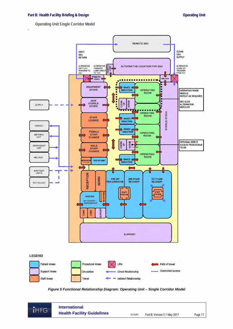
Part B: Health Facility Briefing & Design Operating Unit
International
Health Facility Guidelines © TAHPI
Part B: Version 5.1 May 2017
Page 11
Operating Unit Single Corridor Model
`
Figure 5 Functional Relationship Diagram: Operating Unit – Single Corridor Model

Part B: Health Facility Briefing & Design Operating Unit
International
Health Facility Guidelines © TAHPI
Part B: Version 5.1 May 2017
Page 12
Operating Unit Dual Corridor Model
Figure 6 Functional Relationship Diagram: Operating Unit – Dual Corridor Model
Modules and Air Pressurisation Diagrams
The module diagrams with air pressurisation shown below represent acceptable variations of the arrangement of Operating Rooms with Anaesthetic and support rooms. Each module represents ideal relationships and maintains correct clean/ dirty flows.

Part B: Health Facility Briefing & Design Operating Unit
International
Health Facility Guidelines © TAHPI
Part B: Version 5.1 May 2017
Page 13
Air pressurisation and traffic flows have been graded according to the following legend:
Modules A to D
Figure 7 Air Pressurisation Diagrams: Operating Unit – Modules A to D

Part B: Health Facility Briefing & Design Operating Unit
International
Health Facility Guidelines © TAHPI
Part B: Version 5.1 May 2017
Page 14
Module Types E to H
Figure 8 Air Pressurisation Diagrams: Operating Unit – Modules E to H

Part B: Health Facility Briefing & Design Operating Unit
International
Health Facility Guidelines © TAHPI
Part B: Version 5.1 May 2017
Page 15
3 Design
Environmental Considerations
Acoustics
Acoustic privacy is required in Operating Rooms, Procedure rooms, Interview, Treatment rooms and any rooms where confidential information will be discussed. The transfer of sound between clinical spaces should be minimised to reduce the potential of staff error from disruptions and miscommunication and to increase patient safety and privacy. Noisy areas such as Staff rooms should be located away from procedural areas.
Natural Light
The need for an external view from the Operating Room is an important consideration. Provision of windows need to consider the following:
Vision from the Operating Room could be through a corridor, set up area or directly to the external environment
Many procedures require black-out
There are heating, cooling and shading implications for windows in the Unit located on the outside of the building that may have an impact on the recurrent costs for maintenance and cleaning
Viewing windows from a corridor to the Operating Room can be useful for supervision and training purposes
Windows to Recovery, Staff Lounge and TSSU areas where staff spend a majority of their time should be given a high priority.
Privacy
Careful consideration of privacy and patient comfort is required to reduce discomfort and stress for patients and privacy screening will be required to all patient bed bays.
Interior Decor
Interior décor refers to colour, textures, surface finishes, fixtures, fittings, furnishings, artworks and atmosphere. It is desirable that these elements are combined to create a calming, non-threatening environment. Colours should be used in combination with lighting to ensure that they do not mask skin colours as this can be a problem in areas where clinical observation takes place.
Space Standards and Components
Accessibility
The Reception desk, Waiting areas and Interview rooms should provide access for patient relatives and visitors in wheelchairs.
Doors
All entry points, doors or openings requiring bed/trolley access including Operating Rooms are recommended to be a minimum of 1400 mm wide, unobstructed. Larger openings may be required for special equipment, as determined by the Operational Policy, to allow the manoeuvring of equipment without manual handling risks and risk of damage. Also refer to Part C – Access, Mobility, OH&S of these Guidelines.
Ergonomics/ OH&S
Design of clinical spaces including Operating and Procedure rooms must consider Ergonomics and OH&S issues for patient and staff safety and welfare. Refer to Part C – Access, Mobility, OH&S of these Guidelines for more information.

Part B: Health Facility Briefing & Design Operating Unit
International
Health Facility Guidelines © TAHPI
Part B: Version 5.1 May 2017
Page 16
Size of the Unit
The size of the Operating Unit will be determined by the Clinical Services Plan establishing the intended services scope and complexity. Schedules of Accommodation have been provided for typical units at role delineation levels 2 (less complex services) to 6 (teaching/ research facilities).
Safety and Security
Access control is required to the patient and staff entry areas of the Operating Unit. Limiting the number of entries and locating the Reception area with direct overview of entry areas is highly desirable. The perimeter of the Unit must be secured and consideration given to electronic access for all staff areas.
Finishes
Operating Units shall have the following finishes:
Floors that are smooth, non-slip impervious material laid in a continuous washable material and graded where necessary to fall to floor waste; floor material that resists staining is recommended
Wall finishes which are seamless, impervious and washable
Ceilings which are smooth and impervious
Intersections of walls and architraves to be rendered watertight junctions.
Fixtures, Fittings and Equipment
Equipment, furniture, fittings and the facility itself shall be designed and constructed to be safe, robust and meet the needs of a range of users. All furniture, fittings and equipment selections for the Operating Unit should be made with consideration to ergonomic and Occupational Health and Safety (OH& S) aspects. Particular consideration should be given to compactus units for sterile items, storage and movement of loan equipment and shelving for storage of heavy items. Refer to Part C of these Guidelines, the Room Layout Sheets (RLS) and Room Data Sheets (RDS) for more information.
Building Service Requirements
Communications
The Operating Unit will require special consideration of the following IT/ Communications items in the design of the Unit:
Picture archiving communications systems (PACS) and location of monitors
Paging for staff and emergencies
Voice and data cabling for telephones and computers
Bar coding systems for supplies and records
Wireless network requirements
Videoconferencing requirements for meeting rooms
Digital operating room requirements particularly linkages to seminar and education facilities for teaching purposes
Communications rooms and server requirements. Patient and Emergency Call facilities shall be provided in all patient bed areas (e.g. Holding bays, Recovery bays, Lounges, Change Rooms and Toilets) in order for patients and staff to request for urgent assistance. The individual call buttons shall alert to an annunciator system. Annunciator panels should be located in strategic points visible from Staff Stations Staff Stations and audible in Staff Rooms,

Part B: Health Facility Briefing & Design Operating Unit
International
Health Facility Guidelines © TAHPI
Part B: Version 5.1 May 2017
Page 17
and Meeting Rooms, and should be of the “non-scrolling” type, allowing all calls to be displayed at the same time.
HVAC
The Operating Rooms will require special air-conditioning with positive pressure and HEPA filtration to comply with relevant standards and guidelines .Individual Operating Room temperatures should be controllable by staff from within the room.
Medical Gases
The main storage of medical gases must be outside the facility and reticulated internally to gas outlets. Provision shall be made for additional separate storage of reserve gas cylinders necessary to complete at least one day's procedures.
Radiation Shielding and Radiation Safety
Operating Rooms that are used for undertaking imaging procedures require radiation shielding. A certified physicist or qualified expert will need to assess the plans and specifications for radiation protection as required by the relevant local radiation/nuclear safety authorities. A radiation protection assessment will specify the type, location and amount of radiation protection required for an area according to the final equipment selections, the layout of the space and the relationship between the space and other occupied areas. Incorporate all radiation protection requirements into the final specifications and building plans and re-evaluate radiation protection if the intended use of a room changes, equipment is upgraded or surrounding room occupancy is altered. Consideration should be given to the provision of floor and ceiling shielding when rooms immediately above and below are occupied.
Infection Control
Infection control issues are paramount in the Operating Unit and require careful attention to planning models and separation of clean and dirty workflows. The need for Isolation rooms (Positive and Negative Pressure) in Holding and Recovery areas is to be evaluated by an infection control risk assessment and will reflect the requirements of the Service Plan. Clinical hand-washing facilities shall be provided within all patient holding and recovery areas and convenient to the Staff Stations. The ratio of provision shall be a minimum of one clinical hand-washing facility for every four patient bays in open-plan areas. Refer also to Part D - Infection Control in these Guidelines for additional information. 4 Components of the Unit
Standard Components
The Operating Unit will consist of Standard Components to comply with details described in these Guidelines. Refer also to Standard Components Room Data Sheets and Room Layout Sheets.
Non-Standard Components
Non Standard rooms are identified in the Schedules of Accommodation as NS and are described below.
Biomedical Store/ Workshop
An area for testing operating equipment may be included in the Operating Unit. This room may be collocated with a General Store, or a dedicated room for this purpose may be necessary. A direct corridor access to this room is recommended, with controlled access to the remainder of the Operating Unit

Part B: Health Facility Briefing & Design Operating Unit
International
Health Facility Guidelines © TAHPI
Part B: Version 5.1 May 2017
Page 18
Perfusion Room
The Perfusion Room is for the preparation of perfusion equipment, and where set-up of perfusion equipment for cardiac procedures may be undertaken. The room will be located in close proximity to the Cardiac Operating Room/s and adjacent to a Perfusion Store. Room requirements may include:
Heavy duty shelving for storage of perfusion fluids and equipment
Computer workstation for a perfusion technician including power and data outlets
Handwashing basin Type B with paper towel and soap fittings
Bench, sink and cupboard unit for servicing of the perfusion machine.

Part B: Health Facility Briefing & Design Operating Unit
International
Health Facility Guidelines © TAHPI
Part B: Version 5.1 May 2017
Page 19
5 Schedule of Accommodation – Operating Unit
Operating Unit at RDL 2 to 6
ROOM/ SPACE Standard Component RDL 2 RDL 3 RDL 4 RDL 5/6 Remarks Room Codes Qty x m2 Qty x m2 Qty x m2 Qty x m2
Admission/ Reception/ Pre-op Holding 1 OR 2 ORs 4 ORs 12 ORs Reception/ Clerical RECL-9-I RECL-12-I RECL-15-I 1 x 9 1 x 12 1 x 12 1 x 15
Waiting WAIT-10-I WAIT-25-I 1 x 10 1 x 10 1 x 10 1 x 25 May be divided into female/ family areas as applicable
Waiting - Family WAIT-10-I WAIT-25-I 1 x 10 1 x 10 1 x 10 1 x 25
Meeting Room - Small MEET-9-I MEET-12-I 1 x 9 1 x 9 1 x 12
Patient Bay - Holding (M/F) PBTR-H-10-I 2 x 10 2 x 10 4 x 10 6 x 12 1 per Operating Room; optional; Separate Male/Female areas
Staff Station SSTN-5-I 1 x 5 Reception area can be used for levels 2-4
Bay - Blanket Warmer BBW-I 1 x 2 1 2 As required
Bay - Handwashing, Type B BHWS-B-I 1 x 1 1 x 1 1 x 1 2 x 1
Bay - Linen BLIN-I 1 x 2 1 x 2 Linen Bay may be shared for Levels 2-3; 1 per 16 bed spaces
Clean Utility - Sub CLUR-8-I 1 x 8 1 x 8 1 x 8 1 x 8
Dirty Utility - Sub DTUR-S-I 1 x 8 1 x 8 Levels 2-3 may share Dirty Utility
Office - Write-up Bay OFF-WI-6-I 1 x 6 1 x 6 1 x 6 Staff work area based on 3m2 per person, as required
Operating Rooms (OR) Areas 1 OR 2 ORs 4 ORs 12 ORs Anaesthetic Induction ANIN-I 1 15 2 x 15 4 x 15 10 x 15 Optional
Anaesthetic Induction - Large ANIN-I (Similar) 2 x 18 Optional, larger room for specialty ORs as needed
Operating Room - General ORGN-I 1 x 42 1 x 42 1 x 42 2 x 42 For minor procedures
Operating Room - Digital OR-DIG-I 1 x 55 3 x 55 10 x 55
Operating Room - Large ORLA-I 58 Optional; Provide according to service demand
Operating Room - Hybrid/ CT OR-HY-CT-I 70 Optional; Provide according to service demand
Operating Room - Imaging (Vascular/ Cardiac) OR-VC-I 65 Optional; Provide according to service demand
Scrub-Up/ Gowning SCRB-8-I 1 x 8 2 8 4 8 12 8 1 per Operating Room
Exit Bay NS 1 x 8 2 8 4 8 12 8 1 per Operating Room
OR Support Areas Audio-visual Room AUDV-I 1 10 As required for digital recording
Anaesthetic Store ANST-I 1 15 1 20 2 20
Anaesthetic Workroom ANWM-I 1 10 1 15 1 20 Also used for Biomedical equipment
Bay - Blanket Warmer BBW-I 1 x 1 1 x 1 1 x 1 1 x 1 Optional

Part B: Health Facility Briefing & Design Operating Unit
International
Health Facility Guidelines © TAHPI
Part B: Version 5.1 May 2017
Page 20
ROOM/ SPACE Standard Component RDL 2 RDL 3 RDL 4 RDL 5/6 Remarks Room Codes Qty x m2 Qty x m2 Qty x m2 Qty x m2 Bay - Linen BLIN-I 1 x 2 1 x 2 2 x 2 2 x 2
Bay - Mobile Equipment BMEQ-2.5-I 1 x 2.5 1 x 2.5 2 x 2.5 2 x 2.5 1 per OR, may be collocated
Bay - Pathology BPATH-I (similar) 1 x 1 1 x 1 1 x 4 1 x 6 Optional for RDL 3 & 4
Blood Store BLST-I (similar) 1 x 2 1 x 2 1 x 2 1 x 4
Cleaners Room CLRM-5-I 1 x 5 1 x 5 1 x 5 2 x 5 Minimum of 1 per approximately 1000m2
Clean-Up Room CLUP-7-I 1 x 7 1 x 7 1 x 7 1 x 7 1 per OR, may be collocated and shared between ORs
Disposal Room DISP-10-I 1 x 10 1 x 10 1 x 10 2 x 10
Flash Steriliser FST-2-I 1 x 2 1 x 2 1 x 2 1 x 2
Office - Write-up Bay OFF-WI-6-I 1 x 6 1 x 6 1 x 6 1 x 6
Set-up Room SETUP-8-I SETUP-16-I 1 x 8 1 x 8 1 x 16 1 x 16 Optional. depends on Operational Policy of the unit
Store - Drugs STDR-5-I STDR-10-I 1 x 5 1 x 10
Store - Equipment, Major STEQ-10-I STEQ-14-I STEQ-30-I 1 x 10 1 x 15 1 x 30 2 x 36 6m2 per OR recommended for RDL 5/6
Store - Equipment, Minor STEQ-10-I STEQ-14-I STEQ-30-I 1 x 10 1 x 15 1 x 15 2 x 30 5m2 per OR recommended for RDL 5/6
Store - Loan Equipment STEQ-10-I STEQ-14-I 1 x 10 1 x 10 1 x 15 Optional, for equipment on consignment
Store - Non-Sterile/ De-boxing STEQ-20-I STEQ-30-I 1 x 20 1 x 20 1 x 30 1 x 30
Store - Sterile Stock STSS-12-I STSS-44-I (similar) 1 12 1 24 1 x 44 1 x 120 Based on 10-12 m2 per OR
Perfusion Room NS 1 x 20 Optional, for cardiac specialties
Store - Perfusion STGN-20-I 1 x 20 Optional, for cardiac specialties
Toilet - Staff WCST-I 1 x 3 1 x 3 In addition to toilets in Change Rooms
Recovery Areas – Stage 1 1 OR 2 ORs 4 ORs 12 ORs Patient Bay – Recovery Stage 1 PBTR-RS1-9-I PBTR-RS1-12-I 2 x 9 4 9 8 12 22 x 12 2 bays per OR; separate Male/ Female areas
Patient Bay Enclosed – Recovery Stage 1, Isolation
PBTR-RS1-12-I 2 x 12 Provide according to service demand
Staff Station SSTN-10-I SSTN-12-I SSTN-20-I 1 x 10 2 x 10 2 x 12 2 x 20 1 each for Male/ Female areas
Bay – Blanket Warmer BBW-I 1 x 1 1 x 1 1 x 1 1 x 1 As required
Bay - Handwashing, Type A BHWS-A-I 1 x 1 1 x 1 2 x 1 6 x 1 1 per 4 bays; Refer to Infection Control Part D
Bay - Linen BLIN-I 1 x 2 1 x 2 2 x 2 2 x 2
Bay - Resuscitation BRES-I 1 x 1.5 1 x 1.5 1 x 1.5 1 x 1.5
Clean Utility CLUR-12-I CLUR-14-I 1 x 12 1 x 12 2 x 12 2 x 14 May be combined with Staff Station for RDL 2; Direct access
Dirty Utility DTUR-12-I 1 x 12 1 x 12 2 x 12 2 x 12
Store - General STGN-6-I STGN-10-I 1 x 6 2 x 6 2 x 10
OR Staff Areas 1 OR 2 ORs 4 ORs 12 ORs

Part B: Health Facility Briefing & Design Operating Unit
International
Health Facility Guidelines © TAHPI
Part B: Version 5.1 May 2017
Page 21
ROOM/ SPACE Standard Component RDL 2 RDL 3 RDL 4 RDL 5/6 Remarks Room Codes Qty x m2 Qty x m2 Qty x m2 Qty x m2 Change - Staff (Male/Female) CHST-12-I CHST-14-I CHST-20-I 2 x 12 2 x 20 2 x 35 2 x 120 Toilets, Shower and Lockers; size dependent on staffing numbers
Meeting Room - Small MEET-9-I MEET-12-I shared 1 x 9 1 x 9 1 x 12 Optional, according to service demand
Meeting Room – Medium/ Large MEET-L-15-I MEET-L-30-I shared shared 1 x 15 1 x 30 Optional, according to service demand
Office - Single Person, 12 m2 OFF-S12-I 1 x 12 1 x 12 Note 1; Service Manager
Office - Single Person, 9 m2 OFF-S9-I 1 x 9 1 x 9 2 x 9 Note 1; Unit Manager OR, Unit Manager Recovery
Office - Single Person, 9 m2 OFF-S9-I 1 x 9 1 x 9 2 x 9 4 x 9 Note 1; Surgeons, Anaesthetists, Clinical Nurse Consultants
Office - 2 Person, Shared OFF-2P-I 1 x 12 1 x 12 Note 1; Nurse Educators, Medical Specialists, Clinicians
Office - 3 Person, Shared OFF-3P-I 1 x 15 2 x 15 Note 1; Registrars, Medical Officers
Staff Room SRM-15-I SRM-30-I (similar) 1 x 15 1 x 15 1 x 30 1 x 60 May divide into Male & Female areas
Toilet - Staff WCST-I 1 x 3 In addition to toilets in Change Rooms, separate M/ F
Toilet - Accessible, Staff WCAC-I 1 6 Unless available nearby
Sub Total 335.0 564.0 1051.5 2566.5
Circulation % 35 35 40 45
Area Total 452.3 761.4 1472.1 3721.4
Peri-operative Unit (Optional – May be Collocated with Operating Unit)
ROOM/ SPACE Standard Component RDL 2 RDL 3 RDL 4 RDL 5/6 Remarks Room Codes Qty x m2 Qty x m2 Qty x m2 Qty x m2
Admissions/ Reception Reception/ Clerical RECL-9-I RECL-12-I 1 x 9 1 x 9 1 x 9 1 x 12 May be shared with OR/ Day Surgery Reception
Office OFF-S9-I OFF-2P-I 1 x 9 1 x 9 1 x 9 1 x 12 Clerical Support/ records; May be shared with OR/ Day Surgery
Toilet – Public (Male/ Female) WCPU-3-I 2 x 3 2 x 3 2 x 3 2 x 3 Unless access available nearby
Toilet - Accessible WCAC-I 1 x 6 1 x 6 1 x 6 2 x 6 Unless access available nearby
Waiting WAIT-10-I WAIT-20-I WAIT-25-I 1 x 10 1 x 20 1 x 20 1 x 25
Waiting – Female/ Family WAIT-15-I WAIT-30-I WAIT-50-I 1 x 15 1 x 20 1 x 30 1 x 50 Separate Female/ Family Waiting areas may be provided
Waiting WAIT-SUB-I 5 5 5 Wards persons/ Orderlies
Pre-operative Area 2 Bed 4 Bed 6 Bed 12 Bed
Change –Patient (Male/ Female) CHPT-12-I (similar) 2 x 6 2 x 12 2 x 12 2 x 24 Includes Toilet, Shower, Lockers; provide toilets and showers not less than 1:6 bed bays, each
Waiting – Changed Patient (Male/ Female) WAIT-10-I WAIT-20-I WAIT-25-I 2 x 10 2 x 10 2 x 25 2 x 25 Alternatively, use patient holding bays

Part B: Health Facility Briefing & Design Operating Unit
International
Health Facility Guidelines © TAHPI
Part B: Version 5.1 May 2017
Page 22
ROOM/ SPACE Standard Component RDL 2 RDL 3 RDL 4 RDL 5/6 Remarks Room Codes Qty x m2 Qty x m2 Qty x m2 Qty x m2 Patient Bay - Holding PBTR-H-10-I 2 x 10 3 x 10 4 x 10 10 x 10 1 per OR recommended
Patient Bay Enclosed, Isolation PBTR-H-E-12-I 1 x 12 2 x 12 2 x 12 Class S Isolation
1 Bed Room – Isolation, Negative Pressure 1BR-IS-N-I 18 Provide according to service demand
Anteroom ANRM-I 6 for Isolation Room, Negative Pressure
Bay - Handwashing, Type B BHWS-B-I 1 x 1 1 x 1 1 x 1 3 x 1 1 per 4 bays; Refer to Part D Infection Control
Bay - Linen BLIN-I 1 x 2 1 x 2 May be shared with Recovery
Bay - Resuscitation Trolley BRES-I 1 x 1.5 1 x 1.5 1 x 1.5 1 x 1.5 May be shared with Recovery if close
Clean Utility CLUR-S-I CLUR-12-I 1 x 8 1 x 8 1 x 12 1 x 12 Includes medications; May be collocated with Staff Station
Consult/ Exam Room CONS-I 2 x 14 2 x 14 3 x 14 4 x 14 Provide according to service demand
Dirty Utility DTUR-S-I 1 x 8 1 x 8 1 x 8 1 x 8 May be shared with Recovery
Ensuite ENS-ST-I 1 x 5 1 x 5 2 x 5 2 x 5 For Enclosed Bed Bay & Isolation Room Negative Pressure
Toilet – Accessible, Patient WCAC 1 x 6 1 x 6 2 x 6 2 x 6 May share with Recovery areas if close
Post-operative Area (Recovery Stage 2/3) 1 Proc Rm 2 Proc Rms 4 Proc Rms 6 Proc Rms
Patient Bay - Holding, Recovery Stage 2 PBTR-H-10-I 3 x 10 6 x 10 12 x 10 18 x 10 Separate Male/Female areas, may be combination of bed and chair spaces; allow 3 beds/ chairs per Day Surgery OR
Lounge – Recovery, Stage 2/3 LNPT-RS2-I (similar) 2 x 12 2 x 18 2 x 36 2 x 54 Separate Male/Female areas, may be collocated; allow 3 lounge chairs per Day Surgery OR at 6m2 per chair
Staff Station SSTN-10-I SSTN-12-I SSTN-14-I 1 x 10 1 x 10 2 x 12 2 x 14
Bay - Beverage, Open Plan BBEV-OP-I 1 x 4 1 x 4 1 x 4 1 x 4
Bay -Blanket/ Fluid Warmer BBW-I 1 x 1 1 x 1 1 x 1 1 x 1 As required
Bay - Handwashing, Type B BHWS-B-I 2 x 1 4 x 1 6 x 1 9 x 1 1 per 4 beds/ chairs; refer to Part D Infection Control
Bay - Linen BLIN-I 1 x 2 1 x 2 1 x 2 2 x 2
Bay - Pathology BPATH-I 1 x 1 1 x 1 1 x 1 1 x 1
Bay - Resuscitation Trolley BRES-I 1 x 1.5 1 x 1.5 1 x 1.5 1 x 1.5
Cleaner’s Room CLRM-5-I 1 x 5 1 x 5 1 x 5 1 x 5
Clean Utility CLUR-8-I CLUR-12-I CLUR-14-I 1 x 8 1 x 8 1 x 12 1 x 14
Dirty Utility DTUR-S-I DTUR-12-I DTUR-14-I 1 x 8 1 x 8 1 x 12 1 x 14 May be shared
Disposal Room DISP-8-I DISP-10-I 1 x 8 1 x 8 1 x 10 1 x 10 May be shared
Store - Equipment/ General STEQ-15-I STEQ-20-I 1 x 12 1 x 15 1 x 15 1 x 20 Equipment, consumable stock
Toilet – Patient WCPT-I 1 x 3 1 x 3 2 x 3 4 x 3
Toilet - Accessible WCAC-I 1 x 6 1 x 6 2 x 3 2 x 6
Staff Areas Meeting Room - Small MEET-9-I 1 x 9 1 x 9 1 x 9 May be shared

Part B: Health Facility Briefing & Design Operating Unit
International
Health Facility Guidelines © TAHPI
Part B: Version 5.1 May 2017
Page 23
ROOM/ SPACE Standard Component RDL 2 RDL 3 RDL 4 RDL 5/6 Remarks Room Codes Qty x m2 Qty x m2 Qty x m2 Qty x m2 Office – Write-up (Shared) OFF-WIS-I 1 x 12 1 x 12 1 x 12
Office – Single Person OFF-S9-I 1 x 9 1 x 9 1 x 9 1 x 9 Unit Nurse Manager
Property Bay - Staff PROP-3-I PROP-6-I 1 x 3 1 x 3 2 x 6 2 x 6
Staff Room SRM-15-I SRM-20-I 1 x 15 1 x 15 1 x 20 1 x 20 May share with an adjacent Unit
Toilet - Staff WCST-I 1 x 3 1 x 3 2 x 3 2 x 3
Sub Total 320.0 442.0 677.0 964.0 Circulation % 35 35 35 35
Total Area 432.0 596.7 914.0 1301.4
Note 1: Offices to be provided according to the number of approved full time positions within the Unit
Also note the following:
Areas noted in Schedules of Accommodation take precedence over all other areas noted in the FPU. Rooms indicated in the schedule reflect the typical arrangement according to the Role Delineation. Exact requirements for room quantities and sizes will reflect Key Planning Units identified in the Service Plan and the Operational Policies of the Unit. Room sizes indicated should be viewed as a minimum requirement; variations are acceptable to reflect the needs of individual Unit. Office areas are to be provided according to the Unit role delineation and number of endorsed full time positions in the unit. Staff and support rooms may be shared between Functional Planning Units dependent on location and accessibility to each unit and may provide scope to reduce duplication of
facilities.

Part B: Health Facility Briefing & Design Operating Unit
International
Health Facility Guidelines © TAHPI
Part B: Version 5.1 May 2017
Page 24
6 Future Trends When planning for future developments the following trends should be considered:
Increasing demand for digital operating rooms
Increasing availability and use of robotic surgery
Increasing use of imaging within the operating room particularly CT scanning, MRI and angiography
Technological development of support, monitoring, diagnostic, treatment and procedural equipment
Increasing sophistication of information systems
Demand for transparency about quality, safety and cost. 7 Further Reading
ASHRAE American Society of Heating Refrigeration and Air-conditioning Engineers, HVAC design manual for hospitals and clinics, 2003 refer to website: https://www.ashrae.org/standards-research--technology/standards--guidelines
Australasian Health Facility Guidelines, Part B Health Facility Briefing and Planning, HPU B.0520 Operating Unit, 2016; refer to website https://healthfacilityguidelines.com.au/health-planning-units
CDC Centres for Disease Control and Prevention, Guideline for Disinfection and Sterilisation in Healthcare Facilities, 2008, refer to website http://www.cdc.gov/hicpac/pdf/guidelines/Disinfection_Nov_2008.pdf
DH (Department of Health) (UK) Health Building Note HBN 26 Facilities for surgical procedures: Volume 1, 2009, refer to website: https://www.gov.uk/government/uploads/system/uploads/attachment_data/file/148490/HBN_26.pdf
DH (Department of Health) (UK) Health Building Note HBN 00-03 Clinical and clinical support spaces, 2013, refer to website: https://www.gov.uk/government/uploads/system/uploads/attachment_data/file/147845/HBN_00-03_Final.pdf
Guidelines for Design and Construction of Health Care Facilities; The Facility Guidelines Institute, 2014 Edition refer to website www.fgiguidelines.org
Bureau of Health Stattistics (Aus) Occupancy rates in Health Facilities, available from website http://www.statistics.health.pa.gov/StatisticalResources/UnderstandingHealthStats/ToolsoftheTrade/Documents/Occupancy_Rates_in_Health_Facilities.pdf

Part B – Health Facility Briefing & Design 245 Outpatients Unit
International Health Facility Guidelines Version 5 October 2016

Part B: Health Facility Briefing & Design
International
Health Facility Guidelines © TAHPI
Part B: Version 5 Oct 2016
Page 2
Table of Contents
245 Outpatients Unit ........................................................................................................................ 3
1 Introduction ............................................................................................................................................... 3 Description .................................................................................................................................................. 3
2 Functional and Planning Considerations ............................................................................................... 3 Operational Models ..................................................................................................................................... 3 Planning Models .......................................................................................................................................... 7 Functional Areas ......................................................................................................................................... 9 Functional Relationships ........................................................................................................................... 10
3 Design ...................................................................................................................................................... 12 General...................................................................................................................................................... 12 Environmental Considerations .................................................................................................................. 12 Space Standards and Components .......................................................................................................... 13 Safety & Security ....................................................................................................................................... 13 Finishes ..................................................................................................................................................... 13 Fixtures, Fittings & Equipment .................................................................................................................. 14 Building Service Requirements ................................................................................................................. 14 Infection Control ........................................................................................................................................ 14
4 Components of the Unit .......................................................................................................................... 16 Standard Components .............................................................................................................................. 16 Non-Standard Components ....................................................................................................................... 16
5 Schedule of Accommodation – Outpatients Unit ................................................................................. 17 Outpatients Unit located within a health facility ......................................................................................... 17 Outpatients Unit - Stand-alone .................................................................................................................. 19
6 Future Trends .......................................................................................................................................... 22
7 Further Reading ....................................................................................................................................... 22

Part B: Health Facility Briefing & Design Outpatients Unit
International
Health Facility Guidelines © TAHPI
Part B: Version 5 Oct 2016
Page 3
245 Outpatients Unit
1 Introduction
Description The Outpatient Unit, also known as Ambulatory Care Unit, refers to health care provided in hospital-based outpatient or stand-alone clinics, physician offices, ambulatory surgical centres, and many other specialized settings where patients receive care but do not remain overnight. The Outpatient Unit may perform the following functions: Consultation with medical specialists, examination and investigations Treatment on a same day basis Minor procedures Follow up review consultation and ongoing case management Patient screening prior to surgery – perioperative services Health education or counselling sessions for patients and families Referral of patients to other units or disciplines for ongoing care and treatment Referral for admission to a hospital for inpatient services. The services or clinical specialties that may be provided in the Outpatient Unit encompass: GP (General Practitioner) Clinics Primary Care centres Women and child health services A comprehensive range of surgical specialties Medical specialties including diabetes and multidisciplinary team reviews e.g. chronic disease
clinics, infectious diseases services Pain management Genetics clinics Health Promotion initiatives. The following specialist services provided on an outpatient or same day basis are addressed in the relevant FPU: Community Health Unit Dental (refer to Dental Surgery Unit and Oral Health Unit) Day Surgery (refer to Day Surgery/ Procedure Unit) Oncology/ Day Chemotherapy (refer to Oncology Unit – Medical (Chemotherapy) Mental Health including Drug & Alcohol services (refer to Mental Health Unit - Outpatient) Radiotherapy (refer to Radiation Oncology/ Cancer Care Centre) Rehabilitation, Physiotherapy, Occupational Therapy (refer to Rehabilitation/ Allied Health) Renal Dialysis (refer to Renal Dialysis Unit) Urgent Care Centres, Acute Assessment Units, Medical Assessment Units (refer to
Emergency Unit). The elements described in this FPU will apply to Outpatient Units located within a larger facility, located within a commercial development or stand-alone units. 2 Functional and Planning Considerations
Operational Models
Hours of Operation
Patient services will generally be provided during normal business hours: Monday to Friday 08.00am – 5.00pm. However, patient care requirements and flexible work schedules may require hours of operation to be extended to evenings and weekends to meet demand and operational

Part B: Health Facility Briefing & Design Outpatients Unit
International
Health Facility Guidelines © TAHPI
Part B: Version 5 Oct 2016
Page 4
policies. Availability of support, cleaning and maintenance services should be considered during the planning phase.
Models of Service Delivery
Flexible operational models can be built into an existing unit using modular spaces and designs. Each module should include reception, waiting, examination and treatment rooms supported by patient and staff facilities, support areas and clerical offices. It is vital to clearly identify the Main patient/public entry; reinforce the entry sequence with the design of site circulation systems. Staff entry and circulation should be separated from patient circulation where possible. Consultation methods differ between medical practitioners depending on the situation. However, in all cases, the emphasis should be on achieving the optimal environment for a fully informed consultation Operational Models applicable to the Outpatient Unit include:
Single Corridor Access Model: This examination/ treatment model permits multidisciplinary rooms with similar configurations accessed by a single entry point. Common reception and waiting areas enhance efficient staffing and resourcing.
Above: Single Corridor Access model
Double Corridor Access Model Where space permits, the double corridor model enables staff support and service areas to remain discreetly separate from public access. Common reception and waiting areas enhance efficient staffing and resourcing while the consult/ examination rooms can be used by either multi-disciplinary teams or specialist providers.

Part B: Health Facility Briefing & Design Outpatients Unit
International
Health Facility Guidelines © TAHPI
Part B: Version 5 Oct 2016
Page 5
Above: Double Corridor Access model with waiting area at the entry
In this model, waiting areas can be located centrally, but this may reduce patient privacy and confidentiality. Consideration of these benefits may be off-set, where appropriate, by convenient patient access and fast turn-over for each room module.
Above: Double Corridor Access mode with centralized waiting area

Part B: Health Facility Briefing & Design Outpatients Unit
International
Health Facility Guidelines © TAHPI
Part B: Version 5 Oct 2016
Page 6
Multidisciplinary Consult Rooms The adoption of modular consult rooms enables efficient use by multidisciplinary practitioners on a sessional basis. As service needs and workload projections vary, staffing efficiencies and patient convenience can be maintained while duplications are prevented.
Single Specialty Consult Rooms Where a range of highly specialized equipment is required during each consultation, rooms can be configured to accommodate these special requirements. Each medical specialty can be assigned their group of medical suites with associated waiting and reception areas, patient facilities and support areas. Examples of specialities this models suits includes: ENT/ Ophthalmology, Endoscopy specialties, Cancer Centre (Chemotherapy, Radiotherapy and Consulting) and Specialist Medical Suites
Above: Typical Specialist Medical Suites of varying sizes
The service plan of an Individual facility will determine the planning needs of the Outpatients Unit. Influencing factors include: Patient attendance numbers Numbers of specialities Medical, allied health and support staffing number Anticipated usage of medical suites and potential to share rooms between specialities Population profiles which drive speciality service delivery.

Part B: Health Facility Briefing & Design Outpatients Unit
International
Health Facility Guidelines © TAHPI
Part B: Version 5 Oct 2016
Page 7
Planning Models Planning models applicable to the Outpatient Unit include: A discreet Unit within a Hospital facility or located within a hospital campus, sharing the
support services of the hospital facility An integrated Unit such as a private medical practise within a commercial development such
as a shopping centre or an office building A stand-alone Unit not connected with a hospital or commercial facility.
Location
Outpatients Units are commonly located at the entrance of large and small health facilities with an efficient connection to the Main Entry of the hospital. Key considerations during planning include the provision of Convenient ground floor access to outpatient entry with set-down points for ambulances,
patient support vehicles and private cars Effective wayfinding boards and enquiry points at entrances Patient refreshment, pharmaceutical and toilet facilities Waiting areas to accommodate patients, carers, children and the disabled Patient flow patterns to enable clinical pre-assessment, pathology, radiology services etc.
prior to medical consultation Storage facilities for patient belongings Clustering procedure rooms to service consultation rooms Furniture, fittings, equipment, services and hydraulics to meet specific clinical requirements.
Configuration
An important consideration during planning of the Outpatients Unit will be the determination of the model of consult/ examination rooms. This can have a major impact on space provision for the Unit.
Combined Consult/ Examination Rooms Consult and examination takes place within a single room. The room will have a desk and chairs in the consultation zone and a screened examination area with a couch. The layout of the room should ensure patient privacy particularly in the examination area. The room is suitable for multifunction use; specialist equipment is brought into the room as needed and stored when not in use. The benefits of this type of room are: Flexible use – can be used for consultation or examination or both Compact rooms result in a space saving floor plan.
Above: Typical Consult Rooms with combined consult/ examination functions

Part B: Health Facility Briefing & Design Outpatients Unit
International
Health Facility Guidelines © TAHPI
Part B: Version 5 Oct 2016
Page 8
Separate Consult and Examination Rooms Consult and examination rooms are provided as individual rooms with separate access to each, allowing a patient to be examined separately to the consult function. This type of arrangement is appropriate for both multi-functional and specialist use of the rooms. Benefits of this type of room: allows increased throughput of patients by enabling a patient to be examined or to be
changing in the examination room while another patient is occupying the Consult room separate examination rooms can be converted in future to full consult/ examination rooms
when additional clinic capacity is needed convenient for patient consultation with multiple clinical specialists; the patient remains in
place and clinicians visit the patient
Above: Separate Consult and Examination functions in collocated rooms, with alternative couch arrangements; consult and examination rooms are the same size allowing for future flexibility Examination rooms may be sized to accommodate the examination couch and hand basin only which is space efficient and reduces the overall departmental area.
Specialist Consult/ Exam Rooms Consult/ Examination rooms designed to accommodate a particular discipline with specialty equipment that remains in the room e.g. ENT, Ophthalmology, Podiatry and colorectal rooms Benefits: Avoids excessive handling of expensive or sensitive equipment Specialist equipment available and ready to use instantly without setting up
Above: Specialist Consult/ Exam room – ENT/ Ophthalmology

Part B: Health Facility Briefing & Design Outpatients Unit
International
Health Facility Guidelines © TAHPI
Part B: Version 5 Oct 2016
Page 9
Functional Areas The Outpatient Unit consists of the following key functional areas: Entry Area including:
- Reception/ Patient registration - Waiting Areas including provision for families - Interview room/s for patient and family discussions - Public amenities such as toilets, play area, parenting rooms
Consult Areas with: - Consult and examination rooms, (combined or separate) - Interview and meeting rooms for patient discussions, team meetings - Vital signs room - Blood collection facilities - Support areas including utilities, store rooms, patient toilets
Treatment Areas (optional) if provided may include: - Procedure and Treatment rooms - Plaster room/s - Patient bed bays for recovery following procedures - Support areas incorporating utilities
Staff and Support areas such as: - Offices - Staff Room - Staff toilets and lockers.
Entry Area
If a direct and separate entry is provided to the Unit at street level, an entry canopy shall be provided for patient drop-off and pick-up. The canopy shall be designed and sized appropriately to permit easy manoeuvring and weather protection of vehicles including cars, ambulances, taxis, and mini-vans. The entry canopy shall be located next to the Lobby/ Airlock if one is provided. Arrival areas should allow for separate drop off by cars and ambulances and community vehicles and patients arriving by public transport or walking.
Reception/ Waiting
The Reception/ Waiting area of the Outpatients Unit may be shared by consulting and treatment zones and should be located to provide convenient access to both areas while allowing access to public and disabled amenities for patients and visitors. The Reception area may include patient registration, a patient queuing system and cashier facilities where appropriate. Waiting areas may be designed with separation to meet cultural requirements where appropriate. Waiting areas should accommodate a wide range of occupants including children, those less mobile or in wheelchairs. Provisions should be made for prams and play areas for children.
Consult and Treatment/ Procedure Areas
Consult/ examination rooms may be provided as combined consult/ examination rooms or separate rooms depending on the operational policy of the facility and the clinical specialties to be incorporated. Consult / Treatment Areas should promote efficiency, provide a pleasant environment for all patient types Treatment rooms and Procedure Rooms will be used for minor treatments and procedures under local anaesthetic that do not require admission to the Day Surgery/ Procedures Unit. Patient Vital signs room/s will be used for measurement and recording of patient height, weight and vital signs recording prior to Consultation. Patient Bed Bays are provided as required for patient recovery following procedures attended within the Unit. The bed bays will require staff handwashing basins (refer to Part D for quantity), a staff station and support areas including clean and dirty utilities. This area could also be utilized for trolley or wheel chair patients awaiting transport if there is no transit lounge.

Part B: Health Facility Briefing & Design Outpatients Unit
International
Health Facility Guidelines © TAHPI
Part B: Version 5 Oct 2016
Page 10
Support Areas
Support areas for the Outpatient Units will include: Bays for linen, resuscitation trolley and mobile equipment including wheelchairs Cleaners room Clean Utility with provision for drug storage Dirty Utility room including facilities for urine testing and waste holding Store Rooms for general consumables, sterile stock and equipment; this may include specialty
equipment held in storage until needed in the Consult or Treatment rooms, and bulky items such as crutches, walkers and lifting equipment.
Staff Areas
Offices and workstations may be required for the Unit manager and administrative staff, to undertake administrative functions, or to facilitate educational and research activities. Staff will need access to the following: Meeting room/s for education and tutorial sessions as well as meetings Staff room with beverage and food storage facilities Toilets and lockers. Staff areas may be shared with an adjacent unit if located conveniently.
Functional Relationships
External
The Outpatient Unit, whether free-standing or part of a larger facility will generally have working relationships with many other Units. The planning and design of the Unit should locate the following with convenient access: Drop off zone/ car park and Main Entry Admission Unit (satellite, stand alone or central) for patient referrals Clinical Information Unit for delivery/ return of clinical records unless digital records are used Day Surgery/ Procedure Unit Emergency Unit, for patient referrals Medical Imaging for diagnostic procedures Pharmacy for patient medications Pathology, specimen collection, for diagnostic studies Rehabilitation Unit/ Allied Health for patient follow-up Transit Lounge for patients awaiting transport.
Internal
The internal planning of the Outpatient Unit will reflect the functional areas mentioned above. Some of the critical considerations are: Flexibility in accommodating various types of use throughout different hours in the day Reception area should allow patients to move conveniently to and from the Consult and
Treatment areas and accommodate high volume of patients, support staff, care-takers and mobility aids
Interview rooms for support services such as social worker, cashier etc. to be conveniently located
Sub Waiting areas may be located close to Treatment areas for patient and staff accessibility Staff must be able to move easily to and from Treatment areas and Reception/ Registration
and Waiting areas; discreet and private work areas away from patients is recommended; staff areas may have restricted access to patients.
It is important for the functional areas to work effectively together to allow for an efficient, safe and pleasant environment.

Part B: Health Facility Briefing & Design Outpatients Unit
International
Health Facility Guidelines © TAHPI
Part B: Version 5 Oct 2016
Page 11
Functional Relationship Diagram
Outpatients Unit, all models
Figure 1 Functional Relationship Diagram: Outpatients Unit

Part B: Health Facility Briefing & Design Outpatients Unit
International
Health Facility Guidelines © TAHPI
Part B: Version 5 Oct 2016
Page 12
The optimum external relationships include: Patient access from a main circulation corridor with a relationship to the Main Entrance and
car park Separate entry and access for staff from hospital units via a service corridor Alternative access away from the Reception for patients and staff in transit to other hospital
units Access for service units such as Supply, Housekeeping and Clinical Information via a service
corridor. Internal relationships should include the following: Reception at the entrance with access to an interview area Access for patients to Consult and Treatment rooms directly from Waiting areas with
Reception/ Administration acting as a control centre Support areas located in Consult/ Treatment and staff areas close to the activity centres for
staff convenience. 3 Design
General Waiting areas, patient Consult and Treatment areas will need to be designed to cater for a wide range of patients visiting the unit, including elderly, parents with children, patients with limited mobility and bariatric patients. The design should give patients and visitors the impression of an organised and efficient unit.
Environmental Considerations
Acoustics
Acoustic privacy is required in Consult, Interview, Treatment rooms and any rooms where confidential information will be discussed. The transfer of sound between clinical spaces should be minimised to reduce the potential of staff error from disruptions and miscommunication and to increase patient safety and privacy. Noisy areas such as Waiting rooms and play areas should be located away from consult, treatment and staff areas.
Natural Light/ Lighting
Where possible, the use of natural light shall be maximised within the Unit. Sufficient levels of natural lighting can provide a sense of wellbeing for both staff and patients, reduce patient discomfort and stress and is more likely to lead to better service outcomes. Windows are particularly desirable in waiting areas and staff lounges. If windows cannot be provided, alternatives such as skylights may be considered.
Privacy
Careful consideration of privacy and patient comfort is required to reduce discomfort and stress for patients including: Discreet and non-public access to medical records Privacy screening to all examination bays and patient bed bays Location of doors to avoid patient exposure in Consult and Treatment rooms.
Interior Decor
Interior décor refers to colour, textures, surface finishes, fixtures, fittings, furnishings, artworks and atmosphere. It is desirable that these elements are combined to create a calming, non-threatening environment. Colours should be used in combination with lighting to ensure that they do not mask skin colours as this can be a problem in areas where clinical observation takes place.

Part B: Health Facility Briefing & Design Outpatients Unit
International
Health Facility Guidelines © TAHPI
Part B: Version 5 Oct 2016
Page 13
Space Standards and Components
Accessibility
Wheelchair access is required in all patient areas including Consult, Treatment, Procedure and Waiting rooms. Waiting areas should also include space and power outlets for charging electric mobility equipment along with suitable seating for patients with disabilities or mobility aids. The Unit will require suitable seating and provisions for bariatric patients.
Doors
All entry points, doors or openings, shall be a minimum of 1200 mm wide, unobstructed. Larger openings may be required for special equipment, as determined by the Operational Policy, to allow the manoeuvring of beds, trolleys, equipment and wheelchairs without manual handling risks and risk of damage. Doors used for emergency bed transfer to the Operating Units must be appropriately positioned and sized. A minimum of 1400mm clear opening is recommended for doors requiring bed/ trolley access. Also refer to Part C – Access, Mobility, OH&S of these Guidelines.
Ergonomics/ OH&S
Design of clinical spaces including Consult, Examination and Procedure rooms must consider Ergonomics and OH&S issues for patient and staff safety and welfare. Refer to Part C – Access, Mobility, OH&S of these Guidelines for more information.
Size of the Unit
The size of the Unit will be determined by a Clinical Services Plan and will take into consideration: The size of the population served by the Unit and demographic trends The number of clinical practitioners available The average length of consultation or treatment The number of referrals and transfers from other local regions or hospitals The number of other Outpatient Units in the vicinity.
Safety & Security A high standard of safety and security can be achieved with early planning in the development of the unit and careful configuration of spaces and zones in order to: Control the entry and exits points to and from the Unit Improve the observation of patient and clinical areas for staff Reduce duplication by grouping of functions, optimizing the space utilization and promoting
efficient staff and patient management. The perimeter of the Unit should be secured and consideration given to electronic access. Access to public areas shall be carefully planned so that the safety and security of staff areas within the Unit are not compromised. Zones within the Unit may need to be lockable when not in use, preferably electronically. This can be achieved by the use of doors to circulation corridors and automated shutters to entrances when the Outpatient Service is not operational after hours and weekends. Internally within the Outpatients Unit all offices require lockable doors and all store rooms for files, records and equipment should be lockable.
Finishes In all areas where patient observation is critical, colours shall be chosen that do not alter the observer's perception of skin colour. The following aspects should always be considered when specifying internal finishes: Cleaning and infection control Fire safety of the materials Patient care and comfort
Part B: Health Facility Briefing & Design Outpatients Unit
International
Health Facility Guidelines © TAHPI
Part B: Version 5 Oct 2016
Page 14
Staff safety, particularly for floor finishes Cultural/ social perceptions of a professional healthcare environment. Refer to Part C of these Guidelines and Standard Components for more information on wall protection, floor finishes and ceiling finishes.
Fixtures, Fittings & Equipment Equipment, furniture, fittings and the facility itself shall be designed and constructed to be safe, robust and meet the needs of a range of users with varying mobility needs. All furniture, fittings and equipment selections for the Outpatients Unit should be made with consideration to ergonomic and Occupational Health and Safety (OH& S) aspects. Refer to Part C of these Guidelines - Access, Mobility, OH&S, the Room Layout Sheets (RLS) and Room Data Sheets (RDS) for more information.
Window Treatments
Window treatments should be durable and easy to clean. Consideration may be given to use of blinds, shutters, tinted glass, reflective glass, exterior overhangs or louvers to control the level of lighting.
Building Service Requirements
Communications
The Outpatients Unit requires a wide range of systems to ensure the storage of patient information and image management is efficient and effective. These systems include but are not limited to: Picture archiving communications systems (PACS) and storage for digital archives Voice/ data cabling and outlets for phones, fax and computers Network data requirements and wireless network requirements to support remote reporting Video and teleconferencing capability CCTV surveillance if indicated Patient, staff, emergency call, duress alarms and paging systems Communications rooms and server rooms. Patient, staff assist and emergency call facilities shall be provided in all Consult, Examination, Procedure, Treatment rooms and patient areas (including toilets) in order for patients and staff to request for urgent assistance. Close collaboration with the IT Unit and obtaining advice from consultants early in the design phase is recommended.
Heating, Ventilation and Air conditioning
The unit shall have appropriate air conditioning that allows control of temperature and humidity for patient and staff comfort. Refer also to Standard Components Room Data Sheets.
Medical Gases
Medical gases may be provided within Consult, Procedure and Treatment rooms as required by the facility’s operational policy. Refer to Part E of these guidelines and to the Standard Components, RDS and RLS.
Infection Control Standard precautions apply to the Outpatients Unit areas to prevent cross infection between patients, staff and visitors. Hand hygiene is important and it is recommended that in addition to hand basins, medicated hand gel dispensers be located strategically in staff circulation corridors.

Part B: Health Facility Briefing & Design Outpatients Unit
International
Health Facility Guidelines © TAHPI
Part B: Version 5 Oct 2016
Page 15
Hand Basins
Basins suitable for surgical scrubbing procedures shall be provided for each Procedure and Treatment room (refer to Standard Components Room Layout and Room Data Sheets). Clinical hand-washing facilities shall be located convenient to the Staff Stations and patient areas. For further information refer to Part D – Infection Control in these Guidelines.
Waste Management
Clinical waste management shall be provided within the Consult, Procedure and Treatment rooms according to the facility’s operational policies. Provision of sharps containers shall be in compliance with the Hospital’s Infection Control Policy. Refer also to Part D – Infection Control for further information.

Part B: Health Facility Briefing & Design Outpatients Unit
International
Health Facility Guidelines © TAHPI
Part B: Version 5 Oct 2016
Page 16
4 Components of the Unit
Standard Components The Outpatient Unit will contain Standard Components to comply with details in the Standard Components described in these Guidelines. Refer to Standard Components Room Data Sheets and Room Layout Sheets.
Non-Standard Components Non Standard rooms are identified in the Schedules of Accommodation as NS and are described below.
Vital Signs Room
The Vital Sign room is a room for measurement and recording of patient vital signs. The room will include: Desk and chair for staff Chairs for patient and support person Handbasin with paper towel and soap dispensers Clinical measurement equipment:
- Weighing scales - Stadiometer - height measurement device - Vital signs monitoring equipment, electronic

Part B: Health Facility Briefing & Design Outpatients Unit
International
Health Facility Guidelines © TAHPI
Part B: Version 5 Oct 2016
Page 17
5 Schedule of Accommodation – Outpatients Unit
Outpatients Unit located within a health facility The following Schedule of Accommodation includes both combined and separate Consult/ Examination Rooms.
ROOM/ SPACE Standard Component RDL 2 & 3 RDL 4 RDL 5 RDL 6 Remarks Room Codes Qty x m2 Qty x m2 Qty x m2 Qty x m2
Entry / Reception 3 Rooms 6 Rooms 12 Rooms 18 Rooms Reception/ Clerical RECL-9-I RECL-15-I RECL-20-I 1 x 9 1 x 9 1 x 15 1 x 20 May include space for self-registration of patients
Waiting WAIT-10-I WAIT-15-I WAIT-25-I 1 x 10 1 x 10 1 x 15 1 x 25 May be divided into Female/ Family areas as applicable Part may be provided as Sub Waiting near Consult rooms
Waiting - Family WAIT-10-I WAIT-15-I WAIT-25-I 1 x 10 1 x 15 1 x 25
Play Area PLAP-8-I PLAP-10-I 1 x 8 1 x 10 1 x 10
Bay - Wheelchair Park BWC-I 1 x 4 1 x 4 1 x 4 May share with Main facility if located close
Bay - Drinking Fountain BFD-1-I 1 x 1 1 x 1 1 x 1 1 x 1
Interview Room - Family INTF-I 1 x 12 1 x 12 2 x 12
Store - Files STFS-8-I STFS-10-I 1 x 8 1 x 8 1 x 10 1 x 10 For clinical records; optional if electronic records used
Toilet - Accessible WCAC-I 1 x 6 1 x 6 1 x 6 1 x 6 May share with Main facility if located close
Toilet - Public WCPU-3-I 2 x 3 2 x 3 2 x 3 May share with Main facility if located close
Consult Areas 3 Rooms 6 Rooms 12 Rooms 18 Rooms Consult Room CONS-I 3 x 14 6 x 14 12 x 14 9 x 14 Combined Consult/ Examination Room
Consult - Office CONS-I 9 x 14 Separate Consult/ Office and Examination rooms
Examination Room CONS-I 9 x 14 Separate Consult/ Office and Examination rooms
Interview Room - Family INTF-I 1 x 12 1 x 12 1 x 12 Also for Allied Health use
Meeting Room - Small MEET-9-I 1 x 9 1 x 9 1 x 9 Optional; Interviews, private discussions, team meetings
Vital Signs Room NS 1 x 8 2 x 8 2 x 8
Bay - Handwashing, Type B BHWS-B-I 1 x 1 2 x 1 3 x 1 4 x 1 In corridors and staff work areas
Bay – Linen BLIN-I 1 x 2 1 x 2 1 x 2 1 x 2
Bay - Mobile Equipment BMEQ-4-I 1 x 4 2 x 4 2 x 4 For scales, lifting equipment
Bay - Resuscitation Trolley BRES-I 1 x 1.5 1 x 1.5 1 x 1.5 1 x 1.5
Blood Collection Bay BLDC-5-I 1 x 1.5 1 x 5 1 x 5 2 x 5 Optional; may use a shared facility if located close
Clean-up Room CLUP-7-I 1 x 7 1 x 7 1 x 7 Optional may use Dirty Utility
Clean Utility CLUR-8-I CLUR-12-I CLUR-14-I 1 x 8 1 x 12 1 x 14
Dirty Utility DTUR-S-I DTUR-10-I DTUR-12-I 1 x 8 1 x 8 1 x 10 1 x 12
Staff Station SSTN-5-I SSTN-10-I SSTN-14-I 1 x 5 1 x 10 1 x 14 May be provided as small sub stations to a group of rooms
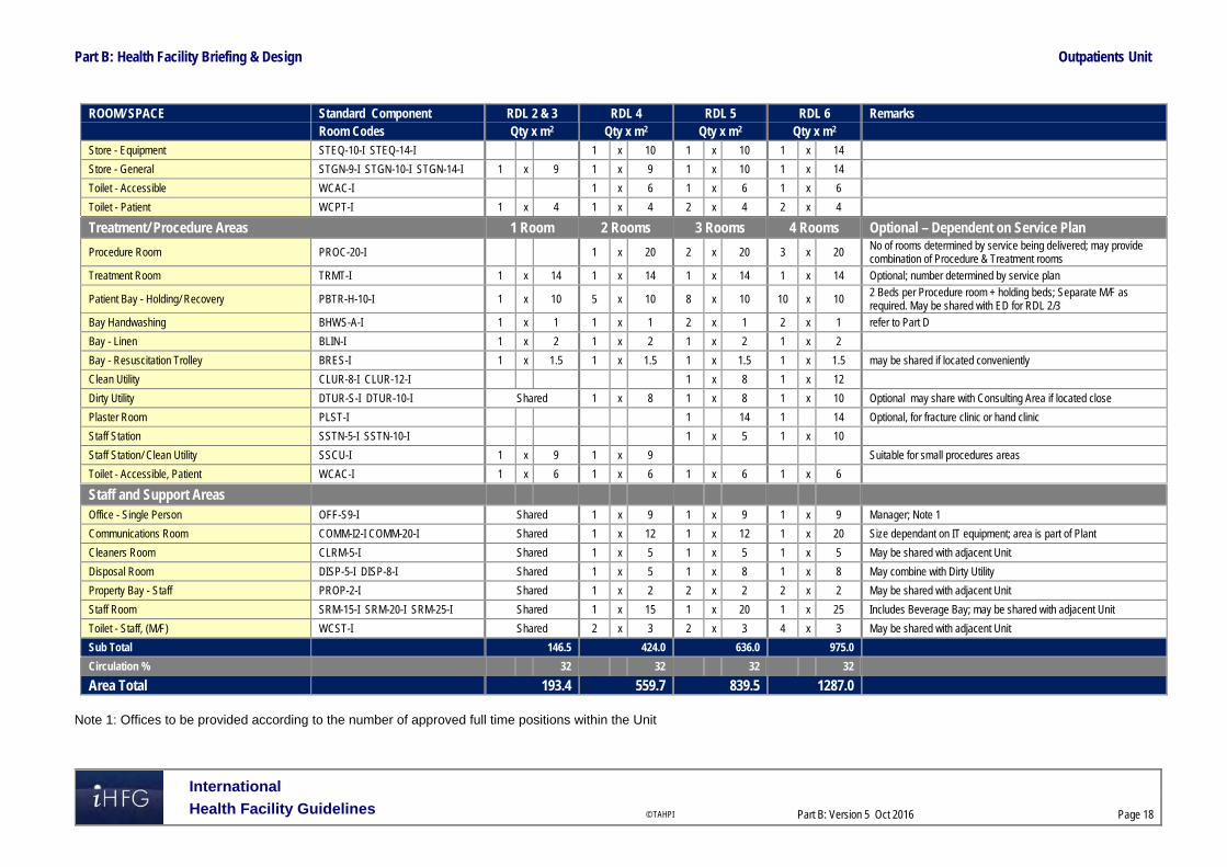
Part B: Health Facility Briefing & Design Outpatients Unit
International
Health Facility Guidelines © TAHPI
Part B: Version 5 Oct 2016
Page 18
ROOM/ SPACE Standard Component RDL 2 & 3 RDL 4 RDL 5 RDL 6 Remarks Room Codes Qty x m2 Qty x m2 Qty x m2 Qty x m2 Store - Equipment STEQ-10-I STEQ-14-I 1 x 10 1 x 10 1 x 14
Store - General STGN-9-I STGN-10-I STGN-14-I 1 x 9 1 x 9 1 x 10 1 x 14
Toilet - Accessible WCAC-I 1 x 6 1 x 6 1 x 6
Toilet - Patient WCPT-I 1 x 4 1 x 4 2 x 4 2 x 4
Treatment/ Procedure Areas 1 Room 2 Rooms 3 Rooms 4 Rooms Optional – Dependent on Service Plan
Procedure Room PROC-20-I 1 x 20 2 x 20 3 x 20 No of rooms determined by service being delivered; may provide combination of Procedure & Treatment rooms
Treatment Room TRMT-I 1 x 14 1 x 14 1 x 14 1 x 14 Optional; number determined by service plan
Patient Bay - Holding/ Recovery PBTR-H-10-I 1 x 10 5 x 10 8 x 10 10 x 10 2 Beds per Procedure room + holding beds; Separate M/F as required. May be shared with ED for RDL 2/3
Bay Handwashing BHWS-A-I 1 x 1 1 x 1 2 x 1 2 x 1 refer to Part D
Bay - Linen BLIN-I 1 x 2 1 x 2 1 x 2 1 x 2
Bay - Resuscitation Trolley BRES-I 1 x 1.5 1 x 1.5 1 x 1.5 1 x 1.5 may be shared if located conveniently
Clean Utility CLUR-8-I CLUR-12-I 1 x 8 1 x 12
Dirty Utility DTUR-S-I DTUR-10-I Shared 1 x 8 1 x 8 1 x 10 Optional may share with Consulting Area if located close
Plaster Room PLST-I 1 14 1 14 Optional, for fracture clinic or hand clinic
Staff Station SSTN-5-I SSTN-10-I 1 x 5 1 x 10
Staff Station/ Clean Utility SSCU-I 1 x 9 1 x 9 Suitable for small procedures areas
Toilet - Accessible, Patient WCAC-I 1 x 6 1 x 6 1 x 6 1 x 6
Staff and Support Areas Office - Single Person OFF-S9-I Shared 1 x 9 1 x 9 1 x 9 Manager; Note 1
Communications Room COMM-I2-I COMM-20-I Shared 1 x 12 1 x 12 1 x 20 Size dependant on IT equipment; area is part of Plant
Cleaners Room CLRM-5-I Shared 1 x 5 1 x 5 1 x 5 May be shared with adjacent Unit
Disposal Room DISP-5-I DISP-8-I Shared 1 x 5 1 x 8 1 x 8 May combine with Dirty Utility
Property Bay - Staff PROP-2-I Shared 1 x 2 2 x 2 2 x 2 May be shared with adjacent Unit
Staff Room SRM-15-I SRM-20-I SRM-25-I Shared 1 x 15 1 x 20 1 x 25 Includes Beverage Bay; may be shared with adjacent Unit
Toilet - Staff, (M/F) WCST-I Shared 2 x 3 2 x 3 4 x 3 May be shared with adjacent Unit
Sub Total 146.5 424.0 636.0 975.0
Circulation % 32 32 32 32
Area Total 193.4 559.7 839.5 1287.0
Note 1: Offices to be provided according to the number of approved full time positions within the Unit

Part B: Health Facility Briefing & Design Outpatients Unit
International
Health Facility Guidelines © TAHPI
Part B: Version 5 Oct 2016
Page 19
Outpatients Unit - Stand-alone The following Schedule of Accommodation includes both combined and separate Consult/ Examination Rooms.
ROOM/ SPACE Standard Component RDL 2 & 3 RDL 4 RDL 5 RDL 6 Remarks Room Codes N/A Qty x m2 Qty x m2 Qty x m2
Entry / Reception 6 Rooms 12 Rooms 18 Rooms Airlock - Entry AIRLE-6-I AIRLE-10-I 1 x 6 1 x 10 1 x 10
Reception/ Clerical RECL-9-I RECL-15-I RECL-20-I 1 x 9 1 x 15 1 x 20 May include space for self-registration of patients
Waiting WAIT-10-I WAIT-15-I WAIT-25-I 1 x 10 1 x 15 1 x 25 May be divided into Female/ Family areas as applicable Part may be provided as Sub Waiting near Consult rooms
Waiting - Family WAIT-10-I WAIT-15-I WAIT-25-I 1 x 10 1 x 15 1 x 25
Play Area PLAP-8-I PLAP-10-I 1 x 8 1 x 10 1 x 10
Bay - Wheelchair Park BWC-I 1 x 4 1 x 4 1 x 4 May share with Main facility if located close
Bay - Drinking Fountain BFD-1-I 1 x 1 1 x 1 1 x 1
Interview Room - Family INTF-I 1 x 12 1 x 12 2 x 12
Store - Files STFS-8-I STFS-10-I 1 x 8 1 x 10 1 x 10 For clinical records; optional if electronic records used
Toilet - Accessible WCAC-I 1 x 6 1 x 6 1 x 6 May share with Main facility if located close
Toilet - Public WCPU-3-I 2 x 3 2 x 3 2 x 3 May share with Main facility if located close
Consult Areas 6 Rooms 12 Rooms 18 Rooms Consult Room CONS-I 6 x 14 12 x 14 9 x 14 Combined Consult/ Examination Room
Consult - Office CONS-I 9 x 14 Separate Consult/ Office and Examination rooms
Examination Room CONS-I 9 x 14 Separate Consult/ Office and Examination rooms
Interview Room - Family INTF-I 1 x 12 1 x 12 1 x 12 Also for Allied Health use
Meeting Room - Small MEET-9-I 1 x 9 1 x 9 1 x 9 Optional; Interviews, private discussions, team meetings
Vital Signs Room NS 1 x 8 2 x 8 2 x 8
Bay - Handwashing, Type B BHWS-B-I 2 x 1 3 x 1 4 x 1 In corridors and staff work areas
Bay – Linen BLIN-I 1 x 2 1 x 2 1 x 2
Bay - Mobile Equipment BMEQ-4-I 1 x 4 2 x 4 2 x 4 For scales, lifting equipment
Bay - Resuscitation Trolley BRES-I 1 x 1.5 1 x 1.5 1 x 1.5
Blood Collection Bay BLDC-5-I 1 x 5 1 x 5 2 x 5 Optional; may use a shared facility if located close
Clean-up Room CLUP-7-I 1 x 7 1 x 7 1 x 7 Optional may use Dirty Utility
Clean Utility CLUR-8-I CLUR-12-I CLUR-14-I 1 x 8 1 x 12 1 x 14
Dirty Utility DTUR-S-I DTUR-10-I DTUR-12-I 1 x 8 1 x 10 1 x 12
Staff Station SSTN-5-I SSTN-10-I SSTN-14-I 1 x 5 1 x 10 1 x 14 May be provided as small sub stations to a group of rooms

Part B: Health Facility Briefing & Design Outpatients Unit
International
Health Facility Guidelines © TAHPI
Part B: Version 5 Oct 2016
Page 20
ROOM/ SPACE Standard Component RDL 2 & 3 RDL 4 RDL 5 RDL 6 Remarks Room Codes N/A Qty x m2 Qty x m2 Qty x m2 Store - Equipment STEQ-10-I STEQ-14-I 1 x 10 1 x 10 1 x 14
Store - General STGN-9-I STGN-10-I STGN-14-I 1 x 9 1 x 10 1 x 14
Toilet - Accessible WCAC-I 1 x 6 1 x 6 1 x 6
Toilet - Patient WCPT-I 1 x 4 2 x 4 2 x 4
Treatment/ Procedure Areas 2 Rooms 3 Rooms 4 Rooms Optional – Dependent on Service Plan
Procedure Room PROC-20-I 1 x 20 2 x 20 3 x 20 No of rooms determined by service being delivered; may provide combination of Procedure & Treatment rooms
Treatment Room TRMT-I 1 x 14 1 x 14 1 x 14 Optional; number determined by service plan
Patient Bay - Holding/ Recovery PBTR-H-10-I 5 x 10 8 x 10 10 x 10 2 Beds per Procedure room + holding beds; Separate M/F as required. May be shared with ED for RDL 2/3
Bay Handwashing BHWS-A-I 1 x 1 2 x 1 2 x 1 refer to Part D
Bay - Linen BLIN-I 1 x 2 1 x 2 1 x 2
Bay - Resuscitation Trolley BRES-I 1 x 1.5 1 x 1.5 1 x 1.5 may be shared with Consulting area if located conveniently
Clean Utility CLUR-8-I CLUR-12-I 1 x 8 1 x 12
Dirty Utility DTUR-S-I DTUR-10-I 1 x 8 1 x 8 1 x 10 Optional may share with Consulting Area if located close
Plaster Room PLST-I 1 14 1 14 Optional, for fracture clinic or hand clinic
Staff Station SSTN-5-I SSTN-10-I 1 x 5 1 x 10
Staff Station/ Clean Utility SSCU-I 1 x 9 Suitable for small procedures areas
Toilet - Accessible, Patient WCAC-I 1 x 6 1 x 6 1 x 6
Staff and Support Areas Office - Single Person, 12m2 OFF-S12-I 1 x 12 1 x 12 1 x 12 Service Director; Note 1
Office - Single Person OFF-S9-I 1 x 9 1 x 9 1 x 9 Manager; Note 1
Office - 2 Person, Shared OFF-2P-I 1 x 12 1 x 12 1 x 12 Note 1
Communications Room COMM-I2-I COMM-20-I 1 x 12 1 x 12 1 x 20 Size dependant on IT equipment
Cleaners Room CLRM-5-I 1 x 5 1 x 5 1 x 5
Disposal Room DISP-5-I DISP-8-I 1 x 5 1 x 8 1 x 8 May combine with Dirty Utility
Linen Holding - Clean DISP-8-I DISP-10-I 1 x 8 1 x 10 1 x 10
Linen Holding - Dirty DISP-5-I DISP-8-I 1 x 5 1 x 8 1 x 8
Loading Dock LODK-I 1 x 15 1 x 15 1 x 20
Property Bay - Staff PROP-2-I 1 x 2 2 x 2 2 x 2
Staff Room SRM-15-I SRM-20-I SRM-25-I 1 x 15 1 x 20 1 x 25 Includes Beverage Bay; may be shared with adjacent Unit
Store - Gas Bottle STGB-F-I 1 x 10 1 x 10 1 x 10 Optional, provide if medical gases required
Store - Files STFS-10-I STFS-20-I 1 x 10 1 x 10 1 x 20 medical records; optional if electronic records implemented

Part B: Health Facility Briefing & Design Outpatients Unit
International
Health Facility Guidelines © TAHPI
Part B: Version 5 Oct 2016
Page 21
ROOM/ SPACE Standard Component RDL 2 & 3 RDL 4 RDL 5 RDL 6 Remarks Room Codes N/A Qty x m2 Qty x m2 Qty x m2 Toilet - Staff, (M/F) WCST-I 2 x 3 2 x 3 4 x 3 May be shared with adjacent Unit
Waste Holding/ Recyclables WACO-I (Similar) 1 x 15 1 20 1 x 25
Sub Total 517.0 743.0 1102.0
Circulation % 32 32 32
Area Total 682.4 980.8 1454.6
Note 1: Offices to be provided according to the number of approved full time positions within the Unit
The following notes apply to all above Schedules of Accommodation: Areas noted in Schedules of Accommodation take precedence over all other areas noted in the FPU. Rooms indicated in the schedule reflect the typical arrangement according to the Role Delineation. Exact requirements for room quantities and sizes will reflect Key Planning Units identified in the Service Plan and the Operational Policies of the Unit. Room sizes indicated should be viewed as a minimum requirement; variations are acceptable to reflect the needs of individual Unit. Office areas are to be provided according to the Unit role delineation and number of endorsed full time positions in the unit. Staff and support rooms may be shared between Functional Planning Units dependent on location and accessibility to each unit and may provide scope to reduce duplication of
facilities.
.

Part B: Health Facility Briefing & Design Outpatients Unit
International
Health Facility Guidelines © TAHPI
Part B: Version 5 Oct 2016
Page 22
6 Future Trends Aging populations and increasing chronic diseases are projected to lead to more frequent patient visits to outpatient/ ambulatory care facilities. Advances in technology will continue to enable non-invasive procedures and treatments to deliver effective healthcare into more outpatient/ ambulatory settings. Integration of wellness programs into outpatient/ ambulatory care settings to align disease prevention, research and education with site based clinical specialties. Outpatients/ ambulatory care centres are expected to become super specialised and benefit from grouping of medical specialties to allow patients to source all services from one ambulatory model, maximizing capital expenses and extending efficiencies. Telehealth services will offer access to medical expertise that may be unavailable locally. Remote area monitoring and communication conducted through interactive video telemedicine and teleconferencing services may lead to reduced outpatient attendances while promoting preventative medical information. Contemporary and improved healthcare facility designs encourage patient independence with simple layouts, clear uncomplicated routes, visual cues, check-in centres and effective signage. 7 Further Reading American Institute of Architects, John Barker AIA, MCARB, Ed Pocock AIA, & Charles Huber,
Hobbs & Black Associates Inc. ‘The Future of Ambulatory Care’ refer to website: http://www.aia.org/practicing/groups/kc/AIAB086508
Australasian Health Facility Guidelines, Australasian Health Infrastructure Alliance, HPU B.0155 Ambulatory Care Unit (2016) https://healthfacilityguidelines.com.au/health-planning-units
Guidelines for Design and Construction of Health Care Facilities, The Facilities Guidelines Institute, 2014; refer to website www.fgiguidelines.org
Gov.UK Department of Health (DH) Out-patient care Health Building Note 12-01: Consulting, examination and treatment facilities (2008); refer to website https://www.gov.uk/government/uploads/system/uploads/attachment_data/file/142892/HBN_12-01_SuppA_DSSA.pdf
Gov.UK Department of Health (DH) Primary and community care Health Building Note 11-01: Facilities for primary and community care services (2009), refer to website: https://www.england.nhs.uk/mids-east/wp-content/uploads/sites/7/2014/07/health-build-pc.pdf
Part B – Health Facility Briefing & Design 255 Pharmacy Unit
International Health Facility Guidelines Version 4 February 2014

Pharmacy Unit
International
Health Facility Guidelines © TAHPI
Part B: Version 4 2014
Page 2
Table of Contents
255 Pharmacy Unit ........................................................................................................................... 3 1 Introduction ............................................................................................................................................... 3 2 Planning ..................................................................................................................................................... 3 3 Design ........................................................................................................................................................ 6 4 Components of the Unit ............................................................................................................................ 8 5 Schedule of Accommodation – Pharmacy Unit ...................................................................................... 9 6 Functional Relationship Diagram – Pharmacy Unit ............................................................................. 11 7 References and Further Reading ........................................................................................................... 12

Pharmacy Unit
International
Health Facility Guidelines © TAHPI
Part B: Version 4 2014
Page 3
255 Pharmacy Unit 1 Introduction Description The purpose of the Pharmacy Unit is to provide all inpatient and outpatient pharmacy services including dispensing, preparation of non-sterile and sterile commodities as required, conducting clinical trials as needed, reporting on adverse drug reactions, and providing drug information and education. The size and type of service to be provided in the Pharmacy Unit will depend upon the type of drug distribution system used, number of patients to be served, and extent of shared or purchased services. This shall be described in the Operational Policy of the Unit. Facilities (including satellite, if applicable) and equipment shall be as necessary to accommodate the requirements of the Operational Policy. If unit dose procedure is used, provide additional space and equipment for supplies, packaging, labelling, and storage, as well as for the carts. Relevant local authority statutory requirements are to be complied with. 2 Planning Operational Models A Pharmacy may extend its service from a single health care facility to outlying facilities. Specific design requirements for packing, storage and dispatch of goods shall be considered for different operational models.
Unit Dose Systems
The unit dosage system involves packaging of each dose of each medication for patients in a blister pack to provide easy and uniform medication dispensing. For a unit dosage system, the Pharmacy must include additional space and equipment for supplies, packaging, labelling and storage.
Private Pharmacy
If a private Pharmacy is also to be provided within the hospital’s retail area, the hospital’s operational policy shall determine the type of prescription drugs to be supplied by the private Pharmacy. It shall also study the impact it has on the main Pharmacy in relation to outpatient dispensing. Planning Models
Dedicated Outpatient Pharmacy
In facilities where the main Pharmacy cannot be located in a position readily accessible to the outpatients areas due to site constraints, then a separate Outpatient Pharmacy may be provided. This arrangement may result in duplication of services, equipment and support facilities.
Satellite Pharmacy Units
Satellite Pharmacy Units refer to a series of rooms/ suites in a hospital which is remotely positioned from the main Pharmacy and yet managed by the staff of the main Pharmacy. This may include for example, a dedicated Cytotoxic Unit within a Cancer Day Care Unit or an After-hours Drug store.
Unit/ Department-Based Pharmacy Areas
This refers to medication areas located within an Inpatient Unit and may include automated dispensing. Unit based facilities may be located within the Clean Utility or dedicated Medication

Pharmacy Unit
International
Health Facility Guidelines © TAHPI
Part B: Version 4 2014
Page 4
Rooms in Inpatient Units. Facilities will include secured drug storage, refrigerated drug storage, space for medication trolleys and computer access for pharmacy personnel. Functional Areas The functional areas of a Pharmacy Unit may be sub-divided into two types – “restricted” and “accessible” as follows:
Restricted Areas
Dispensing Areas which may include separate areas for inpatients and ambulatory patients (outpatients)
Preparation and manufacturing areas of non-sterile goods Active store for imprest stock storage, including assembly and dispatch areas with space
allocated for trolley parking Bulk stores including unpacking area Secured stores for accountable drugs, refrigerated stores and flammable goods storage Dispatch area for deliveries to inpatient units Drug information areas Staff areas including Offices, Workstations, Meeting Rooms, Staff Room, Change and Toilets
Accessible Areas
Reception and Waiting areas for outpatients; it is possible to share waiting areas with an adjoining unit
Patient counselling and consult areas After-hours drug store for access only by authorised personnel and direct entry from outside
the main Pharmacy Unit if located within; this room can also be located within a 24-hour zone of the hospital
Optional Areas
Depending on the Role Delineation and Operational Policy, the Pharmacy may also include: Sterile Manufacturing, which may include sterile and cytotoxic manufacturing suites, along
with support facilities including Anterooms, Change Rooms and Storage Facilities for clinical trials, which may include dispensing areas, secured storage and records
area and workstations Extemporaneous manufacturing area which requires extra space for compounding products
Sterile Preparation Area
Sterile preparation area refers to either Cleanroom facilities housing clean workstations fitted with laminar cabinets or other types of pharmaceutical isolators to meet relevant standard. This includes cytotoxic suites.
Manufacturing Area
The following minimum elements shall be included if manufacturing is performed on-site: Bulk compounding area Provision of packaging and labelling area Quality control area.
Dispensing Stations (Automated)
An automated Dispensing Station may be provided on an Inpatient or Critical Care Unit to dispense prescriptions for patients in that Unit. The Dispensing Station remains under the control of the Pharmacy Unit. An automated Dispensing Station should be equipped with: Automated Dispensing units and refrigerated dispensing units as required; installation
according to manufacturer’s specifications Shelving for reference texts Lighting level adequate for drug preparation areas Hand-washing facilities in close proximity

Pharmacy Unit
International
Health Facility Guidelines © TAHPI
Part B: Version 4 2014
Page 5
Bench for drug preparation adjacent to dispensing units
Satellite Pharmacy
A Pharmacy Unit Satellite is a room or unit in a hospital that is located remote from the Pharmacy Unit. A Satellite Pharmacy requires: Bench and sink of stainless steel or other impervious material, supplied with hot and cold
water Dispensing bench of stainless steel or impervious material; sized according to requirement
for dispensing, labelling and packaging Computer workstations according to number of Pharmacists in the Satellite unit An area for counselling of clients about dispensed or other medicines so that privacy can be
assured Adequate lighting and ventilation for drug preparation and dispensing Air temperature and humidity control suitable to the storage of drugs and medicines Handwashing basin and fittings. The Satellite Pharmacy must be: Constructed to prevent unauthorised access by persons other than staff through doors,
windows, walls and ceilings Fitted with a security intrusion detector alarm that is control room monitored to a central
agency on a 24 hour basis.
Storage
The following minimum elements, in the form of cabinets, shelves, and/or separate rooms or closets, shall be included as required: Bulk storage Active storage Refrigerated storage Volatile fluids and alcohol storage with construction as required by the relevant regulations
for substances involved Secure storage for narcotics and controlled drugs Storage for general supplies and equipment not in use. Storage for prescriptions and any documents required by relevant legislation
Clinical Trials Dispensing
The Clinical Trials Dispensing area will include storage, dispensing, packaging, labelling and records holding for clinical trials drugs. The Clinical Trials facilities will be a separate area within the main Pharmacy. Clinical Trials storage, preparation and dispensing will be located in a separate area within the Pharmacy, and will have ready access to patient Interview and Consultation rooms. Clinical Trials drugs/medications area will require the following considerations: Workspace with computer for Pharmacist Preparation bench and sink Lockable storage for clinical trials drugs, separate from other Pharmacy supplies Lockable records storage Staff Handwashing basin should be located in close proximity
Aseptic Room (Sterile Manufacturing)/ Cytotoxic Room (Cytotoxic Manufacturing)
The Aseptic Room and the Cytotoxic Room are Clean Rooms for manufacturing of medications in a sterile environment. The room will contain laminar flow cabinets and or isolators for sterile manufacturing. The room will be positive pressure and be accessed via an Anteroom. An external outlook is desirable.

Pharmacy Unit
International
Health Facility Guidelines © TAHPI
Part B: Version 4 2014
Page 6
It shall be located on the perimeter of the facility with an external outlook with access via and Anteroom. The following features shall be considered while designing sterile manufacturing facility: Electronic door management system to prevent the opening of both doors in the Anteroom at
the same time. Handwashing facilities shall be provided immediate outside the Aseptic (Clean) Rooms in
adjoining Anteroom; hand basins are not to be located within the Aseptic (Clean) Rooms. Provide an intercom system shall be provided between Aseptic (Clean) Rooms and
Anteroom High-resolution CCTV cameras for remote monitoring Comply with room requirements in relevant international Clean Room standards for sterile
and cytotoxic manufacturing.
Store - Refrigeration
This can be a room/ bay which consist of multiple refrigerators for storing specific medications. Alternatively, a commercial grade cool room can also be used. This shall be located in proximity to assembly/ preparation area and other storage area within the Unit. Refrigerated storage areas in the Pharmacy will require the following considerations: all access doors (either to room or refrigerators) shall be lockable temperature monitoring system installed and connect to a centralised alarm/ warning system Functional Relationships
External
The Pharmacy Unit shall be located for convenient access, staff control, and security. Direct access to loading dock and bulk storage is required if not located within the main Pharmacy Unit.
Internal
Access points provided for the following personnel/ purpose shall be carefully considered: Visitors to the Unit Pharmacy Staff Non-Pharmacy staff to collect prescriptions and medications Delivery and prescription collection for outpatients Supplies delivery An interview room for outpatients when provided shall have dual access – separate entries from public area and staff area. Access shall be controlled from inside of the Pharmacy. Corridors and door openings shall provide sufficient clearance for large items and equipment from bulk stores. 3 Design General Design may include provisions for barcode technology for patient prescription identification and tracking as well as electronic prescribing, which will require computer and scanning equipment including additional power and data outlets. Environmental Considerations
Natural Light
Natural light is highly desirable within the Unit as well as windows permitting outside views. However, such provisions shall not compromise the security of the Unit. Unauthorised entry and
Pharmacy Unit
International
Health Facility Guidelines © TAHPI
Part B: Version 4 2014
Page 7
maintaining privacy of the operations of the Unit are the primary concerns in the design of the Unit. Windows shall not permit casual viewing from any adjacent public thoroughfare.
Privacy
Privacy shall be considered in patient consultation areas.
Acoustics
Patient interview and counselling rooms will require acoustic treatment. Space Standards and Components
Ergonomics
Storage systems selected within the Unit shall be accessible to all types of staff. Refer also to Part C of these Guidelines. Safety and Security Pharmacy Units and Pharmacies are required to be constructed so as to be as secure as practicable from unauthorised access through doors, windows, walls and ceilings, and to be fitted with a security intrusion detector alarm which is control room monitored to a central agency on a 24 hour basis. Security measures for consideration will include: Electronic door controls Movement sensors Duress alarms to Dispensing counters Security glazing or shutters to Dispensing counters Accountable Drugs Stores/ Safe shall not be placed in a room positioned on the perimeter of the premises or adjoining a staircase. Finishes Wall protection shall be installed to prevent damage to walls caused by all types of trolleys. Refer also to Part C of these Guidelines. Fixtures and Fittings Refer to Part C of these Guidelines and Standard Components for requirements related to fixtures and fittings. Building Service Requirements Refer to Part E of these Guidelines.
HVAC
All drug storage areas shall have temperature and humidity controls; internal room temperature shall be kept below 25oC. Infection Control Hand-washing facilities shall be provided within each separate room where open medication is handled. Sterile Suites must have scrub facilities. Refer also to Part D of these Guidelines.

Pharmacy Unit
International
Health Facility Guidelines © TAHPI
Part B: Version 4 2014
Page 8
4 Components of the Unit The Pharmacy Unit will contain Standard Components to comply with details described in these Guidelines. Refer also to Standard Components Room Data Sheets and Room Layout Sheets.

Pharmacy Unit
International
Health Facility Guidelines © TAHPI
Part B: Version 4 2014
Page 9
5 Schedule of Accommodation – Pharmacy Unit Main Pharmacy
ROOM/ SPACE Standard Level 3 Level 4 Level 5 Level 6 Remarks Component Qty x m2 Qty x m2 Qty x m2 Qty x m2 WAITING WAIT-SUB-I 2 x 5 2 x 5 2 x 10 2 x 10 Separate Male/female areas WAIT-10-I PHARMACY COUNTER PHA-CO-I 1 x 9 1 x 9 1 x 20 1 x 20 Includes shelving for scripts; dedicated staff entry MEETING ROOM – SMALL, 9M2 MEET-9-I 1 x 9 1 x 9 1 x 9 1 x 9 AFTER HOURS DRUGS STORE AHDR-I 1 x 4 1 x 4 1 x 4 OFFICE – SINGLE PERSON OFF-S9-I 1 x 9 1 x 9 1 x 12 1 x 12 (DIRECTOR) OFF-S12-I OFFICE – SINGLE PERSON, 9M2 OFF-S9-I 1 x 9 1 x 9 2 x 9 2 x 9 (DRUG INFORMATION) OFFICE – WORKSTATION OFF-WS-I 1 x 5.5 2 x 5.5 4 x 5.5 6 x 5.5 Qty depends on staffing establishment ASSEMBLY/ PREPARATION ASPR-20-I 1 x 6 1 x 10 1 x 20 1 x 30 Allow 3m2 per pharmacist (PHARMACY) ASPR-30-I station BAY – EMERGENCY SHOWER BES-I 1 x 1 2 x 1 for emergency use BAY – HANDWASHING, TYPE B BHWS-B-I 2 x 1 3 x 1 4 x 1 4 x 1 CLEANER’S ROOM, 5M2 CLRM-5-I 1 x 5 1 x 5 1 x 5 1 x 5 COOL ROOM CORM-I 2 x 10 2 x 10 DISPENSING - CLINICAL TRIALS 1 x 12 1 x 12 Optional GOODS RECEIPT - PHARMACY GRE-I 1 x 5 1 x 5 1 x 15 1 x 15 Could be located in Supply similar unit or receiving dock PREPARATION ROOM - NON STERILE PREP-I 1 x 12 1 x 18 2 x 12 3 x 12 Based on 3m2 per person (PHARMACY) similar optional STORE - BULK STBK-20-I 1 x 20 1 x 40 1 x 100 1 x 150 May include pallets; includes STBK-40-I area for holding/dispatch STORE - BULK (IV FLUIDS) STBK-20-I 1 x 20 1 x 20 May be part of the Bulk store STORE -DRUGS STDR-5-I 1 x 5 1 x 5 1 x 10 1 x 10 High security storage safe for STDR-10-I controlled substances STORE - FILES STFS-8-I 1 x 8 1 x 8 1 x 10 1 x 20 including documents required STFS-20-I by regulations STORE - GENERAL STGN-6-I 1 x 6 1 x 8 1 x 10 Dispensing supplies STGN-10-I STORE - REFRIGERATION 1 x 6 1 x 6 Bay with drug fridges
Staff Areas
ROOM/ SPACE Standard Level 3 Level 4 Level 5 Level 6 Remarks Component Qty x m2 Qty x m2 Qty x m2 Qty x m2 BAY – BEVERAGE, OPEN PLAN BBEV-OP-I 1 x 4 1 x 4 1 x 4 1 x 4 Can be included in meeting room MEETING ROOM MEET-L-15-I shared 1 x 15 1 x 20 1 x 25 MEET-L-25-I OFFICE – WORKSTATION OFF-WS-I 1 x 5.5 2 x 5.5 3 x 5.5 According to staff (PHARMACISTS) establishment PROPERTY BAY – STAFF PROP-2-I 2 x 2 2 x 2 3 x 3 4 x 3 Separate Male/female areas PROP-3-I STORE – PHOTOCOPY/STATIONERY, STPS-8-I 1 x 8 1 x 8 1 x 8 8M2 STAFF ROOM SRM-15-I 2 x 15 2 x 15 2 x 20 2 x 20 Includes beverage bay SRM-20-I TOILET – STAFF WCST-I 2 x 3 2 x 3 4 x 3 4 x 3 Separate Male/female areas

Pharmacy Unit
International
Health Facility Guidelines © TAHPI
Part B: Version 4 2014
Page 10
ROOM/ SPACE Standard Level 3 Level 4 Level 5 Level 6 Remarks Component Qty x m2 Qty x m2 Qty x m2 Qty x m2 CIRCULATION ALLOWANCE 25% 25% 25% 25%
Sterile Manufacturing (For 2 Rooms)
ROOM/ SPACE Standard Level 3 Level 4 Level 5 Level 6 Remarks Component Qty x m2 Qty x m2 Qty x m2 Qty x m2 AIRLOCK AIRL-6-I 2 x 6 2 x 6 ANTEROOM ANRM-I 1 x 8 1 x 12 For scrubbing and gowning similar ASEPTIC CLEAN ROOM 1 x 20 1 x 20 Comply with international clean room standards CHANGE – STAFF (MALE/FEMALE) CHPT-10-I 2 x 8 2 x 8 Separate Male/female areas similar CYTOTOXIC CLEAN ROOM 1 x 15 1 x 15 Comply with international clean room standards OFFICE – WORKSTATION OFF-WS-I 2 x 5.5 3 x 5.5 Qty determined by staff establishment STORE – STERILE STOCK STSS-12-I 1 x 7 1 x 7 similar CIRCULATION ALLOWANCE 25% 25%
Please note the following: Areas noted in Schedules of Accommodation take precedence over all other areas noted in
the FPU. Rooms indicated in the schedule reflect the typical arrangement according to the Role
Delineation. Exact requirements for room quantities and sizes will reflect Key Planning Units identified in
the Service Plan and the Operational Policies of the Unit. Room sizes indicated should be viewed as a minimum requirement; variations are acceptable
to reflect the needs of individual Unit. Office areas are to be provided according to the Unit role delineation and number of
endorsed fulltime positions in the unit. Staff and support rooms may be shared between Functional Planning Units dependant on
location and accessibility to each unit and may provide scope to reduce duplication of facilities.

Pharmacy Unit
International
Health Facility Guidelines © TAHPI
Part B: Version 4 2014
Page 11
6 Functional Relationship Diagram – Pharmacy Unit

Pharmacy Unit
International
Health Facility Guidelines © TAHPI
Part B: Version 4 2014
Page 12
7 References and Further Reading Australasian Health Facility Guidelines, Part B Health Facility Briefing and Planning, Rev 4,
2012; refer to website www.healthfacilitydesign.com.au Refer to DHA website for local licensing requirements www.dha.gov.ae and MOH website
www.moh.gov.ae for local approval procedures The Facility Guidelines Institute (US), 2010 Edition. Guidelines for Design and Construction
of Health Care Facilities) refer to website www.fgiguidelines.org

Part B – Health Facility Briefing & Design 260 Public & Staff Amenities Unit
International Health Facility Guidelines Version 4 May 2014

Public & Staff Amenities Unit
International
Health Facility Guidelines © TAHPI
Part B: Version 4 2014
Page 2
Table of Contents
260 Public & Staff Amenities Unit ................................................................................................... 3 1 Introduction ............................................................................................................................................... 3 2 Planning ..................................................................................................................................................... 3 3 Design ........................................................................................................................................................ 4 4 Components of the Unit ............................................................................................................................ 5 5 Schedule of Accommodation – Public & Staff Amenities Unit ............................................................. 6 6 Functional Relationship Diagram – Public & Staff Amenities Unit ....................................................... 8 7 References and Further Reading ............................................................................................................. 9

Public & Staff Amenities Unit
International
Health Facility Guidelines © TAHPI
Part B: Version 4 2014
Page 3
260 Public & Staff Amenities Unit 1 Introduction Description The Amenities Unit provides facilities for the convenience and comfort of staff and visitors to the hospital. Some of the amenities may optionally be used by patients who are permitted to access other areas of the hospital. 2 Planning Planning Models Amenities may be provided in a uniform configuration to Main Entry areas, public areas, staff areas and every level of the hospital, to ensure ease of access and consistency in location. Functional Areas The Amenities Unit will consist of the following Functional Areas: Public Toilets Parenting Rooms Staff Toilets Staff Change Rooms Staff Lounge Staff Overnight Rest/ Quiet Rooms Staff Study Area Disabled Toilets Bay for drinking water Prayer Rooms Ablutions Rooms
Public Toilets
Public Toilets should be located in a discreet area with ready access to Lifts and Waiting Areas. The number of toilets required will be based on the local building code requirements.
Parenting Rooms
Amenities should include access to baby change and parenting rooms for baby feeding. Separate Parenting Rooms should be provided for Staff & Public use. The Staff Parenting Room will be used by staff for expressing of milk.
Staff Change Rooms and Toilets:
Staff Change rooms will include staff showers and locker areas. Change rooms, toilets and locker areas shall be provided separately for Male and Female staff.
Staff Lounge
Staff Lounge is an area for staff to rest and eat their meals. The Lounge may be used for informal education sessions as required. The room may also include TV and computer area for staff use. Separate Staff Lounges may be provided for Medical Officers, Nurses and other hospital staff.
Staff Overnight Rest/ Quiet Rooms
Staff resting and quiet areas may be provided for staff that are required to be within the hospital facilities for prolonged periods of time e.g. staff on call, medical officers who worked overtime and are required to work a shift after a short period of rest. The rooms may also be used as a quiet area to relax and unwind after a stressful shift.

Public & Staff Amenities Unit
International
Health Facility Guidelines © TAHPI
Part B: Version 4 2014
Page 4
Staff Study Area
A quiet and relaxed study area may be provided for staff which will include workstations, computers, printers and books and journal shelves.
Prayer Rooms
Separate Male and Female Prayer rooms shall be provided, located in a discreet but accessible area. Provide Prayer Rooms may be required on every level of the building as required by local rules and regulations. Refer to Section 4-Planning-Local Design Regulations for Design Considerations for Prayer Rooms; refer to Standard Components for additional Prayer Room requirements. Non-denominational quiet room may be provided where Prayer Rooms are not required.
Ablutions Rooms
Ablutions Rooms shall be provided adjacent to Prayer Rooms for the appropriate washing of face, hands and feet.
Bay –Water Fountain
The Bay – Water Fountain provides a recessed area for a drinking water unit. Accessible height and children’s height water fountain in addition to standard water fountain should be considered. The bay will be located in public access areas close to Waiting areas. The Bay will include: Wall and floor finishes suitable for wet areas Drinking water fountain, with hydraulic connection to drinking water. Refillable water coolers
may also be used. Recurrent cost to the facility should be considered when choosing the water source.
Fittings may include a dispenser for cups and waste bin. Functional Relationships Public amenities should be located close to the Main Entrance with ready access to waiting areas and lifts. Amenities including Prayer Rooms will be required in public areas of the hospital for ease of access. Staff Amenities will generally be located away from public areas but centrally accessible by staff. 3 Design General The design of amenities should create a pleasant atmosphere for staff and visitors to the hospital, whilst retaining the necessary functional requirements. Consideration should be given to private and discreet entry areas for toilets and ablutions facilities. Environmental Considerations
Natural Light
Natural light is highly desirable where achievable, particularly for Prayer Rooms, Staff Lounges and rest areas.
Privacy
Privacy is essential for toilets and ablutions rooms, while providing ease of access.
Acoustics
Acoustic treatment will be required to all Prayer Rooms, Ablutions rooms, Toilets and Quiet rest areas.

Public & Staff Amenities Unit
International
Health Facility Guidelines © TAHPI
Part B: Version 4 2014
Page 5
Space Standards and Components Prayer Rooms, Ablutions rooms, Change areas, Toilets and Lounge Rooms should be sized to suit the numbers of persons requiring use of the facilities and allow safe and effective movement of people through the rooms. Safety and Security Staff Change and Locker areas shall be secured with electronic access. Finishes Floor finishes should be appropriate to the function of the space. Toilets and ablutions facilities should be tiled or vinyl floors with a suitable non-slip finish. Consideration must be given to the appearance and quality of environment required e.g. non-institutional, acoustic performance, slip resistance and infection control. Wall finishes, cabinetry and bench tops must be easily cleaned. Refer also to Part C of these Guidelines. Fixtures and Fittings Fittings and fixtures should be robust and allow heavy usage in public and staff areas. Building Service Requirements Amenities areas will require air conditioning with controlled humidity and temperature to provide a comfortable environment for visitors and staff. 4 Components of the Unit Patient and Staff Amenities will contain a combination of Standard Components. Provide Standard Components to comply with details in the Standard Components described in these Guidelines. Refer also to Standard Components Room Data Sheets and Room Layout Sheets.

Public & Staff Amenities Unit
International
Health Facility Guidelines © TAHPI
Part B: Version 4 2014
Page 6
5 Schedule of Accommodation – Public & Staff Amenities Unit Public & Staff Amenities Unit for Role Delineation Level 3, 4, 5 and 6
ROOM/ SPACE Standard Component RDL 3 RDL4 RDL 5 RDL 6 Remarks
Room Codes N/A N/A Qty x m2 Qty x m2
Public Areas
Bay - Water Fountain BWF-1-I 1 x 1 1 x 1 2 x 1 2 x 1 Accessible & child height water fountain to be considered
Toilet - Accessible WCAC-I 2 x 6 2 x 6 3 x 6 4 x 6 No. of toilets as required by local accessibility code requirements
Toilet - Public (Male/ Female) WCPU-4-I 2 x 4 4 x 4 6 x 4 8 x 4 No. of toilets as required by local building code requirements
Parenting Room PAR-I 1 x 6 1 x 6 1 x 12 1 x 12
Sub Total 27.0 35.0 56.0 70.0
Circulation % 10 10 10 10
Area Total 29.7 38.5 61.6 77.0 Staff Amenities
Change - Staff (Male/ Female) CHST-10-I CHST-14-I CHST-25-I CHST-35-I 2 x 10 2 x 14 2 x 25 2 x 35 May be provided in more than one location
Toilet - Accessible WCAC-I 1 x 6 2 x 6 2 x 6 2 x 6 No. of toilets as required by local accessibility code requirements
Toilet - Staff (Male/ Female) WCST-I 2 x 3 2 x 3 4 x 3 4 x 3 No. of toilets as required by local building code requirements; may be provided in more than one location
Parenting Room PAR-I (sim) 1 x 6 1 x 6 1 x 6 1 x 6
Lounge - Staff SRM-18-I SRM-25-I SRM-35-I SRM-50-I 1 x 18 1 x 25 1 x 35 1 x 50 May be provided in more than one location; size dependent on number of staff
Lounge - Medical Officers LNMO-20-I LNMO-25-I LNMO-35-I (sim) 1 x 20 1 x 25 1 x 35 Size dependent on number of staff
Bay - Handwashing, Type B BHWS-B-I 1 x 1 2 x 1 2 x 1 2 x 1 Locate in close proximity to Staff Lounges
Overnight Stay - Bedroom OVBR-I 1 x 10 1 x 10 2 x 10 3 x 10 No. dependent on service plan
Overnight Stay - Ensuite OVES-I 1 x 4 1 x 4 2 x 4 3 x 4
Library/ Study Area LSRA-40-I LSRA-50-I (sim) 1 x 40 1 x 50 Optional. May be provided in education block of the facility.
Sub Total 72.0 113.0 210.0 279.0
Circulation % 10 10 10 10
Area Total 79.2 124.3 231.0 306.9 Shared Areas
Prayer Room PRAR-20-I (sim) 2 x 15 2 x 15 2 x 20 2 x 20 Qty shown for separated Male & Female areas
Ablution Room ABLU-I (sim) 2 x 8 2 x 8 2 x 13 2 x 13 Qty shown for separated Male & Female areas
Sub Total 46.0 46.0 66.0 66.0
Circulation % 10 10 10 10
Area Total 50.6 50.6 72.6 72.6 Grand Total 159.5 213.4 365.2 456.5

Public & Staff Amenities Unit
International
Health Facility Guidelines © TAHPI
Part B: Version 4 2014
Page 7
Please note the following: Areas noted in Schedules of Accommodation take precedence over all other areas noted in the FPU. Rooms indicated in the schedule reflect the typical arrangement according to the Role Delineation. Exact requirements for room quantities and sizes will reflect Key Planning Units identified in the Service Plan and the Operational Policies of the Unit. Room sizes indicated should be viewed as a minimum requirement; variations are acceptable to reflect the needs of individual Unit. Office areas are to be provided according to the Unit role delineation and number of endorsed full time positions in the unit. Staff and support rooms may be shared between Functional Planning Units dependant on location and accessibility to each unit and may provide scope to
reduce duplication of facilities.

Public & Staff Amenities Unit
International
Health Facility Guidelines © TAHPI
Part B: Version 4 2014
Page 8
6 Functional Relationship Diagram – Public & Staff Amenities Unit

Public & Staff Amenities Unit
International
Health Facility Guidelines © TAHPI
Part B: Version 4 2014
Page 9
7 References and Further Reading Australasian Health Facility Guidelines, Part B Health Facility Briefing and Planning, Rev 4,
2012; refer to website www.healthfacilitydesign.com.au The Facility Guidelines Institute (US), 2010 Edition. Guidelines for Design and Construction
of Health Care Facilities) refer to website www.fgiguidelines.org

Part B – Health Facility Briefing & Design 265 Rehabilitation – Allied Health Unit
International Health Facility Guidelines Version 4 February 2014

Rehabilitation – Allied Health Unit
International
Health Facility Guidelines © TAHPI
Part B: Version 4 2014
Page 2
Table of Contents
265 Rehabilitation – Allied Health Unit ........................................................................................... 3 1 Introduction ............................................................................................................................................... 3 2 Planning ..................................................................................................................................................... 3 3 Design ...................................................................................................................................................... 10 4 Components of the Unit .......................................................................................................................... 12 5 Schedule of Accommodation – Rehabilitation – Allied Health Unit ................................................... 13 6 Functional Relationship Diagram - Rehabilitation – Allied Health Unit ............................................. 17 7 References and Further Reading ........................................................................................................... 18

Rehabilitation – Allied Health Unit
International
Health Facility Guidelines © TAHPI
Part B: Version 4 2014
Page 3
265 Rehabilitation – Allied Health Unit 1 Introduction Description The Rehabilitation – Allied Health Unit provides a multi-disciplinary rehabilitation service care in which the clinical intent or treatment goal is to improve the functional status of a patient with an impairment, disability or handicap. Facilities for Physiotherapy and Occupational Therapy will vary greatly, ranging from large, purpose-designed, central facilities for inpatients and/or outpatients, to basic on-ward or bedside services. Extent, design and location of facilities will be affected by presence or otherwise of the following services (not inclusive): Rehabilitation Medicine Aged Care Spinal Cord Injury Service Orthopaedic Services Neurosciences - (Strokes, Multiple Sclerosis, Traumatic Brain Injuries etc.) Amputees Hand Surgery / Plastic Services. Speech Pathology plays a major role in Neonatal, Paediatric, ENT / Maxillofacial and neurological services; in the absence of these, Speech Pathology may be provided on a part-time basis. Children’s Hospitals or major Paediatric Services generate their own specific spatial needs. At higher Role Delineation levels it is possible that each discipline may have its own discrete department but every attempt should be made to co-locate the therapy units to maximise the potential for sharing and to facilitate multidisciplinary care. The rehabilitation services will be supported by full time Social Work services. At Level 4, Dietetics and Podiatry are generally provided as part time services and can be incorporated into the Unit. At Levels 5 & 6 they will have their own discrete Units and are excluded from the Schedule of Accommodation at those levels. Clinical Psychology and Neuropsychology also play an important role in some aspects of service provision and will need their own or access to office/treatment areas. Patient Characteristics All ages from children to the frail aged may be treated. Almost all patients attending for physiotherapy are physically incapacitated to some extent many of whom use wheelchairs or walking aids and - increasingly - motorised chairs that have implications for parking and recharging. Many patients may be disfigured (burns, throat surgery etc.) and require a non-threatening, private environment. Patients may require access to interpreter services. 2 Planning Operation Models
Hours of Operation
The Unit will generally operate during business hours Monday to Friday with after-hours on-call physiotherapy services available for inpatient units as required. Some departments may provide a limited service at evenings and weekends. If used for health education classes (e.g. antenatal classes), after-hours access will be required. If a hydrotherapy pool is part of the facility, this too may be made available to the community after hours and at week-ends and therefore careful consideration will need to be given to location, controlled access and security.
Flexibility
The facilities of the Unit will be utilised by inpatients and outpatients. It is expected that the majority of inpatients accommodated in the Rehabilitation Inpatient Unit will attend the Unit on a

Rehabilitation – Allied Health Unit
International
Health Facility Guidelines © TAHPI
Part B: Version 4 2014
Page 4
daily basis. The function of these two units is inter-related and the design of the Rehabilitation Unit could provide areas common to both units. As with other areas of health care, rehabilitation services are constantly evolving. This is manifest in terms of: Clinical development - many more categories of patient are able to be rehabilitated than was
previously considered feasible Organisational development - the interrelationship of the various medical, nursing and allied
health services that participate in the rehabilitation process is of paramount importance Technological development - advances in technology have developed techniques which will
ultimately become routine aspects of rehabilitation. Such developments include kinematic analysis, electromyography and ergometry.
Models of Care
Traditionally the model of care has been one-to-one, therapist to patient. Increasingly an educative model is being used that assumes a staff to patient ratio of 1:4 or more and incorporates: Group sessions for peer support; Group exercise classes; Involvement of carers so that they can learn how much activity the patients can safely
tolerate at home and how best to support them; Education programmes. There may need to be separate areas for Respiratory and Cardiac Rehabilitation and general rehabilitation as the patients have differing needs and sometimes equipment. However this will depend on the number of sessions and every opportunity should be made to share areas between programmes.
Satellite Units
One of the problems of providing therapy services for inpatients within the Unit itself is transport to and from hospital units, particularly, for example, neuroscience patients whose attention span may be limited and who need a quiet environment. It also requires either a portering service or use of valuable therapist time in transport functions. If distance from inpatient units to the Rehabilitation therapy areas is considerable and throughput can justify, provision of a small satellite unit may be considered - mainly for physiotherapy - near the units most affected, usually Neuroscience & Orthopaedics. Or alternatively, a small therapy / multipurpose room in an inpatient unit may serve such a purpose.
Hydrotherapy
Whilst there are differing opinions as to the therapeutic benefits of hydrotherapy, a designated Rehabilitation service will probably require access to a hydrotherapy pool. However, in other circumstances, the need for a pool should be carefully considered as the cost per unit of treatment is high and conditions for which hydrotherapy is the only appropriate treatment are limited. Hydrotherapy pools should only be provided where patient numbers can be justified and where the pool is required for a minimum of four hours each days, five days a week. Utilisation of the pool may be extended by making the pool available to groups within the community for their use at times when it is not required for specific therapeutic purposes. Alternatively, use of a pool already established in the community may be used.
Gait Analysis Laboratory
Quantitative gait analysis is useful in objective assessment and documentation of walking ability as well as identifying the underlying causes of walking abnormalities in patients with cerebral palsy, stroke, head injury and other neuromuscular problems. The results of gait analysis have been shown to be useful in determining the best course of treatment in these patients. Equipment for gait analysis may be incorporated into a gymnasium.
Outdoor Gait Area
It is essential to provide mobility training on a range of uneven surfaces necessary for community integration.

Rehabilitation – Allied Health Unit
International
Health Facility Guidelines © TAHPI
Part B: Version 4 2014
Page 5
Operational Policies
General
Depending upon the needs of the individual hospital, it may be decided that the Rehabilitation Allied Health Unit will provide the location for the hospital's Acute Therapy Services. If such a Policy is adopted it may be necessary to upgrade the accommodation to provide: Additional therapy spaces for general acute inpatient and outpatient therapy Additional group office space for physiotherapists to write up notes Additional staff amenities. The Guideline defines functional spaces as discrete areas for defined activities. The Operational Policy of a facility may compel the design team to view the various functions and activities within the Unit from the framework of a team philosophy. Accordingly, patient flow would determine the definition of spaces rather than individual allied health discipline.
Outpatients versus Day Patients
The original “Day Hospital” concept often accommodated patients for respite care; in modern units patients are admitted for treatment, not respite. Patients attending for a single treatment by a single therapist are classified as outpatients. Patients attending for a series of treatments by different therapists will be admitted as day patients where stay is in excess of 4 hours. This latter category will need an area for rest and refreshment between treatments.
Medical Records & X-rays
Assuming a hard copy system, it is usual for non-inpatient records to be kept in the Unit for the duration of treatment. For a hard copy system, x-ray viewing boxes will be required and films requested from the Medical Imaging Unit. When records become electronic, there will be direct data entry and design should indicate likely locations for computers and allow for appropriate power and cabling. Assuming a digital PACS system, X-ray films are available on screen so viewing monitors will be needed.
Patient Lifting/ Transfers
Patient handling measures may include ceiling hoist systems for transfers from wheelchair to plinth, or mobile lifters. Mobile patient lifters will require bays with power for recharging. The Gymnasium should include additional space for holding lifting devices.
Recharging of Electrical Wheelchairs
Inpatients normally using electric wheelchairs or motorised chairs may need somewhere to park and recharge their equipment whilst in hospital. In inpatient and rehabilitation units where wheelchair use is significant, provide sufficient facilities to recharge patients’ electric wheelchairs and motorised chairs overnight including power outlets. Ideally wheelchair parking areas should not impede corridor space.
Specific Needs in Inpatient Units
To avoid unnecessary transport to and from the main unit, space and facilities for ward-based therapy could be considered. Include but not confined to: 10m corridor length for walking tests Storage for equipment & mobility aids Ward-based treatment space larger than the area around a patient’s bed Access to stairs for practising crutches Access to write-up area and storage of resource material.
Staffing
The staffing operational policy assumptions made in this guideline are: Office space will be provided where required for clerical and allied health staff including
workstations in open treatment areas for immediate documentation. “hot” desks will be available for students and visiting staff Staff wearing uniforms will arrive at the Unit in uniform however shower / change facilities will
be required for comfort reasons as much of the work is labour-intensive.

Rehabilitation – Allied Health Unit
International
Health Facility Guidelines © TAHPI
Part B: Version 4 2014
Page 6
The number of staff will depend on the needs of the individual hospital / service. Staff mix may include – either permanently or when required by referral: Director of Rehabilitation Medicine and/or the head of each therapy discipline Medical staff Nursing staff Physiotherapists Occupational therapists Social workers Speech pathologist Neuropsychologist (where brain impairment is an issue) Clinical psychologist (for treatment of complex behavioural disturbances) Prosthetists/ Orthotists Aides Podiatrist Sport & Recreational Officers Dieticians Diversional Therapist Vocational Trainers Case Co-Coordinators Rehabilitation Engineers Clerical staff Housekeeper and cleaning staff Artisan and transport staff. Students of various disciplines
Teaching
Most units will be involved with undergraduate and / or postgraduate training. Attendance will be variable. Students will need write-up space near the area of activity and numbers will need to be ascertained. Facilities will include a workstation for the supervisor and student lockers.
Emergency Equipment
Oxygen (wall panels or cylinders) for oxygen-dependent patients Cardiac monitor for cardiac patients Resuscitation trolley/s Medical gas service panels in selected locations for emergency use. Functional Areas The Rehabilitation – Allied Health services may include Dietetics, Hydrotherapy, Occupational Therapy, Physiotherapy, Podiatry, Psychology, Speech Pathology, and Social Work. The Rehabilitation – Allied Health Unit will include the following Functional Areas: Entry, Reception and Waiting areas Patient accommodation areas including Lounge and Dining areas Patient Therapy areas which may be shared Support areas including Utilities, Cleaner’s Room, Disposal, Pantry and Store Rooms Staff areas including Offices, Meeting Rooms, Staff Change and Toilets.
Occupational Therapy:
Where an Occupational Therapy service is to be provided the following functions or facilities shall be allowed for: Therapy areas Office / Administrative areas Hand-washing facilities Availability of Accessible Toilet

Rehabilitation – Allied Health Unit
International
Health Facility Guidelines © TAHPI
Part B: Version 4 2014
Page 7
Physiotherapy:
Where a Physiotherapy service is to be provided the following facilities shall be allowed for: Individual treatment area or areas that provide for patient privacy Staff hand-washing facilities close to each treatment space; this may serve several treatment
spaces An exercise area with facilities appropriate for the level of intended service Clean linen storage; in the form of built-in cupboards, cabinets or on mobile storage trolleys Storage for equipment and supplies Storage for soiled linen and waste Patient dressing and changing with secure storage of clothing and valuables, showering and
toilet facilities Ice-making facilities to be available in or near the department Wall oxygen in patient waiting areas depending on service mode, and access to appropriate
outdoor therapy areas.
Entry Areas:
The entry canopy is required to provide dry access to the building. Design considerations include: Ensuring the covered area is large enough to allow vehicles such as taxis, buses, cars, and
emergency vehicles to manoeuvre beneath it, and is structured to facilitate free concurrent traffic flow for multiple vehicles
The use of clear roofing material to maximise natural light inside the building. The external Entrance Area, best sited at ground floor level, is the first point of contact for members of the community and should display clear directions informing people where to proceed. Design considerations include: Vehicle access is required at all times Entry facilities should be suitable for people with disabilities, such as limited mobility and poor
vision The entry can incorporate an airlock space and may have sensor or automatically opening
doors to facilitate access.
Patient Lounge Areas:
A Lounge Area is required for therapeutic and social purposes. These include reading, writing and watching television or videos. The Lounge, Kitchenette and Dining Areas may be combined in a large Multi-purpose Day Room or in separate but adjacent areas.
Service Areas:
The service entry is required so that deliveries to the facility do not have to pass through the main entrance of the building. It may also provide ambulance service access and egress in emergency circumstances. Design considerations include: An area large enough to allow vehicles including ambulances to turn and manoeuvre A large space with blank wall space for temporary storage of items such as linen or food
trolleys, furniture or equipment for repair Access to soiled linen should only be available through the service entry or in large
institutions separate zones may be available for the various utilities and deliveries Adequate infection control A loading bay that gives access for delivery staff and staff loading equipment and mobility
aids into vehicles, located away from the client entry point.
Wheelchair Parking:
An area should be provided near the entrance for parking wheelchairs and electric scooters. The wheelchair parking area requires power outlets for recharging of electric wheelchairs and scooters when they are not in use. Cupboards may be provided over wheelchairs for additional storage.

Rehabilitation – Allied Health Unit
International
Health Facility Guidelines © TAHPI
Part B: Version 4 2014
Page 8
ADL Computer Room
The ADL Computer Room provides an area for activities of daily living (ADL) patient assessment and training for computer activities. A range of variable height computer desks will be included. Doors to this room are optional. The ADL computer room may be located adjacent to the ADL Lounge or other ADL assessment areas. Provide adjustable height computer workstations with the following: A variety of desktop and laptop computers Printer and telephone Power and data outlets for each
Bay – Drinking Water
The Bay – Drinking Water provides a recessed area for a drinking water unit. The bay will be located in public access areas close to Waiting areas. The Bay will include: Wall and floor finishes suitable for wet areas Drinking water fountain, with hydraulic connection to drinking water Fittings may include a dispenser for cups and waste bin.
Occupational Therapy/ Workshop Rooms
The Occupational Therapy Rooms are large spaces provided to enable a range of static and dynamic activities to take place. The rooms may include space for table based activities, such as upper limb activities or functional mobility activities such as woodwork or splinting activities in a workshop environment. The Rooms area will be sized according to the number of patients to be accommodated, the activities to be undertaken and will be dependent on Operational Policy and service demand. The Occupational Therapy area may be located adjacent to rehabilitation therapy areas, with ready access to waiting and amenities areas. Fittings and Equipment required in this area may include: Benches with inset sink, wheelchair accessible Shelving for storage of equipment or tools Tables, adjustable height Chairs, adjustable height Hand-washing basin with liquid soap and paper towel fittings Pin board and whiteboard for displays Sufficient GPOs for equipment or tools to be used in activity areas Workshop areas will require suitable air extraction and exhaust for woodwork activities.
Optical Shop
An Optical Shop is where clients and patients can have eye tests and purchase prescribed spectacles. It has a combined clinical and retail function. The Optical Shop shall be located near the main entry and among other retail outlets if provided within a larger facility. A glazed shop-front is recommended and shall be positioned next to the major traffic (main corridor). The following areas and functions shall be included in an optical shop: Large and well-lit open plan area with display cabinets including a small counter for cashier
and paperwork A consult room for eye test including slit lamp, light box (or projector for projected image),
handwashing basin, drug refrigerator etc.

Rehabilitation – Allied Health Unit
International
Health Facility Guidelines © TAHPI
Part B: Version 4 2014
Page 9
Workroom for fitting/ adjusting spectacles Facilities for disinfection, sterilisation and instruments reprocessing if required by the
Operational Policy An office for the optometrist (or can be part of the consult room if sufficient space is provided) Storage for spectacles, patient records, stationery etc. Access to toilet facilities (can be shared if located in a larger premise) Hydrotherapy Pool The need for a hydrotherapy pool should be carefully considered. The cost per unit of treatment is high and conditions for which hydrotherapy is the only appropriate treatment are limited. Hydrotherapy pools should only be provided where patient numbers are appropriate and where the pool is required for a minimum of four hours per day, five days per week.
Pool Size
The recommended pool size is 7500mm x 4500mm. A rectangular shape is recommended, with the length of the pool generally one and a half times the width.
Pool Depth
To optimise the use of a pool for therapeutic purposes, consideration should be given to the average height of both the smallest users and the tallest users. The recommended minimum depth is 800mm at the shallow end and the maximum depth is 1500mm at the deep end.
Gradient of Pool Floor
The floor of the pool should contain no steps.
Entry to Pool
Steps are the accepted method of entry and exit and can also provide functional training. Steps should be placed at the shallow end of the pool and should not intrude into the working area of the pool. A hoist should be provided and placed at a depth where the therapist can stand and maintain body balance to float the patient off and on the hoist without difficulty.
Temperature
The water temperature should be maintained in the range of 30 to 35 degrees Celsius with an optimum temperature of 34-35 degrees for most conditions being treated. The ambient temperature should be lower than the water temperature for comfort of pool side staff and patients. Humidity control needs to be provided to minimise condensation. A pool cover may be considered to assist in maintaining water temperature and to reduce heating costs.
Reflection
The lighting should allow the floor of the pool to be seen and should minimise reflection / glare off the surface of the water.
Pool Surrounds
Non-slip surfaces shall be used for the pool surrounds. Ample space should be provided around the pool for staff and patient movements as well as to provide space for patients who are waiting to enter the pool or relaxing after leaving the pool. The building structure, including all fittings, should be rust-proof.
Change Facilities
Change facilities will be required for patients and staff; the size will be dependent upon the size of the pool and the expected number of users.
Emergency Call System
Adequate emergency call points should be provided. Emergency call points should also be accessible from the concourse area and from within the pool.

Rehabilitation – Allied Health Unit
International
Health Facility Guidelines © TAHPI
Part B: Version 4 2014
Page 10
Plant Room
A Plant Room will be required for water treatment plant and any associated equipment.
Footbaths/ Showers
Footbaths, foot sprays or showers may be considered in the design of the pool area.
Security
Security design should address: Personal security of patients and staff Property security of patients and staff Unit premises and equipment Emergency access and egress
Storage
Design should address the following storage requirements: Therapy equipment Consumables, and pool supplies Pool aids and exercise equipment Personal property of patient and staff
Plant Room – Water Treatment
The Water Treatment Plant Room is a lockable room for water treatment plant equipment used in the hydrotherapy pool and may include booster pumps and filters. Plant equipment must be installed according to manufacturer's specifications. The Water Treatment Plant Room should be located in close proximity to the Hydrotherapy Pool with easy access for staff to monitor and service the water treatment systems. Design Requirements include the following: Ventilation, exhaust and/or air-conditioning must be designed to accommodate the heat
loads of the specified equipment High level sound isolation is required to ensure noise generated from this room does not
invade the pool area Structural Engineer's assessment must be sought for floor load bearing capacity with respect
to water treatment plant equipment Service access will be required around the perimeter of all plant equipment The room will require drainage Functional Relationships The most critical relationship in circumstances where Rehabilitation Medicine is an established service is with its own Inpatient Unit/s. However, consideration must also be given to necessary relationships with the units most utilising therapy services, in terms of the logistics of patient travel and transport. In some instances there may need to be duplication of facilities. The Unit should have ready access to allied health units such as speech pathology, social work and the like where those units are not represented or located within the Unit itself. Physiotherapy areas will require ready access to Orthopaedic Clinics. 3 Design General The design philosophy of the Rehabilitation Unit should convey a friendly and inviting environment and should encourage community members to utilise the available facilities for rehabilitation purposes. A non-institutional, safe and supportive environment needs to be promoted. Building design must be flexible and adaptable to enable the unit to cater for varying client and service needs.

Rehabilitation – Allied Health Unit
International
Health Facility Guidelines © TAHPI
Part B: Version 4 2014
Page 11
Buildings should be designed to cope with a wide range of possible conditions. The aim is to provide an environment that will allow the maximum mobility possible for each person. The Rehabilitation Unit will include access for disabled persons. Accessibility
External
If at ground floor unit with its own entry, an undercover set-down bay should be provided at the entrance to the Unit for those outpatients who arrive by bus or car and for return of loan equipment with parking for people with disabilities. Access to other units in the facility should be convenient and covered.
Internal
The Unit should be accessible from the inside hospital's main entrance. Wheelchair access is required to all patient-accessed areas of the Unit. Access equipment is desirable.
Parking
Drop-off and parking for people with disabilities is recommended. Environmental Considerations
Acoustics
The majority of the therapy areas of the Unit are open space. Further, the activities undertaken therein require hard, impervious flooring (timber or sheet vinyl) and generate noise. Other areas within the Unit require acoustic privacy in order to be effective or prevent embarrassment such as Respiratory Treatment Rooms and rooms used for women’s health disorders. Account should be taken of the potential sources of noise within as well as from outside the Unit. Solutions to the various acoustic characteristics and requirements include: Use of curtains and other soft fabrics Use of solid core doors Co-locate potentially noisy areas Strategic positioning of storage areas to create a sound buffer Carpet in patient areas is not recommended. Speech Pathology rooms have specific requirements in order to operate effectively.
Lighting
Natural lighting is essential in large treatment areas such as gymnasiums and in Staff Rooms. Consideration should be given to lighting levels for patients who are visually impaired.
Climate Control
Good temperature control and ventilation in treatment areas as work can be arduous for both patients and staff. It is important to remember that certain patients such as those with spinal cord injuries are unable to regulate their body temperature. It is therefore imperative that the gymnasium is air-conditioned. Regardless of orientation, there must be means of sun control.
Interior Design
The rehabilitation process is often a long one with patients commencing attendance at the Unit as inpatients and continuing as outpatients. Consequently, the Unit should seek to provide a welcoming and supportive environment as it is essential that patients feel positive about returning to the Unit on a regular basis. Space Standards and Components Some examples of the average circulation space sizes required for ambulant people using the following mobility aids are: One person using a walking stick - 750 mm width One person using elbow crutches - 900 mm width One person using two walking sticks - 800 mm width One person using crutches - 950 mm width

Rehabilitation – Allied Health Unit
International
Health Facility Guidelines © TAHPI
Part B: Version 4 2014
Page 12
One person using walking frame - 900 mm width Safety & Security
Safety
The patient population of this unit in particular requires special consideration in terms of safety as they will be at once disabled or incapacitated and yet are being encouraged to be mobile and self-sufficient. Every aspect of unit design with regard to finishes, surfaces and fittings must be assessed to determine the potential for accidents or hazards to both patients and staff. Sanitary facilities are where most accidents or mishaps occur, to both patients and staff. In particular, consider: Slippery or wet floors Protrusions or sharp edges Stability and height of equipment or fittings Choice of floor covering Handrails and wheelchair access are mandatory.
Security
Security aspects should be considered for after-hours access control if used by the general public for classes, e.g. hydrotherapy. Finishes It is essential that floor finishes are non-slip and do not create “drag” for patients using walking aids and wheelchairs. Refer also to Part C of these Guidelines. Fixtures & Fittings Height of light switches need to abide by accessibility codes. Handrails on both sides of corridors are recommended. Also refer to part C of these Guidelines and to the Room Data Sheets (RDS) and Room Layout Sheets (RLS) for further detailed information Building Services Requirements
Information Technology and Management
IT infrastructure must be compatible with overall hospital systems. There must be sufficient data points and power for computers and student laptops for direct entry of electronic records in the future and for viewing of digital images (PACS).
Duress Alarm System
Locate at Reception and in Treatment Areas.
Nurse & Emergency Call Systems
Nurse call systems in all individual rooms and cubicles including those in Gymnasiums. Staff Assist and Emergency Call at regular intervals. Annunciators (non-scrolling) located in Reception, corridors, treatment areas and Staff Room. 4 Components of the Unit The Rehabilitation – Allied Health Unit will contain Standard Components to comply with details described in these Guidelines. Refer also to Standard Components Room Data Sheets and Room Layout Sheets.

Rehabilitation – Allied Health Unit
International
Health Facility Guidelines © TAHPI
Part B: Version 3 2012
Page 13
5 Schedule of Accommodation – Rehabilitation – Allied Health Unit Rehabilitation – Allied Health Unit for Role Delineation Level 4, 5 and 6
ROOM/ SPACE Standard Component RDL 1 & 2 RDL 4 RDL 5 RDL 6 Remarks
Room Codes N/A Qty x m2 Qty x m2 Qty x m2
Entry/ Reception
Reception / Clerical RECL-10-I RECL-12-I RECL-15-I 1 x 10 1 x 12 1 x 15
Waiting WAIT-10-I WAIT-20-I WAIT-30-I 1 x 10 1 x 20 1 x 30 Increase area if separate female & male/ family areas are required
Bay - Public Telephone BPH-I 1 x 2 1 x 2 1 x 2
Bay - Water Fountain BWF-1-I 1 x 1 1 x 1 1 x 1
Bay - Wheelchair Park, 4m2 BWC-I 1 x 4 1 x 4 1 x 4
Patient Bay - Holding, 10m2 PBTR-H-10-I 2 x 10 4 x 10
Store - Files STFS-8-I STFS-10-I 1 x 8 1 x 8 1 x 10
Store - Photocopy/ Stationery STPS-4-I STPS-6-I STPS-8-I 1 x 4 1 x 6 1 x 8
Toilet - Accessible WCAC-I 1 x 6 1 x 6 1 x 6 Separate male/female areas may be required
Toilet - Patient WCPT-I 2 x 4 2 x 4 2 x 4 Separate male/female areas
Sub Total 53.0 87.0 124.0
Circulation % 25 25 25
Area Total 66.3 108.8 155.0 Allied Health
Audiology Testing Room AUDIO-I 1 x 14 1 x 14 1 x 14
Observation Room (Audiology Room) OBS-I 1 x 9 1 x 9 1 x 9
Consult Room (Speech Pathology) CONS-I 1 x 14 1 x 14 2 x 14
Observation Room (Speech Pathology) OBS-I 1 x 9 1 x 9 2 x 9
Store - General (Speech Pathology) STGN-6-I STGN-8-I 1 x 6 1 x 6 1 x 8
Consult Room (Clinical Psychology) CONS-I 1 x 14 1 x 14 1 x 14 Depends on service demand
Office - Single Person (Dietetics) OFF-S9-I OFF-S12-I 1 x 9 1 x 9 1 x 12
Store - General (Dietetics) STGN-6-I STGN-8-I 1 x 6 1 x 6 1 x 8
Office - Single Person (Social Worker) OFF-S9-I OFF-S12-I 1 x 9 1 x 9 1 x 12
Podiatry Treatment PODTR-12-I PODTR-14-I 1 x 12 1 x 14 1 x 14
Meeting Room MEET-L-15-I MEET-L-20-I 1 x 15 1 x 15 1 x 20 Group Room
Sub Total 117.0 119.0 157.0
Circulation % 30 30 30
Area Total 152.1 154.7 204.1 Occupational Therapy
ADL Bathroom ADLB-I 1 x 12 1 x 12 2 x 12

Rehabilitation – Allied Health Unit
International
Health Facility Guidelines © TAHPI
Part B: Version 3 2012
Page 14
ADL Bedroom ADLBR-I 1 x 15 1 x 15 2 x 15
ADL Computer Room ADL-CR-10-I ADL-CR-15-I ADL-CR-20-I 1 x 10 1 x 15 1 x 20
ADL Kitchen ADLK-OP-I ADLK-ENC-I 1 x 12 1 x 12 2 x 12 May be enclosed or open
ADL Laundry ADLL-I 1 x 8 1 x 8 2 x 8
ADL Lounge ADLN-I 1 x 12 1 x 12 2 x 12
Clean-up Room CLUP-7-I CLUP-10-I 1 x 7 1 x 10 For returned loan equipment
Occupational Therapy Room - Light - Adult OTRL-A 1 x 28 1 x 42 1 x 70 7m2 per patient
Occupational Therapy Room - Light - Paediatrics
OTRL-A (sim) 1 x 40 1 x 60 10m2 per patient
Plaster/ Splint Room PLST-I 1 x 14 1 x 14 Optional. Provide if not provided in Shared Clinical areas
Store - Equipment STEQ-10-I STEQ-14-I STEQ-25-I 1 x 10 1 x 14 1 x 25 For materials & equipment
Store - Equipment STEQ-20-I STEQ-25-I 1 x 20 1 x 25 If workshop is provided; for timber & metal
Store - Equipment STEQ-10-I STEQ-15-I STEQ-20-I 1 x 10 1 x 15 1 x 20 For wheelchairs, lifters and other mobilisation aids
Sub Total 117.0 226.0 362.0
Circulation % 30 30 30
Area Total 152.1 293.8 470.6 Physiotherapy
Bay - Handwashing, Type B BHWS-B-I 2 x 1 4 x 1 6 x 1
Bay - Mobile Equipment BMEQ-4-I BMEQ-6-I BMEQ-10-I 1 x 4 1 x 6 1 x 10
Bay - Water Fountain BWF-1-I 1 x 1 1 x 1 1 x 1 Disabled access
Clean-up Room CLUP-7-I CLUP-10-I 1 x 7 1 x 10
Clean Utility, 14m2 CLUR-14-I 1 x 14 1 x 14
Gymnasium GYAH-45-I GYAH-60-I GYAH-80-I 1 x 45 1 x 60 1 x 80 6m2 per patient; increase area if separate male/female gyms i d Office - Write-up Bay OFF-WI-3-I OFF-WI-6-I OFF-WIS-I 1 x 3 1 x 6 1 x 12 May be part of the Gym
Patient Bay - Non Acute Treatment, 10m2 PBTR-NA-I 2 x 10 4 x 10 6 x 10 Separate male/female areas may be required; no. depends on service demand
Plaster/ Splint Room PLST-I 1 x 14 1 x 14
Store - Equipment STEQ-10-I STEQ-15-I STEQ-20-I 1 x 10 1 x 15 1 x 20 For gym equipment
Store - Equipment STEQ-14-I STEQ-20-I 1 x 14 1 x 20 1 x 20 For exercise equipment
Toilet - Accessible WCAC-I 1 x 6 2 x 6 2 x 6
Treatment Room TRMT-I 1 x 14 1 x 14 1 x 14 Respiratory & treatments that require privacy
Sub Total 119.0 213.0 273.0
Circulation % 30 30 30
Area Total 154.7 276.9 354.9 Hydrotherapy Optional Change - Patient (Male/ Female) CHPT-12-I CHPT-20-I CHPT-24-I 2 x 12 2 x 20 2 x 24
Change - Staff (Male/ Female) CHST-10-I CHST-12-I CHST-14-I 2 x 10 2 x 12 2 x 14
Hydrotherapy Pool HYDP-90-I HYDP-150-I HYDP-240-I 1 x 90 1 x 150 1 x 240 Includes concourse
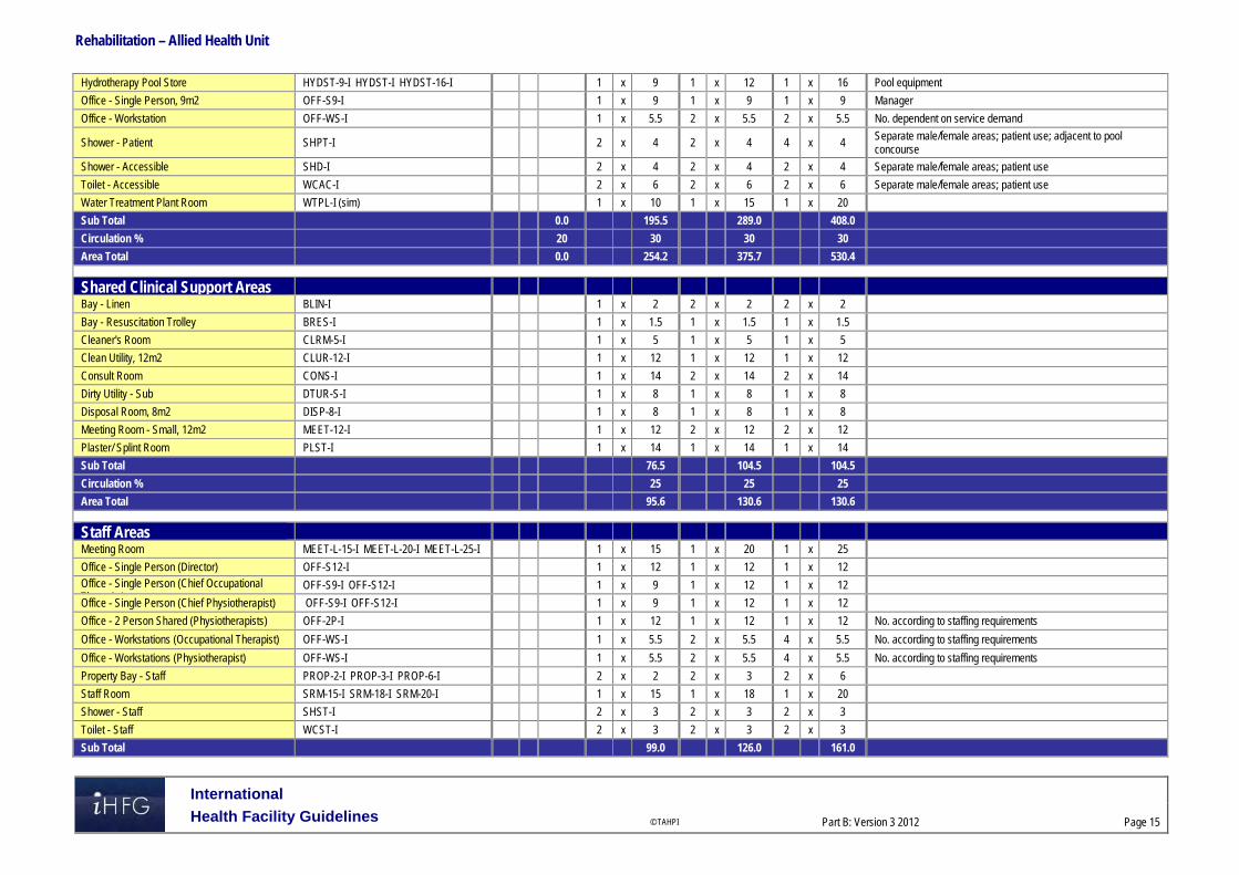
Rehabilitation – Allied Health Unit
International
Health Facility Guidelines © TAHPI
Part B: Version 3 2012
Page 15
Hydrotherapy Pool Store HYDST-9-I HYDST-I HYDST-16-I 1 x 9 1 x 12 1 x 16 Pool equipment
Office - Single Person, 9m2 OFF-S9-I 1 x 9 1 x 9 1 x 9 Manager
Office - Workstation OFF-WS-I 1 x 5.5 2 x 5.5 2 x 5.5 No. dependent on service demand
Shower - Patient SHPT-I 2 x 4 2 x 4 4 x 4 Separate male/female areas; patient use; adjacent to pool concourse
Shower - Accessible SHD-I 2 x 4 2 x 4 2 x 4 Separate male/female areas; patient use
Toilet - Accessible WCAC-I 2 x 6 2 x 6 2 x 6 Separate male/female areas; patient use
Water Treatment Plant Room WTPL-I (sim) 1 x 10 1 x 15 1 x 20
Sub Total 0.0 195.5 289.0 408.0
Circulation % 20 30 30 30
Area Total 0.0 254.2 375.7 530.4 Shared Clinical Support Areas
Bay - Linen BLIN-I 1 x 2 2 x 2 2 x 2
Bay - Resuscitation Trolley BRES-I 1 x 1.5 1 x 1.5 1 x 1.5
Cleaner's Room CLRM-5-I 1 x 5 1 x 5 1 x 5
Clean Utility, 12m2 CLUR-12-I 1 x 12 1 x 12 1 x 12
Consult Room CONS-I 1 x 14 2 x 14 2 x 14
Dirty Utility - Sub DTUR-S-I 1 x 8 1 x 8 1 x 8
Disposal Room, 8m2 DISP-8-I 1 x 8 1 x 8 1 x 8
Meeting Room - Small, 12m2 MEET-12-I 1 x 12 2 x 12 2 x 12
Plaster/ Splint Room PLST-I 1 x 14 1 x 14 1 x 14
Sub Total 76.5 104.5 104.5
Circulation % 25 25 25
Area Total 95.6 130.6 130.6 Staff Areas
Meeting Room MEET-L-15-I MEET-L-20-I MEET-L-25-I 1 x 15 1 x 20 1 x 25
Office - Single Person (Director) OFF-S12-I 1 x 12 1 x 12 1 x 12 Office - Single Person (Chief Occupational Th i t)
OFF-S9-I OFF-S12-I 1 x 9 1 x 12 1 x 12
Office - Single Person (Chief Physiotherapist) OFF-S9-I OFF-S12-I 1 x 9 1 x 12 1 x 12
Office - 2 Person Shared (Physiotherapists) OFF-2P-I 1 x 12 1 x 12 1 x 12 No. according to staffing requirements
Office - Workstations (Occupational Therapist) OFF-WS-I 1 x 5.5 2 x 5.5 4 x 5.5 No. according to staffing requirements
Office - Workstations (Physiotherapist) OFF-WS-I 1 x 5.5 2 x 5.5 4 x 5.5 No. according to staffing requirements
Property Bay - Staff PROP-2-I PROP-3-I PROP-6-I 2 x 2 2 x 3 2 x 6
Staff Room SRM-15-I SRM-18-I SRM-20-I 1 x 15 1 x 18 1 x 20
Shower - Staff SHST-I 2 x 3 2 x 3 2 x 3
Toilet - Staff WCST-I 2 x 3 2 x 3 2 x 3
Sub Total 99.0 126.0 161.0

Rehabilitation – Allied Health Unit
International
Health Facility Guidelines © TAHPI
Part B: Version 3 2012
Page 16
Circulation % 25 25 25
Area Total 123.8 157.5 201.3 Grand Total 998.7 1498.0 2046.9
Please note the following: Areas noted in Schedules of Accommodation take precedence over all other areas noted in the FPU. Rooms indicated in the schedule reflect the typical arrangement according to the Role Delineation. Exact requirements for room quantities and sizes will reflect Key Planning Units identified in the Service Plan and the Operational Policies of the Unit. Room sizes indicated should be viewed as a minimum requirement; variations are acceptable to reflect the needs of individual Unit. Office areas are to be provided according to the Unit role delineation and number of endorsed full time positions in the unit. Staff and support rooms may be shared between Functional Planning Units dependant on location and accessibility to each unit and may provide scope to
reduce duplication of facilities.
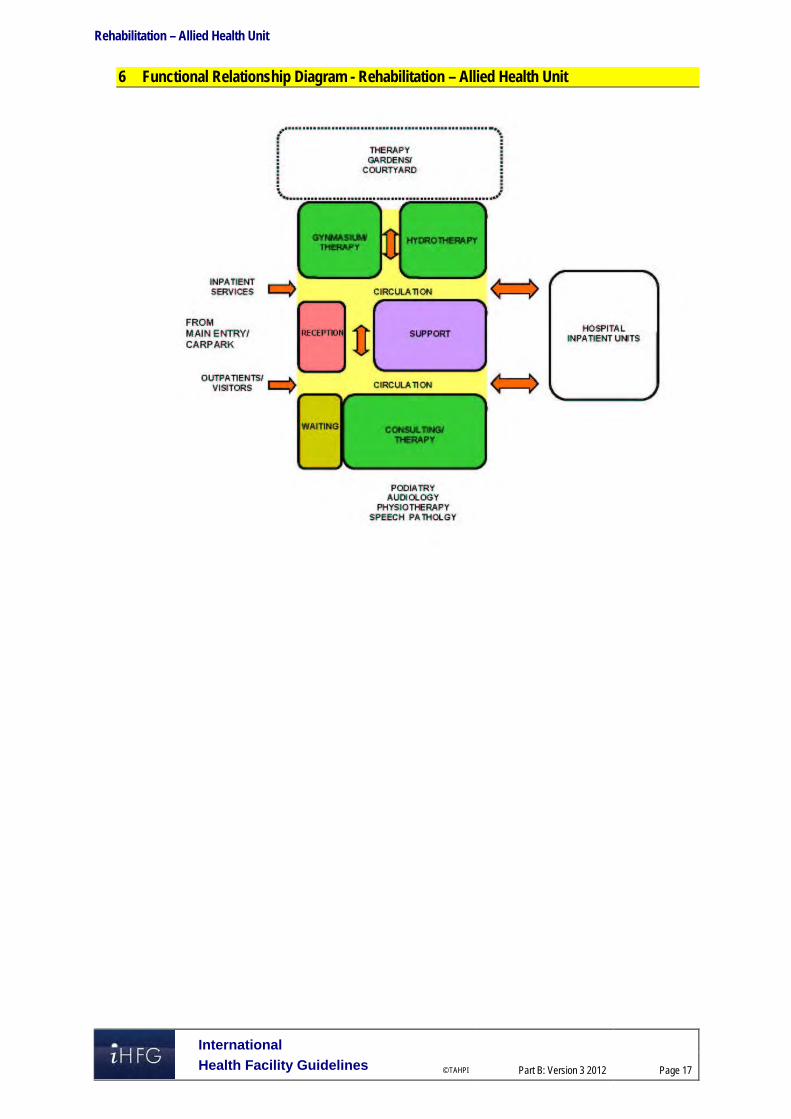
Rehabilitation – Allied Health Unit
International
Health Facility Guidelines © TAHPI
Part B: Version 3 2012
Page 17
6 Functional Relationship Diagram - Rehabilitation – Allied Health Unit

Rehabilitation – Allied Health Unit
International
Health Facility Guidelines © TAHPI
Part B: Version 4 2014
Page 18
7 References and Further Reading Australasian Health Facility Guidelines, Part B Health Facility Briefing and Planning, Rev 4,
2012; refer to website www.healthfacilitydesign.com.au The Facility Guidelines Institute (US), 2010 Edition. Guidelines for Design and Construction
of Health Care Facilities) refer to website www.fgiguidelines.org

Part B – Health Facility Briefing & Design 270 Renal Dialysis Unit
International Health Facility Guidelines Version 4 February 2014

International
Health Facility Guidelines © TAHPI
Part B: Version 4 2014
Page 2
Table of Contents
270 Renal Dialysis Unit .................................................................................................................... 3 1 Introduction ............................................................................................................................................... 3 2 Planning ..................................................................................................................................................... 3 3 Design ........................................................................................................................................................ 5 4 Components of the Unit ............................................................................................................................ 9 5 Schedule of Accommodation – Renal Dialysis Unit ............................................................................ 10 6 Functional Relationship Diagram – Renal Dialysis Unit ...................................................................... 16 7 References and Further Reading ........................................................................................................... 17

Renal Dialysis Unit
International
Health Facility Guidelines © TAHPI
Part B: Version 4 2014
Page 3
270 Renal Dialysis Unit 1 Introduction Description Renal Dialysis is a medical process that becomes necessary when the normal functions of the kidneys become compromised by reduced kidney function and kidney failure. This may be due to disease, injury, infection or genetic factors. Renal failure may be classified as either Acute Renal Failure or chronic Kidney Disease. Haemodialysis and Peritoneal dialysis services involve filtering the blood of excess fluid, and waste products normally filtered by the kidneys. Haemodialysis is a treatment for end stage renal failure where the function of the kidneys to remove substances from the blood is replaced by the use of a haemodialysis (dialysis) machine. Haemodialysis requires the patient to have one of the following - arterio-venous fistula, vein graft (artificial graft) or central line catheter inserted into their neck or upper chest for dialysis. Haemodialysis management may require the patient to undergo dialysis for 3 to 6 hours on a daily basis over 3 to 4 days a week. Haemodialysis may be undertaken in the following locations: a hospital a Satellite unit a Stand-alone unit a Self-care unit at home. Peritoneal dialysis is an alternative to Haemodialysis. Peritoneal dialysis involves the exchange of fluid to and from the abdominal peritoneum via an inserted peritoneal catheter 3 to 4 times each day with this being undertaken either manually or with the assistance of a machine (Automated Peritoneal Dialysis – APD) for 8 to 10 hours, generally overnight. Peritoneal dialysis is usually performed at home after supported technical training and education either as an inpatient or outpatient at a community dialysis unit. The functions of the Renal Dialysis unit are: to receive and provide dialysis services to people who have been referred from the
community or a hospital inpatient unit to provide training for patients, family members and/or relevant others in procedures related
to haemodialysis and/or peritoneal dialysis (optional) to act as a resource to the community, other staff and agencies with regards to the
requirements of renal health services. 2 Planning Operational Models Operational models of care for a service will influence the functional planning components for the unit. The role delineation of a hospital will determine the type and range of the renal dialysis services that will be provided and the associated support systems and services. The Renal Dialysis unit may be provided as: one of the departments in a hospital (in-centre care) and also support dialysis services as
required in an ICU, CCU or in a Renal Inpatient Unit a dialysis unit planned as a satellite unit which may be situated on the hospital site/campus
or a stand-alone unit located within a community setting. Models of Care Renal dialysis can be provided in a number of settings as described in the operational models and Planning Models.

Renal Dialysis Unit
International
Health Facility Guidelines © TAHPI
Part B: Version 4 2014
Page 4
The development of the models of care to deliver a renal dialysis service is provided by a multidiscipline team to support the patient/client, their family and or carer. The important role of education should also be considered in the development of models of care. The development of clear documented models of care by the service for the proposed renal dialysis unit should assist with the design development and planning, ensuring the future functionality of the unit.
Hours of Operation
Units operate from early morning until late afternoon providing multiple sessions per day. Some units may operate for extended hours to accommodate working patients/clients. Planning Models Some of the factors that should be taken into consideration when planning a Renal Dialysis Unit include: The operational model chosen as part of the planning model Age and mix of the patient group Acuity of the proposed or current patient group Comorbidity of the patient group Rate of infectious diseases to be expected in the patient group
Service Delivery Methods
This FPU is applicable to the following Operational Models: Hospital based unit – a unit within the hospital Satellite Unit – on a hospital campus but not in a hospital unit Stand-alone unit – positioned in a community setting Functional Areas The Dialysis Unit will consist of or have access to the following functional areas for all service delivery methods: Main Entry / Reception Area Waiting Treatment Areas Staff Areas Support Areas Storage Areas:
- Clinical - Non clinical - Bulk items storage e.g. fluids, equipment and dialysis machine - Service maintenance
Functional Relationships
External
Planning is to address the following key issues: Ease of access to the unit where the majority of people will arrive by car on a daily basis Separation of walking and stretcher/ ambulance patient arrivals Safe access to the Unit Store rooms for the delivery of bulk items e.g. fluids on a palette
requiring mechanical lifting, moving and storage Safe access for the delivery of food, clean linen, pharmacy, consumables, disposable items
and the related removal of bulk waste and soiled linen etc.

Renal Dialysis Unit
International
Health Facility Guidelines © TAHPI
Part B: Version 4 2014
Page 5
Internal
The internal planning of the Renal Dialysis Unit should be planned by considering the units functional areas/zones. Some of the critical relationships to be considered include: staff work station requires an unobtrusive view of all patient treatment areas; the inclusion of
decentralised staff work areas may be considered in larger units that have multiple rooms or treatment spaces
Reception requires a clear view of entry and exit/egress points of the Unit easy access from the Waiting area to the Patient Treatment area for the convenient arrival
and departure of patients and family functional relationship of training and isolation rooms to the entry of the unit with access to
outdoor space 3 Design General The Unit shall be designed to provide: ease of public access for patients who may arrive either walking, using mobility equipment,
families with children, on an ambulance stretcher or patient trolley ease of access to public parking for patients who are often debilitated and who may need to
visit the unit on a regular basis ease of delivery of large amounts of fluids (dialysate) on palettes to the Unit on a regular
basis. Patient Treatment Areas Patients should be situated so that healthcare providers have direct or indirect visualisation. This approach permits the monitoring of patient status under both routine and emergency circumstances. The preferred design is to allow a direct line of vision between the patient and the staff. Environmental Considerations
Natural Light
Natural light contributes to a sense of wellbeing of patients, staff, visitors and other users. The use of natural light should be maximised throughout the Unit. Natural light and a view to pleasant and interesting outdoor areas is of particular importance for patients who spend long periods of time sitting in dialysis chairs. Every effort should be made to provide a view to all treatment areas either by locating treatment bays adjacent to a window or enabling unobstructed sight lines through areas to an outdoor view.
Privacy
Confidentiality for persons receiving treatment is a highly important consideration to be addressed. The Unit should be designed to: ensure confidentiality of personal discussions and medical records provide an adequate number of rooms for discreet discussions and treatments to occur
whenever required enable sufficient space within each treatment space to permit curtains to be easily drawn
whenever required appropriately locate windows and doors to enhance visual and acoustic privacy
Acoustics
Many of the functions undertaken in the Unit require consideration of acoustic privacy including: family/ case conference/ interviews rooms isolation of noisy areas such as waiting rooms from clinical areas e.g. clean and dirty utilities

Renal Dialysis Unit
International
Health Facility Guidelines © TAHPI
Part B: Version 4 2014
Page 6
staff discussions regarding confidential matters (including Meeting rooms) noise sources may arise both within and from outside the dialysis unit and may include:
- sanitary facilities - equipment - other patients/clients - staff activities - traffic through the unit e.g. visitors, food, linen or other trolleys
Solutions to be considered include: selection of sound absorbing materials and finishes use of sound isolating construction planning to separate quiet areas from noisy areas review of operational management and patient/client flows. This may include separate areas
for patients with special needs location of the unit
Interior Design
This includes the style of design, furnishings, colour, textures and ambience, influenced by perceptions and culture. The décor of the Unit should be of a standard that meets the expectations of people using the services and make every effort to reduce an institutional atmosphere. Cleaning, infection control, fire safety, patient care requirements and the patients’ perception of a professional inviting environment should always be considered. Suggestions to achieve this balance include the following: use of design features such as colours and artworks to distract the sight from clinical areas inclusion of soft furnishings that act as a design feature such as screening, lounges, in
waiting areas and window treatments elimination of corridors through good design wherever possible inclusion of corridors at the minimum required widths to meet the service needs e.g. wide
corridors are a feature that potentiates institutional environments provision of a beverage bay for people to use while waiting background music through a piped system or a centralised unit television systems with head set access to reduce ambient noise in the Unit. Space Standards and Components
Accessibility - External
There should be a weatherproof vehicle drop-off zone with easy access for less-mobile patients and wheelchair bound patients. Consideration should be given to the separation of ambulant and non-ambulant patient arrivals to enhance privacy of ambulance and or stretcher patients frequenting the service. Safety and Security Equipment, furniture, fittings and the facility itself should be designed and constructed to ensure that users are not exposed to avoidable risks or injury. A high standard of safety and security can be achieved by careful configuration of spaces and zones to include: control access / egress to and from the Unit optimise visual observation for staff similar functions shall be co-located for easy staff management. Access to public areas shall be considered with care so that the safety and security of staff areas within the Unit are not compromised. Refer also to Part C of these Guidelines.

Renal Dialysis Unit
International
Health Facility Guidelines © TAHPI
Part B: Version 4 2014
Page 7
Finishes Floor and ceiling finishes shall be selected to suit the function of the space and promote a pleasant environment for patients, visitors and staff. The following factors shall be considered: aesthetic appearance acoustic properties durability ease of cleaning infection control movement of equipment. Refer also to Part C and Part D of these Guidelines. Fixtures and Fittings Refer to Part C of these Guidelines and Standard Components of individual rooms for information related to fixtures and fittings. Building Service Requirements
Communications/ Information Technology
It is vital to provide reliable and effective Information Technology/ Communications service for efficient operation of the Unit. The following items relating to Information Technology/ Communication to support the planning, design and the current and future expansion of the Unit and support the development of technical and operational guidelines require consideration early in the planning process: bar coding for supplies, x-rays and records data entry (e.g. scripts and investigative requests) email access to Picture Archival Communications System (PACS) viewing paging systems electronic medical records and medical record storage systems point of clinical care patient administration system building management system (BMS) videoconferencing, teleconferencing/ telemedicine wireless technology considerations including duress alarm systems – fixed and mobile units communications rooms and server requirements. Nurse Call and Emergency Call facilities shall be provided in all patient areas (e.g. Bed/chair spaces, Toilets and Bathrooms) and clinical areas in order for patients and staff to request for urgent assistance. The individual call buttons shall alert to distributed identified ceiling mounted annunciators and also to a central module situated at or adjacent to the Staff Station (s) or to a paging system. The alert to staff members should be done in a discreet manner. Provision of a duress alarm system is required for the safety of staff members who may at times face threats imposed by clients / visitors. Call buttons will be required at all Reception/ Staff Station areas and Consultation/ Treatment areas where a staff may have to spend time with a client in isolation or alone. The combination of fixed and mobile duress units should be considered as part of the safety review during planning for the unit.
Water Treatment Services
A key component of the Renal Dialysis Unit is the need to treat the water that will be used in the haemodialysis process to remove any contaminants. Different commercial water treatment
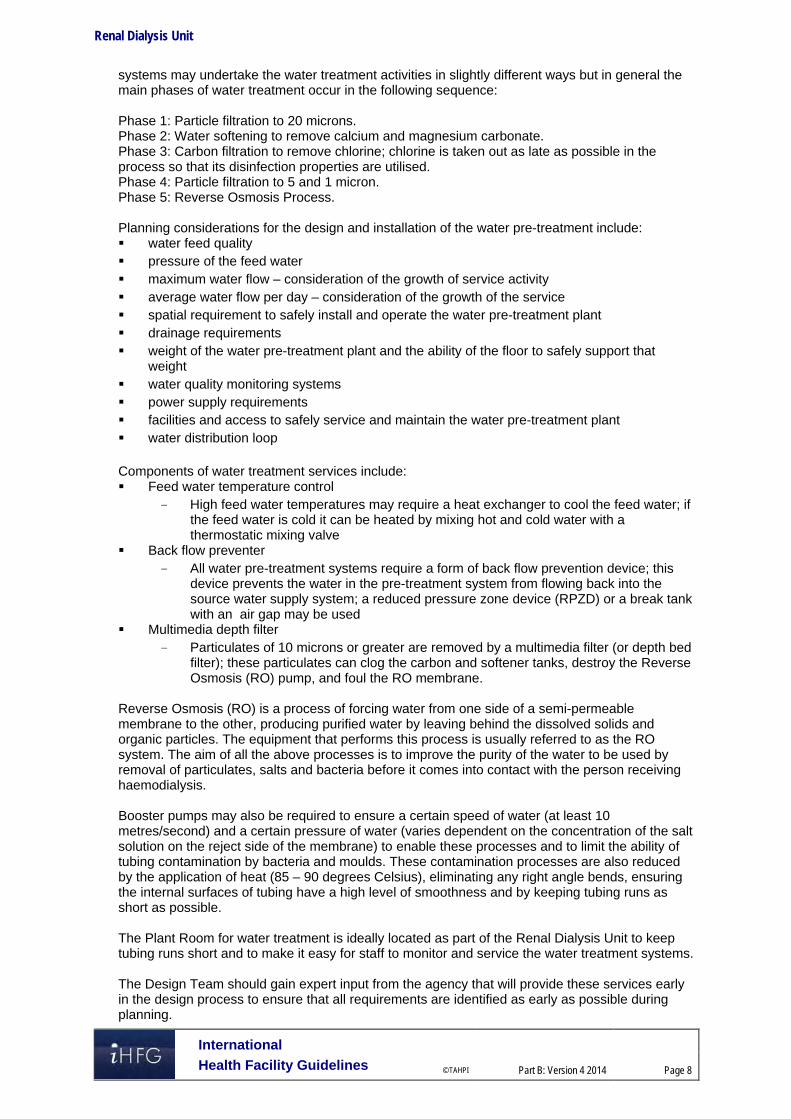
Renal Dialysis Unit
International
Health Facility Guidelines © TAHPI
Part B: Version 4 2014
Page 8
systems may undertake the water treatment activities in slightly different ways but in general the main phases of water treatment occur in the following sequence: Phase 1: Particle filtration to 20 microns. Phase 2: Water softening to remove calcium and magnesium carbonate. Phase 3: Carbon filtration to remove chlorine; chlorine is taken out as late as possible in the process so that its disinfection properties are utilised. Phase 4: Particle filtration to 5 and 1 micron. Phase 5: Reverse Osmosis Process. Planning considerations for the design and installation of the water pre-treatment include: water feed quality pressure of the feed water maximum water flow – consideration of the growth of service activity average water flow per day – consideration of the growth of the service spatial requirement to safely install and operate the water pre-treatment plant drainage requirements weight of the water pre-treatment plant and the ability of the floor to safely support that
weight water quality monitoring systems power supply requirements facilities and access to safely service and maintain the water pre-treatment plant water distribution loop Components of water treatment services include: Feed water temperature control
- High feed water temperatures may require a heat exchanger to cool the feed water; if the feed water is cold it can be heated by mixing hot and cold water with a thermostatic mixing valve
Back flow preventer - All water pre-treatment systems require a form of back flow prevention device; this
device prevents the water in the pre-treatment system from flowing back into the source water supply system; a reduced pressure zone device (RPZD) or a break tank with an air gap may be used
Multimedia depth filter - Particulates of 10 microns or greater are removed by a multimedia filter (or depth bed
filter); these particulates can clog the carbon and softener tanks, destroy the Reverse Osmosis (RO) pump, and foul the RO membrane.
Reverse Osmosis (RO) is a process of forcing water from one side of a semi-permeable membrane to the other, producing purified water by leaving behind the dissolved solids and organic particles. The equipment that performs this process is usually referred to as the RO system. The aim of all the above processes is to improve the purity of the water to be used by removal of particulates, salts and bacteria before it comes into contact with the person receiving haemodialysis. Booster pumps may also be required to ensure a certain speed of water (at least 10 metres/second) and a certain pressure of water (varies dependent on the concentration of the salt solution on the reject side of the membrane) to enable these processes and to limit the ability of tubing contamination by bacteria and moulds. These contamination processes are also reduced by the application of heat (85 – 90 degrees Celsius), eliminating any right angle bends, ensuring the internal surfaces of tubing have a high level of smoothness and by keeping tubing runs as short as possible. The Plant Room for water treatment is ideally located as part of the Renal Dialysis Unit to keep tubing runs short and to make it easy for staff to monitor and service the water treatment systems. The Design Team should gain expert input from the agency that will provide these services early in the design process to ensure that all requirements are identified as early as possible during planning.

Renal Dialysis Unit
International
Health Facility Guidelines © TAHPI
Part B: Version 4 2014
Page 9
Drainage Systems Services that facilitate the drainage of fluids from the haemodialysis machines must be ventilated to prevent condensation and the subsequent growth of mould. This should be considered when designing covers or screens for the drainage systems. Commercial models which comply with the relevant Standards are available. Infection Control Infectious patients and immune-suppressed patients may be sharing the same treatment space at the different times of the same day. The design of all aspects for the Unit should take into consideration the need to ensure a high level of infection control in all aspects of clinical and non-clinical practice. Hand washing facilities for staff within the Unit should be readily available. Where a hand wash basin is provided, there shall also be liquid soap, disposable paper towels and waste bin provided and PPE equipment. For further details relating to the Infection Control refer to Part D of these Guidelines. 4 Components of the Unit The Renal Dialysis Unit will contain Standard Components to comply with details described in these Guidelines. Refer also to Standard Components Room Data Sheets and Room Layout Sheets.

Renal Dialysis Unit
International
Health Facility Guidelines © TAHPI
Part B: Version 4 2014
Page 10
5 Schedule of Accommodation – Renal Dialysis Unit A hospital based Unit with 6, 12, 24 and 30 treatment spaces
ROOM/ SPACE Standard Component RDL 2/3 RDL4 RDL5 RDL6 Remarks
Room Codes Qty x m2 Qty x m2 Qty x m2 Qty x m2
Entry/ Reception 6 spaces 12 spaces 24 spaces 30 spaces
Reception/ Clerical RECL-9-I RECL-12-I RECL-15-I 1 x 9 1 x 9 1 x 12 1 x 15 Size dependent on staffing numbers and activities
Waiting WAIT-10-I WAIT-15-I WAIT-20-I 1 x 10 1 x 10 1 x 15 1 x 20 May be divided for Female areas as applicable; may include public phone & Beverage bay
Waiting - Family WAIT-10-I WAIT-15-I 1 x 10 1 x 15 1 x 15 May include a child Play Area
Consult CONS-I 1 x 14 1 x 14 2 x 14 3 x 14 Also for Interviews
Meeting Room MEET-12-I MEET-L-20-I MEET-L-30-I 1 x 12 1 x 20 1 x 30 1 x 30 Optional; See Note 1
Office - Nurse Manager OFF-S9-I 1 x 9 1 x 9 1 x 9 1 x 9
Store - Photocopy/ Stationery STPS-8-I (sim) 1 x 6 1 x 8 1 x 8 1 x 8 Printers, fax, records; may be combined with Reception
Store - Files STFS-8-I (sim) 1 x 6 1 x 6 1 x 8 Optional; not required for electronic records
Training/ Treatment Room TTRMT 1 x 14 1 x 14 1 x 14 1 x 14 Optional; See Note 2
Toilet - Accessible WCAC-I 1 x 6 1 x 6 1 x 6 1 x 6 Direct access from the Waiting room
Toilet - Public WCPU-3-I 1 x 3 1 x 3 2 x 3 2 x 3 Direct access from the Waiting room
Sub Total 83.0 109.0 149.0 131.0
Circulation % 35 35 35 35
Area Total 112.1 147.2 201.2 176.9 Treatment Area
Treatment Bay - Renal Dialysis TRMT-RD-I 5 x 9 11 x 9 22 x 9 28 x 9 See Note 3
Isolation Room - Type S TRMT-RD-S-I 1 x 14 1 x 14 2 x 14 2 x 14 According to service plan & risk assessment
Ensuite - Standard ENS-ST-I 1 x 5 1 x 5 2 x 5 2 x 5 For Isolation Rooms
Shower - Accessible SHD-I 1 x 4 1 x 4 2 x 4 2 x 4
Toilet - Accessible WCAC-I 1 x 6 1 x 6 2 x 6 2 x 6
Toilet - Patient WCPT-I 1 x 4 1 x 4 1 x 4 2 x 4
Bay - Beverage BBEV-ENC-I 1 x 5 1 x 5 1 x 5 1 x 5 To receive and issue refreshments to patients
Bay - Handwashing, PPE BHWS-PPE-I 2 x 1.5 3 x 1.5 6 x 1.5 8 x 1.5 Refer to part D
Bay - Linen BLIN-I 1 x 2 1 x 2 2 x 2 2 x 2
Bay - Resuscitation Trolley BRES-I 1 x 1.5 1 x 1.5 1 x 1.5 1 x 1.5 Adjacent to Staff Station
Clean Utility CLUR-12-I CLUR-14-I 1 x 12 1 x 12 1 x 14 1 x 14 Including medications and dressing set-ups
Dialysate Preparation Area BUT-2-I 1 x 2 1 x 2 2 x 2 2 x 2 Adjacent to Dialysate Fluid Bay
Dirty Utility DTUR-10-I 1 x 10 1 x 10 1 x 10 1 x 10

Renal Dialysis Unit
International
Health Facility Guidelines © TAHPI
Part B: Version 4 2014
Page 11
ROOM/ SPACE Standard Component RDL 2/3 RDL4 RDL5 RDL6 Remarks
Room Codes Qty x m2 Qty x m2 Qty x m2 Qty x m2
Staff Station SSTN-10-I SSTN-12-I 1 x 10 1 x 12 2 x 10 2 x 12 Subdivided in larger Units
Sub Total 123.5 181.0 327.5 392.5
Circulation % 35 35 35 35
Area Total 166.7 244.4 442.1 529.9 Storage Areas (Treatment Zone)
Bay - Wheelchair Park BWC-I BWC-8-I 1 x 4 1 x 4 1 x 8 1 x 8 May be subdivided
Dialysate Fluid Bay BS-1-I BS-2-I 1 x 1 1 x 1 2 x 2 2 x 2 See Note 4
Store - General STGN-4-I 1 x 4 1 x 4 1 x 4 1 x 4
Store - Main STGN-8-I STGN-16-I STGN-30-I 1 x 8 1 x 16 1 x 30 1 x 30 See Note 5
Sub Total 17.0 25.0 46.0 46.0
Circulation % 25 25 25 25
Area Total 21.3 31.3 57.5 57.5
Staff & Support Areas
Cleaner's Room CLRM-5-I CLRM-10-I 1 x 5 1 x 5 1 x 10 1 x 10 Includes dry storage for cleaning consumables
Communications Room COMM-I 1 x 0 1 x 0 1 x 0 1 x 0 Area as required and to be added to Engineering
Disposal Room DISP-5-I DISP-8-I DISP-10-I 1 x 5 1 x 8 1 x 10 1 x 10 Waste & dirty linen holding
Equipment Clean-Up ECL-8-I ECL-10-I ECL-12-I 1 x 8 1 x 10 1 x 12 1 x 12 For cleaning and servicing of haemodialysis and other machinery
Property Bay - Staff PROP-2-I 1 x 2 1 x 2 2 x 2 2 x 2 Discreet, secure location, adj to Staff Room; Include hanging space
Staff Room SRM-15-I SRM-20-I SRM-25-I 1 x 15 1 x 15 1 x 20 1 x 25 Discreet location; may be shared
Toilet - Staff WCST-I 1 x 3 1 x 3 2 x 3 2 x 3 Discreet location
Water Treatment Plant Room WTPL-12-I WTPL-20-I WTPL-24-I 1 x 12 1 x 15 1 x 20 1 x 24 Close to treatment areas to reduce piping runs
Sub Total 50.0 58.0 82.0 91.0
Circulation % 25 25 25 25
Area Total 62.5 72.5 102.5 113.8 Grand Total 362.5 495.3 803.3 878.0
Note 1: Meeting Room; to support patient education, community training and other functions; should have teleconferencing capability; add 4m2 to room if including a beverage bay Note 2: Training/Treatment room; where there is a developed program of training for home based dialysis as approved in the Service Plan a dedicated space should be provided; this space could also be used for related procedures such as the insertion of catheters etc.

Renal Dialysis Unit
International
Health Facility Guidelines © TAHPI
Part B: Version 4 2014
Page 12
Note 3: Treatment Bays; Bay size needs to be 9 square meters with a clear width of 3 meters along the back of the bay to ensure appropriate service placement, machine accommodation and curtain track placement; spaces of 12m2 will need to be considered where more than 50% of patients are receiving dialysis in patient beds rather than chairs (particularly in RDL 5/6 renal services located in tertiary referral hospitals); bays will accommodate beds or chairs Note 4: Dialysate Fluid Bay; to hold dialysis fluid in a convenient location close to treatment bays; temperature is important for some dialysate fluids and this area may require air-conditioning Note 5: Main Store Room; for general stores, fluids and equipment, to be located on the perimeter of the Unit and accessible by a palette lifter. Shelving must have 100 kg weight capacity and shelves need to be at least 400 mm apart and adjustable. Please also note the following: Areas noted in Schedules of Accommodation take precedence over all other areas noted in the FPU. Rooms indicated in the schedule reflect the typical arrangement according to the Role Delineation. Exact requirements for room quantities and sizes will reflect Key Planning Units identified in the service plan and the policies of the Unit. Room sizes indicated should be viewed as a minimum requirement; variations are acceptable to reflect the needs of individual Unit. Office areas are to be provided according to the Unit role delineation, organisational office policy and the number of endorsed full time positions within the Unit Staff and support rooms may be shared between Functional Planning Units dependant on location and accessibility to each unit and may provide scope to
reduce duplication of facilities.
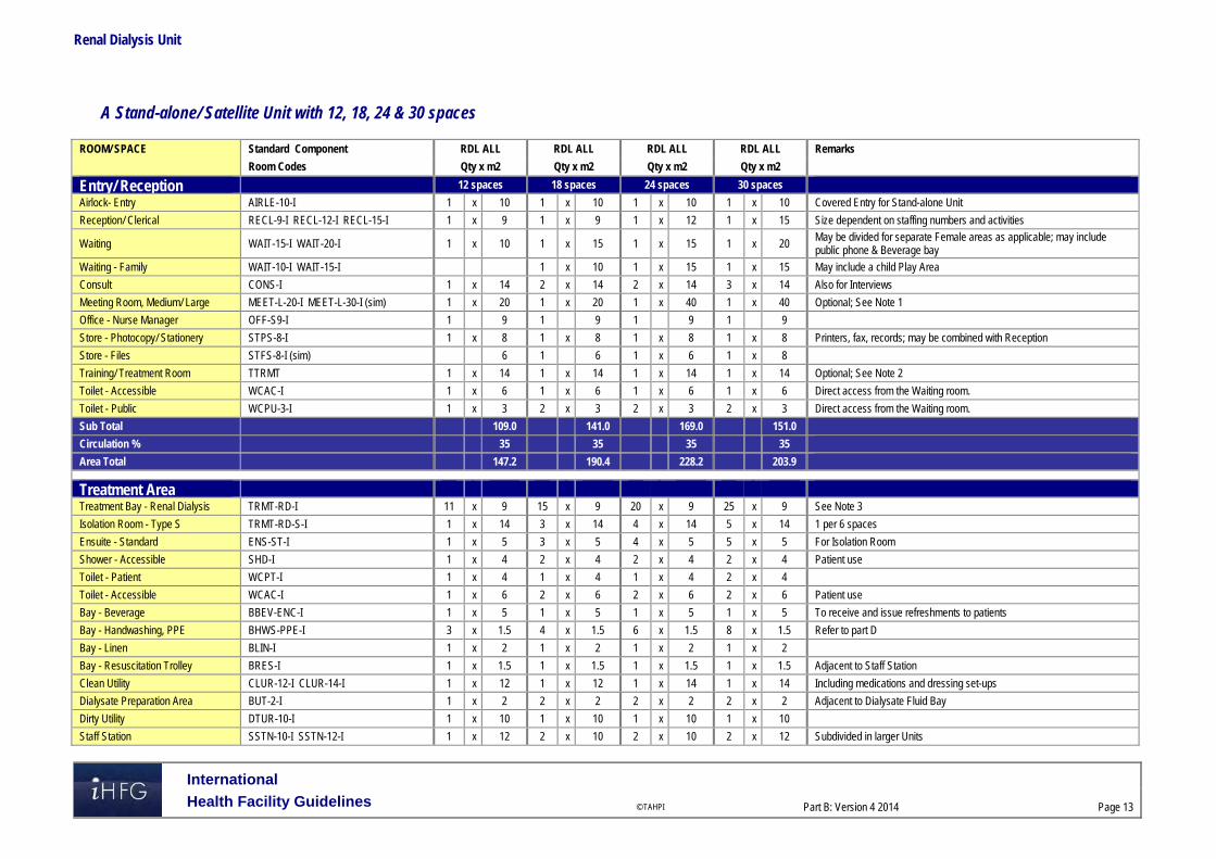
Renal Dialysis Unit
International
Health Facility Guidelines © TAHPI
Part B: Version 4 2014
Page 13
A Stand-alone/ Satellite Unit with 12, 18, 24 & 30 spaces
ROOM/ SPACE Standard Component RDL ALL RDL ALL RDL ALL RDL ALL Remarks Room Codes Qty x m2 Qty x m2 Qty x m2 Qty x m2
Entry/ Reception 12 spaces 18 spaces 24 spaces 30 spaces
Airlock- Entry AIRLE-10-I 1 x 10 1 x 10 1 x 10 1 x 10 Covered Entry for Stand-alone Unit
Reception/ Clerical RECL-9-I RECL-12-I RECL-15-I 1 x 9 1 x 9 1 x 12 1 x 15 Size dependent on staffing numbers and activities
Waiting WAIT-15-I WAIT-20-I 1 x 10 1 x 15 1 x 15 1 x 20 May be divided for separate Female areas as applicable; may include public phone & Beverage bay
Waiting - Family WAIT-10-I WAIT-15-I 1 x 10 1 x 15 1 x 15 May include a child Play Area
Consult CONS-I 1 x 14 2 x 14 2 x 14 3 x 14 Also for Interviews
Meeting Room, Medium/ Large MEET-L-20-I MEET-L-30-I (sim) 1 x 20 1 x 20 1 x 40 1 x 40 Optional; See Note 1
Office - Nurse Manager OFF-S9-I 1 9 1 9 1 9 1 9
Store - Photocopy/ Stationery STPS-8-I 1 x 8 1 x 8 1 x 8 1 x 8 Printers, fax, records; may be combined with Reception
Store - Files STFS-8-I (sim) 6 1 6 1 x 6 1 x 8
Training/ Treatment Room TTRMT 1 x 14 1 x 14 1 x 14 1 x 14 Optional; See Note 2
Toilet - Accessible WCAC-I 1 x 6 1 x 6 1 x 6 1 x 6 Direct access from the Waiting room.
Toilet - Public WCPU-3-I 1 x 3 2 x 3 2 x 3 2 x 3 Direct access from the Waiting room.
Sub Total 109.0 141.0 169.0 151.0
Circulation % 35 35 35 35
Area Total 147.2 190.4 228.2 203.9
Treatment Area
Treatment Bay - Renal Dialysis TRMT-RD-I 11 x 9 15 x 9 20 x 9 25 x 9 See Note 3
Isolation Room - Type S TRMT-RD-S-I 1 x 14 3 x 14 4 x 14 5 x 14 1 per 6 spaces
Ensuite - Standard ENS-ST-I 1 x 5 3 x 5 4 x 5 5 x 5 For Isolation Room
Shower - Accessible SHD-I 1 x 4 2 x 4 2 x 4 2 x 4 Patient use
Toilet - Patient WCPT-I 1 x 4 1 x 4 1 x 4 2 x 4
Toilet - Accessible WCAC-I 1 x 6 2 x 6 2 x 6 2 x 6 Patient use
Bay - Beverage BBEV-ENC-I 1 x 5 1 x 5 1 x 5 1 x 5 To receive and issue refreshments to patients
Bay - Handwashing, PPE BHWS-PPE-I 3 x 1.5 4 x 1.5 6 x 1.5 8 x 1.5 Refer to part D
Bay - Linen BLIN-I 1 x 2 1 x 2 1 x 2 1 x 2
Bay - Resuscitation Trolley BRES-I 1 x 1.5 1 x 1.5 1 x 1.5 1 x 1.5 Adjacent to Staff Station
Clean Utility CLUR-12-I CLUR-14-I 1 x 12 1 x 12 1 x 14 1 x 14 Including medications and dressing set-ups
Dialysate Preparation Area BUT-2-I 1 x 2 2 x 2 2 x 2 2 x 2 Adjacent to Dialysate Fluid Bay
Dirty Utility DTUR-10-I 1 x 10 1 x 10 1 x 10 1 x 10
Staff Station SSTN-10-I SSTN-12-I 1 x 12 2 x 10 2 x 10 2 x 12 Subdivided in larger Units

Renal Dialysis Unit
International
Health Facility Guidelines © TAHPI
Part B: Version 4 2014
Page 14
ROOM/ SPACE Standard Component RDL ALL RDL ALL RDL ALL RDL ALL Remarks Room Codes Qty x m2 Qty x m2 Qty x m2 Qty x m2
Sub Total 181.0 276.5 345.5 420.5
Circulation % 35 35 35 35
Area Total 244.4 373.3 466.4 567.7
Storage Areas
Bay - Wheelchair Park BWC-I BWC-8-I 1 x 4 1 x 4 1 x 8 1 x 8 May be subdivided
Dialysate Fluid Bay BS-1-I BS-2-I 1 x 1 2 x 1 2 x 2 2 x 2 See Note 4
Store - General STGN-8-I STGN-10-I STGN-12-I 1 x 8 1 x 8 1 x 10 1 x 12 Size will be dependent on quantity of stock to be held
Store - Main STGN-8-I STGN-16-I STGN-30-I 1 x 8 1 x 16 1 x 30 1 x 30 See Note 5
Store - Medical Records STFS-20-I (sim) 1 x 10 1 x 10 1 x 20 1 x 25 Optional; not required for electronic records; size will be dependent on quantity of records to be held
Sub Total 21.0 40.0 72.0 79.0
Circulation % 25 25 25 25
Area Total 26.3 50.0 90.0 98.8
Staff & Support Areas
Cleaner's Room CLRM-10-I 1 x 10 1 x 10 1 x 10 1 x 10 Includes dry storage for cleaning consumables
Communications Room COMM-I 1 x 0 1 x 0 1 x 0 1 x 0 Area as required and to be added to Engineering
Disposal Room DISP-8-I DISP-10-I 1 x 8 1 x 10 1 x 10 1 x 10 Waste and dirty linen holding
Equipment Clean-Up ECL-10-I ECL-12-I 1 x 10 1 x 10 1 x 12 1 x 12 For cleaning and servicing of haemodialysis machines
Linen Holding - Clean STGN-8-I 1 x 8 1 x 8 1 x 8 1 x 8 Optional, for additional linen supplies
Loading Dock LODK-I (sim) x 10 x 10 1 x 15 1 x 20 May be shared
Office - Single Person, 12m2 OFF-S12-I 1 x 12 1 x 12 1 x 12 1 x 12 Practice/ Unit Manager
Office - 2 Person Shared OFF-2P-I 1 x 12 1 x 12 1 x 12 1 x 12 According to endorsed full time positions
Property Bay - Staff PROP-2-I 1 x 2 2 x 2 2 x 2 2 x 2 Discreet, secure location, adj to Staff Room; Include hanging space
Store - Gas Bottle STGB-F-I 1 x 10 1 x 10 1 x 10 1 x 10 Optional, provide if medical gases required
Staff Room SRM-15-I SRM-20-I SRM-25-I 1 x 15 1 x 15 1 x 20 1 x 25 Discreet location
Toilet - Staff WCST-I 1 x 3 2 x 3 2 x 3 2 x 3 Discreet location
Water Treatment Plant Room WTPL-I WTPL-20-I WTPL-24-I 1 x 15 1 x 18 1 x 20 1 x 24 Close to treatment areas to reduce piping runs
Waste Holding/ Recyclables WACO-I (sim) 1 x 15 1 x 15 1 x 20 1 x 20 Satellite units may share common facilities
Sub Total 130.0 140.0 159.0 173.0
Circulation % 25 25 25 25
Area Total 162.5 175.0 198.8 216.3
Grand Total 580.3 788.6 983.3 1086.5

Renal Dialysis Unit
International
Health Facility Guidelines © TAHPI
Part B: Version 4 2014
Page 15
Note 1: Meeting Room; to support patient education, community training and other functions; should have teleconferencing capability; add 4m2 to room if including a beverage bay Note 2: Training/Treatment room; where there is a developed program of training for home based dialysis as approved in the Service Plan a dedicated space should be provided; this space could also be used for related procedures such as the insertion of catheters etc. Note 3: Treatment Bays; Bay size needs to be 9 square meters with a clear width of 3 meters along the back of the bay to ensure appropriate service placement, machine accommodation and curtain track placement; spaces of 12m2 will need to be considered where more than 50% of patients are receiving dialysis in patient beds rather than chairs (particularly in RDL 5/6 renal services located in tertiary referral hospitals); bays will accommodate beds or chairs Note 4: Dialysate Fluid Bay; to hold dialysis fluid in a convenient location close to treatment bays; temperature is important for some dialysate fluids and this area may require air-conditioning Note 5: Main Store Room; for general stores, fluids and equipment, to be located on the perimeter of the Unit and accessible by a palette lifter. Shelving must have 100 kg weight capacity and shelves need to be at least 400 mm apart and adjustable. Please also note the following: Areas noted in Schedules of Accommodation take precedence over all other areas noted in the FPU. Rooms indicated in the schedule reflect the typical arrangement according to the Role Delineation. Exact requirements for room quantities and sizes will reflect Key Planning Units identified in the service plan and the policies of the Unit. Room sizes indicated should be viewed as a minimum requirement; variations are acceptable to reflect the needs of individual Unit. Office areas are to be provided according to the Unit role delineation, organisational office policy and the number of endorsed full time positions within the Unit Staff and support rooms may be shared between Functional Planning Units dependant on location and accessibility to each unit and may provide scope to
reduce duplication of facilities.

Renal Dialysis Unit
International
Health Facility Guidelines © TAHPI
Part B: Version 4 2014
Page 16
6 Functional Relationship Diagram – Renal Dialysis Unit Hospital based Unit
Stand-alone/ Satellite Unit

Renal Dialysis Unit
International
Health Facility Guidelines © TAHPI
Part B: Version 4 2014
Page 17
7 References and Further Reading Australasian Health Facility Guidelines. (AusHFG Version 4.0), Part B Health Facility Briefing
and Planning, Rev 4, 2012; refer to website www.healthfacilitydesign.com.au Guidelines for Design and Construction of Health Care Facilities; The Facility Guidelines
Institute, 2010 Edition; refer to website www.fgiguidelines.org . NSW Health – NSW Haemodialysis ‘Models of Care’ Program, NSW Renal Services
Network; 2008

Part B – Health Facility Briefing & Design 280 Sterile Supply Unit
International Health Facility Guidelines Version 5 May 2016
Part B: Health Facility Briefing & Design
International
Health Facility Guidelines © TAHPI
Part B: Version 5 May 2016
Page 2
Table of Contents
280 Sterile Supply Unit .................................................................................................................... 3
1 Introduction ............................................................................................................................................... 3 Description .................................................................................................................................................. 3
2 Functional and Planning Considerations ............................................................................................... 3 Operational Models ..................................................................................................................................... 3 Functional Areas ......................................................................................................................................... 3 Functional Relationships ............................................................................................................................. 7
3 Design ........................................................................................................................................................ 9 General........................................................................................................................................................ 9 Environmental Considerations .................................................................................................................... 9 Space Standards and Components ............................................................................................................ 9 Safety & Security ....................................................................................................................................... 10 Finishes ..................................................................................................................................................... 10 Fixtures, Fittings & Equipment .................................................................................................................. 10 Building Service Requirements ................................................................................................................. 11 Heating, Ventilation & Airconditioning ....................................................................................................... 11 Services..................................................................................................................................................... 11 Infection Control ........................................................................................................................................ 11 Disaster Planning ...................................................................................................................................... 11
4 Components of the Unit .......................................................................................................................... 12 Standard Components .............................................................................................................................. 12 Non Standard Components ....................................................................................................................... 12
5 Schedule of Accommodation – Sterile Supply Unit ............................................................................. 14
6 Future Trends .......................................................................................................................................... 17
7 Further Reading ....................................................................................................................................... 17

Part B: Health Facility Briefing & Design Sterile Supply Unit
International
Health Facility Guidelines © TAHPI
Part B: Version 5 May 2016
Page 3
280 Sterile Supply Unit
1 Introduction
Description The Sterile Supply Unit’s role is to clean, decontaminate and store re-usable equipment and medical devices to ensure patient safety, compliance, efficiency and economy. Where viable, centralised Units minimize duplication and facilitate effective auditing while delivering a one way flow of items between soiled and clean areas. Service planning models will determine the size of each department. Where a full service is unavailable, external suppliers will be relied upon to maintain stock levels. 2 Functional and Planning Considerations
Operational Models The size and role of the sterile goods supply service shall be clearly defined in the Operational Policy Statement. Operational policies will be drafted on project specific basis by users and staff of the Sterile Supply Unit, the Operating unit and all other relevant staff associated with this service.
Hours of Operation
If the service model permits a 24 hour service is desirable. If unavailable, authorised access and/or a pass through cupboard permits a distribution point both after hours and when required in emergency use.
Functional Areas The Sterile Supply Unit will include the following functional areas or zones:
Receiving area with: - Trolley holding for returned trolleys with instruments or case carts - Goods Receipt – Non-Sterile Store for consumable stock used in processing and
packing - Loan Equipment Store for deliveries of loan sets from surgical suppliers
Decontamination area including: - Trolley stripping area for dismantling of trolleys - Cleaning / Decontamination area where all instruments are sorted, rinsed,
ultrasonically cleaned or mechanically washed then dried - Trolley wash area for cleaning of trolleys; this may include manual washing or
automated trolley washing equipment
Sorting and Packing area comprising: - Airlock entry to maintain air pressurization within the clean zone - Sorting, Assembly and Packing area; this is a Clean Workroom where clean
instruments, equipment and other articles are sorted, counted and packaged for sterilizing at packing workstations
Sterilising and Cooling area with: - High temperature sterilisers including loading and unloading space - Low temperature sterilisers for items requiring this method of sterilising - Plant area for access to sterilisers - Cooling area for trolleys unloaded from sterilisers are held while stock is cooling
Dispatch Area for distribution of sterile stock to Operating Unit or other hospital units; sterile stock may also be collected from this area by hospital units if urgently required

Part B: Health Facility Briefing & Design Sterile Supply Unit
International
Health Facility Guidelines © TAHPI
Part B: Version 5 May 2016
Page 4
- An After Hours cupboard may be provided for urgent supplies of sterilized items outside of operating hours
Support Areas including - Handwashing Bays; at entry/ exits to Decontamination and Sorting/ Packing areas - Cleaner’s rooms - Disposal Room - Stores for chemicals used in processing instruments, general supplies used in the
Unit and sterile stock for Operating Unit and Inpatient Units
Administrative and Staff Areas including: - Offices or Workstations - Meeting Room or access to a Meeting room - Change Rooms, which may be shared depending on the size of the Unit - Staff Room; which may also be shared with Operating Unit if convenient.
Receiving Areas
The Trolley Holding area is a lobby or holding space provided for return of used items & trolleys awaiting stripping and cleaning. Trolley Holding should be located with ready access to Trolley Wash, Decontamination and Disposal Rooms. The receiving area is a wet are where and will include a trolley dismantling area where trolleys are stripped. Dirty linen and waste is dispatched to the Disposal Room. Used instruments are delivered to Cleaning/ Decontamination area. The Non-Sterile Store will require external access for deliveries and internal access for decanting supplies to the point of use. The Non-Sterile Store will hold stock that is 'clean' but not sterile; space will also be required for storing trolleys. General unit stock which is clean but not sterile is to be stored separately from sterile stock. The Loan Equipment Store provides a holding area for loan instrument sets and supplies from surgical suppliers. Instruments sets are bulky, heavy items, generally received in boxes or crates and will require mechanical lifters to assist is moving the equipment. The Loan store will require external access for deliveries and should be located with ready access to Decontamination areas
Decontamination Areas
The Decontamination area is a wet area where used instruments are sorted and processed. In the Cleaning/ Decontamination area, instruments are rinsed, ultrasonically cleaned if appropriate, washed/ decontaminated through instrument processing equipment and dried. Special instruments may be hand washed in this area. Instruments may be tracked by using an instrument tracking system. The Cleaning/ Decontamination area shall contain benches for instrument sorting, sinks and mechanical equipment for cleaning and decontamination of reusable surgical equipment. The Decontamination functions may also be provided in a Clean-up Room in smaller units. There will be a need to provide special types of cleaning equipment, dependent on the level of service such as batch washer/ disinfectors, tunnel washers, ultrasonic cleaners, anaesthetic tubing washers and dryers. The Decontamination area should be located between the Receiving area and the Sorting/ Packing area. Convenient access to a Disposal Room for disposal of used/ soiled material will be required. The area must include hand-washing facilities. A trolley/ cart washing area will be required for washing and disinfecting of trolleys and carts prior to re-loading carts with cleaned and sterilised equipment for return. An automated trolley washing equipment may be installed in larger Units.
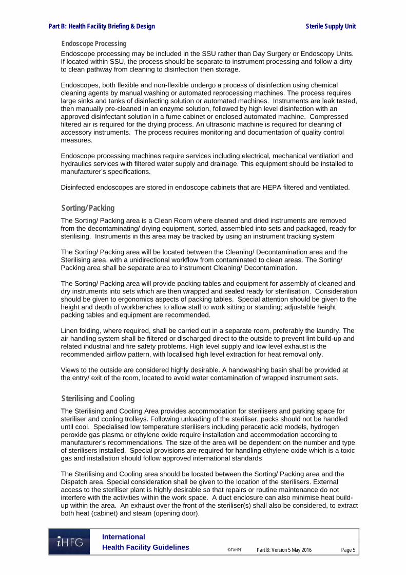
Part B: Health Facility Briefing & Design Sterile Supply Unit
International
Health Facility Guidelines © TAHPI
Part B: Version 5 May 2016
Page 5
Endoscope Processing Endoscope processing may be included in the SSU rather than Day Surgery or Endoscopy Units. If located within SSU, the process should be separate to instrument processing and follow a dirty to clean pathway from cleaning to disinfection then storage. Endoscopes, both flexible and non-flexible undergo a process of disinfection using chemical cleaning agents by manual washing or automated reprocessing machines. The process requires large sinks and tanks of disinfecting solution or automated machines. Instruments are leak tested, then manually pre-cleaned in an enzyme solution, followed by high level disinfection with an approved disinfectant solution in a fume cabinet or enclosed automated machine. Compressed filtered air is required for the drying process. An ultrasonic machine is required for cleaning of accessory instruments. The process requires monitoring and documentation of quality control measures. Endoscope processing machines require services including electrical, mechanical ventilation and hydraulics services with filtered water supply and drainage. This equipment should be installed to manufacturer’s specifications. Disinfected endoscopes are stored in endoscope cabinets that are HEPA filtered and ventilated.
Sorting/ Packing
The Sorting/ Packing area is a Clean Room where cleaned and dried instruments are removed from the decontaminating/ drying equipment, sorted, assembled into sets and packaged, ready for sterilising. Instruments in this area may be tracked by using an instrument tracking system The Sorting/ Packing area will be located between the Cleaning/ Decontamination area and the Sterilising area, with a unidirectional workflow from contaminated to clean areas. The Sorting/ Packing area shall be separate area to instrument Cleaning/ Decontamination. The Sorting/ Packing area will provide packing tables and equipment for assembly of cleaned and dry instruments into sets which are then wrapped and sealed ready for sterilisation. Consideration should be given to ergonomics aspects of packing tables. Special attention should be given to the height and depth of workbenches to allow staff to work sitting or standing; adjustable height packing tables and equipment are recommended. Linen folding, where required, shall be carried out in a separate room, preferably the laundry. The air handling system shall be filtered or discharged direct to the outside to prevent lint build-up and related industrial and fire safety problems. High level supply and low level exhaust is the recommended airflow pattern, with localised high level extraction for heat removal only. Views to the outside are considered highly desirable. A handwashing basin shall be provided at the entry/ exit of the room, located to avoid water contamination of wrapped instrument sets.
Sterilising and Cooling
The Sterilising and Cooling Area provides accommodation for sterilisers and parking space for steriliser and cooling trolleys. Following unloading of the steriliser, packs should not be handled until cool. Specialised low temperature sterilisers including peracetic acid models, hydrogen peroxide gas plasma or ethylene oxide require installation and accommodation according to manufacturer's recommendations. The size of the area will be dependent on the number and type of sterilisers installed. Special provisions are required for handling ethylene oxide which is a toxic gas and installation should follow approved international standards The Sterilising and Cooling area should be located between the Sorting/ Packing area and the Dispatch area. Special consideration shall be given to the location of the sterilisers. External access to the steriliser plant is highly desirable so that repairs or routine maintenance do not interfere with the activities within the work space. A duct enclosure can also minimise heat build-up within the area. An exhaust over the front of the steriliser(s) shall also be considered, to extract both heat (cabinet) and steam (opening door).

Part B: Health Facility Briefing & Design Sterile Supply Unit
International
Health Facility Guidelines © TAHPI
Part B: Version 5 May 2016
Page 6
Dispatch Area
The Dispatch area will coordinate the distribution of sterile stock to the required hospital units. It will include a counter or desk and trolley holding space for packed trolleys awaiting delivery. The Dispatch area will require external access for hospital units to collect urgent stock with restricted access to the internal departmental areas. An After Hours cupboard may be provided in this area for staff to collect urgent supplies, preferably a pass-through cabinet with internal access for re-stocking.
Support Areas
Support areas include Cleaner’s rooms, Disposal rooms and store rooms for chemicals and sterile stock. Cleaner’s rooms should be provided separately in clean and dirty areas of the unit. The Disposal room should be located with access to an external corridor for ease of waste removal, without accessing the Unit. Sterile Stock stores for Operating Unit and other hospital units should be provided separately. The Sterile Stock rooms will require positive pressure, filtered air with humidity and temperature control to ensure stock is maintained in a sterile condition. The level of filtration provided should equal or exceed that of Operating Rooms. The chemical store will hold chemicals used in the washing/ decontaminating process and may be reticulated to the washing equipment. An external access is recommended for delivery of chemical supplies.
Administrative and Staff Areas
Change areas for staff will include toilets, showers, handbasins and lockers with facilities for clean linen holding. All staff working in this Unit must wear personal protective equipment and clothing, including eye and ear protection due to equipment noise in decontamination areas and hospital attire in clean areas. The Change rooms should be located with external access and convenient and separate internal access to clean and dirty operational areas. There should be no cross flows for staff accessing clean and dirty areas of the Unit. Change rooms will include storage for used clothing which will require collection and removal to the Disposal room. Change rooms may be shared with an adjacent Operating Unit if located conveniently. Offices or workstations will be required for routine clerical/ administrative procedures, located in the staff accessed areas. Offices for the Manager/ Supervisor and should have oversight of the operational areas within the Unit. The provision of offices will depend upon the size of the Unit. An area for storage of stationery and files should be provided. Access to a Meeting Room will be required for staff meetings and training purposes, which may be shared with an adjacent Unit.

Part B: Health Facility Briefing & Design Sterile Supply Unit
International
Health Facility Guidelines © TAHPI
Part B: Version 5 May 2016
Page 7
Functional Relationships
External
The Sterile Supply Unit (SSU) should be located with direct or close access to the Operating Unit and Day Surgery Units. This may be achieved with the use of lifts. The SSU should have ready access to:
Service units of the hospital including Supply Unit, Linen Handling Unit and the Loading Dock for delivery of supplies
Hospital units requiring return and delivery of sterilised items including critical care units and inpatient units.
Access to the SSU should be restricted to authorised personnel only.
Internal
A unidirectional flow for instrument processing from contaminated or dirty areas to clean and sterile areas is critical to the functioning of the Unit. The following represents correct relationships in the processing from dirty to clean:
Goods arrive from clinical areas to the Cleaning/ Decontamination Area (dirty) via lifts or service corridors to a holding area
Trolleys and instruments are processed through the cleaning/ decontamination area and trolley wash and move to the Sorting/ Packing area – a clean zone
There is a separation between dirty and clean areas with controlled entries and no back-flow; airlocks may be required to maintain the air pressurisation of the separate zones
Goods then flow from clean packing areas to the sterile areas and then delivered to clinical units
Incoming clean goods are taken directly to a neutral or clean zone including non-sterile supplies and loan equipment
There is a separate entry for staff who may only enter clean areas through a controlled entry
Staff leaving the dirty zone re-enter via change rooms. These relationships are demonstrated in the Functional Relationships Diagram below The diagram demonstrates the flow of goods, staff as well as desirable relationships between external and internal zones.

Part B: Health Facility Briefing & Design Sterile Supply Unit
International
Health Facility Guidelines © TAHPI
Part B: Version 5 May 2016
Page 8
Functional Relationships Diagram
Endoscope processing may be included within the SSU or located as a separate discreet function located within ar adjacent to Day Surgery or Endospy Units. The hospital’s Operational Policies will determin the inclusion of endoscope processing within the SSU. The above diagram demonstrates good functional external relationships which include:
A direct link to/ from the Operating Unit and Day Surgery for goods returned and supplied; this may be by lift
Access from hospital units to the SSU directly from a circulation corridor
Controlled access to the Unit from circulation corridor.

Part B: Health Facility Briefing & Design Sterile Supply Unit
International
Health Facility Guidelines © TAHPI
Part B: Version 5 May 2016
Page 9
The most favourable internal relationships include:
Arrival of returned goods from circulation corridor to dirty receiving area
Arrival of clean goods to a separate entry with access to clean processing areas
Staff access though a separate entry via Change Room
Separation of Cleaning/ Decontamination from Sorting Packing
Sterile stock adjacent to Sterlising, with direct access to Dispatch or lift for delivery to Units. 3 Design
General Two classifications of goods are received by the SSU: contaminated items and raw materials. Design solutions must ensure the separation of clean and dirty products, avoiding routes and cross-flows which potentially could re-contaminate processed items or adversely affect the microbiology of raw materials. There must be a unidirectional workflow from contaminated to clean and sterile areas. Adequate circulating space to accommodate trolleys and containers demanded by the departmental workload is required to ensure effective demarcation of clean and dirty areas.
Environmental Considerations
Acoustics
Provide acoustic treatment for noise generating equipment including washer/ decontaminators, sterilisers and dryers located in Cleaning/ Decontamination and Sterilising areas. Consideration should be given to acoustic privacy in Offices, Staff Rooms and Meeting Rooms.
Natural Light/ Lighting
Natural lighting aids visual inspection and has positive morale on staff. Where natural lighting is not possible, glazed panels should be considered. Windows, where provided, must be non-opening, sealed and flush fitting except in Offices and Staff Rooms. Task lighting, including magnification inspection lights, is desirable for instrument inspection. Light levels shall not be less than 400 lux at the working surface. Light fittings shall be fully recessed and selected to prevent dust and insects from entering.
Space Standards and Components
Doors
Adequately sized automatic/semi-automatic doors are recommended for ease of passage of collection and distribution trolleys.
Ergonomics/ OH&S
Consideration should be given to ergonomic functionality in the Unit. Benches, sinks and packing workstations should be provided as suitable working heights. Adjustable height equipment is recommended. The following occupational health and safety issues should be addressed during planning and design for staff safety and welfare:
Manual handling of heavy instrument that may require lifting equipment
Chemical agents used in Cleaning/ Decontamination processes may require specific chemical handling requirements (Refer to local regulations)
Electrical and fire hazards related to equipment in use
Biological hazards of contaminated equipment undergoing processing, which requires stringent infection control management
Refer to Part C – Access, Mobility and OH&S of these guidelines for further information
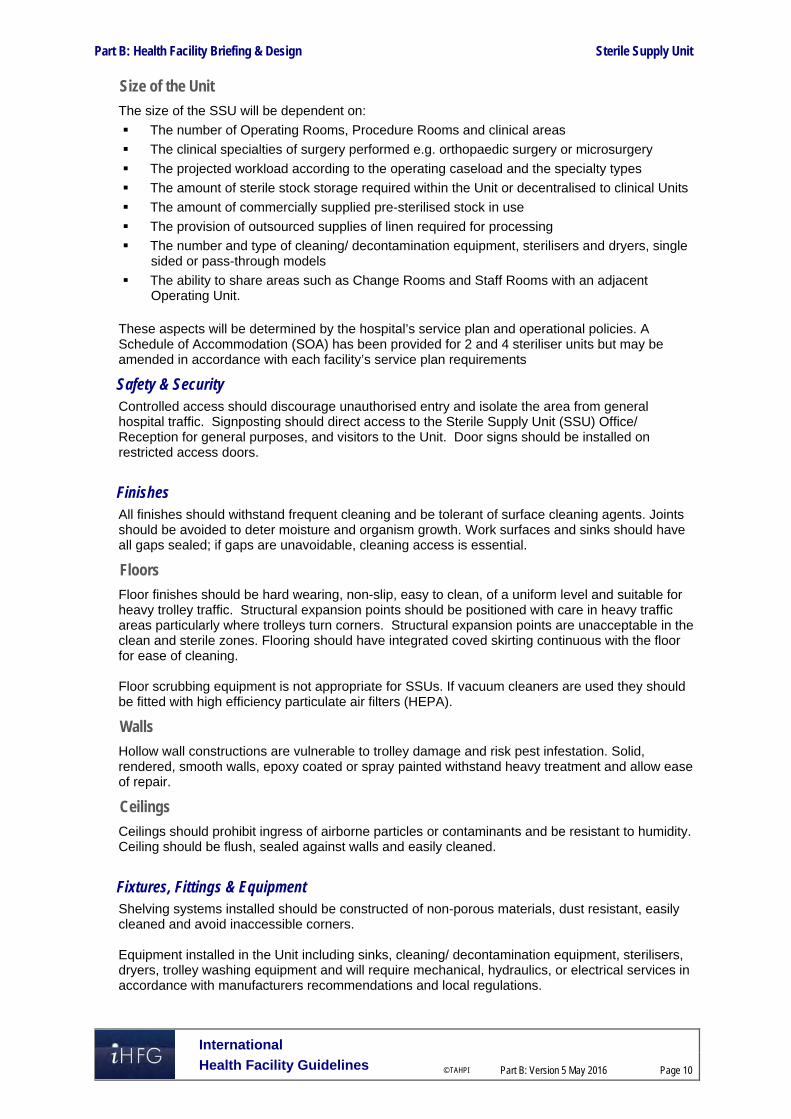
Part B: Health Facility Briefing & Design Sterile Supply Unit
International
Health Facility Guidelines © TAHPI
Part B: Version 5 May 2016
Page 10
Size of the Unit
The size of the SSU will be dependent on:
The number of Operating Rooms, Procedure Rooms and clinical areas
The clinical specialties of surgery performed e.g. orthopaedic surgery or microsurgery
The projected workload according to the operating caseload and the specialty types
The amount of sterile stock storage required within the Unit or decentralised to clinical Units
The amount of commercially supplied pre-sterilised stock in use
The provision of outsourced supplies of linen required for processing
The number and type of cleaning/ decontamination equipment, sterilisers and dryers, single sided or pass-through models
The ability to share areas such as Change Rooms and Staff Rooms with an adjacent Operating Unit.
These aspects will be determined by the hospital’s service plan and operational policies. A Schedule of Accommodation (SOA) has been provided for 2 and 4 steriliser units but may be amended in accordance with each facility’s service plan requirements
Safety & Security Controlled access should discourage unauthorised entry and isolate the area from general hospital traffic. Signposting should direct access to the Sterile Supply Unit (SSU) Office/ Reception for general purposes, and visitors to the Unit. Door signs should be installed on restricted access doors.
Finishes All finishes should withstand frequent cleaning and be tolerant of surface cleaning agents. Joints should be avoided to deter moisture and organism growth. Work surfaces and sinks should have all gaps sealed; if gaps are unavoidable, cleaning access is essential.
Floors
Floor finishes should be hard wearing, non-slip, easy to clean, of a uniform level and suitable for heavy trolley traffic. Structural expansion points should be positioned with care in heavy traffic areas particularly where trolleys turn corners. Structural expansion points are unacceptable in the clean and sterile zones. Flooring should have integrated coved skirting continuous with the floor for ease of cleaning. Floor scrubbing equipment is not appropriate for SSUs. If vacuum cleaners are used they should be fitted with high efficiency particulate air filters (HEPA).
Walls
Hollow wall constructions are vulnerable to trolley damage and risk pest infestation. Solid, rendered, smooth walls, epoxy coated or spray painted withstand heavy treatment and allow ease of repair.
Ceilings
Ceilings should prohibit ingress of airborne particles or contaminants and be resistant to humidity. Ceiling should be flush, sealed against walls and easily cleaned.
Fixtures, Fittings & Equipment Shelving systems installed should be constructed of non-porous materials, dust resistant, easily cleaned and avoid inaccessible corners. Equipment installed in the Unit including sinks, cleaning/ decontamination equipment, sterilisers, dryers, trolley washing equipment and will require mechanical, hydraulics, or electrical services in accordance with manufacturers recommendations and local regulations.

Part B: Health Facility Briefing & Design Sterile Supply Unit
International
Health Facility Guidelines © TAHPI
Part B: Version 5 May 2016
Page 11
Building Service Requirements
Communications
Voice and telephone communications should be installed within the Cleaning/ Decontamination area, the Sorting/ Packing, Sterile areas and Offices to allow contact with outside personnel and departments, without breaching contaminated and clean areas. Management Information Systems (MIS) require adequate data points and electrical points for the tracking and tracing of products and quality assurance records passing through the decontamination process including wet areas, packing areas and sterilising areas.
Heating, Ventilation & Airconditioning The Sterile Supply Unit is a controlled environment and ventilation shall be provided by a treated air supply, with compliant air-conditioning systems and HEPA filters. Positive air pressure differential should be maintained above that of the surrounding areas in Clean and sterile zones. Negative pressure should be maintained in Cleaning/ Decontamination areas. Indicators and alarms systems to alert staff of ventilation system failure should be provided. Humidification will be required to avoid dehydration and subsequent processing problems associated with absorbent materials. Washers-disinfectors, sterilizers emit considerable heat and humidity affecting electronic controls. Fully insulated pipework and machinery backed up by extract ventilation is essential to ensure tolerable working conditions, conserve energy and minimise operating costs. Heat recovery from ventilation systems should be incorporated where appropriate.
Services Maintenance access to steriliser plant should be outside ‘clean’ areas and avoid disruption to the SSU and staff work areas wherever possible. Easy direct access to the front of the sterilisers in the loading/ unloading area and the discharge side for double door machines must be allowed. Mechanical service points e.g. drainage manholes, fire hose reels etc. should be designed out of the SSU area. Sterile Stock areas should not include floor waste outlets. Emergency power should be provided to all essential cleaning/ decontaminating and sterilising equipment. Steam may be provided by local plant generating equipment or sterilising equipment may have integral steam generation. If steam generating plant equipment is to be installed, location to avoid excessive distance from sterilisers will require careful consideration. Water quality will require investigation for efficient functioning of cleaning/ decontamination and sterilising equipment. Water filtration may be required to specific washer/ decontaminators.
Infection Control Handwashing facilities should be provided at the following locations:
Entry and exit of cleaning/ decontamination areas
Entry/ exit of clean and sterile areas. Handbasins should be located to avoid water splashing on clean and sterile goods.
Disaster Planning The SSU should be capable of continued operation during and after a natural disaster, except in instances where a facility sustains primary impact. Special design consideration is needed to protect essential services such as emergency power generation, heating and/or cooling systems, water supply etc.

Part B: Health Facility Briefing & Design Sterile Supply Unit
International
Health Facility Guidelines © TAHPI
Part B: Version 5 May 2016
Page 12
4 Components of the Unit
Standard Components The Sterile Supply Unit Schedule of Accommodation includes a number of Standard Components to comply with Standard Components Room Data Sheets and Room Layout Sheets.
Non Standard Components Non Standard Components are identified in the Schedule of Accommodation as NS and are detailed below:
Receiving Area
This area will receive and hold trolleys and used instruments awaiting processing to cleaning areas. Trolleys and instruments will be sorted initially and waste removed. The Receiving areas will be located with direct access to a circulation corridor or dirty lift from the Operating Unit. There should be controlled or automatic entry door access. The Receiving Area will require:
Benches and sinks with parking space for trolleys
Hot and cold water outlets to sinks
Smooth, impervious and easily cleanable surfaces to walls and ceiling
Impervious and wet area non-slip finishes to the floor
Staff handwashing basin.
Decontamination Area
The Decontamination area includes cleaning/ decontamination processing and trolley washing. The Decontamination area should be located between the Receiving areas and Sorting/ Packing areas. The Decontamination area will require the following finishes:
Walls and ceiling that are smooth, impervious, and easily cleanable
Impervious and wet area non-slip finishes to the floor. Fittings, fixtures and equipment located in this area will include the following:
Stainless steel benches and deep bowl sinks with air and suction outlets for tube cleaning and additional water outlets for water pistols
Instrument and tubing washers/ decontaminators, according to service requirements; these may be single sided, pass through or index tunnel washers
Ultrasonic cleaner, built-in, with consideration to the working height of instrument baskets
Instrument and tubing dryers, as required by the service plan
Staff handwashing basin Exhaust air extraction will be required over sinks and heat/ moisture generating equipment. The trolley washing area will require hot and cold water outlets for manual washing. An automated trolley wash unit may be used
Sorting & Packing
This area is a Clean Room and will include a number of sorting/ packing workstations with areas for parking trolleys, heat sealing devices, examination and testing of instruments. The Sorting/ Packing area will be located between the Cleaning/ Decontamination area and Sterilising/ Cooling area in a one-way flow. Controlled access will be required for staff. The Sorting/ Packing area will require the following finishes:
Walls and ceiling that are smooth, impervious, and easily cleanable
Impervious, non-slip finishes to the floor.

Part B: Health Facility Briefing & Design Sterile Supply Unit
International
Health Facility Guidelines © TAHPI
Part B: Version 5 May 2016
Page 13
Requirements in this area will include the following:
Packing tables complete with wrapping materials, tracking systems, ergonomically designed to avoid staff fatigue; adjustable height stations are recommended
Sealing equipment
Trolleys for holding wrapped sets ready for sterilising
Staff handwashing basin at the entry/ exit, located to avoid water splashing on clean, wrapped sets
Positive pressure HEPA filtered air conditioning with filtration for lint.
Sterilising/ Cooling
This is a sterile area and includes high and low temperature sterilisers with space for loading/ unloading and a cooling area for packed trolleys removed from sterilisers. Sterilising/ Cooling is located between Sorting/ Packing and Sterile Stock stores with a one-way flow The Sterilising/ Cooling area will require the following finishes:
Walls and ceiling that are smooth, impervious, and easily cleanable
Impervious, non-slip finishes to the floor. High temperature sterilisers may be single sided or pass-through. Steriliser plant equipment should ideally have external access for maintenance to avoid access to the Unit A workstation may be located in this area for quality assurance documentation and instrument tracking. The air handling requirements of this area include:
Positive pressure with HEPA filtration
Efficient exhaust for heat/ steam generating equipment
Filtration for lint.
Low temperature sterilisers will require specialised services and should be installed to manufacturer’s specifications.
Dispatch
Dispatch will include a staff station or counter for coordination of deliveries and space for holding packed trolleys awaiting delivery via a circulation corridor or by clean lift to Operating Unit. A double sided after-hours cupboard may be provided for urgent collections out of operating hours. The Dispatch should be located between Sterile Stock Stores and an external circulation corridor. There should be controlled access to Dispatch with a doorbell or intercom point to alert staff. The Dispatch area will require the following finishes:
Walls and ceiling that are smooth, impervious, and easily cleanable
Impervious, non-slip finishes to the floor. Instrument tracking facilities including computers, power and data outlets will be required in this area.

Part B: Health Facility Briefing & Design Sterile Supply Unit
International
Health Facility Guidelines © TAHPI
Part B: Version 5 May 2016
Page 14
5 Schedule of Accommodation – Sterile Supply Unit Sterile Supply Unit for 2 and 4 sterilisers
ROOM/ SPACE Standard Component 2 Sterilisers 4 Sterilisers Remarks Room Codes Qty x m2 Qty x m2
Receiving Area Reception/ Office OFF-S9-I 1 x 9
Trolley Holding NS 1 x 50 1 x 100 Increase area for case cart system
Trolley Stripping NS 1 x 15 1 x 30
Receiving Area - Used Instruments NS 1 x 30 1 x 50 May include Dirty return lift
Goods Receipt – Non Sterile Stock STGN-14-I 1STGN-30-I (sim) 1 x 15 1 x 25
Loan Equipment Store STGN-20-I STEQ-40-I (sim) 1 x 20 1 x 50 Size dependent on service plan
Decontamination Area
Cleaning/ Decontamination NS 1 x 85 1 x 170
Trolley Wash NS 1 x 15 1 x 30 May be automated trolley wash
Sorting & Packing
Airlock AIRL-6-I 1 x 6 1 x 6 To maintain air pressurisation
Instrument Sorting, Assembly & Packing NS 1 x 80 1 x 225
Sterilising & Cooling Area
Airlock AIRL-6-I 1 x 6 1 x 6 To maintain air pressurisation
Sterilising – High Temperature NS 1 x 50 1 x 100 4 sterilisers with expansion space for an additional 2 sterilisers
Sterilising – Low temperature NS 1 x 15 1 x 30 2 sterilisers with expansion space for an additional 2 sterilisers
Steriliser Plant NS 1 x 15 1 x 30
Cooling NS 1 x 25 1 x 50
Dispatch Area
After Hours Cupboard NS 1 x 4 1 x 4 Access from inside & outside the Unit
Dispatch NS 1 x 10 1 x 15 Collection and sterile stock dispatch
Support Areas
Bay – Handwashing, Type B BHWS-B-I 2 x 1 2 x 1 At entry/ exit to Decontamination & Packing areas
Cleaner’s Room CLRM-5-I 1 x 7 2 x 5 Separate Cleaners room or closet in Clean areas

Part B: Health Facility Briefing & Design Sterile Supply Unit
International
Health Facility Guidelines © TAHPI
Part B: Version 5 May 2016
Page 15
ROOM/ SPACE Standard Component 2 Sterilisers 4 Sterilisers Remarks Room Codes Qty x m2 Qty x m2
Disposal Room DISP-8-I DISP-10-I 1 x 8 1 x 10
Store - Chemical STCM-I 1 x 4 1 x 6 Chemicals used in decontamination
Store - General STGN-14-I STGN-20-I 1 x 14 1 x 20
Store - Sterile Stock STSS-40-I STSS-80-I (similar) 1 x 75 1 x 150 For supplying hospital units & Operating Units, OR component may be within OR Unit
Administration & Staff Areas
Change - Staff (Male/ Female) CHST-14-I CHST-20-I 2 x 14 2 x 20 Shower, Toilet, Lockers, Change area
Meeting Room MEET-L-15-I 1 x 15 May be shared with adjacent Unit
Office - Single Person, 9m2 OFF-S9-I 1 x 9 1 x 9 Manager
Staff Room SRM-12-I SRM-15-I 1 x 12 1 x 15
Store - Photocopy/ Stationery STPS-8-I 1 x 8
Sub Total 600.0 1215.0
Circulation % 25 25
Area Total 750.0 1518.8 Please note the following: This SOA assumes linen is provided from external sources ready for use, and linen sorting, examination and folding areas are not required Areas noted in Schedules of Accommodation take precedence over all other areas noted in the FPU. Rooms indicated in the schedule reflect the typical arrangement according to the Role Delineation. Exact requirements for room quantities and sizes will reflect Key Planning Units identified in the Service Plan and the Operational Policies of the Unit. Room sizes indicated should be viewed as a minimum requirement; variations are acceptable to reflect the needs of individual Unit. Office areas are to be provided according to the Unit role delineation and number of endorsed full time positions in the unit. Staff and support rooms may be shared between Functional Planning Units dependent on location and accessibility to each unit and may provide scope to reduce duplication of
facilities.

Part B: Health Facility Briefing & Design Sterile Supply Unit
International
Health Facility Guidelines © TAHPI
Part B: Version 5 May 2016
Page 16
Endoscope Processing for 2 and 4 Decontamination Units (Optional, Collocated with Sterile Supply)
ROOM/ SPACE Standard Component 2 Decon units 4 Decon units Remarks Room Codes Qty x m2 Qty x m2
Entry/ Decontamination Area
Airlock AIRL-6-I 1 x 6 1 x 6
Endoscope Receiving NS 1 x 10 1 x 15
Cleaning/ Decontamination NS 1 x 20 1 x 50
Endoscope Reprocessing
Endoscope Reprocessing NS 1 x 20 1 x 50 Reprocessing & packing
Endoscope Store
Endoscope Store NS 1 x 10 1 x 25 May be located adjacent to Endo Procedure Rooms
Dispatch Area
Dispatch NS 1 x 10 1 x 10 Optional; Collection/dispatch of disinfected scopes
Support Areas
Bay – Handwashing, Type B BHWS-B-I 2 x 1 2 x 1 At entry/ exit to Decontamination & Reprocessing areas
Cleaner’s Room CLRM-5-I 1 x 5 May be shared with adjacent Unit
Store - Chemical STCM-I 1 x 4 1 x 6 Chemicals used in decontamination
Store - General STGN-6-I STGN-10-I 1 x 6 1 x 10 Supplies used in processing
Administration & Staff Areas
Change - Staff (Male/ Female) Shared with adjacent Unit
Meeting Room Shared with adjacent Unit
Office - Single Person, 9m2 OFF-S9-I 1 x 9 Supervisor
Staff Room Shared with adjacent Unit
Sub Total 88.0 188.0
Circulation % 25 25
Area Total 110.0 235.0 Please also refer to Notes on SSU Schedule of Accommodation

Part B: Health Facility Briefing & Design Sterile Supply Unit
International
Health Facility Guidelines © TAHPI
Part B: Version 5 May 2016
Page 17
6 Future Trends Future trends affecting Sterile Supply Units include:
Increasing awareness of storage, ergonomics and OH&S concerns within Sterile Supply Units
Greater reliance on outsourced sterile supplies by healthcare facilities
Healthcare facility, consumer and specialist demands for faster instrument turnaround times placing pressure on existing Sterile Supply Units
WHO and industry demands to ensure facilities enforce validated guidelines for cleaning, sterilization exposure time and use of rigid transport containers
Technological advancements made in medical instruments such as endoscopes and analysers that demand compatible sterilisers and techniques
Demands to reduce reliance on immediate-use steam sterilization (flash sterilisation) requiring effective policies and procedures relating to loan instrumentation
Healthcare facility requirements to ensure Sterile Supply Unit staff have appropriate training, education and resources to follow process monitoring systems according to the manufacturer's instructions
Continued improvements in low-temperature sterilization systems resulting in reduced processing times and expanded capabilities for instrument reprocessing.
E-beam radiation and gamma sterilization that are creating new opportunities for advancement in sterilization techniques.
7 Further Reading
AS/NZS 4187: 2014 – ‘Reprocessing of reusable medical devices in health service organizations’, Refer to: http://infostore.saiglobal.com/store/details.aspx?ProductID=1773923
Australasian Health Facility Guidelines, Part B Health Facility Briefing and Planning, Rev 5, 2016; refer to website www.healthfacilitydesign.com.au
Guidelines for Design and Construction of Health Care Facilities; The Facility Guidelines Institute, 2014 Edition refer to website www.fgiguidelines.org
HBN 13, 2004, Sterile Services Department, Department of Health UK, Refer to: https://www.gov.uk/government/uploads/system/uploads/attachment_data/file/148489/HBN_13.pdf
ISO Standard 14644-1: 2015 ‘Cleanrooms and associated controlled environments – Part 1: Classification of Air Cleanliness by Particle Concentration’ http://www.iso.org/iso/catalogue_detail?csnumber=53394
ISO Standard 14937: 2009, Sterilization of health care products -- General requirements for characterization of a sterilizing agent and the development, validation and routine control of a sterilization process for medical devices, Refer to: http://www.iso.org/iso/iso_catalogue/catalogue_tc/catalogue_detail.htm?csnumber=44954
Philip M. Schneider New technologies and trends in sterilization and disinfection , American Journal of Infection Control, Vol. 41, Issue 5, S81–S86, Refer to: http://www.ajicjournal.org/article/S0196-6553(13)00017-5/fulltext
Rose Seavey, RN, BS, MBA, CNOR, CRCST, CSPDT Current Sterilization Trends, Challenges and Tools, Refer to: www.beckersasc.com/.../current-sterilization-trends-challenges-and-tools
Standards for Endoscopic Facilities and Services, Gastrointestinal Society of Australia (GESA) 2011, Refer to: http://www.gesa.org.au/professional.asp?cid=9&id=131
Part B – Health Facility Briefing & Design 285 Supply Unit
International Health Facility Guidelines Version 4 May 2014

International
Health Facility Guidelines © TAHPI
Part B: Version 4 2014
Page 2
Table of Contents
285 Supply Unit ................................................................................................................................ 3 1 Introduction ............................................................................................................................................... 3 2 Planning ..................................................................................................................................................... 3 3 Design ........................................................................................................................................................ 4 4 Components of the Unit ............................................................................................................................ 5 5 Schedule of Accommodation – Supply Unit ........................................................................................... 6 6 Functional Relationship Diagram - Supply Unit ..................................................................................... 8 7 References and Further Reading ............................................................................................................. 9

Supply Unit
International
Health Facility Guidelines © TAHPI
Part B: Version 4 2014
Page 3
285 Supply Unit 1 Introduction Description The Supply Unit shall provide for the following functions: purchase and receipt of equipment and bulk medical supplies storage of bulk dry goods, consumables, intravenous fluids, drugs and flammable liquids storage of emergency stock for the facility storage of surplus hospital equipment and equipment awaiting repairs deliveries to hospital units for regular restocking of unit based supplies 2 Planning Operational Models The Supply Unit will generally operate during the day with limited entry provisions after hours. Planning Models Supply Unit will consist of a number rooms and areas for storing high volumes of goods, equipment and furniture as necessary. The rooms may vary in sizes depending on the items to be stored and the frequency of stock delivery. The storage areas may be centrally located within the Supply Unit with satellite storage rooms provided closer to the areas requiring specific stock items.
Functional Areas
The Supply Unit consists of the following Functional Areas: Loading Dock Goods Receipt area Dispatch areas for stock awaiting collection Storage areas which may include bulk stores, palleted supplies, flammable stores, furniture
and equipment, gas bottles and equipment for loan to outpatients Staff areas including Offices, Workstations and access to Staff Change and Toilets.
Goods Receipt A dedicated Goods Receipt area shall be provided for the receipt, checking, sorting and temporary holding of incoming stock. The Goods Receipt will require off street unloading facilities. The Goods Receipt shall be located adjacent to the Loading Dock and with ready access to the Bulk Store. Security for incoming stock will require consideration. Visual control of the area from the Store Manager's office is recommended to discourage dumping/leaving of deliveries without proper receiving by Stores personnel. The Goods Receipt may include a workstation with computer.
Dispatch Area The Dispatch Area may be used to hold stores which are ready to be delivered to hospital units or stores that are ready to be collected by external contractors such as loaned equipment and incorrect deliveries. It should be located with easy access to the Loading Dock.
Storage Areas (Bulk) The size of Storage Areas will be determined by the type of items to be stored and the frequency of stock delivery. Stocks are to be stored in heavy duty shelving or on clean pallets which should elevate the goods off the floor.

Supply Unit
International
Health Facility Guidelines © TAHPI
Part B: Version 4 2014
Page 4
Cool room or refrigerators may be required for delivered items which have to be kept at cooler temperatures while awaiting delivery or pick-up to designated Units within the facility. If sterile items are to be stored in the Supply Unit, it is recommended that they are stored separately from non-sterile items. Sterile items are recommended to be stored in shelving which are 250mm minimum from the floor and not too close to the ceiling. IV Fluids may be stored in a designated area within the Bulk Store if IV Fluid storage area is not already provided in the Pharmacy Unit.
Storage Areas – Equipment This area is used for the storage of medical equipment and some furniture for use in the facility. Equipment such as infusion pumps will also be recharged in this room. Additional storage areas for equipment for loan to patients and outpatients should be provided in an amount not less than 5 percent of the total area of the Outpatient Facilities. This may be combined with and in addition to the Equipment Store or be located in a central area within the Outpatient Unit. This storage requirement is generally for therapy equipment and mobility aids loaned to patients. A portion of this storage area may be provided off-site. Functional Relationships
External
The Supply Unit may be located in a separate building on-site, but the preferred location is within the main building. A portion of the storage may be located off-site. Protection against inclement weather during transfer of supplies shall be provided. Fire protection and security are important considerations.
Internal
The Bulk Store is the primary storage area for all delivered supplies and store prior to distribution to various Hospital Units. It shall be located with ready access to the Loading Dock area. This area requires security and controlled access. The Bulk Store should be located within easy access to services/ goods lift for transportation of materials to the hospital units. The corridor should permit two-way traffic of bulky items and should be restricted access to public. 3 Design General Loading Dock shall be a covered area for transport access to service Units for delivery or collection of goods and shall be zoned into clean and dirty areas. This may be shared between a number of Support Service Units (e.g. Catering Unit, Linen Handling, and Supply Unit). Environmental Considerations
Natural Light
Provide natural light to office and staff areas where possible. Space Standards and Components
Ergonomics
Consideration should be given to the need for manual handling devices such as dock levellers and lifters. A well-designed and equipped work area will eliminate injuries resulting from manual handling. Refer also to Part C of these Guidelines.

Supply Unit
International
Health Facility Guidelines © TAHPI
Part B: Version 4 2014
Page 5
Safety and Security All entrances and exits shall be secured. An intercom or call bell should be located at the dock entrance area to announce deliveries when doors are closed. Where required, concave directional mirrors along corridors and bends should be provided to avoid collision of oversized trolleys, motorised transporters and staff. Design of the Supply Unit should ensure that storage areas are free from insects and vermin. Flammable liquids and items must be stored in a room designed according to relevant international and local regulations Exhaust should be provided in rooms for storing and recharging of pallet jacks, motorised transporters and other equipment depending on battery type to avoid build-up of noxious gases. Finishes Door & wall protection shall be installed to prevent damage to walls caused by all types of trolleys, lifting/transport equipment and movement of large items. Sturdy wall protection such as rubber or timber wall protection is recommended to withstand impacts from trolleys, pallet jacks and other bulky transporting equipment. Solid core door with stainless steel door and door frame protection is recommended to avoid chipping and breakage. Floor finish is to be non-slip, impervious, easy to clean and hardwearing. Movement of large equipment and lifting/ transporting equipment are to be considered when choosing appropriate floor finish Refer also to Part C of these Guidelines. Fixtures and Fittings Refer to Part C of these Guidelines and Standard Components for information for fixtures and fittings. Building Service Requirements Natural light is not required in storage areas; however, adequate lighting is required in storage areas to avoid shaded spots where accidents can occur. Refer to Part E of these Guidelines. Infection Control Hand-washing facilities should be located in the Supply Unit. Refer to Part D of these Guidelines. 4 Components of the Unit The Supply Unit will contain Standard Components to comply with details described in these Guidelines. Refer also to Standard Components Room Data Sheets and Room Layout Sheets.

Supply Unit
International
Health Facility Guidelines © TAHPI
Part B: Version 3 2012
Page 6
5 Schedule of Accommodation – Supply Unit Supply Unit for Role Delineation Level 3, 4, 5 and 6
ROOM/ SPACE Standard Component RDL 3 RDL 4 RDL 5 RDL 6 Remarks
Room Codes Qty x m2 Qty x m2 Qty x m2 Qty x m2
Supplies Areas
Dispatch Area DIS-8-I DIS-12-I DIS-20-I 1 x 8 1 x 12 1 x 20 1 x 20
Goods Receipt GR-8-I GRE-12-I GRE-20-I 1 x 8 1 x 8 1 x 12 1 x 20
Loading Dock - Clean LODK-I (sim) 1 x 0 1 x 0 1 x 0 1 x 0 External space which may be shared with other Back of House Services. Area as required.
Store - Bulk STBK-50-I STBK-100-I STBK-150-I 1 x 50 1 x 100 1 x 100 1 x 150 Size according to requirements.
Store - Drugs STDR-5-I STDR-10 1 x 5 1 x 5 1 x 10 1 x 10 Optional. May be located in the Pharmacy Unit.
Store - Equipment STEQ-25-I STEQ- 50-I 1 x 25 1 x 25 1 x 50 1 x 50
Store - Flammable Liquid STFL-I (sim) 1 x 9 1 x 9 1 x 9 1 x 9
Store - Gas Bottles STGB-F-I STGB-E-I (sim) 2 x 5 2 x 5 2 x 10 2 x 10 Full and empty bottles to be stored separately. May be located externally at a secure location.
Store - IV Fluids STIV-10-I STIV-20-I STIV-30-I 1 x 10 1 x 20 1 x 20 1 x 30 May be located within Store - Bulk
Store - Refrigerated STREF-5-I STREF-10-I 1 x 5 1 x 5 1 x 10 1 x 10 Optional. May be located as refrigerator bay within Store - Bulk.
Sub Total 130.0 194.0 251.0 319.0
Circulation % 20 20 20 20
Area Total 156.0 232.8 301.2 382.8 Support Areas
Office - Single Person, 12 m2 OFF-S12-I 1 x 12 1 x 12 For Supply Unit Manager
Office - Single Person, 9 m2 OFF-S9-I 1 x 9 2 x 9 1 x 9 1 x 9 For Supply Unit Manager or Purchasing Manager
Office - 2 Persons Shared OFF-2P-I 1 x 12 1 x 12 For Purchasing Officers
Office - Workstation OFF-WS-I 1 x 5.5 2 x 5.5 2 x 5.5 4 x 12 For Purchasing Officers or Supply personnel
Property Bay - Staff PROP-2-I PROP-6-I 2 x 2 2 x 2 2 x 6 2 x 6 Separate for Male & Female
Toilet - Staff (Male/ Female) WCST-I 2 x 3 2 x 3 4 x 3 4 x 3 Separate for Male & Female
Sub Total 24.5 39.0 68.0 105.0
Circulation % 20 20 20 20
Area Total 29.4 46.8 81.6 126.0 Grand Total 185.4 279.6 382.8 508.8

Supply Unit
International
Health Facility Guidelines © TAHPI
Part B: Version 3 2012
Page 7
Please note the following: Areas noted in Schedules of Accommodation take precedence over all other areas noted in the FPU. Rooms indicated in the schedule reflect the typical arrangement according to the Role Delineation. Exact requirements for room quantities and sizes will reflect Key Planning Units identified in the Service Plan and the Operational Policies of the Unit. Room sizes indicated should be viewed as a minimum requirement; variations are acceptable to reflect the needs of individual Unit. Office areas are to be provided according to the Unit role delineation and number of endorsed full time positions in the unit. Staff and support rooms may be shared between Functional Planning Units dependant on location and accessibility to each unit and may provide scope to
reduce duplication of facilities.

Supply Unit
International
Health Facility Guidelines © TAHPI
Part B: Version 3 2012
Page 8
6 Functional Relationship Diagram - Supply Unit

Supply Unit
International
Health Facility Guidelines © TAHPI
Part B: Version 4 2014
Page 9
7 References and Further Reading Australasian Health Facility Guidelines, Part B Health Facility Briefing and Planning, Rev 4,
2012; refer to website www.healthfacilitydesign.com.au The Facility Guidelines Institute (US), 2010 Edition. Guidelines for Design and Construction
of Health Care Facilities) refer to website www.fgiguidelines.org Purchasing and Supply Manual for Public Health Organisations. Jan 2006, NSW Health
Australia, refer to website. http://www.health.nsw.gov.au/policies/

Part B – Health Facility Briefing & Design 290 Waste Management Unit
International Health Facility Guidelines Version 4 May 2014

International
Health Facility Guidelines © TAHPI
Part B: Version 4 2014
Page 2
Table of Contents
290 Waste Management Unit ........................................................................................................... 3 1 Introduction ............................................................................................................................................... 3 2 Planning ..................................................................................................................................................... 3 3 Design ........................................................................................................................................................ 6 4 Components of the Unit ............................................................................................................................ 7 5 Schedule of Accommodation – Waste Management ............................................................................. 8 6 Functional Relationship Diagram – Waste Management ..................................................................... 10 7 References and Further Reading ........................................................................................................... 11

Waste Management Unit
International
Health Facility Guidelines © TAHPI
Part B: Version 4 2014
Page 3
290 Waste Management Unit 1 Introduction Description Waste Management Unit is a designated area of a healthcare facility which is staffed by a multi-disciplinary team whose roles include collection, transport, processing, disposal, managing and monitoring of waste materials generated from the facility. Hospital waste can be divided into five broad categories: Infectious and Pathological Waste Sharp Waste Pharmaceutical Waste Radioactive Waste General Waste The Waste Management Unit should have the following features: Easily accessible from all functional areas Accessible from within the unit and externally Fitted with security fittings such as door locks, keypad/card access, CCTV and motion sensor
depending on operational policy Located away from food and clean storage areas Not accessible to the public. 2 Planning Operational Models The Waste Management Unit will generally operate during the day with limited entry provisions after hours. Planning Models The configuration of the Waste Management Unit will be dependent on: Types of waste to be stored and disposed Frequency of waste collection Processing of waste to be undertaken at the healthcare facility if any The Waste Management Unit should be located on ground level away from publicly accessible areas and areas involved in food preparation and storage. The location should be adjacent to the ‘Dirty’ Loading Dock for easy access by waste collection trucks.
Functional Areas
The Waste Management Unit will include the following Functional Areas: Enclosed dust free workstation with a workbench, telephone and computer outlet to
undertake recording and reporting functions; it should have visual control of the waste handling facility
General dry waste skip or compactor area with direct contractor access for removal; general waste may be compacted on site
General wet waste holding area Loading Dock and area with provision for front load bins Clinical waste holding and cool room Paper and recyclable materials collection Clean bin storage area; a variety of bins need to be stored pending distribution to the hospital
units Designated adequately drained bin & equipment washing area

Waste Management Unit
International
Health Facility Guidelines © TAHPI
Part B: Version 4 2014
Page 4
Storage space for consumables such as plastic bin liners and cleaning materials; could be located adjacent to the Work Management Station.
The following Functional Areas are optional requirements: An area for bin receiving with room for pull tug and cart trolley access and bin sorting A waste weighing and recording station, which includes a floor level digital weighbridge and
bar code recorder. This area will be required if waste handling policy includes weighing and tracking.
An upright freezer may be required to store tissue pending dispatch for incineration. A radioactive waste storage
Clinical Waste Storage Clinical waste includes human or animal tissue, blood and body fluids, pharmaceutical products, syringe, needles, dressings or any other waste which can be hazardous or may cause infection to any person who comes in contact with it. The three groups of clinical waste include: healthcare wastes which pose as a risk of infection (including human tissue, sharps, items in
contact with body fluids, etc.) healthcare wastes which pose as a chemical hazard (including formaldehyde,
gluteraldehyde, mercury, etc. which disposal is governed by local OH&S regulations) pharmaceuticals and medicinally-contaminated wastes which contain pharmaceutically-active
agent (including expired drugs, partially administered medications, vaccines and discarded items used in the handling of pharmaceuticals)
Sharps are healthcare waste that could cause cuts and punctures wounds including needles, needle part of a syringe, scalpel, broken glass ampoules and the patient end of infusion sets. This waste must be segregated from ‘soft’ clinical waste and stored in robust colour coded receptacles which are clearly identifies the presence of sharps prior to being disposed by the authorised waste management contractor. The Clinical Waste Storage is reserved for healthcare clinical waste only. The storage space should be: well-lit and ventilated; adjacent to ‘Dirty’ Loading Dock; located away from food preparation and general storage areas; located away from routes used by the public; totally enclosed and secure; provided with separate storage areas for sharps receptacles, anatomical and pharmaceutical
waste; sited on a well-drained, impervious surface; readily accessible by authorised staff; kept locked when not in use; secure from entry by animals and free from insect or rodent infestations; provided with staff washing facilities; clearly marked with warning signs; appropriately drained to a sewer (if approved by local regulations)
Soiled Linen Holding Bagged soiled linen in trolleys should be temporarily stored prior to collection by external linen supplier. The room should have a staff handwashing basin and the door should be lockable.
Bins and Equipment Washing Bay A specific area, with adequate drainage, for washing bins and equipment should be located between the dirty and clean storage areas.
Refrigerated Storage Waste in storage must not create offensive odour to pose as a nuisance to staff and visitors of the facility. To prevent odours forming in hot weather, clinical & non-clinical waste should be stored in refrigerated storage prior to collection. Refrigerated storage should be fitted with a device to open

Waste Management Unit
International
Health Facility Guidelines © TAHPI
Part B: Version 4 2014
Page 5
the door from the inside and duress alarm to alert staff as a precaution against people from being trapped.
Radioactive Waste Storage Radioactive waste should be handled in a safe manner to ensure that all staff have minimal exposure to radiation. A Radiation Safety Officer will be responsible for the safe handling, storage and transport of radioactive waste. Radioactive waste must be stored in leak proof containers in a specifically identified area for the storage of radioactive waste separate from clinical and general waste storage. The handling, storage and disposal of radioactive materials must comply with requirements of the Radiation Control Act and other relevant local regulations.
General Waste Storage Waste that are assessed and/or classified as inert or solid waste should be stored in a room separate from clinical waste for collection by outside contractors to be sorted, processed and recycled elsewhere.
Recyclable Waste Recyclables such as cardboard, paper, plastic or glass which are composed of materials or components, capable of being remanufactured or reused. Items are considered recyclable if facilities are available to collect and reprocess them.
Liquid Waste Storage/ Discharge Liquid waste that is unsuitable for discharge into a sewer or waterways such as those from decontamination showers and laboratory wastes must be contained to prevent leakage and stored in a bunded area. Liquid waste may be legally discharged into a sewer or waterways only in accordance with local sewerage authority requirements. Functional Relationships
External
The waste handling area will be frequently serviced by site and contractor's vehicles removing waste in carts and front loading bulk bins. It is important that adequate traffic access is provided for delivery and removal of all wastes. The access roads need to be adequate and turning areas uncongested. Noise levels may be significant during waste collection periods. Bulk waste bin movement around the site and during the disposal process may require that the bins are accessed from a raised dock. A variable level platform may be considered as an option. Servicing of waste and linen storage areas should be undertaken via thoroughfares that avoid regular public, patients and staff facilities. Particular attention should be made to avoiding food handling and high profile public areas. A service lift devoted to materials movement within the hospital is highly recommended.
Internal
Contaminated waste bins should be located in strategic collection points for all clinical areas in all FPUs. Collection points such as Disposal Rooms or Dirty Linen Holding in each FPU need to be easily accessible to the staff responsible for disposing of wastes, as well as to those servicing the facility in removing and replacing the bins. Separate robust colour-coded bins will be required for the disposal of sharps, human tissue, cytotoxic and radioactive materials. These bins are to be stored in separate designated areas within the Waste Management Unit prior to collection and disposal. A Dirty Corridor should be provided for transport of waste which should not be used for transport of clean materials such as food items and general supplies for the facilities. The Waste Management administration area should be located where visual control of the loading dock can be achieved.

Waste Management Unit
International
Health Facility Guidelines © TAHPI
Part B: Version 4 2014
Page 6
3 Design Environmental Considerations
Acoustics
Acoustic performance and sound levels shall be designed to contain the noise from waste management equipment such as waste compactors and bin/equipment washers to an acceptable level so as not to affect the functioning of adjacent departments. Space Standards and Components
Ergonomics
The Waste Management Unit should be designed with consideration to ergonomics to ensure an optimal environment. Turning circles for large waste bins and wider corridors are to be considered to allow for two-way traffic. Manual handling may not be eliminated in the Unit; however, a well-designed and equipped work area will eliminate injuries resulting from manual handling. Refer also to Part C of these Guidelines. Safety and Security The Waste Management Unit should not be accessible by public. Card access, intercom or CCTV cameras are to be provided at the Loading Dock and external access for visitor control to the Unit. Where required, concave directional mirrors along corridors and bends should be provided to avoid collision of oversized trolleys, motorised transporters and staff. Emergency stop button should be installed for large equipment such as waste compactors to prevent entrapment. Exhaust should be provided in rooms for storing and recharging of pallet jacks, motorised transporters and other equipment depending on battery type to avoid build-up of noxious gases. Finishes Where appropriate painted block work walls are recommended in areas where large bins and trolleys are to be stored to resist chipping and breakage of wall lining. Floor finish is to be non-slip, impervious, easy to clean and hardwearing. Movement of large equipment and waste receptacles are to be considered when choosing appropriate floor finish. Refer also to Part C and Part D of these Guidelines Fixtures and Fittings Sturdy and robust door and wall protection are recommended to withstand impacts from large waste bins and trolleys. Timber or rubber wall guards and corner guards, and stainless steel door and frame protection will resist bumps from large equipment better than PVC or vinyl wall and door protection. Water proof fixture and fittings are to be installed in all wet and dirty areas for easy cleaning and disinfecting. Cool rooms for waste storage are to be fitted with proprietary cool room or built on site as per industry requirements and local regulations. Refer also to Standard Components Room Data Sheets and Room Layout Sheets for Furniture, Fittings and Fixtures requirements. Infection Control Walls and floors in areas used for waste storage should be sealed to allow easy cleaning.

Waste Management Unit
International
Health Facility Guidelines © TAHPI
Part B: Version 4 2014
Page 7
Hand-washing facilities should be located adjacent to the waste collection area where clinical waste is handled. Storage bays for Personal Protective Equipment (PPE) such as heavy duty gloves, safety shoes, protective face visors or goggles should be conveniently located to improve staff compliance thereby avoiding preventable risks. Refer to Part D of these Guidelines for further information. Pest & Insects Control Waste storage areas must be designed to prevent the harbourage of vermin and insects. Some examples of preventative measures includes provision of suitable waste receptacles, application of mesh to drains, installation of flushing drains and insect zapper near entry to waste storage. Building Service Requirements Building service requirements for the Waste Management Unit will include the following: The temperature with the waste handling area should be maintained at a temperature that
helps control odours; ideally a negative pressure environment should be provided to contain the spread of odours. Temperature monitor and alarm should be connected to Biomedical Services to alert staff of any malfunction.
Hot and cold water outlets with a hose spray are the minimum requirements to be provided for cleaning waste holding areas and bins as required
A high pressure wash down unit should be provided for the adequate cleaning of the area. Drainage from this area may include disinfectants; therefore liquid wastes may require
special treatment prior to discharge. Walls and floors should be sealed to withstand the frequent wash downs and the floors
graded to allow run off. All power points provided in the waste storage, equipment washing and disposal area should
be waterproof to allow for thorough cleaning of floors and walls. Lighting should be adequate to allow staff to see clearly especially in waste storage areas
and corridors. 4 Components of the Unit The Waste Management Unit will contain Standard Components comply with details described in these Guidelines. Refer also to Standard Components Room Data Sheets and Room Layout Sheets.

Waste Management Unit
International
Health Facility Guidelines © TAHPI
Part B: Version 4 2014
Page 8
5 Schedule of Accommodation – Waste Management Waste Management Unit for Role Delineation Level 4 and 5/6
ROOM/ SPACE Standard Component RDL 1 & 2 RDL 3 RDL 4 RDL 5/6 Remarks
Room Codes N/A N/A Qty x m2 Qty x m2
Waste Storage Area
Bay - Handwashing, Type B BHWS-B-I 1 x 1 2 x 1 Refer to Part D
Bay - Emergency Shower BES-I 1 x 1 1 x 1
Bin Washing Area BWA-10-I BWA-15-I 1 x 10 1 x 15 Optional. May be done off site.
Cool room - Clinical Waste CORM-I (sim) 1 x 20 1 x 30
Linen Holding - Soiled LHO-SO-25-I LHO-SO-I 1 x 25 1 x 50
Store - Clean Bins STGN-15 (sim) STGN-30 (sim) 1 x 15 1 x 30
Waste Holding - Clinical WH-CLIN-I 1 x 20 1 x 40 Includes sharps bin storage
Waste Holding - General Dry WH-GD-I 1 x 40 1 x 60 Adjust size if paper, cardboard & recyclable waste to be stored in the room.
Waste Holding - General Wet WH-GW-I 1 x 20 1 x 40
Waste Holding - Paper and Cardboard WACO-I (sim) 1 x 20 1 x 45 May be located in General Waste Store
Waste Holding - Radioactive WH-RAD-I 1 x 10 1 x 15
Waste Holding - Recyclable WACO-I (sim) 1 x 10 1 x 20 Optional. Maybe located with Paper and Cardboard Storage.
Sub Total 192.0 348.0
Circulation % 20 20
Area Total 230.4 417.6 Support Areas
Loading Dock - Dirty LODK-I (sim) 1 x 0 1 x 0 External area; size as required.
Office - Single Person OFF-S9-I OFF-S12-I 1 x 9 1 x 12 Manager
Office - Workstation OFF-WS-I 1 x 5.5 2 x 5.5 Waste Management personnel
Shower - Staff SHST-I 1 x 4 1 x 4 Optional. May be provided in centralised Staff Amenities.
Toilet - Staff (Male/ Female) WCST-I 2 x 3 2 x 3 Separate for male and female
Sub Total 24.5 33.0
Circulation % 20 20
Area Total 29.4 39.6 Grand Total 259.8 457.2
Please note the following: Areas noted in Schedules of Accommodation take precedence over all other areas noted in the FPU. Rooms indicated in the schedule reflect the typical arrangement according to the Role Delineation.

Waste Management Unit
International
Health Facility Guidelines © TAHPI
Part B: Version 4 2014
Page 9
Exact requirements for room quantities and sizes will reflect Key Planning Units identified in the Service Plan and the Operational Policies of the Unit. Room sizes indicated should be viewed as a minimum requirement; variations are acceptable to reflect the needs of individual Unit. Office areas are to be provided according to the Unit role delineation and number of endorsed full time positions in the unit. Staff and support rooms may be shared between Functional Planning Units dependent on location and accessibility to each unit and may provide scope to
reduce duplication of facilities.

Waste Management Unit
International
Health Facility Guidelines © TAHPI
Part B: Version 4 2014
Page 10
6 Functional Relationship Diagram – Waste Management

Waste Management Unit
International
Health Facility Guidelines © TAHPI
Part B: Version 4 2014
Page 11
7 References and Further Reading Australasian Health Facility Guidelines, Part B Health Facility Briefing and Planning, Rev 4,
2012; refer to website www.healthfacilitydesign.com.au The Facility Guidelines Institute (US), 2010 Edition. Guidelines for Design and Construction
of Health Care Facilities) refer to website www.fgiguidelines.org Waste Management Guidelines for Health Care Facilities - August 1998. (Published Jan
2005), NSW Health, Australia, refer to website http://www.health.nsw.gov.au/publications Safe management of healthcare waste Version:2.0: England. March 2011, Department of
Health, refer to website www.estatesknowledge.dh.gov.uk

Appendix A – Role Delineation Level Guide
7 Appendix A – Role Delineation Level Guide
Refer overleaf the Role Delineation Guide.

IHFG Guidelines Part B - Version 4.1 September 2014; Appendix A Page 1
IHFG Application Guidelines
Role Delineation Guide and Matrix
INTRODUCTION Role Delineation refers to a level of service that describes the complexity of the clinical activities undertaken by that service. The level is chiefly determined by the presence of medical, nursing and other health care personnel who hold qualifications compatible with the defined level of care. Each level of service has associated minimum standards, support services and staffing profiles considered appropriate. Role delineation is a process which ensures that clinical services are provided safely, and are appropriately supported by the provision of adequate staffing numbers and profiles, minimum safety standards and other requirements. The aim of this Guide is to provide a consistent language which health care providers, planners and health officials can use when describing health services. The Guide also acts as a tool for planning, review and approval of health facilities. Levels of Service range from 0 to 6 for each major clinical activity or support service associated with health facilities with Level 0 referring to the lowest complexity service and Level 6 describing the most complex.
Not all services which are provided by health care facilities are described in the Role Delineation Guide - only the core services for hospitals and community health facilities. Those services not identified will generally follow the Role Delineation of the particular hospital or facility they are applicable to. A hospital or health care facility is deemed to be at a particular level when the majority of clinical and support services provided are of that particular level. It is possible to determine the role delineation level of a particular hospital component or the entire hospital between two defined levels, eg between levels 4 & 5. This usually applies to existing facilities which may have minor deficiencies in certain areas compared with the full definition of a role delineation level. This Guide does not attempt to describe all the services which are provided by Health Care Facilities, but confines itself to those that are widely considered to be the core services for Hospitals and Community Health Care Facilities.

IHFG Guidelines Part B - Version 4.1 September 2014; Appendix A Page 2
SPECIALITIES AND SUBSPECIALITIES
MEDICAL SURGICAL
Generalist Type I Subspecialties Type II Subspecialties Generalist Type I Subspecialties Type II Subspecialties
Physician Cardiology Dermatology Endocrinology Gastroenterology Geriatric medicine Neurology Renal Medicine Rheumatology Venereology Paediatrics Respiratory Medicine
Clinical Haematology Clinical Microbiology Immunology Medical Oncology Palliative Care Radiotherapeutic Oncology Genetics Clinical Infectious Diseases
General Surgeon Ear, Nose and Throat Obstetrics and Gynaecology Ophthalmology Orthopaedics Urology
Cardiothoracic Neurosurgery Plastic surgery Transplant Surgery Vascular Surgery Burns
ROLE DELINEATION LEVEL (RDL) – INPATIENT SERVICES 1 Outpatient care – RN and visiting GP. In remote areas possibly support via telephone 2 Outpatient and inpatient care – plus 24 hour GP cover and limited visiting general specialists for outpatient services only 3 Outpatient and inpatient care – plus visiting general specialists (low risk obstetrics and elective surgery) 4 Outpatient and inpatient care – plus resident general specialists plus visiting Type I subspecialists, plus some junior medical staff 5 Outpatient and inpatient care – plus visiting Type II subspecialists plus some medical staffing plus HDU. May include some research and training. 6 Statewide services, including Type II subspecialists and research/education/training
ROLE DELINEATION LEVEL (RDL) – AMBULATORY CARE SERVICES 1 GP only 2 GP and outpatient clinic at discharge hospital. Limited access to generalist domiciliary nursing 3 Visiting specialist. Some hospital avoidance/hospital substitution. Some early discharge services. Access to generalist domiciliary nursing and some allied health 4 Links with HACC. Increasing range and complexity of hospital avoidance/substitution/early discharge. Chronic disease programs. Visiting medical specialist. Good access to generalist allied health/nursing
staff 5 Specialist medical/nursing/allied health staff. Increased range and complexity. HACC integration. Enhanced diagnostics. Teaching and training role 6 Research role. Fully integrated ambulatory care services. Fully integrated diagnostics
ABBREVIATIONS
ED Emergency Department DUE’s Drug Usage Evaluation ICU Intensive Care Unit RMO Registered Medical Officer BBV Blood Borne Viruses EEG Electro-encephalogram LUCS Lower Uterine Caesarian Section RM Registered Midwife CCU Coronary Care Unit EMG Electro-myleogram MRI Magnetic Resonance Image RN Registered Nurse CD Communicable Disease ENT Ear, nose and throat O&G Obstetrics and Gynaecology SP Speech Therapist CDC Child Development Centre GEM Geriatric Evaluation Management OR Operating Room SRN Senior Registered Nurse CHN Child Health Nurse GP General Practitioner OT Occupational Therapist STI Sexually Transmitted Infection COPMI Children of Parents with Mental Illness HACC Home and Community Care PET Positron Emission Tomography CT Computerised Axial Tomography HDU High Dependency Unit PT Physiotherapist

IHFG Guidelines Part B - Version 4.1 September 2014; Appendix A Page 3
Level 1 Level 2 Level 3 Level 4 Level 5 Level 6
Medical Services
General
Care is carried out by GPs (potentially visiting) with or without the assistance of RNs depending on the type of patient care needed
As for level 1 plus: Inpatient and outpatient care Visiting GP 24 hour cover by RN
As for level 2 plus: GP inpatient care 24 hour cover by RN Outpatient care by visiting
general physician/general internal medicine specialist and maybe some Type I specialists
As for level 3 plus: Inpatient care by resident
general physician and GPs Outpatient consultation by
visiting Type I sub-specialists Specialist RN
As for level 4 plus: Inpatient care by resident
general physician and GPs and some/all Type I sub-specialists
Visiting Type II sub-specialists Registrar/RMO/Intern CCU/HDU Regional referral role Some undergraduate teaching Emergency services available
by on call specialist
As for level 5 plus: Full range of medical sub-
specialists Type I and II and emergency medical services
Statewide referral role in certain subspecialties
Undergraduate and postgraduate teaching role
Cardiology
Care is carried out by GPs (potentially visiting) with or without the assistance of RNs depending on the type of patient care needed
As for level 1 plus: Inpatient and outpatient care Visiting GP 24 hour cover by RN
As for level 2 plus: GP inpatient care 24 hour cover by RN Outpatient care by visiting
general physician and possibly cardiologist
As for level 3 plus: Inpatient care by resident
general physician Outpatient consultation by
visiting cardiologist Specialist RN
As for level 4 plus: Inpatient care by resident
cardiologist Registrar/RMO/Intern CCU/HDU Includes Cath Labs Regional referral role Access specialist SRN Some undergraduate teaching
and possibly some research role
Links with level 5 rehabilitation service
Emergency services available by on call cardiologists
As for level 5 plus: Full range cardiac services
including cardiac sub-specialties and emergency services
CCU/HDU Statewide referral role Undergraduate and
postgraduate teaching role Research role
Endocrinology
Care is carried out by GPs (potentially visiting) with or without the assistance of RNs depending on the type of patient care needed
As for level 1 plus: Inpatient and outpatient care Visiting GP 24 hour cover by RN
As for level 2 plus: GP inpatient care 24 hour cover by RN Outpatient care by visiting
general physician
As for level 3 plus: Inpatient care by resident
general physician Outpatient consultation by
visiting endocrinologist Diabetes education service
and integrated hospital/community diabetes management service
Specialist RN
As for level 4 plus: Inpatient care by resident
endocrinologist Registrar/RMO Regional referral role Access to specialist SRN Diabetes education service
and integrated hospital/community diabetes management service
Some undergraduate teaching and possibly research role
Links to level 5 rehabilitation service
Emergency care available from on call specialist
As for level 5 plus: Full range of endocrinology
services, with endocrinology department and emergency care
Statewide referral role Undergraduate and
postgraduate teaching role Research role

IHFG Guidelines Part B - Version 4.1 September 2014; Appendix A Page 4
Level 1 Level 2 Level 3 Level 4 Level 5 Level 6 Geriatric
Care is carried out by GPs (potentially visiting) with or without the assistance of RNs depending on the type of patient care needed
As for level 1 plus: Inpatient and outpatient care Visiting GP and possibly
visiting general physician 24 hour cover by RN Possibly respite care
As for level 2 plus: Inpatient and outpatient care Resident GP and visiting
general physician 24 hour cover by RN and by
GP Respite care and limited
rehabilitation services
As for level 3 plus: Access to consultant physician
specialising in geriatric medicine
Active assessment and rehabilitation services for inpatients and outpatients
As for level 4 plus: Inpatient care by resident
specialist Registrar/RMO Link with inpatient
rehabilitation unit Inpatient assessment unit and
domiciliary consultant services Access to specialist SRN Some undergraduate teaching Links with geriatric psychiatry
services
As for level 5 plus: Resident geriatrician Undergraduate and
postgraduate teaching role Research role Statewide referral role
Neurology
Care is carried out by GPs (potentially visiting) with or without the assistance of RNs depending on the type of patient care needed
As for level 1 plus: Inpatient and outpatient care Visiting GP 24 hour cover by RN
As for level 2 plus: GP Inpatient Care 24 hour cover by RN Outpatient care by visiting
general physician and possibly neurologist
As for level 3 plus: Inpatient care by resident
general physician Outpatient consultation by
visiting neurologist Links with at least level 4
geriatric and rehabilitation services
Specialist RN
As for level 4 plus: Inpatient care by resident
neurologist Registrar/RMO Regional referral role Access to specialist SRN Some undergraduate teaching
and possibly some research role
Neurosurgery support, EMG, nerve conduction, evoked responses and EEG on site
Emergency services provided by on call neurologist
As for level 5 plus: Full range of neurology
services, with neurology department and emergency care
Statewide referral role Undergraduate and
postgraduate teaching role Access to CT and MRI and
possibly PET Research role
Renal – general
Care is carried out by GPs (potentially visiting) with or without the assistance of RNs depending on the type of patient care needed
As for level 1 plus: Inpatient and outpatient care Visiting GP 24 hour cover by RN
As for level 2 plus: General physician (likely to be
visiting) inpatient care GP care 24 hour cover by RN Outpatient care by visiting
general physician and possibly renal specialist
May accommodate self care dialysis in-patients
As for level 3 plus: Inpatient care by resident
general physician Outpatient consultation by
visiting renal specialist Self care dialysis unit with links
to larger renal unit Specialist RN
As for level 4 plus: Inpatient care by resident renal
specialists Registrar/RMO Emergency services provided
by on call specialist Regional referral role Access to specialist SRN Some undergraduate teaching
and possibly some research role
All types of dialysis available and renal biopsies performed
Provides a full range of dialysis access surgery
As for level 5 plus: Full range of renal services,
with renal department and emergency care services
Renal transplantation available Coordinated by full time renal
unit manager Statewide referral role and
statewide geographical area based service delivery role
Undergraduate and postgraduate teaching role
Research role Provides a full range of dialysis
access surgery

IHFG Guidelines Part B - Version 4.1 September 2014; Appendix A Page 5
Level 1 Level 2 Level 3 Level 4 Level 5 Level 6 Renal – dialysis
Services offered by a general health service/clinic
Care under supervision of GP with or without RN
Self-caring stable patients Outreach support for home
dialysis, possibly under remote direction from a Level 5 or Level 6 dialysis facility
As for level 2 plus: Community-based satellite
service Predominately self-caring
stable patients Specialist RN Visiting specialist for more
complicated cases Some assessment services
As for level 3 plus: General hospital-based
satellite service Visiting specialist or general
physician with nephrology skills
More complicated cases Assessment services Specialist RN Access to on-site allied health
support (eg; Dietitians and Social Workers)
As for level 4 plus: Resident specialist Access to specialist SRN More complicated cases Assessment services Regional referral role Access to on-site allied health
support (eg; Dietitians and Social Workers)
As for level 5 plus: Resident specialist More complicated cases Provides acute dialysis when
necessary Assessment services Undergraduate and
postgraduate teaching role Statewide centre of excellence
and referral role Access to specialist SRN Access to on-site allied health
support (eg; Dietitians and Social Workers)
Complicated assessment and treatment of unstable co-morbidities
Oncology
Care is carried out by GPs (potentially visiting) with or without the assistance of RNs depending on the type of patient care needed
As for level 1 plus: Inpatient and outpatient care Visiting GP 24 hour cover by RN
As for level 2 plus: GP inpatient care 24 hour cover by RN Outpatient care by visiting
general physician and possibly oncologist
As for level 3 plus: Inpatient care by resident
general physician Outpatient consultation by
visiting oncologist Links with radiotherapy,
palliative care and pain management services
Specialist RN
As for level 4 plus: Inpatient care by resident
oncologist Registrar/RMO Regional referral role Access to specialist SNR Some undergraduate teaching
and possibly some research role
Multidisciplinary management of patients including case conferences.
Links with palliative care services and may have pain management clinic
Emergency care available Access to specialist SRN
As for level 5 plus: Full range of oncology
services, with oncology department and emergency services
Statewide referral role Undergraduate and
postgraduate teaching role Research role Access to specialist SNR
Radiation Oncology
Visiting radiation oncologist working in conjunction with comprehensive cancer service
No treatment facilities
As for level 4 plus: Basic radiation oncology
service with minimum equipment - possibly only one machine
Has access to radiation oncologists, physicists and radiation therapists
Access to specialist SRN Links to level 5 palliative care
service
As for level 5 plus: Full range of radiation
oncology services, located in principle referral centre with access to all subspecialties
Statewide referral role Undergraduate and
postgraduate teaching role Research role Fully integrated computerised
planning, treatment and verification systems
Mechanical and biomedical support facilities
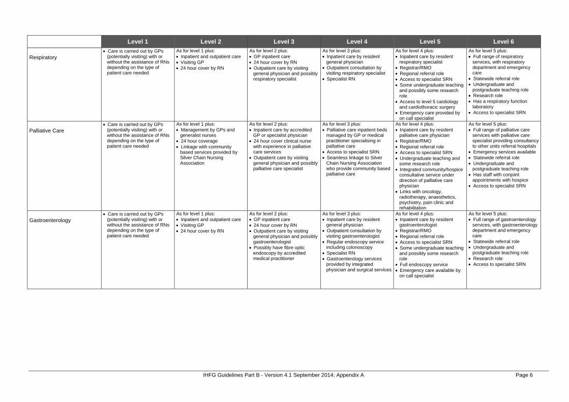
IHFG Guidelines Part B - Version 4.1 September 2014; Appendix A Page 6
Level 1 Level 2 Level 3 Level 4 Level 5 Level 6 Respiratory
Care is carried out by GPs (potentially visiting) with or without the assistance of RNs depending on the type of patient care needed
As for level 1 plus: Inpatient and outpatient care Visiting GP 24 hour cover by RN
As for level 2 plus: GP inpatient care 24 hour cover by RN Outpatient care by visiting
general physician and possibly respiratory specialist
As for level 3 plus: Inpatient care by resident
general physician Outpatient consultation by
visiting respiratory specialist Specialist RN
As for level 4 plus: Inpatient care by resident
respiratory specialist Registrar/RMO Regional referral role Access to specialist SRN Some undergraduate teaching
and possibly some research role
Access to level 5 cardiology and cardiothoracic surgery
Emergency care provided by on call specialist
As for level 5 plus: Full range of respiratory
services, with respiratory department and emergency care
Statewide referral role Undergraduate and
postgraduate teaching role Research role Has a respiratory function
laboratory Access to specialist SRN
Palliative Care
Care is carried out by GPs (potentially visiting) with or without the assistance of RNs depending on the type of patient care needed
As for level 1 plus: Management by GPs and
generalist nurses 24 hour coverage Linkage with community
based services provided by Silver Chain Nursing Association
As for level 2 plus: Inpatient care by accredited
GP or specialist physician 24 hour cover clinical nurse
with experience in palliative care services
Outpatient care by visiting general physician and possibly palliative care specialist
As for level 3 plus: Palliative care inpatient beds
managed by GP or medical practitioner specialising in palliative care
Access to specialist SRN Seamless linkage to Silver
Chain Nursing Association who provide community based palliative care
As for level 4 plus: Inpatient care by resident
palliative care physician Registrar/RMO Regional referral role Access to specialist SRN Undergraduate teaching and
some research role Integrated community/hospice
consultative service under direction of palliative care physician
Links with oncology, radiotherapy, anaesthetics, psychiatry, pain clinic and rehabilitation
As for level 5 plus: Full range of palliative care
services with palliative care specialist providing consultancy to other units referral hospitals
Emergency services available Statewide referral role Undergraduate and
postgraduate teaching role Has staff with conjoint
appointments with hospice Access to specialist SRN
Gastroenterology
Care is carried out by GPs (potentially visiting) with or without the assistance of RNs depending on the type of patient care needed
As for level 1 plus: Inpatient and outpatient care Visiting GP 24 hour cover by RN
As for level 2 plus: GP inpatient care 24 hour cover by RN Outpatient care by visiting
general physician and possibly gastroenterologist
Possibly have fibre optic endoscopy by accredited medical practitioner
As for level 3 plus: Inpatient care by resident
general physician Outpatient consultation by
visiting gastroenterologist Regular endoscopy service
including colonoscopy Specialist RN Gastroenterology services
provided by integrated physician and surgical services
As for level 4 plus: Inpatient care by resident
gastroenterologist Registrar/RMO Regional referral role Access to specialist SRN Some undergraduate teaching
and possibly some research role
Full endoscopy service Emergency care available by
on call specialist
As for level 5 plus: Full range of gastroenterology
services, with gastroenterology department and emergency care
Statewide referral role Undergraduate and
postgraduate teaching role Research role Access to specialist SRN

IHFG Guidelines Part B - Version 4.1 September 2014; Appendix A Page 7
Level 1 Level 2 Level 3 Level 4 Level 5 Level 6
Surgical Services
General
Care is carried out by GPs (potentially visiting) with or without the assistance of RNs depending on the type of patient care needed
As for level 1 plus: Minor outpatient and same day
procedures only by GP or visiting general surgeon
Inpatient care following surgery elsewhere
As for level 2 plus: Day surgery type cases,
uncomplicated elective surgery and emergency surgery
GP and visiting general surgical specialist
Visiting anaesthetist with visiting surgeon
Theatre trained RN
As for level 3 plus: Surgery by GPs, general
surgeons and visiting Type I sub-specialists
Broad range of day and general surgery and some specialty surgery
Theatre trained nurses More than 1 theatre May include high-dependency
nursing unit
As for level 4 plus: General surgeons Some/all Type I sub-
specialists Visiting Type II sub-specialists Registrar/RMO ICU Regional referral role May have some teaching and
research role Undertakes most emergency
surgery May include kidney
transplantation in selected sites
As for level 5 plus: Full range of surgical sub-
specialists Type I and II Statewide referral role Undergraduate and post
graduate teaching role Research role Undertakes emergency
surgery May include kidney and liver
transplantation in selected sites
ENT
Common and intermediate surgery done on low or moderate risk patients by visiting ENT surgeon
No neuro-optic or intracranial surgery
As for level 4 plus: Diagnostic services and
surgery on low, moderate and high risk patents by on call ENT surgeon
Access to specialist SRN Regional referral role May have some teaching and
research role Links with oncology,
radiotherapy and palliative care services
Limited neuro-optic surgery
As for level 5 plus: Ability to deal with all cases
including full range of complex cases in association with other specialists including neuro-optic and intracranial procedures, as long as level 6 neurosurgery available on site
Emergency services available Statewide referral role Undergraduate and post
graduate teaching role Research role ENT registrar/RMO
Gynaecology
Minor outpatient and same day procedures only by GP or visiting general surgeon
Inpatient care following surgery elsewhere
As for level 2 plus: Common and intermediate
procedures on low or moderate risk patients by visiting general surgeon
As for level 3 plus: Common, intermediate and
some major procedures on low and moderate risk patients performed by visiting gynaecologists
Links with oncology, radiotherapy and palliative care services
As for level 4 plus: Diagnostic services and
surgery on low, moderate and high risk patients by on call gynaecologists
Access to specialist SRN May have gynaecology
registrar/RMO Regional referral role May have some teaching and
research role
As for level 5 plus: Ability to deal with all cases
including full range of complex cases in association with other specialists including reproductive endocrinology, infertility, gynaecological malignancy
Full emergency services Statewide referral role Undergraduate and post
graduate teaching role Research role Gynaecology registrar/RMO
and possibly registrars in subspecialties

IHFG Guidelines Part B - Version 4.1 September 2014; Appendix A Page 8
Level 1 Level 2 Level 3 Level 4 Level 5 Level 6 Ophthalmology
Minor procedures and diagnosis on low risk patients by visiting ophthalmic surgeon
As for level 3 plus: Procedures on low or
moderate risk patients performed by visiting ophthalmic surgeon
Access to orthoptists
As for level 4 plus: Diagnostic services and
surgery on low, moderate and high risk patients by on call ophthalmic surgeon
Orthoptists on staff May have teaching and
research role
As for level 5 plus: Ability to deal with all cases
including full range of complex cases in association with other specialists
Full emergency services Ophthalmology registrar/RMO Access to specialist SRN Able to undertake neuro-
ophthalmology where level 6 neurosurgery available on site
Access to level 5 radiotherapy Statewide referral role Undergraduate and post
graduate teaching role Research role
Orthopaedics
Minor reduction of fractures performed on low risk patients by GP or visiting general surgeon with experience in orthopedics
Orthopaedic consultation available
As for level 2 plus: Common and intermediate
procedures on low or moderate risk patients performed by visiting orthopaedic or general surgeon credentialed in orthopaedics
General orthopaedic equipment and theatre x-ray available
Preferably access to specialist SRN
As for level 3 plus: Common and intermediate
procedures on low or moderate risk patients performed by on call orthopaedic surgeon
Access to level 4 rehabilitation service
Access to specialist SRN
As for level 4 plus: Full range of major diagnostic
and procedures on low, moderate and high risk patients performed by on call orthopaedic surgeons
May provide regional services May have teaching and
research role Orthopaedic registrar on call Access to subspecialties Link to level 5 rehabilitation
service Access to specialist SRN
As for level 5 plus: Ability to deal with all cases
including full range of complex cases (and all emergency) in association with other specialists
Statewide referral role Undergraduate and post
graduate teaching role Research role Link to level 6 rehabilitation
role Access to specialist SRN
Urology
Common and intermediate procedures on low or moderate risk patients performed by visiting urologist or general surgeon credentialed in urology
As for level 3 plus: Some major procedures on
low or moderate risk patients performed by visiting urologist
Has links with oncology, radiotherapy and palliative care services
As for level 4 plus: Full range of major diagnostic
and procedures on low, moderate and high risk patients performed by on call urologist
Access to specialist SRN May provide regional services
and teaching and research role
As for level 5 plus: Ability to deal with all cases
including full range of complex cases (and all emergency) in association with other specialists
Urology Registrar/RMO Statewide referral role Undergraduate and post
graduate teaching role Research role

IHFG Guidelines Part B - Version 4.1 September 2014; Appendix A Page 9
Level 1 Level 2 Level 3 Level 4 Level 5 Level 6 Cardiothoracic
Elective and emergency thoracic procedures by visiting/on call thoracic surgeons
As for level 4 plus: Elective and emergency
thoracic and elective cardiothoracic procedures by visiting/on call cardiothoracic surgeons
Level 5 rehabilitation services available on site
Link with palliative care and pain management services
Access to specialist SRN Some regional referral role ICU/CCU
As for level 5 plus: Elective & emergency thoracic
& cardiothoracic procedures by cardiothoracic surgeons
Able to deal with highly complex diagnosis & treatment in association with other specialties
Cardiothoracic registrar/RMO Statewide referral role Undergraduate & post
graduate teaching role Research role Level 6 ICU To include heart & lung
transplantation at selected sites Vascular surgery
Common minor and uncomplicated elective vascular surgery
Performed by visiting vascular or general surgeons
As for level 3 plus: Common, intermediate and
some major procedures on low and moderate risk patients performed by visiting vascular surgeons or general surgeons
Pre-operative rehabilitation specialist consultant available
As for level 4 plus: Diagnostic services and
surgery on low, moderate and high risk patients by on call vascular or general surgeon
May have regional referral May have some teaching and
training and research role Link with level 5 rehabilitation
services
As for level 5 plus: Ability to deal with all cases
including full range of complex cases in association with other specialists
Provides all emergency services
On call vascular surgeon Access to specialist SNR Statewide referral role Undergraduate and post
graduate teaching role Research role
Neurosurgery
Minor head injuries dealt with by general surgeon
Neurosurgical consultation available
Operating equipment adequate for emergency neurosurgery
Link with level 4 rehabilitation services
As for level 4 plus: Diagnostic services and
surgery on low, moderate and high risk patents by on call neurosurgeon
Designated neurosurgical beds
Access to specialist SRN 24 hour access to CT Link with brain and spinal
injury rehabilitation May have some teaching &
research role
As for level 5 plus: Able to deal with all cases
including all emergency cases Neurosurgical ward & neuro-
surgical high dependency/ICU Neurosurgery registrar/RMO Link with level 5 rehabilitation
service Access to specialist SRN Statewide referral role Undergraduate & post
graduate teaching role Research role
Plastics
Minor outpatients and same day procedures by GP
As for level 2 plus: As for level 2 but procedures
may require visiting plastics surgeon
As for level 3 plus: Selected minor procedures on
low and moderate risk patients by visiting plastic surgeons
As for level 4 plus: Diagnostic services & surgery
on low, moderate & high risk patents by on call plastic surgeons
Link with level 5 rehabilitation services
May have some teaching & training role
Visiting burns L6 specialist
As for level 5 plus: Able to deal with all cases
including all emergency cases Plastics registrar/RMO Access to specialist SRN Statewide referral role Undergraduate & post
graduate teaching role May have research role

IHFG Guidelines Part B - Version 4.1 September 2014; Appendix A Page 10
Level 1 Level 2 Level 3 Level 4 Level 5 Level 6 Burns
Minor outpatient and same day procedures only by GP
Able to provide emergency stabilisation service for burns
As for level 2 plus: General surgeon able to
provide services for minor/moderate burns to small areas of body
As for level 3 plus: General surgeon providing
services for minor/moderate burns to small parts of body
Access to specialist SNR Links to level 4 rehabilitation
services
As for level 4 plus: General surgeon providing
services for minor/moderate burns to small parts of body
24 hour on call registrar Access to specialist SRN Links to level 5 rehabilitation
services
As for level 5 plus: Full range of burns services,
with a special burns unit, including all emergency cases
24 hour on call cover Statewide referral role Emergency care services
provided by on call specialist Access to specialist SRN Undergraduate and post
graduate teaching role Research role
Emergency/Trauma Services
Emergency Department Local GPs rostered to provide 24 hour cover with service by RN
Emergency operating theatre facilities
Resuscitation and stabilisation On-call generalist specialists Access to specialist SRN
As for level 4 plus: Medically staffed 24 hours per
day Medical and surgical sub-
specialists available on-call Accepts transfers from other
hospitals in region Access to ICU and CCU
facilities Access to specialist SRN
As for level 5 plus: Emergency medicine
consultant on duty 24 hours per day*
Statewide referral role Access to specialist SRN Backup from full range of
medical and surgical specialists and diagnostic services
ICU and CCU facilities Urgent Primary Care
Care is carried out by GPs (potentially visiting) with or without the assistance of RNs depending on the type of patient care needed
Basic resuscitation equipment and drugs
As for level 1 plus: Limited GP cover Services by RN Resuscitation and stabilisation
capability
As for level 2 plus: Local GPs rostered to provide
24 hour cover with service by RN
Minor procedure capability Resuscitation and stabilisation
capability
Obstetrics Services
Obstetrics
No planned deliveries Antenatal, post natal care is
carried out by GPs (potentially visiting) with or without the assistance of RN/RM depending on the type of patient care needed
As for level 1 plus: No planned deliveries Inpatient care following
delivery elsewhere Antenatal, post natal care is
carried out by GPs with or without the assistance of RN/RM depending on the type of patient care needed
As for level 2 plus: Planned deliveries of low risk
mothers/babies Service by GPs and trained
mid-wives LUCS transferred elsewhere
but must be within safe timeframe
Visiting obstetrician Access to Level 1 Special
Care Nursery
As for level 3 plus: Planned deliveries of low and
moderate risk mothers/babies Access to accredited obstetric
and paediatric trained doctors Able to cope with sudden
unexpected risks Caesarian section capability Access to Level 2A Special
Care Nursery
As for level 4 plus: Deliveries of low, moderate
and high risk mothers/babies Able to cope with most
complications Service provided by specialist
obstetricians and paediatricians to high risk patients
Registrar/RMO Access to specialist
paediatricians/obstetricians and trained nurses and allied health
Regional referral role Access to Level 2B Special
Care Nursery
As for level 5 plus: Specialist obstetric unit for
state Obstetric registrar and
midwives training Access to specialist SRN 24 hour cover by obstetricians
and paediatricians Access to Level 3 Special Care
Nursery

IHFG Guidelines Part B - Version 4.1 September 2014; Appendix A Page 11
Level 1 Level 2 Level 3 Level 4 Level 5 Level 6
Paediatrics Services
Paediatrics
Care is carried out by GPs (potentially visiting) with or without the assistance of RNs depending on the type of patient care needed
Stabilisation and first aid
As for level 1 plus: Paediatric medical beds – care
by general physician On call paediatric advice No surgery
As for level 2 plus: Outpatient care by visiting
paediatrician Limited surgery by visiting
paediatric surgeon or surgeon with paediatric skills
Day surgery, uncomplicated elective surgery and emergency surgery
Designated paediatric medical ward
Inpatient medical care by GP or general physician or paediatrician
As for level 3 plus: Outpatient care by resident
paediatrician Limited surgery by visiting
paediatric surgeon Day surgery, uncomplicated
elective surgery and emergency surgery
Designated medical ward Inpatient medical care by
visiting paediatrician Access to specialist SRN Possibly Resident/RMO
rotations from Level 5 or 6 facility
As for level 4 plus: Inpatient and outpatient care
by resident paediatrician Registrar/RMO Regional referral role Some undergraduate teaching Range of paediatric surgery Resident paediatric surgeon 24 hour on call paediatric
anaesthetist Neonatal ICU Access to specialist SRN
As for level 5 plus: Inpatient and outpatient care
by resident paediatrician Registrar/RMO Statewide referral role Undergraduate and
postgraduate teaching role Full range of paediatric surgery Resident paediatric surgeon Neonatal ICU Operates in specialist facility Access to specialist SRN
Neonatology
Obstetricians, paediatricians and anaesthetists on call 24 hours
Normal low risk pregnancies and deliveries and management of newborns > 36 weeks gestation with minimal complications
Level 1 Special Care Nursery Basic life support for neonates
available with access to 24 hour anaesthetic and neonatal resuscitation service
As for level 3 plus: Obstetricians and
paediatricians on call 24 hours Low to moderate risk
pregnancies and deliveries and management of newborns > 34 weeks gestation with minimal complications
Level 2A Special Care Nursery with low dependency patients and low-level Oxygen therapy and airway management
Basic life support for neonates available with access to 24 hr anaesthetic and neonatal resuscitation service
Provides short-term mechanical ventilation (<6 hours) pending transfer
As for level 4 plus: Has access to clinical and
diagnostic paediatric subspecialties
Obstetricians and paediatricians on call 24 hours
Medical officer(s) on site 24 hours
Moderate to high-risk pregnancies and deliveries and management of newborns > 32 weeks gestation with minimal complications
Level 2B Special Care Nursery with high dependency patients and provision of short term mechanical ventilation (< 6 hours) pending transfer
Access to specialist SRN Multi-disciplinary follow up
service provided Role in post graduate medical
and nursing education
As for level 5 plus: Has access to clinical and
diagnostic paediatric subspecialties
Medical officer(s) on site 24 hours
High-risk, high dependency pregnancies and deliveries
Management of newborns < 32 weeks gestation
Level 3 Special Care Nursery with high dependency patients and provision of medium -long term mechanical ventilation and full life-support
Undertakes neonatal surgery and care for complex congenital and metabolic diseases of the newborn – note currently at PMH
Access to specialist SRN On-site multi-disciplinary
services Role in post graduate medical
and nursing education Has neonatology research

IHFG Guidelines Part B - Version 4.1 September 2014; Appendix A Page 12
Level 1 Level 2 Level 3 Level 4 Level 5 Level 6
Rehabilitation Services
Rehabilitation
Visiting consultative services provided on request
Care is carried out by GPs (potentially visiting) with or without the assistance of RNs depending on the type of patient care needed
As for level 1 plus: Regular visiting services
provided by district/regional allied health staff
Limited level allied health availability
As for level 3 plus: Full time salaried
physiotherapy, occupational therapy
Speech and social work services
District referral role Limited day hospital program
As for level 4 plus: Rehab program for both
inpatient and outpatient Linkages between regions and
designated metropolitan hospitals
Have a day hospital with: Memory clinic Falls Clinic Continence clinic
A GEM unit if ED services collocated
Part time services of Geriatrician1
Rehab Specialist with experienced RN/PT/ OT/SP/ Dietitian
Collocated with psychogeriatric services
As for level 5 plus: Will have GEM unit Have access to acute care Full time rehab specialist Full time geriatrician as per
footnote of level 5 Tertiary level rehab services
(Statewide Rehab Centre) only in one level 6 hospital with a full time clinical director
Continuing Care Services
Community assessment
Visiting services on as required basis
As for level 1 plus: Regular visiting service
supported by limited local allied health
As for level 3 plus: Visiting service supported by
local allied health professionals
Most disciplines available
As for level 4 plus: Home base for team with
regional / district responsibilities - part time geriatrician
Prevention and Promotion Services
Environmental Health Health Protection including food, air, water, radiation, pharmaceutical, pesticides, mosquito borne diseases.
Local Government responsibility with access to DOH statewide unit when required
As for level 1 plus: Assist statewide services
investigation of local incidents
As for level 3 plus: Coordinate investigations of
local incidents
As for level 4 plus: Comprehensive
multidisciplinary Population Health Unit
As for level 5 plus: Statewide program, planning,
and coordination roles Dedicated officers with
statewide responsibilities and legislated service functions
Communicable Disease Control Includes food and water borne
diseases, vaccination programs, STI’s, BBV’s and indigenous diseases
Visiting primary care providers, including GPs and Community Health Nurses
As for level 1 plus: Resident primary care provider
supporting state programs including GPs and Community Health Nurses
As for level 2 plus: CDC Nurse in Population
Health Unit
As for level 4 plus: Comprehensive
multidisciplinary Population Health Unit with disease control doctor and capacity to: Investigate cases/
outbreaks Perform contact tracing Coordinate regional
vaccination programs etc
As for level 5 plus: Statewide program, planning,
and coordination roles Dedicated officers with
statewide responsibilities and legislated service functions
1 Geriatrician should ideally be full time, with part time spent in Level 6 supporting GEM and acute care, and part time in level 5 supporting in rehabilitation unit/day hospital and GEM unit.

IHFG Guidelines Part B - Version 4.1 September 2014; Appendix A Page 13
Level 1 Level 2 Level 3 Level 4 Level 5 Level 6 Child and Community Health Community Health Services,
School Health Services, Child Health Services, Child Development Services
Visiting primary care providers, including GPs and Community Health Nurses
As for level 1 plus: Resident primary care
providers with access to statewide program initiatives
As for level 2 plus: Community Health Centre/
Child Development Centre
As for level 4 plus: Comprehensive
multidisciplinary Population Health Unit with community health staff
As for level 5 plus: Statewide Program, planning,
and coordination roles
Aboriginal Health
Visiting primary care providers As for level 1 plus: Mainstream health service
providers (including GPs)
As for level 2 plus: Mainstream health service
providers
As for level 3 plus: Mainstream providers Community controlled
Aboriginal health service
As for level 4 plus: Mainstream providers Community controlled
Aboriginal health service Integrated service delivery
As for level 5 plus: Statewide program, planning,
and coordination roles Dedicated officers with
statewide responsibilities
Health Promotion Primary prevention including
lifestyle diseases and injury prevention
Visiting primary care providers with access to DOH statewide program resources. Exposure to mass media campaigns
As for level 1 plus: Resident primary care
providers with awareness of statewide program initiatives
As for level 3 plus: Comprehensive
multidisciplinary Population Health Unit including resident officers with health promotion training
As for level 5 plus: Statewide program, planning,
and coordination roles Dedicated officers with
statewide responsibilities
Breastscreen Screening and assessment
Visiting service by mobile screening unit
All images read by specialist radiologist
As for level 2 plus: Fixed site screening clinic
As for level 3 plus: Assessment by an
experienced multidisciplinary team of screen detected abnormalities
As for level 5 plus: Statewide program, planning,
and coordination roles Dedicated officers with
statewide responsibilities Cervical Health promotion, screening
awareness, maintain cervical cytology register
Visiting primary care providers As for level 1 plus: Resident primary care
providers, including GPs
As for level 3 plus: Pathology laboratories trained
in the collation and reporting of Cervical Cytology Registry data
As for level 5 plus: Statewide Program, planning,
and coordination roles Dedicated officers with
statewide responsibilities
Genomics Education, research
Visiting primary care providers with no specific program
As for level 1 plus: Visiting primary care providers
with access to statewide education and information
As for level 2 plus: Resident primary care
providers with access to statewide education and information
As for level 5 plus: Statewide Program, planning,
and coordination roles Dedicated officers with
statewide responsibilities
Primary Care Services
GP based Community nursing
Visiting GP or GP by phone Some visiting allied health Other services such as child
health and post natal care by RN
As for level 1 plus: Resident GPs Some visiting Type I
specialists (outpatients) Resident or visiting
physiotherapy Other visiting allied health Other services by RN/CHN
(resident)
As for level 3 plus: Resident GPs Most visiting Type I sub-
specialists Majority allied health available Resident community nursing
specialist
As for level 4 plus: Resident GPs Resident some/all Type I sub-
specialists Visiting Type II sub-
specialists Full range of allied health Extensive community
nursing service
As for level 5 plus: Resident GPs Full range of Type I and II
sub-specialists Full range of allied health Extensive community
nursing service Research and teaching role

IHFG Guidelines Part B - Version 4.1 September 2014; Appendix A Page 14
Level 1 Level 2 Level 3 Level 4 Level 5 Level 6
Ambulatory Care Services
Surgical
GP only As for level 1 plus: GP and specialist outpatient
clinic at discharge hospital Limited access to generalist
domiciliary nursing
As for level 2 plus: Visiting specialist Some hospital
avoidance/hospital substitution Some early discharge services Access to generalist
domiciliary nursing and some allied health
As for level 3 plus: Links with HACC Increasing range and
complexity of hospital avoidance/substitution/early discharge
Chronic disease programs Visiting medical specialist Good access to generalist
allied health/nursing staff
As for level 4 plus: Specialist medical/nursing/
allied health staff Increased range and
complexity HACC integration Enhanced diagnostics Teaching and training role
As for level 5 plus: Research role Fully integrated ambulatory
care services Fully integrated diagnostics Includes regional subacute
centre/service
Medical
GP only As for level 1 plus: GP and specialist outpatient
clinic at discharge hospital Limited access to generalist
domiciliary nursing
As for level 2 plus: Visiting specialist Some hospital
avoidance/hospital substitution Some early discharge services Access to generalist
domiciliary nursing and some allied health
As for level 3 plus: Links with HACC Increasing range and
complexity of hospital avoidance/substitution/early discharge
Chronic disease programs Visiting medical specialist Good access to generalist
allied health/nursing staff
As for level 4 plus: Specialist medical/nursing/
allied health staff Increased range and
complexity HACC integration Enhanced diagnostics Teaching and training role
As for level 5 plus: Research role Fully integrated ambulatory
care services Fully integrated diagnostics Includes regional subacute
centre/service
Rehabilitation
GP only As for level 1 plus: GP and specialist outpatient
clinic at discharge hospital Limited access to generalist
domiciliary nursing
As for level 2 plus: Visiting specialist Some hospital
avoidance/hospital substitution Some early discharge services Access to generalist
domiciliary nursing and some allied health
As for level 3 plus: Links with HACC Increasing range and
complexity of hospital avoidance/substitution/early discharge
Chronic disease programs Visiting medical specialist Good access to generalist
allied health/nursing staff
As for level 4 plus: Specialist medical/nursing/
allied health staff Increased range and
complexity HACC integration Enhanced diagnostics Teaching and training role
As for level 5 plus: Research role Fully integrated ambulatory
care services Fully integrated diagnostics Includes regional subacute
centre/service
Continuing Care
GP only As for level 1 plus: GP and specialist outpatient
clinic at discharge hospital Limited access to generalist
domiciliary nursing
As for level 2 plus: Visiting specialist Some hospital
avoidance/hospital substitution Some early discharge services Access to generalist
domiciliary nursing and some allied health
As for level 3 plus: Links with HACC Increasing range and
complexity of hospital avoidance/substitution/early discharge
Chronic disease programs Resident/visiting medical
specialist Good access to generalist
allied health/nursing staff
As for level 4 plus: Specialist medical/nursing/
allied health staff Increased range and
complexity HACC integration Enhanced diagnostics Teaching and training role
As for level 5 plus: Research role Fully integrated ambulatory
care services Fully integrated diagnostics Includes regional subacute
centre/service

IHFG Guidelines Part B - Version 4.1 September 2014; Appendix A Page 15
Level 1 Level 2 Level 3 Level 4 Level 5 Level 6 Paediatrics
GP only As for level 1 plus: GP and specialist outpatient
clinic at discharge hospital Limited access to generalist
domiciliary nursing
As for level 2 plus: Visiting specialist Some hospital
avoidance/hospital substitution Some early discharge services Access to generalist
domiciliary nursing and some allied health
As for level 3 plus: Increasing range and
complexity of hospital avoidance/substitution/early discharge
Chronic disease programs Visiting medical specialist Good access to generalist
allied health/nursing staff
As for level 4 plus: Specialist medical/nursing/
allied health staff Increased range and
complexity Enhanced diagnostics Teaching and training role
As for level 5 plus: Research role Fully integrated ambulatory
care services Fully integrated diagnostics Includes regional subacute
centre/service
Obstetrics
Community based GP with or without community nursing post only
As for level 1 plus: No planned deliveries Outpatient clinic for antenatal
and post natal care by visiting GP obstetrician with or without registered midwife
Limited access to generalist domiciliary nursing care
As for level 2 plus: GP obstetrician and midwifery
services Visiting specialist obstetrician Outpatient clinic for antenatal
and post natal care Some early discharge
programs Access to domiciliary nursing
care and visiting midwife Basic ultrasound and
pathology services
As for level 3 plus: Specialist obstetrician Early discharge programs Home visiting midwives Diagnostic ultrasound with
specialist radiologist offering antenatal screening
Full range pathology services Visiting genetic services
As for level 4 plus: Specialist obstetrician Specialised antenatal and
postnatal education and support programs
Teaching and training role Enhanced diagnostics
As for level 5 plus: Research role State obstetric support
service/unit (SOSU) Specialist obstetric services
including maternal foetal medicine subspecialty, obstetric medicine, genetic services
Fully integrated ambulatory care services (social work, psychological medicine etc)
Fully integrated diagnostic services
Mental Health Ambulatory Care Services are covered under Mental Health Services

IHFG Guidelines Part B - Version 4.1 September 2014; Appendix A Page 16
Level 1 Level 2 Level 3 Level 4 Level 5 Level 6
Child and Adolescents Mental Health, Adult Mental Health, Older Persons Mental Health Services
Mental health promotion and illness prevention
Promotion of mental health in the community
Eg. Improving mental health literacy, resource centres and stigma reduction strategies.
Eg. Exposure to mass media campaigns
As for level 1 plus: Universal prevention Identification of risk factors for
mental illness and intervention at the population level before initial onset of a disorder
Eg. Programs to prevent bullying in schools, Aussie Optimism. Triple P
Eg. Local community activity that improves quality of life including Mental Health Week
As for level 2 plus: Selective prevention Targeting population groups at
risk of developing a disorder to prevent its onset
Eg. Support for COPMI
As for level 3 plus: Indicated prevention Targeting high risk individuals
who may have detectable signs and symptoms foreshadowing mental illness
Eg. Suicide prevention strategies
As for level 4 plus: Early intervention for those
with early signs and symptoms of a mental disorder or a first episode of mental illness.
Eg. Early episode psychosis programs
As for level 5 plus: Relapse prevention for those
identified with mental illness GP(s) and local mental health
team member(s) with visiting psychiatrist
Eg. Changes (RPH relapse prevention program) and Wellness Recovery Action Plan (WRAP) a consumer led program
Emergency services (hospital based)
Mainstream providers telephone support from on call team member /psychiatric emergency team
As for level 3 plus: Limited ED mental health
liaison nursing service 24 hour on call liaison
psychiatrist medical service
As for level 4 plus: On duty ED mental health
liaison nursing service On duty psychiatrist medical
service
As for level 5 plus: On duty ED mental health
liaison nursing service On duty psychiatrist medical
service Acute admission unit service
Inpatient services
General hospital inpatient services without designated mental health beds, providing mental health care for voluntary patients admitted under management of GP or other medical officer
As for level 3 plus: Special mental health care
suite with designated beds Generally operated on
demand without permanent staff (rooming in services)
Facility is unauthorised
As for level 4 plus: Dedicated acute mental health
hospital or designated mental health inpatient units in acute hospitals
Psychiatrist consultation available and on call 24 hours
Comprehensive team
As for level 5 plus: Specialist statewide services
provided A strong academic and
research component in the service
Community clinical based services
Local primary health As for level 1 plus: Visiting mental health
professional(s)
As for level 2 plus: Locally based mental health
team Not Multidisciplinary
As for level 3 plus: Community mental health
program with multidisciplinary team
Services generally provided during core business hours only
Limited range assessment and treatment programs provided
As for level 4 plus: Community mental health
program with multidisciplinary team
7 day a week cover Extensive range of
assessment and treatment programs
Some limited after hours services may be provided
Eg. Multisystemic Therapy for families
Eg. Intensive clinical rehabilitation
As for level 5 plus: Community mental health
program with multidisciplinary team providing 24 hour / 7 day a week cover
Specialist statewide services provided
Eg. Psychiatric emergency services
Eg. Specialist residential service
Eg. Forensic discharge service
Day therapy services (hospital based)
Some limited services As for level 3 plus: Limited range of day therapy
services
As for level 4 plus: Extensive range of day
therapy services
As for level 5 plus: Multidisciplinary team Statewide or specialist referral
role

IHFG Guidelines Part B - Version 4.1 September 2014; Appendix A Page 17
Level 1 Level 2 Level 3 Level 4 Level 5 Level 6 Community non clinical support programs
GP and community health centre based screening and early detection of mental illness
Eg. GPs and community health centres
As for level 2 plus: Nonclinical community support
(including psychosocial, disability, recreational, & respite to individuals) in their own homes & the community up to 10 hours per week
Independent living program (with supportive landlord)
Drop-in centres and facilitating recreational activities
Carer respite Carer support & education Independent living skills
support They do not all relate to
respite. This is the range of community support services
As for level 3 plus: Non clinical community
support up to 30 hours per week
Psychosocial support Services for youth at risk of
homelessness and long term mental illness
As for level 4 plus: Non clinical community
support up to 40 hours per week
Intensive disability support for adults at risk of homelessness
Consumer respite/crisis care Supported accommodation
services
As for level 5 plus: Non clinical 24 hour mental
health accommodation and rehabilitation in residential accommodation
Intermediate care
Clinically supervised service in person’s home
As for level 3 plus: Clinically supervised service in
a facility or person’s home Sub acute care
As for level 4 plus: Clinically staffed 24/7 Unauthorised facility Sub acute care
As for level 5 plus: Clinically staffed 24/7 Authorised facility Statewide referral role Sub acute care
Statewide Mental Health Services
Forensic
Specialist mental health program with multidisciplinary team
Extensive range of assess-ment and treatment programs including forensic discharge & accommodation program
As for level 5 plus: Specialist statewide inpatient
services provided A strong academic and
research component in the service
Maternal
Specialist mental health program with multidisciplinary team
Extensive range of assessment & treatment programs
As for level 5 plus: Specialist statewide inpatient
services provided A strong academic and
research component in the service
Neurological
Specialist mental health program with multidisciplinary team
Extensive range of assessment and treatment programs
As for level 5 plus: Specialist statewide inpatient
services provided Includes ABI and intellectual
disability A strong academic and
research component in the service
Alcohol and Drug
Specialist mental health program with multidisciplinary team
Extensive range of assessment and treatment programs
As for level 5 plus: Specialist statewide inpatient
services provided

IHFG Guidelines Part B - Version 4.1 September 2014; Appendix A Page 18
Level 1 Level 2 Level 3 Level 4 Level 5 Level 6 Other Eating disorder
Specialist mental health program with multidisciplinary team
Extensive range of assessment and treatment programs
As for level 5 plus: Specialist statewide inpatient
services provided A strong academic and
research component in the service
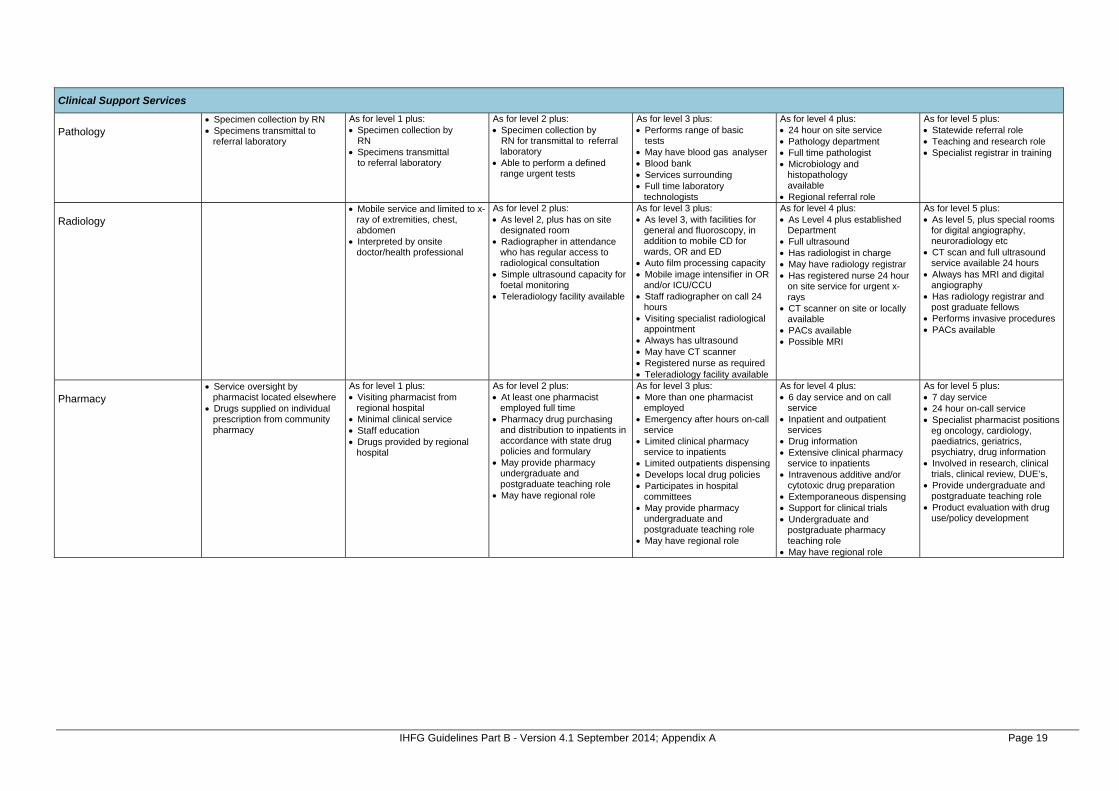
IHFG Guidelines Part B - Version 4.1 September 2014; Appendix A Page 19
Clinical Support Services
Pathology
Specimen collection by RN Specimens transmittal to
referral laboratory
As for level 1 plus: Specimen collection by
RN Specimens transmittal
to referral laboratory
As for level 2 plus: Specimen collection by
RN for transmittal to referral laboratory
Able to perform a defined range urgent tests
As for level 3 plus: Performs range of basic
tests May have blood gas analyser Blood bank Services surrounding Full time laboratory
technologists
As for level 4 plus: 24 hour on site service Pathology department Full time pathologist Microbiology and
histopathology available
Regional referral role
As for level 5 plus: Statewide referral role Teaching and research role Specialist registrar in training
Radiology
Mobile service and limited to x-ray of extremities, chest, abdomen
Interpreted by onsite doctor/health professional
As for level 2 plus: As level 2, plus has on site
designated room Radiographer in attendance
who has regular access to radiological consultation
Simple ultrasound capacity for foetal monitoring
Teleradiology facility available
As for level 3 plus: As level 3, with facilities for
general and fluoroscopy, in addition to mobile CD for wards, OR and ED
Auto film processing capacity Mobile image intensifier in OR
and/or ICU/CCU Staff radiographer on call 24
hours Visiting specialist radiological
appointment Always has ultrasound May have CT scanner Registered nurse as required Teleradiology facility available
As for level 4 plus: As Level 4 plus established
Department Full ultrasound Has radiologist in charge May have radiology registrar Has registered nurse 24 hour
on site service for urgent x-rays
CT scanner on site or locally available
PACs available Possible MRI
As for level 5 plus: As level 5, plus special rooms
for digital angiography, neuroradiology etc
CT scan and full ultrasound service available 24 hours
Always has MRI and digital angiography
Has radiology registrar and post graduate fellows
Performs invasive procedures PACs available
Pharmacy
Service oversight by pharmacist located elsewhere
Drugs supplied on individual prescription from community pharmacy
As for level 1 plus: Visiting pharmacist from
regional hospital Minimal clinical service Staff education Drugs provided by regional
hospital
As for level 2 plus: At least one pharmacist
employed full time Pharmacy drug purchasing
and distribution to inpatients in accordance with state drug policies and formulary
May provide pharmacy undergraduate and postgraduate teaching role
May have regional role
As for level 3 plus: More than one pharmacist
employed Emergency after hours on-call
service Limited clinical pharmacy
service to inpatients Limited outpatients dispensing Develops local drug policies Participates in hospital
committees May provide pharmacy
undergraduate and postgraduate teaching role
May have regional role
As for level 4 plus: 6 day service and on call
service Inpatient and outpatient
services Drug information Extensive clinical pharmacy
service to inpatients Intravenous additive and/or
cytotoxic drug preparation Extemporaneous dispensing Support for clinical trials Undergraduate and
postgraduate pharmacy teaching role
May have regional role
As for level 5 plus: 7 day service 24 hour on-call service Specialist pharmacist positions
eg oncology, cardiology, paediatrics, geriatrics, psychiatry, drug information
Involved in research, clinical trials, clinical review, DUE’s,
Provide undergraduate and postgraduate teaching role
Product evaluation with drug use/policy development

IHFG Guidelines Part B - Version 4.1 September 2014; Appendix A Page 20
Level 1 Level 2 Level 3 Level 4 Level 5 Level 6 ICU/HDU
High dependency area for general ward patients requiring observation over and above that available in general ward area
As for level 3 plus: Provides basic, multisystem
life support usually for less than a 24 hour period
Able to provide mechanical ventilation and simple cardiovascular monitoring for a period of at least several hours, or care of a similar nature
Specialist RN Access to specialist SRN
As for level 4 plus: Provides complex, multisystem
life support Able to provide mechanical
ventilation, extracorporeal renal support services and invasive cardiovascular monitoring for a period of at least several days, or for longer periods in remote areas or care of a similar nature
Specialist RN Access to specialist SRN
As for level 5 plus: Provides complex, multisystem
life support for an indefinite period
Tertiary referral centre for patients in need of intensive care services
Have extensive backup laboratory and clinical service facilities to support the tertiary referral role
Able to provide mechanical ventilation, extracorporeal renal support services and invasive cardiovascular monitoring for an indefinite period, or care of a similar nature
Specialist RN Access to specialist SRN
Paediatric ICU
As for level 5 plus: Provides complex, multisystem
life support for an indefinite period
Tertiary referral centre for children needing intensive care
Have extensive backup laboratory and clinical service facilities to support this tertiary role
Able to provide mechanical ventilation, extracorporeal renal support services and invasive cardiovascular monitoring for an indefinite period to infants and children less than 16 years of age, or care of a similar nature
Specialist RN Access to specialist SRN

IHFG Guidelines Part B - Version 4.1 September 2014; Appendix A Page 21
Level 1 Level 2 Level 3 Level 4 Level 5 Level 6 CCU
As for level 3 plus: Able to supply critical care
expertise for coronary patients Provides a level of care more
intensive than ward based care
Discrete area within the health facility (may be combined within an ICU or HDU)
Non invasive monitoring Can provide resuscitation and
stabilisation of emergencies until transfer or retrieval to a back up facility
Specialist RN Access to specialist SRN Formal link with public or
private health facility(s) for patient referral and transfer to/from a higher level of service, to ensure safe service provision
As for level 4 plus: Able to provide additional
monitoring capacity (central monitoring at staff station) for cardiac patients and increased medical and nursing support
Specialist RN Access to specialist SRN As for CCU service level 4
plus: Bedside and central
monitoring capacity (able to monitor patients at the staff station)
As for level 5 plus: Provides full range of cardiac
monitoring (including invasive monitoring) for cardiac patients
Full cardiology support including 24 hour on call echocardiography, angiography, angioplasty and permanent pacemaker services
Specialist RN Access to specialist SRN As for CCU service level 5
plus: Invasive cardiovascular
monitoring (indefinitely) Highest level referral centre
for CCU patients with active liaison with lower level critical care services for referrals and transfer of patients to ensure safe service provision
Anaesthetics
Analgesia/minimal sedation available by visiting medical officer
As for level 2 plus: General Anaesthetics on low
risk patients given GP anaesthetists or general anaesthetist
May have visiting specialist anaesthetist
As for level 3 plus: General anaesthetics on low
risk patients given by accredited medical practitioner
Specialist anaesthetist appointed for consultation and to provide service for moderate risk patients
Specific operating room anaesthetic staff support available
As for level 4 plus: Specialist anaesthetist on 24
hour roster for low, moderate and high risk patients
Nominated specialist director of anaesthetic staff
Anaesthetic registrar on site 24 hours
As for level 5 plus: 24 specialist anaesthetist
roster Sub specialists, research and
teaching of graduates and undergraduates
24 hour on site anaesthetic registrar
Teaching and research role
Operating Theatres
As for level 1 plus: Minor procedure capability no
emergency operating theatre
As for level 2 plus: Single operating theatre for
minor / same day procedures 24 hour cover for caesarian
section if performing obstetrics
As for level 3 plus: More than one operating
theatre / procedure room Separate recovery Accredited medical practitioner
providing anaesthetic services Specialist RN Access to specialist SRN
As for level 4 plus: Specialist anaesthetist on 24
hour roster for low, moderate and high risk patients
Medical officer on site 24 hours
Access to ICU Specialist RN Access to specialist SRN
As for level 5 plus: Multiple operating theatres
and procedure rooms Major and complex
procedures (cardiothoracic and transplant)
Teaching and research role Specialist RN Access to specialist SRN
Training and Research
As for level 1 plus: Limited – possible medical
student with visiting GP
As for level 2 plus: Some medical nursing and
allied health training
As for level 3 plus: Some registrar and resident
training Some specialist nursing and
allied health training Possibly collaborative
research
As for level 4 plus: Small research unit Specialist training for nursing
and allied health Some intern, resident and
registrar training
As for level 5 plus: Academic Unit Research
Institute Full training program at all
levels Formal training links with the
universities

The International Health Facility Guidelines recommends the use of HFBS “Health Facility Briefing System” to edit all room data sheet information for your project. HFBS provides edit access to all iHFG standard rooms, and departments, and more than 100 custom report templates.
Health Facility Briefing System
Briefing Module
The Health Facility Briefing System (HFBS) has numerous modules available via annual subscription. It suits healthcare Architects, Medical Planners, Equipment Planners Project Managers and Health Authorities.
Use the HFBS Briefing Module to quickly drag in health facility departments or pre-configured room templates from the iHFG standard, edit the room features such as finishes, furniture, fittings, fixtures, medical equipment, engineering services. The system can print or download as PDF more than 100 custom reports including room data sheets, schedules, and more…
To learn more about the HFBS web-based Healthcare Briefing and Design Software and to obtain editable versions of the “Standard Components” including Room Data Sheets (RDS) and Room Layout Sheets (RLS) offered on the iHFG website, signup for HFBS using the link below. Get Started Now: hfbs.healthdesign.com.au
iHFG Room Data Sheets and Departments are instantly editable in the HFBS software available online.
You can access hundreds of report templates to print your iHFG room data in HFBS.
HFBS has a onetime free 3 day trial available to all new users. Get Started Now: hfbs.healthdesign.com.au
Health Facility Briefing System
hfbsinfo.com | [email protected]