Part 1 Fundamentals Digital Signals Technical Information
16
Part 1 Fundamentals Digital Signals Technical Information 1 t 1 bit
-
Upload
independent -
Category
Documents
-
view
2 -
download
0
Transcript of Part 1 Fundamentals Digital Signals Technical Information
Part
1Fu
ndam
enta
ls
Digital Signals
Technical Information
1
t
1 bit
Part 1: Fundamentals
Part 2: Self-operated Regulators
Part 3: Control Valves
Part 4: Communication
Part 5: Building Automation
Part 6: Process Automation
Should you have any further questions or suggestions, pleasedo not hesitate to contact us:
SAMSON AG Phone (+49 69) 4 00 94 67V74 / Schulung Telefax (+49 69) 4 00 97 16Weismüllerstraße 3 E-Mail: [email protected] Frankfurt Internet: http://www.samson.de
Technical Information
Digital Signals
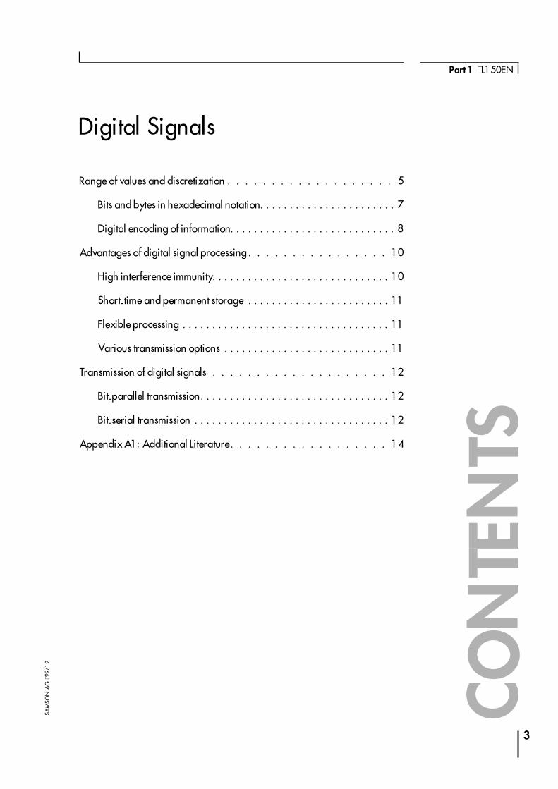
Range of values and discretization . . . . . . . . . . . . . . . . . . . 5
Bits and bytes in hexadecimal notation. . . . . . . . . . . . . . . . . . . . . . . 7
Digital encoding of information. . . . . . . . . . . . . . . . . . . . . . . . . . . . 8
Advantages of digital signal processing . . . . . . . . . . . . . . . . 10
High interference immunity. . . . . . . . . . . . . . . . . . . . . . . . . . . . . . 10
Short-time and permanent storage . . . . . . . . . . . . . . . . . . . . . . . . 11
Flexible processing . . . . . . . . . . . . . . . . . . . . . . . . . . . . . . . . . . . 11
Various transmission options . . . . . . . . . . . . . . . . . . . . . . . . . . . . 11
Transmission of digital signals . . . . . . . . . . . . . . . . . . . . 12
Bit-parallel transmission. . . . . . . . . . . . . . . . . . . . . . . . . . . . . . . . 12
Bit-serial transmission . . . . . . . . . . . . . . . . . . . . . . . . . . . . . . . . . 12
Appendix A1: Additional Literature . . . . . . . . . . . . . . . . . . 14
3
Part 1 ⋅ L150EN
SAM
SON
AG
⋅99/
12
CON
TEN
TS

4
Fundamentals ⋅ Digital Signals
SAM
SON
AG
⋅V74
/D
KE
Digital Signals
In electronic signal and information processing and transmission, digitaltechnology is increasingly being used because, in various applications, digi-tal signal transmission has many advantages over analog signal transmis-sion. Numerous and very successful applications of digital technologyinclude the continuously growing number of PC�s, the communication net-work ISDN as well as the increasing use of digital control stations (Direct Di-gital Control: DDC).
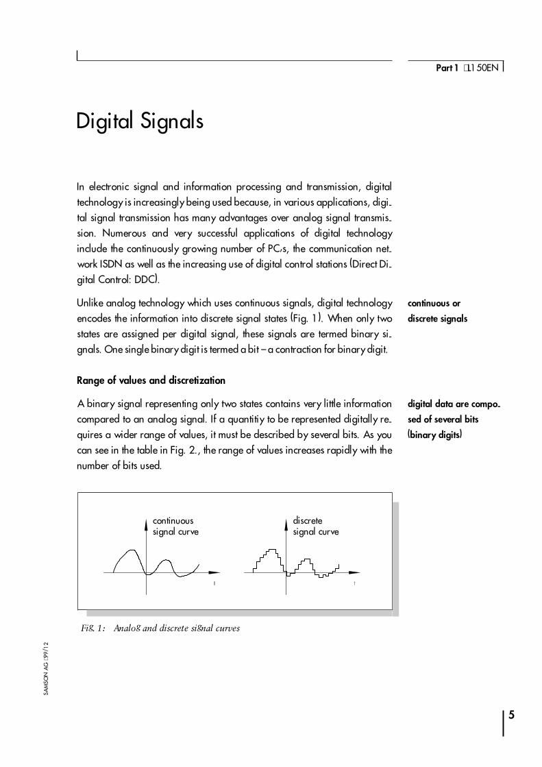
Unlike analog technology which uses continuous signals, digital technologyencodes the information into discrete signal states (Fig. 1). When only twostates are assigned per digital signal, these signals are termed binary si-gnals. One single binary digit is termed a bit � a contraction for binary digit.
Range of values and discretization
A binary signal representing only two states contains very little informationcompared to an analog signal. If a quantitiy to be represented digitally re-quires a wider range of values, it must be described by several bits. As youcan see in the table in Fig. 2., the range of values increases rapidly with thenumber of bits used.
5
Part 1 ⋅ L150EN
SAM
SON
AG
⋅99/
12
Fig. 1: Analog and discrete signal curves
discretesignal curve
continuoussignal curve
continuous or
discrete signals
digital data are compo-
sed of several bits
(binary digits)
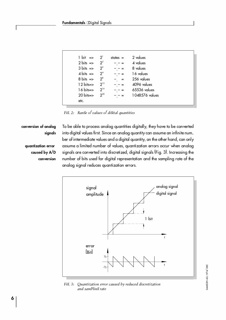
To be able to process analog quantities digitally, they have to be convertedinto digital values first. Since an analog quantity can assume an infinite num-ber of intermediate values and a digital quantity, on the other hand, can onlyassume a limited number of values, quantization errors occur when analogsignals are converted into discretized, digital signals (Fig. 3). Increasing thenumber of bits used for digital representation and the sampling rate of theanalog signal reduces quantization errors.
6
Fundamentals ⋅ Digital Signals
SAM
SON
AG
⋅V74
/D
KE
1 bit => 21 states = 2 values2 bits => 22 � � � = 4 values3 bits => 23 � � � = 8 values4 bits => 24 � � � = 16 values8 bits => 28 � � = 256 values12 bits=> 212 � � � = 4096 values16 bits=> 216 � � � = 65536 values20 bits=> 220 � � � = 1048576 valuesetc.
Fig. 2: Range of values of digital quantities
½
-½
t
t
Fig. 3: Quantization error caused by reduced discretizationand sampling rate
1 bit
error[Bit]
digital signalsignalamplitude
analog signal
quantization error
caused by A/D
conversion
conversion of analog
signals
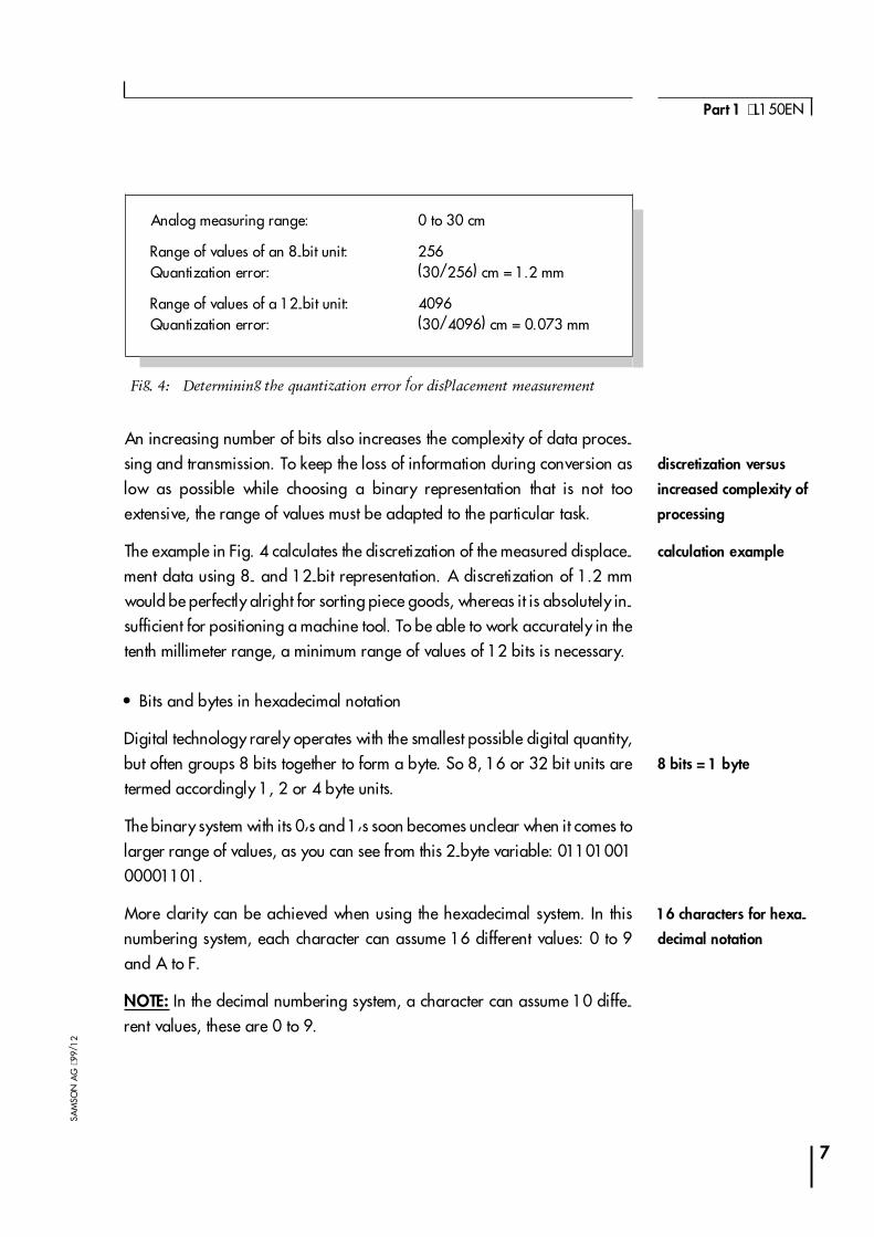
An increasing number of bits also increases the complexity of data proces-sing and transmission. To keep the loss of information during conversion aslow as possible while choosing a binary representation that is not tooextensive, the range of values must be adapted to the particular task.
The example in Fig. 4 calculates the discretization of the measured displace-ment data using 8- and 12-bit representation. A discretization of 1.2 mmwould be perfectly alright for sorting piece goods, whereas it is absolutely in-sufficient for positioning a machine tool. To be able to work accurately in thetenth millimeter range, a minimum range of values of 12 bits is necessary.
� Bits and bytes in hexadecimal notation
Digital technology rarely operates with the smallest possible digital quantity,but often groups 8 bits together to form a byte. So 8, 16 or 32 bit units aretermed accordingly 1, 2 or 4 byte units.
The binary system with its 0�s and 1�s soon becomes unclear when it comes tolarger range of values, as you can see from this 2-byte variable: 0110100100001101.
More clarity can be achieved when using the hexadecimal system. In thisnumbering system, each character can assume 16 different values: 0 to 9and A to F.
NOTE: In the decimal numbering system, a character can assume 10 diffe-rent values, these are 0 to 9.
7
Part 1 ⋅ L150EN
SAM
SON
AG
⋅99/
12
Analog measuring range: 0 to 30 cm
Range of values of an 8-bit unit:Quantization error:
256(30/256) cm = 1.2 mm
Range of values of a 12-bit unit:Quantization error:
4096(30/4096) cm = 0.073 mm
Fig. 4: Determining the quantization error for displacement measurement
8 bits = 1 byte
discretization versus
increased complexity of
processing
calculation example
16 characters for hexa-
decimal notation
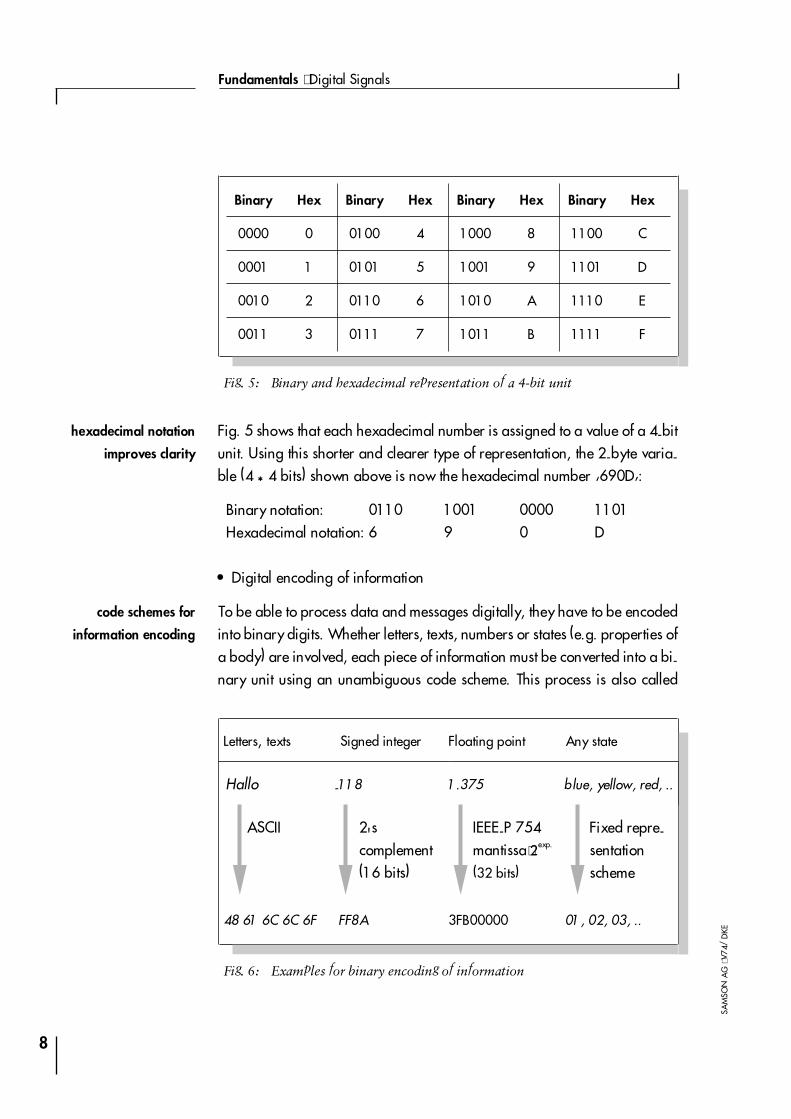
Fig. 5 shows that each hexadecimal number is assigned to a value of a 4-bitunit. Using this shorter and clearer type of representation, the 2-byte varia-ble (4 * 4 bits) shown above is now the hexadecimal number �690D�:
Binary notation: 0110 1001 0000 1101Hexadecimal notation: 6 9 0 D
� Digital encoding of information
To be able to process data and messages digitally, they have to be encodedinto binary digits. Whether letters, texts, numbers or states (e.g. properties ofa body) are involved, each piece of information must be converted into a bi-nary unit using an unambiguous code scheme. This process is also called
8
Fundamentals ⋅ Digital Signals
SAM
SON
AG
⋅V74
/D
KE
Binary Hex Binary Hex Binary Hex Binary Hex
0000 0 0100 4 1000 8 1100 C
0001 1 0101 5 1001 9 1101 D
0010 2 0110 6 1010 A 1110 E
0011 3 0111 7 1011 B 1111 F
Fig. 5: Binary and hexadecimal representation of a 4-bit unit
Letters, texts Signed integer Floating point Any state
Hallo -118 1.375 blue, yellow, red, ..
ASCII 2'scomplement(16 bits)
IEEE-P 754mantissa⋅2exp.
(32 bits)
Fixed repre-sentationscheme
48 61 6C 6C 6F FF8A 3FB00000 01, 02, 03, ..
Fig. 6: Examples for binary encoding of information
code schemes for
information encoding
hexadecimal notation
improves clarity
data encoding. Effective data processing is only possible if cooperating com-puters and programs all use the same codes.
In practice, there are many different, largely standardized types of codes forletters, texts, numbers and states. Fig. 6 gives some of the most common codeschemes. Such codes for characters and numbers exist, of course, also forother � smaller as well as wider � ranges of values.
9
Part 1 ⋅ L150EN
SAM
SON
AG
⋅99/
12
many codes have
proven successful in
practice
Advantages of digital signal processing
At first glance, digital representation and processing of (analog) informationseems extremely complex compared to analog representation. Each analogquantity must be encoded according to a code scheme to be then describedby several binary signals. This disadvantage, however, is more than com-pensated for by the numerous advantages digital technology offers for abroad range of applications:
4high interference immunity,
4easy data storage,
4 flexible processing,
4various transmission options.
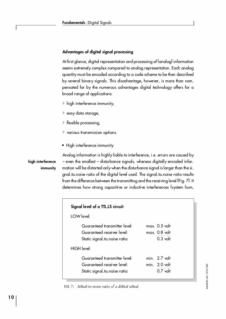
� High interference immunity
Analog information is highly liable to interference, i.e. errors are caused by� even the smallest � disturbance signals, whereas digitally encoded infor-mation will be distorted only when the disturbance signal is larger than the si-gnal-to-noise ratio of the digital level used. The signal-to-noise ratio resultsfrom the difference between the transmitting and the receiving level (Fig. 7). Itdetermines how strong capacitive or inductive interferences (system hum,
10
Fundamentals ⋅ Digital Signals
SAM
SON
AG
⋅V74
/D
KESignal level of a TTL-LS circuit
LOW level:
Guaranteed transmitter level: max. 0.5 voltGuaranteed receiver level: max. 0.8 voltStatic signal-to-noise ratio: 0.3 volt
HIGH level:
Guaranteed transmitter level: min. 2.7 voltGuaranteed receiver level: min. 2.0 voltStatic signal-to-noise ratio: 0.7 volt
Fig. 7: Signal-to-noise ratio of a digital signal
high interference
immunity
noise, switching peaks) or voltage fluctuations can be without distorting thedigital signal. By selecting the binary information representation (see L153e)the signal-to-noise ratio can be adjusted within broad limits to the environ-mental conditions.
� Short-time and permanent storage
Digital data can be stored very easily on a variety of often very cost-effectivedata carriers. There is the option of storing in volatile semiconductor memo-ries (Random Access Memory: RAM), or permanently on magnetic and opti-cal data carriers.
� Flexible processing
Microprocessor-based and software-controlled data processing enableseven complex algorithms to be computed in almost no time with a high de-gree of flexibility.
� Various transmission options
The two states of a binary signal can be encoded in many different ways,thus offering a broad spectrum of application. For data transmission overlong distances, for example, optical fiber cables are used because of theirlow energy consumption and high interference immunity. Binary signals canbe assigned directly to the ON/OFF states of a light signal, while analog si-gnals can only be transmitted optically after expensive and time-consuminglinearization and intensity analysis which is liable to errors.
11
Part 1 ⋅ L150EN
SAM
SON
AG
⋅99/
12
good storage properties
flexible
processing
electrical, optical or
acoustical transmission
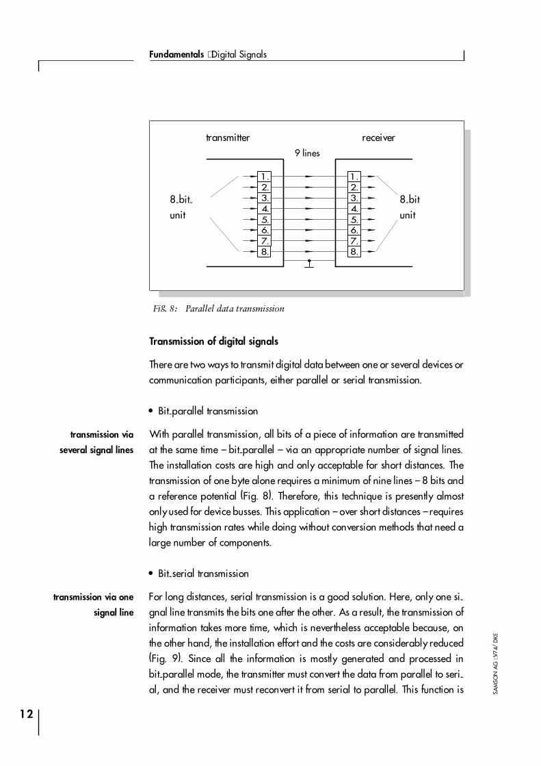
Transmission of digital signals
There are two ways to transmit digital data between one or several devices orcommunication participants, either parallel or serial transmission.
� Bit-parallel transmission
With parallel transmission, all bits of a piece of information are transmittedat the same time � bit-parallel � via an appropriate number of signal lines.The installation costs are high and only acceptable for short distances. Thetransmission of one byte alone requires a minimum of nine lines � 8 bits anda reference potential (Fig. 8). Therefore, this technique is presently almostonly used for device busses. This application � over short distances � requireshigh transmission rates while doing without conversion methods that need alarge number of components.
� Bit-serial transmission
For long distances, serial transmission is a good solution. Here, only one si-gnal line transmits the bits one after the other. As a result, the transmission ofinformation takes more time, which is nevertheless acceptable because, onthe other hand, the installation effort and the costs are considerably reduced(Fig. 9). Since all the information is mostly generated and processed inbit-parallel mode, the transmitter must convert the data from parallel to seri-al, and the receiver must reconvert it from serial to parallel. This function is
12
Fundamentals ⋅ Digital Signals
SAM
SON
AG
⋅V74
/D
KE
1.2.3.4.5.6.7.
1.2.3.4.5.6.7.
8. 8.
Fig. 8: Parallel data transmission
transmitter receiver9 lines
8-bit-unit
8-bitunit
transmission via
several signal lines
transmission via one
signal line

performed by specially operated shift registers which are already integratedin communication modules available on the market.
13
Part 1 ⋅ L150EN
SAM
SON
AG
⋅99/
12
7. 6. 5. 4. 3. 2. 1. 7. 6. 5. 4. 3. 2. 1.
1.2.3.4.5.6.7.
1.2.3.4.5.6.7.
8,7,6,5,4,3,2,1
8.
8.
8.
8.
Fig. 9: Serial data transmission
transmitter receiver
2 lines
8-bi
tuni
t
8-bi
tuni
t
Appendix A1:Additional Literature
[1] L153EN: Serial Data TransmissionTechnical Information; SAMSON AG
[2] L155EN: Networked CommunicationsTechnical Information; SAMSON AG
[3] L450EN: Communication in the FieldTechnical Information; SAMSON AG
[4] L452EN: HART-CommunicationTechnical Information; SAMSON AG
[6] L453EN: PROFIBUS PATechnical Information; SAMSON AG
[7] L454EN: FOUNDATION FieldbusTechnical Information; SAMSON AG
14
Fundamentals ⋅ Digital Signals
SAM
SON
AG
⋅V74
/D
KE
APP
ENDI
X
Figures
Fig. 1: Analog and discrete signal curves . . . . . . . . . . . . . . . 5
Fig. 2: Range of values of digital quantities . . . . . . . . . . . . . . 6
Fig. 3: Quantization error . . . . . . . . . . . . . . . . . . . . . . 6
Fig. 4: Determining the quantization error . . . . . . . . . . . . . . 7
Fig. 5: Binary and hexadecimal representation of a 4-bit unit . . . . . 8
Fig. 6: Examples for binary encoding of information. . . . . . . . . . 8
Fig. 7: Signal-to-noise ratio of a digital signal . . . . . . . . . . . . 10
Fig. 8: Parallel data transmission . . . . . . . . . . . . . . . . . . 12
Fig. 9: Serial data transmission . . . . . . . . . . . . . . . . . . . 13
15
Part 1 ⋅ L150EN
SAM
SON
AG
⋅99/
12
FIG
URE
S

SAMSON AG ⋅ MESS- UND REGELTECHNIK ⋅ Weismüllerstraße 3 ⋅ D-60314 Frankfurt am MainPhone (+49 69) 4 00 90 ⋅ Telefax (+49 69) 4 00 95 07 ⋅ Internet: http://www.samson.de
1999
/12
⋅L15
0EN