PARALLAX INC. (3-923) ADVANCED SUMOBOT KIT - Octopart
350
The content and copyrights of the attached material are the property of its owner. Distributed by: www.Jameco.com ✦ 1-800-831-4242
-
Upload
khangminh22 -
Category
Documents
-
view
2 -
download
0
Transcript of PARALLAX INC. (3-923) ADVANCED SUMOBOT KIT - Octopart

The content and copyrights of the attached material are the property of its owner.
Distributed by:
www.Jameco.com 1-800-831-4242
JMendiola
Text Box
Jameco Part Number 357270
SumoBot® – Mini-Sumo Robotics Assembly Documentation and Programming
VERSION 2.1
WARRANTY Parallax Inc. warrants its products against defects in materials and workmanship for a period of 90 days from receipt of product. If you discover a defect, Parallax Inc. will, at its option, repair or replace the merchandise, or refund the purchase price. Before returning the product to Parallax, call for a Return Merchandise Authorization (RMA) number. Write the RMA number on the outside of the box used to return the merchandise to Parallax. Please enclose the following along with the returned merchandise: your name, telephone number, shipping address, and a description of the problem. Parallax will return your product or its replacement using the same shipping method used to ship the product to Parallax.
14-DAY MONEY BACK GUARANTEE If, within 14 days of having received your product, you find that it does not suit your needs, you may return it for a full refund. Parallax Inc. will refund the purchase price of the product, excluding shipping/handling costs. This guarantee is void if the product has been altered or damaged. See the Warranty section above for instructions on returning a product to Parallax. COPYRIGHTS AND TRADEMARKS This documentation is copyright 2002- 2005 by Parallax Inc. By downloading or obtaining a printed copy of this documentation or software you agree that it is to be used exclusively with Parallax products. Any other uses are not permitted and may represent a violation of Parallax copyrights, legally punishable according to Federal copyright or intellectual property laws. Any duplication of this documentation for commercial uses is expressly prohibited by Parallax Inc. BASIC Stamp, Stamps in Class, Boe-Bot, SumoBot, SX-Key and Toddler are registered trademarks of Parallax, Inc. If you decide to use registered trademarks of Parallax Inc. on your web page or in printed material, you must state that "(registered trademark) is a registered trademark of Parallax Inc.” upon the first appearance of the trademark name in each printed document or web page. HomeWork Board, Parallax, the Parallax logo, are trademarks of Parallax Inc. If you decide to use trademarks of Parallax Inc. on your web page or in printed material, you must state that "(trademark) is a trademark of Parallax Inc.”, “upon the first appearance of the trademark name in each printed document or web page. Other brand and product names are trademarks or registered trademarks of their respective holders.
ISBN 1-928982-26-3
DISCLAIMER OF LIABILITY Parallax Inc. is not responsible for special, incidental, or consequential damages resulting from any breach of warranty, or under any legal theory, including lost profits, downtime, goodwill, damage to or replacement of equipment or property, or any costs of recovering, reprogramming, or reproducing any data stored in or used with Parallax products. Parallax Inc. is also not responsible for any personal damage, including that to life and health, resulting from use of any of our products. You take full responsibility for your BASIC Stamp application, no matter how life-threatening it may be.
Preface · Page iii
INTERNET DISCUSSION LISTS We maintain active web-based discussion forums for people interested in Parallax products. These lists are accessible from www.parallax.com via the Support → Discussion Forums menu. These are the forums that we operate from our web site:
• BASIC Stamps – This list is widely utilized by engineers, hobbyists and students who share their BASIC Stamp projects and ask questions.
• Stamps in Class® – Created for educators and students, subscribers discuss the use of the Stamps in Class educational program in their courses. The list provides an opportunity for both students and educators to ask questions and get answers.
• Parallax Educators –Exclusively for educators and those who contribute to the development of Stamps in Class. Parallax created this group to obtain feedback on our curricula and to provide a forum for educators to develop and obtain Teacher’s Guides.
• Translators – The purpose of this list is to provide a conduit between Parallax and those who translate our documentation to languages other than English. Parallax provides editable Word documents to our translating partners and attempts to time the translations to coordinate with our publications.
• Robotics – Designed exclusively for Parallax robots, this forum is intended to be an open dialogue for a robotics enthusiasts. Topics include assembly, source code, expansion, and manual updates. The Boe-Bot®, Toddler®, SumoBot®, HexCrawler and QuadCrawler robots are discussed here.
• SX Microcontrollers and SX-Key – Discussion of programming the SX microcontroller with Parallax assembly language SX-Key® tools and 3rd party BASIC and C compilers.
Javelin Stamp – Discussion of application and design using the Javelin Stamp, a Parallax module that is programmed using a subset of Sun Microsystems’ Java® programming language.
ERRATA While great effort is made to assure the accuracy of our texts, errors may still exist. If you find an error, please let us know by sending an email to [email protected]. We continually strive to improve all of our educational materials and documentation, and frequently revise our texts. Occasionally, an errata sheet with a list of known errors and corrections for a given text will be posted to our web site, www.parallax.com. Please check the individual product page’s free downloads for an errata file.


Table of Contents · Page v
Table of Contents
Preface .........................................................................................................vii Recognitions ..............................................................................................vii Audience...................................................................................................viii Educational Concepts from the SumoBot.................................................viii Copyright and Reproduction .......................................................................ix
Chapter 1: Assemble the SumoBot ............................................................. 1 Let’s Build the SumoBot .............................................................................. 2 Tools Required ............................................................................................ 2 About the Parts in the SumoBot Kit ............................................................. 2
Chapter 2: SumoBot Locomotion.............................................................. 11 How a Servo Works ................................................................................... 11 Time Measurement and Voltage Levels .................................................... 11 SumoBot Motion Test ................................................................................ 16 Challenge Yourself .................................................................................... 21
Chapter 3: SumoBot Sensors and Border Detection............................... 23 Line Sensor Theory ................................................................................... 23 Our First Operational Sumo Program ........................................................ 29 Challenge Yourself .................................................................................... 34
Chapter 4: Infrared Object Detection ........................................................ 35 Infrared Headlights .................................................................................... 35 The FREQOUT Trick ................................................................................. 36 Installing and Testing the IR Emitters/Detectors........................................ 37 Testing the IR Pairs ................................................................................... 39 SumoBot Motion Control............................................................................ 41
Chapter 5: Basic Competition Code.......................................................... 45 Final Competition Notes ............................................................................ 52
Appendix A: SumoBot Parts List............................................................... 53

Page vi · SumoBot – Mini Sumo Robotics
Appendix B: Standard Mini-Sumo Competition Rules ............................ 55
Appendix C: Mini-Sumo Ring .................................................................... 65
Appendix D: SumoBot PCB Schematic .................................................... 67
Preface · Page vii
PREFACE Like its human counterpart, robot Sumo was born and thrives in Japan. It was introduced to the United States in the early 1990's by Dr. Mato Hattori. One of the early American adopters of robot Sumo was noted Seattle Robotics Society member, Bill Harrison, who organized some of the first U.S. robot Sumo tournaments. While things started out very slowly, robot Sumo eventually caught on. Bill created a "lightweight" class that matched the Japanese physical dimensions of 20 cm by 20 cm, but reduced the mass from three kilograms (6.6 pounds) to one kilogram (2.2 pounds). The intention was to reduce the sophistication of the components required to construct a working Sumo robot. Those early contests didn't have much in the way of corporate support with prizes, so Bill resorted to offering 30 hours of his own machine-shop services to the winner. As luck would have it, Bill's friend Robert Jorgensen won that first contest prize. Since Robert already had a winning Sumo robot, he suggested that they build a smaller version, about half the size and weight of the lightweight class to be used as a robot Sumo demonstrator. The result of their work was a very small Sumo robot that measured just 8 cm by 8 cm and mass about 240 grams. Bill took that first small Sumo to a contest in San Francisco and actually won the lightweight competition – against bigger and heavier robots. The Mini-Sumo robot class was born. The Mini-Sumo dimensions (10 cm x 10 cm) and mass (500 grams) were formalized and Bill published adapted Japanese robot Sumo rules on his Sine Robotics web site (mirrored on many other sites, and reprinted with permission in this document). Through Bill's tireless efforts and nearly ten years of travel – often toting more than 20 robots in his bags – Mini-Sumo robotics has grown to a favorite activity among robot clubs all across the United States.
RECOGNITIONS Many Mini-Sumo designs – especially the dual-wheel-and-scoop concept – can be traced back to Bill Harrison's early efforts to promote Mini-Sumo robotics competition. Parallax also recognizes Bill Boyer of the Dallas Personal Robotics Group for his version of the dual-wheel-and-scoop design that was refined and developed into the Parallax SumoBot robot described in this text.
Page viii · SumoBot – Mini Sumo Robotics
This text was authored by Jon Williams of Parallax, and contains additional material by several contributors, including Andy Lindsay and Ken Gracey of Parallax, as well as Bill Wong of Pennsylvania. Bill is an editor with Electronic Design magazine and a serious BASIC Stamp® robotics enthusiast. Bill enjoys creating BASIC Stamp powered robots with his daughter, who has gone on to win several county and state awards with her maze solving robotics projects.
AUDIENCE SumoBot was written for ages 12+ as a complimentary text to Parallax’s Robotics with the Boe-Bot and Advanced Robotics with the Toddler student guides. Like all Parallax texts, this series of experiments teaches new techniques and circuits with minimal overlap between the other publications. The general topics introduced in this series are: basic SumoBot locomotion under program control, edge avoidance, and opponent detection based on a variety of sensor inputs, as well as navigation opponent hunting using programmed artificial intelligence. Each topic is addressed in an introductory format designed to impart a conceptual understanding along with some hands-on experience. Those who intend to delve further into industrial technology, electronics or robotics are likely to benefit significantly from initial experiences with these topics. If your experience with the SumoBot® robot differs from our expectations, please let us know at [email protected].
EDUCATIONAL CONCEPTS FROM THE SUMOBOT Educators frequently ask us at Parallax what can be learned from our different texts and application notes. The SumoBot is considered an intermediate robotic project and generally will instruct the following concepts:
• Interaction between mechanical and electrical systems, and the ability to tune hardware or adjust software to obtain desired results.
• Intermediate programming skills with the BASIC Stamp 2 microcontroller. An efficient SumoBot program makes use of efficient BASIC Stamp programming techniques with BRANCH and LOOKDOWN, variable aliasing, general sound programming practices (constant/variable definitions that allow for program customization in just a few places rather than throughout an entire program).
• A step-wise process which starts with the basics and builds to something more complex and ultimately more useful.

Preface · Page ix


Chapter 1: Assemble the SumoBot · Page 1
Chapter 1: Assemble the SumoBot There's an old axiom among robot enthusiasts that states, "It's harder than it looks...." Speaking from experience, we know this to be true. That said, the purpose of this statement is not to alarm or dissuade the new robot builder, but simply to remind him or her that robotics – even on a small scale – is a serious endeavor and shouldn't be taken lightly. Patience is indeed a virtue. Follow the construction steps carefully and you'll have your SumoBot running and ready to compete in about an hour or so. The SumoBot is capable of doing any of the things other rolling robots can do. As you learn to program the SumoBot for competition, you’ll become a more proficient – and efficient – programmer and will learn to exploit the BASIC Stamp microcontroller’s capabilities. The SumoBot demonstrates the importance of a PBASIC program that uses constants and variables, as well state-oriented design. A well-designed program means you can easily tune the software for the right mechanical control in just a few places rather than rewriting your entire program. A surface-mounted BASIC Stamp 2 microcontroller provides the intelligence for the SumoBot. The BASIC Stamp is used throughout the Stamps in Class educational series, and provides plenty of program space, speed and memory for use with a SumoBot. The SumoBot is a purpose-built rolling robot, much like its general-purpose cousin the Parallax Boe-Bot. While they share the same differential drive mechanism and the use of sensors, the SumoBot design meets the specific criteria defined by Mini-Sumo competition rules:
• Maximum [width and depth] dimensions of 10 cm by 10 cm • Maximum mass of 500 grams
The standard SumoBot comes with two sets of sensors: two QTI line sensors to keep the SumoBot on the playing surface and two sets of infrared emitters/detectors used to locate its opponent. Advanced users may expand on the standard SumoBot design by adding ultrasonic or IR distance measuring, tilt sensing and motor current sensing.

Page 2 · SumoBot – Mini Sumo Robotics
LET’S BUILD THE SUMOBOT The SumoBot chassis design leaves little room for mechanical alteration; a requirement to stay within standard Mini-Sumo competition rules. Where the student is encouraged to explore changes is in the types of sensors used to detect the Sumo ring border and the opponent and the software algorithms used to control the SumoBot robot’s behaviors. The demonstration code provided with this text will focus on the standard sensors provided in the SumoBot kit. Future supplements may be published that deal with advanced sensors and techniques for incorporating them into the SumoBot robot’s control logic.
TOOLS REQUIRED A Parallax screwdriver is included in your kit. You may find a pair of needle-nose pliers and a wire stripper to be useful (not included).
ABOUT PARTS IN THE SUMOBOT KIT Appendix A includes a parts listing for the SumoBot robot kit. These instructions refer to different pieces of hardware. If your SumoBot kit is missing a piece, Parallax will replace it free of charge. Replacement Parallax Continuous Rotation servos and infrared emitters and detectors are available to purchase online from the Parallax Component Shop (www.parallax.com → Component Shop). If you need other parts replaced, please contact [email protected] or call toll free in the United States: 1-800-512-1024. If you have trouble identifying the type of part referred to in these instructions, see the color back cover of this text that shows each part with a colored picture and Parallax stock code.
Chapter 1: Assemble the SumoBot · Page 3
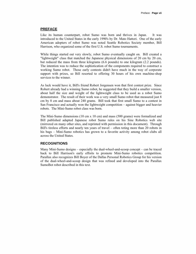
Step #1 Install the Battery Box Parts Required:
• Battery Box • (2) 4/40 3/8" long
flat-head countersunk machine screws
• (2) 4/40 nuts • SumoBot chassis
Stand the SumoBot on its PCB mounting ears. Install the plastic battery pack using two 4/40 3/8” flat-head screws and nuts. The screws will be countersunk into the battery pack when tightened and should be out of the way of the batteries.
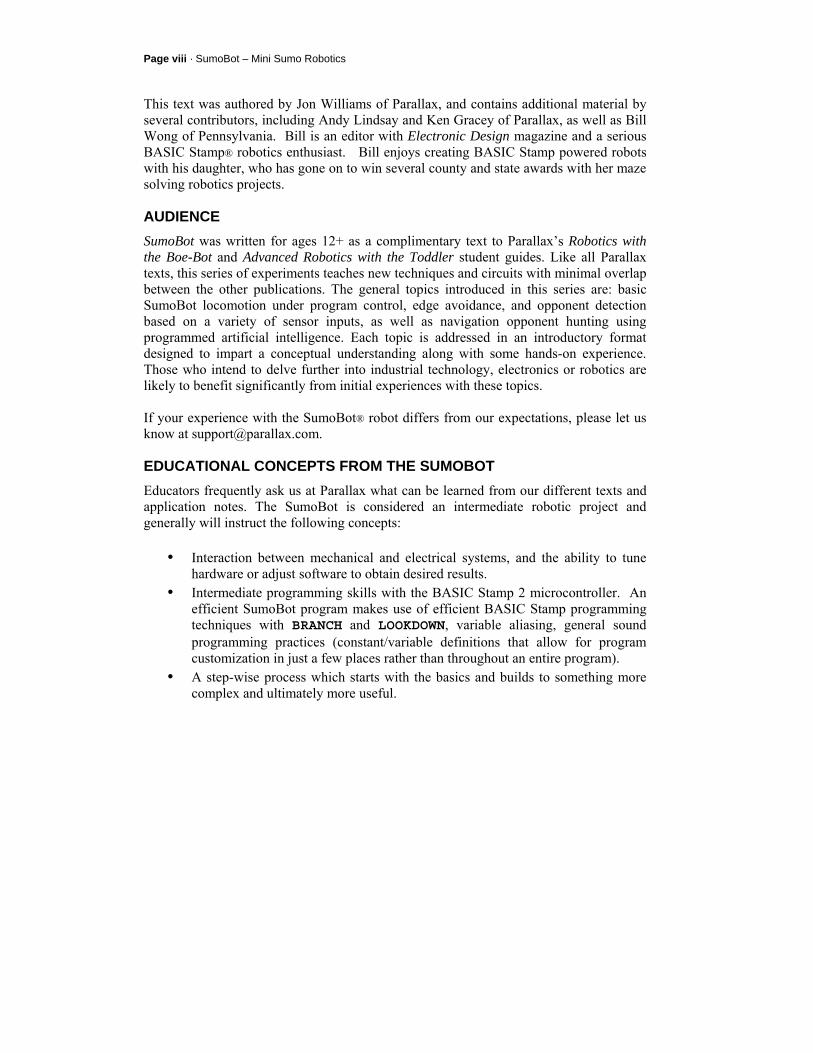
Step #2 Install the Servo Motors Parts Required:
• (2) Parallax Continuous Rotation Servos
• (8) 4/40 3/8" long pan-head machine screws
• (8) 4/40 nuts • SumoBot chassis
Using four 4/40 3/8” pan-head machine screws and 4/40 nuts, attach each servo motor to the chassis. The easiest way to do this is to hold the nut with one finger while turning the screwdriver with the other hand.

Page 4 · SumoBot – Mini Sumo Robotics
Step #3 Install the Rear SumoBot PCB Stand-offs Parts Required:
• (2) 5/8" round standoffs
• (2) 4/40 3/8" long pan-head machine screws
• SumoBot chassis Using a 4/40 3/8" pan-head machine screw, attach each stand-off to the rear of the SumoBot chassis.
Step #4 Install the Front SumoBot PCB Stand-offs Parts Required:
• (2) 5/8" round standoffs
• (2) 4/40 1" long pan-head machine screws
• SumoBot PCB Using a 4/40 1" pan-head machine screw, attach each standoff to the front mounting holes of the SumoBot PCB.
Chapter 1: Assemble the SumoBot · Page 5
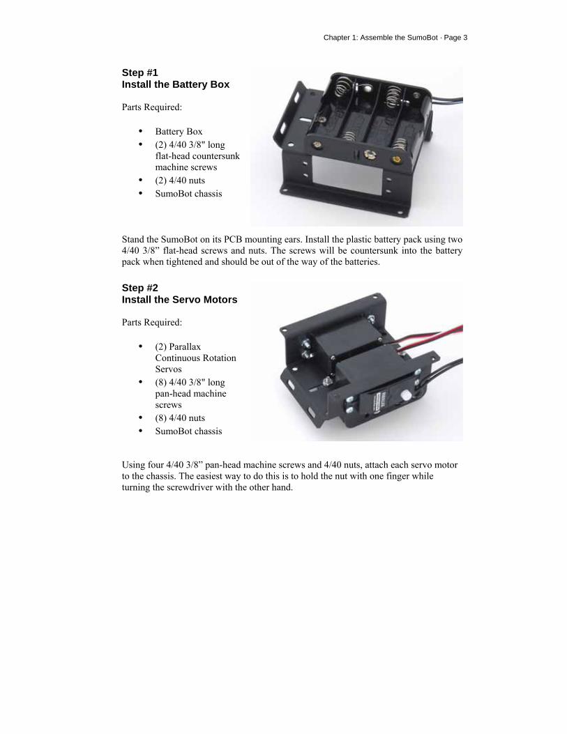
Step #5 Mounting the PCB Parts Required:
• SumoBot PCB • (2) 4/40 3/8" long
pan-head machine screws
• (2) 1-1/4" round stand-offs
• (2) Nylon washers • SumoBot chassis
Feed the ends of the 1" long pan-head machine screws through the front mounting holes on the SumoBot chassis. Secure the rear side of the SumoBot PCB to the 5/8" standoffs with two 3/8" pan-head machine screws. Holding the chassis upside-down, place a nylon washer onto the end of each 1" long pan-head machine screw, then secure by threading on the 1-1/4" round standoff.
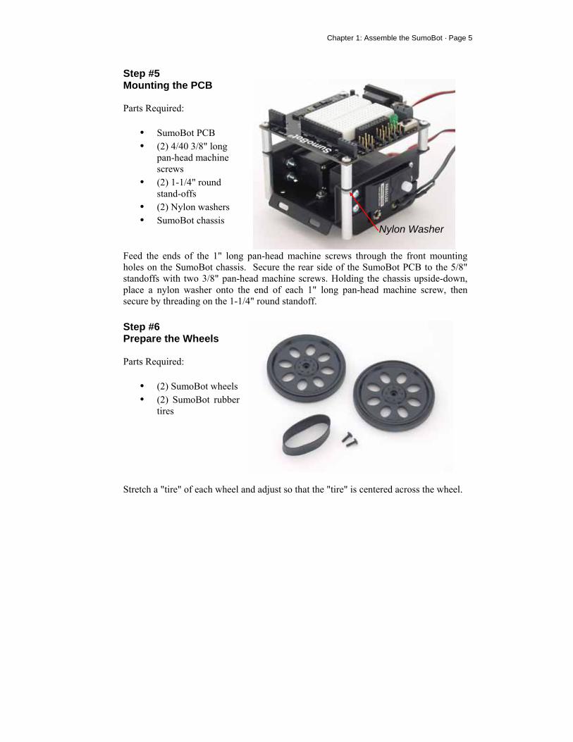
Step #6 Prepare the Wheels Parts Required:
• (2) SumoBot wheels • (2) SumoBot rubber
tires
Stretch a "tire" of each wheel and adjust so that the "tire" is centered across the wheel.
Nylon Washer

Page 6 · SumoBot – Mini Sumo Robotics
Step #7 Mount the Wheels Parts Required:
• (2) Prepared wheels/tires
• (2) Black servo-horn screws
• SumoBot chassis
Carefully press each prepared wheel onto the servo splines. Secure each wheel with the small black Phillips head screw.
Step #8 Mount the Scoop Parts Required:
• SumoBot scoop • (2) 4/40 1/4" long pan-
head machine screws • (2) 4/40 nuts • SumoBot chassis
Using two 4/40 1/4” pan-head machine screws and 4/40 nuts, attach the scoop to the SumoBot chassis. Carefully center the scoop before tightening the screws and nuts.
Chapter 1: Assemble the SumoBot · Page 7
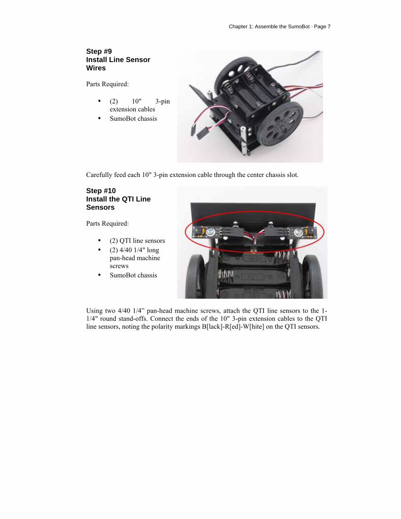
Step #9 Install Line Sensor Wires Parts Required:
• (2) 10" 3-pin extension cables
• SumoBot chassis
Carefully feed each 10" 3-pin extension cable through the center chassis slot.
Step #10 Install the QTI Line Sensors Parts Required:
• (2) QTI line sensors • (2) 4/40 1/4" long
pan-head machine screws
• SumoBot chassis
Using two 4/40 1/4” pan-head machine screws, attach the QTI line sensors to the 1-1/4" round stand-offs. Connect the ends of the 10" 3-pin extension cables to the QTI line sensors, noting the polarity markings B[lack]-R[ed]-W[hite] on the QTI sensors.
Page 8 · SumoBot – Mini Sumo Robotics
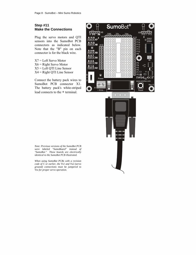
Step #11 Make the Connections Plug the servo motors and QTI sensors into the SumoBot PCB connectors as indicated below. Note that the "B" pin on each connector is for the black wire. X7 = Left Servo Motor X6 = Right Servo Motor X5 = Left QTI Line Sensor X4 = Right QTI Line Sensor Connect the battery pack wires to SumoBot PCB connector X1. The battery pack's white-striped lead connects to the + terminal. Note: Previous versions of the SumoBot PCB were labeled "SumoBoard" instead of "SumoBot." These boards are electrically identical to the SumoBot PCB illustrated. When using SumoBot PCBs with a revision code of C or earlier, the Vs1 and Vs2 (servo ground) connections must be jumpered to Vss for proper servo operation.
Chapter 1: Assemble the SumoBot · Page 9
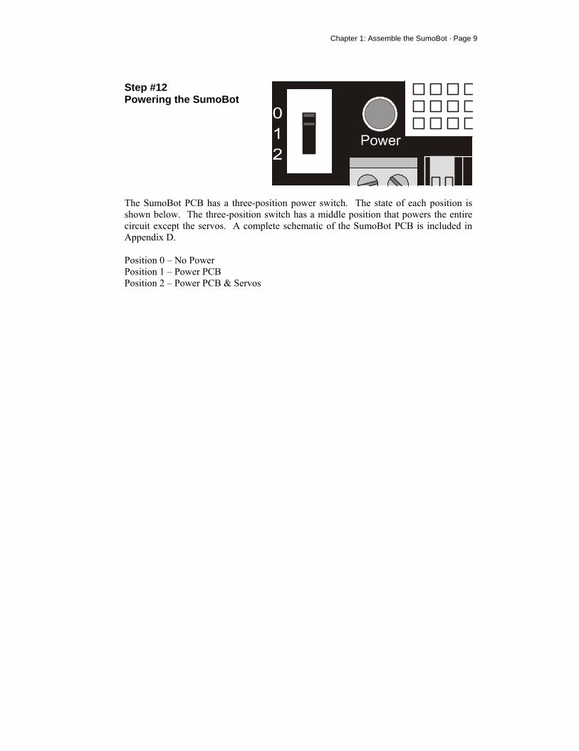
Step #12 Powering the SumoBot
The SumoBot PCB has a three-position power switch. The state of each position is shown below. The three-position switch has a middle position that powers the entire circuit except the servos. A complete schematic of the SumoBot PCB is included in Appendix D. Position 0 – No Power Position 1 – Power PCB Position 2 – Power PCB & Servos


Chapter 2: SumoBot Locomotion · Page 11
Chapter 2: SumoBot Locomotion The first task of any Mini-Sumo robot is to move – most competition rules do not allow the robot to stop (without competitor contact) for more than a few seconds. In this experiment you will learn how to get the SumoBot moving and learn to take control over its motion.
HOW A SERVO WORKS Normal (un-modified) hobby servos are very popular for controlling the steering systems in radio-controlled cars, boats and planes. These servos are designed to control the position of something such as a steering flap on a radio-controlled airplane. Their range of motion is typically 90° to 270°, and they are great for applications where inexpensive, accurate high-torque positioning motion is required. The position of these servos is controlled by an electronic signal called a pulse train, which you’ll get some first hand experience with shortly. An un-modified hobby servo has built-in mechanical stoppers to prevent it from turning beyond its 90° or 270° range of motion. It also has internal mechanical linkages for position feedback so that the electronic circuit that controls the DC motor inside the servo knows where to turn to in response to a pulse train. SumoBot motion is controlled using two pre-modified Parallax Continuous Rotation servo motors using a process called differential drive. The modification "tricks" the feedback circuitry so that the servo will stop only when it receives a centering command; it also allows the servo to continuously rotate in either direction. When both motors are turning in the same direction, the SumoBot will move in that direction. When the SumoBot servo motors turn in different directions, the chassis will rotate. The rate of movement or rotation is determined by motor speeds.
TIME MEASUREMENTS AND VOLTAGE LEVELS Throughout this text, amounts of time will be referred to in units of seconds (s), milliseconds (ms), and microseconds (µs). Seconds are abbreviated with the lower-case letter “s”. So, one second is written as 1 s. Milliseconds are abbreviated as ms, and it means one one-thousandth of a second. One microsecond is one one-millionth of a second. Figure 2.1 shows how Milliseconds and Microseconds equate in terms of both fractions and scientific notation.
Page 12 · SumoBot – Mini Sumo Robotics
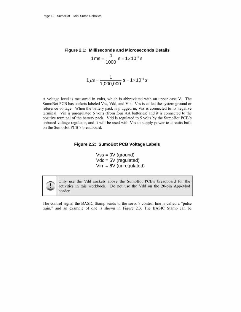
Figure 2.1: Milliseconds and Microseconds Details
s3-101s1000
1ms1 ×==
s6-101s1,000,000
1s1 ×==µ
A voltage level is measured in volts, which is abbreviated with an upper case V. The SumoBot PCB has sockets labeled Vss, Vdd, and Vin. Vss is called the system ground or reference voltage. When the battery pack is plugged in, Vss is connected to its negative terminal. Vin is unregulated 6 volts (from four AA batteries) and it is connected to the positive terminal of the battery pack. Vdd is regulated to 5 volts by the SumoBot PCB’s onboard voltage regulator, and it will be used with Vss to supply power to circuits built on the SumoBot PCB’s breadboard.
Figure 2.2: SumoBot PCB Voltage Labels
Vss = 0V (ground) Vdd = 5V (regulated) Vin = 6V (unregulated)
Only use the Vdd sockets above the SumoBot PCB's breadboard for the activities in this workbook. Do not use the Vdd on the 20-pin App-Mod header.
The control signal the BASIC Stamp sends to the servo’s control line is called a “pulse train,” and an example of one is shown in Figure 2.3. The BASIC Stamp can be
Chapter 2: SumoBot Locomotion · Page 13
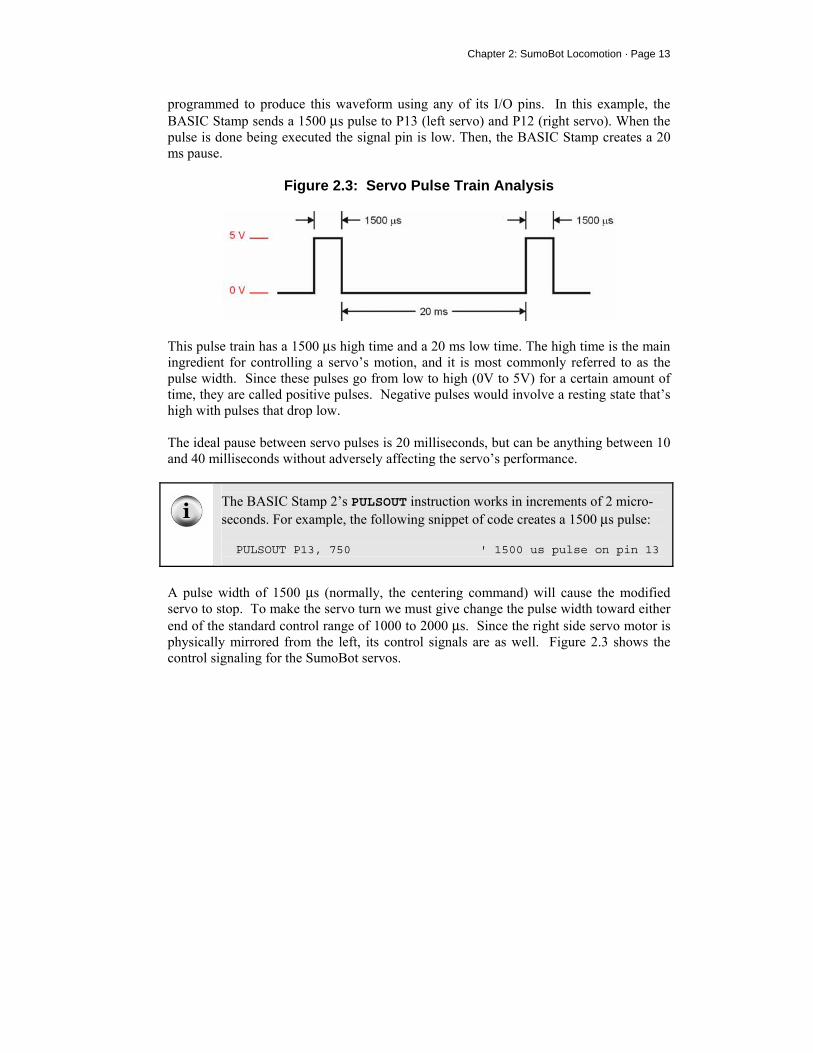
programmed to produce this waveform using any of its I/O pins. In this example, the BASIC Stamp sends a 1500 µs pulse to P13 (left servo) and P12 (right servo). When the pulse is done being executed the signal pin is low. Then, the BASIC Stamp creates a 20 ms pause.
Figure 2.3: Servo Pulse Train Analysis
This pulse train has a 1500 µs high time and a 20 ms low time. The high time is the main ingredient for controlling a servo’s motion, and it is most commonly referred to as the pulse width. Since these pulses go from low to high (0V to 5V) for a certain amount of time, they are called positive pulses. Negative pulses would involve a resting state that’s high with pulses that drop low. The ideal pause between servo pulses is 20 milliseconds, but can be anything between 10 and 40 milliseconds without adversely affecting the servo’s performance.
The BASIC Stamp 2’s PULSOUT instruction works in increments of 2 micro-seconds. For example, the following snippet of code creates a 1500 µs pulse: PULSOUT P13, 750 ' 1500 us pulse on pin 13
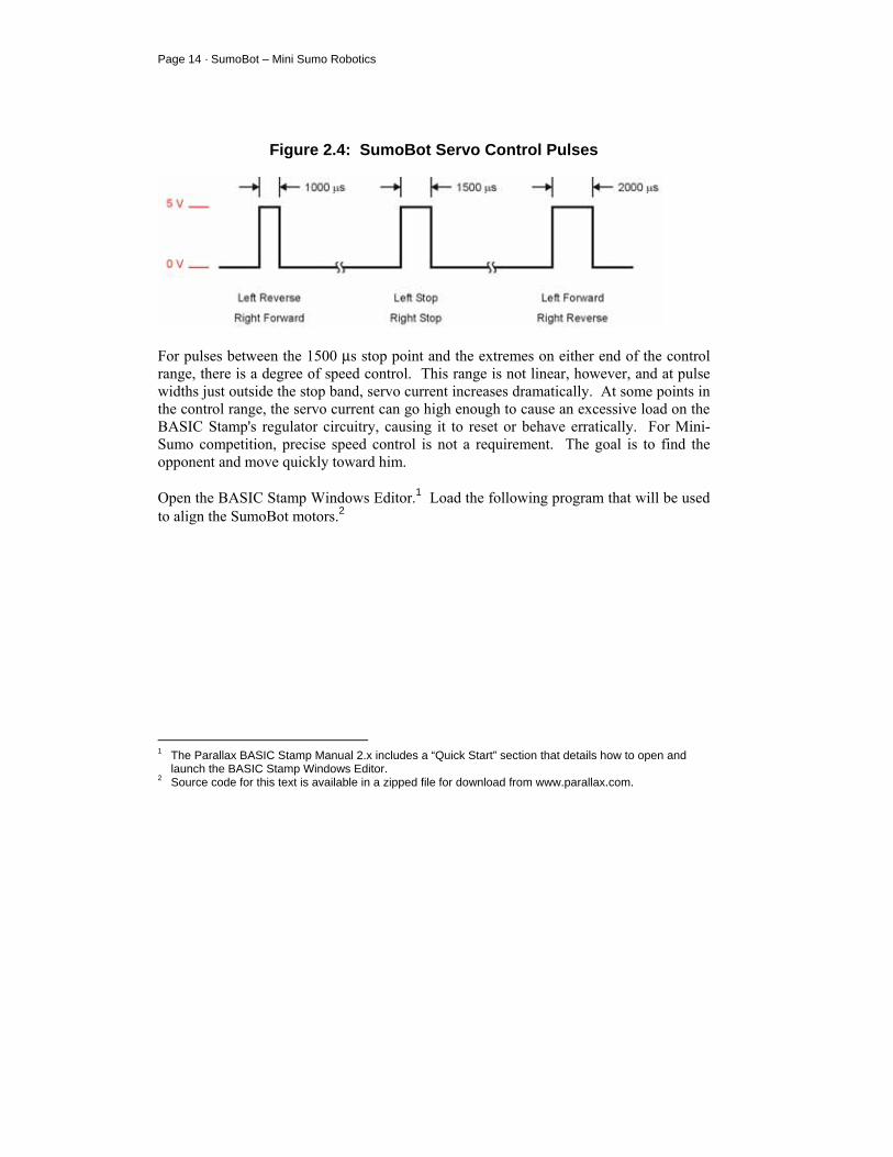
A pulse width of 1500 µs (normally, the centering command) will cause the modified servo to stop. To make the servo turn we must give change the pulse width toward either end of the standard control range of 1000 to 2000 µs. Since the right side servo motor is physically mirrored from the left, its control signals are as well. Figure 2.3 shows the control signaling for the SumoBot servos.
Page 14 · SumoBot – Mini Sumo Robotics
Figure 2.4: SumoBot Servo Control Pulses
For pulses between the 1500 µs stop point and the extremes on either end of the control range, there is a degree of speed control. This range is not linear, however, and at pulse widths just outside the stop band, servo current increases dramatically. At some points in the control range, the servo current can go high enough to cause an excessive load on the BASIC Stamp's regulator circuitry, causing it to reset or behave erratically. For Mini-Sumo competition, precise speed control is not a requirement. The goal is to find the opponent and move quickly toward him. Open the BASIC Stamp Windows Editor.1 Load the following program that will be used to align the SumoBot motors.2
1 The Parallax BASIC Stamp Manual 2.x includes a “Quick Start” section that details how to open and
launch the BASIC Stamp Windows Editor. 2 Source code for this text is available in a zipped file for download from www.parallax.com.
Chapter 2: SumoBot Locomotion · Page 15
' SumoBot_2.1_Motor_Align.BS2 ' $STAMP BS2 ' $PBASIC 2.5 ' -----[ I/O Definitions ]------------------------------------------------- LMotor PIN 13 ' left servo motor RMotor PIN 12 ' right servo motor ' -----[ Constants ]------------------------------------------------------- LStop CON 750 ' left motor stop RStop CON 750 ' right motor stop ' -----[ Initialization ]-------------------------------------------------- Reset: LOW LMotor ' initialize motor outputs LOW RMotor ' -----[ Program Code ]---------------------------------------------------- Main: DO PULSOUT LMotor, LStop ' stop left PULSOUT RMotor, RStop ' stop right PAUSE 20 LOOP END
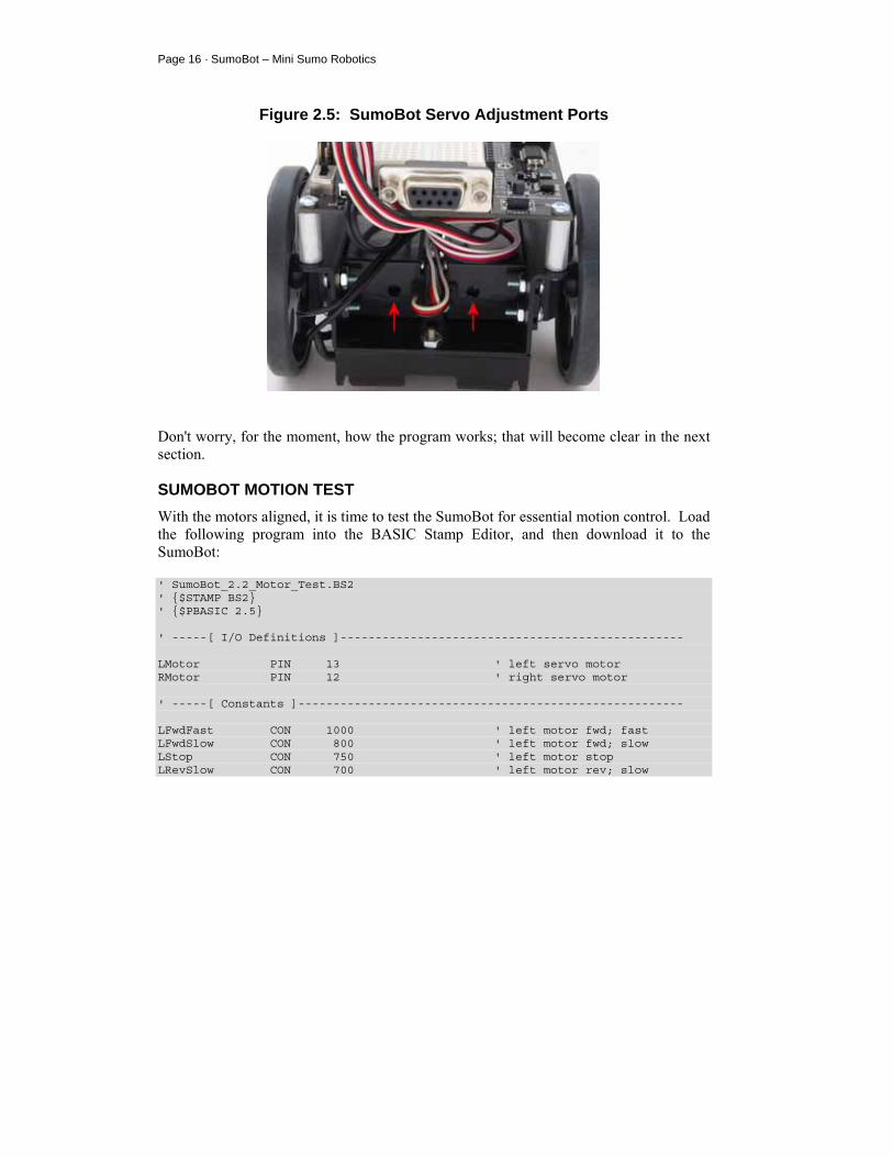
Move the SumoBot power switch to position 2, and then download the code using the Run command from the Run menu, or by pressing the button on the toolbar. As soon as the program is downloaded, watch for wheel movement. If either motor turns, insert a small screwdriver into the adjustment port of the servo and adjust the centering potentiometer until the motor stops. Figure 2.5 shows the location of the servo adjustment ports.
Page 16 · SumoBot – Mini Sumo Robotics
Figure 2.5: SumoBot Servo Adjustment Ports
Don't worry, for the moment, how the program works; that will become clear in the next section.
SUMOBOT MOTION TEST With the motors aligned, it is time to test the SumoBot for essential motion control. Load the following program into the BASIC Stamp Editor, and then download it to the SumoBot: ' SumoBot_2.2_Motor_Test.BS2 ' $STAMP BS2 ' $PBASIC 2.5 ' -----[ I/O Definitions ]------------------------------------------------- LMotor PIN 13 ' left servo motor RMotor PIN 12 ' right servo motor ' -----[ Constants ]------------------------------------------------------- LFwdFast CON 1000 ' left motor fwd; fast LFwdSlow CON 800 ' left motor fwd; slow LStop CON 750 ' left motor stop LRevSlow CON 700 ' left motor rev; slow
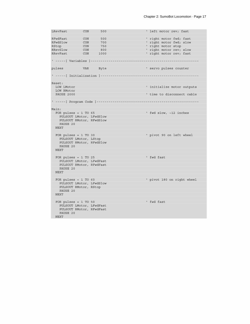
Chapter 2: SumoBot Locomotion · Page 17
LRevFast CON 500 ' left motor rev; fast RFwdFast CON 500 ' right motor fwd; fast RFwdSlow CON 700 ' right motor fwd; slow RStop CON 750 ' right motor stop RRevSlow CON 800 ' right motor rev; slow RRevFast CON 1000 ' right motor rev; fast ' -----[ Variables ]------------------------------------------------------- pulses VAR Byte ' servo pulses counter ' -----[ Initialization ]-------------------------------------------------- Reset: LOW LMotor ' initialize motor outputs LOW RMotor PAUSE 2000 ' time to disconnect cable ' -----[ Program Code ]---------------------------------------------------- Main: FOR pulses = 1 TO 65 ' fwd slow, ~12 inches PULSOUT LMotor, LFwdSlow PULSOUT RMotor, RFwdSlow PAUSE 20 NEXT FOR pulses = 1 TO 30 ' pivot 90 on left wheel PULSOUT LMotor, LStop PULSOUT RMotor, RFwdSlow PAUSE 20 NEXT FOR pulses = 1 TO 25 ' fwd fast PULSOUT LMotor, LFwdFast PULSOUT RMotor, RFwdFast PAUSE 20 NEXT FOR pulses = 1 TO 60 ' pivot 180 on right wheel PULSOUT LMotor, LFwdSlow PULSOUT RMotor, RStop PAUSE 20 NEXT FOR pulses = 1 TO 50 ' fwd fast PULSOUT LMotor, LFwdFast PULSOUT RMotor, RFwdFast PAUSE 20 NEXT
Page 18 · SumoBot – Mini Sumo Robotics
FOR pulses = 1 TO 55 ' spin turn - clockwise PULSOUT LMotor, LFwdFast PULSOUT RMotor, RRevFast PAUSE 20 NEXT Hold_Position: DO PULSOUT LMotor, LStop PULSOUT RMotor, RStop PAUSE 20 LOOP END
As soon as the program is downloaded, remove the programming cable from the SumoBot. This program runs through key motion tests, and then stops the SumoBot. When the SumoBot stops moving after its final spin, move the power switch to position 0 (off). If it doesn't move at all, you may have set the power switch to position 1. You don't have to download the program again if this happened; simply move the power switch to position 2 and then press the Reset button to restart the program.
HOW IT WORKS This program code starts – as well-coded programs do – by defining connection and value constants used in the program. This methodology creates programs that are easier to read, maintain, and debug. In the case of the SumoBot, the motor connections are on pins 13 (left) and 12 (right). For robot Sumo, we don't need infinite speed control; simply stop, slow and fast (these are relative terms, and will vary from servo type to servo type). Speed constants for each motor are defined and can be tuned for motor variances and when changing motor types. The initialization section (labeled Reset as this is the first code that runs after the SumoBot is reset) ensures that the motor control outputs are setup to provide the correct pulse polarity to the servos, and then introduces a two-second delay to allow the programming cable to be removed from the SumoBot. It's best to disconnect the SumoBot while doing any movement testing.
Chapter 2: SumoBot Locomotion · Page 19
The core of the program, at the label Main, is broken down into several sections:
• Move forward slowly • Pivot turn 90 degrees on left wheel • Move forward quickly • Pivot turn 180 degrees on right wheel • Move forward quickly • Spin turn (rotates SumoBot around its own center) 360 degrees • Hold position
Note: If the SumoBot starts by backing up, the motor connections are reversed. Move the power switch to position 0 (off), change the connections, and then move the power switch back to position 2 to retest. You could change the firmware as well, but then you'll need to change all the SumoBot programs included in this kit. Each movement section is constructed using a FOR-NEXT control loop to give the motors enough time to perform the actual movements. You may notice that the SumoBot does not move precisely as the code dictates that it should. Do not be alarmed. Small variations in motors may cause the SumoBot to veer slightly to one side or the other when it should be moving straight. This condition can be corrected (more precisely, tuned) by modifying the speed constants for the motors. If, for example, the SumoBot veers to the left when it should be moving straight, you may want to reduce the right motor speed a bit to correct the path of travel. The same holds true for the turns. In this case, the motor speed is not the culprit. To adjust turns, modify the FOR-NEXT loop end-point value and retest. If the SumoBot turns too much, reduce the loop end-point. If it doesn't turn quite enough, increase the loop end-point value.
Page 20 · SumoBot – Mini Sumo Robotics
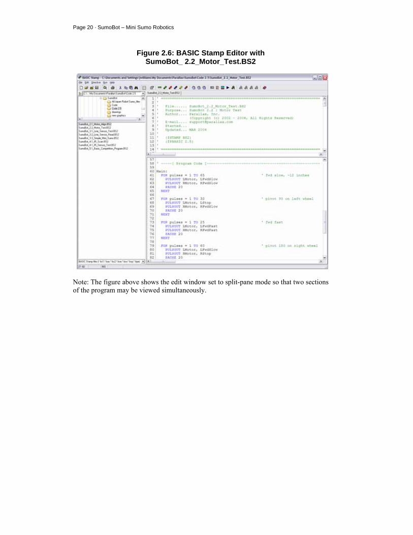
Figure 2.6: BASIC Stamp Editor with SumoBot_ 2.2_Motor_Test.BS2
Note: The figure above shows the edit window set to split-pane mode so that two sections of the program may be viewed simultaneously.
Chapter 2: SumoBot Locomotion · Page 21
CHALLENGE YOURSELF
1. Modify the motor speed constants so that your SumoBot travels straight at low and high speeds.
2. Determine the proper loop count to cause the SumoBot to turn 30 degrees, 45 degrees and 90 degrees.
3. Using the information in # 2 above, see if you can program the SumoBot to travel in the following patterns:
o Square o Triangle o Figure-8

Chapter 3: SumoBot Sensors and Border Detection · Page 23
Chapter 3: SumoBot Sensors and Border Detection Once the SumoBot is moving, the next task is to scan the playing surface to make sure that it doesn't drive itself out of the ring. The task is accomplished by two specialized line detection sensors called QTIs. The QTI uses a reflective infrared sensor to allow the SumoBot to "look" for the ring's border.
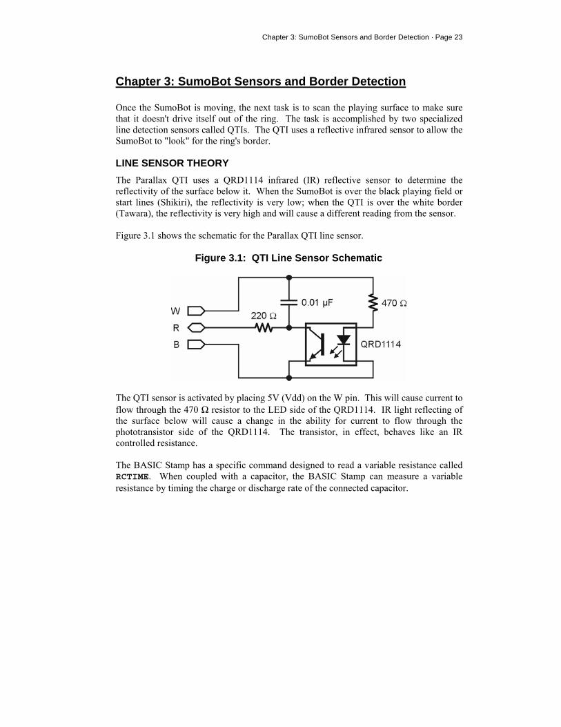
LINE SENSOR THEORY The Parallax QTI uses a QRD1114 infrared (IR) reflective sensor to determine the reflectivity of the surface below it. When the SumoBot is over the black playing field or start lines (Shikiri), the reflectivity is very low; when the QTI is over the white border (Tawara), the reflectivity is very high and will cause a different reading from the sensor. Figure 3.1 shows the schematic for the Parallax QTI line sensor.
Figure 3.1: QTI Line Sensor Schematic
The QTI sensor is activated by placing 5V (Vdd) on the W pin. This will cause current to flow through the 470 Ω resistor to the LED side of the QRD1114. IR light reflecting of the surface below will cause a change in the ability for current to flow through the phototransistor side of the QRD1114. The transistor, in effect, behaves like an IR controlled resistance. The BASIC Stamp has a specific command designed to read a variable resistance called RCTIME. When coupled with a capacitor, the BASIC Stamp can measure a variable resistance by timing the charge or discharge rate of the connected capacitor.
Page 24 · SumoBot – Mini Sumo Robotics
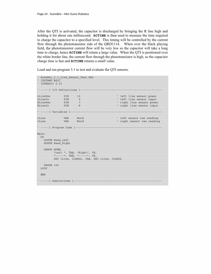
After the QTI is activated, the capacitor is discharged by bringing the R line high and holding it for about one millisecond. RCTIME is then used to measure the time required to charge the capacitor to a specified level. This timing will be controlled by the current flow through the phototransistor side of the QRD1114. When over the black playing field, the phototransistor current flow will be very low so the capacitor will take a long time to charge, hence RCTIME will return a large value. When the QTI is positioned over the white border line, the current flow through the phototransistor is high, so the capacitor charge time is fast and RCTIME returns a small value. Load and run program 3.1 to test and evaluate the QTI sensors. ' SumoBot_3.1_Line_Sensor_Test.BS2 ' $STAMP BS2 ' $PBASIC 2.5 ' -----[ I/O Definitions ]------------------------------------------------- LLinePwr PIN 10 ' left line sensor power LLineIn PIN 9 ' left line sensor input RLinePwr PIN 7 ' right line sensor power RLineIn PIN 8 ' right line sensor input ' -----[ Variables ]------------------------------------------------------- lLine VAR Word ' left sensor raw reading rLine VAR Word ' right sensor raw reading ' -----[ Program Code ]---------------------------------------------------- Main: DO GOSUB Read_Left GOSUB Read_Right DEBUG HOME, "Left ", TAB, "Right", CR, "-----", TAB, "-----", CR, DEC lLine, CLREOL, TAB, DEC rLine, CLREOL PAUSE 100 LOOP END ' -----[ Subroutines ]-----------------------------------------------------
Chapter 3: SumoBot Sensors and Border Detection · Page 25
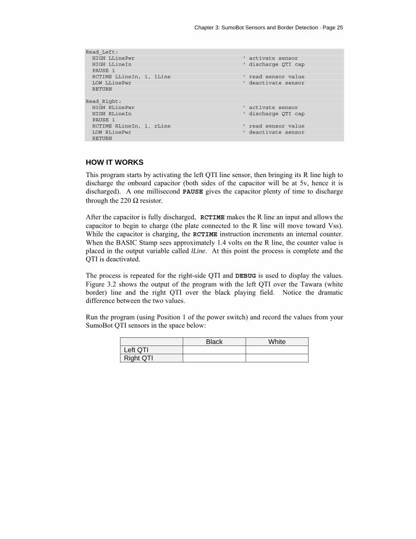
Read_Left: HIGH LLinePwr ' activate sensor HIGH LLineIn ' discharge QTI cap PAUSE 1 RCTIME LLineIn, 1, lLine ' read sensor value LOW LLinePwr ' deactivate sensor RETURN Read_Right: HIGH RLinePwr ' activate sensor HIGH RLineIn ' discharge QTI cap PAUSE 1 RCTIME RLineIn, 1, rLine ' read sensor value LOW RLinePwr ' deactivate sensor RETURN
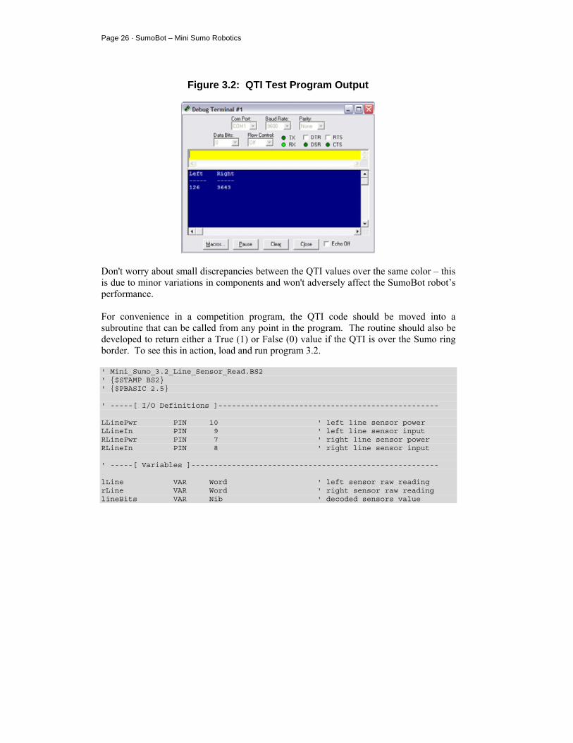
HOW IT WORKS This program starts by activating the left QTI line sensor, then bringing its R line high to discharge the onboard capacitor (both sides of the capacitor will be at 5v, hence it is discharged). A one millisecond PAUSE gives the capacitor plenty of time to discharge through the 220 Ω resistor. After the capacitor is fully discharged, RCTIME makes the R line an input and allows the capacitor to begin to charge (the plate connected to the R line will move toward Vss). While the capacitor is charging, the RCTIME instruction increments an internal counter. When the BASIC Stamp sees approximately 1.4 volts on the R line, the counter value is placed in the output variable called lLine. At this point the process is complete and the QTI is deactivated. The process is repeated for the right-side QTI and DEBUG is used to display the values. Figure 3.2 shows the output of the program with the left QTI over the Tawara (white border) line and the right QTI over the black playing field. Notice the dramatic difference between the two values. Run the program (using Position 1 of the power switch) and record the values from your SumoBot QTI sensors in the space below:
Black White Left QTI Right QTI
Page 26 · SumoBot – Mini Sumo Robotics
Figure 3.2: QTI Test Program Output
Don't worry about small discrepancies between the QTI values over the same color – this is due to minor variations in components and won't adversely affect the SumoBot robot’s performance. For convenience in a competition program, the QTI code should be moved into a subroutine that can be called from any point in the program. The routine should also be developed to return either a True (1) or False (0) value if the QTI is over the Sumo ring border. To see this in action, load and run program 3.2. ' Mini_Sumo_3.2_Line_Sensor_Read.BS2 ' $STAMP BS2 ' $PBASIC 2.5 ' -----[ I/O Definitions ]------------------------------------------------- LLinePwr PIN 10 ' left line sensor power LLineIn PIN 9 ' left line sensor input RLinePwr PIN 7 ' right line sensor power RLineIn PIN 8 ' right line sensor input ' -----[ Variables ]------------------------------------------------------- lLine VAR Word ' left sensor raw reading rLine VAR Word ' right sensor raw reading lineBits VAR Nib ' decoded sensors value
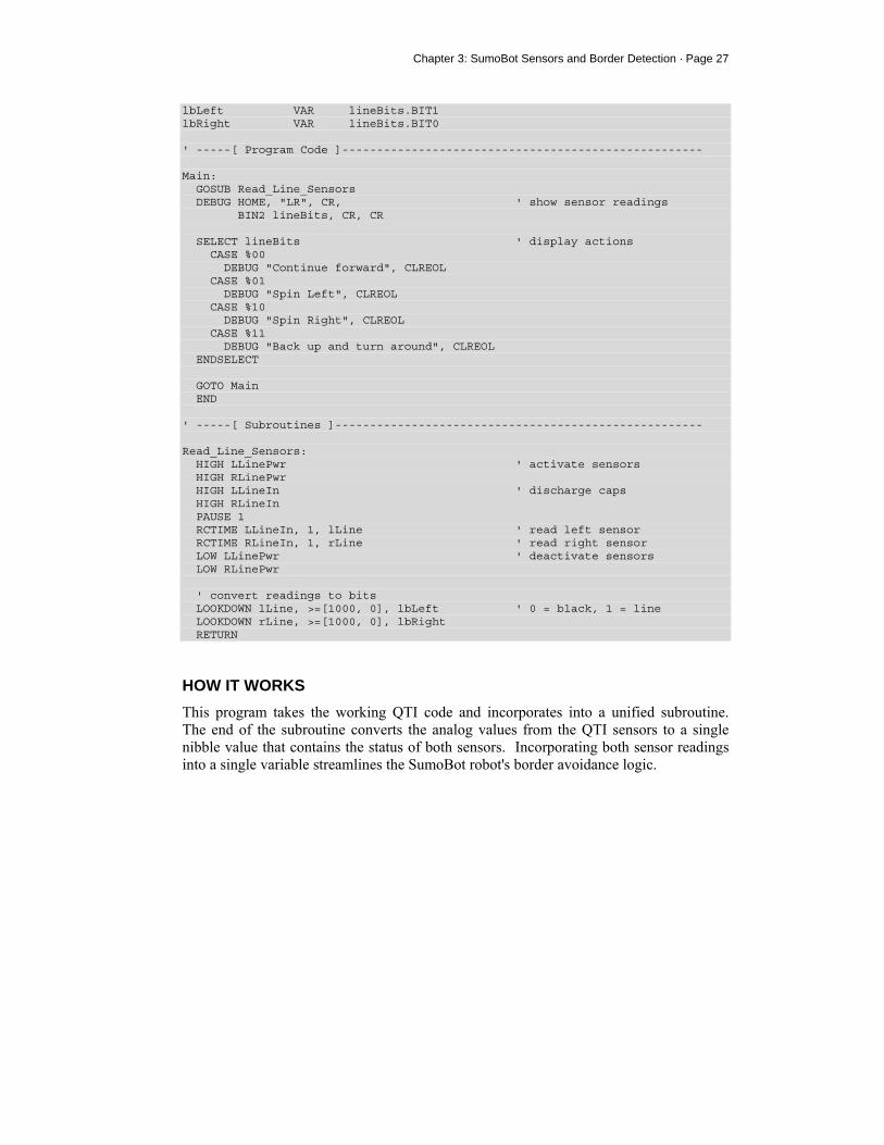
Chapter 3: SumoBot Sensors and Border Detection · Page 27
lbLeft VAR lineBits.BIT1 lbRight VAR lineBits.BIT0 ' -----[ Program Code ]---------------------------------------------------- Main: GOSUB Read_Line_Sensors DEBUG HOME, "LR", CR, ' show sensor readings BIN2 lineBits, CR, CR SELECT lineBits ' display actions CASE %00 DEBUG "Continue forward", CLREOL CASE %01 DEBUG "Spin Left", CLREOL CASE %10 DEBUG "Spin Right", CLREOL CASE %11 DEBUG "Back up and turn around", CLREOL ENDSELECT GOTO Main END ' -----[ Subroutines ]----------------------------------------------------- Read_Line_Sensors: HIGH LLinePwr ' activate sensors HIGH RLinePwr HIGH LLineIn ' discharge caps HIGH RLineIn PAUSE 1 RCTIME LLineIn, 1, lLine ' read left sensor RCTIME RLineIn, 1, rLine ' read right sensor LOW LLinePwr ' deactivate sensors LOW RLinePwr ' convert readings to bits LOOKDOWN lLine, >=[1000, 0], lbLeft ' 0 = black, 1 = line LOOKDOWN rLine, >=[1000, 0], lbRight RETURN
HOW IT WORKS This program takes the working QTI code and incorporates into a unified subroutine. The end of the subroutine converts the analog values from the QTI sensors to a single nibble value that contains the status of both sensors. Incorporating both sensor readings into a single variable streamlines the SumoBot robot's border avoidance logic.
Page 28 · SumoBot – Mini Sumo Robotics
The technique for converting the raw sensor reading to a bit value takes advantage of the optional comparison parameter with the LOOKDOWN function. Without the comparison parameter, LOOKDOWN uses equality to scan its table for a value match. By using the comparison parameter, we can test a range of values with a single table entry. This line: LOOKDOWN lLine, >=[1000, 0], lbLeft
will put 0 into lbLeft if lLine is greater or equal to 1000, otherwise it will but 1 in lbLine (lLine is between 0 and 999). This works because the comparison parameter is >= and the first table entry [index 0] is 1000. LOOKDOWN will transfer the index to the output variable as soon as a match is found. If the sensor value is less than 1000 (as when on the border), the index value of 1 is moved into lbLeft. We could use an IF-THEN-ELSE coding technique to accomplish the same thing: Left_Conv: IF (lLine >= 1000) THEN lbLeft = 0 ELSE lbLeft = 1 ENDIF
As you can see, using LOOKDOWN with the comparison parameter is the more elegant approach. You may be wondering why the value 1000 was used as the black level threshold. It was selected to allow the QTI to be affected by external light and still return an accurate reading. Extra light falling on the playing surface will reduce the QTI output values. By using a value about one-fourth the normal black reading, the program has plenty of margin for lighting variability. Now let's examine what happens with the output values. The bit variables lbLeft and lbRight are aliased into lineBits – this means a change in either will cause a change in lineBits. We will use this variable with the SELECT-CASE structure to determine and display which action to take based on the QTI sensor values.
Chapter 3: SumoBot Sensors and Border Detection · Page 29
The movement logic is controlled by SELECT-CASE. The purpose of SELECT-CASE is to replace several IF-THEN commands that would examine the same control variable. So, the following code structure: SELECT lineBits ' display actions CASE %00 DEBUG "Continue forward", CLREOL CASE %01 DEBUG "Spin Left", CLREOL CASE %10 DEBUG "Spin Right", CLREOL CASE %11 DEBUG "Back up and turn around", CLREOL ENDSELECT
replaces these statements, as well as the program labels and associated code for them: IF (lineBits = %00) THEN Go_Fwd IF (lineBits = %01) THEN Spin_Left IF (lineBits = %10) THEN Spin_Right IF (lineBits = %11) THEN About_Face
and accomplishes the same objective. With simple programs like this one, using SELECT-CASE is a clean solution. As programs grow, we'll examine other instructions (like BRANCH) to replace multiple IF-THEN comparisons and route the program to desired control routines. Keep in mind that program 3.2 doesn't actually move the SumoBot. It simply displays the action that should be taken given the QTI inputs.
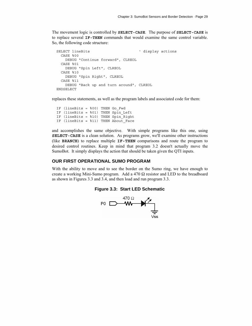
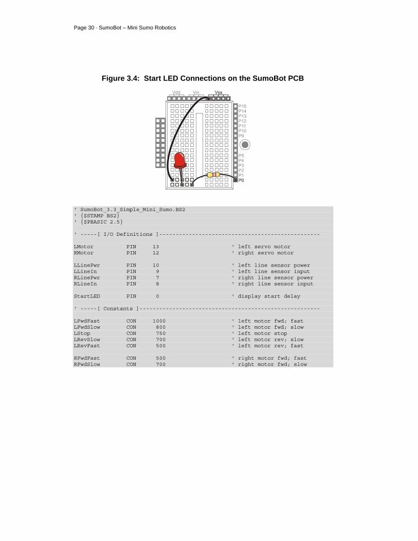
OUR FIRST OPERATIONAL SUMO PROGRAM With the ability to move and to see the border on the Sumo ring, we have enough to create a working Mini-Sumo program. Add a 470 Ω resistor and LED to the breadboard as shown in Figures 3.3 and 3.4, and then load and run program 3.3.
Figure 3.3: Start LED Schematic
Page 30 · SumoBot – Mini Sumo Robotics
Figure 3.4: Start LED Connections on the SumoBot PCB
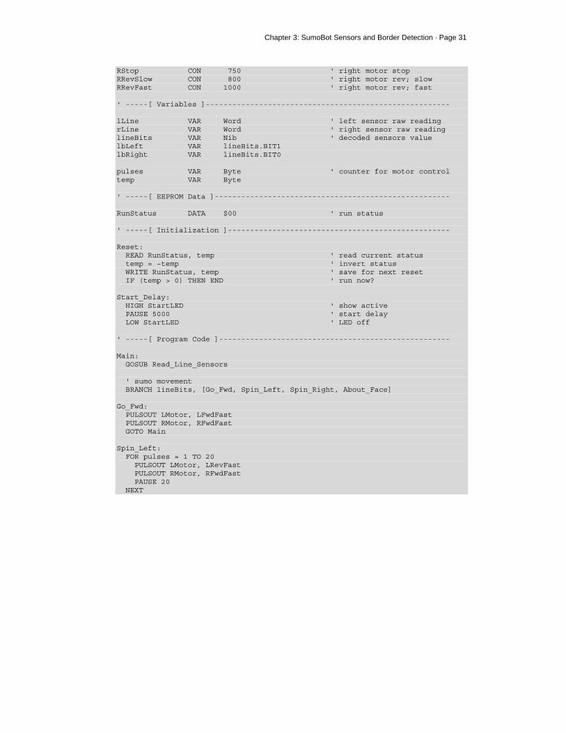
' SumoBot_3.3_Simple_Mini_Sumo.BS2 ' $STAMP BS2 ' $PBASIC 2.5 ' -----[ I/O Definitions ]------------------------------------------------- LMotor PIN 13 ' left servo motor RMotor PIN 12 ' right servo motor LLinePwr PIN 10 ' left line sensor power LLineIn PIN 9 ' left line sensor input RLinePwr PIN 7 ' right line sensor power RLineIn PIN 8 ' right line sensor input StartLED PIN 0 ' display start delay ' -----[ Constants ]------------------------------------------------------- LFwdFast CON 1000 ' left motor fwd; fast LFwdSlow CON 800 ' left motor fwd; slow LStop CON 750 ' left motor stop LRevSlow CON 700 ' left motor rev; slow LRevFast CON 500 ' left motor rev; fast RFwdFast CON 500 ' right motor fwd; fast RFwdSlow CON 700 ' right motor fwd; slow
Chapter 3: SumoBot Sensors and Border Detection · Page 31
RStop CON 750 ' right motor stop RRevSlow CON 800 ' right motor rev; slow RRevFast CON 1000 ' right motor rev; fast ' -----[ Variables ]------------------------------------------------------- lLine VAR Word ' left sensor raw reading rLine VAR Word ' right sensor raw reading lineBits VAR Nib ' decoded sensors value lbLeft VAR lineBits.BIT1 lbRight VAR lineBits.BIT0 pulses VAR Byte ' counter for motor control temp VAR Byte ' -----[ EEPROM Data ]----------------------------------------------------- RunStatus DATA $00 ' run status ' -----[ Initialization ]-------------------------------------------------- Reset: READ RunStatus, temp ' read current status temp = ~temp ' invert status WRITE RunStatus, temp ' save for next reset IF (temp > 0) THEN END ' run now? Start_Delay: HIGH StartLED ' show active PAUSE 5000 ' start delay LOW StartLED ' LED off ' -----[ Program Code ]---------------------------------------------------- Main: GOSUB Read_Line_Sensors ' sumo movement BRANCH lineBits, [Go_Fwd, Spin_Left, Spin_Right, About_Face] Go_Fwd: PULSOUT LMotor, LFwdFast PULSOUT RMotor, RFwdFast GOTO Main Spin_Left: FOR pulses = 1 TO 20 PULSOUT LMotor, LRevFast PULSOUT RMotor, RFwdFast PAUSE 20 NEXT

Page 32 · SumoBot – Mini Sumo Robotics
GOTO Main Spin_Right: FOR pulses = 1 TO 20 PULSOUT LMotor, LFwdFast PULSOUT RMotor, RRevFast PAUSE 20 NEXT GOTO Main About_Face: FOR pulses = 1 TO 10 ' back up from edge PULSOUT LMotor, LRevFast PULSOUT RMotor, RRevFast PAUSE 20 NEXT FOR pulses = 1 TO 30 ' turn around PULSOUT LMotor, LFwdFast PULSOUT RMotor, RRevFast PAUSE 20 NEXT GOTO Main END ' -----[ Subroutines ]----------------------------------------------------- Read_Line_Sensors: HIGH LLinePwr ' activate sensors HIGH RLinePwr HIGH LLineIn ' discharge caps HIGH RLineIn PAUSE 1 RCTIME LLineIn, 1, lLine ' read left sensor RCTIME RLineIn, 1, rLine ' read right sensor LOW LLinePwr ' deactivate sensors LOW RLinePwr ' convert readings to bits LOOKDOWN lLine, >=[1000, 0], lbLeft ' 0 = black, 1 = line LOOKDOWN rLine, >=[1000, 0], lbRight RETURN
HOW IT WORKS This program incorporates a very handy technique created by Andy Lindsay that allows the operator to use the SumoBot PCB's Reset button for Run/Don't Run control. This is

Chapter 3: SumoBot Sensors and Border Detection · Page 33
useful for controlling the SumoBot in a competition without fumbling for the actual power switch. The code at Reset reads a byte from the BASIC Stamp's EEPROM; located at the address called RunStatus. When the program is first downloaded to the BASIC Stamp, the value stored in RunStatus will be $00 (don't run). The READ instruction is used to bring this value into the variable temp, then temp is inverted (to $FF), and finally, WRITE is used to put it back to the EEPROM for the next reset cycle. Next, the value of temp is tested for greater than zero. If this condition is true, the program is halted with END (which puts the BASIC Stamp goes into low-power mode), otherwise it continues to the Start_Delay code. The routine called Start_Delay satisfies a requirement of Mini-Sumo competition rules. The rules state that the robot must not start until five seconds after the command is given by the judge. This code is very simple: it lights the LED to show that the SumoBot is preparing to start and inserts a five second PAUSE. At the end of the delay, the LED will be extinguished and the SumoBot will start moving. The heart of the program begins at Main. The first step is to read the sensors with the Read_Line_ Sensors subroutine. With the QTI sensor data, the SumoBot is moved using the same logic developed earlier:
L R Action 0 0 Move forward 0 1 Spin to left 1 0 Spin to right 1 1 Back up and turn around
BRANCH takes care of routing the program to the right code section based on the QTI inputs. As with SELECT-CASE, we're using BRANCH to replace several IF-THEN comparisons. It should be clear that this is a cleaner approach than IF-THEN. The only thing that might not be clear is that there is no delay (20 ms) in the Go_Fwd routine. It isn't needed when the SumoBot is in the middle of the ring (not touching the border line) because reading the QTI sensors consumes enough time that the delay is not necessary.

Page 34 · SumoBot – Mini Sumo Robotics
CHALLENGE YOURSELF 1. Experiment with the Spin_Left and Spin_Right routines so that the SumoBot
generally moves toward the center after touching the border.
Chapter 4: Infrared Object Detection · Page 35
Chapter 4: Infrared Object Detection Today's hottest products seem to have one thing in common: wireless communication. Personal organizers beam data into desktop computers, and wireless remotes let us channel surf. With a few inexpensive and widely available parts, the BASIC Stamp can also use an infrared LED and detector to detect objects to the front and side of your SumoBot.
Detecting obstacles doesn’t require anything as sophisticated as machine vision. A much simpler system will suffice. Some robots use RADAR or SONAR (sometimes called SODAR when used in air instead of water). An even simpler system is to use infrared light to illuminate the robot’s path and determine when the light reflects off an object. Thanks to the proliferation of infrared (IR) remote controls, IR illuminators and detectors are easily available and inexpensive.
INFRARED HEADLIGHTS The infrared object detection system we’ll build on the SumoBot is like a car’s headlights in several respects. When the light from a car’s headlights reflects off obstacles, your eyes detect the obstacles and your brain processes them and makes your body guide the car accordingly. The SumoBot uses infrared LEDs for headlights. They emit infrared, and in some cases, the infrared reflects off objects, and bounces back in the direction of the SumoBot. The eyes of the SumoBot are the infrared detectors. The infrared detectors send signals to the BASIC Stamp indicating whether or not they detect infrared reflected off an object. The brain of the SumoBot, the BASIC Stamp, makes decisions and operates the servo motors based on this input.
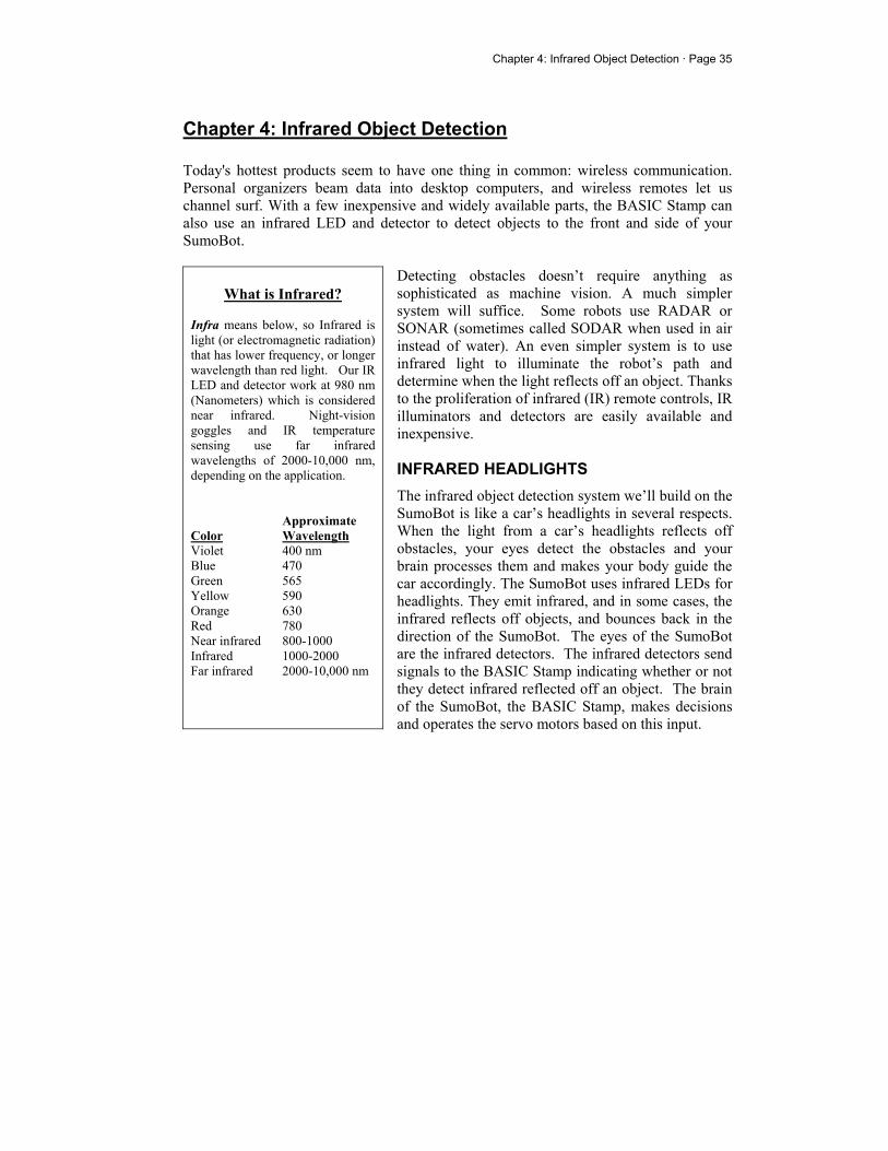
What is Infrared?
Infra means below, so Infrared is light (or electromagnetic radiation) that has lower frequency, or longer wavelength than red light. Our IR LED and detector work at 980 nm (Nanometers) which is considered near infrared. Night-vision goggles and IR temperature sensing use far infrared wavelengths of 2000-10,000 nm, depending on the application. Approximate Color Wavelength Violet 400 nm Blue 470 Green 565 Yellow 590 Orange 630 Red 780 Near infrared 800-1000 Infrared 1000-2000 Far infrared 2000-10,000 nm
Page 36 · SumoBot – Mini Sumo Robotics
The IR detectors have built-in optical filters that allow very little light except the 980 nm infrared that we want to detect onto its internal photodiode sensor. The infrared detector also has an electronic filter that only allows signals around 38.5 kHz to pass through. In other words, the detector is only looking for infrared flashed on and off at 38,500 times per second. This prevents interference from common IR interference sources such as sunlight and indoor lighting. Sunlight is DC interference (0 Hz), and house lighting tends to flash on and off at either 100 or 120 Hz, depending on the main power source in the country where you reside. Since 120 Hz is way outside the electronic filter’s 38.5 kHz band pass frequency, it is, for all practical purposes, completely ignored by the IR detectors.
THE FREQOUT TRICK Since the IR detectors only see IR signals in the neighborhood of 38.5 kHz, the IR LEDs have to be flashed on and off at that frequency. A common 555 timer can be used for this purpose, but the 555 timer circuit is more complex and less functional than the circuit we will use in this and the next chapter. For example, the method of IR detection introduced here can be used for distance detection; whereas, the 555 timer would need additional hardware to do distance detection. A pair of BASIC Stamp enthusiasts found an interesting trick that made the 555 timer scheme unnecessary. This scheme uses the FREQOUT command without the RC filter that’s normally used to smooth the signal into a sine-wave. Even though the highest frequency FREQOUT is designed to transmit is 32,768 Hz, the unfiltered FREQOUT output contains a harmonic with useful properties for a 38.5 kHz IR detector. More useful still is the fact that you can use a command such as FREQOUT Pin, Duration, 38500
to send a 38.5 kHz harmonic that the IR detector can detect. Tuned electronic receivers, such as the IR detectors we’ll be using, can detect components of this signal that are called harmonics. These harmonics are actually components of the unfiltered FREQOUT pulses. The third harmonic of 38.5 kHz can be controlled directly by entering commands such as FREQOUT Pin, Duration, or FREQOUT Pin, Duration, 40000 for 40 kHz (as might be required by different detectors), etc.

Chapter 4: Infrared Object Detection · Page 37
INSTALLING AND TESTING THE IR EMITTERS/DETECTORS The SumoBot is specially designed to accommodate two IR emitter/detector pairs. Before we install them, we need to assemble the IR LEDs into their shells, then bend and trim the leads so that they don't become damaged or misaligned during competition. Figure 4.1 shows the assembly IR LED (clear) into the protective shell (standoff and shield). The purpose of this assembly is to prevent stray IR from falling directly onto the detector and causing a false positive reading.
Figure 4.1: IR LED, Standoff, and Shield Assembly
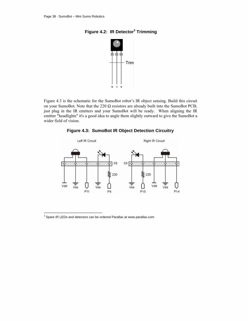
After assembly, bend the leads downward at a 90-degree angle so that when looking at the back side of the shield, the positive (longer) lead is on the right. Trim the leads as shown above. Modify the detectors by trimming the leads to about 3/8" inches. This will cause the detectors to sit lower and more firmly in the sockets, reducing the chance of misalignment during competition.
Page 38 · SumoBot – Mini Sumo Robotics
Figure 4.2: IR Detector3 Trimming
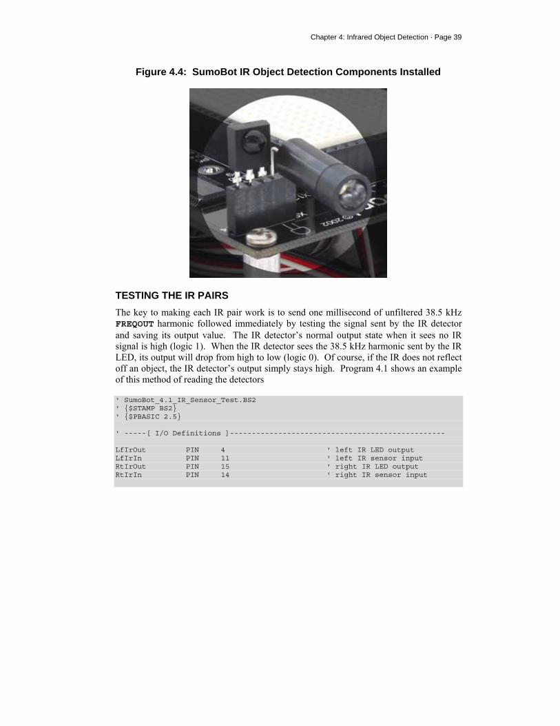
Figure 4.3 is the schematic for the SumoBot robot’s IR object sensing. Build this circuit on your SumoBot. Note that the 220 Ω resistors are already built into the SumoBot PCB; just plug in the IR emitters and your SumoBot will be ready. When aligning the IR emitter "headlights" it's a good idea to angle them slightly outward to give the SumoBot a wider field of vision.
Figure 4.3: SumoBot IR Object Detection Circuitry
3 Spare IR LEDs and detectors can be ordered Parallax at www.parallax.com
Chapter 4: Infrared Object Detection · Page 39
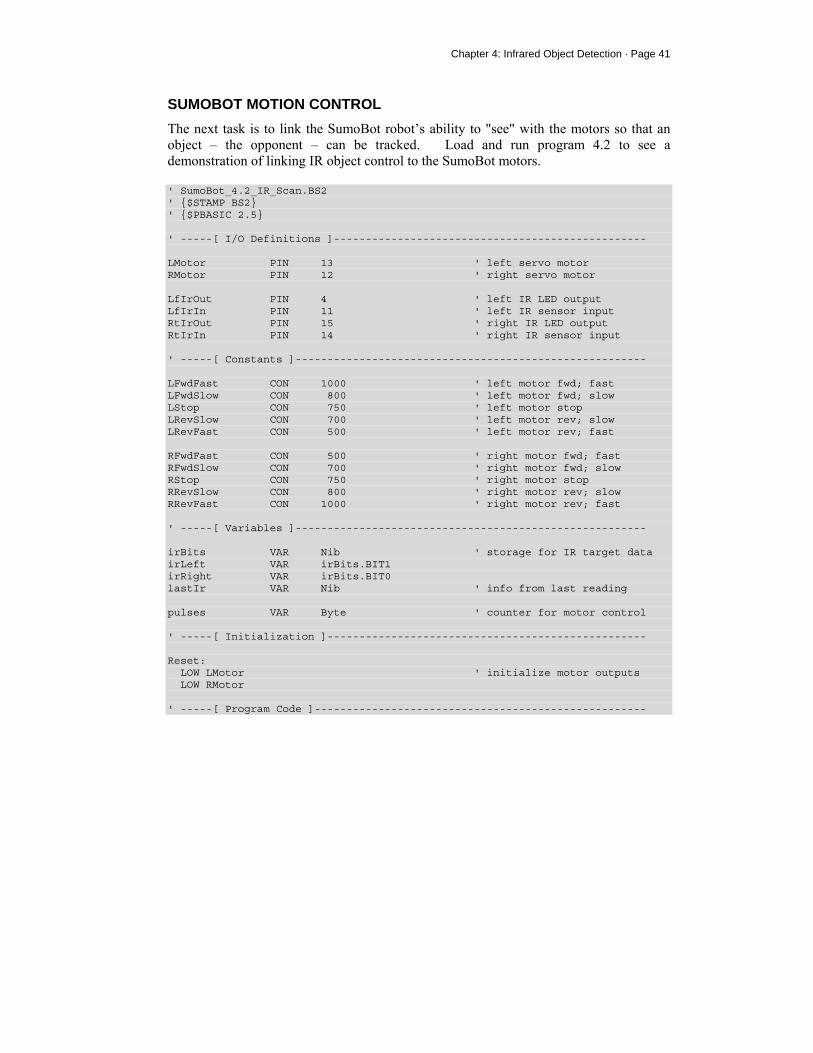
Figure 4.4: SumoBot IR Object Detection Components Installed
TESTING THE IR PAIRS The key to making each IR pair work is to send one millisecond of unfiltered 38.5 kHz FREQOUT harmonic followed immediately by testing the signal sent by the IR detector and saving its output value. The IR detector’s normal output state when it sees no IR signal is high (logic 1). When the IR detector sees the 38.5 kHz harmonic sent by the IR LED, its output will drop from high to low (logic 0). Of course, if the IR does not reflect off an object, the IR detector’s output simply stays high. Program 4.1 shows an example of this method of reading the detectors ' SumoBot_4.1_IR_Sensor_Test.BS2 ' $STAMP BS2 ' $PBASIC 2.5 ' -----[ I/O Definitions ]------------------------------------------------- LfIrOut PIN 4 ' left IR LED output LfIrIn PIN 11 ' left IR sensor input RtIrOut PIN 15 ' right IR LED output RtIrIn PIN 14 ' right IR sensor input

Page 40 · SumoBot – Mini Sumo Robotics
' -----[ Variables ]------------------------------------------------------- irBits VAR Nib ' storage for IR target data irLeft VAR irBits.BIT1 irRight VAR irBits.BIT0 ' -----[ Program Code ]---------------------------------------------------- Main: DO FREQOUT LfIrOut, 1, 38500 ' modulate left IR LED irLeft = ~LfIrIn ' read input (1 = target) FREQOUT RtIrOut, 1, 38500 ' modulate right IR LED irRight = ~RtIrIn ' read input (1 = target) DEBUG HOME, "L R", CR, "----", CR, BIN1 irLeft, " ", BIN1 irRight PAUSE 20 LOOP END
Two bit-sized variables are declared to store the value of each IR detector output. The command FREQOUT LfIrOut, 1, 38500 sends the [unfiltered] modulation signal to the left IR LED, causing it to flash on and off rapidly. The harmonic contained in this signal either bounces off an object, or not. If it bounces off an object and is seen by the IR detector, the IR detector sends a low signal to I/O pin LfIrIn. Otherwise, the IR detector sends a high signal to LfIrIn. The bitwise invert operator (~) is used so that a "hit" (reflection from the opponent) is indicated by "1" and a "miss" is indicated by a "0." So long as the next command after the FREQOUT command is the one testing the state of the IR detector’s output, it can be saved as a variable value in RAM. This is possible as the IR detector output is held active a short time after the signal goes away. The statement irLeft = ~LfIrIn checks LfIrIn, and saves the value (“1” for hit or “0” for miss) in the irLeft bit variable. This process is repeated for the other IR pair, and the IR detector’s output is saved in the irRight variable. The DEBUG statement then displays the values in the Debug Terminal.
Chapter 4: Infrared Object Detection · Page 41
SUMOBOT MOTION CONTROL The next task is to link the SumoBot robot’s ability to "see" with the motors so that an object – the opponent – can be tracked. Load and run program 4.2 to see a demonstration of linking IR object control to the SumoBot motors. ' SumoBot_4.2_IR_Scan.BS2 ' $STAMP BS2 ' $PBASIC 2.5 ' -----[ I/O Definitions ]------------------------------------------------- LMotor PIN 13 ' left servo motor RMotor PIN 12 ' right servo motor LfIrOut PIN 4 ' left IR LED output LfIrIn PIN 11 ' left IR sensor input RtIrOut PIN 15 ' right IR LED output RtIrIn PIN 14 ' right IR sensor input ' -----[ Constants ]------------------------------------------------------- LFwdFast CON 1000 ' left motor fwd; fast LFwdSlow CON 800 ' left motor fwd; slow LStop CON 750 ' left motor stop LRevSlow CON 700 ' left motor rev; slow LRevFast CON 500 ' left motor rev; fast RFwdFast CON 500 ' right motor fwd; fast RFwdSlow CON 700 ' right motor fwd; slow RStop CON 750 ' right motor stop RRevSlow CON 800 ' right motor rev; slow RRevFast CON 1000 ' right motor rev; fast ' -----[ Variables ]------------------------------------------------------- irBits VAR Nib ' storage for IR target data irLeft VAR irBits.BIT1 irRight VAR irBits.BIT0 lastIr VAR Nib ' info from last reading pulses VAR Byte ' counter for motor control ' -----[ Initialization ]-------------------------------------------------- Reset: LOW LMotor ' initialize motor outputs LOW RMotor ' -----[ Program Code ]----------------------------------------------------
Page 42 · SumoBot – Mini Sumo Robotics
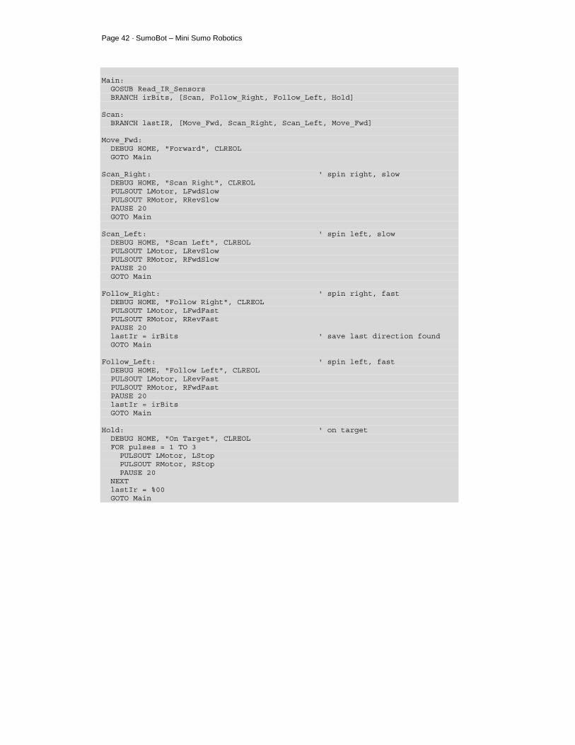
Main: GOSUB Read_IR_Sensors BRANCH irBits, [Scan, Follow_Right, Follow_Left, Hold] Scan: BRANCH lastIR, [Move_Fwd, Scan_Right, Scan_Left, Move_Fwd] Move_Fwd: DEBUG HOME, "Forward", CLREOL GOTO Main Scan_Right: ' spin right, slow DEBUG HOME, "Scan Right", CLREOL PULSOUT LMotor, LFwdSlow PULSOUT RMotor, RRevSlow PAUSE 20 GOTO Main Scan_Left: ' spin left, slow DEBUG HOME, "Scan Left", CLREOL PULSOUT LMotor, LRevSlow PULSOUT RMotor, RFwdSlow PAUSE 20 GOTO Main Follow_Right: ' spin right, fast DEBUG HOME, "Follow Right", CLREOL PULSOUT LMotor, LFwdFast PULSOUT RMotor, RRevFast PAUSE 20 lastIr = irBits ' save last direction found GOTO Main Follow_Left: ' spin left, fast DEBUG HOME, "Follow Left", CLREOL PULSOUT LMotor, LRevFast PULSOUT RMotor, RFwdFast PAUSE 20 lastIr = irBits GOTO Main Hold: ' on target DEBUG HOME, "On Target", CLREOL FOR pulses = 1 TO 3 PULSOUT LMotor, LStop PULSOUT RMotor, RStop PAUSE 20 NEXT lastIr = %00 GOTO Main

Chapter 4: Infrared Object Detection · Page 43
END ' -----[ Subroutines ]----------------------------------------------------- Read_IR_Sensors: FREQOUT LfIrOut, 1, 38500 ' modulate left IR LED irLeft = ~LfIrIn ' read input (1 = target) FREQOUT RtIrOut, 1, 38500 ' modulate right IR LED irRight = ~RtIrIn ' read input (1 = target) RETURN
HOW IT WORKS This program is functionally similar to the line detection program. The IR sensors are scanned and, due to variable aliasing, the state of both sensors is held in the Nibble variable irBits. If no target is detected the SumoBot will go into scanning mode. The code at Scan will look for the opponent in the last known direction (held in the variable lastIr). When a target is detected, the SumoBot will move quickly in the target direction. The direction is stored in the event the target is lost so that the SumoBot will scan in the last know target direction. If you run the program with the power switch in position 1, the Debug Terminal will display the program's logic based on a target placed in front of the SumoBot. If you run the program with the power switch in position 2, the SumoBot will rotate in the direction of the target or scan in the suspect direction.

Chapter 5: Basic Competition Code · Page 45
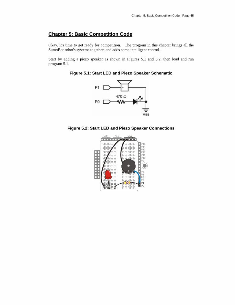
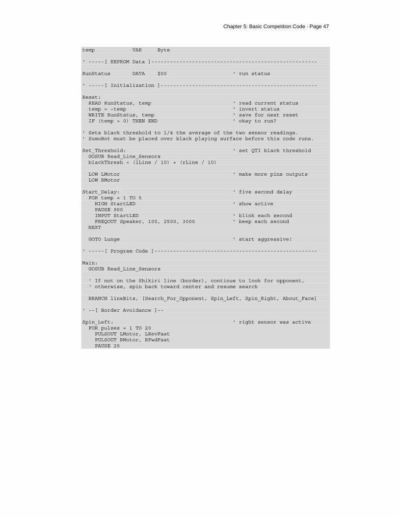
Chapter 5: Basic Competition Code Okay, it's time to get ready for competition. The program in this chapter brings all the SumoBot robot's systems together, and adds some intelligent control. Start by adding a piezo speaker as shown in Figures 5.1 and 5.2, then load and run program 5.1.
Figure 5.1: Start LED and Piezo Speaker Schematic
Figure 5.2: Start LED and Piezo Speaker Connections

Page 46 · SumoBot – Mini Sumo Robotics
' SumoBot_5.1_Basic_Competition_Program.BS2 ' $STAMP BS2 ' $PBASIC 2.5 ' -----[ I/O Definitions ]------------------------------------------------- LMotor PIN 13 ' left servo motor RMotor PIN 12 ' right servo motor LLinePwr PIN 10 ' left line sensor power LLineIn PIN 9 ' left line sensor input RLinePwr PIN 7 ' right line sensor power RLineIn PIN 8 ' right line sensor input LfIrOut PIN 4 ' left IR LED output LfIrIn PIN 11 ' left IR sensor input RtIrOut PIN 15 ' right IR LED output RtIrIn PIN 14 ' right IR sensor input Speaker PIN 1 ' piezo speaker StartLED PIN 0 ' display start delay ' -----[ Constants ]------------------------------------------------------- LFwdFast CON 1000 ' left motor fwd; fast LFwdSlow CON 800 ' left motor fwd; slow LStop CON 750 ' left motor stop LRevSlow CON 700 ' left motor rev; slow LRevFast CON 500 ' left motor rev; fast RFwdFast CON 500 ' right motor fwd; fast RFwdSlow CON 700 ' right motor fwd; slow RStop CON 750 ' right motor stop RRevSlow CON 800 ' right motor rev; slow RRevFast CON 1000 ' right motor rev; fast ' -----[ Variables ]------------------------------------------------------- lLine VAR Word ' left sensor raw reading rLine VAR Word ' right sensor raw reading blackThresh VAR Word ' QTI black threshold lineBits VAR Nib ' decoded sensors value lbLeft VAR lineBits.BIT1 lbRight VAR lineBits.BIT0 irBits VAR Nib ' IR readings (l & r) irLeft VAR irBits.BIT1 irRight VAR irBits.BIT0 lastIr VAR Nib ' info from last reading pulses VAR Byte ' counter for motor control
Chapter 5: Basic Competition Code · Page 47
temp VAR Byte ' -----[ EEPROM Data ]----------------------------------------------------- RunStatus DATA $00 ' run status ' -----[ Initialization ]-------------------------------------------------- Reset: READ RunStatus, temp ' read current status temp = ~temp ' invert status WRITE RunStatus, temp ' save for next reset IF (temp > 0) THEN END ' okay to run? ' Sets black threshold to 1/4 the average of the two sensor readings. ' SumoBot must be placed over black playing surface before this code runs. Set_Threshold: ' set QTI black threshold GOSUB Read_Line_Sensors blackThresh = (lLine / 10) + (rLine / 10) LOW LMotor ' make more pins outputs LOW RMotor Start_Delay: ' five second delay FOR temp = 1 TO 5 HIGH StartLED ' show active PAUSE 900 INPUT StartLED ' blink each second FREQOUT Speaker, 100, 2500, 3000 ' beep each second NEXT GOTO Lunge ' start aggressive! ' -----[ Program Code ]---------------------------------------------------- Main: GOSUB Read_Line_Sensors ' If not on the Shikiri line (border), continue to look for opponent, ' otherwise, spin back toward center and resume search BRANCH lineBits, [Search_For_Opponent, Spin_Left, Spin_Right, About_Face] ' --[ Border Avoidance ]-- Spin_Left: ' right sensor was active FOR pulses = 1 TO 20 PULSOUT LMotor, LRevFast PULSOUT RMotor, RFwdFast PAUSE 20

Page 48 · SumoBot – Mini Sumo Robotics
NEXT lastIr = %00 ' clear scan direction GOTO Lunge Spin_Right: ' left sensor was active FOR pulses = 1 TO 20 PULSOUT LMotor, LFwdFast PULSOUT RMotor, RRevFast PAUSE 20 NEXT lastIr = %00 GOTO Lunge About_Face: ' both sensors on Shikiri FOR pulses = 1 TO 10 ' back up from edge PULSOUT LMotor, LRevFast PULSOUT RMotor, RRevFast PAUSE 20 NEXT FOR pulses = 1 TO 30 ' turn around PULSOUT LMotor, LFwdFast PULSOUT RMotor, RRevFast PAUSE 20 NEXT lastIr = %00 GOTO Lunge ' --[ IR Processing ]-- Search_For_Opponent: GOSUB Read_IR_Sensors ' If opponent is not in view, scan last known direction. Turn toward ' opponent if seen by one "eye" -- if both, lunge forward BRANCH irBits, [Scan, Follow_Right, Follow_Left, Lunge] Scan: BRANCH lastIR, [Move_Fwd, Scan_Right, Scan_Left] Move_Fwd: GOSUB Creep_Forward GOTO Main Scan_Right: ' spin right, slow FOR pulses = 1 TO 5 PULSOUT LMotor, LFwdSlow PULSOUT RMotor, RRevSlow PAUSE 20 NEXT GOSUB Creep_Forward ' keep moving
Chapter 5: Basic Competition Code · Page 49
GOTO Main Scan_Left: ' spin left, slow FOR pulses = 1 TO 5 PULSOUT LMotor, LRevSlow PULSOUT RMotor, RFwdSlow PAUSE 20 NEXT GOSUB Creep_Forward GOTO Main Follow_Right: ' spin right, fast PULSOUT LMotor, LFwdFast PULSOUT RMotor, RRevSlow lastIR = irBits ' save last direction found GOTO Main Follow_Left: ' spin left, fast PULSOUT LMotor, LRevSlow PULSOUT RMotor, RFwdFast lastIR = irBits GOTO Main Lunge: ' locked on -- go get him! FOR pulses = 1 TO 25 PULSOUT LMotor, LFwdFast PULSOUT RMotor, RFwdFast GOSUB Read_Line_Sensors IF (lineBits = %11) THEN Match_Over ' in sight, we're on the line NEXT GOTO Main ' If SumoBot can see the opponent with both "eyes" and both QTIs are ' detecting the border, we must have pushed the opponent out. Match_Over: FOR pulses = 1 TO 10 ' stop motors PULSOUT LMotor, LStop PULSOUT RMotor, RStop PAUSE 20 NEXT INPUT LMotor INPUT RMotor FOR temp = 1 TO 10 ' make some noise HIGH StartLED FREQOUT Speaker, 100, 2500, 3000 ' beep INPUT StartLED ' blink LED PAUSE 100 NEXT
Page 50 · SumoBot – Mini Sumo Robotics
DIRS = $0000 ' disable all outputs GOTO Reset ' reset for next round ' -----[ Subroutines ]----------------------------------------------------- Read_Line_Sensors: HIGH LLinePwr ' activate sensors HIGH RLinePwr HIGH LLineIn ' discharge caps HIGH RLineIn PAUSE 1 RCTIME LLineIn, 1, lLine ' read left sensor RCTIME RLineIn, 1, rLine ' read right sensor LOW LLinePwr ' deactivate sensors LOW RLinePwr ' convert readings to bits LOOKDOWN lLine, >=[1000, 0], lbLeft ' 0 = black, 1 = line LOOKDOWN rLine, >=[1000, 0], lbRight RETURN Read_IR_Sensors: FREQOUT LfIrOut, 1, 38500 ' modulate left IR LED irLeft = ~LfIrIn ' read input (1 = target) FREQOUT RtIrOut, 1, 38500 ' modulate right IR LED irRight = ~RtIrIn ' read input (1 = target) RETURN Creep_Forward: FOR pulses = 1 TO 20 PULSOUT LMotor, LFwdSlow PULSOUT RMotor, RFwdSlow PAUSE 20 NEXT RETURN
HOW IT WORKS After the Reset code for Run/Don't Run developed in the chapter 4, the SumoBot reads the QTI sensors and calculates a suitable threshold level for the playing field that will be used during the match. The net effect is to calculate the average sensor reading ((left + right) / 2) and then divide this value by four. The blackThresh variable holds this level and is recalculated for each match (this works because the SumoBot starts in near the center of the ring, over the black surface). Using this strategy, the SumoBot can deal with variable ambient lighting conditions that may change from match to match.
Chapter 5: Basic Competition Code · Page 51
The Start_Delay section serves the same purpose as described previously, it's just a bit fancier in this version of the program. In this case we've added a piezo speaker. At the start, the LED illuminates and then blinks to tick away each of the five seconds in the mandated delay. The LED blink coincides with a beep from the piezo speaker. Since many matches start with the Mini-Sumo robots facing each other, the subroutine called Lunge is called to get the SumoBot moving quickly. This routine drives the SumoBot forward as fast as possible. It will also be used later when the opponent is located. If your club rules specify that the SumoBot will not face the opponent from the start, you may wish to substitute a rotation command to get the SumoBot oriented toward the opponent as quickly as possible. The core of the program is at Main. The code starts by reading the QTI sensors (now using the calibrated black level for the Sumo ring). If the QTI sensors indicate that the SumoBot is safely on the playing surface, a BRANCH instruction will send the code Search_For_Opponent. If the SumoBot is touching the Tawara line (border), the edge avoidance logic previously developed will be used. When the border is touched, the lastIr variable is cleared so the SumoBot will move toward the center after turning in from the border. The Search_For_Opponent routine employs a bit of logic to minimize random searching. This code calls the Read_IR_Sensors routine and will BRANCH accordingly, based on the logic developed in program 4.2. If the opponent is not currently in sight, the SumoBot will scan in the direction last known. Early on, when the opponent has not been spotted, the SumoBot will creep forward in order to cut down the range between itself and the opponent. If the Read_IR_Sensors subroutine returns a hit, the SumoBot will move quickly in the direction of the opponent. The hit direction is recorded in case the opponent escapes and the SumoBot is forced back into scan mode. When the opponent is locked on (irBits = %11), the SumoBot will go into "Lunge" mode to get to the opponent quickly and move it out of the ring. The best outcome is when the SumoBot can "see" the opponent with both "eyes" and both QTI sensors detect the Tawara border. Under these conditions the assumption is that the opponent has been successfully pushed from the ring and a Yuko point is to be awarded. Many matches will be won when the SumoBot removes the competitor from the ring and an angle; the competitor will be out but the SumoBot will continue to push, or may go
Page 52 · SumoBot – Mini Sumo Robotics
into edge-avoidance and search mode. In this case the Judge will award the Yuko point and the SumoBot can be stopped by pressing the Reset button.
FINAL COMPETITION NOTES The SumoBot – like any robot – will perform best with fresh batteries. The first sign of weak batteries will be degradation in opponent detection range. Make sure that you take plenty of fresh batteries to each contest you participate in. When fully assembled and loaded with batteries, the SumoBot will weigh less than the 500 gram (17.6 oz) limit imposed by standard Mini-Sumo rules. This could be a disadvantage against a heavier robot. There are many ways to add weight to the SumoBot chassis; one of the easiest is with Prather Products stick-on weight. These stick-on weights are particularly convenient to add weight to the back of the scoop. This helps keep the scoop on the playing surface. Prather Products weights are available in hobby shops.
Appendix A: SumoBot Parts List · Page 53
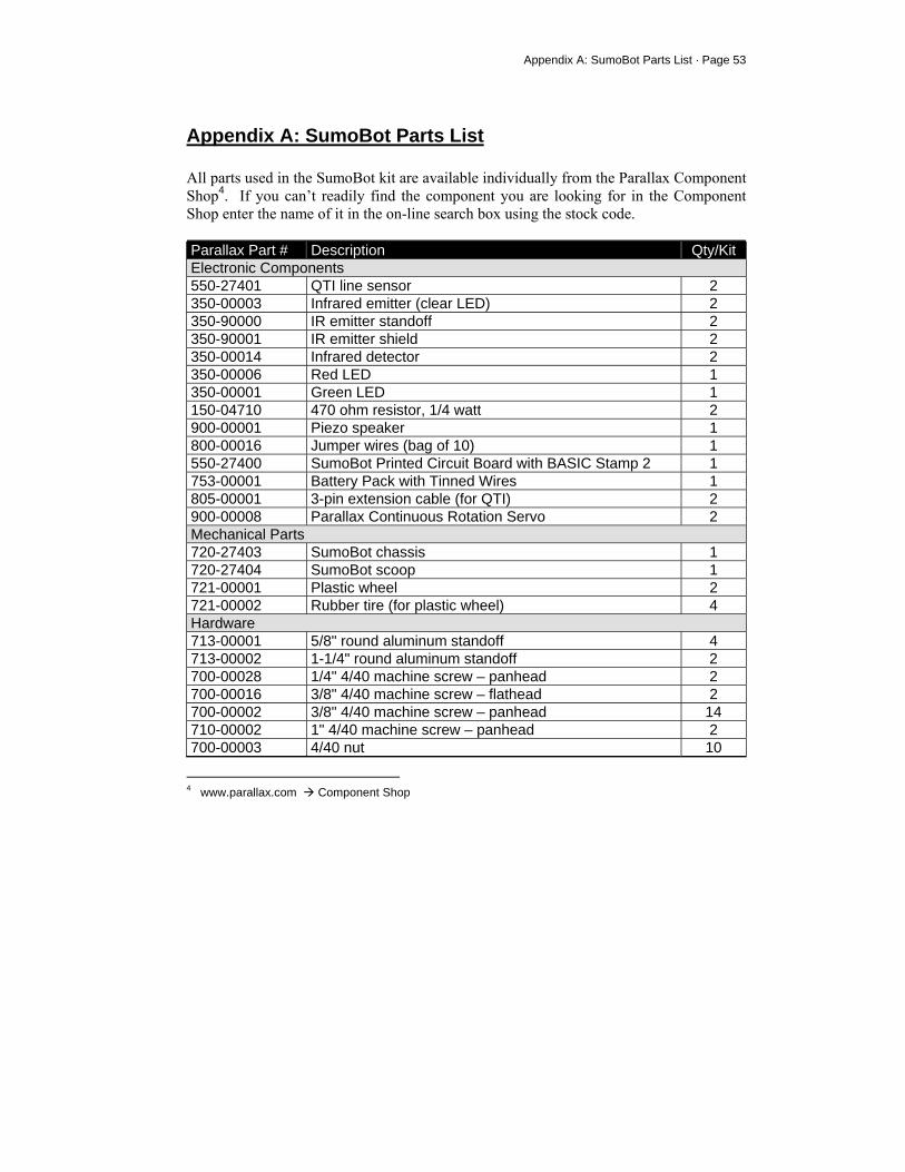
Appendix A: SumoBot Parts List All parts used in the SumoBot kit are available individually from the Parallax Component Shop4. If you can’t readily find the component you are looking for in the Component Shop enter the name of it in the on-line search box using the stock code. Parallax Part # Description Qty/Kit Electronic Components 550-27401 QTI line sensor 2 350-00003 Infrared emitter (clear LED) 2 350-90000 IR emitter standoff 2 350-90001 IR emitter shield 2 350-00014 Infrared detector 2 350-00006 Red LED 1 350-00001 Green LED 1 150-04710 470 ohm resistor, 1/4 watt 2 900-00001 Piezo speaker 1 800-00016 Jumper wires (bag of 10) 1 550-27400 SumoBot Printed Circuit Board with BASIC Stamp 2 1 753-00001 Battery Pack with Tinned Wires 1 805-00001 3-pin extension cable (for QTI) 2 900-00008 Parallax Continuous Rotation Servo 2 Mechanical Parts 720-27403 SumoBot chassis 1 720-27404 SumoBot scoop 1 721-00001 Plastic wheel 2 721-00002 Rubber tire (for plastic wheel) 4 Hardware 713-00001 5/8" round aluminum standoff 4 713-00002 1-1/4" round aluminum standoff 2 700-00028 1/4" 4/40 machine screw – panhead 2 700-00016 3/8" 4/40 machine screw – flathead 2 700-00002 3/8" 4/40 machine screw – panhead 14 710-00002 1" 4/40 machine screw – panhead 2 700-00003 4/40 nut 10
4 www.parallax.com Component Shop

Page 54 · SumoBot – Mini Sumo Robotics
700-00015 Nylon washer 2 Miscellaneous 122-27400 SumoBot Manual 1 800-00003 Serial (programming) cable 1 27000 Parallax CD 1 700-00064 Parallax Screwdriver 1
Appendix B: Standard Mini-Sumo Competition · Page 55
Appendix B: Standard Mini-Sumo Competition Rules Reprinted with permission from Bill Harrison, Sine Robotics. Section 1: Definition of a Match Article 1 Definition
The match shall be contested by two teams (At the event, one team consists of one robot with two team members, one of which is a leader. Other team members must watch from the audience), according to these Rules for Sumo matches (hereafter called "these Rules"), with each team's robot made by each team (either a remote-controlled model or a standalone model) competing to get the effective points (hereafter called "Yuko"), within the perimeter of the defined Sumo Ring. The judges will decide which team wins. A single person can also compete with a Robot Sumo, with the same rules that apply to teams.
Section 2: Requirements for the Ring Area Article 2 Definition of Ring Area
The Ring Area means the Sumo Ring and the space outside the Ring. Anywhere outside this Ring Area is called Outer Area.
Article 3 Sumo Ring
1. The Ring shall be in circular shape with its height being 2.5 cm and its
diameter 77 cm (including the outside of the line that divides the inside of the Ring from its outside). The Ring shall be of black hard rubber (made by Toyo Linoleum; long vinyl sheet NC#R289, or its equivalent) adhered on top of Ring.
2. Shikiri lines (where robots stand at the beginning of the match) are the two parallel lines with 10 cm distance between the lines, drawn in the center of the Ring. The Shikiri lines are painted in brown (or equivalent for reflection

Page 56 · SumoBot – Mini Sumo Robotics
of IR light), 1 cm wide and 10cm long. 3. The Ring shall be marked by a white circular line of 2.5 cm thickness. The
Ring is within the outside of this circular line. Article 4 Space
There should be the space of more than 50 cm wide outside the outer side of the Ring. This space can be of any color except white, and can be of any materials or shape, as long as the basic concepts of these rules are observed. This area, with the ring in the middle, is to be called the: "Ring Area". If there are markings or part of the ring platform outside these dimensions, this area will also be considered in the Ring Area.
Section 3: Requirements for Robots Article 5 Specifications
1. A robot must be in such a size that it can be put in a square tube of 10 cm
wide and 10 cm deep. A robot can be of any height. A robot must not be in such a design that its body will be physically separated into pieces when a match starts. The robot with such a design shall lose the match. The design to stretch a robot's body or its parts shall be allowed, but must remain a single centralized robot. Screws or nuts or other robot parts, with a mass of less than 5 grams total, falling off from a robot's body shall not cause the loss of the match.
2. The mass of a robot must be less than 500 grams including the attachments and parts, but excluding the weight of a proportional system (the transmitter or control box held by the operator, hereafter called "Prop") for remote-controlled models.
3. The radio frequencies for radio-controlled robots must be either 27 MHZ (1-6 bands) or 40 MHZ (61, 63, 65, 67, and 69 bands). 40 MHZ (71-83 bands) cannot be used.
4. Only one Prop can be used for one robot. Radio control Prop must be one of
Appendix B: Standard Mini-Sumo Competition · Page 57
Futaba's, JR's, Sanwa's, or Kondo Kagaku's.
5. For stand-alone robots, any control mechanisms can be employed. 6. Stand-alone models must be so designed that a robot starts operating a
minimum of five seconds after a start switch is pressed (or any method that invokes the operation of a robot).
7. Microcomputers in a robot can be of any manufacturers and any memory sizes can be chosen.
Article 6 Restrictions on Robot Design
1. Jamming devices, such as an IR LED intended to saturate the opponents IR
sensor, are not allowed. Do not disturb your opponent's radio-control by putting into a robot's body such devices as a jamming device.
2. Do not use parts that could break or damage the Ring. Do not use parts that are intended to damage the opponent's robot or its operator. Normal pushes and bangs are not considered intent to damage.
3. Do not put into a robot's body devices that can store liquid, powder, or air, in which are thrown at the opponent.
4. Do not use any inflaming devices.
5. Do not use devices that throw things at your opponent.
6. Do not stick a robot down onto the Ring, using sucking devices or glue, or use any type of sticky tires (such as double sticky foam tape) or any device to assist in adding more down force (such as a vacuum device).
Section 4: Match Principles Article 7 Match Principles
1. One match shall consist of 3 rounds, within a total time of 3 minutes, unless
Page 58 · SumoBot – Mini Sumo Robotics
extended by the Judges.
2. The team who wins two rounds or receives two "Yuko" points first, within the time limit, shall win the match. A team receives a Yuko point when they win a round. If the time limit is reached before one team can get two Yuko points, and one of the teams has received one Yuko point, the team with one Yuko point shall win.
3. When the match is not won by either team within the time limit, the extended match shall be fought during which the team who receives the first Yuko point shall win. However, the winner/loser of the match may be decided by judges or by means of lots, or there can be a rematch.
4. One Yuko point shall be given to the winner when the judges' decision was called for or lots were employed.
Section 5: Match Procedure Article 8 Start
With the chief judge's instructions, the two teams bow in the Outer Ring (For example, stand facing each other, outside the ring platform or "ring area", with ring between), go up to the Ring, and place a robot on or behind the Shikiri line or the imaginary extended Shikiri line. (A robot or a part of a robot may not be placed beyond the front edge of the Shikiri line toward the opponent.). A match starts with the following rules: 1. For remote-controlled robots, start operating a Prop when the chief judge
announces the start of a round.
2. For stand-alone robots, be ready to press a start switch. Press the switch when the chief judge announces the start of the round. After 5 seconds, the robot is allowed to start operating, before which players must clear out of the Ring Area.
Article 9 Stop & Resume
The match stops and resumes when a judge announces so.
Appendix B: Standard Mini-Sumo Competition · Page 59
Article 10 End of Match
The match ends when the judge calls the winner. Both contestants bow after removing their robots.
Section 6: Time of Match Article 11 Time of Match
One Match will be contested for a total of 3 minutes, starting and ending by the chief judge's announcements. For stand-alone robots, the clock shall start ticking 5 seconds after the start is announced.
Article 12 An extended match shall be for 3 minutes, if called by the Judge. Article 13 The following are not included in the time of the Match:
1. The time elapsed after the chief judge announces Yuko and before the match
resumes. 30 seconds shall be the standard before the match resumes.
2. The time elapsed after a judge announces to stop the match and before the match resumes.
Section 7: Yuko Article 14 Yuko
One Yuko point shall be given when: 1. You have legally forced the body of your opponent's robot to touch the
space outside the Ring, which includes the side of the ring itself.
2. A Yuko point is also given in the following cases:
Page 60 · SumoBot – Mini Sumo Robotics
2.1. Your opponent's robot has touched the space outside the Ring, on its own.
2.2. Either of the above takes place at the same time that the End of the Match is announced.
3. When a robot has fallen on the Ring or in similar conditions, Yuko will not be counted and the match continues.
4. When judges' decision is called for to decide the winner, the following points will be taken into considerations: 4.1. Technical merits in movement and operation of a robot 4.2. Penalty points during the match 4.3. Attitude of the players during the match
5. The match shall be stopped and a rematch shall start when:
5.1. Both robots are in clinch and stop movements for 5 seconds, or move in the same orbit for 5 seconds, with no progress being made. If it is not clear if progress is being made or not, the Judge can extend the time limit for a clinch or orbiting robots up to 30 seconds.
5.2. Both robots move, without making progress, or stop (at the exact same time) and stay stopped for five seconds without touching each other. However, if one robot stops its movement first, after 5 seconds, he shall be considered not having the will to fight, and the opponent shall receive a Yuko, even if the opponent also stops. If both robots are moving and it isn't clear if progress is being made or not, the Judge can extend the time limit up to 30 seconds.
5.3. If both robots touch the outside of the ring at about the same time, and it can not be determined which touched first, a rematch is called.
Section 8: Violations Article 15 Violations
If the players perform the deeds as described in Articles 6, 16 and 17, the players shall be declared as violating the rules.
Appendix B: Standard Mini-Sumo Competition · Page 61
Article 16 The player utters insulting words to the opponent or to the judges or puts voice devices in a robot to utter insulting words or writes insulting words on the body of a robot, or any insulting action.
Article 17 A Player
1. Enters into the Ring during the match, except when the player does so to
bring the robot out of the Ring upon the chief judge's announcement of Yuko or stopping the match. To enter into the Ring means: 1.1. A part of the player's body is in the Ring, or 1.2. A player puts any mechanical kits into the Ring to support his/her
body. 2. Performs the following deeds:
2.1. Demand to stop the match without appropriate reasons. 2.2. Take more than 30 seconds before resuming the match, unless the
Judge announces a time extension.. 2.3. Start operating the robot before the chief judge announces the start of
the match (for remote-controlled robots). 2.4. Start operating the robot within 5 seconds after the chief judge
announces the start of the match (for stand-alone robots). 2.5. Do or say that which should disgrace the fairness of the match.
Section 9: Penalties Article 18 Penalties
Those who violate the rules with the deeds described in Articles 6 and 16 shall lose the match. The judge shall give two Yuko points to the opponent and order the violator to clear out. The violator is not honored with any rights.
Article 19 Each occasion of the violations described in Article 17 shall be accumulated.
Two of these violations shall give one Yuko to the opponent. Article 20 The violations described in Article 17 shall be accumulated throughout one
match.

Page 62 · SumoBot – Mini Sumo Robotics
Section 10: Injuries and Accidents during the Match Article 21 Request to Stop the Match
A player can request to stop the game when he/she is injured or his/her robot had an accident and the game cannot continue.
Article 22 Unable to Continue the Match
When the game cannot continue due to player's injury or robot's accident, the player who is the cause of such injury or accident loses the match. When it is not clear which team is such a cause, the player who cannot continue the game, or who requests to stop the game, shall be declared as the loser.
Article 23 Time Required to Handle Injury/Accident Whether the game should continue in case of injury or accident shall be decided by the judges and the Committee members. The decision process shall take no longer than five minutes.
Article 24 Yuko Given to the Player Who Cannot Continue
The winner decided based on Article 22 shall gain two Yuko points. The loser who already gained one Yuko point is recorded as such. When the situation under Article 22 takes place during an extended match, the winner shall gain one Yuko point.
Section 11: Declaring Objections Article 25 Declaring Objections
No objections shall be declared against the judges' decisions.
Article 26 The lead person of a team can present objections to the Committee, before the
match is over, if there are any doubts in exercising these rules. If there is no Committee member present, the objection can be presented to the Judge, before the match is over.
Appendix B: Standard Mini-Sumo Competition · Page 63
Section 12: Requirements for Identifications for Robots Article 27 Identifications for Robots
Some type of name or number, to identify the robot (as registered in the contest) must be easily readable on the robot's body, while the robot is in competition.
Section 13: Miscellaneous Article 28 Flexibility of Rules
As long as the concept and fundamentals of the rules are observed, the rules shall be so flexible that they will be able to encompass the changes in the number of players and of the contents of matches.
Article 29 Change in Rules Any changes to or obsolescence of these rules shall be decided by the General Committee Meeting based on the Sumo Match Committee Rules.

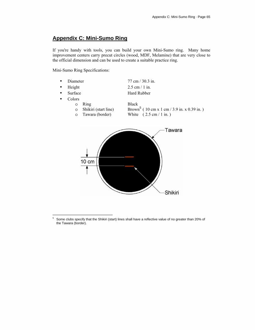
Appendix C: Mini-Sumo Ring · Page 65
Appendix C: Mini-Sumo Ring If you're handy with tools, you can build your own Mini-Sumo ring. Many home improvement centers carry precut circles (wood, MDF, Melamine) that are very close to the official dimension and can be used to create a suitable practice ring. Mini-Sumo Ring Specifications:
• Diameter 77 cm / 30.3 in. • Height 2.5 cm / 1 in. • Surface Hard Rubber • Colors
o Ring Black o Shikiri (start line) Brown5 ( 10 cm x 1 cm / 3.9 in. x 0.39 in. ) o Tawara (border) White ( 2.5 cm / 1 in. )
5 Some clubs specify that the Shikiri (start) lines shall have a reflective value of no greater than 20% of
the Tawara (border).

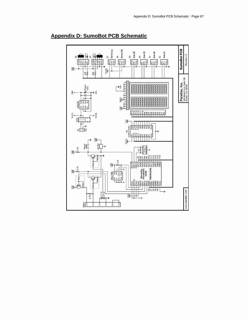
Appendix D: SumoBot PCB Schematic · Page 67
Appendix D: SumoBot PCB Schematic
© Parallax, Inc. SumoBot with LCD 99/2004 1
599 Menlo Drive, Suite 100 Rocklin, California 95765, USA Office: (916) 624-8333 Fax: (916) 624-8003
General: [email protected] Technical: [email protected] Web Site: www.parallax.com Educational: www.stampsinclass.com
Adding an LCD to the SumoBot® Robot Introduction As mini sumo robotics is a competitive endeavor it is helpful to fine-tune competition code for the environment where the contest is held. What is not always possible, however, is to keep the SumoBot tethered to a PC to display sensor values a local display would be useful. One can add a local display to the SumoBot by using the Parallax LCD AppMod. It plugs into the SumoBot PCB AppMod header and will not interfere with sensors when testing. When sensor testing and program fine-tuning is complete, the LCD AppMod can be removed so as not to interfere with the weight or center-of-gravity of the SumoBot. The LCD code used in the following programs is that same as used in many BASIC Stamp® 2 applications with one very small change: the LCD data bus is disconnected (bus pins are made inputs) at the end of any LCD write to prevent activating or interfering with sensors that share pins with the LCD bus. Program Code: Reading QTI Line Sensors This program reads and displays the QTI line sensor values on the LCD. As the LCD is only eight characters wide and the QTI values may require up four characters, the display of QTI values is configured as shown below:
' ========================================================================= ' ' File...... SumoBot_3.1_Line_Sensor_LCD.BS2 ' Purpose... Line Sensor Test ' Author.... Parallax, Inc. ' (Copyright (c) 2002 - 2004, All Rights Reserved) ' E-mail.... [email protected] ' Started... ' Updated... 03 JUN 2004 ' ' $STAMP BS2 ' $PBASIC 2.5 ' ' =========================================================================
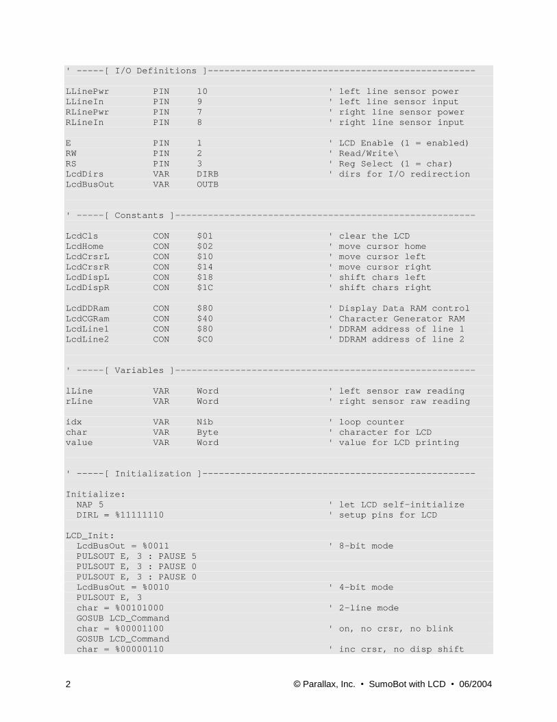
© Parallax, Inc. SumoBot with LCD 06/2004 2
' -----[ I/O Definitions ]------------------------------------------------- LLinePwr PIN 10 ' left line sensor power LLineIn PIN 9 ' left line sensor input RLinePwr PIN 7 ' right line sensor power RLineIn PIN 8 ' right line sensor input E PIN 1 ' LCD Enable (1 = enabled) RW PIN 2 ' Read/Write\ RS PIN 3 ' Reg Select (1 = char) LcdDirs VAR DIRB ' dirs for I/O redirection LcdBusOut VAR OUTB ' -----[ Constants ]------------------------------------------------------- LcdCls CON $01 ' clear the LCD LcdHome CON $02 ' move cursor home LcdCrsrL CON $10 ' move cursor left LcdCrsrR CON $14 ' move cursor right LcdDispL CON $18 ' shift chars left LcdDispR CON $1C ' shift chars right LcdDDRam CON $80 ' Display Data RAM control LcdCGRam CON $40 ' Character Generator RAM LcdLine1 CON $80 ' DDRAM address of line 1 LcdLine2 CON $C0 ' DDRAM address of line 2 ' -----[ Variables ]------------------------------------------------------- lLine VAR Word ' left sensor raw reading rLine VAR Word ' right sensor raw reading idx VAR Nib ' loop counter char VAR Byte ' character for LCD value VAR Word ' value for LCD printing ' -----[ Initialization ]-------------------------------------------------- Initialize: NAP 5 ' let LCD self-initialize DIRL = %11111110 ' setup pins for LCD LCD_Init: LcdBusOut = %0011 ' 8-bit mode PULSOUT E, 3 : PAUSE 5 PULSOUT E, 3 : PAUSE 0 PULSOUT E, 3 : PAUSE 0 LcdBusOut = %0010 ' 4-bit mode PULSOUT E, 3 char = %00101000 ' 2-line mode GOSUB LCD_Command char = %00001100 ' on, no crsr, no blink GOSUB LCD_Command char = %00000110 ' inc crsr, no disp shift
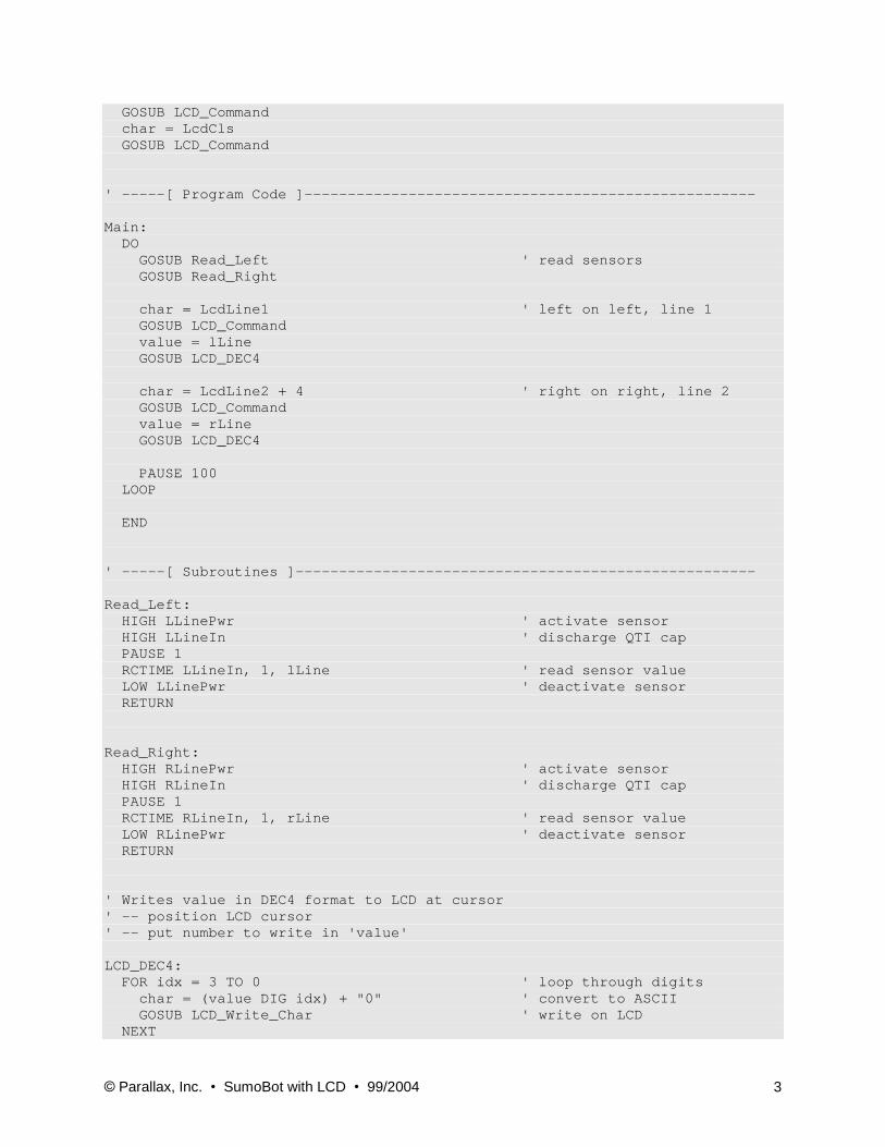
© Parallax, Inc. SumoBot with LCD 99/2004 3
GOSUB LCD_Command char = LcdCls GOSUB LCD_Command ' -----[ Program Code ]---------------------------------------------------- Main: DO GOSUB Read_Left ' read sensors GOSUB Read_Right char = LcdLine1 ' left on left, line 1 GOSUB LCD_Command value = lLine GOSUB LCD_DEC4 char = LcdLine2 + 4 ' right on right, line 2 GOSUB LCD_Command value = rLine GOSUB LCD_DEC4 PAUSE 100 LOOP END ' -----[ Subroutines ]----------------------------------------------------- Read_Left: HIGH LLinePwr ' activate sensor HIGH LLineIn ' discharge QTI cap PAUSE 1 RCTIME LLineIn, 1, lLine ' read sensor value LOW LLinePwr ' deactivate sensor RETURN Read_Right: HIGH RLinePwr ' activate sensor HIGH RLineIn ' discharge QTI cap PAUSE 1 RCTIME RLineIn, 1, rLine ' read sensor value LOW RLinePwr ' deactivate sensor RETURN ' Writes value in DEC4 format to LCD at cursor ' -- position LCD cursor ' -- put number to write in 'value' LCD_DEC4: FOR idx = 3 TO 0 ' loop through digits char = (value DIG idx) + "0" ' convert to ASCII GOSUB LCD_Write_Char ' write on LCD NEXT
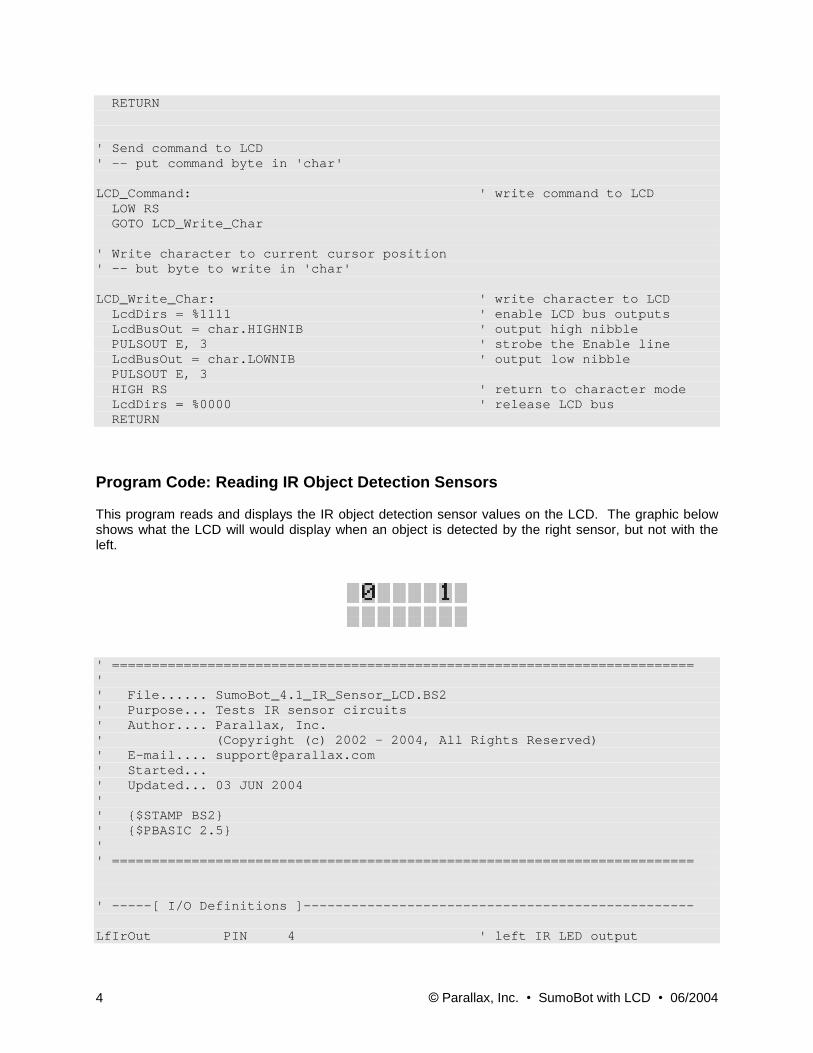
© Parallax, Inc. SumoBot with LCD 06/2004 4
RETURN ' Send command to LCD ' -- put command byte in 'char' LCD_Command: ' write command to LCD LOW RS GOTO LCD_Write_Char ' Write character to current cursor position ' -- but byte to write in 'char' LCD_Write_Char: ' write character to LCD LcdDirs = %1111 ' enable LCD bus outputs LcdBusOut = char.HIGHNIB ' output high nibble PULSOUT E, 3 ' strobe the Enable line LcdBusOut = char.LOWNIB ' output low nibble PULSOUT E, 3 HIGH RS ' return to character mode LcdDirs = %0000 ' release LCD bus RETURN Program Code: Reading IR Object Detection Sensors This program reads and displays the IR object detection sensor values on the LCD. The graphic below shows what the LCD will would display when an object is detected by the right sensor, but not with the left.
' ========================================================================= ' ' File...... SumoBot_4.1_IR_Sensor_LCD.BS2 ' Purpose... Tests IR sensor circuits ' Author.... Parallax, Inc. ' (Copyright (c) 2002 - 2004, All Rights Reserved) ' E-mail.... [email protected] ' Started... ' Updated... 03 JUN 2004 ' ' $STAMP BS2 ' $PBASIC 2.5 ' ' ========================================================================= ' -----[ I/O Definitions ]------------------------------------------------- LfIrOut PIN 4 ' left IR LED output
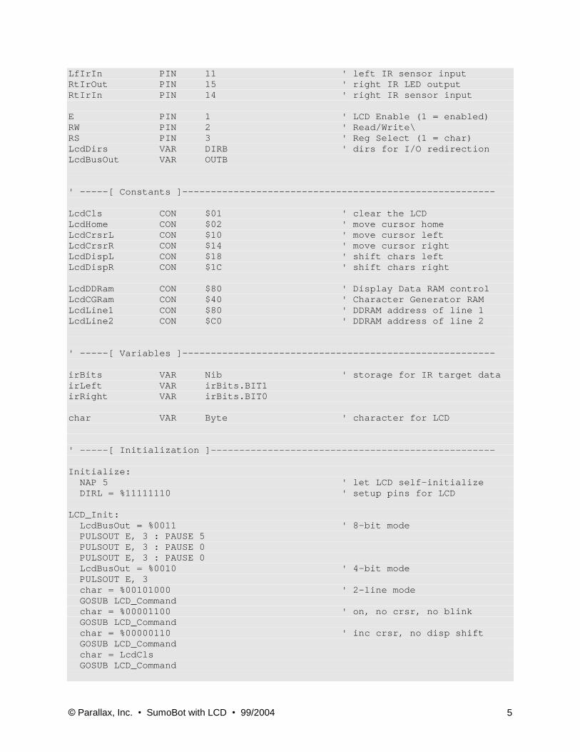
© Parallax, Inc. SumoBot with LCD 99/2004 5
LfIrIn PIN 11 ' left IR sensor input RtIrOut PIN 15 ' right IR LED output RtIrIn PIN 14 ' right IR sensor input E PIN 1 ' LCD Enable (1 = enabled) RW PIN 2 ' Read/Write\ RS PIN 3 ' Reg Select (1 = char) LcdDirs VAR DIRB ' dirs for I/O redirection LcdBusOut VAR OUTB ' -----[ Constants ]------------------------------------------------------- LcdCls CON $01 ' clear the LCD LcdHome CON $02 ' move cursor home LcdCrsrL CON $10 ' move cursor left LcdCrsrR CON $14 ' move cursor right LcdDispL CON $18 ' shift chars left LcdDispR CON $1C ' shift chars right LcdDDRam CON $80 ' Display Data RAM control LcdCGRam CON $40 ' Character Generator RAM LcdLine1 CON $80 ' DDRAM address of line 1 LcdLine2 CON $C0 ' DDRAM address of line 2 ' -----[ Variables ]------------------------------------------------------- irBits VAR Nib ' storage for IR target data irLeft VAR irBits.BIT1 irRight VAR irBits.BIT0 char VAR Byte ' character for LCD ' -----[ Initialization ]-------------------------------------------------- Initialize: NAP 5 ' let LCD self-initialize DIRL = %11111110 ' setup pins for LCD LCD_Init: LcdBusOut = %0011 ' 8-bit mode PULSOUT E, 3 : PAUSE 5 PULSOUT E, 3 : PAUSE 0 PULSOUT E, 3 : PAUSE 0 LcdBusOut = %0010 ' 4-bit mode PULSOUT E, 3 char = %00101000 ' 2-line mode GOSUB LCD_Command char = %00001100 ' on, no crsr, no blink GOSUB LCD_Command char = %00000110 ' inc crsr, no disp shift GOSUB LCD_Command char = LcdCls GOSUB LCD_Command
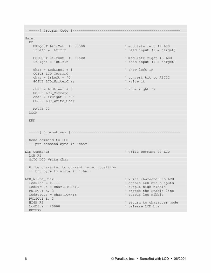
© Parallax, Inc. SumoBot with LCD 06/2004 6
' -----[ Program Code ]---------------------------------------------------- Main: DO FREQOUT LfIrOut, 1, 38500 ' modulate left IR LED irLeft = ~LfIrIn ' read input (1 = target) FREQOUT RtIrOut, 1, 38500 ' modulate right IR LED irRight = ~RtIrIn ' read input (1 = target) char = LcdLine1 + 1 ' show left IR GOSUB LCD_Command char = irLeft + "0" ' convert bit to ASCII GOSUB LCD_Write_Char ' write it char = LcdLine1 + 6 ' show right IR GOSUB LCD_Command char = irRight + "0" GOSUB LCD_Write_Char PAUSE 20 LOOP END ' -----[ Subroutines ]----------------------------------------------------- ' Send command to LCD ' -- put command byte in 'char' LCD_Command: ' write command to LCD LOW RS GOTO LCD_Write_Char ' Write character to current cursor position ' -- but byte to write in 'char' LCD_Write_Char: ' write character to LCD LcdDirs = %1111 ' enable LCD bus outputs LcdBusOut = char.HIGHNIB ' output high nibble PULSOUT E, 3 ' strobe the Enable line LcdBusOut = char.LOWNIB ' output low nibble PULSOUT E, 3 HIGH RS ' return to character mode LcdDirs = %0000 ' release LCD bus RETURN
Applied Robotics with the SumoBot Student Guide
VERSION 1.0
WARRANTY Parallax Inc. warrants its products against defects in materials and workmanship for a period of 90 days from receipt of product. If you discover a defect, Parallax Inc. will, at its option, repair or replace the merchandise, or refund the purchase price. Before returning the product to Parallax, call for a Return Merchandise Authorization (RMA) number. Write the RMA number on the outside of the box used to return the merchandise to Parallax. Please enclose the following along with the returned merchandise: your name, telephone number, shipping address, and a description of the problem. Parallax will return your product or its replacement using the same shipping method used to ship the product to Parallax.
14-DAY MONEY BACK GUARANTEE If, within 14 days of having received your product, you find that it does not suit your needs, you may return it for a full refund. Parallax Inc. will refund the purchase price of the product, excluding shipping/handling costs. This guarantee is void if the product has been altered or damaged. See the Warranty section above for instructions on returning a product to Parallax. COPYRIGHTS AND TRADEMARKS This documentation is Copyright 2005 by Parallax Inc. By downloading or obtaining a printed copy of this documentation or software you agree that it is to be used exclusively with Parallax products. Any other uses are not permitted and may represent a violation of Parallax copyrights, legally punishable according to Federal copyright or intellectual property laws. Any duplication of this documentation for commercial uses is expressly prohibited by Parallax Inc. Duplication for educational use is permitted, subject to the following Conditions of Duplication: Parallax Inc. grants the user a conditional right to download, duplicate, and distribute this text without Parallax's permission. This right is based on the following conditions: the text, or any portion thereof, may not be duplicated for commercial use; it may be duplicated only for educational purposes when used solely in conjunction with Parallax products, and the user may recover from the student only the cost of duplication. This text is available in printed format from Parallax Inc. Because we print the text in volume, the consumer price is often less than typical retail duplication charges. BASIC Stamp, Stamps in Class, Board of Education, Boe-Bot SumoBot, SX-Key and Toddler are registered trademarks of Parallax, Inc. If you decide to use registered trademarks of Parallax Inc. on your web page or in printed material, you must state that "(registered trademark) is a registered trademark of Parallax Inc.” upon the first appearance of the trademark name in each printed document or web page. HomeWork Board, Parallax, and the Parallax logo are trademarks of Parallax Inc. If you decide to use trademarks of Parallax Inc. on your web page or in printed material, you must state that "(trademark) is a trademark of Parallax Inc.”, “upon the first appearance of the trademark name in each printed document or web page. Other brand and product names are trademarks or registered trademarks of their respective holders.
ISBN 1-928982-34-4

DISCLAIMER OF LIABILITY Parallax Inc. is not responsible for special, incidental, or consequential damages resulting from any breach of warranty, or under any legal theory, including lost profits, downtime, goodwill, damage to or replacement of equipment or property, or any costs of recovering, reprogramming, or reproducing any data stored in or used with Parallax products. Parallax Inc. is also not responsible for any personal damage, including that to life and health, resulting from use of any of our products. You take full responsibility for your BASIC Stamp application, no matter how life-threatening it may be.
INTERNET DISCUSSION LISTS We maintain active web-based discussion forums for people interested in Parallax products. These lists are accessible from www.parallax.com via the Support → Discussion Forums menu. These are the forums that we operate from our web site:
• BASIC Stamps – This list is widely utilized by engineers, hobbyists and students who share their BASIC Stamp projects and ask questions.
• Stamps in Class® – Created for educators and students, subscribers discuss the use of the Stamps in Class curriculum in their courses. The list provides an opportunity for both students and educators to ask questions and get answers.
• Parallax Educators –Exclusively for educators and those who contribute to the development of Stamps in Class. Parallax created this group to obtain feedback on our curricula and to provide a forum for educators to develop and obtain Teacher’s Guides.
• Translators – The purpose of this list is to provide a conduit between Parallax and those who translate our documentation to languages other than English. Parallax provides editable Word documents to our translating partners and attempts to time the translations to coordinate with our publications.
• Robotics – Designed exclusively for Parallax robots, this forum is intended to be an open dialogue for robotics enthusiasts. Topics include assembly, source code, expansion, and manual updates. The Boe-Bot®, Toddler®, SumoBot®, HexCrawler and QuadCrawler robots are discussed here.
• SX Microcontrollers and SX-Key – Discussion of programming the SX microcontroller with Parallax assembly language SX – Key® tools and 3rd party BASIC and C compilers.
• Javelin Stamp – Discussion of application and design using the Javelin Stamp, a Parallax module that is programmed using a subset of Sun Microsystems’ Java® programming language.
ERRATA While great effort is made to assure the accuracy of our texts, errors may still exist. If you find an error, please let us know by sending an email to [email protected]. We continually strive to improve all of our educational materials and documentation, and frequently revise our texts. Occasionally, an errata sheet with a list of known errors and corrections for a given text will be posted to our web site, www.parallax.com. Please check the individual product page’s free downloads for an errata file.

Table of Contents · Page i
Table of Contents
Preface........................................................................................................................iii Introduction................................................................................................................ iii Educator Resources.................................................................................................. iv The Stamps In Class Educational Series .................................................................. iv Foreign Translations...................................................................................................v Special Contributors .................................................................................................. vi
Chapter #1: Mechanical Adjustments ......................................................................7 Before You Get Started ..............................................................................................7 Small Adjustments can Make a Big Difference ..........................................................7 ACTIVITY #1: Adjusting the Plow...............................................................................8 ACTIVITY #2: Preventing Servo SlowDown.............................................................16 ACTIVITY #3: Friction Forces - Your SumoBot's Allies............................................22 Summary ..................................................................................................................38
Chapter #2: EEPROM Tricks and Program Tips....................................................41 EEPROM and Program Management ......................................................................41 ACTIVITY #1: A Closer Look at the EEPROM.........................................................42 ACTIVITY #2: Using and Reusing Variables............................................................50 ACTIVITY #3: Program On/Off with Reset ...............................................................55 ACTIVITY #4: Pushbutton, LED, and Speaker.........................................................58 ACTIVITY #5: Pushbutton Program Mode Selection ...............................................65 ACTIVITY #6: Integrating Programs.........................................................................69 Summary ..................................................................................................................75
Chapter #3: Sensor Management............................................................................77 Sensors - Testing, Tuning, and Storing the Results.................................................77 ACTIVITY #1: Testing and Tuning Infrared Object Detectors ..................................78 ACTIVITY #2: A Closer Look at the QTI Line Sensors.............................................95 ACTIVITY #3: Self Calibrating QTI Sensors...........................................................102 ACTIVITY #4: Reading the QTI Sensors More Quickly..........................................107 ACTIVITY #5: Adding and Testing Sensors and Indicators ...................................117 ACTIVITY #6: Testing All Sensors .........................................................................122 ACTIVITY #7: Organizing Sensors with Flag Bits ..................................................129 ACTIVITY #8: Variable Management for Large Programs.....................................132 Summary ................................................................................................................140
Chapter #4: Navigation Tips ..................................................................................143 Sensor Flags and Navigation States ......................................................................143 ACTIVITY #1: Servo Control with Lookup Commands...........................................144 ACTIVITY #2: Setting Your Sights on the Opponent..............................................155
Page ii · Applied Robotics with the SumoBot
ACTIVITY #3: Using Peripheral Vision...................................................................164 ACTIVITY #4: Introduction to State Machines and Diagrams................................170 ACTIVITY #5: Search Pattern and Tawara Avoidance ..........................................176 ACTIVITY #6: Fully Functional Sumo Example Programs.....................................186 Summary................................................................................................................203
Chapter #5: Debugging and Datalogging ............................................................ 207 Seeing what it Sees and Understanding what it Does ...........................................207 ACTIVITY #1: Using the LED to Signal an Event...................................................208 ACTIVITY #2: Conditional Compiling .....................................................................212 ACTIVITY #3: Debugging Problem Behaviors .......................................................216 ACTIVITY #4: Datalogging a Competition Round..................................................233 Summary................................................................................................................253
Appendix A: System Requirements and Parts Listing....................................... 255 Index........................................................................................................................ 259
Preface · Page iii
Preface
INTRODUCTION Robotics is currently enjoying ever increasing popularity with students. Especially when it involves a contest or competition, enthusiasm runs high as participants put everything they've got into their robots in hopes of winning top honors. With this in mind, Parallax developed the SumoBot® Robot Competition Kit and SumoBot Competition Ring as an inexpensive way for technology, programming, pre-engineering, and engineering classes to hold their own robotics competitions. This textbook guides students through a variety of electronics, programming and physics activities as they prepare their SumoBot robots for SumoBot vs. SumoBot competition. Each of the principles presented are of general value to robotics students, applied in such a way as to add something to the SumoBot's competition performance. Examples from electronics are mostly review from What's a Microcontroller and Robotics with the Boe-Bot, the entry-level texts to the Stamps in Class series, and include basics such as controlling LED indicators, speakers, and servos. Sensor basics include digital devices like pushbuttons and infrared receivers as well as analog devices like the QTI line sensors, which involve RC-decay measurements. More advanced electronic topics such as frequency response and thresholds for RC-decay measurements are also included. Physics principles include introductions to time vs. distance at a constant velocity, force, mass, acceleration, coefficients of friction, and free body diagrams. While the physics experiments are optional, they can give students a new view to the direct benefit of experimentation to mechanical designs. The programming topics in this book include many of the basics, such as looping, conditions, subroutines, saving variable space, using compiler directives, and adhering to coding conventions for the sake of debugging and reusable code. Some unique robotics and embedded systems topics are also included, such as sensor management, state machine design, and datalogging to capture real-time sensor events and navigation states for isolating robotic misbehaviors.
Page iv · Applied Robotics with the SumoBot
EDUCATOR RESOURCES While the SumoBot Competition kit is designed for the classroom, it really provides an excellent starting point for the robotics enthusiast who wants to have a first taste of robot sumo wrestling. This book is written for ages 14 and up, and it contains lessons that can be useful additions to a variety of courses, including robotics, physics, technology, and pre-engineering. Students as well as hobbyists working through this text are encouraged to use the public Stamps in Class forum to collaborate on the questions, exercises and projects at the end of each chapter. You can get there by going to forums.parallax.com, then click the Stamps in Class link. As of this 1.0 revision, there are no answer keys or teachers guides available. Parallax does, however, have many resources and a support forum specially designed for instructors to use as a collaborative tool. Instructors should contact Parallax Inc. directly for more details.
THE STAMPS IN CLASS EDUCATIONAL SERIES Applied Robotics with the SumoBot is considered an advanced text in the Stamps in Class educational series, and it is recommended that the student be familiar with the concepts introduced in Robotics with the Boe-Bot. All of the books listed are available for free download from www.parallax.com. The versions cited below were current at the time of this printing. Please check our web sites www.parallax.com or www.stampsinclass.com for the latest revisions; we continually strive to improve our educational program.
Stamps in Class Student Guides:
There are two entry-level text to choose from; either one is an appropriate gateway to the rest of the series.
“What’s a Microcontroller?”, Student Guide, Version 2.2, Parallax Inc., 2004 “Robotics with the Boe-Bot”, Student Guide, Version 2.2, Parallax Inc., 2004
For a well-rounded introduction to the design practices that go into modern devices and machinery, continue on with the following titles:
Preface · Page v
“Applied Sensors”, Student Guide, Version 1.3, Parallax Inc., 2003 “Basic Analog and Digital”, Student Guide, Version 1.3, Parallax Inc., 2004 “Industrial Control”, Student Guide, Version 1.1, Parallax Inc., 1999
Educational Project Kits:
Elements of Digital Logic, Understanding Signals and Experiments with Renewable Energy focus more closely on topics in electronics, while StampWorks provides a variety of projects that are useful to hobbyists, inventors and product designers interested in trying a variety of projects. Advanced Robotics with the Toddler further develops robotics skills with a bipedal walking robot.
“Elements of Digital Logic”, Student Guide, Version 1.0, Parallax Inc., 2003 “Experiments with Renewable Energy”, Student Guide, Version 1.0, Parallax Inc., 2004 “StampWorks”, Manual, Version 1.2, Parallax Inc., 2001 “Understanding Signals”, Student Guide, Version 1.0, Parallax Inc., 2003 “Advanced Robotics: with the Toddler”, Student Guide, Version 1.2, Parallax Inc., 2003
Reference
This book is an essential reference for all Stamps in Class Student Guides. It is packed with information on the BASIC Stamp series of microcontroller modules, our BASIC Stamp Editor, and our PBASIC programming languages.
“BASIC Stamp Manual”, Version 2.2, Parallax Inc., 2005
FOREIGN TRANSLATIONS Parallax educational texts may be translated to other languages with our permission (e-mail [email protected]). If you plan on doing any translations please contact us so we can provide the correctly-formatted MS Word documents, images, etc. We also maintain a discussion group for Parallax translators which you may join. Go to www.yahoogroups.com and search for “Parallax Translators.” This will ensure that you are kept current on our frequent text revisions.

Page vi · Applied Robotics with the SumoBot
SPECIAL CONTRIBUTORS Parallax Inc. would like to recognize the Education Team members who made this book possible: Education and Project Manager Aristides Alvarez, Author and Engineer Andy Lindsay, Technical Illustrator Rich Allred, Graphic Designer Jen Jacobs, and Technical Editor Stephanie Lindsay. Special thanks also go to Ryan Clarke in Tech Support and Kris Magri in Education for their insightful and speedy review, and, as always, to Ken Gracey, the founder of Parallax Inc.’s Stamps in Class educational program.

Chapter 1: Mechanical Adjustments · Page 7
Chapter #1: Mechanical Adjustments
BEFORE YOU GET STARTED To complete the activities in this book, you will need to build, program and test two complete SumoBot robots by following the activities in the SumoBot Manual. Also, since Applied Robotics with the SumoBot is an advanced robotics text that builds upon the concepts introduced in Robotics with the Boe-Bot, familiarity with that material is recommended. Robotics with the Boe-Bot is available for download from www.parallax.com. You will also need additional electronic components and a SumoBot Robot Competition Ring poster. The complete robot kits and these other items are all included in the SumoBot Robot Competition Kit. If you already own two SumoBot robots, the components and poster can also be purchased separately from www.parallax.com. A few common household items are also needed for some activities. Please see Appendix A for the full parts listings. As you go through the activities in this text, you can type all of the program code directly into the BASIC Stamp Editor from the listings in this book, or you can download the listed programs from the SumoBot Robot Competition Kit product page at www.parallax.com.
SMALL ADJUSTMENTS CAN MAKE A BIG DIFFERENCE This chapter introduces some of the mechanical adjustments you can make to your SumoBot robot to improve its performance against other SumoBots. They include plow adjustments, making sure your servos are running at full speed, and modifications you can make to improve your SumoBot's grip on the ring. When it's SumoBot vs. SumoBot, something as simple as a small adjustment to the plow can make a big difference, as you will see in Activity #1. While motor speed doesn't make as much of a difference, it is another factor that can impact a SumoBot's likelihood of winning each round. Activity #2 will demonstrate how taking too much time to read sensors between delivering control pulses to the servos can slow your SumoBot down. Friction is that force which prevents your SumoBot from sliding. More friction between the SumoBot's tire tread and the sumo ring means the SumoBot can push harder against

Page 8· Applied Robotics with the SumoBot
its opponent. The less friction, the more easily the SumoBot slips, which means it can no longer push as hard. There are two ways to increase the friction between the tire tread and sumo ring. First, increase the SumoBot's weight, and second, find the best possible tread material. The interesting thing about tire tread materials is that they have to be paired with the material the sumo ring is made out of. While one material might work best in the SumoBot Competition Ring poster, a different material might work better on a painted wood surface. Activity #3 introduces experiments you can perform to quantify the increases in friction from both increasing the SumoBot's weight and changing the tread materials.
ACTIVITY #1: ADJUSTING THE PLOW One of the keys to increasing your SumoBot's chances of winning a match against another Parallax SumoBot is adjusting the plow so that it's more likely to pass under the opponent's plow. For example, the "winning" SumoBot in Figure 1-1 has the mechanical advantage, with its opponent off balance. In this activity, you will repeatedly test and adjust your SumoBots' plows while looking for the setting that will give one of your SumoBots the best chances in the sumo ring.
Losing Winning
Figure 1-1 SumoBots Wrestling The one on the right has the advantage
Parts Required
(2) Fully assembled and tested Parallax SumoBot robots (1) SumoBot Competition Ring poster, or other sumo ring Clear tape (not included) Black felt-tip marker (not included)
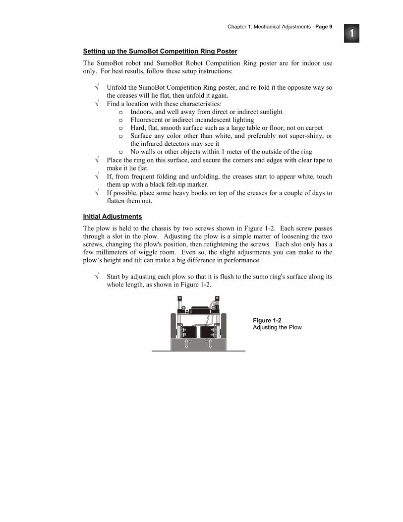
Chapter 1: Mechanical Adjustments · Page 9
Setting up the SumoBot Competition Ring Poster
The SumoBot robot and SumoBot Robot Competition Ring poster are for indoor use only. For best results, follow these setup instructions:
√ Unfold the SumoBot Competition Ring poster, and re-fold it the opposite way so the creases will lie flat, then unfold it again.
√ Find a location with these characteristics: o Indoors, and well away from direct or indirect sunlight o Fluorescent or indirect incandescent lighting o Hard, flat, smooth surface such as a large table or floor; not on carpet o Surface any color other than white, and preferably not super-shiny, or
the infrared detectors may see it o No walls or other objects within 1 meter of the outside of the ring
√ Place the ring on this surface, and secure the corners and edges with clear tape to make it lie flat.
√ If, from frequent folding and unfolding, the creases start to appear white, touch them up with a black felt-tip marker.
√ If possible, place some heavy books on top of the creases for a couple of days to flatten them out.
Initial Adjustments
The plow is held to the chassis by two screws shown in Figure 1-2. Each screw passes through a slot in the plow. Adjusting the plow is a simple matter of loosening the two screws, changing the plow's position, then retightening the screws. Each slot only has a few millimeters of wiggle room. Even so, the slight adjustments you can make to the plow’s height and tilt can make a big difference in performance.
√ Start by adjusting each plow so that it is flush to the sumo ring's surface along its whole length, as shown in Figure 1-2.
Figure 1-2 Adjusting the Plow
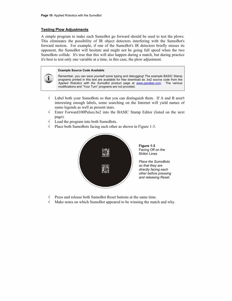
Page 10· Applied Robotics with the SumoBot
Testing Plow Adjustments
A simple program to make each SumoBot go forward should be used to test the plows. This eliminates the possibility of IR object detectors interfering with the SumoBot's forward motion. For example, if one of the SumoBot's IR detectors briefly misses its opponent, the SumoBot will hesitate and might not be going full speed when the two SumoBots collide. It's true that this will also happen during a match, but during practice it's best to test only one variable at a time, in this case, the plow adjustment.
Example Source Code Available
Remember, you can save yourself some typing and debugging! The example BASIC Stamp programs printed in this text are available for free download as .bs2 source code from the Applied Robotics with the SumoBot product page at www.parallax.com. The various modifications and “Your Turn” programs are not provided.
√ Label both your SumoBots so that you can distinguish them. If A and B aren't
interesting enough labels, some searching on the Internet will yield names of sumo legends as well as present stars.
√ Enter Forward100Pulses.bs2 into the BASIC Stamp Editor (listed on the next page).
√ Load the program into both SumoBots. √ Place both SumoBots facing each other as shown in Figure 1-3.
Figure 1-3 Facing Off on the Shikiri Lines Place the SumoBots so that they are directly facing each other before pressing and releasing Reset.
√ Press and release both SumoBot Reset buttons at the same time. √ Make notes on which SumoBot appeared to be winning the match and why.

Chapter 1: Mechanical Adjustments · Page 11
√ Repeat five to ten times to be sure which SumoBot's plow adjustment has the advantage.
√ Adjust the plow of the SumoBot that appeared to lose more often, and repeat the test.
√ When you are confident that one of your SumoBots has a winning plow adjustment, try lots of different adjustments on the other SumoBot to find out if there is any better adjustment that can make it the winner.
√ When you are satisfied with your winning SumoBot's plow, leave its adjustment as-is, and tune the other SumoBot's plow until its chances of winning/losing are close to even.
Example Program: Forward100Pulses.bs2 ' -----[ Program Description ]------------------------------------------------ ' Applied Robotics with the SumoBot - Forward100Pulses.bs2 ' SumoBot goes forward 100 pulses after Reset button is pressed and released. ' To repeat the forward motion, press/release the Reset button twice. ' ' $STAMP BS2 ' $PBASIC 2.5 ' -----[ I/O Definitions ]--------------------------------------------------- ServoLeft PIN 13 ' Left servo connected to P13 ServoRight PIN 12 ' Right servo connected to P12 ' -----[ EEPROM Data ]-------------------------------------------------------- RunStatus DATA 0 ' Start with program not running ' -----[ Variables ]---------------------------------------------------------- temp VAR Byte ' Temporary variable counter VAR Byte ' FOR...NEXT loop counter ' -----[ Initialization ]----------------------------------------------------- DEBUG CLS ' Clear the Debug Terminal Reset_Button: READ RunStatus, temp ' read current status temp = ~temp ' invert status WRITE RunStatus, temp ' save for next reset IF (temp > 0) THEN ' 0 -> End, 1 -> Main routine DEBUG "Press/release Reset..." END ENDIF
Page 12· Applied Robotics with the SumoBot
DEBUG "Main program running...", CR ' Display program status ' -----[ Main Routine ]------------------------------------------------------- FOR counter = 1 TO 100 ' Deliver 100 forward pulses PULSOUT ServoLeft, 850 PULSOUT ServoRight, 650 PAUSE 20 NEXT DEBUG "Done!", CR, ' User instructions "Press/release reset", CR, "twice to restart...", CR END
Understanding Forward100Pulses.bs2
When you click the BASIC Stamp Editor's Run button, the program downloads to the SumoBot's BASIC Stamp. The Reset_Button routine in the Initialization displays the message "Press/release Reset...", then it ends the program. When you press and release the Reset button on the SumoBot board, the same Reset_Button routine displays the message "Main program running..." and moves on to the Main Routine and the servos start turning. If you leave the SumoBot connected to its serial cable and press/release the Reset button a third time, you will again see the "Press/release Reset button" prompt. Repeat a fourth time, and the servos will run for a couple seconds. The reason the Reset_Button routine is able to perform this function is because it manipulates values stored in the SumoBot's EEPROM program memory. The portion of this memory that is not used to store the program can be used to store values. While the BASIC Stamp's RAM memory is erased whenever the power is turned off or the Reset button is pressed and released, the EEPROM memory retains the values stored in it. That's why the same program runs after your turn the SumoBot's power off, then back on. The ability to retrieve values stored in EEPROM, change them, and store them back into EEPROM is what allows the Reset_Button routine to track whether you've pressed and released the Reset button an odd or even number of times. The mechanics of exactly how the Reset_Button routine does this is covered in more detail in Chapter 2, Activity #2. For now, just keep in mind that the Reset_Button routine allows the program to continue to the Main Routine when you have pressed and released the SumoBot's Reset button an odd number of times. That means, the first, third, fifth,... time you press and release the Reset button, the program will continue to the Main Routine, and the servos will turn for about 2 1/2 seconds. Whenever you have pressed/released the Reset button
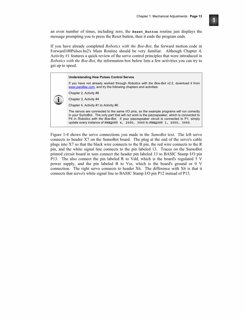
Chapter 1: Mechanical Adjustments · Page 13
an even number of times, including zero, the Reset_Button routine just displays the message prompting you to press the Reset button, then it ends the program ends. If you have already completed Robotics with the Boe-Bot, the forward motion code in Forward100Pulses.bs2's Main Routine should be very familiar. Although Chapter 4, Activity #1 features a quick review of the servo control principles that were introduced in Robotics with the Boe-Bot, the information box below lists a few activities you can try to get up to speed.
Understanding How Pulses Control Servos
If you have not already worked through Robotics with the Boe-Bot v2.2, download it from www.parallax.com, and try the following chapters and activities:
Chapter 2, Activity #6
Chapter 3, Activity #4
Chapter 4, Activity #1 to Activity #6
The servos are connected to the same I/O pins, so the example programs will run correctly in your SumoBot. The only part that will not work is the piezospeaker, which is connected to P4 in Robotics with the Boe-Bot. If your piezospeaker circuit is connected to P1, simply update every instance of FREQOUT 4, 2000, 3000 to FREQOUT 1, 2000, 3000.
Figure 1-4 shows the servo connections you made in the SumoBot text. The left servo connects to header X7 on the SumoBot board. The plug at the end of the servo's cable plugs into X7 so that the black wire connects to the B pin, the red wire connects to the R pin, and the white signal line connects to the pin labeled 13. Traces on the SumoBot printed circuit board in turn connect the header pin labeled 13 to BASIC Stamp I/O pin P13. The also connect the pin labeled R to Vdd, which is the board's regulated 5 V power supply, and the pin labeled B to Vss, which is the board's ground or 0 V connection. The right servo connects to header X6. The difference with X6 is that it connects that servo's white signal line to BASIC Stamp I/O pin P12 instead of P13.
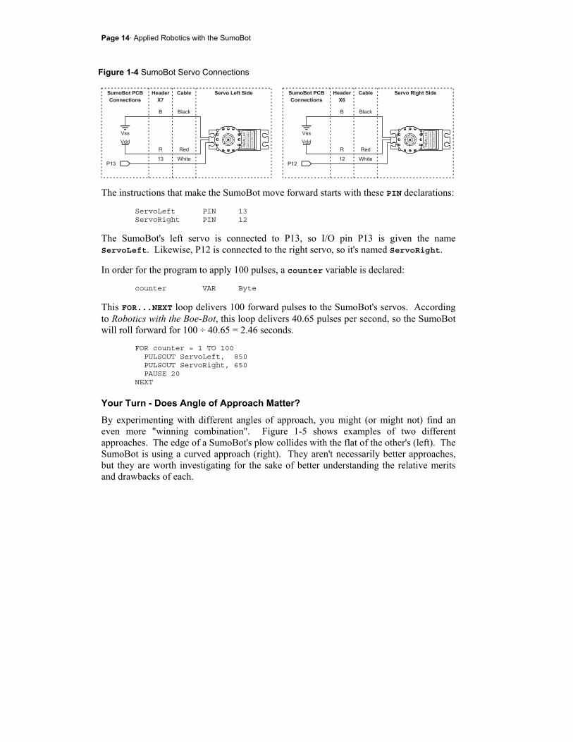
Page 14· Applied Robotics with the SumoBot
Figure 1-4 SumoBot Servo Connections
The instructions that make the SumoBot move forward starts with these PIN declarations:
ServoLeft PIN 13 ServoRight PIN 12
The SumoBot's left servo is connected to P13, so I/O pin P13 is given the name ServoLeft. Likewise, P12 is connected to the right servo, so it's named ServoRight.
In order for the program to apply 100 pulses, a counter variable is declared: counter VAR Byte
This FOR...NEXT loop delivers 100 forward pulses to the SumoBot's servos. According to Robotics with the Boe-Bot, this loop delivers 40.65 pulses per second, so the SumoBot will roll forward for 100 ÷ 40.65 = 2.46 seconds.
FOR counter = 1 TO 100 PULSOUT ServoLeft, 850 PULSOUT ServoRight, 650 PAUSE 20 NEXT
Your Turn - Does Angle of Approach Matter?
By experimenting with different angles of approach, you might (or might not) find an even more "winning combination". Figure 1-5 shows examples of two different approaches. The edge of a SumoBot's plow collides with the flat of the other's (left). The SumoBot is using a curved approach (right). They aren't necessarily better approaches, but they are worth investigating for the sake of better understanding the relative merits and drawbacks of each.
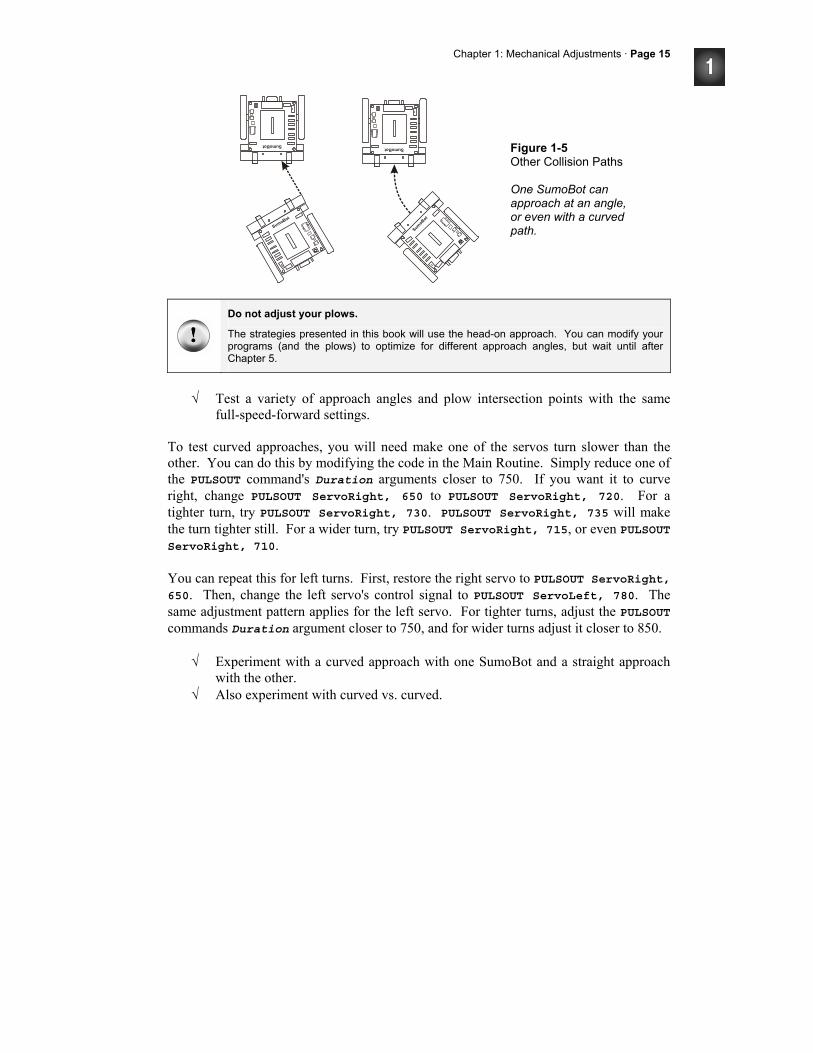
Chapter 1: Mechanical Adjustments · Page 15
Figure 1-5 Other Collision Paths One SumoBot can approach at an angle, or even with a curved path.
Do not adjust your plows.
The strategies presented in this book will use the head-on approach. You can modify your programs (and the plows) to optimize for different approach angles, but wait until after Chapter 5.
√ Test a variety of approach angles and plow intersection points with the same
full-speed-forward settings. To test curved approaches, you will need make one of the servos turn slower than the other. You can do this by modifying the code in the Main Routine. Simply reduce one of the PULSOUT command's Duration arguments closer to 750. If you want it to curve right, change PULSOUT ServoRight, 650 to PULSOUT ServoRight, 720. For a tighter turn, try PULSOUT ServoRight, 730. PULSOUT ServoRight, 735 will make the turn tighter still. For a wider turn, try PULSOUT ServoRight, 715, or even PULSOUT ServoRight, 710. You can repeat this for left turns. First, restore the right servo to PULSOUT ServoRight, 650. Then, change the left servo's control signal to PULSOUT ServoLeft, 780. The same adjustment pattern applies for the left servo. For tighter turns, adjust the PULSOUT commands Duration argument closer to 750, and for wider turns adjust it closer to 850.
√ Experiment with a curved approach with one SumoBot and a straight approach with the other.
√ Also experiment with curved vs. curved.
Page 16· Applied Robotics with the SumoBot
A notebook for your observations - keep notes on the various results you observe for developing wrestling strategies.
ACTIVITY #2: PREVENTING SERVO SLOWDOWN A SumoBot that executes certain maneuvers more quickly will have an edge over a slower opponent. One of the things that can slow your SumoBot down is trying to read too many sensors between servo pulses. This activity examines how much time your SumoBot can actually take between servo pulses before it starts to slow down. Later activities will introduce ways to reduce the time it takes to read certain sensors.
Maximizing speed and strength
In robotics clubs, competitors often rely on new servo gear sets or DC motors along with hobby RC batteries to optimize their competition robot for speed and brute force.
Parts Required
(2) Parallax SumoBot robots (8) New 1.5 volt AA batteries - same brand and type
Top Speed vs. Low Time
The high time of both pulse trains in Figure 1-6 control servo speed and direction. Because both pulse trains have high times of 1.7 ms, either pulse train will make a servo turn full speed counterclockwise. The problem is that full speed for a servo with 40 ms between pulses isn't quite as fast as the full speed for a servo with 20 ms between pulses. For example, the servo might turn 53 RPM with 20 ms pauses between pulses, but only 47 RPM with 40 ms.
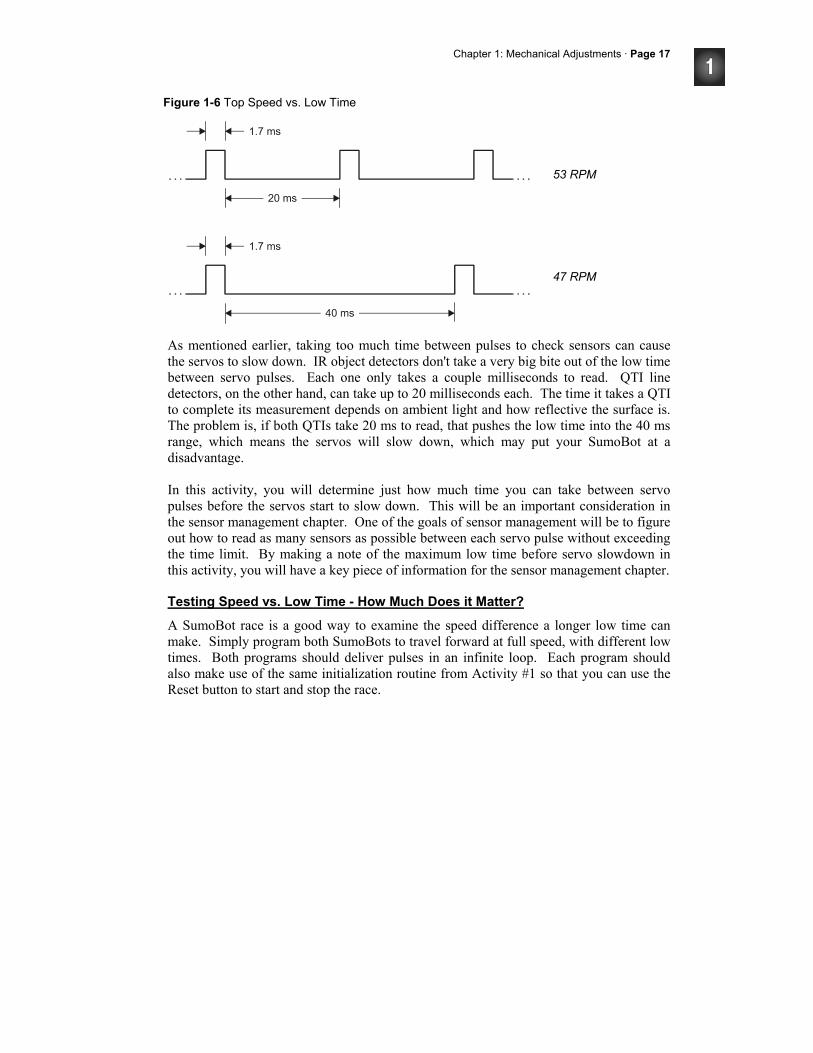
Chapter 1: Mechanical Adjustments · Page 17
Figure 1-6 Top Speed vs. Low Time
As mentioned earlier, taking too much time between pulses to check sensors can cause the servos to slow down. IR object detectors don't take a very big bite out of the low time between servo pulses. Each one only takes a couple milliseconds to read. QTI line detectors, on the other hand, can take up to 20 milliseconds each. The time it takes a QTI to complete its measurement depends on ambient light and how reflective the surface is. The problem is, if both QTIs take 20 ms to read, that pushes the low time into the 40 ms range, which means the servos will slow down, which may put your SumoBot at a disadvantage. In this activity, you will determine just how much time you can take between servo pulses before the servos start to slow down. This will be an important consideration in the sensor management chapter. One of the goals of sensor management will be to figure out how to read as many sensors as possible between each servo pulse without exceeding the time limit. By making a note of the maximum low time before servo slowdown in this activity, you will have a key piece of information for the sensor management chapter.
Testing Speed vs. Low Time - How Much Does it Matter?
A SumoBot race is a good way to examine the speed difference a longer low time can make. Simply program both SumoBots to travel forward at full speed, with different low times. Both programs should deliver pulses in an infinite loop. Each program should also make use of the same initialization routine from Activity #1 so that you can use the Reset button to start and stop the race.
53 RPM
47 RPM
Page 18· Applied Robotics with the SumoBot
With a couple modifications to Forward100Pulses.bs2 from Activity #1, you'll be ready to go.
√ Save Forward100Pulses.bs2 as ForwardLowTimeTest.bs2. √ Add a LowTime constant declaration:
LowTime CON 20
√ Change the FOR...NEXT loop in the Main Routine to a DO...LOOP, and substitute the LowTime constant for the 20 in the PAUSE command's Duration argument: DO PULSOUT ServoLeft, 850 PULSOUT ServoRight, 650 PAUSE LowTime LOOP
It's important to use new batteries in both SumoBots. It's also best to swap programs and re-test to make sure that one SumoBot doesn't happen to be slower than the other. This can be especially common in the classroom, where servos may have been subject do differing levels of wear and tear over time.
Example Program: ForwardLowTimeTest.bs2
√ Load fresh alkaline batteries into both SumoBots. √ Enter and download ForwardLowTimeTest.bs2 to SumoBot A. √ Change the LowTime CON directive from 20 to 40. √ Download the modified program into SumoBot B. √ Set them on a flat surface for the race. √ Press/release both Reset buttons at the same time to start the race. √ Follow the SumoBots for 3 seconds, then press/release the Reset buttons again to
end the race. √ Measure the distance each SumoBot traveled, and make a note of it. √ Divide the distance by 3 to calculate each SumoBot's speed in distance per
second. √ Swap the programs so that SumoBot B now has the program with 20 ms pauses
and SumoBot A has the program with 40 ms pauses. √ Repeat the race and measurement.
Chapter 1: Mechanical Adjustments · Page 19
√ Compare the results of the two trials and determine which program gives the SumoBot better performance.
' -----[ Program Description ]------------------------------------------------ ' Applied Robotics with the SumoBot - ForwardLowTimeTest.bs2 ' SumoBot goes forward indefinitely. Use the Reset button to start and stop ' the forward motion. ' ' $STAMP BS2 ' $PBASIC 2.5 ' -----[ I/O Definitions ]--------------------------------------------------- ServoLeft PIN 13 ' Left servo connected to P13 ServoRight PIN 12 ' Right servo connected to P12 ' -----[ EEPROM Data ]-------------------------------------------------------- RunStatus DATA 0 ' Start with program not running ' -----[ Constants ]---------------------------------------------------------- LowTime CON 20 ' Try 1 SumoBot with 20 ms pulses ' Try the other with 40 ms pulses ' -----[ Variables ]---------------------------------------------------------- temp VAR Byte ' Temporary variable counter VAR Byte ' FOR...NEXT loop counter ' -----[ Initialization ]----------------------------------------------------- DEBUG CLS ' Clear the Debug Terminal READ RunStatus, temp ' read current status temp = ~temp ' invert status WRITE RunStatus, temp ' save for next reset IF (temp > 0) THEN ' 0 -> End, 1 -> Main routine DEBUG "Press/release Reset..." END ENDIF DEBUG "Main program running...", CR ' Display program status ' -----[ Main Routine ]------------------------------------------------------- DO ' Forward pulses indefinitely PULSOUT ServoLeft, 850 PULSOUT ServoRight, 650 PAUSE LowTime
Page 20· Applied Robotics with the SumoBot
LOOP DEBUG "Press/release reset", CR, ' User instructions "twice to restart...", CR END
Your Turn - More Pulses, Less Distance
Chapter 4, Activity #3 in Robotics with the Boe-Bot demonstrates how the amount of time a servo turns translates to distance traveled. When there's less time between each pulse, the program will have to send the servos more pulses to make them turn for the same amount of time. This can make a huge difference in certain maneuvers, especially distance and turns. Let's take a closer look at turns. If the low time between pulses is cut in half, it means you have to deliver around twice as many pulses to execute the same maneuver.
√ Save ForwardLowTimeTest.bs2 as ForwardLowTimeTestYourTurn.bs2 √ Set the LowTime CON directive to 40. √ Replace the DO...LOOP in the Main Routine with this:
For counter = 1 to 15 ' Deliver 15 left turn pulses PULSOUT ServoLeft, 850 PULSOUT ServoRight, 850 PAUSE LowTime NEXT
√ Download the modified program to SumoBot A. √ Set the LowTime CON directive to 20. √ Modify the Main Routine again, this time doubling the number in the
FOR...NEXT loop's EndValue: FOR counter = 1 to 30 ' Deliver 30 left turn pulses PULSOUT ServoLeft, 850 PULSOUT ServoRight, 850 PAUSE LowTime NEXT
√ Download the modified program to SumoBot B.
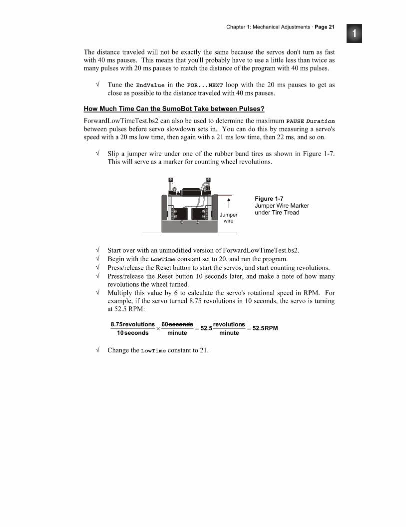
Chapter 1: Mechanical Adjustments · Page 21
The distance traveled will not be exactly the same because the servos don't turn as fast with 40 ms pauses. This means that you'll probably have to use a little less than twice as many pulses with 20 ms pauses to match the distance of the program with 40 ms pulses.
√ Tune the EndValue in the FOR...NEXT loop with the 20 ms pauses to get as close as possible to the distance traveled with 40 ms pauses.
How Much Time Can the SumoBot Take between Pulses?
ForwardLowTimeTest.bs2 can also be used to determine the maximum PAUSE Duration between pulses before servo slowdown sets in. You can do this by measuring a servo's speed with a 20 ms low time, then again with a 21 ms low time, then 22 ms, and so on.
√ Slip a jumper wire under one of the rubber band tires as shown in Figure 1-7. This will serve as a marker for counting wheel revolutions.
Figure 1-7 Jumper Wire Marker under Tire Tread
√ Start over with an unmodified version of ForwardLowTimeTest.bs2. √ Begin with the LowTime constant set to 20, and run the program. √ Press/release the Reset button to start the servos, and start counting revolutions. √ Press/release the Reset button 10 seconds later, and make a note of how many
revolutions the wheel turned. √ Multiply this value by 6 to calculate the servo's rotational speed in RPM. For
example, if the servo turned 8.75 revolutions in 10 seconds, the servo is turning at 52.5 RPM:
√ Change the LowTime constant to 21.
RPM52.5minute
srevolution52.5minuteseconds60
seconds10srevolution8.75 ==×
Page 22· Applied Robotics with the SumoBot
√ Run the modified program. √ Repeat the 10 second measurement and record the servo speed. √ Keep increasing the LowTime constant and measuring servo speed until you note
obvious speed decay. √ Record the maximum LowTime value you can use without slowing down your
SumoBot in your notes for future reference.
Your Turn - Wheel Rotation Speed Measurements
You can also calculate the percent speed reduction for a given pause time. Here's an example of how to compare the percent speed reduction between programs with 20 and 40 ms pause times. Start by dividing the wheel's rotational speed (RPM) with 40 ms pause times by its rotational speed (RPM) with 20 ms pause times. Subtract the fractional value from 1, then multiply by 100%. If your result turns out to be a value like 12%, that means the SumoBot goes 12% slower with 40 ms low times.
⎟⎟⎠
⎞⎜⎜⎝
⎛−×=
)ms20(RPM)ms40(RPM1%100reductionspeedPercent
√ Calculate the percent impact of 40 ms vs. 20 ms pause times on your servo's
speed.
ACTIVITY #3: FRICTION FORCES - YOUR SUMOBOT'S ALLIES Friction between tire treads and the sumo ring surface is another performance issue that you will likely examine and reexamine as you customize your SumoBot. There are two areas that you can change to improve your SumoBot's traction on the sumo ring. The first is to increase the SumoBot's mass from 354 grams up to the maximum allowed 500 grams. The second is to experiment with tire tread materials that will grip the ring better. This activity explains some of the physics principles behind each of these strategies and introduces tests you can perform to measure the resulting changes in your SumoBot's ability to push harder against its opponent.
Measurements - Force Vs. Mass
Pounds and ounces are measurements of weight. Weight is the force a planet's gravity exerts on an object. Mass, on the other hand, is a measure of how much stuff an object is made of - a grand total of protons, neutrons, and electrons.
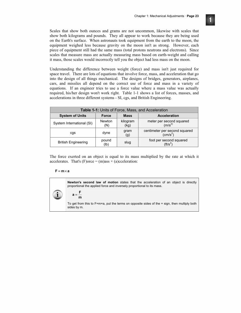
Chapter 1: Mechanical Adjustments · Page 23
Scales that show both ounces and grams are not uncommon, likewise with scales that show both kilograms and pounds. They all appear to work because they are being used on the Earth's surface. When astronauts took equipment from the earth to the moon, the equipment weighed less because gravity on the moon isn't as strong. However, each piece of equipment still had the same mass (total protons neutrons and electrons). Since scales that measure mass are actually measuring mass based on earth-weight and calling it mass, those scales would incorrectly tell you the object had less mass on the moon. Understanding the difference between weight (force) and mass isn't just required for space travel. There are lots of equations that involve force, mass, and acceleration that go into the design of all things mechanical. The designs of bridges, generators, airplanes, cars, and missiles all depend on the correct use of force and mass in a variety of equations. If an engineer tries to use a force value where a mass value was actually required, his/her design won't work right. Table 1-1 shows a list of forces, masses, and accelerations in three different systems - SI, cgs, and British Engineering.
Table 1-1: Units of Force, Mass, and Acceleration System of Units Force Mass Acceleration
System International (SI) Newton (N)
kilogram (kg)
meter per second squared (m/s2)
cgs dyne gram (g)
centimeter per second squared (cm/s2)
British Engineering pound (lb) slug foot per second squared
(ft/s2) The force exerted on an object is equal to its mass multiplied by the rate at which it accelerates. That's (F)orce = (m)ass × (a)cceleration: amF ×=
Newton's second law of motion states that the acceleration of an object is directly proportional the applied force and inversely proportional to its mass.
mFa =
To get from this to F=m×a, put the terms on opposite sides of the = sign, then multiply both sides by m.
Page 24· Applied Robotics with the SumoBot
Since weight is a force, and gravity is a form of acceleration, an equation you will find useful in your calculations is: gmW ×=
The acceleration due to gravity is 9.8 m/s2 in the SI system and 32 ft/s2 in the British Engineering system.
Problem: An object has a mass of 0.75 kg, what's its weight in newtons? Solution: Start with the equation w = mg, and figure out which system to use and which pieces of information you already know. Also, look at Table 1-1 again. The units of your result should be in kg×m/s2. Since the mass is in kg units, we can start with the SI system. The acceleration due to gravity in the SI system is 9.8 m/s2. Now that we know two pieces of the puzzle, we can calculate the third.
N35.7s/mkg35.7
s/m8.9kg75.0mgw
2
2
==
×==
A newton is in fact a kg m/s2. Likewise, a pound is a slug ft/s2.
Unit Conversions
There are 1000 grams in 1 kilogram. That's: kg1g1000 = If you divide both sides of the equal sign by one of these values, you will have 1 = conversion factor. For example: 1
kg1g1000and
g1000kg11 ==
Chapter 1: Mechanical Adjustments · Page 25
If you measure an object's mass to be a certain number of grams, converting to kilograms is a matter of using the conversion factor that will make the units you don't want cancel out. Problem: You measured your mass to be 280 g, and you want kg. Solution: Multiply by the conversion factor with the g in the denominator.
g1000kg11 =
It will cancel out the g in the numerator of the term you are starting with (280 g), and the result will have units of kg.
1 ft = 0.3048 m 1 lb = 16 oz 1 lb = 453.592 g
Problem: Your scale gives you a measurement of 8 oz, but you need kilograms for your SI force calculations. Solution: There isn't a single term in information box to get you from ounces to kilograms, but we do know how many ounces are in a pound, how many grams are in a pound, and how many grams are in a kilogram. Knowing this, you can make three fractions, all equal to 1, for conversion.
g1000kg11kg1g1000
lb1g6.4531g6.453lb1
oz16lb11oz16lb1
=→=
=→=
=→=
Next, all you have to do is multiply 8 oz by 1 three times. Look closely at the second line of the calculation below. In this cascade of conversion factors, the oz measurements cancel, then the lb measurements cancel, then the g measurements cancel, and you are left with just kg units.
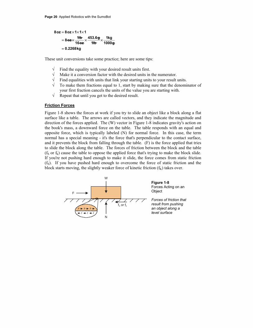
Page 26· Applied Robotics with the SumoBot
These unit conversions take some practice; here are some tips:
√ Find the equality with your desired result units first. √ Make it a conversion factor with the desired units in the numerator. √ Find equalities with units that link your starting units to your result units. √ To make them fractions equal to 1, start by making sure that the denominator of
your first fraction cancels the units of the value you are starting with. √ Repeat that until you get to the desired result.
Friction Forces
Figure 1-8 shows the forces at work if you try to slide an object like a block along a flat surface like a table. The arrows are called vectors, and they indicate the magnitude and direction of the forces applied. The (W) vector in Figure 1-8 indicates gravity's action on the book's mass, a downward force on the table. The table responds with an equal and opposite force, which is typically labeled (N) for normal force. In this case, the term normal has a special meaning - it's the force that's perpendicular to the contact surface, and it prevents the block from falling through the table. (F) is the force applied that tries to slide the block along the table. The forces of friction between the block and the table (fS or fk) cause the table to oppose the applied force that's trying to make the block slide. If you're not pushing hard enough to make it slide, the force comes from static friction (fS). If you have pushed hard enough to overcome the force of static friction and the block starts moving, the slightly weaker force of kinetic friction (fK) takes over.
Figure 1-8 Forces Acting on an Object Forces of friction that result from pushing an object along a level surface
kg2268.0g1000
kg1lb1
g6.453oz16lb1oz8
111oz8oz8
=
×××=
×××=
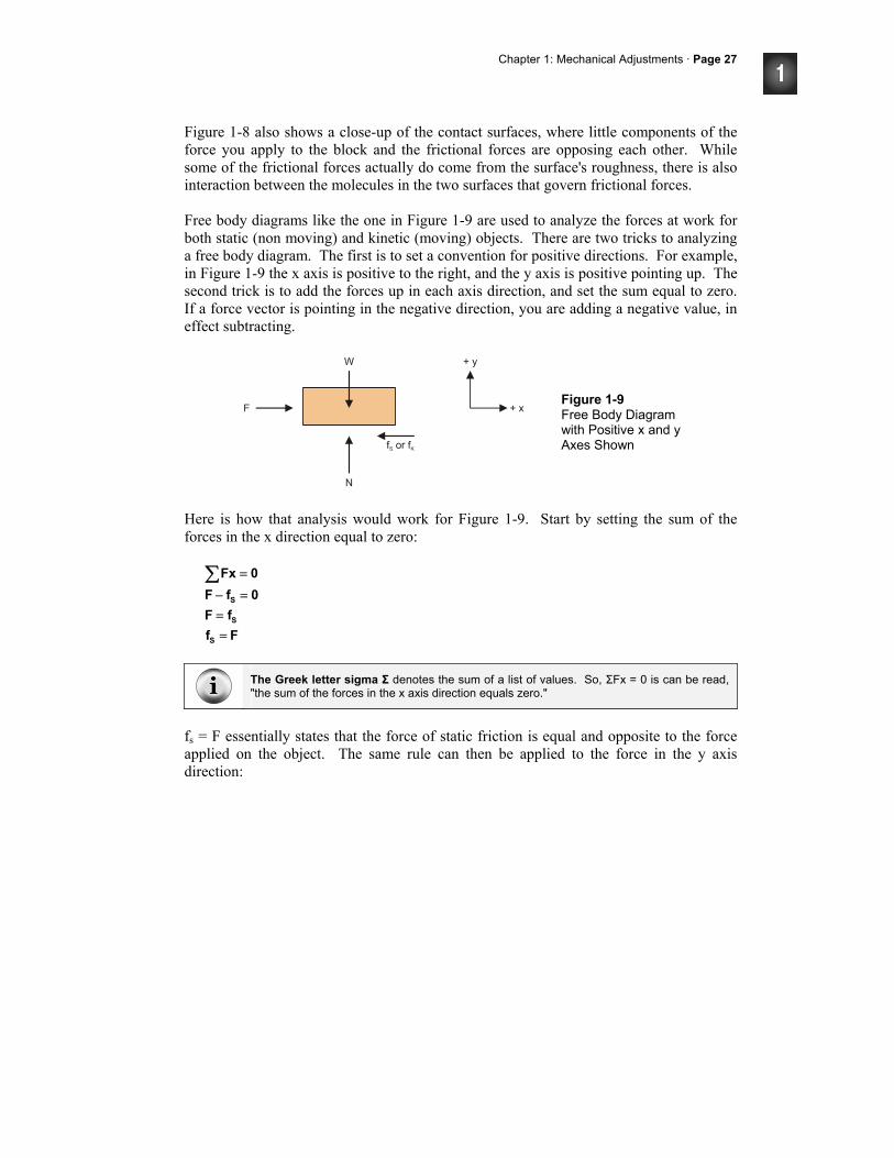
Chapter 1: Mechanical Adjustments · Page 27
Figure 1-8 also shows a close-up of the contact surfaces, where little components of the force you apply to the block and the frictional forces are opposing each other. While some of the frictional forces actually do come from the surface's roughness, there is also interaction between the molecules in the two surfaces that govern frictional forces. Free body diagrams like the one in Figure 1-9 are used to analyze the forces at work for both static (non moving) and kinetic (moving) objects. There are two tricks to analyzing a free body diagram. The first is to set a convention for positive directions. For example, in Figure 1-9 the x axis is positive to the right, and the y axis is positive pointing up. The second trick is to add the forces up in each axis direction, and set the sum equal to zero. If a force vector is pointing in the negative direction, you are adding a negative value, in effect subtracting.
Figure 1-9 Free Body Diagram with Positive x and y Axes Shown
Here is how that analysis would work for Figure 1-9. Start by setting the sum of the forces in the x direction equal to zero:
FffF
0fF0Fx
S
S
S
==
=−
=∑
The Greek letter sigma Σ denotes the sum of a list of values. So, ΣFx = 0 is can be read, "the sum of the forces in the x axis direction equals zero."
fs = F essentially states that the force of static friction is equal and opposite to the force applied on the object. The same rule can then be applied to the force in the y axis direction:
Page 28· Applied Robotics with the SumoBot
WN0WN
0Fy
==−
=∑
N = W indicates that the normal force, N, is pushing back just as hard as the object's weight is pushing down on the surface. This has to be true. If it wasn't, the block would sink through the table, or maybe the table would start sinking into the earth.
Newton's Third Law can be summarized like this: if two bodies (such as the block and the surface it's on) interact, each body exerts an equal and opposite force on the other.
The drawings of the forces acting on the block and setting the sum of all the forces equal to zero is dictated by this law.
Coefficients of Friction
Different pairs of surfaces tend to exert different kinetic and maximum static frictional forces. For example, if you try to slip your shoe along concrete on a sidewalk, it'll probably resist pretty strongly. However, if there's ice on the sidewalk, your shoe will slip right along it with barely any frictional force. Since each pair of materials resists the applied force with different levels of fS and fK, a term called the coefficient of friction is used to predict how much force it will take to make one material slide along another. In the case of static friction, this coefficient, µs is the maximum force you can apply before the object starts sliding divided by the normal force. In the case of kinetic friction, µk is the force required to keep the object sliding, divided by the normal force.
Nfand
Nf K
KMax,S
S == µµ
The Greek letter mu - µ - is commonly used for to denote coefficients of friction. µ is also a coefficient for units such as seconds, amps, and meters (µs, µA, µm). In those cases, µ is a different coefficient, with a value of one-one-millionth (1/1,000,000). If you are referring to the coefficient of static friction, µS, always remember to subscript the capital S. When referring to microseconds, it's just µs, with a lower-case 's'.
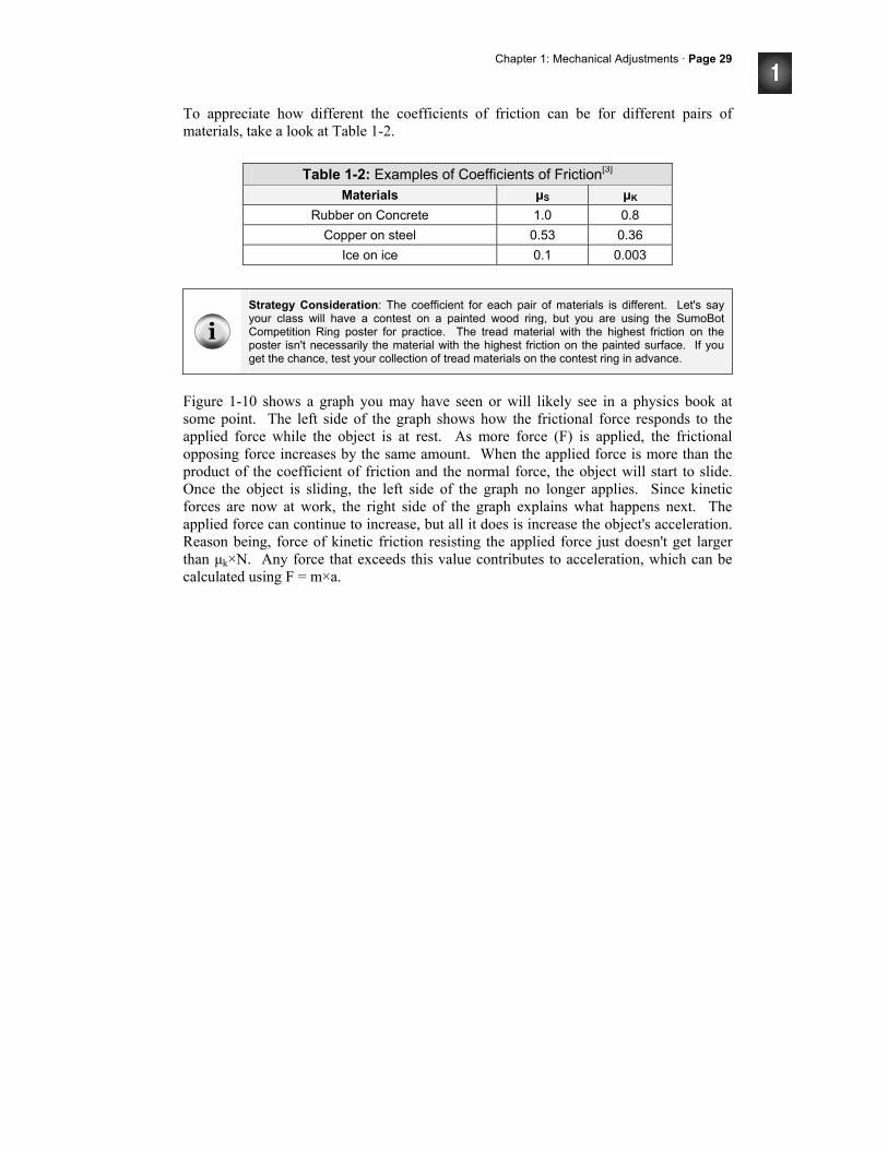
Chapter 1: Mechanical Adjustments · Page 29
To appreciate how different the coefficients of friction can be for different pairs of materials, take a look at Table 1-2.
Table 1-2: Examples of Coefficients of Friction[3] Materials µS µK
Rubber on Concrete 1.0 0.8 Copper on steel 0.53 0.36
Ice on ice 0.1 0.003
Strategy Consideration: The coefficient for each pair of materials is different. Let's say your class will have a contest on a painted wood ring, but you are using the SumoBot Competition Ring poster for practice. The tread material with the highest friction on the poster isn't necessarily the material with the highest friction on the painted surface. If you get the chance, test your collection of tread materials on the contest ring in advance.
Figure 1-10 shows a graph you may have seen or will likely see in a physics book at some point. The left side of the graph shows how the frictional force responds to the applied force while the object is at rest. As more force (F) is applied, the frictional opposing force increases by the same amount. When the applied force is more than the product of the coefficient of friction and the normal force, the object will start to slide. Once the object is sliding, the left side of the graph no longer applies. Since kinetic forces are now at work, the right side of the graph explains what happens next. The applied force can continue to increase, but all it does is increase the object's acceleration. Reason being, force of kinetic friction resisting the applied force just doesn't get larger than µk×N. Any force that exceeds this value contributes to acceleration, which can be calculated using F = m×a.
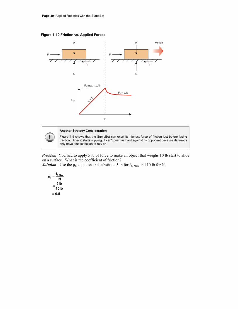
Page 30· Applied Robotics with the SumoBot
Figure 1-10 Friction vs. Applied Forces
Another Strategy Consideration
Figure 1-9 shows that the SumoBot can exert its highest force of friction just before losing traction. After it starts slipping, it can't push as hard against its opponent because its treads only have kinetic friction to rely on.
Problem: You had to apply 5 lb of force to make an object that weighs 10 lb start to slide on a surface. What is the coefficient of friction? Solution: Use the µS equation and substitute 5 lb for fS, Max and 10 lb for N.
5.0lb10lb5N
f Max,SS
=
=
=µ
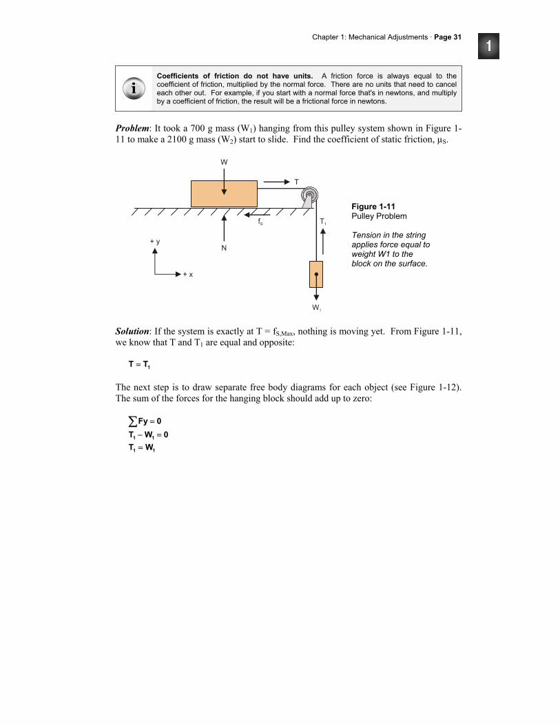
Chapter 1: Mechanical Adjustments · Page 31
Coefficients of friction do not have units. A friction force is always equal to the coefficient of friction, multiplied by the normal force. There are no units that need to cancel each other out. For example, if you start with a normal force that's in newtons, and multiply by a coefficient of friction, the result will be a frictional force in newtons.
Problem: It took a 700 g mass (W1) hanging from this pulley system shown in Figure 1-11 to make a 2100 g mass (W2) start to slide. Find the coefficient of static friction, µS.
Figure 1-11 Pulley Problem Tension in the string applies force equal to weight W1 to the block on the surface.
Solution: If the system is exactly at T = fS,Max, nothing is moving yet. From Figure 1-11, we know that T and T1 are equal and opposite: 1TT = The next step is to draw separate free body diagrams for each object (see Figure 1-12). The sum of the forces for the hanging block should add up to zero:
11
11
WT0WT
0Fy
==−
=∑
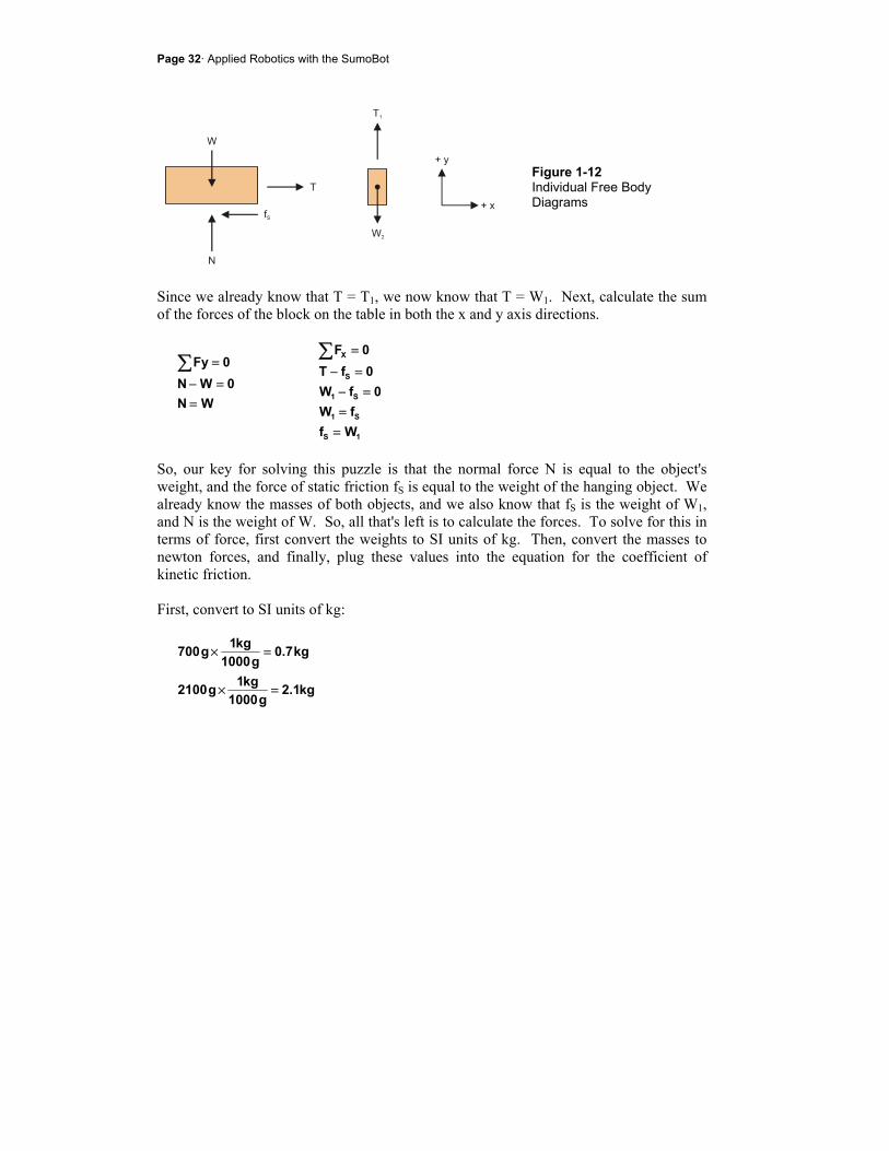
Page 32· Applied Robotics with the SumoBot
Figure 1-12 Individual Free Body Diagrams
Since we already know that T = T1, we now know that T = W1. Next, calculate the sum of the forces of the block on the table in both the x and y axis directions.
WN0WN
0Fy
==−
=∑
1S
S1
S1
S
X
WffW
0fW0fT
0F
==
=−=−
=∑
So, our key for solving this puzzle is that the normal force N is equal to the object's weight, and the force of static friction fS is equal to the weight of the hanging object. We already know the masses of both objects, and we also know that fS is the weight of W1, and N is the weight of W. So, all that's left is to calculate the forces. To solve for this in terms of force, first convert the weights to SI units of kg. Then, convert the masses to newton forces, and finally, plug these values into the equation for the coefficient of kinetic friction. First, convert to SI units of kg:
kg1.2g1000
kg1g2100
kg7.0g1000
kg1g700
=×
=×
Chapter 1: Mechanical Adjustments · Page 33
Next, convert to the corresponding units of force (newtons):
N86.6s/m8.9kg7.0f
N58.20s/m8.9kg1.2N
mgW
2S
2
=×=
=×=
=
Finally, plug these forces into the coefficient of kinetic friction equation and calculate the result:
...333.0N58.20N86.6
NfK
S
=
=
=µ
Why couldn't I have just used the ratio of the masses? For this particular problem on the earth's surface, you can use this shortcut. The ratio of the masses does give you the correct answer, 700/2100 = 0.333... However, you should always keep in mind that the µs and µk are ratios of forces. While you won't encounter it in this book, the problems get more complex when they incorporate things like thrust and a body's tendency to rotate. In general, when the problems get more complex, you will have to be strict about the difference between mass and force.
Coefficients of friction make predicting how much force it will take to get something to slide really easy. The same applies for sustained sliding and the coefficient of kinetic friction. In either case, all you have to do is multiply the normal force by the coefficient of friction. NfandNf KKSS ×=×= µµ When the surface is tilting, the normal force takes some extra calculating, but when it's horizontal to the ground, like in Figure 1-8, the normal force is just the object's weight on the surface. The force to start it sliding is the coefficient of friction multiplied by the object's weight, and the force to keep it sliding is the coefficient of kinetic friction multiplied by the object's weight. WfandWf KKSS ×=×= µµ

Page 34· Applied Robotics with the SumoBot
Problem: The coefficient of static friction for two surfaces is 0.1 (pretty slippery). How much force will it take to get a 10 lb weight to start to slide if the contact surfaces are level? Solution: It takes 1 lb of force to start the object's slide:
lb1lb101.0
Wf SS
=×=×= µ
Problem: If you increase the weight from the previous problem to 20 lb, how much force will you need to overcome static friction? Solution: Twice the weight means you need to apply twice the force.
lb2lb201.0
Wf SS
=×=×= µ
This is the reason adding weight to your SumoBot will increase the friction force the sumo ring exerts on it.
Parts and Equipment
A pulley and weight system will be used to test the SumoBot tread's coefficient of friction and response to increased weight. Unless noted, these parts are not included in the SumoBot Robot Competition Kit (1) SumoBot (included) (1) Sumo ring (included) (1) String or fishing line strong enough to suspend both your SumoBots. Length
should be approximately 1 m. (1) Scale able to measure grams or ounces (1) Pulley and attachment hardware (1) Disposable plastic cup (misc) Assorted weights (nails, nuts, bolts, pennies, fishing sinkers, etc).
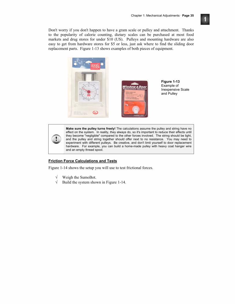
Chapter 1: Mechanical Adjustments · Page 35
Don't worry if you don't happen to have a gram scale or pulley and attachment. Thanks to the popularity of calorie counting, dietary scales can be purchased at most food markets and drug stores for under $10 (US). Pulleys and mounting hardware are also easy to get from hardware stores for $5 or less, just ask where to find the sliding door replacement parts. Figure 1-13 shows examples of both pieces of equipment.
Figure 1-13 Example of Inexpensive Scale and Pulley
Make sure the pulley turns freely! The calculations assume the pulley and string have no effect on the system. In reality, they always do, so it's important to reduce their effects until they become "negligible" compared to the other forces involved. The string should be light, and the pulley and string together should offer next to no resistance. You may need to experiment with different pulleys. Be creative, and don't limit yourself to door replacement hardware. For example, you can build a home-made pulley with heavy coat hanger wire and an empty thread spool.
Friction Force Calculations and Tests
Figure 1-14 shows the setup you will use to test frictional forces.
√ Weigh the SumoBot. √ Build the system shown in Figure 1-14.
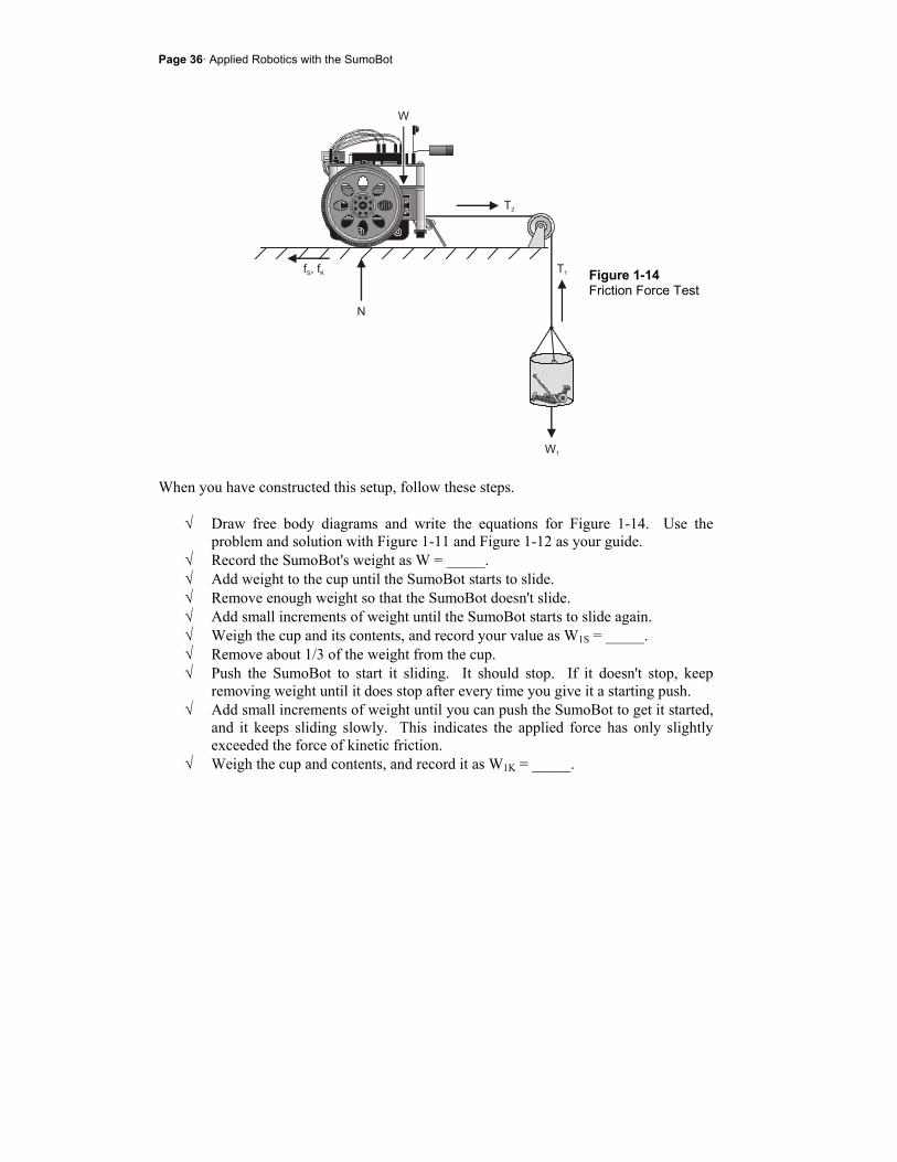
Page 36· Applied Robotics with the SumoBot
Figure 1-14 Friction Force Test
When you have constructed this setup, follow these steps.
√ Draw free body diagrams and write the equations for Figure 1-14. Use the problem and solution with Figure 1-11 and Figure 1-12 as your guide.
√ Record the SumoBot's weight as W = _____. √ Add weight to the cup until the SumoBot starts to slide. √ Remove enough weight so that the SumoBot doesn't slide. √ Add small increments of weight until the SumoBot starts to slide again. √ Weigh the cup and its contents, and record your value as W1S = _____. √ Remove about 1/3 of the weight from the cup. √ Push the SumoBot to start it sliding. It should stop. If it doesn't stop, keep
removing weight until it does stop after every time you give it a starting push. √ Add small increments of weight until you can push the SumoBot to get it started,
and it keeps sliding slowly. This indicates the applied force has only slightly exceeded the force of kinetic friction.
√ Weigh the cup and contents, and record it as W1K = _____.
Chapter 1: Mechanical Adjustments · Page 37
√ Use your weights and the equations introduced in this activity to calculate the coefficients of static and kinetic friction for the SumoBot tire treads and the sumo ring surface.
√ Put the SumoBot on the scale, and add mass until the scale indicates your SumoBot and payload is just under 500 g.
√ Repeat these tests with your 500 g SumoBot. √ Compare the forces of friction the sumo ring exerts on the tire tread with and
without payload. √ Remove the tire treads and repeat the experiment.
Your Turn
√ Repeat Activity #1, and test to find out if the position of the payload added to the SumoBot can be adjusted to give it added advantage.
√ Be creative with testing different materials for tire treads. Try cutting a balloon in half and then stretch it around each tire. How about the material in surgical gloves? Neoprene, broccoli rubber-bands, sections of bicycle innertube, silicone tubing, paint-on urethane, rubber cement?
Page 38· Applied Robotics with the SumoBot
SUMMARY This chapter introduced a variety of mechanical adjustments you can make to the SumoBot. Adjusting the plow angle is one important consideration. Managing the pause time between servo pulses is another important consideration because it can result in slower servo motor operation. Frictional forces are yet another important consideration. There are two ways to increase the friction between the SumoBot's tire treads and the competition ring. The first is to increase the SumoBot's weight. Adding mass to get it to the maximum allowed 500 g can make a significant difference. Choosing a tire tread material that features the highest possible coefficient of friction between the tread and ring surfaces is a second way to increase the friction forces. These friction forces are what will make it possible for your SumoBot to push harder against its opponent. This chapter introduced several experimental approaches along the way. Adjusting the SumoBot's plow involved trial and error. Testing for servo speed involved percent difference calculations. Testing for frictional forces involved designing and building a pulley system to test and quantify forces of static and kinetic friction between the tire tread and sumo ring. The friction forces activity also introduced a number of physics principles including static and kinetic friction and their coefficients. Free body diagrams were also introduced as a way to analyze the sum of the forces acting on an object. Free body diagrams were also applied to the SumoBot to analyze the forces involved in the pulley experiment.
Questions
1. What does the Reset_Button routine in Forward100Pulses.bs2 do? 2. How many servo control pulses does Forward100Pulses.bs2 send to a servo
signal line? 3. How does the PULSOUT command control servo speed? 4. How is reducing the left servo speed different from reducing the right servo
speed? 5. What sensor considerations have to be made with regards to the maximum time
between servo pulses? 6. What's the equation for percent speed reduction when comparing a faster and
slower servo? 7. What's the difference between force and mass? 8. What's the SI unit of force? 9. What's the SI unit for acceleration?
Chapter 1: Mechanical Adjustments · Page 39
10. What's the British Engineering unit of mass? 11. How does force relate to mass and acceleration? 12. What's the acceleration due to gravity in SI units? 13. What is an object's weight in terms of its mass and the earth's gravity? 14. How do you apply a conversion factor to a quantity whose units you want to
convert? 15. What's a free body diagram? 16. Should a free body diagram of a block show the surface it's sliding on? 17. What does ΣFy mean? 18. What is kinetic friction? 19. What is a coefficient of static friction? 20. How do you calculate the coefficient of kinetic friction? 21. What's a normal force? 22. How can different coefficients of frictions indicate different frictional forces,
given the same weight?
Exercises
1. Write a block of code that makes your SumoBot travel in a path that curves to the left indefinitely.
2. Modify Forward100Pulses.bs2 so that it makes the SumoBot go forward 200 pulses instead.
3. If a SumoBot's wheel makes 9.25 revolutions in 10 seconds, calculate the wheel's rotational speed in RPM.
4. If a particular piece of code slows the servo's speed from 60 to 50 RPM, calculate the percent speed reduction.
5. Calculate the weight of a 450 g SumoBot in newtons. 6. Calculate the weight of a 475 g SumoBot in newtons. 7. Calculate the SI mass of a SumoBot that weighs 17.12 oz. 8. Calculate the SI mass of a SumoBot that weighs 17.46 oz. 9. Calculate the force it takes to start a 10 lb rubber object sliding along a level
concrete sidewalk. 10. Calculate the force it takes to start a 5 kg rubber object sliding along a level
concrete sidewalk. 11. Calculate the force it takes to start an 8 oz steel object sliding along a level
copper surface. 12. Calculate the force it takes to start a 100 lb block of ice sliding across a frozen
lake.
Page 40· Applied Robotics with the SumoBot
13. It takes 70 lbs of force to start a 100 lb object sliding along a level surface. Calculate the coefficient of static friction between the object and the surface.
14. It takes 28 lb of force to start a 37 lb object sliding along a level surface. Calculate the coefficient of static friction between the object and the surface.
15. It takes 4.9 N of force to start a 1 kg object sliding along a level surface. Calculate the coefficient of static friction between the object and the surface.
16. It takes 9.3 N of force to start a 1 kg object sliding along a level surface. Calculate the coefficient of static friction between the object and the surface.
Projects
1. How much does 40 ms between pulses reduce the likelihood of winning a round compared to 20 ms between pulses. Start by adjusting the plows so that each SumoBot gets the advantage in 5 out of 10 trials. You may want to repeat 20 or 30 trials to be sure the odds are close to 50/50. Modify Forward100Pulses.bs2 so that the SumoBots' servos turn indefinitely. The trial should then be run long enough to give you a clear idea of which SumoBot will win the round. You will want to see one SumoBot obviously losing ground and getting pushed backwards by the other. Modify a second version of Forward100Pulses.bs2 so that it runs indefinitely with 40 ms pause times instead of 20 ms pause times. Repeat another 30 trials. How many times did the SumoBot with 20 ms PAUSE times win? Is this a significant or negligible increase?
2. How much advantage does a SumoBot with a payload that increases its mass to 500 g have over a SumoBot with no payload? As with Project 1, start with two SumoBots that are equally matched for gaining plow advantage. Use Forward100Pulses.bs2 in each SumoBot. This time, the programs should have identical PAUSE durations. Add a payload to one of the SumoBots to increase its mass to about 500 g. Repeat 30 trials and compare to the initial advantage. How many times did the SumoBot with more mass win? Again, is this a significant or negligible increase.
Chapter 2: EEPROM Tricks and Program Tips · Page 41
Chapter #2: EEPROM Tricks and Program Tips The BASIC Stamp's EEPROM is a great tool for storing values that you don't want to get erased. After you've stored a value to EEPROM, it doesn't matter whether the power has been turned off or the Reset button has been pressed and released. The value will still be there (in EEPROM) when your program needs it. This chapter introduces some of the techniques that will be reused in later chapters for things like self-calibrating sensors (Chapter 3) and datalogging a sumo round (Chapter 5). This chapter also takes a closer look at how a PBASIC program can make the Reset button function as an on/off switch for sumo wrestling mode. When used with a pushbutton, speaker, and LED, the EEPROM programming techniques make it possible to select between many different modes of operation, which can come in handy for strategy changes on the fly. This chapter also introduces some conventions that will allow you to use just a couple of variables to do many different jobs. These conventions, along with some program design and organization strategies, will make it possible for you to mix and match old code into future application programs.
EEPROM AND PROGRAM MANAGEMENT DATA directives are great tools for setting aside bytes, words, and clusters of bytes for later use in the program. DATA directives can pre-store values in EEPROM, and they can also give the beginning of a group of reserved EEPROM bytes a unique name that your program can then use to always find the particular bytes it needs to do its jobs. Regardless of whether you're logging data, calibrating sensors, or toggling between wrestling modes, if you've arranged your EEPROM with DATA directives that have Symbol names, it will make retrieving and storing all the values a snap. Following common code conventions also yields a variety of benefits. For example, if your subroutines make effective use of temporary variables for counting and manipulating values, you'll be able to copy subroutines from old programs into new programs and get them working with minimal trouble-shooting. Another feature that helps when combining old and new programs is maintaining clearly defined sections, like EEPROM Data, Variables, Main Routine, Subroutines, and so on. When integrating parts of older programs into current programs, going through section by section greatly simplifies the job.
Page 42· Applied Robotics with the SumoBot
As the SumoBot programs get larger and more complex, both good EEPROM management and strict adherence to code conventions will make large and complex programs seem easy, or at least, not nearly as hard as they might look.
ACTIVITY #1: A CLOSER LOOK AT THE EEPROM The optional Symbol names that you can use to precede DATA directives are powerful programming tools that make storing and accessing values much easier. Especially when you're dealing with more than one list of stored values, Symbol names are indispensable. This activity starts by examining the relationship between a DATA directive's Symbol name and the values the DATA directive pre-writes to EEPROM when the program downloads. This activity also introduces techniques you can use to store new values in an EEPROM byte to track how many times the Reset button has been pressed and released. In addition, distinguishing between odd and even values as well as odd and even numbers of resets is introduced.
Symbol Names, Addresses, and EEPROM Bytes
The BASIC Stamp 2's EEPROM is 2048 bytes. Each byte has an address that can store either program tokens or values you tell it to store. When a program is downloaded to EEPROM, it occupies the highest addresses, starting at address 2047, 2046, 2045, etc. If a program is 500 bytes, it will occupy memory from EEPROM addresses 2047 to 1548. That leaves EEPROM addresses 0 to 1547 free for storing data. You can use DATA directives to pre-store values in available EEPROM bytes (those not being used for program storage) at the time a program is downloaded. Once the program is running, EEPROM bytes are not like variables in that they cannot be manipulated directly, but READ commands can copy values stored in EEPROM to variables. After the values are copied to variables, they can be manipulated, used for comparisons, etc, and then WRITE commands can copy the values stored in those variables back to EEPROM. The program SymbolNamesVsAddressContents.bs2 declares several DATA directives:
Numbers DATA 7, 20, 11, 2, 80 RunStatus DATA 0 UndefData DATA (20) Alphabet DATA "ABCDEFG"
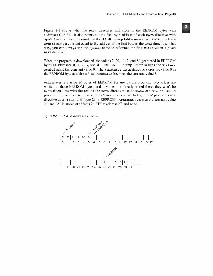
Chapter 2: EEPROM Tricks and Program Tips · Page 43
Figure 2-1 shows what the DATA directives will store in the EEPROM bytes with addresses 0 to 31. It also points out the first byte address of each DATA directive with Symbol names. Keep in mind that the BASIC Stamp Editor makes each DATA directive's Symbol name a constant equal to the address of the first byte in the DATA directive. That way, you can always use the Symbol name to reference the first DataItem in a given DATA directive. When the program is downloaded, the values 7, 20, 11, 2, and 80 get stored in EEPROM bytes at addresses 0, 1, 2, 3, and 4. The BASIC Stamp Editor assigns the Numbers Symbol name the constant value 0. The RunStatus DATA directive stores the value 0 in the EEPROM byte at address 5, so RunStatus becomes the constant value 5. UndefData sets aside 20 bytes of EEPROM for use by the program. No values are written to those EEPROM bytes, and if values are already stored there, they won't be overwritten. As with the rest of the DATA directives, UndefData can now be used in place of the number 6. Since UndefData reserves 20 bytes, the Alphabet DATA directive doesn't start until byte 26 in EEPROM. Alphabet becomes the constant value 26, and "A" is stored at address 26, "B" at address 27, and so on.
Figure 2-1 EEPROM Addresses 0 to 32
Page 44· Applied Robotics with the SumoBot
EEPROM stands for Electrically Erasable Reprogrammable Read Only Memory.
EEPROM memory is nonvolatile. That means, you can store a value in EEPROM, disconnect power, then reconnect power, and the values you stored will still be there.
Compile-time vs. Run-time - DATA directives are processed when the BASIC Stamp Editor compiles the program. In other words, DATA directives are processed at compile-time. The WRITE command can change the values in EEPROM while the program is running. That's why WRITE commands are said to be run-time commands.
Example Program - SymbolNamesVsAddressContents.bs2
This example program helps demonstrate the distinction between the DATA directive Symbol names in and the actual data that gets stored in EEPROM bytes.
√ Review SymbolNamesVsAddressContents.bs2, and predict what it's going to display before you run the program.
√ Enter, save, and run SymbolNamesVsAddressContents.bs2 √ Compare the output in the Debug Terminal to your predictions, and reconcile
any differences. ' Applied Robotics with the SumoBot - SymbolNamesVsAddressContents.bs2 ' $STAMP BS2 ' $PBASIC 2.5 Numbers DATA 7, 20, 11, 2, 80 RunStatus DATA 0 UndefData DATA (20) Alphabet DATA "ABCDEFG" temp VAR Word counter VAR Byte DEBUG "Address of Numbers..........", DEC Numbers, CR DEBUG "Value stored at Numbers....." READ Numbers, temp DEBUG DEC temp, CR DEBUG "Value at (Numbers + 1)....." READ Numbers + 1, temp DEBUG DEC temp, CR, CR DEBUG "Address of RunStatus........", DEC RunStatus, CR DEBUG "Value stored at RunStatus..."
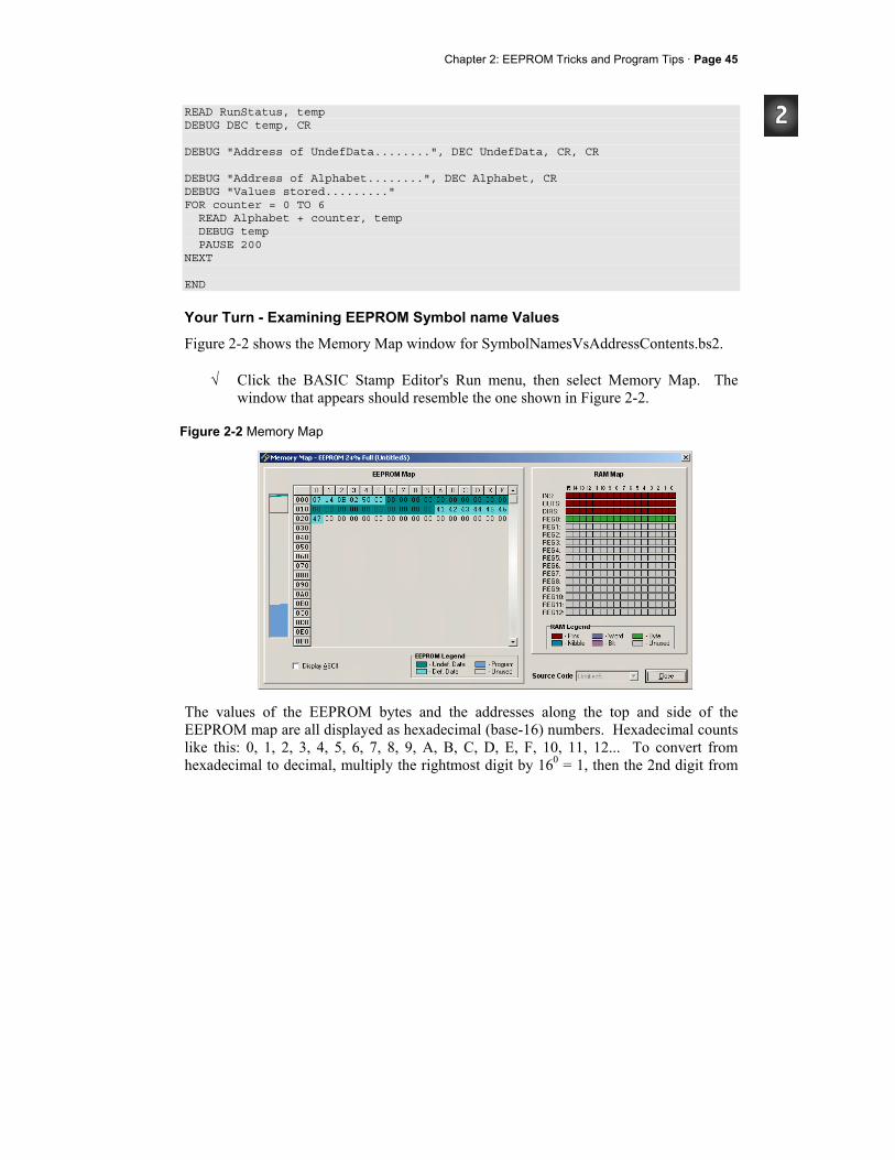
Chapter 2: EEPROM Tricks and Program Tips · Page 45
READ RunStatus, temp DEBUG DEC temp, CR DEBUG "Address of UndefData........", DEC UndefData, CR, CR DEBUG "Address of Alphabet........", DEC Alphabet, CR DEBUG "Values stored........." FOR counter = 0 TO 6 READ Alphabet + counter, temp DEBUG temp PAUSE 200 NEXT END
Your Turn - Examining EEPROM Symbol name Values
Figure 2-2 shows the Memory Map window for SymbolNamesVsAddressContents.bs2.
√ Click the BASIC Stamp Editor's Run menu, then select Memory Map. The window that appears should resemble the one shown in Figure 2-2.
Figure 2-2 Memory Map
The values of the EEPROM bytes and the addresses along the top and side of the EEPROM map are all displayed as hexadecimal (base-16) numbers. Hexadecimal counts like this: 0, 1, 2, 3, 4, 5, 6, 7, 8, 9, A, B, C, D, E, F, 10, 11, 12... To convert from hexadecimal to decimal, multiply the rightmost digit by 160 = 1, then the 2nd digit from
Page 46· Applied Robotics with the SumoBot
the right by 161 = 16, then the third digit from the right by 162 = 256, and so on. Add up all the products, and you've got your conversion. For example,
7C3 = (3 × 160) + (C × 161) + (7 × 162) place values = (3 × 1) + (C × 16) + (7 × 256) power expansion = (3 × 1) + (12 × 16) + (7 × 256) hex digit value = 3 + 192 + 1792 = 1987
The first five bytes in the EEPROM map are the hexadecimal equivalents of list of DataItems from the Numbers DATA directive: 7, 20, 11, 2, and 80. The fifth byte is 0 from the RunStatus DATA directive. Notice on your monitor that the next 20 bytes have a darker green color code corresponding to undefined data. These are the EEPROM bytes that were reserved by the UndefData DATA directive. The final list of digits starts at hexadecimal address 1A (decimal-26). These are the ASCII codes for "A", "B", "C", etc.
√ To view the list of characters in the last DATA directive, click the Display ASCII checkbox in the Memory map window.
√ Look for the ABCDEFG in the Memory Map. DATA directives build sequentially from EEPROM address 0 upward. However, you can use the optional @Address operator to specify a particular starting address for each DATA directive.
√ Use the optional @Address operator to move RunStatus to the 10th byte in EEPROM like this: RunStatus DATA @10, 0
√ View the Memory Map again and note the effect. √ Try the example program with this modification. Because of the way the
optional Symbol names are used, it should make no difference to the way the program behaves.
You can also use the Word modifier to store values larger than 255. The Word modifier stores the value in EEPROM as 2 bytes. It works with the DATA directive as well as the READ and WRITE commands.
Chapter 2: EEPROM Tricks and Program Tips · Page 47
√ Modify the RunStatus DATA directive like this: RunStatus DATA @10, Word 500
√ Modify the command that reads the EEPROM byte at the RunStatus address like this: READ RunStatus, Word temp
√ Test the program to make sure it can retrieve and display 500. √ Check the Memory Map and verify that the RunStatus DATA directive sets
aside 2 bytes instead of 1.
Changing EEPROM Values Between Resets
Let's take a closer look at how an EEPROM byte can be used to track the number of times the SumoBot's Reset button has been pressed and released. This technique can also be applied to counting the number of times the power to the BASIC Stamp has been turned off and back on. You can just as easily insert the READ and WRITE commands from the next example program into an IF...THEN statement and count sensor events.
EEPROM is not a replacement for RAM. EEPROM bytes can certainly be used to store values, count events, and so on. However, the EEPROM on the BASIC Stamp 2 is limited to 10-million rewrites. In contrast, variables, which reference values stored in the BASIC Stamp's RAM memory, do not have a limitation on the number of times you can rewrite the values they store.
If your BASIC Stamp modifies a single byte in EEPROM once a minute, that EEPROM byte will wear out in between 19 and 20 years. At once per second, the EEPROM byte will wear out in around 4 months.
This EepromCounter DATA directive from the next example program stores a 0 to an EEPROM byte when the program is downloaded. The Symbol name EepromCounter becomes a constant for the address of that byte.
EepromCounter DATA 0
A byte variable will be used to manipulate a copy of the EEPROM value. temp VAR Byte
The program can then use the READ command to fetch the value stored in the EEPROM byte whose address is EepromCounter, and copy it to the temp variable.
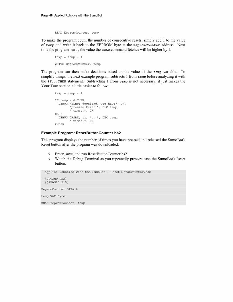
Page 48· Applied Robotics with the SumoBot
READ EepromCounter, temp
To make the program count the number of consecutive resets, simply add 1 to the value of temp and write it back to the EEPROM byte at the EepromCounter address. Next time the program starts, the value the READ command fetches will be higher by 1.
temp = temp + 1 WRITE EepromCounter, temp
The program can then make decisions based on the value of the temp variable. To simplify things, the next example program subtracts 1 from temp before analyzing it with the IF...THEN statement. Subtracting 1 from temp is not necessary, it just makes the Your Turn section a little easier to follow.
temp = temp - 1 IF temp = 0 THEN DEBUG "Since download, you have", CR, "pressed Reset ", DEC temp, " times.", CR ELSE DEBUG CRSRX, 11, "...", DEC temp, " times.", CR ENDIF
Example Program: ResetButtonCounter.bs2
This program displays the number of times you have pressed and released the SumoBot's Reset button after the program was downloaded.
√ Enter, save, and run ResetButtonCounter.bs2. √ Watch the Debug Terminal as you repeatedly press/release the SumoBot's Reset
button. ' Applied Robotics with the SumoBot - ResetButtonCounter.bs2 ' $STAMP BS2 ' $PBASIC 2.5 EepromCounter DATA 0 temp VAR Byte READ EepromCounter, temp
Chapter 2: EEPROM Tricks and Program Tips · Page 49
temp = temp + 1 WRITE EepromCounter, temp temp = temp - 1 IF temp = 0 THEN DEBUG "Since download, you have", CR, "pressed Reset ", DEC temp, " times.", CR ELSE DEBUG CRSRX, 11, "...", DEC temp, " times.", CR ENDIF END
Your Turn - Distinguishing Odd from Even
You can determine whether the Reset button has been pressed/released an odd or even number of times by examining the temp variable as a binary number. When a variable counts up in binary, the rightmost binary bit (1 or 0) changes every time. Here is an example:
Decimal Binary 0 %0000 1 %0001 2 %0010 3 %0011 4 %0100 5 %0101 6 %0110 7 %0111
Aside from the fact that it changes every time, notice that the rightmost bit is always 1 for odd numbers and 0 for even numbers. If you want your program to take action based on whether a value is odd or even, you'll need to access this rightmost binary bit and use it in IF...THEN statements. PBASIC has the .BIT (pronounced "dot-bit") operator for accessing the individual binary values in a variable. The rightmost binary value, is accessed with .BIT0. The second
Page 50· Applied Robotics with the SumoBot
binary value from the right is accessed with .BIT1; the third binary value is accessed with .BIT2, and so on. Here is an IF...THEN statement you can use to determine whether the value of temp is odd or even in ResetButtonCounter.bs2:
IF temp.BIT0 = 0 THEN DEBUG DEC temp, " is even.", CR ELSE DEBUG DEC temp, " is odd.", CR ENDIF
√ Save ResetButtonCounter as ResetButtonCounterYourTurn.bs2 √ Insert the odd/even IF...THEN statement just before the END command in the
program. √ Run the program, and verify that it correctly identifies each successive value of
temp as odd or even.
ACTIVITY #2: USING AND REUSING VARIABLES The next example program demonstrates how you can do many different tasks with three variables. It will prompt you to enter a threshold value, after which, it will prompt you to enter up to 20 more values. To enter your values, click the Transmit windowpane shown in Figure 2-3. Then type each value and press the enter key. When you are done entering values, press the 0 (zero) key, then press Enter. The program will then ask you if you want to compare the values to the threshold you entered. If you respond by pressing the "y" key, the program will display all the values you entered and compare them to the threshold value you entered.

Chapter 2: EEPROM Tricks and Program Tips · Page 51
Figure 2-3 Debug Terminal Transmit and Receive Windowpanes
Illustrating Many Jobs with a Few Variables
The temp and counter variables get used and re-used in the next example program. In later example programs they will be used and re-used by many different subroutines. The temp variable is first used in a DEBUGIN command to get a threshold variable from the Debug Terminal's Transmit windowpane.
' Get threshold value and store it in EEPROM DEBUG CLS, "Enter a threshold value", CR, "between 100 and 1000", CR, ">" DEBUGIN DEC temp WRITE Threshold, Word temp
Next, the temp variable is used to get successive values from the Debug Terminal and store each in EEPROM. This is also the first (but not the last) time in the program that the counter variable is used as a loop counter.
Transmit WindowpaneType each value here, then press Enter.
Receive Windowpane Prompts you to enter values and replies into the Transmit Windowpane.
Page 52· Applied Robotics with the SumoBot
DEBUG CR, "Enter up to 20 values", CR, "between 100 and 1000", CR, "Press 0 (zero) when done", CR, ">" counter = 0 DO UNTIL counter >= 40 OR temp = 0 DEBUGIN DEC temp WRITE Values + counter, Word temp counter = counter + 2 DEBUG ">" LOOP
The temp variable is then used to get a character from the Debug Terminal's Transmit windowpane and use it to make a decision.
' Display & compare values? (y/n) DEBUG CR, "Compare values to ", CR, "threshold? (y/n)", CR, ">" DEBUGIN temp ' Display and compare values IF temp = "y" OR temp = "Y" THEN
Finally, temp is used to store successive values that get fetched from EEPROM. In this case, counter is re-used as a loop counter, and a third variable, compare, is used to store the threshold value for comparison.
' Display and compare values IF temp = "y" OR temp = "Y" THEN DEBUG CR, " Threshold", CR, "Value Comparison", CR, "---------- ----------", CR counter = 0 READ Threshold, Word compare DO UNTIL counter >= 40 OR temp = 0 READ Values + counter, Word temp
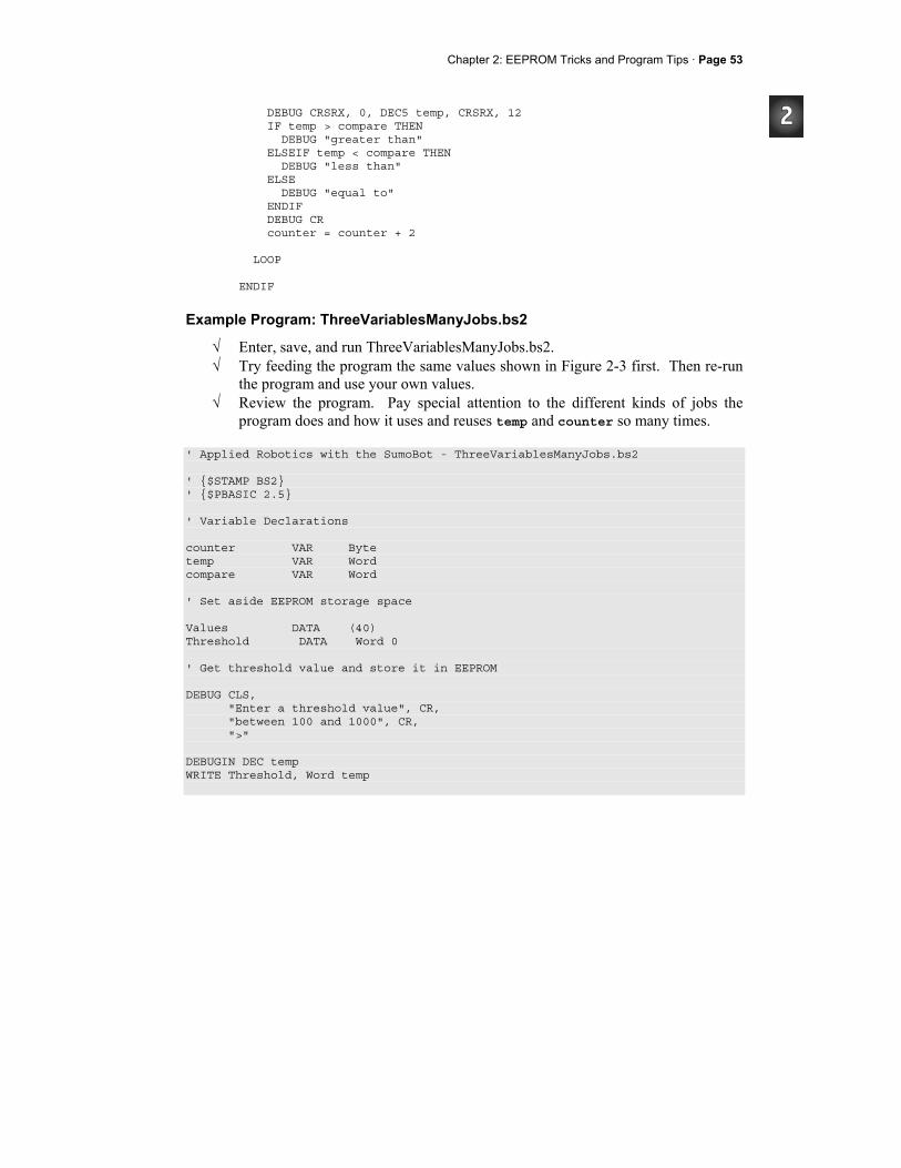
Chapter 2: EEPROM Tricks and Program Tips · Page 53
DEBUG CRSRX, 0, DEC5 temp, CRSRX, 12 IF temp > compare THEN DEBUG "greater than" ELSEIF temp < compare THEN DEBUG "less than" ELSE DEBUG "equal to" ENDIF DEBUG CR counter = counter + 2 LOOP ENDIF
Example Program: ThreeVariablesManyJobs.bs2
√ Enter, save, and run ThreeVariablesManyJobs.bs2. √ Try feeding the program the same values shown in Figure 2-3 first. Then re-run
the program and use your own values. √ Review the program. Pay special attention to the different kinds of jobs the
program does and how it uses and reuses temp and counter so many times. ' Applied Robotics with the SumoBot - ThreeVariablesManyJobs.bs2 ' $STAMP BS2 ' $PBASIC 2.5 ' Variable Declarations counter VAR Byte temp VAR Word compare VAR Word ' Set aside EEPROM storage space Values DATA (40) Threshold DATA Word 0 ' Get threshold value and store it in EEPROM DEBUG CLS, "Enter a threshold value", CR, "between 100 and 1000", CR, ">" DEBUGIN DEC temp WRITE Threshold, Word temp
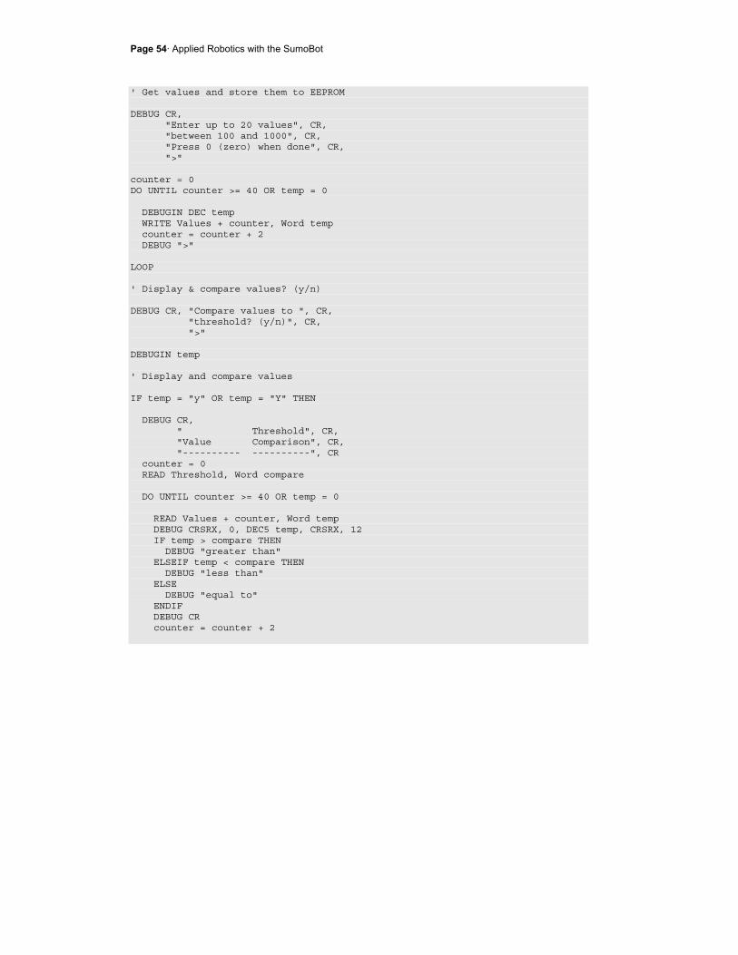
Page 54· Applied Robotics with the SumoBot
' Get values and store them to EEPROM DEBUG CR, "Enter up to 20 values", CR, "between 100 and 1000", CR, "Press 0 (zero) when done", CR, ">" counter = 0 DO UNTIL counter >= 40 OR temp = 0 DEBUGIN DEC temp WRITE Values + counter, Word temp counter = counter + 2 DEBUG ">" LOOP ' Display & compare values? (y/n) DEBUG CR, "Compare values to ", CR, "threshold? (y/n)", CR, ">" DEBUGIN temp ' Display and compare values IF temp = "y" OR temp = "Y" THEN DEBUG CR, " Threshold", CR, "Value Comparison", CR, "---------- ----------", CR counter = 0 READ Threshold, Word compare DO UNTIL counter >= 40 OR temp = 0 READ Values + counter, Word temp DEBUG CRSRX, 0, DEC5 temp, CRSRX, 12 IF temp > compare THEN DEBUG "greater than" ELSEIF temp < compare THEN DEBUG "less than" ELSE DEBUG "equal to" ENDIF DEBUG CR counter = counter + 2
Chapter 2: EEPROM Tricks and Program Tips · Page 55
LOOP ENDIF DEBUG CR, "All done!" END
ACTIVITY #3: PROGRAM ON/OFF WITH RESET It's really handy to be able to start and halt a sumo wrestling program by pressing and releasing the SumoBot's Reset button. This technique was first introduced in Chapter 3 of the SumoBot book. It makes it possible to press and release the Reset button to toggle between two separate program modes: wrestle, and wait for reset.
Reset Subroutine for the New Program Design
The new Reset subroutine will still depend on an EEPROM byte with the Symbol name RunStatus. This DATA directive will write 0 to the RunStatus address when the program is downloaded.
' -----[ EEPROM Data ]-------------------------------------------------------- RunStatus DATA 0 ' Run status EEPROM byte
The Reset routine from the SumoBot text was a code block in the program's Initialization section. The programs in this text will instead call a subroutine named Reset from the Initialization routine. ' -----[ Initialization ]----------------------------------------------------- GOSUB Reset ' Wait for Reset press/release GOSUB Start_Delay ' 5 Second delay ' -----[ Main Routine ]------------------------------------------------------- ResetTest: DEBUG CR, "Done!" ' Verify we made it to main. END
Here is the new Reset subroutine. It uses the odd/even number technique introduced in Activity #1 of this chapter. In this subroutine, if temp is odd (after 1 has been added to it), it displays the "Press/release Reset button" message, and then ends the program. If
Page 56· Applied Robotics with the SumoBot
temp is even, it displays "Program running..." and returns the program to initialization and onward from there. ' -----[ Subroutine - Reset ]------------------------------------------------- Reset: READ RunStatus, temp ' Byte @RunStatus -> temp temp = temp + 1 ' Increment temp WRITE RunStatus, temp ' Store new value for next time IF (temp.BIT0 = 1) THEN ' Examine temp.BIT0 DEBUG CLS, "Press/release Reset", CR, ' 1 -> end, 0 -> keep going "button..." END ELSE DEBUG CR, "Program running..." ENDIF RETURN
If the program has just been downloaded, the DATA directive causes a 0 to be written to the RunStatus address. Then, READ RunStatus, temp copies the value 0 from the EEPROM byte at the RunStatus address to the temp variable. temp = temp + 1 adds 1 to temp. The command WRITE RunStatus, temp stores this 1 back to the EEPROM byte at the RunStatus address. Since temp.BIT0 is 1, the subroutine displays the message "Press/release Reset button...". Then, the program ends, which in turn causes the BASIC Stamp goes into low power mode. At this point, there is a 1 in the EEPROM byte at the RunStatus address. When you press and release the Reset button, READ RunStatus, temp fetches that 1 and copies it to the temp variable. temp = temp + 1 changes that 1 to a 2, and WRITE RunStatus, temp writes that 2 back to EEPROM. The IF...THEN statement does not end the program this time. Since temp is now an even number, temp.BIT0 stores a 0. As a result, the IF...THEN statement instead displays the message "Program running...". After that, the RETURN statement sends the program back to the Initialization routine, where it calls the next subroutine, then moves on to the Main Routine. If you press/release the Reset button a third time, it starts again by fetching the 2 from the RunStatus EEPROM byte, adds 1 to make it 3, then stores it back to EEPROM, and ends the program with the "Press/release Reset button..." message. If you press/release the Reset button a fourth time, it fetches the 3, adds 1 to make it 4, stores it, and

Chapter 2: EEPROM Tricks and Program Tips · Page 57
continues to the rest of the program. As you keep pressing the Reset button, the odd/even pattern continues, as does the program's alternation between the "Press/release Reset..." and "Program running..." messages.
Example Program: TestResetButton.bs2
√ Enter, save, and download TestResetButton.bs2. √ Verify that it displays the "Press/release reset button..." message and ends the
program. √ Press/release the Reset button. Verify that the program displays the message
"Program running...", beeps 5 times, then displays the message "Done!". √ Press/release the Reset button a second time. √ Verify that the program behaves the same as it did when you first downloaded it. √ Press/release the Reset button a third time, and verify that it behaves the same
way it did the first time you did it. √ Keep repeating a few more times to make sure the odd/even pattern continues.
' -----[ Title ]-------------------------------------------------------------- ' Applied Robotics with the SumoBot - TestResetButton.bs2 ' $STAMP BS2 ' Target = BASIC Stamp 2 ' $PBASIC 2.5 ' Language = PBASIC 2.5 ' -----[ I/O Definitions ]--------------------------------------------------- LedSpeaker PIN 5 ' P5 controls LED & speaker ' -----[ Variables ]---------------------------------------------------------- temp VAR Word ' Temporary variable counter VAR Byte ' Loop counting variable. ' -----[ EEPROM Data ]-------------------------------------------------------- RunStatus DATA 0 ' Run status EEPROM byte ' -----[ Initialization ]----------------------------------------------------- GOSUB Reset ' Wait for Reset press/release GOSUB Start_Delay ' 5 Second delay ' -----[ Main Routine ]------------------------------------------------------- ResetTest: DEBUG CR, "Done!" ' Verify we made it to main.
Page 58· Applied Robotics with the SumoBot
END ' -----[ Subroutine - Reset ]------------------------------------------------- Reset: READ RunStatus, temp ' Byte @RunStatus -> temp temp = temp + 1 ' Increment temp WRITE RunStatus, temp ' Store new value for next time IF (temp.BIT0 = 1) THEN ' Examine temp.BIT0 DEBUG CLS, "Press/release Reset", CR, ' 1 -> end, 0 -> keep going "button..." END ELSE DEBUG CR, "Program running..." ENDIF RETURN ' -----[ Subroutine - Start_Delay ]------------------------------------------- Start_Delay: FOR counter = 1 TO 5 ' 5 beeps, 1/second PAUSE 900 FREQOUT LedSpeaker, 100, 3000 NEXT RETURN
Your Turn
√ Try modifying the program so that it displays the number of times you have pressed and released the Reset button.
ACTIVITY #4: PUSHBUTTON, LED, AND SPEAKER The LED and speaker can be used as status indicators. Primarily, the beeping and LED blinking helps you know when the SumoBot is doing its 5 second countdown. These indicators are also useful for trouble-shooting SumoBot behavior problems. The single pushbutton can be used along with the indicators to adjust the SumoBot's behavior between sumo rounds and even select between different operation modes.
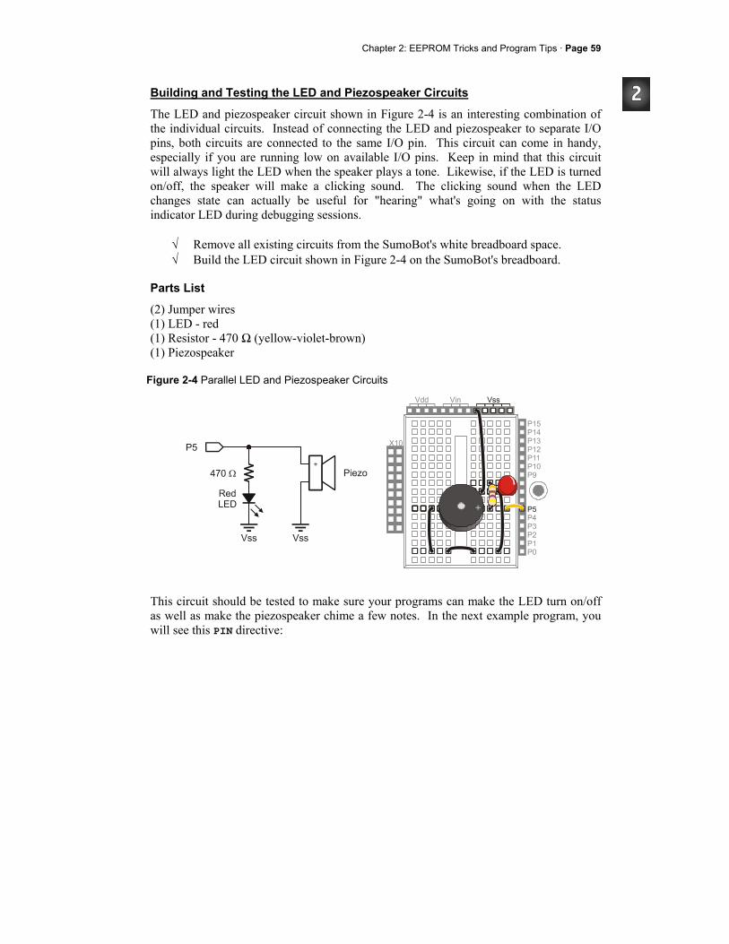
Chapter 2: EEPROM Tricks and Program Tips · Page 59
Building and Testing the LED and Piezospeaker Circuits
The LED and piezospeaker circuit shown in Figure 2-4 is an interesting combination of the individual circuits. Instead of connecting the LED and piezospeaker to separate I/O pins, both circuits are connected to the same I/O pin. This circuit can come in handy, especially if you are running low on available I/O pins. Keep in mind that this circuit will always light the LED when the speaker plays a tone. Likewise, if the LED is turned on/off, the speaker will make a clicking sound. The clicking sound when the LED changes state can actually be useful for "hearing" what's going on with the status indicator LED during debugging sessions.
√ Remove all existing circuits from the SumoBot's white breadboard space. √ Build the LED circuit shown in Figure 2-4 on the SumoBot's breadboard.
Parts List
(2) Jumper wires (1) LED - red (1) Resistor - 470 Ω (yellow-violet-brown) (1) Piezospeaker
Figure 2-4 Parallel LED and Piezospeaker Circuits
This circuit should be tested to make sure your programs can make the LED turn on/off as well as make the piezospeaker chime a few notes. In the next example program, you will see this PIN directive:
Page 60· Applied Robotics with the SumoBot
LedSpeaker PIN 5
After declaring this PIN directive, the name LedSpeaker can be used as either an input or an output. The BASIC Stamp Editor examines each command with LedSpeaker as an argument and decides whether to send an output to the pin or store the input value sensed by the pin. When used in the PIN argument of commands like HIGH, LOW, TOGGLE, or FREQOUT, the BASIC Stamp Editor treats the I/O pin as an output.
Example Program: TestLedSpeaker.bs2
√ Enter, save, and run TestLedSpeaker.bs2. √ Verify that it makes the LED rapidly turn on/off several times. √ The piezospeaker should then play a brief tone. √ If either of the components do not behave as expected, check your circuit and
program for errors.
Remember Each time the LED changes state, the speaker will make a clicking noise, and each time the speaker plays, the LED will turn on.
If the LED doesn't turn on, remember from What's a Microcontroller and Robotics with the Boe-Bot that the LED is a 1-way current valve. The LED's shorter cathode lead should be connected to Vss; otherwise current will not flow through it.
' -----[ Title ]-------------------------------------------------------------- ' Applied Robotics with the SumoBot - TestLedSpeaker.bs2 ' Tests the LED and piezospeaker circuit connected to P5 by flashing ' the LED on/off 15 times, then playing a tone on the speaker. ' $STAMP BS2 ' Target = BASIC Stamp 2 ' $PBASIC 2.5 ' Language = PBASIC 2.5 ' -----[ I/O Definitions ]--------------------------------------------------- LedSpeaker PIN 5 ' LED/speaker connected to P5 ' -----[ Variables ]---------------------------------------------------------- counter VAR Byte ' Loop counting variable ' -----[ Initialization ]----------------------------------------------------- DEBUG CLS, "LED flashing..." ' Prompt to check LED ' -----[ Main Routine ]-------------------------------------------------------

Chapter 2: EEPROM Tricks and Program Tips · Page 61
FOR counter = 1 TO 30 ' Flash LED on/off 15 times TOGGLE LedSpeaker PAUSE 250 NEXT DEBUG CR, "Speaker playing tone" ' Prompt to listen for tone FREQOUT LedSpeaker, 2000, 3000 ' Play 3 kHz tone for 2 seconds DEBUG CR, "All done." ' Prompt user - program finished END
Your Turn - Playing Musical Notes
The LOOKUP command can be handy for storing brief sequences of musical notes.
√ Save a copy of the program as TestLedSpeakerYourTurn.bs2. √ Add the variable declaration note VAR Word. √ Replace the single FREQOUT command in TestLedSpeaker.bs2 with this
FOR...NEXT loop. FOR counter = 0 TO 7 LOOKUP counter, [1046, 1175, 1319, 1397, 1580, 1760, 1976, 2093], note FREQOUT 5, 500, note PAUSE 25 NEXT
√ Run the program and listen to the results. √ Save the modified program.
Building and Testing the Pushbutton Circuit
Figure 2-5 shows the pushbutton circuit connected to P6. When the pushbutton is not pressed, P6 senses ground through the 470 Ω and 10 kΩ resistors, and stores a 0 in its IN6 input register. If the pushbutton is pressed, P6 senses the direct connection to Vdd, and stores a 1 in IN6.
√ Build the circuit shown in Figure 2-5.
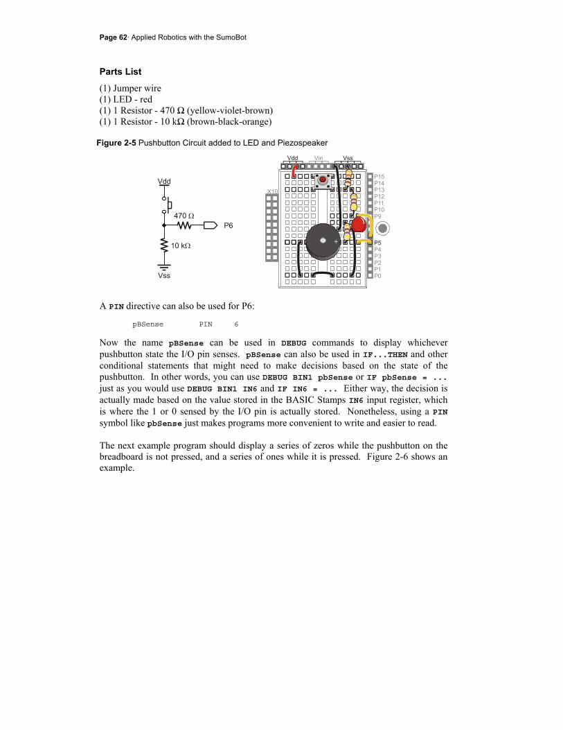
Page 62· Applied Robotics with the SumoBot
Parts List
(1) Jumper wire (1) LED - red (1) 1 Resistor - 470 Ω (yellow-violet-brown) (1) 1 Resistor - 10 kΩ (brown-black-orange)
Figure 2-5 Pushbutton Circuit added to LED and Piezospeaker
A PIN directive can also be used for P6:
pBSense PIN 6
Now the name pBSense can be used in DEBUG commands to display whichever pushbutton state the I/O pin senses. pBSense can also be used in IF...THEN and other conditional statements that might need to make decisions based on the state of the pushbutton. In other words, you can use DEBUG BIN1 pbSense or IF pbSense = ... just as you would use DEBUG BIN1 IN6 and IF IN6 = ... Either way, the decision is actually made based on the value stored in the BASIC Stamps IN6 input register, which is where the 1 or 0 sensed by the I/O pin is actually stored. Nonetheless, using a PIN symbol like pbSense just makes programs more convenient to write and easier to read. The next example program should display a series of zeros while the pushbutton on the breadboard is not pressed, and a series of ones while it is pressed. Figure 2-6 shows an example.
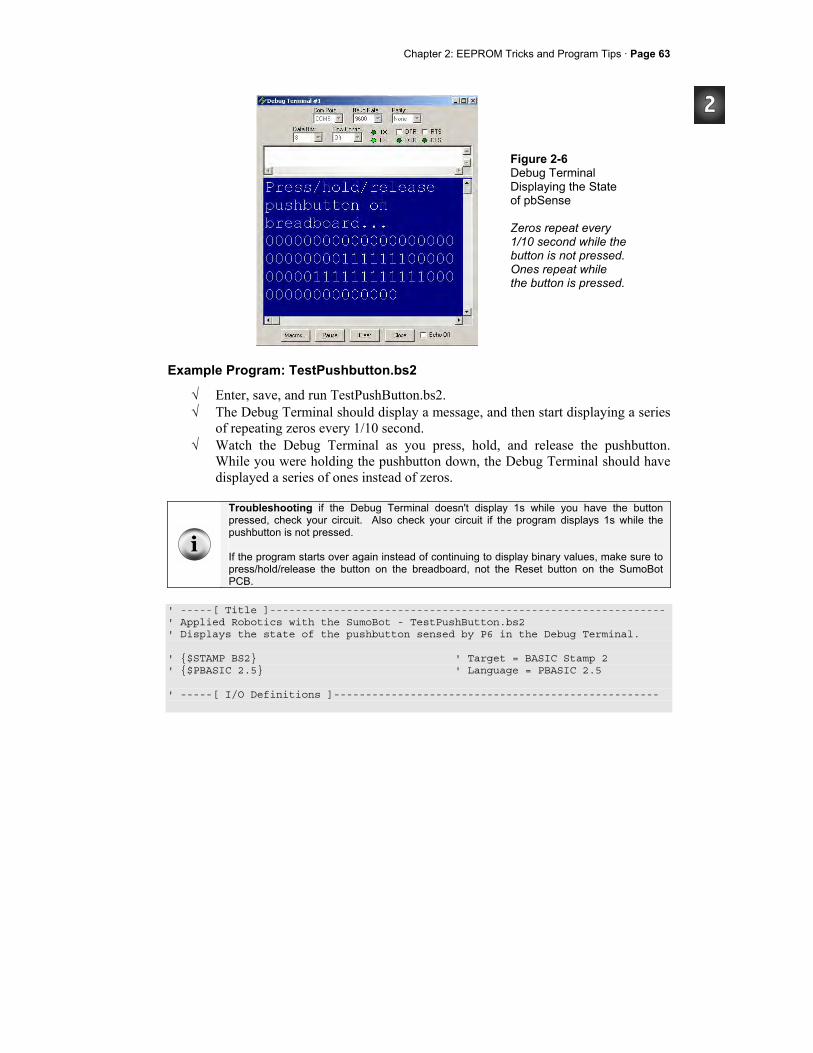
Chapter 2: EEPROM Tricks and Program Tips · Page 63
Figure 2-6 Debug Terminal Displaying the State of pbSense Zeros repeat every 1/10 second while the button is not pressed. Ones repeat while the button is pressed.
Example Program: TestPushbutton.bs2
√ Enter, save, and run TestPushButton.bs2. √ The Debug Terminal should display a message, and then start displaying a series
of repeating zeros every 1/10 second. √ Watch the Debug Terminal as you press, hold, and release the pushbutton.
While you were holding the pushbutton down, the Debug Terminal should have displayed a series of ones instead of zeros.
Troubleshooting if the Debug Terminal doesn't display 1s while you have the button pressed, check your circuit. Also check your circuit if the program displays 1s while the pushbutton is not pressed. If the program starts over again instead of continuing to display binary values, make sure to press/hold/release the button on the breadboard, not the Reset button on the SumoBot PCB.
' -----[ Title ]-------------------------------------------------------------- ' Applied Robotics with the SumoBot - TestPushButton.bs2 ' Displays the state of the pushbutton sensed by P6 in the Debug Terminal. ' $STAMP BS2 ' Target = BASIC Stamp 2 ' $PBASIC 2.5 ' Language = PBASIC 2.5 ' -----[ I/O Definitions ]---------------------------------------------------
Page 64· Applied Robotics with the SumoBot
pbSense PIN 6 ' Pushbutton connected to P6 ' -----[ Initialization ]----------------------------------------------------- DEBUG CLS, "Press/hold/release" , CR, ' PROMPT press/release pushbutton "pushbutton on", CR, "breadboard...", CR ' -----[ Main Routine ]------------------------------------------------------- DO ' DO...LOOP repeats indefinitely DEBUG BIN1 pbSense ' Display state of pbSense (IN6) PAUSE 100 ' Delay for slower PCs LOOP
Your Turn - Controlling the LED with the Pushbutton
After adding the LedSpeaker PIN directive to this program, you can make the LED flash on/off while you hold down the pushbutton. All it takes in an IF...THEN added to the DO...LOOP in the main routine.
√ Save a copy of the program as TestPushButtonYourTurn.bs2. √ Add the PIN directive LedSpeaker PIN 5. √ Replace the DO...LOOP in the Main Routine with this one:
DO ' DO...LOOP repeats indefinitely DEBUG BIN1 pbSense ' Display state of pbSense (IN6) IF pbSense = 1 THEN ' Flash LED if pbSense = 1 TOGGLE LedSpeaker ELSE LOW LedSpeaker ' Otherwise, keep pin low ENDIF PAUSE 100 ' Delay for slower PCs LOOP
√ Run the program and verify that you now have pushbutton control of the LED. √ Save the modified program. √ For fun, try modifying the program so that it plays a list of notes when you
press/release the button.
Chapter 2: EEPROM Tricks and Program Tips · Page 65
ACTIVITY #5: PUSHBUTTON PROGRAM MODE SELECTION In some competitions, changing strategy between sumo rounds could make a big difference in your SumoBot's standing. This activity introduces a simple technique you can use to select the SumoBot's mode of operation based on cues from the speaker.
Selecting the Mode
In the next example program, you can enter a mode selection by pressing and holding the pushbutton while you press and release the Reset button. After releasing the Reset button, the program will beep once, then twice, then three times, and so on up to five times. To select mode one, let go of the pushbutton after the speaker has beeped once. To select mode two, keep holding the pushbutton, and instead let go after the speaker has beeped twice. For mode three, wait for three beeps before letting go, and so on. This program uses an EEPROM byte with a different Symbol name - ModeSelect. This is another value that is initialized to zero when the program is downloaded, but WRITE commands will change this value during run-time.
' -----[ EEPROM Data ]------------------------------------------------- ModeSelect DATA 0 ' Program select byte
This IF...THEN statement in the Initialization routine checks to see if the pushbutton is pressed. If it is, the Mode_Select subroutine gets called. Otherwise, the program just moves on to the next command.
' -----[ Initialization ]---------------------------------------------- IF pbSense = 1 THEN GOSUB Mode_Select ' Call Mode_Select subroutine
The Mode_Select subroutine uses a pair of nested FOR...NEXT loops. The outer loop uses the temp variable to count from 1 to 5. The inner loop counts from 1 to temp. The first time through the outer loop, temp is 1, so the inner loop beeps the speaker once. The inner loop is followed by a 1-second PAUSE, after which, an IF...THEN statement checks the pushbutton. If the pushbutton has been released, the IF...THEN statement writes the value 1 stored by temp to the ModeSelect EEPROM byte and exits the outer loop. If the pushbutton has not yet been released, the outer loop repeats. The second time through the FOR...NEXT loop, temp will be 2. So, the inner loop beeps twice. After another 1 second PAUSE, the outer loop again checks the pushbutton. If the pushbutton

Page 66· Applied Robotics with the SumoBot
has still not been released, the outer loop repeats again, the inner loop beeps three times, and so on.
' -----[ Subroutine - Mode_Select ]------------------------------------ ' Selects mode of operation Mode_Select: DEBUG CR, ' Display user instructions CR, "Release pushbutton after", CR, "number of beeps to select", CR, "mode (1 to 5)." FOR temp = 1 TO 5 ' Cycle 5 times FOR counter = 1 TO temp ' temp beeps, 1/second PAUSE 100 FREQOUT LedSpeaker, 100, 4000 NEXT PAUSE 1000 ' 1 second between beeps IF pbSense = 0 THEN ' Button released? WRITE ModeSelect, temp ' Record mode to EEPROM EXIT ' Exit FOR...NEXT loop ENDIF NEXT RETURN
The Main Routine checks to find out which mode was selected with the command READ ModeSelect, temp. An IF...THEN statement checks to see if the mode argument is zero, which indicates that a mode was not selected. In this case, more instructions are displayed in the Debug Terminal. The ELSE condition features a DEBUG command and SELECT...CASE code block that displays the mode.
' -----[ Main Routine ]------------------------------------------------ ModeTest: READ ModeSelect, temp ' Fetch mode from EEPROM IF temp = 0 THEN ' Mode = 0 -> no mode selected DEBUG CR, "No mode selected", CR, "Hold down pushbutton", CR, "then press/release", CR, "Reset button." ELSE ' mode <> 0 -> display mode DEBUG CR, CR, "Operating in mode ", CR ' Mode Message SELECT temp ' Select mode value to display
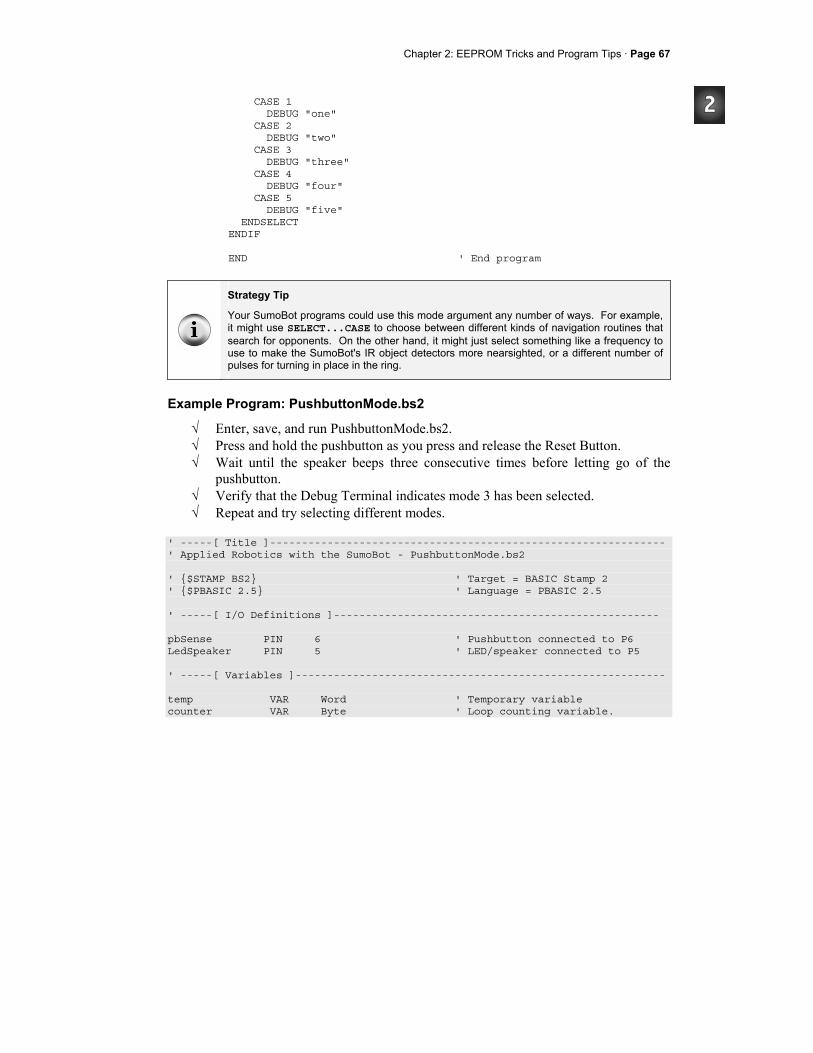
Chapter 2: EEPROM Tricks and Program Tips · Page 67
CASE 1 DEBUG "one" CASE 2 DEBUG "two" CASE 3 DEBUG "three" CASE 4 DEBUG "four" CASE 5 DEBUG "five" ENDSELECT ENDIF END ' End program
Strategy Tip
Your SumoBot programs could use this mode argument any number of ways. For example, it might use SELECT...CASE to choose between different kinds of navigation routines that search for opponents. On the other hand, it might just select something like a frequency to use to make the SumoBot's IR object detectors more nearsighted, or a different number of pulses for turning in place in the ring.
Example Program: PushbuttonMode.bs2
√ Enter, save, and run PushbuttonMode.bs2. √ Press and hold the pushbutton as you press and release the Reset Button. √ Wait until the speaker beeps three consecutive times before letting go of the
pushbutton. √ Verify that the Debug Terminal indicates mode 3 has been selected. √ Repeat and try selecting different modes.
' -----[ Title ]-------------------------------------------------------------- ' Applied Robotics with the SumoBot - PushbuttonMode.bs2 ' $STAMP BS2 ' Target = BASIC Stamp 2 ' $PBASIC 2.5 ' Language = PBASIC 2.5 ' -----[ I/O Definitions ]--------------------------------------------------- pbSense PIN 6 ' Pushbutton connected to P6 LedSpeaker PIN 5 ' LED/speaker connected to P5 ' -----[ Variables ]---------------------------------------------------------- temp VAR Word ' Temporary variable counter VAR Byte ' Loop counting variable.
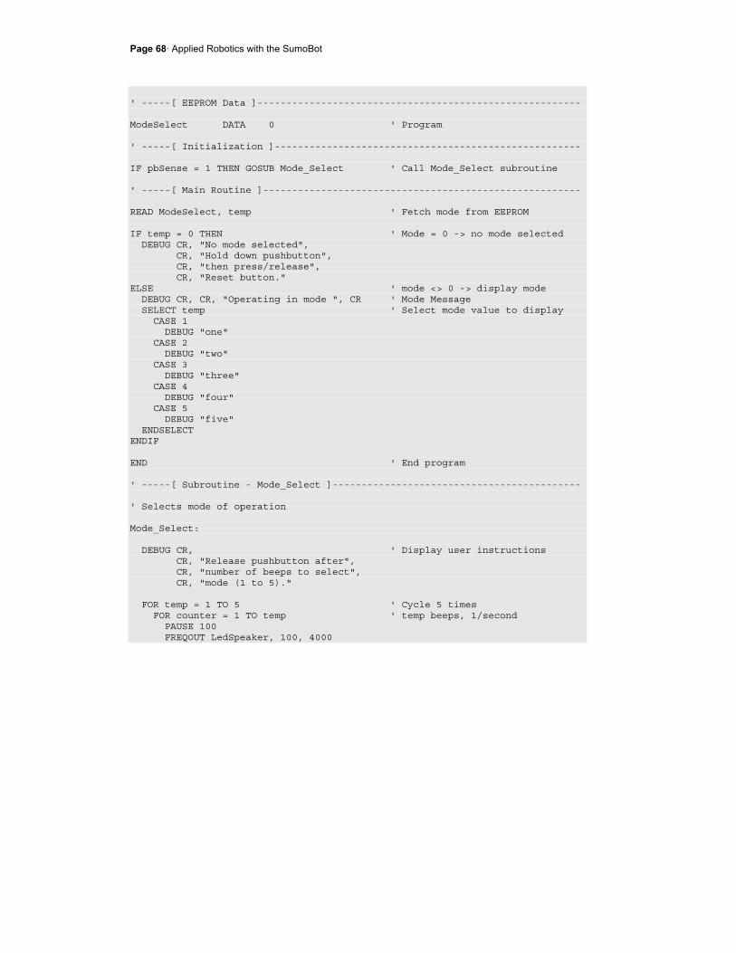
Page 68· Applied Robotics with the SumoBot
' -----[ EEPROM Data ]-------------------------------------------------------- ModeSelect DATA 0 ' Program ' -----[ Initialization ]----------------------------------------------------- IF pbSense = 1 THEN GOSUB Mode_Select ' Call Mode_Select subroutine ' -----[ Main Routine ]------------------------------------------------------- READ ModeSelect, temp ' Fetch mode from EEPROM IF temp = 0 THEN ' Mode = 0 -> no mode selected DEBUG CR, "No mode selected", CR, "Hold down pushbutton", CR, "then press/release", CR, "Reset button." ELSE ' mode <> 0 -> display mode DEBUG CR, CR, "Operating in mode ", CR ' Mode Message SELECT temp ' Select mode value to display CASE 1 DEBUG "one" CASE 2 DEBUG "two" CASE 3 DEBUG "three" CASE 4 DEBUG "four" CASE 5 DEBUG "five" ENDSELECT ENDIF END ' End program ' -----[ Subroutine - Mode_Select ]------------------------------------------- ' Selects mode of operation Mode_Select: DEBUG CR, ' Display user instructions CR, "Release pushbutton after", CR, "number of beeps to select", CR, "mode (1 to 5)." FOR temp = 1 TO 5 ' Cycle 5 times FOR counter = 1 TO temp ' temp beeps, 1/second PAUSE 100 FREQOUT LedSpeaker, 100, 4000
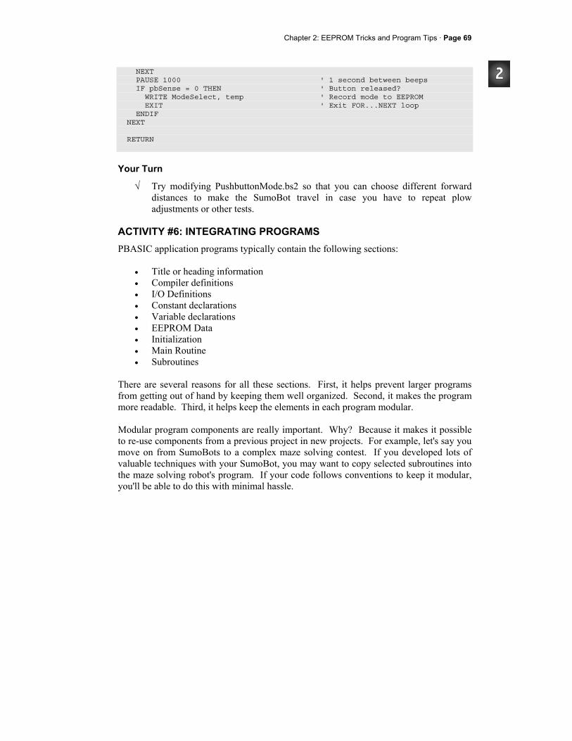
Chapter 2: EEPROM Tricks and Program Tips · Page 69
NEXT PAUSE 1000 ' 1 second between beeps IF pbSense = 0 THEN ' Button released? WRITE ModeSelect, temp ' Record mode to EEPROM EXIT ' Exit FOR...NEXT loop ENDIF NEXT RETURN
Your Turn
√ Try modifying PushbuttonMode.bs2 so that you can choose different forward distances to make the SumoBot travel in case you have to repeat plow adjustments or other tests.
ACTIVITY #6: INTEGRATING PROGRAMS PBASIC application programs typically contain the following sections:
• Title or heading information • Compiler definitions • I/O Definitions • Constant declarations • Variable declarations • EEPROM Data • Initialization • Main Routine • Subroutines
There are several reasons for all these sections. First, it helps prevent larger programs from getting out of hand by keeping them well organized. Second, it makes the program more readable. Third, it helps keep the elements in each program modular. Modular program components are really important. Why? Because it makes it possible to re-use components from a previous project in new projects. For example, let's say you move on from SumoBots to a complex maze solving contest. If you developed lots of valuable techniques with your SumoBot, you may want to copy selected subroutines into the maze solving robot's program. If your code follows conventions to keep it modular, you'll be able to do this with minimal hassle.
Page 70· Applied Robotics with the SumoBot
One of the most important ingredients of modular programs is keeping the same naming conventions for variables. For example, in this book, temp is a temporary variable that is used to receive and manipulate stored information and sensor measurements. After decisions are made based on temp in one subroutine, temp is always free to be used in the next subroutine. The same applies to the counter variable. When it's done counting in a loop in one subroutine, it is free to count in a different loop in the next subroutine. In this activity, you will combine two programs that were developed in this chapter: TestResetButton.bs2 from Activity #3, and PushbuttonMode.bs2 from Activity #5. Because both programs follow the same rules for sectioning and temporary variable use, they will be really easy to combine. Both of these programs have clearly defined sections (I/O Definitions, Variables, EEPROM Data, Subroutines and so on). Both programs also follow the same naming conventions for reusable variables like temp and counter. As you will see, these are two key ingredients for making all of your test and application programs building blocks for future programs.
Combining the Reset and Pushbutton Mode Programs
The first step to combining TestResetButton.bs2 and PushbuttonMode.bs2 is to save a copy of one of the programs. We'll start by saving TestResetButton.bs2 as ResetAndStartMode.bs2. Then, we'll copy the elements from PushbuttonMode.bs2 that were not already in TestResetButton.bs2. For example, TestResetButton.bs2 already had the LedSpeaker PIN directive, but not the pbSense PIN directive. So, the pbSense PIN directive will be copied from PushbuttonMode.bs2 to the new ResetAndStartMode.bs2. After repeating this process for each section (Variables, EEPROM Data, Initialization, etc), we'll have a complete program that performs both the reset-start function and the mode-select function.
√ Open TestResetButton.bs2 and save it as ResetStartAndMode.bs2 √ Open PushbuttonMode.bs2. √ Copy the pbSense PIN directive from the I/O definitions section in
PushbuttonMode.bs2, and paste it into the I/O definitions section in ResetAndStartMode.bs2.
√ Copy the ModeSelect DATA directive from the EEPROM Data section in PushbuttonMode.bs2, and paste it to the EEPROM Data section in ResetAndStartMode.bs2.
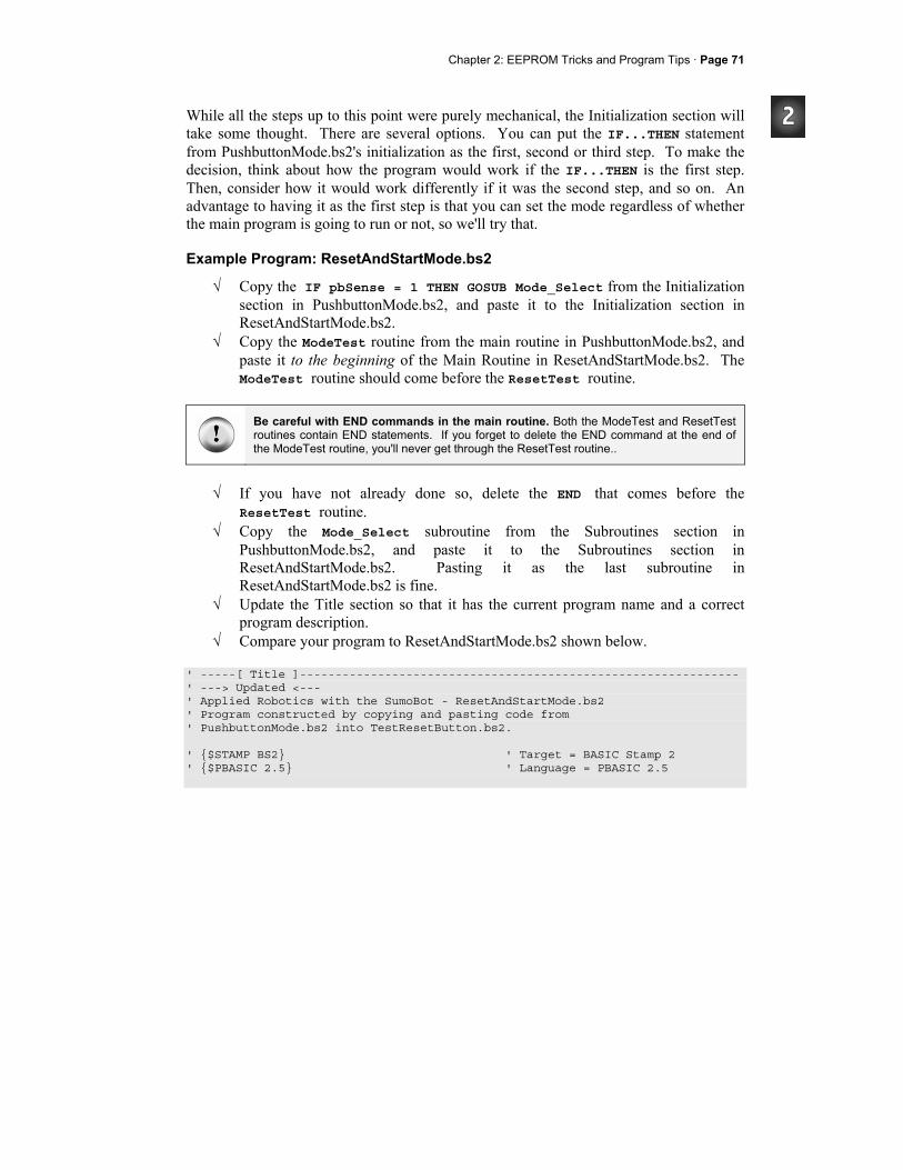
Chapter 2: EEPROM Tricks and Program Tips · Page 71
While all the steps up to this point were purely mechanical, the Initialization section will take some thought. There are several options. You can put the IF...THEN statement from PushbuttonMode.bs2's initialization as the first, second or third step. To make the decision, think about how the program would work if the IF...THEN is the first step. Then, consider how it would work differently if it was the second step, and so on. An advantage to having it as the first step is that you can set the mode regardless of whether the main program is going to run or not, so we'll try that.
Example Program: ResetAndStartMode.bs2
√ Copy the IF pbSense = 1 THEN GOSUB Mode_Select from the Initialization section in PushbuttonMode.bs2, and paste it to the Initialization section in ResetAndStartMode.bs2.
√ Copy the ModeTest routine from the main routine in PushbuttonMode.bs2, and paste it to the beginning of the Main Routine in ResetAndStartMode.bs2. The ModeTest routine should come before the ResetTest routine.
Be careful with END commands in the main routine. Both the ModeTest and ResetTest routines contain END statements. If you forget to delete the END command at the end of the ModeTest routine, you'll never get through the ResetTest routine..
√ If you have not already done so, delete the END that comes before the
ResetTest routine. √ Copy the Mode_Select subroutine from the Subroutines section in
PushbuttonMode.bs2, and paste it to the Subroutines section in ResetAndStartMode.bs2. Pasting it as the last subroutine in ResetAndStartMode.bs2 is fine.
√ Update the Title section so that it has the current program name and a correct program description.
√ Compare your program to ResetAndStartMode.bs2 shown below. ' -----[ Title ]-------------------------------------------------------------- ' ---> Updated <--- ' Applied Robotics with the SumoBot - ResetAndStartMode.bs2 ' Program constructed by copying and pasting code from ' PushbuttonMode.bs2 into TestResetButton.bs2. ' $STAMP BS2 ' Target = BASIC Stamp 2 ' $PBASIC 2.5 ' Language = PBASIC 2.5
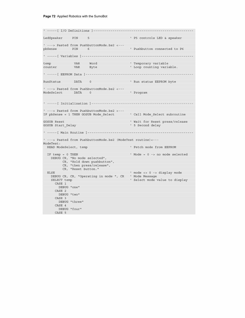
Page 72· Applied Robotics with the SumoBot
' -----[ I/O Definitions ]---------------------------------------------------- LedSpeaker PIN 5 ' P5 controls LED & speaker ' ---> Pasted from PushbuttonMode.bs2 <--- pbSense PIN 6 ' Pushbutton connected to P6 ' -----[ Variables ]---------------------------------------------------------- temp VAR Word ' Temporary variable counter VAR Byte ' Loop counting variable. ' -----[ EEPROM Data ]-------------------------------------------------------- RunStatus DATA 0 ' Run status EEPROM byte ' ---> Pasted from PushbuttonMode.bs2 <--- ModeSelect DATA 0 ' Program ' -----[ Initialization ]----------------------------------------------------- ' ---> Pasted from PushbuttonMode.bs2 <--- IF pbSense = 1 THEN GOSUB Mode_Select ' Call Mode_Select subroutine GOSUB Reset ' Wait for Reset press/release GOSUB Start_Delay ' 5 Second delay ' -----[ Main Routine ]------------------------------------------------------- ' ---> Pasted from PushbuttonMode.bs2 (ModeTest routine)<--- ModeTest: READ ModeSelect, temp ' Fetch mode from EEPROM IF temp = 0 THEN ' Mode = 0 -> no mode selected DEBUG CR, "No mode selected", CR, "Hold down pushbutton", CR, "then press/release", CR, "Reset button." ELSE ' mode <> 0 -> display mode DEBUG CR, CR, "Operating in mode ", CR ' Mode Message SELECT temp ' Select mode value to display CASE 1 DEBUG "one" CASE 2 DEBUG "two" CASE 3 DEBUG "three" CASE 4 DEBUG "four" CASE 5
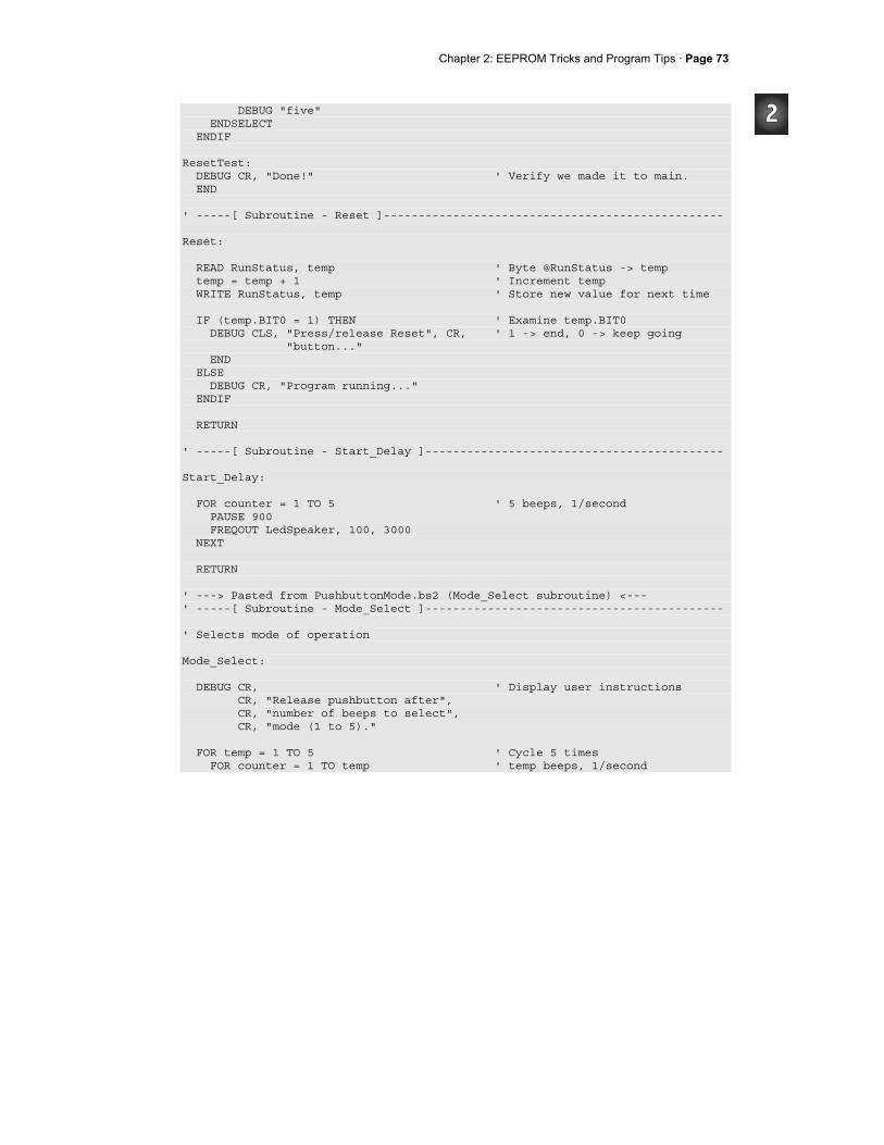
Chapter 2: EEPROM Tricks and Program Tips · Page 73
DEBUG "five" ENDSELECT ENDIF ResetTest: DEBUG CR, "Done!" ' Verify we made it to main. END ' -----[ Subroutine - Reset ]------------------------------------------------- Reset: READ RunStatus, temp ' Byte @RunStatus -> temp temp = temp + 1 ' Increment temp WRITE RunStatus, temp ' Store new value for next time IF (temp.BIT0 = 1) THEN ' Examine temp.BIT0 DEBUG CLS, "Press/release Reset", CR, ' 1 -> end, 0 -> keep going "button..." END ELSE DEBUG CR, "Program running..." ENDIF RETURN ' -----[ Subroutine - Start_Delay ]------------------------------------------- Start_Delay: FOR counter = 1 TO 5 ' 5 beeps, 1/second PAUSE 900 FREQOUT LedSpeaker, 100, 3000 NEXT RETURN ' ---> Pasted from PushbuttonMode.bs2 (Mode_Select subroutine) <--- ' -----[ Subroutine - Mode_Select ]------------------------------------------- ' Selects mode of operation Mode_Select: DEBUG CR, ' Display user instructions CR, "Release pushbutton after", CR, "number of beeps to select", CR, "mode (1 to 5)." FOR temp = 1 TO 5 ' Cycle 5 times FOR counter = 1 TO temp ' temp beeps, 1/second

Page 74· Applied Robotics with the SumoBot
PAUSE 100 FREQOUT LedSpeaker, 100, 4000 NEXT PAUSE 1000 ' 1 second between beeps IF pbSense = 0 THEN ' Button released? WRITE ModeSelect, temp ' Record mode to EEPROM EXIT ' Exit FOR...NEXT loop ENDIF NEXT RETURN
Your Turn - Testing the New Program
There should be two ways to set the program mode. The first is to hold down the pushbutton as you download the program. The other is to hold the pushbutton down as you press and release the Reset button. Since EEPROM memory is used to store the mode, it's nonvolatile, meaning that disconnecting power or pressing and releasing Reset cannot erase the value. You can also change the mode value by simply holding down the pushbutton as you press and release Reset again.
√ Hold down the pushbutton (not the Reset button!) as you download ResetAndStartMode.bs2 to your SumoBot.
√ Keep holding the button down until the SumoBot makes three consecutive beeps, then let go.
√ Press and release the Reset button. √ Verify that the SumoBot is operating in mode three. √ Don't hold the pushbutton down as you press and release the Reset button a few
more times to verify that the SumoBot retains the mode three setting. √ Press and hold the pushbutton, then press/release the Reset button. √ Keep holding the pushbutton until after four consecutive beeps, then let go. √ Press and release the Reset button again, and verify that the SumoBot has now
retained mode four. √ Download the program one more time, and verify that the mode setting has been
erased (because the ModeSelect DATA directive writes a 0 to ModeSelect. √ Try also changing ModeSelect DATA 0 to just ModeSelect DATA. That way,
the program won't overwrite the mode you chose whenever you download it. You pretty much always have the choice of making the DATA directive pre-store values in EEPROM, or just having them reserve the space.

Chapter 2: EEPROM Tricks and Program Tips · Page 75
SUMMARY This chapter introduced a variety of EEPROM and program management techniques. EEPROM management focused on declaring and naming DATA directives for all EEPROM bytes and groups of bytes used in the program. Techniques for counting resets were introduced for both toggling between different SumoBot program modes and for selecting from a list of program modes. Programming focused on adhering to code conventions for the sake of making large programs easy to build from smaller programs in your library. A DATA directive is a compile-time command that pre-stores values to EEPROM when the program is downloaded. DATA directives can also be used to organize the portion of EEPROM used for storing values. An optional Symbol name preceding the DATA keyword can be used to give a meaningful name to the starting address of each group of bytes. Since this Symbol name represents an address in EEPROM it simplifies READ and WRITE operations in programs that maintain more than one group of EEPROM DataItems. A procedure was introduced for merging components of smaller programs into larger programs. It depended on keeping programs organized in common sections: Title, Compiler Directives, I/O Definitions, Constants, Variables, EEPROM Data, Initialization, Main Routine, and Subroutines. It also depended on using a common naming convention for temporary and counting variables.
Questions
1. How many bytes are in the BASIC Stamp 2's EEPROM memory? 2. If your program took 20 bytes, what would be the addresses of the bytes that
store the program? 3. If your program takes 1024 bytes, how many bytes are available for EEPROM
storage of values? 4. If your program has a DATA directive Values DATA 1, 2, 3, and DEBUG DEC
Values displays the value 100, what does that mean? 5. What does EEPROM stand for? 6. What's does compile-time mean? 7. What number system does the BASIC Stamp's EEPROM map use to display the
byte addresses and contents? 8. What is the hexadecimal number for decimal-15?
Page 76· Applied Robotics with the SumoBot
9. What is the decimal number for hexadecimal-E? 10. What PBASIC operator allows you to examine individual bits in larger
variables? 11. What does the IF...THEN statement in the Reset subroutine do if the temp
variable is even? 12. What variable stores the binary 1/0 values sensed by pbSense? 13. In PushbuttonMode.bs2, what how is temp used? 14. Why are PBASIC programs separated into sections? 15. What's the advantage in using the optional Symbol name for all DATA directives?
Exercises
1. Write a DATA directive that stores the prime numbers between 0 and 100. Write a routine to display all the values.
2. Calculate the decimal equivalent of hexadecimal-3FF. 3. Write a routine that displays each bit in a byte variable. 4. Modify the SELECT...CASE statement in PushbuttonMode.bs2 so that you can
select forward travel in different distances with each mode. 5. Write a line of code that sets aside 100 consecutive EEPROM bytes as
undefended data. 6. Write a routine that captures two values from the Debug Terminal's Transmit
windowpane and compares them.
Projects
1. Use the techniques from Activity #5 to make an adjustable version of Forward100Pulses.bs2 from Chapter 1, Activity #1. Make it so you can select between 6 different distances ranging from 100 to 500 in steps of 100 and infinite loop mode.
2. Modify the Reset subroutine so that you can use the Reset button to select from four different modes of operation. Test this routine in a modified version of Pushbuttonmode.bs2 that does not require the pushbutton.
Chapter 3: EEPROM Tricks and Program Tips · Page 77
Chapter #3: Sensor Management The SumoBot's sensors are critical components to its performance in the Sumo ring. To get the most out of the sensors that come in the SumoBot Robot Competition Kit, it's important to have a better understanding of how the sensors work. Understanding each sensor's strengths, weaknesses and pitfalls will be important ingredients to your SumoBot strategies. It's also important to know how to write code to calibrate sensors, as well as code to make them self-calibrating. Preventing sensor measurements from taking too much time is important, as is preventing them from taking too much memory. Beyond that, storing each sensor's reading in a way that makes it easier for the program to make decisions can help you translate your strategies into PBASIC programs. Sensor subroutines should also follow the coding conventions introduced in the previous chapter. That way, you can mix and match different sensors on the same robot with minimal difficulty integrating them into your sumo wrestling code.
SENSORS - TESTING, TUNING, AND STORING THE RESULTS This chapter will take a closer look at how the SumoBot's IR detectors work. In addition to the basics, reliability testing, IR interference testing, and procedures for tuning IR receiver sensitivity will be introduced. Side-mounted IR object detectors will also be added to give your SumoBot peripheral vision. This chapter will also take a closer look at how QTIs work and how PBASIC code for making the QTIs self-calibrating works. In addition, techniques that limit the QTI measurement times to prevent servo slowdown are also introduced. By the end of the chapter, your SumoBot will be sporting four IR detectors, two QTIs, and a pushbutton. You'll find that some of the techniques for storing sensor results that this chapter introduces are very useful for future navigation decisions. Techniques introduced in Chapter 2 for the naming of temporary variables and placing code in sections will be revisited here as all the sensor readings are combined into a single program.

Page 78· Applied Robotics with the SumoBot
ACTIVITY #1: TESTING AND TUNING INFRARED OBJECT DETECTORS Figure 3-1 shows the SumoBot and the locations of its front left and front right infrared (IR) object detectors. The IR LED and receivers were plugged into headers X8 and X9 and tested in the Chapter 4 of the SumoBot Manual. Testing and tuning these object detectors can make a huge difference in your SumoBot's performance in the competition ring. This activity introduces four important tests you should perform on your SumoBot's IR detectors before starting a match:
1. Basic functionality 2. Sources of IR interference 3. Electrical continuity 4. Effective range
Figure 3-1 Front IR Object Detectors in the X8/X9 Headers
Parts Required
(1) SumoBot with QTIs and IR detectors mounted. See SumoBot text, Chapter 4 for instructions.
IR Object Detection
Figure 3-2 shows schematics of the left and right IR object detectors. The left detector is connected to header X8, and the right to X9. Each schematic is separated into three columns. The leftmost column shows the connections that are built into the SumoBot printed circuit board (PCB). The middle column shows the silk-screened markings next
IR Object Detector Front Left
IR Object Detector
Front Right
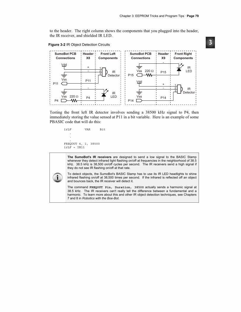
Chapter 3: EEPROM Tricks and Program Tips · Page 79
to the header. The right column shows the components that you plugged into the header, the IR receiver, and shielded IR LED.
Figure 3-2 IR Object Detection Circuits
Testing the front left IR detector involves sending a 38500 kHz signal to P4, then immediately storing the value sensed at P11 in a bit variable. Here is an example of some PBASIC code that will do this:
irLF VAR Bit . . . FREQOUT 4, 1, 38500 irLF = IN11
The SumoBot's IR receivers are designed to send a low signal to the BASIC Stamp whenever they detect infrared light flashing on/off at frequencies in the neighborhood of 38.5 kHz. 38.5 kHz is 38,500 on/off cycles per second. The IR receivers send a high signal if they do not see IR flashing on/off at that rate.
To detect objects, the SumoBot's BASIC Stamp has to use its IR LED headlights to shine infrared flashing on/off at 38,500 times per second. If the infrared is reflected off an object and bounces back, the IR receiver will detect it.
The command FREQOUT Pin, Duration, 38500 actually sends a harmonic signal at 38.5 kHz. The IR receivers can't really tell the difference between a fundamental and a harmonic. To learn more about this and other IR object detection techniques, see Chapters 7 and 8 in Robotics with the Boe-Bot.
Page 80· Applied Robotics with the SumoBot
If the IR receiver is sending 5 V to P11, it means it doesn't see any reflected infrared. If this is the case, the BASIC Stamp stores the value 1 in the P11 input register bit IN11. If the IR receiver does detect infrared reflected off some object, it will send 0 V to P11. While P11 senses 0 V, IN11 stores a 0. The problem is, the IR receiver only sends that 0 V for a fraction of a millisecond after the FREQOUT command stops. After the IR receiver's output rebounds to 5 V, IN11 stores a 1 again. That's why the command irLF = IN11 must come immediately after the FREQOUT command. Even though IN11 will return to 1 by the time the next PBASIC command gets executed, the value 0 gets safely stored in the irLF (short for infrared-left-front) variable for as long as the program needs it. A more formal way to write the IR detection routine is to use a PIN directive, and give P11 a name like irSenseLF, which stands for infrared-sensor-left-front. Likewise, you can give P4 a name, like IrLedLF, which is short for infrared-light-emitting-diode-left-front. You can then use these pin names in place of the 4 and the IN11. In addition, give the value 38500 a constant name, like IrFreq. Your code will then look like this:
IrLedLF PIN 4 IrSenseLF PIN 11 . . . IrFreq CON 38500 . . . irLF VAR Bit . . . FREQOUT IrLedLF, 1, IrFreq irLF = IrSenseLF
The PIN directive has lots of advantages. For example, imagine you have a program that uses the same I/O pin in 20 different places. What if you disconnect the circuit from the I/O pin you were using and connect it to a different I/O pin? Instead of replacing 20 different references to the I/O pin, simply update the number in the PIN directive, and the program is fixed. Another PIN directive advantage is that the BASIC Stamp Editor looks at each command and decides whether you are using the I/O pin as an output or an input.
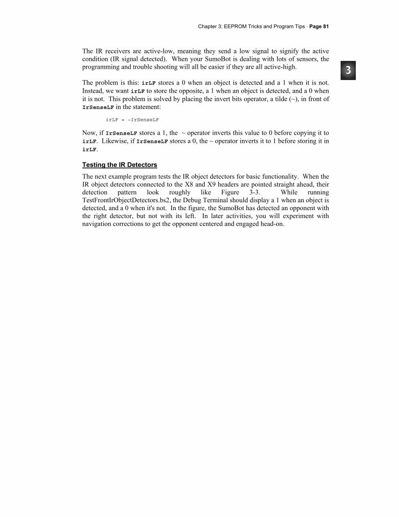
Chapter 3: EEPROM Tricks and Program Tips · Page 81
The IR receivers are active-low, meaning they send a low signal to signify the active condition (IR signal detected). When your SumoBot is dealing with lots of sensors, the programming and trouble shooting will all be easier if they are all active-high. The problem is this: irLF stores a 0 when an object is detected and a 1 when it is not. Instead, we want irLF to store the opposite, a 1 when an object is detected, and a 0 when it is not. This problem is solved by placing the invert bits operator, a tilde (~), in front of IrSenseLF in the statement:
irLF = ~IrSenseLF
Now, if IrSenseLF stores a 1, the ~ operator inverts this value to 0 before copying it to irLF. Likewise, if IrSenseLF stores a 0, the ~ operator inverts it to 1 before storing it in irLF.
Testing the IR Detectors
The next example program tests the IR object detectors for basic functionality. When the IR object detectors connected to the X8 and X9 headers are pointed straight ahead, their detection pattern look roughly like Figure 3-3. While running TestFrontIrObjectDetectors.bs2, the Debug Terminal should display a 1 when an object is detected, and a 0 when it's not. In the figure, the SumoBot has detected an opponent with the right detector, but not with its left. In later activities, you will experiment with navigation corrections to get the opponent centered and engaged head-on.
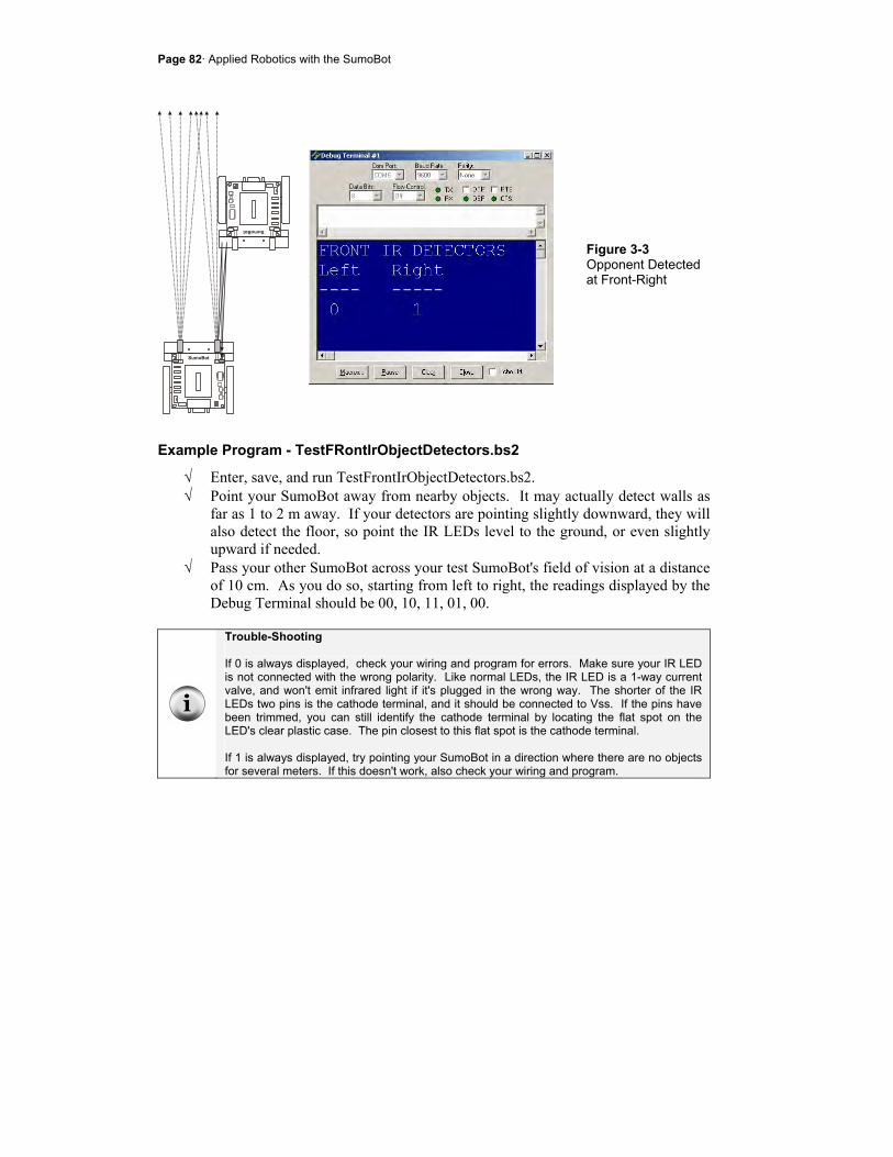
Page 82· Applied Robotics with the SumoBot
Figure 3-3 Opponent Detected at Front-Right
Example Program - TestFRontIrObjectDetectors.bs2
√ Enter, save, and run TestFrontIrObjectDetectors.bs2. √ Point your SumoBot away from nearby objects. It may actually detect walls as
far as 1 to 2 m away. If your detectors are pointing slightly downward, they will also detect the floor, so point the IR LEDs level to the ground, or even slightly upward if needed.
√ Pass your other SumoBot across your test SumoBot's field of vision at a distance of 10 cm. As you do so, starting from left to right, the readings displayed by the Debug Terminal should be 00, 10, 11, 01, 00.
Trouble-Shooting If 0 is always displayed, check your wiring and program for errors. Make sure your IR LED is not connected with the wrong polarity. Like normal LEDs, the IR LED is a 1-way current valve, and won't emit infrared light if it's plugged in the wrong way. The shorter of the IR LEDs two pins is the cathode terminal, and it should be connected to Vss. If the pins have been trimmed, you can still identify the cathode terminal by locating the flat spot on the LED's clear plastic case. The pin closest to this flat spot is the cathode terminal. If 1 is always displayed, try pointing your SumoBot in a direction where there are no objects for several meters. If this doesn't work, also check your wiring and program.
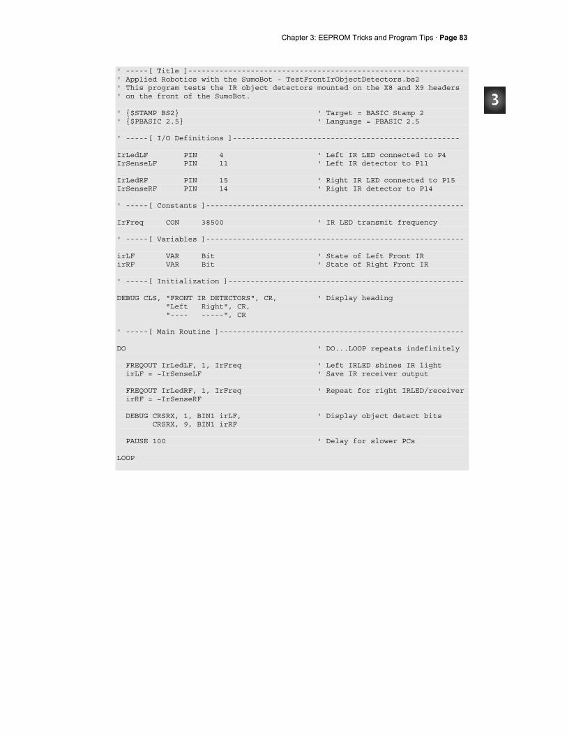
Chapter 3: EEPROM Tricks and Program Tips · Page 83
' -----[ Title ]-------------------------------------------------------------- ' Applied Robotics with the SumoBot - TestFrontIrObjectDetectors.bs2 ' This program tests the IR object detectors mounted on the X8 and X9 headers ' on the front of the SumoBot. ' $STAMP BS2 ' Target = BASIC Stamp 2 ' $PBASIC 2.5 ' Language = PBASIC 2.5 ' -----[ I/O Definitions ]--------------------------------------------------- IrLedLF PIN 4 ' Left IR LED connected to P4 IrSenseLF PIN 11 ' Left IR detector to P11 IrLedRF PIN 15 ' Right IR LED connected to P15 IrSenseRF PIN 14 ' Right IR detector to P14 ' -----[ Constants ]---------------------------------------------------------- IrFreq CON 38500 ' IR LED transmit frequency ' -----[ Variables ]---------------------------------------------------------- irLF VAR Bit ' State of Left Front IR irRF VAR Bit ' State of Right Front IR ' -----[ Initialization ]----------------------------------------------------- DEBUG CLS, "FRONT IR DETECTORS", CR, ' Display heading "Left Right", CR, "---- -----", CR ' -----[ Main Routine ]------------------------------------------------------- DO ' DO...LOOP repeats indefinitely FREQOUT IrLedLF, 1, IrFreq ' Left IRLED shines IR light irLF = ~IrSenseLF ' Save IR receiver output FREQOUT IrLedRF, 1, IrFreq ' Repeat for right IRLED/receiver irRF = ~IrSenseRF DEBUG CRSRX, 1, BIN1 irLF, ' Display object detect bits CRSRX, 9, BIN1 irRF PAUSE 100 ' Delay for slower PCs LOOP
Page 84· Applied Robotics with the SumoBot
Your Turn - Headlight Adjustments
A small change in the direction the SumoBot's IR LEDs are pointing can make a huge difference in its performance. Remember this when testing the competition code at the end of chapter 4 and the datalogging code at the end of Chapter 5. You will probably find yourself adjusting the direction each IR LED points to get the most consistent detection of your opponent. For the programs in this text, you should start by pointing the IR LEDs straight ahead. Pointing the IR LEDs outward can cause the SumoBot to not realize its opponent is straight in front of it because both IR detectors can't see the opponent at the same time. Pointing the IR LEDs inward can result in the SumoBot thinking the opponent is on it's front right, when it is in fact on its front left (and visa-versa). Pointing the IR LEDs upward can result in missing an opponent because the headlights are too high. One adjustment that can be useful is pointing the IR LEDs slightly downward. The angle should be very slight, certainly not more than 5° below horizontal when viewed from the side. When viewed from the top, the IR LEDs should still be pointing straight ahead, there should be no detectable angle outward or inward. The slight downward angle can be helpful during the part of a round when the SumoBots are pushing against each other. As they push against each other, sometimes both the SumoBots tip upward briefly. At this moment, if the IR LEDs are not tilting slightly down, it can cause even the SumoBot with the advantage to think its opponent is no longer in front of it. Its program might cause it to change from lunging forward to executing a search pattern, which will in turn cause it to give up its advantage.
√ With TestFrontIrObjectDetectors.bs2, try pushing the SumoBots against each other to create the symptom just described.
√ Try to tilt the IR LEDs so that it still sees its opponent if it has the plow advantage (Chapter 1, Activity #1), and so that it loses sight of its opponent if it has the plow disadvantage.
√ Make a note to yourself to revisit this issue during Chapter 4, Activity #6 and also during Chapter 5, Activity #4.
Certain SumoBots may benefit from very slight outward or inward adjustments as well. This again will be a trail and error experiment you can try in Chapter 4, Activity #6 and also during Chapter 5, Activity #4.

Chapter 3: EEPROM Tricks and Program Tips · Page 85
Testing for Sources of IR Interference
Fluorescent lights have a part called a ballast built into them. The ballast is responsible for amplifying the AC outlet voltage to a level that is high enough to make the gas inside the glass tube fluoresce and emit light. Some of the electronic ballasts built into more recently manufactured fluorescent lights can be a problem for the infrared detectors. These ballasts cause the light to send off a signal that the IR receiver is sensitive to. When the IR receiver detects this signal, it sends a low signal to the BASIC Stamp, and the BASIC Stamp thinks an object has been detected when it really hasn't. To make matters more confusing, certain other devices like handheld remotes and video cameras or camcorders can also send out interfering signals. It's best to stage your SumoBot competitions well away from fluorescent lights and other devices that broadcast this kind of interference, either by turning off the light, or moving the competition ring. With a few modifications to TestFrontIrObjectDetectors.bs2, you can then use your SumoBot as an IR interference sniffer. To test and make sure the SumoBot can indeed detect IR interferences, simply run the unmodified version of TestFrontIrObjecDetectors.bs2 in the other SumoBot. Point the two SumoBots at each other, and the one running the modified code should sense the IR from the other SumoBot and sound the alarm. The key to making an IR interference sniffer is to not send out any IR before checking the IR receiver's output. In other words, remove the FREQOUT commands to the IrLedLeft and IrLedRight pins. If the SumoBot's infrared headlights are off, but it the receivers are still detecting an infrared signal in the neighborhood of 38.5 kHz, it must mean it's coming from a source of IR interference. So, sound the alarm. The next example program started as TestFrontIrObjectDetectors.bs2. The two most important changes that convert TestFrontObjectDetectors.bs2 to IrInterferenceSniffer.bs2 are:
(1) removing the FREQOUT commands, and (2) adding code that makes sounds if either of the IR receivers tell the BASIC Stamp
they detect an infrared signal.
Page 86· Applied Robotics with the SumoBot
' -----[ Main Routine ]------------------------------------------------ DO ' DO...LOOP repeats indefinitely irLF = ~IrSenseLF ' Save IR receiver outputs irRF = ~IrSenseRF ' Sound alarm if IR detected IF irLF = 1 OR irRF = 1 THEN DEBUG "IR interference detected!!!", CR FOR counter = 1 TO 7 FREQOUT LedSpeaker, 50, 4000 PAUSE 50 NEXT ENDIF LOOP ' Repeat DO...LOOP
The modified Main Routine also necessitates a few smaller changes, like a PIN declaration for LedSpeaker as well as a counter variable for sending a series of rapid alarm beeps. The Initialization message in the next example program is also changed, as are the comments at the beginning of the program.
Example Program: IrInterferenceSniffer.bs2
IrInterferenceSniffer.bs2 sounds the SumoBot's piezospeaker alarm whenever it receives infrared signals in the neighborhood of 38.5 kHz. This could be from another SumoBot, a handheld remote that controls a TV, a video recorder, or fluorescent lights with an interfering ballast.
√ Make sure one of your SumoBots is running TestFrontIrObjectDetectors.bs2. √ Disconnect that first SumoBot from the serial cable and set it aside. √ Enter and save run IrInterferenceSniffer.bs2. √ Download it to the second SumoBot. √ Point the first SumoBot's IR LED headlights at the second SumoBot. The
second SumoBot's alarm should sound indicating it has detected IR interference. √ Point the first SumoBot away from the second SumoBot, and the alarm should
stop. √ Try walking under various fluorescent lights while pointing the second SumoBot
(running IrInterferenceSniffer.bs2) at them. Does its alarm sound? If not, that's good. If yes, you'll want to keep your SumoBot Competition Ring well away from those lights, or turn them off.
Chapter 3: EEPROM Tricks and Program Tips · Page 87
Always test for and eliminate sources of IR interference near your SumoBot Competition Ring.
' -----[ Title ]-------------------------------------------------------------- ' Applied Robotics with the SumoBot - IrInterferenceSniffer.bs2 ' This program tests for IR interference from other fluorescent lights, ' handheld remotes, video recorders and other SumoBot robots. ' $STAMP BS2 ' Target = BASIC Stamp 2 ' $PBASIC 2.5 ' Language = PBASIC 2.5 ' -----[ I/O Definitions ]--------------------------------------------------- IrLedLF PIN 4 ' Left IR LED connected to P4 IrSenseLF PIN 11 ' Left IR detector to P11 IrLedRF PIN 15 ' Right IR LED connected to P15 IrSenseRF PIN 14 ' Right IR detector to P14 LedSpeaker PIN 5 ' LED/speaker connected to P5 ' -----[ Variables ]---------------------------------------------------------- irLF VAR Bit ' State of Left Front IR irRF VAR Bit ' State of Right Front IR counter VAR Byte ' Loop counting variable ' -----[ Initialization ]----------------------------------------------------- DEBUG CLS, "Checking for IR interference...", CR, CR ' -----[ Main Routine ]------------------------------------------------------- DO ' DO...LOOP repeats indefinitely irLF = ~IrSenseLF ' Save IR receiver output irRF = ~IrSenseRF IF irLF = 1 OR irRF = 1 THEN DEBUG "IR interference detected!!!", CR FOR counter = 1 TO 7 FREQOUT LedSpeaker, 50, 4000 PAUSE 50 NEXT ENDIF LOOP
Page 88· Applied Robotics with the SumoBot
Testing for Electrical Continuity
The leads on the IR LEDs and receivers tend to be thinner than jumper wires and other component leads. The X8 and X9 sockets on some SumoBot boards may also have sockets with slightly larger holes than the ones in the breadboard. A resulting loose fit could be a problem for some IR LEDs and detectors. During a match, vibration can cause brief electrical continuity interruptions between the IR component pins and the header sockets. This in turn can result in the SumoBot losing sight of its opponent, or maybe never even catching a glimpse.
Electrical Continuity is when there's a continuous pathway through which current can flow. If two conductive metals are firmly pressed against each other, it provides electrical continuity. If the pieces of metal are separated briefly, current can no longer flow, and electrical continuity is interrupted.
Sometimes skin oils or surface oxidation on the metal can prevent the actual conductive parts of the metal from making contact. The act of inserting a lead into a breadboard socket typically abrades the surfaces enough to establish electrical continuity.
Continuity Tests
√ Remove one of the IR components from either the X8 or X9 header, and make a note of how much force you used. Did it slide right out, or did the socket kind of gently grip the components leads and resist the component's removal?
Especially if the component slid right out, the leads will lose contact (electrical continuity) during the jostling and vibration of a sumo match.
√ If you are unsure if the socket gripped the leads firmly enough, compare it to removing the same component from the breadboard sockets.
If it's way easier to remove the component from the X8/X9 header than it is to remove it from the breadboard, it's also a good indicator that there will continuity problems during a match.
√ Repeat for each component in the X8/X9 headers.
Ensuring Continuity
The SumoBot Robot Competition Kit may have extra components that are not used in the activities in this book, such as 10 µF capacitors. The leads on these spare capacitors or
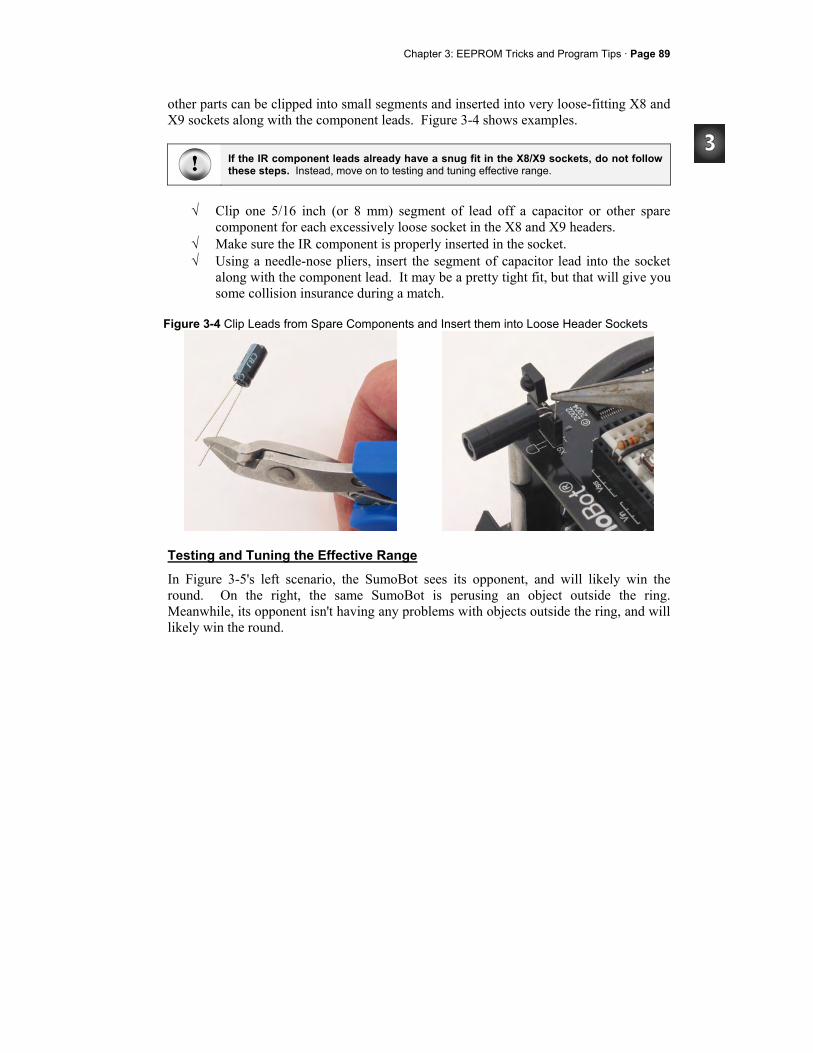
Chapter 3: EEPROM Tricks and Program Tips · Page 89
other parts can be clipped into small segments and inserted into very loose-fitting X8 and X9 sockets along with the component leads. Figure 3-4 shows examples.
If the IR component leads already have a snug fit in the X8/X9 sockets, do not follow these steps. Instead, move on to testing and tuning effective range.
√ Clip one 5/16 inch (or 8 mm) segment of lead off a capacitor or other spare
component for each excessively loose socket in the X8 and X9 headers. √ Make sure the IR component is properly inserted in the socket. √ Using a needle-nose pliers, insert the segment of capacitor lead into the socket
along with the component lead. It may be a pretty tight fit, but that will give you some collision insurance during a match.
Figure 3-4 Clip Leads from Spare Components and Insert them into Loose Header Sockets
Testing and Tuning the Effective Range
In Figure 3-5's left scenario, the SumoBot sees its opponent, and will likely win the round. On the right, the same SumoBot is perusing an object outside the ring. Meanwhile, its opponent isn't having any problems with objects outside the ring, and will likely win the round.
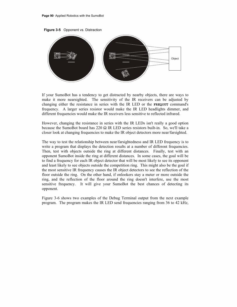
Page 90· Applied Robotics with the SumoBot
Figure 3-5 Opponent vs. Distraction
If your SumoBot has a tendency to get distracted by nearby objects, there are ways to make it more nearsighted. The sensitivity of the IR receivers can be adjusted by changing either the resistance in series with the IR LED or the FREQOUT command's frequency. A larger series resistor would make the IR LED headlights dimmer, and different frequencies would make the IR receivers less sensitive to reflected infrared. However, changing the resistance in series with the IR LEDs isn't really a good option because the SumoBot board has 220 Ω IR LED series resistors built-in. So, we'll take a closer look at changing frequencies to make the IR object detectors more near/farsighted. The way to test the relationship between near/farsightedness and IR LED frequency is to write a program that displays the detection results at a number of different frequencies. Then, test with objects outside the ring at different distances. Finally, test with an opponent SumoBot inside the ring at different distances. In some cases, the goal will be to find a frequency for each IR object detector that will be most likely to see its opponent and least likely to see objects outside the competition ring. This might also be the goal if the most sensitive IR frequency causes the IR object detectors to see the reflection of the floor outside the ring. On the other hand, if onlookers stay a meter or more outside the ring, and the reflection of the floor around the ring doesn't interfere, use the most sensitive frequency. It will give your SumoBot the best chances of detecting its opponent. Figure 3-6 shows two examples of the Debug Terminal output from the next example program. The program makes the IR LED send frequencies ranging from 36 to 42 kHz,
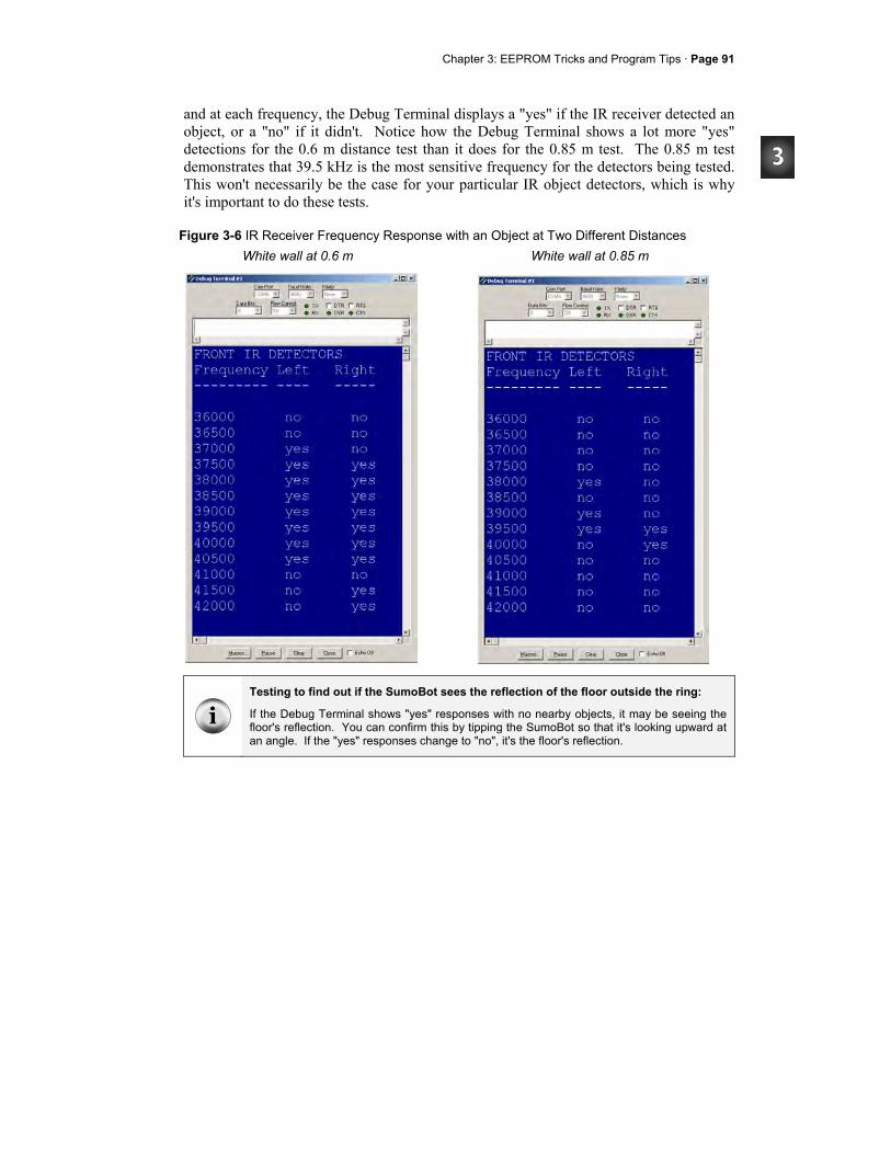
Chapter 3: EEPROM Tricks and Program Tips · Page 91
and at each frequency, the Debug Terminal displays a "yes" if the IR receiver detected an object, or a "no" if it didn't. Notice how the Debug Terminal shows a lot more "yes" detections for the 0.6 m distance test than it does for the 0.85 m test. The 0.85 m test demonstrates that 39.5 kHz is the most sensitive frequency for the detectors being tested. This won't necessarily be the case for your particular IR object detectors, which is why it's important to do these tests.
Figure 3-6 IR Receiver Frequency Response with an Object at Two Different Distances
Testing to find out if the SumoBot sees the reflection of the floor outside the ring:
If the Debug Terminal shows "yes" responses with no nearby objects, it may be seeing the floor's reflection. You can confirm this by tipping the SumoBot so that it's looking upward at an angle. If the "yes" responses change to "no", it's the floor's reflection.
White wall at 0.6 m
White wall at 0.85 m

Page 92· Applied Robotics with the SumoBot
The next example program is another modified version of TestIrFrontObjectDetectors.bs2. The IrFreq constant in the FREQOUT command's Freq1 argument is replaced with a Word variable named frequency. This variable is swept from 36000 to 42000 in steps of 500 by a FOR...NEXT loop. It's a quick and easy way to perform a frequency sweep with the IR LEDs and capture the IR receivers' frequency responses. ' -----[ Main Routine ]------------------------------------------------------- FOR frequency = 36000 TO 42000 STEP 500 FREQOUT IrLedLF, 1, frequency ' Left IRLED shines IR light irLF = ~IrSenseLF ' Save IR receiver output FREQOUT IrLedRF, 1, frequency ' Repeat for right IRLED/receiver irRF = ~IrSenseRF DEBUG CR, DEC frequency, CRSRX, 11 ' Display yes/no for detection IF irLF = 1 THEN DEBUG "yes" ELSE DEBUG "no" DEBUG CRSRX, 19 IF irRF = 1 THEN DEBUG "yes" ELSE DEBUG "no" PAUSE 50 ' Delay for slower PCs NEXT
Frequency Sweep and Frequency Response
Transmitting a sequence of frequencies is commonly referred to as "frequency sweep". The response of a sensor or circuit to a frequency sweep is called its "frequency response".
Example Program: TestFrequencyResponse.bs2
This program should be used with a white wall at various distances from the front of the SumoBot to get an idea of which frequencies make it more nearsighted and which frequencies make it more farsighted. These tests should then be repeated with a SumoBot in the ring. The goal is to determine a frequency for each detector that is most likely to detect the SumoBot opponent and least likely to detect a nearby onlooker.
√ Enter, save, and run TestFrequencyResponse.bs2, and leave the SumoBot connected to the serial cable.
√ Face the SumoBot at a white wall 1 m away. √ Press and release the Reset button.
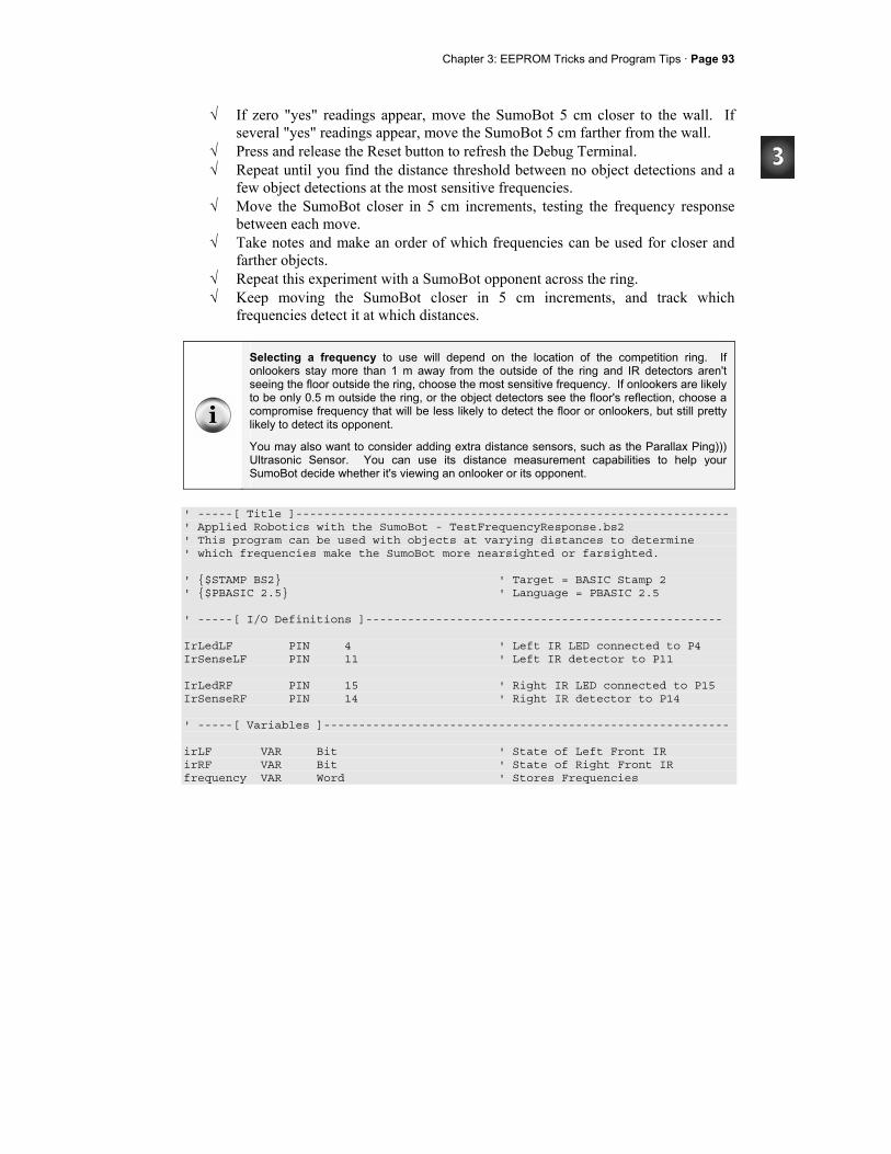
Chapter 3: EEPROM Tricks and Program Tips · Page 93
√ If zero "yes" readings appear, move the SumoBot 5 cm closer to the wall. If several "yes" readings appear, move the SumoBot 5 cm farther from the wall.
√ Press and release the Reset button to refresh the Debug Terminal. √ Repeat until you find the distance threshold between no object detections and a
few object detections at the most sensitive frequencies. √ Move the SumoBot closer in 5 cm increments, testing the frequency response
between each move. √ Take notes and make an order of which frequencies can be used for closer and
farther objects. √ Repeat this experiment with a SumoBot opponent across the ring. √ Keep moving the SumoBot closer in 5 cm increments, and track which
frequencies detect it at which distances.
Selecting a frequency to use will depend on the location of the competition ring. If onlookers stay more than 1 m away from the outside of the ring and IR detectors aren't seeing the floor outside the ring, choose the most sensitive frequency. If onlookers are likely to be only 0.5 m outside the ring, or the object detectors see the floor's reflection, choose a compromise frequency that will be less likely to detect the floor or onlookers, but still pretty likely to detect its opponent.
You may also want to consider adding extra distance sensors, such as the Parallax Ping))) Ultrasonic Sensor. You can use its distance measurement capabilities to help your SumoBot decide whether it's viewing an onlooker or its opponent.
' -----[ Title ]-------------------------------------------------------------- ' Applied Robotics with the SumoBot - TestFrequencyResponse.bs2 ' This program can be used with objects at varying distances to determine ' which frequencies make the SumoBot more nearsighted or farsighted. ' $STAMP BS2 ' Target = BASIC Stamp 2 ' $PBASIC 2.5 ' Language = PBASIC 2.5 ' -----[ I/O Definitions ]--------------------------------------------------- IrLedLF PIN 4 ' Left IR LED connected to P4 IrSenseLF PIN 11 ' Left IR detector to P11 IrLedRF PIN 15 ' Right IR LED connected to P15 IrSenseRF PIN 14 ' Right IR detector to P14 ' -----[ Variables ]---------------------------------------------------------- irLF VAR Bit ' State of Left Front IR irRF VAR Bit ' State of Right Front IR frequency VAR Word ' Stores Frequencies
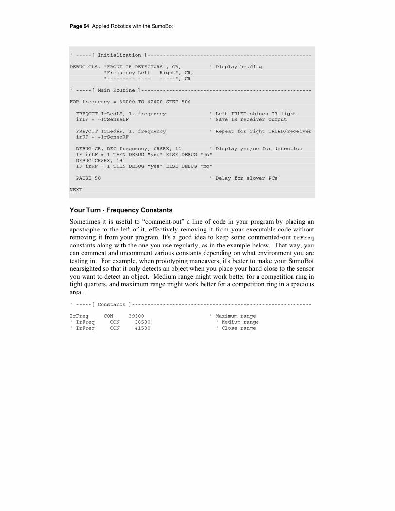
Page 94· Applied Robotics with the SumoBot
' -----[ Initialization ]----------------------------------------------------- DEBUG CLS, "FRONT IR DETECTORS", CR, ' Display heading "Frequency Left Right", CR, "--------- ---- -----", CR ' -----[ Main Routine ]------------------------------------------------------- FOR frequency = 36000 TO 42000 STEP 500 FREQOUT IrLedLF, 1, frequency ' Left IRLED shines IR light irLF = ~IrSenseLF ' Save IR receiver output FREQOUT IrLedRF, 1, frequency ' Repeat for right IRLED/receiver irRF = ~IrSenseRF DEBUG CR, DEC frequency, CRSRX, 11 ' Display yes/no for detection IF irLF = 1 THEN DEBUG "yes" ELSE DEBUG "no" DEBUG CRSRX, 19 IF irRF = 1 THEN DEBUG "yes" ELSE DEBUG "no" PAUSE 50 ' Delay for slower PCs NEXT
Your Turn - Frequency Constants
Sometimes it is useful to “comment-out” a line of code in your program by placing an apostrophe to the left of it, effectively removing it from your executable code without removing it from your program. It's a good idea to keep some commented-out IrFreq constants along with the one you use regularly, as in the example below. That way, you can comment and uncomment various constants depending on what environment you are testing in. For example, when prototyping maneuvers, it's better to make your SumoBot nearsighted so that it only detects an object when you place your hand close to the sensor you want to detect an object. Medium range might work better for a competition ring in tight quarters, and maximum range might work better for a competition ring in a spacious area. ' -----[ Constants ]---------------------------------------------------------- IrFreq CON 39500 ' Maximum range ' IrFreq CON 38500 ' Medium range ' IrFreq CON 41500 ' Close range

Chapter 3: EEPROM Tricks and Program Tips · Page 95
√ Modify TestIrFrontObjecDetectors.bs2 so that it has 3 or 4 useful versions of the IrFreq CON directive.
ACTIVITY #2: A CLOSER LOOK AT THE QTI LINE SENSORS The SumoBot shown in Figure 3-7 has its QTI line sensors mounted under left and right sides of the plow. The QTIs are designed to detect the white tawara line, which is the border of the competition ring. This activity reviews the testing procedure for the QTI line sensors and takes a closer look at how they work.
Figure 3-7 QTI Line Sensor's on the SumoBot
Testing the QTI Line Sensors
Figure 3-8 shows schematics of your SumoBot's two front QTI line sensors. Like the IR object detectors, the QTI's are connected to headers on your SumoBot. When you plug the cable into the QTI, the white wire should line up with the W on the QTI. Likewise, the red wire should line up with the R, and black with B. When plugging the other end of the cable into the header on the SumoBot board, make sure to line up the black wire with the pin labeled B. On the SumoBot PCB, the X5 header connects the pin labeled 10 to BASIC Stamp I/O pin P10. The PCB also connects the pin labeled 9 to I/O pin P9, and the pin labeled B to Vss. Header X4 makes similar connections, but with different I/O pin connections.
QTI Line Sensor (Front Left)
QTI Line Sensor (Front Right)
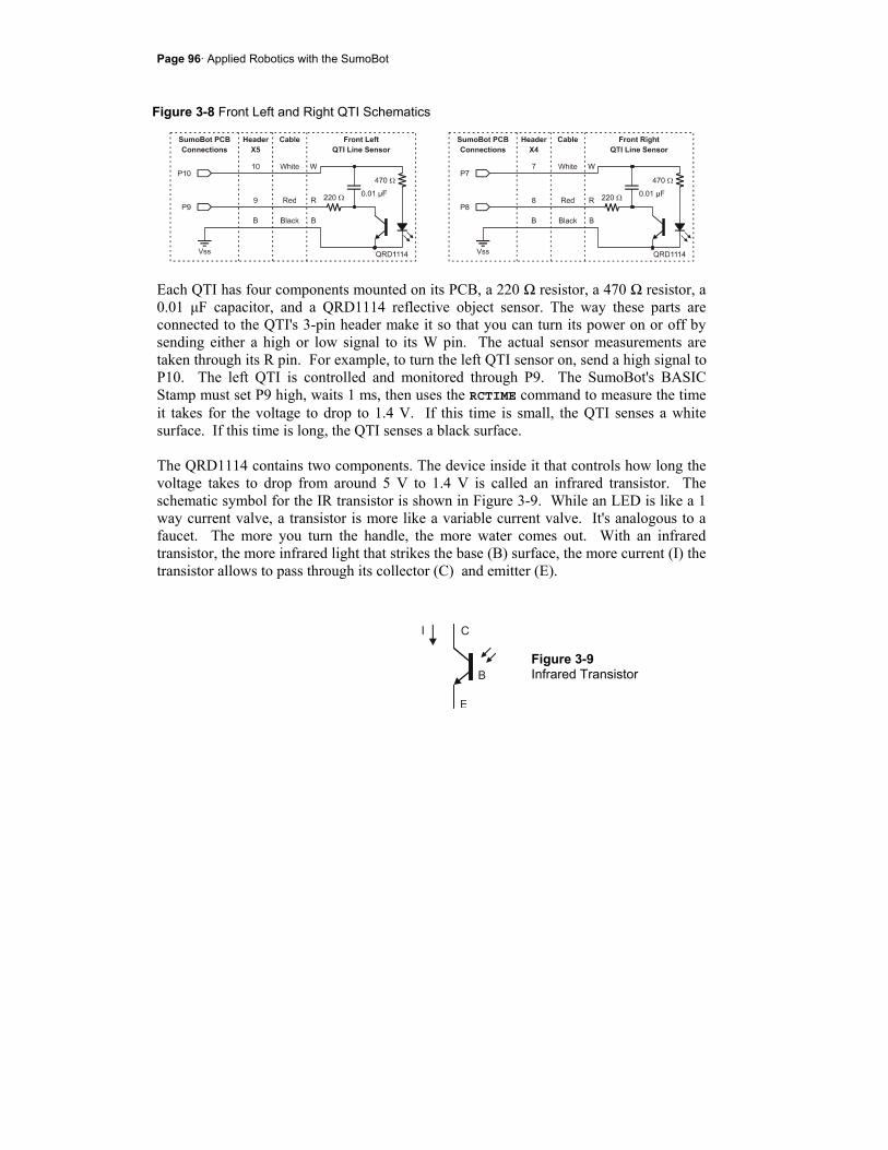
Page 96· Applied Robotics with the SumoBot
Figure 3-8 Front Left and Right QTI Schematics
Each QTI has four components mounted on its PCB, a 220 Ω resistor, a 470 Ω resistor, a 0.01 µF capacitor, and a QRD1114 reflective object sensor. The way these parts are connected to the QTI's 3-pin header make it so that you can turn its power on or off by sending either a high or low signal to its W pin. The actual sensor measurements are taken through its R pin. For example, to turn the left QTI sensor on, send a high signal to P10. The left QTI is controlled and monitored through P9. The SumoBot's BASIC Stamp must set P9 high, waits 1 ms, then uses the RCTIME command to measure the time it takes for the voltage to drop to 1.4 V. If this time is small, the QTI senses a white surface. If this time is long, the QTI senses a black surface. The QRD1114 contains two components. The device inside it that controls how long the voltage takes to drop from around 5 V to 1.4 V is called an infrared transistor. The schematic symbol for the IR transistor is shown in Figure 3-9. While an LED is like a 1 way current valve, a transistor is more like a variable current valve. It's analogous to a faucet. The more you turn the handle, the more water comes out. With an infrared transistor, the more infrared light that strikes the base (B) surface, the more current (I) the transistor allows to pass through its collector (C) and emitter (E).
Figure 3-9 Infrared Transistor
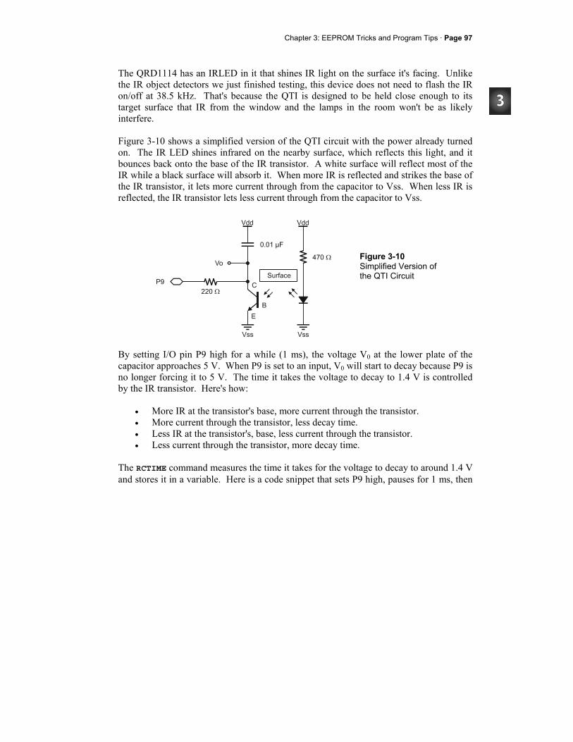
Chapter 3: EEPROM Tricks and Program Tips · Page 97
The QRD1114 has an IRLED in it that shines IR light on the surface it's facing. Unlike the IR object detectors we just finished testing, this device does not need to flash the IR on/off at 38.5 kHz. That's because the QTI is designed to be held close enough to its target surface that IR from the window and the lamps in the room won't be as likely interfere. Figure 3-10 shows a simplified version of the QTI circuit with the power already turned on. The IR LED shines infrared on the nearby surface, which reflects this light, and it bounces back onto the base of the IR transistor. A white surface will reflect most of the IR while a black surface will absorb it. When more IR is reflected and strikes the base of the IR transistor, it lets more current through from the capacitor to Vss. When less IR is reflected, the IR transistor lets less current through from the capacitor to Vss.
Figure 3-10 Simplified Version of the QTI Circuit
By setting I/O pin P9 high for a while (1 ms), the voltage V0 at the lower plate of the capacitor approaches 5 V. When P9 is set to an input, V0 will start to decay because P9 is no longer forcing it to 5 V. The time it takes the voltage to decay to 1.4 V is controlled by the IR transistor. Here's how:
• More IR at the transistor's base, more current through the transistor. • More current through the transistor, less decay time. • Less IR at the transistor's, base, less current through the transistor. • Less current through the transistor, more decay time.
The RCTIME command measures the time it takes for the voltage to decay to around 1.4 V and stores it in a variable. Here is a code snippet that sets P9 high, pauses for 1 ms, then
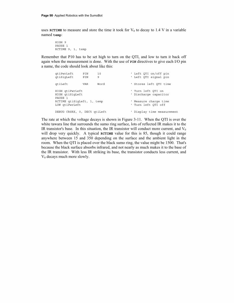
Page 98· Applied Robotics with the SumoBot
uses RCTIME to measure and store the time it took for V0 to decay to 1.4 V in a variable named temp:
HIGH 9 PAUSE 1 RCTIME 9, 1, temp
Remember that P10 has to be set high to turn on the QTI, and low to turn it back off again when the measurement is done. With the use of PIN directives to give each I/O pin a name, the code should look about like this:
qtiPwrLeft PIN 10 ' Left QTI on/off pin qtiSigLeft PIN 9 ' Left QTI signal pin qtiLeft VAR Word ' Stores left QTI time HIGH qtiPwrLeft ' Turn left QTI on HIGH qtiSigLeft ' Discharge capacitor PAUSE 1 RCTIME qtiSigLeft, 1, temp ' Measure charge time LOW qtiPwrLeft ' Turn left QTI off DEBUG CRSRX, 0, DEC5 qtiLeft ' Display time measurement
The rate at which the voltage decays is shown in Figure 3-11. When the QTI is over the white tawara line that surrounds the sumo ring surface, lots of reflected IR makes it to the IR transistor's base. In this situation, the IR transistor will conduct more current, and V0 will drop very quickly. A typical RCTIME value for this is 85, though it could range anywhere between 15 and 350 depending on the surface and the ambient light in the room. When the QTI is placed over the black sumo ring, the value might be 1500. That's because the black surface absorbs infrared, and not nearly as much makes it to the base of the IR transistor. With less IR striking its base, the transistor conducts less current, and V0 decays much more slowly.

Chapter 3: EEPROM Tricks and Program Tips · Page 99
Figure 3-11 QTI RC-Decay for Different Surfaces
If there is no surface to reflect IR from the QTI's IR LED, the only source of infrared for the IR transistor's base is the ambient light in the room. That might be a lot of infrared if sunlight is streaming through the windows, or a little if the blinds are closed and only a few fluorescent lights are on. That's the case with the 3500 RCTIME measurement. Keep in mind, your values will also vary with the type of surfaces you are using. Figure 3-12 shows an example of the SumoBot with one QTI over the white tawara line, and the other QTI over the black sumo ring surface. It also shows an example of what the Debug Terminal might display under these conditions. The left QTI only reads 66, a strong indication that the QTI is over a white line. The right sensor reads 1554, which is typical for a dark surface. These values will vary from one room and sumo ring to the next, and in an upcoming activity, we'll take a close look at self calibration so that your SumoBot can automatically adjust to its environment.
Avoiding Interference to the QTI’s –The QTI sensor has a built-in daylight filter that is adequate for indirect sunlight indoors. However, you should still avoid placing your sumo ring in direct or bright indirect sunlight. If you find that your sumo-ring’s surface is too reflective in direct sunlight, causing false QTI readings, move your ring to an indoor shaded location.
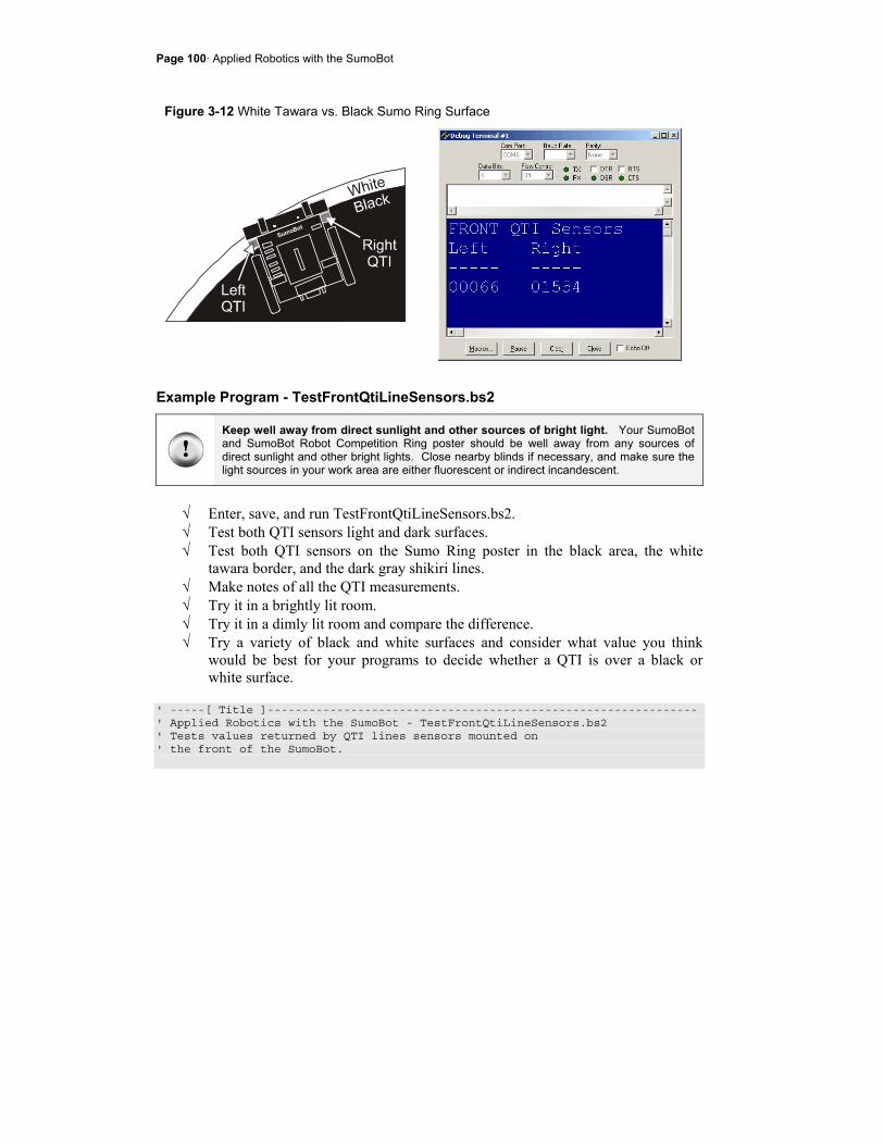
Page 100· Applied Robotics with the SumoBot
Figure 3-12 White Tawara vs. Black Sumo Ring Surface
Example Program - TestFrontQtiLineSensors.bs2
Keep well away from direct sunlight and other sources of bright light. Your SumoBot and SumoBot Robot Competition Ring poster should be well away from any sources of direct sunlight and other bright lights. Close nearby blinds if necessary, and make sure the light sources in your work area are either fluorescent or indirect incandescent.
√ Enter, save, and run TestFrontQtiLineSensors.bs2. √ Test both QTI sensors light and dark surfaces. √ Test both QTI sensors on the Sumo Ring poster in the black area, the white
tawara border, and the dark gray shikiri lines. √ Make notes of all the QTI measurements. √ Try it in a brightly lit room. √ Try it in a dimly lit room and compare the difference. √ Try a variety of black and white surfaces and consider what value you think
would be best for your programs to decide whether a QTI is over a black or white surface.
' -----[ Title ]-------------------------------------------------------------- ' Applied Robotics with the SumoBot - TestFrontQtiLineSensors.bs2 ' Tests values returned by QTI lines sensors mounted on ' the front of the SumoBot.
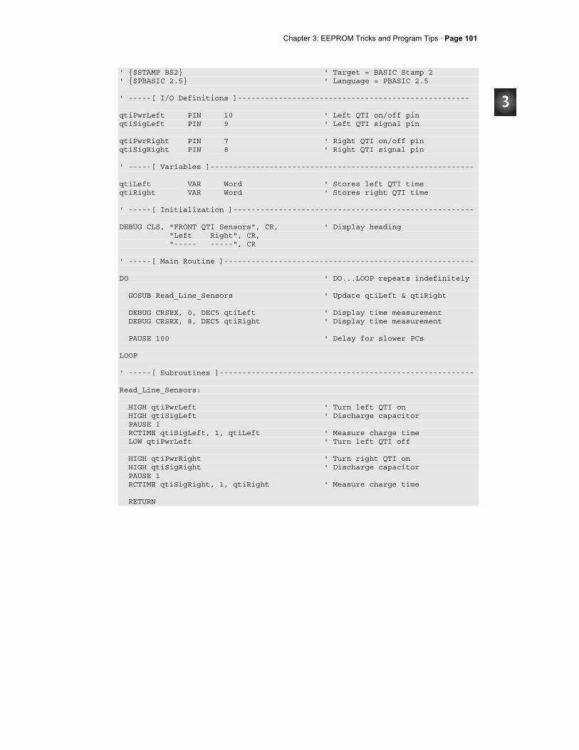
Chapter 3: EEPROM Tricks and Program Tips · Page 101
' $STAMP BS2 ' Target = BASIC Stamp 2 ' $PBASIC 2.5 ' Language = PBASIC 2.5 ' -----[ I/O Definitions ]--------------------------------------------------- qtiPwrLeft PIN 10 ' Left QTI on/off pin qtiSigLeft PIN 9 ' Left QTI signal pin qtiPwrRight PIN 7 ' Right QTI on/off pin qtiSigRight PIN 8 ' Right QTI signal pin ' -----[ Variables ]---------------------------------------------------------- qtiLeft VAR Word ' Stores left QTI time qtiRight VAR Word ' Stores right QTI time ' -----[ Initialization ]----------------------------------------------------- DEBUG CLS, "FRONT QTI Sensors", CR, ' Display heading "Left Right", CR, "----- -----", CR ' -----[ Main Routine ]------------------------------------------------------- DO ' DO...LOOP repeats indefinitely GOSUB Read_Line_Sensors ' Update qtiLeft & qtiRight DEBUG CRSRX, 0, DEC5 qtiLeft ' Display time measurement DEBUG CRSRX, 8, DEC5 qtiRight ' Display time measurement PAUSE 100 ' Delay for slower PCs LOOP ' -----[ Subroutines ]-------------------------------------------------------- Read_Line_Sensors: HIGH qtiPwrLeft ' Turn left QTI on HIGH qtiSigLeft ' Discharge capacitor PAUSE 1 RCTIME qtiSigLeft, 1, qtiLeft ' Measure charge time LOW qtiPwrLeft ' Turn left QTI off HIGH qtiPwrRight ' Turn right QTI on HIGH qtiSigRight ' Discharge capacitor PAUSE 1 RCTIME qtiSigRight, 1, qtiRight ' Measure charge time RETURN
Page 102· Applied Robotics with the SumoBot
Your Turn - Detecting Tilt
What if the QTIs were to give you a unique signature when the SumoBot is tilted backward?
√ Try tilting the SumoBot while it's sitting on the sumo ring. √ Are the readings different from black and white? √ How does the light level in the room effect tilt measurements?
Strategy tip
While it seems like this might be a great way to detect whether your SumoBot is at a disadvantage, it tends not to work in practice. Whether the SumoBot's plow is under or over its opponent’s, both SumoBots may tip upward for a moment as they push against each other. Therefore, detecting a tilt does not necessarily indicate that your SumoBot is winning or losing, so these measurements would not necessarily be helpful in deciding what type of maneuver to do next. While QTI tilt is probably a blind alley, similar experiments may lead to more useful sensor data and new strategies.
ACTIVITY #3: SELF CALIBRATING QTI SENSORS As mentioned earlier, different lighting conditions and different competition rings will cause the QTIs to give different measurements. If you selected a value to discern between the black ring and the white tawara line based on your own practice ring, you might be in for a surprise when you move your ring to a different location or use a ring made of different materials. Reason being, the value you chose for your practice ring might not work with the new conditions. When this happens, your SumoBot will drive right out of the ring, maybe before it's even had a chance to engage with its opponent. The solution to this problem was first introduced in the SumoBot text - a QTI self-calibration routine. In this activity, you will take a closer look at how this kind of self-calibration routine works.
QTI Self Calibration Code
Making the QTIs self calibrating isn't difficult if you start with the example program from this chapter's Activity #2 - TestFrontQtiLineSensors.bs2. The first step is to add a word variable to store a threshold value.
qtiThreshold VAR Word
Since the SumoBot will have to start off in the middle of the ring, the only piece of information it will have is the QTI measurements for the black surface. The program
Chapter 3: EEPROM Tricks and Program Tips · Page 103
should measure the QTI readings for the black surface and use them as a basis for setting a threshold value to decide whether the QTIs are "seeing" black or white. As you may have noticed from Activity #2, white QTI measurements are very small in comparison. Your program can safely set the threshold at 1/4 of the average of the two QTI sensors' measurements of black. It takes three steps: (1) call the Read_Line_Sensors subroutine to update the values of qtiLeft and qtiRight. (2) take the average of the two readings. (3) divide this average by 4. Here is an example:
GOSUB Read_Line_Sensors qtiThreshold = (qtiLeft + qtiRight) / 2 qtiThreshold = qtiThreshold / 4
You can set higher or lower thresholds. For example, if you divide qtiThreshold by 3 instead of 4, the threshold will be higher. If you divide qtiThreshold by 5 or 6, the threshold will be lower. A lower threshold value makes the SumoBot less likely to mistake a crease in the SumoBot Robot Competition Ring for a white tawara line. It also helps somewhat in brightly lit rooms. In contrast, a higher threshold value may be better for rings where there is less difference in IR reflectivity between black and white.
You can also save a line of code. These two lines of code:
qtiThreshold = (qtiLeft + qtiRight) / 2 qtiThreshold = qtiThreshold / 4
are equivalent to this one line of code:
qtiThreshold = (qtiLeft + qtiRight) / 8
To discern whether the QTI is looking at black or white, use IF...THEN statements:
IF qtiLeft < qtiThreshold THEN DEBUG "White" ELSE DEBUG "Black" ENDIF
The next example program uses these code blocks to tell you whether each QTI is looking at black or white. Figure 3-13 shows an example of how this program can be used to test the calibration routine and make sure it's working right.
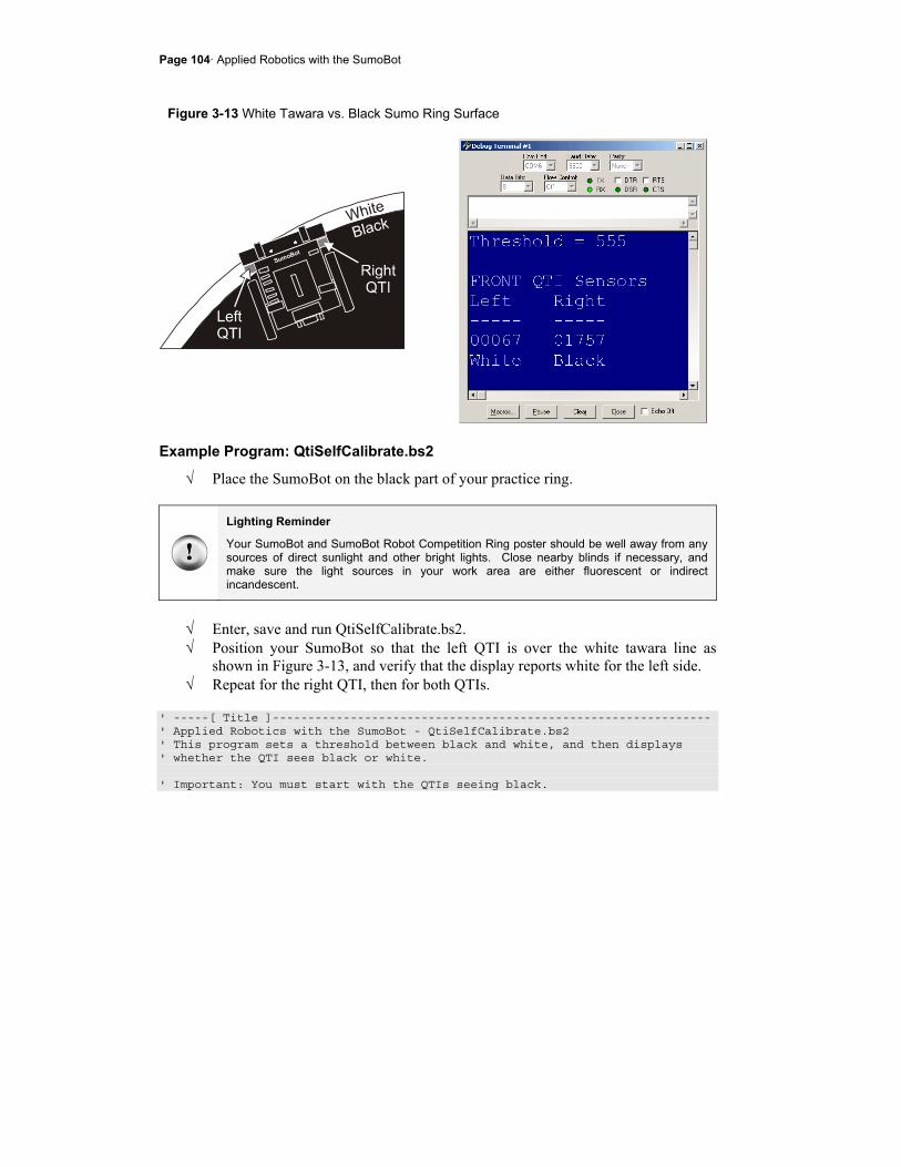
Page 104· Applied Robotics with the SumoBot
Figure 3-13 White Tawara vs. Black Sumo Ring Surface
Example Program: QtiSelfCalibrate.bs2
√ Place the SumoBot on the black part of your practice ring.
Lighting Reminder
Your SumoBot and SumoBot Robot Competition Ring poster should be well away from any sources of direct sunlight and other bright lights. Close nearby blinds if necessary, and make sure the light sources in your work area are either fluorescent or indirect incandescent.
√ Enter, save and run QtiSelfCalibrate.bs2. √ Position your SumoBot so that the left QTI is over the white tawara line as
shown in Figure 3-13, and verify that the display reports white for the left side. √ Repeat for the right QTI, then for both QTIs.
' -----[ Title ]-------------------------------------------------------------- ' Applied Robotics with the SumoBot - QtiSelfCalibrate.bs2 ' This program sets a threshold between black and white, and then displays ' whether the QTI sees black or white. ' Important: You must start with the QTIs seeing black.
Chapter 3: EEPROM Tricks and Program Tips · Page 105
' $STAMP BS2 ' Target = BASIC Stamp 2 ' $PBASIC 2.5 ' Language = PBASIC 2.5 ' -----[ I/O Definitions ]--------------------------------------------------- qtiPwrLeft PIN 10 ' Left QTI on/off pin qtiSigLeft PIN 9 ' Left QTI signal pin qtiPwrRight PIN 7 ' Right QTI on/off pin qtiSigRight PIN 8 ' Right QTI signal pin ' -----[ Variables ]---------------------------------------------------------- qtiLeft VAR Word ' Stores left QTI time qtiRight VAR Word ' Stores right QTI time qtiThreshold VAR Word ' Stores black/white threshold ' -----[ Initialization ]----------------------------------------------------- GOSUB Read_Line_Sensors ' Get reflection values qtiThreshold = (qtiLeft + qtiRight) / 2 ' Calculate average qtiThreshold = qtiThreshold / 4 ' Take 1/4 average DEBUG CLS, "Threshold = ",DEC qtiThreshold ' Display threshold DEBUG CR, CR, "FRONT QTI Sensors", CR, ' Display column headings "Left Right", CR, "----- -----", CR ' -----[ Main Routine ]------------------------------------------------------- DO ' DO...LOOP repeats indefinitely GOSUB Read_Line_Sensors ' Get reflection values DEBUG CRSRXY, 0, 5, DEC5 qtiLeft, CRSRX, 8, ' Display reflection values DEC5 qtiRight, CR IF qtiLeft < qtiThreshold THEN ' Indicate what left QTI sees DEBUG "White" ELSE DEBUG "Black" ENDIF DEBUG CRSRX, 8 IF qtiRight < qtiThreshold THEN ' Indicate what right QTI sees DEBUG "White" ELSE
Page 106· Applied Robotics with the SumoBot
DEBUG "Black" ENDIF PAUSE 100 ' Delay for slower PCs LOOP ' -----[ Subroutine - Read_Line_Sensors ]------------------------------------- Read_Line_Sensors: HIGH qtiPwrLeft ' Turn left QTI on HIGH qtiSigLeft ' Discharge capacitor PAUSE 1 RCTIME qtiSigLeft, 1, qtiLeft ' Measure charge time LOW qtiPwrLeft ' Turn left QTI off HIGH qtiPwrRight ' Turn right QTI on HIGH qtiSigRight ' Discharge capacitor PAUSE 1 RCTIME qtiSigRight, 1, qtiRight ' Measure charge time RETURN
Your Turn - QTI Navigation Decisions
Incorporating navigation can be as simple as an IF...THEN statement that calls subroutines that perform preprogrammed maneuvers. Instead of subroutine calls, the code block below uses DEBUG commands to display what action should be taken.
√ Save QtiSelfCalibrate.bs2 as QtiSelfCalibrateYourTurn.bs2 √ Remove the two IF...THEN...ENDIF code blocks, and replace them with this:
' Indicate maneuver that should be taken based on QTI readings DEBUG CR, "Maneuver", CR, "-----------", CR IF qtiLeft < qtiThreshold AND qtiRight < qtiThreshold THEN DEBUG "Avoid tawara - both" ELSEIF qtiLeft < qtiThreshold THEN DEBUG "Avoid tawara - left" ELSEIF qtiRight < qtiThreshold THEN DEBUG "Avoid tawara - right" ELSE DEBUG "search" ENDIF DEBUG CLREOL

Chapter 3: EEPROM Tricks and Program Tips · Page 107
√ Save and then run the modified program, starting with both QTIs over a black portion of the practice ring.
√ Repeat your tests with the tawara line, and verify that the SumoBot is making the correct navigation decisions.
ACTIVITY #4: READING THE QTI SENSORS MORE QUICKLY How much time does it take to read QTIs? It depends a lot on the surface and the lighting conditions in the room. If both QTIs are on the black surfaces in the examples from Activities #2 and #3, they tend to be in the 1000 to 4000 range. The time measurement the RCTIME command stores in a variable are in terms of 2 µs units. So, an RCTIME measurement of 2000 equates to 4 ms:
ms4s1000
ms1s4000
s1000ms1s22000
s1000ms1s2tmeasuremenRCTIME)ms(time
=
×=
××=
××=
µµ
µµ
µµ
Since there are two QTIs, that's 8 ms between servo pulses. What if the material is more absorbent of infrared, and the room is dark? Maybe both QTIs will return a measurement of 3600, which equates to 7.2 ms per QTI, and 14.4 ms for the pair of them. There's probably 2 ms of processing time to execute all the commands in the Read_Line_Sensors subroutine, and another 2 ms worth of PAUSE commands to set up for the RCTIME measurements. That adds up to 18.4 ms. By the measurements in Chapter 1, Activity #2, there's probably still enough time to check the IR detectors without slowing down the servos. What if you want to add a pair of QTIs to check the back of the SumoBot? That's twice the time, or 36.4 ms. That will slow the servos down, and there still hasn't been any time to check the IR detectors. You might be able to fix the problem by checking some of the sensors between one set of servo pulses, and another set of sensors between the next. It will reduce the time between servo pulses, but at the same time, it will increase the risk that your SumoBot won't see something in time, like its opponent or the white tawara line.

Page 108· Applied Robotics with the SumoBot
With some creative programming, you can actually check as many QTIs as you want, and it will only a fraction of the time that it takes to check just one QTI with the RCTIME command when it's detecting black. This activity will show you how.
The Pulse-Decay Trick
Figure 3-14 is a repeat of Figure 3-10, a schematic for what's happening inside the QTIs after Vdd has been applied to its on/off input, P10.
Figure 3-14 Simplified Version of the QTI circuit
Below is a routine that calibrates only the left QTI. After turning the device on by setting P10 high, P9 is also set high, which pushes the value of V0 toward 5 V. After a 1 ms pause, the RCTIME command measures the time it takes for V0 to decay to 1.4 V. The amount of time it takes gets stored in the time variable. The threshold variable is set equal to 1/4 the value of the time variable.
HIGH 10 HIGH 9 PAUSE 1 RCTIME 9, 1, time threshold = time / 4
The program could next use the RCTIME command and compare the decay time to the threshold time. If the decay time is greater than the threshold time, the program can assume the QTI is detecting black. If the decay time is less than the threshold time, the program can assume the QTI is detecting white.
Chapter 3: EEPROM Tricks and Program Tips · Page 109
The code block below takes less time than an RCTIME command would over a black surface. It starts like it's going to take an RCTIME measurement, by setting P9 high and waiting 1 ms for the V0 to approach 5 V. Instead of taking an RCTIME measurement, the code bock changes P9 from output to input. That's the same thing the RCTIME command does internally, and it's what causes the voltage to start to decay. Instead of waiting for the voltage to decay all the way to 1.4 V like the RCTIME command would, this code block sends a PULSOUT command to an I/O pin whose circuit will not be affected by it (the pushbutton).
HIGH 9 PAUSE 1 INPUT 9 PULSOUT 6, threshold qtiStateLeft = IN9
What about the pushbutton?
True, P6 is connected to the pushbutton, but while the pushbutton is not being monitored, PULSOUT commands can be sent to it. It is safe to be used as an output because of the 470 Ω current-limiting resistor between the I/O pin and the pushbutton terminal. Regardless of whether the pushbutton is pressed or not pressed, the I/O pin is protected. Before the pushbutton is checked, P6 will have to be set back to input with the command INPUT 6, or if you have used the PIN declaration for it in your program, INPUT pbSense.
Keep in mind that the Duration of this PULSOUT command is the threshold variable. Figure 3-15 shows what happens in terms of the signals. The instant the PULSOUT command finishes is the instant the threshold amount of time has passed. The code block takes a snapshot of IN9 at that instant by copying the value it stores into a variable named QtiStateLeft. If the QTI sees white, V0 will have decayed below 1.4 V, and IN9 will store 0. If the QTI sees black, V0 will not have decayed below 1.4 V, and IN9 will store 1.
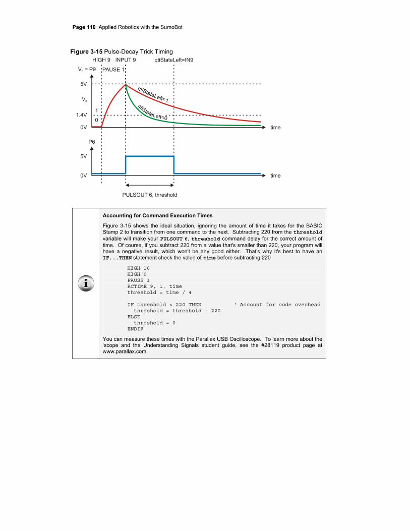
Page 110· Applied Robotics with the SumoBot
Figure 3-15 Pulse-Decay Trick Timing
Accounting for Command Execution Times
Figure 3-15 shows the ideal situation, ignoring the amount of time it takes for the BASIC Stamp 2 to transition from one command to the next. Subtracting 220 from the threshold variable will make your PULSOUT 6, threshold command delay for the correct amount of time. Of course, if you subtract 220 from a value that's smaller than 220, your program will have a negative result, which won't be any good either. That's why it's best to have an IF...THEN statement check the value of time before subtracting 220
HIGH 10 HIGH 9 PAUSE 1 RCTIME 9, 1, time threshold = time / 4 IF threshold > 220 THEN ' Account for code overhead threshold = threshold - 220 ELSE threshold = 0 ENDIF
You can measure these times with the Parallax USB Oscilloscope. To learn more about the ‘scope and the Understanding Signals student guide, see the #28119 product page at www.parallax.com.
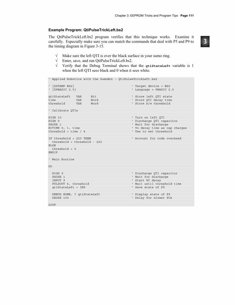
Chapter 3: EEPROM Tricks and Program Tips · Page 111
Example Program: QtiPulseTrickLeft.bs2
The QtiPulseTrickLeft.bs2 program verifies that this technique works. Examine it carefully. Especially make sure you can match the commands that deal with P5 and P9 to the timing diagram in Figure 3-15.
√ Make sure the left QTI is over the black surface in your sumo ring. √ Enter, save, and run QtiPulseTrickLeft.bs2. √ Verify that the Debug Terminal shows that the qtiStateLeft variable is 1
when the left QTI sees black and 0 when it sees white. ' Applied Robotics with the SumoBot - QtiPulseTrickLeft.bs2 ' $STAMP BS2 ' Target device = BS2 ' $PBASIC 2.5 ' Language = PBASIC 2.5 qtiStateLeft VAR Bit ' Store left QTI state time VAR Word ' Store QTI decay time threshold VAR Word ' Store b/w threshold ' Calibrate QTIs HIGH 10 ' Turn on left QTI HIGH 9 ' Discharge QTI capacitor PAUSE 1 ' Wait for discharge RCTIME 9, 1, time ' Vo decay time as cap charges threshold = time / 4 ' Use to set threshold IF threshold > 220 THEN ' Account for code overhead threshold = threshold - 220 ELSE threshold = 0 ENDIF ' Main Routine DO HIGH 9 ' Discharge QTI capacitor PAUSE 1 ' Wait for discharge INPUT 9 ' Start RC decay PULSOUT 6, threshold ' Wait until threshold time qtiStateLeft = IN9 ' Save state of P9 DEBUG HOME, ? qtiStateLeft ' Display state of P9 PAUSE 100 ' Delay for slower PCs LOOP

Page 112· Applied Robotics with the SumoBot
Your Turn - Incorporating the Right QTI
Here's the interesting part, you can add another QTI measurement to the same block of code that performed the time measurement on the left QTI. The routine will take approximately the same amount of time, but you will be measuring two QTIs.
√ Add a variable declaration for the state of the right QTI. qtiStateLeft VAR Bit
√ Add this code block right after the code that sets the threshold based on P9 measurements. It should be inserted just above the IF threshold > 220 THEN statement. HIGH 7 HIGH 8 PAUSE 1 RCTIME 8, 1, time threshold = (threshold + (time / 4)) / 2
√ Add the commands with ' <---Add comments to the existing code in the Main Routine’s DO...LOOP: HIGH 9 HIGH 8 ' <--- Add PAUSE 1 INPUT 9 INPUT 8 ' <--- Add PULSOUT 5, threshold qtiStateLeft = IN9 qtiStateRight = IN8 ' <--- Add DEBUG HOME, ? qtiStateLeft DEBUG ? qtiStateRight ' <--- Add PAUSE 100
√ Save and run the program √ Test the program and verify that both QTI's now indicate white tawara line with
0 or black ring surface with 1.

Chapter 3: EEPROM Tricks and Program Tips · Page 113
Incorporating the Pulse-Decay Trick into Another Program
Here is how to incorporate the test code from QtiPulseTrickLeft.bs2 into TestFrontQtiLineSensors.bs2 from Activity #2. The first step is to declare a dummy PIN name for P6.
DummyPin PIN 6
Also declare a couple of extra bit variables to store the states of qtiSigLeft (P9) and qtiSigRight (P8). Remember, they need a snapshot immediately after the PULSOUT command that passes the threshold amount of time:
qtiStateLeft VAR Bit qtiStateRight VAR Bit
Next, move the entire contents of the QTI calibration code block from the initialization routine into a single subroutine and name it Calibrate_Qtis:
Calibrate_Qtis: HIGH qtiPwrLeft ' Turn left QTI on HIGH qtiSigLeft ' Discharge capacitor PAUSE 1 RCTIME qtiSigLeft, 1, qtiLeft ' Measure charge time LOW qtiPwrLeft ' Turn left QTI off HIGH qtiPwrRight ' Turn right QTI on HIGH qtiSigRight ' Discharge capacitor PAUSE 1 RCTIME qtiSigRight, 1, qtiRight ' Measure charge time qtiThreshold = (qtiLeft + qtiRight) / 2 ' Calculate average qtiThreshold = qtiThreshold / 4 ' Take 1/4 average IF threshold > 220 THEN ' For code overhead threshold = threshold - 220 ELSE threshold = 0 ENDIF RETURN
After the Calibrate_Qtis subroutine is called, the program can use a modified version of the Read_Line_Sensors subroutine that uses the pulse-decay trick. Here it is, and it's essentially the same as the code block from the previous Your Turn.
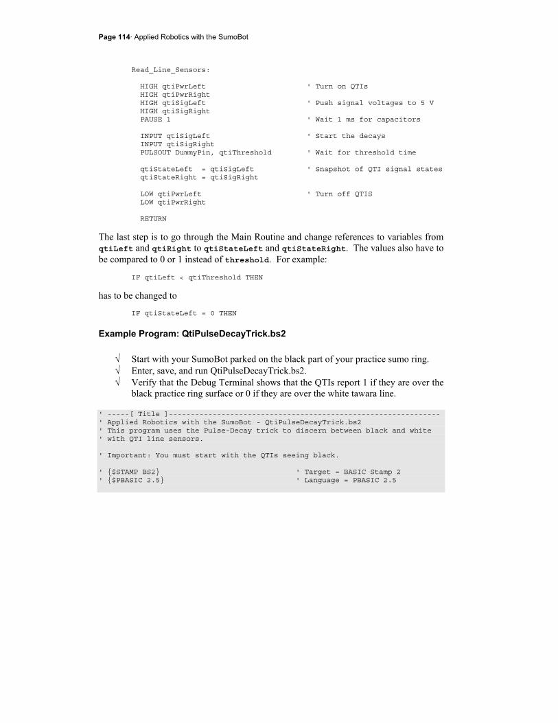
Page 114· Applied Robotics with the SumoBot
Read_Line_Sensors: HIGH qtiPwrLeft ' Turn on QTIs HIGH qtiPwrRight HIGH qtiSigLeft ' Push signal voltages to 5 V HIGH qtiSigRight PAUSE 1 ' Wait 1 ms for capacitors INPUT qtiSigLeft ' Start the decays INPUT qtiSigRight PULSOUT DummyPin, qtiThreshold ' Wait for threshold time qtiStateLeft = qtiSigLeft ' Snapshot of QTI signal states qtiStateRight = qtiSigRight LOW qtiPwrLeft ' Turn off QTIS LOW qtiPwrRight RETURN
The last step is to go through the Main Routine and change references to variables from qtiLeft and qtiRight to qtiStateLeft and qtiStateRight. The values also have to be compared to 0 or 1 instead of threshold. For example:
IF qtiLeft < qtiThreshold THEN
has to be changed to IF qtiStateLeft = 0 THEN
Example Program: QtiPulseDecayTrick.bs2
√ Start with your SumoBot parked on the black part of your practice sumo ring. √ Enter, save, and run QtiPulseDecayTrick.bs2. √ Verify that the Debug Terminal shows that the QTIs report 1 if they are over the
black practice ring surface or 0 if they are over the white tawara line. ' -----[ Title ]-------------------------------------------------------------- ' Applied Robotics with the SumoBot - QtiPulseDecayTrick.bs2 ' This program uses the Pulse-Decay trick to discern between black and white ' with QTI line sensors. ' Important: You must start with the QTIs seeing black. ' $STAMP BS2 ' Target = BASIC Stamp 2 ' $PBASIC 2.5 ' Language = PBASIC 2.5

Chapter 3: EEPROM Tricks and Program Tips · Page 115
' -----[ I/O Definitions ]--------------------------------------------------- qtiPwrLeft PIN 10 ' Left QTI on/off pin qtiSigLeft PIN 9 ' Left QTI signal pin qtiPwrRight PIN 7 ' Right QTI on/off pin qtiSigRight PIN 8 ' Right QTI signal pin DummyPin PIN 6 ' Unused I/O pin ' -----[ Variables ]---------------------------------------------------------- qtiStateLeft VAR Bit ' Stores snapshot of QtiSigLeft qtiStateRight VAR Bit ' Stores snapshot of QtiSigRight qtiLeft VAR Word ' Stores left QTI time qtiRight VAR Word ' Stores right QTI time qtiThreshold VAR Word ' Stores black/white threshold ' -----[ Initialization ]----------------------------------------------------- GOSUB Calibrate_Qtis DEBUG CLS, "FRONT QTI Sensors", CR, ' Display column headings "Left Right", CR, "----- -----", CR ' -----[ Main Routine ]------------------------------------------------------- DO ' DO...LOOP repeats indefinitely GOSUB Read_Line_Sensors ' Get reflection values DEBUG CRSRXY, 0, 3, BIN1 qtiStateLeft, CRSRX, 8, ' Display reflection values BIN1 qtiStateRight, CR IF qtiStateLeft = 0 THEN ' Indicate what left QTI sees DEBUG "White" ELSE DEBUG "Black" ENDIF DEBUG CRSRX, 8 IF qtiStateRight = 0 THEN ' Indicate what right QTI sees DEBUG "White" ELSE DEBUG "Black" ENDIF PAUSE 100 ' Delay for slower PCs
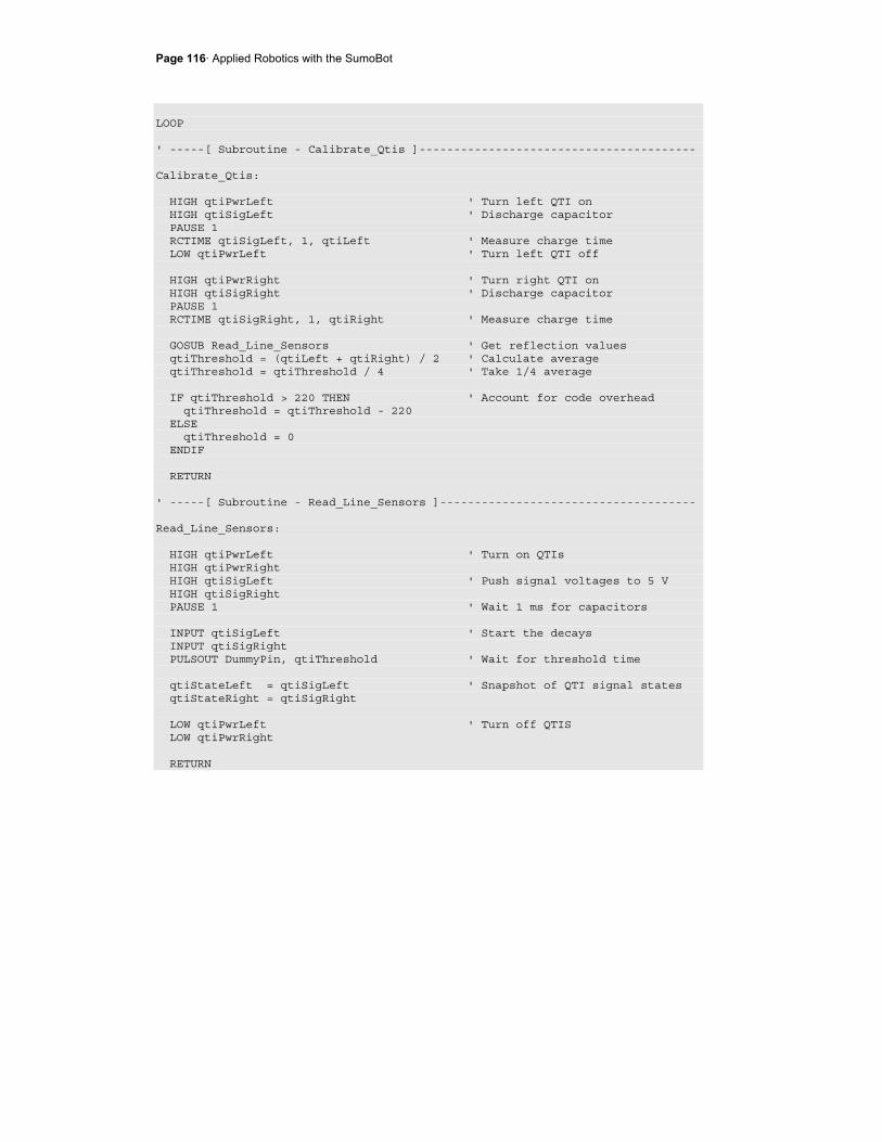
Page 116· Applied Robotics with the SumoBot
LOOP ' -----[ Subroutine - Calibrate_Qtis ]---------------------------------------- Calibrate_Qtis: HIGH qtiPwrLeft ' Turn left QTI on HIGH qtiSigLeft ' Discharge capacitor PAUSE 1 RCTIME qtiSigLeft, 1, qtiLeft ' Measure charge time LOW qtiPwrLeft ' Turn left QTI off HIGH qtiPwrRight ' Turn right QTI on HIGH qtiSigRight ' Discharge capacitor PAUSE 1 RCTIME qtiSigRight, 1, qtiRight ' Measure charge time GOSUB Read_Line_Sensors ' Get reflection values qtiThreshold = (qtiLeft + qtiRight) / 2 ' Calculate average qtiThreshold = qtiThreshold / 4 ' Take 1/4 average IF qtiThreshold > 220 THEN ' Account for code overhead qtiThreshold = qtiThreshold - 220 ELSE qtiThreshold = 0 ENDIF RETURN ' -----[ Subroutine - Read_Line_Sensors ]------------------------------------- Read_Line_Sensors: HIGH qtiPwrLeft ' Turn on QTIs HIGH qtiPwrRight HIGH qtiSigLeft ' Push signal voltages to 5 V HIGH qtiSigRight PAUSE 1 ' Wait 1 ms for capacitors INPUT qtiSigLeft ' Start the decays INPUT qtiSigRight PULSOUT DummyPin, qtiThreshold ' Wait for threshold time qtiStateLeft = qtiSigLeft ' Snapshot of QTI signal states qtiStateRight = qtiSigRight LOW qtiPwrLeft ' Turn off QTIS LOW qtiPwrRight RETURN
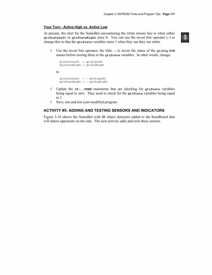
Chapter 3: EEPROM Tricks and Program Tips · Page 117
Your Turn - Active High vs. Active Low
At present, the alert for the SumoBot encountering the white tawara line is when either qtiStateLeft or qtiStateRight store 0. You can use the invert bits operator (~) to change this so that the qtiState variables store 1 when they see they see white.
√ Use the invert bits operator, the tilde ~, to invert the states of the qtiSig PIN names before storing them in the qtiState variables. In other words, change: qtiStateLeft = qtiSigLeft qtiStateRight = qtiSigRight
to qtiStateLeft = ~ qtiSigLeft qtiStateRight = ~ qtiSigRight
√ Update the IF...THEN statements that are checking for qtiState variables being equal to zero. They need to check for the qtiState variables being equal to 1.
√ Save, run and test your modified program.
ACTIVITY #5: ADDING AND TESTING SENSORS AND INDICATORS Figure 3-16 shows the SumoBot with IR object detectors added to the breadboard that will detect opponents on the side. The next activity adds and tests these sensors.
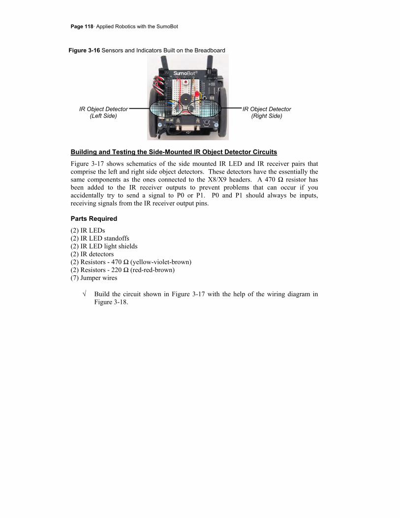
Page 118· Applied Robotics with the SumoBot
Figure 3-16 Sensors and Indicators Built on the Breadboard
Building and Testing the Side-Mounted IR Object Detector Circuits
Figure 3-17 shows schematics of the side mounted IR LED and IR receiver pairs that comprise the left and right side object detectors. These detectors have the essentially the same components as the ones connected to the X8/X9 headers. A 470 Ω resistor has been added to the IR receiver outputs to prevent problems that can occur if you accidentally try to send a signal to P0 or P1. P0 and P1 should always be inputs, receiving signals from the IR receiver output pins.
Parts Required
(2) IR LEDs (2) IR LED standoffs (2) IR LED light shields (2) IR detectors (2) Resistors - 470 Ω (yellow-violet-brown) (2) Resistors - 220 Ω (red-red-brown) (7) Jumper wires
√ Build the circuit shown in Figure 3-17 with the help of the wiring diagram in Figure 3-18.
IR Object Detector (Right Side)
IR Object Detector (Left Side)

Chapter 3: EEPROM Tricks and Program Tips · Page 119
Figure 3-17 Side-mounted IR Object Detection Circuits Right Left
Figure 3-18 Wiring Diagram
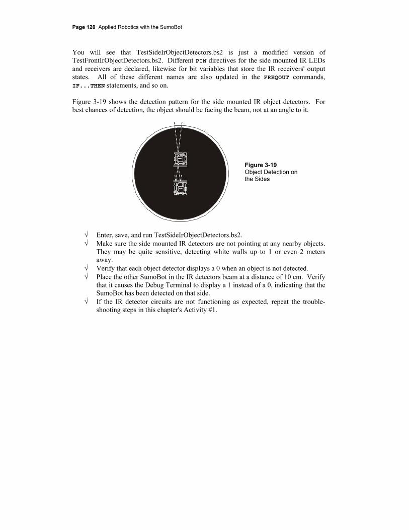
Page 120· Applied Robotics with the SumoBot
You will see that TestSideIrObjectDetectors.bs2 is just a modified version of TestFrontIrObjectDetectors.bs2. Different PIN directives for the side mounted IR LEDs and receivers are declared, likewise for bit variables that store the IR receivers' output states. All of these different names are also updated in the FREQOUT commands, IF...THEN statements, and so on. Figure 3-19 shows the detection pattern for the side mounted IR object detectors. For best chances of detection, the object should be facing the beam, not at an angle to it.
Figure 3-19 Object Detection on the Sides
√ Enter, save, and run TestSideIrObjectDetectors.bs2. √ Make sure the side mounted IR detectors are not pointing at any nearby objects.
They may be quite sensitive, detecting white walls up to 1 or even 2 meters away.
√ Verify that each object detector displays a 0 when an object is not detected. √ Place the other SumoBot in the IR detectors beam at a distance of 10 cm. Verify
that it causes the Debug Terminal to display a 1 instead of a 0, indicating that the SumoBot has been detected on that side.
√ If the IR detector circuits are not functioning as expected, repeat the trouble-shooting steps in this chapter's Activity #1.
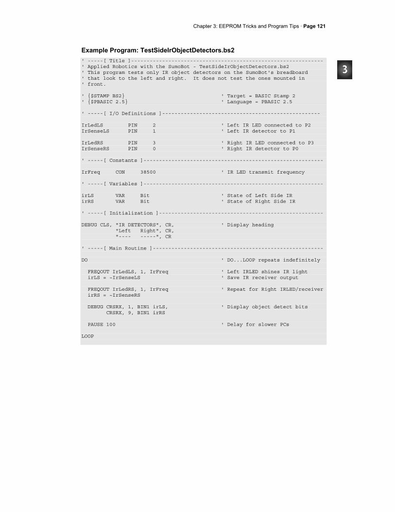
Chapter 3: EEPROM Tricks and Program Tips · Page 121
Example Program: TestSideIrObjectDetectors.bs2 ' -----[ Title ]-------------------------------------------------------------- ' Applied Robotics with the SumoBot - TestSideIrObjectDetectors.bs2 ' This program tests only IR object detectors on the SumoBot's breadboard ' that look to the left and right. It does not test the ones mounted in ' front. ' $STAMP BS2 ' Target = BASIC Stamp 2 ' $PBASIC 2.5 ' Language = PBASIC 2.5 ' -----[ I/O Definitions ]--------------------------------------------------- IrLedLS PIN 2 ' Left IR LED connected to P2 IrSenseLS PIN 1 ' Left IR detector to P1 IrLedRS PIN 3 ' Right IR LED connected to P3 IrSenseRS PIN 0 ' Right IR detector to P0 ' -----[ Constants ]---------------------------------------------------------- IrFreq CON 38500 ' IR LED transmit frequency ' -----[ Variables ]---------------------------------------------------------- irLS VAR Bit ' State of Left Side IR irRS VAR Bit ' State of Right Side IR ' -----[ Initialization ]----------------------------------------------------- DEBUG CLS, "IR DETECTORS", CR, ' Display heading "Left Right", CR, "---- -----", CR ' -----[ Main Routine ]------------------------------------------------------- DO ' DO...LOOP repeats indefinitely FREQOUT IrLedLS, 1, IrFreq ' Left IRLED shines IR light irLS = ~IrSenseLS ' Save IR receiver output FREQOUT IrLedRS, 1, IrFreq ' Repeat for Right IRLED/receiver irRS = ~IrSenseRS DEBUG CRSRX, 1, BIN1 irLS, ' Display object detect bits CRSRX, 9, BIN1 irRS PAUSE 100 ' Delay for slower PCs LOOP
Page 122· Applied Robotics with the SumoBot
Your Turn - Testing All Four
Your SumoBot will eventually need to check and process information from all four IR object detectors each time through the Main Routine’s DO...LOOP. In this case, it's a matter of incorporating elements from the IR object detector programs from this activity and Activity #1 into a single program. If you start with one of the programs, you can copy the following elements from the other program: PIN directives, variable declarations, FREQOUT commands and statements that set variables equal to pin names. After that, all that remains is modifying a couple of DEBUG commands.
√ Save a copy of TestSideIrObjectDetectors.bs2 as TestAllIrObjectDetectors.bs2. √ Copy all the elements you need from TestFrontIrObjectDetectors.bs2 into your
new program. √ Modify the DEBUG commands to display all the object detection bits. √ Test and troubleshoot until you've got it working. √ Save the modified program.
ACTIVITY #6: TESTING ALL SENSORS This activity combines portions of test code that have already been developed for the following sensors into one program:
• Front IR object detectors • Side IR object detectors • Front QTI line sensors • Pushbutton
Combining Programs
So far, the SumoBot has seven sensors: 2 QTI line sensors, 4 IR object detectors, and 1 pushbutton. Each has a test program that displays binary values for these sensors, either one at a time or in pairs. This next example combines them into a master program that stores the state of each sensor via a series of subroutines, then displays them all with a single DEBUG command. This can actually be done with minimal additions, effort, and debugging.
Chapter 3: EEPROM Tricks and Program Tips · Page 123
√ Start by opening all of the following programs:
o TestLedSpeaker.bs2 o TestPushButton.bs2 o TestFrontIrObjectDetectors.bs2 o QtiPulseDecayTrick.bs2 o TestSideIrObjectDetectors.bs2
√ Save QtiPulseDecayTrick.bs2 as TestAllSensors.bs2 √ Copy and paste the I/O definitions and variables from the other programs into
your new program. √ Add one more bit variable that was not found in the other programs, to store the
state of the pushbutton: pushbutton VAR Bit
√ Make subroutines for the speaker, IR detectors, and QTI detectors from the functional portions of their test programs. If the actual work of a sensor is done in the program's Main Routine, (like IR object detection), paste that part of the routine into a subroutine. For example, a Read_Object_Detectors subroutine could take four lines from the Main Routine of TestFrontIrObjectDetectors.bs2, and four more from TestSideIrObjectDetectors.bs2. Read_Object_Detectors: FREQOUT IrLedRS, 1, IrFreq ' Right side IR LED headlight irRS = ~IrSenseRS ' Save right side IR receiver FREQOUT IrLedRF, 1, IrFreq ' Repeat for right-front irRF = ~IrSenseRF FREQOUT IrLedLF, 1, IrFreq ' Repeat for left-front irLF = ~IrSenseLF FREQOUT IrLedLS, 1, IrFreq ' Repeat for left side irLS = ~IrSenseLS RETURN
The subroutine for the pushbutton needs a different approach. Remember that pbSense and DummyPin both reference P6, which is serving two purposes. It's getting used as an output when DummyPin sends the PULSOUT command pulses from the Read_Line_Sensors subroutine. For P6 to next be used to monitor the pushbutton, it
Page 124· Applied Robotics with the SumoBot
has to be changed back to an input first. So, the Main Routine of TestPushButton.bs2 will not serve our purpose, but this simple subroutine will.
√ Add a Read_Pushbutton subroutine:
Read_Pushbutton: INPUT pbSense ' Set I/O pin to input pushbutton = pbSense ' Store state of pbSense RETURN
Some of the initialization routines will not be necessary. Others, like Calibrate_Qtis are crucial. It's important to pick and choose what you'll need for both the Initialization and Main Routine. You'll need to make sure to call all the subroutines and display only the relevant values.
√ Construct an Initialization section and Main Routine that will make your program function.
√ Test and troubleshoot it. √ Convert all active low bit variables to active high. √ Compare what you came up with to the TestAllSensors.bs2 below.
Example Program: TestAllSensors.bs2
√ Run and test TestAllSensors.bs2. ' -----[ Title ]-------------------------------------------------------------- ' Applied Robotics with the SumoBot - TestAllSensors.bs2 ' This program is a combination of the following: ' - QtiPulseDecayTrick.bs2 ' - TestFrontIrObjectDetectors.bs2 ' - TestSideIrObjectDetectors.bs2 ' - TestPushButton.bs2 ' - TestLedSpeaker.bs2 ' Important: You must start with the QTIs seeing black. ' $STAMP BS2 ' Target = BASIC Stamp 2 ' $PBASIC 2.5 ' Language = PBASIC 2.5 ' -----[ I/O Definitions ]---------------------------------------------------
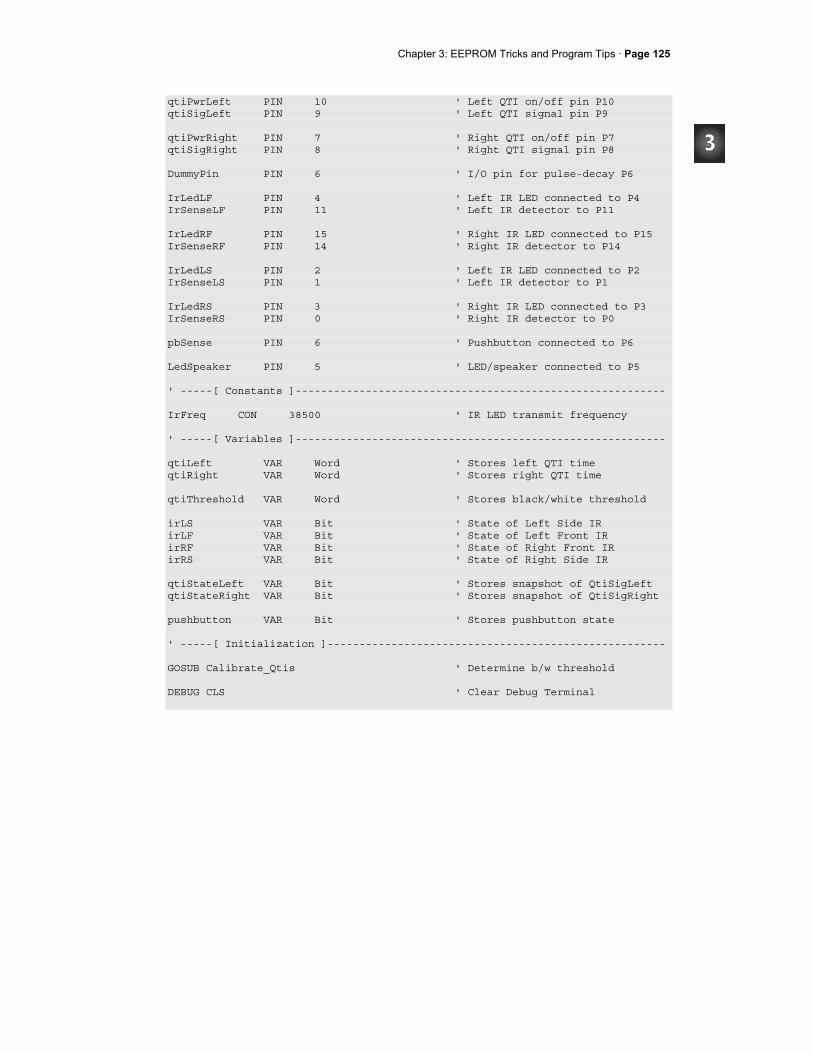
Chapter 3: EEPROM Tricks and Program Tips · Page 125
qtiPwrLeft PIN 10 ' Left QTI on/off pin P10 qtiSigLeft PIN 9 ' Left QTI signal pin P9 qtiPwrRight PIN 7 ' Right QTI on/off pin P7 qtiSigRight PIN 8 ' Right QTI signal pin P8 DummyPin PIN 6 ' I/O pin for pulse-decay P6 IrLedLF PIN 4 ' Left IR LED connected to P4 IrSenseLF PIN 11 ' Left IR detector to P11 IrLedRF PIN 15 ' Right IR LED connected to P15 IrSenseRF PIN 14 ' Right IR detector to P14 IrLedLS PIN 2 ' Left IR LED connected to P2 IrSenseLS PIN 1 ' Left IR detector to P1 IrLedRS PIN 3 ' Right IR LED connected to P3 IrSenseRS PIN 0 ' Right IR detector to P0 pbSense PIN 6 ' Pushbutton connected to P6 LedSpeaker PIN 5 ' LED/speaker connected to P5 ' -----[ Constants ]---------------------------------------------------------- IrFreq CON 38500 ' IR LED transmit frequency ' -----[ Variables ]---------------------------------------------------------- qtiLeft VAR Word ' Stores left QTI time qtiRight VAR Word ' Stores right QTI time qtiThreshold VAR Word ' Stores black/white threshold irLS VAR Bit ' State of Left Side IR irLF VAR Bit ' State of Left Front IR irRF VAR Bit ' State of Right Front IR irRS VAR Bit ' State of Right Side IR qtiStateLeft VAR Bit ' Stores snapshot of QtiSigLeft qtiStateRight VAR Bit ' Stores snapshot of QtiSigRight pushbutton VAR Bit ' Stores pushbutton state ' -----[ Initialization ]----------------------------------------------------- GOSUB Calibrate_Qtis ' Determine b/w threshold DEBUG CLS ' Clear Debug Terminal
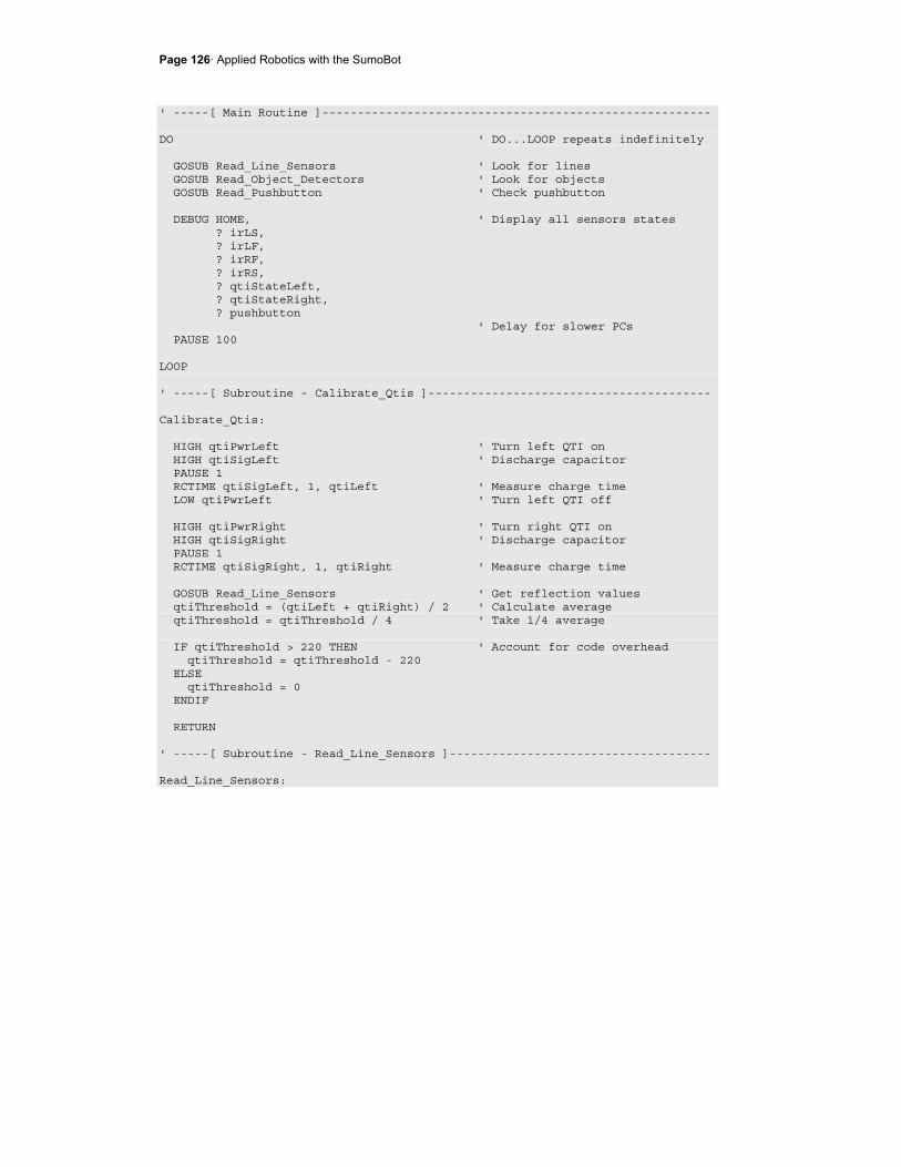
Page 126· Applied Robotics with the SumoBot
' -----[ Main Routine ]------------------------------------------------------- DO ' DO...LOOP repeats indefinitely GOSUB Read_Line_Sensors ' Look for lines GOSUB Read_Object_Detectors ' Look for objects GOSUB Read_Pushbutton ' Check pushbutton DEBUG HOME, ' Display all sensors states ? irLS, ? irLF, ? irRF, ? irRS, ? qtiStateLeft, ? qtiStateRight, ? pushbutton ' Delay for slower PCs PAUSE 100 LOOP ' -----[ Subroutine - Calibrate_Qtis ]---------------------------------------- Calibrate_Qtis: HIGH qtiPwrLeft ' Turn left QTI on HIGH qtiSigLeft ' Discharge capacitor PAUSE 1 RCTIME qtiSigLeft, 1, qtiLeft ' Measure charge time LOW qtiPwrLeft ' Turn left QTI off HIGH qtiPwrRight ' Turn right QTI on HIGH qtiSigRight ' Discharge capacitor PAUSE 1 RCTIME qtiSigRight, 1, qtiRight ' Measure charge time GOSUB Read_Line_Sensors ' Get reflection values qtiThreshold = (qtiLeft + qtiRight) / 2 ' Calculate average qtiThreshold = qtiThreshold / 4 ' Take 1/4 average IF qtiThreshold > 220 THEN ' Account for code overhead qtiThreshold = qtiThreshold - 220 ELSE qtiThreshold = 0 ENDIF RETURN ' -----[ Subroutine - Read_Line_Sensors ]------------------------------------- Read_Line_Sensors:
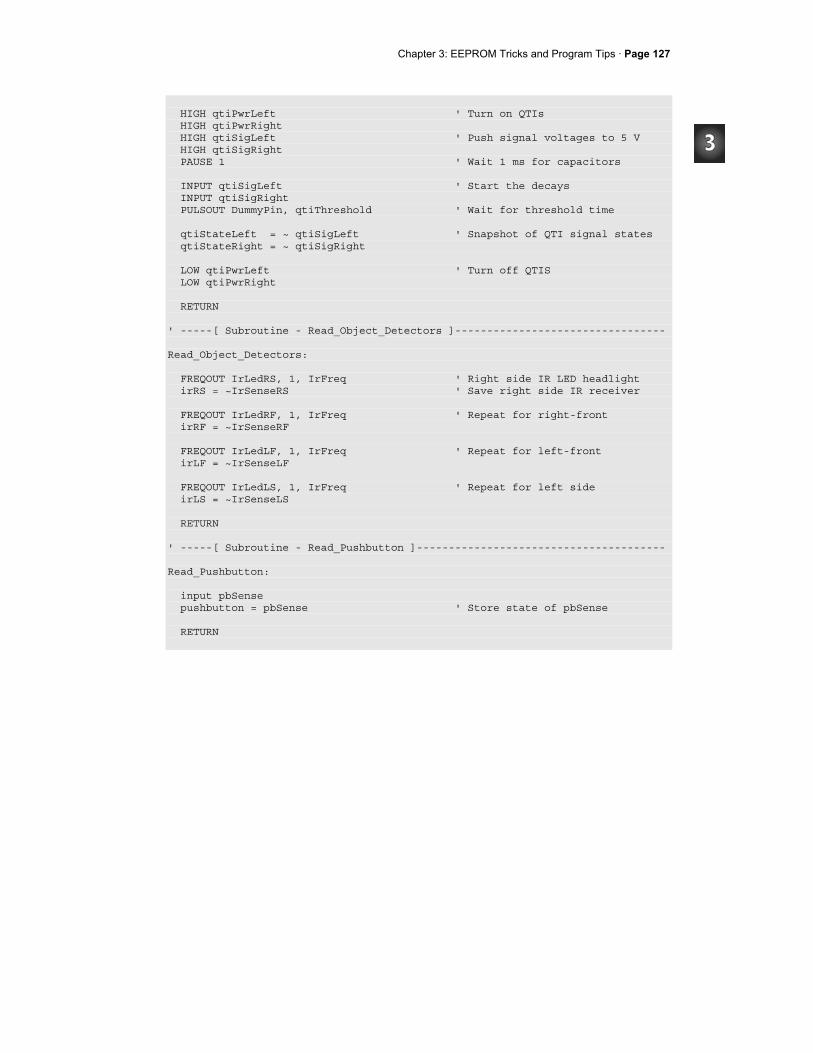
Chapter 3: EEPROM Tricks and Program Tips · Page 127
HIGH qtiPwrLeft ' Turn on QTIs HIGH qtiPwrRight HIGH qtiSigLeft ' Push signal voltages to 5 V HIGH qtiSigRight PAUSE 1 ' Wait 1 ms for capacitors INPUT qtiSigLeft ' Start the decays INPUT qtiSigRight PULSOUT DummyPin, qtiThreshold ' Wait for threshold time qtiStateLeft = ~ qtiSigLeft ' Snapshot of QTI signal states qtiStateRight = ~ qtiSigRight LOW qtiPwrLeft ' Turn off QTIS LOW qtiPwrRight RETURN ' -----[ Subroutine - Read_Object_Detectors ]--------------------------------- Read_Object_Detectors: FREQOUT IrLedRS, 1, IrFreq ' Right side IR LED headlight irRS = ~IrSenseRS ' Save right side IR receiver FREQOUT IrLedRF, 1, IrFreq ' Repeat for right-front irRF = ~IrSenseRF FREQOUT IrLedLF, 1, IrFreq ' Repeat for left-front irLF = ~IrSenseLF FREQOUT IrLedLS, 1, IrFreq ' Repeat for left side irLS = ~IrSenseLS RETURN ' -----[ Subroutine - Read_Pushbutton ]--------------------------------------- Read_Pushbutton: input pbSense pushbutton = pbSense ' Store state of pbSense RETURN
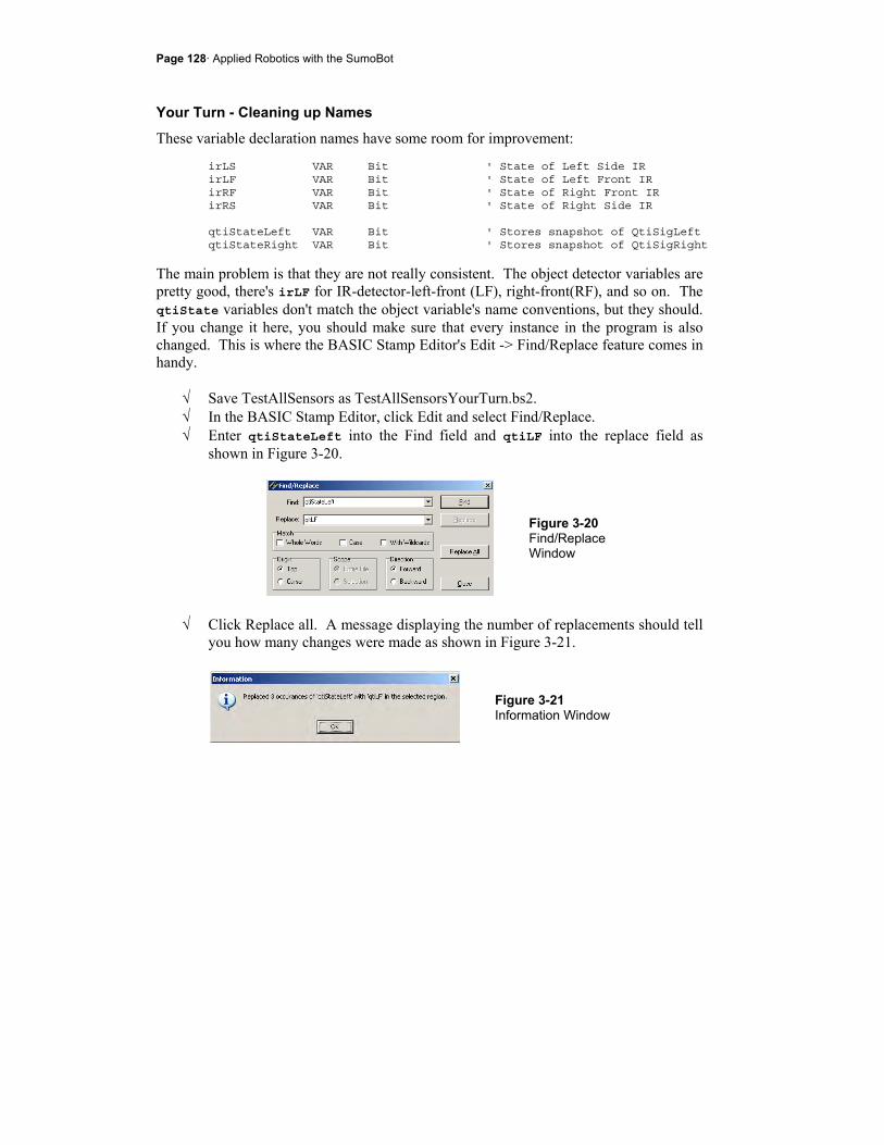
Page 128· Applied Robotics with the SumoBot
Your Turn - Cleaning up Names
These variable declaration names have some room for improvement: irLS VAR Bit ' State of Left Side IR irLF VAR Bit ' State of Left Front IR irRF VAR Bit ' State of Right Front IR irRS VAR Bit ' State of Right Side IR qtiStateLeft VAR Bit ' Stores snapshot of QtiSigLeft qtiStateRight VAR Bit ' Stores snapshot of QtiSigRight
The main problem is that they are not really consistent. The object detector variables are pretty good, there's irLF for IR-detector-left-front (LF), right-front(RF), and so on. The qtiState variables don't match the object variable's name conventions, but they should. If you change it here, you should make sure that every instance in the program is also changed. This is where the BASIC Stamp Editor's Edit -> Find/Replace feature comes in handy.
√ Save TestAllSensors as TestAllSensorsYourTurn.bs2. √ In the BASIC Stamp Editor, click Edit and select Find/Replace. √ Enter qtiStateLeft into the Find field and qtiLF into the replace field as
shown in Figure 3-20.
Figure 3-20 Find/Replace Window
√ Click Replace all. A message displaying the number of replacements should tell
you how many changes were made as shown in Figure 3-21.
Figure 3-21 Information Window

Chapter 3: EEPROM Tricks and Program Tips · Page 129
√ Repeat by using this feature to change qtiStateLeft to qtiLF. √ Some of the comments may now be out of alignment. Go through the program
and insert spaces to line the side comments back up to column 46. √ Save your modified program; you will need it in the next couple activities.
ACTIVITY #7: ORGANIZING SENSORS WITH FLAG BITS Storing each sensor value as an individual bit is great for decision making, especially if you want to isolate only one or two variables. In other cases, it's better to have all your bits in a larger variable. It makes it easier for your program to analyze patterns in the sensor flags. With PBASIC, you can have it both ways. This activity demonstrates how to declare a sensors variable, and then declare individual flag bits within that variable.
Bit Declarations inside a Byte
By storing all your flag bits in a larger variable, they are still accessible as individual values, but they are also accessible as a group for pattern analysis. It doesn't make programming any more difficult. In fact, with PBASIC all you have to do is declare a byte variable, and then declare the names of each individual bit in the byte. For example, here are the 7 bit-variable declarations from TestAllSensorsYourTurn.bs2.
irLS VAR Bit ' State of Left Side IR irLF VAR Bit ' State of Left Front IR irRF VAR Bit ' State of Right Front IR irRS VAR Bit ' State of Right Side IR qtiLF VAR Bit ' Stores snapshot of QtiSigLeft qtiRF VAR Bit ' Stores snapshot of QtiSigRight pushbutton VAR Bit ' Stores pushbutton state
To arrange these in a byte, simply declare the byte variable, and then declare each bit as a member of the byte variable. For example, if the byte is named sensors, irRS can be sensors.BIT0, irRF can be sensors.BIT1, and so on. Here is the entire series of variable declarations within a single sensors byte variable:
sensors VAR Byte ' Sensor flags byte pushbutton VAR sensors.BIT6 ' Stores pushbutton state qtiLF VAR sensors.BIT5 ' Stores snapshot of QtiSigLeft qtiRF VAR sensors.BIT4 ' Stores snapshot of QtiSigRight
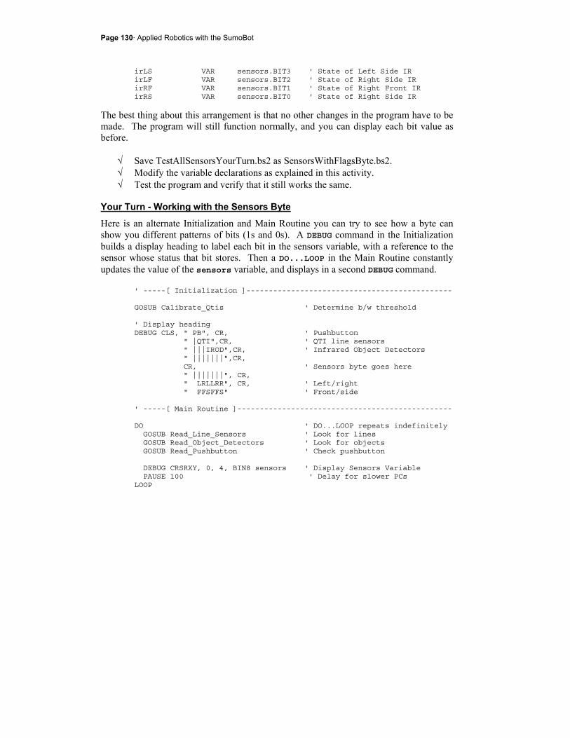
Page 130· Applied Robotics with the SumoBot
irLS VAR sensors.BIT3 ' State of Left Side IR irLF VAR sensors.BIT2 ' State of Right Side IR irRF VAR sensors.BIT1 ' State of Right Front IR irRS VAR sensors.BIT0 ' State of Right Side IR
The best thing about this arrangement is that no other changes in the program have to be made. The program will still function normally, and you can display each bit value as before.
√ Save TestAllSensorsYourTurn.bs2 as SensorsWithFlagsByte.bs2. √ Modify the variable declarations as explained in this activity. √ Test the program and verify that it still works the same.
Your Turn - Working with the Sensors Byte
Here is an alternate Initialization and Main Routine you can try to see how a byte can show you different patterns of bits (1s and 0s). A DEBUG command in the Initialization builds a display heading to label each bit in the sensors variable, with a reference to the sensor whose status that bit stores. Then a DO...LOOP in the Main Routine constantly updates the value of the sensors variable, and displays in a second DEBUG command.
' -----[ Initialization ]---------------------------------------------- GOSUB Calibrate_Qtis ' Determine b/w threshold ' Display heading DEBUG CLS, " PB", CR, ' Pushbutton " |QTI",CR, ' QTI line sensors " |||IROD",CR, ' Infrared Object Detectors " |||||||",CR, CR, ' Sensors byte goes here " |||||||", CR, " LRLLRR", CR, ' Left/right " FFSFFS" ' Front/side ' -----[ Main Routine ]------------------------------------------------ DO ' DO...LOOP repeats indefinitely GOSUB Read_Line_Sensors ' Look for lines GOSUB Read_Object_Detectors ' Look for objects GOSUB Read_Pushbutton ' Check pushbutton DEBUG CRSRXY, 0, 4, BIN8 sensors ' Display Sensors Variable PAUSE 100 ' Delay for slower PCs LOOP
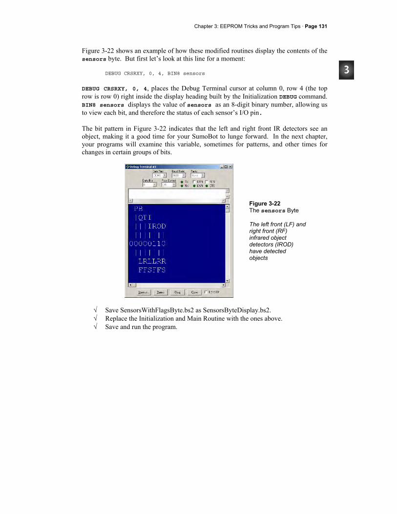
Chapter 3: EEPROM Tricks and Program Tips · Page 131
Figure 3-22 shows an example of how these modified routines display the contents of the sensors byte. But first let’s look at this line for a moment:
DEBUG CRSRXY, 0, 4, BIN8 sensors
DEBUG CRSRXY, 0, 4, places the Debug Terminal cursor at column 0, row 4 (the top row is row 0) right inside the display heading built by the Initialization DEBUG command. BIN8 sensors displays the value of sensors as an 8-digit binary number, allowing us to view each bit, and therefore the status of each sensor’s I/O pin. The bit pattern in Figure 3-22 indicates that the left and right front IR detectors see an object, making it a good time for your SumoBot to lunge forward. In the next chapter, your programs will examine this variable, sometimes for patterns, and other times for changes in certain groups of bits.
Figure 3-22 The sensors Byte The left front (LF) and right front (RF) infrared object detectors (IROD) have detected objects
√ Save SensorsWithFlagsByte.bs2 as SensorsByteDisplay.bs2. √ Replace the Initialization and Main Routine with the ones above. √ Save and run the program.
Page 132· Applied Robotics with the SumoBot
√ In order from BIT0 to BIT6, test the sensors in this order: infrared object detectors - right side, right front, left front, left side. QTI line sensors - right front, left front, pushbutton.
ACTIVITY #8: VARIABLE MANAGEMENT FOR LARGE PROGRAMS When you have a project with a lot of sensors and programmed machine reactions, variable space can become pretty tight. For example, the program in the previous activity uses three words and one byte. There's one byte to take each QTI reading, and another to store the QTI threshold. All three of these bytes are used at the beginning of the program, but only one (threshold) is accessed repeatedly as the program runs. Since threshold isn't even changed repeatedly as the program runs, it's not necessarily the best use of a RAM variable either. This activity uses the techniques introduced in Chapter 2, Activity #2 to use and reuse temporary variables. As you go through the activities in this book, you will use the same few temporary variables to monitor sensors, control servos, log data, and perform a variety of maneuvers. In virtually every subroutine you build to perform these functions, the same few variables will be used in different ways. Even after the activities in this book, you can continue to add functionality to your SumoBot, without worrying that the next sensor might take up too much RAM.
Incorporating Temporary Variables into SensorsWithByteDisplay.bs2
It's important to modify the sensor testing program (SensorsWithByteDisplay.bs2) so that it uses the memory management techniques introduced in ThreeVariablesManyJobs.bs2. Specifically, it has to use and re-use temporary variables and use EEPROM to store and access values that don't change frequently. After the program has been modified, features like more sensors, servo control, navigation, and datalogging can be added in many cases without ever having to declare any more RAM variables.
√ Start by saving SensorsWithByteDisplay.bs2 as SensorsWithTempVariables.bs2. √ Next, the qtiLeft, qtiRight, and qtiThreshold variable declarations need to
be commented out. In place of these three variables, you can use two word variables - temp (short for temporary) and multi (short for multipurpose). ' -----[ Variables ]--------------------------------------------------- ' qtiLeft VAR Word ' Stores left QTI time ' qtiRight VAR Word ' Stores right QTI time
Chapter 3: EEPROM Tricks and Program Tips · Page 133
' qtiThreshold VAR Word ' Stores black/white threshold temp VAR Word ' <--- New temporary variable multi VAR Word ' <--- New multipurpose variable
As mentioned earlier, a variable doesn't have to store the QTI decay black/white threshold value because it doesn't change after it is set at the beginning of the program. This makes it a prime candidate for EEPROM storage. We can use a DATA directive to set aside a word-size variable to hold this threshold value.
√ Add this DATA directive to give this EEPROM address the Symbol name QtiThresh. ' -----[ EEPROM Data ]------------------------------------------------- QtiThresh DATA Word 0 ' Word for QTI threshold time
Even though the DATA directive writes a 0 to this EEPROM location when the program is downloaded, a WRITE command can change this value after the program starts running. Any value that is stored in EEPROM will remain there even if the power is disconnected from the SumoBot. The only things that can change that value are another WRITE command, or a download with a DATA directive that overwrites it.
All commands in the Calibrate_Qtis subroutine that involve the qtiLeft, qtiRight, or qtiThreshold variables can be replaced with commands that use temp and multi. Each command that got replaced was commented, with an apostrophe ' placed to the left of it. Each command that was added has a comment to the right with either ' <--- Add or ' <--- New. Notice that multi and temp are also used to calculate the threshold time. Notice also that the threshold value is then copied from the multi variable to the byte at the QtiThresh address in EEPROM.
√ Go through and examine each commented command and its replacement in this entire subroutine. ' -----[ Subroutine - Calibrate_Qtis ]--------------------------------- Calibrate_Qtis: HIGH qtiPwrLeft ' Turn left QTI on HIGH qtiSigLeft ' Discharge capacitor PAUSE 1 ' RCTIME qtiSigLeft, 1, qtiLeft ' Measure charge time
Page 134· Applied Robotics with the SumoBot
RCTIME qtiSigLeft, 1, temp ' <--- New measure charge time LOW qtiPwrLeft ' Turn left QTI off multi = temp ' <--- Add HIGH qtiPwrRight ' Turn right QTI on HIGH qtiSigRight ' Discharge capacitor PAUSE 1 ' RCTIME qtiSigRight, 1, qtiRight ' Measure charge time RCTIME qtiSigRight, 1, temp ' <--- New measure charge time ' qtiThreshold = (qtiLeft + qtiRight) / 2 ' Calculate average multi = (multi + temp) / 2 ' <--- New calculate average ' qtiThreshold = qtiThreshold / 4 ' Take 1/4 average multi = multi / 4 ' <--- New take 1/4 average 'IF qtiThreshold > 220 THEN ' Account for code overhead ' qtiThreshold = qtiThreshold - 220 ' ELSE ' qtiThreshold = 0 ' ENDIF IF multi > 220 THEN ' <--- New multi = multi - 220 ' <--- New ELSE ' <--- New threshold = 0 ' <--- New ENDIF ' <--- New WRITE QtiThresh, multi ' <--- New threshold to EEPROM RETURN
Since there's no more qtiThreshold variable and the value is instead stored at the QtiThresh address in EEPROM, the Read_Line_Sensors subroutine will have to be changed too. A READ command is used to copy the QtiThresh value from EEPROM to the temp variable. Then, PULSOUT DummyPin, temp replaces PULSOUT DummyPIN, qtiThreshold.
' -----[ Subroutine - Read_Line_Sensors ]------------------------------ Read_Line_Sensors: . . . READ QtiThresh, Word temp ' <-- Add get threshold time INPUT qtiSigLeft ' Start the decays INPUT qtiSigRight
Chapter 3: EEPROM Tricks and Program Tips · Page 135
' PULSOUT DummyPin, qtiThreshold ' Wait for threshold time PULSOUT DummyPin, temp ' <--- New wait threshold time qtiLF = ~qtiSigLeft ' Snapshot of QTI signal states qtiRF = ~qtiSigRight . . .
Remember, the goal of all this work is to make the program more easily expandable. The other goal is to make it so that you can move parts of this program to other programs that follow the same conventions. However, it still has to perform the same functions that it did before the adjustments.
Example Program: SensorsWithTempVariables.bs2
√ Enter, save, and run SensorsWithTempVariables.bs2 √ Verify that the QTIs work the same as before.
' -----[ Title ]-------------------------------------------------------------- ' Applied Robotics with the SumoBot - SensorsWithTempVariables.bs2 ' Demonstrates the use of a temporary and multipurpose variable in conjunction ' with DATA, WRITE, and READ for calculating, storing, and using the qti ' threshold value. ' $STAMP BS2 ' Target = BASIC Stamp 2 ' $PBASIC 2.5 ' Language = PBASIC 2.5 ' -----[ I/O Definitions ]--------------------------------------------------- qtiPwrLeft PIN 10 ' Left QTI on/off pin P10 qtiSigLeft PIN 9 ' Left QTI signal pin P9 qtiPwrRight PIN 7 ' Right QTI on/off pin P7 qtiSigRight PIN 8 ' Right QTI signal pin P8 DummyPin PIN 6 ' I/O pin for pulse-decay P6 IrLedLF PIN 4 ' Left IR LED connected to P4 IrSenseLF PIN 11 ' Left IR detector to P11 IrLedRF PIN 15 ' Right IR LED connected to P15 IrSenseRF PIN 14 ' Right IR detector to P14 IrLedLS PIN 2 ' Left IR LED connected to P2 IrSenseLS PIN 1 ' Left IR detector to P1
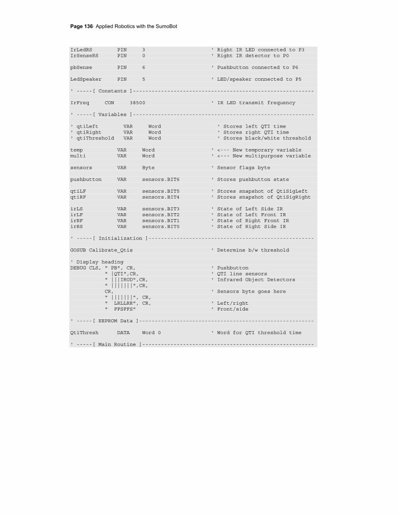
Page 136· Applied Robotics with the SumoBot
IrLedRS PIN 3 ' Right IR LED connected to P3 IrSenseRS PIN 0 ' Right IR detector to P0 pbSense PIN 6 ' Pushbutton connected to P6 LedSpeaker PIN 5 ' LED/speaker connected to P5 ' -----[ Constants ]---------------------------------------------------------- IrFreq CON 38500 ' IR LED transmit frequency ' -----[ Variables ]---------------------------------------------------------- ' qtiLeft VAR Word ' Stores left QTI time ' qtiRight VAR Word ' Stores right QTI time ' qtiThreshold VAR Word ' Stores black/white threshold temp VAR Word ' <--- New temporary variable multi VAR Word ' <--- New multipurpose variable sensors VAR Byte ' Sensor flags byte pushbutton VAR sensors.BIT6 ' Stores pushbutton state qtiLF VAR sensors.BIT5 ' Stores snapshot of QtiSigLeft qtiRF VAR sensors.BIT4 ' Stores snapshot of QtiSigRight irLS VAR sensors.BIT3 ' State of Left Side IR irLF VAR sensors.BIT2 ' State of Left Front IR irRF VAR sensors.BIT1 ' State of Right Front IR irRS VAR sensors.BIT0 ' State of Right Side IR ' -----[ Initialization ]----------------------------------------------------- GOSUB Calibrate_Qtis ' Determine b/w threshold ' Display heading DEBUG CLS, " PB", CR, ' Pushbutton " |QTI",CR, ' QTI line sensors " |||IROD",CR, ' Infrared Object Detectors " |||||||",CR, CR, ' Sensors byte goes here " |||||||", CR, " LRLLRR", CR, ' Left/right " FFSFFS" ' Front/side ' -----[ EEPROM Data ]-------------------------------------------------------- QtiThresh DATA Word 0 ' Word for QTI threshold time ' -----[ Main Routine ]-------------------------------------------------------
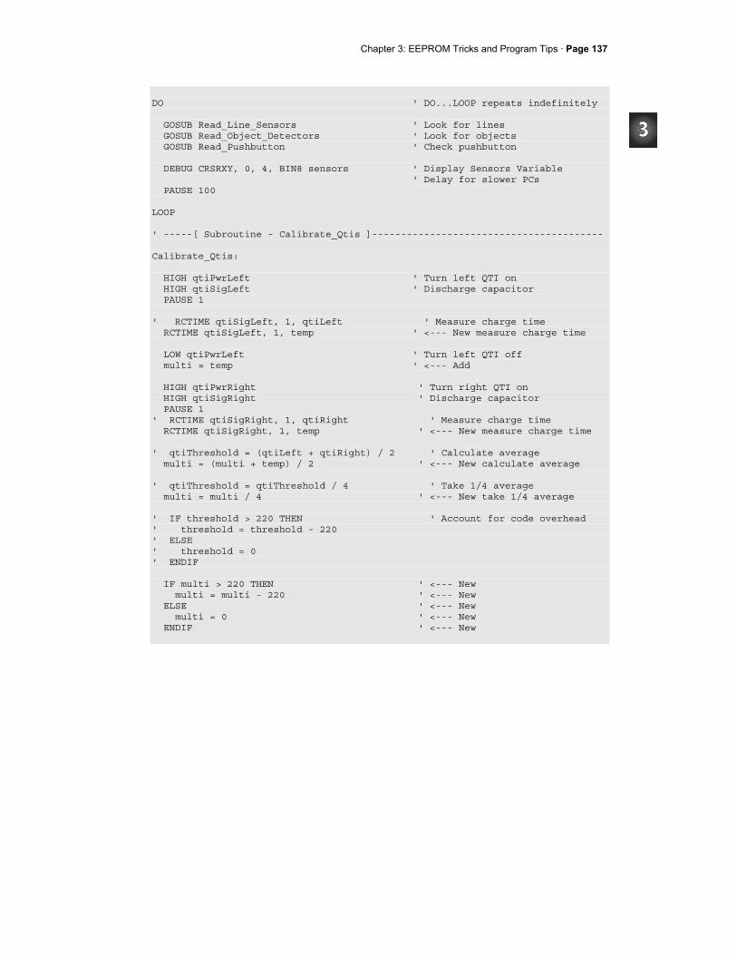
Chapter 3: EEPROM Tricks and Program Tips · Page 137
DO ' DO...LOOP repeats indefinitely GOSUB Read_Line_Sensors ' Look for lines GOSUB Read_Object_Detectors ' Look for objects GOSUB Read_Pushbutton ' Check pushbutton DEBUG CRSRXY, 0, 4, BIN8 sensors ' Display Sensors Variable ' Delay for slower PCs PAUSE 100 LOOP ' -----[ Subroutine - Calibrate_Qtis ]---------------------------------------- Calibrate_Qtis: HIGH qtiPwrLeft ' Turn left QTI on HIGH qtiSigLeft ' Discharge capacitor PAUSE 1 ' RCTIME qtiSigLeft, 1, qtiLeft ' Measure charge time RCTIME qtiSigLeft, 1, temp ' <--- New measure charge time LOW qtiPwrLeft ' Turn left QTI off multi = temp ' <--- Add HIGH qtiPwrRight ' Turn right QTI on HIGH qtiSigRight ' Discharge capacitor PAUSE 1 ' RCTIME qtiSigRight, 1, qtiRight ' Measure charge time RCTIME qtiSigRight, 1, temp ' <--- New measure charge time ' qtiThreshold = (qtiLeft + qtiRight) / 2 ' Calculate average multi = (multi + temp) / 2 ' <--- New calculate average ' qtiThreshold = qtiThreshold / 4 ' Take 1/4 average multi = multi / 4 ' <--- New take 1/4 average ' IF threshold > 220 THEN ' Account for code overhead ' threshold = threshold - 220 ' ELSE ' threshold = 0 ' ENDIF IF multi > 220 THEN ' <--- New multi = multi - 220 ' <--- New ELSE ' <--- New multi = 0 ' <--- New ENDIF ' <--- New
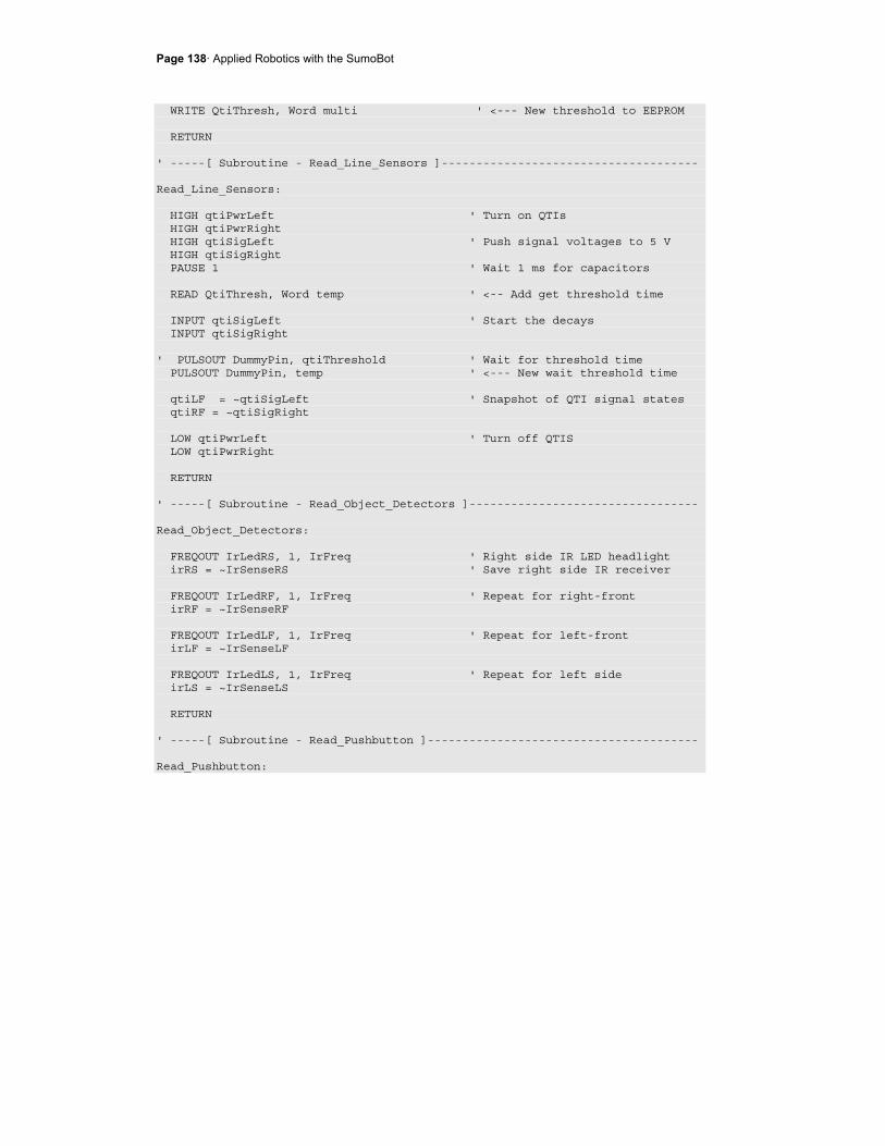
Page 138· Applied Robotics with the SumoBot
WRITE QtiThresh, Word multi ' <--- New threshold to EEPROM RETURN ' -----[ Subroutine - Read_Line_Sensors ]------------------------------------- Read_Line_Sensors: HIGH qtiPwrLeft ' Turn on QTIs HIGH qtiPwrRight HIGH qtiSigLeft ' Push signal voltages to 5 V HIGH qtiSigRight PAUSE 1 ' Wait 1 ms for capacitors READ QtiThresh, Word temp ' <-- Add get threshold time INPUT qtiSigLeft ' Start the decays INPUT qtiSigRight ' PULSOUT DummyPin, qtiThreshold ' Wait for threshold time PULSOUT DummyPin, temp ' <--- New wait threshold time qtiLF = ~qtiSigLeft ' Snapshot of QTI signal states qtiRF = ~qtiSigRight LOW qtiPwrLeft ' Turn off QTIS LOW qtiPwrRight RETURN ' -----[ Subroutine - Read_Object_Detectors ]--------------------------------- Read_Object_Detectors: FREQOUT IrLedRS, 1, IrFreq ' Right side IR LED headlight irRS = ~IrSenseRS ' Save right side IR receiver FREQOUT IrLedRF, 1, IrFreq ' Repeat for right-front irRF = ~IrSenseRF FREQOUT IrLedLF, 1, IrFreq ' Repeat for left-front irLF = ~IrSenseLF FREQOUT IrLedLS, 1, IrFreq ' Repeat for left side irLS = ~IrSenseLS RETURN ' -----[ Subroutine - Read_Pushbutton ]--------------------------------------- Read_Pushbutton:

Chapter 3: EEPROM Tricks and Program Tips · Page 139
INPUT pbSense pushbutton = pbSense ' Store state of pbSense RETURN
Your Turn - Program Cleanup
√ Review the commented lines of code and their replacements. √ Remove the commented lines of code. √ Run the program and verify that it still works properly.
Page 140· Applied Robotics with the SumoBot
SUMMARY This chapter reviewed how the SumoBot's IR detectors work, then introduced basic IR detector testing along with IR interference, electrical continuity, and IR receiver frequency response tests. Using these tests will help ensure that the SumoBot's IR detectors are reliable, and more likely to detect an opponent than lead the SumoBot on a snipe hunt. Side-mounted IR object detectors were added to the breadboard to give the SumoBot peripheral vision. This chapter also reviewed how QTI line sensors work, and then introduced a technique you can use in your programs to read multiple QTI sensors, all in less than the time it takes to read a single QTI sensor on a black surface. Self calibration techniques for QTI line sensors were reviewed and refined so that your SumoBot can automatically adjust to different sumo ring surfaces and ambient lighting conditions. Programs were developed to read and track the values of each of the seven sensors (4 IR detectors, 2 QTI sensors, and 1 pushbutton). A flags variable was introduced as a way of storing the state of each of the individual sensor bits for pattern analysis. Temporary variables for storage and counting were then incorporated into the program so that each subroutine doesn't require its own special set of variables, which is an unnecessary use of variable space.
Questions
1. What label designates the header with the front-left IR detector? 2. What connections does the SumoBot board make to the header with the front-left
IR detector that you don't have to build on a breadboard? 3. What does FREQOUT 4, 1, 38500 do? 4. What does FREQOUT 14, 1, 38500 do? 5. Are the SumoBot's IR receivers active-low or active-high output devices? 6. What is a ballast? 7. What's the main coding difference between "sniffing" for IR interference and IR
object detection? 8. What is an interruption in electrical continuity? 9. What problems can occur if your SumoBot's IR object detectors are set for
maximum sensitivity? 10. What does "frequency response" refer to?
Chapter 3: EEPROM Tricks and Program Tips · Page 141
11. What factors should you keep in mind when selecting a frequency for a given SumoBot ring?
12. What label designates the header with the front-left QTI sensor? 13. What connections does the SumoBot board make to the header with the front-left
QTI Sensor that you don't have to build on a breadboard? 14. How does the BASIC Stamp turn the power to a QTI on and off? 15. How many components are on the QTI sensor? 16. What water analogy was used for the infrared transistor inside the QRD1114? 17. Does the QRD1114 need a 38.5 kHz infrared signal? 18. Regarding Figure 3-11 on page 99, why does V0 decay more quickly when the
infrared transistor receives more IR? 19. Regarding Figure 3-11 on page 99, what does each of the three downward curves
indicate? 20. How does voltage decay relate to the amount of infrared a surface reflects? Use
black and white as examples. 21. What are the measurement units of RCTIME and PULSOUT in the BASIC Stamp
2? 22. What code block can you use to improve the accuracy of the pulse-decay trick? 23. With the pulse-decay trick, are the QTIs active-high or active low? 24. How do the circuits from the side-mounted IR object detectors differ from the
front-mounted ones? 25. How much more memory does it take to use a sensors variable to store all the
individual sensor bits?
Exercises
1. Write a routine that counts the number of IR interferences detected in a minute. 2. Write a routine that tests the IR receiver's frequency response at increments of
250 instead of 500. 3. Calculate the value threshold will store in QtiSelfCalibrate.bs2 if the white
measurement is 100 and the black measurement is 2000. 4. Expand the band of frequencies examined by TestFrequencyResponse.bs2 from
36 kHz ≤ f ≤ 42 kHz to 33 kHz ≤ f ≤ 45 kHz 5. Modify TestFrontQtiLineSensors.bs2 so that it notifies you if tilt is detected. 6. Calculate the time it would take 3 QTIs to each take measurements that average
RCTIME measurements of 2500. 7. Modify the Your Turn program from Activity #7 so that it displays a 1 in
sensors.BIT7 if all IR detectors simultaneously detect an object.

Page 142· Applied Robotics with the SumoBot
Projects
1. Write a program that beeps at different notes to tell you which sensor it detects. 2. Place an object on the SumoBot's left at a distance outside the SumoBot
Competition Ring that the SumoBot can detect with only its most sensitive IR object detection frequencies. Place the other SumoBot on the right side. Write a self calibrating routine to select the frequency that most effectively detects the SumoBot, but not the object outside the competition ring.
Chapter 4: Navigation Tips · Page 143
Chapter #4: Navigation Tips Effectively using four object detectors and two QTI line sensors for SumoBot navigation can seem a little daunting at first, especially when you consider that there are 64 different possible combinations of detected and not detected that you can get from this array. It turns out that you can reduce all these possibilities to a very simple IF...ELSEIF...ELSE...ENDIF statement. In fact, just an IF, six ELSIFs, and one ELSE can control the whole show and give you a highly functional wrestling program. The IF, all the ELSEIFs and the ELSE conditions in the final program call subroutines that do specific maneuvers until either a sensor condition is detected indicating the subroutine succeeded, or the allowed amount of time for the subroutine to execute the maneuver has expired. It makes the SumoBot's behavior both predictable and automated. This chapter demonstrates the various building blocks that go into a program that simplifies the SumoBot's decision process and automates maneuver's responses to sensor events.
SENSOR FLAGS AND NAVIGATION STATES There are several ingredients to building a program that makes a lot of different sensors and maneuvers easy to manage. First, build a subroutine that makes selecting servo pulse durations fully automated. All your program should have to do is set a variable equal to a maneuver name, and then call the servo control subroutine. Second, build a subroutine that calls both the servo control subroutine and updates all the sensors. That way, after your program has picked its maneuver, the sensors variable can be completely updated between each servo pulse. Third, construct independent navigation states. Each navigation state should be a subroutine that does a job with no further intervention until it has either succeeded or its time for the maneuver has expired. Finally, construct an IF...THEN statement that checks and responds to the most important sensor flags first, and then goes down a list of possible conditions that the SumoBot should react to. This IF...THEN statement simply responds to each sensor condition by calling the navigation subroutine that is designed to respond to that condition. It takes a few steps to get to the final form of the program, starting as always with small programs. These small programs are then converted into programs that feature sections and a common variable use convention. After several of these are built, they can be merged into a larger test program. After the test program is tested, it can be rearranged into a simplified Main Routine that makes executive decisions and then passes control to navigation subroutines.
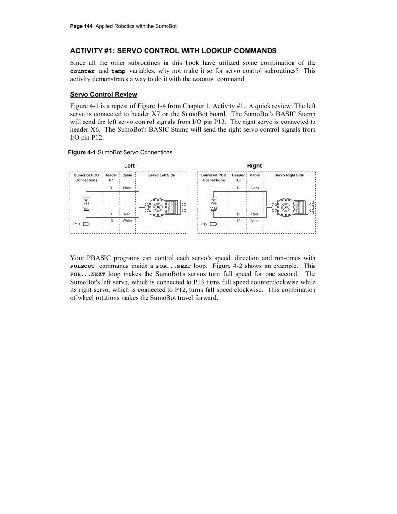
Page 144· Applied Robotics with the SumoBot
ACTIVITY #1: SERVO CONTROL WITH LOOKUP COMMANDS Since all the other subroutines in this book have utilized some combination of the counter and temp variables, why not make it so for servo control subroutines? This activity demonstrates a way to do it with the LOOKUP command.
Servo Control Review
Figure 4-1 is a repeat of Figure 1-4 from Chapter 1, Activity #1. A quick review: The left servo is connected to header X7 on the SumoBot board. The SumoBot's BASIC Stamp will send the left servo control signals from I/O pin P13. The right servo is connected to header X6. The SumoBot's BASIC Stamp will send the right servo control signals from I/O pin P12.
Figure 4-1 SumoBot Servo Connections
Left Right
Your PBASIC programs can control each servo’s speed, direction and run-times with PULSOUT commands inside a FOR...NEXT loop. Figure 4-2 shows an example. This FOR...NEXT loop makes the SumoBot's servos turn full speed for one second. The SumoBot's left servo, which is connected to P13 turns full speed counterclockwise while its right servo, which is connected to P12, turns full speed clockwise. This combination of wheel rotations makes the SumoBot travel forward.

Chapter 4: Navigation Tips · Page 145
Figure 4-2 The Servo Control Loop
The FOR...NEXT loop's EndValue is the number of 1/41 second increments the servo will run. Every time through the loop takes about 24.6 ms, so 41 times through the 24.6 ms loop takes about 41 × 0.0246 ≈ 1 second. Increasing the FOR...NEXT loop's EndValue argument to 82 would make the servos run for twice the time, about 2 seconds. Half a second of servo rotation would be an EndValue of 20, and so on.
Sensors will change the effective PAUSE time. When the effective PAUSE time has changed, it will take some experimenting to re-tune the FOR...NEXT loop EndValues to get the servo rotation times you want.
The servos have to turn opposite directions to make the SumoBot roll forward. If this seems counterintuitive, look at the SumoBot's right side. That wheel has to turn clockwise to make the SumoBot roll forward. Now look at the SumoBot's left side. That wheel has to turn counterclockwise to make the SumoBot roll forward.
Applying the same train of though for rolling backward, the right servo has to turn counterclockwise, and the left servo has to turn clockwise. By rotating both servos the same direction, you can either make the SumoBot rotate right or left. To make the SumoBot rotate left, both wheels must turn clockwise. To make the SumoBot rotate right, both wheels must turn counterclockwise.
The graph in Figure 4-3 shows how you can use the PULSOUT command's Duration argument to control the servo's speed and direction. Recall that the PULSOUT Duration argument has units of 2 µs. A pulse width of 1300 µs, equal to a PULSOUT Duration of 650, is full speed clockwise. A Duration of 850 (1700 µs) is full speed counterclockwise. A Duration of 750 (1500 µs) yields no rotation.
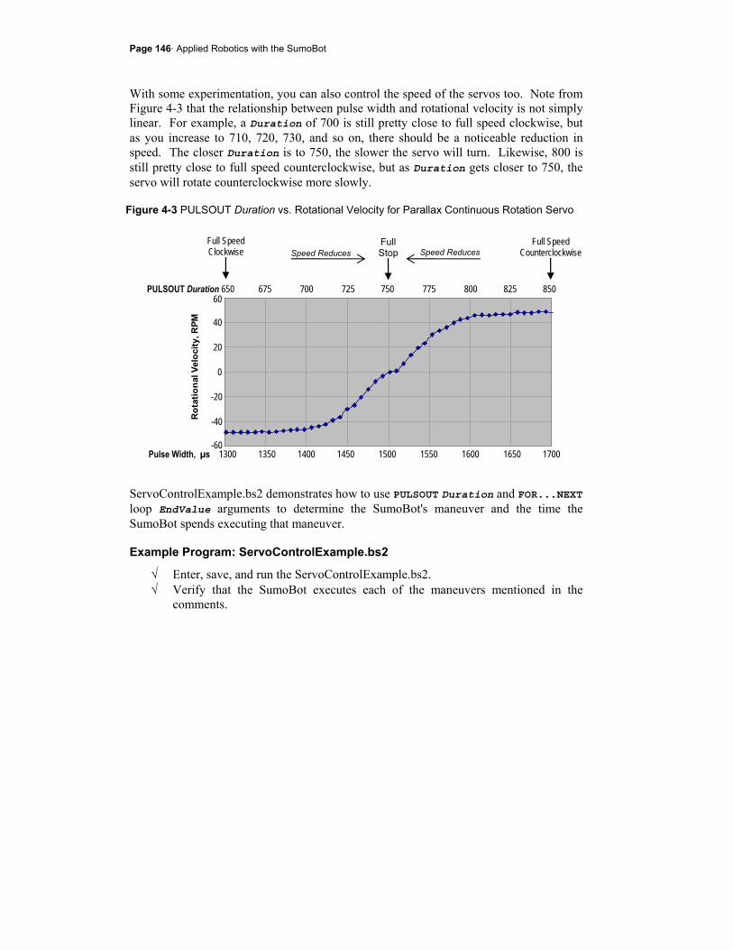
Page 146· Applied Robotics with the SumoBot
With some experimentation, you can also control the speed of the servos too. Note from Figure 4-3 that the relationship between pulse width and rotational velocity is not simply linear. For example, a Duration of 700 is still pretty close to full speed clockwise, but as you increase to 710, 720, 730, and so on, there should be a noticeable reduction in speed. The closer Duration is to 750, the slower the servo will turn. Likewise, 800 is still pretty close to full speed counterclockwise, but as Duration gets closer to 750, the servo will rotate counterclockwise more slowly.
Figure 4-3 PULSOUT Duration vs. Rotational Velocity for Parallax Continuous Rotation Servo
ServoControlExample.bs2 demonstrates how to use PULSOUT Duration and FOR...NEXT loop EndValue arguments to determine the SumoBot's maneuver and the time the SumoBot spends executing that maneuver.
Example Program: ServoControlExample.bs2
√ Enter, save, and run the ServoControlExample.bs2. √ Verify that the SumoBot executes each of the maneuvers mentioned in the
comments.
Speed Reduces
Pulse Width, µs 1300 1350 1400 1450 1500 1550 1600 1650 1700
PULSOUT Duration 650 675 700 725 750 775 800 825 850
Full Speed Clockwise
Full Speed Counterclockwise
Full Stop Speed Reduces
60 40 20 0 -20 -40 -60
Rot
atio
nal V
eloc
ity, R
PM

Chapter 4: Navigation Tips · Page 147
' Applied Robotics with the SumoBot - ServoControlExample.bs2 ' $STAMP BS2 ' $PBASIC 2.5 counter VAR byte ' SumoBot goes forward 3 seconds. FOR counter = 1 TO 122 PULSOUT 13, 850 PULSOUT 12, 650 PAUSE 20 NEXT ' SumoBot goes backward 3 seconds. FOR counter = 1 TO 122 PULSOUT 13, 650 PULSOUT 12, 850 PAUSE 20 NEXT ' SumoBot rotates left .75 seconds. FOR counter = 1 TO 30 PULSOUT 13, 650 PULSOUT 12, 650 PAUSE 20 NEXT ' SumoBot rotates right .75 seconds. FOR counter = 1 TO 30 PULSOUT 13, 850 PULSOUT 12, 850 PAUSE 20 NEXT ' SumoBot pivots right 1.5 seconds. FOR counter = 1 TO 61 PULSOUT 13, 850 PULSOUT 12, 750 PAUSE 20 NEXT ' SumoBot curves left 1.5 seconds. FOR counter = 1 TO 61 PULSOUT 13, 765 PULSOUT 12, 650 PAUSE 20 NEXT

Page 148· Applied Robotics with the SumoBot
Your Turn - Using PIN Definitions and Constants
Instead of the number 13 in the PULSOUT command's Pin argument, the example program can use the PIN directive ServoLeft. Likewise, the program can use ServoRight in place of the number 12. Since we know that 650 is the PULSOUT Duration for full-speed-clockwise, a good constant name for this number would be FS_CW. Along the same lines, 850 can be FS_CCW for full speed counterclockwise, and 750 can be NO_ROT for no rotation.
√ Add these PIN directives and constant declarations to the program: ' -----[ I/O Definitions ]-------------------------------------------- ServoLeft PIN 13 ' Left servo connected to P13 ServoRight PIN 12 ' Right servo connected to P12 ' -----[ Constants ]--------------------------------------------------- ' Servo pulse width rotation constants FS_CCW CON 850 ' Full speed counterclockwise FS_CW CON 650 ' Full speed clockwise NO_ROT CON 750 ' No rotation
Here is an example of the first one updated with PIN directives and constant names. ' SumoBot goes forward 3 seconds. FOR counter = 1 TO 122 PULSOUT ServoLeft, FS_CCW PULSOUT ServoRight, FS_CW PAUSE 20 NEXT
√ Modify all the motion routines to use these constants.
LOOKUP Command Review
The LOOKUP command picks a value from the lookup table (the list within the square braces) and copies that value to Variable. The value LOOKUP picks depends on the Index variable.
LOOKUP Index, [Value1, Value2, ... ValueN], Variable
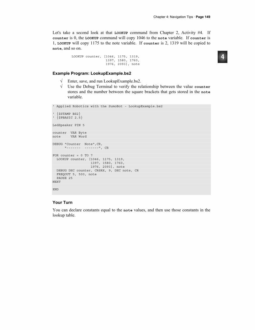
Chapter 4: Navigation Tips · Page 149
Let's take a second look at that LOOKUP command from Chapter 2, Activity #4. If counter is 0, the LOOKUP command will copy 1046 to the note variable. If counter is 1, LOOKUP will copy 1175 to the note variable. If counter is 2, 1319 will be copied to note, and so on.
LOOKUP counter, [1046, 1175, 1319, 1397, 1580, 1760, 1976, 2093], note
Example Program: LookupExample.bs2
√ Enter, save, and run LookupExample.bs2. √ Use the Debug Terminal to verify the relationship between the value counter
stores and the number between the square brackets that gets stored in the note variable.
' Applied Robotics with the SumoBot - LookupExample.bs2 ' $STAMP BS2 ' $PBASIC 2.5 LedSpeaker PIN 5 counter VAR Byte note VAR Word DEBUG "Counter Note",CR, "------- -------", CR FOR counter = 0 TO 7 LOOKUP counter, [1046, 1175, 1319, 1397, 1580, 1760, 1976, 2093], note DEBUG DEC counter, CRSRX, 9, DEC note, CR FREQOUT 5, 500, note PAUSE 25 NEXT END
Your Turn
You can declare constants equal to the note values, and then use those constants in the lookup table.
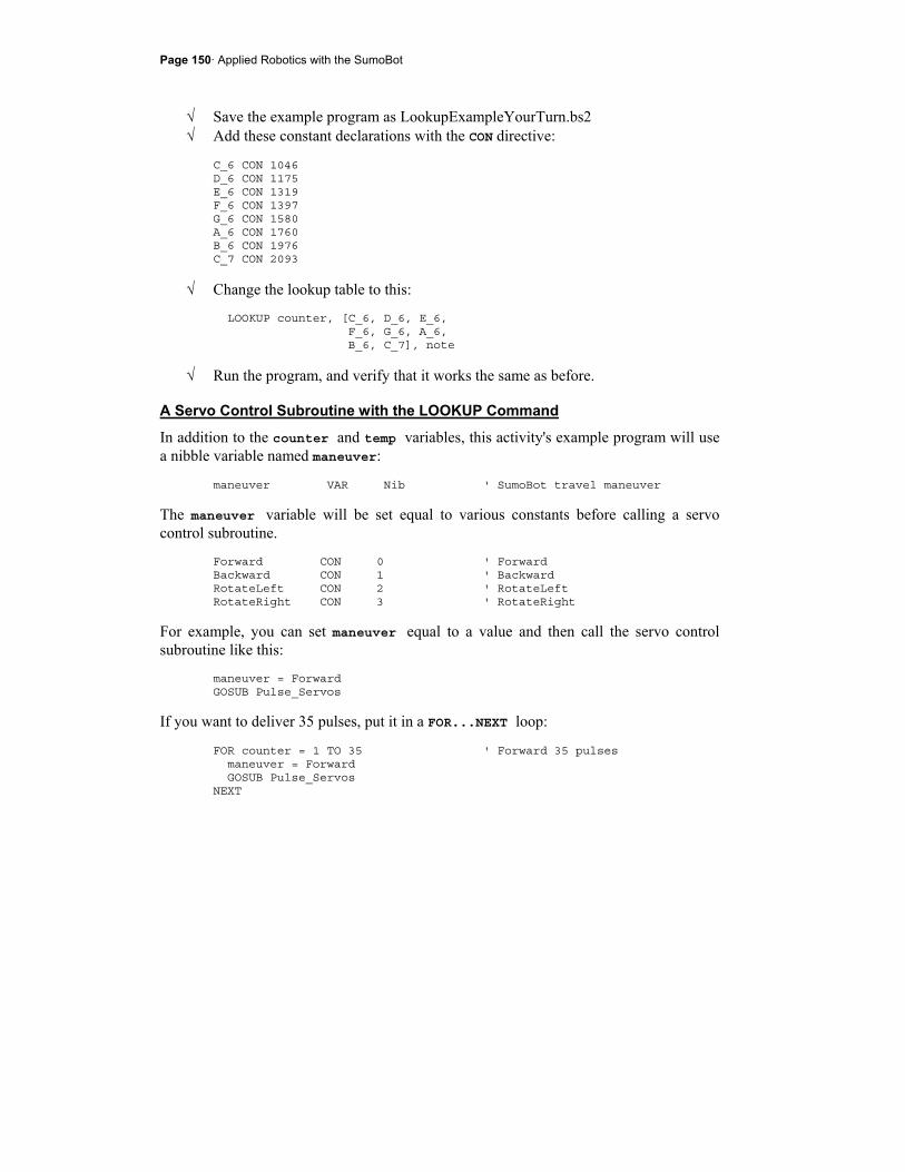
Page 150· Applied Robotics with the SumoBot
√ Save the example program as LookupExampleYourTurn.bs2 √ Add these constant declarations with the CON directive:
C_6 CON 1046 D_6 CON 1175 E_6 CON 1319 F_6 CON 1397 G_6 CON 1580 A_6 CON 1760 B_6 CON 1976 C_7 CON 2093
√ Change the lookup table to this: LOOKUP counter, [C_6, D_6, E_6, F_6, G_6, A_6, B_6, C_7], note
√ Run the program, and verify that it works the same as before.
A Servo Control Subroutine with the LOOKUP Command
In addition to the counter and temp variables, this activity's example program will use a nibble variable named maneuver:
maneuver VAR Nib ' SumoBot travel maneuver
The maneuver variable will be set equal to various constants before calling a servo control subroutine.
Forward CON 0 ' Forward Backward CON 1 ' Backward RotateLeft CON 2 ' RotateLeft RotateRight CON 3 ' RotateRight
For example, you can set maneuver equal to a value and then call the servo control subroutine like this:
maneuver = Forward GOSUB Pulse_Servos
If you want to deliver 35 pulses, put it in a FOR...NEXT loop: FOR counter = 1 TO 35 ' Forward 35 pulses maneuver = Forward GOSUB Pulse_Servos NEXT
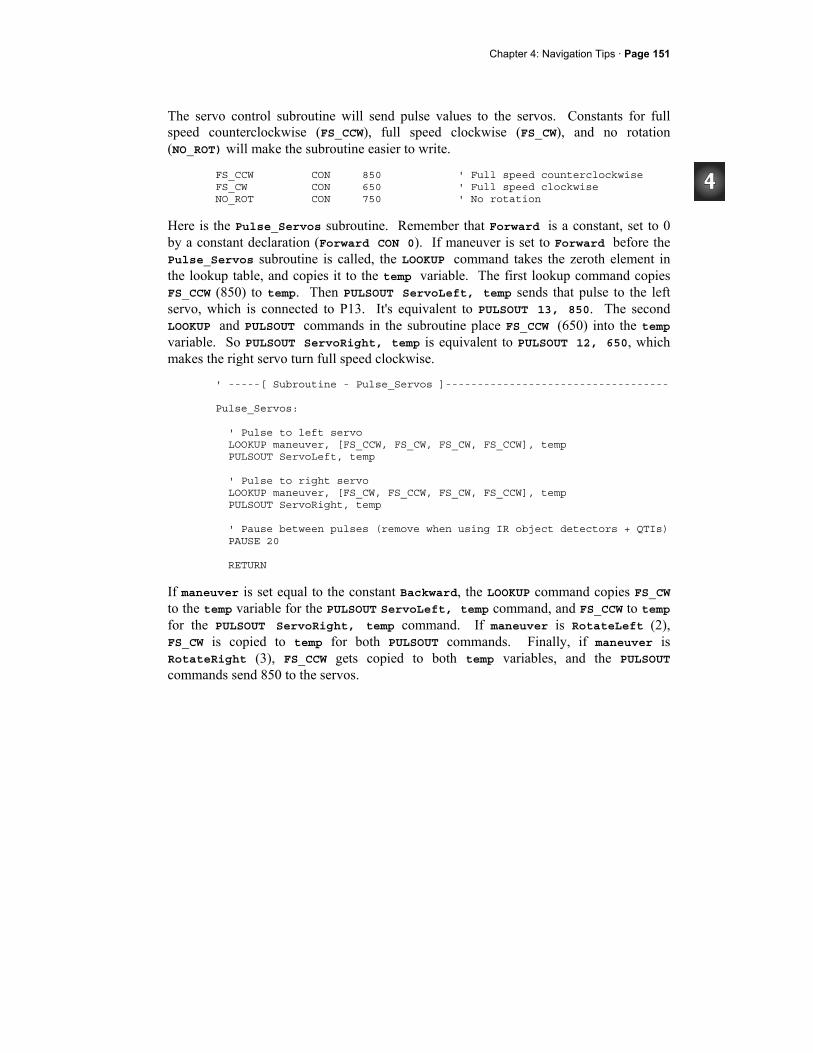
Chapter 4: Navigation Tips · Page 151
The servo control subroutine will send pulse values to the servos. Constants for full speed counterclockwise (FS_CCW), full speed clockwise (FS_CW), and no rotation (NO_ROT) will make the subroutine easier to write.
FS_CCW CON 850 ' Full speed counterclockwise FS_CW CON 650 ' Full speed clockwise NO_ROT CON 750 ' No rotation
Here is the Pulse_Servos subroutine. Remember that Forward is a constant, set to 0 by a constant declaration (Forward CON 0). If maneuver is set to Forward before the Pulse_Servos subroutine is called, the LOOKUP command takes the zeroth element in the lookup table, and copies it to the temp variable. The first lookup command copies FS_CCW (850) to temp. Then PULSOUT ServoLeft, temp sends that pulse to the left servo, which is connected to P13. It's equivalent to PULSOUT 13, 850. The second LOOKUP and PULSOUT commands in the subroutine place FS_CCW (650) into the temp variable. So PULSOUT ServoRight, temp is equivalent to PULSOUT 12, 650, which makes the right servo turn full speed clockwise.
' -----[ Subroutine - Pulse_Servos ]----------------------------------- Pulse_Servos: ' Pulse to left servo LOOKUP maneuver, [FS_CCW, FS_CW, FS_CW, FS_CCW], temp PULSOUT ServoLeft, temp ' Pulse to right servo LOOKUP maneuver, [FS_CW, FS_CCW, FS_CW, FS_CCW], temp PULSOUT ServoRight, temp ' Pause between pulses (remove when using IR object detectors + QTIs) PAUSE 20 RETURN
If maneuver is set equal to the constant Backward, the LOOKUP command copies FS_CW to the temp variable for the PULSOUT ServoLeft, temp command, and FS_CCW to temp for the PULSOUT ServoRight, temp command. If maneuver is RotateLeft (2), FS_CW is copied to temp for both PULSOUT commands. Finally, if maneuver is RotateRight (3), FS_CCW gets copied to both temp variables, and the PULSOUT commands send 850 to the servos.
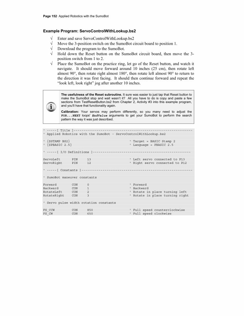
Page 152· Applied Robotics with the SumoBot
Example Program: ServoControlWithLookup.bs2
√ Enter and save ServoControlWithLookup.bs2 √ Move the 3-position switch on the SumoBot circuit board to position 1. √ Download the program to the SumoBot. √ Hold down the Reset button on the SumoBot circuit board, then move the 3-
position switch from 1 to 2. √ Place the SumoBot on the practice ring, let go of the Reset button, and watch it
navigate. It should move forward around 10 inches (25 cm), then rotate left almost 90°, then rotate right almost 180°, then rotate left almost 90° to return to the direction it was first facing. It should then continue forward and repeat the “look left, look right” jog after another 10 inches.
The usefulness of the Reset subroutine. It sure was easier to just tap that Reset button to make the SumoBot stop and wait wasn’t it? All you have to do is copy and paste a few sections from TestResetButton.bs2 from Chapter 2, Activity #3 into this example program, and you'll have that functionality again.
Calibration: Your servos may perform differently, so you many need to adjust the FOR...NEXT loops' EndValue arguments to get your SumoBot to perform the search pattern the way it was just described.
' -----[ Title ]-------------------------------------------------------------- ' Applied Robotics with the SumoBot - ServoControlWithLookup.bs2 ' $STAMP BS2 ' Target = BASIC Stamp 2 ' $PBASIC 2.5 ' Language = PBASIC 2.5 ' -----[ I/O Definitions ]--------------------------------------------------- ServoLeft PIN 13 ' Left servo connected to P13 ServoRight PIN 12 ' Right servo connected to P12 ' -----[ Constants ]---------------------------------------------------------- ' SumoBot maneuver constants Forward CON 0 ' Forward Backward CON 1 ' Backward RotateLeft CON 2 ' Rotate in place turning left RotateRight CON 3 ' Rotate in place turning right ' Servo pulse width rotation constants FS_CCW CON 850 ' Full speed counterclockwise FS_CW CON 650 ' Full speed clockwise
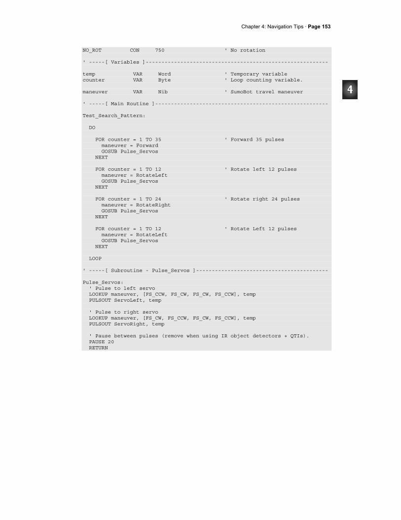
Chapter 4: Navigation Tips · Page 153
NO_ROT CON 750 ' No rotation ' -----[ Variables ]---------------------------------------------------------- temp VAR Word ' Temporary variable counter VAR Byte ' Loop counting variable. maneuver VAR Nib ' SumoBot travel maneuver ' -----[ Main Routine ]------------------------------------------------------- Test_Search_Pattern: DO FOR counter = 1 TO 35 ' Forward 35 pulses maneuver = Forward GOSUB Pulse_Servos NEXT FOR counter = 1 TO 12 ' Rotate left 12 pulses maneuver = RotateLeft GOSUB Pulse_Servos NEXT FOR counter = 1 TO 24 ' Rotate right 24 pulses maneuver = RotateRight GOSUB Pulse_Servos NEXT FOR counter = 1 TO 12 ' Rotate Left 12 pulses maneuver = RotateLeft GOSUB Pulse_Servos NEXT LOOP ' -----[ Subroutine - Pulse_Servos ]------------------------------------------ Pulse_Servos: ' Pulse to left servo LOOKUP maneuver, [FS_CCW, FS_CW, FS_CW, FS_CCW], temp PULSOUT ServoLeft, temp ' Pulse to right servo LOOKUP maneuver, [FS_CW, FS_CCW, FS_CW, FS_CCW], temp PULSOUT ServoRight, temp ' Pause between pulses (remove when using IR object detectors + QTIs). PAUSE 20 RETURN
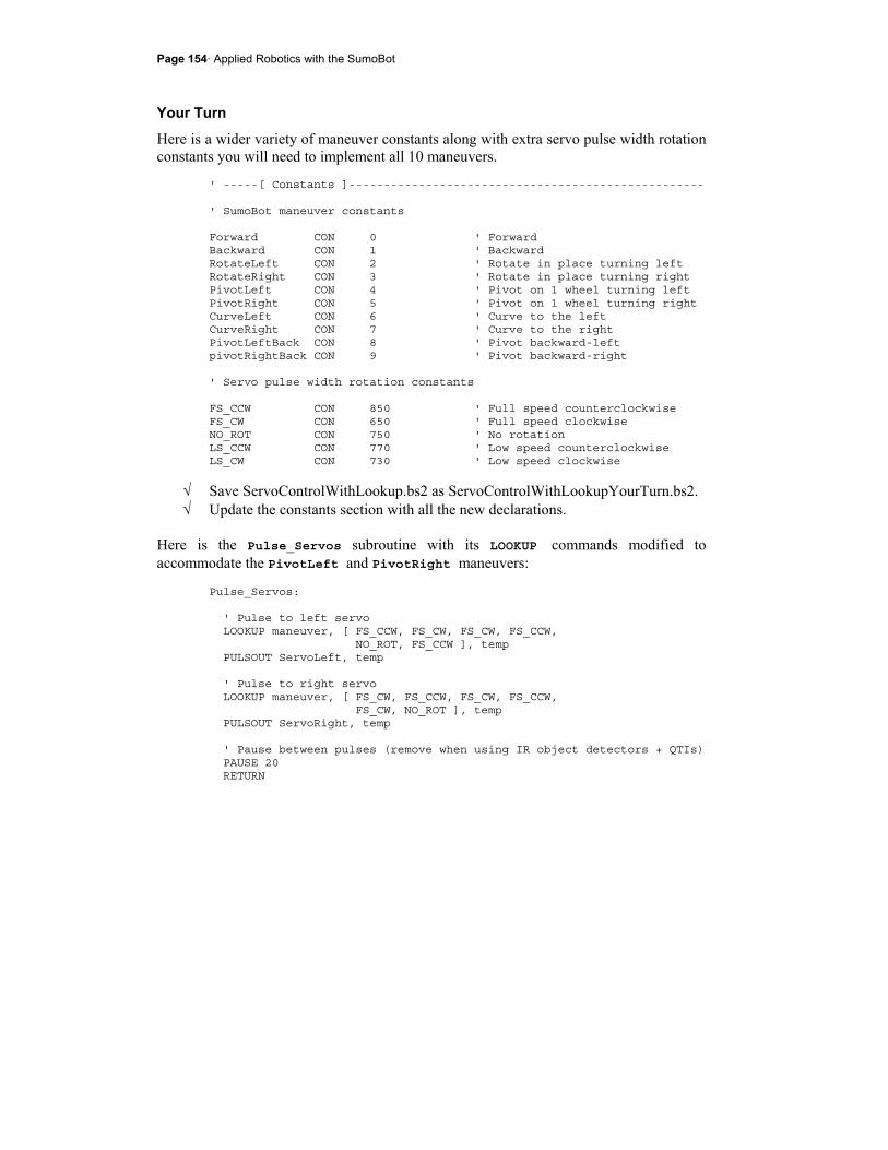
Page 154· Applied Robotics with the SumoBot
Your Turn
Here is a wider variety of maneuver constants along with extra servo pulse width rotation constants you will need to implement all 10 maneuvers.
' -----[ Constants ]--------------------------------------------------- ' SumoBot maneuver constants Forward CON 0 ' Forward Backward CON 1 ' Backward RotateLeft CON 2 ' Rotate in place turning left RotateRight CON 3 ' Rotate in place turning right PivotLeft CON 4 ' Pivot on 1 wheel turning left PivotRight CON 5 ' Pivot on 1 wheel turning right CurveLeft CON 6 ' Curve to the left CurveRight CON 7 ' Curve to the right PivotLeftBack CON 8 ' Pivot backward-left pivotRightBack CON 9 ' Pivot backward-right ' Servo pulse width rotation constants FS_CCW CON 850 ' Full speed counterclockwise FS_CW CON 650 ' Full speed clockwise NO_ROT CON 750 ' No rotation LS_CCW CON 770 ' Low speed counterclockwise LS_CW CON 730 ' Low speed clockwise
√ Save ServoControlWithLookup.bs2 as ServoControlWithLookupYourTurn.bs2. √ Update the constants section with all the new declarations.
Here is the Pulse_Servos subroutine with its LOOKUP commands modified to accommodate the PivotLeft and PivotRight maneuvers:
Pulse_Servos: ' Pulse to left servo LOOKUP maneuver, [ FS_CCW, FS_CW, FS_CW, FS_CCW, NO_ROT, FS_CCW ], temp PULSOUT ServoLeft, temp ' Pulse to right servo LOOKUP maneuver, [ FS_CW, FS_CCW, FS_CW, FS_CCW, FS_CW, NO_ROT ], temp PULSOUT ServoRight, temp ' Pause between pulses (remove when using IR object detectors + QTIs) PAUSE 20 RETURN
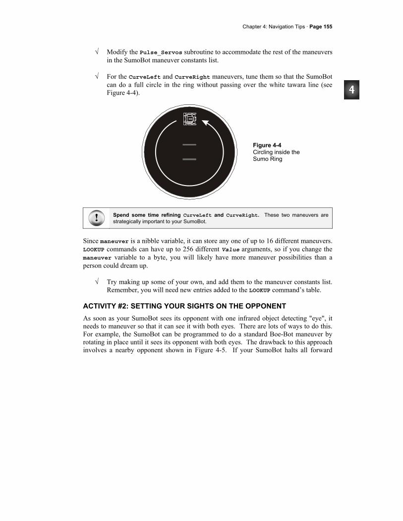
Chapter 4: Navigation Tips · Page 155
√ Modify the Pulse_Servos subroutine to accommodate the rest of the maneuvers in the SumoBot maneuver constants list.
√ For the CurveLeft and CurveRight maneuvers, tune them so that the SumoBot
can do a full circle in the ring without passing over the white tawara line (see Figure 4-4).
Figure 4-4 Circling inside the Sumo Ring
Spend some time refining CurveLeft and CurveRight. These two maneuvers are strategically important to your SumoBot.
Since maneuver is a nibble variable, it can store any one of up to 16 different maneuvers. LOOKUP commands can have up to 256 different Value arguments, so if you change the maneuver variable to a byte, you will likely have more maneuver possibilities than a person could dream up.
√ Try making up some of your own, and add them to the maneuver constants list. Remember, you will need new entries added to the LOOKUP command’s table.
ACTIVITY #2: SETTING YOUR SIGHTS ON THE OPPONENT As soon as your SumoBot sees its opponent with one infrared object detecting "eye", it needs to maneuver so that it can see it with both eyes. There are lots of ways to do this. For example, the SumoBot can be programmed to do a standard Boe-Bot maneuver by rotating in place until it sees its opponent with both eyes. The drawback to this approach involves a nearby opponent shown in Figure 4-5. If your SumoBot halts all forward

Page 156· Applied Robotics with the SumoBot
motion and the opponent collides with it at that moment, it will be at a disadvantage. If the SumoBots are already pushing each other and one of them does this maneuver, it will also give its opponent an opportunity to push it closer to the white tawara line.
Figure 4-5 Nearby Opponent Seen by only one IR object detector
Other approaches include pivoting on one wheel and curving while continuing forward. Pivoting on one wheel has similar drawbacks to rotating in place. Drawing a curve has some advantages over an opponent that's very close. The curve keeps the SumoBot moving toward its opponent as it lines up to start pushing. If the two SumoBots are already pushing on each other, and the SumoBot happens to lose sight of its opponent with one eye for a moment, it doesn't lose as much advantage correcting with a curve. In some cases, it may even help. Curving to see the opponent with both eyes has its own drawbacks though. For example, if the opponent is still some distance off and traveling away from the one eye that detected it, curving won't catch up with it. (See Figure 4-6.)
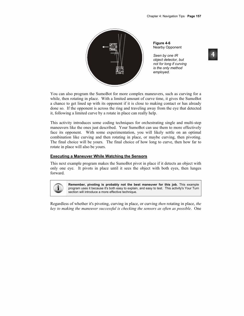
Chapter 4: Navigation Tips · Page 157
Figure 4-6 Nearby Opponent Seen by one IR object detector, but not for long if curving is the only method employed.
You can also program the SumoBot for more complex maneuvers, such as curving for a while, then rotating in place. With a limited amount of curve time, it gives the SumoBot a chance to get lined up with its opponent if it is close to making contact or has already done so. If the opponent is across the ring and traveling away from the eye that detected it, following a limited curve by a rotate in place can really help. This activity introduces some coding techniques for orchestrating single and multi-step maneuvers like the ones just described. Your SumoBot can use them to more effectively face its opponent. With some experimentation, you will likely settle on an optimal combination like curving and then rotating in place, or maybe curving, then pivoting. The final choice will be yours. The final choice of how long to curve, then how far to rotate in place will also be yours.
Executing a Maneuver While Watching the Sensors
This next example program makes the SumoBot pivot in place if it detects an object with only one eye. It pivots in place until it sees the object with both eyes, then lunges forward.
Remember, pivoting is probably not the best maneuver for this job. This example program uses it because it's both easy to explain, and easy to test. This activity's Your Turn section will introduce a more effective technique.
Regardless of whether it's pivoting, curving in place, or curving then rotating in place, the key to making the maneuver successful is checking the sensors as often as possible. One
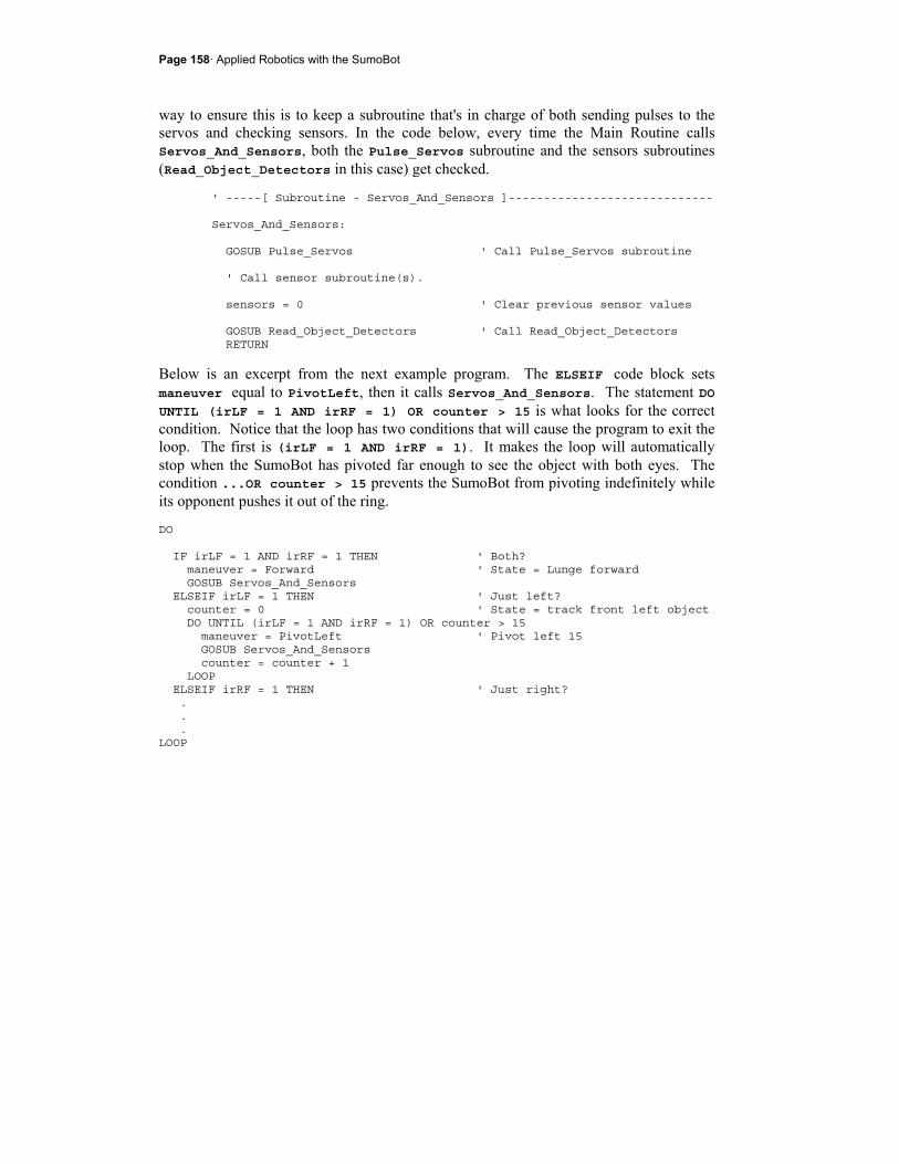
Page 158· Applied Robotics with the SumoBot
way to ensure this is to keep a subroutine that's in charge of both sending pulses to the servos and checking sensors. In the code below, every time the Main Routine calls Servos_And_Sensors, both the Pulse_Servos subroutine and the sensors subroutines (Read_Object_Detectors in this case) get checked.
' -----[ Subroutine - Servos_And_Sensors ]----------------------------- Servos_And_Sensors: GOSUB Pulse_Servos ' Call Pulse_Servos subroutine ' Call sensor subroutine(s). sensors = 0 ' Clear previous sensor values GOSUB Read_Object_Detectors ' Call Read_Object_Detectors RETURN
Below is an excerpt from the next example program. The ELSEIF code block sets maneuver equal to PivotLeft, then it calls Servos_And_Sensors. The statement DO UNTIL (irLF = 1 AND irRF = 1) OR counter > 15 is what looks for the correct condition. Notice that the loop has two conditions that will cause the program to exit the loop. The first is (irLF = 1 AND irRF = 1). It makes the loop will automatically stop when the SumoBot has pivoted far enough to see the object with both eyes. The condition ...OR counter > 15 prevents the SumoBot from pivoting indefinitely while its opponent pushes it out of the ring.
DO IF irLF = 1 AND irRF = 1 THEN ' Both? maneuver = Forward ' State = Lunge forward GOSUB Servos_And_Sensors ELSEIF irLF = 1 THEN ' Just left? counter = 0 ' State = track front left object DO UNTIL (irLF = 1 AND irRF = 1) OR counter > 15 maneuver = PivotLeft ' Pivot left 15 GOSUB Servos_And_Sensors counter = counter + 1 LOOP ELSEIF irRF = 1 THEN ' Just right? . . . LOOP
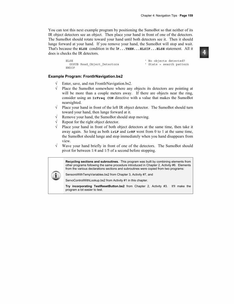
Chapter 4: Navigation Tips · Page 159
You can test this next example program by positioning the SumoBot so that neither of its IR object detectors see an object. Then place your hand in front of one of the detectors. The SumoBot should rotate toward your hand until both detectors see it. Then it should lunge forward at your hand. If you remove your hand, the SumoBot will stop and wait. That's because the ELSE condition in the IF...THEN...ELSIF...ELSE statement. All it does is checks the IR detectors.
ELSE ' No objects detected? GOSUB Read_Object_Detectors ' State = search pattern ENDIF
Example Program: FrontIrNavigation.bs2
√ Enter, save, and run FrontIrNavigation.bs2. √ Place the SumoBot somewhere where any objects its detectors are pointing at
will be more than a couple meters away. If there are objects near the ring, consider using an IrFreq CON directive with a value that makes the SumoBot nearsighted.
√ Place your hand in front of the left IR object detector. The SumoBot should turn toward your hand, then lunge forward at it.
√ Remove your hand, the SumoBot should stop moving. √ Repeat for the right object detector. √ Place your hand in front of both object detectors at the same time, then take it
away again. So long as both irLF and irRF went from 0 to 1 at the same time, the SumoBot should lunge and stop immediately when you hand disappears from view.
√ Wave your hand briefly in front of one of the detectors. The SumoBot should pivot for between 1/4 and 1/5 of a second before stopping.
Recycling sections and subroutines. This program was built by combining elements from other programs following the same procedure introduced in Chapter 2, Activity #6. Elements from the various declarations sections and subroutines were copied from two programs:
SensorsWithTempVariables.bs2 from Chapter 3, Activity #7, and
ServoControlWithLookup.bs2 from Activity #1 in this chapter.
Try incorporating TestResetButton.bs2 from Chapter 2, Activity #3. It'll make the program a lot easier to test.

Page 160· Applied Robotics with the SumoBot
' -----[ Title ]-------------------------------------------------------------- ' Applied Robotics with the SumoBot - FrontIrNavigation.bs2 ' When it sees an object with only one object detecting eye, it corrects ' it's heading until it sees the object with both eyes. ' $STAMP BS2 ' Target = BASIC Stamp 2 ' $PBASIC 2.5 ' Language = PBASIC 2.5 ' -----[ I/O Definitions ]--------------------------------------------------- ServoLeft PIN 13 ' Left servo connected to P13 ServoRight PIN 12 ' Right servo connected to P12 IrLedLS PIN 2 ' Left IR LED connected to P2 IrSenseLS PIN 1 ' Left IR detector to P1 IrLedLF PIN 4 ' Left IR LED connected to P4 IrSenseLF PIN 11 ' Left IR detector to P11 IrLedRF PIN 15 ' Right IR LED connected to P15 IrSenseRF PIN 14 ' Right IR detector to P14 IrLedRS PIN 3 ' Right IR LED connected to P3 IrSenseRS PIN 0 ' Right IR detector to P0 ' -----[ Constants ]---------------------------------------------------------- ' SumoBot maneuvers Forward CON 0 ' Forward Backward CON 1 ' Backward RotateLeft CON 2 ' RotateLeft RotateRight CON 3 ' RotateRight PivotLeft CON 4 ' Pivot to the left PivotRight CON 5 ' Pivot to the right CurveLeft CON 6 ' Curve to the left CurveRight CON 7 ' Curve to the right ' Servo pulse width rotations FS_CCW CON 850 ' Full speed counterclockwise FS_CW CON 650 ' Full speed clockwise NO_ROT CON 750 ' No rotation LS_CCW CON 770 ' Low speed counterclockwise LS_CW CON 730 ' Low speed clockwise ' IR object detectors IrFreq CON 38500 ' IR LED frequency ' -----[ Variables ]----------------------------------------------------------
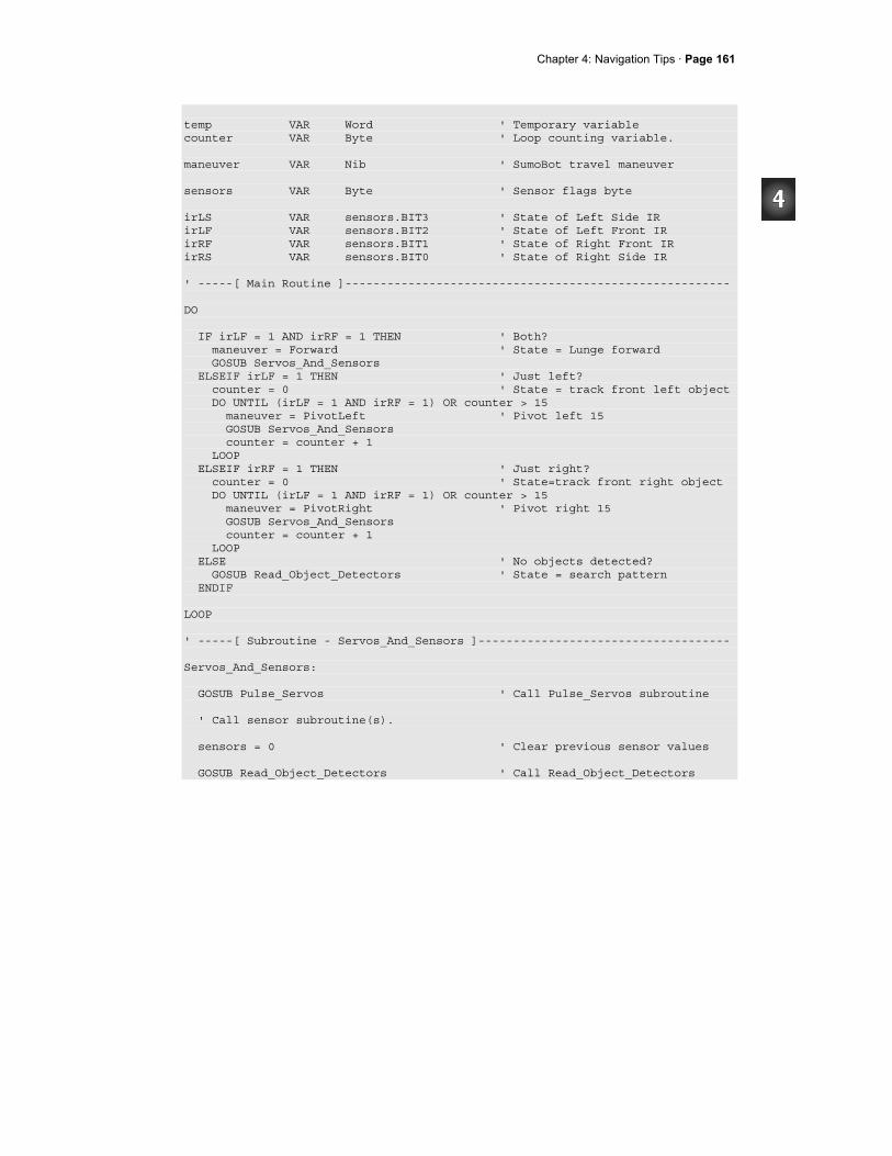
Chapter 4: Navigation Tips · Page 161
temp VAR Word ' Temporary variable counter VAR Byte ' Loop counting variable. maneuver VAR Nib ' SumoBot travel maneuver sensors VAR Byte ' Sensor flags byte irLS VAR sensors.BIT3 ' State of Left Side IR irLF VAR sensors.BIT2 ' State of Left Front IR irRF VAR sensors.BIT1 ' State of Right Front IR irRS VAR sensors.BIT0 ' State of Right Side IR ' -----[ Main Routine ]------------------------------------------------------- DO IF irLF = 1 AND irRF = 1 THEN ' Both? maneuver = Forward ' State = Lunge forward GOSUB Servos_And_Sensors ELSEIF irLF = 1 THEN ' Just left? counter = 0 ' State = track front left object DO UNTIL (irLF = 1 AND irRF = 1) OR counter > 15 maneuver = PivotLeft ' Pivot left 15 GOSUB Servos_And_Sensors counter = counter + 1 LOOP ELSEIF irRF = 1 THEN ' Just right? counter = 0 ' State=track front right object DO UNTIL (irLF = 1 AND irRF = 1) OR counter > 15 maneuver = PivotRight ' Pivot right 15 GOSUB Servos_And_Sensors counter = counter + 1 LOOP ELSE ' No objects detected? GOSUB Read_Object_Detectors ' State = search pattern ENDIF LOOP ' -----[ Subroutine - Servos_And_Sensors ]------------------------------------ Servos_And_Sensors: GOSUB Pulse_Servos ' Call Pulse_Servos subroutine ' Call sensor subroutine(s). sensors = 0 ' Clear previous sensor values GOSUB Read_Object_Detectors ' Call Read_Object_Detectors
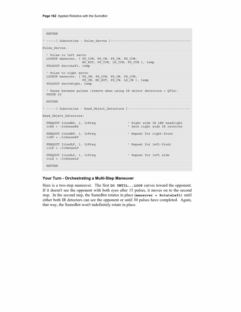
Page 162· Applied Robotics with the SumoBot
RETURN ' -----[ Subroutine - Pulse_Servos ]------------------------------------------ Pulse_Servos: ' Pulse to left servo LOOKUP maneuver, [ FS_CCW, FS_CW, FS_CW, FS_CCW, NO_ROT, FS_CCW, LS_CCW, FS_CCW ], temp PULSOUT ServoLeft, temp ' Pulse to right servo LOOKUP maneuver, [ FS_CW, FS_CCW, FS_CW, FS_CCW, FS_CW, NO_ROT, FS_CW, LS_CW ], temp PULSOUT ServoRight, temp ' Pause between pulses (remove when using IR object detectors + QTIs). PAUSE 20 RETURN ' -----[ Subroutine - Read_Object_Detectors ]--------------------------------- Read_Object_Detectors: FREQOUT IrLedRS, 1, IrFreq ' Right side IR LED headlight irRS = ~IrSenseRS ' Save right side IR receiver FREQOUT IrLedRF, 1, IrFreq ' Repeat for right-front irRF = ~IrSenseRF FREQOUT IrLedLF, 1, IrFreq ' Repeat for left-front irLF = ~IrSenseLF FREQOUT IrLedLS, 1, IrFreq ' Repeat for left side irLS = ~IrSenseLS RETURN
Your Turn - Orchestrating a Multi-Step Maneuver
Here is a two-step maneuver. The first DO UNTIL...LOOP curves toward the opponent. If it doesn't see the opponent with both eyes after 15 pulses, it moves on to the second step. In the second step, the SumoBot rotates in place (maneuver = RotateLeft) until either both IR detectors can see the opponent or until 30 pulses have completed. Again, that way, the SumoBot won't indefinitely rotate in place.
Chapter 4: Navigation Tips · Page 163
ELSEIF irLF = 1 THEN ' Just left? DO UNTIL (irLF = 1 AND irRF = 1) OR counter > 15 maneuver = CurveLeft ' Curve left 15 GOSUB Servos_And_Sensors counter = counter + 1 LOOP DO UNTIL (irLF = 1 AND irRF = 1) OR counter > 30 maneuver = RotateLeft ' Rotate left 30 GOSUB Servos_And_Sensors counter = counter + 1 LOOP
The Main Routine below incorporates this code for both sides, and is a drop-in replacement for the main routine in FrontIrNavigation.bs2.
√ Save FrontIrNavigation.bs2 as FrontIrNavigationYourTurn.bs2. √ Replace the Main Routine in the program with the one shown below. √ Test the program and note the differences in the way the SumoBot faces and
lunges toward your hand. ' -----[ Main Routine ]------------------------------------------------------- DO IF irLF = 1 AND irRF = 1 THEN ' Both? maneuver = Forward ' State = Lunge forward GOSUB Servos_And_Sensors ELSEIF irLF = 1 THEN ' Just left? counter = 0 ' State = track front left object DO UNTIL (irLF = 1 AND irRF = 1) OR counter > 15 maneuver = CurveLeft ' Curve left 15 GOSUB Servos_And_Sensors counter = counter + 1 LOOP DO UNTIL (irLF = 1 AND irRF = 1) OR counter > 30 maneuver = RotateLeft ' Rotate left 30 GOSUB Servos_And_Sensors counter = counter + 1 LOOP ELSEIF irRF = 1 THEN ' Just right? counter = 0 ' State=track front right object DO UNTIL (irLF = 1 AND irRF = 1) OR counter > 15 maneuver = CurveRight ' Curve right 15 GOSUB Servos_And_Sensors counter = counter + 1 LOOP DO UNTIL (irLF = 1 AND irRF = 1) OR counter > 30 maneuver = RotateRight ' Rotate right 30

Page 164· Applied Robotics with the SumoBot
GOSUB Servos_And_Sensors counter = counter + 1 LOOP ELSE ' No objects detected? GOSUB Read_Object_Detectors ' State = search pattern ENDIF LOOP
ACTIVITY #3: USING PERIPHERAL VISION When autonomous robots start a sumo match facing each other, the match tends to be more a battle of brawn than brains. When a match starts with the SumoBot robots sideways to each other, things get a little more interesting. Is the opponent on the SumoBot's left or right, and for that matter, which direction is the opponent facing? Sumo cards like the ones shown in Figure 4-7 can help keep this random. Between each round in a match, a new card should be drawn to determine the placement of the SumoBots for the start of the next round.
Figure 4-7 Random Cards to Draw for Start Positions
As shown in Figure 4-8, peripheral vision with the help of side mounted IR object detectors can give your SumoBot an advantage, both at the start of the match, and in detecting attacks from the side. This activity introduces a coding technique you can use to make effective use of the SumoBot's peripheral vision afforded by those side-mounted IR object detectors.

Chapter 4: Navigation Tips · Page 165
Figure 4-8 Peripheral Vision for Opponent Detection
Responding to an Object Detection on the Side
This code for side IR object detection works about the same as the examples from the previous activity. They can be added to the IF...THEN statements in the previous example program's main routine. They will make the SumoBot respond by rotating in place to turn toward objects it detects on either side. If an object is on the SumoBot's left side, the ELSEIF irLS = 1 THEN code block will get executed. The DO UNTIL...LOOP makes the SumoBot rotate left until either one of the front IR detectors sees the object. The ELSEIF irRS = 1 THEN... code block behaves similarly for objects on the right side. ELSEIF irLS = 1 THEN ' Object left side? DO UNTIL irRF = 1 OR irLF = 1 ' State = track left side object maneuver = RotateLeft ' Rotate left GOSUB Servos_And_Sensors LOOP ELSEIF irRS = 1 THEN ' Object right side? DO UNTIL irRF = 1 OR irLF = 1 ' State = track right side object maneuver = RotateRight ' Rotate right GOSUB Servos_And_Sensors LOOP

Page 166· Applied Robotics with the SumoBot
Example Program: FrontAndSideIrNavigation.bs2
The beauty in terminating the rotate loop as soon as one of the front IR detectors sees the object is that one of the other code blocks will then take over to get the SumoBot to face its opponent. Let's see how it performs:
√ Save FrontIrNavigiation.bs2 as FrontAndSideIrNavigation.bs2 √ Insert the peripheral vision ELSEIF...THEN... code blocks shown above just
before the ELSE keyword in the Main Routine. √ Use the printed example program to check your work. √ Run the program. √ Press and hold the Reset button as you take the SumoBot to the practice ring.
Make sure there all objects are well away from the SumoBot's front and side. If there are objects near the ring, consider using an IrFreq CON directive that makes the SumoBot nearsighted.
√ Set the SumoBot on the practice ring so that you are behind it. Otherwise, it will see you and react immediately. Make sure that there are no other objects within a couple meters of the ring.
√ Let go of the Reset button. The SumoBot should stay still because it doesn't see anything.
√ Place your hand in view of its right IR object detector. The SumoBot should immediately turn to face your hand and then lunge forward.
√ Press and hold the Reset button, and again place the SumoBot so that it can't see you.
√ Place your hand in view of its left IR object detector and verify that it rounds on an object to its left as well.
' -----[ Title ]-------------------------------------------------------------- ' Applied Robotics with the SumoBot - FrontAndSideIrNavigation.bs2 ' This is FrontIrNavigation.bs2 with peripheral IR object detection added. ' $STAMP BS2 ' Target = BASIC Stamp 2 ' $PBASIC 2.5 ' Language = PBASIC 2.5 ' -----[ I/O Definitions ]--------------------------------------------------- ServoLeft PIN 13 ' Left servo connected to P13 ServoRight PIN 12 ' Right servo connected to P12 IrLedLS PIN 2 ' Left IR LED connected to P2 IrSenseLS PIN 1 ' Left IR detector to P1
Chapter 4: Navigation Tips · Page 167
IrLedLF PIN 4 ' Left IR LED connected to P4 IrSenseLF PIN 11 ' Left IR detector to P11 IrLedRF PIN 15 ' Right IR LED connected to P15 IrSenseRF PIN 14 ' Right IR detector to P14 IrLedRS PIN 3 ' Right IR LED connected to P3 IrSenseRS PIN 0 ' Right IR detector to P0 ' -----[ Constants ]---------------------------------------------------------- ' SumoBot maneuvers Forward CON 0 ' Forward Backward CON 1 ' Backward RotateLeft CON 2 ' RotateLeft RotateRight CON 3 ' RotateRight PivotLeft CON 4 ' Pivot to the left PivotRight CON 5 ' Pivot to the right CurveLeft CON 6 ' Curve to the left CurveRight CON 7 ' Curve to the right ' Servo pulse width rotations FS_CCW CON 850 ' Full speed counterclockwise FS_CW CON 650 ' Full speed clockwise NO_ROT CON 750 ' No rotation LS_CCW CON 770 ' Low speed counterclockwise LS_CW CON 730 ' Low speed clockwise ' IR object detectors IrFreq CON 38500 ' IR LED frequency ' -----[ Variables ]---------------------------------------------------------- temp VAR Word ' Temporary variable counter VAR Byte ' Loop counting variable. maneuver VAR Nib ' SumoBot travel maneuver sensors VAR Byte ' Sensor flags byte irLS VAR sensors.BIT3 ' State of Left Side IR irLF VAR sensors.BIT2 ' State of Left Front IR irRF VAR sensors.BIT1 ' State of Right Front IR irRS VAR sensors.BIT0 ' State of Right Side IR ' -----[ Main Routine ]------------------------------------------------------- DO
Page 168· Applied Robotics with the SumoBot
IF irLF = 1 AND irRF = 1 THEN ' Both? maneuver = Forward ' State = Lunge forward GOSUB Servos_And_Sensors ELSEIF irLF = 1 THEN ' Just left? counter = 0 ' State = track front left object DO UNTIL (irLF = 1 AND irRF = 1) OR counter > 15 maneuver = CurveLeft ' Curve left 15 GOSUB Servos_And_Sensors counter = counter + 1 LOOP DO UNTIL (irLF = 1 AND irRF = 1) OR counter > 30 maneuver = RotateLeft ' Rotate left 30 GOSUB Servos_And_Sensors counter = counter + 1 LOOP ELSEIF irRF = 1 THEN ' Just right? counter = 0 ' State=track front right object DO UNTIL (irLF = 1 AND irRF = 1) OR counter > 15 maneuver = CurveRight ' Curve right 15 GOSUB Servos_And_Sensors counter = counter + 1 LOOP DO UNTIL (irLF = 1 AND irRF = 1) OR counter > 30 maneuver = RotateRight ' Rotate right 30 GOSUB Servos_And_Sensors counter = counter + 1 LOOP ELSEIF irLS = 1 THEN ' Object left side? DO UNTIL irRF = 1 OR irLF = 1 ' State = track left side object maneuver = RotateLeft ' Rotate left GOSUB Servos_And_Sensors LOOP ELSEIF irRS = 1 THEN ' Object right side? DO UNTIL irRF = 1 OR irLF = 1 ' State = track right side object maneuver = RotateRight ' Rotate right GOSUB Servos_And_Sensors LOOP ELSE ' No objects detected? GOSUB Read_Object_Detectors ' State = search pattern ENDIF LOOP ' -----[ Subroutine - Servos_And_Sensors ]------------------------------------ Servos_And_Sensors: GOSUB Pulse_Servos ' Call Pulse_Servos subroutine ' Call sensor subroutine(s).
Chapter 4: Navigation Tips · Page 169
sensors = 0 ' Clear previous sensor values GOSUB Read_Object_Detectors ' Call Read_Object_Detectors RETURN ' -----[ Subroutine - Pulse_Servos ]------------------------------------------ Pulse_Servos: ' Pulse to left servo LOOKUP maneuver, [ FS_CCW, FS_CW, FS_CW, FS_CCW, NO_ROT, FS_CCW, LS_CCW, FS_CCW ], temp PULSOUT ServoLeft, temp ' Pulse to right servo LOOKUP maneuver, [ FS_CW, FS_CCW, FS_CW, FS_CCW, FS_CW, NO_ROT, FS_CW, LS_CW ], temp PULSOUT ServoRight, temp ' Pause between pulses (remove when using IR object detectors + QTIs). PAUSE 20 RETURN ' -----[ Subroutine - Read_Object_Detectors ]--------------------------------- Read_Object_Detectors: FREQOUT IrLedRS, 1, IrFreq ' Right side IR LED headlight irRS = ~IrSenseRS ' Save right side IR receiver FREQOUT IrLedRF, 1, IrFreq ' Repeat for right-front irRF = ~IrSenseRF FREQOUT IrLedLF, 1, IrFreq ' Repeat for left-front irLF = ~IrSenseLF FREQOUT IrLedLS, 1, IrFreq ' Repeat for left side irLS = ~IrSenseLS RETURN
Page 170· Applied Robotics with the SumoBot
Your Turn - Limiting Rotation
Unlike the front IR detectors, the loops for the side IR detectors do not limit the amount of rotation in place the SumoBot will perform.
√ Add conditions to the DO UNTIL...LOOP code blocks that allow your SumoBot to turn and face objects detected to the side, but that prevent the SumoBot from rotating more than 180°.
Is it worth sweeping back in case the SumoBot might have missed something on its first rotation? Maybe. It might be something to fine tune after getting more familiar with how your SumoBot performs in matches.
ACTIVITY #4: INTRODUCTION TO STATE MACHINES AND DIAGRAMS True to its name, a state machine is a machine that can operate in different states or modes of operation. A desk lamp is a very simple state machine, with two states, on or off. If the desk lamp starts out in the off state, and you flip its on/off switch, it will transition to the on state. Flip the switch again, and it transitions back to the off state. The act of flipping the switch is considered a condition that causes a transition from one state to another. Traffic lights are somewhat more complex state machines, transitioning from green to yellow, to red, and then back to green again. In some traffic lights, these transitions are initiated by the traffic light's timer. Other traffic lights use a combination of a timer and sensors under the pavement. The transition from green to yellow might occur due to a timer, or it might occur because a car going the other direction is waiting (over the sensor under the pavement) for a green light. Both the timer and the sensor under the street provide the traffic light's state machine with conditions for changing states.
Reset state is another state machine term. For example, maintenance workers might shut off the power to the traffic lights at an intersection for repairs. When they turn the power back on, the traffic lights start in a particular pattern, such as red for the east/west street and green for the north/south street. Turning the power back on is an example of a reset condition, and green on north/south and red on east/west is would be called the initial or reset state.
Computers, cell phones, and factory production machines are significantly more complex state machines, but they still have something in common with desk lamps and traffic lights. They all operate in a finite number of states, and so they are defined as "finite

Chapter 4: Navigation Tips · Page 171
state machines". However, the term "state machine" is commonly used to refer to finite state machines. Your SumoBot is without a doubt, a state machine. The last couple of example programs have used terms like "State = search pattern" and "State = track front left object" in the comments. The IR object detectors sense conditions, and the SumoBot's embedded BASIC Stamp executes a program that interprets each new condition and makes the transition to the correct state. Of course, the SumoBot reads the sensors and transitions between states because the PBASIC program it runs makes it do that. This activity examines how PBASIC code can make the SumoBot transition from one state to the next based on sensor input. This activity also introduces a visual aid for planning the SumoBot's states and transitions - the state diagram.
A Simple State Diagram and Program
Figure 4-9 shows an example of a simple state diagram. Each circle signifies a state that the SumoBot can operate in. Both states are labeled, LED Off and Blink LED. Some of the arrows curve around and point back to the same state while other arrows point to the other state. These arrows represent state transitions. Each state transition arrow is labeled with a condition, like pbSense = 0 or pbSense = 1. The reset condition is the arrow with the jagged shaft labeled Reset, and it indicates that this system will start in the LED Off state.
Figure 4-9 Simple State Machine Diagram
The curved arrow that keeps returning to the LED off state labeled pbSense = 0 indicates that so long as pbSense stores zero, the state machine will just keep transitioning back to the LED off state. The arrow that points from LED Off to Blink LED shows that when the condition is pbSesne = 1, the state machine will transition from the LED off state to the Blink LED state. The Blink LED state also has two transition arrows, one that keeps it in
Page 172· Applied Robotics with the SumoBot
that state while pbSense = 1, and the other that transitions to LED off when pbSesnse = 0. State diagrams can be visual aids for describing the different states in certain programs along with the conditions the programs use to transition from one state to the next. For example, PushbuttonLed.bs2 can be thought of as the instructions to make the SumoBot a state machine implementation of Figure 4-9.
Example Program: PushbuttonLed.bs2
√ Enter, save, and run PushbuttonLed.bs2 √ Monitor the LED and Debug Terminal as you press and hold and then release the
pushbutton on the SumoBot's breadboard. Do you agree that this program really does implement the state machine diagram in Figure 4-9? Is it the only way the figure can be implemented?
' Applied Robotics with the SumoBot - PushbuttonLed.bs2 ' Simple finite state machine example. ' $STAMP BS2 ' $PBASIC 2.5 pbSense PIN 6 LedSpeaker PIN 5 LOW LedSpeaker DO IF pbSense = 1 THEN DEBUG HOME, "State = Blink LED" TOGGLE LedSpeaker ELSE DEBUG HOME, "State = Led off", CLREOL LOW LedSpeaker ENDIF PAUSE 100 LOOP
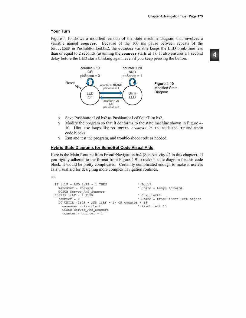
Chapter 4: Navigation Tips · Page 173
Your Turn
Figure 4-10 shows a modified version of the state machine diagram that involves a variable named counter. Because of the 100 ms pause between repeats of the DO...LOOP in PushubttonLed.bs2, the counter variable keeps the LED blink-time less than or equal to 2 seconds (assuming the counter starts at 1). It also ensures a 1 second delay before the LED starts blinking again, even if you keep pressing the button.
Figure 4-10 Modified State Diagram
√ Save PushbuttonLed.bs2 as PushbuttonLedYourTurn.bs2. √ Modify the program so that it conforms to the state machine shown in Figure 4-
10. Hint: use loops like DO UNTIL counter ≥ 10 inside the IF and ELSE code blocks.
√ Run and test the program, and trouble-shoot code as needed.
Hybrid State Diagrams for SumoBot Code Visual Aids
Here is the Main Routine from FrontIrNavigation.bs2 (See Activity #2 in this chapter). If you rigidly adhered to the format from Figure 4-9 to make a state diagram for this code block, it would be pretty complicated. Certainly complicated enough to make it useless as a visual aid for designing more complex navigation routines. DO IF irLF = AND irRF = 1 THEN ' Both? maneuver = Forward ' State = Lunge forward GOSUB Servos_And_Sensors ELSEIF irLF = 1 THEN ' Just left? counter = 0 ' State = track front left object DO UNTIL (irLF = AND irRF = 1) OR counter > 15 maneuver = PivotLeft ' Pivot left 15 GOSUB Servos_And_Sensors counter = counter + 1
Page 174· Applied Robotics with the SumoBot
LOOP ELSEIF irRF = 1 THEN ' Just right? counter = 0 ' State=track front right object DO UNTIL (irLF = AND irRF = 1) OR counter > 15 maneuver = PivotRight ' Pivot right 15 GOSUB Servos_And_Sensors counter = counter + 1 LOOP ELSE ' No objects detected? GOSUB Read_Object_Detectors ' State = search pattern ENDIF LOOP
Software that is used for designing and modeling state machines that go into automated machinery and/or integrated circuits have various ways of both simplifying state diagrams and at the same time making them more versatile. One of the techniques is assigning priority to various conditions for transition from one state to another. That way, the programmer (or the software that writes the program from the hybrid state diagram) can decide in what order to examine each condition. It also simplifies the conditions and reduces the number of transitions. Another common technique is to have a node in the transition line that can branch to multiple states depending on multiple conditions – “conditional branch.” Figure 4-11 shows an example of a hybrid state diagram that describes the FrontIrNavigation.bs2's Main Routine. The "Next State" state is unconventional, as are the numbers inside the Next State circle that show what order it evaluates the conditions for transition. Even so, the figure describes what's happening in the main routine much more succinctly than a normal state diagram.

Chapter 4: Navigation Tips · Page 175
Figure 4-11 Hybrid State Machine Diagram
√ Compare Figure 4-11 to the Main Routine from FrontIrNavigation.bs2 and verify that they describe the same state transitions.
State diagrams are not a replacement for flowcharts. While state diagrams introduced in this activity provide an overview of states in a state machine design, flow charts provide a detailed visual description of what the code in a program does. Flowcharts are introduced in the Stamps in Class Industrial Control text, available for download from www.parallax.com.
The NOT(irLF = 1 AND irRF = 1) conditions are taken care of implicitly by DO UNTIL (irLF = AND irRF = 1).
Page 176· Applied Robotics with the SumoBot
Your Turn - Drawing a State Machine Diagram
√ Try drawing a hybrid state machine diagram for the Main Routine in FrontAndSideIrNavigation.bs2 from this chapter's Activity #3.
ACTIVITY #5: SEARCH PATTERN AND TAWARA AVOIDANCE Before your SumoBot will be ready for a match, it's got to be able to stay inside that white tawara line. When it doesn't see anything with its IR object detectors, it's also got to have a search pattern that's more effective than sitting in one spot and waiting. Especially for matches that start the SumoBots facing away from each other, an effective search technique can make a huge difference in your SumoBot's likelihood of winning each round. While this activity demonstrates one of many search patterns you can use, it will be up to you to develop an optimal search pattern for your SumoBot.
Another State Machine Main Routine
The example program in this activity is the QTI version of the programs from this Chapter's Activity #2 and Activity #3. Those programs combined the IR detection pin definitions, constants, variables, and subroutines developed in Chapter 3 with the navigation routines from Activity #1 in this chapter. The example program in this activity combines the QTI line sensor program elements that were developed in chapter 3, again with the navigation program elements developed in this chapter. You've seen all the PIN and DATA directives, constant and variable declarations and subroutines before. The only thing that's really new is the Main Routine below, and even that follows the techniques similar to the ones introduced in this chapter's Activity #2 and #3. Notice that the code blocks that handle the QTI detections (IF qtiLF..., ELSIF qtiRF...) do not have any sensor conditions for exiting the loops. While it makes absolutely sure that the SumoBot doesn't accidentally exit the ring chasing after a spectator who's too close, it also prevents the SumoBot from decisively finishing off its opponent in some cases. More about this double-edged sword on the Your Turn section.
Chapter 4: Navigation Tips · Page 177
' -----[ Main Routine ]------------------------------------------------------- DO IF qtiLF = 1 THEN ' Left qti sees line? FOR counter = 1 TO 15 ' State = Avoid tawara left maneuver = Backward ' Back up GOSUB Servos_And_Sensors NEXT FOR counter = 1 TO 15 ' Turn right maneuver = RotateRight GOSUB Servos_And_Sensors NEXT ELSEIF qtiRF = 1 THEN ' Right qti sees line? FOR counter = 1 TO 15 ' State = Avoid tawara right maneuver = Backward ' Back up GOSUB Servos_And_Sensors NEXT FOR counter = 1 TO 15 ' Turn left maneuver = RotateLeft GOSUB Servos_And_Sensors NEXT . . .
The ELSE condition in the Main Routine performs the same search pattern introduced in this chapter's Activity #1, but with a twist - IF sensors <> 0 THEN GOTO
Next_State. This IF...THEN statement is in all four FOR...NEXT loops in the search pattern. If none of the sensors see anything, each FOR...NEXT loop continues to execute. However, if any sensor sees something, the sensors variable will no longer be zero. When that happens, the ELSE condition terminates. Next, the outermost DO...LOOP in the Main Routine repeats itself, and the correct state for handling the sensor(s) that changed from 0 to 1 handle the situation. Since there are no IR detectors in this program, the only sensors that can cause this condition are the QTIs. In the next activity, all four IR detectors and both QTIs will have an opportunity to set a bit in the sensors variable, causing the program to terminate the search condition and transition to the state that handles the sensor that went high. . . . ELSE ' No objects detected? FOR counter = 1 TO 35 ' State = search pattern maneuver = Forward ' Straight ahead 35 pulses GOSUB Servos_And_Sensors IF sensors <> 0 THEN GOTO Next_State NEXT
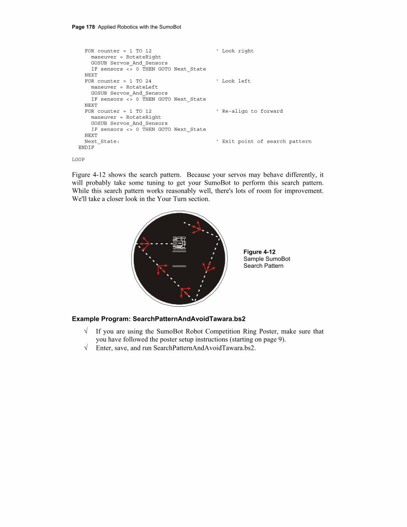
Page 178· Applied Robotics with the SumoBot
FOR counter = 1 TO 12 ' Look right maneuver = RotateRight GOSUB Servos_And_Sensors IF sensors <> 0 THEN GOTO Next_State NEXT FOR counter = 1 TO 24 ' Look left maneuver = RotateLeft GOSUB Servos_And_Sensors IF sensors <> 0 THEN GOTO Next_State NEXT FOR counter = 1 TO 12 ' Re-align to forward maneuver = RotateRight GOSUB Servos_And_Sensors IF sensors <> 0 THEN GOTO Next_State NEXT Next_State: ' Exit point of search pattern ENDIF LOOP
Figure 4-12 shows the search pattern. Because your servos may behave differently, it will probably take some tuning to get your SumoBot to perform this search pattern. While this search pattern works reasonably well, there's lots of room for improvement. We'll take a closer look in the Your Turn section.
Figure 4-12 Sample SumoBot Search Pattern
Example Program: SearchPatternAndAvoidTawara.bs2
√ If you are using the SumoBot Robot Competition Ring Poster, make sure that you have followed the poster setup instructions (starting on page 9).
√ Enter, save, and run SearchPatternAndAvoidTawara.bs2.
Chapter 4: Navigation Tips · Page 179
√ Press and hold the Reset button until you place it on the ring as shown in Figure 4-12.
√ Let go of the Reset button, and compare your search pattern to the one shown in the figure.
Does your SumoBot mistake creases in the poster for white tawara lines? If your SumoBot backs up and then executes a turn before it gets to the white tawara line, it may be detecting one or more of the creases in the SumoBot Competition Ring poster. This is most likely to happen when the SumoBot Competition Ring poster is in or near direct sunlight.
√ If your SumoBot is having problems detecting the creases on the poster, go back to page 9 and make sure you have followed the setup instructions.
If the lighting conditions are still too bright, you can make the QTI self calibration code set a lower threshold by changing this command:
multi = multi / 4 ' Take 1/4 average
√ Instead of dividing multi by 4, try 5, 6, 7, 8, 9, and 10.
The higher the value divided into multi, the lower the threshold, and the less sensitive the SumoBot will be to creases in the poster. This is a bit of a double-edged sword, because it also makes the SumoBot less sensitive to the white tawara line, and we don't want it to miss that.
√ Tune your FOR...NEXT loops so that your SumoBot's search pattern either starts
to resemble the one in the figure, or if you have a search pattern in mind that you think will be effective, modify the State = search routine as you see fit.
' -----[ Title ]-------------------------------------------------------------- ' Applied Robotics with the SumoBot - SearchPatternAndAvoidTawara.bs2 ' SumoBot searches the sumo ring for opponent and changes direction whenever ' it encounters the white Tawara line. ' $STAMP BS2 ' Target = BASIC Stamp 2 ' $PBASIC 2.5 ' Language = PBASIC 2.5 ' -----[ I/O Definitions ]--------------------------------------------------- ServoLeft PIN 13 ' Left servo connected to P13 ServoRight PIN 12 ' Right servo connected to P12 qtiPwrLeft PIN 10 ' Left QTI on/off pin P10 qtiSigLeft PIN 9 ' Left QTI signal pin P9 qtiPwrRight PIN 7 ' Right QTI on/off pin P7 qtiSigRight PIN 8 ' Right QTI signal pin P8
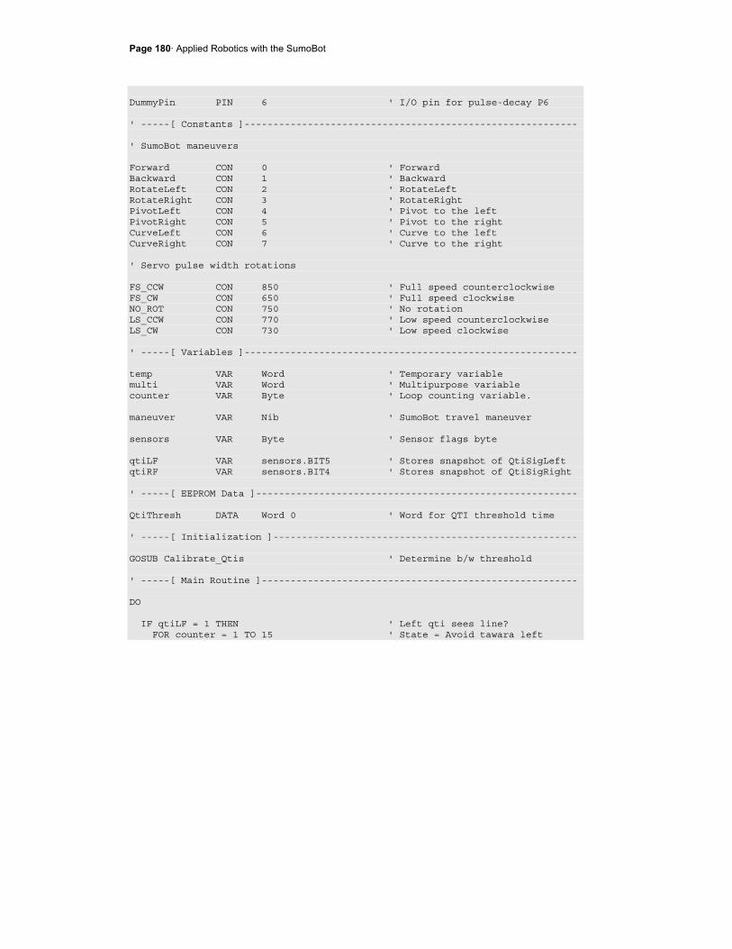
Page 180· Applied Robotics with the SumoBot
DummyPin PIN 6 ' I/O pin for pulse-decay P6 ' -----[ Constants ]---------------------------------------------------------- ' SumoBot maneuvers Forward CON 0 ' Forward Backward CON 1 ' Backward RotateLeft CON 2 ' RotateLeft RotateRight CON 3 ' RotateRight PivotLeft CON 4 ' Pivot to the left PivotRight CON 5 ' Pivot to the right CurveLeft CON 6 ' Curve to the left CurveRight CON 7 ' Curve to the right ' Servo pulse width rotations FS_CCW CON 850 ' Full speed counterclockwise FS_CW CON 650 ' Full speed clockwise NO_ROT CON 750 ' No rotation LS_CCW CON 770 ' Low speed counterclockwise LS_CW CON 730 ' Low speed clockwise ' -----[ Variables ]---------------------------------------------------------- temp VAR Word ' Temporary variable multi VAR Word ' Multipurpose variable counter VAR Byte ' Loop counting variable. maneuver VAR Nib ' SumoBot travel maneuver sensors VAR Byte ' Sensor flags byte qtiLF VAR sensors.BIT5 ' Stores snapshot of QtiSigLeft qtiRF VAR sensors.BIT4 ' Stores snapshot of QtiSigRight ' -----[ EEPROM Data ]-------------------------------------------------------- QtiThresh DATA Word 0 ' Word for QTI threshold time ' -----[ Initialization ]----------------------------------------------------- GOSUB Calibrate_Qtis ' Determine b/w threshold ' -----[ Main Routine ]------------------------------------------------------- DO IF qtiLF = 1 THEN ' Left qti sees line? FOR counter = 1 TO 15 ' State = Avoid tawara left
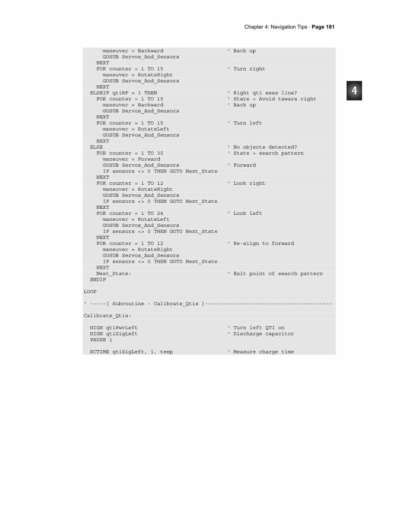
Chapter 4: Navigation Tips · Page 181
maneuver = Backward ' Back up GOSUB Servos_And_Sensors NEXT FOR counter = 1 TO 15 ' Turn right maneuver = RotateRight GOSUB Servos_And_Sensors NEXT ELSEIF qtiRF = 1 THEN ' Right qti sees line? FOR counter = 1 TO 15 ' State = Avoid tawara right maneuver = Backward ' Back up GOSUB Servos_And_Sensors NEXT FOR counter = 1 TO 15 ' Turn left maneuver = RotateLeft GOSUB Servos_And_Sensors NEXT ELSE ' No objects detected? FOR counter = 1 TO 35 ' State = search pattern maneuver = Forward GOSUB Servos_And_Sensors ' Forward IF sensors <> 0 THEN GOTO Next_State NEXT FOR counter = 1 TO 12 ' Look right maneuver = RotateRight GOSUB Servos_And_Sensors IF sensors <> 0 THEN GOTO Next_State NEXT FOR counter = 1 TO 24 ' Look left maneuver = RotateLeft GOSUB Servos_And_Sensors IF sensors <> 0 THEN GOTO Next_State NEXT FOR counter = 1 TO 12 ' Re-align to forward maneuver = RotateRight GOSUB Servos_And_Sensors IF sensors <> 0 THEN GOTO Next_State NEXT Next_State: ' Exit point of search pattern ENDIF LOOP ' -----[ Subroutine - Calibrate_Qtis ]---------------------------------------- Calibrate_Qtis: HIGH qtiPwrLeft ' Turn left QTI on HIGH qtiSigLeft ' Discharge capacitor PAUSE 1 RCTIME qtiSigLeft, 1, temp ' Measure charge time
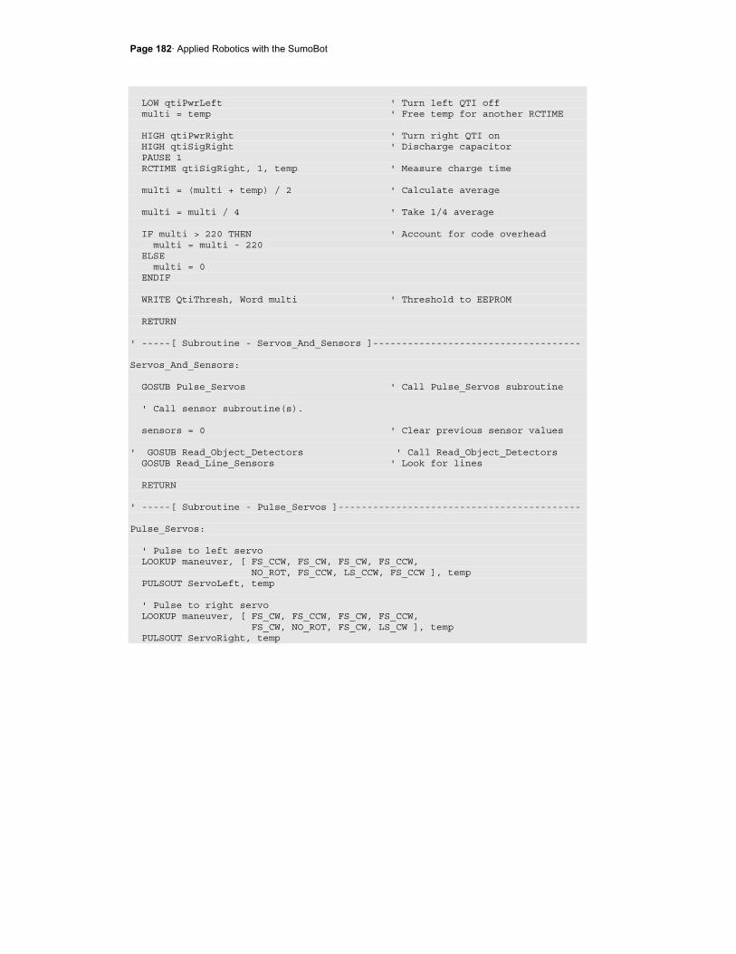
Page 182· Applied Robotics with the SumoBot
LOW qtiPwrLeft ' Turn left QTI off multi = temp ' Free temp for another RCTIME HIGH qtiPwrRight ' Turn right QTI on HIGH qtiSigRight ' Discharge capacitor PAUSE 1 RCTIME qtiSigRight, 1, temp ' Measure charge time multi = (multi + temp) / 2 ' Calculate average multi = multi / 4 ' Take 1/4 average IF multi > 220 THEN ' Account for code overhead multi = multi - 220 ELSE multi = 0 ENDIF WRITE QtiThresh, Word multi ' Threshold to EEPROM RETURN ' -----[ Subroutine - Servos_And_Sensors ]------------------------------------ Servos_And_Sensors: GOSUB Pulse_Servos ' Call Pulse_Servos subroutine ' Call sensor subroutine(s). sensors = 0 ' Clear previous sensor values ' GOSUB Read_Object_Detectors ' Call Read_Object_Detectors GOSUB Read_Line_Sensors ' Look for lines RETURN ' -----[ Subroutine - Pulse_Servos ]------------------------------------------ Pulse_Servos: ' Pulse to left servo LOOKUP maneuver, [ FS_CCW, FS_CW, FS_CW, FS_CCW, NO_ROT, FS_CCW, LS_CCW, FS_CCW ], temp PULSOUT ServoLeft, temp ' Pulse to right servo LOOKUP maneuver, [ FS_CW, FS_CCW, FS_CW, FS_CCW, FS_CW, NO_ROT, FS_CW, LS_CW ], temp PULSOUT ServoRight, temp
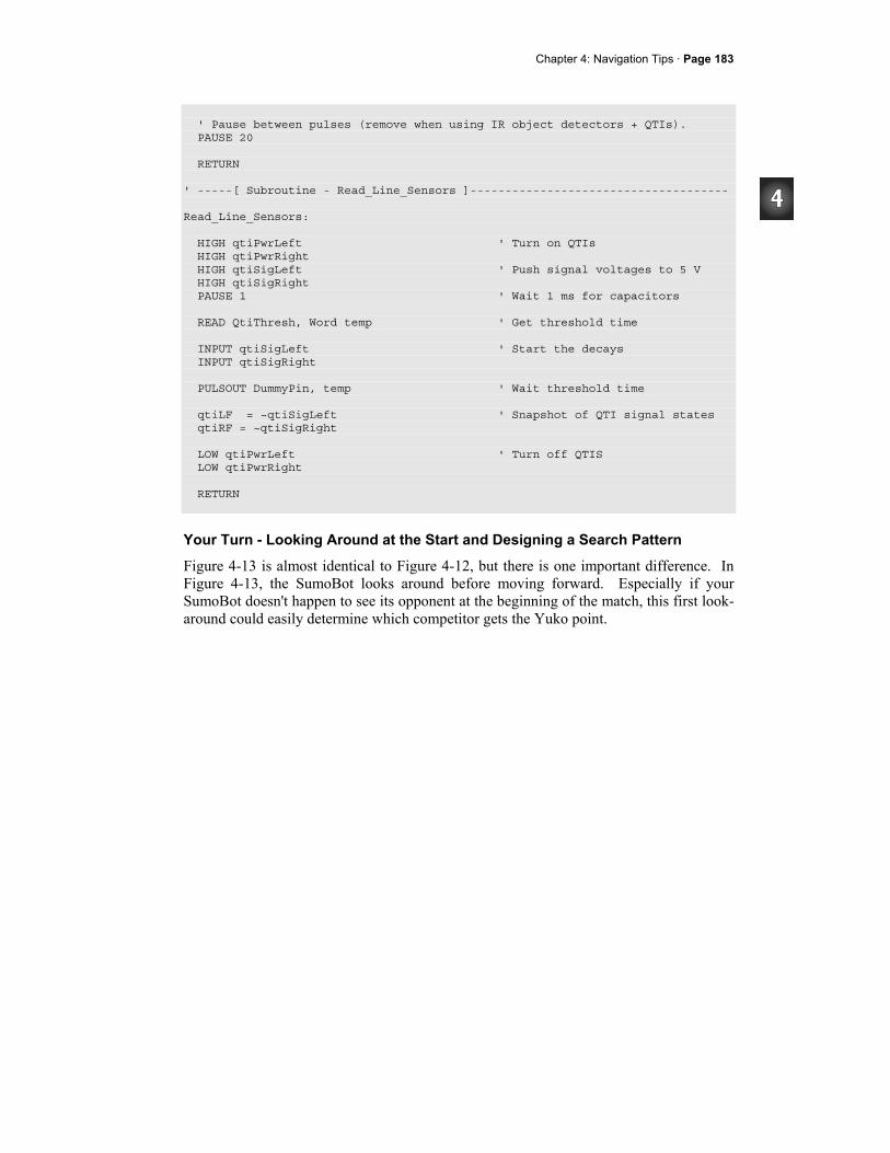
Chapter 4: Navigation Tips · Page 183
' Pause between pulses (remove when using IR object detectors + QTIs). PAUSE 20 RETURN ' -----[ Subroutine - Read_Line_Sensors ]------------------------------------- Read_Line_Sensors: HIGH qtiPwrLeft ' Turn on QTIs HIGH qtiPwrRight HIGH qtiSigLeft ' Push signal voltages to 5 V HIGH qtiSigRight PAUSE 1 ' Wait 1 ms for capacitors READ QtiThresh, Word temp ' Get threshold time INPUT qtiSigLeft ' Start the decays INPUT qtiSigRight PULSOUT DummyPin, temp ' Wait threshold time qtiLF = ~qtiSigLeft ' Snapshot of QTI signal states qtiRF = ~qtiSigRight LOW qtiPwrLeft ' Turn off QTIS LOW qtiPwrRight RETURN
Your Turn - Looking Around at the Start and Designing a Search Pattern
Figure 4-13 is almost identical to Figure 4-12, but there is one important difference. In Figure 4-13, the SumoBot looks around before moving forward. Especially if your SumoBot doesn't happen to see its opponent at the beginning of the match, this first look-around could easily determine which competitor gets the Yuko point.
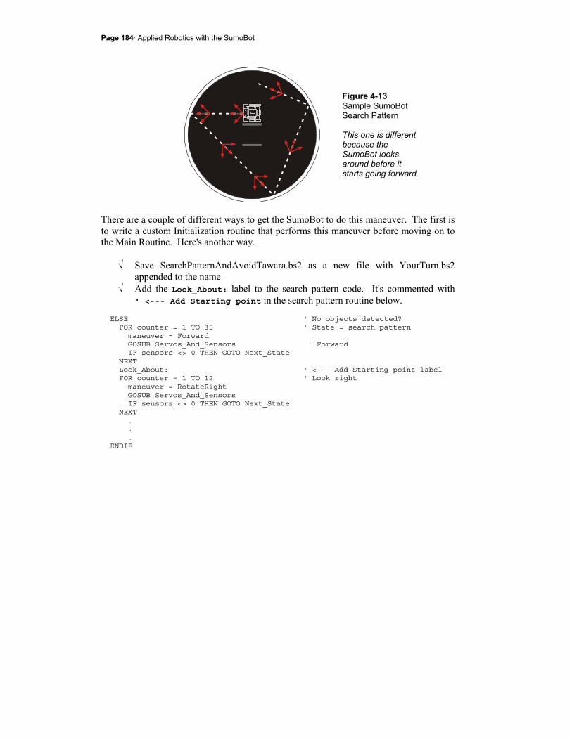
Page 184· Applied Robotics with the SumoBot
Figure 4-13 Sample SumoBot Search Pattern This one is different because the SumoBot looks around before it starts going forward.
There are a couple of different ways to get the SumoBot to do this maneuver. The first is to write a custom Initialization routine that performs this maneuver before moving on to the Main Routine. Here's another way.
√ Save SearchPatternAndAvoidTawara.bs2 as a new file with YourTurn.bs2 appended to the name
√ Add the Look_About: label to the search pattern code. It's commented with ' <--- Add Starting point in the search pattern routine below.
ELSE ' No objects detected? FOR counter = 1 TO 35 ' State = search pattern maneuver = Forward GOSUB Servos_And_Sensors ' Forward IF sensors <> 0 THEN GOTO Next_State NEXT Look_About: ' <--- Add Starting point label FOR counter = 1 TO 12 ' Look right maneuver = RotateRight GOSUB Servos_And_Sensors IF sensors <> 0 THEN GOTO Next_State NEXT . . . ENDIF
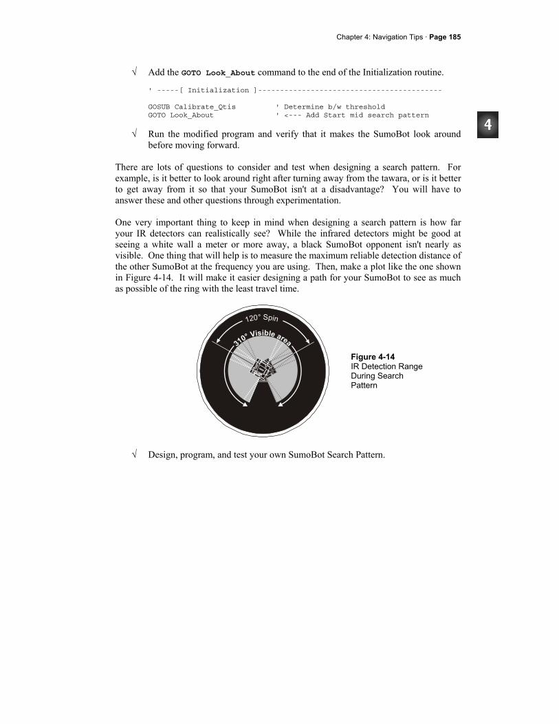
Chapter 4: Navigation Tips · Page 185
√ Add the GOTO Look_About command to the end of the Initialization routine.
' -----[ Initialization ]------------------------------------------ GOSUB Calibrate_Qtis ' Determine b/w threshold GOTO Look_About ' <--- Add Start mid search pattern
√ Run the modified program and verify that it makes the SumoBot look around before moving forward.
There are lots of questions to consider and test when designing a search pattern. For example, is it better to look around right after turning away from the tawara, or is it better to get away from it so that your SumoBot isn't at a disadvantage? You will have to answer these and other questions through experimentation. One very important thing to keep in mind when designing a search pattern is how far your IR detectors can realistically see? While the infrared detectors might be good at seeing a white wall a meter or more away, a black SumoBot opponent isn't nearly as visible. One thing that will help is to measure the maximum reliable detection distance of the other SumoBot at the frequency you are using. Then, make a plot like the one shown in Figure 4-14. It will make it easier designing a path for your SumoBot to see as much as possible of the ring with the least travel time.
Figure 4-14 IR Detection Range During Search Pattern
√ Design, program, and test your own SumoBot Search Pattern.
Page 186· Applied Robotics with the SumoBot
ACTIVITY #6: FULLY FUNCTIONAL SUMO EXAMPLE PROGRAMS This activity features two fully functional SumoBot example programs. While they both do the same things; they are organized a little differently. The first is simply a combination of the example programs, mainly from this chapter. The second has the code for each state moved to subroutines.
First Sumo Program - Navigation Code in Main Routine
This first example program followed the same steps used in Chapter 2, Activity #6 for integrating programs. The three programs that were combined were:
• SearchPatternAndAvoidTawara.bs2 from Activity #6 in this chapter. • FrontAndSideIrNavigation.bs2 from Activity #3 in this chapter. • TestResetButton.bs2 from Chapter 2, Activity #2.
Example Program: TestSumoWrestler.bs2
Did you skip ahead to get here? If you skipped any thing in Chapter 3 or 4, go back and do it now.
The programs that follow are dependent upon the sensor circuits built, tested and calibrated in the previous activities in Chapter 3 and 4.
√ Pick a sumo start card from Activity #3, Figure 4-7. √ Download TestSumoWrestler.bs2 to one SumoBot A and place it in the practice
ring in position A. √ Save TestSumoWrestler.bs2 as MySumoWrestler.bs2. √ Incorporate your search pattern into the Main Routine. √ Download that program to SumoBot B. √ Place it in the practice ring in position B. √ Press/release both SumoBots' Reset buttons simultaneously. √ Fine tune the MySumoWrestler.bs2 program for victory. √ After enough tests to determine the probability of victory, make sure to repeat
the test with the programs swapped. SumoBot A gets SumoBot B's program and vice versa.
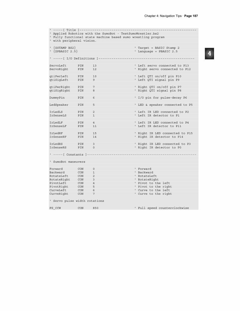
Chapter 4: Navigation Tips · Page 187
' -----[ Title ]-------------------------------------------------------------- ' Applied Robotics with the SumoBot - TestSumoWrestler.bs2 ' Fully functional state machine based sumo wrestling program ' with peripheral vision. ' $STAMP BS2 ' Target = BASIC Stamp 2 ' $PBASIC 2.5 ' Language = PBASIC 2.5 ' -----[ I/O Definitions ]--------------------------------------------------- ServoLeft PIN 13 ' Left servo connected to P13 ServoRight PIN 12 ' Right servo connected to P12 qtiPwrLeft PIN 10 ' Left QTI on/off pin P10 qtiSigLeft PIN 9 ' Left QTI signal pin P9 qtiPwrRight PIN 7 ' Right QTI on/off pin P7 qtiSigRight PIN 8 ' Right QTI signal pin P8 DummyPin PIN 6 ' I/O pin for pulse-decay P6 LedSpeaker PIN 5 ' LED & speaker connected to P5 IrLedLS PIN 2 ' Left IR LED connected to P2 IrSenseLS PIN 1 ' Left IR detector to P1 IrLedLF PIN 4 ' Left IR LED connected to P4 IrSenseLF PIN 11 ' Left IR detector to P11 IrLedRF PIN 15 ' Right IR LED connected to P15 IrSenseRF PIN 14 ' Right IR detector to P14 IrLedRS PIN 3 ' Right IR LED connected to P3 IrSenseRS PIN 0 ' Right IR detector to P0 ' -----[ Constants ]---------------------------------------------------------- ' SumoBot maneuvers Forward CON 0 ' Forward Backward CON 1 ' Backward RotateLeft CON 2 ' RotateLeft RotateRight CON 3 ' RotateRight PivotLeft CON 4 ' Pivot to the left PivotRight CON 5 ' Pivot to the right CurveLeft CON 6 ' Curve to the left CurveRight CON 7 ' Curve to the right ' Servo pulse width rotations FS_CCW CON 850 ' Full speed counterclockwise

Page 188· Applied Robotics with the SumoBot
FS_CW CON 650 ' Full speed clockwise NO_ROT CON 750 ' No rotation LS_CCW CON 770 ' Low speed counterclockwise LS_CW CON 730 ' Low speed clockwise ' IR object detectors IrFreq CON 38500 ' IR LED frequency ' -----[ Variables ]---------------------------------------------------------- temp VAR Word ' Temporary variable multi VAR Word ' Multipurpose variable counter VAR Byte ' Loop counting variable. maneuver VAR Nib ' SumoBot travel maneuver sensors VAR Byte ' Sensor flags byte qtiLF VAR sensors.BIT5 ' Stores snapshot of QtiSigLeft qtiRF VAR sensors.BIT4 ' Stores snapshot of QtiSigRight irLS VAR sensors.BIT3 ' State of Left Side IR irLF VAR sensors.BIT2 ' State of Left Front IR irRF VAR sensors.BIT1 ' State of Right Front IR irRS VAR sensors.BIT0 ' State of Right Side IR ' -----[ EEPROM Data ]-------------------------------------------------------- RunStatus DATA 0 ' Run status EEPROM byte QtiThresh DATA Word 0 ' Word for QTI threshold time ' -----[ Initialization ]----------------------------------------------------- GOSUB Reset ' Wait for Reset press/release GOSUB Start_Delay ' 5 Second delay GOSUB Calibrate_Qtis ' Determine b/w threshold GOTO Look_About ' Start mid search pattern ' -----[ Main Routine ]------------------------------------------------------- DO IF qtiLF = 1 THEN ' Left QTI sees line? FOR counter = 1 TO 15 ' State = Avoid tawara left maneuver = Backward ' Back up GOSUB Servos_And_Sensors NEXT FOR counter = 1 TO 15 ' Turn right maneuver = RotateRight GOSUB Servos_And_Sensors
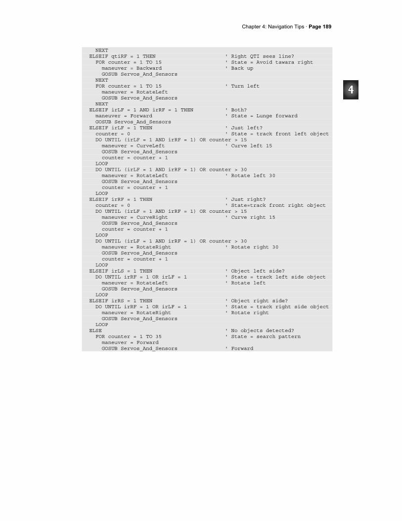
Chapter 4: Navigation Tips · Page 189
NEXT ELSEIF qtiRF = 1 THEN ' Right QTI sees line? FOR counter = 1 TO 15 ' State = Avoid tawara right maneuver = Backward ' Back up GOSUB Servos_And_Sensors NEXT FOR counter = 1 TO 15 ' Turn left maneuver = RotateLeft GOSUB Servos_And_Sensors NEXT ELSEIF irLF = 1 AND irRF = 1 THEN ' Both? maneuver = Forward ' State = Lunge forward GOSUB Servos_And_Sensors ELSEIF irLF = 1 THEN ' Just left? counter = 0 ' State = track front left object DO UNTIL (irLF = 1 AND irRF = 1) OR counter > 15 maneuver = CurveLeft ' Curve left 15 GOSUB Servos_And_Sensors counter = counter + 1 LOOP DO UNTIL (irLF = 1 AND irRF = 1) OR counter > 30 maneuver = RotateLeft ' Rotate left 30 GOSUB Servos_And_Sensors counter = counter + 1 LOOP ELSEIF irRF = 1 THEN ' Just right? counter = 0 ' State=track front right object DO UNTIL (irLF = 1 AND irRF = 1) OR counter > 15 maneuver = CurveRight ' Curve right 15 GOSUB Servos_And_Sensors counter = counter + 1 LOOP DO UNTIL (irLF = 1 AND irRF = 1) OR counter > 30 maneuver = RotateRight ' Rotate right 30 GOSUB Servos_And_Sensors counter = counter + 1 LOOP ELSEIF irLS = 1 THEN ' Object left side? DO UNTIL irRF = 1 OR irLF = 1 ' State = track left side object maneuver = RotateLeft ' Rotate left GOSUB Servos_And_Sensors LOOP ELSEIF irRS = 1 THEN ' Object right side? DO UNTIL irRF = 1 OR irLF = 1 ' State = track right side object maneuver = RotateRight ' Rotate right GOSUB Servos_And_Sensors LOOP ELSE ' No objects detected? FOR counter = 1 TO 35 ' State = search pattern maneuver = Forward GOSUB Servos_And_Sensors ' Forward
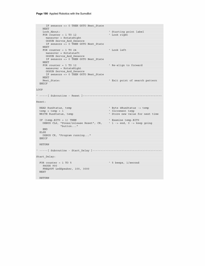
Page 190· Applied Robotics with the SumoBot
IF sensors <> 0 THEN GOTO Next_State NEXT Look_About: ' Starting point label FOR counter = 1 TO 12 ' Look right maneuver = RotateRight GOSUB Servos_And_Sensors IF sensors <> 0 THEN GOTO Next_State NEXT FOR counter = 1 TO 24 ' Look left maneuver = RotateLeft GOSUB Servos_And_Sensors IF sensors <> 0 THEN GOTO Next_State NEXT FOR counter = 1 TO 12 ' Re-align to forward maneuver = RotateRight GOSUB Servos_And_Sensors IF sensors <> 0 THEN GOTO Next_State NEXT Next_State: ' Exit point of search pattern ENDIF LOOP ' -----[ Subroutine - Reset ]------------------------------------------------- Reset: READ RunStatus, temp ' Byte @RunStatus -> temp temp = temp + 1 ' Increment temp WRITE RunStatus, temp ' Store new value for next time IF (temp.BIT0 = 1) THEN ' Examine temp.BIT0 DEBUG CLS, "Press/release Reset", CR, ' 1 -> end, 0 -> keep going "button..." END ELSE DEBUG CR, "Program running..." ENDIF RETURN ' -----[ Subroutine - Start_Delay ]------------------------------------------- Start_Delay: FOR counter = 1 TO 5 ' 5 beeps, 1/second PAUSE 900 FREQOUT LedSpeaker, 100, 3000 NEXT RETURN
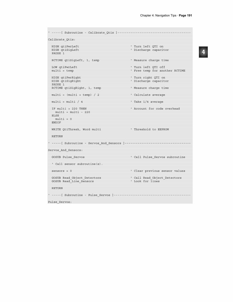
Chapter 4: Navigation Tips · Page 191
' -----[ Subroutine - Calibrate_Qtis ]---------------------------------------- Calibrate_Qtis: HIGH qtiPwrLeft ' Turn left QTI on HIGH qtiSigLeft ' Discharge capacitor PAUSE 1 RCTIME qtiSigLeft, 1, temp ' Measure charge time LOW qtiPwrLeft ' Turn left QTI off multi = temp ' Free temp for another RCTIME HIGH qtiPwrRight ' Turn right QTI on HIGH qtiSigRight ' Discharge capacitor PAUSE 1 RCTIME qtiSigRight, 1, temp ' Measure charge time multi = (multi + temp) / 2 ' Calculate average multi = multi / 4 ' Take 1/4 average IF multi > 220 THEN ' Account for code overhead multi = multi - 220 ELSE multi = 0 ENDIF WRITE QtiThresh, Word multi ' Threshold to EEPROM RETURN ' -----[ Subroutine - Servos_And_Sensors ]------------------------------------ Servos_And_Sensors: GOSUB Pulse_Servos ' Call Pulse_Servos subroutine ' Call sensor subroutine(s). sensors = 0 ' Clear previous sensor values GOSUB Read_Object_Detectors ' Call Read_Object_Detectors GOSUB Read_Line_Sensors ' Look for lines RETURN ' -----[ Subroutine - Pulse_Servos ]------------------------------------------ Pulse_Servos:
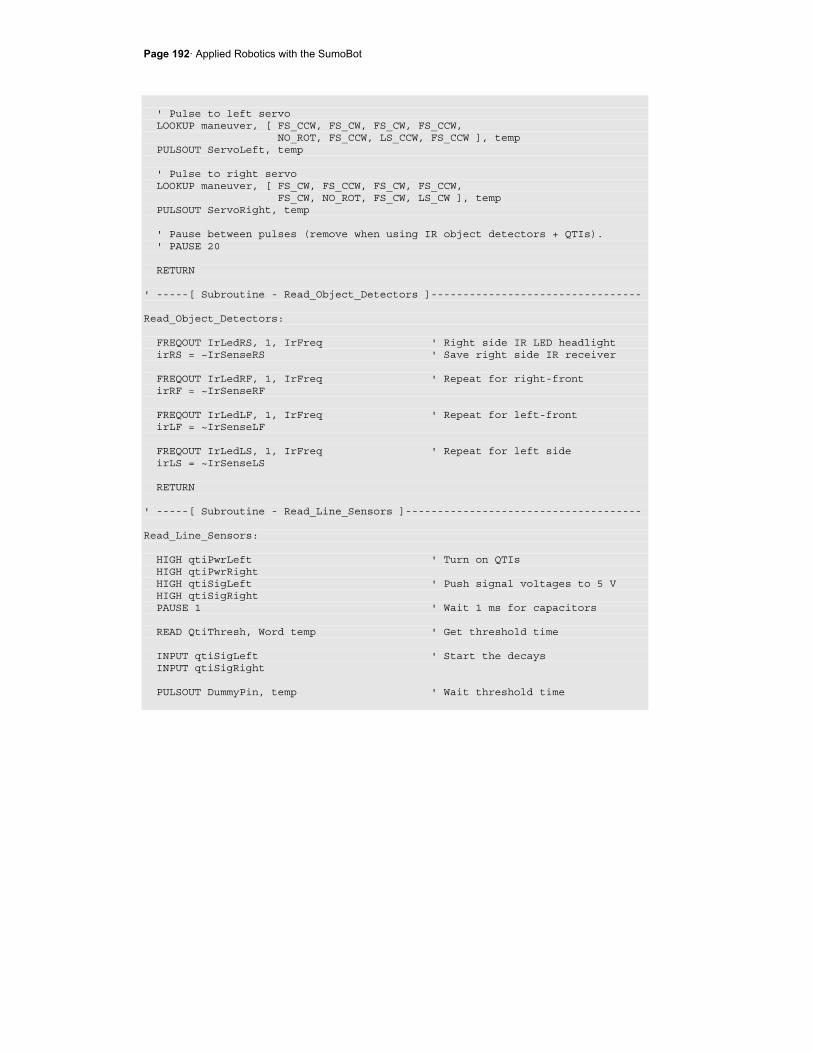
Page 192· Applied Robotics with the SumoBot
' Pulse to left servo LOOKUP maneuver, [ FS_CCW, FS_CW, FS_CW, FS_CCW, NO_ROT, FS_CCW, LS_CCW, FS_CCW ], temp PULSOUT ServoLeft, temp ' Pulse to right servo LOOKUP maneuver, [ FS_CW, FS_CCW, FS_CW, FS_CCW, FS_CW, NO_ROT, FS_CW, LS_CW ], temp PULSOUT ServoRight, temp ' Pause between pulses (remove when using IR object detectors + QTIs). ' PAUSE 20 RETURN ' -----[ Subroutine - Read_Object_Detectors ]--------------------------------- Read_Object_Detectors: FREQOUT IrLedRS, 1, IrFreq ' Right side IR LED headlight irRS = ~IrSenseRS ' Save right side IR receiver FREQOUT IrLedRF, 1, IrFreq ' Repeat for right-front irRF = ~IrSenseRF FREQOUT IrLedLF, 1, IrFreq ' Repeat for left-front irLF = ~IrSenseLF FREQOUT IrLedLS, 1, IrFreq ' Repeat for left side irLS = ~IrSenseLS RETURN ' -----[ Subroutine - Read_Line_Sensors ]------------------------------------- Read_Line_Sensors: HIGH qtiPwrLeft ' Turn on QTIs HIGH qtiPwrRight HIGH qtiSigLeft ' Push signal voltages to 5 V HIGH qtiSigRight PAUSE 1 ' Wait 1 ms for capacitors READ QtiThresh, Word temp ' Get threshold time INPUT qtiSigLeft ' Start the decays INPUT qtiSigRight PULSOUT DummyPin, temp ' Wait threshold time
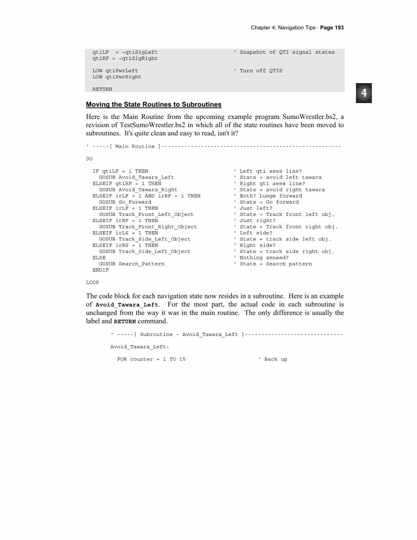
Chapter 4: Navigation Tips · Page 193
qtiLF = ~qtiSigLeft ' Snapshot of QTI signal states qtiRF = ~qtiSigRight LOW qtiPwrLeft ' Turn off QTIS LOW qtiPwrRight RETURN
Moving the State Routines to Subroutines
Here is the Main Routine from the upcoming example program SumoWrestler.bs2, a revision of TestSumoWrestler.bs2 in which all of the state routines have been moved to subroutines. It's quite clean and easy to read, isn't it? ' -----[ Main Routine ]------------------------------------------------------- DO IF qtiLF = 1 THEN ' Left qti sees line? GOSUB Avoid_Tawara_Left ' State = avoid left tawara ELSEIF qtiRF = 1 THEN ' Right qti sees line? GOSUB Avoid_Tawara_Right ' State = avoid right tawara ELSEIF irLF = 1 AND irRF = 1 THEN ' Both? Lunge forward GOSUB Go_Forward ' State = Go forward ELSEIF irLF = 1 THEN ' Just left? GOSUB Track_Front_Left_Object ' State = Track front left obj. ELSEIF irRF = 1 THEN ' Just right? GOSUB Track_Front_Right_Object ' State = Track front right obj. ELSEIF irLS = 1 THEN ' Left side? GOSUB Track_Side_Left_Object ' State = track side left obj. ELSEIF irRS = 1 THEN ' Right side? GOSUB Track_Side_Left_Object ' State = track side right obj. ELSE ' Nothing sensed? GOSUB Search_Pattern ' State = Search pattern ENDIF LOOP
The code block for each navigation state now resides in a subroutine. Here is an example of Avoid_Tawara_Left. For the most part, the actual code in each subroutine is unchanged from the way it was in the main routine. The only difference is usually the label and RETURN command.
' -----[ Subroutine - Avoid_Tawara_Left ]------------------------------ Avoid_Tawara_Left: FOR counter = 1 TO 15 ' Back up
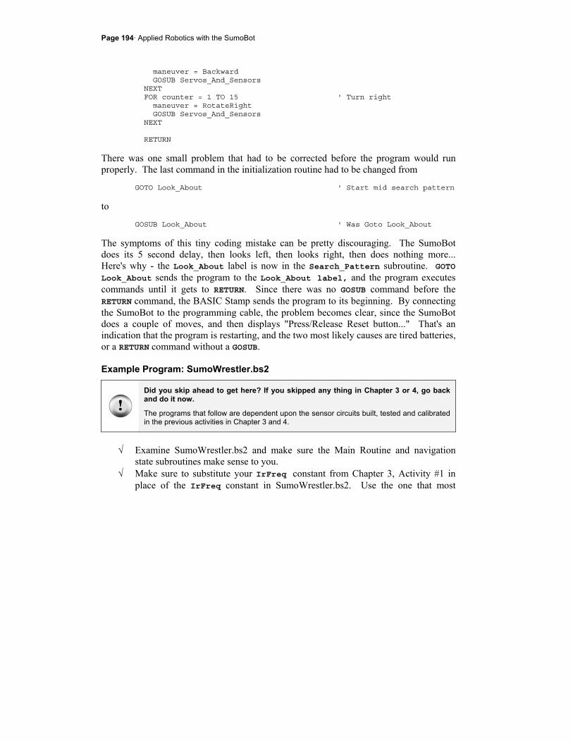
Page 194· Applied Robotics with the SumoBot
maneuver = Backward GOSUB Servos_And_Sensors NEXT FOR counter = 1 TO 15 ' Turn right maneuver = RotateRight GOSUB Servos_And_Sensors NEXT RETURN
There was one small problem that had to be corrected before the program would run properly. The last command in the initialization routine had to be changed from
GOTO Look_About ' Start mid search pattern
to GOSUB Look_About ' Was Goto Look_About
The symptoms of this tiny coding mistake can be pretty discouraging. The SumoBot does its 5 second delay, then looks left, then looks right, then does nothing more... Here's why - the Look_About label is now in the Search_Pattern subroutine. GOTO Look_About sends the program to the Look_About label, and the program executes commands until it gets to RETURN. Since there was no GOSUB command before the RETURN command, the BASIC Stamp sends the program to its beginning. By connecting the SumoBot to the programming cable, the problem becomes clear, since the SumoBot does a couple of moves, and then displays "Press/Release Reset button..." That's an indication that the program is restarting, and the two most likely causes are tired batteries, or a RETURN command without a GOSUB.
Example Program: SumoWrestler.bs2
Did you skip ahead to get here? If you skipped any thing in Chapter 3 or 4, go back and do it now.
The programs that follow are dependent upon the sensor circuits built, tested and calibrated in the previous activities in Chapter 3 and 4.
√ Examine SumoWrestler.bs2 and make sure the Main Routine and navigation
state subroutines make sense to you. √ Make sure to substitute your IrFreq constant from Chapter 3, Activity #1 in
place of the IrFreq constant in SumoWrestler.bs2. Use the one that most
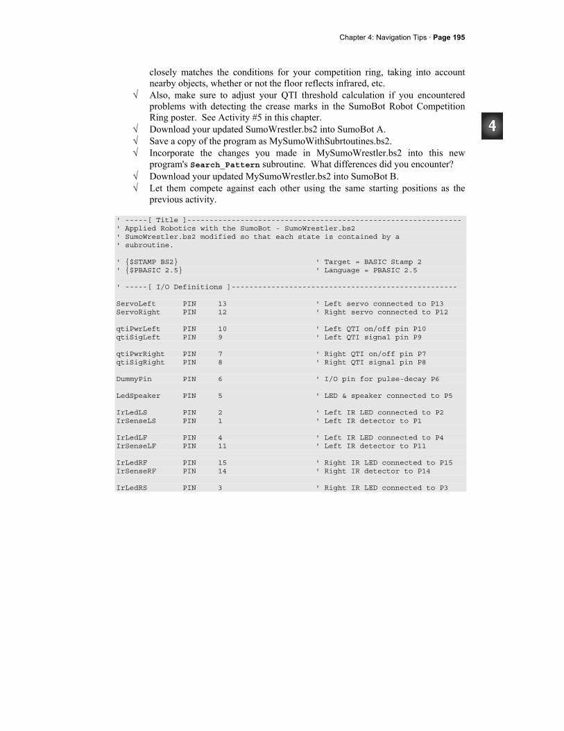
Chapter 4: Navigation Tips · Page 195
closely matches the conditions for your competition ring, taking into account nearby objects, whether or not the floor reflects infrared, etc.
√ Also, make sure to adjust your QTI threshold calculation if you encountered problems with detecting the crease marks in the SumoBot Robot Competition Ring poster. See Activity #5 in this chapter.
√ Download your updated SumoWrestler.bs2 into SumoBot A. √ Save a copy of the program as MySumoWithSubrtoutines.bs2. √ Incorporate the changes you made in MySumoWrestler.bs2 into this new
program's Search_Pattern subroutine. What differences did you encounter? √ Download your updated MySumoWrestler.bs2 into SumoBot B. √ Let them compete against each other using the same starting positions as the
previous activity. ' -----[ Title ]-------------------------------------------------------------- ' Applied Robotics with the SumoBot - SumoWrestler.bs2 ' SumoWrestler.bs2 modified so that each state is contained by a ' subroutine. ' $STAMP BS2 ' Target = BASIC Stamp 2 ' $PBASIC 2.5 ' Language = PBASIC 2.5 ' -----[ I/O Definitions ]--------------------------------------------------- ServoLeft PIN 13 ' Left servo connected to P13 ServoRight PIN 12 ' Right servo connected to P12 qtiPwrLeft PIN 10 ' Left QTI on/off pin P10 qtiSigLeft PIN 9 ' Left QTI signal pin P9 qtiPwrRight PIN 7 ' Right QTI on/off pin P7 qtiSigRight PIN 8 ' Right QTI signal pin P8 DummyPin PIN 6 ' I/O pin for pulse-decay P6 LedSpeaker PIN 5 ' LED & speaker connected to P5 IrLedLS PIN 2 ' Left IR LED connected to P2 IrSenseLS PIN 1 ' Left IR detector to P1 IrLedLF PIN 4 ' Left IR LED connected to P4 IrSenseLF PIN 11 ' Left IR detector to P11 IrLedRF PIN 15 ' Right IR LED connected to P15 IrSenseRF PIN 14 ' Right IR detector to P14 IrLedRS PIN 3 ' Right IR LED connected to P3
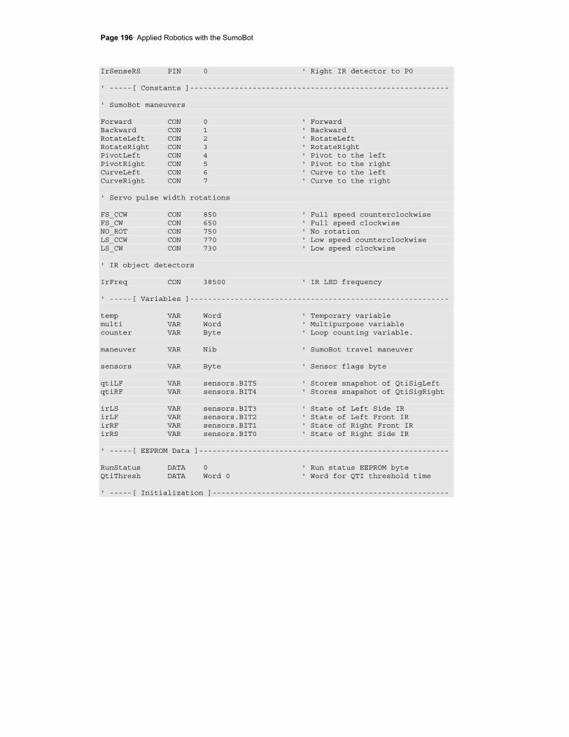
Page 196· Applied Robotics with the SumoBot
IrSenseRS PIN 0 ' Right IR detector to P0 ' -----[ Constants ]---------------------------------------------------------- ' SumoBot maneuvers Forward CON 0 ' Forward Backward CON 1 ' Backward RotateLeft CON 2 ' RotateLeft RotateRight CON 3 ' RotateRight PivotLeft CON 4 ' Pivot to the left PivotRight CON 5 ' Pivot to the right CurveLeft CON 6 ' Curve to the left CurveRight CON 7 ' Curve to the right ' Servo pulse width rotations FS_CCW CON 850 ' Full speed counterclockwise FS_CW CON 650 ' Full speed clockwise NO_ROT CON 750 ' No rotation LS_CCW CON 770 ' Low speed counterclockwise LS_CW CON 730 ' Low speed clockwise ' IR object detectors IrFreq CON 38500 ' IR LED frequency ' -----[ Variables ]---------------------------------------------------------- temp VAR Word ' Temporary variable multi VAR Word ' Multipurpose variable counter VAR Byte ' Loop counting variable. maneuver VAR Nib ' SumoBot travel maneuver sensors VAR Byte ' Sensor flags byte qtiLF VAR sensors.BIT5 ' Stores snapshot of QtiSigLeft qtiRF VAR sensors.BIT4 ' Stores snapshot of QtiSigRight irLS VAR sensors.BIT3 ' State of Left Side IR irLF VAR sensors.BIT2 ' State of Left Front IR irRF VAR sensors.BIT1 ' State of Right Front IR irRS VAR sensors.BIT0 ' State of Right Side IR ' -----[ EEPROM Data ]-------------------------------------------------------- RunStatus DATA 0 ' Run status EEPROM byte QtiThresh DATA Word 0 ' Word for QTI threshold time ' -----[ Initialization ]-----------------------------------------------------
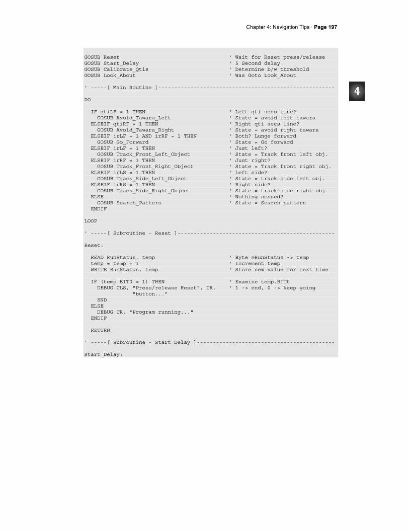
Chapter 4: Navigation Tips · Page 197
GOSUB Reset ' Wait for Reset press/release GOSUB Start_Delay ' 5 Second delay GOSUB Calibrate_Qtis ' Determine b/w threshold GOSUB Look_About ' Was Goto Look_About ' -----[ Main Routine ]------------------------------------------------------- DO IF qtiLF = 1 THEN ' Left qti sees line? GOSUB Avoid_Tawara_Left ' State = avoid left tawara ELSEIF qtiRF = 1 THEN ' Right qti sees line? GOSUB Avoid_Tawara_Right ' State = avoid right tawara ELSEIF irLF = 1 AND irRF = 1 THEN ' Both? Lunge forward GOSUB Go_Forward ' State = Go forward ELSEIF irLF = 1 THEN ' Just left? GOSUB Track_Front_Left_Object ' State = Track front left obj. ELSEIF irRF = 1 THEN ' Just right? GOSUB Track_Front_Right_Object ' State = Track front right obj. ELSEIF irLS = 1 THEN ' Left side? GOSUB Track_Side_Left_Object ' State = track side left obj. ELSEIF irRS = 1 THEN ' Right side? GOSUB Track_Side_Right_Object ' State = track side right obj. ELSE ' Nothing sensed? GOSUB Search_Pattern ' State = Search pattern ENDIF LOOP ' -----[ Subroutine - Reset ]------------------------------------------------- Reset: READ RunStatus, temp ' Byte @RunStatus -> temp temp = temp + 1 ' Increment temp WRITE RunStatus, temp ' Store new value for next time IF (temp.BIT0 = 1) THEN ' Examine temp.BIT0 DEBUG CLS, "Press/release Reset", CR, ' 1 -> end, 0 -> keep going "button..." END ELSE DEBUG CR, "Program running..." ENDIF RETURN ' -----[ Subroutine - Start_Delay ]------------------------------------------- Start_Delay:
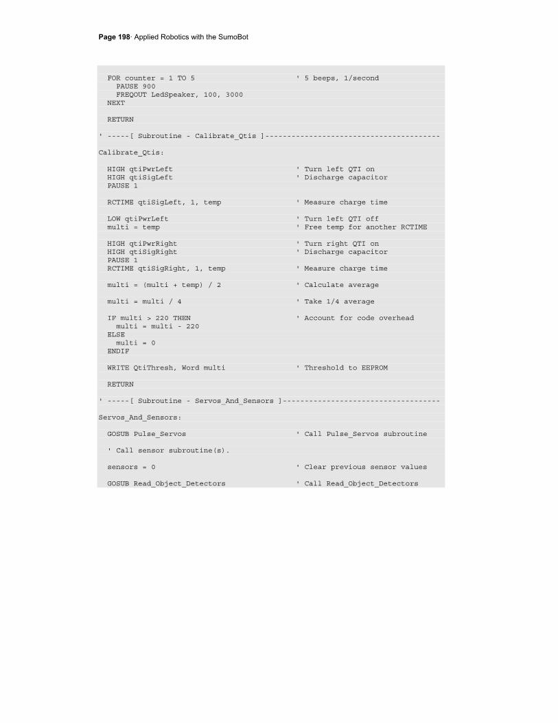
Page 198· Applied Robotics with the SumoBot
FOR counter = 1 TO 5 ' 5 beeps, 1/second PAUSE 900 FREQOUT LedSpeaker, 100, 3000 NEXT RETURN ' -----[ Subroutine - Calibrate_Qtis ]---------------------------------------- Calibrate_Qtis: HIGH qtiPwrLeft ' Turn left QTI on HIGH qtiSigLeft ' Discharge capacitor PAUSE 1 RCTIME qtiSigLeft, 1, temp ' Measure charge time LOW qtiPwrLeft ' Turn left QTI off multi = temp ' Free temp for another RCTIME HIGH qtiPwrRight ' Turn right QTI on HIGH qtiSigRight ' Discharge capacitor PAUSE 1 RCTIME qtiSigRight, 1, temp ' Measure charge time multi = (multi + temp) / 2 ' Calculate average multi = multi / 4 ' Take 1/4 average IF multi > 220 THEN ' Account for code overhead multi = multi - 220 ELSE multi = 0 ENDIF WRITE QtiThresh, Word multi ' Threshold to EEPROM RETURN ' -----[ Subroutine - Servos_And_Sensors ]------------------------------------ Servos_And_Sensors: GOSUB Pulse_Servos ' Call Pulse_Servos subroutine ' Call sensor subroutine(s). sensors = 0 ' Clear previous sensor values GOSUB Read_Object_Detectors ' Call Read_Object_Detectors
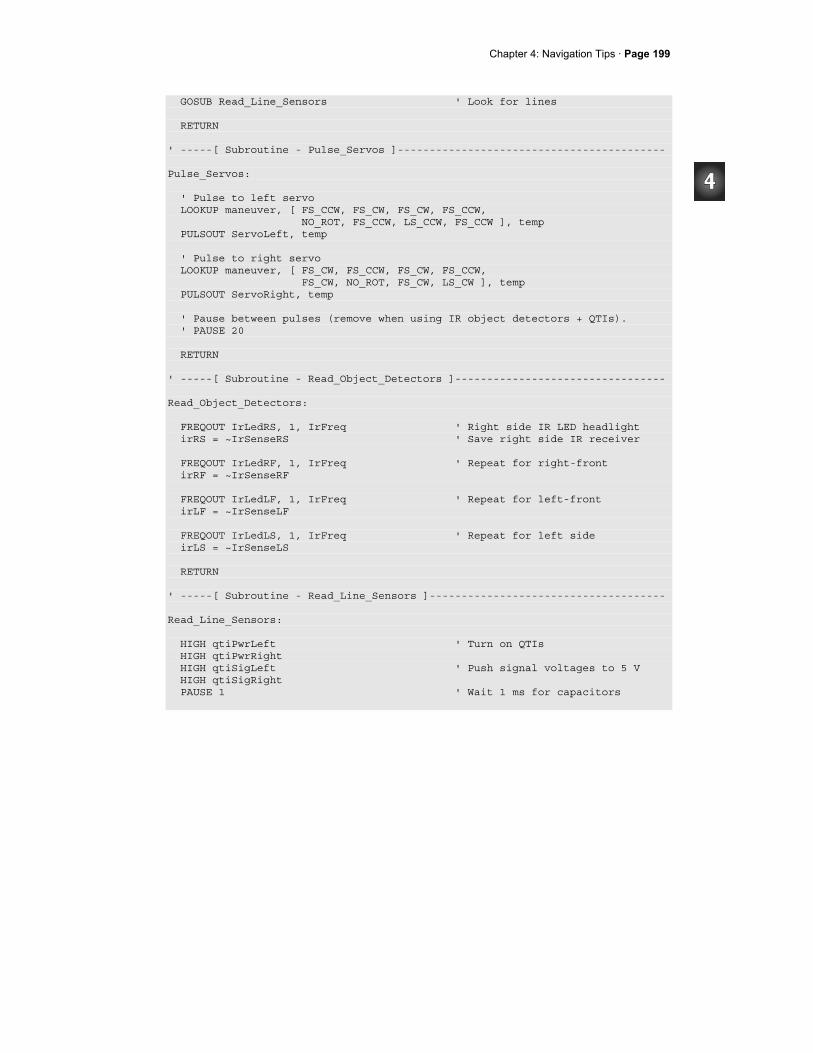
Chapter 4: Navigation Tips · Page 199
GOSUB Read_Line_Sensors ' Look for lines RETURN ' -----[ Subroutine - Pulse_Servos ]------------------------------------------ Pulse_Servos: ' Pulse to left servo LOOKUP maneuver, [ FS_CCW, FS_CW, FS_CW, FS_CCW, NO_ROT, FS_CCW, LS_CCW, FS_CCW ], temp PULSOUT ServoLeft, temp ' Pulse to right servo LOOKUP maneuver, [ FS_CW, FS_CCW, FS_CW, FS_CCW, FS_CW, NO_ROT, FS_CW, LS_CW ], temp PULSOUT ServoRight, temp ' Pause between pulses (remove when using IR object detectors + QTIs). ' PAUSE 20 RETURN ' -----[ Subroutine - Read_Object_Detectors ]--------------------------------- Read_Object_Detectors: FREQOUT IrLedRS, 1, IrFreq ' Right side IR LED headlight irRS = ~IrSenseRS ' Save right side IR receiver FREQOUT IrLedRF, 1, IrFreq ' Repeat for right-front irRF = ~IrSenseRF FREQOUT IrLedLF, 1, IrFreq ' Repeat for left-front irLF = ~IrSenseLF FREQOUT IrLedLS, 1, IrFreq ' Repeat for left side irLS = ~IrSenseLS RETURN ' -----[ Subroutine - Read_Line_Sensors ]------------------------------------- Read_Line_Sensors: HIGH qtiPwrLeft ' Turn on QTIs HIGH qtiPwrRight HIGH qtiSigLeft ' Push signal voltages to 5 V HIGH qtiSigRight PAUSE 1 ' Wait 1 ms for capacitors
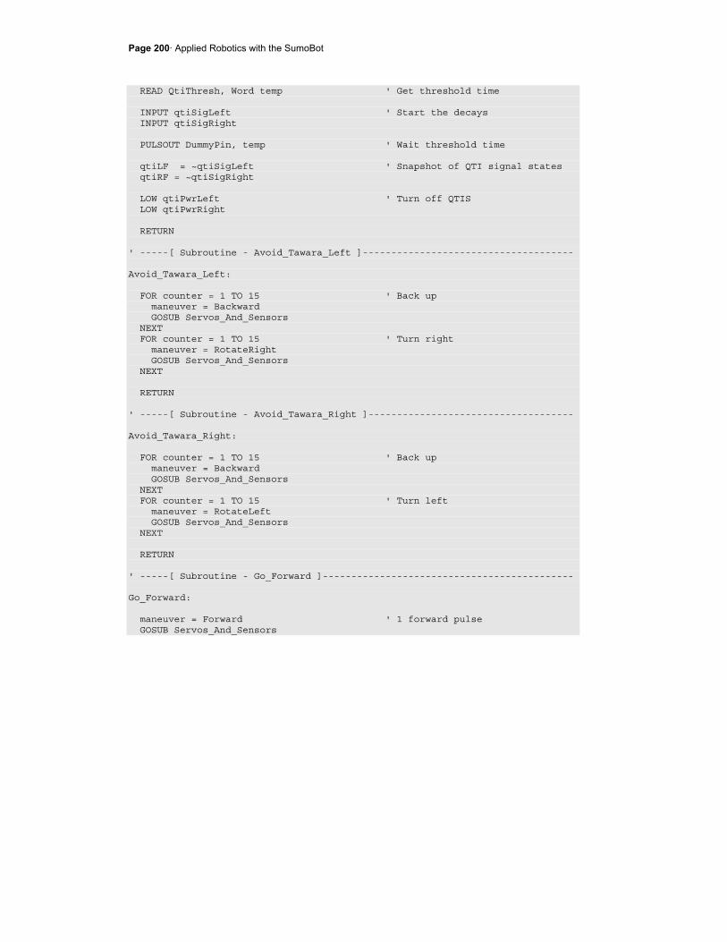
Page 200· Applied Robotics with the SumoBot
READ QtiThresh, Word temp ' Get threshold time INPUT qtiSigLeft ' Start the decays INPUT qtiSigRight PULSOUT DummyPin, temp ' Wait threshold time qtiLF = ~qtiSigLeft ' Snapshot of QTI signal states qtiRF = ~qtiSigRight LOW qtiPwrLeft ' Turn off QTIS LOW qtiPwrRight RETURN ' -----[ Subroutine - Avoid_Tawara_Left ]------------------------------------- Avoid_Tawara_Left: FOR counter = 1 TO 15 ' Back up maneuver = Backward GOSUB Servos_And_Sensors NEXT FOR counter = 1 TO 15 ' Turn right maneuver = RotateRight GOSUB Servos_And_Sensors NEXT RETURN ' -----[ Subroutine - Avoid_Tawara_Right ]------------------------------------ Avoid_Tawara_Right: FOR counter = 1 TO 15 ' Back up maneuver = Backward GOSUB Servos_And_Sensors NEXT FOR counter = 1 TO 15 ' Turn left maneuver = RotateLeft GOSUB Servos_And_Sensors NEXT RETURN ' -----[ Subroutine - Go_Forward ]-------------------------------------------- Go_Forward: maneuver = Forward ' 1 forward pulse GOSUB Servos_And_Sensors
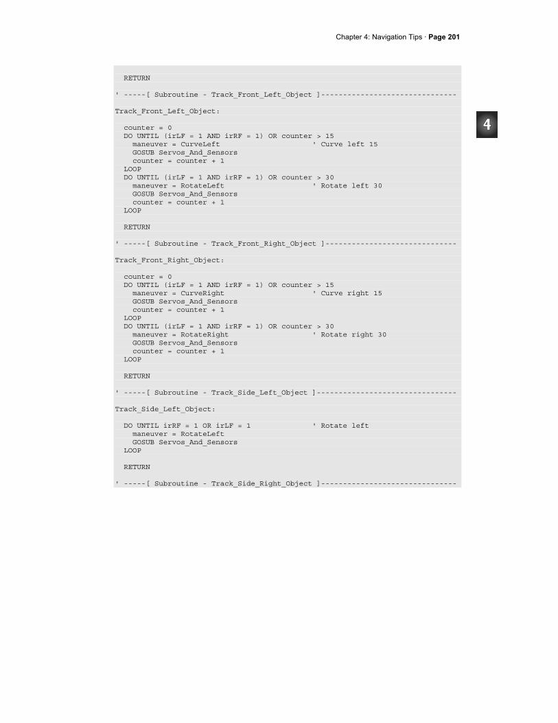
Chapter 4: Navigation Tips · Page 201
RETURN ' -----[ Subroutine - Track_Front_Left_Object ]------------------------------- Track_Front_Left_Object: counter = 0 DO UNTIL (irLF = 1 AND irRF = 1) OR counter > 15 maneuver = CurveLeft ' Curve left 15 GOSUB Servos_And_Sensors counter = counter + 1 LOOP DO UNTIL (irLF = 1 AND irRF = 1) OR counter > 30 maneuver = RotateLeft ' Rotate left 30 GOSUB Servos_And_Sensors counter = counter + 1 LOOP RETURN ' -----[ Subroutine - Track_Front_Right_Object ]------------------------------ Track_Front_Right_Object: counter = 0 DO UNTIL (irLF = 1 AND irRF = 1) OR counter > 15 maneuver = CurveRight ' Curve right 15 GOSUB Servos_And_Sensors counter = counter + 1 LOOP DO UNTIL (irLF = 1 AND irRF = 1) OR counter > 30 maneuver = RotateRight ' Rotate right 30 GOSUB Servos_And_Sensors counter = counter + 1 LOOP RETURN ' -----[ Subroutine - Track_Side_Left_Object ]-------------------------------- Track_Side_Left_Object: DO UNTIL irRF = 1 OR irLF = 1 ' Rotate left maneuver = RotateLeft GOSUB Servos_And_Sensors LOOP RETURN ' -----[ Subroutine - Track_Side_Right_Object ]-------------------------------
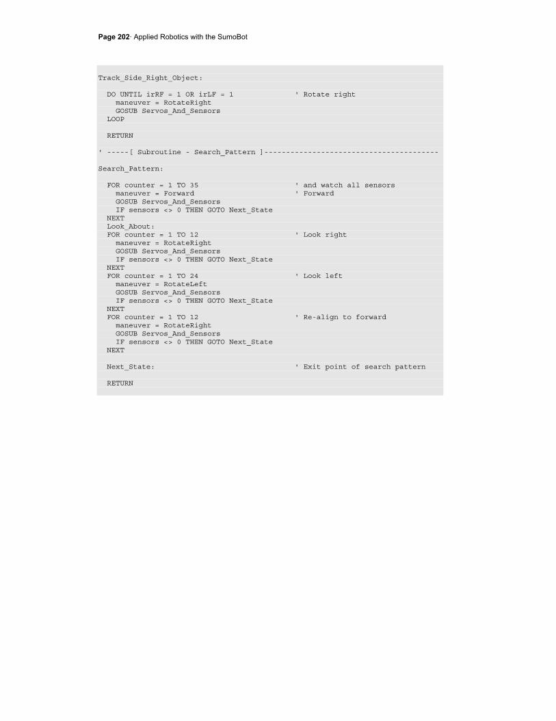
Page 202· Applied Robotics with the SumoBot
Track_Side_Right_Object: DO UNTIL irRF = 1 OR irLF = 1 ' Rotate right maneuver = RotateRight GOSUB Servos_And_Sensors LOOP RETURN ' -----[ Subroutine - Search_Pattern ]---------------------------------------- Search_Pattern: FOR counter = 1 TO 35 ' and watch all sensors maneuver = Forward ' Forward GOSUB Servos_And_Sensors IF sensors <> 0 THEN GOTO Next_State NEXT Look_About: FOR counter = 1 TO 12 ' Look right maneuver = RotateRight GOSUB Servos_And_Sensors IF sensors <> 0 THEN GOTO Next_State NEXT FOR counter = 1 TO 24 ' Look left maneuver = RotateLeft GOSUB Servos_And_Sensors IF sensors <> 0 THEN GOTO Next_State NEXT FOR counter = 1 TO 12 ' Re-align to forward maneuver = RotateRight GOSUB Servos_And_Sensors IF sensors <> 0 THEN GOTO Next_State NEXT Next_State: ' Exit point of search pattern RETURN

Chapter 4: Navigation Tips · Page 203
SUMMARY This chapter introduced a technique that uses the LOOKUP command for adapting servo control to use with the temp and counter variables. It also introduced a subroutine that makes checking the sensors between each servo pulse automatic. DO UNTIL...LOOP code blocks were used to respond to a sensor with an action until another sensor event occurred or a counter exceeded a certain number of repetitions. This makes it possible for the SumoBot to react to sensor detections on either the front or side that causes it to face its opponent. Similar routines for detecting and avoiding the white tawara line were also introduced along with search patterns the SumoBot can use to locate its opponent more quickly and effectively. The SumoBot navigation routines in this chapter can be conveniently viewed as state machines. Selected sensor detections cause the SumoBot to transition between different navigation states. State machine diagrams were introduced along with hybridized state machine diagrams as a potential visual aid for mapping the SumoBot's various responses to sensor events. Two fully functional SumoWrestler programs were presented. Both make use of the majority of the techniques presented earlier in this book. One contains all the navigation states and state transitions in the main routine. The other only has state transitions in the Main Routine, and all the navigation states are handled in subroutines.
Questions
1. Which BASIC Stamp I/O pin does the X7 signal line connect to? 2. What feature of servo motion does a FOR...NEXT loop's EndValue control? 3. What feature of SumoBot motion does a PULSOUT command's Pin argument
determine? 4. What do the numbers 700, 710, 720, 730 and 740 do for servo control? 5. Assuming a FOR...NEXT loop with 20 ms pauses, how many pulses will it take
to make the servos go forward for 3 seconds? 6. What effect do sensors have on the amount of time a loop makes the servos run? 7. What combination of PULSOUT commands does it take to make the SumoBot
execute a full speed reverse maneuver? 8. What combination of PULSOUT commands does it take to make the SumoBot
execute a right turn (rotating in place)?
Page 204· Applied Robotics with the SumoBot
9. What combination of PULSOUT commands does it take to make the SumoBot execute a pivot-right turn?
10. In the lookup command review, what value will the counter variable have to store to make the LOOKUP command copy 1580 to the note variable?
11. What constant values were chosen for Forward, Backward, RotateLeft, and RotateRight?
12. What variable has to be set to a value before the Pulse_Servos subroutine is called?
13. What PULSOUT commands does maneuver = 3; GOSUB Pulse_Servos dictate?
14. What are the two kinds of conditions that are typically evaluated while executing a maneuver?
15. What programming elements are needed for the SumoBot to perform one maneuver if a sensor condition is detected and evaluate the results, then perform another maneuver if the results are undesirable?
16. How does responding to a peripheral vision detection differ from responding to a forward vision detection?
17. What is a reset condition? 18. What is a state? 19. In Figure 4-9, what condition keeps the LED off? 20. In Figure 4-9, what condition maintains the Blink LED state? 21. How do the Avoid_Tawara states differ from other states? 22. How can you make a program start in the beginning of its Main Routine loop? 23. In TestSumoWrestler.bs2, if the front right and front left QTIs detect the white
tawara line at the same instant, what will happen?
Exercises
1. Write routines for ServoControlExample.bs2 that make the SumoBot curve left and then curve right.
2. Write a routine that tests all the maneuvers you added to ServoControlWithLookup.bs2 in the Your Turn section.
3. Write a routine for FrontAndSideIrNavigation.bs2 that makes the SumoBot turn slowly in place until it finds an object to go after.
4. Draw a hybrid state machine diagram for the Main Routine in Activity #5.
Chapter 4: Navigation Tips · Page 205
Projects
1. Hold some sumo matches, and make sure to draw cards from the list in Figure 4-7 between each round.
2. Modify the two-eyed Basic_Competition_Program from the SumoBot Manual text to improve its chances against the modified four-eyed SumoBot when starting from any of the positions in Figure 4-7.

Page 206· Applied Robotics with the SumoBot
Chapter 5: Debugging and Datalogging · Page 207
Chapter #5: Debugging and Datalogging If the SumoBot exhibits a problem behavior in the ring, figuring out the problem's actual cause can be rather confounding. Things happen pretty fast in the sumo ring, and it's often hard to discern what the SumoBot might have "seen" when you're watching a round. Especially if you extensively modify SumoWrestler.bs2 or add new sensors and navigation states, you might find yourself relying heavily on the techniques introduced in this chapter.
Author's Note
I relied heavily on the techniques in this chapter, especially Activity #3 an #4. They helped me figure out a number of problems, including program bugs, circuit continuity, and IR reflected off the floor outside the SumoBot competition ring.
SEEING WHAT IT SEES AND UNDERSTANDING WHAT IT DOES Problem behaviors aren't always confounding. In face, sometimes, it's pretty easy to guess the cause. In that case, simply using an LED to signal when the suspect part of the program starts to run will confirm your guess. Other times, you might expect the LED to come on, but it just doesn't. At that point you might have to add pieces of code throughout your program that test other guesses. You may not want these pieces of test code to execute all the time, only when you tell them to. There's no need to waste variable space or set up a pushbutton controlled mode though, because the BASIC Stamp Editor supports compiler directives. These compiler directives are added to the program to make the BASIC Stamp Editor either include or leave out lines of code. It works both for multiple small statements scattered throughout the program as well as for really large blocks of diagnostic code. One really nice thing about compiler directives is you can add the diagnostic code directly to the actual competition code. By simply changing one value at the beginning of your program, you can incorporate debugging routines that show every sensor detection, navigation state and maneuver your SumoBot chooses in slow motion. This makes it possible to see what it sees, and understand the decisions it makes. Most importantly, it's not in a separate test program, it's all part of the actual SumoWrestler.bs2 code.
Page 208· Applied Robotics with the SumoBot
Slow motion debugging leaves out one crucial element: the actual conditions the SumoBot experiences during a round. This is where datalogging comes in. The SumoBot can be programmed to save all the Debug Terminal information it displayed to EEPROM. After the round, you can play it all back, and match what the SumoBot saw and did to its problem behavior.
The Scientific Method
The five steps in the scientific method are:
1. State the problem 2. Make observations 3. Form a hypotheses 4. Do an experiment 5. Draw a conclusion
Following these steps may involve several iterations, with the first few conclusions being "the hypothesis does not explain the SumoBot's behavior." Even so, combined with the programming concepts introduced in this chapter, these five steps will serve you well.
ACTIVITY #1: USING THE LED TO SIGNAL AN EVENT The LED can provide you with a number of quick tests to determine whether or not an event occurred. For example, let's say that the SumoBot has stopped responding to objects on its right side The problem could be with the wiring, or it could be somewhere in your modified program. Ruling out the wiring is easy. Just run TestSideIrObjectDetectors.bs2 from Chapter 3, Activity #5. Then, simply waving your hand in front of the LED in question with the Debug Terminal running will tell you whether or not the circuit is working. Assuming the wiring checks out okay, the LED can then be used to test and find out if the program is doing what it's supposed to. This activity demonstrates how you test for potential problems in the program by inserting LED code into key locations.
LED Bug Testing Examples
There are a lot of potential coding problems that can come up as you modify the program. For example, did the irRF bit get accidentally cleared somewhere in the program? If not, is there a problem with the looping code inside the Track_Side_Right_Object subroutine? Is there a problem with the program's branching?
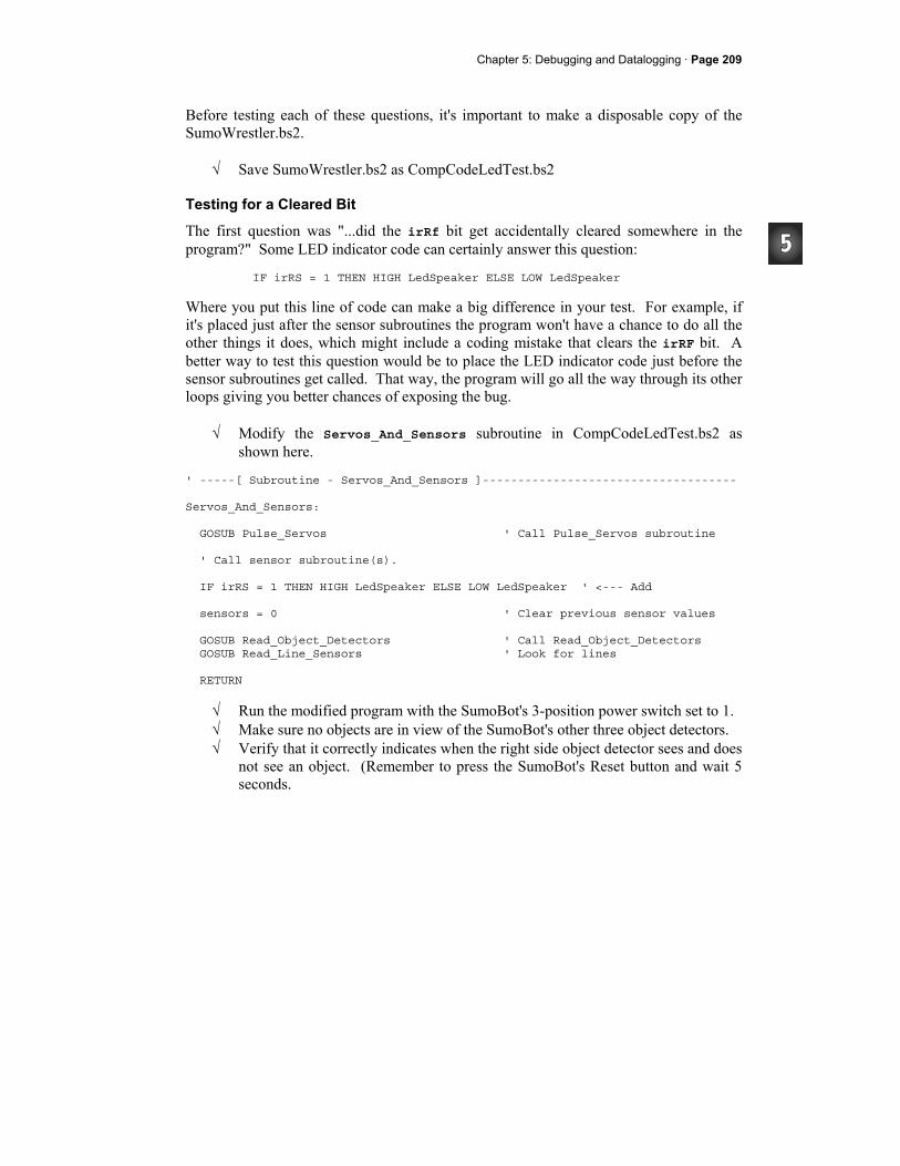
Chapter 5: Debugging and Datalogging · Page 209
Before testing each of these questions, it's important to make a disposable copy of the SumoWrestler.bs2.
√ Save SumoWrestler.bs2 as CompCodeLedTest.bs2
Testing for a Cleared Bit
The first question was "...did the irRf bit get accidentally cleared somewhere in the program?" Some LED indicator code can certainly answer this question:
IF irRS = 1 THEN HIGH LedSpeaker ELSE LOW LedSpeaker
Where you put this line of code can make a big difference in your test. For example, if it's placed just after the sensor subroutines the program won't have a chance to do all the other things it does, which might include a coding mistake that clears the irRF bit. A better way to test this question would be to place the LED indicator code just before the sensor subroutines get called. That way, the program will go all the way through its other loops giving you better chances of exposing the bug.
√ Modify the Servos_And_Sensors subroutine in CompCodeLedTest.bs2 as shown here.
' -----[ Subroutine - Servos_And_Sensors ]------------------------------------ Servos_And_Sensors: GOSUB Pulse_Servos ' Call Pulse_Servos subroutine ' Call sensor subroutine(s). IF irRS = 1 THEN HIGH LedSpeaker ELSE LOW LedSpeaker ' <--- Add sensors = 0 ' Clear previous sensor values GOSUB Read_Object_Detectors ' Call Read_Object_Detectors GOSUB Read_Line_Sensors ' Look for lines RETURN
√ Run the modified program with the SumoBot's 3-position power switch set to 1. √ Make sure no objects are in view of the SumoBot's other three object detectors. √ Verify that it correctly indicates when the right side object detector sees and does
not see an object. (Remember to press the SumoBot's Reset button and wait 5 seconds.
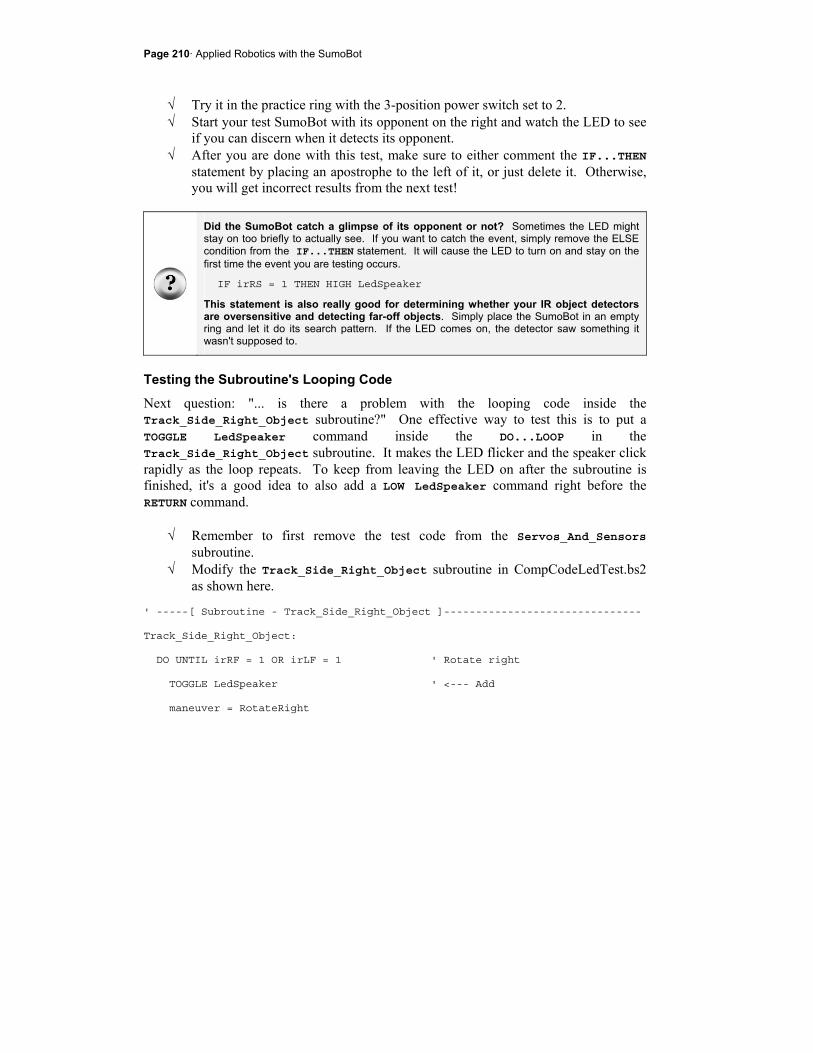
Page 210· Applied Robotics with the SumoBot
√ Try it in the practice ring with the 3-position power switch set to 2. √ Start your test SumoBot with its opponent on the right and watch the LED to see
if you can discern when it detects its opponent. √ After you are done with this test, make sure to either comment the IF...THEN
statement by placing an apostrophe to the left of it, or just delete it. Otherwise, you will get incorrect results from the next test!
Did the SumoBot catch a glimpse of its opponent or not? Sometimes the LED might stay on too briefly to actually see. If you want to catch the event, simply remove the ELSE condition from the IF...THEN statement. It will cause the LED to turn on and stay on the first time the event you are testing occurs.
IF irRS = 1 THEN HIGH LedSpeaker
This statement is also really good for determining whether your IR object detectors are oversensitive and detecting far-off objects. Simply place the SumoBot in an empty ring and let it do its search pattern. If the LED comes on, the detector saw something it wasn't supposed to.
Testing the Subroutine's Looping Code
Next question: "... is there a problem with the looping code inside the Track_Side_Right_Object subroutine?" One effective way to test this is to put a TOGGLE LedSpeaker command inside the DO...LOOP in the Track_Side_Right_Object subroutine. It makes the LED flicker and the speaker click rapidly as the loop repeats. To keep from leaving the LED on after the subroutine is finished, it's a good idea to also add a LOW LedSpeaker command right before the RETURN command.
√ Remember to first remove the test code from the Servos_And_Sensors subroutine.
√ Modify the Track_Side_Right_Object subroutine in CompCodeLedTest.bs2 as shown here.
' -----[ Subroutine - Track_Side_Right_Object ]------------------------------- Track_Side_Right_Object: DO UNTIL irRF = 1 OR irLF = 1 ' Rotate right TOGGLE LedSpeaker ' <--- Add maneuver = RotateRight

Chapter 5: Debugging and Datalogging · Page 211
GOSUB Servos_And_Sensors LOOP LOW LedSpeaker ' <--- Add RETURN
√ Run the modified program with the SumoBot's 3-position power switch set to 1. √ Make sure no objects are in view of the SumoBot's other three object detectors. √ Wave your hand in front of the right object detector. √ Verify that the LED blinks and the speaker clicks rapidly until you wave your
hand in front of one of the front IR detectors. √ Try it in the practice ring with the 3-position power switch set to 2. √ Start your test SumoBot, again, with its opponent on the right. √ Press/release the Reset button, and verify that the LED flickers and the speaker
clicks as it rounds on its opponent. √ Leave the LED code where it is for the next test.
If the LED doesn't flicker, there may be an object in front of the SumoBot, or there could be a branching problem. To test to find out if there is an object in front of the Boe-Bot, try moving the LED test to the Go_Forward subroutine. If the LED flickers constantly, then it confirms the problem. This test would also have to be repeated for the Track_Front_Left_Object and Track_Front_Right_Object subroutines.
Testing for Branching Problems
IF...THEN, GOTO, GOSUB, and RETURN are all examples of branching commands. They can cause the code to skip from one "branch" of the program to another. If a program has a branching problem, it would be because a command is telling the program to skip to a place you don't want it to go to. Let's say this is the real bug in the program is in the Main Routine. In the code block below, the programmer typed GOSUB Track_Side_Left_Object twice by accident. It's the correct response to the first ELSEIF, but the second ELSEIF code block should call the Track_Side_Right_Object subroutine.
Page 212· Applied Robotics with the SumoBot
√ Modify the main routine so that this bug is incorporated. ELSEIF irLS = 1 THEN ' Left side? GOSUB Track_Side_Left_Object ' State = track side left obj. ELSEIF irRS = 1 THEN ' Right side? GOSUB Track_Side_Left_Object ' State = track side right obj.
With this particular bug, the LED would not turn on in the previous test indicating that the code just wasn't making it there. Assuming you have already ruled out the possibility of the front IR object detectors seeing something, the next thing to examine is a branching problem.
√ Start by repeating the TOGGLE LedSpeaker test in the Track_Side_Right_Object subroutine. The LED should not respond to waving your hand in front of the SumoBot's side-right object detector because the subroutine never gets called.
√ Remove the TOGGLE LedSpeaker command and LOW LedSpeaker commands from the Track_Side_Right_Object subroutine.
√ Add this IF...THEN statement to the DO...LOOP in the Main Routine. DO IF irRS = 1 THEN HIGH LedSpeaker ELSE LOW LedSpeaker ' <--- Add IF qtiLF = 1 THEN ' Left qti sees line? GOSUB Avoid_Tawara_Left ' State = avoid left tawara
When you wave your hand in front of the right IR object detector, the LED should turn on. When you wave your hand in front of one of the front IR detectors, the LED should turn off again. That indicates that a navigation subroutine is getting called, it's just that it's not the right one. So now, check which one, and the problem will be found.
ACTIVITY #2: CONDITIONAL COMPILING Commenting and uncommenting lines of test routines can be time consuming and leaves the door open for a lot of mistakes. Conditional compiler directives can help, and this activity demonstrates how.
Compiler Directives
Here is a new section, Compiler Definitions. These #DEFINE directives do not get downloaded to the BASIC Stamp. Instead, the BASIC Stamp Editor just makes a note to
Chapter 5: Debugging and Datalogging · Page 213
itself that you have declared two symbols, LED_MODE, which has been set equal to one, and DEBUG_MODE, which has been set equal to two.
' -----[ Compiler Definitions ]---------------------------------------- #DEFINE LED_MODE = 1 #DEFINE DEBUG_MODE = 2
Most compiler directives begin with #. Examples include #DEFINE, #IF, #THEN, #ELSE, #SELECT, and #CASE. The others begin with the dollar sign, such as $STAMP and $PBASIC.
The #IF...#ENDIF code block below is called a conditional compiler directive. The condition is LED_MODE = 1. If that's how LED_MODE was declared, then the LedSpeaker PIN directive will be compiled. In other words, the BASIC Stamp Editor will consider LedSpeaker PIN 5 to be part of the program. If LED_MODE is any value other than 1, the LedSpeaker PIN directive would be ignored, just as comments are ignored.
' -----[ I/O Definitions ]--------------------------------------------- #IF LED_MODE = 1 #THEN LedSpeaker PIN 5 #ENDIF
Here is a variable declaration and DEBUG command that are not nested inside any conditional compiler directives, so they will be part of the program regardless of the value of DEBUG_MODE or LED_MODE.
' -----[ Variables ]--------------------------------------------------- counter VAR Word ' -----[ Initialization ]---------------------------------------------- DEBUG CLS, "Program running...", CR, CR
Since DEBUG_MODE was declared as 2, only the command DEBUG "DEBUG_MODE = 2." will be part of the program. Again the commands in the other #CASE directives might as well be comments. However, if you change #DEFINE DEBUG_MODE = 2 to #DEFINE DEBUG_MODE = 0 and re-run the program, only the DEBUG command in the #CASE 0 block will be compiled. The program would instead display the message "DEBUG_MODE is zero."
Page 214· Applied Robotics with the SumoBot
#SELECT DEBUG_MODE #CASE 0 DEBUG "DEBUG_MODE is zero." #CASE 1 DEBUG "DEBUG_MODE is one." #CASE 2 DEBUG "DEBUG_MODE is two." #ENDSELECT
Because LED_MODE is 1, the code inside the commands nested in the #IF LED_MODE = 1 #THEN code block will become part of the program. The code inside the #ELSE block will be ignored, unless of course, you change the #DEFINE LED_MODE directive to zero.
' -----[ Main Routine ]------------------------------------------------ DO DEBUG CRSRX, 0, ? counter counter = counter + 1 #IF LED_MODE = 1 #THEN DEBUG "LED state = ", BIN1 counter.BIT0, CRSRUP TOGGLE LedSpeaker PAUSE 200 #ELSE DEBUG "LED_MODE disabled", CRSRUP PAUSE 100 #ENDIF LOOP
Example Program: CompilerDirectives.bs2
CompilerDirectives.bs2 can actually be six different programs. That's because it has conditional compiler directives for three different DEBUG_MODEs and two different LED_MODEs. This gives you six different combinations of DEBUG_MODE and LED_MODE.
√ Based on the LED_MODE and DEBUG_MODE #DEFINES, predict what CompilerDirectives.bs2 is going to do when you download it to the BASIC Stamp.
Chapter 5: Debugging and Datalogging · Page 215
√ Enter, save, and run Compiler directives.bs2 and check the program's behavior against your predictions.
√ Change #DEFINE LED_MODE = 1 to #DEFINE LED_MODE = 0. √ Predict how the program will behave the next time it is downloaded to the
BASIC Stamp. √ Run the program, and again test your predictions. √ Repeat for the other four combinations of values that you can set LED_MODE and
DEBUG_MODE equal to. ' -----[ Title ]-------------------------------------------------------------- ' Applied Robotics with the SumoBot - CompilerDirectives.bs2 ' How to use compiler directives to select which code blocks to run. ' $STAMP BS2 ' $PBASIC 2.5 ' -----[ Compiler Definitions ]----------------------------------------------- #DEFINE LED_MODE = 1 #DEFINE DEBUG_MODE = 2 ' -----[ I/O Definitions ]---------------------------------------------------- #IF LED_MODE = 1 #THEN LedSpeaker PIN 5 #ENDIF ' -----[ Variables ]---------------------------------------------------------- counter VAR Word ' -----[ Initialization ]----------------------------------------------------- DEBUG CLS, "Program running...", CR, CR #SELECT DEBUG_MODE #CASE 0 DEBUG "DEBUG_MODE is zero." #CASE 1 DEBUG "DEBUG_MODE is one." #CASE 2 DEBUG "DEBUG_MODE is two." #ENDSELECT DEBUG CR, CR ' -----[ Main Routine ]-------------------------------------------------------
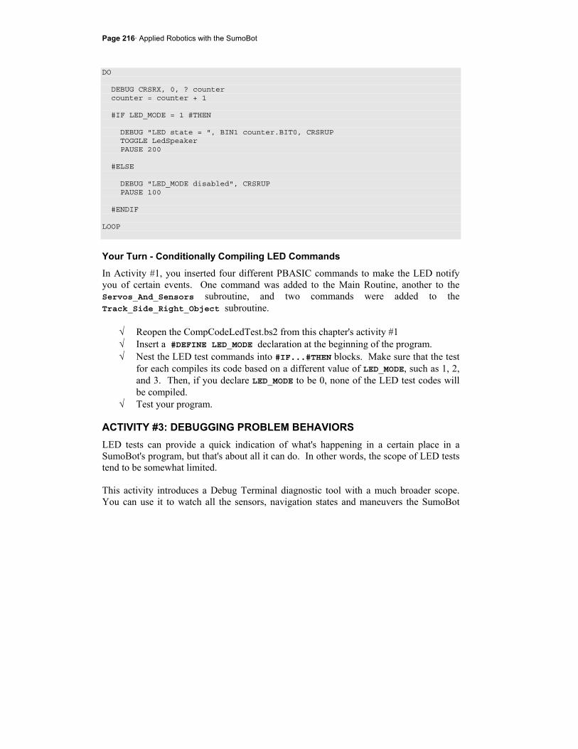
Page 216· Applied Robotics with the SumoBot
DO DEBUG CRSRX, 0, ? counter counter = counter + 1 #IF LED_MODE = 1 #THEN DEBUG "LED state = ", BIN1 counter.BIT0, CRSRUP TOGGLE LedSpeaker PAUSE 200 #ELSE DEBUG "LED_MODE disabled", CRSRUP PAUSE 100 #ENDIF LOOP
Your Turn - Conditionally Compiling LED Commands
In Activity #1, you inserted four different PBASIC commands to make the LED notify you of certain events. One command was added to the Main Routine, another to the Servos_And_Sensors subroutine, and two commands were added to the Track_Side_Right_Object subroutine.
√ Reopen the CompCodeLedTest.bs2 from this chapter's activity #1 √ Insert a #DEFINE LED_MODE declaration at the beginning of the program. √ Nest the LED test commands into #IF...#THEN blocks. Make sure that the test
for each compiles its code based on a different value of LED_MODE, such as 1, 2, and 3. Then, if you declare LED_MODE to be 0, none of the LED test codes will be compiled.
√ Test your program.
ACTIVITY #3: DEBUGGING PROBLEM BEHAVIORS LED tests can provide a quick indication of what's happening in a certain place in a SumoBot's program, but that's about all it can do. In other words, the scope of LED tests tend to be somewhat limited. This activity introduces a Debug Terminal diagnostic tool with a much broader scope. You can use it to watch all the sensors, navigation states and maneuvers the SumoBot
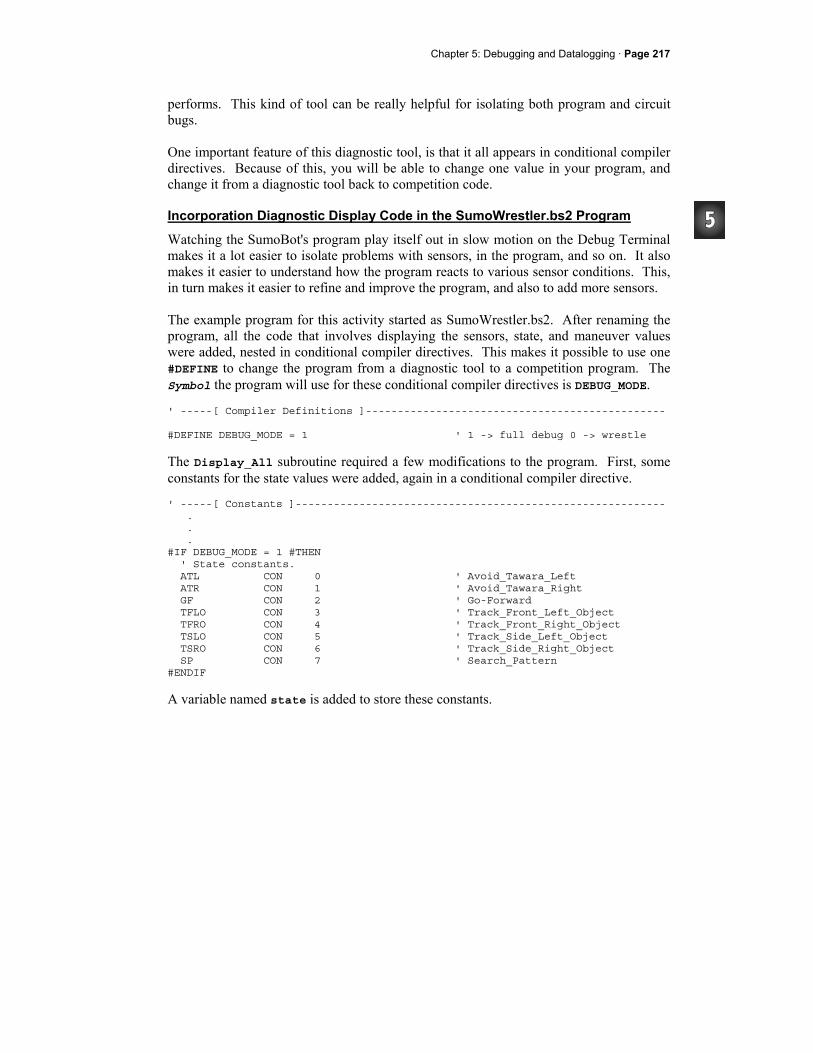
Chapter 5: Debugging and Datalogging · Page 217
performs. This kind of tool can be really helpful for isolating both program and circuit bugs. One important feature of this diagnostic tool, is that it all appears in conditional compiler directives. Because of this, you will be able to change one value in your program, and change it from a diagnostic tool back to competition code.
Incorporation Diagnostic Display Code in the SumoWrestler.bs2 Program
Watching the SumoBot's program play itself out in slow motion on the Debug Terminal makes it a lot easier to isolate problems with sensors, in the program, and so on. It also makes it easier to understand how the program reacts to various sensor conditions. This, in turn makes it easier to refine and improve the program, and also to add more sensors. The example program for this activity started as SumoWrestler.bs2. After renaming the program, all the code that involves displaying the sensors, state, and maneuver values were added, nested in conditional compiler directives. This makes it possible to use one #DEFINE to change the program from a diagnostic tool to a competition program. The Symbol the program will use for these conditional compiler directives is DEBUG_MODE. ' -----[ Compiler Definitions ]----------------------------------------------- #DEFINE DEBUG_MODE = 1 ' 1 -> full debug 0 -> wrestle
The Display_All subroutine required a few modifications to the program. First, some constants for the state values were added, again in a conditional compiler directive. ' -----[ Constants ]---------------------------------------------------------- . . . #IF DEBUG_MODE = 1 #THEN ' State constants. ATL CON 0 ' Avoid_Tawara_Left ATR CON 1 ' Avoid_Tawara_Right GF CON 2 ' Go-Forward TFLO CON 3 ' Track_Front_Left_Object TFRO CON 4 ' Track_Front_Right_Object TSLO CON 5 ' Track_Side_Left_Object TSRO CON 6 ' Track_Side_Right_Object SP CON 7 ' Search_Pattern #ENDIF
A variable named state is added to store these constants.
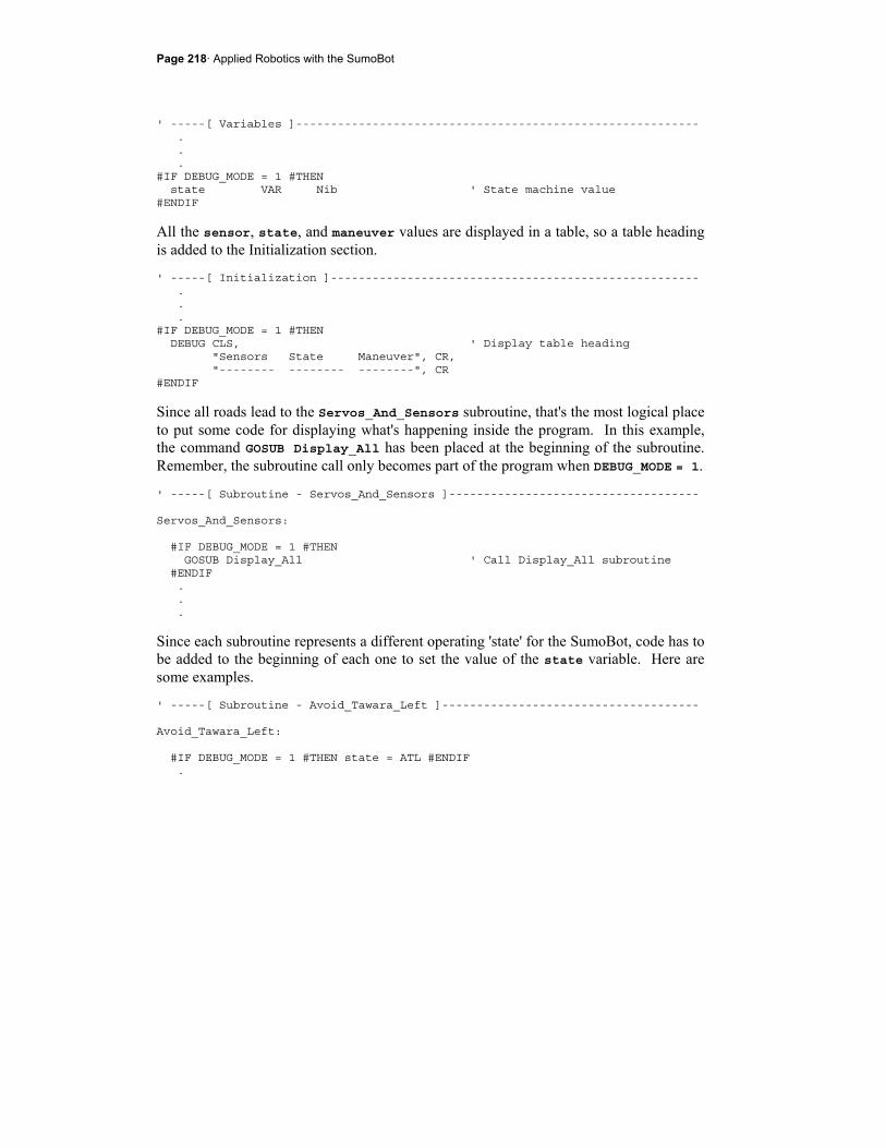
Page 218· Applied Robotics with the SumoBot
' -----[ Variables ]---------------------------------------------------------- . . . #IF DEBUG_MODE = 1 #THEN state VAR Nib ' State machine value #ENDIF
All the sensor, state, and maneuver values are displayed in a table, so a table heading is added to the Initialization section. ' -----[ Initialization ]----------------------------------------------------- . . . #IF DEBUG_MODE = 1 #THEN DEBUG CLS, ' Display table heading "Sensors State Maneuver", CR, "-------- -------- --------", CR #ENDIF
Since all roads lead to the Servos_And_Sensors subroutine, that's the most logical place to put some code for displaying what's happening inside the program. In this example, the command GOSUB Display_All has been placed at the beginning of the subroutine. Remember, the subroutine call only becomes part of the program when DEBUG_MODE = 1.
' -----[ Subroutine - Servos_And_Sensors ]------------------------------------ Servos_And_Sensors: #IF DEBUG_MODE = 1 #THEN GOSUB Display_All ' Call Display_All subroutine #ENDIF . . .
Since each subroutine represents a different operating 'state' for the SumoBot, code has to be added to the beginning of each one to set the value of the state variable. Here are some examples. ' -----[ Subroutine - Avoid_Tawara_Left ]------------------------------------- Avoid_Tawara_Left: #IF DEBUG_MODE = 1 #THEN state = ATL #ENDIF .
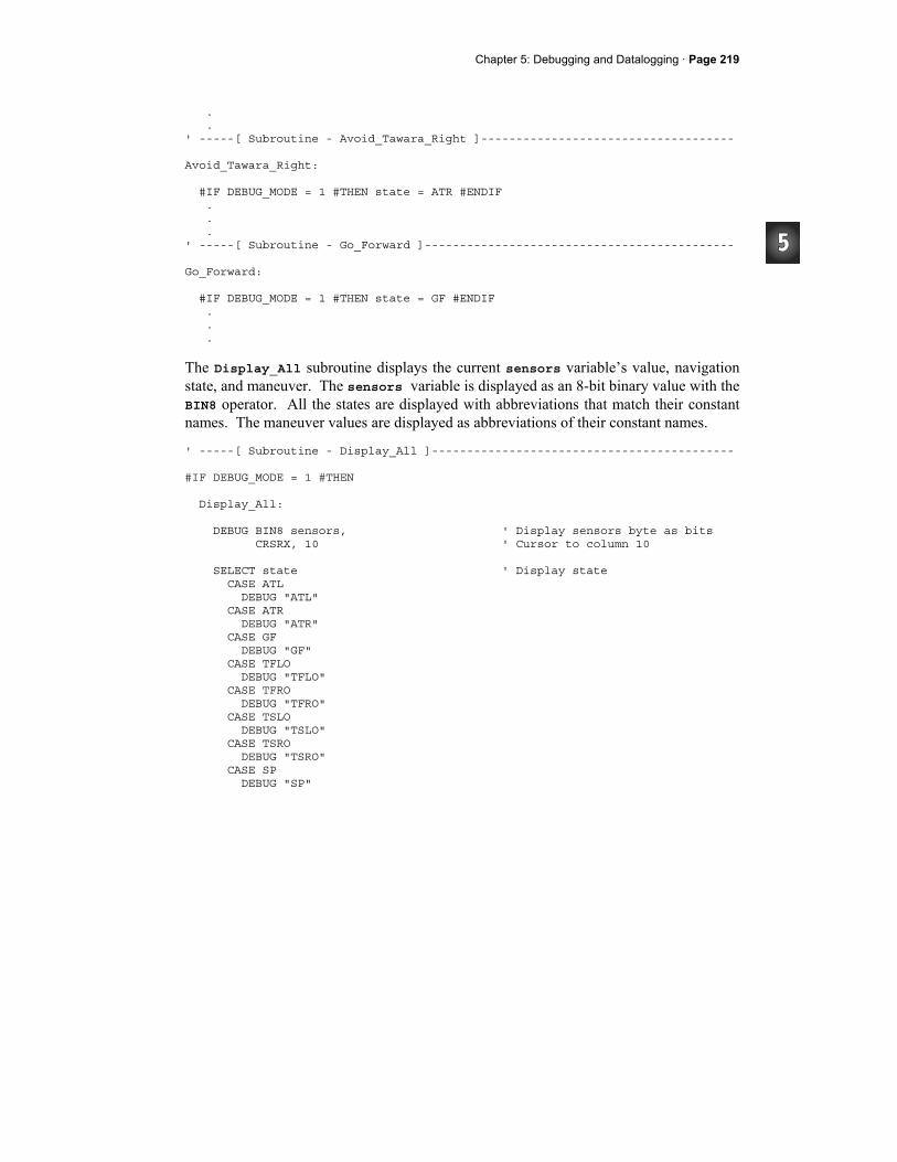
Chapter 5: Debugging and Datalogging · Page 219
. . ' -----[ Subroutine - Avoid_Tawara_Right ]------------------------------------ Avoid_Tawara_Right: #IF DEBUG_MODE = 1 #THEN state = ATR #ENDIF . . . ' -----[ Subroutine - Go_Forward ]-------------------------------------------- Go_Forward: #IF DEBUG_MODE = 1 #THEN state = GF #ENDIF . . .
The Display_All subroutine displays the current sensors variable’s value, navigation state, and maneuver. The sensors variable is displayed as an 8-bit binary value with the BIN8 operator. All the states are displayed with abbreviations that match their constant names. The maneuver values are displayed as abbreviations of their constant names. ' -----[ Subroutine - Display_All ]------------------------------------------- #IF DEBUG_MODE = 1 #THEN Display_All: DEBUG BIN8 sensors, ' Display sensors byte as bits CRSRX, 10 ' Cursor to column 10 SELECT state ' Display state CASE ATL DEBUG "ATL" CASE ATR DEBUG "ATR" CASE GF DEBUG "GF" CASE TFLO DEBUG "TFLO" CASE TFRO DEBUG "TFRO" CASE TSLO DEBUG "TSLO" CASE TSRO DEBUG "TSRO" CASE SP DEBUG "SP"

Page 220· Applied Robotics with the SumoBot
ENDSELECT DEBUG CRSRX, 20 ' Cursor to column 20 SELECT maneuver ' Display maneuver CASE Forward DEBUG "Fwd" CASE Backward DEBUG "Bkwd" CASE RotateLeft DEBUG "RotLft" CASE RotateRight DEBUG "RotRt" CASE CurveLeft DEBUG "CrvLft" CASE CurveRight DEBUG "CrvRt" ENDSELECT DEBUG CR ' Carriage return for next line PAUSE 200 ' Pause 0.2 seconds for reading. RETURN #ENDIF
Example Program: SumoWrestlerWithDebugMode.bs2
With this program, you can examine what the SumoBot sees and how its program responds. Before going into how it works, recall that Chapter 3, Activity #7 demonstrated how to read the bits in the sensors variable. Figure 5-1 shows the sensors variable storing an example value.
Figure 5-1 Sensors Variable Six of the eight bits each correspond to a different SumoBot sensor. Two bits are unused.
In this case, there is an object directly in front of the SumoBot because both the left and right IR object detectors (irLF and irRF) store 1s. The IR object detectors on the left and
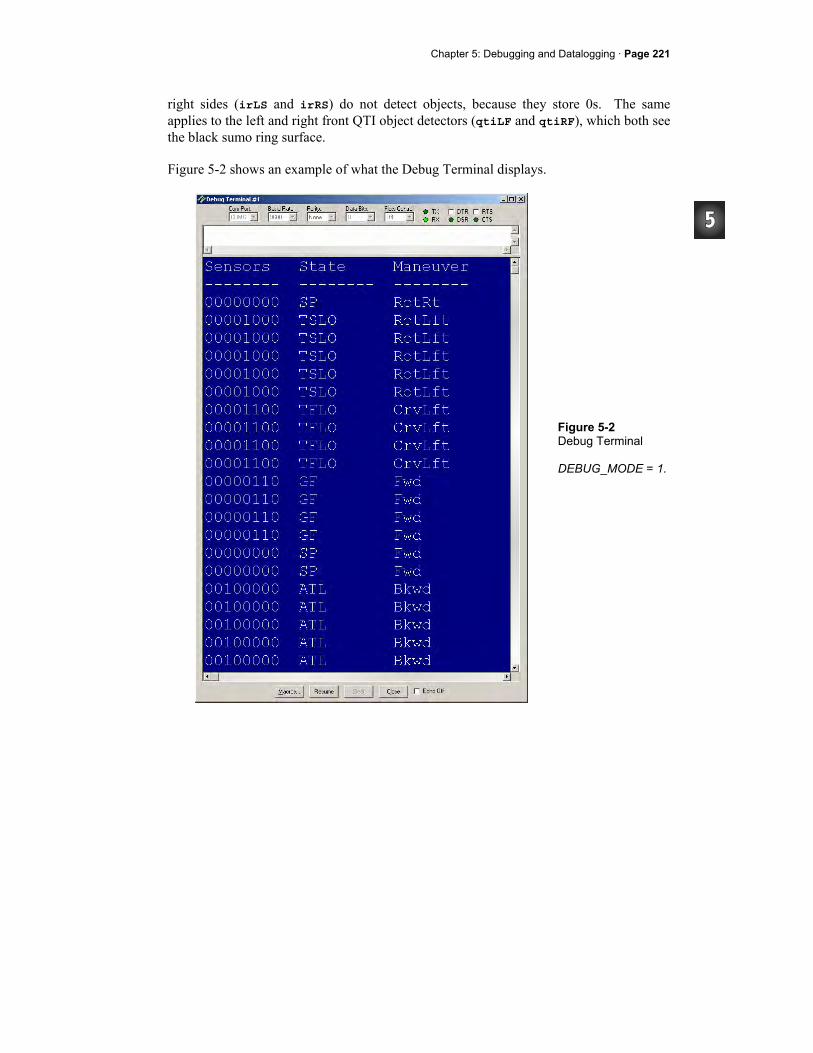
Chapter 5: Debugging and Datalogging · Page 221
right sides (irLS and irRS) do not detect objects, because they store 0s. The same applies to the left and right front QTI object detectors (qtiLF and qtiRF), which both see the black sumo ring surface. Figure 5-2 shows an example of what the Debug Terminal displays.
Figure 5-2 Debug Terminal DEBUG_MODE = 1.
Page 222· Applied Robotics with the SumoBot
In the first row, none of the sensors see anything, the state is search pattern (SP), and the SumoBot is starting by rotating right. On the second row, the SumoBot has detected an object on its left, and the state has transitioned to track side left object (TSLO). The maneuver is rotate left (RotLft). The object is then moved in front of the front-left IR object detector. The state transitions to track front left object (TFLO), and the maneuver is curve left (CrvLft). Then, the object is moved in front of both IR detectors, which transitions the SumoBot to the go forward state (GF) with the forward maneuver (Fwd). The object is then taken away, and the left QTI is placed over the white tawara line. This results in the avoid tawara left (ATL) state, which starts out with backing up (Bkwd).
√ Leave the SumoBot connected to the serial cable as you set it on the competition ring.
√ Set the 3-position power switch to position-1. √ Enter, save, and run SumoWrestlerWithDebugMode.bs2. √ Press/release the SumoBot's Reset button. √ To emulate the output shown in Figure 5-2, start with an object on the
SumoBot's left side. √ Move it from the left side to the left front, then in front of both IR detectors.
Then, take the object away, and place the left QTI over the white tawara line. √ Experiment with various sensor events, and compare events displayed in the
Debug Terminal to what the program is supposed to do for each event. √ Set DEBUG_MODE to 0 and download the modified program to the SumoBot. √ Move the 3-position power switch to position-2. √ Press and release Reset, and verify that the program now functions at full speed,
with no diagnostic code. ' -----[ Title ]-------------------------------------------------------------- ' Applied Robotics with the SumoBot - SumoWrestlerWithDebugMode.bs2 ' SumoWrestlerWithStateSubroutines.bs2 modified so that ' you can toggle DEBUG_MODE between 0 (competition mode) and 1 (display mode). ' $STAMP BS2 ' Target = BASIC Stamp 2 ' $PBASIC 2.5 ' Language = PBASIC 2.5 ' -----[ Compiler Definitions ]----------------------------------------------- #DEFINE DEBUG_MODE = 1 ' 1 -> full debug 0 -> wrestle ' -----[ I/O Definitions ]---------------------------------------------------

Chapter 5: Debugging and Datalogging · Page 223
ServoLeft PIN 13 ' Left servo connected to P13 ServoRight PIN 12 ' Right servo connected to P12 qtiPwrLeft PIN 10 ' Left QTI on/off pin P10 qtiSigLeft PIN 9 ' Left QTI signal pin P9 qtiPwrRight PIN 7 ' Right QTI on/off pin P7 qtiSigRight PIN 8 ' Right QTI signal pin P8 DummyPin PIN 6 ' I/O pin for pulse-decay P6 LedSpeaker PIN 5 ' LED & speaker connected to P5 IrLedLS PIN 2 ' Left IR LED connected to P2 IrSenseLS PIN 1 ' Left IR detector to P1 IrLedLF PIN 4 ' Left IR LED connected to P4 IrSenseLF PIN 11 ' Left IR detector to P11 IrLedRF PIN 15 ' Right IR LED connected to P15 IrSenseRF PIN 14 ' Right IR detector to P14 IrLedRS PIN 3 ' Right IR LED connected to P3 IrSenseRS PIN 0 ' Right IR detector to P0 ' -----[ Constants ]---------------------------------------------------------- ' SumoBot maneuvers Forward CON 0 ' Forward Backward CON 1 ' Backward RotateLeft CON 2 ' RotateLeft RotateRight CON 3 ' RotateRight PivotLeft CON 4 ' Pivot to the left PivotRight CON 5 ' Pivot to the right CurveLeft CON 6 ' Curve to the left CurveRight CON 7 ' Curve to the right ' Servo pulse width rotations FS_CCW CON 850 ' Full speed counterclockwise FS_CW CON 650 ' Full speed clockwise NO_ROT CON 750 ' No rotation LS_CCW CON 770 ' Low speed counterclockwise LS_CW CON 730 ' Low speed clockwise ' IR object detectors IrFreq CON 38500 ' IR LED frequency #IF DEBUG_MODE = 1 #THEN
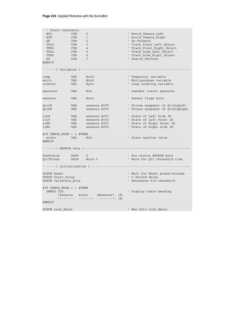
Page 224· Applied Robotics with the SumoBot
' State constants. ATL CON 0 ' Avoid_Tawara_Left ATR CON 1 ' Avoid_Tawara_Right GF CON 2 ' Go-Forward TFLO CON 3 ' Track_Front_Left_Object TFRO CON 4 ' Track_Front_Right_Object TSLO CON 5 ' Track_Side_Left_Object TSRO CON 6 ' Track_Side_Right_Object SP CON 7 ' Search_Pattern #ENDIF ' -----[ Variables ]---------------------------------------------------------- temp VAR Word ' Temporary variable multi VAR Word ' Multipurpose variable counter VAR Byte ' Loop counting variable. maneuver VAR Nib ' SumoBot travel maneuver sensors VAR Byte ' Sensor flags byte qtiLF VAR sensors.BIT5 ' Stores snapshot of QtiSigLeft qtiRF VAR sensors.BIT4 ' Stores snapshot of QtiSigRight irLS VAR sensors.BIT3 ' State of Left Side IR irLF VAR sensors.BIT2 ' State of Left Front IR irRF VAR sensors.BIT1 ' State of Right Front IR irRS VAR sensors.BIT0 ' State of Right Side IR #IF DEBUG_MODE = 1 #THEN state VAR Nib ' State machine value #ENDIF ' -----[ EEPROM Data ]-------------------------------------------------------- RunStatus DATA 0 ' Run status EEPROM byte QtiThresh DATA Word 0 ' Word for QTI threshold time ' -----[ Initialization ]----------------------------------------------------- GOSUB Reset ' Wait for Reset press/release GOSUB Start_Delay ' 5 Second delay GOSUB Calibrate_Qtis ' Determine b/w threshold #IF DEBUG_MODE = 1 #THEN DEBUG CLS, ' Display table heading "Sensors State Maneuver", CR, "-------- -------- --------", CR #ENDIF GOSUB Look_About ' Was Goto Look_About
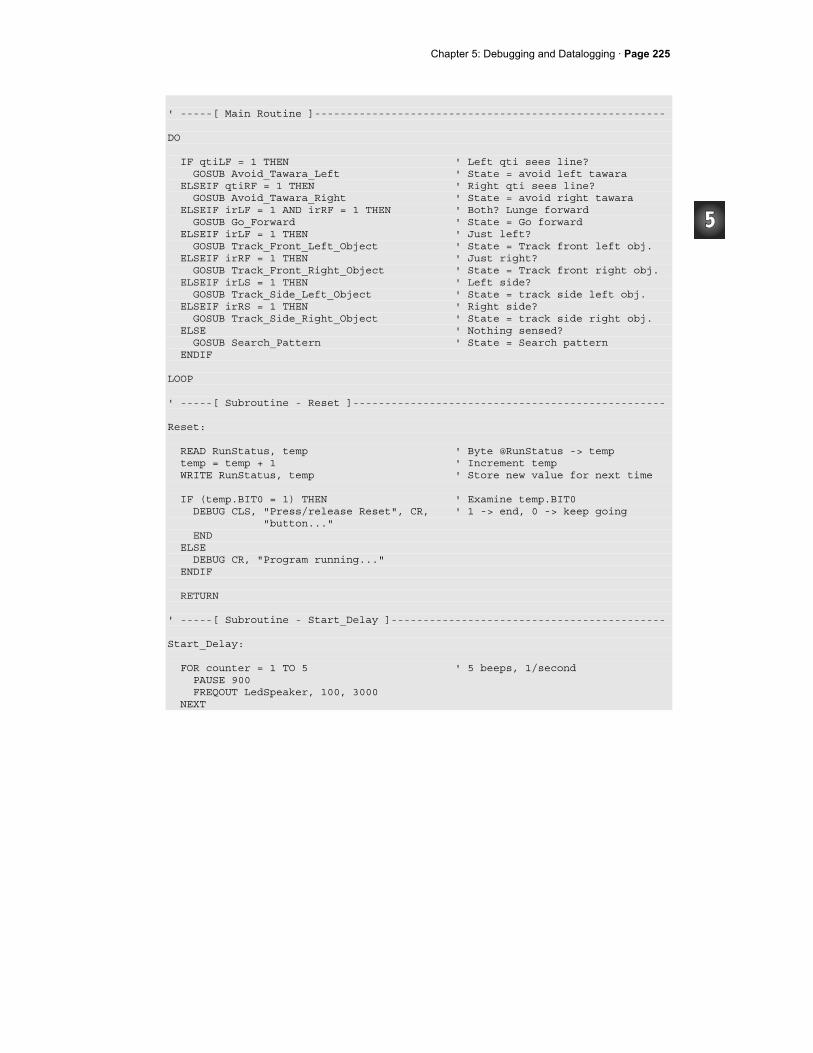
Chapter 5: Debugging and Datalogging · Page 225
' -----[ Main Routine ]------------------------------------------------------- DO IF qtiLF = 1 THEN ' Left qti sees line? GOSUB Avoid_Tawara_Left ' State = avoid left tawara ELSEIF qtiRF = 1 THEN ' Right qti sees line? GOSUB Avoid_Tawara_Right ' State = avoid right tawara ELSEIF irLF = 1 AND irRF = 1 THEN ' Both? Lunge forward GOSUB Go_Forward ' State = Go forward ELSEIF irLF = 1 THEN ' Just left? GOSUB Track_Front_Left_Object ' State = Track front left obj. ELSEIF irRF = 1 THEN ' Just right? GOSUB Track_Front_Right_Object ' State = Track front right obj. ELSEIF irLS = 1 THEN ' Left side? GOSUB Track_Side_Left_Object ' State = track side left obj. ELSEIF irRS = 1 THEN ' Right side? GOSUB Track_Side_Right_Object ' State = track side right obj. ELSE ' Nothing sensed? GOSUB Search_Pattern ' State = Search pattern ENDIF LOOP ' -----[ Subroutine - Reset ]------------------------------------------------- Reset: READ RunStatus, temp ' Byte @RunStatus -> temp temp = temp + 1 ' Increment temp WRITE RunStatus, temp ' Store new value for next time IF (temp.BIT0 = 1) THEN ' Examine temp.BIT0 DEBUG CLS, "Press/release Reset", CR, ' 1 -> end, 0 -> keep going "button..." END ELSE DEBUG CR, "Program running..." ENDIF RETURN ' -----[ Subroutine - Start_Delay ]------------------------------------------- Start_Delay: FOR counter = 1 TO 5 ' 5 beeps, 1/second PAUSE 900 FREQOUT LedSpeaker, 100, 3000 NEXT
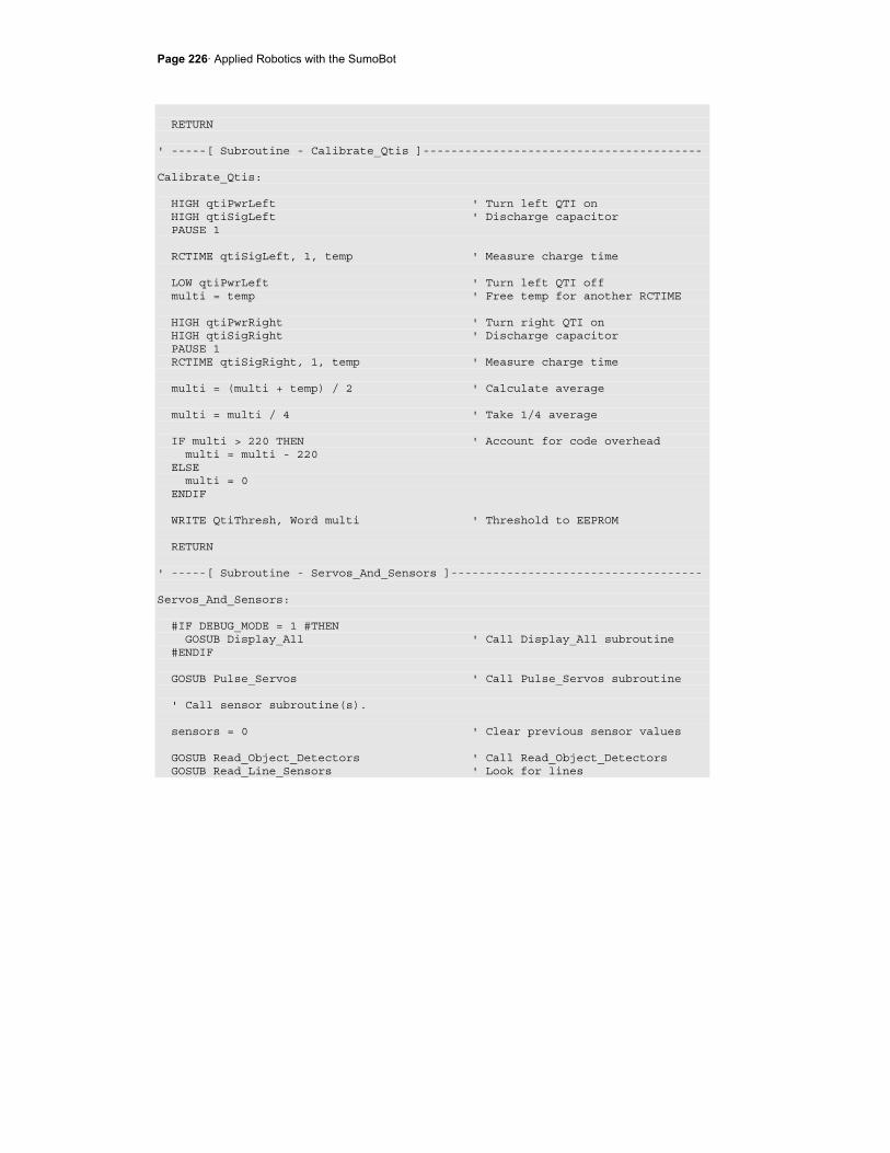
Page 226· Applied Robotics with the SumoBot
RETURN ' -----[ Subroutine - Calibrate_Qtis ]---------------------------------------- Calibrate_Qtis: HIGH qtiPwrLeft ' Turn left QTI on HIGH qtiSigLeft ' Discharge capacitor PAUSE 1 RCTIME qtiSigLeft, 1, temp ' Measure charge time LOW qtiPwrLeft ' Turn left QTI off multi = temp ' Free temp for another RCTIME HIGH qtiPwrRight ' Turn right QTI on HIGH qtiSigRight ' Discharge capacitor PAUSE 1 RCTIME qtiSigRight, 1, temp ' Measure charge time multi = (multi + temp) / 2 ' Calculate average multi = multi / 4 ' Take 1/4 average IF multi > 220 THEN ' Account for code overhead multi = multi - 220 ELSE multi = 0 ENDIF WRITE QtiThresh, Word multi ' Threshold to EEPROM RETURN ' -----[ Subroutine - Servos_And_Sensors ]------------------------------------ Servos_And_Sensors: #IF DEBUG_MODE = 1 #THEN GOSUB Display_All ' Call Display_All subroutine #ENDIF GOSUB Pulse_Servos ' Call Pulse_Servos subroutine ' Call sensor subroutine(s). sensors = 0 ' Clear previous sensor values GOSUB Read_Object_Detectors ' Call Read_Object_Detectors GOSUB Read_Line_Sensors ' Look for lines
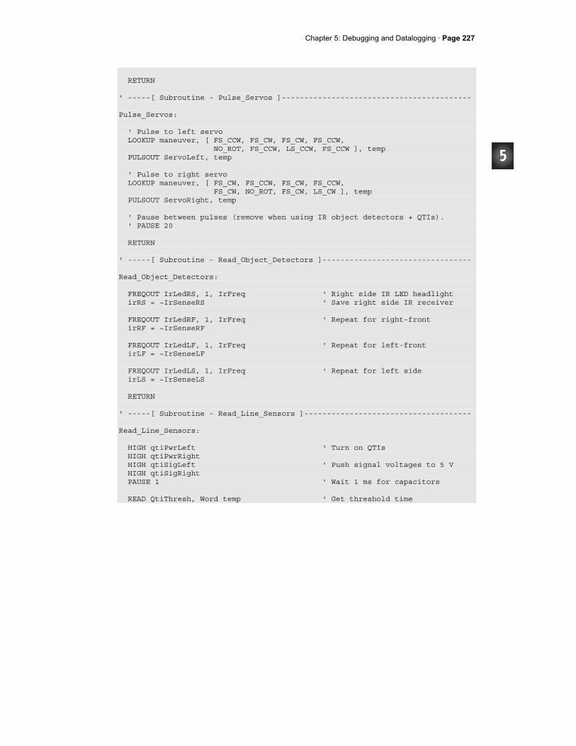
Chapter 5: Debugging and Datalogging · Page 227
RETURN ' -----[ Subroutine - Pulse_Servos ]------------------------------------------ Pulse_Servos: ' Pulse to left servo LOOKUP maneuver, [ FS_CCW, FS_CW, FS_CW, FS_CCW, NO_ROT, FS_CCW, LS_CCW, FS_CCW ], temp PULSOUT ServoLeft, temp ' Pulse to right servo LOOKUP maneuver, [ FS_CW, FS_CCW, FS_CW, FS_CCW, FS_CW, NO_ROT, FS_CW, LS_CW ], temp PULSOUT ServoRight, temp ' Pause between pulses (remove when using IR object detectors + QTIs). ' PAUSE 20 RETURN ' -----[ Subroutine - Read_Object_Detectors ]--------------------------------- Read_Object_Detectors: FREQOUT IrLedRS, 1, IrFreq ' Right side IR LED headlight irRS = ~IrSenseRS ' Save right side IR receiver FREQOUT IrLedRF, 1, IrFreq ' Repeat for right-front irRF = ~IrSenseRF FREQOUT IrLedLF, 1, IrFreq ' Repeat for left-front irLF = ~IrSenseLF FREQOUT IrLedLS, 1, IrFreq ' Repeat for left side irLS = ~IrSenseLS RETURN ' -----[ Subroutine - Read_Line_Sensors ]------------------------------------- Read_Line_Sensors: HIGH qtiPwrLeft ' Turn on QTIs HIGH qtiPwrRight HIGH qtiSigLeft ' Push signal voltages to 5 V HIGH qtiSigRight PAUSE 1 ' Wait 1 ms for capacitors READ QtiThresh, Word temp ' Get threshold time
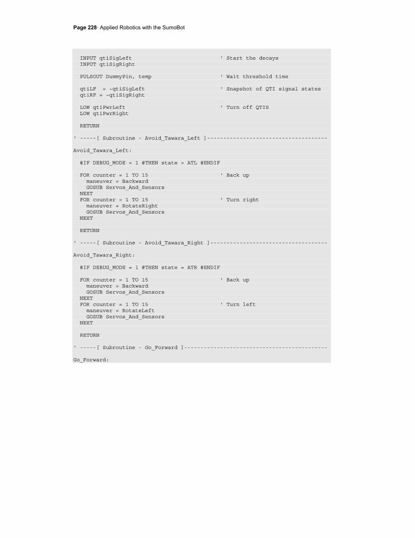
Page 228· Applied Robotics with the SumoBot
INPUT qtiSigLeft ' Start the decays INPUT qtiSigRight PULSOUT DummyPin, temp ' Wait threshold time qtiLF = ~qtiSigLeft ' Snapshot of QTI signal states qtiRF = ~qtiSigRight LOW qtiPwrLeft ' Turn off QTIS LOW qtiPwrRight RETURN ' -----[ Subroutine - Avoid_Tawara_Left ]------------------------------------- Avoid_Tawara_Left: #IF DEBUG_MODE = 1 #THEN state = ATL #ENDIF FOR counter = 1 TO 15 ' Back up maneuver = Backward GOSUB Servos_And_Sensors NEXT FOR counter = 1 TO 15 ' Turn right maneuver = RotateRight GOSUB Servos_And_Sensors NEXT RETURN ' -----[ Subroutine - Avoid_Tawara_Right ]------------------------------------ Avoid_Tawara_Right: #IF DEBUG_MODE = 1 #THEN state = ATR #ENDIF FOR counter = 1 TO 15 ' Back up maneuver = Backward GOSUB Servos_And_Sensors NEXT FOR counter = 1 TO 15 ' Turn left maneuver = RotateLeft GOSUB Servos_And_Sensors NEXT RETURN ' -----[ Subroutine - Go_Forward ]-------------------------------------------- Go_Forward:

Chapter 5: Debugging and Datalogging · Page 229
#IF DEBUG_MODE = 1 #THEN state = GF #ENDIF maneuver = Forward ' 1 forward pulse GOSUB Servos_And_Sensors RETURN ' -----[ Subroutine - Track_Front_Left_Object ]------------------------------- Track_Front_Left_Object: #IF DEBUG_MODE = 1 #THEN state = TFLO #ENDIF counter = 0 DO UNTIL (irLF = 1 AND irRF = 1) OR counter > 15 maneuver = CurveLeft ' Curve left 15 GOSUB Servos_And_Sensors counter = counter + 1 LOOP DO UNTIL (irLF = 1 AND irRF = 1) OR counter > 30 maneuver = RotateLeft ' Rotate left 30 GOSUB Servos_And_Sensors counter = counter + 1 LOOP RETURN ' -----[ Subroutine - Track_Front_Right_Object ]------------------------------ Track_Front_Right_Object: #IF DEBUG_MODE = 1 #THEN state = TFRO #ENDIF counter = 0 DO UNTIL (irLF = 1 AND irRF = 1) OR counter > 15 maneuver = CurveRight ' Curve right 15 GOSUB Servos_And_Sensors counter = counter + 1 LOOP DO UNTIL (irLF = 1 AND irRF = 1) OR counter > 30 maneuver = RotateRight ' Rotate right 30 GOSUB Servos_And_Sensors counter = counter + 1 LOOP RETURN ' -----[ Subroutine - Track_Side_Left_Object ]-------------------------------- Track_Side_Left_Object:
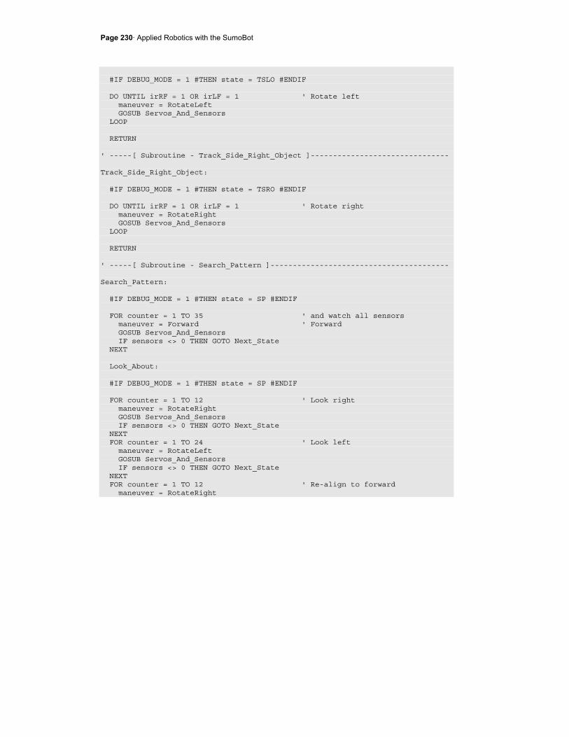
Page 230· Applied Robotics with the SumoBot
#IF DEBUG_MODE = 1 #THEN state = TSLO #ENDIF DO UNTIL irRF = 1 OR irLF = 1 ' Rotate left maneuver = RotateLeft GOSUB Servos_And_Sensors LOOP RETURN ' -----[ Subroutine - Track_Side_Right_Object ]------------------------------- Track_Side_Right_Object: #IF DEBUG_MODE = 1 #THEN state = TSRO #ENDIF DO UNTIL irRF = 1 OR irLF = 1 ' Rotate right maneuver = RotateRight GOSUB Servos_And_Sensors LOOP RETURN ' -----[ Subroutine - Search_Pattern ]---------------------------------------- Search_Pattern: #IF DEBUG_MODE = 1 #THEN state = SP #ENDIF FOR counter = 1 TO 35 ' and watch all sensors maneuver = Forward ' Forward GOSUB Servos_And_Sensors IF sensors <> 0 THEN GOTO Next_State NEXT Look_About: #IF DEBUG_MODE = 1 #THEN state = SP #ENDIF FOR counter = 1 TO 12 ' Look right maneuver = RotateRight GOSUB Servos_And_Sensors IF sensors <> 0 THEN GOTO Next_State NEXT FOR counter = 1 TO 24 ' Look left maneuver = RotateLeft GOSUB Servos_And_Sensors IF sensors <> 0 THEN GOTO Next_State NEXT FOR counter = 1 TO 12 ' Re-align to forward maneuver = RotateRight
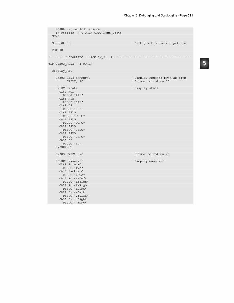
Chapter 5: Debugging and Datalogging · Page 231
GOSUB Servos_And_Sensors IF sensors <> 0 THEN GOTO Next_State NEXT Next_State: ' Exit point of search pattern RETURN ' -----[ Subroutine - Display_All ]------------------------------------------- #IF DEBUG_MODE = 1 #THEN Display_All: DEBUG BIN8 sensors, ' Display sensors byte as bits CRSRX, 10 ' Cursor to column 10 SELECT state ' Display state CASE ATL DEBUG "ATL" CASE ATR DEBUG "ATR" CASE GF DEBUG "GF" CASE TFLO DEBUG "TFLO" CASE TFRO DEBUG "TFRO" CASE TSLO DEBUG "TSLO" CASE TSRO DEBUG "TSRO" CASE SP DEBUG "SP" ENDSELECT DEBUG CRSRX, 20 ' Cursor to column 20 SELECT maneuver ' Display maneuver CASE Forward DEBUG "Fwd" CASE Backward DEBUG "Bkwd" CASE RotateLeft DEBUG "RotLft" CASE RotateRight DEBUG "RotRt" CASE CurveLeft DEBUG "CrvLft" CASE CurveRight DEBUG "CrvRt"

Page 232· Applied Robotics with the SumoBot
ENDSELECT DEBUG CR ' Carriage return for next line PAUSE 200 ' Pause 0.2 seconds for reading. RETURN #ENDIF
Your Turn
The bulk of the commands that are added to the program when DEBUG_MODE is set to 1 are DEBUG commands with strings of characters. The strings of characters take up a considerable amounts of memory. You can compare how much program memory is consumed by the diagnostic code as follows:
√ Set DEBUG_MODE = 0. √ Click the BASIC Stamp Editor's Run menu, and select Memory map.
The Memory Map you see should resemble Figure 5-3. Notice on the left that the blue program codes are taking up less than half the BASIC Stamp's EEPROM.
Figure 5-3 Memory Map - DEBUG_MODE = 0
√ Close the Memory Map. √ Set DEBUG_MODE = 1
Blue program code take less than half the
EEPROM
EEPROM window control
Chapter 5: Debugging and Datalogging · Page 233
√ Click Run -> Memory map again and compare how much EEPROM is used by the code that was added for debugging.
ACTIVITY #4: DATALOGGING A COMPETITION ROUND Displaying values in slow motion while the SumoBot is sitting still won't necessarily expose or solve problems the SumoBot has when it's up against another SumoBot in the competition ring. It's also not convenient to try to have a round while the SumoBot is tethered to the serial cable. Even if it was convenient, the serial communication of all those characters to the PC takes so much time that it would reduce the servos to twitching between each message. This activity introduces a solution to the tether problem. The solution works like this: Save all the information the previous activity's example program displayed in EEPROM during the round. After the round is over, connect the SumoBot to the PC again, and have it display all the SumoBot's sensor readings, navigation states and maneuvers.
Logging and Reporting Routines
Another #DEFINE can be added to select the various datalogging features. In the next example program, the DATALOG_MODE symbol can be set equal to 0 (no logging), 1 (log round), or 2 (display logged round). ' -----[ Compiler Definitions ]----------------------------------------------- #DEFINE DEBUG_MODE = 1 ' 0 -> wrestle ' 1 -> display #DEFINE DATALOG_MODE = 1 ' 0 -> No log ' 1 -> log round ' 2 -> display log
Since the same constants and variables that were used for debugging will be used for datalogging, the conditions of the compiler directives for these constants have to be updated. For example, the condition for the #IF...#THEN directive below used to be DEBUG_MODE = 1. Now, it's DEBUG_MODE = 1 OR DATALOG_MODE > 0. Why greater than zero? When DATALOG_MODE is set to 0, the datalogging features are not needed. However, when it's set to 1 or 2, the datalogging features should be compiled, and this includes the extra constants and variables used in the previous activity's debugging program.
Page 234· Applied Robotics with the SumoBot
#IF DEBUG_MODE = 1 OR DATALOG_MODE > 0 #THEN ' State constants. ATL CON 0 ' Avoid_Tawara_Left ATR CON 1 ' Avoid_Tawara_Right GF CON 2 ' Go-Forward . . . #ENDIF
A constant named MaxBytes is declared to make it convenient to set the number of bytes that can be used for storing data logged during a round. In this example, MaxBytes is $150. The $ makes a number hexadecimal. A hexadecimal value is used because the Memory Map uses hexadecimal values. This makes it convenient to view the Memory Map and decide how much memory you have available for datalogging. $10 (decimal-16) is subtracted from MaxBytes because the DATA directives that set aside EEPROM for storing records will begin at EEPROM address $10. #IF DATALOG_MODE > 0 #THEN ' Datalogging constants MaxBytes CON $150 - $10 ' Maximum number of bytes stored #ENDIF
Recall from Chapter 2, Activity #1 that converting from hexadecimal to decimal involves multiplying the rightmost digit by 160 = 1, the next digit by 161 = 16, then next digit by 162=256, and the next by 163 = 4096, and so on. Add up all the products, and you'll have the decimal equivalent. For example, the decimal equivalent of $150, is: (1 × 256) + (5 × 16) + (0 × 1) = decimal 336. It's more convenient to declare MaxBytes in terms of hexadecimal values because that's the way the EEPROM map displays all its addresses. Figure 5-4 shows the EEPROM map for the next example program compiled with DATALOG_MODE = 2. The highest EEPROM value not occupied by PBASIC program tokens is $257. Since records will be stored as word values, each record will take up 2 bytes, and MaxBytes should be even. Therefore, MaxBytes could be declared as $256 - $10. This would use up all the available EEPROM.
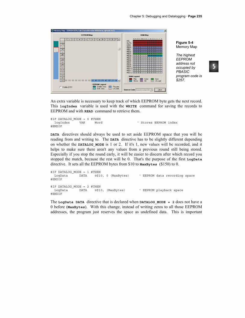
Chapter 5: Debugging and Datalogging · Page 235
Figure 5-4 Memory Map The highest EEPROM address not occupied by PBASIC program code is $257.
An extra variable is necessary to keep track of which EEPROM byte gets the next record. This logIndex variable is used with the WRITE command for saving the records to EEPROM and with READ command to retrieve them. #IF DATALOG_MODE > 0 #THEN logIndex VAR Word ' Stores EEPROM index #ENDIF
DATA directives should always be used to set aside EEPROM space that you will be reading from and writing to. The DATA directive has to be slightly different depending on whether the DATALOG_MODE is 1 or 2. If it's 1, new values will be recorded, and it helps to make sure there aren't any values from a previous round still being stored. Especially if you stop the round early, it will be easier to discern after which record you stopped the match, because the rest will be 0. That's the purpose of the first LogData directive. It sets all the EEPROM bytes from $10 to MaxBytes ($150) to 0. #IF DATALOG_MODE = 1 #THEN LogData DATA @$10, 0 (MaxBytes) ' EEPROM data recording space #ENDIF #IF DATALOG_MODE = 2 #THEN LogData DATA @$10, (MaxBytes) ' EEPROM playback space #ENDIF
The LogData DATA directive that is declared when DATALOG_MODE = 2 does not have a 0 before (MaxBytes). With this change, instead of writing zeros to all those EEPROM addresses, the program just reserves the space as undefined data. This is important
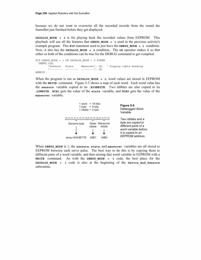
Page 236· Applied Robotics with the SumoBot
because we do not want to overwrite all the recorded records from the round the SumoBot just finished before they get displayed. DATALOG_MODE = 2 is for playing back the recorded values from EEPROM. This playback will use all the features that DEBUG_MODE = 1 used in the previous activity's example program. This #IF statement used to just have the DEBUG_MODE = 1 condition. Now, it also has the DATALOG_MODE = 2 condition. The OR operator makes it so that either or both of the conditions can be true for the DEBUG command to get compiled. #IF DEBUG_MODE = 1 OR DATALOG_MODE = 2 #THEN DEBUG CLS, "Sensors State Maneuver", CR, ' Display table heading "-------- -------- --------", CR #ENDIF
When the program is run as DATALOG_MODE = 1, word values are stored in EEPROM with the WRITE command. Figure 5-5 shows a map of each word. Each word value has the sensors variable copied to its .HIGHBYTE. Two nibbles are also copied to its .LOWBYTE. NIB1 gets the value of the state variable, and NIB0 gets the value of the maneuver variable.
Figure 5-5 Datalogged Word Variable Two nibbles and a byte are copied to different parts of a word variable before it is copied to an EEPROM address.
When DEBUG_MODE is 1, the sensors, state, and maneuver variables are all stored to EEPROM between each servo pulse. The best way to do this is by copying them to different parts of a word variable, and then storing that word variable in EEPROM with a WRITE command. As with the DEBUG_MODE = 1 code, the best place for the DATALOG_MODE = 1 code is also at the beginning of the Servos_And_Sensors subroutine.
Chapter 5: Debugging and Datalogging · Page 237
' -----[ Subroutine - Servos_And_Sensors ]------------------------------------ Servos_And_Sensors: #IF DEBUG_MODE = 1 #THEN GOSUB Display_All ' Call Display_All subroutine #ENDIF #IF DATALOG_MODE = 1 #THEN temp.HIGHBYTE = sensors ' Copy values to parts of temp temp.NIB1 = state temp.NIB0 = maneuver WRITE LogData + LogIndex, Word temp ' Store record in EEPROM logIndex = logIndex + 2 ' Word values -> index + 2 IF logIndex >= (LogData + MaxBytes) THEN END #ENDIF . . .
The last conditional compiler directive in the initialization section sends the program to a label named Playback_Round if DATALOG_MODE = 2. #IF DATALOG_MODE = 2 #THEN GOTO Playback_Round ' Alternate main routine #ENDIF GOSUB Look_About ' Was Goto Look_About
The Playback_Round label comes after the DO...LOOP in the Main Routine. It's kind of like an alternate main routine when DATALOG_MODE = 2. It contains a FOR...NEXT loop that takes the logIndex variable from 0 to MaxBytes in steps of 2. Each time through the loop, the READ LogData + logIndex, Word temp command copies the word at the EEPROM address LogData + logIndex into the temp variable. The .HIGHBYTE of the temp variable is then copied to the sensors variable. temp.NIB1 is copied to the state variable, and temp.NIB0 is copied to the maneuver variable. Once those three variables contain the values from a given record, the Display_All subroutine is called, and a new line of values appears in the Debug Terminal before the FOR...NEXT loop does its next iteration. ' -----[ Main Routine ]------------------------------------------------------- DO . . . LOOP

Page 238· Applied Robotics with the SumoBot
#IF DATALOG_MODE = 2 #THEN Playback_Round: FOR logIndex = 0 TO MaxBytes STEP 2 ' Loop gets all records READ LogData + logIndex, Word temp ' Get record sensors = temp.HIGHBYTE ' state = temp.NIB1 maneuver = temp.NIB0 GOSUB Display_All NEXT END #ENDIF
The same state variable that was updated by the navigation subroutines for the previous example program also has to be updated when DATALOG_MODE = 1. This ensures that correct state values are written to EEPROM. ' -----[ Subroutine - Avoid_Tawara_Left ]------------------------------------- Avoid_Tawara_Left: #IF DEBUG_MODE = 1 OR DATALOG_MODE = 1 #THEN state = ATL #ENDIF . . . ' -----[ Subroutine - Avoid_Tawara_Right ]------------------------------------ Avoid_Tawara_Right: #IF DEBUG_MODE = 1 OR DATALOG_MODE = 1 #THEN state = ATR #ENDIF . . . ' -----[ Subroutine - Go_Forward ]-------------------------------------------- Go_Forward: #IF DEBUG_MODE = 1 OR DATALOG_MODE = 1 #THEN state = GF #ENDIF . . .
Chapter 5: Debugging and Datalogging · Page 239
To display all the datalogged values when DATALOG_MODE = 2, the same Display_All subroutine from the previous activity's example program is used. So, its conditional compiler directive has to be adjusted as well. ' -----[ Subroutine - Display_All ]------------------------------------------- #IF DEBUG_MODE = 1 OR DATALOG_MODE = 2 #THEN . . .
Example Program: SumoWrestlerWithDataLogMode.bs2 This example program can be used to both record and play back the EEPROM values recorded by a match. You can use it to see what the SumoBot saw and understand what decisions it made during a round. It will be especially useful for both tuning the sensors and making adjustments to your competition code. Any time the SumoBot makes a move that causes it to lose a round, you can use this program to understand how it happened and correct the problem. The program has the same debugging functionality as the previous activity's example program. It's best to start by leading the SumoBot around with your hand so that you can have a good guess which sensors detect your hand and which maneuvers it should make. When you use two SumoBots make sure that both are logging data. Reason being, the WRITE commands between pulses extend the low time long enough that it slows down the servos slightly. If both are logging data, the playing field is still even.
Did you skip ahead to get here? If you skipped any thing in Chapter 3 or 4, go back and do it now.
The programs that follow are dependent upon the sensor circuits built, tested and calibrated in the previous activities in Chapter 3 and 4.
√ Enter and save SumoWrestlerWithDataLogMode.bs2 √ To log a match, start by setting DEBUG_MODE = 0 and DATALOG_MODE = 1. √ Download the program to the SumoBot and disconnect the serial cable. √ Place it on the competition ring, and press and release the Reset button. √ Place your hand in front of various object detectors as you make mental notes of
how it responds.
Page 240· Applied Robotics with the SumoBot
√ The SumoBot will log data as it competes for just under 10 seconds, then it stops.
√ After the SumoBot stops, connect it to the serial cable. √ Change DATALOG_MODE = 1 to DATALOG_MODE = 2. √ Run the program and leave the SumoBot connected to the serial cable. √ Press/release the Reset button. After the speaker beeps 5 times, it will display
the logged data to the Debug Terminal in the same format as the previous activity.
√ Compare what the Debug Terminal shows to the different sensor conditions the SumoBot must have seen as you lead it around with your hand.
√ Start practicing this with both your SumoBots set to log data (DATALOG_MODE = 1). It will be important to watch them closely, and then examine their data to determine the factors that contribute to victories or losses. You can then adjust the sensors and/or the program to improve its performance.
As you expand and modify your program, the accuracy of DATALOG_MODE recording and playback may have to be checked. One way to do this is by setting the DEBUG_MODE and DATALOG_MODE values to 1. You can then view the data before it is recorded. Then, set DEBUG_MODE to 0 and DATALOG_MODE to 2 for playback, and compare the two. As with the previous activity, it will help to have the 3-position power switch set to 1 and a controlled set of objects and tawara lines. ' -----[ Title ]-------------------------------------------------------------- ' Applied Robotics with the SumoBot - SumoWrestlerWithDataLogMode.bs2 ' SumoWrestler.bs2 modified so that each state is contained by a ' subroutine. ' $STAMP BS2 ' Target = BASIC Stamp 2 ' $PBASIC 2.5 ' Language = PBASIC 2.5 ' -----[ Compiler Definitions ]----------------------------------------------- #DEFINE DEBUG_MODE = 0 ' 0 -> wrestle ' 1 -> display #DEFINE DATALOG_MODE = 1 ' 0 -> No log ' 1 -> log round ' 2 -> display log ' -----[ I/O Definitions ]--------------------------------------------------- ServoLeft PIN 13 ' Left servo connected to P13 ServoRight PIN 12 ' Right servo connected to P12
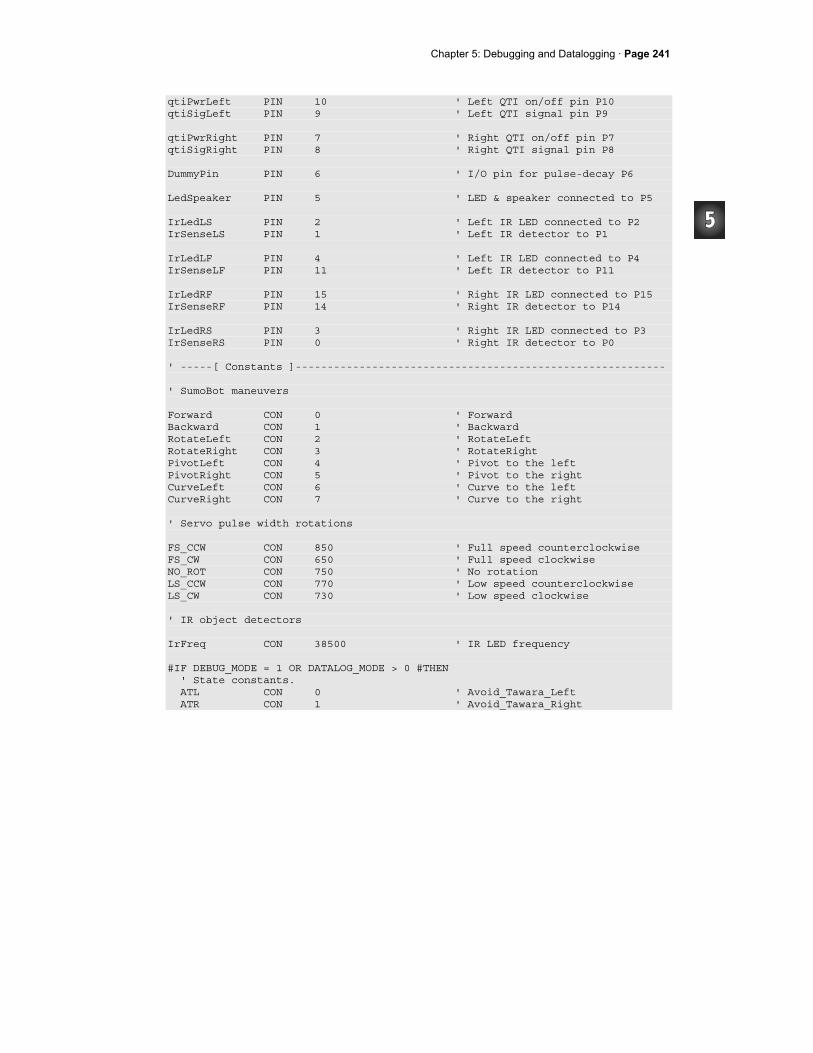
Chapter 5: Debugging and Datalogging · Page 241
qtiPwrLeft PIN 10 ' Left QTI on/off pin P10 qtiSigLeft PIN 9 ' Left QTI signal pin P9 qtiPwrRight PIN 7 ' Right QTI on/off pin P7 qtiSigRight PIN 8 ' Right QTI signal pin P8 DummyPin PIN 6 ' I/O pin for pulse-decay P6 LedSpeaker PIN 5 ' LED & speaker connected to P5 IrLedLS PIN 2 ' Left IR LED connected to P2 IrSenseLS PIN 1 ' Left IR detector to P1 IrLedLF PIN 4 ' Left IR LED connected to P4 IrSenseLF PIN 11 ' Left IR detector to P11 IrLedRF PIN 15 ' Right IR LED connected to P15 IrSenseRF PIN 14 ' Right IR detector to P14 IrLedRS PIN 3 ' Right IR LED connected to P3 IrSenseRS PIN 0 ' Right IR detector to P0 ' -----[ Constants ]---------------------------------------------------------- ' SumoBot maneuvers Forward CON 0 ' Forward Backward CON 1 ' Backward RotateLeft CON 2 ' RotateLeft RotateRight CON 3 ' RotateRight PivotLeft CON 4 ' Pivot to the left PivotRight CON 5 ' Pivot to the right CurveLeft CON 6 ' Curve to the left CurveRight CON 7 ' Curve to the right ' Servo pulse width rotations FS_CCW CON 850 ' Full speed counterclockwise FS_CW CON 650 ' Full speed clockwise NO_ROT CON 750 ' No rotation LS_CCW CON 770 ' Low speed counterclockwise LS_CW CON 730 ' Low speed clockwise ' IR object detectors IrFreq CON 38500 ' IR LED frequency #IF DEBUG_MODE = 1 OR DATALOG_MODE > 0 #THEN ' State constants. ATL CON 0 ' Avoid_Tawara_Left ATR CON 1 ' Avoid_Tawara_Right
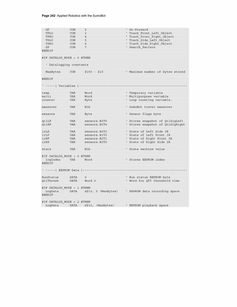
Page 242· Applied Robotics with the SumoBot
GF CON 2 ' Go-Forward TFLO CON 3 ' Track_Front_Left_Object TFRO CON 4 ' Track_Front_Right_Object TSLO CON 5 ' Track_Side_Left_Object TSRO CON 6 ' Track_Side_Right_Object SP CON 7 ' Search_Pattern #ENDIF #IF DATALOG_MODE > 0 #THEN ' Datalogging constants MaxBytes CON $150 - $10 ' Maximum number of bytes stored #ENDIF ' -----[ Variables ]---------------------------------------------------------- temp VAR Word ' Temporary variable multi VAR Word ' Multipurpose variable counter VAR Byte ' Loop counting variable. maneuver VAR Nib ' SumoBot travel maneuver sensors VAR Byte ' Sensor flags byte qtiLF VAR sensors.BIT5 ' Stores snapshot of QtiSigLeft qtiRF VAR sensors.BIT4 ' Stores snapshot of QtiSigRight irLS VAR sensors.BIT3 ' State of Left Side IR irLF VAR sensors.BIT2 ' State of Left Front IR irRF VAR sensors.BIT1 ' State of Right Front IR irRS VAR sensors.BIT0 ' State of Right Side IR state VAR Nib ' State machine value #IF DATALOG_MODE > 0 #THEN logIndex VAR Word ' Stores EEPROM index #ENDIF ' -----[ EEPROM Data ]-------------------------------------------------------- RunStatus DATA 0 ' Run status EEPROM byte QtiThresh DATA Word 0 ' Word for QTI threshold time #IF DATALOG_MODE = 1 #THEN LogData DATA @$10, 0 (MaxBytes) ' EEPROM data recording space #ENDIF #IF DATALOG_MODE = 2 #THEN LogData DATA @$10, (MaxBytes) ' EEPROM playback space

Chapter 5: Debugging and Datalogging · Page 243
#ENDIF ' -----[ Initialization ]----------------------------------------------------- GOSUB Reset ' Wait for Reset press/release GOSUB Start_Delay ' 5 Second delay GOSUB Calibrate_Qtis ' Determine b/w threshold #IF DEBUG_MODE = 1 OR DATALOG_MODE = 2 #THEN DEBUG CLS, "Sensors State Maneuver", CR, ' Display table heading "-------- -------- --------", CR #ENDIF #IF DATALOG_MODE = 2 #THEN GOTO Playback_Round ' Alternate main routine #ENDIF GOSUB Look_About ' Was Goto Look_About ' -----[ Main Routine ]------------------------------------------------------- DO IF qtiLF = 1 THEN ' Left qti sees line? GOSUB Avoid_Tawara_Left ' State = avoid left tawara ELSEIF qtiRF = 1 THEN ' Right qti sees line? GOSUB Avoid_Tawara_Right ' State = avoid right tawara ELSEIF irLF = 1 AND irRF = 1 THEN ' Both? Lunge forward GOSUB Go_Forward ' State = Go forward ELSEIF irLF = 1 THEN ' Just left? GOSUB Track_Front_Left_Object ' State = Track front left obj. ELSEIF irRF = 1 THEN ' Just right? GOSUB Track_Front_Right_Object ' State = Track front right obj. ELSEIF irLS = 1 THEN ' Left side? GOSUB Track_Side_Left_Object ' State = track side left obj. ELSEIF irRS = 1 THEN ' Right side? GOSUB Track_Side_Right_Object ' State = track side right obj. ELSE ' Nothing sensed? GOSUB Search_Pattern ' State = Search pattern ENDIF LOOP #IF DATALOG_MODE = 2 #THEN Playback_Round: FOR logIndex = 0 TO MaxBytes STEP 2 ' Loop gets all records READ LogData + logIndex, Word temp ' Get record

Page 244· Applied Robotics with the SumoBot
sensors = temp.HIGHBYTE ' state = temp.NIB1 maneuver = temp.NIB0 GOSUB Display_All NEXT END #ENDIF ' -----[ Subroutine - Reset ]------------------------------------------------- Reset: READ RunStatus, temp ' Byte @RunStatus -> temp temp = temp + 1 ' Increment temp WRITE RunStatus, temp ' Store new value for next time IF (temp.BIT0 = 1) THEN ' Examine temp.BIT0 DEBUG CLS, "Press/release Reset", CR, ' 1 -> end, 0 -> keep going "button..." END ELSE DEBUG CR, "Program running..." ENDIF RETURN ' -----[ Subroutine - Start_Delay ]------------------------------------------- Start_Delay: FOR counter = 1 TO 5 ' 5 beeps, 1/second PAUSE 900 FREQOUT LedSpeaker, 100, 3000 NEXT RETURN ' -----[ Subroutine - Calibrate_Qtis ]---------------------------------------- Calibrate_Qtis: HIGH qtiPwrLeft ' Turn left QTI on HIGH qtiSigLeft ' Discharge capacitor PAUSE 1 RCTIME qtiSigLeft, 1, temp ' Measure charge time LOW qtiPwrLeft ' Turn left QTI off

Chapter 5: Debugging and Datalogging · Page 245
multi = temp ' Free temp for another RCTIME HIGH qtiPwrRight ' Turn right QTI on HIGH qtiSigRight ' Discharge capacitor PAUSE 1 RCTIME qtiSigRight, 1, temp ' Measure charge time multi = (multi + temp) / 2 ' Calculate average multi = multi / 4 ' Take 1/4 average IF multi > 220 THEN ' Account for code overhead multi = multi - 220 ELSE multi = 0 ENDIF WRITE QtiThresh, Word multi ' Threshold to EEPROM RETURN ' -----[ Subroutine - Servos_And_Sensors ]------------------------------------ Servos_And_Sensors: #IF DEBUG_MODE = 1 #THEN GOSUB Display_All ' Call Display_All subroutine #ENDIF #IF DATALOG_MODE = 1 #THEN temp.HIGHBYTE = sensors ' Copy values to parts of temp temp.NIB1 = state temp.NIB0 = maneuver WRITE LogData + LogIndex, Word temp ' Store record in EEPROM logIndex = logIndex + 2 ' Word values -> index + 2 IF logIndex >= (LogData + MaxBytes) THEN END #ENDIF GOSUB Pulse_Servos ' Call Pulse_Servos subroutine ' Call sensor subroutine(s). sensors = 0 ' Clear previous sensor values GOSUB Read_Object_Detectors ' Call Read_Object_Detectors GOSUB Read_Line_Sensors ' Look for lines RETURN ' -----[ Subroutine - Pulse_Servos ]------------------------------------------
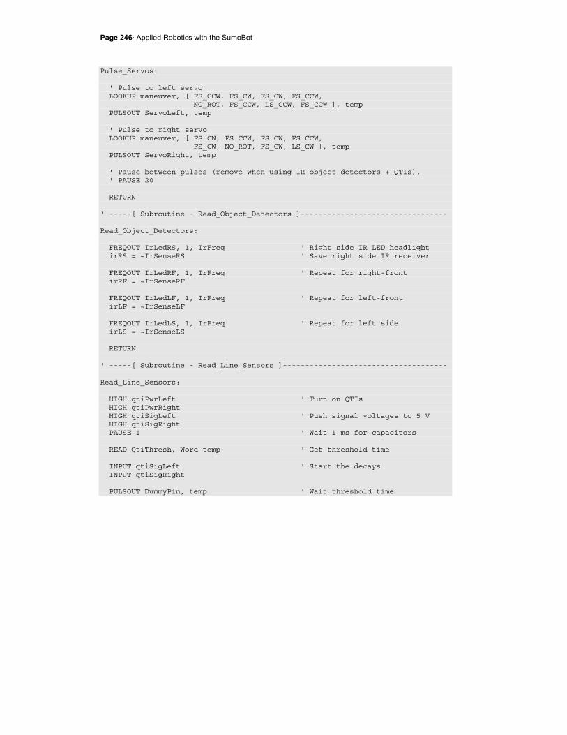
Page 246· Applied Robotics with the SumoBot
Pulse_Servos: ' Pulse to left servo LOOKUP maneuver, [ FS_CCW, FS_CW, FS_CW, FS_CCW, NO_ROT, FS_CCW, LS_CCW, FS_CCW ], temp PULSOUT ServoLeft, temp ' Pulse to right servo LOOKUP maneuver, [ FS_CW, FS_CCW, FS_CW, FS_CCW, FS_CW, NO_ROT, FS_CW, LS_CW ], temp PULSOUT ServoRight, temp ' Pause between pulses (remove when using IR object detectors + QTIs). ' PAUSE 20 RETURN ' -----[ Subroutine - Read_Object_Detectors ]--------------------------------- Read_Object_Detectors: FREQOUT IrLedRS, 1, IrFreq ' Right side IR LED headlight irRS = ~IrSenseRS ' Save right side IR receiver FREQOUT IrLedRF, 1, IrFreq ' Repeat for right-front irRF = ~IrSenseRF FREQOUT IrLedLF, 1, IrFreq ' Repeat for left-front irLF = ~IrSenseLF FREQOUT IrLedLS, 1, IrFreq ' Repeat for left side irLS = ~IrSenseLS RETURN ' -----[ Subroutine - Read_Line_Sensors ]------------------------------------- Read_Line_Sensors: HIGH qtiPwrLeft ' Turn on QTIs HIGH qtiPwrRight HIGH qtiSigLeft ' Push signal voltages to 5 V HIGH qtiSigRight PAUSE 1 ' Wait 1 ms for capacitors READ QtiThresh, Word temp ' Get threshold time INPUT qtiSigLeft ' Start the decays INPUT qtiSigRight PULSOUT DummyPin, temp ' Wait threshold time
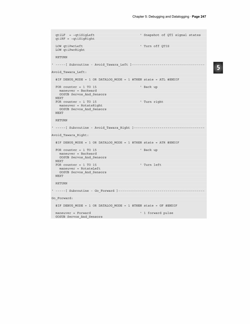
Chapter 5: Debugging and Datalogging · Page 247
qtiLF = ~qtiSigLeft ' Snapshot of QTI signal states qtiRF = ~qtiSigRight LOW qtiPwrLeft ' Turn off QTIS LOW qtiPwrRight RETURN ' -----[ Subroutine - Avoid_Tawara_Left ]------------------------------------- Avoid_Tawara_Left: #IF DEBUG_MODE = 1 OR DATALOG_MODE = 1 #THEN state = ATL #ENDIF FOR counter = 1 TO 15 ' Back up maneuver = Backward GOSUB Servos_And_Sensors NEXT FOR counter = 1 TO 15 ' Turn right maneuver = RotateRight GOSUB Servos_And_Sensors NEXT RETURN ' -----[ Subroutine - Avoid_Tawara_Right ]------------------------------------ Avoid_Tawara_Right: #IF DEBUG_MODE = 1 OR DATALOG_MODE = 1 #THEN state = ATR #ENDIF FOR counter = 1 TO 15 ' Back up maneuver = Backward GOSUB Servos_And_Sensors NEXT FOR counter = 1 TO 15 ' Turn left maneuver = RotateLeft GOSUB Servos_And_Sensors NEXT RETURN ' -----[ Subroutine - Go_Forward ]-------------------------------------------- Go_Forward: #IF DEBUG_MODE = 1 OR DATALOG_MODE = 1 #THEN state = GF #ENDIF maneuver = Forward ' 1 forward pulse GOSUB Servos_And_Sensors
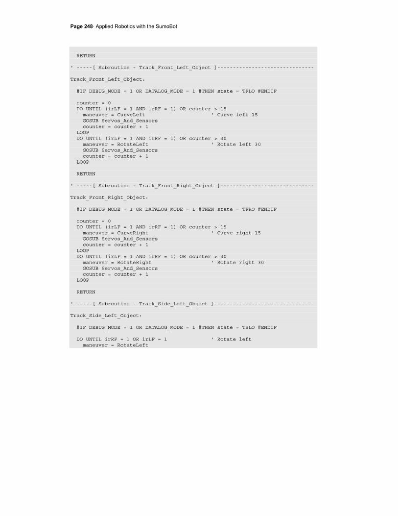
Page 248· Applied Robotics with the SumoBot
RETURN ' -----[ Subroutine - Track_Front_Left_Object ]------------------------------- Track_Front_Left_Object: #IF DEBUG_MODE = 1 OR DATALOG_MODE = 1 #THEN state = TFLO #ENDIF counter = 0 DO UNTIL (irLF = 1 AND irRF = 1) OR counter > 15 maneuver = CurveLeft ' Curve left 15 GOSUB Servos_And_Sensors counter = counter + 1 LOOP DO UNTIL (irLF = 1 AND irRF = 1) OR counter > 30 maneuver = RotateLeft ' Rotate left 30 GOSUB Servos_And_Sensors counter = counter + 1 LOOP RETURN ' -----[ Subroutine - Track_Front_Right_Object ]------------------------------ Track_Front_Right_Object: #IF DEBUG_MODE = 1 OR DATALOG_MODE = 1 #THEN state = TFRO #ENDIF counter = 0 DO UNTIL (irLF = 1 AND irRF = 1) OR counter > 15 maneuver = CurveRight ' Curve right 15 GOSUB Servos_And_Sensors counter = counter + 1 LOOP DO UNTIL (irLF = 1 AND irRF = 1) OR counter > 30 maneuver = RotateRight ' Rotate right 30 GOSUB Servos_And_Sensors counter = counter + 1 LOOP RETURN ' -----[ Subroutine - Track_Side_Left_Object ]-------------------------------- Track_Side_Left_Object: #IF DEBUG_MODE = 1 OR DATALOG_MODE = 1 #THEN state = TSLO #ENDIF DO UNTIL irRF = 1 OR irLF = 1 ' Rotate left maneuver = RotateLeft
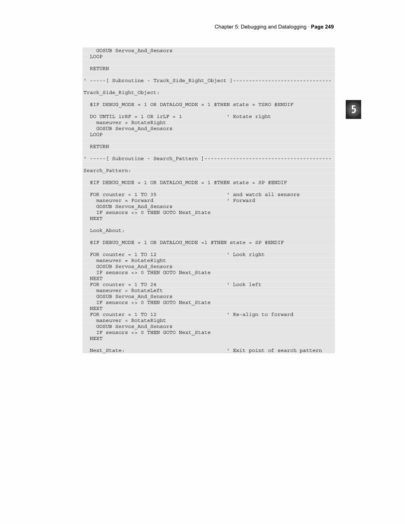
Chapter 5: Debugging and Datalogging · Page 249
GOSUB Servos_And_Sensors LOOP RETURN ' -----[ Subroutine - Track_Side_Right_Object ]------------------------------- Track_Side_Right_Object: #IF DEBUG_MODE = 1 OR DATALOG_MODE = 1 #THEN state = TSRO #ENDIF DO UNTIL irRF = 1 OR irLF = 1 ' Rotate right maneuver = RotateRight GOSUB Servos_And_Sensors LOOP RETURN ' -----[ Subroutine - Search_Pattern ]---------------------------------------- Search_Pattern: #IF DEBUG_MODE = 1 OR DATALOG_MODE = 1 #THEN state = SP #ENDIF FOR counter = 1 TO 35 ' and watch all sensors maneuver = Forward ' Forward GOSUB Servos_And_Sensors IF sensors <> 0 THEN GOTO Next_State NEXT Look_About: #IF DEBUG_MODE = 1 OR DATALOG_MODE =1 #THEN state = SP #ENDIF FOR counter = 1 TO 12 ' Look right maneuver = RotateRight GOSUB Servos_And_Sensors IF sensors <> 0 THEN GOTO Next_State NEXT FOR counter = 1 TO 24 ' Look left maneuver = RotateLeft GOSUB Servos_And_Sensors IF sensors <> 0 THEN GOTO Next_State NEXT FOR counter = 1 TO 12 ' Re-align to forward maneuver = RotateRight GOSUB Servos_And_Sensors IF sensors <> 0 THEN GOTO Next_State NEXT Next_State: ' Exit point of search pattern
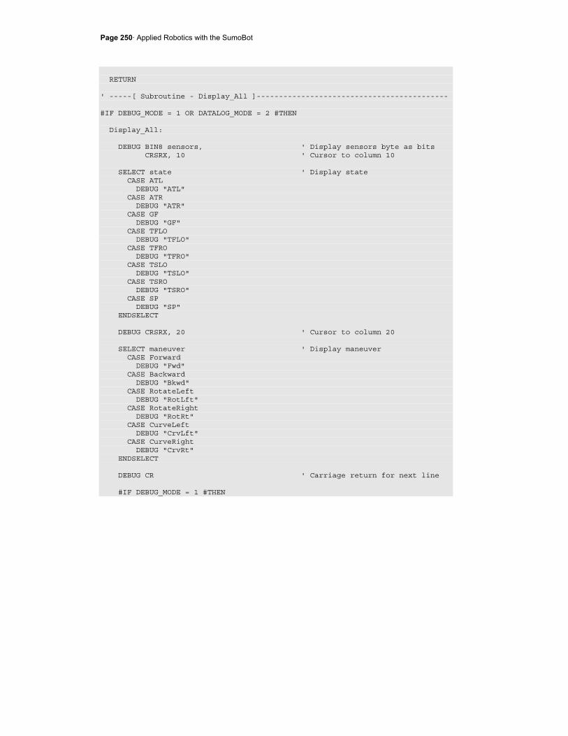
Page 250· Applied Robotics with the SumoBot
RETURN ' -----[ Subroutine - Display_All ]------------------------------------------- #IF DEBUG_MODE = 1 OR DATALOG_MODE = 2 #THEN Display_All: DEBUG BIN8 sensors, ' Display sensors byte as bits CRSRX, 10 ' Cursor to column 10 SELECT state ' Display state CASE ATL DEBUG "ATL" CASE ATR DEBUG "ATR" CASE GF DEBUG "GF" CASE TFLO DEBUG "TFLO" CASE TFRO DEBUG "TFRO" CASE TSLO DEBUG "TSLO" CASE TSRO DEBUG "TSRO" CASE SP DEBUG "SP" ENDSELECT DEBUG CRSRX, 20 ' Cursor to column 20 SELECT maneuver ' Display maneuver CASE Forward DEBUG "Fwd" CASE Backward DEBUG "Bkwd" CASE RotateLeft DEBUG "RotLft" CASE RotateRight DEBUG "RotRt" CASE CurveLeft DEBUG "CrvLft" CASE CurveRight DEBUG "CrvRt" ENDSELECT DEBUG CR ' Carriage return for next line #IF DEBUG_MODE = 1 #THEN
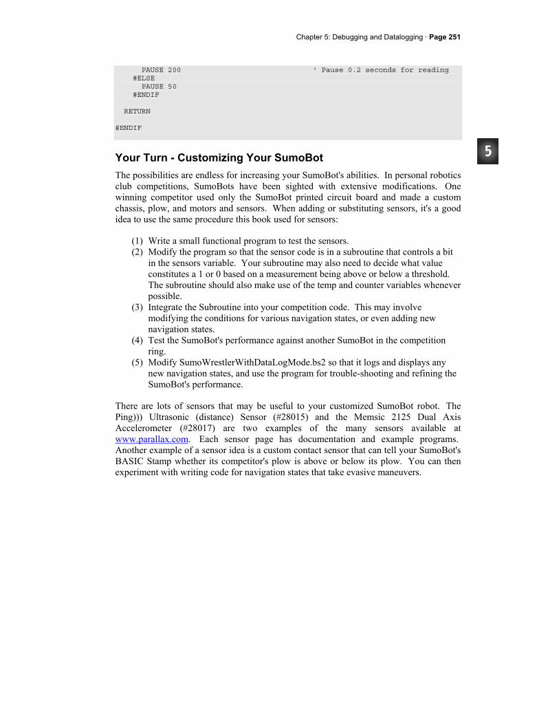
Chapter 5: Debugging and Datalogging · Page 251
PAUSE 200 ' Pause 0.2 seconds for reading #ELSE PAUSE 50 #ENDIF RETURN #ENDIF
Your Turn - Customizing Your SumoBot The possibilities are endless for increasing your SumoBot's abilities. In personal robotics club competitions, SumoBots have been sighted with extensive modifications. One winning competitor used only the SumoBot printed circuit board and made a custom chassis, plow, and motors and sensors. When adding or substituting sensors, it's a good idea to use the same procedure this book used for sensors:
(1) Write a small functional program to test the sensors. (2) Modify the program so that the sensor code is in a subroutine that controls a bit
in the sensors variable. Your subroutine may also need to decide what value constitutes a 1 or 0 based on a measurement being above or below a threshold. The subroutine should also make use of the temp and counter variables whenever possible.
(3) Integrate the Subroutine into your competition code. This may involve modifying the conditions for various navigation states, or even adding new navigation states.
(4) Test the SumoBot's performance against another SumoBot in the competition ring.
(5) Modify SumoWrestlerWithDataLogMode.bs2 so that it logs and displays any new navigation states, and use the program for trouble-shooting and refining the SumoBot's performance.
There are lots of sensors that may be useful to your customized SumoBot robot. The Ping))) Ultrasonic (distance) Sensor (#28015) and the Memsic 2125 Dual Axis Accelerometer (#28017) are two examples of the many sensors available at www.parallax.com. Each sensor page has documentation and example programs. Another example of a sensor idea is a custom contact sensor that can tell your SumoBot's BASIC Stamp whether its competitor's plow is above or below its plow. You can then experiment with writing code for navigation states that take evasive maneuvers.
Page 252· Applied Robotics with the SumoBot
Displaying the sensors variable can help for quick trouble-shooting between rounds. The LCD Terminal AppMod (#29121) is designed to be attached directly to the SumoBot board’s AppMod Header for this purpose, but you will have to move some of your other sensors around to accommodate it. Another option is the Parallax Serial LCD (#27976), which only takes one I/O pin, and lots less code to control, and it can be used in place of the status LED and pushbutton. Local robotics club competitions can be interesting, both to watch and to compete in. The SumoBots in these competitions will come in many different shapes, sizes, and strengths. It's best to consider your first time in a competition a reconnaissance experience. You will likely discover that some of these competitors have advantages that your practice SumoBot competitor never had. Watch each victory and loss carefully, not just with your SumoBot, but all the others too. It's crucial information so that you can customize your SumoBot for victory in future competitions.
Chapter 5: Debugging and Datalogging · Page 253
SUMMARY This chapter introduced three techniques to help find the cause(s) of SumoBot problem behaviors: (1) LED signals, (2) debugging routines, and (3) datalogging a sumo round. Conditional compiler directives were applied to all these techniques, so that you can change one or two values at the beginning of the program to either include or exclude your conditional LED/debugging/datalogging code from the program.
Questions
1. What are the five steps in the Scientific Method? 2. How can one line of code signal the occurrence of an event with an LED? 3. What are the advantages of turning and leaving the LED on when an event
occurs? 4. What is branching? 5. What is conditional compiling? 6. What are some examples of things you can use #DEFINE to do? 7. What's the difference between SELECT...CASE and #SELECT...#CASE? 8. Is it possible to put constant declarations and DATA directives in conditional
compiler directives, or just PBASIC commands? 9. Which two bits of the sensors variable are available if you want to add sensors? 10. What key features are missing that might prevent you from finding a bug while
the SumoBot is connected to the serial cable displaying information on the Debug Terminal?
11. What are some examples of changes that had to be made to the conditional compiler directives in SumoWrestlerWithPlayback.bs2?
12. What's the purpose of the Playback_Round routine, and under what circumstances does that code get executed?
13. What role does the temp variable play in logging data? 14. How does the temp variable store more than one value in the program
SumoWrestlerWithDatalogMode.bs2?
Exercises
1. Add LED events to the Track_Front_Left_Object subroutine that signal the start and end of each of its maneuvers.
2. Write conditional compiler directives to add IR interference testing to SumoWrestlerWithDebugMode.bs2.
3. Calculate how many records you can store with addresses $10 to $24F.

Page 254· Applied Robotics with the SumoBot
4. Modify SumoWrestlerWithDebugMode.bs2 so that it displays numbers next to each record.
Projects
1. Determine the average number of samples per second the SumoWrestlerWithDatalogMode.bs2 takes. If you have not already done so, modify the program so that it displays numbers next to each record. Use a stopwatch to identify certain events, then look for them by calculating the approximate record number that should hold the event.
2. Integrate the mode selection techniques introduced in Chapter 2, Activity #5 into SumoWrestlerWithDebugMode.bs2. When you are done, you should be able to use the pushbutton to select between the functions that used to be selected by #DEFINE DEBUG_MODE.
Appendix A: System Requirements and Parts Listing · Page 255
Appendix A: System Requirements and Parts Listing
System and Software Requirements
• PC running Windows® 2000/XP or higher operating system. • Available serial port OR USB port with USB-to serial adapter (#800-00030) • BASIC Stamp Editor for Windows v2.0 or higher • Optional: BASIC Stamp source code for the experiments in this book, available
for free download from www.parallax.com on the Applied Robotics with the SumoBot page (#27403).
The BASIC Stamp Editor is included on the Parallax CD in your kit. You may check for the latest versions at www.parallax.com under the Downloads menu.
Hardware Requirements
The Applied Robotics with the SumoBot text was written to accompany, and is included with, the SumoBot Robot Competition Kit (#27402). This kit’s contents are listed in Table A-1. If you already have two individual SumoBot kits and you would like to try the experiments in this text, you would need to separately purchase the items in Table A-2. In either case, you will also need some common household items listed on page 257.

Page 256· Applied Robotics with the SumoBot
Table A-1: SumoBot Robot Competition Kit (#27402) Parts and quantities subject to change without notice
Part # Description Quantity 27000 Parallax CD-ROM 1 27400 SumoBot Manual 1 27403 Applied Robotics with the SumoBot text 1 27404 SumoBot Competition Ring poster 1 150-02210 220 Ω resistors ¼ W 5% 6 150-04710 470 Ω resistors ¼ W 5% 8 150-01030 10 kΩ resistors ¼ W 5% 2 350-00003 LED-Infrared 10 350-00006 LED-Red 2 350-00014 IR Receiver 10 350-90000 LED Standoff 10 350-90001 LED Light Shield 10 400-00001 Pushbutton 2 555-27400 SumoBot printed circuit board 2 555-27401 QTI Line Sensor 4 700-00002 Machine screw, 4-40, 3/8” panhead 24 700-00003 4-40 nuts 24 700-00015 Nylon Washer #4 4 700-00016 Flat head screw, 4-40, 3/8” 4 700-00028 Screw, panhead, Phillips, 4-40, ¼” 8 700-00064 Parallax screwdriver 1 710-00002 Screw, panhead, Phillips, 4-40, 1” 4 713-00001 Standoff, Alum, ¼ round, 5/8”, 4-40 8 713-00002 Standoff, 1.25”, 4/40, F to F 4 720-27403 SumoBot Chassis 2 720-27404 SumoBot Front Scoop 2 721-00001 Wheel, plastic, 2.58” diameter 4 721-00001 Rubber Band Tire for Wheel 8 753-00001 Battery holder, 4 cell AA, leads 2 800-00003 Serial cable 1 800-00016 Jumper wires, 3” (bag of 10) 3 805-00001 Servo extension cable 4 900-00001 Piezospeaker 2 900-00008 Parallax Continuous Rotation Servo 4

Appendix A: System Requirements and Parts Listing · Page 257
Table A-2: For SumoBot Robots purchased separately Parts and quantities subject to change without notice
Part# Description Quantity 27400 SumoBot Robot Kit 2 27403 Applied Robotics with the SumoBot text 1 27404 SumoBot Competition Ring poster 1 150-02210 220 Ω resistors ¼ W 5% 4 150-04710 470 Ω resistors ¼ W 5% 6 150-01030 10 kΩ resistors ¼ W 5% 2 350-00003 LED-Infrared 4 350-00014 IR Receiver 4 350-90000 LED Standoff 4 350-90001 LED Light Shield 4 400-00001 Pushbutton 2
Additional Items
You will also need several common tools and household items that are not included in your kit:
• Clear non-shiny cellophane tape • Needle-nose pliers • Small pulley, such as those used for screen doors • Fishing line • Disposable foam cup • Small weights (nails, nuts, washers, etc) • Gram scale, such as a diet or postal scale • Black felt-tip marker, such as a Sharpie® marker

Page 258· Applied Robotics with the SumoBot
Index - # -
#. See conditional compile directives
- $ -
$. See hexadecimal, See compiler directives
- . -
.BIT operator, 49
.HIGHBYTE, 236
.LOWBYTE, 236
.NIB, 237
- @ -
@Address operator, 46
- ~ -
~. See invert bits operator
- A -
acceleration, 24 Accelerometer, 251
- B -
British Engineering units, 23
- C -
cgs units, 23 coefficient of friction, 28, 31 coefficients of friction, 29 comment-out, 94 compiler directives, 212, 213 compile-time, 44 conditional compile directives
#DEFINE, 212
#IF...#ENDIF, 213
#SELECT...#CASE, 213
CRSRXY, 131
- D -
DATA, 41 DATA directive
@Address operator, 46
datalogging, 233 DEBUG, 131
CRSRXY, 131
debugging, 216 DEBUGIN, 51 DO UNTIL...LOOP, 52 dyne, 23
- E -
EEPROM, 12, 41, 44 EEPROM addresses, 42 EEPROM vs. RAM, 47 electrical continuity, 88
- F -
Find/Replace, 128 flag bits, 129 flowcharts, 175 force, iii, 7, 22, 23, 24, 25, 26, 27, 28,
31, 33 free body diagram, 27 frequency sweep, 92 friction, 7

friction force, 31 friction forces, 26 frictional force diagram, 29
- G -
gram, 23 gravity, 24 Guarantee, 2
- H -
hardware requirements, 255 additional household items, 257
hexadecimal, 234 hexadecimal conversion, 45, 234 hybrid state machine diagram, 175
- I -
IF...ELSEIF...ELSE...ENDIF, 143 input register, 61 invert bits operator, 117 IR interference, 85 IR LED, 78 IR object detection circuits, 79 IR Object Detection circuits, side-
mounted, 119 IR object detection troubleshooting, 82 IR object detector range, 89 IR object detectors, 78 IR receiver frequency response, 91
- K -
kilogram, 23 kinetic friction, 26 kinetic objects, 27 kit contents. See Appendix A
- L -
LCD, 252
LED circuit, 59 LOOKUP, 61, 144, 148
- M -
mass, 23 mechanical advantage, 8 Memory Map, 45, 232 modified state machine diagram, 173 mu, 28
- N -
Newton, 23 Newton's second law of motion, 23 Newton's Third Law, 28 normal force, 26, 31
- P -
PBASIC commands DATA directives, 41
DEBUG, 131
DEBUGIN, 51
DO UNTIL...LOOP, 52
IF...ELSEIF...ELSE...ENDIF, 143
LOOKUP, 61, 144, 148
PULSOUT, 145
RCTIME, 97
READ, 42
SELECT...CASE, 66
WRITE, 42
piezospeaker circuit, 59 pliers, 89 plow adjustment, 8 plow adjustments, 9 pound, 23
programs CompilerDirectives.bs2, 214
Forward100Pulses.bs2, 11
ForwardLowTimeTest.bs2, 18
FrontAndSideIrNavigation.bs2, 166
FrontIrNavigation.bs2, 159
IrInterferenceSniffer.bs2, 86
LookupExample.bs2, 149
PushbuttonLed.bs2, 172
PushbuttonMode.bs2, 67
QtiPulseDecayTrick.bs2, 114
QtiPulseTrickLeft.bs2, 111
QtiSelfCalibrate.bs2, 104
ResetAndStartMode.bs2, 71
ResetButtonCounter.bs2, 48
SearchPatternAndAvoidTawara.bs2, 178
SensorsWithTempVariables.bs2, 135
ServoControlExample.bs2, 146
ServoControlWithLookup.bs2, 152
SumoWrestler.bs2, 194
SumoWrestlerWithDataLogMode.bs2, 239
SumoWrestlerWithDebugMode.bs2, 222
SymbolNamesVsAddressContents.bs2, 44
TestAllSensors.bs2, 124
TestFrequencyResponse.bs2, 92
TestFrontIrObjectDetectors.bs2, 82
TestFrontQtiLineSensors.bs2, 100
TestLedSpeaker.bs2, 60
TestPushButton.bs2, 63
TestResetButton.bs2, 57
TestSideIrObjectDetectors.bs2, 120
TestSumoWrestler.bs2, 186
ThreeVariablesManyJobs.bs2, 53
pulley, 34 Pulse-Decay Trick, 108 Pulse-Decay Trick timing graph, 110 PULSOUT, 145 pushbutton circuit, 61 pushbutton program mode selection, 65
- Q -
QRD1114, 97 QTI Circuit, 108 QTI line sensors, 95
schematics, 96
testing, 95
QTIs self calibrating, 102
- R -
RAM, 47 RC-decay graph, 99 RCTIME, 97 READ, 42 Receive windowpane, 51 requency response, 92 Reset button program control, 55 reset state, 170 RPM calculation for servos, 22 run-time, 44
- S -
scale, 35
Scientific Method, 208 SELECT...CASE, 66 self calibrating QTI sensors, 102 sensor flags, 143 servo connections, 13 servo control, 145 servo rotational velocity graph, 146 servo RPM calculation, 21 servo slow-down, 16, 21 sigma, 27 slug, 23 software requirements, 255 state machine, 170
reset state, 170
state machine diagram, hybrid, 175 state machine diagram, modified, 173 state machine.diagram, 171 static friction, 26 static objects, 27 SumoBot Competition Ring poster, 9 Symbol names, 41 System International (SI), 23
- T -
temporary variables, 51, 132 tilt detection, 102 Transmit windowpane, 50
- U -
Ultrasonic Sensor, 251 unit conversions, 24 Units of Force, Mass, and Acceleration,
23
- V -
variables, temporary, 51, 132 vectors, 26
- W -
weight, 22, 24 WRITE, 42
- Μ -
µ, 28