
Paper No. NIGIS * CORCON 2021 * 18th – 20th November ...
19
Paper No. CLT22 NIGIS * CORCON 2021 * 18 th – 20 th November, India All the rights belong to the author(s). The material presented and the views expressed are solely those of the author(s). NIGIS does not own the copyright of any information presented in this paper and is not responsible for any action arising out of this publication. Consequences of Elevated Temperature on Long Term ‘Cathodic Disbondment’ Test of 3LPE Coated Pipe: A Report Prajakta Joge 1 , Sudip Maji 1 , Mehul Patel 1 , Amit Dharva 1 1 Gujarat Industrial Research & Development Agency (GIRDA) (A Government of Gujarat Organization) Science College Compound, B/H Bio-Chemistry Department, The Maharaja Sayajirao University of Baroda, Sayajigunj, Vadodara-390002, Gujarat, India [email protected] ABSTRACT 3LPE coated pipe samples are subjected to Cathodic Disbondment (CD) test to investigate susceptibility of coating towards cathodic delamination and applicability in ‘High Transmission Gas Pipeline Industry’. 3LPE samples are usually exposed to standard operating temperature of 65°C for maximum test duration of 28 days. Differently, present study deals with innovative idea of 3LPE coated pipe samples’ CD tests wherein, three different 3LPE samples from same batch are chosen and exposed to elevated temperature 80°C in 3% Sodium Chloride (NaCl) environment at potential of -1.42 V for varying time duration of 28, 56 and 84 days, respectively. Maximum operating temperature of 80 °C and long term CD test duration > 28 days makes present work different from common standard practice. Present study investigates effects of various factors and selected test conditions on performance and integrity of coatings of all considered 3LPE coated pipe samples at extended time durations, respectively. Keywords: 3LPE, Long Term Cathodic Disbondment Test, Electrochemical Reactions, Coating Failure.
-
Upload
khangminh22 -
Category
Documents
-
view
1 -
download
0
Transcript of Paper No. NIGIS * CORCON 2021 * 18th – 20th November ...
Paper No.
CLT22
NIGIS * CORCON 2021 * 18th – 20th November, India All the rights belong to the author(s). The material presented and the views expressed are solely those of the author(s).
NIGIS does not own the copyright of any information presented in this paper and is not responsible for any action arising out of this publication.
Consequences of Elevated Temperature on Long Term ‘Cathodic
Disbondment’ Test of 3LPE Coated Pipe: A Report
Prajakta Joge1, Sudip Maji1, Mehul Patel1, Amit Dharva1
1Gujarat Industrial Research & Development Agency (GIRDA)
(A Government of Gujarat Organization)
Science College Compound, B/H Bio-Chemistry Department,
The Maharaja Sayajirao University of Baroda, Sayajigunj, Vadodara-390002, Gujarat, India
ABSTRACT
3LPE coated pipe samples are subjected to Cathodic Disbondment (CD) test to
investigate susceptibility of coating towards cathodic delamination and applicability in ‘High
Transmission Gas Pipeline Industry’. 3LPE samples are usually exposed to standard operating
temperature of 65°C for maximum test duration of 28 days. Differently, present study deals
with innovative idea of 3LPE coated pipe samples’ CD tests wherein, three different 3LPE
samples from same batch are chosen and exposed to elevated temperature 80°C in 3% Sodium
Chloride (NaCl) environment at potential of -1.42 V for varying time duration of 28, 56 and 84
days, respectively. Maximum operating temperature of 80 °C and long term CD test duration
> 28 days makes present work different from common standard practice. Present study
investigates effects of various factors and selected test conditions on performance and integrity
of coatings of all considered 3LPE coated pipe samples at extended time durations,
respectively. Keywords: 3LPE, Long Term Cathodic Disbondment Test, Electrochemical Reactions, Coating Failure.
NIGIS * CORCON 2021 * 18th – 20th November, India All the rights belong to the author(s). The material presented and the views expressed are solely those of the author(s).
NIGIS does not own the copyright of any information presented in this paper and is not responsible for any action arising out of this publication.
1 INTRODUCTION
Oil and gas transport pipelines have gained major importance since ever owing to their
immense applicability in pipeline industry, especially in ‘High Pressure Gas Transmission
Pipeline Industry’. So far ‘Carbon Steel’ has been one of the most favorite materials chosen for
pipeline production. However, the same carbon steel pipe can get easily corroded when
exposed atmospheric effects owing to various electrochemical reactions. Hence, corrosion of
pipeline has become major risk factor for pipeline owners. Such a problem of corrosion of
transportable pipeline can be overcome and/or prevented upto a major extent by implementing
a highly effective ‘Coating of Steel Substrate’ method as herein, the steel substrate can be
considerably protected from getting corroded by coating it with suitable organic coatings.
Basically, when an intact, void or defect i.e. holiday free coating is applied on a steel substrate,
it remains impermeable for the corrosive substances viz. water, oxygen and carbon-di-oxide
molecules or ions from reaching or entering the steel substrate. This in turn successfully
prevents pipeline’s steel substrate from getting corroded owing to which the substrate remains
corrosion free and corrosion protected. But usually during construction, transportation and
underground installation of these coated pipes, the coatings may break and get damaged. Such
a break or damage in the coating is responsible for forming defects or holidays in the coating
owing to which the coating loses its intactness and becomes a medium for various corrosive
products. These corrosion causing substances easily penetrate through the damaged coating
and reach the pipe’s highly susceptible substrate. This process finally leads to slow
disbondment of coating followed by a start-up of corrosion beneath this disbonded coating
which in turn results in a gradual damage of the pipeline. This discussion clearly focuses on
the fact that still so far, a complete prevention of corrosion reactions is not possible since, all
coatings show somewhat permeability to the corrosive products which any how permeate
through these coatings, reach metal substrate, delaminate the coating, causing corrosion and
finally, the pipeline damage [1-7].
In addition to technique of coating application, ‘Cathodic Protection (CP)’ is equally
successful in protecting steel substrate. CP technique prevents steel pipeline from getting
corroded even in cases wherein bare steel is partly exposed to the damaged coating. The
objective of this CP technique is to prevent or reduce the electrochemical reactions occurring
in pipeline that are responsible for causing corrosion of pipe’s metal substrate. Technically, in
CP method, current is applied to a pipeline by using either (i) from external power source
(impressed current method) or (ii) sacrificial anode method. In the impressed current method,
organic coating in conjunction with impressed current protects the pipelines whereas; in
sacrificial anode method, anodes protect the damages in coating films. But as coating reduces
the current demand for CP at initial level in this method, weight of the anode gradually drops
down. Conclusively, application of protective coatings on pipeline’s metallic steel substrate
and CP altogether provide an effective overall corrosion protection. However, a coating should
possess high specific electrical resistance for its application in CP and this specialty of high
resistant coating makes itself different from low resistant coating which can easily form
corrosion cells from free corrosion [1,3-5,8].
So far in pipeline coating technology for oil and gas transportation, ‘Three Layer
Polyethylene (3LPE)’ has been one of the most significantly used coating as this type of coating
not only provides corrosion protection to pipelines but is highly compatible in enhancing pipe’s
service life. As the name suggests, 3LPE coating comprises of three major functional layers
wherein, the 1st functional layer is basically a high performance ‘Fusion Bonded Epoxy (FBE)’
layer which works as a powder epoxy primer. As the major function of this layer is to protect
pipeline’s steel substrate against oxidation and corrosion, it is also termed as ‘Anti-Corrosion
Layer’. The second functional layer of 3LPE coating is ‘Copolymer (Grafted) Adhesive’ layer
NIGIS * CORCON 2021 * 18th – 20th November, India All the rights belong to the author(s). The material presented and the views expressed are solely those of the author(s).
NIGIS does not own the copyright of any information presented in this paper and is not responsible for any action arising out of this publication.
which is sandwiched between 1st and 3rd functional layers. This adhesive layer consists of
certain active materials which when react with epoxy of FBE, makes a beautiful chemical bond
with FBE layer and adhesive layer of 3LPE coating system. The final or third functional layer
of 3LPE coating is the outermost topcoat layer which is thickest of all the three layers. It is
basically a polyethylene (PE) layer, most often made of high density polyethylene (HDPE) and
is one of the highly preferred topcoat layer of 3LPE samples over other coatings in oil and gas
pipelines when in conjunction with CP systems [2,3,6,7,9,10].
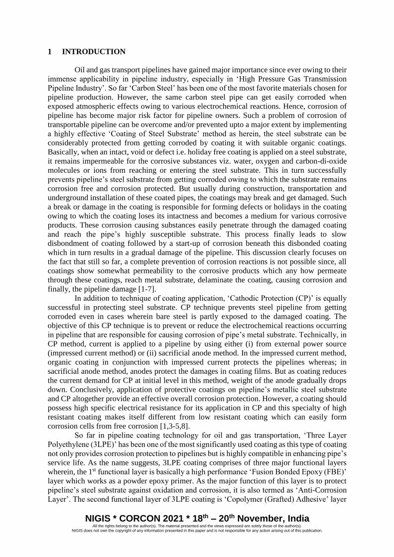
Each of these layers of 3LPE coating system not only perform individually but also
carry out collective functions. Such a 3LPE coated pipe along with its three functional layers
is depicted pictorially in Fig. 1. 3LPE coated pipes show comparatively higher and flexible
moderately operating temperature range of -40 to 80 °C which make them immensely suitable
in pipeline applications no matter how much expensive and complex they are and how much
critical is their application process due to the presence of FBE layer in it [2,9-11].
Fig. 1: 3LPE Coated Pipe
Very rare publications are available till date which deal with CD test of pipeline
coatings under field conditions. One of the first reports on field experience with PE coating
was provided by Pickelmann [12]. On the other hand, several literatures are available today
which relate with laboratory testing. But so far no strong correlation has been easily established
between CD test under field conditions and CD test under laboratory conditions. However,
laboratory CD tests are highly advantageous over field CD tests as they though being short
time tests, provide complete information about various types of disbonding and this is because
laboratory CD test is unable to predict maximum level of disbonding of coating during period
of mere few months [5]. But unfortunately, despite of considerable research and development
background this multistage CD process is not yet clearly understood due to its complex nature
[8]. Considering all this discussion, the present work is carried out which revolves around the
CD experimentations of selected 3LPE coated pipe samples under relevant laboratory
conditions and their related results and discussion. An elevated temperature condition of 80 °C
and extrapolated test time duration > 28 days makes the present work unusual and quite
different from the usual practice.
2 EXPERIMENTAL DETAILS
Present study deals with the investigation of cathodic delamination resistance i.e.
resistance to disbondment of 3LPE coating coated on mild steel pipe samples along with the
factors leading to its delamination influenced by cathodic polarization and simulated exposure
conditions so as to evaluate the risk of pipeline owners, by performing their Cathodic
Disbondment (CD) test [3, 11,13] as per ISO 21809-1:2018(E) [11]. Hence obtained CD test
NIGIS * CORCON 2021 * 18th – 20th November, India All the rights belong to the author(s). The material presented and the views expressed are solely those of the author(s).
NIGIS does not own the copyright of any information presented in this paper and is not responsible for any action arising out of this publication.
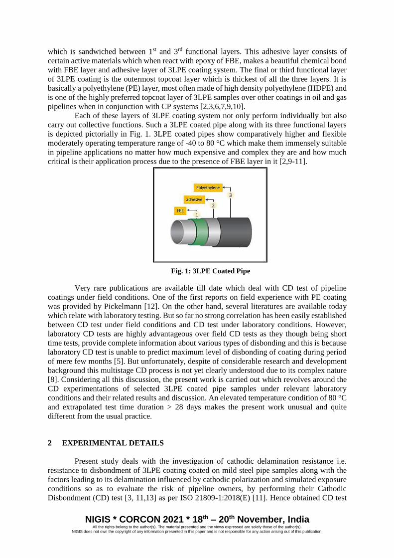
results of these samples further investigate about their quality and suitability in ‘New Steel
Underground High Pressure Gas Transmission Pipeline Industry Applications’. Here, firstly
three different 3LPE coated pipe samples of the same batch, termed as Sample 1, Sample 2 and
Sample 3 as shown in Fig. 2 are chosen and then exposed to same laboratory based CD test
conditions for three different respective test durations of 28, 56 and 84 days.
Fig. 2: 3LPE Coated Pipe Samples
In usual cases, CD test of newly applied coating is carried out for a very short duration
of say 30 days irrespective of the duration of lifetime expectancy of a pipeline which is much
longer than 30 days. In some of the cases the range of CD test varies from minimum 28 days
to maximum 90 days [1,5]. Considering this, suitable test duration in present work is chosen
from minimum 28 days to maximum 84 days which is much higher than the usual 30 days’ CD
test duration.
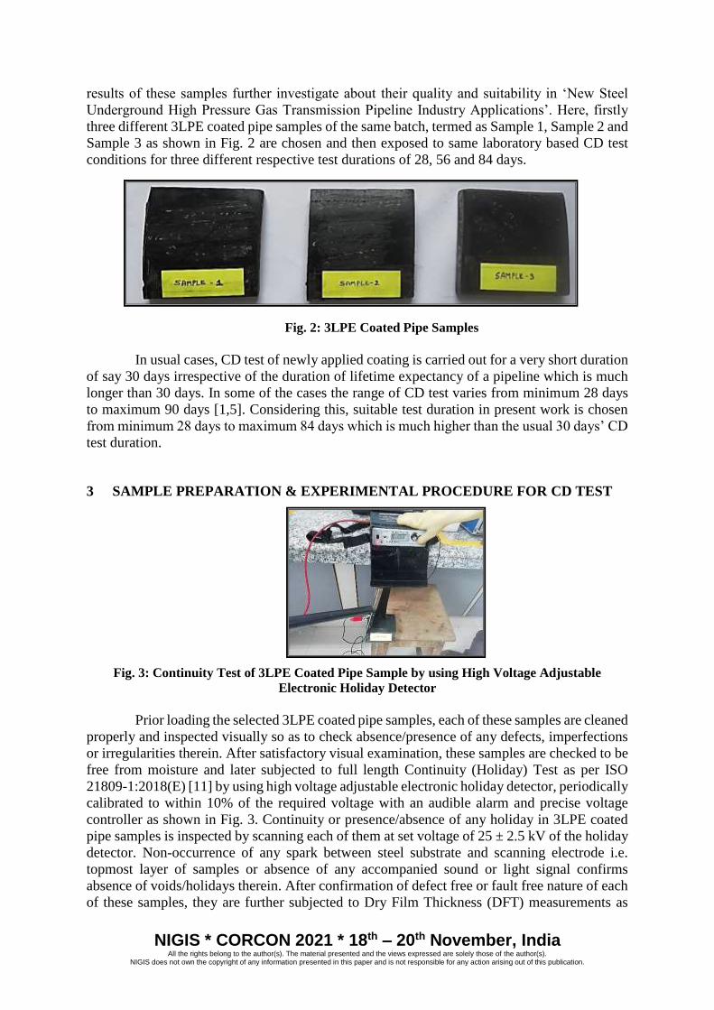
3 SAMPLE PREPARATION & EXPERIMENTAL PROCEDURE FOR CD TEST
Fig. 3: Continuity Test of 3LPE Coated Pipe Sample by using High Voltage Adjustable
Electronic Holiday Detector
Prior loading the selected 3LPE coated pipe samples, each of these samples are cleaned
properly and inspected visually so as to check absence/presence of any defects, imperfections
or irregularities therein. After satisfactory visual examination, these samples are checked to be
free from moisture and later subjected to full length Continuity (Holiday) Test as per ISO
21809-1:2018(E) [11] by using high voltage adjustable electronic holiday detector, periodically
calibrated to within 10% of the required voltage with an audible alarm and precise voltage
controller as shown in Fig. 3. Continuity or presence/absence of any holiday in 3LPE coated
pipe samples is inspected by scanning each of them at set voltage of 25 ± 2.5 kV of the holiday
detector. Non-occurrence of any spark between steel substrate and scanning electrode i.e.
topmost layer of samples or absence of any accompanied sound or light signal confirms
absence of voids/holidays therein. After confirmation of defect free or fault free nature of each
of these samples, they are further subjected to Dry Film Thickness (DFT) measurements as
NIGIS * CORCON 2021 * 18th – 20th November, India All the rights belong to the author(s). The material presented and the views expressed are solely those of the author(s).
NIGIS does not own the copyright of any information presented in this paper and is not responsible for any action arising out of this publication.
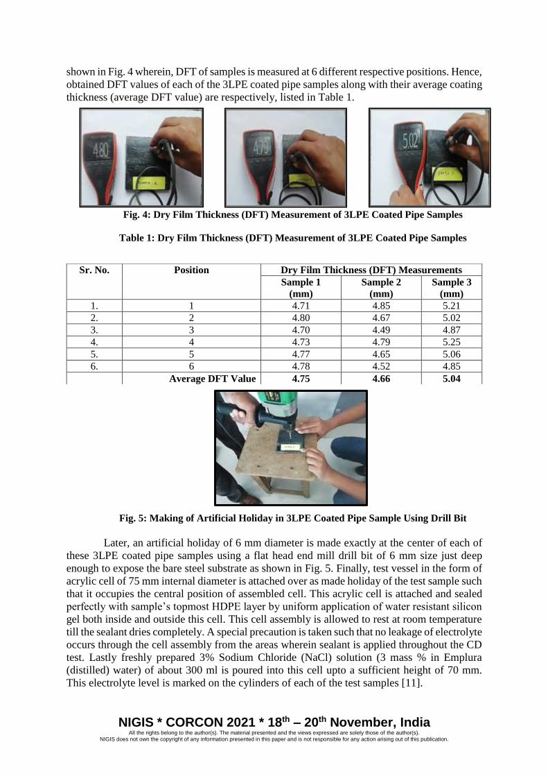
shown in Fig. 4 wherein, DFT of samples is measured at 6 different respective positions. Hence,
obtained DFT values of each of the 3LPE coated pipe samples along with their average coating
thickness (average DFT value) are respectively, listed in Table 1.
Fig. 4: Dry Film Thickness (DFT) Measurement of 3LPE Coated Pipe Samples
Table 1: Dry Film Thickness (DFT) Measurement of 3LPE Coated Pipe Samples
Fig. 5: Making of Artificial Holiday in 3LPE Coated Pipe Sample Using Drill Bit
Later, an artificial holiday of 6 mm diameter is made exactly at the center of each of
these 3LPE coated pipe samples using a flat head end mill drill bit of 6 mm size just deep
enough to expose the bare steel substrate as shown in Fig. 5. Finally, test vessel in the form of
acrylic cell of 75 mm internal diameter is attached over as made holiday of the test sample such
that it occupies the central position of assembled cell. This acrylic cell is attached and sealed
perfectly with sample’s topmost HDPE layer by uniform application of water resistant silicon
gel both inside and outside this cell. This cell assembly is allowed to rest at room temperature
till the sealant dries completely. A special precaution is taken such that no leakage of electrolyte
occurs through the cell assembly from the areas wherein sealant is applied throughout the CD
test. Lastly freshly prepared 3% Sodium Chloride (NaCl) solution (3 mass % in Emplura
(distilled) water) of about 300 ml is poured into this cell upto a sufficient height of 70 mm.
This electrolyte level is marked on the cylinders of each of the test samples [11].
Sr. No. Position Dry Film Thickness (DFT) Measurements
Sample 1
(mm)
Sample 2
(mm)
Sample 3
(mm)
1. 1 4.71 4.85 5.21
2. 2 4.80 4.67 5.02
3. 3 4.70 4.49 4.87
4. 4 4.73 4.79 5.25
5. 5 4.77 4.65 5.06
6. 6 4.78 4.52 4.85
Average DFT Value 4.75 4.66 5.04
NIGIS * CORCON 2021 * 18th – 20th November, India All the rights belong to the author(s). The material presented and the views expressed are solely those of the author(s).
NIGIS does not own the copyright of any information presented in this paper and is not responsible for any action arising out of this publication.
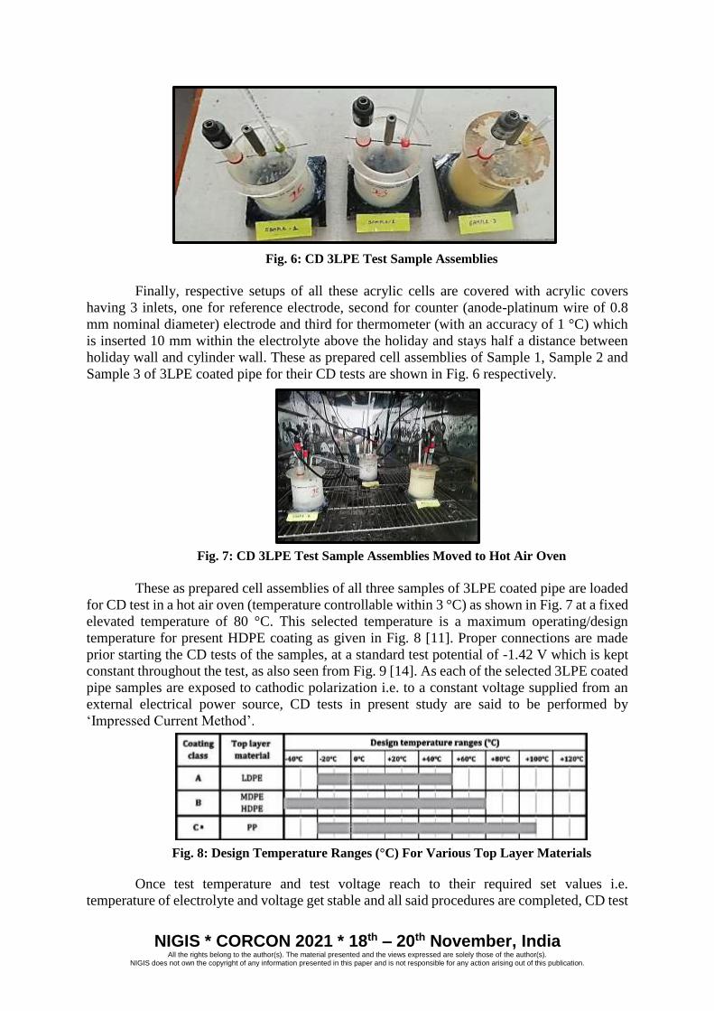
Fig. 6: CD 3LPE Test Sample Assemblies
Finally, respective setups of all these acrylic cells are covered with acrylic covers
having 3 inlets, one for reference electrode, second for counter (anode-platinum wire of 0.8
mm nominal diameter) electrode and third for thermometer (with an accuracy of 1 °C) which
is inserted 10 mm within the electrolyte above the holiday and stays half a distance between
holiday wall and cylinder wall. These as prepared cell assemblies of Sample 1, Sample 2 and
Sample 3 of 3LPE coated pipe for their CD tests are shown in Fig. 6 respectively.
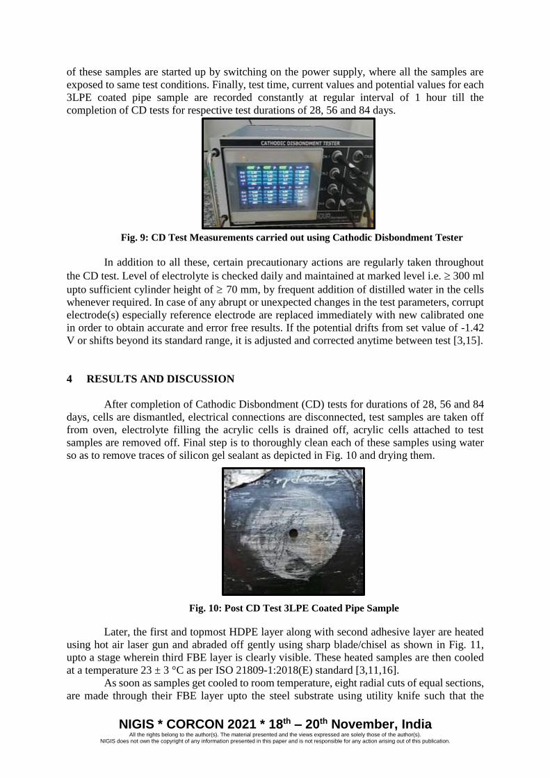
Fig. 7: CD 3LPE Test Sample Assemblies Moved to Hot Air Oven
These as prepared cell assemblies of all three samples of 3LPE coated pipe are loaded
for CD test in a hot air oven (temperature controllable within 3 °C) as shown in Fig. 7 at a fixed
elevated temperature of 80 °C. This selected temperature is a maximum operating/design
temperature for present HDPE coating as given in Fig. 8 [11]. Proper connections are made
prior starting the CD tests of the samples, at a standard test potential of -1.42 V which is kept
constant throughout the test, as also seen from Fig. 9 [14]. As each of the selected 3LPE coated
pipe samples are exposed to cathodic polarization i.e. to a constant voltage supplied from an
external electrical power source, CD tests in present study are said to be performed by
‘Impressed Current Method’.
Fig. 8: Design Temperature Ranges (°C) For Various Top Layer Materials
Once test temperature and test voltage reach to their required set values i.e.
temperature of electrolyte and voltage get stable and all said procedures are completed, CD test
NIGIS * CORCON 2021 * 18th – 20th November, India All the rights belong to the author(s). The material presented and the views expressed are solely those of the author(s).
NIGIS does not own the copyright of any information presented in this paper and is not responsible for any action arising out of this publication.
of these samples are started up by switching on the power supply, where all the samples are
exposed to same test conditions. Finally, test time, current values and potential values for each
3LPE coated pipe sample are recorded constantly at regular interval of 1 hour till the
completion of CD tests for respective test durations of 28, 56 and 84 days.
Fig. 9: CD Test Measurements carried out using Cathodic Disbondment Tester
In addition to all these, certain precautionary actions are regularly taken throughout
the CD test. Level of electrolyte is checked daily and maintained at marked level i.e. 300 ml
upto sufficient cylinder height of 70 mm, by frequent addition of distilled water in the cells
whenever required. In case of any abrupt or unexpected changes in the test parameters, corrupt
electrode(s) especially reference electrode are replaced immediately with new calibrated one
in order to obtain accurate and error free results. If the potential drifts from set value of -1.42
V or shifts beyond its standard range, it is adjusted and corrected anytime between test [3,15].
4 RESULTS AND DISCUSSION
After completion of Cathodic Disbondment (CD) tests for durations of 28, 56 and 84
days, cells are dismantled, electrical connections are disconnected, test samples are taken off
from oven, electrolyte filling the acrylic cells is drained off, acrylic cells attached to test
samples are removed off. Final step is to thoroughly clean each of these samples using water
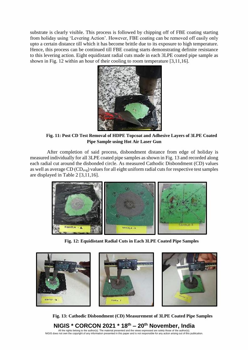
so as to remove traces of silicon gel sealant as depicted in Fig. 10 and drying them.
Fig. 10: Post CD Test 3LPE Coated Pipe Sample
Later, the first and topmost HDPE layer along with second adhesive layer are heated
using hot air laser gun and abraded off gently using sharp blade/chisel as shown in Fig. 11,
upto a stage wherein third FBE layer is clearly visible. These heated samples are then cooled
at a temperature 23 ± 3 °C as per ISO 21809-1:2018(E) standard [3,11,16].
As soon as samples get cooled to room temperature, eight radial cuts of equal sections,
are made through their FBE layer upto the steel substrate using utility knife such that the
NIGIS * CORCON 2021 * 18th – 20th November, India All the rights belong to the author(s). The material presented and the views expressed are solely those of the author(s).
NIGIS does not own the copyright of any information presented in this paper and is not responsible for any action arising out of this publication.
substrate is clearly visible. This process is followed by chipping off of FBE coating starting
from holiday using ‘Levering Action’. However, FBE coating can be removed off easily only
upto a certain distance till which it has become brittle due to its exposure to high temperature.
Hence, this process can be continued till FBE coating starts demonstrating definite resistance
to this levering action. Eight equidistant radial cuts made in each 3LPE coated pipe sample as
shown in Fig. 12 within an hour of their cooling to room temperature [3,11,16].
Fig. 11: Post CD Test Removal of HDPE Topcoat and Adhesive Layers of 3LPE Coated
Pipe Sample using Hot Air Laser Gun
After completion of said process, disbondment distance from edge of holiday is
measured individually for all 3LPE coated pipe samples as shown in Fig. 13 and recorded along
each radial cut around the disbonded circle. As measured Cathodic Disbondment (CD) values
as well as average CD (CDavg) values for all eight uniform radial cuts for respective test samples
are displayed in Table 2 [3,11,16].
Fig. 12: Equidistant Radial Cuts in Each 3LPE Coated Pipe Samples
Fig. 13: Cathodic Disbondment (CD) Measurement of 3LPE Coated Pipe Samples
NIGIS * CORCON 2021 * 18th – 20th November, India All the rights belong to the author(s). The material presented and the views expressed are solely those of the author(s).
NIGIS does not own the copyright of any information presented in this paper and is not responsible for any action arising out of this publication.
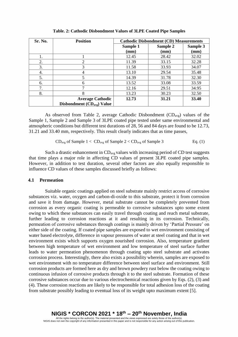
Table. 2: Cathodic Disbondment Values of 3LPE Coated Pipe Samples
Sr. No. Position Cathodic Disbondment (CD) Measurements
Sample 1
(mm)
Sample 2
(mm)
Sample 3
(mm)
1. 1 12.45 28.42 32.02
2. 2 11.39 33.15 32.28
3. 3 11.58 33.93 34.07
4. 4 13.10 29.54 35.48
5. 5 14.39 31.78 32.30
6. 6 13.52 33.08 33.59
7. 7 12.16 29.51 34.95
8. 8 13.23 30.23 32.50
Average Cathodic
Disbondment (CDavg) Value
12.73 31.21 33.40
As observed from Table 2, average Cathodic Disbondment (CDavg) values of the
Sample 1, Sample 2 and Sample 3 of 3LPE coated pipe tested under same environmental and
atmospheric conditions but different test durations of 28, 56 and 84 days are found to be 12.73,
31.21 and 33.40 mm, respectively. This result clearly indicates that as time passes,
CDavg of Sample 1 < CDavg of Sample 2 < CDavg of Sample 3 Eq. (1)
Such a drastic enhancement in CDavg values with increasing period of CD test suggests
that time plays a major role in affecting CD values of present 3LPE coated pipe samples.
However, in addition to test duration, several other factors are also equally responsible to
influence CD values of these samples discussed briefly as follows:
4.1 Permeation
Suitable organic coatings applied on steel substrate mainly restrict access of corrosive
substances viz. water, oxygen and carbon-di-oxide to this substrate, protect it from corrosion
and save it from damage. However, metal substrate cannot be completely prevented from
corrosion as every organic coating is permeable to corrosive substances upto some extent
owing to which these substances can easily travel through coating and reach metal substrate,
further leading to corrosion reactions at it and resulting in its corrosion. Technically,
permeation of corrosive substances through coatings is mainly driven by ‘Partial Pressure’ on
either side of the coating. If coated pipe samples are exposed to wet environment consisting of
water based electrolyte, difference in vapour pressures of water at steel coating and that in wet
environment exists which supports oxygen nourished corrosion. Also, temperature gradient
between high temperature of wet environment and low temperature of steel surface further
leads to water permeation phenomenon through coating upto steel substrate and activates
corrosion process. Interestingly, there also exists a possibility wherein, samples are exposed to
wet environment with no temperature difference between steel surface and environment. Still
corrosion products are formed here as dry and brown powdery rust below the coating owing to
continuous infusion of corrosive products through it to the steel substrate. Formation of these
corrosive substances occur due to various electrochemical reactions given by Eqs. (2), (3) and
(4). These corrosion reactions are likely to be responsible for total adhesion loss of the coating
from substrate possibly leading to eventual loss of its weight upto maximum extent [5].

NIGIS * CORCON 2021 * 18th – 20th November, India All the rights belong to the author(s). The material presented and the views expressed are solely those of the author(s).
NIGIS does not own the copyright of any information presented in this paper and is not responsible for any action arising out of this publication.
2Fe + (3/2)O2 Fe2O3 Eq. (2)
Fe + 2H2O Fe(OH)2 + H2 Eq. (3)
Fe + H2O + CO2 FeCO3 + H2 Eq. (4)
But in the present case of 3LPE coated pipe samples, there is only a partial probability
of development of temperature difference between steel substrate and NaCl salt based test
environment with test temperature of 80 °C. On the contrary, permeation of corrosive
substances to steel substrate is quite possible no matter whether there exists such a temperature
difference or not, which sequentially leads to corrosion below coating owing to occurrence of
various corrosion reactions, eventual weight loss of steel substrate and finally adhesion loss of
this coating. With increasing time duration of CD test from 28 days to 84 days, phenomenon
of permeation is expected to graduate because with increasing availability of time, enough
(higher) amount of corrosive substances penetrate through coating to reach steel substrate
hence, promoting the process of corrosion from Sample 1 to Sample 3.
4.2 Cathodic Reactions
Disbondment theory states that when high negative potentials are applied to CD cell
assembly, hydrogen reduction reaction given by Eq. (5) takes place at bare steel substrate that
is acting as cathode. Rise in this potential in electronegative direction results in transfer of
cathodic current across cathodic steel surface owing to which water gets reduced to produce
atomic hydrogen on this surface. This nascent hydrogen combines by consuming electrons and
form hydrogen gas which further evolves or expands to form ‘Blister’ so as to force coating
away from steel substrate. Thus, hydrogen gas formed during reduction reaction plays a
significant role in affecting CD mechanism and properties of coating which surrounds coating
defect i.e. holiday and this fact is also supported by Coulsen & Temple [17,18] in their
experimental results [1,5,16,17].
2H2O + 2e- 2OH- + H2(g) Eq. (5)
On the other hand, if applied potentials are less negative, dissolved oxygen and water
get easily transported through highly permeable coatings. Constant supply of oxygen and water
further leads to oxygen reduction reactions given by Eq. (6). As oxygen concentration drops,
disbonding rate also lowers down which indicates that oxygen is one of most the essential
factors to cause disbondment effect [5,8,16,17]. Stratsmann et al. [19] reported that in the
absence of oxygen, no disbonding occurs under free corrosion potentials. Leidheiser & Wang
[20,21] also supports this fact that if oxygen is removed from electrolyte, very little cathodic
disbonding occurs. Reduction reaction of oxygen also produces negative charged hydroxide
(OH-) ions which are responsible for alkaline behaviour. However, these (OH-) ions are
balanced by cations on the product side. Hence, both, hydrogen gas evolved during hydrogen
reduction reaction and oxygen involved in oxygen reduction reaction altogether are responsible
for the rise in pH at cathode. In addition to as mentioned reactions, two counter chemical
reactions given by respective Eqs. (7) and (8) occur at anode. Additionally, when chlorine
molecules diffuse towards cathode, chemical reaction given by Eq. (9) occur [1].
NIGIS * CORCON 2021 * 18th – 20th November, India All the rights belong to the author(s). The material presented and the views expressed are solely those of the author(s).
NIGIS does not own the copyright of any information presented in this paper and is not responsible for any action arising out of this publication.
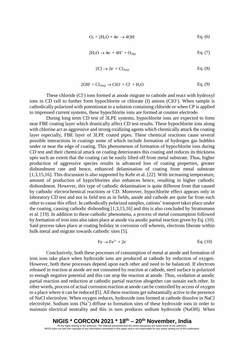
O2 + 2H2O + 4e- 4OH- Eq. (6)
2H2O 4e- + 4H+ + O2(g) Eq. (7)
2Cl 2e- + Cl2(aq) Eq. (8)
2OH- + Cl2(aq) ClO- + Cl- + H2O Eq. (9)
These chloride (Cl-) ions formed at anode migrate to cathode and react with hydroxyl
ions in CD cell to further form hypochlorite or chlorate (I) anions (ClO-). When sample is
cathodically polarized with potentiostat in a solution containing chloride or when CP is applied
to impressed current systems, these hypochlorite ions are formed at counter electrode.
During long term CD test of 3LPE systems, hypochlorite ions are expected to form
near FBE coating layer which drastically affect CD test results. These hypochlorite ions along
with chlorine act as aggressive and strong oxidizing agents which chemically attack the coating
layer especially, FBE layer of 3LPE coated pipes. These chemical reactions cause several
possible interactions in coatings some of which include formation of hydrogen gas bubbles
under or near the edge of coating. This phenomenon of formation of hypochlorite ions during
CD test and their chemical attack on coating deteriorates this coating and reduces its thickness
upto such an extent that the coating can be easily lifted off from metal substrate. Thus, higher
production of aggressive species results in advanced loss of coating properties, greater
disbondment rate and hence, enhanced delamination of coating from metal substrate
[1,3,15,16]. This discussion is also supported by Kehr et al. [22]. With increasing temperature,
amount of production of hypochlorites also enhances hence, resulting in higher cathodic
disbondment. However, this type of cathodic delamination is quite different from that caused
by cathodic electrochemical reactions or CD. Moreover, hypochlorite effect appears only in
laboratory CD test and not in field test as in fields, anode and cathode are quite far from each
other to cause this effect. In cathodically polarized samples, cations’ transport takes place under
the coating, causing cathodic disbonding [1,3,15,16] and this is also concluded by Strattsmann
et al. [19]. In addition to these cathodic phenomena, a process of metal consumption followed
by formation of iron ions also takes place at anode via anodic partial reaction given by Eq. (10).
Said process takes place at coating holiday in corrosion cell wherein, electrons liberate within
bulk metal and migrate towards cathodic sites [5].
Fe Fe2+ + 2e- Eq. (10)
Conclusively, both these processes of consumption of metal at anode and formation of
iron ions take place when hydroxide ions are produced at cathode by reduction of oxygen.
However, both these processes depend upon each other and need to be balanced. If electrons
released in reaction at anode are not consumed by reaction at cathode, steel surface is polarized
to enough negative potential and this can stop the reaction at anode. Thus, oxidation at anodic
partial reaction and reduction at cathodic partial reaction altogether can sustain each other. In
other words, process of actual corrosion reaction at anode can be controlled by access of oxygen
to a place where it can be reduced [5]. All these reactions get substantially active in the presence
of NaCl electrolyte. When oxygen reduces, hydroxide ions formed at cathode dissolve in NaCl
electrolyte. Sodium ions (Na+) diffuse to formation sites of these hydroxide ions in order to
maintain electrical neutrality and this in turn produces sodium hydroxide (NaOH). When

NIGIS * CORCON 2021 * 18th – 20th November, India All the rights belong to the author(s). The material presented and the views expressed are solely those of the author(s).
NIGIS does not own the copyright of any information presented in this paper and is not responsible for any action arising out of this publication.
reaction products at anode and cathode mix, reaction product of consecutive reactions form
sodium hypochlorite (NaOCl) as shown in Eq. (11) [13].
Cl2 + 2NaOH NaCl + NaOCl + H2O Eq. (11)
NaOH which is supposed to have similar effect as that of NaOCl i.e. oxidant, is
responsible for effective removal of interfacial oxide layer to which coating is bound and
decomposition of saponification of coating. These hence, formed NaOH and NaOCl reaction
products altogether play a major role in delamination of coating in the surrounding of an
artificial holiday or defect, upto a certain extent. However, both these phenomena are
temperature dependent and vary with varying temperatures [13].
These above discussed phenomena are likely to take place during CD test of present
3LPE coated samples also. Electrochemical reactions are expected to get considerably active
at high test temperature of 80 °C in the presence of NaCl based salt environment. This further
enhances rate of formation of chemical substances at electrode and their significant attack on
coating, leading to its removal from metal substrate. However, with increasing CD test
duration, these processes of coating deterioration and hence, its delamination also get gradually
effective. Owing to this fact, CD effect or coating delamination also increases successively
from Sample 1 to Sample 3, respectively of 3LPE coated pipe as also seen from Fig. 13 and
Table 2. In other words, presence of NaCl salt environment, elevated temperature of 80 °C and
increasing time duration from 1st day to 84th day of CD test are major factors which govern
enhancement in the electrochemical reactions and formation of chemical substances at
electrodes, leading to gradual attack of the coating and substantial increase in its deterioration
and delamination from steel substrates from Sample 1 to Sample 3. All this indicates that CD
effect observed in Sample 3 > Sample 2 > Sample 1.
4.3 Alkali Formation
According to Watts [23], CD mechanisms are sorted in 3 mechanisms depending upon
the locus of failure where 1st mechanism is in the coating near interface, the 2nd at interface and
the 3rd in oxide on steel surface. ‘Cathodic Reaction’ is one of these three mechanisms which
majorly lead to disbonding under the coating by forming highly aqueous or alkaline film at the
interface. According to various researchers, occurrence of cathodic reactions and transport of
reactants formed due to these reactions during CD tests are likely to be responsible for the
production of alkaline water films or alkali metal hydroxide solutions, under the coating. In
case of CD tests of certain coated samples, alkalinity enhances which causes appreciable
reduction in surface tension of water by non-ionic surfactant. Thus, due to strong alkali effect,
this alkaline solution easily creep into crevice under the chemically sensitive coating and hence,
lead to CD effect and affect coating-to-substrate interaction. This phenomenon in turn destroys
mechanical properties and adhesion strength under the coating and produces disbondment
finally, displacing/delaminating this coating from metal substrate. This entire process starts to
take place from edge of the coating holiday. Rodriguez [24] also supported this theory which
suggests that higher alkalinity of test environment leads to higher CD. This discussion indicates
that CD process can be said as alkaline cleaning of metal surface. However, one of the major
requirement for occurrence of this CD effect is strong alkalinity of electrolyte at steel surface
and this is possible only when alkali ions are present to balance hydroxyl ions formed at this
steel surface. Thus, no CD effect can occur if alkali ions are absent. Interestingly, CD effect
can take place efficiently in the absence of cathodic protection also. However, such a
phenomenon is not possible to occur either in case of neutral solutions or in acid solutions
NIGIS * CORCON 2021 * 18th – 20th November, India All the rights belong to the author(s). The material presented and the views expressed are solely those of the author(s).
NIGIS does not own the copyright of any information presented in this paper and is not responsible for any action arising out of this publication.
because in these solutions, specific ions forming strong soluble alkalis such as alkali metals
leading to CD effect are absent [3,5,15,16].
Above discussion is valid for present case also wherein, greater amount of alkali
solution is expected to form and penetrate beneath the coating of 3LPE coated pipe samples
with increasing time duration of CD test that is carried out under CP influence. Such a
phenomenon can also be pictorially observed from Fig. 14 (Forthcoming: ‘Cathodic
Blistering’). In other words, with the rise in CD test duration, amount of alkaline solution
creeping beneath the coating also enhances owing to which number of alkali ions reacting with
steel substrate grows substantially. Thus, alkali effect systematically progresses with increasing
CD test time which not only enhances CD effect but also gradually promotes delamination of
coating from Sample 1 to Sample 3 of present 3LPE coated pipe as also seen from Fig. 13 and
Table 2.
4.4 Coating Holiday
In CD test, usually edge of holiday in a coating acts as a cathode whereas; center of
this holiday is stabilized as anode. This holiday is basically a route for transport of reactants
and cations, as moisture or water along with oxygen can easily creep along the coating-steel
substrate interface so as to result in adhesion loss of this coating from metal substrate and
cathodic disbonding. In this way, holiday in the coating of present 3LPE coated pipe samples
also act as a start-up place for its destruction and damage [5,16].
4.5 CD Test Temperature, Electrolyte Effect & Test Time Dependency
Temperature is one of the factors which considerably influence various properties of
coatings. Fluid temperatures in oil and gas reservoirs usually get higher which demands for
evaluation of CD performance of pipeline coating system at higher temperatures and hence, for
high temperature based short term/long term CD tests. However, till date very few
investigations have been done on properties of coatings at their maximum service temperature.
CD tests is highly flexible to test various types of coatings over wide range of test temperatures
from 95 °C for onshore pipeline applications to > 95 °C for offshore/subsea pipeline
applications. For standard 3LPE coating systems, maximum operating temperature is
recommended as 80 °C. However, such high temperatures not only lead to but also accelerate
significant degradation mechanism of coating of the pipeline even if it is combined with CP,
resulting in corrosion of metal substrate followed by its failure and hence, affecting the
performance of pipeline’s coating. Thus, enough precautions should be considered throughout
the CD tests especially when they are conducted at elevated temperatures. Usually, this
condition is satisfied by controlling and maintaining electrolyte temperature of CD test cell so
as to simulate actual/specific external service temperature conditions [3-5,13,15].
On the other hand, when non-chemically pre-treated laboratory coated single layer
FBE samples are exposed to high temperature CD tests, not only water delaminates the coating
around drill upto a certain extent but also thermal expansion i.e. rise in vapor pressure also
occurs which leads to high porosity of the coating and hence, increased permeation of water
through it. Additionally, at elevated temperatures, significant chemical attack is likely to occur
resulting in bubble formation at coating holiday. These bubbles formed at holiday further
impedes impressed current flow (leading the current value to zero at times) thus, affecting the
coating properties and reducing the electrochemical activities. All these factors are overall
responsible for increased level of oxygen concentrations in electrolyte and also in the rate of
NIGIS * CORCON 2021 * 18th – 20th November, India All the rights belong to the author(s). The material presented and the views expressed are solely those of the author(s).
NIGIS does not own the copyright of any information presented in this paper and is not responsible for any action arising out of this publication.
coating disbondment [3-5,13,15,16,25]. Moreover, as temperature rises, process of formation
of hypochlorite ions also gets substantially active which results in degradation and loss of
thickness of the coating. Conclusively, thumb rule states that higher temperature leads to larger
CD effect [3,4,13,15,26].
But in CD test, use of high temperature electrolyte creates only an artificial
environment to cause aggressive attacks resulting in weakening and thinning of coating.
However, this process is unable to perfectly simulate with actual conditions of offshore/subsea
pipeline services as unlike laboratory based CD test, anode and cathode in fields are placed far
enough to produce adequate amount of hypochlorite ions, owing to which coating
disintegration, degradation and delamination that is observed in laboratory based CD test is
quite different from that occurring in fields [3,15,26]. Other than temperature, electrolyte
volume also plays a prominent role in affecting CD results. If volume of electrolyte drops
down, significant concentration of hypochlorite ions can develop in electrolyte which further
enhances CD process to cause chemical effect and to lead coating delamination. Such an effect
can be minimized upto a certain extent by frequent replenishment of electrolyte as per
requirement [15,16].
Usually, it is the concentration of cations and not of anions in electrolyte which affects
disbonding rate of coating. As proposed by Leidheiser & Wang [20,21], rise in concentration
of electrolyte reduces water activity i.e. concentration of water in the coating. This results the
fall in both water transport through coating and ionic conductivity. Also, there is a decrement
in oxygen solubility which further drops coating’s disbonding rate. This process is different
from the one taking place in case of oxygen saturated electrolyte wherein, concentration of
oxygen is high enough to cause significant cathodic disbondment of coating [16].
All the above discussion is quite apt for present CP combined simulated long term CD
test also which is carried out for three different samples of 3LPE coated pipe at a controlled
and constantly maintained maximum operating temperature of 80 °C. As CD test temperature
of 80 °C is quite near to boiling point of water, water from electrolyte continuously evaporates
with time even though the test cells are completely sealed. This is one of the biggest problems
of high temperature based long term CD test as it constantly lowers down the amount of water
in electrolyte hence, changing the volume of NaCl electrolyte and increasing the concentrations
of ionic components therein. However, such a loss of evaporated water in present test cells is
compensated upto a major extent by frequently refilling every CD test cell by distilled water
such that not only concentration of NaCl salt is maintained in electrolyte but also minimum
level of electrolyte in all the test cells is preserved [3,15]. This method of electrolyte
refreshment in present case is mainly inspired by the related works carried out by J. Holub [26].
In addition to elevated temperature and electrolyte concentration, test duration also
plays a major role in affecting CD test results of present 3LPE coated pipe samples. According
to previous discussion, hypochlorite ions are effectively formed during CD test at elevated
temperatures and high electrolyte concentrations. However, as time of test increases, formation
and building up of these hypochlorite ions becomes more prominent which actively lead to
higher CD effect. Technically, building up hypochlorite ions is a time consuming process.
Hence, for short term CD tests of duration ranging from 48 hours to 7 days, no matter the test
temperature is sufficiently high, amount of hypochlorite formation is likely to be insufficient
as these ions do not get enough time for the process of their building up. But as this test duration
elongates from 72 hours to 28 days or longer, enough time is available for these hypochlorite
ions to form. Along with the rise in building up of hypochlorite ions with time, various
associated electrochemical reactions also get gradually prominent which further enhances level
of oxygen concentration in electrolyte. This phenomenon clearly indicates that with the passage
of time, higher and higher amount of reactants in the form of hypochlorite and oxygen ions are
formed which gradually enter firstly into the coating and then move to the substrate under this
NIGIS * CORCON 2021 * 18th – 20th November, India All the rights belong to the author(s). The material presented and the views expressed are solely those of the author(s).
NIGIS does not own the copyright of any information presented in this paper and is not responsible for any action arising out of this publication.
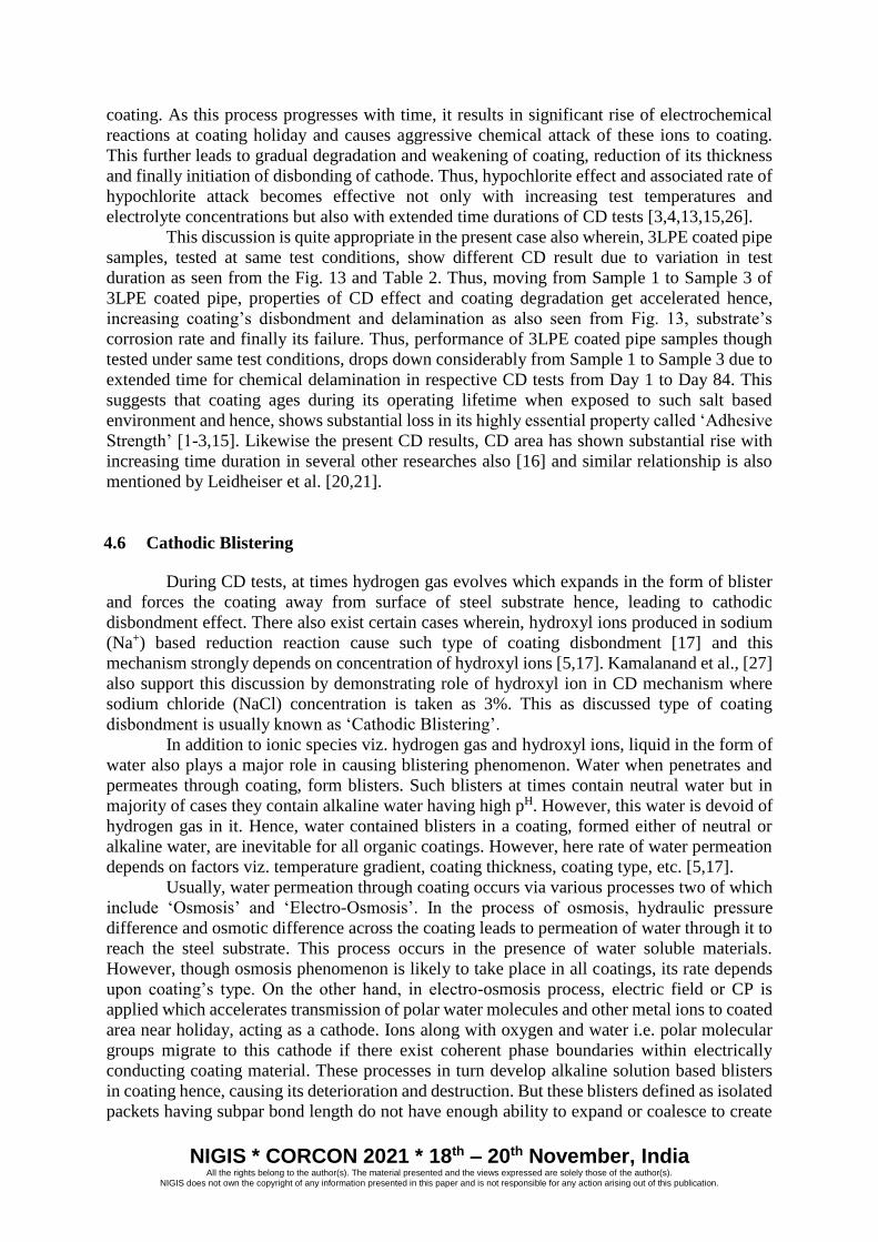
coating. As this process progresses with time, it results in significant rise of electrochemical
reactions at coating holiday and causes aggressive chemical attack of these ions to coating.
This further leads to gradual degradation and weakening of coating, reduction of its thickness
and finally initiation of disbonding of cathode. Thus, hypochlorite effect and associated rate of
hypochlorite attack becomes effective not only with increasing test temperatures and
electrolyte concentrations but also with extended time durations of CD tests [3,4,13,15,26].
This discussion is quite appropriate in the present case also wherein, 3LPE coated pipe
samples, tested at same test conditions, show different CD result due to variation in test
duration as seen from the Fig. 13 and Table 2. Thus, moving from Sample 1 to Sample 3 of
3LPE coated pipe, properties of CD effect and coating degradation get accelerated hence,
increasing coating’s disbondment and delamination as also seen from Fig. 13, substrate’s
corrosion rate and finally its failure. Thus, performance of 3LPE coated pipe samples though
tested under same test conditions, drops down considerably from Sample 1 to Sample 3 due to
extended time for chemical delamination in respective CD tests from Day 1 to Day 84. This
suggests that coating ages during its operating lifetime when exposed to such salt based
environment and hence, shows substantial loss in its highly essential property called ‘Adhesive
Strength’ [1-3,15]. Likewise the present CD results, CD area has shown substantial rise with
increasing time duration in several other researches also [16] and similar relationship is also
mentioned by Leidheiser et al. [20,21].
4.6 Cathodic Blistering
During CD tests, at times hydrogen gas evolves which expands in the form of blister
and forces the coating away from surface of steel substrate hence, leading to cathodic
disbondment effect. There also exist certain cases wherein, hydroxyl ions produced in sodium
(Na+) based reduction reaction cause such type of coating disbondment [17] and this
mechanism strongly depends on concentration of hydroxyl ions [5,17]. Kamalanand et al., [27]
also support this discussion by demonstrating role of hydroxyl ion in CD mechanism where
sodium chloride (NaCl) concentration is taken as 3%. This as discussed type of coating
disbondment is usually known as ‘Cathodic Blistering’.
In addition to ionic species viz. hydrogen gas and hydroxyl ions, liquid in the form of
water also plays a major role in causing blistering phenomenon. Water when penetrates and
permeates through coating, form blisters. Such blisters at times contain neutral water but in
majority of cases they contain alkaline water having high pH. However, this water is devoid of
hydrogen gas in it. Hence, water contained blisters in a coating, formed either of neutral or
alkaline water, are inevitable for all organic coatings. However, here rate of water permeation
depends on factors viz. temperature gradient, coating thickness, coating type, etc. [5,17].
Usually, water permeation through coating occurs via various processes two of which
include ‘Osmosis’ and ‘Electro-Osmosis’. In the process of osmosis, hydraulic pressure
difference and osmotic difference across the coating leads to permeation of water through it to
reach the steel substrate. This process occurs in the presence of water soluble materials.
However, though osmosis phenomenon is likely to take place in all coatings, its rate depends
upon coating’s type. On the other hand, in electro-osmosis process, electric field or CP is
applied which accelerates transmission of polar water molecules and other metal ions to coated
area near holiday, acting as a cathode. Ions along with oxygen and water i.e. polar molecular
groups migrate to this cathode if there exist coherent phase boundaries within electrically
conducting coating material. These processes in turn develop alkaline solution based blisters
in coating hence, causing its deterioration and destruction. But these blisters defined as isolated
packets having subpar bond length do not have enough ability to expand or coalesce to create
NIGIS * CORCON 2021 * 18th – 20th November, India All the rights belong to the author(s). The material presented and the views expressed are solely those of the author(s).
NIGIS does not own the copyright of any information presented in this paper and is not responsible for any action arising out of this publication.
massive disbondment. This indicates that adhesive strength of coating is sufficient enough to
prevent its overall failure. Conversely, blisters formed at steel due to cathodic polarization are
quite different from those produced because of anodic polarization wherein, pits containing
acidic solution are produced in steel [5,16,17].
Blister formation is controlled by temperature factor also. It is quite common to see
complete disbondment in all coatings at high temperature of 70 °C. But only few coatings show
formation of alkaline content based blisters at this condition. Such signs of blister formation or
deterioration of coating due to swelling is generally shown by coating samples whose CD test
is carried out in NaCl salt based electrolytic environment. With increasing concentration of
strong alkali forming cations such as Na+, higher level of CD can be explained [5,16,17]. This
explanation is suitable for the present 3LPE coated system also wherein, each sample is
exposed at an elevated temperature of 80 °C that is much greater than normal disbondment
temperature of 70 °C of almost all coatings.
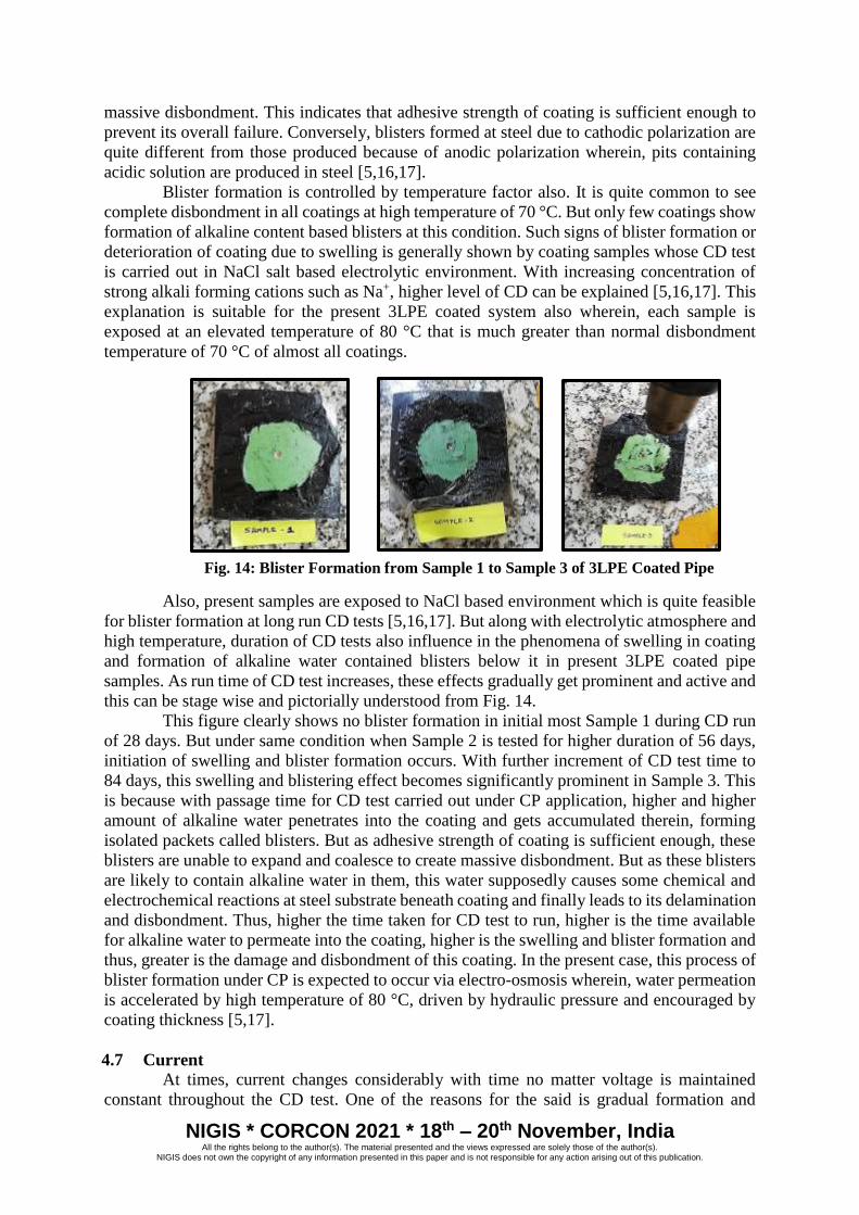
Fig. 14: Blister Formation from Sample 1 to Sample 3 of 3LPE Coated Pipe
Also, present samples are exposed to NaCl based environment which is quite feasible
for blister formation at long run CD tests [5,16,17]. But along with electrolytic atmosphere and
high temperature, duration of CD tests also influence in the phenomena of swelling in coating
and formation of alkaline water contained blisters below it in present 3LPE coated pipe
samples. As run time of CD test increases, these effects gradually get prominent and active and
this can be stage wise and pictorially understood from Fig. 14.
This figure clearly shows no blister formation in initial most Sample 1 during CD run
of 28 days. But under same condition when Sample 2 is tested for higher duration of 56 days,
initiation of swelling and blister formation occurs. With further increment of CD test time to
84 days, this swelling and blistering effect becomes significantly prominent in Sample 3. This
is because with passage time for CD test carried out under CP application, higher and higher
amount of alkaline water penetrates into the coating and gets accumulated therein, forming
isolated packets called blisters. But as adhesive strength of coating is sufficient enough, these
blisters are unable to expand and coalesce to create massive disbondment. But as these blisters
are likely to contain alkaline water in them, this water supposedly causes some chemical and
electrochemical reactions at steel substrate beneath coating and finally leads to its delamination
and disbondment. Thus, higher the time taken for CD test to run, higher is the time available
for alkaline water to permeate into the coating, higher is the swelling and blister formation and
thus, greater is the damage and disbondment of this coating. In the present case, this process of
blister formation under CP is expected to occur via electro-osmosis wherein, water permeation
is accelerated by high temperature of 80 °C, driven by hydraulic pressure and encouraged by
coating thickness [5,17].
4.7 Current
At times, current changes considerably with time no matter voltage is maintained
constant throughout the CD test. One of the reasons for the said is gradual formation and
NIGIS * CORCON 2021 * 18th – 20th November, India All the rights belong to the author(s). The material presented and the views expressed are solely those of the author(s).
NIGIS does not own the copyright of any information presented in this paper and is not responsible for any action arising out of this publication.
deposition of ‘Calcareous Deposits’ on coating holiday with increasing time. These calcareous
deposits which are expected to develop on coating holiday usually in about 30 days, grow
gradually with the passage of time and act as resistance of the holiday against transport of ions.
This phenomenon in turn drops cathodic current as well as reduces disbonding rate of coating.
Thus, higher the formation of calcareous deposits on coating holiday, lesser is the current
requirement with passing time and lower is coating’s disbonding rate [5,16,17,26].
In addition to this factor, the highly aggressive hypochlorite ions and chlorate (I)
anions (ClO-) formed by conversion of NaCl salt in electrolyte is another major reason which
affects polarization current in CD cell. These aggressive ions are most apparent reason for
oxidative destruction of coating and leads in turn to the change in current. As time passes,
concentration of these ions continue to increase due to occurrence of electrochemical reactions
and their chemical attack on coating. This phenomenon further increases the flow of
polarization current that is drawn from coating sample to CD test cell and results in coating’s
disintegration. Extended current capacity is quite low in such disbonded areas where coating
rests to steel surface consisting of only a thin moisture film in between [3,5,16,26]. At times,
these ions along with air bubbles formed due to hot electrolyte get accumulated at coating
holiday and hence, create obstruction for the flow of current in the circuit due to which circuit
breaks down and current and related voltage drops, at times even to zero. Conclusively, though
rarely, but under same test conditions and test parameters there do exist stages between CD
tests wherein, current of the samples drop hence, leading to a fall in respective voltage values
and this phenomenon usually takes place owing to two of the major reasons which include (i)
formation of calcareous deposits at the coating holiday and (ii) production of highly aggressive
hypochlorite ions and chlorate (I) anions (ClO-) formed by conversion of NaCl salt in
electrolyte. Thus, in order to maintain continuous flow of impressed current via circuit
throughout the CD test run, to retain the required set voltage and to continue electrochemical
activity during laboratory performance of CD test for each 3LPE coated pipe sample, these
ions and air bubbles are constantly removed off from the coating holiday [5,15,16].
5 CONCLUSIONS
Present study investigates, reports and concludes effects of various factors that
influence cathodic delamination/disbondment and assesses extent of delamination radius on 3
different test samples of a common 3LPE coated pipe, by testing them under same simulated
test conditions for 3 different test durations of 28, 56 and 84 days, respectively. Disbonded area
seen in every 3LPE coated pipe sample shows an extent to which oxides are removed i.e.
delamination of coating or CD effect. As time duration of CD test increases, ‘Average Cathodic
Disbondment (CDavg) Value’ increases from 12.73 mm of Sample 1, to 31.21 mm of Sample 2
to 33.40 mm of Sample 3. This concludes significant enhancement in coating delamination and
disbondment with increasing CD test duration from 28 days to 84 days, respectively at constant
elevated temperature of 80 °C (maximum operating temperature of HDPE topcoat) of NaCl
electrolyte and fixed CP of -1.42 V.
Three major factors responsible for above mentioned CD effect are CD test time
duration, electrolyte test temperature and NaCl based electrolyte environment. At an elevated
temperature of 80 °C, alkaline water of NaCl electrolyte easily penetrates or creeps beneath
coating. This gradually makes the coating porous and leads to occurrence of various
electrochemical reactions at electrode and alkali effects to cause aggressive chemical attack on
coating at its holiday. Such electrochemical reactions form various corrosive ions which
actively attack the coating chemically. These ions significantly rise with increasing CD test
duration, which in turn accelerates electrochemical reaction rate and chemical attack on
coating. Also, swelling of coating or formation of isolated packets called ‘blisters’ containing
NIGIS * CORCON 2021 * 18th – 20th November, India All the rights belong to the author(s). The material presented and the views expressed are solely those of the author(s).
NIGIS does not own the copyright of any information presented in this paper and is not responsible for any action arising out of this publication.
alkali solution also get significantly prominent and active from Sample 1 to Sample 3 due to
increasing amount of alkaline water penetration below the coating which further promotes
chemical and electrochemical reactions at steel substrate beneath the coating with passage of
CD test duration. All these factors result in gradual degradation, weakening and delamination
of this coating, increase in substrate’s corrosion rate and finally coating failure, moving from
present Sample 1 to Sample 3 of 3LPE coated pipe. Hence, performance of 3LPE coated pipe
samples significantly drop down with increasing CD test time from Day 1 to Day 84. This
suggests that coating integrity and hence, coating performance is drastically reduced under the
constant test conditions from Sample 1 to Sample 3 of 3LPE coated pipe with increasing CD
test duration. All this discussion suggests that present 3LPE pipeline coating systems may fail
to provide appropriate performance in their long term usage especially, at elevated
temperatures and in NaCl based environmental conditions. Hence, there exists future scope of
development of new pipeline coating system whose integrity remains intact even at long run
after its installation in adverse conditions.
6 REFERENCES
[1] Broesder E., Stopaq B.V. and Stadskanaal, “Coatings and Cathodic Disbondment - The True Story”,
The Netherlands K.C. Lax, Asset Integrity Services Ltd., Aldermaston, United Kingdom.
[2] Qazi H.A.A. (2019), “Study of Qualification of Coating Procedure Specifications as Per Din 30670
for 3LPE Coating of 8 Inch Diameter Erw Pipe”, HSOA Journal of Environmental Science: Current
Research, Vol. 2, pp. 008.
[3] Guan S.W. and Kehr A. (2014), “High Temperature Cathodic Disbondment Testing for Pipeline
Coatings”, Corrosion, Paper No. 3860.
[4] Knudsen O.O. and Eggen T.G. (2010), “Test Method for Studying Cathodic Disbonding at High
Temperature”, NACE International Corrosion Conference & Expo, Paper No. 10007.
[5] (1987), “Cathodic Disbonding of Steel Pipe Coatings”, CEOCOR CR2 “C.D.” Final Report.
[6] “Standard Specification for 3 Layer Polyethylene Coating of Linepipes”, Bharat Petroleum
Corporation Limited.
[7] Kehr A. (2016), “Edge Disbondment 3LPP and Other Issues”, Tecnimont.
[8] Roy D., Simon G.P., Forsyth M. and Mardel J. (2002), “Towards a Better Understanding of the
Cathodic Disbondment Performance of Polyethylene Coatings on Steel”, Advances in Polymer
Technology, Vol. 21, No. 1, pp. 44-58.
[9] Ahmadizadeh S. and Monfared A.H., “The effect of coating parameters on the mechanism of
cathodic disbondment of the gas transmission pipeline coatings”, National Iranian Gas Company
(NIGC), Iran.
[10] Guan S., Mayes P., Andrenacci A., Wong D. and Shaw B., “Advanced two layer polyethylene
coating technology for pipeline protection”, Corrosion Control 007, ShawCor, Paper 039.
[11] (2018-10), “ISO 21809-1: Petroleum and natural gas industries — External coatings for buried or
submerged pipelines used in pipeline transportation systems — Part 1: Polyolefin coatings (3- layer
PE and 3-layer PP)”, Second edition.
[12] Pickelmann P., Haftungsverlust Und Unterrostung Von PE-Stahlrohrumhul-lungen (1975), ). gwf-
gas/erdgas, 116, Vol 6, pp.. 229.
[13] Betz M., Bosch C., Gronsfeld P.J. and Bagaviev M. (2012), “Cathodic Disbondment Test: What
Are We Testing?”, NACE International Corrosion Conference & Expo, Paper No. C2012-0001285.
[14] (2012), “DIN 30670: Polyethylene coatings on steel pipes and fittings – Requirements and testing”.
[15] Guan S.W. and Kehr J.A., “High-Temperature Cathodic Disbondment Testing: Review and
Survey—Part 1”, Coatings & Linings.
[16] Knudsen O.O. and Skar J.I. (2008), “Cathodic Disbonding of Epoxy Coatings – Effect of Test
Parameters”, NACE International Corrosion Conference & Expo, Paper No. 08005.
[17] Gummow R.A. and Eng P. (1983), “Cathodic Protection Myth-Conceptions – Part 1”, Correng
Consulting Service Inc., 205 Riviera Drive, Markham, ON, L3R 5J8, Canada.
[18] Coulson K.E.W. and Temple D.G. (1983), 5th International Conference on Internal and External

NIGIS * CORCON 2021 * 18th – 20th November, India All the rights belong to the author(s). The material presented and the views expressed are solely those of the author(s).
NIGIS does not own the copyright of any information presented in this paper and is not responsible for any action arising out of this publication.
Protection of Pipes, Innsbruck, Austria, pp. 21-49.
[19] Stratmann M., Feser R. and Leng A. (1994), Electrochimica Acta, Vol. 39, No. 8/9. pp. 1207.
[20] Leidheiser H. Jr andWang W. (1981), Journal of Coatings Technology, Vol. 53, No. 672. pp.
77-84.
[21] Leidheiser H., Wang W., Igetoft L. (1983), Progress in Organic Coatings, Vol. 11, No. 1, pp.
19-40.
[22] Kehr J.A. (2003), “Chapter 9. Quality Assurance in the FBE-Pipecoating Application Process: In-
Plant, Tests, and Test Variance", in Fusion-Bonded Epoxy (FBE): A Foundation for Pipeline
Corrosion Protection”, Houston, TX: NACE.
[23] Watts J.F. (1989), Journal of Adhesion, Vol. 31, No. 1, pp. 73-85.
[24] Rodriguez R.E., Trautman B.L. and Payer J.H. (2000), “Influencing Factors in Cathodic
Disbondment of Fusion Bonded Epoxy Coatings”, NACE Corrosion Conference & Expo, Houston,
TX: NACE, Paper No. 00166.
[25] Knudsen O.O. and Skar J.I. (2008), “Cathodic Disbonding of Epoxy Coatings—Effect of Test
Parameters”, CORROSION, Houston, TX: NACE, paper no. 08005.
[26] Holub J., Wong D. and Tan M. (2007), “Analysis of CDT Methods and Factors Affecting Cathodic
Disbondment”, NACE Corrosion Conference & Expo, Houston, TX: NACE, Paper No. 07022.
[27] Kamalanand N., et al. (1998), “Role of Hydrogen and Hydroxyl Ion in Cathodic Disbondment”,
Anti-Corrosion Methods and Materials, Vol. 45, No. 4, pp 243-247.