Owner's Manual For Maintenance and Safety SWITCHBACK ...
233
Owner's Manual For Maintenance and Safety SWITCHBACK ASSAULT SKS RMK INDY ADVENTURE INDY XCR INDY XC INDY SP VOYAGEUR
-
Upload
khangminh22 -
Category
Documents
-
view
1 -
download
0
Transcript of Owner's Manual For Maintenance and Safety SWITCHBACK ...

Owner's Manual
For Maintenance and Safety
SWITCHBACK ASSAULTSKS
RMKINDY ADVENTURE
INDY XCRINDY XCINDY SP
VOYAGEUR

WARNINGOperating, servicing, and maintaining a passenger vehicle or off-road
vehicle can expose you to chemicals including engine exhaust, carbon monoxide, phthalates, and lead, which are known to the State of California to cause cancer and birth defects or other reproductive harm. To minimize
exposure, avoid breathing exhaust, do not idle the engine except as necessary, service your vehicle in a well-ventilated area and wear gloves
or wash your hands frequently when servicing your vehicle.
For more information go to www.P65Warnings.ca.gov/passenger-vehicle.
! WARNINGRead, understand, and follow all of the instructions and safety
precautions in this manual and on all product labels.
Failure to follow the safety precautionscould result in serious injury or death.
For videos and more informationabout a safe riding experience withyour Polaris vehicle, scan this QR
code with your smartphone.
!

2020 Owner’s Manual
Switchback Assault 144 RMK 144 SKS 146
Indy SP 129 Indy XC 129
Indy XCR 129 Indy SP 137 Indy XC 137
Indy Adventure 137 Voyageur 144

POLARIS®, AXYS™, SWITCHBACK®, SWITCHBACK ADVENTURE®, PERC®, RUSH®, XCR®, and LOCK & RIDE® are trademarks of POLARIS Industries Inc.Copyright 2019 Polaris Industries Inc. All information contained within this publication is based on the latest product information at the time of publication. Due to constant improvements in the design and quality of production components, some minor discrepancies may result between the actual vehicle and the information presented in this publication. Depictions and/or procedures in this publication are intended for reference use only. No liability can be accepted for omissions or inaccuracies. Any reprinting or reuse of the depictions and/or procedures contained within, whether whole or in part, is expressly prohibited.The original instructions for this vehicle are in English. Other languages are provided as translations of the original instructions.Printed in U.S.A.2020 Owner's Manual9929775

Thank you for purchasing a POLARIS vehicle, and welcome to our world-wide family of POLARIS enthusiasts. Be sure to visit us online at www.polaris.com for the latest news, new product introductions, upcoming events, career opportunities and more.Here at POLARIS we proudly produce an exciting line of utility and recreational products. We believe POLARIS sets a standard of excellence for all utility and recreational vehicles manufactured in the world today. Many years of experience have gone into the engineering, design, and development of your POLARIS vehicle, making it the finest machine we’ve ever produced.
• Snowmobiles• SPORTSMAN® All-terrain vehicles• Low emission vehicles (LEVs)• RANGER® utility vehicles• BRUTUS® work vehicles• SLINGSHOT® three wheel
motorcycles
• RZR® sport vehicles• GEM® vehicles• INDIAN® motorcycles• POLARIS POWER® generators• POLARIS DEFENSE® combat
vehicles• Timbersled® Snow Bikes
For safe and enjoyable operation of your vehicle, be sure to follow the instructions and recommendations in this owner’s manual. Your manual contains instructions for minor maintenance, but information about major repairs is outlined in the POLARIS Service Manual and can be performed by a factory certified Master Service Dealer® (MSD) technician.
Your POLARIS dealer knows your vehicle best and is interested in your total satisfaction. Your POLARIS dealership can perform all of your service needs during, and after, the warranty period.
3
WELCOME

The following signal words and symbols appear throughout this manual and on your vehicle. Your safety is involved when these words and symbols are used. Become familiar with their meanings before reading the manual.
DANGERDANGER indicates a hazardous situation which, if not avoided, WILL result in
death or serious injury.
WARNINGSAFETY ALERT WARNING indicates a hazardous situation which, if not
avoided, COULD result in serious injury or death.
CAUTIONSAFETY ALERT CAUTION indicates a hazardous situation which, if not
avoided, COULD result in minor to moderate injury.
CAUTIONCAUTION indicates special precautions that must be taken to avoid vehicle
damage or property damage.
IMPORTANTIMPORTANT provides key reminders during disassembly, assembly, and
inspection of components.
NOTICENOTICE provides key information by clarifying instructions.
The Prohibition Safety Sign indicates an action NOT to take in order to avoid a hazard.
The Mandatory Action Sign indicates an action that NEEDS to be taken to avoid a hazard.
4
SAFETY SYMBOLS AND SIGNAL WORDS

Introduction . . . . . . . . . . . . . . . . . . . . 7Safety . . . . . . . . . . . . . . . . . . . . . . 11Features . . . . . . . . . . . . . . . . . . . . . 31Gauge . . . . . . . . . . . . . . . . . . . . . 39The Perfect Fit . . . . . . . . . . . . . . . . . . 65Pre-Ride Inspections . . . . . . . . . . . . . . . 87Operation . . . . . . . . . . . . . . . . . . . . 93Maintenance . . . . . . . . . . . . . . . . . . 103Specifications . . . . . . . . . . . . . . . . . . 151Diagnostic Trouble Codes (DTC). . . . . . . . . . 177Troubleshooting . . . . . . . . . . . . . . . . . 203Warranty . . . . . . . . . . . . . . . . . . . . 213Maintenance Log . . . . . . . . . . . . . . . . 223
5
TABLE OF CONTENTS

6

INTRODUCTIONIMPORTANT NOTES FOR OWNERS AND DRIVERSAfter reading this manual, store it in the snowmobile for convenient reference. It should remain with the snowmobile when the snowmobile is sold.Some of the illustrations and photos used in this manual are general representations. Your model may differ.
Follow the maintenance program outlined in this manual. Preventive maintenance ensures that critical components of the snowmobile are inspected at specific mileage intervals. This service can be performed by your authorized POLARIS dealer.
You and your dealer must complete the registration form included with your snowmobile and forward it to us. This completed form is necessary to ensure warranty coverage.
Protect and preserve your right to ride by joining your local trail riding clubs.
When teaching inexperienced operators to ride, set up a predetermined course for practice. Make sure they know how to drive and control the snowmobile before allowing them to make longer trips. Teach them proper snowmobile courtesy, and enroll them in driver’s training and safety courses sponsored by local or state organizations.
7
INTRODUCTION

PRESERVATION OF THE ENVIRONMENTPOLARIS is committed to supporting an environmental education campaign. We encourage state and provincial governments across the snowbelt to adopt rigorous safety training programs that encourage protection of our environment, including wildlife and vegetation.Snowmobile clubs and other organizations are working together to protect our environment. Please support their efforts and operate your snowmobile with consideration for the protection and preservation of our environment.
NOISE LEVELOne of the most publicized issues about snowmobiles is noise. The Society of Automotive Engineers (SAE), the standard-setting body for snowmobile development, recommends that snowmobiles conform to prescribed sound levels.POLARIS snowmobiles are engineered to conform to these SAE standards. Our muffler systems are designed to reduce noise levels and must not be altered or removed. The sound of your snowmobile may not be welcome to non- snowmobilers, so you have a responsibility to operate your snowmobile with concern for others. We do our part by manufacturing quieter machines; we ask your help to further reduce the impact of noise by operating your snowmobile safely and responsibly.
AIR POLLUTIONPOLARIS engineers continuously investigate ways to reduce emission levels of two-stroke engines. We expect our efforts to lead to the reduction of potential air pollution.In addition to our technological research, we encourage government agencies, manufacturers, distributors, dealers, ecologists, and other interested parties to work together to develop data on environmental topics.
8
INTRODUCTION

VEHICLE IDENTIFICATION NUMBERSRecord your snowmobile's identification numbers and key number in the spaces provided.
NOTICEIf installing an aftermarket tunnel wrap, do not cover the tunnel certification, tunnel VIN or emissions certification labels with the wrap. If the tunnel wrap
doesn’t provide an opening for these labels, remove the section of wrap where the labels are located.
q Certification Label
w Tunnel VIN
e Emission Certification Label
VEHICLE MODEL NUMBER:
TUNNEL VIN (RIGHT SIDE OF TUNNEL):
ENGINE SERIAL NUMBER (ON RECOIL HOUSING):
KEY NUMBER:
9
INTRODUCTION

ENGINE SERIAL NUMBERThe engine serial number q is located on the identification label on the engine recoil cover.
600/800 Models 850 Models
KEY IDENTIFICATIONThe ignition keys are etched with an identification number. Remove the spare key and store it in a safe place. Your key can be duplicated only by mating a POLARIS key blank using the same identification number with one of your existing keys, so if both keys are lost, the ignition switch assembly must be replaced.
10
INTRODUCTION

SAFETYOPERATOR SAFETYFollow the recommended maintenance program beginning on page 104 of this manual to ensure that all critical components on the snowmobile are thoroughly inspected at specific mileage intervals. Your dealer can perform this service.
WARNINGDriving a snowmobile requires your full attention. DO NOT drink alcohol or use drugs or medications before or while driving or riding as a passenger. They will
reduce your alertness and slow your reaction time.
Snowmobiles are capable of traveling at high speeds. Use extra caution to ensure operator safety. Make sure your snowmobile is in excellent operating condition at all times. Always check major and vital safety components before
every ride.
All POLARIS snowmobiles are designed and tested to provide safe operation when used as directed. Failure of critical machine components may result from
operation with any modifications, especially those that increase speed or power. DO NOT MODIFY YOUR MACHINE. The snowmobile may become
aerodynamically unstable at speeds higher than those for which it is designed. Loss of control may occur at higher speeds. Modifications may also create a
safety hazard and lead to bodily injury.
The warranty on your entire machine is terminated if any equipment has been added, or any modifications have been made, to increase the speed or power
of the snowmobile.
11
SAFETY

STAY CLEAR OF TRACKYour snowmobile is propelled by a revolving track that must be partially exposed for proper operation. Do not stand on the plastic flap.
WARNINGSerious injuries may result if hands, feet, or clothing become entangled in the
track. Be alert when riding, and remain properly seated to stay clear of the track. Never hold the snowmobile up or stand behind it while warming up the track. A loose track or flying debris could cause serious injury or death. We
recommend having your dealer perform all track service and alignment procedures.
STAY CLEAR OF ENGINENever attempt adjustments with the engine running. Turn off the ignition, open the side panels or hood, make the adjustment, secure shields and guards, secure the side panels and hood, and then restart the engine to check its operation.
WARNINGSerious injury can occur if fingers or clothing contact the moving parts of an
engine. Always stop the engine before attempting adjustments.
RIDING POSITIONOperating a snowmobile requires skill and balance for proper control. Rider positions may vary with experience and the features available on some snowmobiles, but under many conditions, the proper position is to be seated with both feet on the running boards and both hands on the handlebar grips for proper throttle, brake and steering control.
WARNINGImproper riding position may reduce control and could result in serious injury or
death. Always ride in a position that allows for control of your vehicle.
RIDER CAPACITYSome POLARIS snowmobiles are designed for a single rider only, while some are designed for up to two riders. A safety label on the vehicle indicates whether the vehicle is designed for a single rider or for two riders.
12
SAFETY

RIDING APPARELEYE PROTECTIONDo not depend on eyeglasses or sunglasses for eye protection. Whenever riding a POLARIS vehicle, always wear shatterproof goggles or use a shatterproof helmet face shield. POLARIS recommends wearing approved Personal Protective Equipment (PPE) bearing markings such as VESC 8, V-8, Z87.1, or CE. Make sure protective eye wear is kept clean.
CLOTHING
WARNINGAvoid wearing loose clothing or long scarves, which can become entangled in moving parts and cause serious injury. Always wear an approved helmet and
eye protection.
Be prepared, be warm and be comfortable when riding. Be aware of the weather forecast, especially the windchill, and dress accordingly. See page 26.
13
SAFETY

SURVIVAL PREPARATIONFor your safety, always ride in a group of other snowmobilers. Always tell someone where you're going and how long you expect to be gone. If it isn't possible to ride with others, and you must travel into remote areas, always carry survival equipment that's appropriate to the conditions you may encounter. Such equipment may include, but is not limited to: extra clothing, a sleeping bag, a flashlight, food and water, a signaling mirror, a means of building a fire, and a two-way radio or cellular telephone.Always carry the owner’s manual on your snowmobile. For added protection, purchase and carry the following items on your snowmobile as well:
• Spare Drive Belt• Extra Set of Spark Plugs• Tow Rope• Extra Oil• Fuel Deicer
• Winter Survival Kit• Trail Map• First Aid Kit• Tool Kit
EXCESSIVE SPEEDWARNING
High speed driving, especially at night, could result in serious injury or death. Always reduce speed when driving at night or in inclement weather.
Always observe all state and local laws governing snowmobile operation and speed limits. Always be alert and pay attention to the trail ahead. If your speed is 40 MPH (64 km/h), your snowmobile is traveling about 60 feet (18 m) per second. If you look back for only two seconds, your snowmobile will travel about 120 feet (36 m). If your speed is 60 MPH (96 km/h), your snowmobile will travel about 180 feet (55 m) in two seconds.Traveling at night requires extra caution. Check headlight and taillight to ensure proper operation, and don’t over-drive your headlight beam. Always be able to bring your snowmobile to a stop in the distance illuminated by the headlight.
14
SAFETY

DRIVER AWARENESSSlow down when traveling near poles, posts, or other obstacles. Be especially alert if you're snowmobiling after dark. Always be on the alert for wire fences. Single strands are especially dangerous, since there may be a great distance between posts. Guy wires on utility poles are also difficult to distinguish.Make sure the way is clear before crossing railroads and other roads and highways. The noise of your snowmobile will drown out the sound of approaching vehicles. Look ahead, behind, and to both sides before turning or crossing railroad tracks or highways. Steep embankments may also hide your view. Always leave yourself a way out.
Variances in snow depth and/or water currents may result in uneven ice thickness. You may drown if you break through the ice. Never travel on frozen bodies of water unless you have first verified that the ice is sufficiently thick to support the weight and moving force of the snowmobile, you and your cargo, together with any other vehicles in your party. Always check with local authorities and residents to confirm ice conditions and thickness over your entire route. Snowmobile operators assume all risk associated with ice conditions on frozen bodies of water.
When teaching inexperienced operators to ride, set up a predetermined course for practice. Make sure they know how to drive and control the snowmobile before allowing them to make longer trips. Teach them proper snowmobile courtesy, and enroll them in driver's training and safety courses.
DISABLED OPERATORSSafe operation of this rider-active vehicle requires good judgement and physical skills. Operators with cognitive or physical disabilities have an increased risk of loss of control, which could result in serious injury or death.
15
SAFETY

MOUNTAINOUS TERRAIN RIDINGMountainous terrain operation, even for experienced riders, can present conditions and situations that could result in serious injury or death. Please review all of the information about riding in mountainous terrain on the following pages of this manual.
WARNINGAn avalanche can occur at any time, in any conditions and on any slope.
The avalanche information provided in this manual should be considered basic information and is not intended to replace your participation in an avalanche safety training course. After reviewing the avalanche information in this manual, be sure to participate in an avalanche safety training course before riding in mountainous terrain. The training course will provide more information as well as the opportunity to practice riding and using proper search and recovery techniques.
For more information, education, training courses, and links to international resources, visit www.avalanche. org or scan the QR code with your smartphone or other device.
16
SAFETY

GET THE SAFETY GEARIn addition to carrying a spare belt, spark plugs and tools on each snowmobile, each person in your riding group should wear the recommended snowmobile riding apparel and carry (on their person) the following survival items when riding in mountainous terrain:
• A digital avalanche beacon with new “fresh” alkaline batteries
• An avalanche probe• A compact shovel and hand saw• A backpack (preferably an avalanche
air bag backpack)• Emergency provisions, including the
following items:– Small first aid kit– Extra pair of gloves– Extra dry socks– Tow rope, map, compass/GPS– Lighter or waterproof matches– Signal mirror and whistle– Bottled water– High calorie snack food– Compact emergency blanket
17
SAFETY

GET TO KNOW YOUR SAFETY GEARFollowing the safety gear and apparel recommendations will increase your chances of survival if you encounter an avalanche or become stranded in the backcountry, but even experienced and properly-equipped snowmobilers, hikers and skiers perish in avalanches or succumb to hypothermia. Using a beacon or probe for the first time during an avalanche recovery operation, or not knowing how to deploy your avalanche air bag backpack during a slide, should be considered UNACCEPTABLE to you and all members of your riding group. It’s critical that you and all members of your riding group know how to use the safety gear.While you may know how to use your gear, you may have to rely on your riding group to find you in an avalanche. Make sure they know how to use their gear.
• Dress in layers. Multiple layers of clothing provide the best barrier to cold and wind. Layers can be removed, but if you start out without enough layers, they cannot be added later. Avoid cotton materials, which will freeze if they get wet.
• Wear highly visible gear.• Try on all gear and equipment to make sure it fits and doesn’t interfere with
your riding capabilities. Place all survival aids in your backpack and wear the backpack at all times. Non-essential items can be stored on the snowmobile in an accessory bag.
• Read and follow the manufacturer’s user and maintenance instructions for all gear. If you have questions about how your gear works, contact the manufacturer for more information.
• Practice using your beacons, shovels and probes with your riding group in real-world conditions wearing all of your gear. Have someone hide an active “transmitting” beacon by throwing it (not walking it) into a snowbank and timing your group’s search for it.
• Test deploying your gear. If you own an avalanche air bag backpack, check with the manufacturer’s test deployment guidelines and bottle weight replacement specifications. Most air bag backpack manufacturers recommend testing the pack once a year so you know it works and feel comfortable with the bag and deployment time.
• Make sure your probe and shovel are in good condition and that you know how to assemble them.
18
SAFETY

GET THE PICTURESlopes steeper than 30º are more prone to avalanches, but any slope should be considered avalanche terrain, even small slopes with trees. Low-angle slopes are also avalanche terrain if they have steeper slopes above them.
NOTEThe 30º slope graphic is for illustration purposes only. The risk of an avalanche
is always present in mountainous terrain, regardless of slope angle.
Always look for the following warning signs of unstable snow. If you see or hear any of these signs, riding on or below any slope is dangerous and should be avoided:
• Recent avalanches• A “whumpfing” sound under a
snowpack• Cracks across the top of a snowpack
• A recent heavy snowfall• Blowing snow• Rain• Rapid warming
GET OUT OF HARM’S WAY• Before riding, always tell a responsible person (i.e. at the lodge or gas station)
where your group is going.• Never ride alone. Always ride in a small, manageable group. Riding in a large
group makes it more difficult to track riders or find missing members.• Go “one at a time”. Only one snowmobile at a time should cross, ascend or
highmark a slope. Other riders should watch from a safe location until the previous rider exits the slope.
• Never park at the base of a slope or at the bottom of a gully or valley. When parking to take a break or watch other riders, park at the sides of the slope with the front of your snowmobile pointed away from the slope.
19
SAFETY

GET THE FORECASTMake a riding plan based on the current avalanche and weather forecast. It is important to remember that overnight weather conditions may have created unsafe riding terrain that was considered safe the day before. Visit www.avalanche.org or scan the QR code. Follow the page links to locate current avalanche reports and conditions for your area of operation.
GET AVALANCHE SAFETY TRAININGPOLARIS recommends you and all members of your riding group participate in an avalanche safety course. Visit www.avalanche.org/education or scan the QR code for education and training resources.
AVALANCHE AWARENESSAvalanches are a matter of timing. A steep slope can be safe one day, but unsafe the next day due to changing weather and wind conditions.
• Always review the user instructions provided with your safety equipment and follow the recommendations for maintenance, testing and use. Always test your safety equipment to ensure it works properly before riding in mountainous terrain.
• Always store your survival gear in your backpack and wear the backpack. Do not store your survival gear on the snowmobile.
• Always research current avalanche conditions in your area of operation before riding. Check with local law enforcement, resort or lodging personnel, gas station attendants and other riders to learn about current conditions and any advisories in the area.
• Read and understand the avalanche danger scale. Pay attention to any danger level warnings issued for your area of operation.
• Always remain alert while riding in mountainous terrain. Be aware of snowpack conditions above you as you ride. Avalanches can occur at any time regardless of current condition reports.
20
SAFETY

North American Public Avalanche Danger ScaleAvalanche danger is determined by the likelihood, size and distribution of avalanches.
DANGER LEVEL TRAVEL ADVICE LIKELIHOOD OF
AVALANCHES
AVALANCHE SIZE AND
DISTRIBUTION
5 Extreme
Avoid all avalanche terrain.
Natural and human-triggered
avalanches certain.
Large to very large avalanches in many areas.
4 High
Very dangerous avalanche
conditions. Travel in avalanche terrain not recommended.
Natural avalanches
likely; human- triggered
avalanches very likely.
Large avalanches in many areas; or
very large avalanches in specific areas.
3 Considerable
Dangerous avalanche
conditions. Careful snowpack evaluation,
cautious route- finding and
conservative decision-making
essential.
Natural avalanches possible;
human-triggered avalanches
likely.
Small avalanches in many areas; or
large avalanches in specific areas;
or very large avalanches in isolated areas.
2 Moderate
Heightened avalanche
conditions on specific terrain
features. Evaluate snow and terrain carefully; identify
features of concern.
Natural avalanches
unlikely; human- triggered
avalanches possible.
Small avalanches in
specific areas; or large avalanches in isolated areas.
1 Low
Generally safe avalanche
conditions. Watch for unstable snow on isolated terrain
features.
Natural and human-triggered
avalanches unlikely.
Small avalanches in
isolated areas or extreme terrain.
Safe backcountry travel requires training and experience. You control your own risk by choosing where, when and how you travel.
21
SAFETY

ICE AND SNOW BUILD-UPWARNING
Ice and snow build-up may interfere with the steering of your snowmobile, resulting in serious injury or death. Keep the underhood area free of snow and
ice.
Before driving, manually turn the skis to the left and right to be sure ice and snow are not interfering with full left and right steering. If difficulty is encountered, remove ice and snow build-up that may be obstructing the steering linkage.
DRIVING ON SLIPPERY SURFACESWARNING
Never attempt an abrupt change of direction when operating on slippery surfaces. Proceed slowly and use extra caution. Driving on ice or hard-packed snow reduces steering and braking control, which may result in loss of control and serious injury or death. Slow down and use extra caution when operating
on slippery surfaces.
INADEQUATE SNOW CONDITIONSSince snow provides the only lubrication for the power slide suspension and, on liquid cooled models, cooling for the engine, adequate snow cover is a requirement for operation of your snowmobile.
NOTICEDriving in too little snow will result in excessive wear and damage to the slide
rail, track and/or engine.
WARNINGInadequate cooling and lubrication will lead to overheating of the slide rail and track, causing premature wear, damage and failure, which can result in serious injury. Reduce speeds and frequently drive into fresh snow to allow adequate cooling and polishing of the slide rail and track surfaces. Avoid operating for
prolonged periods on ice, hard-packed surfaces or roads.
OPERATING IN DEEP SNOWIf the snowmobile becomes stuck in snow, clear the running board area of snow, then step down the snow in front of the snowmobile so that when the throttle is opened, the snowmobile will be able to climb up and over the snow.
22
SAFETY

DRIVING DOWNHILLWhen riding downhill, shift your weight to the rear of the snowmobile and reduce your speed to a minimum. Apply just enough throttle to keep the clutch engaged, allowing the engine's compression to help slow the snowmobile and keep it from rolling freely downhill.
WARNINGWhen driving on long downhill stretches, pump the brakes. Riding the brakes may cause the brake system to overheat, which may result in brake failure.
Excessive or repetitive use of the brakes for high speed stops will also cause an overheated brake system. This condition may lead to a sudden loss of
brakes and/or fire and may result in serious injury or death.
DRIVING IN HILLY TERRAINWARNING
Climbing a hill or crossing the face of a slope may result in loss of balance and snowmobile rollover, causing serious injury or death. Use caution and good
judgement when driving in hilly terrain.
Use extra caution when operating in hilly terrain. If climbing a hill is unavoidable, keep your weight low and forward. If you must cross the face of a slope, keep your weight on the uphill side of the snowmobile to maintain proper balance and avoid possible roll-over.Slow down when reaching the crest of a hill. Be prepared to react to obstacles, sharp drops or other people or vehicles that may be on the other side of the hill.
If you're unable to continue up a hill, turn the snowmobile downhill before it loses momentum. If this isn't possible, spin the track just enough to dig in to prevent it from rolling back down the hill. Stop the engine and set the parking brake (if equipped). Keeping away from the downhill side of the snowmobile, pull the rear of the snowmobile around and point the front end and skis downhill. Remount the snowmobile, restart the engine, release the parking brake, and descend the hill carefully.
23
SAFETY

DRIVE BELTDo not operate the engine with the drive belt removed.Any servicing that requires operation without a belt can be performed by your dealer.
WARNINGOperation of the engine with the belt removed may result in injury or damage to
the engine.
INTAKE SILENCERDo not operate the engine with the intake silencer or filter removed.
NOTICEDamage to the engine may occur if the intake silencer or filter are removed.
CLUTCHESDo not attempt to service the clutches.All clutch service can be performed by your dealer. The clutch is a complex mechanism that rotates at high speeds. Each clutch is dynamically balanced before installation. Any tampering may disrupt this precision balancing and create an unstable condition.
COLD WEATHER DRIVE-AWAYWhenever your snowmobile has been parked for a length of time, especially overnight, always make sure the skis and track are loosened from ice and snow before attempting to drive. Apply the throttle with enough authority to put the snowmobile into motion, but always operate within safety limits.On 2-up machines, always operate with respect for a passenger.
MANEUVERABILITYWhile much control and maneuverability is achieved through the steering system and skis, maximum control is achieved by the shifting of your body weight. Maneuverability will change based on rider weight and foot position on running boards.
24
SAFETY

DRIVING RESPONSIBLYEvery snowmobile handles differently, and even the most docile conditions may become dangerous if operators drive improperly. If you're new to snowmobiling, acquaint yourself with the snowmobile and with what it will and won't do under various conditions. Even seasoned drivers should spend some time getting the feel for a snowmobile before attempting ambitious maneuvers.
• A snowmobile depends on the rider's body position for proper balance in executing turns, traversing hills, etc. Always start on a smooth, level area to begin building your operating experience.
• Before allowing someone else to use your snowmobile, know the extent of their operating skills. Check to see if they've taken a snowmobile safety course and have an operator's certificate. For their protection, as well as yours, make sure they take a snowmobile safety course. Everyone can benefit from the course.
• Don't “jump” your snowmobile over large drifts or similar terrain. Jumping may injure your back because of spinal compression that could occur when the snowmobile impacts the ground. The seat and suspension of your snowmobile have been designed to provide protection under normal riding conditions. Your snowmobile is not intended for this kind of use.
• Be courteous to oncoming traffic by dimming your headlights and reducing your speed.
• When traveling in a group of snowmobiles, don't tailgate (follow too closely). Leave enough distance between snowmobiles to provide ample stopping room and to provide protection from flying snow and debris. Allow even more distance when driving on slippery surfaces or when driving in darkness or other low visibility conditions. Be aware of any snowmobile traffic around your vehicle. Drive defensively to avoid accidents.
• Remove the key from the ignition when you leave the snowmobile unattended.
25
SAFETY
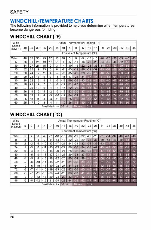
WINDCHILL/TEMPERATURE CHARTSThe following information is provided to help you determine when temperatures become dangerous for riding.
WINDCHILL CHART (°F)Wind
Speed in MPH
Actual Thermometer Reading (°F)
40 35 30 25 20 15 10 5 0 -5 -10 -15 -20 -25 -30 -35 -40 -45
Equivalent Temperature (°F)
Calm 40 35 30 25 20 15 10 5 0 -5 -10 -15 -20 -25 -30 -35 -40 -455 36 31 25 19 13 7 1 -5 -11 -16 -22 -28 -34 -40 -46 -52 -57 -6310 34 27 21 15 9 3 -4 -10 -16 -22 -28 -35 -41 -47 -53 -59 -66 -7215 32 25 19 13 6 0 -7 -13 -19 -26 -32 -39 -45 -51 -58 -64 -71 -7720 30 24 17 11 4 -2 -9 -15 -22 -29 -35 -42 -48 -55 -61 -68 -74 -8125 29 23 16 9 3 -4 -11 -17 -24 -31 -37 -44 -51 -58 -64 -71 -78 -8430 28 22 15 8 1 -5 -12 -19 -26 -33 -39 -46 -53 -60 -67 -73 -80 -8735 28 21 14 7 0 -7 -14 -21 -27 -34 -41 -48 -55 -62 -69 -76 -82 -8940 27 20 13 6 -1 -8 -15 -22 -29 -36 -43 -50 -57 -64 -71 -78 -84 -9145 26 19 12 5 -2 -9 -16 -23 -30 -37 -44 -51 -58 -65 -72 -79 -86 -9350 26 19 12 4 -3 -10 -17 -24 -31 -38 -45 -52 -60 -67 -74 -81 -88 -9555 25 18 11 4 -3 -11 -18 -25 -32 -39 -46 -54 -61 -68 -75 -82 -89 -9760 25 17 10 3 -4 -11 -19 -26 -33 -40 -48 -55 -62 -69 -76 -84 -91 -98
Frostbite in >> 30 min. 10 min. 5 min.
WINDCHILL CHART (°C)Wind
Speed in Km/h
Actual Thermometer Reading (°C)
5 2 -1 -4 -7 -10 -13 -16 -19 -22 -25 -28 -31 -34 -37 -40 -43 -46
Equivalent Temperature (°C)
Calm 5 2 -1 -4 -7 -10 -13 -16 -19 -22 -25 -28 -31 -34 -37 -40 -43 -468 3 0 -4 -7 -11 -14 -18 -22 -25 -29 -32 -36 -39 -43 -46 -50 -53 -5716 2 -2 -6 -10 -13 -17 -21 -24 -28 -32 -36 -39 -43 -47 -50 -54 -58 -6224 1 -3 -7 -11 -15 -19 -22 -26 -30 -34 -38 -42 -45 -49 -53 -57 -61 -6532 0 -4 -8 -12 -16 -20 -24 -28 -32 -36 -39 -43 -47 -51 -55 -59 -63 -6740 -1 -5 -9 -13 -17 -21 -25 -29 -33 -37 -41 -45 -49 -53 -57 -61 -65 -6948 -1 -5 -9 -13 -18 -22 -26 -30 -34 -38 -42 -46 -50 -54 -58 -62 -66 -7056 -2 -6 -10 -14 -18 -22 -26 -31 -35 -39 -43 -47 -51 -55 -59 -64 -68 -7264 -2 -6 -10 -15 -19 -23 -27 -31 -35 -40 -44 -48 -52 -56 -61 -65 -69 -7372 -2 -7 -11 -15 -19 -23 -28 -32 -36 -40 -45 -49 -53 -57 -61 -66 -70 -7480 -3 -7 -11 -15 -20 -24 -28 -33 -37 -41 -45 -50 -54 -58 -62 -67 -71 -7588 -3 -7 -12 -16 -20 -24 -29 -33 -37 -42 -46 -50 -55 -59 -63 -67 -72 -7696 -3 -8 -12 -16 -21 -25 -29 -34 -38 -42 -47 -51 -55 -60 -64 -68 -73 -77
Frostbite in >> 30 min. 10 min. 5 min.
26
SAFETY

SAFETY LABELS AND LOCATIONSWarning labels are placed on the snowmobile for your protection. Read and follow the instructions of the labels and warnings on the snowmobile carefully. If any of the labels depicted in this manual differ from the labels on your snowmobile, always read and follow the instructions of the labels on the snowmobile.If any label becomes illegible or comes off, contact your POLARIS dealer to purchase a replacement. Replacement safety labels are provided by POLARIS at no charge. The part number is printed on the label.
NO PASSENGER WARNING (ONE RIDER MODELS)The No Passenger Warning/Fuel Recommendation label q is located below the steering post.WARNING This vehicle is designed for operator only. NO PASSENGER. Fuel Recommended: 91+ Octane Without Ethanol. For Maximum Performance See Decal On Left Hand Side Panel For Proper Gauge Setting.
REVERSE WARNINGThe Reverse Warning label w is located on either side of the operator seat. WARNING Reverse operation, even at low speeds, can cause loss of control resulting in serious injury or death. To avoid loss of control, always:
• Look behind before and while backing up.
• Avoid sharp turns.• Shift to or from reverse only when
stopped.• Apply throttle slowly.
NOTE: For more information, see Owner’s Manual.
If electric reverse:
• Machine stopped and engine at idle, push yellow button on LH control to reverse. Flashing light on dash indicates reverse operation.
• Push button again to return to forward.
27
SAFETY

TUNNEL WARNINGThe Tunnel Warning label is located on the rear of the tunnel.WARNING
Hot SurfaceDo Not TouchBurn may result. Entire top of tunnel may be hot. Install only accessories specifically approved for this model by Polaris.
WARNINGStay clear of track. Do not sit on seat back. Entanglement with the track or a fall from seat back can result in severe injury or death.
MAX. 25 lbs.
CLUTCH WARNING/BELT REMOVALThe clutch warning label e is found on the oil bottle:WARNING
Do not operate engine with hood or side panels open.Do not attempt adjustment with engine running.Do not operate engine with the clutch guard removed.Never run engine with drive belt removed.Never service clutches yourself. Your dealer can perform this service.
BELT REMOVAL - ALL UNITS
1. For electric reverse models, engine must be stopped in forward to allow clutch opening.
2. Install L-wrench from fender into the open threaded hole in the driven clutch.
3. Turn the L-wrench clockwise to open the sheaves and replace the belt. Return the L-wrench to the fender.
SEE OWNER’S MANUAL FOR SHEAVE WIDTH ADJUSTMENT PROCEDURE.
28
SAFETY

OPERATION WARNINGThe operation warning label is located on the console.WARNING
• To avoid serious injury or death, read and understand all warnings and the Owner's Manual before operation. If manual is missing, contact a POLARIS dealer for a replacement.
• This vehicle is capable of high speeds. Buried objects or uneven terrain can cause loss of control. Reduce speed and use extreme caution when operating in unfamiliar terrain.
• Excessive speed, especially at night or with limited visibility, can result in insufficient time for you to react to terrain changes, to avoid unexpected obstacles, or to stop safely.
• Never consume alcohol or drugs before or while operating this vehicle.• In an emergency, push down the Auxiliary Shut-Off Switch, located on the top
of the throttle control assembly, to stop the engine. Then pull the brake lever to stop.
• Always wear an approved helmet, eye protection, and adequate clothing while operating this vehicle.
• This vehicle is designed for adult use only. Check local laws for age requirements.
• When operating with a passenger (on approved models only) reduce speed and allow extra space for steering and stopping. A passenger reduces your ability to control the vehicle.
• When operating on hard-packed snow, ice, or when crossing roads, steering and braking ability are greatly reduced. Reduce speed and allow extra space to turn or stop.
• To maintain vehicle control on ice or hard-packed surfaces, you should have a proper balance of ski carbides to track studs. See Owner's Manual for proper use of traction products.
• Repeated stops from high speed may cause fading or sudden loss of braking ability.
• Parking brake may relax when used for long periods. Do not leave brake engaged for more than five minutes.
• Before starting engine, check throttle, brake, and steering for proper operation. Make sure hood and side panels are latched. Be seated and in position to control the vehicle.
Oil injection system: Use unmixed fuel only. Check oil level when refueling.
29
SAFETY

30

FEATURESCOMPONENT LOCATIONS
NOTEThe figures below are for reference only. Your model may differ slightly.
q Skis i Operator Seat h Independent Front Suspension
w Nosepan o Taillight j Side Panel
e Front Bumper a Rear Bumper k Torsion Spring
r Hood s Snow Flap l Rear Track Shock
t Headlight d Upper Control Arm 1( Front Track Shock
y Windshield (accessory) f Lower Control Arm 2) Rail
u Handlebar g Spindle
31
FEATURES

CONTROLSNOTE
The figures below are for reference only. Your model may differ slightly.
q Brake Leverw Parking Brake Locke Ignition Switchr Instrument Clustert Engine Stop Switchy Throttle Controlu Recoil Starter Handlei Handlebar Grip Warmer Switcho Thumb Warmer Switcha Electronic Reverse Buttons Headlight Dimmer Switchd MODE/SET Switch
32
FEATURES

IGNITION SWITCHOFF Vehicle / PIDD power offRUN Vehicle / PIDD power onSTART Activates starter motor (if equipped)
The ignition switch has three positions: OFF, RUN, and START.
If equipped with electric start, turn the key to START to crank the engine. When the key is released, it automatically returns to the RUN position.
NOTEIf the key remains in the RUN position after using the engine stop switch to stop the engine, the PIDD (POLARIS Interactive Digital Display) remains
active. The PIDD screen will turn off after several minutes of inactivity, but if a battery is installed, the PIDD will continue to draw a small amount of current
from the battery until the key is turned off. This feature is useful for accessing the PIDD without starting the engine, but turn the key off when the PIDD is not
in use.The PIDD is not dependent on a battery while the engine is running, but a battery (if installed) supplies a constant power source when the engine is
turned off or when the engine is transitioning between forward and reverse operation. If a battery is not installed, the PIDD reboots when the engine is
started and when electronic reverse (PERC) is used.
33
FEATURES

12-VOLT DC POWER RECEPTACLEIf equipped, the 12-volt DC power receptacle is located on the hood next to the instrument cluster. The 12-volt power receptacle is protected by a 2 amp mini blade fuse located in the protective bag above the clutch cover. Use of the 12-volt DC power receptacle is recommended for connecting power- sensitive devices such as GPS units and cell phones.
NOTEThe 12-volt DC power receptacle and the jumper harness required to connect
the receptacle to the hood wiring harness can be purchased from your POLARIS dealer.
12-VOLT RCA POWER SOURCESSome rider accessories require the use of an RCA power adapter. If your model is not equipped with an RCA power plug on the handlebar cover, an accessory 12-volt RCA adapter or RCA power plug can be purchased from your POLARIS dealer.
12-VOLT RCA ADAPTERThe RCA adapter can be used if your model is equipped with the 12-volt DC power receptacle. Plug the adapter into the receptacle to convert it to a 12-volt RCA power outlet.
12-VOLT RCA POWER PLUGThe RCA power plug (with cover) mounts to the handlebar cover and is plugged into the main vehicle wire harness. Installation instructions are provided with the accessory. This power point is powered by the load shed relay and is not fuse protected. POLARIS recommends using this power point for electric helmet shields.
34
FEATURES

ADJUSTABLE HEADLIGHTNOTE
The image below is for reference only. Your model may differ slightly.
The headlight can be adjusted for vertical aim using the following procedure.
1. In a well-ventilated area, position the snowmobile on a level surface with the headlight approximately 25 feet (7.6 m) from a wall q.
2. Place the rider or the approximate weight of the rider on the seat or tunnel floorboards.
3. Measure the distance from the floor to the center of the headlight and make a mark on the wall at the same height.
4. Start the engine. Move the headlight switch to high beam.
5. Observe the headlight aim on the wall. The most intense part of the headlight beam should be two inches (5 cm) w below the mark on the wall.
6. If adjustment is necessary, access the headlight adjuster knob through the left side panel. Turn the adjuster knob clockwise to lower the beam. Turn the adjuster counter-clockwise to raise the beam.
35
FEATURES

TOOLSThe belt removal L-wrench tool, spare belt, spark plug, and spark plug tool container are located behind the left engine compartment panel.
NOTESpare belt and spark plugs are not provided with the snowmobile.
L-WRENCHWhen properly engaged in the bracket, the L-wrench secures the fender to the console. To retrieve the L-wrench, rotate it counter-clockwise and slide it upward from the bracket. Return the L- wrench to the bracket and rotate it clockwise when it’s not in use.
SPARK PLUG WRENCHThe spark plug wrench secures the spare belt/spark plug tool container to the front bumper. Remove the container to add or access a spare spark plug or belt.
REPLACEMENT DRIVE BELTTo insert a replacement drive belt into the spare drive belt container, do the following:
1. Rotate the spark plug wrench counter-clockwise to release it from the bracket.
2. Pull the wrench upward to remove it.
3. Tilt the container until the bracket detaches from the bumper tube.
4. Pull the container out of the compartment.
5. When placing a drive belt into the container, fold the belt as shown. Verify that the belt loop at the rear of the container is positioned slightly higher than the front loop.
6. Slide the container into the engine compartment at an angle.
7. Position the container bracket onto the bumper tube and rotate it downward.
8. Reinstall the spark plug wrench into the bracket and through the hole in the bumper tube.
9. Rotate the spark plug wrench clockwise until it locks into place.
36
FEATURES

RAIL SCRATCHERSSome models are equipped with rail scratchers to help prevent overheating when riding on ice or hard-packed snow.
NOTICEDo not install accessory bogie wheels on the inside of the rail beams if your model is equipped with a remote reservoir rear track shock or damage will
occur. The rail scratchers must be removed as they interfere with the accessory bogie wheels.
DETONATION ELIMINATION TECHNOLOGY (DET)When DET senses and takes action to reduce detonation, the driver may notice a drop in engine RPM and/or reduced performance.The ECU will illuminate the check engine LED and display “DETONATION” on the LCD screen whenever the DET system is active.
If the ECU determines the detonation cannot be controlled by normal means, and further operation may cause engine damage, the check engine LED will flash, the instrument clusters will display “DETONATION” and the ECU will either limit the maximum engine speed or turn off the engine.
If the ECU limits RPM, the limit will remain active until the driver stops and restarts the engine.
DETONATION PROTECTION MODES
Check Engine LED/Gauge Display Protection Mode
LED illuminated / “DETONATION” displayed
Slight drop in engine RPM/power
LED flashing / “DETONATION” displayed Exhaust valves close to reduce engine RPM/power. Restart engine to reset.
NOTEThe instrument cluster alert indicates which cylinder is experiencing detonation
NOTEThe most likely causes of severe detonation are outlined in the troubleshooting
table below.
37
FEATURES

OIL PUMP FAILURE PROTECTION (IF EQUIPPED)If the ECU determines there is a problem with the electronic oil pump control circuit, the engine management system will limit engine speed to approximately 4000 RPM and illuminate the check engine indicator light on the instrument cluster or PIDD.
EXTENDED IDLE ENGINE SHUTOFFThis engine feature causes the ECU to shut down the engine when engine temperature reaches 120° F (50° C) and there is no throttle lever input for five minutes.
NOTEIf equipped with an PIDD, the gauge will remain on because the key is in the
ON position.
SECURITY SYSTEM (IGNITION LOCK SYSTEM)Your snowmobile has an optional security function that can be activated by an authorized POLARIS dealer. If you have this feature activated, you can lock the ignition to prevent unauthorized use when leaving the snowmobile unattended. A locked system will limit engine speed to 3000 RPM, which prevents clutch engagement, and the snowmobile will not move when throttle is applied.If your model is equipped with the POLARIS Interactive Digital Display (PIDD), please see the PIDD Owner’s Manual provided with your snowmobile.
38
FEATURES

GAUGESTANDARD INSTRUMENT CLUSTER
q Check Enginew Engine Hote Low Oilr Low Battery Voltaget Playback
y Low Fuelu High Beami Parking Brakeo Reversea Security
NOTICECertain products will damage the lens and other plastic surfaces. Do not use
alcohol to clean the instrument cluster. Immediately clean off any gasoline that splashes on the instrument cluster.
The instrument cluster contains indicator lights and the rider information center. The information center can be controlled by either the MODE and SELECT buttons on the instrument cluster or by the MODE/SET switch s on the Left Hand Control.
39
GAUGE

INDICATOR LAMPSINDICATOR CONDITION
This indicator appears if an EFI-related fault occurs. Do not operate the snowmobile if this warning appears. Serious engine damage could result. Your dealer can assist.
The over-temperature indicator will illuminate when the engine is overheating. Take action to cool the engine. The indicator will flash when engine temperature reaches critical levels. Stop the engine immediately.
The low oil indicator light may flicker at times due to oil movement in the bottle, but when the light comes on and remains on, add the recommended oil before further operation.
The low battery voltage indicator illuminates when the battery voltage is low.
The playback indicator illuminates when the gauge is in playback mode.
The low fuel indicator illuminates when fuel is low.
The high beam indicator illuminates when the lights are set to high beam.
The parking brake Indicator illuminates when the parking brake is engaged. It will also illuminate when the service brake is in use.
The reverse indicator flashes when the transmission is in reverse.
The security indicator illuminates when the security system is activated.
40
GAUGE

RIDER INFORMATION CENTERThe rider information center is located in the instrument cluster. The center displays vehicle speed, engine speed, odometer, resettable trip meters (2), total engine hours of operation, fuel level, engine temperature, and a diagnostic display mode.Setting changes must be made with the engine running or with the vehicle powered by an external DC power supply connector. The information center is set to display standard units of measurement for distance and temperature.
q Information Display Area - This area displays either engine speed or vehicle speed (whichever is not displayed in the speed display), engine temperature and maximum vehicle speed.
w Speed Display - The speed display area displays either vehicle speed or engine speed.
e Fuel Gauge - Not available on all models. The segments of the fuel gauge show the level of fuel in the fuel tank. When the last segment clears, a low fuel warning is activated. All segments including the fuel icon will flash. Refuel immediately.
NOTEThe low fuel indicator and fuel level gauge on the Standard Instrument Cluster
are not supported on models with a fuel level gauge on the fuel cap.
41
GAUGE

TIPIf the fuel icon fails to display, an open or short circuit has occurred in the fuel
sensor circuit. See your dealer.
r Odometer/Engine Hour Display - This area displays the odometer, Trip A, Trip B and engine hours.
INFORMATION DISPLAY AREAThis area displays either engine speed or vehicle speed (whichever is not displayed in the speed display), engine temperature, maximum vehicle speed, and speed or RPM. To change the display, press and release the MODE button or the MODE switch until the desired item is displayed.
SPEED DISPLAY AREAThe speed display area displays either vehicle speed or engine speed. Vehicle speed is displayed in either miles per hour (MPH) or kilometers per hour (km/h). Engine speed is displayed in revolutions per minute (RPM).
1. To change which item displays, first make sure the information display area is set to display either engine speed or vehicle speed.
2. Press and release the center button.
FUEL GAUGE (IF EQUIPPED)The segments of the fuel gauge show the level of fuel in the fuel tank. When the last segment clears, a low fuel warning is activated. All segments including the fuel icon will flash. Refuel immediately.
NOTEThe low fuel indicator and fuel level gauge on the Standard Instrument Cluster
are not supported on models with a fuel level gauge on the fuel cap.
TIPIf the fuel icon fails to display, an open or short circuit has occurred in the fuel
sensor circuit. See your dealer.
ODOMETER/ENGINE HOUR DISPLAY AREAThis area displays the odometer, Trip 1 meter, Trip 2 meter, CLOCK, and Engine Hours meter.The odometer displays the total distance traveled by the vehicle since manufacture. Each trip meter records the distance traveled by the vehicle on a trip if the meter is reset before each trip. The CLOCK displays the time, and the
42
GAUGE

engine hour meter displays the total hours the engine has been in operation since manufacture.
To change the display, press and release the SET button or SET switch until the desired item is displayed.
To reset a trip meter, press and hold the SET button or SET switch until the meter resets to zero.
PLAYBACK FUNCTIONThe playback function allows the rider to record and play back engine speed, vehicle speed and throttle position sensor information for up to three minutes.
TO RECORD1. Press and hold the center button on the instrument cluster to enter the
Options Menu.
2. Press and release the MODE button until PLAYBACK appears in the information display area.
43
GAUGE

3. Press and release the SET button.
RECORD will appear in the information display area.
4. To begin recording, Press and release the SET button.
The playback indicator will flash while recording is in progress. Recording is complete when the light stops flashing.
NOTETo stop recording at any time during the recording process, press and release
the SET button.
44
GAUGE

TO PLAYBACK1. To play back the recorded data, stop the vehicle and wait for engine speed to
drop below clutch engagement.
2. Press and hold the center button on the instrument cluster to enter the Options Menu.
3. Press and release the MODE button until PLAYBACK appears in the information display area.
4. Press and release the SET button twice.
PLAY will appear in the information display area.
5. Press and release the SET button to play the recorded data.
Once playback has concluded, REPLAY will appear in the information display area.
6. Press and release the SET button to REPLAY recorded data.
7. Press and release the MODE button to end playback and return to the Options Menu.
45
GAUGE
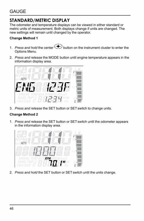
STANDARD/METRIC DISPLAYThe odometer and temperature displays can be viewed in either standard or metric units of measurement. Both displays change if units are changed. The new settings will remain until changed by the operator.Change Method 1
1. Press and hold the center button on the instrument cluster to enter the Options Menu.
2. Press and release the MODE button until engine temperature appears in the information display area.
3. Press and release the SET button or SET switch to change units.
Change Method 2
1. Press and release the SET button or SET switch until the odometer appears in the information display area.
2. Press and hold the SET button or SET switch until the units change.
46
GAUGE

SECURITY SYSTEM (IGNITION LOCK SYSTEM)This system is an optional feature and will not function until it has been activated by your authorized POLARIS dealer. If you have this feature activated, you can lock the ignition to prevent unauthorized use when leaving the snowmobile unattended. A locked system will limit engine speed to 3000 RPM, which prevents clutch engagement, and the snowmobile will not move when throttle is applied.If you wish to use this feature, you must complete all four tasks on the following pages to have your system activated and to change the security code to one of your own choosing.
FIRST TIME USE OF YOUR SECURITY SYSTEMPerform all tasks in the order shown if you wish to activate and use the optional security system.TASK 1: Activate the security systemSee your authorized POLARIS dealer to have the optional security system feature activated in the electronic control unit (ECU).
TASK 2: Lock the System the First Time
NOTETo lock the system for the first time, use code 000.
1. Press and hold the center button on the instrument cluster to enter the Options Menu.
2. Press and release the MODE button until SECURITY OFF appears in the information display area.
47
GAUGE

3. Press and release the SET button.
ENTER CODE will appear in the information display area.
4. Press and release the SET button to increase the 1st digit.
5. Press and hold the SET button to accept the 1st digit and advance to the 2nd digit.
6. Press and release the SET button to increase the 2nd digit.
48
GAUGE

7. Press and hold the SET button to accept the 2nd digit and advance to the 3rd digit.
8. Press and hold the SET button to accept the 3rd digit and submit code.
If code is correct, SECURITY ON will appear in the information display area. The system is now locked. Proceed immediately to Task 3.
If code is incorrect, BAD CODE will appear in the information display area. Return to step 3 to re-enter code.
49
GAUGE

TASK 3: Unlock the System
NOTETo unlock the system for the first time, use code 000.
1. While the engine is running, Press and release the SET button.
ENTER CO will appear in the information display area.
2. Press and release the SET button to increase the 1st digit.
3. Press and hold the SET button to accept the 1st digit and advance to the 2nd digit.
4. Press and release the SET button to increase the 2nd digit.
50
GAUGE

5. Press and hold the SET button to accept the 2nd digit and advance to the 3rd digit.
6. Press and release the SET button to increase the 3rd digit.
7. Press and hold the SET button to accept the 3rd digit and submit code.
If code is correct, SECURITY OFF will appear in the information display area
NOTEThe system is now unlocked.
If code is incorrect, BAD CODE will appear in the information display area. Return to step 1 to re-enter code.
8. You must now enter a new security code. Proceed immediately to TASK 4.
51
GAUGE

TASK 4: Enter Your New Security Code
1. Immediately after locking and unlocking the system, and while SECURE OFF is displayed, simultaneously press and hold the MODE and SET buttons.
SET NEW CODE will appear on the information display area.
2. Press and release the SET button to increase the 1st digit.
3. Press and hold the SET button to accept the 1st digit and advance to the 2nd digit.
4. Press and release the SET button to increase the 2nd digit.
5. Press and hold the SET button to accept the 2nd digit and advance to the 3rd digit.
52
GAUGE

6. Press and release the SET button to increase the 3rd digit.
7. Press and hold the SET button to accept the 3rd digit.
CODE SET will appear in the information display area, and then the new code will blink three times in the information display area
NOTEYour new code is now set. The system is NOT locked.
8. Record your new security code in a safe place for future reference.
Record your new personal security code here: __________________
TIPIf you lose your personal security code, see your dealer to have the code reset to “000”. Then perform TASK 2 through TASK 4 to change the code to one of
your own choosing.
53
GAUGE

LOCKING SYSTEM WITH PERSONAL SECURITY CODE1. Start the engine.
2. Press and hold the center button on the instrument cluster to enter the Options Menu.
3. Press and release the MODE button until SECURITY OFF appears in the information display area.
4. Press and release the SET button.
ENTER CODE will appear in the information display area.
5. Press and release the SET button to increase the 1st digit.
6. Press and hold the SET button to accept the 1st digit and advance to the 2nd digit.
54
GAUGE

7. Press and release the SET button to increase the 2nd digit.
8. Press and hold the SET button to accept the 2nd digit and advance to the 3rd digit.
9. Press and hold the SET button to accept the 3rd digit and submit code.
If code is correct, SECURITY ON will appear in the information display area. The system is now locked. Proceed immediately to Task 3.
If code is incorrect, BAD CODE will appear in the information display area. Return to step 3 to re-enter code.
55
GAUGE

UNLOCKING SYSTEM WITH PERSONAL SECURITY CODE1. While the engine is running, Press and release the SET button.
ENTER CODE will appear in the information display area.
2. Press and release the SET button to increase the 1st digit.
3. Press and hold the SET button to accept the 1st digit and advance to the 2nd digit.
4. Press and release the SET button to increase the 2nd digit.
5. Press and hold the SET button to accept the 2nd digit and advance to the 3rd digit.
56
GAUGE

6. Press and release the SET button to increase the 3rd digit.
7. Press and hold the SET button to accept the 3rd digit and submit code.
If code is correct, SECURITY OFF will appear in the information display area
NOTEThe system is now unlocked.
If code is incorrect, BAD CODE will appear in the information display area. Return to step 1 to re-enter code.
CHANGING TO A NEW SECURITY CODEAny time you wish to change your current security code to a new code, perform TASK 2 through TASK 4 of the First Time Use of Your Security System procedure. Instead of using the factory default code “000” in TASK 2 and TASK 3, use your current security code.
57
GAUGE

SECURITY SYSTEM ACCESS QUICK REFERENCENow that you have become familiar with the procedure for locking and unlocking the system, use the chart below as a quick reference.
SECURITY SYSTEM ACCESS QUICK REFERENCE CHART
Action Result
1. Start engine
2. Press and hold the center button
3. Press and release the SET button until SECURITY appears in information display area.
4. Press and release SET button.
Displays ENTER CODE (to lock the system)
Press and release the SET button
Advances a digit on the ENTER CODE screen
Press and hold the SET button
Accepts a digit and displays the next digit position (if any remain) on the ENTER CODE screen
While SECURITY OFF is shown on the information display area, simultaneously Press and hold the MODE and SET button.
Allows user to change security code.
58
GAUGE

DIAGNOSTIC DISPLAY MODEThe diagnostic display mode is for informational purposes only. Your POLARIS dealer can perform all major repairs.
The diagnostic mode is accessible only when the check engine warning indicator is illuminated and a diagnostic code is active.Do not stop the engine if you want to view the active code (failure code). Active codes cannot be retrieved if power is interrupted to the instrument cluster. The codes will become inactive codes if power is interrupted. Inactive codes are stored in the history of the unit. Please see your POLARIS dealer can help retrieve inactive codes.
Use the following procedure to view active codes.
1. Do not stop the engine.
2. Press and hold the center button on the instrument cluster to enter the Options Menu.
3. Press and release the MODE button until DIAGCODE appears in the information display area. The Diagnostic display mode will appear in the Options Menu if there is an active trouble code.
TIPWhen the diagnostic mode is displayed, the check engine warning indicator will
begin to flash.
4. A set of two numbers will appear in the display.• The 2-6 digit suspect parameter number (SPN) in the information display
area indicates which component is generating the fault code.• The 1-2 digit failure mode indicator (FMI) number in the odometer area
indicates the fault mode, such as open or short circuit.
5. More than one fault may be active. Press and hold the SET button or SET switch for two seconds to toggle to the next active code. Repeat until all codes are retrieved.
6. See Diagnostic Trouble Codes for code definitions and failure descriptions.
59
GAUGE

POLARIS INTERACTIVE DIGITAL DISPLAY (PIDD)The POLARIS Interactive Digital Display (PIDD) provides the rider with:
• Speedometer• Tachometer• Odometer• 2 Trip Meters• Fuel Level Indicator• Coolant Temperature• Battery Voltage• Fuel Type Selection• Vehicle Security• Gear Indicator
CAUTIONUse a microfiber hand towel to clean the LCD screen. Certain products will
damage the screen and other plastic surfaces. Do not use alcohol to clean the display screen. Immediately clean off any gasoline that splashes on the
instrument cluster.
NOTICEThe speedometer may give wrong values at the existence of electromagnetic
radiation >= 10 V/m.
The PIDD also offers GPS mapping and Bluetooth® connectivity for compatible smartphones/devices. This feature will display text messages and missed phone calls on the display screen. The PIDD sub- menus and most display features are controlled by either the five button keypad on the PIDD or by the MODE/SET q switch on the left hand control. Please see your PIDD Owner’s Manual for more information. This manual is frequently updated for accuracy and new features.
60
GAUGE

FUEL TYPE SELECTIONWhen using the recommended 91 non- ethanol gasoline, always select the 91 NON-ETHANOL setting. When using ethanol, MTBE, or other forms of oxygenated gasoline, the fuel type must be changed to NON-PREMIUM/ ETHANOL in the gauge.
IMPORTANTWhenever in doubt of your fuel purchase, use the NON-PREMIUM / ETHANOL
mode.
Use the following procedure to change the fuel type designation in the gauge. Refer to the fuel type selection label located inside the left side panel.
1. Start the engine.
2. Press and hold the center button to enter the Options Menu.
3. Press and release the MODE button until FUEL TYPE is displayed in the information display area.
4. Press and release the SET button to toggle through available options until the desired fuel type is displayed in the information display area.
5. To exit Options Menu, Press and release the MODE button until EXIT appears in the information display area.
6. Press and release the SET button to exit. The fuel type being displayed is the active fuel type.
POLARIS INTERACTIVE DIGITAL DISPLAY (PIDD)If your model is equipped with the POLARIS interactive digital display (PIDD), please see your PIDD Owner’s Manual for fuel type selection procedures.
61
GAUGE

ENGINE OVERHEAT INDICATORSOVER-TEMPERATURE INDICATOR (STANDARD CLUSTER)The over-temperature indicator on the standard instrument cluster will illuminate when the engine is overheating. Take action to cool the engine. See page 63. The indicator will flash when engine temperature reaches critical levels. Stop the engine immediately.
OVERHEAT WARNING (PIDD)The engine temperature scale q located on the right side of the PIDD screen changes to RED and the check engine temperature indicator w located on the top left of the screen illuminates when the engine is overheating. Take action to cool the engine. See page 63. The indicator will flash when engine temperature reaches critical levels. Stop the engine immediately.
Please see your PIDD Owner’s Manual for more information.
ENGINE TEMPERATURE PROTECTION MODES
Hot Lamp Threshold*
ON Lamp illuminates: Idle = 201° F (94° C), WOT = 185° F (85° C)
FLASHING Lamp Flashes, Engine Turns Off: Idle = 215.6° F (102° C), WOT = 201° F (94° C)
* Only the minimum (idle) and maximum (WOT) parameters are listed.
62
GAUGE

FLASHING INDICATORFlashing indicators indicate continued operation could result in serious engine damage. The engine management system will automatically reduce engine power and create a misfire condition. Stop the engine immediately. Allow the engine to cool down.
NOTEIf engine overheating seems to be caused by something other than poor
cooling conditions, your dealer can perform this service.
ENGINE-COOLING ACTIONSIf the engine is overheating, promptly take action to cool the engine.
• Drive in loose snow.• View the coolant level. Do not open the pressure cap while the engine is hot.• Stop the engine and allow it to cool down.• Add coolant if the level is low. Do not add coolant while the engine is hot. Wait
for the engine to cool before adding coolant.
NOTICEIf you must continue to operate while the indicator light is illuminated, drive
slowly and stop the engine frequently to allow it to cool down.
63
GAUGE

64

THE PERFECT FITSUSPENSION QUICK SET-UP GUIDEThe front and rear suspensions on your snowmobile are easy to adjust. Just remember three simple steps:Step 1: Ride your snowmobile.Ride the snowmobile in various terrain to fully experience the existing suspension settings before making any adjustments.
Step 2: Adjust the torsion spring to tune vehicle balance.After riding, you should be able to determine if the snowmobile needs more or less transfer.
• For more transfer, decrease the torsion spring preload. • For less transfer, increase the torsion spring preload.
If you prefer your snowmobile has lighter steering, decrease the torsion spring preload or increase the front track shock spring preload.
Step 3: Adjust shock clickers (if equipped) for ride quality.For models equipped with monotube shocks, always adjust the rear torsion spring preload to enhance bottoming resistance.
For models with shock clickers, you can adjust the clickers to control bottoming and adjust ride comfort.
• Turn a clicker counter-clockwise to decrease damping for a softer ride. • Turn a clicker clockwise to increase damping for a stiffer ride and less
bottoming.
NOTEAlways adjust the clicker at least one click below full stiff (full clockwise) or
shock damage could occur.
Test ride the snowmobile and continue making spring and clicker adjustments until you achieve the perfect ride.
NOTEAdding traction components, such as traction studs or additional ski skag carbides, or changing the factory equipped track, could change handling
characteristics. Addition setup may be required.
65
THE PERFECT FIT
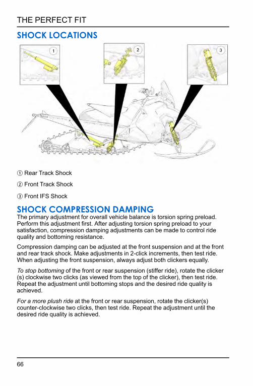
SHOCK LOCATIONS
q Rear Track Shock
w Front Track Shock
e Front IFS Shock
SHOCK COMPRESSION DAMPINGThe primary adjustment for overall vehicle balance is torsion spring preload. Perform this adjustment first. After adjusting torsion spring preload to your satisfaction, compression damping adjustments can be made to control ride quality and bottoming resistance.Compression damping can be adjusted at the front suspension and at the front and rear track shock. Make adjustments in 2-click increments, then test ride. When adjusting the front suspension, always adjust both clickers equally.
To stop bottoming of the front or rear suspension (stiffer ride), rotate the clicker (s) clockwise two clicks (as viewed from the top of the clicker), then test ride. Repeat the adjustment until bottoming stops and the desired ride quality is achieved.
For a more plush ride at the front or rear suspension, rotate the clicker(s) counter-clockwise two clicks, then test ride. Repeat the adjustment until the desired ride quality is achieved.
66
THE PERFECT FIT

TORSION SPRING ADJUSTMENTS
To adjust rear torsion spring preload, rotate the three-position cam q using the engine spark plug tool. Adjustment is easiest when the cam is rotated from low to medium, and then to high. Rotating directly from low to high will require significantly more effort. Different rate torsion springs are available if a firmer ride is desired. See your dealer for more information.
NOTEAdding 1+1 seat, or additional cargo may affect handling and require a spring
rate change.
TORSION SPRING SETTING
RECOMMENDED USAGE
Low Rider(s) and gear =140-180lbIf less than 140, use the optional spring chart for softer springs.
Medium Rider(s) and gear = 180-220lb
High Rider(s) and gear = 220-260lbIf above 260, use the optional spring chart for heaver springs.
67
THE PERFECT FIT

OPTIONAL SPRINGSPART NUMBER SPRING TYPE DESCRIPTION
7041942–329 Spring, Torsion .375/77, BLK, LH, HEAVY
7041943–329 Spring, Torsion .375/77, BLK, RH, HEAVY
7041627–067 Spring, Torsion .347/77, BLK, LH, LIGHT
7041628–067 Spring, Torsion .347/77, BLK, RH, LIGHT
OPTIONAL SPRINGS (INDY SP/XC/XCR)If the correct balance cannot be obtained by adjusting the stock springs, please install the appropriate optional heavy or light springs listed below.
PART NUMBER SPRING TYPE DESCRIPTION
7043859–329 Spring, Torsion LH Light Duty
7043860–329 Spring, Torsion RH Light Duty
7045207–329 Spring, Torsion LH Heavy Duty
7045208–329 Spring, Torsion RH Heavy Duty
7045209–329 Spring, Torsion LH Extra Heavy Duty
7045210–329 Spring, Torsion RH Extra Heavy Duty
FRONT TRACK SHOCK SPRING SETTINGS (INDY MODELS)Factory settings, combined with user adjustments to the rear torsion spring, should be all that’s necessary to provide the best riding experience for most riders. The primary adjustment for overall vehicle balance is the rear torsion spring preload. Perform this adjustment first.Always perform shock spring preload adjustments with the weight of the vehicle removed from the shock and with the shock at full extension.
NOTICENever adjust spring preload to an installed length longer than the factory length or shorter than the minimum length as shown in the following chart. Damage to the suspension could result. When decreasing preload, make sure at least two
turns of preload are holding the retainer against the spring.
68
THE PERFECT FIT

INDY SP INDY XC
FRONT TRACK SHOCK SPRING SETTINGSFACTORY SPRING MAXIMUM INSTALLED
LENGTHMINIMUM INSTALLED
LENGTH
INDY SP 1.25" (3.2 cm) 0.75" (1.9 cm)
INDY XC 1.88" (4.8 cm) 1.38" (3.5 cm)
INDY XCR 2.12" (5.4 cm) 1.62" (4.1 cm)
FRONT TRACK FACTORY CLICKER SETTINGSMODEL CLICKER SETTING
(FROM FULL HARD)
INDY SP N/A
INDY XC 5
INDY XCR Low: 6High: 5
69
THE PERFECT FIT

FRONT TRACK SHOCK SPRING SETTINGS (SWITCH-BACK ASSAULT/SKS MODELS)Factory settings, combined with user adjustments to the rear torsion spring, should be all that’s necessary to provide the best riding experience for most riders. The primary adjustment for overall vehicle balance is the rear torsion spring preload. Perform this adjustment first.Always perform shock spring preload adjustments with the weight of the vehicle removed from the shock and with the shock at full extension.
NOTICENever adjust spring preload to an installed length longer than the factory length or shorter than the minimum length as shown in the following chart. Damage to the suspension could result. When decreasing preload, make sure at least two
turns of preload are holding the retainer against the spring.
FRONT TRACK SHOCK SPRING SETTINGSFACTORY SPRING MAXIMUM
INSTALLED LENGTHMINIMUM INSTALLED
LENGTH
Switchback ASSAULT
SKS 146
1.25" (3.2 cm) 1" (2.5 cm)
Switchback SP 2" (5 cm) 1.75" (4.5 cm)
600 RMK 144 Not Adjustable Not Adjustable
600 Voyageur Not Adjustable Not Adjustable
70
THE PERFECT FIT

FRONT TRACK FACTORY CLICKER SETTINGSMODEL CLICKER SETTING
(FROM FULL SOFT)
Switchback ASSAULT 2
SKS 146 2
REAR TRACK SHOCK FACTORY CLICKER SETTINGSINDY XC MODELS
MODEL FACTORY CLICKER SETTING(FROM FULL STIFF)
Indy XC 5
71
THE PERFECT FIT

SWITCHBACK ASSAULT/SKS MODELS
MODEL CLICKER SETTING(FROM FULL SOFT)
Switchback Assault 8
SKS 146 8
72
THE PERFECT FIT

REAR REAR SCISSOR STOP (RRSS) (IF EQUIPPED)The rear rear scissor stop (RRSS) couples the movement of the rear torque arm with the front torque arm and limits the amount of independent movement between the rear torque and the front torque arm.Adjusting the RRSS either allows more weight to transfer to the rear for more traction, or allows less weight to transfer to the rear, resulting in improved cornering performance. An adjustment dot is located on the RRSS. This dot is on the longest end of the scissor stop.
REAR REAR SCISSOR STOP (RRSS) - ATTRIBUTESMoving the RRSS to a higher position will have the following effects on the suspension: • Reduced weight transfer• Improved chatter bump ride• Improved cornering performance• Increased load carrying capacity (2–up)
WEIGHT TRANSFER DURING ACCELERATIONThe preferred method for controlling weight transfer during acceleration is by adjusting the rear rear scissor stop. Use the scissor stop tool located in your tool kit it make the adjustments.
To decrease weight transfer under acceleration (for improved cornering), rotate the stop to a higher position.
To increase weight transfer or ski lift during acceleration, move the stop to the rearward upper position. The stop may also be rotated to a lower position for even more weight transfer if desired.
Low Position — This setting will increase weight transfer
Medium Position — This setting is the production setting and will provide the best overall trail riding
High Position — This setting will decrease weight transfer
Rearward Upper Position (optional hole location) — This setting will increase weight transfer
73
THE PERFECT FIT

High Low Medium Low
The preferred method for controlling weight transfer during acceleration is by adjusting the rear rear scissor stop (RRSS) q. The factory setting is the best for most trail riding conditions.
To decrease weight transfer under acceleration (for improved cornering), rotate the RRSS to a higher position.
To increase weight transfer or ski lift during acceleration, rotate the RRSS to a lower position.
TIPYour dealer can help you with initial setup and additional setup instructions to help you achieve your optimum ride. A scissor stop tool is also available from
your dealer.
74
THE PERFECT FIT

FRONT SUSPENSION (IFS) SHOCK ADJUSTMENTS (IF EQUIPPED)Always perform shock spring preload adjustments with the weight of the vehicle removed from the shock and with the shock at full extension.
To reset IFS clickers, rotate the clicker to full stiff, and then back off the same number of clicks for each shock.
IFS SHOCK SPRING SETTINGSFACTORY SPRING FACTORY INSTALLED
LENGTHMINIMUM INSTALLED
LENGTH
INDY SP 10.75” (27.3 cm) 10” (25.4 cm)
INDY XC 10” (25.4 cm) 10” (25.4 cm)
INDY XCR 9.75” (24.8 cm) 9.25” (23.5 cm)
Switchback ASSAULT 10” (25.4 cm) 9.5” (24 cm)
SKS 146 10” (25.4 cm) 9.5” (24 cm)
Switchback SP 10” (25.4 cm) 9.5” (24 cm)
600 RMK 144 10.5” (26.7 cm) 10” (25.4)
600 Voyageur 10.5” (26.7 cm) 10” (25.4)
75
THE PERFECT FIT

IFS REMOTE RESERVOIR SHOCK FACTORY CLICKER SETTINGS
MODEL CLICKER SETTING(FROM FULL HARD)
INDY SP N/A
INDY XC 12
INDY XCR Low: 6High: 5
Switchback ASSAULT 6
SKS 146 6
CORNERING ADJUSTMENTSTo improve cornering ability, remove up to 1/2" of preload from factory IFS spring setting. Trade-off for removing 1/2" of preload will add steering effort.
LIMITER STRAP ADJUSTMENTThe front torque arm limiter strap is set at position q.POLARIS recommends leaving the limiter strap length at position q to maintain the optimum ride characteristics of the snowmobile. Riders who desire less ski pressure and more weight transfer toward the rear of the snowmobile can lengthen the limiter strap by changing to position w.
1. Loosen the lock nut.
2. Adjust the limiter strap.
3. Tighten the lock nut.
TORQUE16 ft-lbs (21 Nm).
76
THE PERFECT FIT

HANDLE BAR EXAMPLESHANDLEBAR COMPONENT FASTENER TORQUES
IMPORTANTMoving a handlebar component without first loosening its screws/set screws
may cut grooves into the handlebar, making it difficult to secure the component. Do not move a handlebar component without first loosening its
mounting screws/set screws. Take care to avoid damaging hand warmer/brake switch wires when moving components.
COMPONENT TORQUE DO NOT OVER-TIGHTEN
q Left Handlebar Control Block 20 in-lbs (2.3 Nm)
w Brake Lever / Master Cylinder Torque the front screw first, then torque the screw next to the reservoir.
70 in-lbs (7.9 Nm)
e Upper / Lower Riser Clamps 14.8 ft-lbs (20 Nm)
r Throttle Lever Block Set Screw 27 in-lbs (3.1 Nm)
t Throttle Lever Block Cover Screws 6 in-lbs (0.7 Nm)
y Auxiliary Engine Stop Switch Set Screw 12 in-lbs (1.4 Nm)
u Riser Install with the “FWD” stamp facing toward the hood
77
THE PERFECT FIT

COMPONENT TORQUE DO NOT OVER-TIGHTEN
Not Shown
Hand Guard Mounts (if applicable) Hand-Tight
Not Shown
Mountain Hoop Bar (if applicable) 10 ft-lbs (13.6 Nm)
HANDLEBAR ANGLE
Handlebar angle can be adjusted to suit rider preference.
1. Loosen the four bolts on the top riser block q.
2. Adjust the handlebar upward or downward to the desired angle. Be sure the handlebar, brake lever and throttle lever operate smoothly and do not hit the gas tank, windshield or any other part of the machine when turned fully to the left or right. If necessary, loosen the set screws for the left and right controls, rotate the controls slightly, then tighten the set screws to the proper torque.
NOTICEDo not stretch wires while adjusting the controls. Stretching the wires could
damage the handwarmers.
3. Tighten the bolts.
TORQUE14.8 ft-lbs (20 Nm)
78
THE PERFECT FIT

RISER ANGLERiser angle can be adjusted to suit rider preference.
1. Loosen the four bolts on the bottom of the adjuster block w. If necessary, pry the blocks apart with a screwdriver.
2. Adjust the riser forward or rearward to the desired position.
3. Tighten the bolts to 14.8 ft-lbs (20 Nm).
ADJUSTABLE RISER (IF EQUIPPED)To adjust the riser (if equipped), do the following:
1. Release the riser clamp q.
2. Adjust the handlebar upward or downward to the desired height.
3. Secure the riser clamp q.
Periodically inspect the torque of the upper/lower handlebar clamp fasteners, and slide fasteners.
TORQUEHandlebar Clamp Fastener Torque:
16 ft-lbs (21 Nm)ROX Slide Fastener Torque:
16 ft-lbs (21 Nm)Adjuster Cranks:
Hand Tight
79
THE PERFECT FIT

LEFT HAND CONTROL ALIGNMENT1. Loosen the brake master cylinder A mounting screws and move it away from
the left hand control B.
CAUTIONTake care to avoid damaging hand warmer/brake switch wires when moving
components.
2. Loosen the four left hand control mounting screws.
3. Move the control block to the desired position.
NOTEIf the control is loose and was inadvertently moved without loosening the
screws, move the control block slightly to the left or right to relocate the pins.
80
THE PERFECT FIT

4. Tighten the screws to specification in the sequence shown in the image. Do not over-torque.
TORQUE24 in-lbs (2.7 Nm)
5. Return the master cylinder to its specified position. Make sure the clamp will not pinch the brake light signal wire. Tighten the clamp screws to specification beginning with the front screw first, then the screw next to reservoir. Do not over-torque.
TORQUE70 in-lbs (7.9 Nm)
HANDLEBAR COMPONENTSRefer to the following illustration and measurements to position handlebar components at factory-specified locations.
q .011 in. (3 mm)w 6.65 in. (169 mm)e 6.7 in. (170 mm)
r 10 in. (254 mm)t .47 in. (12 mm)y .08 in. (2 mm)
81
THE PERFECT FIT

THROTTLE BLOCK ALIGNMENTNOTICE
Take care to avoid damaging hand warmer wires when moving components.
1. Slightly loosen the set screw q on the bottom of the housing.
2. Move the control block to the desired position.
3. Tighten the screw to specification. Do not over-torque.
4. With the engine off, test throttle lever movement after tightening the screw. See page 99.
TORQUE27 in-lbs (3 Nm)
ENGINE STOP SWITCH ALIGNMENTCAUTION
The stop switch must be positioned in an easily accessible location.
1. Slightly loosen the set screw on the bottom of the housing w.
2. Move the switch to the desired position.
3. Tighten the screw to specification. Do not over-torque.
TORQUE12 in-lbs (1.4 Nm)
82
THE PERFECT FIT

TRACTION PRODUCTSTRACK STUDDINGTrack studding will enhance braking control on hard-packed snow or ice, but extreme caution is still required on such surfaces. Steering ability may be reduced on hard-packed snow or ice.When studded tracks are used, increased wear to the brake pads will result from increased braking and requires increased brake inspection intervals.
Installing studs can also cause the track to stretch more than a non-studded track. For this reason, POLARIS recommends inspecting track tension more often and setting the tension at the preferred measurement.
Always adhere to the manufacturer’s stud maintenance procedures and stud nut torque specifications.
Before equipping your snowmobile with traction products, be aware of regulations pertaining to the use of traction products in your area of operation.
83
THE PERFECT FIT

STUDSTrack damage resulting from improperly installed or maintained studs is not covered under warranty. Use only POLARIS-approved traction products on your snowmobile. See your dealer for more information about installing studs and/or carbides.
CAUTIONFailure to heed the following recommendations will result in tunnel or track
damage:
• Use of studs longer than the recommended length on snowmobiles equipped with center coolers will result in center cooler damage or damage to the tunnel.
• Aggressive studding patterns may require grinding protruding stud bolts flush to prevent idler wheel damage. Maintain track tension on studded tracks on the tight side of the specification to prevent heat exchanger damage. The center of the stud must be at least 1 1/8 inch (2.9 cm) from any edge of the track, including track window.
• Studding the outside band of the track diminishes durability.• Polaris does not recommend studs on the outside band of the Storm 150
track. Damage will occur.
The AXYS Indy 129 chassis requires stud protection kit 2883572 to be installed before installing studs or chassis damage will occur. This stud protection kit will protect against chassis damage with the following track/stud combinations.
• 1.325” Polaris/Woody’s studs installed in a Ripsaw II 1.25” or Cobra 1.352” track .
• 1.575” Polaris/Woody’s studs installed in a Storm 150 track, center band only.
84
THE PERFECT FIT

MAXIMUM PENETRATION
POLARIS Studs
Stud Length
1.25-Inch (3.2 cm)
Track
1.352-Inch (3.4 cm) Cobra Track
Overall Installed Height
Recom-mended for AXYS models
in. cm in. cm in. cm in. cm
Signature Series 1.325 3.4 .375 .95 .27 .7 1.58 4.0 YES
Signature Series 1.45 3.7 - - - - 1.7 4.3 NO
CARBIDE SKAGSA skag is a replaceable bar attached to the underside of the ski to assist in turning the snowmobile and to prevent ski wear caused by contact with roads and other bare terrain. Use carbide skags with studded tracks to help maintain proper steering and control. See page 132.Maintain a proper balance between the number of studs and the length of carbide on the skags (the more studs you use, the longer the carbide on the skags should be). See your dealer's track studding chart.
85
THE PERFECT FIT

86

PRE-RIDE INSPECTIONSPRE-RIDE CHECKLISTInspect all items on the checklist for proper operation or condition before each use of the snowmobile. Procedures are outlined in the referenced sections.
ITEM SEE SECTION
Drive Belt page 124
Steering System page 91
Recoil Rope page 92
Coolant Level page 116
Chaincase Oil Level (if equipped) page 108
Injection Oil Level page 98
Parking Brake Lock/Brake Lever/ Brake System
page 89, page 90, and page 120
Auxiliary Shut-Off Switch (Engine Stop Switch)
page 92
Ignition Switch page 33
Headlight/Taillight/Brakelight page 92
Suspension Mounting Bolts page 88
Skags (Wear Bars) page 132
Ski Saddle and Spindle Bolts page 88
Hood and Side Panel Fasteners page 112
Throttle Lever/Safety Switch page 89 and page 89
Rear Wheel Idler Bolt page 127
Tether Switch/Strap (if equipped) page 92
Track Alignment/Condition page 91 and page 129
Rail Slide Condition page 133
87
PRE-RIDE INSPECTIONS

PRE-RIDE SUSPENSION INSPECTIONLoose nuts and bolts can reduce your snowmobile's reliability and cause needless repairs and down time. Before beginning any snowmobile trip, a visual inspection will uncover potential problems. Check the following items on a weekly basis or before any long trip.
ITEM SEE SECTION
Check suspension mounting bolts for tightness.
-
Check rear idler wheel bolt for tightness.
page 127
Check rear idler adjusting bolt locknuts for tightness.
-
Check front torque arm limiter strap condition.
-
Check rail slide condition. page 133
Check track tension. page 127
Check ski runner/skag condition. page 132
Check ski spindle bolts for tightness. -
Check tie rod end nuts for tightness. -
88
PRE-RIDE INSPECTIONS

BEFORE STARTING THE ENGINEBefore starting the engine, always refer to all safety warnings pertaining to snowmobile operation. Never start the engine without checking all vehicle components to be sure of proper operation.
WARNINGOperating the vehicle with worn, damaged, or malfunctioning components
could result in serious injury or death. Never start the engine without checking all vehicle components to be sure of proper operation.
READ AND UNDERSTAND YOUR OWNER'S MANUALRead the Owner's Manual completely and refer to it often. The manual is your guide to safe and enjoyable snowmobiling experience.
THROTTLE LEVERThe throttle and brake are the primary controls of your snowmobile. Always make sure both are functioning properly.Squeeze the throttle lever to make sure it compresses evenly and smoothly. When released, the lever should immediately return to the idle position without binding or hesitation. If the throttle does not function smoothly, or if you discover excessive lever freeplay, DO NOT start the engine. Have the throttle serviced immediately.
THROTTLE SAFETY SWITCHTest the throttle safety switch system before the snowmobile is operated.
BRAKESAlways check the following items for proper operation before starting the engine.
BRAKE LEVER TRAVELSqueeze the brake lever. It should move no closer to the handgrip than 1/2 inch (1.3 cm) q. A smaller distance indicates low brake fluid level or air in the hydraulic system. Refer to the brake bleeding information in the Hydraulic Brake Inspection section. A dealer can assist.
89
PRE-RIDE INSPECTIONS

LEVER FEELIf the brake lever feels “spongy” when squeezed, check the brake fluid level and condition. Add fluid as needed. See the Brake Fluid section for details.
WARNINGContinued use of “spongy” brakes may cause a complete loss of brakes, which could result in serious injury or death. Always have the brakes serviced at the
first sign of sponginess.
PARKING BRAKE LEVER LOCKUse the parking brake lever lock only when you want the snowmobile to remain stationary; for example, when parked on an incline for a period of five minutes or less.
1. Brake Lever
2. Parking Brake Lever Lock
3. Master Cylinder Reservoir/Cover
LOCK ENGAGEMENTTo engage the lock, squeeze the brake lever tightly and push forward on the lock. Hold the lock forward while releasing the brake lever.
NOTEIf the brake lever is squeezed tightly enough, the lock will move freely into
place. Do not force the lock or it may break.
The parking brake light on the gauge will light up if the parking brake lever lock is set while the engine is running. It will also be lit when the service brake is in use. If the parking brake light does not come on when the parking brake or service brake is in use, have it serviced by your dealer.
90
PRE-RIDE INSPECTIONS

LOCK RELEASETo release the lock, squeeze the brake lever tightly. The lock will return to the unlocked position.
WARNINGIf the parking brake lever lock is partially or entirely engaged while riding, the brakes may overheat, resulting in brake damage. In extreme cases it could
cause a fire, which could result in serious injury or death. Always ensure that the lever lock is completely disengaged before operating the snowmobile.
STEERING SYSTEMWARNING
Ice and snow build-up may interfere with the steering of your snowmobile, resulting in serious injury or death. Keep the underhood area free of snow and
ice.
Before driving, manually turn the skis to the left and right to be sure ice and snow are not interfering with full left and right steering. If difficulty is encountered, remove ice and snow build-up that may be obstructing the steering linkage.
TRACKTrack damage or failure caused by operation on ice or poor lubrication conditions voids the track warranty.
WARNINGOperating the snowmobile with a damaged track increases the possibility of track failure, which could cause loss of control resulting in serious injury or
death. Always inspect the track for damage before using the vehicle.
WARNINGUse of traction products such as studs increases the possibility of track
damage and/or failure. Driving at high speeds for extended periods of time in marginal lubrication could severely damage track rods, break track edges, and
cause other track damage. Examples of marginal lubrication would include frozen bodies of water without snow cover, icy trails, and no-snow conditions.
91
PRE-RIDE INSPECTIONS

HOOD AND SIDE PANEL FASTENERSCAUTION
The hood and side panels of the snowmobile protect the operator from moving parts. Never operate a snowmobile with the hood or side panels open or
removed. Always ensure that the hood and side panels are securely in place before starting the engine.
RECOIL ROPEInspect the recoil rope and handle for excessive wear, and make sure the knot securing the rope inside the handle is secure. If excessive wear is found, your POLARIS dealer can provide a replacement.
START THE ENGINE AND CHECKBefore starting the engine, always refer to all safety warnings pertaining to snowmobile operation. Never engage the starter when the engine is running. Never start the engine without checking all vehicle components to be sure of proper operation. See page 89.
ENGINE STOP SWITCHCheck the auxiliary shut-off switch for proper operation. Push the switch down to stop the engine. Pull it up to allow restarting.
IGNITION SWITCHMake sure the engine stops when the ignition switch is turned to OFF.
TETHER SWITCH (IF EQUIPPED)If your snowmobile has a tether switch, remove the tether from the switch to make sure the engine stops immediately.
LIGHTINGCheck the headlight (high and low beam), taillight, and brake light. Replace burned out lamps before operating.
MIRRORS (IF EQUIPPED)Adjust the mirrors so they can be used to their full advantage.
OPERATING AREABefore driving away, check your surroundings. Be aware of obstacles and make sure bystanders are a safe distance from the snowmobile.
92
PRE-RIDE INSPECTIONS

OPERATIONSTARTING THE ENGINE
CAUTIONEngaging the starter when the engine is running WILL result in serious engine damage, especially if the engine is in reverse. Never engage the starter when
the engine is running.
1. Turn the key to the ON position.
2. Pull the engine stop switch up to the RUN position.
3. If equipped with electric start, turn the key to START to crank the engine. Release the key to the ON position when the engine starts.
4. If not equipped with electric start, grasp the starter handle and pull slowly until the recoil engages; then pull abruptly to crank the engine.
TIPDon’t pull the starter rope to the fully extended position and don’t allow it to
snap back into the housing. Damage may result.
5. If the engine does not start after several attempts, slightly depress the throttle no more than 1/4 inch (2.54 cm) open while cranking the engine. When the engine starts, immediately release the throttle.
CAUTIONTo avoid injury and/or engine damage, do not operate the electric starter or
pull-rope starter while the engine is running.
NOTICEOperating the vehicle immediately after cold starting could cause engine
damage. Allow the engine to warm up for several minutes before operating the vehicle. If cold drive-away is attempted, the engine RPM may stumble slightly
to protect the engine.
RESTARTING AN ENGINEIf the rider stops the engine by pushing the engine stop switch down, restart the engine using the normal starting procedure. If the engine fails to start using the normal procedure:
1. Push the engine stop switch down to the OFF position.
2. Turn the key to the OFF position.
93
OPERATION

3. With both switches OFF, squeeze and hold the throttle in the wide open position.
4. Crank the engine several times to clear the engine.
5. Release the throttle.
6. Restart the engine using the normal starting procedure.
BREAK-IN PERIODENGINE BREAK-IN
IMPORTANTEngines equipped with an electronic oil pump do not require initial fuel premix.
Excessive heat build-up during the first three hours of operation will damage close-fitted engine parts. Do not operate at full throttle or high speeds for extended periods during the first three hours of use. Vary the throttle openings and vehicle speeds to reduce friction on all close-fitting machined parts, allowing them to break in slowly without damage.
NOTICEThe AXYS engine management system utilizes both a fuel injector break-in
period and oil pump enrichment program. The duration of these break-in programs are independent of each other and are timed-out based on engine
run-time. Regardless of these automatic engine break-in / enrichment features, the following engine break-in procedures must be performed when the engine
is new or overhauled.
CAUTIONNever mix brands of oil. Serious chemical reactions can cause injection system blockage, resulting in serious engine damage. Oils may also be incompatible
and the result could be sludge formation, filter blockage, and reduced cold weather flow rates. All Polaris oils are compatible with each other.
Drive with extra caution during the break-in period. Perform regular checks on fluid levels, lines, and all other important areas of the snowmobile.
Always check and fill the oil bottle when refueling.
CAUTIONSerious engine damage can occur without the proper lubrication. Check the oil
bottle level often during the first tank of fuel. If the oil level doesn't go down, inspect oil injection system.
94
OPERATION

ENGINE BREAK-IN PERIODS600/800 MODELS
BREAK-IN FUNCTION ENGINE RUN TIME DURATION DESCRIPTION
Fuel Injectors 2 hours Additional fuel600 AXYS Engine Oil
Pump Enrichment Period5 Hours Enriched oil supply to
engine800 AXYS Engine Oil
Pump Enrichment Period18 Hours Enriched oil supply to
engine* = Total engine run time above 5,500 RPM
850 MODELSBREAK-IN FUNCTION ENGINE RUN TIME
DURATION DESCRIPTION
Fuel Injectors 2 hours * Additional fuelOil Pump Enrichment
Period 10 Hours * Enriched oil supply to engine
* = Total engine run time above 5,500 RPM
OIL INJECTION SYSTEMAlways check and fill the oil bottle when refueling.
NOTICESerious engine damage can occur without the proper lubrication. Check the oil
bottle level often during the first tank of fuel. If the oil level doesn't go down, contact your dealer or equivalent person immediately.
DRIVE BELT BREAK-INThe break-in period for a new drive belt is 30 miles (48 km). During this time, vary the throttle position under 50% and limit full throttle use. New drive belts should be washed with warm, soapy water and allowed to air dry prior to use.Always take time to warm up the belt and driveline prior to operating the snowmobile. Free the track and skis from the ground before engaging throttle.
95
OPERATION

TRACK WARM-UPWARNING
A loose track or flying debris could cause serious injury or death. Stand clear of the front of the snowmobile and the moving track. Never hold the snowmobile up or stand behind it while warming up the track. Do not use excessive throttle during warm-up or when the track is free-hanging. Use a stable rear support.
WARNINGUse of traction products such as studs, ice growsers, etc. will increase the possibility of track damage and/or failure. This could cause loss of control, resulting in serious injury or death. Always inspect for track damage before
operating the snowmobile.
Follow these steps to ensure proper warm-up of the engine, drive train and track.
1. Use an appropriate stand to securely support the rear of the snowmobile at the rear bumper. The track should be about 4 inches (10 cm) off the ground.
2. Start the engine and allow it to warm up two to three minutes.
3. Depress the throttle abruptly and allow the track to rotate several revolutions.
TIPIt will take longer to warm up the track sufficiently during colder outdoor
temperatures.
4. Release the throttle, apply the brakes, shut off the engine and lower the snowmobile to the ground.
5. Grasp the skis by their front loops and move them from side to side to loosen snow and ice.
SLIDE RAIL AND TRACK COOLINGNOTICE
Inadequate cooling and lubrication will lead to overheating of the slide rail and track, resulting in premature wear and failure. Reduce speeds and frequently drive into fresh snow to allow adequate cooling and polishing of the slide rail and track surfaces. Avoid operating on ice, hard-packed surfaces or roads.
96
OPERATION

FUELWARNING
Gasoline is highly flammable and explosive under certain conditions. • Always exercise extreme caution whenever handling gasoline.• Always refuel outdoors or in a well-ventilated area. • Always turn off the engine before refueling.• Do not overfill the tank. Do not fill the tank neck.• Do not smoke or allow open flames or sparks in or near the area where
refueling is performed or where gasoline is stored.• If gasoline spills on your skin or clothing, immediately wash it off with soap
and water and change clothing.• Never start the engine or let it run in an enclosed area. Engine exhaust
fumes are poisonous and can cause loss of consciousness or death in a short time.
WARNINGThe engine exhaust from this product contains chemicals known to cause cancer, birth defects or other reproductive harm. Operate this vehicle only
outdoors or in well-ventilated areas.
FUEL RECOMMENDATIONFor peak performance, POLARIS recommends the use of 91 octane fuel or higher, with no ethanol. Although 87 octane fuel is usable, some engine performance will be lost and fuel economy will decrease. Do not use lower than 87 octane fuel.
IMPORTANTDo not use fuel containing more than 10% ethanol. Never use E85 or 88 E15
fuel in your snowmobile.
NOTICEOperating with obstructed fuel systems will result in serious engine damage. Perform maintenance as recommended. Prolonged exposure to petroleum based products may damage paint. Always protect painted surfaces when
handling fuel.
97
OPERATION

FUEL SYSTEM DEICERSIf you use non-ethanol fuel (sometimes labeled “non-oxygenated”), POLARIS recommends the regular use of isopropyl-based fuel system deicer. Add one to two ounces per gallon (8-16 ml per liter) of gasoline to prevent damage resulting from fuel system icing. Never use deicers or additives containing methanol. POLARIS recommends the use of Carbon Clean.If you use fuel with up to 10% ethanol (sometimes labeled “oxygenated”) do not add deicers or additives that contain any form of alcohol.
OILLOW OIL LEVELAlways maintain the oil level between the “add” mark and the bottle neck. Do not fill the bottle neck.
1. Immediately stop the engine if the low oil indicator light comes on.
2. Open the left side panel.
3. View the oil level in the oil bottle.
4. Add oil as needed before operating.
NOTICEOperating the snowmobile without adequate engine lubrication can result in
serious engine damage. Always check the oil level when refueling. Add oil as needed.
The oil bottle cap is vented to allow proper oil flow. Your POLARIS dealer can assist with recommended replacement parts.
THROTTLE LEVERWARNING
An improperly functioning throttle lever may cause erratic snowmobile behavior and loss of control, which could result in serious injury or death. If the throttle
lever does not work properly, DO NOT start the engine.
If the engine stops abruptly when the throttle lever is released:
1. Turn the ignition switch to OFF.
2. Visually inspect the throttle cable and carburetor/throttle body to determine what caused the safety switch to activate.
98
OPERATION

3. Test the throttle lever by compressing and releasing it several times. The lever and cable must return to the idle position quickly and completely.
4. If the throttle lever operates properly, turn the ignition switch on and go through normal starting procedures.
5. If the engine doesn't start, your authorized POLARIS dealer can perform this service.
Excessive freeplay in the throttle cable may cause the safety switch to activate, preventing the engine from starting. If this occurs, return the snowmobile to an authorized POLARIS dealer for service.
If an emergency exists and it's necessary to start the engine, the throttle safety switch and engine stop switch may be disconnected from the wire harness. When these switches are disconnected, the ignition key switch must be used to shut off the engine. DO NOT continue to operate the snowmobile with the throttle safety switch disconnected. Return the snowmobile to an authorized POLARIS dealer for service as soon as possible.
ENGINE STOP SWITCHPush down on the engine stop switch q to ground out the ignition and stop the engine quickly. Pull the switch up to the ON position to allow restarting.
THROTTLE SAFETY SWITCHThe throttle safety switch is designed to stop the engine whenever all pressure is removed from the throttle lever and the throttle cable or valves do not return to the normal closed position.
99
OPERATION

WARNINGOperating the snowmobile with a faulty throttle safety switch can result in
serious injury or death in the event of an accident. If the throttle safety switch does not shut off the engine during a carburetor/throttle system malfunction, immediately push down the engine stop switch. Do not start the engine again
until the malfunction has been corrected by your dealer.
Test the throttle safety switch system daily before operation.
1. Sit on the seat.
2. Start the engine and allow it to idle.
3. Hold the throttle lever pin stationary by exerting pressure on the pivot pin in the direction shown in the illustration.
4. Apply a slight amount of throttle. A properly functioning switch must shut down the engine.
POLARIS ELECTRONIC REVERSE CONTROL (PERC)WARNING
Improper reverse operation, even at low speeds, may cause loss of control, resulting in serious injury or death. Damage will occur to the chaincase or
transmission if shifting is attempted when the engine is operating above idle speed.
• Shift to or from reverse only when the snowmobile is stopped and when engine speed is at idle.
• Look behind the vehicle before and while backing.• Avoid sharp turns.• Apply throttle slowly.
Electronic reverse will activate only if the engine RPM is below 3000.
CAUTIONEngaging the starter when the engine is running WILL result in serious engine damage, especially if the engine is in reverse. Never engage the starter when
the engine is running.
100
OPERATION

ENGAGING REVERSE1. Stop the snowmobile and leave the engine idling.
2. Make sure the area behind your vehicle is clear.
3. Push the yellow reverse button on the left-hand control for one second, then release. The engine will automatically reduce RPM and start a reverse rotation. A flashing reverse light on the instrument panel will indicate that the transmission is in reverse.
4. Apply the throttle slowly to make sure the transmission is in reverse. The maximum engine RPM will be 5000 when in reverse.
TIPIf the engine stops running, the snowmobile will be in forward gear when it's
restarted.
DISENGAGING REVERSE1. Stop the snowmobile and leave the engine idling.
CAUTIONEngaging the starter when the engine is running WILL result in serious engine damage, especially if the engine is in reverse. Never engage the starter when
the engine is running.
2. Push the yellow reverse button for one second and release. The engine will slow and begin to rotate forward. The light on the instrument panel will shut off.
3. Apply the throttle slowly to make sure the vehicle is in forward.
EMERGENCY STOPPINGThe following chart lists methods for stopping the snowmobile in the event of an emergency.
SYSTEM WHAT IT DOES
Ignition Switch Interrupts ignition circuit
Brake Slows jackshaft
Engine Stop Switch Interrupts ignition circuit
Throttle Safety Switch Interrupts ignition circuit
Tether Switch (Option) Interrupts ignition circuit
101
OPERATION

DAILY STORAGEAt the end of each ride, park the snowmobile on a level surface and support it at the rear with an appropriate track stand. The track should be suspended approximately 4 inches (10 cm) off the ground.Remove the key and cover the snowmobile.
TOWINGFor your safety, do not attempt to use a tow hitch until you've read the following warnings and understand the proper hitch functions.
WARNINGObjects towed with a rope have no braking power and can easily collide with
the rear of the snowmobile or other objects, resulting in serious injury or death. DO NOT tow toboggans, sleds, saucers, or any type of vehicle with a rope. Only a stiff metal pole connecting the towed object and the tow hitch on the
snowmobile should be used. If passengers are to be towed on a toboggan or sled, make sure the pole is at least four feet (1.2 meters) long to prevent any
possibility of contact between the snowmobile's track and a person riding in the towed object.
WARNINGBraking distances increase when towing loads. Slow down to maintain control
of the snowmobile.
If the snowmobile becomes inoperable and must be towed, and if it isn't possible to use a rigid tow bar, attach the tow rope to the ski spindles (not to the ski loops) to prevent damage to the steering components. Remove the drive belt before towing, and have someone ride on the towed snowmobile to operate the brake and steering when necessary.
NOTICETowing a disabled snowmobile with the drive belt in place can result in serious damage to the engine and drive system. Always remove the drive belt from a
disabled snowmobile before towing.
102
OPERATION

MAINTENANCEEMISSION CONTROL INFORMATIONAny qualified repair shop or qualified person may maintain, replace, or repair the emission control devices or systems on your snowmobile. An authorized POLARIS dealer can perform any service that may be necessary for your vehicle. POLARIS also recommends POLARIS parts for emissions related service, however equivalent parts may be used for such service. It is a potential violation of the Clean Air Act if a part supplied by an aftermarket parts manufacturer reduces the effectiveness of the vehicle's emission controls. Tampering with emission controls is prohibited by federal law.
EMISSION CONTROL LABELYour snowmobile is equipped at the time of sale with an emission control information (ECI) label and a factory-installed emissions information hangtag. These items are required by U.S. Environmental Protection Agency regulations. The ECI label is permanently affixed to either the right side of the tunnel or the engine recoil cover. The ECI label should not be removed, even after you purchase the snowmobile. You may remove the factory-installed emissions information hangtag, which is intended solely for your use in making a purchasing decision.
EMISSION CONTROL MAINTENANCE REQUIREMENTSYour snowmobile is certified to operate on gasoline with a minimum octane level of 87 (R+M)/2. If your snowmobile is equipped with a check engine light and it comes on, you must take your snowmobile to a qualified dealer for diagnostic service. Specifications and adjustments for engine tune-ups are located in the Service Manual, which is available to your qualified service technician. Reverse (if equipped) must not be engaged during engine tune-ups.
OWNER'S RESPONSIBILITIESPlease read the Snowmobile Engine Emissions Limited Warranty, and read the maintenance section of your owner's manual. You are responsible for ensuring that the specified maintenance is performed. POLARIS recommends that you contact an authorized POLARIS dealer, or other qualified person, to perform any service that may be necessary.
NON-IONIZING RADIATIONThis vehicle emits some electromagnetic energy. People with active or non- active implantable medical devices (such as heart monitoring or controlling devices) should review the limitations of their device and the applicable electromagnetic standards and directives that apply to this vehicle.
103
MAINTENANCE

POLARIS RECOMMENDED MAINTENANCE PROGRAM
NOTICEHot components can cause damage to plastic. Always make sure the exhaust system and engine have cooled before tipping the snowmobile on its side for
service or inspection.
To ensure many trouble-free miles of snowmobiling enjoyment, follow recommended regular maintenance and perform service checks as outlined in this manual. Record maintenance and service in the Maintenance Log beginning on page 223.The recommended maintenance schedule on your snowmobile calls for service and maintenance inspections at 150 miles (240 km), 500 miles (800 km) and 1000 miles (1600 km). These inspections should be performed by a qualified service technician. For continued optimum performance and component life, continue maintenance checks at 1000 mile (1600 km) intervals.
All necessary replacement parts and labor incurred, with the exception of authorized warranty repairs, become the responsibility of the registered owner. If, during the course of the warranty period, part failures occur as a result of owner neglect in performing recommended regular maintenance, the cost of repairs are the responsibility of the owner.
Personal safety is critical when attempting to service or make adjustments to your snowmobile. If you're not familiar with safe service or adjustment procedures and the use of tools, or if you don't feel comfortable performing these tasks yourself, your authorized POLARIS dealer can provide any needed service.
104
MAINTENANCE

PERIODIC MAINTENANCE CHARTThe following chart is a guide based on average riding conditions. You may need to increase frequency based on riding conditions. When inspection reveals the need for replacement parts, always use genuine Polaris parts.
PERIODIC MAINTENANCE SCHEDULE
ITEM
FREQUENCY / INTERVALS150 MI.
(240 KM)
500 MI.
(800 KM)
1000 MI.
(1600 KM)
2000 MI.
(3200 KM)
PRE- SEA-SON
L = LUBRICATE / I = INSPECT OR ADJUST / R = REPLACE / C = CLEANDrive / Driven ClutchClutch Alignment / Offset I I I IDrive Belt Condition / Ride Out Pre-Ride Inspection IQUICKDRIVE Belt (If Equipped) I I I R IDrive / Driven Clutch Condition I C I I CDrive Belt Tension I I I IEngineEngine Mounts I I I IRecoil Handle / Rope / Function I I I ICylinder Head Bolts I I ICylinder Base Nuts I I IIgnition Timing BTDC I I ISpark Plugs I I R IExhaust Pipe I IExhaust System Retaining Springs I I I I
VES System (600 Engine Only)
C (clean at 1500 MI/2414 KM)
I
Coolant Level Pre-Ride Inspection I50/50 Extended Life Coolant Replace every 5 years60/40 Coolant (If applicable) Replace every 2 yearsCooling Hoses / Pipes I I I IBrake SystemBrake Lever Pre-Ride InspectionHose Condition / Routing I I I I
105
MAINTENANCE

PERIODIC MAINTENANCE SCHEDULE
ITEM
FREQUENCY / INTERVALS150 MI.
(240 KM)
500 MI.
(800 KM)
1000 MI.
(1600 KM)
2000 MI.
(3200 KM)
PRE- SEA-SON
L = LUBRICATE / I = INSPECT OR ADJUST / R = REPLACE / C = CLEANFluid Level / Leaks / Fluid Condition I I I I
Brake Pads / Brake Disc I I I IParking Brake Pre-Ride InspectionBrake System IBrake Fluid RFuel SystemThrottle Lever / Throttle Cable I I I I IFuel / Vent Hoses I I I IOil Hoses I I IAir Box I I I I IElectrical SystemAuxiliary Shut-Off Pre-Ride Inspection IThrottle Release Switch Pre-Ride Inspection IIgnition Switch Pre-Ride Inspection IHeadlights / Brake light / Taillights Pre-Ride Inspection IHand / Thumbwarmers Pre-Ride Inspection IPERC Reverse System Pre-Ride Inspection IChassis / SuspensionSki Toe Alignment I I IFront / Rear Suspension Mounting Bolts Pre-Ride Inspection
Steering Fasteners / Linkage / Handlebars Pre-Ride Inspection
Ski Fasteners Pre-Ride Inspection CSki Skags Pre-Ride InspectionHood / Side Panel Fasteners I I I I IDrive Chain Tension (If Equipped) I I I I IChaincase Oil (If Equipped) I R I R I
106
MAINTENANCE

PERIODIC MAINTENANCE SCHEDULE
ITEM
FREQUENCY / INTERVALS150 MI.
(240 KM)
500 MI.
(800 KM)
1000 MI.
(1600 KM)
2000 MI.
(3200 KM)
PRE- SEA-SON
L = LUBRICATE / I = INSPECT OR ADJUST / R = REPLACE / C = CLEANTrack Alignment / Track Tension I I I I IFront Limiter Strap I I I I IRail Slide Condition I I I I IRebuildable IFP Shock Oil RRear Shock Threads LBogie / Wheel Condition / Fastener Bolts I I I I I
Rear Idler Wheel Bolts I I I I IRear Idler Adjuster Bolt Jam Nuts I I I I ICooling Fins and Shroud I I I ICamber Alignment I I IHandlebar Centering IHood / Seat / Chassis / Engine Compartment C C
107
MAINTENANCE

LUBRICATIONREAR SUSPENSIONLubricate the suspension pivot shafts with POLARIS All Season Grease at the intervals outlined in the Periodic Maintenance Table beginning on page 105 and before seasonal storage. When operating in heavy, wet snow conditions, lubricate every 500 miles (800 km).Lack of lubrication will adversely affect your ride and the life of the suspension. For more information about suspension lubrication and adjustments, see your POLARIS dealer.
CHAINCASE OIL (IF EQUIPPED)Check and change the chaincase oil at the intervals outlined in the maintenance charts beginning pages. Maintain the oil level at the top of the fill plug hole. POLARIS recommends the use of POLARIS Synthetic Chaincase Lube, or equivalent product.
OIL LEVEL CHECK1. Position the snowmobile on a level surface.
2. Remove the fill plug.
3. Using a funnel, slowly add the recommended oil until the fluid begins to overflow.
4. Clean the area with a clean, dry shop towel. Reinstall the fill plug.
TORQUE4-4.9 ft-lbs (5.4-6.6 Nm)
108
MAINTENANCE

OIL CHANGE (PUMP METHOD)
NOTEThis procedure requires the use of a commercially available hand pump oil
extractor.
1. Elevate the front of the snowmobile using a floor jack or appropriate lift.
2. Remove the fill plug. Clean all metal shavings off the plug.
3. Insert the tube of a hand pump oil extractor into the fill hole. Direct the hose toward the bottom front area of the cover, away from the chain/sprocket.
4. Extract the oil from the chaincase.
5. Lower the snowmobile.
6. Using a funnel, slowly add the recommended oil until the fluid begins to overflow. Maximum fluid capacity is 10.5 oz. (310 ml).
7. Clean the area with a clean, dry shop towel.
8. Reinstall the fill plug.
TORQUE4-4.9 ft-lbs (5.4-6.6 Nm)
109
MAINTENANCE

OIL CHANGE (COVER DRAIN METHOD)1. Position the snowmobile on a level surface.
2. Remove the two (2)screws securing the fender to the chaincase q.
3. Remove the right side panel. If equipped with a battery, remove the battery.
4. Place a drain pan under the chaincase.
5. Loosen (do not remove) the three (3) chaincase cover screws w.
6. Carefully pry the cover open.
NOTICEDO NOT insert a screwdriver or pry bar between the cover and chaincase.
Seal damage may occur.
7. Allow the oil to drain completely.
110
MAINTENANCE

8. Tighten the cover screws w.
TORQUE6-10 ft-lbs (8-13 Nm)
9. Remove the fill plug e. Clean all metal shavings off the plug.
10. Using a funnel, slowly add the recommended oil until the fluid begins to overflow. Maximum fluid capacity is 10.5 oz. (310 ml).
11. Clean the area with a clean, dry shop towel.
12. Reinstall the fill plug e.
TORQUE4-4.9 ft-lbs (5.4-6.6 Nm)
13. Reinstall the battery(if equipped).
14. Reinstall the screws securing the fender to the chaincase.
OIL LINESInspect oil line condition every 1000 miles (1600 km).
111
MAINTENANCE

SIDE PANEL/HOODCAUTION
The hood and side panels of the snowmobile protect the operator from moving parts. Never operate a snowmobile with the hood or side panels open or
removed. Always ensure that the hood and side panels are securely in place before starting the engine
SIDE PANELSTo open a side panel, rotate the two 1/4- turn fasteners at the upper edges of the side panel. Release the side panel strap at the lower edge of the panel. To remove an open side panel, pull the panel outward to release the tabs at the lower edge of the panel.
HOOD
To remove the hood, do the following:
1. Remove the left and right side panels.
2. Rotate the 1/4 turn fasteners q at the rear corners if the hood.
3. Disconnect the hood wire harness connector e.
4. Remove the hood assembly from the vehicle.
NOTEStore the hood in a position that will not damage the brake cooler duct.
112
MAINTENANCE

INTAKE FILTERSThe intake foam filters q limit snow ingestion into the intake system. When operating in loose powder snow, check the foam filters periodically to remove any accumulation of snow.
FUEL PUMPAll fuel pump service must be performed by an authorized POLARIS dealer. Do not attempt to service the fuel pump.
FUEL FILTER / FUEL LINESThis snowmobile is not equipped with an in-line fuel filter. The fuel pump uses a sock-type pickup filter located within the fuel tank. This filter should only require maintenance if debris or foreign material enters the fuel tank. An authorized dealer can provide service.Contaminated or poor quality fuel may shorten the life of fuel system components and result in poor engine performance. Always store fuel in clean fuel containers. If low fuel pressure or reduced engine performance occurs, the filter may need replacement. An authorized dealer can assist.
Inspect the fuel lines regularly for signs of deterioration or damage. Always check fuel line condition after periods of storage. Normal deterioration from weather and fuel compounds may occur. Replace worn or damaged fuel lines promptly.
NOTICEKinking the fuel lines or using a pliers or similar tools to remove fuel lines may cause damage to the lines. If a fuel line has been damaged or kinked, replace
it promptly.
113
MAINTENANCE

SPARK PLUGSSPARK PLUG RECOMMENDATIONS
NOTEUsing non-recommended spark plugs can result in serious engine damage. A spark plug with a heat range too high will always cause engine damage if the
engine is operated in conditions more severe than intended for that plug. Always use the spark plugs recommended for your snowmobile.
A new engine can cause temporary spark plug fouling due to the preservative added during the assembly process. Avoid prolonged idle speeds, which cause plug fouling and carbonization.Refer to the Specifications chapter for the specific spark plug to be used in your snowmobile.
Change the spark plugs at the intervals outlined in the Periodic Maintenance section.
• Use recommended spark plugs with the proper gap. Refer to the specifications section for the specific spark plug to be used in your snowmobile.
• Use only resistor-type spark plugs.• Torque spark plugs to specification.
TORQUE18-22 ft. lbs. (24-30 Nm)
• Always carry spare spark plugs.
SPARK PLUG INSPECTIONSpark plug condition is indicative of engine operation. The spark plug firing end condition should be read after the engine has been warmed up and the vehicle has been driven at higher speeds. Immediately check the spark plug for correct color.
WARNINGA hot exhaust system and engine can cause burns. Wear protective gloves
when removing a spark plug for inspection.
1. Remove the left side panel and hood.
2. Remove the spark plug cap.
114
MAINTENANCE

3. Using the spark plug wrench provided in the tool kit, rotate the spark plug counter-clockwise to remove it.
4. Reverse the procedure for spark plug installation. Torque to specification.
5. Reinstall the spark plug cap. Verify an “audible” click is heard when installing the plug cap.
SPARK PLUG CONDITIONNORMAL PLUGThe normal insulator tip is gray, tan or light brown. There will be few combustion deposits. The electrodes are not burned or eroded. This indicates the proper type and heat range for the engine and the service.
TIPThe tip should not be white. A white insulator tip indicates overheating, caused
by use of an improper spark plug or incorrect carburetor/throttle body adjustments.
WET FOULED PLUGThe wet fouled insulator tip is black. A damp oil film covers the firing end. There may be a carbon layer over the entire nose. Generally, the electrodes are not worn. General causes of fouling are excessive oil or use of non-recommended injection oil.
COOLING SYSTEMCOOLANTPOLARIS recommends the use of POLARIS Antifreeze 50/50 Premix. This antifreeze is already premixed and ready to use. Do not dilute with water. If the vehicle will be stored or operated at extremely low temperatures, greater protection may be required. An authorized dealer can assist.To ensure that the coolant maintains its ability to protect the engine, we recommend that the system be completely drained every five (5) years and fresh Antifreeze 50/50 Premix.
Any time the cooling system has been drained for maintenance or repair, replace the coolant with fresh Antifreeze 50/50 Premix.
NOTICEIf coolant flow becomes restricted or plugged, coolant loss, air lock, or engine
damage may result. Most cooling systems are equipped with a filter that should be periodically inspected or replaced.
115
MAINTENANCE

COOLANT LEVELThe engine coolant level is controlled by the recovery system. The recovery system components are:
• Coolant bottle/overflow tank• Pressure cap• Connecting hoses• In-bottle Thermostat (850 models only)
Always maintain the coolant level at or slightly above the FULL COLD mark on the coolant bottle (when the engine is cold).
1. Stop the engine.
2. Open the right side panel.
3. View the coolant level in the coolant bottle. Add coolant as needed.
NOTICEOperating the snowmobile with insufficient coolant will result in overheating
and serious engine damage. Always maintain the coolant level as recommended.
FLUSHING THE COOLING SYSTEMTo ensure that the coolant maintains its ability to protect the engine, we recommend that the system be completely drained every five (5) years and fresh Antifreeze 50/50 Premix added. This service must be performed when the engine is cold. Your POLARIS dealer can check the coolant when performing the fall tune-up on your snowmobile.
BLEEDING THE COOLING SYSTEM (600/800 MODELS)
WARNINGSteam and hot liquids will cause burns to your skin. Never bleed the cooling
system or remove the pressure cap when the engine is warm or hot.
Use of a non-standard pressure cap will not allow the recovery system to function properly. If the pressure cap needs replacement, contact your dealer for the correct part.
NOTICESevere engine damage may occur if the cooling system becomes restricted or
plugged or contains trapped air pockets.
116
MAINTENANCE

Perform this procedure in a well-ventilated area. Use the recommended coolant. See page 115.
1. Open the side panels and remove the hood.
2. Close the side panels.
WARNINGNever operate a snowmobile with the side panels open or removed.
3. Position the snowmobile with the right ski and control arms elevated at a 45- degree angle.
4. Fill the coolant bottle to the COLD FILL mark.
5. Install the coolant bottle cap to the first lock. Do not tighten to the fully seated position.
6. Lock the parking brake.
7. Start the engine and allow it to run at a fast idle for several minutes, until the heaters are warm to the touch. Loosen the bleed screw occasionally to purge any trapped air.
8. When all heater extrusions are warm to the touch, stop the engine.
9. Allow the engine and cooling system to cool. Secure the bleed screw.
10. Fill the coolant bottle to the COLD FILL mark. Reinstall the bottle cap securely.
11. Carefully lower the front end of the snowmobile.
12. Open the side panels and reinstall the hood. Close the side panels.
BLEEDING THE COOLING SYSTEM (850 MODELS)The cooling system is a self bleeding system.
CAUTIONCooling system under pressure. Steam and hot liquids will cause burns to your
skin. Never bleed the cooling system or remove the pressure cap when the engine is warm or hot. Wear eye protection when servicing the cooling system.
NOTICEPressure cap rated at 13 PSI (0.9 BAR). Use of a non-standard pressure cap
will not allow the recovery system to function properly.
117
MAINTENANCE

CAUTIONPerform this procedure in a well-ventilated area. Use the recommended 50/50
Extended-Life Antifreeze.
1. Open the side panels and remove the hood.
2. Close the side panels.
3. Fill the coolant bottle to the COLD FILL mark.
4. Install the coolant bottle cap to the first lock. Do not tighten to the fully seated position.
5. Lock the parking brake.
6. Start the engine and allow it to run at a fast idle for several minutes, until the heaters are warm to the touch.
CAUTIONKeep the coolant level in the coolant bottle at or near the COLD FILL mark
when engine is running. The engine may suck the coolant down quickly which my require coolant to be added a few times to stabilize the coolant level.
7. When all heater extrusions are warm to the touch, stop the engine.
8. Allow the engine and cooling system to cool.
9. Fill the coolant bottle to the COLD FILL mark. Reinstall the bottle cap securely.
10. Open the side panels and reinstall the hood. Close the side panels.
EXHAUST SYSTEMCheck the exhaust system for wear or damage at approximately 2000 miles (3200 km). Always allow the engine and exhaust system to cool completely before inspecting.
WARNINGHot exhaust system parts can cause burns. Allow adequate time for the
exhaust system to cool. Never perform this procedure with the engine running.
1. Open the side panels and remove the hood.
2. Inspect the muffler and pipes for cracks or damage.
3. Check for weak or missing retaining springs or damper/support grommets.
118
MAINTENANCE

4. Check for loose clamps on the pipe covers.
5. Reinstall the hood and side panels.
DRIVE CHAIN TENSIONCheck drive chain tension weekly and before each long trip.
1. Remove the side panels.
2. Rotate the driven clutch counter-clockwise to move all chain slack to the tensioner side. Lock the brake lever lock, or have an assistant hold the brake lever firmly.
3. Loosen the adjuster bolt jam nut q.
4. Finger tighten the adjuster bolt w until it can no longer be adjusted by hand, then back off 1/4 turn.
5. Tighten the jam nut while holding the adjuster bolt.
TORQUE21 ft. lbs. (28 Nm)
6. Reinstall the side panels.
7. Release the brake lever lock.
119
MAINTENANCE

BRAKESHYDRAULIC BRAKE INSPECTIONInspect the brake lever reserve before each use of the snowmobile. See page 89.Brake pads must be replaced when the brake pad material becomes thinner than the backing plate (approximately 1/16 inch or 1.5 mm). A kit is available for replacing brake pads. Your POLARIS dealer can assist.
WARNINGBrake failure during operation can result in serious injury or death. Properly
functioning brakes are vital to your safety. Be sure the brake pads do not drag on the disc and that brake lever travel is not excessive. Always replace brake
pads when the brake pad material becomes thinner than the backing plate (approximately 1/16 inch or 1.5 mm).
BRAKE COMPONENTSq Brake Caliperw Brake Disce Brake Pad Material - Replace when thickness is less than 1/16 inch (1.5 mm).
EXCESSIVE LEVER TRAVELHydraulic brakes are self-adjusting, but if excessive brake pad clearance develops, bring the snowmobile to an authorized POLARIS dealer for inspection and adjustment.
TIPThe lightweight brake discs have vent holes that may cause a high-pitched
sound during operation.
120
MAINTENANCE

BRAKE FLUIDThe brake fluid level can be seen through a plastic sight glass in the brake reservoir. If the fluid is sufficient, the sight glass will be black. If the sight glass is any color other than black, add brake fluid.Replace brake fluid at least every two years with POLARIS DOT 4 high temperature brake fluid, or an equivalent product.
WARNINGAfter opening a bottle of brake fluid, always discard any unused portion. Never
store or use a partial bottle. Brake fluid is hygroscopic, meaning it rapidly absorbs moisture from the air. The moisture causes the boiling temperature of the brake fluid to drop, which can lead to early brake fade and the possibility of
accident or serious injury.
WARNINGKeep the master cylinder cover free of dirt and debris. The vent slits allow for diaphragm movement, and if they become plugged, movement of brake fluid
below the diaphragm may be restricted, altering brake function.
NOTICEBrake fluid will damage labels, paint and some plastics. Always wipe up spills
immediately.
121
MAINTENANCE

BLEEDING THE HYDRAULIC BRAKE SYSTEMAir in the hydraulic brake system will cause spongy brake lever action. Bleed the system before operating the snowmobile.
WARNINGOperating the vehicle with a spongy brake lever can result in loss of brakes,
which could cause an accident and lead to serious injury or death. Never operate the vehicle with a spongy-feeling brake lever.
CAUTIONHot exhaust system parts can cause burns. Allow adequate time for the
exhaust system to cool. Never perform this procedure with the engine running.
During the bleeding procedure, keep the brake handle as level as possible. The reservoir must be in this position to minimize the possibility of air entering the system through the reservoir vent.
1. Remove the brake master cylinder reservoir cover and gasket.
2. Fill the master cylinder reservoir to between the MIN and MAX marks or 1/4- 5/16 inch (.6-.8 cm) below the lip of the reservoir opening. Reinstall the gasket and cover.
3. Slip a rubber tube over the ball of the bleeder valve and direct the flow of fluid into an approved container.
4. Squeeze the brake lever a full stroke. Then unscrew the bleeder valve 3/4 of a turn to release air.
5. Close the bleeder valve and release the brake lever.
6. Repeat steps 4–5 until fluid flows from the bleeder valve in a solid stream free of air bubbles.
WARNINGOverfilling the master cylinder leaves no room for fluid expansion and may
cause the brakes to lock, resulting in serious injury or death. Always add brake fluid to the fill line as recommended.
7. After bleeding is complete, refill the reservoir to the proper level. See page 121.
8. Reinstall the gasket and cover.
122
MAINTENANCE

LIGHTSThe headlight and taillight assemblies feature LED elements and are not serviceable. If an LED fails to illuminate in either the headlight or taillight, the entire assembly must be replaced.
FUSE REPLACEMENTIf the engine stops or will not start, or if an electrical component fails to operate, a fuse may need replacement. Locate and correct any damage or short circuits that may have caused the blown fuse, then replace the fuse.
NOTICEAlways replace a blown fuse with a new fuse having the same amperage rating
of the blown fuse. Never replace a fuse with a fuse of a higher amperage rating.
CONSTANT POWER FUSEModels equipped with electric start or an IDD have a battery/electric start wire harness. The 2 amp constant power fuse is located in the hood harness. This fuse protects KEY ON power at the ignition switch. KEY ON power supplies battery voltage to the IDD and GPS puck.If the IDD does not turn on when the key is in the ON position, check for a blown fuse. If the fuse is blown, inspect the constant power circuit. Repair or replace any damaged components before replacing the fuse.
CLUTCH SYSTEMPeriodically inspect clutch sheaves for damage, wear or belt residue. To maintain optimum performance, clean with non-oil based cleaners such as isopropyl alcohol.
WARNINGIf you become aware of higher than normal clutch engagement or an unusual vibration or shift pattern, see your dealer or qualified person immediately. Do
not operate the snowmobile until repairs have been made.
All clutch maintenance and repairs can be performed by an authorized POLARIS dealer. Any unauthorized modifications to clutches, such as adding or removing weights, will void the warranty.
NOTICEThe bushings in the weights and rollers of POLARIS clutches are made of a material that may be damaged if lubricated. Do not lubricate clutch bushings.
123
MAINTENANCE

CLUTCH ALIGNMENT OFFSETClutch alignment offset is important for maintaining optimum performance. Your dealer can perform service and adjustments. A special tool is required to check for proper alignment.
DRIVE BELT CONDITIONPeriodically check the condition and tension of the drive belt. Inspect the belt for signs of excessive wear (frayed edges, missing cogs, cracks) and excessive looseness. Replace the belt if any of these conditions exist. See page 207.Always carry a spare drive belt. When placing the belt in the holder, orientate the belt to match the profile of the hood.
For improved drive-away during extremely cold temperatures, remove the belt and warm it to room temperature. Reinstall it before starting the snowmobile.
DRIVE BELT DEFLECTIONMeasure belt deflection with both clutches at rest and in their full neutral position.Place a straight edge on the belt and apply downward pressure while measuring at point. This measurement should be 1 1/4 inches (3.2 cm).
DRIVE BELT DEFLECTION ADJUSTMENTTo adjust the drive belt, do the following:
1. Loosen the driven clutch set screw with 7/16 wrench
2. Using an 1/8" allen wrench, adjust set screw until belt deflection meets specification
3. Holding set screw with allen wrench, lightly tighten nut
4. Using the L wrench, open driven clutch sheaves 0.5 in.
5. Tighten deflection screw nut to specification
TORQUE145 in-lbs
6. Rotate belt clockwise while removing L wrench
124
MAINTENANCE

DRIVE BELT REMOVAL NOTICE
Do not attempt to remove the drive belt after operating in reverse. The snowmobile must be stopped after forward motion to prevent damage to
components during belt removal. Rotate the driven clutch counter-clockwise 1/ 4 turn by hand to ensure forward engagement before attempting to remove the
belt.
1. Stop the engine after operating in a forward motion.
2. Turn the ignition key off. Wait for the engine to come to a complete stop.
3. Lock the parking brake.
4. Remove the left side panel.
5. Rotate the driven clutch counter-clockwise 1/4 turn by hand to ensure forward engagement.
6. Locate the L-wrench in the tool kit. Install the wrench into the open threaded hole in the outer sheave of the clutch.
7. Turn the wrench clockwise until the sheaves open far enough to remove the belt. If the wrench does not turn readily, rotate the driven clutch counter- clockwise an additional 1/4 turn by hand and try again.
8. Remove the belt from the driven clutch.
DRIVE BELT INSTALLATION1. With the L-wrench inserted into the threaded hole and the sheaves in the
open position, install the drive belt.
TIPInstall the belt so that the numbers can be read correctly on the left side of the
vehicle, or in the direction in which the belt was originally installed.
2. Rotate the belt clockwise to remove slack while removing the L-wrench.
3. Reinstall the side panel.
4. Break in the new belt. See page 95.
125
MAINTENANCE

TRACK MAINTENANCEWARNING
Moving parts can cut and crush body parts. When performing the checks and adjustments recommended on the following pages, stay clear of all moving
parts. Never perform track measurement or adjustments with the engine running.
TRACK INSPECTIONWARNING
Broken track rods can cause a rotating track to come off the snowmobile, which could cause serious injury or death. Never operate with a damaged
track. Never rotate a damaged track under power.
NOTEThe figures below are for reference only. Your model may differ slightly.
1. Using a hoist, safely lift and support the rear of the snowmobile off the ground.
2. Rotate the track by hand to check for damage.
3. Carefully examine the track along the entire length of each rod q. Bend the track to check for breakage.
4. Replace the track if any rod damage is found.
126
MAINTENANCE

TRACK LUBRICATIONThe slide rail needs snow for lubrication. Excessive wear indicates insufficient lubrication. A new rail slide can cause faster heat build-up in limited lubrication, resulting in excessive wear.
WARNINGOperating with insufficient lubrication between the rail slide and track guide
clips can cause track failure, loss of vehicle control and loss of braking ability, which can result in serious injury or death. Avoid operating for extended
periods on ice and other surfaces that have little or no snow for lubrication.
If excessive rail slide wear occurs due to poor snow conditions, additional wheel kits are available. Your dealer can provide more information.
Track damage or failure caused by operation on ice or under other poor lubrication conditions will void the track warranty.
TRACK TENSIONTrack adjustment is critical for proper handling. Always maintain correct tension and alignment.
TRACK TENSION DATA CHART
SUSPENSION SLACK MEASUREMENT
WEIGHT MEASUREMENT LOCATION
All Models 7/8-1 1/8 inch(2.2-2.6 cm)
10 lbs.(4.54 kg)
16 inches (40 cm) ahead of rear idler
shaft
TIPTension adjustments should be made only after the track is warmed up and
limber.
1. Turn the engine off.
2. Lift the rear of the snowmobile and safely support it off the ground.
3. Place the recommended weight or downward pressure on the track at the specified distance (see chart) ahead of the center of the rear idler wheel.
4. Measure at the point where the weight is hanging.
5. Check for specified slack between the wear surface of the track clip and the plastic slider. Refer to the Track Tension Data Chart above.
If the track needs adjustment:6. Loosen the rear idler shaft bolt.
127
MAINTENANCE

7. Loosen the locknuts.
8. Tighten or loosen the track adjusting screws to provide equal adjustment on both sides of the track.
9. Repeat the measurement on the other side of the track.
TIPCheck more frequently when the snowmobile is new.
10. Start the engine and slowly rotate the track at least five revolutions. Let the track come to a stop (do not apply brakes).
11. Check track alignment (see page 129) and adjust as necessary.
12. Tighten the locknuts.
13. Tighten the idler shaft bolt.
TORQUE35 ft. lbs. (47.5 Nm)
128
MAINTENANCE

TRACK ALIGNMENTPeriodically check that the track is centered and running evenly on the slide rails q. Misalignment will cause excessive wear to the track and slide rail.
1. Safely support the rear of the snowmobile with the track off the ground.
2. Start the engine and apply a small amount of throttle until the track turns slowly at least five complete revolutions. Stop the engine and let the track come to a stop (do not apply brakes).
3. Inspect track alignment by looking through the track window to make sure the rails are evenly spaced on each side. If the track runs to the left, loosen the idler shaft bolt, then loosen the left locknut and tighten the left adjusting bolt. If the track runs to the right, loosen the idler shaft bolt, then loosen the right locknut and tighten the right adjusting bolt.
4. After adjustments are complete, tighten the locknuts and torque the idler shaft bolt 55 ft. lbs. (75 Nm).
5. Repeat steps 2–3 to verify proper alignment.
STEERING SYSTEMThe steering systems on POLARIS snowmobiles can be adjusted with ski toe alignment. Improper toe alignment can cause erratic steering. Your dealer can assist with adjustments.
WARNINGImproper alignment or adjustment may cause loss of steering control, resulting
in serious injury or death. Do not attempt to change the ski alignment. Your POLARIS dealer can assist.
129
MAINTENANCE

FRONT SUSPENSION INSPECTIONWARNING
Improper fastener torque or front suspension component damage may cause loss of steering control, resulting in serious injury or death. Your POLARIS
dealer can assist.
Each week, or before a long ride, check the following items. If component damage or loose fasteners are found, your POLARIS dealer can provide service.
q Ski Bolt Nutsw Tie Rod End Nutse Upper/Lower Control Arm Nuts (All)r Sway Bar Fastenerst Shock Mounting Fasteners
y Lower Control Arm Spindle Nutsu Upper Control Arm Spindle Nutsi Ski Loop Rear Fastenerso Ski Loop Front Fastenersa Ski Skag Fasteners
130
MAINTENANCE

SKI ALIGNMENTWARNING
Improper ski alignment or adjustment may cause loss of steering control, resulting in serious injury or death. Do not attempt to change the ski alignment
or camber adjustment. Your POLARIS dealer can assist.
1. Place the handlebars in a straight-ahead position.
2. With only vehicle weight compressing the suspension, measure 10 inches (25.4 cm) forward from the center of the ski mounting bolt (see in illustration below). At this point, measure between the skis. This is measurement q.
3. Perform the same measurement rearward from the center of the ski mounting bolt. This is measurement w.
4. The q measurement should be 1/8 inch (3 mm) greater than the w measurement. If the skis are misaligned, your dealer can assist with alignment correction as camber adjustment may also be affected.
131
MAINTENANCE

SKI SKAGSWARNING
Worn skis and/or skags will adversely affect handling. Loss of vehicle control may result, causing serious injury or death. Your dealer's studding chart can
provide the recommended skags. If you install longer or more aggressive carbide skags than the original equipment, it may also be necessary to add track studs to maintain proper vehicle control while turning on hard-packed
snow or ice.
Check skags before each use of the snowmobile to ensure positive steering characteristics. Skags must be replaced when worn to half their original diameter.
TIPCarbide skags must be replaced if any abnormal wear or chipping is found.
SKAG REPLACEMENT1. Raise and support the front of the
snowmobile so the skis are approximately 6 inches (15.2 cm) from the ground.
2. Remove the attaching nuts and pry the skag q downward.
3. Remove the front end of the skag.
4. Remove the rear end of the skag.
5. Reverse the steps to install a skag.
132
MAINTENANCE

RAIL SLIDE WEAR INSPECTIONPolaris rail slides run along the bottom of the rail to prevent track wear. The rail slide should be inspected periodically and replaced when necessary.
For ease of inspection, all POLARIS rail slides have a wear limit indicator groove w to indicate the minimum permissible slide thickness q. Replace the rail slides if they are worn to the top of the groove at any point along their length. Failure to do so may result in permanent damage to the track or rails.
133
MAINTENANCE

BATTERY MAINTENANCEKeep battery terminals and connections free of corrosion. If cleaning is necessary, remove the corrosion with a stiff wire brush. Wash with a solution of one tablespoon baking soda and one cup water. Rinse well with tap water and dry off with clean shop towels. Coat the terminals with dielectric grease or petroleum jelly.
WARNINGCALIFORNIA PROPOSITION 65 WARNING:
Batteries, battery posts, terminals and related accessories can expose you to chemicals including lead, which is known to the State of California to cause birth defects or other reproductive harm. For more information go to www.
P65Warnings.ca.gov.
WARNINGBattery electrolyte is poisonous. It contains sulfuric acid. Serious burns can
result from contact with skin, eyes or clothing. Antidote:
• External: Flush with water.• Internal: Drink large quantities of water or milk. Follow with milk of
magnesia, beaten egg, or vegetable oil. Call physician immediately.• Eyes: Flush with water for 15 minutes and get prompt medical attention.
Batteries produce explosive gases. Keep sparks, flame, cigarettes, etc. away. Ventilate when charging or using in
an enclosed space. Always shield eyes when working near batteries.KEEP OUT OF REACH OF CHILDREN.
BATTERY REMOVALWARNING
Improperly connecting or disconnecting battery cables can result in an explosion and cause serious injury or death. When removing the battery, always disconnect the negative (black) cable first. When reinstalling the
battery, always connect the negative (black) cable last.
134
MAINTENANCE

1. Remove the right side panel to access the battery.
2. Remove the two plastic rivets q securing the console panel to the chassis.
3. Remove the plastic rivet w securing the fender to the chassis.
4. Disconnect the black (negative) battery cable first.
5. Disconnect the red (positive) battery cable last.
6. Remove the battery hold-down strap.
135
MAINTENANCE

7. Remove the battery shield e.
8. Remove the battery from the battery bracket.
BATTERY INSTALLATION (600/800 MODELS)When installing a new battery, make sure it's fully charged prior to its initial use. Using a new battery that has not been fully charged can damage the battery and result in a shorter life. It can also hinder vehicle performance. Follow the battery charging instructions before installing the battery.
1. Ensure that the battery is fully charged.
2. Set the battery in the battery holder.
3. Place the battery shield on the battery bracket. Install the screw to secure the shield.
TORQUE7 ft-lbs (10 Nm)
4. Install the battery hold-down strap.
5. Connect and tighten the red (positive) cable first.
6. Connect and tighten the black (negative) cable last.
CAUTIONVerify the battery cables and wiring harness do not come into contact with the brake disc. Move the wiring harness/cables behind the chassis tube and away
from the brake disc.
136
MAINTENANCE

7. Route the BROWN harness ground wires A and BLACK main battery ground cable B as shown in the image. Both are routed up and over the rubber strap. If the ground wires/cable are routed down the side of the battery, they may interfere with the rear side panel tab. Note the routing of the RED (positive) battery cable C and that the right fender D is pulled away from the chassis. Item E is the constant power fuse connector.
8. Verify that cables are properly routed.
NOTICEEnsure that the battery wires are routed in such a way that they cannot come
into contact with the brake disc.
9. Secure the right fender using the plastic rivet.
10. Reinstall the console using the two plastic rivets.
11. Reinstall the side panel.
137
MAINTENANCE

BATTERY INSTALLATION (850 MODELS)When installing a new battery, make sure it's fully charged prior to its initial use. Using a new battery that has not been fully charged can damage the battery and result in a shorter life. It can also hinder vehicle performance. Follow the battery charging instructions before installing the battery.
1. Ensure that the battery is fully charged.
2. Set the battery in the battery holder.
3. Place the battery shield on the battery bracket.
4. Install the battery hold-down strap.
5. Connect and tighten the red (positive) cable first.
6. Connect and tighten the black (negative) cable last.
CAUTIONVerify the battery cables and wiring harness do not come into contact with the brake disc. Move the wiring harness/cables behind the chassis tube and away
from the brake disc.
7. Route the BROWN harness ground wires q and BLACK main battery ground cable w as shown in the image. Both are routed up and over the rubber strap. If the ground wires/cable are routed down the side of the battery, they may interfere with the rear side panel tab. Note the routing of the RED (positive) battery cable e and that the right fender is pulled away from the chassis. Item r is the constant power fuse connector.
138
MAINTENANCE

8. Verify that cables are properly routed.
NOTICEEnsure that the battery wires are routed in such a way that they cannot come
into contact with the brake disc.
9. Secure the right fender using the plastic rivet.
10. Reinstall the console using the two plastic rivets. Reinstall the side panel.
BATTERY IDENTIFICATIONIMPORTANT
It is important to identify what type of battery is installed in the vehicle. Different types of batteries require different service procedures. Proper servicing and
upkeep of the battery is very important for maintaining long battery life.
The types of batteries are: • Lead Acid Conventional• Dry Shipped Absorbed Glass Mat (AGM) • Lead Acid Low Maintenance• AGM Low Maintenance
Refer to the examples below to identify the type of battery in your vehicle.
LEAD ACID CONVENTIONAL / DRY SHIPPED AGM BATTERY• The battery is NOT activated when packaged• A removable cap plugs / strip is located on top of the battery• Distilled water is added as required (Lead Acid only)• A vent tube is located on the side of battery (Lead Acid only)
139
MAINTENANCE

LOW MAINTENANCE BATTERY• The battery is activated when packaged• Non removable cap(s) is / are located on top of the battery• Distilled water or electrolyte is NEVER added
BATTERY CHARGINGTo ensure your battery maintains its level of charge, the battery should be connected to a battery tender/trickle charger using the battery tender port q.
1. Check the battery voltage with a voltmeter or multimeter. A fully charged battery will register 12.8 V or higher.
2. If the voltage is less than 12.8 volts, recharge the battery at 1.2 amps or less until the battery voltage is 12.8 or greater using the battery tender port q.
140
MAINTENANCE

RESTRICTIONWhen using an automatic charger, refer to the charger manufacturer's
instructions for recharging. When using a constant current charger, use the following guidelines for recharging.
WARNINGAn overheated battery may explode, causing severe injury or death. Always watch charging times carefully. Stop charging if the battery becomes very
warm to the touch. Allow it to cool before resuming charging.
TIPAlways verify battery condition before and 1-2 hours after the end of charging.
State of Charge Voltage Action Charge Time*
100% 12.8-13.0 volts None, check at 3 mos. from date of manufacture
None required
75%-100% 12.5-12.8 volts May need slight charge, if no charge given, check in 3 months
3-6 hours
50%-75% 12.0-12.5 volts Needs charge 5-11 hours
25%-50% 11.5-12.0 volts Needs charge At least 13 hours, verify state of charge
0%-25% 11.5 volts or less Needs charge with desulfating charger
At least 20 hours
*Using constant current charge @ standard amps specified on top of battery.
BATTERY CHARGE RELAY CONTROLSome models are equipped with a battery. The battery provides power for only two purposes:
• Engaging the electric starter motor to start the engine• Powering the Polaris Interactive Digital Display (PIDD) with the ignition key
when the engine is off
The engine management system turns on the battery charge relay and charges the battery only when the following conditions are met:
141
MAINTENANCE
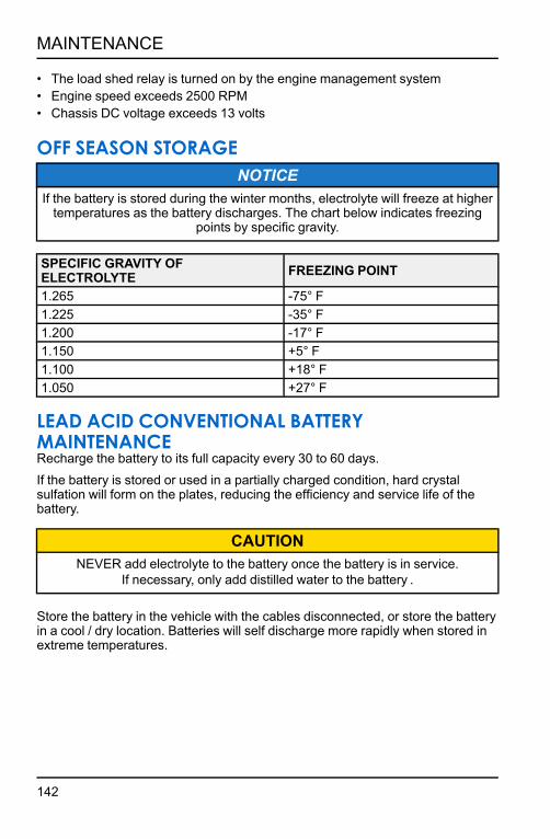
• The load shed relay is turned on by the engine management system• Engine speed exceeds 2500 RPM• Chassis DC voltage exceeds 13 volts
OFF SEASON STORAGENOTICE
If the battery is stored during the winter months, electrolyte will freeze at higher temperatures as the battery discharges. The chart below indicates freezing
points by specific gravity.
SPECIFIC GRAVITY OF ELECTROLYTE FREEZING POINT
1.265 -75° F1.225 -35° F1.200 -17° F1.150 +5° F1.100 +18° F1.050 +27° F
LEAD ACID CONVENTIONAL BATTERY MAINTENANCERecharge the battery to its full capacity every 30 to 60 days.If the battery is stored or used in a partially charged condition, hard crystal sulfation will form on the plates, reducing the efficiency and service life of the battery.
CAUTIONNEVER add electrolyte to the battery once the battery is in service.
If necessary, only add distilled water to the battery .
Store the battery in the vehicle with the cables disconnected, or store the battery in a cool / dry location. Batteries will self discharge more rapidly when stored in extreme temperatures.
142
MAINTENANCE

DRY SHIPPED AGM BATTERY MAINTENANCECAUTION
NEVER add electrolyte or distilled water to the battery once the battery is in service.
If you do not drive the vehicle for more than TWO weeks, maintain the Absorbent Glass Mat (AGM) battery with the BatteryMINDer® 2012 AGM - 2 AMP charger (or a similar charger).
BatteryMINDer® 2012 AGM - 2 AMP battery charger2830438
If you plan to store the vehicle for ONE month or longer, remove the battery from the vehicle and store the battery in a cool / dry location. Continue to maintain the battery with the 2 AMP charger and inspect the battery every 60 days.
LEAD ACID LOW MAINTENANCE BATTERY MAINTENANCERecharge the battery to its full capacity every 30 to 60 days.If the battery is stored or used in a partially charged condition, hard crystal sulfation will form on the plates, reducing the efficiency and service life of the battery.
CAUTIONNEVER add electrolyte or distilled water to the battery. Doing so will damage
the case and shorten the life of the battery.
Store the battery in the vehicle with the cables disconnected, or store the battery in a cool / dry location. Batteries will self discharge more rapidly when stored in extreme temperatures.
AGM LOW MAINTENANCE BATTERY MAINTENANCECAUTION
NEVER add electrolyte or distilled water to the battery. Doing so will damage the case and shorten the life of the battery.
If you do not drive the vehicle for more than TWO weeks, maintain the Absorbent Glass Mat (AGM) battery with the BatteryMINDer® 2012 AGM - 2 AMP charger (or a similar charger).
BatteryMINDer® 2012 AGM - 2 AMP battery charger2830438
143
MAINTENANCE

If you plan to store the vehicle for ONE month or longer, remove the battery from the vehicle and store the battery in a cool / dry location. Continue to maintain the battery with the BatteryMINDer® 2012 AGM - 2 AMP charger (or a similar charger) and inspect the battery every 60 days.
TRANSPORTING THE SNOWMOBILEWhenever the snowmobile is transported:
1. Be sure the fuel cap and oil cap are installed correctly.
2. Tie the snowmobile to the transporting unit securely using suitable straps.
3. Remove the ignition key to prevent loss.
NOTEUse of a cover is recommended when transporting your vehicle on an open
trailer or sled deck.
SUMMER STORAGE GUIDETREATING THE FUEL SYSTEMAs the riding season draws to a close, Polaris recommends riders begin treating their snowmobile’s fuel system with Polaris Carbon Clean or similar commercially-available fuel stabilizer.Treating the fuel system with Carbon Clean during the last few rides of the season ensures the entire fuel system is treated. Then, when it comes time to store the snowmobile, all the rider has to do is completely fill the fuel tank with fresh, non-oxygenated fuel and treat the new fuel with Carbon Clean. It is also recommended riders use non-oxygenated fuel during the last rides of the season as non-oxygenated fuel stores better than oxygenated fuel and resists water vapor absorption. If the rider was unable to treat the fuel system and/or use non-oxygenated fuel at the end of the riding season, the rider should do the following:
1. The rider should consume as much fuel in the fuel tank as possible during the last rides of the season.
2. When performing the summerization storage procedures, fill the fuel tank completely with non-oxygenated fuel. Note that most oxygenated fuels contain ethanol. Since ethanol is hydroscopic, oxygenated fuel will absorb a small amount of water vapor during the storage season and more so in humid locations. Completely filling the tank with non-oxygenated fuel minimizes water vapor absorption during the storage period and limits the amount of air and water vapor that can accumulate in the tank.
3. Treat the fuel in the fuel tank with the recommend amount of Polaris Carbon Clean. The recommended mixing ratio is outlined on the bottle label.
144
MAINTENANCE

4. Position the snowmobile outside in a well-ventilated area.
5. Start and run the engine for 10-15 minutes to distribute the treated fuel throughout the fuel system.
NOTEOn Carbureted engines (550cc / 120 Youth), run the engine for 10-15 minutes and then turn the fuel shut off valve to ‘OFF’. Continue to run the engine until
the engine stalls and turns off. Doing this drains the carburetors of fuel.
FOGGING THE ENGINEFogging the engine with Polaris fogging oil or similar commercial alternative is probably the most important storage step a rider can do to ensure the internal parts of their snowmobile’s engine do not rust and corrode during the storage season.To fog the engine, do the following:
1. Remove the spark plugs from the engine.
2. Liberally spray fogging oil into each spark plug hole. If possible, have an assistant slowly pull on the recoil rope to rotate the engine while spraying the oil into each cylinder.
3. Loosely install the spark plugs.
NOTEDo not install new spark plugs after fogging the cylinders. Fogging oil prevents the formation of rust / corrosion by sticking to the internal engine components –
including the spark plug electrodes. Replace these spark plugs the following season after all of the fogging oil has been burned out of the engine.
DRIVE BELT STORAGENever leave the drive belt installed in the clutches as oxidation may form where the belt contacts the aluminum clutch sheave faces.To clean the drive and driven clutches, do the following:
1. Remove the primary and secondary drive belt from the snowmobile.
2. Inspect the drive belt for wear and glazing. Compare the primary belt with the back-up (secondary) belt. Decide if a new belt is needed next season and note the primary belt can now be used as the back-up belt next season.
3. Clean the driven and driven clutch sheaves with Isopropyl Alcohol. Allow the alcohol to air dry. Continue cleaning the sheave faces until all belt residue is removed.
145
MAINTENANCE

BATTERY/ELECTRICAL SYSTEM STORAGENever leave a battery unattended during the storage season. Snowmobile batteries are small and cannot maintain their charge over the storage season. To ensure your battery maintains its level of charge, the battery should be connected to a battery tender/trickle charger using the battery tender port q.
1. While the battery can remain installed on the snowmobile, it is recommended the battery be removed from the snowmobile and stored in a cool, and dry location. Removing the battery from the snowmobile facilitates off-site storage of the snowmobile where electricity may not be available to connect a battery tender. In addition, removing the battery allows access to other maintenance items, such as the chaincase chain tensioner bolt.
2. Connect a Polaris battery tender or equivalent commercially available tender to the battery.
3. Inspect the electrical connections and wire harnesses throughout the snowmobile. If damage is found, make a note of the damage so that you and your authorized Polaris dealer can address the concern.
CHAINCASENever leave ‘used’ lubricant in the chaincase during the storage season. Doing so may leave water present in the chaincase which may cause corrosion and rust.
1. Follow the Owner’s Manual procedures and drain / fill the chaincase with new Polaris SCL (Synthetic Chaincase Lubricant). All Polaris PRO-RIDE and AXYS snowmobile feature ‘fill-to-spill’ lubricant fill specifications which makes it relatively ‘easy’ to re-fill the chaincase.
2. Rotate the driven clutch in the direction of forward vehicle travel to move the chain slack to the tensioner-side of the drive system. Lock the parking brake.
3. Loosen the drive chain adjuster lock nut. Turn the adjuster screw inwards until it can no longer be turned by hand.
4. At this point, turn the adjuster nut ¼ turn counter clockwise.
5. Tighten and then torque the jam nut to the specification listed in the Owner’s Manual. Release the parking brake.
NOTEIf the snowmobile is equipped with a transmission (Titan / WideTrak
snowmobiles), there is not a drive chain adjustment procedure.
146
MAINTENANCE

CLEANING THE SNOWMOBILESnowmobiles, especially those transported on sled decks and open trailers can accumulate allot of water and road dirt / salt during the riding season. The snowmobile must be thoroughly washed and cleaned to prevent corrosion and rust formation.
1. Wash the snowmobile with a garden hose and a solution of soapy water.Note that if a pressure washer is used, care should be taken to not point thepressure washer nozzle close to the snowmobile which may force highpressure water into suspension / shock shaft seals and exposed electricalconnectors.
2. Dry the snowmobile with a lint-free towel. Allow the entire snowmobile to airdry afterwards.
3. Clean the engine compartment. Use a shop vacuum if required to removedirt, leaves, cat tails, etc. from within the engine compartment.
4. Hand wash the exhaust system and dry the pipe and silencer with a cleanshop towel.
5. Apply “spray” metal protectant on exposed metal components, such as theexhaust pipe, silencer, shock shafts, and suspension springs / pivots.
IMPORTANTDo not spray metal protectant on the drive or driven clutches.
LUBRICATE THE PIVOTSAfter washing the snowmobile, it is important to use Polaris Premium All Season grease to lubricate the various suspension / steering pivot points. Doing so forces any water accumulated within the joints out which prevents the formation of corrosion and rust.
1. Use a grease gun and Polaris Premium All Season Grease. Reference theappropriate Owner’s Manual to locate any / all grease zerks on the steeringand suspension systems.
2. Pump fresh grease into all zerks until the grease can be seen purging out ofeach joint.
3. Use a paper towel to clean up and remove all of the residual purged greasefrom the joints.
147
MAINTENANCE

STORING THE SNOWMOBILENever store the snowmobile in a hot, humid location if possible. Try to store the snowmobile away from direct sunlight.
1. Cover the snowmobile with a Polaris cover or after-market equivalent cover.
2. Store in a location always from water, tall grass, and direct sunlight. The storage location should have some level of ventilation to prevent stagnant, humid air from accumulating in and around the snowmobile.
WINTER RIDE PREPARATIONPreparing a snowmobile for in-season service is basically performing some of the summer storage procedures in reverse order.
1. Move the snowmobile outside to a well-ventilated area. Raise the rear suspension up, off the ground. Remove the engine compartment side panel and hood.
2. Prep the primary and back up (secondary) for winter use. It is recommended the belts be washed with a solution of warm, soapy water and allowed to air dry.
3. If the snowmobile is equipped with electric start or a PIDD on-board battery, remove the battery from the battery tender and re-install it back into the battery box. Follow the owner’s manual for battery installation procedures.
4. Verify the spark plugs are installed and torqued. Re-install the spark plug wires.
NOTEVerify you hear an audible “click” when pushing the spark plug caps down onto
the spark plugs. This ensures the plug caps are seated properly.
5. If you placed dryer sheets inside the engine compartment, remove them.
6. Using clean and dry shop towel, wipe down the exhaust pipe , silencer, and clutch sheaves.
7. Install the primary drive belt onto the clutches with the “Polaris” writing readable from the outside of the snowmobile.
8. Install the back-up (secondary) drive belt into the belt holder.
9. On the carbureted snowmobiles, turn the fuel shut-off valve to the ON position.
10. With the track suspended up, off the ground, follow the track tension adjustment procedure as outlined in your owner’s manual.
148
MAINTENANCE

11. Start and run the engine. Allow the engine to run for at least 15 minutes. Occasionally “blip” the throttle to rev the engine.
NOTEThe exhausted may emit more smoke than usual as the fogging oil is burned
out of the engine.
12. While the engine is running, verify there are no coolant leaks (on liquid cooled engines). After engaging the throttle a few times to spin the track, verify the track is aligned with the slide rails.
13. Turn off the engine. If the track requires, re-align the track at this time.
14. After adjusting the track or allowing the engine to cool down. Add coolant to reservoir bottle if required.
15. Re-start the engine and allow it ti run for another 15 minutes. After 15 Minutes, shutoff the engine and allow the exhaust pipe to cool.
16. Remove and discard the spark plugs. Install new spark plugs into the engine. Obtain two more new spark plugs and install them into the spark plug holders or storage bag.
17. Inspect the ski wear bars/carbides. Now is the time to replace the wear bars if damage if found or carbides are worn.
18. Add Carbon Clean to the fuel tank.
19. Log onto www.ridecommand.com and download the latest TRAILS PIDD update files. Update the PIDD (if equipped) with the latest TRAILS update file.
20. Grease the rear suspension grease zerks with Polaris Premium All Season grease just enough to push out any water that may have accumulated in the suspension pivot points.
149
MAINTENANCE

150

SPECIFICATIONS600 SWITCHBACK ASSAULT
CAPACITIES AND DIMENSIONS
Body Style AXYS
Rider Capacity 1
Coolant Capacity 4 qts. (3.8 l)
Chaincase Oil Capacity 10 oz. (296 ml)
Fuel Tank Capacity 12 gal. (45.4 l)
Gearcase Oil Capacity N/A
Oil Capacity (qts./l) 3.9 qts. (3.7 l)
Height 54.5 inches (138.4 cm)
Length 125 inches (317.5 cm)
Designed Width 47 inches (119 cm)
Brake Type Hayes Phantom Floating Piston DOT 4
Drive Clutch Center Distance 10.625 inches (27 cm)
Drive Belt P/N 3211165
Drive Clutch P-85
Driven Clutch Lightweight Team Roller Reverse
Reverse Transmission Electronic Reverse
ENGINE AND COOLING
Engine ASM-ENG S6011-6044-LP6P
Displacement 599 cc
Cylinders 2
Bore x Stroke (mm) 77.25 x 64
Alternator Output 400 watt
Throttle Body 1204920
Recommended Engine Oil VES
151
SPECIFICATIONS

Throttle Body Bore Size 46 mm
Idle RPM 1700 +/- 200
Rated Operating RPM 8250 +0/- 250
Cooling Liquid
Ignition Type CDI
Ignition Timing °BTDC 18° @ idle, 1700 RPM w/120°F (49°C) water temp
Spark Plug / Gap NGK BPR9ES / .70 inches (.027 mm)
Recommended Fuel Octane 91 recommended (87 minimum)
CLUTCH SETTINGS
ALTITUDE METERS (FEET)
DRIVE CLUTCH DRIVEN CLUTCH
SHIFT WEIGHT
CLUTCH SPRING (ELEC-TRIC
START)
CLUTCH SPRING
DRIVEN HELIX
GEARING (U : L
-PITCH)
* Shaded cells indicate factory settings. Use 2 gram lighter shift weights when operating in temperatures above 40° F (5° C). Drive Clutch Bolt Torque: 80 ft-lbs (108 Nm) Re-torque after running engine.
0-600 (0-2000)10-64
(132158-5)
140/330 (7043829)
Blk/Purple (7043363)
48/42–.36 (5140312)
22:41-70 1.352 Cobra
20:39-68 1.6 Cobra
19:40-68 2.0” Series 4
600-1200 (2000- 4000)
10-62 (132158-
6)
1200-1800 (4000- 6000)
10-60 (132158-
7)
1800-2400 (6000- 8000)
10-58 (132158-
8)
2400-3000 (8000- 10,000)
10-56 (132168-
4)
3000-3600 (10,000-12,000)
10A-L (132153-
1)
152
SPECIFICATIONS

600 RMK 144CAPACITIES AND DIMENSIONS
Body Style AXYS
Rider Capacity 1
Coolant Capacity 4 qts. (3.8 l)
Chaincase Oil Capacity 10 oz. (296 ml)
Fuel Tank Capacity 12 gal. (45.4 l)
Gearcase Oil Capacity N/A
Oil Capacity (qts./l) 3.9 qts. (3.7 l)
Height 48.5 inches (123.2 cm)
Length 125 inches (317.5 cm)
Designed Width 46.5 inches (118 cm)
Brake Type Hayes Phantom
Drive Clutch Center Distance 10.625 inches (27 cm)
Drive Belt P/N 3211165
Drive Clutch P-85
Driven Clutch Lightweight Team Roller Reverse
Reverse Transmission Electronic Reverse
ENGINE AND COOLING
Engine ASM-ENG S6011-6044-LP6P
Displacement 599 cc
Cylinders 2
Bore x Stroke (mm) 77.25 x 64
Alternator Output 400 watt
Throttle Body 1204920
Recommended Engine Oil VES
Throttle Body Bore Size 46 mm
153
SPECIFICATIONS

Idle RPM 1700 +/- 200
Rated Operating RPM 8250 +0/- 250
Cooling Liquid
Ignition Type CDI
Ignition Timing °BTDC 18° @ idle, 1700 RPM w/120°F (49°C) water temp
Spark Plug / Gap NGK BPR9ES / .70 inches (.027 mm)
Recommended Fuel Octane 91 recommended (87 minimum)
CLUTCH SETTINGS
ALTITUDE METERS (FEET)
DRIVE CLUTCH DRIVEN CLUTCH
SHIFT WEIGHT
CLUTCH SPRING
CLUTCH SPRING
DRIVEN HELIX
GEARING (U : L
-PITCH)* Shaded cells indicate factory settings. Use 2 gram lighter shift weights whenoperating in temperatures above 40° F (5° C).Drive Clutch Bolt Torque: 80 ft-lbs (108 Nm) Re-torque after running engine.
0-450 (0-1500)10-64
(132158-5)
140/330 (7043829)
BLK/ PURPLE (7043363)
STR 40 LW (5140109) 19:40–68
450-900 (1500-3000)
10-62(132158-
6)
900-1500 (3000-5000)
10-60(132158-
7)
1500-2100 (5000- 7000)
10-58(132158-
8)
2100-2700 (70000-9,000)
10-56(132168-
4)
2700-3350 (9000- 11,000)
10-54(132168-
5)
154
SPECIFICATIONS

600 VOYAGEURCAPACITIES AND DIMENSIONS
Body Style AXYS
Rider Capacity 1
Coolant Capacity 4 qts. (3.8 l)
Chaincase Oil Capacity 10 oz. (296 ml)
Fuel Tank Capacity 12 gal. (45.4 l)
Gearcase Oil Capacity N/A
Oil Capacity (qts./l) 3.9 qts. (3.7 l)
Height 48.5 inches (123.2 cm)
Length 127 inches (322.6 cm)
Designed Width 46.5 inches (118 cm)
Brake Type Hayes Phantom
Drive Clutch Center Distance 10.625 inches (27 cm)
Drive Belt P/N 3211165
Drive Clutch P-85
Driven Clutch Lightweight Team Roller Reverse
Reverse Transmission Electronic Reverse
ENGINE AND COOLING
Engine ASM-ENG S6011-6044-LP6P
Displacement 599 cc
Cylinders 2
Bore x Stroke (mm) 77.25 x 64
Alternator Output 400 watt
Throttle Body 1204920
Recommended Engine Oil VES
Throttle Body Bore Size 46 mm
155
SPECIFICATIONS

Idle RPM 1700 +/- 200
Rated Operating RPM 8250 +0/- 250
Cooling Liquid
Ignition Type CDI
Ignition Timing °BTDC 18° @ idle, 1700 RPM w/120°F (49°C) water temp
Spark Plug / Gap NGK BPR9ES / .70 inches (.027 mm)
Recommended Fuel Octane 91 recommended (87 minimum)
CLUTCH SETTINGS
ALTITUDE METERS (FEET)
DRIVE CLUTCH DRIVEN CLUTCH
SHIFT WEIGHT
CLUTCH SPRING
CLUTCH SPRING
DRIVEN HELIX
GEARING (U : L
-PITCH)* Shaded cells indicate factory settings. Use 2 gram lighter shift weights whenoperating in temperatures above 40° F (5° C).Drive Clutch Bolt Torque: 80 ft-lbs (108 Nm) Re-torque after running engine.
0-600 (0-2000)10-64
(132158-5)
140/330 (7043829)
BLK/PUR 7043363
48/42.36 (5140312) 19:40-68
600-1200 (2000-4000)
10-62(132158-
6)
1200-1800 (4000- 6000)
10-60(132158-
7)
1800-2400 (6000- 8000)
10-58(132158-
8)
2400-3000 (8000- 10,000)
10-56(132168-
4)
3000-3600 (10,000-12,000)
10–54 (132168-
5)
156
SPECIFICATIONS

600 INDY SP/XC/XCR 129CAPACITIES AND DIMENSIONS
Body Style AXYS
Rider Capacity 1
Coolant Capacity 4 qts. (3.8 l)
Chaincase Oil Capacity 10 oz. (296 ml)
Fuel Tank Capacity 12 gal. (45.4 l)
Gearcase Oil Capacity N/A
Oil Capacity (qts./l) 3.9 qts. (3.7 l)
Height 46 inches (116.8 cm)
Length 117 inches (297.2 cm)
Designed Width 47 inches (119.4 cm)
Brake Type AXYS Radial XCR: AXYS Race Radial
Drive Clutch Center Distance 10.625 inches (27 cm)
Drive Belt P/N 3211165
Drive Clutch P-85
Driven Clutch Lightweight Team Roller Reverse
Reverse Transmission Electronic Reverse
ENGINE AND COOLING
Engine ASM-ENG S6011-6044-LP6P
Displacement 599 cc
Cylinders 2
Bore x Stroke (mm) 77.25 x 64
Alternator Output 400 watt
Throttle Body 1204920
Recommended Engine Oil VES
Throttle Body Bore Size 46 mm
157
SPECIFICATIONS

Idle RPM 1700 +/- 200
Rated Operating RPM 8250 +0/- 250
Cooling Liquid
Ignition Type CDI
Ignition Timing °BTDC 18° @ idle, 1700 RPM w/120°F (49°C) water temp
Spark Plug / Gap NGK BPR9ES / .70 inches (.027 mm)
Recommended Fuel Octane 91 recommended (87 minimum)
CLUTCH SETTINGS
ALTITUDE METERS (FEET)
DRIVE CLUTCH DRIVEN CLUTCH
SHIFT WEIGHT
CLUTCH SPRING
(ELECTRIC START)
CLUTCH SPRING
DRIVEN HELIX GEARING
0-600(0-2000)
10-64(132158-
5)
Black 140/330
(7043829)
Black/Purple 160/240
(7043363)
48/42/.36 BA35
(5140312)
22/41/70P 1.25" Ice
Ripper XT 1.352" Cobra
20/39/68P 1.5" Storm
1.75" Backcountry
600-1200(2000-4000)
10-62(132158-
6)
1200-1800 (4000-6000)
10-60(132158-
7)
1800-2400 (6000-8000)
10-58(132158-
8)
2400-3000 (8000-10,000)
10-56(132168-
4)
21/42/70P 1.25" Ice
Ripper XT 1.352" Cobra
19/40/68P 1.5" Storm
1.75" Backcountry
3000-3600 (10,000-12,000)
10 AL (132153-
1)
Drive Clutch Bolt Torque: 80 ft-lbs (108Nm) Re-torque after running engine. OPTIONAL-USE 2 GRAM LIGHTER CLUTCH WEIGHTS WHEN OPERATING IN PROLONGED WARM TEMPERATURES (LATE FALL/SPRING SEASON) TO MAINTAIN PEAK OPERATING RPM.
158
SPECIFICATIONS

600 INDY SP/XC/ADVENTURE 137CAPACITIES AND DIMENSIONS
Body Style AXYS
Rider Capacity 1
Coolant Capacity 4 qts. (3.8 l)
Chaincase Oil Capacity 10 oz. (296 ml)
Fuel Tank Capacity 12 gal. (45.4 l)
Gearcase Oil Capacity N/A
Oil Capacity (qts./l) 3.9 qts. (3.7 l)
Height 46 inches (116.8 cm)
Length 120 inches (305 cm)
Designed Width 47 inches (119.4 cm)
Brake Type AXYS™ Radial
Drive Clutch Center Distance 10.625 inches (27 cm)
Drive Belt P/N 3211165
Drive Clutch P-85
Driven Clutch Lightweight Team Roller Reverse
Reverse Transmission Electronic Reverse
ENGINE AND COOLING
Engine ASM-ENG S6011-6044-LP6P
Displacement 599 cc
Cylinders 2
Bore x Stroke (mm) 77.25 x 64
Alternator Output 400 watt
Throttle Body 1204920
Recommended Engine Oil VES
Throttle Body Bore Size 46 mm
159
SPECIFICATIONS

Idle RPM 1700 +/- 200
Rated Operating RPM 8250 +0/- 250
Cooling Liquid
Ignition Type CDI
Ignition Timing °BTDC 18° @ idle, 1700 RPM w/120°F (49°C) water temp
Spark Plug / Gap NGK BPR9ES / .70 inches (.027 mm)
Recommended Fuel Octane 91 recommended (87 minimum)
CLUTCH SETTINGS
ALTITUDE METERS (FEET)
DRIVE CLUTCH DRIVEN CLUTCH
SHIFT WEIGHT
CLUTCH SPRING
(ELECTRIC START)
CLUTCH SPRING
DRIVEN HELIX GEARING
0-600(0-2000)
10-64(132158-
5)
Black 140/330
(7043829)
Black/Purple 160/240
(7043363)
48/42/.36 BA35
(5140312)
22/41/70P 1.25" RIP II
1.352" Cobra
1.25” Ice Rip
20/39/68P 1.5" Storm
600-1200(2000-4000)
10-62(132158-
6)
1200-1800 (4000-6000)
10-60(132158-
7)
1800-2400 (6000-8000)
10-58(132158-
8)
2400-3000 (8000-10,000)
10-56(132168-
4)
3000-3600 (10,000-12,000)
10 AL (132153-
1)Drive Clutch Bolt Torque: 80 ft-lbs (108Nm) Re-torque after running engine. OPTIONAL-USE 2 GRAM LIGHTER CLUTCH WEIGHTS WHEN OPERATING IN PROLONGED WARM TEMPERATURES (LATE FALL/SPRING SEASON) TO MAINTAIN PEAK OPERATING RPM.
160
SPECIFICATIONS

800 SWITCHBACK ASSAULTCAPACITIES AND DIMENSIONS
Body Style AXYS
Rider Capacity 1
Coolant Capacity 4 qts. (3.8 l)
Chaincase Oil Capacity 10oz. (296 ml)
Fuel Tank Capacity 12 gal. (45.4 l)
Gearcase Oil Capacity N/A
Oil Capacity (qts./l) 3.9 qts. (3.7 l)
Height 54.5 inches (138.4 cm)
Length 125 inches (317.5 cm)
Designed Width 47 inches (119 cm)
Brake Type AXYS™ Radial
Drive Clutch Center Distance 10.625 inches (27 cm)
Drive Belt P/N 3211177
Drive Clutch P-85
Driven Clutch Lightweight Team Roller Reverse
Reverse Transmission Electronic Reverse
ENGINE AND COOLING
Engine ASM-ENG S6012-8044-LP8P
Displacement 794 cc
Cylinders 2
Bore x Stroke (mm) 85 x 70
Alternator Output 400 watt
Throttle Body 1205241
Recommended Engine Oil VES
Throttle Body Bore Size 48 mm
161
SPECIFICATIONS

Idle RPM 1700 +/- 200
Rated Operating RPM 8250 +0/- 250
Cooling Liquid
Ignition Type CDI
Ignition Timing °BTDC 18° @ idle, 1700 RPM w/120°F (49°C) water temp
Spark Plug / Gap BPR 9ES /.027 inches (0.7 mm)
Recommended Fuel Octane 91 recommended (87 minimum)
CLUTCH SETTINGS
ALTITUDE METERS (FEET)
DRIVE CLUTCH DRIVEN CLUTCH
SHIFT WEIGHT
CLUTCH SPRING
CLUTCH SPRING
DRIVEN HELIX
GEARING (U : L
-PITCH)* Shaded cells indicate factory settings. Use 2 gram lighter shift weights whenoperating in temperatures above 40° F (5° C).Drive Clutch Bolt Torque: 80 ft-lbs (108 Nm) Re-torque after running engine.
0-600 (0-2000)10-68
(132242-7)
110-290(7042287)
BLU/BLK (7043064) 58/44/.36
(5140311)
23:40-70 1.352 Cobra
22:41-70 1.6 Cobra
19:40-68 2.0” Series 4
600-1200 (2000-4000)
10-66(132158-
4)
1200-1800 (4000- 6000)
10-64(132158-
5)1800-2400 (6000- 8000) 10-62
(132158-6) BLK
(7043063)2400-3000 (8000- 10,000)
120-320(7044537)
STR 40LW (5140109)
19:40-68 1.352 Cobra 1.6 Cobra
2.0” Series 4 3000-3600 (10,000-12,000)
10-60(132158-
7)* = STOCK INTERNATIONAL
162
SPECIFICATIONS

800 SKS 146CAPACITIES AND DIMENSIONS
Body Style AXYS
Rider Capacity 1
Coolant Capacity 4 qts. (3.8 l)
Chaincase Oil Capacity 10oz. (296 ml)
Fuel Tank Capacity 12 gal. (45.4 l)
Gearcase Oil Capacity N/A
Oil Capacity (qts./l) 3.9 qts. (3.7 l)
Height 51 inches (129.5 cm)
Length 125 inches (317.5 cm)
Designed Width 46.5 inches (118 cm)
Brake Type Hayes Phantom Floating Piston DOT 4
Drive Clutch Center Distance 10.625 inches (27 cm)
Drive Belt P/N 3211177
Drive Clutch P-85
Driven Clutch Lightweight Team Roller Reverse
Reverse Transmission Electronic Reverse
ENGINE AND COOLING
Engine ASM-ENG S6012-8044-LP8P
Displacement 794 cc
Cylinders 2
Bore x Stroke (mm) 85 x 70
Alternator Output 400 watt
Throttle Body 1205241
Recommended Engine Oil VES
Throttle Body Bore Size 48 mm
Idle RPM 1700 +/- 200
163
SPECIFICATIONS

Rated Operating RPM 8250 +0/- 250
Cooling Liquid
Ignition Type CDI
Ignition Timing °BTDC 18° @ idle, 1700 RPM w/120°F (49°C) water temp
Spark Plug / Gap BPR 9ES /.027 inches (0.7 mm)
Recommended Fuel Octane 91 recommended (87 minimum)
CLUTCHING CHART
ALTITUDEMeters(Feet)
Drive Clutch Shift
Weight
Drive Clutch Spring
Driven Clutch Spring
Driven Helix Chaincase Gearing/
Pitch
0-600 (0-2000)
10-70 (1322414)
120/320(7044537)
BLACK(7043063)
STR 40 LW(5140109) 19:40 70P
600-1200 (2000- 4000)
10-68(1322427)
1200-1800 (4000- 6000)
10-66 (11321584)
1800-2400 (6000- 8000)
10-64 (1321585)
2400-3000 (8000- 10000)
10-62 (1321586)
3000-3600 (10000- 12000)
10-60 (1321587)
Shaded cells indicate factory settings.Use 2 gram lighter shift weights when operating in temperatures above 40° F (5° C).Drive Clutch Bolt Torque: 80 ft-lbs (108 Nm) Re-torque after running engine.
164
SPECIFICATIONS

800 INDY XC/XCR 129CAPACITIES AND DIMENSIONS
Body Style AXYS
Rider Capacity 1
Coolant Capacity 4 qts. (3.8 l)
Chaincase Oil Capacity 10oz. (296 ml)
Fuel Tank Capacity 12 gal. (45.4 l)
Gearcase Oil Capacity N/A
Oil Capacity (qts./l) 3.9 qts. (3.7 l)
Height 46 inches (116.8 cm)
Length 117 inches (297.2 cm)
Designed Width 47 inches (119.4 cm)
Brake Type
Drive Clutch Center Distance 10.625 inches (27 cm)
Drive Belt P/N 3211177
Drive Clutch P-85
Driven Clutch Lightweight Team Roller Reverse
Reverse Transmission Electronic Reverse
ENGINE AND COOLING
Engine ASM-ENG S6012-8044-LP8P
Displacement 794 cc
Cylinders 2
Bore x Stroke (mm) 85 x 70
Alternator Output 400 watt
Throttle Body 1205241
Recommended Engine Oil VES
Throttle Body Bore Size 46 mm
165
SPECIFICATIONS
AXYS™ Radial

Idle RPM 1700 +/- 200
Rated Operating RPM 8250 +0/- 250
Cooling Liquid
Ignition Type CDI
Ignition Timing °BTDC 18° @ idle, 1700 RPM w/120°F (49°C) water temp
Spark Plug / Gap BPR 9ES /.027 inches (0.7 mm)
Recommended Fuel Octane 91 recommended (87 minimum)
CLUTCH SETTINGS
ALTITUDE METERS (FEET)
DRIVE CLUTCH DRIVEN CLUTCHSHIFT
WEIGHTCLUTCH SPRING
CLUTCH SPRING
DRIVEN HELIX
GEARING (U : L -PITCH)
* Shaded cells indicate factory settings. Use 2 gram lighter shift weights whenoperating in temperatures above 40° F (5° C).Drive Clutch Bolt Torque: 80 ft-lbs (108 Nm) Re-torque after running engine.0-600 (0-2000) 10-68
110-290(7042287)
BLU/BLK 120-200
(7043064)
58/44/.36 (5140311)
23:37-68 1.25” ICE II
1.352” Cobra
22:41-70 1.5” Storm
600-1200 (2000-4000) 10-66
1200-1800 (4000- 6000) 10-64
1800-2400 (6000- 8000)
10-62BLK
155-222(7043063)
2400-3000 (8000- 10,000) Black
140-330(7043829)
21:42-68 1.25” ICE II
1.352” Cobra
22:41-70 1.75”
Backcountry
3000-3600 (10,000-12,000) 10-60
*Use 2 gram lighter shift weights when operating in temperatures above 40° F (5° C).Drive Clutch Bolt Torque: 80 ft-lbs (108 Nm) Re-torque after running engine.
166
SPECIFICATIONS

800 INDY XC/ADVENTURE 137CAPACITIES AND DIMENSIONS
Body Style AXYS
Rider Capacity 1
Coolant Capacity 4 qts. (3.8 l)
Chaincase Oil Capacity 10oz. (296 ml)
Fuel Tank Capacity 12 gal. (45.4 l)
Gearcase Oil Capacity N/A
Oil Capacity (qts./l) 3.9 qts. (3.7 l)
Height 46 inches (116.8 cm)
Length 120 inches (305 cm)
Designed Width 47 inches (119.4 cm)
Brake Type
Drive Clutch Center Distance 10.625 inches (27 cm)
Drive Belt P/N 3211177
Drive Clutch P-85
Driven Clutch Lightweight Team Roller Reverse
Reverse Transmission Electronic Reverse
ENGINE AND COOLING
Engine ASM-ENG S6012-8044-LP8P
Displacement 795 cc
Cylinders 2
Bore x Stroke (mm) 85 x 70
Alternator Output 400 watt
Throttle Body 1205241
Recommended Engine Oil VES
Throttle Body Bore Size 46 mm
167
SPECIFICATIONS
AXYS™ Radial

Idle RPM 1700 +/- 200
Rated Operating RPM 8250 +0/- 250
Cooling Liquid
Ignition Type CDI
Ignition Timing °BTDC 18° @ idle, 1700 RPM w/120°F (49°C) water temp
Spark Plug / Gap BPR 9ES /.027 inches (0.7 mm)
Recommended Fuel Octane 91 recommended (87 minimum)
CLUTCH SETTINGS
ALTITUDE METERS (FEET)
DRIVE CLUTCH DRIVEN CLUTCHSHIFT
WEIGHTCLUTCH SPRING
CLUTCH SPRING
DRIVEN HELIX
GEARING (U : L -PITCH)
* Shaded cells indicate factory settings. Use 2 gram lighter shift weights whenoperating in temperatures above 40° F (5° C).Drive Clutch Bolt Torque: 80 ft-lbs (108 Nm) Re-torque after running engine.
0-600 (0-2000)10-68
(132242-7)
110-290(7042287)
Blue/Black 120-200
(7043064)
58/44/.36 (5140311)
23:37-68 1.25” ICE
RIP
22:37–68 1.352” Cobra
22:41-70 1.5” Storm
600-1200 (2000-4000)
10-66(132158-
4)
1200-1800 (4000- 6000)
10-64(132158-
5)1800-2400 (6000- 8000) 10-62
(132158-6) Black
155-222(7043063)
2400-3000 (8000- 10,000) Black
140-330(7043829)3000-3600
(10,000-12,000)10-60
(132158-7)
*Use 2 gram lighter shift weights when operating in temperatures above 40° F (5° C).Drive Clutch Bolt Torque: 80 ft-lbs (108 Nm) Re-torque after running engine.
168
SPECIFICATIONS

850 SWITCHBACK ASSAULT 144CAPACITIES AND DIMENSIONS
Body Style AXYS
Rider Capacity 1
Coolant Capacity 4 qts. (3.8 l)
Chaincase Oil Capacity 10oz. (296 ml)
Fuel Tank Capacity 12 gal. (45.4 l)
Gearcase Oil Capacity N/A
Oil Capacity (qts./l) 3.9 qts. (3.7 l)
Height 54.5 inches (138.4 cm)
Length 125 inches (317.5 cm)
Designed Width 47 inches (119 cm)
Brake Type
Drive Clutch Center Distance 10.625 inches (27 cm)
Drive Belt P/N 3211215
Drive Clutch P-85
Driven Clutch Lightweight Team Roller Reverse
Reverse Transmission Electronic Reverse
ENGINE AND COOLING
Engine ASM-ENG S6032-8444-LP8R
Displacement 840 cc
Cylinders 2 Monoblock
Bore x Stroke (mm) 85 x 74
Alternator Output 500 watt @ 5000 RPM
Throttle Body 1205875
Oil Injection Electronic Oil Pump
Recommended Engine Oil VES
169
SPECIFICATIONS
AXYS™ Radial

Throttle Body Bore Size 50 mm
Idle RPM 1800 +/- 200
Rated Operating RPM 8250 +0/- 150
Cooling Liquid
Thermostat Opening Temp. 120°F (49°C)
Ignition Type Multi-Dimensional CDI
Spark Plug / Gap NGK BPR 9ES /.027 inches (0.7 mm)
Recommended Fuel Octane 91 recommended (87 minimum)
CLUTCH SETTINGS
ALTITUDE METERS (FEET)
DRIVE CLUTCH DRIVEN CLUTCH
SHIFT WEIGHT
CLUTCH SPRING
CLUTCH SPRING
DRIVEN HELIX
GEARING (U : L
-PITCH)* Shaded cells indicate factory settings. Use 2 gram lighter shift weights whenoperating in temperatures above 40° F (5° C).Drive Clutch Bolt Torque: 80 ft-lbs (108 Nm) Re-torque after running engine.
0-600 (0-2000)10-72
(132242-8)
Black 110-290
(7042287)
BLU/RED (7043057)
58/44/.36 (5140311)
23:40-70 1.352 Cobra
22:41-70 1.6 Cobra
19:40-68 2.0” Series 4
600-1200 (2000-4000)
10-70(132241-
4)1200-1800 (4000- 6000) 10-68
(132242-7)1800-2400 (6000-
8000)
BLK (7043063)
2400-3000 (8000- 10,000)
10-66(113215-
84) 120-320(7044537)
19:40-68 1.352 Cobra 1.6 Cobra
2.0” Series 4 3000-3600 (10,000-12,000)
10-64(132158-
5)* = STOCK INTERNATIONAL
170
SPECIFICATIONS

850 SKS 146CAPACITIES AND DIMENSIONS
Body Style AXYS
Rider Capacity 1
Coolant Capacity 4 qts. (3.8 l)
Chaincase Oil Capacity 10oz. (296 ml)
Fuel Tank Capacity 12 gal. (45.4 l)
Gearcase Oil Capacity N/A
Oil Capacity (qts./l) 3.9 qts. (3.7 l)
Height 51 inches (129.5 cm)
Length 125 inches (317.5 cm)
Designed Width 46.5 inches (118 cm)
Brake Type Hayes Phantom Floating Piston DOT 4
Drive Clutch Center Distance 10.625 inches (27 cm)
Drive Belt P/N 3211215
Drive Clutch P-85
Driven Clutch Lightweight Team Roller Reverse
Reverse Transmission Electronic Reverse
ENGINE AND COOLING
Engine S5836-8444-ON8R
Displacement 840 cc
Cylinders 2 Monoblock
Bore x Stroke (mm) 85 x 74
Alternator Output 500 watt @ 5000 RPM
Throttle Body 1205875
Oil Injection Electronic Oil Pump
Recommended Engine Oil VES
171
SPECIFICATIONS

Throttle Body Bore Size 50 mm
Idle RPM 1800 +/- 200
Rated Operating RPM 8250 +0/- 150
Cooling Liquid
Thermostat Opening Temp. 120°F (49°C)
Ignition Type Multi-Dimensional CDI
Spark Plug / Gap NGK BPR 9ES /.027 inches (0.7 mm)
Recommended Fuel Octane 91 recommended (87 minimum)
CLUTCHING CHART
ALTITUDEMeters(Feet)
Drive Clutch Shift
Weight
Drive Clutch Spring
Driven Clutch Spring
Driven Helix Chaincase Gearing/
Pitch
0-600 (0-2000)
10-70 (1322414)
120/320(7044537)
BLACK(7043063)
STR 40LW(5140109) 19:40 68P
600-1200 (2000- 4000)
10-68(1322427)
1200-1800 (4000- 6000)
10-66 (1321584)
1800-2400 (6000- 8000)
10-64 (1321585)
2400-3000 (8000- 10000)
10-62 (1321586)
3000-3600 (10000- 12000)
10-60 (1321587)
* Shaded cells indicate factory settings.Use 2 gram lighter shift weights when operating in temperatures above 40° F (5° C).Drive Clutch Bolt Torque: 80 ft-lbs (108 Nm) Re-torque after running engine.
172
SPECIFICATIONS

850 INDY XC/XCR 129CAPACITIES AND DIMENSIONS
Body Style AXYS
Rider Capacity 1
Coolant Capacity 4 qts. (3.8 l)
Chaincase Oil Capacity 10oz. (296 ml)
Fuel Tank Capacity 12 gal. (45.4 l)
Gearcase Oil Capacity N/A
Oil Capacity (qts./l) 3.9 qts. (3.7 l)
Height 46 inches (116.8 cm)
Length 117 inches (297.2 cm)
Designed Width 47 inches (119 cm)
Brake Type
Drive Clutch Center Distance 10.625 inches (27 cm)
Drive Belt P/N 3211215
Drive Clutch P-85
Driven Clutch Lightweight Team Roller Reverse
Reverse Transmission Electronic Reverse
ENGINE AND COOLING
Engine ASM-ENG S6032-8444-LP8R
Displacement 840 cc
Cylinders 2
Bore x Stroke (mm) 85 x 74
Alternator Output 700 watt
Throttle Body 1205875
Recommended Engine Oil VES
Throttle Body Bore Size 50 mm
173
SPECIFICATIONS
AXYS Radial XCR: AXYS Race Radial

Idle RPM 1800 +/- 200
Rated Operating RPM 8250 +0/- 150
Cooling Liquid
Ignition Type CDI
Ignition Timing °BTDC 18° @ idle, 1700 RPM w/120°F (49°C) water temp
Spark Plug / Gap NGK BPR9ES / .027 inches (0.7 mm)
Recommended Fuel Octane 91 recommended (87 minimum)
CLUTCH SETTINGS
ALTITUDE METERS (FEET)
DRIVE CLUTCH DRIVEN CLUTCH
SHIFT WEIGHT
CLUTCH SPRING
CLUTCH SPRING
DRIVEN HELIX
GEARING (U : L
-PITCH)* Shaded cells indicate factory settings. Use 2 gram lighter shift weights whenoperating in temperatures above 40° F (5° C).Drive Clutch Bolt Torque: 80 ft-lbs (108 Nm) Re-torque after running engine.
0-600 (0-2000)10-72
(132242-8)
BLACK 110-290
(7042287)
RED/BLU 140-200
(7043057)
58/44/.36 (5140311)
23:37-68 1.25” Ice
Ripper XT 1.352” Cobra
22:41–70 1.5” Storm
600-1200 (2000-4000)
10-70(132241-
4)1200-1800 (4000- 6000) 10-68
(132242-7)1800-2400 (6000-
8000)
120-320(7044537)
BLK 155-222
(7043063)
2400-3000 (8000- 10,000)
10-66(132158-
4)
20:39-68 1.25” Rip XT
1.352” Cobra
21:42–70 1.5” Storm
3000-3600 (10,000-12,000)
10-64(132158-
5)
* = STOCK INTERNATIONAL
174
SPECIFICATIONS

850 INDY XC/ADVENTURE 137CAPACITIES AND DIMENSIONS
Body Style AXYS
Rider Capacity 1
Coolant Capacity 4 qts. (3.8 l)
Chaincase Oil Capacity 10oz. (296 ml)
Fuel Tank Capacity 12 gal. (45.4 l)
Gearcase Oil Capacity N/A
Oil Capacity (qts./l) 3.9 qts. (3.7 l)
Height 46 inches (116.8 cm)
Length 120 inches (305 cm)
Designed Width 47 inches (119 cm)
Brake Type
Drive Clutch Center Distance 10.625 inches (27 cm)
Drive Belt P/N 3211215
Drive Clutch P-85
Driven Clutch Lightweight Team Roller Reverse
Reverse Transmission Electronic Reverse
ENGINE AND COOLING
Engine ASM-ENG S6032-8444-LP8R
Displacement 840 cc
Cylinders 2
Bore x Stroke (mm) 85 x 74
Alternator Output 700 watt
Throttle Body 1205875
Recommended Engine Oil VES
Throttle Body Bore Size 50 mm
175
SPECIFICATIONS
AXYS™ Radial

Idle RPM 1800 +/- 200
Rated Operating RPM 8250 +0/- 150
Cooling Liquid
Ignition Type CDI
Ignition Timing °BTDC 18° @ idle, 1700 RPM w/120°F (49°C) water temp
Spark Plug / Gap NGK BPR9ES / .027 inches (0.7 mm)
Recommended Fuel Octane 91 recommended (87 minimum)
CLUTCH SETTINGS
ALTITUDE METERS (FEET)
DRIVE CLUTCH DRIVEN CLUTCH
SHIFT WEIGHT
CLUTCH SPRING
CLUTCH SPRING
DRIVEN HELIX
GEARING (U : L
-PITCH)* Shaded cells indicate factory settings. Use 2 gram lighter shift weights whenoperating in temperatures above 40° F (5° C).Drive Clutch Bolt Torque: 80 ft-lbs (108 Nm) Re-torque after running engine.
0-600 (0-2000)10-72
(132242-8)
BLACK 110-290
(7042287)
RED/BLU 140-200
(7043057)
58/44/.36 (5140311)
23:37-68 1.25” Ice Ripper 1.352” Cobra
22:41–70 1.5” Storm
600-1200 (2000-4000)
10-70(132241-
4)1200-1800 (4000- 6000) 10-68
(132242-7)1800-2400 (6000-
8000)
120-320(7044537)
BLK 155-222
(7043063)
2400-3000 (8000- 10,000)
10-66(132158-
4)
3000-3600 (10,000-12,000)
10-64(132158-
5)* = STOCK INTERNATIONAL
176
SPECIFICATIONS

DIAGNOSTIC TROUBLE CODES (DTC)DIAGNOSTIC TROUBLE CODES (DTCS) – 600/800 MODELSDIAGNOSTIC TROUBLE CODES (DTCS) – AXYS
SPN = SUSPECT PARAMETER NUMBER / FMI = FAILURE MODE INDICATOR MIL STATUS: ON = CHECK ENGINE LED ILLUMINATED
TROUBLE CODE SPN FMI P-CODE MIL STATUS CONDITION
Throttle Position Sensor 1 51
3 P0123
ON
This Trouble Code sets if the Throttle Position Sensor Signal is above 4.39
Volts. Can be caused by Damaged Wiring, a faulty Throttle Position Sensor or ECU /
Connections.
4 P0122
This Trouble Code sets if the Throttle Position Sensor Signal is below 0.7
Volts. Can be caused by Damaged Wiring, a faulty Throttle Position Sensor or ECU /
Connections.
10 P0120
This Trouble Code sets when the Throttle Position Sensor Signal
changes too rapidly to be correct. The condition can be caused by intermittent connections causing the TPS voltage to jump around between readings. Check
for damaged connectors or wiring.
Vehicle Speed Signal 84 2 P0503
This Trouble Code Sets if the Vehicle Speed Signal is intermittent or missing.
Can be caused by Damaged Wiring/ Connections or a Faulty / Loose Vehicle
Speed Sensor
Engine Oil Level Sensor / Switch 98 17 P250F OFF
This Trouble Code Sets if the Oil Level is Too Low.
Can be caused by Low Oil Level, a faulty Oil Level Sensor or Faulty ECU /
Connections.
Intake Air Temperature
Sensor105
3 P0113
ON
This Trouble Code sets if the Intake Air Temperature Sensor Signal is above
4.9 Volts. Can be caused by Damaged Wiring, a faulty Intake Air Temperature Sensor or
ECU / Connections.
4 P0112
This Trouble Code sets if the Intake Air Temperature Sensor Signal is below
0.19 Volts. Can be caused by Damaged Wiring, a faulty Intake Air Temperature Sensor or
ECU / Connections.10 P0114 Abnormal Rate of Change.
Barometric Pressure Sensor 108 3 P2229 ON
This Trouble Code Sets if the Barometric Pressure Sensor Signal Circuit is Open or Shorted to Battery
Voltage.
177
DIAGNOSTIC TROUBLE CODES (DTC)

DIAGNOSTIC TROUBLE CODES (DTCS) – AXYS
SPN = SUSPECT PARAMETER NUMBER / FMI = FAILURE MODE INDICATOR MIL STATUS: ON = CHECK ENGINE LED ILLUMINATED
TROUBLE CODE SPN FMI P-CODE MIL STATUS CONDITION
Can be caused by Damaged Wiring / Connections, a Faulty Ambient
Pressure Sensor or ECU
4 P2228
This Trouble Code Sets if the Barometric Pressure Sensor Signal
Circuit is Shorted to Ground. Can be caused by Damaged Wiring /
Connections, a Faulty Ambient Pressure Sensor or ECU
10 P2230
This Trouble Code sets if the Barometric Pressure Sensor Signal
indicates an Unrealistic Rate of Change.
Can be caused by Damaged Wiring, a faulty Barometric Pressure Sensor or
ECU / Connections.
Engine Temperature
Sensor110
3 P0118
ON
This Trouble Code sets if the Engine Coolant Temperature Sensor Signal is
above 4.8 Volts. Can be caused by Damaged Wiring, a faulty Coolant Temperature Sensor or
ECU / Connections.
4 P0117
This Trouble Code sets if the Engine Coolant Temperature Sensor Signal is
below 0.1 Volts. Can be caused by Damaged Wiring, a faulty Coolant Temperature Sensor or
ECU / Connections.
0 P1217
OFF
This Trouble Code sets if the Engine Temperature indicates a Critical Over Temperature Condition and the engine
is running in a limp-home mode to prevent damage.
Can be caused by any failure that would cause the engine to overheat.
16 P0217
This Trouble Code sets if the Engine Temperature indicates a Severe Over
Temperature Condition. Can be caused by any failure that
would cause the engine to overheat. This Trouble Code Does Not indicate a problem with the Engine Temperature
Sensor.
15 P1116
This Trouble Code sets if the Engine Temperature indicates an Over
Temperature Condition. Can be caused by any failure that
would cause the engine to overheat. This Trouble Code Does Not indicate a problem with the Engine Temperature
Sensor.DC Chassis
Voltage 167 3 P1569 ON This Trouble Code sets if the System Voltage is above an acceptable level.
178
DIAGNOSTIC TROUBLE CODES (DTC)

DIAGNOSTIC TROUBLE CODES (DTCS) – AXYS
SPN = SUSPECT PARAMETER NUMBER / FMI = FAILURE MODE INDICATOR MIL STATUS: ON = CHECK ENGINE LED ILLUMINATED
TROUBLE CODE SPN FMI P-CODE MIL STATUS CONDITION
Can be caused by Damaged Wiring, a Faulty Voltage Regulator or Faulty
ECU.
4 P1568
This Trouble Code sets if the System Voltage is below an acceptable level. Can be caused by Damaged Wiring, a faulty stator, Faulty Voltage Regulator
or Faulty ECU.
Exhaust Temperature
Sensor173
3 P0546
ON
This Trouble Code sets if the engine has been running above 3000 RPM for more than 2 minutes and the Exhaust Temperature Sensor Signal is above
4.90 Volts. Can be caused by Damaged Wiring, a faulty Engine Temperature Sensor or
ECU / Connections.
4 P0545
This Trouble Code sets if the engine has been running above 3000 RPM for more than 2 minutes and the Exhaust Temperature Sensor Signal is below
0.06 Volts. Can be caused by Damaged Wiring, a faulty Engine Temperature Sensor or
ECU / Connections.
0 P1517
This Trouble Code Sets if the Engine was Shut Down due to High Exhaust
Temperature. Can be caused by a Faulty Exhaust
Temperature Sensor / Connections or Lean Air / Fuel Ratio causing high
exhaust temperature.
10 P1546 Abnormal rate of change.
ECU Memory Checksum Error 628 13 P0601 OFF
This Trouble Code Sets if an Internal Memory Fault is detected in the Engine
Controller Can only be caused by a defective
ECU.
Crankshaft Sensor Signal Fault 636 2 P0335 OFF
This Trouble Code sets if the Engine is Running and No Signal is Detected
from the 5X Crankshaft Sensor. Can be caused by Damaged Wiring, a
faulty Crankshaft Sensor or ECU / Connections.
Crankshaft Position Sensor
Circuit Fault636 8 P0336 OFF
This Trouble Code sets if the Engine is Running and the number of pulses from
the 5X Crankshaft Sensor is not correct.
Can be caused by Damaged Wiring, a faulty Crankshaft Sensor or ECU /
Connections.
Fuel Injector (MAG) 651 5 P0261 ON
This Trouble Code sets if an Open Circuit Condition is detected in the MAG Cylinder Port Injector Control
Circuit.
179
DIAGNOSTIC TROUBLE CODES (DTC)

DIAGNOSTIC TROUBLE CODES (DTCS) – AXYS
SPN = SUSPECT PARAMETER NUMBER / FMI = FAILURE MODE INDICATOR MIL STATUS: ON = CHECK ENGINE LED ILLUMINATED
TROUBLE CODE SPN FMI P-CODE MIL STATUS CONDITION
Can be caused by Damaged Wiring, a faulty Fuel Injector or ECU /
Connections.
3 P0262
This Trouble Code sets if a Short to Voltage is detected in the MAG Cylinder
Port Injector Control Circuit. Can be caused by Damaged Wiring, a
faulty Fuel Injector or ECU / Connections.
Fuel Injector (PTO) 652
5 P0264
ON
This Trouble Code sets if an Open Circuit Condition is detected in the PTO
Cylinder Port Injector Control Circuit. Can be caused by Damaged Wiring, a
faulty Fuel Injector or ECU / Connections.
3 P0265
This Trouble Code sets if a Short to Voltage is detected in the PTO Cylinder
Port Injector Control Circuit. Can be caused by Damaged Wiring, a
faulty Fuel Injector or ECU / Connections.
Knock Sensor 731
4 P0327
ON
This Trouble Code sets if the Engine Speed is above 6000 RPM and the
Detonation Sensor Signal is below 1.23 Volts for more than 2 seconds.
Can be caused by Damaged Wiring, a faulty Detonation Sensor or ECU /
Connections.
2 P0325
This Trouble Code Sets if the Knock Sensor Signal indicates an Unrealistic
Value. Can be caused by a Faulty Knock
Sensor / Connections, a Loose Sensor or Excessive Engine Mechanical Noise.
Ignition Coil Primary Driver
(MAG)1268 5 P1351 ON
This Trouble Code Sets if the Ignition Coil Driver Circuit is Open.
Can be caused by Damaged Wiring / Connections, a Ignition Coil or ECU
Fuel Pump Driver Circuit 1347 5 P0230 ON
This Trouble Code Sets if the Fuel Pump Relay Driver Circuit is Open.
Can be caused by Damaged Wiring / Connections, a Faulty Fuel Pump or
ECU.
Knock (DET) Level (MAG) 1352
0 P1336
ON
This Trouble Code Sets if the Engine Controller Reaches the Maximum Detonation Control Limit by Fuel Correction on the Mag Cylinder
16 P2336
This Trouble Code Sets if Cylinder 1 (MAG) Knock Sensor reaches a Critical
Level. Can be caused by Excessive Knock (Fuel Problems), a Lean Running Condition or Engine
Mechanical Problems.
180
DIAGNOSTIC TROUBLE CODES (DTC)

DIAGNOSTIC TROUBLE CODES (DTCS) – AXYS
SPN = SUSPECT PARAMETER NUMBER / FMI = FAILURE MODE INDICATOR MIL STATUS: ON = CHECK ENGINE LED ILLUMINATED
TROUBLE CODE SPN FMI P-CODE MIL STATUS CONDITION
Knock (DET) Level (PTO) 1353
0 P1337
ON
This Trouble Code Sets if the Engine Controller Reaches the Maximum Detonation Control Limit by Fuel Correction on the PTO Cylinder.
16 P2337
This Trouble Code Sets if Cylinder 2 (PTO) Knock Sensor reaches a Critical
Level. Can be caused by Excessive Knock (Fuel Problems), a Lean Running Condition or Engine
Mechanical Problems.
Sensor Supply Voltage 1
(TPS / TMAP)3509 4 P06B1 ON
This Trouble Code sets if the Sensor Supply 1 Voltage is below an
acceptable limit (4.50 Volts). Can be caused by Damaged Wiring or Faulty /
Shorted Sensors.
Sensor Supply Voltage 2
(Speed Sensor)3510 4 P06B4 OFF
This Trouble Code sets if the Sensor Supply 2 Voltage is below an
acceptable limit (4.50 Volts). Can be caused by Damaged Wiring or Faulty /
Shorted Sensors.
Electronic Oil Pump 3589
5 P16BA
ON
This Trouble Code Sets if the Oil Pump Driver Circuit is Open.
Can be caused by Damaged Wiring / Connections, a Faulty Oil Pump/
Connections or Faulty ECU / Connections.
12 P16BC
This Trouble Code Sets if a Failure is Detected in the Oil Pump Driver Circuit. Can be caused by Damaged Wiring /
Connections, a Faulty Oil Pump/ Connections or Faulty ECU /
Connections.
ECU Output Supply Voltage
Fuel Injector Power (16V)
3598
3 P16A9
ON
This Trouble Code sets if the Injector Output Supply 2 Voltage is above an acceptable limit. Can be caused by Damaged Wiring or Faulty / Shorted
Connectors.
4 P16A8
This Trouble Code sets if the Injector Output Supply 2 Voltage is below an acceptable limit. Can be caused by Damaged Wiring or Faulty / Shorted
Connectors.
ECU Output Supply Voltage Ground Speed
Sensor (5V)3599
3 P17AA
ON
This Trouble Code Sets if the ECU Output Supply Voltage #3 (Vehicle
Speed Sensor Supply) is Too High. Can be caused by Damaged Wiring /
Connections, a Faulty Vehicle Speed Sensor / Connections or Faulty ECU /
Connections.
4 P17AB
This Trouble Code Sets if the ECU Output Supply Voltage #3 (Vehicle
Speed Sensor Supply) is Too Low. Can be caused by Damaged Wiring /
181
DIAGNOSTIC TROUBLE CODES (DTC)

DIAGNOSTIC TROUBLE CODES (DTCS) – AXYS
SPN = SUSPECT PARAMETER NUMBER / FMI = FAILURE MODE INDICATOR MIL STATUS: ON = CHECK ENGINE LED ILLUMINATED
TROUBLE CODE SPN FMI P-CODE MIL STATUS CONDITION
Connections, a Faulty Vehicle Speed Sensor / Connections or Faulty ECU
/Connections.
Throttle Release Signal 520194
3 P1555
ON
This Trouble Code Sets if the Throttle Release Switch Signal is Open Circuit or Shorted to Battery Voltage. Can be
caused by Damaged Wiring / Connections, a Faulty Throttle Safety
Switch or ECU.
4 P1554
This Trouble Code Sets if the Throttle Safety Switch Signal is Shorted to
Ground. Can be caused by Damaged Wiring / Connections, a Faulty Throttle
Safety Switch or ECU.
7 P1552
This Trouble Code Sets if the Throttle Release Switch Signal Indicates a
Throttle Stuck Open. Can be caused by a Stuck Throttle or Mis-adjusted / Stuck
Throttle Linkage.
Exhaust Valve Solenoid
(600 Only)520215
5 P1477
ON
This Trouble Code sets if an Short to Voltage Condition is detected in the
Exhaust Valve Solenoid Control Circuit. Can be caused by Damaged Wiring, a faulty Exhaust Valve Solenoid or ECU /
Connections.
3 P1479
This Trouble Code sets if an Short to Voltage Condition is detected in the
Exhaust Valve Solenoid Control Circuit. Can be caused by Damaged Wiring, a faulty Exhaust Valve Solenoid or ECU /
Connections.
Load Shed Relay 520219
5 P1646
ON
This Trouble Code Sets if the Load Shed Relay Driver Circuit is Open. Can
be caused by Damaged Wiring / Connections, a Accessory Ignition
Relay or ECU.
3 P1647
This Trouble Code Sets if the Load Shed Relay Driver Circuit is Shorted to Voltage. Can be caused by Damaged
Wiring / Connections, a Faulty Accessory Relay or ECU.
Battery Charge Relay
Battery-Equipped Models Only
520220
5 P163C
ON
This Trouble Code Sets if the Charge Relay Driver Circuit is Open. Can be
caused by Damaged Wiring / Connections, a Charge Relay or ECU.
3 P163D
This Trouble Code Sets if the Charge Relay Driver Circuit is Shorted to
Voltage. Can be caused by Damaged Wiring / Connections, a Faulty Charge
Relay or ECU.
182
DIAGNOSTIC TROUBLE CODES (DTC)

DIAGNOSTIC TROUBLE CODES (DTCS) – AXYS
SPN = SUSPECT PARAMETER NUMBER / FMI = FAILURE MODE INDICATOR MIL STATUS: ON = CHECK ENGINE LED ILLUMINATED
TROUBLE CODE SPN FMI P-CODE MIL STATUS CONDITION
Oil Pump or Fuel Injector Settings Not Programmed
520241 13 P1278 ON
This Trouble Code Sets if Either the Fuel Injector or Oil Injection Pump
Calibration has Not Been Programmed. Update the Injector/Oil Pump Settings.
WARNING: Do Not Operate the Vehicle with This Trouble Code Set.
Ground Speed Pulses per Mile Not
Programmed520242 13 P1279 ON
This Trouble Code Sets if the Vehicle Speed Sensor Setting is Not Properly
Programmed in the ECU. Reflash ECU.
Exhaust Valve Actuator
800 HO Only (PWM Converter –
Diagnostics)
520324
3 P1400
ON
For all E-VES Diagnostic Trouble Codes (DTCs), see: page 198
5 P1401
13 P1402
12 P1403
7 P1404
2 P1405Exhaust Valve
Actuator 800 HO Only
(PWM Converter – Position)
520335
3 P1406
ON5 P1407
10 P1408
EV Actuator Overheat Condition
800 HO Only520334 31 P1409 ON
EV Actuator Learning Default
Position 800 HO Only
520337 31 P1410 ON
Exhaust Valve Position Out of Range (OPEN) 800 HO Only
520325 31 P140A ON
Exhaust Valve Position Out of Range (MID) 800 HO Only
520326 31 P140B ON
Exhaust Valve Position Out of
Range (CLOSED) 800 HO Only
520327 31 P140C ON
EV Actuator / Gauge Relay 520328
5 P140DON
3 P140ERiding With Brakes
on Moderately Severe
52055531
C2418ON Brakes are applied too long above
certain engine rpm.Riding With Brakes
on Most Severe 520556 C2419
183
DIAGNOSTIC TROUBLE CODES (DTC)

DIAGNOSTIC TROUBLE CODES (DTCS) — 850 MODELS
DIAGNOSTIC TROUBLE CODES (DTCS)
SPN = SUSPECT PARAMETER NUMBER / FMI = FAILURE MODE INDICATOR
TROUBLE CODE SPN FMI P-CODE FAULT CONDITION
Throttle Position Sensor 51
3 P0123
Throttle Position Sensor 1 Voltage
High
This Trouble Code sets if the Throttle Position Sensor Signal is above 4.61 Volts. Can be caused
by Damaged Wiring, a faulty Throttle Position Sensor or ECU /
Connections.
4 P0122
Throttle Position Sensor 1 Voltage
Low
This Trouble Code sets if the Throttle Position Sensor Signal is below 0.7 Volts. Can be caused by Damaged Wiring, a faulty Throttle
Position Sensor or ECU / Connections.
10 P0120TPS
Unrealis-tic
Transition
This Trouble Code sets when the Throttle Position Sensor Signal
changes too rapidly to be correct. The condition can be caused by intermittent connections causing the TPS voltage to jump around
between readings. Check for damaged connectors or wiring.
Vehicle Speed Sensor 84 2 P0503
Vehicle Speed Sensor Signal Fault
This Trouble Code Sets if the Vehicle Speed Signal is intermittent
or missing. Can be caused by Damaged Wiring/Connections or a
Faulty/Loose Vehicle Speed Sensor
Intake Air Temperature
Sensor105
3 P0113
Intake Air Temp
Sensor Circuit Voltage
High
This Trouble Code sets if the Intake Air Temperature Sensor Signal is
above 4.9 Volts. Can be caused by Damaged Wiring, a faulty Intake Air
Temperature Sensor or ECU / Connections.
4 P0112
Intake Air Temp
Sensor Circuit Voltage
Low
This Trouble Code sets if the Intake Air Temperature Sensor Signal is
below 0.19 Volts. Can be caused by Damaged Wiring, a faulty Intake Air
Temperature Sensor or ECU / Connections.
10 P0114
IAT Sensor
Abnormal Rate of Change
This Trouble Code sets if the Intake Air Temperature Sensor Signal indicates an Unrealistic Rate of
Change. Can be caused by Damaged Wiring, a faulty Intake Air
Temperature Sensor or ECU / Connections.
184
DIAGNOSTIC TROUBLE CODES (DTC)

DIAGNOSTIC TROUBLE CODES (DTCS)
SPN = SUSPECT PARAMETER NUMBER / FMI = FAILURE MODE INDICATOR
TROUBLE CODE SPN FMI P-CODE FAULT CONDITION
Barometric Pressure Sensor
108
3 P2229
Baromet-ric
Sensor Circuit Voltage
High
This Trouble Code Sets if the Barometric Pressure Sensor Signal
Circuit is Open or Shorted to Battery Voltage. Can be caused by Damaged Wiring/Connections, a
Faulty Ambient Pressure Sensor or ECU
4 P2228
Baromet-ric
Sensor Circuit Voltage
Low
This Trouble Code Sets if the Barometric Pressure Sensor Signal Circuit is Shorted to Ground. Can be caused by Damaged Wiring/ Connections, a Faulty Ambient
Pressure Sensor or ECU.
Engine Temperature
Sensor110
0 P1217
Engine Tempera-
ture Over- Temp Shut-down
This Trouble Code sets if the Engine Temperature indicates a
Critical Over Temperature Condition and the engine is running
in a limp-home mode to prevent damage. Can be caused by any
failure that would cause the engine to overheat. This Trouble.
3 P0118
Engine Tempera-
ture Sensor Circuit Voltage
High
This Trouble Code sets if the Engine Coolant Temperature
Sensor Signal is above 4.8 Volts. Can be caused by Damaged
Wiring, a faulty Coolant Temperature Sensor or ECU /
Connections.
4 P0117
Engine Tempera-
ture Sensor Circuit Voltage
Low
This Trouble Code sets if the Engine Coolant Temperature
Sensor Signal is below 0.1 Volts. Can be caused by Damaged
Wiring, a faulty Coolant Temperature Sensor or ECU /
Connections.
10 P0119
Engine Tempera-
ture Abnormal Rate of Change
This Trouble Code sets if the Engine Temperature Sensor Signal
indicates an Unrealistic Rate of Change.
Can be caused by Damaged Wiring, a faulty Engine
Temperature Sensor or ECU / Connections.
16 P0217Engine Over-
tempera-ture Fault
This Trouble Code sets if the Engine Temperature indicates a
Severe Over Temperature Condition. Can be caused by any
failure that would cause the engine
185
DIAGNOSTIC TROUBLE CODES (DTC)

to overheat. This Trouble Code Does Not indicate a problem with the Engine Temperature Sensor.
Fuel Pressure Sensor 157
3 P0193
Fuel Rail Pressure Sensor Voltage
High
This trouble code sets if the Fuel Pressure Sensor Voltage is above 4.85V. Can be caused by Damaged
Wiring, a faulty Fuel Pressure Sensor or ECU / Connections.
4 P0192
Fuel Rail Pressure Sensor Voltage
Low
This Trouble Code Sets if the Fuel Pressure Sensor Circuit is below
0.1V. Can be caused by Damaged Wiring, a faulty Fuel Pressure Sensor or ECU / Connections.
18 P0196
Fuel Rail Pressure
Below Power Limit
This Trouble Code Sets if the Fuel Pressure drops below 3Bar
(43.5PSI) for 10 seconds. Can be caused by a faulty Pump Flange
Assembly (PFA).
Fuel Temperature
Sensor 174
3 P1322
Fuel Tempera-
ture Sensor Voltage
High
This trouble code sets if the Fuel Temperature Sensor Voltage is above 4.81V. Can be caused by Damaged Wiring, a faulty Fuel
Pressure Sensor or ECU / Connections.
4 P1323
Fuel Tempera-
ture Sensor Voltage
Low
This trouble code sets if the Fuel Temperature Sensor Voltage is Below 0.01V. Can be caused by Damaged Wiring, a faulty Fuel
Pressure Sensor or ECU / Connections.
Battery 158
3 P1567Battery Voltage
High
This Trouble Code Sets if the if the Battery Voltage is above 15.0V Can be caused by Damaged Wiring, a
faulty Battery or ECU / Connections
4 P1566Battery Voltage
Low
This Trouble Code Sets if the if the Battery Voltage isBelow 10.0V Can be caused by Damaged Wiring, a
faulty Battery or ECU / Connections
Pipe Temperature
Sensor173
0 P1517
Exhaust Over-
Tempera-ture
Shut-down
This Trouble Code Sets if the Engine was Shut Down due to High
Exhaust Temperature. Can be caused by a Faulty Exhaust
Temperature Sensor/Connections or Lean Air/Fuel Ratio causing high
exhaust temperature.
3 P0546
Exhaust Temp
Sensor Signal High
This Trouble Code sets if the engine has been running above
3000 RPM for more than 2 minutes and the Exhaust Temperature
Sensor Signal is above 4.90 Volts. Can be caused by Damaged
186
DIAGNOSTIC TROUBLE CODES (DTC)

Wiring, a faulty Engine Temperature Sensor or ECU /
Connections.
4 P0545
Exhaust Temp
Sensor Signal Low
This Trouble Code sets if the engine has been running above
3000 RPM for more than 2 minutes and the Exhaust Temperature
Sensor Signal is below 0.06 Volts. Can be caused by Damaged
Wiring, a faulty Engine Temperature Sensor or ECU /
Connections.
10 P1546
Exhaust Temp
Sensor Unrealis-
tic Transition
This Trouble Code sets if the Exhaust Temperature Sensor
Signal changes Too Quickly to be considered a Realistic Value. Can be caused by Damaged Wiring, a
faulty Exhaust Temperature Sensor or ECU / Connections.
Silencer Temperature
Sensor5201-
73
0 P1487
Exhaust Tempera-
ture Sensor 2
- Tempera-ture Too
High
This Trouble Code sets if the Exhaust Temperature 2 Signal is
greater than 750C. Can be caused by a Faulty Exhaust Temperature Sensor/Connections or Lean Air/ Fuel Ratio causing high exhaust
temperature.
3 P1484
Exhaust Tempera-
ture Sensor 2 Voltage
High
This Trouble Code Sets if the if the Exhaust Temp Sensor 2 Voltage is above 4.96V. Can be caused by
Damaged Wiring, a faulty Exhaust Temp Sensor or ECU / Connections
4 P1485
Exhaust Tempera-
ture Sensor 2 Voltage
Low
This Trouble Code Sets if the if the Exhaust Temp Sensor 2 Voltage is Below 0.06V. Can be caused by
Damaged Wiring, a faulty Exhaust Temp Sensor or ECU / Connections
10 P1486
Exhaust Tempera-
ture Sensor 2 Abnormal Rate of Change
This Trouble Code sets if the Exhaust Temperature Sensor
Signal changes Too Quickly to be considered a Realistic Value. Can be caused by Damaged Wiring, a
faulty Exhaust Temperature Sensor or ECU / Connections.
14 P1488
Exhaust Tempera-
ture Sensor 2 Mismatch
with Sensor 1
This Trouble Code Sets when Exhaust Temperature Sensor 2
signal is 250C greater than Exhaust Temp Sensor 1 signal. The condition can be caused by
Damaged Wiring, faulty Exhaust Temperature Sensor or ECU /
Connections.
187
DIAGNOSTIC TROUBLE CODES (DTC)

Gear Position Sensor 523
2 P0914
Gear Sensor Signal Circuit Fault
This Trouble Code indicates the Gear Switch Signal Voltage is
Outside an Acceptable Range. Can be caused by Damaged Wiring or
Connectors in the Gear Switch Circuit, a Damaged Switch,
Resistor Pack or Faulty ECU /Connections. NOTE: This T
3 P0917
Gear Sensor Signal High
This Trouble Code indicates the Gear Switch Signal Voltage is
Above the Maximum Acceptable Voltage. Can be caused by
Damaged Wiring or Connectors in the Gear Switch Circuit, a
Damaged Switch or Faulty ECU /Connections.
4 P0916Gear
Sensor Signal Low
This Trouble Code indicates the Gear Switch Signal Voltage is
Below the Minimum Acceptable Voltage. Can be caused by
Damaged Wiring or Connectors in the Gear Switch Circuit, a
Damaged Switch or Faulty ECU /Connections.
ECU Memory 628 13 P0601ECU
Memory Check-
sum Error
This Trouble Code Sets if an Internal Memory Fault is detected in the Engine Controller Can only be
caused by a defective ECU
Crank Position Sensor 636
2 P0335
Crank-shaft
Sensor Signal Fault
This Trouble Code sets if the Engine is Running and No Signal is Detected from the 5X Crankshaft
Sensor. Can be caused by Damaged Wiring, a faulty
Crankshaft Sensor or ECU / Connections. NOTE: If the status of
this code is Historic while
8 P0336
Crank-shaft
Position Sensor Circuit Fault
This Trouble Code sets if the Engine is Running and the number of pulses from the 5X Crankshaft
Sensor is not correct. Can be caused by Damaged Wiring, a
faulty Crankshaft Sensor or ECU / Connections. NOTE: If the status of
this code is
MAG Injector 651
3 P0262
MAG Cylinder
Port Injector
Short to B +
This Trouble Code sets if a Short to Voltage is detected in the MAG Cylinder Port Injector Control
Circuit. Can be caused by Damaged Wiring, a faulty Fuel Injector or ECU / Connections.
5 P0261MAG
Cylinder Port
This Trouble Code sets if an Open Circuit Condition is detected in the MAG Cylinder Port Injector Control
188
DIAGNOSTIC TROUBLE CODES (DTC)

Injector Open Circuit
Circuit. Can be caused by Damaged Wiring, a faulty Fuel Injector or ECU / Connections.
PTO Injector 652
3 P0265
PTO Cylinder
Port Injector
Short to B +
This Trouble Code sets if a Short to Voltage is detected in the PTO Cylinder Port Injector Control
Circuit. Can be caused by Damaged Wiring, a faulty Fuel Injector or ECU / Connections.
5 P0264
PTO Cylinder
Port Injector Open Circuit
This Trouble Code sets if an Open Circuit Condition is detected in the PTO Cylinder Port Injector Control
Circuit. Can be caused by Damaged Wiring, a faulty Fuel Injector or ECU / Connections.
Knock Sensor 731
2 P0325
Knock Sensor
Plausibili-ty Fault
This Trouble Code Sets if the Knock Sensor Signal indicates an Unrealistic Value. Can be caused
by a Faulty Knock Sensor/ Connections, a Loose Sensor or Excessive Engine Mechanical
Noise.
4 P0327Knock
Sensor 1 Signal
Too Low
This Trouble Code sets if the Engine Speed is above 6000 RPM and the Detonation Sensor Signal is below 1.23 Volts for more than 2
seconds. Can be caused by Damaged Wiring, a faulty
Detonation Sensor or ECU / Connections.
MAG Ignition Coil 1268 5 P1351
Ignition Coil 1 (MAG) Driver Circuit Open
This Trouble Code Sets if Ignition Coil 1 (MAG) Driver Circuit is Open.
Can be caused by Damaged Wiring/Connections, a Faulty MAG
Ignition Coil or ECU.
PTO Ignition Coil 1269 5 P1352
Ignition Coil 2 (PTO) Driver Circuit Open
This Trouble Code Sets if Ignition Coil 2 (PTO) Driver Circuit is Open.
Can be caused by Damaged Wiring/Connections, a Faulty PTO
Ignition Coil or ECU.
MAG Detonation 1352 0 P1336
Max. Detona-
tion Correc-
tion Limit Reached,
MAG Cylinder
This Trouble Code Sets if the Engine Controller Reaches the
Maximum Detonation Control Limit by Fuel Correction on the Mag
Cylinder Can be caused by Incorrect Fuel (low octane or Ethanol content), Low Fuel
Pressure or any other condition that can
189
DIAGNOSTIC TROUBLE CODES (DTC)

16 P2336
Cylinder 1 (MAG) Knock Level
Critical
This Trouble Code Sets if Cylinder 1 (MAG) Knock Sensor reaches a Critical Level. Can be caused by
Excessive Knock (Fuel Problems), a Lean Running Condition or Engine Mechanical Problems.
PTO Detonation 1353
0 P1337
Max. Detona-
tion Correc-
tion Limit Reached,
PTO Cylinder
This Trouble Code Sets if the Engine Controller Reaches the
Maximum Detonation Control Limit by Fuel Correction on the PTO
Cylinder. Can be caused by Incorrect Fuel (low octane or Ethanol content), Low Fuel
Pressure or any other condition.
16 P2337
Cylinder 2 (PTO) Knock Level
Critical
This Trouble Code Sets if Cylinder 2 (PTO) Knock Sensor reaches a Critical Level. Can be caused by
Excessive Knock (Fuel Problems), a Lean Running Condition or Engine Mechanical Problems.
Sensor Supply Voltage 1 3509 4 P06B1
Sensor Supply
Voltage 1 Low
This Trouble Code sets if the Sensor Supply 1 Voltage is below an acceptable limit (approx. 4.50
Volts). Can be caused by Damaged Wiring or Faulty/Shorted Sensors.
Sensor Supply Voltage 2 3510 4 P06B4
Sensor Supply
Voltage 2 Low
This Trouble Code sets if the Sensor Supply 2 Voltage is below an acceptable limit (approx. 4.50
Volts). Can be caused by Damaged Wiring or Faulty/Shorted Sensors.
Sensor Supply Voltage 3 3511 4 P16B6
Vehicle Speed Sensor Supply Voltage
Low
This Trouble Code sets if the Sensor Supply 3 Voltage is below an acceptable limit (approx. 4.5
Volts). Can be caused by Damaged Wiring or Faulty Sensor/shorted to
ground.
Oil pump 3589
5 P16BA
Oil Pump Driver Circuit Open
This Trouble Code Sets if the Oil Pump Driver Circuit is Open. Can be caused by Damaged Wiring/ Connections, a Faulty Oil Pump/
Connections or Faulty ECU/ Connections
12 P16BCOil Pump
Driver Circuit Fault
This Trouble Code Sets if a Failure is Detected in the Oil Pump Driver
Circuit. Can be caused by Damaged Wiring/Connections, a Faulty Oil Pump/Connections or
Faulty ECU/Connections
190
DIAGNOSTIC TROUBLE CODES (DTC)

Injector Supply Voltage 3598
3 P16A9
Injector Output
Supply 2 Voltage
High
This Trouble Code sets if the Injector Output Supply 2 Voltage is above an acceptable limit. Can be
caused by Damaged Wiring or Faulty/Shorted Connectors.
4 P16A8
Injector Output
Supply 2 Voltage
Low
This Trouble Code sets if the Injector Output Supply 2 Voltage is below an acceptable limit. Can be
caused by Damaged Wiring or Faulty/Shorted Connectors.
PBR
32522
208 P1603Regulator Thermal
Shut-down
This Trouble Code Sets if the Regulator has entered thermal
shutdown. Can be caused by Long periods of high load operation and
idle with a snow-covered hood
223 P1604
Regulator Tempera-
ture Warning
This Trouble Code Sets if the Regulator has indicated a
temperature warning. Can be caused by Long periods of high
load operation and idle with a snow- covered hood
245 P1606Regula-tor: ECU
Open Circuit
This Trouble Code Sets if the Regulator has detected an Open Circuit in the ECU Supply Can be caused by a blown ECU Fuse or Open Circuit in the ECU power
wiring.
246 P1607Regula-tor: ECU Overload
This Trouble Code Sets if the Regulator has detected Excessive Current Draw in the ECU Supply
Can be caused by defective power circuit to the ECU, electrical modifications or faulty ECU
255 P1608
Regula-tor: ECU Voltage
Too High
This Trouble Code Sets if the Regulator has detected Excessive Voltage in the ECU Supply Can be
caused by damaged wiring, Regulator connections or Regulator
32523
4 P1609
Regula-tor:
Critical Voltage Too Low
This Trouble Code Sets if the Regulator has detected Low
Voltage in the Critical Circuit Can be caused by damaged Regulator wiring or connections, electrical modifications or faulty Regulator
5 P160B
Regula-tor:
Critical Open Circuit
This Trouble Code Sets if the Regulator has detected an Open
Circuit in the Critical Circuit Can be caused by damaged wiring, faulty headlight, Fuel Pump or Regulator
connections
191
DIAGNOSTIC TROUBLE CODES (DTC)

6 P160C
Regula-tor:
Critical Short Circuit
This Trouble Code Sets if the Regulator has detected Excessive Current in the Critical Circuit Can be caused by damaged wiring, faulty headlight, Fuel Pump or
Regulator connections
15 P160D
Regula-tor:
Critical Voltage
Too High
This Trouble Code Sets if the Regulator has detected Excessive Voltage in the Critical Circuit Can be caused by damaged wiring, faulty headlight, Fuel Pump or
Regulator connections
20 P160E
Regula-tor:
Chassis Voltage Too Low
This Trouble Code Sets if the Regulator has detected Low
Voltage in the Chassis Circuit Can be caused by damaged wiring or
faulty grip heaters
22 P160F
Regula-tor:
Chassis Short Circuit
This Trouble Code Sets if the Regulator has detected Excessive Current Draw in the Chassis Circuit Can be caused by damaged wiring
or faulty grip heaters
31 P1610
Regula-tor:
Chassis Voltage
Too High
This Trouble Code Sets if the Regulator has detected Excessive Voltage in the Chassis Circuit Can
be caused by damaged wiring, Regulator connections or Regulator
32531
36 P1510Regula-
tor: Stator Output
Low
This Trouble Code Sets if the Regulator has detected a Low
Voltage condition in the Stator Can be caused by a Short to ground in
the Stator or damaged Stator wiring.
37 P1511Regula-
tor: Stator Open Circuit
This Trouble Code Sets if the Regulator has detected an Open Circuit condition in the Stator Can
be caused by an Open Circuit in the Stator or damaged Stator wiring.
5203-76 31 P1618
Regulator Chassis Voltage Disabled
This Trouble Code Sets if the Regulator has detected an internal
fault Can be caused by a faulty Voltage Regulator Module
5203-77 31 P1619
Regulator ECU
Voltage Too Low
This Trouble Code Sets if the Regulator has detected an internal
Low Voltage Condition Can be caused by damaged wiring/ connections or Regulator/
connections
192
DIAGNOSTIC TROUBLE CODES (DTC)

5203-78 31 P161A
Regulator Reduced Perform-
ance
This Trouble Code Sets if the Regulator has detected an internal
fault Can be caused by a faulty Voltage Regulator Module
5206-60 31 P161B
Regulator Near
Thermal Shut-down
This Trouble Code Sets if the Regulator is near the thermal
shutdown point Can be caused by excessive power consumption or
insufficient cooling air flow
ECU Voltage 5201-74
3 P1341
ECU Supply Voltage
High
This Trouble Code sets if the ECU Supply Voltage is above 17.00V Can be based by faulty wiring,
faulty regulator or ECU / Connections
4 P1342ECU
Supply Voltage
Low
This Trouble Code sets if the ECU Supply Voltage is below 10.00V Can be based by faulty wiring,
faulty regulator or ECU / Connections
Critical Voltage 5201-75
3 P1343
Critical Supply Voltage
High
This Trouble Code sets if the Critical Supply Voltage is above 17.00V Can be based by faulty wiring, faulty regulator or ECU /
Connections
4 P1344Critical Supply Voltage
Low
This Trouble Code sets if the Critical Supply Voltage is below 10.00V Can be cbased by faulty wiring, faulty regulator or ECU /
Connections
Chassis Voltage
5201-76
3 P1345
Chassis Supply Voltage
High
This Trouble Code sets if the Chassis Supply Voltage is above 18.00V Can be based by faulty wiring, faulty regulator or ECU /
Connections
4 P1346Chassis Supply Voltage
Low
This Trouble Code sets if the Chasssis Supply Voltage is below
14.00V Can be based by faulty wiring, faulty regulator or ECU /
Connections
22V Injector Voltage
5201-77
3 P1347
Peak Injector Voltage
High
This Trouble Code sets if the Peak Injector Supply Voltage is above 24.00V Can be based by faulty wiring, faulty regulator or ECU /
Connections
4 P1348Peak
Injector Voltage
Low
This Trouble Code sets if the Peak Injector Supply Voltage is below 20.00V Can be based by faulty wiring, faulty regulator or ECU /
Connections
193
DIAGNOSTIC TROUBLE CODES (DTC)

Throttle Safety Switch
5201-94
3 P1555
Throttle Release Switch Signal Circuit
Short to Voltage
This Trouble Code Sets if the Throttle Release Switch Signal is Open Circuit or Shorted to Battery
Voltage. Can be caused by Damaged Wiring/Connections, a Faulty Throttle Safety Switch or
ECU
4 P1554
Throttle Release Switch Signal Circuit
Short to Ground
This Trouble Code Sets if the Throttle Safety Switch Signal is
Shorted to Ground. Can be caused by Damaged Wiring/Connections, a
Faulty Throttle Safety Switch or ECU
7 P1552Throttle Stuck Error
This Trouble Code Sets if the Throttle Release Switch Signal
Indicates a Throttle Stuck Open. Can be caused by a Stuck Throttle
or Misadjusted/Stuck Throttle Linkage.
Accessory Relay
5202-19
3 P1647
Accesso-ry Relay Driver Circuit
Short to B +
This Trouble Code Sets if the Accessory Relay Driver Circuit is
Shorted to Voltage. Can be caused by Damaged Wiring/Connections, a
Faulty Accessory Relay or ECU
5 P1646
Accesso-ry Relay Driver Circuit Open
This Trouble Code Sets if the Accessory Relay Driver Circuit is
Open. Can be caused by Damaged Wiring/Connections, a Accessory
Ignition Relay or ECU
Battery Charge Relay
5202-20
3 P163D
Charge Relay Driver Circuit
Short to B +
This Trouble Code Sets if the Charge Relay Driver Circuit is
Shorted to Voltage. Can be caused by Damaged Wiring/Connections, a
Faulty Charge Relay or ECU
5 P163C
Charge Relay Driver Circuit Open
This Trouble Code Sets if the Charge Relay Driver Circuit is
Open. Can be caused by Damaged Wiring/Connections, a Charge
Relay or ECU
Oil Pump/ Injector Offset
5202-41 13 P1278
Oil Pump or Fuel Injector
Offset not Program-
med
This Trouble Code Sets if Either the Fuel Injector or Oil Injection Pump
Calibration has Not Been Programmed. Update the Injector/ Oil Pump Settings. WARNING: Do Not Operate the Vehicle with This
Trouble Code Set!
194
DIAGNOSTIC TROUBLE CODES (DTC)

Ground Speed PPM
5202-42 13 P1279
Ground Speed Pulses
Per Mile not
Program-med
This Trouble Code Sets if the Vehicle Speed Sensor Setting is Not Properly Programmed in the
ECU Reset the ECU Offset Values to Resolve this Fault Condition.
EV Position
5201-78
16 P2627
EV Actuator Position High in Open
Position
For all E-VES Diagnostic Trouble Codes (DTCs), see: page 198.
18 P2628
EV Actuator Position Low in Open
Position
5201-79
16 P2629
EV Actuator Position High in
Mid Position
18 P2630
EV Actuator Position Low in
Mid Position
5201-80
16 P2631
EV Actuator Position High in Closed Position
18 P2632
EV Actuator Position Low in Closed Position
EV Position Faults
5203-25 31 P140A
Exhaust Valve
Position Out of Range (Open)
5203-26 31 P140B
Exhaust Valve
Position
195
DIAGNOSTIC TROUBLE CODES (DTC)

Out of Range (Mid)
5203-27 31 P140C
Exhaust Valve
Position Out of Range
(Closed)
EV Learn 5203-28
3 P140E
Exhaust Valve
Learn / Gauge Relay
Short to Voltage
5 P140D
Exhaust Valve
Learn / Gauge Relay Open Circuit
Actuator Diagnostic
5203-34 31 P1409
EV Actuator Overheat Condition
5203-35
3 P1406
EV Actuator Position Driver
Voltage High
5 P1407
EV Actuator Position Driver
Voltage Low
10 P1408
EV Actuator Position
Abnormal Rate of Change
5203-37 31 P1410
EV Actuator Learning Default Position
196
DIAGNOSTIC TROUBLE CODES (DTC)

5203-65 16 P1605
Regulator Tempera-
ture Alarm
Actuator Feedback
Faults5203-
73
2 P1313
Exhaust Valve
Actuator Feedback
Set Signal
Missing
7 P1316
Exhaust Valve
Actuator Feedback Position
Fault
8 P1319
Exhaust Valve
Actuator Feedback
Signal Missing
12 P1317
Exhaust Valve
Actuator Feedback Actuator Failure
13 P1318
Exhaust Valve
Actuator Feedback Calibra-
tion Fault
Brake Engaged
5205-55 31 C2418
Riding With
Brakes On
Moder-ately
Severe
This Trouble Code Sets if the Sled has been driven with the brakes
applied continuously for 10 seconds, 4500 RPM
5205-56 31 C2419
Ridiing With
Brakes On Most Severe
This Trouble Code Sets if the Sled has been driven with the brakes
applied continuously for 20 seconds , 4500 RPM
197
DIAGNOSTIC TROUBLE CODES (DTC)

E-VES DIAGNOSTIC TROUBLE CODES (DTCS)E-VES DIAGNOSTIC TROUBLE CODES (DTCS)
SPN = SUSPECT PARAMETER NUMBER / FMI = FAILURE MODE INDICATOR
P-CODE SPN FMI DESCRIP-TION
LIKELY CAUSE (S)
ECU RESPONSE
PRIMARY COURSE OF
ACTION
P1400
5203-24
3Diagnostic voltage too
high
Diagnostic line (Pink / Black in harness, Brown
on signal converter) short
to +12V
Actuator power (Red / Black)
removed
ECU will not allow UP
state.
Fuel according to
actual position
Inspect PWM converter wiring for
chaffing / broken wires
Ensure no loose pins in converter
connector
Replace signal converter if no wire / connector issues
are foundP1401 5
Diagnostic circuit open /
grounded
Diagnostic line (Pink / Black in harness, Brown
on signal converter) open
circuit
Command wire (Dark Blue /
White) short to GND
Command wire (Dark Blue / White) open
Actuator power (Red / Black)
removed
P1402 13 Learn failureFeedback
voltage out of range during
learn
ECU will force to DOWN
state and fuel accordingly
Ensure battery is sufficient for
relearn (maintains 11.5 volts during
the entire procedure)
Ensure Signal converter and / or actuator are not disconnected
Ensure EV relay is connected,
operational (clicks) and has no
damage to terminal wiring
Check for broken EV cable
198
DIAGNOSTIC TROUBLE CODES (DTC)

E-VES DIAGNOSTIC TROUBLE CODES (DTCS)
SPN = SUSPECT PARAMETER NUMBER / FMI = FAILURE MODE INDICATOR
P-CODE SPN FMI DESCRIP-TION
LIKELY CAUSE (S)
ECU RESPONSE
PRIMARY COURSE OF
ACTIONPerform cable
measurement test per service manual
Remove and inspect the valve
assembly for causes for too little or too much travel.
P1403 12 Hardware fault
Actuator position sensor failed
Voltage too high during EV learn
Replace EV Actuator
P1404 7 Position not achieved
Actuator does not reach
commanded state
Will also trigger one of the following:
P140A / B / C
Fuel according to actual valve
position
See actions for P140A / B / C
P1405 2 PWM set missing
Command wire (Dark Blue /
White) to actuator open
circuit
Command wire (Dark Blue /
White) short to GND
All valve positions
allowed, Fuel according to
actual position,
When signal is returned, actuator will re-initialize Inspect signal
converter wiring for chaffing or broken
wires
Ensure no loose pins on converter
connector
Replace signal converter if no wire / connector issues
are found
P1406
5203-35
3Feedback
position short to +12V
Feedback position (Dark
Blue / Yellow on harness, Grey on signal converter)
short to +12V
Actuator power (Red / Black)
removedECU will force
to DOWN state and fuel accordingly
P1407 5
Feedback position circuit
open / grounded
Feedback position (Dark Blue/Yellow on
harness, Grey on signal converter)
short to GND
Feedback position (Dark Blue/Yellow on
199
DIAGNOSTIC TROUBLE CODES (DTC)

E-VES DIAGNOSTIC TROUBLE CODES (DTCS)
SPN = SUSPECT PARAMETER NUMBER / FMI = FAILURE MODE INDICATOR
P-CODE SPN FMI DESCRIP-TION
LIKELY CAUSE (S)
ECU RESPONSE
PRIMARY COURSE OF
ACTIONharness, Grey on signal converter)
open
Actuator power (Red / Black)
removed
P1408 10 Abnormal rate of change
Actuator achieves valve state too fast or resistance too
low
Actuator power (Red / Black)
removed
Command wire (Dark Blue /
White) short to +12V
Command wire (Dark Blue /
White) short to GND
Position forced to last known state,
fuel according to last known
state
Inspect EV cable for damage or
loose attachment at valve assembly
P1409 5203-34 31 Actuator
overheat
Actuator Circuit board too hot
Internal short circuit
ECU will not allow UP
state, Fuel worst case valve UP
state
Replace EV Actuator
P1410 5203-37 31 Learn default
position
Actuator / Signal converter power
(Red / Black) removed
ECU will not allow UP operation
Inspect Signal converter wiring for chaffing or broken
wires
Ensure no loose pins on converter
connector
Check actuator wiring for broken wires, loose pins
on actuator connector
Replace signal converter
P140A 5203-25 31
Valve OPEN position not achieved
Valve UP position voltage
out of range
Fuel according to actual valve
position
Measure cable travel length
200
DIAGNOSTIC TROUBLE CODES (DTC)

E-VES DIAGNOSTIC TROUBLE CODES (DTCS)
SPN = SUSPECT PARAMETER NUMBER / FMI = FAILURE MODE INDICATOR
P-CODE SPN FMI DESCRIP-TION
LIKELY CAUSE (S)
ECU RESPONSE
PRIMARY COURSE OF
ACTIONVerify smooth valve
operation by operating the cable by hand through its
full travel
Perform EV relearn procedure
Remove E-VES assembly and
inspect for heavy carbon build-up and / or damage
P140B 5203-26 31
Valve MID position not achieved
Valve MID position voltage
out of range
P140C 5203-27 31
Valve DOWN position not achieved
Valve DOWN position voltage
out of range
If occasional, this fault is nothing to
be concerned about If persistent:
Measure cable travel length
Verify smooth valve operation by
operating the cable by hand through its
full travel
Perform EV relearn procedure
Remove E-VES assembly and
inspect for heavy carbon build-up and / or damage
P140D5203-
28
5EV relay circuit
open / grounded
EV relay supply power line is
openECU will force
to DOWN state and fuel accordingly
Inspect EV relay for corrosion or loose
terminals
Replace EV relayP140E 3 EV relay short to power
EV relay Grey / Yellow wire short
to Power
201
DIAGNOSTIC TROUBLE CODES (DTC)

202

TROUBLESHOOTINGENGINE TROUBLESHOOTINGUnless you have experience and training in two-cycle engine repair, your dealer can assist if technical problems arise.
PROBLEM PROBABLE CAUSE SOLUTION
Erratic engine operating RPM during acceleration or load variations
Drive clutch binding Your dealer can perform this service.
Driven clutch malfunction Your dealer can perform this service
Harsh drive clutch engagement
Drive belt worn or too narrow
Replace the drive belt.
Excessive belt/sheave clearance
Your dealer can perform this service.
Drive belt turns over
Wrong belt for application Replace the drive belt.
Clutch alignment out of spec
Your dealer can perform this service.
Engine mount broken or loose
Inspect and replace. Your dealer can perform this service.
Machine fails to move
Clutch jammed Check for twisted belt or broken spring. Your dealer can perform this service.
Track jammed • Foreign object may be caught or the rail slide melted to the track clips due to lack of lubrication.
• Track may be iced up or frozen to the ground.
Chaincase sprocket or chain jammed or broken
Chain is loose or broken or chain tightener is loose. Your dealer can perform this service.
203
TROUBLESHOOTING

PROBLEM PROBABLE CAUSE SOLUTION
Noise in drive system
Broken drive clutch components
Your dealer can perform this service.
Bearing failure/ chaincase, jackshaft, or front drive shaft
Your dealer can perform this service.
Drive belt surface flat spots
Inspect and replace as needed.
Drive chain loose Inspect and adjust (or replace).
Drive chain worn, sprocket teeth broken
Your dealer can perform this service.
Poor low RPM performance
Worn drive belt Inspect and replace as needed.
Excessive belt/sheave clearance
Your dealer can perform this service.
Sticky clutch Your dealer can perform this service.
Poor fuel quality Use 87-91 octane fuel (or higher).
Engine doesn't turn
Seized engine Your dealer can perform this service. Seizure is a result of poor lubrication, inadequate fuel supply, broken parts or improper cooling.
Hydrostatic lock Fuel may have entered the crankcase while the vehicle was standing or being transported. Drain plug(s) are located on the lower crankcase for emergency draining. Your dealer can perform this service
204
TROUBLESHOOTING

PROBLEM PROBABLE CAUSE SOLUTION
Engine turns but fails to start
Faulty ignition Install new spark plug(s). If engine still fails to start, check for spark. If there's no spark, Your dealer can perform this service.
No fuel to engine • Make sure the fuel valve is on.
• Make sure tank contains fuel.
• Ice may be in the fuel line, filter or pump. Add isopropyl alcohol to the fuel system.
• Your dealer can perform this service.
Poor engine compression This indicates a major engine problem that must be repaired before operating. Your dealer can perform this service.
Engine lacks power
Fouled or defective spark plug(s)
Replace the plug(s).
Fuel filter (loss of high RPM power)
Your dealer can perform this service.
Plugged fuel filter or tank pick-up sock
Your dealer can perform this service.
Incorrect clutching Your dealer can perform this service.
Engine continually backfires
Faulty plug(s) Change plug(s), ensure caps are seated.
Fuel System Dirt or ice may be in the fuel system (deicer should be added to non-ethanol fuel at all times for assurance against fuel line icing).
205
TROUBLESHOOTING

PROBLEM PROBABLE CAUSE SOLUTION
Incorrect throttle freeplay or faulty switch
Your dealer can perform this service.
Engine requires more than normal pulls to start
Poor fuel Replace with fresh winter fuel.
Not enough fuel getting to engine
Your dealer can perform this service.
Plugged fuel filter or tank pick-up sock
Your dealer can perform this service.
SUSPENSION TROUBLESHOOTINGPROBLEM SOLUTION
Rear suspension bottoms too easily • Refer to the Suspension Quick Set-Up Guide for
details.• Revalve rear track shock (see your dealer).
Rides too stiff in rear • Refer to .• Check for binding suspension shafts and grease
all pivot points.
Too much weight transfer when climbing
Refer to the Suspension Quick Set-Up Guide for details.
Too little weight transfer when climbing
Refer to the Suspension Quick Set-Up Guide for details.
Machine darts from side to side • See your dealer for ski alignment inspection.
• Make sure spindles and all steering components turn freely.
• Check for excessive play in steering assembly (your dealer can assist).
• Ensure skags are straight on skis.
206
TROUBLESHOOTING

PROBLEM SOLUTION
Front end pushes • Refer to the Suspension Quick Set-Up Guide for details.
• Check for worn skags.• Check for binding front suspension shafts and
steering components, grease all pivot points (elevate front of snowmobile).
• Increase IFS preload (if equipped).
Steering is heavy • Refer to the Suspension Quick Set-Up Guide for details.
• Make sure spindles and all steering components turn freely.
• See your dealer for ski alignment inspection.• Check skags and skis for damage.
DRIVE BELT TROUBLESHOOTINGBELT WEAR/BURN DIAGNOSIS
CAUSES SOLUTIONS
Driving at low RPM Drive at higher RPMs. Gear the machine down. Check belt deflection.
Insufficient warm-up Warm the engine at least five minutes. Put the transmission in neutral to warm belt. In extreme cold weather, take the drive belt off the snowmobile and warm it up. Break snowmobile loose from the snow.
Towing at low RPM Do not tow in deep snow. Use fast, aggressive throttle to engage clutch.
Riding with high RPM and slow speed (8000 RPM/10 MPH/16 km/h)
Lower the gear ratio. Reduce RPM. Avoid riding in high ambient temperatures. Check for snow ingestion.
Ice and snow build-up between track and tunnel
Warm the engine at least five minutes. Take the drive belt off the snowmobile in extremely cold weather and warm it up. Break snowmobile loose from the snow.
Poor engine performance
Check for fouled plugs and water, ice or dirt in the fuel tank or fuel line.
207
TROUBLESHOOTING

BELT WEAR/BURN DIAGNOSIS
CAUSES SOLUTIONS
Loading snowmobiles onto trailers
Skis may gouge into trailers and prevent the drivetrain from spinning properly. Use enough speed to drive the snowmobile completely onto the trailer. Push and pull it to finish loading if necessary.
Clutch malfunction Inspect clutch components. Your dealer can perform this service.
Slow, easy clutch engagement
Use fast, aggressive throttle to engage clutch.
TROUBLESHOOTING (DET)CAUSE OF DET ACTIVATION SOLUTION
Poor quality fuel Replace with higher quality fuel
Low fuel/no fuel in tank Refuel with recommended fuel
Water in fuel Replace with recommended fuel
Plugged fuel filter or tank pick-up sock
Your POLARIS dealer can perform service
Alcohol-based fuel additive used with Ethanol fuel
Do not add deicers or additives that contain any form of alcohol while using up to 10% Ethanol fuel
Improper engine modifications Do not modify the engine
DIAGNOSTIC DISPLAY CODE DEFINITIONSOpen Load: There is a break in the wires that lead to the item listed in the chart (injector, fuel pump, etc.), or the item has failed.Short-to-Ground: The wire is shorted to ground between the electronic control unit and the item listed in the chart.
Shorted Load: The wires leading to the item listed in the chart are shorted together, or the item has shorted internally.
Short-to-Battery: The wire leading from the item listed in the chart to the electronic control unit is shorted to a wire at battery voltage.
208
TROUBLESHOOTING

DIAGNOSTIC CODES
COMPONENT CONDITION SPN FMI
Throttle Position Sensor Voltage Too High 51 3
Voltage Too Low 4
Abnormal Rate of Change 10
Vehicle Speed Sensor Data Erratic, Intermittent or Missing
84 2
Intake Air Temperature Sensor
Voltage Too High 105 3
Voltage Too Low 4
Barometric Pressure Sensor
Voltage Too High 108 3
Voltage Too Low 4
Engine Temperature Sensor
Voltage Too High 110 3
Voltage Too Low 4
Temperature Too High 16
Engine Overheat Shutdown 0
Temperature Above Normal Range
15
Alternator Power Supply Potential (DC Chassis Voltage)
Voltage Too High 167 3
Voltage Too Low 4
Exhaust Temperature Sensor
Voltage Too High 173 3
Voltage Too Low 4
ECU Memory Checksum/CRC Error 628 13
Injector 1 (MAG Driver Circuit Open/Grounded 651 5
Driver Circuit Short to B+ 3
Injector 2 (PTO) Driver Circuit Open/Grounded 652 5
Driver Circuit Short to B+ 3
Knock Sensor 1 Voltage Too Low 731 4
209
TROUBLESHOOTING

DIAGNOSTIC CODES
COMPONENT CONDITION SPN FMI
Ignition Coil Primary Driver 1 (MAG)
Driver Circuit Open/Grounded 1268 5
Fuel Pump Driver Circuit Driver Circuit Open/Grounded 1347 5
Knock Level Cylinder 1 (MAG)
Maximum Detonation Correction Limit Reached
1352 0
Knock Above Critical Level 16
Knock Level Cylinder 2 (PTO)
Maximum Detonation Correction Limit Reached
1353 0
Knock Above Critical Level 16
Sensor Supply Voltage 1 (TPS/TMAP Sensor Power)
Voltage Too Low 3509 4
Sensor Supply Voltage 2 (Ground Speed Sensor)
Voltage Too Low 3510 4
ECU Output Supply Voltage 2 (Injection Supply PWR)
Voltage Too High 3598 3
Voltage Too Low 4
Throttle Release Signal Voltage Too High 520194 3
Voltage Too Low 4
Throttle Stuck 7
Chassis Relay Driver Circuit Open/Grounded 520208 5
Driver Circuit Short to B+ 3
Exhaust Valve Solenoid (600 Only)
Driver Circuit Grounded 520215 5
Driver Circuit Short to B+ 3
EV Actuator Driver (Controller) (800 H.O. Only)
Voltage Too High 520324 3
Voltage Too Low 4
Learn Failure 13
Hardware Failure 12
Commanded Pos. Not Achieved
7
210
TROUBLESHOOTING

DIAGNOSTIC CODES
COMPONENT CONDITION SPN FMI
PWM Set Missing 2
MAX Temperature Exceeded 520334 31
Signal Out of Range - Valve Open
520325 31
Signal Out of Range - Valve Mid 520326 31
Signal Out of Range - Valve Closed
520327 31
Short to Battery Voltage 520335 3
Short to Ground 4
Abnormal Transition 10
Electronic Oil Pump Driver Circuit Open / Grounded 3589 4
Driver Circuit Grounded 5
Oil Pump or Fuel Injector Settings not Programmed
Out of Calibration 520241 13
211
TROUBLESHOOTING

212

WARRANTYSERVICE AND WARRANTY INFORMATIONOBTAINING SERVICE AND WARRANTY ASSISTANCERead and understand the service data and the POLARIS warranty information contained in this manual. Contact your POLARIS dealer for replacement parts, service or warranty. Your dealer receives frequent updates on changes, modifications and tips on snowmobile maintenance, which may supersede information contained in this manual. Your dealer is also familiar with POLARIS policies and procedures and will be happy to assist you.When contacting us about parts, service, or warranty, always provide the following information:
1. Serial number
2. Model number
3. Dealer name
4. Date of purchase
5. Details of trouble experienced
6. Length of time and conditions of operation
7. Previous correspondence
Use the page provided near the front of your owner’s manual to record the identification numbers of your snowmobile and its engine.
POLARIS CUSTOMER SERVICEUnited States & Canada: 1-800-POLARIS (1-800-765-2747)
French: 1-800-268-6334
213
WARRANTY

LIMITED WARRANTYPOLARIS Industries Inc., 2100 Highway 55, Medina, MN 55340 (POLARIS) gives a 12 MONTH LIMITED WARRANTY on all components of your POLARIS vehicle against defects in material or workmanship. This warranty covers parts and labor charges for repair or replacement of defective parts and begins on the date of purchase by the original retail purchaser. This warranty is transferable to another owner during the warranty period through a POLARIS dealer, but any such transfer will not extend the original term of the warranty. The duration of this warranty may vary by international region based upon local laws and regulations.THIS WARRANTY MAY BE VOIDED BY ANY UNAPPROVED MODIFICATIONS TO THIS VEHICLE THAT AFFECT POWERTRAIN, EXHAUST, CHASSIS OR SUSPENSION.
Promotional warranties are sometimes offered by POLARIS, including but not limited to:
• Two-year extended engine coverage• Two-year powertrain coverage• Extended service contract
See your dealer for details and separate terms and conditions for any promotional warranties.
REGISTRATIONAt the time of sale, the Warranty Registration Form must be completed by your dealer and submitted to POLARIS within ten days of purchase. Upon receipt of this registration, POLARIS will record the registration for warranty. No verification of registration will be sent to the purchaser as the copy of the Warranty Registration Form will be your proof of warranty coverage. If you have not signed the original registration and received the customer copy, please contact your dealer immediately. NO WARRANTY COVERAGE WILL BE ALLOWED UNLESS YOUR VEHICLE IS REGISTERED WITH POLARIS. Initial dealer preparation and set-up of your vehicle is very important in ensuring trouble-free operation. Purchasing a machine in the crate or without proper dealer set-up will void your warranty coverage.
214
WARRANTY

WARRANTY COVERAGE AND EXCLUSIONSLIMITATIONS OF WARRANTIES AND REMEDIESThis POLARIS Limited Warranty excludes any failures that are not caused by a defect in material or workmanship. THIS WARRANTY DOES NOT COVER CLAIMS OF DEFECTIVE DESIGN. This warranty also does not cover acts of God, accidental damage, normal wear and tear, abuse or improper handling. This warranty also does not cover any vehicle, component or part that has been altered structurally, modified, neglected, improperly maintained or used for racing, competition or purposes other than for which it was designed.This warranty also excludes failures resulting from improper lubrication; improper engine timing; improper fuel; surface imperfections caused by external stress, heat, cold or contamination; operator error or abuse; improper component alignment, tension, adjustment or altitude compensation; failure due to snow, water, dirt or other foreign substance ingestion/contamination; improper maintenance; modified components; use of aftermarket components; unauthorized repairs; repairs made after the warranty period expires or by an unauthorized repair center; use of the product in competition or for commercial purposes. Warranty will not apply to any product which has been damaged by abuse, accident, fire or any other casualty not determined a defect of materials or workmanship.
This warranty excludes damages or failures caused by abuse, accident, fire or any other cause other than a defect in materials or workmanship and provides no coverage for consumable components, general wear items or any parts exposed to friction surfaces, stresses, environmental conditions and/or contamination for which they were not designed or not intended, including but not limited to the following items:
SkisTracksSuspension componentsBrake componentsSeat componentsClutches and componentsSteering componentsBatteriesLight bulbs/Sealed beam lampsIdler wheelsSealantsCoolantFuel
Ski wear rodsSlide railsFinished and unfinished surfacesCarburetor/Throttle body componentsEngine componentsDrive beltsHydraulic componentsCircuit breakers/FusesElectronic componentsSpark PlugsLubricantsFilters
215
WARRANTY

LUBRICANTS AND FLUIDS1. Mixing oil brands or using non-recommended oil may cause engine damage. We recommend the use of POLARIS engine oil.2. Damage or failure resulting from the use of non-recommended lubricants or fluids is not covered by this warranty.
This warranty provides no coverage for personal loss or expense, including mileage, transportation costs, hotels, meals, shipping or handling fees, product pick-up or delivery, replacement rentals, loss of product use, loss of profits, or loss of vacation or personal time.
THE EXCLUSIVE REMEDY FOR BREACH OF THIS WARRANTY SHALL BE, AT POLARIS’ OPTION, REPAIR OR REPLACEMENT OF ANY DEFECTIVE MATERIALS, COMPONENTS, OR PRODUCTS. THE REMEDIES SET FORTH IN THIS WARRANTY ARE THE ONLY REMEDIES AVAILABLE TO ANY PERSON FOR BREACH OF THIS WARRANTY. POLARIS SHALL HAVE NO LIABILITY TO ANY PERSON FOR INCIDENTAL, CONSEQUENTIAL OR SPECIAL DAMAGES OF ANY DESCRIPTION, WHETHER ARISING OUT OF EXPRESS OR IMPLIED WARRANTY OR ANY OTHER CONTRACT, NEGLIGENCE, OR OTHER TORT OR OTHERWISE. THIS EXCLUSION OF CONSEQUENTAL, INCIDENTAL AND SPECIAL DAMAGES IS INDEPENDENT FROM AND SHALL SURVIVE ANY FINDING THAT THE EXCLUSIVE REMEDY FAILED OF ITS ESSENTIAL PURPOSE.
THE IMPLIED WARRANTY OF FITNESS FOR A PARTICULAR PURPOSE IS EXCLUDED FROM THIS LIMITED WARRANTY. ALL OTHER IMPLIED WARRANTIES (INCLUDING BUT NOT LIMITED TO THE IMPLIED WARRANTY OF MERCHANTABILITY) ARE LIMITED IN DURATION TO THE ABOVE 12 MONTH WARRANTY PERIOD. POLARIS DISCLAIMS ALL EXPRESS WARRANTIES NOT STATED IN THIS WARRANTY. SOME STATES DO NOT PERMIT THE EXCLUSION OR LIMITATION OF INCIDENTAL OR CONSEQUENTIAL DAMAGES OR ALLOW LIMITATIONS ON THE DURATION OF IMPLIED WARRANTIES, SO THE ABOVE LIMITATIONS MAY NOT APPLY TO YOU IF INCONSISTENT WITH CONTROLLING STATE LAW.
HOW TO OBTAIN WARRANTY SERVICEIf your vehicle requires warranty service, you must take it to a POLARIS Servicing Dealer. When requesting warranty service you must present your copy of the Warranty Registration Form to the dealer. (THE COST OF TRANSPORTATION TO AND FROM THE DEALER IS YOUR RESPONSIBILITY.) POLARIS suggests that you use your original selling dealer; however, you may use any POLARIS Servicing Dealer to perform warranty service.
216
WARRANTY

IN THE COUNTRY WHERE YOUR PRODUCT WAS PURCHASED:Warranty or service bulletin repairs must be done by an authorized POLARIS dealer. If you move or are traveling within the country where your product was purchased, warranty and service bulletin repairs may be requested from any authorized POLARIS dealer that sells the same line as your product.
OUTSIDE THE COUNTRY WHERE YOUR PRODUCT WAS PURCHASED:If you are traveling temporarily outside the country where your product was purchased, you should take your product to an authorized POLARIS dealer. You must show the dealer photo identification from the country of the selling dealer’s authorized location as proof of residence. Upon residence verification, the servicing dealer will be authorized to perform the warranty repair.
IF YOU MOVE:If you move to another country, be sure to contact POLARIS Customer Assistance and the customs department of the destination country before you move. Product importation rules vary considerably from country to country. You may be required to present documentation of your move to POLARIS in order to continue your warranty coverage. You may also be required to obtain documentation from POLARIS in order to register your product in your new country. You should warranty register your product at a local POLARIS dealer in your new country immediately after you move to continue your warranty coverage and to ensure that you receive information and notices regarding your vehicle.
IF YOU PURCHASE FROM A PRIVATE PARTY:If you purchase a POLARIS product from a private party, to be kept and used outside of the country in which the product was originally purchased, all warranty coverage will be denied. You must nonetheless register your product under your name and address with a local POLARIS dealer in your country to ensure that you receive safety information and notices regarding your product.
217
WARRANTY

EXPORTED PRODUCTSEXCEPT WHERE SPECIFICALLY REQUIRED BY LAW, THERE IS NO WARRANTY OR SERVICE BULLETIN COVERAGE ON THIS PRODUCT IF IT IS SOLD OUTSIDE THE COUNTRY OF THE SELLING DEALER’S AUTHORIZED LOCATION. This policy does not apply to products that have received authorization for export from POLARIS. Dealers may not give authorization for export. You should consult an authorized dealer to determine this product’s warranty or service coverage if you have any questions. This policy does not apply to products registered to government officials or military personnel on assignment outside the country of the selling dealer’s authorized location. This policy does not apply to safety bulletins.
NOTICEIf your product is registered outside of the country where it was purchased and you have not followed the procedure set above, your product will no longer be eligible for warranty or service bulletin coverage of any kind, other than safety bulletins. Products registered to Government officials or military personnel on assignment outside of the country where the product was purchased will continue to be covered by the Limited Warranty.Please work with your dealer to resolve any warranty issues. Should your dealer require any additional assistance, they will contact the appropriate person at POLARIS.
This warranty gives you specific legal rights, and you may also have other rights which vary from state to state or in different countries. If any of the above terms are void because of federal, state, local law, all other warranty terms will remain in effect.
For questions call POLARIS Customer Assistance:
United States & Canada: 1-800-POLARIS (1-800-765-2747)
French: 1-800-268-6334
218
WARRANTY

U.S.A. EPA EMISSIONS LIMITED WARRANTYThis Emissions Limited Warranty is in addition to the POLARIS standard Limited Warranty for your vehicle. POLARIS Industries Inc. warrants that at the time it is first purchased, this emissions-certified vehicle is designed, built and equipped so it conforms with applicable U.S. Environmental Protection Agency emission regulations. POLARIS warrants that the vehicle is free from defects in materials and workmanship that would cause it to fail to meet these regulations.The warranty period for this emissions-certified vehicle starts on the date the vehicle is first purchased and continues for a period of 200 hours of engine operation; 4,000 kilometers (2,485 miles) of vehicle travel; or 30 calendar months from the date of purchase, whichever comes first.
This Emissions Limited Warranty covers components if their failure increases the vehicle’s regulated emissions, and it covers components of systems if their only purpose is to control emissions. Repairing or replacing other components not covered by this warranty is the responsibility of the vehicle owner. This Emissions Limited Warranty does not cover components if their failure does not increase the vehicle’s regulated emissions.
For exhaust emissions, emission-related components include any engine parts related to the following systems:
• Air-induction system• Fuel system
• Ignition system• Exhaust gas recirculation systems
The following parts are also considered emission-related components for exhaust emissions:
• Aftertreatment devices• Crankcase ventilation valves
• Sensors• Electronic control units
219
WARRANTY

The following parts are considered emission-related components for evaporative emissions:
• Fuel Tank• Fuel Cap• Fuel Line• Fuel Line Fittings• Clamps*• Pressure Relief Valves*• Control Valves*• Control Solenoids*• Electronic Controls*
• Vacuum Control Diaphragms*• Control Cables*• Control Linkages*• Purge Valves• Vapor Hoses• Liquid/Vapor Separator• Carbon Canister• Canister Mounting Brackets• Carburetor Purge Port Connector
*As related to the evaporative emission control system.
The exclusive remedy for breach of this Limited Warranty shall be, at the exclusive option of POLARIS, repair or replacement of any defective materials, components or products. THE REMEDIES SET FORTH IN THIS LIMITED WARRANTY ARE THE ONLY REMEDIES AVAILABLE TO ANY PERSON FOR BREACH OF THIS WARRANTY. POLARIS SHALL HAVE NO LIABILITY TO ANY PERSON FOR INCIDENTAL, CONSEQUENTIAL OR SPECIAL DAMAGES OF ANY DESCRIPTION,WHETHER ARISING OUT OF EXPRESS OR IMPLIED WARRANTY OR ANY OTHER CONTRACT, NEGLIGENCE OR OTHER TORT OR OTHERWISE. THIS EXCLUSION OF CONSEQUENTIAL, INCIDENTAL, AND SPECIAL DAMAGES IS INDEPENDENT FROM AND SHALL SURVIVE ANY FINDING THAT THE EXCLUSIVE REMEDY FAILED OF ITS ESSENTIAL PURPOSE.
ALL IMPLIED WARRANTIES (INCLUDING BUT NOT LIMITED TO ANY IMPLIED WARRANTIES OF MERCHANTABILITY AND FITNESS FOR A PARTICULAR PURPOSE) ARE LIMITED IN DURATION TO THE WARRANTY PERIOD DESCRIBED HEREIN. POLARIS DISCLAIMS ALL EXPRESS WARRANTIES NOT STATED IN THIS WARRANTY. Some states do not allow limitations on how long an implied warranty lasts, so the above limitation may not apply if it is inconsistent with the controlling state law.
This Limited Warranty excludes failures not caused by a defect in material or workmanship. This Limited Warranty does not cover damage due to accidents, abuse or improper handling, maintenance or use. This Limited Warranty also does not cover any engine that has been structurally altered, or when the vehicle has been used in racing competition. This Limited Warranty also does not cover physical damage, corrosion or defects caused by fire, explosions or other similar causes beyond the control of POLARIS.
Owners are responsible for performing the scheduled maintenance identified in the owner’s manual. POLARIS may deny warranty claims for failures that have been caused by the owner’s or operator’s improper maintenance or use, by accidents for which POLARIS has no responsibility, or by acts of God.
220
WARRANTY

Any qualified repair shop or person may maintain, replace, or repair the emission control devices or systems on your vehicle. POLARIS recommends that you contact an authorized POLARIS dealer to perform any service that may be necessary for your vehicle. POLARIS also recommends that you use only POLARIS parts. It is a potential violation of the Clean Air Act if a part supplied by an aftermarket parts manufacturer reduces the effectiveness of the vehicle’s emission controls. Tampering with emission controls is prohibited by federal law.
If you have any questions regarding your warranty rights and responsibilities, please contact POLARIS Customer Assistance:
United States & Canada: 1-800-POLARIS (1-800-765-2747)
French: 1-800-268-6334
221
WARRANTY

222

MAINTENANCE LOGMAINTENANCE LOGPresent this section of your manual to your dealer each time your snowmobile is serviced. This will provide you and future owners with an accurate log of maintenance and services performed on the snowmobile.
DATE MILES (KM) TECHNICIAN SERVICE PERFORMED /
COMMENTS150 mi.
(240 km)
500 mi (800 km)
1000 mi (1600 km)2000 mi
(3200 km)
223
MAINTENANCE LOG

DATE HOURS TECHNICIAN SERVICE PERFORMED / COMMENTS
224
MAINTENANCE LOG

12-Volt DC Power Receptacle . . . . . . 3412-Volt RCA Power Sources . . . . . . . . 34
AAir Pollution. . . . . . . . . . . . . . . . . . . . . . . . . . . . . . . . 8Avalanche Awareness . . . . . . . . . . . . . . . . 20Avalanche Danger Scale. . . . . . . . . . . . . 16Avalanches . . . . . . . . . . . . . . . . . . . . . . . . . . . . . . 16
BBattery
AGM Dry Shipped Maintenance . . . . . . . . . . . . . . . . . . . . 143
AGM Low Maintenance Maintenance . . . . . . . . . . . . . . . . . . . . 143
Charge Relay Control . . . . . . . . . . . . 141Charging . . . . . . . . . . . . . . . . . . . . . . . . . . . . 140Identification. . . . . . . . . . . . . . . . . . . . . . . . 139Installation . . . . . . . . . . . . . . . . . . . . 136, 138Lead Acid Conventional
Maintenance . . . . . . . . . . . . . . . . . . . . 142Lead Acid Low Maintenance
Maintenance . . . . . . . . . . . . . . . . . . . . 143Maintenance . . . . . . . . . . . . . . . . . . . . . . . 134Off Season Storage. . . . . . . . . . . . . . . 142Removal . . . . . . . . . . . . . . . . . . . . . . . . . . . . . 134
Battery/Electrical System Storage. . . . . . . . . . . . . . . . . . . . . . . . . . . . . . . . 146
Before Starting the Engine. . . . . . . . . . . 89Belt Break-In . . . . . . . . . . . . . . . . . . . . . . . . . . . . 95Bleeding Hydraulic Brake System . . . . . . . . . . . . . . . . . . . . . . . . . . . . . . . . 122
Brake Inspection . . . . . . . . . . . . . . . . . . . . . 120Brake pads. . . . . . . . . . . . . . . . . . . . . . . . . . . . . 120Brakes . . . . . . . . . . . . . . . . . . . . . . . . . . . . . . 89, 120
Brake Fluid. . . . . . . . . . . . . . . . . . . . . . . . . . 121Components. . . . . . . . . . . . . . . . . . . . . . . . 120Inspection . . . . . . . . . . . . . . . . . . . . . . . . . . . 120Lever Travel . . . . . . . . . . . . . . . . . . . . . . . . 120System Bleeding . . . . . . . . . . . . . . . . . . 122
Break-In Period . . . . . . . . . . . . . . . . . . . . . . . . . 94
CCarbide Skags . . . . . . . . . . . . . . . . . . . . . . . . . . 85Chaincase . . . . . . . . . . . . . . . . . . . . . . . . . . . . . 146Chaincase Oil . . . . . . . . . . . . . . . . . . . . . . . . . 108Cleanfire Fuel Injection System
Diagnostic Trouble Codes . . . . . . 177Diagnostic Trouble Codes (DTCs). . . . . . . . . . . . . . . . . . . . . . . . . . . . . . 184
Clutch Alignment Offset . . . . . . . . . . . . 124Clutch Safety . . . . . . . . . . . . . . . . . . . . . . . . . . . . 24Clutch System . . . . . . . . . . . . . . . . . . . . . . . . 123Clutch Warning . . . . . . . . . . . . . . . . . . . . . . . . . 28Clutching Chart
600 INDY SP . . . . . . . . . . . . . . . . . . . . . . . 157600 INDY SP/XC/ADV . . . . . . . . . . . 159600 RMK 144 . . . . . . . . . . . . . . . . . . . . . . 153600 SB Assault . . . . . . . . . . . . . . . . . . . . 151600 Voyageur . . . . . . . . . . . . . . . . . . . . . . 155800 INDY XC/ADV. . . . . . . . . . . . . . . . 167800 INDY XC/XCR. . . . . . . . . . . . . . . . 165800 SB Assault . . . . . . . . . . . . . . . . . . . . 161800 SKS. . . . . . . . . . . . . . . . . . . . . . . . . . . . . 163850 INDY XC/ADV 137 . . . . . . . . . . 175850 INDY XC/XCR. . . . . . . . . . . . . . . . 173850 SB Assault . . . . . . . . . . . . . . . . . . . . 169850 SKS. . . . . . . . . . . . . . . . . . . . . . . . . . . . . 171
Cold Weather Drive-Away . . . . . . . . . . . 24Component Locations. . . . . . . . . . . . . . . . . 31Constant Power Fuse . . . . . . . . . . . . . . . 123Controls . . . . . . . . . . . . . . . . . . . . . . . . . . . . . . . . . . 32Coolant . . . . . . . . . . . . . . . . . . . . . . . . . . . . . . . . . . 115Coolant Level . . . . . . . . . . . . . . . . . . . . . . . . . . 116Cooling System. . . . . . . . . . . . . . . . . . . . . . . . 115Cooling System, Bleeding . . . . . . . . . . 116Cooling System, Flushing. . . . . . . . . . . 116
DDetonation Elimination Technology (DET) . . . . . . . . . 37-38, 208
Diagnostic Display Codes. . . . . . . . . . 208Diagnostic Display Mode. . . . . . . . . . . . . 59Disabled Operators . . . . . . . . . . . . . . . . . . . . 15Display, Standard/Metric . . . . . . . . . . . . . 46Drive Belt
Condition . . . . . . . . . . . . . . . . . . . . . . . . . . . . 124
225
INDEX

Deflection . . . . . . . . . . . . . . . . . . . . . . . . . . . 124Installation . . . . . . . . . . . . . . . . . . . . . . . . . . 125Removal . . . . . . . . . . . . . . . . . . . . . . . . . . . . . 125Safety . . . . . . . . . . . . . . . . . . . . . . . . . . . . . . . . . . 24
Drive Belt Break-In. . . . . . . . . . . . . . . . . . . . . 95Drive Belt Deflection. . . . . . . . . . . . . . . . . 124
Adjustment. . . . . . . . . . . . . . . . . . . . . . . . . . 124Drive Belt Storage . . . . . . . . . . . . . . . . . . . 145Drive Chain Tension . . . . . . . . . . . . . . . . . . 119Driver Awareness . . . . . . . . . . . . . . . . . . . . . . 15Driving Downhill . . . . . . . . . . . . . . . . . . . . . . . . 23Driving in Hilly Terrain . . . . . . . . . . . . . . . . . 23Driving on Slippery Surfaces . . . . . . . . 22Driving Responsibly . . . . . . . . . . . . . . . . . . . 25
EE-VES
Diagnostic Trouble Codes . . . . . . 198Emission Control Information . . . . . 103Emission Control Label . . . . . . . . . . . . . 103Emission Control Maintenance Requirements . . . . . . . . . . . . . . . . . . . . . . . 103
Engine Break-In . . . . . . . . . . . . . . . . . . . . . . . . 94Engine Overheating . . . . . . . . . . . . . . . . . . . 62Engine Restarting . . . . . . . . . . . . . . . . . . . . . . 93Engine Serial Number . . . . . . . . . . . . . . . . 10Engine Starting . . . . . . . . . . . . . . . . . . . . . . . . . 93Engine Stop Switch. . . . . . . . . . . . . . . 92, 99Engine Stop Switch Alignment. . . . . . 82Engine-Cooling Actions. . . . . . . . . . . . . . . 63Environment Preservation . . . . . . . . . . . . . 8Exhaust System . . . . . . . . . . . . . . . . . . . . . . . 118Exported Products . . . . . . . . . . . . . . . . . . . 218Extended Idle Engine Shutoff . . . . . . . 38
FFasteners, Hood and Side Panel. . . 92Fluid Change
Chaincase . . . . . . . . . . . . . . . . . . . . . . . . . . . 110Fluid Change, Chaincase . . . . . . . . . . 109Fluid Change:Coolant. . . . . . . . . . . . . . . . 116Fluid Level
Brake Fluid. . . . . . . . . . . . . . . . . . . . . . . . . . 121Chaincase . . . . . . . . . . . . . . . . . . . . . . . . . . 108
Coolant . . . . . . . . . . . . . . . . . . . . . . . . . . . . . . . 116Fogging the Engine. . . . . . . . . . . . . . . . . . 145Front (IFS) Shock Adjustments . . . . . 75Front Suspension Inspection. . . . . . 130Front Track Shock Factory Spring Settings . . . . . . . . . . . . . . . . . . . 68, 70
Fuel . . . . . . . . . . . . . . . . . . . . . . . . . . . . . . . . . . . . . . . . 97Fuel Filter . . . . . . . . . . . . . . . . . . . . . . . . . . . . . . . 113Fuel Gauge . . . . . . . . . . . . . . . . . . . . . . . . . . . . . . 42Fuel Lines . . . . . . . . . . . . . . . . . . . . . . . . . . . . . . . 113Fuel Pump . . . . . . . . . . . . . . . . . . . . . . . . . . . . . . 113Fuel Recommendation. . . . . . . . . . . . . . . . 97Fuel System Deicers . . . . . . . . . . . . . . . . . . 98Fuel Type Selection . . . . . . . . . . . . . . . . . . . 61Fuse Replacement. . . . . . . . . . . . . . . . . . . 123
HHand Control Alignment
Throttle . . . . . . . . . . . . . . . . . . . . . . . . . . . . . . . . 82Hand Control Alignment, Left . . . . . . . 80Hand Control Alignment, Stop Switch . . . . . . . . . . . . . . . . . . . . . . . . . . . . . . . . . . . 82
Handlebar Angle . . . . . . . . . . . . . . . . . . . . . . . 78Handlebar Component Fasteners. . . . . . . . . . . . . . . . . . . . . . . . . . . . . . . 77
Handlebar Components . . . . . . . . . . . . . . 81Headlight Adjustment . . . . . . . . . . . . . . . . . 35Hood Access . . . . . . . . . . . . . . . . . . . . . . . . . . . 112Hood Fasteners . . . . . . . . . . . . . . . . . . . . . . . . 92Hood Latches . . . . . . . . . . . . . . . . . . . . . . . . . . . 92
IIFS Shock Factory Clicker Settings . . . . . . . . . . . . . . . . . . . . . . . . . . . . . . . . . 75
IFS Shock Spring Settings . . . . . . . . . . . 75Ignition Lock System . . . . . . . . . . . . . . . . . . 47Ignition Switch . . . . . . . . . . . . . . . . . . . . . 33, 92Inadequate Snow Conditions . . . . . . . 22Indicator Lamps . . . . . . . . . . . . . . . . . . . . . . . . 40Information Display Area . . . . . . . . . . . . . 42Inspection, Pre-Ride. . . . . . . . . . . . . . . . . . . 87Instrument Cluster . . . . . . . . . . . . . . . . . . . . . 39Instrument Cluster, PIDD. . . . . . . . . . . . . 60Intake Filters. . . . . . . . . . . . . . . . . . . . . . . . . . . . 113
226
INDEX

Intake Silencer . . . . . . . . . . . . . . . . . . . . . . . . . . 24Interactive Digital Display (PIDD) . . . . . . . . . . . . . . . . . . . . . . . . . . . . . . . . . . . 60
KKey Identification . . . . . . . . . . . . . . . . . . . . . . . 10
LLighting . . . . . . . . . . . . . . . . . . . . . . . . . . . . . . . . . . . 92Lights. . . . . . . . . . . . . . . . . . . . . . . . . . . . . . . . . . . . 123Limited Warranty . . . . . . . . . . . . . . . . . . . . . 214Locking System With Personal Security Code . . . . . . . . . . . . . . . . . . . . . . . . . 54
Lubricate the Pivots . . . . . . . . . . . . . . . . . 147Lubrication . . . . . . . . . . . . . . . . . . . . . . . . . . . . . 108Lubrication, Rear Suspension . . . . 108
MMaintenance
Cooling System Bleeding . . . . . . . . 117Periodic Chart. . . . . . . . . . . . . . . . . . . . . . 105
Maintenance Log. . . . . . . . . . . . . . . . . . . . . 223Maintenance Recommendations. . . 11Maneuverability. . . . . . . . . . . . . . . . . . . . . . . . . 24Metric/Standard Display . . . . . . . . . . . . . . 46Mirrors . . . . . . . . . . . . . . . . . . . . . . . . . . . . . . . . . . . . 92Mountainous Terrain Riding . . . . . . . . . 16
NNoise . . . . . . . . . . . . . . . . . . . . . . . . . . . . . . . . . . . . . . . . 8Non-ionizing Radiation. . . . . . . . . . . . . . 103Notice . . . . . . . . . . . . . . . . . . . . . . . . . . . . . . . . . . . 218
OOdometer/Engine Hour Display Area. . . . . . . . . . . . . . . . . . . . . . . . . . . . . . . . . . . . . . 42
Oil Change, Chaincase . . . . . . . . 109-110Oil Injection System . . . . . . . . . . . . . . . . . . . 95
Oil Level . . . . . . . . . . . . . . . . . . . . . . . . . . . . . . . . . . 98Oil Level, Chaincase . . . . . . . . . . . . . . . . 108Oil Level, Injection . . . . . . . . . . . . . . . . . . . . . 98Oil Lines . . . . . . . . . . . . . . . . . . . . . . . . . . . . . . . . . 111Oil Pump Failure Protection . . . . . 37-38Oil Recommendations . . . . . . . . . . . . . . . . 94Operating Area . . . . . . . . . . . . . . . . . . . . . . . . . 92Operating in Deep Snow . . . . . . . . . . . . . 22Operation Warning. . . . . . . . . . . . . . . . . . . . . 29Operator Safety. . . . . . . . . . . . . . . . . . . . . 11-12Overheating, Engine . . . . . . . . . . . . . . . . . . 62
PParking Brake Lever Lock. . . . . . . . . . . . 90Playback Function . . . . . . . . . . . . . . . . . . . . . 43Pre-Ride Checklist . . . . . . . . . . . . . . . . . . . . . 87Pre-Ride Suspension Inspection . . . 88
RRail Scratchers . . . . . . . . . . . . . . . . . . . . . . . . . 37Rail Slide Wear Inspection. . . . . . . . . 133Rear Rear Scissor Stop (RRSS) . . . 73Rear Track Shock Adjustments. . . . . 67Rear Track Shock Factory Clicker Settings . . . . . . . . . . . . . . . . . . . . . . . 71
Recoil Rope . . . . . . . . . . . . . . . . . . . . . . . . . . . . . 92Recoil Rope Inspection . . . . . . . . . . . . . . . 92Recommended Maintenance . . . . . 104Registration. . . . . . . . . . . . . . . . . . . . . . . . . . . . 214Restarting . . . . . . . . . . . . . . . . . . . . . . . . . . . . . . . . 93Reverse Operation. . . . . . . . . . . . . 100-101Reverse Warning. . . . . . . . . . . . . . . . . . . . . . . 27Rider Capacity . . . . . . . . . . . . . . . . . . . . . . . . . . 12Rider Information Center . . . . . . . . . . . . . 41Riding Apparel . . . . . . . . . . . . . . . . . . . . . . . . . . 13Riding Position. . . . . . . . . . . . . . . . . . . . . . . . . . 12Riser Angle . . . . . . . . . . . . . . . . . . . . . . . . . . . . . . 79
SSafety Labels. . . . . . . . . . . . . . . . . . . . . . . . . . . . 27Safety Symbols . . . . . . . . . . . . . . . . . . . . . . . . . . . 4Security System . . . . . . . . . . . . . . . . . . . . . . . . 47
227
INDEX

Shock Compression Damping . . . . . . 66Shock Locations. . . . . . . . . . . . . . . . . . . . . . . . 66Side Panel Access. . . . . . . . . . . . . . . . . . . . 112Signal Words . . . . . . . . . . . . . . . . . . . . . . . . . . . . . . 4Skags, Carbide . . . . . . . . . . . . . . . . . . . . . . . . . 85Ski Alignment . . . . . . . . . . . . . . . . . . . . . . . . . 131Ski Skags . . . . . . . . . . . . . . . . . . . . . . . . . . . . . . 132Slide Rail and Track Cooling . . . . . . . . 96Snow Conditions . . . . . . . . . . . . . . . . . . . . . . . 22Spark Plug Condition. . . . . . . . . . . . . . . . . 115Spark Plug Inspection. . . . . . . . . . . . . . . . 114Spark Plug Recommendations . . . . 114Spark Plugs. . . . . . . . . . . . . . . . . . . . . . . . . . . . . 114Specifications
600 INDY SP . . . . . . . . . . . . . . . . . . . . . . . 157600 INDY SP/XC/ADV . . . . . . . . . . . 159600 RMK 144 . . . . . . . . . . . . . . . . . . . . . . 153600 SB Assault . . . . . . . . . . . . . . . . . . . . 151600 Voyageur . . . . . . . . . . . . . . . . . . . . . . 155800 INDY XC/ADV. . . . . . . . . . . . . . . . 167800 INDY XC/XCR. . . . . . . . . . . . . . . . 165800 SB Assault . . . . . . . . . . . . . . . . . . . . 161800 SKS. . . . . . . . . . . . . . . . . . . . . . . . . . . . . 163850 INDY XC/ADV 137 . . . . . . . . . . 175850 INDY XC/XCR. . . . . . . . . . . . . . . . 173850 SB Assault . . . . . . . . . . . . . . . . . . . . 169850 SKS. . . . . . . . . . . . . . . . . . . . . . . . . . . . . 171
Speed Display . . . . . . . . . . . . . . . . . . . . . . . . . . 42Spindle bolts. . . . . . . . . . . . . . . . . . . . . . . . . . . . . 88Standard/Metric Display . . . . . . . . . . . . . . 46Starting the Engine . . . . . . . . . . . . . . . . . . . . 93Steering System. . . . . . . . . . . . . . . . 129-130Steering System Inspection . . . . . . . . . 91Steering/Suspension Maintenance
Adjustable Riser . . . . . . . . . . . . . . . . . . . . . 79Stopping, Emergency . . . . . . . . . . . . . . . 101Storage, Daily . . . . . . . . . . . . . . . . . . . . . . . . . 102Studs . . . . . . . . . . . . . . . . . . . . . . . . . . . . . . . . . . . . . . 84Survival Preparation. . . . . . . . . . . . . . . . . . . 14Suspension Inspection, Pre- Ride . . . . . . . . . . . . . . . . . . . . . . . . . . . . . . . . . . . . . . 88
Suspension Lubrication, Rear . . . . 108Suspension mounting bolts. . . . . . . . . . 88Suspension Quick Set-Up Guide . . . . . . . . . . . . . . . . . 65-66, 68, 70, 75
Switches Engine Stop Switch. . . . . . . . . . . . . . . . . 99Ignition Switch . . . . . . . . . . . . . . . . . . 33, 92
Mode/Select Buttons . . . . . . . . . . 39, 60Mode/Set Switch . . . . . . . . . . . . . . . 39, 60Tether Switch. . . . . . . . . . . . . . . . . . . . . . . . . 92Throttle Safety Switch. . . . . . . . . 89, 99
TTemperature Charts . . . . . . . . . . . . . . . . . . . 26Tether Switch. . . . . . . . . . . . . . . . . . . . . . . . . . . . 92Throttle Block Alignment . . . . . . . . . . . . . 82Throttle Lever . . . . . . . . . . . . . . . . . . . . . . 89, 98Throttle Lever Inspection. . . . . . . . . . . . . 89Throttle Safety Switch. . . . . . . . . . . . . . . . . 99Throttle Safety Switch Inspection . . . . . . . . . . . . . . . . . . . . . . . . . . . . . . 89
Tools. . . . . . . . . . . . . . . . . . . . . . . . . . . . . . . . . . . . . . . 36Towing . . . . . . . . . . . . . . . . . . . . . . . . . . . . . . . . . . 102Track
Alignment . . . . . . . . . . . . . . . . . . . . . . . . . . . 129Inspection . . . . . . . . . . . . . . . . . . . . . . . . . . . 126Lubrication . . . . . . . . . . . . . . . . . . . . . . . . . . 127Tension . . . . . . . . . . . . . . . . . . . . . . . . . . . . . . 127
Track Inspection. . . . . . . . . . . . . . . . . . . . . . . . 91Track Maintenance . . . . . . . . . . . . . . . . . . 126Track Studding. . . . . . . . . . . . . . . . . . . . . . . . . . 83Track Tension Data Chart . . . . . . . . . . 127Track Warm-Up. . . . . . . . . . . . . . . . . . . . . . . . . 96Track Warning . . . . . . . . . . . . . . . . . . . . . . . . . . 28Transporting the Snowmobile . . . . . 144Treating the Fuel System . . . . . . . . . . 144Troubleshooting, Drive Belt. . . . . . . . 207Troubleshooting, Engine . . . . . . . . . . . 203Troubleshooting, Suspension . . . . . 206
UUnlocking System With Personal Security Code. . . . . . . . . . . . . 56
VVehicle Identification Numbers . . . . . . . 9
228
INDEX

WWarning Symbols . . . . . . . . . . . . . . . . . . . . . . . . 4Windchill Charts . . . . . . . . . . . . . . . . . . . . . . . . 26Winter Ride Preparation. . . . . . . . . . . . 148
229
INDEX


For your nearest Polaris dealer, call 1-800-POLARIS (765-2747)
or visit www.polaris.com
Polaris Industries Inc.2100 Highway 55
Medina, MN 55340
Part No. 9929775 Rev 01Printed in USA