2019 Nissan Frontier | Owner's Manual and Maintenance ...
516
2019 FRONTIER OWNER’S MANUAL and MAINTENANCE INFORMATION For your safety, read carefully and keep in this vehicle.
-
Upload
khangminh22 -
Category
Documents
-
view
0 -
download
0
Transcript of 2019 Nissan Frontier | Owner's Manual and Maintenance ...

2019 FRONTIEROWNER’S MANUAL
and MAINTENANCE INFORMATION
For your safety, read carefully and keep in this vehicle.
CALIFORNIA PROPOSITION 65 WARNINGWARNING
Operating, servicing and maintaining a passengervehicle or off-highwaymotor vehicle can expose you tochemicals including engine exhaust, carbon monoxide,phthalates, and lead, which are known to the State ofCalifornia to cause cancer and birth defects or otherreproductive harm. To minimize exposure, avoidbreathing exhaust, do not idle the engine except asnecessary, service your vehicle in a well-ventilated areaand wear gloves or wash your hands frequently whenservicing your vehicle. For more information go towww.P65Warnings.ca.gov/passenger-vehicle.
This manual was prepared to help you un-derstand the operation and maintenanceof your vehicle so that you may enjoy manymiles (kilometers) of driving pleasure.Please read through this manual beforeoperating your vehicle.
A separate Warranty Information Book-let explains details about the warrantiescovering your vehicle. The “Maintenanceand schedules” section of this manualexplains details about maintaining andservicing your vehicle. Additionally, aseparate Customer Care/Lemon LawBooklet (U.S. only) will explain how to re-solve any concerns you may have withyour vehicle, and clarify your rights un-der your state’s lemon law.
When you require any service or have anyquestions, a NISSAN dealer will be glad toassist you with the extensive resourcesavailable to them.
In addition to factory-installed options,your vehicle may also be equipped withadditional accessories installed prior to de-livery. It is recommended that you visit aNISSAN dealer for details concerning theparticular accessories with which your ve-hicle is equipped. It is important that youfamiliarize yourself with all disclosures,
warnings, cautions and instructions con-cerning proper use of such accessoriesprior to operating the vehicle and/or ac-cessory. It is recommended that you visit aNISSAN dealer for details concerning theparticular accessories with which your ve-hicle is equipped.
Before driving your vehicle, please read thisOwner’s Manual carefully. This will ensurefamiliarity with controls and maintenancerequirements assisting you in the safe op-eration of your vehicle.
WARNINGIMPORTANT SAFETY INFORMATIONREMINDERS!
Follow these important driving rules tohelp ensure a safe and comfortable tripfor you and your passengers!
∙ NEVER drive under the influence of al-cohol or drugs.
∙ ALWAYS observe posted speed limitsand never drive too fast forconditions.
∙ ALWAYS give your full attention todriving and avoid using vehicle fea-tures or taking other actions thatcould distract you.
∙ ALWAYS use your seat belts and ap-propriate child restraint systems. Pre-teen children should be seated in therear seat.
FOREWORD READ FIRST—THEN DRIVE SAFELY
∙ ALWAYS provide information aboutthe proper use of vehicle safety fea-tures to all occupants of the vehicle.
∙ ALWAYS review this Owner’s Manualfor important safety information.
For descriptions specified for 4-wheel drivemodels, a mark is placed at the be-ginning of the applicable sections/items.As with other vehicles with features foroff-road use, failure to operate 4-wheeldrive models correctly may result in lossof control or a collision. For additionalinformation, refer to “Driving safety pre-cautions” in the “Starting and driving”section of this manual.
ON-PAVEMENT AND OFF-ROAD DRIV-INGThis vehicle will handle and maneuverdifferently from an ordinary passen-ger car because it has a higher centerof gravity for off-road use. As withother vehicles with features of thistype, failure to operate this vehiclecorrectly may result in loss of controlor an accident.
For additional information, refer to“On-pavement and off-road drivingprecautions”, “Avoiding collision androllover” and “Driving safety precau-tions” in the “Starting and driving”section of this manual.
MODIFICATION OF YOUR VEHICLEThis vehicle should not be modified.Modification could affect itsperformance, safety, emissions or du-rability and may even violate govern-mental regulations. In addition, dam-age or performance problemsresulting from modifications may notbe covered under NISSAN warranties.
WARNINGInstalling an aftermarket On-Board Di-agnostic (OBD) plug-in device that usesthe port during normal driving, for ex-ample remote insurance companymonitoring, remote vehicle diagnostics,telematics or engine reprogramming,may cause interference or damage tovehicle systems. We do not recommendor endorse the use of any aftermarketOBD plug-in devices, unless specificallyapproved by NISSAN. The vehicle war-ranty may not cover damage caused byany aftermarket plug-in device.

This manual includes information for allfeatures and equipment available on thismodel. Features and equipment in your ve-hicle may vary depending on model, trimlevel, options selected, order, date of pro-duction, region or availability. Therefore,you may find information about features orequipment that are not included or in-stalled on your vehicle.
All information, specifications and illustra-tions in this manual are those in effect atthe time of printing. NISSAN reserves theright to change specifications, perfor-mance, design or component supplierswithout notice and without obligation.From time to time, NISSAN may update orrevise this manual to provide Owners withthe most accurate information currentlyavailable. Please carefully read and retainwith this manual all revision updates sentto you by NISSAN to ensure you have ac-cess to accurate and up-to-date informa-tion regarding your vehicle. Current ver-sions of vehicle Owner’s Manuals and anyupdates can also be found in the Ownersection of the NISSAN website athttps://owners.nissanusa.com/nowners/navigation/manualsGuide. If you havequestions concerning any information inyour Owner’s Manual, contact NISSAN Con-
sumer Affairs. For contact information, re-fer to the NISSAN CUSTOMER CARE PRO-GRAM page in this Owner’s Manual.
IMPORTANT INFORMATION ABOUTTHIS MANUALYou will see various symbols in this manual.They are used in the following ways:
WARNINGThis is used to indicate the presence ofa hazard that could cause death or seri-ous personal injury. To avoid or reducethe risk, the procedures must be fol-lowed precisely.
CAUTIONThis is used to indicate the presence ofa hazard that could cause minor ormoderate personal injury or damage toyour vehicle. To avoid or reduce the risk,the procedures must be followedcarefully.
If you see this symbol, it means “Do not dothis” or “Do not let this happen.”
If you see a symbol similar to these in anillustration, it means the arrow points tothe front of the vehicle.
Arrows in an illustration that are similar tothese indicate movement or action.
APD1005
WHEN READING THE MANUAL
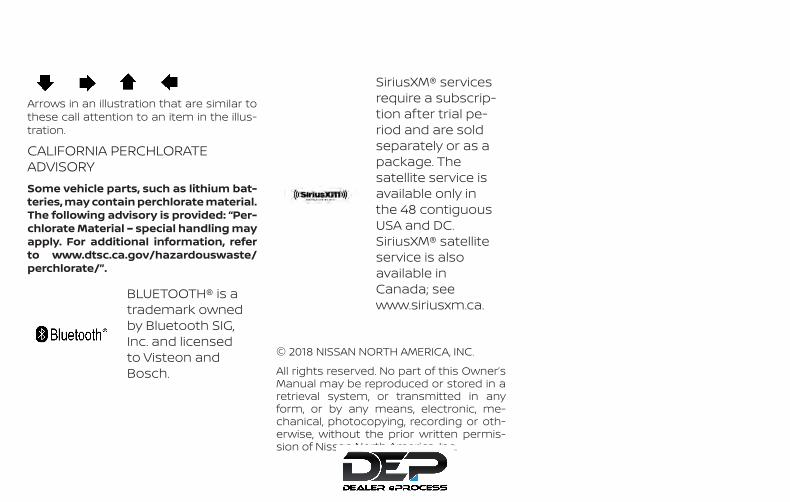
Arrows in an illustration that are similar tothese call attention to an item in the illus-tration.
CALIFORNIA PERCHLORATEADVISORYSome vehicle parts, such as lithium bat-teries, may contain perchlorate material.The following advisory is provided: “Per-chlorate Material – special handling mayapply. For additional information, referto www.dtsc.ca.gov/hazardouswaste/perchlorate/”.
BLUETOOTH® is atrademark ownedby Bluetooth SIG,Inc. and licensedto Visteon andBosch.
SiriusXM® servicesrequire a subscrip-tion after trial pe-riod and are soldseparately or as apackage. Thesatellite service isavailable only inthe 48 contiguousUSA and DC.SiriusXM® satelliteservice is alsoavailable inCanada; seewww.siriusxm.ca.
© 2018 NISSAN NORTH AMERICA, INC.
All rights reserved. No part of this Owner’sManual may be reproduced or stored in aretrieval system, or transmitted in anyform, or by any means, electronic, me-chanical, photocopying, recording or oth-erwise, without the prior written permis-sion of Nissan North America, Inc.
NISSAN CARES . . .
Both NISSAN and your NISSAN dealer are dedicated to serving all your automotive needs. Your satisfaction with your vehicle and yourNISSAN dealer are our primary concerns. Your NISSAN dealer is always available to assist you with all your automobile sales and serviceneeds.However, if there is something that yourNISSAN dealer cannot assist you with oryou would like to provide NISSAN directlywith comments or questions, please con-tact the NISSAN Consumer Affairs Depart-ment using our toll-free number:
For U.S. customers1-800-NISSAN-1(1-800-647-7261)
For Canadian customers1-800-387-0122
The Consumer Affairs Department will askfor the following information:
– Your name, address, and telephonenumber
– Vehicle identification number (attachedto the top of the instrument panel on thedriver’s side)
– Date of purchase
– Current odometer reading
– Your NISSAN dealer’s name
– Your comments or questions
OR
You can write to NISSAN with the informa-tion at:
For U.S. customersNissan North America, Inc.Consumer Affairs DepartmentP.O. Box 685003Franklin, TN 37068-5003or via e-mail at:[email protected]
For Canadian customersNissan Canada Inc.5290 Orbitor DriveMississauga, Ontario L4W 4Z5or via e-mail at:[email protected]
If you prefer, visit us at:www.nissanusa.com (for U.S. customers)orwww.nissan.ca (for Canadian customers)
We appreciate your interest in NISSAN and thank you for buying a quality NISSAN vehicle.
NISSAN CUSTOMER CARE PROGRAM


Table ofContents
Illustrated table of contents
Safety—Seats, seat belts and supplemental restraint system
Instruments and controls
Pre-driving checks and adjustments
Monitor, climate, audio, phone and voice recognition systems
Starting and driving
In case of emergency
Appearance and care
Do-it-yourself
Maintenance and schedules
Technical and consumer information
Index
0
1
2
3
4
5
6
7
8
9
10
11

0 Illustrated table of contents
Air bags, seat belts and child restraints . . . . . . . . . . 0-2Exterior front . . . . . . . . . . . . . . . . . . . . . . . . . . . . . . . . . . . . 0-3Exterior rear . . . . . . . . . . . . . . . . . . . . . . . . . . . . . . . . . . . . . 0-4Passenger compartment. . . . . . . . . . . . . . . . . . . . . . . . 0-5
Instrument panel . . . . . . . . . . . . . . . . . . . . . . . . . . . . . . . . 0-6Engine compartment check locations . . . . . . . . . . . 0-8Warning and indicator lights . . . . . . . . . . . . . . . . . . . . 0-10
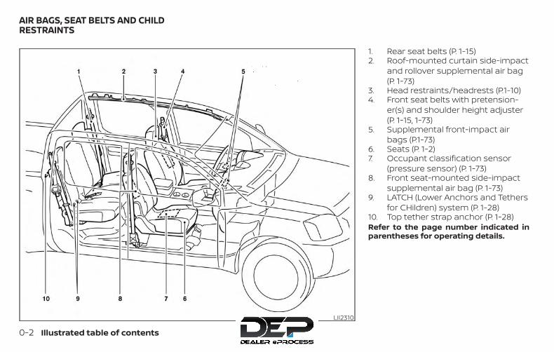
1. Rear seat belts (P. 1-15)2. Roof-mounted curtain side-impact
and rollover supplemental air bag(P. 1-73)
3. Head restraints/headrests (P.1-10)4. Front seat belts with pretension-
er(s) and shoulder height adjuster(P. 1-15, 1-73)
5. Supplemental front-impact airbags (P.1-73)
6. Seats (P. 1-2)7. Occupant classification sensor
(pressure sensor) (P. 1-73)8. Front seat-mounted side-impact
supplemental air bag (P. 1-73)9. LATCH (Lower Anchors and Tethers
for CHildren) system (P. 1-28)10. Top tether strap anchor (P. 1-28)Refer to the page number indicated inparentheses for operating details.
LII2310
AIR BAGS, SEAT BELTS AND CHILDRESTRAINTS
0-2 Illustrated table of contents

1. Engine hood (P. 3-10)2. Wiper and washer switch (P. 2-28)3. Windshield (P. 8-20)4. Windows (P. 2-49)5. Door locks (P. 3-3)
Key fob (if so equipped) (P. 3-6)Keys (P. 3-2)
6. Mirrors (P. 3-15)7. Tire pressure (P. 8-32)
Flat tire (P. 6-3)Tire chains (P. 8-32)
8. Headlight and turn signal switch(P. 2-29)Daytime Running Lights (DRL)system (if so equipped) (P. 2-29)Replacing bulbs (P. 8-27)
9. Fog light switch (if so equipped)(P. 2-29)
Refer to the page number indicated inparentheses for operating details.
LII2481
EXTERIOR FRONT
Illustrated table of contents 0-3
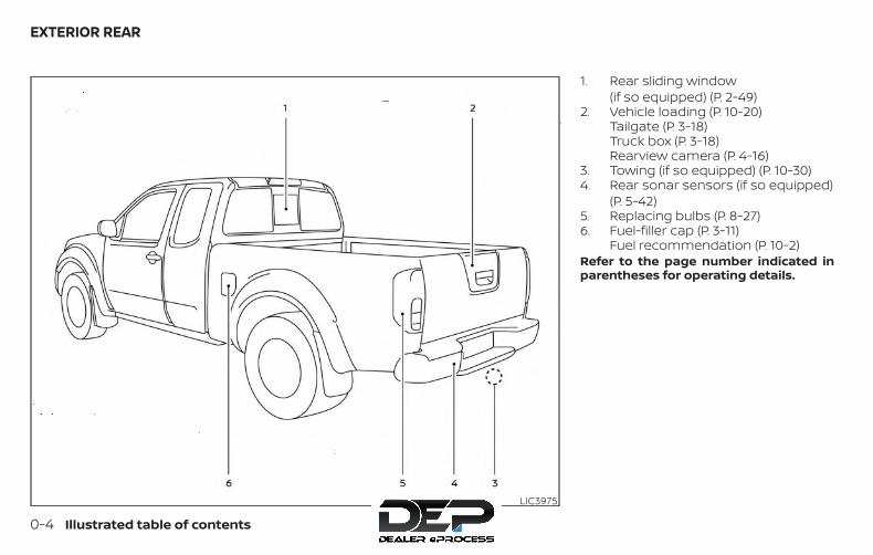
1. Rear sliding window(if so equipped) (P. 2-49)
2. Vehicle loading (P. 10-20)Tailgate (P. 3-18)Truck box (P. 3-18)Rearview camera (P. 4-16)
3. Towing (if so equipped) (P. 10-30)4. Rear sonar sensors (if so equipped)
(P. 5-42)5. Replacing bulbs (P. 8-27)6. Fuel-filler cap (P. 3-11)
Fuel recommendation (P. 10-2)Refer to the page number indicated inparentheses for operating details.
LIC3975
EXTERIOR REAR
0-4 Illustrated table of contents
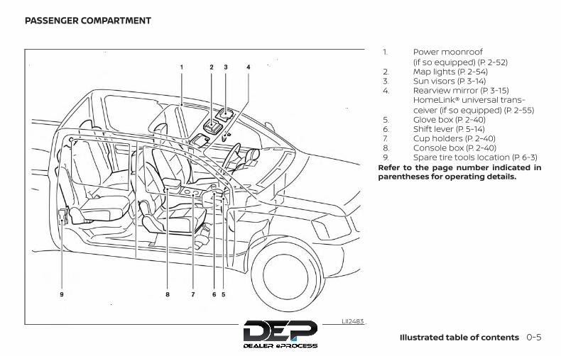
1. Power moonroof(if so equipped) (P. 2-52)
2. Map lights (P. 2-54)3. Sun visors (P. 3-14)4. Rearview mirror (P. 3-15)
HomeLink® universal trans-ceiver (if so equipped) (P. 2-55)
5. Glove box (P. 2-40)6. Shift lever (P. 5-14)7. Cup holders (P. 2-40)8. Console box (P. 2-40)9. Spare tire tools location (P. 6-3)
Refer to the page number indicated inparentheses for operating details.
LII2483
PASSENGER COMPARTMENT
Illustrated table of contents 0-5
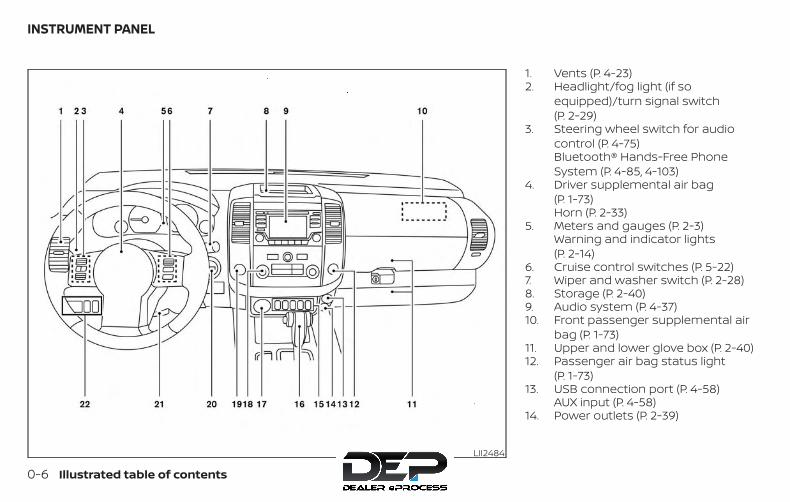
1. Vents (P. 4-23)2. Headlight/fog light (if so
equipped)/turn signal switch(P. 2-29)
3. Steering wheel switch for audiocontrol (P. 4-75)Bluetooth® Hands-Free PhoneSystem (P. 4-85, 4-103)
4. Driver supplemental air bag(P. 1-73)Horn (P. 2-33)
5. Meters and gauges (P. 2-3)Warning and indicator lights(P. 2-14)
6. Cruise control switches (P. 5-22)7. Wiper and washer switch (P. 2-28)8. Storage (P. 2-40)9. Audio system (P. 4-37)10. Front passenger supplemental air
bag (P. 1-73)11. Upper and lower glove box (P. 2-40)12. Passenger air bag status light
(P. 1-73)13. USB connection port (P. 4-58)
AUX input (P. 4-58)14. Power outlets (P. 2-39)
LII2484
INSTRUMENT PANEL
0-6 Illustrated table of contents
15. Electronic locking rear differential(E-Lock) system switch(if so equipped) (P. 2-37)Heated seat switches(if so equipped) (P. 2-34)Rear sonar switch (if so equipped)(P. 2-39)Vehicle Dynamic Control (VDC) OFFswitch (P. 2-35)
16. Shift lever (P. 5-14)17. 4WD shift switch (if so equipped)
(P. 5-26)18. Climate controls (P. 4-23, P. 4-32)19. Hazard warning flasher switch
(P. 6-2)20. Ignition switch (P. 5-11)21. Tilt steering wheel control
(if so equipped) (P. 3-14)22. Cargo lamp switch (P. 2-34)
Clutch interlock (clutch start)switch (if so equipped) (P. 2-38)Hill descent control switch(if so equipped) (P. 2-36)Outside mirror controls(if so equipped) (P. 3-15)
Illustrated table of contents 0-7
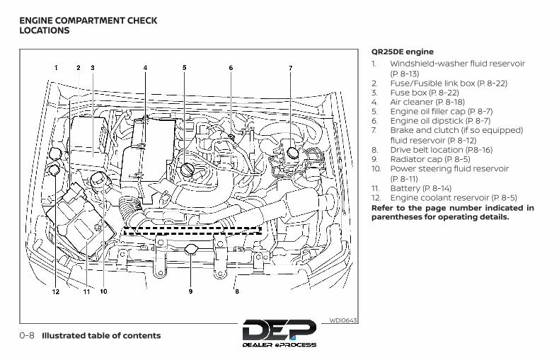
QR25DE engine1. Windshield-washer fluid reservoir
(P. 8-13)2. Fuse/Fusible link box (P. 8-22)3. Fuse box (P. 8-22)4. Air cleaner (P. 8-18)5. Engine oil filler cap (P. 8-7)6. Engine oil dipstick (P. 8-7)7. Brake and clutch (if so equipped)
fluid reservoir (P. 8-12)8. Drive belt location (P.8-16)9. Radiator cap (P. 8-5)10. Power steering fluid reservoir
(P. 8-11)11. Battery (P. 8-14)12. Engine coolant reservoir (P. 8-5)Refer to the page number indicated inparentheses for operating details.
WDI0643
ENGINE COMPARTMENT CHECKLOCATIONS
0-8 Illustrated table of contents
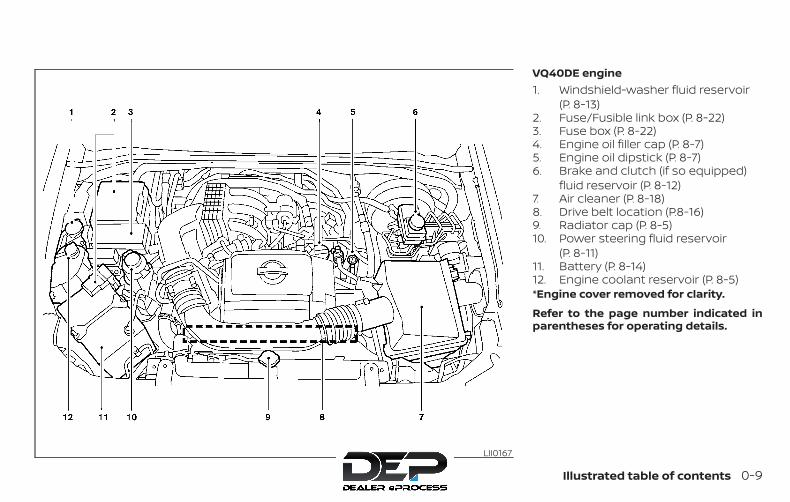
VQ40DE engine1. Windshield-washer fluid reservoir
(P. 8-13)2. Fuse/Fusible link box (P. 8-22)3. Fuse box (P. 8-22)4. Engine oil filler cap (P. 8-7)5. Engine oil dipstick (P. 8-7)6. Brake and clutch (if so equipped)
fluid reservoir (P. 8-12)7. Air cleaner (P. 8-18)8. Drive belt location (P.8-16)9. Radiator cap (P. 8-5)10. Power steering fluid reservoir
(P. 8-11)11. Battery (P. 8-14)12. Engine coolant reservoir (P. 8-5)*Engine cover removed for clarity.
Refer to the page number indicated inparentheses for operating details.
LII0167
Illustrated table of contents 0-9
Warninglight
Name Page
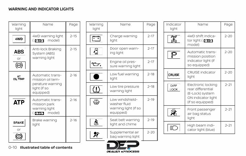
4WD warning light( model)
2-15
or
Anti-lock BrakingSystem (ABS)warning light
2-15
Automatic trans-mission oil tem-perature warninglight (if soequipped)
2-16
Automatic trans-mission parkwarning light( model)
2-16
or
Brake warninglight
2-16
Warninglight
Name Page
Charge warninglight
2-17
Door open warn-ing light
2-17
Engine oil pres-sure warning light
2-17
Low fuel warninglight
2-18
Low tire pressurewarning light
2-18
Low windshield-washer fluidwarning light (if soequipped)
2-19
Seat belt warninglight and chime
2-19
Supplemental airbag warning light
2-20
Indicatorlight
Name Page
4WD shift indica-tor light (model)
2-20
Automatic trans-mission positionindicator light (ifso equipped)
2-20
CRUISE indicatorlight
2-20
Electronic lockingrear differential(E-Lock) systemON indicator light(if so equipped)
2-21
Front passengerair bag statuslight
2-21
High beam indi-cator light (blue)
2-21
WARNING AND INDICATOR LIGHTS
0-10 Illustrated table of contents

Indicatorlight
Name Page
Hill descent con-trol system ONindicator light (ifso equipped)
2-21
Malfunction Indi-cator Light (MIL)
2-21
Overdrive OFFindicator light (ifso equipped)
2-22
Security indicatorlight (if soequipped)
2-22
SET indicator light 2-22
Slip indicator light 2-23
Transfer 4LO posi-tion indicator light( model)
2-23
Indicatorlight
Name Page
Turn signal/hazard indicatorlights
2-23
Vehicle DynamicControl (VDC) OFFindicator light
2-23
Illustrated table of contents 0-11

1 Safety—Seats, seat belts andsupplemental restraint system
Seats . . . . . . . . . . . . . . . . . . . . . . . . . . . . . . . . . . . . . . . . . . . . 1-2Front manual seat adjustment(if so equipped) . . . . . . . . . . . . . . . . . . . . . . . . . . . . . . . .1-3Front power seat adjustment(if so equipped) . . . . . . . . . . . . . . . . . . . . . . . . . . . . . . . 1-5Rear bench seat (if so equipped). . . . . . . . . . . . . . 1-6Jump seat (if so equipped). . . . . . . . . . . . . . . . . . . . .1-7Armrest (if so equipped) . . . . . . . . . . . . . . . . . . . . . . .1-7Flexible seating . . . . . . . . . . . . . . . . . . . . . . . . . . . . . . . .1-7
Head restraints/headrests . . . . . . . . . . . . . . . . . . . . . .1-10Adjustable head restraint/headrestcomponents . . . . . . . . . . . . . . . . . . . . . . . . . . . . . . . . . 1-11Non-adjustable head restraint/headrest components. . . . . . . . . . . . . . . . . . . . . . . .1-12Remove . . . . . . . . . . . . . . . . . . . . . . . . . . . . . . . . . . . . . .1-12Install. . . . . . . . . . . . . . . . . . . . . . . . . . . . . . . . . . . . . . . . .1-13Adjust . . . . . . . . . . . . . . . . . . . . . . . . . . . . . . . . . . . . . . . .1-13Front-seat active head restraints . . . . . . . . . . . . .1-14
Seat belts . . . . . . . . . . . . . . . . . . . . . . . . . . . . . . . . . . . . . . .1-15Precautions on seat belt usage. . . . . . . . . . . . . . .1-15Seat belt warning light. . . . . . . . . . . . . . . . . . . . . . . .1-18
Pregnant women. . . . . . . . . . . . . . . . . . . . . . . . . . . . .1-18Injured persons. . . . . . . . . . . . . . . . . . . . . . . . . . . . . . .1-18Three-point type seat belt withretractor . . . . . . . . . . . . . . . . . . . . . . . . . . . . . . . . . . . . .1-18Seat belt extenders. . . . . . . . . . . . . . . . . . . . . . . . . . 1-24Seat belt maintenance . . . . . . . . . . . . . . . . . . . . . . 1-25
Child safety. . . . . . . . . . . . . . . . . . . . . . . . . . . . . . . . . . . . . 1-25Infants . . . . . . . . . . . . . . . . . . . . . . . . . . . . . . . . . . . . . . 1-26Small children . . . . . . . . . . . . . . . . . . . . . . . . . . . . . . . 1-26Larger children . . . . . . . . . . . . . . . . . . . . . . . . . . . . . . 1-27
Child restraints . . . . . . . . . . . . . . . . . . . . . . . . . . . . . . . . . 1-28Precautions on child restraints . . . . . . . . . . . . . . 1-28LATCH (Lower Anchors and Tethers forCHildren) system . . . . . . . . . . . . . . . . . . . . . . . . . . . . .1-31Rear-facing child restraint installationusing LATCH (Crew Cab models) . . . . . . . . . . . . . 1-35Rear-facing child restraint installationusing LATCH — jump seat(King Cab® models) . . . . . . . . . . . . . . . . . . . . . . . . . . 1-37Rear-facing child restraint installationusing the seat belts (Crew Cab models). . . . . . .1-41

Rear-facing child restraint installationusing the seat belts — jump seat(King Cab® models) . . . . . . . . . . . . . . . . . . . . . . . . . . 1-44Forward-facing child restraintinstallation using LATCH (Crew Cabmodels) . . . . . . . . . . . . . . . . . . . . . . . . . . . . . . . . . . . . . 1-48Forward-facing child restraintinstallation using LATCH — jump seat(King Cab® models) . . . . . . . . . . . . . . . . . . . . . . . . . . 1-52Forward-facing child restraintinstallation using the seat belts — frontpassenger and rear bench seat(Crew Cab models) . . . . . . . . . . . . . . . . . . . . . . . . . . 1-56
Forward-facing child restraintinstallation using the seat belts — frontpassenger and jump seats(King Cab® models) . . . . . . . . . . . . . . . . . . . . . . . . . . .1-61Booster seats . . . . . . . . . . . . . . . . . . . . . . . . . . . . . . . 1-68
Supplemental Restraint System (SRS). . . . . . . . . . . 1-73Precautions on SRS. . . . . . . . . . . . . . . . . . . . . . . . . . 1-73Supplemental air bag warning labels . . . . . . . . 1-89Supplemental air bag warning light. . . . . . . . . . 1-90
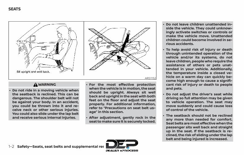
WARNING∙ Do not ride in a moving vehicle when
the seatback is reclined. This can bedangerous. The shoulder belt will notbe against your body. In an accident,you could be thrown into it and re-ceive neck or other serious injuries.You could also slide under the lap beltand receive serious internal injuries.
∙ For the most effective protectionwhen the vehicle is in motion, the seatshould be upright. Always sit wellback and upright in the seat with bothfeet on the floor and adjust the seatproperly. For additional information,refer to “Precautions on seat belt us-age” in this section.
∙ After adjustment, gently rock in theseat to make sure it is securely locked.
∙ Do not leave children unattended in-side the vehicle. They could unknow-ingly activate switches or controls ormake the vehicle move. Unattendedchildren could become involved in se-rious accidents.
∙ To help avoid risk of injury or deaththrough unintended operation of thevehicle and/or its systems, do notleave children, people who require theassistance of others or pets unat-tended in your vehicle. Additionally,the temperature inside a closed ve-hicle on a warm day can quickly be-come high enough to cause a signifi-cant risk of injury or death to peopleand pets.
∙ Do not adjust the driver’s seat whiledriving so full attention may be givento vehicle operation. The seat maymove suddenly and could cause lossof control of the vehicle.
∙ The seatback should not be reclinedany more than needed for comfort.Seat belts are most effective when thepassenger sits well back and straightup in the seat. If the seatback is re-clined, the risk of sliding under the lapbelt and being injured is increased.
ARS1152
SEATS
1-2 Safety—Seats, seat belts and supplemental restraint system
CAUTIONWhen adjusting the seat positions, besure not to contact any moving parts toavoid possible injuries and/or damage.
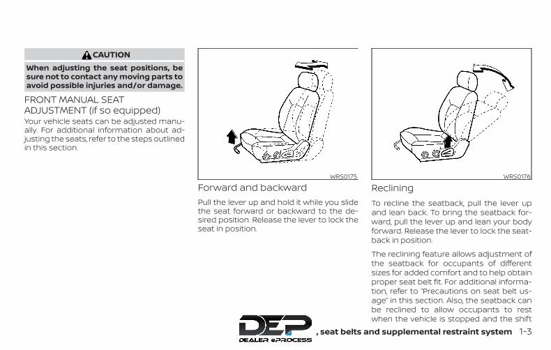
FRONT MANUAL SEATADJUSTMENT (if so equipped)Your vehicle seats can be adjusted manu-ally. For additional information about ad-justing the seats, refer to the steps outlinedin this section.
Forward and backwardPull the lever up and hold it while you slidethe seat forward or backward to the de-sired position. Release the lever to lock theseat in position.
RecliningTo recline the seatback, pull the lever upand lean back. To bring the seatback for-ward, pull the lever up and lean your bodyforward. Release the lever to lock the seat-back in position.
The reclining feature allows adjustment ofthe seatback for occupants of differentsizes for added comfort and to help obtainproper seat belt fit. For additional informa-tion, refer to “Precautions on seat belt us-age” in this section. Also, the seatback canbe reclined to allow occupants to restwhen the vehicle is stopped and the shift
WRS0175 WRS0176
Safety—Seats, seat belts and supplemental restraint system 1-3
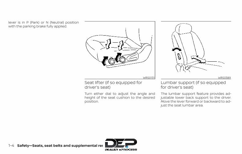
lever is in P (Park) or N (Neutral) positionwith the parking brake fully applied.
Seat lifter (if so equipped fordriver’s seat)Turn either dial to adjust the angle andheight of the seat cushion to the desiredposition.
Lumbar support (if so equippedfor driver’s seat)The lumbar support feature provides ad-justable lower back support to the driver.Move the lever forward or backward to ad-just the seat lumbar area.
WRS0131 WRS0389
1-4 Safety—Seats, seat belts and supplemental restraint system
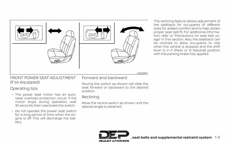
FRONT POWER SEAT ADJUSTMENT(if so equipped)Operating tips
∙ The power seat motor has an auto-reset overload protection circuit. If themotor stops during operation, wait30 seconds then reactivate the switch.
∙ Do not operate the power seat switchfor a long period of time when the en-gine is off. This will discharge the bat-tery.
Forward and backwardMoving the switch as shown will slide theseat forward or backward to the desiredposition.
RecliningMove the recline switch as shown until thedesired angle is obtained.
The reclining feature allows adjustment ofthe seatback for occupants of differentsizes for added comfort and to help obtainproper seat belt fit. For additional informa-tion, refer to “Precautions on seat belt us-age” in this section. Also, the seatback canbe reclined to allow occupants to restwhen the vehicle is stopped and the shiftlever is in P (Park) or N (Neutral) positionwith the parking brake fully applied.
LRS2897
Safety—Seats, seat belts and supplemental restraint system 1-5
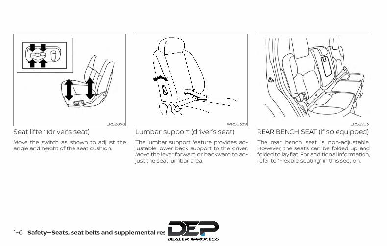
Seat lifter (driver’s seat)Move the switch as shown to adjust theangle and height of the seat cushion.
Lumbar support (driver’s seat)The lumbar support feature provides ad-justable lower back support to the driver.Move the lever forward or backward to ad-just the seat lumbar area.
REAR BENCH SEAT (if so equipped)The rear bench seat is non-adjustable.However, the seats can be folded up andfolded to lay flat. For additional information,refer to “Flexible seating” in this section.
LRS2898 WRS0389 LRS2903
1-6 Safety—Seats, seat belts and supplemental restraint system

JUMP SEAT (if so equipped)
WARNING∙ Do not use a child restraint in the driv-
er’s side jump seat. This seating posi-tion is not suitable for child restraintinstallation. A child restraint can be in-stalled in the passenger’s side jumpseat when the seat extension is un-folded from the seat base.
∙ When folding the jump seat, be carefulnot to squeeze your finger betweenthe seat cushion and the body side.
ARMREST (if so equipped)To use the center armrest on the rearbench seat, pull on the tab in the center ofthe seat and fold it down as shown.
FLEXIBLE SEATING
WARNING∙ Never allow anyone to ride in the
cargo area or on the rear seats whenthey are in the fold-down position. In acollision, people riding in these areaswithout proper restraints are morelikely to be seriously injured or killed.
∙ Do not allow people to ride in any areaof your vehicle that is not equippedwith seats and seat belts. Be sure ev-eryone in your vehicle is in a seat andusing a seat belt properly.
∙ Do not allow more than one person touse the same seat belt.
∙ Do not fold down the rear seats whenoccupants are in the rear seat area orany luggage is on the rear seats.
– Make sure that the seat path isclear before moving the seat.
– Be careful not to allow hands orfeet to get caught or pinched in theseat.
∙ Head restraints/headrests should beadjusted properly as they may pro-vide significant protection against in-jury in an accident. Always replaceand adjust them properly if they havebeen removed for any reason.
∙ If the head restraints/headrests areremoved for any reason, they shouldbe securely stored to prevent themfrom causing injury to passengers ordamage to the vehicle in case of sud-den braking or an accident.
LRS0556 LRS2901
Safety—Seats, seat belts and supplemental restraint system 1-7

∙ When returning the seatbacks to theupright position, be certain they arecompletely secured in the latched po-sition. If they are not completely se-cured, passengers may be injured inan accident or sudden stop.
∙ Properly secure all cargo to help pre-vent it from sliding or shifting. Do notplace cargo higher than the seat-backs. In a sudden stop or collision,unsecured cargo could cause per-sonal injury.
Folding the rear bench seat up (ifso equipped)To fold the rear bench seat up:
1. Lift up on the lever, located on the sideof the seat, while lifting the front of theseat cushion up.
2. Fold the bottom of the seat cushiontoward the back of the vehicle until itlocks in place.
LRS2475 LRS2476
1-8 Safety—Seats, seat belts and supplemental restraint system

3. Repeat this process to raise and securethe seat cushion on the other side ofthe vehicle for maximum storage ca-pacity.
To return the rear bench seat to a seatingposition, reverse the process. Make sure toproperly push the seat cushion downinto place.
WARNING∙ When the vehicle is being used to
carry cargo, properly secure all cargoto help prevent it from sliding or shift-ing. Do not place cargo higher thanthe seatbacks. In a sudden stop or col-lision, unsecured cargo could causepersonal injury.
∙ Do not allow people to ride in any areaof your vehicle that is not equippedwith seats and seat belts. Be sure ev-eryone in your vehicle is in a seat andusing a seat belt properly. Never ridein the rear seat unless the seat bot-tom cushions are in place and latched.
∙ When returning the seatbacks to theupright position, be certain they arecompletely secured in the latched po-sition. If they are not completely se-cured, passengers may be injured inan accident or sudden stop.
A. Child restraint anchor points
Folding the rear bench seat down(if so equipped)The rear bench seatback can be tilted for-ward to access the child restraint anchorpoint locations or the jacking equipment.
To tilt the seatback forward, pull the strapup �1 and tilt the seatback. The child re-straint anchor points can be accessed be-hind the rear bench seatback. The jackingequipment can be accessed from behindthe passenger’s side seatback.
LRS2477 LRS2478
Safety—Seats, seat belts and supplemental restraint system 1-9

WARNINGNever allow anyone to ride in the cargoarea or on the rear seat when it is in thefold-down position. Use of these areasby passengers without proper re-straints could result in serious injury ordeath in an accident or sudden stop.
WARNINGHead restraints/headrests supplementthe other vehicle safety systems. Theymay provide additional protectionagainst injury in certain rear end colli-sions. Adjustable headrestraints/headrests must be adjustedproperly, as specified in this section.Check the adjustment after someoneelse uses the seat. Do not attach any-thing to the head restraint/headreststalks or remove the headrestraint/headrest. Do not use the seatif the head restraint/headrest has beenremoved. If the head restraint/headrestwas removed, reinstall and properly ad-just the head restraint/headrest beforean occupant uses the seating position.Failure to follow these instructions canreduce the effectiveness of the headrestraints/headrests. This may in-crease the risk of serious injury or deathin a collision.
Crew CabLRS2361
HEAD RESTRAINTS/HEADRESTS
1-10 Safety—Seats, seat belts and supplemental restraint system
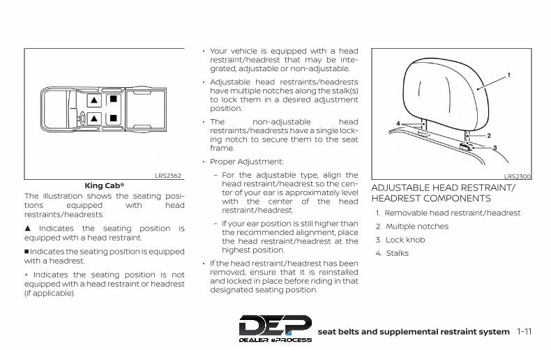
The illustration shows the seating posi-tions equipped with headrestraints/headrests.
� Indicates the seating position isequipped with a head restraint.
� Indicates the seating position is equippedwith a headrest.
+ Indicates the seating position is notequipped with a head restraint or headrest(if applicable).
∙ Your vehicle is equipped with a headrestraint/headrest that may be inte-grated, adjustable or non-adjustable.
∙ Adjustable head restraints/headrestshave multiple notches along the stalk(s)to lock them in a desired adjustmentposition.
∙ The non-adjustable headrestraints/headrests have a single lock-ing notch to secure them to the seatframe.
∙ Proper Adjustment:
– For the adjustable type, align thehead restraint/headrest so the cen-ter of your ear is approximately levelwith the center of the headrestraint/headrest.
– If your ear position is still higher thanthe recommended alignment, placethe head restraint/headrest at thehighest position.
∙ If the head restraint/headrest has beenremoved, ensure that it is reinstalledand locked in place before riding in thatdesignated seating position.
ADJUSTABLE HEAD RESTRAINT/HEADREST COMPONENTS
1. Removable head restraint/headrest
2. Multiple notches
3. Lock knob
4. Stalks
King Cab®LRS2362 LRS2300
Safety—Seats, seat belts and supplemental restraint system 1-11
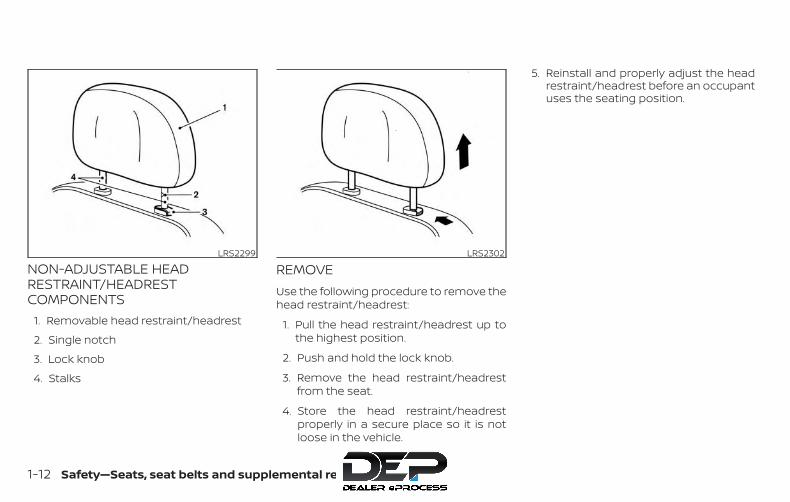
NON-ADJUSTABLE HEADRESTRAINT/HEADRESTCOMPONENTS
1. Removable head restraint/headrest
2. Single notch
3. Lock knob
4. Stalks
REMOVEUse the following procedure to remove thehead restraint/headrest:
1. Pull the head restraint/headrest up tothe highest position.
2. Push and hold the lock knob.
3. Remove the head restraint/headrestfrom the seat.
4. Store the head restraint/headrestproperly in a secure place so it is notloose in the vehicle.
5. Reinstall and properly adjust the headrestraint/headrest before an occupantuses the seating position.
LRS2299 LRS2302
1-12 Safety—Seats, seat belts and supplemental restraint system

INSTALL1. Align the head restraint/headrest
stalks with the holes in the seat. Makesure that the head restraint/headrest isfacing the correct direction. The stalkwith the notch (notches) �1 must beinstalled in the hole with the lock knob�2 .
2. Push and hold the lock knob and pushthe head restraint/headrest down.
3. Properly adjust the head restraint/headrest before an occupant uses theseating position.
ADJUSTFor adjustable head restraint/headrest
Adjust the head restraint/headrest so thecenter is level with the center of your ears. Ifyour ear position is still higher than therecommended alignment, place the headrestraint/headrest at the highest position.
For non-adjustable head restraint/headrest
Make sure the head restraint/headrest ispositioned so the lock knob is engaged inthe notch before riding in that designatedseating position.
LRS2303 WRS0134 LRS2351
Safety—Seats, seat belts and supplemental restraint system 1-13
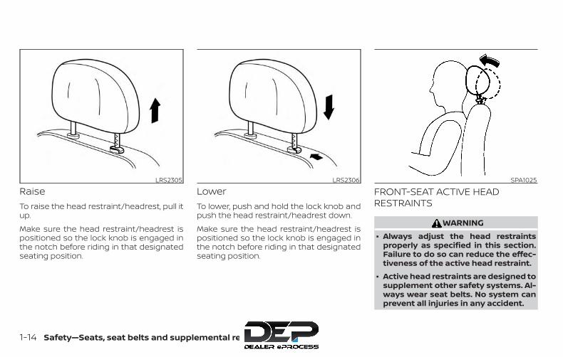
RaiseTo raise the head restraint/headrest, pull itup.
Make sure the head restraint/headrest ispositioned so the lock knob is engaged inthe notch before riding in that designatedseating position.
LowerTo lower, push and hold the lock knob andpush the head restraint/headrest down.
Make sure the head restraint/headrest ispositioned so the lock knob is engaged inthe notch before riding in that designatedseating position.
FRONT-SEAT ACTIVE HEADRESTRAINTS
WARNING∙ Always adjust the head restraints
properly as specified in this section.Failure to do so can reduce the effec-tiveness of the active head restraint.
∙ Active head restraints are designed tosupplement other safety systems. Al-ways wear seat belts. No system canprevent all injuries in any accident.
LRS2305 LRS2306 SPA1025
1-14 Safety—Seats, seat belts and supplemental restraint system
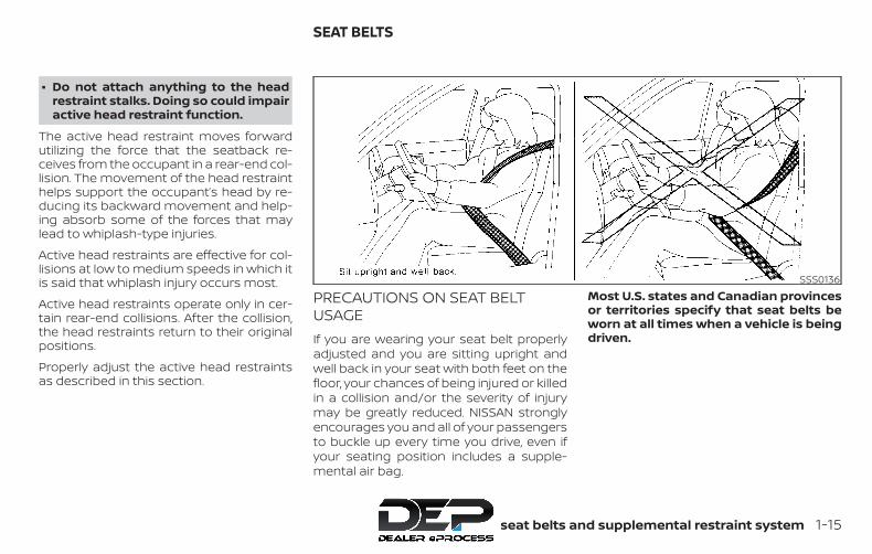
∙ Do not attach anything to the headrestraint stalks. Doing so could impairactive head restraint function.
The active head restraint moves forwardutilizing the force that the seatback re-ceives from the occupant in a rear-end col-lision. The movement of the head restrainthelps support the occupant’s head by re-ducing its backward movement and help-ing absorb some of the forces that maylead to whiplash-type injuries.
Active head restraints are effective for col-lisions at low to medium speeds in which itis said that whiplash injury occurs most.
Active head restraints operate only in cer-tain rear-end collisions. After the collision,the head restraints return to their originalpositions.
Properly adjust the active head restraintsas described in this section.
PRECAUTIONS ON SEAT BELTUSAGEIf you are wearing your seat belt properlyadjusted and you are sitting upright andwell back in your seat with both feet on thefloor, your chances of being injured or killedin a collision and/or the severity of injurymay be greatly reduced. NISSAN stronglyencourages you and all of your passengersto buckle up every time you drive, even ifyour seating position includes a supple-mental air bag.
Most U.S. states and Canadian provincesor territories specify that seat belts beworn at all times when a vehicle is beingdriven.
SSS0136
SEAT BELTS
Safety—Seats, seat belts and supplemental restraint system 1-15
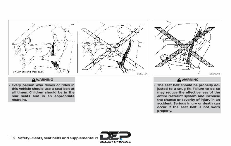
WARNING∙ Every person who drives or rides in
this vehicle should use a seat belt atall times. Children should be in therear seats and in an appropriaterestraint.
WARNING∙ The seat belt should be properly ad-
justed to a snug fit. Failure to do somay reduce the effectiveness of theentire restraint system and increasethe chance or severity of injury in anaccident. Serious injury or death canoccur if the seat belt is not wornproperly.
SSS0134 SSS0016
1-16 Safety—Seats, seat belts and supplemental restraint system
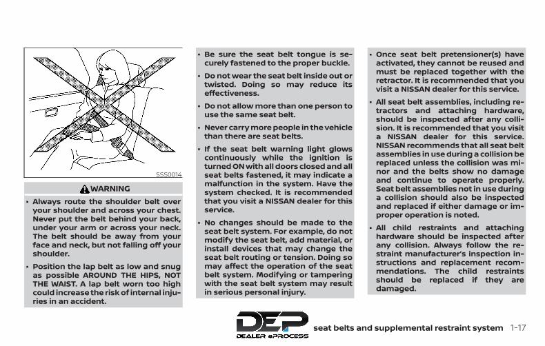
WARNING∙ Always route the shoulder belt over
your shoulder and across your chest.Never put the belt behind your back,under your arm or across your neck.The belt should be away from yourface and neck, but not falling off yourshoulder.
∙ Position the lap belt as low and snugas possible AROUND THE HIPS, NOTTHE WAIST. A lap belt worn too highcould increase the risk of internal inju-ries in an accident.
∙ Be sure the seat belt tongue is se-curely fastened to the proper buckle.
∙ Do not wear the seat belt inside out ortwisted. Doing so may reduce itseffectiveness.
∙ Do not allow more than one person touse the same seat belt.
∙ Never carry more people in the vehiclethan there are seat belts.
∙ If the seat belt warning light glowscontinuously while the ignition isturned ON with all doors closed and allseat belts fastened, it may indicate amalfunction in the system. Have thesystem checked. It is recommendedthat you visit a NISSAN dealer for thisservice.
∙ No changes should be made to theseat belt system. For example, do notmodify the seat belt, add material, orinstall devices that may change theseat belt routing or tension. Doing somay affect the operation of the seatbelt system. Modifying or tamperingwith the seat belt system may resultin serious personal injury.
∙ Once seat belt pretensioner(s) haveactivated, they cannot be reused andmust be replaced together with theretractor. It is recommended that youvisit a NISSAN dealer for this service.
∙ All seat belt assemblies, including re-tractors and attaching hardware,should be inspected after any colli-sion. It is recommended that you visita NISSAN dealer for this service.NISSAN recommends that all seat beltassemblies in use during a collision bereplaced unless the collision was mi-nor and the belts show no damageand continue to operate properly.Seat belt assemblies not in use duringa collision should also be inspectedand replaced if either damage or im-proper operation is noted.
∙ All child restraints and attachinghardware should be inspected afterany collision. Always follow the re-straint manufacturer’s inspection in-structions and replacement recom-mendations. The child restraintsshould be replaced if they aredamaged.
SSS0014
Safety—Seats, seat belts and supplemental restraint system 1-17
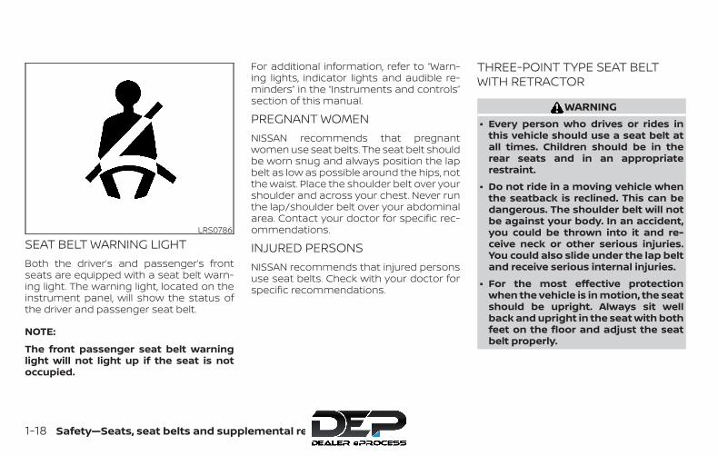
SEAT BELT WARNING LIGHTBoth the driver’s and passenger’s frontseats are equipped with a seat belt warn-ing light. The warning light, located on theinstrument panel, will show the status ofthe driver and passenger seat belt.
NOTE:
The front passenger seat belt warninglight will not light up if the seat is notoccupied.
For additional information, refer to “Warn-ing lights, indicator lights and audible re-minders” in the “Instruments and controls”section of this manual.
PREGNANT WOMENNISSAN recommends that pregnantwomen use seat belts. The seat belt shouldbe worn snug and always position the lapbelt as low as possible around the hips, notthe waist. Place the shoulder belt over yourshoulder and across your chest. Never runthe lap/shoulder belt over your abdominalarea. Contact your doctor for specific rec-ommendations.
INJURED PERSONSNISSAN recommends that injured personsuse seat belts. Check with your doctor forspecific recommendations.
THREE-POINT TYPE SEAT BELTWITH RETRACTOR
WARNING∙ Every person who drives or rides in
this vehicle should use a seat belt atall times. Children should be in therear seats and in an appropriaterestraint.
∙ Do not ride in a moving vehicle whenthe seatback is reclined. This can bedangerous. The shoulder belt will notbe against your body. In an accident,you could be thrown into it and re-ceive neck or other serious injuries.You could also slide under the lap beltand receive serious internal injuries.
∙ For the most effective protectionwhen the vehicle is in motion, the seatshould be upright. Always sit wellback and upright in the seat with bothfeet on the floor and adjust the seatbelt properly.
LRS0786
1-18 Safety—Seats, seat belts and supplemental restraint system
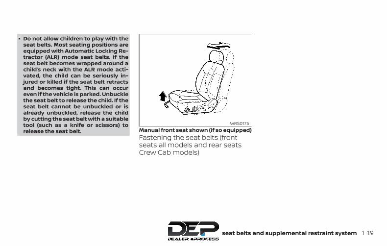
∙ Do not allow children to play with theseat belts. Most seating positions areequipped with Automatic Locking Re-tractor (ALR) mode seat belts. If theseat belt becomes wrapped around achild’s neck with the ALR mode acti-vated, the child can be seriously in-jured or killed if the seat belt retractsand becomes tight. This can occureven if the vehicle is parked. Unbucklethe seat belt to release the child. If theseat belt cannot be unbuckled or isalready unbuckled, release the childby cutting the seat belt with a suitabletool (such as a knife or scissors) torelease the seat belt.
Fastening the seat belts (frontseats all models and rear seatsCrew Cab models)
Manual front seat shown (if so equipped)WRS0175
Safety—Seats, seat belts and supplemental restraint system 1-19

1. Adjust the seat. For additional informa-tion, refer to “Seats” in this section.
2. Slowly pull the seat belt out of the re-tractor and insert the tongue into thebuckle �A until you hear and feel thelatch engage.
∙ The retractor is designed to lockduring a sudden stop or on impact.A slow pulling motion permits theseat belt to move, and allows yousome freedom of movement in theseat.
∙ If the seat belt cannot be pulledfrom its fully retracted position,firmly pull the belt and release it.Then smoothly pull the belt out ofthe retractor.
Power front seat shown (if so equipped)LRS2897 LRS2674
1-20 Safety—Seats, seat belts and supplemental restraint system
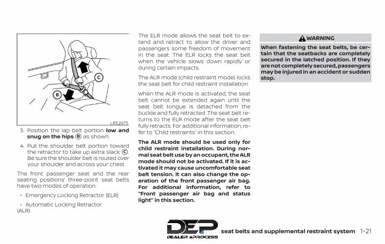
3. Position the lap belt portion low andsnug on the hips �B as shown.
4. Pull the shoulder belt portion towardthe retractor to take up extra slack �C .Be sure the shoulder belt is routed overyour shoulder and across your chest.
The front passenger seat and the rearseating positions’ three-point seat beltshave two modes of operation:
∙ Emergency Locking Retractor (ELR)
∙ Automatic Locking Retractor(ALR)
The ELR mode allows the seat belt to ex-tend and retract to allow the driver andpassengers some freedom of movementin the seat. The ELR locks the seat beltwhen the vehicle slows down rapidly orduring certain impacts.
The ALR mode (child restraint mode) locksthe seat belt for child restraint installation.
When the ALR mode is activated, the seatbelt cannot be extended again until theseat belt tongue is detached from thebuckle and fully retracted. The seat belt re-turns to the ELR mode after the seat beltfully retracts. For additional information, re-fer to “Child restraints” in this section.
The ALR mode should be used only forchild restraint installation. During nor-mal seat belt use by an occupant, the ALRmode should not be activated. If it is ac-tivated it may cause uncomfortable seatbelt tension. It can also change the op-eration of the front passenger air bag.For additional information, refer to“Front passenger air bag and statuslight” in this section.
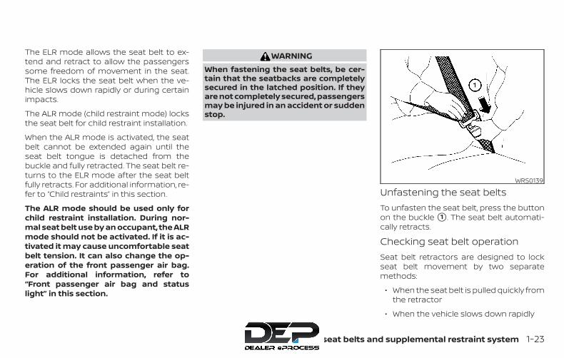
WARNINGWhen fastening the seat belts, be cer-tain that the seatbacks are completelysecured in the latched position. If theyare not completely secured, passengersmay be injured in an accident or suddenstop.
LRS2675
Safety—Seats, seat belts and supplemental restraint system 1-21

Fastening the seat belts ( jumpseats for King Cab® models)
1. Open the jump seat. For additional in-formation, refer to “Seats” in this sec-tion.
2. Slowly pull the seat belt out of the re-tractor and insert the tongue into thebuckle �A until you hear and feel thelatch engage.
∙ The retractor is designed to lock dur-ing a sudden stop or on impact. Aslow pulling motion permits the seatbelt to move, and allows you somefreedom of movement in the seat.
∙ If the seat belt cannot be pulled fromits fully retracted position, firmly pullthe belt and release it. Then smoothlypull the belt out of the retractor.
3. Position the lap belt portion low andsnug on the hips �B as shown.
4. Pull the shoulder belt portion towardthe retractor to take up extra slack �C .Be sure the shoulder belt is routed overyour shoulder and across your chest.
The jump seat position’s three-point seatbelts have two modes of operation:
∙ Emergency Locking Retractor (ELR)
∙ Automatic Locking Retractor (ALR)
LRS0556 LRS2723 LRS2724
1-22 Safety—Seats, seat belts and supplemental restraint system
The ELR mode allows the seat belt to ex-tend and retract to allow the passengerssome freedom of movement in the seat.The ELR locks the seat belt when the ve-hicle slows down rapidly or during certainimpacts.
The ALR mode (child restraint mode) locksthe seat belt for child restraint installation.
When the ALR mode is activated, the seatbelt cannot be extended again until theseat belt tongue is detached from thebuckle and fully retracted. The seat belt re-turns to the ELR mode after the seat beltfully retracts. For additional information, re-fer to “Child restraints” in this section.
The ALR mode should be used only forchild restraint installation. During nor-mal seat belt use by an occupant, the ALRmode should not be activated. If it is ac-tivated it may cause uncomfortable seatbelt tension. It can also change the op-eration of the front passenger air bag.For additional information, refer to“Front passenger air bag and statuslight” in this section.
WARNINGWhen fastening the seat belts, be cer-tain that the seatbacks are completelysecured in the latched position. If theyare not completely secured, passengersmay be injured in an accident or suddenstop.
Unfastening the seat beltsTo unfasten the seat belt, press the buttonon the buckle �1 . The seat belt automati-cally retracts.
Checking seat belt operationSeat belt retractors are designed to lockseat belt movement by two separatemethods:
∙ When the seat belt is pulled quickly fromthe retractor
∙ When the vehicle slows down rapidly
WRS0139
Safety—Seats, seat belts and supplemental restraint system 1-23
To increase your confidence in the seatbelts, check the operation as follows:
∙ Grasp the shoulder belt and pull for-ward quickly. The retractor should lockand restrict further belt movement.
If the retractor does not lock during thischeck, get the system checked. It is recom-mended that you visit a NISSAN dealer forthis service or to learn more about seat beltoperation.
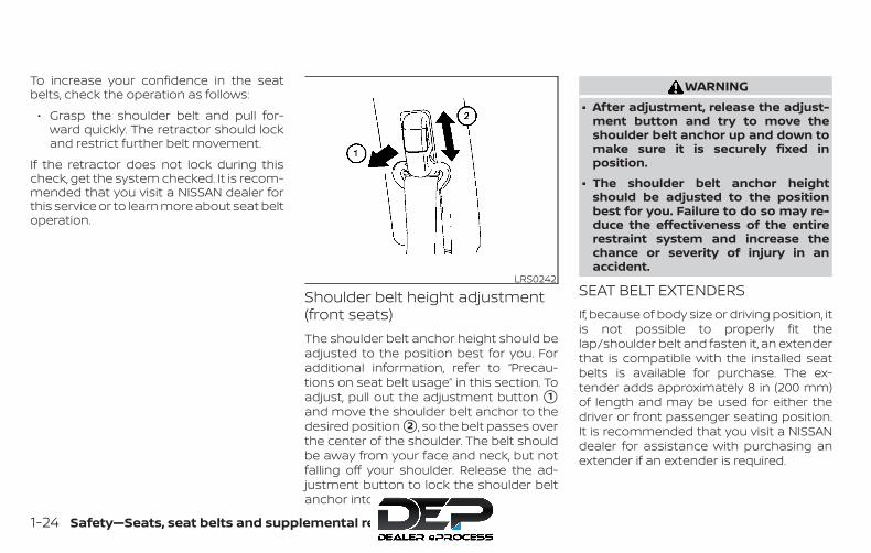
Shoulder belt height adjustment(front seats)The shoulder belt anchor height should beadjusted to the position best for you. Foradditional information, refer to “Precau-tions on seat belt usage” in this section. Toadjust, pull out the adjustment button �1and move the shoulder belt anchor to thedesired position �2 , so the belt passes overthe center of the shoulder. The belt shouldbe away from your face and neck, but notfalling off your shoulder. Release the ad-justment button to lock the shoulder beltanchor into position.
WARNING∙ After adjustment, release the adjust-
ment button and try to move theshoulder belt anchor up and down tomake sure it is securely fixed inposition.
∙ The shoulder belt anchor heightshould be adjusted to the positionbest for you. Failure to do so may re-duce the effectiveness of the entirerestraint system and increase thechance or severity of injury in anaccident.
SEAT BELT EXTENDERSIf, because of body size or driving position, itis not possible to properly fit thelap/shoulder belt and fasten it, an extenderthat is compatible with the installed seatbelts is available for purchase. The ex-tender adds approximately 8 in (200 mm)of length and may be used for either thedriver or front passenger seating position.It is recommended that you visit a NISSANdealer for assistance with purchasing anextender if an extender is required.
LRS0242
1-24 Safety—Seats, seat belts and supplemental restraint system
WARNING∙ Only NISSAN seat belt extenders,
made by the same company whichmade the original equipment seatbelts, should be used with NISSANseat belts.
∙ Adults and children who can use thestandard seat belt should not use anextender. Such unnecessary usecould result in serious personal injuryin the event of an accident.
∙ Never use seat belt extenders to in-stall child restraints. If the child re-straint is not secured properly, thechild could be seriously injured orkilled in a collision or a sudden stop.
SEAT BELT MAINTENANCE∙ To clean the seat belt webbing, apply
a mild soap solution or any solution rec-ommended for cleaning upholstery orcarpet. Then wipe with a cloth and allowthe seat belts to dry in the shade. Do notallow the seat belts to retract until theyare completely dry.
∙ If dirt builds up in the shoulder beltguide of the seat belt anchors, theseat belts may retract slowly. Wipe theshoulder belt guide with a clean, drycloth.
∙ Periodically check to see that the seatbelt and the metal components, suchas buckles, tongues, retractors, flexiblewires and anchors, work properly. Ifloose parts, deterioration, cuts or otherdamage on the webbing is found, theentire seat belt assembly should be re-placed.
WARNINGDo not allow children to play with theseat belts. Most seating positions areequipped with Automatic Locking Re-tractor (ALR) mode seat belts. If the seatbelt becomes wrapped around a child’sneck with the ALR mode activated, thechild can be seriously injured or killed ifthe seat belt retracts and becomestight. This can occur even if the vehicleis parked. Unbuckle the seat belt to re-lease the child. If the seat belt cannot beunbuckled or is already unbuckled, re-lease the child by cutting the seat beltwith a suitable tool (such as a knife orscissors) to release the seat belt.
Children need adults to help protectthem. They need to be properly re-strained.
In addition to the general information inthis manual, child safety information isavailable from many other sources, includ-ing doctors, teachers, government trafficsafety offices, and community organiza-tions. Every child is different, so be sure tolearn the best way to transport your child.
CHILD SAFETY
Safety—Seats, seat belts and supplemental restraint system 1-25
There are three basic types of child re-straint systems:
∙ Rear-facing child restraint
∙ Forward-facing child restraint
∙ Booster seat
The proper restraint depends on the child’ssize. Generally, infants up to about 1 yearand less than 20 lbs. (9 kg) should be placedin rear-facing child restraints. Forward-facing child restraints are available for chil-dren who outgrow rear-facing child re-straints and are at least 1 year old. Boosterseats are used to help position a vehiclelap/shoulder belt on a child who can nolonger use a forward-facing child restraint.
WARNINGInfants and children need special pro-tection. The vehicle’s seat belts may notfit them properly. The shoulder belt maycome too close to the face or neck. Thelap belt may not fit over their small hipbones. In an accident, an improperly fit-ting seat belt could cause serious or fa-tal injury. Always use appropriate childrestraints.
All U.S. states and Canadian provinces orterritories require the use of approved childrestraints for infants and small children. Foradditional information, refer to “Child re-straints” in this section.
A child restraint may be secured in the vehicleby using either the LATCH (Lower Anchorsand Tethers for CHildren) system or with thevehicle seat belt. For additional information,refer to “Child restraints” in this section.
NISSAN recommends that all pre-teensand children be restrained in the rearseat if available (Crew Cab models). Stud-ies show that children are safer whenproperly restrained in the rear seat thanin the front seat.
This is especially important becauseyour vehicle has a supplemental re-straint system (air bag system) for thefront passenger. For additional informa-tion, refer to “Supplemental RestraintSystem (SRS)” in this section.
INFANTSInfants up to at least 1 year old should beplaced in a rear-facing child restraint. NISSANrecommends that infants be placed in childrestraints that comply with Federal MotorVehicle Safety Standards or Canadian Motor
Vehicle Safety Standards. You should choosea child restraint that fits your vehicle andalways follow the manufacturer’s instruc-tions for installation and use.
SMALL CHILDRENChildren that are over 1 year old and weighat least 20 lbs. (9 kg) should remain in arear-facing child restraint as long as pos-sible up to the height or weight limit of thechild restraint. Children who outgrow theheight or weight limit of the rear-facingchild restraint and are at least 1 year oldshould be secured in a forward-facing childrestraint with a harness. Refer to the manu-facturer’s instructions for minimum andmaximum weight and height recommen-dations. NISSAN recommends that smallchildren be placed in child restraints thatcomply with Federal Motor Vehicle SafetyStandards or Canadian Motor VehicleSafety Standards. You should choose achild restraint that fits your vehicle and al-ways follow the manufacturer’s instruc-tions for installation and use.
1-26 Safety—Seats, seat belts and supplemental restraint system

LARGER CHILDRENChildren should remain in a forward-facingchild restraint with a harness until theyreach the maximum height or weight limitallowed by the child restraint manufac-turer.
Once a child outgrows the height or weightlimit of the harness-equipped forward-facing child restraint, NISSAN recommendsthat the child be placed in a commerciallyavailable booster seat to obtain properseat belt fit. For a seat belt to fit properly, thebooster seat should raise the child so thatthe shoulder belt is properly positionedacross the chest and the top, middle por-tion of the shoulder. The shoulder beltshould not cross the neck or face andshould not fall off the shoulder. The lap beltshould lie snugly across the lower hips orupper thighs, not the abdomen. A boosterseat can only be used in seating positionsthat have a three-point type seat belt. Thebooster seat should fit the vehicle seat andhave a label certifying that it complies withFederal Motor Vehicle Safety Standards orCanadian Motor Vehicle Safety Standards.
A booster seat should be used until thechild can pass the seat belt fit test below:
∙ Are the child’s back and hips against thevehicle seatback?
∙ Is the child able to sit without slouch-ing?
∙ Do the child’s knees bend easily overthe front edge of the seat with feet flaton the floor?
∙ Can the child safely wear the seat belt(lap belt low and snug across the hipsand shoulder belt across mid-chestand shoulder)?
∙ Is the child able to use the properly ad-justed head restraint/headrest?
∙ Will the child be able to stay in positionfor the entire ride?
If you answered no to any of these ques-tions, the child should remain in a boosterseat using a three-point type seat belt.
NOTE:
Laws in some communities may followdifferent guidelines. Check local andstate regulations to confirm your child isusing the correct restraint system beforetraveling.
LRS2690
Safety—Seats, seat belts and supplemental restraint system 1-27
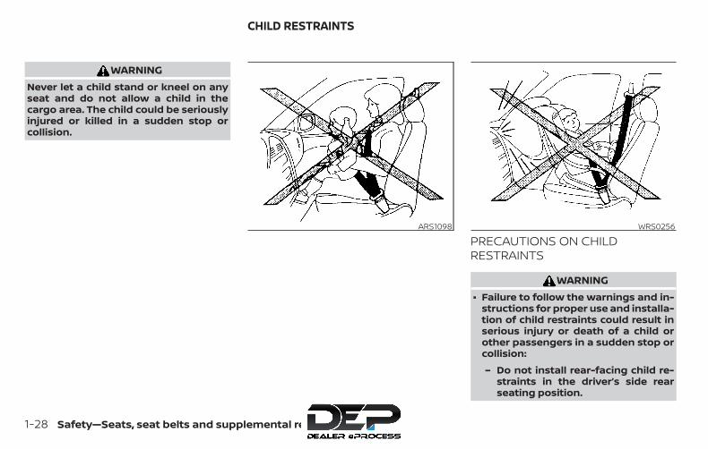
WARNINGNever let a child stand or kneel on anyseat and do not allow a child in thecargo area. The child could be seriouslyinjured or killed in a sudden stop orcollision.
PRECAUTIONS ON CHILDRESTRAINTS
WARNING∙ Failure to follow the warnings and in-
structions for proper use and installa-tion of child restraints could result inserious injury or death of a child orother passengers in a sudden stop orcollision:
– Do not install rear-facing child re-straints in the driver’s side rearseating position.
ARS1098 WRS0256
CHILD RESTRAINTS
1-28 Safety—Seats, seat belts and supplemental restraint system

– For forward-facing child seats andboosters, DO NOT install if the childrestraint base extends past theforward edge of the seat cushion.
– The child restraint must be usedand installed properly. Always fol-low all of the child restraint manu-facturer’s instructions for installa-tion and use.
– Infants and children should neverbe held on anyone’s lap. Even thestrongest adult cannot resist theforces of a collision.
– Do not put a seat belt around botha child and another passenger.
– NISSAN recommends that all childrestraints be installed in the rearseat. Studies show that childrenare safer when properly restrainedin the rear seat than in the frontseat. If you must install a forward-facing child restraint in the frontseat, refer to “Forward-facing childrestraint installation using the seatbelts” in this section.
– Even with the NISSAN Advanced AirBag System, never install a rear-facing child restraint in the frontseat. An inflating air bag could se-riously injure or kill a child. A rear-facing child restraint must only beused in the rear seat.
– Be sure to purchase a child re-straint that will fit the child and ve-hicle. Some child restraints maynot fit properly in your vehicle.
– Child restraint anchorages are de-signed to withstand only thoseloads imposed by correctly fittedchild restraints. Under no circum-stances are they to be used to at-tach adult seat belts, or other itemsor equipment to the vehicle. Doingso could damage the child re-straint anchorages. The child re-straint will not be properly in-stalled using the damagedanchorage, and a child could be se-riously injured or killed in acollision.
– Never use the anchor points foradult seat belts, or other items.
– A child restraint with a top tetherstrap should not be used in thefront passenger seat (King Cab®models).
– Keep seatbacks as upright as pos-sible after fitting the childrestraint.
– Infants and children should alwaysbe placed in an appropriate childrestraint while in the vehicle.
∙ When the child restraint is not in use,keep it secured with the LATCH systemor a seat belt. In a sudden stop or col-lision, loose objects can injure occu-pants or damage the vehicle.
CAUTIONA child restraint in a closed vehicle canbecome very hot. Check the seatingsurface and buckles before placing achild in the child restraint.
Safety—Seats, seat belts and supplemental restraint system 1-29

This vehicle is equipped with a universalchild restraint anchor system, referred toas the LATCH (Lower Anchors and Tethersfor CHildren) system. Some child restraintsinclude rigid or webbing-mounted attach-ments that can be connected to these an-chors. For additional information, refer to“LATCH (Lower Anchors and Tethers forCHildren) system” in this section.
If you do not have a LATCH compatiblechild restraint, the vehicle seat belts can beused.
Several manufacturers offer child re-straints for infants and children of varioussizes. When selecting any child restraint,keep the following points in mind:
∙ Choose only a restraint with a label cer-tifying that it complies with Federal Mo-tor Vehicle Safety Standard 213 or Cana-dian Motor Vehicle Safety Standard 213.
∙ Check the child restraint in your vehicleto be sure it is compatible with the vehi-cle’s seat and seat belt system.
∙ If the child restraint is compatible withyour vehicle, place your child in the childrestraint and check the various adjust-ments to be sure the child restraint iscompatible with your child. Choose achild restraint that is designed for yourchild’s height and weight. Always followall recommended procedures.
∙ If the combined weight of the child andchild restraint is less than 65 lbs.(29.5 kg), you may use either the LATCHanchors or the seat belt to install thechild restraint (not both at the sametime).
∙ If the combined weight of the child andchild restraint is greater than 65 lbs.(29.5 kg), use the vehicle’s seat belt (notthe lower anchors) to install the childrestraint.
∙ Be sure to follow the child restraintmanufacturer’s instructions for installa-tion.
All U.S. states and Canadian provinces orterritories require that infants and smallchildren be restrained in an approvedchild restraint at all times while the ve-hicle is being operated. Canadian law re-quires the top tether strap on forward-facing child restraints be secured to thedesignated anchor point on the vehicle.
1-30 Safety—Seats, seat belts and supplemental restraint system

LATCH (Lower Anchors andTethers for CHildren) SYSTEMYour vehicle is equipped with special an-chor points that are used with LATCH sys-tem compatible child restraints. This sys-tem may also be referred to as the ISOFIXor ISOFIX compatible system. With this sys-tem, you do not have to use a vehicle seatbelt to secure the child restraint unless thecombined weight of the child and child re-straint exceeds 65 lbs., (29.5 kg). If the com-bined weight of the child and child restraintis greater than 65 lbs. (29.5 kg) use the vehi-
cle’s seat belt (not the lower anchors) toinstall the child restraint. Be sure to followthe child restraint manufacturer’s instruc-tions for installation.
The LATCH lower anchor points are pro-vided to install child restraints in the rearoutboard seating positions only. Do not at-tempt to install a child restraint in the cen-ter position using the LATCH lower an-chors.
LATCH lower anchor
WARNINGFailure to follow the warnings and in-structions for proper use and installa-tion of child restraints could result inserious injury or death of a child orother passengers in a sudden stop orcollision:
– Attach LATCH system compatiblechild restraints only at the loca-tions shown in the illustration.
– Do not secure a child restraint inthe center rear seating position us-ing the LATCH lower anchors. Thechild restraint will not be securedproperly.
– Inspect the lower anchors by in-serting your fingers into the loweranchor area. Feel to make surethere are no obstructions over theanchors such as seat belt webbingor seat cushion material. The childrestraint will not be secured prop-erly if the lower anchors areobstructed.
LATCH system lower anchor locations(Crew Cab models)
LRS2962LATCH system lower anchor locations
(King Cab® models)
LRS2963
Safety—Seats, seat belts and supplemental restraint system 1-31

Child restraint anchorages are de-signed to withstand only those loadsimposed by correctly fitted child re-straints. Under no circumstances arethey to be used to attach adult seatbelts, or other items or equipment tothe vehicle. Doing so could damage thechild restraint anchorages. The child re-straint will not be properly installed us-ing the damaged anchorage, and achild could be seriously injured or killedin a collision.
LATCH lower anchor locationThe LATCH lower anchors are located asshown. A label is attached to the seatback(Crew Cab models) to help you locate theLATCH lower anchors.
LATCH lower anchor locationLRS3036
LATCH label locations (Crew Cab models)LRS2984
1-32 Safety—Seats, seat belts and supplemental restraint system
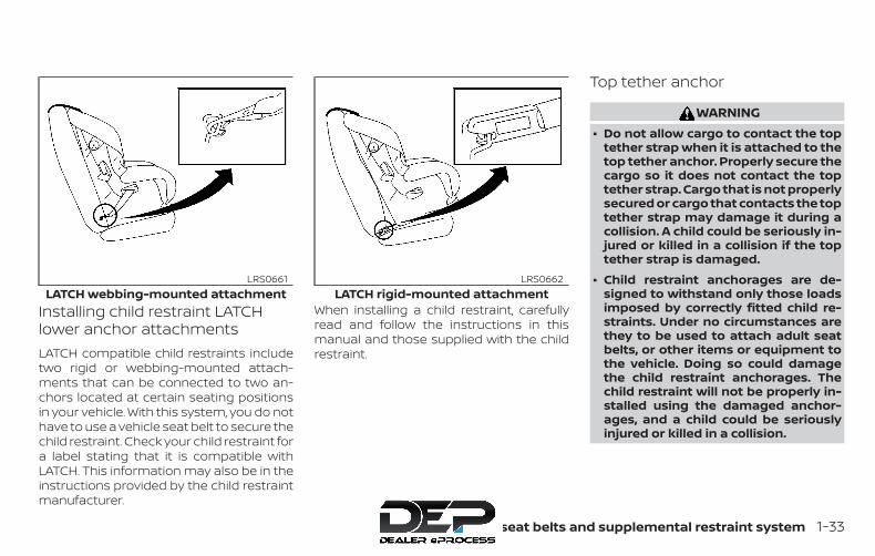
Installing child restraint LATCHlower anchor attachmentsLATCH compatible child restraints includetwo rigid or webbing-mounted attach-ments that can be connected to two an-chors located at certain seating positionsin your vehicle. With this system, you do nothave to use a vehicle seat belt to secure thechild restraint. Check your child restraint fora label stating that it is compatible withLATCH. This information may also be in theinstructions provided by the child restraintmanufacturer.
When installing a child restraint, carefullyread and follow the instructions in thismanual and those supplied with the childrestraint.
Top tether anchor
WARNING∙ Do not allow cargo to contact the top
tether strap when it is attached to thetop tether anchor. Properly secure thecargo so it does not contact the toptether strap. Cargo that is not properlysecured or cargo that contacts the toptether strap may damage it during acollision. A child could be seriously in-jured or killed in a collision if the toptether strap is damaged.
∙ Child restraint anchorages are de-signed to withstand only those loadsimposed by correctly fitted child re-straints. Under no circumstances arethey to be used to attach adult seatbelts, or other items or equipment tothe vehicle. Doing so could damagethe child restraint anchorages. Thechild restraint will not be properly in-stalled using the damaged anchor-ages, and a child could be seriouslyinjured or killed in a collision.
LATCH webbing-mounted attachmentLRS0661
LATCH rigid-mounted attachmentLRS0662
Safety—Seats, seat belts and supplemental restraint system 1-33
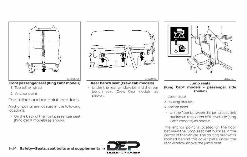
1. Top tether strap
2. Anchor point
Top tether anchor point locationsAnchor points are located in the followinglocations:
∙ On the back of the front passenger seat(King Cab® models) as shown.
∙ Under the rear window behind the rearbench seat (Crew Cab models) asshown. 1. Cover plate
2. Routing bracket3. Anchor point
∙ On the floor between the jump seat beltbuckles in the center of the vehicle (KingCab® models) as shown.
The anchor point is located on the floorbetween the jump seat belt buckles in thecenter of the vehicle. The routing bracket islocated behind the cover plate under therear window above the jump seat.
Front passenger seat (King Cab® models)LRS0572
Rear bench seat (Crew Cab models)LRS0393
Jump seats(King Cab® models - passenger side
shown)
LRS2101
1-34 Safety—Seats, seat belts and supplemental restraint system
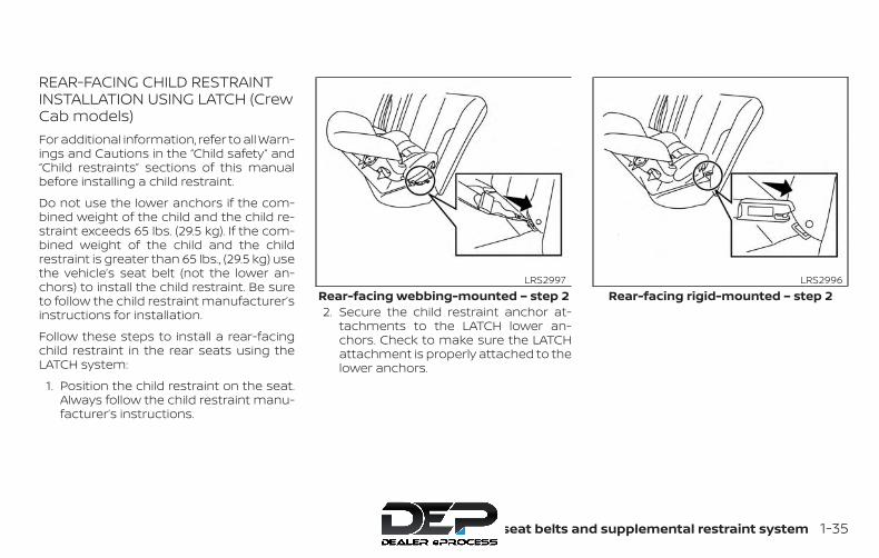
REAR-FACING CHILD RESTRAINTINSTALLATION USING LATCH (CrewCab models)For additional information, refer to all Warn-ings and Cautions in the “Child safety” and“Child restraints” sections of this manualbefore installing a child restraint.
Do not use the lower anchors if the com-bined weight of the child and the child re-straint exceeds 65 lbs. (29.5 kg). If the com-bined weight of the child and the childrestraint is greater than 65 lbs., (29.5 kg) usethe vehicle’s seat belt (not the lower an-chors) to install the child restraint. Be sureto follow the child restraint manufacturer’sinstructions for installation.
Follow these steps to install a rear-facingchild restraint in the rear seats using theLATCH system:
1. Position the child restraint on the seat.Always follow the child restraint manu-facturer’s instructions.
2. Secure the child restraint anchor at-tachments to the LATCH lower an-chors. Check to make sure the LATCHattachment is properly attached to thelower anchors.
Rear-facing webbing-mounted – step 2LRS2997
Rear-facing rigid-mounted – step 2LRS2996
Safety—Seats, seat belts and supplemental restraint system 1-35
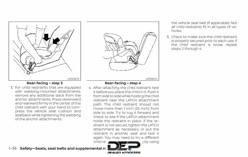
3. For child restraints that are equippedwith webbing-mounted attachments,remove any additional slack from theanchor attachments. Press downwardand rearward firmly in the center of thechild restraint with your hand to com-press the vehicle seat cushion andseatback while tightening the webbingof the anchor attachments.
4. After attaching the child restraint, testit before you place the child in it. Push itfrom side to side while holding the childrestraint near the LATCH attachmentpath. The child restraint should notmove more than 1 inch (25 mm), fromside to side. Try to tug it forward andcheck to see if the LATCH attachmentholds the restraint in place. If the re-straint is not secure, tighten the LATCHattachment as necessary, or put therestraint in another seat and test itagain. You may need to try a differentchild restraint or try installing by using
the vehicle seat belt (if applicable). Notall child restraints fit in all types of ve-hicles.
5. Check to make sure the child restraintis properly secured prior to each use. Ifthe child restraint is loose, repeatsteps 2 through 4.
Rear-facing – step 3LRS0673
Rear-facing – step 4LRS0674
1-36 Safety—Seats, seat belts and supplemental restraint system

REAR-FACING CHILD RESTRAINTINSTALLATION USING LATCH —JUMP SEAT (King Cab® models)
WARNING∙ If a child restraint system is not in-
stalled properly, the child could be se-riously injured or killed in a suddenstop or collision.
– Never install a rear-facing child re-straint system on the driver’s sidejump seat.
– Do not install a child restraint sys-tem on the passenger’s side jumpseat without unfolding the seatextender.
WARNING∙ To install a rear-facing child restraint
on the passenger’s side jump seat, itwill be necessary to move the frontpassenger’s seat fully forward andplace the front seatback upright or tiltit forward. Failure to do so may causethe child restraint to not be installedproperly and cause serious injury ordeath in a sudden stop or collision.
LRS2357 LRS2356
Safety—Seats, seat belts and supplemental restraint system 1-37

– The front seat cannot be usedwhen a rear-facing child restraintis installed on the jump seat. At-tempting to do so could cause se-rious injury in a sudden stop orcollision.
For additional information, refer to all Warn-ings and Cautions in the “Child safety” and“Child restraints” sections of this manualbefore installing a child restraint.
Do not use the lower anchors if the com-bined weight of the child and the child re-straint exceeds 65 lbs. (29.5 kg). If the com-bined weight of the child and the childrestraint is greater than 65 lbs., (29.5 kg) usethe vehicle’s seat belt (not the lower an-chors) to install the child restraint. Be sureto follow the child restraint manufacturer’sinstructions for installation.
Follow these steps to install a child re-straint on the jump seat.
1. To access the jump seat extension(passenger’s side only) �A on the jumpseat, pull up �B on the extension to un-fold it to the open position. Then unfoldthe two support legs �C and lower thejump seat to the full open seating posi-tion.
LRS2725
1-38 Safety—Seats, seat belts and supplemental restraint system

2. Move the front passenger’s seat intothe full forward position. Then movethe front seatback to the upright ortilted forward position. Position thechild restraint on the jump seat. Thedirection of the child restraint dependson the type of the child restraint andthe size of the child. Always follow thechild restraint manufacturer’s instruc-tions.
3. Position the child restraint on the seat.Always follow the child restraint manu-facturer’s instructions.
4. Secure the child restraint anchor at-tachments to the LATCH lower an-chors. Check to make sure the LATCHattachment is properly attached to thelower anchors.
Full open seating positionLRS2502
Rear-facing — step 2LRS2552
Rear-facing webbing-mounted – step 4LRS2997
Safety—Seats, seat belts and supplemental restraint system 1-39
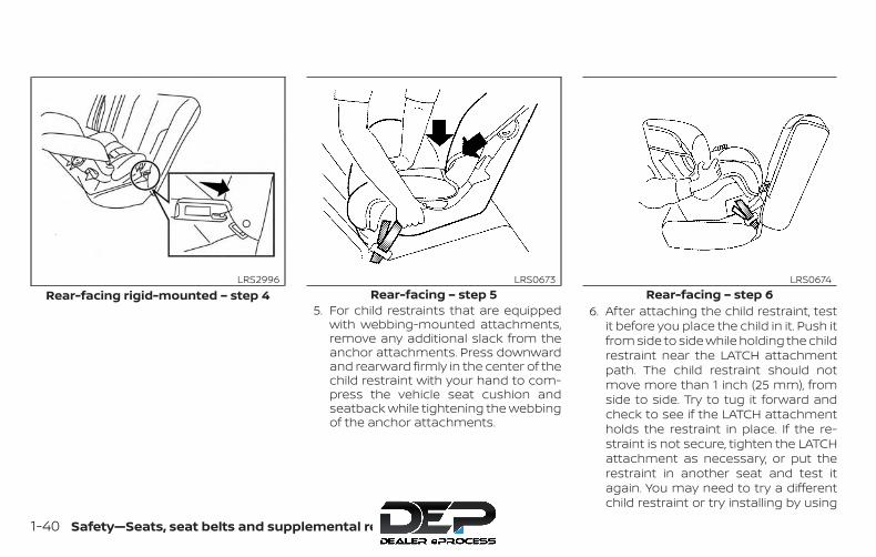
5. For child restraints that are equippedwith webbing-mounted attachments,remove any additional slack from theanchor attachments. Press downwardand rearward firmly in the center of thechild restraint with your hand to com-press the vehicle seat cushion andseatback while tightening the webbingof the anchor attachments.
6. After attaching the child restraint, testit before you place the child in it. Push itfrom side to side while holding the childrestraint near the LATCH attachmentpath. The child restraint should notmove more than 1 inch (25 mm), fromside to side. Try to tug it forward andcheck to see if the LATCH attachmentholds the restraint in place. If the re-straint is not secure, tighten the LATCHattachment as necessary, or put therestraint in another seat and test itagain. You may need to try a differentchild restraint or try installing by using
Rear-facing rigid-mounted – step 4LRS2996
Rear-facing – step 5LRS0673
Rear-facing – step 6LRS0674
1-40 Safety—Seats, seat belts and supplemental restraint system

the vehicle seat belt (if applicable). Notall child restraints fit in all types of ve-hicles.
7. Check to make sure the child restraintis properly secured prior to each use. Ifthe child restraint is loose, repeatsteps 1 through 6.
REAR-FACING CHILD RESTRAINTINSTALLATION USING THE SEATBELTS (Crew Cab models)
WARNINGThe three-point seat belt with Auto-matic Locking Retractor (ALR) must beused when installing a child restraint.Failure to use the ALR mode will result inthe child restraint not being properlysecured. The restraint could tip over orbe loose and cause injury to a child in asudden stop or collision. Also, it canchange the operation of the front pas-senger air bag. For additional informa-tion, refer to “Front passenger air bagand status light” in this section.
For additional information, refer to all Warn-ings and Cautions in the “Child safety” and“Child restraints” sections of this manualbefore installing a child restraint.
Do not use the lower anchors if the com-bined weight of the child and the child re-straint exceeds 65 lbs. (29.5 kg). If the com-bined weight of the child and the childrestraint is greater than 65 lbs. (29.5 kg), usethe vehicle’s seat belt (not the lower an-chors) to install the child restraint. Be sureto follow the child restraint manufacturer’sinstructions for installation.
Follow these steps to install a rear-facingchild restraint using the vehicle seat belts inthe rear seats:
1. Child restraints for infants must beused in the rear-facing direction andtherefore must not be used in thefront seat. Position the child restrainton the seat. Always follow the child re-straint manufacturer’s instructions.
Rear-facing – step 1WRS0256
Safety—Seats, seat belts and supplemental restraint system 1-41
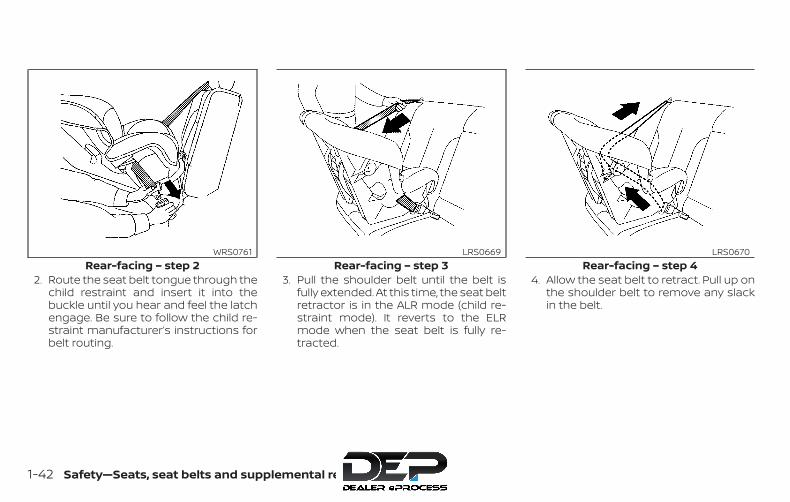
2. Route the seat belt tongue through thechild restraint and insert it into thebuckle until you hear and feel the latchengage. Be sure to follow the child re-straint manufacturer’s instructions forbelt routing.
3. Pull the shoulder belt until the belt isfully extended. At this time, the seat beltretractor is in the ALR mode (child re-straint mode). It reverts to the ELRmode when the seat belt is fully re-tracted.
4. Allow the seat belt to retract. Pull up onthe shoulder belt to remove any slackin the belt.
Rear-facing – step 2WRS0761
Rear-facing – step 3LRS0669
Rear-facing – step 4LRS0670
1-42 Safety—Seats, seat belts and supplemental restraint system
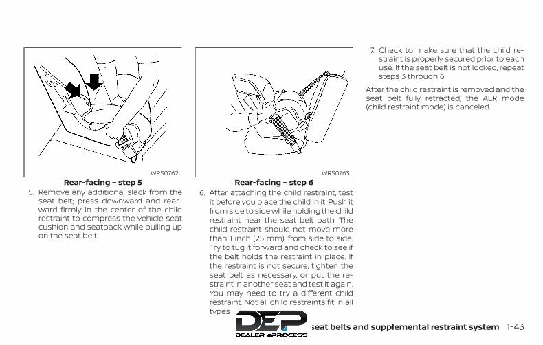
5. Remove any additional slack from theseat belt; press downward and rear-ward firmly in the center of the childrestraint to compress the vehicle seatcushion and seatback while pulling upon the seat belt.
6. After attaching the child restraint, testit before you place the child in it. Push itfrom side to side while holding the childrestraint near the seat belt path. Thechild restraint should not move morethan 1 inch (25 mm), from side to side.Try to tug it forward and check to see ifthe belt holds the restraint in place. Ifthe restraint is not secure, tighten theseat belt as necessary, or put the re-straint in another seat and test it again.You may need to try a different childrestraint. Not all child restraints fit in alltypes of vehicles.
7. Check to make sure that the child re-straint is properly secured prior to eachuse. If the seat belt is not locked, repeatsteps 3 through 6.
After the child restraint is removed and theseat belt fully retracted, the ALR mode(child restraint mode) is canceled.
Rear-facing – step 5WRS0762
Rear-facing – step 6WRS0763
Safety—Seats, seat belts and supplemental restraint system 1-43
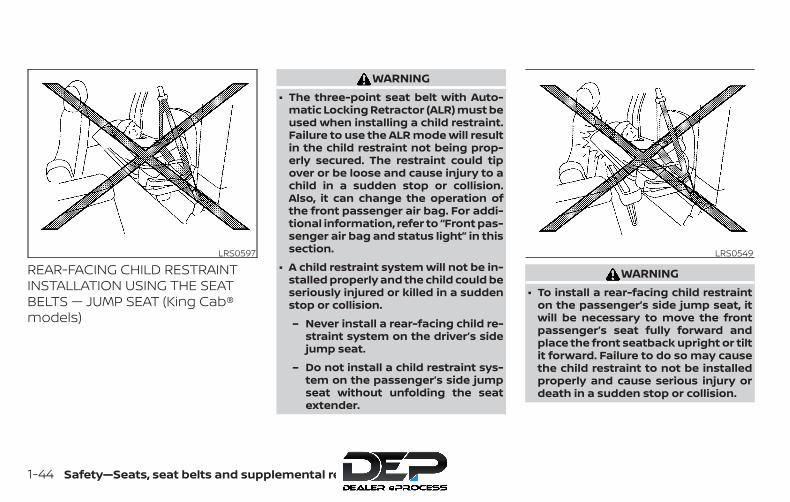
REAR-FACING CHILD RESTRAINTINSTALLATION USING THE SEATBELTS — JUMP SEAT (King Cab®models)
WARNING∙ The three-point seat belt with Auto-
matic Locking Retractor (ALR) must beused when installing a child restraint.Failure to use the ALR mode will resultin the child restraint not being prop-erly secured. The restraint could tipover or be loose and cause injury to achild in a sudden stop or collision.Also, it can change the operation ofthe front passenger air bag. For addi-tional information, refer to “Front pas-senger air bag and status light” in thissection.
∙ A child restraint system will not be in-stalled properly and the child could beseriously injured or killed in a suddenstop or collision.
– Never install a rear-facing child re-straint system on the driver’s sidejump seat.
– Do not install a child restraint sys-tem on the passenger’s side jumpseat without unfolding the seatextender.
WARNING∙ To install a rear-facing child restraint
on the passenger’s side jump seat, itwill be necessary to move the frontpassenger’s seat fully forward andplace the front seatback upright or tiltit forward. Failure to do so may causethe child restraint to not be installedproperly and cause serious injury ordeath in a sudden stop or collision.
LRS0597 LRS0549
1-44 Safety—Seats, seat belts and supplemental restraint system

– The front seat cannot be usedwhen a rear-facing child restraintis installed on the jump seat. At-tempting to do so could cause se-rious injury in a sudden stop orcollision.
For additional information, refer to all Warn-ings and Cautions in the “Child safety” and“Child restraints” sections of this manualbefore installing a child restraint.
Do not use the lower anchors if the com-bined weight of the child and the child re-straint exceeds 65 lbs. (29.5 kg). If the com-bined weight of the child and the childrestraint is greater than 65 lbs. (29.5 kg), usethe vehicle’s seat belt (not the lower an-chors) to install the child restraint. Be sureto follow the child restraint manufacturer’sinstructions for installation.
Follow these steps to install a child re-straint on the passenger’s side jump seat.
1. To access the jump seat extension �Aon the passenger’s side jump seat, pullup �B on the extension to unfold it tothe open position. Then unfold the twosupport legs �C and lower the jumpseat to the full open seating position.
LRS2725
Safety—Seats, seat belts and supplemental restraint system 1-45
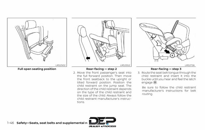
2. Move the front passenger’s seat intothe full forward position. Then movethe front seatback to the upright ortilted forward position. Position thechild restraint on the jump seat. Thedirection of the child restraint dependson the type of the child restraint andthe size of the child. Always follow thechild restraint manufacturer’s instruc-tions.
3. Route the seat belt tongue through thechild restraint and insert it into thebuckle until you hear and feel the latchengage �A .
Be sure to follow the child restraintmanufacturer’s instructions for beltrouting.
Full open seating positionLRS2502
Rear-facing — step 2LRS2552
Rear-facing — step 3LRS2726
1-46 Safety—Seats, seat belts and supplemental restraint system
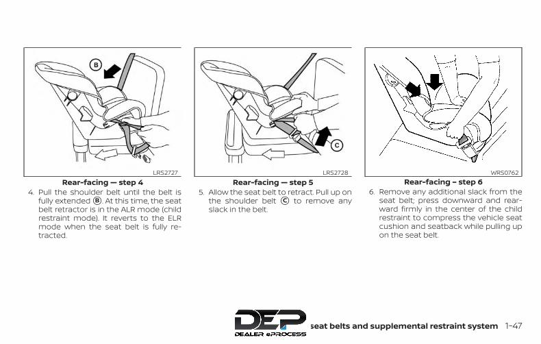
4. Pull the shoulder belt until the belt isfully extended �B . At this time, the seatbelt retractor is in the ALR mode (childrestraint mode). It reverts to the ELRmode when the seat belt is fully re-tracted.
5. Allow the seat belt to retract. Pull up onthe shoulder belt �C to remove anyslack in the belt.
6. Remove any additional slack from theseat belt; press downward and rear-ward firmly in the center of the childrestraint to compress the vehicle seatcushion and seatback while pulling upon the seat belt.
Rear-facing — step 4LRS2727
Rear-facing — step 5LRS2728
Rear-facing – step 6WRS0762
Safety—Seats, seat belts and supplemental restraint system 1-47

7. After attaching the child restraint, test itbefore you place the child in it. Push itfrom side to side while holding the seatnear the seat belt path. The child re-straint should not move more than1 inch (25 mm), from side to side. Try totug it forward and check to see if theseat belt holds the restraint in place. Ifthe restraint is not secure, tighten theseat belt as necessary, or put the re-straint in another seat and test it again.You may need to try a different childrestraint. Not all child restraints fit in alltypes of vehicles.
8. Check to make sure that the child re-straint is properly secured prior to eachuse. If the seat belt is not locked, repeatsteps 3 through 7.
After the child restraint is removed and theseat belt fully retracted, the ALR mode(child restraint mode) is canceled.
FORWARD-FACING CHILDRESTRAINT INSTALLATION USINGLATCH (Crew Cab models)For additional information, refer to all Warn-ings and Cautions in the “Child safety” and“Child restraints” sections of this manualbefore installing a child restraint.
Do not use the lower anchors if the com-bined weight of the child and the child re-straint exceeds 65 lbs. (29.5 kg). If the com-bined weight of the child and the childrestraint is greater than 65 lbs., (29.5 kg) usethe vehicle’s seat belt (not the lower an-chors) to install the child restraint. Be sureto follow the child restraint manufacturer’sinstructions for installation.
Follow these steps to install a forward-facing child restraint in the rear seats usingthe LATCH system:
1. Position the child restraint on the seat.Always follow the child restraint manu-facturer’s instructions.
Rear-facing — step 7WRS0918
1-48 Safety—Seats, seat belts and supplemental restraint system
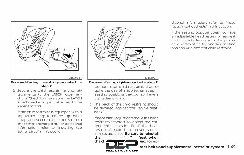
2. Secure the child restraint anchor at-tachments to the LATCH lower an-chors. Check to make sure the LATCHattachment is properly attached to thelower anchors.
If the child restraint is equipped with atop tether strap, route the top tetherstrap and secure the tether strap tothe tether anchor point. For additionalinformation, refer to “Installing toptether strap” in this section.
Do not install child restraints that re-quire the use of a top tether strap inseating positions that do not have atop tether anchor.
3. The back of the child restraint shouldbe secured against the vehicle seat-back.
If necessary, adjust or remove the headrestraint/headrest to obtain the cor-rect child restraint fit. If the headrestraint/headrest is removed, store itin a secure place. Be sure to reinstallthe head restraint/headrest whenthe child restraint is removed. For ad-
ditional information, refer to “Headrestraints/headrests” in this section.
If the seating position does not havean adjustable head restraint/headrestand it is interfering with the properchild restraint fit, try another seatingposition or a different child restraint.
Forward-facing webbing-mounted –step 2
LRS2995Forward-facing rigid-mounted – step 2
LRS2994
Safety—Seats, seat belts and supplemental restraint system 1-49

4. For child restraints that are equippedwith webbing-mounted attachments,remove any additional slack from theanchor attachments. Press downwardand rearward firmly in the center of thechild restraint with your knee to com-press the vehicle seat cushion andseatback while tightening the webbingof the anchor attachments.
5. Tighten the tether strap according tothe manufacturer’s instructions to re-move any slack.
6. After attaching the child restraint, testit before you place the child in it. Push itfrom side to side while holding the childrestraint near the LATCH attachmentpath. The child restraint should notmove more than 1 inch (25 mm), fromside to side. Try to tug it forward andcheck to see if the LATCH attachmentholds the restraint in place. If the re-straint is not secure, tighten the LATCHattachment as necessary, or put therestraint in another seat and test itagain. You may need to try a differentchild restraint. Not all child restraints fitin all types of vehicles.
7. Check to make sure the child restraintis properly secured prior to each use. Ifthe child restraint is loose, repeatsteps 3 through 6.
Forward-facing – step 4LRS0671
Forward-facing – step 6WRS0697
1-50 Safety—Seats, seat belts and supplemental restraint system

1. Pull strap2. Anchor points
Installing top tether strap (rearbench seat for Crew Cab models)To access the anchor points behind therear bench seat, tilt the rear seatback for-ward by lifting up on the pull strap behindthe seatback.
1. Top tether strap2. Tether strap3. Tether anchor point
Before securing the child restraint with theLATCH lower anchors (rear outboard seat-ing positions for Crew Cab models) followthese steps.
1. If necessary, raise or remove the headrestraint/headrest to position the toptether strap as shown. If the headrestraint/headrest is removed, store itin a secure place. Be sure to reinstall thehead restraint/headrest when the child
restraint is removed. For additional in-formation, refer to “Headrestraints/headrests” in this section.
2. Position the top tether strap as shown.
3. Secure the tether strap to the tetheranchor point as shown.
4. Return the seatback to the locked po-sition.
5. Refer back to child restraint installationsteps before tightening the tetherstrap.
If you have any questions when install-ing a top tether strap, it is recommendedthat you visit a NISSAN dealer for thisservice.
Anchor point accessLRS0392
Rear bench seat (Crew Cab models)LRS0576
Safety—Seats, seat belts and supplemental restraint system 1-51
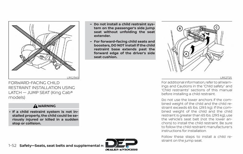
FORWARD-FACING CHILDRESTRAINT INSTALLATION USINGLATCH — JUMP SEAT (King Cab®models)
WARNING∙ If a child restraint system is not in-
stalled properly, the child could be se-riously injured or killed in a suddenstop or collision.
– Do not install a child restraint sys-tem on the passenger’s side jumpseat without unfolding the seatextender.
– For forward-facing child seats andboosters, DO NOT install if the childrestraint base extends past theforward edge of the driver’s sideseat cushion.
For additional information, refer to all Warn-ings and Cautions in the “Child safety” and“Child restraints” sections of this manualbefore installing a child restraint.
Do not use the lower anchors if the com-bined weight of the child and the child re-straint exceeds 65 lbs. (29.5 kg). If the com-bined weight of the child and the childrestraint is greater than 65 lbs. (29.5 kg), usethe vehicle’s seat belt (not the lower an-chors) to install the child restraint. Be sureto follow the child restraint manufacturer’sinstructions for installation.
Follow these steps to install a child re-straint on the jump seat.
LRS2360 LRS2725
1-52 Safety—Seats, seat belts and supplemental restraint system

1. To access the jump seat extension(passenger’s side only) �A on the jumpseat, pull up �B on the extension to un-fold it to the open position. Then unfoldthe two support legs �C and lower thejump seat to the full open seating posi-tion.
2. Position the child restraint on the seat.Always follow the child restraint manu-facturer’s instructions.
3. Secure the child restraint anchor at-tachments to the LATCH lower an-chors. Check to make sure the LATCHattachment is properly attached to thelower anchors.
If the child restraint is equipped with atop tether strap, route the top tetherstrap and secure the tether strap tothe tether anchor point. For additionalinformation, refer to “Installing toptether strap” in this section. Do not in-stall child restraints that require theuse of a top tether strap in seating po-
Full open seating positionLRS2502
Forward-facing webbing-mounted –step 3
LRS2995
Safety—Seats, seat belts and supplemental restraint system 1-53
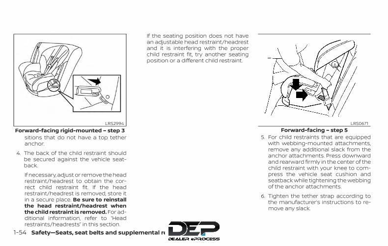
sitions that do not have a top tetheranchor.
4. The back of the child restraint shouldbe secured against the vehicle seat-back.
If necessary, adjust or remove the headrestraint/headrest to obtain the cor-rect child restraint fit. If the headrestraint/headrest is removed, store itin a secure place. Be sure to reinstallthe head restraint/headrest whenthe child restraint is removed. For ad-ditional information, refer to “Headrestraints/headrests” in this section.
If the seating position does not havean adjustable head restraint/headrestand it is interfering with the properchild restraint fit, try another seatingposition or a different child restraint.
5. For child restraints that are equippedwith webbing-mounted attachments,remove any additional slack from theanchor attachments. Press downwardand rearward firmly in the center of thechild restraint with your knee to com-press the vehicle seat cushion andseatback while tightening the webbingof the anchor attachments.
6. Tighten the tether strap according tothe manufacturer’s instructions to re-move any slack.
Forward-facing rigid-mounted – step 3LRS2994
Forward-facing – step 5LRS0671
1-54 Safety—Seats, seat belts and supplemental restraint system
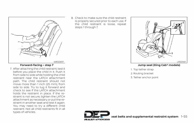
7. After attaching the child restraint, test itbefore you place the child in it. Push itfrom side to side while holding the childrestraint near the LATCH attachmentpath. The child restraint should notmove more than 1 inch (25 mm), fromside to side. Try to tug it forward andcheck to see if the LATCH attachmentholds the restraint in place. If the re-straint is not secure, tighten the LATCHattachment as necessary, or put the re-straint in another seat and test it again.You may need to try a different childrestraint. Not all child restraints fit in alltypes of vehicles.
8. Check to make sure the child restraintis properly secured prior to each use. Ifthe child restraint is loose, repeatsteps 1 through 7.
1. Top tether strap2. Routing bracket3. Tether anchor point
Forward-facing – step 7WRS0697
Jump seat (King Cab® models)LRS0561
Safety—Seats, seat belts and supplemental restraint system 1-55

Installing top tether strap — jumpseat (King Cab® models)
WARNING∙ Do not secure the top tether strap to
the routing bracket. If the child re-straint is not anchored properly, therisk of a child being injured or killed ina collision or a sudden stop greatlyincreases.
∙ Child restraint anchorages are de-signed to withstand only those loadsimposed by correctly fitted child re-straints. Under no circumstances arethey to be used to attach adult seatbelts, or other items or equipment tothe vehicle. Doing so could damagethe child restraint anchorages. Thechild restraint will not be properly in-stalled using the damaged anchor-ages, and a child could be seriouslyinjured or killed in a collision.
The child restraint top tether strap must beused when installing the child restraint withLATCH lower anchor attachments.
First, secure the child restraint with theLATCH lower anchors (rear seating posi-tions).
1. Pull the cover plate off to access the toptether strap routing bracket for thejump seat.
2. Route the top tether strap through therouting bracket.
3. Secure the top tether strap to thetether anchor point as shown.
4. Refer back to child restraint installationsteps before tightening the tetherstrap.
If you have any questions when install-ing a top tether strap, it is recommendedthat you visit a NISSAN dealer for thisservice.
FORWARD-FACING CHILDRESTRAINT INSTALLATION USINGTHE SEAT BELTS — FRONTPASSENGER AND REAR BENCHSEAT (Crew Cab models)
WARNINGThe three-point seat belt with Auto-matic Locking Retractor (ALR) must beused when installing a child restraint.Failure to use the ALR mode will result inthe child restraint not being properlysecured. The restraint could tip over orbe loose and cause injury to a child in asudden stop or collision. Also, it canchange the operation of the front pas-senger air bag. For additional informa-tion, refer to “Front passenger air bagand status light” in this section.
1-56 Safety—Seats, seat belts and supplemental restraint system
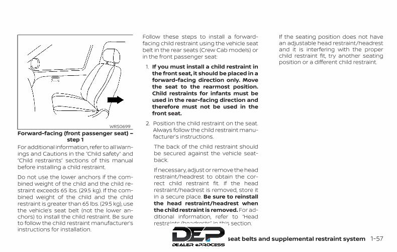
For additional information, refer to all Warn-ings and Cautions in the “Child safety” and“Child restraints” sections of this manualbefore installing a child restraint.
Do not use the lower anchors if the com-bined weight of the child and the child re-straint exceeds 65 lbs. (29.5 kg). If the com-bined weight of the child and the childrestraint is greater than 65 lbs. (29.5 kg), usethe vehicle’s seat belt (not the lower an-chors) to install the child restraint. Be sureto follow the child restraint manufacturer’sinstructions for installation.
Follow these steps to install a forward-facing child restraint using the vehicle seatbelt in the rear seats (Crew Cab models) orin the front passenger seat:
1. If you must install a child restraint inthe front seat, it should be placed in aforward-facing direction only. Movethe seat to the rearmost position.Child restraints for infants must beused in the rear-facing direction andtherefore must not be used in thefront seat.
2. Position the child restraint on the seat.Always follow the child restraint manu-facturer’s instructions.
The back of the child restraint shouldbe secured against the vehicle seat-back.
If necessary, adjust or remove the headrestraint/headrest to obtain the cor-rect child restraint fit. If the headrestraint/headrest is removed, store itin a secure place. Be sure to reinstallthe head restraint/headrest whenthe child restraint is removed. For ad-ditional information, refer to “Headrestraints/headrests” in this section.
If the seating position does not havean adjustable head restraint/headrestand it is interfering with the properchild restraint fit, try another seatingposition or a different child restraint.
Forward-facing (front passenger seat) –step 1
WRS0699
Safety—Seats, seat belts and supplemental restraint system 1-57
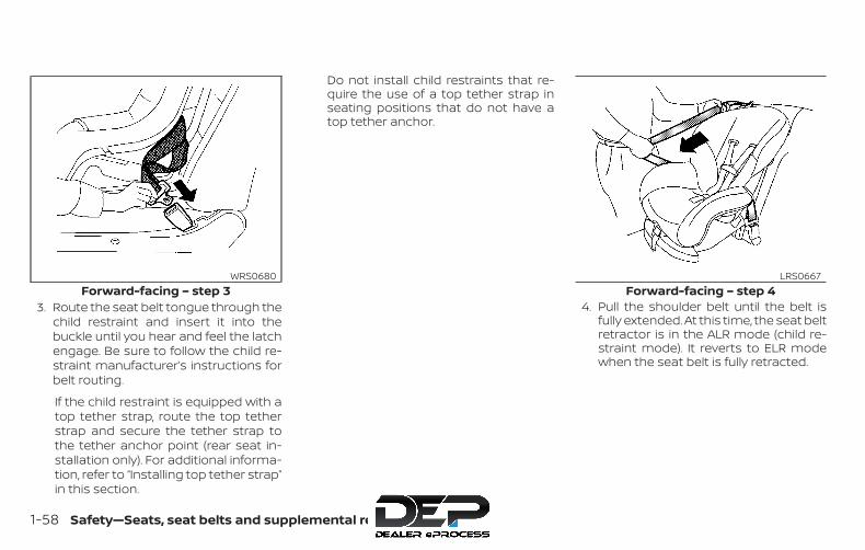
3. Route the seat belt tongue through thechild restraint and insert it into thebuckle until you hear and feel the latchengage. Be sure to follow the child re-straint manufacturer’s instructions forbelt routing.
If the child restraint is equipped with atop tether strap, route the top tetherstrap and secure the tether strap tothe tether anchor point (rear seat in-stallation only). For additional informa-tion, refer to “Installing top tether strap”in this section.
Do not install child restraints that re-quire the use of a top tether strap inseating positions that do not have atop tether anchor.
4. Pull the shoulder belt until the belt isfully extended. At this time, the seat beltretractor is in the ALR mode (child re-straint mode). It reverts to ELR modewhen the seat belt is fully retracted.
Forward-facing – step 3WRS0680
Forward-facing – step 4LRS0667
1-58 Safety—Seats, seat belts and supplemental restraint system

5. Allow the seat belt to retract. Pull up onthe shoulder belt to remove any slackin the belt.
6. Remove any additional slack from theseat belt; press downward and rear-ward firmly in the center of the childrestraint with your knee to compressthe vehicle seat cushion and seatbackwhile pulling up on the seat belt.
7. Tighten the tether strap according tothe manufacturer’s instructions to re-move any slack.
8. After attaching the child restraint, testit before you place the child in it. Push itfrom side to side while holding the childrestraint near the seat belt path. Thechild restraint should not move morethan 1 inch (25 mm), from side to side.Try to tug it forward and check to see ifthe seat belt holds the restraint inplace. If the restraint is not secure,tighten the seat belt as necessary, orput the restraint in another seat andtest it again. You may need to try adifferent child restraint. Not all child re-straints fit in all types of vehicles.
Forward-facing – step 5LRS0668
Forward-facing – step 6WRS0681
Forward-facing – step 8WRS0698
Safety—Seats, seat belts and supplemental restraint system 1-59

9. Check to make sure the child restraintis properly secured prior to each use. Ifthe seat belt is not locked, repeatsteps 3 through 8.
10. If the child restraint is installed in thefront passenger seat, place the ignitionswitch in the ON position. The frontpassenger air bag status lightshould illuminate. If this light is not illu-minated, refer to "Front passenger airbag and status light" in this section.Move the child restraint to anotherseating position. Have the systemchecked. It is recommended that youvisit a NISSAN dealer for this service.
After the child restraint is removed and theseat belt is fully retracted, the ALR mode(child restraint mode) is canceled.
1. Pull strap2. Anchor points
Installing top tether strap (rearbench seat for Crew Cab models)To access the anchor points behind therear bench seat, tilt the rear seatback for-ward by lifting up on the pull strap behindthe seatback.
Forward-facing – step 10WRS0475
Anchor point accessLRS0392
1-60 Safety—Seats, seat belts and supplemental restraint system

1. Top tether strap2. Tether strap3. Tether anchor point
The child restraint top tether strap must beused when installing the child restraint withthe seat belts.
First, secure the child restraint with the seatbelt.
1. If necessary, raise or remove the headrestraint/headrest to position the toptether strap as shown. If the headrestraint/headrest is removed, store it
in a secure place. Be sure to reinstall thehead restraint/headrest when the childrestraint is removed. For additional in-formation, refer to “Head restraints/headrests” in this section.
2. Position the top tether strap as shown.
3. Secure the tether strap to the tetheranchor point as shown.
4. Return the seatback to the locked po-sition.
5. Refer back to child restraint installationsteps before tightening the tetherstrap.
If you have any questions when install-ing a top tether strap, it is recommendedthat you visit a NISSAN dealer for thisservice.
FORWARD-FACING CHILDRESTRAINT INSTALLATION USINGTHE SEAT BELTS — FRONTPASSENGER AND JUMP SEATS(King Cab® models)
Rear bench seat (Crew Cab models)LRS0576 LRS0598
Safety—Seats, seat belts and supplemental restraint system 1-61

WARNING∙ The three-point seat belt with Auto-
matic Locking Retractor (ALR) must beused when installing a child restraint.Failure to use the ALR mode will resultin the child restraint not being prop-erly secured. The restraint could tipover or be loose and cause injury to achild in a sudden stop or collision.Also, it can change the operation ofthe front passenger air bag. For addi-tional information, refer to “Front pas-senger air bag and status light” in thissection.
∙ If a child restraint system is not in-stalled properly, the child could be se-riously injured or killed in a suddenstop or collision.
– Do not install a child restraint sys-tem on the passenger’s side jumpseat without unfolding the seatextender.
– For forward-facing child seats andboosters, DO NOT install if the childrestraint system base extendspast the forward edge of the driv-er’s side seat cushion.
For additional information, refer to all Warn-ings and Cautions in the “Child safety” and“Child restraints” sections of this manualbefore installing a child restraint.
Do not use the lower anchors if the com-bined weight of the child and the child re-straint exceeds 65 lbs. (29.5 kg). If the com-bined weight of the child and the childrestraint is greater than 65 lbs. (29.5 kg) usethe vehicle’s seat belt (not the lower an-chors) to install the child restraint. Be sureto follow the child restraint manufacturer’sinstructions for installation.
Follow these steps to install a forward-facing child restraint using the vehicle seatbelt in the jump seats (King Cab® models)or in the front passenger seat:
1. If you must install a child restraint inthe front seat, it should be placed in aforward-facing direction only. Movethe seat to the rearmost position.Child restraints for infants must beused in the rear-facing direction andtherefore must not be used in thefront seat.
Forward-facing (front passenger seat) —step 1
WRS0699Forward-facing ( jump seat for King Cab®
models) — step 2
LRS2725
1-62 Safety—Seats, seat belts and supplemental restraint system
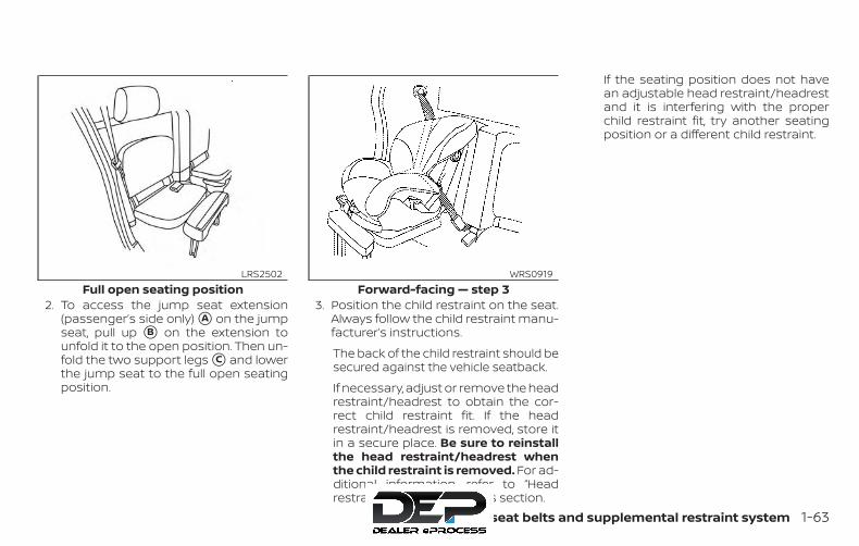
2. To access the jump seat extension(passenger’s side only) �A on the jumpseat, pull up �B on the extension tounfold it to the open position. Then un-fold the two support legs �C and lowerthe jump seat to the full open seatingposition.
3. Position the child restraint on the seat.Always follow the child restraint manu-facturer’s instructions.
The back of the child restraint should besecured against the vehicle seatback.
If necessary, adjust or remove the headrestraint/headrest to obtain the cor-rect child restraint fit. If the headrestraint/headrest is removed, store itin a secure place. Be sure to reinstallthe head restraint/headrest whenthe child restraint is removed. For ad-ditional information, refer to “Headrestraints/headrests” in this section.
If the seating position does not havean adjustable head restraint/headrestand it is interfering with the properchild restraint fit, try another seatingposition or a different child restraint.
Full open seating positionLRS2502
Forward-facing — step 3WRS0919
Safety—Seats, seat belts and supplemental restraint system 1-63
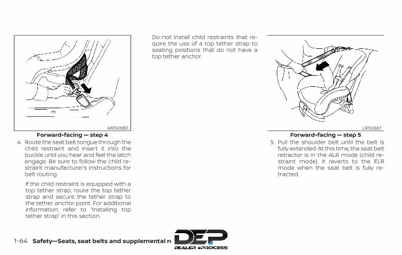
4. Route the seat belt tongue through thechild restraint and insert it into thebuckle until you hear and feel the latchengage. Be sure to follow the child re-straint manufacturer’s instructions forbelt routing.
If the child restraint is equipped with atop tether strap, route the top tetherstrap and secure the tether strap tothe tether anchor point. For additionalinformation, refer to “Installing toptether strap” in this section.
Do not install child restraints that re-quire the use of a top tether strap toseating positions that do not have atop tether anchor.
5. Pull the shoulder belt until the belt isfully extended. At this time, the seat beltretractor is in the ALR mode (child re-straint mode). It reverts to the ELRmode when the seat belt is fully re-tracted.
Forward-facing — step 4WRS0680
Forward-facing — step 5LRS0667
1-64 Safety—Seats, seat belts and supplemental restraint system
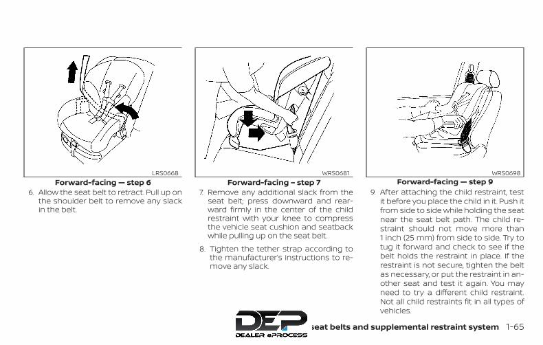
6. Allow the seat belt to retract. Pull up onthe shoulder belt to remove any slackin the belt.
7. Remove any additional slack from theseat belt; press downward and rear-ward firmly in the center of the childrestraint with your knee to compressthe vehicle seat cushion and seatbackwhile pulling up on the seat belt.
8. Tighten the tether strap according tothe manufacturer’s instructions to re-move any slack.
9. After attaching the child restraint, testit before you place the child in it. Push itfrom side to side while holding the seatnear the seat belt path. The child re-straint should not move more than1 inch (25 mm) from side to side. Try totug it forward and check to see if thebelt holds the restraint in place. If therestraint is not secure, tighten the beltas necessary, or put the restraint in an-other seat and test it again. You mayneed to try a different child restraint.Not all child restraints fit in all types ofvehicles.
Forward-facing — step 6LRS0668
Forward-facing – step 7WRS0681
Forward-facing — step 9WRS0698
Safety—Seats, seat belts and supplemental restraint system 1-65

10. Check to make sure that the child re-straint is properly secured prior to eachuse. If the seat belt is not locked, repeatsteps 3 through 9.
11. If the child restraint is installed in thefront passenger seat, place the ignitionswitch in the ON position. The front pas-senger air bag status light shouldilluminate. If this light is not illuminated,refer to “Front passenger air bag andstatus light” in this section. Move thechild restraint to another seating po-sition. Have the system checked. It isrecommended that you visit a NISSANdealer for this service.
After the child restraint is removed and theseat belt is fully retracted, the ALR mode(child restraint mode) is canceled.
1. Top tether strap2. Anchor point
Forward-facing — step 11WRS0475
Front passenger seat (King Cab® models)LRS0572
1-66 Safety—Seats, seat belts and supplemental restraint system

Installing top tether strap — frontpassenger seat (King Cab®models)
WARNINGChild restraint anchorages are de-signed to withstand only those loadsimposed by correctly fitted child re-straints. Under no circumstances arethey to be used to attach adult seatbelts, or other items or equipment tothe vehicle. Doing so could damage thechild restraint anchorages. The child re-straint will not be properly installed us-ing the damaged anchorages, and achild could be seriously injured or killedin a collision.
The child restraint top tether strap must beused when installing the child restraint withthe seat belts.
First, secure the child restraint with the seatbelt.
1. If necessary, raise or remove the headrestraint/headrest to position the toptether straps over the top of the seat-back. If the head restraint/headrest isremoved, store it in a secure place. Besure to reinstall the head
restraint/headrest when the child re-straint is removed. For additional infor-mation, refer to “Headrestraints/headrests” in this section.
2. Position the top tether strap as shown.
3. Secure the tether strap to the tetheranchor point as shown.
4. Tighten the tether strap according tothe manufacturer’s instructions to re-move any slack.
If you have any questions when install-ing a top tether strap, it is recommendedthat you visit a NISSAN dealer for thisservice.
1. Top tether strap2. Routing bracket3. Tether anchor point
Jump seat (King Cab® models)LRS0561
Safety—Seats, seat belts and supplemental restraint system 1-67
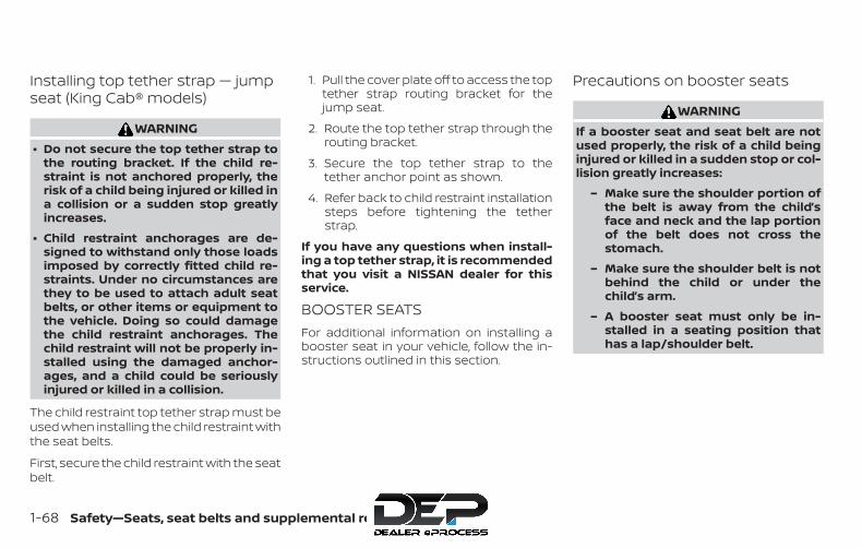
Installing top tether strap — jumpseat (King Cab® models)
WARNING∙ Do not secure the top tether strap to
the routing bracket. If the child re-straint is not anchored properly, therisk of a child being injured or killed ina collision or a sudden stop greatlyincreases.
∙ Child restraint anchorages are de-signed to withstand only those loadsimposed by correctly fitted child re-straints. Under no circumstances arethey to be used to attach adult seatbelts, or other items or equipment tothe vehicle. Doing so could damagethe child restraint anchorages. Thechild restraint will not be properly in-stalled using the damaged anchor-ages, and a child could be seriouslyinjured or killed in a collision.
The child restraint top tether strap must beused when installing the child restraint withthe seat belts.
First, secure the child restraint with the seatbelt.
1. Pull the cover plate off to access the toptether strap routing bracket for thejump seat.
2. Route the top tether strap through therouting bracket.
3. Secure the top tether strap to thetether anchor point as shown.
4. Refer back to child restraint installationsteps before tightening the tetherstrap.
If you have any questions when install-ing a top tether strap, it is recommendedthat you visit a NISSAN dealer for thisservice.
BOOSTER SEATSFor additional information on installing abooster seat in your vehicle, follow the in-structions outlined in this section.
Precautions on booster seats
WARNINGIf a booster seat and seat belt are notused properly, the risk of a child beinginjured or killed in a sudden stop or col-lision greatly increases:
– Make sure the shoulder portion ofthe belt is away from the child’sface and neck and the lap portionof the belt does not cross thestomach.
– Make sure the shoulder belt is notbehind the child or under thechild’s arm.
– A booster seat must only be in-stalled in a seating position thathas a lap/shoulder belt.
1-68 Safety—Seats, seat belts and supplemental restraint system

A. Low back booster seatB. High back booster seat
Booster seats of various sizes are offeredby several manufacturers. When selectingany booster seat, keep the following pointsin mind:
∙ Choose only a booster seat with a labelcertifying that it complies with FederalMotor Vehicle Safety Standard 213 orCanadian Motor Vehicle Safety Stan-dard 213.
∙ Check the booster seat in your vehicleto be sure it is compatible with the vehi-cle’s seat and seat belt system.
∙ Make sure the child’s head will be prop-erly supported by the booster seat orvehicle seat. The seatback must be ator above the center of the child’s ears.For example, if a low back booster seatis chosen, the vehicle seatback must beat or above the center of the child’s ears.If the seatback is lower than the centerof the child’s ears, a high back boosterseat should be used.
LRS2479 LRS0453 LRS0464
Safety—Seats, seat belts and supplemental restraint system 1-69
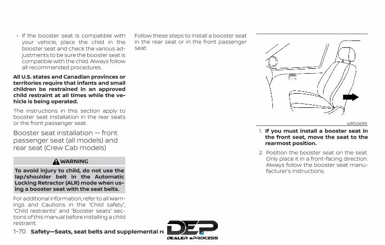
∙ If the booster seat is compatible withyour vehicle, place the child in thebooster seat and check the various ad-justments to be sure the booster seat iscompatible with the child. Always followall recommended procedures.
All U.S. states and Canadian provinces orterritories require that infants and smallchildren be restrained in an approvedchild restraint at all times while the ve-hicle is being operated.
The instructions in this section apply tobooster seat installation in the rear seatsor the front passenger seat.
Booster seat installation — frontpassenger seat (all models) andrear seat (Crew Cab models)
WARNINGTo avoid injury to child, do not use thelap/shoulder belt in the AutomaticLocking Retractor (ALR) mode when us-ing a booster seat with the seat belts.
For additional information, refer to all Warn-ings and Cautions in the “Child safety”,“Child restraints” and “Booster seats” sec-tions of this manual before installing a childrestraint.
Follow these steps to install a booster seatin the rear seat or in the front passengerseat:
1. If you must install a booster seat inthe front seat, move the seat to therearmost position.
2. Position the booster seat on the seat.Only place it in a front-facing direction.Always follow the booster seat manu-facturer’s instructions.
WRS0699
1-70 Safety—Seats, seat belts and supplemental restraint system
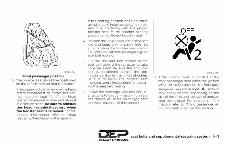
3. The booster seat should be positionedon the vehicle seat so that it is stable.
If necessary, adjust or remove the headrestraint/headrest to obtain the cor-rect booster seat fit. If the headrestraint/headrest is removed, store itin a secure place. Be sure to reinstallthe head restraint/headrest whenthe booster seat is removed. For ad-ditional information, refer to “Headrestraints/headrests” in this section.
If the seating position does not havean adjustable head restraint/headrestand it is interfering with the properbooster seat fit, try another seatingposition or a different booster seat.
4. Position the lap portion of the seat beltlow and snug on the child’s hips. Besure to follow the booster seat manu-facturer’s instructions for adjusting theseat belt routing.
5. Pull the shoulder belt portion of theseat belt toward the retractor to takeup extra slack. Be sure the shoulderbelt is positioned across the top,middle portion of the child’s shoulder.Be sure to follow the booster seatmanufacturer’s instructions for adjust-ing the seat belt routing.
6. Follow the warnings, cautions and in-structions for properly fastening a seatbelt shown in “Three-point type seatbelt with retractor” in this section.
7. If the booster seat is installed in thefront passenger seat, place the ignitionswitch in the ON position. The front pas-senger air bag status light may ormay not illuminate, depending on thesize of the child and the type of boosterseat being used. For additional infor-mation, refer to “Front passenger airbag and status light” in this section.
Front passenger positionLRS0454 WRS0475
Safety—Seats, seat belts and supplemental restraint system 1-71

Booster seat installation — jumpseat (King Cab® models)
WARNING∙ If a child restraint system is not in-
stalled properly, the child could be se-riously injured or killed in a suddenstop or collision.
– For boosters, DO NOT install if thechild restraint system base ex-tends past the forward edge of theseat cushion.
– Do not install a child restraint sys-tem on the passenger’s side jumpseat without unfolding the seatextender.
∙ To avoid injury to child, do not use thelap/shoulder belt in the AutomaticLocking Retractor (ALR) mode whenusing a booster seat with the seatbelts.
For additional information, refer to all Warn-ings and Cautions in the “Child safety”,“Child restraints” and “Booster seats” sec-tions of this manual before installing a childrestraint.
Follow these steps to install a booster seatin the jump seats:
1. To access the jump seat extension(passenger’s side only) �A on the jumpseat, pull up �B on the extension to un-fold it to the open position. Then unfoldthe two support legs �C and lower thejump seat to the full open seating posi-tion.
LRS2725 LRS2502
1-72 Safety—Seats, seat belts and supplemental restraint system
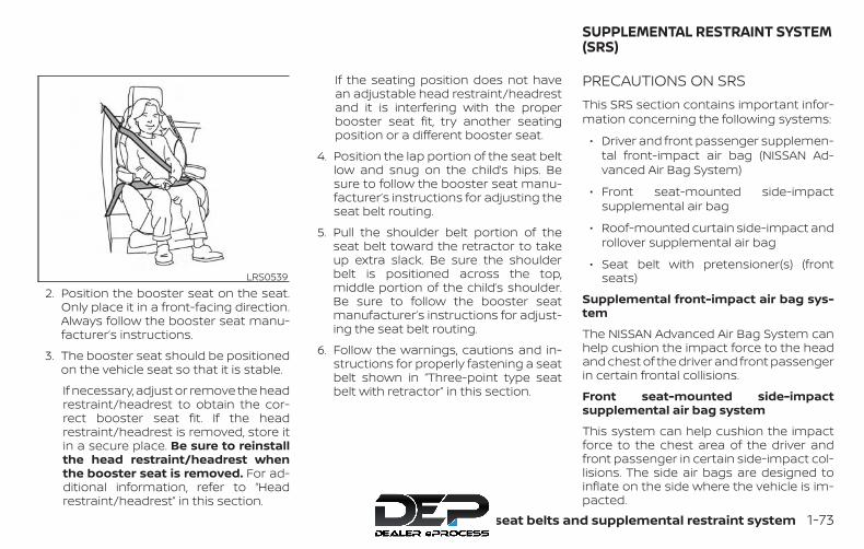
2. Position the booster seat on the seat.Only place it in a front-facing direction.Always follow the booster seat manu-facturer’s instructions.
3. The booster seat should be positionedon the vehicle seat so that it is stable.
If necessary, adjust or remove the headrestraint/headrest to obtain the cor-rect booster seat fit. If the headrestraint/headrest is removed, store itin a secure place. Be sure to reinstallthe head restraint/headrest whenthe booster seat is removed. For ad-ditional information, refer to “Headrestraint/headrest” in this section.
If the seating position does not havean adjustable head restraint/headrestand it is interfering with the properbooster seat fit, try another seatingposition or a different booster seat.
4. Position the lap portion of the seat beltlow and snug on the child’s hips. Besure to follow the booster seat manu-facturer’s instructions for adjusting theseat belt routing.
5. Pull the shoulder belt portion of theseat belt toward the retractor to takeup extra slack. Be sure the shoulderbelt is positioned across the top,middle portion of the child’s shoulder.Be sure to follow the booster seatmanufacturer’s instructions for adjust-ing the seat belt routing.
6. Follow the warnings, cautions and in-structions for properly fastening a seatbelt shown in “Three-point type seatbelt with retractor” in this section.
PRECAUTIONS ON SRSThis SRS section contains important infor-mation concerning the following systems:
∙ Driver and front passenger supplemen-tal front-impact air bag (NISSAN Ad-vanced Air Bag System)
∙ Front seat-mounted side-impactsupplemental air bag
∙ Roof-mounted curtain side-impact androllover supplemental air bag
∙ Seat belt with pretensioner(s) (frontseats)
Supplemental front-impact air bag sys-tem
The NISSAN Advanced Air Bag System canhelp cushion the impact force to the headand chest of the driver and front passengerin certain frontal collisions.
Front seat-mounted side-impactsupplemental air bag system
This system can help cushion the impactforce to the chest area of the driver andfront passenger in certain side-impact col-lisions. The side air bags are designed toinflate on the side where the vehicle is im-pacted.
LRS0539
SUPPLEMENTAL RESTRAINT SYSTEM(SRS)
Safety—Seats, seat belts and supplemental restraint system 1-73

Roof-mounted curtain side-impact androllover supplemental air bag system
This system can help cushion the impactforce to the head of occupants in front andrear outboard seating positions in certainside-impact or rollover collisions. In a side-impact, the curtain air bags are designedto inflate on the side where the vehicle isimpacted. In a rollover, the curtain air bagsare designed to inflate and remain inflatedfor a short time.
The SRS is designed to supplement thecrash protection provided by the seat beltsand is not a substitute for them. Seat beltsshould always be correctly worn and theoccupant seated a suitable distance awayfrom the steering wheel, instrument paneland door finishers. For additional informa-tion, refer to “Seat belts” in this section.
The supplemental air bags operate onlywhen the ignition switch is in the ON orSTART position.
After placing the ignition switch in theON position, the supplemental air bagwarning light illuminates. The supple-mental air bag warning light will turn offafter about 7 seconds if the system isoperational.
WARNING∙ The front air bags ordinarily will not
inflate in the event of a side impact,rear impact, rollover, or lower severityfrontal collision. Always wear yourseat belts to help reduce the risk orseverity of injury in various kinds ofaccidents.
∙ The front passenger air bag will notinflate if the passenger air bag statuslight is lit or if the front passenger seatis unoccupied. For additional infor-mation, refer to “Front passenger airbag and status light” in this section.
WRS0031
1-74 Safety—Seats, seat belts and supplemental restraint system

∙ The seat belts and the front air bagsare most effective when you are sit-ting well back and upright in the seat.The front air bags inflate with greatforce. Even with the NISSAN AdvancedAir Bag System, if you are unre-strained, leaning forward, sitting side-ways or out of position in any way, youare at greater risk of injury or death ina crash. You may also receive seriousor fatal injuries from the front air bagif you are up against it when it inflates.Always sit back against the seatbackand as far away as practical from thesteering wheel or instrument panel.Always properly use the seat belts.
∙ The driver and front passenger seatbelt buckles are equipped with sen-sors that detect if the seat belts arefastened. The NISSAN Advanced AirBag System monitors the severity of acollision and seat belt usage, then in-flates the air bags as needed. Failureto properly wear seat belts can in-crease the risk or severity of injury inan accident.
∙ The front passenger seat is equippedwith an occupant classification sen-sor (pressure sensor) that turns thefront passenger air bag OFF undersome conditions. This sensor is onlyused in this seat. Failure to be properlyseated and wearing the seat belt canincrease the risk or severity of injury inan accident. For additional informa-tion, refer to “Front passenger air bagand status light” in this section.
∙ Keep hands on the outside of thesteering wheel. Placing them insidethe steering wheel rim could increasethe risk that they are injured when thefront air bag inflates.
Safety—Seats, seat belts and supplemental restraint system 1-75
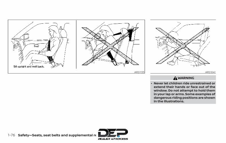
WARNING∙ Never let children ride unrestrained or
extend their hands or face out of thewindow. Do not attempt to hold themin your lap or arms. Some examples ofdangerous riding positions are shownin the illustrations.
ARS1133 ARS1041
1-76 Safety—Seats, seat belts and supplemental restraint system
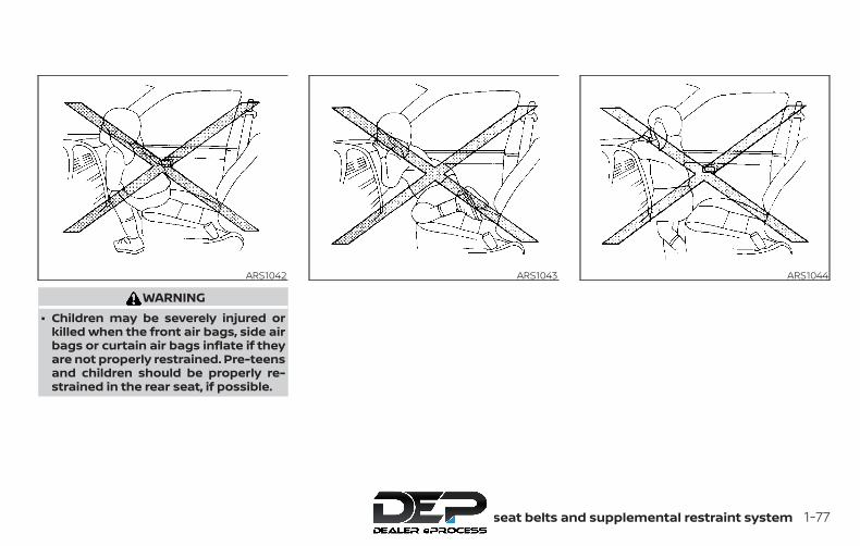
WARNING∙ Children may be severely injured or
killed when the front air bags, side airbags or curtain air bags inflate if theyare not properly restrained. Pre-teensand children should be properly re-strained in the rear seat, if possible.
ARS1042 ARS1043 ARS1044
Safety—Seats, seat belts and supplemental restraint system 1-77

WARNING∙ Even with the NISSAN Advanced Air
Bag System, never install a rear-facing child restraint in the front seat.An inflating front air bag could seri-ously injure or kill your child. For addi-tional information, refer to “Child re-straints” in this section.
WARNINGFront seat-mounted side-impactsupplemental air bags and roof-mounted curtain side-impact and roll-over supplemental air bags:
∙ The side air bags and curtain air bagsordinarily will not inflate in the eventof a frontal impact, rear impact, orlower severity side collision. Alwayswear your seat belts to help reducethe risk or severity of injury in variouskinds of accidents.
ARS1045 WRS0256Do not lean against the door.
WRS0431
1-78 Safety—Seats, seat belts and supplemental restraint system
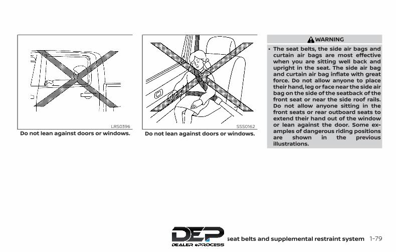
WARNING∙ The seat belts, the side air bags and
curtain air bags are most effectivewhen you are sitting well back andupright in the seat. The side air bagand curtain air bag inflate with greatforce. Do not allow anyone to placetheir hand, leg or face near the side airbag on the side of the seatback of thefront seat or near the side roof rails.Do not allow anyone sitting in thefront seats or rear outboard seats toextend their hand out of the windowor lean against the door. Some ex-amples of dangerous riding positionsare shown in the previousillustrations.
Do not lean against doors or windows.LRS0396
Do not lean against doors or windows.SSS0162
Safety—Seats, seat belts and supplemental restraint system 1-79

WARNING∙ When sitting in the rear seat, do not
hold onto the seatback of the frontseat. If the side air bag inflates, youmay be seriously injured. Be espe-cially careful with children, whoshould always be properly restrained.Some examples of dangerous ridingpositions are shown in theillustrations.
∙ Do not use seat covers on the frontseatbacks. They may interfere withside air bag inflation.
LRS0421 SSS0159
1-80 Safety—Seats, seat belts and supplemental restraint system
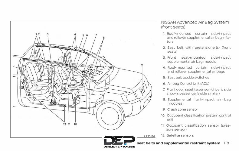
NISSAN Advanced Air Bag System(front seats)
1. Roof-mounted curtain side-impactand rollover supplemental air bag infla-tors
2. Seat belt with pretensioner(s) (frontseats)
3. Front seat-mounted side-impactsupplemental air bag module
4. Roof-mounted curtain side-impactand rollover supplemental air bags
5. Seat belt buckle switches
6. Air bag Control Unit (ACU)
7. Front door satellite sensor (driver’s sideshown; passenger’s side similar)
8. Supplemental front-impact air bagmodules
9. Crash zone sensor
10. Occupant classification system controlunit
11. Occupant classification sensor (pres-sure sensor)
12. Satellite sensorsLRS3124
Safety—Seats, seat belts and supplemental restraint system 1-81
This vehicle is equipped with the NISSANAdvanced Air Bag System for the driver andfront passenger seats. This system is de-signed to meet certification requirementsunder U.S. regulations. It is also permitted inCanada. However, all of the information,cautions and warnings in this manualstill apply and must be followed.
The driver supplemental front-impact airbag is located in the center of the steeringwheel. The front passenger supplementalfront-impact air bag is mounted in thedashboard above the glove box. The frontair bags are designed to inflate in higherseverity frontal collisions, although theymay inflate if the forces in another type ofcollision are similar to those of a higherseverity frontal impact. They may not in-flate in certain frontal collisions. Vehicledamage (or lack of it) is not always an indi-cation of proper front air bag system op-eration.
The NISSAN Advanced Air Bag Systemmonitors information from the crash zonesensor, the Air bag Control Unit (ACU), seatbelt buckle sensors, occupant classifica-tion sensor (pressure sensor) and passen-ger seat belt tension sensor. Inflator opera-tion is based on the severity of a collisionand seat belt usage for the driver. For the
front passenger, it additionally monitorsthe weight of an occupant or object on theseat and seat belt tension. Based on infor-mation from the sensors, only one front airbag may inflate in a crash, depending onthe crash severity and whether the frontoccupants are belted or unbelted. Addi-tionally, the front passenger air bag may beautomatically turned off under some con-ditions, depending on the weight detectedon the front passenger seat and how theseat belt is used. If the front passenger airbag is OFF, the front passenger air bag sta-tus light will be illuminated (if the seat isunoccupied, the light will not be illumi-nated, but the air bag will be off). For addi-tional information, refer to “Front passen-ger air bag and status light” in this section.One front air bag inflating does not indicateimproper performance of the system.
If you have any questions about your airbag system, it is recommended that youvisit a NISSAN dealer to obtain informationabout the system. If you are consideringmodification of your vehicle due to a dis-ability, you may also contact NISSAN. Con-tact information is contained in the front ofthis Owner’s Manual.
When a front air bag inflates, a fairly loudnoise may be heard, followed by the re-
lease of smoke. This smoke is not harmfuland does not indicate a fire. Care should betaken to not inhale it, as it may cause irrita-tion and choking. Those with a history of abreathing condition should get fresh airpromptly.
Front air bags, along with the use of seatbelts, help to cushion the impact force onthe face and chest of the front occupants.They can help save lives and reduce seri-ous injuries. However, an inflating front airbag may cause facial abrasions or otherinjuries. Front air bags do not provide re-straint to the lower body.
Even with NISSAN Advanced Air Bags, seatbelts should be correctly worn and thedriver and front passenger seated uprightas far as practical away from the steeringwheel or instrument panel. The front airbags inflate quickly in order to help protectthe front occupants. Because of this, theforce of the front air bag inflating can in-crease the risk of injury if the occupant istoo close to, or is against, the front air bagmodule during inflation.
The front air bags deflate quickly after acollision.
1-82 Safety—Seats, seat belts and supplemental restraint system

The front air bags operate only when theignition switch is in the ON or START po-sition.After placing the ignition switch in theON position, the supplemental air bagwarning light illuminates. The supple-mental air bag warning light will turn offafter about 7 seconds if the system isoperational.
Front passenger air bag and status light
WARNINGThe front passenger air bag is designedto automatically turn OFF under someconditions. Read this section carefullyto learn how it operates. Proper use ofthe seat, seat belt and child restraints isnecessary for most effective protec-tion. Failure to follow all instructions inthis manual concerning the use ofseats, seat belts and child restraints canincrease the risk or severity of injury inan accident.
Status lightThe front passenger air bag statuslight is located near the climate con-trols. After the ignition switch is placed inthe "ON" position, the front passenger airbag status light on the instrument panelilluminates for about 7 seconds and thenturns off or remains illuminated dependingon the front passenger seat occupied sta-tus. The light operates as follows:
∙ Unoccupied front passenger’s seat:The light is OFF and the front pas-senger air bag is OFF and will not inflatein a crash.
∙ Front passenger’s seat occupied by asmall adult, child or child restraint asoutlined in this section: The lightilluminates to indicate that the frontpassenger air bag is OFF and will notinflate in a crash.
∙ Occupied front passenger seat and thepassenger meet the conditions out-lined in this section: The light isOFF to indicate that the front passen-ger air bag is operational.
WRS0475
Safety—Seats, seat belts and supplemental restraint system 1-83
Front passenger air bagThe front passenger air bag is designed toautomatically turn OFF when the vehicle isoperated under some conditions as de-scribed below in accordance with U.S. regu-lations. If the front passenger air bag is OFFit will not inflate in a crash. The driver air bagand other air bags in your vehicle are notpart of this system.
The purpose of the regulation is to helpreduce the risk of injury or death from aninflating air bag to certain front passengerseat occupants, such as children, by requir-ing the air bag to be automatically turnedOFF. Certain sensors are used to meet therequirements.
One sensor used is the occupant classifi-cation sensor (pressure sensor). It is in thebottom of the front passenger seat cush-ion and is designed to detect an occupantand objects on the seat by weight. It workstogether with seat belt sensors describedin this section. For example, if a child is inthe front passenger seat, the NISSAN Ad-vanced Air Bag System is designed to turnthe front passenger air bag OFF in accor-dance with the regulations. Also, if a childrestraint of the type specified in the regula-tions is on the seat, its weight and thechild’s weight can be detected and cause
the air bag to turn OFF. Occupant classifi-cation sensor operation can vary depend-ing on the front passenger seat belt sen-sors.
The front passenger seat belt sensors aredesigned to detect if the seat belt is buck-led and the amount of tension on the seatbelt, such as when it is in the AutomaticLocking Retractor (ALR) mode (child re-straint mode). Based on the weight on theseat detected by the occupant classifica-tion sensor and the belt tension detectedon the seat belt, the NISSAN Advanced AirBag System determines whether the frontpassenger air bag should be automaticallyturned OFF as required by the regulations.
Front passenger seat adult occupants whoare properly seated and using the seat beltas outlined in this manual should notcause the front passenger air bag to beautomatically turned OFF. For small adultsit may be turned OFF, however, if the occu-pant does not sit in the seat properly (forexample, by not sitting upright, by sitting onan edge of the seat, or by otherwise beingout of position), this could cause the sensorto turn the air bag OFF. In addition, if theoccupant improperly uses the seat belt inthe ALR mode, this could cause the air bagto be turned OFF. Always be sure to be
seated and wearing the seat belt properlyfor the most effective protection by theseat belt and supplemental air bag.
NISSAN recommends that pre-teens andchildren be properly restrained in a rearseat. NISSAN also recommends that ap-propriate child restraints and boosterseats be properly installed in a rear seat. Ifthis is not possible, the occupant classifica-tion sensor and seat belt sensors are de-signed to operate as described above toturn the front passenger air bag OFF forspecified child restraints as required by theregulations. Failing to properly secure childrestraints and to use the ALR mode mayallow the restraint to tip or move in a colli-sion or sudden stop. This can also result inthe passenger air bag inflating in a crashinstead of being OFF. For additional infor-mation, refer to “Child restraints” in this sec-tion.
If the front passenger seat is not occupied,the front passenger air bag is designed notto inflate in a crash. However, heavy objectsplaced on the seat could result in air baginflation, because of the object’s weight de-tected by the occupant classification sen-sor. Other conditions could also result in airbag inflation, such as if a child is standingon the seat, or if two children are on the
1-84 Safety—Seats, seat belts and supplemental restraint system

seat, contrary to the instructions in thismanual. Always be sure that you and allvehicle occupants are seated and re-strained properly.
Using the front passenger air bag statuslight, you can monitor when the front pas-senger air bag is automatically turned OFFwith the seat occupied. The light will notilluminate when the front passenger seat isunoccupied.
If an adult occupant is in the seat but thefront passenger air bag status light is illu-minated (indicating that the air bag is OFF),it could be that the person is a small adult,or is not sitting on the seat properly or notusing the seat belt properly.
If a child restraint must be used in the frontseat, the front passenger air bag statuslight may or may not be illuminated, de-pending on the size of the child and thetype of child restraint being used. If the airbag status light is not illuminated (indicat-ing that the air bag might inflate in a crash),it could be that the child restraint or seatbelt is not being used properly. Make surethat the child restraint is installed properly,the seat belt is used properly and the occu-pant is positioned properly. If the air bag
status light is not illuminated, repositionthe occupant or child restraint in a rearseat.
If the front passenger air bag status lightwill not illuminate even though you believethat the child restraint, the seat belts andthe occupant are properly positioned, thesystem may be sensing an unoccupiedseat (in which case the air bag is OFF). ANISSAN dealer can check that the system isOFF by using a special tool. However, untilyou have confirmed with a dealer that yourair bag is working properly, reposition theoccupant or child restraint in a rear seat.
The NISSAN Advanced Air Bag System andfront passenger air bag status light willtake a few seconds to register a change inthe passenger seat status. For example, if alarge adult who is sitting in the front pas-senger seat exits the vehicle, the front pas-senger air bag status light will go from OFFto ON for a few seconds and then to OFF.This is normal system operation and doesnot indicate a malfunction.
If a malfunction occurs in the front passen-ger air bag system, the supplemental airbag warning light , located in the me-ter and gauges area of the instrumentpanel, will blink. Have the system checked. It
is recommended that you visit a NISSANdealer for this service.
Other supplemental front-impact airbag precautions
WARNING∙ Do not place any objects on the steer-
ing wheel pad or on the instrumentpanel. Also, do not place any objectsbetween any occupant and the steer-ing wheel or instrument panel. Suchobjects may become dangerous pro-jectiles and cause injury if the front airbags inflate.
∙ Immediately after inflation, severalfront air bag system components willbe hot. Do not touch them; you mayseverely burn yourself.
∙ No unauthorized changes should bemade to any components or wiring ofthe supplemental air bag system. Thisis to prevent accidental inflation ofthe supplemental air bag or damageto the supplemental air bag system.
Safety—Seats, seat belts and supplemental restraint system 1-85

∙ Do not make unauthorized changesto your vehicle’s electrical system,suspension system or front end struc-ture. This could affect proper opera-tion of the front air bag system.
∙ Tampering with the front air bag sys-tem may result in serious personal in-jury. Tampering includes changes tothe steering wheel and the instru-ment panel assembly by placing ma-terial over the steering wheel pad andabove the instrument panel or by in-stalling additional trim materialaround the air bag system.
∙ Modifying or tampering with the frontpassenger seat may result in seriouspersonal injury. For example, do notchange the front seats by placing ma-terial on the seat cushion or by install-ing additional trim material, such asseat covers, on the seat that are notspecifically designed to assure properair bag operation. Additionally, do notstow any objects under the front pas-senger seat or the seat cushion andseatback. Such objects may interferewith the proper operation of the occu-pant classification sensor (pressuresensor).
∙ No unauthorized changes should bemade to any components or wiring ofthe seat belt system. This may affectthe front air bag system. Tamperingwith the seat belt system may resultin serious personal injury.
∙ It is recommended that you visit aNISSAN dealer for work on and aroundthe front air bag. It is also recom-mended that you visit a NISSAN dealerfor installation of electrical equip-ment. The Supplemental RestraintSystem (SRS) wiring harnesses*should not be modified or discon-nected. Unauthorized electrical testequipment and probing devicesshould not be used on the air bagsystem.
∙ A cracked windshield should be re-placed immediately by a qualified re-pair facility. A cracked windshieldcould affect the function of thesupplemental air bag system.
*The SRS wiring harness connectors areyellow and orange for easy identifica-tion.
When selling your vehicle, we request thatyou inform the buyer about the front airbag system and guide the buyer to theappropriate sections in this Owner’sManual.
1-86 Safety—Seats, seat belts and supplemental restraint system

Front seat-mounted side-impactsupplemental air bag androof-mounted curtain side-impact and rollover supplementalair bag systemsThe side air bags are located in the outsideof the seatback of the front seats. The cur-tain air bags are located in the side roofrails. All of the information, cautions andwarnings in this manual apply and mustbe followed. The side air bags and curtainair bags are designed to inflate in higherseverity side collisions, although they mayinflate if the forces in another type of colli-
sion are similar to those of a higher severityimpact. They are designed to inflate on theside where the vehicle is impacted. Theymay not inflate in certain side collisions.
Curtain air bags are also designed to inflatein certain types of rollover collisions or nearrollovers. As a result, certain vehicle move-ments (for example, during severe off-roading) may cause the curtain air bags toinflate.
Vehicle damage (or lack of it) is not alwaysan indication of proper side air bag andcurtain air bag operation.
When the side air bags and curtain air bagsinflate, a fairly loud noise may be heard,followed by release of smoke. This smoke isnot harmful and does not indicate a fire.Care should be taken not to inhale it, as itmay cause irritation and choking. Thosewith a history of a breathing conditionshould get fresh air promptly.
Side air bags, along with the use of seatbelts, help to cushion the impact force onthe chest and pelvic area of the front occu-pants. Curtain air bags help to cushion theimpact force to the head of occupants inthe front and rear outboard seating posi-tions. They can help save lives and reduceserious injuries. However, an inflating side
air bag or curtain air bag may cause abra-sions or other injuries. Side air bags andcurtain air bags do not provide restraint tothe lower body.
The seat belts should be correctly wornand the driver and passenger seated up-right as far as practical away from the sideair bag. Rear seat passengers should beseated as far away as practical from thedoor finishers and side roof rails. The sideair bags and curtain air bags inflate quicklyin order to help protect the occupants. Be-cause of this, the force of the side air bagand curtain air bag inflating can increasethe risk of injury if the occupant is too closeto, or is against, these air bag modules dur-ing inflation. The side air bag will deflatequickly after the collision is over.
The curtain air bags will remain inflated fora short time.
The side air bags and curtain air bagsoperate only when the ignition switch isin the ON or START position.
After placing the ignition switch in theON position, the supplemental air bagwarning light illuminates. The supple-mental air bag warning light will turn offafter about 7 seconds if the system isoperational.
LRS2501
Safety—Seats, seat belts and supplemental restraint system 1-87

WARNING∙ Do not place any objects near the
seatback of the front seats. Also, donot place any objects (an umbrella,bag, etc.) between the front door fin-isher and the front seat. Such objectsmay become dangerous projectilesand cause injury if a side air baginflates.
∙ Right after inflation, several side airbag and curtain air bag system com-ponents will be hot. Do not touchthem; you may severely burn yourself.
∙ No unauthorized changes should bemade to any components or wiring ofthe side air bag and curtain air bagsystems. This is to prevent damage toor accidental inflation of the side airbag and curtain air bag systems.
∙ Do not make unauthorized changesto your vehicle’s electrical system,suspension system or side panel. Thiscould affect proper operation of thecurtain air bag systems.
∙ Tampering with the side air bag sys-tem may result in serious personal in-jury. For example, do not change thefront seats by placing material nearthe seatbacks or by installing addi-tional trim material, such as seat cov-ers, around the side air bag.
∙ It is recommended that you visit aNISSAN dealer for work on and aroundthe side air bag and curtain air bag. Itis also recommended that you visit aNISSAN dealer for installation of elec-trical equipment. The SRS wiring har-nesses* should not be modified or dis-connected. Unauthorized electricaltest equipment and probing devicesshould not be used on the side air bagor curtain air bag systems.
* The SRS wiring harness or connectorsare yellow or orange for easy identifica-tion.
When selling your vehicle, we request thatyou inform the buyer about the side air bagand curtain air bag systems and guide thebuyer to the appropriate sections in thisOwner’s Manual.
Seat belt with pretensioner(s)(front seats)
WARNING∙ The pretensioner(s) cannot be reused
after activation. They must be re-placed together with the retractorand buckle as a unit.
∙ If the vehicle becomes involved in acollision but pretensioner(s) are notactivated, be sure to have the preten-sioner system checked and, if neces-sary, replaced. It is recommended thatyou visit a NISSAN dealer for thisservice.
∙ No unauthorized changes should bemade to any components or wiring ofthe pretensioner system. This is toprevent damage to or accidental acti-vation of the pretensioner(s). Tamper-ing with the pretensioner system mayresult in serious personal injury.
1-88 Safety—Seats, seat belts and supplemental restraint system

∙ It is recommended that you visit aNISSAN dealer for work on and aroundthe pretensioner system. It is also rec-ommended that you visit a NISSANdealer for installation of electricalequipment. Unauthorized electricaltest equipment and probing devicesshould not be used on the preten-sioner system.
∙ If you need to dispose of the preten-sioner(s) or scrap the vehicle, it is rec-ommended that you visit a NISSANdealer for this service. Incorrect dis-posal procedures could cause per-sonal injury.
The pretensioner system may activatewith the supplemental air bag system incertain types of collisions. Working with theseat belt retractor, the pretensioner(s) helptighten the seat belt when the vehicle be-comes involved in certain types of colli-sions, helping to restrain front seat occu-pants.
The pretensioner(s) are encased within theseat belt retractor and to the seat belt an-chor affixed to the floor of the vehicle.These seat belts are used the same way asconventional seat belts.
When pretensioner(s) activate, smoke is re-leased and a loud noise may be heard. Thissmoke is not harmful and does not indi-cate a fire. Care should be taken not toinhale it, as it may cause irritation andchoking. Those with a history of a breath-ing condition should get fresh air promptly.After the pretensioner(s’) activation, loadlimiters allow the seat belt to release web-bing (if necessary) to reduce forces againstthe chest.
The supplemental air bag warninglight is used to indicate malfunctionsin the pretensioner system. For additionalinformation, refer to "Supplemental air bagwarning light" in this section. If the opera-tion of the supplemental air bag warninglight indicates there is a malfunction, havethe system checked. It is recommendedthat you visit a NISSAN dealer for this ser-vice.When selling your vehicle, we request thatyou inform the buyer about the preten-sioner system and guide the buyer to theappropriate sections in this Owner’sManual.
1. SRS Air bag warning labels
The warning labels are located on thesurface of the sun visor.
SUPPLEMENTAL AIR BAG WARNINGLABELSWarning labels about the supplementalfront-impact air bag system are placed inthe vehicle as shown in the illustration.
WRS0885
Safety—Seats, seat belts and supplemental restraint system 1-89
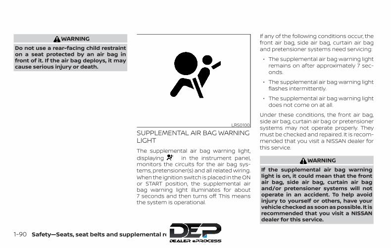
WARNINGDo not use a rear-facing child restrainton a seat protected by an air bag infront of it. If the air bag deploys, it maycause serious injury or death.
SUPPLEMENTAL AIR BAG WARNINGLIGHTThe supplemental air bag warning light,displaying in the instrument panel,monitors the circuits for the air bag sys-tems, pretensioner(s) and all related wiring.When the ignition switch is placed in the ONor START position, the supplemental airbag warning light illuminates for about7 seconds and then turns off. This meansthe system is operational.
If any of the following conditions occur, thefront air bag, side air bag, curtain air bagand pretensioner systems need servicing:
∙ The supplemental air bag warning lightremains on after approximately 7 sec-onds.
∙ The supplemental air bag warning lightflashes intermittently.
∙ The supplemental air bag warning lightdoes not come on at all.
Under these conditions, the front air bag,side air bag, curtain air bag or pretensionersystems may not operate properly. Theymust be checked and repaired. It is recom-mended that you visit a NISSAN dealer forthis service.
WARNINGIf the supplemental air bag warninglight is on, it could mean that the frontair bag, side air bag, curtain air bagand/or pretensioner systems will notoperate in an accident. To help avoidinjury to yourself or others, have yourvehicle checked as soon as possible. It isrecommended that you visit a NISSANdealer for this service.
LRS0100
1-90 Safety—Seats, seat belts and supplemental restraint system
Repair and replacementprocedureThe front air bags, side air bags, curtain airbags and pretensioner(s) are designed toinflate on a one-time-only basis. As a re-minder, unless it is damaged, the supple-mental air bag warning light remains illu-minated after inflation has occurred. Thesesystems should be repaired and/or re-placed as soon as possible. It is recom-mended that you visit a NISSAN dealer forthis service.
When maintenance work is required on thevehicle, the front air bags, side air bags,curtain air bags, pretensioner(s) and re-lated parts should be pointed out to theperson performing the maintenance. Theignition switch should always be placed inthe LOCK position when working under thehood or inside the vehicle.
WARNING∙ Once a front air bag, side air bag, or
curtain air bag has inflated, the airbag module will not function againand must be replaced. Additionally,the activated pretensioner(s) mustalso be replaced. The air bag moduleand pretensioner(s) should be re-placed. It is recommended that youvisit a NISSAN dealer for this service.However, the air bag module and pre-tensioner(s) cannot be repaired.
∙ The front air bag, side air bag, curtainair bag systems and the pretensionersystem should be inspected if there isany damage to the front end or sideportion of the vehicle. It is recom-mended that you visit a NISSAN dealerfor this service.
∙ If you need to dispose of the supple-mental air bag or pretensioner sys-tems or scrap the vehicle, it is recom-mended that you visit a NISSANdealer. Incorrect disposal procedurescould cause personal injury.
∙ If there is an impact to your vehiclefrom any direction, your OccupantClassification Sensor (OCS) should bechecked to verify it is still functioningcorrectly. It is recommended that youvisit a NISSAN dealer for this service.The OCS should be checked even if noair bags deploy as a result of the im-pact. Failure to verify proper OCSfunction may result in an improper airbag deployment resulting in injury ordeath.
Safety—Seats, seat belts and supplemental restraint system 1-91

2 Instruments and controls
Instrument panel . . . . . . . . . . . . . . . . . . . . . . . . . . . . . . . . 2-2Meters and gauges. . . . . . . . . . . . . . . . . . . . . . . . . . . . . . 2-3
Speedometer and odometer . . . . . . . . . . . . . . . . . 2-4Tachometer . . . . . . . . . . . . . . . . . . . . . . . . . . . . . . . . . . 2-6Engine coolant temperature gauge . . . . . . . . . . 2-6Fuel gauge . . . . . . . . . . . . . . . . . . . . . . . . . . . . . . . . . . . 2-7Engine oil pressure gauge(if so equipped) . . . . . . . . . . . . . . . . . . . . . . . . . . . . . . . 2-8Voltmeter (if so equipped) . . . . . . . . . . . . . . . . . . . . 2-8Trip computer (if so equipped) . . . . . . . . . . . . . . . . 2-9
Compass and outside temperature display(if so equipped) . . . . . . . . . . . . . . . . . . . . . . . . . . . . . . . . . 2-10
Outside temperature display . . . . . . . . . . . . . . . . .2-11Compass. . . . . . . . . . . . . . . . . . . . . . . . . . . . . . . . . . . . .2-11
Warning lights, indicator lights and audiblereminders . . . . . . . . . . . . . . . . . . . . . . . . . . . . . . . . . . . . . . 2-14
Checking lights . . . . . . . . . . . . . . . . . . . . . . . . . . . . . . 2-15Warning lights . . . . . . . . . . . . . . . . . . . . . . . . . . . . . . . 2-15Indicator lights . . . . . . . . . . . . . . . . . . . . . . . . . . . . . . 2-20Audible reminders . . . . . . . . . . . . . . . . . . . . . . . . . . . 2-24
Security systems (if so equipped) . . . . . . . . . . . . . . . 2-25Vehicle security system (if so equipped) . . . . . 2-25NISSAN Vehicle Immobilizer System(if so equipped) . . . . . . . . . . . . . . . . . . . . . . . . . . . . . . 2-26
Wiper and washer switch . . . . . . . . . . . . . . . . . . . . . . . 2-28Switch operation . . . . . . . . . . . . . . . . . . . . . . . . . . . . 2-28
Rear window or outside mirror defrosterswitch (if so equipped). . . . . . . . . . . . . . . . . . . . . . . . . . 2-28Headlight and turn signal switch . . . . . . . . . . . . . . . 2-29
Headlight control switch. . . . . . . . . . . . . . . . . . . . . 2-29Daytime Running Lights (DRL) system(if so equipped) . . . . . . . . . . . . . . . . . . . . . . . . . . . . . . 2-32Instrument brightness control. . . . . . . . . . . . . . . 2-32Turn signal switch . . . . . . . . . . . . . . . . . . . . . . . . . . . 2-32Fog light switch (if so equipped) . . . . . . . . . . . . . 2-33
Horn . . . . . . . . . . . . . . . . . . . . . . . . . . . . . . . . . . . . . . . . . . . 2-33Cargo lamp switch . . . . . . . . . . . . . . . . . . . . . . . . . . . . . 2-34Heated seat switches (if so equipped) . . . . . . . . . . 2-34Vehicle Dynamic Control (VDC) OFF switch. . . . . . 2-35Hill descent control switch (if so equipped). . . . . . 2-36Electronic locking rear differential (E-Lock)system switch (if so equipped). . . . . . . . . . . . . . . . . . 2-37Clutch interlock (clutch start) switch(if so equipped) . . . . . . . . . . . . . . . . . . . . . . . . . . . . . . . . . 2-38Rear Sonar System (RSS) OFF switch(if so equipped) . . . . . . . . . . . . . . . . . . . . . . . . . . . . . . . . . 2-39Power outlets . . . . . . . . . . . . . . . . . . . . . . . . . . . . . . . . . . 2-39Storage . . . . . . . . . . . . . . . . . . . . . . . . . . . . . . . . . . . . . . . . 2-40
Front-door pockets. . . . . . . . . . . . . . . . . . . . . . . . . . 2-40Rear-door pockets . . . . . . . . . . . . . . . . . . . . . . . . . . 2-41Seatback pocket (if so equipped) . . . . . . . . . . . . 2-41Under-seat storage bins. . . . . . . . . . . . . . . . . . . . . 2-42Storage trays . . . . . . . . . . . . . . . . . . . . . . . . . . . . . . . . 2-43Glove box. . . . . . . . . . . . . . . . . . . . . . . . . . . . . . . . . . . . 2-44Console box . . . . . . . . . . . . . . . . . . . . . . . . . . . . . . . . . 2-45Overhead sunglasses storage . . . . . . . . . . . . . . . 2-45Cup holders . . . . . . . . . . . . . . . . . . . . . . . . . . . . . . . . . 2-46Roof rack (if so equipped) . . . . . . . . . . . . . . . . . . . . 2-48
Windows . . . . . . . . . . . . . . . . . . . . . . . . . . . . . . . . . . . . . . . 2-49Manual windows (if so equipped) . . . . . . . . . . . . 2-49Power windows (if so equipped) . . . . . . . . . . . . . 2-49Rear sliding window (if so equipped) . . . . . . . . . 2-52
Moonroof (if so equipped) . . . . . . . . . . . . . . . . . . . . . . 2-52
Power moonroof . . . . . . . . . . . . . . . . . . . . . . . . . . . . 2-52Interior lights . . . . . . . . . . . . . . . . . . . . . . . . . . . . . . . . . . . 2-54
Map lights (if so equipped) . . . . . . . . . . . . . . . . . . . 2-55HomeLink® universal transceiver(if so equipped) . . . . . . . . . . . . . . . . . . . . . . . . . . . . . . . . . 2-55
Programming HomeLink® . . . . . . . . . . . . . . . . . . . 2-56Programming HomeLink® for Canadiancustomers and gate openers. . . . . . . . . . . . . . . . 2-57Operating the HomeLink® UniversalTransceiver . . . . . . . . . . . . . . . . . . . . . . . . . . . . . . . . . . 2-58Programming trouble-diagnosis . . . . . . . . . . . . 2-58Clearing the programmed information . . . . . . 2-58Reprogramming a single HomeLink®button. . . . . . . . . . . . . . . . . . . . . . . . . . . . . . . . . . . . . . . 2-59If your vehicle is stolen. . . . . . . . . . . . . . . . . . . . . . . 2-59

1. Vents (P. 4-23)2. Headlight/fog light (if so
equipped)/turn signal switch(P. 2-29)
3. Steering wheel switch for audiocontrol (P. 4-75)Bluetooth® Hands-Free PhoneSystem (P. 4-85, 4-103)
4. Driver supplemental air bag(P. 1-73)Horn (P. 2-33)
5. Meters and gauges (P. 2-3)Warning and indicator lights(P. 2-14)
6. Cruise control switches (P. 5-22)7. Wiper and washer switch (P. 2-28)8. Storage (P. 2-40)9. Audio system (P. 4-37)10. Front passenger supplemental air
bag (P. 1-73)11. Upper and lower glove box (P. 2-40)12. Passenger air bag status light
(P. 1-73)13. USB connection port (P. 4-58)
AUX input (P. 4-58)14. Power outlets (P. 2-39)
LII2484
INSTRUMENT PANEL
2-2 Instruments and controls

15. Electronic locking rear differential(E-Lock) system switch(if so equipped) (P. 2-37)Heated seat switches(if so equipped) (P. 2-34)Rear sonar switch (if so equipped)(P. 2-39)Vehicle Dynamic Control (VDC) OFFswitch (P. 2-35)
16. Shift lever (P. 5-14)17. 4WD shift switch (if so equipped)
(P. 5-26)18. Climate controls (P. 4-23, P. 4-32)19. Hazard warning flasher switch
(P. 6-2)20. Ignition switch (P. 5-11)21. Tilt steering wheel control
(if so equipped) (P. 3-14)22. Cargo lamp switch (P. 2-34)
Clutch interlock (clutch start)switch (if so equipped) (P. 2-38)Hill descent control switch(if so equipped) (P. 2-36)Outside mirror controls(if so equipped) (P. 3-15)
1. Warning and indicator lights2. Tachometer3. Speedometer4. Fuel gauge5. Change/reset button6. Voltmeter (if so equipped)
7. OdometerTwin trip odometerTrip computer (if so equipped)Instrument brightness control knob
8. Engine oil pressure gauge9. Engine coolant temperature gauge
LIC3327
METERS AND GAUGES
Instruments and controls 2-3
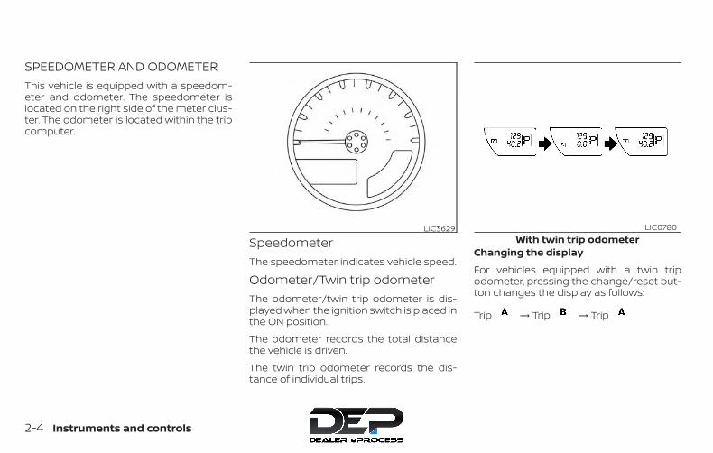
SPEEDOMETER AND ODOMETERThis vehicle is equipped with a speedom-eter and odometer. The speedometer islocated on the right side of the meter clus-ter. The odometer is located within the tripcomputer.
SpeedometerThe speedometer indicates vehicle speed.
Odometer/Twin trip odometerThe odometer/twin trip odometer is dis-played when the ignition switch is placed inthe ON position.
The odometer records the total distancethe vehicle is driven.
The twin trip odometer records the dis-tance of individual trips.
Changing the display
For vehicles equipped with a twin tripodometer, pressing the change/reset but-ton changes the display as follows:
Trip → Trip → Trip
LIC3629With twin trip odometer
LIC0780
2-4 Instruments and controls

For vehicles equipped with a trip computer,pressing the change/reset buttonchanges the display as follows:
Trip → Trip → Distance to Empty→ Average speed → Average fuel con-sumption → Journey time → TripFor additional information, refer to “Tripcomputer” in this section.
Resetting the trip odometer
Pressing the change/reset button formore than 1 second resets the currentlydisplayed trip odometer to zero.
Loose fuel cap warning messagePress the change/reset button �A for morethan 1 second to reset the LOOSE FUEL CAPwarning message after the fuel cap hasbeen tightened. For additional information,refer to “Fuel-filler cap” in the “Pre-drivingchecks and adjustments” section of thismanual.
Check tire pressure warningmessageThe CHECK TIRE PRES (pressure) warningmessage is displayed when the low tirepressure warning light is illuminated andlow tire pressure is detected. Check andadjust the tire pressure to the recom-mended COLD tire pressure shown on theTire and Loading Information label. TheCHECK TIRE PRES (pressure) warning mes-sage turns off when the low tire pressurewarning light turns off.
With trip computerWIC0922 LIC3741 LIC3742
Instruments and controls 2-5
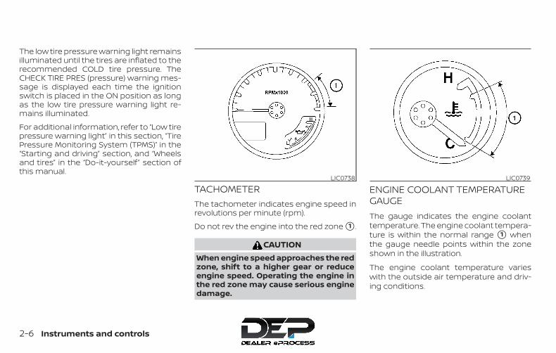
The low tire pressure warning light remainsilluminated until the tires are inflated to therecommended COLD tire pressure. TheCHECK TIRE PRES (pressure) warning mes-sage is displayed each time the ignitionswitch is placed in the ON position as longas the low tire pressure warning light re-mains illuminated.
For additional information, refer to “Low tirepressure warning light” in this section, “TirePressure Monitoring System (TPMS)” in the“Starting and driving” section, and “Wheelsand tires” in the “Do-it-yourself ” section ofthis manual.
TACHOMETERThe tachometer indicates engine speed inrevolutions per minute (rpm).
Do not rev the engine into the red zone �1 .
CAUTIONWhen engine speed approaches the redzone, shift to a higher gear or reduceengine speed. Operating the engine inthe red zone may cause serious enginedamage.
ENGINE COOLANT TEMPERATUREGAUGEThe gauge indicates the engine coolanttemperature. The engine coolant tempera-ture is within the normal range �1 whenthe gauge needle points within the zoneshown in the illustration.
The engine coolant temperature varieswith the outside air temperature and driv-ing conditions.
LIC0738 LIC0739
2-6 Instruments and controls

CAUTIONIf the gauge indicates coolant tempera-ture near the hot (H) end of the normalrange, reduce vehicle speed to decreasetemperature. If the gauge is over thenormal range, stop the vehicle as soonas safely possible. If the engine is over-heated, continued operation of the ve-hicle may seriously damage the engine.For additional information, refer to “Ifyour vehicle overheats” in the “In caseof emergency” section of this manualfor immediate action required.
FUEL GAUGEThe gauge indicates the approximate fuellevel in the tank.
The gauge may move slightly during brak-ing, turning, acceleration, or going up ordown hills.
The gauge needle returns to 0 (Empty) af-ter the ignition switch is placed in the OFFposition.
The low fuel warning light comes on whenthe amount of fuel in the tank is getting low.
Refill the fuel tank before the gauge reg-isters 0 (Empty).
The indicates that the fuel-fillerdoor is located on the driver’s side of thevehicle.
CAUTION
∙ If the vehicle runs out of fuel, theMalfunction Indicator Light (MIL) maycome on. Refuel as soon as possible.After a few driving trips, the lightshould turn off. If the light remains onafter a few driving trips, have the ve-hicle inspected. It is recommendedthat you visit a NISSAN dealer for thisservice.
∙ For additional information, refer to“Malfunction Indicator Light (MIL)” inthis section.
LIC0740
Instruments and controls 2-7

ENGINE OIL PRESSURE GAUGE (ifso equipped)The gauge indicates the engine lubricationsystem oil pressure while the engine is run-ning. The needle should be in the middle ofthe gauge when the engine is running.
CAUTION∙ This gauge is not designed to indicate
low engine oil level. Use the dipstick tocheck the oil level. For additional in-formation, refer to “Engine oil” in the“Do-it-yourself” section of thismanual.
∙ If the gauge needle does not movewith the proper amount of engine oil,have the vehicle checked. It is recom-mended that you visit a NISSAN dealerfor this service. Continued vehicle op-eration in such a condition couldcause serious damage to the engine.
VOLTMETER (if so equipped)When the ignition switch is placed in the ONposition, the voltmeter indicates the bat-tery voltage. When the engine is running, itindicates the generator voltage.
While cranking the engine, the volts dropbelow the normal range. If the needle is notin the normal range (11 - 15 volts) �1 whilethe engine is running, it may indicate thatthe charging system is not functioningproperly. Have the system checked. It isrecommended that you visit a NISSANdealer for this service.
LIC0741 WIC1299
2-8 Instruments and controls

TRIP COMPUTER (if so equipped)The display of the trip computer is situatedin the speedometer display. When the igni-tion switch is placed in the ON position, thedisplay scrolls all the modes of the tripcomputer and then shows the mode cho-sen before the ignition switch was placedin the OFF position.
When the ignition switch is placed in the ONposition, modes of the trip computer canbe selected by pressing the change/resetbutton. The following modes can be se-lected:
Distance To Empty (DTE—mile orkm)The DTE mode provides you with an esti-mation of the distance that can be drivenbefore refueling. The DTE is constantly be-ing calculated, based on the amount of fuelin the fuel tank and the actual fuel con-sumption.
The display is updated every 30 seconds.
The DTE mode includes a low range warn-ing feature: when the fuel level is low, theDTE mode is automatically selected andthe digits blink in order to draw the driver’sattention. Press the change/reset button ifyou wish to return to the mode that wasselected before the warning occurred. TheDTE mark will remain blinking until the ve-hicle is refueled.
When the fuel level drops even lower, theDTE display will change to (----).
NOTE:
∙ If the amount of fuel added while theignition switch is off is small, the dis-play just before the ignition switch isturned off may continue to be dis-played.
∙ When driving uphill or roundingcurves, the fuel in the tank shifts,which may momentarily change thedisplay.
Average fuel consumption (Mpgor l/100km)The average fuel consumption modeshows the average fuel consumption sincethe last reset. Resetting is done by pressingthe change/reset button for more than ap-proximately 1 second. The display is up-dated every 30 seconds. At about the first1/3 miles (500 m) after a reset, the displayshows (----).
Average speed (mph or km/h)The average speed mode shows the aver-age vehicle speed since last reset. Reset-ting is done by pressing the change/resetbutton for more than approximately 1 sec-ond. The display is updated every 30 sec-onds. The first 30 seconds after a reset, thedisplay shows (----).
Journey timeThe journey time mode shows the timesince the last reset. The displayed time canbe reset by pressing the change/reset but-ton for more than approximately 1 second.
LIC3743
Instruments and controls 2-9

Trip computer resetPressing the change/reset button formore than 3 seconds will reset all modesexcept Trip A and distance to empty.
This unit has the following functions:
∙ Measures terrestrial magnetism and in-dicates the heading direction of the ve-hicle
∙ Indicates outside air temperature
With the ignition switch in the ON position,press the or button as de-scribed in the charts below to activate vari-ous features of the automatic anti-glarerearview mirror.Type A (if so equipped)
Press and holdthebutton forabout:
Feature:(Press button again for about1 second to change settings)
1 second Compass toggles on/off
8 seconds Automatic anti-glare/indicatorlight toggles on/off
11 secondsCompass zone can be changedto correct false compass read-ings
13 seconds Compass enters calibrationmode
Type B (if so equipped)
Press and holdthebutton forabout:
Feature:(Press button again for about1 second to change settings)
1 second Compass toggles on/off
8 secondsCompass zone can be changedto correct false compass read-ings
10 seconds Compass enters calibrationmode
For additional information, refer to “Auto-matic anti-glare rearview mirror” in the“Pre-driving checks and adjustments” sec-tion of this manual.
COMPASS AND OUTSIDETEMPERATURE DISPLAY (if soequipped)
2-10 Instruments and controls

OUTSIDE TEMPERATURE DISPLAY
Press the or button for about1 second when the ignition key is in the ONposition to toggle the outside temperatureand compass direction display �1 on or off.
∙ To change from °F to °C, press and holdthe button for about 5 seconds orthe button for about 3 secondsuntil the display begins to flash. Pressthe button again to toggle between °Cand °F.
∙ When the outside temperature is be-tween 140°F (60°C) and 194°F (90°C), thedisplay will read 140°F (60°C). When thetemperature is above 194°F (90°C), thedisplay will read “SC.”
∙ When the outside temperature is be-tween than -40°F (-40°C) and -60°F(-51°C), the display will read -40°F (-40°C).When the temperature is below -60°F(-51°C), the display will read “OC.”
∙ The outside temperature sensor is lo-cated in front of the radiator. The sensormay be affected by road or engine heat,wind direction and other driving condi-tions. The display may differ from theactual outside temperature or the tem-perature displayed on various signs orbillboards.
COMPASSPress the or button for about1 second when the ignition switch is placedin the ON position to toggle the outsidetemperature and compass direction dis-play �1 on or off. The display will indicatethe direction that the vehicle is heading.N: NorthE: EastS: SouthW: West
If the display reads “C,” calibrate the com-pass by driving the vehicle in three com-plete circles at less than 5 mph (8 km/h).
You can also calibrate the compass by driv-ing your vehicle on your everyday route.The compass will be calibrated once it hastracked three complete circles.
Type A (if so equipped)WIC0904
Type B (if so equipped)LIC0583
Instruments and controls 2-11
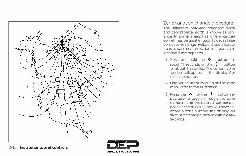
Zone variation change procedureThe difference between magnetic northand geographical north is known as vari-ance. In some areas, this difference cansometimes be great enough to cause falsecompass readings. Follow these instruc-tions to set the variance for your particularlocation if this happens:
1. Press and hold the button forabout 11 seconds or the buttonfor about 8 seconds. The current zonenumber will appear in the display. Re-lease the button.
2. Find your current location on the zonemap. Refer to the illustration.
3. Press the or the button re-peatedly to toggle through the zonenumbers until the desired number ap-pears in the display. Once you have se-lected a zone number, the display willshow a compass direction within a fewseconds.
WIC0355
2-12 Instruments and controls

NOTE:
Use zone number 5 for Hawaii.
Inaccurate compass direction
The compass display is equipped with au-tomatic correction function. If the correctdirection is not shown, follow this proce-dure.
1. With the display turned on, press andhold the button for about 13 sec-onds or the button for about10 seconds. The “C” icon in the compassdisplay will illuminate.
2. Calibrate the compass by driving thevehicle in three complete circles at amaximum speed of 5 mph (8 km/h).
3. After completing the circles, the displayshould return to normal.
CAUTION∙ Do not install a ski rack, antenna, etc.,
which are attached to the vehicle bymeans of a magnet. They affect theoperation of the compass.
∙ When cleaning the mirror, use a papertowel or similar material dampenedwith glass cleaner. Do not spray glasscleaner directly on the mirror as itmay cause the liquid cleaner to enterthe mirror housing.
Instruments and controls 2-13

4WD warning light ( model) Low windshield-washer fluid warning light(if so equipped)
Malfunction Indicator Light (MIL)
or Anti-lock Braking System(ABS) warning light
Seat belt warning light and chime Overdrive OFF indicator light (if soequipped)
Automatic transmission oil temperaturewarning light (if so equipped)
Supplemental air bag warning light Security indicator light (if so equipped)
Automatic transmission park warninglight ( model)
4WD shift indicator light (model)
SET indicator light
or Brake warning light Automatic transmission position indica-tor light (if so equipped)
Slip indicator light
Charge warning light CRUISE indicator light Transfer 4LO position indicator light( model)
Door open warning light Electronic locking rear differential (E-Lock)system ON indicator light (if so equipped)
Turn signal/hazard indicator lights
Engine oil pressure warning light Front passenger air bag status light Vehicle Dynamic Control (VDC) OFF indi-cator light
Low fuel warning light High beam indicator light (blue)
Low tire pressure warning light Hill descent control system ON indicatorlight (if so equipped)
WARNING LIGHTS, INDICATOR LIGHTSAND AUDIBLE REMINDERS
2-14 Instruments and controls

CHECKING LIGHTSWith all doors closed, apply the parkingbrake, fasten the seat belts and place theignition switch in the ON position withoutstarting the engine. The following lights (ifso equipped) will come on:
, or , , ,The following lights (if so equipped) willcome on briefly and then go off:
or , , , , ,
, ,If any light fails to come on or operate in away other than described, it may indicate aburned-out bulb and/or a system mal-function. Have the system checked. It isrecommended that you visit a NISSANdealer for this service.
WARNING LIGHTSThis vehicle has various warning lights thatmay illuminate to indicate a potential prob-lem. For additional information, refer to thespecific light in this section.
4WD warning light (model)
The 4WD warning light comes on when theignition switch is turned to the ON position.It turns off soon after the engine is started.
If the engine or vehicle is not functioningproperly, the warning light will either re-main illuminated or blink. For additional in-formation, refer to “Using 4–wheel drive(4WD)” in the “Starting and driving” sectionof this manual.
CAUTION∙ If the warning light comes on or blinks
during operation, have your vehiclechecked as soon as possible. It is rec-ommended that you visit a NISSANdealer for this service.
∙ Do not drive on dry hard surface roadsin the 4H or 4LO position. If the 4WDwarning light turns on when you aredriving on dry hard surface roads:
– In the 4H position, shift the 4WDshift switch to 2WD.
– In the 4LO position for automatictransmission models, stop the ve-hicle and shift the shift lever to theN (Neutral) position with the brakepedal depressed and shift the 4WDshift switch to 2WD.
– In the 4LO position for manualtransmission models, stop the ve-hicle and shift the shift lever to theN (Neutral) position with the clutchpedal depressed and shift the 4WDshift switch to 2WD.
∙ If the warning light is still on after theabove operation, have your vehiclechecked as soon as possible. It is rec-ommended that you visit a NISSANdealer for this service.
or Anti-lock BrakingSystem (ABS)warning light
When the ignition switch is placed in the ONposition, the ABS warning light illuminatesand then turns off. This indicates the ABS isoperational.
Instruments and controls 2-15
If the ABS warning light illuminates whilethe engine is running or while driving, itmay indicate the ABS is not functioningproperly. Have the system checked. It isrecommended that you visit a NISSANdealer for this service.
If an ABS malfunction occurs, the anti-lockfunction is turned off. The brake systemthen operates normally but without anti-lock assistance. For additional information,refer to “Brake system” in the “Starting anddriving” section of this manual.
Automatic transmission oiltemperature warning light(if so equipped)
This light comes on when the automatictransmission oil temperature is too high. Ifthe light comes on while driving, reduce thevehicle speed as soon as safely possibleuntil the light turns off.
CAUTIONContinued vehicle operation when theA/T oil temperature warning light is onmay damage the automatictransmission.
Automatic transmissionpark warning light (model)
WARNING∙ If the ATP light is ON, this indicates
that the automatic transmission P(Park) position will not function andthe transfer case is in neutral.
∙ When parking, always make sure thatthe 4WD shift indicator light illumi-nates and the parking brake is set.Failure to engage the transfer posi-tion in 2WD, 4H or 4LO could result inthe vehicle moving unexpectedly, re-sulting in serious personal injury orproperty damage.
∙ Shift the 4WD switch into the 2WD, 4Hor 4LO position again to turn off theATP warning light when the shift leveris in the P position and the ATP warn-ing light is ON. (Before shifting the4WD switch into the 4LO position,move the shift lever into the N posi-tion once, shift the shift lever into Pagain and make sure the ATP warninglight is OFF.)
This light indicates that the automatictransmission parking function is not en-gaged. If the transfer control is not securedin any drive position while the shift lever isin the P (Park) position, the transmission willdisengage and the drive wheels will notlock.
or Brake warninglight
This light functions for both the parkingbrake and the foot brake systems.
Parking brake indicator
When the ignition switch is placed in the ONposition, the light comes on when the park-ing brake is applied.
Low brake fluid warning light
When the ignition switch is placed in the ONposition, the light warns of a low brake fluidlevel. If the light comes on while the engineis running with the parking brake not ap-plied, stop the vehicle and perform the fol-lowing:
1. Check the brake fluid level. Add brakefluid as necessary. For additional infor-mation, refer to “Brake fluid” in the “Do-it-yourself ” section of this manual.
2-16 Instruments and controls
2. If the brake fluid level is correct, havethe warning system checked. It is rec-ommended that you visit a NISSANdealer for this service.
WARNING∙ Your brake system may not be work-
ing properly if the warning light is on.Driving could be dangerous. If youjudge it to be safe, drive carefully tothe nearest service station for repairs.Otherwise, have your vehicle towedbecause driving it could bedangerous.
∙ Pressing the brake pedal with the en-gine stopped and/or a low brake fluidlevel may increase your stopping dis-tance and braking will require greaterpedal effort as well as pedal travel.
∙ If the brake fluid level is below theMINIMUM or MIN mark on the brakefluid reservoir, do not drive until thebrake system has been checked. It isrecommended that you visit a NISSANdealer for this service.
Charge warning light
If this light comes on while the engine isrunning, it may indicate the charging sys-tem is not functioning properly. Turn theengine off and check the generator belt. Ifthe belt is loose, broken, or missing, or if thelight remains on, have the system checked.It is recommended that you visit a NISSANdealer for this service.
CAUTION∙ Do not ground electrical accessories
directly to the battery terminal. Doingso will bypass the variable voltagecontrol system and the vehicle bat-tery may not charge completely. Foradditional information, refer to “Vari-able voltage control system” in the“Do-it-yourself” section of thismanual.
∙ Do not continue driving if the genera-tor belt is loose, broken or missing.
Door open warning light
This light comes on when any of the doorsare not closed securely while the ignitionswitch is in the ON position.
Engine oil pressurewarning light
This light warns of low engine oil pressure. Ifthe light flickers or comes on during nor-mal driving, pull off the road in a safe area,stop the engine immediately and call aNISSAN dealer or other authorized repairshop.
The engine oil pressure warning light isnot designed to indicate a low oil level.Use the dipstick to check the oil level. Foradditional information, refer to “Engine oil”in the “Do-it-yourself ” section of thismanual.
CAUTIONRunning the engine with the engine oilpressure warning light on could causeserious damage to the engine almostimmediately. Such damage is not cov-ered by the NISSAN New Vehicle LimitedWarranty. Turn off the engine as soon asit is safe to do so.
Instruments and controls 2-17

Low fuel warning light
This light comes on when the fuel level inthe fuel tank is getting low. Refuel as soonas it is convenient, preferably before thefuel gauge reaches E (Empty). There will bea small reserve of fuel in the tank whenthe fuel gauge needle reaches E (Empty).
Low tire pressure warninglight
Your vehicle is equipped with a Tire Pres-sure Monitoring System (TPMS) that moni-tors the tire pressure of all tires except thespare.
The low tire pressure warning light warnsof low tire pressure or indicates that theTPMS is not functioning properly.
After the ignition switch is placed in the ONposition, this light illuminates for about1 second and turns off.
Low tire pressure warning
If the vehicle is being driven with low tirepressure, the warning light will illumi-nate. A CHECK TIRE PRES (pressure)warning message is also displayed in theodometer.
When the low tire pressure warning lightilluminates, you should stop and adjustthe tire pressure of all four tires to therecommended COLD tire pressure shownon the Tire and Loading Information la-bel located in the driver’s door opening.The low tire pressure warning light doesnot automatically turn off when the tirepressure is adjusted. After the tire is in-flated to the recommended pressure,the vehicle must be driven at speedsabove 16 mph (25 km/h) to activate theTPMS and turn off the low tire pressurewarning light. Use a tire pressure gaugeto check the tire pressure.
The low tire pressure warning light remainsilluminated until the tires are inflated to therecommended COLD tire pressure. TheCHECK TIRE PRES warning message is dis-played each time the ignition switch isplaced in the ON position as long as the lowtire pressure warning light remains illumi-nated.
For additional information, refer to “Checktire pressure warning message” in this sec-tion and “Tire Pressure Monitoring System(TPMS)” in the “Starting and driving” sectionand in the “In case of emergency” section ofthis manual.
TPMS malfunction
If the TPMS is not functioning properly, thelow tire pressure warning light will flash forapproximately 1 minute when the ignitionswitch is placed in the ON position. Thelight will remain on after 1 minute. Have thesystem checked. It is recommended thatyou visit a NISSAN dealer for this service.The "CHECK TIRE PRES" warning does notappear if the low tire pressure warning lightilluminates to indicate a TPMS malfunction.
For additional information, refer to “TirePressure Monitoring System (TPMS)” in the“Starting and driving” section and “Tirepressure” in the “Do-it-yourself ” section ofthis manual.
WARNING∙ Radio waves could adversely affect
electric medical equipment. Thosewho use a pacemaker should contactthe electric medical equipmentmanufacturer for the possible influ-ences before use.
2-18 Instruments and controls
∙ If the light does not illuminate with theignition switch placed in the ON posi-tion, have the vehicle checked as soonas possible. It is recommended that youvisit a NISSAN dealer for this service.
∙ If the light illuminates while driving,avoid sudden steering maneuvers orabrupt braking, reduce vehicle speed,pull off the road to a safe location andstop the vehicle as soon as possible.Driving with under-inflated tires maypermanently damage the tires and in-crease the likelihood of tire failure. Se-rious vehicle damage could occur andmay lead to an accident and could re-sult in serious personal injury or death.Check the tire pressure for all four tires.Adjust the tire pressure to the recom-mended COLD tire pressure show onthe Tire and Loading Information labellocated in the driver’s door opening toturn the low tire pressure warning lightoff. If the light still illuminates whiledriving after adjusting the tire pres-sure, a tire may be flat or the TPMS maybe malfunctioning. If you have a flattire, replace it with a spare tire as soonas possible. If no tire is flat and all tiresare properly inflated, have the vehiclechecked. It is recommended that youvisit a NISSAN dealer for this service.
∙ When replacing a wheel without theTPMS such as the spare tire, the TPMSwill not function and the low tire pres-sure warning light will flash for ap-proximately 1 minute. The light will re-main on after 1 minute. Have yourtires replaced and/or TPMS systemreset as soon as possible. It is recom-mended that you visit a NISSAN dealerfor these services.
∙ Replacing tires with those not origi-nally specified by NISSAN could affectthe proper operation of the TPMS.
CAUTION∙ The TPMS is not a substitute for the
regular tire pressure check. Be sure tocheck the tire pressure regularly.
∙ If the vehicle is being driven at speedsof less than 16 mph (25 km/h), theTPMS may not operate correctly.
∙ Be sure to install the specified size oftires to the four wheels correctly.
Low windshield-washerfluid warning light (if soequipped)
This light comes on when the windshield-washer fluid is at a low level. Addwindshield-washer fluid as necessary. Foradditional information, refer to “Windshield-washer fluid” in the “Do-it-yourself ” sectionof this manual.
Seat belt warning light andchime
The light and chime remind you to fastenyour seat belts. The light illuminates when-ever the ignition switch is placed in the ONor START position and remains illuminateduntil the driver’s seat belt is fastened. At thesame time, the chime sounds for about6 seconds unless the driver’s seat belt issecurely fastened.
The seat belt warning light may also illumi-nate if the front passenger’s seat belt is notfastened when the front passenger’s seatis occupied. For 7 seconds after the ignitionswitch is placed in the ON position, the sys-tem does not activate the warning light forthe front passenger.
Instruments and controls 2-19
For additional information, refer to “Seatbelts” in the “Safety—Seats, seat belts andsupplemental restraint system” section ofthis manual.
Supplemental air bagwarning light
When the ignition switch is placed in the ONor START position, the supplemental airbag warning light illuminates for about7 seconds and then turns off. This meansthe system is operational.
If any of the following conditions occur, thefront air bag, side air bag, curtain air bag,and pretensioner seat belt systems needservicing:
∙ The supplemental air bag warning lightremains on after approximately 7 sec-onds.
∙ The supplemental air bag warning lightflashes intermittently.
∙ The supplemental air bag warning lightdoes not come on at all.
It is recommended that you visit a NISSANdealer for these services.
Unless checked and repaired, the supple-mental restraint system (air bag system)and/or the pretensioner(s) may not func-
tion properly. For additional information, re-fer to “Supplemental Restraint System(SRS)” in the “Safety—Seats, seat belts andsupplemental restraint system” section ofthis manual.
WARNINGIf the supplemental air bag warninglight is on, it could mean that the frontair bag, side air bag, curtain air bagand/or pretensioner systems will notoperate in an accident. To help avoidinjury to yourself or others, have yourvehicle checked as soon as possible. It isrecommended that you visit a NISSANdealer for this service.
INDICATOR LIGHTSThis vehicle has various indicator lightsthat may illuminate to indicate a systemstatus. For additional information, refer tothe specific light in this section.
4WD shift indicator light( model)
The light should turn off within 1 secondafter placing the ignition switch in the ONposition.
While the engine is running, the 4WD shiftindicator light will illuminate the positionselected by the 4WD shift switch.
The 4WD shift indicator light may blinkwhile shifting from one drive mode tothe other.
Automatic transmissionposition indicator light (ifso equipped)
For additional information, refer to “Drivingthe vehicle” in the “Starting and driving” sec-tion of this manual.
CRUISE indicator light
The light comes on when the cruise controlON/OFF switch is pushed. The light goesout when the ON/OFF switch is pushedagain. When the CRUISE indicator lightcomes on, the cruise control system is op-erational. For additional information, referto “Cruise control” in the “Starting and driv-ing” section of this manual.
2-20 Instruments and controls

Electronic locking reardifferential (E-Lock) systemON indicator light (if soequipped)
This light comes on when the electroniclocking rear differential (E-Lock) systemclutch is fully engaged.
The indicator light flashes when the sys-tem is first turned on. When the system fullyengages, the light remains on. If the switchis on and the indicator light continues toflash, the system is not engaged.
For additional information, refer to “Elec-tronic locking rear differential (E-Lock) sys-tem switch” in this section and “Electroniclocking rear differential (E-Lock) system” inthe “Starting and driving” section of thismanual.
Front passenger air bagstatus light
The front passenger air bag statuslight will be lit and the passenger frontair bag will be off depending on how thefront passenger seat is being used.For additional information, refer to “Frontpassenger air bag and status light” in the
“Safety — Seats, seat belts and supplemen-tal restraint system” section of this manual.
High beam indicator light(blue)
This blue light comes on when the head-light high beams are on and goes out whenthe low beams are selected.
The high beam indicator light also comeson when the passing signal is activated.
Hill descent control systemON indicator light (if soequipped)
When the ignition switch is placed in the ONposition, this light comes on briefly andthen turns off.
The light comes on when the hill descentcontrol system is activated.
If the hill descent control switch is on andthe indicator light blinks, the system is notengaged.
If the indicator light does not come onwhen the hill descent switch is on, the sys-tem may not be functioning properly. Havethe system checked. It is recommendedthat you visit a NISSAN dealer for this ser-vice.
For additional information, refer to “Hill de-scent control switch” in this section and “Hilldescent control system” in the “Startingand driving” section of this manual.
Malfunction Indicator Light(MIL)
If this indicator light comes on steady orblinks while the engine is running, it mayindicate a potential emission control mal-function.
The MIL may also come on steady if thefuel-filler cap is loose or missing, or if thevehicle runs out of fuel. Check to make surethe fuel-filler cap is installed and closedtightly, and that the vehicle has at least3 gal (11.4 L) of fuel in the fuel tank.
After a few driving trips, the lightshould turn off if no other potential emis-sion control system malfunction exists.If this indicator light comes on steady for20 seconds and then blinks for 10 secondswhen the engine is not running, it indicatesthat the vehicle is not ready for an emissioncontrol system inspection/maintenancetest. For additional information, refer to“Readiness for inspection/maintenance(I/M) test” in the “Technical and consumerinformation” section of this manual.
Instruments and controls 2-21

Operation
The MIL will come on in one of two ways:
∙ MIL on steady — An emission controlsystem malfunction has been de-tected. Check the fuel-filler cap if theLOOSE FUEL CAP warning appears inthe trip computer. If the fuel-filler cap isloose or missing, tighten or install thecap and continue to drive the vehicle.The light should turn off after afew driving trips. If the light doesnot turn off after a few driving trips, havethe vehicle inspected. It is recom-mended that you visit a NISSAN dealerfor this service. You do not need to haveyour vehicle towed to the dealer.
∙ MIL blinking — An engine misfire hasbeen detected which may damage theemission control system. To reduce oravoid emission control system dam-age:
– Do not drive at speeds above45 mph (72 km/h).
– Avoid hard acceleration or decelera-tion.
– Avoid steep uphill grades.
– If possible, reduce the amount ofcargo being hauled or towed.
The MIL may stop blinking and come onsteady. Have the vehicle inspected. It is rec-ommended that you visit a NISSAN dealerfor this service. You do not need to haveyour vehicle towed to the dealer.
CAUTIONContinued vehicle operation withouthaving the emission control systemchecked and repaired as necessarycould lead to poor driveability, reducedfuel economy, and possible damage tothe emission control system.
Overdrive OFF indicatorlight (if so equipped)
This light comes on when the overdrivefunction is off.
The automatic transmission overdrivefunction is controlled by the overdrive OFFswitch.
When the ignition switch is placed in the ONposition, the light comes on for about2 seconds. If the light comes on at anyother time, it may indicate the automatictransmission system is not functioningproperly. Have the system checked. It is
recommended that you visit a NISSANdealer for this service.
For additional information, refer to “Drivingthe vehicle” in the “Starting and driving” sec-tion of this manual.
Security indicator light (ifso equipped)
This light blinks when the ignition switch isin the OFF, LOCK or ACC position. This func-tion indicates the security systemsequipped on the vehicle are operational.
For additional information, refer to “Securitysystems” in this section.
SET indicator light
The light comes on while the vehicle speedis controlled by the cruise control system. Ifthe light blinks while the engine is running,it may indicate the cruise control system isnot functioning properly. Have the systemchecked. It is recommended that you visit aNISSAN dealer for this service.
2-22 Instruments and controls
Slip indicator light
This indicator will blink when the VDC sys-tem is operating, thus alerting the driver tothe fact that the road surface is slipperyand the vehicle is nearing its traction limits.
You may feel or hear the system working;this is normal.
The light will blink for a few seconds afterthe VDC system stops limiting wheel spin.
The indicator light also comes onwhen you place the ignition switch in theON position. The light will turn off after ap-proximately 2 seconds if the system is op-erational. If the light does not come onhave the system checked. It is recom-mended that you visit a NISSAN dealer forthis service.
Transfer 4LO positionindicator light (model)
This light comes on when the 4WD shiftswitch is set in the 4LO position with theignition switch in the ON position.
The transfer case may be damaged if youshift the switch while driving.
Make sure the transfer 4LO position indica-tor light turns on when you shift the 4WDshift switch to 4LO.
The indicator light may blink while shift-ing from one drive mode to the other.
The 4LO indicator light must stop blinkingand remain illuminated or turn off beforeshifting the transmission into gear. If theshift lever is shifted from the N (Neutral)position to any other gear when the 4LOindicator light is blinking, the vehicle maymove unexpectedly.
When you shift between 4H and 4LO, followthe instructions below:
∙ For automatic transmission (A/T) mod-els, stop the vehicle and shift the shiftlever to the N (Neutral) position with thebrake pedal depressed, then depressand turn the 4WD shift switch to 4LO or4H.
∙ For manual transmission (M/T) models,stop the vehicle and shift the shift leverto the N (Neutral) position with theclutch pedal depressed, then depressand turn the 4WD shift switch to 4LO or4H.
You cannot move the transfer 4WD shiftswitch between 4H and 4LO unless youstop the vehicle and shift the shift lever tothe N position with the brake pedal (A/Tmodels) or clutch pedal (M/T models) de-pressed.
Turn signal/hazardindicator lights
The appropriate light flashes when the turnsignal switch is activated.
NOTE:
In case of turn signal light bulb malfunc-tion, the turn signal will flash at a higherfrequency when the turn signal switch isactivated.
Both lights flash when the hazard switch isturned on.
Vehicle Dynamic Control(VDC) OFF indicator light
This indicator light comes on when theVDC OFF switch is pushed to the OFF posi-tion, the transfer case is in the 4LO position( model), or when the VDC systemis not functioning properly. This indicatesthe VDC system is not operating.
Instruments and controls 2-23
Push the VDC OFF switch again or restartthe engine and the system will operatenormally. For additional information, referto “Vehicle Dynamic Control (VDC) system”in the “Starting and driving” section of thismanual.
The VDC light also comes on when you turnthe ignition key to the ON position. The lightwill turn off after about 2 seconds if thesystem is operational. If the light stays onor comes on along with the indicatorlight while you are driving, have the VDCsystem checked. It is recommended thatyou visit a NISSAN dealer for this service.If the battery is removed or discharged, theVDC system is disabled and the VDC indi-cator light will not turn off after 2 secondswhen the ignition switch is placed in the ONposition. To reset the system, you mustperform the reset procedure. For addi-tional information, refer to “Vehicle Dy-namic Control (VDC) system” in the “Start-ing and driving” section of this manual.
If the light does not go off after performingthe reset procedure, have the traction con-trol system checked. It is recommendedthat you visit a NISSAN dealer for this ser-vice.
While the VDC system is operating, youmight feel slight vibration or hear the sys-tem working when starting the vehicle oraccelerating, but this is normal.
The VDC system will be disabled and theVDC light will illuminate when the elec-tronic locking rear differential (E-lock) sys-tem switch (if so equipped) is turned onand the E-lock system is engaged. If theE-lock system disengages or the switch isturned off, the VDC system will be enabledand the VDC light will turn off.
AUDIBLE REMINDERSBrake pad wear warningThe disc brake pads have audible wearwarnings. When a disc brake pad requiresreplacement, it makes a high pitchedscraping sound when the vehicle is in mo-tion, whether or not the brake pedal is de-pressed. Have the brakes checked as soonas possible if the warning sound is heard.
Key reminder chimeA chime sounds if the driver’s door isopened while the key is left in the ignitionswitch. Remove the key and take it with youwhen leaving the vehicle.
Light reminder chimeWith the ignition switch placed in the OFFposition, a chime sounds when the driver’sdoor is opened if the headlights or parkinglights are on.
Turn the headlight control switch off beforeleaving the vehicle.
2-24 Instruments and controls

Your vehicle may have two types of securitysystems:
∙ Vehicle security system (if so equipped)
∙ NISSAN Vehicle Immobilizer System (ifso equipped)
VEHICLE SECURITY SYSTEM (if soequipped)The vehicle security system provides visualand audible alarm signals if someoneopens the doors when the system isarmed. It is not, however, a motiondetection-type system that activateswhen a vehicle is moved or when a vibra-tion occurs.
The system helps deter vehicle theft butcannot prevent it, nor can it prevent thetheft of interior or exterior vehicle compo-nents in all situations. Always secure yourvehicle even if parking for a brief period.Never leave your keys in the ignition, andalways lock the vehicle when unattended.Be aware of your surroundings, and park insecure, well-lit areas whenever possible.
Many devices offering additional protec-tion, such as component locks, identifica-tion markers, and tracking systems, areavailable at auto supply stores and spe-cialty shops. A NISSAN dealer may also offersuch equipment. Check with your insur-ance company to see if you may be eligiblefor discounts for various theft protectionfeatures.
How to arm the vehicle securitysystem
1. Close all windows. (The system can bearmed even if the windows are open.)
2. Remove the key from the ignitionswitch.
3. Close all doors. Lock all doors. Thedoors can be locked with the key,power door lock switch (if the door isopened, locked and then closed), orwith the key fob.
Key fob operation:
∙ Press the button on the keyfob. All doors lock. The hazard lightsflash twice and the horn beeps onceto indicate all doors are locked.
∙ When the button is pressedwith all doors locked, the hazardlights flash twice and the horn beepsonce as a reminder that the doorsare already locked.
The horn may or may not beep. Foradditional information, refer to “Silenc-ing the horn beep feature” in the “Pre-driving checks and adjustments” sec-tion of this manual.
LIC3766
SECURITY SYSTEMS (if so equipped)
Instruments and controls 2-25
4. Confirm that the indicator lightcomes on. The indicator lightstays on for about 30 seconds. The ve-hicle security system is now pre-armed. After about 30 seconds the ve-hicle security system automaticallyshifts into the armed phase. Theindicator light begins to flash once ev-ery 3 seconds. If, during the 30-secondpre-arm time period, the driver’s dooris unlocked by the key or the key fob orthe ignition switch is placed in ACC orON position, the system will not arm.
∙ If the key is turned slowly when lock-ing the driver’s door, the system maynot arm. Furthermore, if the key isturned beyond the vertical positiontoward the unlock position the sys-tem may be disarmed when the key isremoved. If the indicator light fails toglow for a period of time, unlock thedoor once and lock it again.
∙ Even when the driver and/or passen-gers are in the vehicle, the system willarm with all doors closed and lockedwith the ignition switch placed in theOFF position.
Vehicle security system activationThe vehicle security system will give thefollowing alarm:
∙ The headlights blink and the hornsounds intermittently.
∙ The alarm automatically turns off aftera period of time. However, the alarmreactivates if the vehicle is tamperedwith again. The alarm can be shut off byunlocking the driver’s door with the keyor by pressing the button on thekey fob.
The alarm is activated by:
∙ Opening a door without using the key orkey fob (even if the door is unlocked byusing the inside lock knob or the powerdoor lock switch).
How to stop an activated alarmThe alarm stops only by unlocking the driv-er’s door with the key or by pressingthe button on the key fob.
NISSAN VEHICLE IMMOBILIZERSYSTEM (if so equipped)The NISSAN Vehicle Immobilizer Systemwill not allow the engine to start withoutthe use of a registered key.
If the engine fails to start using a registeredkey (for example, when interference iscaused by another registered key, an auto-mated toll road device or automatic pay-ment device on the key ring), restart theengine using the following procedures:
1. Leave the ignition switch in the ON po-sition for approximately 5 seconds.
2. Turn the ignition switch to the OFF orLOCK position, and wait approximately10 seconds.
3. Repeat steps 1 and 2.
4. Restart the engine while holding thedevice (which may have caused the in-terference) separate from the regis-tered key.
If the no start condition re-occurs, NISSANrecommends placing the registered key ona separate key ring to avoid interferencefrom other devices.
2-26 Instruments and controls
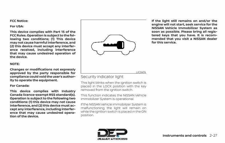
FCC Notice:
For USA:
This device complies with Part 15 of theFCC Rules. Operation is subject to the fol-lowing two conditions; (1) This devicemay not cause harmful interference, and(2) this device must accept any interfer-ence received, including interferencethat may cause undesired operation ofthe device.
NOTE:
Changes or modifications not expresslyapproved by the party responsible forcompliance could void the user’s author-ity to operate the equipment.
For Canada:
This device complies with IndustryCanada licence-exempt RSS standard(s).Operation is subject to the following twoconditions: (1) this device may not causeinterference, and (2) this device must ac-cept any interference, including interfer-ence that may cause undesired opera-tion of the device.
Security indicator lightThis light blinks when the ignition switch isplaced in the LOCK position with the keyremoved from the ignition switch.
This function indicates the NISSAN VehicleImmobilizer System is operational.
If the NISSAN Vehicle Immobilizer System ismalfunctioning, the light will remain onwhile the ignition switch is placed in the ONposition.
If the light still remains on and/or theengine will not start, seek service for theNISSAN Vehicle Immobilizer System assoon as possible. Please bring all regis-tered keys that you have. It is recom-mended that you visit a NISSAN dealerfor this service.
LIC0474
Instruments and controls 2-27
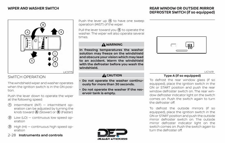
SWITCH OPERATIONThe windshield wiper and washer operateswhen the ignition switch is in the ON posi-tion.
Push the lever down to operate the wiperat the following speed:
�1 Intermittent (INT) — intermittent op-eration can be adjusted by turning theknob toward �A (Slower) or �B (Faster)
�2 Low (LO) — continuous low speed op-eration
�3 High (HI) — continuous high speed op-eration
Push the lever up �4 to have one sweepoperation (MIST) of the wiper.
Pull the lever toward you �5 to operate thewasher. The wiper will also operate severaltimes.
WARNINGIn freezing temperatures the washersolution may freeze on the windshieldand obscure your vision which may leadto an accident. Warm the windshieldwith the defroster before you wash thewindshield.
CAUTION∙ Do not operate the washer continu-
ously for more than 30 seconds.
∙ Do not operate the washer if the res-ervoir tank is empty.
To defrost the rear window glass (if soequipped), place the ignition switch in theON or START position and push the rearwindow defroster switch on. The rear win-dow defroster indicator light on the switchcomes on. Push the switch again to turnthe defroster off.
To defrost the outside mirrors (if soequipped), place the ignition switch in theON or START position and push the outsidemirror defroster switch on. The outsidemirror defroster indicator light on theswitch comes on. Push the switch again toturn the defroster off.
LIC3775Type A (if so equipped)
LIC1419
WIPER AND WASHER SWITCH REAR WINDOW OR OUTSIDE MIRRORDEFROSTER SWITCH (if so equipped)
2-28 Instruments and controls
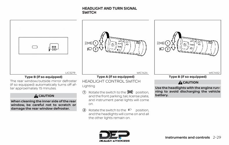
The rear window/outside mirror defroster(if so equipped) automatically turns off af-ter approximately 15 minutes.
CAUTIONWhen cleaning the inner side of the rearwindow, be careful not to scratch ordamage the rear window defroster.
HEADLIGHT CONTROL SWITCHLighting
�1 Rotate the switch to the position,and the front parking, tail, license plate,and instrument panel lights will comeon.
�2 Rotate the switch to the position,and the headlights will come on and allthe other lights remain on.
CAUTIONUse the headlights with the engine run-ning to avoid discharging the vehiclebattery.
Type B (if so equipped)LIC3279
Type A (if so equipped)WIC1424
Type B (if so equipped)WIC1452
HEADLIGHT AND TURN SIGNALSWITCH
Instruments and controls 2-29
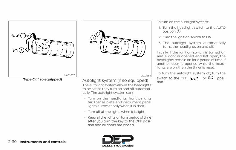
Autolight system (if so equipped)The autolight system allows the headlightsto be set so they turn on and off automati-cally. The autolight system can:
∙ Turn on the headlights, front parking,tail, license plate and instrument panellights automatically when it is dark.
∙ Turn off all the lights when it is light.
∙ Keep all the lights on for a period of timeafter you turn the key to the OFF posi-tion and all doors are closed.
To turn on the autolight system:
1. Turn the headlight switch to the AUTOposition �1 .
2. Turn the ignition switch to ON.
3. The autolight system automaticallyturns the headlights on and off.
Initially, if the ignition switch is turned offand a door is opened and left open, theheadlights remain on for a period of time. Ifanother door is opened while the head-lights are on, then the timer is reset.
To turn the autolight system off, turn theswitch to the OFF, , or posi-tion.
Type C (if so equipped)WIC1426 LIC0561
2-30 Instruments and controls

Be sure you do not put anything on topof the autolight sensor �1 located in thetop side of the instrument panel. The au-tolight sensor controls the autolight; if itis covered, the autolight sensor reacts asif it is dark out and the headlights willilluminate. If this occurs while parkedwith the engine off and the switch in theON position, your vehicle’s battery couldbecome discharged.
Headlight beam select
�1 To select the high beam function, en-sure the low beams are engaged andpush the lever forward. The high beamlights come on and the light illu-minates. For additional information, re-fer to “Headlight control switch” in thissection.
�2 Pull the lever back to return to the lowbeams.
�3 Pulling and releasing the lever flashesthe headlight high beams on and off.The low beams need not be engagedfor this function.
Battery saver systemThe battery saver system automaticallyturns off the following lights after a periodof time when the ignition switch is placed inthe OFF position and the doors are closed:
∙ Headlights, when the headlight switchis in the or position
∙ Interior lights, when left in the ON posi-tion (if so equipped)
After the headlights automatically turn offwith the headlight switch in theor position, the headlights will illumi-nate again if the headlight switch is movedto the OFF position and then turned tothe or position.
CAUTIONEven though the battery saver featureautomatically turns off the headlightsafter a period of time, you should turnthe headlight switch to the OFF positionwhen the engine is not running to avoiddischarging the vehicle battery.
LIC0835 LIC0562
Instruments and controls 2-31
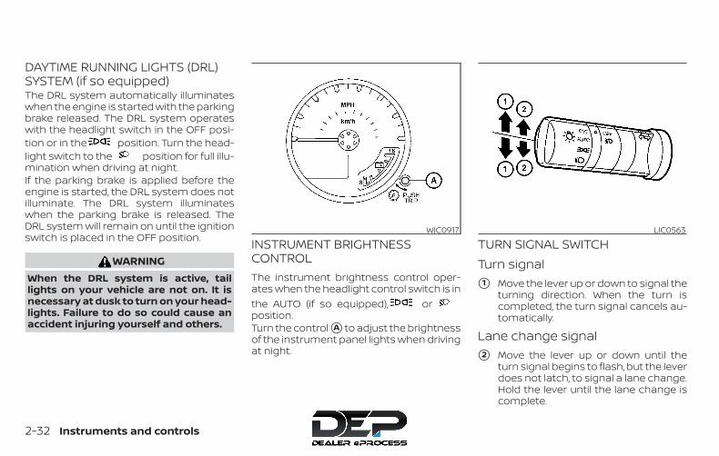
DAYTIME RUNNING LIGHTS (DRL)SYSTEM (if so equipped)The DRL system automatically illuminateswhen the engine is started with the parkingbrake released. The DRL system operateswith the headlight switch in the OFF posi-tion or in the position. Turn the head-light switch to the position for full illu-mination when driving at night.If the parking brake is applied before theengine is started, the DRL system does notilluminate. The DRL system illuminateswhen the parking brake is released. TheDRL system will remain on until the ignitionswitch is placed in the OFF position.
WARNINGWhen the DRL system is active, taillights on your vehicle are not on. It isnecessary at dusk to turn on your head-lights. Failure to do so could cause anaccident injuring yourself and others.
INSTRUMENT BRIGHTNESSCONTROLThe instrument brightness control oper-ates when the headlight control switch is inthe AUTO (if so equipped), orposition.Turn the control �A to adjust the brightnessof the instrument panel lights when drivingat night.
TURN SIGNAL SWITCHTurn signal�1 Move the lever up or down to signal the
turning direction. When the turn iscompleted, the turn signal cancels au-tomatically.
Lane change signal�2 Move the lever up or down until the
turn signal begins to flash, but the leverdoes not latch, to signal a lane change.Hold the lever until the lane change iscomplete.
WIC0917 LIC0563
2-32 Instruments and controls

FOG LIGHT SWITCH (if soequipped)To turn the fog lights on, turn the headlightswitch to the position, then turn thefog light switch to the position.To turn the fog lights on with the headlightswitch in the AUTO position (if so equipped),the headlights must be on, then turn thefog light switch to the position.To turn the fog lights off, turn the fog lightswitch to the OFF position.
The headlights must be on and the lowbeams selected for the fog lights to oper-ate. The fog lights automatically turn offwhen the high beam headlights are se-lected.
To sound the horn, push the area betweenthe horn icons on the steering wheel.
WARNINGDo not disassemble the horn. Doing socould affect proper operation of thesupplemental front air bag system.Tampering with the supplemental frontair bag system may result in seriouspersonal injury.
LIC0393 WIC1449
HORN
Instruments and controls 2-33
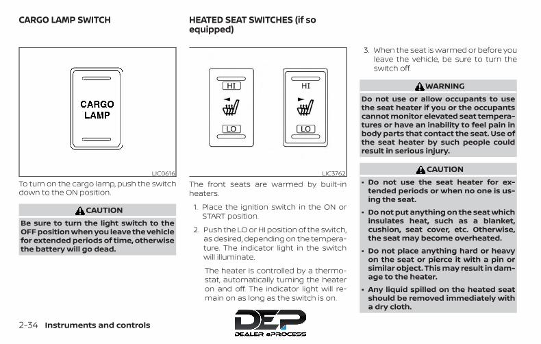
To turn on the cargo lamp, push the switchdown to the ON position.
CAUTIONBe sure to turn the light switch to theOFF position when you leave the vehiclefor extended periods of time, otherwisethe battery will go dead.
The front seats are warmed by built-inheaters.
1. Place the ignition switch in the ON orSTART position.
2. Push the LO or HI position of the switch,as desired, depending on the tempera-ture. The indicator light in the switchwill illuminate.
The heater is controlled by a thermo-stat, automatically turning the heateron and off. The indicator light will re-main on as long as the switch is on.
3. When the seat is warmed or before youleave the vehicle, be sure to turn theswitch off.
WARNINGDo not use or allow occupants to usethe seat heater if you or the occupantscannot monitor elevated seat tempera-tures or have an inability to feel pain inbody parts that contact the seat. Use ofthe seat heater by such people couldresult in serious injury.
CAUTION∙ Do not use the seat heater for ex-
tended periods or when no one is us-ing the seat.
∙ Do not put anything on the seat whichinsulates heat, such as a blanket,cushion, seat cover, etc. Otherwise,the seat may become overheated.
∙ Do not place anything hard or heavyon the seat or pierce it with a pin orsimilar object. This may result in dam-age to the heater.
∙ Any liquid spilled on the heated seatshould be removed immediately witha dry cloth.
LIC0616 LIC3762
CARGO LAMP SWITCH HEATED SEAT SWITCHES (if soequipped)
2-34 Instruments and controls

∙ When cleaning the seat, never usegasoline, benzine, thinner, or anysimilar materials.
∙ If any malfunctions are found or theheated seat does not operate, turnthe switch off and have the systemchecked. It is recommended that youvisit a NISSAN dealer for this service.
∙ The battery could run down if the seatheater is operated while the engine isnot running.
The vehicle should be driven with the VDCsystem on for most driving conditions.
If the vehicle is stuck in mud or snow, theVDC system reduces the engine output toreduce wheel spin. The engine speed willbe reduced even if the accelerator is de-pressed to the floor. If maximum enginepower is needed to free a stuck vehicle,turn the VDC system off.
To turn off the VDC system, push the VDCOFF switch. The indicator will comeon.
Push the VDC OFF switch again or restartthe engine to turn on the system. For addi-tional information, refer to “Vehicle Dy-namic Control (VDC) system” in the “Start-ing and driving” section of this manual.
LIC3344
VEHICLE DYNAMIC CONTROL (VDC)OFF SWITCH
Instruments and controls 2-35
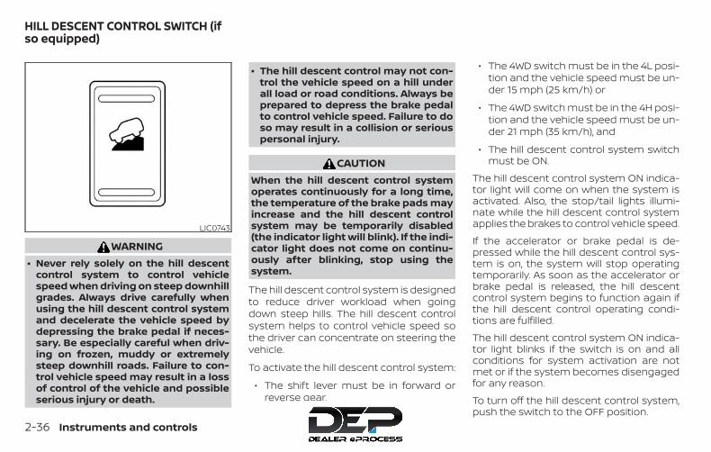
WARNING∙ Never rely solely on the hill descent
control system to control vehiclespeed when driving on steep downhillgrades. Always drive carefully whenusing the hill descent control systemand decelerate the vehicle speed bydepressing the brake pedal if neces-sary. Be especially careful when driv-ing on frozen, muddy or extremelysteep downhill roads. Failure to con-trol vehicle speed may result in a lossof control of the vehicle and possibleserious injury or death.
∙ The hill descent control may not con-trol the vehicle speed on a hill underall load or road conditions. Always beprepared to depress the brake pedalto control vehicle speed. Failure to doso may result in a collision or seriouspersonal injury.
CAUTIONWhen the hill descent control systemoperates continuously for a long time,the temperature of the brake pads mayincrease and the hill descent controlsystem may be temporarily disabled(the indicator light will blink). If the indi-cator light does not come on continu-ously after blinking, stop using thesystem.
The hill descent control system is designedto reduce driver workload when goingdown steep hills. The hill descent controlsystem helps to control vehicle speed sothe driver can concentrate on steering thevehicle.
To activate the hill descent control system:
∙ The shift lever must be in forward orreverse gear,
∙ The 4WD switch must be in the 4L posi-tion and the vehicle speed must be un-der 15 mph (25 km/h) or
∙ The 4WD switch must be in the 4H posi-tion and the vehicle speed must be un-der 21 mph (35 km/h), and
∙ The hill descent control system switchmust be ON.
The hill descent control system ON indica-tor light will come on when the system isactivated. Also, the stop/tail lights illumi-nate while the hill descent control systemapplies the brakes to control vehicle speed.
If the accelerator or brake pedal is de-pressed while the hill descent control sys-tem is on, the system will stop operatingtemporarily. As soon as the accelerator orbrake pedal is released, the hill descentcontrol system begins to function again ifthe hill descent control operating condi-tions are fulfilled.
The hill descent control system ON indica-tor light blinks if the switch is on and allconditions for system activation are notmet or if the system becomes disengagedfor any reason.
To turn off the hill descent control system,push the switch to the OFF position.
LIC0743
HILL DESCENT CONTROL SWITCH (ifso equipped)
2-36 Instruments and controls
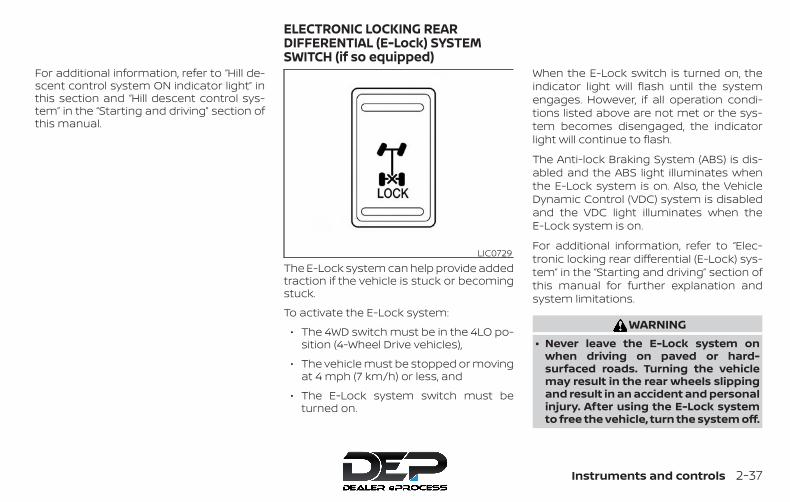
For additional information, refer to “Hill de-scent control system ON indicator light” inthis section and “Hill descent control sys-tem” in the “Starting and driving” section ofthis manual.
The E-Lock system can help provide addedtraction if the vehicle is stuck or becomingstuck.
To activate the E-Lock system:
∙ The 4WD switch must be in the 4LO po-sition (4-Wheel Drive vehicles),
∙ The vehicle must be stopped or movingat 4 mph (7 km/h) or less, and
∙ The E-Lock system switch must beturned on.
When the E-Lock switch is turned on, theindicator light will flash until the systemengages. However, if all operation condi-tions listed above are not met or the sys-tem becomes disengaged, the indicatorlight will continue to flash.
The Anti-lock Braking System (ABS) is dis-abled and the ABS light illuminates whenthe E-Lock system is on. Also, the VehicleDynamic Control (VDC) system is disabledand the VDC light illuminates when theE-Lock system is on.
For additional information, refer to “Elec-tronic locking rear differential (E-Lock) sys-tem” in the “Starting and driving” section ofthis manual for further explanation andsystem limitations.
WARNING∙ Never leave the E-Lock system on
when driving on paved or hard-surfaced roads. Turning the vehiclemay result in the rear wheels slippingand result in an accident and personalinjury. After using the E-Lock systemto free the vehicle, turn the system off.
LIC0729
ELECTRONIC LOCKING REARDIFFERENTIAL (E-Lock) SYSTEMSWITCH (if so equipped)
Instruments and controls 2-37
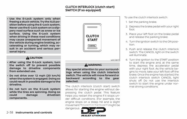
∙ Use the E-Lock system only whenfreeing a stuck vehicle. Try the 4LO po-sition before using the E-Lock system.Never use the E-Lock system on a slip-pery road surface such as snow or icesurface. Using the E-Lock systemwhen driving in these road conditionsmay cause unexpected movement ofthe vehicle during engine braking, ac-celerating or turning, which may re-sult in an accident and serious per-sonal injury.
CAUTION∙ After using the E-Lock system, turn
the switch off to prevent possibledamage to driveline componentsfrom extended use.
∙ Do not drive over 12 mph (20 km/h)when the system is engaged. Doing socould result in possible damage to thedriveline.
∙ Do not turn on the E-Lock systemwhile the tires are spinning. Doing socould damage drivetraincomponents.
WARNINGPay special attention to your surround-ings when using the clutch interlockswitch. The vehicle will move forward orbackward according to the gearselected.
The clutch interlock (clutch start) switchallows for starting the engine without de-pressing the clutch pedal. This featurehelps you restart the engine if it stops un-der difficult conditions. (For example, theengine stops on a steep hill and a slightmovement forward or backward might bedangerous.)
To use the clutch interlock switch:
1. Set the parking brake.
2. Depress the brake pedal with your rightfoot.
3. Place your left foot on the brake pedaland release the parking brake.
4. Turn the ignition switch to the ON posi-tion.
5. Push and release the clutch interlockswitch. The CANCEL light on the switchwill illuminate.
6. Turn the ignition to the START positionto start the engine and, at the sametime, depress the accelerator pedalwith your right foot. As the vehicle be-gins to move, take your left foot off thebrake. Once the engine has started, theclutch interlock switch CANCEL lightshuts off. Do not use the interlockswitch to start the engine under nor-mal driving conditions.
WIC0817
CLUTCH INTERLOCK (clutch start)SWITCH (if so equipped)
2-38 Instruments and controls
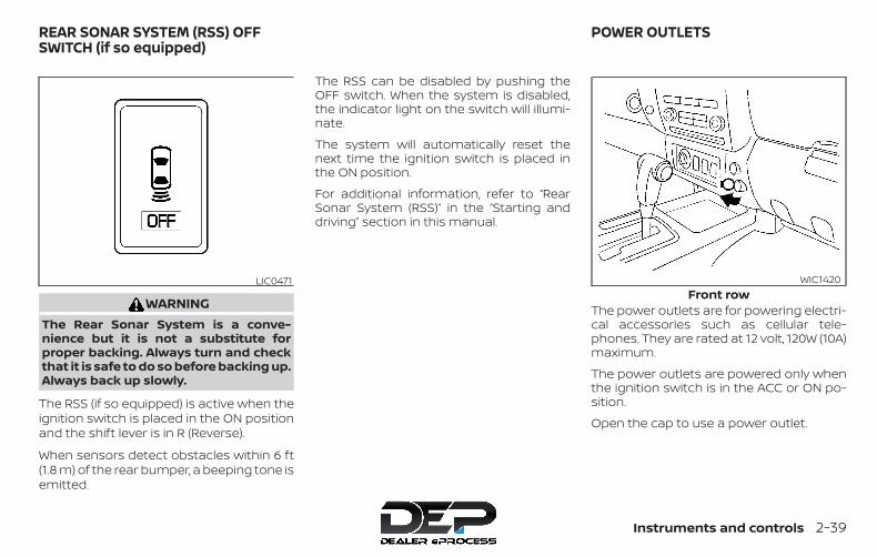
WARNINGThe Rear Sonar System is a conve-nience but it is not a substitute forproper backing. Always turn and checkthat it is safe to do so before backing up.Always back up slowly.
The RSS (if so equipped) is active when theignition switch is placed in the ON positionand the shift lever is in R (Reverse).
When sensors detect obstacles within 6 ft(1.8 m) of the rear bumper, a beeping tone isemitted.
The RSS can be disabled by pushing theOFF switch. When the system is disabled,the indicator light on the switch will illumi-nate.
The system will automatically reset thenext time the ignition switch is placed inthe ON position.
For additional information, refer to “RearSonar System (RSS)” in the “Starting anddriving” section in this manual.
The power outlets are for powering electri-cal accessories such as cellular tele-phones. They are rated at 12 volt, 120W (10A)maximum.
The power outlets are powered only whenthe ignition switch is in the ACC or ON po-sition.
Open the cap to use a power outlet.
LIC0471Front row
WIC1420
REAR SONAR SYSTEM (RSS) OFFSWITCH (if so equipped)
POWER OUTLETS
Instruments and controls 2-39
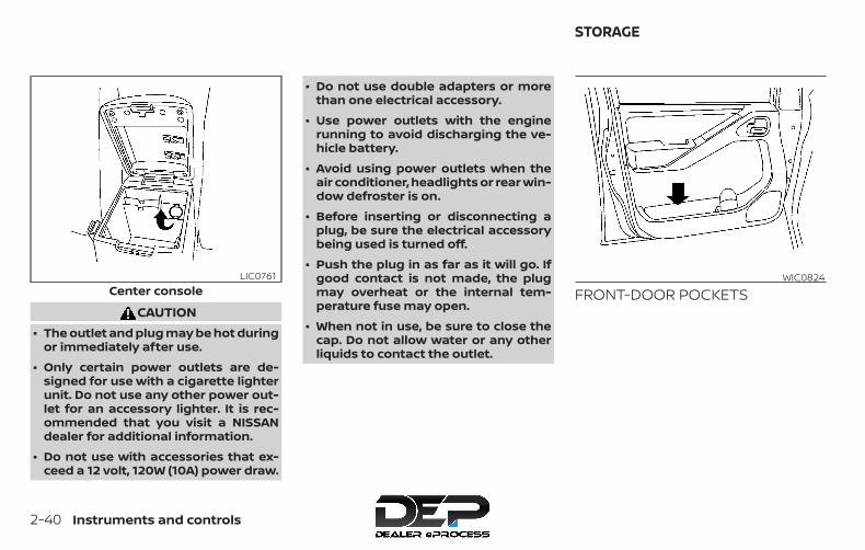
CAUTION∙ The outlet and plug may be hot during
or immediately after use.
∙ Only certain power outlets are de-signed for use with a cigarette lighterunit. Do not use any other power out-let for an accessory lighter. It is rec-ommended that you visit a NISSANdealer for additional information.
∙ Do not use with accessories that ex-ceed a 12 volt, 120W (10A) power draw.
∙ Do not use double adapters or morethan one electrical accessory.
∙ Use power outlets with the enginerunning to avoid discharging the ve-hicle battery.
∙ Avoid using power outlets when theair conditioner, headlights or rear win-dow defroster is on.
∙ Before inserting or disconnecting aplug, be sure the electrical accessorybeing used is turned off.
∙ Push the plug in as far as it will go. Ifgood contact is not made, the plugmay overheat or the internal tem-perature fuse may open.
∙ When not in use, be sure to close thecap. Do not allow water or any otherliquids to contact the outlet.
FRONT-DOOR POCKETSCenter consoleLIC0761 WIC0824
STORAGE
2-40 Instruments and controls
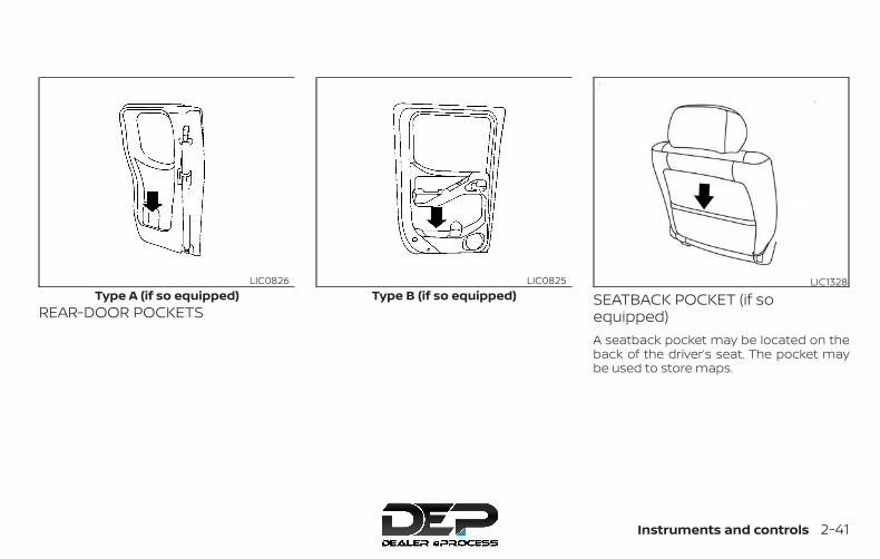
REAR-DOOR POCKETSSEATBACK POCKET (if soequipped)A seatback pocket may be located on theback of the driver’s seat. The pocket maybe used to store maps.
Type A (if so equipped)LIC0826
Type B (if so equipped)LIC0825 LIC1328
Instruments and controls 2-41

UNDER-SEAT STORAGE BINS
WARNING∙ Properly secure all cargo with ropes or
straps to help prevent it from slidingor shifting. In a sudden stop or colli-sion, unsecured cargo could causepersonal injury.
∙ The cargo restrained in the under-seat storage bins must not exceed theweight limits listed below or the binsmay not stay secured. In a suddenstop or collision, the unsecured binscould cause personal injury.King Cab® model: 16 lbs. (7.25 kg)Crew Cab model
Driver’s side: 16 lbs. (7.25 kg)Passenger’s side: 25 lbs. (11.33 kg)
∙ If the under-seat storage bins are re-moved for any reason, they should besecurely stored to prevent them fromcausing injury to passengers or dam-age to the vehicle in case of suddenbraking or an accident.Rear row under-seat storage bin
(King Cab® model)
LIC0821Rear row under-seat storage bin
(Crew Cab model)
LIC0820
2-42 Instruments and controls

∙ Do not place sharp objects in theunder-seat storage bins. Such objectsmay become dangerous projectilesand cause injury when the vehicle ismoving or if the vehicle is involved in acollision.
To access the under-seat storage bins:
For King Cab® models, lift up the jump seat.For additional information, refer to “Jumpseat” in the “Safety—Seats, seat belts andsupplemental restraint system” section ofthis manual.
For Crew Cab models, lift up the rear benchseat. For additional information, refer to“Folding the rear bench seat down” in the“Safety—Seats, seat belts and supplemen-tal restraint system” section of this manual.
To remove the under-seat storage bins:
1. Remove the storage net.
2. Turn the knobs to the UNLOCK position�2 .
3. Remove the tray by lifting it out of thestorage bin (King Cab® model).
To install the under-seat storage bins:
1. Position the under-seat storage bin sothe holes line up with the holes in thefloorboard.
2. Insert the knobs and turn them to theLOCK position �1 .
STORAGE TRAYS
WARNINGDo not place sharp objects in the traysto help prevent injury in an accident orsudden stop.
LIC0822Top center tray
LIC1539
Instruments and controls 2-43

GLOVE BOXTo open the top portion of the glove box,push the latch �A up and raise the lid.
To open the lower portion of the glove box,pull the handle �B down and lower the lid.
WARNINGKeep the glove box lid closed while driv-ing to help prevent injury in an accidentor a sudden stop.
A/T modelLIC0818
M/T model — Type A (if so equipped)LIC3646
M/T model — Type B (if so equipped)LIC3647
2-44 Instruments and controls
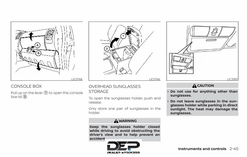
CONSOLE BOXPull up on the lever �1 to open the consolebox lid �2 .
OVERHEAD SUNGLASSESSTORAGETo open the sunglasses holder, push andrelease.
Only store one pair of sunglasses in theholder.
WARNINGKeep the sunglasses holder closedwhile driving to avoid obstructing thedriver’s view and to help prevent anaccident.
CAUTION∙ Do not use for anything other than
sunglasses.
∙ Do not leave sunglasses in the sun-glasses holder while parking in directsunlight. The heat may damage thesunglasses.
LIC0768 LIC0766 LIC3387
Instruments and controls 2-45
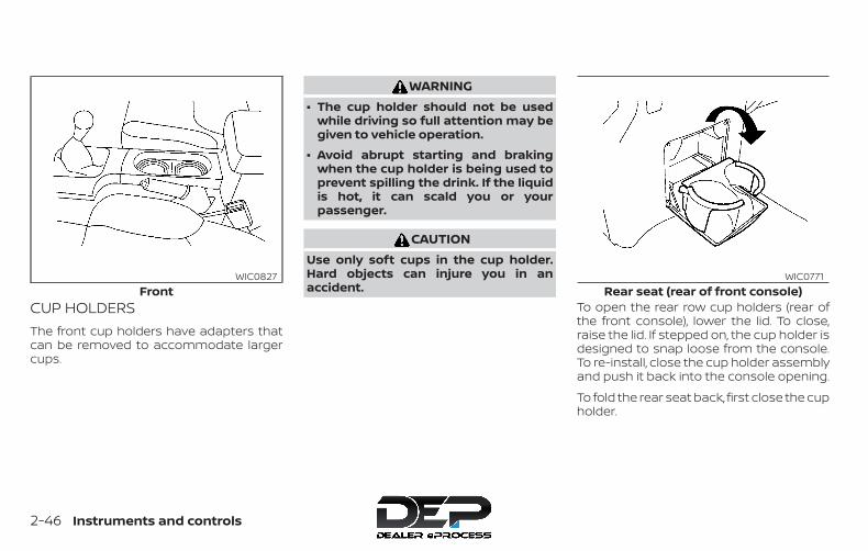
CUP HOLDERSThe front cup holders have adapters thatcan be removed to accommodate largercups.
WARNING∙ The cup holder should not be used
while driving so full attention may begiven to vehicle operation.
∙ Avoid abrupt starting and brakingwhen the cup holder is being used toprevent spilling the drink. If the liquidis hot, it can scald you or yourpassenger.
CAUTIONUse only soft cups in the cup holder.Hard objects can injure you in anaccident.
To open the rear row cup holders (rear ofthe front console), lower the lid. To close,raise the lid. If stepped on, the cup holder isdesigned to snap loose from the console.To re-install, close the cup holder assemblyand push it back into the console opening.
To fold the rear seat back, first close the cupholder.
FrontWIC0827
Rear seat (rear of front console)WIC0771
2-46 Instruments and controls
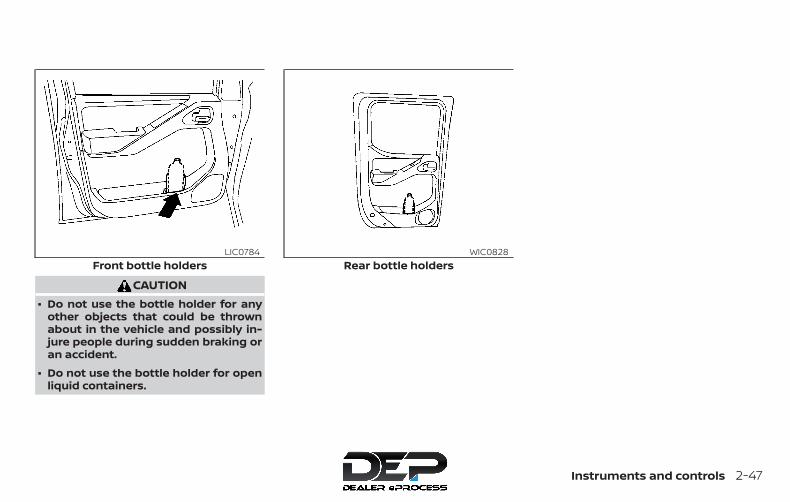
CAUTION∙ Do not use the bottle holder for any
other objects that could be thrownabout in the vehicle and possibly in-jure people during sudden braking oran accident.
∙ Do not use the bottle holder for openliquid containers.
Front bottle holdersLIC0784
Rear bottle holdersWIC0828
Instruments and controls 2-47

ROOF RACK (if so equipped)
WARNING∙ Drive extra carefully when the vehicle
is loaded at or near the cargo carryingcapacity, especially if the significantportion of that load is carried on theroof rack.
∙ Heavy loading of the roof rack has thepotential to affect the vehicle stabilityand handling during sudden or ab-normal handling maneuvers.
∙ Roof rack load should be evenlydistributed.
∙ Do not exceed maximum roof rackload weight capacity.
∙ Properly secure all cargo with ropes orstraps to help prevent it from slidingor shifting. In a sudden stop or colli-sion, unsecured cargo could causepersonal injury.
CAUTIONUse care when placing or removingitems from the roof rack. If you cannotcomfortably lift the items onto the roofrack from the ground, use a ladder orstool.
WIC0857
2-48 Instruments and controls
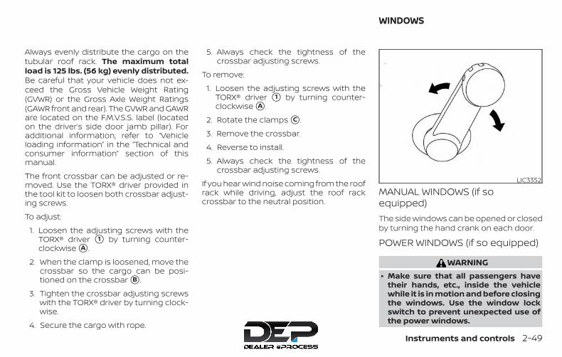
Always evenly distribute the cargo on thetubular roof rack. The maximum totalload is 125 lbs. (56 kg) evenly distributed.Be careful that your vehicle does not ex-ceed the Gross Vehicle Weight Rating(GVWR) or the Gross Axle Weight Ratings(GAWR front and rear). The GVWR and GAWRare located on the F.M.V.S.S. label (locatedon the driver’s side door jamb pillar). Foradditional information, refer to “Vehicleloading information” in the “Technical andconsumer information” section of thismanual.
The front crossbar can be adjusted or re-moved. Use the TORX® driver provided inthe tool kit to loosen both crossbar adjust-ing screws.
To adjust:
1. Loosen the adjusting screws with theTORX® driver �1 by turning counter-clockwise �A .
2. When the clamp is loosened, move thecrossbar so the cargo can be posi-tioned on the crossbar �B .
3. Tighten the crossbar adjusting screwswith the TORX® driver by turning clock-wise.
4. Secure the cargo with rope.
5. Always check the tightness of thecrossbar adjusting screws.
To remove:
1. Loosen the adjusting screws with theTORX® driver �1 by turning counter-clockwise �A .
2. Rotate the clamps �C .
3. Remove the crossbar.
4. Reverse to install.
5. Always check the tightness of thecrossbar adjusting screws.
If you hear wind noise coming from the roofrack while driving, adjust the roof rackcrossbar to the neutral position.
MANUAL WINDOWS (if soequipped)The side windows can be opened or closedby turning the hand crank on each door.
POWER WINDOWS (if so equipped)
WARNING∙ Make sure that all passengers have
their hands, etc., inside the vehiclewhile it is in motion and before closingthe windows. Use the window lockswitch to prevent unexpected use ofthe power windows.
LIC3352
WINDOWS
Instruments and controls 2-49
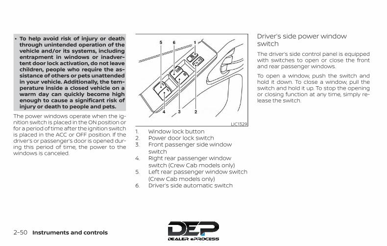
∙ To help avoid risk of injury or deaththrough unintended operation of thevehicle and/or its systems, includingentrapment in windows or inadver-tent door lock activation, do not leavechildren, people who require the as-sistance of others or pets unattendedin your vehicle. Additionally, the tem-perature inside a closed vehicle on awarm day can quickly become highenough to cause a significant risk ofinjury or death to people and pets.
The power windows operate when the ig-nition switch is placed in the ON position orfor a period of time after the ignition switchis placed in the ACC or OFF position. If thedriver’s or passenger’s door is opened dur-ing this period of time, the power to thewindows is canceled.
1. Window lock button2. Power door lock switch3. Front passenger side window
switch4. Right rear passenger window
switch (Crew Cab models only)5. Left rear passenger window switch
(Crew Cab models only)6. Driver’s side automatic switch
Driver’s side power windowswitchThe driver’s side control panel is equippedwith switches to open or close the frontand rear passenger windows.
To open a window, push the switch andhold it down. To close a window, pull theswitch and hold it up. To stop the openingor closing function at any time, simply re-lease the switch.
LIC1329
2-50 Instruments and controls
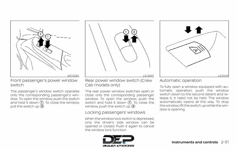
Front passenger’s power windowswitchThe passenger’s window switch operatesonly the corresponding passenger’s win-dow. To open the window, push the switchand hold it down �1 . To close the window,pull the switch up �2 .
Rear power window switch (CrewCab models only)The rear power window switches open orclose only the corresponding passengerwindow. To open the window, push theswitch and hold it down �1 . To close thewindow, push the switch up �2 .
Locking passengers’ windowsWhen the window lock switch is depressed,only the driver’s side window can beopened or closed. Push it again to cancelthe window lock function.
Automatic operationTo fully open a window equipped with au-tomatic operation, push the windowswitch down to the second detent and re-lease it; it need not be held. The windowautomatically opens all the way. To stopthe window, lift the switch up while the win-dow is opening.
WIC0260 LIC2663 LIC0410
Instruments and controls 2-51
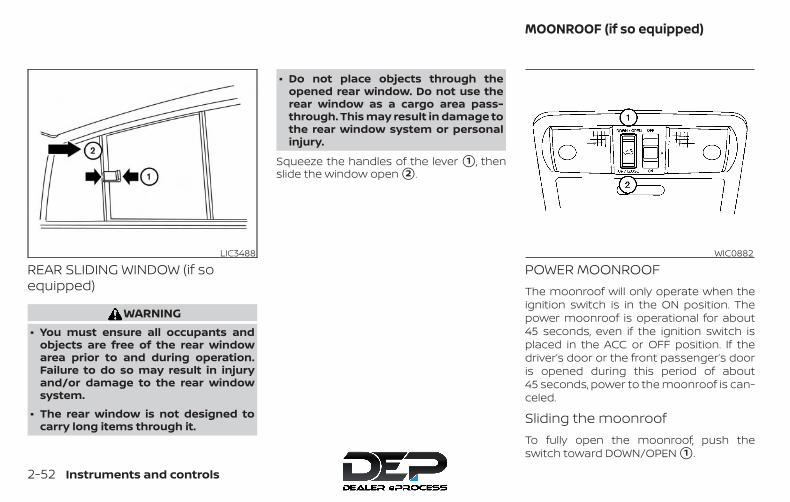
REAR SLIDING WINDOW (if soequipped)
WARNING∙ You must ensure all occupants and
objects are free of the rear windowarea prior to and during operation.Failure to do so may result in injuryand/or damage to the rear windowsystem.
∙ The rear window is not designed tocarry long items through it.
∙ Do not place objects through theopened rear window. Do not use therear window as a cargo area pass-through. This may result in damage tothe rear window system or personalinjury.
Squeeze the handles of the lever �1 , thenslide the window open �2 .
POWER MOONROOFThe moonroof will only operate when theignition switch is in the ON position. Thepower moonroof is operational for about45 seconds, even if the ignition switch isplaced in the ACC or OFF position. If thedriver’s door or the front passenger’s dooris opened during this period of about45 seconds, power to the moonroof is can-celed.
Sliding the moonroofTo fully open the moonroof, push theswitch toward DOWN/OPEN �1 .
LIC3488 WIC0882
MOONROOF (if so equipped)
2-52 Instruments and controls
To fully close the moonroof, push theswitch toward UP/CLOSE �2 .
To open or close the moonroof part way,push the switch in any direction while themoonroof is sliding to stop it in the desiredposition.
Tilting the moonroofClose the moonroof by pushing the switchtoward UP/CLOSE �2 . Release the switch,then push the UP/CLOSE switch again totilt the moonroof up.
To tilt the moonroof down, push the switchtoward DOWN/OPEN �1 .
Auto-reverse function (whenclosing or tilting down themoonroof)The auto-reverse function can be acti-vated when the moonroof is closed ortilted down by automatic operation whenthe ignition switch is placed in the ON po-sition or for a period of time after the igni-tion switch is placed in the OFF position.
Depending on the environment or driv-ing conditions, the auto-reverse func-tion may be activated if an impact orload similar to something being caughtin the moonroof occurs.
WARNINGThere are some small distances imme-diately before the closed position whichcannot be detected. Make sure that allpassengers have their hands, etc., in-side the vehicle before closing themoonroof.
When closing
If the control unit detects somethingcaught in the moonroof as it moves to thefront, the moonroof will immediately openbackward.
When tilting down
If the control unit detects somethingcaught in the moonroof as it tilts down, themoonroof will immediately tilt up.
If the auto-reverse function malfunctionsand repeats opening or tilting up themoonroof, keep pushing the tilt downswitch within 5 seconds after it happens;the moonroof will fully close gradually.Make sure nothing is caught in the moon-roof.
WARNING∙ In an accident you could be thrown
from the vehicle through an openmoonroof. Always use seat belts andchild restraints.
∙ Do not allow anyone to stand up orextend any portion of their body outof the moonroof opening while thevehicle is in motion or while themoonroof is closing.
CAUTION∙ Remove water drops, snow, ice or
sand from the moonroof beforeopening.
∙ Do not place heavy objects on themoonroof or surrounding area.
If the moonroof does not closeHave your moonroof checked and re-paired. It is recommended that you visit aNISSAN dealer for this service.
Instruments and controls 2-53

The interior lights have a three-positionswitch and operate regardless of ignitionswitch position.
When the switch is in the ON position �1 ,the interior lights illuminate, regardless ofdoor position. The lights will go off after aperiod of time unless the ignition switch isin the ON position.
When the switch is in the O (DOOR) position�2 , the interior lights will stay on for a periodof time when:
∙ The doors are unlocked by the key fob, akey or the power door lock switch whileall doors are closed and the ignitionswitch is in the OFF position.
∙ The driver’s door is opened and thenclosed while the key is removed fromthe ignition switch.
∙ The key is removed from the ignitionswitch while all doors are closed.
The lights will turn off while the timer isactivated when:
∙ The driver’s door is locked by the keyfob, a key, or the power door lock switch.
∙ The ignition switch is turned on.
The lights will turn off automatically after aperiod of time while doors are open to pre-vent the battery from becoming dis-charged.
When the switch is in the OFF position �3 ,the interior lights do not illuminate, regard-less of door position.
CAUTIONDo not use for extended periods of timewith the engine stopped. This could re-sult in a discharged battery.
Type A (if so equipped)LIC0789
Type B (if so equipped)LIC0792
Type C (if so equipped)LIC0630
INTERIOR LIGHTS
2-54 Instruments and controls
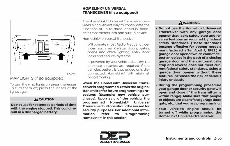
MAP LIGHTS (if so equipped)To turn the map lights on, press the lenses.To turn them off, press the lenses of thelights again.
CAUTIONDo not use for extended periods of timewith the engine stopped. This could re-sult in a discharged battery.
The HomeLink® Universal Transceiver pro-vides a convenient way to consolidate thefunctions of up to three individual hand-held transmitters into one built-in device.
HomeLink® Universal Transceiver:
∙ Will operate most Radio Frequency de-vices such as garage doors, gates,home and office lighting, entry doorlocks and security systems.
∙ Is powered by your vehicle’s battery. Noseparate batteries are required. If thevehicle’s battery is discharged or is dis-connected, HomeLink® will retain allprogramming.
When the HomeLink® Universal Trans-ceiver is programmed, retain the originaltransmitter for future programming pro-cedures (Example: new vehicle pur-chases). Upon sale of the vehicle, theprogrammed HomeLink® UniversalTransceiver buttons should be erased forsecurity purposes. For additional infor-mation, refer to “ProgrammingHomeLink®” in this section.
WARNING∙ Do not use the HomeLink® Universal
Transceiver with any garage dooropener that lacks safety stop and re-verse features as required by federalsafety standards. (These standardsbecame effective for opener modelsmanufactured after April 1, 1982.) Agarage door opener which cannot de-tect an object in the path of a closinggarage door and then automaticallystop and reverse does not meet cur-rent federal safety standards. Using agarage door opener without thesefeatures increases the risk of seriousinjury or death.
∙ During the programming procedureyour garage door or security gate willopen and close (if the transmitter iswithin range). Make sure that peopleor objects are clear of the garage door,gate, etc., that you are programming.
∙ Your vehicle’s engine should beturned off while programming theHomeLink® Universal Transceiver.
LIC0791
HOMELINK® UNIVERSALTRANSCEIVER (if so equipped)
Instruments and controls 2-55
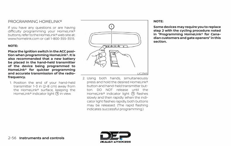
PROGRAMMING HOMELINK®If you have any questions or are havingdifficulty programming your HomeLink®buttons, refer to the HomeLink® web site at:www.homelink.com or call 1-800-355-3515.
NOTE:
Place the ignition switch in the ACC posi-tion when programming HomeLink®. It isalso recommended that a new batterybe placed in the hand-held transmitterof the device being programmed toHomeLink® for quicker programmingand accurate transmission of the radio-frequency.
1. Position the end of your hand-heldtransmitter 1–3 in (2–8 cm) away fromthe HomeLink® surface, keeping theHomeLink® indicator light �1 in view.
2. Using both hands, simultaneouslypress and hold the desired HomeLink®button and hand-held transmitter but-ton. DO NOT release until theHomeLink® indicator light �1 flashesslowly and then rapidly. When the indi-cator light flashes rapidly, both buttonsmay be released. (The rapid flashingindicates successful programming.)
NOTE:
Some devices may require you to replacestep 2 with the cycling procedure notedin “Programming HomeLink® for Cana-dian customers and gate openers” in thissection.
LIC2365
2-56 Instruments and controls
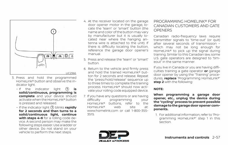
3. Press and hold the programmedHomeLink® button and observe the in-dicator light.∙ If the indicator light �1 is
solid/continuous, programming iscomplete and your device shouldactivate when the HomeLink® buttonis pressed and released.
∙ If the indicator light �1 blinks rapidlyfor 2 seconds and then turns to asolid/continuous light, continuewith steps 4-6 for a rolling code de-vice. A second person may make thefollowing steps easier. Use a ladder orother device. Do not stand on yourvehicle to perform the next steps.
4. At the receiver located on the garagedoor opener motor in the garage, lo-cate the “learn” or “smart” button (thename and color of the button may varyby manufacturer but it is usually lo-cated near where the hanging an-tenna wire is attached to the unit). Ifthere is difficulty locating the button,reference the garage door opener’smanual.
5. Press and release the “learn” or “smart”button.
6. Return to the vehicle and firmly pressand hold the trained HomeLink® but-ton for 2 seconds and release. Repeatthe “press/hold/release” sequence upto three times to complete the trainingprocess. HomeLink® should now acti-vate your rolling code equipped device.
7. If you have any questions or are havingdifficulty programming yourHomeLink® buttons, refer to theHomeLink® web site at:www.homelink.com or call 1-800-355-3515.
PROGRAMMING HOMELINK® FORCANADIAN CUSTOMERS AND GATEOPENERSCanadian radio-frequency laws requiretransmitter signals to “time-out” (or quit)after several seconds of transmission –which may not be long enough forHomeLink® to pick up the signal duringtraining. Similar to this Canadian law, someU.S. gate operators are designed to “tim-eout” in the same manner.
If you live in Canada or you are having diffi-culties training a gate operator or garagedoor opener by using the “Training” proce-dures, replace “Programming HomeLink®”step 2 with the following:
NOTE:
When programming a garage dooropener, etc., unplug the device duringthe “cycling” process to prevent possibledamage to the garage door opener com-ponents.
1. For additional information, refer to “Pro-gramming HomeLink®” step 1 in thissection.
LIC2366
Instruments and controls 2-57

2. Using both hands, simultaneouslypress and hold the desired HomeLink®button and the hand-held transmitterbutton. During training, your hand-heldtransmitter may automatically stoptransmitting. Continue to press andhold the desired HomeLink® buttonwhile you press and re-press (“cycle”)your hand-held transmitter every2 seconds until the frequency signalhas been learned. The HomeLink® indi-cator light will flash slowly and thenrapidly after several seconds uponsuccessful training. DO NOT release un-til the HomeLink® indicator light flashesslowly and then rapidly. When the indi-cator light flashes rapidly, both buttonsmay be released. The rapid flashing in-dicates successful training.Proceed with “ProgrammingHomeLink®” step 3 to complete.If the device was unplugged during theprogramming procedure, rememberto plug it back in when programming iscompleted.
OPERATING THE HOMELINK®UNIVERSAL TRANSCEIVERThe HomeLink® Universal Transceiver, afterit is programmed, can be used to activatethe programmed device. To operate, sim-ply press and release the appropriate pro-grammed HomeLink® Universal Trans-ceiver button. The amber indicator light willilluminate while the signal is being trans-mitted.
For convenience, the hand-held transmit-ter of the device may also be used at anytime.
PROGRAMMING TROUBLE-DIAGNOSISIf the HomeLink® does not quickly learn thehand-held transmitter information:
∙ Replace the hand-held transmitter bat-teries with new batteries.
∙ Position the hand-held transmitter withits battery area facing away from theHomeLink® surface.
∙ Press and hold both the HomeLink®and hand-held transmitter buttonswithout interruption.
∙ Position the hand-held transmitter 1 -3 inches (26 - 76 mm) away from theHomeLink® surface. Hold the transmit-ter in that position for up to 15 seconds.If HomeLink® is not programmed withinthat time, try holding the transmitter inanother position – keeping the indicatorlight in view at all times.
If you have any questions or are havingdifficulty programming your HomeLink®buttons, refer to the HomeLink® web site at:www.homelink.com or call 1-800-355-3515.
CLEARING THE PROGRAMMEDINFORMATIONThe following procedure clears the pro-grammed information from both buttons.Individual buttons cannot be cleared. How-ever, individual buttons can be repro-grammed. For additional information, referto “Reprogramming a single HomeLink®button” in this section.
To clear all programming:
1. Press and hold the two outer HomeLink®buttons until the indicator light begins toflash in approximately 10 seconds. Do nothold for longer than 20 seconds.
2. Release both buttons.2-58 Instruments and controls
HomeLink® is now in the programmingmode and can be programmed at anytime beginning with “ProgrammingHomeLink®” - Step 1.
REPROGRAMMING A SINGLEHOMELINK® BUTTONTo reprogram a HomeLink® UniversalTransceiver button, complete the following:
1. Press and hold the desired HomeLink®button. DO NOT release the button.
2. The indicator light will begin to flashafter 20 seconds. Without releasing theHomeLink® button, proceed with “Pro-gramming HomeLink®” - Step 1.
For questions or comments, contactHomeLink® at: www.homelink.com or1–800–355–3515 (except Mexico).
The HomeLink® Universal Transceiver but-ton has now been reprogrammed. Thenew device can be activated by pressingthe HomeLink® button that was just pro-grammed. This procedure will not affectany other programmed HomeLink® but-tons.
IF YOUR VEHICLE IS STOLENIf your vehicle is stolen, you should changethe codes of any non-rolling code devicethat has been programmed intoHomeLink®. Consult the Owner’s Manual ofeach device or call the manufacturer ordealer of those devices for additional infor-mation.
When your vehicle is recovered, you willneed to reprogram the HomeLink® Uni-versal Transceiver with your new trans-mitter information.
FCC Notice:
For USA:
This device complies with Part 15 of theFCC Rules. Operation is subject to the fol-lowing two conditions: (1) This devicemay not cause interference, and (2) thisdevice must accept any interference re-ceived, including interference that maycause undesired operation.
NOTE:
Changes or modifications not expresslyapproved by the party responsible forcompliance could void the user’s author-ity to operate the equipment.
For Canada:
This device complies with IndustryCanada licence-exempt RSS standard(s).Operation is subject to the following twoconditions: (1) this device may not causeinterference, and (2) this device must ac-cept any interference, including interfer-ence that may cause undesired opera-tion of the device.
Instruments and controls 2-59

MEMO
2-60 Instruments and controls

3 Pre-driving checks and adjustments
Keys . . . . . . . . . . . . . . . . . . . . . . . . . . . . . . . . . . . . . . . . . . . . . 3-2NISSAN Vehicle Immobilizer Systemkeys (if so equipped) . . . . . . . . . . . . . . . . . . . . . . . . . . 3-2
Doors . . . . . . . . . . . . . . . . . . . . . . . . . . . . . . . . . . . . . . . . . . . 3-3Locking with key. . . . . . . . . . . . . . . . . . . . . . . . . . . . . . 3-3Locking with inside lock knob. . . . . . . . . . . . . . . . . 3-4Locking with power door lock switch(if so equipped) . . . . . . . . . . . . . . . . . . . . . . . . . . . . . . . 3-4Rear doors (King Cab® models) . . . . . . . . . . . . . . . 3-5Automatic door locks (if so equipped) . . . . . . . . 3-6Child safety rear door lock(if so equipped) . . . . . . . . . . . . . . . . . . . . . . . . . . . . . . . 3-6
Remote keyless entry system (if so equipped) . . . 3-6How to use remote keyless entrysystem . . . . . . . . . . . . . . . . . . . . . . . . . . . . . . . . . . . . . . . 3-7
Hood . . . . . . . . . . . . . . . . . . . . . . . . . . . . . . . . . . . . . . . . . . . 3-10
Fuel-filler door . . . . . . . . . . . . . . . . . . . . . . . . . . . . . . . . . . .3-11Fuel-filler cap . . . . . . . . . . . . . . . . . . . . . . . . . . . . . . . . .3-11
Steering wheel . . . . . . . . . . . . . . . . . . . . . . . . . . . . . . . . . 3-14Tilt operation (if so equipped) . . . . . . . . . . . . . . . . 3-14
Sun visors . . . . . . . . . . . . . . . . . . . . . . . . . . . . . . . . . . . . . . 3-14Vanity mirrors (if so equipped) . . . . . . . . . . . . . . . 3-15
Mirrors . . . . . . . . . . . . . . . . . . . . . . . . . . . . . . . . . . . . . . . . . 3-15Manual anti-glare rearview mirror(if so equipped) . . . . . . . . . . . . . . . . . . . . . . . . . . . . . . 3-15Automatic anti-glare rearview mirror(if so equipped) . . . . . . . . . . . . . . . . . . . . . . . . . . . . . . 3-16Outside mirrors . . . . . . . . . . . . . . . . . . . . . . . . . . . . . 3-17
Truck box. . . . . . . . . . . . . . . . . . . . . . . . . . . . . . . . . . . . . . . 3-18Tailgate. . . . . . . . . . . . . . . . . . . . . . . . . . . . . . . . . . . . . . 3-18Bed extender (if so equipped). . . . . . . . . . . . . . . . 3-22Tie down hooks (if so equipped) . . . . . . . . . . . . . 3-24

1. Two master keys with transponder chipand chrome NISSAN brand symbol onone side
2. Transponder chip
3. Key number plate
A key number plate is supplied with yourkeys. Record the key number and keep theplate in a safe place (such as your wallet),not in the vehicle. If you lose your keys, it isrecommended that you visit a NISSANdealer for duplicates by using the key num-ber. NISSAN does not record key numbersso it is very important to keep track of yourkey number plate.
A key number is only necessary when youhave lost all your keys. If you still have a key,it can duplicated without knowing the keynumber.
NISSAN VEHICLE IMMOBILIZERSYSTEM KEYS (if so equipped)You can only drive your vehicle using themaster key which is registered to theNISSAN Vehicle Immobilizer System com-ponents in your vehicle. This key has a tran-sponder chip in the key head.
The master key can be used for all thelocks.
Never leave these keys in the vehicle.
Additional or replacement keys:
If you still have a key, the key number is notnecessary when you need extra NISSANVehicle Immobilizer System keys. A NISSANdealer can duplicate your existing key. Asmany as five NISSAN Vehicle ImmobilizerSystem keys can be used with one vehicle.You should bring all NISSAN Vehicle Immo-bilizer System keys that you have to theNISSAN dealer for registration. This is be-cause the registration process will erasethe memory of all key codes previously reg-istered into the NISSAN Vehicle Immobilizer
System. After the registration process,these components will only recognize keyscoded into the NISSAN Vehicle ImmobilizerSystem during registration. Any key that isnot given to the dealer at the time of regis-tration will no longer be able to start yourvehicle.
CAUTIONDo not allow the immobilizer systemkey, which contains an electrical tran-sponder, to come into contact with wa-ter or salt water. This could affect sys-tem function.
LPD0348
KEYS
3-2 Pre-driving checks and adjustments
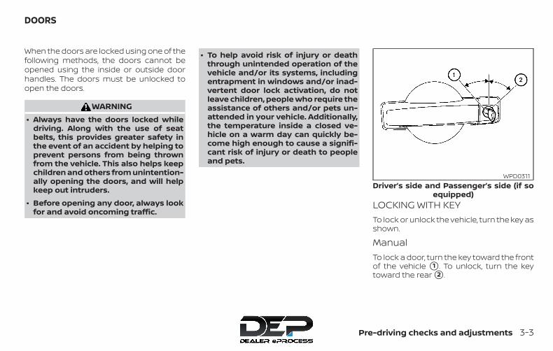
When the doors are locked using one of thefollowing methods, the doors cannot beopened using the inside or outside doorhandles. The doors must be unlocked toopen the doors.
WARNING∙ Always have the doors locked while
driving. Along with the use of seatbelts, this provides greater safety inthe event of an accident by helping toprevent persons from being thrownfrom the vehicle. This also helps keepchildren and others from unintention-ally opening the doors, and will helpkeep out intruders.
∙ Before opening any door, always lookfor and avoid oncoming traffic.
∙ To help avoid risk of injury or deaththrough unintended operation of thevehicle and/or its systems, includingentrapment in windows and/or inad-vertent door lock activation, do notleave children, people who require theassistance of others and/or pets un-attended in your vehicle. Additionally,the temperature inside a closed ve-hicle on a warm day can quickly be-come high enough to cause a signifi-cant risk of injury or death to peopleand pets.
LOCKING WITH KEYTo lock or unlock the vehicle, turn the key asshown.
ManualTo lock a door, turn the key toward the frontof the vehicle �1 . To unlock, turn the keytoward the rear �2 .
Driver’s side and Passenger’s side (if soequipped)
WPD0311
DOORS
Pre-driving checks and adjustments 3-3
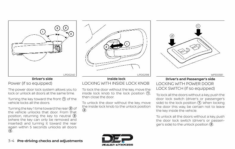
Power (if so equipped)The power door lock system allows you tolock or unlock all doors at the same time.
Turning the key toward the front �1 of thevehicle locks all the doors.
Turning the key 1 time toward the rear �2 ofthe vehicle unlocks that door. From thatposition, returning the key to neutral �3(where the key can only be removed andinserted) and turning it toward the rearagain within 5 seconds unlocks all doors�4 .
LOCKING WITH INSIDE LOCK KNOBTo lock the door without the key, move theinside lock knob to the lock position �1 ,then close the door.
To unlock the door without the key, movethe inside lock knob to the unlock position�2 .
LOCKING WITH POWER DOORLOCK SWITCH (if so equipped)To lock all the doors without a key, push thedoor lock switch (driver’s or passenger’sside) to the lock position �1 . When lockingthe door this way, be certain not to leavethe key inside the vehicle.
To unlock all the doors without a key, pushthe door lock switch (driver’s or passen-ger’s side) to the unlock position �2 .
Driver’s sideLPD0240
Inside lockLPD0298
Driver’s and Passenger’s sideWPD0381
3-4 Pre-driving checks and adjustments
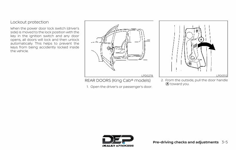
Lockout protectionWhen the power door lock switch (driver’sside) is moved to the lock position with thekey in the ignition switch and any dooropens, all doors will lock and then unlockautomatically. This helps to prevent thekeys from being accidently locked insidethe vehicle.
REAR DOORS (King Cab® models)1. Open the driver’s or passenger’s door.
2. From the outside, pull the door handle�A toward you.
LPD0278 LPD0312
Pre-driving checks and adjustments 3-5
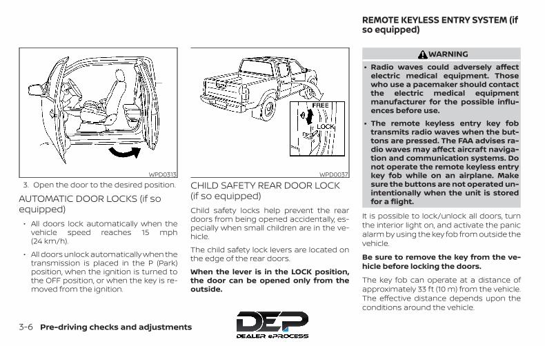
3. Open the door to the desired position.
AUTOMATIC DOOR LOCKS (if soequipped)
∙ All doors lock automatically when thevehicle speed reaches 15 mph(24 km/h).
∙ All doors unlock automatically when thetransmission is placed in the P (Park)position, when the ignition is turned tothe OFF position, or when the key is re-moved from the ignition.
CHILD SAFETY REAR DOOR LOCK(if so equipped)Child safety locks help prevent the reardoors from being opened accidentally, es-pecially when small children are in the ve-hicle.
The child safety lock levers are located onthe edge of the rear doors.
When the lever is in the LOCK position,the door can be opened only from theoutside.
WARNING∙ Radio waves could adversely affect
electric medical equipment. Thosewho use a pacemaker should contactthe electric medical equipmentmanufacturer for the possible influ-ences before use.
∙ The remote keyless entry key fobtransmits radio waves when the but-tons are pressed. The FAA advises ra-dio waves may affect aircraft naviga-tion and communication systems. Donot operate the remote keyless entrykey fob while on an airplane. Makesure the buttons are not operated un-intentionally when the unit is storedfor a flight.
It is possible to lock/unlock all doors, turnthe interior light on, and activate the panicalarm by using the key fob from outside thevehicle.
Be sure to remove the key from the ve-hicle before locking the doors.
The key fob can operate at a distance ofapproximately 33 ft (10 m) from the vehicle.The effective distance depends upon theconditions around the vehicle.
WPD0313 WPD0037
REMOTE KEYLESS ENTRY SYSTEM (ifso equipped)
3-6 Pre-driving checks and adjustments
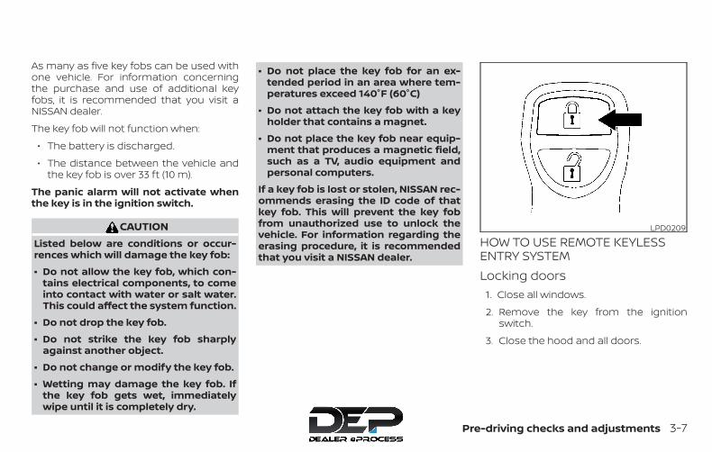
As many as five key fobs can be used withone vehicle. For information concerningthe purchase and use of additional keyfobs, it is recommended that you visit aNISSAN dealer.
The key fob will not function when:
∙ The battery is discharged.
∙ The distance between the vehicle andthe key fob is over 33 ft (10 m).
The panic alarm will not activate whenthe key is in the ignition switch.
CAUTIONListed below are conditions or occur-rences which will damage the key fob:
∙ Do not allow the key fob, which con-tains electrical components, to comeinto contact with water or salt water.This could affect the system function.
∙ Do not drop the key fob.
∙ Do not strike the key fob sharplyagainst another object.
∙ Do not change or modify the key fob.
∙ Wetting may damage the key fob. Ifthe key fob gets wet, immediatelywipe until it is completely dry.
∙ Do not place the key fob for an ex-tended period in an area where tem-peratures exceed 140°F (60°C)
∙ Do not attach the key fob with a keyholder that contains a magnet.
∙ Do not place the key fob near equip-ment that produces a magnetic field,such as a TV, audio equipment andpersonal computers.
If a key fob is lost or stolen, NISSAN rec-ommends erasing the ID code of thatkey fob. This will prevent the key fobfrom unauthorized use to unlock thevehicle. For information regarding theerasing procedure, it is recommendedthat you visit a NISSAN dealer.
HOW TO USE REMOTE KEYLESSENTRY SYSTEMLocking doors
1. Close all windows.
2. Remove the key from the ignitionswitch.
3. Close the hood and all doors.
LPD0209
Pre-driving checks and adjustments 3-7
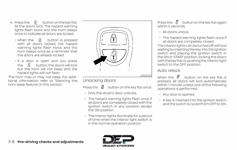
4. Press the button on the key fob.All the doors lock. The hazard warninglights flash twice and the horn beepsonce to indicate all doors are locked.
∙ When the button is pressedwith all doors locked, the hazardwarning lights flash twice and thehorn beeps once as a reminder thatthe doors are already locked.
∙ If a door is open and you pressthe button, the doors will lockbut the horn will not beep and thehazard lights will not flash.
The horn may or may not beep. For addi-tional information, refer to “Silencing thehorn beep feature” in this section.
Unlocking doorsPress the button on the key fob once.
∙ Only the driver’s door unlocks.
∙ The hazard warning lights flash once ifall doors are completely closed with theignition switch in any position exceptthe ON position.
∙ The interior lights illuminate for a periodof time when the interior light switch isin the normal operation position.
Press the button on the key fob againwithin 5 seconds.
∙ All doors unlock.
∙ The hazard warning lights flash once ifall doors are completely closed.
The interior lights can be turned off withoutwaiting by inserting the key into the ignitionswitch and placing the ignition switch inthe ON or START position, locking the doorswith the key fob or pushing the interior lightswitch to the OFF position.
Auto relockWhen the button on the key fob ispressed, all doors will lock automaticallywithin 1 minute unless one of the followingoperations is performed:
∙ Any door is opened.
∙ A key is inserted into the ignition switchand the switch is cycled from OFF to ON.
LPD0210
3-8 Pre-driving checks and adjustments

Opening automatic windows (if soequipped)The key fob allows you to open windowsequipped with automatic operation.
∙ To open the windows, press thebutton on the key fob for longer than3 seconds after all doors are unlocked.
The door windows will open while pressingthe button on the key fob.The door windows cannot be closed byusing the key fob.
Using the panic alarmIf you are near your vehicle and feel threat-ened, you may activate the panic alarm tocall attention by pressing and holdingthe button on the key fob for longerthan 0.5 seconds.The panic alarm and headlights will stay onfor a period of time.
The panic alarm stops when:
∙ It has run for a period of time.
∙ Any button is pressed on the key fob.
Using the interior lightsPress the button on the key fob onceto turn on the interior lights.For additional information, refer to “Interiorlights” in the “Instruments and controls”section in this manual.
LPD2497
Pre-driving checks and adjustments 3-9

Silencing the horn beep featureIf desired, the horn beep feature can bedeactivated using the key fob.
To deactivate: Press and hold theand buttons for at least 2 seconds.The hazard warning lights will flash threetimes to confirm that the horn beep fea-ture has been deactivated.
To activate: Press and hold theand buttons for at least 2 secondsonce more.
The hazard warning lights will flash onceand the horn will sound once to confirmthat the horn beep feature has been reac-tivated.
Deactivating the horn beep feature doesnot silence the horn if the alarm is trig-gered.
1. Pull the hood lock release handle �1located below the driver’s side instru-ment panel. The hood will spring upslightly.
2. Push the lever �2 at the front of thehood to the side as illustrated with yourfingertips and raise the hood.
3. Insert the support rod into the slot onthe underside of the hood �3 .
When closing the hood, return the hood rodto its original position. Lower the hood ap-proximately 12 in (30 cm) above the latchand release it. This allows proper engage-ment of the hood latch.
LPD0262 LPD0302
HOOD
3-10 Pre-driving checks and adjustments
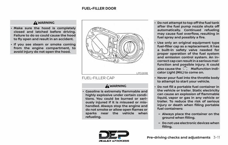
WARNING∙ Make sure the hood is completely
closed and latched before driving.Failure to do so could cause the hoodto fly open and result in an accident.
∙ If you see steam or smoke comingfrom the engine compartment, toavoid injury do not open the hood.
FUEL-FILLER CAP
WARNING∙ Gasoline is extremely flammable and
highly explosive under certain condi-tions. You could be burned or seri-ously injured if it is misused or mis-handled. Always stop the engine anddo not smoke or allow open flames orsparks near the vehicle whenrefueling.
∙ Do not attempt to top off the fuel tankafter the fuel pump nozzle shuts offautomatically. Continued refuelingmay cause fuel overflow, resulting infuel spray and possibly a fire.
∙ Use only an original equipment typefuel-filler cap as a replacement. It hasa built-in safety valve needed forproper operation of the fuel systemand emission control system. An in-correct cap can result in a serious mal-function and possible injury. It couldalso cause the Malfunction Indi-cator Light (MIL) to come on.
∙ Never pour fuel into the throttle bodyto attempt to start your vehicle.
∙ Do not fill a portable fuel container inthe vehicle or trailer. Static electricitycan cause an explosion of flammableliquid, vapor or gas in any vehicle ortrailer. To reduce the risk of seriousinjury or death when filling portablefuel containers:
– Always place the container on theground when filling.
– Do not use electronic devices whenfilling.
LPD2698
FUEL-FILLER DOOR
Pre-driving checks and adjustments 3-11
– Keep the pump nozzle in contactwith the container while you arefilling it.
– Use only approved portable fuelcontainers for flammable liquid.
CAUTION∙ The LOOSE FUEL CAP warning mes-
sage will be displayed if the fuel-fillercap is not properly tightened. It maytake a few driving trips for the mes-sage to be displayed. Failure totighten the fuel-filler cap properly af-ter the LOOSE FUEL CAP warning mes-sage is displayed may cause theMalfunction Indicator Light (MIL) toilluminate.
∙ Failure to tighten the fuel-filler capproperly may cause the Mal-function Indicator Light (MIL) to illumi-nate. If the light illuminates be-cause the fuel-filler cap is loose ormissing, tighten or install the cap andcontinue to drive the vehicle.The light should turn off after afew driving trips. If the light doesnot turn off after a few driving trips,have the vehicle inspected. It is rec-ommended that you visit a NISSANdealer for this service.
∙ For additional information, refer tothe “Malfunction Indicator Light (MIL)”in the “Instruments and Controls” sec-tion in this manual.
∙ If fuel is spilled on the vehicle body,flush it away with water to avoid paintdamage.
Fuel recommendation (for VQ40DEmodels):
∙ Do not use E-15 or E-85 fuel in yourvehicle. For additional information,refer to “Fuel recommendation (forVQ40DE models)” in the “Technicaland consumer information” section ofthis manual.
Flexible Fuel Vehicle (FFV) fuel recom-mendation (if so equipped):
∙ Only vehicles with the E-85 filler doorlabel can operate on up to E-85 fuel.Fuel system or other damage can oc-cur if up to E-85 fuel is used in vehiclesthat are not designed to run on E-85fuel. For additional information, referto “Flexible Fuel Vehicle (FFV) fuel rec-ommendation” in the “Technical andconsumer information” section of thismanual.
Fuel recommendation (for QR25DEmodels):
∙ Do not use a fuel containing morethan 15% ethanol in your vehicle. Foradditional information, refer to “Fuelrecommendation (for QR25DE mod-els)” in the “Technical and consumerinformation” section of this manual.
For additional information, refer to “Fuelrecommendation (for QR25DE models),”“Fuel recommendation (for VQ40DE mod-els)” or “Flexible Fuel Vehicle (FFV) fuel rec-ommendation” in the “Technical and con-sumer information” section of this manual.
3-12 Pre-driving checks and adjustments
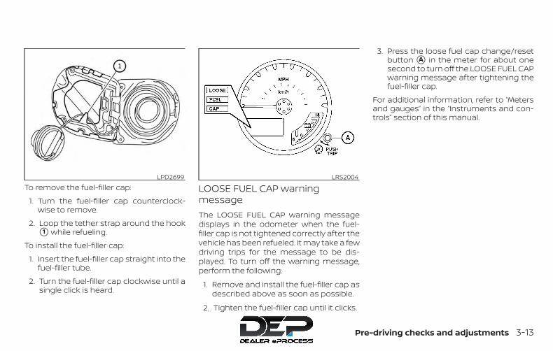
To remove the fuel-filler cap:
1. Turn the fuel-filler cap counterclock-wise to remove.
2. Loop the tether strap around the hook�1 while refueling.
To install the fuel-filler cap:
1. Insert the fuel-filler cap straight into thefuel-filler tube.
2. Turn the fuel-filler cap clockwise until asingle click is heard.
LOOSE FUEL CAP warningmessageThe LOOSE FUEL CAP warning messagedisplays in the odometer when the fuel-filler cap is not tightened correctly after thevehicle has been refueled. It may take a fewdriving trips for the message to be dis-played. To turn off the warning message,perform the following:
1. Remove and install the fuel-filler cap asdescribed above as soon as possible.
2. Tighten the fuel-filler cap until it clicks.
3. Press the loose fuel cap change/resetbutton �A in the meter for about onesecond to turn off the LOOSE FUEL CAPwarning message after tightening thefuel-filler cap.
For additional information, refer to “Metersand gauges” in the “Instruments and con-trols” section of this manual.
LPD2699 LRS2004
Pre-driving checks and adjustments 3-13

TILT OPERATION (if so equipped)
WARNING∙ Do not adjust the steering wheel while
driving. You could lose control of yourvehicle and cause an accident.
∙ Do not adjust the steering wheel anycloser to you than is necessary forproper steering operation and com-fort. The driver’s air bag inflates withgreat force. If you are unrestrained,leaning forward, sitting sideways orout of position in any way, you are atgreater risk of injury or death in acrash. You may also receive serious orfatal injuries from the air bag if youare up against it when it inflates. Al-ways sit back against the seatbackand as far away as practical from thesteering wheel. Always use the seatbelts.
Pull the lock lever toward the driver andhold it to adjust the steering wheel up ordown to the desired position.
Release the lock lever to lock the steeringwheel in place.
LPD0304
WPD0344
STEERING WHEEL SUN VISORS
3-14 Pre-driving checks and adjustments
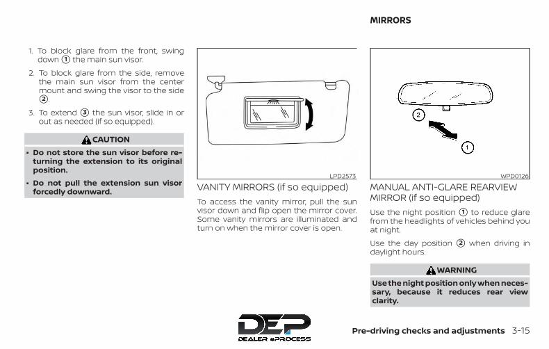
1. To block glare from the front, swingdown �1 the main sun visor.
2. To block glare from the side, removethe main sun visor from the centermount and swing the visor to the side�2 .
3. To extend �3 the sun visor, slide in orout as needed (if so equipped).
CAUTION∙ Do not store the sun visor before re-
turning the extension to its originalposition.
∙ Do not pull the extension sun visorforcedly downward. VANITY MIRRORS (if so equipped)
To access the vanity mirror, pull the sunvisor down and flip open the mirror cover.Some vanity mirrors are illuminated andturn on when the mirror cover is open.
MANUAL ANTI-GLARE REARVIEWMIRROR (if so equipped)Use the night position �1 to reduce glarefrom the headlights of vehicles behind youat night.
Use the day position �2 when driving indaylight hours.
WARNINGUse the night position only when neces-sary, because it reduces rear viewclarity.
LPD2573 WPD0126
MIRRORS
Pre-driving checks and adjustments 3-15
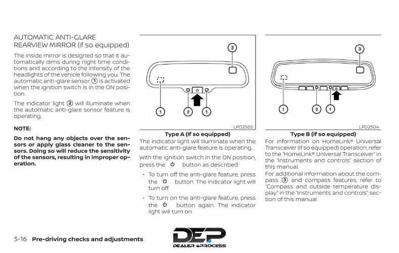
AUTOMATIC ANTI-GLAREREARVIEW MIRROR (if so equipped)The inside mirror is designed so that it au-tomatically dims during night time condi-tions and according to the intensity of theheadlights of the vehicle following you. Theautomatic anti-glare sensor �1 is activatedwhen the ignition switch is in the ON posi-tion.
The indicator light �2 will illuminate whenthe automatic anti-glare sensor feature isoperating.
NOTE:
Do not hang any objects over the sen-sors or apply glass cleaner to the sen-sors. Doing so will reduce the sensitivityof the sensors, resulting in improper op-eration.
The indicator light will illuminate when theautomatic anti-glare feature is operating.
With the ignition switch in the ON position,press the button as described:
∙ To turn off the anti-glare feature, pressthe button. The indicator light willturn off.
∙ To turn on the anti-glare feature, pressthe button again. The indicatorlight will turn on.
For information on HomeLink® UniversalTransceiver (if so equipped) operation, referto the “HomeLink® Universal Transceiver” inthe “Instruments and controls” section ofthis manual.For additional information about the com-pass �3 and compass features, refer to“Compass and outside temperature dis-play” in the “Instruments and controls” sec-tion of this manual.
Type A (if so equipped)LPD2505
Type B (if so equipped)LPD2504
3-16 Pre-driving checks and adjustments

OUTSIDE MIRRORS
WARNING∙ Objects viewed in the outside mirror
on the passenger side are closer thanthey appear. Be careful when movingto the right. Using only this mirrorcould cause an accident. Use the in-side mirror or glance over your shoul-der to properly judge distances toother objects.
∙ Do not adjust the mirrors while driv-ing. You could lose control of your ve-hicle and cause an accident.
Manual control type (if soequipped)The outside mirrors can be moved in anydirection for a better rear view.
Electric control type (if soequipped)The outside mirror remote control will op-erate only when the ignition switch isplaced in the ACC or ON position.
Move the small switch �1 to select the rightor left mirror. Move the large switch �2 toadjust each mirror to the desired position.Move the small switch �1 to the center(neutral) position to prevent accidentallymoving the mirror.
WPD0170 LPD0237
Pre-driving checks and adjustments 3-17

Foldable outside mirrorsPull the outside mirror toward the door tofold it.
Heated mirrors (if so equipped)Some outside mirrors can be heated todefrost, defog, or de-ice for improved vis-ibility. For additional information, refer to“Rear window or outside mirror defrosterswitch (if so equipped)” in the “Instrumentsand controls” section of this manual.
TAILGATEOpening the tailgatePull the tailgate handle upward and lowerthe tailgate. The support cables hold thetailgate open.
When closing the tailgate, make sure thelatches are securely locked.
Do not drive the vehicle with the tailgatedown, unless equipped with NISSAN’sBed Extender (accessory) or equivalentin the extended position.
For additional information on proper truckbox loading, refer to “Vehicle loading infor-mation” in the “Technical and consumer in-formation” section of this manual.
WARNING∙ Never allow anyone to ride in the
cargo area or on the rear seat when itis in the folded position. Use of theseareas by passengers without properrestraints could result in serious injuryor death in an accident or suddenstop.
∙ It is extremely dangerous to ride in acargo area inside a vehicle. In a colli-sion, people riding in these areas aremore likely to be seriously injured orkilled.
∙ Do not allow people to ride in any areaof your vehicle that is not equippedwith seats and seat belts.
∙ Be sure everyone in your vehicle is in aseat and using a seat belt properly.
LPD0259 LPD0270
TRUCK BOX
3-18 Pre-driving checks and adjustments

Disconnecting the rear camera (ifso equipped)Before removing the tailgate disconnectthe rear camera by performing the follow-ing:
1. Open the tailgate to access the rearcamera connector bracket �1 locatedon the rear sill.
2. Remove the connector bracket �2from the sill by pressing the locking tabinward, in the direction shown, whilepulling the bracket apart.
3. Disconnect the chassis wiring harness�3 by pressing inward on the lockingtab, in the direction shown, while pullingthe connectors apart. Hold the con-nector firmly to prevent the connectorin the chassis harness from falling intothe sill.
4. Take the chassis plug and bracket fromthe glove box and connect them to thechassis wiring harness to avoid con-tamination to the terminals which willlead to malfunction of the rear camera.
5. Insert the bracket back into the sill.
6. Take the tailgate plug from the glovebox and connect it to the tailgate wir-ing harness to avoid contaminationwhich will lead to malfunction of therear camera.
7. Remove the tailgate. For additional in-formation, refer to “Removing the tail-gate” in this section.
LPD2097
Pre-driving checks and adjustments 3-19

Removing the tailgate1. Release the tailgate support cables.
CAUTION∙ The tailgate is heavy. Two people
should remove or install it. Be carefulnot to drop it during removal.
∙ After releasing the support cables, donot let the tailgate rest on thebumper.
2. Hold the tailgate at a 15 degree angle.
3. Pull the tailgate out from the right sidehinge.
4. Slide the tailgate out of the left sidehinge.
Installing the tailgate1. Insert the tailgate into the left side
hinge.
2. Hold the tailgate at a 15 degree angleand insert into the right side hinge.
3. Continue to hold the tailgate at a 15degree angle and attach the tailgatesupport cables.
4. Close the tailgate securely.LPD2208
3-20 Pre-driving checks and adjustments

Connecting the rear camera (if soequipped)Before closing the tailgate reconnect therear camera by performing the following:
1. After attaching the rear tailgate to thetruck, keep the tailgate open and checkthat the tailgate harness is not hangingbelow the tailgate.
2. Remove the connector bracket �2from the sill by pressing the locking tabinward, in the direction shown, whilepulling the bracket apart.
3. Disconnect the chassis plug andbracket from the chassis wiring har-ness �3 . Keep the connector andbracket in a safe place such as theglove box.
4. Disconnect the tailgate plug from thetailgate wiring harness. Keep the tail-gate plug in a safe place such as theglove box.
5. Connect the tailgate wiring harness tothe chassis wiring harness.
6. Securely fix the rear camera connectorbracket �1 to the rear sill.
7. Close the tailgate securely.
LPD2097
Pre-driving checks and adjustments 3-21

Locking the tailgateTo lock the tailgate, turn the key toward thepassenger side of the vehicle �1 . To unlock,turn the key toward the driver side �2 .
BED EXTENDER (if so equipped)
CAUTION∙ Do not overload the bed extender.
Maximum load on the open tailgate is200 lbs. (890N).
∙ Evenly distribute and properly secureall cargo.
∙ Do not use the bed extender or tail-gate to secure cargo.
Positioning the bed extenderTo use the bed extender in the inward po-sition perform the following:
1. Rotate the bed extender �1 toward thecab of the truck.
2. If necessary, remove tethers from thetailgate latch.
3. Tighten the knobs to secure the ex-tender into the desired position.
4. Close the tailgate.
LPD0272 LPD0480
3-22 Pre-driving checks and adjustments

5. Place cargo inside the bed extender inthe truck bed.
6. Properly secure the cargo.
To use the bed extender in the outwardposition perform the following:
1. Open the tailgate.
2. Rotate the bed extender �2 away fromthe cab of the truck until the extendersits on the tailgate.
3. Lock the buckles �3 into the tailgatelatch on both sides.
The bed extender can be adjusted in theoutward position by moving the extenderalong the rail.
NOTE:
Use care when rotating extender, buck-les may come in contact with the truckbed railing.
Removing and installing the bedextenderTo remove or install the bed extender per-form the following:
1. Open the tailgate.
2. Rotate the bed extender into a verticalposition and lift straight up (to remove)or lower straight down (to install).
To store the bed extender in the front of thetruck when not in use perform the follow-ing:
1. Position the sliding brackets past thecenter of the wheel well.
2. Re-install the extender into the brack-ets (see above).
3. Rotate the extender to the inward po-sition.
4. Push the brackets forward until the ex-tender comes in contact with the frontwall of the truck box.
LPD0479
Pre-driving checks and adjustments 3-23

TIE DOWN HOOKS (if so equipped)For your convenience, tie down hooks areplaced at each corner of the truck box.These may be used to help secure cargoloaded into the truck box.
∙ The weight of the cargo load must beevenly distributed over both the frontand the rear axles.
∙ All cargo should be securely fastenedwith ropes or straps to prevent it fromshifting or sliding within the vehicle.
WARNING∙ Properly secure all cargo with ropes or
straps to help prevent it from slidingor shifting. In a sudden stop or colli-sion, unsecured cargo could causepersonal injury.
LTI0102
3-24 Pre-driving checks and adjustments

4 Monitor, climate, audio, phone andvoice recognition systems
Control panel buttons — models withoutNavigation System (if so equipped) . . . . . . . . . . . . . . 4-4
How to use the touch-screen. . . . . . . . . . . . . . . . . 4-5How to use the MENU button . . . . . . . . . . . 4-8
(brightness control) button . . . . . . . . . . . . . 4-9How to use the VOL (volume) knob /PUSH (power) button . . . . . . . . . . . . . . . . . . . 4-9Selecting menu from launch bar . . . . . . . . . . . . . 4-9
Control panel buttons — models withNavigation System (if so equipped) . . . . . . . . . . . . . 4-10
How to use the touch-screen. . . . . . . . . . . . . . . . .4-11How to use the BACK button . . . . . . . . . . . . . . . . 4-13How to use the button. . . . . . . . . . . . . . . . 4-13
button. . . . . . . . . . . . . . . . . . . . . . . . . . . . . . . . . 4-15How to use the ON-OFF button/VOL(volume) control knob . . . . . . . . . . . . . . . . . . . . . . . 4-15How to use the CAMERA button . . . . . . . . . . . . . 4-15
RearView Monitor . . . . . . . . . . . . . . . . . . . . . . . . . . . . . . 4-16RearView Monitor system operation . . . . . . . . . 4-17How to read the displayed lines. . . . . . . . . . . . . . 4-18Difference between predicted andactual distances. . . . . . . . . . . . . . . . . . . . . . . . . . . . . 4-18Adjusting the screen . . . . . . . . . . . . . . . . . . . . . . . . 4-20
RearView Monitor system limitations . . . . . . . . 4-21System maintenance. . . . . . . . . . . . . . . . . . . . . . . . 4-22
Vents. . . . . . . . . . . . . . . . . . . . . . . . . . . . . . . . . . . . . . . . . . . 4-23Heater and air conditioner (manual)(if so equipped) . . . . . . . . . . . . . . . . . . . . . . . . . . . . . . . . . 4-23
Controls . . . . . . . . . . . . . . . . . . . . . . . . . . . . . . . . . . . . . 4-24Controls . . . . . . . . . . . . . . . . . . . . . . . . . . . . . . . . . . . . . 4-25Heater operation . . . . . . . . . . . . . . . . . . . . . . . . . . . . 4-26Air conditioner operation . . . . . . . . . . . . . . . . . . . . 4-27Air flow charts . . . . . . . . . . . . . . . . . . . . . . . . . . . . . . . 4-28
Heater and air conditioner (automatic)(if so equipped) . . . . . . . . . . . . . . . . . . . . . . . . . . . . . . . . . 4-32
Automatic operation . . . . . . . . . . . . . . . . . . . . . . . . 4-35Manual operation . . . . . . . . . . . . . . . . . . . . . . . . . . . 4-36Operating tips . . . . . . . . . . . . . . . . . . . . . . . . . . . . . . . 4-37
Servicing air conditioner . . . . . . . . . . . . . . . . . . . . . . . . 4-37Audio system. . . . . . . . . . . . . . . . . . . . . . . . . . . . . . . . . . . 4-37
Radio. . . . . . . . . . . . . . . . . . . . . . . . . . . . . . . . . . . . . . . . 4-37FM radio reception . . . . . . . . . . . . . . . . . . . . . . . . . . 4-38AM radio reception . . . . . . . . . . . . . . . . . . . . . . . . . . 4-38Satellite radio reception (if so equipped) . . . . . 4-38Audio operation precautions . . . . . . . . . . . . . . . . 4-39FM/AM radio (if so equipped) . . . . . . . . . . . . . . . . 4-46
FM/AM/SAT radio with Compact Disc(CD) player (if so equipped) . . . . . . . . . . . . . . . . . . 4-51USB (Universal Serial Bus) connectionport (models without NavigationSystem) (if so equipped) . . . . . . . . . . . . . . . . . . . . .4-58USB (Universal Serial Bus) connectionport (models with Navigation System)(if so equipped) . . . . . . . . . . . . . . . . . . . . . . . . . . . . . . 4-61iPod®* player operation withoutNavigation System (if so equipped) . . . . . . . . . . 4-63iPod®* player operation with NavigationSystem (if so equipped). . . . . . . . . . . . . . . . . . . . . . 4-67Bluetooth® streaming audio withoutNavigation System (if so equipped) . . . . . . . . . . 4-70Bluetooth® streaming audio withNavigation System (if so equipped) . . . . . . . . . . 4-73CD care and cleaning. . . . . . . . . . . . . . . . . . . . . . . . 4-75Steering wheel switch for audio control. . . . . . 4-75Antenna. . . . . . . . . . . . . . . . . . . . . . . . . . . . . . . . . . . . . 4-76
NissanConnect® Mobile Apps (if so equipped). . . 4-77Registering with NissanConnect®Mobile Apps . . . . . . . . . . . . . . . . . . . . . . . . . . . . . . . . . 4-77Connect Phone. . . . . . . . . . . . . . . . . . . . . . . . . . . . . . 4-77Application download . . . . . . . . . . . . . . . . . . . . . . . 4-77
Siri® Eyes Free (models without NavigationSystem) (if so equipped) . . . . . . . . . . . . . . . . . . . . . . . . 4-78
Requirements . . . . . . . . . . . . . . . . . . . . . . . . . . . . . . . 4-78Operating Siri® Eyes Free . . . . . . . . . . . . . . . . . . . . 4-78Troubleshooting guide . . . . . . . . . . . . . . . . . . . . . .4-80
Siri® Eyes Free (models with NavigationSystem) (if so equipped) . . . . . . . . . . . . . . . . . . . . . . . . 4-81
Requirements . . . . . . . . . . . . . . . . . . . . . . . . . . . . . . . 4-81Siri® Activation. . . . . . . . . . . . . . . . . . . . . . . . . . . . . . . 4-81Operating Siri® Eyes Free . . . . . . . . . . . . . . . . . . . .4-82Changing Siri® Eyes Free settings. . . . . . . . . . . .4-82Troubleshooting guide . . . . . . . . . . . . . . . . . . . . . . 4-83
Car phone or CB radio . . . . . . . . . . . . . . . . . . . . . . . . . .4-84Bluetooth® Hands-Free Phone Systemwithout Navigation System (if so equipped) . . . . .4-85
Regulatory information . . . . . . . . . . . . . . . . . . . . . . 4-87Using the system. . . . . . . . . . . . . . . . . . . . . . . . . . . . 4-87Indicators . . . . . . . . . . . . . . . . . . . . . . . . . . . . . . . . . . .4-88Control buttons . . . . . . . . . . . . . . . . . . . . . . . . . . . . .4-89Connecting procedure . . . . . . . . . . . . . . . . . . . . . .4-90Voice commands . . . . . . . . . . . . . . . . . . . . . . . . . . . 4-91Phone display screen. . . . . . . . . . . . . . . . . . . . . . . . 4-93Making a call . . . . . . . . . . . . . . . . . . . . . . . . . . . . . . . .4-94Receiving a call . . . . . . . . . . . . . . . . . . . . . . . . . . . . . . 4-95

During a call . . . . . . . . . . . . . . . . . . . . . . . . . . . . . . . . . 4-95Ending a call. . . . . . . . . . . . . . . . . . . . . . . . . . . . . . . . .4-96Text messaging (if so equipped) . . . . . . . . . . . . .4-96Bluetooth® connections screen . . . . . . . . . . . . 4-100Phone and text message settings . . . . . . . . . . 4-101
Bluetooth® Hands-Free Phone System withNavigation System (if so equipped) . . . . . . . . . . . . 4-103
Regulatory information . . . . . . . . . . . . . . . . . . . . . 4-105Voice commands . . . . . . . . . . . . . . . . . . . . . . . . . . 4-106Connecting procedure . . . . . . . . . . . . . . . . . . . . . 4-106Vehicle phonebook . . . . . . . . . . . . . . . . . . . . . . . . . 4-107Making a call . . . . . . . . . . . . . . . . . . . . . . . . . . . . . . . 4-107Receiving a call . . . . . . . . . . . . . . . . . . . . . . . . . . . . . 4-107During a call . . . . . . . . . . . . . . . . . . . . . . . . . . . . . . . . 4-107Ending a call. . . . . . . . . . . . . . . . . . . . . . . . . . . . . . . . 4-108Text messaging (if so equipped) . . . . . . . . . . . . 4-108
Bluetooth® settings . . . . . . . . . . . . . . . . . . . . . . . . 4-110Phone settings . . . . . . . . . . . . . . . . . . . . . . . . . . . . . .4-111Troubleshooting guide . . . . . . . . . . . . . . . . . . . . . 4-112
NISSAN Voice Recognition System(if so equipped) . . . . . . . . . . . . . . . . . . . . . . . . . . . . . . . . 4-113
Using the system. . . . . . . . . . . . . . . . . . . . . . . . . . . 4-113System features . . . . . . . . . . . . . . . . . . . . . . . . . . . . 4-114Bluetooth® Hands-Free Phone Systemvoice commands. . . . . . . . . . . . . . . . . . . . . . . . . . . 4-115Navigation System voice commands . . . . . . . 4-116Audio system voice commands . . . . . . . . . . . . 4-116Information voice commands . . . . . . . . . . . . . . 4-116My Apps voice commands . . . . . . . . . . . . . . . . . 4-117Help voice commands. . . . . . . . . . . . . . . . . . . . . . 4-117Troubleshooting guide . . . . . . . . . . . . . . . . . . . . . 4-117

WARNING∙ Positioning of the heating or air con-
ditioning controls and display con-trols should not be done while drivingin order that full attention may begiven to the driving operation.
∙ Do not disassemble or modify thissystem. If you do, it may result in acci-dents, fire, or electrical shock.
∙ Do not use this system if you noticeany abnormality, such as a frozenscreen or lack of sound. Continueduse of the system may result in acci-dent, fire or electric shock.
∙ In case you notice any foreign objectin the system hardware, spill liquid onit, or notice smoke or smell comingfrom it, stop using the system imme-diately. Ignoring such conditions maylead to accidents, fire or electricalshock. It is recommended that youvisit a NISSAN dealer for servicing.
1. MENU button
2. button*
3. Display screen
4. (brightness control) button
5. VOL (volume) knob / PUSH(power) button
* For additional information regarding theBluetooth® Hands-Free Phone Systemcontrol button, refer to “Bluetooth® Hands-
LHA4680
CONTROL PANEL BUTTONS —MODELS WITHOUT NAVIGATIONSYSTEM (if so equipped)
4-4 Monitor, climate, audio, phone and voice recognition systems
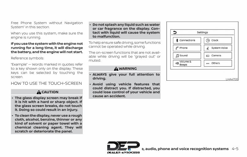
Free Phone System without NavigationSystem” in this section.
When you use this system, make sure theengine is running.
If you use the system with the engine notrunning for a long time, it will dischargethe battery, and the engine will not start.
Reference symbols:
“Example” — Words marked in quotes referto a key shown only on the display. Thesekeys can be selected by touching thescreen.
HOW TO USE THE TOUCH-SCREEN
CAUTION∙ The glass display screen may break if
it is hit with a hard or sharp object. Ifthe glass screen breaks, do not touchit. Doing so could result in an injury.
∙ To clean the display, never use a roughcloth, alcohol, benzine, thinner or anykind of solvent or paper towel with achemical cleaning agent. They willscratch or deteriorate the panel.
∙ Do not splash any liquid such as wateror car fragrance on the display. Con-tact with liquid will cause the systemto malfunction.
To help ensure safe driving, some functionscannot be operated while driving.
The on-screen functions that are not avail-able while driving will be “grayed out” ormuted.
WARNING∙ ALWAYS give your full attention to
driving.
∙ Avoid using vehicle features thatcould distract you. If distracted, youcould lose control of your vehicle andcause an accident.
LHA4700
Monitor, climate, audio, phone and voice recognition systems 4-5

Touch-screen operationMenu Item Result
Selecting the item Touch an item to select. To select the “Phone” key, touch the “Phone” key on the screen. Touch the “ ” key toreturn to the previous screen.
Adjusting the item Touch the “+” key or the “�” key to adjust the settings of an item. Touch the up arrow to scroll up the page oneitem at a time. Touch the down arrow to scroll down the page one item at a time.
Inputting characters Touch the number key. There are some options available when inputting characters.123 Touch to manually enter numbers.OK Completes the character input.
4-6 Monitor, climate, audio, phone and voice recognition systems
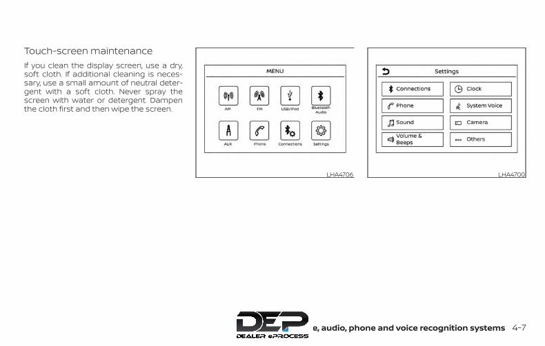
Touch-screen maintenanceIf you clean the display screen, use a dry,soft cloth. If additional cleaning is neces-sary, use a small amount of neutral deter-gent with a soft cloth. Never spray thescreen with water or detergent. Dampenthe cloth first and then wipe the screen.
LHA4706 LHA4700
Monitor, climate, audio, phone and voice recognition systems 4-7
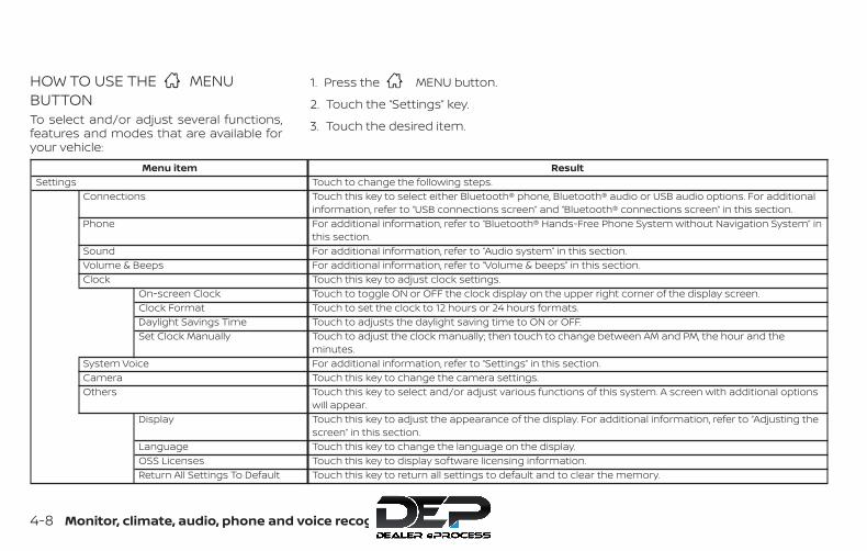
HOW TO USE THE MENUBUTTONTo select and/or adjust several functions,features and modes that are available foryour vehicle:
1. Press the MENU button.
2. Touch the “Settings” key.
3. Touch the desired item.
Menu item ResultSettings Touch to change the following steps.
Connections Touch this key to select either Bluetooth® phone, Bluetooth® audio or USB audio options. For additionalinformation, refer to “USB connections screen” and “Bluetooth® connections screen” in this section.
Phone For additional information, refer to “Bluetooth® Hands-Free Phone System without Navigation System” inthis section.
Sound For additional information, refer to “Audio system” in this section.Volume & Beeps For additional information, refer to “Volume & beeps” in this section.Clock Touch this key to adjust clock settings.
On-screen Clock Touch to toggle ON or OFF the clock display on the upper right corner of the display screen.Clock Format Touch to set the clock to 12 hours or 24 hours formats.Daylight Savings Time Touch to adjusts the daylight saving time to ON or OFF.Set Clock Manually Touch to adjust the clock manually; then touch to change between AM and PM, the hour and the
minutes.System Voice For additional information, refer to “Settings” in this section.Camera Touch this key to change the camera settings.Others Touch this key to select and/or adjust various functions of this system. A screen with additional options
will appear.Display Touch this key to adjust the appearance of the display. For additional information, refer to “Adjusting the
screen” in this section.Language Touch this key to change the language on the display.OSS Licenses Touch this key to display software licensing information.Return All Settings To Default Touch this key to return all settings to default and to clear the memory.
4-8 Monitor, climate, audio, phone and voice recognition systems

(brightness control) BUTTON
To change the display brightness, pressthe button. Pressing the button againwill change the display to the day or thenight display.Press and hold the button for morethan 2 seconds to turn the display off. Pressand hold the button again to turn the dis-play on.
HOW TO USE THE VOL (volume)KNOB / PUSH (power)BUTTONPress the PUSH (power) button toturn audio function on and off. Turn the VOL(volume) knob to adjust audio volume.
SELECTING MENU FROM LAUNCHBARVarious system functions can be accessedby touching the items on the Launch Bar�1 which is displayed on most of the mainmenu screens (the Launch Bar does notappear on some screens such as settingsscreens, camera screens, etc.)
Touch the keys on the Launch Bar to dis-play the corresponding menu screens.
The following menu items are available onthe Launch Bar:
∙ AM
∙ FM
∙ USB/iPod
∙ Bluetooth
∙ AUX
∙ Settings
LHA4707
Monitor, climate, audio, phone and voice recognition systems 4-9

1. MAP button*
2. Display screen
3. button**
4. button
5. (brightness control) button
6. BACK button
7. ENTER/AUDIO button / TUNE knob
8. ON-OFF button/VOL (volume) controlknob
9. CAMERA button
10. NAV button*
* For additional information, refer to theseparate NissanConnect® Owner’s Manualregarding the Navigation system controlbuttons.
** For additional information, refer to the“Bluetooth® Hands-Free Phone Systemwith Navigation System” in this section.
When you use this system, make sure theengine is running.
If you use the system with the engine notrunning (ignition ON or ACC) for a longtime, it will discharge the battery, andthe engine will not start.
Reference symbols:
“Example” — Words marked in quotes referto a key shown only on the display. Thesekeys can be selected by touching thescreen.LHA3138
CONTROL PANEL BUTTONS —MODELS WITH NAVIGATION SYSTEM(if so equipped)
4-10 Monitor, climate, audio, phone and voice recognition systems

HOW TO USE THE TOUCH-SCREEN
CAUTION∙ The glass display screen may break if
it is hit with a hard or sharp object. Ifthe glass screen breaks, do not touchit. Doing so could result in an injury.
∙ To clean the display, never use a roughcloth, alcohol, benzine, thinner or anykind of solvent or paper towel with achemical cleaning agent. They willscratch or deteriorate the panel.
∙ Do not splash any liquid such as wateror car fragrance on the display. Con-tact with liquid will cause the systemto malfunction.
To help ensure safe driving, some functionscannot be operated while driving.
The on-screen functions that are not avail-able while driving will be grayed out ormuted.
Park the vehicle in a safe location and thenoperate the navigation system.
WARNING∙ ALWAYS give your full attention to
driving.
∙ Avoid using vehicle features thatcould distract you. If distracted, youcould lose control of your vehicle andcause an accident.
LHA3748
Monitor, climate, audio, phone and voice recognition systems 4-11
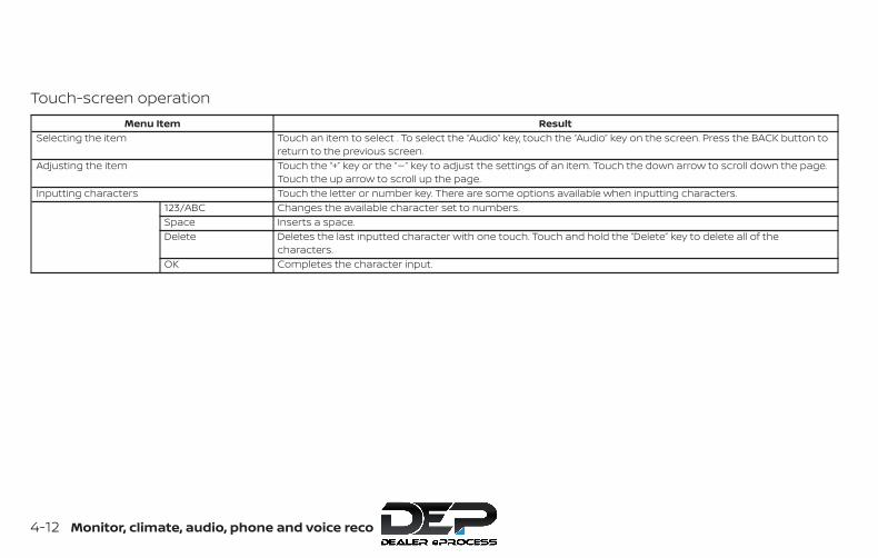
Touch-screen operationMenu Item Result
Selecting the item Touch an item to select . To select the “Audio” key, touch the “Audio” key on the screen. Press the BACK button toreturn to the previous screen.
Adjusting the item Touch the “+” key or the “�” key to adjust the settings of an item. Touch the down arrow to scroll down the page.Touch the up arrow to scroll up the page.
Inputting characters Touch the letter or number key. There are some options available when inputting characters.123/ABC Changes the available character set to numbers.Space Inserts a space.Delete Deletes the last inputted character with one touch. Touch and hold the “Delete” key to delete all of the
characters.OK Completes the character input.
4-12 Monitor, climate, audio, phone and voice recognition systems

Touch-screen maintenanceIf you clean the display screen, use a dry,soft cloth. If additional cleaning is neces-sary, use a small amount of neutral deter-gent with a soft cloth. Never spray thescreen with water or detergent. Dampenthe cloth first and then wipe the screen.
HOW TO USE THE BACK BUTTONPress the BACK button to return to the pre-vious screen.
HOW TO USE THE BUTTONFor additional information, refer to theseparate NissanConnect® Owner’s Manualregarding the “SiriusXM® Travel Link” and“SiriusXM® Traffic” features.
For additional information, refer to“NissanConnect® Mobile Apps” in this sec-tion.
For additional information, refer to “NISSANVoice Recognition System” in this section.
To select and/or adjust several functions,features and modes that are available foryour vehicle:
1. Press the [ ] button.
2. Touch the “Settings” key.
3. Touch the desired item.
LHA2773 LHA3748
Monitor, climate, audio, phone and voice recognition systems 4-13
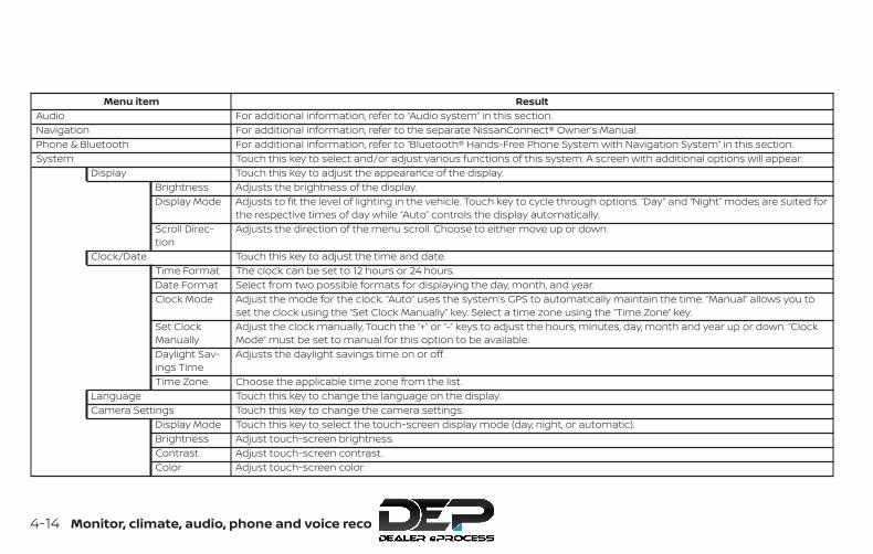
Menu item ResultAudio For additional information, refer to “Audio system” in this section.Navigation For additional information, refer to the separate NissanConnect® Owner’s Manual.Phone & Bluetooth For additional information, refer to “Bluetooth® Hands-Free Phone System with Navigation System” in this section.System Touch this key to select and/or adjust various functions of this system. A screen with additional options will appear.
Display Touch this key to adjust the appearance of the display.Brightness Adjusts the brightness of the display.Display Mode Adjusts to fit the level of lighting in the vehicle. Touch key to cycle through options. “Day” and “Night” modes are suited for
the respective times of day while “Auto” controls the display automatically.Scroll Direc-tion
Adjusts the direction of the menu scroll. Choose to either move up or down.
Clock/Date Touch this key to adjust the time and date.Time Format The clock can be set to 12 hours or 24 hours.Date Format Select from two possible formats for displaying the day, month, and year.Clock Mode Adjust the mode for the clock. “Auto” uses the system’s GPS to automatically maintain the time. “Manual” allows you to
set the clock using the “Set Clock Manually” key. Select a time zone using the “Time Zone” key.Set ClockManually
Adjust the clock manually, Touch the “+” or “-” keys to adjust the hours, minutes, day, month and year up or down. “ClockMode” must be set to manual for this option to be available.
Daylight Sav-ings Time
Adjusts the daylight savings time on or off.
Time Zone Choose the applicable time zone from the list.Language Touch this key to change the language on the display.Camera Settings Touch this key to change the camera settings.
Display Mode Touch this key to select the touch-screen display mode (day, night, or automatic).Brightness Adjust touch-screen brightness.Contrast Adjust touch-screen contrast.Color Adjust touch-screen color.
4-14 Monitor, climate, audio, phone and voice recognition systems
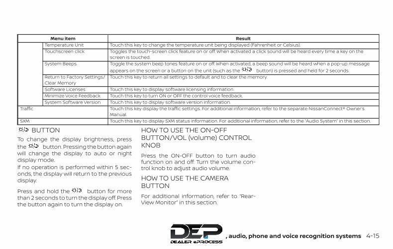
Menu item ResultTemperature Unit Touch this key to change the temperature unit being displayed (Fahrenheit or Celsius).Touchscreen click Toggles the touch-screen click feature on or off. When activated a click sound will be heard every time a key on the
screen is touched.System Beeps Toggle the system beep tones feature on or off. When activated, a beep sound will be heard when a pop-up message
appears on the screen or a button on the unit (such as the button) is pressed and held for 2 seconds.Return to Factory Settings/Clear Memory
Touch this key to return all settings to default and to clear the memory.
Software Licenses Touch this key to display software licensing information.Minimize Voice Feedback Touch this key to turn ON or OFF the control voice feedback.System Software Version Touch this key to display software version information.
Traffic Touch this key display the traffic settings. For additional information, refer to the separate NissanConnect® Owner’sManual.
SXM Touch this key to display SXM status information. For additional information, refer to the “Audio System” in this section.
BUTTONTo change the display brightness, pressthe button. Pressing the button againwill change the display to auto or nightdisplay mode.If no operation is performed within 5 sec-onds, the display will return to the previousdisplay.
Press and hold the button for morethan 2 seconds to turn the display off. Pressthe button again to turn the display on.
HOW TO USE THE ON-OFFBUTTON/VOL (volume) CONTROLKNOBPress the ON-OFF button to turn audiofunction on and off. Turn the volume con-trol knob to adjust audio volume.
HOW TO USE THE CAMERABUTTONFor additional information, refer to “Rear-View Monitor” in this section.
Monitor, climate, audio, phone and voice recognition systems 4-15
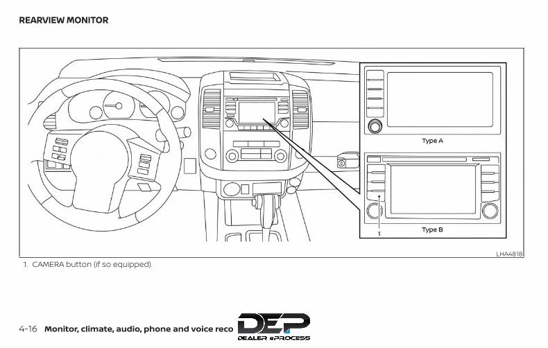
1. CAMERA button (if so equipped)LHA4818
REARVIEW MONITOR
4-16 Monitor, climate, audio, phone and voice recognition systems
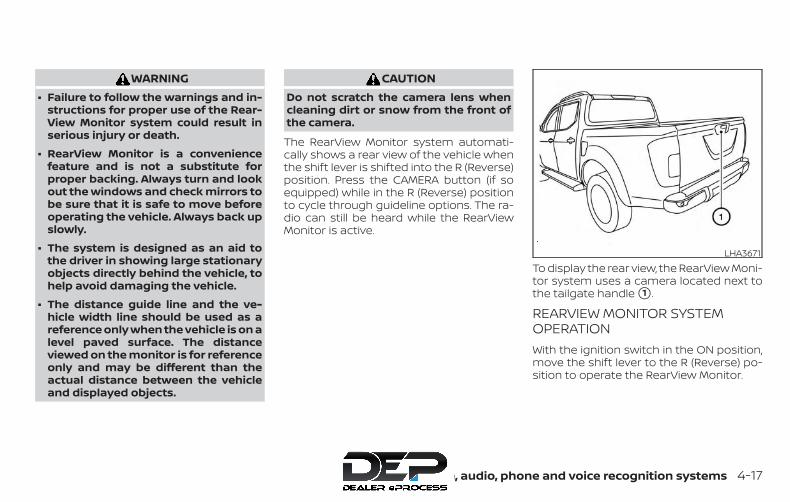
WARNING∙ Failure to follow the warnings and in-
structions for proper use of the Rear-View Monitor system could result inserious injury or death.
∙ RearView Monitor is a conveniencefeature and is not a substitute forproper backing. Always turn and lookout the windows and check mirrors tobe sure that it is safe to move beforeoperating the vehicle. Always back upslowly.
∙ The system is designed as an aid tothe driver in showing large stationaryobjects directly behind the vehicle, tohelp avoid damaging the vehicle.
∙ The distance guide line and the ve-hicle width line should be used as areference only when the vehicle is on alevel paved surface. The distanceviewed on the monitor is for referenceonly and may be different than theactual distance between the vehicleand displayed objects.
CAUTIONDo not scratch the camera lens whencleaning dirt or snow from the front ofthe camera.
The RearView Monitor system automati-cally shows a rear view of the vehicle whenthe shift lever is shifted into the R (Reverse)position. Press the CAMERA button (if soequipped) while in the R (Reverse) positionto cycle through guideline options. The ra-dio can still be heard while the RearViewMonitor is active.
To display the rear view, the RearView Moni-tor system uses a camera located next tothe tailgate handle �1 .
REARVIEW MONITOR SYSTEMOPERATIONWith the ignition switch in the ON position,move the shift lever to the R (Reverse) po-sition to operate the RearView Monitor.
LHA3671
Monitor, climate, audio, phone and voice recognition systems 4-17

HOW TO READ THE DISPLAYEDLINESGuiding lines which indicate the vehiclewidth and distances to objects with refer-ence to the vehicle body line �A are dis-played on the monitor.
Distance guide lines
Indicate distances from the vehicle body.
∙ Red line �1 : approx. 0.5 m (1.5 ft)
∙ Yellow line �2 : approx. 1 m (3 ft)
∙ Green line �3 : approx. 2 m (7 ft)
∙ Green line �4 : approx. 3 m (10 ft) (if soequipped)
Vehicle width guide lines �5
Indicate the vehicle width when backingup.
DIFFERENCE BETWEEN PREDICTEDAND ACTUAL DISTANCESThe displayed guidelines and their loca-tions on the ground are for approximatereference only. Objects on uphill or downhillsurfaces or projecting objects will be actu-ally located at distances different fromthose displayed in the monitor relative tothe guidelines (refer to illustrations). Whenin doubt, turn around and view the objectsas you are backing up, or park and exit thevehicle to view the positioning of objectsbehind the vehicle.
Backing up on a steep uphillWhen backing up the vehicle up a hill, thedistance guide lines and the vehicle widthguide lines are shown closer than the actualdistance. Note that any object on the hill isfurther than it appears on the monitor.
LHA2944
LHA3672
4-18 Monitor, climate, audio, phone and voice recognition systems
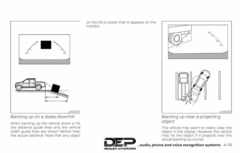
Backing up on a steep downhillWhen backing up the vehicle down a hill,the distance guide lines and the vehiclewidth guide lines are shown farther thanthe actual distance. Note that any object
on the hill is closer than it appears on themonitor.
Backing up near a projectingobjectThe vehicle may seem to nearly clear theobject in the display. However, the vehiclemay hit the object if it projects over theactual backing up course.
LHA3673 LHA4513
Monitor, climate, audio, phone and voice recognition systems 4-19
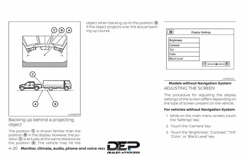
Backing up behind a projectingobjectThe position �C is shown farther than theposition �B in the display. However, the po-sition �C is actually at the same distance asthe position �A . The vehicle may hit the
object when backing up to the position �Aif the object projects over the actual back-ing up course.
ADJUSTING THE SCREENThe procedure for adjusting the displaysettings of the screen differs depending onthe type of screen present on the vehicle.
For vehicles without Navigation System
1. While on the main menu screen, touchthe “Settings” key.
2. Touch the “Camera” key.
3. Touch the “Brightness”, “Contrast”, “Tint”“Color”, or “Black Level” key.
LHA3674
Models without Navigation SystemLHA3522
4-20 Monitor, climate, audio, phone and voice recognition systems

4. Adjust the item by touching the “+” or “-”key on the touch-screen display.
∙ Do not adjust the display settings of theRearView Monitor while the vehicle ismoving.
For vehicles with Navigation System
1. Firmly apply the brake and place theshift lever in R (Reverse)
2. Press the button on the controlpanel.
3. The screen will display the Night set-tings.
4. Turn the TUNE knob to adjust the set-ting up or down.
5. Press the button again to accessthe Auto settings.
6. Turn the TUNE knob to adjust the set-ting up or down.
∙ Do not adjust the display settings of theRearView Monitor while the vehicle ismoving.
REARVIEW MONITOR SYSTEMLIMITATIONS
WARNINGListed below are the system limitationsfor RearView Monitor. Failure to operatethe vehicle in accordance with thesesystem limitations could result in seri-ous injury or death.
∙ The system cannot completely elimi-nate blind spots and may not showevery object.
∙ Underneath the bumper and the cor-ner areas of the bumper cannot beviewed on the RearView Monitor be-cause of its monitoring range limita-tion. The system will not show smallobjects below the bumper, and maynot show objects close to the bumperor on the ground.
∙ Objects viewed in the RearView Moni-tor differ from actual distance be-cause a wide-angle lens is used.
∙ Objects in the RearView Monitor willappear visually opposite compared towhen viewed in the rearview and out-side mirrors.
∙ Use the displayed lines as a reference.The lines are highly affected by thenumber of occupants, fuel level, ve-hicle position, road conditions androad grade.
∙ Make sure that the tailgate is securelyclosed when backing up.
∙ Do not put anything on the rearviewcamera. The rearview camera is in-stalled on the tailgate.
Models with Navigation SystemLHA3679
Monitor, climate, audio, phone and voice recognition systems 4-21

∙ When washing the vehicle with highpressure water, be sure not to spray itaround the camera. Otherwise, watermay enter the camera unit causingwater condensation on the lens, amalfunction, fire or an electric shock.
∙ Do not strike the camera. It is a preci-sion instrument. Otherwise, it maymalfunction or cause damage result-ing in a fire or an electric shock.
The following are operating limitations anddo not represent a system malfunction:
∙ When the temperature is extremelyhigh or low, the screen may not clearlydisplay objects.
∙ When strong light directly shines on thecamera, objects may not be displayedclearly.
∙ Vertical lines may be seen in objects onthe screen. This is due to strong re-flected light from the bumper.
∙ The screen may flicker under fluores-cent light.
∙ The colors of objects on the RearViewMonitor may differ somewhat from theactual color of objects.
∙ Objects on the monitor may not beclear in a dark environment.
∙ There may be a delay when switchingbetween views.
∙ If dirt, rain or snow accumulate on thecamera, RearView Monitor may not dis-play objects clearly. Clean the camera.
∙ Do not use wax on the camera lens.Wipe off any wax with a clean clothdampened with a diluted mild cleaningagent, then wipe with a dry cloth.
SYSTEM MAINTENANCE
CAUTION∙ Do not use alcohol, benzine or thinner
to clean the camera. This will causediscoloration.
∙ Do not damage the camera as the moni-tor screen may be adversely affected.
If dirt, rain or snow accumulates on thecamera �1 , the RearView Monitor may notdisplay objects clearly. Clean the cameraby wiping it with a cloth dampened with adiluted mild cleaning agent and then wip-ing it with a dry cloth.
LHA3671
4-22 Monitor, climate, audio, phone and voice recognition systems

Adjust air flow direction for the vents di-rected at the driver’s and passenger’s sidewindows �1 , driver and passenger �2 , orcenter �3 by moving the vent slide and/orvent assemblies. Open or close the driverand passenger vents by using the dial.Move the dial toward the to open thevents or toward the to close them.
WARNING∙ The air conditioner cooling function
operates only when the engine isrunning.
∙ Do not leave children or adults whowould normally require the assis-tance of others alone in your vehicle.Pets should also not be left alone.They could accidentally injure them-selves or others through inadvertentoperation of the vehicle. Also, on hot,sunny days, temperatures in a closedvehicle could quickly become highenough to cause severe or possiblyfatal injuries to people or animals.
∙ Do not use the recirculation mode forlong periods as it may cause the inte-rior air to become stale and the win-dows to fog up.
LHA4512
VENTS HEATER AND AIR CONDITIONER(manual) (if so equipped)
Monitor, climate, audio, phone and voice recognition systems 4-23

NOTE:
∙ Odors from inside and outside the ve-hicle can build up in the air condi-tioner unit. Odor can enter the pas-senger compartment through thevents.
∙ When parking, set the heater and airconditioner controls to turn off air re-circulation to allow fresh air into thepassenger compartment. This shouldhelp reduce odors inside the vehicle.
CONTROLS1. Fan speed control dial
2. Front window defroster button
3. Rear window defroster switch (ifso equipped)
4. Air recirculation button
5. Temperature control dial
6. Max A/C button
7. Air flow control buttons
8. A/C (air conditioner) button
Type A (if so equipped)WHA1406
4-24 Monitor, climate, audio, phone and voice recognition systems

CONTROLS1. Fan speed control dial
2. Front window defroster button
3. Outside mirror defroster switch (ifso equipped)
4. Air recirculation button
5. Temperature control dial
6. Max A/C button
7. Air flow control buttons
8. A/C (air conditioner) button
Fan control dial
The fan control dial turns the fan onand off, and controls fan speed.
Air flow control buttonsThe air flow control dial or buttons allowyou to select the air flow outlets.MAXA/C
— Air flows from center and sidevents with maximum cooling(air conditioning).
— Air flows from center and sidevents.
— Air flows from center and sidevents and foot outlets.
— Air flows mainly from footoutlets.
— Air flows from defroster out-lets and foot outlets.
— Air flows mainly from de-froster outlets.
Temperature control dialThe temperature control dial allows you toadjust the temperature of the outlet air. Tolower the temperature, turn the dial to theleft. To increase the temperature, turn thedial to the right.
Air recirculation buttonON position (Indicator light on)Interior air is recirculated inside the vehicle.
Press the button to the ON positionwhen:
∙ driving on a dusty road.
∙ to prevent traffic fumes from enteringpassenger compartment.
∙ for maximum cooling when using theair conditioner.
Type B (if so equipped)LHA3167
Monitor, climate, audio, phone and voice recognition systems 4-25
OFF position (Indicator light off)Outside air is drawn into the passengercompartment and distributed through theselected outlet.
Use the OFF position for normal heater orair conditioner operation.
A/C (air conditioner) buttonStart the engine, turn the fan speedcontrol dial to the desired position andpress the button to turn on the airconditioner. To turn off the air conditioner,press the button again.The air conditioner cooling function op-erates only when the engine is running.
Rear window or outside mirrordefroster switch (if so equipped)For additional information about the rearwindow or outside mirror defroster switch,refer to “Rear window or outside mirror de-froster switch.” in the “Instruments andcontrols” section of this manual.
HEATER OPERATIONHeatingThis mode is used to direct heated air tothe foot outlets. Some air also flows fromthe defrost outlets.
1. Press the air flow control button.
2. Turn the fan speed control dial tothe desired position.
3. Turn the temperature control dial tothe desired position between themiddle and the hot position.
VentilationThis mode directs outside air to the sideand center vents.
1. Press the button to the OFF posi-tion. The indicator light on thebutton will go off.
2. Press the air flow control button.
3. Turn the fan speed control dial tothe desired position.
4. Turn the temperature control dial tothe desired position.
Defrosting or defoggingThis mode directs the air to the defrostoutlets to defrost/defog the windows.
1. Press the defrost/defog button.
2. Turn the fan speed control dial tothe desired position.
3. Turn the temperature control dial tothe desired position between themiddle and the hot position.
∙ To quickly remove ice or fog from thewindows, turn the fan control dialto the highest setting and the tempera-ture control to the full HOT position.
∙ When the position is selected, theair conditioner automatically turns on ifthe outside temperature is more than36°F (2°C). This dehumidifies the airwhich helps defog the windshield.The mode automatically turns off,allowing outside air to be drawn into thepassenger compartment to further im-prove the defogging performance. Therecirculation mode cannot be activatedin the position.
4-26 Monitor, climate, audio, phone and voice recognition systems
Bi-level heatingThe bi-level mode directs warmed air tothe side and center vents and to the frontand rear floor outlets.
1. Press the button to the OFF posi-tion. The indicator light onthe button will go off.
2. Press the air flow control button.
3. Turn the fan speed control dial tothe desired position.
4. Turn the temperature control dial tothe desired position.
Heating and defoggingThis mode heats the interior and defogsthe windshield.
1. Press the air flow control button.
2. Turn the fan speed control dial tothe desired position.
3. Turn the temperature control dial tothe desired position between themiddle and the hot position.
∙ When the position is selected, theair conditioner automatically turns on ifthe outside temperature is more than36°F (2°C). If the air flow controlbutton is selected for more than 1 min-ute, the air conditioning system willcontinue to operate until the fanspeed control dial is turned to OFF, thevehicle is shut off, or the A/C button isused to turn off the compressor even ifthe air flow control dial is turned to aposition other than the position.This dehumidifies the air which helpsdefog the windshield. The modeautomatically turns off, allowing outsideair to be drawn into the passengercompartment to further improve thedefogging performance.
Operating tipsClear snow and ice from the wiper bladesand air inlet in front of the windshield.This improves heater operation.
AIR CONDITIONER OPERATION
Start the engine, turn the fan speedcontrol dial to the desired position, andpress the button to activate the airconditioner. When the air conditioner is on,
cooling and dehumidifying functions areadded to the heater operation.The air conditioner cooling function op-erates only when the engine is running.
CoolingThis mode is used to cool and dehumidifythe air.
1. Press the button to the OFF posi-tion.
2. Press the air flow control button.
3. Turn the fan speed control dial tothe desired position.
4. Press the button.
5. Turn the temperature control dial tothe desired position.
∙ For quick cooling when the outsidetemperature is high, press thebutton to the ON position. Be sure toreturn the to the OFF position fornormal cooling. The indicator light onthe button will go off. You mayalso select MAX A/C for quick cooling.
Monitor, climate, audio, phone and voice recognition systems 4-27
Dehumidified heatingThis mode is used to heat and dehumidifythe air.
1. Press the air flow control button.
2. Turn the fan speed control dial tothe desired position.
3. Press the button on.
4. Turn the temperature control dial tothe desired position.
Dehumidified defoggingThis mode is used to defog the windowsand dehumidify the air.
1. Press the air flow control button.
2. Turn the fan speed control dial tothe desired position.
∙ When the or are selected, the airconditioner automatically turns on ifthe outside temperature is more than36° F (2° C). This dehumidifies the airwhich helps defog the windshield.The mode automatically turns off,allowing outside air to be drawn into thepassenger compartment to further im-prove the defogging performance.
∙ The air conditioner is always on inthe mode, regardless of whetherthe indicator light is on or off.
3. Turn the temperature control dial tothe desired position.
Operating tips∙ Keep the windows and moonroof (if so
equipped) closed while the air condi-tioner is in operation.
∙ After parking in the sun, drive for two orthree minutes with the windows opento vent hot air from the passengercompartment. Then, close the win-dows. This allows the air conditioner tocool the interior more quickly.
∙ The air conditioning system shouldbe operated for approximately10 minutes at least once a month.This helps prevent damage to thesystem due to lack of lubrication.
∙ A visible mist may be seen coming fromthe ventilators in hot, humid conditionsas the air is cooled rapidly. This does notindicate a malfunction.
∙ If the engine coolant temperaturegauge indicates engine coolant tem-perature over the normal range, turnthe air conditioner off. For additionalinformation, refer to “If your vehicleoverheats” in the “In case of emer-gency” section of this manual.
AIR FLOW CHARTSThe following charts show the button anddial positions for MAXIMUM AND QUICKheating, cooling or defrosting. The air re-circulation ( ) button should alwaysbe in the OFF position for heating anddefrosting.
4-28 Monitor, climate, audio, phone and voice recognition systems
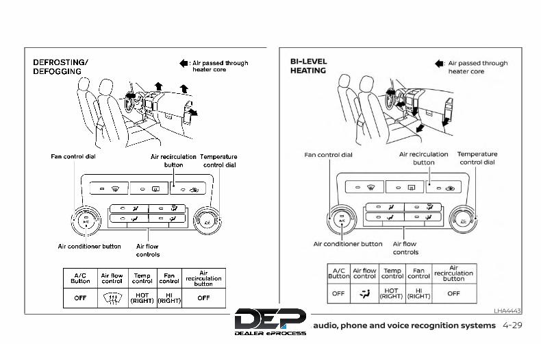
WHA0916 LHA4443
Monitor, climate, audio, phone and voice recognition systems 4-29
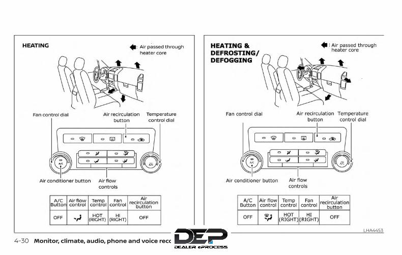
LHA4444 LHA4453
4-30 Monitor, climate, audio, phone and voice recognition systems

LHA4446
Monitor, climate, audio, phone and voice recognition systems 4-31

1. Driver temperature control dial
2. A/C (air conditioner) button
3. Front window defroster button
4. Fan speed control dial
5. OFF button
6. Fresh air intake button
7. Air recirculation button
8. Passenger temperature control dial
9. DUAL button
10. Air flow control buttons
11. AUTO button
Type A (if so equipped)LHA2886
HEATER AND AIR CONDITIONER(automatic) (if so equipped)
4-32 Monitor, climate, audio, phone and voice recognition systems
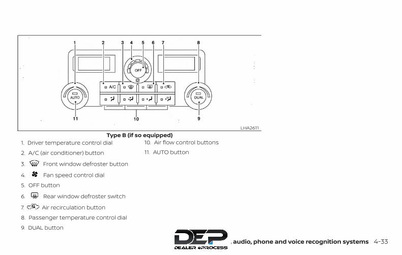
1. Driver temperature control dial
2. A/C (air conditioner) button
3. Front window defroster button
4. Fan speed control dial
5. OFF button
6. Rear window defroster switch
7. Air recirculation button
8. Passenger temperature control dial
9. DUAL button
10. Air flow control buttons
11. AUTO button
Type B (if so equipped)LHA2611
Monitor, climate, audio, phone and voice recognition systems 4-33

1. Driver temperature control dial
2. A/C (air conditioner) button
3. Front window defroster button
4. Fan speed control dial
5. OFF button
6. Outside mirror defroster switch
7. Air recirculation button
8. Passenger temperature control dial
9. DUAL button
10. Air flow control buttons
11. AUTO button
WARNING∙ The air conditioner cooling function
operates only when the engine isrunning.
∙ Do not leave children or adults whowould normally require the assis-tance of others alone in your vehicle.Pets should also not be left alone.They could accidentally injure them-selves or others through inadvertentoperation of the vehicle. Also, on hot,sunny days, temperatures in a closedvehicle could quickly become highenough to cause severe or possiblyfatal injuries to people or animals.
∙ Do not use the recirculation mode forlong periods as it may cause the inte-rior air to become stale and the win-dows to fog up.
Start the engine and operate the controlsto activate the air conditioner.
NOTE:
∙ Odors from inside and outside the ve-hicle can build up in the air condi-tioner unit. Odor can enter the pas-senger compartment through thevents.
Type C (if so equipped)LHA3168
4-34 Monitor, climate, audio, phone and voice recognition systems

∙ When parking, set the heater and airconditioner controls to turn off air re-circulation to allow fresh air into thepassenger compartment. This shouldhelp reduce odors inside the vehicle.
AUTOMATIC OPERATIONCooling or heating (auto)This mode may be normally used all yearround as the system automatically worksto keep a constant temperature. Air flowdistribution and fan speed are also con-trolled automatically.
1. Press the AUTO button on.
2. Turn the temperature dial to the left orright to set the desired temperature.Driver and passenger temperaturescan be set independently. Press DUALto activate dual climate control func-tions. Turn the passenger’s side tem-perature control dial to the left or rightto set the desired passenger’s tem-perature.
∙ Adjust the temperature dial to about75°F (24°C) for normal operation.
∙ The temperature of the passengercompartment will be maintained auto-matically. Air flow distribution, fan speedand A/C on/off are also controlled auto-matically.
∙ A visible mist may be seen coming fromthe vents in hot, humid conditions asthe air is cooled rapidly. This does notindicate a malfunction.
Heating (A/C OFF)The air conditioner does not activate. Whenyou need to heat only, use this mode.
1. Press the AUTO button.
2. Turn the temperature control dial to setthe desired temperature.
∙ The temperature of the passengercompartment will be maintained auto-matically. Air flow distribution and fanspeed are also controlled automatically.
∙ Do not set the temperature lower thanthe outside air temperature. Otherwise,the system may not work properly.
∙ Not recommended if windows fog up.
Dehumidified defrosting ordefogging
1. Press the defroster controlswitch to turn the system on. The indi-cator light in the button will illuminate.
2. Turn the temperature dial to the left orright to set the desired temperature.
∙ To quickly remove ice from the outsideof the windows, turn the manual fancontrol to the maximum position.
∙ As soon as possible after the wind-shield is clean, press the AUTO button toreturn to the auto mode.
Monitor, climate, audio, phone and voice recognition systems 4-35
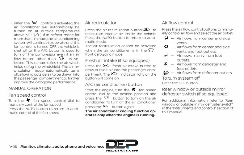
∙ When the control is activated, theair conditioner will automatically beturned on at outside temperaturesabove 36°F (2°C). If in defrost mode formore than 1 minute, the air conditioningsystem will continue to operate until thefan control is turned OFF, the vehicle isshut off or the A/C button is used toturn off the compressor even if an airflow button other than is se-lected. This dehumidifies the air whichhelps defog the windshield. The air re-circulation mode automatically turnsoff, allowing outside air to be drawn intothe passenger compartment to furtherimprove the defogging performance.
MANUAL OPERATIONFan speed controlTurn the fan speed control dial tomanually control the fan speed.Press the AUTO button to return to auto-matic control of the fan speed.
Air recirculationPress the air recirculation button torecirculate interior air inside the vehicle.Press the AUTO button to return to auto-matic mode.The air recirculation cannot be activatedwhen the air conditioner is in thefront defogging mode.
Fresh air intake (if so equipped)Press the fresh air intake button todraw outside air into the passenger com-partment. The indicator light on thebutton will come on.
A/C (air conditioner) buttonStart the engine, turn the fan speedcontrol dial to the desired position andpress the button to turn on the airconditioner. To turn off the air conditioner,press the button again.The air conditioner cooling function op-erates only when the engine is running.
Air flow controlPress the air flow control buttons to manu-ally control air flow and select the air outlet:
— Air flows from center and sidevents.
— Air flows from center and sidevents and foot outlets.
— Air flows mainly from footoutlets.
— Air flows from defroster andfoot outlets.
— Air flows from defroster outlets.To turn system offPress the OFF button.
Rear window or outside mirrordefroster switch (if so equipped)For additional information, refer to “Rearwindow or outside mirror defroster switch”in the “Instruments and controls” section ofthis manual.
4-36 Monitor, climate, audio, phone and voice recognition systems
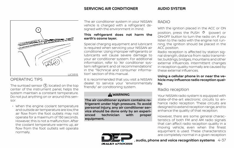
OPERATING TIPSThe sunload sensor �1 , located on the topcenter of the instrument panel, helps thesystem maintain a constant temperature.Do not put anything on or around this sen-sor.
∙ When the engine coolant temperatureand outside air temperature are low, theair flow from the foot outlets may notoperate for a maximum of 150 seconds.However, this is not a malfunction. Afterthe coolant temperature warms up, airflow from the foot outlets will operatenormally.
The air conditioner system in your NISSANvehicle is charged with a refrigerant de-signed with the environment in mind.
This refrigerant does not harm theearth’s ozone layer.
Special charging equipment and lubricantis required when servicing your NISSAN airconditioner. Using improper refrigerants orlubricants will cause severe damage toyour air conditioner system. For additionalinformation, refer to “Air conditioner sys-tem refrigerant and oil recommendations”in the “Technical and consumer informa-tion” section of this manual.
It is recommended that you visit a NISSANdealer to service your “environmentallyfriendly” air conditioning system.
WARNINGThe air conditioner system contains re-frigerant under high pressure. To avoidpersonal injury, any air conditioner ser-vice should be done only by an experi-enced technician with properequipment.
RADIOWith the ignition placed in the ACC or ONposition, press the PUSH (power) orON•OFF button to turn the radio on. If youlisten to the radio with the engine not run-ning, the ignition should be placed in theACC position.Radio reception is affected by station sig-nal strength, distance from radio transmit-ter, buildings, bridges, mountains and otherexternal influences. Intermittent changesin reception quality normally are caused bythese external influences.
Using a cellular phone in or near the ve-hicle may influence radio reception qual-ity.
Radio receptionYour NISSAN radio system is equipped withstate-of-the-art electronic circuits to en-hance radio reception. These circuits aredesigned to extend reception range, and toenhance the quality of that reception.
However, there are some general charac-teristics of both FM and AM radio signalsthat can affect radio reception quality in amoving vehicle, even when the finestequipment is used. These characteristicsare completely normal in a given reception
LIC0515
SERVICING AIR CONDITIONER AUDIO SYSTEM
Monitor, climate, audio, phone and voice recognition systems 4-37

area and do not indicate any malfunctionin your NISSAN radio system.
Reception conditions will constantlychange because of vehicle movement.Buildings, terrain, signal distance and inter-ference from other vehicles can workagainst ideal reception. Described beloware some of the factors that can affect yourradio reception.
Some cellular phones or other devices maycause interference or a buzzing noise tocome from the audio system speakers.Storing the device in a different locationmay reduce or eliminate the noise.
FM RADIO RECEPTIONRange: FM range is normally limited to 25 –30 mi (40 – 48 km), with monaural (singlechannel) FM having slightly more rangethan stereo FM. External influences maysometimes interfere with FM station re-ception even if the FM station is within 25mi (40 km). The strength of the FM signal isdirectly related to the distance betweenthe transmitter and receiver. FM signals fol-low a line-of-sight path, exhibiting many ofthe same characteristics as light. For ex-ample, they will reflect off objects.
Fade and drift: As your vehicle moves awayfrom a station transmitter, the signals willtend to fade and/or drift.
Static and flutter: During signal interfer-ence from buildings, large hills or due toantenna position (usually in conjunctionwith increased distance from the stationtransmitter), static or flutter can be heard.This can be reduced by adjusting the treblecontrol to reduce treble response.
Multipath reception: Because of the reflec-tive characteristics of FM signals, direct andreflected signals reach the receiver at thesame time. The signals may cancel eachother, resulting in momentary flutter or lossof sound.
AM RADIO RECEPTIONAM signals, because of their low frequency,can bend around objects and skip alongthe ground. In addition, the signals can bebounced off the ionosphere and bent backto earth. Because of these characteristics,AM signals are also subject to interferenceas they travel from transmitter to receiver.
Fading: Occurs while the vehicle is passingthrough freeway underpasses or in areaswith many tall buildings. It can also occur
for several seconds during ionospheric tur-bulence even in areas where no obstaclesexist.
Static: Caused by thunderstorms, electricalpower lines, electric signs and even trafficlights.
SATELLITE RADIO RECEPTION (if soequipped)When the satellite radio is used for the firsttime or the battery has been replaced, thesatellite radio may not work properly. Thisis not a malfunction. Wait more than10 minutes with satellite radio ON and thevehicle outside of any metal or large build-ing for satellite radio to receive all of thenecessary data.
No satellite radio reception is available and“NO SAT” is displayed when the SAT bandoption is selected unless optional satellitereceiver and antenna are installed and aSiriusXM® Satellite Radio service subscrip-tion is active. Satellite radio is not availablein Alaska, Hawaii and Guam.
Satellite radio performance may be af-fected if cargo carried on the roof blocksthe satellite radio signal.
4-38 Monitor, climate, audio, phone and voice recognition systems

If possible, do not put cargo over the satel-lite antenna.
A build up of ice on the satellite radio an-tenna can affect satellite radio perfor-mance. Remove the ice to restore satelliteradio reception.
AUDIO OPERATION PRECAUTIONS
Compact Disc (CD) player (if soequipped)
CAUTION∙ Do not force a compact disc into the
CD insert slot. This could damage theCD and/or CD player.
∙ Trying to load a CD with the CD doorclosed could damage the CD and/orCD player.
∙ Only one CD can be loaded into the CDplayer at a time.
∙ Only use high quality 4.7 in (12 cm)round discs that have the “COMPACTdisc DIGITAL AUDIO” logo on the discor packaging.
∙ During cold weather or rainy days, theplayer may malfunction due to thehumidity. If this occurs, remove theCD and dehumidify or ventilate theplayer completely.
∙ The player may skip while driving onrough roads.
LHA0099
Monitor, climate, audio, phone and voice recognition systems 4-39

∙ The CD player sometimes cannotfunction when the compartmenttemperature is extremely high or low.Decrease/increase the temperaturebefore use.
∙ Do not expose the CD to direct sun-light.
∙ CDs that are in poor condition or aredirty, scratched or covered with fin-gerprints may not work properly.
∙ The following CDs may not workproperly:
∙ Copy Control Compact Discs (CCCD)
∙ Recordable Compact Discs (CD-R)
∙ Rewritable Compact Discs (CD-RW)
∙ Do not use the following CDs as theymay cause the CD player to malfunc-tion:
∙ 3.1 in (8 cm) discs with an adapter
∙ CDs that are not round
∙ CDs with a paper label
∙ CDs that are warped, scratched, orhave abnormal edges
∙ This audio system can only play pre-recorded CDs. It has no capability torecord or burn CDs.
∙ If the CD cannot be played, one of thefollowing messages will be displayed.
CHECK DISC:
∙ Confirm that the CD is inserted cor-rectly (the label side is facing up,etc.).
∙ Confirm that the CD is not bent orwarped and it is free of scratches.
PRESS EJECT:
This is an error due to excessive tem-perature inside the player. Removethe CD by pressing the EJECT button.After a short time, reinsert the CD.The CD can be played when the tem-perature of the player returns to nor-mal.
UNPLAYABLE:
The file is unplayable in this audiosystem (only MP3 or WMA CD).
Compact disc with MP3 or WMA (ifso equipped)Terms
∙ MP3 — MP3 is short for Moving PicturesExperts Group Audio Layer 3. MP3 is themost well-known compressed digitalaudio file format. This format allows fornear “CD quality” sound, but at a fractionof the size of normal audio files. MP3conversion of an audio track from CD-ROM can reduce the file size by approxi-mately a 10:1 ratio with virtually no per-ceptible loss in quality. MP3compression removes the redundantand irrelevant parts of a sound signalthat the human ear doesn’t hear.
∙ WMA — Windows Media Audio (WMA)* isa compressed audio format created byMicrosoft as an alternative to MP3. TheWMA codec offers greater file compres-sion than the MP3 codec, enabling stor-age of more digital audio tracks in thesame amount of space when com-pared to MP3s at the same level of qual-ity.
4-40 Monitor, climate, audio, phone and voice recognition systems
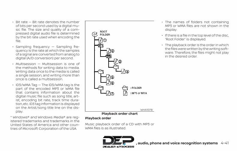
∙ Bit rate — Bit rate denotes the numberof bits per second used by a digital mu-sic file. The size and quality of a com-pressed digital audio file is determinedby the bit rate used when encoding thefile.
∙ Sampling frequency — Sampling fre-quency is the rate at which the samplesof a signal are converted from analog todigital (A/D conversion) per second.
∙ Multisession — Multisession is one ofthe methods for writing data to media.Writing data once to the media is calleda single session, and writing more thanonce is called a multisession.
∙ ID3/WMA Tag — The ID3/WMA tag is thepart of the encoded MP3 or WMA filethat contains information about thedigital music file such as song title, art-ist, encoding bit rate, track time dura-tion, etc. ID3 tag information is displayedon the Artist/song title line on the dis-play.
* Windows® and Windows Media® are reg-istered trademarks and trademarks in theUnited States of America and other coun-tries of Microsoft Corporation of the USA.
Playback order
Music playback order of a CD with MP3 orWMA files is as illustrated.
∙ The names of folders not containingMP3 or WMA files are not shown in thedisplay.
∙ If there is a file in the top level of the disc,“Root Folder” is displayed.
∙ The playback order is the order in whichthe files were written by the writing soft-ware. Therefore, the files might not playin the desired order.
Playback order chartWHA1078
Monitor, climate, audio, phone and voice recognition systems 4-41

Specification chart
Supported media CD, CD-R, CD-RWSupported file systems ISO9660 LEVEL1, ISO9660 LEVEL2, Apple ISO, Romeo, Joliet * ISO9660 Level 3 (packet writing) is not supported.
Supportedversions*1
MP3
Version MPEG1, MPEG2, MPEG2.5Sampling fre-quency
8 kHz - 48 kHz
Bit rate 8 kbps - 320 kbps, VBRWMA Version WMA7, WMA8, WMA9
Sampling fre-quency
32 kHz - 48 kHz
Bit rate 48 kbps - 192 kbps, VBRTag information ID3 tag VER1.0, VER1.1, VER2.2, VER2.3 (MP3 only)Folder levels Folder levels: 8, Max folders: 255 (including root folder), Files: 512 (Max. 255 files for one folder)Text character number limitation 128 characters
Displayable character codes*2 01: ASCII, 02: ISO-8859-1, 03: UNICODE (UTF-16 BOM Big Endian), 04: UNICODE (UTF-16 Non-BOM Big Endian), 05: UNI-CODE (UTF-8), 06: UNICODE (Non-UTF-16 BOM Little Endian)
*1 Files created with a combination of 48 kHz sampling frequency and 64 kbps bit rate cannot be played.
*2 Available codes depend on what kind of media, versions and information are going to be displayed.
4-42 Monitor, climate, audio, phone and voice recognition systems

Troubleshooting guide
Symptom Cause and Countermeasure
Cannot play
Check if the disc was inserted correctly.Check if the disc is scratched or dirty.Check if there is condensation inside the player. If there is, wait until the condensation is gone (about 1 hour) before using the player.If there is a temperature increase error, the CD player will play correctly after it returns to the normal temperature.If there is a mixture of music CD files (CD-DA data) and MP3/WMA files on a CD, only the music CD files (CD-DA data) will be played.Files with extensions other than “.MP3”,“.WMA”, “.mp3” or “.wma” cannot be played. In addition, the character codes and number of char-acters for folder names and file names should be in compliance with the specifications.Check if the finalization process, such as session close and disc close, is done for the disc.Check if the disc is protected by copyright.
Poor sound qualityCheck if the disc is scratched or dirty.Bit rate may be too low.
It takes a relatively longtime before the musicstarts playing.
If there are many folders or file levels on the MP3/WMA disc, or if it is a multisession disc, some time may be required before the musicstarts playing.
Music cuts off or skips The writing software and hardware combination might not match, or the writing speed, writing depth, writing width, etc., might notmatch the specifications. Try using the slowest writing speed.
Skipping with high bitrate files
Skipping may occur with large quantities of data, such as for high bit rate data.
Moves immediately tothe next song when play-ing
When a non-MP3/WMA file has been given an extension of “.MP3”, “.WMA”, .“mp3”or “.wma”, or when play is prohibited by copyrightprotection, there will be approximately 5 seconds of no sound and then the player will skip to the next song.
Songs do not play backin the desired order
The playback order is the order in which the files were written by the writing software. Therefore, the files might not play in the de-sired order.
Monitor, climate, audio, phone and voice recognition systems 4-43

USB (Universal Serial Bus)connection port
WARNINGDo not connect, disconnect, or operatethe USB device while driving. Doing socan be a distraction. If distracted youcould lose control of your vehicle andcause an accident or serious injury.
CAUTION∙ Do not force the USB device into the
USB port. Inserting the USB devicetilted or up-side-down into the portmay damage the port. Make sure thatthe USB device is connected correctlyinto the USB port.
∙ Do not grab the USB port cover (if soequipped) when pulling the USB de-vice out of the port. This could dam-age the port and the cover.
∙ Do not leave the USB cable in a placewhere it can be pulled unintentionally.Pulling the cable may damage theport.
The vehicle is not equipped with a USB de-vice. USB devices should be purchasedseparately as necessary.
This system cannot be used to format USBmemory devices. To format a USB device,use a personal computer.
In some jurisdictions, the USB device for thefront seats plays only sound without im-ages for regulatory reasons, even when thevehicle is parked.
This system supports various USBmemory devices, USB hard drives andiPod® players. Some USB devices may notbe supported by this system.
∙ Partitioned USB devices may not playcorrectly.
∙ Some characters used in other lan-guages (Chinese, Japanese, etc.) maynot appear properly in the display. UsingEnglish language characters with a USBdevice is recommended.
General notes for USB use
∙ For additional information, refer to yourdevice manufacturer’s owner informa-tion regarding the proper use and careof the device.
Notes for iPod® use
iPod® is a trademark of Apple Inc., regis-tered in the U.S. and other countries.
∙ Improperly plugging in the iPod® maycause a check mark to be displayed onand off (flickering). Always make surethat the iPod® is connected properly.
∙ An iPod® nano (1st Generation) may re-main in fast forward or rewind mode if itis connected during a seek operation. Inthis case, please manually reset theiPod®.
∙ An iPod® nano (2nd Generation) willcontinue to fast-forward or rewind if it isdisconnected during a seek operation.
∙ An incorrect song title may appearwhen the Play Mode is changed whileusing an iPod® nano (2nd Generation).
∙ Audiobooks may not play in the sameorder as they appear on an iPod®.
∙ Large video files cause slow responsesin an iPod®. The vehicle center displaymay momentarily black out, but willsoon recover.
4-44 Monitor, climate, audio, phone and voice recognition systems

∙ If an iPod® automatically selects largevideo files while in the shuffle mode, thevehicle center display may momen-tarily black out, but will soon recover.
Bluetooth® streaming audio∙ Some Bluetooth® audio devices may
not be recognized by the in-vehicle au-dio system.
∙ It is necessary to set up the wirelessconnection between a compatibleBluetooth® audio device and the in-vehicle Bluetooth® module before usingthe Bluetooth® audio.
∙ Operating procedure of the Bluetooth®audio will vary depending on the de-vices. Make sure how to operate youraudio device before using it with thissystem.
∙ The Bluetooth® audio may be stoppedunder the following conditions:
∙ Receiving a call on the Hands-FreePhone System.
∙ Checking the connection to thehands-free phone.
∙ Do not place the Bluetooth® audio de-vice in an area surrounded by metal orfar away from the in-vehicle Bluetooth®module to prevent tone quality degra-dation and wireless connection disrup-tion.
∙ While an audio device is connectedthrough the Bluetooth® wireless con-nection, the battery power of the devicemay discharge quicker than usual.
∙ This system supports the Bluetooth®Audio Distribution Profile (A2DP, AVRCP).
BLUETOOTH® is atrademark ownedby Bluetooth SIG,Inc. and licensedto Visteon andBosch.
Monitor, climate, audio, phone and voice recognition systems 4-45

FM/AM RADIO (if so equipped)
1. MENU button
2. AUDIO button
3. Display screen
4. / (SEEK/TRACK) buttons
5. VOL (volume) knob / PUSH(power) button
For additional information, refer to “Audiooperation precautions” regarding all opera-tion precautions in this section.
Audio main operationVOL (volume) knob / PUSH(power) buttonPlace the ignition switch in the ON positionand press the PUSH (power) buttonwhile the system is off to call up the mode(radio, AUX, Bluetooth® audio, USB or iPod®)that was playing immediately before thesystem was turned off.To turn the system off, press thePUSH (power) button.Turn the VOL (volume) knob to adjust thevolume.
This vehicle may be equipped with SpeedSensitive Volume. When this feature is ac-tive, the audio volume changes as the driv-ing speed changes.
MENU button
Press the MENU button to show theMenu screen. Touch the “Settings” key onthe display, then touch the “Sound” key.
LHA4672
4-46 Monitor, climate, audio, phone and voice recognition systems
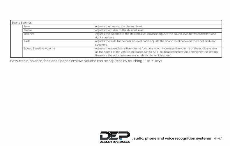
Sound SettingsBass Adjusts the bass to the desired level.Treble Adjusts the treble to the desired level.Balance Adjusts the balance to the desired level. Balance adjusts the sound level between the left and
right speakers.Fade Adjusts the fade to the desired level. Fade adjusts the sound level between the front and rear
speakers.Speed Sensitive Volume Adjusts the speed sensitive volume function, which increases the volume of the audio system
as the speed of the vehicle increases. Set to “OFF” to disable the feature. The higher the setting,the more the volume increases in relation to vehicle speed.
Bass, treble, balance, fade and Speed Sensitive Volume can be adjusted by touching “-” or “+” keys.
Monitor, climate, audio, phone and voice recognition systems 4-47

AUDIO button
Push to display the audio screen. When thisbutton is pushed while the audio screen isnot displayed, the last audio source playedwill play.
AM/FM radio screen1. “AM Menu” / “FM Menu” key
Touch to display the radio menuscreen.
2. “Direct Tune” (if so equipped)Touch to manually enter a station.
3. Audio source indicatorIndicates the currently selected audiosource.
4. Reception information displayReception information currently avail-able such as frequency, station name,etc. is displayed.
5. Preset listTo listen to a preset station, touch thecorresponding station from the presetlist. If displayed, touch the “<” or “>” keysto scroll the preset list.
AM radio operation
Press the MENU button and touch the“AM” key or press the AUDIO button andselect AM on the bottom of the Launch Barto bring up the AM display screen.If another audio source is playing when the“AM” key is pressed, the audio source play-ing will automatically be turned off and thelast radio station played will begin playing.
AM Menu
Touch the “AM Menu” key to display the AMMenu screen options:
∙ SCAN: To scan tune the stations, touchthe “AM Menu” key on the radio screenand then touch the “SCAN” key. The sta-tions will be tuned from low to high fre-quencies and stop at each broadcast-ing station for several seconds.Touching the “SCAN” key again duringthis period of several seconds will stoptuning and the radio will remain tunedto that station.
LHA4708
4-48 Monitor, climate, audio, phone and voice recognition systems

∙ Refresh: Touch the “Refresh” key to scanand update the station list displayed onthe right side of the AM Menu screen.
(SEEK/TRACK) buttons
Press the or buttons to tunefrom low to high or high to low frequenciesand to stop at the next broadcasting sta-tion.1 to 6 station memory operations
Up to six stations can be registered in thepreset list.
1. Select the AM radio band.
2. Tune to the station you wish to store.
3. Touch and hold one of the preset num-bers in the preset list.
The information such as frequency will bedisplayed on the preset list.
To select and listen to the preset stations,push or on the steering wheelbriefly or touch a preferred station on thepreset list on the radio screen.
FM radio operationPress the MENU button and touch the“FM” key or press the AUDIO button andselect FM on the bottom of the Launch Barto bring up the FM display screen.If another audio source is playing when the“FM” key is pressed, the audio source play-ing will automatically be turned off and thelast radio station played will begin playing.
The FM stereo indicator (STEREO) is shownon the screen during FM stereo reception.When the stereo broadcast signal is weak,the radio automatically changes from ste-reo to monaural reception.
FM Menu
Touch the “FM Menu” key to display the FMMenu screen options:
∙ SCAN: To scan tune the stations, touchthe “FM Menu” key on the radio screenand then touch the “SCAN” key. The sta-tions will be tuned from low to high fre-quencies and stop at each broadcast-ing stations for several seconds.Touching the “SCAN” key again duringthis period of several seconds will stoptuning and the radio will remain tunedto that station.
∙ Refresh: Touch the “Refresh” key to up-date the station list displayed on theright side of the FM Menu screen.
∙ RDS Info: Radio station and song infor-mation can be displayed on the FM dis-play screen.
(SEEK/TRACK) buttons
Press the or buttons to tunefrom low to high or high to low frequenciesand to stop at the next broadcasting sta-tion.1 to 12 Station memory operations
Up to 12 stations can be registered in thepreset list.
1. Select the FM radio band.
2. Tune to the station you wish to store.
3. Touch and hold one of the preset num-bers in the preset list.
The information such as frequency will bedisplayed on the preset list.
To select and listen to the preset stations,push or on the steering wheelbriefly or touch a preferred station on thepreset list on the radio screen.
Monitor, climate, audio, phone and voice recognition systems 4-49

Auxiliary (AUX) devices operationConnecting auxiliary devices
Connect an AUX device into the AUX inputjack located on the center console belowthe heater and air conditioner controls.
The AUX input jack accepts any standardanalog audio input such as from a portablecassette player, CD player, MP3 player orphone.
Insert a 1/8 in (3.5 mm) stereo mini plug inthe audio input jack. If a cable with a monoplug is used, the audio output may notfunction normally.
Activation and playing
Turn on the AUX device. Connect an AUXcable to the AUX device and the AUX inputjack. Select AUX mode from the audiosource menu screen or by pressing theSource button on the steering wheel.
AUX screen
∙ Audio source indicatorIndicates that the AUX source is cur-rently playing.
∙ “Volume Setting” keysTouch one of the keys to select thesound output gain from Low, Mediumand High.
∙ AUX from Launch BarTouch to change from another sourceto AUX.
Additional featuresFor additional information, refer to “iPod®player operation without Navigation Sys-tem” in this section.
For additional information, refer to “USB(Universal Serial Bus) connection port(models without Navigation System)” in thissection.
For additional information, refer to“Bluetooth® streaming audio without Navi-gation System” in this section.
Microsoft (WMA) Obligation ofLabelingAdditional Obligation of Labeling
This product is protected by certain intel-lectual property rights of MicrosoftCorporation and third parties. Use or distri-bution of such technology outside of thisproduct is prohibited without a licensefrom Microsoft or an authorized Microsoftsubsidiary and third parties.
LHA4709
4-50 Monitor, climate, audio, phone and voice recognition systems

FM/AM/SAT RADIO WITHCOMPACT DISC (CD) PLAYER (if soequipped)
1. CD eject button
2. FM-AM button
3. AUX button
4. CD insert slot
5. Backward seek button andForward seek button
6. BACK button
7. AUDIO button / TUNE knob
8. Display screen
9. ON-OFF button / VOL (volume) controlknob
10. CD button
11. SXM button*
*No satellite radio reception is availablewhen the SXM button is pressed to accesssatellite radio stations unless optional sat-ellite receiver and antenna are installedand an SiriusXM® Satellite Radio servicesubscription is active. Satellite radio is notavailable in Alaska, Hawaii and Guam.
For additional information, refer to “Audiooperation precautions” regarding all opera-tion precautions in this section.
Audio main operationON-OFF button / VOL (volume) controlknob
Place the ignition switch in the ACC or ONposition and press the ON-OFF buttonwhile the system is off to call up the mode(radio, CD, AUX, Bluetooth® audio, USB oriPod®) that was playing immediately beforethe system was turned off.
LHA2895
Monitor, climate, audio, phone and voice recognition systems 4-51

To turn the system off, press the ON-OFFbutton.
Turn the VOL (volume) control knob to ad-just the volume.
This vehicle may be equipped with SpeedSensitive Volume. When this feature is ac-tive, the audio volume changes as the driv-ing speed changes.
Audio settings
1. Press the [ ] button.
2. Touch the “Settings” key.
3. Touch the “Audio” key.Use the touch-screen to adjust the follow-ing items to the desired setting:
AudioBass Adjusts the bass to the desired level.Treble Adjusts the treble to the desired level.Balance Adjusts the balance to the desired level. Balance adjusts the sound level between the left and right
speakers.Fade Adjusts the fade to the desired level. Fade adjusts the sound level between the front and rear speakers.Speed Sensitive Vol. Adjusts the speed sensitive volume function, which increases the volume of the audio system as the
speed of the vehicle increases. Set to “ 0 ” to disable the feature. The higher the setting, the more the vol-ume increases in relation to vehicle speed.
AUX Volume Level Controls the volume level of incoming sound when an auxiliary device is connected to the system. Avail-able options are Low (Quiet), Medium, and High (Loud).
Bass, treble, balance and fade can also be adjusted by pressing the AUDIO button and turning the TUNE knob to select the item to adjust.When the desired item is shown on the display, turn the tuning to adjust and then press the AUDIO button until the display returns to themain audio screen. If the button is not pressed for approximately 10 seconds, the radio or CD display will automatically reappear.
4-52 Monitor, climate, audio, phone and voice recognition systems

SXM settings
To view the SXM settings:
1. Press the [ ] button.
2. Touch the “Settings” key.
3. Touch the “SXM” key.The signal strength, activation status andother information are displayed on thescreen.
FM/AM/SAT radio operationFM·AM button
Press the FM·AM button to change theband as follows:
AM →P1→ FM1 →FM→P2
If another audio source is playing when theFM·AM button is pressed, the audio sourceplaying will automatically be turned off andthe last radio station played will begin play-ing.
The FM stereo indicator (STEREO) is shownon the screen during FM stereo reception.When the stereo broadcast signal is weak,the radio automatically changes from ste-reo to monaural reception.
SXM band select
Pressing the SXM button will change theband as follows:
SXM1* → SXM2* → SXM3* → SXM1* (satellite,if so equipped)
When the SXM button is pressed while theignition switch is in the ACC or ON position,the radio will come on at the last stationplayed.
The last station played will also come onwhen the ON-OFF button is pressed to turnthe radio on.
*When the SXM button is pressed, the sat-ellite radio mode will be skipped unless anoptional satellite receiver and antenna areinstalled and a SiriusXM® Satellite Radioservice subscription is active. Satellite radiois not available in Alaska, Hawaii and Guam.
If a compact disc is playing when the SXMbutton is pressed, the compact disc willautomatically be turned off and the lastradio station played will come on.
While the radio is in SXM mode, the opera-tion can be controlled through the touch-screen. Touch the “Categories” key to dis-play a list of categories. Touch a categorydisplayed on the list to display optionswithin that category.
Tuning with the touch-screen
When in AM or FM mode, the radio can betuned using the touch-screen. To bring upthe visual tuner, touch the “Tune” key on thelower right corner of the screen. A screenappears with a bar running from low fre-quencies on the left to high frequencies onthe right. Touch the screen at the locationof the frequency you wish to tune and thestation will change to that frequency. Toreturn to the regular radio display screen,touch the “OK” key.
Tuning with the TUNE knob
The radio can also be manually tuned us-ing the TUNE knob. When in FM or AM mode,turn the TUNE knob to the left for lowerfrequencies or to the right for higher fre-quencies. When in SXM mode, turn theTUNE knob to change the channel.
Monitor, climate, audio, phone and voice recognition systems 4-53
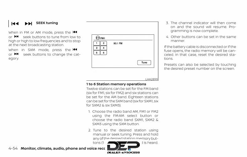
SEEK tuning
When in FM or AM mode, press theor seek buttons to tune from low tohigh or high to low frequencies and to stopat the next broadcasting station.When in SXM mode, press theor seek buttons to change the cat-egory.
1 to 6 Station memory operationsTwelve stations can be set for the FM band(six for FM1, six for FM2) and six stations canbe set for the AM band. Eighteen stationscan be set for the SXM band (six for SXM1, sixfor SXM2 & six SXM3).
1. Choose the radio band AM, FM1 or FM2using the FM·AM select button orchoose the radio band SXM1, SXM2 &SXM3 using the SXM button.
2. Tune to the desired station usingmanual or seek tuning. Press and holdany of the desired station memory but-tons (1 – 6) until a beep sound is heard.
3. The channel indicator will then comeon and the sound will resume. Pro-gramming is now complete.
4. Other buttons can be set in the samemanner.
If the battery cable is disconnected or if thefuse opens, the radio memory will be can-celed. In that case, reset the desired sta-tions.
Presets can also be selected by touchingthe desired preset number on the screen.
LHA2899
4-54 Monitor, climate, audio, phone and voice recognition systems
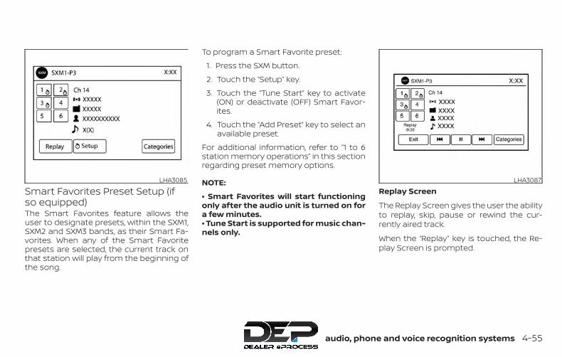
Smart Favorites Preset Setup (ifso equipped)The Smart Favorites feature allows theuser to designate presets, within the SXM1,SXM2 and SXM3 bands, as their Smart Fa-vorites. When any of the Smart Favoritepresets are selected, the current track onthat station will play from the beginning ofthe song.
To program a Smart Favorite preset:
1. Press the SXM button.
2. Touch the “Setup” key.
3. Touch the “Tune Start” key to activate(ON) or deactivate (OFF) Smart Favor-ites.
4. Touch the “Add Preset” key to select anavailable preset.
For additional information, refer to “1 to 6station memory operations” in this sectionregarding preset memory options.
NOTE:
• Smart Favorites will start functioningonly after the audio unit is turned on fora few minutes.• Tune Start is supported for music chan-nels only.
Replay Screen
The Replay Screen gives the user the abilityto replay, skip, pause or rewind the cur-rently aired track.
When the “Replay” key is touched, the Re-play Screen is prompted.
LHA3085 LHA3087
Monitor, climate, audio, phone and voice recognition systems 4-55
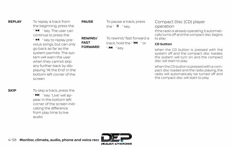
REPLAY To replay a track fromthe beginning, press the“ ” key. The user cancontinue to press the“ ” key to replay pre-vious songs, but can onlygo back as far as thesystem permits. The sys-tem will warn the userwhen they cannot skipany further back by dis-playing “At the End” in thebottom left corner of thescreen.
SKIP To skip a track, press the“ ” key. “Live” will ap-pear in the bottom leftcorner of the screen indi-cating the differencefrom play time to liveaudio.
PAUSE To pause a track, pressthe “ ” key.
REWIND/FASTFORWARD
To rewind/ fast forward atrack, hold the “ ” or“ ” key.
Compact Disc (CD) playeroperationIf the radio is already operating, it automati-cally turns off and the compact disc beginsto play.
CD button
When the CD button is pressed with thesystem off and the compact disc loaded,the system will turn on and the compactdisc will start to play.
When the CD button is pressed with a com-pact disc loaded and the radio playing, theradio will automatically be turned off andthe compact disc will start to play.
4-56 Monitor, climate, audio, phone and voice recognition systems
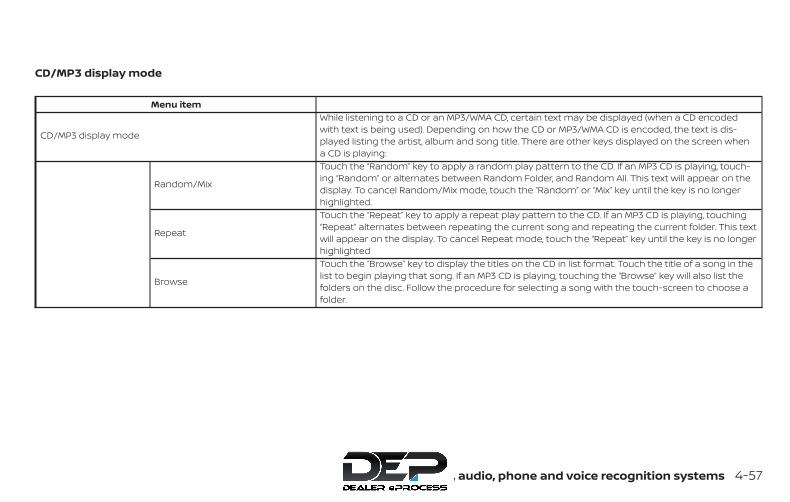
CD/MP3 display mode
Menu item
CD/MP3 display mode
While listening to a CD or an MP3/WMA CD, certain text may be displayed (when a CD encodedwith text is being used). Depending on how the CD or MP3/WMA CD is encoded, the text is dis-played listing the artist, album and song title. There are other keys displayed on the screen whena CD is playing:
Random/Mix
Touch the “Random” key to apply a random play pattern to the CD. If an MP3 CD is playing, touch-ing “Random” or alternates between Random Folder, and Random All. This text will appear on thedisplay. To cancel Random/Mix mode, touch the “Random” or “Mix” key until the key is no longerhighlighted.
Repeat
Touch the “Repeat” key to apply a repeat play pattern to the CD. If an MP3 CD is playing, touching“Repeat” alternates between repeating the current song and repeating the current folder. This textwill appear on the display. To cancel Repeat mode, touch the “Repeat” key until the key is no longerhighlighted
Browse
Touch the “Browse” key to display the titles on the CD in list format. Touch the title of a song in thelist to begin playing that song. If an MP3 CD is playing, touching the “Browse” key will also list thefolders on the disc. Follow the procedure for selecting a song with the touch-screen to choose afolder.
Monitor, climate, audio, phone and voice recognition systems 4-57
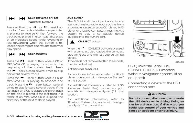
SEEK (Reverse or FastForward) buttons
Press and hold the or seek but-tons for 1.5 seconds while the compact discis playing to reverse or fast forward thetrack being played. The compact disc playsat an increased speed while reversing orfast forwarding. When the button is re-leased, the compact disc returns to normalplay speed.
SEEK buttons
Press the seek button while a CD orMP3/WMA CD is playing to return to thebeginning of the current track. Pressthe seek button several times to skipbackward several tracks.Press the seek button while a CD orMP3/WMA CD is playing to advance onetrack. Press the seek button severaltimes to skip forward several tracks. If thelast track on a CD is skipped, the first trackon the disc is played. If the last track in afolder of an MP3/WMA CD is skipped, thefirst track of the next folder is played.
AUX buttonThe AUX IN audio input port accepts anystandard analog audio input such as froma portable cassette tape/CD player, MP3player or a laptop computer. Press the AUXbutton to play a compatible deviceplugged into the AUX IN port.
CD EJECT button
When the CD EJECT button is pressedwith a compact disc loaded, the compactdisc will eject and the last source will beplayed.If the disc is not removed within 10 seconds,the disc will reload.
Additional featuresFor additional information, refer to “iPod®player operation with Navigation System”in this section.
For additional information, refer to “USB(Universal Serial Bus) connection port(models with Navigation System)” in thissection.
For additional information, refer to“Bluetooth® streaming audio with Naviga-tion System” in this section.
USB (Universal Serial Bus)CONNECTION PORT (modelswithout Navigation System) (if soequipped)Connecting a device to the USBconnection port
WARNINGDo not connect, disconnect, or operatethe USB device while driving. Doing socan be a distraction. If distracted youcould lose control of your vehicle andcause an accident or serious injury.
LHA4319
4-58 Monitor, climate, audio, phone and voice recognition systems
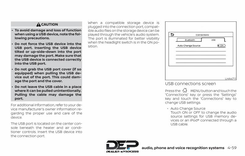
CAUTION∙ To avoid damage and loss of function
when using a USB device, note the fol-lowing precautions.
∙ Do not force the USB device into theUSB port. Inserting the USB devicetilted or up-side-down into the portmay damage the port. Make sure thatthe USB device is connected correctlyinto the USB port.
∙ Do not grab the USB port cover (if soequipped) when pulling the USB de-vice out of the port. This could dam-age the port and the cover.
∙ Do not leave the USB cable in a placewhere it can be pulled unintentionally.Pulling the cable may damage theport.
For additional information, refer to your de-vice manufacturer’s owner information re-garding the proper use and care of thedevice.
The USB port is located on the center con-sole beneath the heater and air condi-tioner controls. Insert the USB device intothe connection port.
When a compatible storage device isplugged into the connection port, compat-ible audio files on the storage device can beplayed through the vehicle’s audio system.The port is illuminated for better visibilitywhen the headlight switch is in the ON po-sition.
USB connections screenPress the MENU button and touch the“Connections” key or press the “Settings”key and touch the “Connections” key tochange USB settings.
∙ Auto Change SourceTouch ON or OFF to change the audiosource settings for USB memory de-vices or an iPod® connected through aUSB cable.
LHA4711
Monitor, climate, audio, phone and voice recognition systems 4-59
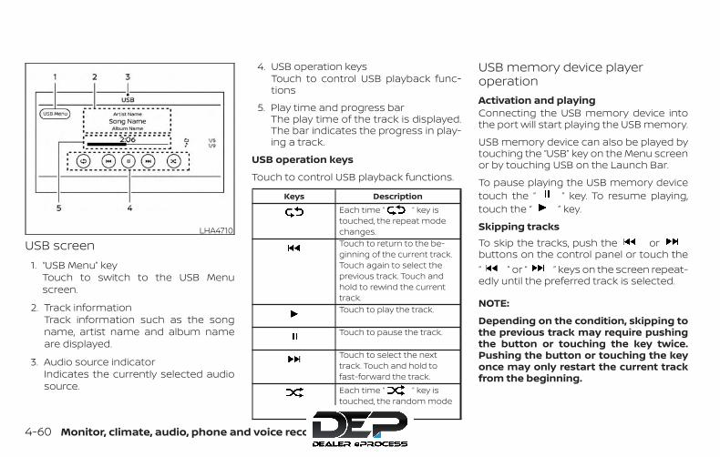
USB screen1. “USB Menu” key
Touch to switch to the USB Menuscreen.
2. Track informationTrack information such as the songname, artist name and album nameare displayed.
3. Audio source indicatorIndicates the currently selected audiosource.
4. USB operation keysTouch to control USB playback func-tions
5. Play time and progress barThe play time of the track is displayed.The bar indicates the progress in play-ing a track.
USB operation keys
Touch to control USB playback functions.
Keys DescriptionEach time “ ” key istouched, the repeat modechanges.Touch to return to the be-ginning of the current track.Touch again to select theprevious track. Touch andhold to rewind the currenttrack.Touch to play the track.
Touch to pause the track.
Touch to select the nexttrack. Touch and hold tofast-forward the track.Each time “ ” key istouched, the random modechanges.
USB memory device playeroperationActivation and playingConnecting the USB memory device intothe port will start playing the USB memory.
USB memory device can also be played bytouching the “USB” key on the Menu screenor by touching USB on the Launch Bar.
To pause playing the USB memory devicetouch the “ ” key. To resume playing,touch the “ ” key.
Skipping tracksTo skip the tracks, push the orbuttons on the control panel or touch the“ ” or “ ” keys on the screen repeat-edly until the preferred track is selected.
NOTE:
Depending on the condition, skipping tothe previous track may require pushingthe button or touching the key twice.Pushing the button or touching the keyonce may only restart the current trackfrom the beginning.
LHA4710
4-60 Monitor, climate, audio, phone and voice recognition systems
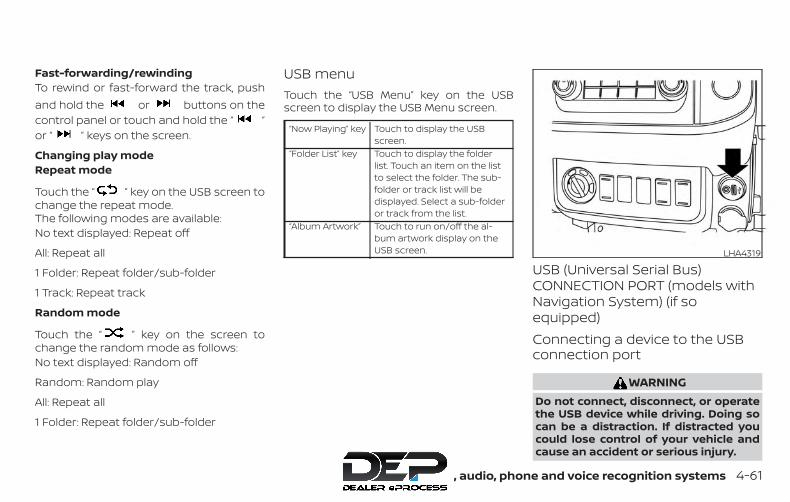
Fast-forwarding/rewindingTo rewind or fast-forward the track, pushand hold the or buttons on thecontrol panel or touch and hold the “ ”or “ ” keys on the screen.
Changing play modeRepeat mode
Touch the “ ” key on the USB screen tochange the repeat mode.The following modes are available:No text displayed: Repeat off
All: Repeat all
1 Folder: Repeat folder/sub-folder
1 Track: Repeat track
Random mode
Touch the “ ” key on the screen tochange the random mode as follows:No text displayed: Random off
Random: Random play
All: Repeat all
1 Folder: Repeat folder/sub-folder
USB menuTouch the “USB Menu” key on the USBscreen to display the USB Menu screen.
“Now Playing” key Touch to display the USBscreen.
“Folder List” key Touch to display the folderlist. Touch an item on the listto select the folder. The sub-folder or track list will bedisplayed. Select a sub-folderor track from the list.
“Album Artwork” Touch to run on/off the al-bum artwork display on theUSB screen.
USB (Universal Serial Bus)CONNECTION PORT (models withNavigation System) (if soequipped)Connecting a device to the USBconnection port
WARNINGDo not connect, disconnect, or operatethe USB device while driving. Doing socan be a distraction. If distracted youcould lose control of your vehicle andcause an accident or serious injury.
LHA4319
Monitor, climate, audio, phone and voice recognition systems 4-61

CAUTION∙ Do not force the USB device into the
USB port. Inserting the USB devicetilted or up-side-down into the portmay damage the port. Make sure thatthe USB device is connected correctlyinto the USB port.
∙ Do not grab the USB port cover (if soequipped) when pulling the USB de-vice out of the port. This could dam-age the port and the cover.
∙ Do not leave the USB cable in a placewhere it can be pulled unintentionally.Pulling the cable may damage theport.
For additional information, refer to your de-vice manufacturer’s owner information re-garding the proper use and care of thedevice.
The USB port is located on the instrumentpanel. Insert the USB device into the instru-ment panel.
When a compatible storage device isplugged into the connection port, compat-ible audio files on the storage device can beplayed through the vehicle’s audio system.
Audio file operationAUX (auxiliary) button
Place the ignition switch in the ON or ACCposition and press the AUX button toswitch to the USB input mode. If anotheraudio source is playing and a USB connec-tion port device is inserted, press the AUXbutton until the center display changes tothe USB memory mode.
If the system has been turned off while theUSB memory was playing, press the ON-OFF button to restart the USB memory.
Play information
Information about the audio files beingplayed is shown on the display screen ofthe vehicle’s audio system. Touch “Browse”to display the list of folders and files on theUSB device. Touch the name of a song onthe screen to begin playing that song.
Seeking buttons
Press the seeking button while anaudio file on the USB device is playing toreturn to the beginning of the current track.Press the seeking button severaltimes to skip backward several tracks.
LHA4006
4-62 Monitor, climate, audio, phone and voice recognition systems
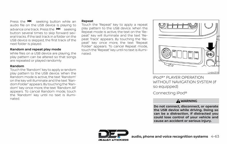
Press the seeking button while anaudio file on the USB device is playing toadvance one track. Press the seekingbutton several times to skip forward sev-eral tracks. If the last track in a folder on theUSB device is skipped, the first track of thenext folder is played.
Random and repeat play modeWhile files on a USB device are playing, theplay pattern can be altered so that songsare repeated or played randomly.
RandomTouch the “Random” key to apply a randomplay pattern to the USB device. When theRandom mode is active, the text “Random”on the key will illuminate and the text “Ran-dom Folder” appears. By touching the “Ran-dom” key once more, the text “Random All”appears. To cancel Random mode, touchthe “Random” key until no text is illumi-nated.
RepeatTouch the “Repeat” key to apply a repeatplay pattern to the USB device. When theRepeat mode is active, the text on the “Re-peat” key will illuminate and the text “Re-peat Track” appears. By touching the “Re-peat” key once more, the text “RepeatFolder” appears. To cancel Repeat mode,touch the “Repeat” key until no text is illumi-nated.
iPod®* PLAYER OPERATIONWITHOUT NAVIGATION SYSTEM (ifso equipped)Connecting iPod®
WARNINGDo not connect, disconnect, or operatethe USB device while driving. Doing socan be a distraction. If distracted youcould lose control of your vehicle andcause an accident or serious injury.
LHA4319
Monitor, climate, audio, phone and voice recognition systems 4-63
CAUTION∙ Do not force the USB device into the
USB port. Inserting the USB devicetilted or up-side-down into the portmay damage the port. Make sure thatthe USB device is connected correctlyinto the USB port.
∙ Do not grab the USB port cover (if soequipped) when pulling the USB de-vice out of the port. This could dam-age the port and the cover.
∙ Do not leave the USB cable in a placewhere it can be pulled unintentionally.Pulling the cable may damage theport.
For additional information, refer to your de-vice manufacturer’s owner information re-garding the proper use and care of thedevice.
To connect an iPod® to the vehicle so thatthe iPod® can be controlled with the audiosystem controls and display screen, usethe USB connection port located on thecenter console below the heater and airconditioner controls. Connect the iPod®-specific end of the cable to the iPod® andthe USB end of the cable to the USB con-nection port on the vehicle. If your iPod®
supports charging via a USB connection, itsbattery will be charged while connected tothe vehicle with the ignition switch in theON position. The port is illuminated for bet-ter visibility when the headlight switch is inthe ON position.
While connected to the vehicle, the iPod®can only be operated by the vehicle audiocontrols.
To disconnect the iPod® from the vehicle,remove the USB end of the cable from theUSB connection port on the vehicle, thenremove the cable from the iPod®.
* iPod® is a trademark of Apple Inc., regis-tered in the U.S. and other countries.
CompatibilityThe following models are compatible:
∙ iPod® Classic 5th generation (firmwareversion 1.3.0 or later)
∙ iPod® Classic 6th generation (firmwareversion 2.0.1 or later)
∙ iPod® Classic 7th generation (firmwareversion 2.0.4 or later)
∙ iPod® Touch 2nd generation (firmwareversion 4.2.1 or later)*
∙ iPod® Touch 3rd generation (firmwareversion 5.1 or later)
∙ iPod® Touch 4th generation (firmwareversion 5.1 or later)
∙ iPod® nano - 1st generation (firmwareversion 1.3.1 or later)
∙ iPod® nano - 2nd generation (firmwareversion 1.1.3 or later)
∙ iPod® nano - 3rd generation (firmwareversion 1.1.3 or later)
∙ iPod® nano - 4th generation (firmwareversion 1.0.4 or later)
∙ iPod® nano - 5th generation (firmwareversion 1.0.2 or later)
∙ iPod® nano - 6th generation (firmwareversion 1.1 or later)
∙ iPhone® 3G (firmware version 4.2.1 orlater)
∙ iPhone® 3GS (firmware version 5.1 orlater)
∙ iPhone® 4 (firmware version 5.1 or later)
∙ iPhone® 4S (firmware version 5.1 or later)
* Some features of this iPod® may not befully functional.
4-64 Monitor, climate, audio, phone and voice recognition systems
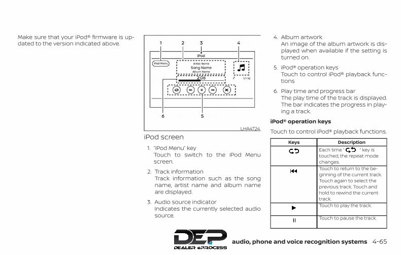
Make sure that your iPod® firmware is up-dated to the version indicated above.
iPod screen1. “iPod Menu” key
Touch to switch to the iPod Menuscreen.
2. Track informationTrack information such as the songname, artist name and album nameare displayed.
3. Audio source indicatorIndicates the currently selected audiosource.
4. Album artworkAn image of the album artwork is dis-played when available if the setting isturned on.
5. iPod® operation keysTouch to control iPod® playback func-tions
6. Play time and progress barThe play time of the track is displayed.The bar indicates the progress in play-ing a track.
iPod® operation keys
Touch to control iPod® playback functions.
Keys DescriptionEach time “ ” key istouched, the repeat modechanges.Touch to return to the be-ginning of the current track.Touch again to select theprevious track. Touch andhold to rewind the currenttrack.Touch to play the track.
Touch to pause the track.
LHA4724
Monitor, climate, audio, phone and voice recognition systems 4-65
Keys DescriptionTouch to select the nexttrack. Touch and hold tofast-forward the track.Each time “ ” key istouched, the random modechanges.
iPod® memory device playeroperationActivation and playing
Connecting the iPod® to the vehicle via USBcable will activate the iPod® mode.
The iPod® can also be played by touchingthe “iPod” key on the Menu screen or bytouching iPod on the Launch Bar.
Skipping tracks
To skip the tracks, push the orbuttons on the control panel or touch the“ ” or “ ” keys on the screen repeat-edly until the preferred track is selected.
NOTE:
Depending on the condition, skipping tothe previous track may require pushingthe button or touching the key twice.Pushing the button or touching the keyonce may only restart the current trackfrom the beginning.
Fast-forwarding/rewinding
To rewind or fast-forward the track, pushand hold the or buttons on thecontrol panel or touch and hold the “ ”or “ ” keys on the screen,
Changing play modeRepeat mode
Touch the “ ” key on the iPod® screento change the repeat mode. The followingmodes are available.No text displayed: Repeat off
All: Repeat all
One: Repeat track
Random mode
Touch the “ ” key on the screen tochange the random mode as follows.No text displayed: Random off
Songs: Random play
iPod® MenuTouch the “iPod Menu” key on the iPod®screen to display the iPod® Menu screen.
“Now Playing” key Touch to display the USBscreen.
“Folder List” key(if so equipped)
Touch to display the folderlist. Touch an item on the listto select the folder. The sub-folder or track list will bedisplayed. Select a sub-folderor track from the list.
“Album Artwork”key
Touch to run on/off the al-bum artwork display on theUSB screen.
“Playlists” key Touch to display the list ac-cording to the selected item.“Artists” key
“Albums” key“Songs” key“Podcasts” key“Genres” key“Composers” key“Audiobooks” key“iTunes Radio”key
4-66 Monitor, climate, audio, phone and voice recognition systems

iPod®* PLAYER OPERATION WITHNAVIGATION SYSTEM (if soequipped)Connecting iPod®
WARNINGDo not connect, disconnect or operatethe USB device while driving. Doing socan be a distraction. If distracted youcould lose control of your vehicle andcause an accident or serious injury.
CAUTION∙ Do not force the USB device into the
USB port. Inserting the USB devicetilted or up-side-down into the portmay damage the port. Make sure thatthe USB device is connected correctlyinto the USB port.
∙ Do not grab the USB port cover (if soequipped) when pulling the USB de-vice out of the port. This could dam-age the port and the cover.
∙ Do not leave the USB cable in a placewhere it can be pulled unintentionally.Pulling the cable may damage theport.
For additional information, refer to your de-vice manufacturer’s owner information re-garding the proper use and care of thedevice.
To connect an iPod® to the vehicle so thatthe iPod® can be controlled with the audiosystem controls and display screen, usethe USB port located on the instrumentpanel. Connect the iPod®-specific end ofthe cable to the iPod® and the USB end ofthe cable to the USB port on the vehicle. Ifyour iPod® supports charging via a USBconnection, its battery will be charged
while connected to the vehicle with the ig-nition switch in the ACC or ON position.
While connected to the vehicle, the iPod®can only be operated by the vehicle audiocontrols.
To disconnect the iPod® from the vehicle,remove the USB end of the cable from theUSB port on the vehicle, then remove thecable from the iPod®.
* iPod® is a trademark of Apple Inc., regis-tered in the U.S. and other countries.
CompatibilityThe following models are compatible:
∙ iPod® Classic 5th generation (firmwareversion 1.3.0 or later)
∙ iPod® Classic 6th generation (firmwareversion 2.0.1 or later)
∙ iPod® Classic 7th generation (firmwareversion 2.0.4 or later)
∙ iPod® Touch 2nd generation (firmwareversion 4.2.1 or later)*
∙ iPod® Touch 3rd generation (firmwareversion 5.1 or later)
∙ iPod® Touch 4th generation (firmwareversion 5.1 or later)
LHA4319
Monitor, climate, audio, phone and voice recognition systems 4-67
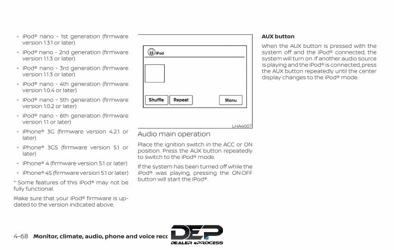
∙ iPod® nano - 1st generation (firmwareversion 1.3.1 or later)
∙ iPod® nano - 2nd generation (firmwareversion 1.1.3 or later)
∙ iPod® nano - 3rd generation (firmwareversion 1.1.3 or later)
∙ iPod® nano - 4th generation (firmwareversion 1.0.4 or later)
∙ iPod® nano - 5th generation (firmwareversion 1.0.2 or later)
∙ iPod® nano - 6th generation (firmwareversion 1.1 or later)
∙ iPhone® 3G (firmware version 4.2.1 orlater)
∙ iPhone® 3GS (firmware version 5.1 orlater)
∙ iPhone® 4 (firmware version 5.1 or later)
∙ iPhone® 4S (firmware version 5.1 or later)
* Some features of this iPod® may not befully functional.
Make sure that your iPod® firmware is up-dated to the version indicated above.
Audio main operationPlace the ignition switch in the ACC or ONposition. Press the AUX button repeatedlyto switch to the iPod® mode.
If the system has been turned off while theiPod® was playing, pressing the ON·OFFbutton will start the iPod®.
AUX button
When the AUX button is pressed with thesystem off and the iPod® connected, thesystem will turn on. If another audio sourceis playing and the iPod® is connected, pressthe AUX button repeatedly until the centerdisplay changes to the iPod® mode.
LHA4007
4-68 Monitor, climate, audio, phone and voice recognition systems
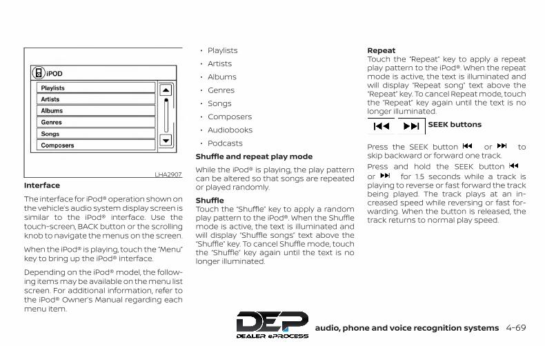
Interface
The interface for iPod® operation shown onthe vehicle’s audio system display screen issimilar to the iPod® interface. Use thetouch-screen, BACK button or the scrollingknob to navigate the menus on the screen.
When the iPod® is playing, touch the “Menu”key to bring up the iPod® interface.
Depending on the iPod® model, the follow-ing items may be available on the menu listscreen. For additional information, refer tothe iPod® Owner’s Manual regarding eachmenu item.
∙ Playlists
∙ Artists
∙ Albums
∙ Genres
∙ Songs
∙ Composers
∙ Audiobooks
∙ Podcasts
Shuffle and repeat play mode
While the iPod® is playing, the play patterncan be altered so that songs are repeatedor played randomly.
ShuffleTouch the “Shuffle” key to apply a randomplay pattern to the iPod®. When the Shufflemode is active, the text is illuminated andwill display “Shuffle songs” text above the“Shuffle” key. To cancel Shuffle mode, touchthe “Shuffle” key again until the text is nolonger illuminated.
RepeatTouch the “Repeat” key to apply a repeatplay pattern to the iPod®. When the repeatmode is active, the text is illuminated andwill display “Repeat song” text above the“Repeat” key. To cancel Repeat mode, touchthe “Repeat” key again until the text is nolonger illuminated.
SEEK buttons
Press the SEEK button or toskip backward or forward one track.Press and hold the SEEK buttonor for 1.5 seconds while a track isplaying to reverse or fast forward the trackbeing played. The track plays at an in-creased speed while reversing or fast for-warding. When the button is released, thetrack returns to normal play speed.
LHA2907
Monitor, climate, audio, phone and voice recognition systems 4-69

Scrolling menusWhile navigating long lists of artists, al-bums or songs in the music menu, it ispossible to scroll the list by the first charac-ter in the name. To activate character in-dexing, touch and hold the “A-Z” key in theupper right corner of the screen. Turn theTUNE knob to choose the number or letterto jump to in the list and then press theENTER/AUDIO button.
If no character is selected after a few sec-onds, the display returns to normal.
BLUETOOTH® STREAMING AUDIOWITHOUT NAVIGATION SYSTEM (ifso equipped)If you have a compatible Bluetooth® audiodevice that is capable of playing audio files,the device can be connected to the vehi-cle’s audio system so that the audio files onthe device play through the vehicle’sspeakers.
Connecting procedure
NOTE:
The connecting procedure must be per-formed when the vehicle is stationary. Ifthe vehicle starts moving during the pro-cedure, the procedure will be canceled.
LHA2279 LHA4726
4-70 Monitor, climate, audio, phone and voice recognition systems
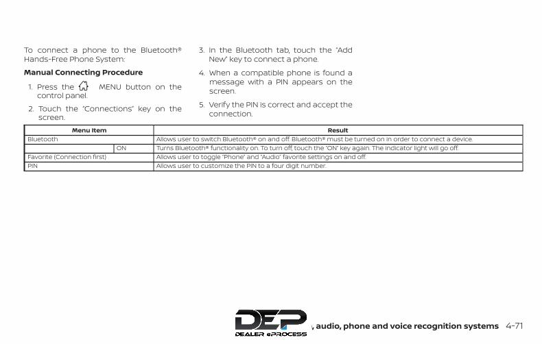
To connect a phone to the Bluetooth®Hands-Free Phone System:
Manual Connecting Procedure
1. Press the MENU button on thecontrol panel.
2. Touch the “Connections” key on thescreen.
3. In the Bluetooth tab, touch the “AddNew” key to connect a phone.
4. When a compatible phone is found amessage with a PIN appears on thescreen.
5. Verify the PIN is correct and accept theconnection.
Menu Item ResultBluetooth Allows user to switch Bluetooth® on and off. Bluetooth® must be turned on in order to connect a device.
ON Turns Bluetooth® functionality on. To turn off, touch the “ON” key again. The indicator light will go off.Favorite (Connection first) Allows user to toggle “Phone” and “Audio” favorite settings on and off.PIN Allows user to customize the PIN to a four digit number.
Monitor, climate, audio, phone and voice recognition systems 4-71
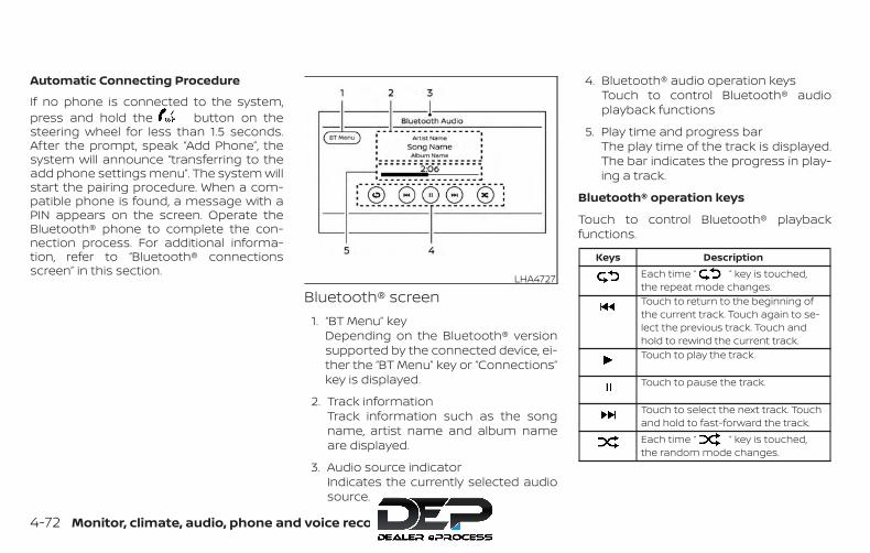
Automatic Connecting Procedure
If no phone is connected to the system,press and hold the button on thesteering wheel for less than 1.5 seconds.After the prompt, speak “Add Phone”, thesystem will announce “transferring to theadd phone settings menu”. The system willstart the pairing procedure. When a com-patible phone is found, a message with aPIN appears on the screen. Operate theBluetooth® phone to complete the con-nection process. For additional informa-tion, refer to “Bluetooth® connectionsscreen” in this section.
Bluetooth® screen1. “BT Menu” key
Depending on the Bluetooth® versionsupported by the connected device, ei-ther the “BT Menu” key or “Connections”key is displayed.
2. Track informationTrack information such as the songname, artist name and album nameare displayed.
3. Audio source indicatorIndicates the currently selected audiosource.
4. Bluetooth® audio operation keysTouch to control Bluetooth® audioplayback functions
5. Play time and progress barThe play time of the track is displayed.The bar indicates the progress in play-ing a track.
Bluetooth® operation keys
Touch to control Bluetooth® playbackfunctions.
Keys DescriptionEach time “ ” key is touched,the repeat mode changes.Touch to return to the beginning ofthe current track. Touch again to se-lect the previous track. Touch andhold to rewind the current track.Touch to play the track.
Touch to pause the track.
Touch to select the next track. Touchand hold to fast-forward the track.Each time “ ” key is touched,the random mode changes.
LHA4727
4-72 Monitor, climate, audio, phone and voice recognition systems

Bluetooth® audio operationThe ability to pause, change tracks, fastforward, rewind, randomize and repeatmusic may be different between devices.Some or all of these functions may not besupported on each device.
NOTE:
Depending on the Bluetooth® audio de-vice that is connected, it may not be pos-sible to perform audio operations or adelay may occur before music is playedback.
Activation and playing
A Bluetooth® audio device can be played bytouching the “Bluetooth” key on the Menuscreen or by touching Bluetooth on theLaunch Bar.
To pause playing the Bluetooth® audio,touch the “ ” key. Touch the “ ” keyto resume playing.
Changing foldersTo change folders, touch the “BT Menu” key.
Fast-forwarding/rewinding
To fast-forward or rewind the track, pushand hold the or buttons on thecontrol panel or touch the “ ” or “ ”keys on the screen.
Changing play modeRepeat mode
Touch the “ ” key on the screen tochange the repeat mode.Random mode
Touch the “ ” key on the screen tochange the random mode.
NOTE:
Available repeat/random modes changedepending on the connected device.
BT MenuTouch the “BT Menu” key on the Bluetooth®audio screen to display the Bluetooth® au-dio menu screen.
The following items are available.
“Now Playing” key Touch to display theBluetooth® audio screen.
“Current List” key (if soequipped)*
A list of track in the cur-rently selected folder isdisplayed.
“Connections” key Touch to display theconnections screen.
“Folder List” key* Touch to display thefolder list. Touch an itemon the list to select thefolder.
*: displayed only when available.
NOTE:
Depending on the connected device, the“BT Menu” key may not be displayed.
BLUETOOTH® STREAMING AUDIOWITH NAVIGATION SYSTEM (if soequipped)If you have a compatible Bluetooth® audiodevice that is capable of playing audio files,the device can be connected to the vehi-cle’s audio system so that the audio files onthe device play through the vehicle’sspeakers.
Monitor, climate, audio, phone and voice recognition systems 4-73
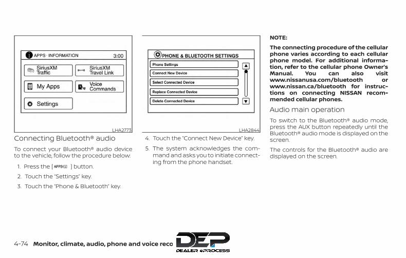
Connecting Bluetooth® audioTo connect your Bluetooth® audio deviceto the vehicle, follow the procedure below:
1. Press the [ ] button.
2. Touch the “Settings” key.
3. Touch the “Phone & Bluetooth” key.
4. Touch the “Connect New Device” key.
5. The system acknowledges the com-mand and asks you to initiate connect-ing from the phone handset.
NOTE:
The connecting procedure of the cellularphone varies according to each cellularphone model. For additional informa-tion, refer to the cellular phone Owner’sManual. You can also visitwww.nissanusa.com/bluetooth orwww.nissan.ca/bluetooth for instruc-tions on connecting NISSAN recom-mended cellular phones.
Audio main operationTo switch to the Bluetooth® audio mode,press the AUX button repeatedly until theBluetooth® audio mode is displayed on thescreen.
The controls for the Bluetooth® audio aredisplayed on the screen.
LHA2773 LHA2844
4-74 Monitor, climate, audio, phone and voice recognition systems
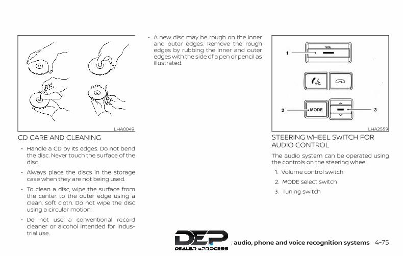
CD CARE AND CLEANING∙ Handle a CD by its edges. Do not bend
the disc. Never touch the surface of thedisc.
∙ Always place the discs in the storagecase when they are not being used.
∙ To clean a disc, wipe the surface fromthe center to the outer edge using aclean, soft cloth. Do not wipe the discusing a circular motion.
∙ Do not use a conventional recordcleaner or alcohol intended for indus-trial use.
∙ A new disc may be rough on the innerand outer edges. Remove the roughedges by rubbing the inner and outeredges with the side of a pen or pencil asillustrated.
STEERING WHEEL SWITCH FORAUDIO CONTROLThe audio system can be operated usingthe controls on the steering wheel.
1. Volume control switch
2. MODE select switch
3. Tuning switch
LHA0049 LHA2559
Monitor, climate, audio, phone and voice recognition systems 4-75
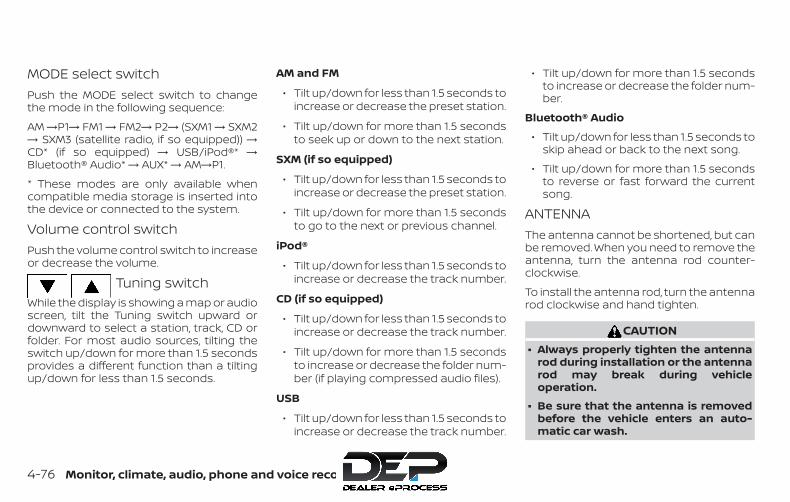
MODE select switchPush the MODE select switch to changethe mode in the following sequence:
AM →P1→ FM1 → FM2→ P2→ (SXM1 → SXM2→ SXM3 (satellite radio, if so equipped)) →CD* (if so equipped) → USB/iPod®* →Bluetooth® Audio* → AUX* → AM→P1.
* These modes are only available whencompatible media storage is inserted intothe device or connected to the system.
Volume control switchPush the volume control switch to increaseor decrease the volume.
Tuning switchWhile the display is showing a map or audioscreen, tilt the Tuning switch upward ordownward to select a station, track, CD orfolder. For most audio sources, tilting theswitch up/down for more than 1.5 secondsprovides a different function than a tiltingup/down for less than 1.5 seconds.
AM and FM
∙ Tilt up/down for less than 1.5 seconds toincrease or decrease the preset station.
∙ Tilt up/down for more than 1.5 secondsto seek up or down to the next station.
SXM (if so equipped)
∙ Tilt up/down for less than 1.5 seconds toincrease or decrease the preset station.
∙ Tilt up/down for more than 1.5 secondsto go to the next or previous channel.
iPod®
∙ Tilt up/down for less than 1.5 seconds toincrease or decrease the track number.
CD (if so equipped)
∙ Tilt up/down for less than 1.5 seconds toincrease or decrease the track number.
∙ Tilt up/down for more than 1.5 secondsto increase or decrease the folder num-ber (if playing compressed audio files).
USB
∙ Tilt up/down for less than 1.5 seconds toincrease or decrease the track number.
∙ Tilt up/down for more than 1.5 secondsto increase or decrease the folder num-ber.
Bluetooth® Audio
∙ Tilt up/down for less than 1.5 seconds toskip ahead or back to the next song.
∙ Tilt up/down for more than 1.5 secondsto reverse or fast forward the currentsong.
ANTENNAThe antenna cannot be shortened, but canbe removed. When you need to remove theantenna, turn the antenna rod counter-clockwise.
To install the antenna rod, turn the antennarod clockwise and hand tighten.
CAUTION∙ Always properly tighten the antenna
rod during installation or the antennarod may break during vehicleoperation.
∙ Be sure that the antenna is removedbefore the vehicle enters an auto-matic car wash.
4-76 Monitor, climate, audio, phone and voice recognition systems

This vehicle is equipped with SmartphoneIntegration technology. This allows manycompatible Smartphone applications tobe displayed and easily controlled throughthe vehicle’s touch-screen.
NOTE:
A compatible smartphone and registra-tion is required to use mobile applica-tions or to access connected features ofcertain vehicle applications.
REGISTERING WITHNISSANCONNECT® MOBILE APPSTo use the Smartphone Integration feature,it is necessary for the user to register. Inorder to register, visit the NissanConnect®Mobile Apps website,www.nissanusa.com/connect/ orwww.nissan.ca/en/connect orwww.nissan.ca/fr/connect and sign up orcreate an account through the prompts onthe NissanConnect® Mobile Apps. Onceregistered, download the NissanConnect®Mobile Apps from your compatible phone’sapplication download source and then loginto the application. If you already have anaccount created through the App, pleaselog in.
CONNECT PHONETo use this feature, a compatible smart-phone must be connected via Bluetooth®or USB to the vehicle. For additional infor-mation, refer to “Bluetooth® Hands-FreePhone System with Navigation System” inthis section.
NOTE:
Apple iPhones® require the phone to beplugged in via USB for NissanConnect®Mobile Apps to function.For Android phones, NissanConnect®Mobile Apps requires the phone to bepaired via Bluetooth®.
APPLICATION DOWNLOADOnce connected, the NissanConnect® Appwill search your phone to determine whichcompatible applications are currently in-stalled. The user will then choose whichapps they want to bring into their vehiclefrom the list of apps within the “Manage MyApps” section of the NissanConnect® Appon their smartphone. The vehicle will thendownload the in-vehicle interface for eachof these compatible applications. Oncedownloaded, the user can access their se-lected smartphone applications throughthe vehicle touch-screen. For additional in-formation, refer to www.nissanusa.com/connect or www.nissan.ca/en/connect orwww.nissan.ca/fr/connect regardingapplication availability.
NISSANCONNECT® MOBILE APPS (ifso equipped)
Monitor, climate, audio, phone and voice recognition systems 4-77

Apple Siri® Eyes Free personal assistantcan be accessed from the vehicle. Siri EyesFree can be accessed in Siri Eyes Freemode to reduce user distraction. In thismode, Siri Eyes Free is available for interac-tion by voice control. After connecting acompatible Apple device by usingBluetooth®, Siri Eyes Free can be activatedfrom the button on the steeringwheel.Siri® is a trademark of Apple Inc., registeredin the U.S. and other countries.
∙ Some Siri Eyes Free functions, such asdisplaying pictures or opening apps,may not be available while driving.
∙ For getting best results, always updateyour device to the latest software ver-sion.
∙ Keep the interior of the vehicle as quietas possible. Close the windows to elimi-nate the surrounding noises (trafficnoises, vibration sounds, etc.), whichmay prevent the system from recogniz-ing the voice commands correctly.
∙ For functions that can be used in SiriEyes Free, please refer to the Applewebsite.
REQUIREMENTSSiri® is only available on the iPhone® 4S orlater. Devices released before iPhone® 4Sare not supported by the Siri® Eyes Freesystem. Visit www.apple.com/ios/siri fordetails about device compatibility.
Siri must be enabled on the phone. Pleasecheck phone settings.
If the device has a lock screen, Siri must beaccessible from the lock screen. Pleasecheck phone settings.
For best results, always update your deviceto the latest software version.
OPERATING SIRI® EYES FREE1. Push button for more than
1.5 seconds.
2. Speak your command and then listento the Siri® Eyes Free reply.
After starting Siri Eyes Free, push thebutton again within 5 seconds of the end ofthe Siri Eyes Free announcement to extendthe session.
LHA2589
SIRI® EYES FREE (models withoutNavigation System) (if so equipped)
4-78 Monitor, climate, audio, phone and voice recognition systems
Example 1 – Playing music
1. Push button for more than1.5 seconds.
2. Say “Play (artist name, song name,etc.)”.
3. Your vehicle will automatically changeto Bluetooth® Audio or iPod® mode*when the music starts playing. Modeselection is determined by the phone.
* If the iPhone® is also connected with theUSB cable.
If the audio track does not start playingautomatically after Siri Eyes Free ends, trychanging the track or audio source to re-sume playback.
NOTE:
For best results, use the native musicapp. Performance of music control func-tion while using Podcasts, Audiobook orother 3rd party music apps may vary andis controlled by the iPhone®.
Example 2 – Replying to text messages
1. If a compatible iPhone® is connectedand “Show Notifications” of the iPhone®settings is enabled, the vehicle will dis-play a notification for new incomingtext messages.
2. After reading the message, push orpush and hold the button to replyusing Siri Eyes Free.
3. After a beep sounds, say “Text mes-sage” or a similar command to replyusing Siri Eyes Free.
Monitor, climate, audio, phone and voice recognition systems 4-79

TROUBLESHOOTING GUIDE
Symptom Cause and CountermeasureCannot access Siri EyesFree from switch on thesteering wheel
Check if a Bluetooth® connection is established between the iPhone® and the system.Check if Siri is enabled on the device. On your phone, go to Siri setting.Check that Siri can be accessed from the device lock screen. This can be set in the settings menu of your phone.
Audio Source does notchange automatically toiPod® or Bluetooth® Au-dio mode
For best results, use the native Music app. Performance of music control function while using Podcasts, Audiobook or other 3rd partymusic apps may vary.For best results, play media already stored on your device. Streaming music or playback from cloud storage may degradeperformance.Switch the source manually by pressing the AUX or MEDIA button on the vehicle audio system or the SOURCE select switch on thesteering wheel.
Play, pause, next track,previous track or playtimer does not work
For best results, use the native Music app. Performance of music control function while using Podcasts, Audiobook or other 3rd partymusic apps may vary and is controlled by the device.
Cannot hear any music/audio being played backfrom a connectediPhone®
Check that the audio source is set to Bluetooth® Audio or iPod® mode. A USB connection is required for iPod® mode.
Cannot receive text mes-sage notifications on thevehicle audio system
Check if “Send Notifications” is enabled on your phone. On the phone, go to Bluetooth® settings. Find the device name, like “My Car”.Press the INFO button. Turn on “Show Notifications”.
Cannot reply to textmessage notifications bySiri Eyes Free
After receiving an incoming text message, follow on-screen guidance. Push the button on the steering wheel for more than1.5 seconds for Siri Eyes Free. After Siri Eyes Free starts, say “Text Message”.
4-80 Monitor, climate, audio, phone and voice recognition systems
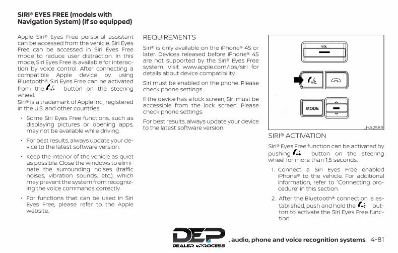
Apple Siri® Eyes Free personal assistantcan be accessed from the vehicle. Siri EyesFree can be accessed in Siri Eyes Freemode to reduce user distraction. In thismode, Siri Eyes Free is available for interac-tion by voice control. After connecting acompatible Apple device by usingBluetooth®, Siri Eyes Free can be activatedfrom the button on the steeringwheel.Siri® is a trademark of Apple Inc., registeredin the U.S. and other countries.
∙ Some Siri Eyes Free functions, such asdisplaying pictures or opening apps,may not be available while driving.
∙ For best results, always update your de-vice to the latest software version.
∙ Keep the interior of the vehicle as quietas possible. Close the windows to elimi-nate the surrounding noises (trafficnoises, vibration sounds, etc.), whichmay prevent the system from recogniz-ing the voice commands correctly.
∙ For functions that can be used in SiriEyes Free, please refer to the Applewebsite.
REQUIREMENTSSiri® is only available on the iPhone® 4S orlater. Devices released before iPhone® 4Sare not supported by the Siri® Eyes Freesystem. Visit www.apple.com/ios/siri fordetails about device compatibility.
Siri must be enabled on the phone. Pleasecheck phone settings.
If the device has a lock screen, Siri must beaccessible from the lock screen. Pleasecheck phone settings.
For best results, always update your deviceto the latest software version.
SIRI® ACTIVATIONSiri® Eyes Free function can be activated bypushing button on the steeringwheel for more than 1.5 seconds.
1. Connect a Siri Eyes Free enablediPhone® to the vehicle. For additionalinformation, refer to “Connecting pro-cedure” in this section.
2. After the Bluetooth® connection is es-tablished, push and hold the but-ton to activate the Siri Eyes Free func-tion.
LHA2589
SIRI® EYES FREE (models withNavigation System) (if so equipped)
Monitor, climate, audio, phone and voice recognition systems 4-81

OPERATING SIRI® EYES FREE
1. Push or push and hold the button.
2. Speak your command and then listento the Siri Eyes Free reply.
After starting Siri Eyes Free, push thebutton again within 5 seconds of the end ofthe Siri Eyes Free announcement to extendthe session.Example 1 – Playing music
1. Push or push and hold the button.
2. Say “Play (artist name, song name,etc.)”.
3. Your vehicle will automatically changeto Bluetooth® Audio or iPod® mode*when the music starts playing. Modeselection is determined by the phone.
* If the iPhone® is also connected with theUSB cable.
If the audio track does not start playingautomatically after Siri Eyes Free ends, trychanging the track or audio source to re-sume playback.
NOTE:
For best results, use the native musicapp. Performance of music control func-tion while using Podcasts, Audiobook orother 3rd party music apps may vary andis controlled by the iPhone®.Example 2 – Replying to text messages
1. If a compatible iPhone® is connectedand “Show Notifications” of the iPhone®settings is enabled, the vehicle will dis-play a notification for new incomingtext messages.
2. After reading the message, push orpush and hold the button to replyusing Siri Eyes Free.
3. After a beep sounds, say “Text mes-sage” or a similar command to replyusing Siri Eyes Free.
CHANGING SIRI® EYES FREESETTINGSSettings for Siri® Eyes Free can be found inthe Bluetooth® settings menu. For addi-tional information, refer to “Bluetooth® set-tings” in this section.
1. Press the [ ] button.
2. Touch the “Settings” key.
3. Touch the “Phone & Bluetooth” key.
4. Touch the “Phone settings” key.
5. Select “Short Press” or “Long Press” toset the activation.
4-82 Monitor, climate, audio, phone and voice recognition systems

TROUBLESHOOTING GUIDE
Symptom Cause and CountermeasureCannot access Siri EyesFree from switch on thesteering wheel
Check if a Bluetooth® connection is established between the iPhone® and the system.Check if Siri is enabled on the device. On your phone, go to Siri setting.Check that Siri can be accessed from the device lock screen. This can be set in the settings menu of your phone.
Audio Source does notchange automatically toiPod® or Bluetooth® Au-dio mode
For best results, use the native Music app. Performance of music control function while using Podcasts, Audiobook or other 3rd partymusic apps may vary.For best results, play media already stored on your device. Streaming music or playback from cloud storage may degradeperformance.Switch the source manually by pressing the AUX or MEDIA button on the vehicle audio system or the SOURCE select switch on thesteering wheel.
Play, pause, next track,previous track or playtimer does not work
For best results, use the native Music app. Performance of music control function while using Podcasts, Audiobook or other 3rd partymusic apps may vary and is controlled by the device.
Cannot hear any music/audio being played backfrom a connectediPhone®
Check that the audio source is set to Bluetooth® Audio or iPod® mode. A USB connection is required for iPod® mode.
Cannot hear map turn-by-turn direction guid-ance from a connectediPhone®
Check that the audio source is set to Bluetooth® Audio or iPod® mode. A USB connection is required for iPod® mode.
Cannot receive text mes-sage notifications on thevehicle audio system
Check if “Send Notifications” is enabled on your phone. On the phone, go to Bluetooth® settings. Find the device name, like “My Car”.Press the info button. Turn on “Show Notifications”.
Cannot reply to textmessage notifications bySiri Eyes Free
After receiving an incoming text message, follow on-screen guidance. Push or push and hold the button on the steering wheelfor Siri Eyes Free. After Siri Eyes Free starts, say “Text Message”.
Monitor, climate, audio, phone and voice recognition systems 4-83
When installing a CB, ham radio or carphone in your vehicle, be sure to observethe following precautions; otherwise, thenew equipment may adversely affect theengine control system and other electronicparts.
WARNING∙ A cellular phone should not be used
for any purpose while driving so fullattention may be given to vehicle op-eration. Some jurisdictions prohibitthe use of cellular phones whiledriving.
∙ If you must make a call while your ve-hicle is in motion, the hands free cellu-lar phone operational mode (if soequipped) is highly recommended.Exercise extreme caution at all timesso full attention may be given to ve-hicle operation.
∙ If you are unable to devote full atten-tion to vehicle operation while talkingon the phone, pull off the road to asafe location and stop your vehicle.
CAUTION∙ Keep the antenna as far away as pos-
sible from the electronic controlmodules.
∙ Keep the antenna wire more than 8 in(20 cm) away from the electronic con-trol system harnesses. Do not routethe antenna wire next to any harness.
∙ Adjust the antenna standing-waveratio as recommended by themanufacturer.
∙ Connect the ground wire from the CBradio chassis to the body.
∙ For additional information, it is rec-ommended that you visit a NISSANdealer.
∙ Do not ground electrical accessoriesdirectly to the battery terminal. Doingso will bypass the variable voltagecontrol system and the vehicle bat-tery may not charge completely. Foradditional information, refer to “Vari-able voltage control system” in the“Do-it-yourself” section of thismanual.
∙ Use electrical accessories with the en-gine running to avoid discharging thevehicle battery.
CAR PHONE OR CB RADIO
4-84 Monitor, climate, audio, phone and voice recognition systems

WARNING∙ Use a phone after stopping your ve-
hicle in a safe location. If you have touse a phone while driving, exercise ex-treme caution at all times so full at-tention may be given to vehicleoperation.
∙ If you are unable to devote full atten-tion to vehicle operation while talkingon the phone, pull off the road to asafe location and stop your vehicle.
CAUTIONTo avoid discharging the vehicle bat-tery, use a phone after starting theengine.
Your NISSAN is equipped with theBluetooth® Hands-Free Phone System. Ifyou have a compatible Bluetooth® enabledcellular phone, you can set up the wirelessconnection between your cellular phoneand the in-vehicle phone module. WithBluetooth® wireless technology, you can
make or receive a hands-free telephonecall with your cellular phone in the vehicle.
Once your cellular phone is connected tothe in-vehicle phone module, no otherphone connecting procedure is required.Your phone is automatically connected
LHA4813
BLUETOOTH® HANDS-FREE PHONESYSTEM WITHOUT NAVIGATIONSYSTEM (if so equipped)
Monitor, climate, audio, phone and voice recognition systems 4-85

with the in-vehicle phone module whenthe ignition switch is placed in the ON po-sition with the previously connected cellu-lar phone turned on and carried in the ve-hicle.
NOTE:
Some devices require the user to acceptconnections to other Bluetooth® de-vices. If your phone does not connect au-tomatic ally to the system, consult thephone’s Owner’s Manual for details ondevice operation.
You can connect up to five differentBluetooth® cellular phones to the in-vehicle phone module. However, you cantalk on only one cellular phone at a time.
Before using the Bluetooth® Hands-FreePhone System, refer to the following notes.
∙ Set up the wireless connection be-tween a compatible cellular phone andthe in-vehicle phone module before us-ing the hands-free phone system.
∙ Some Bluetooth® enabled cellularphones may not be recognized or workproperly. Please visitwww.nissanusa.com/bluetooth orwww.nissan.ca/bluetooth for a recom-mended phone list and connecting in-structions.
∙ You will not be able to use a hands-freephone under the following conditions:
– Your vehicle is outside of the cellularservice area.
– Your vehicle is in an area where it isdifficult to receive a cellular signal;such as in a tunnel, in an under-ground parking garage, near a tallbuilding or in a mountainous area.
– Your cellular phone is locked to pre-vent it from being dialed.
∙ When the radio wave condition is notideal or ambient sound is too loud, itmay be difficult to hear the other per-son’s voice during a call.
∙ Do not place the cellular phone in anarea surrounded by metal or far awayfrom the in-vehicle phone module toprevent tone quality degradation andwireless connection disruption.
∙ While a cellular phone is connectedthrough the Bluetooth® wireless con-nection, the battery power of the cellu-lar phone may discharge quicker thanusual. The Bluetooth® Hands-FreePhone System cannot charge cellularphones.
∙ For additional information, you can visitwww.nissanusa.com/bluetooth orwww.nissan.ca/bluetooth for trouble-shooting help.
∙ Some cellular phones or other devicesmay cause interference or a buzzingnoise to come from the audio systemspeakers. Storing the device in a differ-ent location may reduce or eliminatethe noise.
∙ For additional information, refer to thecellular phone Owner’s Manual regard-ing the telephone charges, cellularphone antenna and body, etc.
4-86 Monitor, climate, audio, phone and voice recognition systems

REGULATORY INFORMATIONFCC Regulatory information
– CAUTION: To maintain compliance withFCC’s RF exposure guidelines, use onlythe supplied antenna. Unauthorized an-tenna, modification, or attachmentscould damage the transmitter and mayviolate FCC regulations.
– Operation is subject to the following twoconditions:
1. This device may not cause interferenceand
2. this device must accept any interfer-ence, including interference that maycause undesired operation of the de-vice.
IC Regulatory information
– Operation is subject to the following twoconditions: (1) this device may not causeinterference, and (2) this device must ac-cept any interference, including interfer-ence that may cause undesired opera-tion of the device.
– This Class B digital apparatus meets allrequirements of the CanadianInterference-Causing Equipment Regu-lations.
BLUETOOTH® is atrademark ownedby Bluetooth SIG,Inc. and licensedto Panasonic.
USING THE SYSTEMThe system allows hands-free operation ofthe Bluetooth® Hands-Free Phone System.
If the vehicle is in motion, some commandsmay not be available so full attention maybe given to vehicle operation.
InitializationWhen the ignition switch is placed in the ONposition, NISSAN Voice Recognition is initial-ized, which takes a few seconds. If thebutton is pressed before the initializationcompletes, the system will announce“There is no phone connected” and will notreact to voice commands.
Operating tipsTo get the best performance out of theNISSAN Voice Recognition System, observethe following:
∙ Keep the interior of the vehicle as quietas possible. Keep all vents pointed awayfrom the microphone and close thewindows to eliminate surroundingnoises (traffic noises, vibration sounds,etc.), which may prevent the systemfrom recognizing voice commands cor-rectly.
∙ Wait until the tone sounds beforespeaking a command. Otherwise, thecommand will not be received properly.
∙ Start speaking a command within5 seconds after the tone sounds.
∙ Speak in a natural voice without paus-ing between words.
∙ For calling contacts by name, pleasesay both the first and last name of thecontact for better recognition.
Monitor, climate, audio, phone and voice recognition systems 4-87

Giving voice commandsTo operate NISSAN Voice Recognition,press the button located on thesteering wheel for less than 1.5 seconds.After the tone sounds, speak a command.The command given is picked up by themicrophone, and voice feedback is givenwhen the command is accepted.
∙ If a command is not recognized, thesystem announces, “Please say or se-lect a command from the displayed list.”Make sure the command is said exactlyas prompted by the system and repeatthe command in a clear voice.
∙ If you want to go back to the previouscommand, you can say “Go back” anytime the system is waiting for a re-sponse.
∙ You can cancel a command when thesystem is waiting for a response by say-ing, “Cancel” or “Quit.” The system an-nounces “Exit” and ends the Voice Rec-ognition session. You can also pressand hold the button on the steer-ing wheel for 1.5 seconds at any time toend the Voice Recognition session.Whenever the Voice Recognition ses-sion is canceled, a double beep isplayed to indicate you have exited thesystem.
∙ If you want to adjust the volume of thevoice feedback, push the (+ or -) volumecontrol switches on the steering wheelwhile being provided with feedback. Youcan also use the radio volume controlknob.
Voice Prompt InterruptIn most cases you can interrupt the voicefeedback to speak the next command bypressing the button on the steeringwheel. After interrupting the system, waitfor a beep before speaking your command.
INDICATORSWhen a cellular phone is connectedthrough the Bluetooth® wireless connec-tion, indicators �1 for the phone and textmessaging are displayed on the top of thescreen.
LHA4723
4-88 Monitor, climate, audio, phone and voice recognition systems

Indicator DescriptionIndicates there are un-read receivedmessages.Indicates theBluetooth® device thatis currently connected.Indicates the strengthof the signal theBluetooth® device isreceiving.Indicates the amountof remainingBluetooth® devicebattery.
CONTROL BUTTONSThe control buttons for the Bluetooth®Hands-Free Phone System are located onthe steering wheel.
VOICE COMMAND BUTTON
Press and hold the buttonfor less than 1.5 seconds to initi-ate the Voice Recognitionsession. To exit the Voice Recog-nition session press and holdthe for less than 1.5 sec-onds. For additional information,refer to “Voice prompt interrupt”in this section.
You can use the button tointerrupt the system feedbackand give a command at once.
If an iPhone® is connected, Siri®can be accessed by pressingthe button for more thantwo seconds. For additionalinformation, refer to “Siri® EyesFree” in this section.
PHONE BUTTONTo answer an incoming call or toend a call press the button.
To reject a call press and holdthe button.
LHA2561
Monitor, climate, audio, phone and voice recognition systems 4-89

CONNECTING PROCEDURE
NOTE:
The connecting procedure must be per-formed when the vehicle is stationary. Ifthe vehicle starts moving during the pro-cedure, the procedure will be canceled.To connect a phone to the Bluetooth®Hands-Free Phone System:
Manual Connecting Procedure
1. Press the MENU button on thecontrol panel.
2. Touch the “Connections” key on thescreen.
3. In the Bluetooth tab, touch the “AddNew” key to connect a phone.
4. When a compatible phone is found amessage with a PIN appears on thescreen.
5. Verify the PIN is correct and accept theconnection.
6. To access the Bluetooth® settingsmenu touch the “ ” key on the Con-nections screen. The following optionsare available:
Menu Item ResultBluetooth Allows user to switch Bluetooth® on and off. Bluetooth® must be turned on in order to connect a device.
ON Turns Bluetooth® functionality on. To turn off, touch the “ON” key again. The indicator light will go off.Favorite (Connection first) Allows user to toggle “Phone” and “Audio” favorite settings on and off.PIN Allows user to customize the PIN to a four digit number.
LHA4726
4-90 Monitor, climate, audio, phone and voice recognition systems

NOTE:Some cellular phones may require you toaccept certain permissions in order toenable features on your Bluetooth® sys-tem. During the Bluetooth® pairing pro-cess, please check your cellular phone’sdisplay for a pop-up with the request togrant phonebook access.Granting phonebook access permissionwill allow your contacts to be down-loaded to the vehicle’s Bluetooth® sys-tem. A pop-up may display on your cellu-lar phone stating that the Bluetooth®system would like to access your con-tacts and call history. Please select “Al-low” or Yes” to grant this permission.
Automatic Connecting Procedure
If no phone is connected to the system,press and hold the button on thesteering wheel for less than 1.5 seconds.After the prompt, speak “Add Phone”, thesystem will announce “transferring to theadd phone settings menu”. The system willstart the pairing procedure. When a com-patible phone is found, a message with aPIN appears on the screen. Operate theBluetooth® phone to complete the con-nection process. For additional informa-tion, refer to “Bluetooth® connectionsscreen” in this section.
VOICE COMMANDSVoice commands can be used to operatethe Bluetooth® Hands-Free Phone System.Press and hold the button for morethan 1.5 seconds to bring up the phonecommand menu. The commands avail-able are:
∙ Call <name>
∙ Dial <number>
∙ Recent Calls
∙ Read/Send Text (if so equipped)
∙ Siri® (if so equipped)
∙ Voice Assistant (if so equipped)
∙ Phonebook
∙ Quick Dial
∙ Redial
∙ Select Phone
∙ Add Phone
∙ Call <name> Mobile
∙ Call <name> Home
∙ Call <name> Office
∙ Call <name> Main
∙ Call <name> Other
∙ Settings
“Call <name>”Speak this command to make a call to acontact that is stored in the phonebook.Say “Call” followed by a phonebook name toinitiate a call. If the system does not recog-nize the name it will display a list of similarnames. After the prompt, speak or touchan item number from the displayed list toplace the call.
“Dial <number>”Speak this command to make a call with aspoken phone number. After the prompt,say “Dial” followed by a 7 to 10 digit phonenumber. The system will repeat the num-ber back. Say “Dial” to initiate the call or“Correction” to re-enter the phone number.
Monitor, climate, audio, phone and voice recognition systems 4-91

“Recent Calls”The following commands are available un-der “Recent Calls”:
∙ Incoming CallsSpeak this command to list the last20 incoming calls to the vehicle. If thecall is from an entry in the phonebook,the name will be displayed. Otherwise,the phone number of the incoming callwill be displayed.When prompted, speak or touch theitem number on the screen to place thecall. Select the “Next” key to movethrough the list of incoming calls.
∙ Outgoing CallsSpeak this command to list the last 20outgoing calls from the vehicle. If thecall was to an entry in the phonebook,the name will be displayed. Otherwise,the phone number of the outgoing callwill be displayed.When prompted, speak or touch theitem number on the screen to place thecall. Select the “Next” key to movethrough the list of outgoing calls.
∙ Missed CallsSpeak this command to list the last 20missed calls to the vehicle. If the call isfrom an entry in the phonebook, thename will be displayed. Otherwise, thephone number of the missed call will bedisplayed.When prompted, speak or touch theitem number on the screen to place thecall. Select the “Next” key to movethrough the list of missed calls.
“Read Text/Send Text” (if soequipped)Speak this command to access text mes-saging functions. For additional informa-tion, refer to “Text messaging” in this sec-tion.
“Phonebook through voicecommand”Speak “Phonebook” to view a list of quicksteps to access entries stored in thephonebook. Commands are organized bythe phone number type selected in the cel-lular device. For additional information, re-fer to the cellular phone’s Owner’s Manual.
The following commands are available:
∙ <Say a Contact Name>
∙ <Say a Contact Name> Main
∙ <Say a Contact Name> Home
∙ <Say a Contact Name> Mobile
∙ <Say a Contact Name> Office
∙ <Say a Contact Name> Other
For additional information on manually se-lecting phonebook entries, refer to “Makinga call” in this section.
“Quick dial”Speak this command to access the Quickdial menu. After the prompt, speak or se-lect an item number on the displayed list toplace the call. For additional information,refer to “Making a call” in this section.
“Redial”Speak this command to call the last num-ber dialed. After the prompt, say “Redial” todial the number of the last outgoing call.The system will display “Redialing<name/number>”. The name of thephonebook entry will be displayed if it isavailable, otherwise the number being re-dialed will be displayed.
4-92 Monitor, climate, audio, phone and voice recognition systems

“Select Phone”Speak this command to access the Con-nections menu. For additional information,refer to “Bluetooth® connections screen” inthis section.
“Add Phone”Speak this command to access the Con-nections menu. For additional information,refer to “Bluetooth® connections screen” inthis section.
“Settings”Speak this command to access the Sys-tem Voice settings menu. The system willexit Voice Recognition mode. Touch one ofthe following options on the screen tochange the settings.
∙ Beep Only for Opening PromptBy touching the “ON” key, the indicatorlight will illuminate, the system voice willturn off and only a tone will sound whenthe Bluetooth® Hands-Free Phone Sys-tem is activated. To turn the systemvoice back on, touch the “ON” key again,the indicator light will turn off.
∙ Best Match ListWhen the system doesn’t recognize aphonebook name or dial number, it willprovide a list of similar sounding results.To turn this off, touch the “ON” button,the indicator light will turn off. To turn on,touch the “ON” key again, the indicatorlight will turn on.
PHONE DISPLAY SCREENThe Phone screen can be displayed bypressing the button on the controlpanel.The following options are displayed:
∙ Quick DialDisplays the Quick Dial screen. For addi-tional information, refer to “Quick dial” inthis section.
LHA4705
Monitor, climate, audio, phone and voice recognition systems 4-93

∙ PhonebookDisplays the Phonebook screen. For ad-ditional information, refer to “Making acall” in this section.
∙ Call HistoryDisplays the Call History screen. For ad-ditional information, refer to “Making acall” in this section.
∙ Dial NumberDisplays the Dial Number screen. Foradditional information, refer to “Makinga call” in this section.
∙ Text MessageDisplays the received message screen.For additional information, refer to “Textmessaging” in this section.
∙ ConnectionsDisplays the Connections screen. Foradditional information, refer to“Bluetooth® connections screen” in thissection.
∙ VolumeDisplays the volume adjustmentscreen. For additional information, referto “Volume & beeps” in this section.
MAKING A CALL
To make a call press the button onthe control panel. Touch an option frommenu screen:
∙ PhonebookSelect a person and the phone numberyou wish to call from the phonebook.Depending on the device, the phone-book will be downloaded from the cel-lular phone automatically when it isconnected. If the automatic downloaddoes not take place, the phone numbermust be transferred to the hands-freephone system from the cellular phoneprior to using this method. For addi-tional information, refer to “Phone andtext message settings” in this section.
∙ Call HistorySelect a phonebook name or phonenumber from the recent incoming, out-going or missed calls tabs. Touch aphonebook name or phone numberlisted to initiate the call.
∙ Dial NumberEnter the phone number manually us-ing the keypad displayed on the screen.Press the “OK” key on the screen to initi-ate the call.
For additional options to make a call, referto “Voice commands” in this section.
Quick DialQuick Dial entries can be used to quicklymake a call. The system allows up to 20entries to be stored. To set up a quick dialpress the button on the controlpanel. Touch the “Quick Dial” key to display alist of quick dial entries. Touch the “Edit” keyto edit current entries or touch the “AddNew” key to make a new entry. Two meth-ods are given to create a quick dial entry:
∙ Touch the “Copy from Call History” keyto save a phone number from the In-coming, Outgoing or Missed call historylists. Select the person or phone num-ber from the menu to be added. A reg-istration menu will display the Entry #,phone number, phone number typestored in the cellular phone and VoiceTag. Select the “OK” key.
∙ Touch the “Copy from Phonebook” key tosave a number from the phonebook. Usethe scroll keys on the side to move upand down through the menu. Select aperson to be added. A menu will displaythe Entry #, phone number, phone num-ber type stored in the cellular phone andVoice Tag. Select the “OK” key.
4-94 Monitor, climate, audio, phone and voice recognition systems
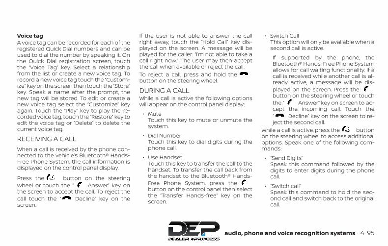
Voice tagA voice tag can be recorded for each of theregistered Quick Dial numbers and can beused to dial the number by speaking it. Onthe Quick Dial registration screen, touchthe “Voice Tag” key. Select a relationshipfrom the list or create a new voice tag. Torecord a new voice tag touch the “Custom-ize” key on the screen then touch the “Store”key. Speak a name after the prompt, thenew tag will be stored. To edit or create anew voice tag select the “Customize” keyagain. Touch the “Play” key to play the re-corded voice tag, touch the “Restore” key toedit the voice tag or “Delete” to delete thecurrent voice tag.
RECEIVING A CALLWhen a call is received by the phone con-nected to the vehicle’s Bluetooth® Hands-Free Phone System, the call information isdisplayed on the control panel display.
Press the button on the steeringwheel or touch the “ Answer” key onthe screen to accept the call. To reject thecall touch the “ Decline” key on thescreen.
If the user is not able to answer the callright away, touch the “Hold Call” key dis-played on the screen. A message will beplayed for the caller: “I’m not able to take acall right now.” The user may then acceptthe call when available or reject the call.To reject a call, press and hold thebutton on the steering wheel.
DURING A CALLWhile a call is active the following optionswill appear on the control panel display:
∙ MuteTouch this key to mute or unmute thesystem.
∙ Dial NumberTouch this key to dial digits during thephone call.
∙ Use HandsetTouch this key to transfer the call to thehandset. To transfer the call back fromthe handset to the Bluetooth® Hands-Free Phone System, press thebutton on the control panel then selectthe “Transfer Hands-free” key on thescreen.
∙ Switch CallThis option will only be available when asecond call is active.
If supported by the phone, theBluetooth® Hands-Free Phone Systemallows for call waiting functionality. If acall is received while another call is al-ready active, a message will be dis-played on the screen. Press thebutton on the steering wheel or touchthe “ Answer” key on screen to ac-cept the incoming call. Touch the“ Decline” key on the screen to re-ject the second call.
While a call is active, press the buttonon the steering wheel to access additionaloptions. Speak one of the following com-mands:
∙ “Send Digits”Speak this command followed by thedigits to enter digits during the phonecall.
∙ “Switch call”Speak this command to hold the sec-ond call and switch back to the originalcall.
Monitor, climate, audio, phone and voice recognition systems 4-95

ENDING A CALLTo end an active call, press the buttonon the steering wheel or touch the“ Hang up” key on the screen.
TEXT MESSAGING (if so equipped)
WARNING∙ Laws in some jurisdictions may re-
strict the use of “Text-to-Speech”.Check local regulations before usingthis feature.
∙ Laws in some jurisdictions may re-strict the use of some of the applica-tions and features, such as social net-working and texting. Check localregulations for any requirements.
∙ Use the text messaging feature afterstopping your vehicle in a safe loca-tion. If you have to use the featurewhile driving, exercise extreme cau-tion at all times so full attention maybe given to vehicle operation.
∙ If you are unable to devote full atten-tion to vehicle operation while usingthe text messaging feature, pull offthe road to a safe location and stopyour vehicle.
NOTE:
This feature is automatically disabled ifthe connected device does not supportthe Message Access Profile (MAP). Foradditional information, refer to thephone’s Owner’s Manual for details andinstructions.
NOTE:
Many phones may require special per-mission to enable text messaging. Checkthe phone’s screen during Bluetooth®pairing. For some phones, you may needto enable ‘Notifications’ in the phone’sBluetooth® menu for text messages toappear on the headunit. For additionalinformation, refer to your phone’s Own-er’s manual. Text message integrationrequires that the phone support MAP(Message Access Profile) for both receiv-ing and sending text messages. Somephones may not support all text mes-saging features. Please refer towww.nissanusa.com/bluetooth orwww.nissan.ca/bluetooth for compat-ibility information, as well as your de-vice’s Owner’s manual.The system allows for the sending and re-ceiving of text messages through the ve-hicle interface.
The availability of the text message func-tion may vary depending on the cellularphone.When the cellular phone connected to thevehicle receives a text message, a notifica-tion will appear on the control panel dis-play. To check the message, touch the“Read” key. Touch the “Ignore” key to savethe message to be checked later.
Access text messaging through the ve-hicles Bluetooth® Hands-Free Phone orthrough the vehicles control panel.
Text messaging using Bluetooth®Hands-Free Phone System (if soequipped)Sending a text message (if so equipped)
1. Press and hold the button on thesteering wheel for less than 1.5 sec-onds.
2. Say “Send Text” after the tone.
3. The system will provide a list of avail-able commands in order to determinethe recipient of the text message.Choose from the following:
∙ Phonebook
∙ Quick Dial4-96 Monitor, climate, audio, phone and voice recognition systems
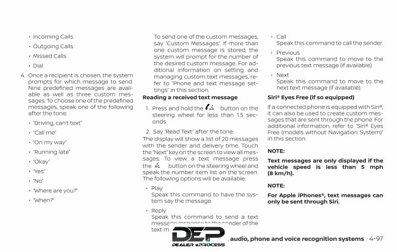
∙ Incoming Calls
∙ Outgoing Calls
∙ Missed Calls
∙ Dial
4. Once a recipient is chosen, the systemprompts for which message to send.Nine predefined messages are avail-able as well as three custom mes-sages. To choose one of the predefinedmessages, speak one of the followingafter the tone:
∙ “Driving, can’t text”
∙ “Call me”
∙ “On my way”
∙ “Running late”
∙ “Okay”
∙ “Yes”
∙ “No”
∙ “Where are you?”
∙ “When?”
To send one of the custom messages,say “Custom Messages”. If more thanone custom message is stored, thesystem will prompt for the number ofthe desired custom message. For ad-ditional information on setting andmanaging custom text messages, re-fer to “Phone and text message set-tings” in this section.
Reading a received text message
1. Press and hold the button on thesteering wheel for less than 1.5 sec-onds.
2. Say “Read Text” after the tone.The display will show a list of 20 messageswith the sender and delivery time. Touchthe “Next” key on the screen to view all mes-sages. To view a text message pressthe button on the steering wheel andspeak the number item list on the screen.The following options will be available:
∙ PlaySpeak this command to have the sys-tem say the message.
∙ ReplySpeak this command to send a textmessage response to the sender of thetext message.
∙ CallSpeak this command to call the sender.
∙ PreviousSpeak this command to move to theprevious text message (if available).
∙ NextSpeak this command to move to thenext text message (if available).
Siri® Eyes Free (if so equipped)
If a connected phone is equipped with Siri®,it can also be used to create custom mes-sages that are sent through the phone. Foradditional information, refer to “Siri® EyesFree (models without Navigation System)”in this section.
NOTE:
Text messages are only displayed if thevehicle speed is less than 5 mph(8 km/h).
NOTE:
For Apple iPhones®, text messages canonly be sent through Siri.
Monitor, climate, audio, phone and voice recognition systems 4-97
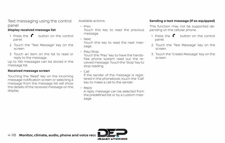
Text messaging using the controlpanelDisplay received message list
1. Press the button on the controlpanel.
2. Touch the “Text Message” key on thescreen
3. Touch an item on the list to read orreply to the message.
Up to 100 messages can be stored in themessage list.
Received message screen
Touching the “Read” key on the incomingmessage notification screen or selecting amessage from the message list will showthe details of the received message on thedisplay.
Available actions:
∙ Prev.Touch this key to read the previousmessage.
∙ NextTouch this key to read the next mes-sage.
∙ Play/StopTouch the “Play” key to have the hands-free phone system read out the re-ceived message. Touch the “Stop” key tostop reading.
∙ CallIf the sender of the message is regis-tered in the phonebook, touch the “Call”key to make a call to the sender.
∙ ReplyA reply message can be selected fromthe predefined list or by a custom mes-sage.
Sending a text message (if so equipped)
This function may not be supported de-pending on the cellular phone.
1. Press the button on the controlpanel.
2. Touch the “Text Message” key on thescreen.
3. Touch the “Create Message” key on thescreen.
4-98 Monitor, climate, audio, phone and voice recognition systems

The following items are available:
Available item ActionTo Enter Number by Keypad Enter the phone number of the recipient using the keypad. Touch the “OK” key to confirm.
Quick Dial Select a recipient from the quick dial list.Phonebook Select a recipient from the phonebook.Call History Select a recipient/phone number from call history.
Select Text Fixed Touch to display a list of predefined text messages.Customized Touch to display a list of custom text messages. Custom text can be created or edited from the setting
menu. For additional information, refer to “Phone and text message settings” in this section.Send Touch to send the message.
Monitor, climate, audio, phone and voice recognition systems 4-99
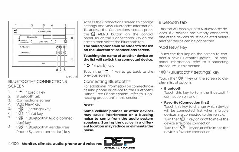
BLUETOOTH® CONNECTIONSSCREEN1. “ ” (back) key2. Bluetooth tab3. Connections screen4. “Add New” key5. “ ” (settings) key6. “ ” (info) key7. “ ” (Bluetooth® Audio connec-
tion) key8. “ ” (Bluetooth® Hands-Free
Phone System connection) key
Access the Connections screen to changesettings and view Bluetooth® information.To access the Connections screen pressthe MENU button on the controlpanel. Touch the “Connections” key on thescreen then select the Bluetooth tab.The paired phone will be added to the liston the Bluetooth® connections screen.
Touching the name of another device onthe list will switch the connected device.
“ ” (back) keyTouch the “ ” key to go back to theprevious screen.
Connecting Bluetooth®For additional information on connecting acellular phone or device to the Bluetooth®Hands-Free Phone System, refer to “Con-necting procedure” in this section.
NOTE:
Some cellular phones or other devicesmay cause interference or a buzzingnoise to come from the audio systemspeakers. Storing the device in a differ-ent location may reduce or eliminate thenoise.
Bluetooth tabThis tab will display up to 6 Bluetooth® de-vices. If 6 devices are already connected,one of the devices must be deleted beforeanother device can be connected.
“Add New” keyTouch the this key on the screen to con-nect a new Bluetooth® device. For addi-tional information, refer to “Connectingprocedure” in this section.,
“ ” (Bluetooth® settings) keyTouch the “ ” key on the screen to dis-play a list of options.
∙ BluetoothTouch this key to turn the Bluetooth®connection on or off
∙ Favorite (Connection first)Touch this key to change which devicewill be connected first when multipledevices are connected to the vehicle.Turn the “ ” key on or off to make thedevice a favorite connection.Turn the “ ” key on or off to make thedevice a favorite connection.
LHA4716
4-100 Monitor, climate, audio, phone and voice recognition systems

∙ PinTouch this key to customize the PINcode. Input a four digit number thentouch the “OK” key. The new PIN will beset.
“ ” (info) keyTouch the “ ” key on the screen to dis-play the information of the cellular phoneor to delete the device.Touch the “Delete” key to remove a paireddevice then select “Yes” when a messageappears.
“ ” (Bluetooth® Hands-FreePhone System connection) keyA list of connected devices will be displayedon the screen. Touch the “ ” key next tothe name to connect a device to theHands-Free Phone System. If the phone islisted as a favorite, a star will appear on theicon. Select the key again to disconnect thedevice. The device will not be removedfrom the list. For additional information onremoving a device, refer to “ (info) key”in this section.
“ ” (Bluetooth® Audioconnection) keyA list of connected devices will be displayedon the screen. Touch the “ ” key next tothe name to connect a device toBluetooth® Audio. If the device is listed as afavorite, a star will appear on the icon. Se-lect the key again to disconnect the device.The device will not be removed from thelist. For additional information on removinga device, refer to “ (info) key” in thissection.
PHONE AND TEXT MESSAGESETTINGSBluetooth® Hands-Free Phone System set-tings can be changed according to the us-er’s preference. To access the “Phone” set-tings menu press the MENU buttonon the control panel. Touch the “Settings”key then select the “Phone” key.
LHA4721
Monitor, climate, audio, phone and voice recognition systems 4-101
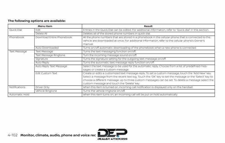
The following options are available:Menu Item Result
Quick Dial Edit Entries in the Quick Dial can be edited. For additional information, refer to “Quick dial” in this section.Delete All Deletes all of the stored phone numbers in quick dial.
Phonebook Download Entire Phonebook All the phone numbers that are stored in a phonebook in the cellular phone that is connected to thevehicle are downloaded at once. For additional information, refer to the cellular phone’s Owner’smanual.
Auto Downloaded Turns on/off automatic downloading of the phonebook when a new phone is connected.Text Message Text Message Turns the text messaging function on/off.
Text Message Ringtone Turn the incoming message sound on/off.Signature Turns the signature setting for the outgoing text message on/off.Auto Reply Turns the automatic text message reply function on/off.Auto Reply Text Message Select the text message to be used for the automatic reply. Choose from a list of predefined mes-
sages or create a custom message.Edit Custom Text Create or edits a customized text message reply. To set a custom message, touch the “Add New” key.
Select a message from the recent text log. Touch the “OK” key to set the message or the “Select” key tochoose a different message. Up to three custom messages can be set. To delete a message select thecustom message and touch the “Delete” key.
Notifications Driver Only When this item is turned on, incoming call notification is displayed only on the handset.Vehicle Ringtone Turns the vehicle ringtone on/off.
Automatic Hold When this item turns on, an incoming call will be put on hold automatically.
4-102 Monitor, climate, audio, phone and voice recognition systems
Volume & beepsThere are several methods to customizethe volume settings.
Volume & BeepsThe Volume & Beeps screen can be foundby pressing the MENU button on thecontrol panel, touching the “Settings” keyon the screen and selecting “Volume &Beeps”. To adjust the volume of the follow-ing options, touch the “–” and “+” keys on thescreen.The available settings are:
∙ RingtoneAdjust the volume level of the ringtoneof incoming calls.
∙ Outgoing CallAdjust the volume level of the outgoingcalls.
∙ Voice Prompt Vol.Adjust the volume level of the systemvoice.
∙ Text-to-speech Vol.Adjust the volume of the replay voice fortext messaging.
∙ Button BeepsTurns on/off the button beep soundsand alarm for prohibited operations.
Volume SettingsThe Volume settings screen can be foundby pressing the button on the controlpanel then touching the “Volume” key onthe screen. To adjust the volume of thefollowing options, touch the “–” and “+” keyson the screen.The available settings are:
∙ RingtoneAdjust the volume level of the ringtoneof incoming calls.
∙ Outgoing CallAdjust the volume level of the outgoingcalls.
WARNING∙ Use a phone after stopping your ve-
hicle in a safe location. If you have touse a phone while driving, exercise ex-treme caution at all times so full at-tention may be given to vehicleoperation.
∙ If you are unable to devote full atten-tion to vehicle operation while talkingon the phone, pull off the road to asafe location and stop your vehicle.
CAUTIONTo avoid discharging the vehicle bat-tery, use a phone after starting theengine.
BLUETOOTH® HANDS-FREE PHONESYSTEM WITH NAVIGATION SYSTEM(if so equipped)
Monitor, climate, audio, phone and voice recognition systems 4-103

Your NISSAN is equipped with theBluetooth® Hands-Free Phone System. Ifyou have a compatible Bluetooth® enabledcellular phone, you can set up the wirelessconnection between your cellular phoneand the in-vehicle phone module. WithBluetooth® wireless technology, you can
make or receive a hands-free telephonecall with your cellular phone in the vehicle.
Once your cellular phone is connected tothe in-vehicle phone module, no otherphone connecting procedure is required.Your phone is automatically connected
with the in-vehicle phone module whenthe ignition switch is placed in the ON po-sition with the connected cellular phoneturned on and carried in the vehicle.
You can register up to five differentBluetooth® cellular phones to the in-vehicle phone module. However, you cantalk on only one cellular phone at a time.
NISSAN Voice Recognition system sup-ports the phone commands, so dialing aphone number using your voice is possible.For additional information, refer to “NISSANVoice Recognition System” in this section.
Before using the Bluetooth® Hands-FreePhone System, refer to the following notes.
∙ Set up the wireless connection be-tween a cellular phone and the in-vehicle phone module before using thehands-free phone system.
∙ Some Bluetooth® enabled cellularphones may not be recognized by thein-vehicle phone module. Please visitwww.nissanusa.com/bluetooth orwww.nissan.ca/bluetooth for a recom-mended phone list and connecting in-structions.
LHA3144
4-104 Monitor, climate, audio, phone and voice recognition systems

∙ You will not be able to use a hands-freephone under the following conditions:
– Your vehicle is outside of the cellularservice area.
– Your vehicle is in an area where it isdifficult to receive cellular signal;such as in a tunnel, in an under-ground parking garage, near a tallbuilding or in a mountainous area.
– Your cellular phone is locked to pre-vent it from being dialed.
∙ When the radio wave condition is notideal or ambient sound is too loud, itmay be difficult to hear the other per-son’s voice during a call.
∙ Immediately after the ignition switch isplaced in the ON position, it may be im-possible to receive a call for a short pe-riod of time.
∙ Do not place the cellular phone in anarea surrounded by metal or far awayfrom the in-vehicle phone module toprevent tone quality degradation andwireless connection disruption.
∙ While a cellular phone is connectedthrough the Bluetooth® wireless con-nection, the battery power of the cellu-lar phone may discharge quicker thanusual. The Bluetooth® Hands-FreePhone System cannot charge cellularphones.
∙ If the hands-free phone system seemsto be malfunctioning, refer to “Trouble-shooting guide” in this section. You canalso visitwww.nissanusa.com/bluetooth orwww.nissan.ca/bluetooth for trouble-shooting help.
∙ Some cellular phones or other devicesmay cause interference or a buzzingnoise to come from the audio systemspeakers. Storing the device in a differ-ent location may reduce or eliminatethe noise.
∙ Refer to the cellular phone owner’smanual regarding the telephonecharges, cellular phone antenna andbody, etc.
∙ The signal strength display on themonitor will not coincide with the signalstrength display of some cellularphones.
REGULATORY INFORMATIONFCC Regulatory information
– CAUTION: To maintain compliance withFCC’s RF exposure guidelines, use onlythe supplied antenna. Unauthorized an-tenna, modification, or attachmentscould damage the transmitter and mayviolate FCC regulations.
– Operation is subject to the following twoconditions:
1. This device may not cause interferenceand
2. this device must accept any interfer-ence, including interference that maycause undesired operation of the de-vice.
IC Regulatory information
– Operation is subject to the following twoconditions: (1) this device may not causeinterference, and (2) this device must ac-cept any interference, including interfer-ence that may cause undesired opera-tion of the device.
– This Class B digital apparatus meets allrequirements of the CanadianInterference-Causing Equipment Regu-lations.
Monitor, climate, audio, phone and voice recognition systems 4-105
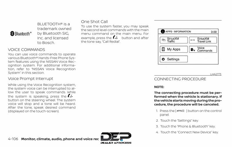
BLUETOOTH® is atrademark ownedby Bluetooth SIG,Inc. and licensedto Bosch.
VOICE COMMANDSYou can use voice commands to operatevarious Bluetooth® Hands-Free Phone Sys-tem features using the NISSAN Voice Rec-ognition system. For additional informa-tion, refer to “NISSAN Voice RecognitionSystem” in this section.
Voice Prompt InterruptWhile using the Voice Recognition system,the system voice can be interrupted to al-low the user to speak commands. Whilethe system is speaking, press thebutton on the steering wheel. The systemvoice will stop and a tone will be heard.After the tone, speak desired command(displayed on the touch-screen).
One Shot CallTo use the system faster, you may speakthe second level commands with the mainmenu command on the main menu. Forexample, press the button and afterthe tone say, “Call Redial”.
CONNECTING PROCEDURE
NOTE:
The connecting procedure must be per-formed when the vehicle is stationary. Ifthe vehicle starts moving during the pro-cedure, the procedure will be canceled.
1. Press the [ ] button on the controlpanel.
2. Touch the “Settings” key.
3. Touch the “Phone & Bluetooth” key.
4. Touch the “Connect New Device” key.
LHA2773
4-106 Monitor, climate, audio, phone and voice recognition systems
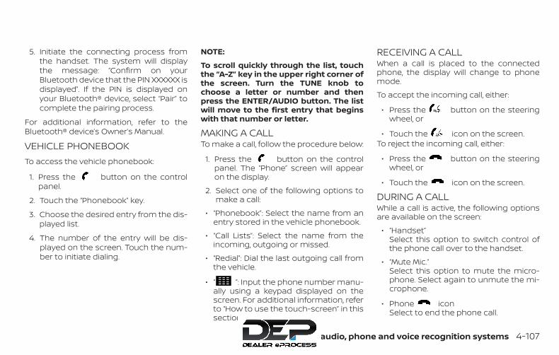
5. Initiate the connecting process fromthe handset. The system will displaythe message: “Confirm on yourBluetooth device that the PIN XXXXXX isdisplayed”. If the PIN is displayed onyour Bluetooth® device, select “Pair” tocomplete the pairing process.
For additional information, refer to theBluetooth® device’s Owner’s Manual.
VEHICLE PHONEBOOKTo access the vehicle phonebook:
1. Press the button on the controlpanel.
2. Touch the “Phonebook” key.
3. Choose the desired entry from the dis-played list.
4. The number of the entry will be dis-played on the screen. Touch the num-ber to initiate dialing.
NOTE:
To scroll quickly through the list, touchthe “A-Z” key in the upper right corner ofthe screen. Turn the TUNE knob tochoose a letter or number and thenpress the ENTER/AUDIO button. The listwill move to the first entry that beginswith that number or letter.
MAKING A CALLTo make a call, follow the procedure below:
1. Press the button on the controlpanel. The “Phone” screen will appearon the display.
2. Select one of the following options tomake a call:
∙ “Phonebook”: Select the name from anentry stored in the vehicle phonebook.
∙ “Call Lists”: Select the name from theincoming, outgoing or missed.
∙ “Redial”: Dial the last outgoing call fromthe vehicle.
∙ “ ”: Input the phone number manu-ally using a keypad displayed on thescreen. For additional information, referto “How to use the touch-screen” in thissection.
RECEIVING A CALLWhen a call is placed to the connectedphone, the display will change to phonemode.
To accept the incoming call, either:
∙ Press the button on the steeringwheel, or
∙ Touch the icon on the screen.To reject the incoming call, either:
∙ Press the button on the steeringwheel, or
∙ Touch the icon on the screen.
DURING A CALLWhile a call is active, the following optionsare available on the screen:
∙ “Handset”Select this option to switch control ofthe phone call over to the handset.
∙ “Mute Mic.”Select this option to mute the micro-phone. Select again to unmute the mi-crophone.
∙ Phone iconSelect to end the phone call.
Monitor, climate, audio, phone and voice recognition systems 4-107

ENDING A CALLTo end a phone call, select the phoneicon on the screen or press the but-ton on the steering wheel.
TEXT MESSAGING (if so equipped)
WARNING∙ Laws in some jurisdictions may re-
strict the use of “Text-to-Speech”.Check local regulations before usingthis feature.
∙ Laws in some jurisdictions may re-strict the use of some of the applica-tions and features, such as social net-working and texting. Check localregulations for any requirements.
∙ Use the text messaging feature afterstopping your vehicle in a safe loca-tion. If you have to use the featurewhile driving, exercise extreme cau-tion at all times so full attention maybe given to vehicle operation.
∙ If you are unable to devote full atten-tion to vehicle operation while usingthe text messaging feature, pull offthe road to a safe location and stopyour vehicle.
NOTE:
This feature is automatically disabled ifthe connected device does not supportthe Message Access Profile (MAP). Foradditional information, refer to thephone’s Owner’s Manual for details andinstructions.
NOTE:
Many phones may require special per-mission to enable text messaging. Checkthe phone’s screen during Bluetooth®pairing. For some phones, you may needto enable ‘Notifications’ in the phone’sBluetooth® menu for text messages toappear on the headunit. For additionalinformation, refer to your phone’s Own-er’s manual. Text message integrationrequires that the phone support MAP(Message Access Profile) for both receiv-ing and sending text messages. Somephones may not support all text mes-saging features. For additional informa-tion, please refer towww.nissanusa.com/bluetooth orwww.nissan.ca/bluetooth for compat-ibility information, as well as your de-vice’s Owner’s manual.
The system allows for the sending and re-ceiving of text messages through the ve-hicle interface.Sending a text message:
1. Press the button on the steeringwheel.
2. Say “Phone” after the tone.
3. Say “Send Text” after the tone.
4. The system will provide a list of avail-able commands in order to determinethe recipient of the text message.Choose from the following:
∙ To (a name)
∙ Enter Number
∙ Missed Calls
∙ Incoming Calls
∙ Outgoing Calls
For additional information about theseoptions, refer to “Voice commands” inthis section.
4-108 Monitor, climate, audio, phone and voice recognition systems
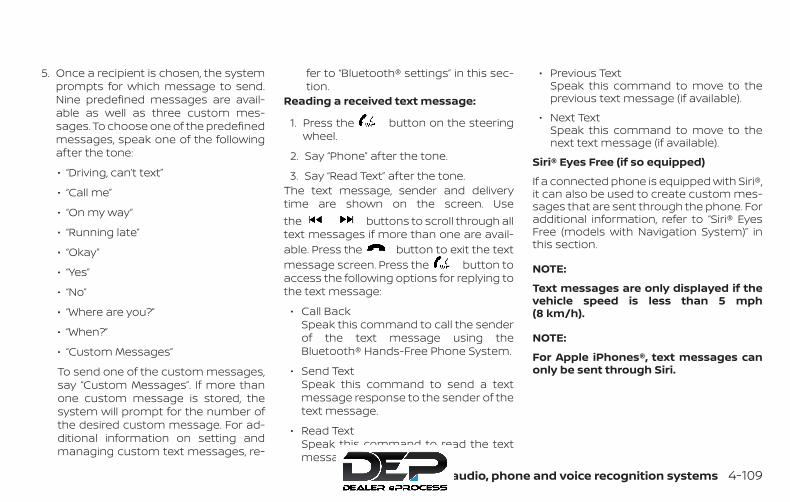
5. Once a recipient is chosen, the systemprompts for which message to send.Nine predefined messages are avail-able as well as three custom mes-sages. To choose one of the predefinedmessages, speak one of the followingafter the tone:
∙ “Driving, can’t text”
∙ “Call me”
∙ “On my way”
∙ “Running late”
∙ “Okay”
∙ “Yes”
∙ “No”
∙ “Where are you?”
∙ “When?”
∙ “Custom Messages”
To send one of the custom messages,say “Custom Messages”. If more thanone custom message is stored, thesystem will prompt for the number ofthe desired custom message. For ad-ditional information on setting andmanaging custom text messages, re-
fer to “Bluetooth® settings” in this sec-tion.
Reading a received text message:
1. Press the button on the steeringwheel.
2. Say “Phone” after the tone.
3. Say “Read Text” after the tone.The text message, sender and deliverytime are shown on the screen. Usethe buttons to scroll through alltext messages if more than one are avail-able. Press the button to exit the textmessage screen. Press the button toaccess the following options for replying tothe text message:
∙ Call BackSpeak this command to call the senderof the text message using theBluetooth® Hands-Free Phone System.
∙ Send TextSpeak this command to send a textmessage response to the sender of thetext message.
∙ Read TextSpeak this command to read the textmessage again.
∙ Previous TextSpeak this command to move to theprevious text message (if available).
∙ Next TextSpeak this command to move to thenext text message (if available).
Siri® Eyes Free (if so equipped)
If a connected phone is equipped with Siri®,it can also be used to create custom mes-sages that are sent through the phone. Foradditional information, refer to “Siri® EyesFree (models with Navigation System)” inthis section.
NOTE:
Text messages are only displayed if thevehicle speed is less than 5 mph(8 km/h).
NOTE:
For Apple iPhones®, text messages canonly be sent through Siri.
Monitor, climate, audio, phone and voice recognition systems 4-109

BLUETOOTH® SETTINGSTo access the phone settings:
1. Press the [ ] button.
2. Touch the “Settings” key.
3. Touch the “Phone & Bluetooth” key.
Menu Item ResultPhone Settings For additional information, refer to “Phone settings” in this section.Connect New Device Select to connect a new Bluetooth® device to the Bluetooth® Hands-Free Phone System.Select Connected Device Select to choose a Bluetooth® device from a list of those devices connected to the Bluetooth® Hands-Free Phone System.Replace Connected Device Select to replace a Bluetooth® device from a list of those devices connected to the Bluetooth® Hands-Free Phone System.Delete Connected Device Select to delete a Bluetooth® device from a list of those devices connected to the Bluetooth® Hands-Free Phone System.Bluetooth Select to toggle Bluetooth® on and off.
LHA2844
4-110 Monitor, climate, audio, phone and voice recognition systems

PHONE SETTINGSTo access the phone settings:
1. Press the [ ] button.
2. Touch the “Settings” key.
3. Touch the “Phone & Bluetooth” key.
4. Touch the “Phone Settings” key and ad-just the following settings as desired:
∙ Start Siri® by:Touch “Short Press” or “Long Press” toset how Siri® is operated on the steeringwheel.
∙ Sort Phonebook By:Touch “First Name” or “Last Name” tochoose how phonebook entries are al-phabetically displayed on the screen.
∙ Use Phonebook From:Touch “Handset” to use the phone’sphonebook. Touch “SIM” to use thephonebook on the SIM card. Select“Both” to use both sources.
∙ Download Phonebook Now:Touch to download the phonebook tothe vehicle from the chosen source.
∙ Record Name for Phonebook Entry:Touch to record a name for a phone-book entry for use with the NISSANVoice Recognition System.
∙ Phone Notifications for:Notifications may be displayed on thecenter display screen.
∙ Text Messaging (if so equipped):Touch to toggle the text message func-tionality on or off.
∙ Show Incoming Text for:Text notifications may be displayed onthe center display screen. Touch “Off ” toturn off all text notifications.
∙ Auto Reply:Touch to toggle the auto reply function-ality on or off.
∙ Auto Reply Message:Touch to indicate preferred message tobe sent when “Auto Reply” function isactivated.
∙ Use Vehicle’s Signature:Touch to toggle on or off the addition ofthe vehicle signature to outgoing mes-sages.
∙ Custom Text Messages:Touch this option to select a custommessage to edit. There are 4 customermessage slots available.
Monitor, climate, audio, phone and voice recognition systems 4-111
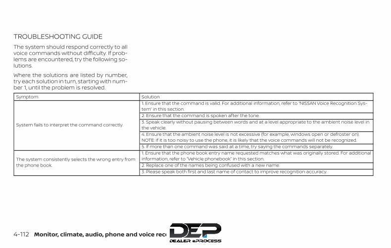
TROUBLESHOOTING GUIDEThe system should respond correctly to allvoice commands without difficulty. If prob-lems are encountered, try the following so-lutions.
Where the solutions are listed by number,try each solution in turn, starting with num-ber 1, until the problem is resolved.
Symptom Solution
System fails to interpret the command correctly.
1. Ensure that the command is valid. For additional information, refer to “NISSAN Voice Recognition Sys-tem” in this section.2. Ensure that the command is spoken after the tone.3. Speak clearly without pausing between words and at a level appropriate to the ambient noise level inthe vehicle.4. Ensure that the ambient noise level is not excessive (for example, windows open or defroster on).NOTE: If it is too noisy to use the phone, it is likely that the voice commands will not be recognized.5. If more than one command was said at a time, try saying the commands separately.
The system consistently selects the wrong entry fromthe phone book.
1. Ensure that the phone book entry name requested matches what was originally stored. For additionalinformation, refer to “Vehicle phonebook” in this section.2. Replace one of the names being confused with a new name.3. Please speak both first and last name of contact to improve recognition accuracy.
4-112 Monitor, climate, audio, phone and voice recognition systems

The NISSAN Voice Recognition System al-lows hands-free operation of the systemsequipped on this vehicle, such as thephone and navigation systems.
To operate NISSAN Voice Recognition,press the button located on thesteering wheel. When prompted, speak thecommand for the system you wish to acti-vate. The command given is picked up bythe microphone and performed when it isproperly recognized. NISSAN Voice Recog-nition will provide a voice response as wellas a message in the center display to in-form you of the command results.
USING THE SYSTEMInitializationWhen the ignition switch is in the ON posi-tion, NISSAN Voice Recognition is initialized,which takes a few seconds. When com-pleted, the system is ready to accept voicecommands. If the button is pressedbefore the initialization completes, the sys-tem will announce: “Voice Recognition Sys-tem not ready. Please wait.”
Giving voice commands1. Press the button.
2. The system announces: “Please say acategory like phone or a command likepoints of interest followed by a brandname”. A list of available commands isthen spoken by the system.
3. After the tone sounds and the face iconon the display changes, speak a com-mand. Available commands are dis-cussed in this section.
4. Voice and display feedback are pro-vided when the command is accepted.
∙ If the command is not recognized, thesystem announces: “Command notrecognized”. Repeat the command in aclear voice.
∙ If you want to cancel the command orgo back to the previous menu of com-mands, press the button. The sys-tem will announce: “Canceling VoiceRecognition” or “Go back” depending onthe current menu level.
∙ If you want to adjust the volume of thevoice feedback, use the volume controlswitches on the steering wheel or thevolume knob on the control panel.
∙ The voice command screen can also beaccessed using the control panel dis-play:
1. Press the [ ] button.
2. Touch the “Voice Commands” key.
LHA2589
NISSAN VOICE RECOGNITIONSYSTEM (if so equipped)
Monitor, climate, audio, phone and voice recognition systems 4-113
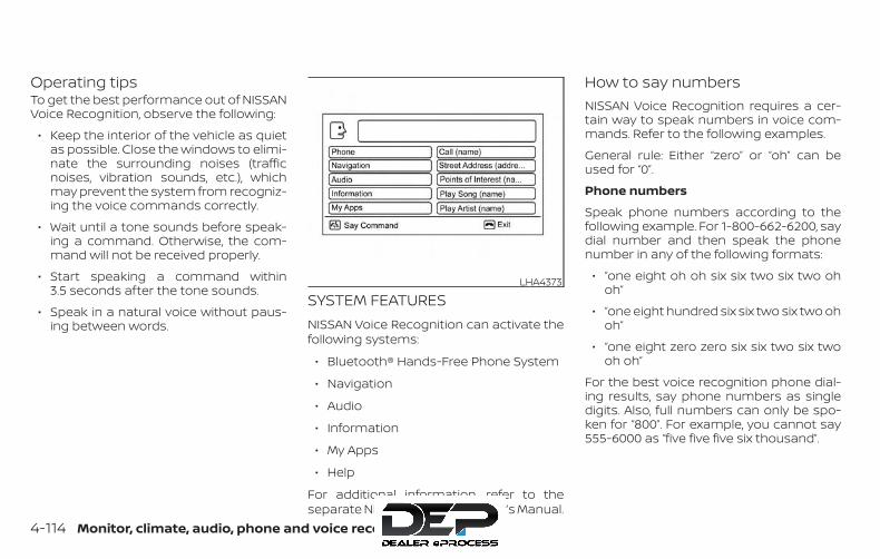
Operating tipsTo get the best performance out of NISSANVoice Recognition, observe the following:
∙ Keep the interior of the vehicle as quietas possible. Close the windows to elimi-nate the surrounding noises (trafficnoises, vibration sounds, etc.), whichmay prevent the system from recogniz-ing the voice commands correctly.
∙ Wait until a tone sounds before speak-ing a command. Otherwise, the com-mand will not be received properly.
∙ Start speaking a command within3.5 seconds after the tone sounds.
∙ Speak in a natural voice without paus-ing between words.
SYSTEM FEATURESNISSAN Voice Recognition can activate thefollowing systems:
∙ Bluetooth® Hands-Free Phone System
∙ Navigation
∙ Audio
∙ Information
∙ My Apps
∙ Help
For additional information, refer to theseparate NissanConnect® Owner’s Manual.
How to say numbersNISSAN Voice Recognition requires a cer-tain way to speak numbers in voice com-mands. Refer to the following examples.
General rule: Either “zero” or “oh” can beused for “0”.
Phone numbers
Speak phone numbers according to thefollowing example. For 1-800-662-6200, saydial number and then speak the phonenumber in any of the following formats:
∙ “one eight oh oh six six two six two ohoh”
∙ “one eight hundred six six two six two ohoh”
∙ “one eight zero zero six six two six twooh oh”
For the best voice recognition phone dial-ing results, say phone numbers as singledigits. Also, full numbers can only be spo-ken for “800”. For example, you cannot say555-6000 as “five five five six thousand”.
LHA4373
4-114 Monitor, climate, audio, phone and voice recognition systems

BLUETOOTH® HANDS-FREEPHONE SYSTEM VOICECOMMANDSTo access the Bluetooth® Hands-FreePhone System voice commands:
1. Press the button.
2. Say “Call” and then a name in the ve-hicle phonebook to call that entry. Oth-erwise, say “Phone” to access variousphone commands.
If the Bluetooth® has been set to “Off ”, thesystem announces: “Bluetooth® is off.Would you like to turn Bluetooth® on?”
If no phone is connected to the system andthe vehicle is stationary, the system an-nounces: “There is no phone connected.Would you like to connect a phone now?”Say “Yes” to connect a phone. All furtherBluetooth® Hands-Free Phone Systemvoice commands are only available if aphone is connected.
If a phone is connected and Bluetooth® isset to “On”, the following voice commandsare available:
∙ Call (a name)
Speak the name of the contact inwhich you are trying to call. System willconfirm correct contact. Say “Dial” toinitiate dialing.
∙ Dial Number
Allows for up to 24 digits to be dialed.After the number is entered, say “Dial”to initiate dialing. Say “Correction” tocorrect the number entered. Say “GoBack” to return to the main menu.
∙ List Phonebook
Starting with the first alphabetical en-try in the vehicle phonebook, the sys-tem prompts for an additional com-mand. Say “Dial” to call the number ofthe phonebook entry. Say “Send Text”to send a text message to the numberof the phonebook entry. Say “Next En-try” to skip to the next alphabetical en-try in the vehicle phonebook, wherethe same options will then be available.
∙ Recent Calls
The system prompts for an additionalcommand. Say “Missed Calls”, “Incom-ing Calls” or “Outgoing Calls” to displaya list of such calls on the screen.
Speak the number of the entry dis-played on the screen to dial that num-ber or say “Next Page” to view entrieson the next page (if available).
∙ RedialRedials the last called number.
∙ Read TextReads an incoming text message.
∙ Send TextSends a text message.
∙ Select PhoneThe system replies “Please use manualcontrols to continue”. Use manual con-trols to change the active phone fromamong the listed phones connectedto the vehicle.
∙ Siri (if so equipped)
The system replies “starting Siri”. Foradditional information, refer to “Siri®Eyes Free (models with Navigation Sys-tem)” in this section.
Monitor, climate, audio, phone and voice recognition systems 4-115
For additional information, refer to“Bluetooth® Hands-Free Phone Systemwith Navigation System” in this section.
NAVIGATION SYSTEM VOICECOMMANDSThe following voice commands are avail-able for the navigation system:
∙ Street Address (address)
∙ Points of Interest (name)
∙ POI by Category
∙ Home
∙ Address Book
∙ Previous Destinations
∙ Enter Address in Steps
∙ Cancel Route
For additional information, refer to theseparate NissanConnect® Owner’s Manual.
AUDIO SYSTEM VOICE COMMANDSTo access the audio system voice commands:
1. Press the button.
2. Say “Audio”
3. Speak a command from the followingavailable commands:
∙ Play (AM, FM, etc.)
Allows user to select radio band
∙ Tune AM (number)
Allows user to tune directly to a desiredAM frequency
∙ Tune FM (number)
Allows user to tune directly to a desiredFM frequency
∙ SXM channel (number)
Allows user to tune directly to a desiredSXM station (if so equipped)
∙ CD Track (number)
Allows user to select track to be played
∙ Play Song (name)
Allows user to select song name to beplayed
∙ Play Artist (name)
Allows user to select artist to be played
∙ Play Album (name)
Allows user to select album name tobe played
For additional information, refer to “Audiosystem” in this section.
INFORMATION VOICE COMMANDSThe following voice commands are avail-able for the information functions of thenavigation system:
∙ Traffic
∙ Fuel Prices
∙ Stocks
∙ Movie Listings
∙ Current Weather
∙ Weather Map
∙ 5 — day Forecast
∙ 6 — hour Forecast
For additional information, refer to theseparate NissanConnect® Owner’s Manual.
4-116 Monitor, climate, audio, phone and voice recognition systems

MY APPS VOICE COMMANDSMany Apps can be accessed using thisvoice command. For additional informa-tion, refer to “NissanConnect® Mobile Apps”in this section.
HELP VOICE COMMANDSThe following voice commands can bespoken to have the system provide in-structions and tips for using the NISSANVoice Recognition System.
∙ List Commands
∙ What Can I Say?
∙ General Help
∙ Go Back
∙ Quit
∙ Exit
TROUBLESHOOTING GUIDEThe system should respond correctly to allvoice commands without difficulty. If prob-lems are encountered, follow the solutionsgiven in this guide for the appropriate error.Where the solutions are listed by number,try each solution in turn, starting with num-ber one, until the problem is resolved.
Symptom/error message SolutionThe system responds “CommandNot Recognized” or the system failsto recognize the commandcorrectly.
1. Ensure that the command format is valid. Use the “List Commands” or “What Can I Say?” command under the “Help”menu.
2. Speak clearly without pausing between words and at a level appropriate to the ambient noise level.3. Ensure that the ambient noise level is not excessive (for example, with the windows open or the defroster on).
NOTE:
If it is too noisy to use the phone, it is likely that voice commands will not be recognized.4. If optional words of the command have been omitted, then the command should be tried with these in place.
Monitor, climate, audio, phone and voice recognition systems 4-117

5 Starting and driving
Precautions when starting and driving . . . . . . . . . . 5-2Exhaust gas (carbon monoxide) . . . . . . . . . . . . . . 5-2Three-way catalyst . . . . . . . . . . . . . . . . . . . . . . . . . . . 5-3Tire Pressure Monitoring System(TPMS). . . . . . . . . . . . . . . . . . . . . . . . . . . . . . . . . . . . . . . . 5-3On-pavement and off-road drivingprecautions . . . . . . . . . . . . . . . . . . . . . . . . . . . . . . . . . . 5-6Avoiding collision and rollover . . . . . . . . . . . . . . . . 5-6Off-road recovery . . . . . . . . . . . . . . . . . . . . . . . . . . . . 5-7Rapid air pressure loss . . . . . . . . . . . . . . . . . . . . . . . 5-7Drinking alcohol/drugs and driving . . . . . . . . . . . 5-8Driving safety precautions . . . . . . . . . . . . . . . . . . . . 5-8
Ignition switch. . . . . . . . . . . . . . . . . . . . . . . . . . . . . . . . . . .5-11Automatic transmission(if so equipped) . . . . . . . . . . . . . . . . . . . . . . . . . . . . . . .5-11Manual transmission (M/T)(if so equipped) . . . . . . . . . . . . . . . . . . . . . . . . . . . . . . 5-12Key positions . . . . . . . . . . . . . . . . . . . . . . . . . . . . . . . . 5-12NISSAN Vehicle Immobilizer System(if so equipped) . . . . . . . . . . . . . . . . . . . . . . . . . . . . . . 5-12
Before starting the engine. . . . . . . . . . . . . . . . . . . . . . 5-13Starting the engine . . . . . . . . . . . . . . . . . . . . . . . . . . . . . 5-13Driving the vehicle . . . . . . . . . . . . . . . . . . . . . . . . . . . . . . 5-14
Automatic transmission (A/T)(if so equipped) . . . . . . . . . . . . . . . . . . . . . . . . . . . . . . 5-14Manual transmission (if so equipped) . . . . . . . . 5-19
Parking brake . . . . . . . . . . . . . . . . . . . . . . . . . . . . . . . . . . 5-21Cruise control . . . . . . . . . . . . . . . . . . . . . . . . . . . . . . . . . . 5-22
Precautions on cruise control. . . . . . . . . . . . . . . . 5-22Cruise control operations. . . . . . . . . . . . . . . . . . . . 5-23
Break-in schedule . . . . . . . . . . . . . . . . . . . . . . . . . . . . . . 5-24Fuel efficient driving tips . . . . . . . . . . . . . . . . . . . . . . . . 5-24Increasing fuel economy . . . . . . . . . . . . . . . . . . . . . . . 5-25
Using 4–Wheel Drive (4WD)(if so equipped) . . . . . . . . . . . . . . . . . . . . . . . . . . . . . . . . . 5-26
Transfer case shifting procedures . . . . . . . . . . . 5-26Electronic locking rear differential (E-Lock)system (if so equipped) . . . . . . . . . . . . . . . . . . . . . . . . . 5-33Parking/parking on hills . . . . . . . . . . . . . . . . . . . . . . . . 5-34Power steering . . . . . . . . . . . . . . . . . . . . . . . . . . . . . . . . . 5-35Brake system. . . . . . . . . . . . . . . . . . . . . . . . . . . . . . . . . . . 5-35
Brake precautions . . . . . . . . . . . . . . . . . . . . . . . . . . . 5-35Anti-lock Braking System (ABS) . . . . . . . . . . . . . . 5-36
Active Brake Limited Slip (ABLS) system. . . . . . . . . 5-37Vehicle Dynamic Control (VDC) system . . . . . . . . . 5-38
Brake force distribution. . . . . . . . . . . . . . . . . . . . . . 5-40
Hill descent control system (if so equipped) . . . . . 5-41Hill start assist system (if so equipped) . . . . . . . . . 5-42Rear Sonar System (RSS) (if so equipped) . . . . . . . 5-42Cold weather driving . . . . . . . . . . . . . . . . . . . . . . . . . . . 5-43
Freeing a frozen door lock . . . . . . . . . . . . . . . . . . . 5-43Antifreeze . . . . . . . . . . . . . . . . . . . . . . . . . . . . . . . . . . . 5-43
Battery . . . . . . . . . . . . . . . . . . . . . . . . . . . . . . . . . . . . . . 5-43Draining of coolant water. . . . . . . . . . . . . . . . . . . . 5-43Tire equipment . . . . . . . . . . . . . . . . . . . . . . . . . . . . . . 5-44Special winter equipment . . . . . . . . . . . . . . . . . . . 5-44Driving on snow or ice . . . . . . . . . . . . . . . . . . . . . . . 5-44Engine block heater (if so equipped) . . . . . . . . . 5-45
WARNING∙ Do not leave children or adults who
would normally require the assis-tance of others alone in your vehicle.Pets should also not be left alone.They could accidentally injure them-selves or others through inadvertentoperation of the vehicle. Also, on hot,sunny days, temperatures in a closedvehicle could quickly become highenough to cause severe or possiblyfatal injuries to people or animals.
∙ Properly secure all cargo with ropes orstraps to help prevent it from slidingor shifting. Do not place cargo higherthan the seatbacks. In a sudden stopor collision, unsecured cargo couldcause personal injury.
EXHAUST GAS (carbon monoxide)
WARNING∙ Do not breathe exhaust gases; they
contain colorless and odorless carbonmonoxide. Carbon monoxide is dan-gerous. It can cause unconsciousnessor death.
∙ If you suspect that exhaust fumes areentering the vehicle, drive with allwindows fully open, and have the ve-hicle inspected immediately.
∙ Do not run the engine in closed spacessuch as a garage.
∙ Do not park the vehicle with the en-gine running for any extended lengthof time.
∙ Keep the rear vent windows, liftgates,doors and trunk lids (if so equipped)closed while driving, otherwise ex-haust gases could be drawn into thepassenger compartment. If you mustdrive with one of these open, followthese precautions:
1. Open all the windows.
2. Set the air recirculation but-ton to off and the fan control dial tohigh to circulate the air.
∙ If electrical wiring or other cable con-nections must pass to a trailerthrough the seal on the liftgate or thebody, follow the manufacturer’s rec-ommendation to prevent carbonmonoxide entry into the vehicle.
∙ The exhaust system and body shouldbe inspected by a qualified mechanicwhenever:
a. The vehicle is raised for service.
b. You suspect that exhaust fumesare entering into the passengercompartment.
c. You notice a change in the sound ofthe exhaust system.
d. You have had an accident involvingdamage to the exhaust system,underbody, or rear of the vehicle.
∙ If a special body, camper, or otherequipment is added for recreationalor other usage, follow the manufac-turer’s recommendation to preventcarbon monoxide entry into the ve-hicle. Do not occupy these areas whilethe engine is running even if the ve-hicle is parked. Some recreational ve-hicle appliances such as stoves, re-frigerators, heaters, etc. may alsogenerate carbon monoxide.
PRECAUTIONS WHEN STARTING ANDDRIVING
5-2 Starting and driving
THREE-WAY CATALYSTThe three-way catalyst is an emission con-trol device installed in the exhaust system.Exhaust gases in the three-way catalystare burned at high temperatures to helpreduce pollutants.
WARNING∙ The exhaust gas and the exhaust sys-
tem are very hot. Keep people, ani-mals or flammable materials awayfrom the exhaust systemcomponents.
∙ Do not stop or park the vehicle overflammable materials such as drygrass, waste paper or rags. They mayignite and cause a fire.
CAUTION∙ Do not use leaded gasoline. Deposits
from leaded gasoline will seriously re-duce the three-way catalyst’s abilityto help reduce exhaust pollutants.
∙ Keep your engine tuned up. Malfunc-tions in the ignition, fuel injection, orelectrical systems can cause overrichfuel flow into the three-way catalyst,causing it to overheat. Do not keepdriving if the engine misfires, or if no-ticeable loss of performance or otherunusual operating conditions are de-tected. Have the vehicle inspectedpromptly. It is recommended that youvisit a NISSAN dealer for this service.
∙ Avoid driving with an extremely lowfuel level. Running out of fuel couldcause the engine to misfire, damag-ing the three-way catalyst.
∙ Do not race the engine while warmingit up.
∙ Do not push or tow your vehicle tostart the engine.
TIRE PRESSURE MONITORINGSYSTEM (TPMS)Each tire, including the spare (if provided),should be checked monthly when cold andinflated to the inflation pressure recom-mended by the vehicle manufacturer onthe vehicle placard or tire inflation pressurelabel. (If your vehicle has tires of a differentsize than the size indicated on the vehicle
placard or tire inflation pressure label, youshould determine the proper tire inflationpressure for those tires.)
As an added safety feature, your vehiclehas been equipped with a Tire PressureMonitoring System (TPMS) that illuminatesa low tire pressure telltale when one ormore of your tires is significantly under-inflated. Accordingly, when the low tirepressure telltale illuminates, you shouldstop and check your tires as soon as pos-sible, and inflate them to the proper pres-sure. Driving on a significantly under-inflated tire causes the tire to overheat andcan lead to tire failure. Under-inflation alsoreduces fuel efficiency and tire tread life,and may affect the vehicle’s handling andstopping ability.
Please note that the TPMS is not a substi-tute for proper tire maintenance, and it isthe driver’s responsibility to maintain cor-rect tire pressure, even if under-inflationhas not reached the level to trigger illumi-nation of the TPMS low tire pressure telltale.
Your vehicle has also been equipped with aTPMS malfunction indicator to indicatewhen the system is not operating properly.The TPMS malfunction indicator is com-bined with the low tire pressure telltale.
Starting and driving 5-3

When the system detects a malfunction,the telltale will flash for approximately1 minute and then remain continuously illu-minated. This sequence will continue uponsubsequent vehicle start-ups as long asthe malfunction exists. When the malfunc-tion indicator is illuminated, the systemmay not be able to detect or signal low tirepressure as intended. TPMS malfunctionsmay occur for a variety of reasons, includ-ing the installation of replacement or alter-nate tires or wheels on the vehicle thatprevent the TPMS from functioning prop-erly. Always check the TPMS malfunctiontelltale after replacing one or more tires orwheels on your vehicle to ensure that thereplacement or alternate tires and wheelsallow the TPMS to continue to functionproperly.
Additional information:
∙ When replacing a wheel without theTPMS such as the spare tire, the TPMSdoes not monitor the tire pressure ofthe spare tire.
∙ The TPMS will activate only when the ve-hicle is driven at speeds above 16 mph(25 km/h). Also, this system may not de-tect a sudden drop in tire pressure (forexample, a flat tire while driving).
∙ The low tire pressure warning light doesnot automatically turn off when the tirepressure of your tires are adjusted. Afterthe tires are inflated to the recom-mended pressure, the vehicle must bedriven at speeds above 16 mph(25 km/h) to activate the TPMS and turnoff the low tire pressure warning light.Use a tire pressure gauge to check thetire pressure.
∙ The CHECK TIRE PRES (pressure) warn-ing message is displayed in the odom-eter when the low tire pressure warninglight is illuminated and low tire pressureis detected. The CHECK TIRE PRES warn-ing message turns off when the low tirepressure warning light turns off. The lowtire pressure warning light remains illu-minated until the tires are inflated to therecommended COLD tire pressure. TheCHECK TIRE PRES warning message isdisplayed each time the ignition switchis placed in the ON position as long asthe low tire pressure warning light re-mains illuminated. For additional infor-mation, refer to “Check tire pressurewarning message” in the “Instrumentsand controls” section of this manual.
∙ The CHECK TIRE PRES warning is notdisplayed if the low tire pressure warn-ing light illuminates to indicate a TPMSmalfunction.
∙ The CHECK TIRE PRES warning appearseach time the ignition switch is placedin the ON position as long as the low tirepressure warning light remains illumi-nated.
∙ Tire pressure rises and falls dependingon the heat caused by the vehicle’s op-eration and the outside temperature.Do not reduce the tire pressure afterdriving because the tire pressure risesafter driving. Low outside temperaturecan lower the temperature of the airinside the tire which can cause a lowertire inflation pressure. This may causethe low tire pressure warning light toilluminate. If the warning light illumi-nates, check the tire pressure for all fourtires.
∙ The Tire and Loading Information labelis located in the driver’s door opening.
For additional information, refer to “Low tirepressure warning light” in the “Instrumentsand controls” section and “Tire PressureMonitoring System (TPMS)” in the “In case ofemergency” section of this manual.
5-4 Starting and driving

WARNING∙ Radio waves could adversely affect
electric medical equipment. Thosewho use a pacemaker should contactthe electric medical equipmentmanufacturer for the possible influ-ences before use.
∙ If the low tire pressure warning lightilluminates while driving, avoid suddensteering maneuvers or abrupt braking,reduce vehicle speed, pull off the roadto a safe location and stop the vehicleas soon as possible. Driving with under-inflated tires may permanently dam-age the tires and increase the likeli-hood of tire failure. Serious vehicledamage could occur and may lead toan accident and could result in seriouspersonal injury. Check the tire pressurefor all four tires. Adjust the tire pressureto the recommended COLD tire pres-sure shown on the Tire and Loading In-formation label to turn the low tirepressure warning light off. If you have aflat tire, replace it with a spare tire assoon as possible. For additional infor-mation, refer to “Flat tire” in the “In caseof emergency” section of this manualfor changing a flat tire.
∙ When replacing a wheel without theTPMS such as the spare tire, when aspare tire is mounted or a wheel isreplaced, the TPMS will not functionand the low tire pressure warninglight will flash for approximately1 minute. The light will remain on after1 minute. Have your tires replacedand/or TPMS system reset as soon aspossible. It is recommended that youvisit a NISSAN dealer for this service.
∙ Replacing tires with those not origi-nally specified by NISSAN could affectthe proper operation of the TPMS.
∙ Do not inject any tire liquid or aerosoltire sealant into the tires, as this maycause a malfunction of the tire pres-sure sensors.
CAUTIONDo not place metalized film or anymetal parts (antenna, etc.) on the win-dows. This may cause poor reception ofthe signals from the tire pressure sen-sors, and the TPMS will not functionproperly.
Some devices and transmitters may tem-porarily interfere with the operation of theTPMS and cause the low tire pressurewarning light to illuminate.
Some examples are:
∙ Facilities or electric devices using simi-lar radio frequencies are near the ve-hicle.
∙ If a transmitter set to similar frequen-cies is being used in or near the vehicle.
∙ If a computer (or similar equipment) ora DC/AC converter is being used in ornear the vehicle.
The low tire pressure warning light mayilluminate in the following cases:
∙ If the vehicle is equipped with a wheeland tire without TPMS.
∙ If the TPMS has been replaced and theID has not been registered.
∙ If the wheel is not originally specified byNISSAN.
Starting and driving 5-5

FCC Notice:
For USA:
This device complies with Part 15 of theFCC Rules. Operation is subject to the fol-lowing two conditions: (1) This devicemay not cause harmful interference, and(2) this device must accept any interfer-ence received, including interferencethat may cause undesired operation.
NOTE:
Changes or modifications not expresslyapproved by the party responsible forcompliance could void the user’s author-ity to operate the equipment.
For Canada:
This device complies with IndustryCanada licence-exempt RSS standard(s).Operation is subject to the following twoconditions: (1) this device may not causeinterference, and (2) this device must ac-cept any interference, including interfer-ence that may cause undesired opera-tion of the device.
ON-PAVEMENT AND OFF-ROADDRIVING PRECAUTIONSUtility vehicles have a significantlyhigher rollover rate than other types ofvehicles.
They have higher ground clearance thanpassenger cars to make them capable ofperforming in a variety of on-pavementand off-road applications. This gives thema higher center of gravity than ordinary ve-hicles. An advantage of higher groundclearance is a better view of the road, allow-ing you to anticipate problems. However,they are not designed for cornering at thesame speeds as conventional 2-WheelDrive vehicles any more than low-slungsports cars are designed to perform satis-factorily under off-road conditions. If at allpossible, avoid sharp turns at high speeds.As with other vehicles of this type, failure tooperate this vehicle correctly may result inloss of control or vehicle rollover. In a roll-over crash, an unbelted person is signifi-cantly more likely to die than a personwearing a seat belt.
For additional information, refer to “Drivingsafety precautions” in this section.
AVOIDING COLLISION ANDROLLOVER
WARNINGFailure to operate this vehicle in a safeand prudent manner may result in lossof control or an accident.
Be alert and drive defensively at all times.Obey all traffic regulations. Avoid excessivespeed, high speed cornering, or suddensteering maneuvers, because these drivingpractices could cause you to lose control ofyour vehicle.
As with any vehicle, loss of control couldresult in a collision with other vehicles orobjects or cause the vehicle to roll over,particularly if the loss of control causesthe vehicle to slide sideways.
Be attentive at all times, and avoid drivingwhen tired. Never drive when under the in-fluence of alcohol or drugs (including pre-scription or over-the-counter drugs whichmay cause drowsiness). Always wear yourseat belt as outlined in the “Safety – Seats,seat belts and supplemental restraint sys-tem” section of this manual, and also in-struct your passengers to do so.
5-6 Starting and driving

Seat belts help reduce the risk of injury incollisions and rollovers. In a rollover crash,an unbelted or improperly belted personis significantly more likely to be injuredor killed than a person properly wearinga seat belt.
OFF-ROAD RECOVERYWhile driving, the right side or left sidewheels may unintentionally leave the roadsurface. If this occurs, maintain control ofthe vehicle by following the procedure be-low. Please note that this procedure is onlya general guide. The vehicle must be drivenas appropriate based on the conditions ofthe vehicle, road and traffic.
1. Remain calm and do not overreact.
2. Do not apply the brakes.
3. Maintain a firm grip on the steeringwheel with both hands and try to hold astraight course.
4. When appropriate, slowly release theaccelerator pedal to gradually slow thevehicle.
5. If there is nothing in the way, steer thevehicle to follow the road while vehiclespeed is reduced. Do not attempt todrive the vehicle back onto the roadsurface until vehicle speed is reduced.
6. When it is safe to do so, gradually turnthe steering wheel until both tires re-turn to the road surface. When all tiresare on the road surface, steer the ve-hicle to stay in the appropriate drivinglane.
∙ If you decide that it is not safe to re-turn the vehicle to the road surfacebased on vehicle, road or traffic con-ditions, gradually slow the vehicle to astop in a safe place off the road.
RAPID AIR PRESSURE LOSSRapid air pressure loss or a “blow-out” canoccur if the tire is punctured or is damageddue to hitting a curb or pothole. Rapid airpressure loss can also be caused by drivingon under-inflated tires.
Rapid air pressure loss can affect the han-dling and stability of the vehicle, especiallyat highway speeds.
Help prevent rapid air pressure loss bymaintaining the correct air pressure andvisually inspecting the tires for wear anddamage. For additional information, referto “Wheels and tires” in the “Do-it-yourself ”section of this manual. If a tire rapidly losesair pressure or “blows-out” while driving,maintain control of the vehicle by followingthe procedure below. Please note that thisprocedure is only a general guide. The ve-hicle must be driven as appropriate basedon the conditions of the vehicle, road andtraffic.
WARNINGThe following actions can increase thechance of losing control of the vehicle ifthere is a sudden loss of tire air pres-sure. Losing control of the vehicle maycause a collision and result in personalinjury.
∙ The vehicle generally moves or pullsin the direction of the flat tire.
∙ Do not rapidly apply the brakes.
∙ Do not rapidly release the acceleratorpedal.
∙ Do not rapidly turn the steering wheel.
Starting and driving 5-7
1. Remain calm and do not overreact.
2. Maintain a firm grip on the steeringwheel with both hands and try to hold astraight course.
3. When appropriate, slowly release theaccelerator pedal to gradually slow thevehicle.
4. Gradually steer the vehicle to a safelocation off the road and away fromtraffic if possible.
5. Lightly apply the brake pedal to gradu-ally stop the vehicle.
6. Turn on the hazard warning flashersand contact a roadside emergencyservice to change the tire. For addi-tional information, refer to “Changing aflat tire” in the “In case of emergency”section of this manual.
DRINKING ALCOHOL/DRUGS ANDDRIVING
WARNINGNever drive under the influence of alco-hol or drugs. Alcohol in the bloodstreamreduces coordination, delays reactiontime and impairs judgement. Drivingafter drinking alcohol increases thelikelihood of being involved in an acci-dent injuring yourself and others. Addi-tionally, if you are injured in an accident,alcohol can increase the severity of theinjury.
NISSAN is committed to safe driving. How-ever, you must choose not to drive underthe influence of alcohol. Every year thou-sands of people are injured or killed inalcohol-related collisions. Although the lo-cal laws vary on what is considered to belegally intoxicated, the fact is that alcoholaffects all people differently and mostpeople underestimate the effects of alco-hol.
Remember, drinking and driving don’t mix!That is true for drugs (over-the-counter,prescription) and illegal drugs, too. Don’t
drive if your ability to operate your vehicle isimpaired by alcohol, drugs, or some otherphysical condition.
DRIVING SAFETY PRECAUTIONSYour NISSAN is designed for both normaland off-road use. However, avoid driving indeep water or mud as your NISSAN ismainly designed for leisure use, unlike aconventional off-road vehicle.
Remember that 2-Wheel Drive models areless capable than 4–Wheel Drive (4WD)models for rough road driving and extrica-tion when stuck in deep snow or mud, orthe like.
Please observe the following precautions:
WARNING∙ Drive carefully when off the road and
avoid dangerous areas. Every personwho drives or rides in this vehicleshould be seated with their seat beltfastened. This will keep you and yourpassengers in position when drivingover rough terrain.
5-8 Starting and driving

∙ Do not drive across steep slopes. In-stead drive either straight up orstraight down the slopes. Off-road ve-hicles can tip over sideways muchmore easily than they can forward orbackward.
∙ Many hills are too steep for any ve-hicle. If you drive up them, you maystall. If you drive down them, you maynot be able to control your speed. Ifyou drive across them, you may rollover.
∙ Do not shift gears while driving ondownhill grades as this could causeloss of control of the vehicle.
∙ Stay alert when driving to the top of ahill. At the top there could be a drop-off or other hazard that could causean accident.
∙ If your engine stalls or you cannotmake it to the top of a steep hill, neverattempt to turn around. Your vehiclecould tip or roll over. Always backstraight down in R (Reverse) gear.Never back down in N (Neutral) or withthe clutch depressed (manual trans-mission vehicles), using only thebrake, as this could cause loss ofcontrol.
∙ Heavy braking going down a hill couldcause your brakes to overheat andfade, resulting in loss of control andan accident. Apply brakes lightly anduse a low gear to control your speed.Use the hill descent control feature (ifso equipped).
∙ Unsecured cargo can be thrownaround when driving over rough ter-rain. Properly secure all cargo so it willnot be thrown forward and cause in-jury to you or your passengers.
∙ To avoid raising the center of gravityexcessively, do not exceed the ratedcapacity of the roof rack (if soequipped) and evenly distribute theload. Secure heavy loads in the cargoarea as far forward and as low as pos-sible. Do not equip the vehicle withtires larger than specified in thismanual. This could cause your vehicleto roll over.
∙ Do not grip the inside or spokes of thesteering wheel when driving off-road.The steering wheel could move sud-denly and injure your hands. Insteaddrive with your fingers and thumbs onthe outside of the rim.
∙ Before operating the vehicle, ensurethat the driver and all passengershave their seat belts fastened.
∙ Always drive with the floor mats inplace as the floor may become hot.
∙ Lower your speed when encounteringstrong crosswinds. With a higher cen-ter of gravity, your NISSAN is more af-fected by strong side winds. Slowerspeeds ensure better vehicle control.
Starting and driving 5-9
∙ Do not drive beyond the performancecapability of the tires, even with 4WDengaged (if so equipped).
∙ For 4WD equipped vehicles, do not at-tempt to raise two wheels off theground and shift the transmission toany drive or reverse position with theengine running. Doing so may resultin drivetrain damage or unexpectedvehicle movement which could resultin serious vehicle damage or personalinjury.
∙ Do not attempt to test a 4WDequipped vehicle on a 2-wheel dyna-mometer (such as the dynamometersused by some states for emissionstesting), or similar equipment even ifthe other two wheels are raised off theground. Make sure you inform test fa-cility personnel that your vehicle isequipped with 4WD before it is placedon a dynamometer. Using the wrongtest equipment may result in drive-train damage or unexpected vehiclemovement which could result in seri-ous vehicle damage or personalinjury.
∙ Accelerating quickly, sharp steeringmaneuvers or sudden braking maycause loss of control.
∙ If at all possible, avoid sharp turningmaneuvers, particularly at highspeeds. Your NISSAN 4WD vehicle hasa higher center of gravity than a pas-senger car. The vehicle is not de-signed for cornering at the samespeeds as passenger cars. Failure tooperate this vehicle correctly couldresult in loss of control and/or a roll-over accident.
∙ Always use tires of the same type,size, brand, construction (bias, bias-belted, or radial), and tread pattern onall four wheels. Install tire chains onthe rear wheels when driving on slip-pery roads and drive carefully.
∙ Be sure to check the brakes immedi-ately after driving in mud or water. Foradditional information, refer to “Wetbrakes” in this section.
∙ Avoid parking your vehicle on steephills. If you get out of the vehicle and itrolls forward, backward or sideways,you could be injured.
∙ Whenever you drive off-road throughsand, mud or water as deep as thewheel hub, more frequent mainte-nance may be required. For additionalinformation, refer to “Maintenanceunder severe operating conditions” inthe “Maintenance and schedules” sec-tion of this manual.
5-10 Starting and driving

WARNING∙ Never remove the ignition key or place
the ignition switch in the LOCK posi-tion while driving. The steering wheelwill lock (for models with a steeringlock mechanism). This may cause thedriver to lose control of the vehicleand could result in serious vehicledamage or personal injury.
AUTOMATIC TRANSMISSION (if soequipped)The ignition lock is designed so the ignitionswitch cannot be placed in the LOCK posi-tion and the key removed until the shiftlever is moved to the P (Park) position.
When removing the key from the ignition,make sure the shift lever is in the P (Park)position.
If the shift lever is not returned to P (Park)position, the ignition switch cannot beplaced in the LOCK position.
To remove the key from the ignition switch:
1. Move the shift lever to the P (Park) posi-tion with the ignition switch in the ONposition.
2. Place the ignition switch in the LOCKposition.
3. Remove the key from the ignition.
If the shift lever is moved to the P (Park)position after the ignition switch is placedin the OFF position or when the ignitionswitch cannot be turned to the LOCK posi-tion, proceed as follows to remove the key.
1. Move the shift lever into the P (Park)position.
2. Turn the ignition key slightly toward theON position.
3. Turn the key to the LOCK position.
4. Remove the key.
The shift lever is designed so it cannot bemoved out of P (Park) and into any of theother gear positions if the ignition key isplaced in the OFF position or if the key isremoved from the switch.
The shift lever can be moved if the igni-tion switch is in the ON position and thefoot brake pedal is depressed.
WSD0041
IGNITION SWITCH
Starting and driving 5-11

There is an OFF position between theLOCK and ON positions. The OFF positionis indicated by a “1” on the ignitionswitch. When the ignition is in the OFFposition, the steering wheel is not locked(for models with a steering lock mecha-nism).
In order for the steering wheel to be locked,it must be turned about 1/8 of a turn clock-wise from the straight up position.
To lock the steering wheel, turn the keyto the LOCK position. Remove the key. Tounlock the steering wheel, insert the keyand turn it gently while rotating thesteering wheel slightly right and left.
If the key will not turn from the LOCKposition, turn the steering wheel to theleft or right while turning the key to un-lock the key cylinder.
MANUAL TRANSMISSION (M/T) (ifso equipped)The ignition switch includes a device thathelps prevent accidental removal of thekey while driving.
The key can only be removed when theignition switch is in the LOCK position.
On M/T models, to turn the ignition switchto the LOCK position from the ACC or ONposition, place the ignition switch in theOFF position, push the key in, then place theignition switch in the LOCK position.
KEY POSITIONSLOCK: Normal parking position (0)
OFF: (Not used) (1)
ACC: (Accessories) (2)
This position activates electrical accesso-ries such as the radio when the engine isnot running.
ON: Normal operating position (3)
This position turns on the ignition systemand the electrical accessories.
START: (4)
This position starts the engine. As soon asthe engine has started, release the key. Itautomatically returns to the ON position.
NISSAN VEHICLE IMMOBILIZERSYSTEM (if so equipped)The NISSAN Vehicle Immobilizer Systemwill not allow the engine to start withoutthe use of the registered key.
WSD0052
5-12 Starting and driving
If the engine fails to start using a registeredkey (for example, when interference iscaused by another registered key, an auto-mated toll road device or automatic pay-ment device on the key ring), restart theengine using the following procedures:
1. Leave the ignition switch in the ON po-sition for approximately 5 seconds.
2. Place the ignition switch in the OFF orLOCK position, and wait approximately10 seconds.
3. Repeat steps 1 and 2.
4. Restart the engine while holding thedevice (which may have caused the in-terference) separate from the regis-tered key.
If the no start condition re-occurs, NISSANrecommends placing the registered key ona separate key ring to avoid interferencefrom other devices.
∙ Make sure the area around the vehicle isclear.
∙ Check fluid levels such as engine oil,coolant, brake and clutch fluid (if soequipped), and windshield-washer fluidas frequently as possible, or at leastwhenever you refuel.
∙ Check that all windows and lights areclean.
∙ Visually inspect tires for their appear-ance and condition. Also check tires forproper inflation.
∙ Check that all doors are closed.
∙ Position seat and adjust headrestraints/headrests.
∙ Adjust inside and outside mirrors.
∙ Fasten the seat belt and ask all passen-gers to do likewise.
∙ Check the operation of warning lightswhen the key is placed in the ON posi-tion. For additional information, refer to“Warning lights, indicator lights and au-dible reminders” in the “Instrumentsand controls” section of this manual.
1. Apply the parking brake.
2. Automatic transmission:
Move the shift lever to P (Park) or N(Neutral). P (Park) is recommended.
The shift lever cannot be moved outof the P (Park) position and into anyof the other gear positions if the ig-nition switch is placed in the OFF po-sition or if the key is removed fromthe ignition switch.
The starter is designed not to oper-ate if the shift lever is in any of thedriving positions.
Manual transmission:
Move the shift lever to N (Neutral). De-press the clutch pedal to the floorwhile cranking the engine.
The starter is designed not to oper-ate unless the clutch pedal is fullydepressed.
3. Crank the engine with your foot offthe accelerator pedal by placing theignition switch in the START position.Release the key when the enginestarts. If the engine starts, but fails torun, repeat the above procedure.
BEFORE STARTING THE ENGINE STARTING THE ENGINE
Starting and driving 5-13
∙ If the engine is very hard to start inextremely cold weather or when re-starting, depress the acceleratorpedal a little (approximately 1/3 to thefloor) and hold it and then crank theengine. Release the key and the ac-celerator pedal when the enginestarts.
∙ If the engine is very hard to start be-cause it is flooded, depress the accel-erator pedal all the way to the floorand hold it. Crank the engine for5-6 seconds. After cranking the en-gine, release the accelerator pedal.Crank the engine with your foot offthe accelerator pedal by placing theignition in the START position. Re-lease the key when the engine starts.If the engine starts, but fails to run,repeat the above procedure.
CAUTIONDo not operate the starter for morethan 15 seconds at a time. If the enginedoes not start, turn the key off and wait10 seconds before cranking again, oth-erwise the starter could be damaged.
4. Allow the engine to idle for at least30 seconds after starting. Do not racethe engine while warming it up. Drive ata moderate speed for a short distancefirst, especially in cold weather.
NOTE:
Care should be taken to avoid situationsthat can lead to potential battery dis-charge and potential no-start conditionssuch as:
1. Installation or extended use of elec-tronic accessories that consume bat-tery power when the engine is notrunning (phone chargers, GPS, DVDplayers, etc.).
2. The vehicle is not driven regularlyand/or only driven short distances.
In these cases, the battery may need tobe charged to maintain battery health.
AUTOMATIC TRANSMISSION (A/T)(if so equipped)
WARNING∙ Do not depress the accelerator pedal
while shifting from P (Park) or N (Neu-tral) to R (Reverse), D (Drive), 3, 2 or 1.Always depress the brake pedal untilshifting is completed. Failure to do socould cause you to lose control andhave an accident.
∙ Cold engine idle speed is high, so usecaution when shifting into a forwardor reverse gear before the engine haswarmed up.
∙ Never shift to either the P (Park) or R(Reverse) position while the vehicle ismoving forward and P (Park) or D(Drive) position while the vehicle is re-versing. This could cause an accidentor damage the transmission.
∙ Except in an emergency, do not shiftto the N (Neutral) position while driv-ing. Coasting with the transmission inthe N (Neutral) position may cause se-rious damage to the transmission.
DRIVING THE VEHICLE
5-14 Starting and driving

∙ Do not downshift abruptly on slipperyroads. This may cause a loss ofcontrol.
CAUTION∙ Except in an emergency, do not shift
to the N (Neutral) position while driv-ing. Coasting with the transmission inthe N (Neutral) position may cause se-rious damage to the transmission.
∙ To avoid possible damage to your ve-hicle, when stopping the vehicle on anuphill grade, do not hold the vehicle bydepressing the accelerator pedal. Thefoot brake should be used for thispurpose.
The A/T in your vehicle is electronically con-trolled to produce maximum power andsmooth operation.
The recommended operating proceduresfor this transmission are shown on the fol-lowing pages. Follow these procedures formaximum vehicle performance and driv-ing enjoyment.
Starting the vehicle1. After starting the engine, fully depress
the foot brake pedal before moving theshift lever out of the P (Park) position.
2. Keep the foot brake pedal depressedand move the shift lever into a drivinggear.
3. Release the foot brake, then graduallystart the vehicle in motion.
The automatic transmission is designedso the foot brake pedal MUST be de-pressed before shifting from P (Park) toany drive position while the ignitionswitch is in the ON position.
The shift lever cannot be moved out ofthe P (Park) position and into any of theother gear positions if the ignitionswitch is placed in the LOCK or OFF posi-tion.
To move the shift lever:
Press the button while depressingthe brake pedal
Press the button to shiftShift without depressing the brake
pedal
ShiftingAfter starting the engine, fully depress thebrake pedal and move the shift lever out ofthe P (Park) position.
LSD0151
Starting and driving 5-15
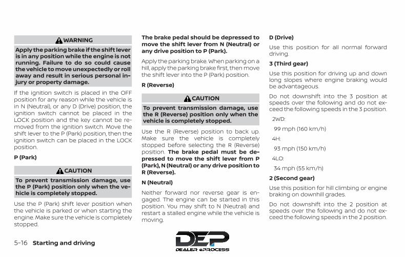
WARNINGApply the parking brake if the shift leveris in any position while the engine is notrunning. Failure to do so could causethe vehicle to move unexpectedly or rollaway and result in serious personal in-jury or property damage.
If the ignition switch is placed in the OFFposition for any reason while the vehicle isin N (Neutral), or any D (Drive) position, theignition switch cannot be placed in theLOCK position and the key cannot be re-moved from the ignition switch. Move theshift lever to the P (Park) position, then theignition switch can be placed in the LOCKposition.
P (Park)
CAUTIONTo prevent transmission damage, usethe P (Park) position only when the ve-hicle is completely stopped.
Use the P (Park) shift lever position whenthe vehicle is parked or when starting theengine. Make sure the vehicle is completelystopped.
The brake pedal should be depressed tomove the shift lever from N (Neutral) orany drive position to P (Park).
Apply the parking brake. When parking on ahill, apply the parking brake first, then movethe shift lever into the P (Park) position.
R (Reverse)
CAUTIONTo prevent transmission damage, usethe R (Reverse) position only when thevehicle is completely stopped.
Use the R (Reverse) position to back up.Make sure the vehicle is completelystopped before selecting the R (Reverse)position. The brake pedal must be de-pressed to move the shift lever from P(Park), N (Neutral) or any drive position toR (Reverse).
N (Neutral)
Neither forward nor reverse gear is en-gaged. The engine can be started in thisposition. You may shift to N (Neutral) andrestart a stalled engine while the vehicle ismoving.
D (Drive)
Use this position for all normal forwarddriving.
3 (Third gear)
Use this position for driving up and downlong slopes where engine braking wouldbe advantageous.
Do not downshift into the 3 position atspeeds over the following and do not ex-ceed the following speeds in the 3 position.
2WD:
99 mph (160 km/h)
4H:
93 mph (150 km/h)
4LO:
34 mph (55 km/h)
2 (Second gear)
Use this position for hill climbing or enginebraking on downhill grades.
Do not downshift into the 2 position atspeeds over the following and do not ex-ceed the following speeds in the 2 position.
5-16 Starting and driving
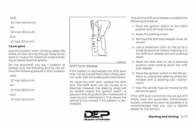
2WD:
62 mph (100 km/h)
4H:
59 mph (95 km/h)
4LO:
21 mph (35 km/h)
1 (Low gear)
Use this position when climbing steep hillsslowly or slow driving through deep snow,sand or mud, or for maximum engine brak-ing on steep downhill grades.
Do not downshift into the 1 position atspeeds over the following and do not ex-ceed the following speeds in the 1 position.
2WD:
37 mph (60 km/h)
4H:
37 mph (60 km/h)
4LO:
12 mph (20 km/h)
Shift lock releaseIf the battery is discharged, the shift levermay not be moved from the P (Park) posi-tion even with the brake pedal depressed.
To move the shift lever, release the shiftlock. The shift lever can be moved to N(Neutral). However, the steering wheel willbe locked unless the ignition switch isplaced in the ON position (for models with asteering lock mechanism). This allows thevehicle to be moved if the battery is dis-charged.
To push the shift lock release, complete thefollowing procedure:
1. Place the ignition switch in the LOCKposition and remove the key.
2. Apply the parking brake.
3. Remove the shift lock release cover asshown.
4. Use a protective cloth on the tip of asmall screwdriver before inserting it inthe shift lock release slot and pushingdown.
5. Move the shift lever to the N (Neutral)position while holding down the shiftlock release.
6. Place the ignition switch in the ON po-sition to unlock the steering wheel (formodels with a steering lock mecha-nism).
7. Now the vehicle may be moved to thedesired location.
If the shift lever cannot be moved out of P(Park), have the automatic transmissionsystem checked as soon as possible. It isrecommended that you visit a NISSANdealer for this service.
LSD0141
Starting and driving 5-17

WARNINGIf the shift lever cannot be moved fromthe P (Park) position while the engine isrunning and the brake pedal is de-pressed, the stop lights may not work.Malfunctioning stop lights could causean accident injuring yourself andothers.
Accelerator downshift— in D (Drive) position —For passing or hill climbing, depress theaccelerator pedal to the floor. This shiftsthe transmission down into a lower gear,depending on the vehicle speed. Overdrive (O/D) OFF switch
Each time your vehicle is started, the trans-mission is automatically “reset” to overdriveON.ON: With the engine running and
the shift lever in the D (Drive)position, the transmission up-shifts into overdrive as vehiclespeed increases.
Overdrive does not engage until the en-gine has reached operating tempera-ture.OFF: For driving up and down long
slopes where engine braking isnecessary push the O/D offswitch once. The Overdrive OFFindicator light in the instrumentpanel comes on at this time.
When cruising at a low speed or climbing agentle slope, you may feel uncomfortableshift shocks as the transmission shifts intoand out of overdrive repeatedly. In thiscase, depress the overdrive switch to turnthe overdrive off. The Overdrive OFF indica-tor light in the instrument panel comes onat this time.
When driving conditions change, depressthe O/D off switch to turn the overdrive on.
Remember not to drive at high speeds forextended periods of time with the over-drive off. This reduces fuel economy.
WSD0045
5-18 Starting and driving
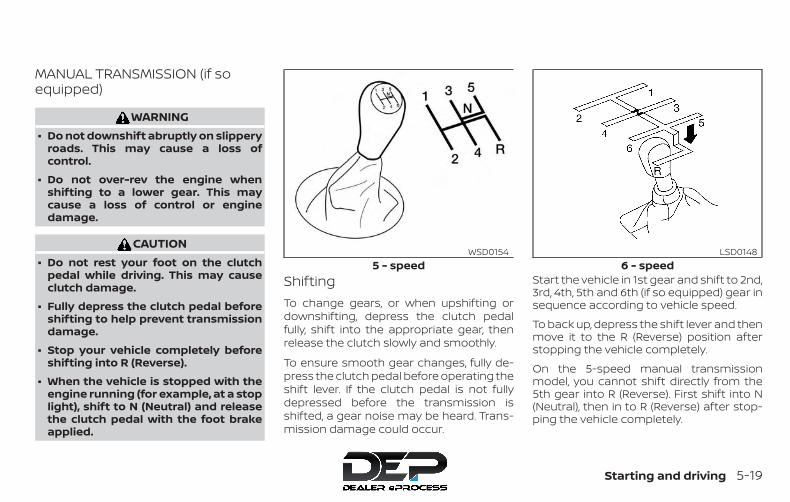
MANUAL TRANSMISSION (if soequipped)
WARNING∙ Do not downshift abruptly on slippery
roads. This may cause a loss ofcontrol.
∙ Do not over-rev the engine whenshifting to a lower gear. This maycause a loss of control or enginedamage.
CAUTION∙ Do not rest your foot on the clutch
pedal while driving. This may causeclutch damage.
∙ Fully depress the clutch pedal beforeshifting to help prevent transmissiondamage.
∙ Stop your vehicle completely beforeshifting into R (Reverse).
∙ When the vehicle is stopped with theengine running (for example, at a stoplight), shift to N (Neutral) and releasethe clutch pedal with the foot brakeapplied.
ShiftingTo change gears, or when upshifting ordownshifting, depress the clutch pedalfully, shift into the appropriate gear, thenrelease the clutch slowly and smoothly.
To ensure smooth gear changes, fully de-press the clutch pedal before operating theshift lever. If the clutch pedal is not fullydepressed before the transmission isshifted, a gear noise may be heard. Trans-mission damage could occur.
Start the vehicle in 1st gear and shift to 2nd,3rd, 4th, 5th and 6th (if so equipped) gear insequence according to vehicle speed.
To back up, depress the shift lever and thenmove it to the R (Reverse) position afterstopping the vehicle completely.
On the 5-speed manual transmissionmodel, you cannot shift directly from the5th gear into R (Reverse). First shift into N(Neutral), then in to R (Reverse) after stop-ping the vehicle completely.
5 - speedWSD0154
6 - speedLSD0148
Starting and driving 5-19

If it is difficult to move the shift lever into R(Reverse) or 1st, shift into N (Neutral), thenrelease the clutch pedal. Fully depress theclutch pedal again and shift into R (Re-verse) or 1st.
If your vehicle is equipped with 4-wheeldrive, refer to “Transfer case shifting proce-dures” in this section.
Suggested up-shift speedsThe following are suggested vehiclespeeds for shifting into a higher gear.These suggestions relate to fuel economyand vehicle performance. Actual upshiftspeeds will vary according to road condi-tions, the weather and individual drivinghabits.
∙ For QR25DE 2-Wheel Drive models:
GEAR CHANGE mph (km/h)1st to 2nd 11 (17)2nd to 3rd 15 (24)3rd to 4th 24 (38)4th to 5th 35 (56)
∙ For VQ40DE 4-Wheel Drive models and4-Wheel Drive models (2H and 4H posi-tion):
GEAR CHANGE mph (km/h)1st to 2nd 11 (17)2nd to 3rd 17 (27)3rd to 4th 25 (40)4th to 5th 32 (51)5th to 6th 45 (72)
Suggested maximum speed ineach gearDownshift to a lower gear if the engine isnot running smoothly, or if you need to ac-celerate.
Do not exceed the maximum suggestedspeed (shown below) in any gear. For levelroad driving, use the highest gear sug-gested for that speed. Always observeposted speed limits, and drive according tothe road conditions, which will ensure safeoperation. Do not over-rev the enginewhen shifting to a lower gear as it maycause engine damage or loss of vehiclecontrol.
Allowable maximum speed in each gear:
2–Wheel Drive models (QR25DE engine)
GEAR mph (km/h)1st 34 (54)
2nd 58 (94)3rd 89 (144)4th —5th —
2–Wheel Drive models (VQ40DE engine)
GEAR mph (km/h)1st 35 (56)
2nd 60 (97)3rd 87 (141)4th —5th —
4–Wheel Drive models (VQ40DE engine)
2H position
GEAR mph (km/h)1st 33 (54)
2nd 58 (93)3rd 84 (135)4th —5th —6th —
5-20 Starting and driving
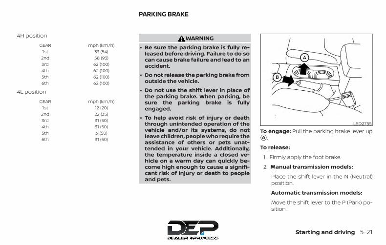
4H position
GEAR mph (km/h)1st 33 (54)
2nd 58 (93)3rd 62 (100)4th 62 (100)5th 62 (100)6th 62 (100)
4L position
GEAR mph (km/h)1st 12 (20)
2nd 22 (35)3rd 31 (50)4th 31 (50)5th 31(50)6th 31 (50)
WARNING∙ Be sure the parking brake is fully re-
leased before driving. Failure to do socan cause brake failure and lead to anaccident.
∙ Do not release the parking brake fromoutside the vehicle.
∙ Do not use the shift lever in place ofthe parking brake. When parking, besure the parking brake is fullyengaged.
∙ To help avoid risk of injury or deaththrough unintended operation of thevehicle and/or its systems, do notleave children, people who require theassistance of others or pets unat-tended in your vehicle. Additionally,the temperature inside a closed ve-hicle on a warm day can quickly be-come high enough to cause a signifi-cant risk of injury or death to peopleand pets.
To engage: Pull the parking brake lever up�A .
To release:
1. Firmly apply the foot brake.
2. Manual transmission models:
Place the shift lever in the N (Neutral)position.
Automatic transmission models:
Move the shift lever to the P (Park) po-sition.
LSD2755
PARKING BRAKE
Starting and driving 5-21
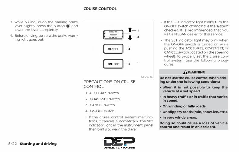
3. While pulling up on the parking brakelever slightly, press the button �B andlower the lever completely.
4. Before driving, be sure the brake warn-ing light goes out.
PRECAUTIONS ON CRUISECONTROL
1. ACCEL•RES switch
2. COAST•SET switch
3. CANCEL switch
4. ON•OFF switch
∙ If the cruise control system malfunc-tions, it cancels automatically. The SETindicator light in the instrument panelthen blinks to warn the driver.
∙ If the SET indicator light blinks, turn theON•OFF switch off and have the systemchecked. It is recommended that youvisit a NISSAN dealer for this service.
∙ The SET indicator light may blink whenthe ON•OFF switch is turned on whilepushing the ACCEL•RES, COAST•SET, orCANCEL switch (located on the steeringwheel). To properly set the cruise con-trol system, use the following proce-dures.
WARNINGDo not use the cruise control when driv-ing under the following conditions:
∙ When it is not possible to keep thevehicle at a set speed.
∙ In heavy traffic or in traffic that variesin speed.
∙ On winding or hilly roads.
∙ On slippery roads (rain, snow, ice, etc.).
∙ In very windy areas.
Doing so could cause a loss of vehiclecontrol and result in an accident.
LSD2753
CRUISE CONTROL
5-22 Starting and driving
CAUTIONOn manual transmission models, do notshift into N (Neutral) without depress-ing the clutch pedal when the cruisecontrol is set. Should this occur, depressthe clutch pedal and turn the ON•OFFswitch off immediately. Failure to do somay cause engine damage.
CRUISE CONTROL OPERATIONSThe cruise control allows driving at a speedbetween 25 - 89 mph (40 - 144 km/h) with-out keeping your foot on the acceleratorpedal.
To turn on the cruise control, push theON•OFF switch. The CRUISE indicator lightin the instrument panel comes on.
To set cruising speed, accelerate the ve-hicle to the desired speed, push the COAST-•SET switch and release it. The SET indica-tor light in the instrument panel comes on.Take your foot off the accelerator pedal.Your vehicle maintains the set speed.
∙ To pass another vehicle, depress theaccelerator pedal. When you release thepedal, the vehicle returns to the previ-ously set speed.
∙ The vehicle may not maintain the setspeed when going up or down steephills. If this happens, drive without thecruise control.
To cancel the preset speed, use one of thefollowing three methods:
∙ Push the CANCEL switch; the SET indi-cator light in the instrument panel goesout.
∙ Tap the brake pedal; the SET indicatorlight goes out.
∙ Turn the ON•OFF switch off. Both theCRUISE indicator light and SET indicatorlight in the instrument panel go out.
The cruise control is automatically can-celed and the SET indicator light in the in-strument panel goes out if:
∙ You depress the brake or clutch pedal (ifso equipped) while pushing the ACCEL-•RES or COAST•SET switch. The presetspeed is deleted from memory.
∙ The vehicle slows down more than8 mph (13 km/h) below the set speed.
∙ You depress the clutch pedal (manualtransmission), or move the shift lever toN (Neutral) (automatic transmission).
To reset at a faster cruising speed, useone of the following three methods:
∙ Depress the accelerator pedal. When thevehicle attains the desired speed, pushand release the COAST•SET switch.
∙ Push and hold the ACCEL•RES switch.When the vehicle attains the speed youdesire, release the switch.
∙ Push and release the ACCEL•RES switch.Each time you do this, the set speedincreases by about 1 mph (1.6 km/h).
To reset at a slower cruising speed, useone of the following three methods:
∙ Lightly tap the brake pedal. When thevehicle attains the desired speed, pushthe COAST•SET switch and release it.
∙ Push and hold the COAST•SET switch.Release the switch when the vehicleslows to the desired speed.
∙ Push and release the COAST•SETswitch. Each time you do this, the setspeed decreases by about 1 mph(1.6 km/h).
To resume the preset speed, push andrelease the ACCEL•RES switch. The vehiclereturns to the last set cruising speed whenthe vehicle speed is over 25 mph (40 km/h).
Starting and driving 5-23

CAUTIONDuring the first 1,200 miles (2,000 km),follow these recommendations to ob-tain maximum engine performanceand ensure the future reliability andeconomy of your new vehicle. Failure tofollow these recommendations may re-sult in shortened engine life and re-duced engine performance.
∙ Avoid driving for long periods at con-stant speed, either fast or slow, and donot run the engine over 4,000 rpm.
∙ Do not accelerate at full throttle in anygear.
∙ Avoid quick starts.
∙ Avoid hard braking as much as pos-sible.
∙ Do not tow a trailer for the first 500 miles(805 kilometers). Your engine, axle orother parts could be damaged.
Follow these easy-to-use Fuel EfficientDriving Tips to help you achieve the mostfuel economy from your vehicle.
1. Use Smooth Accelerator and BrakePedal Application
∙ Avoid rapid starts and stops.
∙ Use smooth, gentle accelerator andbrake application whenever possible.
∙ Maintain constant speed while com-muting and coast whenever pos-sible.
2. Maintain Constant Speed
∙ Look ahead to try and anticipate andminimize stops.
∙ Synchronizing your speed with trafficlights allows you to reduce your num-ber of stops.
∙ Maintaining a steady speed can mini-mize red light stops and improve fuelefficiency.
3. Use Air Conditioning (A/C) at HigherVehicle Speeds
∙ Below 40 mph (64 km/h), it is moreefficient to open windows to cool thevehicle due to reduced engine load.
∙ Above 40 mph (64 km/h), it is moreefficient to use A/C to cool the vehicledue to increased aerodynamic drag.
∙ Recirculating the cool air in the cabinwhen the A/C is on reduces coolingload.
4. Drive at Economical Speeds and Dis-tances
∙ Observing the speed limit and notexceeding 60 mph (97 km/h) (wherelegally allowed) can improve fuel effi-ciency due to reduced aerodynamicdrag.
∙ Maintaining a safe following distancebehind other vehicles reduces un-necessary braking.
∙ Safely monitoring traffic to anticipatechanges in speed permits reducedbraking and smooth accelerationchanges.
∙ Select a gear range suitable to roadconditions.
BREAK-IN SCHEDULE FUEL EFFICIENT DRIVING TIPS
5-24 Starting and driving
5. Use Cruise Control
∙ Using cruise control during highwaydriving helps maintain a steadyspeed.
∙ Cruise control is particularly effectivein providing fuel savings when drivingon flat terrains.
6. Plan for the Shortest Route
∙ Utilize a map or navigation system todetermine the best route to savetime.
7. Avoid Idling
∙ Shutting off your engine when safefor stops exceeding 30–60 secondssaves fuel and reduces emissions.
8. Buy an Automated Pass for TollRoads
∙ Automated passes permit drivers touse special lanes to maintain cruis-ing speed through the toll and avoidstopping and starting.
9. Winter Warm Up
∙ Limit idling time to minimize impactto fuel economy.
∙ Vehicles typically need no more than30 seconds of idling at start-up toeffectively circulate the engine oil be-fore driving.
∙ Your vehicle will reach its ideal oper-ating temperature more quicklywhile driving versus idling.
10. Keeping your Vehicle Cool
∙ Park your vehicle in a covered parkingarea or in the shade whenever pos-sible.
∙ When entering a hot vehicle, openingthe windows will help to reduce theinside temperature faster, resulting inreduced demand on your A/C sys-tem.
∙ Keep your engine tuned up.
∙ Follow the recommended scheduledmaintenance.
∙ Keep the tires inflated to the correctpressure. Low tire pressure increasestire wear and lowers fuel economy.
∙ Keep the wheels in correct alignment.Improper alignment increases tire wearand lowers fuel economy.
∙ For vehicles equipped with , use4H or 4L position only when necessary.4-Wheel Drive operation lowers fueleconomy.
∙ Use the recommended viscosity engineoil. For additional information, refer to“Engine oil and oil filter recommenda-tions” in the “Technical and consumerinformation” section of this manual.
INCREASING FUEL ECONOMY
Starting and driving 5-25
WARNING∙ For 4WD equipped vehicles, do not at-
tempt to raise two wheels off theground and shift the transmission toany drive or reverse position with theengine running. Doing so may resultin drivetrain damage or unexpectedvehicle movement which could resultin serious vehicle damage or personalinjury.
∙ Do not attempt to test a 4WDequipped vehicle on a 2-wheel dyna-mometer (such as the dynamometersused by some states for emissionstesting), or similar equipment even ifthe other two wheels are raised off theground. Make sure you inform test fa-cility personnel that your vehicle isequipped with 4WD before it is placedon a dynamometer. Using the wrongtest equipment may result in drive-train damage or unexpected vehiclemovement which could result in seri-ous vehicle damage or personalinjury.
CAUTION∙ Do not drive the vehicle in the 4H or
4LO position on dry hard surfaceroads. Driving on dry, hard surfaces in4H or 4LO may cause unnecessarynoise, tire wear and increased fuelconsumption.
If the 4WD warning light turns onwhen you are driving on dry hard sur-face roads:
– In the 4H position, shift the 4WDshift switch to 2–Wheel Drive(2WD).
– In the 4LO position for automatictransmission vehicles, stop the ve-hicle and shift the shift lever to theN (Neutral) position with the brakepedal depressed and shift the 4WDshift switch to 2WD.
– In the 4LO position for manualtransmission vehicles, stop the ve-hicle and shift the shift lever to theN (Neutral) position with the clutchpedal depressed and shift the 4WDshift switch to 2WD.
∙ If the warning light is still on after theabove operation, have your vehiclechecked as soon as possible. It is rec-ommended that you visit a NISSANdealer for this service.
TRANSFER CASE SHIFTINGPROCEDURESThe part-time 4WD system provides threepositions (2WD, 4H and 4LO), so you canselect the desired drive mode according tothe driving conditions.
USING 4–WHEEL DRIVE (4WD)(if so equipped)
5-26 Starting and driving

2WD or 4WD shift procedure:
4WD Shift SwitchPosition Wheels Driven Indicator Light Use Conditions 4WD Shift Procedure4WD shift Transfer 4LO position
2WDRear wheels
For driving on dry,paved roads(Economy drive)
Move the 4WD switch.2WD <—> 4H4WD shift indicator light will indicate trans-fer shift position engaged.
4H
4 wheelsFor driving on rocky,sandy or snow-covered roads
N (Neutral)
*1May blink
N (Neutral) disen-gages the automatictransmission (A/T)mechanical parkinglock, which will allowthe vehicle to roll. Donot leave the trans-fer shift position in N(Neutral).*2
1. Stop the vehicle.2. For A/T vehicles: Move the shift lever
to the N (Neutral) position with thebrake pedal depressed.For manual transmission (M/T) ve-hicles: Move the shift lever to the N(Neutral) position with the clutchdepressed.
3. For A/T vehicles: Depress and turn the4WD shift switch to 4LO or 4H with thebrake pedal depressed.For M/T vehicles: Depress and turn the4WD switch to 4LO or 4H with theclutch pedal depressed.
THE TRANSFER CASE DOES NOT ENGAGEBETWEEN 4H AND 4LO (OR 4LO TO 4H) UN-LESS YOU HAVE FIRST STOPPED THE VE-HICLE, DEPRESSED THE BRAKE PEDAL ANDMOVED THE SHIFT LEVER TO N (NEUTRAL)FOR A/T VEHICLES. FOR M/T VEHICLESYOU MUST MOVE THE SHIFT LEVER TO N(NEUTRAL). *3
4LO
4 wheels
Illuminated
For use when maxi-mum power andtraction is required(for example, onsteep grades orrocky, sandy, muddyroads)
*1: Before moving the shift lever from N (Neutral), wait until the transfer 4LO position indicator light stays on steady. This indicates that the4WD shift procedure is completed and the transfer gear is correctly set in the 4LO position. If the vehicle is shifted into gear before theindicator is on steady, the transfer gear may grind, not engage correctly or stay in the neutral position.
Starting and driving 5-27

- If the 4WD warning light illuminates, perform the following procedure to return the transfer case to correct operating condition.1. Turn off the engine by turning the ignition switch off.
2. Start the engine.
- Check that the 4WD warning light turns off. If the 4WD warning light illuminates, have the system checked. It is recommended that youvisit a NISSAN dealer for this service.
3. Apply the parking brake, for A/T vehicles, depress the brake pedal and move the shift lever to N (Neutral) position. For M/T vehicles,move the shift lever to the N (Neutral) position.
4. With the brake pedal depressed on A/T vehicles or with the clutch pedal depressed on M/T vehicles, move the 4WD shift switch tothe desired mode.
- Be sure to wait until the transfer gear change completes before shifting the shift lever from the N (Neutral) position.
*2: While changing in and out of 4LO, the ignition key must be on and the vehicle’s engine must be running for a shift to take place and forthe indicator lights (4WD shift and 4LO position indicator) to be operable. Otherwise, the shift will not take place and no indicator lightswill be on or flashing.
*3: Make sure the transfer 4LO position indicator light turns on when you shift the 4WD shift switch to 4LO. The indicator light will alsoturn on when 4LO is selected. For additional information, refer to “Vehicle Dynamic Control (VDC) system” in this section.
5-28 Starting and driving

The transfer case 4WD shift switch is usedto select either 2WD or 4WD depending onthe driving conditions. There are threetypes of drive modes available, 2WD, 4H and4LO.The 4WD shift switch electronically controlsthe transfer case operation. Rotate theswitch to move between each mode, 2WD,4H and 4LO.
To change into or out of 4LO, the vehicleMUST be stationary, move the shift leverto N (Neutral), and for A/T vehicles de-press the brake pedal or for M/T vehiclesdepress the clutch pedal. The switchmust be depressed and turned whenchanging into or out of 4LO.
WARNING∙ When parking, apply the parking
brake before stopping the engine andmake sure that the 4WD shift indica-tor light is on and the ATP warninglight goes off. Otherwise, the vehiclecould unexpectedly move even if theA/T is in the P (Park) position.
∙ The transfer 4LO position indicatorlight must stop blinking and remainilluminated or turn off before shiftingthe transmission into gear. If the shiftlever is shifted from the N (Neutral)position to any other gear when thetransfer 4LO position indicator light isblinking, the vehicle may moveunexpectedly.
CAUTION∙ Never shift the 4WD shift switch be-
tween 4LO and 4H while driving.
∙ The 4H position provides greater trac-tion. Avoid excessive speed, as it willcause increased fuel consumptionand higher oil temperatures, andcould damage drivetrain compo-nents. Speeds over 62 mph(100 km/h) in 4H is not recommended.
∙ The 4LO position provides maximumpower and traction. Avoid raising ve-hicle speed excessively, as the maxi-mum speed is approximately 31 mph(50 km/h).
∙ When driving straight, shift the 4WDshift switch to the 2WD or 4H position.Do not move the 4WD shift switchwhen making a turn or reversing.
∙ Do not shift the 4WD shift switch (be-tween 2WD and 4H) while driving onsteep downhill grades. Use the enginebrake and low A/T gears 2 (Secondgear) or 1 (Low gear), or M/T (1st gearor 2nd gear) for engine braking.
∙ Do not operate the 4WD shift switch(between 2WD and 4H) with the rearwheels spinning.
∙ Do not drive on dry hard surface roadsin the 4H or 4LO position. Driving ondry hard surfaces in 4H or 4LO maycause unnecessary noise and tirewear. NISSAN recommends driving inthe 2WD position under theseconditions.
∙ The 4WD transfer case may not beshifted between 4H and 4LO at lowambient temperatures and the trans-fer 4LO position indicator light mayblink even when the 4WD shift switchis shifted. After driving for a while youcan change the 4WD transfer case be-tween 4H and 4LO.
Starting and driving 5-29

When driving on rough roads:
∙ Set the 4WD shift switch to 4H or 4LO.
∙ Drive carefully according to the roadsurface conditions.
When the vehicle is stuck:
∙ Set the 4WD shift switch to 4H or 4LO.
∙ Use the Electronic Locking Rear Differ-ential (E-Lock) system (if so equipped).Turn the switch ON while the vehicle isstationary and apply the throttle to tryto free the vehicle.
∙ If it is difficult to free the vehicle, rock thevehicle back and forth between R (Re-verse) and D (Drive) gears.
∙ If the vehicle is stuck deep in mud, placestones or wooden blocks under thetires. Then try the recovery proceduresabove. Tire chains may be effective.
CAUTION∙ Do not spin the tires excessively. Tires
will sink deep into the mud, making itdifficult to free the vehicle.
∙ Avoid shifting gears with the enginerunning at high speeds as this maycause malfunction.
4WD shift switch operations∙ Shift the 4WD shift switch to either the
2WD, 4H or 4LO position, depending ondriving conditions.
∙ If the 4WD shift switch is operatedwhile making a turn, accelerating ordecelerating or if the key switch isturned off while in the 4H or 4LO posi-tion, you may feel a jolt. This is notabnormal.
∙ When the vehicle is stopped aftermaking a turn, you may feel a slightjolt after the shift lever is moved to N(Neutral) or P (Park). This occurs be-cause the transfer clutch is releasedand not because of a malfunction.
CAUTION∙ When driving straight, shift the 4WD
shift switch to the 2WD or 4H position.Do not move the 4WD shift switchwhen making a turn or reversing.
∙ Do not shift the 4WD shift switchwhile driving on steep downhillgrades. Use the engine brake and lowautomatic transmission gears 2 (Sec-ond gear) or 1 (Low gear) or manualtransmission (1st gear or 2nd gear) forengine braking.
∙ Do not operate the 4WD shift switchwith the rear wheels spinning.
∙ Before placing the 4WD shift switch inthe 4H position from 2WD, ensure thevehicle speed is less than 62 mph(100 km/h). Failure to do so can dam-age the 4WD system.
∙ Never shift the 4WD shift switch be-tween 4LO and 4H while driving.
LSD0145
5-30 Starting and driving

4WD shift indicator lightThe 4WD shift indicator light is located inthe odometer display.
The light should turn off within 1 secondafter placing the ignition switch in the ONposition.
While the engine is running, the 4WD shiftindicator light will illuminate the positionselected by the 4WD shift switch.
∙ The 4WD shift indicator light mayblink while shifting from one drivemode to the other. When the shiftingis completed, the 4WD shift indicatorlight will come on.
∙ If the 4WD warning light comes on, the4WD shift indicator light goes out.
CAUTIONIf the 4WD shift indicator light indica-tion changes to 2WD when the 4WDshift switch is shifted to the 4H positionat low ambient temperatures, the 2WDmode may be being engaged due tomalfunctioning drive system. If the in-dicator does not return to normal andthe 4WD warning light comes on, havethe system checked. It is recommendedthat you visit a NISSAN dealer for thisservice.
4WD warning light
Warning light Comes on orblinks when:
Comes on
There is a mal-function in the4–Wheel Drive
system
Blinksslowly
The differencein wheel rota-
tion is large
The 4WD warning light is located in the me-ter.
The 4WD warning light comes on when theignition switch is placed in the ON position.It turns off soon after the engine is started.
If any malfunction occurs in the 4WD sys-tem when the ignition switch is ON, thewarning light will either remain illuminatedor blink.
If the 4WD warning light comes on, the 4WDshift indicator light goes out.
LSD0147
Starting and driving 5-31

A large difference between the diametersof front and rear wheels will make thewarning light blink slowly (about once per2 seconds). Change the 4WD shift switchinto 2WD and do not drive fast.
CAUTION∙ If the warning light comes on or blinks
slowly during operation, have yourvehicle checked as soon as possible. Itis recommended that you visit aNISSAN dealer for this service.
∙ Shifting between 4H and 4LO is notrecommended when the 4WD warn-ing light turns on.
∙ When the warning light comes on, the2WD mode may be engaged even ifthe 4WD shift switch is in 4H. Be espe-cially careful when driving. If corre-sponding parts are malfunctioning,the 4WD mode will not be engagedeven if the 4WD shift switch is shifted.
∙ Do not drive the vehicle in the 4H or4LO position on dry hard surfaceroads. Driving on dry, hard surfaces in4H or 4LO may cause unnecessarynoise, tire wear and increased fuelconsumption.
If the 4WD warning light turns onwhen you are driving on dry hard sur-face roads:
– In the 4H position, shift the 4WDshift switch to 2WD.
– In the 4LO position for automatictransmission vehicles, stop the ve-hicle and shift the shift lever to theN (Neutral) position with the brakepedal depressed and shift the 4WDshift switch to 2WD.
– In the 4LO position for manualtransmission vehicles, stop the ve-hicle and shift the shift lever to theN (Neutral) position with the clutchpedal depressed and shift the 4WDshift switch to 2WD.
∙ If the warning light is still on after theabove operation, have your vehiclechecked as soon as possible. It is rec-ommended that you visit a NISSANdealer for this service.
∙ The transfer case may be damaged ifyou continue driving with the warninglight blinking.
5-32 Starting and driving
The E-Lock system can provide additionaltraction and should only be used when avehicle has become or is becoming stuck.This system operates by electronically“locking” the two rear drive wheels to-gether, allowing them to turn at the samespeed. The system is used when it is notpossible to free a stuck vehicle even whenusing the 4LO position (4-Wheel Drive ve-hicles).
When added traction is required, activatethe E-Lock system by pushing the switchON. For additional information, refer to“Electronic locking rear differential (E-Lock)system switch” in the “Instruments andcontrols” section of this manual. Once thesystem fully engages, the indicator light inthe instrument panel will remain on. Whenthe system is activated, both rear wheelswill engage, providing added traction.
The rear wheels may momentarily slip ormove to engage the system, and the sys-tem will only engage up to approximately4 mph (7 km/h). Once the vehicle is free, thesystem should be turned off and drivingresumed.
The Anti-Lock Braking (ABS) system is dis-abled and the ABS light illuminates whenthe E-Lock system is on. Also, the Vehicle
Dynamic Control (VDC) system is disabledand the indicator light illuminateswhen the E-Lock system is on.
WARNING∙ Never leave the E-Lock system on
when driving on paved or hard-surfaced roads. Turning the vehiclemay result in the rear wheels slippingand result in an accident and personalinjury. After using the E-Lock systemto free the vehicle, turn the system off.
∙ Use the E-Lock system only whenfreeing a stuck vehicle. Try the 4LO po-sition before using the E-Lock system.Never use the E-Lock system on a slip-pery road surface such as snow or icesurface. Using the E-Lock systemwhen driving in these road conditionsmay cause unexpected movement ofthe vehicle during engine braking, ac-celerating or turning, which may re-sult in an accident and serious per-sonal injury.
CAUTION∙ After using the E-Lock system, turn
the switch OFF to prevent possibledamage to driveline componentsfrom extended use.
∙ Do not drive the vehicle at speedsfaster than 12 mph (20 km/h) whenthe system is engaged. Doing so coulddamage drivetrain components.
∙ Do not turn on the E-Lock systemwhile the tires are spinning. Doing socould damage drivetraincomponents.
ELECTRONIC LOCKING REARDIFFERENTIAL (E-Lock) SYSTEM (ifso equipped)
Starting and driving 5-33

WARNING∙ Do not stop or park the vehicle over
flammable materials such as drygrass, waste paper or rags. They mayignite and cause a fire.
∙ Safe parking procedures require thatboth the parking brake be set and thetransmission placed into P (Park) forautomatic transmission (A/T) modelsor in an appropriate gear for manualtransmission (M/T) models. Failure todo so could cause the vehicle to moveunexpectedly or roll away and resultin an accident. Make sure the shift le-ver has been pushed as far forward asit can go and cannot be moved with-out depressing the foot brake pedal.
∙ Never leave the engine running whilethe vehicle is unattended.
∙ To help avoid risk of injury or deaththrough unintended operation of thevehicle and/or its systems, do notleave children, people who require theassistance of others or pets unat-tended in your vehicle. Additionally,the temperature inside a closed ve-hicle on a warm day can quickly be-come high enough to cause a signifi-cant risk of injury or death to peopleand pets.
1. Firmly apply the parking brake.
2. M/T models:
Place the shift lever in the R (Reverse)position. When parking on an uphillgrade, place the shift lever in 1st gear.
A/T models:
Move the shift lever to the P (Park) po-sition.
3. To help prevent the vehicle from rollinginto traffic when parked on an incline, itis a good practice to turn the wheels asillustrated.
∙ HEADED DOWNHILL WITH CURB �A :
Turn the wheels into the curb andmove the vehicle forward until the curb
WSD0050
PARKING/PARKING ON HILLS
5-34 Starting and driving
side wheel gently touches the curb.
∙ HEADED UPHILL WITH CURB �B :
Turn the wheels away from the curband move the vehicle back until thecurb side wheel gently touches thecurb.
∙ HEADED UPHILL OR DOWNHILL, NOCURB �C :
Turn the wheels toward the side of theroad so the vehicle will move awayfrom the center of the road if it moves.
4. Place the ignition switch in the LOCKposition and remove the key.
The power assisted steering uses a hy-draulic pump, driven by the engine, to as-sist steering.If the engine stops or the drive belt breaks,you will still have control of the vehicle.However, much greater steering effort isneeded, especially in sharp turns and atlow speeds.
WARNINGIf the engine is not running or is turnedoff while driving, the power assist forthe steering will not work. Steering willbe harder to operate.
The brake system has two separate hy-draulic circuits. If one circuit malfunctions,you will still have braking at two wheels.
BRAKE PRECAUTIONSVacuum assisted brakesThe brake booster aids braking by usingengine vacuum. If the engine stops, youcan stop the vehicle by depressing thebrake pedal. However, greater foot pres-sure on the brake pedal will be required tostop the vehicle and stopping distance willbe longer.
Using the brakesAvoid resting your foot on the brake pedalwhile driving. This will overheat the brakes,wear out the brake pads faster, and reducegas mileage.
To help reduce brake wear and to preventthe brakes from overheating, reduce speedand downshift to a lower gear before goingdown a slope or long grade. Overheatedbrakes may reduce braking performanceand could result in loss of vehicle control.
POWER STEERING BRAKE SYSTEM
Starting and driving 5-35
WARNING∙ While driving on a slippery surface, be
careful when braking, accelerating ordownshifting. Abrupt braking or ac-celerating could cause the wheels toskid and result in an accident.
∙ If the engine is not running or isturned off while driving, the power as-sist for the brakes will not work. Brak-ing will be harder.
Wet brakesWhen the vehicle is washed or driventhrough water, the brakes may get wet. Asa result, your braking distance will be lon-ger and the vehicle may pull to one sideduring braking.
To dry the brakes, drive the vehicle at a safespeed while lightly pressing the brakepedal to heat up the brakes. Do this untilthe brakes return to normal. Avoid drivingthe vehicle at high speeds until the brakesfunction correctly.
Parking brake break-inBreak in the parking brake shoes wheneverthe stopping effect of the parking brake isweakened or whenever the parking brake
shoes and/or drums/rotors are replaced,in order to assure the best braking perfor-mance.
This procedure is described in the vehicleservice manual. It is recommended thatyou visit a NISSAN dealer for this service.
ANTI-LOCK BRAKING SYSTEM (ABS)
WARNING∙ The ABS is a sophisticated device, but
it cannot prevent accidents resultingfrom careless or dangerous drivingtechniques. It can help maintain ve-hicle control during braking on slip-pery surfaces. Remember that stop-ping distances on slippery surfaceswill be longer than on normal sur-faces even with ABS. Stopping dis-tances may also be longer on rough,gravel or snow covered roads, or if youare using tire chains. Always maintaina safe distance from the vehicle infront of you. Ultimately, the driver isresponsible for safety.
∙ Tire type and condition may also af-fect braking effectiveness.
– When replacing tires, install thespecified size of tires on all fourwheels.
– When installing a spare tire, makesure that it is the proper size andtype as specified on the Tire andLoading Information label. For ad-ditional information, refer to “Tireand Loading Information label” inthe “Technical and consumer infor-mation” section of this manual.
– For additional information, refer to“Wheels and tires” in the “Do-it-yourself” section of this manual.
The ABS controls the brakes so the wheelsdo not lock during hard braking or whenbraking on slippery surfaces. The systemdetects the rotation speed at each wheeland varies the brake fluid pressure to pre-vent each wheel from locking and sliding.By preventing each wheel from locking, thesystem helps the driver maintain steeringcontrol and helps to minimize swervingand spinning on slippery surfaces.
5-36 Starting and driving

Using the systemDepress the brake pedal and hold it down.Depress the brake pedal with firm steadypressure, but do not pump the brakes. TheAnti-lock Braking System will operate toprevent the wheels from locking up. Steerthe vehicle to avoid obstacles.
WARNINGDo not pump the brake pedal. Doing somay result in increased stoppingdistances.
Self-test featureThe Anti-lock Braking System (ABS) in-cludes electronic sensors, electric pumps,hydraulic solenoids and a computer. Thecomputer has a built-in diagnostic featurethat tests the system each time you startthe engine and move the vehicle at a lowspeed in forward or reverse. When the self-test occurs, you may hear a “clunk” noiseand/or feel a pulsation in the brake pedal.This is normal and does not indicate a mal-function. If the computer senses a mal-function, it switches the ABS off and illumi-nates the ABS warning light on the
instrument panel. The brake system thenoperates normally but without anti-lockassistance.
If the ABS warning light illuminates duringthe self-test or while driving, have the ve-hicle checked. It is recommended that youvisit a NISSAN dealer for this service.
Normal operationThe Anti-lock Braking System (ABS) oper-ates at speeds above 3 - 6 mph (5 -10 km/h). The speed varies according toroad conditions.
When the ABS senses that one or morewheels are close to locking up, the actuatorrapidly applies and releases hydraulic pres-sure. This action is similar to pumping thebrakes very quickly. You may feel a pulsa-tion in the brake pedal and hear a noisefrom under the hood or feel a vibrationfrom the actuator when it is operating. Thisis normal and indicates that the ABS is op-erating properly. However, the pulsationmay indicate that road conditions are haz-ardous and extra care is required whiledriving.
∙ The ABLS system uses automatic brak-ing to transfer power from a slippingdrive wheel to the wheel on the sameaxle with more traction. The ABLS sys-tem applies braking to the slippingwheel, which helps redirect power tothe other wheel.
∙ On 4–Wheel Drive models the ABLS sys-tem operates in both 4H and 4LOmodes. If 4WD mode is engaged, theABLS system operates for both driveaxles. On 2–Wheel Drive vehicles, theABLS system operates on the drive axleonly.
∙ The ABLS system is always on. In someconditions, the system may automati-cally turn the ABLS system off. If the sys-tem is automatically turned off, normalbrake function will continue. ABLS willfunction even when the Vehicle Dy-namic Control system is turned off.
∙ The ABLS does not operate if bothwheels on a drive axle are slipping.
ACTIVE BRAKE LIMITED SLIP (ABLS)SYSTEM
Starting and driving 5-37

WARNING∙ The ABLS system helps provide in-
creased traction, but will not preventaccidents due to abrupt steering op-eration or by careless driving or dan-gerous driving practices. Reduce ve-hicle speed and be especially carefulwhen driving and cornering on slip-pery surfaces. Always drive carefully.
∙ Do not modify the vehicle’s suspen-sion. If suspension parts such asshock absorbers, struts, springs, sta-bilizer bars, bushings and wheels arenot NISSAN approved for your vehicleor are extremely deteriorated, theABLS system may not operate prop-erly. This could adversely affect ve-hicle handling performance, and theslip indicator light may illuminate.
∙ If brake related parts such as brakepads, rotors and calipers are notNISSAN recommended or are ex-tremely deteriorated, the ABLS sys-tem may not operate properly and theslip indicator light may illuminate.
∙ If wheels or tires other than theNISSAN recommended ones are used,the ABLS system may not operateproperly and the slip indicator lightmay illuminate.
The VDC system uses various sensors tomonitor driver inputs and vehicle motion.Under certain driving conditions, the VDCsystem helps to perform the followingfunctions:
∙ Controls brake pressure to reducewheel slip on one slipping drive wheelso power is transferred to a non-slipping drive wheel on the same axle.
∙ Controls brake pressure and engineoutput to reduce drive wheel slip basedon vehicle speed (traction control func-tion).
∙ If the 4WD transfer case is shifted into4LO the indicator light will comeon and the VDC system will be turnedoff. For additional information, refer to“Using 4–Wheel Drive (4WD)” in this sec-tion.
∙ Controls brake pressure at individualwheels and engine output to help thedriver maintain control of the vehicle inthe following conditions:
– Understeer (vehicle tends to not fol-low the steered path despite in-creased steering input)
– Oversteer (vehicle tends to spin dueto certain road or driving conditions)
VEHICLE DYNAMIC CONTROL (VDC)SYSTEM
5-38 Starting and driving

The VDC system can help the driver tomaintain control of the vehicle, but it can-not prevent loss of vehicle control in all driv-ing situations.
When the VDC system operates, theindicator light in the instrument panelflashes so note the following:
∙ The road may be slippery or the systemmay determine some action is requiredto help keep the vehicle on the steeredpath.
∙ You may feel a pulsation in the brakepedal and hear a noise or vibration fromunder the hood. This is normal and indi-cates that the VDC system is workingproperly.
∙ Adjust your speed and driving to theroad conditions.
For additional information, refer to “Slip in-dicator light” and ”Vehicle Dynamic Control(VDC) OFF indicator light” in the ”Instru-ments and controls” section of this manual.
If a malfunction occurs in the system,the indicator light will come on in theinstrument panel. The VDC system auto-matically turns off when these indicatorlights are off.
The VDC OFF switch is used to turn off theVDC system. The indicator light illu-minates to indicate the VDC system is off.When the VDC OFF switch is used to turn offthe system, the VDC system still operatesto prevent one drive wheel from slipping bytransferring power to a non-slipping drivewheel. The indicator light flashes ifthis occurs. All other VDC functions are offand the indicator light will not flash.The VDC system is automatically reset toon when the ignition switch is placed in theOFF position then back to the ON position.
The computer has a built-in diagnostic fea-ture that tests the system each time youstart the engine and move the vehicle for-ward or in reverse at a slow speed. Whenthe self-test occurs, you may hear a clunknoise and/or feel a pulsation in the brakepedal. This is normal and is not an indica-tion of a malfunction.
WARNING∙ The VDC system is designed to help
the driver maintain stability but doesnot prevent accidents due to abruptsteering operation at high speeds orby careless or dangerous drivingtechniques. Reduce vehicle speed andbe especially careful when driving andcornering on slippery surfaces and al-ways drive carefully.
∙ Do not modify the vehicle’s suspen-sion. If suspension parts such asshock absorbers, struts, springs, sta-bilizer bars, bushings and wheels arenot NISSAN recommended for yourvehicle or are extremely deteriorated,the VDC system may not operateproperly. This could adversely affectvehicle handling performance, andthe indicator light may flash orthe indicator light mayilluminate.
Starting and driving 5-39
∙ If brake related parts such as brakepads, rotors and calipers are notNISSAN recommended or are ex-tremely deteriorated, the VDC systemmay not operate properly and boththe and indicator lightsmay illuminate.
∙ If engine control related parts are notNISSAN recommended or are ex-tremely deteriorated, both theand indicator lights mayilluminate.
∙ When driving on extremely inclinedsurfaces such as higher banked cor-ners, the VDC system may not operateproperly and the indicator lightmay flash or the indicator lightmay illuminate. Do not drive on thesetypes of roads.
∙ When driving on an unstable surfacesuch as a turntable, ferry, elevator orramp, the indicator light mayflash or the indicator light mayilluminate. This is not a malfunction.Restart the engine after driving ontoa stable surface.
∙ If wheels or tires other than theNISSAN recommended ones are used,the VDC system may not operateproperly and the indicator lightmay flash or the indicator lightmay illuminate.
∙ The VDC system is not a substitute forwinter tires or tire chains on a snowcovered road.
BRAKE FORCE DISTRIBUTIONDuring braking while driving through turns,the system optimizes the distribution offorce to each of the four wheels dependingon the radius of the turn.
WARNING∙ The VDC system is designed to help
the driver maintain stability but doesnot prevent accidents due to abruptsteering operation at high speeds orby careless or dangerous drivingtechniques. Reduce vehicle speed andbe especially careful when driving andcornering on slippery surfaces and al-ways drive carefully.
∙ Do not modify the vehicle’s suspen-sion. If suspension parts such asshock absorbers, struts, springs, sta-bilizer bars, bushings and wheels arenot NISSAN recommended for yourvehicle or are extremely deteriorated,the VDC system may not operateproperly. This could adversely affectvehicle handling performance, andthe indicator light may flash orthe indicator light mayilluminate.
∙ If brake related parts such as brakepads, rotors and calipers are notNISSAN recommended or are ex-tremely deteriorated, the VDC systemmay not operate properly and boththe and the indicatorlights may illuminate.
∙ If engine control related parts are notNISSAN recommended or are ex-tremely deteriorated, both theand indicator lights mayilluminate.
5-40 Starting and driving
∙ When driving on extremely inclinedsurfaces such as higher banked cor-ners, the VDC system may not operateproperly and the indicator lightmay flash or the indicator lightmay illuminate. Do not drive on thesetypes of roads.
∙ When driving on an unstable surfacesuch as a turntable, ferry, elevator orramp, the indicator light mayflash or the indicator light mayilluminate. This is not a malfunction.Restart the engine after driving ontoa stable surface.
∙ If wheels or tires other than theNISSAN recommended ones are used,the VDC system may not operateproperly and the indicator lightmay flash or the indicator lightmay illuminate.
∙ The VDC system is not a substitute forwinter tires or tire chains on a snowcovered road.
WARNING∙ Never rely solely on the hill descent
control system to control vehiclespeed when driving on steep downhillgrades. Always drive carefully and at-tentively when using the hill descentcontrol system and decelerate the ve-hicle speed by depressing the brakepedal if necessary. Be especially care-ful when driving on frozen, muddy orextremely steep downhill roads. Fail-ure to control vehicle speed may re-sult in a loss of control of the vehicleand possible serious injury or death.
∙ The hill descent control may not con-trol the vehicle speed on a hill underall load or road conditions. Always beprepared to depress the brake pedalto control vehicle speed. Failure to doso may result in a collision or seriouspersonal injury.
The hill descent control system helpsmaintain vehicle speed when driving under15-21 mph (25-35 km/h) on steeper down-hill grades. Hill descent control is usefulwhen engine braking alone in 4H or 4L can-not control vehicle speed. Hill descent con-trol applies the vehicle brakes to controlvehicle speed allowing the driver to con-
centrate on steering while reducing theburden of brake and accelerator operation.
∙ When additional braking is required onsteep downhill roads, activate the hilldescent control system by pushing theswitch on. For additional information,refer to “Hill descent control switch” inthe “Instruments and controls” sectionof this manual.
∙ Once the system is activated, the indi-cator light will remain on in the instru-ment panel. For additional information,refer to “Hill descent control system ONindicator light” in the “Instruments andcontrols” section of this manual.
If the accelerator or brake pedal is de-pressed while the hill descent control sys-tem is on, the system will stop operatingtemporarily. As soon as the accelerator orbrake pedal is released, the hill descentcontrol system begins to function again ifthe hill descent control operating condi-tions are fulfilled.
For the best results, when descendingsteep downhill grades, the hill descent con-trol switch should be on and the shift leverin 2 (Second gear) or 1 (Low gear) for enginebraking.
HILL DESCENT CONTROL SYSTEM (ifso equipped)
Starting and driving 5-41
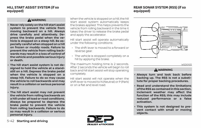
WARNING∙ Never rely solely on the hill start assist
system to prevent the vehicle frommoving backward on a hill. Alwaysdrive carefully and attentively. De-press the brake pedal when the ve-hicle is stopped on a steep hill. Be es-pecially careful when stopped on a hillon frozen or muddy roads. Failure toprevent the vehicle from rolling back-wards may result in a loss of control ofthe vehicle and possible serious injuryor death.
∙ The hill start assist system is not de-signed to hold the vehicle at a stand-still on a hill. Depress the brake pedalwhen the vehicle is stopped on asteep hill. Failure to do so may causethe vehicle to roll backwards and mayresult in a collision or serious personalinjury.
∙ The hill start assist may not preventthe vehicle from rolling backwards ona hill under all load or road conditions.Always be prepared to depress thebrake pedal to prevent the vehiclefrom rolling backwards. Failure to doso may result in a collision or seriouspersonal injury.
When the vehicle is stopped on a hill, the hillstart assist system automatically keepsthe brakes applied. This helps prevents thevehicle from rolling backward in the time ittakes the driver to release the brake pedaland apply the accelerator.
Hill start assist will operate automaticallyunder the following conditions:
∙ The shift lever is moved to a forward orreverse gear.
∙ The vehicle is stopped completely on ahill by applying the brake.
The maximum holding time is 2 seconds.After 2 seconds the vehicle will begin to rollback and hill start assist will stop operatingcompletely.
Hill start assist will not operate when theshift lever is moved to N (Neutral) or P (Park)or on a flat and level road.
WARNING∙ Always turn and look back before
backing up. The RSS is not a substi-tute for proper backing procedures.
∙ Read and understand the limitationsof the RSS as contained in this section.Inclement weather may affect thefunction of the RSS; this may includereduced performance or a falseactivation.
∙ This system is not designed to pre-vent contact with small or movingobjects.
WSD0103
HILL START ASSIST SYSTEM (if soequipped)
REAR SONAR SYSTEM (RSS) (if soequipped)
5-42 Starting and driving
∙ The system is designed as an aid tothe driver in detecting large station-ary objects to help avoid damagingthe vehicle. The system will not detectsmall objects below the bumper, andmay not detect objects close to thebumper or on the ground.
∙ If your vehicle sustains damage to therear bumper fascia, leaving it mis-aligned or bent, the sensing zone maybe altered causing inaccurate mea-surement of obstacles or false alarms.
The RSS sounds a tone to warn the driver ofobstacles near the rear bumper when theshift lever is in R (Reverse). The system maynot detect objects at speeds above 3 mph(5 km/h) and may not detect certain angu-lar or moving objects.
The RSS detects obstacles up to 5.9 ft(1.8 m) from the rear bumper with a de-creased coverage area at the outer cor-ners of the bumper (refer to the illustrationfor approximate zone coverage areas). Asyou move closer to the obstacle, the rate ofthe tone increases. When the obstacle isless than 10 in (25.0 cm) away, the tone willsound continuously. If the RSS detects astationary or receding object further than10 in (25.0 cm) from the side of the vehicle,
the tone will sound for only 3 seconds.Once the system detects an object ap-proaching, the tone will sound again.
The RSS automatically turns on when theshift lever is placed in R (Reverse) and theignition is ON. The RSS OFF switch on theinstrument panel allows the driver to turnthe RSS on and off. To turn the RSS off, theignition must be on, and the shift lever in R(Reverse). An indicator light on the switchwill illuminate when the system is turnedoff. If the indicator light illuminates whenthe RSS is not turned off, it may indicate amalfunction in the RSS.
Keep the RSS sensors (located on the rearbumper fascia) free from snow, ice andlarge accumulations of dirt (do not cleanthe sensors with sharp objects). If the sen-sors are covered, it will affect the accuracyof the RSS.
FREEING A FROZEN DOOR LOCKTo prevent a door lock from freezing, applyde-icer through the key hole. If the lockbecomes frozen, heat the key before in-serting it into the key hole or use the re-mote keyless entry key fob (if so equipped).
ANTIFREEZEIn the winter when it is anticipated that thetemperature will drop below 32°F (0°C),check the antifreeze to assure proper win-ter protection. For additional information,refer to “Engine cooling system” in the “Do-it-yourself ” section of this manual.
BATTERYThis vehicle is equipped with a sealedmaintenance free battery. It is recom-mended that you visit a NISSAN dealer forservice.
DRAINING OF COOLANT WATERIf the vehicle is to be left outside withoutantifreeze, drain the cooling system, includ-ing the engine block. Refill before operatingthe vehicle. For additional information, referto “Changing engine coolant” in the “Do-it-yourself ” section of this manual.
COLD WEATHER DRIVING
Starting and driving 5-43

TIRE EQUIPMENT1. SUMMER tires have a tread designed to
provide superior performance on drypavement. However, the performanceof these tires will be substantially re-duced in snowy and icy conditions. Ifyou operate your vehicle on snowy oricy roads, NISSAN recommends the useof MUD & SNOW or ALL SEASON TIRESon all four wheels. It is recommendedthat you visit a NISSAN dealer for the tiretype, size, speed rating and availabilityinformation.
2. For additional traction on icy roads,studded tires may be used. However,some U.S. states and Canadian prov-inces prohibit their use. Check local,state and provincial laws before install-ing studded tires.
Skid and traction capabilities of studdedsnow tires on wet or dry surfaces may bepoorer than that of non-studded snowtires.
3. Tire chains may be used. For additionalinformation, refer to “Tire chains” in the“Do-it-yourself ” section of this manual.
SPECIAL WINTER EQUIPMENTIt is recommended that the following itemsbe carried in the vehicle during winter:
∙ A scraper and stiff-bristled brush to re-move ice and snow from the windowsand wiper blades.
∙ A sturdy, flat board to be placed underthe jack to give it firm support.
∙ A shovel to dig the vehicle out of snow-drifts.
∙ Extra washer fluid to refill thewindshield-washer fluid reservoir.
DRIVING ON SNOW OR ICE
WARNING∙ Wet ice (32°F, 0°C and freezing rain),
very cold snow or ice can be slick andvery hard to drive on. The vehicle willhave much less traction or “grip” un-der these conditions. Try to avoid driv-ing on wet ice until the road is saltedor sanded.
∙ Whatever the condition, drive withcaution. Accelerate and slow downwith care. If accelerating or down-shifting too fast, the drive wheels willlose even more traction.
∙ Allow more stopping distance underthese conditions. Braking should bestarted sooner than on dry pavement.
∙ Allow greater following distances onslippery roads.
∙ Watch for slippery spots (glare ice).These may appear on an otherwiseclear road in shaded areas. If a patchof ice is seen ahead, brake beforereaching it. Try not to brake while onthe ice, and avoid any sudden steeringmaneuvers.
∙ Do not use the cruise control on slip-pery roads.
∙ Snow can trap dangerous exhaustgases under your vehicle. Keep snowclear of the exhaust pipe and fromaround your vehicle.
5-44 Starting and driving

ENGINE BLOCK HEATER (if soequipped)Engine block heaters are used to assistwith cold temperature starting.
The engine block heater should be usedwhen the outside temperature is 20°F (-7°C)or lower.
WARNING∙ Do not use your engine block heater
with an ungrounded electrical systemor a 2-pronged adapter. You can beseriously injured by an electricalshock if you use an ungroundedconnection.
∙ Disconnect and properly store the en-gine block heater cord before startingthe engine. Damage to the cord couldresult in an electrical shock and cancause serious injury.
∙ Use a heavy-duty 3-wire, 3-prongedextension cord rated for at least 10 A.Plug the extension cord into a GroundFault Interrupt (GFI) protected,grounded 110-VAC outlet. Failure touse the proper extension cord or agrounded outlet can result in a fire orelectrical shock and cause seriouspersonal injury.
To use the engine block heater:
1. Turn the engine off.
2. Open the hood and unwrap the engineblock heater cord.
3. Plug the engine block heater cord intoa grounded 3-wire, 3-pronged exten-sion cord.
4. Plug the extension cord into a GroundFault Interrupt (GFI) protected,grounded 110-volt AC (VAC) outlet.
5. The engine block heater must beplugged in for at least 2–4 hours, de-pending on outside temperatures, toproperly warm the engine coolant. Usean appropriate timer to turn the engineblock heater on.
6. Before starting the engine, unplug andproperly store the cord to keep it awayfrom moving parts.
Starting and driving 5-45

MEMO
5-46 Starting and driving

6 In case of emergency
Hazard warning flasher switch . . . . . . . . . . . . . . . . . . 6-2First aid kit (if so equipped) . . . . . . . . . . . . . . . . . . . . . . 6-2Flat tire . . . . . . . . . . . . . . . . . . . . . . . . . . . . . . . . . . . . . . . . . . 6-3
Tire Pressure Monitoring System(TPMS). . . . . . . . . . . . . . . . . . . . . . . . . . . . . . . . . . . . . . . . 6-3Changing a flat tire . . . . . . . . . . . . . . . . . . . . . . . . . . . 6-4
Jump starting . . . . . . . . . . . . . . . . . . . . . . . . . . . . . . . . . . 6-12
Push starting . . . . . . . . . . . . . . . . . . . . . . . . . . . . . . . . . . . 6-14If your vehicle overheats . . . . . . . . . . . . . . . . . . . . . . . . 6-14Towing your vehicle . . . . . . . . . . . . . . . . . . . . . . . . . . . . 6-15
Towing recommended by NISSAN . . . . . . . . . . . 6-15Vehicle recovery(freeing a stuck vehicle). . . . . . . . . . . . . . . . . . . . . . 6-19

Push the switch on to warn other driverswhen you must stop or park under emer-gency conditions. All turn signal lights flash.
WARNING∙ If stopping for an emergency, be sure
to move the vehicle well off the road.
∙ Do not use the hazard warning flash-ers while moving on the highway un-less unusual circumstances force youto drive so slowly that your vehiclemight become a hazard to othertraffic.
∙ Turn signals do not work when thehazard warning flasher lights are on.
The flashers will operate with the ignitionswitch placed in any position.
Some jurisdictions may prohibit the useof the hazard warning flasher switchwhile driving.
The first aid kit is located in the under-seatstorage bins.
To access the first aid kit:
LIC0394
HAZARD WARNING FLASHER SWITCH FIRST AID KIT (if so equipped)
6-2 In case of emergency

For King Cab® model, lift up the rear jumpseat and remove net to remove the first aidkit. For additional information, refer to“Jump Seats” in the “Safety — Seats, seatbelts and supplemental restraint system”section of this manual.
For Crew Cab model, lift up the rear benchseat and remove the net to remove the firstaid kit. For additional information, refer to“Folding the rear bench seat up” in the“Safety — Seats, seat belts and supplemen-tal restraint system” section of this manual.
TIRE PRESSURE MONITORINGSYSTEM (TPMS)This vehicle is equipped with TPMS. It moni-tors tire pressure of all tires except thespare. When the low tire pressure warninglight is lit, and the CHECK TIRE PRES (pres-sure) warning message is displayed in theodometer, one or more of your tires is sig-nificantly under-inflated. If the vehicle is be-ing driven with low tire pressure, the TPMSwill activate and warn you of it by the lowtire pressure warning light. This system willactivate only when the vehicle is driven atspeeds above 16 mph (25 km/h). For addi-tional information, refer to “Warning lights,indicator lights and audible reminders” inthe “Instruments and Controls” section,and “Tire Pressure Monitoring System(TPMS)” in the “Starting and driving” sectionof this manual.
WARNING∙ Radio waves could adversely affect
electric medical equipment. Thosewho use a pacemaker should contactthe electric medical equipmentmanufacturer for the possible influ-ences before use.
King Cab® modelLCE0108
Crew Cab modelLCE0113
FLAT TIRE
In case of emergency 6-3

∙ If the low tire pressure warning lightilluminates while driving, avoid sud-den steering maneuvers or abruptbraking, reduce vehicle speed, pull offthe road to a safe location and stopthe vehicle as soon as possible. Driv-ing with under-inflated tires may per-manently damage the tires and in-crease the likelihood of tire failure.Serious vehicle damage could occurand may lead to an accident and couldresult in serious personal injury.Check the tire pressure for all fourtires. Adjust the tire pressure to therecommended COLD tire pressureshown on the Tire and Loading Infor-mation label to turn the low tire pres-sure warning light OFF. If the light stillilluminates while driving after adjust-ing the tire pressure, a tire may be flator the TPMS may be malfunctioning. Ifyou have a flat tire, replace it with aspare tire as soon as possible. If no tireis flat and all tires are properly in-flated, have the vehicle checked. It isrecommended that you visit a NISSANdealer for this service.
∙ When replacing a wheel without theTPMS such as the spare tire, the TPMSwill not function and the low tire pres-sure warning light will flash for ap-proximately 1 minute. The light will re-main on after 1 minute. Have yourtires replaced and/or TPMS systemreset as soon as possible. It is recom-mended that you visit a NISSAN dealerfor these services.
∙ Replacing tires with those not origi-nally specified by NISSAN could affectthe proper operation of the TPMS.
∙ Do not inject any tire liquid or aerosoltire sealant into the tires, as this maycause a malfunction of the tire pres-sure sensors.
CHANGING A FLAT TIREIf you have a flat tire, follow the instructionsbelow:
Stopping the vehicle1. Safely move the vehicle off the road and
away from traffic.
2. Turn on the hazard warning flashers.
3. Park on a level surface and apply theparking brake. Shift the manual trans-mission into R (Reverse), or the auto-matic transmission into P (Park).
4. Turn off the engine.
5. Raise the hood to warn other trafficand to signal professional road assis-tance personnel that you need assis-tance.
6. Have all passengers get out of the ve-hicle and stand in a safe place, awayfrom traffic and clear of the vehicle.
WARNING∙ Make sure the parking brake is se-
curely applied and the manual trans-mission is shifted into R (Reverse), orthe automatic transmission into P(Park).
∙ Never change tires when the vehicle ison a slope, ice or slippery areas. This ishazardous.
∙ Never change tires if oncoming trafficis close to your vehicle. Wait for pro-fessional road assistance.
6-4 In case of emergency
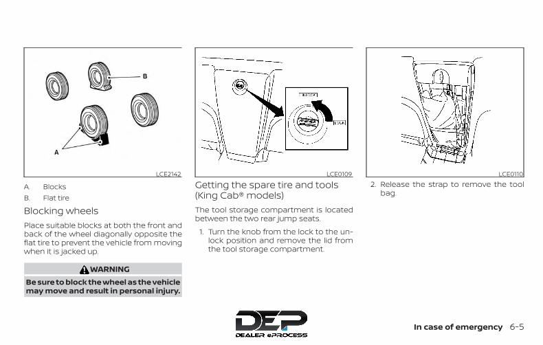
A. BlocksB. Flat tire
Blocking wheelsPlace suitable blocks at both the front andback of the wheel diagonally opposite theflat tire to prevent the vehicle from movingwhen it is jacked up.
WARNINGBe sure to block the wheel as the vehiclemay move and result in personal injury.
Getting the spare tire and tools(King Cab® models)The tool storage compartment is locatedbetween the two rear jump seats.
1. Turn the knob from the lock to the un-lock position and remove the lid fromthe tool storage compartment.
2. Release the strap to remove the toolbag.
LCE2142 LCE0109 LCE0110
In case of emergency 6-5

3. Collapse the jack to remove it from thestorage location by inserting the wheelnut wrench into the jack screw at thetop of the jack as shown. Turn thewheel-nut wrench counterclockwiseas shown until the jack screw becomesloose. Then loosen the jack with yourfingers until it becomes free.
4. Remove the jack.
5. To reinstall the jack and tools, reversesteps 1 to 4.
Getting the spare tire and tools(Crew Cab models)The tools and tool bag are located behindthe rear bench seat.
1. Remove the head restraints/headrestsand fold the rear bench seat down. Foradditional information, refer to “Foldingthe rear bench seat down ” in the “Safe-ty–Seats, seat belts and supplementalrestraint system” section of thismanual.
2. Remove the tool bag and locate thewheel-nut wrench.
3. Collapse the jack to remove it from thestorage location by inserting thewheel-nut wrench into the jack screwas shown and turning the wheel-nutwrench towards you until the jack be-comes loose. Then loosen the jackscrew with your fingers until it is free.
4. Remove the jack from behind the seat.
5. To reinstall the jack and tools, reversesteps 1 to 4.
LCE2164 LCE2159 LCE2165
6-6 In case of emergency
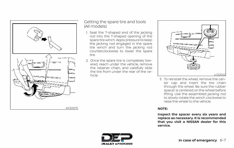
Getting the spare tire and tools(All models)
1. Seat the T-shaped end of the jackingrod into the T-shaped opening of thespare tire winch. Apply pressure to keepthe jacking rod engaged in the sparetire winch and turn the jacking rodcounterclockwise to lower the sparetire.
2. Once the spare tire is completely low-ered, reach under the vehicle, removethe retainer chain, and carefully slidethe tire from under the rear of the ve-hicle.
3. To reinstall the wheel, remove the cen-ter cap and insert the tire chainthrough the wheel. Be sure the rubberspacer is centered on the wheel beforelifting. Use the assembled jacking rodto slowly rotate the winch clockwise toraise the wheel to the vehicle.
NOTE:
Inspect the spacer every six years andreplace as necessary. It is recommendedthat you visit a NISSAN dealer for thisservice.
WCE0070
LCE2022
In case of emergency 6-7
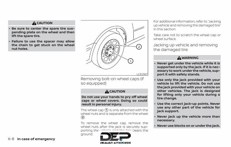
CAUTION∙ Be sure to center the spare tire sus-
pending plate on the wheel and thenlift the spare tire.
∙ Failure to use the spacer may allowthe chain to get stuck on the wheelnut holes.
Removing bolt-on wheel caps (ifso equipped)
CAUTIONDo not use your hands to pry off wheelcaps or wheel covers. Doing so couldresult in personal injury.
The wheel cap �1 is only attached with thewheel nuts and is separate from the wheel�2 .
To remove the wheel cap, remove thewheel nuts after the jack is securely sup-porting the vehicle and the tire clears theground.
For additional information, refer to “Jackingup vehicle and removing the damaged tire”in this section.
Take care not to scratch the wheel cap orwheel surface.
Jacking up vehicle and removingthe damaged tire
WARNING∙ Never get under the vehicle while it is
supported only by the jack. If it is nec-essary to work under the vehicle, sup-port it with safety stands.
∙ Use only the jack provided with yourvehicle to lift the vehicle. Do not usethe jack provided with your vehicle onother vehicles. The jack is designedfor lifting only your vehicle during atire change.
∙ Use the correct jack-up points. Neveruse any other part of the vehicle forjack support.
∙ Never jack up the vehicle more thannecessary.
∙ Never use blocks on or under the jack.
LCE2367
6-8 In case of emergency
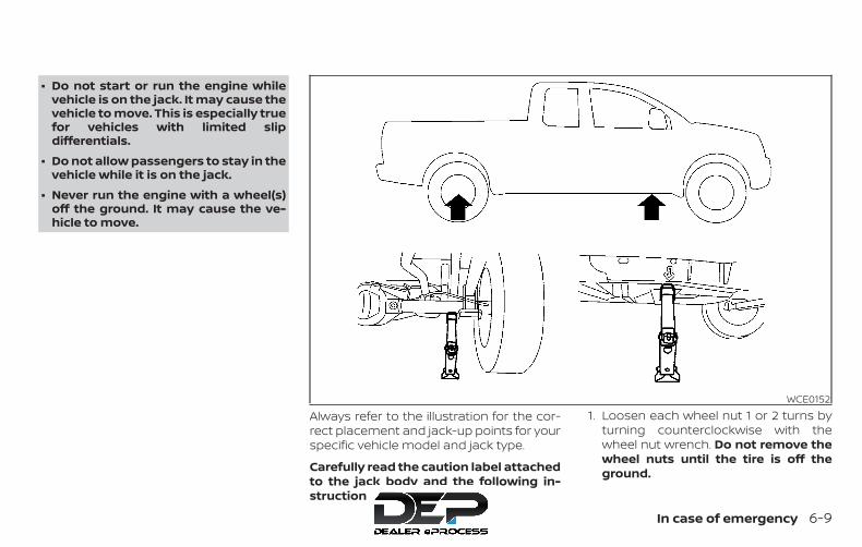
∙ Do not start or run the engine whilevehicle is on the jack. It may cause thevehicle to move. This is especially truefor vehicles with limited slipdifferentials.
∙ Do not allow passengers to stay in thevehicle while it is on the jack.
∙ Never run the engine with a wheel(s)off the ground. It may cause the ve-hicle to move.
Always refer to the illustration for the cor-rect placement and jack-up points for yourspecific vehicle model and jack type.
Carefully read the caution label attachedto the jack body and the following in-structions.
1. Loosen each wheel nut 1 or 2 turns byturning counterclockwise with thewheel nut wrench. Do not remove thewheel nuts until the tire is off theground.
WCE0152
In case of emergency 6-9

2. Place the jack directly under thejack-up point as illustrated so the topof the jack contacts the vehicle at thejack-up point. Align the jack head underthe arrow stamped on the side of theframe or rear as shown.
The jack should be used on firm andlevel ground.
3. Install the assembled jacking rod intothe jack as shown.
4. To lift the vehicle, securely hold thejacking lever and rod. Carefully raise thevehicle until the tire clears the ground.
5. Remove the wheel nuts and then re-move the tire.
LCE0087
6-10 In case of emergency
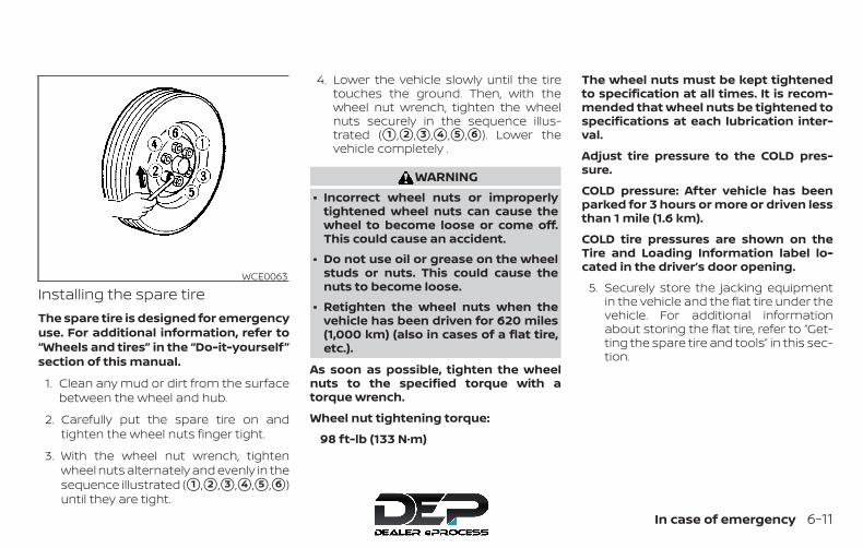
Installing the spare tireThe spare tire is designed for emergencyuse. For additional information, refer to“Wheels and tires” in the “Do-it-yourself”section of this manual.
1. Clean any mud or dirt from the surfacebetween the wheel and hub.
2. Carefully put the spare tire on andtighten the wheel nuts finger tight.
3. With the wheel nut wrench, tightenwheel nuts alternately and evenly in thesequence illustrated (�1 ,�2 ,�3 ,�4 ,�5 ,�6 )until they are tight.
4. Lower the vehicle slowly until the tiretouches the ground. Then, with thewheel nut wrench, tighten the wheelnuts securely in the sequence illus-trated (�1 ,�2 ,�3 ,�4 ,�5 ,�6 ). Lower thevehicle completely .
WARNING∙ Incorrect wheel nuts or improperly
tightened wheel nuts can cause thewheel to become loose or come off.This could cause an accident.
∙ Do not use oil or grease on the wheelstuds or nuts. This could cause thenuts to become loose.
∙ Retighten the wheel nuts when thevehicle has been driven for 620 miles(1,000 km) (also in cases of a flat tire,etc.).
As soon as possible, tighten the wheelnuts to the specified torque with atorque wrench.
Wheel nut tightening torque:
98 ft-lb (133 N·m)
The wheel nuts must be kept tightenedto specification at all times. It is recom-mended that wheel nuts be tightened tospecifications at each lubrication inter-val.
Adjust tire pressure to the COLD pres-sure.
COLD pressure: After vehicle has beenparked for 3 hours or more or driven lessthan 1 mile (1.6 km).
COLD tire pressures are shown on theTire and Loading Information label lo-cated in the driver’s door opening.
5. Securely store the jacking equipmentin the vehicle and the flat tire under thevehicle. For additional informationabout storing the flat tire, refer to “Get-ting the spare tire and tools” in this sec-tion.
WCE0063
In case of emergency 6-11
WARNING∙ Always make sure that the spare tire
and jacking equipment are properlysecured after use. Such items can be-come dangerous projectiles in an ac-cident or sudden stop.
∙ The spare tire is designed for emer-gency use. For additional information,refer to “Wheels and tires” in the “Do-it-yourself” section of this manual.
To start your engine with a booster battery,the instructions and precautions belowmust be followed.
WARNING∙ If done incorrectly, jump starting can
lead to a battery explosion, resultingin severe injury or death. It could alsodamage your vehicle.
∙ Explosive hydrogen gas is alwayspresent in the vicinity of the battery.Keep all sparks and flames away fromthe battery.
∙ Do not allow battery fluid to come intocontact with eyes, skin, clothing orpainted surfaces. Battery fluid is acorrosive sulfuric acid solution whichcan cause severe burns. If the fluidshould come into contact with any-thing, immediately flush the con-tacted area with water.
∙ Keep battery out of the reach ofchildren.
∙ The booster battery must be rated at12 volts. Use of an improperly ratedbattery can damage your vehicle.
∙ Whenever working on or near a bat-tery, always wear suitable eye protec-tors (for example, goggles or indus-trial safety spectacles) and removerings, metal bands, or any other jew-elry. Do not lean over the batterywhen jump starting.
∙ Do not attempt to jump start a frozenbattery. It could explode and causeserious injury.
∙ The automatic engine cooling fan (ifso equipped) may come on at anytime without warning, even if the igni-tion switch is in the OFF position andthe engine is not running. To avoid in-jury, keep hands and other objectsaway from it.
JUMP STARTING
6-12 In case of emergency
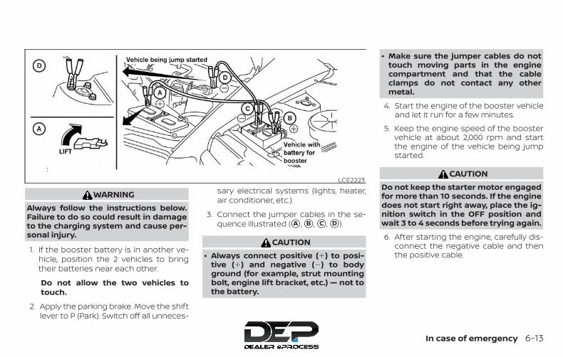
WARNINGAlways follow the instructions below.Failure to do so could result in damageto the charging system and cause per-sonal injury.
1. If the booster battery is in another ve-hicle, position the 2 vehicles to bringtheir batteries near each other.
Do not allow the two vehicles totouch.
2. Apply the parking brake. Move the shiftlever to P (Park). Switch off all unneces-
sary electrical systems (lights, heater,air conditioner, etc.).
3. Connect the jumper cables in the se-quence illustrated (�A , �B , �C , �D ).
CAUTION∙ Always connect positive (�) to posi-
tive (�) and negative (�) to bodyground (for example, strut mountingbolt, engine lift bracket, etc.) — not tothe battery.
∙ Make sure the jumper cables do nottouch moving parts in the enginecompartment and that the cableclamps do not contact any othermetal.
4. Start the engine of the booster vehicleand let it run for a few minutes.
5. Keep the engine speed of the boostervehicle at about 2,000 rpm and startthe engine of the vehicle being jumpstarted.
CAUTIONDo not keep the starter motor engagedfor more than 10 seconds. If the enginedoes not start right away, place the ig-nition switch in the OFF position andwait 3 to 4 seconds before trying again.
6. After starting the engine, carefully dis-connect the negative cable and thenthe positive cable.
LCE2223
In case of emergency 6-13
CAUTION∙ Do not push start this vehicle. The
3-way catalyst may be damaged.
∙ Automatic transmission models can-not be push-started or tow-started.Attempting to do so may cause trans-mission damage.
∙ For manual transmission models,never try to start the vehicle by tow-ing it. When the engine starts, the for-ward surge could cause the vehicle tocollide with the tow vehicle.
WARNING∙ Do not continue to drive if your vehicle
overheats. Doing so could cause en-gine damage or a vehicle fire.
∙ To avoid the danger of being scalded,never remove the radiator cap whilethe engine is still hot. When the radia-tor cap is removed, pressurized hotwater will spurt out, possibly causingserious injury.
∙ Do not open the hood if steam is com-ing out.
If your vehicle is overheating (indicated byan extremely high temperature gaugereading), or if you feel a lack of enginepower, detect abnormal noise, etc. take thefollowing steps.
1. Move the vehicle safely off the road, ap-ply the parking brake and move theshift lever to N (Neutral) (manual trans-mission) or to P (Park) (automatic trans-mission).
Do not stop the engine.
2. Turn off the air conditioner. Open all thewindows, move the heater or air condi-tioner temperature control to maxi-mum hot and fan control to highspeed.
3. Get out of the vehicle. Look and listenfor steam or coolant escaping from theradiator before opening the hood. Ifsteam or coolant is escaping, turn offthe engine. Do not open the hood fur-ther until no steam or coolant can beseen.
4. Open the engine hood.
WARNINGIf steam or water is coming from theengine, stand clear to prevent gettingburned.
5. Visually check drive belts for damageor looseness. Also check if the coolingfan is running. The radiator hoses andradiator should not leak water. If cool-ant is leaking, the water pump belt ismissing or loose, or the cooling fandoes not run, stop the engine.
PUSH STARTING IF YOUR VEHICLE OVERHEATS
6-14 In case of emergency
WARNINGBe careful not to allow your hands, hair,jewelry or clothing to come into contactwith, or get caught in, engine belts orthe engine cooling fan. The engine cool-ing fan can start at any time.
6. After the engine cools down, check thecoolant level in the engine coolant res-ervoir tank with the engine running.Add coolant to the engine coolant res-ervoir tank if necessary. Have your ve-hicle repaired. It is recommended thatyou visit a NISSAN dealer for this ser-vice.
When towing your vehicle, all jurisdictionaland local regulations for towing must befollowed. Incorrect towing equipmentcould damage your vehicle. Towing in-structions are available from a NISSANdealer. Local service operators are gener-ally familiar with the applicable laws andprocedures for towing. To assure propertowing and to prevent accidental damageto your vehicle, NISSAN recommends hav-ing a service operator tow your vehicle. It isadvisable to have the service operatorcarefully read the following precautions:
WARNING∙ Never ride in a vehicle that is being
towed.
∙ Never get under your vehicle after ithas been lifted by a tow truck.
CAUTION∙ When towing, make sure that the
transmission, axles, steering systemand powertrain are in working condi-tion. If any of these conditions apply,dollies or a flatbed tow truck must beused.
∙ Always attach safety chains beforetowing.
For additional information, refer to “Flattowing — 4WD with automatic transmis-sion,” “Flat towing — 2WD with automatictransmission” and “Flat towing — 2WD/4WDwith manual transmission” in the “Technicaland consumer information” section of thismanual.
TOWING RECOMMENDED BYNISSANNISSAN recommends towing your vehiclebased upon the type of drivetrain. For addi-tional information, refer to the diagrams inthis section to ensure that your vehicle isproperly towed.
TOWING YOUR VEHICLE
In case of emergency 6-15

Four-Wheel Drive (4WD) modelswith automatic transmissionNISSAN recommends that towing dolliesbe used when towing your vehicle or placethe vehicle on a flatbed truck as illustrated.
CAUTIONNever tow 4WD models equipped withan automatic transmission with any ofthe wheels on the ground as this maycause serious and expensive damageto the transfer case and transmission.
LCE2141
6-16 In case of emergency
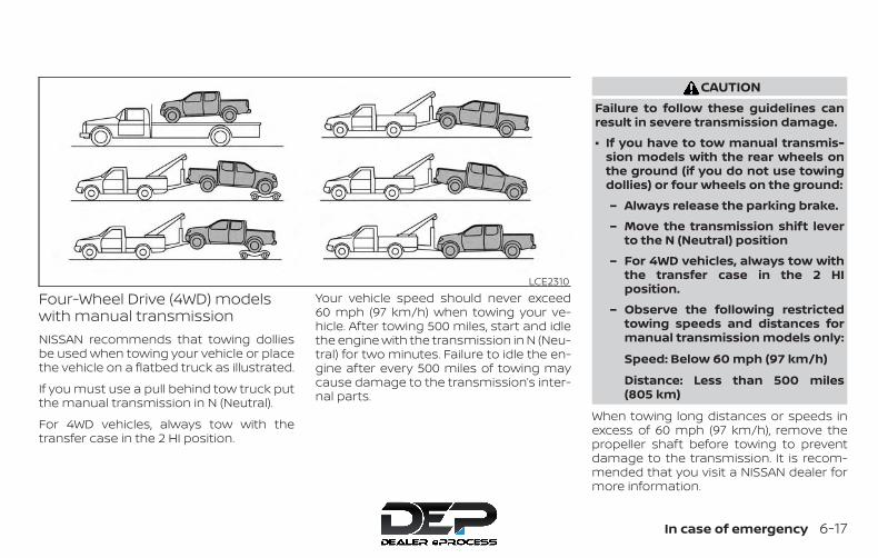
Four-Wheel Drive (4WD) modelswith manual transmissionNISSAN recommends that towing dolliesbe used when towing your vehicle or placethe vehicle on a flatbed truck as illustrated.
If you must use a pull behind tow truck putthe manual transmission in N (Neutral).
For 4WD vehicles, always tow with thetransfer case in the 2 HI position.
Your vehicle speed should never exceed60 mph (97 km/h) when towing your ve-hicle. After towing 500 miles, start and idlethe engine with the transmission in N (Neu-tral) for two minutes. Failure to idle the en-gine after every 500 miles of towing maycause damage to the transmission’s inter-nal parts.
CAUTIONFailure to follow these guidelines canresult in severe transmission damage.
∙ If you have to tow manual transmis-sion models with the rear wheels onthe ground (if you do not use towingdollies) or four wheels on the ground:
– Always release the parking brake.
– Move the transmission shift leverto the N (Neutral) position
– For 4WD vehicles, always tow withthe transfer case in the 2 HIposition.
– Observe the following restrictedtowing speeds and distances formanual transmission models only:
Speed: Below 60 mph (97 km/h)
Distance: Less than 500 miles(805 km)
When towing long distances or speeds inexcess of 60 mph (97 km/h), remove thepropeller shaft before towing to preventdamage to the transmission. It is recom-mended that you visit a NISSAN dealer formore information.
LCE2310
In case of emergency 6-17
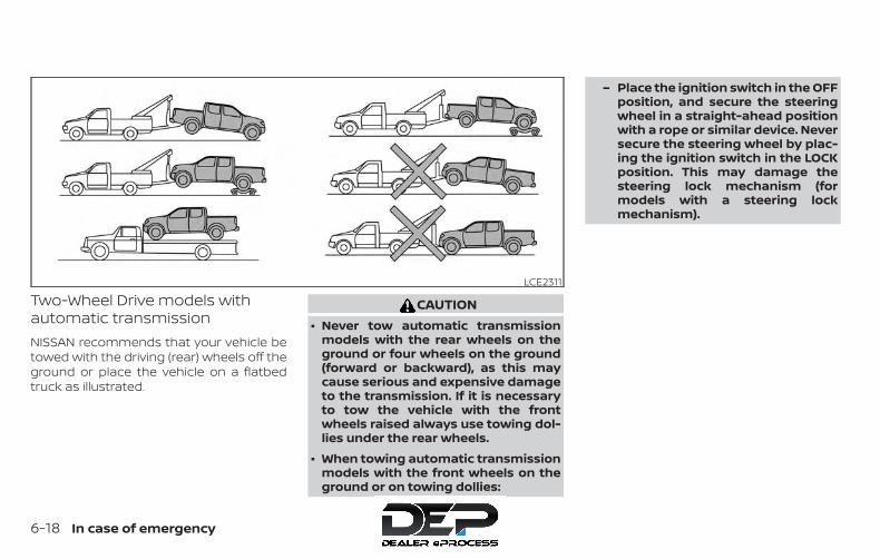
Two-Wheel Drive models withautomatic transmissionNISSAN recommends that your vehicle betowed with the driving (rear) wheels off theground or place the vehicle on a flatbedtruck as illustrated.
CAUTION∙ Never tow automatic transmission
models with the rear wheels on theground or four wheels on the ground(forward or backward), as this maycause serious and expensive damageto the transmission. If it is necessaryto tow the vehicle with the frontwheels raised always use towing dol-lies under the rear wheels.
∙ When towing automatic transmissionmodels with the front wheels on theground or on towing dollies:
– Place the ignition switch in the OFFposition, and secure the steeringwheel in a straight-ahead positionwith a rope or similar device. Neversecure the steering wheel by plac-ing the ignition switch in the LOCKposition. This may damage thesteering lock mechanism (formodels with a steering lockmechanism).
LCE2311
6-18 In case of emergency

Two-Wheel Drive models withmanual transmissionNISSAN recommends that towing dolliesbe used when towing your vehicle or placethe vehicle on the flatbed truck as illus-trated.
If you must use a pull behind tow truck putthe manual transmission in N (Neutral).
Your vehicle speed should never exceed60 mph (97 km/h) when towing your ve-hicle. After towing 500 miles, start and idlethe engine with the transmission in N (Neu-tral) for two minutes. Failure to idle the en-
gine after every 500 miles of towing maycause damage to the transmission’s inter-nal parts.
CAUTIONFailure to follow these guidelines canresult in severe transmission damage.
∙ If you have to tow manual transmis-sion models with the rear wheels onthe ground (if you do not use towingdollies) or four wheels on the ground:
– Always release the parking brake.
– Move the transmission shift leverto the N (Neutral) position
– Observe the following restrictedtowing speeds and distances formanual transmission models only:
Speed: Below 60 mph (97 km/h)
Distance: Less than 500 miles(805 km)
When towing long distances or speeds inexcess of 60 mph (97 km/h), remove thepropeller shaft before towing to preventdamage to the transmission. For additionalinformation, it is recommended that youvisit a NISSAN dealer.
VEHICLE RECOVERY (freeing astuck vehicle)There are two options to recover a stuckvehicle: pulling and rocking. For additionalinformation regarding these options,please refer to the following sections.
LCE2310
In case of emergency 6-19

Pulling a stuck vehicle
WARNINGTo avoid vehicle damage, serious per-sonal injury or death when recovering astuck vehicle:
∙ Contact a professional towing serviceto recover the vehicle if you have anyquestions regarding the recoveryprocedure.
∙ Attach recovery devices only to mainstructural members of the vehicle orthe recovery hooks.
∙ Do not use the vehicle tie-downs totow or free a stuck vehicle.
∙ Only use devices specifically designedfor vehicle recovery and follow themanufacturer’s instructions.
∙ Always pull the recovery devicestraight out from the front of the ve-hicle. Never pull at an angle.
∙ Route recovery devices so they do nottouch any part of the vehicle exceptthe attachment point.
If your vehicle is stuck in sand, snow, mud,etc., use a tow strap or other device de-signed specifically for vehicle recovery. Al-ways follow the manufacturer’s instruc-tions for the recovery device.
Rocking a stuck vehicle
WARNING∙ Stand clear of a stuck vehicle.
∙ Do not spin your tires at high speed.This could cause them to explode andresult in serious injury. Parts of yourvehicle could also overheat and bedamaged.
If your vehicle is stuck in sand, snow, mud,etc., use the following procedure:
1. Turn off the Vehicle Dynamic Control(VDC) system.
2. Make sure the area in front and behindthe vehicle is clear of obstructions.
3. Turn the steering wheel right and left toclear an area around the front tires.
4. Slowly rock the vehicle forward andbackward.
∙ Shift back and forth between R (Re-verse) and D (Drive) (automatic trans-mission models) or 1st (Low) and R(Reverse) (manual transmissionmodels).
∙ Apply the accelerator as little as pos-sible to maintain the rocking motion.
∙ Release the accelerator pedal beforeshifting between R and D (automatictransmission models) or 1st and R(manual transmission models).
∙ Do not spin the tires above 34 mph(55 km/h).
5. If the vehicle cannot be freed after afew tries, contact a professional towingservice to remove the vehicle.
6-20 In case of emergency

7 Appearance and care
Cleaning exterior . . . . . . . . . . . . . . . . . . . . . . . . . . . . . . . . 7-2Washing. . . . . . . . . . . . . . . . . . . . . . . . . . . . . . . . . . . . . . 7-2Waxing . . . . . . . . . . . . . . . . . . . . . . . . . . . . . . . . . . . . . . . 7-2Removing spots . . . . . . . . . . . . . . . . . . . . . . . . . . . . . . 7-3Underbody . . . . . . . . . . . . . . . . . . . . . . . . . . . . . . . . . . . 7-3Glass . . . . . . . . . . . . . . . . . . . . . . . . . . . . . . . . . . . . . . . . . 7-3Aluminum alloy wheels (if so equipped) . . . . . . . 7-3Chrome parts . . . . . . . . . . . . . . . . . . . . . . . . . . . . . . . . 7-3Tire dressings . . . . . . . . . . . . . . . . . . . . . . . . . . . . . . . . 7-3
Cleaning interior. . . . . . . . . . . . . . . . . . . . . . . . . . . . . . . . . 7-4
Air fresheners . . . . . . . . . . . . . . . . . . . . . . . . . . . . . . . . 7-5Floor mats (if so equipped) . . . . . . . . . . . . . . . . . . . 7-5Seat belts . . . . . . . . . . . . . . . . . . . . . . . . . . . . . . . . . . . . 7-6
Corrosion protection . . . . . . . . . . . . . . . . . . . . . . . . . . . . 7-7Most common factors contributing tovehicle corrosion . . . . . . . . . . . . . . . . . . . . . . . . . . . . . 7-7Environmental factors influence therate of corrosion. . . . . . . . . . . . . . . . . . . . . . . . . . . . . . 7-7Protect your vehicle from corrosion . . . . . . . . . . 7-7

In order to maintain the appearance ofyour vehicle, it is important to take propercare of it.
To protect the paint surfaces, wash yourvehicle as soon as you can:
∙ After a rainfall to prevent possible dam-age from acid rain.
∙ After driving on coastal roads.
∙ When contaminants such as soot, birddroppings, tree sap, metal particles orbugs get on the paint surface.
∙ When dust or mud builds up on the sur-face.
Whenever possible, store or park your ve-hicle inside a garage or in a covered area.
When it is necessary to park outside, park ina shady area or protect the vehicle with abody cover.
Be careful not to scratch the paint sur-face when putting on or removing thebody cover.
WASHINGWash dirt off with a wet sponge and plentyof water. Clean the vehicle thoroughly us-ing a mild soap, a special vehicle soap orgeneral purpose dishwashing liquid mixedwith clean, lukewarm (never hot) water.
CAUTION∙ Do not use car washes that use acid in
the detergent. Some car washes, es-pecially brushless ones, use someacid for cleaning. The acid may reactwith some plastic vehicle compo-nents, causing them to crack. Thiscould affect their appearance, andalso could cause them not to functionproperly. Always check with your carwash to confirm that acid is not used.
∙ Do not wash the vehicle with stronghousehold soap, strong chemical de-tergents, gasoline or solvents.
∙ Do not wash the vehicle in direct sun-light or while the vehicle body is hot,as the surface may becomewater-spotted.
∙ Avoid using tight-napped or roughcloths, such as washing mitts. Caremust be taken when removingcaked-on dirt or other foreign sub-stances so the paint surface is notscratched or damaged.
Rinse the vehicle thoroughly with plenty ofclean water.
Inside edges, seams and folds on thedoors, hatches and hood are particularlyvulnerable to the effects of road salt. There-fore, these areas must be cleaned regularly.Take care that the drain holes in the loweredge of the door are open. Spray waterunder the body and in the wheel wells toloosen the dirt and wash away road salt.
A damp chamois can be used to dry thevehicle to avoid water spots.
WAXINGRegular waxing protects the paint surfaceand helps retain new vehicle appearance.Polishing is recommended to removebuilt-up wax residue and to avoid a weath-ered appearance before re-applying wax.
A NISSAN dealer can assist you in choosingthe proper product.
CLEANING EXTERIOR
7-2 Appearance and care
∙ Wax your vehicle only after a thoroughwashing. Follow the instructions sup-plied with the wax.
∙ Do not use a wax containing any abra-sives, cutting compounds or cleanersthat may damage the vehicle finish.
Machine compounding or aggressive pol-ishing on a base coat/clear coat paint fin-ish may dull the finish or leave swirl marks.
REMOVING SPOTSRemove tar and oil spots, industrial dust,insects, and tree sap as quickly as possiblefrom the surface of the paint to avoid last-ing damage or staining. Special cleaningproducts are available at a NISSAN dealeror any automotive accessory store. It isrecommended that you visit a NISSANdealer for these products.
UNDERBODYIn areas where road salt is used in winter, itis necessary to clean the underbody regu-larly in order to prevent dirt and salt frombuilding up and causing the acceleration ofcorrosion on the underbody and suspen-sion. Before the winter period and again inthe spring, the underseal must be checkedand, if necessary, re-treated.
GLASSUse glass cleaner to remove smoke anddust film from the glass surfaces. It is nor-mal for glass to become coated with a filmafter the vehicle is parked in the hot sun.Glass cleaner and a soft cloth will easilyremove this film.
CAUTIONWhen cleaning the inside of the win-dows, do not use sharp-edged tools,abrasive cleaners or chlorine-baseddisinfectant cleaners. They could dam-age the electrical conductors, radio an-tenna elements or rear window de-froster elements.
ALUMINUM ALLOY WHEELS (if soequipped)Wash the wheels regularly with a spongedampened in a mild soap solution, espe-cially during winter months in areas whereroad salt is used. If not removed, road saltcan discolor the wheels.
CAUTIONFollow the directions below to avoidstaining or discoloring the wheels:
∙ Do not use a cleaner that uses strongacid or alkali contents to clean thewheels.
∙ Do not apply wheel cleaners to thewheels when they are hot. The wheeltemperature should be the same asambient temperature.
∙ Rinse the wheel to completely removethe cleaner within 15 minutes afterthe cleaner is applied.
CHROME PARTSClean all chrome parts regularly with anon-abrasive chrome polish to maintainthe finish.
TIRE DRESSINGSNISSAN does not recommend the use oftire dressings. Tire manufacturers apply acoating to the tires to help reduce discolor-ation of the rubber. If a tire dressing is ap-plied to the tires, it may react with the coat-ing and form a compound. This compoundmay come off the tire while driving andstain the vehicle paint.
Appearance and care 7-3
If you choose to use a tire dressing, take thefollowing precautions:
∙ Use a water-based tire dressing. Thecoating on the tire dissolves more easilythan with an oil-based tire dressing.
∙ Apply a light coat of tire dressing to helpprevent it from entering the tiretread/grooves (where it would be diffi-cult to remove).
∙ Wipe off excess tire dressing using a drytowel. Make sure the tire dressing iscompletely removed from the tiretread/grooves.
∙ Allow the tire dressing to dry as recom-mended by the tire dressing manufac-turer.
Occasionally remove loose dust from theinterior trim, plastic parts and seats using avacuum cleaner or soft bristled brush. Wipethe vinyl and leather (if so equipped) sur-faces with a clean, soft cloth dampened inmild soap solution, then wipe clean with adry, soft cloth.
Regular care and cleaning is required inorder to maintain the appearance of theleather (if so equipped).
Before using any fabric protector, read themanufacturer’s recommendations. Somefabric protectors contain chemicals thatmay stain or bleach the seat material.
Use a cloth dampened only with water toclean the meter and gauge lens.
WARNINGDo not use water or acidic cleaners (hotsteam cleaners) on the seat. This candamage the seat or occupant classifi-cation sensor. This can also affect theoperation of the air bag system and re-sult in serious personal injury.
CAUTION∙ Never use benzine, thinner or any
similar material.
∙ Small dirt particles can be abrasiveand damaging to leather surfacesand should be removed promptly. Donot use saddle soap, car waxes, pol-ishes, oils, cleaning fluids, solvents,detergents or ammonia-based clean-ers as they may damage the leather’snatural finish.
∙ Never use fabric protectors unlessrecommended by the manufacturer.
∙ Do not use glass or plastic cleaner onmeter or gauge lens covers. It maydamage the lens cover.
CLEANING INTERIOR
7-4 Appearance and care
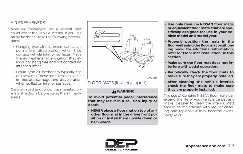
AIR FRESHENERSMost air fresheners use a solvent thatcould affect the vehicle interior. If you usean air freshener, take the following precau-tions:
∙ Hanging-type air fresheners can causepermanent discoloration when theycontact vehicle interior surfaces. Placethe air freshener in a location that al-lows it to hang free and not contact aninterior surface.
∙ Liquid-type air fresheners typically clipon the vents. These products can causeimmediate damage and discolorationwhen spilled on interior surfaces.
Carefully read and follow the manufactur-er’s instructions before using the air fresh-eners.
FLOOR MATS (if so equipped)
WARNINGTo avoid potential pedal interferencethat may result in a collision, injury ordeath:
∙ NEVER place a floor mat on top of an-other floor mat in the driver front po-sition or install them upside down orbackwards.
∙ Use only Genuine NISSAN floor mats,or equivalent floor mats, that are spe-cifically designed for use in your ve-hicle model and model year.
∙ Properly position the mats in thefloorwell using the floor mat position-ing hook. For additional information,refer to "Floor mat installation" in thissection.
∙ Make sure the floor mat does not in-terfere with pedal operation.
∙ Periodically check the floor mats tomake sure they are properly installed.
∙ After cleaning the vehicle interior,check the floor mats to make surethey are properly installed.
The use of Genuine NISSAN floor mats canextend the life of your vehicle carpet andmake it easier to clean the interior. Matsshould be maintained with regular clean-ing and replaced if they become exces-sively worn.
LAI2085
Appearance and care 7-5
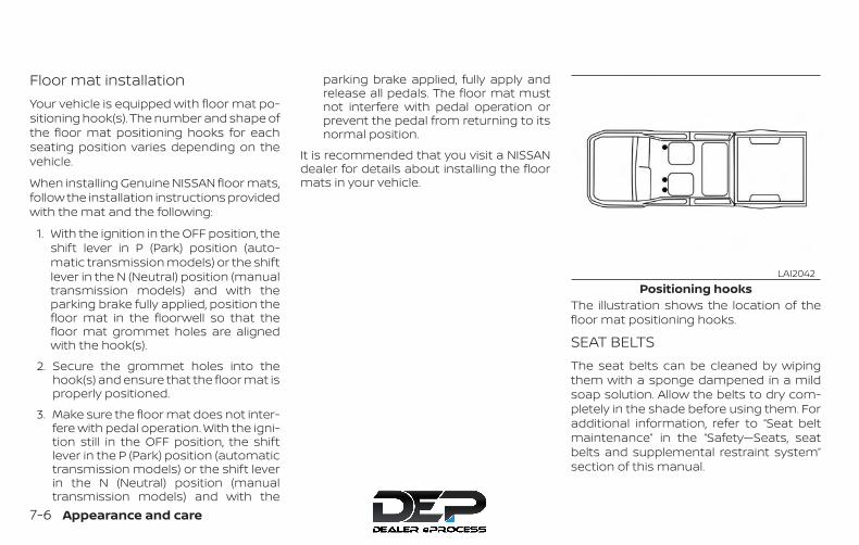
Floor mat installationYour vehicle is equipped with floor mat po-sitioning hook(s). The number and shape ofthe floor mat positioning hooks for eachseating position varies depending on thevehicle.
When installing Genuine NISSAN floor mats,follow the installation instructions providedwith the mat and the following:
1. With the ignition in the OFF position, theshift lever in P (Park) position (auto-matic transmission models) or the shiftlever in the N (Neutral) position (manualtransmission models) and with theparking brake fully applied, position thefloor mat in the floorwell so that thefloor mat grommet holes are alignedwith the hook(s).
2. Secure the grommet holes into thehook(s) and ensure that the floor mat isproperly positioned.
3. Make sure the floor mat does not inter-fere with pedal operation. With the igni-tion still in the OFF position, the shiftlever in the P (Park) position (automatictransmission models) or the shift leverin the N (Neutral) position (manualtransmission models) and with the
parking brake applied, fully apply andrelease all pedals. The floor mat mustnot interfere with pedal operation orprevent the pedal from returning to itsnormal position.
It is recommended that you visit a NISSANdealer for details about installing the floormats in your vehicle.
The illustration shows the location of thefloor mat positioning hooks.
SEAT BELTSThe seat belts can be cleaned by wipingthem with a sponge dampened in a mildsoap solution. Allow the belts to dry com-pletely in the shade before using them. Foradditional information, refer to “Seat beltmaintenance” in the “Safety—Seats, seatbelts and supplemental restraint system”section of this manual.
Positioning hooksLAI2042
7-6 Appearance and care
WARNINGDo not allow wet seat belts to roll up inthe retractor. NEVER use bleach, dye orchemical solvents to clean the seatbelts, since these materials may se-verely weaken the seat belt webbing.
MOST COMMON FACTORSCONTRIBUTING TO VEHICLECORROSIONMost vehicle corrosion is caused by:
∙ The accumulation of moisture-retaining dirt and debris in body panelsections, cavities, and other areas.
∙ Damage to paint and other protectivecoatings caused by gravel and stonechips or minor traffic collisions.
ENVIRONMENTAL FACTORSINFLUENCE THE RATE OFCORROSIONMoistureAccumulation of sand, dirt and water onthe vehicle body underside can acceleratecorrosion. Wet floor coverings will not drycompletely inside the vehicle and shouldbe removed for drying to avoid floor panelcorrosion.
Relative humidityCorrosion will be accelerated in areas ofhigh relative humidity, especially those ar-eas where the temperatures stay above
freezing and where atmospheric pollutionexists and road salt is used.
TemperatureHigh temperatures accelerate the rate ofcorrosion to those parts which are not wellventilated.
Air pollutionIndustrial pollution, the presence of salt inthe air in coastal areas, or heavy road saltuse accelerates the corrosion process.Road salt also accelerates the disintegra-tion of paint surfaces.
PROTECT YOUR VEHICLE FROMCORROSION
∙ Wash and wax your vehicle often tokeep the vehicle clean.
∙ Always check for minor damage to thepaint and repair it as soon as possible.
∙ Keep drain holes at the bottom of thedoors open to avoid water accumula-tion.
∙ Check the underbody for accumulationof sand, dirt or salt. If present, wash withwater as soon as possible.
CORROSION PROTECTION
Appearance and care 7-7
CAUTION∙ NEVER remove dirt, sand or other de-
bris from the passenger compart-ment by washing it out with a hose.Remove dirt with a vacuum cleaner orbroom.
∙ Never allow water or other liquids tocome in contact with electronic com-ponents inside the vehicle as this maydamage them.
Chemicals used for road surface de-icingare extremely corrosive. They acceleratecorrosion and deterioration of underbodycomponents such as the exhaust system,fuel and brake lines, brake cables, floor panand fenders.
In winter, the underbody must becleaned periodically.
For additional protection against rust andcorrosion, which may be required in someareas, it is recommended that you consulta NISSAN dealer.
7-8 Appearance and care

8 Do-it-yourself
Maintenance precautions . . . . . . . . . . . . . . . . . . . . . . . 8-2Engine compartment check locations . . . . . . . . . . . 8-3Engine cooling system . . . . . . . . . . . . . . . . . . . . . . . . . . 8-5
Checking engine coolant level . . . . . . . . . . . . . . . . 8-6Changing engine coolant. . . . . . . . . . . . . . . . . . . . . 8-6
Engine oil. . . . . . . . . . . . . . . . . . . . . . . . . . . . . . . . . . . . . . . . 8-7Checking engine oil level . . . . . . . . . . . . . . . . . . . . . 8-7Changing engine oil . . . . . . . . . . . . . . . . . . . . . . . . . . 8-8Changing engine oil filter . . . . . . . . . . . . . . . . . . . . 8-10
5-speed Automatic Transmission(if so equipped) Fluid (ATF) . . . . . . . . . . . . . . . . . . . . . . .8-11Power Steering Fluid (PSF) . . . . . . . . . . . . . . . . . . . . . . .8-11Brake and clutch (if so equipped) fluid . . . . . . . . . . 8-12
Brake fluid . . . . . . . . . . . . . . . . . . . . . . . . . . . . . . . . . . . 8-12Clutch (if so equipped) fluid . . . . . . . . . . . . . . . . . . 8-12
Windshield-washer fluid . . . . . . . . . . . . . . . . . . . . . . . . 8-13Windshield-washer fluid reservoir. . . . . . . . . . . . 8-13
Battery . . . . . . . . . . . . . . . . . . . . . . . . . . . . . . . . . . . . . . . . . 8-14Jump starting . . . . . . . . . . . . . . . . . . . . . . . . . . . . . . . 8-15
Variable voltage control system . . . . . . . . . . . . . . . . 8-16Drive belt . . . . . . . . . . . . . . . . . . . . . . . . . . . . . . . . . . . . . . . 8-16Spark plugs . . . . . . . . . . . . . . . . . . . . . . . . . . . . . . . . . . . . 8-17
Replacing spark plugs . . . . . . . . . . . . . . . . . . . . . . . 8-17Air cleaner. . . . . . . . . . . . . . . . . . . . . . . . . . . . . . . . . . . . . . 8-18
In-cabin microfilter . . . . . . . . . . . . . . . . . . . . . . . . . . 8-19Windshield wiper blades . . . . . . . . . . . . . . . . . . . . . . . .8-20
Cleaning . . . . . . . . . . . . . . . . . . . . . . . . . . . . . . . . . . . .8-20Replacing . . . . . . . . . . . . . . . . . . . . . . . . . . . . . . . . . . .8-20
Brakes. . . . . . . . . . . . . . . . . . . . . . . . . . . . . . . . . . . . . . . . . . 8-21Fuses. . . . . . . . . . . . . . . . . . . . . . . . . . . . . . . . . . . . . . . . . . . 8-22
Engine compartment . . . . . . . . . . . . . . . . . . . . . . . 8-23Passenger compartment. . . . . . . . . . . . . . . . . . . . 8-24
Battery replacement . . . . . . . . . . . . . . . . . . . . . . . . . . . 8-25Key fob (if so equipped) . . . . . . . . . . . . . . . . . . . . . . 8-26
Lights . . . . . . . . . . . . . . . . . . . . . . . . . . . . . . . . . . . . . . . . . . 8-27Headlights. . . . . . . . . . . . . . . . . . . . . . . . . . . . . . . . . . . 8-27Fog lights (if so equipped) . . . . . . . . . . . . . . . . . . .8-28Exterior and interior lights . . . . . . . . . . . . . . . . . . . 8-29
Wheels and tires. . . . . . . . . . . . . . . . . . . . . . . . . . . . . . . . 8-32Tire pressure . . . . . . . . . . . . . . . . . . . . . . . . . . . . . . . . 8-32Tire labeling . . . . . . . . . . . . . . . . . . . . . . . . . . . . . . . . . 8-36Types of tires . . . . . . . . . . . . . . . . . . . . . . . . . . . . . . . .8-38Tire chains . . . . . . . . . . . . . . . . . . . . . . . . . . . . . . . . . . 8-39Changing wheels and tires . . . . . . . . . . . . . . . . . .8-40
When performing any inspection or main-tenance work on your vehicle, always takecare to prevent serious accidental injury toyourself or damage to the vehicle. The fol-lowing are general precautions whichshould be closely observed.
WARNING∙ Park the vehicle on a level surface, ap-
ply the parking brake securely andblock the wheels to prevent the ve-hicle from moving. For manual trans-mission models, move the shift leverto N (Neutral). For Automatic Trans-mission (A/T) move the shift lever to P(Park)
∙ Be sure the ignition key is in the OFF orLOCK position when performing anyparts replacement or repairs.
∙ If you must work with the engine run-ning, keep your hands, clothing, hairand tools away from moving fans,belts and any other moving parts.
∙ It is advisable to secure or remove anyloose clothing and remove any jew-elry, such as rings, watches, etc. be-fore working on your vehicle.
∙ Always wear eye protection wheneveryou work on your vehicle.
∙ If you must run the engine in an en-closed space such as a garage, be surethere is proper ventilation for exhaustgases to escape.
∙ Never get under the vehicle while it issupported only by a jack. If it is neces-sary to work under the vehicle, sup-port it with safety stands.
∙ Keep smoking materials, flame andsparks away from the fuel tank andbattery.
∙ On gasoline engine models, the fuelfilter or fuel lines should be servicedbecause the fuel lines are under highpressure even when the engine is off.It is recommended that you visit aNISSAN dealer for this service.
CAUTION∙ Do not work under the hood while the
engine is hot. Turn the engine off andwait until it cools down.
∙ Avoid contact with used engine oil andcoolant. Improperly disposed engineoil, engine coolant and/or other vehiclefluids can damage the environment. Al-ways conform to local regulations fordisposal of vehicle fluid.
∙ Never leave the engine or the trans-mission related component harnessconnector disconnected while the ig-nition switch is in the ON position.
∙ Never connect or disconnect the bat-tery or any transistorized componentwhile the ignition switch is in the ONposition.
This “Do-it-yourself ” section gives instruc-tions regarding only those items which arerelatively easy for an owner to perform.
A Genuine NISSAN service manual is alsoavailable. For additional information, referto “Owner’s Manual/Service Manual orderinformation” in the “Technical and con-sumer information” section of this manual.
You should be aware that incomplete orimproper servicing may result in operatingdifficulties or excessive emissions, andcould affect warranty coverage. If in doubtabout any servicing, it is recommendedthat you have it done by a NISSAN dealer.
MAINTENANCE PRECAUTIONS
8-2 Do-it-yourself

QR25DE engine1. Windshield-washer fluid reservoir2. Fuse/Fusible link box3. Fuse box4. Air cleaner5. Engine oil filler cap6. Engine oil dipstick7. Brake and clutch (if so equipped)
fluid reservoir8. Drive belt location9. Radiator cap10. Power steering fluid reservoir11. Battery12. Engine coolant reservoir
WDI0643
ENGINE COMPARTMENT CHECKLOCATIONS
Do-it-yourself 8-3

VQ40DE engine1. Windshield-washer fluid reservoir2. Fuse/Fusible link box3. Fuse box4. Engine oil filler cap5. Engine oil dipstick6. Brake and clutch (if so equipped)
fluid reservoir7. Air cleaner8. Drive belt location9. Radiator cap10. Power steering fluid reservoir11. Battery12. Engine coolant reservoir
LII0167
8-4 Do-it-yourself

The engine cooling system is filled at thefactory with a pre-diluted mixture of 50%Genuine NISSAN Long LifeAntifreeze/Coolant (blue) and 50% water toprovide year-round antifreeze and coolantprotection. The antifreeze solution con-tains rust and corrosion inhibitors. Addi-tional engine cooling system additives arenot necessary.
WARNING∙ Never remove the radiator or coolant
reservoir cap when the engine is hot.Wait until the engine and radiator cooldown. Serious burns could be causedby high pressure fluid escaping fromthe radiator. For additional informa-tion on precautions, refer to “If yourvehicle overheats” in the “In case ofemergency” section of this manual.
∙ The radiator is equipped with a pres-sure type radiator cap. To prevent en-gine damage, use only a GenuineNISSAN radiator cap.
CAUTION∙ Never use any cooling system addi-
tives such as radiator sealer. Additivesmay clog the cooling system andcause damage to the engine, trans-mission and/or cooling system.
∙ When adding or replacing coolant, besure to use only Genuine NISSAN LongLife Antifreeze/Coolant (blue) orequivalent. Genuine NISSAN Long LifeAntifreeze/Coolant (blue) is pre-diluted to provide antifreeze protec-tion to -34° F (-37° C). If additionalfreeze protection is needed due toweather where you operate your ve-hicle, add Genuine NISSAN Long LifeAntifreeze/Coolant (blue) concen-trate following the directions on thecontainer. If an equivalent coolantother than Genuine NISSAN Long LifeAntifreeze/Coolant (blue) is used, fol-low the coolant manufacturer’s in-structions to maintain minimum anti-freeze protection to -34° F (-37° C). Theuse of other types of coolant solu-tions other than Genuine NISSAN LongLife Antifreeze/Coolant (blue) orequivalent may damage the enginecooling system.
∙ The life expectancy of the factory-fillcoolant is 105,000 miles (168,000 km)or 7 years. Mixing any other type ofcoolant other than Genuine NISSANLong Life Antifreeze/Coolant (blue),including Genuine NISSAN Long LifeAntifreeze/Coolant (green), or the useof non-distilled water will reduce thelife expectancy of the factory-fill cool-ant. For additional information, referto the "Maintenance and schedules"section of this manual.
ENGINE COOLING SYSTEM
Do-it-yourself 8-5
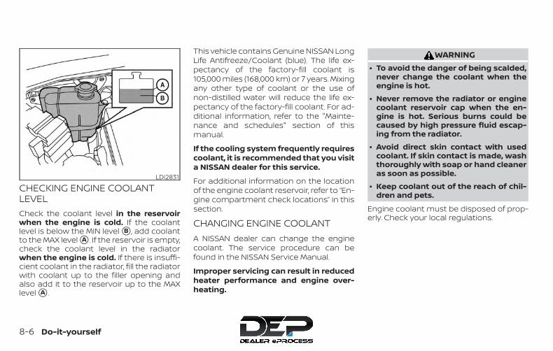
CHECKING ENGINE COOLANTLEVELCheck the coolant level in the reservoirwhen the engine is cold. If the coolantlevel is below the MIN level �B , add coolantto the MAX level �A . If the reservoir is empty,check the coolant level in the radiatorwhen the engine is cold. If there is insuffi-cient coolant in the radiator, fill the radiatorwith coolant up to the filler opening andalso add it to the reservoir up to the MAXlevel �A .
This vehicle contains Genuine NISSAN LongLife Antifreeze/Coolant (blue). The life ex-pectancy of the factory-fill coolant is105,000 miles (168,000 km) or 7 years. Mixingany other type of coolant or the use ofnon-distilled water will reduce the life ex-pectancy of the factory-fill coolant. For ad-ditional information, refer to the "Mainte-nance and schedules" section of thismanual.
If the cooling system frequently requirescoolant, it is recommended that you visita NISSAN dealer for this service.
For additional information on the locationof the engine coolant reservoir, refer to “En-gine compartment check locations” in thissection.
CHANGING ENGINE COOLANTA NISSAN dealer can change the enginecoolant. The service procedure can befound in the NISSAN Service Manual.
Improper servicing can result in reducedheater performance and engine over-heating.
WARNING∙ To avoid the danger of being scalded,
never change the coolant when theengine is hot.
∙ Never remove the radiator or enginecoolant reservoir cap when the en-gine is hot. Serious burns could becaused by high pressure fluid escap-ing from the radiator.
∙ Avoid direct skin contact with usedcoolant. If skin contact is made, washthoroughly with soap or hand cleaneras soon as possible.
∙ Keep coolant out of the reach of chil-dren and pets.
Engine coolant must be disposed of prop-erly. Check your local regulations.
LDI2831
8-6 Do-it-yourself
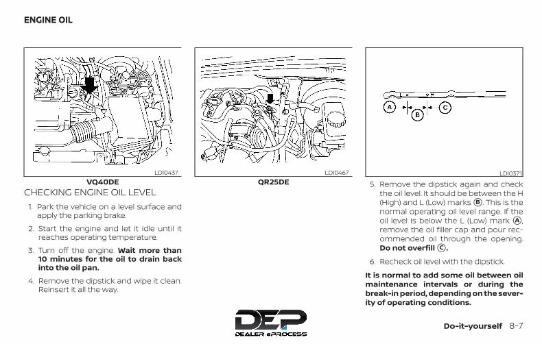
CHECKING ENGINE OIL LEVEL1. Park the vehicle on a level surface and
apply the parking brake.
2. Start the engine and let it idle until itreaches operating temperature.
3. Turn off the engine. Wait more than10 minutes for the oil to drain backinto the oil pan.
4. Remove the dipstick and wipe it clean.Reinsert it all the way.
5. Remove the dipstick again and checkthe oil level. It should be between the H(High) and L (Low) marks �B . This is thenormal operating oil level range. If theoil level is below the L (Low) mark �A ,remove the oil filler cap and pour rec-ommended oil through the opening.Do not overfill �C .
6. Recheck oil level with the dipstick.
It is normal to add some oil between oilmaintenance intervals or during thebreak-in period, depending on the sever-ity of operating conditions.
VQ40DELDI0437
QR25DELDI0467 LDI0371
ENGINE OIL
Do-it-yourself 8-7
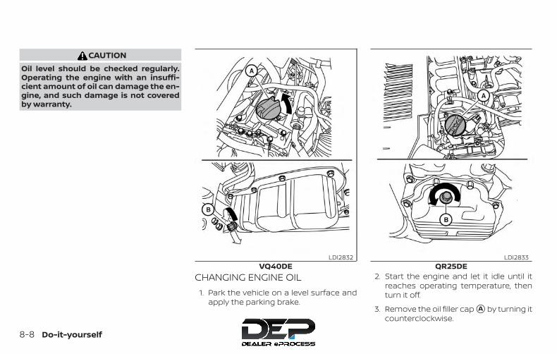
CAUTIONOil level should be checked regularly.Operating the engine with an insuffi-cient amount of oil can damage the en-gine, and such damage is not coveredby warranty.
CHANGING ENGINE OIL1. Park the vehicle on a level surface and
apply the parking brake.
2. Start the engine and let it idle until itreaches operating temperature, thenturn it off.
3. Remove the oil filler cap �A by turning itcounterclockwise.
VQ40DELDI2832
QR25DELDI2833
8-8 Do-it-yourself

4. Place a large drain pan under the drainplug �B .
5. Remove the drain plug with a wrenchby turning it counterclockwise andcompletely drain the oil.
If the oil filter is to be changed, removeand replace it at this time. For addi-tional information, refer to “Changingengine oil filter” in this section.
∙ Waste oil must be disposed of prop-erly.
∙ Check your local regulations.
WARNING∙ Prolonged and repeated contact with
used engine oil may cause skincancer.
∙ Try to avoid direct skin contact withused oil. If skin contact is made, washthoroughly with soap or hand cleaneras soon as possible.
∙ Keep used engine oil out of reach ofchildren.
CAUTIONBe careful not to burn yourself. The en-gine oil may be hot.
6. Clean and reinstall the drain plug and anew washer. Securely tighten the drainplug with a wrench. Do not use exces-sive force.
Drain plug tightening torque:25 ft-lb (34 N·m)
7. Refill engine with recommended oilthrough the oil filler opening, then installthe oil filler cap securely.
For additional information on drainand refill capacity, refer to “Recom-mended fluids/lubricants and capaci-ties” in the “Technical and consumerinformation” section of this manual.
The drain and refill capacity dependson the oil temperature and drain time.Use these specifications for referenceonly. Always use the dipstick to deter-mine when the proper amount of oil isin the engine.
8. Start the engine. Check for leakagearound the drain plug and oil filter. Cor-rect as required.
9. Turn the engine off and wait more than10 minutes. Check the oil level with thedipstick. Add engine oil if necessary.
Do-it-yourself 8-9
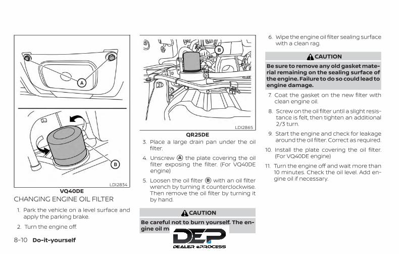
CHANGING ENGINE OIL FILTER1. Park the vehicle on a level surface and
apply the parking brake.
2. Turn the engine off.
3. Place a large drain pan under the oilfilter.
4. Unscrew �A the plate covering the oilfilter exposing the filter. (For VQ40DEengine)
5. Loosen the oil filter �B with an oil filterwrench by turning it counterclockwise.Then remove the oil filter by turning itby hand.
CAUTIONBe careful not to burn yourself. The en-gine oil may be hot.
6. Wipe the engine oil filter sealing surfacewith a clean rag.
CAUTIONBe sure to remove any old gasket mate-rial remaining on the sealing surface ofthe engine. Failure to do so could lead toengine damage.
7. Coat the gasket on the new filter withclean engine oil.
8. Screw on the oil filter until a slight resis-tance is felt, then tighten an additional2/3 turn.
9. Start the engine and check for leakagearound the oil filter. Correct as required.
10. Install the plate covering the oil filter.(For VQ40DE engine)
11. Turn the engine off and wait more than10 minutes. Check the oil level. Add en-gine oil if necessary.
VQ40DELDI2834
QR25DELDI2865
8-10 Do-it-yourself
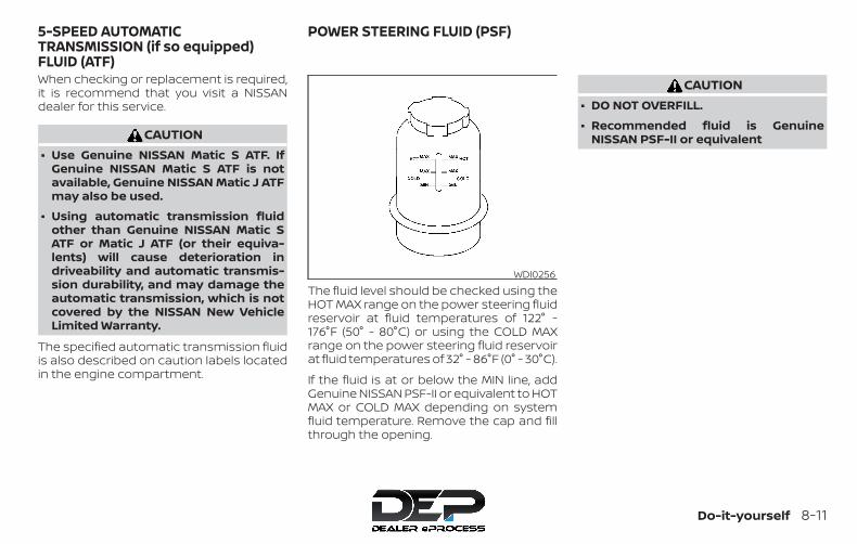
When checking or replacement is required,it is recommend that you visit a NISSANdealer for this service.
CAUTION∙ Use Genuine NISSAN Matic S ATF. If
Genuine NISSAN Matic S ATF is notavailable, Genuine NISSAN Matic J ATFmay also be used.
∙ Using automatic transmission fluidother than Genuine NISSAN Matic SATF or Matic J ATF (or their equiva-lents) will cause deterioration indriveability and automatic transmis-sion durability, and may damage theautomatic transmission, which is notcovered by the NISSAN New VehicleLimited Warranty.
The specified automatic transmission fluidis also described on caution labels locatedin the engine compartment.
The fluid level should be checked using theHOT MAX range on the power steering fluidreservoir at fluid temperatures of 122° -176°F (50° - 80°C) or using the COLD MAXrange on the power steering fluid reservoirat fluid temperatures of 32° - 86°F (0° - 30°C).
If the fluid is at or below the MIN line, addGenuine NISSAN PSF-II or equivalent to HOTMAX or COLD MAX depending on systemfluid temperature. Remove the cap and fillthrough the opening.
CAUTION∙ DO NOT OVERFILL.
∙ Recommended fluid is GenuineNISSAN PSF-II or equivalent
WDI0256
5-SPEED AUTOMATICTRANSMISSION (if so equipped)FLUID (ATF)
POWER STEERING FLUID (PSF)
Do-it-yourself 8-11
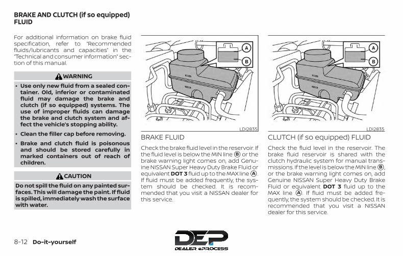
For additional information on brake fluidspecification, refer to “Recommendedfluids/lubricants and capacities” in the“Technical and consumer information” sec-tion of this manual.
WARNING∙ Use only new fluid from a sealed con-
tainer. Old, inferior or contaminatedfluid may damage the brake andclutch (if so equipped) systems. Theuse of improper fluids can damagethe brake and clutch system and af-fect the vehicle’s stopping ability.
∙ Clean the filler cap before removing.
∙ Brake and clutch fluid is poisonousand should be stored carefully inmarked containers out of reach ofchildren.
CAUTIONDo not spill the fluid on any painted sur-faces. This will damage the paint. If fluidis spilled, immediately wash the surfacewith water.
BRAKE FLUIDCheck the brake fluid level in the reservoir. Ifthe fluid level is below the MIN line �B or thebrake warning light comes on, add Genu-ine NISSAN Super Heavy Duty Brake Fluid orequivalent DOT 3 fluid up to the MAX line �A .If fluid must be added frequently, the sys-tem should be checked. It is recom-mended that you visit a NISSAN dealer forthis service.
CLUTCH (if so equipped) FLUIDCheck the fluid level in the reservoir. Thebrake fluid reservoir is shared with theclutch hydraulic system for manual trans-missions. If the level is below the MIN line �B ,or the brake warning light comes on, addGenuine NISSAN Super Heavy Duty BrakeFluid or equivalent DOT 3 fluid up to theMAX line �A . If fluid must be added fre-quently, the system should be checked. It isrecommended that you visit a NISSANdealer for this service.
LDI2835 LDI2835
BRAKE AND CLUTCH (if so equipped)FLUID
8-12 Do-it-yourself

WINDSHIELD-WASHER FLUIDRESERVOIRFill the windshield-washer fluid reservoirperiodically. Add windshield-washer fluidwhen the low windshield-washer fluidwarning light (if so equipped) comes on.
To fill the windshield-washer fluid reservoir,lift the cap off the reservoir and pour thewindshield-washer fluid into the reservoiropening.
Add a washer solvent to the washer forbetter cleaning. In the winter season, add awindshield-washer antifreeze. Follow themanufacturer’s instructions for the mix-ture ratio.
Refill the reservoir more frequently whendriving conditions require an increasedamount of windshield-washer fluid.
Recommended fluid is Genuine NISSANWindshield-Washer Concentrate Cleaner &Antifreeze or equivalent.
CAUTION∙ Do not substitute engine antifreeze
coolant for windshield-washer solu-tion. This may result in damage to thepaint.
∙ Do not fill the windshield-washer res-ervoir with washer fluid concentratesat full strength. Some methyl alcoholbased washer fluid concentrates maypermanently stain the grille if spilledwhile filling the windshield-washerreservoir.
∙ Pre-mix washer fluid concentrateswith water to the manufacturer’s rec-ommended levels before pouring thefluid into the windshield-washer res-ervoir. Do not use the windshield-washer reservoir to mix the washerfluid concentrate and water.
LDI3136
WINDSHIELD-WASHER FLUID
Do-it-yourself 8-13
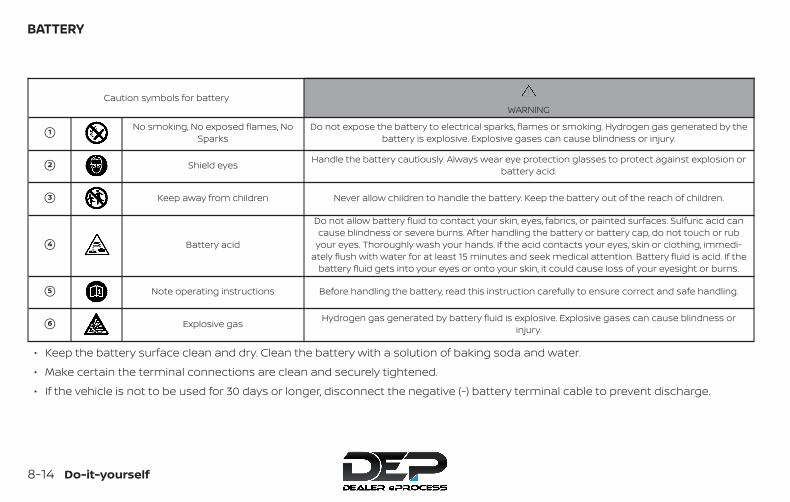
Caution symbols for batteryWARNING
�1 No smoking, No exposed flames, NoSparks
Do not expose the battery to electrical sparks, flames or smoking. Hydrogen gas generated by thebattery is explosive. Explosive gases can cause blindness or injury.
�2 Shield eyes Handle the battery cautiously. Always wear eye protection glasses to protect against explosion orbattery acid.
�3 Keep away from children Never allow children to handle the battery. Keep the battery out of the reach of children.
�4 Battery acid
Do not allow battery fluid to contact your skin, eyes, fabrics, or painted surfaces. Sulfuric acid cancause blindness or severe burns. After handling the battery or battery cap, do not touch or rub
your eyes. Thoroughly wash your hands. If the acid contacts your eyes, skin or clothing, immedi-ately flush with water for at least 15 minutes and seek medical attention. Battery fluid is acid. If the
battery fluid gets into your eyes or onto your skin, it could cause loss of your eyesight or burns.
�5 Note operating instructions Before handling the battery, read this instruction carefully to ensure correct and safe handling.
�6 Explosive gas Hydrogen gas generated by battery fluid is explosive. Explosive gases can cause blindness orinjury.
∙ Keep the battery surface clean and dry. Clean the battery with a solution of baking soda and water.
∙ Make certain the terminal connections are clean and securely tightened.
∙ If the vehicle is not to be used for 30 days or longer, disconnect the negative (-) battery terminal cable to prevent discharge.
BATTERY
8-14 Do-it-yourself
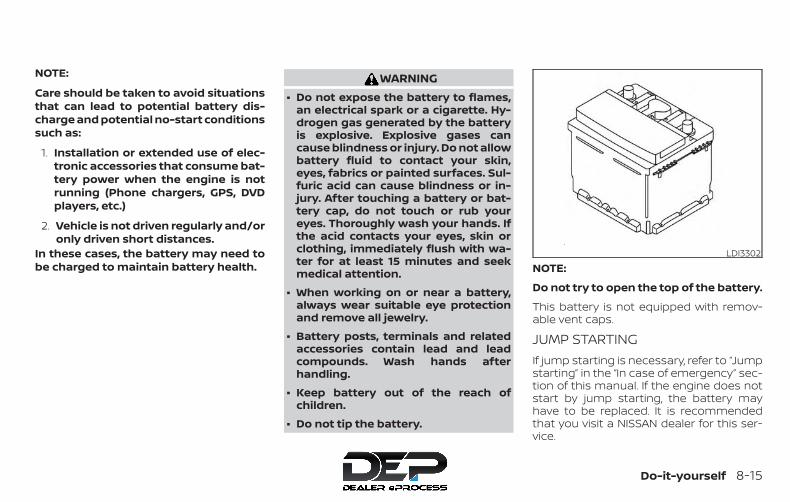
NOTE:
Care should be taken to avoid situationsthat can lead to potential battery dis-charge and potential no-start conditionssuch as:
1. Installation or extended use of elec-tronic accessories that consume bat-tery power when the engine is notrunning (Phone chargers, GPS, DVDplayers, etc.)
2. Vehicle is not driven regularly and/oronly driven short distances.
In these cases, the battery may need tobe charged to maintain battery health.
WARNING∙ Do not expose the battery to flames,
an electrical spark or a cigarette. Hy-drogen gas generated by the batteryis explosive. Explosive gases cancause blindness or injury. Do not allowbattery fluid to contact your skin,eyes, fabrics or painted surfaces. Sul-furic acid can cause blindness or in-jury. After touching a battery or bat-tery cap, do not touch or rub youreyes. Thoroughly wash your hands. Ifthe acid contacts your eyes, skin orclothing, immediately flush with wa-ter for at least 15 minutes and seekmedical attention.
∙ When working on or near a battery,always wear suitable eye protectionand remove all jewelry.
∙ Battery posts, terminals and relatedaccessories contain lead and leadcompounds. Wash hands afterhandling.
∙ Keep battery out of the reach ofchildren.
∙ Do not tip the battery.
NOTE:
Do not try to open the top of the battery.
This battery is not equipped with remov-able vent caps.
JUMP STARTINGIf jump starting is necessary, refer to “Jumpstarting” in the “In case of emergency” sec-tion of this manual. If the engine does notstart by jump starting, the battery mayhave to be replaced. It is recommendedthat you visit a NISSAN dealer for this ser-vice.
LDI3302
Do-it-yourself 8-15

CAUTION∙ Do not ground accessories directly to
the battery terminal. Doing so will by-pass the variable voltage control sys-tem and the vehicle battery may notcharge completely.
∙ Use electrical accessories with the en-gine running to avoid discharging thevehicle battery.
Your vehicle is equipped with a variablevoltage control system. This system mea-sures the amount of electrical dischargefrom the battery and controls voltage gen-erated by the generator.
The current sensor �A is located near thebattery along the negative battery cable. Ifyou add electrical accessories to your ve-hicle, be sure to ground them to a suitablebody ground such as the frame or engineblock area.
1. Power steering fluid pump pulley2. Automatic belt tensioner pulley3. Cooling fan pulley4. Air conditioner compressor pulley5. Crankshaft pulley6. Generator pulley
WARNINGBe sure the ignition key is in the OFF orLOCK position before servicing drivebelt. The engine could rotateunexpectedly.
LDI3300VQ40DE
WDI0639
VARIABLE VOLTAGE CONTROLSYSTEM
DRIVE BELT
8-16 Do-it-yourself
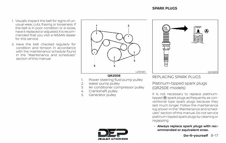
1. Visually inspect the belt for signs of un-usual wear, cuts, fraying or looseness. Ifthe belt is in poor condition or is loose,have it replaced or adjusted. It is recom-mended that you visit a NISSAN dealerfor this service.
2. Have the belt checked regularly forcondition and tension in accordancewith the maintenance schedule foundin the "Maintenance and schedules"section of this manual.
1. Power steering fluid pump pulley2. Water pump pulley3. Air conditioner compressor pulley4. Crankshaft pulley5. Generator pulley
REPLACING SPARK PLUGSPlatinum-tipped spark plugs(QR25DE models)It is not necessary to replace platinum-tipped �A spark plugs as frequently as con-ventional type spark plugs because theylast much longer. Follow the maintenancelog shown in the "Maintenance and sched-ules" section of this manual. Do not serviceplatinum-tipped spark plugs by cleaning orregapping.
∙ Always replace spark plugs with rec-ommended or equivalent ones.
QR25DELDI0461 SDI1895
SPARK PLUGS
Do-it-yourself 8-17

If replacement is required, it is recom-mended that you visit a NISSAN dealer forthis service.
Iridium-tipped spark plugs(VQ40DE models)It is not necessary to replace iridium-tipped �A spark plugs as frequently as con-ventional type spark plugs because theylast much longer. Follow the maintenancelog shown in the "Maintenance and sched-ules" section of this manual. Do not serviceiridium-tipped spark plugs by cleaning orregapping.
∙ Always replace spark plugs with rec-ommended or equivalent ones.
If replacement is required, it is recom-mended that you visit a NISSAN dealer forthis service.
The air cleaner filter should not be cleanedand reused. Replace it according to themaintenance log shown in the "Mainte-nance and schedules" section of thismanual. When replacing the filter, wipe theinside of the air cleaner filter housing andthe cover with a damp cloth.
To remove the VQ40DE air cleaner filter:
�1 Unlatch the clips and remove the aircleaner cover. Remove the air cleanerfilter.
To remove the QR25DE air cleaner filter:
1. Unlatch the clips �A , �B , �C .
2. Push down half of air cleaner to clearthe bottom retainers.
3. Lift up on half of air cleaner to removethe air cleaner filter
VQ40DEWDI0686
QR25DELDI0465
AIR CLEANER
8-18 Do-it-yourself
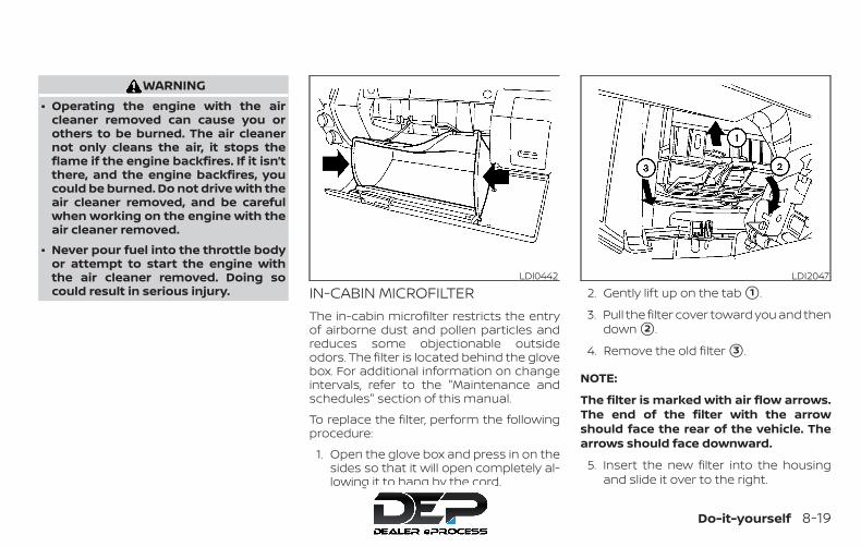
WARNING∙ Operating the engine with the air
cleaner removed can cause you orothers to be burned. The air cleanernot only cleans the air, it stops theflame if the engine backfires. If it isn’tthere, and the engine backfires, youcould be burned. Do not drive with theair cleaner removed, and be carefulwhen working on the engine with theair cleaner removed.
∙ Never pour fuel into the throttle bodyor attempt to start the engine withthe air cleaner removed. Doing socould result in serious injury. IN-CABIN MICROFILTER
The in-cabin microfilter restricts the entryof airborne dust and pollen particles andreduces some objectionable outsideodors. The filter is located behind the glovebox. For additional information on changeintervals, refer to the "Maintenance andschedules" section of this manual.
To replace the filter, perform the followingprocedure:
1. Open the glove box and press in on thesides so that it will open completely al-lowing it to hang by the cord.
2. Gently lift up on the tab �1 .
3. Pull the filter cover toward you and thendown �2 .
4. Remove the old filter �3 .
NOTE:
The filter is marked with air flow arrows.The end of the filter with the arrowshould face the rear of the vehicle. Thearrows should face downward.
5. Insert the new filter into the housingand slide it over to the right.
LDI0442 LDI2047
Do-it-yourself 8-19
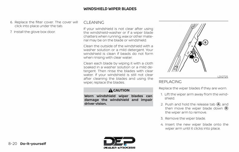
6. Replace the filter cover. The cover willclick into place under the tab.
7. Install the glove box door.
CLEANINGIf your windshield is not clear after usingthe windshield-washer or if a wiper bladechatters when running, wax or other mate-rial may be on the blade or windshield.
Clean the outside of the windshield with awasher solution or a mild detergent. Yourwindshield is clean if beads do not formwhen rinsing with clear water.
Clean each blade by wiping it with a clothsoaked in a washer solution or a mild de-tergent. Then rinse the blades with clearwater. If your windshield is still not clearafter cleaning the blades and using thewiper, replace the blades.
CAUTIONWorn windshield wiper blades candamage the windshield and impairdriver vision.
REPLACINGReplace the wiper blades if they are worn.
1. Lift the wiper arm away from the wind-shield.
2. Push and hold the release tab �A , andthen move the wiper blade down �Bthe wiper arm to remove.
3. Remove the wiper blade.
4. Insert the new wiper blade onto thewiper arm until it clicks into place.
LDI2725
WINDSHIELD WIPER BLADES
8-20 Do-it-yourself

CAUTION∙ After wiper blade replacement, return
the wiper arm to its original position;otherwise it may be damaged whenthe hood is opened.
∙ Make sure the wiper blades contactthe glass; otherwise the arms may bedamaged from wind pressure.
∙ Worn windshield wiper blades candamage the windshield and impairdriver vision.
If you wax the surface of the hood, be care-ful not to let wax get into the windshield-washer nozzle . This may cause clogging orimproper windshield-washer operation. Ifwax gets into the nozzle, remove it with aneedle or small pin �1 .
If the brakes do not operate properly, havethe brakes checked. It is recommendedthat you visit a NISSAN dealer for this ser-vice.
Self-adjusting brakesYour vehicle is equipped with self-adjustingbrakes.
The front and rear disc-type brakes self-adjust every time the brake pedal is ap-plied.
WARNINGHave your brake system checked if thebrake pedal height does not return tonormal. It is recommended that youvisit a NISSAN dealer for this service.
Brake pad wear indicatorsThe disc brake pads on your vehicle haveaudible wear indicators. When a brake padrequires replacement, a high pitchedscraping or screeching sound will be heardwhen the vehicle is in motion. The noise willbe heard whether or not the brake pedal isdepressed. Have the brakes checked assoon as possible if the wear indicatorsound is heard.
LDI3120
BRAKES
Do-it-yourself 8-21
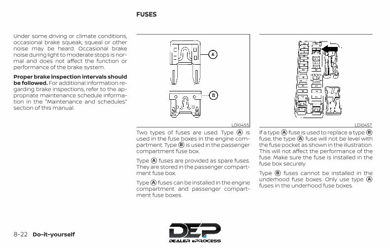
Under some driving or climate conditions,occasional brake squeak, squeal or othernoise may be heard. Occasional brakenoise during light to moderate stops is nor-mal and does not affect the function orperformance of the brake system.
Proper brake inspection intervals shouldbe followed. For additional information re-garding brake inspections, refer to the ap-propriate maintenance schedule informa-tion in the "Maintenance and schedules"section of this manual.
Two types of fuses are used. Type �A isused in the fuse boxes in the engine com-partment. Type �B is used in the passengercompartment fuse box.
Type �A fuses are provided as spare fuses.They are stored in the passenger compart-ment fuse box.
Type �A fuses can be installed in the enginecompartment and passenger compart-ment fuse boxes.
If a type �A fuse is used to replace a type �Bfuse, the type �A fuse will not be level withthe fuse pocket as shown in the illustration.This will not affect the performance of thefuse. Make sure the fuse is installed in thefuse box securely.
Type �B fuses cannot be installed in theunderhood fuse boxes. Only use type �Afuses in the underhood fuse boxes.
LDI0455 LDI0457
FUSES
8-22 Do-it-yourself
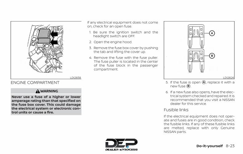
ENGINE COMPARTMENT
WARNINGNever use a fuse of a higher or loweramperage rating than that specified onthe fuse box cover. This could damagethe electrical system or electronic con-trol units or cause a fire.
If any electrical equipment does not comeon, check for an open fuse.
1. Be sure the ignition switch and theheadlight switch are OFF.
2. Open the engine hood.
3. Remove the fuse box cover by pushingthe tab and lifting the cover up.
4. Remove the fuse with the fuse puller.The fuse puller is located in the centerof the fuse block in the passengercompartment.
5. If the fuse is open �A , replace it with anew fuse �B .
6. If a new fuse also opens, have the elec-trical system checked and repaired. It isrecommended that you visit a NISSANdealer for this service.
Fusible linksIf the electrical equipment does not oper-ate and fuses are in good condition, checkthe fusible links. If any of these fusible linksare melted, replace with only GenuineNISSAN parts.
LDI2838 LDI2826
Do-it-yourself 8-23
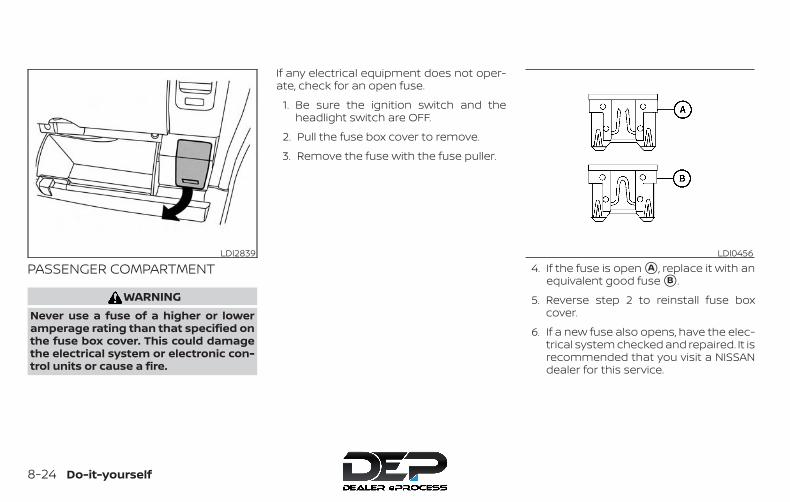
PASSENGER COMPARTMENT
WARNINGNever use a fuse of a higher or loweramperage rating than that specified onthe fuse box cover. This could damagethe electrical system or electronic con-trol units or cause a fire.
If any electrical equipment does not oper-ate, check for an open fuse.
1. Be sure the ignition switch and theheadlight switch are OFF.
2. Pull the fuse box cover to remove.
3. Remove the fuse with the fuse puller.
4. If the fuse is open �A , replace it with anequivalent good fuse �B .
5. Reverse step 2 to reinstall fuse boxcover.
6. If a new fuse also opens, have the elec-trical system checked and repaired. It isrecommended that you visit a NISSANdealer for this service.
LDI2839 LDI0456
8-24 Do-it-yourself
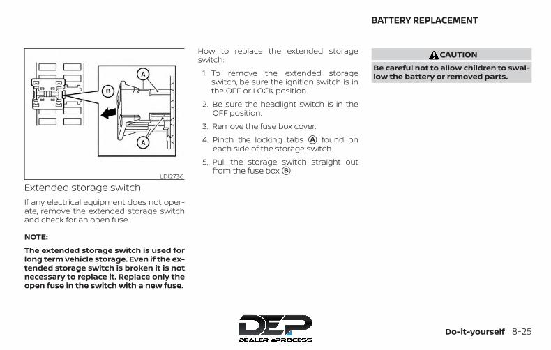
Extended storage switchIf any electrical equipment does not oper-ate, remove the extended storage switchand check for an open fuse.
NOTE:
The extended storage switch is used forlong term vehicle storage. Even if the ex-tended storage switch is broken it is notnecessary to replace it. Replace only theopen fuse in the switch with a new fuse.
How to replace the extended storageswitch:
1. To remove the extended storageswitch, be sure the ignition switch is inthe OFF or LOCK position.
2. Be sure the headlight switch is in theOFF position.
3. Remove the fuse box cover.
4. Pinch the locking tabs �A found oneach side of the storage switch.
5. Pull the storage switch straight outfrom the fuse box �B .
CAUTIONBe careful not to allow children to swal-low the battery or removed parts.
LDI2736
BATTERY REPLACEMENT
Do-it-yourself 8-25

KEY FOB (if so equipped)Replace the battery in the key fob as fol-lows:
�1 Open the lid using a coin �A .
�2 Remove the battery �B .
�3 Install a new battery �C with the “+” fac-ing down.
∙ Hold the battery by the edges. Holdingthe battery across the contact pointswill seriously deplete the storage ca-pacity.
∙ Do not touch the internal circuit andelectric terminals as it could cause amalfunction.
∙ When changing the battery, do not letdust or oil get on the key fob.
∙ There is danger of explosion if a lithiumbattery is incorrectly replaced. Replaceonly with the same or equivalent type.
Recommended battery: CR2025 or equiva-lent.
�4 Close the lid securely.
5. Press the button, thenthe button two or three times tocheck the key fob operation.
If the battery is removed for any reasonother than replacement, perform step 5.
∙ An improperly disposed battery canhurt the environment. Always confirmlocal regulations for battery disposal.
∙ The key fob is water-resistant; how-ever, if it does get wet, immediatelywipe completely dry.
∙ The operational range of the key fobextends to approximately 33 ft (10 m)from the vehicle. This range may varywith conditions.
LDI2026
8-26 Do-it-yourself
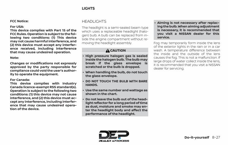
FCC Notice:
For USA:This device complies with Part 15 of theFCC Rules. Operation is subject to the fol-lowing two conditions: (1) This devicemay not cause harmful interference, and(2) this device must accept any interfer-ence received, including interferencethat may cause undesired operation.
Note:
Changes or modifications not expresslyapproved by the party responsible forcompliance could void the user’s author-ity to operate the equipment.
For Canada:This devise complies with IndustryCanada licence-exempt RSS standard(s).Operation is subject to the following twoconditions: (1) this device may not causeinterference, and (2) this device must ac-cept any interference, including interfer-ence that may cause undesired opera-tion of the device.
HEADLIGHTSThe headlight is a semi-sealed beam typewhich uses a replaceable headlight (halo-gen) bulb. A bulb can be replaced from in-side the engine compartment without re-moving the headlight assembly.
CAUTION∙ High pressure halogen gas is sealed
inside the halogen bulb. The bulb maybreak if the glass envelope isscratched or the bulb is dropped.
∙ When handling the bulb, do not touchthe glass envelope.
∙ DO NOT TOUCH THE BULB WITH BAREHANDS.
∙ Use the same number and wattage asshown in the chart.
∙ Do not leave the bulb out of the head-light reflector for a long period of timeas dust, moisture and smoke may en-ter the headlight body and affect theperformance of the headlight.
∙ Aiming is not necessary after replac-ing the bulb. When aiming adjustmentis necessary, it is recommended thatyou visit a NISSAN dealer for thisservice.
Fog may temporarily form inside the lensof the exterior lights in the rain or in a carwash. A temperature difference betweenthe inside and the outside of the lenscauses the fog. This is not a malfunction. Iflarge drops of water collect inside the lens,it is recommended that you visit a NISSANdealer for servicing.
LIGHTS
Do-it-yourself 8-27
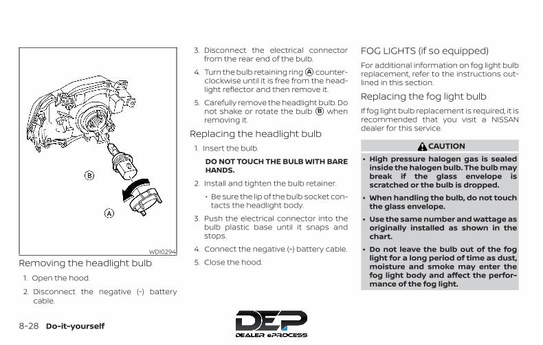
Removing the headlight bulb1. Open the hood.
2. Disconnect the negative (-) batterycable.
3. Disconnect the electrical connectorfrom the rear end of the bulb.
4. Turn the bulb retaining ring �A counter-clockwise until it is free from the head-light reflector and then remove it.
5. Carefully remove the headlight bulb. Donot shake or rotate the bulb �B whenremoving it.
Replacing the headlight bulb1. Insert the bulb.
DO NOT TOUCH THE BULB WITH BAREHANDS.
2. Install and tighten the bulb retainer.
∙ Be sure the lip of the bulb socket con-tacts the headlight body.
3. Push the electrical connector into thebulb plastic base until it snaps andstops.
4. Connect the negative (-) battery cable.
5. Close the hood.
FOG LIGHTS (if so equipped)For additional information on fog light bulbreplacement, refer to the instructions out-lined in this section.
Replacing the fog light bulbIf fog light bulb replacement is required, it isrecommended that you visit a NISSANdealer for this service.
CAUTION∙ High pressure halogen gas is sealed
inside the halogen bulb. The bulb maybreak if the glass envelope isscratched or the bulb is dropped.
∙ When handling the bulb, do not touchthe glass envelope.
∙ Use the same number and wattage asoriginally installed as shown in thechart.
∙ Do not leave the bulb out of the foglight for a long period of time as dust,moisture and smoke may enter thefog light body and affect the perfor-mance of the fog light.
WDI0294
8-28 Do-it-yourself
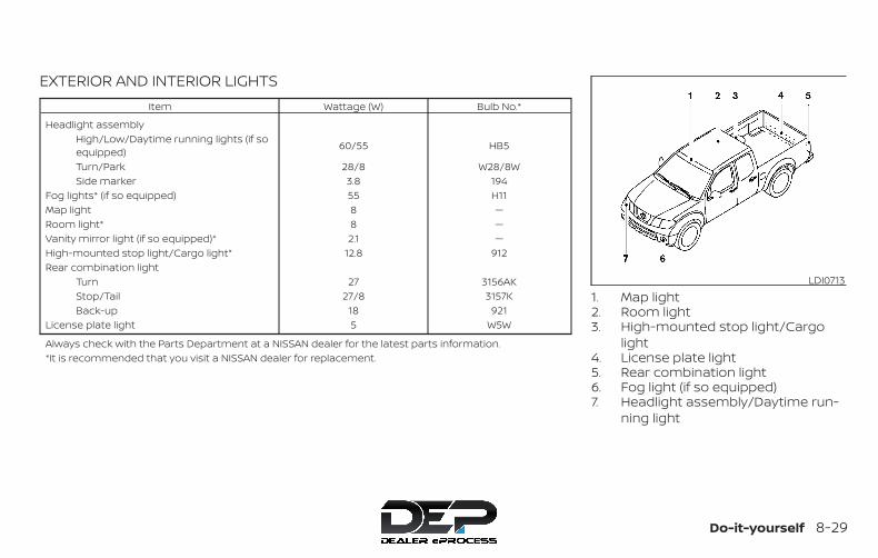
EXTERIOR AND INTERIOR LIGHTSItem Wattage (W) Bulb No.*
Headlight assemblyHigh/Low/Daytime running lights (if soequipped) 60/55 HB5
Turn/Park 28/8 W28/8WSide marker 3.8 194
Fog lights* (if so equipped) 55 H11Map light 8 —Room light* 8 —Vanity mirror light (if so equipped)* 2.1 —High-mounted stop light/Cargo light* 12.8 912Rear combination light
Turn 27 3156AKStop/Tail 27/8 3157KBack-up 18 921
License plate light 5 W5W
Always check with the Parts Department at a NISSAN dealer for the latest parts information.*It is recommended that you visit a NISSAN dealer for replacement.
1. Map light2. Room light3. High-mounted stop light/Cargo
light4. License plate light5. Rear combination light6. Fog light (if so equipped)7. Headlight assembly/Daytime run-
ning light
LDI0713
Do-it-yourself 8-29

Replacement proceduresAll other lights are either type A, B, C or D.When replacing a bulb, first remove the lensand/or cover using a cloth and suitabletool.
: Indicates bulb removal: Indicates bulb installation
Use a cloth �1 to protect the housing.
WDI0306
Map lightLDI0478
8-30 Do-it-yourself
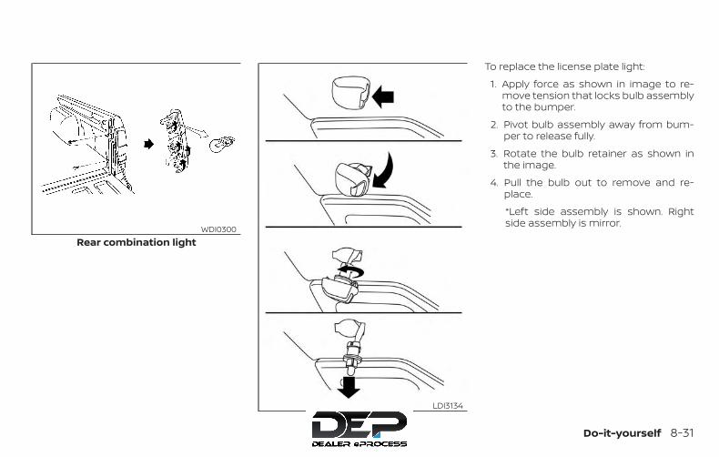
To replace the license plate light:
1. Apply force as shown in image to re-move tension that locks bulb assemblyto the bumper.
2. Pivot bulb assembly away from bum-per to release fully.
3. Rotate the bulb retainer as shown inthe image.
4. Pull the bulb out to remove and re-place.
*Left side assembly is shown. Rightside assembly is mirror.
Rear combination lightWDI0300
License plate lightLDI3134
Do-it-yourself 8-31

If you have a flat tire, refer to “Flat tire” inthe “In case of emergency” section ofthis manual.
TIRE PRESSURETire Pressure Monitoring System(TPMS)This vehicle is equipped with TPMS. Itmonitors tire pressure of all tires ex-cept the spare. When the low tirepressure warning light is lit and theCHECK TIRE PRES (pressure) warningmessage is displayed in the odom-eter, one or more of your tires is sig-nificantly under-inflated.TPMS will activate only when the ve-hicle is driven at speeds above16 mph (25 km/h). Also, this systemmay not detect a sudden drop in tirepressure (for example, a flat tire whiledriving).For additional information, refer to“Low tire pressure warning light” inthe “Instruments and controls” sec-tion, “Tire Pressure Monitoring Sys-tem (TPMS)” in the “Starting and driv-
ing” section, and “Flat tire” in the “Incase of emergency” section of thismanual.
Tire inflation pressureCheck the tire pressures (includingthe spare) often and always prior tolong distance trips. The recom-mended tire pressure specificationsare shown on the F.M.V.S.S./C.M.V.S.S.certification label or the Tire andLoading Information label under the“Cold Tire Pressure” heading. The Tireand Loading Information label is af-fixed to the driver side center pillar.Tire pressures should be checkedregularly because:∙ Most tires naturally lose air over
time.∙ Tires can lose air suddenly when
driven over potholes or other ob-jects or if the vehicle strikes acurb while parking.
The tire pressures should bechecked when the tires are cold. Thetires are considered COLD after thevehicle has been parked for 3 ormore hours, or driven less than 1 mile(1.6 km) at moderate speeds.
WHEELS AND TIRES
8-32 Do-it-yourself
Incorrect tire pressure, includingunder inflation, may adversely af-fect tire life and vehicle handling.
WARNING∙ Improperly inflated tires can fail
suddenly and cause anaccident.
∙ The Gross Vehicle Weight Rating(GVWR) is located on theF.M.V.S.S./C.M.V.S.S. certifica-tion label. The vehicle weightcapacity is indicated on the Tireand Loading Information label.Do not load your vehicle beyondthis capacity. Overloading yourvehicle may result in reducedtire life, unsafe operating condi-tions due to premature tire fail-ure, or unfavorable handlingcharacteristics and could alsolead to a serious accident. Load-ing beyond the specified capac-ity may also result in failure ofother vehicle components.
∙ Before taking a long trip, orwhenever you heavily load yourvehicle, use a tire pressuregauge to ensure that the tirepressures are at the specifiedlevel.
∙ For additional information re-garding tires, refer to “Impor-tant Tire Safety Information”(US) or “Tire Safety Information”(Canada) in the Warranty Infor-mation Booklet.
Do-it-yourself 8-33

Tire and Loading Informationlabel
�1 Seating capacity: The maximumnumber of occupants that canbe seated in the vehicle.
�2 Vehicle load limit: Refer to “Ve-hicle loading information” in the“Technical and consumer infor-mation” section of this manual.
�3 Original tire size: The size of thetires originally installed on thevehicle at the factory.
�4 Cold tire pressure: Inflate thetires to this pressure when thetires are cold. Tires are consid-ered COLD after the vehicle hasbeen parked for 3 or more hours,or driven less than 1 mile (1.6 km)at moderate speeds. The rec-ommended cold tire inflation isset by the manufacturer to pro-vide the best balance of tirewear, vehicle handling, driveabil-ity, tire noise, etc., up to the vehi-cle’s GVWR.
�5 Tire size: Refer to “Tire labeling” inthis section.
�6 Spare tire size.
LDI2007
8-34 Do-it-yourself

Checking tire pressure1. Remove the valve stem cap from
the tire.
2. Press the pressure gaugesquarely onto the valve stem. Donot press too hard or force thevalve stem sideways, or air willescape. If the hissing sound of airescaping from the tire is heardwhile checking the pressure, re-position the gauge to eliminatethis leakage.
3. Remove the gauge.
4. Read the tire pressure on thegauge stem and compare to thespecification shown on theF.M.V.S.S./C.M.V.S.S. label or theTire and Loading Information la-bel.
5. Add air to the tire as needed. Iftoo much air is added, press thecore of the valve stem brieflywith the tip of the gauge stem torelease pressure. Recheck thepressure and add or release airas needed.
6. Install the valve stem cap.
7. Check the pressure of all othertires, including the spare.
Size Cold Tire Infla-tion Pressure
Front and RearOriginal Tire:235/75R15P265/70R16P265/75R16P265/60R18
240 kPa, 35 PSI
Spare Tire: Full size
LDI0393
Do-it-yourself 8-35
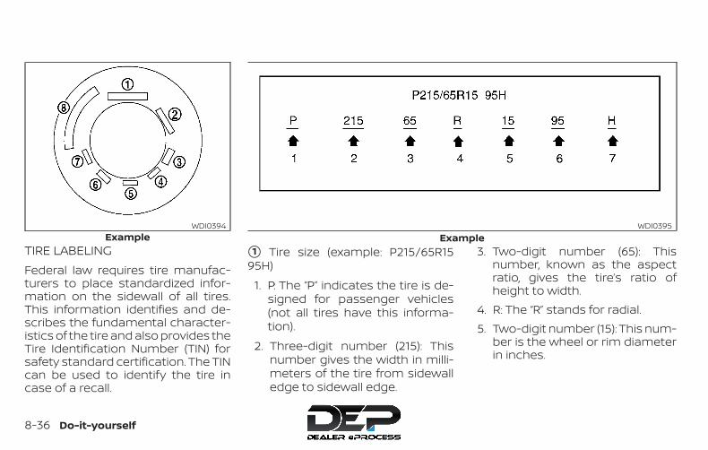
TIRE LABELINGFederal law requires tire manufac-turers to place standardized infor-mation on the sidewall of all tires.This information identifies and de-scribes the fundamental character-istics of the tire and also provides theTire Identification Number (TIN) forsafety standard certification. The TINcan be used to identify the tire incase of a recall.
�1 Tire size (example: P215/65R1595H)
1. P: The “P” indicates the tire is de-signed for passenger vehicles(not all tires have this informa-tion).
2. Three-digit number (215): Thisnumber gives the width in milli-meters of the tire from sidewalledge to sidewall edge.
3. Two-digit number (65): Thisnumber, known as the aspectratio, gives the tire’s ratio ofheight to width.
4. R: The “R” stands for radial.5. Two-digit number (15): This num-
ber is the wheel or rim diameterin inches.
ExampleWDI0394
ExampleWDI0395
8-36 Do-it-yourself
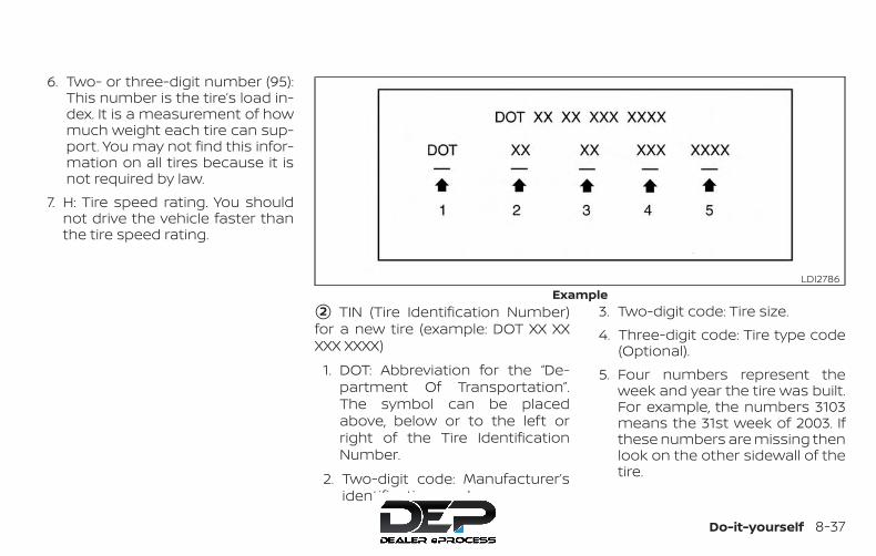
6. Two- or three-digit number (95):This number is the tire’s load in-dex. It is a measurement of howmuch weight each tire can sup-port. You may not find this infor-mation on all tires because it isnot required by law.
7. H: Tire speed rating. You shouldnot drive the vehicle faster thanthe tire speed rating.
�2 TIN (Tire Identification Number)for a new tire (example: DOT XX XXXXX XXXX)
1. DOT: Abbreviation for the “De-partment Of Transportation”.The symbol can be placedabove, below or to the left orright of the Tire IdentificationNumber.
2. Two-digit code: Manufacturer’sidentification mark.
3. Two-digit code: Tire size.4. Three-digit code: Tire type code
(Optional).5. Four numbers represent the
week and year the tire was built.For example, the numbers 3103means the 31st week of 2003. Ifthese numbers are missing thenlook on the other sidewall of thetire.
ExampleLDI2786
Do-it-yourself 8-37
�3 Tire ply composition and material
The number of layers or plies ofrubber-coated fabric in the tire. Tiremanufacturers also must indicatethe materials in the tire, which in-clude steel, nylon, polyester and oth-ers.
�4 Maximum permissible inflationpressure
This number is the greatest amountof air pressure that should be put inthe tire. Do not exceed the maximumpermissible inflation pressure.
�5 Maximum load rating
This number indicates the maxi-mum load in kilograms and poundsthat can be carried by the tire. Whenreplacing the tires on the vehicle, al-ways use a tire that has the sameload rating as the factory installedtire.
�6 Term of “tubeless” or “tube type”
Indicates whether the tire requiresan inner tube (“tube type”) or not(“tubeless”).
�7 The word “radial”The word “radial” is shown if the tirehas radial structure.
�8 Manufacturer or brand nameManufacturer or brand name isshown.Other Tire-related Terminology
In addition to the many terms thatare defined throughout this section,Intended Outboard Sidewall is (1) thesidewall that contains a whitewall,bears white lettering or bearsmanufacturer, brand, and/or modelname molding that is higher ordeeper than the same molding onthe other sidewall of the tire, or (2)the outward facing sidewall of anasymmetrical tire that has a particu-lar side that must always face out-ward when mounted on a vehicle.
TYPES OF TIRES
WARNING∙ When changing or replacing tires, be
sure all four tires are of the same type(i.e., Summer, All Season or Snow) andconstruction. A NISSAN dealer may beable to help you with informationabout tire type, size, speed rating andavailability.
∙ Replacement tires may have a lowerspeed rating than the factoryequipped tires, and may not matchthe potential maximum vehiclespeed. Never exceed the maximumspeed rating of the tire.
∙ Replacing tires with those not origi-nally specified by NISSAN could affectthe proper operation of the low tirepressure warning system.
8-38 Do-it-yourself
∙ Always use tires of the same type,size, brand, construction and treadpattern on all four wheels. Failure todo so may result in a circumferencedifference between tires on the frontand rear axles which can cause theVehicle Dynamic Control (VDC) systemto malfunction resulting in personalinjury or death, excessive tire wearand may damage the transmissionand differential gears.
∙ For additional information regardingtires, refer to “Important Tire SafetyInformation” (US) or “Tire Safety Infor-mation” (Canada) in the Warranty In-formation Booklet.
All season tiresNISSAN specifies All Season tires on somemodels to provide good performance allyear, including snowy and icy road condi-tions. All Season tires are identified by ALLSEASON and/or M&S on the tire sidewall.Snow tires have better snow traction thanAll Season tires and may be more appropri-ate in some areas.
Summer tiresNISSAN specifies summer tires on somemodels to provide superior performanceon dry roads. Summer tire performance issubstantially reduced in snow and ice.Summer tires do not have the tire tractionrating “M&S” on the tire sidewall.
If you plan to operate your vehicle in snowyor icy conditions, NISSAN recommends theuse of SNOW tires or ALL SEASON tires on allfour wheels.
Snow tiresIf snow tires are needed, it is necessary toselect tires equivalent in size and load rat-ing to the original equipment tires. If you donot, it can adversely affect the safety andhandling of your vehicle.
Generally, snow tires have lower speed rat-ings than factory equipped tires and maynot match the potential maximum vehiclespeed. Never exceed the maximum speedrating of the tire.
If you install snow tires, they must be thesame size, brand, construction and treadpattern on all four wheels.
For additional traction on icy roads, stud-ded tires may be used. However, some U.S.states and Canadian provinces prohibittheir use. Check local, state and provinciallaws before installing studded tires. Skidand traction capabilities of studded snowtires on wet or dry surfaces may be poorerthan that of non-studded snow tires.
TIRE CHAINSUse of tire chains may be prohibited ac-cording to location. Check the local lawsbefore installing tire chains. When installingtire chains, make sure they are the propersize for the tires on your vehicle and areinstalled according to the chain manufac-turer’s suggestions. Use only SAE class “S”chains. Class “S” chains are used on ve-hicles with restricted tire to vehicle clear-ance. Vehicles that can use Class “S” chainsare designed to meet the minimum clear-ances between the tire and the closest ve-hicle suspension or body component re-quired to accommodate the use of awinter traction device (tire chains orcables). The minimum clearances are de-termined using the factory equipped tiresize. Other types may damage your vehicle.Use chain tensioners when recommendedby the tire chain manufacturer to ensure atight fit. Loose end links of the tire chain
Do-it-yourself 8-39
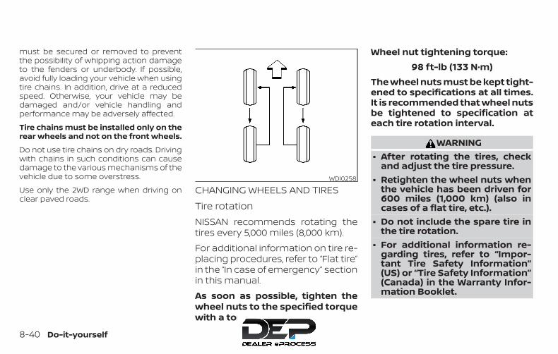
must be secured or removed to preventthe possibility of whipping action damageto the fenders or underbody. If possible,avoid fully loading your vehicle when usingtire chains. In addition, drive at a reducedspeed. Otherwise, your vehicle may bedamaged and/or vehicle handling andperformance may be adversely affected.
Tire chains must be installed only on therear wheels and not on the front wheels.
Do not use tire chains on dry roads. Drivingwith chains in such conditions can causedamage to the various mechanisms of thevehicle due to some overstress.
Use only the 2WD range when driving onclear paved roads.
CHANGING WHEELS AND TIRESTire rotationNISSAN recommends rotating thetires every 5,000 miles (8,000 km).
For additional information on tire re-placing procedures, refer to “Flat tire”in the “In case of emergency” sectionin this manual.
As soon as possible, tighten thewheel nuts to the specified torquewith a torque wrench.
Wheel nut tightening torque:98 ft-lb (133 N·m)
The wheel nuts must be kept tight-ened to specifications at all times.It is recommended that wheel nutsbe tightened to specification ateach tire rotation interval.
WARNING∙ After rotating the tires, check
and adjust the tire pressure.∙ Retighten the wheel nuts when
the vehicle has been driven for600 miles (1,000 km) (also incases of a flat tire, etc.).
∙ Do not include the spare tire inthe tire rotation.
∙ For additional information re-garding tires, refer to “Impor-tant Tire Safety Information”(US) or “Tire Safety Information”(Canada) in the Warranty Infor-mation Booklet.
WDI0258
8-40 Do-it-yourself
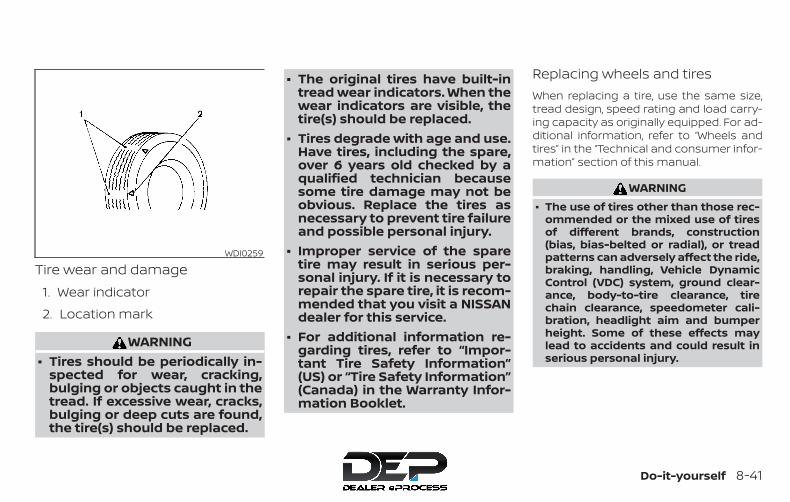
Tire wear and damage1. Wear indicator
2. Location mark
WARNING∙ Tires should be periodically in-
spected for wear, cracking,bulging or objects caught in thetread. If excessive wear, cracks,bulging or deep cuts are found,the tire(s) should be replaced.
∙ The original tires have built-intread wear indicators. When thewear indicators are visible, thetire(s) should be replaced.
∙ Tires degrade with age and use.Have tires, including the spare,over 6 years old checked by aqualified technician becausesome tire damage may not beobvious. Replace the tires asnecessary to prevent tire failureand possible personal injury.
∙ Improper service of the sparetire may result in serious per-sonal injury. If it is necessary torepair the spare tire, it is recom-mended that you visit a NISSANdealer for this service.
∙ For additional information re-garding tires, refer to “Impor-tant Tire Safety Information”(US) or “Tire Safety Information”(Canada) in the Warranty Infor-mation Booklet.
Replacing wheels and tiresWhen replacing a tire, use the same size,tread design, speed rating and load carry-ing capacity as originally equipped. For ad-ditional information, refer to “Wheels andtires” in the “Technical and consumer infor-mation” section of this manual.
WARNING∙ The use of tires other than those rec-
ommended or the mixed use of tiresof different brands, construction(bias, bias-belted or radial), or treadpatterns can adversely affect the ride,braking, handling, Vehicle DynamicControl (VDC) system, ground clear-ance, body-to-tire clearance, tirechain clearance, speedometer cali-bration, headlight aim and bumperheight. Some of these effects maylead to accidents and could result inserious personal injury.
WDI0259
Do-it-yourself 8-41
∙ If your vehicle was originallyequipped with four tires that were thesame size and you are only replacingtwo of the four tires, install the newtires on the rear axle. Placing new tireson the front axle may cause loss ofvehicle control in some driving condi-tions and cause an accident and per-sonal injury.
∙ If the wheels are changed for any rea-son, always replace with wheelswhich have the same off-set dimen-sion. Wheels of a different off-setcould cause premature tire wear, de-grade vehicle handling characteris-tics, affect the VDC system and/or in-terference with the brake discs. Suchinterference can lead to decreasedbraking efficiency and/or early brakepad wear. For additional informationon wheel off-set dimensions, refer to“Wheels and tires” in the “Technicaland consumer information” section ofthis manual.
∙ When replacing a wheel without theTPMS such as the spare tire, TPMS willnot function and the low tire pressurewarning light will flash for approxi-mately 1 minute. The light will remainon after 1 minute. Have your tires re-placed and/or TPMS system reset assoon as possible. It is recommendedthat you visit a NISSAN dealer for thisservice.
∙ Replacing tires with those not origi-nally specified by NISSAN could affectthe proper operation of the TPMS.
∙ The TPMS sensor may be damaged ifit is not handled correctly. Be carefulwhen handling the TPMS sensor.
∙ When replacing the TPMS sensor, theID registration may be required. It isrecommended that you visit a NISSANdealer for ID registration.
∙ Do not use a valve stem cap that is notspecified by NISSAN. The valve stemcap may become stuck.
∙ Be sure that the valve stem caps arecorrectly fitted. Otherwise the valvemay be clogged up with dirt andcause a malfunction or loss ofpressure.
∙ Do not install a damaged or deformedwheel or tire even if it has been re-paired. Such wheels or tires couldhave structural damage and could failwithout warning.
∙ The use of retread tires is notrecommended.
∙ For additional information regardingtires, refer to “Important Tire SafetyInformation” (US) or “Tire Safety Infor-mation” (Canada) in the Warranty In-formation Booklet.
Four-wheel drive models
CAUTIONAlways use tires of the same type, size,brand, construction (bias, bias-beltedor radial), and tread pattern on all fourwheels. Failure to do so may result in acircumference difference between tireson the front and rear axles which willcause excessive tire wear and maydamage the transmission, transfer caseand differential gears.
8-42 Do-it-yourself

If excessive tire wear is found, it is recom-mended that all four tires be replaced withtires of the same size, brand, constructionand tread pattern. The tire pressure andwheel alignment should also be checkedand corrected as necessary. It is recom-mended that you visit a NISSAN dealer forthis service.
Wheel balanceUnbalanced wheels may affect vehiclehandling and tire life. Even with regular use,wheels can get out of balance. Therefore,they should be balanced as required.
Wheel balance service should be per-formed with the wheels off the vehicle.Spin balancing the wheels on the vehiclecould lead to mechanical damage.
∙ For additional information regardingtires, refer to “Important Tire SafetyInformation” (US) or “Tire Safety In-formation” (Canada) in the WarrantyInformation Booklet.
Care of wheels∙ Wash the wheels when washing the ve-
hicle to maintain their appearance.
∙ Clean the inner side of the wheels whenthe wheel is changed or the undersideof the vehicle is washed.
∙ Do not use abrasive cleaners whenwashing the wheels.
∙ Inspect wheel rims regularly for dentsor corrosion. Such damage may causeloss of pressure or poor seal at the tirebead.
∙ NISSAN recommends waxing the roadwheels to protect against road salt inareas where it is used during winter.
Spare tire (FULL SIZE TEMPORARYUSE ONLY spare tire)When replacing a wheel without the TPMSsuch as the spare tire, the TPMS will notfunction.
Your vehicle may be equipped with a fullsize spare that is a different size or brandthan the tires originally installed on the ve-hicle. This full size spare tire is intended fortemporary use only and should be re-placed at the first opportunity.
Observe the following precautions if theFULL SIZE TEMPORARY USE ONLY spare tiremust be used. Otherwise, your vehiclecould be damaged or involved in an acci-dent:
WARNINGTo help reduce the risk of a crash whichmay result in personal injury or death:
∙ The TEMPORARY FULL SIZE spare tireshould be used for emergency useonly. It should be replaced with thestandard tire at the first opportunityto avoid possible tire or differentialdamage.
∙ Drive carefully while the TEMPORARYFULL SIZE spare tire is installed. Avoidsharp turns and abrupt braking whiledriving. The vehicle driving perfor-mance may be affected when drivingon wet or snow covered roads.
∙ When the TEMPORARY FULL SIZEspare tire is installed, the Vehicle Dy-namic Control (VDC) will normally notbe affected.
Do-it-yourself 8-43

∙ When the TEMPORARY FULL SIZEspare tire is installed, the followingsystems may not work correctly:
– Tire Pressure Monitoring System(TPMS)
– Forward Emergency Braking (FEB)(if so equipped)
∙ Periodically check the TEMPORARYFULL SIZE spare tire inflation pressure.Always keep the TEMPORARY FULLSIZE spare tire inflated to the pressurespecification shown on the Tire andLoading Information label.
∙ With the TEMPORARY FULL SIZE sparetire installed do not drive the vehicleat speeds faster than 50 mph(80 km/h).
∙ When driving on roads covered withsnow or ice, the TEMPORARY FULL SIZEspare tire should be used on the frontwheels and the original tire used onthe rear wheels. Use tire chains onlyon the drive wheels.
∙ Do not use the TEMPORARY FULL SIZEspare tire on other vehicles.
∙ Do not use more than one TEMPO-RARY FULL SIZE spare tire at the sametime.
∙ Do not tow a trailer when the TEMPO-RARY FULL SIZE spare tire is installed.
CAUTION∙ Do not use tire chains on a TEMPO-
RARY FULL SIZE spare tire. Tire chainswill not fit properly and may causedamage to the vehicle.
8-44 Do-it-yourself
9 Maintenance and schedules
Maintenance requirements. . . . . . . . . . . . . . . . . . . . . . 9-2General maintenance . . . . . . . . . . . . . . . . . . . . . . . . 9-2Scheduled maintenance . . . . . . . . . . . . . . . . . . . . . 9-2Where to go for service . . . . . . . . . . . . . . . . . . . . . . . 9-2
General maintenance . . . . . . . . . . . . . . . . . . . . . . . . . . . 9-2Explanation of general maintenanceitems. . . . . . . . . . . . . . . . . . . . . . . . . . . . . . . . . . . . . . . . . 9-2
Explanation of scheduled maintenance items . . . 9-5Emission control system maintenance:. . . . . . . 9-5Chassis and body maintenance:. . . . . . . . . . . . . . 9-6
Maintenance schedules . . . . . . . . . . . . . . . . . . . . . . . . . 9-7Additional maintenance items forsevere operating conditions . . . . . . . . . . . . . . . . . . 9-7
Standard maintenance . . . . . . . . . . . . . . . . . . . . . . . . . . 9-7Emission control system maintenance . . . . . . . 9-8Chassis & body maintenance. . . . . . . . . . . . . . . . 9-10
Maintenance under severe operatingconditions. . . . . . . . . . . . . . . . . . . . . . . . . . . . . . . . . . . . . . 9-12
Severe driving conditions . . . . . . . . . . . . . . . . . . . . 9-12Maintenance log . . . . . . . . . . . . . . . . . . . . . . . . . . . . . . . 9-13
Some day-to-day and regular mainte-nance is essential to maintain your vehiclegood mechanical condition, as well as itsemissions and engine performance.
It is the owner’s responsibility to make surethat the scheduled maintenance, as well asgeneral maintenance, is performed.
As the vehicle owner, you are the only onewho can ensure that your vehicle receivesproper maintenance. You are a vital link inthe maintenance chain.
GENERAL MAINTENANCEGeneral maintenance includes those itemswhich should be checked during normalday-to-day operation. They are essentialfor proper vehicle operation. It is your re-sponsibility to perform these proceduresregularly as prescribed.
Performing general maintenance checksrequires minimal mechanical skill and onlya few general automotive tools.
These checks or inspections can be doneby yourself, a qualified technician or, if youprefer, a NISSAN dealer.
SCHEDULED MAINTENANCEThe maintenance items listed in this sec-tion are required to be serviced at regularintervals. However under severe drivingconditions, additional or more frequentmaintenance will be required.
WHERE TO GO FOR SERVICEIf maintenance service is required or yourvehicle appears to malfunction, have thesystems checked and serviced. It is recom-mended that you visit a NISSAN dealer forthis service.
NISSAN technicians are well-trained spe-cialists and are kept up-to-date with thelatest service information through techni-cal bulletins, service tips and training pro-grams. They are completely qualified towork on NISSAN vehicles before work be-gins.
You can be confident that a NISSAN deal-er’s service department can perform theservice needed to meet the maintenancerequirements on your vehicle.
During the normal day-to-day operation ofthe vehicle, general maintenance shouldbe performed regularly as prescribed inthis section. If you detect any unusualsounds, vibrations or smells, be sure tocheck for the cause or have it checkedpromptly. In addition, it is recommendedthat you visit a NISSAN dealer if you thinkthat repairs are required.
When performing any checks or mainte-nance work, closely observe the “Mainte-nance precautions” in the “Do-it-yourself ”section of this manual.
EXPLANATION OF GENERALMAINTENANCE ITEMSAdditional information on the followingitems with “ * ” is found in the “Do-it-yourself” section of this manual.
Outside the vehicleThe maintenance items listed here shouldbe performed from time to time, unlessotherwise specified.
Doors and engine hood: Check that thedoors and engine hood operate properly.Also ensure that all latches lock securely.Lubricate hinges, latches, latch pins, rollersand links if necessary. Make sure that the
MAINTENANCE REQUIREMENTS GENERAL MAINTENANCE
9-2 Maintenance and schedules
secondary latch keeps the hood fromopening when the primary latch is re-leased.
When driving in areas using road salt orother corrosive materials, check lubrica-tion frequently.
Lights*: Clean the headlights on a regularbasis. Make sure that the headlights, stoplights, tail lights, turn signal lights, and otherlights are all operating properly and in-stalled securely. Also check headlight aim.
Road wheel nuts (lug nuts)*: When check-ing the tires, make sure no wheel nuts aremissing, and check for any loose wheelnuts. Tighten if necessary.
Tire rotation*: Tires should be rotated ev-ery 5,000 miles (8,000 km).
Tires*: Check the pressure with a gaugeoften and always prior to long distancetrips. If necessary, adjust the pressure in alltires, including the spare, to the pressurespecified. Check carefully for damage, cutsor excessive wear.
Tire Pressure Monitoring System (TPMS)transmitter components: Replace theTPMS transmitter grommet seal, valve coreand cap when the tires are replaced due towear or age.
Wheel alignment and balance: If the ve-hicle should pull to either side while drivingon a straight and level road, or if you detectuneven or abnormal tire wear, there maybe a need for wheel alignment. If the steer-ing wheel or seat vibrates at normal high-way speeds, wheel balancing may beneeded.
For additional information regarding tires,refer to “Important Tire Safety Information”(US) or “Tire Safety Information” (Canada) inthe Warranty Information Booklet.
Windshield: Clean the windshield on aregular basis. Check the windshield at leastevery six months for cracks or other dam-age. Have a damaged windshield repairedby a qualified repair facility.
Windshield wiper blades*: Check forcracks or wear if they do not wipe properly.
Inside the vehicleThe maintenance items listed here shouldbe checked on a regular basis, such aswhen performing scheduled maintenance,cleaning the vehicle, etc.
Accelerator pedal: Check the pedal forsmooth operation and make sure the
pedal does not catch or require uneveneffort. Keep the floor mat away from thepedal.
Automatic transmission P (Park) mecha-nism: On a fairly steep hill check that thevehicle is held securely with the shift leverin the P (Park) position without applying anybrakes.
Brake pedal: Check the pedal for smoothoperation. If the brake pedal suddenly goesdown further than normal, the pedal feelsspongy or the vehicle seems to take longerto stop, have your vehicle checked imme-diately. It is recommended that you visit aNISSAN dealer for this service. Keep thefloor mat away from the pedal.
Brakes: Check that the brakes do not pullthe vehicle to one side when applied.
Parking brake: Check the parking brakeoperation regularly. The vehicle should besecurely held on a fairly steep hill with onlythe parking brake applied. If the parkingbrake needs adjustment, it is recom-mended that you visit a NISSAN dealer forthis service.
Seats: Check seat position controls suchas seat adjusters, seatback recliner, etc., toensure they operate smoothly and all
Maintenance and schedules 9-3

latches lock securely in every position.Check that the head restraints/headrestsmove up and down smoothly and the locks(if so equipped) hold securely in all latchedpositions.
Seat belts: Check that all parts of the seatbelt system (for example, buckles, anchors,adjusters and retractors) operate properlyand smoothly, and are installed securely.Check the belt webbing for cuts, fraying,wear or damage.
Steering wheel: Check for changes in thesteering system, such as excessive freeplay, hard steering or strange noises.
Warning lights and chimes: Make sure allwarning lights and chimes are operatingproperly.
Windshield defroster: Check that the aircomes out of the defroster outlets properlyand in sufficient quantity when operatingthe heater or air conditioner.
Windshield wiper and washer*: Checkthat the wipers and washer operate prop-erly and that the wipers do not streak.
Under the hood and vehicleThe maintenance items listed here shouldbe checked periodically (for example, eachtime you check the engine oil or refuel).
Battery (for maintenance free batter-ies)*: This vehicle is equipped with a sealedmaintenance free battery. It is recom-mended that you visit a NISSAN dealer forservice.
NOTE:
Care should be taken to avoid situationsthat can lead to potential battery dis-charge and potential no-start conditionssuch as:
1. Installation or extended use of elec-tronic accessories that consume bat-tery power when the engine is notrunning (Phone chargers, GPS, DVDplayers, etc.).
2. Vehicle is not driven regularly and/oronly driven short distances.
In these cases, the battery may need tobe charged to maintain battery health.
Brake and clutch (if so equipped) fluidlevel*: Make sure that the fluid level is be-tween the MAX and MIN lines on the reservoir.
Engine coolant level*: Check the coolantlevel when the engine is cold.
Engine drive belts*: Make sure the drivebelts are not frayed, worn, cracked or oily.
Engine oil level*: Check the level afterparking the vehicle on a level spot andturning off the engine. Wait more than15 minutes for the oil to drain back into theoil pan.
Exhaust system: Make sure there are noloose supports, cracks or holes. If thesound of the exhaust seems unusual orthere is a smell of exhaust fumes, immedi-ately have the exhaust system inspected. Itis recommended that you visit a NISSANdealer for this service. For additional infor-mation, refer to “Exhaust gas (carbon mon-oxide)” in the “Starting and driving” sectionof this manual.
Fluid leaks: Check under the vehicle forfuel, oil, water or other fluid leaks after thevehicle has been parked for a while. Waterdripping from the air conditioner after useis normal. If you should notice any leaks or iffuel fumes are evident, check for the causeand have it corrected immediately.
9-4 Maintenance and schedules

Power steering fluid level* and lines:Check the level when the fluid is cold, withthe engine off. Check the lines for properattachment, leaks, cracks, etc.
Radiator and hoses: Check the front of theradiator and clean off any dirt, insects,leaves, etc., that may have accumulated.Make sure the hoses have no cracks, defor-mation, rot or loose connections.
Underbody: The underbody is frequentlyexposed to corrosive substances such asthose used on icy roads or to control dust. Itis very important to remove these sub-stances, otherwise rust may form on thefloor pan, frame, fuel lines and around theexhaust system. At the end of winter, theunderbody should be thoroughly flushedwith plain water, being careful to cleanthose areas where mud and dirt may accu-mulate. For additional information, refer tothe “Appearance and care” section of thismanual.
Windshield-washer fluid*: Check thatthere is adequate fluid in the reservoir.
The following descriptions are provided togive you a better understanding of thescheduled maintenance items that shouldbe regularly checked or replaced. Themaintenance schedule indicates at whichmileage/time intervals each item requiresservice.
In addition to scheduled maintenance,your vehicle requires that some items bechecked during normal day-to-day opera-tion. For additional information, refer to“General maintenance” in this section.
Items marked with “*” are recommendedby NISSAN for reliable vehicle operation.You are not required to perform mainte-nance on these items in order to maintainthe warranties which come with yourNISSAN. Other maintenance items and in-tervals are required.
When applicable, additional informationcan be found in the “Do-it-yourself ” sectionof this manual.
NOTE:
NISSAN does not advocate the use ofnon-OEM approved aftermarket flush-ing systems and strongly advisesagainst performing these services on aNISSAN product. Many of the aftermar-ket flushing systems use non-OEM ap-proved chemicals or solvents, the use ofwhich has not been validated by NISSAN.
For recommended fuel, lubricants, fluids,grease, and refrigerant, refer to “Recom-mended fluids/lubricants and capaci-ties” in the “Technical and consumer in-formation” section of this manual.
EMISSION CONTROL SYSTEMMAINTENANCE:Drive belts*: Check engine drive belts forwear, fraying or cracking and for propertension. Replace any damaged drive belts.
Engine air filter: Replace at specified inter-vals. When driving for prolonged periods industy conditions, check/replace the filtermore frequently.
Engine coolant*: Replace coolant at thespecified interval. When adding or replac-ing coolant, be sure to use only GenuineNISSAN Long Life Antifreeze/Coolant (blue)
EXPLANATION OF SCHEDULEDMAINTENANCE ITEMS
Maintenance and schedules 9-5
or equivalent with the proper mixture. (Foradditional information on the proper mix-ture for your area, refer to “Engine coolingsystem” in the “Do-it-yourself ” section ofthis manual.)
NOTE: Mixing any other type of coolantor the use of non-distilled water may re-duce the recommended service intervalof the coolant.
Engine oil and oil filter: Replace engine oiland oil filter at the specified intervals. Forrecommended oil grade and viscosity referto “Recommended fluids/lubricants andcapacities” in the “Technical and consumerinformation” section of this manual.
Evaporative emissions control vaporlines*: Check vapor lines for leaks or loose-ness. Tighten connections or replace partsas necessary.
Fuel lines*: Check the fuel hoses, pipingand connections for leaks, looseness, ordeterioration. Tighten connections or re-place parts as necessary.
Spark plugs: Replace at specified intervals.Install new plugs of the same type as origi-nally equipped.
CHASSIS AND BODYMAINTENANCE:Brake lines and cables: Visually inspect forproper installation. Check for chafing,cracks, deterioration, and signs of leaking.Replace any deteriorated or damagedparts immediately.
Brake pads and rotors: Check for wear,deterioration and fluid leaks. Replace anydeteriorated or damaged parts immedi-ately.
Exhaust system: Visually inspect the ex-haust pipes, muffler and hangers for leaks,cracks, deterioration, and damage. Tightenconnections or replace parts as necessary.
In-cabin microfilter: Replace at specifiedintervals. When driving for prolonged peri-ods in dusty conditions, replace the filtermore frequently.
Steering gear and linkage, axle and sus-pension parts, drive shaft boots: Checkfor damage, looseness, and leakage of oilor grease. Under severe driving conditions,inspect more frequently.
Tire rotation: Tires should be rotated every5,000 miles (8,000 km) according to the in-structions under “Explanation of generalmaintenance items” in this section. Whenrotating tires, check for damage and un-even wear. Replace if necessary.
Transmission fluid/oil, differential oil: Vi-sually inspect for signs of leakage at speci-fied intervals.
9-6 Maintenance and schedules

To help ensure smooth, safe and economi-cal driving, NISSAN provides two mainte-nance schedules that may be used, de-pending upon the conditions in which youusually drive. These schedules containboth distance and time intervals, up to120,000 miles (192,000 km)/144 months. Formost people, the odometer reading will in-dicate when service is needed. However, ifyou drive very little, your vehicle should beserviced at the regular time intervalsshown in the schedule.
After 120,000 miles(192,000 km)/144 months, continuemaintenance at the same mileage/timeintervals.
ADDITIONAL MAINTENANCE ITEMSFOR SEVERE OPERATINGCONDITIONSAdditional maintenance items for severeoperating conditions should be per-formed on vehicles that are driven underespecially demanding conditions. Addi-tional maintenance items should be per-formed if you primarily operate your vehicleunder the following conditions:
∙ Repeated short trips of less than 5 miles(8 km).
∙ Repeated short trips of less than10 miles (16 km) with outside tempera-tures remaining below freezing.
∙ Operating in hot weather in stop-and-go “rush hour” traffic.
∙ Extensive idling and/or low speed driv-ing for long distances, such as police,taxi or door-to-door delivery use.
∙ Driving in dusty conditions.
∙ Driving on rough, muddy or salt spreadroads.
∙ Towing a trailer, using a camper or usinga car-top carrier.
NOTE:
For vehicles operated in Canada, bothstandard and severe maintenance itemsshould be performed at every interval.
The following tables show the standardmaintenance schedule. Depending uponweather and atmospheric conditions,varying road surfaces, individual drivinghabits and vehicle usage, additional ormore frequent maintenance may be re-quired. After 120,000 miles(192,000 km)/144 months, continuemaintenance at the same mileage/timeinterval.
MAINTENANCE SCHEDULES STANDARD MAINTENANCE
Maintenance and schedules 9-7

EMISSION CONTROL SYSTEM MAINTENANCE
Abbreviations: I = Inspect and correct or replace as necessary, R = Replace
MAINTENANCE OPERATIONPerform at number of miles, kilometers or
months, whichever comes first.miles x 1,000(km x 1,000)
Months
MAINTENANCE INTERVAL5
(8)6
10(16)12
15(24)18
20(32)24
25(40)30
30(48)36
35(56)42
40(64)48
45(72)54
50(80)60
55(88)66
60(96)72
Drive belts See NOTE (1) I* I* I*Air cleaner filter See NOTE (2) R REVAP vapor lines I* I* I*Fuel lines I* I* I*Fuel filter See NOTE (3)Engine coolant* See NOTE (4)(5)Engine oil R R R R R R R R R R R REngine oil filter R R R R R R R R R R R RSpark plugs See NOTE (6) Replace every 105,000 miles (168,000 km)Intake and exhaust valve clearances* See NOTE (7)
9-8 Maintenance and schedules

MAINTENANCE OPERATIONPerform at number of miles, kilometers or
months, whichever comes first.miles x 1,000(km x 1,000)
Months
MAINTENANCE INTERVAL65
(104)78
70(112)84
75(120)90
80(128)96
85(136)102
90(144)108
95(152)114
100(160)120
105(168)126
110(176)132
115(184)138
120(192)144
Drive belts See NOTE (1) I* I* I* I* I* I*Air cleaner filter See NOTE (2) R REVAP vapor lines I* I* I*Fuel lines I* I* I*Fuel filter See NOTE (3)Engine coolant* See NOTE (4)(5)Engine oil R R R R R R R R R R R REngine oil filter R R R R R R R R R R R RSpark plugs See NOTE (6) Replace every 105,000 miles (168,000 km)Intake and exhaust valve clearances* See NOTE (7)
NOTE:
(1) After 40,000 miles (64,000 km) or 48 months, inspect every 10,000 miles (16,000 km) or 12 months. Replace the drive belts iffound damaged.(2) If operating mainly in dusty conditions, more frequent maintenance may be required.(3) Periodic maintenance is not required.(4) First replacement interval is 105,000 miles (168,000 km) or 84 months. After first replacement, replace every 75,000 miles(120,000 km) or 60 months.(5) Use only Genuine NISSAN Long Life Antifreeze/Coolant (blue) or equivalent with proper mixture ratio of 50% antifreeze and 50%demineralized or distilled water. Mixing any other type of coolant or the use of non-distilled water may reduce the life expectancyof the factory fill coolant.(6) Replace spark plug when the plug gap exceeds 0.053 in (1.35 mm) even if within specified periodic replacement mileage.(7) Periodic maintenance is not required. However, if valve noise increased, inspect valve clearance.
* Maintenance items and intervals with “*” are recommended by NISSAN for reliable vehicle operation. The owner need not performsuch maintenance in order to maintain the emission warranty or manufacturer recall liability. Other maintenance items andintervals are required.
Maintenance and schedules 9-9
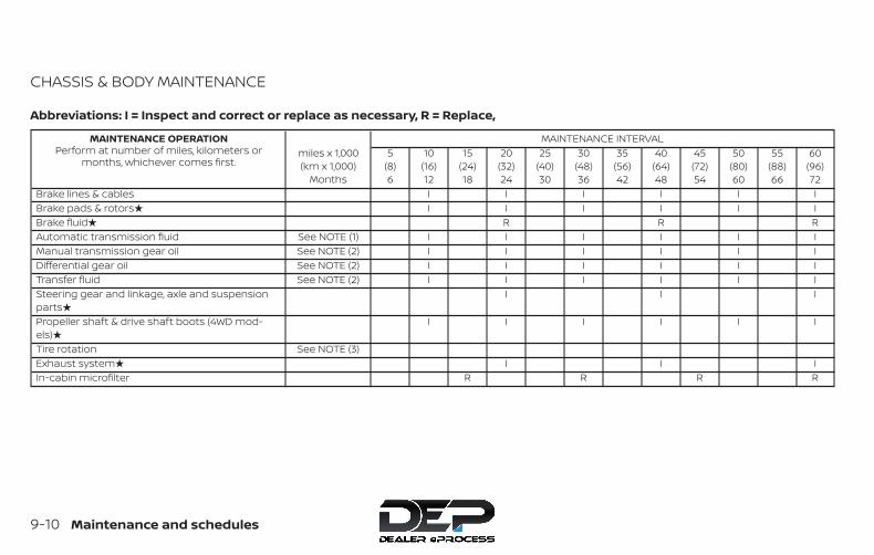
CHASSIS & BODY MAINTENANCE
Abbreviations: I = Inspect and correct or replace as necessary, R = Replace,
MAINTENANCE OPERATIONPerform at number of miles, kilometers or
months, whichever comes first.miles x 1,000(km x 1,000)
Months
MAINTENANCE INTERVAL5
(8)6
10(16)12
15(24)18
20(32)24
25(40)30
30(48)36
35(56)42
40(64)48
45(72)54
50(80)60
55(88)66
60(96)72
Brake lines & cables I I I I I IBrake pads & rotors� I I I I I IBrake fluid� R R RAutomatic transmission fluid See NOTE (1) I I I I I IManual transmission gear oil See NOTE (2) I I I I I IDifferential gear oil See NOTE (2) I I I I I ITransfer fluid See NOTE (2) I I I I I ISteering gear and linkage, axle and suspensionparts�
I I I
Propeller shaft & drive shaft boots (4WD mod-els)�
I I I I I I
Tire rotation See NOTE (3)Exhaust system� I I IIn-cabin microfilter R R R R
9-10 Maintenance and schedules

MAINTENANCE OPERATIONPerform at number of miles, kilometers or
months, whichever comes first.miles x 1,000(km x 1,000)
Months
MAINTENANCE INTERVAL65
(104)78
70(112)84
75(120)90
80(128)96
85(136)102
90(144)108
95(152)114
100(160)120
105(168)126
110(176)132
115(184)138
120(192)144
Brake lines & cables I I I I I IBrake pads & rotors� I I I I I IBrake fluid� R R RAutomatic transmission fluid See NOTE (1) I I I I I IManual transmission gear oil See NOTE (2) I I I I I IDifferential gear oil See NOTE (2) I I I I I ITransfer fluid See NOTE (2) I I I I I ISteering gear and linkage, axle and suspensionparts�
I I I
Propeller shaft & drive shaft boots (4WD mod-els)�
I I I I I I
Tire rotation See NOTE (3)Exhaust system� I I IIn-cabin microfilter R R R R
NOTE:
Maintenance items with “�” should be performed more frequently according to “Maintenance under severe driving conditions”.(1) If towing a trailer, using a car-top carrier, or driving on rough or muddy roads, change (not just inspect) oil at every 20,000 miles(32,000 km) or 24 months. Using automatic transmission fluid other than Genuine NISSAN Matic S ATF or Matic J ATF (or theirequivalents) may cause deterioration in driveability and automatic transmission durability, and may damage the automatictransmission. Damage caused by the use of other fluids is not covered by the NISSAN New Vehicle Limited Warranty.(2) If towing a trailer, using a camper or a car-top, or driving on rough or muddy roads, change (not just inspect) oil at every20,000 miles (32,000 km) or 24 months.(3) For additional information on tire rotation, refer to “General maintenance” in this section.
Maintenance and schedules 9-11
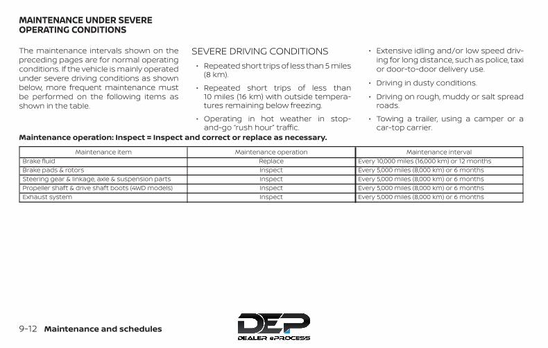
The maintenance intervals shown on thepreceding pages are for normal operatingconditions. If the vehicle is mainly operatedunder severe driving conditions as shownbelow, more frequent maintenance mustbe performed on the following items asshown in the table.
SEVERE DRIVING CONDITIONS∙ Repeated short trips of less than 5 miles
(8 km).
∙ Repeated short trips of less than10 miles (16 km) with outside tempera-tures remaining below freezing.
∙ Operating in hot weather in stop-and-go “rush hour” traffic.
∙ Extensive idling and/or low speed driv-ing for long distance, such as police, taxior door-to-door delivery use.
∙ Driving in dusty conditions.
∙ Driving on rough, muddy or salt spreadroads.
∙ Towing a trailer, using a camper or acar-top carrier.
Maintenance operation: Inspect = Inspect and correct or replace as necessary.
Maintenance item Maintenance operation Maintenance intervalBrake fluid Replace Every 10,000 miles (16,000 km) or 12 monthsBrake pads & rotors Inspect Every 5,000 miles (8,000 km) or 6 monthsSteering gear & linkage, axle & suspension parts Inspect Every 5,000 miles (8,000 km) or 6 monthsPropeller shaft & drive shaft boots (4WD models) Inspect Every 5,000 miles (8,000 km) or 6 monthsExhaust system Inspect Every 5,000 miles (8,000 km) or 6 months
MAINTENANCE UNDER SEVEREOPERATING CONDITIONS
9-12 Maintenance and schedules

5,000 Miles (8,000 km) or 6MonthsDealer Name:Date:Mileage:DealerStamp:
10,000 Miles (16,000 km) or 12MonthsDealer Name:Date:Mileage:DealerStamp:
15,000 Miles (24,000 km) or 18MonthsDealer Name:Date:Mileage:DealerStamp:
20,000 Miles (32,000 km) or 24MonthsDealer Name:Date:Mileage:DealerStamp:
25,000 Miles (40,000 km) or 30MonthsDealer Name:Date:Mileage:DealerStamp:
30,000 Miles (48,000 km) or 36MonthsDealer Name:Date:Mileage:DealerStamp:
35,000 Miles (56,000 km) or 42MonthsDealer Name:Date:Mileage:DealerStamp:
40,000 Miles (64,000 km) or 48MonthsDealer Name:Date:Mileage:DealerStamp:
45,000 Miles (72,000 km) or 54MonthsDealer Name:Date:Mileage:DealerStamp:
MAINTENANCE LOG
Maintenance and schedules 9-13

50,000 Miles (80,000 km) or 60MonthsDealer Name:Date:Mileage:DealerStamp:
55,000 Miles (88,000 km) or 66MonthsDealer Name:Date:Mileage:DealerStamp:
60,000 Miles (96,000 km) or 72MonthsDealer Name:Date:Mileage:DealerStamp:
65,000 Miles (104,000 km) or 78MonthsDealer Name:Date:Mileage:DealerStamp:
70,000 Miles (112,000 km) or 84MonthsDealer Name:Date:Mileage:DealerStamp:
75,000 Miles (120,000 km) or 90MonthsDealer Name:Date:Mileage:DealerStamp:
80,000 Miles (128,000 km) or 96MonthsDealer Name:Date:Mileage:DealerStamp:
85,000 Miles (136,000 km) or 102MonthsDealer Name:Date:Mileage:DealerStamp:
90,000 Miles (144,000 km) or 108MonthsDealer Name:Date:Mileage:DealerStamp:
9-14 Maintenance and schedules

95,000 Miles (152,000 km) or 114MonthsDealer Name:Date:Mileage:DealerStamp:
100,000 Miles (160,000 km) or120 MonthsDealer Name:Date:Mileage:DealerStamp:
105,000 Miles (168,000 km) or 126MonthsDealer Name:Date:Mileage:DealerStamp:
110,000 Miles (176,000 km) or 132MonthsDealer Name:Date:Mileage:DealerStamp:
115,000 Miles (184,000 km) or 138MonthsDealer Name:Date:Mileage:DealerStamp:
120,000 Miles (192,000 km) or 144MonthsDealer Name:Date:Mileage:DealerStamp:
Maintenance and schedules 9-15
10 Technical and consumer information
Recommended fluids/lubricants andcapacities . . . . . . . . . . . . . . . . . . . . . . . . . . . . . . . . . . . . . . 10-2
Fuel recommendation(for QR25DE models). . . . . . . . . . . . . . . . . . . . . . . . . 10-5Fuel recommendation(for VQ40DE models) . . . . . . . . . . . . . . . . . . . . . . . . 10-7Flexible Fuel Vehicle (FFV) fuelrecommendation (if so equipped) . . . . . . . . . . . 10-9Engine oil and oil filterrecommendations . . . . . . . . . . . . . . . . . . . . . . . . . . 10-11Air conditioner system refrigerant andoil recommendations . . . . . . . . . . . . . . . . . . . . . . 10-12
Specifications . . . . . . . . . . . . . . . . . . . . . . . . . . . . . . . . . 10-13Engine . . . . . . . . . . . . . . . . . . . . . . . . . . . . . . . . . . . . . 10-13Wheels and tires. . . . . . . . . . . . . . . . . . . . . . . . . . . . 10-14Dimensions and weights . . . . . . . . . . . . . . . . . . . 10-15
When traveling or registering in anothercountry. . . . . . . . . . . . . . . . . . . . . . . . . . . . . . . . . . . . . . . . 10-16Vehicle identification . . . . . . . . . . . . . . . . . . . . . . . . . . 10-16
Vehicle Identification Number (VIN)plate . . . . . . . . . . . . . . . . . . . . . . . . . . . . . . . . . . . . . . . 10-16Engine serial number. . . . . . . . . . . . . . . . . . . . . . . 10-16F.M.V.S.S./C.M.V.S.S. certification label . . . . . . . . 10-17Emission control information label . . . . . . . . . 10-18
Tire and Loading Information label . . . . . . . . . 10-18Air conditioner specification label. . . . . . . . . . . 10-19
Installing front license plate. . . . . . . . . . . . . . . . . . . . 10-19Installing front license plate withgrommets. . . . . . . . . . . . . . . . . . . . . . . . . . . . . . . . . . 10-19
Vehicle loading information . . . . . . . . . . . . . . . . . . . 10-20Terms . . . . . . . . . . . . . . . . . . . . . . . . . . . . . . . . . . . . . . 10-20Vehicle load capacity . . . . . . . . . . . . . . . . . . . . . . . 10-21Securing the load. . . . . . . . . . . . . . . . . . . . . . . . . . . 10-22Utili-track® channel system(if so equipped) . . . . . . . . . . . . . . . . . . . . . . . . . . . . . 10-23Loading tips . . . . . . . . . . . . . . . . . . . . . . . . . . . . . . . . 10-28
Truck-camper loading information . . . . . . . . . . . . 10-29Crew cab models. . . . . . . . . . . . . . . . . . . . . . . . . . . 10-29King Cab® models . . . . . . . . . . . . . . . . . . . . . . . . . . 10-29Special Body vehicles. . . . . . . . . . . . . . . . . . . . . . . 10-29Location for center of gravity . . . . . . . . . . . . . . . 10-29Vehicle load weight capacity . . . . . . . . . . . . . . . 10-30Measurement of weights . . . . . . . . . . . . . . . . . . . 10-30
Towing a trailer . . . . . . . . . . . . . . . . . . . . . . . . . . . . . . . . 10-30Maximum load limits . . . . . . . . . . . . . . . . . . . . . . . 10-31Towing load/specification . . . . . . . . . . . . . . . . . . 10-34Towing safety . . . . . . . . . . . . . . . . . . . . . . . . . . . . . . 10-36

Flat towing – 4WD with automatictransmission . . . . . . . . . . . . . . . . . . . . . . . . . . . . . . . 10-42Flat towing – 2WD with automatictransmission . . . . . . . . . . . . . . . . . . . . . . . . . . . . . . . 10-43Flat towing – 2WD/4WD with manualtransmission . . . . . . . . . . . . . . . . . . . . . . . . . . . . . . . 10-43
Uniform tire quality grading. . . . . . . . . . . . . . . . . . . . 10-44
Emission control system warranty. . . . . . . . . . . . . 10-45Reporting safety defects . . . . . . . . . . . . . . . . . . . . . . 10-45Readiness for Inspection/Maintenance (I/M)test. . . . . . . . . . . . . . . . . . . . . . . . . . . . . . . . . . . . . . . . . . . . 10-46Event Data Recorders (EDR). . . . . . . . . . . . . . . . . . . . 10-47Owner’s Manual/Service Manual orderinformation . . . . . . . . . . . . . . . . . . . . . . . . . . . . . . . . . . . 10-47

The following are approximate capacities. The actual refill capacities may be a little different. When refilling, follow the proceduredescribed in the “Do-it-yourself” section to determine the proper refill capacity.
Fluid type Capacity (approximate) Recommended Fluids/LubricantsMetric
MeasureUS
MeasureImperialMeasure
Fuel 80 L 21-1/8 gal 17-5/8 gal
• For additional information, refer to “Fuel recommenda-tion (for QR25DE models)”, “Fuel recommendation (forVQ40DE models)” or “Flexible Fuel Vehicle (FFV) fuel rec-ommendation” in this section.
Engine oil*1Drain and refill*1: For additionalinformation, refer to“Engine” in the “Do-it-yourself ” section ofthis manual.
QR25DE
With oil filterchange 4.6 L 4-7/8 qt 4 qt
• Genuine “Nissan Motor Oil 5W-30” (or equivalent) isrecommended.• If the above motor oil is not available, a synthetic SAE5W-30 GF-5 SN engine oil may be used. Damage causedby the use of motor oil (or engine oil) other than as rec-ommended is not covered under NISSAN’s New VehicleLimited Warranty. For additional information, refer to “En-gine oil and oil filter recommendation” in this section.
Without oilfilter change 4.3 L 4-1/2 qt 3-3/4 qt
VQ40DE
With oil filterchange 5.1 L 5-3/8 qt 4-1/2 qt
• Genuine “Nissan Motor Oil 5W-30” (or equivalent) isrecommended.• If the above motor oil is not available, a synthetic SAE5W-30 GF-5 SN engine oil may be used. Damage causedby the use of motor oil (or engine oil) other than as rec-ommended is not covered under NISSAN’s New VehicleLimited Warranty. For additional information, refer to “En-gine oil and oil filter recommendation” in this section.
Without oilfilter change 4.8 L 5-1/8 qt 4-1/4 qt
Engine coolant(with reservoir)
QR25DE 9.4 L 2-1/2 gal 2-1/8 gal • Pre-diluted Genuine NISSAN Long Life Antifreeze/Coolant (blue) or equivalentVQ40DE 10.2 L 2-3/4 gal 2-1/4 gal
RECOMMENDED FLUIDS/LUBRICANTS AND CAPACITIES
10-2 Technical and consumer information
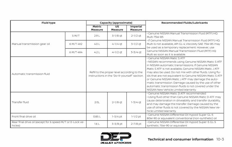
Fluid type Capacity (approximate) Recommended Fluids/LubricantsMetric
MeasureUS
MeasureImperialMeasure
Manual transmission gear oil
5 M/T 2.9 L 3-1/8 qt 2-1/2 qt• Genuine NISSAN Manual Transmission Fluid (MTF) HQMulti 75W-85• If Genuine NISSAN Manual Transmission Fluid (MTF) HQMulti is not available, API GL-4, Viscosity SAE 75W-85 maybe used as a temporary replacement. However, useGenuine NISSAN Manual Transmission Fluid (MTF) HQMulti as soon as it is available.
6 M/T 4X2 4.0 L 4-1/4 qt 3-1/2 qt
6 M/T 4X4 4.2 L 4-1/2 qt 3-3/4 qt
Automatic transmission fluid Refill to the proper level according to theinstructions in the “Do-it-yourself ” section.
• Genuine NISSAN Matic S ATF• NISSAN recommends using Genuine NISSAN Matic S ATFin NISSAN automatic transmissions. If Genuine NISSANMatic S ATF is not available, Genuine NISSAN Matic J ATFmay also be used. Do not mix with other fluids. Using flu-ids that are not equivalent to Genuine NISSAN Matic S ATFor Genuine NISSAN Matic J ATF may damage the auto-matic transmission. Damage caused by the use of otherautomatic transmission fluids is not covered under theNISSAN New Vehicle Limited Warranty.
Transfer fluid 2.0L 2-1/8 qt 1-3/4 qt
• Genuine NISSAN Matic D ATF recommended• Using fluid other than Genuine NISSAN Matic D ATF maycause deterioration in driveability and transfer durability,and may damage the transfer. Damage caused by theuse of other fluids is not covered by the NISSAN New Ve-hicle Limited Warranty.
Front final drive oil 0.85 L 1-3/4 pt 1-1/2 pt • Genuine NISSAN Differential Oil Hypoid Super GL-580W-90 or equivalent conventional (non-synthetic) oil
Rear final drive oil (except for 6 speed M/T or E-Lock ve-hicles) 1.6 L 3-3/8 pt 2-7/8 pt • Genuine NISSAN Differential Oil Hypoid Super-S GL-5
synthetic 75W-90 or equivalent
Technical and consumer information 10-3

Fluid type Capacity (approximate) Recommended Fluids/LubricantsMetric
MeasureUS
MeasureImperialMeasure
Rear final drive oil (for 6 speed M/T or E-Lock vehicles) 2.0 L 4-1/4 pt 3-1/2 pt • Genuine NISSAN Differential Oil synthetic 75W-140 or APIGL-5 synthetic gear oil, Viscosity SAE 75W-140
Power Steering Fluid (PSF) — — — • Genuine NISSAN PSF-II or equivalent.
Brake and clutch (if so equipped) fluid — — —• Genuine NISSAN Super Heavy Duty Brake Fluid*2 orequivalent DOT 3*2: Available in mainland USA through a NISSAN dealer.
Multi-purpose grease — — — • NLGI No. 2 (Lithium Soap base)
Air conditioning system refrigerant — — —• HFC-134a (R-134a)• For additional information, refer to “Air conditioner speci-fication label” in this section.
Air conditioning system oil — — —
• Genuine NISSAN A/C System Oil Type R (KLH00-PAGR0)or equivalent• For additional information, refer to “Air conditioner speci-fication label” in this section.
Windshield-washer fluid 4.5 L 1-1/4 gal 1 gal • Genuine NISSAN Windshield Washer ConcentrateCleaner & Antifreeze or equivalent
10-4 Technical and consumer information
FUEL RECOMMENDATION (forQR25DE models)Use unleaded regular gasoline with an oc-tane rating of at least 87 AKI (Anti-KnockIndex) number (Research octane number91).
CAUTION∙ Only vehicles with the E-85 filler door
label can operate on E-85. Fuel systemor other damage can occur if E-85 isused in vehicles that are not designedto run on E-85.
∙ Using a fuel other than that specifiedcould adversely affect the emissioncontrol system, and may also affectthe warranty coverage.
∙ Under no circumstances should aleaded gasoline be used, because thiswill damage the three-way catalyst.
∙ Do not use a fuel containing morethan 15% ethanol in your vehicle. Yourvehicle is not designed to run on a fuelcontaining more than 15% ethanol.Using a fuel containing more than 15%ethanol in a vehicle not specificallydesigned for a fuel containing morethan 15% ethanol can adversely affectthe emission control devices and sys-tems of the vehicle. Damage causedby such fuel is not covered by theNISSAN New Vehicle Limited Warranty.
∙ Do not use fuel that contains the oc-tane booster methylcyclopentadienylmanganese tricarbonyl (MMT). Usingfuel containing MMT may adverselyaffect vehicle performance and ve-hicle emissions. Not all fuel dispens-ers are labeled to indicate MMT con-tent, so you may have to consult yourgasoline retailer for more details.Note that Federal and California lawsprohibit the use of MMT in reformu-lated gasoline.
∙ U.S. government regulations requireethanol dispensing pumps to be iden-tified by a small, square, orange andblack label with the common abbre-viation or the appropriate percentagefor that region.
Gasoline specificationsNISSAN recommends using gasoline thatmeets the World-Wide Fuel Charter (WWFC)specifications where it is available. Many ofthe automobile manufacturers developedthis specification to improve emission con-trol system and vehicle performance. Askyour service station manager if the gaso-line meets the WWFC specifications.
Reformulated gasolineSome fuel suppliers are now producing re-formulated gasolines. These gasolines arespecially designed to reduce vehicle emis-sions. NISSAN supports efforts towardscleaner air and suggests that you use re-formulated gasoline when available.
Technical and consumer information 10-5
Gasoline containing oxygenatesSome fuel suppliers sell gasoline contain-ing oxygenates such as ethanol, MethylTert-butyl Ether (MTBE) and methanol withor without advertising their presence.NISSAN does not recommend the use offuels of which the oxygenate content andthe fuel compatibility for your NISSAN can-not be readily determined. If in doubt, askyour service station manager.
If you use oxygenate-blend gasoline,please take the following precautions asthe usage of such fuels may cause vehicleperformance problems and/or fuel systemdamage.
∙ The fuel should be unleaded and havean octane rating no lower than thatrecommended for unleaded gasoline.
∙ If an oxygenate-blend other thanmethanol blend is used, it shouldcontain no more than 15% oxygenate.
∙ If a methanol blend is used, it shouldcontain no more than 5% methanol(methyl alcohol, wood alcohol). Itshould also contain a suitableamount of appropriate cosolventsand corrosion inhibitors. If not prop-erly formulated with appropriate co-solvents and corrosion inhibitors,such methanol blends may cause fuelsystem damage and/or vehicle per-formance problems. At this time, suf-ficient data is not available to ensurethat all methanol blends are suitablefor use in NISSAN vehicles.
If any driveability problems such as enginestalling and difficult hot-starting are expe-rienced after using oxygenate-blend fuels,immediately change to a non-oxygenatefuel or a fuel with a low blend of MTBE.
Take care not to spill gasoline during re-fueling. Gasoline containing oxygenatescan cause paint damage.
E–15 fuelE-15 fuel is a mixture of approximately 15%fuel ethanol and 85% unleaded gasoline.E-15 can only be used in vehicles designedto run on E-15 fuel. U.S. government regula-tions require fuel ethanol dispensingpumps to be identified with small, square,
orange and black label with the commonabbreviation or the appropriate percent-age for that region.
E–85 fuelE-85 fuel is a mixture of approximately 85%fuel ethanol and 15% unleaded gasoline.E-85 can only be used in a Flexible FuelVehicle (FFV). Do not use E-85 in your ve-hicle. U.S. government regulations requirefuel ethanol dispensing pumps to be iden-tified by a small, square, orange and blacklabel with the common abbreviation or theappropriate percentage for that region.
Fuel containing MMTMMT, or methylcyclopentadienyl manga-nese tricarbonyl, is an octane boosting ad-ditive. NISSAN does not recommend theuse of fuel containing MMT. Such fuel mayadversely affect vehicle performance, in-cluding the emissions control system. Notethat while some fuel pumps label MMTcontent, not all do, so you may have toconsult your gasoline retailer for more de-tails.
10-6 Technical and consumer information

Aftermarket fuel additivesNISSAN does not recommend the use ofany aftermarket fuel additives (for ex-ample, fuel injector cleaner, octanebooster, intake valve deposit removers,etc.) which are sold commercially. Many ofthese additives intended for gum, varnishor deposit removal may contain active sol-vents or similar ingredients that can beharmful to the fuel system and engine.
Octane rating tipsUsing unleaded gasoline with an octanerating lower than recommended cancause persistent, heavy “spark knock.”(“Spark knock” is a metallic rappingnoise.) If severe, this can lead to enginedamage. If you detect a persistent heavyspark knock even when using gasolineof the stated octane rating, or if you hearsteady spark knock while holding asteady speed on level roads, have aNISSAN dealer correct the condition. Fail-ure to correct the condition is misuse ofthe vehicle, for which NISSAN is not re-sponsible.
Incorrect ignition timing may result inspark knock, after-run and/or overheating,which may cause excessive fuel consump-tion or engine damage. If any of the abovesymptoms are encountered, have your ve-hicle checked. It is recommended that youvisit a NISSAN dealer for servicing.
However, now and then you may noticelight spark knock for a short time whileaccelerating or driving up hills. This is nota cause for concern, because you get thegreatest fuel benefit when there is lightspark knock for a short time under heavyengine load.
FUEL RECOMMENDATION (forVQ40DE models)Use unleaded regular gasoline with an oc-tane rating of at least 87 AKI (Anti-KnockIndex) number (Research octane number91).
CAUTION∙ Only vehicles with the E-85 filler door
label can operate on E-85. Fuel systemor other damage can occur if E-85 isused in vehicles that are not designedto run on E-85.
∙ Using a fuel other than that specifiedcould adversely affect the emissioncontrol system, and may also affectthe warranty coverage.
∙ Under no circumstances should aleaded gasoline be used, because thiswill damage the three-way catalyst.
∙ Do not use E-15 or E-85 fuel in yourvehicle. Your vehicle is not designed torun on E-15 or E-85 fuel. Using E-15 orE-85 fuel in a vehicle not specificallydesigned for E-15 or E-85 fuel can ad-versely affect the emission controldevices and systems of the vehicle.Damage caused by such fuel is notcovered by the NISSAN New VehicleLimited Warranty.
∙ Do not use fuel that contains the oc-tane booster methylcyclopentadienylmanganese tricarbonyl (MMT). Usingfuel containing MMT may adverselyaffect vehicle performance and ve-hicle emissions. Not all fuel dispens-ers are labeled to indicate MMT con-tent, so you may have to consult yourgasoline retailer for more details.Note that Federal and California lawsprohibit the use of MMT in reformu-lated gasoline.
Technical and consumer information 10-7
∙ U.S. government regulations requireethanol dispensing pumps to be iden-tified by a small, square, orange andblack label with the common abbre-viation or the appropriate percentagefor that region.
Gasoline specificationsNISSAN recommends using gasoline thatmeets the World-Wide Fuel Charter (WWFC)specifications where it is available. Many ofthe automobile manufacturers developedthis specification to improve emission con-trol system and vehicle performance. Askyour service station manager if the gaso-line meets the WWFC specifications.
Reformulated gasolineSome fuel suppliers are now producing re-formulated gasolines. These gasolines arespecially designed to reduce vehicle emis-sions. NISSAN supports efforts towardscleaner air and suggests that you use re-formulated gasoline when available.
Gasoline containing oxygenatesSome fuel suppliers sell gasoline contain-ing oxygenates such as ethanol, MethylTert-butyl Ether (MTBE) and methanol withor without advertising their presence.
NISSAN does not recommend the use offuels of which the oxygenate content andthe fuel compatibility for your NISSAN can-not be readily determined. If in doubt, askyour service station manager.
If you use oxygenate-blend gasoline,please take the following precautions asthe usage of such fuels may cause vehicleperformance problems and/or fuel systemdamage.
∙ The fuel should be unleaded and havean octane rating no lower than thatrecommended for unleaded gasoline.
∙ If an oxygenate-blend other thanmethanol blend is used, it shouldcontain no more than 10% oxygenate.(MTBE may, however, be added up to15%.)
∙ E-15 fuel contains more than 10% oxy-genate. E-15 fuel will adversely affectthe emission control devices and sys-tems of the vehicle and should not beused. Damage caused by such fuel isnot covered by the NISSAN New Ve-hicle Limited Warranty.
∙ If a methanol blend is used, it shouldcontain no more than 5% methanol(methyl alcohol, wood alcohol). Itshould also contain a suitableamount of appropriate cosolventsand corrosion inhibitors. If not prop-erly formulated with appropriate co-solvents and corrosion inhibitors,such methanol blends may cause fuelsystem damage and/or vehicle per-formance problems. At this time, suf-ficient data is not available to ensurethat all methanol blends are suitablefor use in NISSAN vehicles.
If any driveability problems such as enginestalling and difficult hot-starting are expe-rienced after using oxygenate-blend fuels,immediately change to a non-oxygenatefuel or a fuel with a low blend of MTBE.
Take care not to spill gasoline during re-fueling. Gasoline containing oxygenatescan cause paint damage.
10-8 Technical and consumer information

E–15 fuelE-15 fuel is a mixture of approximately 15%fuel ethanol and 85% unleaded gasoline.E-15 can only be used in vehicles designedto run on E-15 fuel. Do not use E-15 in yourvehicle. U.S. government regulations re-quire fuel ethanol dispensing pumps to beidentified with small, square, orange andblack label with the common abbreviationor the appropriate percentage for that re-gion.
E–85 fuelE-85 fuel is a mixture of approximately 85%fuel ethanol and 15% unleaded gasoline.E-85 can only be used in a Flexible FuelVehicle (FFV). Do not use E-85 in your ve-hicle. U.S. government regulations requirefuel ethanol dispensing pumps to be iden-tified by a small, square, orange and blacklabel with the common abbreviation or theappropriate percentage for that region.
Fuel containing MMTMMT, or methylcyclopentadienyl manga-nese tricarbonyl, is an octane boosting ad-ditive. NISSAN does not recommend theuse of fuel containing MMT. Such fuel mayadversely affect vehicle performance, in-cluding the emissions control system. Note
that while some fuel pumps label MMTcontent, not all do, so you may have toconsult your gasoline retailer for more de-tails.
Aftermarket fuel additivesNISSAN does not recommend the use ofany aftermarket fuel additives (for ex-ample, fuel injector cleaner, octanebooster, intake valve deposit removers,etc.) which are sold commercially. Many ofthese additives intended for gum, varnishor deposit removal may contain active sol-vents or similar ingredients that can beharmful to the fuel system and engine.
Octane rating tipsUsing unleaded gasoline with an octanerating lower than recommended cancause persistent, heavy “spark knock.”(“Spark knock” is a metallic rappingnoise.) If severe, this can lead to enginedamage. If you detect a persistent heavyspark knock even when using gasolineof the stated octane rating, or if you hearsteady spark knock while holding asteady speed on level roads, have aNISSAN dealer correct the condition. Fail-ure to correct the condition is misuse ofthe vehicle, for which NISSAN is not re-sponsible.
Incorrect ignition timing may result inspark knock, after-run and/or overheating,which may cause excessive fuel consump-tion or engine damage. If any of the abovesymptoms are encountered, have your ve-hicle checked. It is recommended that youvisit a NISSAN dealer for servicing.
However, now and then you may noticelight spark knock for a short time whileaccelerating or driving up hills. This is nota cause for concern, because you get thegreatest fuel benefit when there is lightspark knock for a short time under heavyengine load.
FLEXIBLE FUEL VEHICLE (FFV) FUELRECOMMENDATION (if soequipped)Your vehicle is designed to use (E-85) FuelEthanol, “Regular” unleaded regular gaso-line or any percentage of the two fuelscombined.
U.S. government regulations require FuelEthanol dispensing pumps to have asmall, square, orange and black labelwith the common abbreviation or theappropriate percentage for that region.
Technical and consumer information 10-9

CAUTIONUse of other fuels such as Fuel Metha-nol may cause powertrain damage or aloss of vehicle performance.
Under no circumstances should aleaded gasoline be used, because thiswill cause damage to the three-waycatalyst.
General informationThis information is for Flexible Fuel Vehicles(FFV) only. FFV vehicles can be identified bythe fuel filler door label that states Ethanol(E-85) or Unleaded Gasoline Only. This sec-tion only covers those subjects that areunique to Flexible Fuel Vehicles.
CAUTIONOnly vehicles with the E-85 filler doorlabel can operate on E-85. Fuel systemor other damage can occur if E-85 isused in vehicles that are not designedto run on E-85.
Ethanol Fuel (E-85)E-85 is a mixture of approximately 85% fuelethanol and 15% unleaded gasoline.
WARNING∙ Ethanol vapors are extremely flam-
mable and could cause serious per-sonal injury.
∙ Never have any smoking materials litin or near the vehicle when removingthe fuel filler cap or filling the tank.
∙ Do not use E-85 as a cleaning agentand never use it near an open flame.
Fuel requirements
Your vehicle will operate on both unleadedregular gasoline with an octane rating of atleast 87 AKI (Anti-Knock Index) number (Re-search octane number 91), or E-85 fuel, orany mixture of these two.
For the best starting and vehicle driveabil-ity results, do not continually switch be-tween E-85 and unleaded regular gasoline.If you must switch fuels, NISSAN recom-mends the following:
∙ do not switch when the fuel gauge indi-cates less than 1/4 full
∙ add more than 5 gallons of fuel
∙ operate the vehicle immediately afterrefueling for a period of at least 5 min-utes
NOTE:
When the ambient temperature is above90°F (32°C), you may experience hardstarting and rough idle following startup even if the above recommendationsare followed.
Starting
The characteristics of E-85 fuel make it un-suitable for use when ambient tempera-tures fall below 0°F (-18°C). In the range of0°F (-18°C) to 32°F (0°C), you may experiencean increase in the time it takes for you en-gine to start, and a deterioration in drivabil-ity (sags and/or hesitations) until the en-gine is fully warmed up.
Fuel consumption
Because E-85 fuel contains less energy pergallon than gasoline, you will experience anincrease in fuel consumption. You can ex-pect your fuel mileage to decrease byabout 30% compared to gasoline opera-tion.
10-10 Technical and consumer information

Replacement parts
Many components in your Flexible Fuel Ve-hicle (FFV) are designed to be compatiblewith ethanol. Always be sure that your ve-hicle is serviced with correct ethanol com-patible parts.
CAUTIONReplacing fuel system componentswith non-ethanol compatible compo-nents can damage your vehicle andmay also affect the warranty coverage.
Maintenance
If you operate your vehicle using E-85 fuel,follow the correct maintenance log shownin the “Maintenance and schedules” sec-tion of this manual.
CAUTIONDo not use ethanol mixture greaterthan 85% in your vehicle. It will causedifficulty in cold starting and may affectdriveability.
ENGINE OIL AND OIL FILTERRECOMMENDATIONSSelecting the correct oilIt is essential to choose the correct grade,quality and viscosity engine oil to ensuresatisfactory engine life and performance.For additional information, refer to “Recom-mended fluids/lubricants and capacities”in this section. NISSAN recommends theuse of an energy conserving oil in order toimprove fuel economy.
Select only engine oils that meet theAmerican Petroleum Institute (API) certifi-
cation or International Lubricant Standard-ization and Approval Committee (ILSAC)certification and SAE viscosity standard.These oils have the API certification markon the front of the container. Oils which donot have the specified quality label shouldnot be used as they could cause enginedamage.
Oil additivesNISSAN does not recommend the use of oiladditives. The use of an oil additive is notnecessary when the proper oil type is usedand maintenance intervals are followed.
LTI2061
Technical and consumer information 10-11

Oil which may contain foreign matter orhas been previously used should not beused.
Oil viscosityThe engine oil viscosity or thicknesschanges with temperature. Because ofthis, it is important to select the engine oilviscosity based on the temperatures atwhich the vehicle will be operated beforethe next oil change. Choosing an oil viscos-ity other than that recommended couldcause serious engine damage.
Selecting the correct oil filterYour new NISSAN vehicle is equipped with ahigh-quality Genuine NISSAN oil filter. Whenreplacing, use a Genuine NISSAN oil filter orits equivalent for the reason described in“Change intervals.”
Change intervalsThe oil and oil filter change intervals foryour engine are based on the use of thespecified quality oils and filters. Using en-gine oil and filters that are not of the speci-fied quality, or exceeding recommended oiland filter change intervals could reduceengine life. Damage to the engine causedby improper maintenance or use of incor-
rect oil and filter quality and/or viscosity isnot covered by the NISSAN New VehicleLimited Warranty.
Your engine was filled with a high-qualityengine oil when it was built. You do not haveto change the oil before the first recom-mended change interval. Oil and filterchange intervals depend upon how youuse your vehicle.
Operation under the following conditionsmay require more frequent oil and filterchanges:
∙ repeated short distance driving at coldoutside temperatures
∙ driving in dusty conditions
∙ extensive idling
∙ towing a trailer
∙ stop and go commuting
For additional information, refer to the“Maintenance and schedules” section ofthis manual.
AIR CONDITIONER SYSTEMREFRIGERANT AND OILRECOMMENDATIONSThe air conditioner system in yourNISSAN vehicle must be charged with therefrigerant HFC-134a (R-134a) andNISSAN A/C system oil Type R (KLH00-PAGRO) or the exact equivalents.
CAUTIONThe use of any other refrigerant or oilwill cause severe damage to the air con-ditioning system and will require the re-placement of all air conditioner systemcomponents.
The refrigerant HFC-134a (R-134a) in yourNISSAN vehicle does not harm the earth’sozone layer. Although this refrigerant doesnot affect the earth’s atmosphere, certaingovernment regulations require the recov-ery and recycling of any refrigerant duringautomotive air conditioner system service. ANISSAN dealer has the trained techniciansand equipment needed to recover and re-cycle your air conditioner system refrigerant.
It is recommended that you visit a NISSANdealer when servicing your air conditionersystem.
10-12 Technical and consumer information
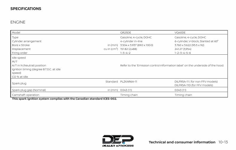
ENGINE
Model QR25DE VQ40DE
Type Gasoline, 4-cycle, DOHC Gasoline, 4-cycle, DOHCCylinder arrangement 4-cylinder in-line 6-cylinder, V-block, Slanted at 60°Bore x Stroke in (mm) 3.504 x 3.937 (89.0 x 100.0) 3.760 x 3.622 (95.5 x 92)Displacement cu in (cm3) 151.82 (2,488) 241.27 (3,954)Firing order 1–3–4–2 1–2–3–4–5–6
Idle speedM/TA/T in N (Neutral) position Refer to the “Emission control information label” on the underside of the hood.Ignition timing (degree B.T.D.C. at idlespeed)CO % at idle
Spark plug Standard PLZKAR6A-11 DILFR5A-11 ( for non FFV models)DILFR5A-11D (for FFV models)
Spark plug gap (Nominal) in (mm) 0.043 (1.1) 0.043 (1.1)
Camshaft operation Timing chain Timing chainThis spark ignition system complies with the Canadian standard ICES-002.
SPECIFICATIONS
Technical and consumer information 10-13

WHEELS AND TIRESWheel Type Offset in (mm) Size
Steel 0.79 (20) 15 x 6.5JJSteel 1.18 (30) 16 x 7JJAluminum 1.18 (30) 16 x 7JAluminum 1.18 (30) 18 x 7.5J
Tires Size
235/75R15P265/70R16P265/75R16P265/60R18
Spare tire Size
Steel Full sizeAlloy 16” Full sizeAlloy 18” P265/70R16
10-14 Technical and consumer information
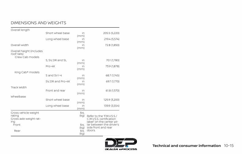
DIMENSIONS AND WEIGHTSOverall length
Short wheel base in(mm)
205.5 (5,220)
Long wheel base in(mm)
219.4 (5,574)
Overall width in(mm)
72.8 (1,850)
Overall height (includesroof rails)
Crew Cab modelsS, SV, DR and SL in
(mm)70.1 (1,780)
Pro-4X in(mm)
73.9 (1,878)
King Cab® modelsS and SV I-4 in
(mm)68.7 (1,745)
SV, DR and Pro-4X in(mm)
69.7 (1,770)
Track WidthFront and rear in
(mm)61.8 (1,570)
WheelbaseShort wheel base in
(mm)125.9 (3,200)
Long wheel base in(mm)
139.9 (3,554)
Gross vehicle weightrating
lbs.(kg) Refer to the “F.M.V.S.S./
C.M.V.S.S. certificationlabel” on the center pil-lar between the driver’sside front and reardoors.
Gross axle weight rat-ing
Front lbs.(kg)
Rear lbs.(kg)
Technical and consumer information 10-15
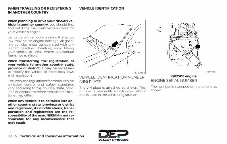
When planning to drive your NISSAN ve-hicle in another country, you should firstfind out if the fuel available is suitable foryour vehicle's engine.
Using fuel with an octane rating that is toolow may cause engine damage. All gaso-line vehicles must be operated with un-leaded gasoline. Therefore, avoid takingyour vehicle to areas where appropriatefuel is not available.
When transferring the registration ofyour vehicle to another country, state,province or district, it may be necessaryto modify the vehicle to meet local lawsand regulations.
The laws and regulations for motor vehicleemission control and safety standardsvary according to the country, state, prov-ince or district; therefore, vehicle specifica-tions may differ.
When any vehicle is to be taken into an-other country, state, province or districtand registered, its modifications, trans-portation and registration are the re-sponsibility of the user. NISSAN is not re-sponsible for any inconvenience thatmay result.
VEHICLE IDENTIFICATION NUMBER(VIN) PLATEThe VIN plate is attached as shown. Thisnumber is the identification for your vehicleand is used in the vehicle registration.
ENGINE SERIAL NUMBERThe number is stamped on the engine asshown.
LTI0085QR25DE engine
LTI0130
WHEN TRAVELING OR REGISTERINGIN ANOTHER COUNTRY
VEHICLE IDENTIFICATION
10-16 Technical and consumer information

F.M.V.S.S./C.M.V.S.S. CERTIFICATIONLABELThe Federal/Canadian Motor VehicleSafety Standard (F.M.V.S.S./C.M.V.S.S.) certifi-cation label is affixed as shown. This labelcontains valuable vehicle information, suchas: (GVWR), (GAWR), month and year ofmanufacture, (VIN), etc. Review it carefully.
VQ40DE engineLTI0127
Type A (if so equipped)LTI0135
Type B (if so equipped)WTI0099
Technical and consumer information 10-17
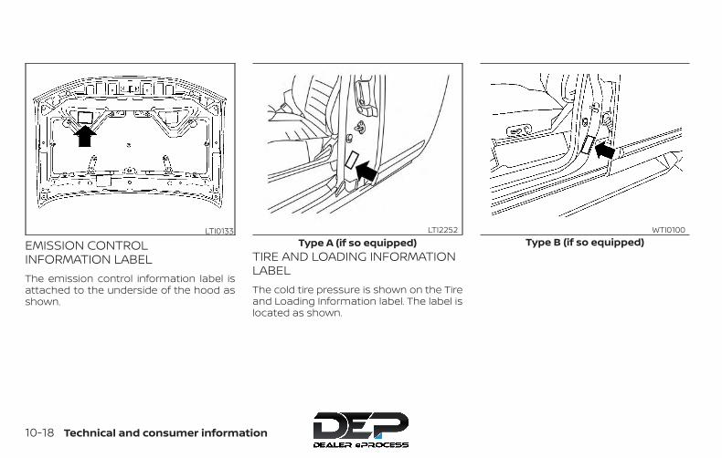
EMISSION CONTROLINFORMATION LABELThe emission control information label isattached to the underside of the hood asshown.
TIRE AND LOADING INFORMATIONLABELThe cold tire pressure is shown on the Tireand Loading Information label. The label islocated as shown.
LTI0133Type A (if so equipped)
LTI2252Type B (if so equipped)
WTI0100
10-18 Technical and consumer information
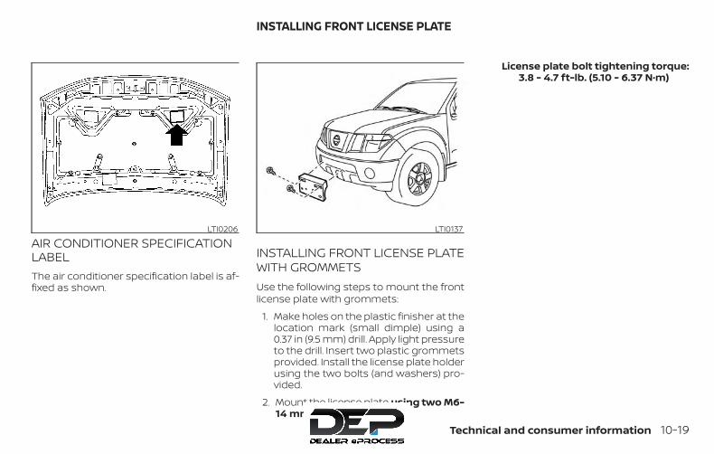
AIR CONDITIONER SPECIFICATIONLABELThe air conditioner specification label is af-fixed as shown.
INSTALLING FRONT LICENSE PLATEWITH GROMMETSUse the following steps to mount the frontlicense plate with grommets:
1. Make holes on the plastic finisher at thelocation mark (small dimple) using a0.37 in (9.5 mm) drill. Apply light pressureto the drill. Insert two plastic grommetsprovided. Install the license plate holderusing the two bolts (and washers) pro-vided.
2. Mount the license plate using two M6-14 mm bolts.
License plate bolt tightening torque:3.8 - 4.7 ft-lb. (5.10 - 6.37 N·m)
LTI0206 LTI0137
INSTALLING FRONT LICENSE PLATE
Technical and consumer information 10-19

WARNING∙ It is extremely dangerous to
ride in a cargo area inside a ve-hicle. In a collision, people ridingin these areas are more likely tobe seriously injured or killed.
∙ Do not allow people to ride inany area of your vehicle that isnot equipped with seats andseat belts.
∙ Be sure everyone in your vehicleis in a seat and using a seat beltproperly.
TERMSIt is important to familiarize yourselfwith the following terms beforeloading your vehicle:
∙ Curb Weight (actual weight ofyour vehicle) - vehicle weight in-cluding: standard and optionalequipment, fluids, emergencytools, and spare tire assembly.This weight does not includepassengers and cargo.
∙ GVW (Gross Vehicle Weight) - curbweight plus the combined weightof passengers and cargo.
∙ GVWR (Gross Vehicle Weight Rat-ing) - maximum total combinedweight of the unloaded vehicle,passengers, luggage, hitch, trailertongue load and any other op-tional equipment. This informa-tion is located on theF.M.V.S.S./C.M.V.S.S. certificationlabel.
∙ GAWR (Gross Axle Weight Rating) -maximum weight (load) limitspecified for the front or rear axle.This information is located on theF.M.V.S.S./C.M.V.S.S. certificationlabel.
∙ GCWR (Gross Combined Weightrating) - The maximum totalweight rating of the vehicle, pas-sengers, cargo, and trailer.
∙ Vehicle Capacity Weight, Loadlimit, Total load capacity - maxi-mum total weight limit specifiedof the load (passengers andcargo) for the vehicle. This is themaximum combined weight ofoccupants and cargo that can beloaded into the vehicle. If the ve-hicle is used to tow a trailer, thetrailer tongue weight must be in-cluded as part of the cargo load.This information is located on theTire and Loading Information la-bel.
∙ Cargo capacity - permissibleweight of cargo, the subtractedweight of occupants from theload limit.
VEHICLE LOADING INFORMATION
10-20 Technical and consumer information

VEHICLE LOAD CAPACITYBefore driving a loaded vehicle, con-firm that you do not exceed theGross Vehicle Weight Rating (GVWR)or the Gross Axle Weight Rating(GAWR) for your vehicle. Both theGVWR and GAWR are located on theF.M.V.S.S./C.M.V.S.S. certification label.For additional information, refer to“Measurement of weights” in thissection.Do not exceed the load limit of yourvehicle shown as “The combinedweight of occupants and cargo” onthe Tire and Loading Information la-bel. Do not exceed the number ofoccupants shown as “Seating Ca-pacity” on the Tire and Loading Infor-mation label.To get “the combined weight of oc-cupants and cargo”, add the weightof all occupants, then add the totalluggage weight. Examples areshown in the following illustration.
ExampleLTI2320
Technical and consumer information 10-21

Steps for determining correctload limit
1. Locate the statement “The com-bined weight of occupants andcargo should never exceed XXXlbs. or XXX kg” on your vehicle’splacard.
2. Determine the combined weightof the driver and passengersthat will be riding in your vehicle.
3. Subtract the combined weightof the driver and passengersfrom XXX lbs. or XXX kg.
4. The resulting figure equals theavailable amount of cargo andluggage load capacity. For ex-ample, if the XXX amount equals1,400 lbs. and there will be five150 lbs. passengers in your ve-hicle, the amount of availablecargo and luggage load capac-ity is 650 lbs. (1,400-750 (5 X 150) =650 lbs.) or (640-340 (5 X 70) =300 kg.)
5. Determine the combined weightof luggage and cargo beingloaded on the vehicle. Thatweight may not safely exceedthe available cargo and luggageload capacity calculated instep 4.
6. If your vehicle will be towing atrailer, load from your trailer willbe transferred to your vehicle.Consult this manual to deter-mine how this reduces the avail-able cargo and luggage load ca-pacity of your vehicle.
Before driving a loaded vehicle, con-firm that you do not exceed theGVWR or the GAWR for your vehicle.For additional information, refer to“Measurement of weights” in thissection.Also check tires for proper inflationpressures. For additional informa-tion, refer to the “Tire and LoadingInformation label” in the “Do-it-yourself ” section of this manual.
SECURING THE LOADFor your convenience, tie down hooks (if soequipped) are placed at each corner of thetruck box. These may be used to help se-cure cargo loaded into the truck box.
WARNING∙ Properly secure all cargo with ropes or
straps to help prevent it from slidingor shifting. Do not place cargo higherthan the seatbacks. In a sudden stopor collision, unsecured cargo couldcause personal injury.
LTI0102
10-22 Technical and consumer information
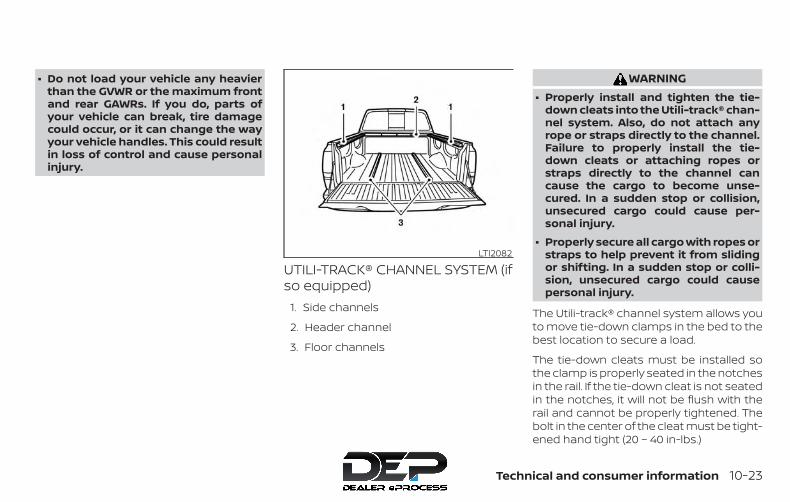
∙ Do not load your vehicle any heavierthan the GVWR or the maximum frontand rear GAWRs. If you do, parts ofyour vehicle can break, tire damagecould occur, or it can change the wayyour vehicle handles. This could resultin loss of control and cause personalinjury.
UTILI-TRACK® CHANNEL SYSTEM (ifso equipped)
1. Side channels
2. Header channel
3. Floor channels
WARNING∙ Properly install and tighten the tie-
down cleats into the Utili-track® chan-nel system. Also, do not attach anyrope or straps directly to the channel.Failure to properly install the tie-down cleats or attaching ropes orstraps directly to the channel cancause the cargo to become unse-cured. In a sudden stop or collision,unsecured cargo could cause per-sonal injury.
∙ Properly secure all cargo with ropes orstraps to help prevent it from slidingor shifting. In a sudden stop or colli-sion, unsecured cargo could causepersonal injury.
The Utili-track® channel system allows youto move tie-down clamps in the bed to thebest location to secure a load.
The tie-down cleats must be installed sothe clamp is properly seated in the notchesin the rail. If the tie-down cleat is not seatedin the notches, it will not be flush with therail and cannot be properly tightened. Thebolt in the center of the cleat must be tight-ened hand tight (20 – 40 in-lbs.)
LTI2082
Technical and consumer information 10-23

Check the tightness of the tie-down cleatperiodically during a trip to make sure thecenter bolt has not become loose.
Install the tie-down cleat as follows:
1. Remove the side channels by slidingthem out the back of the truck bed.Properly store the side channels.
2. Loosen the center bolt completely.
3. Insert the cleat into the channel per-pendicular to the channel as shown.Then rotate the cleat clockwise 90° andslide it to the desired location.
4. Position the cleat so the nubs on thebottom fully seat into the channel de-tents.
LTI0103
LTI0104
10-24 Technical and consumer information

5. There should be no gap between thebottom of the cleat and the top of thechannel. Tighten the center bolt handtight (20-40 in-lbs.).
WTI0124
Technical and consumer information 10-25
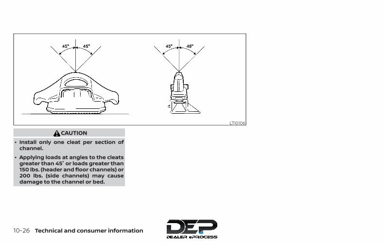
CAUTION∙ Install only one cleat per section of
channel.
∙ Applying loads at angles to the cleatsgreater than 45° or loads greater than150 lbs. (header and floor channels) or200 lbs. (side channels) may causedamage to the channel or bed.
LTI0106
10-26 Technical and consumer information

WARNINGDo not install accessories over the gapbetween the front and rear side chan-nels. Doing this could affect the rearstructure in certain rear impacts, whichcould result in serious injury.
CAUTIONProperly secure all cargo with ropes orstraps to prevent it from sliding or shift-ing. Use the channel end stoppers tohelp secure items in the channels fromsliding off the end of the truck bed.
Channel end stoppers (if soequipped)The channel end stoppers should be usedto help prevent accessories installed in thechannels from sliding or shifting off the endof the truck bed.
1 correct installation, 2 incorrect installationLTI0123 WTI0119
Technical and consumer information 10-27
They must be installed so they are properlyseated in the detents in the channel.
Install the channels end stoppers as fol-lows:
1. Remove the channel protectors by slid-ing them out the back of the truck bed.Properly store the channel protectors.
2. Loosen the bolt on the center of theend stopper with the provided wrenchand insert it into the channel.
3. Position the end stopper to the desiredlocation on the channel so the nubs onthe bottom of the end stopper fullyseat into the channel detents.
4. Tighten the bolt on the center of theend stopper with the provided wrench.
LOADING TIPS∙ The GVW must not exceed GVWR
or GAWR as specified on theF.M.V.S.S./C.M.V.S.S. certificationlabel.
∙ Do not load the front and rearaxle to the GAWR. Doing so willexceed the GVWR.
WARNING∙ Properly secure all cargo with
ropes or straps to help preventit from sliding or shifting. Do notplace cargo higher than theseatbacks. In a sudden stop orcollision, unsecured cargo couldcause personal injury.
∙ Do not load your vehicle anyheavier than the GVWR or themaximum front and rearGAWRs. If you do, parts of yourvehicle can break, tire damagecould occur, or it can change theway your vehicle handles. Thiscould result in loss of controland cause personal injury.
∙ Overloading not only canshorten the life of your vehicleand the tire, but can also causeunsafe vehicle handling andlonger braking distances. Thismay cause a premature tire fail-ure which could result in a seri-ous accident and personal in-jury. Failures caused byoverloading are not covered bythe vehicle’s warranty.
10-28 Technical and consumer information
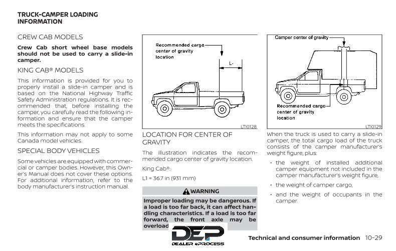
CREW CAB MODELSCrew Cab short wheel base modelsshould not be used to carry a slide-incamper.
KING CAB® MODELSThis information is provided for you toproperly install a slide-in camper and isbased on the National Highway TrafficSafety Administration regulations. It is rec-ommended that, before installing thecamper, you carefully read the following in-formation and ensure that the campermeets the specifications.
This information may not apply to someCanada model vehicles.
SPECIAL BODY VEHICLESSome vehicles are equipped with commer-cial or camper bodies. However, this Own-er’s Manual does not cover these options.For additional information, refer to thebody manufacturer’s instruction manual.
LOCATION FOR CENTER OFGRAVITYThe illustration indicates the recom-mended cargo center of gravity location.
King Cab®:
L1 = 36.7 in (931 mm)
WARNINGImproper loading may be dangerous. Ifa load is too far back, it can affect han-dling characteristics. If a load is too farforward, the front axle may beoverloaded.
When the truck is used to carry a slide-incamper, the total cargo load of the truckconsists of the camper manufacturer’sweight figure, plus:
∙ the weight of installed additionalcamper equipment not included in thecamper manufacturer’s weight figure,
∙ the weight of camper cargo,
∙ and the weight of occupants in thecamper.
LTI0128 LTI0129
TRUCK-CAMPER LOADINGINFORMATION
Technical and consumer information 10-29

The total cargo load should not exceed thetruck’s pay load weight rating and thecamper’s center of gravity should fall withinthe truck’s recommended center of gravitylocation when installed.
WARNINGOverloading or improper loading canadversely affect vehicle handling, brak-ing and performance and may lead toaccidents.
VEHICLE LOAD WEIGHT CAPACITYThe vehicle payload weight capacityshown on the Tire and Loading Informationlabel, refer to “Tire and Loading Informationlabel” in this section, indicates the maxi-mum total weight of passengers, optionalequipment (air conditioning, trailer hitch,etc.) and cargo that your vehicle is de-signed to carry.
Before driving a loaded vehicle, confirmthat you do not exceed the GVWR or theGAWR for your vehicle. For additional infor-mation, refer to ’’Vehicle loading informa-tion’’ in this section.
Also check tires for proper inflation pres-sures. For additional information, refer tothe Tire and Loading Information label.
MEASUREMENT OF WEIGHTSSecure loose items to preventweight shifts that could affect thebalance of your vehicle. When the ve-hicle is loaded, drive to a scale andweigh the front and the rear wheelsseparately to determine axle loads.Individual axle loads should not ex-ceed either of the GAWR. The total ofthe axle loads should not exceed theGVWR. These ratings are given onthe vehicle certification label. Ifweight ratings are exceeded, moveor remove items to bring all weightsbelow the ratings.
WARNING∙ Overloading or improper loading of a
trailer and its cargo can adversely af-fect vehicle handling, braking andperformance and may lead toaccidents.
∙ Do not tow a trailer when the TEMPO-RARY FULL SIZE spare tire is installed.
CAUTION∙ Do not tow a trailer or haul a heavy
load for the first 500 mile (805 km).Your engine, axle or other parts couldbe damaged.
∙ For the first 500 miles (805 km) thatyou tow a trailer, do not drive over50 mph (80 km/h) and do not makestarts at full throttle. This helps theengine and other parts of your vehiclewear in at the heavier loads.
Your new vehicle was designed to be usedprimarily to carry passengers and cargo.Remember that towing a trailer places ad-ditional loads on your vehicle’s engine,drive train, steering, braking and other sys-tems.
TOWING A TRAILER
10-30 Technical and consumer information

A NISSAN Towing Guide (U.S. only) is avail-able on the website atwww.nissanusa.com. This guide includesinformation on trailer towing capability andthe special equipment required for propertowing.
MAXIMUM LOAD LIMITSMaximum trailer loadsNever allow the total trailer load to exceedthe value specified in the “TowingLoad/Specification” chart found in this sec-tion. The total trailer load equals trailerweight plus its cargo weight.
∙ When towing a trailer load of3,500 lbs. (1,587 kg) or more, trailerswith a brake system MUST be used.
The maximum Gross Combined WeightRating (GCWR) should not exceed the valuespecified in the following “TowingLoad/Specification” chart.
The GCWR equals the combined weight ofthe towing vehicle (including passengersand cargo) plus the total trailer load. Tow-ing loads greater than these or using im-proper towing equipment could adverselyaffect vehicle handling, braking and perfor-mance.
The ability of your vehicle to tow a trailer isnot only related to the maximum trailerloads, but also the places you plan to tow.Tow weights appropriate for level highwaydriving may have to be reduced for lowtraction situations (for example, on slipperyboat ramps).
Temperature conditions can also affecttowing. For example, towing a heavy trailerin high outside temperatures on gradedroads can affect engine performance andcause overheating. The engine protectionmode, which helps reduce the chance ofengine damage, could activate and auto-matically decrease engine power. Vehiclespeed may decrease under high load. Planyour trip carefully to account for trailer andvehicle load, weather and road conditions.
WARNINGOverheating can result in reduced en-gine power and vehicle speed. The re-duced speed may be lower than othertraffic, which could increase the chanceof a collision. Be especially careful whendriving. If the vehicle cannot maintain asafe driving speed, pull to the side of theroad in a safe area. Allow the engine tocool and return to normal operation. Foradditional information, refer to “If yourvehicle overheats” in the “In case ofemergency” section of this manual.
LTI0161
Technical and consumer information 10-31
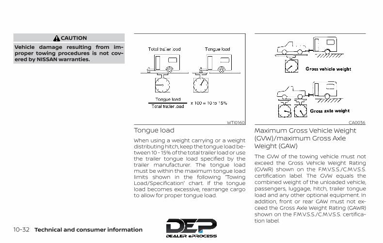
CAUTIONVehicle damage resulting from im-proper towing procedures is not cov-ered by NISSAN warranties.
Tongue loadWhen using a weight carrying or a weightdistributing hitch, keep the tongue load be-tween 10 - 15% of the total trailer load or usethe trailer tongue load specified by thetrailer manufacturer. The tongue loadmust be within the maximum tongue loadlimits shown in the following “TowingLoad/Specification” chart. If the tongueload becomes excessive, rearrange cargoto allow for proper tongue load.
Maximum Gross Vehicle Weight(GVW)/maximum Gross AxleWeight (GAW)The GVW of the towing vehicle must notexceed the Gross Vehicle Weight Rating(GVWR) shown on the F.M.V.S.S./C.M.V.S.S.certification label. The GVW equals thecombined weight of the unloaded vehicle,passengers, luggage, hitch, trailer tongueload and any other optional equipment. Inaddition, front or rear GAW must not ex-ceed the Gross Axle Weight Rating (GAWR)shown on the F.M.V.S.S./C.M.V.S.S. certifica-tion label.
WTI0160 CA0036
10-32 Technical and consumer information
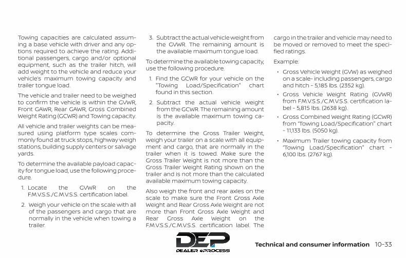
Towing capacities are calculated assum-ing a base vehicle with driver and any op-tions required to achieve the rating. Addi-tional passengers, cargo and/or optionalequipment, such as the trailer hitch, willadd weight to the vehicle and reduce yourvehicle’s maximum towing capacity andtrailer tongue load.
The vehicle and trailer need to be weighedto confirm the vehicle is within the GVWR,Front GAWR, Rear GAWR, Gross CombinedWeight Rating (GCWR) and Towing capacity.
All vehicle and trailer weights can be mea-sured using platform type scales com-monly found at truck stops, highway weighstations, building supply centers or salvageyards.
To determine the available payload capac-ity for tongue load, use the following proce-dure.
1. Locate the GVWR on theF.M.V.S.S./C.M.V.S.S. certification label.
2. Weigh your vehicle on the scale with allof the passengers and cargo that arenormally in the vehicle when towing atrailer.
3. Subtract the actual vehicle weight fromthe GVWR. The remaining amount isthe available maximum tongue load.
To determine the available towing capacity,use the following procedure.
1. Find the GCWR for your vehicle on the"Towing Load/Specification" chartfound in this section.
2. Subtract the actual vehicle weightfrom the GCWR. The remaining amountis the available maximum towing ca-pacity.
To determine the Gross Trailer Weight,weigh your trailer on a scale with all equip-ment and cargo, that are normally in thetrailer when it is towed. Make sure theGross Trailer Weight is not more than theGross Trailer Weight Rating shown on thetrailer and is not more than the calculatedavailable maximum towing capacity.
Also weigh the front and rear axles on thescale to make sure the Front Gross AxleWeight and Rear Gross Axle Weight are notmore than Front Gross Axle Weight andRear Gross Axle Weight on theF.M.V.S.S./C.M.V.S.S. certification label. The
cargo in the trailer and vehicle may need tobe moved or removed to meet the speci-fied ratings.
Example:
∙ Gross Vehicle Weight (GVW) as weighedon a scale- including passengers, cargoand hitch - 5,185 lbs. (2352 kg).
∙ Gross Vehicle Weight Rating (GVWR)from F.M.V.S.S./C.M.V.S.S. certification la-bel - 5,815 lbs. (2638 kg).
∙ Gross Combined Weight Rating (GCWR)from “Towing Load/Specification" chart- 11,133 lbs. (5050 kg).
∙ Maximum Trailer towing capacity from“Towing Load/Specification" chart -6,100 lbs. (2767 kg).
Technical and consumer information 10-33
5,815 lbs. (2638 kg) GVWR– 5,185 lbs. (2352 kg) GVW
= 630 lbs. (286 kg) Available for tongueweight
11,133 lbs. (5050 kg) GCWR– 5,185 lbs. (2352 kg) GVW
= 5,948 lbs. (2698 kg) Capacity available fortowing
630 lbs. (286 kg) Available tongueweight
/ 5,948 lbs. (2698 kg) Available capacity
= 10 % tongue weight
The available towing capacity may be lessthan the maximum towing capacity due tothe passenger and cargo load in the ve-hicle.
Remember to keep trailer tongue weightbetween 10 - 15 percent of the trailer weightor within the trailer tongue load specifica-tion recommended by the trailer manufac-turer. If the tongue load becomes exces-sive, rearrange the cargo to obtain theproper tongue load. Do not exceed themaximum tongue weight specification
shown in the “Towing Load/Specification”chart even if the calculated availabletongue weight is greater than 15 percent. Ifthe calculated tongue weight is less than10 percent, reduce the total trailer weight tomatch the available tongue weight.
Always verify that available capacities arewithin the required ratings.
Trailer frontal area
CAUTIONExceeding the maximum trailer frontalarea specification may exceed the tow-ing capacity of the vehicle. This may af-fect the towing performance and leadto vehicle damage.
The trailer frontal area affects the towingload of a trailer. The frontal area is the totalarea of the vehicle and trailer that is af-fected by air resistance while towing. Donot exceed the maximum trailer frontalarea specification shown in the "TowingLoad/Specification” chart. The frontal areacan be determined by multiplying thewidth of the trailer by the height of thetrailer. For example, a trailer that is 8 feetwide by 6 feet tall has a trailer frontal area of48 square feet.
TOWING LOAD/SPECIFICATION
WARNINGThe towing capacities provided in thismanual are for general reference only.The safe towing capacity of your vehicleis affected by dealer and factory in-stalled options and passenger andcargo loads. You must weigh the vehicleand trailer as described in this manualto determine the actual vehicle towingcapacity. Do not exceed the publishedmaximum towing capacity or the GCWRor the GVWR shown on theFMVSS/CMVSS label. Doing so can re-sult in an accident causing serious per-sonal injury or property damage.
10-34 Technical and consumer information
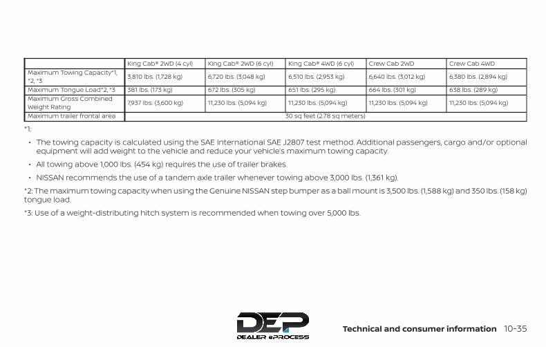
King Cab® 2WD (4 cyl) King Cab® 2WD (6 cyl) King Cab® 4WD (6 cyl) Crew Cab 2WD Crew Cab 4WDMaximum Towing Capacity*1,*2, *3 3,810 lbs. (1,728 kg) 6,720 lbs. (3,048 kg) 6,510 lbs. (2,953 kg) 6,640 lbs. (3,012 kg) 6,380 lbs. (2,894 kg)
Maximum Tongue Load*2, *3 381 lbs. (173 kg) 672 lbs. (305 kg) 651 lbs. (295 kg) 664 lbs. (301 kg) 638 lbs. (289 kg)Maximum Gross CombinedWeight Rating 7,937 lbs. (3,600 kg) 11,230 lbs. (5,094 kg) 11,230 lbs. (5,094 kg) 11,230 lbs. (5,094 kg) 11,230 lbs. (5,094 kg)
Maximum trailer frontal area 30 sq feet (2.78 sq meters)
*1:
∙ The towing capacity is calculated using the SAE International SAE J2807 test method. Additional passengers, cargo and/or optionalequipment will add weight to the vehicle and reduce your vehicle’s maximum towing capacity.
∙ All towing above 1,000 lbs. (454 kg) requires the use of trailer brakes.
∙ NISSAN recommends the use of a tandem axle trailer whenever towing above 3,000 lbs. (1,361 kg).
*2: The maximum towing capacity when using the Genuine NISSAN step bumper as a ball mount is 3,500 lbs. (1,588 kg) and 350 lbs. (158 kg)tongue load.
*3: Use of a weight-distributing hitch system is recommended when towing over 5,000 lbs.
Technical and consumer information 10-35

TOWING SAFETYTrailer hitchYour vehicle may be equipped with an op-tional trailer tow package. The trailer towpackage includes a receiver-type framemounted hitch. This hitch is rated for themaximum towing capacity of this vehiclewhen the proper towing equipment isused. Choose a proper ball mount andhitch ball that is rated for the trailer to betowed. Genuine NISSAN ball mounts andhitch balls are available from a NISSANdealer.
If your vehicle is not equipped with the op-tional trailer tow package, check the tow-ing capacity of your bumper hitch orreceiver-type frame mounted hitch.Choose a proper hitch for your vehicle andtrailer. A Genuine NISSAN trailer hitch isavailable from a NISSAN dealer. Make surethe trailer hitch is securely attached to thevehicle to help avoid personal injury orproperty damage due to sway caused bycrosswinds, rough road surfaces or pass-ing trucks.
WARNINGTrailer hitch components have specificweight ratings. Your vehicle may be ca-pable of towing a trailer heavier thanthe weight rating of the hitch compo-nents. Never exceed the weight ratingof the hitch components. Doing so cancause serious personal injury or prop-erty damage.
Hitch ballChoose a hitch ball of the proper size andweight rating for your trailer:
∙ The required hitch ball size is stampedon most trailer couplers. Most hitchballs also have the size printed on thetop of the ball.
∙ Choose the proper class hitch ballbased on the trailer weight.
∙ The diameter of the threaded shank ofthe hitch ball must be matched to theball mount hole diameter. The hitch ballshank should be no more than 1/16”smaller than the hole in the ball mount.
∙ The threaded shank of the hitch ballmust be long enough to be properlysecured to the ball mount. There shouldbe at least 2 threads showing beyondthe lock washer and nut.
Ball mountThe hitch ball is attached to the ball mountand the ball mount is inserted into thehitch receiver. Choose a proper class ballmount based on the trailer weight. Addi-tionally, the ball mount should be chosen tokeep the trailer tongue level with theground.
10-36 Technical and consumer information

Bumper towingThe Genuine NISSAN step bumper has pro-visions to install a trailer hitch ball and isdesigned to tow trailers of a maximumweight of 3,500 lbs. (1,588 kg).
To install a trailer hitch ball cut out the circlein the center of the step bumper �A , thenremove it to install the trailer hitch ball.
Weight carrying hitchesA weight carrying or “dead weight” ballmount is one that is designed to carry thewhole amount of tongue weight and grossweight directly on the ball mount and onthe receiver.
Weight distribution hitchThis type of hitch is also called a “load-leveling” or “equalizing” hitch. A set of barsattach to the ball mount and to the trailerto distribute the tongue weight (hitchweight) of your trailer. Many vehicles can’tcarry the full tongue weight of a giventrailer, and need some of the tongueweight transferred through the frame andpushing down on the front wheels. Thisgives stability to the tow vehicle.
A weight-distributing hitch system (ClassIV) is recommended if you plan to tow trail-ers with a maximum weight over 5,000 lbs.(2,268 kg). Check with the trailer and towingequipment manufacturers to determine ifthey recommend the use of a weight-distributing hitch system.
NOTE:
A weight-distributing hitch system mayaffect the operation of trailer surgebrakes. If you are considering use of aweight-distributing hitch system with asurge brake-equipped trailer, check withthe surge brake, hitch or trailer manufac-turer to determine if and how this can bedone.
Follow the instructions provided by themanufacturer for installing and using theweight-distributing hitch system.
General set-up instructions are as follows:
1. Park unloaded vehicle on a level sur-face. With the ignition on and the doorsclosed, allow the vehicle to stand forseveral minutes so that it can level.
2. Measure the height of a reference pointon the front and rear bumpers at thecenter of the vehicle.
3. Attach the trailer to the vehicle and ad-just the hitch equalizers so that thefront bumper height is within 0 -.5 inches (0 – 13 mm) of the referenceheight measured in step 2. The rearbumper should be no higher than thereference height measured in step 2.
LTI0132
Technical and consumer information 10-37
WARNINGProperly adjust the weight distributinghitch so the rear of the bumper is nohigher than the measured referenceheight when the trailer is attached. Ifthe rear bumper is higher than the mea-sured reference height when loaded,the vehicle may handle unpredictablywhich could cause a loss of vehicle con-trol and cause serious personal injury orproperty damage.
Sway control deviceSudden maneuvers, wind gusts, and buf-feting caused by other vehicles can affecttrailer handling. Sway control devices maybe used to help control these affects. If youchoose to use one, contact a reputabletrailer hitch supplier to make sure the swaycontrol device will work with the vehicle,hitch, trailer and the trailer’s brake system.Follow the instructions provided by themanufacturer for installing and using thesway control device.
Class I hitchClass I trailer hitch equipment (receiver, ballmount and hitch ball) can be used to towtrailers of a maximum weight of 2,000 lbs.(907 kg).
Class II hitchClass II trailer hitch equipment (receiver,ball mount and hitch ball) can be used totow trailers of a maximum weight of3,500 lbs. (1,587 kg).
The Genuine NISSAN step bumper is con-sidered a Class II ball mount.
Class III hitchClass III trailer hitch equipment (receiver,ball mount and hitch ball) can be used totow trailers of a maximum weight of5,000 lbs. (2,268 kg).
Class IV hitchClass IV trailer hitch equipment (receiver,ball mount and hitch ball) can be used totow trailers of a maximum weight of10,000 lbs. (4,535 kg). A weight distributinghitch should be used to tow trailers thatweigh over 5,000 lbs. (2,268 kg).
Your vehicle may be equipped with Class IVtrailer hitch equipment that has a10,000 lbs. (4,535 kg) maximum weight rat-ing, but your vehicle is only capable of tow-ing the maximum trailer weights shown inthe “Towing Load/Specification” chart inthis section.
CAUTION∙ Special hitches which include frame
reinforcements are required for tow-ing above 2,000 lbs. (907 kg). SuitableGenuine NISSAN hitches, ball mountsand hitch balls for pickup trucks andsport utility vehicles are available at aNISSAN dealer.
∙ The hitch should not be attached to oraffect the operation of the impact-absorbing bumper.
WARNING∙ Do not use axle-mounted hitches.
∙ Do not modify the vehicle exhaustsystem, brake system, etc. to install atrailer hitch.
∙ To reduce the possibility of additionaldamage if your vehicle is struck fromthe rear, where practical, remove thereceiver when not in use.
∙ Regularly check that all trailer hitchmounting bolts are securelymounted.
10-38 Technical and consumer information
Tire pressures∙ When towing a trailer, inflate the
vehicle tires to the recom-mended cold tire pressure indi-cated on the Tire and Loading In-formation label.
∙ Trailer tire condition, size, load rat-ing and proper inflation pressureshould be in accordance with thetrailer and tire manufacturer’sspecifications.
Safety chainsAlways use suitable safety chains betweenyour vehicle and the trailer. The safetychains should be crossed and should beattached to the hitch, not to the vehiclebumper or axle. The safety chains can beattached to the bumper if the hitch ball ismounted to the bumper. Be sure to leaveenough slack in the chains to permit turn-ing corners.
Trailer lights
CAUTIONWhen splicing into the vehicle electricalsystem, a commercially availablepower-type module/converter must beused to provide power for all trailerlighting. This unit uses the vehicle bat-tery as a direct power source for alltrailer lights while using the vehicle taillight, stop light and turn signal circuitsas a signal source. Themodule/converter must draw no morethan 15 milliamps from the stop and taillamp circuits. Using amodule/converter that exceeds thesepower requirements may damage thevehicle’s electrical system. See a repu-table trailer dealer to obtain the properequipment and to have it installed.
Trailer lights should comply with federaland/or local regulations. For assistance inhooking up trailer lights, it is recommendedthat you visit a NISSAN dealer or reputabletrailer dealer. Vehicles equipped with theoptional trailer tow package are equippedwith a 7-pin trailer harness connector. A flat4–pin harness is available from your dealerfor vehicles without a tow package. If yourtrailer is equipped with a flat 4-pin connec-
tor, an adapter will be needed to connectthe trailer lights to the vehicle. Adapters areavailable at auto parts stores and hitch re-tailers.
Trailer brakesIf your trailer is equipped with a brakingsystem, make sure it conforms to federaland/or local regulations and that it is prop-erly installed.
Vehicles equipped with a 7–pin trailer har-ness connector are pre-wired for a trailerbrake controller. It is recommended thatyou visit a NISSAN dealer for a trailer brakeadapter harness.
WARNINGNever connect a trailer brake system di-rectly to the vehicle brake system.
When towing a trailer load of 3,500 lbs.(1587 kg) or more, trailers with a brakesystem MUST be used. However, moststates require a separate braking systemon trailers with a loaded weight above aspecific amount. Make sure the trailermeets the local regulations and the regu-lations where you plan to tow.
Several types of braking systems are avail-able.
Technical and consumer information 10-39
Surge Brakes -The surge brake actuator ismounted on the trailer tongue with a hy-draulic line running to each trailer wheel.Surge brakes are activated by the trailerpushing against the hitch ball when thetow vehicle is braking. Hydraulic surgebrakes are common on rental trailers andsome boat trailers. In this type of system,there is no hydraulic or electric connectionfor brake operation between the tow ve-hicle and the trailer.
Electric Trailer Brakes -Electric brakingsystems are activated by an electronic sig-nal sent from a trailer brake controller (spe-cial brake-sensing module). If electric trailerbrakes are used, refer to “Electric trailerbrake controller" in this section.
Have a professional supplier of towingequipment make sure the trailer brakes areproperly installed and demonstrate properbrake function testing.
Electric trailer brake controllerTrailers equipped with electric brakes mayrequire the installation of an aftermarkettrailer brake controller.
A Genuine NISSAN jumper harness is avail-able that is specifically designed to be usedwhen installing an aftermarket brake con-troller.
Install the aftermarket electric trailer brakecontroller according to the manufacturer’sinstructions.
Pre-towing tips∙ Be certain your vehicle maintains a level
position when a loaded and/or un-loaded trailer is hitched. Do not drive thevehicle if it has an abnormal nose-up ornose-down condition; check for im-proper tongue load, overload, worn sus-pension or other possible causes of ei-ther condition.
∙ Always secure items in the trailer to pre-vent load shift while driving.
∙ Keep the cargo load as low as possiblein the trailer to keep the trailer center ofgravity low.
∙ Load the trailer so approximately 60%of the trailer load is in the front half and40% is in the back half. Also make surethe load is balanced side to side.
∙ Check your hitch, trailer tire pressure,vehicle tire pressure, trailer light opera-tion, and trailer wheel lug nuts everytime you attach a trailer to the vehicle.
∙ Be certain your rearview mirrors con-form to all federal, state or local regula-tions. If not, install any mirrors requiredfor towing before driving the vehicle.
∙ Determine the overall height of the ve-hicle and trailer so the required clear-ance is known.
Trailer towing tipsIn order to gain skill and an understandingof the vehicle’s behavior, you should prac-tice turning, stopping and backing up in anarea which is free from traffic. Steering sta-bility and braking performance will besomewhat different than under normaldriving conditions.
∙ Always secure items in the trailer to pre-vent load shift while driving.
∙ Lock the trailer hitch coupler with a pinor lock to prevent the coupler from in-advertently becoming unlatched.
∙ Avoid abrupt starts, acceleration orstops.
∙ Avoid sharp turns or lane changes.10-40 Technical and consumer information
∙ Always drive your vehicle at a moderatespeed.
∙ When backing up, hold the bottom ofthe steering wheel with one hand. Moveyour hand in the direction in which youwant the trailer to go. Make small cor-rections and back up slowly. If possible,have someone guide you when you arebacking up.
Always block the wheels on both vehicleand trailer when parking. Parking on aslope is not recommended; however, if youmust do so:
CAUTIONIf you move the shift lever to the P (Park)position before blocking the wheelsand applying the parking brake, trans-mission damage could occur.
1. Apply and hold the brake pedal.
2. Have someone place blocks on thedownhill side of the vehicle and trailerwheels.
3. After the wheel blocks are in place,slowly release the brake pedal until theblocks absorb the vehicle load.
4. Apply the parking brake.
5. Shift the transmission into P (Park).
6. Make sure the indicator light (if soequipped) indicates the transfer case isin 4H, 4L, or 2H and that the ATP light isoff. If the indicator light is flashing,or the ATP light is ON, make sure thetransmission is in P (Park) (A/T) andturn the 4WD switch to 2WD or 4H. Foradditional information, refer to “Auto-matic transmission park warning light”in the “Instruments and controls” sec-tion and “Using 4-wheel drive (4WD)” inthe “Starting and driving” section of thismanual.
7. Turn off the engine.To drive away:
1. Start the vehicle.
2. Apply and hold the brake pedal.
3. Shift the transmission into gear.
4. Release the parking brake.
5. Drive slowly until the vehicle and trailerare clear from the blocks.
6. Apply and hold the brake pedal.
7. Have someone retrieve and store theblocks.
∙ While going downhill, the weight of thetrailer pushing on the tow vehicle maydecrease overall stability. Therefore, tomaintain adequate control, reduce yourspeed and shift to a lower gear. Avoidlong or repeated use of the brakeswhen descending a hill, as this reducestheir effectiveness and could causeoverheating. Shifting to a lower gear in-stead provides “engine braking” and re-duces the need to brake as frequently.
∙ If the engine coolant temperature risesto a high temperature, refer to “If yourvehicle overheats” in the “In case ofemergency” section of this manual.
∙ Trailer towing requires more fuel thannormal circumstances.
∙ Avoid towing a trailer for your vehicle’sfirst 500 miles (805 km).
∙ For the first 500 miles (805 km) that youdo tow, do not drive over 50 mph(80 km/h).
∙ Have your vehicle serviced more oftenthan at intervals specified. For addi-tional information, refer to “Mainte-nance Schedules” in the “Maintenanceand schedules” section of this manual.
Technical and consumer information 10-41
∙ When making a turn, your trailer wheelswill be closer to the inside of the turnthan your vehicle wheels. To compen-sate for this, make a larger than normalturning radius during the turn.
∙ Crosswinds and rough roads will ad-versely affect vehicle/trailer handling,possibly causing vehicle sway. Whenbeing passed by larger vehicles, be pre-pared for possible changes in cross-winds that could affect vehicle han-dling.
Do the following if the trailer begins tosway:
1. Take your foot off the accelerator pedalto allow the vehicle to coast and steeras straight ahead as the road condi-tions allow. This combination will helpstabilize the vehicle
– Do not correct trailer sway by steer-ing or applying the brakes.
2. When the trailer sway stops, gently ap-ply the brakes and pull to the side of theroad in a safe area.
3. Try to rearrange the trailer load so it isbalanced as described in this section.
∙ Be careful when passing other vehicles.Passing while towing a trailer requiresconsiderably more distance than nor-mal passing. Remember, the length ofthe trailer must also pass the other ve-hicle before you can safely changelanes.
∙ Downshift the transmission to a lowergear for engine braking when drivingdown steep or long hills. This will helpslow the vehicle without applying thebrakes.
∙ Avoid holding the brake pedal down toolong or too frequently. This could causethe brakes to overheat, resulting in re-duced braking efficiency.
∙ Increase your following distance to al-low for greater stopping distanceswhile towing a trailer. Anticipate stopsand brake gradually.
∙ NISSAN recommends that the cruisecontrol not be used while towing atrailer.
∙ Some states or provinces have specificregulations and speed limits for ve-hicles that are towing trailers. Obey thelocal speed limits.
∙ Check your hitch, trailer wiring harnessconnections, and trailer wheel lug nutsafter 50 miles (80 km) of travel and atevery break.
∙ When launching a boat, don’t allow thewater level to go over the exhaust tailpipe or rear bumper.
∙ Make sure you disconnect the trailerlights before backing the trailer into thewater or the trailer lights may burn out.
When towing a trailer, final drive gear oilshould be replaced and transmissionoil/fluid should be changed more fre-quently. For additional information, referto the “Do-it-yourself” section in thismanual.
FLAT TOWING – 4WD WITHAUTOMATIC TRANSMISSIONTowing a vehicle behind a recreational ve-hicle, such as a motor home, is sometimescalled flat towing.
10-42 Technical and consumer information
CAUTION∙ DO NOT flat tow a 4WD vehicle
equipped with an automatic trans-mission. Flat towing or using a vehicledolly WILL DAMAGE internal transmis-sion parts due to lack of lubrication.
∙ For emergency towing procedures re-fer to “Towing recommended byNISSAN” in the “In case of emergency”section of this manual.
FLAT TOWING – 2WD WITHAUTOMATIC TRANSMISSIONTowing a vehicle behind a recreational ve-hicle, such as a motor home, is sometimescalled flat towing.
CAUTION∙ Failure to follow these guidelines can
result in severe transmission damage.
∙ Whenever flat towing your vehicle, al-ways tow forward, never backward.
∙ DO NOT tow any automatic transmis-sion vehicle with all four wheels on theground. Doing so WILL DAMAGE inter-nal transmission parts due to lack oftransmission lubrication.
∙ For emergency towing procedures re-fer to “Towing recommended byNISSAN” in the “In case of emergency”section of this manual.
To tow a vehicle equipped with an auto-matic transmission, an appropriate vehicledolly MUST be placed under the towed ve-hicle’s drive wheels. Always follow the dollymanufacturer’s recommendations whenusing their product.
FLAT TOWING – 2WD/4WD WITHMANUAL TRANSMISSIONTowing a vehicle behind a recreational ve-hicle, such as a motor home, is sometimescalled flat towing.
CAUTION∙ Failure to follow these guidelines can
result in severe transmission damage.
∙ Whenever flat towing your vehicle, al-ways tow forward, never backward.
∙ For emergency towing procedures re-fer to “Towing recommended byNISSAN” in the “In case of emergency”section of this manual.
∙ Always tow with the manual transmis-sion in Neutral.
∙ For 4WD vehicles, always flat tow withthe transfer case in the 2 HI position.
∙ Your vehicle should never exceed60 mph (97 km/h) when flat towing yourvehicle.
∙ After towing 500 miles (805 km), startand idle the engine with the transmis-sion in Neutral for two minutes. Failureto idle the engine after every 500 miles(805 km) of towing may cause damageto the transmission’s internal parts.
Technical and consumer information 10-43

DOT (Department of Transportation) Qual-ity Grades: All passenger car tires mustconform to federal safety requirements inaddition to these grades.
Quality grades can be found where appli-cable on the tire sidewall between treadshoulder and maximum section width. Forexample:
Treadwear 200 Traction AA TemperatureA
Treadwear
The treadwear grade is a comparative rat-ing based on the wear rate of the tire whentested under controlled conditions on aspecified government test course. For ex-ample, a tire graded 150 would wear oneand one-half (1 1/2) times as well on thegovernment course as a tire graded 100.The relative performance of tires dependsupon the actual conditions of their use,however, and may depart significantly fromthe norm due to variations in driving habits,service practices and differences in roadcharacteristics and climate.
Traction AA, A, B and C
The traction grades, from highest to low-est, are AA, A, B, and C. Those grades repre-sent the tire’s ability to stop on wet pave-
ment as measured under controlledconditions on specified government testsurfaces of asphalt and concrete. A tiremarked C may have poor traction perfor-mance.
WARNINGThe traction grade assigned to this tireis based on straight-ahead brakingtraction tests, and does not include ac-celeration, cornering, hydroplaning, orpeak traction characteristics.
Temperature A, B and C
The temperature grades are A (the high-est), B, and C, representing the tire’s resis-tance to the generation of heat, and itsability to dissipate heat when tested undercontrolled conditions on a specified indoorlaboratory test wheel. Sustained high tem-perature can cause the material of the tireto degenerate and reduce tire life, and ex-cessive temperature can lead to suddentire failure. The grade C corresponds to alevel of performance which all passengercar tires must meet under the Federal Mo-tor Safety Standard No. 109. Grades B and Arepresent higher levels of performance onthe laboratory test wheel than the mini-mum required by law.
WARNINGThe temperature grade for this tire isestablished for a tire that is properly in-flated and not overloaded. Excessivespeed, under-inflation, or excessiveloading, either separately or in combi-nation, can cause heat build-up andpossible tire failure.
UNIFORM TIRE QUALITY GRADING
10-44 Technical and consumer information

Your NISSAN vehicle is covered by the fol-lowing emission warranties:
For USA
1. Emission Defects Warranty
2. Emissions Performance Warranty
Details of this warranty may be found withother vehicle warranties in your Warranty In-formation Booklet which comes with yourNISSAN vehicle. If you did not receive a War-ranty Information Booklet, or it is lost, youmay obtain a replacement by writing to:
∙ Nissan North America, Inc.Consumer Affairs DepartmentP.O. Box 685003Franklin, TN 37068-5003
For Canada
Emission Control System Warranty
Details of this warranty may be found withother vehicle warranties in your Warranty In-formation Booklet which comes with yourNISSAN vehicle. If you did not receive a War-ranty Information Booklet, or it is lost, youmay obtain a replacement by writing to:
∙ Nissan Canada Inc.5290 Orbitor DriveMississauga, Ontario, L4W 4Z5
For USA
If you believe that your vehicle has adefect which could cause a crash orcould cause injury or death, youshould immediately inform the Na-tional Highway Traffic Safety Admin-istration (NHTSA) in addition to noti-fying NISSAN.
If NHTSA receives similar complaints,it may open an investigation, and if itfinds that a safety defect exists in agroup of vehicles, it may order a re-call and remedy campaign. However,NHTSA cannot become involved inindividual problems between you,your dealer, or NISSAN.To contact NHTSA, you may call theVehicle Safety Hotline toll-free at1-888-327-4236 (TTY: 1-800-424-9153);go to http://www.safercar.gov; orwrite to: Administrator, NHTSA, 400Seventh Street, SW., Washington, D.C.20590. You can also obtain other in-formation about motor vehicle safetyfrom http://www.safercar.gov.
You may notify NISSAN by contact-ing our Consumer Affairs Depart-ment, toll-free, at 1-800-NISSAN-1.
For Canada
If you believe that your vehicle has adefect which could cause a crash orcould cause injury or death, youshould immediately inform Trans-port Canada in addition to notifyingNISSAN.If Transport Canada receives com-plaints, it may open an investigation,and if it finds that a safety defectexists in a group of vehicles, it mayrequest that NISSAN conduct a recallcampaign. However, TransportCanada cannot become involved inindividual problems between you,your dealer, or NISSAN.You may contact Transport Canada’sDefect Investigations and Recalls Divi-sion toll free at 1-800-333-0510. Youmay also report safety defects onlineat: https://wwwapps.tc.gc.ca/Saf-Sec-Sur/7/PCDB-BDPP/fc-
EMISSION CONTROL SYSTEMWARRANTY
REPORTING SAFETY DEFECTS
Technical and consumer information 10-45

cp.aspx?lang=eng (English speakers)or https://wwwapps.tc.gc.ca/Saf-Sec-Sur/7/PCDB-BDPP/fc-cp.aspx?lang=fra (French speakers)Additional information concerningmotor vehicle safety may be ob-tained from Transport Canada’sRoad Safety Information Centre at1-800-333-0371 or online atwww.tc.gc.ca/roadsafety (Englishspeakers) orwww.tc.gc.ca/securiteroutiere(French speakers).To notify NISSAN of any safety con-cerns please contact our ConsumerInformation Centre toll free at 1-800-387-0122.
WARNINGA vehicle equipped with Four-WheelDrive (4WD) should never be tested us-ing a two wheel dynamometer (such asthe dynamometers used by somestates for emissions testing), or similarequipment. Make sure you inform thetest facility personnel that your vehicleis equipped with 4WD before it is placedon a dynamometer. Using the wrongtest equipment may result in transmis-sion damage or unexpected vehiclemovement which could result in seriousvehicle damage or personal injury.
Due to legal requirements in some statesand Canadian Provinces, your vehicle maybe required to be in what is called the“ready condition” for anInspection/Maintenance (I/M) test of theemission control system.
The vehicle is set to the “ready condition”when it is driven through certain drivingpatterns. Usually, the ready condition canbe obtained by ordinary usage of the ve-hicle.
If a powertrain system component is re-paired or the battery is disconnected, thevehicle may be reset to a “not ready” condi-tion. Before taking the I/M test, check thevehicle’s inspection/maintenance testreadiness condition. Place the ignitionswitch in the ON position without startingthe engine. If the Malfunction IndicatorLight (MIL) comes on steady for 20 secondsand then blinks for 10 seconds, the I/M testcondition is “not ready”. If the MIL does notblink after 20 seconds, the I/M test condi-tion is “ready”. It is recommended that youvisit a NISSAN dealer to set the “ready con-dition” or to prepare the vehicle for testing.
READINESS FOR INSPECTION/MAINTENANCE (I/M) TEST
10-46 Technical and consumer information
This vehicle is equipped with an Event DataRecorder (EDR). The main purpose of anEDR is to record, in certain crash or nearcrash-like situations, such as an air bagdeployment or hitting a road obstacle, datathat will assist in understanding how a ve-hicle’s systems performed. The EDR is de-signed to record data related to vehicle dy-namics and safety systems for a shortperiod of time, typically 30 seconds or less.The EDR in this vehicle is designed to re-cord such data as:
∙ How various systems in your vehiclewere operating;
∙ Whether or not the driver and passen-ger safety belts were buckled/fastened;
∙ How far (if at all) the driver was depress-ing the accelerator and/or brake pedal;and,
∙ How fast the vehicle was traveling.
∙ Sounds are not recorded.
These data can help provide a better un-derstanding of the circumstances in whichcrashes and injuries occur. NOTE: EDR dataare recorded by your vehicle only if a non-trivial crash situation occurs; no data arerecorded by the EDR under normal drivingconditions and no personal data (e.g.name, gender, age and crash location) arerecorded. However, other parties, such aslaw enforcement, could combine the EDRdata with the type of personally identifyingdata routinely acquired during a crash in-vestigation.
To read data recorded by an EDR, specialequipment is required and access to thevehicle or the EDR is needed. In addition tothe vehicle manufacturer and NISSANdealer, other parties, such as law enforce-ment, that have the special equipment, canread the information if they have access tothe vehicle or the EDR. EDR data will only beaccessed with the consent of the vehicleowner or lessee or as otherwise required orpermitted by law.
Genuine NISSAN Service Manuals for thismodel year and prior can be purchased. AGenuine NISSAN Service Manual is the bestsource of service and repair information foryour vehicle. This manual is the same oneused by the factory-trained techniciansworking at NISSAN dealerships. GenuineNISSAN Owner’s Manuals can also be pur-chased.
For USA
For current pricing and availability of Genu-ine NISSAN Service Manuals, contact:
www.nissan-techinfo.com
For current pricing and availability of Genu-ine NISSAN Owner’s Manuals, contact:
1-800-247-5321
For Canada
To purchase a copy of a Genuine NISSANService Manual or Owner’s Manual, for thismodel year and prior, please contact yournearest NISSAN dealer. For the phone num-ber and location of a NISSAN dealer in yourarea, call the NISSAN Information Center at1-800-387-0122 and a bilingual NISSAN rep-resentative will assist you.
EVENT DATA RECORDERS (EDR) OWNER’S MANUAL/SERVICEMANUAL ORDER INFORMATION
Technical and consumer information 10-47

MEMO
10-48 Technical and consumer information
11 Index4WD warning light . . . . . . . . . . . . . .2-155-Speed automatic transmissionfluid (ATF) . . . . . . . . . . . . . . . . . . . .8-11
A
Active Brake Limited Slip (ABLS)system . . . . . . . . . . . . . . . . . . . . .5-37Air bag (See supplemental restraintsystem) . . . . . . . . . . . . . . . . . . . . .1-73Air bag system
Front (See supplemental front impact airbag system) . . . . . . . . . . . . . . . .1-81
Air bag warning labels . . . . . . . . . . . .1-89Air bag warning light . . . . . . . . .1-90, 2-20Air bag warning light,supplemental . . . . . . . . . . . . . .1-90, 2-20Air cleaner housing filter . . . . . . . . . .8-18Air conditioner
Air conditioner operation . . . . .4-27, 4-35Air conditioner service. . . . . . . . . .4-37Air conditioner specification label . .10-19Air conditioner system refrigerant and oilrecommendations . . . . . . . . . . .10-12Air conditioner system refrigerantrecommendations . . . . . . . . . . .10-12Heater and air conditionercontrols . . . . . . . . . . . . . . .4-23, 4-35Servicing air conditioner . . . . . . . .4-37
Air flow charts. . . . . . . . . . . . . . . . .4-28Alarm system(See vehicle security system) . . . . . . .2-25
Anchor point locations . . . . . . . . . . .1-34Antenna . . . . . . . . . . . . . . . . . . . .4-76Antifreeze . . . . . . . . . . . . . . . . . . .5-43Anti-lock brake warning light. . . . . . . .2-15Anti-lock Braking System (ABS) . . . . . .5-36Apps. . . . . . . . . . . . . . . . . . . . . . .4-77Audible reminders . . . . . . . . . . . . . .2-24Audio system . . . . . . . . . . . . . . . . .4-37
AM/FM radio. . . . . . . . . . . . . . . .4-48AM radio reception. . . . . . . . . . . .4-38Auxliliary (AUX) devices operation . . .4-50Bluetooth® audio. . . . . . . . . .4-70, 4-73Compact disc (CD) player . . . . . . .4-56FM/AM/SAT radio with compact disc (CD)player. . . . . . . . . . . . . . . . .4-46, 4-51FM radio reception . . . . . . . . . . . .4-38iPod® Player . . . . . . . . . . . . .4-63, 4-67iPod® player operation . . . . . .4-63, 4-67Radio . . . . . . . . . . . . . . . . . . . .4-37Steering wheel audio controlswitch. . . . . . . . . . . . . . . . . . . .4-75
Autolight switch . . . . . . . . . . . . . . .2-30Automatic
Automatic power window switch . . .2-51Automatic transmission positionindicator light . . . . . . . . . . . . . . .2-20Driving with automatictransmission. . . . . . . . . . . . . . . .5-14
Automatic anti-glare inside mirror . . . .3-16Automatic door locks . . . . . . . . . . . . .3-6AUX jack . . . . . . . . . . . . . . . . . . . .4-58
B
Back button . . . . . . . . . . . . . . . . . .4-13Battery . . . . . . . . . . . . . . . . . .5-43, 8-14
Charge warning light . . . . . . . . . . .2-17Battery replacement . . . . . . . . . . . .8-25
Key fob. . . . . . . . . . . . . . . .8-25, 8-26Before starting the engine . . . . . . . . .5-13Belt (See drive belt) . . . . . . . . . . . . . .8-16Bluetooth® audio. . . . . . . . . . . .4-70, 4-73Bluetooth® hands-free phonesystem . . . . . . . . . . . . . . . . . . . .4-103
Bluetooth® connections . . . . . . . .4-100Connecting procedure . . . . .4-90, 4-106Phone indicators . . . . . . . . . . . . .4-88Text messaging. . . . . . . . . .4-96, 4-108Voice commands. . . . . . . . . . . . .4-91
Bluetooth® Hands-Free Phone Systemwithout Navigation System . . . . . . . .4-85Bluetooth® streaming audio withNavigation System . . . . . . . . . . . . . .4-73Booster seats . . . . . . . . . . . . . . . . .1-68Brake
Anti-lock Braking System (ABS) . . . .5-36Brake fluid . . . . . . . . . . . . . . . . .8-12Brake light (See stop light) . . . . . . .8-29Brake system . . . . . . . . . . . . . . .5-35Brake warning light. . . . . . . . . . . .2-16Brake wear indicators . . . . . . .2-24, 8-21Parking brake operation. . . . . . . . .5-21Self-adjusting brakes . . . . . . . . . .8-21
Brake fluid . . . . . . . . . . . . . . . . . . .8-12
Brakes . . . . . . . . . . . . . . . . . . . . . .8-21Brake system. . . . . . . . . . . . . . . . . .5-35Break-in schedule . . . . . . . . . . . . . . .5-24Brightness/contrast button . . . . . .4-9, 4-15Brightness control
Instrument panel . . . . . . . . . . . . .2-32Bulb check/instrument panel . . . . . . . .2-15Bulb replacement . . . . . . . . . . . . . . .8-29
C
Capacities and recommended fuel/lubricants . . . . . . . . . . . . . . . . . . . .10-2Cargo lamp switch . . . . . . . . . . . . . .2-34Cargo(See vehicle loading information) . . . . .10-20Car phone or CB radio . . . . . . . . . . . .4-84CD care and cleaning . . . . . . . . . . . . .4-75CD player (See audio system). . . . . . . .4-56Child restraints . . . . . . . .1-25, 1-26, 1-28, 1-31
LATCH (Lower Anchors and Tethers forCHildren) System . . . . . . . . . . . . . .1-31Precautions on childrestraints . . . . . . . . .1-28, 1-41, 1-56, 1-68Top tether strap anchor pointlocations . . . . . . . . . . . . . . . . . . .1-34
Child restraint with top tether strap . . . .1-33Child safety rear door lock . . . . . . . . . .3-6Chimes, audible reminders . . . . . . . . .2-24Cleaning exterior and interior . . . . . .7-2, 7-4Clock set/adjustment . . . . . . . . . .4-8, 4-13Clock setting (models with NavigationSystem) . . . . . . . . . . . . . . . . . . . . .4-13
ClutchClutch fluid . . . . . . . . . . . . . . . . .8-12
Clutch interlock (clutch start) switch . . .2-38C.M.V.S.S. certification label . . . . . . . . .10-17Cold weather driving . . . . . . . . . . . . .5-43Compact disc (CD) player . . . . . . . . . .4-56Compass. . . . . . . . . . . . . . . . . . . . .2-11Compass and outside temperaturedisplay . . . . . . . . . . . . . . . . . . . . . .2-10Compass display . . . . . . . . . . . . . . . .2-11Connect phone . . . . . . . . . . . . . . . .4-77Console box . . . . . . . . . . . . . . . . . .2-45Control panel buttons . . . . . . . . . .4-4, 4-10
Back button . . . . . . . . . . . . . . . . .4-13Brightness/contrast button . . . .4-9, 4-15Enter button . . . . . . . . . . . . . .4-4, 4-10Setting button. . . . . . . . . . . . .4-8, 4-13With navigation system. . . . . . .4-10, 4-11
ControlsAudio controls (steering wheel). . . . .4-75Heater and air conditionercontrols . . . . . . . . . . . . . . . .4-23, 4-35
CoolantCapacities and recommendedfuel/lubricants . . . . . . . . . . . . . . .10-2Changing engine coolant . . . . . . . . .8-6Checking engine coolant level . . . . . .8-6Engine coolant temperature gauge . .2-6
Corrosion protection . . . . . . . . . . . . . .7-7Cruise control . . . . . . . . . . . . . . . . .5-22Cup holders . . . . . . . . . . . . . . . . . .2-46Curtain side-impact and rollover airbag . . . . . . . . . . . . . . . . . . . . . . . .1-87
D
Daytime Running Lights (DRL) system . .2-32Defroster switch
Rear window and outside mirrordefroster switch . . . . . . . . . . . . . .2-28Rear window defroster switch . . . . .2-28
Dimensions and weights . . . . . . . . . .10-15Dimmer switch for instrument panel . . .2-32Display controls(see control panel buttons). . . . . . .4-4, 4-10Door locks . . . . . . . . . . . . . . . . . . . .3-3Door open warning light . . . . . . . . . . .2-17Drive belt . . . . . . . . . . . . . . . . . . . .8-16Driving
Cold weather driving . . . . . . . . . . .5-43Driving with automatictransmission . . . . . . . . . . . . . . . .5-14Driving with manual transmission . . .5-19Precautions when starting anddriving . . . . . . . . . . . . . . . . . . . . .5-2
Driving the vehicle . . . . . . . . . . . . . . .5-14
E
Economy - fuel . . . . . . . . . . . . . . . . .5-25Electronic locking rear differential (E-Lock)system. . . . . . . . . . . . . . . . . . . . . .5-33Electronic locking rear differential (E-Lock)system switch . . . . . . . . . . . . . . . . .2-37Emission control information label . . . .10-18Emission control system warranty . . . .10-45Engine
Before starting the engine . . . . . . . .5-13
11-2
Capacities and recommendedfuel/lubricants . . . . . . . . . . . . . . .10-2Changing engine coolant . . . . . . . . .8-6Changing engine oil . . . . . . . . . . . .8-8Changing engine oil filter. . . . . . . . .8-10Checking engine coolant level . . . . . .8-6Checking engine oil level . . . . . . . . .8-7Engine compartment checklocations . . . . . . . . . . . . . . . . . . .8-3Engine coolant temperature gauge . .2-6Engine cooling system . . . . . . . . . .8-5Engine oil . . . . . . . . . . . . . . . . . . .8-7Engine oil and oil filterrecommendation . . . . . . . . . . . . .10-11Engine oil pressure gauge . . . . . . . .2-8Engine oil pressure warning light . . . .2-17Engine oil viscosity . . . . . . . . . . . .10-12Engine serial number . . . . . . . . . .10-16Engine specifications . . . . . . . . . .10-13Starting the engine . . . . . . . . . . . .5-13
Engine Block Heater . . . . . . . . . . . . .5-45Engine coolant temperature gauge . . . .2-6Engine oil pressure gauge . . . . . . . . . .2-8Enter button . . . . . . . . . . . . . . . .4-4, 4-10Event Data recorders . . . . . . . . . . . .10-47Exhaust gas (Carbon monoxide). . . . . . .5-2Explanation of maintenance items . . . . .9-2Explanation of scheduled maintenanceitems . . . . . . . . . . . . . . . . . . . . . . .9-5Extended storage switch . . . . . . . . . .8-25Eyeglass case . . . . . . . . . . . . . . . . .2-45
F
First aid kit . . . . . . . . . . . . . . . . . . . .6-2Flashers(See hazard warning flasher switch) . . . .6-2Flat tire . . . . . . . . . . . . . . . . . . . .6-3, 6-4Floor mat positioning aid . . . . . . . . . . .7-6Fluid
Brake fluid . . . . . . . . . . . . . . . . . .8-12Capacities and recommendedfuel/lubricants . . . . . . . . . . . . . . .10-2Clutch fluid . . . . . . . . . . . . . . . . .8-12Engine coolant . . . . . . . . . . . . . . .8-5Engine oil . . . . . . . . . . . . . . . . . . .8-7Power steering fluid . . . . . . . . . . . .8-11Windshield-washer fluid . . . . . . . . .8-13
F.M.V.S.S. certification label . . . . . . . . .10-17Fog light switch . . . . . . . . . . . . . . . .2-33Front air bag system(See supplemental restraint system). . . .1-81Front-door pocket . . . . . . . . . . . . . .2-40Front power seat adjustment . . . . . . . .1-5Front seats . . . . . . . . . . . . . . . . . . . .1-2Fuel
Capacities and recommendedfuel/lubricants . . . . . . . . . . . . . . .10-2Fuel economy . . . . . . . . . . . . . . .5-25Fuel gauge . . . . . . . . . . . . . . . . . .2-7Fuel octane rating . . . . . . . . . .10-7, 10-9Fuel recommendation . . . . . . .10-5, 10-7Loose fuel cap warning . . . . . . .2-5, 3-11
Fuel efficient driving tips . . . . . . . . . . .5-24Fuel-filler door. . . . . . . . . . . . . . . . . .3-11Fuel gauge . . . . . . . . . . . . . . . . . . . .2-7Fuses. . . . . . . . . . . . . . . . . . . . . . .8-22
Fusible links. . . . . . . . . . . . . . . . . . .8-23
G
Garage door opener, HomeLink® UniversalTransceiver . .2-55, 2-56, 2-57, 2-58, 2-58, 2-59Gauge
Engine coolant temperature gauge . .2-6Engine oil pressure gauge . . . . . . . .2-8Fuel gauge . . . . . . . . . . . . . . . . . .2-7Odometer . . . . . . . . . . . . . . . . . .2-4Speedometer . . . . . . . . . . . . . . . .2-4Tachometer . . . . . . . . . . . . . . . . .2-6Trip computer . . . . . . . . . . . . . . . .2-9Trip odometer . . . . . . . . . . . . . . . .2-4Voltmeter. . . . . . . . . . . . . . . . . . .2-8
General maintenance . . . . . . . . . . . . .9-2Glove box . . . . . . . . . . . . . . . . . . . .2-44
H
Hands-free phone system,Bluetooth® . . . . . . . . . . . . . . . . . . .4-103Hazard warning flasher switch. . . . . . . .6-2Headlight and turn signal switch. . . . . .2-29Headlight control switch . . . . . . . . . . .2-29Headlights . . . . . . . . . . . . . . . . . . .8-27Head restraints . . . . . . . . . . . . . . . . .1-10Heated seat switches . . . . . . . . . . . .2-34Heater
Heater and air conditionercontrols . . . . . . . . . . . . . . . .4-23, 4-35Heater operation . . . . . . . . . .4-26, 4-36
Hill descent control switch. . . . . . . . . .2-36
11-3

Hill descent control system . . . . . . . . .5-41Hill start assist system . . . . . . . . . . . .5-42HomeLink® UniversalTransceiver . .2-55, 2-56, 2-57, 2-58, 2-58, 2-59Hood release . . . . . . . . . . . . . . . . . .3-10Horn . . . . . . . . . . . . . . . . . . . . . . .2-33
I
Ignition switch . . . . . . . . . . . . . . . . .5-11Immobilizer system. . . . . . . . . . .2-26, 5-12Important vehicle information label . . .10-17In-cabin microfilter . . . . . . . . . . . . . .8-19Increasing fuel economy. . . . . . . . . . .5-25Indicator lights and audible reminders(See warning/indicator lights and audiblereminders) . . . . . . . . . . . . . . . . . . .2-20Inside automatic anti-glare mirror . . . . .3-16Instrument brightness control . . . . . . .2-32Instrument panel . . . . . . . . . . . . .0-6, 2-2Instrument panel dimmer switch . . . . .2-32Interior light. . . . . . . . . . . . . . . . . . .2-54iPod® Player . . . . . . . . . . . . . . .4-63, 4-67ISOFIX child restraints . . . . . . . . . . . . .1-31
J
Jump seat. . . . . . . . . . . . . . . . . . . . .1-7Jump starting . . . . . . . . . . . . . .6-12, 8-15
K
Key . . . . . . . . . . . . . . . . . . . . . . . . .3-2
Key fob battery replacement. . . . .8-25, 8-26Keyless entry
Without Intelligent Key system(See remote keyless entry system) . . .3-7
KeysNISSAN Vehicle Immobilizer Systemkeys . . . . . . . . . . . . . . . . . . . . . .3-2
L
LabelsAir conditioner specification label . . .10-19C.M.V.S.S. certification label . . . . . . .10-17Emission control information label . .10-18Engine serial number . . . . . . . . . .10-16F.M.V.S.S. certification label . . . . . . .10-17Tire and Loading Information label . .10-18Vehicle identification number (VIN) . .10-16Vehicle identification number (VIN)plate . . . . . . . . . . . . . . . . . . . . .10-16Warning labels (for SRS) . . . . . . . . .1-89
LATCH (Lower Anchors and Tethers forCHildren) System . . . . . . . . . . . . . . . .1-31Launch bar menu. . . . . . . . . . . . . . . .4-9License plate
Installing the license plate . . . . . . .10-19Light
Air bag warning light . . . . . . . .1-90, 2-20Brake light (See stop light) . . . . . . . .8-29Bulb check/instrument panel . . . . . .2-15Bulb replacement . . . . . . . . . . . . .8-29Charge warning light . . . . . . . . . . .2-17Exterior and Interior lights . . . . . . . .8-29Fog lights . . . . . . . . . . . . . . . . . .8-28Fog light switch . . . . . . . . . . . . . .2-33
Headlight and turn signal switch. . . .2-29Headlight control switch . . . . . . . . .2-29Headlights . . . . . . . . . . . . . . . . .8-27Interior light. . . . . . . . . . . . . . . . .2-54Light bulbs . . . . . . . . . . . . . . . . .8-27Low tire pressure warning light . . . . .2-18Low windshield-washer fluid warninglight . . . . . . . . . . . . . . . . . . . . . .2-19Passenger air bag and status light. . .1-83Security indicator light . . . . . . . . . .2-22Warning/indicator lights and audiblereminders . . . . . . . . . . . . . . . . . .2-20
Lights . . . . . . . . . . . . . . . . . . . . . .8-27Map lights . . . . . . . . . . . . . . . . . .2-55
LockChild safety rear door lock . . . . . . . .3-6Door locks . . . . . . . . . . . . . . . . . .3-3Power door locks . . . . . . . . . . . . . .3-4
Loose fuel cap warning . . . . . . . . .2-5, 3-11Low fuel warning light . . . . . . . . . . . .2-18Low tire pressure warning light . . . . . . .2-18Low windshield-washer fluid warninglight . . . . . . . . . . . . . . . . . . . . . . . .2-19Luggage rack (see roof rack) . . . . . . . .2-48Luggage(See vehicle loading information) . . . . .10-20
M
MaintenanceGeneral maintenance . . . . . . . . . . .9-2Inside the vehicle . . . . . . . . . . . . . .9-3Maintenance precautions. . . . . . . . .8-2Outside the vehicle . . . . . . . . . . . . .9-2Seat belt maintenance . . . . . . . . . .1-25
11-4

Under the hood and vehicle . . . . . . .9-4Maintenance log . . . . . . . . . . . . . . . .9-13Maintenance requirements. . . . . . . . . .9-2Maintenance schedules . . . . . . . . . . . .9-7Maintenance under severe operationconditions . . . . . . . . . . . . . . . . . . . .9-12Malfunction indicator light . . . . . . . . . .2-21Manual front seat adjustment . . . . . . . .1-3Manual windows . . . . . . . . . . . . . . .2-49Map lights . . . . . . . . . . . . . . . . . . . .2-55Map pocket . . . . . . . . . . . . . . . . . . .2-41Meters and gauges . . . . . . . . . . . . . . .2-3
Instrument brightness control . . . . .2-32Mirror
Automatic anti-glare inside mirror . . .3-16Outside mirrors. . . . . . . . . . . . . . .3-17Rearview . . . . . . . . . . . . . . . . . . .3-15Vanity mirror . . . . . . . . . . . . . . . .3-15
Mirrors . . . . . . . . . . . . . . . . . . . . . .3-15Mobile apps . . . . . . . . . . . . . . . . . . .4-77Moonroof . . . . . . . . . . . . . . . . . . . .2-52
N
NissanConnect® . . . . . . . . . . . . . . . .4-77NISSAN Vehicle ImmobilizerSystem . . . . . . . . . . . . . . . . . .2-26, 5-12NISSAN voice recognition system . . . . .4-113
O
Octane rating(See fuel octane rating) . . . . . . . . .10-7, 10-9Odometer . . . . . . . . . . . . . . . . . . . .2-4
OilCapacities and recommendedfuel/lubricants . . . . . . . . . . . . . . .10-2Changing engine oil . . . . . . . . . . . .8-8Changing engine oil filter. . . . . . . . .8-10Checking engine oil level . . . . . . . . .8-7Engine oil . . . . . . . . . . . . . . . . . . .8-7Engine oil and oil filterrecommendation . . . . . . . . . . . . .10-11Engine oil viscosity . . . . . . . . . . . .10-12
One shot call . . . . . . . . . . . . . . . . .4-106Outside mirrors. . . . . . . . . . . . . . . . .3-17Overdrive switch . . . . . . . . . . . . . . . .5-18Overhead sunglasses holder . . . . . . . .2-45Overheat
If your vehicle overheats . . . . . . . . .6-14Owner's manual order form . . . . . . . .10-47Owner's manual/service manual orderinformation . . . . . . . . . . . . . . . . . .10-47
P
ParkingParking brake operation . . . . . . . . .5-21Parking/parking on hills . . . . . . . . .5-34
Phone, Bluetooth® hands-free system. .4-103Power
Front seat adjustment . . . . . . . . . . .1-5Power door locks . . . . . . . . . . . . . .3-4Power outlet . . . . . . . . . . . . . . . .2-39Power steering fluid . . . . . . . . . . . .8-11Power steering system. . . . . . . . . .5-35Power windows . . . . . . . . . . . . . .2-49Rear power windows . . . . . . . . . . .2-51
Power outlet . . . . . . . . . . . . . . . . . .2-39
Power steering. . . . . . . . . . . . . . . . .5-35Power steering fluid . . . . . . . . . . . . . .8-11Precautions
Maintenance precautions. . . . . . . . .8-2On-pavement and off-road drivingprecautions . . . . . . . . . . . . . . . . .5-6Precautions on boosterseats . . . . . . . . . . . .1-28, 1-41, 1-56, 1-68Precautions on childrestraints . . . . . . . . .1-28, 1-41, 1-56, 1-68Precautions on seat belt usage . . . . .1-15Precautions on supplemental restraintsystem . . . . . . . . . . . . . . . . . . . .1-73Precautions when starting anddriving . . . . . . . . . . . . . . . . . . . . .5-2
Programmable features . . . . . . . .4-8, 4-13Push starting . . . . . . . . . . . . . . . . . .6-14
R
RadioCar phone or CB radio . . . . . . . . . .4-84FM/AM/SAT radio with compact disc (CD)player . . . . . . . . . . . . . . . . .4-46, 4-51Steering wheel audio controlswitch . . . . . . . . . . . . . . . . . . . .4-75
Readiness for inspection maintenance(I/M) test . . . . . . . . . . . . . . . . . . . .10-46Rear power windows . . . . . . . . . . . . .2-51Rear seat . . . . . . . . . . . . . . . . . . . . .1-6Rear sliding window. . . . . . . . . . . . . .2-52Rear sonar system OFF switch . . . . . . .2-39Rear Sonar System (RSS). . . . . . . . . . .5-42Rearview mirror . . . . . . . . . . . . . . . .3-15RearView Monitor . . . . . . . . . . . . . . .4-16
11-5

Rear window and outside mirror defrosterswitch . . . . . . . . . . . . . . . . . . . . . .2-28Rear window defroster switch . . . . . . .2-28Recommended Fluids . . . . . . . . . . . .10-2Recorders
Event Data . . . . . . . . . . . . . . . . .10-47Refrigerant recommendation . . . . . . .10-12Registering a vehicle in anothercountry . . . . . . . . . . . . . . . . . . . . .10-16Remote keyless entry system . . . . . .3-6, 3-7Reporting safety defects (US only) . . . .10-45Roof rack . . . . . . . . . . . . . . . . . . . .2-48
S
SafetyChild safety rear door lock . . . . . . . .3-6Child seat belts . . . . .1-28, 1-41, 1-56, 1-68Reporting safety defects (US only) . .10-45
SeatJump seat. . . . . . . . . . . . . . . . . . .1-7
Seat adjustmentFront manual seat adjustment . . . . . .1-3Front power seat adjustment . . . . . .1-5
Seatback pockets . . . . . . . . . . . . . . .2-41Seat belt
Child safety . . . . . . . . . . . . . . . . .1-25Infants and small children . . . . . . . .1-26Injured Person . . . . . . . . . . . . . . .1-18Larger children . . . . . . . . . . . . . . .1-27Precautions on seat belt usage . . . . .1-15Pregnant women . . . . . . . . . . . . .1-18Seat belt extenders . . . . . . . . . . . .1-24Seat belt maintenance . . . . . . . . . .1-25Seat belts . . . . . . . . . . . . . . . .1-15, 7-6
Shoulder belt height adjustment . . . .1-24Three-point type with retractor . . . . .1-18
Seat belt extenders . . . . . . . . . . . . . .1-24Seat belt warning light . . . . . . . . .1-18, 2-19Seats
Adjustment . . . . . . . . . . . . . . . . . .1-2Front seats . . . . . . . . . . . . . . . . . .1-2Manual front seat adjustment . . . . . .1-3Rear seat . . . . . . . . . . . . . . . . . . .1-6
Security indicator light . . . . . . . . . . . .2-22Security system (NISSAN Vehicle ImmobilizerSystem), engine start . . . . . . . . . .2-26, 5-12Security systems
Vehicle security system . . . . . . . . .2-25Self-adjusting brakes . . . . . . . . . . . . .8-21Service manual order form. . . . . . . . .10-47Servicing air conditioner . . . . . . . . . . .4-37Setting button. . . . . . . . . . . . . . .4-8, 4-13Shifting
Automatic transmission . . . . . . . . .5-15Manual transmission . . . . . . . . . . .5-19
Shift lock release . . . . . . . . . . . . . . . .5-17Shoulder belt height adjustment . . . . . .1-24Side air bag system (See supplementalside air bag, curtain and rollover air bagsystems) . . . . . . . . . . . . . . . . . . . . .1-87Siri® Eyes-Free . . . . . . . . . . . . . .4-78, 4-81Smartphone connectivity . . . . . . . . . .4-77Sonar
Rear system . . . . . . . . . . . . . . . .5-42Spark plug replacement . . . . . . . . . . .8-17Spark plugs . . . . . . . . . . . . . . . . . . .8-17Specifications . . . . . . . . . . . . . . . . .10-13Speedometer . . . . . . . . . . . . . . . . . .2-4Speedometer and odometer . . . . . . . .2-4SRS warning label . . . . . . . . . . . . . . .1-89
Stability control . . . . . . . . . . . . . . . .5-38Standard maintenance . . . . . . . . . . . .9-7Starting
Before starting the engine . . . . . . . .5-13Jump starting . . . . . . . . . . . .6-12, 8-15Precautions when starting anddriving . . . . . . . . . . . . . . . . . . . . .5-2Push starting . . . . . . . . . . . . . . . .6-14Starting the engine . . . . . . . . . . . .5-13
Starting the engine . . . . . . . . . . . . . .5-13Steering
Power steering fluid . . . . . . . . . . . .8-11Power steering system. . . . . . . . . .5-35Tilting steering wheel . . . . . . . . . . .3-14
Steering wheel . . . . . . . . . . . . . . . . .3-14Steering wheel audio control switch . . .4-75Stop light . . . . . . . . . . . . . . . . . . . .8-29Storage . . . . . . . . . . . . . . . . . . . . .2-40Storage tray . . . . . . . . . . . . . . . . . .2-43Sunglasses case. . . . . . . . . . . . . . . .2-45Sunglasses holder . . . . . . . . . . . . . .2-45Sunroof . . . . . . . . . . . . . . . . . . . . .2-52Sun visors . . . . . . . . . . . . . . . . . . . .3-14Supplemental air bag warning labels . . .1-89Supplemental air bag warninglight . . . . . . . . . . . . . . . . . . . .1-90, 2-20Supplemental front impact air bagsystem . . . . . . . . . . . . . . . . . . . . . .1-81Supplemental restraint system
Information and warning labels . . . .1-89Precautions on supplemental restraintsystem . . . . . . . . . . . . . . . . . . . .1-73
Supplemental restraint system(Supplemental air bag system) . . . . . . .1-73Switch
Autolight switch . . . . . . . . . . . . . .2-30
11-6
Automatic power window switch . . .2-51Clutch interlock (clutch start)switch . . . . . . . . . . . . . . . . . . . .2-38Electronic locking rear differential (E-Lock)system switch . . . . . . . . . . . . . . .2-37Fog light switch . . . . . . . . . . . . . .2-33Hazard warning flasher switch. . . . . .6-2Headlight and turn signal switch. . . .2-29Headlight control switch . . . . . . . . .2-29Hill descent control switch. . . . . . . .2-36Ignition switch . . . . . . . . . . . . . . .5-11Instrument brightness control . . . . .2-32Overdrive switch . . . . . . . . . . . . . .5-18Power door lock switch . . . . . . . . . .3-4Rear sonar system OFF switch . . . . .2-39Rear window and outside mirrordefroster switch . . . . . . . . . . . . . .2-28Rear window defroster switch . . . . .2-28Turn signal switch . . . . . . . . . . . . .2-32
T
Tachometer . . . . . . . . . . . . . . . . . . .2-6Tailgate . . . . . . . . . . . . . . . . . .3-18, 3-18Tailgate latch. . . . . . . . . . . . . . .3-22, 3-23Temperature gauge
Engine coolant temperature gauge . .2-6Theft (NISSAN Vehicle Immobilizer System),engine start . . . . . . . . . . . . . . .2-26, 5-12Three-way catalyst . . . . . . . . . . . . . . .5-3Tie down hooks . . . . . . . . . . . . . . . .3-24Tilting steering wheel . . . . . . . . . . . . .3-14Tire
Flat tire . . . . . . . . . . . . . . . . . .6-3, 6-4Spare tire. . . . . . . . . . . . . . . .6-5, 8-43
Tire and Loading Information label . .10-18Tire chains . . . . . . . . . . . . . . . . .8-39Tire pressure. . . . . . . . . . . . .8-32, 8-32Tire rotation . . . . . . . . . . . . . . . .8-40Tires of 4-wheel drive. . . . . . . . . . .8-42Types of tires . . . . . . . . . . . . . . . .8-38Uniform tire quality grading . . . . . .10-44Wheels and tires . . . . . . . . . .8-32, 10-14Wheel/tire size. . . . . . . . . . . . . . .10-14
Tire pressureLow tire pressure warning light . . . . .2-18
Tire Pressure Monitoring System (TPMS) . .5-3Top tether strap child restraint . . . . . . .1-33Towing
2-wheel drive models . . . . . . . . . . .6-194-wheel drive models . . . . . . . .6-17, 6-18Flat towing . . . . . . . . . . . . .10-42, 10-43Towing load/specification . . . . . . .10-34Tow truck towing . . . . . . . . . . . . .6-15Trailer towing . . . . . . . . . . . . . . .10-30
Towing a trailer . . . . . . . . . . . . . . . .10-30Transceiver
HomeLink® UniversalTransceiver . . . . . . . . . .2-55, 2-56, 2-57,
2-58, 2-58, 2-59Transmission
Driving with automatictransmission . . . . . . . . . . . . . . . .5-14Driving with manual transmission . . .5-19
Travel (See registering a vehicle in anothercountry). . . . . . . . . . . . . . . . . . . . .10-16Trip computer . . . . . . . . . . . . . . . . . .2-9Trip odometer . . . . . . . . . . . . . . . . . .2-4Troubleshooting guide (NISSAN voicerecognition system) . . . . . . . . . . . . .4-117Truck box . . . . . . . . . . . . . . . . .3-18, 3-18
Truck - camper loading . . . . . . . . . . .10-29Turn signal switch . . . . . . . . . . . . . . .2-32
U
Under seat storage bin. . . . . . . . . . . .2-42Uniform tire quality grading . . . . . . . .10-44USB interface
Audio file operation . . . . . . . . . . . .4-62USB (Universal Serial Bus) Connection Port(models with Navigation System) . . . . .4-61USB (Universal Serial Bus) Connection Port(models without Navigation System) . . .4-58Using 4-Wheel Drive (4WD). . . . . . . . . .5-26
V
Vanity mirror . . . . . . . . . . . . . . . . . .3-15Variable voltage control system . . . . . .8-16Vehicle dimensions and weights . . . . .10-15Vehicle Dynamic Control (VDC)OFF switch . . . . . . . . . . . . . . . . . . .2-35Vehicle Dynamic Control (VDC) system . .5-38Vehicle identification . . . . . . . . . . . . .10-16Vehicle identification number (VIN) . . . .10-16Vehicle identification number (VIN)plate . . . . . . . . . . . . . . . . . . . . . . .10-16Vehicle immobilizer system. . . . . .2-26, 5-12Vehicle loading information . . . . . . . .10-20Vehicle recovery . . . . . . . . . . . . . . . .6-19Vehicle security system . . . . . . . . . . .2-25Vehicle security system (NISSAN VehicleImmobilizer System), engine start . .2-26, 5-12Ventilators . . . . . . . . . . . . . . . . . . .4-23
11-7

Visors. . . . . . . . . . . . . . . . . . . . . . .3-14Voice Prompt Interrupt. . . . . . . .4-88, 4-106Voice recognition system . . . . . . . . . .4-113Voltmeter. . . . . . . . . . . . . . . . . . . . .2-8
W
Warning4WD warning light . . . . . . . . . . . . .2-15Air bag warning light . . . . . . . .1-90, 2-20Anti-lock brake warning light . . . . . .2-15Battery charge warning light . . . . . .2-17Brake warning light . . . . . . . . . . . .2-16Door open warning light . . . . . . . . .2-17Engine oil pressure warning light . . . .2-17Hazard warning flasher switch. . . . . .6-2Loose fuel cap warning . . . . . . .2-5, 3-11Low fuel warning light . . . . . . . . . .2-18Low tire pressure warning light . . . . .2-18Low windshield-washer fluid warninglight . . . . . . . . . . . . . . . . . . . . . .2-19Passenger air bag and status light. . .1-83Seat belt warning light . . . . . . .1-18, 2-19Supplemental air bag warninglight . . . . . . . . . . . . . . . . . .1-90, 2-20TPMS. . . . . . . . . . . . . . . . . . . . . .2-4Vehicle security system . . . . . . . . .2-25Warning/indicator lights and audiblereminders . . . . . . . . . . . . . . . . . .2-20Warning labels (for SRS) . . . . . . . . .1-89
Warning/indicator lights and audiblereminders . . . . . . . . . . . . . . . . . . . .2-20
Audible reminders. . . . . . . . . . . . .2-20Indicator lights . . . . . . . . . . . . . . .2-20Warning lights . . . . . . . . . . . . . . .2-20
Warning lights . . . . . . . . . . . . . . . . .2-20Warning lights, indicator lights and audiblereminders . . . . . . . . . . . . . . . . . . . .2-14Weights(See dimensions and weights) . . . . . . .10-15Wheels and tires . . . . . . . . . . . .8-32, 10-14Wheel/tire size. . . . . . . . . . . . . . . . .10-14When traveling or registering in anothercountry . . . . . . . . . . . . . . . . . . . . .10-16Windows . . . . . . . . . . . . . . . . . . . .2-49
Locking passengers' windows . . . . .2-51Manual windows . . . . . . . . . . . . .2-49Power windows . . . . . . . . . . . . . .2-49Rear power windows . . . . . . . . . . .2-51Rear sliding window. . . . . . . . . . . .2-52
Windshield-washer fluid . . . . . . . . . . .8-13Windshield wiper blades . . . . . . . . . . .8-20Wiper
Wiper blades . . . . . . . . . . . . . . . .8-20Wiper and washer switch . . . . . . . . . .2-28
11-8

MEMO

MEMO

MEMO

MEMO

MEMO
FUEL RECOMMENDATION (forQR25DE models):Use unleaded regular gasoline with an oc-tane rating of at least 87 AKI (Anti-Knock In-dex) number (Research octane number 91).
CAUTION∙ Only vehicles with the E-85 filler door
label can operate on E-85. Fuel systemor other damage can occur if E-85 isused in vehicles that are not designedto run on E-85.
∙ Using a fuel other than that specifiedcould adversely affect the emissioncontrol system, and may also affectthe warranty coverage.
∙ Under no circumstances should aleaded gasoline be used, because thiswill damage the three-way catalyst.
∙ Do not use a fuel containing morethan 15% ethanol in your vehicle. Yourvehicle is not designed to run on a fuelcontaining more than 15% ethanol.Using a fuel containing more than 15%ethanol in a vehicle not specificallydesigned for a fuel containing morethan 15% ethanol can adversely affectthe emission control devices and sys-tems of the vehicle. Damage causedby such fuel is not covered by theNISSAN New Vehicle Limited Warranty.
∙ Do not use fuel that contains the oc-tane booster methylcyclopentadienylmanganese tricarbonyl (MMT). Usingfuel containing MMT may adversely af-fect vehicle performance and vehicleemissions. Not all fuel dispensers arelabeled to indicate MMT content, so youmay have to consult your gasoline re-tailer for more details. Note that Fed-eral and California laws prohibit the useof MMT in reformulated gasoline.
∙ U.S. government regulations requireethanol dispensing pumps to be iden-tified by a small, square, orange andblack label with the common abbre-viation or the appropriate percentagefor that region.
For additional information, refer to “Recom-mended fluids/lubricants and capacities”in the “Technical and consumer informa-tion” section of this manual.
FUEL RECOMMENDATION (forVQ40DE models):Use unleaded regular gasoline with an oc-tane rating of at least 87 AKI (Anti-KnockIndex) number (Research octane number91).
CAUTION∙ Only vehicles with the E-85 filler door
label can operate on E-85. Fuel systemor other damage can occur if E-85 isused in vehicles that are not designedto run on E-85.
∙ Using a fuel other than that specifiedcould adversely affect the emissioncontrol system, and may also affectthe warranty coverage.
∙ Under no circumstances should aleaded gasoline be used, because thiswill damage the three-way catalyst.
GAS STATION INFORMATION

∙ Do not use E-15 or E-85 fuel in yourvehicle. Your vehicle is not designed torun on E-15 or E-85 fuel. Using E-15 orE-85 fuel in a vehicle not specificallydesigned for E-15 or E-85 fuel can ad-versely affect the emission controldevices and systems of the vehicle.Damage caused by such fuel is notcovered by the NISSAN New VehicleLimited Warranty.
∙ Do not use fuel that contains the oc-tane booster methylcyclopentadienylmanganese tricarbonyl (MMT). Usingfuel containing MMT may adverselyaffect vehicle performance and ve-hicle emissions. Not all fuel dispens-ers are labeled to indicate MMT con-tent, so you may have to consult yourgasoline retailer for more details.Note that Federal and California lawsprohibit the use of MMT in reformu-lated gasoline.
∙ U.S. government regulations requireethanol dispensing pumps to be iden-tified by a small, square, orange andblack label with the common abbre-viation or the appropriate percentagefor that region.
For additional information, refer to “Recom-mended fluids/lubricants and capacities”in the “Technical and consumer informa-tion” section of this manual.
FLEXIBLE FUEL VEHICLE (FFV)FUEL RECOMMENDATION (if soequipped):If your vehicle is equipped as a Flexible FuelVehicle (FFV) your vehicle is designed touse (E-85) Fuel Ethanol, “Regular” unleadedregular gasoline or any percentage of thetwo fuels combined.
CAUTION∙ Using a fuel other than that specified
could adversely affect the emissioncontrol system, and may also affectthe warranty coverage.
∙ Under no circumstances should aleaded gasoline be used, because thiswill damage the three-way catalyst.
For additional information, refer to “Recom-mended fluids/lubricants and capacities”in the “Technical and consumer informa-tion” section of this manual.
ENGINE OIL RECOMMENDATION:QR25DE engine models:
• Genuine “NISSAN Motor Oil 5W-30” (orequivalent)
VQ40DE engine models:
• Genuine “NISSAN Motor Oil 5W-30” (orequivalent)
For additional information, refer to “Engineoil and oil filter recommendations” in the“Technical and consumer information” sec-tion of this manual.
COLD TIRE PRESSURE:For additional information, refer to “Tire andLoading Information label” in the “Technicaland consumer information” section of thismanual.
The label is typically located on the driverside center pillar or on the driver’s door. Foradditional information, refer to “Wheels andtires” in the “Do-it-yourself ” section of thismanual.
RECOMMENDED NEW VEHICLEBREAK-IN PROCEDURE:During the first 1,200 miles (2,000 km) ofvehicle use, follow the break-in procedurerecommendations for the future reliabilityand economy of your new vehicle. For ad-ditional information, refer to “Break-inschedule” in the “Starting and driving” sec-tion of this manual. Failure to follow theserecommendations may result in vehicledamage or shortened engine life.


D40-D
Printing : July 2018Publication No.:
Printed in the U.S.A.OM19EA 0D40U0