OWNER'S MANUAL Discovery - TEBCO
56
OWNER’S MANUAL Discovery www.electricbicycle.com.au
-
Upload
khangminh22 -
Category
Documents
-
view
1 -
download
0
Transcript of OWNER'S MANUAL Discovery - TEBCO

OWNER’S MANUAL
Discovery
www.electricbicycle.com.au

Introduction: Thank you for you choosing the Discovery from The Electric Bicycle Co. We have created a stylish and serviceable bicycle for your personal transport and enjoyment. Prior to riding your new Discovery please thoroughly read and understand this manual - it is provided for YOUR benefit. Should you not understand any part of this manual please consult your supplier. Our company has developed this Discovery to strict quality control systems to IS09001 certification standard. Our company’s aim is to provide customers with high quality, serviceable and affordable personal electric transportation that will give many years of trouble free and enjoyable use, whilst at the same time helping to sustain our fragile environment by utilizing clean, green renewable energy. Attention:
Before you use this Discovery, please thoroughly read and understand this Owner’s Manual.
Once you understand the Owner’s Manual and know that you are familiar with the
bicycles operation you are free to ride. Please do not lend your Discovery to others who are unfamiliar with its operation.
NEVER RIDE YOUR DISCOVERY UNLESS YOU ARE WEARING A PROPERLY
FITTED AND APPROVED BICYCLE HELMET!
ALWAYS ENSURE THAT THE POWER IS TURNED OFF WHEN YOU MOUNT AND DISMOUNT THE BICYCLE
Please be familiar with and observe all local traffic rules of your city / town.
The Discovery is designed for single rider use. At no time should you ever carry a
pillion passenger as it is illegal to do so.
Please ride cautiously when riding in wet or slippery conditions or on uneven surfaces.
This Owner’s Manual is designed for use only with the Discovery supplied by The
Electric Bicycle Co. Please enjoy your ride! A. J. (Tony) Morgan The Electric Bicycle Co. P/L

Preface The Discovery has set precedents in design and performance of electric bicycles. The aesthetically designed frame styling makes it appealing to look at whilst offering excellent operating performance and manoeuvrability. There is no other electric bicycle in the world that offers comparable comfort and safe riding. Your exceptional insight has allowed you to select a fashionable product that is fun to ride whilst also being 100% environmentally friendly. Thank you for selecting our product and congratulations for doing your part to preserve the environment. To ensure proper usage and extended life of your fabulous Discovery please read this Owners Manual carefully. Main Functions and Characteristics 1. Highly efficient rare earth brushless geared DC motor. 2. 36V 15Ah Programmable Digital controller. 3. Proportional twist grip throttle for smooth effortless acceleration and control. 4. Front and rear Disc Brakes with power cut-off switches. 5. Heavy duty side mount prop stand. 6. 10Ah 36v LITHIUM batteries offering stronger starting current and extended distance
between re-charges. 7. Front suspension providing a smooth and comfortable ride. 8. State of the art easy to read LCD Trip Computer. 9. Removable battery box making it convenient to charge both in bicycle and in house.
IF DISCOVERY IS NOT USED REGULARLY THEN THE BATTERY MUST BE RE-CHARGED EVERY MONTH.
FAILURE TO RE-CHARGE BATTERY REGULARLY CAN
LEAD TO SEVERE DEGRADATION OF BATTERY. NEGLIGENCE IN THIS MATTER MAY VOID WARRANTY.
FOR REPLACEMENT BATTERIES –
CONTACT TEBCO DIRECTLY ON 03 9584 3000

Operating Methods Before operating:
1. Depress Power ON / OFF button to ‘Power ON’ Discovery – LCD Indicator Panel will activate.
2. If battery status gauge does not show at least half full – recharge before you attempt to
ride. (To extend battery life - re-charge batteries every time you get home.) 3. Check both brakes to see if they are both working effectively. Check ‘Honka Hoota’
operation. 4. Check the pressure of front and rear wheels. Pressure should be Min 40psi – Max 65psi Riding Technique 1. Position side ‘Prop Stand’ to up position adjacent to chain stay.. 2. Seat yourself comfortably on seat. If seat too high or too low - adjust to suit your comfort.
3. Depress Power ON / OFF button to ‘Power ON’ Discovery – LCD Indicator Panel will activate.
4. The ‘Discovery’ is powered by a 9 Level ‘Pedal Activation System’ – Select desired
PAS level simply by depressing + or – buttons on Left Hand Side Controller Panel and start to pedal - power will automatically activate the motor.
5. The ‘Discovery’ is also fitted with a ‘Twist Grip Accelerator’ which is speed governed at
max 6kmh – use of this Accelerator can assist at ‘take-off’ for the rider. 6. To decelerate – release ‘twist grip throttle’ or ‘cease pedalling’ and controller will
automatically cut power to motor. 7. Slowly pull on both brake levers to ‘brake’ and slow the bicycle to a stop. Power ‘Override Switches’ Your Discovery is equipped with 2 power ‘Override Switches’ 1. These are small micro-switches situated within each brake lever. 2. By simply pulling either brake lever on slightly – power is cut to the motor. 3. These are safety switches, which can prevent your bicycle from accidentally ‘starting’
whilst you are stationary.

Battery charging: 1. The battery is the most important part of your Discovery. To ensure good performance -
proper usage and maintenance will maximise battery life. 2. Over-discharging of batteries should be avoided at all times. Batteries should always be
re-charged ready for riding. If not used for a period of 30 days, batteries should be re-charged fully.
3. After usage and when bicycle is not in use always be sure to turn Power off. If bicycle left
unattended with Power ON for 5 minutes then electric system will auto turn Power OFF. 4. If the ‘Battery Status Gauge’ drops to half way - this means that batteries need to be
immediately re-charged. Continuing to ride whilst battery ‘charge’ is low can cause severe battery damage.
5. To use battery charger, first insert the plug into charging socket on side of bicycle or
battery box. Next insert plug into 240V power supply. After the charger is connected properly, turn on 240V AC supply. To disconnect after charging, turn off 240V AC supply, remove plug from 240V socket then pull out plug from Bicycle or battery socket. REFER TO BATTERY CHARGER OPERATING INSTRUCTIONS SUPPLIED WITH YOUR CHARGER
6. When charging the battery, charger status lamp will glow RED to indicate ‘charging’.
When lamp turns GREEN ‘charging’ is complete and charger should be turned OFF. Charging duration depends on the level of discharge of the battery. Normal charging duration is 5-6 hours from flat.
7. Battery performances can be greatly influenced by many factors - weight of rider, type of
terrain, prevailing climatic conditions, style of riding etc. Be observant of your battery performance and never try to achieve more than your batteries are capable of delivering.
8. If battery needs to be taken out of the Bicycle for re-charging or bicycle transport - unlock
battery lock and slide battery assembly towards you to remove from bicycle. To replace battery pack – reverse this operation.
ALWAYS CLOSELY MONITOR BATTERY RE-CHARGIUNG PROCESS – WHEN BATTERY RE-CHARGED THEN CHARGER SHOULD BE TURNED OFF.
Adjustment & Maintenance 1. As a general rule to ensure longevity and good performance of your Discovery, have it
regularly serviced by a qualified and experienced bicycle mechanic. 2. There is no specific maintenance required on your electrical components. Simply re-
charge your batteries after each ride to ensure longest possible life. 3. Adjustment of the height of saddle. Loosen quick release on seat tube and adjust saddle
to a suitable height. The raised height of the saddle cannot exceed the height marked with minimum insertion mark on saddle stem.

4. Brakes and their adjustment are standard to the bicycle industry. Be sure to keep brakes properly adjusted at all times.
5. Regular checking of spoke tension and wheel alignment can also ensure maximum performance of your Bicycle.
Tyre Pressure: 1. It is most important for continued effective operation of your Discovery that you maintain
the correct tyre inflation. 2. Both front and rear tyres should be maintained at Min 40psi and Max 65psi inflation. Safety Precautions 1. Always make sure key or remote device is in OFF position when you mount or dismount
your bicycle. Only turn power ON once you are safely seated on your bicycle. 2. When starting the bicycle, the twist grip throttle should be turned slowly and evenly to
ensure smooth gentle acceleration. 3. Never try to RACE your bicycle or ride at high speeds for long periods of time. 4. Never try to climb hills that are too steep and that will force the bicycle to slow below
10kms. Best performance is achieved on flat or gently rising terrain. 5. When either the left or right brake lever is engaged, a micro switch will cut power to motor.
Should either of these switches fail to work at any time please contact your supplier immediately.
6. In wet or rainy weather, the bicycle should be ridden slowly and with much greater care. Main technical parameter 1 Dimensions – L 1780mm x H 1100mm x W 650mm 2 Wheelbase ~ 1060mm 3 Weight - 22kg 4 Carrying Capacity ~ 120kgs 5 Max Speed 26kmh 6 Maximum Range - 40km Electric Power – 80km Pedal Assist Mode 7 Minimum Ground Clearance - 160mm 8 Lithium Battery - 1pc x 36v 10Ah 9 Motor ~ Brushless geared 10 Rated Continuous Output - 200W / 250W 11 Input of Charger - 240V 12 Output of Charger – 2A 36V DC 13 Charging Duration – 4 to 5 hours

Indicator Panel Your new discovery comes fitted with a ‘State of the Art’ LCD Trip Computer with the following functions:
• Trip Computer Display • Handlebar Control Buttons • Backlit Display • Smart Battery Indicator • Power Draw Indicator • Pedestrian Function • Front / Rear Light Control
Power ON / OFF To switch ON the Discovery, hold the power button for 2 (two) seconds. To switch OFF the Discovery, hold the power button again for 2 (two) seconds. If the bike is stationary for more than 10 minutes, it will switch off automatically. Top Level Menu
NOTE: The menus are disabled whilst the bike is not stationary.
Home Screen At power on, the display shows current speed and the total distance the bike has travelled. Use the ‘i‘ button to rotate through the various display functions below:
• Current Speed (km/h) • Average Speed (km/h) • Maximum Speed (km/h) • Trip Distance (km) • Total Distance (km) • Trip Time (hours)

The battery charge status is displayed in the top right corner of the display. When the battery is discharged, the battery frame will flash to indicate the battery needs to be recharged immediately. The power draw from the battery by the electric bicycle can be read under the battery charge status indicator in real time. If there are any faults with the electrical system, an error code will be displayed at the bottom of the display. Consult TEBCO or your retailer for assistance.
Pedestrian Function
The Discovery has an in built 6 km/h pedestrian function so that the bike can be safely wheeled under power whilst walking beside it. To activate, hold down the ‘-‘ button for as long as you wish to walk the bicycle. Headlights and Taillights To switch ON the headlight and taillight, press the ‘headlight’ button. To switch OFF the headlight and taillight, press the ‘headlight’ button again. NOTE: The display backlight will dim when the headlight and taillight are illuminated. PAS Setting The pedal assist function sets the amount of assistance from the motor when pedaling. This is adjusted with the ‘-‘ and ‘+’ buttons. The default level is 0 (zero) - no output power. This can be adjusted between 0 (zero) and 9 (nine) as desired by the user.

General Settings Menu
With the bicycle switched on, the general settings menu is accessed by holding both the ‘+’ and ‘-‘ buttons for two seconds. To exit the menu, hold the ‘i’ button for 2 (two) seconds. Any menu will timeout after approximately 2 (two) minutes and return to the home screen. tC - Trip Distance Clearance
To clear the trip distance, press the ‘+’ or ‘-‘ buttons until Y (yes) is displayed. Press the ‘i’ button confirm and proceed to the next screen in the menu.
bL - Backlight Contrast
The backlight contrast setting can be adjusted between 1 (one) and 3 (three) with the ‘+’ and ‘-‘ buttons. To store the setting, press the ‘i’ button and proceed to the next screen in the menu.
U - Unit of Measurement
This allows the user to select between miles and kilometres. The default value is 2 - kilometres. The value 1 represents miles. The units are also shown on the display.

General Parameter Setting Menu
From the general settings menu, the general parameter settings menu can be accessed by pressing the ‘-‘ and ‘i’ buttons for two seconds. NOTE: This menu can only be accessed whilst already in the general settings menu. To advance a screen in the menu, use the ‘+’ or ‘-‘ buttons whilst the black text is flashing. To advance a screen in the menu use the ‘i’ button when the white text is flashing. To exit the menu, hold the ‘i’ button for 2 (two) seconds. Ld - Wheel Diameter
The bicycle wheel diameter can be adjusted by pressing ‘i’ whilst ‘Ld’ is flashing on screen. The wheel diameter will begin to flash, and can be adjusted with the ‘+’ and ‘-‘ buttons as desired. If the wheel diameter is already flashing, it can be adjusted immediately with the ‘+’ and ‘-‘ buttons.
LS - Speed Limit The maximum speed of the electrical system (only) of the bicycle can be adjusted by pressing ‘i’ whilst ‘LS’ is flashing on screen. The speed limit setting will being to flash, and can be adjusted with the ‘+’ and ‘-‘ buttons as desired. If the speed limit setting is already flashing, it can be adjusted immediately with the ‘+’ and ‘-‘ buttons.

Many Sections of this Manual are indeed irrelevant to your Discovery Electric Bicycle. However this is the format that Australian Standards mandate that we must follow.
Please read the Manual in its entirety – take particular note of Sections that are specific to The Discovery. Acknowledgments
This Manual has been developed by BIA Ltd. Illustrations reproduced courtesy of BIA member Companies. The information contained in this Manual complies with relevant Australian Standards at the time of printing. This Manual may not be reproduced without the express and written permission of BIA Ltd. Bicycle Industries Australia Ltd. ABN 84 094 666 538 Bicycle Industry of Australia on the Web: www.bikeoz.com.au

YOU SHOULD READ THIS MANUAL
Your bicycle is legally a vehicle. It can be ridden on roads mixing with other traffic. You need to know about certain legal and common sense
requirements for the enjoyable, safe and trouble free use of your bicycle.
OWNER’S INFORMATION AND RESPONSIBILITY
To reduce the risk of serious personal injury, you should read the instructions in this manual carefully.
There are warnings throughout this manual. Follow all warning instructions. Don’t risk injury, mechanical failure or damage.
Your bicycle has been supplied fully assembled and adjusted ready for use. This manual is not an ‘assembly instruction’. If your bicycle has been supplied in a form not ready for use you must obtain “assembly instructions” from your supplier.
Return your bicycle for an initial service by your bicycle retailer to ensure correct functions of components. The owner or main rider is then responsible for normal maintenance of the bicycle to keep it in good operating condition.
Know how to operate all standard and accessory equipment on the bicycle.
Ensure that anyone who uses the bicycle has been fully instructed in the operation of bicycle functions.
Your bicycle conforms to relevant Australian Standards. Other local regulations may apply. Check with your bicycle retailer.
Many bicycle product manufacturers and suppliers provide additional information on Web
sites. The Bicycle Industry in Australia Web site includes many useful links and other
information at: www.bikeoz.com.au
The Cycling Promotion Fund offers helpful hints and links at:

WHAT KIND OF BICYCLE IS IT? Bicycles can be broadly categorised into four types: Road or Touring Mountain or Off Road Cross, Hybrid, City or Comfort BMX Freestyle
Bicycles for younger riders use are generally scaled down versions of adult bicycles including the step through design. Other bicycles include tandems, recumbents and folding bicycles. Which type is your new bicycle?
ROAD OR TOURING Typically has narrow tyres and drop handlebar. Variations include bicycles suited for touring, commuting, sports, and recreational riding.
MOUNTAIN OR OFF ROAD The Mountain Bicycle is designed to give the rider maximum control and durability on a wide variety of harsh terrain. Everything about the Mountain Bicycle is more rugged. Its frame geometry provides maximum ground clearance and allows you to quickly and easily shift your weight to change the balance of the bicycle as terrain conditions demand.
WARNING: Not all Mountain type bicycles are intended for off road or competition use. Check specifications and technical advice from your bicycle retailer before use.
CROSS, HYBRID, CITY OR COMFORT Usually something of a mixture of characteristics of the Road and Mountain types but may include evolving frame shapes and components. Suited for general purpose riding.

BMX BMX, are general purpose bicycles for younger riders. The BMX type Bicycle is a versatile machine usually of 20”(510mm) or less sized wheels with wide section tyres,ideal for general purpose use by younger riders.
WARNING: General purpose Freestyle and BMX bicycles are not designed for stunting, racing or competition use.
FREESTYLE Modelled on a trick riding style machine, featuring 360 degree revolving handlebar/fork assembly, axle pegs and wide profile tyres. Using a freestyle type bicycle for trick or competition riding may void warranty.
POWER ASSISTED BICYCLES Have characteristics and equipment which may require special instruction, adjustment, care and maintenance. Read carefully all instruction manuals. Ask your bicycle retailer for advice on maintenance, adjustments and repair.
Unauthorised work may limit or void the warranty.
FOLDING BICYCLES Designed for easy storage. May require special instruction before use. Ensure that all locking devices are correctly secured before riding a Folding bicycle.

WHAT IS IT CALLED?
Although bicycle components vary in design, weight and method of use, basically all bicycles are the same.
A bicycle is made up of a frame, wheels, drive train, brakes, stem, handle bars and saddle. Frames must show a makers ID label.
Familiarise yourself with the bicycle’s terminology; it will make basic maintenance instructions much easier to follow.
TYPICAL PARTS OF A BICYCLE
NOTE: Not all components nor all bicycle types are shown.
WARNING: Handlebar handgrips or tube-end plugs should be replaced if damaged. Unprotected tube-ends can cause injury. Bicycles used by children should especially be checked to ensure bar end handgrips are in good condition.

FOR ALL TYPES
Where a suspension unit, disk and / or hydraulic brake units, multi-gear hub, electric gear changing system, etc, are fitted, consult manufacturers specification and warranty documents. For correct selection and repair advice, ask your bicycle retailer. Unauthorised work may limit or void a product warranty.
1. SAFETY PRECAUTIONS
1.1 FITTING YOUR BICYCLE FOR A SAFE RIDE To ride safely and comfortably a bicycle and its equipment must be matched properly to the size and skills of the rider.
FITTING FOR LEG LENGTH
FRAME SIZE RIDER LEG LENGTH
14.5” 25 - 26” 15” 26 - 27” 16” 27 - 28” 17” 28 - 30” 18” 29 - 31” 19” 30 - 32” 20” 31 - 33” 21” 32 - 34” 22” 33 - 35” 23” 34 - 36”
24” 35 - 37”
25” 36 - 38”
MAKE SURE THE BICYCLE FITS
A bicycle that is too big or too small for the rider is hard to control and can be uncomfortable. If your bicycle does not fit properly, you may lose control and fall.

SADDLE HEIGHT To ride comfortably and pedal efficiently, it’s very important to have the saddle at the correct height. Your leg length determines the correct saddle height. The saddle is at the correct height for you when, while seated on the saddle, your knee is slightly bent when the crank is at the maximum down stroke (pedal is closest to the ground). To adjust the saddle height, loosen the seat binder bolt (A) or the quick release (B) and move the seat post up or down as required. Make sure that the saddle is parallel to the top tube of the bicycle. Retighten the seat post tight enough so that you cannot twist the saddle out of alignment. A loose seat post will allow the saddle to turn or slip and may cause you to lose control and fall. Therefore:
1. Ask your bicycle retailer to help you make sure you know how to correctly clamp your seat post.
2. Before you ride the bicycle, first check that the
seat post is securely clamped. Under no circumstances should the seat post project from the frame beyond its ‘Minimum Insertion’ or ‘Maximum Extension’ mark.
WARNING: do not replace the seat post with a post which is: A) not of the same diameter or B) longer than the original. Either will void the warranty and could lead to seat post failure, loss of rider control and injury.
HANDLEBAR HEIGHT AND ANGLE After you have set the saddle height and tilt, adjust the handlebar for a safe and comfortable ride.
Ask your bicycle retailer for advice.

WARNING: Under no circumstances should the head stem be retightened with its ‘Minimum Insertion’ or ‘Maximum Extension’ mark visible.
‘Threadless’ headset. DO NOT over tighten the two securing bolts. If unsure, consult your bicycle retailers.
If the front brake cable is attached to the handlebar stem moving the stem up or down will require a readjustment of the brake. If in doubt, ask your bicycle retailer to make the adjustment.
CONTROLS POSITION ADJUSTMENT The brake and shifting controls on your bicycle are positioned where they work best for most riders. The angle of the controls and the position on the handlebars can be changed. Ask your bicycle retailer to make the adjustments for you.
WARNING: Front wheel brake lever must be mounted on the right hand side; rear brake lever on the left hand side.
HAND BRAKE LEVER ‘REACH’
Many bicycles have brake levers which can be adjusted for ‘reach’. If you have small hands and find it difficult to squeeze the brake levers, your bicycle retailer can either adjust the reach or fit shorter reach brake levers.

1.2 SAFETY CHECK BEFORE RIDING YOUR BICYCLE
Check and tighten any loose nuts, bolts and straps. If you’re not sure, ask your bicycle retailer to check.
Tyres correctly inflated? Check by pushing down with your thumb on the top of the tyre. The tyre should depress slightly. Compare to how it feels when you know the tyres are correctly inflated.
Replace damaged tyres before they puncture.
Wheels true? Spin each wheel and check for brake clearance and side-to-side wobble. If a wheel wobbles or hits the brake pads, take the bicycle to your bicycle retailer.
Brakes: Check that the brakes operate effectively.
QUICK RELEASES
Are the front wheel, rear wheel and seat post quick releases properly adjusted and in the locked position? Check all quick release mechanisms are correctly and securely closed.
CHECK LIGHTS AND REFLECTORS
Working
Correctly aligned
HANDLEBAR AND SADDLE
Are the handlebar and saddle system: horizontal? tight enough so they won’t twist? handlebars secure, good condition? handle bar ends plugged?
Is a bell fitted and working?
Any broken or worn parts should be replaced before the bicycle is used.

Certain activities may damage your bicycle and result in serious personal injury. Take these precautions:
avoid jumping kerbs avoid potholes and gratings avoid stunt riding and jumping
WARNING: Do not remove protective safety equipment fitted to your bicycle, including handlebar end covers or plugs; reflectors fitted to frame, wheels and pedals; reflector mount brackets (where cantilever brakes are fitted); front chain ring guard; rear wheel spoke protector (right hand side); chain guard where fitted; warning stickers affixed to frame.
Note: A replacement fork must be the same length and maintain the same rake and trail characteristics as the original. Ask your bicycle retailer for advice.
1.3 SAFETY EQUIPMENT AND SENSIBLE RIDING
As a road user you have responsibility for your own safety and the safety of others.
You need to know:
the road rules how to ride safely
YOUR BICYCLE
Check your bicycle before you use it. (Use the safety check 1.2 including the adjustments).

YOUR BICYCLE (CONT)
Know how to work all bicycle controls.
For riding in low light and night conditions, fit your bicycle with appropriate front and rear lamps.
WARNING: Check reflectors and mounting brackets regularly to make sure that they are clean, straight, unbroken and securely mounted. Equip your bicycle with lights: white front and red rear. Riding in low light or at night time without reflectors and lights is extremely dangerous.
YOUR CLOTHING
Wear a correctly fitted and fastened Approved helmet.
Be seen:
wear brightly coloured clothes - yellow, green and orange are best for day, reflective tape improves the conspicuity of riders at night.
Wear shoes, not thongs or ride with bare feet.

WARNING: Always wear a correctly fitted and fastened helmet when riding your bicycle.
BE ALERT
Obey all road rules
Watch out for other road and pathway users.
Adapt your riding to suit the conditions.
HOOK TURN
This manoeuvre can assist in safer right hand turns at intersections.
There are three steps to the hook turn:
1. Stay on the left, go straight ahead and cross the intersection. Stop on the other side of the intersection.
2. Swing your bike around to face the new direction.
3. Obey any traffic lights and complete your turn when it is safe.
CARRYING LOADS
Use correctly fitted carriers, racks, panniers or a back pack for parcels.
RIDING IN THE WET
Wet weather affects visibility for all road users.
It is harder for you, and other vehicles, to stop in the wet. Allow more distance to brake.

RIDING IN LOW LIGHT
Riding when light levels are low: - use lamps and reflectors, - wear bright reflective clothing.
BE RESPONSIBLE
Follow the road rules. Use common sense. If riding in remote areas:
go with a friend
leave details of route and return time with a responsible person
tell them when you get back!
PARENTS
Most cycling incidents involve small children and teenagers.
Make sure:
The bicycle is in good working order
The rider knows: How to use the controls The road rules
Clothing, helmet, lighting are appropriate for the bicycle trips undertaken.
QUICK SAFETY SUMMARY
Obey all traffic laws
Be predictable
Be alert
Use reliable safety equipment
Use the bicycle for the manufacturer’s recommended purpose
Adjust riding to traffic and weather conditions
Wear appropriate clothing
Follow the manufacturer’s instructions for any adjustments

2. HOW THINGS WORK
It’s important for your enjoyment and safety to know how things work on your bicycle.
QUICK RELEASE (QR) MECHANISM
The bicycle quick release allows wheel removal without the need for tools.
WARNING: Riding with an improperly adjusted wheel quick release can allow the wheel to wobble or disengage from the bicycle, causing damage to the bicycle and risk of a crash.
It is essential that you:
Ask your bicycle retailer to show you how to install and remove your wheels safely.
Use the correct technique for clamping your wheel in place with a quick release.
Before you ride the bicycle, check that each
wheel is securely clamped.
The Wheel Quick Release is a long bolt called a skewer, with a lever on one end and a nut on the other, the wheel quick release uses a cam action to clamp a bicycle wheel in place.

ADJUSTING THE QUICK RELEASE MECHANISM
The wheel hub is clamped in place by the force of the Quick Release lever cam pushing against one dropout and pulling the adjusting nut using the skewer against the other dropout.
Turning the adjusting nut CLOCKWISE will INCREASE the clamping strength of the lever.
Turning the adjusting nut ANTI-CLOCKWISE will DECREASE the clamping strength of the lever.
The full force of the cam action is needed to clamp the wheel securely. You cannot secure the quick release mechanism by twisting the adjusting nut. Never use the QR lever to wind up the mechanism. Tighten or loosen using the adjusting nut with the QR lever in the open position.
FRONT WHEEL SECONDARY RETENTION DEVICES
Some bicycles have front forks which use a secondary wheel retention device to keep the wheel from disengaging if the axle nuts loosen.
Some bicycle front forks have a shaped lug which acts to keep the wheel from disengaging if the axle nuts are loosened. To remove the wheel the axles nuts (or quick release mechanism) must be backed off far enough for the wheel to be removed.
WARNING: Removing or disabling the secondary retention device is extremely dangerous, may void the warranty, and can lead to serious injury.

REMOVING THE FRONT WHEEL
Cantilever and Linear brakes
Release the Brake Quick Release. (This will allow the brakes to be opened to let the tyre pass between the brake blocks).
Side pull brakes
Release the Brake Quick Release. (This will allow the brakes to be opened to let the tyre pass between the brake blocks).
Move the Wheel Quick Release Lever to the open position.
If your bicycle is fitted with secondary retention devices unwind the Quick Release Lever enough to allow the wheel to be removed.
If your front wheel is fitted with axle nuts instead of a Quick Release mechanism, use a spanner of the correct size to fit the axle nuts.
Unwind the axle nut sufficiently to allow the secondary retention devices to release.
Hold the front of the bicycle 30mm to 50mm off the ground to allow the wheel to be removed.
INSTALLATION OF THE FRONT WHEEL
The installation is the reverse procedure to Removing the Front Wheel, except:
Make sure the wheel axle is correctly positioned in the fork (see diagram).
Position the Quick Release parallel to the front fork when it is in the CLOSE position. This will prevent the lever being knocked open whilst riding.
The Quick Release Lever is positioned on the left
hand side.
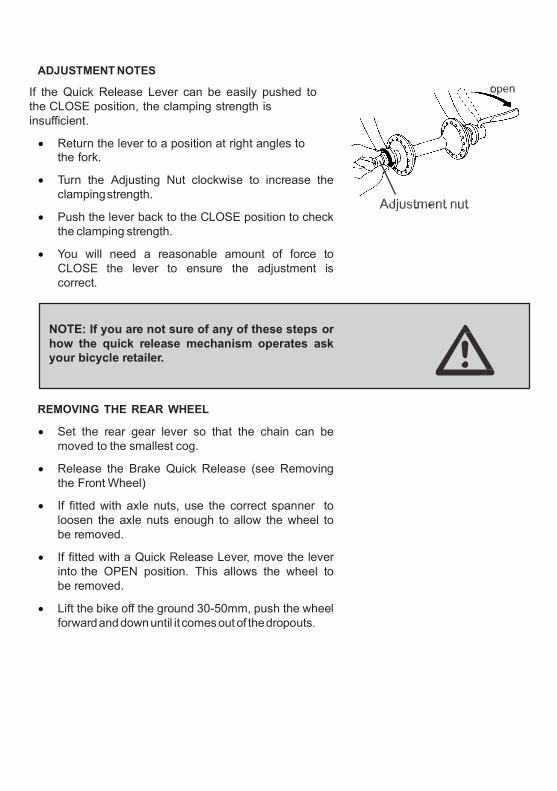
ADJUSTMENT NOTES
If the Quick Release Lever can be easily pushed to the CLOSE position, the clamping strength is insufficient.
Return the lever to a position at right angles to the fork.
Turn the Adjusting Nut clockwise to increase the clamping strength.
Push the lever back to the CLOSE position to check the clamping strength.
You will need a reasonable amount of force to CLOSE the lever to ensure the adjustment is correct.
NOTE: If you are not sure of any of these steps or how the quick release mechanism operates ask your bicycle retailer.
REMOVING THE REAR WHEEL
Set the rear gear lever so that the chain can be moved to the smallest cog.
Release the Brake Quick Release (see Removing the Front Wheel)
If fitted with axle nuts, use the correct spanner to loosen the axle nuts enough to allow the wheel to be removed.
If fitted with a Quick Release Lever, move the lever into the OPEN position. This allows the wheel to be removed.
Lift the bike off the ground 30-50mm, push the wheel forward and down until it comes out of the dropouts.

INSTALLING THE REAR WHEEL
Installation is the reverse procedure of removing the rear wheel. NOTE: Make sure that the chain is on the small cog as you position the rear wheel in the dropouts.
Check that you have the correct clamping pressure (Quick Release Lever).
If you have axle nuts make sure they are tightened correctly.
Ensure that the Quick Release Lever is positioned as shown to prevent the lever from releasing whilst riding.
When repositioning the wheel in the frame make sure that it is centrally located to prevent ‘rubbing’ of the wheel on the frame.
WARNING: Failure to properly reinstall a wheel may result in a crash.
SEAT POST QUICK RELEASE
Many bicycles are equipped with quick release seat post clamps. The seat post quick release clamps work exactly like the Wheel Quick Release.
See Adjusting the Quick Release Mechanism.
Follow the steps described to adjust the height of your seat post.
WARNING: The full force of the cam action is needed to clamp the seat post securely.

OTHER SEAT POST FIXINGS
An Allen Key Bolt or a nut is used. You must use the correct type of tool to make adjustments.
The Seat Post must be inserted in the seat tube to at least the minimum insertion point.
Ensure indexing lug on the seat post clamp bolt is correctly engaged in the seat tube clamp.
BRAKES
The braking action of a bicycle is a function of friction between brake surfaces, usually the brake blocks and the wheel rims.
Keep your wheel rims and brake blocks clean and free of lubricants, waxes or polishes.
Make sure that your hands can reach and squeeze the brake levers comfortably.
Most bicycles are fitted with front and rear hand brake levers and these are attached to either CANTILEVER CALIPERS, SIDE PULL CALIPERS, DISK or LINEAR BRAKES.
When replacing both brake cables check that the left hand cable is fitted to the rear brake when looking from the riding position.
To adjust chain tension on a bicycle fitted with a back pedal brake or internally geared hub with a single freewheel cog, the back wheel must be moved forward or backward in the dropouts. Loosen the axle nuts and brake arm clip. Allow 10 -12mm of up / down chain movement halfway between chainring (front) and cog (rear). Re-tighten nuts and brake arm clip.
For back pedal brakes: check that the brake arm clip is securely attached to the chain stay.

WARNING: Careless use of the front brake first can cause a crash.
Note: Most brakes have some form of quick release mechanism to allow the brake shoes to clear the tyre when a wheel is removed or reinstalled. When the brake quick release is in the open position, the brake will not operate. Ask your bicycle retailer for help. Make sure you understand the way the brake quick release works on your bicycle.
BRAKE ADJUSTMENT
CANTILEVER TYPE BRAKES
You should have approximately 2mm clearance between the brake blocks and the wheel rim.
To adjust the brakes, on the brake lever turn the barrel adjuster CLOCKWISE to loosen the brake. Move the adjuster ANTI-CLOCKWISE to tighten the brake. Turn the lock ring located below the barrel until it stops to set your adjustments.
If your brakes shudder/squeal you need to check the toe in/out alignment of the brake blocks. The leading edge of the block should be 0.5 - 1mm, closer to the wheel rim than the trailing edge.
To centre the brake arms, loosen the cable carrier nut, slide the cable carrier up or down until it centres the brake blocks (so there is an even gap on either side of the rim).
Retighten the cable carrier nut.
Spin the wheel to ensure the brake blocks, do not rub on the wheel rim.

Use the springforce adjustment screw to change toe in/out position.
Using an Allen key turn CLOCKWISE to move the brake pad trailing edge out. Turn the Allen key ANTI- CLOCKWISE to move the brake pad trailing edge in.
LINEAR TYPE BRAKES
A Linear brake arm might have a post type brake block (as for a Cantilever brake) or a block which can only be adjusted for toe-in and block-to-rim alignment, in which case brake block-to-rim clearance is adjusted by changing the brake cable length at the brake arm or at the brake lever cable adjuster. Ask your bicycle retailer how to make the correct adjustment.
To release a Linear brake press the brake arms together and unclip the cable lead unit (curved metal tube) from the pivotted metal stirrup. The brake cable remains attached to the opposite brake arm. If the cable lead unit and cone shaped ferrule cannot be unclipped either slacken the cable at the brake lever (using the cable adjuster) or release the cable end which is attached to the brake arm.
NOTE: Allow sufficient ‘travel’ in the brake lever and cable to enable the curved cable lead tube to be unclipped from the stirrup.
To reset the cable lead tube press the brake arms together and re-clip into the pivotted metal stirrup.
IMPORTANT: Ensure the cone shaped ferrule is fully seated in the stirrup. Ensure the protective flexible bellows or accordion-like cable protector between the brake arm and the stirrup is correctly located.

LINEAR BRAKE (CONT)
Brake lever ‘travel’ can be adjusted for ease of use by a child or anyone with small hands by means of the adjuster screw usually located on the body of the brake lever.
NOTE: a brake lever with too little ‘travel’ before hitting the handlebar may cause a linear brake to ‘lock up’ if the lever is pulled on hard. Longer lever ‘travel’ allows more progressive and better controlled braking. Adjust to suit your riding style, or ask your bicycle retailer to assist you make the correct adjustment.
NOTE: all components of a linear brake must be compatible. Do not mix brake types.
The brake lever for a linear brake is not designed to work with other types.
SIDE PULL TYPE BRAKES (ROAD BICYCLES)
When your side pull brake caliper is properly adjusted, you should have between 1-2mm gap between the brake block and the wheel rim.
To centre the brake caliper use the centering adjustment screw to centre the brakes.
Turn the screw CLOCKWISE to move the caliper to the right.
Turn the screw ANTI-CLOCKWISE to move the caliper to the left.
To set the gap between the blocks and the wheel rim use the Cable Adjustment Bolt.
Turn the Adjustment Bolt CLOCKWISE to move the brake block away from the rim.
Turn the Adjustment Bolt ANTI-CLOCKWISE to move the brake block towards the rim.
Tighten the Cable Adjustment Bolt Lock Nut in a CLOCKWISE direction to set your adjustment.

If your brakes shudder/squeal you need to adjust the toe in / out.
As you need to realign the caliper arms to overcome this problem, your dealer should make this adjustment to your bike.
DISK STYLE BRAKES
The distinctive feature of disk brakes is the actual braking disk that is fixed to the wheel and the caliper unit attached to the front fork or rear wheel frame.
The brake is activated either by a cable or hydraulic system. Disk brake systems require special care of the disk itself, which can even be damaged by some bicycle parking racks.
Hydraulic systems may require special tools and adjustments. If in doubt about any adjustments or maintainance consult your bicycle retailer or the manufacturer’s manual or specifications data. Some brands provide technical data on their websites.
WARNING: Failure to properly maintain your brake system may result in a crash.
The brake Quick Release mechanisms are used to open the brake arm to assist in the removal / installation of wheels. The brakes will not function if the Quick Release is left open.
WARNING: Failure to firmly secure the Brake Quick Release Mechanism may cause a crash.

THE DERAILLEUR GEAR SYSTEM
The gear system on your bicycle consists of:
A rear cluster (freewheel) which is attached to the rear wheel.
A rear derailleur which moves the chain across the cluster to change the gear ratio.
A front derailleur which moves the chain between the front chain rings to change the gear ratio.
Gear levers which, when moved, change the gears.
Control cables which attach the gear levers to both the front and rear derailleurs.
A chain.
INTERNAL GEARED HUB
If your bicycle is fitted with a multi speed internal geared rear hub it may require special instruction for correct use, adjustment, care and maintenance. Read carefully the instruction manual supplied with your bicycle.
Ask your bicycle retailer for advice on use and maintenance of an internal geared hub.
NOTE: Unauthorised work may limit or void the warranty.
The purpose of derailleurs is to move from one sprocket to another to allow for a variety of gear ratios.
These ratios allow the rider to maintain a constant pedal revolution in a variety of road and speed conditions.
Ask your bicycle retailer for advice.

SHIFTING GEARS
Identify your gear levers from the diagrams.
Mountain / Cross bicycles have handlebar mounted shifters.
Road bikes use various types of shifters, these can include Integrated Brake and Gear Levers, rotating handlebar ‘grip shift’ systems or other variants. Ask your bicycle retailer to explain the gear changing procedure. Practice changing gears to gain confidence.
For smooth operation of all types of levers you must be pedalling forwards when changing gears. NOTE: Some bicycles have gear levers mounted on the down tube (see diagram) of the frame. Using this type of mounting requires practice.
WARNING: Pedalling backwards whilst changing gears can jam the chain causing damage to your bicycle and / or a crash.
FRICTION GEAR SHIFT LEVERS
Friction levers are ‘stopless’ and hold the derailleur in place with simple force (tension). The amount of friction can be adjusted by means of the screw on top of the lever assembly.
If derailleur gears on your bicycle are indexed, each time you move the gear lever one click the derailleur travels a set distance to engage the next gear. This enables you easier and more accurate gear changing.

The gear shift principle: The right hand lever operates the rear gears. The left hand lever operates the front chain ring shifter.
When shifting through a wide range of gears, you may notice a noise as a result of the chain rubbing on the inside of the front derailleur cage.
This noise can be eliminated by moving the gear lever (friction systems) or adjusting the gear cable (indexing systems.)
WARNING: Avoid riding with the chain on both the largest front chain ring and the largest rear cog, smallest rear cog and small chain ring. This puts excessive strain on the chain and can damage derailleur parts.
Practice changing to a lower gear before stopping. This will assist easier starting at take-off.
As you gain more experience with your gear ratios you will be able to select the most suitable gear for the terrain and weather conditions.
NOTE: Your bicycle retailer will be able to assist you if you are uncertain about the steps in shifting gears.
DERAILLEUR ADJUSTMENT
From time to time your rear derailleur needs adjustment. You may need to tighten the derailleur cable to remove excessive cable slack. Excessive slack in the cable will cause the derailleur to miss shift.

Locate the Adjusting Barrel on the back of the derailleur.
Turn the barrel ANTI-CLOCKWISE half a turn and test the derailleur by changing gear.
Continue to turn the barrel until the chain is pitching correctly onto each gear.
NOTE: If you are not sure of these steps consult your bicycle retailer.
After the initial settling in period, if you have any adjustments that need attention, return to your bicycle retailer for advice.
TOE CLIPS AND TOE STRAPS
Toe clips and straps are used to assist with the correct positioning of your feet on the pedals and to help your riding technique. The toe clip positions the ball of the foot over the pedal spindle, which gives maximum pedalling power. The toe strap, when tightened, keeps the foot engaged throughout the rotation cycle of the pedal.
Getting into and out of pedals with toe clips and straps requires skill which can only be acquired with practice. Do not ride in traffic or around other hazards until you can use toe clips and straps as a reflex action. Never ride in traffic with your toe straps tight.
CLIPLESS PEDALS
Clipless pedals are usually adjustable. Your bicycle retailer can show you how to make this adjustment.
WARNING: Clipless pedals are intended for use with shoes specifically made to fit them and are designed to firmly keep the foot engaged with the pedal. Practice is required to learn to engage and disengage the foot safely.

TYRES AND TUBES
Bicycle tyres are available in many designs and specifications, ranging from general purpose designs to tyres designed to perform best under very specific weather or terrain conditions. Your bicycle retailer can help you select the most appropriate tyre and tube.
The size and pressure rating of a tyre is marked on the sidewall of the tyre. The part of this information which is most important to you is Tyre Pressure.
The best way to inflate a bicycle tyre to the correct pressure is with a bicycle pump. Your bicycle retailer can help you select an appropriate pump.
TAKE CARE: When using compressed air, over inflation can burst the tube and tyre. Never inflate a tyre beyond the maximum pressure marked on the sidewall of the tyre.
If the tyre pressure on your tyres is not in kilopascals please refer to the conversion table on Page 43. Tyre pressure is given either as maximum pressure or as a pressure range. How a tyre performs under different terrain or weather conditions depends largely on tyre pressure.
Inflating the tyre to near its maximum recommended pressure gives the lowest rolling resistance; but also produces the harshest ride. High pressures work best on smooth, dry pavement.
Very low pressures, at the bottom of the recommended pressure range, give the best performance on loose or muddy surfaces.
Riding with your tyres underinflated can cause a puncture, the tyre deforms and pinches the inner tube between the rim and the riding surface. Cornering with underinflated tyres can cause the tyre to roll off the rim resulting in a fall.
Ask your bicycle retailer to recommend the best tyre pressure for your kind of riding.

TYRE VALVES
There are two kinds of bicycle tube valves in common use - the Schraeder Valve and the Presta Valve. The bicycle pump you use must have the fitting appropriate to the valve stems on your bicycle.
The Schraeder is like the valve on a car tyre. To inflate a Schraeder valve tube with compressed air or with a bicycle pump, remove the valve cap and push the air hose or pump fitting on to the end of the valve stem. To let air out of a Schraeder valve, depress the pin in the end of the valve stem with the end of a key or other appropriate object.
The Presta valve has a narrower diameter and is only found on bicycle tyres. To inflate a Presta valve tube using a Presta headed bicycle pump:
remove the valve cap
unscrew (anti-clockwise) the valve stem lock nut
push down on the valve stem to free it up
push the pump head on to the valve head, and inflate.
BICYCLE SUSPENSIONS
Some bicycles come equipped with suspension systems. There are many different types of suspension systems.
If your bicycle has a suspension system ask your bicycle retailer to explain care and use. Return your bicycle for regular maintenance and adjustment of the suspension system.

NOTE: Changing suspension adjustment can change the handling and braking characteristics of your bicycle. Read and follow manufacturer’s instructions
Not all bicycles can be safely retrofitted with suspension systems. Check with your bicycle retailer.
3.1 MAINTAINING YOUR BICYCLE
SERVICE AND BASIC MAINTENANCE
Bicycles perform best when they are kept clean, lubricated and serviced regularly.
How much of your bicycle’s service and maintenance you can do yourself depends on your level of skill and experience, and whether or not you have the special tools required.
Warning: Some bicycle service and repair tasks require special knowledge and tools. Do not begin any adjustments or service on your bicycle if you have doubt about your ability. Unauthorised or incorrect service and repairs may void product warranty.
CLEANING
Mud and dust can be highly abrasive. Regular cleaning will help maintain your bicycle in good condition.
Always dry and lubricate your bicycle after washing to prevent rust.

LUBRICATION
Keep your bicycle regularly lubricated for good performance and durability. Lubrication reduces friction and helps protect against rust.
All bearings and other moving parts require regular appropriate lubrication:
Grease type lubrication:- bearings in head stem, wheels, bottom bracket and pedals (requires disassembly refer to your bicycle retailer).
Oil type lubrication:- Brake and derailleur pivot points and jockey wheels, chain, free wheel.
For advice on appropriate special lubricants, ask your bicycle retailer.
3.2 MONTHLY SERVICE CHART
Monthly servicing of your bicycle is recommended. This consists of lubrication and adjustment of components.
Use the correct type of lubricants and tools, service the bicycle’s components in logical groups and clean before you start.
TYRES AND TUBES
Clean the tyres and inspect treads for wear.
Remove any debris from tread or walls.
Check tyre pressure is correct.
Replace faulty tubes.
WHEELS
Clean rims and check they are not dented or dimpled.
Check rims for trueness and spokes for evenness of tension.
Replace any bent or broken spokes.

CHAIN
Check chain for excessive wear or stretching.
Check for any stiff links.
Use recommended lubricant.
BRAKES
Check brake block and brake lever mounting bolts.
Check brake blocks for wear. Replace if necessary.
Check block toe-in is correct.
Lubricate brake pivot bolts and adjust where necessary.
GEAR AND BRAKE CABLES
Inspect all cable housing for damage. Replace if necessary.
Clean and examine all cable wires for kinks and frayed ends. Replace if necessary.
Adjust barrel adjusters and/or cable anchor bolts to compensate for cable stretch.
HUBS
Check front and rear hub bearings for excess play or binding. Have adjustable cup-and-cone bearings, tightened or loosened if necessary.
Check hubs are correctly lubricated.
Tighten hub axle nuts and check quick release levers.
FRONT AND REAR DERAILLEURS
Clean derailleur cages bushings.
Check the accuracy of the indexing and adjust cable tension at barrel adjusters and/or cable anchor bolts as required.

CRANK/CHAINRINGS AND FREEWHEELS
Clean chainrings; check they are true and have no excessively worn, or broken teeth.
Check crank arms are tight on bottom bracket spindle.
Clean and lubricate freewheel and check for wear.
Check freewheel sprockets for worn or broken teeth.
BOTTOM BRACKET/AXLE
Test bottom bracket bearings for excess play or binding.
Check that the locknut is tight.
Check bottom bracket is correctly lubricated.
HEADSET
Check headset for excess play or binding.
Check the locknut is tight.
PEDALS
Check pedal bodies are not cracked.
If pedals are loose, tighten the mounting bolts firmly.
Inspect toe clips/toe straps for damage.
GENERAL
Check frame alignment and all the tubes for dents or damage.
Check all bolts and nuts are secure. Tighten bolts with the correct tools.
CAUTION: Alloy bicycle parts can be damaged by overtightening.

STORAGE
The best protection for your bicycle is to store it under cover in a dry environment and away from corrosive materials such as battery acid and swimming pool chemicals. Thoroughly dry off your bicycle after use in wet conditions. Wax or lubricate as required.
Failure to follow this procedure may lead to rust and corrosion of metal work.
4. ADDITIONAL INFORMATION
HELPFUL HINTS, SPECIAL INSTRUCTIONS AND WARRANTY
4.1 ABOUT YOUR BICYCLE RETAILER
Your bicycle retailer will help you to select bicycle accessories for the kind of riding you wish to do. Bicycle shop staff have the knowledge, tools and experience to give you reliable advice and provide maintenance services. If you have a problem with your bicycle or your riding, talk to your bicycle retailer.
4.2 SPECIAL INSTRUCTIONS FOR CARE OF CARBON FIBRE BICYCLES
A carbon fibre frame requires special care due to the nature of its construction.
Never clamp the bicycle using any of the carbon fibre frame tubes. Use the seat post to hold the frame during assembly.
Do not use any solvents on the frame. Clean only with a mild detergent and water.
Do not paint the frame.

Avoid scratches and direct impacts to the frame. If you are involved in a mishap, or your bicycle is scratched during use, immediately see your bicycle retailer for inspection of the damage.
Use a chain protector to lessen the chance of chipping the carbon fibre tubing.
Use the manufacturer’s recommended size seatpost and headset. Do not attempt to alter the original sizes of these parts.
Avoid overtightening of the seatpost.
Any other questions? Please contact your bicycle retailer.
4.3 TOOLS AND BICYCLE ASSEMBLY
Should you intend to undertake maintenance the following tools are considered to be the basic requirement:
Adjustable wrench 5-10cm
Adjustable wrench 32cm
Flat screw driver 15mm
Phillips head screw driver 15mm
Allen Key set 2mm-6mm
Set of open end spanners 7-17mm
Set of tyre levers
Chain link remover
Wire cutters
Torque wrench

All nuts and bolts should be checked on a regular basis for tightness. To assist in achieving the correct tension when tightening nuts and bolts the use of a torque wrench is recommended. Apply the following torque for the nominated parts of your bicycle:
Front Wheel Nuts 22-27 Newton Metres
Rear Wheel Nuts 24-29 Newton Metres
Seat Binder Nut 12-17 Newton Metres
Seat Pillar Clamp Nut 4-19 Newton Metres
Brake Anchor Nut 7-11 Newton Metres
Handle Bar Clamp Nut 5-19 Newton Metres
Head Stem Expander Bolt 17-19 Newton Metres
Crank Cotter Pin Nuts 5-10 Newton Metres
Brake Centre Bolt 5-7 Newton Metres
Pedals 35-40 Newton Metres
The following checklist presumes a bicycle which is assembled except for the handlebar & stem, brake and gear levers, saddle and seat stem, pedals, frame reflectors and wheels.
Fit wheels to frame and align. Secure axle nuts or Quick Release (QR) mechanism.
Lubricate handlebar stem, slacken wedge bolt and wedge, slide into head set to below minimum insert mark, align square to front wheel, tighten wedge bolt. Tighten wedge bolt. Check head stem lock nut is tight and that the handlebar will not rotate.
If your bicycle is equipped with a ‘threadless’ headset, check fitting adjustments with your bicycle retailer. DO NOT OVER TIGHTEN the two securing bolts.
Slide brake and gear lever assemblies onto handlebar in correct configuration. Tighten locking bolts. Adjust brake assembly cables and align brake blocks for prescribed clearance.

Fit handlebar tape or handgrips, stop ends to bar if
bar is taped, and bell.
Assemble saddle onto seat stem. Tighten fixing nuts. Lubricate seat stem and insert in seat tube to
below minimum insert mark. Tighten seat binder bolt or Quick Release mechanism.
Fit pedals to crank in correct order; pedal marked R on the right hand side; L on the left.
Fit frame mounted reflector brackets and reflectors. Align reflectors to vertical. Tighten all bolts.
Confirm that wheel reflectors are fitted.
Recheck that all components are correctly assembled, all bolts, nuts and QR correctly secure. Check that handlebar and saddle cannot be swivelled sideways.
Check derailleur gears/hub gears for correct operation; adjust to manufacturer’s specification. Check both brakes for correct operation.
WARNING: If you are unsure about correct assembly and/or adjustment, seek advice from a qualified bicycle mechanic.
‘Threadless’ head sets: some bicycles, especially those equipped with a front fork suspension system, are fitted with a ‘threadless’ head set. Special tools and/or procedures may be required to correctly secure such devices.
4.4 LOCK YOUR BICYCLE
If you lock up your bicycle, it is much less likely to be stolen. Nearly all bicycles stolen were not locked at the time.
Lock your bicycle to something solid e.g. a tree, a parking meter or a post. Make sure the bicycle cannot be lifted from the post or the post lifted out of the ground or pavement. Use a good quality U-Lock.

A good quality, hardened steel U-lock is your bicycle’s best protection from theft. U-locks are more secure than cables or chains with padlocks. Combination locks provide least security.
Make sure the lock or cable is not in a position which makes it easy to be removed or cut.
A front wheel with Quick Release can be removed and locked to the frame.
A good quality U-Lock may be the most secure device for locking your bicycle.
Bicycle parking rails should comply with Australian Standard AS2890.3 (1993).
Refer to Guide to Traffic Engineering Practice Part 14 - Bicycles (AUSTROADS 1999).
www.bikeoz.com.au - provides additional information.
www.cyclingpromotion.com.au - helping you get more out of your riding.
4.5 KEEP A RECORD OF YOUR BICYCLE
Take a colour photograph of your bicycle, write the frame number on the back of the photograph and keep it in a safe place. Less than one in ten stolen bicycles is returned, partly because the owner cannot describe the bicycle. Engraving a registration number on the bicycle will also help. The police, Neighbourhood Watch and service clubs run bicycle registration programs.
If you keep a record of the details of your bicycle it will greatly increase the possibility of getting it back should it be lost or stolen.
Remember the advice about LOCKING YOUR BICYCLE. A good quality lock is cheap insurance. See the record chart at end of this manual.

TROUBLESHOOTING CHART
PROBLEM POSSIBLE CAUSE REMEDY Frequent punctures
Inner tube old or faulty
Replace inner tube
Tyre tread / casing worn Replace tyre
Tyre unsuited to rim Replace with correct tyre
Tyre not checked after previous puncture
Remove sharp object embedded in tyre
Tyre pressure too low Correct tyre pressure
Spoke protruding into rim File down spoke
When applying the brakes they squeal / squeak
Brake blocks worn down Replace blocks
Brake block toe-in incorrect Correct block toe-in
Brake blocks / rim dirty or wet Clean blocks and rim
Brake arms loose Tighten mounting bolts
Brakes not working effectively
Brake blocks worn down Replace brake blocks
Brake blocks or rims greasy, wet or dirty
Clean blocks and rims
Brake cables are binding / stretched / damaged
Clean / adjust / replace cables
Brake levers are binding Adjust brake levers
Brakes out of adjustment Centre brakes
Steering not accurate Wheels not aligned Align wheels correctly
Headset loose or binding Adjust / tighten headset
Front forks or frame bent Seek advice at a bicycle shop
continued over

TROUBLESHOOTING CHART (CONTINUED)
PROBLEM POSSIBLE CAUSE REMEDY Knocking or shuddering when applying the brakes
Bulge in the rim or rim out of true
True wheel or take rim to a bicycle shop for repair *
Brake mounting bolts loose Tighten bolts
Brakes out of adjustment Centre brakes and / or adjust brake block toe-in
Disk brakes: disk may be bent or blocks not free
Seek advice at a bicycle shop
Forks loose in head tube Tighten headset
Wobbling wheel Axle broken Replace axle
Wheel out of true True wheel
Hub cones loose Adjust hub bearings
Headset binding Adjust headset
Gear shifts faulty Derailleur cables sticking stretched / damaged
Lubricate / tighten / replace cables
Front or rear derailleur not adjusted properly
Adjust derailleurs
Indexed shifting not adjusted properly
Adjust indexing
Slipping chain Excessively worn / chipped chainring or freewheel
Replace chainring, sprockets and chain
Chain worn / stretched Replace chain
Stiff link in chain Lubricate or replace link
Non compatible chain / chainring / freewheel
Seek advice at a bicycle shop
* Repair of damaged front wheel rim not recommended. Replace wheel rim.

TROUBLESHOOTING CHART (CONTINUED)
PROBLEM POSSIBLE CAUSE REMEDY Chain jumping off
Chainring bent
Replace Chainring
Chainring loose Tighten mounting bolts
Chainring teeth bent or broken
Replace Chainring
Rear or front derailleur side-to-side travel out of adjustment
Adjust derailleur travel
Constant clicking noises when pedalling
Stiff chain link Lubricate or replace link
Loose pedal spindle / bearings
Adjust bearings / spindle nut
Loose bottom bracket spindle / bearings
Adjust bottom bracket
Bent bottom bracket / pedal spindle
Replace bottom bracket / spindle
Loose crank Tighten crank bolt
Grinding noise when pedalling
Pedal bearings too tight Adjust bearings
Bottom bracket bearings too tight
Adjust bearings
Chain fouling derailleurs Adjust chain line
Derailleur jockey wheels dirty / binding
Clean and lubricate jockey wheels
Freewheel does not freewheel
Freewheel internal pawl pins are jammed
Lubricate. If problem persists, replace freewheel
Regular maintenance by your bicycle retailer is recommended

KILOPASCAL FROM PSI CONVERSION TABLE
PSI BAR KPA PSI BAR KPA
35 2.4 241 100 6.9 689
40 2.8 276 105 7.2 724
45 3.1 310 110 7.6 758
50 3.5 345 115 7.9 793
55 3.8 379 120 8.3 827
60 4.1 414 125 8.6 862
65 4.5 448 130 9.0 896
70 4.8 483 135 9.3 931
75 5.2 517 140 9.7 965
80 5.5 552 145 10.0 1000
85 5.9 586 150 10.3 1034
90 6.2 621 155 10.7 1069
95 6.6 655 160 11.0 1103
NOTES

It is the responsibility of the supplier of your bicycle to include with this Owner Manual all relevant WARRANTY details.
Proof of ownership may be required before warranty provisions can be processed.
YOUR CONSUMER RIGHTS: White pages telephone directories list State and
Territory consumer and fair trading office numbers.
Key words: CONSUMER AFFAIRS / FAIR TRADING
Government web sites provide extensive information. Check these sources
Warranty enquiries should be made to the point of sale (the retailer) in the first instance.
THE INFORMATION CONTAINED IN THIS MANUAL COMPLIES WITH RELEVANT
AUSTRALIAN AND NEW ZEALAND STANDARDS AT THE TIME OF PRINTING.
THIS MANUAL MAY NOT BE REPRODUCED
WITHOUT THE WRITTEN PERMISSION OF BIA LTD.

WARRANTY
THE ELECTRIC BICYCLE CO ELECTRIC BICYCLES, TRICYCLES and SCOOTERS
This Warranty is given by: THE ELECTRIC BICYCLE CO PTY LTD ACN 007 066 319 ("The Electric Bicycle Co") PO Box 2014 Parkdale VIC Australia 3195 Phone: (03) 9584 3000 Email: [email protected] The Electric Bicycle Co warrants to the original purchaser ("Purchaser") of bicycles, tricycles, scooters and or parts from The Electric Bicycle Co ("TEBCO Product") that this TEBCO Product when used for normal riding purposes is free from defects in workmanship and materials (the "Warranty"). 1. TERM OF WARRANTY AND ITEMS COVERED
The Warranty extends to the specific TEBCO Product purchased by the Purchaser for the following period from the date of purchase:
(a) the frame of the bicycle, tricycle or scooter for a period of two years; (b) the mechanical and electrical components (including but not limited to the motor, charger and
circuit boards) for a period of two years; and (c) the batteries for a period of two years or 600 charges, whichever comes first, subject to
section 3.4.
2. NOTICE 2.1 The Electric Bicycle Co bicycle, The Electric Bicycle Co tricycle and The Electric Bicycle Co scooter are
designed and intended only for the purpose of normal riding and they are specifically not designed or intended for off-road riding or any other uses including but not limited to jumping, stunt riding or racing.
2.2 To the greatest extent permitted by law and subject to the Warranty, the Electric Bicycle Co shall not be
liable for any loss, damage, cost, injury, harm and expense of any kind (including without limitation, consequential loss) arising from the use or supply of the TEBCO Product to the Purchaser. The Purchaser agrees to exclude all warranties implied by law which may lawfully be excluded.
2.3 The Electric Bicycle Company accepts to the extent set out in the clauses herein, liability for all
warranties implied under the Australian Consumer Law (set out in Schedule 2 to the Australian Competition and Consumer Act 2010 (Cth)) or under any other legislation the effect of which cannot be lawfully excluded. All warranties and conditions that are capable of exclusion (save for those expressly contained in the clauses herein) are expressly excluded.
3. EXCEPTIONS TO WARRANTY 3.1 The Warranty does not apply where a TEBCO Product:
(a) has been used in a way for which it was not designed or intended to be used as set out in
clause 2.1 above; (b) has been used for hire, rental or any other commercial purpose; (c) has been modified or changed since its original supply by The Electric Bicycle Co;

(d) fails due to an accident, abuse or neglect not caused by The Electric Bicycle Co; (e) does not consist solely of original TEBCO Product parts or equipment; or (f) is defective or fails as a result, directly or indirectly, from a person (other than a person explicitly
authorised by The Electric Bicycle Co) attempting to repair, maintain or service a TEBCO Product, or adjusting or failing to adjust any TEBCO Product requiring normal maintenance and service.
3.2 The Warranty does not apply to wheels, tyres or tubes.
3.3 The Warranty extends only to the Purchaser and only if the TEBCO Product was purchased from a
person authorised by The Electric Bicycle Co to sell the TEBCO Product ("Dealer"). The Warranty may not be transferred by the Purchaser to any other person.
3.4 The Electrical Bicycle Co warrants that its batteries will re-charge to at least 60% of original nominal
capacity (60% being sufficient to operate the TEBCO Product) for a period of either two years or 600 re-charges, whichever comes first. Battery life is optimised through regular charging, so the battery warranty does not apply unless batteries are re-charged (from flat or partial discharge) at least once a month during the Warranty period.
4. HOW TO CLAIM UNDER THIS WARRANTY 4.1 The Purchaser must immediately cease using the TEBCO Product upon becoming aware of a Warranty
claim. To claim under this warranty, the Purchaser must deliver, at its own cost, the TEBCO Product and proof of purchase to the Dealer from which the TEBCO Product was purchased or to the address above, together with the following information:
(a) the brand, model and serial number of the TEBCO Product; (b) the date, place and name of the Dealer from which the TEBCO Product was purchased; (c) details of the defect or failure in respect of which the claim under the warranty is made; and (d) written reasons why the Purchaser believes it is entitled to claim under the warranty provided
herein.
4.2 Where the Warranty does apply to the TEBCO Product, The Electric Bicycle Co shall (at its option) repair the relevant TEBCO Product or replace the relevant TEBCO Product with a comparable product or part without charge.
4.3 In the event that the TEBCO Product is not defective within the terms of this Warranty, all reasonable
costs and expenses relating to the processing of the claim under the warranty shall be borne by the Purchaser.
5. AUSTRALIAN CONSUMER LAW 5.1 Our goods come with guarantees that cannot be excluded under the Australian Consumer Law. You are
entitled to a replacement or refund for a major failure and compensation for any other reasonably foreseeable loss or damage. You are also entitled to have the goods repaired or replaced if the goods fail to be of acceptable quality and the failure does not amount to a major failure.
5.2 The benefits given to the Purchaser under this Warranty are in addition to other rights and remedies of
the Purchaser under the Australian Consumer Law and other applicable laws. 5.3 While this Warranty applies to the original Purchaser only, subsequent purchasers may have rights
under the Australian Consumer Law.

Retailer Signature:
(Retailer to forwa
nIF DISCOVERY IS NOT USED REGULARLY THEN THE BATTERY
MUST BE RE-CHARGED EVERY MONTH.
FAILURE TO RE-CHARGE BATTERY REGULARLY CAN LEAD TO SEVERE
DEGRADATION OF BATTERY. NEGLIGENCE IN THIS MATTER MAY
VOID WARRANTY.
FOR REPLACEMENT BATTERIES – CONTACT TEBCO DIRECTLY
ON 03 9584 3000 www.electricbicycle.com.au
03 9584 3000