
OUTLAW XPMODEL - Bad Boy Mowers
64
ZERO-TURN MOWER OWNER’S, SERVICE & PARTS MANUAL For additional information, please see us at www.badboymowers.com Bad Boy, Inc. 102 Industrial Drive Batesville, Arkansas 72501 ©2017 12-6 OUTLAW XP MODEL
-
Upload
khangminh22 -
Category
Documents
-
view
1 -
download
0
Transcript of OUTLAW XPMODEL - Bad Boy Mowers

ZERO-TURN MOWEROWNER’S, SERVICE & PARTS MANUALFor additional information, please see us at
www.badboymowers.com Bad Boy, Inc. 102 Industrial Drive Batesville, Arkansas 72501
©2017 12-6
OUTLAW XP MODEL

PAGE 2
TABLE OF CONTENTS Basic Information ..................................................................................................... Section 1 Page 4
Bad Boy Safety Guidelines ....................................................................................... Section 2 Page 5
Operation ................................................................................................................. Section 3 Page 9
Maintenance ............................................................................................................. Section 4 Page 10
Storage and Transportation ...................................................................................... Section 5 Page 10
Troubleshooting and FAQ ........................................................................................ Section 6 Page 12
Controls .................................................................................................................... Section 7 Page 13
Moving In-operable Mower ....................................................................................... Section 8 Page 14
Instrumentation ........................................................................................................ Section 9 Page 14
Mower Blade Maintenance ....................................................................................... Section 10 Page 15
Greasing Bearings.................................................................................................... Section 11 Page 15
How To Choose the Right Blade ..................................................................................................... Page 16
Mowing Tips .................................................................................................................................... Page 17
Service Section ............................................................................................................................... Page 18
Parts Section ................................................................................................................................... Page 40
Limited Warranty ............................................................................................................................. Page 61

PAGE 3
THIS MANUAL APPLIES TO THE FOLLOWING EQUIPMENT: BAD BOY OUTLAW XP SERIES
OUTLAW XP 5400 54” 852CC Kawasaki FX850 OUTLAW XP 6100 61” 852CC Kawasaki FX850 OUTLAW XP 7200 72” 852CC Kawasaki FX850 OUTLAW XP 6100 61” 824CC Yamaha EFI OUTLAW XP 7200 72” 824CC Yamaha EFI OUTLAW XP 6100 61” 933CC Vanguard OUTLAW XP 7200 72” 933CC Vanguard
COMMONLY USED ITEMS AND PART NUMBERS 54” Blade Hi-Lift Fusion Gator Blade Wave Blade
038-0001-00 038-0003-00 038-5220-00
61” Blade Hi-Lift Fusion Gator Blade Wave Blade 038-6080-00 038-6081-00 038-6090-00
72” Blade Hi-Lift Fusion Gator Blade Wave Blade 038-7230-00 038-5400-00 038-7215-00
Deck Belt 54” 041-1650-00
61” 041-0178-00
72” 041-0202-00
Pump Belt 041-8411-00
Oil Filter Vanguard 993cc 063-8018-00
Kawasaki FX850v 063-8017-00
Yamaha 824CC EFI 015-0053-02
Air Filter Inner Filter 063-8020-00
Outer Filter 063-8019-00
Fuel Filter 063-6000-00 Hydraulic Filter 063-8014-00
Spark Plug Vanguard 993cc 015-8000-00
Kawasaki FX850v 015-8001-00
Yamaha 824CC EFI 015-0056-06
Motor Oil 10W-30 Motor Oil - Bad Boy Synthetic Blend Motor Oil Recommended.
085-6015-00
Hydraulic Oil 20W-50 Motor Oil-Bad Boy Hydrostatic Oil Recommended (Approximately 2.5 Quarts/Transaxle)
085-6000-00

PAGE 4
SECTION 1: BASIC INFORMATION Congratulations on the purchase of your new Bad Boy Mower! The purpose of this manual is to assist operators in maintaining and operating their machine. The information and instructions in this manual can help you attain years of performance from your new Bad Boy. Also, check out our website to learn more about the Bad Boy family. 1.1 All Bad Boy engines use 10W-30 engine oil. For maximum protection, Bad Boy synthetic blend engine
oil is recommended. 1.2 All Bad Boy hydraulic systems use 20W-50 engine oil (Conventional or Synthetic). Bad Boy Hydrostatic
oil is recommended. 1.3 All Bad Boy Mowers use hi-temp multi-purpose grease. NLGI No. 2 for the grease fittings. 1.4 Outlaw models have 12 psi in both front and rear tires. 1.5 Most Briggs, Kohler, Kawasaki, and Vanguard engines hold approximately two (2) quarts of motor oil.
Be careful not to over fill engine oil. Refer to engine’s service manual.
WARRANTY REGISTRATION The Warranty Registration form must be completed within 30 days to validate your warranty. As the new equipment owner, you are expected to see that the form is completed and forwarded to Bad Boy Inc. at time of delivery. Warranty is nontransferable. Warranty registration should be completed by the selling dealership using the on-line registration site.
MODEL/SERIAL NUMBER Your OUTLAW XP model serial numbers are found on the SIN plate underneath the seat. These numbers can assist you in the ordering of new parts when replacements become necessary.
PARTS/SERVICE Only Bad Boy replacement parts are to be used on your mower. Replacement parts are available through your local Bad Boy Mowers Dealer. Remember to always provide the following information when ordering parts:
1. Correct part number 2. Correct serial number
All warranty repair and service must be handled through your authorized Bad Boy Mowers Dealer. To locate the nearest dealer, go to our website and click on Locate a Dealer.
EVAPORATIVE EMISSION CONTROL WARRANTY STATEMENT Federal Evaporative Emission Control Warranty: Your Warranty Rights and Obligations The Environmental Protection Agency (EPA), and Bad Boy Inc. are pleased to explain the evaporative emission control system's warranty on your 2018 equipment. New equipment that uses spark ignition engines for off-road use must meet stringent anti-smog standards. the evaporative emission control system on your equipment is designed, built, and equipped so it conforms at the time of sale to the ultimate purchaser with the requirements of 40 CFR 1060. The evaporative emission control system is free from defects in materials and workmanship that may keep it from meeting said requirements. Bad Boy Inc. must warrant the evaporative mission control system on your equipment for two years provided there has been no abuse, neglect, or improper maintenance. If an evaporative emission control system component does fail in a manner that would cause the equipment to no longer meet the requirements of 40 CFR 1060 within the first two years Bad Boy Inc. will replace the defective component. Your evaporative emission control system may include parts such as fuel tanks, fuel lines, carbon canisters, fuel caps, valves, vapor hoses, clamps, or connectors.

PAGE 5
SECTION 2: MOWER SAFETY GUIDELINESNever allow untrained people to operate this machine. It is the owner’s responsibility to get training and see to it that anyone who has permission to use your machine receives the proper training. Do not mow around people. The factory discharge chute is designed to deflect debris downward, but it could be possible for debris to be thrown in a way that can cause damage to people or property. Seek additional training when possible to learn more about safety techniques and practices. This cutting machine is capable of amputating hands and feet and throwing objects. Failure to observe the following safety instructions could result in serious injury or death.
GENERAL OPERATION2.1 Read, understand, and follow all instructions on the machine and in the manual before starting. 2.2 Do not put hands or feet near rotating parts or under the machine. Keep clear of the discharge opening
at all times. 2.3 Always remain seated while operating the machine. If the machine is equipped with Roll
Over Protection (ROPs), make sure the ROPs are in the upright and locked position and always buckle your seat belt.
2.4 Only allow responsible adults who are familiar with the instructions to operate this machine. 2.5 Clear the area of objects such as rocks, wire, toys etc., which could be thrown by the blades 2.6 Always maintain a safe distance from people and pets just prior to, and during, operation. Stop the
machine if anyone enters the area. 2.7 Never carry passengers. 2.8 Do not mow in reverse unless absolutely necessary. Always look down and behind before and while
backing. 2.9 Never direct discharged material toward anyone. Avoid discharging material against a wall or
obstruction as material may ricochet back toward the operator. Stop the blades when crossing gravel surfaces.
2.10 Never operate the machine without the discharge chute, grass catcher, or other safety devices correctly in place and functioning properly.
2.11 Slow down before turning. 2.12 Always disengage blades, place steering controls in neutral, engage parking brake, and remove
ignition key when leaving operators seat. Never leave a running machine unattended. 2.13 Disengage blades when not mowing. Shut off engine and wait for all parts to come to a complete stop
before cleaning the machine, inspecting the machine for damage, removing the grass catcher, or unclogging the discharge guard.
2.14 Always operate machine in daylight or with adequate working lights. 2.15 Do not operate the machine while under the influence of alcohol or drugs. 2.16 Watch for traffic when operating near or crossing roadways. 2.17 Always wear eye protection when operating or servicing the machine. 2.18 Always wear ear protection, such as earplugs, while mowing. 2.19 Use extra care when loading or unloading the machine into a trailer or truck. 2.20 Be alert of surroundings. Watch for rocks, stumps, mounds, depressions, and low hanging limbs or
objects that could be potentially hazardous while mowing. 2.21 Data indicates that operators 60 years of age and above are involved in a large percentage of riding
mower related injuries. These operators should periodically evaluate their ability to operate the riding mower safely enough to protect themselves and others from serious injury.

PAGE 6
SLOPE OPERATIONSlopes are a major factor related to loss of control and tip over accidents, which can result in severe injury or death. Operation on all slopes requires extra caution. If you cannot back up the slope, or you feel uneasy on it, do not mow it. 2.22 Mow up and down slopes, not across. 2.23 Watch for holes, ruts, bumps, rocks, or other hidden objects that tall grass can obscure. Uneven terrain
could overturn the machine. 2.24 Choose a low ground speed when operating the machine on a slope. 2.25 Do not mow on wet grass, the tires may lose traction. 2.26 Do not attempt to coast down a slope in the neutral position. 2.27 Avoid starting, stopping, or turning on a slope. If the tires lose traction, disengage the blades and
proceed slowly, straight down the slope. 2.28 Keep all movement on slopes slow and gradual. Sudden changes in speed or direction could cause the
machine to roll over. 2.29 Use extra care while operating machine with grass catchers or other attachments: they can affect the
stability of the machine. Do not use on steep slopes. 2.30 Do not try to stabilize the machine by putting your foot on the ground. 2.31 Do not mow near drop offs, ditches or embankments. The machine could suddenly roll over if a wheel
goes over the edge or the edge caves in. 2.32 Be aware of what is located at the bottom of slopes. For example: rocks, water, cliffs, and roadways.
CHILDREN Tragic accidents can occur if the operator is not alert to the presence of children. Children are often attracted to the machine and the mowing activity. NEVER assume that children will remain where you last saw them. 2.33 Keep children out of the mowing area and in the watchful care of a responsible adult other than the
operator. 2.34 Maintain Alertness and turn machine off if a child enters the area. 2.35 Before and while backing, look behind and down for small children. 2.36 Never carry children, even with blades shut off. They may fall off and be seriously injured or interfere
with safe machine operation. Children who have been given rides in the past may suddenly appear in the mowing area for another ride and be run over or backed over by the machine.
2.37 Never allow children to operate the machine. 2.38 Never leave the key in the ignition, especially around children. 2.39 Use extreme care when approaching blind corners, shrubs, trees, or other objects that may block your
view of a child

PAGE 7
TOWING Max pulling weight: 600 lbs. Max at 5°: 530 lbs. Max tongue weight: 54” = 85 lbs.; 61” = 90 lbs.; 72” = 95 lbs. 2.40 Tow only with a machine that has a hitch specifically designed for towing. Do not attach towed
equipment except at the hitch point. 2.41 Follow the manufacturer’s recommendation for weight limits for towed equipment and towing on slopes. 2.42 Never allow children or others in or on towed equipment. 2.43 On slopes, the weight of the towed equipment may cause loss of traction and loss of control. 2.44 Travel slowly and allow extra distance to stop.
SERVICE SAFE HANDLING OF GASOLINE To avoid personal injury or property damage, use extreme care in handling gasoline. Gasoline is extremely flammable and the vapors are explosive. 2.45 Extinguish all cigarettes, cigars, pipes, and all other sources of ignition. 2.46 Use only an approved gasoline container. 2.47 Never remove gas cap or add fuel with the engine running. 2.48 Allow engine to cool before refueling. 2.49 Never fuel the machine indoors. 2.50 Do not store machine near open flame or source of ignition, such as a water heater or furnace. 2.51 Remove gas powered equipment from the truck or trailer and refuel it on the ground. If this is not
possible, then refuel such equipment with a portable container, rather than from a gasoline dispenser nozzle.
2.52 Never fill gasoline containers inside a vehicle or on a truck or trailer bed with a plastic liner. Always place containers on the ground away from your vehicle before filling.
2.53 Keep the nozzle in contact with the rim of the fuel tank or container opening at all times until the fueling is complete. Do not use a nozzle lock-open device.
2.54 If fuel is spilled on clothing, change clothing immediately. 2.55 Never overfill fuel tank. Replace gas cap and tighten securely. Tank is full when level reaches
bottom of fill tube.
GENERAL SERVICE 2.56 Never operate machine in a closed area where dangerous carbon monoxide fumes can collect. 2.57 Keep all nuts and bolts tight to be sure the equipment is in safe working condition. Never operate a
poorly maintained machine. 2.58 Do not touch hot areas of the machine. 2.59 Never interfere with the intended function of a safety device or reduce the protection provided by a
safety device. Check their proper operation regularly.

PAGE 8
2.60 Keep the entire machine free of grass, leaves, or other debris build up. Clean up oil or fuel spillage and remove any fuel soaked debris. Failure to do so can affect the safety and functionality of the machine, as well as increase the danger of a fire due to contact with the hot surfaces of the machine.
2.61 Allow machine to cool before storing. 2.62 If you strike something with the mower, turn the mower and blades off, engage the parking brake, and inspect
the machine for damage. Repair, if necessary, before resuming. 2.63 Never make any adjustments or repairs with the engine running. 2.64 Check grass catcher components and the discharge guard frequently and replace with manufacturer’s
recommended parts, when necessary. 2.65 Mower blades are sharp. Wrap the blade or wear gloves before servicing them. 2.66 Check parking brake operation frequently. Adjust and service as required. 2.67 Maintain or replace safety and instruction labels, as necessary. 2.68 Do not attempt to mount a tire without the proper equipment and experience to perform the job. 2.69 Always maintain the correct tire pressure. Do not inflate the tires above the recommended pressure. Never weld
or heat a wheel and tire assembly. The heat can cause an increase in air pressure resulting in a tire explosion. Welding can structurally weaken or deform the wheel.
2.70 Park machine on level ground. Never allow untrained personnel to service machine. Understand service procedure before doing work.
2.71 Mower deck, frame, and engine compartment should remain free of debris to prevent premature parts failures or fire hazards.
SAFETY INTERLOCK SYSTEM Your Bad Boy mower is equipped with a safety interlock system. This system is designed to prevent serious injury or death to the operator and other people or property damage. The system consists of an operator presence switch in the seat, the parking brake, drive lever neutral position, the mower blade engagement switch, and the ignition switch. These interlocks are vitally important and must be tested frequently. Following are instructions to test these very important safety precautions. Note: the operator must be seated properly on the machine during these tests and the engine should have been previously allowed to warm to operating temperature. 2.72 With the parking brake engaged, bring lever arms to their inward position Attempt to start the machine with the
blade actuator in off position. The engine should not start. 2.73 On a level surface, disengage the parking brake and place lever arms to their outward position. Then, attempt to
start the machine with the blade actuator in off position. The engine should not start. 2.74 Engage parking brake and leave lever arms in outward position. Put blade actuator in the on position, then
attempt to start the machine. The engine should not start. 2.75 Next, start the engine as stated in the Mower Operation Section. Disengage parking brake and, Very Slowly,
begin to rise from the seat. The engine should stop. If any of these tests fail to produce the results indicated and the problem cannot be identified, contact your Bad Boy Mower dealer or the support contacts in the rear of this manual.
ROLL OVER PROTECTION STRUCTURES (ROPS)This machine is not equipped with ROPS from the factory. If ROPS are added as an option, it is vital that the rules below are adhered to. ROPS, when used correctly, dramatically decrease the fatality rate in roll-over instances. 2.76 Periodically ensure the bolts that attach the ROPS to the machine are securely fastened. 2.77 Always operate the machine with the ROPS secured in the upright position. 2.78 If the surrounding environment (e.g. low-lying limbs, signage, etc.) makes it impossible to mow with the
ROPS upright, lower the ROPS at the hinge point, mow the area, then immediately secure the ROPS upright. 2.79 Upright ROPS are taller than then operators head. Be aware of this and your surrounding environment, as
referenced above. The mower and operator may clear low lying items, but the ROPS may not. 2.80 Always wear the provided seat belt when ROPS are utilized. Failure to use the seat belt severely handicaps the
safety benefits of the ROPS. 2.81 In the event of a roll-over, replace the ROPS before resuming use of the machine.

PAGE 9
SECTION 3: MOWER OPERATION Never operate the machine with faulty equipment. Always be alert of sudden changes in landscape, as the mower will react differently on slopes or embankments than it will on flat surfaces. Never operate the mower with the discharge chute open. Do not cross terrain, other than grass, with blades turning. This could cause damage to property or bystanders. 3.1 Place parking brake in up position. 3.2 Drive arms must be in the “open” position. While sitting on the machine, each arm is positioned away
from the operator, to the right and left. Drive arms will lock into place and must be in this position to start machine.
3.3 Put PTO switch in the OFF position. 3.4 If your machine has been equipped with a ROPS (Roll Over Protection System) then you must fasten
seatbelt. 3.5 If machine has not been started recently, engage the choke. 3.6 Make sure nothing is under or around machine. 3.7 Place key in ignition and turn. 3.8 Once machine is started, disengage the choke. 3.9 Increase RPM by sliding the throttle to fast position, toward the rabbit. 3.10 Owners must become familiar with the controls before operating a zero-turn radius vehicle. 3.11 Start slowly and build your skill level. Have ample practice before using the machine at full
capabilities. 3.12 Be comfortable with machine before engaging blades. Know what each component controls
before using machine. 3.13 Your mower will perform differently on an incline /decline. Be cautious, slow down, and do not make
any sudden jerking movements with control arms. The machine could lose traction on a decline or tip backwards on an incline.
3.14 Once you become comfortable with your Bad Boy Mower you will notice your overall mowing time will decrease.
Avoid operating your mower on side hills of over 5 degrees, inclines of over 10 degrees,
and declines of over 15 degrees.

PAGE 10
SECTION 4: MOWER MAINTENANCE
Maintenance
Interval
Daily First 5 Hours
Every 50 Hours or Annually*
Every 100 Hours or Annually*
Every 250
Hours Section
Check and add engine oil Section3
Check all belts for proper alignment Section 2 (Pump) 6
(Deck) Check tire pressure and wheel lug nuts Section 5
Check battery terminal connections Section 4 Check condition of blades Section 6 Check for fuel and oil leakage Section 3 Initial oil change Section 3 Tighten nuts and screws Change engine oil and filter Section 3 Initial change of hydraulic oil and filter Section 1
Grease mower Section 5 Replace air element and pre-cleaner Section3
Replace fuel filter Section 3 Clean or replace spark plugs and set gap Section 3
Change hydraulic oil and filter Section 1 Clean combustion chamberDealer Check and adjust valve clearanceDealer
Clean and lap valve seating surfaceDealer
*Maintenance by hour or annually whichever comes firstCheck air and fuel filter more often in dusty conditions
DealerGet maintenance performed at a registered dealership
SECTION 5: MOWER STORAGE & TRANSPORTATION
5.1 Keep machine from collecting debris by storing in a covered area while not in use. 5.2 Fuel can harm your machine if left for more than 30 days without changing, especially if the fuel
contains ethanol. Never use fuel with more than 10% ethanol by volume. E-15 is not permitted. 5.3 Disconnect the negative battery cable when machine will be stored for more than 30 days. 5.4 Always secure machine properly when transporting machine. 5.5 Do not load machine on trailer with blades engaged. 5.6 Do not use ramps to load the machine. 5.7 Make sure Parking Brake is in “up” position. 5.8 In wet conditions tires may spin while loading / unloading. If necessary, wait for dry conditions before
loading/unloading. 5.9 Make sure mode of transportation is suitable to bear the weight of mower. 5.10 Deck height should be set at maximum before attempting to load. 5.11 Secure mower with at least two straps capable of securing weight of mower.

PAGE 11
MAINTENANCE LOG Date: Hours: Performed:
Date: Hours: Performed:
Date: Hours: Performed:
Date: Hours: Performed:
Date: Hours: Performed:
Date: Hours: Performed:
Date: Hours: Performed:
Date: Hours: Performed:
Date: Hours: Performed:
Date: Hours: Performed:
Date: Hours: Performed:
Date: Hours: Performed:
Date: Hours: Performed:
Date: Hours: Performed:
Date: Hours: Performed:
Date: Hours: Performed:
Date: Hours: Performed:
Date: Hours: Performed:
Date: Hours: Performed:
Date: Hours: Performed:
Date: Hours: Performed:

PAGE 12
SECTION 6: TROUBLESHOOTING 6.1 Q: How do I prevent an uneven cutting pattern and increase the quality of cut?
A: Check tire pressure, check blade sharpness (replace blades or sharpen at least once per year or when needed), make sure blades are tightened properly, check spring and belt tension, check the underside of the deck to ensure the mower deck is free of grass build-up and debris, make sure your machine is at full throttle, and vary your mowing pattern each time you cut your grass.
6.2 Q: What should I do if my mower won’t start? A: Check battery charge and connection (grounds), check your fuel (make sure fuel is less than 30 days old and contains no water), make sure your spark plug is in good condition and spark plug wire is attached, and make sure air filter is clean (a dirty filter makes it more difficult for the engine to draw air). Check the integrity of the 25-amp main fuse; also check for any bare wires and/or bad connections.
6.3 Q: What should I do if the blades won’t engage? A: Make sure the safety switch is plugged in on the bottom of seat. Check the underside of the PTO engager to ensure the plug is secure at switch. Also check PTO fuse underneath operator console (10-amps)
6.4 Q: What type of fuel is recommended for my mower? A: We recommend that you use a name brand fuel to ensure quality. Use fuel with an octane rating near 87. Higher octane fuels offer no benefit. Only fuels with an ethanol content of 10% or less may be used. By law, E-15 fuel is not permitted. Usage of E-15 will result in premature engine failure.
6.5 Q: Do you offer touch-up paint for your mowers? A: Touch-up paint is available. Contact your local dealer for more information.
6.6 Q: How do I clean my mower? A: It is recommended that you use an air hose or blower to remove dust and debris from the mower, to ensure there is not a buildup of grass on the mower deck and engine compartment, which could become a fire hazard. If you must wash the mower, ensure you run the engine to operating temp to dry water and engage the blades to spin off any standing water on the pulleys. Avoid spraying water onto electrical components and bearings to prevent premature failure of these parts.

PAGE 13
SECTION 7: CONTROLS 7.1 Ignition Switch: Bad Boy mowers have a three-position ignition switch: off, run, and start. With key
inserted, rotate it clockwise to START position and release key when engine starts, and switch will automatically return to the RUN position.
7.2 Throttle Control: A cable is connected to the engine throttle for controlling engine speed. Move lever forward to increase engine rpm, move lever backward to decrease engine rpm.
7.3 Choke Control: The choke control, located to the right of the operator’s left, is a ‘push-pull’ type. When the choke knob is pushed in, the choke is in the off (run) position. When the choke is pulled out it is in the on (start) position. Do not operate the machine in the on (start) position.
7.4 Control Levers: (Not Shown) These levers control the mower’s speed, direction, and neutral lock. These levers are used to steer, accelerate, decelerate and change direction.
7.5 Blade Engage Switch: This switch engages the blades. Pull the switch up to engage the blades and push the switch down to disengage the blades.
7.6 Parking Brake: (Not Shown) This lever engages the parking brake. Pull back fully to engage the parking brake; push forward to disengage.
7.7 Deck Height Adjust: OUTLAW XP has a rocker switch for deck height adjustment.
7.2 7.7 7.5 7.1 7.3

PAGE 14
SECTION 8: MOVING INOPERABLE MOWER 8.1 Do not tow machine. Use a winch to load on a trailer for transporting.
8.2 ATTENTION: RETURN BYPASS VALVES TO OPERATING POSITION BEFORE RUNNING MOWER FOLLOWING REPAIRS.
8.3 If it is necessary to move mower when the engine is inoperable, the hydraulic drive pumps. re equipped with bypass valves. Before moving the mower, turn the bypass valves counterclockwise one-half to one revolution. The bypass valve bolts are located on the side of each pump and are easily identified by the hole through the bolt heads
Your Bad Boy Mower Weighs: OUTLAW XP SERIES: 1180-1310 lbs. ***Weights fluctuate with the addition of accessories.
8.4 As you can see by the weights of the machines, you shouldn’t ever try to push or pull a Bad Boy Mower by hand. This could cause serious bodily injury.
8.5 Hopefully, you’ll never need to use this section of the manual. However, if you do, use extreme caution when moving machine!
SECTION 9: INSTRUMENTATION
9.1 Electronic Hour Meter: Displays total operating hours (0.1 hour increments, up to 9,999.9 hours), resettable timers, oil change reminders (5 hour break-in reminder followed by 50 hour interval reminders), air filter cleaning reminder, and RPM gauge. Press button to cycle between functions. To reset a timer, depress and hold button for 2 seconds.

PAGE 15
SECTION 10: MOWER BLADE MAINTENANCE 10.1 Check mower blades after each use. This is essential for maintaining well-groomed turf. Keep the
blades sharp. If a dull blade is used for cutting, the grass will tear rather than cut. This could damage the grass leaving a brown frayed top on the grass within a few hours. A dull blade will also require more power from the engine.
10.2 NEVER attempt to straighten a bent blade by heating. NEVER attempt to weld a cracked blade. The blades can break and cause serious injury or death.
10.3 NEVER work with blades while engine is running or deck clutch is engaged. 10.4 ALWAYS place deck clutch in DISENGAGE position while performing maintenance. 10.5 Use blocks when you MUST work under mower. 10.6 ALWAYS wear thick gloves when handling blades. 10.7 ALWAYS check for blade damage if mower strikes rock, branch, or other objects that could potentially
damage the blade.
(REMEMBER: NEVER CHECK BLADE WHILE ENGINE IS ON! NEVER CHECK BLADES WHILE BLADES ARE ENGAGED!)
SECTION 11: EQUIPMENT LUBRICATION 11.1 Park the machine on a level surface and disengage the blade control switch. 11.2 Move the motion control levers outward to the neutral position, engage parking brake, stop the engine,
remove the key, and wait for all moving parts to stop before leaving the operating position. 11.3 Grease Type: NGLI grade #2 multi-purpose gun grease. 11.4 Clean the grease fittings with a cloth. Scrape any paint off the front of the fitting(s). 11.5 Connect a grease gun to each fitting. Pump grease into the fitting until grease seepage is observed. Be
mindful of over-pressurization. Do not force the lever arm if there is strong back pressure as this can lead to reduced life of the component(s). Wipe up excess grease.
11.6 Refer to service manual section for grease fitting locations.

PAGE 16
HOW TO CHOOSE THE RIGHT BLADE Essentially there are only TWO basic styles of mowing blades used or approved for use on our current products:
1. The standard style of mowing blade is essentially designed for cutting grass and effectively discharging the clippings out from the deck to fall onto the lawn or to be captured in a grass collection system. Standard blades are also referred to as “2-in-1” (discharging & bagging) or “high-lift” blades (because they are designed to create a higher-lifting airflow).
2. Mulching blades generally have a more curved style surface and frequently include extra cutting surfaces along the blade edges. These blades may also come in a “+” design (which is actually two individual blades arranged in a perpendicular fashion to enhance mulching). The “+” blades are usually found on older style mowers; newer ones utilize blades with more advanced mulching technology. Mulching blades may also be referred to as “3-in-1” (mulching, discharging & bagging) or “all-purpose” blades.
Bear in mind that the re-circulating airflow design of 3/1 blades makes them less efficient at discharging grass clippings than a standard 2/1 blade. As with most all-purpose tools, there is some give and take as opposed to using a tool designed for a more specific purpose.
If you’re experiencing less-than-desired cutting or discharging performance with a 3/1 blade, you may want to check into using a 2/1 blade. Conversely, if you’re using a 2/1 blade and want to mulch clippings, you should see about the availability of mulching blades or a mulching kit. *
The type of blade installed on a new mower is a decision the retailer makes for each model of mower, based on the expected needs of most customers. If you’re unsure of which blade is on a particular model, inspect the blade. Blades have part numbers stamped into them. Then compare these part numbers with the unit’s Operator’s Manual or Parts List.
It is true there are many other styles of blades available. But since we don’t manufacture or recommend using these other aftermarket styles, we will leave them out of this discussion. Should you want more information on special application or aftermarket blades, you should contact the companies that make these products. NOTE: Customers using non-OEM blades do so at their own risk. The use of unapproved (non-OEM) blades may void any or all of the mower and engine factory warranties.
* MULCHING KITS – These generally consist of mulching blades and a mulching plug (which closes off the discharge opening to keep the clippings contained under the deck for re-cutting) plus any necessary hardware for installation. Please check with your parts distributor regarding the contents of a particular mulching kit.
PAGE 17
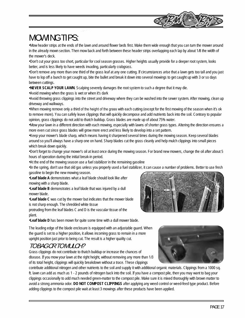
MOWING TIPS: •Mow header strips at the ends of the lawn and around flower beds first. Make them wide enough that you can turn the mower aroundin the already mown section. Then mow back and forth between these header strips overlapping each lap by about 1/8 the width ofthe mower’s deck.•Don’t cut your grass too short, particular for cool season grasses. Higher heights usually provide for a deeper root system, looksbetter, and is less likely to have weeds invading, particularly crabgrass.•Don’t remove any more than one third of the grass leaf at any one cutting. If circumstances arise that a lawn gets too tall and you justhave to lop off a bunch to get caught up, bite the bullet and break it down into several mowings to get caught up with 3 or so daysbetween cuttings.•NEVER SCALP YOUR LAWN. Scalping severely damages the root system to such a degree that it may die.•Avoid mowing when the grass is wet or when it’s dark•Avoid throwing grass clippings into the street and driveway where they can be washed into the sewer system. After mowing, clean updriveway and walkways.•When mowing remove only a third of the height of the grass with each cutting (except for the first mowing of the season when it’s okto remove more). You can safely leave clippings that will quickly decompose and add nutrients back into the soil. Contrary to popularopinion, grass clippings do not add to thatch buildup. Grass blades are made up of about 75% water.•Mow your lawn in a different direction with each mowing, especially with lawns of shorter grass types. Altering the direction ensures amore even cut since grass blades will grow more erect and less likely to develop into a set pattern.•Keep your mower’s blade sharp, which means having it sharpened several times during the mowing season. Keep several bladesaround so you’ll always have a sharp one on hand. Sharp blades cut the grass cleanly and help mulch clippings into small pieceswhich break down quickly.•Don’t forget to change your mower’s oil at least once during the mowing season. For brand new mowers, change the oil after about 5hours of operation during the initial break-in period.•At the end of the mowing season use a fuel stabilizer in the remaining gasoline•In the spring, don’t use that old gas unless you properly used a fuel stabilizer, it can cause a number of problems. Better to use freshgasoline to begin the new mowing season.•Leaf blade A demonstrates what a leaf blade should look like aftermowing with a sharp blade.•Leaf blade B demonstrates a leaf blade that was injured by a dullmower blade.•Leaf blade C was cut by the mower but indicates that the mower bladeis not sharp enough. The shredded white tissueprotruding from the leaf blades C and D is the vascular tissue of theplant.•Leaf blade D has been mown for quite some time with a dull mower blade.
The leading edge of the blade enclosure is equipped with an adjustable guard. When the guard is set to a higher position, it allows incoming grass to remain in a more upright position just prior to being cut. The result is a higher quality cut.
TO BAG OR TO MULCH? Grass clippings do not contribute to thatch buildup or increase the chances of disease. If you mow your lawn at the right height, without removing any more than 1/3 of its total height, clippings will quickly breakdown without a trace. These clippings contribute additional nitrogen and other nutrients to the soil and supply it with additional organic materials. Clippings from a 1000 sq. ft. lawn can add as much as 1 - 2 pounds of nitrogen back into the soil. If you have a compost pile, then you may want to bag your clippings occasionally to add much needed green-matter to the compost pile. Make sure it is mixed thoroughly with brown matter to avoid a strong ammonia odor. DO NOT COMPOST CLIPPINGS after applying any weed control or weed-feed type product. Before adding clippings to the compost pile wait at least 3 mowings after these products have been applied.

PAGE 18
SERVICE SECTION SECTION 1: HYDROSTATIC SYSTEM The hydraulic reservoir tank on the Outlaw XP model is located on each side of the rear cover. There is a dipstick that indicates the current hydraulic oil level. Use only 20W-50 motor oil in this tank. Conventional or synthetic oil may be used. Bad Boy Hydrostatic Oil is recommended. Bad Boy recommends that the hydraulic oil and filters be changed within the first 50 hours of use; then at intervals of 250 usage hours. Use only Bad Boy replacement filters. Use of any other filters may result in damage to the hydraulic system and void the warranty. Each side requires approximately two quarts of oil to refill the system. THE FOLLOWING MAINTENACE IS TO BE PERFORMED ON A LEVEL SURFACE. CHANGING YOUR HYDRAULIC OIL AND FILTER 1. Place an oil pan under the engine. Locate the
clear oil return lines that come from the hydraulic pump and connect to the back side of the oil tanks as labeled in the picture above. Disconnect the return lines from the reservoir and place them into the oil drain pan.
2. Start the engine in order to cycle out the old hydraulic oil.
3. When you see air bubbles in the hydraulic lines immediately shut off the mower. keep in mind that only 75-80% of the hydraulic oil can be changed at a time.
4. Place rags under the hydraulic filters. Turn the hydraulic filters counter clockwise to remove.
5. Fill the new hydraulic oil filters with 20W-50 motor oil. Only use Bad Boy replacement filters.
6. Place the hydraulic return lines back onto the hydro oil reservoirs. Fill each hydraulic reservoir tank until the oil level reaches the bubble on the dipstick. Be careful not to overfill the hydraulic reservoir tanks.
7. Proceed to the purge procedure.8. Recheck oil level and fill as necessary.

PAGE 19
PURGING PROCEDURE Due to the effects air has on the efficiency in hydrostatic drive applications, it is critical that the air is purged from the system. These purge procedures should be implemented any time a hydrostatic system has been opened to facilitate maintenance or any additional oil has been added to the system. 1. Lift the rear tires of the mower off of the ground
and chock your front tires so they do no move. 2. With the bypass valve open and the engine
running, slowly move the directional drive arms in the forward and reverse directions (5 to 6 times), as air is purged from the unit, the oil level will drop.
3. With the bypass valve closed and the engine running, slowly move the directional drive arms in the forward and reverse directions (5 to 6 times). Check the oil level, and add oil as required after stopping the engine.
4. It may be necessary to repeat steps 2 and 3 until all the air is completely purged from the system. When the transaxle moves forward and reverse at normal speed purging is complete.
When adjusting the tracking on the mower, the length of the pushrods can be changed by screwing the pivot joint in or out on the ends of the rods. Shortening the overall length of the rod slows the pump down. Lengthening the rod will increase the speed of the pump.

PAGE 20
SECTION 2: DRIVE BELT Shown on the right is the tensioner for your pump belt. Adjusting this will either increase or decrease tension on the belt. Use a 3/4 “wrench to loosen the jam nuts and either tighten for more belt tension or loosen for less belt tension.
The belt tension should be set to 50-60 lbs.
Use a belt tension gauge to ensure the proper tension. Your dealer or service center will have belt tension gauge or you can buy one from the Bad Boy Parts Department by calling 866-622-3629 and ask for Parts Department. (Part Number 041-9999-00)

PAGE 21
SECTION 3: ENGINE KAWASAKI FX850V
This machine has an oil drain hose installed on the engine to allow for easier oil changes. Bad Boy recommends that the oil and filter be changed after the initial 8 hrs. of use, and at intervals of 50 usage hours or yearly, whichever occurs first after that. The oil capacity is 2 quarts. Bad Boy 10W-30 synthetic blend engine oil is recommended for maximum protection.
CHANGING YOUR ENGINE OIL AND OIL FILTER 1. Remove oil dipstick and open oil drain
using a 10 mm socket or a flat head screwdriver until oil begins flowing. Allow oil to completely drain. (Make sure to have an oil pan ready to capture old oil and properly dispose old oil.)
2. The oil filter is located on the right side of the engine. Clean area around oil filter. Place a container under the oil filter to capture any oil and remove filter. Wipe off mounting surface and reinstall drain plug. Torque to 10 ft.-lb.
3. Place new filter in shallow pan with open end up. Fill with new oil until oil reaches the bottom of the threads. Allow 2 minutes for oil to be absorbed by filter material.
4. Apply a thin film of clean oil to rubber gasket on new filter.
5. Refer to instructions on oil filter for proper installation.
6. Fill crankcase with approximately 2 quarts of new oil. Level should top of indicator on dipstick.
7. Reinstall oil fill/dipstick and tighten securely.
8. Start engine; check for oil leaks. Stop Engine; correct oil leaks. Recheck oil level.
9. Dispose of used oil and filter in accordance with local ordinances.

PAGE 22
KAWASAKI FX850V (CONTINUED)
The fuel filter is located in the fuel line on the left side of the engine by the starter motor. Replace the filter yearly. Prior to the removal of the old filter, note the direction of fuel flow as indicated on the filter. Have towels readily available in order to quickly remove any fuel leakage. Always use new hose clamps and ensure the security of the new filter by lightly pulling on each hose. Always perform maintenance outdoors or in a well-ventilated area. Do not smoke or allow any open flames in the vicinity of any maintenance activities. CHANGING YOUR FUEL FILTER 1. Locate your fuel filter and mark the direction it is
facing. 2. Clamp each side of the fuel filter to minimize any
gas spills. 3. Remove the clops from each side of the fuel filter
and remove the filter. 4. Place the new fuel filter in the same direction as
the old one and place the clips back into place and remove clamps.
The air cleaner is the engines only defense against damaging foreign particles. It is very important that the air cleaner element is inspected prior to each use. Remove the element and tap its sides in order to remove debris. Do not blow the filter out using compressed air. Doing so will greatly reduce the air cleaner’s effectiveness. Replace yearly: more often in dusty environments. Adhering to these practices will help prevent loss of power and premature engine failure. CHANGING THE AIR CLEANER 1. Locate the air filter and unbuckle the air filter
cover. 2. Remove the cover and take out the outer white
element and the inner blue element. 3. Clean or replace elements. 4. Reattach the cover making sure the air intake is
facing down.

PAGE 23
KAWASAKI FX850V (CONTINUED)
CHANGING THE SPARK PLUGS AND CHECKING THE SPARK PLUG GAP
1. Remove the wire on the spark plug and use a13/16” socket to remove the spark plug.
2. Check the gap on the spark plug to verify that it is0.03 in using a feeler gauge.
3. If the spark plug is worn, overheated, wet orcarbon fouled replace the spark plug.
4. Install the plug into cylinder head and torque to16 ft.-lbs. Be careful not to overtighten the sparkplug.
PAGE 24
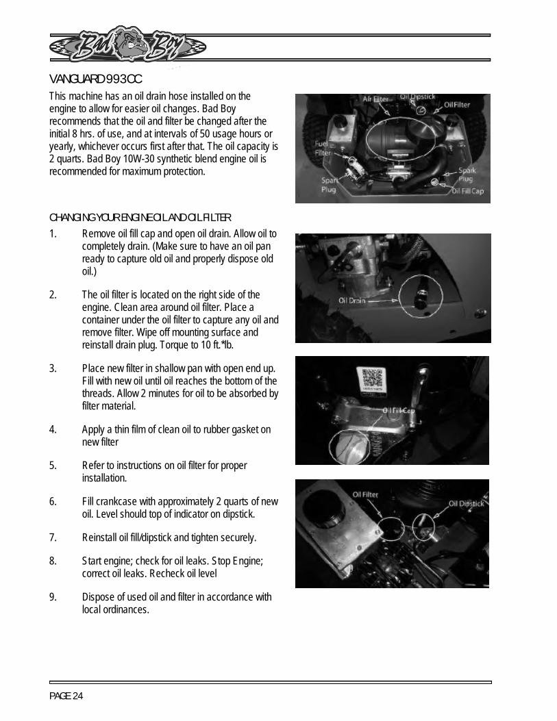
VANGUARD 993CC This machine has an oil drain hose installed on the engine to allow for easier oil changes. Bad Boy recommends that the oil and filter be changed after the initial 8 hrs. of use, and at intervals of 50 usage hours or yearly, whichever occurs first after that. The oil capacity is 2 quarts. Bad Boy 10W-30 synthetic blend engine oil is recommended for maximum protection.
CHANGING YOUR ENGINE OIL AND OIL FILTER 1. Remove oil fill cap and open oil drain. Allow oil to
completely drain. (Make sure to have an oil pan ready to capture old oil and properly dispose old oil.)
2. The oil filter is located on the right side of the engine. Clean area around oil filter. Place a container under the oil filter to capture any oil and remove filter. Wipe off mounting surface and reinstall drain plug. Torque to 10 ft.*lb.
3. Place new filter in shallow pan with open end up. Fill with new oil until oil reaches the bottom of the threads. Allow 2 minutes for oil to be absorbed by filter material.
4. Apply a thin film of clean oil to rubber gasket on new filter
5. Refer to instructions on oil filter for proper installation.
6. Fill crankcase with approximately 2 quarts of new oil. Level should top of indicator on dipstick.
7. Reinstall oil fill/dipstick and tighten securely.
8. Start engine; check for oil leaks. Stop Engine; correct oil leaks. Recheck oil level
9. Dispose of used oil and filter in accordance with local ordinances.

PAGE 25
VANGUARD 993CC (CONTINUED)
The fuel filter is located in the fuel line about 12˝ from the carburetor on the side of the engine. Replace the filter yearly. Prior to the removal of the old filter, note the direction of fuel flow as indicated on the filter. Have towels readily available in order to quickly remove any fuel leakage. Always use new hose clamps and ensure the security of the new filter by lightly pulling on each hose. Always perform maintenance outdoors or in a well-ventilated area. Do not smoke or allow any open flames in the vicinity of any maintenance activities.
CHANGING YOUR FUEL FILTER
1. Locate your fuel filter and mark the direction it isfacing.
2. Clamp each side of the fuel filter to minimize andgas spills.
3. Remove the clips from each side of the fuel filterand remove the fuel filter.
4. Place the new fuel filter in the same direction asthe old and place clips back into place andremove clamps.
PAGE 26
VANGUARD 993CC (CONTINUED)
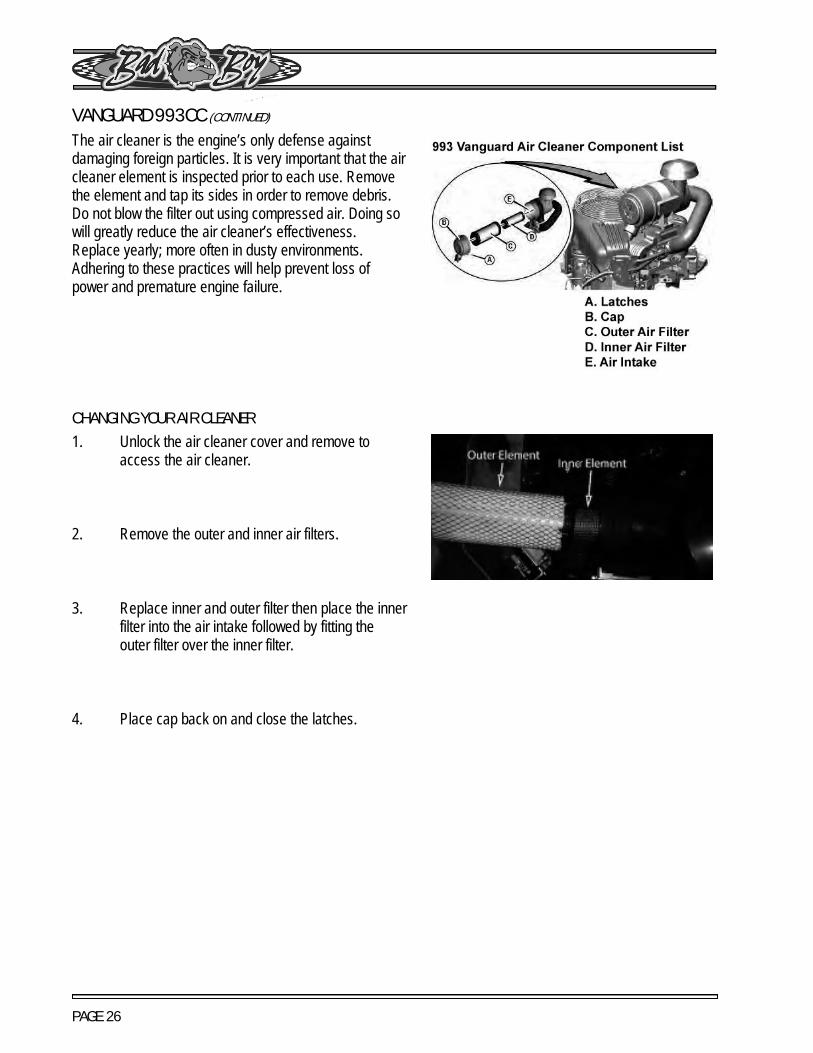
The air cleaner is the engine’s only defense against damaging foreign particles. It is very important that the air cleaner element is inspected prior to each use. Remove the element and tap its sides in order to remove debris. Do not blow the filter out using compressed air. Doing so will greatly reduce the air cleaner’s effectiveness. Replace yearly; more often in dusty environments. Adhering to these practices will help prevent loss of power and premature engine failure.
CHANGING YOUR AIR CLEANER 1. Unlock the air cleaner cover and remove to
access the air cleaner.
2. Remove the outer and inner air filters.
3. Replace inner and outer filter then place the inner filter into the air intake followed by fitting the outer filter over the inner filter.
4. Place cap back on and close the latches.

PAGE 27
VANGUARD 993CC (CONTINUED)
CHANGING THE SPARK PLUGS AND CHECKING THE SPARK PLUG GAP
1. Remove the wire on the spark plug and use a 5/8" socket to remove the spark plug.
2. Check the gap on the spark plug to verify that it is 0.03 in using a feeler gauge.
3. If the spark plug is worn, overheated, wet, or carbon fouled replace the spark plug.
4. Install the plug into cylinder head and torque to 20ft.-lbs. Be careful not to overtighten the spark plug.

PAGE 28
YAMAHA 824CC EFI This machine has an oil drain hose installed on the engine to allow for easier oil changes. Bad Boy recommends that the oil and filter be changed after the initial 8 hrs of use, and at intervals of 50 usage hours or yearly, whichever occurs first after that. The oil capacity is 2 quarts. Bad Boy 10W-30 synthetic blend engine oil is recommended for maximum protection.
CHANGING YOUR ENGINE OIL AND OIL FILTER 1. Remove oil fill cap and open oil drain. Allow oil to
completely drain. (Make sure to have an oil panready to capture old oil and properly dispose oldoil.)
2. The oil filter is located on the right side of theengine. Clean area around oil filter. Place acontainer under the oil filter to capture any oil andremove filter. Wipe off mounting surface andreinstall drain plug. Torque to 10 ft.*lb.
3. Place new filter in shallow pan with open end up.Fill with new oil until oil reaches the bottom of thethreads. Allow 2 minutes for oil to be absorbed byfilter material.
4. Apply a thin film of clean oil to rubber gasket onnew filter.
5. Refer to instructions on oil filter for properinstallation.
6. Fill crankcase with approximately 2 quarts of newoil. Level should top of indicator on dipstick.
7. Reinstall oil fill/dipstick and tighten securely.8. Start engine, check for oil leaks. Stop Engine,
correct oil leaks. Recheck oil level9. Dispose of used oil and filter in accordance with
local ordinances.

PAGE 29
YAMAHA 824CC EFI (CONTINUED) The fuel filter is located in the fuel line about 12˝ from the fuel pump on the side of the engine. Replace the filter yearly. Prior to the removal of the old filter, note the direction of fuel flow as indicated on the filter. Have towels readily available in order to quickly remove any fuel leakage. Always use new hose clamps and ensure the security of the new filter by lightly pulling on each hose. Always perform maintenance outdoors or in a well ventilated area. Do not smoke or allow any open flames in the vicinity of any maintenance activities.
CHANGING YOUR FUEL FILTER 1. Locate your fuel filter and mark the direction it is
facing.
2. Clamp each side of the fuel filter to minimize any gas spills.
3. Remove the clips from each side of the fuel filter and remove the fuel filter.
4. Place the new fuel filter in the same direction as the old one.

PAGE 30
YAMAHA 824CC EFI (CONTINUED) The air cleaner is the engine’s only defense against damaging foreign particles. It is very important that the air cleaner element is inspected prior to each use. Remove the element and tap its sides in order to remove debris. Do not blow the filter out using compressed air. Doing so will greatly reduce the air cleaner’s effectiveness. Replace yearly; more often in dusty environments. Adhering to these practices will help prevent loss of power and premature engine failure.
CHANGING THE AIR CLEANER 1. Unlock the air cleaner cover and remove to
access the air cleaner.
2. Remove the outer and inner air filters.
3. Replace inner and outer filter then place the inner filter into the air intake followed by fitting the outer filter over the inner filter.
4. Place cap back on and close the latches.

PAGE 31
YAMAHA 824CC EFI (CONTINUED)
CHANGING THE SPARK PLUGS AND CHECKING THE SPARK PLUG GAP 1. Remove the wire on the spark plug and use a
13/16” socket to remove the spark plug.
2. Check the gap on the spark plug to verify that it is 0.03 in using a feeler gauge.
3. If the spark plug is worn, overheated, wet, or carbon fouled replace the spark plug.
4. Install the plug into cylinder head and torque to 20ft.-lbs. Be careful not to overtighten the spark plug.

PAGE 32
SECTION 4: ELECTRICAL SYSTEM This mower is equipped with one protective fuse: a 30 amp main fuse (pictured to the right).
A blown fuse usually indicates a problem within the electrical system or an electrical component. Ensure the battery terminals are tightly fastened.
Never replace a fuse with one of a higher amperage rating or ‘bypass’ a fuse in any way. Doing so creates a significant fire hazard and can cause severe damage to the mower’s electrical components. If a fuse is repeatedly blowing, contact your Bad Boy dealer.
On most models, the red wire coming out of the engine is the charging wire from the alternator. Check for 13.6 - 14.2 volts dc at this wire with engine at full throttle.
If you are having issues starting your mower ensure the signal wire is connected to your starter solenoid.
Check the condition and connection of the relays located under the control panel. Ensure that they are clean and connected. Make sure that wire terminal ends have not been pushed out of the relay block.
The linear actuator is the mechanism that raises and lowers the deck. If it ever starts to make noise when raising and lowering the deck you might find it necessary to tighten
the nuts and bolts on the front and rear of the actuator. Be careful not to overtighten these
as you can damage the actuator. Also if your actuator ever stops working make sure to check the main fuse.

PAGE 33
ELECTRICAL SYSTEM (CONTINUED)
WIRING DIAGRAM
PAGE 34
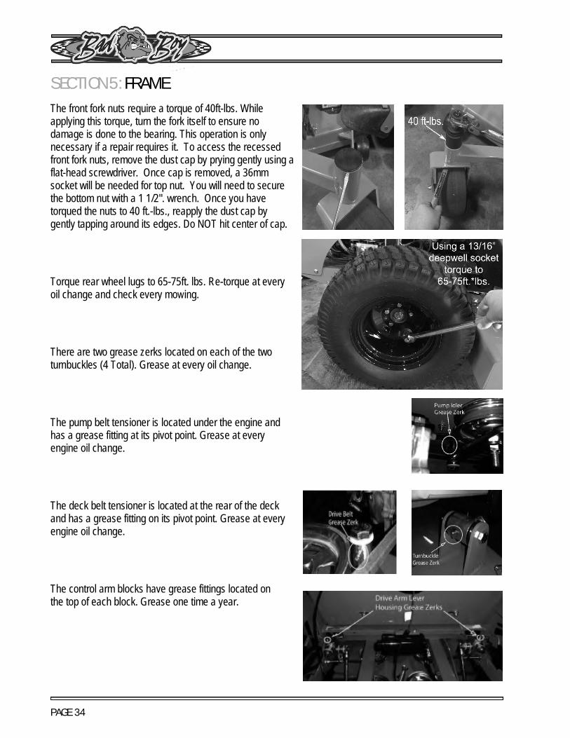
SECTION 5: FRAMEThe front fork nuts require a torque of 40ft-lbs. While applying this torque, turn the fork itself to ensure no damage is done to the bearing. This operation is only necessary if a repair requires it. To access the recessed front fork nuts, remove the dust cap by prying gently using a flat-head screwdriver. Once cap is removed, a 36mm socket will be needed for top nut. You will need to secure the bottom nut with a 1 1/2". wrench. Once you have torqued the nuts to 40 ft.-lbs., reapply the dust cap by gently tapping around its edges. Do NOT hit center of cap.
Torque rear wheel lugs to 65-75ft. lbs. Re-torque at every oil change and check every mowing.
There are two grease zerks located on each of the two turnbuckles (4 Total). Grease at every oil change.
The pump belt tensioner is located under the engine and has a grease fitting at its pivot point. Grease at every engine oil change.
The deck belt tensioner is located at the rear of the deck and has a grease fitting on its pivot point. Grease at every engine oil change.
The control arm blocks have grease fittings located on the top of each block. Grease one time a year.

PAGE 35
SECTION 6: CUTTING DECK DECK BELT REMOVAL 1. Use proper safety precaution when preforming
procedures.
2. Raise the deck to its highest position.
3. Remove the right pulley cover.
4. While lifting up on the belt (as shown in the photograph), rotate the pulley until the belt is free of the pulley. Exercise caution while performing this step as fingers can easily become caught between the belt and pulley.
DECK BELT INSTALLATION 1. Use proper safety precaution when preforming
procedures.
2. Raise the deck to its highest position.
3. Take off both pulley covers and route the belt by following the belt route decal. (The easiest way to finish running the belt is routing the belt through the deck pulleys and carefully slipping the belt onto the clutch in the rear of the engine.)
4. Verify that the belt is routed properly as improper routing can damage the spindles as well as the engine.

PAGE 36
LEVELING THE DECK 1. Start on a flat level surface and set the air
pressure in all four tires to 12 psi. Measure thedeck at all four corners. The deck should belevel from left to right but 1/4" lower in the frontthan in the rear. adjustments can be made byadjusting the deck hangers in their slots.
2. Using a pair of approximately 3 ft. long 2x4's,stand the boards on edge and slide them underthe deck from front to back as shown.
3. Remove the foot pedal and raise the floor plate.Remove one end of the deck lift spring assistdampener using a pair of 1/2" wrenches asshown
4. Lower the deck down onto the 2x4's and installthe deck height pin into its highest available hole.This should be relatively close to the width of the2x4 boards.
5. Using a pair of 3/4" wrenches, loosen all deckhanger bolts on the top of the deck. These arethe lower bolts in the slots of the deck as shown.Do not loosen the upper bolts that attach thedeck hangers to the actuator lift bars.
6. The deck is now loose from the frame andmovement of the lift pedal should only move thehanger bolts up and down in the deck slots. atthis point a different deck height adjustment pinlocation may be chosen. choosing a lowernumber will raise the decks cutting height.choosing a higher number will decrease thedecks overall cutting height. Remember, youshould be approximately in the 3.5" range onyour selection.
7. You may now tighten all of the deck hanger boltsin the deck slots starting with the rear first, thenthe front. Lift the deck to the highest position.measure all four corners of the deck again toensure that no further adjustments arenecessary. reattach the deck lift assist dampenerwith the pedal pressed to its maximum travel.this may require assistance from another personto achieve.
8. Close the floor plate and reattach the foot pedal.check belt tension before mowing.

PAGE 37
ADJUST DECK BELT TENSION The deck spring tension is critical. if the tension is too high, premature failure of the deck belt and blade spindles can occur. If the tension is too low, the belt can "jump off" or slip on the pulleys. This results in reduced cut quality and early belt failure.
Spring tension adjustments can be made by sliding the bolt shown above forward or backward in the slot of the deck. Belt tension should be 60-65 lbs. with the deck at its lowest setting.
Use a belt tension gauge to ensure the proper tension. Your dealer or service center will have a belt tension gauge or you can buy one from the Bad Boy Parts Department by calling 866-622-3269 and asking for the Parts Department. (Part Number 041-9999-00).
BLADE SHARPENING The blade on the top (see photo) was utilized long after replacement was required. In addition to a decline in cut quality, failure to replace a worn or damaged blade creates a major safety hazard. Bad Boy recommends that blade sharpening be performed by a professional.

PAGE 38
BLADE REMOVAL To change blades, it may be easier to use a piece of wood to keep the blade from turning so that the bolt can be loosened. Use a 15/16" socket and impact drill, or a wrench and an extension to gain more leverage. You might need to put a 3/4" wrench on top of the pulley bolt to keep the blade from spinning. Bolts used have right-handed threads.
Re-torque the blade bolts to 90-110 lbs.
The blade spindles contain a sealed ball earing inside the top and bottom of the spindle. The bearings are replaceable for a more cost-effective repair.

PAGE 39
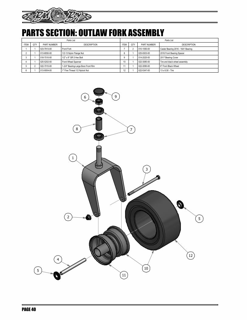
Parts List
ITEM QTY PART NUMBER DESCRIPTION
1 1 023-7913-00 Front Fork
2 1 013-8050-00 1/2-13 Nylon Flange Nut
3 1 018-7010-00 1/2" x 9" GR 5 Hex Bolt
4 1 025-5202-00 Front Wheel Spanner
5 2 022-7010-00 1-3/4" Bearing-Large Bore Front Rim
6 1 013-9004-00 1" Fine Thread 1/2 Nylock Nut
Parts List
ITEM QTY PART NUMBER DESCRIPTION
7 2 010-1050-00 Caster Bearing 2016 - 1641 Bearing
8 1 025-0003-00 2016 Front Bearing Spacer
9 1 014-2025-00 2017 Bearing Cover
10 1 022-3085-00 Tire and black wheel assembly
11 1 022-3090-00 6" Front Black Wheel
12 1 022-5347-00 13 x 6.50 - Tire
PARTS SECTION: OUTLAW FORK ASSEMBLY
PAGE 40
5
5
2
3
1
7
9
10
4
6
8
11
12
Parts List
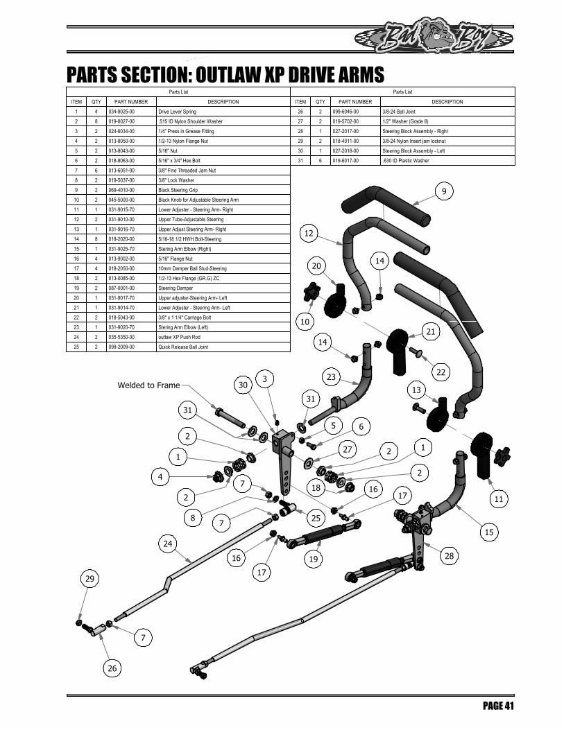
ITEM QTY PART NUMBER DESCRIPTION
1 4 034-8025-00 Drive Lever Spring
2 8 019-8027-00 .515 ID Nylon Shoulder Washer
3 2 024-6034-00 1/4" Press in Grease Fitting
4 2 013-8050-00 1/2-13 Nylon Flange Nut
5 2 013-8043-00 5/16" Nut
6 2 018-8063-00 5/16" x 3/4" Hex Bolt
7 6 013-6051-00 3/8" Fine Threaded Jam Nut
8 2 019-5037-00 3/8" Lock Washer
9 2 069-4010-00 Black Steering Grip
10 2 045-5000-00 Black Knob for Adjustable Steering Arm
11 1 031-9015-70 Lower Adjuster - Steering Arm- Right
12 2 031-9010-00 Upper Tube-Adjustable Steering
13 1 031-9016-70 Upper Adjust Steering Arm- Right
14 8 018-2020-00 5/16-18 1/2 HWH Bolt-Steering
15 1 031-9025-70 Stering Arm Elbow (Right)
16 4 013-9002-00 5/16" Flange Nut
17 4 018-2050-00 10mm Damper Ball Stud-Steering
18 2 013-0085-00 1/2-13 Hex Flange (GR.G) ZC
19 2 087-0001-00 Steering Damper
20 1 031-9017-70 Upper adjuster-Steering Arm- Left
21 1 031-9014-70 Lower Adjuster - Steering Arm- Left
22 2 018-5043-00 3/8" x 1 1/4" Carriage Bolt
23 1 031-9020-70 Stering Arm Elbow (Left)
24 2 035-5350-00 outlaw XP Push Rod
25 2 099-2009-00 Quick Release Ball Joint
Parts List
ITEM QTY PART NUMBER DESCRIPTION
26 2 099-6046-00 3/8-24 Ball Joint
27 2 019-5702-00 1/2" Washer (Grade 8)
28 1 027-2017-00 Steering Block Assembly - Right
29 2 018-4011-00 3/8-24 Nylon Insert jam locknut
30 1 027-2018-00 Steering Block Assembly - Left
31 6 019-6017-00 .630 ID Plastic Washer
PARTS SECTION: OUTLAW XP DRIVE ARMS
PAGE 41
24
29
26
7
17
16
78
7
25
19
1716
65
330
23
14
14
10
20
12
9
22
21
15
11
13
28
2 1
2
18
Welded to Frame
2
1
4
2
31
27
31

DETAIL A
DETAIL B
A
B
PARTS SECTION: OUTLAW XP GAS TANK ASSEMBLIES
PAGE 42
36
35
1617
17
15
17
16
1620 35
10
21
25
24
23
22
28
29
26
33
30
27
32
34
3478
9
63
219
14
13 15 14
13
13
14
11
12
4
5
7
8
91
3118
37
38
34
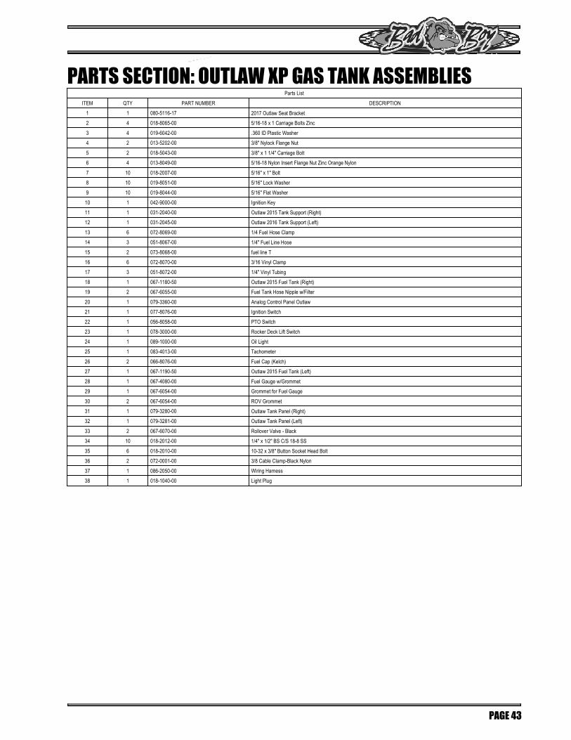
Parts List
ITEM QTY PART NUMBER DESCRIPTION
1 1 080-5116-17 2017 Outlaw Seat Bracket
2 4 018-8065-00 5/16-18 x 1 Carriage Bolts Zinc
3 4 019-6042-00 .360 ID Plastic Washer
4 2 013-5202-00 3/8" Nylock Flange Nut
5 2 018-5043-00 3/8" x 1 1/4" Carriage Bolt
6 4 013-8049-00 5/16-18 Nylon Insert Flange Nut Zinc Orange Nylon
7 10 018-2007-00 5/16" x 1" Bolt
8 10 019-8051-00 5/16" Lock Washer
9 10 019-8044-00 5/16" Flat Washer
10 1 042-9000-00 Ignition Key
11 1 031-2040-00 Outlaw 2015 Tank Support (Right)
12 1 031-2045-00 Outlaw 2016 Tank Support (Left)
13 6 072-8069-00 1/4 Fuel Hose Clamp
14 3 051-8067-00 1/4" Fuel Line Hose
15 2 073-8068-00 fuel line T
16 6 072-8070-00 3/16 Vinyl Clamp
17 3 051-8072-00 1/4" Vinyl Tubing
18 1 067-1180-50 Outlaw 2015 Fuel Tank (Right)
19 2 067-6055-00 Fuel Tank Hose Nipple w/Filter
20 1 079-3360-00 Analog Control Panel Outlaw
21 1 077-8076-00 Ignition Switch
22 1 056-8058-00 PTO Switch
23 1 078-3000-00 Rocker Deck Lift Switch
24 1 089-1000-00 Oil Light
25 1 083-4013-00 Tachometer
26 2 066-8076-00 Fuel Cap (Kelch)
27 1 067-1190-50 Outlaw 2015 Fuel Tank (Left)
28 1 067-4080-00 Fuel Gauge w/Grommet
29 1 067-6054-00 Grommet for Fuel Gauge
30 2 067-6054-00 ROV Grommet
31 1 079-3280-00 Outlaw Tank Panel (Right)
32 1 079-3281-00 Outlaw Tank Panel (Left)
33 2 067-6070-00 Rollover Valve - Black
34 10 018-2012-00 1/4" x 1/2" BS C/S 18-8 SS
35 6 018-2010-00 10-32 x 3/8" Button Socket Head Bolt
36 2 072-0001-00 3/8 Cable Clamp-Black Nylon
37 1 086-2050-00 Wiring Harness
38 1 018-1040-00 Light Plug
PARTS SECTION: OUTLAW XP GAS TANK ASSEMBLIES
PAGE 43

DETAIL A
DETAIL B
DETAIL C
A
B
C
PARTS SECTION: OUTLAW XP FLOORBOARD & BATTERY
PAGE 44
64
2
3
35 3732
3334
3638
18.2
1513
12
17
16
14
20
16
18 18.1
18.3 21
22
8
7
10
11
9
67
5
6
4
4353
54
51
55
48
49
52
47
502527
26
25
46
25
30
29
28
31
39
41 42
40
43
23
24
59
58
57
56
60
25
27
4570
44
68
69
6362
651
2561
52
2642

Parts List
ITEM QTY PART NUMBER DESCRIPTION
1 12 040-6080-00 Ratchet Fastener
2 1 018-8064-00 1/4" x 5/8" BS C/S 18-8 SS
3 1 064-2006-00 Floor board Cable W/ Swivel Ends
4 2 013-8049-00 5/16" Nylock Flange Nut Zinc
5 2 018-8065-00 5/16" x 1" Carriage Bolt
6 2 019-6042-00 .360 ID Plastic Washer
7 6 030-3050-00 #10 x 1/2" Self Tapping Screw
8 6 029-4010-00 Button Bumper
9 1 029-8000-00 2017 XP Bumper
10 2 030-7039-00 1/4" x 1 1/2" Self Tapping Screw
11 2 019-7040-00 1/4" Flat Washer
12 2 013-9001-00 1/4-20 Hex Flange Nuts Zinc w/Serrations
13 2 018-8052-00 1/4-20 x 3/4 GR 5 Hex Bolts Zinc
14 1 064-5300-00 24" Red Battery Cable
15 1 068-8049-00 Battery
16 2 103-5400-00 Black Boot For Ground Cable
17 1 103-5300-00 Red Boot
18 1 043-8929-00 Hold Down Assembly
18.1 1 043-8929-00 Battery Hold Down
18.2 2 018-8050-00 1/4"-20 x 8" Carriage Bolt
18.3 2 013-8051-00 1/4" Wing Nut
20 1 086-0005-00 Ground Cable
21 1 089-0002-00 2015 Outlaw 2x2 Folding ROPS
22 1 070-5380-17 2017 XP Frame
23 1 028-6030-00 2015 Outlaw Act Bar Assembly (Front)
24 1 028-6040-00 2015 Outlaw Act Bar Assembly (Rear)
25 12 013-8050-00 1/2-13 Nylon Flange Nut
26 2 032-3000-00 Bushing- SF-1620-4
27 2 018-0008-00 1/2 x 1-1/2 Carriage Bolt
28 4 017-9000-00 Two Piece Pillow Block (Male)
29 4 017-9050-00 Two Piece Pillow Block (Female)
30 4 017-9025-00 Two Piece Pillow Block Strap
31 8 018-5019-00 1/2" x 4" Bolt (Grade 8)
32 3 025-5203-00 Spacer 3/4 OD x 1/2 ID x 3\4 Length
33 4 018-0009-00 3/8 x 1 3/4 Carriage Bolt
34 1 040-4000-00 Deck height lever pin
Parts List
ITEM QTY PART NUMBER DESCRIPTION
35 4 013-5202-00 3/8" Nylock Flange Nut
36 1 031-0100-00 Outlaw Deck Lever Lock
37 1 026-2100-00 Outlaw Height Indicator Plate (Outer)
38 5 019-2003-00 .390 x .750 x .062 Nylon Washer
39 1 026-0013-00 Outlaw Deck Lift Pedal
40 1 040-5000-00 Pull Pin
41 1 030-0010-00 5/16-18 x1 Thumb Screw Zinc
42 3 013-9002-00 5/16" Flange Nut
43 3 013-7018-00 1/2" Hex Nut
44 1 087-5400-00 200 lb Gas Spring- 54" Deck outlaw
45 2 018-2050-00 10mm Damper Ball Stud-Steering
46 1 028-6055-00 Outlaw Linkage Bar Susp Frame
47 1 039-5944-00 Pump Idler Bracket
48 3 019-6017-00 .630 ID Plastic Washer
49 1 024-6034-00 1/4" Press in Grease Fitting
50 1 013-5301-00 5/8" Nylock (1/2 Jam)
51 1 018-6036-00 1/2" x 2 3/4" Hex Bolt
52 2 025-7036-00 1/2 x 1/2 Spacer
53 1 018-2004-00 All Thread-Pump Idler Tensioner
54 1 034-2009-00 2009 Deck/Pump Idler Spring
55 1 033-6001-00 4 3/4" Idler Pulley
56 1 035-7033-00 Actuator
57 1 018-0022-00 1/2-13x2 Grade 8 Hex Bolt
58 2 019-5702-00 1/2" Washer (Grade 8)
59 1 018-4010-00 1/2" Nylock Nut (1/2 Jam)
60 1 018-7016-00 1/2" x 3" Hex Bolt
61 2 019-8054-00 .505 Nylon Spacer
62 4 018-0050-00 1/2-13 X 3.25 Hex Bolt - Grade 5
63 4 013-0005-00 1/2" Center Lock Nut
64 1 079-3150-00 2017 XP Outlaw Floor Panel
65 1 081-2050-00 2016 Outlaw Floor Mat
67 1 013-8039-00 1/4-20 Hex Nut
68 1 087-6100-00 250 lb Gas Spring 61" Deck Outlaw
69 1 087-7200-00 300 lb Gas Spring 72" Deck Outlaw
70 2 018-2049-00 13mm Ball Stud (72" Deck Only)
PARTS SECTION: OUTLAW XP FLOORBOARD & BATTERY
PAGE 45

DETAIL A
A
PARTS SECTION: OUTLAW XP DRIVE TRAIN & REAR COVER
PAGE 46
16
17
18
57
56
46
9
732
198
25
21
25
24
20
23
22
9
76
15
40
42 41
43
35
35
44
3339
39
36
60
37
34
26
30
77
75
81
6
5859
38
61
13
62
67 66
64
7174
70
68
70
70
63
6870
72
731
45
47
54 55
51
5349
46 52
48
1480
50
11
79
12
10
78
1328
27
32
31
29
13
32
82
12
11
5
69
65

Parts List
ITEM QTY PART NUMBER DESCRIPTION
1 1 070-5380-17 2017 XP Frame
2 4 018-5043-00 3/8" x 1 1/4" Carriage Bolt
3 4 013-5041-00 3/8 Nylock Nut
4 2 018-4702-00 1/4-20 x 1-1/4 GR 5 Hex Bolt
5 1 029-7037-00 14" Rubber Bumper
6 4 019-7040-00 1/4" Flat Washer
7 1 026-2190-00 Outlaw Rear Plate
8 4 019-8040-00 1/4" x 3/4" Carriage Bolt
9 6 013-2050-00 1/4-20 Nylon Insert flange Nut
10 2 070-8000-00 60 Suspension kit Wheel Motor
11 8 018-2030-00 1/2" x 1" Hex Bolt
12 8 019-5007-00 1/2" Lock Washer
13 10 019-5702-00 1/2" Washer (Grade 8)
14 4 051-2000-00 18" hose Assembly W/forged 45 Degr
15 2 033-5003-00 5" Pump Pulley
16 2 022-4095-00 2018 24x12-12 Reaper Turf Tire
17 2 022-4070-00 12x12" Black Wheel For 2015 Outlaw
18 10 018-7033-00 1/2-20 x 1-1/2 Lug Bolts Zinc
19 1 067-8051-00 Outlaw Hydraulic Tank Left
20 2 066-8050-00 Hydraulic Tank Cap W/Dipstick
21 2 051-8063-00 3/8" Clear Hose
22 2 051-8064-00 1/2 Clear Braded Hose Priced/Foot
23 4 072-8066-00 1/2 Hose Clamp
24 1 067-8050-00 Outlaw Hydraulic Tank Right
25 4 072-8065-00 3/8" Hose Clamp
26 2 014-9000-00 2X2 Frame Plug
27 4 032-5056-00 Flange Bushing for Deck Arm - Upper
28 2 018-2051-00 5/8''x10'' Hex Bolt (Grade8)
29 2 013-5301-00 5/8" Nylock (1/2 Jam)
30 2 024-3050-00 1/4" Drive in Grease Fitting (72" Suspension Kit Wheel Moter)
31 2 013-7021-00 5/8 Std NC Nylock Nut
32 4 (2-72" Deck) 032-9000-00 Vibration Mount-Green Dot
33 2 015-9999-00 Hydraulic Fan
34 2 013-8043-00 5/16" Nut
35 4 024-5206-00 3/8" X 9/16"-18 ORB Male Fitting (S,A-2 P-4)
36 2 031-5333-00 Pump Arm
37 2 013-8073-00 1/4" Nylock Nut
38 2 018-4007-00 1/4-20 x 1 GR 5 hex bolt zinc
39 4 024-5343-00 Hydraulic Pump Fitting 6400-10
40 4 018-6012-00 3/8" x 1 1/2" Hex Bolt
41 4 019-5037-00 3/8" Lock Washer
Parts List
ITEM QTY PART NUMBER DESCRIPTION
42 4 019-5029-00 3/8" Flat Washer
43 4 013-6014-00 3/8" Hex Nut
44 2 014-5600-00 Fan Guard 6" Fits wheel Motor Pumps
45 2 020-7022-00 1/8x2-1/4 cotter pin Zinc
46 2 042-7041-00 Woodruff Key
47 2 013-7050-00 1" Castle Nut for Wheel Motor
48 4 024-0050-00 45 Degree Fitting 31704-10-10
49 8 013-5300-00 1/2" Flange Nut
50 8 018-6036-00 1/2" x 2 1/2" Hex Bolt
51 2 013-8047-00 5/16-18 Nylock Insert Locknut
52 1 015-4501-00 15cc Parker Wheel Motor- Left
53 2 092-5201-00 Brake Disk
54 1 092-7001-00 XP/AOS Left Brake Caliper
55 2 018-6049-00 3/8" x 1" Hex Bolt
56 1 015-4500-00 15cc Parker Wheel Motor- Right
57 1 092-7000-00 XP/AOS Right Brake Caliper
58 2 019-4008-00 1/4" Lock Washer
59 2 018-0024-00 M6-1.0 X 16MM Hex Bolt
60 2 042-5301-00 5MM X 1 Square Key Stock
61 2 032-9002-00 Vibration Mount- Red Dot
62 2 018-1055-00 1/2" x 3/4" Hex Bolt
63 2 014-3010-00 5/8 Round Insert
64 2 018-0026-00 1-14 x 5.5 Hex Bolt Grade 8 Zinc Yellow
65 2 013-9004-00 1" Fine Thread Nut
66 1 029-8000-00 2017 XP Bumper
67 2 030-7040-00 1/4 x 1 Hex Head Tek screw
68 2 025-0003-00 2016 Front Bearing Spacer
69 2 058-1000-00 1" x .25" Spacer
70 4 010-1050-00 Caster Bearing 2016 - 1641 Bearing
71 1 250-2650-00 2017 XP Suspension Arm - Right
72 1 250-2600-98 2017 XP Arm Assembly - Left
73 1 250-2600-00 2017 XP Suspension Arm -Left
74 1 250-2650-98 2017 XP Arm Assembly - Right
75 1 050-3000-00 Left Pump 12cc
76 2 022-4100-00 2018 24x12-12 Reaper Turf Tire and Black Wheel Assembly
77 2 024-8000-00 3/8" Threaded Grease Fitting (60" Suspension Kit Wheel Moter)
78 2 070-8001-00 72" Suspension Kit Wheel Motor
79 8 018-2080-00 1/2-13 x 1 1/4 Hex Bolt (Only on 60" Suspension Kit Wheel Motor)
80 4 051-6005-00 18" Hydraulic Hose Only
81 1 050-3050-00 Right Pump 12cc
82 2 (72" Deck) 032-8999-00 Vibration Mount-Blue Dot
PARTS SECTION: OUTLAW XP DRIVE TRAIN & REAR COVER
PAGE 47

DETAIL A
DETAIL B
PARTS SECTION: OUTLAW XP SEAT ASSEMBLY
PAGE 48
A
B
6718
19
72
70
71
74
73 1213
3
4
9
4
10
9
69
23
68
16
24
49
42
4
22
43
5538
1456
48
37
39
39
9
40
41
36
36
62
62
3652
51
49 50
35 63
3563
35
35
56
33
32
34
5453
7
6
61
60
58
57
22
59
64
5
65
9
64
6
22
2120
6 47
1517
14 16
45
4
5
9
2726
8
2
166
302931
28
46
44
25
11

Parts List
ITEM QTY PART NUMBER DESCRIPTION
1 1 080-5116-17 2017 Outlaw Seat Bracket
2 1 014-2100-00 Outlaw Cooler Cover
3 1 026-2016-00 2016 Seat Plate Outlaw
4 10 018-8065-00 *Varies*
5 6 019-6042-00 .360 ID Plastic Washer
6 10 013-5202-00 3/8" Nylock Flange Nut
7 2 018-5043-00 3/8" x 1 1/4" Carriage Bolt
8 4 030-7042-00 5/16 x 3/4 washer head type F screw
9 14 013-8049-00 5/16" Nylock Flange Nut Zinc
10 2 019-6050-00 .360 ID Plastic Washer-Black
11 1 071-5060-00 2015 Outlaw Seat
12 4 013-9002-00 5/16" Flange Nut
13 1 036-5300-00 Seat Switch Adapter
14 3 077-8073-00 Safety Switch
15 4 018-8058-00 10-24 x 1 BS C/S 18-8 SS
16 6 013-5019-00 10-24 Nylon Insert Locknut
17 2 025-6041-00 Switch Block Plastic
18 1 054-8017-00 Choke
19 1 013-6051-00 3/8" Fine Threaded Jam Nut
20 2 018-0009-00 3/8 x 1 3/4 Carriage Bolt
21 4 018-1010-00 3/8-16x3-1/2 grade 5 hex bolt
22 9 019-5029-00 3/8" Flat Washer
23 1 055-2012-00 Universal Throttle
24 2 018-5200-00 10-24 X 5/8 BS Button Head Bolt
25 2 018-4700-00 3/8-16x3 grade 5 hex bolt
26 2 018-0024-00 M6-1.0 X 16MM Hex Bolt
27 1 067-0020-00 Carbon Canister
28 1 051-8072-00 1/4" Vinyl Tubing
29 1 051-8073-00 3/16 Vinyl Tubing
30 2 072-8073-00 3/16" Vinyl Hose Clamp
31 2 072-8070-00 3/16 Vinyl Clamp
32 1 039-2130-00 Outlaw Filter Bracket
33 2 013-5041-00 3/8 Nylock Nut
34 4 019-7040-00 1/4" Flat Washer
35 4 072-8066-00 1/2 Hose Clamp
36 4 072-8065-00 3/8" Hose Clamp
37 1 039-0150-00 Brake Cable Adapter Bracket
38 2 018-1080-00 12-24x 1/2 HWH Bolt
Parts List
ITEM QTY PART NUMBER DESCRIPTION
39 2 013-9005-00 5/16-18 Nylock Jam Nut 1/2 Nut
40 1 069-1000-00 Brake Handle Cam Over
41 1 069-7000-00 Rubber Brake Grip-cZT/ZT 2013
42 1 032-5053-00 Bronze Bushing SF-1220-8
43 1 013-9003-00 3/8 Nylock Jam Nut 1/2 Nut
44 1 031-2045-00 Outlaw 2016 Tank Support (Left)
45 1 031-2040-00 Outlaw 2015 Tank Support (Right)
46 1 064-9001-00 2015 XP Brake Cable - Long
47 1 064-9000-00 2015 XP Brake Cable - Short
48 1 018-2007-00 5/16" x 1" Bolt
49 2 062-8013-00 Filter Head-Hydraulic Filter
50 2 024-5050-00 Filter Head Fitting 1/2 x 1/2
51 2 063-8014-00 Filter
52 2 024-5342-00 1/2" Pipe to 3/8" Barb
53 4 018-8052-00 1/4" x 3/4" Hex Bolt
54 4 019-4008-00 1/4" Lock Washer
55 1 025-0001-00 2015 Brake Lever Spacer
56 3 018-4706-00 3/8 x 1 1/2 Carriage Bolt
57 2 018-5040-00 3/8" x 1 1/4" Hex Bolt
58 2 034-8045-00 Seat Spring
59 2 014-8047-00 Seat Spring Cap Cover
60 2 019-5037-00 3/8" Lock Washer
61 2 013-6014-00 3/8-16 Hex Nuts Zinc
62 2 051-8063-00 3/8" Clear Hose
63 2 051-8064-00 1/2 Clear Braded Hose Priced/Foot
64 2 034-1025-00 Brake Spring
65 1 028-0085-00 Seat Latch Rod Assembly 2016 Models
66 1 064-8081-00 Seat Cable
67 1 055-2013-00 Throttle Knob
68 1 055-8021-75 Outlaw Throttle Cable (Cable Only)
69 1 071-5063-00 Extreme/XP Outlaw Seat Cushion - Bottom
70 1 071-5064-00 Extreme/XP Outlaw Seat Cushion - Back
71 1 071-5062-00 Extreme/XP Outlaw Seat Arm Pads Only (Pair)
72 1 071-5061-00 Extreme/XP Outlaw Seat Arm Rest (Pair)
73 1 071-5015-00 Extreme/XP Outlaw Seat Rails
74 1 071-8061-00 Seat Switch
75 1 071-2013-00 Seat Belt Kit (Not Shown)
PARTS SECTION: OUTLAW XP SEAT ASSEMBLY
PAGE 49

DETAIL ADETAIL B
DETAIL C
DETAIL D
A
B
C
D
PARTS SECTION: OUTLAW 54" DECK
PAGE 50
4
41
4464
42
42
61
8
4
517
5857
5732
56
6055
59
16 15
35
3445
13
1220
18
17
33
19
54
52
4
47
43
41
57584
57
32
24
28
23
65
27
22 26
25
321
2
28
1
37
36
14
4
1830
29
4
46 29
30
184
5
6
531
53 4
4
53
11
10
9
48
62
49
50
4 39 40
38
47
63

Parts List
ITEM QTY PART NUMBER DESCRIPTION
1 1 060-5550-00 2015 54" Deck
2 3 018-5250-00 3/8" x 3/4" Hex Bolt
3 3 013-5201-00 3/8" Flange Nut
4 30 013-8050-00 1/2-13 Nylon Flange Nut
5 3 018-2018-00 1/2 x 3 1/2 Flange Bolt Grade 8
6 2 025-5338-00 Idler Pulley Standoff
7 1 018-1050-00 1/2 x 2" Carriage Bolt
8 1 034-2020-00 Deck Idler Spring
9 1 018-5311-00 5/8" x 4" Hex Bolt
10 2 019-6017-00 .630 ID Plastic Washer
11 1 013-5301-00 5/8-11 Nylon Insert Jam Half Nut
12 12 019-5037-00 3/8 Lockwasher Zinc
13 12 013-6014-00 3/8-16 Hex Nuts Zinc
14 6 018-3003-00 1/2" x 1 1/4 Carriage Bolt
15 3 019-5038-00 5/8'' Flat Washer
16 3 018-6020-00 5/8" x 1 1/2" Grade 8 Hex Bolt (Fine)
17 3 018-6019-00 1/2"-20 x 1 1/2 - Grade 5 Fine Thread Bolt
18 9 019-6020-00 1/2" Belleville Washer
19 3 030-0050-00 5/16 Set Screw
20 3 042-6030-00 1/4" x 1" Key
21 1 206-6017-00 Discharge Chute Hanger (deck mounted)
22 1 039-4864-00 60" Discharge Chute Upper Hanger
23 1 210-6005-00 Rubber Discharge Chute
24 1 039-4863-00 60" Discharge Lower Bracket
25 2 019-6042-00 .360 ID Plastic Washer
26 2 018-2007-00 5/16" x 1" Bolt
27 5 018-4703-00 5/16" x 1 1/4" Carriage Bolt
28 7 013-8049-00 5/16" Nylock Flange Nut Zinc
29 6 018-0010-00 Deck Wheel Bolt
30 6 022-1000-00 Anti-Scalp Roller
31 1 025-5339-00 1 3/4" Pulley Spacer
32 4 018-5019-00 1/2" x 4" Bolt (Grade 8)
33 3 033-6006-00 5.25" Deck Spindle Pulley
Parts List
ITEM QTY PART NUMBER DESCRIPTION
34 12 018-5040-00 3/8" x 1 1/4" Hex Bolt
35 3 038-0001-00 54" Deck Fusion Blade For Outlaw
36 1 060-5520-00 54 Deck Adustable Front (Left)
37 1 060-5530-00 54 Deck Adustable Front (Right)
38 2 014-5000-00 Pulley Cover
39 4 013-0004-00 Acorn nut-pulley Cover
40 4 019-6050-00 .360 ID Plastic Washer-Black
41 16 019-8054-00 .505 Nylon Spacer
42 8 018-6037-00 1/2-13X 2-1/4 GR Hex Bolts
43 8 013-5300-00 1/2" Flange Nut
44 4 039-2125-00 Deck_Hanging_Tab
45 3 037-4000-00 OUTLAW SPINDLE ASSEMBLY
46 1 041-1650-00 60" ZT Deck Belt
47 5 024-6034-00 1/4" Press in Grease Fitting
48 1 039-6945-00 Deck Idler
49 1 025-5203-00 Spacer 3/4 OD x 1/2 ID x 3\4 Length
50 1 033-8050-00 5" Idler Pully
51 1 019-0007-00 .517 Square Hole Round Washer
52 3 019-5007-00 1/2" Lock Washer
53 3 033-7201-25 5-3/4 Idler Pulley-Capitol Stampings
54 2 048-7020-00 2015 Outlaw Toplink Body
55 2 013-0008-00 3/4-10 Left-Handed Hex Nuts Zinc
56 2 013-0007-00 3/4-10 Hex Nuts Zinc
57 8 032-2000-00 Bushing
58 4 032-2001-00 Sleeve
59 2 048-7022-00 Turn Left-Handed
60 2 048-7021-00 Right-Handed End
61 1 018-7016-00 1/2-13 x GR 5 Hex Bolt Zinc
62 1 039-6945-01 Deck Idler Assembly - Includes parts:4, 47, 48, 49, 50, 61
63 2 048-7000-00 Turnbuckle Assembly
64 1 039-2125-17 Outlaw Deck Hanger Assembly - Includes Parts:4,41,42,43,44
65 1 210-6005-98 Chute Assembly - Includes Parts:22,23,24,27,28
PARTS SECTION: OUTLAW 54" DECK
PAGE 51

DETAIL ADETAIL B
DETAIL C
DETAIL D
A
B
C
D
PARTS SECTION: OUTLAW 61" DECK
PAGE 52
8
50
7 53
4
42
4564
43
44
4
458
57
48
6057 33
56 55
59
17
20
3419
18
1213
21
46
36
35
1516
5448
47
3031
18
4
532
61
4
461
6
5
910
48
11
51
524
4962
40 41
39
1
38
44
14
3718
31
30
29
25
24
65
28
2327
2629
2
3
22
63

Parts List
ITEM QTY PART NUMBER DESCRIPTION
1 1 060-6150-00 2015 61" Deck
2 3 018-5250-00 3/8" x 3/4" Hex Bolt
3 3 013-5201-00 3/8" Flange Nut
4 32 013-8050-00 1/2-13 Nylon Flange Nut
5 3 018-2018-00 1/2 x 3 1/2 Flange Bolt Grade 8
6 2 025-5338-00 Idler Pulley Standoff
7 1 018-1050-00 1/2 x 2" Carriage Bolt
8 1 034-2020-00 Deck Idler Spring
9 1 018-5311-00 5/8" x 4" Hex Bolt
10 2 019-6017-00 .630 ID Plastic Washer
11 1 013-5301-00 5/8-11 Nylon Insert Jam Half Nut
12 12 019-5037-00 3/8 Lockwasher Zinc
13 12 013-6014-00 3/8-16 Hex Nuts Zinc
14 8 018-3003-00 1/2" x 1 1/4 Carriage Bolt
15 3 019-5038-00 5/8'' Flat Washer
16 3 018-6020-00 5/8" x 1 1/2" Grade 8 Hex Bolt (Fine)
17 3 018-6019-00 1/2"-20 x 1 1/2 - Grade 5 Fine Thread Bolt
18 9 019-6020-00 1/2" Belleville Washer
19 3 030-0050-00 5/16 Set Screw
20 3 019-5007-00 1/2" Lock Washer
21 3 042-6030-00 1/4" x 1" Key
22 1 206-6017-00 Discharge Chute Hanger (deck mounted)
23 1 039-4864-00 60" Discharge Chute Upper Hanger
24 1 210-6005-00 Rubber Discharge Chute
25 1 039-4863-00 60" Discharge Lower Bracket
26 2 019-6042-00 .360 ID Plastic Washer
27 2 018-2007-00 5/16" x 1" Bolt
28 5 018-4703-00 5/16" x 1 1/4" Carriage Bolt
29 7 013-8049-00 5/16" Nylock Flange Nut Zinc
30 6 018-0010-00 Deck Wheel Bolt
31 6 022-1000-00 Anti-Scalp Roller
32 1 025-5339-00 1 3/4" Pulley Spacer
33 4 018-5019-00 1/2" x 4" Bolt (Grade 8)
Parts List
ITEM QTY PART NUMBER DESCRIPTION
34 3 033-6004-00 6 1/4" Drive Pulley
35 3 038-6080-00 61 inch Fusion Blade
36 12 018-5040-00 3/8" x 1 1/4" Hex Bolt
37 1 060-6220-00 61 Deck Adustable Front (Left)
38 1 060-6210-00 61 Deck Adustable Front (Right)
39 2 014-5000-00 Pulley Cover
40 4 013-0004-00 Acorn nut-pulley Cover
41 4 019-6050-00 .360 ID Plastic Washer-Black
42 16 019-8054-00 .505 Nylon Spacer
43 8 018-6037-00 1/2-13X 2-1/4 GR Hex Bolts
44 8 013-5300-00 1/2" Flange Nut
45 4 039-2125-00 Deck_Hanging_Tab
46 3 037-4000-00 OUTLAW SPINDLE ASSEMBLY
47 1 041-0178-00 B178 Belt For 61 Inch Outlaw
48 5 024-6034-00 1/4" Press in Grease Fitting
49 1 039-6945-00 Deck Idler
50 1 018-7016-00 1/2-13 x GR 5 Hex Bolt Zinc
51 1 025-5203-00 Spacer 3/4 OD x 1/2 ID x 3\4 Length
52 1 033-8050-00 5" Idler Pully
53 1 019-0007-00 .517 Square Hole Round Washer
54 2 048-7020-00 2015 Outlaw Toplink Body
55 2 013-0008-00 3/4-10 Left-Handed Hex Nuts Zinc
56 2 013-0007-00 3/4-10 Hex Nuts Zinc
57 8 032-2000-00 Bushing
58 4 032-2001-00 Sleeve
59 2 048-7022-00 Turn Left-Handed
60 2 048-7021-00 Right-Handed End
61 3 033-7201-25 5-3/4 Idler Pulley-Capitol Stampings
62 1 039-6945-01 Deck Idler Assembly - Includes parts: 4, 49, 48, 50, 51, 52,
63 2 048-7000-00 Turnbuckle Assembly
64 1 039-2125-17 Outlaw Deck Hanger Assembly - Includes Parts:4,42,43,44,45
65 1 210-6005-98 Chute Assembly - Includes Parts:23,24,25,28,29
PARTS SECTION: OUTLAW 61" DECK
PAGE 53
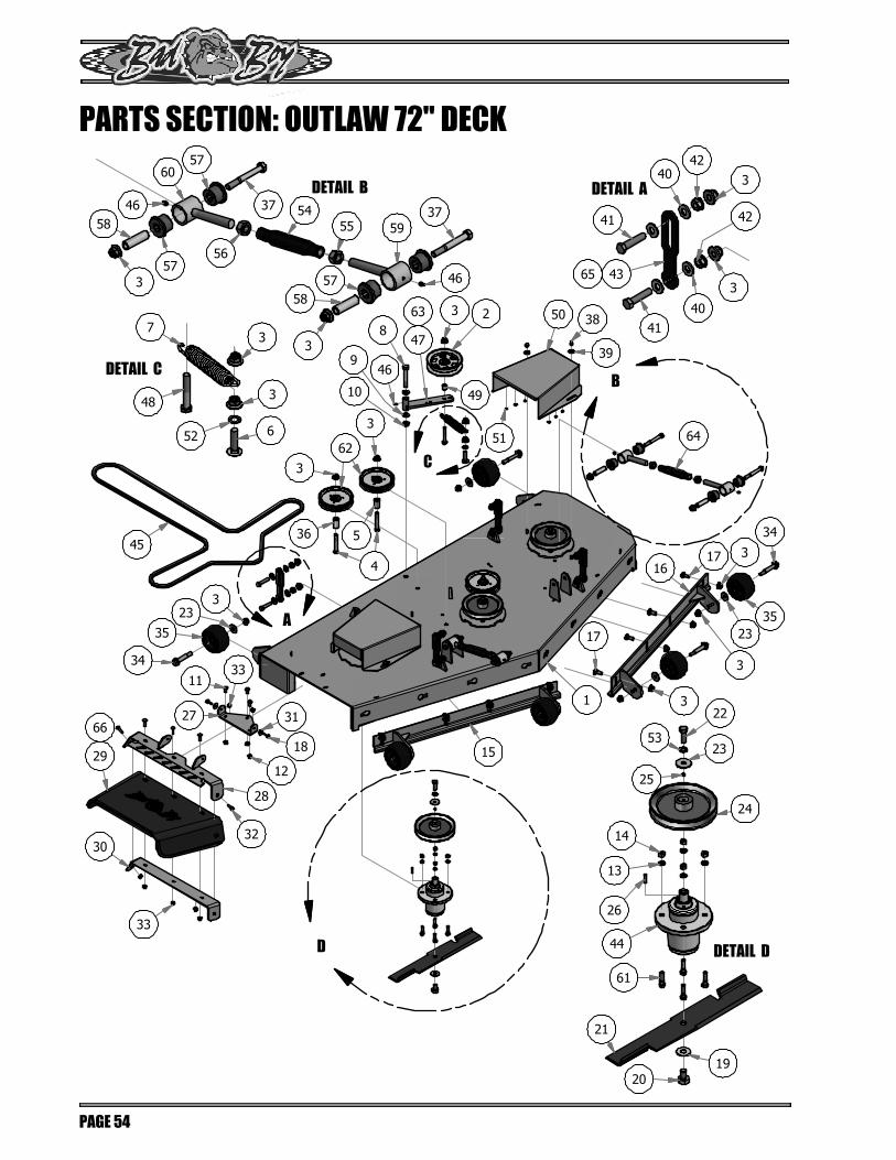
DETAIL ADETAIL B
DETAIL C
DETAIL D
A
B
C
D
PARTS SECTION: OUTLAW 72" DECK
PAGE 54
2019
21
61
44
26
13
14
24
23
22
25
652
3
3
48
7 41
3
42
40
43653
58
57
57
37
60
56
55 5954
53
46
40
41
423
58
3
57
3746
30
29
66
33
28
32
12
18
31
15
17 3
2335
34
3
3
17
1
51
50
39
38
45
323
35
3433
11
27
4
62
3
3
3 2
49
47
63
10
946
8
36 5
16
64

Parts List
ITEM QTY PART NUMBER DESCRIPTION
1 1 060-7250-00 2015 72" Deck
2 1 033-8050-00 5" Idler Pully
3 32 013-8050-00 1/2-13 Nylon Flange Nut
4 3 018-2018-00 1/2 x 3 1/2 Flange Bolt Grade 8
5 2 025-5338-00 Idler Pulley Standoff
6 1 018-1050-00 1/2 x 2" Carriage Bolt
7 1 034-2020-00 Deck Idler Spring
8 1 018-5311-00 5/8" x 4" Hex Bolt
9 2 019-6017-00 .630 ID Plastic Washer
10 1 013-5301-00 5/8-11 Nylon Insert Jam Half Nut
11 3 018-5250-00 3/8" x 3/4" Hex Bolt
12 3 013-5201-00 3/8" Flange Nut
13 12 019-5037-00 3/8 Lockwasher Zinc
14 12 013-6014-00 3/8-16 Hex Nuts Zinc
15 1 060-7211-00 72" Deck Adustable Front (Right)
16 1 060-7210-00 72" Deck Adjustable Front (Left)
17 8 018-3003-00 1/2" x 1 1/4 Carriage Bolt
18 2 018-2007-00 5/16" x 1" Bolt
19 3 019-5038-00 5/8'' Flat Washer
20 3 018-6020-00 5/8" x 1 1/2" Grade 8 Hex Bolt (Fine)
21 3 038-7230-00 72" High Lift Fusion Blade
22 3 018-6019-00 1/2"-20 x 1 1/2 - Grade 5 Fine Thread Bolt
23 9 019-6020-00 1/2" Belleville Washer
24 3 033-7203-00 7" Deck Pulley
25 3 030-0050-00 5/16 Set Screw
26 3 042-6030-00 1/4" x 1" Key
27 1 206-6017-00 Discharge Chute Hanger (deck mounted)
28 1 039-4864-00 60" Discharge Chute Upper Hanger
29 1 210-6005-00 Rubber Discharge Chute
30 1 039-4863-00 60" Discharge Lower Bracket
31 2 019-6042-00 .360 ID Plastic Washer
32 5 018-4703-00 5/16" x 1 1/4" Carriage Bolt
33 7 013-8049-00 5/16" Nylock Flange Nut Zinc
Parts List
ITEM QTY PART NUMBER DESCRIPTION
34 6 018-0010-00 Deck Wheel Bolt
35 6 022-1000-00 Anti-Scalp Roller
36 1 025-5339-00 1 3/4" Pulley Spacer
37 4 018-5019-00 1/2" x 4" Bolt (Grade 8)
38 4 013-0004-00 Acorn nut-pulley Cover
39 4 019-6050-00 .360 ID Plastic Washer-Black
40 16 019-8054-00 .505 Nylon Spacer
41 8 018-6037-00 1/2-13X 2-1/4 GR Hex Bolts
42 8 013-5300-00 1/2" Flange Nut
43 4 039-2125-00 Deck_Hanging_Tab
44 3 037-4000-00 OUTLAW SPINDLE ASSEMBLY
45 1 041-0202-00 B202 Belt for 72" Outlaw
46 5 024-6034-00 1/4" Press in Grease Fitting
47 1 039-6945-00 Deck Idler
48 1 018-7016-00 1/2-13 x GR 5 Hex Bolt Zinc
49 1 025-5203-00 Spacer 3/4 OD x 1/2 ID x 3\4 Length
50 2 014-7204-00 72 Outlaw Spindle Pulley Cover
51 12 058-6000-00 Black, Round Stick-On Rubber Bumper
52 1 019-0007-00 .517 Square Hole Round Washer
53 3 019-5007-00 1/2" Lock Washer
54 2 048-7020-00 2015 Outlaw Toplink Body
55 2 013-0008-00 3/4-10 Left-Handed Hex Nuts Zinc
56 2 013-0007-00 3/4-10 Hex Nuts Zinc
57 8 032-2000-00 Bushing
58 4 032-2001-00 Sleeve
59 2 048-7022-00 Turn Left-Handed
60 2 048-7021-00 Right-Handed End
61 12 018-6012-00 3/8" x 1 1/2" Hex Bolt
62 3 033-7201-25 5-3/4 Idler Pulley-Capitol Stampings
63 1 039-6945-01 Deck Idler Assembly - Includes parts: 2,3,46,47,48,49
64 2 048-7000-00 Turnbuckle Assembly
65 1 039-2125-17 Outlaw Deck Hanger Assembly - Includes Parts:3,40,41,42,43
66 1 210-6005-98 Chute Assembly - Includes Parts:28,29,30,32,33
PARTS SECTION: OUTLAW 72" DECK
PAGE 55

PARTS SECTION: 037-4000-00 DOUBLE BEARING SPINDLE
PAGE 56
Parts List
ITEM QTY PART NUMBER DESCRIPTION
1 1 037-4000-01 4000 Series Spindle Housing
2 1 037-4002-00 4000 Series Spindle Spacer
3 1 037-9050-00 Locking Collar w/ 1/4"-20 Set Screw
4 2 037-8002-00 Spindle Dust Cap
5 1 037-6026-00 Spindle Shaft
6 4 037-6029-00 Bearing - Peer 6206
3
4
6
2
1
6
4
5

Parts List
ITEM QTY PART NUMBER DESCRIPTION
1 1 015-0031-00 Kawasaki Engine FX-850-V-CS09R
2 1 033-5035-00 4 3/4 Motor Pulley
3 1 041-8411-00 Pump Belt
4 1 030-6029-00 3/8" Set Screw
5 1 042-5020-00 1/4 x 2 Square key Stock
6 4 018-1075-00 3/8 x 1 1/8 bolt
7 1 103-5400-00 Black Boot For Ground Cable
8 1 018-5321-00 M8x1.20x20MM Hex head bolt
9 5 019-8051-00 5/16" Lock Washer
10 1 063-6000-00 Universal Inline Fuel Filter
11 1 015-0035-00 Kawasaki Exhaust
12 1 063-8020-00 Canister Air Filter- Inner
13 1 063-8019-00 Canister Air Filter- Outer
14 4 013-0075-00 M8-1.25 Zinc Nut
15 1 086-0005-00 Ground Cable
Parts List
ITEM QTY PART NUMBER DESCRIPTION
16 1 019-8053-00 7/16" Lock Washer
17 1 018-5300-00 7/16" x 2 1/2" Hex Bolt
18 1 070-1000-00 Clutch Assembly
19 1 070-2000-00 Clutch Pigtail
20 1 057-5906-00 PTO Engager Holder
21 2 018-6049-00 3/8" x 1" Hex Bolt
22 2 019-5037-00 3/8" Lock Washer
23 2 013-6014-00 3/8" Hex Nut
24 2 015-2709-00 Exhaust Gasket
25 1 086-9002-00 Harness Adaptor
26 1 019-6029-00 1 1/8" Flat Spacer
27 2 015-8001-00 Spark Plug - Kawasaki
28 1 051-5404-00 Oil drain Hose
29 1 063-8017-00 Kawsaki Oil Filter
30 1 088-1071-00 Kawasaki Rain Cap
PARTS SECTION: FX 850-V KAWASAKI
PAGE 57
8
28
7
15
21
20
24
5
22
23
10
317
18
19
1
1213
11
14
9
29
30
24
25
27
6
16
9
26

Parts List
ITEM QTY PART NUMBER DESCRIPTION
1 1 033-5035-00 4 3/4 Motor Pulley
2 1 042-5020-00 1/4 x 2 Square key Stock
3 1 019-6029-00 1 1/8" Flat Spacer
4 1 030-6029-00 3/8" Set Screw
5 1 019-8053-00 7/16" Lock Washer
6 1 018-5300-00 7/16" x 2 1/2" Hex Bolt
7 1 070-1000-00 Clutch Assembly
8 1 070-2000-00 Clutch Pigtail
9 1 057-5906-00 PTO Engager Holder
10 2 018-6049-00 3/8" x 1" Hex Bolt
11 2 019-5037-00 3/8" Lock Washer
12 2 013-6014-00 3/8" Hex Nut
13 1 015-0050-00 Yamaha Muffler
14 1 015-0053-05 O2 Sensor for Yamaha
15 2 015-0053-01 Exhaust Gasket for yamaha
16 4 019-8051-00 5/16" Lock Washer
17 4 013-0075-00 M8-1.25 Zinc Nut
Parts List
ITEM QTY PART NUMBER DESCRIPTION
18 1 041-8411-00 Pump Belt Diesel
19 1 051-5403-00 Oil drain Hose for Yamaha
20 1 063-6000-00 Universal Inline Fuel Filter
21 1 015-0053-00 Yamaha 33hp Engine
22 1 015-0053-03 Yamaha Fuel Pump
23 1 015-0053-04 Yamaha Fuel Pump Bracket
24 3 019-8040-00 1/4" x 3/4" Carriage Bolt
25 3 013-2050-00 1/4-20 Nylon Insert flange Nut
26 3 018-0099-00 M6-1.0x16mm Washer Head Hex Bolt
27 4 018-1075-00 3/8 x 1 1/8 bolt
28 2 015-0053-06 Spark Plug - Yamaha
29 1 051-8067-00 1/4 Fuel Line 15"
30 1 063-8019-00 Canister Air Filter- Outer
31 1 015-0053-02 Oil Filter
32 1 063-8020-00 Canister Air Filter- Inner
33 1 015-0053-21 Yamaha Fuel Filter
PARTS SECTION: 824CC YAMAHA
PAGE 58
22
18
6
5
7
12
11
10
93
4
21
2033
1716
13
26
25
2324
8
19
32
30 21
14
15
27
27
31
28
29

Parts List
ITEM QTY PART NUMBER DESCRIPTION
1 1 042-6030-00 1/4" x 1" Key
2 1 030-0050-00 5/16 Set Screw
3 1 086-0005-00 Ground Cable
4 1 019-8051-00 5/16" Lock Washer
5 1 013-8043-00 5/16" Nut
6 1 103-5400-00 Black Boot For Ground Cable
7 1 018-8059-00 5/16" x 1 3/4" Hex Bolt
8 3 018-1075-00 3/8 x 1 1/8 bolt
9 2 015-0025-00 Exhaust Gasket for 23 Vanguard
10 1 015-3600-00 993cc Briggs Vanguard Engine
11 1 033-5035-00 4 3/4 Motor Pulley
12 1 063-6000-00 Universal Inline Fuel Filter
13 1 063-8020-00 Canister Air Filter- Inner
14 1 063-8019-00 Canister Air Filter- Outer
15 1 051-5402-00 14 mm Oil drain Hose 993cc Vanguard
16 1 019-6029-00 1 1/8" Flat Spacer
Parts List
ITEM QTY PART NUMBER DESCRIPTION
17 1 041-8411-00 Pump Belt
18 1 019-8053-00 7/16" Lock Washer
19 1 018-5300-00 7/16" x 2 1/2" Hex Bolt
20 1 070-1000-00 Clutch Assembly
21 1 070-2000-00 Clutch Pigtail
22 1 057-5906-00 PTO Engager Holder
23 2 018-6049-00 3/8" x 1" Hex Bolt
24 2 019-5037-00 3/8" Lock Washer
25 2 013-6014-00 3/8" Hex Nut
26 1 086-9001-00 Harness Adaptor - 933cc Vanguard
27 1 015-0049-00 2015 Exhaust - 36hp Vanguard
30 4 018-0017-00 Torx Bolt-Exhaust
28 2 015-8000-00 Spark Plug
30 1 063-8018-00 Briggs Oil Filter
31 1 015-2705-00 Complete Canister
32 1 063-2045-00 Rain Cap Fits all Canisters
PARTS SECTION: 993CC VANGUARD
PAGE 59
27
21
19
18
20
22
24
25
23
11
2
1
5
4
3
7
6
15
10
14
13 12
30
9
31
32
16
8
17
26
30
28

PARTS SECTION: DECALS
PAGE 60
091-0414-18824cc BACKPLATE DECAL
091-0348-18852cc BACKPLATE DECAL
091-0347-18993cc BACKPLATE DECAL
091-0904-1854" DECK DECAL
091-0917-1861" DECK DECAL
091-0918-1872" DECK DECAL
091-0919-18ARMORTEK5 DECAL
091-3060-00SWING-AWAYPATENT DECAL
091-8000-00EZ RIDE
PATENT DECAL
091-8001-00IMPACT ABSORPTION
PATENT DECAL091-3017-00
PUMP BELT ROUTE DECAL091-3309-00
DECK BELT ROUTE DECAL
091-1020-00CAUTION DECAL
091-3012-00DANGER DECAL
091-0902-00FLOORBOARD LOGO DECAL
091-1101-18BRAKE DECAL
091-1114-00STEERING SPEEDCONTROL DECAL
091-1104-18THROTTLE DECAL
091-3150-00CAUTION/DANGER DECAL
091-1154-18CONTROL PANEL DECAL
091-1105-18DECK HEIGHT DECAL

PAGE 61
2018 LIMITED WARRANTY FOR
BAD BOY COMMERCIAL MOWER (STAND ON, WALK-BEHIND, DIESEL, OUTLAW, OUTLAW EXTREME, AND OUTLAW XP)
1. WHAT THIS WARRANTY COVERS, AND FOR HOW LONG: Bad Boy, Inc. will, at its option, repair or replace, without charge, any part covered by the warranty which is found to be defective in material and/or workmanship for two (2) years * after the date of sale to the original retail purchaser unless the product is used for rental purposes, in which case this warranty is limited to ninety (90) days. The leading edge of the deck shell will be warranted for the entire lifetime of the machine to the orginal purchaser against defects in materials and workmanship. Labor required to repair or replace the leading edge of the deck shell will be covered by Bad Boy Inc. for two years and at the unit owner’s expense during the balance of the lifetime of the machine. Belts are warranted for a period of ninety (90) days against materials or workmanship defects. Seats are warranted for a period of (6) months against material or workmanship defects. At Bad Boy, Inc.’s request, customer will make the defective part available for inspection by Bad Boy, Inc. and/or return the defective part to Bad Boy, Inc., transportation charges prepaid.
2. WHAT THIS WARRANTY DOES NOT COVER: A. This warranty does not cover defects caused by depreciation or damage caused by normal wear, accidents, improper maintenance, improper
use or abuse of the product, alterations, or failure to follow the instruction contained in the Owner’s Manual for operation and maintenance. B. The customer shall pay any charges for making service calls and/or for transporting the mower to and from the place where the inspection
and/or warranty work is performed.Bad Boy Inc will not be responsible for the pickup and delivery of a machine for warranty purposes.
C. Engines are warranted separately by their respective manufacturer. The available warranties covering this item are furnished with each mower. Bad Boy, Inc does not assume any warranty obligation, liability or modification for this item, which is covered exclusively by the statedwarranty of the respective manufacturers.
D. Tires, blades, deck anti-scalping wheels, and dust covers are considered to be consumable wear items and are therefore not warranted.E. Batteries are warranted for six months (free replacement) from the retail purchase date against materials or workmanship defects. The battery
warranty must be obtained through the battery manufacturer. F. Normal maintenance services such as oil change, cleaning, lubrication, adjustment. G. Replacement of services, items, such as oil, lubricants, spark plugs, belts, rubber hoses or other items subject to normal service replacement.
3. HOW TO OBTAIN SERVICE UNDER THIS WARRANTY: A. Warranty service can be arranged by contacting the dealer where you purchased the mower. Proof of the date of purchase may be required to
verify warranty coverage. Warranty repairs must be completed by an authorized Bad Boy center. B. Warranty claims will not be reviewed or paid unless the warranty registration is received by Bad Boy, Inc. within 30 days of the retail
purchase date.C. Warranty claims requiring parts returned will be settled upon return of parts to Bad Boy for inspection.D. All warranty issues must be handled through an authorized service center or dealership.
4. WARRANTY LIMITATION: A. THERE IS NO OTHER EXPRESS WARRANTY. ANY WARRANTY THAT MAY BE IMPLIED FROM THIS PURCHASE INCLUDING
MERCHANTABILITY AND FITNESS FOR A PARTICULAR PURPOSE IS HEREBY LIMITED TO THE DURATION OF THIS WARRANTYAND TO THE EXTENT PERMITTED BY LAW ANY AND ALL IMPLIED WARRANTIES ARE EXCLUDED. Some states do not allowlimitations on how long an implied warranty lasts, so the above limitations may not apply to you.
B. BAD BOY, INC. WILL NOT BE LIABLE FOR ANY INCIDENTAL, CONSEQUENTIAL, OR SPECIAL DAMAGES AND/OR EXPENSES IN CONNECTION WITH THE PURCHASE OR USE OF THE MOWER. Some states do not allow the exclusion or limitation of incidental or consequential damages, so the above limitation(s) or exclusion(s) may not apply to you.
C. Only the warranty expressed in this limited warranty shall apply and no dealer, distributor, or individual is authorized to amend, modify, or extend this warranty in any way. Accordingly, additional statements such as dealer advertising or presentations, whether oral or written, do not constitute warranties by Bad boy, Inc., and should not be relied on.
D. This warranty extends only to turf equipment operated under normal conditions and properly serviced and maintained. The warranty expressly does not cover (i) any defects, damage or deterioration due to normal use, wear and tear, or exposure; (ii) normal maintenance services such as oil change, cleaning, lubrication, adjustment; (iii) replacement of services, items, such as oil, lubricants, spark plugs, belts, rubber hoses or other items subject to normal service replacement; (iv) damage or defects arising out of or relating to misuse, neglect, alteration, negligence or accident; (v) repair or replacement arising from operation of or use of the turf equipment which is not in accordance with operating instructions as specified in the operator’s manual or other operational instructions provided by Bad Boy Inc.; (vi) repair or replacement arising as a result of any operation from turf equipment that has been altered or modified so as to, indetermination of Bad Boy, Inc., adversely affect the operation, performance or durability of the equipment or that has altered, modified or affected the turf equipment so as to change the intended use of the product; (vii) repair or replacement necessitated by use of parts, accessories or supplies, including gasoline, oil or lubricants, incompatible with the turf equipment or other than as recommended in the operator’s manual or other operational instructions provided by Bad Boy, Inc.; (viii) repairs or replacements resulting from parts or accessories which have adversely affected the operation, performance or durability of the turf equipment; or (ix) damage or defects due to or arising out of repair of turf equipment by person or persons other than an authorized Bad Boy, Inc., service dealer or the installation of parts other than genuine Bad Boy, Inc., recommended parts. As a condition to this warranty, customer shall have read the operator’s manual and ensured the mower has been registered within 30 days of purchase.
E. This warranty gives you specific legal rights, and you may also have other rights, which vary from state to state.

PAGE 62
NOTES:_______________________________________________________________________________________________________________________________________________________________________________________________________________________________________________________________________________________________________________________________________________________________________________________________________________________________________________________________________________________________________________________________________________________________________________________________________________________________________________________________________________________________________________________________________________________________________________________________________________________________________________________________________________________________________________________________________________________________________________________________________________________________________________________________________________________________________________________________________

PAGE 63
BAD BOY, INC. 102 INDUSTRIAL DRIVE BATESVILLE, AR 72501 WWW.BADBOYMOWERS.COM
Technical Support: .......................................................... [email protected] Warranty: .............................................................................. [email protected] Parts: .................................................................................... [email protected]
WARRANTY REGISTRATION Ensure selling dealership has registered mower within
30 days of purchase to validate warranty.
Please record your serial number, date of purchase and dealership information for your records.
Serial # _______________________________________________________
Date of Purchase ________________________________________________
Dealer Information _______________________________________________

For additional information, please see us at
www.badboymowers.com
Bad Boy, Inc.102 Industrial Drive
Batesville, Arkansas 72501