Service Adaptable 3G Turbo Decoder for Indoor/Low Range Outdoor Environment
Upload
independentCategory
view
2download
0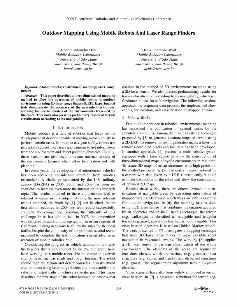
Outdoor Mapping Using Mobile Robots And Laser Range Finders
Alberto Yukinobu HataMobile Robotics Laboratory
University of Sao PauloSao Carlos, Sao Paulo, Brazil
Denis Fernando WolfMobile Robotics Laboratory
University of Sao PauloSao Carlos, Sao Paulo, Brazil
Keywords-Mobile robots; environment mapping; laser rangefinder;
Abstract—This paper describes a three-dimensional mappingmethod to allow the operation of mobile robots in outdoorenvironments using 2D laser range finders (LRF). Experimentaltests demonstrate the accuracy of the presented techniques,allowing for precise models of the environments traversed bythe robot. This work also presents preliminary results of terrainclassification according to its navigability.
I. INTRODUCTION
Mobile robotics is a field of robotics that focus on thedevelopment of devices capable of moving autonomously toperform certain tasks. In order to navigate safely, robots useperception sensors like lasers and cameras to get informationfrom the environment and detect potential obstacles. Usually,these sensors are also used to create internal models ofthe environment (maps), which allow localization and pathplanning.
In recent years, the development of autonomous vehicleshas been receiving considerable attention from roboticsresearchers. A challenge sponsored by the U.S. militaryagency (DARPA) in 2004, 2005, and 2007 has been re-sponsible to increase even more the interest on this researchtopic. The results obtained in these competitions lead torelevant advances in this subject. Among the most relevantresults obtained, the work by [1] [2] can be cited. In thefirst edition occurred in 2004, no team could successfullycomplete the competition, showing the difficulty of thischallenge. In its last edition, held in 2007, the competitionwas centered in autonomous navigation in urban regions ofCalifornia, making necessary to follow the rules for the localtraffic. Despite the complexity of the problem, several teamsmanaged to complete the test, indicating a great advance inresearch of mobile robotics field.
Considering the progress in vehicle automation and alsothe benefits that it can conduct to society, our group havebeen working on a mobile robot able to operate in externalenvironments such as roads and rough terrains. The robotshould map the terrain and detect obstacles in unstructuredenvironments using laser range finders and thus establish thesafest and fastest paths to achieve a specific goal. This paperdescribes the first stage of the robot automation process that
consists in the method of 3D environments mapping usinga 2D laser sensor. We also present prelimininary results forterrain classification according to its navigability, which is afundamental task for safe navigation. The following sessionsapproach the acquiring data process, the implemented algo-rithms, the creation, and classification of mapped terrain.
A. Related Works
Due to its importance in robotics, environmental mappinghas motivated the publication of several works by thescientific community. Among them we can cite the techniqueproposed by [3] to generate accurate maps of terrain usinga 2D LRF. To remove noises in generated maps, a filter thatremoves corrupted pixels and lost data has been developed.In another approach, [4] presents a multi-robotic systemequipped with a laser sensor to allow the construction ofthree-dimensional maps of cyclic environments in real time.To create 3D maps of urban structures with high precision,the method proposed by [5], associates images captured bya camera with data given by a LRF. Consequently, it couldestimate the motion of the robot and allow the constructionof detailed 3D maps.
Besides these works, there are others devoted to iden-tification of navigable areas by extracting information ofmapped terrains. Determine which ways are safe is essentialfor outdoor navigation. In [6], the mapping task is doneusing a 2D laser sensor that combines information acquiredby an odometer and an IMU. In this technique, flat terrain(e.g. walkways) is classified as navigable and irregularterrain (e.g. grass, gravel) is classified as non-navigable. Thisclassification algorithm is based on Hidden Markov Model.The work presented in [7] investigates a mapping techniquethat uses 3D laser range finder to make possible robotnavigation in vegetated terrains. The work by [8] appliesa 3D laser sensor to perform classification of the wholeenvironment. The elements of the scene are segmentedinto three classes, which are, surface (e.g. ground), linearstructures (e.g. cables and trunks) and dispersed structures(e.g. grass). The segmentation algorithm uses a Bayesianclassifier.
Video cameras have also been widely employed in terrainclassification. In [9] is presented a method for terrain seg-
2009 Electronics, Robotics and Automotive Mechanics Conference
978-0-7695-3799-3/09 $26.00 © 2009 IEEE
DOI 10.1109/CERMA.2009.12
181
2009 Electronics, Robotics and Automotive Mechanics Conference
978-0-7695-3799-3/09 $26.00 © 2009 IEEE
DOI 10.1109/CERMA.2009.12
209
2009 Electronics, Robotics and Automotive Mechanics Conference
978-0-7695-3799-3/09 $26.00 © 2009 IEEE
DOI 10.1109/CERMA.2009.12
209
2009 Electronics, Robotics and Automotive Mechanics Conference
978-0-7695-3799-3/09 $26.00 © 2009 IEEE
DOI 10.1109/CERMA.2009.12
209
mentation that combines information obtained from a LRFand the image captured by a camera. Colors and texturesextracted from the images are used to classify the land asill-structured, gravel and asphalt. Finally, in [10] a cameraand a vibration sensor have been used to classify terraincovered by the robot.
II. MAPPING
Mapping is a fundamental task to allow robot automation[4] [6]. Through the maps robots are able to estimate theirown position in the environment and plan a path to aparticular location [11], which are the basic functionalitiesto navigate autonomously.
The mapping process consists on generating computermodels of the real scenarios from data collected by sen-sors. Most mapping techniques are based on either distancesensors (e.g. laser range finders and sonar) or video cameras.
The work presented in this paper is based on a laser rangefinder data. This type of sensor has the advantage of havinghigh accuracy, ability to directly acquire the distance toobstacles, and their readings are little influenced by variationof environmental conditions.
Part of the mapping techniques focus on creating acomputational model of the terrain. It is particularly usefulwhen the robot navigates in outdoor environments, wherethe ground is not flat. In these cases, it is necessary toidentify the regions that can be safely traversed by the robot.Therefore, besides the map of the terrain, it is also necessaryto classify the terrain according to its navigability.
A. Terrain Mapping
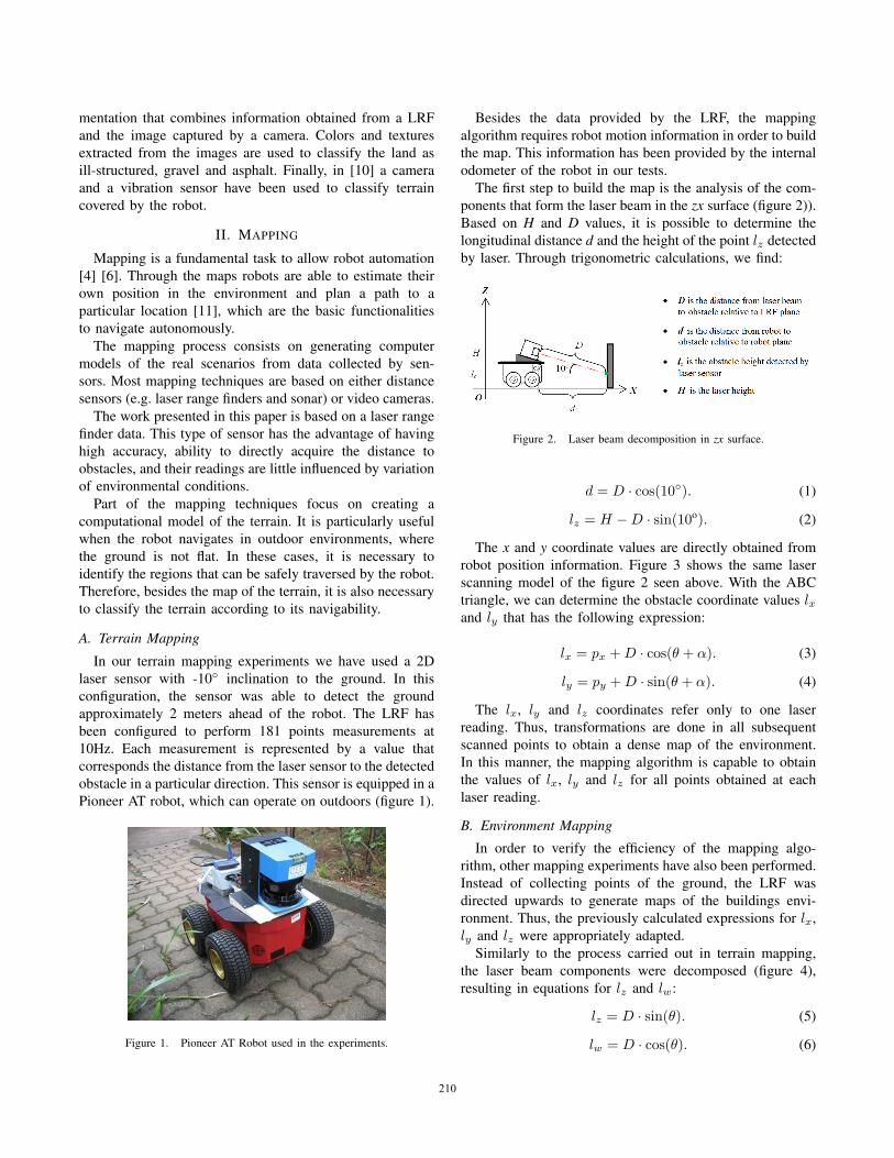
In our terrain mapping experiments we have used a 2Dlaser sensor with -10◦ inclination to the ground. In thisconfiguration, the sensor was able to detect the groundapproximately 2 meters ahead of the robot. The LRF hasbeen configured to perform 181 points measurements at10Hz. Each measurement is represented by a value thatcorresponds the distance from the laser sensor to the detectedobstacle in a particular direction. This sensor is equipped in aPioneer AT robot, which can operate on outdoors (figure 1).
Figure 1. Pioneer AT Robot used in the experiments.
Besides the data provided by the LRF, the mappingalgorithm requires robot motion information in order to buildthe map. This information has been provided by the internalodometer of the robot in our tests.
The first step to build the map is the analysis of the com-ponents that form the laser beam in the zx surface (figure 2)).Based on H and D values, it is possible to determine thelongitudinal distance d and the height of the point lz detectedby laser. Through trigonometric calculations, we find:
Figure 2. Laser beam decomposition in zx surface.
d = D · cos(10◦). (1)
lz = H −D · sin(10o). (2)
The x and y coordinate values are directly obtained fromrobot position information. Figure 3 shows the same laserscanning model of the figure 2 seen above. With the ABCtriangle, we can determine the obstacle coordinate values lxand ly that has the following expression:
lx = px +D · cos(θ + α). (3)
ly = py +D · sin(θ + α). (4)
The lx, ly and lz coordinates refer only to one laserreading. Thus, transformations are done in all subsequentscanned points to obtain a dense map of the environment.In this manner, the mapping algorithm is capable to obtainthe values of lx, ly and lz for all points obtained at eachlaser reading.
B. Environment Mapping
In order to verify the efficiency of the mapping algo-rithm, other mapping experiments have also been performed.Instead of collecting points of the ground, the LRF wasdirected upwards to generate maps of the buildings envi-ronment. Thus, the previously calculated expressions for lx,ly and lz were appropriately adapted.
Similarly to the process carried out in terrain mapping,the laser beam components were decomposed (figure 4),resulting in equations for lz and lw:
lz = D · sin(θ). (5)
lw = D · cos(θ). (6)
182210210210
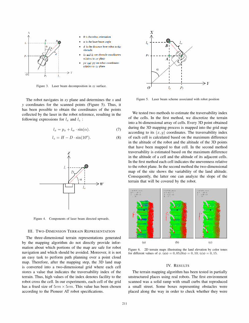
Figure 3. Laser beam decomposition in xy surface.
The robot navigates in xy plane and determines the x andy coordinates for the scanned points (Figure 5). Thus, ithas been possible to obtain the coordinates of the pointscollected by the laser in the robot reference, resulting in thefollowing expressions for lx and lz :
lx = px + lw · sin(α). (7)
lz = H −D · sin(10o). (8)
Figure 4. Components of laser beam directed upwards.
III. TWO-DIMENSION TERRAIN REPRESENTATION
The three-dimensional terrain representations generatedby the mapping algorithm do not directly provide infor-mation about which portions of the map are safe for robotnavigation and which should be avoided. Moreover, it is notan easy task to perform path planning over a point cloudmap. Therefore, after the mapping step, the 3D land mapis converted into a two-dimensional grid where each cellstores a value that indicates the traversability index of theterrain. Thus, high values of the index denotes facility to therobot cross the cell. In our experiments, each cell of the gridhas a fixed size of 5cm× 5cm. This value has been chosenaccording to the Pioneer AT robot specifications.
Figure 5. Laser beam scheme associated with robot position
We tested two methods to estimate the traversability indexof the cells. In the first method, we discretize the terraininto a bi-dimensional array of cells. Every 3D point obtainedduring the 3D mapping process is mapped into the grid mapaccording to its (x, y) coordinates. The traversability indexof each cell is calculated based on the maximum differencein the altitude of the robot and the altitude of the 3D pointsthat have been mapped to that cell. In the second methodtraversability is estimated based on the maximum differencein the altitude of a cell and the altitude of its adjacent cells.In the first method each cell indicates the unevenness relativeto the robot plane. In the second method the two-dimensionalmap of the site shows the variability of the land altitude.Consequently, the latter one can analyze the slope of theterrain that will be covered by the robot.
(a) (b) (c)
Figure 6. 2D terrain maps illustrating the land elevation by color tonesfor different values of φ. (a)φ = 0, 05;(b)φ = 0, 10; (c)φ = 0, 15.
IV. RESULTS
The terrain mapping algorithm has been tested in partiallyunstructured places using real robots. The first environmentscanned was a solid ramp with small curbs that reproduceda small street. Some boxes representing obstacles wereplaced along the way in order to check whether they were
183211211211
detected by the laser sensor. The figure 7 is showing acomparison between the real environment and the samescenario recreated by the robot. It should be noted that theboxes could be clearly reproduced, showing the ability ofthe laser sensor to accurately detect even small objects inthe environment. The 2D grid representation is also shownafterwards. Note that the classification could distinguish highareas of the map, such as curbs and vegetation, from theground. The method of relative differences could correctedsome classification errors done by the method of absoluteheight, however, for the reason that it is a method still indevelopment, there are classification errors in some places.
In the second experiment, the robot was placed betweengrass and a traversable pathway. The objective of this testwas to check through the created map, if the LRF was ableto detect slight height changes in apparently plane sites. Byfigure 8 it is verified in the built map a clear distinctionbetween the grass and the navigable way. In the 2D map it isfound a similar behave to the previous experiment, however,in this case, the method could accurately classify the groundas a navigable path. On the other hand it was not able todistinguish the grass from the ground.
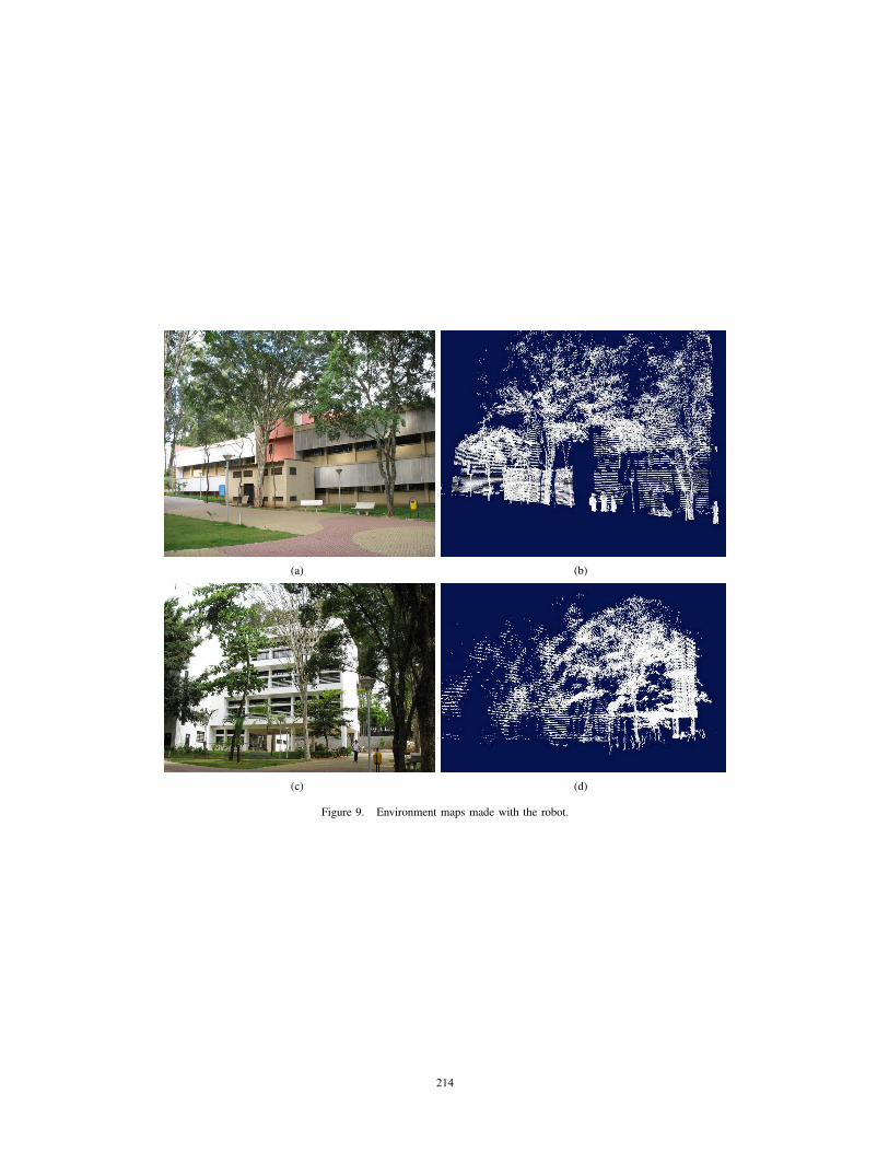
To evaluate the environment mapping algorithm, exper-imental tests were performed in places with structuredelements such as buildings and unstructured such as trees.In these experiments the laser sensor was tilted up. Figure 9illustrates the obtained results. Comparing with the pictureof the real environment, it is verified that the sensor wasable to capture in detail all elements of the surroundings.
The representation of the travesability index grid mapis made using different color tones. Therefore, cells withgreater index values induce to green tones and smaller indexinduce to red tons. Negative obstacles (altitude of the pointsare lower than the altitude of the robot) are representedin blue tones. In the figures 7 and 8 we can see someexamples of two-dimensional representation of the land. Inthis classification, it is also necessary set a threshold φ whichdetermines a border value for the cell index value. Thus, if apoint has a height or height difference value greater than φ,it will be automatically allocated to the cell a traversabilityindex 0. For other values, it will be calculated an indexproportional to the range that extends from 0 to φ. Figure 6illustrates the effect of the variation of φ in 2D maps withthree different values. It can be noticed that large values of φ,increases the sensitivity of the classifier for boundary pointsof the map and low values of φ mitigate this sensitivity. Forthis work was chosen φ = 0.10 by presenting a classificationcloser to the real environment.
V. CONCLUSION
Despite the presented work being in the initial phase,the mapping algorithm was completely satisfactory to usein the robot. The generated 3D maps could accuratelyreproduce the surroundings covered by the robot and lead to
precise traversability maps, which easily allow path planningthrough the environment. A visual analysis shows that theboth methods presented in this paper lead to a reasonableidentification of the safe areas in the ground. In order toverify its accuracy, we also successfully tested the mappingalgorithm to create 3D maps of the building in the environ-ment.
Future work includes the use of a machine learningtechnique to improve the terrain classification results andthe integration of the mapping technique to path planningalgorithms, allowing autonomous safe navigation in theenvironments.
REFERENCES
[1] S. Thrun, M. Montemerlo, H. Dahlkamp, D. Stavens,A. Aron, J. Diebel, P. Fong, J. Gale, M. Halpenny,G. Hoffmann, K. Lau, C. Oakley, M. Palatucci, V. Pratt,P. Stang, S. Strohband, C. Dupont, L. E. Jendrossek,C. Koelen, C. Markey, C. Rummel, J. van Niekerk,E. Jensen, P. Alessandrini, G. Bradski, B. Davies, S. Ettinger,A. Kaehler, A. Nefian, and P. Mahoney, “Stanley: The robotthat won the darpa grand challenge: Research articles,” J.Robot. Syst., vol. 23, no. 9, pp. 661–692, 2006. [Online].Available: http://dx.doi.org/10.1002/rob.v23:9
[2] C. Urmson, J. Anhalt, D. Bagnell, C. Baker, R. Bittner,M. N. Clark, J. Dolan, D. Duggins, T. Galatali, C. Geyer,M. Gittleman, S. Harbaugh, M. Hebert, T. M. Howard, S. Kol-ski, A. Kelly, M. Likhachev, M. McNaughton, N. Miller,K. Peterson, B. Pilnick, R. Rajkumar, P. Rybski, B. Salesky,Y.-W. Seo, S. Singh, J. Snider, A. Stentz, W. R. Whittaker,Z. Wolkowicki, J. Ziglar, H. Bae, T. Brown, D. Demitrish,B. Litkouhi, J. Nickolaou, V. Sadekar, W. Zhang, J. Struble,M. Taylor, M. Darms, and D. Ferguson, “Autonomous drivingin urban environments: Boss and the urban challenge,” J.Field Robot., vol. 25, no. 8, pp. 425–466, 2008.
[3] C. Ye and J. Borenstein, “A new terrain mapping method formobile robots obstacle negotiation,” Proceedings of the UGVTechnology Conference at SPIE AeroSense Symposium, pp.52–62, 2003.
[4] S. Thrun, W. Burgard, and D. Fox, “A real-time algorithm formobile robot mapping with applications to multi-robot and3d mapping,” Robotics and Automation, 2000. Proceedings.ICRA ’00. IEEE International Conference on, vol. 1, pp. 321–328 vol.1, 2000.
[5] Y. Bok, Y. Hwang, and I. S. Kweon, “Accurate motionestimation and high-precision 3d reconstruction by sensorfusion,” Robotics and Automation, 2007 IEEE InternationalConference on, pp. 4721–4726, April 2007.
[6] D. Wolf, G. Sukhatme, D. Fox, and W. Burgard, “Au-tonomous terrain mapping and classification using hiddenmarkov models,” Robotics and Automation, 2005. ICRA 2005.Proceedings of the 2005 IEEE International Conference on,pp. 2026–2031, April 2005.
[7] H. Schafer, A. Hach, M. Proetzsch, and K. Berns, “3d obstacledetection and avoidance in vegetated off-road terrain,” May2008, pp. 923–928.
184212212212
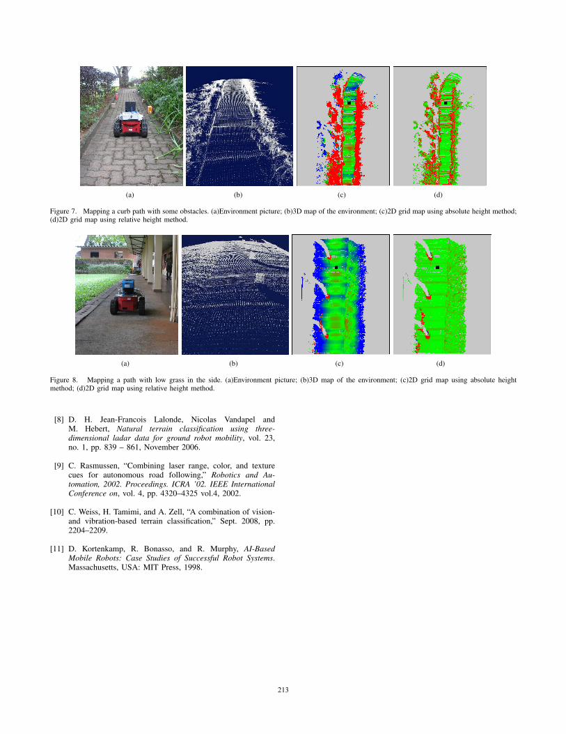
(a) (b) (c) (d)
Figure 7. Mapping a curb path with some obstacles. (a)Environment picture; (b)3D map of the environment; (c)2D grid map using absolute height method;(d)2D grid map using relative height method.
(a) (b) (c) (d)
Figure 8. Mapping a path with low grass in the side. (a)Environment picture; (b)3D map of the environment; (c)2D grid map using absolute heightmethod; (d)2D grid map using relative height method.
[8] D. H. Jean-Francois Lalonde, Nicolas Vandapel andM. Hebert, Natural terrain classification using three-dimensional ladar data for ground robot mobility, vol. 23,no. 1, pp. 839 – 861, November 2006.
[9] C. Rasmussen, “Combining laser range, color, and texturecues for autonomous road following,” Robotics and Au-tomation, 2002. Proceedings. ICRA ’02. IEEE InternationalConference on, vol. 4, pp. 4320–4325 vol.4, 2002.
[10] C. Weiss, H. Tamimi, and A. Zell, “A combination of vision-and vibration-based terrain classification,” Sept. 2008, pp.2204–2209.
[11] D. Kortenkamp, R. Bonasso, and R. Murphy, AI-BasedMobile Robots: Case Studies of Successful Robot Systems.Massachusetts, USA: MIT Press, 1998.
185213213213
(a) (b)
(c) (d)
Figure 9. Environment maps made with the robot.
186214214214
Copyright © 2022 FDOKUMEN