Optimum performance of heat engine-driven heat pumps: A finite-time approach
13
Pergamon Energy Convers. Mgmf Vol. 38, No. 4, pp. 401413, 1997 Copyright 0 1996Elsevier Science Ltd PII: S0196-8904(%)00041-6 Printed in Great Britain. All rights reserved 0196-8904/97 $17.00 + 0.00 OPTIMUM PERFORMANCE OF HEAT ENGINE-DRIVEN HEAT PUMPS: A FINITE-TIME APPROACH MASSIMO DENTICE D’ACCADIA, MAURIZIO SASS0 and SERGIO SIBILIO Universita degli Studi di Napoli “Federico II”, Napoli, Italy (Received 20 June 1995) Abstract-Classic thermodynamics, assuming the Camot machine as the upper comparison limit in energy conversion systems analysis, considers thermal equilibrium during heat transfer interactions. Such an assumption requires either infinitely slow cycles or infinitely large heat exchanger surfaces. More realistic limits on the optimal operation of energy systems can be provided by finite-time thermodynamics, which takes into account the constraints represented by finite operation time and limited heat interaction area. This paper focuses on the search for the optimum heating performance of a heat engine-driven heat pump in which the waste engine heat is used for heating purposes. At first, only thermal irreversibilities are considered; then, in order to obtain a more realistic model, the so called “internal” heat leak irreversibilities are taken into account too. Finally, a comparison between the performances of the irreversible model and those of actual plants is carried out. Copyright 6 1996 Elsevier Science Ltd Endoreversible thermodynamics Engine driven-heat pump GHP NOMENCLATURE C = Conductance of heat exchanger (kW/K) COP = Coefficient of performance $ = Thermal flow rate (kW) = Work transfer rate (kW) T = Absolute temperature (K) t = Thermodynamic mean temperature (K) x = Prime mover conductance (CPM) allocation ratio y = Heat pump conductance (C”‘) allocation ratio z = Global conductance (CC) allocation ratio Greek symbols a = Fraction of internal to global energy input 6 = Efficiency defect rj = Prime mover efficiency 7 = Temperature ratio, ~‘H/TM 7c = Prime mover Camot temperature ratio, FI~H/TM ‘TV = High reservoir dimensionless exergetic temperature in eqn (2) 5L = Medium reservoir dimensionless exergetic temperature in eqn (2) ‘CM = Medium reservoir dimensionless exergetic temperature in eqn (2) Y = Exergetic efficiency Subscripts C = Camot cycle G = Global conductance H = High temperature thermal reservoir or high level heat exchanger i = “Internal” heat leak L = Low temperature thermal reservoir or low level heat exchanger M = Medium temperature thermal reservoir or medium level heat exchanger opt = Optimum Superscripts HP = Vapor compression heat pump HT = Heat transformer PM = Prime mover. 401
Transcript of Optimum performance of heat engine-driven heat pumps: A finite-time approach
Pergamon Energy Convers. Mgmf Vol. 38, No. 4, pp. 401413, 1997
Copyright 0 1996 Elsevier Science Ltd
PII: S0196-8904(%)00041-6 Printed in Great Britain. All rights reserved
0196-8904/97 $17.00 + 0.00
OPTIMUM PERFORMANCE OF HEAT ENGINE-DRIVEN HEAT PUMPS: A FINITE-TIME APPROACH
MASSIMO DENTICE D’ACCADIA, MAURIZIO SASS0 and SERGIO SIBILIO Universita degli Studi di Napoli “Federico II”, Napoli, Italy
(Received 20 June 1995)
Abstract-Classic thermodynamics, assuming the Camot machine as the upper comparison limit in energy conversion systems analysis, considers thermal equilibrium during heat transfer interactions. Such an assumption requires either infinitely slow cycles or infinitely large heat exchanger surfaces. More realistic limits on the optimal operation of energy systems can be provided by finite-time thermodynamics, which takes into account the constraints represented by finite operation time and limited heat interaction area. This paper focuses on the search for the optimum heating performance of a heat engine-driven heat pump in which the waste engine heat is used for heating purposes. At first, only thermal irreversibilities are considered; then, in order to obtain a more realistic model, the so called “internal” heat leak irreversibilities are taken into account too. Finally, a comparison between the performances of the irreversible model and those of actual plants is carried out. Copyright 6 1996 Elsevier Science Ltd
Endoreversible thermodynamics Engine driven-heat pump GHP
NOMENCLATURE
C = Conductance of heat exchanger (kW/K) COP = Coefficient of performance
$ = Thermal flow rate (kW) = Work transfer rate (kW)
T = Absolute temperature (K) t = Thermodynamic mean temperature (K) x = Prime mover conductance (CPM) allocation ratio y = Heat pump conductance (C”‘) allocation ratio z = Global conductance (CC) allocation ratio
Greek symbols a = Fraction of internal to global energy input 6 = Efficiency defect rj = Prime mover efficiency 7 = Temperature ratio, ~‘H/TM
7c = Prime mover Camot temperature ratio, FI~H/TM ‘TV = High reservoir dimensionless exergetic temperature in eqn (2) 5L = Medium reservoir dimensionless exergetic temperature in eqn (2) ‘CM = Medium reservoir dimensionless exergetic temperature in eqn (2) Y = Exergetic efficiency
Subscripts C = Camot cycle G = Global conductance H = High temperature thermal reservoir or high level heat exchanger
i = “Internal” heat leak L = Low temperature thermal reservoir or low level heat exchanger
M = Medium temperature thermal reservoir or medium level heat exchanger opt = Optimum
Superscripts HP = Vapor compression heat pump HT = Heat transformer PM = Prime mover.
401
402 D’ACCADIA er al.: HEAT ENGINE-DRIVEN HEAT PUMPS
INTRODUCTION
Considerable research effort has been expended on finding more realistic limits of the optimal operation of heat machines in finite time. Great emphasis has been put on the problem of obtaining the maximum work from an arbitrary fluid in a heat engine, usually working in an endoreversible cycle. The most common thermodynamic cycles, such as the Otto, Brayton, cascade and combined cycles, have been modeled thermodynamically, assuming a finite rate of heat interaction [l-l 11. A very wide application field has been analysed, as high and low temperature power plants, and the optimization has been accomplished with respect to power, mean effective pressure and economical exploitation. Similarly, the optimal performance of the endoreversible refrigerator and heat pump has been considered, see Refs [12-191.
Of particular interest are the systems constituted by a heat pump driven by a heat engine; in particular, the optimum performance of such systems has been investigated in irreversible processes, finding the conditions of maximum heating or cooling load achievable [20,21].
Nevertheless, one of the main features of the Prime mover-Heat pump coupling, that is, the possibility to recover the waste engine heat, has not yet been analysed by means of the finite-time approach.
In this paper, referring to a heat engine-driven heat pump recovering waste engine heat, and assuming that the irreversibilities are only due to heat transfer under finite temperature differences (the endoreversible model), the performances of the whole plant and its main subsystems, Prime mover and Heat pump, have been analysed as a function of the thermal resistances and their distribution among the heat exchangers of the equipment. In a second step, a more accurate model is introduced to identify a realistic design goal of the COP of this equipment.
TRITHERMAL THERMODYNAMIC SYSTEMS
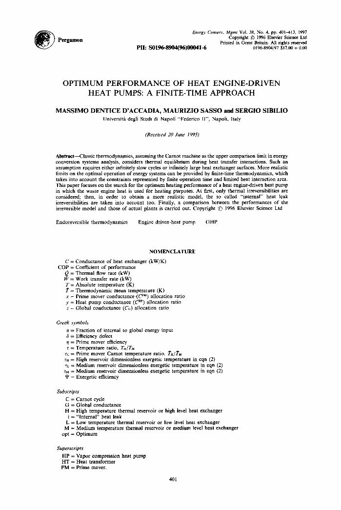
Simplified approach A complex of a Prime mover (PM) driving a Heat pump (HP) can be presented as a Heat
transformer (HT) that doesn’t produce or consume any shaft work, excluding auxiliary equipment. The simplest type of Heat transformer, HT # 1, steadily operates among at least three different
(4
I 2 .HP I
QM I I 4 I
Fig. l(a). Caption on p. 404.
D’ACCADIA et al.: HEAT ENGINE-DRIVEN HEAT PUMPS 403
(b)
‘PM QH
HP QM
??
L_-
I
I
ti 1 I
-t
>
+
I
I I I
TM
Fig. l(b). Caption on p. 404
heat sources and/or heat sinks (trithermal thermodynamic systems) [22-241, at temperatures TH > TM > TL, as shown in Fig. la.
The equipment takes heat from high-level and low-level heat sources and delivers heat to the medium-level heat sink. Usually, the environmental temperature, TO, is identical to the temperature of the low reservoir during the heating mode and to the temperature of the medium reservoir during the cooling mode. When the HT operates in the heating mode, it delivers the useful thermal flow rate, &’ = &’ + &*, to the medium temperature sink, while in the cooling mode, it draws the useful thermal flow rate, & , HP from the low level heat source.
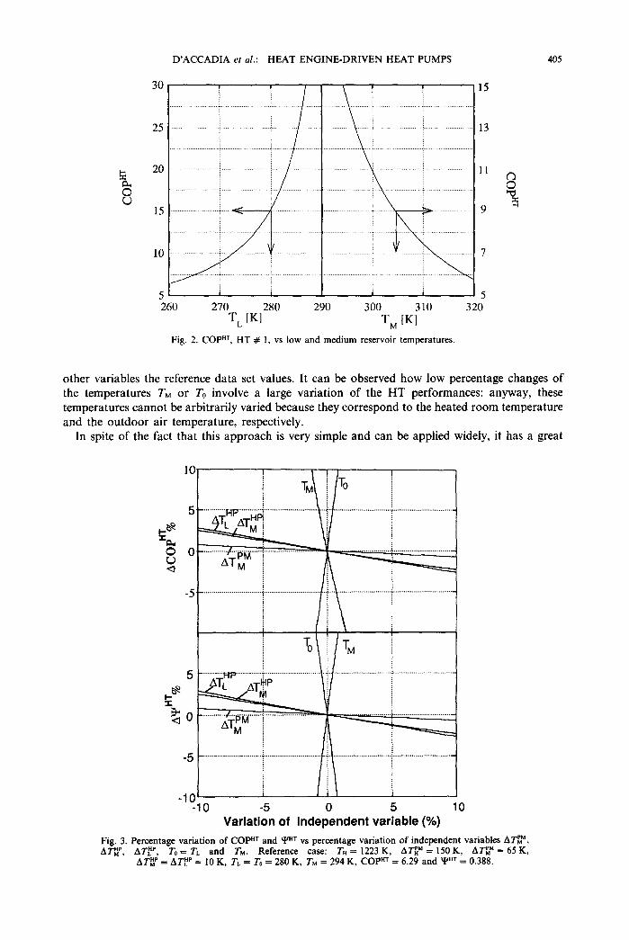
If we assume that the PM and HP both operate according to a fully reversible Camot cycle, HT # 1, the energetic efficiency COP of the Heat transformer is only a function of the reservoir temperatures. As an example, in Fig. 2, the influence of the low and medium level temperatures has been analysed.
In an effort to get closer to a real cycle, often the irreversibilities due to finite temperature differences between the heat reservoirs and the working fluids are considered. Introducing a suitable
404 D’ACCADIA et al.: HEAT ENGINE-DRIVEN HEAT PUMPS
(cl
T-l - - ------
1
di 1 I 7 i I I
K llci
I I
l il
I I
--- I I
I 1/c; -1’ TM
& a- - -
I- --
T I I
-L I I I
-, TM 1 I I
-Ic I I I
I I
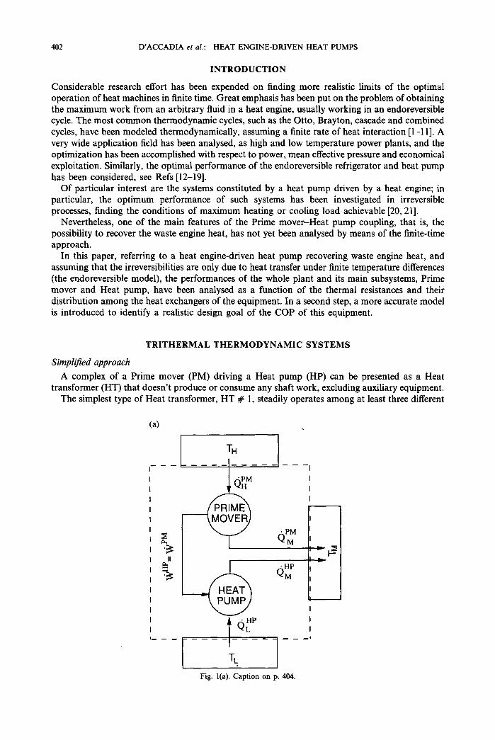
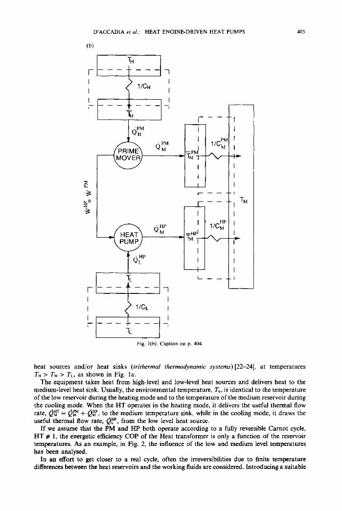
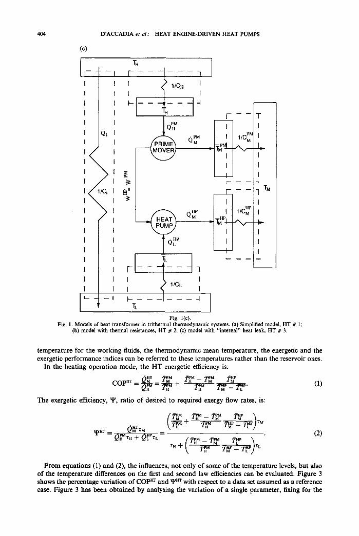
Fig. l(c). Fig. 1. Models of heat transformer in trithermal thermodynamic systems. (a) Simplified model, HT # 1;
(b) model with thermal resistances, HT # 2; (c) model with “internal” heat leak, HT # 3.
temperature for the working fluids, the thermodynamic mean temperature, the energetic and the exergetic performance indices can be referred to these temperatures rather than the reservoir ones.
In the heating operation mode, the HT energetic efficiency is:
The exergetic efficiency, Y, ratio of desired to required exergy flow rates, is:
(1)
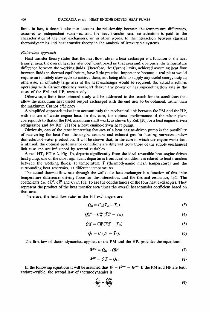
From equations (1) and (2), the influences, not only of some of the temperature levels, but also of the temperature differences on the first and second law efficiencies can be evaluated. Figure 3 shows the percentage variation of COPHT and Y” with respect to a data set assumed as a reference case. Figure 3 has been obtained by analysing the variation of a single parameter, fixing for the
D’ACCADIA er al.: HEAT ENGINE-DRIVEN HEAT PUMPS 405
I
5 1 1 1 1 5 260 270 280 290 300 310 320
T,_ WI T, WI Fig. 2. COPHT, HT # 1, vs low and medium reservoir temperatures.
other variables the reference data set values. It can be observed how low percentage changes of the temperatures TM or To involve a large variation of the HT performances: anyway, these temperatures cannot be arbitrarily varied because they correspond to the heated room temperature and the outdoor air temperature, respectively.
In spite of the fact that this approach is very simple and can be applied widely, it has a great
5 . . . . Hp” ;; cok .,f i.. i v -10 -5 0 5 10
Variation of independent variable (%)
Fig. 3. Percentage variation of COPaT and YHr vs percentage variation of independent variables A?‘;?‘, ATip, AT!‘, To= TL and TM. Reference case: TH = 1223 K, ATLM = 150 K, ATL,” = 65 K,
ATiP = AT,Hp = 10 K, T,, = To = 280 K, TM = 294 K, COPaT = 6.29 and YHT = 0.388.
406 D’ACCADIA et al.: HEAT ENGINE-DRIVEN HEAT PUMPS
limit. In fact, it doesn’t take into account the relationship between the temperature differences, assumed as independent variables, and the heat transfer rate: no attention is paid to the characteristics of the heat exchangers, or in other words, to the interaction between classical thermodynamics and heat transfer theory in the analysis of irreversible systems.
Finite-time approach Heat transfer theory states that the heat flow rate in a heat exchanger is a function of the heat
transfer area, the overall heat transfer coefficient based on that area and, obviously, the temperature difference between the working fluids. Therefore, the Carnot limits, achieved assuming heat flow between fluids in thermal equilibrium, have little practical importance because a real plant would require an infinitely slow cycle to achieve them, not being able to supply any useful energy output; otherwise, an infinitely large area of the heat exchanger would be required. So, actual machines operating with Carnot efficiency wouldn’t deliver any power or heating/cooling flow rate in the cases of the PM and HP, respectively.
Otherwise, a finite-time-oriented study will be addressed to the search for the conditions that allow the maximum heat useful output exchanged with the end user to be obtained, rather than the maximum Carnot efficiency.
A simplified approach takes into account only the mechanical link between the PM and the HP, with no use of waste engine heat. In this case, the optimal performance of the whole plant corresponds to that of the PM, maximum shaft work, as shown by Ref. [20] for a heat engine-driven refrigerator and by Ref. [21] for a heat engine-driven heat pump.
Obviously, one of the most interesting features of a heat engine-driven pump is the possibility of recovering the heat from the engine coolant and exhaust gas for heating purposes and/or domestic hot water production. It will be shown that, in the case in which the engine waste heat is utilized, the optimal performance conditions are different from those of the simple mechanical link case and are influenced by several variables.
A real HT, HT # 2, Fig. lb, departs significantly from the ideal reversible heat engine-driven heat pump: one of the most significant departures from ideal conditions is related to heat transfers between the working fluids, at temperature in (thermodynamic mean temperature) and the surrounding heat reservoirs, at different temperatures.
The actual thermal flow rate through the walls of a heat exchanger is a function of this finite temperature difference, driving force for the interaction, and the thermal resistance, l/C. The coefficients CH, CL”, CE’ and CL in Fig. lb are the conductances of the four heat exchangers. They represent the product of the heat transfer area times the overall heat-transfer coefficient based on that area.
Therefore, the heat flow rates in the HT exchangers are:
Qri = G-I(TH - T”) (3)
QLM = CL"'( KM - TM) (4)
Qfip = C~p(~ - TM)
& = C,(T, - %). (6)
The first law of thermodynamics, applied to the PM and the HP, provides the equations:
ri”“=&--(-g (7)
p’ = & - QL. (8)
In the following equations it will be assumed that I@ = I@” = pp. If the PM and HP are both endoreversible, the second law of thermodynamics is:
D’ACCADIA et al.: HEAT ENGINE-DRIVEN HEAT PUMPS 407
(10)
Referring to the PM, following the approach of Ref. [3], the combination of equations (7) (9) and (4) leads to:
w= ,,(~- 1)(-g- 1).
From equation (9), utilizing equations (3) and (4), it can be shown that:
where r and tc are, respectively:
Substituting equation (12) into (11):
(T - Zc)(Q - 1) @‘= c&i”T, (cH _ c;~)zc
(11)
(13)
From equations (9) and (7), substituting eqn (13) the heat recoverable from the PM can be obtained:
&iM = CH cLM TM &-;$,~, . (14)
The HP thermal flow rate delivered to the medium sink, TM, can be obtained from the energy and entropy balances of the heat pump, equations (8) and (IO), combined with equations (5) and (6), with the result:
+ (GG"'(T~ - TL)* + @(CL + CL")' 2cLc;"+2c;m
+ 2C~chql~(C~ + CL")(T~ + TL)@)'* _ 2CLCLM + 2CEP
T M. >
(15)
Obviously, the global thermal flow rate supplied to the heated room is & = eLM + @jp and is a function of:
TM, Tr, CH, CL", CEp, CL,T and TC.
It is worth noting that, while in the case of power plants, the maximum desired output (I&‘) is independent of the conductances [l, 31, in this case, it has been shown that the maximum 0:’ is strongly influenced by their values, so that the analysis of the problem is quite complicated.
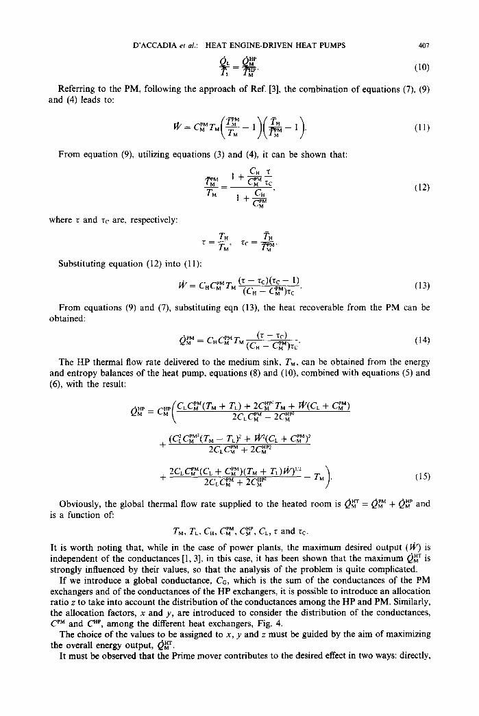
If we introduce a global conductance, C G, which is the sum of the conductances of the PM exchangers and of the conductances of the HP exchangers, it is possible to introduce an allocation ratio z to take into account the distribution of the conductances among the HP and PM. Similarly, the allocation factors, x and y, are introduced to consider the distribution of the conductances, CPM and CHP, among the different heat exchangers, Fig. 4.
The choice of the values to be assigned to x, y and z must be guided by the aim of maximizing the overall energy output, &jT.
It must be observed that the Prime mover contributes to the desired effect in two ways: directly,
408 D’ACCADIA ef al.: HEAT ENGINE-DRIVEN HEAT PUMPS
C PM CH
PM CM
CHP Fig. 4. Distribution of global conductance in PM and HP and then in the four heat exchangers.
by means of its waste heat, Q ‘s”, and indirectly, by means of the shaft work supplied to the Heat pump. Since &‘, equation (15), is a monotone increasing function of ri/, the best case occurs if I@ and eLM achieve their maximum for the same value of x. The analysis of equations (1 l), (12) and (14) shows that this situation is verified for x = xoPt = l/2, according to Ref. [3].
Referring to the Heat pump, solving the equation @ip/8y = 0, gives the result that the maximum &‘:‘, for a fixed #‘, is achieved for y = yopt = l/2, again.
Therefore, when x = l/2 and y = l/2, the aim of optimizing the total heat flow rate &* is, with no doubt, satisfied.
From the previous analysis, for fixed x and y, it results:
& = &*(Cc, z, r, rc, TM, TL) (16)
0:’ = &ip(co, z, 2, k, TM, TL.) (17)
FP = W(Co, Z, T, ~c, TM). (19)
Since work and heat flow rates vary linearly with the global conductance, CG, the corresponding specific quantities, per unit of CG, can be considered.
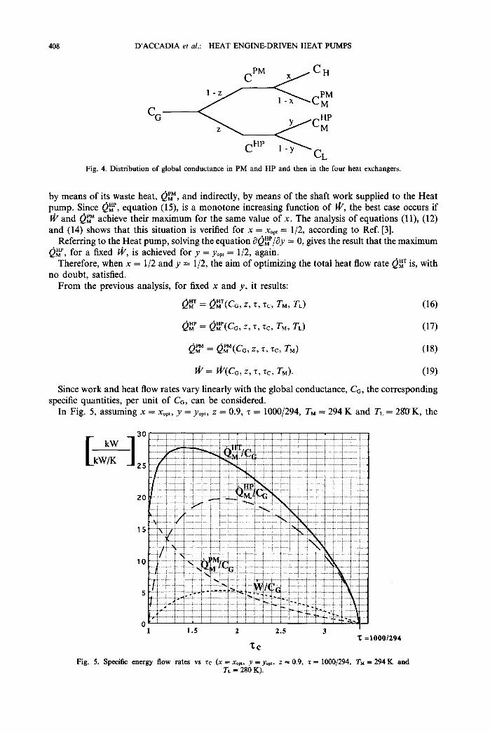
In Fig. 5, assuming x = xopt, y = yopt, z = 0.9, r = 1000/294, TM = 294 K and TL = 28O’K, the
Fig. 5. Specific energy flow rates vs TC (x = xopt, JJ = yopt. .z = 0.9, T = 1000/294, 7’~ = TL = 280 K).
0001294
294K and
D’ACCADIA et al.: HEAT ENGINE-DRIVEN HEAT PUMPS 409
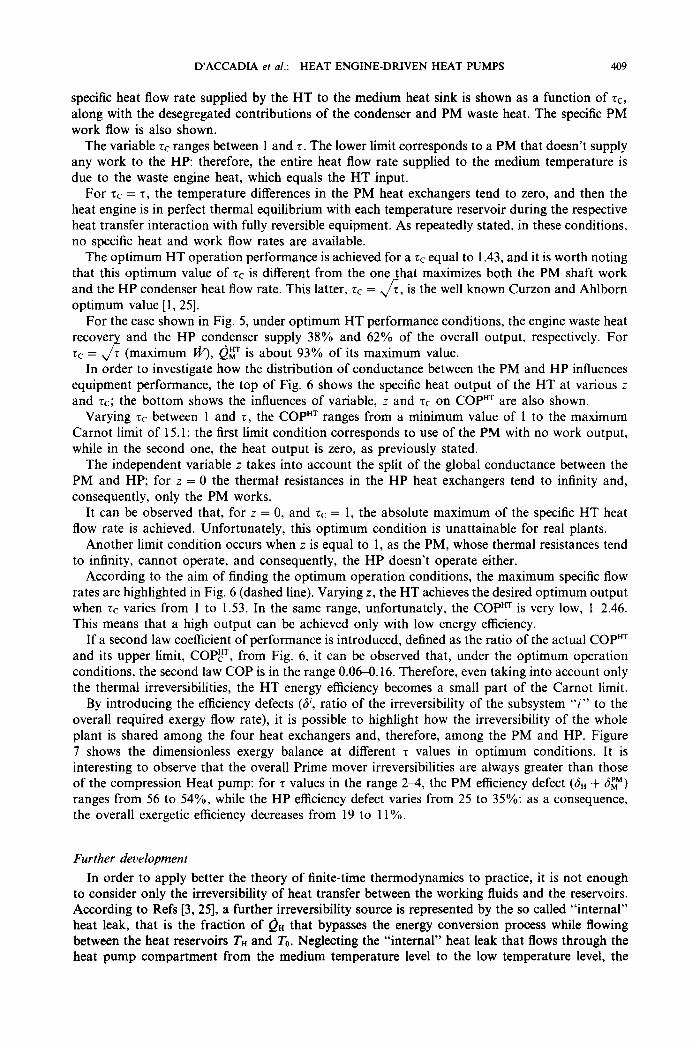
specific heat flow rate supplied by the HT to the medium heat sink is shown as a function of rc, along with the desegregated contributions of the condenser and PM waste heat. The specific PM work flow is also shown.
The variable rc ranges between 1 and T. The lower limit corresponds to a PM that doesn’t supply any work to the HP: therefore, the entire heat flow rate supplied to the medium temperature is due to the waste engine heat, which equals the HT input.
For Q = z, the temperature differences in the PM heat exchangers tend to zero, and then the heat engine is in perfect thermal equilibrium with each temperature reservoir during the respective heat transfer interaction with fully reversible equipment. As repeatedly stated, in these conditions, no specific heat and work flow rates are available.
The optimum HT operation performance is achieved for a zc equal to 1.43, and it is worth noting that this optimum value of zc is different from the one that maximizes both the PM shaft work and the HP condenser heat flow rate. This latter, rc = J T, is the well known Curzon and Ahlborn optimum value ‘[ 1,251.
For the case shown in Fig. 5, under optimum HT performance conditions, the engine waste heat recover and the HP condenser supply 38% and 62% of the overall output, respectively. For tc = 4 7 (maximum @), eGT is about 93% of its maximum value.
In order to investigate how the distribution of conductance between the PM and HP influences equipment performance, the top of Fig. 6 shows the specific heat output of the HT at various z and 7c; the bottom shows the influences of variable, z and 7c on COPHT are also shown.
Varying zc between 1 and 7, the COP”’ ranges from a minimum value of 1 to the maximum Carnot limit of 15.1: the first limit condition corresponds to use of the PM with no work output, while in the second one, the heat output is zero, as previously stated.
The independent variable z takes into account the split of the global conductance between the PM and HP; for z = 0 the thermal resistances in the HP heat exchangers tend to infinity and, consequently, only the PM works.
It can be observed that, for z = 0, and zc = 1, the absolute maximum of the specific HT heat flow rate is achieved. Unfortunately, this optimum condition is unattainable for real plants.
Another limit condition occurs when z is equal to 1, as the PM, whose thermal resistances tend to infinity, cannot operate, and consequently, the HP doesn’t operate either.
According to the aim of finding the optimum operation conditions, the maximum specific flow rates are highlighted in Fig. 6 (dashed line). Varying z, the HT achieves the desired optimum output when 7~ varies from 1 to 1.53. In the same range, unfortunately, the COPHT is very low, l-2.46. This means that a high output can be achieved only with low energy efficiency.
If a second law coefficient of performance is introduced, defined as the ratio of the actual COPHT and its upper limit, COP,HT, from Fig. 6, it can be observed that, under the optimum operation conditions, the second law COP is in the range 0.060.16. Therefore, even taking into account only the thermal irreversibilities, the HT energy efficiency becomes a small part of the Carnot limit.
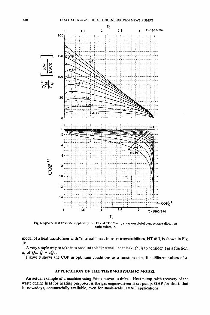
By introducing the efficiency defects (8, ratio of the irreversibility of the subsystem “i” to the overall required exergy flow rate), it is possible to highlight how the irreversibility of the whole plant is shared among the four heat exchangers and, therefore, among the PM and HP. Figure 7 shows the dimensionless exergy balance at different 7 values in optimum conditions. It is interesting to observe that the overall Prime mover irreversibilities are always greater than those of the compression Heat pump: for r values in the range 24, the PM efficiency defect (6” + Bh”) ranges from 56 to 54%, while the HP efficiency defect varies from 25 to 35%: as a consequence, the overall exergetic efficiency decreases from 19 to 11%.
Further development
In order to apply better the theory of finite-time thermodynamics to practice, it is not enough to consider only the irreversibility of heat transfer between the working fluids and the reservoirs. According to Refs [3,25], a further irreversibility source is represented by the so called “internal” heat leak, that is the fraction of 0i.i that bypasses the energy conversion process while flowing between the heat reservoirs TH and TO. Neglecting the “internal” heat leak that flows through the heat pump compartment from the medium temperature level to the low temperature level, the
410 D’ACCADIA et al.: HEAT ENGINE-DRIVEN HEAT PUMPS
ZC 1 1.5 2 2.5 3 0 =1000/z
200 - :‘. : : i : . : ~ : : .,. .., .
194
. 1 ;...) . . . .
1 1.5 2 2.5 3 ‘t = 10001294
Fig. 6. Specific heat flow rate supplied by the HT and COPHT vs TC at various global conductance allocation ratio values, z.
model of a heat transformer with “internal” heat transfer irreversibilities, HT # 3, is shown in Fig. lc.
A very simple way to take into account this “internal” heat leak, Qi, is to consider it as a fraction, c1, Of &I Qi=C&.
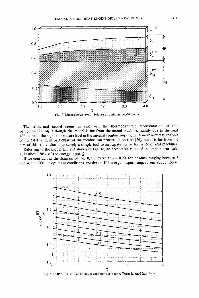
Figure 8 shows the COP in optimum conditions as a function of r, for different values of CL
APPLICATION OF THE THERMODYNAMIC MODEL
An actual example of a machine using Prime mover to drive a Heat pump, with recovery of the waste engine heat for heating purposes, is the gas engine-driven Heat pump, GHP for short, that is, nowadays, commercially available, even for small-scale HVAC applications.
D’ACCADIA et al.: HEAT ENGINE-DRIVEN HEAT PUMPS 411
1.0
0.8
0.6
/ / / / / Y
HT
*
PM
&M
PM
2.0 2.5 3.0 3.5 4.0 z
Fig. 7. Dimensionless exergy balance at optimum conditions vs 7.
The trithermal model seems to suit well the thermodynamic representation of this equipment [22,24], although the model is far from the actual machine, mainly due to the heat adduction at the high temperature level in the internal combustion engine. A more accurate analysis of the GHP and, in particular, of the combustion process, is possible [26], but it is far from the aim of this study, that is to supply a simple tool to anticipate the performance of real machines.
Referring to the model HT # 3 shown in Fig. lc, an acceptable value of the engine heat leak, a, is about 20% of the energy input 0”.
If we consider, in the diagram of Fig. 8, the curve at SC = 0.20, for T values ranging between 3 and 4, the COP at optimum conditions, maximum HT energy output, ranges from about 1.55 to
2 17
.6
. i ,...,.,,.. ..: . . . ( _ . I . . . , . _
. :
.2 :” 2.5 3 3.5 4
z
Fig. 8. COPHI, HT # 3, at optimum conditions vs T for different internal heat leaks
412 D’ACCADIA er al.: HEAT ENGINE-DRIVEN HEAT PUMPS
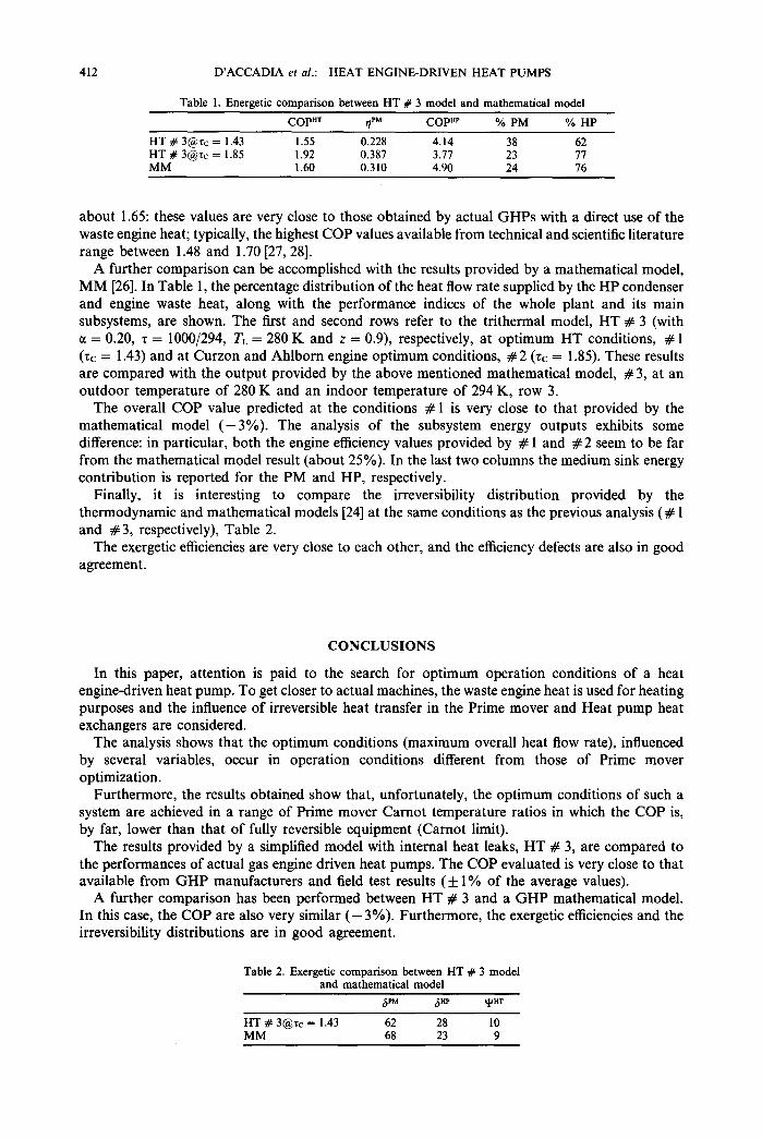
Table 1. Energetic comparison between HT # 3 model and mathematical model
COP”T PM rl COPHP % PM % HP
HT # 3@rc = 1.43 1.55 0.228 4.14 38 62
FM# 3@tc = 1.85 1.92 1.60 0.387 0.310 4.90 3.77 23 24 77 76
about 1.65: these values are very close to those obtained by actual GHPs with a direct use of the waste engine heat; typically, the highest COP values available from technical and scientific literature range between 1.48 and 1.70 [27,28].
A further comparison can be accomplished with the results provided by a mathematical model, MM [26]. In Table 1, the percentage distribution of the heat flow rate supplied by the HP condenser and engine waste heat, along with the performance indices of the whole plant and its main subsystems, are shown. The first and second rows refer to the trithermal model, HT # 3 (with CI = 0.20, z = 1000/294, TL = 280 K and z = 0.9) respectively, at optimum HT conditions, # 1 (zc = 1.43) and at Curzon and Ahlborn engine optimum conditions, # 2 (rc = 1.85). These results are compared with the output provided by the above mentioned mathematical model, #3, at an outdoor temperature of 280 K and an indoor temperature of 294 K, row 3.
The overall COP value predicted at the conditions # 1 is very close to that provided by the mathematical model (-3%). The analysis of the subsystem energy outputs exhibits some difference: in particular, both the engine efficiency values provided by # 1 and #2 seem to be far from the mathematical model result (about 25%). In the last two columns the medium sink energy contribution is reported for the PM and HP, respectively.
Finally, it is interesting to compare the irreversibility distribution provided by the thermodynamic and mathematical models [24] at the same conditions as the previous analysis (# 1 and #3, respectively), Table 2.
The exergetic efficiencies are very close to each other, and the efficiency defects are also in good agreement.
CONCLUSIONS
In this paper, attention is paid to the search for optimum operation conditions of a heat engine-driven heat pump. To get closer to actual machines, the waste engine heat is used for heating purposes and the influence of irreversible heat transfer in the Prime mover and Heat pump heat exchangers are considered.
The analysis shows that the optimum conditions (maximum overall heat flow rate), influenced by several variables, occur in operation conditions different from those of Prime mover optimization.
Furthermore, the results obtained show that, unfortunately, the optimum conditions of such a system are achieved in a range of Prime mover Carnot temperature ratios in which the COP is, by far, lower than that of fully reversible equipment (Carnot limit).
The results provided by a simplified model with internal heat leaks, HT # 3, are compared to the performances of actual gas engine driven heat pumps. The COP evaluated is very close to that available from GHP manufacturers and field test results (f 1% of the average values).
A further comparison has been performed between HT # 3 and a GHP mathematical model. In this case, the COP are also very similar (- 3%). Furthermore, the exergetic efficiencies and the irreversibility distributions are in good agreement.
Table 2. Exergetic comparison between HT # 3 model and mathematical model
8PM Sap YHT
HT # 3@rc = 1.43 62 28 10 MM 68 23 9
D’ACCADIA et al.: HEAT ENGINE-DRIVEN HEAT PUMPS 413
REFERENCES
I. F. L. Curzon and B. Ahlborn, American Journal Phys. 43, 22 (1975). 2. P. Salamon, Y. B. Band and 0. Kafri, Journal Applied Phys. 53, 197 (1982). 3. A. Bejan, International Journal of Heat & Mass Transfer 31, 121 I (1988). 4. G. Grazzini, Maximum work with isothermal exchange irreversible heat engine. In Proc. Florence World Energy
Research Symposium FLOWERS ‘90 (Edited by S. S. Stecco and M. J. Moran), pp. 473484. Pergamon Press, New York (1990).
5. C. Wu, Energy Convers. Mgmt 30, 261 (1990). 6. C. Wu, Energy Conoers. Mgmt 32, 249 (1991). 7. C. Wu, Energy Comers. Mgmr 34, 1239 (1993). 8. C. Wu and D. A. Blank, Energy Convers. Mgm? 34, 1255 (1993). 9. A. De Vos, Energy Convers. Mgmr 36, 1 (1995).
10. C. Wu and W. H. Schulden, Heat Recovery Systems & CHP 15, 13 (1995). 11. C. Wu, Heat Recovery Systems & CHP 15, 351 (1995). 12. Z. Yan and J. Chen, Coefficient of performance for an irreversible Carnot heat pump. In Proc. Florence World Energy
Research Symposium FL0 WERS ‘90 (Edited by S. S. Stecco and M. J. Moran), pp. 193-200. Pergamon Press, New York (1990).
13. C. Wu, Int. J. of Ambient Energy 13, 133 (1992). 14. C. Wu, Heat Recovery Systems & CHP 13, 161 (1993). IS. S. A. Klein, Int. J. Refrigeration 15, 181 (1992). 16. G. Grazzini, Inr. J. Refrigerafion 16, 101 (1993). 17. C. Wu, Energy Convers. Mgmt 34, 1249 (1993). 18. C. Wu, Energy Convers. Mgmf 36, 7 (1995). 19. C. Wu and J. Chen, Int. J. of Ambient Energy 16, 17 (1995). 20. C. Wu, Energy Conoers. Mgmt 34, 691 (1993). 2 1. G. W. Davis and C. Wu, Optimal performance of a heat engine-driven-heat pump utilizing low grade thermal energy.
In Thermodynamics and the Design, Analysis, and Improvement of Energy Systems (Edited by R. J. Krane), Vol. 33, pp. 271-275. ASME, New York, AES (1994).
22. G. Cohen, J. Salvat and A. Rojey, Entropie 84, 31 (1978). 23. J. Szargut, D. R. Morris and F. R. Steward, Exergy Analysis of Thermal, Chemical and Metallurgical Processes.
Hemisphere Publishing Corp., New York (1988). 24. M. Dkntice d’Accadia, M.- Sasso and S. Sibilio, The exergy analysis of the gas engine driven heat pump. In
Thermodynamics and the Design, Anal_vsis, and Improvemenr of Energ?, Systems (Edited by R. J. Krane), Vol. 33, pp. 2633269. ASME, New York, AES (1994).
25. A. Bejan. Advanced Engineering Thermodynamics, p. 407. John Wiley & Sons, New York (1988). 26. R. P. Rusk. J. H. Van Geroen. R. M. Nelson and M. B. Pate, ASHRAE Trans. 96, 282 (1990). 27. H. Kazuta, ASHRAE Trans. 9i, 982 (1989). 28. G. A. Nowakowski, M. Inada and M. P. Dearing, ASHRAE Trans. 98, 994 (1992).