Optical Telemeters - Cesare Svelto Home Page
58
1/58 Optical Telemeters Prof. Cesare Svelto Politecnico di Milano “Optical Measurements” Master Degree in Engineering Automation-, Electronics-, Physics-, Telecommunication- Engineering Some pictures are taken from the Book “Electro-Optical Instrumentation: Sensing and Measuring with Lasers” by Prof. Silvano Donati
-
Upload
khangminh22 -
Category
Documents
-
view
0 -
download
0
Transcript of Optical Telemeters - Cesare Svelto Home Page
1/58
Optical Telemeters
Prof. Cesare SveltoPolitecnico di Milano
“Optical Measurements”Master Degree in EngineeringAutomation-, Electronics-, Physics-, Telecommunication- Engineering
Some pictures are taken from the Book “Electro-Optical Instrumentation: Sensing and Measuring with Lasers” by Prof. Silvano Donati
2/58
Summary
• Measurement principles and applications
• Triangulation- passive- active
• LIDAR (LIght Detection And Ranging)
• Time Of Flight (TOF) - pulsed- Continuous Wave (CW) [with sine modulation]
- power budget of a laser telemeter and system equations - timing and optimal filtering, noise and accuracy, ambiguity - optics (launch/receiving), instrumental development
3/58
Measurement principles in Telemetry (1/2)
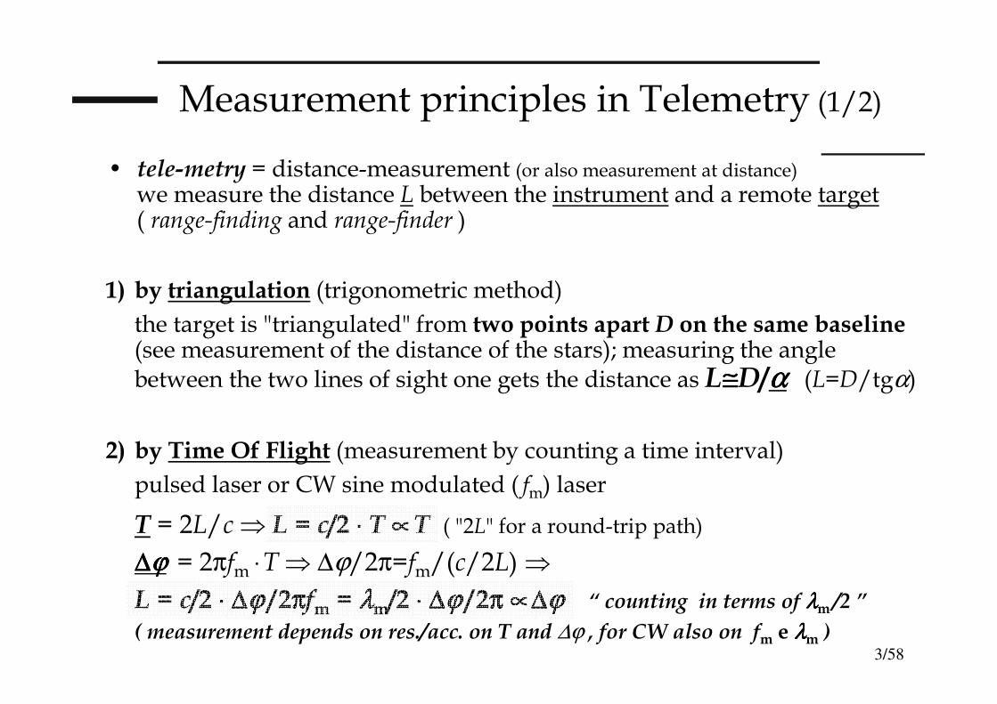
• tele-metry = distance-measurement (or also measurement at distance)
we measure the distance L between the instrument and a remote target( range-finding and range-finder )
1) by triangulation (trigonometric method)
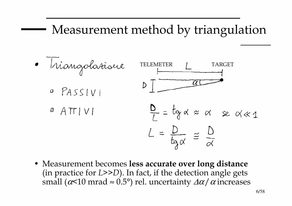
the target is "triangulated" from two points apart D on the same baseline (see measurement of the distance of the stars); measuring the angle between the two lines of sight one gets the distance as L≅≅≅≅D/αααα (L=D/tgα)
2) by Time Of Flight (measurement by counting a time interval)
pulsed laser or CW sine modulated ( fm) laser
T = 2L/c⇒ L = c/2 ⋅⋅⋅⋅ T ∝∝∝∝T ( "2L" for a round-trip path)
∆∆∆∆ϕϕϕϕ = 2πfm ⋅T ⇒ ∆ϕ/2π=fm/(c/2L) ⇒
L = c/2 ⋅⋅⋅⋅ ∆∆∆∆ϕϕϕϕ /2ππππfm = λλλλm/2 ⋅⋅⋅⋅ ∆∆∆∆ϕϕϕϕ /2ππππ ∝∝∝∝∆∆∆∆ϕϕϕϕ “ counting in terms of λλλλm /2 ”
( measurement depends on res./acc. on T and ∆ϕ , for CW also on fm e λλλλm )
4/58
Measuement principles in Telemetry (2/2)
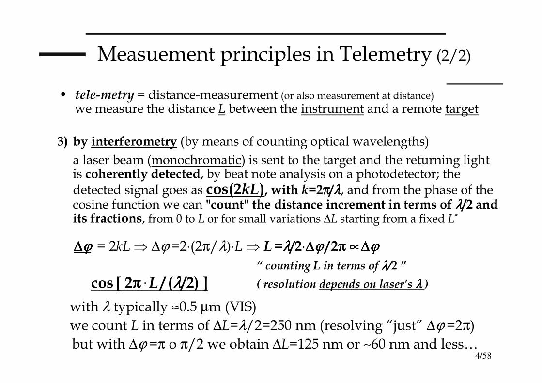
3) by interferometry (by means of counting optical wavelengths)
a laser beam (monochromatic) is sent to the target and the returning light is coherently detected, by beat note analysis on a photodetector; the detected signal goes as cos(2kL), with k=2ππππ/λλλλ, and from the phase of the cosine function we can "count" the distance increment in terms of λλλλ/2 and its fractions, from 0 to L or for small variations ∆L starting from a fixed L*
∆∆∆∆ϕϕϕϕ = 2kL⇒ ∆ϕ =2⋅(2π/λ)⋅L⇒ L=λλλλ/2⋅⋅⋅⋅∆∆∆∆ϕϕϕϕ /2ππππ ∝∝∝∝∆∆∆∆ϕϕϕϕ
“ counting L in terms of λλλλ/2 ”
cos [ 2ππππ· L / (λλλλ/2) ] ( resolution depends on laser’s λλλλ )
with λ typically ≈0.5 µm (VIS)
we count L in terms of ∆L=λ/2=250 nm (resolving “just” ∆ϕ =2π)
but with ∆ϕ =π o π/2 we obtain ∆L=125 nm or ∼60 nm and less…
• tele-metry = distance-measurement (or also measurement at distance)
we measure the distance L between the instrument and a remote target
5/58
T E L E M E T E R S
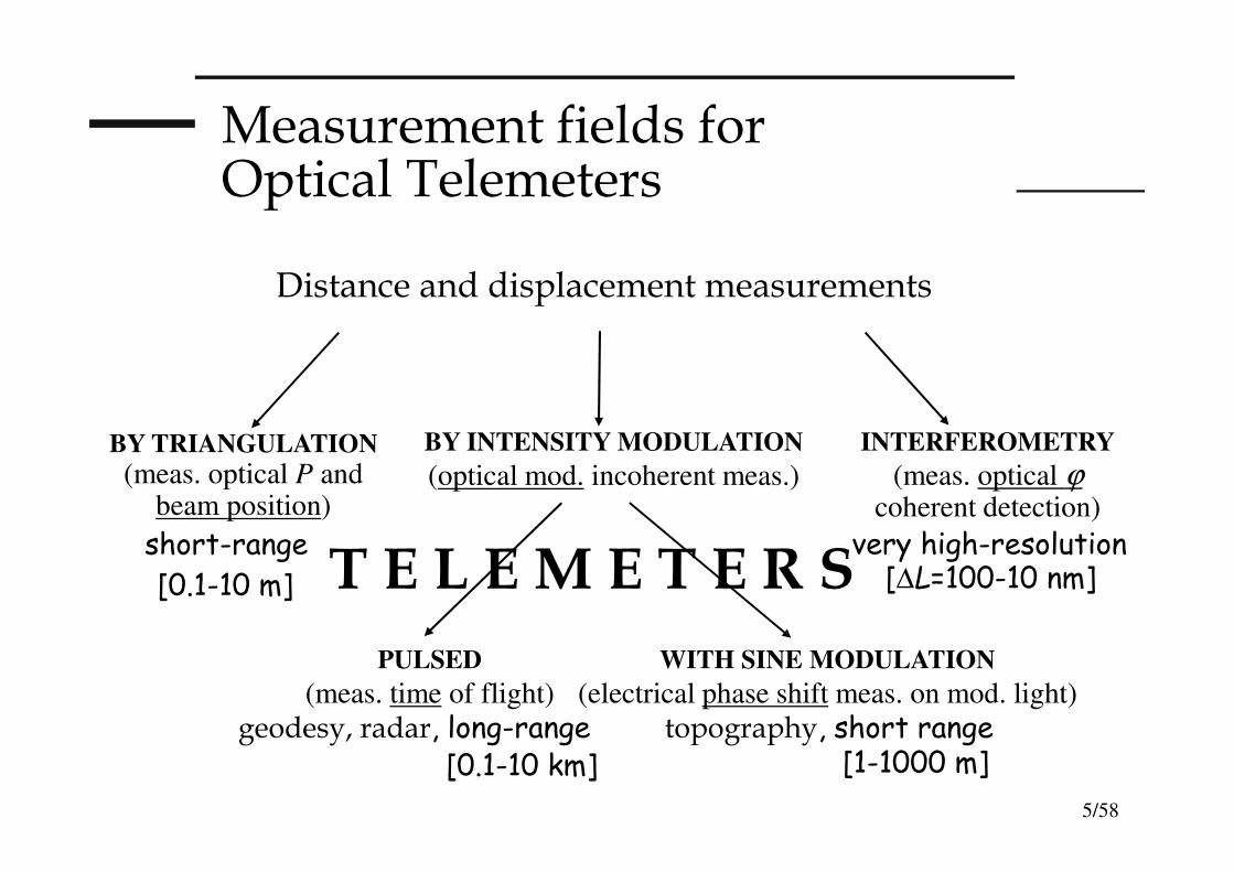
Measurement fields for Optical Telemeters
Distance and displacement measurements
WITH SINE MODULATION
(electrical phase shift meas. on mod. light)
topography, short range
PULSED
(meas. time of flight)
geodesy, radar, long-range
INTERFEROMETRY
(meas. optical ϕcoherent detection)
very high-resolution
BY INTENSITY MODULATION
(optical mod. incoherent meas.)BY TRIANGULATION
(meas. optical P and beam position)
short-range
[0.1-10 m] [∆L=100-10 nm]
[0.1-10 km] [1-1000 m]
6/58
Measurement method by triangulation
• Measurement becomes less accurate over long distance(in practice for L>>D). In fact, if the detection angle gets small (α<10 mrad ≈ 0.5°) rel. uncertainty ∆α/α increases
α
TELEMETER TARGET
7/58
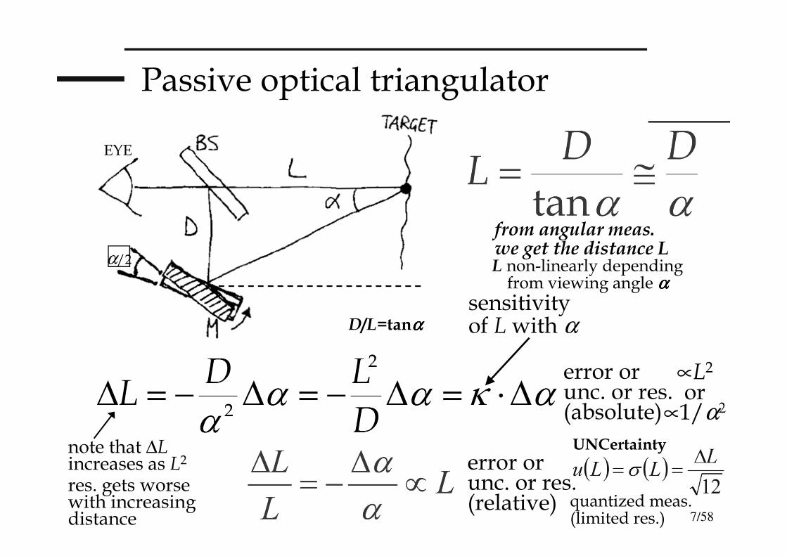
Passive optical triangulator
sensitivity of L with α
error orunc. or res.(absolute)
error orunc. or res.(relative)
D/L=tanαααα
from angular meas. we get the distance L
note that ∆Lincreases as L2
res. gets worse with increasing distance
EYE
UNCertainty
quantized meas. (limited res.)
α/2 L non-linearly depending from viewing angle αααα
∝L2
or∝1/α2
8/58
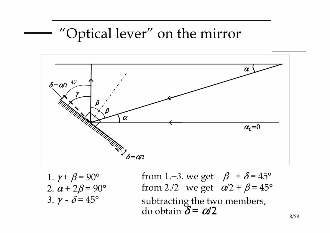
“Optical lever” on the mirror
δ δ δ δ ====αααα/2
αααα
αααα
ββββββββ
αααα 0000====0000
γγγγ
δ δ δ δ ====αααα/2
1. γ + β = 90°2. α + 2β = 90°3. γ - δ = 45°
from 1.−3. we get β + δ = 45°from 2./2 we get α/2 + β = 45°
subtracting the two members,do obtain δ δ δ δ = αααα/2/2/2/2
45°
9/58
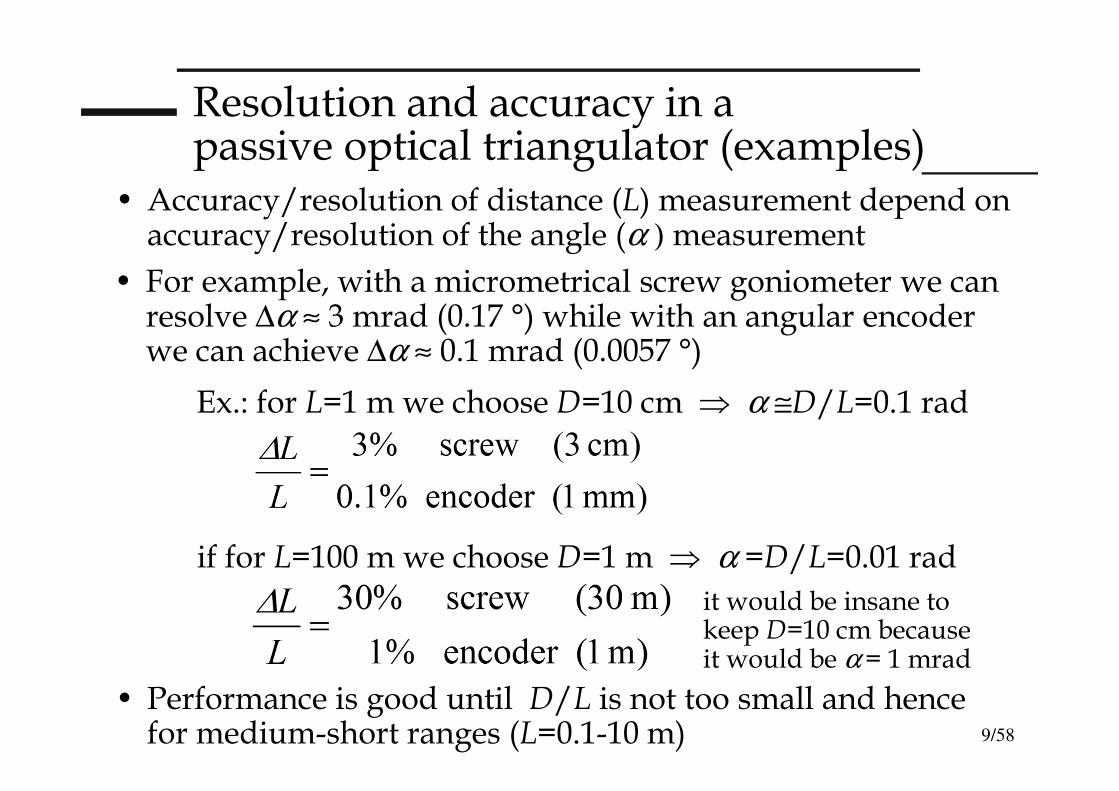
Resolution and accuracy in a passive optical triangulator (examples)
• Accuracy/resolution of distance (L) measurement depend on accuracy/resolution of the angle (α ) measurement
• For example, with a micrometrical screw goniometer we can resolve ∆α ≈ 3 mrad (0.17 °) while with an angular encoderwe can achieve ∆α ≈ 0.1 mrad (0.0057 °)
Ex.: for L=1 m we choose D=10 cm ⇒ α ≅D/L=0.1 rad
• Performance is good until D/L is not too small and hence for medium-short ranges (L=0.1-10 m)
if for L=100 m we choose D=1 m ⇒ α =D/L=0.01 rad
it would be insane to keep D=10 cm becauseit would be α = 1 mrad
10/58
“Active” (laser) optical triangulator
• We remove moving parts (no goniom. With respect to passive triangulator) and we achieve a very quick and accurate response, very repeatable
• We use visible λλλλ for simplicity of “target viewing” (He-Ne at 633 nm or LD-VIS or Nd:YAG2××××)
• The laser beam undergoes a round trip path from telemeter to target. Misura 1D measurement with optical position sensor (2Q/PSD/CCD) of theangle αααα between going and returning beam.Receiving optics is off-axis at a distance D from launching optics: we then retrieve L=D/tanαααα
11/58
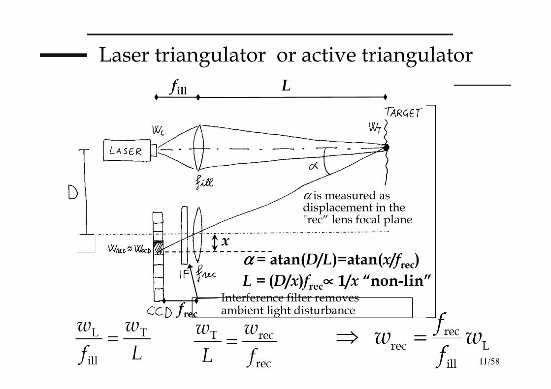
Laser triangulator or active triangulator
⇒
Interference filter removes ambient light disturbance
fill L
frec
α is measured as displacement in the "rec“ lens focal plane
xαααα = atan(D/L)=atan(x/frec)
L = (D/x)frec∝∝∝∝ 1/x “non-lin”
12/58
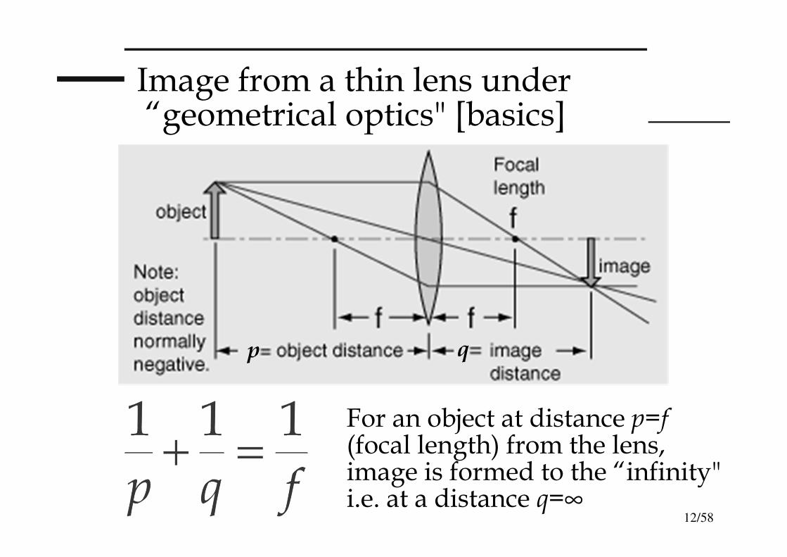
Image from a thin lens under“geometrical optics" [basics]
qp
For an object at distance p=f(focal length) from the lens, image is formed to the “infinity" i.e. at a distance q=∞
13/58
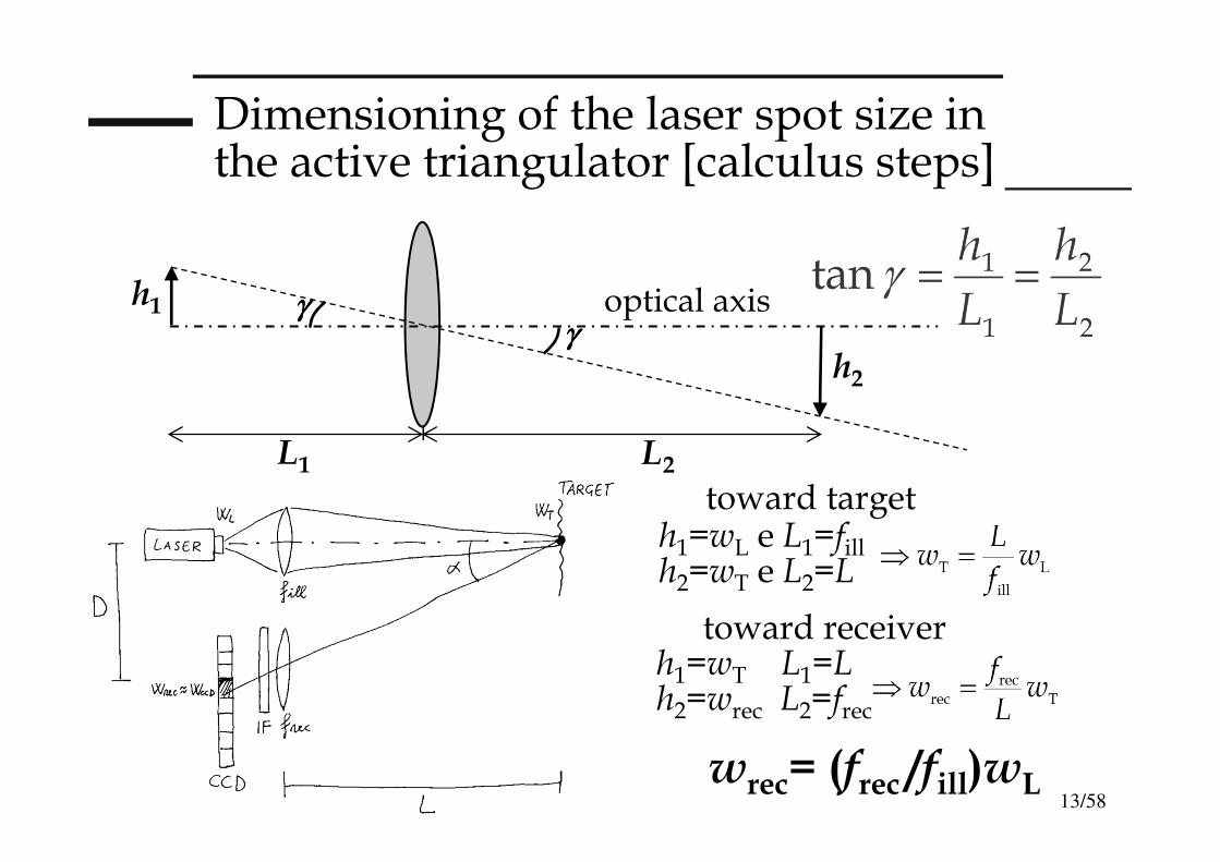
Dimensioning of the laser spot size in the active triangulator [calculus steps]
optical axisγγγγγγγγ
L1 L2
h1
h2
wrec= (frec /fill)wL
h1=wL e L1=fillh2=wT e L2=L
toward target
h1=wT L1=Lh2=wrec L2=frec
toward receiver
14/58
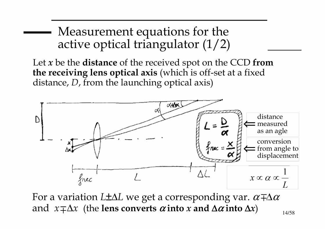
Measurement equations for the active optical triangulator (1/2)
Let x be the distance of the received spot on the CCD from the receiving lens optical axis (which is off-set at a fixed distance, D, from the launching optical axis)
For a variation L±±±±∆L we get a corresponding var. α ∆αand x ∆x (the lens converts αααα into x and ∆∆∆∆αααα into ∆∆∆∆x)
⇐⇐⇐⇐conversion from angle to displacement
⇐⇐⇐⇐distance measured as an agle
15/58
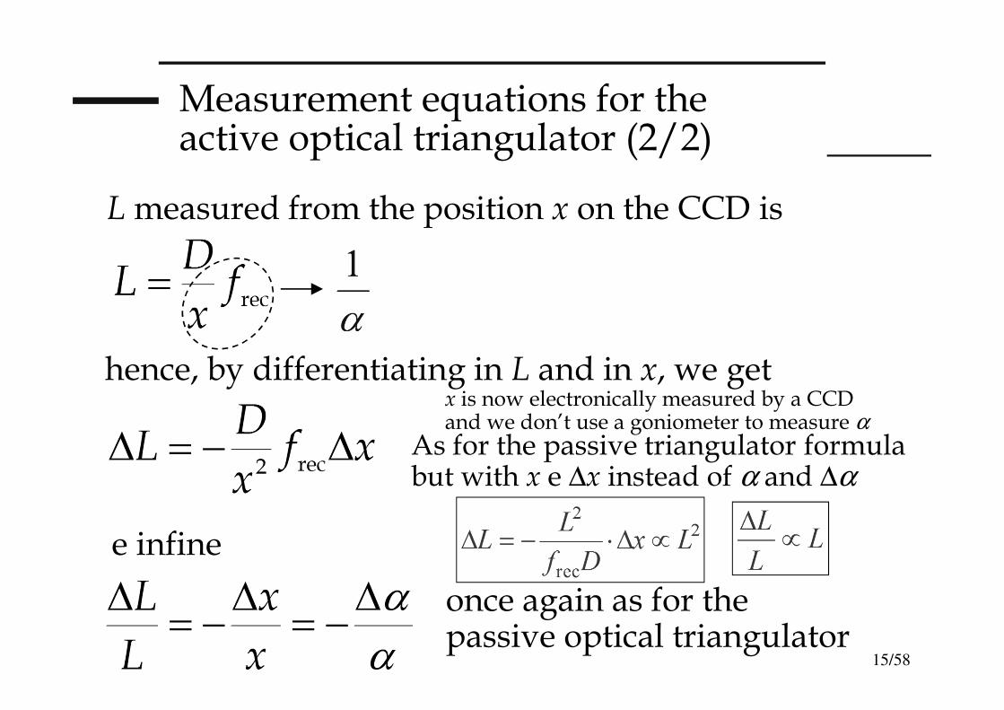
Measurement equations for the active optical triangulator (2/2)
Lmeasured from the position x on the CCD is
e infine
once again as for the passive optical triangulator
hence, by differentiating in L and in x, we get
As for the passive triangulator formula but with x e ∆x instead of α and ∆α
x is now electronically measured by a CCD and we don’t use a goniometer to measure α

16/58
Exercise on the laser triangulator(“known“ formulas: only calculations)
DATA: as in the case of passive optical triangulator, we work with D=10 cm (and frec=25 cm) for L=1 mand we now consider wL=5 µm and wCCD=10 µm:
If we resolve ∆x=10 µm (≈wCCD) on the photodetector,
( ∆∆∆∆L=400 µµµµm )( for L = 1 m )
Remind how for the passive triangulator we had ∆α ≈ 3 mrad (micro-screw goniometer) and ∆α ≈ 0.1mrad (angular encoder)
17/58
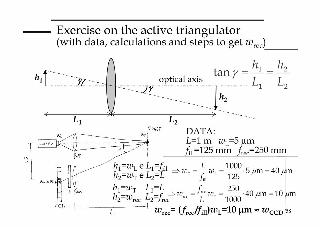
DATA:L=1 m wL=5 µm fill=125 mm frec=250 mm
Exercise on the active triangulator (with data, calculations and steps to get wrec)
optical axisγγγγγγγγ
L1 L2
h1
h2
wrec= ( frec /fill)wL=10 µµµµm ≈≈≈≈ wCCD
h1=wL e L1=fillh2=wT e L2=L
h1=wT L1=Lh2=wrec L2=frec
18/58
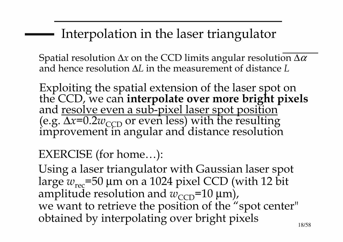
Interpolation in the laser triangulator
Exploiting the spatial extension of the laser spot on the CCD, we can interpolate over more bright pixelsand resolve even a sub-pixel laser spot position(e.g. ∆x=0.2wCCD or even less) with the resulting improvement in angular and distance resolution
EXERCISE (for home…):
Using a laser triangulator with Gaussian laser spot large wrec=50 µm on a 1024 pixel CCD (with 12 bit amplitude resolution and wCCD=10 µm), we want to retrieve the position of the “spot center" obtained by interpolating over bright pixels
Spatial resolution ∆x on the CCD limits angular resolution ∆αand hence resolution ∆L in the measurement of distance L
19/58
Exercise on the laser triangulator
QUESTIONS:
- if the telemeter laser is an He-Ne laser at 633 nm, what kind of CCD we should use? why?
- how many and which pixels on the CCD are “well lit" when the “background light" covers 1/100 (in amplitude) of the measurement dynamic range?
- how shall me measure the position of the spot centeron the CCD? How much wide is the “visible” spot?
- which are the practical limits to the accuracy?
- Imagine we can achieve a resolution of 0.1 pixel: calculate the absolute resolution of the telemeter at the minimum measurable distance Lmin=10 m
20/58
Exercise on the laser triangulator
[in general one pixel is lit if its signal level brings its output voltage to a greater than zero (just quantization limit) or here the pixel is well lit when its "signal" level is > 1/100 of the peak/dynamic-range of the whole optical signal (limits due to “noise" and background light)]
ANSWERS:
- for a red He-Ne laser we can conveniently use a Si CCD, sensible in the visible range and inexpensive
- To calculate how many and which pixels on the CCD are “well lit", we must before define what we mean for “well lit": since the single pixel can resolve N=2n=212=4096 levels of photocurrent and hence incident optical power, we can say that a pixel is well lit (SNR=1) if the current signal is equal to the minimum detectable current (due to quantization or electronic noise of the receiver + “background light")
21/58
Exercise on the laser triangulator
We hence can calculate
r≈≈≈≈k⋅⋅⋅⋅wrec with k=[0.5⋅⋅⋅⋅2.3⋅⋅⋅⋅log10M]0.5
clearly wrec corresponds to a certain number of pixels and so r can be given by “counting pixels"
The optical power on the single pixel is the optical intensity times the pixel area (precisely one should integrate the intensity over the pixel surface)
Optical intensity is decreasing as exp(-2r2/w2rec)
getting farer from the peak (in r=0). So we obtain an1/M part of the peak value when 2r2=w2
recln(M)or equivalently r/wrec=(0.5lnM)0.5=[0.5⋅2.3⋅log10M]0.5
22/58
Exercise on the laser triangulator
we hence obtain r≈2wrec=2⋅50µm≅100µm corresponding to 10 pixels each of size10 µm (starting from the Gaussan center). The total number of well-lit pixels is finally 20 pixel (±10), for a "visible" spot size (diameter) of approximately 200 µµµµm
just quantization:we get 1/4096 ≈ 1/4000 of the peak value for 2r2=w2
recln(4000) (≈ 4000 amplitude levels for n=12 bit)
r/wrec=(0.5⋅ln4000)0.5=[1.15⋅log104000]0.5=[1.15×3.6]0.5≈2
with noise and background (at 1/M=1/100 from peak):we get 1/100 of the peak value for 2r2=w2
recln(100) r/wrec=(0.5⋅ln100)0.5=[1.15⋅log10100]0.5=[2.3]0.5≈1.5 and r≅75µm with a well-lit spot of about 150 µµµµmdiameter or 15 pixel for 1/M=1/10 of peak, r ≅ 1.1⋅wrec
[as we know exp(-2)=13 %≈1/10]
23/58
Exercise on the laser triangulator
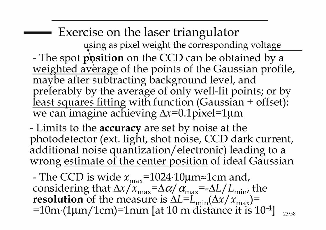
- The CCD is wide xmax=1024⋅10µm≈1cm and, considering that ∆x/xmax=∆α/αmax=-∆L/Lmin, the resolution of the measure is ∆L=Lmin(∆x/xmax)= =10m⋅(1µm/1cm)=1mm [at 10 m distance it is 10-4]
- The spot position on the CCD can be obtained by a weighted average of the points of the Gaussian profile, maybe after subtracting background level, and preferably by the average of only well-lit points; or by least squares fitting with function (Gaussian + offset): we can imagine achieving ∆x=0.1pixel=1µm
- Limits to the accuracy are set by noise at the photodetector (ext. light, shot noise, CCD dark current, additional noise quantization/electronic) leading to a wrong estimate of the center position of ideal Gaussian
using as pixel weight the corresponding voltage
24/58
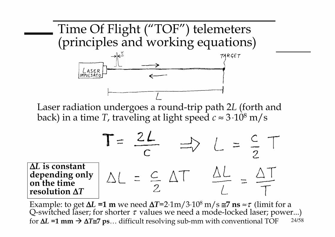
Time Of Flight (“TOF”) telemeters(principles and working equations)
Example: to get ∆∆∆∆L =1 m we need ∆∆∆∆T=2⋅1m/3⋅108 m/s ≅≅≅≅7 ns ≈τ (limit for a Q-switched laser; for shorter τ values we need a mode-locked laser; power...)for ∆∆∆∆L =1 mm ∆∆∆∆T≅≅≅≅7 ps… difficult resolving sub-mm with conventional TOF
Laser radiation undergoes a round-trip path 2L (forth and back) in a time T, traveling at light speed c ≈ 3 ⋅108 m/s
∆∆∆∆L is constantdepending onlyon the timeresolution ∆∆∆∆T
25/58
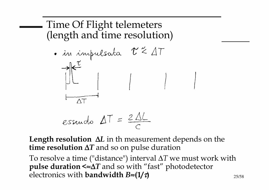
Time Of Flight telemeters(length and time resolution)
Length resolution ∆∆∆∆L in th measurement depends on the time resolution ∆∆∆∆T and so on pulse duration
To resolve a time ("distance") interval ∆Twe must work with pulse duration<≈≈≈≈∆∆∆∆T and so with “fast” photodetector electronics with bandwidth B≈≈≈≈(1/ττττ)
26/58
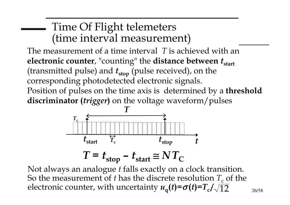
Time Of Flight telemeters(time interval measurement)
The measurement of a time interval T is achieved with an electronic counter, "counting" the distance between tstart(transmitted pulse) and tstop (pulse received), on the corresponding photodetected electronic signals.Position of pulses on the time axis is determined by a threshold discriminator (trigger) on the voltage waveform/pulses
Not always an analogue t falls exactly on a clock transition.So the measurement of t has the discrete resolution Tc of the electronic counter, with uncertainty uq(t)=σσσσ (t)=Tc /
tstart tstop t
TTc
T = tstop – tstart ≅≅≅≅ NTC
Tc
27/58
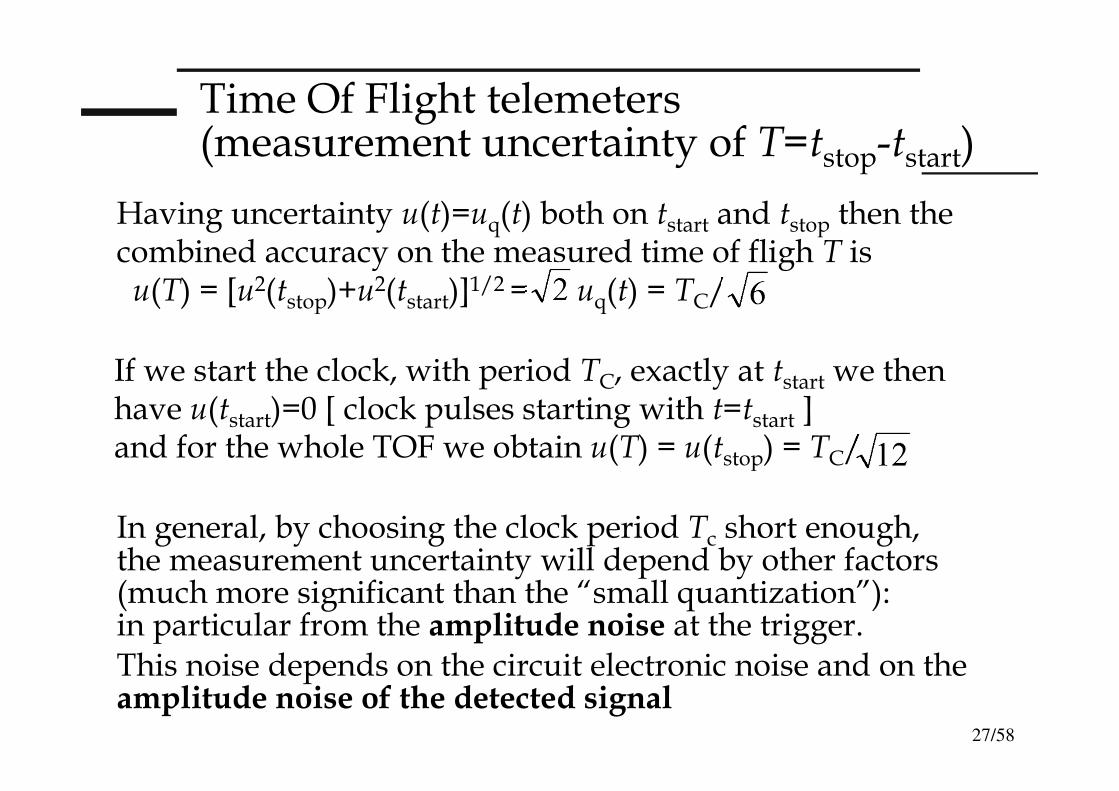
Time Of Flight telemeters(measurement uncertainty of T=tstop-tstart)
Having uncertainty u(t)=uq(t) both on tstart and tstop then the combined accuracy on the measured time of fligh T isu(T) = [u2(tstop)+u
2(tstart)]1/2 = uq(t) = TC/
In general, by choosing the clock period Tc short enough, the measurement uncertainty will depend by other factors (much more significant than the “small quantization”): in particular from the amplitude noise at the trigger. This noise depends on the circuit electronic noise and on the amplitude noise of the detected signal
If we start the clock, with period TC, exactly at tstart we then have u(tstart)=0 [ clock pulses starting with t=tstart ] and for the whole TOF we obtain u(T) = u(tstop) = TC/
28/58
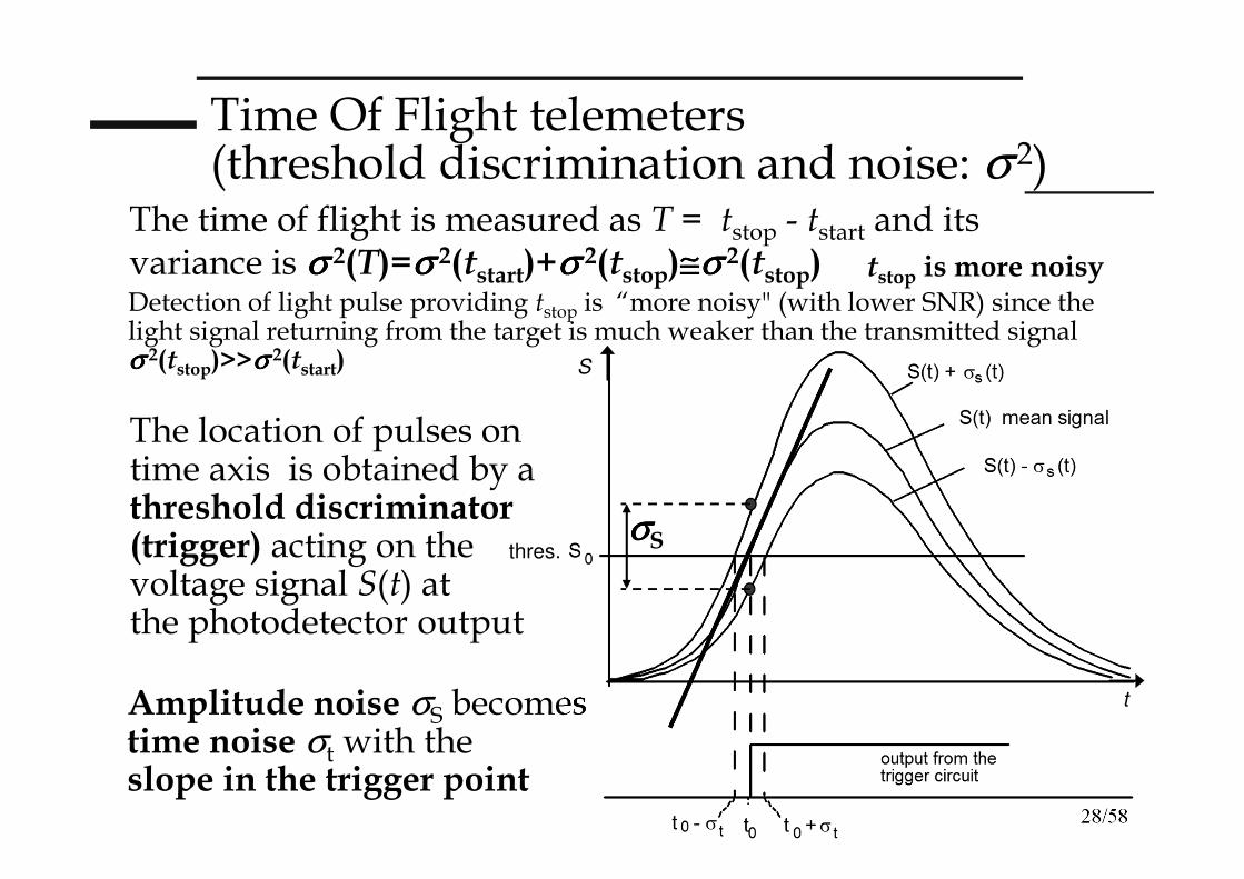
Time Of Flight telemeters (threshold discrimination and noise: σ 2)
The time of flight is measured as T = tstop - tstart and its variance is σσσσ 2(T)=σσσσ 2(tstart)+σσσσ 2(tstop)≅≅≅≅σσσσ 2(tstop)
The location of pulses on time axis is obtained by a threshold discriminator (trigger) acting on the voltage signal S(t) at the photodetector output
Amplitude noise σS becomes time noise σt with the slope in the trigger point
tstop is more noisy
thres.
S
t
σσσσS
Detection of light pulse providing tstop is “more noisy" (with lower SNR) since the light signal returning from the target is much weaker than the transmitted signal σσσσ 2(tstop)>>σσσσ 2(tstart)
29/58
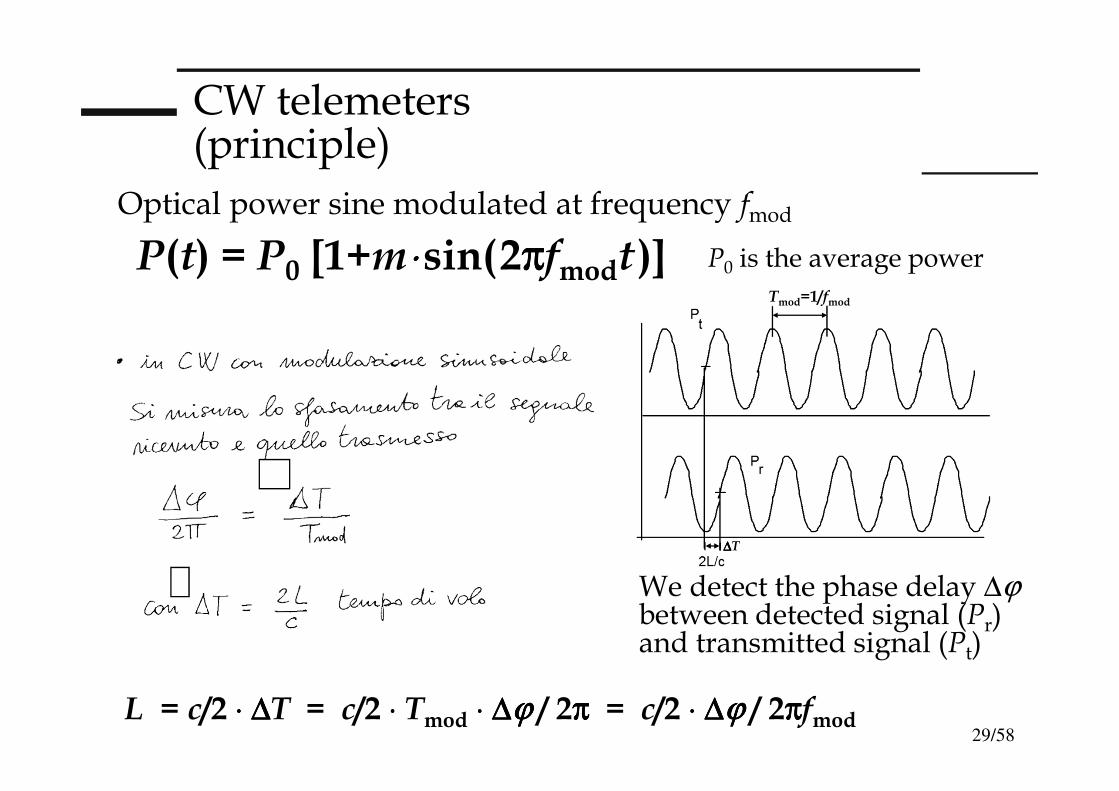
CW telemeters (principle)
Optical power sine modulated at frequency fmod
We detect the phase delay ∆ϕbetween detected signal (Pr) and transmitted signal (Pt)
P(t) = P0 [1+m⋅⋅⋅⋅sin(2ππππfmodt)]
∆∆∆∆T
Tmod=1/fmod
L = c/2 ⋅⋅⋅⋅ ∆∆∆∆T = c/2 ⋅⋅⋅⋅ Tmod ⋅⋅⋅⋅ ∆∆∆∆ϕϕϕϕ / 2ππππ = c/2 ⋅⋅⋅⋅ ∆∆∆∆ϕϕϕϕ / 2ππππfmod
P0 is the average power
30/58
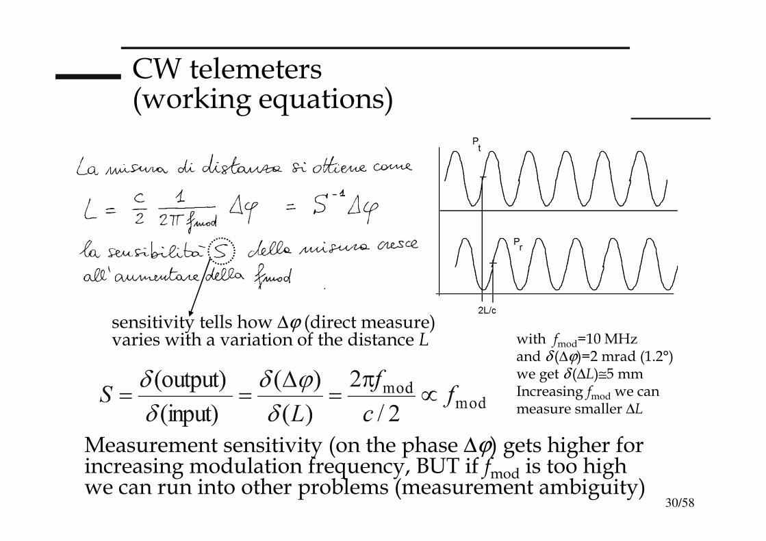
CW telemeters (working equations)
Measurement sensitivity (on the phase ∆ϕ) gets higher for increasing modulation frequency, BUT if fmod is too high we can run into other problems (measurement ambiguity)
sensitivity tells how ∆ϕ (direct measure)varies with a variation of the distance L with fmod=10 MHz
and δ (∆ϕ)=2 mrad (1.2°)we get δ (∆L)≅5 mmIncreasing fmod we canmeasure smaller ∆L
31/58
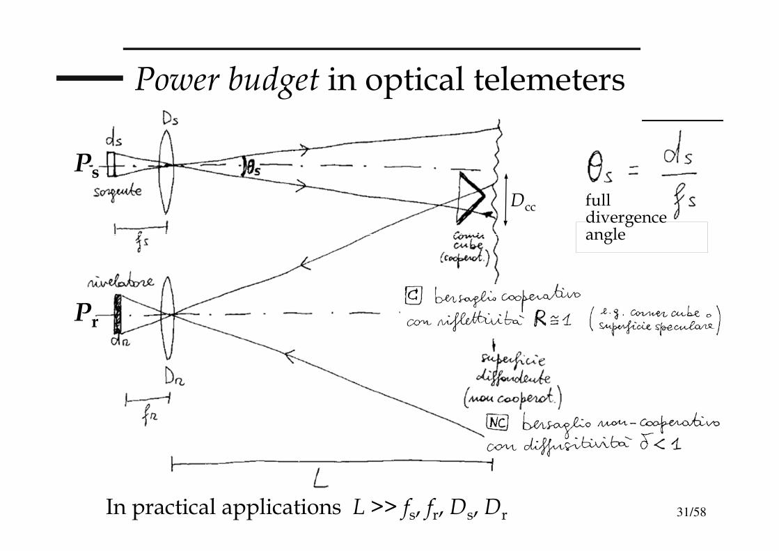
Power budget in optical telemeters
Ps
Pr
Dcc full divergence angle
In practical applications L >> fs, fr, Ds, Dr
32/58
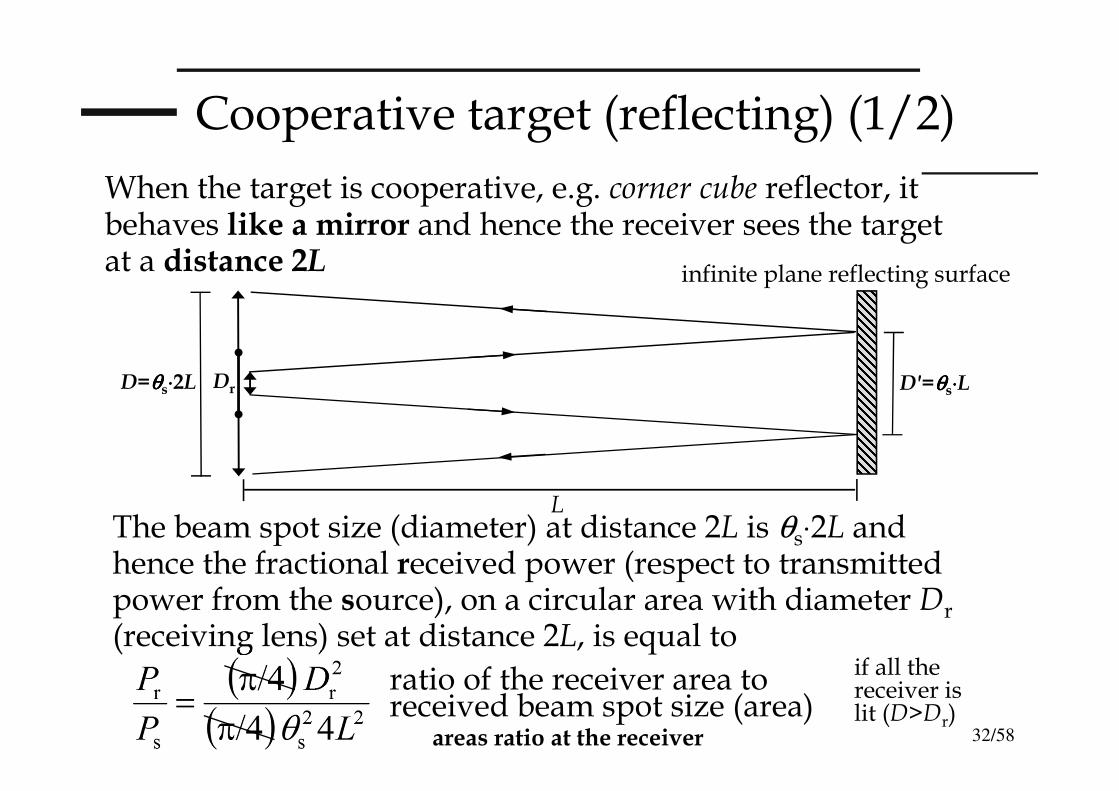
Cooperative target (reflecting) (1/2)
When the target is cooperative, e.g. corner cube reflector, it behaves like a mirror and hence the receiver sees the target at a distance 2L
The beam spot size (diameter) at distance 2L is θs⋅2L and hence the fractional received power (respect to transmitted power from the source), on a circular area with diameter Dr
(receiving lens) set at distance 2L, is equal to
ratio of the receiver area to received beam spot size (area)
DrD=θθθθs⋅⋅⋅⋅2L
L
D'=θθθθs⋅⋅⋅⋅L
infinite plane reflecting surface
if all the receiver is lit (D>Dr)
areas ratio at the receiver
33/58
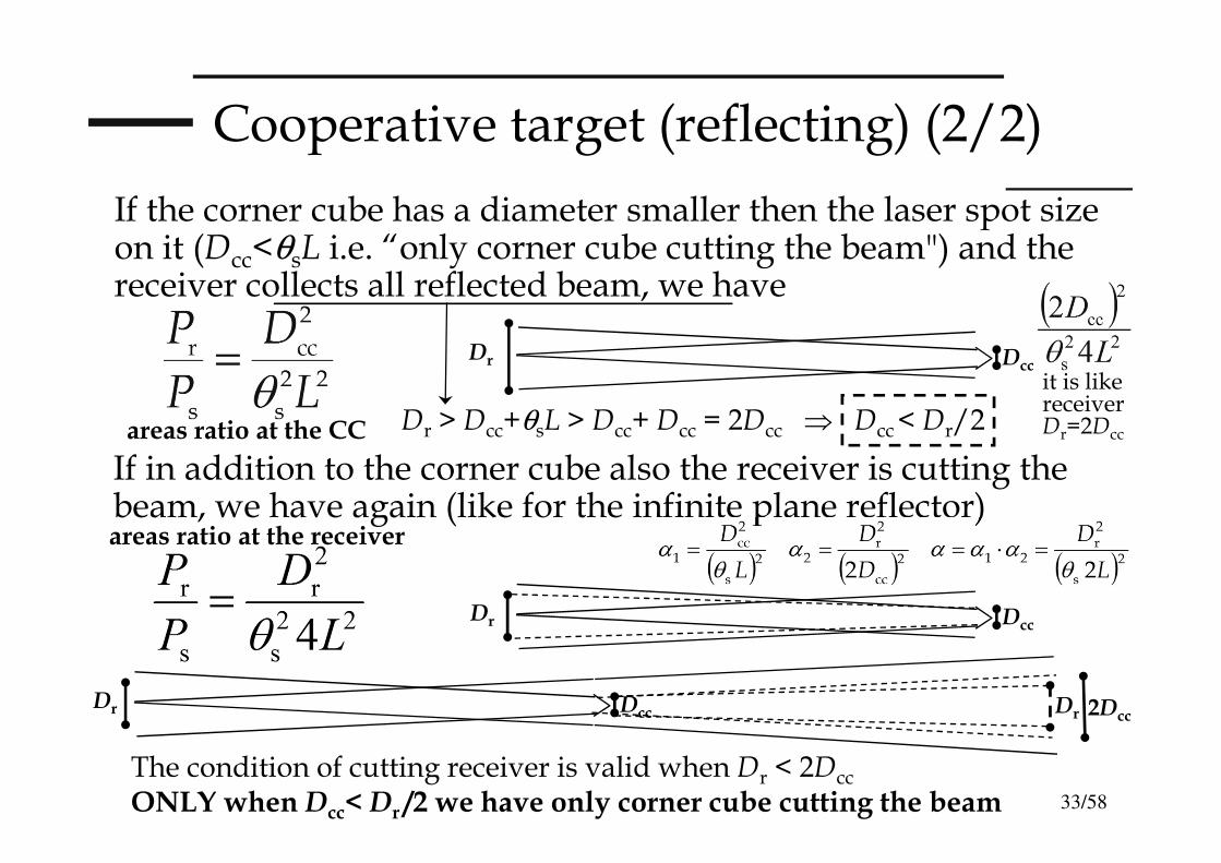
Cooperative target (reflecting) (2/2)
If the corner cube has a diameter smaller then the laser spot size on it (Dcc<θsL i.e. “only corner cube cutting the beam") and the receiver collects all reflected beam, we have
Dr Dcc
If in addition to the corner cube also the receiver is cutting the beam, we have again (like for the infinite plane reflector)
Dr Dcc
The condition of cutting receiver is valid when Dr < 2Dcc
ONLY when Dcc< Dr /2 we have only corner cube cutting the beam
Dr > Dcc+θsL > Dcc+ Dcc = 2Dcc ⇒ Dcc< Dr/2
Dr Dcc Dr 2Dcc
areas ratio at the CC
it is likereceiverDr=2Dcc
areas ratio at the receiver
34/58
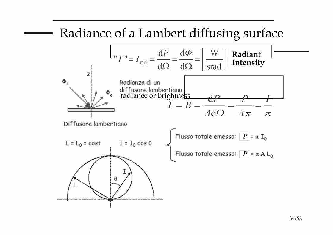
Radiance of a Lambert diffusing surface
P
P
RadiantIntensity
radiance or brightness
35/58
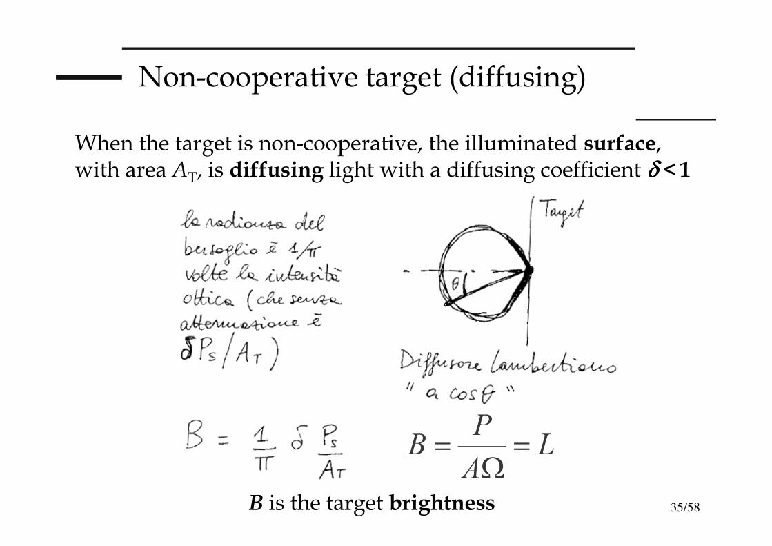
Non-cooperative target (diffusing)
When the target is non-cooperative, the illuminated surface, with area AT, is diffusing light with a diffusing coefficient δδδδ <1
B is the target brightness
36/58
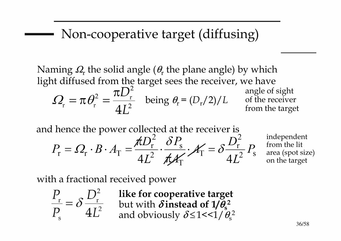
Naming Ωr the solid angle (θr the plane angle) by which light diffused from the target sees the receiver, we have
being θr = (Dr/2)/L
with a fractional received power
like for cooperative targetbut with δδδδ instead of 1/θθθθs
2
and obviously δ ≤1<<1/θs2
angle of sight of the receiver from the target
and hence the power collected at the receiver isindependent from the lit area (spot size) on the target
Non-cooperative target (diffusing)
37/58
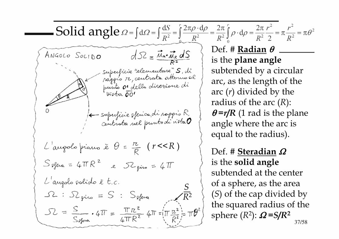
Solid angle
Def. # Radian θθθθis the plane anglesubtended by a circular arc, as the length of the arc (r) divided by the radius of the arc (R): θθθθ =r/R (1 rad is the plane angle where the arc is equal to the radius).
Def. # Steradian ΩΩΩΩis the solid anglesubtended at the center of a sphere, as the area (S) of the cap divided by the squared radius of the sphere (R2): ΩΩΩΩ =S/R2
SR2
( r<<R )
38/58
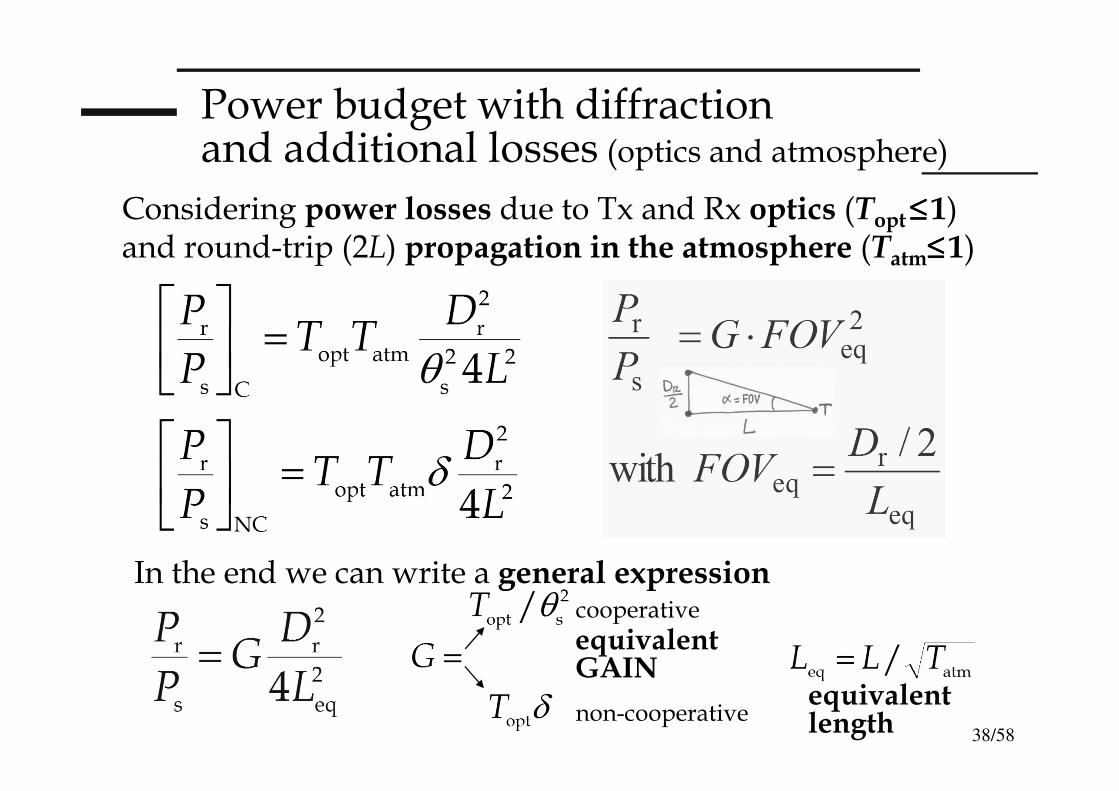
Power budget with diffraction and additional losses (optics and atmosphere)
Considering power losses due to Tx and Rx optics (Topt≤≤≤≤1) and round-trip (2L) propagation in the atmosphere (Tatm≤≤≤≤1)
In the end we can write a general expressioncooperative
non-cooperativeequivalent length
equivalent GAIN
39/58
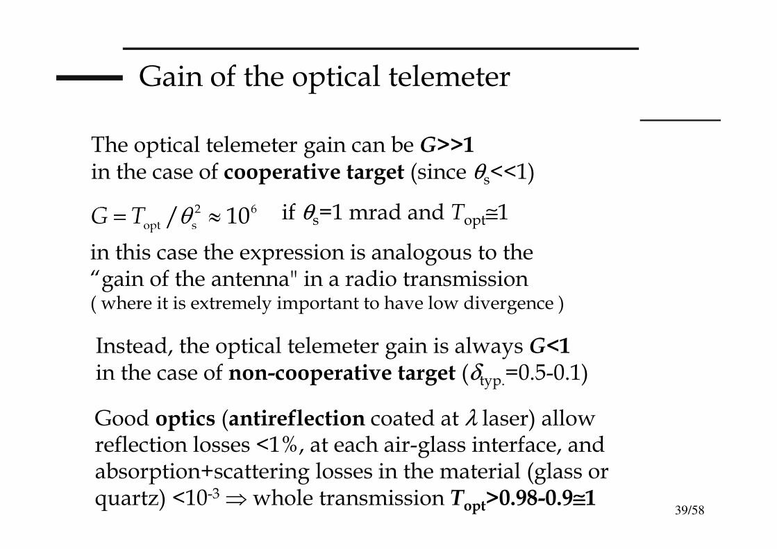
Gain of the optical telemeter
The optical telemeter gain can be G>>1in the case of cooperative target (since θs<<1)
if θs=1 mrad and Topt≅1
in this case the expression is analogous to the “gain of the antenna" in a radio transmission( where it is extremely important to have low divergence )
Instead, the optical telemeter gain is always G<1in the case of non-cooperative target (δtyp.=0.5-0.1)
Good optics (antireflection coated at λ laser) allow reflection losses <1%, at each air-glass interface, and absorption+scattering losses in the material (glass or quartz) <10-3 ⇒ whole transmission Topt>0.98-0.9≅≅≅≅1
40/58
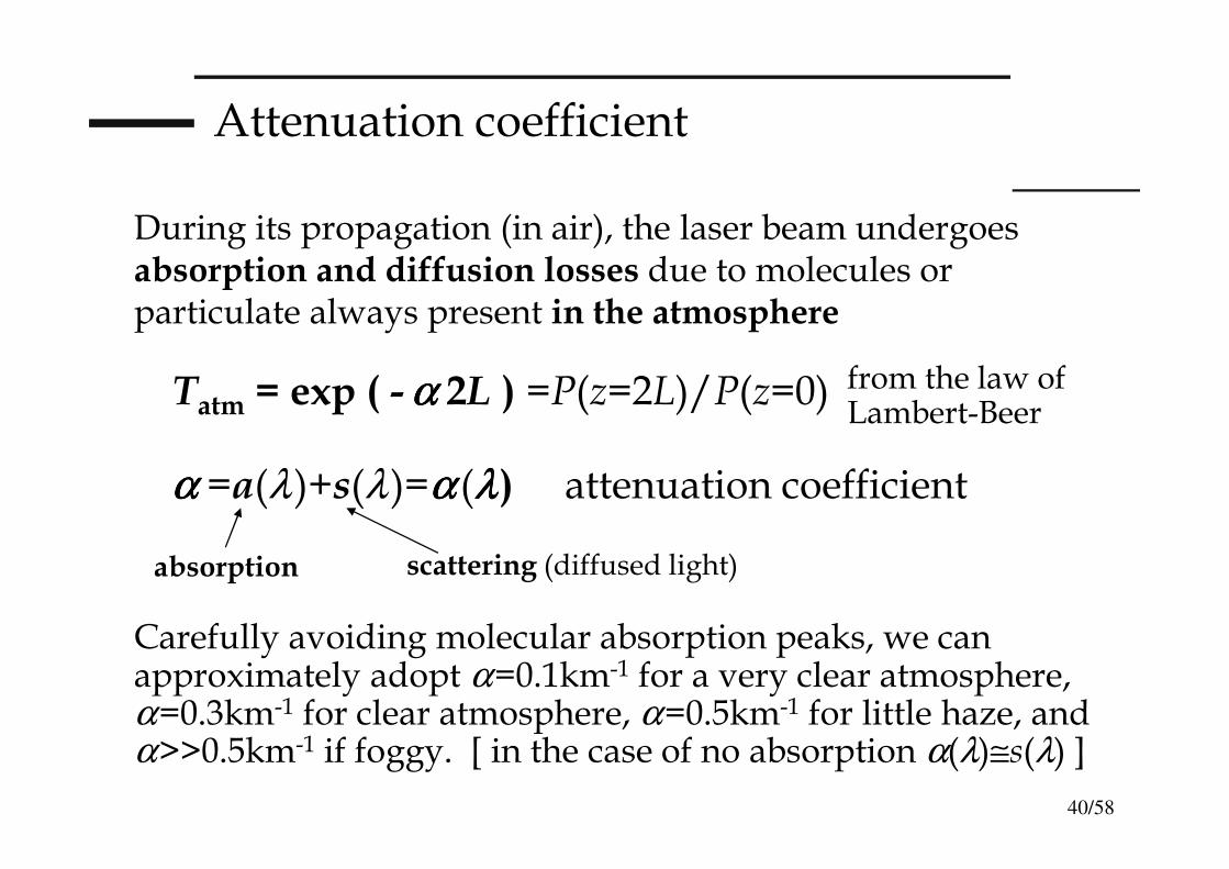
Attenuation coefficient
During its propagation (in air), the laser beam undergoes absorption and diffusion losses due to molecules or particulate always present in the atmosphere
Carefully avoiding molecular absorption peaks, we can approximately adopt α=0.1km-1 for a very clear atmosphere,α=0.3km-1 for clear atmosphere, α=0.5km-1 for little haze, and α>>0.5km-1 if foggy. [ in the case of no absorption α(λ)≅s(λ) ]
Tatm = exp ( -α α α α 2L ) =P(z=2L)/P(z=0) from the law ofLambert-Beer
α α α α =a(λ)+s(λ)=αααα (λλλλ) attenuation coefficient
absorption scattering (diffused light)
41/58
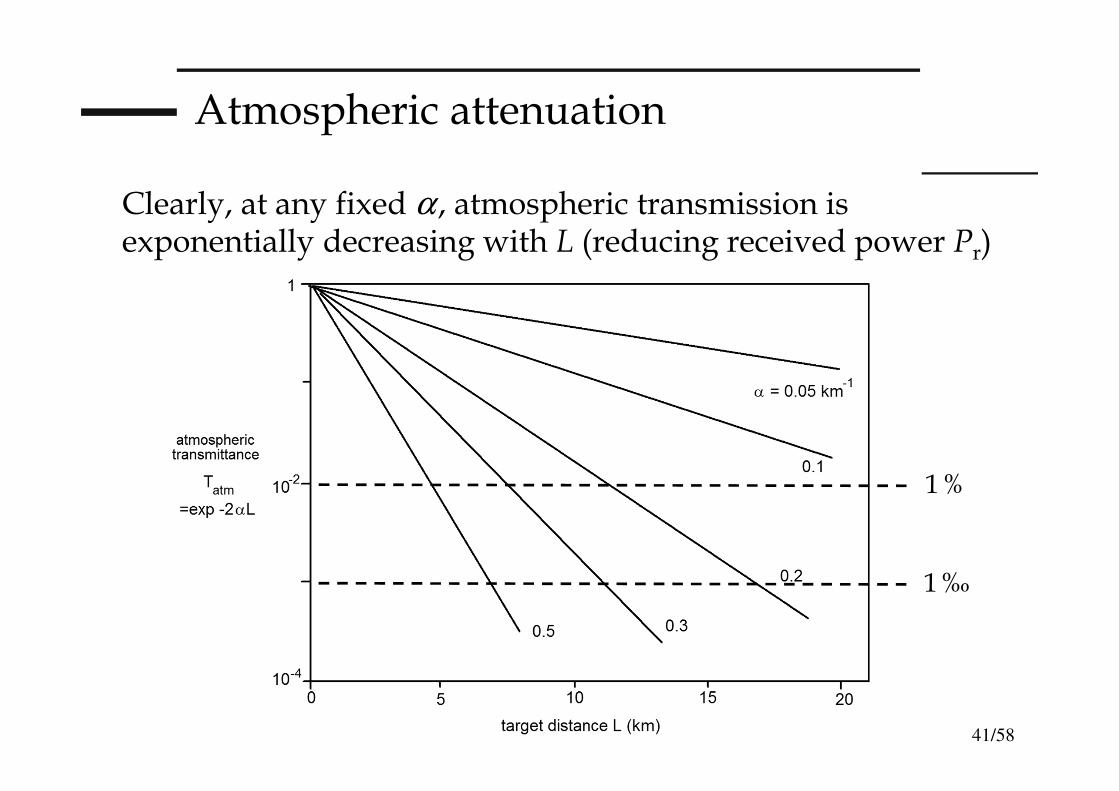
Atmospheric attenuation
Clearly, at any fixed α , atmospheric transmission is exponentially decreasing with L (reducing received power Pr)
1%
1‰
42/58
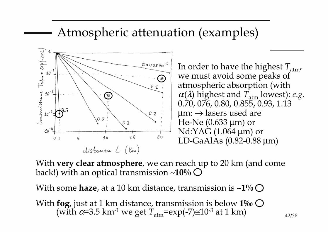
Atmospheric attenuation (examples)
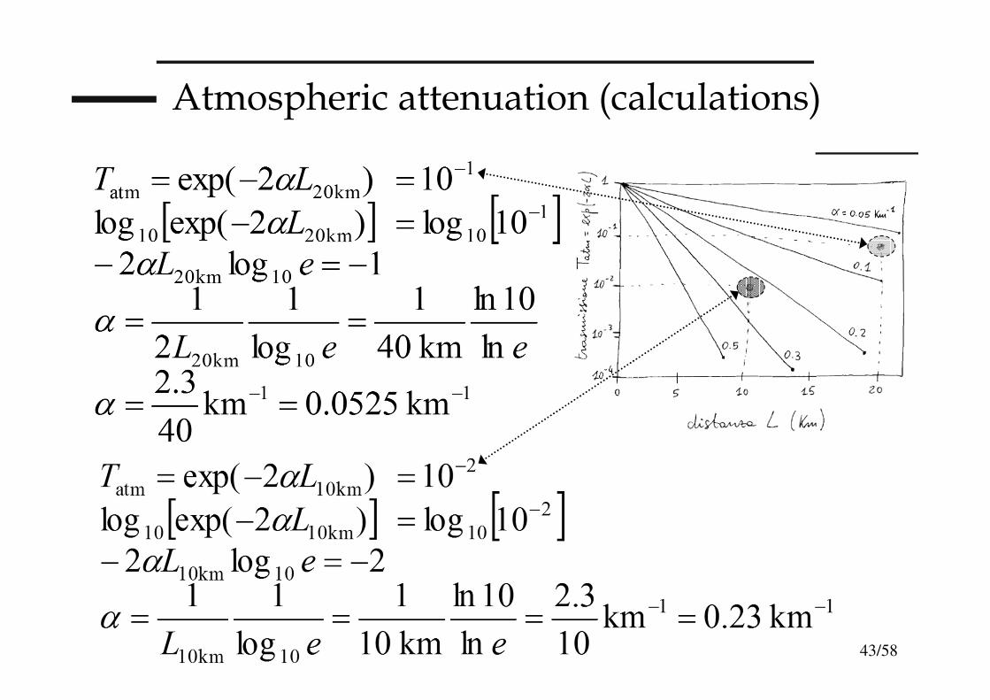
With very clear atmosphere, we can reach up to 20 km (and come back!) with an optical transmission ∼∼∼∼10%
With some haze, at a 10 km distance, transmission is ∼∼∼∼1%
With fog, just at 1 km distance, transmission is below 1‰
In order to have the highest Tatm, we must avoid some peaks of atmospheric absorption (with α(λ) highest and Tatm lowest): e.g. 0.70, 076, 0.80, 0.855, 0.93, 1.13 µm: → lasers used are He-Ne (0.633 µm) or Nd:YAG (1.064 µm) or LD-GaAlAs (0.82-0.88 µm)
(with α=3.5 km-1 we get Tatm=exp(-7)≅10-3 at 1 km)
1
3.5
43/58
Atmospheric attenuation (calculations)
44/58
θ
Atmospheric attenuation (examples)
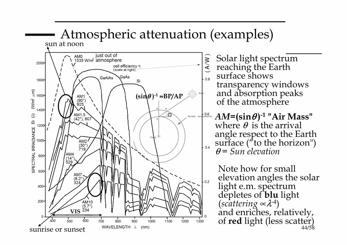
Solar light spectrum reaching the Earth surface shows transparency windows and absorption peaks of the atmosphere
AM=(sinθθθθ )-1 "Air Mass"where θ is the arrival angle respect to the Earth surface (“to the horizon")θ = Sun elevation
( A
/W )
Note how for small elevation angles the solar light e.m. spectrum depletes of blu light (scattering ∝λ-4)and enriches, relatively, of red light (less scatter)
VIS
sun at noon
sunrise or sunset
(sinθθθθ )-1 ≈≈≈≈BP/AP
just out of atmosphere

45/58
System equations and telemeter SNR
The photoreceiver (photodetector+transimpedance amp.) detecting receiver optical power Pr has electronic noise to be added to optical and shot noise to obtain the total noise power Pn (as incident optical power on the photodiode)
In order to work with a given ratio (S/N)=Pr /Pn
at the telemeter receiver, we must have:
remindthat we have
telemeterequivalent power
The received signal optical power is Pr (depending on Ps)
⇒⇒⇒⇒
46/58
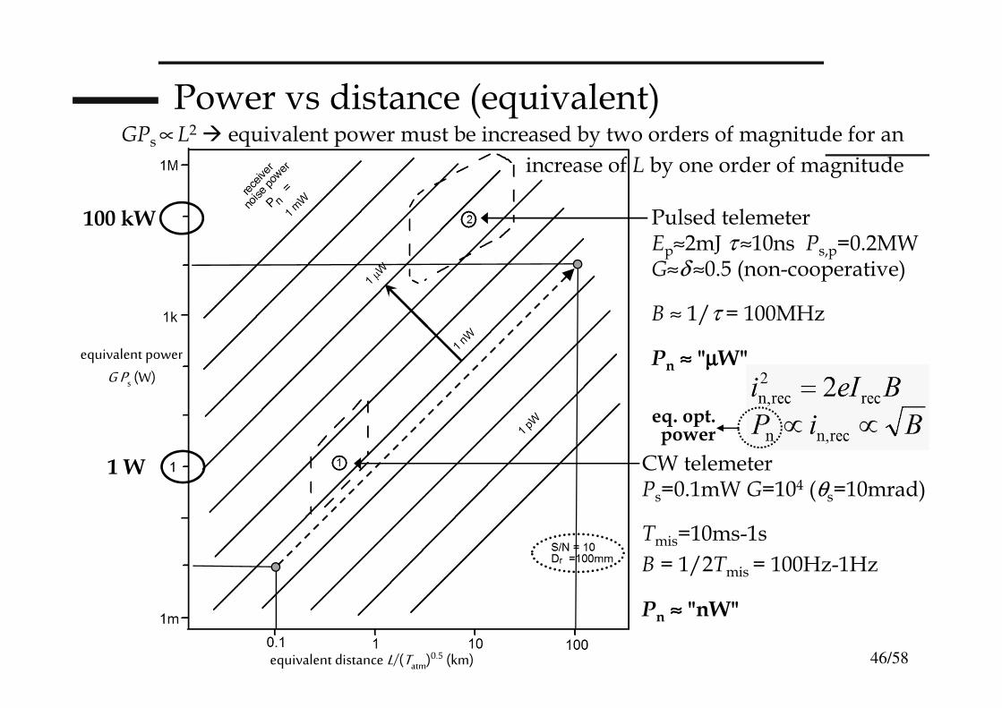
Power vs distance (equivalent)
CW telemeter Ps=0.1mW G=104 (θs=10mrad)
Tmis=10ms-1s
B = 1/2Tmis = 100Hz-1Hz
Pn ≈≈≈≈ "nW"
Pulsed telemeterEp≈2mJ τ ≈10ns Ps,p=0.2MW G≈δ ≈0.5 (non-cooperative)
B ≈ 1/τ = 100MHz
Pn ≈≈≈≈ "µµµµW"
equivalent distance L/(Tatm)0.5 (km)
equivalent power
G Ps (W)
GPs ∝L2 equivalent power must be increased by two orders of magnitude for an
increase of L by one order of magnitude
eq. opt.power
100 kW
1 W
47/58
Noise at the receiver (of the telemeter)
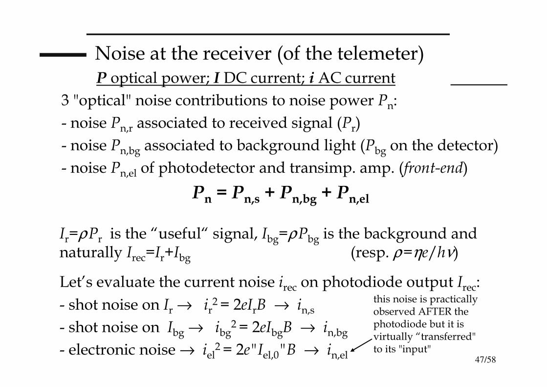
3 "optical" noise contributions to noise power Pn:
- noise Pn,r associated to received signal (Pr)
- noise Pn,bg associated to background light (Pbg on the detector)
- noise Pn,el of photodetector and transimp. amp. (front-end)
Pn = Pn,s + Pn,bg + Pn,el
Ir=ρPr is the “useful“ signal, Ibg=ρPbg is the background and naturally Irec=Ir+Ibg (resp. ρ=ηe/hν)
Let’s evaluate the current noise irec on photodiode output Irec:
- shot noise on Ir → ir2 = 2eIrB → in,s
- shot noise on Ibg → ibg2 = 2eIbgB → in,bg
- electronic noise → iel2 = 2e"Iel,0"B → in,el
this noise is practically observed AFTER the photodiode but it is virtually “transferred" to its "input"
P optical power; I DC current; i AC current
48/58
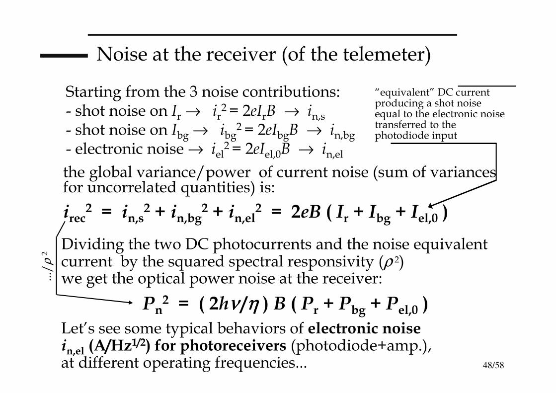
Noise at the receiver (of the telemeter)
the global variance/power of current noise (sum of variances for uncorrelated quantities) is:
irec2 = in,s
2 + in,bg2 + in,el
2 = 2eB ( Ir + Ibg + Iel,0 )
Dividing the two DC photocurrents and the noise equivalent current by the squared spectral responsivity (ρ 2) we get the optical power noise at the receiver:
Pn2 = ( 2hνννν /η η η η ) B ( Pr + Pbg + Pel,0 )
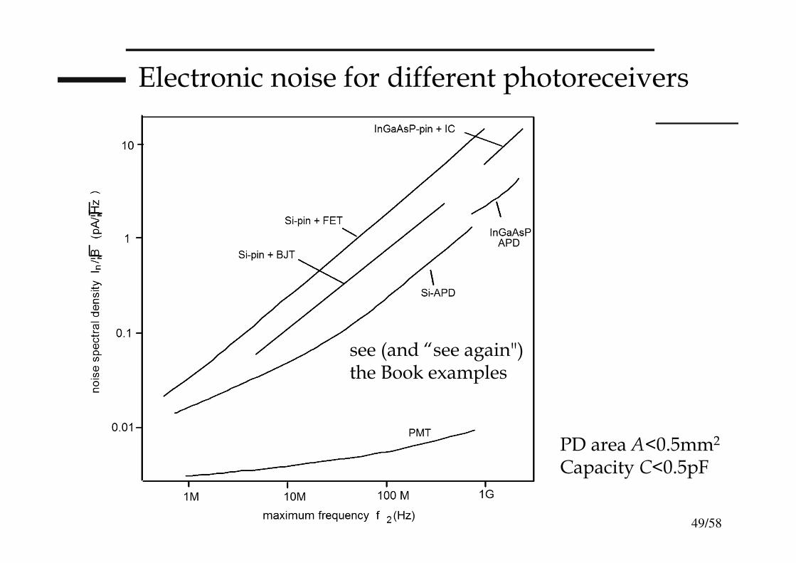
Let’s see some typical behaviors of electronic noise in,el (A/Hz1/2) for photoreceivers (photodiode+amp.), at different operating frequencies...
Starting from the 3 noise contributions:- shot noise on Ir → ir
2 = 2eIrB → in,s
- shot noise on Ibg → ibg2 = 2eIbgB → in,bg
- electronic noise → iel2 = 2eIel,0B → in,el
“equivalent” DC current producing a shot noise equal to the electronic noise transferred to the photodiode input
.../
ρ 2
49/58
Electronic noise for different photoreceivers
PD area A<0.5mm2
Capacity C<0.5pF
see (and “see again") the Book examples

50/58
Evaluation of the background light (optical background power Pbg)
We start from the solar light spectrum (slide 44) and from working conditions (AM, clouds, etc.) we get the scene spectral radiance Escena (W/m2µm) that multiplied ("integrated") for the bandwidth ∆λ of the interference filter, gives the optical intensity of background light (“scene”):
Isc = Esc ⋅⋅⋅⋅ ∆∆∆∆λλλλ (W/m2) scene “background" intensity
Optical power collected on the receiver is 1/π times the background intensity (Isc) times the scene diffusivity (δsc ) times the viewing solid angle (Ω sc) [received intensity Ibg] then multiplied by the receiver area (A=πdr
2/4):
Ibg = (1/ππππ)[ δδδδsc Isc ]]]] ⋅⋅⋅⋅ΩΩΩΩ sc (W/m2)
Pbg = [ δδδδs Esc ∆∆∆∆λλλλ ΝΑΝΑΝΑΝΑ2222 ] ] ] ] ⋅⋅⋅⋅ (π(π(π(πdr2/4) ) ) ) (W)
being Ω =πθ 2≅π(NA)2 with NA=sin(Dr/2f ) Numerical Aperture( in this slide "I" stays for optical intensity and not electric current )
Ωsc=πNA2
51/58
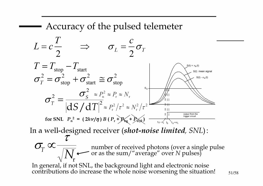
Accuracy of the pulsed telemeter
In general, if not SNL, the background light and electronic noise contributions do increase the whole noise worsening the situation!
In a well-designed receiver (shot-noise limited, SNL) :
number of received photons (over a single pulse or as the sum/“average” over N pulses)
for SNL Pn2 = ( 2hν ν ν ν /η η η η ) B ( Pr + Pbg + Pel,0 )
52/58
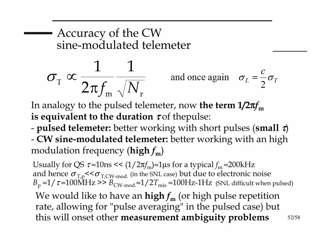
Accuracy of the CWsine-modulated telemeter
In analogy to the pulsed telemeter, now the term 1/2ππππfmis equivalent to the duration ττττ of thepulse:- pulsed telemeter: better working with short pulses (small ττττ) - CW sine-modulated telemeter: better working with an highmodulation frequency (high fm)
We would like to have an high fm (or high pulse repetition rate, allowing for "pulse averaging" in the pulsed case) but this will onset other measurement ambiguity problems
Usually for QS τ ≈10ns << (1/2πfm)≈1µs for a typical fm ≈200kHzand hence σ T,p<<σ T,CW-mod. (in the SNL case) but due to electronic noise Bp ≈1/τ ≈100MHz >> BCW-mod.≈1/2Tmis ≈100Hz-1Hz (SNL difficult when pulsed)
53/58
Ambiguity in Time Of Flight telemeters
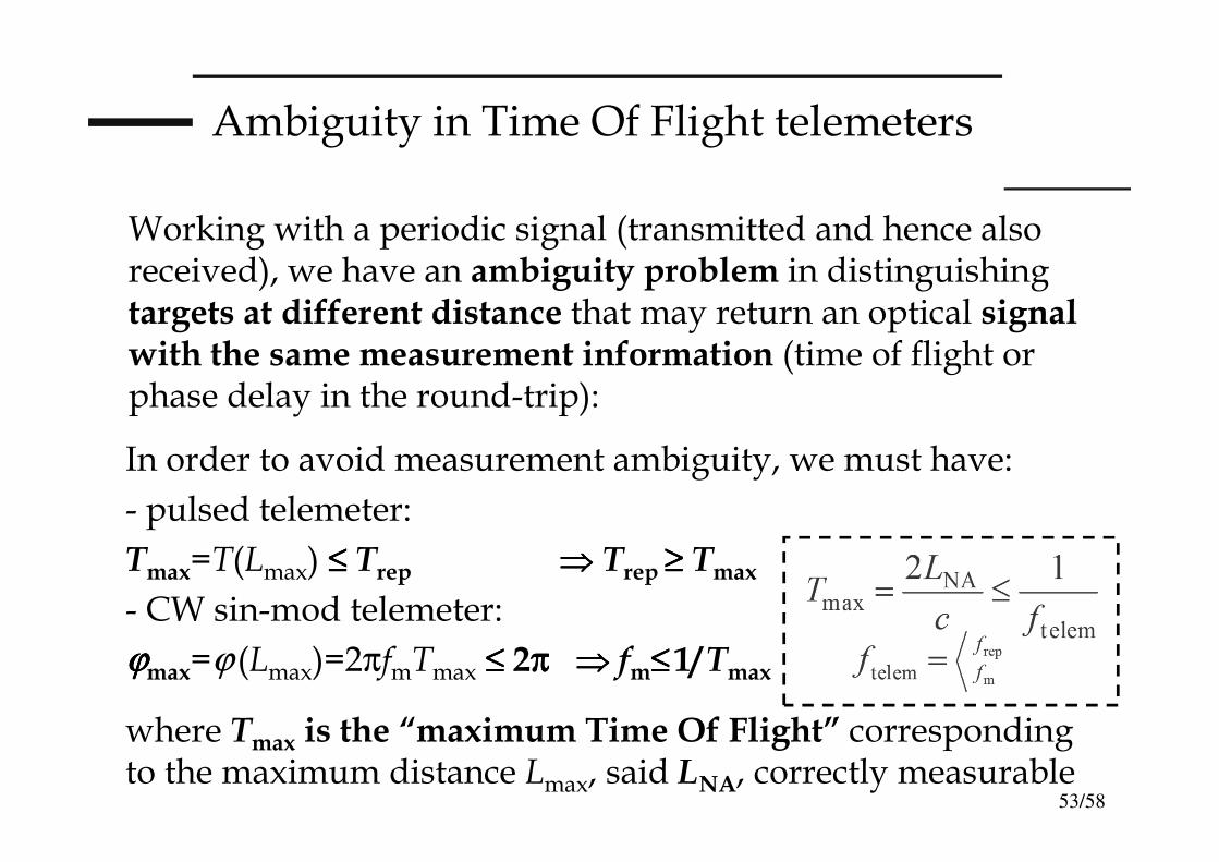
Working with a periodic signal (transmitted and hence also received), we have an ambiguity problem in distinguishing targets at different distance that may return an optical signal with the same measurement information (time of flight or phase delay in the round-trip):
In order to avoid measurement ambiguity, we must have:
- pulsed telemeter:
Tmax=T(Lmax) ≤≤≤≤ Trep ⇒⇒⇒⇒ Trep ≥≥≥≥ Tmax
- CW sin-mod telemeter:
ϕϕϕϕmax=ϕ (Lmax)=2πfmTmax ≤≤≤≤ 2π π π π ⇒⇒⇒⇒ fm≤≤≤≤1/Tmax
where Tmax is the “maximum Time Of Flight” corresponding to the maximum distance Lmax, said LNA, correctly measurable
54/58
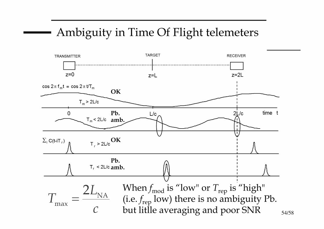
Ambiguity in Time Of Flight telemeters
When fmod is “low" or Trep is “high"(i.e. frep low) there is no ambiguity Pb. but litlle averaging and poor SNR
Pb.amb.
Pb.amb.
OK
OK
55/58
Ambiguity in Time Of Flight telemeters
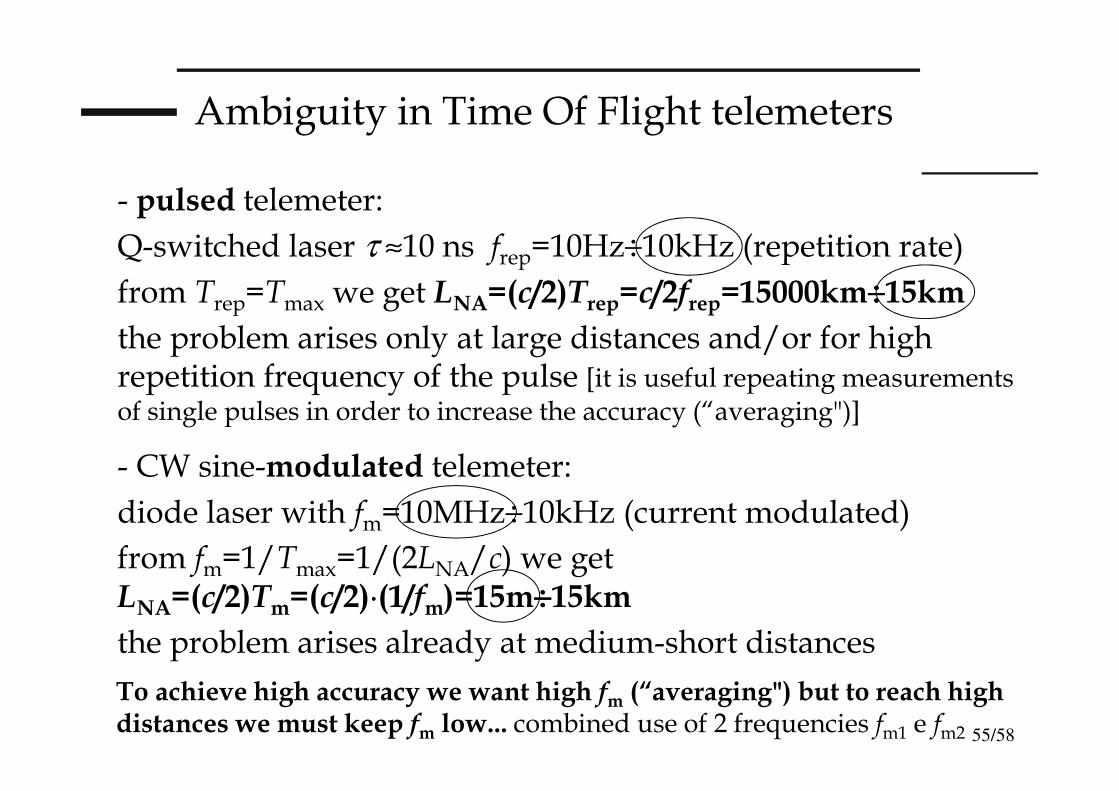
- pulsed telemeter:
Q-switched laser τ ≈10 ns frep=10Hz÷10kHz (repetition rate)
from Trep=Tmax we get LNA=(c/2)Trep=c/2frep=15000km÷÷÷÷15km
the problem arises only at large distances and/or for high repetition frequency of the pulse [it is useful repeating measurements of single pulses in order to increase the accuracy (“averaging")]
- CW sine-modulated telemeter:
diode laser with fm=10MHz÷10kHz (current modulated)
from fm=1/Tmax=1/(2LNA/c) we get LNA=(c/2)Tm=(c/2)⋅⋅⋅⋅(1/fm)=15m÷÷÷÷15km
the problem arises already at medium-short distances
To achieve high accuracy we want high fm (“averaging") but to reach high distances we must keep fm low... combined use of 2 frequencies fm1 e fm2
56/58
LIDAR
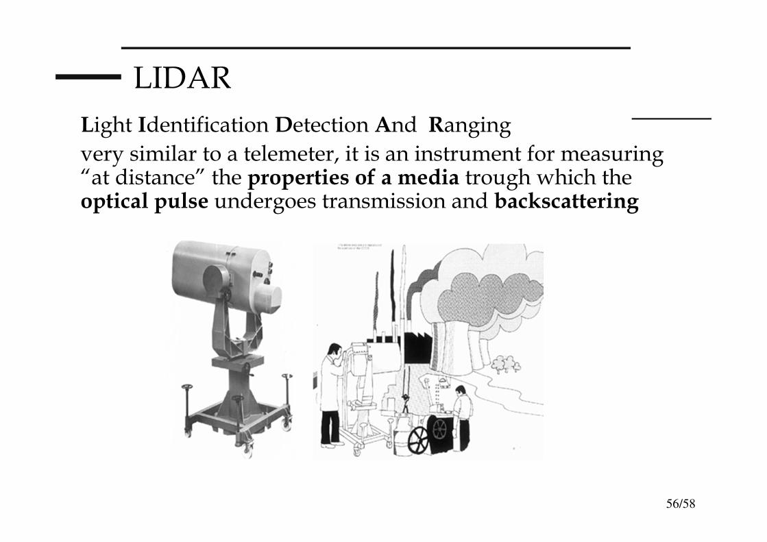
Light Identification Detection And Ranging
very similar to a telemeter, it is an instrument for measuring “at distance” the properties of a media trough which the optical pulse undergoes transmission and backscattering
57/58
LIDAR
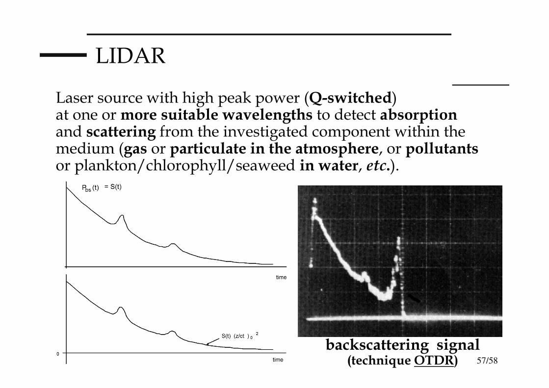
Laser source with high peak power (Q-switched) at one or more suitable wavelengths to detect absorption and scattering from the investigated component within the medium (gas or particulate in the atmosphere, or pollutantsor plankton/chlorophyll/seaweed in water, etc.).
backscattering signal(technique OTDR)

58/58
LIDAR
From measured Time Of Flight t=2L/cwe get the distanceof the investigated target (τ → size of investigated volume);
from measured backscattered signal we get the composition (chemical/physical) of the investigated volume;
we obtain maps, even fake-colored, as a function of the telemeter elevation angle and distance