
O.P.No.9of 2020 Capital Investment Plan.pdf - TSERC
161
1YLL&c d D r BEFORE THE TELANGANA STATE ELECTRICITY REGULATORY COMMISSION HYDERABAD CASE NO. OF 2019 (To be filled by the office) IN THE MATTER OF: Filing of Capital Investment Plan during the control period comprising five years from 1st April 2019 to 3 l March 2024 in respec.t of 2X600 MW Singareni Thermal Power Plant for approval in accordance with Regulation 7(h) of Telangana State Electricity Regulatory Commission (Terms and Conditions of Generation Tariff) regulation 2019. AN[) IN THE MATTER OF: The Singareni Collieries Company Limited (SCCL): Kothagudem CoIlicries Bhadradri Kothagudern Dist, Telangana State - 507101; Represented by its authorized representative i.e., Director Finance, SCCL. PETITION ER AND 1. Southern Power Distribution Company of Telangana Limited (TSSPDCL): Corporate Office: # 6-1-50, Mint Compound, Hyderabad, Telangana-500 063. 2. Northern Power Distribution Company of Telangana Limited (TSNPI )CL): H.No: 2-5-31/2, corporate Office, Vidyut Bhavan, Nakkalagutta, Hanamhonda, Warangal, Telangana- 506001 RESPONI) INTS Master Index Sr No Particular Page N 1. Affidavit 1-2 2. Cause title 3. Facts of the case 3__L. 4. Ground of the case 5. Summary of Capital investment Plan 5- 6. Authorization for filing on the petition 0 6
-
Upload
khangminh22 -
Category
Documents
-
view
2 -
download
0
Transcript of O.P.No.9of 2020 Capital Investment Plan.pdf - TSERC

1YLL&c d D r
BEFORE THE TELANGANA STATE ELECTRICITY REGULATORY COMMISSION
HYDERABAD
CASE NO. OF 2019
(To be filled by the office)
IN THE MATTER OF:
Filing of Capital Investment Plan during the control period comprising five years
from 1st April 2019 to 3 l March 2024 in respec.t of 2X600 MW Singareni
Thermal Power Plant for approval in accordance with Regulation 7(h) of
Telangana State Electricity Regulatory Commission (Terms and Conditions of
Generation Tariff) regulation 2019.
AN[) IN THE MATTER OF:
The Singareni Collieries Company Limited (SCCL): Kothagudem CoIlicries
Bhadradri Kothagudern Dist, Telangana State - 507101; Represented by its
authorized representative i.e., Director Finance, SCCL.
PETITION ER
AND
1. Southern Power Distribution Company of Telangana Limited (TSSPDCL):
Corporate Office: # 6-1-50, Mint Compound, Hyderabad, Telangana-500 063.
2. Northern Power Distribution Company of Telangana Limited (TSNPI )CL):
H.No: 2-5-31/2, corporate Office, Vidyut Bhavan, Nakkalagutta, Hanamhonda,
Warangal, Telangana- 506001
RESPONI) INTS
Master Index
Sr No Particular Page N
1. Affidavit 1-2
2. Cause title
3. Facts of the case 3__L.
4. Ground of the case
5. Summary of Capital investment Plan 5- 6. Authorization for filing on the petition
0
6

7. Jurisdiction
8. Limitation
9. Court Fee
10. Declaration
11. Prayer before Hon'ble commission
Annexure I Detail Capital Investment Plan _ ( Annexure ii Authorization for filing before TSERC.
Annexure III A copy of Banker's Cheque No. 253068
dated 27-03-2019 for Rs 10,000 (Ten
thousand) submitted as filing fee.
I S
Through
Shri IN. Bairam Director(Fivance)
The Singareni Collieries Company Limited Kothagudem Collieries
Bhadradri Kothagudem I)ist, Telangana State - 507101

.(orni II)
(See clause 14 and 15)
General Heading for Proceedings
BEFORE THE TELANGANA STATE ELECTRICITY REGULATORY COMMISSION
HYDERABAD
CASE NO. OF 20
(To be filled by the office)
IN THE MATTER OF:
Filing of Capital Investment Plan during the control period comprising five years
from 1st April 2019 to 31st March 2024 in respect of 2X600 MW Singareni.
Thermal Power Plant for approval in accordance with Regulation 7(b) of
Telangana State Electricity Regulatory Commission (Terms and Conditions of
Generation Tariff) regulation 2019.
AND TN THE MATTER OF:
The Singareni Collieries Company Limited (SCCL): Kothagudem Coil icrie,
Bhadradri Kothagudem Dist, Telangana State - 507101; Represented by is
authorized representative i.e., Director Finance, SC CL.
PETITR) IR
AND
1. Southern Power Distribution Company of Telangana Limited (TSSPDCI ):
Corporate Office: # 6-1-50, Mint Compound, Hyderabad, Telanganu-500. f\ ,- -., U O...
2. Northern Power Distribution Company of Telangana Limited (TSNPD(I ):
H,No: 2-5-3 1/2, corporate Office, Vidyut Bhavan, Nakkalagi ha,
Hanamkonda, Warangal, Telangana- 506001
9 \AM 2 RESPOND E NTS

ATTESTED
ATTEST D
OTARY
Affidavit:'verifyingThe Petition
I, Shri N. Bairarn, son of N. Hunya aged 38 years residing at Bungalow no: S-4,
Bungalows area, Lakshrnidevipally, Kothagudem -- 507101 do solemnly affirm and
say that
1 am the Director Finance of SCCL, the petitioner in the above matter aiid
am duly authorized by the said petitioner to make this affidavit.
2. 1 have read and understood the contents of the accompanying capi1iI
investment plan from St April 2019 to 31 St March 2024 for 2 X 600 M W
Singareni Thermal Power Project located in Jaipur, Macherial filed in
this petition before this Hon'ble Commission for approval .The
statements made in paragraphs of the petition accompanying affidavit
now shown to me are true to my knowledge and are derived from o 'ficial
records made available to me and are based on information and idvice
received which I believeto be true and true.
I Solemnly affirm at Hyderabad on 29th day of March, 2019 that the contents of
the above affidavit are true to my knowledge, no part of it is false ancl notHing
material has been concealed there from.
(Shri N. F3al [diii)
Place : Hyderabad
Date 29.03.2019
M. ': MCHANDER RAO ADVOCATE
H. No. 22-2-849/3 Noor Khan Bazar) HYD-24. T.S. India. Goms No. 457/11.
29 R2U9
(Form I) (See clause 13 and 14)
General Heading for Proceedings BEFORE THE TELANGAN.A STATE ELECTRICITY REGULATORY COMMISSION
HYDE RABAD
CASE NO. OF 2019
(To be filled by the office)
IN THE MATTER OF:
Filing of Capital Investment Plan during the control period comprising five years
from I April 2019 to 31st Ma:rch 2024 in respect of 2X600 MW Singareni
Thermal Power Plant for approval in accordance with Regulation 7(h) of
Telangana State Electricity Regulatory Commission (Terms and Conditions of
Generation Tariff) regulation 2019.
ANt) IN THE MATTER OF:
The S ngareni Collieries Company Limited (S CCL): Kothagudern Coil ieries,
Bhadradri Kothagudem Dist, Telangana State - 507101; Represented. by u.s
authorized representative i.e., Director Finance, SCCL.
PETITION ER
AND
3. Southern Power Distribution Company of Telangana Limited (TSSPDCL):
Corporate Office: # 6-1-50, Mint Compound, Hyderabad, Telangana-500 063.
4. Northern Power Distribution Company of Telangana Limited (TSNPI.)CL):
H.No: 2-5-31/2, corporate Office, Vidyut Bhavan, Nakkalagutta, Hanamkonda,
Warangal, Telangana- 506001
RESPON DENTS
3. Facts of the Case: This petition is filed for approval of Capital Tnvestmeiit Plan
during the control period comprising five years from i April 2019 to 31st March
2024 in respect of 2X600 MW Singareni Thermal Power Plant in accordance with
Regulation 7(b) of Telangana State Electricity Regulatory Commission (Terms
and' Conditions of Generation Tariff) regulation 2019.

I
The details of Petitioner are respectfully submitted as under:
Name and Address of Applicant: The Singareni Collieries Company Limited
(SCCL), Kothagudem Collieries, Bhadradri Kothagudem Dist, Tela ugana
State -507101
II. Primary Business of the Applicant: Coal Mining
III. Details of Distribution Licensee purchasing power:
a. Southern Power Distribution Company of Telangana Limited
(TSSPDCL): Corporate Office: # 6-1-50, Mint Compound,
llyderabad,Telangana- 500063.
b. Northern Power Distribution Company of Telangana Limited
(TSNPDCL): H.No: 2-5-31/2, Corporate Office, Vidyut Bhavan,
Nakkalgutta, Hanamkonda, Warangal, Telangana- 506001.
IV. Details of Generating Company: The Singareni Collieries Company
Limited(SCCL): Kothagudem Collieries, Bhadradri Kothagudem I)ist,
Telangana State -507101.
V. Name and Location of the Generating station for which Aggregate Revenue
Requirement and tariff to be determined, is as follows:
a. Name/Location of Generating Station: Singareni Thermal Power Project
(STPP), Pegadapalli (V), Jaipur Mandal, Mancherial District,
Telangana
b. Total existing unit wise installed capacity in MW: Unit-I: 6Q0 MW,
Unit-Il: 600 MW
c. Nature of Generation plant: Thermal
d. Type of primary and secondary fuel:
i. Primary Fuel: Coal
ii. Secondary Fuel: Light Diesel OiliHeavy Fuel Oil
e. Commercial operation of units:
1. Unit-I: 25.09.2016
ii. Unit-Il: 02.12.2016
4. Grounds of the case: This filing for capital investment plan is in
accordance with the provisions of the Section 62.1 and 86.1 (a) of Electricity
Act 2003 read with regulation 7 of Telangana State Electricity Regulatory
Commission (Terms and Conditions of Generation Tariff) regulation 2019.

While filing the present Capital investment plan, The Singareni Collieries
Company Limited has endeavored to comply with the various applicable
legal aid regulatory directions of this Hon'ble Commission including the
directions contained in the Conduct of Business regulation 2015 and the
Regulations lof 2019 (Terms and Conditions of generation Tariff regulation
2019 ) issued by Hon'ble TSERC.
Based on the information available, the applicant has made bona-fide cfThrts
to comply with the directions of the Hon'ble Commission and discharge its
obligations to the best of its abilities. However, should any further material
become available in the near future, the Applicant reserves the right to file
such additional information and consequently amend/revise the application.
5. Summary of Capital Investment Plan
A summary of capital investment plan is placed below:
Singareni Collieries Company Limited (SCCL) is a coal mining company
owned by the Government of Telangana with 51% shareholding.
Government of India owns remaining 49°/o shares of the company. SCCL
established Coal based Singareni Thermal Power Plant (STPP) with two
units of 600 MW in Jaipur Mandal, Mancherial District of Telanganu. The
units of STPP achieved COD during financial year 20 16-17. STPP supplies
power to state Discorns of Telangana and the tariff of such sale of power is
to be determined by Hon'ble TSERC as per 86.1(a) of electricity Act 2003.
l-lon'ble TSERC has notified terms and condition of generation tariff
regulation 2019 (Regulation no 1 of 2019) for determination of multi-year
tariff for the period 2019-24. Regulation 7(b) of aforesaid tariff regulation
stipulates the generator to submit capital investment plan for 20 19-24 at the
beginning of the contrOl period for the existing capacity.
The capital investment plan (CIP) for STPP is prepared primarily based on
capital expenditure towards compliance of new pollution norms for which
DPR was prepared by M/s NTPC limited and capital expenditure l'or
procurement of critical modules for which proposal is obtained from original
equipment manufacturer (OEM). The other part of CIP is proposed for

SUMMARY OF CAPITAL INVESTMENT PLAN FOR FY 20 19-24 (BASED ON I:.uI"FO
USE)
(IN (rores)
S L
NO DESCRIPTION
FY
2019-20
FY
2020-21
FY FY
2021-22 2022-23
FY
2023-24 lotal
FLUE GAS DE-
SULPHURISATION
SYSTEM (FGD)
0 0 645.32 0 0 645.32
2
IN-FUPNACE
MODIFICATIONS
FOR NOX
MITIGATION
0 19 19 0 0 -
OPERATION &
MAINTENANCE
MODULES
1 1.-i. 82.95 65.12 0 301.18
4 RAILWAY WORKS 26.94 24.50 79.60 1 I (\ ) I .LL)
5 MAIN PLANT .IVIL
WORKS 26.91 20.98 8.00 0 0 5.89
6 TOWNSHIP CIVIL
WORKS 7.81 10.20 6.14 0 24 1 5
Total 214.75 157.63 823.18 0 1195.57
works required for railway siding and for civil work in main plant area and
township area.
Proposed expenditure of CIP is given in the table below:
• Further, as it is difficult to project the capital expenditure for 2019-24 as pci'
md AS 16, STPP has sought permission from the Hon'bIe commission to
submit these expenditures during Mid-term review and End of control period
review for consideration of the commission.
The detail Capital investment Plan is enclosed in Annexure I.
6. Authorization for filing on the petition: The Director (Finance) of SCCL
has been authorized to sign on the petition / documents to be filed before the
l-lon'ble TSERC. Copy of the authorization is enclosed as Annexure II.

7. Jurisdiction: This Capital investment Plan is related to tariff determination
and is within the Juusdiction of TSERC As pei section 62, Apiopi talt
commission can determine the tariff for supply of electricity by a genurating
company to a distribution licensee. Further, the state electricity rcgulatory
commission shall determine the tariff for gcneration within the statc as iei
section 86.1(a).
8. Limitation: The determination of tariff is a continuous process and the
provisions of limitation Act does not apply to the issues to be decided as part
of regulatory process such as approval of capital investment plan etc.
9. Court Fee: The present petition is filed as normal petition accompanying
the Multi Year tariff petition for 20 19-24. Hence a fees of Rs 10,000/- k
paid as per regulation 4 (c) of regulation 2of 2016 (levy of fees for vaitotis
services rendered by the commission). A copy of the banker's cheqLic is
attached as Annexure -III.
10.Declaration: This subject matter of this petition has not been raised b the
petitioner before any other competent forum and that no other competent
forum is currently seized of the matter or has passed any order in reftit ion
thereto.
11. Prayer before Hon'ble commission
SCCL prays to the Hon'ble Commission that it may be pleased to:
a) Consider the submissions made by SCCL and allow the capital investment
plan for Financial year 2019-24 in respect of 2x 600 MW Singareni Thermal
Power Plant;
b) Pass such further Orders, as the, Hon'ble Commission may deem fit and
appropriate considering the circumstances of the case.
(Shri iN. 1aIi-am)
Place : Hyderabad Date :29.03.20 19
Filing of
Capital Investment Plan 2019-2024
For
Singareni Thermal Power Project (2 X 600 MW) in Jaipur,
Mancherial District.
To
Telangana State Electricity Regulatory Commission
(TSERC)
By
The Singareni Collieries Company Limited

FNDEX
1 EXECUTIVE SUMMARY ... ... 2
2 INTRODUCTION: 4
2.1 BACKGROUND: 4
2.2 ENABLING REGULATION 4
2.3 CAPITAL EXPENDITURE UP TO CUTOFF PERrOD: 4
3 APPROACH TO CAPITAL INVESTMENT PLAN: 5
4 CAPITAL INVESTMENT FOR ENVIRONMENTAL COMPLIANCE 5
4.1 BACKGROUND 5
4.2 CAPITAL INVESTMENT FOR SOx COMPLIANCE: 6
4.2.1 Preamble: 6
4.2.2 Different Desu/phurization Processes 7
4.2.3 Comparison of different technolc.gies of desulph .irisation process: 7
4.2.4 The reasons foropting Wet limestone process 8
4.2.5 Lime stone requirement for STPP 8
4.2.6 Additional auxiliary consumption for FGD 8
4.2.7 Cost Eslimate For installation Of Flue Gas Desuiftirizat (on (FGD) System 9
4.2.8 Summary of proposalfor FGD 9
4.3 CAPITAL INVESTMENT FOR NOx COMPJANCE:. . . 10
4.3.1 Preamble: 10
4.3.2 Sumrhary of proposal for NOx mitigatfton: 10
5 CAPITAL INVESTMENT IN CRITICAL MODULE.... . 11
5.1 JUSTIFICATION . 11
5.2 DETAILED PROPOSAL FOR CAPITAL MODULES 14
6 CAPITAL INVESTMENT IN RAILWAY WORKS: 14
6.1 JUSTIFICATION 14
6.2 DETAILED PROPOSAL 16
7 CAPITAL INVESTMENT IN ERECTION WORK IN MAIN PLANT: 18
7.1 JUSTIFICATION: 18
7.2 DETAILED PROPOSAL 19
8 CAPITAL INVESTMENT IN TOWNSHIP CIVIL WORKS . . 24
8.1 JUSTIFICATION 24
8.2 DETAILED PROPOSAL . 24
9 NON-SCHEME CAPITAL EXPENDITURE ... . 27
10 FINANCING PLAN: - . 27
11 THE COMPLETE PROPOSAL - 28
12 THE SPILL OVER ITEMS: - 28
13 PRAYER BEFORE HON'BLE COMMISSION... - 29

1 Executive summary
Singareni Collieries Company Limited (SCCL) is a coal mining company owned
by the Government of Telangana with 51 % shareholding. Government of India
owns remaining 49% shares of the company. SCCL established Coal based
Singareni Thermal Power Plant (STPP) with two units of 600 MW in Jaipur
Mandal, Mancherial District of Telangana. The units of STPP achieved COD
during financial year 2016-17. STPP supplies power to state Discorns of
Telangana and the tariff of such sale of power is to be determined by Hon'ble
TSERC as per 86.1(a) of elect:ricity Act 2003.
Hon'ble TSERC has notified terms and condition of generation tariff regulation
201 9 (Regulation no I of 2019) for determination of multiyear tariff for the period
2019-24. Regulation 7(b) of aforesaid tariff regulation stipulates the generator
to submit capital investment plan for 2019-24 at the beginning of the control
period for the existing capacity.
The capital investment plan (CIP) for STPP is prepared primarily based on
capital expenditure towards compliance of new pollution norms for wh.ch DPR
was prepared by M/s NTPC limited and capital expenditure for procurement of
critical modules for which proposal is obtained from original equipment
manufacturer (OEM). The other part of CIP is proposed for works required for
railway siding and for civil work in main plant area and township area.
Proposed expenditure of CIP is given in the table below:
SUMMARY OF CAPITAL INVESTMENT PLAN FOR FY 2019-24 ( BASED ON PUT TO USE)
(IN Crores)
SL
NO DESCRIPTION
FY 2019- FY 2020-
20 21
FY 2'D21-
22
FY 2022-
23
FY 2023-
24 Total
0 I
FLUE GAS DE-
SULPHURISATION
SYSTEM (FGD)
0 0 645.3:2 0 645.32
2
IN-FURNACE
MODIFICATIONS FOR
NOX MITIGATION
0 19 19 0 0 38
3
OPERATION &
MAINTENANCE
MODULES
153.10 82.95 65.12 0 0 301.18
4 RAILWAY WORKS 26.94 24.50 79.60 0 0 131.03

ERECTION WORKS IN 5 26.91 20.98 8.00 0 0 55.89
MAIN PLANT
TOWNSHIP CIVIL 6 7.81 10.2 6.14 0 0 24.15
WORKS
Total 214.75 157.63 823.13 0 0 1195.57
Further, as it is difficult to project the capital expenditure for 201 9-24 as per md
AS 16, STPP has sought permission from the Hon'ble commission to submit
these expenditures during Mid-term review and End of control period review for
consideration of the commission.
The projected expenditure from 01.10.2018 to 31 .03.2019 was 360.62 Crore.
However, some of these expenditures will be spilled over to next control period.
ge

2 Introduction:
2.1 Background:
Singareni Collieries Company Limited (SCCL) is a coal mining company incorporated under
the companies Act 1956. The company is owned by the Government of Telangana with 51
% Shareholding. The shreholding of Government of India in SCCL is 49%.
SCCL has entered into the business of power generation by setting up a 2X600 MW Coal
based Thermal Power Plant, namely Singareni Thermal Power Plant (STPP) in Jaipur of
Mancherial District. The units of STPP achieved COD during financial year 2016-17 in the
dates as mentioned below.
COD Unit-I : 25.09.2016
COD Unit-Il 02.12.2016
SCCL had entered into a Power Purchase Agreement (PPA) with two Distribution companies
of Telangana for supplying the total power generated from STPP at a tariff decided by
honble Telangana State Electricity Regulatory Commission (TSERC). The PPA shall remain
valid for a period of 25 years from the COD of the last unit (unit-Il).
2.2 Enabling Regulation
It is to state that as per section 62, the app'opriate commission can determine the tariff for
supply of electricity by a generating company to a distribution licensee. The state electricity
regulatory commission shall determine the generation tariff within the state in accordance
with section 86.1(a) of electricity act.
Hon'ble TSERC has notified terms & conditions o generation tariff 2019 for determination
of tariff with respect to generators selling within the state. This regulation shall be applicable
for the control period consisting five years from April l 2019 to March 31st 2024.
Regulation 7(b) of aforesaid tarff regulation provides for submission of capital investment
plan by the generators which is to be filed at the beginning of the control period.
Regulation 7.4 provides that the capital investment plan during 2019-24 is required to be
commensurate with existing capacity. Accordingly, STPP has prepared capital investment
plan during the control period commensurate witn the requirement of existing generating
capacity of 2X600 MW.
It is to state that the proposal of constructing STFP Phase II (1 x 800 MW) is under active
consideration by the SCCL management. However, the necessary permissions have not
been obtained till date. The Honble commission is requested to allow SCCL to submit capital
investment plan for STPP phase II after receiving all necessary approval.
2.3 Capital expenditure up to cutoff period:
The capital cost of the STPP (2 x 600 MW) project as per revised cost estimate was 8584
crore which is the net of capital expenditure amounting 8780 crore and a claim of grant from
CCDAC amounting 196 crores. The project has expended 8461.94 crore upto 30.09.2018
as per audited statement of capital expenditure. The balance expenditure is expected to be
made by 31st March 2019 except some spill over items.
4 P a g e

3 Approach to Capital Investment Plan:
It is stated that the capital investment Plan is prepared by considering schemes of high
importance. Some of the schemes are ne:essitated to comply new environment protection
rules. Scheme to purchase critical modules is found to be important considering the high
PLF commitment in the coming control period and the cases of failures reported in similar
machines.
Railway electrification by constructing overhead lines and by commissioning signalling and
telecommunication system shall be made to ensure safe running of railway siding. The
facilities such as market complex, sports comdex or club building are a regular feature in
other thermal power plants. These infrastructures are required for modest living in the
township and are required to be constructed by the company. Expenditures for construction
of watch towers along the boundary wall are required from security point of view. The
requirement of works in main plant area and township were reviewed. It is also found that
several work in these areas also need to be taken up during 2019-24.
The accounting of Property, Plant and equipment is required to be made as per new
accounting standard lnd AS 16. The segregation of capital item as per md AS 16 is a
complicated process. Accordingly, the non-scheme capital expenditures as per AS 16 will
be known at the end of years and a projection of these expenditures cannot be made now.
4 Capital investment for Environmental compliance:
4.1 Background
It is to submit that Ministry of Environment. Forest and Climate Change (MOEF &CC) has
issued notification no: S.O.3305(E) titled 'Environmental (Protection) Amendment rules,
2015 dated 7.12.2015. The said notification has brought out amendments to Schedule - I of
Environment (Protection) Rules, 1986 fcr emission norms applicable to thermal power
stations.
Both the units of STPP have been commissioned in calendar year 2016. Accordingly,
following emission norms which are applicable to the thermal power plant TPPs (Units)
installed between 1st January 2004 and 1st January2017 as perthe amendment notification
will also be applicable to STPP unil:s.
POLLUTANTS BEFORE AMENDMENT AFTER AMENDMENT
Particulate Matter (PM) 100 mg/Nm3 50 mg/Nm3
Sulphur Dioxide (S02) 600 mg/Nm3 200 mg/Nm3
Oxides of Nitrogen NOT SPECIFIED 300 mg/Nm3

Mercury (Hg) 0.03 mg/Nm3
0.03 mg/Nm3
Currently STPP, SCCL is in compliance with the normative emission limit with respect to
particulate matter and mercury. It is to state that STFDP, SCCL has awarded the work of
preparing feasibility report and Detailed project Report (DPR) to M/s NTPC for complying
SO2 emission norms and working closely wth original equipment manufacturer (OEM)
towards In-furnace modifications for NOx mitigation.
The emission limits as per amended notification are to be met within two years from date of
the amendment notification.
However, in view of technical Challenges in implementing new technologies like FGD,
revised dates for compliance of nevv emission standards was submitted by Ministry of Power
vide its letter dated 13.10.2017.
As per the timeline provided in the revised plan, the FGD system for Units 1 and 2 (2X600
MW) of SCCL was required to be put into operation wil:hin the Dec2019.
It is stated that STFP sought extension of time from Dec2019 to Dec2022 for complying
SO2 emission limit considering the time required for floating tender, awarding work, erecting
and commissioning of FGD system by its lette- dated :23.01.2019. The letter is attached as
Appendix A.
It is stated that M/s NTPC Ltd submitted DPR for FGD system which is attached as
Appendix B.
4.2 Capital investment for SOx compliance:
A summary of the DPR for FGD system as prepared by M/s NTPC Ltd is presented below:
4.2.1 Preamble:
SO2 emission from fossil fuel fired power plants is proportional to Sulphur content of fuel.
Power plants in India traditionally use a very lowlmedium grade coal with low/medium
Sulphur content. The sulphur content in the coal supplied to STPP is in the range of 0.65%-
1.15% as revealed by ultimate analysis of coal made on as received basis (100% BMCR
Condition).
The 502 emissions from STFF. SCCL (2X600 MW) is estimated to be around 2000-3500
mg/Nm3 considering the reported range of sulphur content in the coal supplied to STPP in
absence of desulphurization system.
The estimated 502 emission from STPP is aoproximately 9-15 times the S02 emissions
permitted by the new environment norms. It is :herefor'e, required to install desulphurization
61

system capable to reduce S02 by 9S0/c which shall result in a net emission level lesser than
given limit of 200 mg/Nm3.
4.2.2 Different Desuiphurization Processes
Nearly all flue gas desulphurization processes depend cn the fact that S02 is acidic in nature
and use an alkaline substance, most commonly lime r lime stone to neutralize it. Other
alkalis like sodium based, magnesium-based alkalis and other type of alkalis such as
Ammonia etc. are also used. FGD processes are classified into three different types:
i) Semi dry I dry process
ii) Wet FGD process
iii) Dry Sorbent Injection System
4.2.3 Comparison of different technologies of desuiphurisation process:
The following table depicts the comparison made for available desuperization processes
across different technological and commercial parameters.
Item Spray Dry
Process
Process
CFB I
CDS Dry
Wet
Limestone
Ammonia
process
Dry Sobent
Injection (DSI)
Sorbent Lime Lime Limestone Ammonia Sodium
bicarbonate
Coal Sulphur
Limit
For low and
medium
Sulphur
content coat
No limit Jo Sulphur
content limit
No Sulphur
content limit
For low and
medium
Sulphur content
coal
Removal
efficiency
90-95% Above
95%
Above 95% Above 95% <85%
Sorbent
source
Hard to
obtain
Hard to
obtain
Local Depends on
availability
Depends on
availability
Sorbent
Utilization
Poor Poor Good Good Poor
Aux. Power Low Low High Very High Low
Capital Cost Low Low High High Low

Operating
Cost
High High Low Low Very High
Reference
Plants above
500MW
Few Few Many Few Few
4.2.4 The reasons for opting Wet limestone process:
The Wet Limestone process is selected or SCCL (2X600 MW) Stage-I for the following
reasons:
Ability to achieve high desulphurization efficiency (removal efficiency is above 95%)
ii. High Dust removal as a co•benefit.
iii. High reagent utilization factor (sorbent utilisation is good)
iv. Reagent material (limestone) used by the process is plentiful and readily available.
v. Large number of reference plants.
vi. Maturity of technology involving minimum commercial risks and large number of
suppliers resulting in enhanced competition.
4.2.5 Lime stone requirement for STPP
The daily requirement of limestone for plant shall be approximately 650 ton at100% plant
load factor. The lime stone requirement is indicated in table below for 100 %, 90 %, 80 %
and 70 % plant load factor.
PLF 100% 90% 80% 70%
Lime stone
requirement in
Ton/Day
650 585 520 455
4.2.6 Additional auxiliary consumption forFGD
The uninterrupted electrical power requirement shall be met through three voltage levels i.e.
11 kV. 3.3kV & 0.415 kV which are already adopted in the existing system of Stage-I for
feeding power to the plant auxiliaries.
The total connected load expected for proposed FG[) system will be around 15.0 -18.0
MW for 600 MW unit. However, the running loads will be around 9.0 MW for 600 MW unit.
The auxiliary power consumption for introduction of FGD would contribute to increase in
plant auxiliary consumption by 1 .5%.

4.2.7 Cost Estimate For Installation Of Flue Gas Desulfurization (FGD) System
The estimated head wise cost for FGO system is given in the table below:
Serial No Cost Head Value in Lakhs
1 Supply 30556.63
2 Spares 1527.83
3 Type Test charges 8.63
4 Freight & Insurance 1283.38
5 Civil 9136.34
6 Structural 540.92
7 Erection & commissioning 6111.33
8 Training 10.00
9 System Integration 23.39
Subtotal 49198.45
10 GST 8855.72
11 Work cost including GST 58054.17
12 Contingency @3% 1741.63
13 100 Including FC 4736.95
Grand total 64532.75
The quarter wise phasing of the expenditure from 2019-20 to 2021-22 for FGD system is
given in Clause no 4.00.00 of Chapter No -13 of financial analysis of detailed project report
(DFR) for FGD system which is attached as Appendix: B.
4.2.8 Summary of proposal for FGD:
• The Wet Limestone process is selected for SCCL (2X600 MW) for flue gas
d esu Iphu rization.
• Estimated cost for installation of FGD in Singareni TFP (2 X 600 MW) will be 645.33
Crores (including 100)
• Time for completion: 27 MONTHS (after placement of order).
• Expected FY for commissioning of FGD: 2C21-22.
• The interest rate considered for IDC calculation is 9.46%
• Increase in plant auxiliary consumption: 1.5%
• Lime stone consumption: Approximate 650 ton at 100% plant load factor depending
on sulphur content of coal.
• The estimated impact of the FGD installaticn in the fixed charge is 12 Paise/Kwh
• The estimated impact of the FGD installaticn in the variable charge is 4 Paise/Kwh
9 I

4.3 Capital investment for NOx compliance:
4.3.1 Preamble:
STPF units (2X600 MW) of SCCL was commissioned in the year 2016 . The Boilers of the
units were originally designed for NOx level of 750 mg/Nm3. The measured value of NOx is
found to be almost near to the designed value. However, as per the Gazette notification
dated 15.12.2015 the NOx level has to be reduced to 300 mg/Nm3.
NOx mitigation can be approached in three different ways for this plant.
• In-furnace modifications like providing OFA, EOFA and Horizontal offset air system
depending on the boiler capacity
• SNCR (Selective Non Catalytic Reduction)
• 5CR (Selective Catalytic Reduction)
In furnace modifications do not require chemical treatment by reagents and therefore is a
cost-effective measure compared to other meffods. Moreover, original eqLlipment
manufacturer (OEM) also specified this methodology for reduction of NOx level. Accordingly,
Combustion Modification is to be undertaken in both unts of STPP to reduce the NOx to the
desired level.
In-furnace modification produces staged combustion by diverting a portion of the secondary
air above the firing zone, which in turn reduces the amount of available oxygen in the main
combustion zone, where NOx is mostly generated.
It is stated that combustion modification is to be carried out as a part of furnace modification,
which would be required to reduce the NOx generation in combustion chamber. Combustion
modification consists of replacing/modification the existing wind box by new redesigned wind
box and installation of separator over fire air panel along with dampers.
The objective of combustion modification is to reduce the NOx generated to the required
level during the combustion in boiler without effecting the designed boiler steam and flue gas
parameters at various loads, under various mills combination for the range of coals.
The letter from OEM detailing the cost of the NOx mitigation proposal is attached in
Appendix C
4.3.2 Summary of proposal for NO mitigation:
• M/s BHEL has provided the estimated cost for NOx reduction system.
• Estimated cost for installation of low NOx system would be approximately 38.00
Crores.
10I

• Time for completion (after placement of order): 09 MONTHS considering engineering,
supply and erection. However, the work recuires Unit shutdown for final attachments
with the boiler which shall be planned as per the Annual Overhaul schedule of units.
• Expected FY for commissioning of tow NOx system: U 1 :2020-21, U 2: FY 2021-22
SUMMARY OF CAPITAL INVESTMENT PLAN FOR NOx MITIGATION SYSTEM
(IN Croresl
FY FY FY FY FY
DESCRIPTION 2019- 2020- 2021- 2022- 2023- Total
20 21 22 23 24
IN-FURNACE MODIFICATIONS FOR NOX 0 19 19 0 0 38
MITIGATION
5 Capital investment in Critical Module
5.1 Justification
It is to state that the projected PLF during 201 9-24 is around 91% as detailed
in the generation planning part of the business plan. It is utmost important to
keep necessary capital spares available during the coming control period for
successful execution of generation plan. It is submitted that HF module, IF
module, LF rotor, Generator stator, rotor and exciter are the major constituents
of turbine generator assembly used for generation of electricity.
It is observed from the past experiences that when any of this equipment fails
for whatever reason and'order is placed for replacement of Original Equipment
Manufacturer (OEM), the manufacturer requires a high lead time of around one
year to supply a new one or at least four months time for refurbishment.
The high lead time is attributable to the fact that OEM imports the input
materials necessary for these modules from other countries and arrange
required machining and assembling activity here. Therefore, any failures of any
of these equipment are costly and needs special attention while formulating
capital investment plan.
As per the power purchase agreement entered between SCCL and
TSDiscoms, STPP is expected to meet the availability norms set by the
regulator and full fixed charges can be claimed only after achieving the
normative availability. Therefore shut down of units in the range of four months
to one year will impact the cash flow of both SCCL and TSDISCOMs.

SCCL will lose due to non-recovery f full fixed charges while TSDiscoms will
also loss from the arrangement of alternative power supply from the market. It
is submitted that the short-term power markets are highly volatile and
unpredictable. Therefore, a win-win situation may be achieved if STPP is
allowed to make capital expenditures to procure the critical modules.
STPP has two similar units of 600 MW supplied by BHEL. Accordingly, it is
planned to purchase one set of HP module, IP module, LP rotor, generator
stator, rotor and excited assembly which would cater the need of both the units
effectively.
It is submitted that major break down have been experienced recently in 600
MW BHEL sets for the following stations:
• TSGENCO faced generator rotor failure on 14.12.2018
• Similar incidents were witnessed in TNSEB, North Chennai where outage
duration extended up to 6 months.
• Jindal India Thermal Power Limited in Odisha has experienced similar
failure in generator.
• Unit of MS Avanta Power had witnessed generator failure which forced it
to be in outage condition for 6 months.
STPP has obtained budgetary offer for the critical modules from the original
equipment manufacturer i.e., E3HEL. The same is enclosed in Appendix D.
It may please be noted from the failure history cited above that the generator
stator and rotor are the most vulnerable modules and required to be purchased
in the beginning years of the control period. II: is also submitted that unit-I of
STPP witnessed cracks in couple of LP turbine blades. Accordingly, LP turbine
is required to be recognised as high problem area and LP rotor is also planned
to be purchased i,n the initial years of coming control period. The purchase of
HP module, IP moduIe and exciter assembly is planned during 2020-2022 to
distribute capita investment judiciously SC) that the impact of these
expenditures on tariff gets minimised.
The year wise add cap proposal for purchasing the critical modules are given
below:
(In INR Crores)
Total Critical modules Financial Year
12 I P a g e

2019-20 2020-21 2021-22
HP module 0.00 46.51 0.00 46.51
IF module 0.00 0.03 53.82 53.82
LP rotor 25.20 0.00 0.00 25.20
Generator stator 63.00 0.00 0.00 63.00
Generator rotor 38.33 0.00 0.00 38.33
Exciter assembly 0.00 22.05 0.00 22.05
Total 126.53 68.56 53.82 248.91
The above cost are quoted by OEM Ex works basis and the associated taxes
duties and transportation cost needs to be incurred to bring the above items in
the plant.
Therefore, it is required to add freight and GST to arrive at final cost. The final
cost of the module is computed witn a freight © 3% and IGST © 18% of ex
work quoted price.
It is to further state that the capital expenciture approved on account of initial
spare as per the Hon'ble TSERC order dated 17.06.2017 was 168.40 Crore.
This amount was less than the ceiling of 4% Dl cost of Plant and Machinery. It
is to submit that Hon'ble TSERC has adopl:ed CERC regulation 2014 for
determination of tariff for STPP. As per Regulation 13 of the CERC (Terms and
Conditions of Tariff) Regulations, 2014, ceiting norm of initial spares is 4.0% of
the cost of Plant and Machinery. The commission has observed the following
in respect of initial spare in STPP's tariff order dated 19.06.2017:
"3.17 INITIAL SPARES
Commission's Analysis and Ruling
3. 17. 1 Regulation 13 of the CERC (Terms and Conditions of Tariff)
Regulations, 2014 specifies the ceiling norm of initial spares as 4.0% of the
cost of Plant and Machinery. In reply to a specific query of the Commission,
SCCL submitted the total amount of spares included in the capital cost as Rs.
168.40 Crore. The Commission observes that the spares of Rs. 168.40 Crore
amounts to 2.50% of the GFA of Rs. 6730.42 Crore underthe asset class Plant
& Machine,'y. Hence, the total spares are well within the ceiling limit"
131 F :Oe

It is also to submit before the Hon'ble commission that the TSERC generation
tariff regulation 201 9 also provides the following norm in respect of initial spare:
7.17. The capital cost may include initial spares capitalised as a percentage
of the plant and machinery cost up to the Cut-Off Date, subject to the following
ceiling norms: -
Coal based Generating Stations: 4°/o
Accordingly, the hon'ble commission is requested to allow the expenditures for
proposed modules These modules will definitely improve the plant availability
not only for the coming control period but for the entire life of the plant.
5.2 Detailed Proposal for capital modules
Final summary of price estimation of the critical modules along with the
schedule of capitalisation is given below:
(In INR Crores)
— Critical modules
Financial Year Total
2019-20 2020-21 2021-22
HP module 0.00 56.28 0.00 56.28
IP module 0.00 0.00 65.12 65.12
LP rotor 30.49 0.00 0.00 30.49
Generatorstator 76.23 0.00 0.00 76.23
Generator rotor 46:38 0.00 0.00 46.38
Exciter assembly 0.0(J 26.68 0.00 26.68
Total 153.10 82.96 65.12 301.18
6 Capital Investment in Railway Works:
6.1 Justification
It is to submit that the railway siding work was commissioned during the
financial Year 2018-19. Most of the coal required for power generation is now
received at the project site through railway mode. At present, the railway locos
are running with diesel engines and manually managed signalling system.
Railway authorities have advised to arrange for overhead electrification system
along with necessary signalling and telecommunication works to ensure safe
running of railway wagons. It is to submit that 1:he railway electrification will be
141

taken LI as per the cabinet decision of Govt of India. The relevant letter dated
27.09.2018 is enclosed as appendix E
It is to kindly state that The S&T (Signalling & Telecommunication) work is
required due to following reasons:
1 STFF siding consists three numbers yards (SRP-CHP, SRP-OCP and
STPP).
2. Single track-line is only provided for movement in-between the yards.
3. Loading arrangements are being planned at two locations i.e., SRP-
CHP and SRF-OCP.
4. For 2x600 MW: —
• 6 coal load rakes and 6 empty rakes move on the track-line on daily
basis.
• Fuel oil rake is expected once in a fortnight.
• Fly-ash evacuation is also planned from STFF through rakes.
5. After addition of 1x800 MW, the traffic increases further.
6. Railways have deployed rakes for transport of coal and are operating
movement of rolling stock. Railways designated track speed as 50
KMPH.
7 Operation of so many rakes in a short distance requires higher efficiency
and to ensure safety , S&T is recommended to avoid human error.
8. S&T enables optimum utilisation of the track structure with minimum
man-power and interference.
9. Railways further opined that as main line is provided with S&T, provision
of S&T in STPP yard will enable smooth operation of rolling stock
avoiding accidents and ensures safety.
10. Due to implementation of this lot o man-hour and expenditure will be
saved.
15

M/s Rites Ltd was the consultant for railway siding work for STPP. MIs Rites
prepared detailed report for overhead electrification and telecommunication
work providing the detail scope and cost estimation. It is expected to finish
electrification and signalling w'ork by the financial year 2021 -22.
It is to state that some of the associated works related to construction of railway
siding system such as construction of drainage system along the railway track
is also planned in the coming control period as per the original drawing.
It is stated that post commercial operation, some incidents of wagons
derailment was observed during operation of railway system. It is also planned
to get special tools and capital spares related to railway system to mitigate such
emergency situation.
Accordingly, a comprehensive capitalization plan for railway siding is prepared
for the approval of the Hon'ble commission.
6.2 detailed proposal
The detailed proposal for railway works is placed below:
Capital Investment Plan for railway works in 2019-2024
(Amounts in Lakhs
SLNo Name of
Investment
Year in which proposed to put to
use
Total
(2019-
22)
Justification
2019-20 2020-21 2021-22
Casting & fixing of
boundary pillars
along the railway
tracks
17.11 - - 17.11
To prevent
encroachment in
acquired land of
railway track area.
2 Three numbers
120T in motion
weigh bridges and
associated civil
works
91,40 - - 91.40 These are required
for weighing coal, fly
ash & oil carried by
rail wagons.
16

3 Overhead
Electrification
(OHE) works
200.00 2C0.00 4,100.00 4,500.00 The scope of this
work was included in
detailed project
report (DFR). The
delay in awarding the
contract is due to
land acquisition
issues.
4 Signalling &
Telecommunication
(S&T) works
including civil works
450.00 460.00 3,860.00 4760.00 The scope of this
work was included in
detailed project
report (DPR). The
delay in awarding the
contract is due to
land acquisition
issues.
5 Re-organisation of
village roads along
the track-line,
construction of
walk-ways & foot
bridges, misc. and
unforeseen
350.00 150.00 - 500.00 Some village roads
got blocked by
construction of plant
railway line. So re-
organisation of
village roads are
required for public
convenience.
6 Drains along
railway track
1000.00 650.00 - 1,650.00 The proposed drains
are required to be
constructed as per
approved design of
railway track.
7 Rerailing tools 85.00 - - 85.00 These tools are
required for re-railing
of derailed railway
wagons/engine.
8 Inspection road along track line
500.00 600.00 - 1000.00
.
171 e

9 Capital spares for
railway track:
Sleepers and rails
- 500.00 - 500.00 These spares are
required to replace
damaged sleepers
and rails as a result
of unforeseen
derailment.
subtotal main
railway
2,693.51 2,450.00 7,960.00 13,103.51
7 Capital Investment In erection work in Main Plant:
7.1 Justification:
The requirement of capital works especially of the nature of erection /civil work
inside the main plant area is reviewed. It is found that several expenditures
such as construction of watch towers along the boundary wall and parking shed
near 01SF office are required from security point of view.
It is to submit that some of the mandatory works as per the factories act 1948
such as provision for creche and rest hail and construction of pit for hazardous
waste shall be taken up in the upcoming control period.
It is also observed that the movement of trucks carrying bottom ash near weigh
bridge area was not smooth due to the lack of parking yard for trucks.
Accordingly, a parking lot for trucks is proposed near main gate area. This is
also expected to reduce occurrence of accidents near main gate area.
it is to state that the plant soil is of black cotton type which lacks adequate
strength to support movement of heavy vehicles specially during rainy season.
It is planned to construct RCC flooring near High concentrated slurry disposal
system (HCSD) area, stacker reclaimer area and lOOT area where movement
of heavy vehicles were observed during past years of operation.
It is stated that the drainage and sewage system of main plant area was also
reviewed. It is found that some of the necessary works like connecting outer
point of BOP & BTG drains up to peripheral compound wall, connecting plant
sewage pits to sewage treatment plant constructing RCC drain across fly ash
road are to be taken up in the control period 2019-24.
18! Pae
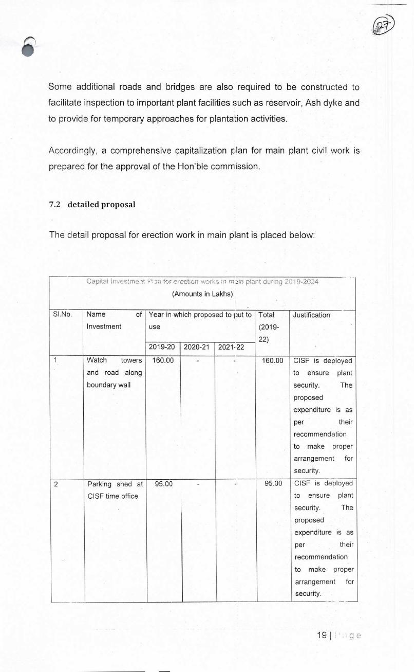
Some additional roads and bridges are also required to be constructed to
facilitate inspection to important plant facilities such as reservoir, Ash dyke and
to provide for temporary approaches for plantation activities.
Accordingly, a comprehensive capitalization plan for main plant civil work is
prepared for the approval of the Honble commission.
7.2 detailed proposal
The detail proposal for erection work in main pant is placed below:
ç c'r' ;rr (
(Amounts in Lakhs)
Sl.No. Name of
Investment
Year in which proposed to put to
use
Total
(2019-
22)
Justification
2019-20 2020-21 2021-22
Watch towers
and road along
boundary wall
160.00 - -, 160.00 01SF is deployed
to ensure plant
security. The
proposed
expenditure is as
per their
recommendation
to make proper
arrangement for
security.
2 Parking shed at
01SF time office
95.00 - -. 95.00 01SF is deployed
to ensure plant
security. The
proposed
expenditure is as
per their
recommendation
to make proper
arrangement for
security.
19 I

3 Construction of
creche and rest
hail
50.00 50.00 100.00 The facility is
required to be
provided as per
Factories Act
1948.
4 Construction of
shed for lube oil
barrels, RCC pit
for hazardous
waste
50.00 5.0Q -. 100.00 The facility is
required to be
provided as per
Factories Act
1948.
5 Ash trucks
parking yards at
ash weighbridge
near main gate
50.00 50.00 -. 100.00 This work - is
required to be
taken up to avoid
stuck up of trucks
at plant gate
during entering or
exiting plant
premise.
6 CC flooring
around HCSD
silo area
I15.00 - -. 115.00 The plant soil is of
black cotton type
which are clayey in
nature. The
vehicle
movements during
monsoon season
over this black soil
is very difficult due
to its sticky nature.
Accordingly, CC
flooring around
HCSD silo area is
required to
maintain smooth
movement of
vehicles even in
rainy season.
7 Widening of CC
platforms and
roads around
lDCT
400.00 186.00 - 586.00 The plant soil is of
black cotton type
which are clayey in
nature. The
vehicle
movements during.
monsoon season
over this black soil
is very difficult due
20 I

to its sticky nature.
Accordingly,
widening of CC
plafforms and
roads around
lOOT area is
required to
maintain smooth
movement of
vehicles even in
rainy season.
8 CC Roads
around Stacker
Reclaimer
300.00 400.00 300.00 1,000.00
The plant soil is of
black cotton type
which are claycy in
nature. The
vehicle
movements during
monsoon season
over this black soil
is very difficult due
toits sticky nature.
Accordingly, roads
around stacker
reclaimer is
required to
maintain smooth
movement of
vehicles even in
rainy season.
9 Paving with
chequered tiles
under pipe &
cable rack areas
and below coal
gantries
500.0C) 500.00 500.00 1,500.00
Required to
prevent vegetation
growth and to
ensure ease in
equipment access.
Also prevents fire
hazards.
21Ige

10 RCC drain along
fly ash transport
road
- 162.00 162.00 The RCC drain will
prevent stagnation
of storm water
inside the
compound wall of
STPP.
11 Extension of BOP
& BTG drains up
to peripheral
compound wall
- 300.00 -. 300.00 Kucha drains are
existing from the
outfall point of
BTG & BOP drains
up to the drains at
outer periphery of
compound wall.
These kucha
drains were
conducive for
vegetation growth
and resultant earth
collapse. To
prohibit such
occurrence, the
BTG & BOP drain
outfalls need to be
connected to the
drains at
peripheral
compound wall.
12 Chambers and
dewatering
pumps in main
plant area
60.00 60.00 -. 120.00 To avoid water
stagnation inside
the main plant
area specially
during rainy
season.
13 Sewage pits
(pumps) / pipe
line from BTG
area to STP
60.00 43.00 -. 100.00 Required to
connect the
sewage system of
BTG to sewage
treatment plant.
22 I

14 Metal road on
reservoir bund
63.00 - - 63.00 This is required for
inspection of
reservoir bund
especially during
rainy season.
15 B.T. over
inspection road
along periphery
compound wall
from Ash dyke to
Rly bridge across
Rasulpalli vagu
3.60 KM) and
B.T. road over
reservoir
150.00 150.00 300.00 Required for
inspection of along
peripheral
compound wall
and reservoir.
16 Making
approaches to
plantation at
various locations
100.00 50.00 - 150.00 The approach
road is required for
inspecting as well
as attending
plantation activity
spread across
entire plant area.
17 Bridge over
diverted nala
near 01SF time
office
248.00 - -. 248.00 The diversion of
nala was done to
avoid tIe over
flowing of water
from nala to enter
into main plant
area. The
construction of
bridge oer nala
was taken U to
provide necessary
road access.
18 Work stations ,
furniture's and
portico in
Administration
building and
service building.
290.0r 100.00 -. 390.00 The managers &
staff of The plant
who oversee the
power generating
activity sit in the
administrative
building & service
building. The
required
23 I

expenditure is to
construct work
stations to achieve
full functionality of
admin & service
building.
Sub total plant
works 2,691.00 2,098.00 800.00 558900
8 Capital Investment in Township Civil Works
8.1 Justification
The STPP township was put to use in the last control period. The more people
occupied the township, the more the problem of staying inside the township
surfaced. It is found that the residents of STPP have to go to nearby market
situated at Jaipur which is at least 5 Km away from the township area to get
even an ordinary item
The lack of bare minimum facilities to live inside the township was represented
by various employee unions during the oast two years. Accordingly,SCCL
decided to construct shopping complex, sports complex and other necessary
infrastructure to arrange for modest living inside the township area. These
buildings will be constructed and will be put to use during 201 9-2022.
The development works for existing township like providing roads and drains
,integrating water supply works ,providing fencing around the park, providing
protected parking for vehicles and creating club infrastructure will also be taken
up in the com ng control period.
Extension of armoury building of CISF was required from security point of view.
Rain harvesting structures has to be built as per MoEF notification.
Accordingly, comprehensive capitalization plan for township civil work is
prepared for tke approval of the Honble commIssion.
8.2 detailed roposal
The summary of the proposal is placed b&ow:
24
a

Capital Investment Plan for township civil works in 201 9-2024
(Amounts in Lakhs)
Sl.No. Name of
Investment
Year in which proposed to
putto use
Total
(2019-
22)
Justification
2019-
20
2020-21 2021-22
Construction of
publicbuildingslike
shopping complex,
sports complex
and other
necessary
infrastructures.
250.00 300.00 364.00 914.00
This is to be
constructed to
support modest
living by persons
inside the
township.
2 Township
Development
works like
construction of
roads, drains &
water supply in
township,
providing electric
overhead lines,
providing fencing
around parks,
providing protected
parking for vehicles
and creating club
infrastructure.
315.80 400.00 250.00 965.80
This is to be
constructed to
support modest
living of persons
inside the
township.
3 Electrification and
furniture for 01SF.
25.00 - - 25.00 01SF is deployed
to ensure plant
security. The
proposed
expenditure is for
arranging
moderate living
by CISF
personnel
251 e

4 Extension of
armoury building
for CISF, CC
pavement and rest
sheds
60.00 40.00 - 100.00 01SF is deployed
to ensure plant
security. The
proposed
expenditure is as
per their
recommendation
to make proper
arrangement for
security.
Parade ground,
Stage and roads
for 01SF
30.00 20.00 - 50.00 01SF is deployed
to ensure plant
security. The
proposed
expenditure is as
per their
recommend ation
to make proper
arrangement for
security.
6 Modification to
open shed at
Guest house into
AC Hall
- 130.00 - 100.00 A hail big enough
to conduct public
gathering :With 50
people or more
during adverse
weather condition
is not there in
STPP. Therefore
the open shed of
guest house shall
be converted to
AC hail. The hail
can be used to
celebrate days of
national
importance.
7 Connection of
sanitary system of
Township to STP
- 60.00 - 60.00 It is required to
connect sanitary
system of
township to
sewage
26

treatment plant
for effective
treatment of
township
sewage.
8 Rain harvesting
structures
100.00 100.00 200.00 As per MoEF
guidelines, the
rain harvesting
structure has to
be constructed.
Sub total township 780.80 1,020.00 614.00 2,414.80
9 Non-scheme capital expenditure
It is to submit before the hon'ble commission that accounting of Property, Plant
and equipment is required to be made as per lnd AS 16.
As per this accounting standard, the cost of an item of property, Plant and
Equipment shall be recognised as an asset if
a) It is probable that future economic benefits associated with the item will
flow to the entity; and
b) The cost of the item can be measured reliably.
However, due to practical difficulty in complying with the robust mechanism for
identifying asset as laid out in lnd AS 16, ft is very difficult to estimate
expenditures in capital assets in future periods as per this standard.
Accordingly, STPP crave leave before this Hon'ble commission to submit the
actual capitalisation identified by applying AS 16 during Mid term review and
End of control period review for consideration of the commission.
10 Financing Plan:
STPP plans to fund the proposed capital investment through equity and
domestic borrowing. The debt: equity ratio is proposed as 70: 30 for the total
capital expenditure.
27 I

11 The complete proposal
The capital investment plan is given below:
Capital Expenditure scheme:
SUMMARY OF CAPITAL INVESTMENT PLAN FOR FY 2019-24 BASED ON PUT TO USE
(NCrores)
S
N DESCRIPTION FY 2019-20 FY 2020-21 FY 2021-22
FY 2022-
23
FY 2023-
24 Total
1
FLUE GAS DE-
SULPHURISATION
SYSTEM (FGD)
0 0 645.32 0 0 645.32
2
IN-FURNACE
MODIFICATIONS FOR
NOX MITIGATION
0 19 19 0 0 38
3
OPERATION &
MAINTENANCE
MODULES
153.10 82.95 65.12 0 0 301.18
4 RAILWAY WORKS 26.94 24.50 79.60 0 0 131.03
5 ERECTION WORKS IN
MAIN PLANT 26.91 20.98 ELOO 0 0 55.89
6 TOWNSHIP CIVIL
WORKS 7.81 10.20 6.14 0 0 24.15
Total 214.75 157.63 823.18 0 0 1195.57
Non-scheme capital expenditure
STPP crave leave before this Hon'ble commission to submit the actual
capitalisation identified as per AS 16 during Mid-term review and End of control
period review for consideration of the commission.
12 The spill over items:
The audited capital expenditure for the project upto 30.09.2018 was 461.94
Crore which was submitted before the commission vide submission dated
28.11.2018. A copy of the same is attached as Appendix F. SCCL also
projected 360.62 Crs of capil:aI expenditure from 01.10.2018 to 31 .03.2018
which is subjected to finalisation of accounts for the financial year 201 8-19.
However, it is kindly stated that some of these expenditures may be spilled to
the next control period, ie beyond 31 .03.2019. The estimated spill over items
along with the reasoning is furnished in Appendix G. The hon'ble commission
28 I

is requested to consider the spill over of this capital expenditures in the control
period 2019-24 based on actuals and to consider the same for determination
of multi-year tariff 2019-24.
13 Prayer before Hon'ble commission
SCCL prays to the Hon'bJe Commission that it may be pleased to:
a. Consider the Capital Investment Plan of STPF during 201 9-24 for approval
as per regulation 7(b),7.19 and 27 of terms and condition of generation tariff
regulation 2019.
b. Grant leave to submit the actual capitalisation identified as per AS 16 during
Mid-term review and End of control period review for consideration of the
commission
c. Condone any inadvertent omissions! errors! shortcomings and permit SCCL
to add! change! modify! alter this filing and make further submissions as may
be required at a future date;
Petitioner
29

SUPPORTING APPENDIXES TO CAPITAL
INVESTMENT PLAN
Index
Item Page No (Gout)
Appendix A: Letter dated 23.01.2019
addressed to Ministry of Power in respect to
FGD system
39-41
Appendix B: DPR for FGD system prepared by
M/sNTPC Ltd 42-144
Appendix C: The letter from OEM detailing the
cost of the NOx mitigation proposal 145
Appendix D : budgetary offer for the critical
modules from the original equipment
manufacturer i.e., BHEL
146-147
Appendix E : The letter dated 27.09.2018
conveying the cabinet decision of Govt of India
for railway electrification
148-150
Appendix F: Audited capital expenditure for the
project upto 30.09.2018 1 51-1 53
Appendix G: The estimated spill over items
along with the reasoning is furnished in.
1 54

THE SINGARENI COLLIERIES COMPANY UMITED ' (GOVERNMENTCOMPANY) CuF PYu1L çj
)?'i Registered Office ? Kothagudem Collieries (P.0) -507 101, Bhadradri Kothagudern Dist., Telangana State
CN: U10102TS1920S0C000571
Environment Dept., 2X600 MW, STPP Pe9adapal!y'V), JaipurM) - 504216, Dist. Mancherial, Telangana State.
Ief: STPP/O&MIENV/1g/3B/i,1 Date: 23.01.2019
10
The Secretary, Ministry of Power Shram Shakti Bhawan Rafi Marg, New Delhi - 110001
PL)
Sub: Compliance of S02 emission limit notified vide MoEF&OC Notification S.O. No. 3305 (E), dated 07.12.2015 - Request for time extension for installation of FGD in 2X600 MW Coal Based Singareni Thermal Power Plant (STPP), Telariana State- Reg.,
1, EC Lr. No. J-13012/88!2008-IA.Jl (T), dated 27.12.2010 2. CPCB Lr.No. .B-33014/07/2017-I8IIPC-(l/TPP/14632, Dt.1 1.12.2017. 3. CPCB ,Divisional Head, lPC-ll mail dated:20.08.2018. 4. Lr. No. STPP/ENV/637/1896, Dated:04.09.2018. 5. CPCB Thernral Plant review meeting, email dated:05.12.2018. 6, Lr. No. STPP/O&M/Env/'18/38/1230,Dt.10.12.2018. 7. CPCB Lr.No.B-33014107/201 8/IPC•-IIJTFP/14853,Dt.07.O1.2019.
* * *
ilie Singareni Collieries Company Limited(SCCL) is Government Company having cool mining operations spread over six Districts of Telangana State. SCCL is also
oI)erating 1200 MW STPP (2XSOOMW,Stage-1), near Pegadapally CV), Jaipur (M), Mancherial (Dist.) in Tolangana SI:ate and is meeting the power requirements of the ;lato. The CoiniTlercial Operation Date (COD) has been achieved fcr Unit-I (1X600
MW) and Unit-Il (1X600 MW) zn 25.09,2016 and 02.12.2016 respectively.
l\oEF&CC accorded Environment Clearance for the 2X600 MW, Stage-1,kSTPP vide Oiler cited at (1). It has been stipulated at specific condition no. A (xiv) that provision For insl:aflation of FGD shall be provided for future use.
SL.ibsequently, CFCB vide letter cited at (2), directed STPP to take vallous measures For complying with MoEF&CC Notification S.O. No. 3305 (E), dated 07.12.201Li wliereiri time lines were stipulated for- installation of PoIlUti0'1 control equipment. It
was stipulated for installing FGD by September 2019 and December2019 in unit 1 &.
2 resl:)ectively so as to comply with S02 emission limit.
/\.; per CPCB directions, STPP is complying with thenorms stipulated for control of I'M emissions, Mercury (Hg) and specific water consumption.
t\s regards instalItion of FGD for complying with S02 emission norms, SCCL awarded the work of preparation of Feasibility Report (FR) and Detailed Project
report (DP for installation of FGD at 2x600MVV STPP to M/s NTPC Ltd. M/s NTPC has prepared [)PR and submitted the same to SCCL and the necessary approvals
are in under process.

It is to bring to your kind notice that floaUng of tender, aw6rd of work, erection & commissioning of FGD will take at least 36 months. Keeping these aspects in view, STPP submitted a letter to MoEF&CC and CPCB vicle letter cited at (4) requesting time extension for FGD tnstallation from Decemher-2019 to December-2022.
CPCB conducted a meeting with all the thermal power plants on 05.12.2018 to review the compliance of norms stipulated vide its Notification, SO. No. 3305 (F), date:I 07.12.2015. On request of STPP for time extension for installation of FGD, CPCI3 authorities advised to approach Miiiistry of Power (MoP) for obtaining necessary permission. Accordingly, STPP submitted a letter to Secretary, MoP Vide letter cited at (6) with a request for extension of time for FGD installation.
Meanwhile, vide letter cited at (7), CPCB informed to STPP as follows:
"STPP has been directed to comply with S02 emission Limit by the same timeline which was proposed by the Ministry of Power vide letter No. FU-1/2017-IPC dated 13.10.2017 to MoEF&CC and hence the request made by STPP regarding Stagel (Unit-1&2). may not be considered's.
/\c STPP has initiated the process of ns:allation of FGD, it is requested to kindly arrange to consider the request of time extension for instalaltion of FGD for 2x6001VV STPP, Stage-I (Unit 1&2 ) frDm December 2019 to December 2022. II ir; learnt that your good offices have accorded extension of time lines for FGD installation in the nearby power plant of Telangana State. Hence, similar extension niy kindly be accorded to STPP also for completing the installation work of proposed pollution control equipment by December 2022.
TPl is pro-active in implementation of var1ois environmental protection measures in the plant and also assures that the directions of CFCB regarding complice of environmental norms stipulated vide its Notification, S.O. No. 3305 (E), dated 07.12.2015 will also be complied with.
Yours faithfully,
ExecutK'e Director 2x600MW, STP P
Copy to:
1. The Member Secretary (Thermal Sector),
IA Division,
Ministry of Environment, Forest and Climate Change,
Indira Paryavaran Bhavan, Jar Bagh Road, Aliganj,
New Delhi— 110003.
2. The Chief Engineer,
Thermal Project Renovation & Modemzation Division,
Central Electricity Authority
Sewa Bhavan, RK Purarn,
New Delhi-i 10066

3, The Chairman, Central Pollution Contro' Board Parivesh Bhawan,East Aijun Nagar, Dlhi-110032
4. The Member Secretary,
Telangana State Pollution Control Board,
Paryavaran Bhavan, A-Ill, Industrial Estate, Sanathnagar,
Hyderabad-50001 8
5. Director(E&M)
6. Director(PP)
7. GM(Env.)
3. GM(E&M),STPP
. Chief Coordinator, (PPD)/Hyd
iu. Cliief of O&M,STPP

FU[ GS DESUIPHLJI{ISATION (FGD) SYSTEM
for
2X600 MW Singareni TIP Stage-I, Jaipur(Mandal) Mancherial (District), Telengana State
/ P PNDfx — '8'
11 o 6bp+cJ 5nveimrT
pLnJ
THE SINGARENI COLLIERIES COMPANY LTD ( Goverrment Cornpny)
•NTPC.

DETAILED PROJECT REPORT FOR FGD SYSTEM Q7741,7
N TPC CLAUSE NO. D ESC RI PT ION
INDEX
CHAPTER DESCRIPTION PAGES
CHAPTER-i RATIONALEOFFGDSYSTEM 2
CHAPTER-2 PROJECT INFORMATION 2
CHAPTER-3 SALIENT DESIGN DATA 4
CHAPTER-4 DIFFERENT FGD PROCESSES 13
CHAPTER-5 FGD SYSTEM-MECI-lANIcAL 17
CHAPTER-6 FGD SYSTEM-CIVIL 6
CHAPTER-7 EGO SYSTEM-ELECTRICAL 19
CHAPTER-8 FGD SYSTEM-CONTOL & INSTRUMENTATION 3
CHAPTER-9 LAYOUT REQUIREMENT 2
CHAPTER-10 LC)WNOXBURNERS 2
CHAPTER-il LIMESTONESOURCES 7
CHAPTER-12 LIST OF PROBABLE VENDOR I
CHAPTER-13 FINANCIAL ANALYSIS 4
CHAPTER-14 IMPLEMENTAION SCHEDULE 3
CHAPTER-15 OPERATION & MAINTENANCE PHILOSOPHY 3
CHAPTER-16 BILL OF QUANTITIES 12
CHAPTER-17 RECOMMENDATIONS 1
SINGARENI TPP STAGE-I (2X600 MW)
FLUE GAS DESULPHURISATICN SYSTEM
Page 1 of 1 INDEX

NTPC
PAGE 1 OF 2
CHAPTER-I
RATIONALE OF FGD SYSTEM
MOEF NOTIFICATION FOR SO EMISSION
The Ministry of Environment, Forest & Climate Change of Government of India introduced The SOx emission limit requirement along with NOx emission and suspended particulate limit requirement frcrn thermal power plant vide the Gazette of India on 7th December 2015. The new standards are aimed at reducing emission of PM1O(0.98 kg/MWh), sulphur dioxide(7,3 Kg/MWh) and Oxide of nitrogen (4.8 kg/MWh), which will in turn help in bringing about an improvement in the Ambient Air Quality (AAQ) in and around thermal power plants. The technolcgy employed for the control of the proposed limit of Sulfur Dioxide - S02 & Nitrogen Oxide - NOx will also help in control of mercury emission (at about 70-90%) as a co-benefit.
The New standard for SO emission from thermal power plant are as follows:
1 .00.00
Pollutants TPPs(Units) Installed on or before 31 December 2003
TPPs(Units) Installed after 1st
January2004
TPPs(Units) to be Installed after 1st
January 2017
Paliculate Matter(PM)
100 mg/Nm3 50 mg/Nm3 30 mg/Nm3
Sulphur Dioxide (SO2) 600 mg/Nm3(Units smaller than 500 MW)
200 mg/Nm3 For Units having capacity of 500 MW or above)
6.00 mg/Nm3(Units smaller than 500 MW)
200 mg/Nm3(For Units having capacity of 500 M or above)
100 mg/Nm3
Oxides of Nitrogen 600 mg/Nm3 300 mg/Nm3 100 mg/Nm3
Mercury(Hg) 0.03 mglNm3 0.03 mg/Nm3 0.03 mg/Nm3
The provisions for Emission standards from thermal power plant have been further amended vide notification dated 28th June 2018 as follows:
SINGARENI TPP STAGE-I (2X600 MW)
FLUE GAS DESULPHUIRISATION SYSTEM
CHAPTER NO-I RATIONALE OF FGD SYSTEM
DETAILED PROJECT REPORT FOR FGD SYSTEM
CLAUSE NO. DESCRIPTION ccL

PAGE 2 OF 2
Taking into Consideration the technical Challenges and time requirement for installation of FGD and other technologies to meet the new emission limt MoEF&CC vide its letter F. No. Q-15017/4012007-CPW dated 07.12.17 has directed CPCB to direct all the thermal power plants :o ensure compliance with the norms laid down in the 07.12.2015 notification in accordance with the revised plan submitted by Ministry of Power dated 13.10.2017as well as NOx by 2022.
Accordingly, as per plan the FGJ system at SCCL, Units 1 and 2 (2X600 MW) needs to be implemented within this time limit i.e. by the Dec2019.
As per the present status it is not possible to installed FGD system by Dec2019. Accordingly, a letter was written by SCCL to CPCB & MOP for time extension from Dec2019 to Dec2022. (Enclosed).
SINGARENI TPP STAGE-I (2X600 MW)
FLUE GAS DESULPHURISATION SYSTEM
CHAPTER NO-I RATIONALE OF FGD SYSTEM
DETAILED PROJECT REPORT FOR FGD
SYSTEM i7714147 NTPC
CLAUSE NO. DESCRIPTION
"All monitored values for S02, NOx and Particulate Matter shall be corrected to 6% Oxygen, on dry basis"
2.00.00 REQUIREMENT OF FGD
As the units of SCCL (2X600 MW) come under the category of power generating units commissioned before 31 December 20' 6, SOx emission need to be controlled below 200mg/Nm3. As reported the coal based power units at SCCL are operating at SOx emission value, which is beyond the statutory limit of 200mg/Nm3 (maximum).
Accordingly a suitable flue gas desuiphurization system is required to be installed in order keep actual SOx emission value well within statutory limit.
3.00.00 I TARGET SOX EMISSION VALUE FOR SCCL
As mentioned above, the applicable SOx emission limit for SCCL (Units 1 &2) is 200mg/Nm3. However to take care variation in operating input parameters such as deterioration in coal quality, higher Sulphur contert in coal, higher flue gas temperature and flow, higher plant heat rate etc., we need to keep sufficient margin in maximum SO emission target from SCCL. Accordingly target value of 100mg/Nm3 (maximum) for SO: emission is being considered for design of flue Gas desulphurization system for SCCL.
4.00.00 IMPLEMENTATION TARGET SCHEDULE FOR FGD SYSTEM

P..
CEL
DETAILED PROJECT REPORT FOR FGD t7!j74147 NTPC
CLAUSE NO. DESCRIPTION
CHAPTER-2
PROJECT INFORMATION
PROJECT DETAiLS:
SI. No.
Item Details
a) Place Near Pegadapaili village, Jaipur Mandal, District Mancherial, Telangana
b) Location 250 km (approx.) from Hyderabad and 250 km (approx.) from Nagpur
c) District Mancherial
d) State Telangana
e) Country India
f) Postal Address Singa-eni Thermal Power Plant, Pegadapalli, Jaipur, Telangana 504216
g) Access by Rail Nearest railaway station is Mancherial railway station on Nagpur-Kazipet main rail line of South Central Railway, located at a distance of about 14.6 kms.
h) Access by Air Nearest airport is Shamshabad Airport, Hyderabad at a distance of about 250 KM
i) Latitude And Longitude of SCCL Thermal Power Station
The latitude and longitude of site are 18° 48' 30" to 18° 50' 35" N and 790 34' 00" to 790 35' 30" E respectively
j) Dry Bulb 29.2 CC M951 to 1980)
k) Minimum 19.7 C
1.00.00
PAGE 1 OF 2 SINGARENI TPP STAGE-I (2X600 MW)
FLUE GAS DESULPHURISATfON SYSTEM
CHAPTER-2 PROJECT IN FORMATION

DETAILEE) PROJECT REPORT FOR FGD t7T1ITh7 N TPC
CLAUSE NO. DESCRIPTION
I) Elevation above mean
sea level
156 m
m) Maximum ambient temp.
45.7° C
n) Wind velocity Basic, per SI 44 rn/s
o) Maximum Rain fall intensity
75mm/hr
p) Seismic Zone Zone no lIF as lS-1893-2002
2.00.00 STAGE & UNITS
Stage unit Capacity Date of commissioning
I 600 MW 25.09.2016 II 600 MW 02.12.2016
FUEL SOURCE:
Coal: Coal sources are mainly from Srirampur 0CM of SCCL and nearby coalmines of SCCL.
Oil: From various HP & I0CL scurces 3.02.00
SINGARENI TPP STAGE-I (2X600 MW)
FLUE GAS DESULPHIJRISATION SYSTEM
CHAPTER-2 PROJECT INFORMATION
PAGE 2 OF 2
3.00.00
3.01 .00

DETAILED PROJECT REPORT FOR FGD SYSTEM
4
NTPC CLAUSE NO. DESCRIPTION
CHAPTER-3
SALIENT DESIGN DATA
1.00.01
1 .00.00 FUEL DATA
PRIMARY FUEL ANALYSIS (Design and worst coal)-COAL AS FIRED BASIS
Indigenous Coal Data
S.No. Characteristics Unit Range of 95% coal supplies Range of 5% coal
supplies Design Coal
Worst Coal
Best Coal
1.0 PROXIMATE ANALYSIS
(As received basis)
1.1 Total Moisture 7.62 6.62 8.04 7.05-12.00 1.2 Ash 30.72 37.71 29.32 30.00-48.00 1.3 Volatile matter % 27.95 25.83 26.37 25.00-30.00 1 .4 Fixed carbon 33.71 29.84 36.27 35.00-25.00
2.0 ULTIMATE ANALYSIS (As received basis)
2.1 Carbon C% 49.91 41.63 49.38 40.00-55.00
2.2 Hydrogen H2% 2.83 2.50 3.93 2.50-4.00
2.3 Nitrogen N2% 0.85 0.81 1.12 0.50-1.20
2.4 Oxygen (By
difference)
N2% 796 8.27 7.81 6.00-9.00
2.5 Sulphur S2% 0.42 0.69* 0.21 0.20-1.00
2.6 Carbonates CO2% 0.19 1.77 0.19 0.19-1.77
2.7 Phosphorous P2% None Detected
None Detected
None Detected
None
2.8 Total Moisture H20% 7.62 6.62 8.04 7.50-12.00
2.9 ash 30.72 37.71 29.32 30.00-48.00
2.10 Gross Calorific
Value (kcal/kg) (as
received basis)
Kcal/Kg 4529 3786 4724 4800-3600
211 Hardgroveindex 52 60 48 45-70
2.12 YGP Index (mg/kg) 69.8 61.6 69.8 61 .6-69.8
* %S varies from 0.65 to 1.15 (Data furnished by SCCL)
SINGARENI TPP STAGE-I (2X600 MW)
FLUE GAS DESULPHURISATION SYSTEM
CHAPTER NO-3 SALIENT DESIGN DATA
PAGE 1 OF 4

.s
0 DETAILEE) PROJECT REPORT FOR FGD SYSTEM
rj74j47 NTPC
CLAUSE NO. DESCRIPTION
3.0 ASH ANALYSIS
3.1 Silica (SiO2) % 67.36 66.11 59.966 55.00-70.00 3.2 Alumina (A1203) 21.28 24.48 23.756 20.00-26.00 3.3 lronOxide(Fe2O) 0/3 8.11 5.57 6.854 5.00-10.00 3.4 Titania(TiO2) 0.00 0.00 0.00 1.00-1.50 3.5 Phosphoric
Anhydride(P205) 0.00 0.00 0.00 0.0-0.50
3.6 Lime (CaO) 1.60 2.32 5.774 1.50-8.00 3.7 Magnesia (MgO) 0.00 0.00 0.00 0.00-3.00 3.8 Sulphuric
Anhydride (Sb 3) 0.00 0.00 0.00 0.40-0.80
3.9 Sodium Oxide (NaO3)
% 0.20 0.15 0.192 0.10-0.35
3.10 Balance Alkalies (By Difference)
% 1.45 1.37 3.46 1.25-4.00
4.0 ASH FUSION RANGE (reducing atmosphere)
4.1 Initial Deformal:ion Temperature (IDT)
°C 1400 1380 1342 1150-1400
4.2 Hemispherical temperature
CC 1403 1400 1400 1300-1400
4.3 Flow temperature 00 1400 1400 1400 1400-1400
SINGARENI TPP STAGE-I (2X600 MW)
FLUE GAS DESULPHURISATION SYSTEM
CHAPTER NO-3 SALIENT DESIGN DATA
PAGE 2 OF 4

Clarified Water Analysis
SI. No. Constituent as mg I litre 1 Calcium CaCO3 103
2 Magrsium CaCO3 96 3 Sodium & Potassium CaCO3 172
4 Bicarbonate CaCO3 146
5 Chloride CaCO3 100 6 Sulpha:e CaCO3 122
7 Corbonate CaCO Nil
8 Silica SiO2 21
9 Iron Fe 006
10 pHValue - 7.84
11 Turbidity NTU 5.00
12 Temperature (°C) 27.1
Cooling/ CW Blowdown Water Analysis
SI. No. Constituent as mg I litre 1 Calcium CaCO3 515
2 Magnesium CaCO3 480
3 Sodium & Potassium CaCO3 860
4 Bicarbonate CaCO3 730
5 Chloride CaCO3 500
6 Sulphate CaCO3 610
7 Corbonate CaCC3 Nil
8 Silica SiO2 105
9 Iron Fe 0.3
10 pH Value - 8.5
11 Turbidity NTU 25
12 Temperature (°C) 27.1
Note : The OW system is expected to opera:e a about 5.0 cycles ot concentration
SINGARENI TPP STAGE-I (2X600 MW)
FLUE GAS DESULPHURISATION SYSTEM
CHAPTER NO-3 SALIENT DESIGN DATA
PAGE 3 OF 4
DETAILED PROJECT REPORT FOR FGD SYSTEM NTPC,
CLAUSE NO. DESCRIPTION
2.00.00 I WATER QUALITY
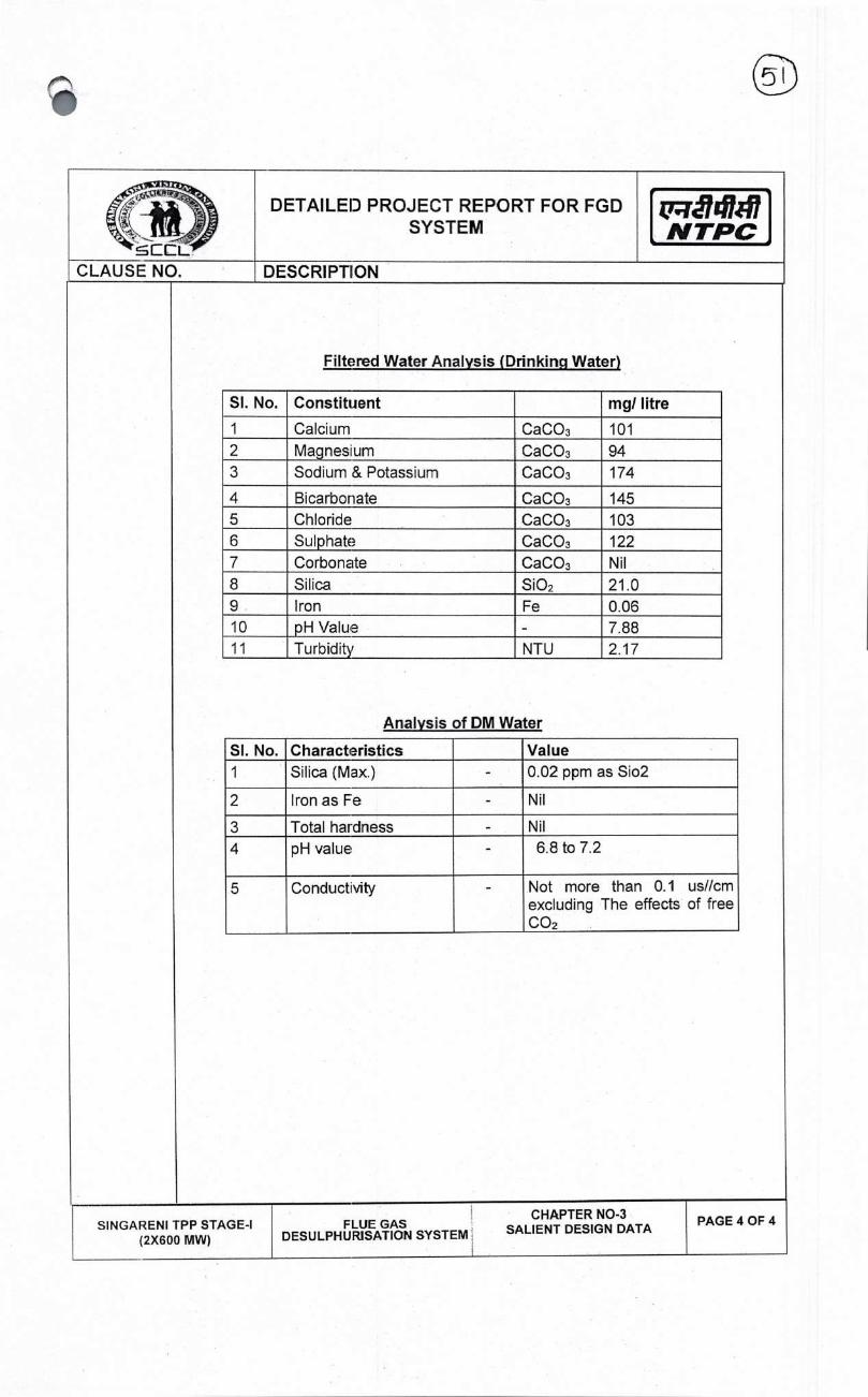
(D
DETAILED PROJECT REPORT FOR FGD SYSTEM N TPC
CLAUSE NO. DESCRiPTION
Filtered Water Analysis (Drinkinq Water)
SI. No. Constituent mg/litre
1 Calcium CaCO3 101 2 Magnesium CaCO3 94 3 Sodium & Potassium CaCO3 174
4 Bicarbonate CaCO3 145 5 Chloride CaCO3 103 6 Sulphate CaCO3 122 7 Carbonate CaCO3 Nil 8 Silica SiO2 21.0 9 Iron Fe 0.06 10 pH Value - 7.88 11 Turbidity NTU 2.17
Analysis of DM Water
Si. No. Characteristics Value 1 Silica (Max.) - 0.02 ppm as Sio2
2 IronasFe - Nil
3 Total hardness - Nil
4 pH value - 6.8 to 7.2
5 Conducti\ity - Not more than 0.1 us//cm excluding The effects of free CO2
SIN GARENI TPP STAGE-I (2X600 MW)
FLUE GAS DESULPHURISATION SYSTEM
CHAPTER NO-3 SALIENT DESIGN DATA
PAGE 4 OF 4

V ç
DETAILED PROJECT REPORT FOR FGD SYSTEM
'
NTPC
CLAUSE NO. DESCRIPTIION
CHAPTER-4
DIFFERENT DESULPHURIZATION PROCESSES
INTRODUCTION:
SO2 emission from fossil fuel fired power plants is proportional to the fuel Sulphur content, although with respect to coal a small percentage, usually less than 10% is absorbed by ash. Power plants in India traditionally use a very low/medium grade coal with low/medium Sulphur oontent. The SO2 emissions from SCCL (2X600 MVV) are in the range of 2000-3500 mg/Nm3 considering sulphere in coal in range of 0.65%-1.15% (100% BMCR Conditon).
The power plant is expected to release about 10-16 tons per hour of SO2, without any emission control. It may not be possible o achieve adequate control of SO2 by dispersion alone and SO2 emission contro mechanism will become necessary for the plant.
SO2 CONTROL PHILOSOPHY
As discussed above, the estimated SOx emission from SCCL is approximately 09-15 times the SOx emissions permitted by the new environment norms. In view of the MOEF norms in India, controlling the SO2 emission from the SCCL is necessary.
It is therefore, proposed to reduce the SO2 emission from each unit by at least 90% on a sustained basis, which will result in a net emission of 200 mg/Nm3 (approx.). However, to account for change in coal Sulphur content during the plant life and some performance deterioration, the Desutphurization system shall be designed to achieve a SO2 reduction of 95%.
1 .00.00
2.00.00
DIFFERENT DESULPHIJRIZAT1ON PROCESSES
The selection of Desuiphurization process depends on a number of factors including technical suitability, economic aspects and commercial considerations. Technical suitability includes the suitability of the process for the fuel under consideration, ability to achieve the required SO2 reduction efficiency and turn-down capability of the process. The economic aspect includes the capital cost of the plant, the operation cost including the cost of auxiliary power, cost of sorbent, disposal cost of the byproduct and market for the scrubber by-product, if any. The sorbent utilization will be a major criterion for selection as the cost of transportation of the limestone is likely to be very high. The commercial considerations include the availability of proven technology for the process, availability and successful operation of the previously installed Units and guarantees offered by the vendors.
A wide range of technologies is available to reduce the SO2 from burning of coal.
This includes:
i. Fuel Desulphurization
ii. In Bed SO2 removal
SINGARENI TPP STAGE-I (2X600 MW)
FLUE GAS DESULPHURISATION SYSTEM
CHAPTER NO-4 DIFFERENT EESULPHURIZATION
PROCESSES
PAGE I OF 13

I
' -M !)
CL
DETAILED PROJECT REPORT FOR FGD SYSTEM
NTPC
CLAUSE NO. DESCRIPTION
3M0.00
3.01.00
iii. Flue Gas Desuiphurization System
In the case of SCCL, Units I and 2 (2X&OO MW), since the units are already in operation, option of in Bed removal is not applicable.
FUEL DESULPHURIZATION
A major portion of Sulphur (30 — 7Q%) in coal is usually present in the form of pyrites or FeS2. The pyrites have high specific gravities and can be removed by washing. Other chemical processes are available to remove the organically bound Sulphur from coal.
Coal washing is generally used for removal of ash and is not a common practice for high-grade coals. The efficiency of this process depends largely on the percentage of pyrites and it may not be possible to achieve the desired reduction in Sulphur by this method alone. Besides, the process generates a huge amount of waste with a significant combustible content. The coal desulphurization process is very expensive compared to other desulphurization processes and are rarely used in large-scale plants.
The rejects generated from the washing process is also a source of other environmental problems like ground and soil water contamination.
As stated above, Coal desulphrization is a very expensive method for reduction of SO2 emission and may lead to other environmental problems. It may also not be possible to achieve the desired level of SO2 control by this method, for high Sulphur coals.
Therefore, this process is not considered suitable for SCCL(2X600 MW).
3.02.00 FLUE GAS DESULPHURIZATION
Nearly all flue gas desulphurizatioi processes depend on the fact that SO2 is acidic in nature and use an alkaline substance, most commonly lime or hme stone to neutralize it. Other alkalis like sodium based, magnesium-based alkalis and other type of alkalis such as Ammonia etc. are also used. FGD processes may be broadly classified into three different types:
i) Semi dry I dry process
ii) Wet FGD process
iii) Dry Sorbent Injection System
SINGARENI TPP STAGE-I (2X600 MW)
FLUE GAS DESULPHURISATION SYSTEM
CHAPTER NO-4 DIFFERENT DESULPHURIZATION
PROCESSES
PAGE 2 OF 13

ES
DETAILED PROJECT REPORT FOR FGD SYSTEM
'
NTPC
CLAUSE NO. DESCRIPTION
3.02.01 DRY/SEMI DRY PROCESS
Dry FGD technologies include the more established spray dryer absorber (SDA) system, which sprays a fine dry must of lime into the flue gas, and the relatively new concept of employing circulating fluidised bed (CFB) technology, with boiler ash and lime circulated through an absorber reactor and typically a fabric filter.
Dry scrubbing technology has much lower capital cost and uses less water than wet FGD technology but in the past has generally only been selected for projects where the boiler size was not too large and the fuel Sulphur level was not too high. The various semi dry technologies are discussed below.
A. Spray-Dry Process
Spray Dryer Absorption (SDA) is a dry scrubbing process that is generally used for low-sulfur coal. SDA FGD systems are tyoically located after the air preheaters, and the waste products are collected either in a bag house or electrostatic precipitator. However, to achieve sulfur dioxide (SO2) reduction above 80% with good reagent use, the dry scrubber is generally followed by a baghouse.
Flue gas is treated in an absorber by mixing the gas stream concurrently with atomized lime slurry droplets. The lime slurry is atomized through rotary cup spray atomizers or through dual fluid nozzles. Some of the water in the spray droplets evaporates, cooling the gas at the inlet from 140 °C or higher to 70°C to 80°C, depending on the relationship between approach to saturation and removal efficiency. The droplets absorb SO2 from the gas and reacts the SO2 with the lime in the slurry. The desulfurized flue gas, along with reaction products, unreacted lime, and the fry ash passes out the dry scrubber to the bed-house.
In spray-dry process, a very finely atomized spray of very thick slurry of the sorbent is introduced into the flue gas stream uostream of the ESP or bag filter. The normal sorbent for the process is quick lime, which is slaked at site to generate Calcium hydroxide. SO2 reacts with Ca(OH)2 to form calcium sulfite, which then collected with ash in the ESP or bag filter. The gas ard the sorbent may be mixed either in a spray-dryer vessel or in the duct.
The SO2 absorbed in the atomized slurry reacts with lime in the slurry to form calcium sulfite (CaS03) in the following reaction:
S02+CaO+1/2 H2O=>CaSO3.1/2 H20
A part of the CaSO3 reacts 'Mth oxygen in the flue gas to form calcium sulfate
(CaSO4): CaSO3 +1/2 02 + 2H20 => CaSO4.2H20
SINGARENI TPP STAGE-I (2X600 MW)
FLIJE GAS DESULPHURISATION SYSTEM
CHAPTER NO-4 DIFFERENT DESULPHURIZATION
PROCESSES
PAGE 3 OF 13

DETAILED PROJECT REPORT FOR FGD SYSTEM tri1417
N TPC CLAUSE NO. DESCRIPTION
The process can achieve a removal efficiency of 90-95%, with a spray-dryer vessel, for medium Sulphur (up to 2.5%) coals. The semi-dry is one of the lowest capital cost option for desulphurization of flue gas, typically being about 70% of the cost of the Limestone-gypsum plant.
Blower Lime SiLirry teed tank
Spray-drr
From hoUer air heater
L
Flue ESP or FE
ID fan
Disposal Blower silo
Li ru e storage silo \Vater
"L Llne I eed bin
Slaker
V
Blower
Lime reception system
The spray-dry FGD process is suitable for low and medium Sulphur coal, where a desulphurization efficiency of 0% can be achieved with the process. However, the operating cost of the process fs among the highest due to poor utilization of lime, high pressure drop in the Bag Filter, additional handling requirement for lime and waste generated from the process and O&M cost of operating a Bed Filter.
For the above reasons, the process is not being considered for SCCL (2X600 MW) because of its high capital & operational cost.
B. CFB I CDS Process
In the Circulating Fluiclized Bad (OFB) FGD or Circulating Dry Scrubber (CDS) process, flue gas from the air heater is carried through the inlet venturi throat through a fluidized bed of lime, reactioi products and fly ash particles contained within the vertical reactor tower. Here the lime reacts with SO2 to produce a mixture of calcium compounds. The gas is then passed through an ESP or Fabric Filter where the ash
SIN GARENI TPP STAGE-I (2X600 MW)
FLUE GAS DESULPHURISATION SYSTEM
CHAPTER NO-4 DIFFERENT DESULPHURIZATION
PROCESSES
PAGE 4 OF 13

PAGE 5 OF 13 SIN GARENI TPP STAGE-I
(2X600 MW) FLUE GAS
CHAPTER NO-4 DESULPHURISATION SYSTEM DIFFERENT DESULPHURIZATION
PROCESSES
DETAILED PROJECT REPORT FOR FGD SYSTEM
r
ciL CLAUSE NO. DESCRIPTION
and calcium compounds are collected. The clean gas is then discharged through the ID fans and Stack. The normal sorbent for the process is lime which is slaked at site to form calcium hydroxide (slaked lime).
CFB reactor New FF or ESP
Fr ow boiler air heater — —
Recle
Water
Lime ;IID stora
Disposal
Feed bin
[uric receorrtenr — -
Dry
BIoN , Hydrator product
Irri disposal
Blower
Blower
The process is capable of achieving up to 97% removal of the SO2 and all of the SO3 and HCI from the flue gas. It is a relatively simple process and has low space requirement. The capital cost of the process is low and the process has very good turn down capability.
However, the sorbent utilization of the process is similar to the spray-dry process with Ca-S molar ratio of 2-3. The normal sorbent for the process is lime, which is costlier than limestone. Further, the product of the chemical reaction is a mixture of calcium compounds, sulfite and sulfates, along with unutilized lime and ash. The by-product is not saleable and has to be disposed, which further increases the operational cost of the system. Further, there only a few such installations with unit size above 250 MW.
Although the CFB process is very simple compared to Wet FGD systems and has a lower capital cost, the operational cost is among the highest (similar to the spray-dry process) due to its poor lime utilization, costly reagent and additional cost incurred in handling the lime and waste generated from the process.
The process is not being considered for SCCL (2X600 MW) because of its high operational cost and limitation in references.
t71i14h47 N TPC
2

DETAILED PROJECT REPORT FOR FGD SYSTEM r141I7
N TPC
CLAUSE NO. DESCRIPTION
3.02.02
C. Combined De-SOx I De-NOx Process
Another new development in dry process is the combined SOx — NOx removal process. This is a cold end process after the ESP in which the flue gas is passed through two beds of activated coke. SO2 is absorbed by activated coke in the first bed after which NH3 is introduced in the flue gas which then passes through the second bed of activated char. The coke here, acts as a catalyst for reduction of NOx to N2. The saturated coke from the first bed is regenerated continuously in another chamber which produces a very concentrated stream of SO2. This can be used to produce a commercially saleable elemental Sulphur or sulphuric acid.
Adsorber AC
Regenerator
FLUGAS OUT 2niISJage A
• [DoNOx) ---\
> &RG.
AC Make FLUE GA S 1W .
-Up
1 t Stage I Hopper
[DSOxJ I _—j - A?ON1
. , AC -* Oust MAKE-LJPAC
Sparater
AC FINES/OUST
The SO2 removal efficiency of such process is up to 95-99%. The process has the added advantage of -90% removal of NOx. However, the combined process is very complex with a very high capita' cost.
The process is still in the developmental stages with not many units in operation across the world. The process has therefore, not been considered for SCCL (2X600 MW).
WET PROCESS
In the wet process, thin slurry of sorbent is sprayed into the flue gas streams, typically after the ash has been removed in the ESP. The water dissolves most of SO2 from the flue gas to form H2S03 which then reacts with the sorbent. Lime stone
SIN GARENI TPP STAGE-i (2X600 MW)
FLUE GASCHAPTER NO-4
DESULPHURISATION SYSTEM DIFFERENT DESULPHURIZATION PROCESSES
PAGE 6 OF 13
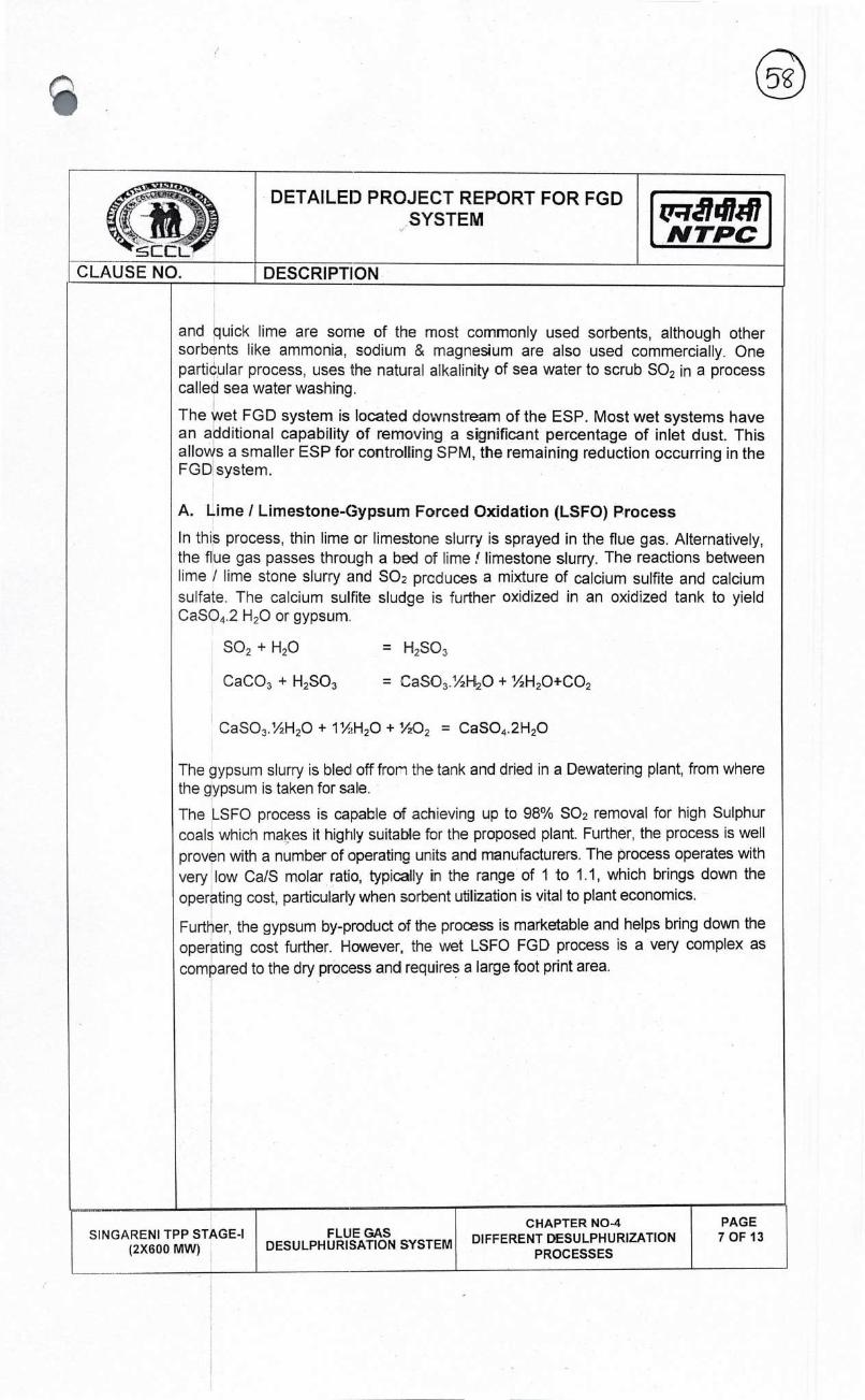
cI:L
DETAILED PROJECT REPORT FOR FGD
NTPC
CLAUSE NO. DESCRIPTION
and quick lime are some of the most commonly used sorbents, although other sorbents like ammonia, sodium & magnesium are also used commercially. One particular process, uses the natural alkalinity of sea water to scrub SO2 in a process called sea water washing.
The wet FGD system is located downstream of the ESP. Most wet systems have an additional capability of removing a significant percentage of inlet dust. This allows a smaller ESP for controlling SPM, the remaining reduction occurring in the FGD system.
A. Lime I Limestone-Gypsum Forced Oxidation (LSFO) Process
In this process, thin lime or limestone slurry is sprayed in the flue gas. Alternatively, the flue gas passes through a bed of lime! limestone slurry. The reactions between lime I lime stone slurry and SO2 prcduces a mixture of calcium sulfite and calcium sulfate. The calcium sulfite sludge is further oxidized in an oxidized tank to yield CaSO4.2 H20 or gypsum.
SO2 + H2O = H2S03
CaCO3 + H2S03 = CaSO3.1/21-I2O + %H2O+CO2
CaSO3.%H2O + 1½H20 + 1/202 = CaSO4.2H20
The gypsum slurry is bled off from the tank and dried in a Dewatering plant, from where the gypsum is taken for sale.
The LSFO process is capable of achieving up to 98% SO2 removal for high Sulphur coals which makes it highly suitable for the proposed plant. Further, the process is well proven with a number of operating units and manufacturers. The process operates with very low Ca/S molar ratio, typically in the range of 1 to 1.1, which brings down the
operating cost, particularly when sorbent utilization is vital to plant economics.
Further, the gypsum by-product of the pross is marketable and helps bring down the operating cost further. However, the wet LSFO FGD process is a very complex as compared to the dry process and requires a large foot print area.
SIN GARENI TPP STAGE-I (2X600 MW)
FLUE GAS DESULPHURISATION SYSTEM
CHAPTER NO-4 DIFFERENT D€SULPHURIZATION
PROCESSES
PAGE 7 OF 13

DETAILED PROJECT REPORT FOR FGD SYSTEM t71i!4h47
NTPC
CLAUSE NO. DESCRIPTION
fiiie______ . Fit
I I
J EXETIr..G CHIMNEY
NEW WET
Fiy -aTh i ... 9 ...,.
lDtn
LX)S I tr8tff)fIt I-A t._—.,_- 1ç •f'-
- V Wa'er dthp Lirnctocie Limetoi' H1royiones .
L
°- L. F Surry — tiik
The choice of reagent depends on the availability, cost and handling. The lime requirement per ton of SO2 removal in typically 56% of the limestone requirement. However, this difference the higher cost of lime as compared to limestone. The availability lime from local source is another issue which favors the use of of the above factors, limestone is the chosen reagent for the wet FGD system.
The process is the most well proven technology to achieve high efficiency with high Sulphur coal, with a large number of reference capital cost and auxiliary power consumption of the process are partially high sorbent utilization and sale ability of the gypsum by-product.
Cpum
other issues like a wet process is
is off set by of high quality
limestone. In view limestone based
desulphurization plants. The high
off-set by the
The above process is the moss suited for SCCL (2X600 MVI9. Other Wet systems are costlier due to higher cost of reagent and higher energy consumption. Accordingly, this system is selected.
B. Sea Water Process
The sea-water washing (S\A'V\J) process uses natural alkalinity of the untreated sea water in order to neutralize the SO2. The gas from ID fan passes through a booster fan (optional) into the scrubber, where sea water is sprayed into the flue gas. The sea water dissolves most of the SO2 and practically all of HCI. The clean gas is again passed through a re-heater before discharge through stack.
SINGARENI TPP STAGE-I (2X600 MW)
FLUE GAS DESULPHURISATION SYSTEM
CHAPTER NO-4 DIFFERENT DESULPHURIZATION
PROCESSES
PAGE 8 OF 13

Out let iariiper
Flue B',-pass Ctirii p(?I Flue CjaS
0
Booster tat-i [ Reheater
Absorber Sea water trom co ridenser -
I Packing
Oxidation air
Return tOSeO
net dart rper-
DETAILEID PROJECT REPORT FOR FGD SYSTEM
NTPC
CLAUSE NO. DESCRJPTIION
The acidified liquor is collected in a sump and ifien taken to a mixing basin where more sea water is mixed and air is blown through the water to reduce its chemical oxygen demand, before being discharge into the sea. Most sea water applications, utilize water from condenser water bo outlet, which is partially used for scrubbing and the remaining for neutralization of the acidified liquor.
The sea water process is a very simple process with no requirement for any additional reagent. The sea water is capable of achieving desulphurization efficiency upto 95% with low and medium Sulphur coal. However, their efficiency with high Sulphur coal is limited by the huge amount of water that will be required for such applications.
Since this process is applicable only to coastal power stations and hence not considered for SCCL (2X600 MW).
C. Ammonia Process
The process is similar to the LSFO process, except that the reagent is an aqueous ammonia solution. The reaction between Ammonia solution and SO2 produces a mixture of ammonium sulfite and sulfate. The ammonium sulfite sludge is further oxidized in an oxidization tank to yield Ammonium sulfate ((NH4)2SO4) which can be used as fertilizer.
SO2 + H20 = H2S03
2NH3 + H2S03 = (NH4)2S03
(NH4)2S03 + 1/20 = (NH4)2SO4
The (NH4)2SO4 slurry is bled off from the tank and dried in a Dewatering plant, from
where the (NH4)2SO4 is taken for sale or disposal.
PAGE 9 OF 13 SINGARENI TPP STAGE-I
(2X600 M) FLUE GAS
DESULPHURISATION SYSTEM
CHAPTER NO-4 DIFFERENT DESULPHURIZATION
PROCESSES

DETAILED PROJECT REPORT FOR FGD SYSTEM
CLAUSE NO. DESC RI PT 110 N
The Ammonia FGD process is capable of achieving upto 98% removal of SO2. The byproduct of the process (NH4)2SO4 is a very high value fertilizer, the sale cost of which can offset the operating cost.
The process is very high in capital cost and has very high auxiliary power consumption (2-3%). The storage and handling of aqueous ammonia is potentially risky and proper planning is required. The system requires a large foot print area, similar to the limestone gypsum FGD system.
eheate
Precipitator
Rooster tar Absorber Water
Ammonia swrage tank
Fly ash
Purge Pe-scrubber
H ydrocyc lone
RI eecl Bleed
9 Damper
The Ammonia Process is not being considered for the SCCL (2X600 MW) because of their high capital cost, high auxiliary power consumption and lack of adequate reference plants
DSI TECHNOLOGY
A Dry Sorbent Injection (DSI) system is a dry process in which a sorbent is pneumatically injected either directly into a coal-fired boiler or into ducting downstream of where the coal is combusted and exhaust (flue) gas is produced. The goal of the sorbent injection is to interact the sorbent with various pollutants in the flue gases (such as sulfur trioxide (SO3), various acid gases including hydrochloric acid (HCI), and sulfur dioxide (SO2). such that some fractions of these pollutants are removed from the gas stream. After the appropriate chemical interactions between the pollutants in the flue gas and the sorbent, the dry waste product of reaction is
3.02.03
SINGARENI TPP STAGE-I (2X600 MW)
FLUE GAS DESULPHURISATION SYSTEM
CHAPTER NO-4 DIFFERENT DESULPHURIZATION
PROCESSES
PAGE 10 OF 13
1gfl47 , N TPC

DETAILEID PROJECT REPORT FOR FGD SYSTEM
EIL CLAUSE NO. DESCRIPTION
removed at the existing particulate control device downstream of the injection point-which is either an electrostatic precipitator (ESP) or a fabric filter baghouse.
Ory SorbEnt 1nection (OSI} system — 1rcn or ot1ruri cmhnit' RC1
DSI is a mature technology that has been widely applied since the early 2000's by utilities in the USA requiring S03/HCL/HF emissions reduction. DSI offers the following benefits over ol:her acid gas control technologies: 1. Low installed capital cost w.r.t Wet Limestone FGD & semi dry FGD.
2. Relatively easy to retrofit (only injection lances are in contact with exhaust gas) with very short unit shutdown time.
3. System has good process flexibility for various sorbents and ability to easily modulate based on unit load and/or different fuels.
4. Small equipment footprint (typically footprint of one or two silos and Mill/Blower building)
5. Relatively short installation schedule as there is approximately less than one year schedule from contract award to commercial operation.
6. No water requirement
7. Low Auxiliary Power consumption
8. Easy to operate
Sorbents Two primary sorbents are utilized in DSl systems: (a) Sodium based sodium bicarbonate or Trona and lime based hydrated lime (Ca (OH)2). Sodium Bicarbonate is more effective in removing SO2 emissions than hydrated lime. Although hydrated
PAGE 11 OF 13 SIN GARENI TPP STAGE-I
(2X600 MW) FLUE GAS
DESULPHURISATION SYSTEM
CHAPTER NO-4 DIFFERENT DESULPHURIZATION
PROCESSES

1cL
DETAILED PROJECT REPORT FOR FGD SYSTEM I
NTPC
CLAUSE NO. DESCRIPTIION
lime effectively mitigates 503, i is less effective in mitigating SO2. In most of the cases, hydrated lime is used to remove 503, HCI and HF primarily these are very reactive acidic pollutants compared to SO2 with hydrated Lime. To mitigate SO2 with hydrated lime, water must be added to the process to reach acceptable performance levels. The water is needed to facilitate the reaction of hydrated lime and SO2. Further reactivity of hydrated lime as compared to sodium bicarbonate with SO2 is much lowe' requiring 6 to 10 times the stoichiometric requirement for SO2 capture compared to 1 to 1.5 for Sodium Bicarbonate. This parents and added level of difficulty in designing a cost effective solution.
Coal being fired in the plant contains around 35-40% ash. Further, for low SO2 removal efficiency required to rreet the norris the sodium bi carbonate consumption will be very less. In such a scenario the sodium content in fly ash will not exceed more than 0.6%-1% which is much less than the permissible 1.5% alkali content in fly ash.
The Operational cost of DSI system is very high because of high cost of sorbents. Further Process is only suited for low PLF and low SO2 removal efficiency .So this process is being not suited for SCCL (2X600 MW) because of its very high operating cost, low SO2 removal efficiency.
Comparison of Different FGD technologies
Item Spray Dry Process
CFB CDSDry
Wet Limestone- Gypsum
Ammonia process
DSI
Sorbent Lime Lime Limestone Ammonia
Sodium bicarbonate
Coal Sulphur Limit
For low and medium Sulphur content coal
Nc limit No Sulphur content limit
No Sulphur content limit
For low and medium Sulphur content coal
Removal efficiency 90-95% Above 95% Above 95%
Above <85%
Process Hard to obtain
Hard to obtain
Local Depends on availability
Depends on availability
Sorbent source
Hard to obtain
Hard to obtain
Loca' Depends on availability
Depends on availability
SINGARENI TPP (2X600
STAGE-I MW)
FLUE GAS DESULPHURISATION SYSTEM
CHAPTER NO-4 DIFFERENT DESULPHURIZATION
PROCESSES
PAGE 12 OF 13

ccL
DETAILED PROJECT REPORT FOR FGD SYSTEM
NTPC
CLAUSE NO. DESCRIPTIION
Sorbent Utilization Poor Poor Good Good
Poor
By- product
Waste Mixture of Calcium compounds (Sulfite and sulfates)
Waste Mixture of Ca cium compounds (Sulfite and sulfates)
Gypsum
High value fertilizer Ammonia sulfate solution
Along with Fly Ash
Aux. Power Low Low High Very High
Low
Capital Cost Low Low High High
Low
Operating Cost High High Low Low
Very High
Reference Plants above 500 MW
Few Few Many Few Few
S1NGARENI TPP STAGE-I (2X600 MW)
FLUE GAS DESULPHURISATION SYSTEM
CHAPTER NO-4 DIFFERENT DESULPHURIZATION
PROCESSES
PAGE 13 OF 13

DETAILED PROJECT REPORT FOR FGD SYSTEM NTPC
CLAUSE NO. DESCRIPTION
1.00.00
PROPOSED CHAPTER-5
SYSTEM WET LIIMESTONE FLUE GAS DESULPHURISATION
The wet FGD process is considered a commercially offered by a number of suppliers. The reliability substantially in recent times.
As discussed in the previous section Limestone Gypsum Process is selected following reasons:
i. Ability to achieve high desulphurization
ii. High Dust removal as a co-benefit.
iii. High reagent utilization factor or Low
iv. Reagent material (limestone) used available.
v. Saleable By-product (gyosum).
vi. Large number of reference plants.
vii. Maturity of technology involving minimum number of suppliers resulting in enhanced
The FGD shall be designed to achieve high reliable & proven design to achieve high availability. having additional advantage of reducing the
It is proposed to market the by-product gypsum
WET LIMESTONE FGD SYSTEM
Various systems required for the wet limestone
a. Booster Fans
b. Limestone Transportation
c. Limestone Handling System
d. Milling System
e. The FGDAbsorber
f. Gypsum De-watering system
g. Gypsum Handling System
h. Process Water Distribution System
i. ECW system
j. Waste Water Treatment System
Description of the selection and sizing of desired requirements of efficient operation
mature technology and is on the wet FGD has been increased
and seen in Table, the Wet Lime/ for SCCL 2X6OO MW) Stage-I for the
efficiency
reagent consumption rate.
by the process is plentiful and readily
commercial risks and large competition.
SO2 removal efficiency of -95% with Further, the FGD system is
dust burden substantially.
by locating suitable buyers.
scrubbing process are:
various above systems to meet the & life of the plant shall follows:
CHAPTER NO-5 PROPOSED FGD SYSTEM
PAGE 1 OF 17 SINGARENI TPP STAGE-I (2X600 MW)
FLUE GAS DESULPHURISATION SYSTEM
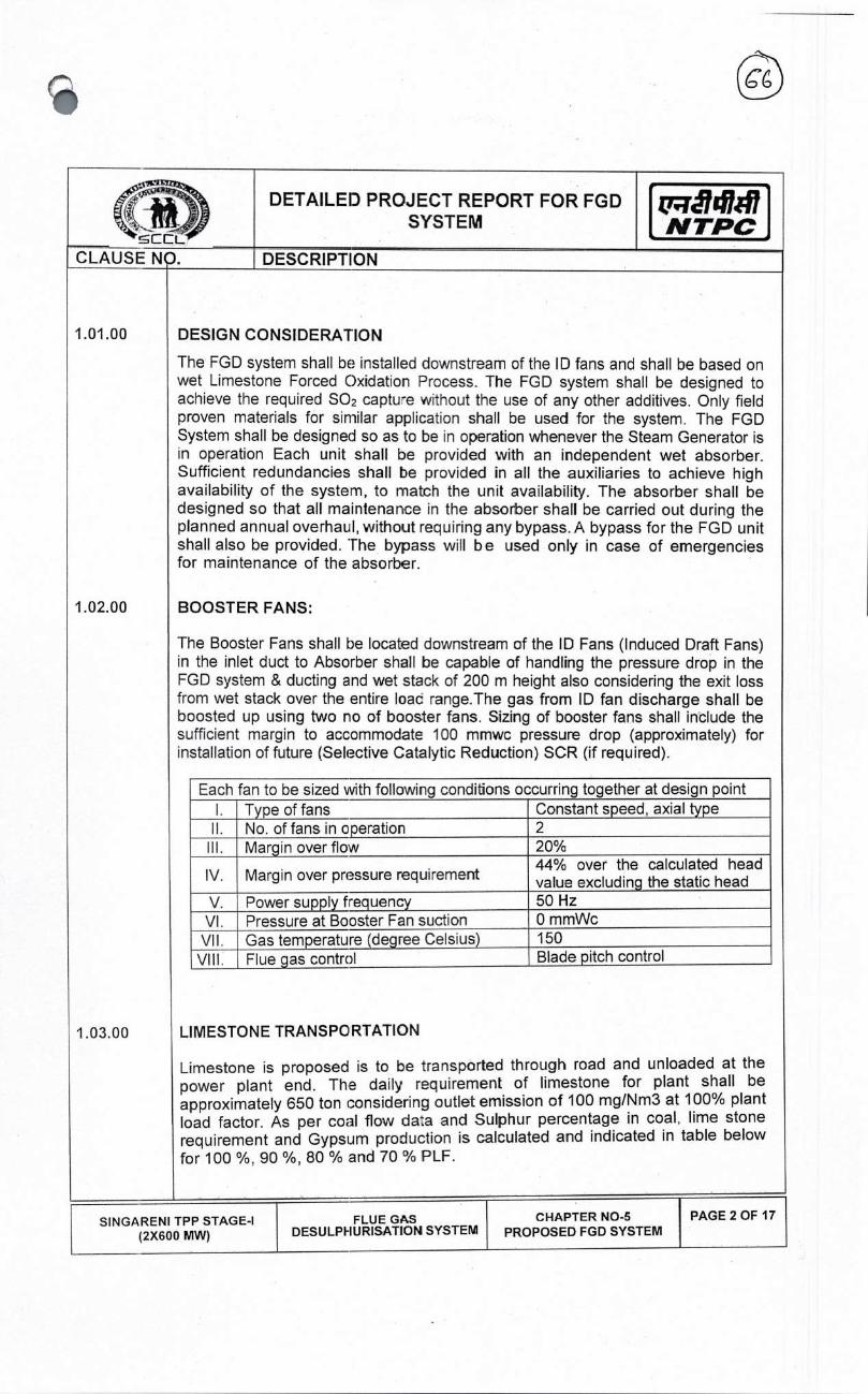
NTPC CLAUSE NO
DETAILED PROJECT REPORT FOR FGD SYSTEM
DESCRIPTION
DESIGN CONSIDERATION
The FGD system shall be installed downstream of the ID fans and shall be based on wet Limestone Forced Oxidation Process. The FGD system shall be designed to achieve the required SO2 captu-e without the use of any other additives. Only field proven materials for similar application shall be used for the system. The FGD System shall be designed so as to be in operation whenever the Steam Generator is in operation Each unit shall be provided with an independent wet absorber. Sufficient redundancies shall be provided in all the auxiliaries to achieve high availability of the system, to match the unit availability. The absorber shall be designed so that all maintenance in the absorber shall be carried out during the planned annual overhaul, without requiring any bypass. A bypass for the FGD unit shall also be provided. The bypass will be used only in case of emergencies for maintenance of the absorber.
BOOSTER FANS:
The Booster Fans shall be located downstream of the ID Fans (Induced Draft Fans) in the inlet duct to Absorber shall be capable of handling the pressure drop in the FGD system & ducting and wet stack of 200 m height also considering the exit loss from wet stack over the entire loac range.The gas from ID fan discharge shall be boosted up using two no of booster fans. Sizing of booster fans shall include the sufficient margin to accommodate 100 mmwc pressure drop (approximately) for installation of future (Selective Catalytic Reduction) SCR (if required).
Each fan to be sized with following conditions occurring together at design point I. Type of fans Constant speed, axial type II. No.offansincperation 2 Ill. Margin overflow 20%
IV. Margin over pressure requirement 44% over the calculated head value excluding the static head
V. Power supply frequency 50 Hz VI. Pressure at Booster Fan suction 0 mmWc VII. Gas temperature (degree Celsius) 150 VIII. Flue gas control Blade pitch control
LIMESTONE TRANSPORTATION
Limestone is proposed is to be transported through road and unloaded at the power plant end. The daily requirement of limestone for plant shall be approximately 650 ton considering outlet emission of 100 mg/Nm3 at 100% plant load factor. As per coal flow da:a and Sulphur percentage in coal, lime stone requirement and Gypsum production is calculated and indicated in table below for 100%, 90%, 80% and 70% PLF.
1.01 .00
1 .02.00
1.03.00
SINGARENI TPP STAGE-I (2X600 MW)
FLUE GAS DESULPHURISATION SYSTEM
CHAPTER NO-S PAGE 2 OF 17 PROPOSED FGD SYSTEM

t77JN1I7 N TPC
CLAUSE NO.
DETAILED PROJECT REPORT FOR FGD SYSTEM
DESCRIPTIION !ccL
The calculation is based on 1.15 % of Sulphur (data furnished by SCCL) content in coal & target emission of 100 mg/Nm3
PLF 100% 90% 80% 70% LIMESTONE (T/Day) 653 585 520 455 GYPSUM (1/Day) 10B5 980 870 760
1.04.00 LIMESTONE HANDLING SYSTEM
It is assumed that Lime stone of approx. 250 mm shall be received in power plant through road trarsport and unloaded at lime stone handling area of proposed FGD Plant.
Lime stone shall be unloaded and conveyed by double stream conveyors of 100 TPH capacity to the crusher hcuse for sizing it to -20 mm.
Limestone shall be unloaded into the Underground Hopper from the Limestone Stack out area. The Underground Hoppers include Rack and Pinion Gates and Belt Feeders which feed limestone onto the Belt Conveyors. Belt Conveyors transfer the limestone to the Limestone Crushers through Rack and Pinion Gates.
Each Limestone Crusher is designed to crush the limestone rock, and then discharge it onto the Belt Feeders and Bucket Elevators, and to be sent to the three numbers of Limestone Storage Silos having capacity of 1800 T each (07-08 days storage capacity).
The crushed limestone will be conveyed from the three no of Limestone Storage Silos to the dedicated 24-hr s:orage Limestone Bins/mill bunker through Rotary Feeders, Belt Feeders and Buccet Elevators(if required) in the Limestone Grinding building.
The storage silos and hopper cones shall be fabricated of minimum 10 mm thick carbon steel with a SS lining of grade S5304 of minimum 4 mm thickness in the complete cones to ensure reliable discharge of matenal.
The design of storage silos shall confirm to IS 9178 (Part 1 to 3). The storage bin shall be capable of feeding the limestone by means of gravimetric feeder to the wet ball mills. The top 0 the unloading hopper shall be equipped with a grate to protect the downstream equipment from gravel lumps or tramp waste.
Dust suppression & dust extraction system, ventilation system, potable water and service water system shall be provided throughout the Lime stone handling plant.
SINGARENI TPP STAGE-I (2X600 MW)
FLUE GAS DESULPHURISATION SYSTEM
CHAPTER NO-5 PROPOSED FGD SYSTEM
PAGE 3 OF 17

tr14141 NTPC
FLUE GAS DESULPHURISATION SYSTEM
CHAPTER NO-5 PROPOSED FGD SYSTEM
PAGE 4 OF 17
CLAUSE N
DETAILED PROJECT REPORT FOR FGD SYSTEM
DESCRIPTHON
1 .05.00 BASIS FOR SELECTION OF MILLING SYSTEM:
Limestone requirement
To cater to any change in coal Sulphur content during the plant life and deterioration in mill perfom-iance, it is proposed that the milling system shall be designed with a minimum margin of 10% above the maximum requirement of the station. The milling system for the FGD can be either common or unitized i.e. independent milling system for each unit.
Since the unitized system requires additional space in the unit area, Common milling system has been envisaged with one working and one stand-by mills. Two alternatives were explored for the common milling system.
Two common type of milling system employed for wet FGD process are the dry milling system and the wet milling system.
1. In dry milling systems, the limestone is ground in air medium and compressed air is used for conveying the pulverized limestone to a storage silo from where a gravimetric belt feeder feeds measured quantity to the lime slurry preparation system. For proper grinding, the limestone has to be dried prior to feeding to the mill and the limestone moisture at mill inlet has to be limited to 1-2%. This may require an additional hot air supply system for drying of limestone in case the crushed limestone has higher moisture. The dry mills typically have a longer life for the wear parts but consume more power for grinding & transportation. The capacity of the mill is also reduced compared to wet mill of the same volume.
2. In wet milling system, slurry of crushed limestone is fed to the mill. The pulverized limestone slurry is classified in a single or multi-stage hydro cyclone and stored in a storage tank, from where it is pumped to the absorber. The wet milling system have a lower power consumption but also a lower wear life due to heavy erosion by liquid slurries. However, wet milling system is widely preferred due to their lower operatirg cost and overall requirements of the unit, which needs slurry feed to the absorber.
In view of the above, it is proposed to have a wet milling system for FGD
Horizontal wet ball & tube mills are the most preferred choice for FGD installations, through vertical medium speed mills are also used. However, the fineness required for the FGD limestone power is typically above 90% through 325 mesh for which the horizontal ball mills are more suited. Horizontal ball mills have the capability of grinding an average feed size of 3/4" & 1" to the required fineness. A new development in FGD applications is the use of vertical ball mill. The power consumption of these mills is lower than that of horizontal ball mills. However, they require a typical feed size of about 1/4", which increase the crushing requirements.
SIN GARENI TPP STAGE-I (2X600 MW)

SINGARENI TPP STAGE-I (2X600 MW)
FLUE GAS DESULPHURJSATION SYSTEJV1
CHAPTER NO-5 PROPOSED FGD SYSTEM
DETAILED PROJECT REPORT FOR FGD SYSTEM
(
NTPC CLAUSE NO. DESCRIPTION
The horizontal ball mills, being the most widely used & proven system for FGD applications, are also proposed for SCCL (2X600 MW).
There shall be common milling system as two number horizontal/vertical wet ball mills, 1 working & I standby, common for the two units. Each mill shall be sized to meet the following conditions, occurring together:
Load 100% BMCR ii Ca/S Ratio (for
Mill Sizing) 1.1
iii InputFeedSize 1' iv Output fineness Not less than 90% through 325 mesh or as per the
requirements of the FGD absorber, whichever is more stringent.
v Capacity 110% of limestcrie requirement of all the absorbers at Design point with the mill wear parts in nearly worn out condition.
The mill shall have a peripheral drive system with necessary speed reducers. In addition, an emergency auxiliary drive shall also be provided to prevent settling /solidification of limestone when the mill is out of operation and also for maintenance purpose.
Each mill shall be fed from an independent bunker through a gravimetric belt feeder. The gravimetric belt feeder shall be sized to meet 110% of the mill maximum demand and shall have a variable speed drive and weighing instruments to accurately control the feed rate. The belt shall be of rubber, while all other internal parts shah be of Stainless Steel construction.
The dry feed from the feeder shall be mixed with process water in a hopper and fed to the mill through trunnion on one side of the mill. The ground limestone slurry shall be discharged through the mill trunnion at the other end into a settling tank. The mill discharge slurry sall be pumped to single or multi-stage hydro-cyclones from where the fine product slurry shall be taken to slurry storage tank while the coarse slurry shall be mixed with the mill inlet feed.
Each mill shall be provided with an independent mill separator tank and hydro-cyclone. 2x1 00% slurry pumps shall be orovided for each separator tank.
The hydro-cyclone over fow of the required fineness shall be taken into two common lime slurry storage tanks, each sized for minimum storage capacity of 12 hours' requirement of 2 units operating at 100% BMCR. For tank volume calculation, solid concentration (by weight) in the slurry shall be assumed, not more than 20% or actual required whichever is lower. The limestone shall be pumped from the slurry storage tank to the individual FGD units by 2x100% slurry pumps for each unit. A 100% stand-by pipeline shall also be provided. The slu'ry pump shall be sized to meet the required capacity with a maximum of 30% solid weight in the slurry. The pumps shall be equipped with a VFD motor or a hydra-coupling for control of flow. The pumps shall be sized to meet the following criteria, all conditions occurring together:
PAGE 5 OF 17

t7;Tã71V7 N TPC
FLUE GAS DESULPHURISATION SYSTEM
CHAPTER NO-5 PROPOSED FGD SYSTEM
PAGE S OF 17
CLAUSE N
DETAILED PROJECT REPORT FOR FGD SYSTEM
DESCRIPTION
1 .06.00
Load 100% BMCR (both units) Maximum Solid Concentration at inlet to hydro-cyclone
Max. 300/s by weight
Ca/S Ratio 1.1 Maximum Solid Concentration 30% Flow 110% of one absorber requirement with
the limestone requirement at Design point.
Head As system requirement to meet the above flow
Margin on Flow Minimum 10% Margin on Head Minimum 15%
All the tanks shall be provided with sufficient no. of agitators to prevent deposition of solids at the bank. All the agitators shal be motor driven with power supply from emergency system.
The mills shall have replaceable rubber lining bolted to the mill shell. The lining shall have a minimum wear life of 2 years. The limestone slurry pumps and the pipelines shall be of CS construction with replaceable elastomer or rubber lining with a minimum wear life of 2 years.
ABSORBER SYSTEM
The wet limestone spray absorber shall be deigned to achieve an outlet SO2 emission of 100mg/Nm3 at 6% 02 (dry) with the following conditions occurring together:
a) Flue gas flow & inlet SO2 concentration b) Flue gas temperature
Load 100% BMCR Excess air economizer outlet 20% APH air in leakage 15% Duct air-in leakage 2% ESP air-in leakage 1%
The absorber shall be either a spray type absorber, with single or multiple levels of spray, or an absorber with gas buobling through the slurry. In Spray type absorber wet limestone slurry shall be sprayed in the tower by slurry recirculation pumps taking suction from the absorber tank. The absorber shall have single or multiple levels of spray nozzles, as per the proven practice. Each level of spray nozzles shall have an independent slurry recirculation pumping system. In Bubbling Type absorber, no recirculating pump and spray header and rozzles shall be required in such case. However, Gas Cooling Pumps instead of Slurry Recirculation shall be provided
SINGARENI TPP STAGE-I (2X600 MW)

N TPC DETAILEE) PROJECT REPORT FOR FGD
SYSTEM
CLAUSE NO. DESCRIPTION
ABSORBER TOWER
The efficiency of the wet Hmestone SO2 scrubbing system depends on the following absorber related factors:
I. Flue gas velocity ii. Liquid to gas volume flow (LJG) ratio iii. Recirculation slurry pH iv. Ca/S molarratio
During earlier times, the flue gas velocity through the absorber was kept below 3.0 m/s to give sufficient residence lime for the gas to react with atomized slurry. However, during recent times with improvements in design of various components, the latest FGDs have a much higher velocity up to 4.5 m/s.
Increasing the flue gas velocity increases the SO2 removal efficiency of the liquid and the absorbers can operate with a lower slurry flow rate to achieve the same efficiency, which significantly reduces the pumping power.
However, it also leads to an increased gas side pressure drop and a higher mist carryover, which may lead to a plugging of the mist eliminator. The velocity of the flue gas through absorber shall, therefore, be limited to 4 rn/s.
Wet limestone FGD process operates with a very high L/G ratio. However, increasing the gas velocity through the absorber has brought down the L/G ratio due to higher mass transfer. The minimum L/G ratio of the absorber shall be 20 liters per 1000 m3 of gas for effective removal of SO2.
SO2 removal efficiency of a wet limestone process increases with increasing pH. However, above 6.2 pH, the oxidation of calcium sulfite to gypsum becomes difficult and this can lead to scale formation. The pH of the absorber slurry shall therefore, be regulated between 5.5 to 6.2 for effective removal of SO2 and oxidation of calcium sulfite to gypsum.
The SO2 removal efficiency increases with increasing Ca/S molar ratio. However, wet limestone process is capable of achieving very high SO2 removal efficiency with very low Ca/S ratio. Further, in order that the gypsum produced is saleable, the molar ratio should not exceed 1 .03, which means about 97% utilization of limestone.
The absorber tower shall be therefore sized with the following parameters at 100% BMCR:
Flue gas velocity: 4 m/s (max) L/G ratio : 20 L/1000m3(min)
5.5 to 6.2 pH: Ca/S ratio: 1.03 max
SLURRY RECIRCULATION PUMPS
The absorber shall have single or multiple levels of spray nozzles. Each spray level shall have an independent pumping system. The capacity of the pumps
1.06.01
1.06.02
SINGARENI TPP STAGE-I (2X600 MW)
FLUE GAS DESULPHURISATION SYSTEM
CHAPTER NO-5 PROPOSED FGD SYSTEM
PAGE 7 OF 17

iri14i47 NTPC
CLAUSE NO.
DETAILED PROJECT REPORT FOR FGD SYSTEM
DESC RI PT ION
shall be sufficient to maintain an LIG -atio of 20L per 1000m3 of gas at BMCR. The maximum solid concentration in the recirculation slurry shall not exceed 30%.
In case the absorber has a single level of nozzles, there shall be a minimum of 3 pumps of 50% capacity each. For multiple spray levels, 2x100% pump shall be provided for each level. Alternatively, a spare absorber spray level with independent pump can be provided. It shall be possible to reduce the slurry flow rate at lower loads to save power. For this purpose, the pump shall be provided with a VFD motor or a variable scoop hydro-coupling drive.
The absorber recirculation pumps shall be sized to achieve a minimum L/G ratio of 20 liters per 1000 m3 of gas or actual predicted, whichever is higher, at BMCR without the spare pumps I spray levels working. Further each pump shall be designed with the following margins to cater to deterioration in performance due to wear of impeller liners:
i. Flow: minimum 20%
ii. Head:minimum20%
The number, capacity and spread of the spray nozzles shall be in line with the proven practice and shall be adequate to cover the whole absorber cross-section uniformly without too much impingement in the absorber walls. A minimum of 5% redundancy shall be provided in the spray nozzles at each level to ensure adequate coverage with a few choked nozzles.
1 .06.03 ABSORBER TANK
The absorber shall have an integrated oxidation tank at its bottom. The tank shall be sized to provide a minimum mean residence time of 12 hrs for the slurry to be oxidized to gypsum.
For oxidation of calcium sulphite to gypsum, the absorber shall have a grid type oxidation system or a sparge jet oxidation system or lance type or air rotary sparge system or jet air sparger system , as per the proven practice. The tank should be equipped with a sufficient no. of agita:ors to work in conjunction with the oxygen sparging system to keep the slurry in continuous motion.
The oxygen required for oxidation snaIl be supplied by 2x100% oxidation air blowers for each absorber. The comressorIblower shall be sized to supply at least 2.5 times the stoichiometric air requirement for spray tower process & at least 4.0 times the stoichiometric air requirement for Bubbling Type process or the actual requirement, whichever is higher, under the following condition, all-occurring simultaneously. The natural oxidation of sulfite by residual oxygen in flue gas shall not be considered for this purpose.
SINGARENI TPP STAGE-I (2X600 MW)
FLUE GAS DESULPHURISATION SYSTEM
CHAPTER NO-S PROPOSED FGD SYSTEM
PAGE 8 OF 17

DETAILED PROJECT REPORT FOR FGD SYSTEM
CLAUSE NO. DESC RI PT ION
Load 100%BMCR
Flow Minimum 2.5 times for spray tower process & 4.0 for Bubbling Type process, the stoichiometric requirement.
Head
For spray tower process actual requirement considering chokingf blockage of minimum 10% of the oxidation nozzles / sprayers or minimum 8500 mmwc whichever is higher.
For Bubbling Type process actual requirement considering choking! blockage of minimum 10% of the oxidation nozzles / sprayers or minimum 3500 mmwc whichever is higher.
Margin on Head 10% under above conditions.
Ambient Conditions
45°C (60% RH.
Oxidation nozzles / spargers shall have a minimum redundancy of 10% The oxidation system shall be complete with a quenching system to cool down heated oxidation air in order to prevent any scaling or buildup that could occur at the sparger tips due to localized evaporation of recycled slurry.
1.06.04 MIST ELIMINATORS
The clean Flue gas from the absorber tank shall be demisted in a three stage chevron type Mist Eliminators (ME). Prcvision shall be made for continuous washing of both ends of the first & second stage and the front section of the third stage of mist eliminators. Wash water arrangement siall also be provided at the back end of the third stage of mist eliminator.
EMERGENCY SPRAY SYSTEM
An emergency cooling system for automatic spray of quenching water for a sufficient time (minimum 15 mm) at the inlet to the absorber, in case the gas temperature exceeds the design ternperatue due to failure of upstream equipment's shall be provided to protect the FGD and all other sensitive downstream equipment against high flue gas temperatures. The water shall be supplied from an elevated tank (emergency water tank) installed near to the absorber. The tank volume and the injection lances/nozzles shall be designed to protect the inlet duct and the lining of the absorber
AUXILIARY ABSORBENT TANK
One Number auxiliary absorbent tank snail be provide for both unit, sized to contain the complete slurry of one absorber tank at its maximum level equipped with all
N TPC
1 .06.05
1.06.06
SINGARENI TPP STAGE-I (2X600 MW)
PAGE 9 OF 17 FLUE GAS DESULPHURISATION SYSTEM
CHAPTER NO-5 PROPOSED FGD SYSTEM

PAGE 10 OF 17 SINGARENI TPP STAGE-i (2X600 MW)
FLUE GAS DESULPHURISATION SYSTEM
CHAPTER NO-5 PROPOSED FGD SYSTEM
DETAILED PROJECT REPORT FOR FGD SYSTEM
Lri14141 • NTPC
CLAUSE N DESCRIPTION
necessary pumps, agitator, valves, oiping and controls to transfer the tank's contents back to the absorber to refill the absorber sump It should be possible to discharge the each absorber into the Auxiliary Absorbent tank within 2 hours. The contractor shall provide 1 x100% pump to pump back the slurry from the sump back to the absorber in a maximum time of B hours.
1.06.07 CONSTRUCTIONAL FEATURES I MATERIALS OF CONSTRUCTION
The FGD absorber shall be self-supported from the bottom to suit site conditions. The absorber shall have adequate stiffening arangement from the external side. Internal stiffeners shall be used only when it is not possible to provide proper external stiffening.
The inlet duct to the absorber from the booster fans shall have provision for automatic spray of quenching water if the temperature at this section exceeds the design temperature of the absorber, due to failure of the upstream equipment. For multi-level spray absorbers, a minimum distance of 1 .5m shall be kept between two spray levels for ease of maintenance. All the agitators shall have supply from the emergency power supply.
The choice of material for various sections of the FGD absorber is very critical as they are subject to varying degree of corrosion & abrasion. The material shall be able to withstand localized pitting & crevice corrosion due to conditions of low pH and high sulphuric / sulphurous acid & chlcride concentration. The early FGDs absorber tower typically used CS casing lined with rubber. However, these faced repeated failures due to failure of the rubber fining exposing the parent material to corrosive attack. The liners in most FGDs absorber have been replaced with either with 2mm (mm) thickness Alloy C276/Alloy59 in the absorber tower.
The absorber inlet sections, including the portion of inlet duct subject to splashing liquids from the spray zone, are subject to a very severe environment of low pH, coupled with high acid concentrations. The wet dry interface may also be subject to scaling which can lead to localized pitting attack. The inlet zone shall be of 7 mm carbon steel with a 2 mm thick plate equivalent to or better than Alloy C276 I Alloy 59 or equivalent wall paper or cladding. This area shall also be provided with sufficient flushing Iwashing arrangement to prevent scale formation.
The main absorber spray zone operates with a comparatively higher pH but may be subject to severe erosion from the sprays. This zone may be 7 mm thick CS with 2 mm thick wall papering made of C 276 1 Alloy 59. Alloy C276 / Alloy 59 is a costlier option but is known to give a better corrosion resistance. The absorber outlet duct from top of 1:he spray iozzles to the chimney shall be of CS with mm 7mm thickness cladded with 2mm (mm) thickness Alloy C276IAlloy59/Titanium Gr-ll.
The mist eliminators are proposed to be of chevron type made of polysulfone or SS along with continuous washing system.
The spray piping and headers & the oxidation headers shall be of FRP, or CS with rubber lining (mm 10mm natural rubber lining) chemically & abrasion resistant on both inner & outer surfaces.

PAGE 11 OF 17
DETAILED PROJECT REPORT FOR FGD SYSTEM
t7?j14147 N TPC
CLAUSE NO DESCRIPTION
The Auxiliary Absorbent tank shall be made of minimum 7 mm thick carbon steel with minimum 4 mm thick rubber lining of best quality bromine butyl rubber
Oxidation tanks shall have a 2 mm thick cladding of 0276/Alloy 59 over 7 mm thick Cs:
Component Material
Absorber In let Flue Duct CS with mm 7mm thickness
Absorber Wet Dry Interface
CS with 0276 / Alloy 59 cladding
Absorber & Oxidation tanks
CS with mm 7mm thickness cladded with 2mm (mm) thickness Alloy 0276/AIloy59
Absorber Outlet Duct up to Chimney
CS with mm 7mm tiickness cladded with 2mm (mm) thickness Alloy 0276/AIloy59/Titanium Gr-ll
Mist Eliminator Polysulfone or stainless steel
Spray Piping / Header FRP or CS with rubber lining
GYPSUM DEWATERING SYSTEM
Gypsum slurry from each absorber tank shall be pumped by 2x100% variable speed pump (for each unit) to the common dewatering system. The slurry shall have 15-30% solid concentration (by weight) as per the standard practice of the manufacturer. A 100% stand-by pipeline shall also be provided. Eaci pump shall be sized with a minimum margin of 10% on flow and pressure over 120% of the maximum flow requirement frcm the absorber at 100% BMCR
In order that the gypsum produced in the absorber is saleable, the same has to be dewatered to ensure less than 10% moisture in the gypsum. Most FGD systems in the world use a two stage dewate ring system, where the primary stage consisting of sets of hydro-cyclones increases the solid content in the slurry to 45-60%. This thick slurry is further dewatered to less than 10% moisture in a secondary dewatering system.
The secondary dewatering system is either a vertical basket centrifuge or a vacuum belt filter.
1. Vacuum basket centrifuges have a batch discharge which may lead to cake heeling. They are also high in capital cost, require a larger amount of water for cake washing and have higher maintenance requirements due to high operating speeds.
1 .07.00
SIN GARENI TPP STAGE-I (2X600 MW)
FLUE GAS DESULPHURISATION SYSTEM
CHAPTER NO-S PROPOSED FGD SYSTEM

DETAILED PROJECT REPORT FOR FGD SYSTEM
u,ã417 N TPC
CLAUSE NO. DESCRIPTION
2. The vacuum belt filters have a continuous cake discharge and have a very low wash water requirement. They are also lower in capital cost. However, the filter cloth may require frequent replacement.
The vacuum belt filter system along with a primary dewatering system consisting of multiple sets of hydro-cyclones is therefore chosen for the project.
Providing an independent dewatering system for each unit will require a large number of hydro-cyclone / belt filters because each unit will require an independent stand-by arrangement
A common gypsum dewatering system 2 X 100% for both unit operating at design point is proposed with each stream sized to dewater 110% of the maximum gypsum produced by both units operating at design point. The two stage gypsum dewatering system, consisting cf a primary stage of sets of hydro-cyclones and secondary stage of vacuum belt filters for dewatering of gypsum. Each belt filter shall be capable of removing 90% of the moisture from gypsum. They shall have a minimum two stages of cake washing to remove other impurities from the gypsum coke. The filtrate from gypsum slurry and from cake washing shall be taken to vacuum receiver tank.
The primary hydro-cyclone shall be installed directly above the belt filters. The overflow of the primary hydro-cvclones shall be taken to a secondary hydro-cyclone feed tank for feeding the secondary water hydro-cydones. The underflow from primary hydro-cyclone shall be taken to belt filter. The overflow from secondary hydra-cyclone shall be taken to a waste wate tank. The under flow water from secondary hydro-cyclone and water from vacuum receiver tank(s) shall be taken to a common filtrate tank for recirculation to the absorber tanks.
Each set of primary dewatering hydra-cyclone shall be sized to dewater the gypsum slurry produced by both units operating at design point with an additional 10% margin.
Each belt filter shall be fed from either set of hydro-cyclone. Each hydra-cyclone & belt filter shall be sized to nieet 110% of the maximum requirement of both absorbers at 100% BMCR. Further, each set of hydra-cyclone shall be provided with at least 10% spare hydra- cyclones.
Each set of hydra-cyclone / belt filter set shall be sized to meet the following requirements, occurring together:
Load 100% BMCR (both units) Maximum Solid Concentraton at inlet to hydra-cyclone
Solid 30%
Flow maximum gypsum production. 110% of a both unit's
Outlet Moisture 1 0%
SIN GARENI TPP STAGE-I (2X600 MW)
FLUE GAS DESULPHURISATION SYSTEM
CHAPTER NO-5 PROPOSED FGD SYSTEM
PAGE 12 OF 17

DETAILED PROJECT REPORT FOR FGD SYSTEM
t'Tildhfl N TPC
CLAUSE N
DESCRIPTION
Gypsum Purity 90% minimum
1.07.01
The gypsum dewatering pumps and the pipelines shall be of CS construction with replaceable elastomer or rubber lining with a minimum wear life of 2 years. The hydro cyclones shall have replaceable rubber lining. The filter cloth shall be polyester or polypropylene and shall have a life of minimum 6 months. The cloth shall be continuously tracked to avoid slippage. The drive belt (if provided) shall be of rubber construction.
The dried gypsum cake shall b discharged through a hopper & a belt conveying system to the gypsum storage shed.
GYPSUM HANDLING & DISPOSAL SYSTEM
It is estimated that the FGD shall produce 1000-1100 tons of gypsum per day for SCCL (2X600 MW). This by product can be used by cement manufacturers located in the proximil:y of the power plant. The covered storage shed for gypsum shall be sufficient ta store gypsum equivalent to consumption of minimum 7 days at Design point (Generatkn of both units to be considered). Also the space for additional covered shec for gypsum storage has been identified. Gypsum storage area may be further enhanced as per requirement subject to space availability.
1.07.02 ECONOMIC UTILIZATION OF BYPRODUCTIGYPSUM
The byproducts quality depends mainly on the quality of the raw material. The specific properties of an individual FGD gypsum are dependent on the composition of the fuel and limestone used, as well as the process design. Moisture content and crystal size and shape are also important to the gypsum. FGD gypsum can be produced at purity levels well over 90%, to equal or surpass the quality of many sources of natural gypsum. High quality gypsum may be sealable to cement industries.
Gypsum will be disposed-off to nearby cement industry and land filling/road construction. The suitable area in existing ash slurry pond may be marked to disposed-off to existing ash dyke in case, there is no buyer available . SCCL (2X600 MW) may float Expressicn of Interest for exploring the potential buyers.
1.08.00 PROCESS WATER DISTRIBUTION SYSTEM
Two (2) Process water Storage ta- ks along with two numbers of 2x1 00 % Booster water pumps, if required, (Each pt.inp catering to the process water requirements of both units) to feed the blowdown water (tapping from OW system/service water system) to process water tank. Each process water storage tank shall be designed to store 30 minutes of total maximum water required for the entire FGD process (including absorber system and mist eliminator washing system, limestone grinding and slurry preparation system and gypsum dewatering system, etc.) or the units operating at Design point. 2x10³% Process Water Pumps & 2x100% Mist Eliminator
SIN GARENI TPP STAGE-I (2X600 MW)
FLUE GAS DESULPHURISATION SYSTEM
CHAPTER NO-5 PROPOSED FGD SYSTEM
PAGE 13 OF 17

t'iJ141I7 N TPC
DETAILEI) PROJECT REPORT FOR FGD SYSTEM
CLAUSE NO. DESCRIPTION
Wash Water Pump shall be provided for both unit connected to each of the Process water Storage tanks.
COOLING WATER SYSTEM (ECW SYSTEM)
A centralized/combined ECW system is envisaged for both FGD system auxiliaries. In the primary circuit, Demineralised cooling water (DMCW) pumps shall discharge cooling water through plate type heat exchangers (PHE) for cooling of the FGD system auxiliaries. The outlet header from plate heat exchangers shall be suitably branched off to supply cooftg water tc the to the individual Flue Gas Desulphurization system Auxiliaries coolers. Outfet from these auxiliary coolers shall be connected back into a common return header and led back to the suction of DMCW pumps to complete the closed loop primary cooling circuit. The secondary circulating water system shall receive water t.rough a tapping from OW blowdown water. This water will be further pressurised by a set of auxiliary cooling water booster pumps and fed through the plate type heat exchangers and the discharge secondary water from PHEs shall be used as process water for FGD system. For the primary cooling circuit, an overhead tank of mirimum (normal) capacity of 5 Cu.M shall be provided by the bidder. Outlet of this tank shall be connected to the closed circuit return header. Make up to the closed loop primary circuit shall be taken from the DM water transfer pumps located near DM water storage tank and emergency make up from the discharge of condensate transfer pumps. The make-up would be given to overhead storage tank.
Major ECW system shall be comprising of
1.09.02
1.09.03
1.09.00
1.09.01
(a) SCCL shall provide one cold water header tapping from OW Blowdown from OW pump discharge pipe/service water tank. VVater requirement shall be 400-430 T/hr
(b) SCCL shall provide DM water tapping from each normal and emergency DM make up system (existing) for makeup requirement. Make up water requirement shall be 01-02 T/hr
(c) Hot secondary water pipe f-om the PHE's, discharging into the FGD system as process water.
(d) 2x100% capacity self-cleaning strainers on the secondary side.
(e) 3 x 50% (2 working + 1 standby) capacity of plate type heat exchangers.
(f) 4 x 50% (2 Working - 2 standby) capacity FGD Auxiliary (Secondary) Cooling water pumps, along with drives.
(g) 3 x 50% (2 Working + 1 standby) capacity FGD DM (Primary) cooling water pumps along with drives.
SINGARENI TPP STAGE-I (2X600 MW)
FLUE GAS DESULPHURISATION SYSTEM
CHAPTER NO-5 PROPOSED FGD SYSTEM
PAGE 14 OF 17

N TPC
1.10.00
2.00.00
3.00.00
PAGE 15 OF 17
DETAILED PROJECT REPORT FOR FGD SYSTEM
CLAUSE NO. DESCRIPTION
(h) One Overhead DM water taik (ECW 0/H tank).
(i) Alkali (Sodium Hydroxide) preparation tank, agitator and motor, piping, valves etc.
(j) Piping for normal makeup to ECW tank from existing DM water transfer pump, piping for emergency makeup to ECW tank from condensate transfer pump, other piping, fittings, supports, valves and specialties including instrumentation and electrical equioment as required and as specified for the system.
EFFLUENT & WASTE TREATMENT AND DISPOSAL SYSTEM
Installation of zero liquid discharge for FGD Plant will be costly and hence it is suggested to discharge waste water to ash slurry sump. The approximately discharge of waste water will in range of 35-40 m3/hr.
lxl00% Waste water tank shall be provided which shall be sized for 8 hrs storage of waste water with all the units operating at Design point. The Waste water Tank shall be complete with Agitator, level transmit:ers etc. The waste water collection tank shall be of Steel construction with rubber lining. 2x100% horizontal centrifugal pumps shall be provided for pumping the waste water from tank to ash water sump . The waste water shall be neutralized (lime dosing) before discharge.
AC & VENTILATION SYSTEM FOR FGD PLANT
Control room for FGD Plant will be provided with D-X Type Air Conditioning system and all building and Switch gear room will be provided with supply and exhaust fan ventilation system.
FIRE DETECTION AND PROTECTION SYSTEM:
Tapping for hydrantlHVW/MVW system shall be provided by employer from nearby existing header.
Hydrant System:
Complete hydrant system (pipe, hydrant valves, landing valves, water monitors, hoses, branch pipes and nozzles etc) for FGD area shall be provided as per TAC norms.
2 HVW Spray System:
Automatic fire detection cum high velocity water spray system shall be provided for various transformers (having oil capacity 2000 liters or more) envisaged under FGD system.
MVW Spray System: Automatic fire detection cum medium velocity water spray system for the
3
SINGARENI TPP STAGE-I (2X600 MW)
FLUE GAS DESULPHURISATION SYSTEM
CHAPTER NO-5 PROPOSED FGD SYSTEM

N TPC cc CLAUSE N.. DESCRIPTION
DETAILEI) PROJECT REPORT FOR FGD SYSTEM
various cable galleries envisaged under FGD system.
Fire Extinguishers The following quantity (minimum) of fire extinguishers and installation of the same at various locations of FGD system as per TAO requirement. Pressurized water type (9 lit, capacity as per IS 15683): 5 Nos. 002 type (4.5 kg Cap IS:15683): 5 Nos. Dry chemical type (6 kg Cap IS:15683) : 5 Nos.
4.00.00 I COMPRESSED AIR SYSTEM
The compressed air system shall consist of Al- compressors (2 X 100%) & their motor drives, Air Drying (ADPs) Plants, air receivers for each Air compressors, instrumentation and control, control panels, compressed air piping, Instrument Air Piping network, service air-piping network etc.
Air from air compressors shall be dried in respective Air Drying Plants in compressor house and delivered to the Air receivers. From the Compressed air piping header at the downstream of Air receivers, one common header to be provided to meet the service and instrument air requirement for FGD.
5.00.00 I GUARANTEES
The Proposed Performance Guarantees which attract Liquidated Damages (LD) are as follows
1. SO2 removal Efficiency
2. Limestone consumption of FGD system
3. Auxiliary Power Consumption
4. Availability of FGD Plart
Guarantees (The parameters/capabilities shall be demonstrated for various systems/ equipment)
1. Wet ball Mill capacity at rated fineness
2. Wet ball Mill wear parts guarantee
3. Wet ball Mill ball consumption
4. Vacuum Belt Fill:er Capacity
5. Gypsum Purity
6. Waste Water consumption
7. Performance charactenstics of fans (capacity, head developed, etc.)
8. Margins on fans in case Booster Fan is provided by the Contractor.
9. Passenger cum Goods Elevator for FGD absorber & Limestone Grinding
Building:
4
PAGE 16 OF 17 SINGARENI TPP STAGE-I
(2XGOO MW)
FLUE GAS DESULPHURISATION SYSTEM
CHAPTER NO-5 PROPOSED FGD SYSTEM
1ui7417 I NTPC
CLAUSE N
DETAILED PROJECT REPORT FOR FGD SYSTEM
DESCRIPTIION
10. Noise
11. Mist Outlet Droplet Content
12.Availability of FGD Plant
13. Air Conditioning System
14. Ventilation System
15. Compressed Air System
16. Equipment Cooling Water System
SINGARENI TPP STAGE-I (2X600 MW)
FLUE GAS DESULPHURISATION SYSTEM
CHAPTER NO-5 PROPOSED FGD SYSTEM
PAGE 17 OF 17

74h47 NTPC
DETAILED PROJECT REPORT FOR FGD SYSTEM
CLAUSE NO.
DESCRIPTION
CHPATER-6
FGD CIVIL
LAND DEVELOPMENT
Topography of the proposed site for FGD plant is more or less flat with minor undulations. Natural ground levels in the FGD plant area, as per contour map, varies from RL (+) 145 to 150m. Area propcsed for the FGD plant, has already been levelled at the time of construction of the existing power plant. The main plant block formation level or finished ground level (FGL) is at RL (+) 144Dm. The Flue Gas Desuiphurization (FGD) unit shall be coming up beyond the existing chimney. The FGL of chimney area is at RL 144.0Dm. Thus. FGL for FGD unit is being considered at RL (+) 144.0Dm.
GEOTECHNICAL DATA & FOUNDATION SYSTEM
As per Geotechnical investigation repert sol investigation has been carried out (in 2010) before carrying out site levelling or stage —I area. Based on the relevant borelogs from chimney area referred from above Geotechnical Investigation Report, it is seen that, in general, sandy silty clay! clayey silty sand layer is met from the ground surface to about 2.8 to 4.0Dm depth. This stratum is underlain by Brownish & Grayish very Dense Silty Fine Sand With ranging from 4.0Dm to 8.0Dm which is followed by decomposed rock! highly weathered sandstone of thicknesses ranging from 8.00 to 30.0Dm and extending up to the final explored depth in most of the boreholes. Grourd water table as observed in the bcreholes at the time of investigation (2010) was encountered at depths ranging from 3.00 m to 3.5m below the existing ground level.
As per above report, results of chemical test on soil and ground water samples indicate that no special protective measures are required for cement and reinforcement during construction. Portland Pozzolana Cement (PPC) has been considered for foundations with grade of concrete as M25. Minimum slope of
1V:1.5H for deep excavation is to be considered.
Type of Foundation System:
Existing power plant facilities are supported on open! shallow foundations.
Accordingly, FGD System including lime stcrage & disposal arrangement shall be
supported on open foundations (isolated! mbined/ raft foundation). Chimney may
be provided with annular raft! full raft foundation at suitable depth. The foundation
system for FGD system units as wet chimney shall be adopted based on the
geotechnical investigation to ae carried out by the contractor during detailed
engineering.
SINGARENI TPP STAGE-I (2X600 MW)
FLUE GAS DESULPHURISATION SYSTEM
CHAPTER NO-6 FGD CIVIL
PAGE 1 OF 6
1 .00.00
1.01 .00

DETAILED PROJECT REPORT FOR FGD SYSTEM
CLAUSE NO. DESCRIPTION
riI4#7 NTPC
1.02.00
1.02.01
1 .02.02
FGD SYSTEM UNITS.
Structural System
1. Lime Stone Crusher House
Crusher house shall be of structural steel with permanently color coated steel sheet cladding. Floor slabs shall be of RCC. Crushers shall be supported on RCC deck slab which in turn will rest on vibration isolation system consisting of springs & dampers. lronite flooring has been considered for floors.
2. Crushed Lime Silo
Silo of adequate number and volume of structural steel will be specified in mechanical portion along with covering overhead st-uctural shed and access platforms/walkways shall be provided.
3. Cable and Pipe Racks
Structural steel trestles and galleries with provision of walkway with grating shall be provided for supporting overhead cables and pipes in the main plant and outlying areas. However, for below ground routing, RCC trench with removable pre-cast concrete covers / box culverts shall be provided.
4. Limestone Conveyor Galleries & trestles.
Overhead limestone conveyor shall be of structural steel frame with cladding and roofing. Transfer points and intermediate supporting trestles shall be made of braced steel framed structures. The staircase shall be of external type.
Under Ground Structures:
1. Limestone Underground Reclaim Hoppers including Tunnel and Pent
house Tunnel from reclaim hopper to pent house shall be of RCC construction with chemical injection groul:ing and polymer modified cementitious coating as water proofing treatment. Ironite flooring will be provided on tunnel flooring. The hopper and gratings shall be designed for movement of front end loader! bullcozer over
them.
Pent house shall be of R.C.0 framed structures with columns, beams, slabs and
foundations etc.
1.02.03 Other Buildings! Strucl:ures:
1. Gypsum Storage Area
These shall be R. C. C. framed structures with columns, beams, slabs and foundations etc. Cladding shall be of 230mm thick brickwork with plastering on both sides.
SINGARENI TPP STAGE-I (2X600 MW)
FLUE GAS DESULPHURISATION SYSTEM
CHAPTER NO-6 FGD CIVIL
PAGE 2 OF 6

SINGARENI TPP STAGE-I (2X600 MW)
FLUE GAS CHAPTER NO-6 DESULPHURISATION SYSTEM FGD CIvIL
PAGE 3 OF 6
i74147 N TPC
DETAILED PROJECT REPORT FOR FGD SYSTEM
CLAUSE NO. DESCRIPTION
Electrical cum Control Room Building
It shall have RCC framed structural arrangement with brick cladding & RCC roof slab. Control room shall be air-conditioned area with false ceiling.
3. Mill Recycle Pump House
Pump houses shall have RCC famed structural arrangement with brick cladding & metal deck roofing filled with RCC.
Auxiliary and equipment cooling water pump house Civil Foundatioiistructure for Tanks:
a. Makeup Water Tanks b. Absorbent Tank c. Waste Water Tank d. Filtrate Water Tank e. Secondary HC Feed Tank f. Auxiliary Steam Tank
1.02.04
1 .0 2.05
Civil Concepts
Control room internal partitions shall be provided with single or double glazing in aluminium framework. Roof shall be proiided with elastomeric membrane or other suitable water proofing treatment.
Windows shall generally be of aluminum. Doors of control room and office area shall be of aluminium frame with glazing or particle board panels. All fire exits shall be provided with fire proof doors. Hollow metal doors shall be provided for switch-gear
room, cable vaults etc.
Entire FGD plant area shall be p'ovided with paving in combination with interlocking
concrete blocks and high wearing resistant concrete.
Architectural Concepts
a. All buildings and structures shall be architecturally treated in such a way so as to
be in complete harmony ¶Mth the existing main plant building, surrounding
structures and environment. Due considerations shall be given to landscape
design, and interior design All finshes for floors, walls, ceiling, structural
elements, partitions or off ces and ndustrial areas shall be suitable for their
aesthetics, durability and functional requirements and shall include the latest
building material & technology.

DETAILED PROJECT REPORT FOR FGD SYSTEM
NTPC CLAUSE NO. DESCRIPTION
1.03.00
b. Overall color scheme of the FGD system shall be designed judiciously in line with
the existing color scheme of main plant building and in a comprehensive manner
taking into account the mass and void of buildings, its facade, equipment, exposed structural elements, piping, trestles, bus ducts, and other service elements.
c. For adequate light and ventilation, NatIonal Building Code recommendations
shall be followed.
d. All the buildings shall be architecturally designed to meet the National Building
Code requirement.
e. During design stage, Technical specification as prepared shall govern the
finishes as well as quantity.
f. Human safety factors shall form firm basis of design criteria.
g. Due consideration shall be given to preserve and protect the existing Landscape
during the construction, reduce air pollution during construction and provide for
minimum level of sanitation and safety for construction workers.
h. All public buildings shall be designed on the principles of providing barrier free
environment for physically dsab1ed persons.
i. All the buildings shall be cesigned to take care of Rain Water Harvesting &
Ground Water Recharging.
j. Overall emphasis shall be on developing eco-friendly architecture, merging with
the nature with its own sustainable energy management systems.
CHIMNEY
Provision for one new twin flue reinforced concrete chimney with cladding of Titanium/C-276 alloy! Borosilicate Glass Block or mild steel liner for the two 600 MW units of the project has been kept in the layout. The flue gas emission point shall be 200 meters above the plant grade level. The RCC for the chimney shell and other super structure shall be of M-30 grade (using only OPC cement) and for foundation
& grade level slab it shall be of M-25 grade.
Liner shall essentially be constructed from structural steel and shall be of tne hung type (with multiple point liner support system). The liner shall be provided with resin bonded wool type thermal insulation. The portion of the liner projecting above the chimney roof, however, shall be constructed of shaped acid resisting bricks. Brick liner shall be protected by a reinforced concrete mini-shell also constructed from the roof slab. Suitable expansion joints shall be provided between the steel and the brick liner. Internal platforms shall be provided for enabling access to various elevations of the stack and to provide support to the steel liner. There shall be at least one meter
SINGARENI TPP STAGE-I (2X600 MW)
FLUE GAS DESULPHURISATION SYSTEM
CHAPTER NO-6 FGD CIVIL
PAGE 4 OF 6

DETAILED PROJECT REPORT FOR FGD SYSTEM
DESCRIPTION
U74147 N TPC
working space around the flues. External platforms, staircase & lift shall also be provided.
The structural steel transition inlet ducting shall be bottom supported. This transition
ducting shall be suitably profiled from a rectangular shape at the chimney inlet to a
circular shape up inside the chimney where it shall be connected to the suspended
circular steel liner through suitable (non-metallic) fluroelastomeric fabric expansion
joints. Transition ducting shall also be thermally insulated.
Internal platforms shall be of structural steel construction. The chimney roof shall, however, comprise of a reinforced concrete slab supported over a grid of structural steel beams. The external platforms shall be of reinforced concrete construction of grade M-30. An internal structural steel staircase, supported from the shell wall, shall be provided for full height of the stack. Suitable embedments shall be provided in the shell wall for this purpose. An internal ladder shall be provided having its support from the concrete shell inside the chimney and shall be provided for a small height, over the last staircase landing, to access the chimney roof through a roof access hatch. External ladders shall be provided on each of the mini-shell(s) over the roof.
The flooring panels of the platforms and treads of the staircase shall be of chequered plate construction. Handrails for platforms and staircase shall be of tubular construction.
The external portion of the wind shield shall be coated with alternate bands of red and white colors to meet the aviation safety requirements. The mini-shells and the top few meters of the internal surface of the windshield shall be painted for acid and heat protection with bituminous oaint.
The other components of the chimney include cast iron caps over mini-shell(s), liner test ports (for continuous polR.ton monitoring), liner hatches, reinforced concrete roof slab protected for acid and heat protection, grade level slab of reinforced concrete with a metallic hardener floor finish, a large electrically operated grill type roll-up door (with only the bottom small portion of the curtain of solid shutter type) at grade level and personnel access metalhc doors at grade level and at all floors, a personnel access hatch in the roof sab, rain water drainage system, flue liner drainage system, roof drain basin, louvers with bird screens for ventilation openings and all gaps in the wind shield, mild steel discrete strakes, painting of chimney shell surfaces and painting/coating cf all structural steel work and miscellaneous ferrous components (for a maintenance free life of at least ten years), all finishing works, electrical power, distribution boards, lighting panels, power and control cabling and wiring systems, cable conduits. stair and platform lighting, socket outlets, lightning protection and grounding system, aviation obstruction lighting, communication system and a rack and pinion elevator. The chimney shall have a suitable
SINGARENI TPP STAGE-I (2X600 MW)
FLUE GAS DESULPHURISA11ON SYSTEM
CHAPTER NO-6 FGD CIVIL
PAGE 5 OF 6
W( -M DETAILED PROJECT REPORT FOR FGD
SYSTEM NTPC,
CLAUSE NO. DESCRIPTION
1.04.00
foundation. Lightning protection and aviation obstruction lighting shall during construction phase also.
ROADS & DRAINS
Single Lane Roads
All access roads to all buildhgs/facilities/structures shall be single lane wide with 3.75m wide bituminous pavement and 1 .5m wide shoulders on of roads.
Drains
Drains shall be constructed on both sides of double lane and single drains shall be connected to the trunk drain suItably, which finally gets the drains outside plant boundary. All drains shall be of RCC with rectangular
be provided
roads 6.75m both sides
lane roads. All connected to
section.
SINGARENI TPP STAGE-I (2X600 MW)
FLUE GAS DESULPHURISAT1ON SYSTEM
CHAPTER NO-6 FGD CIVIL
PAGE 6 OF 6

DETAILED PROJECT REPORT FOR FGD SYSTEM ur14ii47
N TPC CLAUSE NO. DESCRIPTION
CHAPTER-7
ELECTRICAL SYSTEM
This section shall cover aspects of Electrical Power Supply requirement for proposed FGD System including Auxiliary Power Supply system, Emergency Power Supply system, DC Power Supply system and associated Transformers, Switchgears, cables, cabling, relaying & protection, control & monitoring system and associated electrical system/equipment.
POWER SUPPLY SYSTEM
STAGE-I, 2X600MW
The Singareni Thermal Power Plant, Jaipur of SCCL, Telangana units of Stage-I consist of 2X600MW (unit # 1&2). The unit # 1 & 2 consist of two numbers STG of 600MW rating and the Generation voltage is 21 kV. The Generators are connected to the 400 kV Switchyard through 3X1-phase, 260MVA, 21/420 kV Step-up Generator Transformer and evacuated through 4 (four) numbers transmission lines (400KV), 2 (Two) numbers 132kV transmission lines emanating from the power station. An lOT of rating 100MVA, 400 kV/132 kVI 33 kV (YNa0d11) is used to transmission of power through 132 kV transmission lines. The start-up power is being derived from 400kV switchyard through two (2) nos. 100/50/50 MVA, 400/11.5 kV Station Transformers (ST#1&2). Each generator is connected to two (2) nos. 31.5MVA, 21/11.5 kV Unit Transformers (UT#1A&1 B) to meet the unit auxiliary loads. Three voltage levels i.e. 11 kV, 3.3 kV & 0.415 kV are adopted for feeding the main plant and off-site auxiliaries. The designed fault levels for 11 KV & 3.3 KV systems shall be restricted to 40 kA rms for I second and 45 kA rms for I second for 415 V systems.
FUTURE EXPANSION
1.00.00
2.00.00
2.01.00
2.02.00
Power supply source 1 & 2 for all the common system of FGD has been considered from the existing units station boards, however in case of the expansion of the existing units, the 2 source shall be shifted to new expansion units Station Boards suitability.
SINGARENI TPP STAGE-I (2X600 MW)
FLUE GAS DESULPHURISATION SYSTEM
CHAPTER NO-7 FGD ELECTRICAL
PAGE 1 OF 19
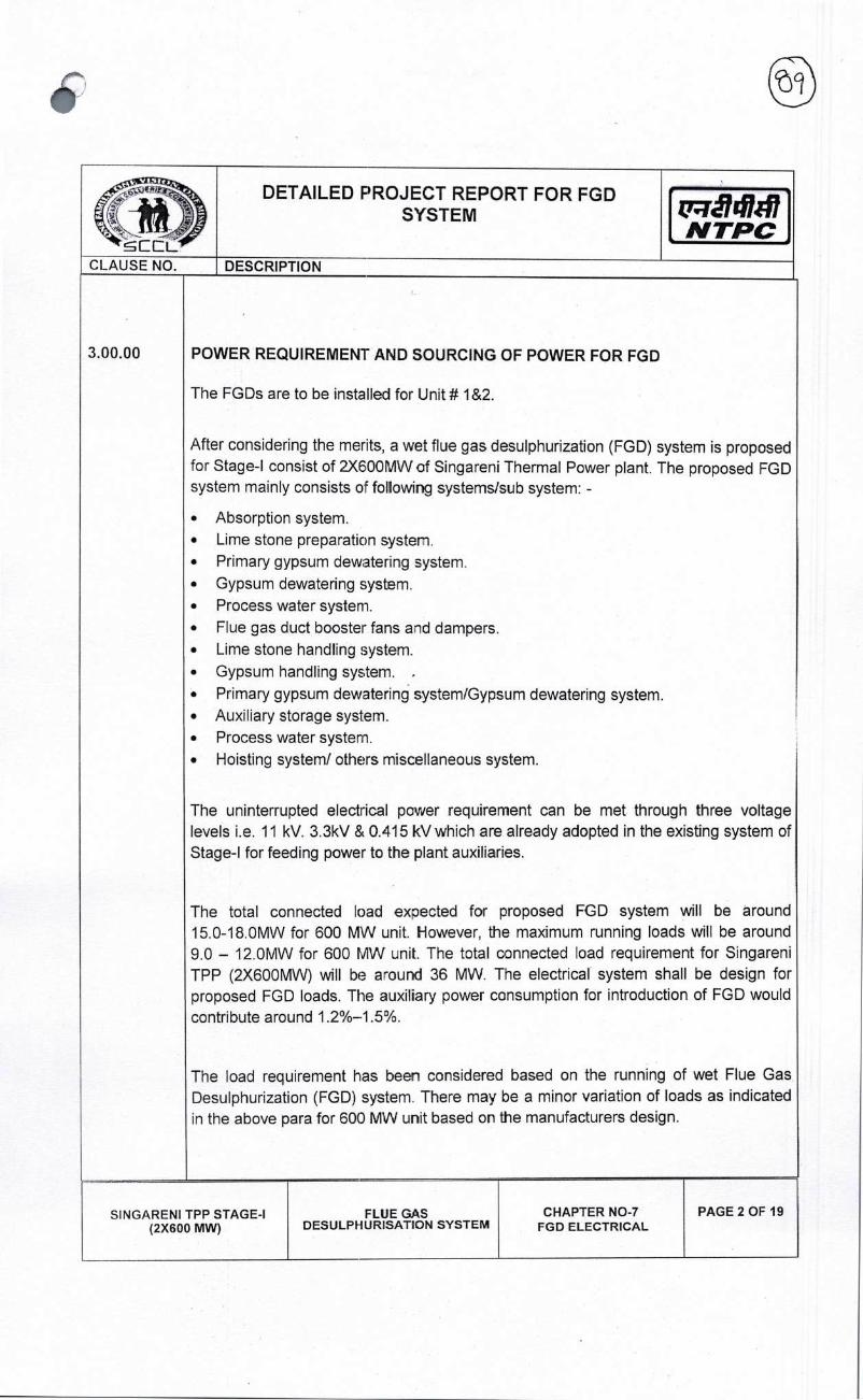
DETAILED PROJECT REPORT FOR FGD SYSTEM
NTPC CLAUSE NO. DESCRIPTION
3.00.00 POWER REQUIREMENT AND SOURCING OF POWER FOR FGD
The FGDs are to be installed for Unit# 1&2.
After considering the merits, a wet flue gas desulphurization (FGD) system is proposed for Stage-I consist of 2X600MW of Singareni Thermal Power plant. The proposed FGD system mainly consists of following systems/sub system: -
• Absorption system. • Lime stone preparation systen. • Primary gypsum dewatering system. • Gypsum dewatering system. • Process water system. • Flue gas duct booster fans a-id dampers. • Lime stone handling system.
• Gypsum handling system.
• Primary gypsum dewatering system/Gypsum dewatering system. • Auxiliary storage system. • Process water system. • Hoisting systemf others miscellaneous system.
The uninterrupted electrical power requirement can be met through three voltage levels i.e. 11 kV. 3.3kV & 0.415 kVwhich are already adopted in the existing system of Stage-I for feeding power to the plant auxiliaries.
The total connected load exected for proposed EGO system will be around 15.0-18.0MW for 600 MW unit. However, the maximum running loads will be around 9.0 - 12.0MW for 600 MW unit. The total connected load requirement for Singareni TPP (2X600MW) will be around 36 MW. The electrical system shall be design for proposed EGO loads. The auxiliary power consumption for introduction of FGO would
contribute around 1.2%-i .5%.
The load requirement has been considered based on the running of wet Flue Gas Desulphurization (FGD) system. There may be a minor variation of loads as indicated in the above para for 60(J MW unit based on the manufacturers design.
SINGARENI TPP STAGE-I (2X600 MW)
FLUE GAS DESULPHURISATION SYSTEM
CHAPTER NO-7 FGD ELECTRICAL
PAGE 2 OF 19

D ci ID
iJ14i47 N TPC
FLUE GAS DESULPHURISATION SYSTEM
CHAPTER NO-7 FGD ELECTRICAL
PAGE 3 OF 19
DETAILED PROJECT REPORT FOR FGD SYSTEM
DESCRIPTION
( 7 -
CLAUSE NO.
4.00.00
The following power supply source has been identified as the best avaiiable option to meet the FGD power requirements.
Power Supply
To tap power from 11 kV Station Auxiliary Boards, 11kV Unit Auxiliary boards of Unit # 1&2 by utilizing existing spare feeders as a main supply. Spare feeders available in Unit boards shall be utilized for feeding the power supply to Booster fan motors. Spare feeders available in Station boards shall be utilized to meet the remaining power. 2 Nos of 11 KV/3.45KV transformers of adequate rating shall be used to feed the 3.3KV loads of respective units.
Power supply source I & 2 for all the common system of FGD of Stage-l&ll has been considered from Stage-I, hcwever after commissioning of Stage-li, the 2t source shall be shifted to Stage-Il Station Boards suitability.
Accordingly, scheme for sourcing of power FGD has been developed. Detail scheme is attached as EXHIBIT- El.
RETROFITTING I REPLACEMENT OF 11 kV BOARDS WORK
a) The nominal current rating of existing BHEL make (VM12) outgoing feeders of 11 kV Station Auxiliary Boards of Unit# 1&2 is 630A, which needs to be upgraded to meet the power recuirement of FGD. Scope shall include replacement I retrofitting of 2 (four) numbers 11 kV feeders identified for FGD with 1250 A CBs including associated items.
b) Scope shall also include necessary modification to be done in the existing transformer feeders in the Unit boards into motor feeders for utilizing them as Booster fan motor feeders including change of relays.
c) Energy meters shall be provided in all above feeders (2 Nos. of feeders in the existing Station board from where FGD power other than booster fan shall be tapped and Boosi:er fan Motor feeders in Unit board) for energy accounting purpose. The energy meters shall be microprocessor based. MWH meters having an accuracy class of 0.2 or better. The energy meters supplied under this package shall be integrated with existing metering master station in control room.
SINGARENI TPP STAGE-I (2X600 MW)

1 ccL.
DETAILED PROJECT REPORT FOR FGD SYSTEM
NTPC CLAUSE NO. DESCRIPTION
PROPOSED SYSTEM I EQUIPMENT REQUIREMENT
The following system is proposed for design, engineering, manufacture, Type testing and inspection at manufacturer's works, packing, supply, transportation, transit insurance, delivery to site ncIuding custom clearance/port clearance (if required), receipt & unloading, handling & storage, in plant transportation, erection including associated civil, structural and architectural works, Testing & commissioning of the complete equipment' system and works of following: -
• 11/3.45 kV FGD Transformers • 11/0.433 kV FGD Auxiliary transformers • HT Switchgears • LT Switchgears • HT< Drives/Motors • DC system — Battery and Battery Charger • Cables, Cabling, Earthing, Ughtning Protection etc. • Indoor & outdoor Lighting etc. • Control & Protection system • VFD • DGSet • Other Associated electrical system
(Bill of Quantity for electrical system is attached at end of this chapter)
PROPOSED SYSTEM I EQUIPMENT DESCRIPTION
General Philosophy of Electrical System Design, Short Circuit Levels and Withstand Duration, Sizing criterion of equipment, Auxiliary Power Supply Schemes, MV & LT System, AC & DC Emergency Power Supply System, Technical Features and Parameters of Electrical System to be Provided for proposed FGD system are described in brief for the purpose of detailed project report (DPR) are as under: -
GENERAL
a) The proposed typical scheme shall be as per the Exhibit-El Titled 'Single line diagram for FGD Auxiliary Power Distribution"
b) For the purpose of design of equipmertlsystems, an ambient temperature of 50 deg. Centigrade and relative humidity of 95% shall be considered.
c) The equipment shall operate in a highly polluted environment. d) All equipment shall be suitable for rated frequency of 50Hz with a variation of
+3% & -5%, and 10% combined variation of voltage and frequency.
5.00.00
6.00.00
6.0100
SINGARENI TPP STAGE-I (2X600 MW)
FLUE GAS DESULPHURISATION SYSTEM
CHAPTER NO-7 FGD ELECTRICAL
PAGE 4 OF 19

N TPC
DETAILED PROJECT REPORT FOR FGD SYSTEM
CLAUSE NO. DESCRIPTION
6.02.00 EQUIPMENT LAYOUT CRITERIA
The following clearances to be maintained for control panels/cabinets:
a) Inter panel spacing 1200mm
b) Clearance from back 1000mm
c) Clearance from front - 1000mm
d) Clearance from side wall - 1000mm
The above clearances are minimum requirement and may increase with increase in door swing of the cabinets.
2. The cable vault space below the HT LT switchgear room and Control Room shall have 800 mm wide and 2.lm high movement passage all around the cable trays in the cable vault / cable spreader room for easy laying/maintenance of cables.
3. Adequate distance shall be maintained between the transformers. As basic guidelines following norms will be adhered to:
a) Power transformers shall be separated from the adjacent building /structures and from each other by a minimum distance as defined below or by a fire wall of two hours of fire resisting of heht at least 600 mm above bushing / pressure relief vent whichever is nigher.
Oil capacity of individual transformer Clear separating distance
(in litres) (in Meters)
5,000to 10,000 8.0
10,001 to 20,000 10.0
20,001 to 30,000 12.5
Over 30,001 15.0
In case of auxiliary transformers havirg an aggregate oil capacity in excess of 2000 liters, the minimum separatirg distance between transformers and surrounding building shall be at least 6M unless they are separated by fire separating walls. For transformers rated above 10 MVA or transformers having an aggregate oil capacity in exzess of 2000 liters, high velocity water spray system or nitrogen-based injecticn system shall be employed.
4. Layout requirements for Electrical MCC/switchgear rooms. The following
clearances shall be maintained for HT Switchboard.
a. Front Clearance
i) For one Row of Swgr. 2.OM (Mm)
SINGARENI TPP STAGE-I (2X600 MW)
FLUE GAS DESULPHURISATICN SYSTEM
CHAPTER NO-7 FGD ELECTRICAL
PAGE 5 OF 19
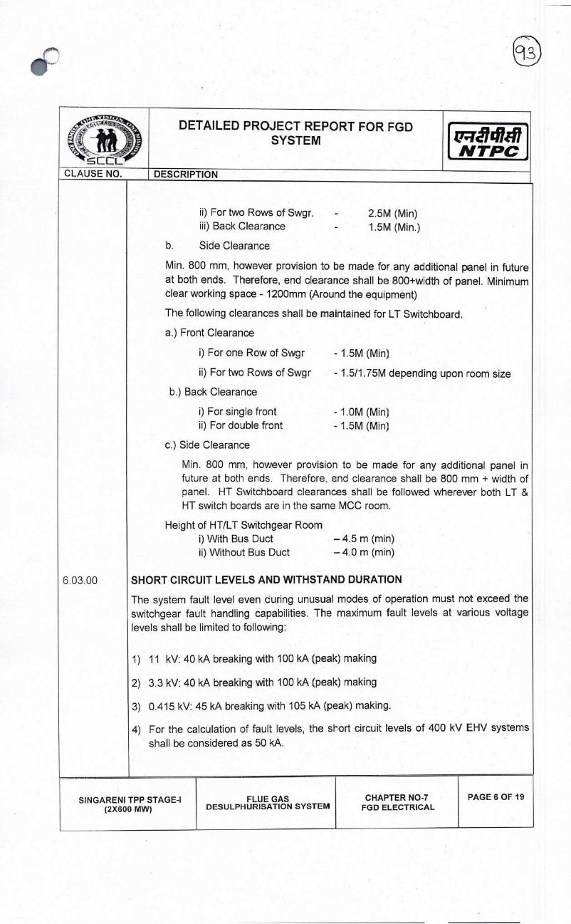
d14h#7 NTPC
DETAILED PROJECT REPORT FOR FGD SYSTEM
ii) For two Rows of Swgr. 2.5M (Mm) iii) Back Clearance 1.5M (Mm.)
b. Side Clearance
Mm. 800 mm, however provision to be made for any additional panel in future at both ends. Therefore, end clearance shall be 800+width of panel. Minimum clear working space - 1200mm (Around the equipment)
The following clearances shall be maintained for LI Switchboard.
a.) Front Clearance
I) For one Row of Swgr - 1.5M (Mm)
ii) For two Rows of Swgr - 1.5/1.75M depending upon mom size
b.) Back Clearance
i) For single front - 1.OM (Mm) ii) For double front - 1.5M (Mm)
c.) Side Clearance
Mm. 800 mm, however provision to be made for any additional panel in future at both ends. Therefore, end clearance shall be 800 mm + width of panel. HI Switchboard clearances shall be followed wherever both LT & HT switch boards are in the same MCC room.
Height of HT/LT Switchgear Room I) With Bus Duct —4.5 m(min) ii) Without Bus Duct — 4.0 m (mm)
6.0300 SHORT CIRCUIT LEVELS AND WITHSTAND DURATION
The system fault level even curing unusual modes of operation must not exceed the switchgear fault handling capabilities. The maximum fault levels at various voltage levels shall be limited to following:
1) 11 kV: 40 kA breaking with 100 kA (peak) making
2) 3.3 kV: 40 kA breaking with 100 kA (peak) making
3) 0.415 kV: 45 kA breaking with 105 kA (peak) making.
4) For the calculation of fault levels, the shod circuit levels of 400 kV EHV systems
shall be considered as 50 kA.
FLUE GAS DESULPHURISATION SYSTEM
CHAPTER NO-7 FGD ELECTRICAL
PAGE 6 OF 19
SINGARENI TPP STAGE-I (2X600 MW)

cc CLAUSE NO.
Qiã14h47 N TPC
DETAILED PROJECT REPORT FOR FGD SYSTEM
DESCRIPTION
The different equipment shall be sized for the following through fault withstand capabilities:
o Aux. transformers (11/0.433 kV, 11/3.45 kV): 2 seconds
o 11 kVbusduct 1 second
o 3.3 kV bus duct I second
o Cables to the feeders protected by breakers - Main protection fault clearing time with 0.12 seconds minimum
o Cables for all other feeders - As per the fault clearing time of fuses.
o 11 kV / 3.3 kV cables sheath 2 seconds for adopted ground fault current
o The switchgear, motor control centers and distribution boards shall have positive, fool-proof interlocking to ensure that different supplies and transformers are not operated in parallel and faut level does not exceed the switchgear capability except during momentary paralleling in case of on-load changeover.
o DCDB 2C) KA for 1 second
6.04.00 H.T. SWITCHGEAR
Switchgears shall be indoor, metal clad draw out type with Vacuum Breakers. Contractors cum fuse units may be used for auxiliaries such as conveyors/crushers motors, which require comparatively freauent switching. The switchgears shall have Communicable Numerical Relay for protection, control, metering and monitoring of the Switchgears. All the relays shall be networked to a dedicated HMI through data concentrator for Monitoring and Supervision of all the breaker panels.
MV switchgears shall be of 11 kV and 3.3 kV Voltage levels. The Switchgears shall be Indoor, Metal clad, single ront and fully compartmentalized, with degree of protection 1P42 for breaker/contactor compartment and 1P52 for metering/relay compartments.
All busbars shall be color coded. All busbars shall be provided with non-halogen based heat shrinkable polymer sleeves having excellent performance in high voltage environments and reduces the noxious and corrosive effects in fire situations. Busbar sleeves shall be of tested design as per relevant lEC/ASTM/equivalent standard.
The designed fault level for 11 kV, 3.3 kV system shall be restricted to 40 KA (rms) for I Sec. The Switchgears shall have an Internal Arc Classification of AC FLR 40kA, 1
SINGARENI TPP STAGE-I (2X600 MW)
FLUE GAS DESULPHURISATION SYSTEM
CHAPTER NO-7 FGD ELECTRICAL
PAGE 7 OF 19

t'1417 NTPC
DETAILED PROJECT REPORT FOR FGD SYSTEM
DESCRIPTION CLAUSE NO
sec. Surge arresters are provided for all motor feeders to limit the switching over voltages (unipolar). Suitable Interlocks are provided to ensure that Breaker is off before opening the back doors.
Circuit Breakers shall be Vacuum type. They comprise of three separate identical single pole interrupting units operated through a common shaft by a sturdy mechanism. Outgoing Breakers are suitable for Switching transformers and motors at any load and shall be suitable for frequent direct-on-line starting of squirrel cage induction motors.
The high voltage contactors shall be of AC-3 utilization category and shall be vacuum type. The fuse and overload relay shall be fully coordinated, so that the contactor operate only for a fault current less than its interrupting capability. The fuses shall have mechanical trip indication. Surge suppressors shall be provided on all contactor controlled motor feeders.
Protection and Con1rols: For protection, control, metering & diagnostics Communicable Numerical relays shall be provided for automation of MV Switchgears. The various Breakers that sha I be automated are:
11 kVI3.3 kV lncomers
Outgoing MV/LV Transformers Breakers
Tie Breakers
Bus Couplers
Bus Transfers & Synchronization
LT lncomers
LTTie Feeders
LT Bus Couplers
LT Outgoing Feeders (Breaker Controlled)
For various feeders including motor feeder numerical relays (Protection units) are proposed and these units shall communicate remotely to PLC/DDCMIS. For Motor
feeders process interlocks!logics are developed in PLC/DDCMIS only.
SIN GARENI TPP STAGE-I (2X600 MW)
FLUE GAS DESULPHURISATION SYSTEM
CHAPTER NO-7 FGD ELECTRICAL
PAGE 8 OF 19
I
:rL

CEL
DETAILED PROJECT REPORTFORFGD SYSTEM
CLAUSE NO. DESCRIPTION
b) The numerical relays proposed shall be of latest version and shall have integrated protection features of all type of protections, control. and metering, self-ciagnosis, MIS for remote locatiors and interface with MMI.
c) There are technical and economical, operational and maintenance advantages of the proposed autornaton system with Numerical relays. Technically the system offers more functionality (with respect to both protections as well as Control), self-diagnostic checks, reliability, trending and monitoring, ease of operation and more flexible engineering. Economically the system wil reduce extensive cabling, reduced cost of maintenance and operations and less down times. The number of CTs/ VTs and their VA burden will also be reduced. The adoption of numerical relays may also reduce the overall height of the Switchgears.
d) Standard IEC 61850 is proposed for communications as it shall allow making HMI an independent subsystem connected to the automation structure through a standard communication interface. lEO 61850 shall take care of multi-vendor lEDs.
Numerical relays with communicable features shall be procured with the following applications:
e) Protection, metering and control schematics, presently being hard wired within individual breaker panel shall be configured at relay level utilizing control and communication features of the relays.
f) All the relays shall be networked to a dedicated switchgear SCADA HMI through data concentrator for Monitoring and supervision of all the breaker panels. All such data flow shall be linked to 000MIS as well througi switchgear SCADA System. The circuit breaker wil normally be controlled from remote control panels (DDCMIS) through closing and shunt trip coils. However, for motor feeders, process interlocks/logics are developed in 000MIS only.
g) Breaker and relay contacts shall be hard wired to DDCMIS for building board wise
logics as being done presently.
BUSDUCT
The busduct will have on all aluminium construction. The busduct shall be natural air cooled. The degree of protection shall be IP-55. Segregated phase bus ducts are envisaged for connecting between MV service transformer and 3.3 kV Switchgear. Non-segregated phase bus ducts are envisaged for connecting between LV service Transformer and 415 V FCC/MOO If Transformer Rating is
1000 kVA and above.
6.05.00
SINGARENI TPP STAGE-I (2X600 MW)
FLUE GAS DESULPHURISATION SYSTETV1
CHAPTER NO-7 FGD ELECTRICAL
PAGE 9 OF 19

FLUE GAS DESULPHURISATION SYSTEM
CHAPTER NO-7 FGD ELECTRICAL
PAGE 10 OF 19
N TPC
FGD TRANSFORMERS I AUXILIARY TRANSFORMERS
FGD Main Transformers and Auxiliary Transformers shall be as per Electrical Single Line Diagram FGD System Org attached as Exhibit-El and as per system requirement under most onerous conditions, with the criteria that eac- 415 V switchgear / MCC I OB shall be fed by 2x100% or 3 X 50 % transformers / feeders, and these shall be rated to carry the maximum load expected to be imposed.
All Auxiliary transformers (1 1/0.433 kV, 111345 kV) shall be sized so as to have 10% margin at design ambient conditions after considering final load requirements at peak load conditions and the No Load Voltage Correction Factor.
All these transformers will be delta connected on the HT side and star connected on the LT/MV side. The LT (0.433 kV side) star point will be solidly earthed. The MV (3.45 kV side) star point will be earthed through resistance to limit the ground fault current to 300A. These transformers shall be mineral oil filled for outdoor installation, dry type transformer forced cooling with temperature controller for indoor installations.
No Load Voltage Correction Factor (=Transformer No Load voltage/ rated bus Voltage) shall be used for sizing of al transformers i.e.
The transformer size = the calculated size X no load voltage correction factor
Rating of the transformers shown in the SLD are indicatve.
MOTORS
All motors are required to have a voltage within permissible limits both during starting and during normal running. In line with 500MW unit size practice, the standard three voltage level scheme i.e. 11 kV, 3.3 kV & 415V system has been adopted. All equipment's shall be suitable for rated frequency of 50 Hz with a variation of +3% & - 5%, and 10% combined variation of voltage and frequency
6.06.00
6. 07.00
i) Auxiliary power system shall be designed in such a way that, voltage variation at different voltage levels do not exceed the limits given below under worst operating conditions at equipment terminal.
ii) HT and LT Motors shall be designed to operate in this specified voltage
variation:
SINGARENI TPP STAGE-I (2X600 MW)
DETAILED PROJECT REPORT FOR FGD SYSTEM
DESCRIPTION CLAUSE NO.

Itf1JJ C.c:L
DETAILED PROJECT REPORT FOR FGD SYSTEM
NTPC CLAUSE NO. DESCRIPTION
Motor rating Voltage drop (Under normal Running)
Starting Voltage requirement (Mm) at motor terminal
Below 110KW 10% 85%
AbovellO KW to 200 KW
10% 80%
201 KW to 1000 KW
6% 85%
1001 KW to 4000 KW
6% 80%
Above 4000 KW 6% 75%
Further as motor driving the essential and vital station and unit auxiliaries on which operational reliability of power plant depends, shall run continuously at rated output with voltage variation as described above. Motors shall not stall due to voltage dips in the system causing momentary drop in voltage to 70% of the rated value for a duration of 2 seconds. Motors shall withstand the application of 150% of the rated voltage for at least 1 second caused due to vector difference between the residual voltage and incoming supply voltage during changeover of buses. The motors shall be capable of withstanding the inrush current caused by such bus transfer without damage.
The voltage level for motors shall be as follows:
a) Uptoo.2KW
b) Above 0.2 KW and up to 200 KW c) Above 200 KW and up to 1500 KW d) Above 1500 KW
Single phase 240V AC I 3 phase, 415VAC 3 phase, 41SVAC 3 phase, 3.3 kV AC 11 kV
Motors shall have lF-54 degree of protection for Indoor motors location and IP-55 for Outdoor location. The All motors shall be either totally enclosed fan cooled (TEFC) or totally enclosed tube ventilated (TETV) or Closed air circuit air cooled (CACA) type. TETVI CACA type shall be provided with shaft mounted fans only. However, Motors rated 3000KW or above can be closed air circuit water cooled (CACW). Motors and EPB located in hazardous areas shall have flame proof enclosures
All HT Motors shall have thermal insulation class 'F' and 240 Volts AC, 415 V AC and 220 V DC motors shall be thermal class B or better with temperature rise limited to 70
SIN GARENI TPP STAGE-I (2X600 MW)
FLUE GAS DESULPHURISATION SYSTEM
CHAPTER NO-i FGD ELECTRICAL
PAGE 11 OF 19
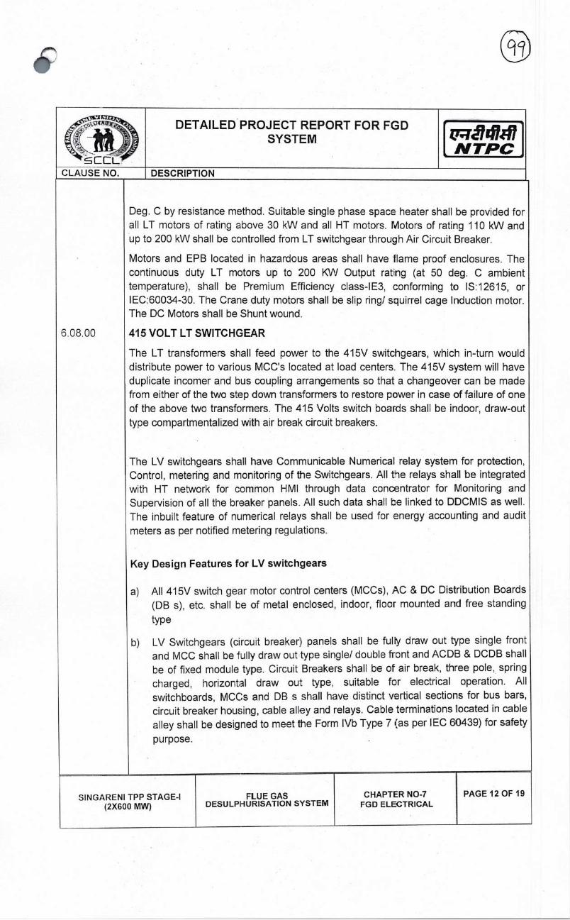
,NTPC
DETAILED PROJECT REPORT FOR FGD SYSTEM
6.08,00
Deg. C by resistance method. Suitable single phase space heater shall be provided for all LT motors of rating above 30 kW and all HT motors. Motors of rating 110 kW and up to 200 kW shall be controlled from LT switchgear through Air Circuit Breaker.
Motors and EPB located in hazardous areas shall have flame proof enclosures. The continuous duty LT motors up to 200 KW Output ratng (at 50 deg. C ambient temperature), shall be Premium Efficiency class-1E3, conforming to IS:12615, or IEC:60034-30. The Crane duty motors shall be slip ring! squirrel cage Induction motor. The DC Motors shall be Shunt wound.
415 VOLT LI swITcHc;EAR
The LT transformers shall feed power to the 415V switcligears, which in-turn would distribute power to various MCC's located at load centers. The 415V system will have duplicate incomer and bus coupling arrangements so that a changeover can be made from either of the two step down transformers to restore power in case of failure of one of the above two transformers. The 415 Volts switch boards shall be indoor, draw-out type compartmentalized with air break circuit breakers.
The LV switchgears shall have Communicable Numerical relay system for protection, Control, metering and monitoring of the Switchgears. All tie relays shall be integrated with HT network for common HMI through data concentrator for Monitoring and Supervision of all the breaker panels. All such data shall be linked to DDCMIS as well. The inbuilt feature of numerical relays shall be used for energy accounting and audit
meters as per notified metering regulations.
Key Design Features for LV switchgears
a) All 415V switch gear motor control centers (MCCs), AC & DC Distribution Boards (DB s), etc. shall be of metal enclosed, indoor, floor mounted and free standing
type
b) LV Switchgears (circuit breaker:) panels shall be fully draw out type single front and MCC shall be fully draw out type single! double front and ACDB & DCDB shall be of fixed module type. Circuit Breakers shall be of air break, three pole, spring charged, horizontal draw out type, suitable for electrical operation. All switchboards, MCCs and DB s shall have distinct vertical sections for bus bars, circuit breaker housing, cable alley and relays. Cable terminations located in cable alley shall be designed to meet the Form lVb Type 7 (as per IEC 60439) for safety
purpose.
FLUE GAS DESULPHURISATION SYSTEM
CHAPTER NO-7 FGD ELECTRICAL
PAGE 12 OF 19
SIN GARENI TPP STAGE-I (2X600 MW)

t7rã741#7 N TPC
DETAILED PROJECT REPORT FOR FGD SYSTEM
DESCRIPTION
The cross-section of the bus bars shall be uniform throughout the length of switchboard and both horizontal as well as vertical bus bars shall be adequately supported and braced to withstand the stresses due to the specified short circuit currents. The bus bars for switchboards with a rating of more than 1600A shall have an interleaving arrangement.
The entire bus-bar system of all switchgears, MOOs, ACDBs, DCDBs and fuse boards shall be PVC sleeve insulated.
CRITERIA FOR AUXILIARY POWER SUPPLY ARRANGEMENT 609.00
The auxiliary power supply system must form a reliable source of power for FGD auxiliaries The requirements to be met by the auxiliary system are as follows: -
a) The auxiliary power supply system shall be desigred with suitable margin to enable the satisfactory operation of the system with voltage and frequency limits as defined.
The overall system shall be such that failure of any piece of equipment has the minimum possible effect on the plants capability. In particular failure of a transformer, section of LT or HT switchgear, DC battery or charger shall not reduce the plant's capability or affect the safe shut down requirements of the plant.
The loads for mechanical auxiliary systems i.e. material handling, water systems etc. shall be met by auxiliary transformers based on the criteria that each switchgear/MCC/Distribution board shall be fed either by 2x100% or 3x50% transformers/feeders and, these shall be rated to carry the maximum load expected to be imposed. Each of the above boards shall be sectionalized.
d) As far as practicable the system shall provide segregated supplies to main and standby auxiliaries so that failure of supply to main auxiliary shall in no way jeopardize the standby auxiliary feed. Automatic changeover at critical switchg ear/ MOO sections shall be provided as necessary to prevent the loss of a
unit or to ensure the equipment safety.
e) The switchgear, motor control centers and distribution boards shall have positive, fool-proof interlocking to ensure that different supplies and transformers are not operated in parallel and fault level does not exceed the switchgear capability
except during momentary paralleling in case of on-load changeover.
All equipment such as sMtchgear & all transformers shall be sized so as to have
SINGARENI TPP STAGE-I (2X600 MW)
FLUE GAS DESULPHIJRISATION SYSTEM
CHAPTER NO-7 FGD ELECTRICAL
PAGE 13 OF 19
c cL CLAUSE NO.
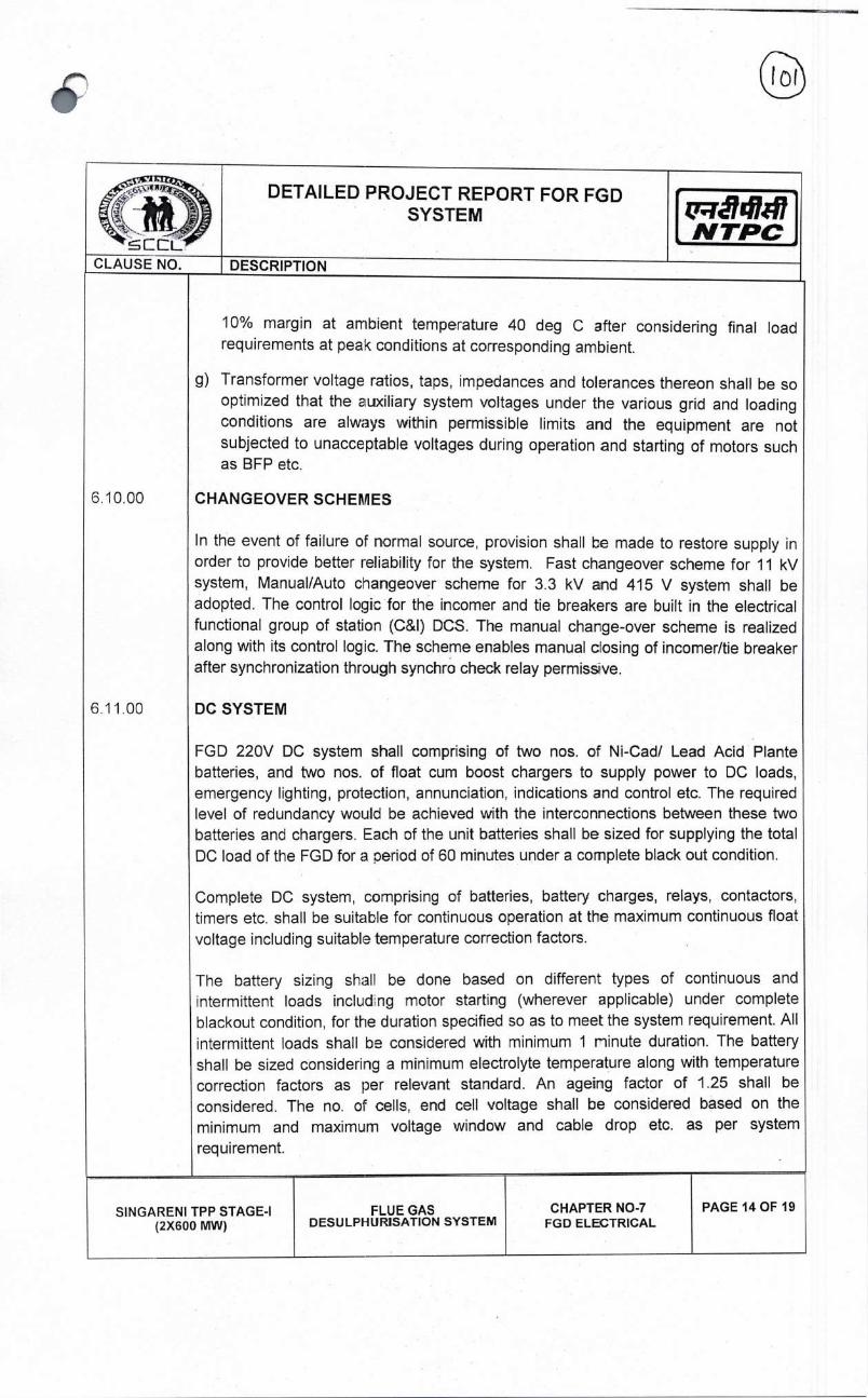
DETAILED PROJECT REPORT FOR FGD SYSTEM
L?1J14141 N TPC
CLAUSE NO.
DESCRIPTION
10% margin at ambient temperature 40 deg C after considering final load requirements at peak conditions at corresponding ambient.
Transformer voltage ratios, taps, impedances and tolerances thereon shall be so optimized that the auxiliary system voltages under the various grid and loading conditions are always within permissible limits and the equipment are not subjected to unacceptable voltages during operation and starting of motors such as BFP etc.
6.10,00 CHANGEOVER SCHEMES
In the event of failure of normal source, provision shall be made to restore supply in order to provide better reliability for the system. Fast changeover scheme for 11 kV system, Manual/Auto changeover scheme for 3.3 kV and 415 V system shall be adopted. The control logic for the incomer and tie breakers are built in the electrical functional group of station (C&l) DOS. The manual charge-over scheme is realized along with its control logic. The scheme enables manual closing of incomer/tie breaker after synchronization through synchro check relay permissve.
6.11.00 DC SYSTEM
FGD 220V DO system shall comprising of two nos. of Ni-Cad! Lead Acid Plante batteries, and two nos. of float cum boost chargers to supply power to DO loads, emergency lighting, protection, annunciation, indications and control etc. The required level of redundancy would be achieved with the interconnections between these two batteries and chargers. Each of the unit batteries shall be sized for supplying the total DC load of the FGD for a oeriod of 60 minutes under a complete black out condition.
Complete DC system, comprisng of batteries, battery charges, relays, contactors, timers etc. shall be suitable for continuous operation at the maximum continuous float voltage including suitable temperature correction factors.
The battery sizing shall be done based on different types of continuous and intermittent loads includ ng motor starting (wherever applicable) under complete blackout condition, for the duration specified so as to meet the system requirement. All intermittent loads shall be considered with minimum 1 ninute duration. The battery shall be sized considering a minimum electrolyte temperature along with temperature correction factors as per relevant standard. An ageing factor of 1 .25 shall be considered. The no. of cells, end cell voltage shall be considered based on the minimum and maximum voltage window and cable drop etc. as per system
requirement.
SINGARENI TPP STAGE-I (2X600 MW)
FLUE GAS DESULPHURJSATION SYSTEM
CHAPTER NO-7 FGD ELECTRICAL
PAGE 14 OF 19

DETAILED PROJECT REPORT FOR FGD SYSTEM
DESCRIPTION
iiã14147 NTPC
Each system shall comprise of two nos. of batteries and two nos. of float-cum-boost chargers each rated for 100% capacity. DC scheme shall ensure that each critical consumer is fed from two different bus sections. DCDBs shall provide adequate number of feeders on each section.
Boost! fast charging time shal be as per worst operating condition and would satisfy technical requirements recommended by battery manufacturer. Each battery charger must be capable of supplying all the continuous D.C. loads (fed through both section of DCDB) plus the trickle charging current of both the batteries. In addition. each charger must have sufficient surplus capacity for running of the largest D.0 auxiliary so that the battery is not drained during testing of the same. Battery charger should also be capable of boost! fast charge the battery from completely discharged condition to fully charged condition without imposing any limitations under worse operating conditions.
DC Health Monitoring Systems shall be provided to monitor the condition of each battery cell of 220V battery banks on-line on 24x7 basis. With DC Health Monitoring System, it shall be possible to measure & analyze the individual cell and battery parameters so that any damage to battery shall be prevented by pro-active maintenance.
EMERGENCY POWER SUPPLY SYSTEM 6.12.00
For the safe shutdown of the plant under emergency condition and in case of total power failure, diesel generating set shall be installed for feeding certain essential applications like battery chargers, emergency lighting, essential air conditioning/ventilation and all auxiliaries necessary for safe operation of plant (such as lime slurry tank agitators, oxidation agitators. Etc). The FGD emergency switchgear section shall be fed by one diesel generator of adequate capacity.
One no. Diesel Generator (DG) shall be provided as indicated in the single line diagram and sizing of DC set shall be to suit the emergency FGD loads.
DG set shall be 415 V, 1500 RPM and Engine BHP rating shall be Limited time running
( LTP ) rated Engine as per ISO 8528-1. DG set shall be provided with acoustic enclosure. DG set shall start automatically in case of power failure of AC power.
DG set including stack height, acoustics, air emission and fuel oil installation shall meet the requirement given by gazette notffications of Ministry of Environment & Forest time to time CPCB guidelines, all statutory requirement of Govt. of India and State Pollution
Board Guidelines.
SINGARENI TPP STAGE-I (2X600 MW)
FLUE GAS DESULPHURISATION SYSTEM
CHAPTER NO-7 FGD ELECTRICAL
PAGE 15 OF 19
CLAUSE NO.

DETAILED PROJECT REPORT FOR FGD SYSTEM
DESCRIPTION
r141#7 NTPC
PROTECTIVE RELAYING
The necessary protective relaying system according to established norms shall be
provided for HV switchyard transformers, motors, auxiliary system etc., to minimize damage to equipment in case of fault and abnormal conditions. The summary of protection details to be provided for the equipment is given below:
FGD TRANSFORMER
1. Back-up over current protection on HV and LV side (5 iT).
2. Restricted earth fault protection (64R) on HV & LV side.
3. Back-up earth fault protection on LV side (51 N).
4. Bucholz relay, winding temperature, oil temperature and oil level alarm and trip.
5. Fire protection to trip it's HV side breaker.
6. Local breaker back up (or breaker failure) protection for the breaker on HV side of transformer.
7. Over fluxing protection (99T).
CABLES
6.13.00
6. 14.00
For HT cable, single core and three Core XLPE insu'ated cables with aluminium conductor would be employed. For 415 V and DC systems, singe core XLPE insulated cables with aluminium conductor would generally be used for higher current ratings and multicore XL.PE!PVC insulated cables with aluminium conductor would be used for lower ratings.
The cables shall be laid overhead! in trenches or directly buried. Inter plant cabling for main routes shall be laid on overhead trestles/pipe racks.
HT cable shall be suitable for Un-Earthed (UE) system. All control cables would be multicore, PVC insulated with copper conductors. The cables shall be laid overhead! in trenches or directly buried. Inter plant cabling for main routes shall be lad on overhead trestles/pipe racks. For HT cable, single core and three core Cross linked Poly Ethylene Insulation (XLPE) insulated cables with Aluminum conductor would be
employed.
All the cables shall be armored type with Flame Retardant Low Smoke (FRLS)
properties.
SINGARENI TPP STAGE-I (2X600 MW)
FLUE GAS DESULPHURISATION SYSTEM
CHAPTER NO-7 FGD ELECTRICAL
PAGE 16 OF 19
Cf:L CLAUSE NO

DETAILED PROJECT REPORT FOR FGD SYSTEM
DESCRIPTION
QTã14kI7 NTPC
FIRE PROOF CABLE SEALING SYSTEM
In order to restrict the prooagation of cable fire and spread of toxic smoke, the cable entry below control panels, cable penetration through walls, cables on the floors and cable entry above switchgears need to be sealed by fire seal system. Fire barriers shall also be provided to meet the segregation! separation requirements. The fire proof cable peretration seal system shall have minimum one hour fire resistance rating and shall fully comply with the requirement of BS:476 Part-8. The fire seal system shall be completely gas & smoke tight, mechanically stable and shall retain their integrity and perform satisfactorily ever after remaining in water for long period
GROUNDING
Buried grounding mats employing sjitable dia. MS rocs, shall be provided for HV switchyards, FGD area, pump house etc. for keeping the step and touch potential within safe limits. All the connections above the ground would be of galvanized steel.
The earthing system for plant and swftchyard shall be designed for a life expectancy of at least forty (40) years, for a system fault current of 50 cA for 1.0 sec. The minimum rate of corrosion of steel fcr selection of earthing conductor shall be 0.12mm per year. Grounding FGD plant, switchyard and other areas or buildings covered in the specification shall be provided in accordance with IS 3043, IS 2309, IEEE 80 and IEEE 665.
Interconnection of earthing grid of extended portion of FGD shall be connected with existing earth grid.
LIGHTING SYSTEM
Adequate lighting arrangement shall be made for the entire FGD plant employing lighting distribution boards, panels, LED Luminaires for the lighting of all the indoor & outdoor areas. However, for DC lighting, hazardous areas & aviation lighting etc. conventional type luminaries shall be used.
6.15.00
6,16. 00
6.17.00
Normal lighting of the plant will operate with the station AC supply. About 20% of these fixtures will also have arrangement for being fed from diesel generators on failure of station AC supply. Ernergercy DC lighting, which wi] normally be off, would be provided for all strategic locations.
SINGARENI TPP STAGE-I (2X600 MW)
FLUE GAS DESULPHURISATION SYSTEM
CHAPTER NO-7 FGD ELECTRICAL
PAGE 17 OF 19
iL C LAU SE NO.
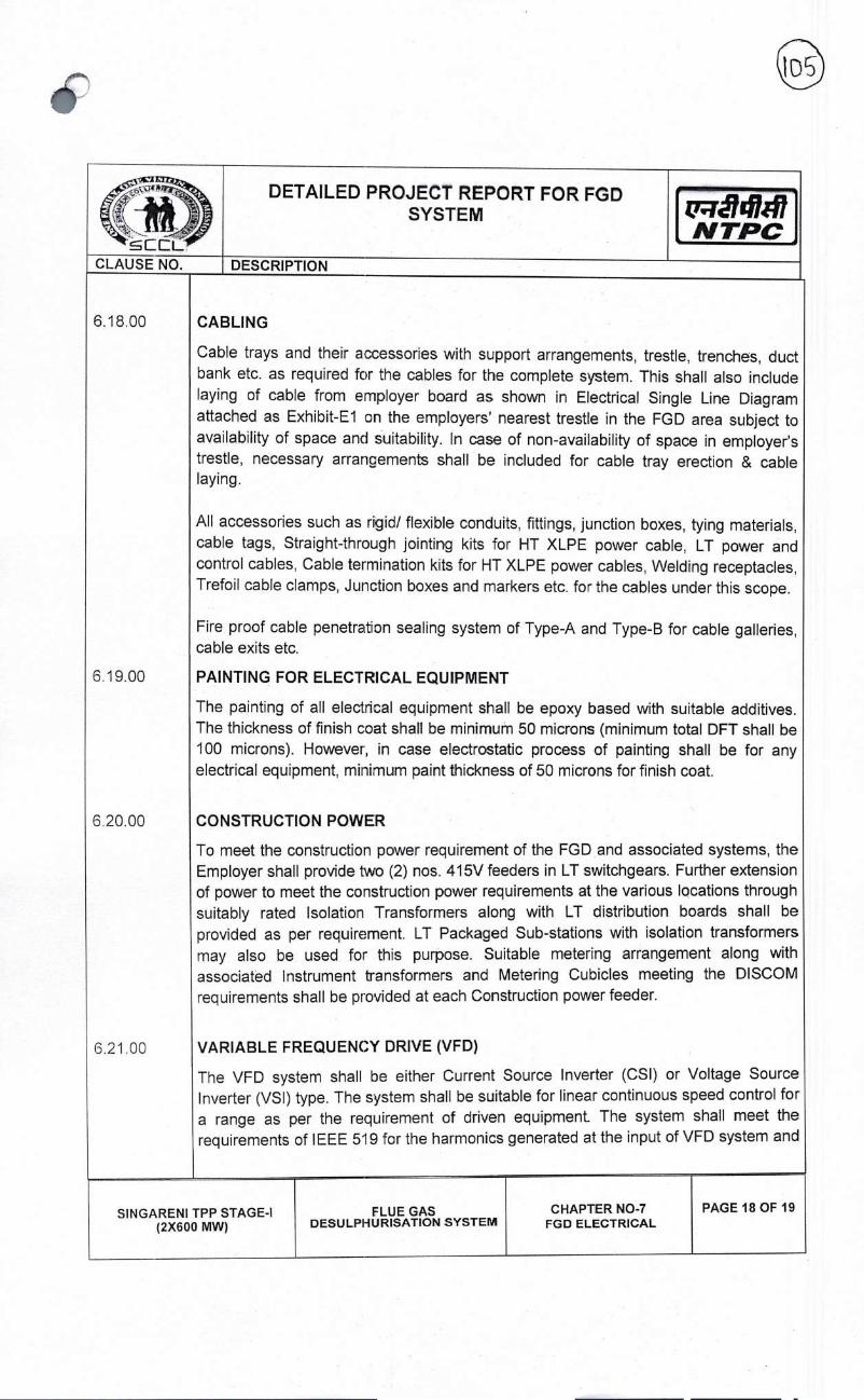
DETAILED PROJECT REPORT FOR FGD SYSTEM Q;i&4h47
N TPC CLAUSE NO. DESCRIPTION
CABLING
Cable trays and their accessories with support arrangements, trestle, trenches, duct bank etc. as required for the cables for the complete system. This shall also include laying of cable from employer board as shown in Electrical Single Line Diagram attached as Exhibit-El on the employers' nearest trestle in the FGD area subject to availability of space and suitability. In case of non-availability of space in employer's trestle, necessary arrangements shall be included for cable tray erection & cable laying.
All accessories such as rigid! flexible conduits, fittings, junction boxes, tying materials, cable tags, Straight-through jointing kits for HT XLPE power cable, LT power and control cables, Cable termination kits for HT XLPE power cables, Welding receptacles, Trefoil cable clamps, Junction boxes and markers etc. for the cables under this scope.
Fire proof cable penetration sealing system of Type-A and Type-B for cable galleries, cable exits etc.
PAINTING FOR ELECTRICAL EQUIPMENT
The painting of all electrical equipment shall be epoxy based with suitable additives. The thickness of finish coat shall be minimum 50 microns (minimum total DFT shall be 100 microns). However, in case electrostatic process of painting shall be for any electrical equipment, minimum paint thickness of 50 microns for finish coat.
CONSTRUCTION POWER
To meet the construction power requirement of the FGD and associated systems, the Employer shall provide two (2) nos. 415V feeders in LT switchgears. Further extension of power to meet the construction power requirements at the various locations through suitably rated Isolation Transformers along with LT distribution boards shall be provided as per requirement. LT Packaged Sub-stations with isolation transformers may also be used for this purpose. Suitable metering arrangement along with associated Instrument transformers and Metering Cubicles meeting the DISCOM requirements shall be provided at each Construction power feeder.
VARIABLE FREQUENCY DRIVE (VFD)
The VFD system shall be either Current Source Inverter (CSl) or Voltage Source Inverter (VS I) type. The system shall be suitable for linear continuous speed control for a range as per the requirement of driven equipment The system shall meet the requirements of IEEE 519 for the harmonics generated at the input of VFD system and
6.18.00
6.19.00
6.20.00
6.21.00
SIN GARENI TPP STAGE-I (2X600 MW)
FLUE GAS CHAPTER NO-7 DESULPHURISATION SYSTEM
PAGE 18 OF 19 FGD ELECTRICAL
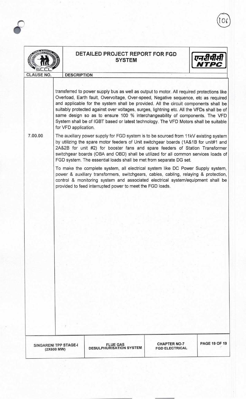
R77J14147 NTPC
CLAUSE NO.
DETAILED PROJECT REPORT FOR FGD SYSTEM
DESCRIPTION
7.00.00
transferred to power supply bus as well as output to motor. All required protections like Overload, Earth fault, Overvoltage, Over-speed, Negative sequence, etc as required and applicable for the system shall be provided. All the circuit components shall be suitably protected against over voltages, surges, lightning etc. All the VFDs shall be of same design so as to ensure 100 % interchangeability of components. The VFD System shall be of IGBT based or latest technology. The VFD Motors shall be suitable for VFD application.
The auxiliary power supply for FGD system is to be sourced from 11 kV existing system by utilizing the spare motor feeders of Unit switchgear boards (1A&IB for unit#1 and 2A&2B for unit #2) for booster fans and spare feeders of Station Transformer switchgear boards (OBA and OBD) shall be utilized for all common services loads of FGD system. The essential loads shall be met from separate DG set.
To make the complete system, all electrical system like DC Power Supply system, power & auxiliary transformers, switchgears, cables, cabling, relaying & protection, control & monitoring system and associated electrical system/equipment shall be provided to feed interrupted power to meet the FGD loads.
SINGARENI TPP STAGE-I (2X600 MW)
FLUE GAS DESULPHURISATION SYSTEM
CHAPTER NO-7 FGD ELECTRICAL
PAGE 19 OF 19

N TPC
DETAILED PROJECT REPORT FOR FGD SYSTEM
DESCRIPTION CLAUSE NO.
1.00.00
2.00.00
3.00.00
4.00.00
CHAPTER-8
FGD SYSTEM - CONTROL & INSTRUMENTATION
GENERAL
The function of the Control & Instrumentation System would be to aid the operator in achieving safe and efficient operation of the unit, resulting in cost effective operation of system. The C&l system would be of the type which normally relieves the operator of continuous duties and would take pre-planned corrective actions in case of drift in process or if unsafe trends or conditions develop in any regime of operation viz. startup, shutdown, normal working and emergency conditions. The design of C&I system would be such as to permit on-line localization, isolation and rectification of fault in the minimum possible time.
CONTROL ROOM CONFIGURATION & LAYOUT
It is proposed to have air-conditioned Common Control Room for the FGD Systems at appropriate place near FGD system with OWS/EWS. The control system cabinets would be located in air-conditioned Room. UPS, 24V DC Modular Power Supply would be located in the air conditioned environment. Batteries for UPS & 24 V modular power supply shall be located near FGD Control Room in air-ventilated environment.
CONTROL & MONITOFtING PHILOSOPHY
Control Desk (UCD) for mounting monitors / Keyboards (KBDs) would be provided.
In line with recent practices, Remote operation with OWS as well as GlU based local operation facility shall also be provided depending on the layout of the control room.
For DDCMIS based standalone FGD control system link shall be provided for exchange of data in the main plant control room for the information of unit-in-charge/shift-in-charge etc. through Station Wide LAN.
MEASURING INSTRUMENTS (PRIMARY & SECONDARY)
Primary measuring instruments such as transmitters, sensors etc. for the measurement of parameters like pressure, temperature, level, flow & CEMS (Continuous Emission Monitoring System) analyzers with associated items (S02/Nox/CO/CO2/02/Hg-Mercury'particulate matters analyzers & Flue gas flow etc) would be used.
All instruments in slurry lines shall be provided with isolation valves and diaphragm. All temperature elements shall be provided with Temperature Transmitters. Only Ultrasonic Level Transmitters shall be provided for slurry tanksfsumps. All pumps manual suction valves shall be provided with open limit switch. All slurry tanks shall be provided with field indicators for local level indications and other tanks shall be provided with level gauges for local level indications.
SIN GARENI TPP STAGE-I (2X600 MW)
FLUE GAS DESULPHURISATION SYSTEM
CHAPTER NO-8 CONTROL & INSTRUMENTATION
PAGE 1 OF 3

DETAILED PROJECT REPORT FOR FGD SYSTEM
NTPC
CLAUSE NO. DESCRIPTION
5.00.00
6.00.00
7.00.00
DISTRIBUTED DIGITAL CONTROL, MONITORING & INFORMATION SYSTEM (DDCMIS)
As already indicated above, microprocessor based Distributed Digital Control Monitoring & Information System (DDCMIS) would be provided for the safe, reliable and efficient operation of complete FGD system including all other accessories in package.
It is proposed to use optimum number of Monitors far the purpose of control, information and alarm monitoring as mentioned above. Each of the screens would be 100% interchangeable (i.e. control or monitoring for any part of the plant can be performed from any screen) and would provide complete control, monitoring, supervisory and display functions for control system variables and ccntrol system status. Changes in system configuration, tuning constants and similar engineering and maintenance functions would be done from Engineer/Programmer cDnsole.
Adequate numbers of printers would be provided for logs, reports and alarms. In addition to this, historical data storage and retrieval system would be provided.
Alarm Annunciation System and Sequence of Events Recording System (SERS) will be envisaged to be performed in DDCMIS itself. It is envisaged to provide alarm analysis system for the project.
POWER SUPPLY SYSTEM (UPS & DC SYSTEM)
Uninterrupted Power Supply (UPS) system to feed AC load like FGD Human Machine Interface (HMl). The UPS for FGD C&l system would consist of 2X100% parallel redundant Chargers and Inverters with Input Isolation Transformers, 1X100% Ni-Cd Battery Bank for one (1) hour duty, Bypass Line Transformers & Voltage Stabilizer, Static switch, manual bypass switch, 2X100% ACDB and other necessary protective devices and accessories.
Independent 24V DC modular DC power supply systems with Ni-Cd batteries shall be provided for FGD independent control system. Each set of power supply system shall consist of 2 sets with each comprising of lxl00% chargers, lxl00% Nickel-Cadmium batteries for one-hour duty, lxl00% DC distribution board (DCDB) for powering the DC load requirement of Contractor's system.
Intelligent Battery health management system (BHMS) shall be provided for each system of 24VDC power supply system and UPS batteries.
CONTROL VALVES, ACTUATORS & ACCESSORIES
Control valves and dampers would be pneumatically operated in most of the applications. However, for few applications electric/hydraulic actuators would be employed. Microprocessor based positioners shall be provided for pneumatic control valves and dampers.
SINGARENI TPP (2X600
STAGE-I MW)
FLUE GAS DESULPHURISATION SYSTEM
CHAPTER NO-8 CONTROL & INSTRUMENTATION
PAGE 2 OF 3

DETAILED PROJECT REPORT FOR FGD SYSTEM
't'r14147 N TPC
CLAUSE NO.
DESCRIPTION
8.00.00
9.00.00
INSTRUMENTATION CABLES
All instrumentation cables including both prefabricated and non-prefabricated type would be with Fire Retardant Low Smoke (FRLS) type Poly Vinyl Chloride (PVC) overall sheath. Multi pair cables of 0.5 sq. mm. shall be used extensively for C&l cables, wherever required, pre-fabricated cables may also be used.
INTERFACING OF FGD CONTROL SYSTEM WITH MAIN PLANT CONTROL SYSTEM
Hardwired Signal exchange: Hardwired signal exchange between main Plant Control system and FGD control system (to be located in FGD control room) like bypass damper status, inlet and outlet gates status, ID Fans status, ESPs status, Boiler Load Index (BLl), MFT etc. shall be envisaged on as required basis, for implementation of protections and interlocks. One Remote Input Output (RIO) per unit to be placed in Central Equipment Room (CER) for the same. lOs and cables for minimum number of hardwired signal exchange to be considered per unit as follows Dl — 130, DO — 130, Al — 50 and AO — 50 (approximately). Same number of I/Os shall be provided in main plant control system by employer for hard wired signal exchange with FGD control system. 2 (Two) nos. of 24V DC power supply feeders per unit from existing charger to be considered by employer, for powering said RIO panel to be located in CER. Cabling from DCDB to RIO panel shall be done.
1 0.00.00
DENOx CONTROL SYSTEM
To achieve NOx reduction, modification in Combustion system is proposed. Control for modified combustion system shall be done from employer's existing control system in main plant with some adcitionimodification in 110 cards to accommodate additional field instruments as per system requirements. Logic, alarms & HMI mimics shall also be modified accordingly in employer's control system. Change in SADC actuators, Instrument air piping, Burner tilt power cylinder, Filter regulators, flow elements, different instruments, cables, copper tubing, power supply etc. to be envisaged as per actual requirements during implementation.
SINGARENI TPP STAGE-I (2X600 MW)
FLuE GAS DESULPHURISATION SYSTEM
CHAPTER NO-8 CONTROL & INSTRUMENTATION
PAGE 3 OF 3

rã74h11 N TPC
FLUE GAS DESULPHURISATION SYSTEM
CHAPTER NO-9 LAYOUT REQUIREMENT
PAGE 1 OF 2
CLAUSE NO.
DETAILED PROJECT REPORT FOR FGD SYSTEM
DESCRIPTION
CHAPTER-9
LAYOUT REQUIREMENT
FOR FLUE GAS DESULFURIZATION SYSTEM
FGD system generally comprises of absorber and related auxiliaries and its upstream systems like lime stone handling, limestone milling. FGD also has other downstream systems like waste treatment & disposal, Gypsum handling & disposal. All these systems require necessary space in and around flue gas downstream area. Following are the major equipment in FGD system
MAIN EQUIPMENTS IN FGD AREA
1. Isolation Dampers for FGD 2. Booster Fans 3. Ductwork, Expansion joints and Duct supports 4. Absorber tank 5. Absorber recirculation pumps 6. Oxidation air blowers 7. Waste water tank 8. Neutralization tank 9. Auxiliary storage tank 10. Unloading hopper II. Vent Filter 12. Crushed Lime Stone Silos 13. Lime Stone Crusher House 14. Lime stone Slurry Tanks 15. Lime stor1e slurry pumps 16. Wet ball mill, mill recycle tank, mill recycle pump 17. Primary Hydrocyclone Classifier 18. Secondary Hydrocyclone classifier
19. Primary HC feed tank and pump
20. Secondary HO feed tank and pump
21. Belt filter wash pump 22. Mist Eliminator wash pump 23. Filtrate water tank
24. Vacuum Filter Tank
25. Vacuum Filter Pump 26. Makeup water tank (Process Water Tank)
27. Gypsum handling system
28. Gypsum storage area
29. ECW system
SIN GARENI TPP STAGE-I (2X600 MW)

FLUE GAS DESULPI-IURISATION SYSTEM
CHAPTER NO-9 LAYOUT REQUIREMENT
PAGE 2 OF 2
DETAILED PROJECT REPORT FOR FGD SYSTEM
N TPC
CLAUSE NO. DESCRIPTION
Area Requirement for FGD System 1. Unloading Hopper 19.0x10.5M
2. Transfer Tower 14.0x9.OM
3. Lime Stone Crusher House 16.5x18.OM
4. Crushed Lime Silo 13.5x13.5M
5. Wet Belt Mill Area 25.5x22.OM
6. Gypsum Storage Area 22.0x18.OM
7. Bed Filter Area 21.0x155M
8. Absorber Area(including reagent tank, 135x105M
make up water tank, pumps etc) for both units
9. MOO/Control Room 50x30.OM
10. Booster Fan Area for one unit 65.0x40OM
11. Electric control Room, Switchgear 40x20 M
Layout drawing is prepared and attached with report for installation of FGD system
Following drawings(tentative) has been also attached with the Report
S.no Drawing No Drawing layout
1 9972-999-POO-F-0O1 General Layout Plan
2 OONS-ENGG-9972-FGD-DPR-001 Layout plan of FGD system
3 CONS-ENGG-9972-FGD-DPR-002 Scheme of FGD absorber system
4 CONS-ENGG-9972-FGD-DPR-003 Scheme of FGD milling system
5 CONS-ENGG-9972-FGD-DPR-004 Scheme of Gypsum dewatering
system
6 CONS-ENGG-9972-FGD-DPR-005 Scheme of limestone handling system
7 OONS-ENGG-9972-FGD-DPR-006 Scheme of Gypsum handing system
8 OONS-ENGG-9972-FGD-DPR-007 Scheme of ECW system
9 CONS-ENGG-9972-FGD-DPR-008 Electrical single line diagram for FGD
auxiliary power distribution.
SINGARENI TPP STAGE-I (2X600 MW)

DETAILED PROJECT REPORT FOR FGD SYSTEM
_
NTPC CLAUSE NO. DESCRIPTION
1.00.00
2.00.00
CHAPTER-I 0
LOW NOX BURNERS
SCCL Stage-I (2X600 MW) was commissioned in the year 2016 and operation. The Boilers were originally designed for NOx level 260 750 mg/Nm3 and the measured value is almost near to the designed the Gazette notification dated 15.12.2015 the NOx level to be mg/Nm3. In order to reduce the NOx level Combustion Modification undertaken in both units of SCCL Stage-I (2X600 MW).
Combustion modification to be carried out as a part of furnace modification, would be required to reduce the NOx generation in combustion Combustion modification consists of replacing/modification the existing new redesigned wind box and installation of separator over fire air dampers. The objective of combusticn modification is to reduce the at required level during the combustion in boiler without effecting the steam and flue gas parameters, FEGT, SH and RH Sprays, unburnt formation and slagging, water wall corrosion due to reduced various loads, under various mills combination for the range of coals.
Major work involved in combustion modifications are
units are under gm/GJ (approx.
value. As per reduced to 300
is to be
which chamber.
wind box by panel along with NOx generated designed boiler
carbon, CO air atmosphere at
(SOFA) panel nozzle tips for all
Burner Tilt & its supports,
out combustion
300 mg/Nm3 entire range of
for whole range of air.
FEGT along the
to fly 0.5% respectively
Supply! modification 01: Wind Box with Separate Over Fire Air New/modified Re-designed Wind box including new coal, oil and air four corners, New Re-designed Tiling Tangential Burner Assembly, Power cylinders, Modification in coal piping, coupling Strengthening/modification of structure as required for carrying modification.
Major guarantees involved in combustion modifications are
(i) NOx emission : The total NOx at the ID Fan outlet shall not exceed at 6% oxygen (02) content in flue gas on dry gas basis over steam generator operation from 40% to 100% TMCR load and specified coal(s), with any mill combination, with mm 20% excess
(ii) Furnance Exit Gas Temperature (FEGT) : The variation in cross section shall be within +/- 20 deg C before and after modification.
(iii) Unburnt Carbon Loss : The variation in unburnt carbon in corresponding ash at ESP hoppers and Bottom ash shall be within +0.3% and before and after modification.
SINGARENI TPP STAGE-I (2X600 MW)
FLUE GAS DESULPHURISATION SYSTEM
CHAPTER NO-b LOW NOX BURNERS
PAGE 1 OF 2

LEL
DETAILED PROJECTREPORTFQRFGD SYSTEM
[CLAUSE NO. DESCRIPTION
The specification
salient Steam Generator design parameters at BMCR as per the original requirements are as foilows:
SI. no.
Description 100% BMCR
1. Steam flow at superheater Outlet (Tlhr)
1625
2. Pressure at Superheater outlet kg/cm2 (abs)
178
3. Temperature at Superheater outlet (Deg C)
540
4. Steam flow to Reheater(T/hr) 1354.2 5. Steam Pressure at RH inlet
Kg/cm2 (abs) 44.89
6. Steam temperature at RH inlet (Deg C)
336.3
7. Steam Temperature at Reheater Outlet (Deg C)
568
SINGARENI TPP STAGE-I (2X600 MW)
FLUE GAS DESULPHLJRISATION SYSTEM
CHAPTER NO-lU LOW NOX BURNERS
PAGE 2 OF 2

zyT14147 N TPC
DETAILED PROJECT REPORT FOR FGD SYSTEM
CLAUSE NO. DESCRIPTION
1.00.00
CHAPTER -11
LIMESTONE SOURCES IN INDIA
Limestone is a sedimentary rock composed mainlyof calcium carbonate (CaCO3)
in the form of the mineral calcite. The two most important constituents are calcite and dolomite. Limestone often contains magnesium carbonate, either as dolomite CaMg (003)2 or magnesite (MgCO3) mixed with calcite.
• Limestone rocks are composed of either calcium carbonate, the double carbonate of calcium and magnesium, or mixture of both.
• Limestone also contains small quantities of silica, alumina, iron oxides, phosphorus and sulphur.
• Limestone deposits are of sedimentary origin and exist in all the geological sequences from Pre-Cambrian to recent rocks except in Gondwana.
• Over three-fourths of the total production of limestone of India is contributed by the states of Madhya Pradesh, Rajasthan, Andhra Pradesh, Gujarat, Chhattisgarh and Tamil Nadu.
Other calcareous material used by industry are 'limeshell', the thick calcareous shells of molluscs deposited in the form of beds as well as present in ancient lakes and shallow seas. "Marl", a lime rich mud which contains variable amounts of clays and silt.
A limestone rock which separates well along the stratification into a few centimetres thick slab is termed 'flagstone'. The dimensional limestone is used for
building and ornamental stone.
RESOURCES
The total reserves/resources of limestone of all categories and grades as per NMI data based on UNFC system as on 1.4.2015 have been estimated at 203,224 million tonnes, of which 16,336 million tonnes (8%) are placed under reserves category and 1,86,889 million tonnes (92%) are under remaining resources category.
Karnataka is the leading state having 27% of the total resources followed by Andhra Pradesh and Rajasthan (12% each), Gujarat (10%), Meghalaya (9%), Telangana (8%), Chhattisgarh and Madhya Pradesh (5% each) and remaining
12% by other states. Grade wise, cement grade (Portland) has leading share of about 70% followed by unclassified grades (12%) and BF grade (7%). Remaining (11%) are different grades.
SINGARENI TPP STAGE-I (2X600 MW)
FLUE GAS DESULF'HURISATION SYSTEM
CHAPTER NO-lI LIMESTONE SOURCES IN
INDIA
PAGE 1 OF 7

R71i1EM1 N TPC
DETAILED PROJECT REPORT FOR FGD SYSTEM
CLAUSE NO. DESCRIPTION
2.00.00 LIMESTONE PRODUCTION
The production of limestone in 2016-17 at 313.2 million tonnes increased by about 2% as compared to that of the previous year.
There were 771 reporting mines in 2016-17 as against 807 during the previous year. Twenty seven mines each producing more than 3 million tonnes per annum contributed 42% of the total production of limestone in 2016-17. The share of 15 mines each in the production range of 2 to 3 million tonnes was 11 % of the total production.
24% of the total production was contributed by 54 mines each producing 1 to 2 million tonnes annually. The remaining 23% of the total production was reported by 673 mines and two associated mines during the year. Twenty five principal producers contributed about 77% of the total production. About 3.3% of the production was reported by public sector mines as against 4% in the previous year.
Rajasthan was the leading producing state accounting for (21%) of the total production of limestone, followed by Madhya Pradesh & Andhra Pradesh (11% each), Chhattisgarh & Karnataka (10% each), Gujarat, Tamil Nadu & Telangana (8% each), Maharashtra & Himachal Pradesh (4% each), and the remaining 5% was contributed by Meghalaya, Odisha, Uttar Pradesh, Assam, Jharkhand, Jammu & Kashmir, Kerala and Bihar.
3.00.00 PRODUCTION OF LIMESTONE BY STATES
Production of Limestone, 2014-15, 2015-16 to 2016 -17 (By States , focussed primarily on nearby states
Qty in MT; Value in m INR
States 2014-15 2105-16 2106-17
Quantity Value (mlNR)
Quantity Value (mlNR)
Quantity Value (mlNR)
India 293273 5800 307001 6867 313196 6688
Gujarat 26010 404 25622 437 24923 433
Himachal Pradesh
12710 197 12390 218 11009 206
Madhya Pradesh
39530 702 39430 887 35843 642
SIN GARENI TPP STAGE-I (2X600 MW)
FLUE GAS DESULFHURISATION SYSTEM
CHAPTER NO-lI LIMESTONE SOURCES IN
INDIA
PAGE 2 OF 7
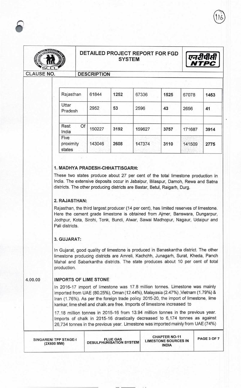
DETAILED PROJECT REPORT FOR FGD SYSTEM
N TPC
CLAUSE NO DESCRIPTION
Rajasthan 61844 1252 67336 1525 67078 1453
Uttar Pradesh
2952 53 2596 43 2656 41
Rest India
150227 3192 159627 3757 171687 3914
Five proximity states
143046 2608 147374 3110 141509 2775
1. MADHYA PRADESH-CHHATTISGARH:
These two states prodLice about 27 per cent of the total limestone production in India. The extensive deposits occur in Jabalpur, Bilaspur, Damoh, Rewa and Satna districts. The other producing districts are Bastar, Betul, Raigarh, Durg.
2. RAJASTHAN:
Rajasthan, the third largest producer (14 per cent), has limited reserves of limestone. Here the cement grade limestone is obtained from Ajmer, Banswara, Dungarpur, Jodhpur, Kota, Sirohi, Tonk, Bundi: Aiwar, Sawai Madhopur, Nagaur, Udaipur and
Pali districts.
3. GUJARAT:
In Gujarat, good quality of limestone is produced in Banaskantha district. The other limestone producing districts are Amreli, Kachchh, Junagarh, Surat, Kheda, Panch Mahal and Sabarkantha districts. The state produces about 10 per cent of total production.
4.00.00 IMPORTS OF LIME STONE
In 2016-17 import of limestone was 17.8 million tonnes. Limestone was mainly imported from UAE (80.25%), Oman (12.44%), Malayasia (2.47%) ,Vietnam (1.79%) & Iran (1.76%). As per the foreign trade policy 2015-20, the import of limestone, lime kankar, lime shell and chalk are free. Imports of limestone increased to
17.18 million tonnes in 2015-16 from 13.94 million tonnes in the previous year. Imports of chalk in 2015-16 drastically decreased to 6,174 tonnes as against 26,734 tonnes in the previous year. Limestone was imported mainly from UAE (74%)
SINGARENI TPP STAGE-I (2X600 MW)
FLUE GAS DESULPHURISATION SYSTEM
CHAPTER NO-lI LIMESTONE SOURCES IN
INDIA
PAGE 3 OF 7
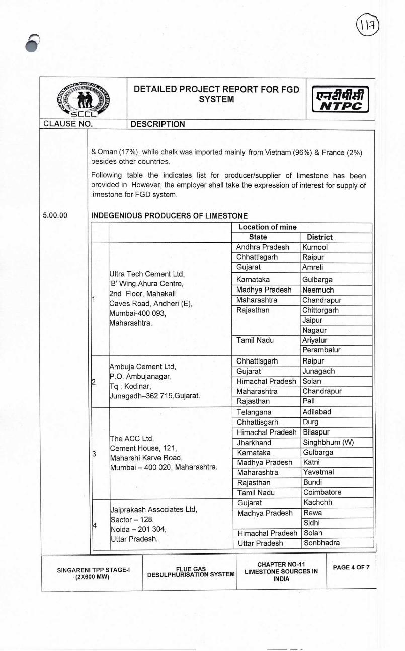
zyrã14117 N TPC
DETAILED PROJECT REPORT FOR FGD SYSTEM
DESCRIPTION CLAUSE NO.
5.00.00
& Oman (17%), while chalk was imported mainly from Vietnam (96%) & France (2%) besides other countries.
Following table the indicates list for producer/supplier of limestone has been provided in. However, the employer shall take the expression of interest for supply of limestone for FGD system.
INDEGENIOUS PRODUCERS OF LIMESTONE
Location of mine State District
Ultra Tech Cement Ltd, 'B' Wing,Ahura Centre, 2nd Floor, Mahakali Caves Road, Andheri (E), Mumbai-400 093 Maharashtra.
Andhra Pradesh Kurnool Chhattisgarh Raipur Gujarat Amreli
Karnataka Gulbarga Madhya Pradesh Neemuch Maharashtra Chandrapur Rajasthan Chittorgarh
Jaipur Nagaur
Tamil Nadu Arlyalur Peram balur
2
Ambuja Cement Ltd, P.O. Ambujanagar, Tq Kodinar, Junagadh-362 715Gujarat.
Chhattisgarh Raipur
Gujarat Junagadh
Himachal Pradesh Solan Maharashtra Chandrapur Rajasthan Pali
The ACC Ltd, Cement House, 121. Maharshi Karve Road, Mumbai — 400 020, Maharashtra.
Telangana Adilabad
Chhattisgarh Durg
Himachal Pradesh Bilaspur
Jharkhand Singhbhum (W)
Karnataka Gulbarga Madhya Pradesh Katni
Maharashtra Yavatmal
Rajasthan Bundi
Tamil Nadu Coimbatore
Jaiprakash Associates Ltd
Sector — 128, Noida — 201 304, Uttar Pradesh.
Gujarat Kachchh
Mad hya Pradesh Rewa Sidhi
Himachal Pradesh Solan
Uttar Pradesh Sonbhadra
SIN GARENI TPP STAGE-I (2X600 MW)
FLUE GAS DESULPHURISATION SYSTEM
CHAPTER NO-lI LIMESTONE SOURCES IN
INDIA
PAGE 4 OF 7

DETAILED PROJECT REPORT FOR FGD SYSTEM iyT741I7
NTPC CLAUSE NO. DESCRIPTION
Shree Cement Ltd, Bangur Nagar,
Rajasthan Ajmer
5 Post Box No. 33, Beawar - 305 901 Rajasthan.
Pall
Andhra Pradesh Cuddapah
The India Cement Ltd, Telangana Nalgonda Ranga - Reddy
6 "Dhun Building" Arlyalur 4th Floor, 827,Anna Salai, Tamil Nadu Perambalur Chennal - 600 002. Tamil Nadu. Tirunelveli
Thoothu- kudi Virudhu- nagar
7
Binani Cement Ltd, 37/2,Chinar Park, New Town,Rajarhat Dist - 24 Parganas North - 700157, West Bengal.
Rajasthan Sirohi
Andhra Pradesh Krishna Madras Cement Ltd, Karnataka Chitradurga
8 Ramamandiram, Tamil Nadu Arlyalur P.O.Rajapalayam-626117, Perambalur Virudh Nagar, Tamil Nadu. Thoothu- kudi
Virudhu- nagar
Dalmia Cement Ltd. Andhra Pradesh Cuddapah
9 P. 0. Dalmiapurarn, Tamil Nadu Ariyalur Thiruchirapalli-621 651, Perambalur Tamil Nadu Thiruchira- palli
Chettinad Cement Corp. Ltd, Tamil Nadu Ariyalur 6th Floor, Rani Seethai Dindigul
10 Hall Building, Karur 603, Anna Salai, Chennai - 600 006, Tamil Nadu.
Perambalur
J. K. Cement Works, Rajasthan Chittorgarh
11 Kamla Tower, Nagaur Kanpur-208 001, Llttar Pradesh Karnataka Bagalkot
Kesoram Industries Ltd, Telangana Karimnagar
12 9/1, R. N. Mukherjee Road, Kolkata - 700001.
Karnataka Gulbarga
SINGARENI TPP STAGE-I (2X600 MW)
FLUE GAS DESULPHLJRISATION SYSTEM
CHAPTER NO-lI PAGE 5 OF 7 LIMESTONE SOURCES IN
INDIA

I DETAILED PROJECT REPORT FOR FGD
SYSTEM 7r141J41 N TPC
CLAUSE NO DESCRIPTION
13 J. K. Lakshmi Cement Ltd, P.O. Jaykaypuram, Sirohi, Rajasthan.
Rajasthan Sirohi
14
Lafarge India Private Ltd, Crescenzo Building B-wing 10th Floor C-38,C-39,G-Block Bandra Kurla Complex, Bandra East, 229, Nariman Point, Mumbai-400 051.
Chhattisgarh Janjgir Champa, Raipur
15 Zuari Cement Ltd, Krishna Nagar, Yerraguntla-51631 1 ,Andhra Pradesh
Andhra Pradesh Cuddapah
Telangana Nalgonda
16
A.P. Mineral Dev. Corpn. Ltd, 3rd Floor Rear Block, HMWSSB, Premises, Khairatabad, Hyderabad — 500004.
Telangana Adilabad
17
Birla Corporation Ltd, Birla Building,9/1 R. N. Mukherjee Road, Kolkata — 700 001, West Bengal.
Madhya Pradesh Satna Rajasthan Chittorgarh
18
Bharathi Cements Corporation Pvt. Ltd. 8-2-626, Reliance Majestic, Road No.-10, Banjara Hills, Hyderabad — 500034.
Andhra Pradesh Cuddapah
19
My Home Industries Ltd, 9th Floor, Block-3, My Home Hub, Madhapur, Hyderabad-500 081, Andhra Pradesh.
Telangana Nalgonda
20
Century Textiles & Industries Ltd, Century Bhawan, Dr. Annie Besant Road, Mumbai— 400025, Maharashtra.
Chhattisgarh Raipur
Madhya Pradesh Satna Maharashtra Chandrapur
21
Sanghi Industries Ltd, P.O. Sanghipuram, Taluka- Abdasa Kachchh, Gujarat- 370511.
Gujarat Kachchh
SIN GARENI TPP STAGE-I (2X600 MW)
FLUE GAS DESULPHURISATION SYSTEM
CHAPTER NO-lI LIMESTONE SOURCES IN
INDIA
PAGE 6 OF 7

t7141f7 NTPC
CLAUSE NO.
DETAILED PROJECT REPORT FOR FGD SYSTEM
DESCRIPTION
22
Prism Cement Ltd, 305, Laxmi Niwas, Apartments, Ameerpeth, Hyderabad-50001 6, Andhra Pradesh.
Andhra Pradesh Kurnool
Madhya Pradesh Satna
23
Penna Cement Industries Ltd, Plot No.-705, Road No.-03, Banjara Hills, Hyderabad-500034, Andhra Pradesh.
Andhra Pradesh Anantapur
24 OCL India Ltd, Rajgangpur Rajgangpur-770017, Odisha
Odisha Sundergarh
SIN GARENI TPP STAGE-I (2X600 MW)
FLUE GAS DESULPHURISATION SYSTEM
CHAPTER NO-lI LIMESTONE SOURCES IN
INDIA
PAGE 7 OF 7
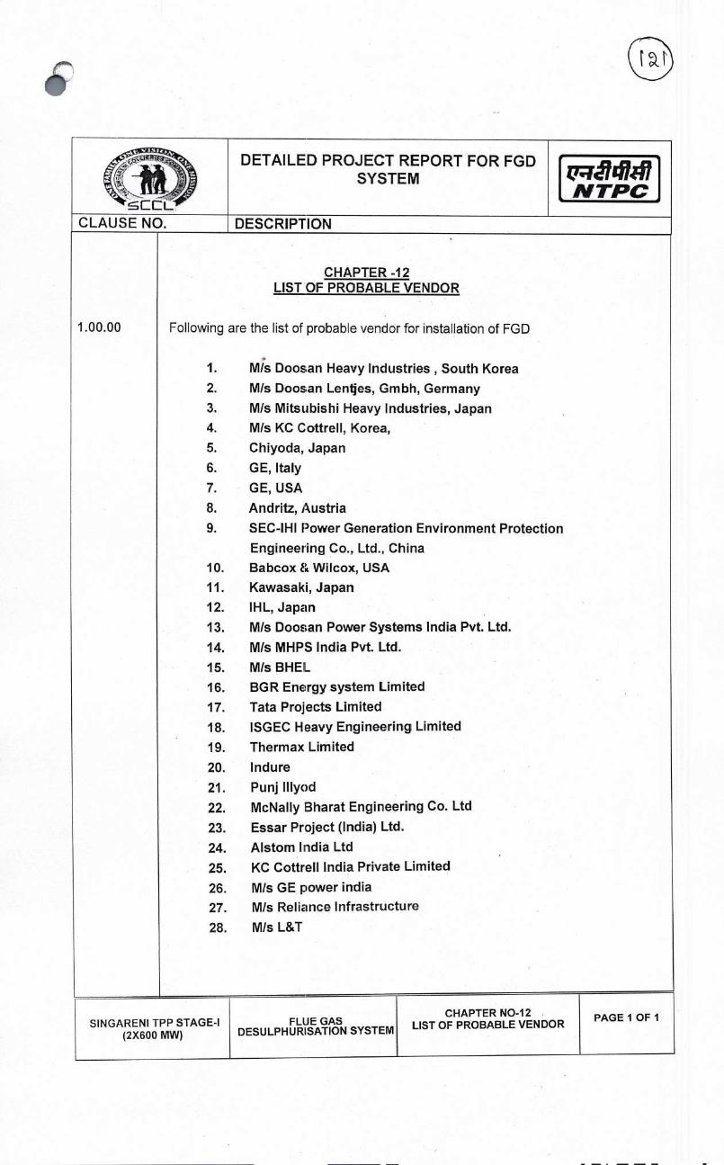
DETAILED PROJECT REPORT FOR FGD SYSTEM
NTPC
CLAUSE NO. DESCRIPTION
1.00.00 Following
1.
2.
3. 4.
5.
6. 7.
8.
9.
10. 11. 12.
13.
14. 15. 16. 17.
18. 19.
20.
21.
22. 23.
24.
25. 26. 27.
28.
CHAPTER -'12 LIST OF PROBABLE VENDOR
are the list of probable vendor for installation of FGD
M/s Doosan Heavy Industries, South Korea M/s Doosan Lentjes, Gmbh, Germany
M/s Mitsubishi Heavy Industries, Japan M/s KC Cottrell. Korea,
Chiyoda, Japan
GE, Italy
GE, USA
Andritz, Austria
SEC-IHI Power Generation Environment Protection Engineering Co.. Ltd., China Babcox&Wilcox, USA Kawasaki, Japan IHL, Japan M/s Doosan Power Systems India Pvt. Ltd.
M/s MHPS India Pvt. Ltd.
M/s BHEL BGR Energy system Limited
Tata Projects Limited ISGEC Heavy Engineering Limited
Thermax Limited
Indure Punj Illyod McNally Bharat Engineering Co. Ltd
Essar Project (India) Ltd. Alstom India Ltd
KC Cottrell India Private Limited
M/s GE power india M/s Reliance Infrastructure
M/s L&T
SINGARENI TPP (2X600
STAGE-I MW)
FLUE GAS DESULPHURISATION SYSTEM
CHAPTER NO-12 LIST OF PROBABLE VENDOR
PAGE 1 OF I

4I DETAILED PROJECT REPORT FOR FGD
SYSTEM QJrj74147 NTPC
CLAUSE NO. DESCRIPTION
1.00.00
CHAPTER-I 3
COST ESTIMATE FOR FLUE GAS DESULFURIZATION (FGD) SYSTEM
FGD system shall be installed in the generating station to minimize SO2 emissions in
compliance with the conditions laid down by MOEF, GOI for the environmental
clearances. The Estimated cost for installation of FGD in Singareni TPP (2 X 600
MW) will be approximately 64532.75 Lakhs.
Basis of cost estimate with break up
Following table indicates the tentative break of total project cost.
S.No Cost head Value in Lakhs
1 Supply 30556.63
2 Spares 1527.83
3 Type Test charges 8.63
4 Freight & Insurance 1283.38
5 Civil 9136.34
6 Structural 540.92
7 Erection & commissioning 6111.33
8 Training 10.00
9 System Integration 23.39
9 Sub total 49198.45
10 GST 8855.72
II Work cost including GST 58054.17
12 Contingency @3% 1741.63
13 100 Including FC 4736.95
14 Grand tolal 64532.75
. For IDC Calculation interest rate has been considered as 9.46%.
SINGARENI TPP STAGE-I (2X600 MW)
FLUE GAS DESULPHURISATION SYSTEM
CHAPTER NO-13 FINANCIAL ANALYSIS
PAGE 1 OF 4

DETAILED PROJECT REPORT FOR SYSTEM
FGD '741r47 NTPC
CLAUSE NO. DESCRIPTION
2.00.00
3.00.00
4.00.00
Auxiliary
The
be
Landed
The
2000/MT
Phasing
Estimated
Power Consumption:
Auxiliary Power Consumption shall be approximately
1.2-1.5%.
price of limestone:
approximate landed price of limestone will be
(excluding taxes) including transportation Cost.
of Expenditure:
work cost including GST 58054.17 Contigency3% 1741.63 lDC Including FC 4736.95
Total 64532.75
14-18 MW, which
© Rs 1200/MT to
will
© Rs
Fin. Year Quarter (%) Expenditure Value in Lakhs
2019-20 quarter 10% 6453.28
Il quarter 10% 6453.28
IlVd quarter 15% 9679.91
lVIh quarter 15% 9679.91
2020-21 st quarter 10% 6453.28
quarter 10% 6453.28
lII quarter 10% 6453.28
lVth quarter 10% 6453.28
2021-22 quarter 10% 6453.28
lI quarter 0% -
11rd quarter
SINGARENI TPP STAGE-I (2X600 MW)
FLUE GAS DESULPHURISATION SYSTEM
CHAPTER NO-13 FINANCIAL ANALYSIS
PAGE 2 OF 4
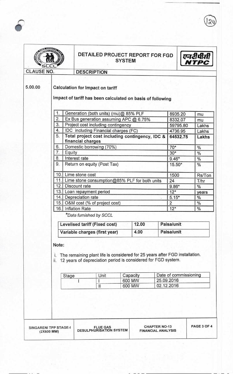
j141J17 NTPC,
CLAUSE NO.
DETAILED PROJECT REPORT FOR FGD SYSTEM
DESCRIPTION
5.00.00 Calculation for Impact on tariff
Impact of tariff has been calculated on basis of following
1. Generation (both units) (mu)© 85% PLF 8935.20 mu 2. Ex Bus generation assuming APC 6.75% 8332.07 mu 3. Project cost including contingency 59795.80 Lakhs 4. 100 including Financial charges (FC) 4736.95 Lakhs 5. Total project cost including contingency, IDC &
financial charges 64532.75 Lakhs
6. Domestic borrowing (70%) 70* 7. Equity 3Q*
8. Interest rate 9.46* % 9. Return on equity (Post Tax) 15.50*
10. Lime stone cost 1500 Rs/Ton 11. Lime stone consumption@85% PLF for both units 24 T/hr 12. Discount rate 9.86* % 13. Loan repayment period 12* years - 14. Depreciation rate 5.15*
15. O&M cost (% of project cost) 2 % 16. Inflation Rate 12* %
*Data furnished by SCCL
Levelised tariff (Fixed cost) 12.00 Paisa/unit
Variable charges (first year) 4.00 Paisa/u nit
Note:
i. The remaining plant life is considered for 25 years after FGD installation. ii. 12 years of depreciation period is considered for FGD system.
Stage Unit Capacity Date of commissioning 25.09.2016 I 600 MW
II 600 MW 02.12.2016
SINGARENI TPP STAGE-I FLUE GAS CHAPTER NO-13 PAGE 3 OF 4
(2X600 MW) DESULPHURISATION SYSTEM FINANCIAL ANALYSIS
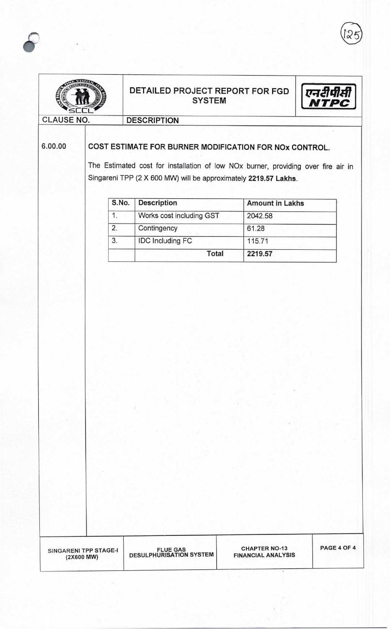
VI.
c:c:L
DETAILED PROJECT REPORT FOR FGD SYSTEM NTPC
CLAUSE NO. DESCRIPTION
6.00.00 COST
Singareni
The Estimated
ESTIMATE FOR BURNER MODIFICATION FOR NOx CONTROL.
cost for installation of low NOx burner, providing over fire
TPP (2 X 600 MW) will be approximately 2219.57 Lakhs.
air in
S.No. Description Amount in Lakhs
1. Works cost including GST 2042.58
2. Contingency 61.28
3. 100 Including FC 115.71
Total 2219.57
SINGARENI TPP STAGE-I (2X600 MW)
FLUE GAS DESULPHURISATION SYSTEM
CHAPTER NO-13 FINANCIAL ANALYSIS
PAGE 4 OF 4
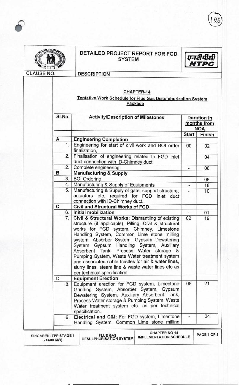
DETAILED PROJECT REPORT FOR FGD SYSTEM
NTPC
CLAUSE NO. DESCRIPTION
CHAPTER-14
Tentative Work Schedule for Flue Gas DesuiDhurization System Packacie
Sl.No. Activity/Description of Milestones Duration in months from
NOA Start Finish
A Engineering Completion 1. Engineering for start of civil work and BOI order
finalization, 00 02
2. Finalisation of engineering related to FGD inlet duct connection with ID-Chimney duct
04
2. Complete engineering - 08 B Manufacturing & Supply
3. BOl Orderinq 06 4. Manufacturing & Supply of Equipments - 18 5. Manufacturing & Supply of gate, support structure,
actuators etc. required for FGD inlet duct connection with ID-Chimney duct.
- 10
C Civil and Structural Works of FGD 6. Initial mobillization - 01 7. Civil & Structural Works: Dismantling of existing
structure (if applicable), Filling, Civil & structural works for FGD system, Chimney, Limestone Handling System, Common Lime stone milling system, Absorber System, Gypsum Dewatering System Gypsum Handling System, Auxiliary Absorbent Tank, Process Water storage & Pumping System, Waste Water treatment system and associated cable trestles for air & water lines, slurry lines, steam line & waste water lines etc as per technical specification.
02 19
D Equipment Erection 8. Equipment erection for FGD system, Limestone
Grinding System, Absorber System, Gypsum Dewatering System, Auxiliary Absorbent Tank, Process Water storage & Pumping System, Waste Water treatment system etc. as per technical specification.
08 21
9. Electrical and C&l: For FGD system, Limestone Handling System, Common Lime stone milling
- 24
SINGARENI TPP STAGE-I (2X600 MW)
FLUE GASCHAPTER NO-14
DESULPHLIRISATION SYSTEM IMPLEMENTATION SCHEDULE PAGE 1 OF 3

DETAILED PROJECT REPORT FOR FGD SYSTEM
N TPC
CLAUSE NO DESCRIPTION
system, Absorber System, Gypsum Dewatering System, Gypsum Handling System, Auxiliary Absorbent Tank etc.
E Commissioning of FGD 10 Commissioning - 25
F Completion of facilities 27
Note:
• The schedule given above is for Unit #1 and Common facilities. The activities specific to subsequent Units shall be phased at an interval of 3 months, except l:or engineering activities which shall be completed along with Unit #1
• Supply of mandatory spares needs to be ensured along with respective main equipment
SINGARENI TPP STAGE-I (2X600 MW)
FLUE GAS DESULPHURISATION SYSTEM
CHAPTER NO-14 IMPLEMENTATION SCHEDULE
PAGE 2 OF 3

PAGE 3 OF 3
DETAILED PROJECT REPORT FOR FGD SYSTEM
N TPC
CLAUSE NO DESCRIPTION
TENTATIVE WORK SCHEDULE FOR LOW NOX BURNER MODIFICATION PACKAGE
SI. No.
Activity! Description of Milestones
Duration in months from NOA
Start Finish
1. Design, Engineering, Manufacturing
00 01
2. Procurement of Raw materials & Manufacturing
01 05
3. Supply & Receipt of material at Site
05 06
4 Dismantling 07 08
5 Erection 07 08
6 Commissioning. Testing & Completion of facilities
08 09
Note:
The above is for first unit. Completion of supply of material for first unit shall be 6 months with an interval of one month for consecutive units. Completion of facility for each unit shall be on availability of unit shut down.
SINGARENI TPP STAGE-I (2X600 MW)
FLUE GAS DESULPHIJRISATION SYSTEM
CHAPTER NO-14 IMPLEMENTATION SCHEDULE

c:E2L
DETAILED PROJECT REPORT FOR FGD SYSTEM u1l4iFfl
NTPC CLAUSE NO. DESCRIPTION
1.00.00 Operation
The details to be carried
The brief elaborated approval, Items operation and
(a) Ensuring reduction producing
Further, engineers,
(b) Carrying overhauls, experts the plant. overhaul
(c) It has to
charge the operators running
(d) The O&M transformer
(e) Submission has to actual or
(f) Monitoring,
(g) It has to
years based
CHAPTER-I 5 OPERATION AND MAINTENANCE PHILOSOPHY
requirements
shalt be further to OWNER for for continuous
specification,:
for required S02 consumption and
service
naintenance, visit of O&M
maintenance of /capital
as per "Operation with Engineer-in
Daily work of as required and
each array and plant.
the FGD plant. It to overcome any
registers.
case of any major period of five
and Maintenance
breakdown/annual
and Maintenance Philosophy
covered below are the general aspects of scope and other out during operation and maintenance of FGD systems.
O&M philosophy as indicated below. The details by the bidder in the O&M manual to be submitted
though not specifically mentioned but needed maintenance of entire FGD plant to meet the intent of
successful operation of FGD Plant in three shifts efficiency with optimum energy and Limestone good quality of gypsum.
maintenance of the entire FGD plant by appointing experienced supervisors, operators and technicians round the clock.
out necessary Preventive maintenance and Breakdown furnishing technical assistance from experts & arranging
to site from time to for ensuring smooth operation and Also carrying out maintenance during annual overhauling
of the unit
ensure that FGD plant is operated and maintained instruction manuals" and in accordance
for coordination with operation/maintenance of main plant. involves logging the all the important parameters
of the FGD plant in most efficient manner.
personnel shall record monthly energy output of and reports shall be prepared on performance of FGD
of periodical reports on the operating conditions of ensure that adequate measures are initiated in advance
likely shortfall n performance
controlling, troub'eshooting, maintaining of records,
maintain all spares and including critical spares in overhaul and consumables required for atleast
on OEM experience.
SIN GARENI TPP STAGE-I (2X600 MW)
FLUE GAS DESULPHURISATION SYSTEM
CHAPTER NO-15 OPERATION AND MAINTENANCE PHILOSOPHY
PAGE 1 OF 3
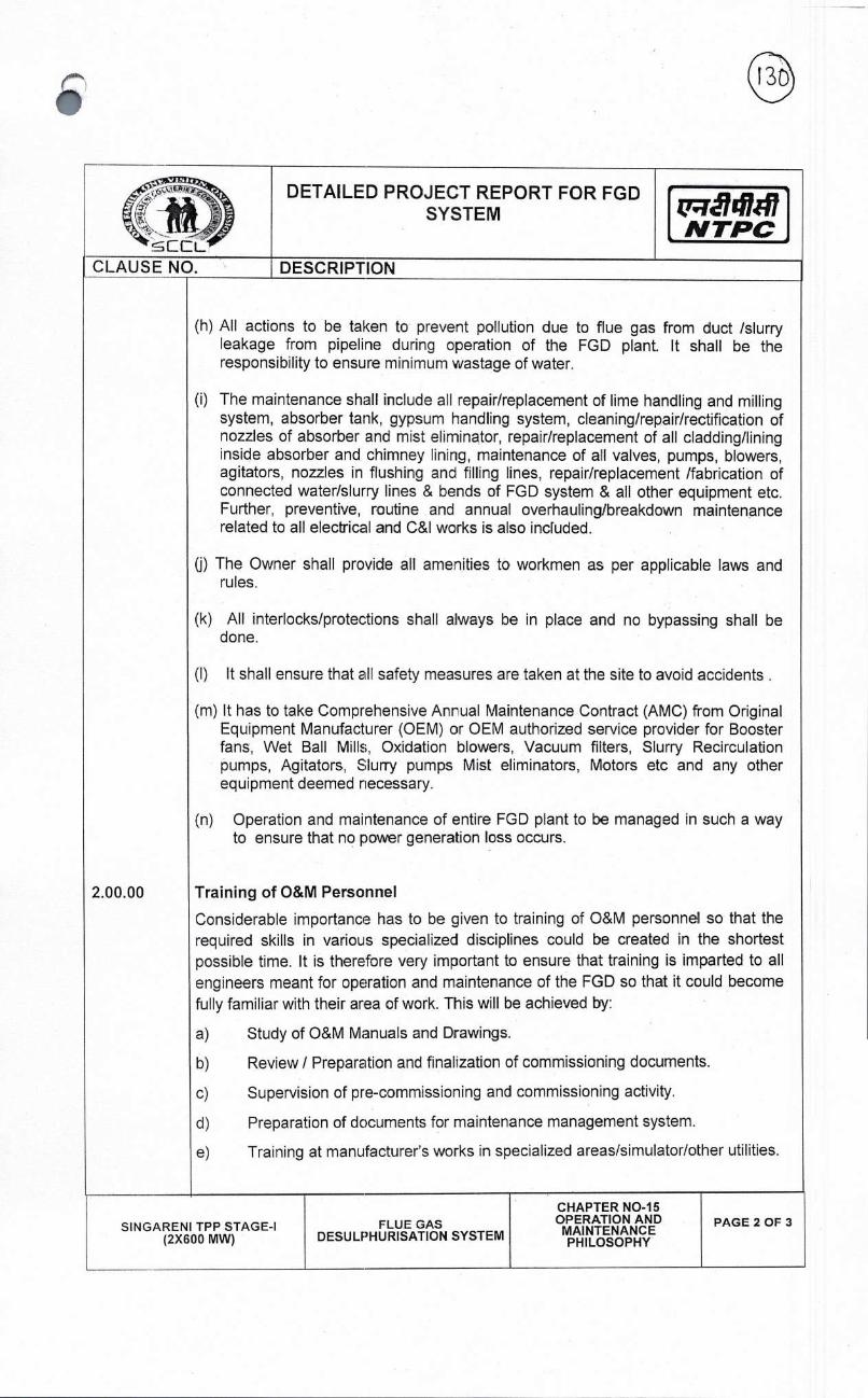
DETAILED PROJECT REPORT FOR FGD SYSTEM
NTPC
CLAUSE NO. DESCRIPTION
(h) All actions to be taken to prevent pollution due to flue gas from duct /slurry leakage from pipeline during operation of the FGD plant. It shall be the responsibility to ensure minimum wastage of water.
(i) The maintenance shall include all repair/replacement of lime handling and milling system, absorber tank, gypsum handling system, cleaning/repair/rectification of nozzles of absorber and mist eliminator, repair/replacement of all cladding/lining inside absorber and chimney lining, maintenance of all valves, pumps, blowers, agitators, nozzles in flushing and filling lines, repair/replacement /fabrication of connected water/slurry lines & bends of FGD system & all other equipment etc. Further, preventive, routine and annual overhauling/breakdown maintenance related to all electrical and C&l works is also incfuded.
(j) The Owner shall provide all amenities to workmen as per applicable laws and rules.
(k) All interlocks/protections shall always be in place and no bypassing shall be done.
(I) It shall ensure that all safety measures are taken at the site to avoid accidents.
(m) It has to take Comprehensive Anr-ual Maintenance Contract (AMC) from Original Equipment Manufacturer (OEM) or OEM authorized service provider for Booster fans, Wet Ball Mills, Oxidation blowers, Vacuum filters, Slurry Recirculation pumps, Agitators, Sluny pumps Mist eliminators, Motors etc and any other equipment deemed necessary.
(n) Operation and maintenance of entire FGD plant to be managed in such a way to ensure that no power generation loss occurs.
2.00.00 Training of O&M Personnel
Considerable importance has to be given to training of O&M personnel so that the required skills in various specialized disciplines could be created in the shortest possible time. It is therefore very important to ensure that training is imparted to all engineers meant for operation and maintenance of the FGD so that it could become fully familiar with their area of work. This will be achieved by:
a) Study of O&M Manuals and Drawings.
b) Review / Preparation and finalization of commissioning documents.
c) Supervision of pre-commissioning and commissioning activity.
d) Preparation of documents for maintenance management system.
e) Training at manufacturer's works in specialized areas/simulator/other utilities.
SIN GARENI TPP STAGE-I (2X600 MW)
FLUE GAS DESULPHURISATION SYSTEM
CHAPTER NO-15 OPERATION AND MAINTENANCE PHILOSOPHY
PAGE 2 OF 3

j . DETAILED PRO RPORT FOR FGD
NTPC
CLAUSE NO. DESCRIPTION
2.01.00
2.02.00
This on-the-job training activity will be coordinated by Head (O&M) and Project Coordinator. Training in the areas of operation and maintenance of modern facilities shall also be organized.
Training of Operation Engineers
a) Training at manufacturers WorKs and other Utilities
The operation engineers will undergo extensive training at manufacturers work for familiarization and for design/testing aspects. They will also be imparted training in the running units of other utilities also where new technologies have already been adopted by these.
Training of Maintenance Engineers
Maintenance engineers will undergo extensive training at stations of other utilities.
They will also be imparted training at manufacturers work for familiarization and for
design/testing aspects.
SIN GARENI TPP STAGE-I (2X600 MW)
FLUE GAS DESULF'HURISATION SYSTEM
CHAPTER NO-15 OPERATION AND MAINTENANCE PHILOSOPHY
PAGE 3 OF 3

DETAILED PROJECT REPORT FOR FGD SYSTEM
ii14717 N TPC
CLAUSE NO. DESCRIPTION
CHAPTER-I 6 BILL OF QUNATITIES (TENTATIVE)
SL.NO.
1.00.00
1.01.00
(i)
1.02.00
(I)
(ii)
1,03.00
1. 04, 00
1.05.00
1.06.00
DESC RI PTION
PRELIMINARY & CIVIL WORKS
Site Clearance
Site Clearance & Site grading
Concrete Road and Drains
Single Lane Cement Concrete Road 0.75 KM (Inside Plant) Rectangular Concrete Catch Drains 1.5 KM
Structural Steel (Supply, Fabrication and Erection)
Conveyor Galleries, TP's, Crusher 4500 MT House, Pipe & Cable racks, Lime storage Shed, Gypsum storage Shed etc.
Foundation All major Foundations like Absorber LOT Tower, Chimney, Absorbent storage tank, Crusher House, Mills. Fans & other Machine Foundations, Silo foundations, Conveyor Gallery, TPs, Pipe & Cable racks, etc.
General Civil works Civil and architectural works in FGD LOT area comprising of Gypsum dewatering building, Ball Mill Building, Control room building, MCC building, Tank foundations, Storage sheds, etc.
Chimney 200 Mts. twin flue RCC chimney with I No. cladding of Titanium/C-276 alloy! Borosilicate Glass Block on mild steel liner, with staircase and elevator (Rack & Pinion Type).
QUANTITY UNIT TECH. PARAMETRS
75000 M2
SINGARENI TPP STAGE-I (2X600 MW)
FLUE GAS CHAPTER-16 DESULPHURISATION SYSTEM BILL OF QUANTITIES
PAGE 1 OF 12

CLAUSE NO.
DETAILEID PROJECT REPORT FOR FGD SYSTEM
D ESC RI PTJION
r7411' NTPC •
1CS
MECHANICAL WORKS
FGD SYSTEM
Flue Gas System (2X600MW)
Booster Fan/FGD Inlet Gate 4 No. 2W/Unit. Motorised
Seal Air Fan for Inlet Gate 8 No. (1W+1S)/Unit
Booster Fan 4 No. 2W/Unit. Axial type, constant speed, variable pitch with drive motor
Lub. system for Booster Fan 4 No. 1W/Booster Fan
Booster Fan Outlet Gate 4 No. 2W/Unit. Motorised
Seal Air Fan for Outlet Gate 8 No. (1W-'-lS)/Unit
Bypass Damper 2 No. I damper each for Unit 1&2
Seal Air Fan for Bypass L)amper 4 No. (1W+1S)/Bypass damper
Flue Gas Duct System Lot From chimney inlet duct to FGD absorber system further to wet chimney
Duct Expansion Joints Lot
Insulation & Cladding for ducts Lot
Absorber System
Absorber Tower with integrated tank at 2 No. 1W/Unit. Absorber
bottom tower with integrated tank at bottom with spray banks and three stage mist
SIN GARENI TPP STAGE-I (2X600 MW)
FLUE GAS DESULPHURISATION SYSTEM
CHAPTER-I 6 BILL OF QUANTITIES
PAGE 2 OF 12
2.00.00
2.01.00
2.01.01
1
2
3
4
5
6
7
8
9
10
11
2.02.00

c)-. ç$flf
LEL
DETAILED PROJECT REPORT FOR FGD SYSTEM
j,'qr7447
CLAUSE NO. DESCRIPTION
eliminator
2 Slurry Recirculation Pumps 6 No. 3X50% (for single spray Ievel)/Absorber
4/per No. 2X100% (for multi level PY spfay)/absorber
3 Oxidation Blowers 4 No. (IW+IS)/Unit
4 Internal piping for oxidation air injection Lot
5 AbsorberAgitators 10 No. (4W+1S)/Unit
6 Emergency Watertank 2 No. 1W/Absorber
7 Gypsum Bleed Pumps 4 No. (IW+1S)/Unit
8 Mist Eliminator Wash Pumps 4 No. (1W+IS)/Unit
9 Absorber Area Sump 2 No 1W/Absorber Area 10 Absorber Area Sump Pump 4 No (1W+1S)/Unit
11 Auxiliary Absorbent Tank I No 1W/Station. Tank
complete with all
agitators, piping,
valves, fittings etc.
12 Auxiliary Absorbent Slurry Pump 2 No. 1W/Unit
13 Piping Instrumentation, Valves etc. Lot
14 Flue Gas Duct System Lot 15 Duct Expansion joint Lot 16 Insulation & Cladding for ducts Lot
2,03.00 Limestone Slurry System
1 Mill Bunker 2 No. (1W+IS)/Station
2 Silo/Bunker Outlet Gate 2 No. 1W/Silo/Bunker
3 Wet Ball Mill with drive system & lubricating system
2 No. (1W+1S)/Station
4 Weighing Feeder 2 No. 1W/Mill
5 Mill Slurry (Separator) Tank 2 No. 1W/Mill
SIN GARENI TPP STAGE-I (2X600 MW)
FLUE GAS DESULPHURISATION SYSTEM
CHAPTER-I 6 BILL OF QUANTITIES
PAGE 3 OF 12

ri14iI7 N TPC
DETAILED PROJECT REPORT FOR FGD SYSTEM
DESCRIPTION CLAUSE NO.
12
10
11
6
8
9
7
Mill Slurry Tank Agitators 2 No. 1W/Mill
Mill Circuit Pump 4 No. (IW+IS)/Mill
Mill Hydrocyclone 2 No. 1W/Mill
Limestone Slurry Tank 2 No. 2/Station
Limestone Slurry Pumps 6 No. (2W+ IS)/Tank
Limestone Slurry Tank Agitators 2 No. 1W/Tank
Reagent (limestone) Preparation Area Sump 1 No for both units
13
14
Reagent Preparation Area Sump Pump 2 No. (1W+1S)/ for both units
Piping, instrumentation, valves etc. LOT Pipes/chutes with valves from mill and hydrocyclone to common slurry storage tanks further to absorber system
2,0400 GYPSUM DEWATERING SYSTEM
Primary Hydrocyclone Feed Tank 1 No. 1/Station
2 Primary Hydrocyclone Feed Pump 2 No. (1W+1S)ITank
3 Primary Hydrocyclone 2 Set. (1W+1S)/Staticn
4 Vacuum Belt Filter 2 No.
5 Vacuum Pump 2 No.
6 Vacuum Receiver Tank 2 No. (IW+IS)/Station
7 Cake wash water storage Tank 2 No. (IW+1S)/Staticn
8 Belt & Cloth Wash Pump 4 No. (1W+1S)/Vacuum
belt filters
9 Cake Wash Pump 4 No. For each vacuum
belt filters
10 Filtrate Water Tank I No. Common for both
units
11 Filtrate Water Pumps 2 No. Common for both
SINGARENI TPP STAGE-I FLUE GAS CHAPTER-16 PAGE 4 OF 12
(2X600 MW) DESULPHURISATION SYSTEM BILL OF QUANTITIES

DETAILED PROJECT REPORT FOR FGD
SYSTEM LT14717 NTPC
CLAUSE NO. DESCRIPTiON
12 Secondary Hydra cyclone Feed Tank 1 No.
13 Secondary Hydra cyclone Feed Pump 2 No.
14 Secondary Hydra cyclone 2 Set
15 Dewatering Area Sump 1 No.
15 Dewatering Area Sump Pump 2 No.
16 Piping, instrumentation, valves etc. Lot
2.05. 00 Waste Water Treatmeni: System
Neutralization Tank 1 No
2 Waste Water Tank 1 No
3 Lime Feeding & Storage System 2 Set
4 Waste Water Pumps 2 Nos.
5 Piping, instrumentation, valves etc. Lot
2.06. 00 Process Water System
Process Water Tank 2 No
2 Process Water Pump 4 No
3 Booster Pump (if required) 2 No
2.07.00 Elevators Passenger cum Goods elevator 2 Nos.
2,08.00 LIMESTONE/GYSUM HANDLING PLANT
2. 08. 0 1 Conveyors & Accessories
Belting 1000 Mtr
2 Carrying ldlers(lncluding SAC) 350 Nos.
units
1/Station
(1W+1S)/Tank
(IW+1S)IStation
for bath units
(1W+1S)/ Station
1/Station
1/Station
(IW+1S)/Station
(IW+1S)/Station
Piping to discharge
waste water at
required pressure
2/Station
(1W4-1S)/Tank
(IW+1S)/Station
With minimum capacity of 1000 kgs for absorber & milling area
Belt Rating : 800mm wide synthetic, cover thick 5/2 mm, ay. Belt strength 50/4 FR Grade 35 deg. Trough., 3 roll,
CHAPTER-I 6 BILL OF QUANTITIES
SINGARENI TPP STAGE-I (2X600 MW)
FLUE GAS DESULPHURISATION SYSTEM
PAGE 5 OF 12

DETAILED PROJECT REPORT FOR FGD SYSTEM
t7T74iI47 NTPC
CLAUSE NO. DESCRIPTION
152 mm dia 4mm thick, 2 deg. Tilt
Impact Idlers 110 Nos. 35 deg. Trough., 3 roll, 152 mm dia 4 mm thick, 2 deg. Tilt along with rubber discs
Return Idlers (Including SAR) 150 Nos. Double roll l0o through 152 mm dia, 4 mm shell thick
Short support, etc. 40 Te a). MS fabricated 10 Te b). Cnute work-20 thk
TISCRAL 260 Mtrs. c). 60 lb/yd rail for
(trippers) Pulleys a) Drive pulleys 15 Nos. M.S. Fabricated, 950
mm face width, dia 800 mm dia
b) Other pulleys, (Tail, snub,bend & 50 Nos. M.S. fabricated, 950 take-up) mm face width, dia 800
mm dia mm ay. Dia 630 mm
Drive motors for conveying system 15 Nos. LT motors
3
4
5
6
7
8 15 Nos. Helical type with integral hold backs for drives in Sl.No.7
15 Nos. Pin bush type coupling
15 Nos. Geared type coupling 15 Nos. Elecfro-hydraulic
thruster type
15 Nos. V-plough type 30 Nos. Double bladed spring
loaded segmented Type
06 Nos Motorized, MS. fabricated
06 Nos MS fabricated, motorized
06 Nos Manually operated, MS fabricated
Lot Pull cord, beltsway, zero speed (Typical)
04 Nos 50 m3/hr 15 mwc, vertical pump
02 Nos Electronic type for continuous weighing
9
10 11
12
13
14
'15
16
17
18
Reduction gears
High speed coupling
Low speed coupling Brakes
Belt cleaners a) Internal b) External
Flap gates
Rack & Pinion gates
Rod gates
Safety switches
Sump pumps
Belt scales
SIN GARENI TPP STAGE-I FLIUE GAS CHAPTER-16 PAGE 6 OF 12
(2X600 MW) DESULPHURISATION SYSTEM BILL OF QUANTITIES

DETAILED PROJECT REPORT FOR FGD SYSTEM
4747 CLAUSE NO. DESCRIPTION
for 150 TPH 19 In Line Magnetic Separator 2 Nos Inline type, 1000 gauss
(for 150 TPH conveyor)
20 Suspended Magnets 2 Nos 1000 gauss (for 150 TPH conveyor)
21 Metal detector 2 Nos (for 150 TPH conveyor)
22 Lime Sampler Unit 1 No For Raw Lime (- )250mm
23 Travelling Trippers 04 Nos For 150 TPH ratedCapacity)
24 Monorails & hoists Lot Nos Electrical operated hoists, Manual hoists and Chain Pulley Block
25 Lime crusher with complete drive 2 Nos 165 TPH, Hammer Mill unit crusher
26 Vulcanising Machine 1 Nos -
27 Passenger cum goods Elevator 1 Nos 1 T (Conventional type)
28 Dust Extraction system Lot Nos
29 Ventilation system and Package AC Lot Nos Typical
30 Service water system, Potable Lot Nos Typical Water System
31 Mandatory spares Lot Typical
32 Special tools & tackles Lot Typical
33 Underground hopper with shed 04 Nos. 25 MT Each
34 Belt Feeder 08 Nos 100 TPH
35 Lime storage Silo 3 Nos 1800 T
36 Fluidising System 200 Nos For Lime Storage silo
37 Bucket elevator 04 Nos 100 T
2.09.00 EQUIPMENT COOUNG WATER SYSTEM
1 Secondary Cooling Water pumps 4 Nos. Horiz,Centri; Each of 150-200M3/hr & 55 MWc FGD / (2W+25)
2 DM cooling water pumps FGD 3 Nos. Horiz,Centri; Each of 50 M3/hr & 4SMWC Motor rating:7.5 KW
SINGARENI TPP STAGE-I (2X600 MW)
FLUE GAS DESULPHURISATION SYSTEM
CHAPTER-I 6 BILL OF QUANTITIES
PAGE 7 OF 12

DETAILEED PROJECT REPORT FOR FGD SYSTEM .IIJ
NTPC 4 CLAUSE NO. DESCRIPTION
Plate type heat exchangers (FGD) Lot
Chemical storage equipment and dosing Lot system (FGD)
GRP Pipes 1000 m
FIRE DETECTION & PROTECTION SYSTEM
(2W+1 S) 3 x 50% (With Titanium plates) One for FGD System
450 NB
Hydrant & spray system mains piping, Lot indoor & outdoor hydrants, hoses, hose boxes, couplings etc.
HVW Spray system for various Lot equipments (Transformers, etc.)
MVW Spray system for cable Galleries Lot
Analogue addressable fire detection and Lot alarm system comprising multisensory detectors, Fire alarm panels, PLC panels, Remote I/O panels, etc.
LHS cable for lime and Gypsum Lot Conveyors & cable galleries along with interface unit for each zone & all supporting arrangement
Cables & cabling for the complete fire Lot detection, alarm & protection system
Fire Extinguishers (Portable & mobile Lot type)
COMPRESSED AIR SYSTEM
3
4
5
2.1000
1
2
3
4
5
6
7
2.11.00
1 Air compressors with control panels, instrumentation & all accessories like piping, valves, etc.
2 Nos. Screw type oil free compressors each of capacity 15 NM3/min (minimum) & discharge Pressure of 8.5 kg/cm2(g).
2 ADP with panels, instrumentation, all accessories like piping, valves & electronic dew point meters
2 Set Capacity15 NM3/min. Design outlet dew point of (-) 40oC (atmospheric).
3 Air receivers 2 Nos. Nominal Capacity: 2
SINGARENI TPP STAGE-I FLUE GAS CHAPTER-16 PAGE 8 OF 12
(2X600 MW) DESULPHURISATION SYSTEM BILL OF QUANTITIES

DETAILED PROJECT REPORT FOR FGD SYSTEM
cc L MW N
CLAUSE NO. DESCRIPTION
m3
2.12.00 AIR CONDITIONING AND VENTILATiON SYSTEM
2.12.01 Air-Conditioning System for FGD Control Room
1 Air cooled condensing unit (D-X type) 2 along with associated refrigerant piping,
Nos. 20 TR
valves, instruments, etc.
2 Built-up double skin air handling units 2 Nos. 15000 CMH (AHUs)
3 Pan Humidifier along with all Lot Accessories
4 Electric strip heater together w:th Lot Controls
5 Cassette (Split) 8 Nos. 4.0 TR
6 Hi-Wall (Split) 8 Nos. 3.0 TR
2.12,02 VENTILATION SYSTEM
1 Ventilation System for FGD Control room Building
a Double skin modular type central unitary I air filtration units
Set 35000 CMH
b 010W centrifugal fans vvith drive motor 1 No. 35000 CMH Capacity at 40 MMWC
c Circulating water pumps with drive motor 1 No. 210 M3/hr & 30 MWC
2.12,03 Accessories such as piping. ductir, Lot grills, dampers, valves diffusers,
2.12.04
dampers, instrumentation, panels, etc
Ventilation System for Misc. areas Lot comprising of supply & exhaust air fans, roof extractor fans, gravity dampers, etc.
SINGARENI TPP STAGE-I (2X600 MW)
FLUE GAS DESULPHURISATION SYSTEM
CHAPTER-I 6 BILL OF QUANTITIES
PAGE 9 OF 12:

DETAILE D PROJECT REPORT FOR FGD
CLAUSE NO. DESCRIPTION
3.00.00 ELECTRICAL
3.0100 TRANSFORMERS (i) FGD HTTransformers 2 Nos. 11/3.45kV, 12.5 MVA,
ONAN, OCTC (ii) FGD LT Transformers 4 Nos 1 1/0.433kV, 2000
KVA, ONAN , OCTC (iii) FGD LTTransformers 3 Nos 11/0.433kV, 16CC'
KVA, ONAN , OCTC 3.02.00 HT SWITCHGEARS
(i) FGD Switchgear— 11KV 20 Panels 11KV, 1250A Bus bar rating. Incomers-1250A Outgoing — 630A. 40kA for 1 second.
(ii) FGD Switchgear — 3.3 KV 15 Panels 3.3 KV, 2500A Bus bar rating. Incomers- 2500 A Outgoing — 630A. 40kA for 1 second.
(iii) Retrofitting of existing 11 kV feeders of unit# 1&2 Station boards.
02 CBs 11KV, 1250A, 40kA. for I second (BHEL make)
(iv) Modification of Transformer feeders to 04 Panels motor feeders in Unit Boards
3,03.00 LT SWITCHGEARS
(i) FGD LT Service Switchgear- Unitised 2 Set 3200A, 50 KA for I sec.
(ii) FGD Common services SWGR I Set 2500A, 50 KA for I sec.
(iii) Emergency FGD MCC -- 1600 A 1 Set 1600A, 50 KA for I sec.
(iv) 4I5VAC Distribution Fuse Board 8 Set
(v) 220V DC Distribution Board (DCDB) 1 Set
(vi) 220V DC Fuse Board ([)CFB) 6 Set
(vii) 415V AC Main Lighting Dstribution 3 Set 2X100KVA, 400A
Board (MLDB)
(viii) 415V AC Emergency Lighting 2 Set 2XSOKVA, 250A
Distribution Board (ELDB).
(ix) Local Stop Push button Stations 130 Nos. Outdoor duty
(x) Local Motor Starter 20 Nos. Metaiclad outdoor duty
(xi) Junction Boxes 80 Nos. GI
SINGARENI TPP STAGE-I (2X600 MW)
FLUE GAS DESULPHURSATION SYSTEM
CHAPTER-I 6 BiLL OF QUANTITIES
PAGE 10 OF 1:2

SINGARENI TPP STAGE-I (2X600 MW)
FLUE GAS DESULPHURSATION SYSTEM
CHAPTER-I 6 BILL OF QUANTITIES
PAGE II OF 1:2
'wãldi#7 NTPC
3.04.00
(I)
(ii)
(iii)
BUSDUCT Metal Enclosed Segregated Phase Busduct. Metal Enclosed Non — Segregated Phase Busduct Metal Enclosed Non — Segregated Phase Busduct
80
40
40
Mtrs.
Mtrs.
Mtrs.
3.3KV, 2500A
415V, 3200A
415V, 2500A
3.05.00 BATTERY & BATTERY CHARGER (i) 220 V. 90 AH Ni-Cdt 2 Nos. 220 V, 90 AH Ni-Cd!
150 AH Lead Acid Batteries 15OAH (ii) 220V 40A Float cum boost Chargers 2 Nos, 220V, 40A
3.06.00 HT CABLES 3. 06.0 1
(i) 11 KV cable, 30-150 sq. mm. 3 Km Armoured, FRLS,
XLPE insulated (ii) 10-300 sq. mm. 12 Km Armou red, FRLS,
XLPE insulated (iii) 10-630 sq. mm. 12 Km Armoured, FRLS,
XLPE insulated 3.06.02
(I)
3.3 KV cable, 3C-150 sq. mm. 4 Km Armoured, FRLS,
XLPE insulated
(ii) 10-185 sq. mm. 6 Km Armoured, FRLS,
XLPE insulated
3.07,00 LT CABLES (i)
(ii)
1.1KV LT Power cables
1.1KV LT Control cables
100
30
Km Km
Armoured, FRLS, Armoured, FRLS,
3.08.00 CABLE TRAYS & SUPPORTS (I) Cable Trays 18 Km Ladder/Perforated GI
(ii) Cable Tray Supports & 1 Lot
Accessories
3.09.00 MISCELLANEOUS ELECTRICAL (i)
(ii)
DG Set,
Cabling
1
I
No.
Lot
63OKVA,415V
(iii) Earthing & Lightning Protection 1 Lot
(iv) Illumination System I Lot
DETAILED PROJECT REPORT FOR FGD SYSTEM
DESCRIPTION

DETAILED PROJECT REPORT FOR FGD SYSTEM N TPC
CLAUSE NO. DESCRIPTION
4.00.00
1
2
CONTROL & INSTRUMENTATION SYSTEM FGD System including Compressed air system, Air conditioning system, Ventilation system, FDPS etc.
000MIS based control system including LOT HMIPIS, Furniture & rack etc with Annual Maintenance Contract (AMC)
Measuring Instruments (Temperature LOT elements with transmitters, Pressure transmitters, Ultrasonic/Radar type level transmitters, pressure! temperature gauges, Flow Transmitters, Analyzers, Vibration monitoring system etc.)
3 Junction boxes, Instrumentation & control cables
LOT
4 Process connection and piping including LOT LIE/LIR
5 24 V DC and 240 V AC UPS power supply system
LOT
6 Pneumatic Control valves, actuators and accessories
LOT
7 Tools & Tackles LOT
SINGARENI TPP STAGE-I FLUE GAS CHAPTER-16 PAGE 12 OF 1:2
(2X600 MW) DESULPHURISATION SYSTEM BILL OF QUANTITIES

DETAILED PROJECT REPORT FOR FGD SYSTEM
NTPC CLAUSE NO. DESCRI PTION
CHAPTER-I 7 RECOMMENDATIONS
Recommendations for control of Sulphur Dioxide (S02 control)
Based on the data provided by SCCL, a comparative study of available technologies was undertaken for control of SO2 and Wet Limestone—Gypsum Forced Oxidation technology was found most suitable for the Singareni TPP (2X600 MW) . This report clearly brings out the performance expectation, layout requirement for the system and its accommodation in the existing plant, SO2 reduction process which is undertaken and the efficacy of the process (above 95%), sources of the reagent (limestone) in India and disposal of the by-products (gypsum) of the desulphurization process in various utilities. Based on the Detail Project Report, the suitable technical specification needs to be prepared for the FGD system.
Recommendations for control of Oxide of Nitroqen (NOx control)
As per the scope of work, Combustion Modification-Low NOx burner is the most suitable technology for Singareni TPP (2X600 MVV).
In this process following modification are likely to be undertaken in the boiler i.e. new/modified Re-designed Wind box including new coal, oil and air nozzle tips for all four corners, New Re-designed Tilting Tangential Burner Assembly, Burner Tilt Power cylinders, Modification in coal piping, coupling & its supports which requires boiler down time as per implementation schedule. This process has one time capital expenditure with no requirement of operational expenditure during running of the plant and is having high reliability.
SINGARENI TPP STAGE-I (2X600 MW)
FLUE GAS DESULPHURISATION SYSTEM
CHAPTER NO-17 RECOMMENDATIONS
PAGE 1 OF I

Gurpret Singh Senior E gineer BHEL- SSBG(R&M)
4PpENrnTx-
C o 2Lp+CJ drin
p'Or)J
Bharat Heavy Electricals Limited (A Government of India Undertaking)
Power Sector - Spares & Services Business Group (R & M Division) II Floor, KRIBHCO BHAWAN, A 8-10, Sector 1, NOIDA - 201301
Ph: 0120-2440836: Fax: 0120- 2532158; E-maIl: gurpreetcbhel.in
Ref: PS/SSBG/R&M/F-1564 Date: 31st January 2019
Shri. JN Singh Chief (O&M) Singareni Thermal Power Plant, Pegadapalli, Jaipur, Telangana 504216
Sub: NOx Mitigation System for 2X600 MW Singareni TPS Unit 1 & 2 of MIs SCCL
Ref: 1. SCCL letter dtd 08.08.2018. 2. BHEL Budgetary offer dtd 06.09.2018. 3. BHEL presentation reg. DE-NOx at SCCL site dtd 09.01.2019.
Dear Sir,
We thank you very much for the hospitality offered by M/s SCCL to team BHEL during their visit to Singareni site on 09.01.2019.
For designing the NOx mitigation system, BHEL has considered the baseline value of NOx emission as 480 mg/Nm3 for both the units (as furnished by SCCL vlde their letter cited at 51#1 under reference). As explained during the presentation made at site, BHEL will be offering Combustion modification package (In-furnace) including two revel SOFA arrangement for abatement of the NOx emissions. The above system will be able to reduce the NOx emissions by 40%. (i.e. NOx level could be brought down to the range of 280-290 mg/Nm3).
Budgetary Price for the NOx mitigation system (as furnished vide BHEL letter dtd 06.09,2018) for both the units is INR 37.88 Crores (Inclusive of Freight, Insurance and GST). As discussed during the meeting at site, a minimum of 45 Days shutdown would be required to implement the said package. Other Terms &. conditions may be agreed mutually on a convenient date, time and venue.
We look forward for your esteemed order on us as soon as possible.
Thanking you and assuring of our bt services always,
Yours faithfully, for Bharat Heavy Electricals Limited
Regd. Office: B}-IEL House, Sin fort, New Delhi — 110049
Scanned by CamScanner
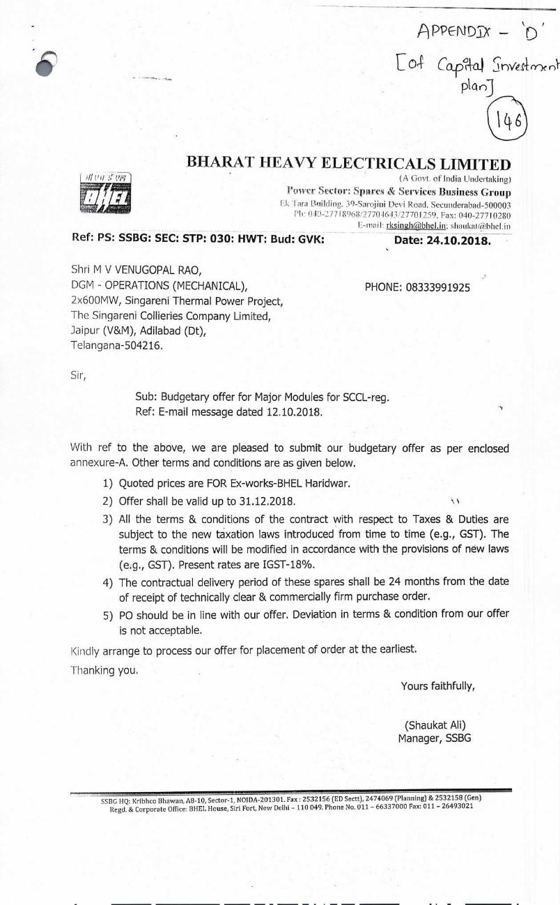
,PPEf'iDi,c
[o4' Cap?4cLI rVnr
ptOJ
BHARAT HEAVY ELECTRICALS LIMITED
Ref: PS: SSBG: SEC: STP: 030: HWT: Bud: GVK:
(A Go\'t. of' India Undertaking)
Prwcr SecU'; S3ares & Services Business Group IF1 I:UddlI11. i9-Saroiui Devi Road. Secutiderabad-500003
1r ():I[/7 I o8!277O4&I3./277() 29, Iax: 040-2771028() Lmail: iksing1ib1ieI.in: shaukatid1thel.in
Date: 24.10.2018.
Shri M V VENUGOPAL RAO,
DGM - OPERATIONS (MECHANICAL),
2x600MW, Singareni Thermal Power Project,
The Singareni Collieries Company Limited,
Jaipur (V&M), Adilabad (Dt),
Telangana-504216.
PHONE: 08333991925
Sir,
Sub: Budgetary offer for Major Modules for SCCL-reg.
Ref: E-mail message dated 12.10.2018.
With ref to the above, we are pleased to submit our budgetary offer as per enclosed
annexure-A. Other terms and conditions are as given below.
1) Quoted prices are FOR Ex-works-BHEL Haridwar.
2) Offer shall be valid up to 3 1.12.2018.
3) All the terms & conditions of the contract with respect to Taxes & Duties are
subject to the new taxation laws introduced from time to time (e.g., GST). The
terms & conditions will be modified in accordance with the provisions of new laws
(e.g., GST). Present rates are IGST-18%.
4) The contractual delivery period of these spares shall be 24 months from the date
of receipt of technically clear & commercially firm purchase order.
5) P0 should be in line with our offer. Deviation in terms & condition from our offer
is not acceptable.
Kindly arrange to process our offer for placement of order at the earliest.
Thanking you.
Yours faithfully,
(Shaukat Au) Manager, SSBG
SSBG FIQ: Kribhco T3hawan, AS-b, Sector-i, NOIDA-201301. Fax: 2532156 (ED Sectt), 2474069 (Planning) & 2532158 (Gen) Regd. & Corporate Office: I3HEL House, Sin Fort, New Delhi - 110 049. Phone No. 011 - €6337000 Fax: 011 - 26493021

ANNEXURE-A
Ref: PS: SSBG: SEC: STP: 030: HWT: Bud: GVK: Date: 24.10.2018.
SI NO Description Qty Unit Ex-works Price
mRs 1 HP MODULE 1 No 465045000
2 IP MODULE 1 No 538125000
3 LP TURBINE ROTOR-i I No 252000000
4 LP TURBINE ROTOR-2 1 No 252000000
5 GENERATOR STATOR 1 No 630000000
6 GENERATOR ROTOR 1 No 383250000
7 EXCITER ASSEMBLY* 1 No 220500000
TOTAL EX-WORKS VALUE IN RS 274,09,20,000
Amount in words: Rupees Two Hundred Seventy Four Crores Nine Lakhs Twenty Thousand Only.
Note: For item no: 7, EXCITER ASSEMBLY
1. Price of exciter cooler is not considered.
2. Price of bed plate access and rack assembly, bed plate accessories, fuse monitoring,
Dry air blower installation and assembly of covers are not considered.
QUALITY PLAN:
1) All material supplied by I3HEL shall be inspected as per BHEL standard procedure
and practices. BHEL shall submit Certi9cate of Compliance (COC)on1y for these
spares.
2) Kindly note that BHEL may procure raw material in semi-finished/finished
condition from their approved ad established vendors.
3) We will ensure the warranLy and interchangeability of the spares, but no physical
certificate (TC/GC) shall be furnished.
4) Budgetary offers are submitted to facili:ate you for estimation and are provisional
only. Prices may vary from time to time. Please don't compare these budgetary
offer prices with your firm offers.
5) Kindly release firm enquiry/Purchase order to enable us to plan our Manufacturing
activity to suit your delivery requirement.
SSIIG HQ: Kribhco Bhawan, AO-10, Sector-i, NOIDA-201301. Fax 2332156 lED Sectt), 2474069 ftlanning) & 2532158 (Gen
Regd. & Corporate Office: BHEL House, Sin Frt, New Delhi - liii 09. Phone No. 011 -66337000 Fax: 011 -26493021
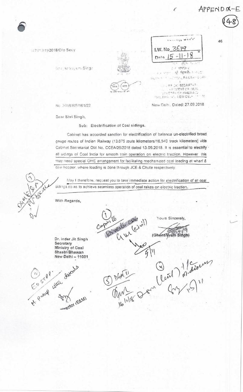
46
No
May therefore, request you to thice immediate action for ictriicatior of fl coal
sidns so as to achieve searnlas.s operation of coal rakes on elec:ric traction.
With Reards,
\(JW/ V) v
Dr. Inder Jit Sirigh Socrota Ministry of Coal Shastri Bhavian New Delhi — 11001
'IOLLrS Sincerely,
a Zn Singh) (Gh4fi
AFPr D (2 -
1l)I20i8/OiO Secy
f< /1 \.__., ____./
4_• ;•.'
Nc 7.)18,'RE11$1122 Na. Deh. Daed: 27.09.C18
Dac Shri Sncjh,
Sub: Electrification of Coal sidings.
Cabinet has accorded sanction for elecLrifcation of balance n-electriuied broad
giuge routes of lndia Railway (13;675 route .kiio:meters!16,540 track kflometers) vtd
Cabinet Secretariat OM No. CCEAi26i2O18 dated 13.0'9•2O18. It is es:s:etialtO electfiy
all sid:ngs of Coal India for smooth train operation on electrc trction. Howeve.r this
rry need special OHE arrangement for facilitating mechanized cal loading at whar &
00:3 hopper, where loading s done through .JCE. & Chute respectrelv.
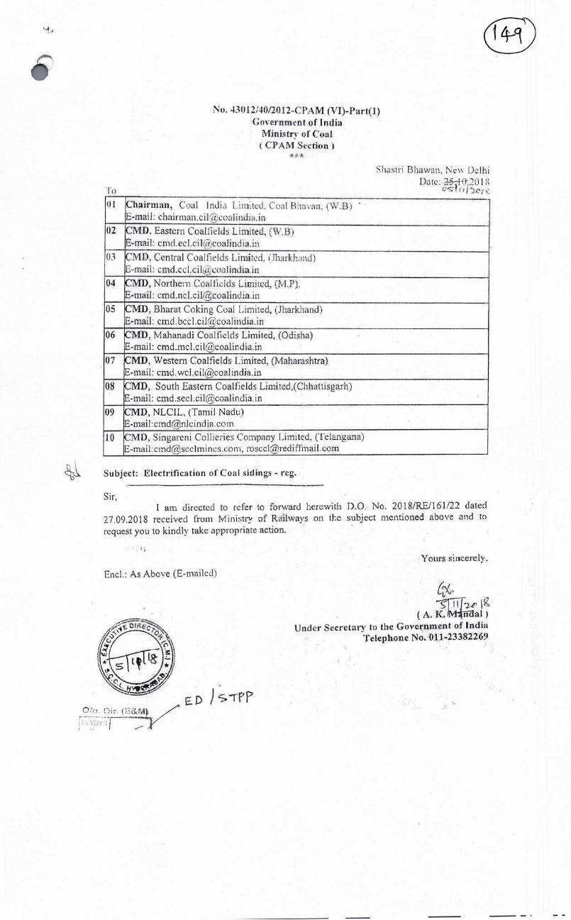
laD O'o. 03r. (E&M
No. 43012J4/201' CPM (VI)_:P.a:rt() Government of India
Ministry of Coal (CPAM Section i
Shastri Biiawa..n, N.ev Delhi Dae:-i20.l 1 itj
01 Chairman, Coal Jndi I iimkd Coal Br in (W t3j E-mail chairman cii 2 )a1mda In
02 MD Eastern Coailields Limited, (VS' Bi E-mail cmd eel cii a oalmdi i in
03 CMD Central Coal flelds Limited. (Tharkhand) C-mail crnd CLI cii LU ilindi ui
04 CMD, Northern Coalficids Limited, (MY). E-mail: cthd.ncl.cilZI;coalindia.in
O CMD, Bharat Coking Coal Limited; (JharkharLd) E-mail cmd bed ciVcoalmdia in
06 CMD, Mahanadi Coalfields Limited, (Odisha) E-mail: cmd.mc1.cilcoa1india.in
07 CMI), Western Coalfields Limited (Maharashtra) E-mail: [email protected]
08 CMD, South Eastern Coalfields Limited (Chhawsgarh) E-mail: [email protected]
09 CMD, NLCIL. (Tarnil Nadu) E-mail:[email protected].
10 CMD, Singareni Collieries Company Limited, (Telangana) L-rnad clnd@scclmlnLs &,orn rosLcl@iedlffmall corn
Subject: Electrification of Coal sidings - reg.
Sir, I am directed to refet to forward hercwimh D.O. No. 2018iREfl61t22 dated
27.09.2018 received from Ministry of Ri1ways on the subject meiitioned above nd to
request you to kindly take appropriate action.
Yours siticerely.
End.: As Above (E-mailcd)
(7
(A.K!M4iiThiI) Under Secretary to the Government of India
Telephone No. 011-23382269

Scale: Not to Scale
The Singareni ColIees Company Ltd.
Construction of Railway Line for STPP 3 x 600 MW
Sketch showing the proposed Additional Facilities CHP Yard to InpIant Yard
Drg. Sc RrrES/SC/SCCL/STPP/5115TC551
PRODUCED BY AN AUTODESK EDUCATIONAL PRODUCT
- -T S aJ) Co £L, Noe i',74Lt,1
4-&~kLk V 20q, Ce)°Yt— (T
1onaOId 1VNOIIV3fla isaoinv NV A aonaod

THE SINGARENI COLLIERIES COMPANY LTD A (OVEflENMENT UOi\IPANY)
XG()O \I\V , SINGARENI rp}1]?1)\1I1 PO\•VER PROJECT .JAIPLJR ( V & M) , I'IN 50421, MANC'J-1ERIAL 1)1ST rfF1VN(Nj STvrE
• Statement showing break-up of actual capital cost of STPP up to CoD of U-i , CoD of U-2 , addl cap exp beyond CoD of U-2 in FY 2016-17, FY 2017-i 8, upto 30.09.2018 & Estimated upto 31.03.2019
Ruoees in ci•
• DPR Head
As per Tariff filing in 2O16
Cost Approved as per Revised Cost
Estimate -2
Up to COD U4 1 (25 09 2016)
Oct-Nov'16 (From COD1
to COD2)
Up to COD U- 2 (02 12 2016)
Actual as on 31 03 2017
Actuálas 31 03 2018 -
Actual as on
30.09.2018
Estimated Capital Cost as on 31.03.2019
1..BTG,Packa'e . . . S
BTG Total 4878.00 4934.50 - 4749.95 31.59 4781.54 4772.14 4772.14 4,810.61 4934.50 2 BOP Package
BoP lotal 103800 102000 83726 2770 86496 877i0 97742 98672 102000 3.SCCL Scope works
-S
Land* 59.00 50.00 39.70 0.66 40.36 39.71 39.87 51.82 51.82 Survey & Soil Investigation . 1.00 0.30 0.02 .......0.00 0.02 0.02 002.........0.02 . 0.30 Site Dev, Enabling,1emp Sheds 25.00 24.00 21.35 0.00 . 21.35 23.38. 23.39 23.39 24.00 Roads & Culverts 20.00 20.00 11.44 0.00 11.44 1.1.75 12.34 12.41 20.00 Coal transport roads 5648 5200 42 61 000 4261 45 72 44 63 44 16 5200 Boundarywalls 17.00. 19.00 16.58 0.36 16.94. 17.19 17.19 17.19 19.00 Reservoir - 67 00 58 00 42 93 24 43 17 46 07 51 48 51 52 58 00 Water supply-I TMC 86.00 85.00 79.86 3.62 . 83.48 83.96 84.18 84.22 85.00 Water s.upply-2 TMC(incl elec) 320.00 293.00 - . 240.78 4.53 24531 250.38 274.53 308.22 320.00 Gate complex, Security etc . . 5.40 5.4 , 0.23 0.00 . 0.23 0.60 1.45 . 1.34 - 5.40 RIy Siding** . 80.00 380.00 - 78.53 2.21. 80.74 153.10 270.87 293.69 380.00 Township & GH 145.00 145.00. 50.20 1.98 52.18 .i 63.50 90.30 99.39 - 145.00 Environment 5 00 400 074 005 079 0 78 0 87 1.20 4 00 CSR * . 22.10 .22.10 9.29 0.16 9.45 10.05 10.73 11.00 22 10 Weigh bridges, fire tender etc 2.00 2.00 . 0.42 0.00 . 0.42 0.45 0.45 0.45 - 2.00 - Start up power & commcn eqpt . 42.00 49.00 . 42.00 0.00 42.00 48.02 - 48.02 48.02 49.00 Costruction power •• . 2s.00 30.00 24.66 0.31 24.97 24.40 24.40 2440 30.00 Furniture & office automation 5.00 . 6.00 2.37 0.00 2.37 2.18 2.72 4.16 6.00 Misc Expenditure . 5.00 8.00 3.25 0.23 . 348 . . - 3.99 4.50 4.50 8.00 BAY, CCI & cvm • . - 0.00 28.70 - 0 0 0.00 0.00 28.70 30.74 30.74 )
SCCL ScopeTotal 987.98 181.50 706.96 14.35 - 721.31 -. 825.27 - 1,030.64 1,111.85 1,312.36

For RAMAMOORTHY (N) & Co., • Chartered Accountants
FRN: 02899 S
CA. 3urendraiith Sharathi Partner
Mem. No: 023837
DPR Head As per Tariff
filing in 2OI6
Cost Approved as per Revised Cost
Estimate -2
Up to COD 1 (25.09.201 6)
....
Oct-Nov'16 (From COD!
to COD2)
Up to COD U- 2 (02.12.2016)
Actual as on 31.03.2017
Actual as on 31.03.2018
Actual as on
30.09.2018
Estimated Capital Cost as on 31 .03.2019
4. OTHERS Contingencies 47.52 5.00 11.32 0.00 11.32 13.79 16.20 16.20 16.20 Establishment costs 70.00 94.00 6980 0.00 69.80 89.89 88.73 92.13 94Øo Consultancy & Engg 127.00 120.00 107.77 1.96 109.73 114.93 119.44 119.44 120.00 Start up fuel 40.00 41.00 38.69 2.09 40.78 40.20 40.20 40.20 40.20 Operator Training 1.50 0.00 0.00 0.00 0.00 0.00 0.00 0.00 0.00 IDevelopment p 0.00 0.00 0.00 0.00 0.00 2.96 2.96 2.96 2.96 Margin Money 0.00 0.00 0.00 0.00 0.00 0.00 0.00 FinancingExpenses ______ 2.00 1.00 o.00 0.00 0.00 Q50 0.50 0.50 1.00 Interest during construction 1058.00 1266.00 1231.73 32.61 1264.34 . 1.80.98 1302.53 1,264.34 O&M-Expenditure upto COD 0.00 17.00 18.1.5 2.75 20.90 16.90 . 17.00 17.00 17.00 • Others Total 134602 1544.00 147! 39.41 1516.87 1560.14 1587.56 1,552.77 . •1555.70'
-- Grand Total 8250.00 8780.00 7771.63 113.05 •. 7884.68 8034.65 8367.76 8461.94 8822.56
** Railway Expenditure is inclusive of CCDAC Claim Receivable of Rs.175 crs Notes: 1. Advances given against MDCC are considered as Expenditure upto COD-2 2. Due to SAP Configuration, Back date Posting of Expenditure is Not Allowed even though expenditure. is related to before COD date
3. Delay in Submissiofl of Bills by BHEL oven after completion of work upto COD
4. PVC bills & Mandatory Spare Bills Subsequently submitted after COD by BHEL •1
5. Land value inôludes deposits 8.66 crs which was not accounted due to SAP Configuration as at 30.09.2018 6; CSR expenditure can be read as Mandatory capital expenditure under MoEF clearance. 7. IDC Incurred after COD of unit -2 is allocated to the balance of assets as on 30.09.2018.
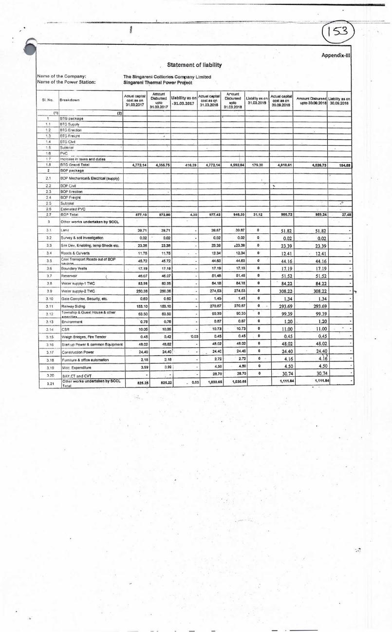
Appendix-UI
Statement of liability
Ntrne of the Company: The Slngareni Collieries Company Limited Name of the Poweir Station: Slngareni Thermal Fowar Project
SI. No. flreakdrwn Actual capital
coat as on 31.03.2017
Amount Disbursed
UptO 11.03.2017
Uabiiitj as on
-31,03 201.7
Actui CaPital Coal as on 31 23.2018
Anouflt Disoursed
pto 31.C3.2018
Liability ,, 31.03.2018
Actual capital cost as on 30092018
Amount Cisburaed upt030.09.2018
Liability as on 30.09.2018
(1) (2) I 1370 package
1 1 1370 Supply
1 2 ETC tireciion
1,3 ETC Freiç1lrt
1 4 ETC Civil
1 5 SuhtolI
16 PVC
I 7
1.8
Increase is axes and duties
BTG (lrnrd Total 4,772.14 4,355.75 416.39 4,772.14 4,592.84 179.30 4,810.61 4,526.73 184.88
2 GOP a:kage
2.1 GOP Moctranlcai& Electrical (supply)
2 2 GOP Civil
2.3 GOP Irreclion
2,4 GOP Ireighl
2 5 Subtolal
2.6 Estimated PVC
2.7 GOP Total 877.10 872,80 4.30 977.42 946.30 31.12 986.72 959.24 27.49
3 Other works undertaken by SCCL
3 1 l.9n1 39.71 39.71 - 39.87 39.87 0 51.82 51.82
3 2 Survey & soil InvestigatIon 0.02 ' 0. - 0.02 0.02 0 0.02 0.02
3.3 Site Dcv, Enabling, temp Sheds etc. 23.38 23.38 - 23.39 ,23.39 0 23.39 23.39
34 Roatis & Cuverts 11.75 11.75 . . 12.34 12.34 0 12.41 12.41 Coal Transport Roads out of GOP
..s4dnris 45.72 45.72 - 44.63 4.4.63 0 44.16 44.16
36 floundary Wells 17.19 17.19 - 17.18 17.19 0 17.19 17.19
3.7 Reservoir 46.07 46.C7 . 51.48 51.48 0 51.52 51.52
3.8 Wvtor supply-i TMC 83.96 8l j
84.18 84.18 0 84.22 84.22
3 9 Waler supply.2 TMC 250.38 250.38 - 274.53 274.53 0 308.22 308.22
3 10 Gala Cortiplex, Securfly, etc. 0.60 0.60 . 1.45 1.45 0 1,34 1.34
3.11 Railway Sidlig 153.10 163.10 - 270.87 270.87 0 . 293.69 2.93.69
3.12 Township & Guest House & other 63.50 5350 - 90.30 90.30 0 9939 9939
3.13 Environment 0.78 ('.78 - 0.87 0.87 0 1.20 . 1.20
r CSR 10.05 1005 - 10.73 10.73 0 11,00 11.00
3.15 Welglr Brldces, Fire Tender 0.45 (1.42 0.03 0.45 0.45 0 0.45 0.45
3 10 Start up Power & common Equipment 48.02 48.02 - 48.02 48.02 0 48.02 48.02
3.17 Corisiruction Power 24.40 24,40 ' . 24.0 24.40 0 24.40 24.40
3.16 Fiirnilure & ofltce automaton 2.18 2.18 - 2.72 2.72 0 4.16 4.16
3,19 Misc Expenditure 3.99 3.95 - 4.50 4.50 0 4.50 4.50
320 BAY,CT and CVT - . - - 28.70 28.70 0 30.74 30.74
3.21 OIler works undertaken by SCCL 1'nlxi
825.25 820.22 . 0.03 1,030.66 1,030.65 1,111.8.4 rt,111.8.4

(j ; App
Rupees 1(1 crores
'
DPR H ea Actual as on
30.09.2018
ma e Esti td
Estimated
cost
between 01.10.2018
t 31.03.2019 (
as on 2.8.11.2018)
Expected Spill Over
after
31.03.2019
Remarks
• BTG Package BTG Total 4810.61 4934.50 123.89 0.00
BOP Package BoP TQtal 986.72 120.00 33.28 0.00
.SCCL Scope works and* 51.82 51.82 0.00. urvey & Soil Investigation 0.02 0.30 0.28
;ite Dev, Enabling,Temp Sheds 23.39 24.00 0.61 toads & Culverts 12.41 20.00 7.59 oa1 transport roads 44.16 52.00 7.84
3oundarywalls 17.19 19.00 1.81 eservoir 51.52 58.00 6.48
Water supply-i TMC 84.22 85.00 0.78 Water supply-2 TMC(incl elec) 308.22 320.00 11.78 3ate complex, Security etc 1.34 5.40 4.06
ftly Sidi ng** 293.69 380.00 86.31 22.00
D Codal charges have to be paid to railways (on completion cost of railway line) after completion & commissioning of the total siding.
Project Management Consultant (PMC) charg have to be paid to RITEs (on completion cost of railway line) after completion & commissioning of the total siding. LI Track linking work is in progress and is expected for completion by 30.04.2019. Bills of expenditure! final bill payable on this work.
Township & GH 99.39 145.00 45.61 22.70
MIs Sunil Hitech Engineers Limited got admitted in NCLT. Thereby, progress of the works affected. When the IRP (Interim Resolution Professional)assured for payments, works are restarted and the works are in progress.
Environment 1.20 4.00 2.80
CSR * ii .00 22.10 11.10 9.00
CSR works are being taken up by the District Collector: Mancherial.30 % advance amounts were released to the District Collector for various approved works and Claims are yet to be receivedfor the balance 70%.
Weigh bridges, fire tender etc 0.45 2.00 1.55
Start up power & commcn eqpt 48.02 49.00 0.98
Construction power 24.40 30.00 5.60
Furniture & office automation 4.16 6.00 1.84
Misc Expenditure 4.50 8.00 3.50 3.00
Contingency in nature heng monitored different departments of STPP. Executed as per the requirement.
BAY, CCT & CVTs 30.74 30.74 0.00
SCCL ScopeTotal 1111.85 1312.36 200.51 56.70
4. OTHERS Contingencies 16.20 16.20 0.00
Establishment costs 92.13 94.00 1.87
Consultancy & Engg 119.44 120.00 0.56
Start up fuel 40.20 40.20 0.00
Operator Training 0.00 0.00 0.00
Development exp 2.96 2.96 0.00
Margin Money 0.00 0.00 0.00
Financing Expenses 0.50 1 .00 0.50
Interest during construction 1264.34 1264.34 0.00
O&M-Expenditure upto COD 17.00 17.00 0.00 Others Total 1552.77 1555.70 2.93 0.00

THE SINGARENI COLLIERIES COMPANY LIMITED
(A Government Company)
2 X 600 MW SINGARENI THERMAL POWER PLANT
Jaipur (V&M)-504216, Mancherial (Dist), Telangana State.
Ref No: STPP/COML/2019-20/45 /C i Dt. 18.03.2019 NOTE
Sub: Approval for submission of ARR and MYT petition and Business and
Payment of requisite filing fee to TSERC along with required
authorization for filing Multi-year tariff petition for ensuing control period of 2019-24.
1. SCCL has established Singareni thermal power plant (STPP) in Jaipur, Telangana
in FY 2016-17. SCCL had entered into a Power Purchase Agreement (PPA) with
two Distribution companies 01: Telangana for supplying the total power
generated from STPP at a tariff decided by hon'ble Telangana State Electricity
Regulatory Commission (TSERC).
2. The Hon'ble TSERC has notified terms and condition for determination of
generation tariff regulation 2019 on 04.0L20L9. This regulation shall be
applicable to all existing and future generating entities for determination of
annual revenue requirement in the state of Telangana from 1st April 2019 to
31st March 2024.
3. SCCL has to submit Aggregate Revenue Requirement and Multi-Year tariff
petition 2019-24,Business Plan 2019-24 and Capital investment Plan 2019-24
within 31st March 2019 before the Hon'ble TSERC as per regulation 3.8.1,
regulation 7 and regulation 27 of generation tariff regulation 2019.The
relevant portion of regulation is attached as Flag -A.
4. The capital investment plan is already approved by the competent authority.
Further to this, the Aggregate revenue requirement (ARR) and Business Plan
are made with the necessary inputs from O&M, finance, Civil, Coal, Personnel
& E&M department for submission. The same is now ready for submission to
1 I P p e

Ref No: STPP/COML/2019-20/45 Dt.18.03.2019
TSERC. The copy of ARR is attached in Flag -B and copy of business plan is
attached in Flag-C.
5. As per Telangana State Electricity Regulation commission, Hyderabad (Conduct
of Business) Regulations, 2015, Chapter II, point SI. No. 11(5), the proceedings
initiated before the commission is to be signed by the Managing Director or a
Director of the Company. Any other person signing the petition should have
authorization from the Board of Directors by a specific or general resolution.
Copy of the relevant portion of the regulation is attached as Flag D.
6. Further, as per Sl.No. 4.3.a of Regulation no. 2 of 2016 "Levy of fees for
various services rendered by the comniission" a fee of Rs 20,000/- per MW
with a maximum of Rs 150 lakhs, Further, business plan and capital investment
plan can be filed under section 94(2) for which a fee of 10,000 each will be
required as per 4.4.c of the fees regulations. Copy of the relevant portion is
attached as Flag E.
7. It is to submit that the Director (Finance) was authorized to sign the Tariff
Petition for the first control period (2016-19).
8. Accordingly, it is kindly requested to approve
I. The ARR and MYT petition and Business Plan for submission to TSERC
II. Payment of Rs 150 Lakhs to TSERC towards tariff filing fee along with
tariff application.
III. Payment of 20 thousand (10 thousand each) towards filing fee for
Business plan & capital investment plan.
IV. Authorisation of Director (Finance) to sign tariff application of STPP
(2X600MW) & all other associated filing related to tariff (Business plan &
Capital investment plan) for 2019-24 as it was done previously.
DG M(R&C)/STPP
V.
2Page
Director rations)
Directo (FinancS
Ref No: STPP/COM L/2019-20/45 Dt.18.03.2019
GM STPP
2/3 GM F&A)/Corporate
Director ( '&M)
Ar&4 '
Director (P&P)
C&1D
3 I P a p a

0 .2019
I
Ref No: STPP/CQMI 01920"4S
GM (F), STPP
ED STPP
--•c
GM F&A)JCQrpOrate
Director
Di rec,f (P &P)
DirectOr (Operations)
Director (Finance)
c&MD
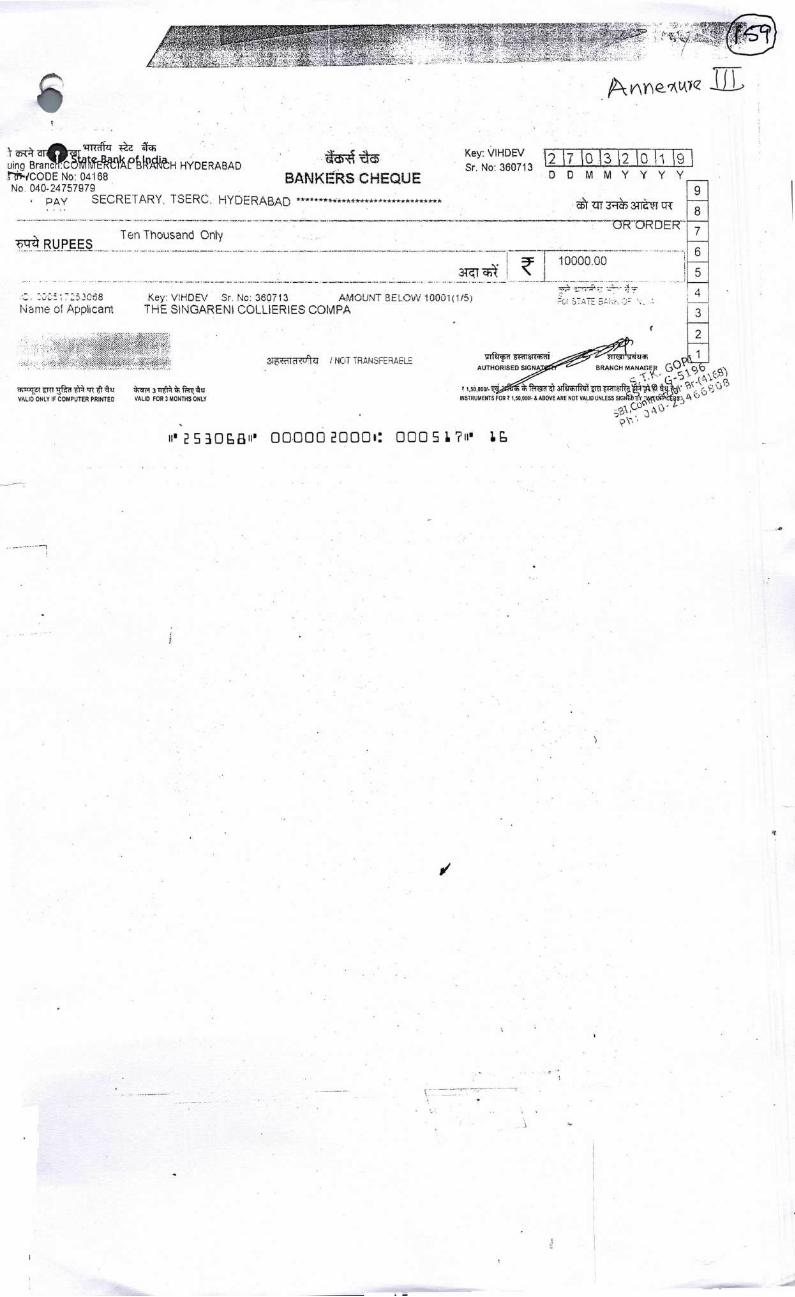
J L
10000,00
HYDERABAD r1coDE No: 04168 No. 040-24757979
pAy SECRETARY, TSERC. HYDERABAD ***************************
RUPEESTen Thousand Onty
Key: VIHDE\/ Sr. No: 360713 AMOUNT BELOW 10001(115) Name o Applicant THE S)NARENI COLLIERIES COMPA
BANKERS CHEQUE
ZIT 3TJ5 3T1 tt
0R ORDER
Key: VIHD'
Sr. No: 360713
DDMMYYY
9 8 7
6
5
4
T11N5
VALID ONLY IF COMPUTER PRINTED VALID FOR 3 MONTHS ONLY
TfTRIITR 1RT
AUTHORISED BRANCH MANAX o; )
INSTRUMENTS FOR I,5D,ODOI. & ABOVE ARE NOT VALID UNLESS SIG
-
2ii1RTJ9'ZI / NOT TRANSFERAELE
'253Oi3" 000002000': 0005L?" L
a,