OPMI® VISU 210 on S8, S81, S88 Suspension Systems
252
OPMI ® VISU 210 on S8, S81, S88 Suspension Systems Instructions for use G-30-1530-en Issue 1.0 Printed on 19. 04. 2004 MISU241
-
Upload
khangminh22 -
Category
Documents
-
view
1 -
download
0
Transcript of OPMI® VISU 210 on S8, S81, S88 Suspension Systems

OPMI® VISU 210on S8, S81, S88
Suspension Systems
Instructions for useG-30-1530-en
Issue 1.0
Printed on 19. 04. 2004
MISU241

Key to symbols
Different symbols used in this user's manual draw your attention to safetyaspects and useful tips. The symbols are explained in the following.
Warning!The warning triangle indicates potential sources of danger which mayconstitute a risk of injury for the user or a health hazard.
Caution:The square indicates situations which may lead to malfunction, defects,collision or damage of the instrument.
Note:The hand indicates hints on the use of the instrument or other tips for theuser.
OPMI® is a registered trademark of Carl Zeiss.OPMI®
MISU241

G-30-1530-en OPMI® VISU 210 on S8, S81, S88 Suspension Systems Issue 1.0Printed on 19. 04. 2004
Contents
– Key to symbols 2
Functions at a glance 7
– VISU 210 surgical microscope 8
– Illumination systems 11
– S88 floor stand 12
– S8 ceiling mount 14
– S81 ceiling mount 16
Safety 19
– Directives and standards 20
– Notes on installation and use 21
– When using a fundus imaging system (e.g. BIOM 3) 25
– Phototoxic retinal injury in eye surgery 25
– Safety devices of the suspension systems 30
– Warning labels and notes 38
Description 43
VISU 210 surgical microscope 46
– Intended use 46
– Description of the modules 46
– Illumination system 53
– Controls, displays, connections 56
– Binocular tubes and eyepieces 64
Illumination systems - halogen and xenon 68
– Halogen illumination system 68
– Xenon illumination system 72
S88 floor stand 76
– Intended use 76
– Description of the modules 77
– Design 78
MISU241

G-30-1530-en OPMI® VISU 210 on S8, S81, S88 Suspension Systems Issue 1.0Printed on 19. 04. 2004
– Stand base with column 82
– Connection panel 84
– Suspension arm 86
– Display field with control keys 88
– Instrument tray (option) 90
S8 Ceiling Mount 92
– Intended use 92
– Description of the modules 93
– Design 94
– Handle 98
– Power switch with connector (option) 100
– Suspension arm 102
– Display field with control keys 104
S81 ceiling mount 106
– Intended use 106
– Description of the modules 107
– Design 108
– Power switch, connector and socket (option) 112
– Suspension arm 114
– Display field with control keys 116
VISU 210 surgical microscope on S88 floor stand 118
– Intended use 118
– Design 118
VISU 210 surgical microscope on S8 ceiling mount 120
– Intended use 120
– Design 120
VISU 210 surgical microscope on S81 ceiling mount 122
– Intended use 122
– Design 122
Foot control panel (option) 124
– Intended use 124
– Design 124
MISU241

G-30-1530-en OPMI® VISU 210 on S8, S81, S88 Suspension Systems Issue 1.0Printed on 19. 04. 2004
Preparations 127
Attaching the equipment 128
– Mounting the surgical microscope 128
– Mounting the tube, the eyepieces and the objective lens 132
– Changing the microscope accessories 136
Connections 138
– Connecting the surgical microscope 138
– Connecting the S light guide 138
– Strain relief device on S88 floor stand 140
– Connecting the S88 floor stand 142
– Relocating the system 144
Adjusting the system - S88 floor stand 146
– Adjusting the balance setting of the suspension arm 146
– Adjusting the limit of downward movement 148
Adjusting the system - S8 ceiling mount 150
– Adjusting the balance setting of the suspension arm 150
– Adjusting the limit of downward movement 152
– Positioning the S8 ceiling mount 154
Adjusting the system - S81 ceiling mount 156
– Adjusting the balance setting of the suspension arm 156
– Adjusting the limit of downward movement 158
Adjusting the system - General 161
– Adjusting the supension system 161
– Adjusting the tilt angle 162
– Adjusting the microscope tilt to angles greater than 15° 164
– Adjusting the surgical microscope 166
Operation 167
Checklist 168
– When using a fundus imaging system (e.g. BIOM 3) 172
Positioning the S88 floor stand 174
Using the display and key field 176
– General functions 176
– Operating the OPMI on the suspension system 180
MISU241

G-30-1530-en OPMI® VISU 210 on S8, S81, S88 Suspension Systems Issue 1.0Printed on 19. 04. 2004
Procedure 192
What to do in an emergency 194
– Failure of the halogen lamp 194
– Failure of a xenon lamp 196
– Failure of lamp control 198
– Failure of focusing system 198
– Failure of magnetic brakes 200
– Failure of the X-Y coupling 200
– Failure of the zoom function 201
Maintenance / Further information 203
– Trouble-shooting table 204
– Changing the halogen lamp 212
– Changing the xenon lamp module 216
– Magnifications / Fields of view 218
– Care of the unit 219
– Sterilization 220
– Disinfecting the control keys 221
– Auxiliaries from Zeiss 222
– Ordering data 223
– Spare parts 225
– Accessories 227
Technical data 229
– Technical data 230
– Ambient requirements 244
Index 245
MISU241

G-30-1530-en OPMI® VISU 210 on S8, S81, S88 Suspension Systems Issue 1.0Printed on 19. 04. 2004
Functions at a glance 7
Functions at a glance
VISU 210 surgical microscope 8
Illumination systems 11
S88 floor stand 12
S8 ceiling mount 14
S81 ceiling mount 16
MISU241

8 Functions at a glance
G-30-1530-en OPMI® VISU 210 on S8, S81, S88 Suspension Systems Issue 1.0Printed on 19. 04. 2004
VISU 210 surgical microscope
1 Resetting the X-Y coupling and focus to their initial posi-tions
2 Adjusting the interpupillary distance page 643 Adjusting the eyecups4 Setting your prescription5 Handgrip page 586 Display of the magnification factor of the zoom system page 587 Changing the magnification on assistant's microscope page 628 Focusing of assistant's microscope page 629 Tilting the surgical microscope page 16210 Arrows indicating the focusing range page 5611 Locking screw for assistant's microscope (vertical) page 6212 Manual zoom adjustment page 20113 Selecting light stops page 6014 Setting the 6° illumination page 6015 Connecting the light guide page 13816 Locking screw for assistant's microscope (horizontal) page 16217 DeepView button page 60
MISU241

G-30-1530-en OPMI® VISU 210 on S8, S81, S88 Suspension Systems Issue 1.0Printed on 19. 04. 2004
Functions at a glance 9
1
2
3
4
5
6
8 9 117 131210
5
734 14 15 16 17
MISU241

10 Functions at a glance
G-30-1530-en OPMI® VISU 210 on S8, S81, S88 Suspension Systems Issue 1.0Printed on 19. 04. 2004
MISU241

G-30-1530-en OPMI® VISU 210 on S8, S81, S88 Suspension Systems Issue 1.0Printed on 19. 04. 2004
Functions at a glance 11
Illumination systems
Halogen illumination system1 Closed flap: main lamp is on - open flap: backup lamp
is onPage 48
2 Selecting a filter Page 483 Opening the lamp module Page 484 Manual selection of backup lamp Page 48
Xenon illumination system5 Selecting a filter Page 506 Manual selection of backup lamp Page 507 Opening the lamp module Page 508 Red segment is lit - backup lamp is in use Page 50
1 2 4 7653 8
MISU241

12 Functions at a glance
G-30-1530-en OPMI® VISU 210 on S8, S81, S88 Suspension Systems Issue 1.0Printed on 19. 04. 2004
S88 floor stand
1 Control panel page 1762 Lamp housing for halogen illumination (xenon illumi-
nation)page 80
3 Releasing the magnetic brakes of the suspensionsystem
Page 38
4 Limiting the suspension arm's downward movement Page 705 Removing/mounting the coupling for the surgical mi-
croscopePage 54
6 Balance setting Page 687 Locking the stand in position Page 348 Locking the suspension arm in its horizontal position Page 389 Connecting a foot control panel or hand switch, con-
necting the remote control connector. Page 6210 Rated voltage display Page 3611 Connector panel Page 3612 Switching on the suspension system Page 62
MISU241

G-30-1530-en OPMI® VISU 210 on S8, S81, S88 Suspension Systems Issue 1.0Printed on 19. 04. 2004
Functions at a glance 13
1 2 43 5 6
7 4 8 9 10, 11, 12
MISU241

14 Functions at a glance
G-30-1530-en OPMI® VISU 210 on S8, S81, S88 Suspension Systems Issue 1.0Printed on 19. 04. 2004
S8 ceiling mount
1 Locking the suspension arm in its horizontal position Page 362 Releasing the magnetic brakes of the suspension system Page 363 Balance setting Page 604 Lamp housing with halogen or xenon illumination Page 305 Control panel (rotatable through 180°) Page 666 Connecting a foot control panel or hand switch, con-
necting the remote control connector. Page 347 Switching on the suspension system Page 348 Releasing - moving - locking the lift arm Page 329 Removing/mounting the coupling for the surgical micro-
scopePage 50
10 Setting the limit of downward travel Page 62
MISU241

G-30-1530-en OPMI® VISU 210 on S8, S81, S88 Suspension Systems Issue 1.0Printed on 19. 04. 2004
Functions at a glance 15
1027 98
1 5 62 3 4
MISU241

16 Functions at a glance
G-30-1530-en OPMI® VISU 210 on S8, S81, S88 Suspension Systems Issue 1.0Printed on 19. 04. 2004
S81 ceiling mount
1 Locking the suspension arm in its horizontal position Page 342 Releasing the magnetic brakes of the suspension system Page 343 Balance setting Page 564 Lamp housing with halogen or xenon illumination Page 305 Control panel (rotatable through 180°) Page 626 Option: Hand control panel socket for ceiling track mount Page 327 Plugging in the remote control connector Page 328 Connecting the foot control panel or hand switch Page 329 Switching on the suspension system Page 3210 Removing/mounting the coupling for the surgical micro-
scopePage 48
11 Setting the limit of downward travel Page 58
MISU241

G-30-1530-en OPMI® VISU 210 on S8, S81, S88 Suspension Systems Issue 1.0Printed on 19. 04. 2004
Functions at a glance 17
10 1129
4 5 61 2 3 87
MISU241

18 Functions at a glance
G-30-1530-en OPMI® VISU 210 on S8, S81, S88 Suspension Systems Issue 1.0Printed on 19. 04. 2004
MISU241

G-30-1530-en OPMI® VISU 210 on S8, S81, S88 Suspension Systems Issue 1.0Printed on 19. 04. 2004
Safety 19
Safety
Directives and standards 20
Notes on installation and use 21
When using a fundus imaging system (e.g. BIOM 3) 25
Phototoxic retinal injury in eye surgery 25
Safety devices of the suspension systems 30
Warning labels and notes 38
MISU241

20 Safety
G-30-1530-en OPMI® VISU 210 on S8, S81, S88 Suspension Systems Issue 1.0Printed on 19. 04. 2004
The instrument described in this manual has been developed and testedin accordance with Carl Zeiss safety standards and with national and in-ternational regulations. A high degree of instrument safety is thus en-sured.
We would like to inform you on the safety aspects involved in operatingthe instrument. This chapter contains a summary of the most importantprecautions to be observed.
Further safety notes are also contained in other parts of this user'smanual; they are marked with a warning triangle containing an exclama-tion mark as shown here. Please pay special attention to these safetynotes.
Safety is only ensured when this instrument is operated properly. Pleaseread through this manual carefully before turning the instrument on. Alsoread through the user's manuals of the other equipment used with this in-strument. You may obtain further information from our service organiza-tion or authorized representatives.
Directives and standards
The system described in the user manual has been designed in compli-ance with:
– EN
– IEC
– UL
– CSA
In accordance with Directive 93/42/EEC, Annex II, Article 3, the completequality management system of the company Carl Zeiss has been certifiedby the DQS Deutsche Gesellschaft zur Zertifizierung von Management-systemen mbH, a notified body, under registration number 250881 MP21.
• The instrument must be connected to a special emergency backupline supply in accordance with the regulations or directives which ap-ply in your country.
– As per Directive 93/42/EEC, the unit is a Class I instrument.
– For USA: FDA classification Class I.
• Please observe all applicable accident prevention regulations.
MISU241

G-30-1530-en OPMI® VISU 210 on S8, S81, S88 Suspension Systems Issue 1.0Printed on 19. 04. 2004
Safety 21
Notes on installation and use
Safe working order
• Do not operate the equipment contained in the delivery package in
– explosion-risk areas,
– the presence of inflammable anesthetics or volatile solvents suchas alcohol, benzine or similar chemicals.
• Do not station or use the instrument in damp rooms. Do not exposethe instrument to water splashes, dripping water or sprayed water.
• Switch off the unit at the power switch if you notice any smoke, sparksor unusual noise. Do not use the unit until it has been repaired by ourservice team.
• Do not place any fluid-filled containers on top of the instrument. Makesure that no fluids can seep into the instrument.
• Do not force cable connections. If the male and female parts do notreadily connect, make sure that they are appropriate for one another.If any of the connectors are damaged, have our service representativerepair them.
• Potential equalization: If requested, the instrument can be incorpora-ted into potential equalization measures.
• Do not use a mobile phone in the vicinity of the equipment becausethe radio interference can cause the equipment to malfunction. The ef-fects of radio interference on medical equipment depend on a numberof various factors and are therefore entirely unforeseeable.
• Modifications and repairs on these instruments or instruments usedwith them may only be performed by our service representative or byother authorized persons.
• The manufacturer will not accept any liability for damage caused byunauthorized persons tampering with the instrument; this will also for-feit any rights to claim under warranty.
• Use this instrument only for the applications described.
• Only use the instrument with the accessories supplied. Should youwish to use other accessory equipment, make sure that Carl Zeiss orthe equipment manufacturer has certified that its use will not impairthe safety of instrument.
MISU241

22 Safety
G-30-1530-en OPMI® VISU 210 on S8, S81, S88 Suspension Systems Issue 1.0Printed on 19. 04. 2004
• Only personnel who have undergone training and instruction are al-lowed to use this instrument. It is the responsibility of the customer orinstitution operating the equipment to train and instruct all staff usingthe equipment.
• Keep the user's manuals where they are easily accessible at all timesfor the persons operating the instrument.
• Never look at the sun through the binocular tube, the objective lens oran eyepiece.
• Do not pull at the light guide cable, at the power cord or at other cableconnections.
• This instrument is a high-grade technological product. To ensure opti-mum performance and safe working order of the instrument, its safetymust be checked once every 12 months. We recommend having thischeck performed by our service representative as part of regular main-tenance work.If a failure occurs which you cannot correct using the trouble-shootingtable, attach a sign to the instrument stating it is out of order and con-tact our service representative.
Requirements for operation
• For ceiling mounts only: Our service staff or a qualified person ap-pointed by us will install the system on ceiling anchors which havebeen properly mounted by the construction engineers responsible.These ceiling anchors must comply with the specifications containedin our planning manual.
• Our service representative or an expert authorized by us will install thesystem. Please ensure that the following requirements are met for fur-ther operation:
– All mechanical connections (details in the user's manual) which arerelevant to safety are properly connected and screw connections tight-ened.
– All cables and plugs are in good working condition.
– The voltage setting on the instrument conforms to the rated voltage ofthe line supply on site.
– The instrument is plugged into a power outlet which has a properlyconnected protective earth contact.
– The power cord being used is the one designed for use with this in-strument.
MISU241

G-30-1530-en OPMI® VISU 210 on S8, S81, S88 Suspension Systems Issue 1.0Printed on 19. 04. 2004
Safety 23
Before every use and after re-equipping the instrument
• Make sure that all ”Requirements for operation” are fulfilled.
• Go through the checklist.
• Re-attach or close any covers, panels or caps which have been re-moved or opened.
• Pay special attention to warning symbols on the instrument (triangularwarning signs with exclamation marks), labels and any parts such asscrews or surfaces painted red.
• Do not cover any ventilation openings.
For every use of the instrument
General• Never operate the system unattended.
• Avoid looking directly into the light source, e.g. into the microscope ob-jective lens or a light guide.
• When the illumination is on, the light guide must be connected at bothends. Otherwise there is a risk of fire or burn injuries.
• Make sure that the instrument has been switched off before youchange the xenon lamp module. When switched on, the ignition sys-tem generates high voltage.
Xenon lamps feature high luminance and a spectrum resembling that ofnatural daylight. Therefore, only special xenon lamps approved by CarlZeiss must be used in ophthalmology.
• Any kind of radiation has a detrimental effect on biological tissue.Thisalso applies to the light illuminating the surgical field. Please thereforereduce the brightness and duration of illumination on the surgical fieldto the absolute minimum required.
• When operating on the eye, always use a GG 475 protection filter toensure that the patient's retina is not exposed to unnecessary (blue)radiation (retinal injury).
S88 floor stand• Using the locking pedal on the base, secure the stand in position.
Make sure that the stand is stable and cannot roll away.
MISU241
24 Safety
G-30-1530-en OPMI® VISU 210 on S8, S81, S88 Suspension Systems Issue 1.0Printed on 19. 04. 2004
S8 ceiling mount• The lift arm is used to move the microscope into position for surgery
prior to the surgical procedure.Do not constantly move the lift arm up and down, since a thermal cut-out will then automatically deactivate the drive motor. If this occurs,the lift arm cannot be moved until the motor has cooled down.
After every use of the instrument
• Always use the main power switch of the instrument to turn it off.
• The main power switch must always be turned off when the instrumentis not in use.
MISU241

G-30-1530-en OPMI® VISU 210 on S8, S81, S88 Suspension Systems Issue 1.0Printed on 19. 04. 2004
Safety 25
When using a fundus imaging system (e.g. BIOM 3)
When using a fundus imaging system (e.g. BIOM 3 from the company Oc-ulus) which is usually installed between the surgical microscope and thepatient, make sure that the patient is neither put at risk nor injured by themotorized focusing system or the movement of the suspension systemarm.
Only use accessories expressly certified by the manufacturer for combi-nation with the surgical microscope described in this manual.
Warning!
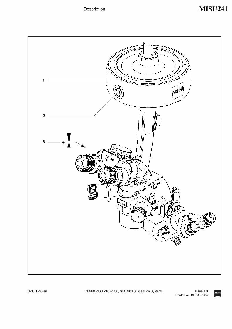
• With the fundus imaging system swung out of position, always positionthe microscope body in such a way that index dot (1) of the micro-scope's focus is in the middle of triangle (2) of the marking.
• Select a medium magnification (e.g. 1.0).
• Lower the surgical microscope toward the surgical field until you seethe patient's cornea sharply defined.
• Turn the locking lever for limiting the downward movement clockwiseas far as it will go and check without the patient that the suspensionarm cannot be lowered any further.
• It is vital that you read the user's manual on the fundus imaging sys-tem used (e.g. BIOM 3 from the company Oculus).
Phototoxic retinal injury in eye surgery
General
Several papers1)-5) dealing with the problem of phototoxicity in oph-thalmic surgery have been published. A comprehensive review of thesepublications reveals five aspects of particular concern:
– Illumination characteristics (spectral composition)
– Illumination intensity
– Angle of illumination
– Focus of the light source
– Exposure time to light
1 2
Risk of collision!
MISU241

26 Safety
G-30-1530-en OPMI® VISU 210 on S8, S81, S88 Suspension Systems Issue 1.0Printed on 19. 04. 2004
In the following, comments on these aspects are given and a descriptionof how Carl Zeiss, as a manufacturer, makes allowance for them in itssystems.
Illumination characteristics (spectral composition)
Studies on exposure of the eye to light of varying spectral compositiondate back to the early 1950s. These studies suggest that the potentialhazard of phototoxic injury to the patient's retina can be reduced byblocking out the blue and ultraviolet light below a wavelength of 475 nm.
Carl Zeiss provides a GG 475 retina protection filter for surgical micro-scopes recommended for use in ophthalmic surgery. This reduces notonly the light exposure of the patient's eye, but also that of the surgeon's.
It should be noted in this context that the use of filters inevitably leads toa change in the color of the light. The surgeon may therefore have to getused to the changed appearance of anatomical structures.
Illumination intensity
The majority of researchers suggest that the surgeon should use thelowest light intensity required at the patient's eye to guarantee goodviewing during surgery.
Carl Zeiss has addressed this aspect by providing its systems with a de-vice for continuously varying the brightness of the light source. This per-mits the surgeon to optimally adapt the light intensity at the patient's eyeto the conditions existing in each case.
Angle of illumination
A number of publications1)-4) suggest that the microscope should betilted to reduce the exposure of the macula to direct illumination.
Carl Zeiss ophthalmic surgical microscopes are therefore equipped withthe following:
– Tilting mechanism for the microscope body
– Oblique illumination with brightness control
Focus of the light source
Studies show that injuries are likely to occur if the filament of the lightsource is imaged on the patient's retina. The peak intensity of a filamentis considerably higher than that of an even and extended light sourcesuch as a light guide.
MISU241

G-30-1530-en OPMI® VISU 210 on S8, S81, S88 Suspension Systems Issue 1.0Printed on 19. 04. 2004
Safety 27
This is the reason why Carl Zeiss uses fiber optic illumination in its sur-gical microscope systems.
Exposure time to light
According to some publications, the phakic or aphakic eye should not beexposed to the light source longer than a few minutes. In every operationthe exposure of the retina to light is dependent on the type and durationof surgery and on any complications which occur. It is therefore recom-mended in ophthalmic surgery to keep the light intensity as low as pos-sible, or to use a device which prevents the light from entering through thepatient's pupil. Also, the surrounding light sources should not cause addi-tional strain to the patient's eye.
Carl Zeiss has provided an answer to this problem in the form of a swing-in retinal protection device for insertion into the beam path of the surgicalmicroscope. This device ensures total eclipsing of the pupil, preventinglight from entering into the patient's eye. It can be swung out when a redreflex is required.
Intensity scale
The intensity scale of our suspension system is calibrated in units of the”spectrally weighted radiance for the photochemical hazard to the phakiceye (LB)”5).
LB is the spectral radiance L(λ) integrated over the spectral range from380 nm to 700 nm and weighted using B(λ):
where B(λ) is the spectral weighting function for the photochemicalhazard of the retina in the phakic eye.
The quantity LB = 500 mW/cm² sr is the reference value and is defined as1.0 on the intensity scale of the suspension system5) . At this referencevalue, photoretinitis might be expected to occur as a result of the micro-scope illumination after a retinal exposure time totaling 10 minutes. Thisapplies to the exposure of a specific point on the retina with an uninter-rupted illumination beam. In cataract surgery, instruments such as thephacoemulsification handpiece, the use of fluids in the eye, manipulationin and movements of the eye ensure that the illumination beam path is in-terrupted. These are factors which considerably increase the period afterwhich photoretinitis might be expected to occur.
700
LB = ∑L(λ) B(λ) ∆λ
380
MISU241

28 Safety
G-30-1530-en OPMI® VISU 210 on S8, S81, S88 Suspension Systems Issue 1.0Printed on 19. 04. 2004
In conclusion
Carl Zeiss recommends:
– Use of the GG 475 retina protection filter.
– Reduction of the illumination of the surgical area to the extent requiredfor the patient's safety and for clear microscopic visualization.
– Tilting of the microscope body as required.
– Use of the retina protection device.
– Maximum reduction of the exposure of the patient's eye to light fromsurrounding light sources.
These measures should help the surgeon to reduce the risk of phototoxicretinal injury in the patient.
Note:The illumination system of the VISU 210 surgical microscope always con-tains a UV blocking filter.
The use of this filter ensures that the illumination intensity lies below 50µW/cm2 in the range between 305 nm and 400 nm.
This helps the surgeon to reduce the risk of phototoxic retinal injury in thepatient.
List of references1) H. Stiller, and B. Rassow, "Light hazards to the patient's retina fromophthalmic instruments," Applied Optics-OT 30, 2187-2196 (1991).2) American Conference of Governmental Industrial Hygienists, "Docu-mentation of the Threshold Limit Values for physical agents. 7th Edition,"(American Conference of Governmental Industrial Hygienists, Cincinnati,2001).3) S. G. Khwarg, F. A. Linstone, S. A. Daniels, S. J. Isenberg, T. A.Hanscom, M. Geoghegan, and B. R. Straatsma, "Incidence, risk factors,and morphology in operating microscope light retinopathy," Am. J. Oph-thalmol. 103, 255-263 (1987).4) G. Kleinmann, P. Hoffman, E. Schechtman, and A. Pollack, "Micro-scope-induced retinal phototoxicity in cataract surgery of short duration,"Ophthalmology 109, 334-338 (2002).5) ISO 10936-2:2001. Optics and optical instruments -- Operation micro-scopes -- Part 2: Light hazard from operation microscopes used in ocularsurgery.
MISU241

G-30-1530-en OPMI® VISU 210 on S8, S81, S88 Suspension Systems Issue 1.0Printed on 19. 04. 2004
Safety 29MISU241

30 Safety
G-30-1530-en OPMI® VISU 210 on S8, S81, S88 Suspension Systems Issue 1.0Printed on 19. 04. 2004
Safety devices of the suspension systems
1 Release barAllows non-sterile persons to release the magnetic brakes of the sus-pension system.
2 Adjustment screw for limiting the downward travelUse this screw to set the minimum vertical distance (working distance)from the surgical field. Check this setting before each surgical proce-dure.
3 Locking knobfor locking the suspension arm in its horizontal position.Before removing or attaching a unit (microscope, tube, etc.), move thesuspension arm into a horizontal position. Pull out the locking knoband turn it clockwise or counterclockwise through 180°, while slightlymoving the suspension arm up and down until the lock engages.When locked, the suspension arm can no longer suddenly spring up-ward when insufficient weight is attached. After attaching a unit, per-form the balancing procedure.
MISU241

G-30-1530-en OPMI® VISU 210 on S8, S81, S88 Suspension Systems Issue 1.0Printed on 19. 04. 2004
Safety 31
1
1
2
3
MISU241

32 Safety
G-30-1530-en OPMI® VISU 210 on S8, S81, S88 Suspension Systems Issue 1.0Printed on 19. 04. 2004
Xenon illumination system
1 Selecting the backup lampThe lamp module contains two xenon lamps. The second lamp is usedas a backup lamp which has to be swung into the illumination beampath when the first lamp fails.If the xenon lamp fails, open the lamp module as follows:Press button (5). The lamp module is slightly ejected. Pull out the lampmodule as far as it will go. Turn knob (1) through 180° until it snaps in.This moves the backup lamp into the illumination beam path. Push thelamp module all the way back into the lamp housing.
2 Display: Backup lamp is in useWhen the red segment in knob (1) lights up, the backup lamp is in use.
Note:If the first lamp has failed and the backup lamp is in use, make sure tohave a backup lamp module ready at hand as a precaution.
3 Yellow indicator lampLights when the lamp has failed, or if the lamp module is defective.After activation and ignition of the backup lamp, the yellow indicatorlamp goes out again.
4 Manual functionWhen the manual function has been activated, all electrical controlsystems are inoperative. The lamp brightness is automatically ad-justed to a fixed setting.
MISU241

G-30-1530-en OPMI® VISU 210 on S8, S81, S88 Suspension Systems Issue 1.0Printed on 19. 04. 2004
Safety 33
3
4
5
1
2 2
MISU241

34 Safety
G-30-1530-en OPMI® VISU 210 on S8, S81, S88 Suspension Systems Issue 1.0Printed on 19. 04. 2004
Halogen illumination system
1 FlapThe flap is the mechanical indicator for the operating status of the hal-ogen lamps.
– When the flap is closed, the main lamp is operative.
– When the flap is open, the main lamp has failed. The backup lampis on.
2 Activating the backup lampThe lamp housing contains a backup lamp which is automaticallyswung into the illumination beam path when the first lamp fails. If thisautomatic function fails, you can switch on the backup lamp bypressing this button.
3 GG 475 retina protection filterWhen operating on the eye, always use a GG 475 protection filter toensure that the patient's retina is not exposed to unnecessary (blue)radiation (risk of retinal injury). The filter knobs have four positions:
4 Yellow indicator lamp
– Lights when the main lamp has failed. In addition, open flap (1) onthe lamp module indicates that the main lamp has failed. The back-up lamp is on.
– Blinks when the backup lamp has failed.
5 Manual functionWhen the manual function has been activated, all electrical controlsystems are inoperative. The lamp brightness is automatically ad-justed to a fixed setting.
0 no filter
1 GG 475 filter: to protect the patient's eye during surgery againstunnecessary (blue) radiation (retinal injury).
2 KK 40 filter: to increase the color temperature
3 no filter
MISU241

G-30-1530-en OPMI® VISU 210 on S8, S81, S88 Suspension Systems Issue 1.0Printed on 19. 04. 2004
Safety 35
4
5
3
2
1
MISU241

36 Safety
G-30-1530-en OPMI® VISU 210 on S8, S81, S88 Suspension Systems Issue 1.0Printed on 19. 04. 2004
Manual function
1 Manual keyThe Manual key permits you to switch to manual operation. The mo-torized control functions of the surgical microscope are deactivated.The lamp brightness is automatically adjusted to a fixed setting, thevalue being shown in the first display section.When the manual mode is activated, the yellow LED is lit and the word"MANUAL" blinks in the third display section.
The surgical microscope can no longer be operated via the foot controlpanel, the handgrips or the display and key field.In the manual mode, you can only switch the illumination on and off onthe foot control panel and release the magnetic brakes by pressing theappropriate key on the surgical microscope.
The manual mode is retained even if you turn the power switch of theinstrument off and on again.
Press the Manual key once again to reactivate electronic control; thedisplay in the display and key field then returns to the basic mode.
MISU241

G-30-1530-en OPMI® VISU 210 on S8, S81, S88 Suspension Systems Issue 1.0Printed on 19. 04. 2004
Safety 37
1
MISU241

38 Safety
G-30-1530-en OPMI® VISU 210 on S8, S81, S88 Suspension Systems Issue 1.0Printed on 19. 04. 2004
Warning labels and notes
Caution:Observe all warning labels and notes!If any label is missing on your instrument or has become illegible, pleasecontact us or one of our authorized representatives. We will supply themissing labels.
OPMI VISU 210
MISU241

G-30-1530-en OPMI® VISU 210 on S8, S81, S88 Suspension Systems Issue 1.0Printed on 19. 04. 2004
Safety 39
Illumination systems
1
Superlux Eye
GG 475
MISU241

40 Safety
G-30-1530-en OPMI® VISU 210 on S8, S81, S88 Suspension Systems Issue 1.0Printed on 19. 04. 2004
S88 floor stand
MISU241

G-30-1530-en OPMI® VISU 210 on S8, S81, S88 Suspension Systems Issue 1.0Printed on 19. 04. 2004
Safety 41
S8 ceiling mount
MISU241

42 Safety
G-30-1530-en OPMI® VISU 210 on S8, S81, S88 Suspension Systems Issue 1.0Printed on 19. 04. 2004
S81 ceiling mount
MISU241

G-30-1530-en OPMI® VISU 210 on S8, S81, S88 Suspension Systems Issue 1.0Printed on 19. 04. 2004
Description 43
Description
VISU 210 surgical microscope 46
Intended use 46
Description of the modules 46
Illumination system 53
Controls, displays, connections 56
Binocular tubes and eyepieces 64
Illumination systems - halogen and xenon 68
Halogen illumination system 68
Xenon illumination system 72
S88 floor stand 76
Intended use 76
Description of the modules 77
Design 78
Stand base with column 82
Connection panel 84
Suspension arm 86
Display field with control keys 88
Instrument tray (option) 90
S8 Ceiling Mount 92
Intended use 92
Description of the modules 93
Design 94
Handle 98
Power switch with connector (option) 100
Suspension arm 102
Display field with control keys 104
S81 ceiling mount 106
MISU241
44 Description
G-30-1530-en OPMI® VISU 210 on S8, S81, S88 Suspension Systems Issue 1.0Printed on 19. 04. 2004
Intended use 106
Description of the modules 107
Design 108
Power switch, connector and socket (option) 112
Suspension arm 114
Display field with control keys 116
VISU 210 surgical microscope on S88 floor stand 118
Intended use 118
Design 118
VISU 210 surgical microscope on S8 ceiling mount 120
Intended use 120
Design 120
VISU 210 surgical microscope on S81 ceiling mount 122
Intended use 122
Design 122
Foot control panel (option) 124
Intended use 124
Design 124
MISU241

G-30-1530-en OPMI® VISU 210 on S8, S81, S88 Suspension Systems Issue 1.0Printed on 19. 04. 2004
Description 45MISU241

46 Description
G-30-1530-en OPMI® VISU 210 on S8, S81, S88 Suspension Systems Issue 1.0Printed on 19. 04. 2004
VISU 210 surgical microscope
Intended use
Note:The illumination system of the VISU 160 surgical microscope always con-tains a UV blocking filter.
The use of this filter ensures that the illumination intensity lies below 50µW/cm2 in the range between 305 nm and 400 nm.
This helps the surgeon to reduce the risk of phototoxic retinal injury in thepatient.
Description of the modules
The VISU 210 surgical microscope is comprised of the following modules:
1 X-Y couplingThe X-Y coupling allows motorized fine positioning of the surgical mi-croscope in a horizontal plane. The range of travel is 40 mm x 40 mm.The speed of travel can be set on the control panel of the suspensionsystem.
The X-Y coupling is provided with a recentering mechanism. Whenyou press actuator button (2) or button (4) or (5) of the foot controlpanel,
– the X-Y coupling adopts its center position,
– the focusing system of the surgical microscope is set to its initialposition (3), if the XY-RES function has been selected in configu-ration mode 1, see page 185.
– the zoom system is set to a preselected magnification factor, if theXYZ-RES function has been selected. This function is only availa-ble with the S88 floor stand.
4 5
MISU241
G-30-1530-en OPMI® VISU 210 on S8, S81, S88 Suspension Systems Issue 1.0Printed on 19. 04. 2004
Description 47
1
2
3
MISU241

48 Description
G-30-1530-en OPMI® VISU 210 on S8, S81, S88 Suspension Systems Issue 1.0Printed on 19. 04. 2004
2 Support arm for surgical microscopeThe support arm incorporates a tilt device. This allows the viewing di-rection of the surgical microscope to be adapted to the requirementsof the surgical field. Using the knob for fine tilt, you can position thesurgical microscope in a range from +180° to -180° (+ in the directionof the surgeon and - in the opposite direction). The +90° setting is idealfor surgery on patients in a seated position or lying on their side.
Caution:Do not tilt the microscope beyond + / - 180°, as this could damage themicroscope cable or the light guide.
3 MicroscopeThe apochromatic optics of the main microscope provide superb op-tical quality. The microscope image displays optimum contrast and ex-cellent detail recognition along with a large depth of field. The brightmicroscope image is a particular benefit in vitreoretinal surgery. A 1:6ratio zoom system allows the magnification of the overall system to beset as required by the surgical procedure.
Two apochromatic objective lenses with focal lengths of 175 mm and200 mm are available for different working distances.
4 180° tiltable binocular tubeDue to its large tilt range, the tiltable binocular tube allows optimumadaptation to extreme surgical conditions.
5 Inclined binocular tube (option)This tube is used as a viewing device for the surgeon. The viewingangle of 45° allows work with minimum fatigue.
The standard equipment includes eyepieces with a magnificationfactor of 12.5x (option: 10x).
MISU241

G-30-1530-en OPMI® VISU 210 on S8, S81, S88 Suspension Systems Issue 1.0Printed on 19. 04. 2004
Description 49
2
3
53
4
MISU241

50 Description
G-30-1530-en OPMI® VISU 210 on S8, S81, S88 Suspension Systems Issue 1.0Printed on 19. 04. 2004
6 Assistant's microscope 0°The assistant's microscope is an integral part of the VISU 210 surgicalmicroscope, i.e. it cannot be separated from the main microscope.The assistant sees the same image as the main surgeon. Thesystem's excellent image quality is also available to the assistant.
The assistant's microscope has two working positions. They are lo-cated on the right and left of the main surgeon at an angle of 90° to themain surgeon's viewing direction. No locking mechanism has beenprovided, allowing the assistant to move the microscope by a certainamount out of the 90° position, if necessary.
Warning!To prevent the assistant's microscope from moving downward of itsown accord when the main microscope is being tilted, the assistant'smicroscope must be adjusted and locked in position using screw (5)before surgery.
The assistant's microscope is equipped with a focusing system and a5-step magnification changer. This enables the assistant to adjust hismicroscope image independently of the main surgeon.
The binocular tube can be turned by ± 12° about the optical axis of theassistant's microscope. In addition, the assistant's microscope can betilted by 15°. If the assistant finds the viewing angle too steep, an op-tical wedge (option) can be installed between the microscope bodyand the binocular tube to permit horizontal viewing.
The standard equipment includes eyepieces with a magnificationfactor of 10x, providing a low initial magnification. This provides thebenefit of a wide field of view and an improved overview of the surgicalfield. The assistant sees the red reflex in both eyepieces.
7 Locking screw for the assistant's microscopeAfter adjusting the assistant's microscope as required, secure it in po-sition using this screw.
MISU241

G-30-1530-en OPMI® VISU 210 on S8, S81, S88 Suspension Systems Issue 1.0Printed on 19. 04. 2004
Description 51
6 7
MISU241

52 Description
G-30-1530-en OPMI® VISU 210 on S8, S81, S88 Suspension Systems Issue 1.0Printed on 19. 04. 2004
MISU241

G-30-1530-en OPMI® VISU 210 on S8, S81, S88 Suspension Systems Issue 1.0Printed on 19. 04. 2004
Description 53
Illumination system
The illumination system has been designed for use in ophthalmology. Alight guide directs the light from the light source in the suspension systemto the surgical microscope.
A retinal protection device is provided to protect the patient's eye fromphotoretinitis. This device can be swung into the beam path if no red reflexis required.
At the light source integrated in the suspension system, a GG 475 eyeprotection filter can be swung into the beam path. This filter markedly re-duces the exposure of the patient's and surgeon's eyes to light.
Warning!
– Avoid looking directly into the light source, e.g. into the microscope ob-jective lens or into the light guide!
– Adjust the intensity of the illumination of the patient's eye through thesurgical microscope in such a way that the fundus is exposed to as lit-tle light as possible.
– If no red reflex is required, swing the retinal protection device into thebeam path. Only use the retro-illumination contrast-enhancing stop(see page 60) if the procedure requires a red reflex.
– When operating on the eye, always use a GG 475 protection filter toensure that the patient's retina is not exposed to unnecessary (blue)radiation (risk of retinal injury).
MISU241

54 Description
G-30-1530-en OPMI® VISU 210 on S8, S81, S88 Suspension Systems Issue 1.0Printed on 19. 04. 2004
6° illumination
The 6° illumination can be faded out continuously. The result is a signifi-cantly reduced illumination reflex on the cornea. Despite this, the imageprovides high contrast and a high information content.
A slight opening (approx. 1/4) of the 6°- illumination is ideal for cataractsurgery.
2° illumination
2° illumination (1) provides a clearly visible red reflex. An optimized redreflex can be obtained by fading out the 6° illumination.
+6°
MISU241

G-30-1530-en OPMI® VISU 210 on S8, S81, S88 Suspension Systems Issue 1.0Printed on 19. 04. 2004
Description 55
1
+ 6°+ 2°
MISU241

56 Description
G-30-1530-en OPMI® VISU 210 on S8, S81, S88 Suspension Systems Issue 1.0Printed on 19. 04. 2004
Controls, displays, connections
1 Securing screw
2 X-Y coupling
3 Actuator button
– recenters the X-Y coupling.
– resets the focus to its initial position in the focusing range
– sets the zoom system to a preselected magnification factor, if theXYZ-RES function has been selected. This function is only availa-ble with the S88 floor stand.
Note:Press this button to start the recentering movement. To stop thismovement, press the button again.
You can also stop the recentering movement by briefly tipping on oneof the direction keys on the foot control panel.
4 Cable and light guide clip
5 Support arm with tilt device
6 Knobfor setting the tilt angle of the surgical microscope;+ 180° in the direction of the surgeon,- 180° in the opposite direction.
7 Arrows indicating the focusing rangeIf the dot is located between the two arrow tips, the focusing systemof the surgical microscope is in its starting position.
When using a fundus-imaging system
With the fundus imaging system swung out of the beam path, always po-sition the microscope body in such a way that index dot (1) of the micro-scope's focus is in the middle of triangle (2) of the marking (also see page25).
1 2
MISU241

G-30-1530-en OPMI® VISU 210 on S8, S81, S88 Suspension Systems Issue 1.0Printed on 19. 04. 2004
Description 57
1
4
5
6
3
2
7
MISU241

58 Description
G-30-1530-en OPMI® VISU 210 on S8, S81, S88 Suspension Systems Issue 1.0Printed on 19. 04. 2004
8 Dust cover
9 Handgripps for releasing the magnetic brakes of the suspension sys-temOnly in combination with suspension systems with magnetic brakes.
10 Display of the magnification factor of the zoom system
11 Securing screw
– Handgrip turned Magnetic brakes are unlocked, the in-strument can be moved as required.
– Handgrip not turned Magnetic brakes are locked, the in-strument cannot be moved.
MISU241

G-30-1530-en OPMI® VISU 210 on S8, S81, S88 Suspension Systems Issue 1.0Printed on 19. 04. 2004
Description 59
10
9
9
8
11
MISU241

60 Description
G-30-1530-en OPMI® VISU 210 on S8, S81, S88 Suspension Systems Issue 1.0Printed on 19. 04. 2004
12 DeepView buttonPermits the selection of different modes. When you switch on thesystem, the mode for transmission optimization is set by default. Thismode is recommended for viewing the posterior segment of the eye.Press the button to activate the mode for depth of field optimization.The green LED in the button is lit. This mode is recommended forviewing the anterior segment of the eye.
The next time the system is switched on, the mode last selected willbe activated.
13 Manual adjustment possibilities of the zoom system
14 Adjusting lever for 6° illuminationfor gradual fading in/out the coaxial illumination. Fading out the 6° illu-mination improves the visualization of structures in retro-illumination.
15 Aperture selector
16 Light guide socket
Retro-illumination contrast-enhancing stop.This stop reduces the straylight reflected from the sclera.Diameter approx. 16 mm (with objective lens f = 200 mm):Clear aperture.Outside the diameter of approx. 16 mm: Partially transmittingperiphery.
Clear aperture. The field of view is fully illuminated.
Retinal protection device. This device does not snap in, i.e. itcan be moved continuously in the image.
Horizontal slit with a width of 2.5 mm. The slit can be continu-ously moved in the vertical direction in the field of view.
Horizontal slit with a width of 5 mm. The slit can be continu-ously moved in the vertical direction in the field of view.
Vertical slit with a width of 2.5 mm. The slit snaps in at thecenter of the field of view.
MISU241

G-30-1530-en OPMI® VISU 210 on S8, S81, S88 Suspension Systems Issue 1.0Printed on 19. 04. 2004
Description 61
13
14 15 16
12
MISU241

62 Description
G-30-1530-en OPMI® VISU 210 on S8, S81, S88 Suspension Systems Issue 1.0Printed on 19. 04. 2004
17 Locking screwfor locking the coobservation tube within the 12° range of rotation.
18 Binocular tube of the assistant's microscope
19 Focusing knobfor focusing the assistant's microscope independently of the main sur-geon.
20 Five-step manual magnification changer
21 Locking screwfor locking the assistant's microscope within the 15° tilt range.
MISU241

G-30-1530-en OPMI® VISU 210 on S8, S81, S88 Suspension Systems Issue 1.0Printed on 19. 04. 2004
Description 63
18
19 20 21
17
MISU241

64 Description
G-30-1530-en OPMI® VISU 210 on S8, S81, S88 Suspension Systems Issue 1.0Printed on 19. 04. 2004
Binocular tubes and eyepieces
You can mount a 180° tiltable tube or a 45° inclined tube on the VISU 210surgical microscope as required.
180° tiltable tube
1 PD adjustment knobThe correct position has been reached when the two eyepiece imagesmerge into one. You can read off the interpupillary distance set on theadjustment knob.
2 180° tiltable tube
3 Eyepiece mount
45° inclined tube
4 45° inclined tube
5 PD adjustment knobThe correct position has been reached when the two eyepiece imagesmerge into one. You can read off the interpupillary distance set on theadjustment knob.
6 Eyepiece mount
MISU241

G-30-1530-en OPMI® VISU 210 on S8, S81, S88 Suspension Systems Issue 1.0Printed on 19. 04. 2004
Description 65
4
5
1
2
3
6
MISU241

66 Description
G-30-1530-en OPMI® VISU 210 on S8, S81, S88 Suspension Systems Issue 1.0Printed on 19. 04. 2004
Widefield eyepieces with magnetic coupling
Note:When you remove these eyepieces from the tube, please note that theyare fitted with a magnetic coupling. When mounted, the eyepieces displaya very weak magnetic field, so that the usual rules for the handling of mag-nets must only be observed with eyepieces which have not been mountedon the microscope:
• Do not place the eyepieces close to instruments where there is anyrisk of magnetization.
• Do not place the eyepieces on sensitive electronic units such as infu-sion pumps, cardiac pace-makers, measuring instruments or magnet-ic data carriers such as disks, audiotapes and videotapes, or creditcards.
• Always store eyepieces not used in their original packaging.
1 EyecupAlways adjust the eyecups in such a way that you can see the full fieldof view.
2 Diopter adjustment ringThe eyepieces provide ametropia compensation between -8 D and+5 D. Eyeglass wearers who perform surgery wearing their glassesset the diopter adjustment ring to 0 D. Turn the ring until you have ob-tained the optimum setting. An integrated brake holds the ring in theposition set.
3 Diopter scalefor reading the prescription set.
– Viewing with eyeglasses: Screw in the eyecups all the way.
– Viewing without eyeglasses: Screw out the eyecups until yousee the full field of view.
MISU241

G-30-1530-en OPMI® VISU 210 on S8, S81, S88 Suspension Systems Issue 1.0Printed on 19. 04. 2004
Description 67
1
2
3
MISU241

68 Description
G-30-1530-en OPMI® VISU 210 on S8, S81, S88 Suspension Systems Issue 1.0Printed on 19. 04. 2004
Illumination systems - halogen and xenon
Halogen illumination system
The ceiling mount is equipped with an illumination system for fiber illumi-nation. The lamp housing contains a backup lamp which is automaticallyswung into the illumination beam path when the first lamp fails.If required, the illumination system can be equipped with a second lamphousing so that two separate illumination systems are available for fiberillumination.
1 Lamp module
2 Ventilation gridDo not cover the ventilation grid! Make sure that drapes do not coverthe grid. This can lead to overheating of the lamp modules and to lampfailure.
3 FlapThe flap is the mechanical indicator for the operating status of the ha-logen lamps.
– When the flap is closed, the main lamp is operative (green light (9)is on).
– When the flap is open, the main lamp has failed. The backup lampis operative (yellow light (8) is on).
4 Manual selection of the backup lampIf the automatic selector system fails, press this button to switch on thebackup lamp.
5 Opening the lamp moduleWhen you press this button, the lamp module is slightly ejected. Pullout the lamp module all the way for lamp change.
6 Filter selector knobsThe filter knobs have four positions:
0 no filter
1 GG 475 filter: to protect the patient's eye during surgery againstunnecessary (blue) radiation (retinal injury).
2 KK 40 filter: to increase the color temperature
3 no filter
MISU241

G-30-1530-en OPMI® VISU 210 on S8, S81, S88 Suspension Systems Issue 1.0Printed on 19. 04. 2004
Description 69
8
9
1
2
3
4
5
6
MISU241

70 Description
G-30-1530-en OPMI® VISU 210 on S8, S81, S88 Suspension Systems Issue 1.0Printed on 19. 04. 2004
7 Brightness controlBrightness can be adjusted using the two keys (7) on the controlpanel.
Note:With suspension systems with two lamp housings, you can also adjustthe brightness of lamp 1 or 2 by pressing the appropriate key on thefoot control panel.
8 Yellow indicator lamp
– Lights when the main lamp has failed. The backup lamp is on.
– Blinks when the backup lamp has failed.
9 Green indicator lampIndicates which illumination system is on.
10 Selector:
After the instrument and one of the illumination systems have beenswitched on:
– If the yellow indicator lamp is lit, the main lamp has failed.
– If the yellow indicator lamp blinks, the backup lamp has failed.
Note:If two lamp housings are available, you can set the selector switch in sucha way
– that one illumination system each can be switched on the left-handand right-hand side of the foot control panel,
– or that both illumination systems can be switched on the left-hand orright-hand side of the foot control panel.
Illumination is off.
Illumination is on.
Illumination can be switched on/off on the left-hand side ofthe foot control panel.
Illumination can be switched on/off on the right-hand side ofthe foot control panel.
MISU241

G-30-1530-en OPMI® VISU 210 on S8, S81, S88 Suspension Systems Issue 1.0Printed on 19. 04. 2004
Description 71
7
9
8
10
0,7
MISU241

72 Description
G-30-1530-en OPMI® VISU 210 on S8, S81, S88 Suspension Systems Issue 1.0Printed on 19. 04. 2004
Xenon illumination system
The suspension system is equipped with a xenon illumination system forfiber illumination. The xenon lamp generates light whose spectrum re-sembles that of natural daylight. Regardless of the brightness setting, thecolor temperature of the light always remains the same. Normal daylightfilm without any additional conversion filters can therefore be used forphotographic documentation. The lamp housing contains two xenonlamps. The second lamp is used as a backup lamp which must be swunginto the illumination beam path should the first lamp fail.
Ventilation gridDo not cover the ventilation grid! For example, drapes could be coveringthe grid. This can lead to overheating of the lamp modules and to lampfailure.
1 Lamp module
2 Manual selection of the backup lampWhen the xenon lamp fails, open the lamp module as follows:Press button (4). The lamp module is slightly ejected. Pull out the lampmodule as far as it will go. Turn knob (2) through 180° until it snaps in.This moves the backup lamp into the illumination beam path. Push thelamp module all the way back into the lamp housing.
Note:When inserting a new lamp module, make sure that knob (2) is set to"1“. If the first lamp fails, you switch to the second lamp in logical se-quence.
3 Display: Backup lamp is in useWhen the red segment in knob (2) lights up, the backup lamp is in use.
4 Filter selector knobThe filter knob has two positions:
5 Opening the lamp moduleWhen you press this button, the lamp module is slightly ejected. Forchanging the lamp, pull out the lamp module as far as it will go. Turnknob (2) through 180° until it snaps in. This moves the backup lampinto the illumination beam path.
0 no filter
1 GG 475 filter swung in
MISU241

G-30-1530-en OPMI® VISU 210 on S8, S81, S88 Suspension Systems Issue 1.0Printed on 19. 04. 2004
Description 73
2
4
3
1
5
3
MISU241

74 Description
G-30-1530-en OPMI® VISU 210 on S8, S81, S88 Suspension Systems Issue 1.0Printed on 19. 04. 2004
6 Brightness controlYou can adjust the brightness using the two control keys on the controlpanel.
Note:The brightness of the xenon lamp can also be adjusted by pressingthe appropriate buttons on the foot control panel.
7 Yellow indicator lampLights when the lamp has failed, or if the lamp module is defective.After activation and ignition of the backup lamp, the yellow indicatorlamp goes out again.
Note:If the first lamp has failed and the backup lamp is in use, make sure tohave a backup lamp module ready at hand as a precaution.
8 Green indicator lampLights when the illumination has been switched on.
9 Selector:
Note:You can adjust the selector in such a way that you can switch the illu-mination on/off on the right-hand and left-hand sides of the foot controlpanel.
Illumination is off.
Illumination is on.
Illumination can be switched on/off on the left-hand side ofthe foot control panel.
Illumination can be switched on/off on the right-hand side ofthe foot control panel.
MISU241

G-30-1530-en OPMI® VISU 210 on S8, S81, S88 Suspension Systems Issue 1.0Printed on 19. 04. 2004
Description 75
6
9
7
8
0,7
MISU241

76 Description
G-30-1530-en OPMI® VISU 210 on S8, S81, S88 Suspension Systems Issue 1.0Printed on 19. 04. 2004
S88 floor stand
Intended use
The floor stand is a carrier system for Zeiss surgical microscopes for al-most all surgical disciplines. It is used to power and control the motorizedfunctions of a surgical microscope. The hallmarks of the floor stand are itssuperb mobility and easy operation. Four steerable casters on the standbase permit easy positioning in the OR. The motorized functions of thesurgical microscope can be controlled using a foot control panel or a handcontrol panel.
Further useful functions include, for example:
– magnetic brakes for almost effortless positioning,
– fully automatic change of the halogen lamp,
– brightness control via a foot control panel,
– reset of X-Y coupling, focus and zoom,
– user-defined basic settings for a maximum of nine users:
– lamp brightness
– speeds for focus, zoom and X-Y coupling
– and configurable keys on the foot control panel for focus memory,XY inversion, camera release, swing in/out of SDI, triggering anAUX signal.
Warning!When using xenon illumination, only operate the system with specialxenon lamps approved by Carl Zeiss. If any other than Carl Zeiss-ap-proved xenon lamps are used, there is the risk of severe injury to the pa-tient's eye.
MISU241

G-30-1530-en OPMI® VISU 210 on S8, S81, S88 Suspension Systems Issue 1.0Printed on 19. 04. 2004
Description 77
Description of the modules
The floor stand comprises an articulated arm, a stand column and a standbase. The articulated arm comprises a carrier arm and a suspension arm.The carrier arm contains the control unit with all electrical supply systemsrequired for the control of a motorized surgical microscope. You can con-trol the motorized functions via a foot control panel or a hand controlpanel.The suspension arm permits almost effortless positioning of the surgicalmicroscope. The spring force of the suspension arm can be varied in arange from 8 to 20 kg, permitting reliable balancing of the microscopeeven with heavy accessory equipment. The downward movement of thesuspension arm can be limited as required.A maneuvering handle is provided on the stand column. This handle isused to move the stand and to attach the foot control panel. The standcolumn is provided on its left and right with cable supports for winding upcables before the unit is relocated. Four steerable casters on the standbase permit easy positioning near the operating table. The stand basehas been designed in such a way that high stability is ensured even withunfavorable loading of the stand. A locking pedal is provided to lock thefloor standquickly and reliably into position.
Note:As the stand is very easy to maneuver, there is a tendency to underesti-mate its considerable weight. Therefore, move the stand slowly and care-fully!
MISU241

78 Description
G-30-1530-en OPMI® VISU 210 on S8, S81, S88 Suspension Systems Issue 1.0Printed on 19. 04. 2004
Design
1 Control unit
2 Carrier arm
3 Lamp housing (optionally with halogen or xenon illumination
4 Suspension arm
5 Stand base
MISU241

G-30-1530-en OPMI® VISU 210 on S8, S81, S88 Suspension Systems Issue 1.0Printed on 19. 04. 2004
Description 79
1 32 4
5
MISU241

80 Description
G-30-1530-en OPMI® VISU 210 on S8, S81, S88 Suspension Systems Issue 1.0Printed on 19. 04. 2004
Two different illumination systems are available for the suspension sy-stem.
1 Xenon illumination systemThe xenon illuminator is equipped with an illumination system for fiberillumination. The xenon lamp generates light whose spectrum resem-bles that of natural daylight. Regardless of the brightness setting, thecolor temperature of the light always remains the same. Normal day-light film without any additional conversion filters can therefore beused for photographic documentation. The lamp module contains twoxenon lamps. The second lamp is used as a backup lamp which hasto be manually swung into the illumination beam path if the first lampfails. You have to pull out the lamp module all the way before beingable to swing in the backup lamp.
Warning!When using xenon illumination, only operate the system with specialxenon lamps approved by Carl Zeiss. If any other than Carl Zeiss-ap-proved xenon lamps are used, there is the risk of severe injury to the pa-tient's eye.
2 Halogen illuminationThe halogen illuminator is equipped with an illumination system forfiber illumination. The lamp housing contains a backup lamp which isautomatically swung into the illumination beam path when the firstlamp fails.If required, the illumination system can be equipped with a secondlamp housing so that two separate illumination systems are availablefor fiber illumination. The second illumination system can be used, forexample, for a fiber slit lamp or a dual fiber illumination system.
MISU241

G-30-1530-en OPMI® VISU 210 on S8, S81, S88 Suspension Systems Issue 1.0Printed on 19. 04. 2004
Description 81
2
1
MISU241

82 Description
G-30-1530-en OPMI® VISU 210 on S8, S81, S88 Suspension Systems Issue 1.0Printed on 19. 04. 2004
Stand base with column
1 Handlefor moving the stand.
2 Supportfor hanging up the foot control panel during transport.
3 Cable support (2x)for winding up the power cord and the cable of the foot control panel.
4 Locking pedalPress once to lock the stand in position.Press a second time to release the locking pedal.
5 Steerable castersThe four steerable casters on the stand base permit easy positioningin the OR.
MISU241

G-30-1530-en OPMI® VISU 210 on S8, S81, S88 Suspension Systems Issue 1.0Printed on 19. 04. 2004
Description 83
1
2
4
5
3
MISU241

84 Description
G-30-1530-en OPMI® VISU 210 on S8, S81, S88 Suspension Systems Issue 1.0Printed on 19. 04. 2004
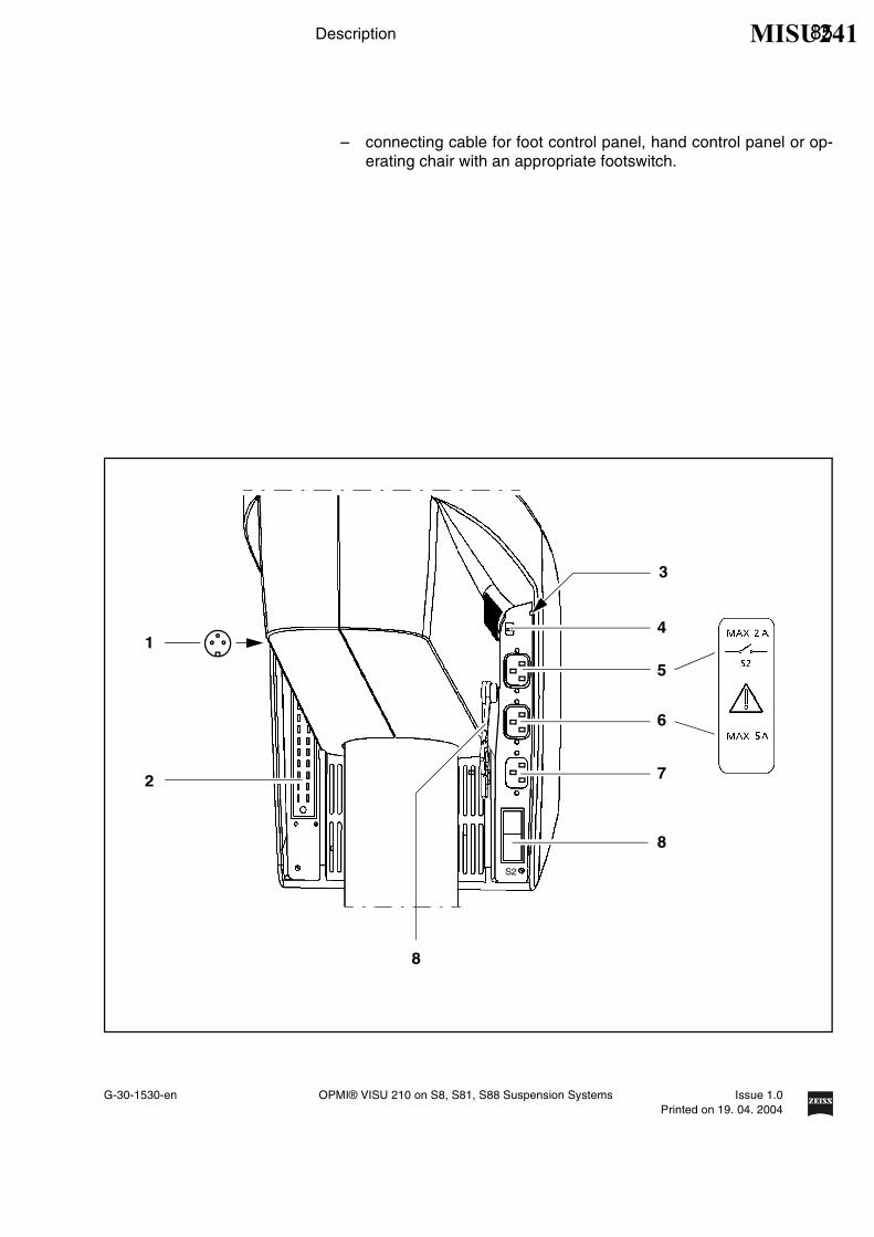
Connection panel
1 Remote control socketfor triggering an AUX signal, e.g. to switch on/off an external devicewith 24V/0.5A max.
2 Connector for switching componentConnection possibility for: a foot control panel, a hand control panel oran operating chair with an appropriate foot switch.
3 Potential equalization bolt
4 Indicator window for rated voltageThe voltage shown here must correspond to the rated voltage pro-vided on the site of installation. You can adjust the sliding switch usinga suitable tool.
Warning!Please observe the maximum power consumption of the two power out-lets (4) and (5). Only connect medical devices which have been approvedby us to these outlets (4) and (5). If you use other devices, make sure thatsafety is guaranteed regarding admissible ground leakage currents. Theadmissible limit value of the leakage current in the stand's power cordmust not exceed 500 µA in accordance with EN60601-1/IEC 601-1. CSAapproval in compliance with UL 2601-1 only allows a maximum groundleakage current of 300 µA.
5 Power outletfor medical devices with a current consumption of max. 2 A.
Note:The current of this power outlet is switched on/off using the S2 powerswitch (7).
6 Power outletfor medical devices with a current consumption of max. 5 A.
7 Power inlet
8 S2 power switchAfter the stand has been switched on, the green lamp in the switch islit.
9 Strain relief deviceThe strain relief device prevents inadvertent unplugging of the fol-lowing electrical connections:
– power cable
MISU241
G-30-1530-en OPMI® VISU 210 on S8, S81, S88 Suspension Systems Issue 1.0Printed on 19. 04. 2004
Description 85
– connecting cable for foot control panel, hand control panel or op-erating chair with an appropriate footswitch.
S2
4
5
6
7
8
2
3
8
1
MISU241

86 Description
G-30-1530-en OPMI® VISU 210 on S8, S81, S88 Suspension Systems Issue 1.0Printed on 19. 04. 2004
Suspension arm
1 Locking cap of arm cover
– To open: turn 90° to the left or right.
– To close: press down and turn 90° to the left or right.
2 Adjustment screw for limiting the downward movement of the armUse this screw to set the minimum vertical distance (working distance)to the surgical field. Move the surgical microscope into the working po-sition. Turn the screw clockwise as far as it will go. Perform this settingbefore each surgical procedure.
3 Weight balancing screwAfter mounting the surgical microscope including all accessories, ad-just the balance setting of the suspension arm using this knob. Theprocedure is described in the chapter “Operation“.
4 Mounting screwfor mounting the OPMI® coupling.
5 Locking knobfor securing the suspension arm in its horizontal position to allowmounting of the surgical microscope. Once secured, the suspensionarm can no longer suddenly spring upward when insufficient weight isattached.
6 Release barAllows non-sterile persons to release the magnetic brakes of the sus-pension system.
Release keys for magnetic brakesThe release keys for the magnetic brakes are located on the surgical mi-croscope. After pressing any one of the keys, you can move the articu-lated arm as required. When you release the key, the magnetic brakeslock all axes simultaneously.
MISU241

G-30-1530-en OPMI® VISU 210 on S8, S81, S88 Suspension Systems Issue 1.0Printed on 19. 04. 2004
Description 87
1 2
5
3
4
6
6
MISU241

88 Description
G-30-1530-en OPMI® VISU 210 on S8, S81, S88 Suspension Systems Issue 1.0Printed on 19. 04. 2004
Display field with control keys
The display and control panel is integrated in the control unit.
The surgical microscope on the suspension system can be controlled ei-ther manually or electronically. The control software required for elec-tronic control is installed in the electronics box of the suspension system.You operate the software via the control and display panel, where you canread off and reconfigure the current settings.
The control and display panel is structured as follows:
– Three display fields (LCD) with the associated keys "−" and "∆".
– One row of keys comprising the MODE, STORE and MANUAL keys,and a yellow LED above the MANUAL key.
User interface
The user interface of the suspension system comprises three displayfields and keys located beside and below them.A pair of keys "−" and "∆" has been assigned to every display field formaking the appropriate settings.
The control functions have been combined in several modes (menupages). The basic mode is always displayed in the normal operatingstatus.
The following is displayed in the basic mode:
– the current lamp brightness of lamp 1 (halogen) in the upper displayfield,
– the current lamp brightness of lamp 2 (halogen) in the middle displayfield,
– the current lamp brightness of lamp 1 (xenon) in the upper displayfield,
– Xe for xenon in the middle display field,
– the current user ID in the lower display field.
Keys
Three keys and an LED are provided below the displays.Use the "MODE", "STORE" and "MANUAL" keys to select the differentcontrol functions (modes).
MODE STORE MANUAL
USER
1
1
1.5
Basic mode
Halogen
MODE STORE MANUAL
USER
1
1
1.5
2
1.5
Xe
Xenon
MISU241

G-30-1530-en OPMI® VISU 210 on S8, S81, S88 Suspension Systems Issue 1.0Printed on 19. 04. 2004
Description 89
"MODE" key and "STORE" keyThe "MODE" and "STORE" keys permit you to access the different modesof the user interface. For details, please see the chapter "Operation".
"STORE" keyYou use the "STORE" key, for example, to save the current focus andzoom settings for OPMI® Vario on the suspension system.
"MANUAL" keyThe "MANUAL" key permits you to switch to manual operation. For de-tails, please see the chapter "Operation".
Yellow LED above the "MANUAL" keyThe yellow LED is lit when you have switched to the manual mode.
The illustration shows the control and display panel of the suspensionsystem with two halogen illumination systems (option).
MISU241

90 Description
G-30-1530-en OPMI® VISU 210 on S8, S81, S88 Suspension Systems Issue 1.0Printed on 19. 04. 2004
Instrument tray (option)
Note:• The floor stand can be equipped (also subsequently) with an instru-
ment carrier (1). Our service department or an authorized person willinstall the instrument carrier to your stand.
The MediLive documentation equipment can be screwed onto this instru-ment carrier. However, it is also possible to attach other instruments onthe carrier using a tension belt.
Warning!– The maximum load on the instrument carrier (1) must not exceed
10 kg! Make sure that the instruments stand as securely as possibleon the instrument carrier.
– Remember there is a risk of collision in the maximum swivel positionof the lift arm (transport position).
– Be careful of heights when passing through doorways.
MISU241

G-30-1530-en OPMI® VISU 210 on S8, S81, S88 Suspension Systems Issue 1.0Printed on 19. 04. 2004
Description 91
1
MISU241

92 Description
G-30-1530-en OPMI® VISU 210 on S8, S81, S88 Suspension Systems Issue 1.0Printed on 19. 04. 2004
S8 Ceiling Mount
Intended use
The S8 ceiling mount is a suspension system for Zeiss surgical micro-scopes. It is used to power and control the motorized functions of the sur-gical microscope. The hallmarks of the S8 ceiling mount are its superbmobility and easy operation. The motorized functions can be controlledusing a foot control panel or hand control panel.
Further useful functions include for example:
– the magnetic brakes for almost effortless positioning,
– fully automatic change of the halogen lamp
– brightness control via the foot control panel,
– reset for the XY coupling, focus and zoom,
– user-defined basic settings for a maximum of nine users:
– lamp brightness
– speed for focusing, zoom and XY coupling
– configuring the buttons on the foot control panel for focus memory,XY inversion, camera release, moving the SDI into and out of thebeam path, triggering of an AUX signal.
Warning!When using xenon illumination, only operate the system with specialxenon lamps approved by Carl Zeiss. If any other than Carl Zeiss-ap-proved xenon lamps are used, there is the risk of severe injury to the pa-tient's eye.
MISU241

G-30-1530-en OPMI® VISU 210 on S8, S81, S88 Suspension Systems Issue 1.0Printed on 19. 04. 2004
Description 93
Description of the modules
The S8 ceiling mount comprises the articulated arm, the suspension armwith the lamp housing, and the control panel.
The articulated arm consists of a lift arm and carrier arm. The lift functionpermits the ceiling mount to be brought into a parking position. A grip isprovided for the vertical adjustment of the ceiling mount.The suspension arm with the lamp housing and the control panel aremounted on the carrier arm. The control panel can be turned through180°; it contains all electrical supply systems required for the control of amotorized surgical microscope. You can control the motorized functionsvia a foot control panel or hand control panel.
The suspension arm permits almost effortless positioning of the surgicalmicroscope. The spring force of the suspension arm can be varied in arange from 8 to 20 kg, permitting reliable balancing of the microscopeeven with heavy accessory equipment attached. The range of downwardmovement of the suspension arm can be adjusted as required using thescrew for limiting downward travel.
MISU241

94 Description
G-30-1530-en OPMI® VISU 210 on S8, S81, S88 Suspension Systems Issue 1.0Printed on 19. 04. 2004
Design
1 Lift arm
2 Carrier arm
3 Suspension arm
4 Lamp housing (optionally with halogen or xenon illumination)
5 Control unit
MISU241

G-30-1530-en OPMI® VISU 210 on S8, S81, S88 Suspension Systems Issue 1.0Printed on 19. 04. 2004
Description 95
1
3
2
4 5
MISU241

96 Description
G-30-1530-en OPMI® VISU 210 on S8, S81, S88 Suspension Systems Issue 1.0Printed on 19. 04. 2004
Two different illumination systems are available for the suspension sy-stem.
1 Xenon illumination systemThe xenon illuminator is equipped with an illumination system for fiberillumination. The xenon lamp generates light whose spectrum resem-bles that of natural daylight. Regardless of the brightness setting, thecolor temperature of the light always remains the same. Normal day-light film without any additional conversion filters can therefore beused for photographic documentation. The lamp module contains twoxenon lamps. The second lamp is used as a backup lamp which hasto be manually swung into the illumination beam path if the first lampfails. You have to pull out the lamp module all the way before beingable to swing in the backup lamp.
Warning!When using xenon illumination, only operate the system with specialxenon lamps approved by Carl Zeiss. If any other than Carl Zeiss-ap-proved xenon lamps are used, there is the risk of severe injury to the pa-tient's eye.
2 Halogen illuminationThe halogen illuminator is equipped with an illumination system forfiber illumination. The lamp housing contains a backup lamp which isautomatically swung into the illumination beam path when the firstlamp fails.If required, the illumination system can be equipped with a secondlamp housing so that two separate illumination systems are availablefor fiber illumination. The second illumination system can be used, forexample, for a fiber slit lamp or a dual fiber illumination system.
MISU241

G-30-1530-en OPMI® VISU 210 on S8, S81, S88 Suspension Systems Issue 1.0Printed on 19. 04. 2004
Description 97
2
1
MISU241

98 Description
G-30-1530-en OPMI® VISU 210 on S8, S81, S88 Suspension Systems Issue 1.0Printed on 19. 04. 2004
Handle
A lift mechanism permits you to bring the ceiling mount into a parking po-sition. A handle is provided for this purpose on the ceiling mount. Thehandle remains within easy reach after the ceiling mount has been movedinto the parking position.
1 HandleUse the handle to pull the ceiling mount into its working position or tobring it into the parking position.The handle moves easily and unlocksthe lift mechanism. When you release the handle, the lift mechanismis locked and the ceiling mount is secured in position
2 Parking position
3 Working position
1
MISU241

G-30-1530-en OPMI® VISU 210 on S8, S81, S88 Suspension Systems Issue 1.0Printed on 19. 04. 2004
Description 99
2
3
MISU241

100 Description
G-30-1530-en OPMI® VISU 210 on S8, S81, S88 Suspension Systems Issue 1.0Printed on 19. 04. 2004
Power switch with connector (option)
The power switch and the connector can be either installed in the OR, orthey can be integrated in the ceiling mount, at the back of the carrier arm(see illustration).
1 RailThe delivery package contains a cable clip which is used to guide thecable of the foot control panel away from the operating table. Thecable clip can be easily attached to rail (1) either on the left or rightside of the arm.
2 Power switchWhen the ceiling mount is on, the green indicator lamp in the switch islit.
3 Connector for control component (option)Optional possibility of connecting a foot control panel or hand controlpanel. (In the standard version, the connector is integrated in the wallconsole).
4 Remote control socketfor triggering an AUX signal, e.g. to switch on/off an external deviceoperating at max. 24V/0.5A.
MISU241

G-30-1530-en OPMI® VISU 210 on S8, S81, S88 Suspension Systems Issue 1.0Printed on 19. 04. 2004
Description 101
3
1
2
22
4
MISU241

102 Description
G-30-1530-en OPMI® VISU 210 on S8, S81, S88 Suspension Systems Issue 1.0Printed on 19. 04. 2004
Suspension arm
1 Locking cap of arm cover
– To open: turn 90° to the left or right.
– To close: press down and turn 90° to the left or right.
2 Adjustment screw for limiting the downward movement of the armUse this screw to set the minimum vertical distance (working distance)to the surgical field. Move the surgical microscope into the working po-sition. Turn the screw clockwise as far as it will go. Perform this settingbefore each surgical procedure.
3 Weight balancing screwAfter mounting the surgical microscope including all accessories, ad-just the balance setting of the suspension arm using this knob. Theprocedure is described in the chapter “Operation“.
4 Mounting screwfor mounting the OPMI® coupling.
5 Locking knobfor securing the suspension arm in its horizontal position to allowmounting of the surgical microscope. Once secured, the suspensionarm can no longer suddenly spring upward when insufficient weight isattached.
6 Release barAllows non-sterile persons to release the magnetic brakes of the sus-pension system.
Release keys for magnetic brakesThe release keys for the magnetic brakes are located on the surgical mi-croscope. After pressing any one of the keys, you can move the articu-lated arm as required. When you release the key, the magnetic brakeslock all axes simultaneously.
MISU241

G-30-1530-en OPMI® VISU 210 on S8, S81, S88 Suspension Systems Issue 1.0Printed on 19. 04. 2004
Description 103
1 2
5
3
4
6
6
MISU241

104 Description
G-30-1530-en OPMI® VISU 210 on S8, S81, S88 Suspension Systems Issue 1.0Printed on 19. 04. 2004
Display field with control keys
The display and control panel is integrated in the control unit.
The surgical microscope on the suspension system can be controlled ei-ther manually or electronically. The control software required for elec-tronic control is installed in the electronics box of the suspension system.You operate the software via the control and display panel, where you canread off and reconfigure the current settings.
The control and display panel is structured as follows:
– Three display fields (LCD) with the associated keys "−" and "∆".
– One row of keys comprising the MODE, STORE and MANUAL keys,and a yellow LED above the MANUAL key.
User interface
The user interface of the suspension system comprises three displayfields and keys located beside and below them.A pair of keys "−" and "∆" has been assigned to every display field formaking the appropriate settings.
The control functions have been combined in several modes (menupages). The basic mode is always displayed in the normal operatingstatus.
The following is displayed in the basic mode:
– the current lamp brightness of lamp 1 (halogen) in the upper displayfield,
– the current lamp brightness of lamp 2 (halogen) in the middle displayfield,
– the current lamp brightness of lamp 1 (xenon) in the upper displayfield,
– Xe for xenon in the middle display field,
– the current user ID in the lower display field.
Keys
Three keys and an LED are provided below the displays.Use the "MODE", "STORE" and "MANUAL" keys to select the differentcontrol functions (modes).
MODE STORE MANUAL
USER
1
1
1.5
Basic mode
Halogen
MODE STORE MANUAL
USER
1
1
1.5
2
1.5
Xe
Xenon
MISU241

G-30-1530-en OPMI® VISU 210 on S8, S81, S88 Suspension Systems Issue 1.0Printed on 19. 04. 2004
Description 105
"MODE" key and "STORE" keyThe "MODE" and "STORE" keys permit you to access the different modesof the user interface. For details, please see the chapter "Operation".
"STORE" keyYou use the "STORE" key, for example, to save the current focus andzoom settings for OPMI® Vario on the suspension system.
"MANUAL" keyThe "MANUAL" key permits you to switch to manual operation. For de-tails, please see the chapter "Operation".
Yellow LED above the "MANUAL" keyThe yellow LED is lit when you have switched to the manual mode.
The illustration shows the control and display panel of the suspensionsystem with two halogen illumination systems (option).
MISU241

106 Description
G-30-1530-en OPMI® VISU 210 on S8, S81, S88 Suspension Systems Issue 1.0Printed on 19. 04. 2004
S81 ceiling mount
Intended use
The S81 ceiling mount is a suspension system for Zeiss surgical micro-scopes. It is used to power and control the motorized functions of the sur-gical microscope. The hallmarks of the S81 ceiling mount are its superbmobility and easy operation. The motorized functions can be controlledusing a foot control panel or hand control panel.
Further useful functions include for example:
– the magnetic brakes for almost effortless positioning,
– fully automatic change of the halogen lamp,
– brightness control via the foot control panel,
– reset for XY coupling, focus and zoom,
– user defined basic settings for a maximum of nine users:
– lamp brightness
– speed for focusing, zoom and XY coupling
– configuring the buttons on the foot control panel for focus memory,XY inversion, camera release, moving the SDI into and out of thebeam path, triggering of an AUX signal.
Warning!When using xenon illumination, only operate the system with specialxenon lamps approved by Carl Zeiss. If any other than Carl Zeiss-ap-proved xenon lamps are used, there is the risk of severe injury to the pa-tient's eye.
MISU241

G-30-1530-en OPMI® VISU 210 on S8, S81, S88 Suspension Systems Issue 1.0Printed on 19. 04. 2004
Description 107
Description of the modules
The S81 ceiling mount comprises a column, the carrier arm and the sus-pension arm.
The suspension arm with the lamp housing and the control panel ismounted on the carrier arm. The control panel can be turned through180°; it contains all electrical supply systems required for the control of amotorized surgical microscope. You can control the motorized functionsvia a foot control panel or hand control panel.
The suspension arm permits almost effortless positioning of the surgicalmicroscope. The spring force of the suspension arm can be varied in arange of 8 to 20 kg, permitting reliable balancing of the microscope evenwith heavy accessory equipment attached. The range of downwardmovement of the suspension arm can be adjusted as required using thescrew for limiting downward travel.
MISU241

108 Description
G-30-1530-en OPMI® VISU 210 on S8, S81, S88 Suspension Systems Issue 1.0Printed on 19. 04. 2004
Design
1 Column
2 Carrier arm
3 Suspension arm
4 Lamp housing (optionally with halogen or xenon illumination)
5 Control unit
MISU241

G-30-1530-en OPMI® VISU 210 on S8, S81, S88 Suspension Systems Issue 1.0Printed on 19. 04. 2004
Description 109
3
4 5
1
2
MISU241

110 Description
G-30-1530-en OPMI® VISU 210 on S8, S81, S88 Suspension Systems Issue 1.0Printed on 19. 04. 2004
Two different illumination systems are available for the suspension sy-stem.
1 Xenon illumination systemThe xenon illuminator is equipped with an illumination system for fiberillumination. The xenon lamp generates light whose spectrum resem-bles that of natural daylight. Regardless of the brightness setting, thecolor temperature of the light always remains the same. Normal day-light film without any additional conversion filters can therefore beused for photographic documentation. The lamp module contains twoxenon lamps. The second lamp is used as a backup lamp which hasto be manually swung into the illumination beam path if the first lampfails. You have to pull out the lamp module all the way before beingable to swing in the backup lamp.
Warning!When using xenon illumination, only operate the system with specialxenon lamps approved by Carl Zeiss. If any other than Carl Zeiss-ap-proved xenon lamps are used, there is the risk of severe injury to the pa-tient's eye.
2 Halogen illuminationThe halogen illuminator is equipped with an illumination system forfiber illumination. The lamp housing contains a backup lamp which isautomatically swung into the illumination beam path when the firstlamp fails.If required, the illumination system can be equipped with a secondlamp housing so that two separate illumination systems are availablefor fiber illumination. The second illumination system can be used, forexample, for a fiber slit lamp or a dual fiber illumination system.
MISU241

G-30-1530-en OPMI® VISU 210 on S8, S81, S88 Suspension Systems Issue 1.0Printed on 19. 04. 2004
Description 111
2
1
MISU241

112 Description
G-30-1530-en OPMI® VISU 210 on S8, S81, S88 Suspension Systems Issue 1.0Printed on 19. 04. 2004
Power switch, connector and socket (option)
The connector and socket can be either installed in the OR, or they canbe integrated in the ceiling mount, at the back of the carrier arm (see illus-tration).
1 RailThe delivery package contains a cable clip which is used to guide thecable of the foot control panel away from the operating table. Thecable clip can be easily attached to rail (1) either on the left or rightside of the arm.
2 Power switchWhen the ceiling mount is on, the green indicator lamp in the switch islit.
3 Connector for control component (option)Possibility of connecting a foot control panel or hand control panel.
4 Socket for control component (option)If the ceiling mount is installed on a ceiling track mount, you can usea hand control panel to move the ceiling mount to its working positionor parking position.
5 Remote control socketfor triggering an AUX signal, e.g. to switch on/off an external deviceoperating at max. 24V/0.5A.
MISU241

G-30-1530-en OPMI® VISU 210 on S8, S81, S88 Suspension Systems Issue 1.0Printed on 19. 04. 2004
Description 113
1
2
3
4
1
5
MISU241

114 Description
G-30-1530-en OPMI® VISU 210 on S8, S81, S88 Suspension Systems Issue 1.0Printed on 19. 04. 2004
Suspension arm
1 Locking cap of arm cover
– To open: turn 90° to the left or right.
– To close: press down and turn 90° to the left or right.
2 Adjustment screw for limiting the downward movement of the armUse this screw to set the minimum vertical distance (working distance)to the surgical field. Move the surgical microscope into the working po-sition. Turn the screw clockwise as far as it will go. Perform this settingbefore each surgical procedure.
3 Weight balancing screwAfter mounting the surgical microscope including all accessories, ad-just the balance setting of the suspension arm using this knob. Theprocedure is described in the chapter “Operation“.
4 Mounting screwfor mounting the OPMI® coupling.
5 Locking knobfor securing the suspension arm in its horizontal position to allowmounting of the surgical microscope. Once secured, the suspensionarm can no longer suddenly spring upward when insufficient weight isattached.
6 Release barAllows non-sterile persons to release the magnetic brakes of the sus-pension system.
Release keys for magnetic brakesThe release keys for the magnetic brakes are located on the surgical mi-croscope. After pressing any one of the keys, you can move the articu-lated arm as required. When you release the key, the magnetic brakeslock all axes simultaneously.
MISU241

G-30-1530-en OPMI® VISU 210 on S8, S81, S88 Suspension Systems Issue 1.0Printed on 19. 04. 2004
Description 115
1 2
5
3
4
6
6
MISU241

116 Description
G-30-1530-en OPMI® VISU 210 on S8, S81, S88 Suspension Systems Issue 1.0Printed on 19. 04. 2004
Display field with control keys
The display and control panel is integrated in the control unit.
The surgical microscope on the suspension system can be controlled ei-ther manually or electronically. The control software required for elec-tronic control is installed in the electronics box of the suspension system.You operate the software via the control and display panel, where you canread off and reconfigure the current settings.
The control and display panel is structured as follows:
– Three display fields (LCD) with the associated keys "−" and "∆".
– One row of keys comprising the MODE, STORE and MANUAL keys,and a yellow LED above the MANUAL key.
User interface
The user interface of the suspension system comprises three displayfields and keys located beside and below them.A pair of keys "−" and "∆" has been assigned to every display field formaking the appropriate settings.
The control functions have been combined in several modes (menupages). The basic mode is always displayed in the normal operatingstatus.
The following is displayed in the basic mode:
– the current lamp brightness of lamp 1 (halogen) in the upper displayfield,
– the current lamp brightness of lamp 2 (halogen) in the middle displayfield,
– the current lamp brightness of lamp 1 (xenon) in the upper displayfield,
– Xe for xenon in the middle display field,
– the current user ID in the lower display field.
Keys
Three keys and an LED are provided below the displays.Use the "MODE", "STORE" and "MANUAL" keys to select the differentcontrol functions (modes).
MODE STORE MANUAL
USER
1
1
1.5
Basic mode
Halogen
MODE STORE MANUAL
USER
1
1
1.5
2
1.5
Xe
Xenon
MISU241

G-30-1530-en OPMI® VISU 210 on S8, S81, S88 Suspension Systems Issue 1.0Printed on 19. 04. 2004
Description 117
"MODE" key and "STORE" keyThe "MODE" and "STORE" keys permit you to access the different modesof the user interface. For details, please see the chapter "Operation".
"STORE" keyYou use the "STORE" key, for example, to save the current focus andzoom settings for OPMI® Vario on the suspension system.
"MANUAL" keyThe "MANUAL" key permits you to switch to manual operation. For de-tails, please see the chapter "Operation".
Yellow LED above the "MANUAL" keyThe yellow LED is lit when you have switched to the manual mode.
The illustration shows the control and display panel of the suspensionsystem with two halogen illumination systems (option).
MISU241

118 Description
G-30-1530-en OPMI® VISU 210 on S8, S81, S88 Suspension Systems Issue 1.0Printed on 19. 04. 2004
VISU 210 surgical microscope on S88 floor stand
Intended use
The VISU 210 surgical microscope has been designed for surgical proce-dures in the field of ophthalmology, i.e. the microscope meets the specialrequirements of this discipline.
The S88 floor stand powers and controls the motorized functions of theVISU 210 surgical microscope. The hallmarks of the S88 floor stand areits superb mobility and easy operation. Four steerable casters on thestand base permit easy positioning in the OR. The motorized functions ofthe surgical microscope can be controlled using a foot control panel or ahand control panel.
The system is intended for use in offices, hospitals or other human med-icine institutions.
The system must only be operated by physicians, nurses and other med-ical staff who have undergone appropriate training and observe the in-structions of the user's manual. The installation conditions and the use ofthe system must meet microsurgical requirements:
– low vibration
– clean environment
– avoidance of extreme mechanical stress.
Design
1 VISU 210 surgical microscope with X-Y coupling
2 Coupling
3 S88 floor stand
MISU241

G-30-1530-en OPMI® VISU 210 on S8, S81, S88 Suspension Systems Issue 1.0Printed on 19. 04. 2004
Description 119
3
2
1
MISU241

120 Description
G-30-1530-en OPMI® VISU 210 on S8, S81, S88 Suspension Systems Issue 1.0Printed on 19. 04. 2004
VISU 210 surgical microscope on S8 ceiling mount
Intended use
The VISU 210 surgical microscope has been designed for surgical proce-dures in the field of ophthalmology, i.e. the microscope meets the specialrequirements of this discipline.
The S8 ceiling mount powers and controls the motorized functions of theVISU 210 surgical microscope. The hallmarks of the S8 ceiling mount areits superb mobility and easy operation. The motorized functions of the sur-gical microscope can be controlled using a foot control panel or a handcontrol panel.
The system is intended for use in offices, hospitals or other human med-icine institutions.
The system must only be operated by physicians, nurses and other med-ical staff who have undergone appropriate training and observe the in-structions of the user's manual. The installation conditions and the use ofthe system must meet microsurgical requirements:
– low vibration
– clean environment
– avoidance of extreme mechanical stress.
Design
1 VISU 210 surgical microscope with X-Y coupling
2 Coupling
3 S8 ceiling mount
MISU241

G-30-1530-en OPMI® VISU 210 on S8, S81, S88 Suspension Systems Issue 1.0Printed on 19. 04. 2004
Description 121
3
2
1
MISU241

122 Description
G-30-1530-en OPMI® VISU 210 on S8, S81, S88 Suspension Systems Issue 1.0Printed on 19. 04. 2004
VISU 210 surgical microscope on S81 ceiling mount
Intended use
The VISU 210 surgical microscope has been designed for surgical proce-dures in the field of ophthalmology, i.e. the microscope meets the specialrequirements of this discipline.
The S81 ceiling mount powers and controls the motorized functions of theVISU 210 surgical microscope. The hallmarks of the S81 ceiling mountare its superb mobility and easy operation. The motorized functions of thesurgical microscope can be controlled using a foot control panel or a handcontrol panel.
The system is intended for use in offices, hospitals or other human med-icine institutions.
The system must only be operated by physicians, nurses and other med-ical staff who have undergone appropriate training and observe the in-structions of the user's manual. The installation conditions and the use ofthe system must meet microsurgical requirements:
– low vibration
– clean environment
– avoidance of extreme mechanical stress.
Design
1 VISU 210 surgical microscope with X-Y coupling
2 Coupling
3 S81 ceiling mount
MISU241

G-30-1530-en OPMI® VISU 210 on S8, S81, S88 Suspension Systems Issue 1.0Printed on 19. 04. 2004
Description 123
3
2
1
MISU241

124 Description
G-30-1530-en OPMI® VISU 210 on S8, S81, S88 Suspension Systems Issue 1.0Printed on 19. 04. 2004
Foot control panel (option)
Intended use
The foot control panel permits you to control 14 different functions of asuspension system or surgical microscope, provided these functions arepart of your configuration (suspension system, surgical microscope). Theassignment of the functions to the controls of the foot control panel isshown on the next page.
Design
The foot control panel is equipped with two rocker switches (1) for con-trolling the ”zoom” and ”focus” functions. The up/down movements ofthese functions are located on the same side, allowing you to control thetwo directions by toe/heel movement, without having to shift your foot.Bridge (3) between two rocker switches (1) serves as a support to restyour foot on.
Connector (2) is used to connect the foot control panel to the connectorof a suspension system or wall-mounted control panel.
The foot control panel is enclosed in a water-tight rubber case.
MISU241

G-30-1530-en OPMI® VISU 210 on S8, S81, S88 Suspension Systems Issue 1.0Printed on 19. 04. 2004
Description 125
2
1
3
1
MISU241

126 Description
G-30-1530-en OPMI® VISU 210 on S8, S81, S88 Suspension Systems Issue 1.0Printed on 19. 04. 2004
The illustration shows the standard assignment of functions to the footcontrol panel. On request, our service staff can change the assignment ofthe focus/zoom functions and that of button (10).
1 Joystick for X-Y coupling
2 Reducing the lamp brightness
3 Recentering of the X-Y coupling and focus starting position (optional:control of Stereo Digital Inverter IIe / 3e from the company Oculus).The button is freely configurable, seepage 185.
4 ZOOM Reducing magnification (optional: FOCUS Reducingworking distance)
5 ZOOM Increasing magnification
6 On/Off of the lamp
7 No function
8 FOCUS Increasing working distance, (ZOOM Reducing magnifi-cation)
9 FOCUS Reducing working distance
10 Controlling external units using the Remote function (option: releaseof 35 mm camera) The button is freely configurable, seepage 185.
11 Increasing the lamp brightness
11
10
9
8
7
2
3
4
5
6
1
MISU241

G-30-1530-en OPMI® VISU 210 on S8, S81, S88 Suspension Systems Issue 1.0Printed on 19. 04. 2004
Preparations 127
Preparations
Attaching the equipment 128
Mounting the surgical microscope 128
Mounting the tube, the eyepieces and the objective lens 132
Changing the microscope accessories 136
Connections 138
Connecting the surgical microscope 138
Connecting the S light guide 138
Strain relief device on S88 floor stand 140
Connecting the S88 floor stand 142
Relocating the system 144
Adjusting the system - S88 floor stand 146
Adjusting the balance setting of the suspension arm 146
Adjusting the limit of downward movement 148
Adjusting the system - S8 ceiling mount 150
Adjusting the balance setting of the suspension arm 150
Adjusting the limit of downward movement 152
Positioning the S8 ceiling mount 154
Adjusting the system - S81 ceiling mount 156
Adjusting the balance setting of the suspension arm 156
Adjusting the limit of downward movement 158
Adjusting the system - General 161
Adjusting the supension system 161
Adjusting the tilt angle 162
Adjusting the microscope tilt to angles greater than 15° 164
Adjusting the surgical microscope 166
MISU241

128 Preparations
G-30-1530-en OPMI® VISU 210 on S8, S81, S88 Suspension Systems Issue 1.0Printed on 19. 04. 2004
Attaching the equipment
Mounting the surgical microscope
Warning!
The maximum weight of the microscope including accessories must notexceed 20 kg!
• Leave the suspension arm locked in its horizontal position until you
– have mounted and secured the complete equipment,
– and made the electrical connections.
• Then perform the balance setting procedure.
• Turn off the system at the power switch.
• Bring the suspension arm into its horizontal position, pull out lockingknob (1) and turn it clockwise or counterclockwise through 180°. At thesame time, slightly move the suspension arm up and down until thelock snaps in. This prevents the suspension arm from uncontrollablymoving upward when insufficient weight is attached.
• Use a 4 mm hex key to loosen mounting screw(3) by a few turns.
• Tilt coupling (2) upward and remove it in the upward direction.
• Loosen locking screw (6) by a few turns.
• Give securing screw(7) a few turns to loosen it.
• Slightly lubricate microscope shaft (8) (e.g. with instrument grease orvaseline).
• Slide coupling (2) from above over microscope shaft (8). Screw inmounting screw (5) from above and firmly tighten securing screw (4)using a 4 mm hex key.
MISU241

G-30-1530-en OPMI® VISU 210 on S8, S81, S88 Suspension Systems Issue 1.0Printed on 19. 04. 2004
Preparations 129
1
2
3
4
6
8
9
7
5
MISU241

130 Preparations
G-30-1530-en OPMI® VISU 210 on S8, S81, S88 Suspension Systems Issue 1.0Printed on 19. 04. 2004
• Screw in the securing screw (7) and tighten it firmly . The securingscrew (7) must go into the groove (9). This is ensured when the secu-ring screw is flush with the outer surface of the coupling.
• Insert the coupling (12) including the surgical microscope from aboveinto the receptacle (11) on the suspension arm and tilt the couplingdownward into its vertical position.
• Firmly tighten the mounting screw (3) using a 5 mm Allen key.
• Plug the cable clip (10) into the opening (13) of the coupling.
• Then perform the balance setting procedure.
Warning!
Before using and after re-equipping the unit, always make sure that se-curing screws (3), (4) and (7) have been tightened firmly.
Note:When mounting surgical microscopes with an integrated coupling, steps3 to 9 need not be performed.
MISU241

G-30-1530-en OPMI® VISU 210 on S8, S81, S88 Suspension Systems Issue 1.0Printed on 19. 04. 2004
Preparations 131
4 10 1211
13
7
3
MISU241

132 Preparations
G-30-1530-en OPMI® VISU 210 on S8, S81, S88 Suspension Systems Issue 1.0Printed on 19. 04. 2004
Mounting the tube, the eyepieces and the objective lens
Note:Always use the assistant's microscope with the associated binocular coo-bservation tube (shown in the illustration). If you use a different tube, thiswill give you an inverted image.
• Bring the suspension arm in a position convenient for you and tightenfriction adjustment knob (1).
• Give securing screw(6) a few turns to loosen it.
• Remove dust cover(2) and store it in a safe place.
• Place binocular tube (3) on the microscope and firmly tighten securingscrew (6).
• You can install further accessories between the binocular tube and themicroscope body. Lock these units in position in the same way usingsecuring screw (6).
• Place binocular tube (11) on the assistant's microscope and firmlytighten securing screw (8).
• You can install further accessories (e.g. 30° optical wedge) betweenthe binocular tube and the microscope body. Lock these units in posi-tion in the same way using securing screw (8).
• Insert 12.5x widefield eyepieces (5) as far as they will go in mounts (4)intended for them. The magnetic coupling reliably secures them in po-sition.
• Insert 10x widefield eyepieces (10) as far as they will go in mounts (9)intended for them. The magnetic coupling reliably secures them in po-sition.
Note:If you wish to use documentation equipment, we can supply an eyepiecewith a reticle to aid focusing. The retrofitting of a reticle to an eyepiece canonly be performed in the factory or by our service staff. Always install theeyepiece with the reticle on the same side of the binocular tube where thedocumentation equipment is located.
• Screw objective lens (7) into the microscope body and tighten it firmly.
MISU241

G-30-1530-en OPMI® VISU 210 on S8, S81, S88 Suspension Systems Issue 1.0Printed on 19. 04. 2004
Preparations 133
1
6 7
4
9
10
2
3
8
5 11
MISU241

134 Preparations
G-30-1530-en OPMI® VISU 210 on S8, S81, S88 Suspension Systems Issue 1.0Printed on 19. 04. 2004
Warning!• Before every use and after re-equipping the system, make sure that
the two binocular tubes (3 and 11) are securely locked in position.
• Make sure that the following components are firmly tightened:
– securing screws (6 and 8) and
– objective lens (7)
• When attaching any components, take care not to damage the Deep-View system.
• Re-adjust the balance of the suspension arm after every change ofequipment.
MISU241

G-30-1530-en OPMI® VISU 210 on S8, S81, S88 Suspension Systems Issue 1.0Printed on 19. 04. 2004
Preparations 135
6 7
3
8
11
MISU241

136 Preparations
G-30-1530-en OPMI® VISU 210 on S8, S81, S88 Suspension Systems Issue 1.0Printed on 19. 04. 2004
Changing the microscope accessories
You can change the microscope accessories in reverse order to that de-scribed before. Please observe the following:
• Turn off the unit at the power switch before changing any accessories.
• Bring the suspension arm in a position convenient for you and tightenfriction adjustment knob (1).
• After changing the accessories, re-adjust the friction as required.
Warning!• Before every use and after re-equipping the system, make sure that
the two binocular tubes (3 and 11) are securely locked in position.
• Make sure that the following components are firmly tightened:
– securing screws (6 and 8) and
– objective lens (7)
• When attaching any components, take care not to damage the Deep-View system.
• Re-adjust the balance of the suspension arm after every change ofequipment.
MISU241

G-30-1530-en OPMI® VISU 210 on S8, S81, S88 Suspension Systems Issue 1.0Printed on 19. 04. 2004
Preparations 137
6 7
3
8
11
MISU241

138 Preparations
G-30-1530-en OPMI® VISU 210 on S8, S81, S88 Suspension Systems Issue 1.0Printed on 19. 04. 2004
Connections
Connecting the surgical microscope
• Turn locking cap (1) by a quarter turn to the right or left and pull up cov-er (2).
• Plug microscope connector (3) into connector (4) and tighten the se-curing screws on the microscope connector.
• Press the microscope cable into cable clip (5). Install the cable in sucha way that it is neither stretched nor kinked when the microscope isturned or tilted.
• Press down cover (2) as far as it will go and lock it with cap (1).
Connecting the S light guide
• Insert the end of the light guide as far as it will go into the light guidesocket (7) of the microscope, and press the light guide into the cableclip (6).
Note:Make sure that the light guide is not stretched or kinked when the micro-scope is turned or tilted.
MISU241

G-30-1530-en OPMI® VISU 210 on S8, S81, S88 Suspension Systems Issue 1.0Printed on 19. 04. 2004
Preparations 139
1
2
3
4
5
6
7
Surgical microscope,shown rotated
MISU241

140 Preparations
G-30-1530-en OPMI® VISU 210 on S8, S81, S88 Suspension Systems Issue 1.0Printed on 19. 04. 2004
Strain relief device on S88 floor stand
Note:To prevent inadvertent unplugging of the power cable and of the controlelement connector, secure the two cables in strain relief device (1).
After strain relief device (1) has been mounted, the cables must have thefollowing length:
– 320 mm from the the strain relief device up to and including power out-let (9).
– 320 mm from the the strain relief device up to connector (10) of thefoot control panel, hand control panel or operating chair equipped witha footswitch.
• Form a loop with the cable as shown in (3).
• Open flap (4).
• Feed the cable through opening (5).
• Close flap (6).
• Tighten the cable until it encloses flap (7).
• Check the length of the cable.
1
MISU241

G-30-1530-en OPMI® VISU 210 on S8, S81, S88 Suspension Systems Issue 1.0Printed on 19. 04. 2004
Preparations 141
2 3 4
5 6 7 8
9
10
320 mm
MISU241

142 Preparations
G-30-1530-en OPMI® VISU 210 on S8, S81, S88 Suspension Systems Issue 1.0Printed on 19. 04. 2004
Connecting the S88 floor stand
• Check the voltage indicated at (3).
Caution:The voltage of the stand is factory-set to the rated voltage used in thecountry of destination. The rated voltage indicated at window (3) must cor-respond to the rated voltage available at the site of installation. If this isnot the case, you must re-adjust the sliding switch using a suitable tool.
Note:Insert or remove connectors (2) and (4) only if power switch (5) is off.
• Plug the connector of the foot control panel or operating chair into con-nector (2) of the stand.
• Attach the microscope cable to the existing cable support in such away that it is not stretched or bent when the microscope is swiveled.
• Secure the light guide in the cable support and insert the light into thelight guide mount on the microscope until stop. Make sure that the lightguide is not stretched or bent when the microscope is turned orswiveled.
Connect external instruments with max. 24 V / 0.5 A to the remote controlsocket (1); you must be able to switch these instruments on or off via anAUX-signal to the foot control keys which can be configured as required.
Connect the stand to line power using the power cord intended for it. Onlyuse power outlets which are provided with a properly connected protec-tive earth contact.
MISU241

G-30-1530-en OPMI® VISU 210 on S8, S81, S88 Suspension Systems Issue 1.0Printed on 19. 04. 2004
Preparations 143
2
3
4
5
6
1
MISU241

144 Preparations
G-30-1530-en OPMI® VISU 210 on S8, S81, S88 Suspension Systems Issue 1.0Printed on 19. 04. 2004
Relocating the system
Note:As the stand is very easy to maneuver, there is a tendency to underesti-mate its considerable weight. Therefore, move the stand slowly and care-fully!
Please observe the following points when relocating the stand:
• Fold the suspension arm to its moving position (see illustration on theopposite page).
• Switch off the illumination system using the knobs, and the system atits power switch.
• Unplug the power cord from the wall outlet.
• Wind up the cable of the foot control panel on one of the cable sup-ports, and hang the foot control panel on the handle.
• Wind up the power cord on the other cable support.
• Use the maneuvering handle for moving the stand.
• Be careful of heights when passing through doorways.
• Avoid collisions of any kind.
• Do not go over steps and edges: The stand might topple!
• Be extremely careful when moving over slopes.
• Do not park the stand on slopes.
Press the brake tab to lock the stand in position. Make sure that the standis no longer able to roll away by itself.
MISU241

G-30-1530-en OPMI® VISU 210 on S8, S81, S88 Suspension Systems Issue 1.0Printed on 19. 04. 2004
Preparations 145MISU241

146 Preparations
G-30-1530-en OPMI® VISU 210 on S8, S81, S88 Suspension Systems Issue 1.0Printed on 19. 04. 2004
Adjusting the system - S88 floor stand
Adjusting the balance setting of the suspension arm
• Now perform the balance setting procedure with the complete micro-scope equipment attached!
Note:Before you precisely adjust the balance setting of the suspension arm, werecommend performing a coarse balance setting of the arm. For this, thesuspension arm must be locked in its horizontal position.
• To perform the coarse balance setting, move the suspension armslightly up and down. At the same time, turn the adjustment screw (2)until you think that the spring force is sufficient to compensate for theweight of the surgical microscope and accessories.
Note:Clockwise turning increases the spring force, counterclockwiseturning reduces the spring force.
• Hold the suspension arm and pull out the locking knob (1). This mustbe possible without requiring a special effort. Otherwise, re-adjust thespring force using the adjustment screw (2).
• Press one of the release keys for the magnetic brakes on the micros-cope during the balance setting procedure. Move the suspension armalternately up and down by approx. 20 cm. Using adjustment screw(2), adjust the spring force in such a way that the effort required tomove the arm up or down is the same in both directions.
MISU241

G-30-1530-en OPMI® VISU 210 on S8, S81, S88 Suspension Systems Issue 1.0Printed on 19. 04. 2004
Preparations 147
1 2
MISU241

148 Preparations
G-30-1530-en OPMI® VISU 210 on S8, S81, S88 Suspension Systems Issue 1.0Printed on 19. 04. 2004
Adjusting the limit of downward movement
The vertical lift of the suspension arm must be limited in such a way thatthe patient's safety is also ensured when the microscope is inadvertentlylowered.
• Loosen the adjustment screw (1) by a few turns.
• Press one of the release keys for the magnetic brakes on the surgicalmicroscope and lower the microscope to a position where it can be fo-cused on the surgical field (depending on the focal length of the objec-tive lens) and where the safety distance to the surgical field is stillsufficient.
• Turn the adjustment screw (1) clockwise as far as it will go.
• Move the surgical microscope again to the lower limit and check thesafety distance.
MISU241

G-30-1530-en OPMI® VISU 210 on S8, S81, S88 Suspension Systems Issue 1.0Printed on 19. 04. 2004
Preparations 149
1
MISU241

150 Preparations
G-30-1530-en OPMI® VISU 210 on S8, S81, S88 Suspension Systems Issue 1.0Printed on 19. 04. 2004
Adjusting the system - S8 ceiling mount
Adjusting the balance setting of the suspension arm
• Now perform the balance setting procedure with the complete micro-scope equipment attached!
Note:Before you precisely adjust the balance setting of the suspension arm, werecommend performing a coarse balance setting of the arm. For this, thesuspension arm must be locked in its horizontal position.
• To perform the coarse balance setting, move the suspension armslightly up and down. At the same time, turn the adjustment screw (2)until you think that the spring force is sufficient to compensate for theweight of the surgical microscope and accessories.
Note:Clockwise turning increases the spring force, counterclockwiseturning reduces the spring force.
• Hold the suspension arm and pull out the locking knob (1). This mustbe possible without requiring a special effort. Otherwise, re-adjust thespring force using the adjustment screw (2).
• Press one of the release keys for the magnetic brakes on the micros-cope during the balance setting procedure. Move the suspension armalternately up and down by approx. 20 cm. Using adjustment screw(2), adjust the spring force in such a way that the effort required tomove the arm up or down is the same in both directions.
MISU241

G-30-1530-en OPMI® VISU 210 on S8, S81, S88 Suspension Systems Issue 1.0Printed on 19. 04. 2004
Preparations 151
1 2
MISU241

152 Preparations
G-30-1530-en OPMI® VISU 210 on S8, S81, S88 Suspension Systems Issue 1.0Printed on 19. 04. 2004
Adjusting the limit of downward movement
The vertical lift of the suspension arm must be limited in such a way thatthe patient's safety is also ensured when the microscope is inadvertentlylowered.
• Loosen the adjustment screw (1) by a few turns.
• Press one of the release keys for the magnetic brakes on the surgicalmicroscope and lower the microscope to a position where it can be fo-cused on the surgical field (depending on the focal length of the objec-tive lens) and where the safety distance to the surgical field is stillsufficient.
• Turn the adjustment screw (1) clockwise as far as it will go.
• Move the surgical microscope again to the lower limit and check thesafety distance.
MISU241

G-30-1530-en OPMI® VISU 210 on S8, S81, S88 Suspension Systems Issue 1.0Printed on 19. 04. 2004
Preparations 153
1
MISU241

154 Preparations
G-30-1530-en OPMI® VISU 210 on S8, S81, S88 Suspension Systems Issue 1.0Printed on 19. 04. 2004
Positioning the S8 ceiling mount
1 Working position
2 Parking position
Working position
• Pull the ceiling mount into the working position using the handle (4).The recommended height is approx. 1750 mm measured from thehandle to the floor.
• When you release the handle (4), the lift arm (3) is locked in the work-ing position (1).
Parking position
• Press the release key of the magnetic brakes on the surgical micro-scope. Move the suspension arm (5) to the highest possible position.
• Push the ceiling mount upward into the parking position using the han-dle (4). The parking position is the highest possible position.
• When you release the handle (4), the lift arm (3) is locked in the park-ing position (2).
MISU241

G-30-1530-en OPMI® VISU 210 on S8, S81, S88 Suspension Systems Issue 1.0Printed on 19. 04. 2004
Preparations 155
1
2
53 4
53 4
MISU241

156 Preparations
G-30-1530-en OPMI® VISU 210 on S8, S81, S88 Suspension Systems Issue 1.0Printed on 19. 04. 2004
Adjusting the system - S81 ceiling mount
Adjusting the balance setting of the suspension arm
• Now perform the balance setting procedure with the complete micro-scope equipment attached!
Note:Before you precisely adjust the balance setting of the suspension arm, werecommend performing a coarse balance setting of the arm. For this, thesuspension arm must be locked in its horizontal position.
• To perform the coarse balance setting, move the suspension armslightly up and down. At the same time, turn the adjustment screw (2)until you think that the spring force is sufficient to compensate for theweight of the surgical microscope and accessories.
Note:Clockwise turning increases the spring force, counterclockwiseturning reduces the spring force.
• Hold the suspension arm and pull out the locking knob (1). This mustbe possible without requiring a special effort. Otherwise, re-adjust thespring force using the adjustment screw (2).
• Press one of the release keys for the magnetic brakes on the micros-cope during the balance setting procedure. Move the suspension armalternately up and down by approx. 20 cm. Using adjustment screw(2), adjust the spring force in such a way that the effort required tomove the arm up or down is the same in both directions.
MISU241

G-30-1530-en OPMI® VISU 210 on S8, S81, S88 Suspension Systems Issue 1.0Printed on 19. 04. 2004
Preparations 157
1 2
MISU241

158 Preparations
G-30-1530-en OPMI® VISU 210 on S8, S81, S88 Suspension Systems Issue 1.0Printed on 19. 04. 2004
Adjusting the limit of downward movement
The vertical lift of the suspension arm must be limited in such a way thatthe patient's safety is also ensured when the microscope is inadvertentlylowered.
• Loosen the adjustment screw (1) by a few turns.
• Press one of the release keys for the magnetic brakes on the surgicalmicroscope and lower the microscope to a position where it can be fo-cused on the surgical field (depending on the focal length of the objec-tive lens) and where the safety distance to the surgical field is stillsufficient.
• Turn the adjustment screw (1) clockwise as far as it will go.
• Move the surgical microscope again to the lower limit and check thesafety distance.
MISU241

G-30-1530-en OPMI® VISU 210 on S8, S81, S88 Suspension Systems Issue 1.0Printed on 19. 04. 2004
Preparations 159
1
MISU241

160 Preparations
G-30-1530-en OPMI® VISU 210 on S8, S81, S88 Suspension Systems Issue 1.0Printed on 19. 04. 2004
MISU241

G-30-1530-en OPMI® VISU 210 on S8, S81, S88 Suspension Systems Issue 1.0Printed on 19. 04. 2004
Preparations 161
Adjusting the system - General
Adjusting the supension system
• Turn on the suspension system at its power switch.
• Successively select the following functions on the suspension system:
– lamp brightness,
– motor speeds for zoom,
– focus and
– X-Y coupling.
• Set the lamp brightness as follows:
Start with the minimum brightness setting, and gradually increase thebrightness until the necessary and still admissible level has beenreached.
– Halogen: adjustment range: 0.1...1.5
– Xenon: adjustment range: 0.1 ... 1.8
Level 1.0 corresponds to the spectral radiance of LB = 500 mW /cm² sr as specified in ISO 10936-2.
• Set the values required for
– motor speeds of the functions zoom,
– focus and
– X-Y coupling.
Motor speedAdjustment range: 1...10Level 1 corresponds to the lowest, level 10 to the highest motor speed.
Notes:– The value set is saved after 10 seconds and displayed the next time
the system is turned on.
MISU241

162 Preparations
G-30-1530-en OPMI® VISU 210 on S8, S81, S88 Suspension Systems Issue 1.0Printed on 19. 04. 2004
Adjusting the tilt angle
Using knob (1), you can position the surgical microscope in a range from+180° to -180° (+ in the direction of the surgeon and - in the opposite di-rection). The +90° setting is ideal for surgery on patients in a seated po-sition or lying on their side.
Caution:Do not tilt the main microscope beyond + / -180°, as this could damagethe microscope cable or the light guide.
• Turn knob (1) until the surgical microscope is in the viewing positionrequired.
After the viewing angle has been set, the surgical microscope remains inthis position. The gear drive is self-locking.
Warning!– To prevent the assistant's microscope from moving downward of its
own accord when the main microscope is being tilted, the assistant'smicroscope must be adjusted and locked in position using screw (2)before surgery.
– Check that the assistant's microscope is firmly seated.
– Do not tilt the main microscope beyond + / - 180°, as this could dam-age the microscope cable or the light guide.
• Using locking screw (2), secure the assistant's microscope in the se-lected working position (on the left or right of the main microscope).
• Turn knob (1) until the surgical microscope is in the viewing positionrequired.
After the viewing angle has been set, the surgical microscope remains inthis position. The gear drive is self-locking.
MISU241

G-30-1530-en OPMI® VISU 210 on S8, S81, S88 Suspension Systems Issue 1.0Printed on 19. 04. 2004
Preparations 163
1
2
MISU241

164 Preparations
G-30-1530-en OPMI® VISU 210 on S8, S81, S88 Suspension Systems Issue 1.0Printed on 19. 04. 2004
Adjusting the microscope tilt to angles greater than 15°
• Using locking screw (2), secure the assistant's microscope in theworking position set (on the left or right of the main microscope).
• Check that the assistant's microscope is firmly seated.
• Remove the binocular tube and all accessories mounted on the assist-ant's microscope.
• Remove all accessories mounted on the objective lens (e.g. 0° or 8°assistant's microscope).
• Turn knob (1) until the surgical microscope is in the viewing positionrequired.
After the viewing angle has been set, the surgical microscope remains inthis position. The gear drive is self-locking.
MISU241

G-30-1530-en OPMI® VISU 210 on S8, S81, S88 Suspension Systems Issue 1.0Printed on 19. 04. 2004
Preparations 165
1
2
MISU241

166 Preparations
G-30-1530-en OPMI® VISU 210 on S8, S81, S88 Suspension Systems Issue 1.0Printed on 19. 04. 2004
Adjusting the surgical microscope
Bring the surgical microscope into starting position within the focusing range. Set the minimum magnification on the surgical micros-cope. Bring the surgical microscope into working position. Adjust the interpupillary distance on the binocular tube. Set the diopter sca-les on the eyepieces. Please note that instrument myopia may occur.
Emmetropesset the diopter scale to 0 diopter (D).
Eyeglass wearers(who perform surgery wearing theirglasses) set the diopter scale to 0 di-opter (D).
Ametropes(who know their refractive powersand perform surgery without wea-ring their glasses) set the diopterscale ring to their refractive powers.
Ametropes (who do not know their refractive powers and perform surgery withoutwearing their glasses):
Set both eyepieces on the main microscope to +8 D.Set both eyepieces on the assistant’s microscope to +5 D (if applicable).
Eyepieces without reticles: Eyepieces with reticles:
Remove the binocular tube andeyepieces from the microscopebody and point them at a distant ob-ject*) , i.e. use them like a pair of bi-noculars.The image of the object isstill unsharp.
Turn the diopter scale ring on the eye-piece slowly clockwise until the reticle isimaged sharply. Stop turning the ring.
Turn the diopter scale ring of oneeyepiece slowly clockwise until theimage of the object is sharp. Stopturning the ring. If necessary, repeatthis procedure three times and takethe average of the readings found.Adjust the second eyepiece in thesame manner.
Focus the surgical microscope on theobject. The reticle and the object mustbe imaged sharply at the same time.
Replace the tube and eyepieces onthe microscope body and firmlytighten the securing screw.
Adjust the second eyepiece in the sameway until the object is seen sharply.
Adjust the eyecups in such a way that the full field of view can be seen. Set the maximum magnification on the microscope and focuson the object. Set the working magnification required. When the magnification is changed, the focal plane is retained, but the depthof field changes.
Note: If several surgeons use the instrument, it is advisable to draw up a tableshowing the individual refractive powers of each surgeon and to keep it in a handylocation near the instrument.
*) CAUTION: Never point the eyepieces at the sun!
MISU241

G-30-1530-en OPMI® VISU 210 on S8, S81, S88 Suspension Systems Issue 1.0Printed on 19. 04. 2004
Operation 167
Operation
Checklist 168
When using a fundus imaging system (e.g. BIOM 3) 172
Positioning the S88 floor stand 174
Using the display and key field 176
General functions 176
Operating the OPMI on the suspension system 180
Procedure 192
What to do in an emergency 194
Failure of the halogen lamp 194
Failure of a xenon lamp 196
Failure of lamp control 198
Failure of focusing system 198
Failure of magnetic brakes 200
Failure of the X-Y coupling 200
Failure of the zoom function 201
MISU241

168 Operation
G-30-1530-en OPMI® VISU 210 on S8, S81, S88 Suspension Systems Issue 1.0Printed on 19. 04. 2004
Checklist
Warning!If a function fails, you must not use this instrument for safety reasons. Cor-rect the fault (see the "Troubleshooting table“) or contact our service dept.
Always check the following points before surgery (without patient!):
– Check that the correct rated voltage has been set.
– Check that all cables have been connected.
– Check that the light guide has been connected.
• Turn on the system at the power switch of the suspension system.
VISU 210 surgical microscope
Check the zoom function– Press the appropriate button on the foot control panel.
Check the focusing function– Press the appropriate button on the foot control panel.
Friction adjustment of the surgical microscope– Check that the friction of the surgical microscope's rotation has been
adjusted as required using the friction adjustment knob on the suspen-sion system.
Locking of the assistant's microscope– Check that the assistant's microscope is locked in the working position
required (on the right or left of the main microscope).
Speeds of the microscope functions– Check that the speeds of the microscope functions have been adjust-
ed as required on the suspension system.
Eyepieces / binocular tube– Check that the surgical microscope and the tube are in a position con-
venient for you.
– Check that the correct interpupillary distance has been set.
– Check that the eyecups have been adjusted in such a way that youcan see the full field of view.
– Check that the correct prescription has been set on the diopter scale.
– Check that image quality is the same throughout the entire magnifica-tion range.
MISU241

G-30-1530-en OPMI® VISU 210 on S8, S81, S88 Suspension Systems Issue 1.0Printed on 19. 04. 2004
Operation 169
Check the accessoriesUsing the manuals provided, check that the other equipment (illuminationsystem, video system, etc.) is functioning properly.
MISU241

170 Operation
G-30-1530-en OPMI® VISU 210 on S8, S81, S88 Suspension Systems Issue 1.0Printed on 19. 04. 2004
Suspension systems
Note:After switching on, the suspension system automatically performs a self-test which takes approx. five seconds. A short beep indicates the comple-tion of the self-test.
The suspension system is equipped either with halogen or xenon illumi-nation.
Lamp brightness (halogen, xenon)• Check the brightness control for correct function:
– A beep sounds after power-on of the system, and stops when thexenon lamp has ignited correctly and if no other error has oc-curred.
– If the beep does not stop, do not continue to operate the system.
• Check that the lamp brightness display shows the minimum level (0.1)after power-on of the system.
• Change the lamp brightness across the entire control range, andcheck that brightness variation has an effect on the surgical field illu-mination (bright/dark).
Halogen illumination– The halogen illumination has been switched on and the green indica-
tor lamp(s) is (are) lit.
– The halogen lamps including the backup lamps are intact, i.e. the yel-low indicator lamp(s) is (are) not lit.
Xenon illumination system– The xenon lamp including the backup lamp is intact.
– The xenon illumination is on and the green indicator lamp is lit.
Note:If the first lamp has failed and the backup lamp is in use (red segmentin the switching knob lights up), make sure to have a backup lampmodule ready at hand as a precaution.
Balance setting– Check that the suspension arm has been properly balanced. When
the release button on the surgical microscope is pressed, the effort re-quired to move the arm up or down must be the same.
Limitation of downward travel– The minimum working distance (height) from the surgical field has
been set using the adjustment screw for limiting downward travel.
MISU241

G-30-1530-en OPMI® VISU 210 on S8, S81, S88 Suspension Systems Issue 1.0Printed on 19. 04. 2004
Operation 171
S88 floor stand only: Stand base– Check that the brake tab has been pressed and that the stand is se-
curely locked in position.
Check the accessories– Using the manuals provided, check that the other equipment (surgical
microscope, coobservation tube, video system, etc.) is functioningproperly.
Foot control panel
– Check that the plug of the foot control panel has been connected.
– Check that the power switch of suspension system has been switchedon.
• Check that all functions assigned to the respective keys on the footcontrol panel are working properly.
MISU241

172 Operation
G-30-1530-en OPMI® VISU 210 on S8, S81, S88 Suspension Systems Issue 1.0Printed on 19. 04. 2004
When using a fundus imaging system (e.g. BIOM 3)
When using a fundus imaging system (e.g. BIOM 3 from the company Oc-ulus) which is usually installed between the surgical microscope and thepatient, make sure that the patient is neither put at risk nor injured by themotorized focusing system or the movement of the suspension systemarm.
Only use accessories expressly certified by the manufacturer for combi-nation with the surgical microscope described in this manual.
Warning!
• With the fundus imaging system swung out of position, always positionthe microscope body in such a way that index dot (1) of the micro-scope's focus is in the middle of triangle (2) of the marking.
• Select a medium magnification (e.g. 1.0).
• Lower the surgical microscope toward the surgical field until you seethe patient's cornea sharply defined.
• Turn the locking lever for limiting the downward movement clockwiseas far as it will go and check without the patient that the suspensionarm cannot be lowered any further.
• It is vital that you read the user's manual on the fundus imaging sys-tem used (e.g. BIOM 3 from the company Oculus).
1 2
Risk of collision!
MISU241

G-30-1530-en OPMI® VISU 210 on S8, S81, S88 Suspension Systems Issue 1.0Printed on 19. 04. 2004
Operation 173MISU241

174 Operation
G-30-1530-en OPMI® VISU 210 on S8, S81, S88 Suspension Systems Issue 1.0Printed on 19. 04. 2004
Positioning the S88 floor stand
Note:Please also read the chapter: "Relocating the stand", page 144.
• Unlock brake tab (2).
• Use maneuvering handle (1) to move the stand to the site of use.Make sure that movement is not obstructed by the power cord and thecable of the foot control panel.
Caution:Press down brake tab (2) and make sure that the stand is securely lockedin position and cannot roll away by itself.
MISU241

G-30-1530-en OPMI® VISU 210 on S8, S81, S88 Suspension Systems Issue 1.0Printed on 19. 04. 2004
Operation 175
1
2
MISU241

176 Operation
G-30-1530-en OPMI® VISU 210 on S8, S81, S88 Suspension Systems Issue 1.0Printed on 19. 04. 2004
Using the display and key field
General functions
Operating keys "-" and "D"
Keys "−" and "∆" always refer to the display field (LCD) on the left, i.e. youcan use them to change the values or settings currently displayed in thisfield.
Every time you press the "−" key, the displayed value is decremented inpredefined steps down to a certain minimum.
Every time you press the "∆" key, the displayed value is incremented inpredefined steps up to a certain maximum.
Keys "∆" and "−" have a repeat function, i.e. if you hold down these keys,the relevant value is automatically incremented or decremented by thepredefined steps until the maximum or minimum value is reached.
Operating the row of keys
"MODE" keyPress the "MODE" key to switch from the basic mode to the speed mode.The "MODE" key also brings you back from the speed mode to the basicmode.
In the configuration modes, use the "MODE" key to return to the basicmode.
"STORE" keyThe function of the "STORE" key is dependent on the surgical microscopeused. For details of the "STORE" key, see the user's manual of the rele-vant surgical microscope.
"MODE" key and "STORE" keyIf you press the "MODE" and "STORE" keys simultaneously, you will getfrom the basic mode to the configuration mode 1. If you press the "MODE"and "STORE" keys simultaneously while you are in one of the configura-tion modes, the program jumps to the next configuration mode, and fromthe last configuration mode back to configuration mode 1, see the illustra-tion "Overview of user interface".
Note:If you have selected any of the modes and do not press a key in the keyfield, the program will return to the basic mode after 20 seconds.
MODE STORE MANUAL
USER
1
1
1.5
Basic mode
Halogen
MODE STORE MANUAL
USER
1
1
1.5
2
1.5
Xe
Xenon
MISU241

G-30-1530-en OPMI® VISU 210 on S8, S81, S88 Suspension Systems Issue 1.0Printed on 19. 04. 2004
Operation 177
"MANUAL" keyThe "MANUAL" key permits you to switch to manual operation. The mo-torized control functions of the surgical microscope are deactivated. Thelamp brightness is automatically adjusted to a fixed setting, the valuebeing shown in the first display.When the manual mode is activated, the yellow LED is lit and the word"MANUAL" blinks in the third display.
The surgical microscope can no longer be operated via the foot controlpanel, the handgrips or the display and key field.In the manual mode, you can only switch the illumination on and off on thefoot control panel and release the magnetic brakes by pressing the appro-priate keys on the surgical microscope.
The selection of the manual mode is retained even if you turn the powerswitch of the instrument off and on again.
Press the "MANUAL" key once again to reactivate electronic control; thedisplay in the display and key field then returns to the basic mode.
MISU241

178 Operation
G-30-1530-en OPMI® VISU 210 on S8, S81, S88 Suspension Systems Issue 1.0Printed on 19. 04. 2004
Basic mode
The basic mode is always displayed in the normal operating status.
In the basic mode, the following settings are displayed, depending on theinstalled surgical microscope:
Setting the user ID (USER)
Every time you switch on the system, the basic mode is automatically dis-played.In the basic mode, the lower display field generally shows the currentUSER, i.e. the user ID selected when the system was last switched off isdisplayed. When the system is switched on, all settings for this user willbe activated, Exception: the lamp brightness, which is always set to theminimum value.
User data records can be stored for a maximum of 9 different users.
Keys "−" and "∆" assigned to the lower display field permit you to select auser ID between 1 and 9.
Saving parameter settingsAs soon as you have entered a parameter setting, it is saved under thecurrent user ID.
Note:If possible, each user should be assigned his own user ID under which hecan enter and save his specific parameter settings. This permits eachuser to call up his specific set of parameters via his user ID and to workwith these settings.
Caution:Make sure never to change the settings of another user. It is therefore ad-visable that you only use your own user ID for your work. Remember thatall settings made are stored under the user ID currently selected.
In the upper display field the current lamp brightness
In the middle displayfield
halogen: backup lamp
xenon: Xe
In the lower display field the user IDMODE STORE MANUAL
USER
1
1
1.5
Basic mode
Halogen
MODE STORE MANUAL
USER
1
1
1.5
2
1.5
Xe
Xenon
MISU241

G-30-1530-en OPMI® VISU 210 on S8, S81, S88 Suspension Systems Issue 1.0Printed on 19. 04. 2004
Operation 179
Acoustic signals
Service display
In the event of an error, e.g. during the software check following thestartup of the suspension system, the display and key field displays anerror message in the form of a wrench symbol, accompanied by threesuccessive beeps.
Motorized control of the surgical microscope is not possible in this case.With the exception of the recentering of the X-Y coupling, allother functions of the surgical microscope can only be manually operated.You can still release the magnetic brakes using the appropriate key in theleft or right handgrip of the surgical microscope.
If you press the "MANUAL" key, the surgical microscope can no longer beoperated via the foot control panel, the handgrips or the display and keyfield.You can continue to use the illumination system. The lamp brightness,however, is automatically set to a fixed value. You can switch the illumi-nation on and off on the foot control panel.
Three succes-sive beeps
– Error message during the software check afterpower-on of the suspension system.
– Error message in the case of an internal system er-ror.
One beep When the focus or zoom position is saved.
One beep When brightness level 1.0 is reached.
One beep After power-on of the suspension system, if the bright-ness of an illumination system has been set to level 1.0or higher.
Intermittentbeep
Error of the illumination system.
MODE STORE MANUAL
MISU241

180 Operation
G-30-1530-en OPMI® VISU 210 on S8, S81, S88 Suspension Systems Issue 1.0Printed on 19. 04. 2004
Operating the OPMI on the suspension system
Overview: user interface for the OPMI(r)
Key for the overview:
MODE STORE MANUAL
FOOTLEFT C:
PHOTO
FOOTRIGHT D:
PHOTO
MODE STORE MANUAL
USER
1
0.7
MODE STORE MANUAL
MODE STORE MANUAL
FOCUSSPEED:
6.0
ZOOMSPEED:
5.0
XYSPEED:
6.0
*)
*)
*)
Basic modeBasic mode
Speed mode
Configurationmode 1
Configurationmode 2
SPEEDFUNCT:
HIGH
SELECTBRAKES:
ALL
Next
Back
*) If no key is pressed within 20 seconds, the program auto-matically returns to the basic mode.
Note:The illustration shows the factory-adjusted default valuesto which you can reset your specific settings if required.
MISU241

G-30-1530-en OPMI® VISU 210 on S8, S81, S88 Suspension Systems Issue 1.0Printed on 19. 04. 2004
Operation 181
Control functions for the OPMI(r)
The control functions for the OPMI(r) have been combined in 4 modes:
The various control functions are explained below.
"STORE" keyIn the basic mode and speed mode, the current zoom setting of the sur-gical microscope can be stored for the user currently selected.
The "STORE" key has no function in the configuration modes.
The current zoom value is saved as zoom memory (ZOOM-MEM).You can set the instrument to this stored zoom value by pressing key Cor D on the foot control panel if the XYZ-RES function has been assignedto one of these keys in configuration mode 1. You can also set the storedzoom value using the RESET key on the X-Y coupling.
Caution:Be extremely careful when changing these settings. You should changesettings only under your own user ID. Notify all users of any changes, ormake sure that each user only works under his own user ID.
Basic mode– Setting the lamp brightness
– Setting the user ID
Speed mode– Setting the speed for focusing
– Setting the speed for the zoomfunction
– Setting the speed for the X-Ycoupling
Configuration mode 1– Assigning a function to button
C of the foot control panel
– Assigning a function to buttonD of the foot control panel
– Setting the focus speed de-pending on the zoom setting
Configuration mode 2– Setting the magnetic brakes to
be released by activating therelease button in the handgrip.
MISU241

182 Operation
G-30-1530-en OPMI® VISU 210 on S8, S81, S88 Suspension Systems Issue 1.0Printed on 19. 04. 2004
OPMI(r): Setting the lamp brightness
This function permits you to set the lamp brightness.
In the basic mode, the lamp brightness currently set is shown in the upperdisplay field.The middle display field remains empty and the associated keys "−" and"∆" have no function.
If the suspension system is equipped with a second halogen lamphousing, the brightness currently set for the second lamp is displayed inthe middle display field.
Adjusting the settingsKeys "−" and "∆" allow you to change the lamp brightness.
– Check that the lamp brightness can be varied and that brightness var-iation has an effect on the surgical field illumination. Perform thischeck across the entire control range:
– Halogen: 0.1 ... 1.5
– Xenon: 0.1 ... 1.8
The brightness can be adjusted in the following ranges:
– Halogen: 0.1 to 1.5 in steps of 0.1
– Xenon: 0.1 to 1.8 steps of 0.1
A beep sounds when brightness level 1.0 has been reached. Level 1.0corresponds to 500 mW/cm2 sr, see ISO 10936-2.
Acoustic signals in OPMI(r) VISUOne beep:
– After power-on of the suspension system, if the brightness of a lamphas been set to level 1.0 or higher.
– During brightness adjustment, when level 1.0 has been reached.
– In case of an error in the illumination system.
Saving the settingsThe brightness setting is not saved! After power-on, the system alwaysstarts with the lowest brightness setting (0.1).
Path: The basic mode is automatically displayed after the instrument hasbeen switched on.
Basic mode
MODE STORE MANUAL
USER
1
0.7
MISU241

G-30-1530-en OPMI® VISU 210 on S8, S81, S88 Suspension Systems Issue 1.0Printed on 19. 04. 2004
Operation 183
OPMI(r): Setting the adjustment speeds
You can set the adjustment speeds for the following microscope func-tions:
– Focusing
– Zoom function
– Adjustment of the X-Y coupling
Changing the settingsThe speed mode is the user interface where you can select the speeds ofthe surgical microscope functions.
Use the "∇" and "∆" keys to change the settings in steps.
Each of the three adjustment speeds is variable in a range from 1 (min-imum) to 10 (maximum) in steps of 0.5.
With low zoom values, optical systems have a large depth of field and thefocusing system has to cover a large adjustment range until the image issharply defined. The X-Y coupling needs to be adjusted within a widerange until the position required is reached. This takes a certain time, anda high adjustment speed is therefore of advantage in this case.With high zoom values, on the other hand, optical systems have a smalldepth of field. The focusing system has to be precisely positioned to ob-tain a sharply defined image, and the X-Y coupling needs to be preciselyadjusted within a narrow range to reach the position required. A low ad-justment speed is therefore preferable here.Select the focusing speed which suits your specific work method.
Note:The "SPEED FUNCT" function in configuration mode 1 permits you to se-lect dynamic speed control for focusing and for the X-Y coupling as afunction of the zoom setting.You can select a high, medium or low value for the dynamic change ofspeed, or deselect dynamic speed control.If you have already set a high adjustment speed for focusing and the X-Ycoupling in the speed mode, dynamic speed control may possibly not beeffective across the entire zoom range, as the maximum adjustmentspeed is reached beforehand. For further details, please see configura-tion mode 1.
Saving parameter settingsAs soon as you have entered a parameter setting, it is saved under thecurrent user ID.
Path: The basic mode is automatically displayed after the instrument hasbeen switched on.Press the "MODE" key to access the speed mode.
Speed mode
MODE STORE MANUAL
FOCUSSPEED:
6.0
ZOOMSPEED:
5.0
XYSPEED:
6.0
MISU241

184 Operation
G-30-1530-en OPMI® VISU 210 on S8, S81, S88 Suspension Systems Issue 1.0Printed on 19. 04. 2004
Caution:Be extremely careful when changing these settings. You should changesettings only under your own user ID. Notify all users of any changes, ormake sure that each user only works under his own user ID.
Path: To return to the basic mode, press the "MODE" key in the speedmode or do not press any key for 20 seconds.To switch to configuration mode 1, simultaneously press the"MODE" and "STORE" keys.
MISU241

G-30-1530-en OPMI® VISU 210 on S8, S81, S88 Suspension Systems Issue 1.0Printed on 19. 04. 2004
Operation 185
OPMI(r): Assigning a function to buttons C and D of the foot controlpanel
Buttons C and D of the foot control panel can be configured as required.
In configuration mode 1, the upper and middle display and key fieldspermit you to assign one of the following functions to buttons C and D:
The functions are explained in detail in the following.
FOOT LEFT C:Use the upper section of the display and key field (FOOT LEFT C:) to as-sign one of the possible functions to key C of the foot control panel.
FOOT RIGHT D:Use the middle section of the display and key field (FOOT RIGHT D:) toassign one of the possible functions to key D of the foot control panel.
Display Function of button C or D of the foot control panel
XY-RES RESET of XY (recentering) and focus
XYZ-RES Recentering of XY, reset of focus and zoom
FOC-MEM
Focus memory pressed for < 2sec:pressed for > 2sec:
triggers positioningsaves position
XY-INV Inversion of direction of X-Y coupling on foot control panel
SDI Triggering of SDI switchover
PHOTO Camera release at the camera interface
AUX Triggering of an AUX signal at the AUX interface (see remotecontrol socket on the suspension system's connector panel).
Path: After you have switched on the instrument, the basic mode is auto-matically displayed.To access configuration mode 1 from the basic mode, simultane-ously press the "MODE" and "STORE" keys.
C D
Configurationmode 1
MODE STORE MANUAL
FOOTLEFT C:
PHOTO
FOOTRIGHT D:
PHOTO
SPEEDFUNCT:
HIGH
MISU241

186 Operation
G-30-1530-en OPMI® VISU 210 on S8, S81, S88 Suspension Systems Issue 1.0Printed on 19. 04. 2004
Roll-over procedureUse the "Roll-over procedure" to select the required function in the defaultsequence of the above table.Every time you press the relevant button "∇" you advance clockwise.Every time you press the relevant button "∆" you advance counterclock-wise.
→XYZ-RES → FOC-MEM →XY-INV →↑ ↓
← XY-RES ← AUX ← PHOTO ←SDI ←
If you have assigned FOC-MEM to key C or D of the foot control panel,you can determine by the length of time for which you press the relevantkey of the foot control panel during operation whether a positioning run isto be triggered (press the key for less than 2 seconds) or whether the cur-rent position is to be saved (press the key for more than 2 seconds).
Caution:Be extremely careful when changing these settings. You should changesettings only under your own user ID. Notify all users of any changes, ormake sure that each user only works under his own user ID.
Saving parameter settingsAs soon as you have entered a parameter setting, it is saved under thecurrent user ID.
Description of the assignable functions:
Path: To return to the basic mode, press the "MODE" key in configurationmode 1 or do not press any key for 20 seconds.To switch to configuration mode 2, simultaneously press the"MODE" and "STORE" keys.
XY-RES Recenters the X-Y coupling and resets the focus to its in-itial position in the focusing range.
XYZ-RES Recenters the X-Y coupling, resets the focus to its initialposition in the focusing range, and sets the zoom to a po-sition previously stored using the STORE key.
XY-INV Inverts the direction of movement of the X-Y coupling. Thisfunction is useful when you are working with an image re-versal system in vitreo-retinal surgery. You can now invertthe direction of movement of the X-Y coupling by tippingon one of the two keys (C or D) of the foot control panel.
SDI The optical system of the Stereo Diagonal Inverter (SDI)2E from Oculus is moved into and out of the beam path ofthe surgical microscope.
MISU241

G-30-1530-en OPMI® VISU 210 on S8, S81, S88 Suspension Systems Issue 1.0Printed on 19. 04. 2004
Operation 187
FOC-MEM To save a new focus position, press the key configured forthis purpose for longer than 2 seconds. A beep is emittedwhen the new position has been saved.To move to a stored focus position, press the key config-ured for this purpose only briefly (less than 2 seconds).You can stop this process at any point by briefly tipping onthe appropriate key on the foot control panel (C or D) or onone of the direction keys (joystick or one of the two rockerswitches).
AUX Triggers an AUX signal, e.g. for switching an external uniton or off.
PHOTO Triggers the shutter of a 35 mm camera, if connected.
MISU241

188 Operation
G-30-1530-en OPMI® VISU 210 on S8, S81, S88 Suspension Systems Issue 1.0Printed on 19. 04. 2004
OPMI(r): Setting the adjustment speeds of focus and X-Y coupling asa function of the zoom setting
In this mode, you can select dynamic speed control for focusing and theX-Y coupling.
The depth of field of the optical system changes as a function of the zoomsetting:
– If a large field of view (low zoom value) is used, this results in a largedepth of field, and the focus must be adjusted over a wide range to ob-tain a sharp image. The X-Y coupling therefore needs to be adjustedwithin a wide range to reach the position required. This means thathigh adjustment speeds should be used in this case.
– A small field of view (high zoom value), on the other hand, results in asmall depth of field, and the focus has to be precisely set within a smallrange to achieve sharp image definition. The X-Y coupling thereforeneeds to be precisely adjusted within a narrow range until the positionrequired is reached. This means that it is advisable to use low adjust-ment speeds for this purpose.
It is therefore a useful feature that the adjustment speed of the focus andX-Y coupling can be varied in accordance with the zoom setting.
The instrument has been factory-adjusted for HIGH variation of the ad-justment speed as a function of the zoom setting. The best effect of dy-namic speed control is achieved if an adjustment speed of 1.0 has beenselected in the speed mode.
Note:The dynamic speed control is based on the basic speed selected for fo-cusing and the X-Y coupling in the speed mode.If you have already set a high adjustment speed for focusing and the X-Ycoupling in the speed mode, dynamic speed control may possibly not beeffective across the entire zoom range, as the maximum adjustmentspeed is reached beforehand.
In the extreme case, if you have set the basic speed for focusing and theX-Y coupling to the maximum value of 10, dynamic speed control willhave no effect at all.
In configuration mode 1, the bottom section (SPEED FUNCT:) of the dis-play and key field permits you to select a high, medium or low value forthe dynamic change of speed, or to deselect dynamic speed control:
HIGH LOW
MEDIUM OFF
Configurationmode 1
MODE STORE MANUAL
FOOTLEFT C:
PHOTO
FOOTRIGHT D:
PHOTO
SPEEDFUNCT:
HIGH
MISU241

G-30-1530-en OPMI® VISU 210 on S8, S81, S88 Suspension Systems Issue 1.0Printed on 19. 04. 2004
Operation 189
RolloverSelect the function required using a rollover run in the sequence definedin the above table.At each press of the "∇" key, you advance in clockwise direction. At eachpress of the "∆" key, you advance in counterclockwise direction:
→ OFF → HIGH →↑ ↓
← LOW ← MEDIUM ←
Caution:Be extremely careful when changing these settings. You should changesettings only under your own user ID. Notify all users of any changes, ormake sure that each user only works under his own user ID.
Saving parameter settingsAs soon as you have entered a parameter setting, it is saved under thecurrent user ID.
Path: After you have switched on the instrument, the basic mode is auto-matically displayed.To access configuration mode 1 from the basic mode, simultane-ously press the "MODE" and "STORE" keys.
Path: To return to the basic mode, press the "MODE" key in configurationmode 1 or do not press any key for 20 seconds.To switch to configuration mode 2, simultaneously press the"MODE" and "STORE" keys.
MISU241

190 Operation
G-30-1530-en OPMI® VISU 210 on S8, S81, S88 Suspension Systems Issue 1.0Printed on 19. 04. 2004
OPMI(r): Selecting the magnetic brakes to be unlocked
You can define which magnetic brakes of the suspension system shouldbe unlocked using the button on the left and/or right handgrips (1) and (2).
In configuration mode 2, the upper display and key field (SELECTBRAKES) permits you to select the following:
SelectionAt each press of the "∇" or "∆" key, the program jumps from one possibleconfiguration to another.
Saving parameter settingsAs soon as you have entered a parameter setting, it is saved under thecurrent user ID.
Caution:Be extremely careful when changing these settings. You should changesettings only under your own user ID. Notify all users of any changes, ormake sure that each user only works under his own user ID.
XY - Z The magnetic brakes of the suspension system for X-Y move-ment and Z movement can be unlocked separately bypressing button (1) or (2) on the left or right handgrip.
• To release the magnetic brakes for X-Y movement only:press the button on the left handgrip (1).
• To release the magnetic brakes for Z movement only:press the button on the right handgrip (2).
• To release all magnetic brakes of the suspension system,i.e. for X-Y and Z movement:simultaneously press the buttons of the left and right hand-grips (1) and (2).
ALL All magnetic brakes are always unlocked, i.e. the suspensionsystem's magnetic brakes are unlocked for X-Y and Z move-ment, irrespective of whether you press the button of the left orright handgrip (1) or (2).
Path: The basic mode is automatically displayed after the instrument hasbeen switched on.To access configuration mode 2 from the basic mode, go via con-figuration mode 1.For this, simultaneously press the "MODE" and "STORE" keystwice in succession:1. Jump from the basic mode to configuration mode 12. Jump from configuration mode 1 to configuration mode 2.
1 2
Configurationmode 2
MODE STORE MANUAL
SELECTBRAKES:
ALL
MISU241

G-30-1530-en OPMI® VISU 210 on S8, S81, S88 Suspension Systems Issue 1.0Printed on 19. 04. 2004
Operation 191
Path: To return to the basic mode, press the "MODE" key in the configu-ration mode or do not press any key for 20 seconds.To access the next configuration mode 3, simultaneously press the"MODE" and "STORE" keys.
MISU241

192 Operation
G-30-1530-en OPMI® VISU 210 on S8, S81, S88 Suspension Systems Issue 1.0Printed on 19. 04. 2004
Procedure
Caution!
– Avoid looking directly into the light source, e.g. into the microscope ob-jective lens or into the light guide!
– When selecting the brightness level for the patient's eye, always takecare to keep the strain on the patient's eye to a minimum.
– If the red reflex is not necessary, move the retinal protection deviceinto the beam path. Only use the retro-illumination contrast stop, if thesurgical procedure requires a red reflex.
– When operating on the eye, always use a GG 475 eye protection filterto ensure that the patient's retina is not exposed to unnecessary (blue)radiation (retinal injury)!
• Switch on the power switch of the suspension system.
• Start with the lowest brightness setting on the suspension system andgradually increase brightness up to the necessary and still admissiblelevel.
• Check the system using the checklist.
• Swing the surgical microscope over the surgical field into an ergonom-ic position within the working distance.
• Press the actuator button on the X-Y coupling.
– The X-Y coupling adopts its center position.
– The focus adopts its initial position in the focusing range.
• Select the lowest magnification (zoom function on the foot control pan-el).
• For coarse focusing, look through the eyepieces and lower the surgi-cal microscope using the suspension arm until the surgical field comesinto focus.
• Select the highest magnification (zoom function on the foot controlpanel).
• Look through the eyepieces and activate the focusing function on thefoot control panel until the microscope is sharply focused on the sur-gical field.
MISU241

G-30-1530-en OPMI® VISU 210 on S8, S81, S88 Suspension Systems Issue 1.0Printed on 19. 04. 2004
Operation 193
• Select the magnification required (zoom). Look through the eyepiecesof the binocular tube. Adjust the eyepieces in such a way that you cansee both the edge of the field of view and the microscope imagesharply. Also see “Adjusting the surgical microscope“.
• Switch off the instrument when you are not using it.
MISU241

194 Operation
G-30-1530-en OPMI® VISU 210 on S8, S81, S88 Suspension Systems Issue 1.0Printed on 19. 04. 2004
What to do in an emergency
Failure of the halogen lamp
Caution:Do not cover the ventilation grid (2)! Make sure that drapes do not coverthe grid. This can lead to overheating of the lamp modules and to lampfailure.
Note:The lamp housing contains a backup lamp which is automatically swunginto the illumination beam path when the first lamp fails. Open flap (3) andyellow indicator lamp (7) indicate that the backup lamp is operative.
Manual switching to the backup lamp
Press button (4) to manually activate the backup lamp.
If the backup lamp fails:
Warning!If you change the lamp shortly after it has failed, the lamp will still be veryhot. Wear heat-protection gloves to avoid burns!
• Turn off the stand at the power switch.
• Press button (5) to slightly eject the lamp module (1). Pull out the lampmodule and replace the lamp, or insert the lamp module of the secondillumination system.
• Switch the stand back on. Set the brightness of the illumination on thedisplay field (6) as required.
MISU241

G-30-1530-en OPMI® VISU 210 on S8, S81, S88 Suspension Systems Issue 1.0Printed on 19. 04. 2004
Operation 195
7
6
1
2
3
4
5
MISU241

196 Operation
G-30-1530-en OPMI® VISU 210 on S8, S81, S88 Suspension Systems Issue 1.0Printed on 19. 04. 2004
Failure of a xenon lamp
Caution:Do not cover the ventilation grid! For example, drapes could be coveringthe grid. This can lead to overheating of the lamp module and to lampfailure.
Note:Yellow indicator lamp (4) lights when the lamp has failed, or if the lampmodule is defective. After activation and ignition of the backup lamp, theyellow indicator lamp goes out again.
Selecting the backup lamp
• Turn off the suspension system at the power switch before selectingthe backup lamp.
The lamp module contains two xenon lamps. The second lamp is used asa backup lamp which can be swung into the illumination beam path whenthe first lamp fails.If the first xenon lamp fails, you can open lamp module (2) as follows:
• Press button (3). The lamp module is slightly ejected.
• Pull out the lamp module as far as it will go.
• Turn knob (1) through 180° until it snaps in. This swings the secondxenon lamp (backup lamp) into the beam path.
• Push the lamp module all the way back into the lamp housing.
• Turn the suspension system back on at the power switch.
Note:If the first lamp has failed and the backup lamp is in use (red segment inknob (1) lights up), make sure to have a backup lamp module ready athand as a precaution.
MISU241

G-30-1530-en OPMI® VISU 210 on S8, S81, S88 Suspension Systems Issue 1.0Printed on 19. 04. 2004
Operation 197
2
3
1
4
GG 475
GG 475
MISU241

198 Operation
G-30-1530-en OPMI® VISU 210 on S8, S81, S88 Suspension Systems Issue 1.0Printed on 19. 04. 2004
Failure of lamp control
• Press the Manual key (1) if brightness control is no longer possible.
Note:When the manual function has been activated, all electrical control sys-tems are inoperative. The lamp brightness is automatically adjusted to afixed setting.
Failure of focusing system
• Press Manual key (1) if, for example, the focusing system alwaysmoves into its upper or lower end position.
• Focus by moving the suspension arm of the ceiling mount (floor stand)up or down.
MISU241

G-30-1530-en OPMI® VISU 210 on S8, S81, S88 Suspension Systems Issue 1.0Printed on 19. 04. 2004
Operation 199
1
MISU241

200 Operation
G-30-1530-en OPMI® VISU 210 on S8, S81, S88 Suspension Systems Issue 1.0Printed on 19. 04. 2004
Failure of magnetic brakes
If the magnetic brakes fail (magnetic brakes are locked), you can manu-ally position the articulated arm including the microscope by overcomingthe locking effect of the magnetic brakes.
Failure of the X-Y coupling
• Disconnect the surgical microscope from the suspension system. Theconnector is located under the cover of the suspension arm. The illu-mination remains on.
• If the X-Y coupling fails, you can manually position the surgical micro-scope utilizing the movement possibilities of the suspension systemyou are using.
MISU241

G-30-1530-en OPMI® VISU 210 on S8, S81, S88 Suspension Systems Issue 1.0Printed on 19. 04. 2004
Operation 201
Failure of the zoom function
• Disconnect the surgical microscope from the suspension system. Theconnector is located under the cover of the suspension arm. The illu-mination remains on.
• Use zoom adjustment knob (1) of the microscope to manually set themagnification required (if necessary, use a tool, e.g. a screwdriver,coin, etc.)
1
MISU241

202 Operation
G-30-1530-en OPMI® VISU 210 on S8, S81, S88 Suspension Systems Issue 1.0Printed on 19. 04. 2004
MISU241

G-30-1530-en OPMI® VISU 210 on S8, S81, S88 Suspension Systems Issue 1.0Printed on 19. 04. 2004
Maintenance / Further information 203
Maintenance / Further information
Trouble-shooting table 204
Changing the halogen lamp 212
Changing the xenon lamp module 216
Magnifications / Fields of view 218
Care of the unit 219
Sterilization 220
Disinfecting the control keys 221
Auxiliaries from Zeiss 222
Ordering data 223
Spare parts 225
Accessories 227
MISU241

204 Maintenance / Further information
G-30-1530-en OPMI® VISU 210 on S8, S81, S88 Suspension Systems Issue 1.0Printed on 19. 04. 2004
Trouble-shooting table
• This instrument is a high-grade technological product. To ensure opti-mum performance and safe working order of the instrument, its safetymust be checked once every 12 months. We recommend having thischeck performed by our service representative as part of regular main-tenance work.If a failure occurs which you cannot correct using the trouble-shootingtable, attach a sign to the instrument stating it is out of order and con-tact our service representative.
VISU 210 surgical microscope
Problem Possible cause Remedy See
No function at all. Power plug of suspensionsystem not inserted.
Plug in power cord. -
Power switch of suspensionsystem not switched on.
Press power switch.Green indicator light inpower switch must be on.
page 84
Automatic circuit breaker inpower switch of suspensionsystem has been activated.
Press power switch again. -
Line power failure. Contact in-house electri-cian.
-
Surgical field illumination onmicroscope not working.
Light guide not properly in-serted in microscope.
Insert light guide as far as itwill go.
page 138
Failure of suspensionsystem electronics.
Illuminate surgical fieldusing an OR illuminator.Contact service dept.
-
Lamp module in suspensionsystem has no contact.
Insert lamp module as far asit will go.
page 212
Insufficient surgical field illu-mination.
Brightness level set too low. Adjust brightness using thecontrol on the suspensionsystem or the foot controlpanel.
-
Defective light guide (illumi-nation not uniform).
Contact service dept.Light guide probably needsto be changed.
-
MISU241

G-30-1530-en OPMI® VISU 210 on S8, S81, S88 Suspension Systems Issue 1.0Printed on 19. 04. 2004
Maintenance / Further information 205
Suspension systems
Surgical field illuminationtoo bright.
Brightness level set toohigh.
Adjust brightness using thecontrol on the suspensionsystem or the foot controlpanel.
-
Switch off illumination onsuspension system.
Illuminate surgical fieldusing an OR illuminator.Contact service dept.
-
Focusing system inopera-tive.
Focusing system does notwork, or moves to upper orlower end position.
Use suspension arm to setcorrect focal plane.Contact service dept.
-
Zoom system inoperative. Zoom system does notwork, or moves to upper orlower end position.
Manually adjust magnifica-tion using zoom knob.Contact service dept.
-
Zoom and focusing systemsinoperative.
Functions not correctly seton suspension system.
Contact service dept. -
Microscope motion too stiff. Friction adjusting knob onsuspension system tight-ened too firmly.
Slightly loosen friction ad-justing knob.
page 128
DeepView inoperative DeepView is on mechanicalend stop.
Press the DeepView buttonto deactivate the function.
-
Problem Possible cause Remedy See
Problem Possible cause Remedy See
No function at all. Line power failure. Contact in-house electri-cian.
-
Power switch of suspensionsystem not switched on.
Press power switch. -
Automatic circuit breaker inpower switch of suspensionsystem has been activated.
Press power switch again. -
MISU241

206 Maintenance / Further information
G-30-1530-en OPMI® VISU 210 on S8, S81, S88 Suspension Systems Issue 1.0Printed on 19. 04. 2004
Surgical field illumination onmicroscope not working.
Thermal cut-out activated. Remove the cause of over-heating. For example,drapes could be coveringthe grid. When the lampmodule has cooled down,the illumination switches onagain.
-
Selector is set in such a waythat illumination can beswitched on using the footcontrol panel.
Switch on illumination usingthe foot control panel(button A or B).
-
Failure of suspensionsystem electronics.
Illuminate surgical fieldusing an OR illuminator.Contact service dept.
-
Yellow indicator lamp in dis-play field blinks.
Defective main and backuplamps.
Change lamp or insertbackup lamp module.
-
Defective lamp module. Illuminate surgical fieldusing an OR illuminator.Contact service dept.
-
Insufficient surgical field illu-mination.
Brightness level set too low. Adjust brightness on thesuspension system's dis-play field or using the footcontrol panel.
-
Halogen lamp not properlyplugged into lamp mount.
Properly push halogen lampinto lamp mount.
-
Defective S light guide (illu-mination not uniform).
Contact service dept.Light guide probably needsto be changed.
-
Surgical field illuminationtoo bright.
Brightness level set toohigh.
Adjust brightness using thecontrol on the suspensionsystem or the foot controlpanel.
page 161
Switch off illumination onsuspension system.
Illuminate surgical fieldusing an OR illuminator.Contact service dept.
-
Lamp brightness cannot beadjusted.
Manual function is acti-vated. (Yellow LED abovethe key lights up).
Switch off manual function. -
Problem Possible cause Remedy See
MISU241

G-30-1530-en OPMI® VISU 210 on S8, S81, S88 Suspension Systems Issue 1.0Printed on 19. 04. 2004
Maintenance / Further information 207
Motorized focusing andzoom functions of surgicalmicroscope are inoperative.
Manual function is acti-vated. (Yellow LED abovethe key lights up).
Switch off manual function. -
Suspension arm is in hori-zontal position and cannotbe moved upwards or down-wards.
Suspension arm still locked. Pull out locking device andturn though 180°.
-
In connection with threesuccessive beeps.
– Error message duringsoftware check afterpower-on of the suspen-sion system.
– Error message in thecase of internal systemerror.
Manual operation is not pos-sible.
Contact service dept.
-
S88 floor stand only: Standwobbles.
Floor not level. Stand basenot appropriately posi-tioned.
Slightly turn stand base. Ar-ticulated arm should be po-sitioned at a right angle withthe tilt axis.
Problem Possible cause Remedy See
MISU241

208 Maintenance / Further information
G-30-1530-en OPMI® VISU 210 on S8, S81, S88 Suspension Systems Issue 1.0Printed on 19. 04. 2004
Halogen illumination system
Problem Possible cause Remedy See
Surgical field illumination onmicroscope not working.
Thermal cut-out activated. Remove the cause of over-heating. Make sure thatdrapes do not cover thegrid. When the lamp modulehas cooled down, the illumi-nation switches on again.
-
Selector is set in such a waythat illumination can beswitched on using the footcontrol panel.
Switch on illumination usingthe foot control panel (key Aor B).
-
Defective halogen lamp.
- If the yellow indicator lampis lit, the main lamp hasfailed.
- If the yellow indicator lampblinks, the backup lamp hasfailed.
Change lamp or insert abackup lamp module.
page 212
Ceramic base does nothave proper contact withhalogen lamp.
Plug ceramic base firmlyonto contacts of halogenlamp.
page 212
Lamp module has no con-tact.
Insert lamp module as far asit will go.
page 68
Failure of stand electronics. Illuminate surgical fieldusing an OR illuminator.Contact service dept.
-
Yellow indicator lamp in dis-play field blinks.
Defective main lamp andbackup lamp.
Change lamp or insertbackup lamp module.
page 212
Insufficient surgical field illu-mination.
Brightness level set too low. Adjust brightness on thestand's display field or usingthe foot control panel.
Halogen lamp not properlyplugged into lamp mount.
Properly push halogen lampinto lamp mount.
page 212
MISU241

G-30-1530-en OPMI® VISU 210 on S8, S81, S88 Suspension Systems Issue 1.0Printed on 19. 04. 2004
Maintenance / Further information 209
Xenon illumination system
Problem Possible cause Remedy See
Surgical field illumination onmicroscope not working.
Thermal cut-out activated. Remove the cause of over-heating. For example,drapes could be coveringthe grid. When the lampmodule has cooled down,the illumination switches onagain.
-
Selector is set in such a waythat illumination can beswitched on using the footcontrol panel.
Switch on illumination usingthe foot control panel(button A or B).
-
Defective xenon lamp. Switch to backup lamp. -
Keep a new xenon backuplamp module ready at hand.
-
Lamp module has no con-tact.
Insert lamp module as far asit will go.
-
Failure of suspensionsystem electronics.
Illuminate surgical fieldusing an OR illuminator.Contact service dept.
-
Insufficient surgical field illu-mination.
Brightness level set too low. Adjust brightness on thesuspension system's dis-play field or using the footcontrol panel.
Surgical field illuminationtoo bright.
Brightness level set toohigh.
Adjust brightness using thecontrol on the suspensionsystem or the foot controlpanel.
page 161
Switch off illumination onsuspension system.
Illuminate surgical fieldusing an OR illuminator.Contact service dept.
-
One beep. Xenon lamp does not ignite. Switch off illumination onsuspension system.
Illuminate surgical fieldusing an OR illuminator.Contact service dept.
--
MISU241

210 Maintenance / Further information
G-30-1530-en OPMI® VISU 210 on S8, S81, S88 Suspension Systems Issue 1.0Printed on 19. 04. 2004
One beep. Defective lamp controlsystem.
Switch off illumination onsuspension system.
Illuminate surgical fieldusing an OR illuminator.Contact service dept.
--
Aged xenon lamp. Switch off illumination onsuspension system.
Illuminate surgical fieldusing an OR illuminator.
Change xenon lamp. page 216
Xenon lamp is lit, but beepsounds intermittently.
Defective lamp controlsystem.
Switch off illumination onsuspension system.
Illuminate surgical fieldusing an OR illuminator.Contact service dept.
--
Problem Possible cause Remedy See
MISU241

G-30-1530-en OPMI® VISU 210 on S8, S81, S88 Suspension Systems Issue 1.0Printed on 19. 04. 2004
Maintenance / Further information 211MISU241

212 Maintenance / Further information
G-30-1530-en OPMI® VISU 210 on S8, S81, S88 Suspension Systems Issue 1.0Printed on 19. 04. 2004
Changing the halogen lamp
Warning!If you change the lamp shortly after it has failed, the lamp will still be veryhot. Wear heat-protection gloves to avoid burns!
Note:If both halogen lamps (4 and 5) fail during surgery, insert an availablebackup lamp module. Therefore, always make sure before surgery thatthe halogen lamp in the backup lamp module is intact.
To change the lamp, proceed as follows:
• Switch off the illumination system via knob (3) and the unit at its powerswitch.
• Press button (2), the lamp module is slightly ejected. Pull out the lampmodule (1).
• Remove the defective halogen lamp from the spring-loaded mount.
• Pull ceramic base (8) from the contact pins of the halogen lamp.
MISU241

G-30-1530-en OPMI® VISU 210 on S8, S81, S88 Suspension Systems Issue 1.0Printed on 19. 04. 2004
Maintenance / Further information 213
3
1
2
6 7
5
8
4
MISU241

214 Maintenance / Further information
G-30-1530-en OPMI® VISU 210 on S8, S81, S88 Suspension Systems Issue 1.0Printed on 19. 04. 2004
• Plug the ceramic base (8) onto the contact pins of the new halogenlamp.
• Insert the new halogen lamp. Make sure you do not touch the lampbulb (7) or the interior of the reflector (6).
• Press the halogen lamp into the spring-loaded mount.
• Push the lamp module including the new halogen lamp back into theunit.
• Press the power switch to turn on the system, and switch on the illu-mination with the relevant knobs.
Note:– Only use 12 V, 100 W halogen lamps available under Cat. No.: 38 00
79- 9040
To use the service life of your halogen lamps as economically as possible,we recommend that you proceed as follows: If the main lamp (4) hasfailed, remove it and replace it by the backup lamp (5). Install the new hal-ogen lamp instead of the backup lamp.
MISU241

G-30-1530-en OPMI® VISU 210 on S8, S81, S88 Suspension Systems Issue 1.0Printed on 19. 04. 2004
Maintenance / Further information 215
3
1
2
6 7
5
8
4
MISU241

216 Maintenance / Further information
G-30-1530-en OPMI® VISU 210 on S8, S81, S88 Suspension Systems Issue 1.0Printed on 19. 04. 2004
Changing the xenon lamp module
Warning!The lamp module must only be changed by appropriately trained per-sonnel.Improper handling of the xenon lamp may lead to damage or injury.Please note the following points:
• First switch off the suspension system at the power switch.
• Only change the lamp module after it has cooled down completely!Due to the high pressure inside the hot lamp, there is the risk of explo-sion in case of an error. The hot surface of the xenon lamp may alsocause burns.
• Only change the lamp module after switching off the instrument. Theigniter produces high voltage when switched on.
• Press button (1), the lamp module is slightly ejected.
• Pull out the lamp module to the stop.
• Slide the original transport case (2) over the lamp module, makingsure that the bolt (3) engages in the bore (4). This unlocks the stop.
• Remove the old lamp module and install the new lamp module by pro-ceeding in the reverse order.
Pack the old lamp module (5) in the transport package of the new lampmodule. Fill in the enclosed return card and send the old lamp module tothe nearest Zeiss service agency.
Note:• Only use the original transport case (2), as it also provides explosion
protection, should xenon lamps be defective.
MISU241

G-30-1530-en OPMI® VISU 210 on S8, S81, S88 Suspension Systems Issue 1.0Printed on 19. 04. 2004
Maintenance / Further information 217
3
4
52
1
GG 475
GG 475
MISU241

218 Maintenance / Further information
G-30-1530-en OPMI® VISU 210 on S8, S81, S88 Suspension Systems Issue 1.0Printed on 19. 04. 2004
Magnifications / Fields of view
Using the magnification factor γ of the zoom system, you can calculatethe total magnification of the surgical microscope according to the follo-wing formula:
where:
ftube is the focal length of the binocular tube
fobj is the focal length of the main objective lens
γ is the magnification factor set on the zoom system
Meye is the magnification of the eyepiece
Example:
ftube= 170 mm, fobj = 200 mm, γ = 1.6 and Meye = 12.5 x.
The resulting total magnification is:
If the total magnification MT of the surgical microscope is known, the field-of-view diameter FoVD can be calculated using the formula:
The field-of-view diameter FoVD is the diameter of the circular area of thesurgical field which can be seen through the eyepieces.FoVN in the above formula stands for the field-of-view number of the eye-piece. This number is marked on our widefield eyepieces.
Using MT = 17.0 from the example above, the field-of-view diameter ob-tained with a 12.5x eyepiece with a field-of-view number FoVN of 18 mmis calculated as follows:
MT
ftube
fobj----------- γ Meye⋅ ⋅=
MT170 mm200 mm--------------------- 1.6 12.5 17.0=⋅ ⋅=
FoVDFoVN Meye⋅
MT------------------------------------=
FoVD18 mm 12.5⋅
17.0------------------------------------- 13.2 mm==
MISU241

G-30-1530-en OPMI® VISU 210 on S8, S81, S88 Suspension Systems Issue 1.0Printed on 19. 04. 2004
Maintenance / Further information 219
Care of the unit
Cleaning optical surfaces
The multilayer T* (T-star) coating of our optical components (e.g. eye-pieces, objective lenses) results in optimum image quality.Image quality is impaired by even slight contamination of the optics or bya fingerprint. In order to protect the internal optics from dust, the instru-ment should never be left without the objective lens, binocular tube andeyepieces installed when it is not in use. Always store objective lenses,eyepieces and accessories which are not being used in dust-free cases.
The external surfaces of optical components (eyepieces, objectivelenses) should only be cleaned when required:
• Do not use any chemical cleaning agents.
• Blow off dust on the optical surfaces using a squeeze blower or re-move the dust using a clean and grease-free brush.
Fogging of optical surfaces
To protect the eyepiece optics from fogging, we recommend using ananti-fogging agent.
Note:Anti-fogging agents provided by eyecare professionals for use with eye-glass lenses are also suitable for Zeiss eyepieces.
• Please observe the instructions for use supplied with each anti-fog-ging agent.
Anti-fogging agents do not only ensure fog-free optics. They also cleanthe eyepiece optics and protect them against dirt, grease, dust, fluff andfingerprints.
Cleaning mechanical surfaces
All mechanical surfaces of the equipment can be cleaned by wiping witha moist cloth. Do not use any aggressive or abrasive cleaning agents.
Wipe off any residue with a mixture of 50% ethyl alcohol and 50% distilledwater plus a dash of household dish-washing liquid.
MISU241

220 Maintenance / Further information
G-30-1530-en OPMI® VISU 210 on S8, S81, S88 Suspension Systems Issue 1.0Printed on 19. 04. 2004
Sterilization
The asepsis sets available from Carl Zeiss contain rubber caps, sleevesand grips which can be sterilized in autoclaves. We recommend the follo-wing program for sterilization:
Sterile single-use drapes are available to cover the surgical microscope.
Note:
When draping the system, make sure there is enough slack in the drapesto allow for movement of the microscope carrier and surgical microscope.It is especially important that the drape is completely loose around thehandgrips. The surgeon must be able to operate the keys through thedrape.
Sterilization temperature: 134° C
Sterilizing time: 10 minutes
MISU241

G-30-1530-en OPMI® VISU 210 on S8, S81, S88 Suspension Systems Issue 1.0Printed on 19. 04. 2004
Maintenance / Further information 221
Disinfecting the control keys
To be able to use the unit in ORs, we recommend disinfecting it usingMELISEPTOL disinfectant solution (B. Braun, Melsungen AG). Carl Zeisscan supply MELISEPTOL and you can obtain it in many countries fromB. Braun representatives.
Caution:– Wear disposable plastic gloves to prevent skin contact with the disin-
fectant.
– MELISEPTOL is inflammable (flame point 31 °C). Please read theproduct information from B. Braun, Melsungen AG.
To apply MELISEPTOL, proceed as follows:
• Switch the unit off before disinfecting.
• Apply the disinfectant across the entire surface of the control panel.Do not let any disinfectant seep into the unit.
• Leave the disinfectant on the unit for approx. 30 minutes.
• Afterwards wipe the disinfectant off the surface using a sterile, lint-freecloth.
• Dispose of the gloves and the cloth as normal waste.
You may obtain the following articles from Carl Zeiss:
Disposable gloves:
Cat. No.
1 l MELISEPTOL in vario-bottle INR 0103.907
5-l refill bottle INR 0103.908
MELISEPTOL HBV spray, 500 ml INR 0103.910
MELISEPTOL HBV cloths INR 0103.911
size 1 (large) INR 0117.736
size 2 (medium) INR 0117.737
size 3 (small) INR 0117.738
MISU241

222 Maintenance / Further information
G-30-1530-en OPMI® VISU 210 on S8, S81, S88 Suspension Systems Issue 1.0Printed on 19. 04. 2004
Auxiliaries from Zeiss
Optics cleaning kit, Cat. No. 1216-071
Suitable for the regular cleaning of objective lenses and eyepieces of sur-gical microscopes.
MISU241

G-30-1530-en OPMI® VISU 210 on S8, S81, S88 Suspension Systems Issue 1.0Printed on 19. 04. 2004
Maintenance / Further information 223
Ordering data
VISU 210 surgical microscope
S88 floor stand
Description Cat. No.
VISU 210 surgical microscope with X-Y coupling30 26 06- 9001
180° tiltable tube 30 37 91- 0000
45° inclined tube (option) 30 37 84- 0000
12.5x eyepiece (2x) 30 55 43- 0000
10x eyepiece (2x) (option) 30 55 42- 0000
Objective lens, f = 200 mm 30 26 52- 9904
Objective lens, f = 175 mm (option) 30 26 51- 9902
Dust cover 1055- 278
Description Cat. No.
S88 floor stand 1154-525
Coupling for VISU 30 59 52- 8030
Halogen illumination system, one module 1174-210
Halogen illumination system, two modules 1174-211
Xenon illumination 30 49 77- 9010
S light guide, 2.0 m 30 34 81- 9020
Complete replacement lamp module with 2 xenonlamps in transport container and with return card;in exchange for a returned module with defectivexenon lamps 1090-805
Complete xenon lamp module with 2 xenon lamps(new component) 1087-810
Foot control panel 2 with 14 functions, 6m cable 30 49 79- 9020
MISU241

224 Maintenance / Further information
G-30-1530-en OPMI® VISU 210 on S8, S81, S88 Suspension Systems Issue 1.0Printed on 19. 04. 2004
S8 ceiling mount
S81 ceiling mount
Description Cat. No.
S8 ceiling mount 1176-968
Coupling for VISU 30 59 52- 8030
Halogen illumination system, one module 1174-210
Halogen illumination system, two modules 1174-211
Xenon illumination system 30 49 77- 9010
S light guide, 2.0 m 30 34 81- 9020
Complete replacement lamp module with 2 xenonlamps in transport container and with return card;in exchange for a returned module with defectivexenon lamps 1090-805
Complete xenon lamp module with 2 xenon lamps(new component) 1087-810
Foot control panel 2 with 14 functions, 6m cable 30 49 79- 9020
Description Cat. No.
S81 ceiling mount 1176-969
Coupling for VISU 30 59 52- 8030
Halogen illumination system, one module 1174-210
Halogen illumination system, two modules 1174-211
Xenon illumination system 30 49 77- 9010
S light guide, 2.0 m 30 34 81- 9020
Complete replacement lamp module with 2 xenonlamps in transport container and with return card;in exchange for a returned module with defectivexenon lamps 1090-805
Complete xenon lamp module with 2 xenon lamps(new component) 1087-810
Foot control panel 2 with 14 functions, 6m cable 30 49 79- 9020
MISU241

G-30-1530-en OPMI® VISU 210 on S8, S81, S88 Suspension Systems Issue 1.0Printed on 19. 04. 2004
Maintenance / Further information 225
Spare parts
VISU 210 surgical microscope
Suspension systems - halogen illumination system
Halogen illumination system
Description Cat. No.
Asepsis set 12 mm (item 1: 2 pcs) 1074-720
Asepsis set 22 mm (item 2: 6 pcs) 305810-0000.000
Asepsis set for OPMI VISU handgrips 1054- 074
For 180° tiltable tube:
Rubber cap for PD adjustment knob, internal diam-eter 51 mm 30791-0153.000
1 2
Description Cat. No.
Halogen lamp 12 V, 100 W 38 00 79- 9040
MISU241

226 Maintenance / Further information
G-30-1530-en OPMI® VISU 210 on S8, S81, S88 Suspension Systems Issue 1.0Printed on 19. 04. 2004
Suspension systems - xenon illumination system
Xenon illumination system
Description Cat. No.
Complete replacement lamp module with 2 xenonlamps in transport container and with return card; inexchange for a returned module with defective xenonlamps
1090-805
Complete xenon lamp module with 2 xenon lamps(new component)
1087-810
MISU241

G-30-1530-en OPMI® VISU 210 on S8, S81, S88 Suspension Systems Issue 1.0Printed on 19. 04. 2004
Maintenance / Further information 227
Accessories
Please observe the following:Only operate the instrument with the accessories included in the deliverypackage. If you want to use other accessories, make sure that Carl Zeissor the manufacturer of the accessories has proved and confirmed thatthese accessories meet the respective technical safety standards andcan be used without risk.
VISU 210 surgical microscope
Description Cat. No.
Objective lens, f = 200 mm 30 26 52- 9904
Objective lens in carrier ring, f = 200 mm 30 26 72- 9904
Objective lens in carrier ring, f = 175 mm 30 26 71- 9902
MISU241

228 Maintenance / Further information
G-30-1530-en OPMI® VISU 210 on S8, S81, S88 Suspension Systems Issue 1.0Printed on 19. 04. 2004
MISU241

G-30-1530-en OPMI® VISU 210 on S8, S81, S88 Suspension Systems Issue 1.0Printed on 19. 04. 2004
Technical data 229
Technical data
Technical data 230
Ambient requirements 244
MISU241

230 Technical data
G-30-1530-en OPMI® VISU 210 on S8, S81, S88 Suspension Systems Issue 1.0Printed on 19. 04. 2004
Technical data
VISU 210 surgical microscope
Optical dataMagnification Main microscope
4.3x - 25.5x
Motorized zoom system with apochromatic op-tics, 1:6 zoom ratio,
magnification factor γ = 0.4x - 2.4x.
Focusing Motorized, focusing range 50 mm
At the press of a button, the focusing drive movesto the starting position of the focusing range.
Objective lens focallength
f = 200 mm (option: f = 175 mm)
Tubes / Eyepieces Main microscope180° tiltable binocular tube, f = 180 mm
12.5x widefield eyepieces (option: 10x) with mag-netic coupling.
Assistant's microscope5-step magnification changer, separate fine fo-cusing system, adjustable tilt.
Binocular tube, rotatable by ±12° about the op-tical axis,
10x widefield eyepieces with magnetic coupling.
Illumination Light guide socket for fiber optic illumination, hal-ogen or xenon
Filter against UV exposure
Protection against IR exposure
6° illumination (continuous fading)
2° illumination for red reflex
MISU241

G-30-1530-en OPMI® VISU 210 on S8, S81, S88 Suspension Systems Issue 1.0Printed on 19. 04. 2004
Technical data 231
Mechanical data
Swing-in stops Patented retinal protection device,
Pat. No. DE 33 39 17 2 C2
Patented field stop for reduced glare from thesclera
Pat. No. G 91 03 43 3.7
Horizontal slit, 2.5 mm wide, continuously mov-able in the vertical direction in the field of view
Horizontal slit, 5 mm wide, continuously movablein the vertical direction in the field of view
Vertical slit, 2.5 mm wide, snaps in at the centerof the field of view
Front-to-back tilt ofmicroscope
With self-locking gear drive, manually adjustableusing a knob.
Tilt angle ± 180°
X-Y coupling Adjustment range: max. 40 mm x 40 mm
Automatic centering at the press of a button
Weight approx. 10.1 kg (with assistant's microscopetube, without main microscope tube, objectivelens and eyepieces)
MISU241

232 Technical data
G-30-1530-en OPMI® VISU 210 on S8, S81, S88 Suspension Systems Issue 1.0Printed on 19. 04. 2004
S88 floor stand
Mechanical dataSuspension arm Length...850 mm
Swivel angle...320°
Vertical lift...± 360 mm
Carrier arm Length...450 mm
Swivel angle...320°
Stand height 1880 mm
Base 805 x 805 mm (length x width)
Admissible max.load on suspensionarm 20 kg (complete microscope equipment, in-
cluding accessories)
Total weight approx. 215 kg
MISU241

G-30-1530-en OPMI® VISU 210 on S8, S81, S88 Suspension Systems Issue 1.0Printed on 19. 04. 2004
Technical data 233
270°
MISU241

234 Technical data
G-30-1530-en OPMI® VISU 210 on S8, S81, S88 Suspension Systems Issue 1.0Printed on 19. 04. 2004
Electrical data of S88 floor standPower connection Only connect the suspension system to wall out-
lets which are provided with a properly connectedprotective ground conductor.
Rated voltage 115 VAC (100...125 VAC± 10%)
230 VAC (220...240 VAC± 10%)
Current consump-tion
115 VAC max.10 A
230 VAC max. 8 A
Rated frequency 50...60 Hz
Fuses Automatic circuit breaker
Electricaloutlets
– Power outlet 115/230 VAC, max. 5 A
– power outlet 115/230 VAC, max. 2 A,
– (via power switch),
– X-Y coupling
– Surgical microscope
– Remote control socket for an external signalof a maximum of 24 V / 0.5 A.
Electricalsafety
complying with IEC 601-1/EN 60 601-1/ UL 2601-1; CSA C22.2 No 601.1
Protection class I,
type B equipment
EMC
requirements
complying with EN 60601-1-2: 1993
Class A (hospital)
Remote control sock-et
1
2
3
12
3
MISU241

G-30-1530-en OPMI® VISU 210 on S8, S81, S88 Suspension Systems Issue 1.0Printed on 19. 04. 2004
Technical data 235
Halogen illumination system
Xenon illumination system
Fiber optic illumina-tion
Lamp housing with 2 halogen reflector lamps(1 backup lamp) with 12 V 100 W in quick-changemodules for one light guide,with GG 475 (retina protection filter) and KK40filter (to increase the color temperature),fully automatic lamp change when the first hal-ogen lamp fails.
Fiber optic illumina-tion
Xenon short-arc reflector lamp,color temperature: approx. 5000 K
Rated power: approx. 100 W
GG 475 retina protection filter
Backup lamp in lamp housing, manually se-lectable.
MISU241

236 Technical data
G-30-1530-en OPMI® VISU 210 on S8, S81, S88 Suspension Systems Issue 1.0Printed on 19. 04. 2004
S8 ceiling mount
Mechanical dataSuspension arm Length...930 mm
Swivel angle...270°
Vertical lift...± 360 mm
Swivel angle of electronics box...180° (± 90°)
Lift and carrier arms Length...1000 mm
Swivel angle...270°
Recommendedworking height
approx. 1750 mm (on handgrip)
Admissible max.load onsuspension arm
20 kg (complete microscope equipment, in-cluding accessories)
Weight ofceiling mount
approx. 200 kg
MISU241

G-30-1530-en OPMI® VISU 210 on S8, S81, S88 Suspension Systems Issue 1.0Printed on 19. 04. 2004
Technical data 237
1000 mm max. 930 mm
270°
±90°
360 mm
360 mm
ca. 1750 mm
max. 350°
max. 700 mm
270°
MISU241

238 Technical data
G-30-1530-en OPMI® VISU 210 on S8, S81, S88 Suspension Systems Issue 1.0Printed on 19. 04. 2004
Electrical data of S8 ceiling mountRated voltage 115 VAC (100...125 VAC± 10%)
230 VAC (220...240 VAC± 10%)
Current consump-tion
230 VAC 3 A
120 VAC 5 A
100 VAC 6 A
Rated frequency 50...60 Hz
Fuses Automatic circuit breaker
Electricaloutlets
– X-Y coupling
– Surgical microscope
– Remote control socket for an external signalof a maximum of 24 V / 0.5 A.
Electricalsafety
complying with IEC 601-1/EN 60 601-1/ UL 2601-1; CSA C22.2 No 601.1
Protection class I,
type B equipment
EMCrequirements
complying with EN 60601-1-2: 1993
Class A (hospital)
Remote control sock-et
1
2
3
12
3
MISU241

G-30-1530-en OPMI® VISU 210 on S8, S81, S88 Suspension Systems Issue 1.0Printed on 19. 04. 2004
Technical data 239
Halogen illumination system
Xenon illumination system
Fiber optic illumina-tion
Lamp housing with 2 halogen reflector lamps(1 backup lamp) with 12 V 100 W in quick-changemodules for one light guide,with GG 475 (retina protection filter) and KK40filter (to increase the color temperature),fully automatic lamp change when the first hal-ogen lamp fails.
Fiber optic illumina-tion
Xenon short-arc reflector lamp,color temperature: approx. 5000 K
Rated power: approx. 100 W
GG 475 retina protection filter
Backup lamp in lamp housing, manually se-lectable.
MISU241

240 Technical data
G-30-1530-en OPMI® VISU 210 on S8, S81, S88 Suspension Systems Issue 1.0Printed on 19. 04. 2004
S81 ceiling mount
Mechanical dataSuspension arm Length...930 mm
Swivel angle...270°
Vertical lift...± 360 mm
Swivel angle of electronics box...180° (± 90°)
Carrier arm Length...600 mm
Swivel angle...270°
Recommendedworking height
approx. 1750 mm
Admissible max.load onsuspension arm
20 kg (complete microscope equipment, in-cluding accessories)
Weight ofceiling mount
approx. 178 kg
MISU241

G-30-1530-en OPMI® VISU 210 on S8, S81, S88 Suspension Systems Issue 1.0Printed on 19. 04. 2004
Technical data 241
600 mm max. 930 mm
270°
270°±90°
360 mm
360 mm
max. 350°
MISU241

242 Technical data
G-30-1530-en OPMI® VISU 210 on S8, S81, S88 Suspension Systems Issue 1.0Printed on 19. 04. 2004
Electrical data of S81 ceiling mountRated voltage 115 VAC (100...125 VAC± 10%)
230 VAC (220...240 VAC± 10%)
Current consump-tion
230 VAC 3 A
120 VAC 5 A
100 VAC 6 A
Rated frequency 50...60 Hz
Fuses Automatic circuit breaker
Electricaloutlets
– X-Y coupling
– Surgical microscope
– Remote control socket for an external signalof a maximum of 24 V / 0.5 A.
Electricalsafety
complying with IEC 601-1/EN 60 601-1/ UL 2601-1; CSA C22.2 No 601.1
Protection class I,
type B equipment
EMCrequirements
complying with EN 60601-1-2: 1993
Class A (hospital)
Remote control sock-et
1
2
3
12
3
MISU241

G-30-1530-en OPMI® VISU 210 on S8, S81, S88 Suspension Systems Issue 1.0Printed on 19. 04. 2004
Technical data 243
Halogen illumination system
Xenon illumination system
Fiber optic illumina-tion
Lamp housing with 2 halogen reflector lamps(1 backup lamp) with 12 V 100 W in quick-changemodules for one light guide,with GG 475 (retina protection filter) and KK40filter (to increase the color temperature),fully automatic lamp change when the first hal-ogen lamp fails.
Fiber optic illumina-tion
Xenon short-arc reflector lamp,color temperature: approx. 5000 K
Rated power: approx. 100 W
GG 475 retina protection filter
Backup lamp in lamp housing, manually se-lectable.
MISU241

244 Technical data
G-30-1530-en OPMI® VISU 210 on S8, S81, S88 Suspension Systems Issue 1.0Printed on 19. 04. 2004
Ambient requirements
Subject to change.
For operation TemperatureRel. humidityAir pressure
+10 °C...+40 °C30%...75%700 hPa...1,060 hPa
For transportation andstorage
TemperatureRel. humidity(withoutcondensation)Air pressure
- 40 °C...+70 °C10%...100%
500 hPa...1,060 hPa
The unit meets the essential requirements stipulated inAnnex I to the 93/42/EEC Directive governing medical de-vices. The unit is marked with:
MISU241

G-30-1530-en OPMI® VISU 210 on S8, S81, S88 Suspension Systems Issue 1.0Printed on 19. 04. 2004
Index 245
Index
Symbols+ 90° position 162
Numerics180° tiltable tube 642° illumination 54
AAccessories 227Accessory carrier 90Accident prevention regulations 20Actuator button 56Adjusting lever for 6° illumination 60Adjusting the balance of the tilt motion 162Adjusting the balance setting of the suspension arm 146, 148, 150, 152,
156, 158Adjusting the limit of downward movement 148, 152, 158Adjusting the microscope tilt to angles greater than 15° 164Adjustment range, lamp brightness 161Adjustment range, motor speed 161Adjustment screw for limiting the downward movement 86, 102, 114Adjustment speeds, setting 183Ambient requirements 244Angle of illumination 26Anti-fogging agent 219Aperture selector 60Arrows indicating the focusing range 56AUX 187AUX signal 84, 185Auxiliaries from Zeiss 222
BBasic mode 178Brightness control 70, 74Brightness of illuminator 182
CCable and light guide clip 56Care of the unit 219Carrier arm, back 88, 104, 116CE marking 244Ceiling anchors 22Changing the halogen lamp. 212Changing the xenon lamp module 216
MISU241

246 Index
G-30-1530-en OPMI® VISU 210 on S8, S81, S88 Suspension Systems Issue 1.0Printed on 19. 04. 2004
Checklist 168Cleaning mechanical surfaces 222Cleaning optical surfaces 219Composition, spectral 26Connecting the S light guide 138Connecting the surgical microscope 138Connection panel 84Connections 138Connector panel 100, 112Control functions for the OPMI(r) 181Control keys, disinfecting 221Controls, displays, connections 56
DDeepView 60Description 43, 128Description of the modules 46, 77, 93, 107Diopter scale 66Directive 93/42/EEC 244Directives 20Disinfecting the control keys 221Display
Backup lamp is in use 32, 72Display field (LCD) 176Display field with control keys 88, 104, 116
EEmergency backup line supply 20Ending operation of the unit 24Exposure time to light 27Eyecup 66Eyepiece mount 64Eyepiece optics, fog-free 219
FFailure of a function 168Failure of a xenon lamp 196Fields of view 218Filter selector knob 72Filter selector knobs 68FOC-MEM 187Focus memory 185Focus of the light source 26Focus speed 183Focusing system failure 198Fogging of optical surfaces 219Foot control panel 124Foot control panel, buttons C and D 185
MISU241

G-30-1530-en OPMI® VISU 210 on S8, S81, S88 Suspension Systems Issue 1.0Printed on 19. 04. 2004
Index 247
Fundus imaging system 25, 172
GGG 475 filter 34, 68GG 475 protection filter 23Green indicator lamp 70, 74Ground leakage current 84
HHalogen illumination system 34, 68Handgrip 190Handgrips for releasing magnetic brakes 58Handle 98Handling the xenon lamp 216
IIllumination characteristics 26Illumination intensity 26Illumination systems, lamp 1 and lamp 2 182Indicator window for rated voltage 84Installation, notes 21Instrument carrier (option) 90Intensity scale 27Inversion of direction of the X-Y coupling 185ISO 10936-2 draft for surgical microscopes used in ophthalmic applicati-
ons 161ISO 10936-2 for surgical microscopes used in ophthalmic applications 27
KKey row 88, 104, 116Key to symbols 2Keys on the right of the display fields 176KK 40 filter 34, 68
LLamp brightness, adjustment range 161Lamp brightness, setting 182Lamp control, failure of 198Lamp failure 194, 196Lamp module 68, 72LB value 27LCD display 88, 104, 116LCD display field 176Light guide socket 60Light source, focus 26Locking cap of arm cover 86, 102, 114
MMagnetic brake failure 200Magnetic brakes, selection of 190
MISU241

248 Index
G-30-1530-en OPMI® VISU 210 on S8, S81, S88 Suspension Systems Issue 1.0Printed on 19. 04. 2004
Magnifications 218Maintenance 203Manual adjustment possibilities of the zoom system 60Manual function 32, 36MANUAL key 88, 104, 116, 177Manual mode 36, 177Manual selection of the backup lamp 68, 72Maximum power consumption 84Mechanical surfaces, cleaning 219Microscope 48Microscope accessories, changing 136Mobile phones 21MODE key 176Motor speed, adjustment range 161Moving position 144
NNotes on safety 20Notes on use 21
OOpening the lamp module 68, 72Operating OPMI VISU 160 on the suspension system 180Operating status, normal 178Operation 167Operation, requirements 22Optical surfaces, fogging 219Optics cleaning kit 222Ordering data 223
PParking position 98, 154PD adjustment knob 64PHOTO 187Photo 185Phototoxic retinal injury in eye surgery 25Potential equalization 21Power outlet 84Power switch 84, 100, 112Preparations 127Procedure 192Protective earth contact 22
QQuality management system 20
RRe-equipping the instrument 23Release bar 86, 102, 114
MISU241

G-30-1530-en OPMI® VISU 210 on S8, S81, S88 Suspension Systems Issue 1.0Printed on 19. 04. 2004
Index 249
Relocating the system 144Remote control socket 84, 100, 112Repeat function 176Requirements for operation 22Retina protection filter GG 475 28Risk of fire 23Row of keys, operation 176
SS81 ceiling mount 106S88 floor stand, connection 142Safety 19, 20Safety check 22, 204Safety standards 20SDI switchover 185Securing and adjustment screws 86, 102, 114Selecting the backup lamp 32, 196Selector 70, 74Service display 179Slit stop 60Spare parts 225Spectral composition 26Speed (focus and XY) as a function of zoom setting 188Speed control, dynamic 188Speeds of focusing, zoom and X-Y 183Stand base with column 82Standard assignment of functions to foot control panel 126Standards 20Starting position of focusing range 56Sterilization 220STORE key 88, 104, 116, 176, 181Support arm for surgical microscope 48Support arm with tilt device 56Surgical microscope on suspension system 88, 104, 116
TTechnical data 229, 230Time of exposure to light 27Trouble-shooting table 204Tube and eyepieces for main microscope 64Tube, eyepieces and objective lens, mounting 132
UUse of the instrument, before 23Use of the instrument, for every 23Use, notes 21User interface 180Using the display and key field 176
MISU241

250 Index
G-30-1530-en OPMI® VISU 210 on S8, S81, S88 Suspension Systems Issue 1.0Printed on 19. 04. 2004
VVentilation grid 68, 72
WWeight balancing screw 86, 102, 114What to do in an emergency 194Widefield eyepieces with magnetic coupling 66Working position 98Wrench symbol 179
XXenon illumination system 32, 72X-Y coupling 56X-Y coupling, failure 200X-Y coupling, speed 183X-Y movement 190X-Y recentering mechanism, focus and zoom 185XY-INV 186XY-RES 186XYZ-RES 186
YYellow indicator lamp 32, 70, 74Yellow LED for "MANUAL" 88, 104, 116
ZZ movement 190Zoom function, failure of 201Zoom Speed 183
MISU241

G-30-1530-en OPMI® VISU 210 on S8, S81, S88 Suspension Systems Issue 1.0Printed on 19. 04. 2004
251MISU241

Carl ZeissSurgical Products Division73446 OberkochenGermany
Fax: +49 (0) 7364 20-4823E-mail: [email protected]/surgical
G-30-1530-en Printed in Germany MS-TD
MISU241