
Operation Heli-STAR - Summary and Major Findings. Volume 1
206
'J .·• , ... ' ;I . ( .l DOT/FAA/ND-97/9 Volume 1 of9 Office of Communication, Navigation, and Surveillance Washington, DC 20591 •• I C !zCD w m-o -= Q) -= Q) - wa:·- !;; .Q .§ ;:! 15 C: U) :::, :::) z a. C: .... 0 0 0:.:; _.._:::, t- "O ..a ::, Q) ·- m > .!:; - 0 .!!2 a: L. 0 t- 0.. enc.. -<C C Operation Heli-ST AR - Summary and Major Findings · Stephen T. Fisher, Principal Editor Dean Resch Federal Aviation Administration General Aviation and Vertical Flight Program Office (AND-710) Washington, DC 20591 Edwin D. Mcconkey, Principal Editor William T. Sampson Ill Ailen L. Judkiewicz, Jr. Deborah J. Peisen Science Applications International Corporation Air Transportation Systems Operation Arlington, Virginia 22202 Charles Stancil Georgia Tech Research Institute . Atlanta, Georgia 30332 September 1997 Final Report This document is available to the public through the National Technical Information Service, Springfield, Virginia 22161. 0 U.S. Department of Transportation Federal Aviation Administration DTIC QUALITY INSPECTED 4 19991129 050
-
Upload
khangminh22 -
Category
Documents
-
view
3 -
download
0
Transcript of Operation Heli-STAR - Summary and Major Findings. Volume 1

'J
.·•
, ...
' ;I . (
.l
DOT/FAA/ND-97/9 Volume 1 of9
Office of Communication, Navigation, and Surveillance Washington, DC 20591
•• I
C !zCD w m-o -= ~ Q) -= Q) -wa:·-!;; .Q .§ ;:! 15 C: U) :::, :::) z a. C:
.... 0 0 0:.:; _.._:::, t- "O ..a ::, Q) ·m > .!:; - 0 .!!2 a: L. 0 t- 0.. enc.. -<C C
Operation Heli-ST AR -Summary and Major Findings
· Stephen T. Fisher, Principal Editor Dean Resch
Federal Aviation Administration General Aviation and Vertical Flight Program Office (AND-710) Washington, DC 20591
Edwin D. Mcconkey, Principal Editor William T. Sampson Ill Ailen L. Judkiewicz, Jr. Deborah J. Peisen
Science Applications International Corporation Air Transportation Systems Operation Arlington, Virginia 22202
Charles Stancil Georgia Tech Research Institute
. Atlanta, Georgia 30332
September 1997
Final Report
This document is available to the public through the National Technical Information Service, Springfield, Virginia 22161.
0 U.S. Department of Transportation
Federal Aviation Administration
DTIC QUALITY INSPECTED 4 19991129 050

NOTICE
This document is disseminated under the sponsorship of the United States Depattment of Transportation in the interest of information exchange.
The United 1States Government assumes no liability for the contents or use thereof.
;?1' (/i t- ~ ...
J

(
t
Technical Report Documentation Page 1. Report No. 2. Government Accession No. 3. Recipient's Catalog No. DOT/FAA/ND-97/9
Volume I of9 4. Title and Subtitle 5. Report Date
Operation Heli-STAR - Summary, Overview, and Major Findings September 1997
6. Performing Organization No.
7. Author (s) 8. Performing Organization Report No. Principal Editors ATS0-97R-l
Steve Fisher, FAA AND-710
Edwin D. McConkey, SAIC 9. Performing Organization Name and Address 10. Work Unit No. (TRAIS) Science Applications International Corporation (SAIC) 1213 Jefferson Davis Highway, Suite 1500 Arlington, VA 22202
11. Contract or Grant No. DTFAOI-93-C-00030, Task Order A3
12. Sponsoring Agency Name and Address 13. Type Report and Period Covered Federal Aviation Administration Final Report General Aviation and Vertical Flight Program Office, AND-710 800 Independence Avenue, S. W. Washington, DC 20591 14. Sponsoring Agency Code
AND-710
15. Supplementary Notes AND-710 General Aviation and Vertical Flight Program Office
16. Abstract Operation Heli-STAR (Helicopter Short-Haul Transportation and Aviation Research} was established and operated in Atlanta, Georgia, during the period of the 1996 Centennial Olympic Games. Heli-STAR had three major thrusts: I) the establishment and operation of a helicopter-based cargo transportation system, 2) the management of low-altitude air traffic in the airspace of an urban area, and 3) the collection and analysis ofresearch and development data associated with items l and 2. Heli-STAR was a cooperative industry/government program that included parcel package shippers and couriers in the Atlanta area, the helicopter industry, aviation electronics manufacturers, the Federal Aviation Administration (FAA), the National Aeronautics and Space Administration (NASA), and support contractors.
Several detailed reports have been produced as a result of Operation Heli-ST AR. These include 4 reports on acoustic measurements and associated analyses, and reports on the Heli-STAR tracking data including the data processing and retrieval system, the Heli-STAR cargo simulation, and the community response system. In addition, NASA's Advanced General Aviation Transport Experiments (AGATE) program has produced a report describing the Atlanta Communications Experiment (ACE) which produced the avionics and ground equipment using automatic dependent surveillance-broadcast (ADS-B) technology. This latter report is restricted to organizations belonging to NASA's AGATE industry consortium. A complete list of the reports is shown on the following page.
17. Key Words 18. Distribution Statement
Helicopter Rotorcraft Automatic Dependent Surveillance This document is available to the U.S. Public
Heliport Datalink Community Involvement through the National Technical Information
Security Short-Haul Transportation Service, 5258 Port Royal Road, Springfield, Virginia Helicopter Acoustics 22161.
19. Security Classif. (of this report) 20. Security Classif. (of this page) 21. No. of Pages 22. Price Unclassified
Fonn DOT F 1700.7 (8-72) Reproduction of this document is authorized Operation Heli-STAR Technical Reports
Unclassified 214

Operation Heli-STAR Technical Reports
Volume 1 Operation Heli-ST AR - Summary and Major Findings; S. Fisher, DOTIF AAIND-9719 FAA AND-710, Washington DC and E. McConkey, Science
Applications International Corporation, Arlington, Virginia;
- Principal Editors; September 1997 Volume2 Operation Heli-STAR- Helicopter Noise Levels Near Dekalb
DOT IF AAIND-97110 Peachtree Airport; Krishan Ahuja, Robert Funk, Jeffrey Hsu, Marcie Benne, Mary L. Rivamonte, and Charles Stancil; Georgia Tech Research Institute, Atlanta, Georgia; September 1997
Volume3 Operation Heli-ST AR - Helicopter Noise Annoyance Near Dekalb DOTIFAA/ND-97/11 Peachtree Airport; Krishan Ahuja, Marcie Benne, Mary L.
Rivamonte, Robert Funk, Jeffrey Hs~ and Charles Stancil; Georgia Tech Research Institute, Atlanta, Georgia; September 1997
Volume4 Operation Heli-STAR- Helicopter Noise at Heliports; Krishan DOT/FAAIND-97/12 Ahuja, Robert Funk, Jeffrey Hsu, and Charles Stancil; Georgia Tech
Research Institute, Atlanta, Georgia; September 1997 Volume 5 Operation Heli-STAR- Effects of Buildings on Helicopter Noise;
DOTIF AA/ND-97 /l 3 Krishan Ahuja, Robert Funk, Jeffrey Hsu, Michael Heiges, and Charles Stancil; Georgia Tech Research Institute, Atlanta, Georgia; September 1997
Volume6 Operation Heli-ST AR - Aircraft Position Data; Michael Heiges, DOT IF AAIND-97114 Shabnam Khan; Georgia Tech Research Institute, Atlanta, Georgia,
September 1997 Volume7 Operation Heli-ST AR - Cargo Simulation System; Ellen Bass, and
DOTIF AA/ND-97 /l 5 Chasles Stancil; Georgia Tech Research Institute, Atlanta, Georgia, September 1997
Volume 8 Operation Heli-ST AR - Community Involvement; Christine DOT IF AAIND-97116 Eberhard and Bobbi Rupp; CommuniQuest, Inc., Manhattan Beach,
California; September 1997 Volume9 Operation Heli-ST AR - Atlanta Communication Experiment (ACE),
DOT IF AA/ND-97 /l 7 - AGATE Flight Systems Communication Work Package 1.4, (AGATE Restricted Information)
L (AGATE Flight Systems Communication Team), December 1996.

,.
·"'
l.
Acknowledgments
A number of persons contributed to the development of this technical report. The following list credits the principal editors and authors by sections~ ·
Principal Editors Stephen T. Fisher Edwin D. McConkey
Editors William T .. Sampson III Allen L. Judkiewicz, Jr. Deborah J. Peisen Charles Stancil Dean Resch
Authors Sect. Description 1 Executive Summary
Company FAAAND-710 SAIC
SAIC SAIC SAIC GTRI FAAAND-710
Author
2 ADS-B Technology Applications Edwin McConkey Michael Heiges Frank Williams William Sampson Robert Roglin Cliff Eckert
3 Air Traffic Management and Security 4 Heliport Infrastructure
5 Flight Operations
6 Heli-ST AR Cargo System 7 Community Involvement 8 Acoustic Analysis 9 Future Implications A Heliport Directory
B Safety Plan
C Heli-STAR Cost Data
Allen Judkiewicz Edwin McConkey Allen Judkiewicz Edwin McConkey Lars Thompson Cliff Eckert Christine Eberhard Robert Funk Stephen Fisher William Sampson Allen Judkiewicz William Sampson Dean Resch Cliff Eckert
Company SAIC GTRI ARNA V Systems SAIC GTRI GTRI SAIC SAIC SAIC SAIC GEMA GTRI Comm uni Quest GTRI FAAAND-710 SAIC SAIC SAIC FAAAND-710 GTRI

TABLE OF CONTENTS
1.0 EXECUTIVE SUMMARY ...................................................................................................... 1 1.1 BACKGROUND .................................................................................................................... 1 1.2 HELI-ST AR PARTICIPANTS ............................................................................................. 2 1.3 HELIPORT/LANDING ZONE DEVELOPMENT ...........................................................•.. 3 1.4 ROUJ':E STRUCTURE AND AIRSPACE ........................................................................•.. 6 1.5 AIRBORNE EQUIPMENT/TECHNOLOGY ................................ _'.·:···································6 1.6 GROUND EQUIPMENT/TECHNOLOGY ........................................ ~ ................................. 8 1.7 OPERATIONS CENTERS ................................................................................................... 9
1.7.1 Traffic Advisory Center .................................................................................................. 9 1.7.3 Project Operations Center ............................................................................................. 11 1. 7 .4 Aviation Emergency Response Center .......................................................................... 12
1.8 CARGO OPERATIONS ....................................................................................................• 12 1.9 RESEARCH AND DEVELOPMENT ................................................................................ 13 1.10 MAJOR ISSUES ......................................................................................... : ..................•.. 14
I.IO.I FAA Funding .............................................................................................................. 15 1.10.2 CNS/ A Equipment Certification ................................................................................. 15 1.10 .3 Access to Airspace ...................................................................................................... 16
1.11 SUMMARY OF SIGNIFICANT FINDINGS ................................................................... 17 _1.12 FUTURE IMPLICATIONS ............................................................................................... 18
1.12.1 Government Perspective ............................................................................................. 19 1.12.2 Helicopter Industry Perspective .................................................................................. 21
1.13 STATISTICAL SUMMARY OF OPERATION HELI-STAR ......................................... 21 2.0 ADS-B TECHNOLOGY APPLICATIONS ........................................................................... 25
2.1 INTRODUCTION ............................................................................................................... 25 2.2 ENABLING TECHNOLOGIES - GPS AND DAT ALINK ............................................... 25
2.2.1 Global Positioning System ............................................................................................ 26 2.2.2 Datalink ......................................................................................................................... 26
2.3 TRACKING EQUIPMENT ................................................................................................ 27 2.3 .1 ARNA V System Design ............................................................................................... 27 2.3 .2 CNS/ A Equipment Definitions ..................................................................................... 28
•• 2.3.2.1 Multi•Function Display <MFD) .............................................................................. 28 2.3.2.2 Airborne Datalink Processor (ADLP) ..................................................................... 28
L 2.3.2.3 Electronic Pilot Report (EPiREP) ........................................................................... 29
2.3.3 Implementation of ADS-B Ground Radio Network ..................................................... 29 2.3.3.1 DeKalb-Peachtree Tower ........................................................................................ 30 2.3.3.2 Hartsfield Atlanta International Tower .................................................................. .30 2.3.3.3 Georgia Technical Research Institute (GTRI) ....................................................... .31 2.3.3.4 ARNA V Network Control Station ......................................................................... .31 2.3.3.5 Harris ATC Workstation ......................................................................................... 31 2.3.3.6 Portable Ground Unit .............................................................................................. 33 2.3.3.7 Georgia Department of Transportation .................................................................. .34
2.4 CNS/A EQUIPMENT CERTIFICATION .......................................................................... 34 2.5 CNS/A AIRCRAFT INSTALLATIONS ............................................................................ 35
vii

2.5.1 Aircraft Installations ...................................................................................................... 35 2.5.2 Installation Certification .......................... ~~ .................................. -................................. .37 2.5.3 Ground Installations ...................................................................................................... 37 2.5.4 CNS/A Operations ........................................................................................................ 38 2.5.5 Equipment and Installation Costs ................................................................................. .39
2.6 DATA PROCESSING/STORAGE EQUIPMENT ............................................................ .39 2.7 DATA COLLECTION .............................................. _ .......................................................... 39 2.8 TEST RESULTS ................................................................................................................. 39
2.8.1 Database File Generation ............................................................• ;-................................ 40 2.8.2 Database Management System ...................................................................................... 40 .. ,.
2.8.3 Database Utilization ...................................................................................................... 40 2.8.4 Track Observations ....................................................................................................... 42 2.8.5 Altitude Correction with Portable ARNA V Unit .......................................................... 42 2.8.6 Ground Tracks at PDK .................................................................................................. 42
2.9 ADS-B TECHNOLOGY SIGNIFICANT FINDINGS ........................................................... 42 3.0 AIR TRAFFIC MANAGEMENT AND SECURITY ............................................................ 47
3.1 INTRODUCTION ............................................................................................................... 47 3.2 TAC OPERATIONS ........................................................................................................... 48 3.3 ROUTE STRUCTURE ............................................ : .......................................................... 52 3.4 AIR TRAFFIC MANAGEMENT CONCLUSION AND RECOMMENDATIONS ......... 53
4.0 HELIPORT INFRASTRUCTURE ......................................................................................... 57 4.1 HELIPORT PLANNING .................................................................................................... 57 4.2 HELIPORT LEASES .......................................................................................................... 58
4.2.1 Lease Term .................. ; ................................................................................................. 58 4.2.2 Consideration ................................................................................................................ 58 4.2.3 Restoration .................................................................................................................... 58 4.2.4 Permitted Use ................................................................................................................ 59 4.2.5 Liability ......................................................................................................................... 59 4.2.6 Special Terms and Conditions ...................................................................................... 59
4.3 HELIPORT CONSTRUCTION .......................................................................................... 59
• 4.3.1 Georgia Emergency Management Agency .................................................................... 59 4.3.2 Atlanta Hartsfield International Airport ........................................................................ 60 4.3.3 DeKalb-Peachtree Airport ............................................................................................. 60 4.3.4 Fulton County Airport ................................................................................................... 61 4.3.5 NationsBank Mitchell Street Rooftop ........................................................................... 61 J
4.3.6 NationsBank Northeast Rooftop ................................................................................... 62 4.3.7 North Fulton Hospital ................................................................................................... 62 4.3 .8 Georgia Baptist Hospital ............................................................................................... 63 4.3.9 Buckhead Wachovia Bank ............................................................................................ 63 4.3.10 Norcross ...................................................................................................................... 63 4.3.11 NationsBank Southside ............................................................................................... 64
4.3.11.1 Heliport Development ........................................................................................... 64 4.3.11.2 Prototype Lighting System ................................................................................... 64
4.3.12 Galleria ........................................................................................................................ 67 4.4 GPS APPROACH PROCEDURE DEVELOPMENT FOR HELi-STAR OPERATIONS68
viii

4.5 HELIPORT DIRECTORY .......................................................................... · ........................ 69 4.6 HELIPORT DEVELOPMENT SIGNIFICANT FINDINGS ............ ~ ....... ~ ......................... 69
5.0 FLIGHT OPERATIONS ........................................................................................................ 71 5.1 SAFETY PLAN ................................................................................................................... 71 5.2 OPERATIONAL TESTS .................................................................................................... 71
5.2.1 OCT Phase 1 ................................................................................................................. 72 5.2.2 OGT Phase 2 ................................................................................................................. 74 - .
5.3 HELi-STAR OPERATIONS ............................................................................................... 75 5.4 SECURITY REQUIREMENTS ....................................................... .,.~ ............................... 76 5.5 PUBLIC SAFETY OPERATIONS ..................................................................................... 76 5.6 PUBLIC SAFETY ROLE OF THE OPERATIONS CENTERS ........................................ 77
5.6.1 Aviation Security Operations Center (ASOC) .............................................................. 77 5 .6.2 Aviation Emergency Response Center (AERC) ........................................................... 77 5.6.3 Traffic Advisory Center (TAC) ..................................................................................... 78 5.6.4 Project Operations Center <POC) .................................................................................. 78
5.7 RDEMS OPERATIONS ..................................................................................................... 79 5.7.1 Airspace Management ...... ~ ............................................................................................ 79 5.7.2 Emergency Response Support ....................................................................................... 80 5. 7 .3 Law Enforcement Integration ........................................................................................ 80 5.7.4 Multi-Agency Adaptability .......................................................................................... 80 5. 7.5 RDEMS Resources ........................................................................................................ 80 5.7.6 RDEMS Results ............................................................................................................ 81
5.8. IN-FLIGHT OBSERVERS ................................................................................................. 81 5.8.1 Overview ....................................................................................................................... 81 5.8.2 Use of the Multi-Function Display ............................................................................... 82 5.8.3 Observer Duties in Cargo Operations ........................................................................... 83
5.9 SIGNIFICANT FINDINGS - HELi-STAR OPERATIONS ............................................... 84 6.0 HELi-STAR CARGO SYSTEM ............................................................................................ 87
6.1 CARGO PARTICIPANTS .................................................................................................. 87 6.2 SHIPPER TYPE .................................................................................................................. 88 6.3 CARGO PLANNING .......................... ................................................................................ 88
6.3.1 Early Planning Activities .............................................................................................. 88
.• 6.3.2 The "16-Hour" Schedule ....•.......................................................................................... 91 6.4 CARGO WEIGHT VERSUS VOLUME ............................................................................ 92 6.5 CARGO TIME SENSITIVITY ........................................................................................... 93 6.6 CARGO RESULTS ............................................................................................................. 94 6. 7 ROUTE DEVELOPMENT AND SCHEDULING ............................................................. 98
6.7.1 Route Planning .............................................................................................................. 98 6. 7 .2 Scheduling Results ........................................................................................................ 99
6.8 BAR CODE SCANNING FOR CARGO TRACKING .................................................... 100 6.9 CARGO LOADING AND UNLOADING ....................................................................... 101 6.10 CARGO SIMULATION ................................................................................................. 101 6.11 CARGO PRICING .......................................................................................................... 102 6.12 COST ANALYSIS .......................................................................................................... 103
6.12.1 Infrastructure Costs ................................................................................................... 103
ix

6.12.2 Property Lease Value ................................................................................................ 104 6.12.3 ADS-B Airborne Costs .............•.......... :: .................................. : ................................ 105 6.12.4 Personnel Costs ......................................................................................................... 105 6.12.5 Costs Unique to Heli-Star ......................................................................................... 105
6.13 CARGO OPERATIONS SIGNIFICANT FINDINGS .................................................... 107 7.0 COMMUNITY INVOLVEMENT ....................................................................................... 111
7.1 INTRODUCTION ............................................................................................................. 111 7.2 THE-ROLE OF COMMUNITYINVOLVEMENT.: ........................................................ 111 7.3 COMMUNITY INVOLVEMENT FOR THE HELi-STAR PROJEGT ........................... 111
7.3.l Objectives .................................................................................................................... 112 . ..
7.3.2 Goals ............................................................................................................................ 113 7.3.3 Community Involvement Plan Methodology Development ....................................... 113 7.3.4 Community Involvement Plan Implementation .......................................................... 114 7.3.5 Community Response Organization and Implementation .......................................... 116
7.4 DATA COLLECTION FINDINGS .................................................................................. 118 7.4.1 Individual Calls ........................................................................................................... 118 7.4.2 Reason for Calling ....................................................................................................... 119 7.4.3 Response Network ....................................................................................................... 119 7.4.4 Total Calls Per Day ofWeek. ...................................................................................... 120 7.4.5 Time oflncident .......................................................................................................... 120
7.5 COMMUNITY INVOLVEMENT SIGNIFICANT FINDINGS ...................................... 120 8.0 ACOUSTIC ANAL YSES ........................................................................................... ~ ......... 123
8.1 INTRODUCTION ........................................................................................ ; .................... 123 8.2 TASK DESCRIPTIONS AND SAMPLE DATA ............................................................. 123
8.2.1 DeKalb-Peachtree Airport Contour Measurements .................................................... 123 8.2.2 Sample Results from PDK Noise Study ...................................................................... 124 8.2.3 PDK Community Survey ............................................................................................ 125 8.2.4 Real Time Contour Measurements .............................................................................. 127
8.3 ACOUSTIC ANALYSIS SIGNIFICANT FINDINGS ..................................................... 129 9.0 FUTURE IMPLICATIONS .................................................................................................. 133
9.1 SIGNIFICANT ELEMENTS ............................................................................................ 133 9.1.1 Process .................................................... · .................................................................... 133 9.1.2 Affordable Technology ............................................................................................... 134 •. 9.1.3 Expanding the Coverage of Communication, Navigation and Surveillance Systems 135
9.2 FUTURE CONSIDERATIONS SIGNIFICANT FINDINGS .......................................... 135 )
ACRONYMS ............................................................................................................................... 137 REFERENCES ............................................................................................................................ 141 APPENDIX A HELIPORT DIRECTORY ................................................................................. 143 APPENDIX B HELi-ST AR SAFETY PLAN ............................................................................ 173 APPENDIX C HELi-STAR INFRASTRUCTURE COST DATA ............................................ 197
X

TABLE OF FIGURES
FIGURE 1-1 HELIPORTLOCATIONS ...................................................................................................................... 5 FIGURE 1-2 CONTROLLED AIRSPACE IN THE ATLANTA AREA DURING THE 1996 OLYMPIC GAMES.7 FIGURE 2-1 LOCATION OF REPEATER UNITS ................................................................................................... 30 FIGURE 2-2 DATALINK CONFIGURATION ........................................................................................................ 32 FIGURE 2-3 FLIGHT ACTIVITY BY LOCATION ................................................................................................. 41
FIGURE 2-4 9..ARGO DISTRIBUTION BY LOCATION .................. :····································································.41 FIGURE 2-5 TYPICAL TRAFFIC PATTERNS AROUND PDK ............................................................................. 43 FIGURE 3-1 ATLANTA LOW-ALTITUDE HELICOPTER ROUTE STRUCTURE :: ............................................ 53 FIGURE 4-l' PROTOTYPE HELIPORT LIGHTING SYSTEM USED TO SUPPORT HELi-STAR ..................... 66 FIGURE 4-2 INTUITIVE LINE-UP CUES USING THE LIGHT PIPE AND COLD CA THODE LIGHTS ........... 67 FIGURE 5-1 OPERATION FLIGHT TEST, NOVEMBER 16, 1995 ....................................................................... 73 FIGURE 5-2 UPDATE RA TES FOR TEST AIRCRAFT DURING OCT PHASE 2 ................................................ 74 FIGURE 6-1 FIRST CARGO PLANNING GRID MAP ........................................................................................... 89 FIGURE 6-2 . SECOND CARGO PLANNING GRID MAP ...................................................................................... 90 FIGURE 6-3 PLANNED VS. ACTUAL CARGO LOADS ....................................................................................... 94 FIGURE 6-4 DEPARTURE/ARRIVAL ON TIME PERFORMANCE ................................................................... 97 FIGURE 6-5 CARGO VOLUME BY HELIPORT .................................................................................................... 98 FIGURE 8-1 VARIATION OF DNL AT LONG-TERM MONITORED LOCATIONS ........................................ 124 FIGURE 8-2 DNL CONTOURS AROUND THE POK HELIPAD DURING THE OLYMPICS .......................... 126 FIGURE 8-3 HELICOPTER ACTIVITY LEVELS SHOWN WITH THE 65 DNL CONTOUR DURING THE
OLYMPICS ....................................................................................................................................................... 127 FIGURE 8-4 COMPARISON OF NOISE TRACES FROM LOCATIONS AROUND THE AJC HELIPAD ........ 129
TABLE OF TABLES
TABLE 6-1 PLANNED AND COMMITTED CARGO (DOES NOT INCLUDE U.S. POSTAL SERVICE) ......... 91 TABLE 6-2 CARGO DENSITY CHARACTERISTICS ........................................................................................... 93 TABLE 6-3 FLIGHT COMPLETION PERCENTAGES .......................................................................................... 96 TABLE 6-4 AVERAGE TIMES BETWEEN LOAD/UNLOAD AND DROP OFF/PICK UP ................................. 98 TABLE 6-5 CARGO SCANNING DATA COLLECTION PROCESSES .............................................................. 101 TABLE 6-6 SUMMARY OF GROUND INFRASTRUCTURE COSTS ................................................................ 104 TABLE 6-7 ESTIMATED HELIPORT LEASE VALUES DURING HELI-STAR ................................................ 104 TABLE 6-8 ADS-B AIRBORNE EQUIPMENT COSTS ........................................................................................ 105 TABLE 6-9 PERSONNEL COSTS - BASED ON PERCENTAGE OF TOTAL TIME ........................................ 106 TABLE 6-10 HELi-STAR VERSUS FUTURE ADS-B INFRASTRUCTURE COSTS ......................................... 108 TABLE C-1 PROJECT OPERATIONS CENTER ................................................................................................... 199
.• TABLE C-2 TRAFFIC ADVISORY CENTER ....................................................................................................... 199 TABLE C-3 GEORGIA EMERGENCY MANAGEMENT AGENCY ................................................................... 200 TABLEC-4 AIRPORTS .......................................................................................................................................... 200
1., TABLE C-5 HELIPORT COSTS ................................................................................................... · .......................... 201 TABLE C-6 SUMMARY OF GROUND INFRASTRUCTURE COSTS ................................................................ 202
xi

•
1.0 EXECUTIVE SUMMARY
Operation Heli-STAR (Helicopter Short-Haul Transportation and Aviation Research) was established and operated in Atlanta, Georgia, during the period of the 1996 Centennial Olympic Garnes. Heli-ST AR had three major thrusts: 1) the establishment and operation of a scheduled helicopter-based cargo transportation system, 2) the management oflow-altitude air traffic in the airspace above an urban area, and 3) the collection and analysis of research and development data associated mth items 1 and 2. Heli-ST AR was a cooperative industry/government program that included p~cel package and courier service providers in the Atlanta area,~the helicopter industry, aviation electronics manufacturers, the Federal Aviation Administration (FAA), the National Aeronautics and Space Administration (NASA), local government organizations, and support contractors. Initially, this project was known as the Atlanta ,S.hort-Haul Iransportation ,S,ystem or ASTS until late 1995 when the Heli-STAR name was selected by the FAA Administrator.
1.1 BACKGROUND
The initial concept of Operation Heli-ST AR was first developed in an FAA-sponsored research grant that was performed by a team led by the Georgia Institute of Technology in 1993. This visionary effort called for the development of "the vertical flight component of an integrated intennodal transportation system." The report further stated that "this system will provide an infrastructure with state-of-the-art capabilities . .. . During the Olympics, this system will provide reliable transportation for Olympic attendees, VIP's, movement of high-value cargo, emergency medical service, contingency operations, and other high-priority needs. After the Olympics, this system will provide a legacy of a modem, integrated transportation infrastructure that will promote economic development and demonstrate America's leadership in innovative transportation." Certainly the first two statements proved to be prophetic. Whether Heli-STAR results in a legacy for vertical flight will best be determined by the vertical flight community and leaders of the FAA and NASA.
The concept ofHeli-STAR identified in the Georgia Tech study was well received by many in the business community in the Atlanta region. Communities, led by the City of Roswell's economic development office, envisioned regional connectivity through the development of heliports and vertiports in their cities to transport visitors to and from the Olympic venues in Atlanta. Strong interest was indicated from other Southern cities (Asheville, Greenville, Huntsville, and Knoxville) and the Tennessee Valley Authority in such a regional concept.
It was the business community in the Atlanta area that became the driving force. These shippers normally relied on ground transportation to move their goods throughout the Atlanta area and to/from Atlanta's primary airport, Hartsfield Atlanta International. The shippers were concerned that the ground transportation system would become bogged down during the Olympics. If this occurred, the shipper's service to their customers would be negatively affected. In addition, the shippers needed to plan for an anticipated increase in their business volume that could be brought on by the Olympics.· Therefore, the shippers saw vertical flight transportation as one potential means of serving their customers during the period of the 1996 Olympic Games. Heli-ST AR was formally established in March 1994 by the FAA and the Helicopter Association International
r
(HAI). Following meetings with the FAA Administrator and Associate Administrator for Research and Acquisition, limited funding was made available to implement Operation Heli
. STAR in Atlanta in the summer of 1995.
1.2 HELi-STAR PARTICIPANTS
Operation Heli-STAR was set up as a joint industry/ government partnership. The initial estimated cost was approximately $10 million to be shared jointly by industry and government. Government's contribution included funding and the project managemeni team to plan and implement the Heli-ST AR infrastructure and technical services to include air traffic and certification support. Industry's contributions were in the fonn ofland, labor, equipment, services, etc. The HAI led the industry consortium by establishing requirements, securing financial commitment and providing project oversight from the early stages of the project through its completion. The FAA' s General Aviation and Vertical Flight Program Office (AND-710) provided the project management team. NASA's Advanced General Aviation Transport Experiment (AGATE) program was responsible for the advanced technology equipment used during Heli-STAR. The AGATE part of the program was called the Atlanta Communication Experiment (ACE). The FAA Southern Region (ASO) in Atlanta provided considerable local and regional support in developing the air route system and air traffic management procedures for Heli-ST AR. FAA ASO also coordinated all public affairs and media support. In addition, the FAA Flight Standards Service and local Flight Standards District Offices were involved in certifying the airborne equipment and training pilots. The Air Traffic Service from FAA' s • Washington Headquarters organized a team of experienced air traffic management specialists. They also assigned a senior air traffic control specialist to work directly with AND-710. Similarly, a number of Department of Defense offices were involved in approving the use of the airborne equipment in active military and National Guard aircraft.
The FAA acquired additional technical expertise for the research and development (R&D) aspects of Heli-ST AR from their technical support contractor, Science Applications International Corporation (SAIC). SAIC, in tum, sought expertise from specialized subcontractors including Georgia Tech Research Institute (GTRI) (local project management, cargo operations, data collection and analysis), Albert and Associates, Inc.(AaAI) (helicopter operations), CommuniQuest (community involvement and community response), and GNSS Corporation (air traffic control infrastructure and equipment certification). In addition, the FAA used GTRI to provide on-site support services. GTRI made arrangements for cargo handling services at each of the heliports. Also, GTRI subcontracted the heliport development services to R. B. Rainey Electric of Acworth, Georgia, and the cargo flight operator services to Petroleum Helicopters, Inc. (PHI) of Lafayette, Louisiana. Training was developed by Crown Communications. Pilot operational training included LZ identification, routes, ARNA V equipment, familiarization, noise control/abatement, community awareness, and most of all safety.
The industry's contributions were coordinated through HAI, the lead private-sector partner. The primary private-sector contributors were major Atlanta businesses, communities, and state agencies that supported the use of vertical flight transportation alternatives during the Olympics. The Atlanta Vertical Flight Association (A VF A) was fonned as a sub-committee of the HAI, to
2
. .

.•
represent the various interest of the local corporate community. In all there were 12 members of the A VF A. Members include national, regional, and local express cargo_ organizations, banks, and newspapers. Public-sector partners included the Georgia state agencies involved in providing emergency medical services, disaster response management, security, and law enforcement. Contributions from these private-sector and public-sector partners included land for heliports, expertise in local area operations, flight time for test and evaluation, support in
. dealing withlocal organizations and logistical services, as well as direct labor services on technical or· operational tasks. .
The equipment manufacturers provided considerable support to the program through the AGATE consortium. They provided backup equipment, on-site support, and troubleshooting. These manufacturers include ARNA V Systems of Puyallup, Washington (airborne Global Positioning System (GPS) receivers, multi-function airborne displays, and datalink network equipment), Harris Corporation, Melbourne, Florida ( datalink network interfaces and air traffic control display equipment), Pan American Weather Services, Minneapolis, Minnesota (weather graphics), Terra Division of Trimble Navigation, Austin, Texas (airborne radar altimeters), AAI SMI Systems Management, Hunt Valley, Maryland (weather observing equipment), Prutzman and Associates, Frederick, Maryland (weather workstation), and Genisys Operation, Arlington, Texas ( cargo handling software). The list of participants includes names of over 220 people.
Agreements between the parties ranged from letters-of-agreement to formal contracts. Major program decisions were made at weekly project team teleconferences and monthly meetings,
_ many of which were held in the Atlanta area. Where appropriate, ad hoc meetings were held to resolve issues that did not need the attention of the entire project team. Significant authority was granted at the lowest level to resolve technical and logistical issues. One of the most important aspects to making the Heli-ST AR partnership a success was that all key policy and project decisions were made with open and frank discussions of all concerned. This was the case in nearly all critical decision milestones. In the few instances where unilateral decisions were made, the results were less than satisfactory. In this type of project, it is very important that all team members be treated as equals and actively involved in critical decisions. Assigned FAA · Heli-STAR personnel were dedicated to the effort during the implementation/operational phase.
1.3 HELIPORT/LANDING ZONE DEVELOPMENT
The project team began initial planning for the heliport network by soliciting inputs from A VF A members. Data requested from each of the shippers included the amount of cargo, in pounds and cubic feet, the time of day when the cargo would be shipped, and the origin/destination of the cargo. These data were collected and analyzed by the project team to establish an initial set of heliports and preliminary flight schedules. These candidate heliport locations and the preliminary schedules were then reviewed by the A VF A. Using the list of desired locations, the project team began identifying potential physical locations for heliports.
A second round of inputs from the A VF A membership was then obtained. This time, the list of potential heliport sites was used as origin/destination locations. In addition, the A VF A members were asked to commit their companies to a specific range of cargo volumes. This second round
3

of data from A VF A provided confirmation of the required heliport sites. At this point, the project team began to formalize agreements with the landowners allowing the FAA to establish a heliport at the sites. In some cases, the landowner was interested in a permanent heliport. In other cases, the landowner was interested only in a temporary heliport for use during the period of the 1996 Olympic Games.
More than 25 heliport locations were identified as viable sites for project support, including a prime location in downtown Atlanta suitable for both passenger and cargo operations. However, due to limitations of time and normal bureaucratic processes, a total of ii heliports were commissioned; 8 locations were stand-alone heliports, 3 locations were at existing airports, and one location, at the Georgia Emergency Management Agency (GEMA) headquarters, was established as an emergency-use heliport. The airport sites were The William B. Hartsfield Atlanta International Airport (ATL) (south), DeKalb-Peachtree Allport (POK) (northeast), and Fulton County Airport-Brown Field (FTY} (west). The heliport locations and the airports in the Atlanta area are shown in figure 1-1.
Other heliports were available to security and emergency management aircraft. They were located at GEMA (southeast of downtown), Capitol (downtown, at the Georgia State Capitol), and Dobbins Air Reserve Base (northwest, beyond the perimeter area). State law enforcement aircraft and the FAA project aircraft, a Sikorsky S-76, were located at McCollum Airport (RYY) in Kennesaw, about 25 miles northwest of Atlanta.
All project heliports that handled cargo aircraft were designed to standards specified in the FAA's Advisory Circular (AC)150/5390-2A, Heliport Design2
• All cargo heliports had marking and lighting for night operations. Equipment included a hard-surface touchdown and lift-off area (TLOF) with an "H" marking, a lighted windsock, landing zone (LZ) edge lights, a visual approach slope indicator (VASI), and approach path alignment lights. Each heliport site had road or freight elevator access to the local street or road system thereby giving shippers easy access to the Heli-ST AR network. Road access to the heliport was an important element in ensuring an intermodal system concept. Several of the heliports were easily accessible to the Metropolitan Atlanta Rapid Transit Authority (MARTA), Atlanta's light rail passenger system.
Because of the effectiveness of the community outreach program, Operation Heli-STAR was able to generate and support late developing interests from the communities in the final stages which helped in flight operations during the 1996 Olympic Games.
4
•.

.•
MCE •
Figure 1-1 Heliport Locations
The stand-alone heliports were strategically located in downtown areas and sites around the Interstate 285 perimeter highway:
• GAL - Galleria Mall (northwest perimeter) • GBH - Georgia Baptist Hospital ( downtown) • NBS - NationsBank Southside (south perimeter) • NBE - NationsBank Northeast (east perimeter) • MIT - NationsBank Mitchell Street ( downtown) • NOR- Norcross (northeast, beyond the perimeter area) • RAF - Roswell (north, beyond the perimeter area) • BUC - Wachovia Buckhead (north side of downtown)
5
I",

1.4 ROUTE STRUCTURE AND AIRSPACE
Controlled airspace restrictions existed at the three Atlanta airports, ATL (Class B airspace), PDK (Class D airspace), and FTY (Class D airspace). Temporary Flight Restriction Areas (TFRs) were placed over the Olympic venues and the Olympic Village that housed the Olympic athletes. One other restricted area became critical during the period of the 1996 Olympic Games -the airsp~~e above the location of the President and Vic~ President of the United States while they made visits to the city during the 1996 Olympic Games. The controlled airspace areas are shown in figure 1-2. - ·
To assist pilots in flying within the Atlanta area in a safe and orderly fashion and with the least amount of noise impact possible, a low-altitude route system was designed. This route system was based upon the informal route system being used by local Atlanta aircraft operators. The route system also took into account the TFR airspace surrounding the Olympic venues. To aid chart developers, the Helicopter Route Chart for Washington, DC was used as a model to build the Atlanta Helicopter Route Chart. The Atlanta Helicopter Route Chart was made available to all pilots flying in or near the Olympic venues during the period of the 1996 Olympic Games.
The Atlanta Helicopter Route Chart was designed to simplify the way aircraft moved about the Atlanta area. The routes primarily overlaid the highway system in Atlanta. Numbers were assigned to each individual route. Place names were used for reporting points at the intersection of routes. This system, when used properly, reduced much of the unnecessary communications between aircraft, decreased helicopter noise impact and greatly simplified radio transmissions to air traffic control (ATC) facilities to advise position or route of flight.
Once the preliminary structure was completed, the chart was delivered to the FAA's Cartographic office. This office completed their portion of the chart and then forwarded the draft product to the National Ocean Service office of the National Oceanographic and Atmospheric Administration (the government agency responsible for producing civil aeronautical charts) for review and printing. Two draft renditions were developed for public review and comments prior to the publishing of the final chart.
The air traffic controllers developed a further refinement to the route structure during the initial operational period ofHeli-STAR. To better facilitate missions of aircraft operating in the TFRs, the FAA air traffic specialists designed a route and altitude structure for flights within the TFRs centered at the Olympic Village and the Olympic Ring as these were the most heavily used.
1.5 AIRBORNE EQUIPMENT/TECHNOLOGY
The communication, navigation, and surveillance airborne (CNS/ A) technology used in the project consisted of a GPS receiver, very high frequency (VHF) data-link transmitter, and a multi-function display (MFD). The MFD was the device by which data-link communications were made with the ground operators at the Project Operations Center (POC) and the Traffic Advisory Center (TAC). The ability for pilots to see the same traffic information as the air traffic controllers was a primary research objective. This permitted improved situational
6
•.

.•
I I
I I
I I
I \
\
- T R Arrspace Boun - Olympic Village Boundary - - · Hartsfield Class B Boundary · · • • • Class D Airs ace Bound
Figure 1-2 Controlled Airspace in the Atlanta Area During the 1996 Olympic Games
awareness and reduced pilot workload for the task of seeing and avoiding other equipped aircraft. In total, 40 Heli-ST AR participating aircraft were equipped with the full capability CNS/ A equipment. The project cargo aircraft were the Eurocopter BO-105 and the Bell 412. The MFD was installed in the BO-105 on a pedestal in place of the cyclic control on the copilot's side. In the Bell 412, the MFD was installed in the front instrument panel also on the copilot's side.
7

The MFD was used during operations for messaging and cockpit display of traffic information ( CDTI), and graphic weather depiction. The CDT(function was used in_ acquiring other equipped traffic in the Atlanta area. The display of traffic is achieved through data exchange with the network base station where the position of each aircraft is sent via the VHF data-link, processed, and sent back to the aircraft with each update of the display. The planned update rate varied between 4 to 8 seconds depending on the amount of aircraft active in the network area and other network control criteria. The. capability to. display traffic was useful as an adjunct to navigation and the "see and avoid" rules regarding aircraft· and obstructions, especially in areas where no advisory services were available. The selectable range scales (3. to 19 nautical miles (NM) in CDTI mode) on the MFD allowed other traffic to be spotted at a known relative distance from the aircraft.
The MFD was also used for messaging while flying the cargo missions. The messaging capability allowed the in-flight observers to send/receive messages, respond to ad hoc shipments that required flight plan and schedule changes, and communicate with other aircraft. The observer would be notified that a message had been received by looking at the message alert in the lower left hand comer of the display. The acknowledgment and response to a received message was a simple two-step or three-step process.
A portable version of the CNS/ A equipment was installed on 48 additional aircraft that needed to operate in the TFRs. This came about from a last-minute security requirement from the National Security Agency (NSA). In a three-week period beginning July 7, 1996, ARNA V Systems and the FAA Heli-ST AR project team designed, developed, tested, and installed the portable systems in approved aircraft. This equipment consisted of a GPS receiver and a VHF transmitter plus antennas. The GPS antenna was designed to be attached to the interior of the aircraft windshield with a suction cup or adhesive tape. Similarly, the VHF antenna was attached to an interior window that provided broad exposure to the exterior of the aircraft. The unit had a built~in, rechargeable power supply. The only control for this unit was an on/off switch. No physical or electrical connections to the aircraft were necessary other than securing the box and attaching the GPS and VHF antennas. Because the portable system was self-contained, no certification of equipment was required. This portable equipment permitted the aircraft to be observed and tracked by the ground-based surveillance equipment in the TAC and POC. Other airborne security aircraft equipped with a MFD were also able to observe these aircraft. The datalink for the portable sets was only one-way, from the aircraft to the TAC. Thus, datalink messaging from the TAC (or POC) to the aircraft was not possible. This was not a problem as surveillance by the TAC and other MFD-equipped aircraft was the desired goal as well as providing additional data.
1.6 GROUND EQUIPMENT/TECHNOLOGY
The ground-based automatic dependent surveillance-broadcast (ADS-B) system consisted of an ARNA V network control station and three Harris ATC consoles. The ARNA V network was based at the POC along with one of the Harris consoles for support of cargo flights and system management. Two consoles were used at the TAC to support air traffic management and security. The two units at the TAC provided backup redundancy in the event one of the units failed. Aircraft position information from all CNS/ A-equipped aircraft was received at the
8
..

. .
ARNA V network control station via the VHF datalink, then sent to the Harris consoles, either by the VHF datalink or via a dedicated modem. At the request of the Olympic Aviation Security Subcommittee, CNS/ A-equipped security aircraft were not displayed at the Harris console located at the POC. However, all CNS/A-equipped aircraft were displayed at the TAC for tracking and surveillance purposes. This function was accomplished by "cloaking" the display of security aircraft on the POC console. This was achieved by using a feature of the ARNAV system that allowed specified aircraft serial numbers to be selectively filtered from the POC display. · - ·
The FAA air traffic specialists at the TAC used the Harris ground station to provide traffic advisory services. The TAC would notify aircraft on the Olympic TAC frequency of other traffic in the area and provide an approximate relative position. This added to the safety function of the visual flight rules (VFR) system by allowing the controller, in a non-radar environment, to provide traffic advisories to CNS/ A-equipped aircraft flying in proximity to other equipped aircraft. This complemented the ability of equipped aircraft to also see other equipped aircraft on theMFD.
1.7 OPERATIONS CENTERS
To manage the various components ofHeli-STAR, four separate operations centers were established, each with a different function. These were: the TAC, the Air Security Operations Center (ASOC), the POC, and the Aviation Emergency Response Center (AERC). Ideally, all these centers should be collocated or be a single center of operations.
1. 7 .1 Traffic Advisory Center (TAC)
The TAC provided air traffic management support to Heli-STAR. The TAC was based at Dobbins Air Reserve Base (ARB) in Marietta, Georgia and staffed by FAA air traffic controllers. The TAC was assigned responsibility to provide support to participating commercial passenger, cargo, and public safety helicopters, and security aircraft flying in the metropolitan Atlanta area during the 1996 Olympic Games. These aircraft operated under VFR in uncontrolled airspace beneath the floor of the Class B airspace and in controlled Class D airspace in the Atlanta area .
The task of the advisory center was to provide "enhanced" VFR services to aircraft using the CNS/ A OPS-based surveillance system. The primary component of the GPS-based system that supported the TAC was ADS-B .. ADS-B combined the use ofGPS navigation with a digital datalink. ADS-B provided controllers with the capability to observe an aircraft's position, speed, and altitude in a non-radar environment. Further, the datalink offered an additional means of communicating with aircraft ( other than by standard voice frequencies) by use of pre-composed or free-text messages.
FAA personnel assigned to work at the TAC were supervisory/management level controllers from many different terminal and en route facilities. These controllers were originally selected primarily to assist in providing safety advisories to the original R&D aircraft component ofHeliSTAR. They also helped evaluate the ADS-B technology used to generate traffic information.
9
Inter-facility communication was provided using three standard telephone lines, a secure telephone with an encryption device, and five dedicated telephone "droplines" that were installed between the TAC and the air traffic control towers at ATL, FTY, PDK, Dobbins ARB, and the Heli-ST AR POC at GTRI. A weather workstation was installed at the TAC to provide up-todate weather information to the controllers.
To enhance air security around the Olympic venues, the Georgia State Patrol (GSP), lead security organization-for the 1996 Olympic Games, requested the FAA to enact TFR zones around all venues. Six of these venues would be of significant importance to the TAC: Olympic Village, Olympic Ring, Wolf Creek, Atlanta Beach, Stone Mountain, and Covington. In order to gain access to any TFR, pilots were required to file an application with the GSP delineating certain specifics about their need to fly in the TFR, consent to an FAA and criminal background examination, and attend training provided by the FAA ASO Flight Standards District Office (FSDO).
Initially, coverage by the controllers was to be made available for a period of approximately 16 hours-a-day with a reduction in services during the weekend periods. Olympic security officials requested the TAC be operational 24 hours-a-day in order to provide continuous air traffic support for security aircraft. It also was determined the TAC would be the "clearing house" for all aircraft requesting entrance into any of the metropolitan area Olympic TFRs. In order to accomplish this, it was necessary for the TAC to establish a letter of agreement (LOA) with the ATL air traffic control tower (ATCT). This LOA allowed the TAC to provide traffic advisories to VFR aircraft operating in certain airspace that otherwise would be within the jurisdiction of ATL ATCT. This LOA also addressed the operation ofHeli-STAR aircraft on specific routes within ATL' s Class B Airspace.
1. 7 .2 Aviation Security Operations Center (ASOC)
Just weeks prior to the start of the 1996 Olympic Games, the White House, on advice from the NSA, directed that no aircraft, except security aircraft, would be permitted in any Olympic TFR. After much discussion, the decision was eventually modified to allow CNS/ A-equipped aircraft into the TFRs. However, to ensure the security of the TFRs and enforcement of any TFR airspace intrusion, the White House requested the United States Customs Service to provide a significant air support presence. Further, because the TAC was only able to track CNS/Aequipped aircraft, a digital bright radar indicator tower equipment (DBRITE) display with a feed from Dobbins ARB Tower was installed. Also, a personal computer was provided to graphically depict scheduled flight information and weather radar overlays. Additionally, the FAA provided security and enforcement personnel to support the TAC and placed FAA inspectors at all venues. Finally, the United States Anny provided a three-dimensional radar and technicians to supplement the Customs Service tracking radar.
To better facilitate the coordination of activities between the TAC, Customs Service, FAA, and Olympic security, all personnel were collocated at the ASOC at Dobbins ARB. This also permitted controlled access to the traffic displays and air control facilities, a key Olympic security requirement.
10
..

..
1.7.3 Project Operations Center (POC)
The POC was the operations center for the cargo activities and the research and development aspects ofHeli-STAR. The POC was located at GTRI in Smyrna, Georgia, adjacent to Dobbins ARB. The ARNA V Systems' network control station was located at the POC and a Harris console provided flight following to all Heli-ST AR aircraft except security aircraft. The POC was staffed by an FAA project officer for approximately 16 hours each day. The main responsibility of the project officer was to monitor all system operations: to coordinate R&D efforts, and in particular, to respond to challenges associated with meeting the Heli-STAR project goals.
The project officer monitored VHF communications on the TAC frequency. Operational messages were sent from the POC to the cargo aircraft and vice versa using the VHF data-link messaging capability of the ARNAV system. The POC was in contact with each ofthe HeliSTAR landing zone personnel via an 800 megahertz (MHz) two-way radio. Landing zone personnel and POC personnel used this radio link to exchange operational messages regarding cargo status, landing zone status (including the weather situation and safety issues), and other operational messages that were pertinent to Heli-STAR. A direct telephone line to the TAC was also available to the project officer. All FAA personnel assigned to the POC were also provided cellular telephones and pagers.
The project officer had access to weather information from a weather workstation and a weather observation station. The project officer also had access to information from cable television news and weather channels.
The POC, center for the data collection, was equipped with two complete independently installed, self-contained, datalink nodes. Data for archiving and project-directed post processing were collected by GTRI at the node 1 personal computer. Node 1 also provided redundancy in the event of signal loss at the POC central control. The ARNA V central control terminal, node 2, provided for re-transmission and Heli-ST AR network control as well as a redundancy for the GTRI node I. All of the data, position reports and messages from the CNS/A-equipped aircraft for both nodes were received from the ARNA V network simultaneously through two separate, collocated antennas. Data from both nodes were down loaded nightly for post-flight analysis and archiving. The cargo data were likewise downloaded via modem from each of the landing zones each day and archived for later analysis. These data were developed and processed using the cargo tracking software provided by Genisys. Data in the form of questionnaires filled out by project pilots, observers, and landing zone captains were collected and recorded on personnel computers for later analysis. In addition, the FAA project officer kept a detailed log of all significant events that occurred on his/her watch.
The POC was the center for cargo scheduling activity. Shipping requirements from the shippers were received on a daily basis (or more often if necessary). Project personnel analyzed the shipping requirements inputs from the shippers and developed schedules for the next-day cargo flights. The FAA project team officer, in coordination with the helicopter operator, prepared a
11

daily flight schedule reflecting these cargo requirements as well as security and research and development flights. This schedule was provided to the TAC and the ASOC prior to the next day's operations.
In support of the cargo scheduling activity, GTRI developed a computerized cargo-system simulation. The project team used this simulation extensively as a schedule planner. The simulation w.as also used to support the heliport system planning effort. As a schedule planner, the simulation was used with shippers' input to forecast each day's fligh:t activity. The simulation identified conflicts and produced recommended changes to the.schedule. These changes were constrained to keep flight scenarios within designated time periods. The simulation accounted for both travel time and ground time. Planned enhancements to the simulation include aeronautical influences (such as weather and air traffic) and ground activities that affect tum-around time allocated for each stop.
The POC also housed the Heli-ST AR community response system (CRS). Project personnel established the CRS to respond to anticipated inquiries from the public regarding helicopter operations. This, too, was a key R&D element. Experience has shown that an aggressive, proactive "fly neighborly" program is very beneficial. The FAA and helicopter industry desired further insight regarding the impact of infrastructure and technology on minimizing noise and intrusion. Arrangements were made with existing Atlanta aviation facilities to channel all helicopter inquiries to the Heli-STAR CRS. Project personnel were available during busy operational periods to answer public concerns directly. At times when the position was not staffed, a phone recording system was in place to give instructions to the caller as to what information to provide and to record the message. Project personnel supporting CRS were equipped with pagers so that messages could be answered as soon as possible, whether the project personnel were on site at the POC or were located elsewhere in the Atlanta area. Calls were returned as soon as possible, and callers were asked to provide as much information as possible regarding their issue. Project personnel then reviewed the traffic displays and aircraft track data or contacted appropriate operational personnel to address the inquiry to the extent possible. Project personnel then made follow up contact within 48 hours to the caller to explain the aircraft's mission or activity and to address any further concerns.
1.7.4 Aviation Emergency Response Center
An ARNA V tracking display was set up in the AERC at GEMA to provide flight following information to emergency management personnel. The AERC had two-way communications equipment with each of their aircraft. This would provide disaster response officials with realtime emergency air and ground unit location and activity. The AERC would function as the POC for coordinating emergency response operations.
1.8 CARGO OPERATIONS
The cargo operations were flown using five Eurocopter BO-I 05s, two Bell 412s, and pilots supplied by PHI under contract to GTRI. Each aircraft was equipped with a full capability CNS/A system that allowed precise position information to be transmitted to the POC, TAC, and
12
other similarly equipped aircraft. To meet project R&D requirements, each cargo aircraft was required to have a crew of two while engaged in fly°ing cargo missions. PHI normally operates the Bell 412s with a two-person crew. However, PHI has a single-pilot requirement for the BO-105. The two-person crew safety requirement was met by using FAA-approved in-flight observers. Each observer was a certificated pilot, attended a Heli-STAR observer training class, and had been cleared by Olympic security to fly in the TFRs. The in-flight observers assisted the pilot-in-command by operating the _CNS/ A equipment and aiding in visual acquisition of other aircraft. The observers also monitored cargo operations. the observer's extra set of eyes, along with the Al)S-B technology, enhanced safety in the VFR flight environment during this busy period. It is anticipated that the two-crew member requirement will not be necessary for fully certified equipment approved for single-pilot operation in the future.
Cargo missions began daily at 0515 and continued throughout the day to 2315 during the period of the 1996 Olympic Games. The first flight of the day started with daily flights from the Atlanta Journal Constitution's heliport at NOR to ATL, and then to FTY. The shipper placed the cargo in bags (newspapers were bundled) and tagged the parcels with the approved Heli-ST AR shipping tags. The LZ captain entered the cargo information on a manifest form, scanned the packages for identification, and then placed them on the aircraft for delivery. Manifests were handed to the in-flight observers so the weight and quantity of packages being loaded could be relayed to the pilot for weight and balance calculations .. Tracking of shipments was accomplished using hand-held scanners that identified the aircraft, the parcels' tags, the route of flight, and the parcels' destination. The information was then downloaded to a computer and transferred via modem to the cargo tracking center at the POC. These data were then placed into a database that would correlate the aircraft track, parcel origin/ destination, and the company to which the parcel belonged.
1.9 RESEARCH AND DEVELOPMENT
As originally envisioned in 1993, the Heli-STAR project attempted to establish a safe, reliable, and community friendly "highway in the sky" in an urban area. The required air and ground infrastructure was to be designed and developed with safety as the paramount .criteria The customer requirements would be the next most critical factor determining location and capabilities of the heliports. The minimization of noise and intrusion on the public were to be constant constraints. Additionally, since regularly scheduled cargo and passenger services would benefit in inclement weather and in urban areas from supportive air traffic control services, the early goals of the project aimed to help quantify the impact of providing such an infrastructure on scheduled cargo operations. The data to be compiled would assist in determining how effective technology, design, and proactive community involvement worked to enhance vertical flight services to urban areas.
One of the primary purposes of the Operation Heli-STAR program was to collect data on all aspects of the program. These data will be used to support future development of vertical flight urban networks and low-altitude route structures in the United States and throughout the world.
13
•

•
Economic data were collected describing the efficiency and effectiveness of the high-value cargo transportation element ofHeli-STAR. Cargo quantity, both in terms of weight and volume, were recorded for each shipper on each flight segment and each origin and destination. These data will be combined with aircraft tracking data from the ARNA V network and related to flight times and flight distances. Correlating these data items with specific aircraft operating costs by make and model of helicopter produced economic data that is available for further detailed assessments_ This detailed level of economi.c data. will be extremely useful in efforts to optimize schedules and route structures in the future. The economic data will also be useful in establishing models to determine the economic viability of operations under consideration at a specific location or for a network of heliports and airports.
The aircraft tracking data is to be used in evaluating the effectiveness of the CNS/ A system for providing low-altitude surveillance coverage in an ATC, Free Flight, or flight-following environment. The tracking data can be evaluated by aircraft, by region of coverage, or by flight regime (takeoff, cruise, approach, landing, or heliport/runway surface). These data will be useful in determining aircraft-specific installation problems, areas of good or poor coverage, and areas of signal blockage. These data will provide methods of evaluating future low-altitude surveillance systems. The tracking data will also provide indicators of the pilot's adherence to a VFR route structure and the effectiveness ofroute discipline in noise sensitive areas.
Detailed noise data were taken at two heliports in the Heli-STAR heliport network, NOR and POK. Norcross represents a relatively isolated heliport with a variety of terrain features (tall vegetation, low vegetation, open areas, etc.). Several controlled aircraft flight profiles were flown by project aircraft at Norcross to determine the effect of procedures on the noise levels. POK represents a busy general aviation airport that had a significant increase in operations for a period of time. Noise measurements were taken before the Olympics began and during the Olympics when helicopter operations increased significantly. Noise contours of both the "before" and "after" scenarios will be developed to demonstrate the effect of increased operations in a real-world environment. These data will also be useful in refining FAA helicopter noise models used in heliport and airport planning models .
Pilot and observer questionnaires will be useful in evaluating the effectiveness of the airborne MFD. It is anticipated that these data will provide information on the usefulness of the MFD functions and ease of use of the controls.
Detailed records of the CRS will provide information on the effectiveness of a pro-active public response system. The follow-up data may provide information on any shift in attitudes as a result of the pro-active approach.
1. 10 MAJOR ISSUES
During the course of Operation Heli-STAR, there were a number of major issues, some of which could be termed "show-stoppers," that had a profound effect upon the program's outcome. It is significant that these issues relate more to policy and management and less to technology.
14
..

• f
1.10.l FAA Funding
The first major issue that Operation Heli-STAR faced was funding from the FAA. Funding for the initial planning was made available from the normal program budget ofFAA's General Aviation and Vertical Flight Program Office. During the early planning, it was estimated that the total project would cost about $10 million. This would be shared between the FAA and the other participants.- The F AA's share was to pay for the ADS-B equipment provided by NASA's AGATE program and to provide contractor support to plan, develop, implement, and document Operation Heli-ST AR. This included construction and safety improvements at the landing sites.
In meetings with the rotorcraft industry, the FAA Administrator openly supported the operational concept, but this management support did not produce tangible evidence of adequate funding until the problem became severe. At times, contractors and subcontractors were working "at risk." Full funding for Heli-ST AR implementation was finally approved by the FAA budget office in January 1996, only 6 months before the Olympic Opening Ceremonies on July 17, 1996'. This funding was adequate to implement and operate Operation Heli-ST AR. Full funding to perform the data analysis and documentation phase of the program was made available to the contractor team in November, 1996, four months after the Olympic Closing Ceremonies on August 4.
In fairness, it should be noted that usually the FAA fully funds projects at the time they are initiated. Furthermore, the FAA is prompt in responding to contractor's needs for funding and progress payments. However, the Heli-STARproject was not funded according to the FAA's normal budgeting process. No funds had been allocated in the FAA's annual budget for HeliST AR activities. Therefore, additional funds needed to be identified to support the Heli-ST AR contractors. Clearly, the lack of funding in the normal FAA budget process was the primary factor leading to Heli-STAR funding problems.
1.10.2 CNS/ A Equipment Certification
The CNS/ A equipment used in Operation Heli-ST AR had five major functions:
• automatic dependent surveillance - broadcast (ADS-B) • cockpit display of traffic information (CDTI) • controller-pilot datalink communication (CPDLC) • broadcast weather • electronic pilot report (EPiREP)
FAA airworthiness certification officials were concerned over the workload required by the pilot to perform some of these functions. However, a Flight Standards Information Bulletin was also necessary to assist field inspectors in determining the correct application of the STC criteria for certified field installations in each type of fixed and rotary wing aircraft. The functions that raised concern were those that required the pilot to interact with the Multi-Function Display. These functions include CDTI, datalink communication, and to a lesser extent, broadcast
15
•

•
weather. FAA officials were concerned that operation of the MFD would require too much "head-down" time by the pilot and take time away from the pilot's ability to perform "see and avoid" tasks involving visual separation from other traffic and obstacles. However, in a VFR environment, pilots do not fly "head-down" as if on instruments, but periodically check situational displays.
This issue is.a long-standing debate in human factors research and it was not the intent to resolve it in Operation Heli-STAR, but nevertheless it had to be considered. For Operation Heli-STAR the problem was solved by the.FAA issuing a STC that applied only for-_ihe period of time surrounding the Olympics. The STC further stipulated that the CNS/ A equipment could not be in the view of the pilot while performing his/her flying tasks. This latter requirement led to twoperson crews in the cargo shipping aircraft, one to pilot the aircraft and one to operate the MFD. This expedient solution for Operation Heli-ST AR certainly is not a long-term solution for routine operations in the National Airspace System (NAS). Two-person crews are expensive and, in many cases, impractical in many general aviation and helicopter operations. The role of new technology in the cockpit, aids to visual flying, pilot workload, and human factors are all issues that must be resolved and reflected in future FAA airworthiness evaluations.
1.10.3 Access to Airspace
Two issues relating to access to airspace were encountered during Operation Heli-ST AR. This first occurred when the White House threatened to close the airspace in the vicinity of the Olympic Village and the Olympic Venues to all air traffic other than those associated with security. This essentially closed down the entire downtown Atlanta area. This issue was resolved satisfactorily when the White House amended their position to allow aircraft equipped with CNS/ A to operate in the airspace subject to additional requirements of criminal background checks and training for all pilots operating in the airspace.
The second access to airspace issue arose during the visits of the President and Vice President. The President and Vice President have a protected airspace bubble surrounding them wherever they travel. While they were in the vicinity of the Olympic venues, this protective bubble extended over two downtown heliports used by the Heli-ST AR cargo operations. These heliports, NationsBank- Mitchell Street and Georgia Baptist Hospital, were critical to Heli-ST AR cargo operations. It was assumed that with the approval to operate within the TFR given by security and with the additional security available from the CNS/ A equipment, Heli-ST AR aircraft would be allowed to continue operations. Unfortunately, this was not the case. Due to unexplained security concerns, a decision was made in Washington to deny non-security HeliST AR aircraft continued access to the TFR during these visits, despite local security officials willingness to permit the aircraft to continue to fly. The Notice to Airmen (NOTAM) issued to advise pilots of the Presidential/Vice Presidential visits contained no exemptions for CNS/Aequipped aircraft to continue to operate in the affected area. Thus, the downtown heliports were closed while the President or Vice President attended Olympic events.
In all three instances severe project impact occurred, the first was the presidential visit during Opening Ceremonies on July 19. This event lasted about 12 hours and essentially closed Heli-
16
t.

. .
ST AR operations in the downtown area. The second event was the Presidential visit on July 25 which lasted about 6 hours, and the third was the Vice Presidential visit on August 4.
During one of these disruptions, some members of the Heli-STAR team tried to arrange with local U.S. Secret Service representatives on how the two affected heliports could be exempted from the restricted airspace. The primary rationale was that the Heli-ST AR cargo aircraft were equipped with CNS tracking gear and could be easily observed throughout their flight and the pilots all hacf background checks on file. The Secret Service indicated that such a request would need to be initiated by FAA. However, FAA representatives in Washington stated that they would not support the exemption of the heliports and directed that the Heli-ST AR team take no further action to open the heliports.
Unfortunately, this action was viewed as a lack of support from the FAA by many of the industry partners in Heli-STAR. Industry was concerned that the shippers had lost confidence in the HeliST AR cargo scheduling system, and regaining their confidence would be exceedingly difficult if not impossible. Indeed, later discussions with the shippers indicated that the closing of the downtown heliports did cause them great concern over the reliability of the cargo scheduling system. The closing of the heliports during these visits along with the lighter than anticipated roadway traffic were major reasons that cargo carried in Heli-STAR aircraft was much less than planned.
Clearly, access to airspace is critical to successful and reliable helicopter operations. This issue must be addressed adequately in any future system design. Provision for continued operation in the·event of dignitary visits and other factors that could potentially lead to restrictions on use of airspace must be considered in the development of the supporting infrastructure.
1.11 SUMMARY OF SIGNIFICANT FINDINGS
Operation Heli-ST AR operated throughout the period of the 1996 Olympic Games in an extremely congested, low altitude environment with a perfect safety record. No safety incidents were recorded during the operational period from mid-June to August 9. During the operational period, 623 cargo flight hours were logged and approximately 3,000 security and law enforcement flight hours were logged .
Operation Heli-ST AR demonstrated that, even under demanding, high traffic volume circumstances, a safe and effective helicopter cargo service could be set up and operated in an urban environment and provide reliable, on-time service to its customers, excluding the PresidentialNice Presidential visit impact.
The ADS-B elements of Heli-ST AR proved to be extremely useful in managing air traffic and providing traffic advisories in the congested, low-altitude, uncontrolled airspace in the Atlanta area during the 1996 Olympic Games. As displayed on the Harris consoles at the TAC, the track data and update rates of the full capability CNS/A-equipped aircraft appeared to be more reliable than the track data and update rates of the portable CNS/A-equipped aircraft. This was as expected since the full capability ADS-B system was designed for greater reliability.
17
,

•
Three factors caused significant disruptions to the ~cheduled cargo service:
• Poor weather in the form oflow visibility and/or low ceilings was one disrupting factor. Project operating minimums for cargo operations were 800-feet ceiling and 2-miles visibility. On several occasions, the morning fog and haze caused the weather to be below the project minimums.
• Afternoon thunderstorms were a second disrupting factor. Most stonns were localized and only affected one or two heliports at any time. Often, with only a few minutes of delay, operations could be resumed after the storm passed. Personnel at the POC coordinated operations with the landing zone personnel using the weather reporting station and displays. Personnel at the POC were able to communicate with the cargo aircraft using the ADS-B dat.alink. Often, using this technology, aircraft were diverted around weather problem areas.
• Presidential and Vice Presidential visits to the 1996 Olympic Games caused significant operational disruptions on three occasions. These visits often lasted up to 12 hours. When either official was in the vicinity of the downtown Olympic venues, the NationsBank: Mitchell Street heliport and the Georgia Baptist Hospital heliport were in the restricted airspace that accompanies these officials. These visits shut down both essential heliports. As a result, Heli-ST AR cargo operations and the A VF A shippers had to make contingency arrangements (canceling and rescheduling flights and/or ground transports) for moving their cargo. The disruptions caused by the loss of these two heliports confirmed the critical importance of downtown, central-business-district, public heliports with free airspace access to support urban operations similar to Heli-STAR.
The operational tempo ofHeli-STAR fully exercised the current FAA regulations on flight-crew duty and rest time. Changes to these regulations could have a profound effect on the number of crew members required for an urban short-haul transportation. This issue will be an important cost driver for future commercial operations similar to Heli-ST AR .
Indications from the pro-active community response system show that it was very effective in addressing the public's concerns regarding helicopter noise and other operational issues. There were no noise complaints due to any of the Heli-STAR cargo aircraft, all of which were equipped with the full CNS/ A technology systems. This is also a testimony to the professionalism of the Heli-ST AR cargo pilots, who strictly adhered to "fly neighborly" principles. In addition, these pilots maintained disciplined flight path management by adhering to the low altitude route structure.
1.12 FUTURE IMPLICATIONS
As this report is being prepared, it is much too early to ascertain just what the legacy of Operation Heli-ST AR will be. That will take much follow on work and several years to
18
'•

determine. Certainly there are many opportunities and metrics for lasting success. These include:
• A VF A and similar user organizations develop and thrive, • heliports and route structures in Atlanta and other locations develop and thrive, • helicopter passenger and cargo transportation systems develop and thrive, • low altitude infrastructure expands in the United States and throughout the world, • GPS ancf datalink become commonplace for communication, navig8:tion, and surveillance in
support.ofFree Flight, • joint industry and government partnerships become commonplace, • air infrastructure development transitions from government-dominated to market driven, and
· • installation approval criteria for certified GPS/datalink avionics become standardized throughout the FAA.
Whether these opportunities, or others demonstrated by Operation Heli-ST AR, will produce a lasting legacy will best be determined by the aviation industry, local and regional leadership, and Federal government leaders.
1.12.1 Government Perspective
This project is a forerunner of ways to develop airspace for the next century. In the future, development will be driven by growing demands for service, ever tightening budgets for government and industry, and greater expectations from new technology. The airspace requirements for air carriers will remain strong and valid; but there will be increased demand by general aviation to receive a comparable level of service and safety. New general aviation and vertical flight aircraft technologies will permit access to new and growing markets from small aircraft transportation systems, more affordable, quieter helicopters, and the civilian tiltrotor aircraft. The infrastructure needed to support these aircraft and their markets will be low altitude, satellite-based, community friendly, and integrated with existing ground transportation systems. Operation Heli-STAR demonstrated and explored all of these concepts successfully.
There are three major elements of Operation Heli-STAR that will most likely impact future developments:
• process, • affordable technology, and • complete navigation and surveillance service.
Process, is the way that the challenges and issues are addressed. Operation Heli-STAR demonstrated that the public/private partnership was an effective means of addressing a challenging problem with a fixed schedule and with limited resources. It also reflected the fact that no single entity alone could create the infrastructure, develop the procedures, and work with the various government agencies and local communities. The required base of knowledge was spread across a broad spectrum of public and private institutions. A second factor relating to
19
•

"
process was a strong statement of requirements. This occurred in the area of security. The Atlanta Committee for the Olympic Games (ACOG) and the NSA established firm requirements for aircraft to operate in the Atlanta airspace during the Olympics. The success of Operation Heli-ST AR would have been much less impressive without these firm requirements, stated from both the local and Federal level of government, and the ability of the Heli-STAR team to meet them. A third factor relating to process is the role of the Federal Government in the future development of air infrastructure. In the past, the government has played a dominant role. Heli-ST AR-demonstrated that a suitably motivated private sector can lead in developing air infrastructure. Perhaps it is time to change the government's role to primarily setting standards and safety guidelines for infrastructure, and let the private sector and the marketplace determine when, where, and what type of infrastructure is to be developed.
Technology must be safe, low cost, readily available, and useful to the pilots and operators ifit is to become commonplace in the future air infrastructure. One of the key contributing factors to widespread aviation interest in Operation Heli-STAR was the team's commitment to using affordable technology. Affordability needs to be considered as a key criterion when determining the type and functions of equipment on any future Heli-STAR project. Affordability includes costs to both the user and the FAA to support and maintain services to the low altitude users. If the safety and effectiveness of affordable avionics can be proven successful in future Heli-ST AR projects, the air carriers will also seek these relatively inexpensive types of equipment. This will help drive the FAA to implement procedures and certification guidelines to make this equipment readily available. Also, with economies of scale, the unit costs would naturally continue to drop, prompting even more general aviation operators to purchase and use them. This will increase the effectiveness and services the FAA can provide to users of the airspace which will enhance safety for all.
For many years, lack of effective low altitude surveillance systems has been identified as the single most limiting element to expanding the life saving capabilities of helicopters. This will be even more critical for the next generation of helicopters and vertical flight aircraft, such as the Sikorsky S-92, European Helicopter's EH-101 and civil tiltrotor, the Bell-Boeing BB-609. Current radar surveillance cannot cost-effectively meet general aviation's requirements for low altitude coverage near small airports and heliports. The availability of cost effective, low altitude surveillance systems will permit the implementation of all-weather capability to many general aviation missions, to include small aircraft transportation systems (passenger and cargo), emergency air medical services, corporate, and business transportation. This is likewise important to the implementation of future free flight systems which will permit air carriers and general aviation to enjoy the full safety and benefits of the NAS.
While any future Heli-STAR type project will no doubt have numerous unique technical, fiscal and organizational challenges, the three major elements that should be a constant factor in each case will be the use of partnerships between the government and private sectors, affordable technologies and expanding the effectiveness of communication, navigation and surveillance services. The success that Operation Heli-ST AR achieved was realized through an effective integration of the above three elements. Finally, the process featuring partnerships along with affordable technology and its application to expand low altitude communication, navigation and
20
. "

surveillance services should be seriously considered as the model for modernizing and establishing a full service NAS for the 21st century: The proposed Flight 2000 Project, the offshore region of the Gulf of Mexico, the establishment regional emergency medical systems, and the development of a civil tiltrotor infrastructure, are ideal candidates for beginning to defme the legacy of Operation Heli-ST AR.
1.12.2 Hel~~opter Industry Perspective
Industry was emphatic that Operation Heli-ST AR be designed to meet several objectives. The primary driver was for the project to make economic sense to the government and to the industry. The ability of the team to identify the cargo market potential in Atlanta brought all the forces needed together to meet a customer demand. The next objective was to determine what benefits could occur to the community with the proper development and placement of operational infrastructure. This goal was achieved. The third objective was to operate in a safe and environmentally responsible manner during a massive, world-class event like the 1996 Centennial Olympic Games. This goal was also achieved.
From an industry perspective, the most significant advance during this project was to focus on the ability of vertical flight aircraft to become an integral part of the urban transportation system. Ultimately, as in any commercial endeavor, this will be driven by economics. Entrepreneurs have expressed interest in further exploring the development of vertical flight components to the urban transportation system on a commercial basis. A key component of this interest is to move high priority mail, freight and other cargo. This will require a significant investment on behalf of potential investors with a significant risk because this has not been done before. It is imperative that government agencies, including the FAA, support these initiatives in a responsible manner to achieve success. In the United States, government subsidizes, both directly and indirectly, virtually all transportation modes (rail, road, shipping, and airplanes) in a variety of ways. However, such support for the helicopter is meager at best. Affordable infrastructure and management tools are critical to the develop the role of vertical flight to the next level.
Operation Heli-STAR proved that the technology works. Now it needs to be made available to the aviation community. Vertical flight infrastructure is important to the future of the nation and must be supported at all levels of government. The small investment made in Operation Heli-ST AR will bring dividends far beyond expectations. Programs like Operation Heli-ST AR are a good way to do business and to produce tangible rewards.
1.13 STATISTICAL SUMMARY OF OPERATION HELi-STAR
Participant Statistics Participants in Operation Heli-STAR Personnel - heliports (SAIC/GTRI) Personnel - CNS airborne (SAIC/GTRI) Personnel - CNS ground (SAIC/GTRI) Personnel - cargo operations (SAIC/GTRI) Personnel - acoustic tests (SAIC/GTRI)
over 220 people 7,915 person hours 8,118 person hours 1,521 person hours 18,265 person hours 5,362 person hours
21
,.

I\
Personnel- community relations Personnel - project management A VF A membership
ADS-B Equipment Statistics Heli-ST AR CNS/ A installations Heli-STAR MFD installations Installation approvals - civil Installation approvals - public/military ADS-B planned/actual update rate Estimated CNS/ A equipment costs/helicopter Estimated CNS/ A equipment installation cost
Air Traffic Management Statistics Air traffic control specialists at TAC TAC operational period Number of aircraft movements logged by TAC TFR intrusions logged by TAC Number of helicopter routes on Atlanta Chart Presidential/Vice Presidential TFRs TAC airspace - most TFRs TAC airspace- Olympic Ring and Covington TAC airspace - published helicopter routes1
Most heavily used TFRs
Operational Statistics Number of accidents/safety incidents Total flight time - cargo operations Total flight time - security/law enforcement Number of operations centers POC operational period Weather minimums for cargo operations Operational concept tests
Heliport Statistics Heli-STAR heliports (total)
Heli-STAR heliports at airports Stand-alone heliports Backup heliports
Busiest airports (number of cargo flights) Busiest heliports (number of cargo flights) Cargo heliport standard Cargo heliport lights Cargo heliport equipment Cargo heliport types Estimated ground infrastructure costs
2,429" person hours 5,666 person hours 12 shippers
35 permanent, 48 portable, 83 total 25 of the 35 permanent installations field approval, FAA Form 33.7 safety of flight release 4 to 8 s 14 to 13 s (1 s - R&D aircraft) $14,600 w!MFD; $5,500 w/o MFD $4,400/helicopter
12 supervisory/management level 24 hours a day, 7 days a week 9,500 (approximate) 43 9 3 (July 19, July 31, August 4) at or below 2,000 feet mean sea level (MSL) at or below 2,500 feet MSL at or below 1,500 feet MSL Olympic Village and Olympic Ring
none/none 623 flight hours 3,000 flight hours (estimated) 4 (ASOC, TAC, POC, AERC) 18 hours a day, 6 days a week 800-foot ceiling, 2-mile visibility 2
12 3 8 I POK (355), ATL (290), FTY(265) MIT (250), NBS (225), GAL (200) Heliport Design (FAA AC l 50/5390-2a) 12 perimeter lights, 5 lineup lights lighted wind cone, beacon, VASI 3 rooftop, 5 ground level $546,000
1 Except in Class B or Class D airspace and within 4-NM radius of temporary towers.
22

.·
Heliport lease periods Estimated heliport lease value
Cargo System Statistics Duration of cargo operation Heli-ST AR cargo-hours of operation Heli-STAR cargo aircraft-A VFA Heli-ST AR cargo aircraft-Wachovia Bank Heli-STAR cargo aircraft-USPS Days of operations for cargo Planned maximum cargo loads Committed minimum cargo loads Planned load factors Actual cargo loads Cargo density (pounds/cubic feet) Flights planned/completed On-time performance-departure/arrival Number of LZ captains Busiest cargo airport-departure/arrival Busiest cargo heliport-departure/arrival Average stops experienced by a cargo package
Community Response/Noise Statistics Community response system active CRS calls Number of persons calling CRS Most calls by one caller Busiest day for CRS Number of com~laints Main complaint Complaints about Heli-STAR cargo aircraft Gender of caller Area generating most complaints Increase in noise (DNL) near POK
3 to 6 months $44,000/8 heliports (avg. $5,500/hpt.)
July 19, 1996 through August 2, 1996 0515 to 2315, Monday through Saturday 5 Eurocopter .105s, 2 Bell 412s 1 Eurocopter.105 1 Sikorsky S-58T 13 570,000 pounds; 75,000 cubic feet 277,000 pounds; 42,000 cubic feet 60 percent (volume), 30 percent (weight) 60,000 pounds newspapers (30), couriers (10), banks (7) 1,436 / l,149 (80 percent) 89 percent/ 77 percent (within 5 min.) 13 ATL- 12,200 / 14,200 pounds NOR - 6,100 / 6,000 pounds 1.56
daily, 24 hours per day 48 (39 complaints, 9 administrative) 25 (14 repeat callers) 5 6 on July 31 (FBI activity near POK) 40 (one caller had 2 complaints) noise (20 complaints) none 71 percent male, 29 percent female near POK 9 dbA near Flightway Dr. (approximate)
2 All noise complaints were related to security and law enforcement aircraft operations where pilots were permitted to fly off the Heli-ST AR routes as missions dictated.
23
,.

..
2.0 ADS-B TECHNOLOGY APPLICATIONS
2.1 INTRODUCTION
One of the most significant aspects ofHeli-STAR was the application and evaluation ofGPS and datalink. technology as a means of observing low flying aircraft. The aircraft tracking system was evaluat~~ on its suitability for flight following, asset ~anagement, and its potential for air traffic control. In addition, the tracking data are used for R&D analysis. Aircraft track histories were processed to generate data for a number of studies including an economic analysis of the short-haul cargo demonstration, acoustic evaluation, and its impact on community outreach. The processed data are stored in a database for follow-on analyses assessing the various potential uses from Operation Heli-ST AR.
In addition, the expanded use of rotorcraft on an extensive low-level route structure presents a challenge in terms of ATC. New technologies were demonstrated during Heli-ST AR that allowed flight following and digital communications between aircraft and a ground monitoring station using a single piece of navigation equipment. The FAA and law enforcement agencies were interested in this technology because it allowed them to identify, track, and advise suitably equipped aircraft. Another issue of interest is aircraft separation; using GPS, how closely do aircraft adhere to the charted route particularly in areas where there are few route markers? The study of these issues is a first step to developing a low-level air traffic control system that relies on GPS for navigation and guidance and would ultimately permit instrument flight rules (IFR) operations. Eventually, many of the low altitude air traffic control functions could be automated leading to an even more efficient service to aircraft flying outside Class B airspace.
2.2 ENABLING TECHNOLOGIES - GPS AND DATALINK
Major challenges to conducting extensive helicopter operations on a low-level route structure include giving ATC controllers the ability to track aircraft and to communicate with them and giving pilots the ability to "see" other aircraft and to navigate safely around a metropolitan area ( obstacle-rich environment). Under the current ATC paradigm, the air traffic controller relies on a radar-based surveillance system to track aircraft. The pilot uses other radio-based systems for navigation and depends upon the controller to advise of traffic beyond his visual range. A radarbased surveillance system can be costly if it requires a large number of radars and sophisticated methods for detecting aircraft in a cluttered urban environment. Furthermore, this type of system does not provide the aircraft pilot an ability to "see" other aircraft outside of visual range. Communications can become impaired if too many transmissions saturate the frequencies used for advisories and control. The inability to transmit instructions to individual aircraft only further aggravates the saturation problem. This is a serious challenge in urban areas where "see and avoid" practices are the primary safe separation criteria.
Two technologies, GPS and datalink., were combined to attack these problems in a single, lowcost system. During the Heli-ST AR demonstration, aircraft were tracked with a datalink. system that transmitted aircraft-derived GPS position data to a ground monitoring station. The datalink. also provided the capability for discreet communications between the ground station and the
25
•

•
aircraft. Aircraft equipped with MFDs could use the system to navigate and "see" other aircraft similarly equipped. This provided a shared traffic management resource _among pilots, dispatchers, and controllers.
2.2.1 Global Positioning System
GPS is a·sp~~e-based radio positioning network providing ~ghly accurate position, velocity, and time information to properly equipped users. It was developed by the U.S. Department of Defense as a satellite-based radio navigation system to meet the navigation-needs of a broad spectrum of users, both military and civilian.
The Standard Positioning Service ofGPS provides accuracy on the order of 100 meters (m) (328 feet) horizontal and 156 m (512 feet) vertical. This level ofGPS service was used throughout Operation Heli-STAR. Additional details on GPS are provided in Volume VI, "Operation HeliSTAR-Aircraft Position Data Processing for the Atlanta Short-Haul Transportation System."
2.2.2 Datalink
Datalink refers to the digital communication system between aircraft and ground monitoring stations. For Operation Heli-STAR, VHF radio frequencies were used to provide two-way (nonvoice) communications consisting of position reports and traffic advisories. Typically the aircraft transmits its identification code, position, speed, heading, and altitude directly to a ground tracking station and to other aircraft. This allows the aircraft to be "seen" on a display screen without the use of secondary surveillance radar (SSR). A major advantage of this approach is the replacement of costly rotating SSR antennas with cheaper, non-rotating omnidirectional antennas. This could be a significant savings in the development of ATC infrastructure for low-level routes which could require several antennas fo:i; adequate coverage.
Aircraft equipped with a suitable display unit can receive and respond to digitally coded advisory messages from the ground tracking station. The unit can also be used to display the location of other aircraft that are transmitting their positions. This provides a relatively inexpensive and accurate system for traffic alerts and collision avoidance. At a minimum, this technology provides a greatly enhanced VFR advisory service.
Initially, Operation Heli-STAR was to demonstrate the ability of various datalink technologies to work together and perform as an integrated system. The plan was to use the air traffic controller workstation, developed by the Harris Corporation, as the integration element for the various datalink technologies. Aircraft position and data information would be received by the Harris workstation from each of the datalink vendors. The Harris workstation would process and reformat the position and data information and make this information available for output to the datalink networks of each of the vendors. In this system architecture, the Harris workstation would know the position and data associated with each aircraft in the system, and each suitably equipped aircraft with a MFD would know the position and data associated with every other aircraft in the system. ·
26
The original plan proposed by the AGATE consortium to meet functional requirements for HeliST AR called for three datalink technologies to be demonstrated. They were: the VHF Datalink used by ARNA V Systems, Inc.; a datalink utilizing the Aeronautical Communication and Reporting System (ACARS) network of Aeronautical Radio, Incorporated (ARINC); and the Mode-S system developed by FAA and the Massachusetts Institute of Technology Lincoln Laboratories. Ultimately, only the ARNAV Systems, Inc., VHF datalink was available for Operation Heli-STAR. The ARINC system could not be ready in time to meet the tight test and evaluation sc'°hedule. The Mode-S equipment was cost prohibitive for the constrained budget, although limited equipment would have been made available. The Mode-.S technology also required more expensive ground infrastructure support than the VHF datalink system. It is recommended that future evaluation of these promising surveillance systems be conducted.
2.3 TRACKING EQUIPMENT
The Heli-STAR economic, noise, and air traffic control studies required a time history of the aircraft's position during operations. Position data are necessary to establish time/distance factors, to correlate acoustic measurements and noise complaints, and to examine airspace usage. Tracking aircraft on a low-level route structure in an urban area presented a challenge for the Heli-ST AR demonstration. The use of surveillance radar would have been costly and would not have taken advantage of the advances that have been made with GPS and datalink technologies.
2.3. l ARNA V System Design
The initial criteria identified by the Heli-ST AR partners was the need to provide communications, navigation, and surveillance services for approximately fifty helicopters to support security and surveillance operations, emergency services, and cargo hauling operations for the duration of the Olympics. After surveying the primary Heli-STAR requirements, design of the ADS-B system was undertaken with the secondary consideration for the technical development nature of the AGATE program's charter. Hence, the attempt was made to meet a mutually agreeable set of objectives during accomplishment of the project. It was with this understanding that the ADS-B system to be delivered would be an engineering prototype assembled from commercial off-the-shelf hardware, and integrated into an operable system capable of handling the entire Heli-STAR requirement.
Five primary ADS-B functions were jointly identified by Heli-ST AR and AGATE leaders as necessary to support the wide range of helicopter operations. These consisted of:
• ADS-B (automatic dependent surveillance - broadcast) • CDTI (cockpit display of traffic information) • weather information uplink (weather broadcast) • CPD LC ( controller/pilot datalink communications) • EPiREP ( electronic pilot reports)
27
..

These functions were given weighted merit during system design deliberations as to their utility for meeting Heli-ST AR needs as well as providing technical insight to re~earch issues identified by AGATE partners. The large scale deployment of aircraft in an operational demonstration, during an event like the Olympics, afforded the unique opportunity to exploit the capabilities this new technology and address issues of concern in the development of a national free-flight infrastructure.
Important and common to all operations was the requirement for ground personnel to track and monitor the l_ocation of participating aircraft as they performed their individual missions. Participating helicopters would be flying in controlled and uncontrolled airspace. The area over the Olympic Village and Olympic venues was subject to temporary flight restrictions during the period of the 1996 Olympic Games (see section 3.2). Most of the operating airspace in the Atlanta area was outside or below the Class-B airspace for ATL. All flights to/from FTY and PDK were inside of Class D airspace, as was most of the route structure. Complicating the surveillance requirement was the fact that the helicopters would be flying below radar coverage from the two nearby air traffic surveillance radars, located at ATL (seven miles south) and Dobbins Air Reserve Base (10 miles northwest). Tracking of the aircraft would be needed beginning at the surface up to approximately 1,500 feet for the typical mission profile whereas conventional radar only allowed tracking down to approximately 1,800-2,000 feet over the city and major venues.
It was decided that a broadcast form of ADS-B would be used to transmit position information from the aircraft to the ground monitoring stations. This technique involves an aircraft broadcasting its position, obtained from an independent onboard navigation system, to receivers on the ground via digital datalink. The ground receivers collect the digital data sequentially and then transmit that data via the best path to the central control node for display. GPS data were used as the airborne navigation information source. Individual aircraft positions in the form of aircraft icons are subsequently displayed on a comptiterscreeiiiif giaphicionrfmuch like a conventional radar display. .
2.3.2 CNS/A Equipment Definitions
2.3.2.1 Multi-Function Display <MFD)
A MFD is a device used for the graphical display of information in the cockpit. Normal display functions include the depiction of the aircraft in relation to airports, navigation aids, victor airways, man-made and terrain obstacles, other geographical features, and the graphical depiction of weather products. The MFD used in the Heli-STAR aircraft was a 5-inch diagonal, monochrome display unit that weigh 2. 7 pounds. A discussion of the operation of the MFD is contained in section 5.8.
2.3.2.2 Airborne Datalink Processor (ADLP)
The aircraft equipment receives weather information from the ground and transmits collected atmospheric raw data from the aircraft. The airborne transceiver determines frequency activity,
28

..
atmospheric noise, and distance from ground stations, allowing appropriate communication parameters with the ground stations. ·· ·
2.3.2.3 Electronic Pilot Report ffiPiREP)
An EPiREP is a pilot report that is automatically transmitted from the aircraft, without pilot intervention:: The elements of the EPiREP are aircraft identification (ID), aircraft type, latitude, longitude, altitude, outside air temperature, humidity, and winds aloft. These data elements are collected using GPS sensors and transducers on the aircraft, formatted by the ADLP, and transmitted to the ground at regular intervals.
Inherent to the design of a broadcast datalink system for air/ground messaging was the capability for aircraft equipped with a graphical display to also receive the position information from other participating aircraft. Hence it was decided to demonstrate CDTI with as many aircraft as could accommodate an onboard MFD.
For those aircraft equipped with a MFD the means was at hand for displaying weather information to the cockpit. Next generation weather radar (NEXRAD) and airport surface observations were coded and processed by the ground datalink station for broadcast to the aircraft on a periodic basis. Approximately every five minutes a new meteorological data set would be automatically transmitted for reception by equipped aircraft.
The opportunity afforded by those aircraft equipped with a MFD to receive and send datalink messages permitted additional testing of several concepts aimed at enhancing controller/pilot communications. Through the use of keyboards and interactive ''touch screen" displays at the ground monitoring stations, operators could send free text or prepared messages to the cockpit. This would allow ground mission managers an alternate means to communicate with aircraft in flight as conventional, two-way radio frequencies were often congested.
Finally, the technology capable of providing the preceding functions also provided the basis to demonstrate a new capability for automatic transmission of EPiREPs. In a manner similar to airlines downlinking information from air-data computers, Heli-ST AR-equipped aircraft could downlink pseudo meteorological data. In a more mature application, temperature, dew point, winds and icing information could be used by National Weather Service computer models to enhance the accuracy of current forecasts and help pave the way towards shorter term forecasts. This potential would help generate benefits to non-aviation entities and represents a significant return on investment by the FAA should such technologies be used in the future.
2.3.3 Implementation of ADS-B Ground Radio Network
The ground network consisted of four ARNA V GPS/data link Geolink transceivers acting as a network to repeat digital signals from the aircraft back to the central control node which was not line of sight for the entire Heli-ST AR system. GNSS designed full Heli-ST AR area repeatability using criteria based on overlapping coverage, physical security, and moderate height locations. The four ground repeater sites were FAA towers at A TL and PDK airports, GTRI Building 3 and
29

the Georgia State Department of Transportation building. These sites also provided 24-hour access for maintenance and repair. Prior coordinatic5n with the site authorities and Olympic frequency spectrum authorities was provided by GNSS six months prior to project start.
2.3.3.l DeKalb-Peachtree Tower
GNSS and ARNA V personnel installed the ADS~B datalink antenna on top of the FAA tower at DeKalb-Peachtree Airport. RG-8 (coaxial cable designation) coaxial cable was routed 40 feet through insulated conduit into the tower at the cab level. The ADS-B ground receiver was set to be a "fixed repeater." The receiver was configured so that if desired, a live feed of all datalink activity could be displayed to tower personnel. Figure 2-1 presents the location of the repeaters.
McColluml
~11:f~ty
Figure 2-1 Location of Repeater Units
2.3.3.2 Hartsfield Atlanta International Tower
Personnel from GNSS and ARNA V installed the ADS-B datalink antenna on a lightning protected pole on top of the ATL ATCT. RG-8 cable was routed 50 feet through insulated conduit into the 12th level of the Tower structure. The ADS-B ground receiver was set to be a
30
..

"fixed repeater." Serial port C was enabled so that if desired, a live feed of all datalink activity could be displayed to tower personnel located two floors above the ADS:-B ground equipment. A preliminary check was performed to determine the difficulty of routing the data the extra two floors up to the tower personnel. It was determined that this would be possible with minimal effort (less than 4 hours to route a serial communication line and to set up a personal computer (PC) workstation).
At the facility housing the POC, GNSS designed a stand-alone datalink !)-Ode to collect system data separate from the ARNA V node for purity of data, post processing alignment with acoustic data, and redundancy. The GNSS manager and ARNAV engineer installed two ADS-B datalink antennas on a roof mounted tower for 360-degree reception and to minimize signal blockage at Building 3 of the GTRI complex adjacent to Dobbins ARB. A weatherproof connector housing was employed to route two separate 100-foot runs of RG-8 coaxial cable for the standalone multi-function receivers in an interference-free cavity, adjacent to the receiving computers.
2.3.3.3 Georgia Technical Research Institute (GTRI)
ARN AV and GNSS personnel installed the ADS-B datalink antenna on a pole on top of Building 3 of the GTRI complex adjacent to Dobbins ARB. This facility housed the POC. At this site, 100 feet ofRG-8 coaxial cable was routed inside the building to the ADS-B ground receiver. The ADS-B ground receiver was then connected to the ARNA V Network Control Terminal through 200 feet of shielded twisted pair cable routed through the ceiling tiles to the cubical area that served as the command center for the POC ..
2.3.3.4 ARNAV Network Control Station
The ARNA V network control station was set up in an office cubicle in Building 3 at GTRI. From this location, status of the entire network was monitored. All messages to the aircraft were generated from this workstation. Received messages from the aircraft were also stored on this work station. A backup network control station was established in an adjacent command center. This backup control station was required to fulfill commitments made to the NSA for fail-safe operations.
2.3.3.5 Harris ATC Workstation
The Harris ground station at the POC received a direct feed from the collocated ARNA V control station using GTRI interface lines. The Harris station at the POC then sent the ARNA V derived presentation to the TAC display via land-line modem. The ARNAV station functioned with 100 percent reliability over the entire Heli-STAR project, however, the land-line modem decoupled often and had to be manually re-programmed and initialized which interrupted the ATC presentation at the TAC. Continuity of actual aircraft position during the interruptions was monitored by the FAA project officer near the ARNA V central control display who was in telephone contact with the TAC. A diagram of the system is shown in figure 2-2.
31

VHF ant._}.)
Multi-Function Display
Telephone Exchange
-l'_J-. -fJ---t
r Monitor Network
i • 9600 baud Station Control Station
1 ' 9600 baud --- 9600 baud --- 9600 baud
• .. .. ..j· j .. ► j- j .... <£ M d ............ ..... -·······---- ••••• F·,xed GeoL·rnk Repeater ~ o em c::::1••······••c::1••·· s:::1••······••c:::a••·· a:::::a=•c:::::I ••• c::1=•-==- ....
Figure 2-2 Datalink Configuration
The Harris workstation consisted of a single-thread ADS-B processor, implemented on a PC/Disk Operating System (DOS) platform; a high-resolution Digital Equipment Corporation (DEC) alpha geographic display; an auxiliary PC controller information display system (CIDS); and a data communication system consisting of multiple RS-232 modems and one spreadspectrum L-band RF modem.
Implementation and deployment of the system was predicated on close cooperation and interaction of the primary industry participants lending their individual expertise to the endeavor. Two operational tests were conducted of the system, one in October 1995 to prove to Heli-STAR personnel that the concept was realizable, and a second in February 1996 to demonstrate all the required capabilities. These tests are discussed in more detail in section 5.2.
Three monitoring stations were deployed to handle the varied Heli-STAR missions. The first was located at the TAC and was used by security officials and air traffic controllers to monitor and track aircraft entering restricted airspace. The TAC employed two ADS-B situation displays for redundancy and were programmed to show the position of all aircraft with compatible ADSB avionics. The 20-inch color displays showed the position of all participating aircraft with small icons annotated with identification tags much like ATC radar. Each console position was equipped with a keyboard and "touch-screen" interactive display for composing two-way digital datalink messages which could be sent to the aircraft.
The second monitoring station was located at the POC at GTRI and was used for dispatch and monitoring of the helicopters used in the trial cargo hauling operation. The POC was accessible to persons wanting to observe the system and view aircraft operations. Traffic shown on the POC displays was filtered to show only non-security flight operations. Requests for datalink
32
. ~

communications with participating aircraft were forwarded to the TAC for transmission. This permitted A TC specialists to coordinate all message traffic to airborne elements.
A third ground display was located in the AERC at GEMA in downtown Atlanta. This display showed the full complement of traffic (i.e. secure and non-secure) as displayed at the TAC. This was the disaster response system and emergency alternate site should the TAC become nonoperational._:
The POC location was chosen as the primary site for network control andfor reception of ADS-B messages from aircraft because of its higher elevation. From there, aircraft position data was transmitted over dedicated telephone lines to the TAC's tracking displays used by security personnel. A backup receiver was installed at the TAC in case of failure of the primary station. Processed data was sent back over phone lines to the POC for display and, similarly, to the AERC at GEMA.
Each airborne datalink unit had the capability of being commanded from the ground to act as a repeater, similar to those on the ground, for relay of signals from aircraft beyond the reception range of the ground stations. Frequently, an airship, operated by the Atlanta Police Department and stationed over the Olympic Village, was used as the sole repeater since it had a commanding view of all participating aircraft. This served to reduce the number of messages being repeated over the RF network allowing for faster update rates during times of peak activity. Output RF power of the airborne units could likewise be controlled remotely from the ground allowing the ARNA V Network Control Station to set priority reporting schemes for the airborne assets.
The fully integrated aircraft avionics suite consisted of three avionics components (integrated OPS receiver and data link transceiver unit with proprietary software; solid-state, 5-inch, liquid crystal MFD; and interface controller) and two antennas (OPS receive antenna and datalink VHF transmit antenna). The non-flying pilot was able to access various display modes from an onscreen menu commanded by a series of buttons on each side of the display. The CDTI mode allowed the ADS-B function of participating aircraft to show other aircraft as icons on the screen with an adjustable scale of approximately 5 to 19 miles in range. A display format was used similar to the traffic alert and collision avoidance system (TCAS) that the airlines use. A moving map mode was implemented which had adjustable ranges from 5 nautical miles to 150 nautical miles, and showed ground obstructions and special use airspace. The graphic weather display showed NEXRAD data in colored block cells representative of the highest level of reflectivity.
2.3.3.6 Portable Ground Unit
A portable ground unit connected to a laptop computer was used as an auxiliary ground station to record position data in areas not well covered by the main datalink system. This was required for tracking aircraft involved in acoustic studies at a site in northeast Atlanta (designated NOR on Fig. 2.3). The aircraft were operating at less than 100 feet above ground level (AGL) during approach and landing and could not be tracked from the PDK repeater. The ground station was also connected to a OPS receiver that allowed the unit to be used as a reference point when it was stationary. This reference point was used to reduce the OPS position error of the tracked aircraft.
33

(Details of this correction scheme are described in Volume VI, "Operation Heli-STAR-Aircraft Position Data J:»rocessing for the Atlanta Short-Hauf Transportation System.")
2.3.3.7 Georgia Department of Transportation
GNSS and the ARNAV personnel installed the ADS-B data link on top of the Georgia Department_~fTransportation (Don building according to the engineering design guide provided by the building engineer. Alignment of the antenna was accomplished with the guidelines and 100 feet of RG-8 coaxial cable was run to the basement and- through the blast proof wall into a direct feed for GEMA.
2.4 CNS/A EQUIPMENT CERTIFICATION
The CNS/A equipment used in Heli-STAR was considered developmental by FAA airworthiness authorities. Therefore, there was no applicable FAA Technical Standard Order (TSO) under which the equipment could be installed or operated in the NAS. As a result, according to FAA airworthiness rules, the CNS/ A equipment was not an approved aircraft part. Considering the high-visibility of the Heli-STAR program, approving authorities were reluctant to approve installation or operation of the equipment in any aircraft.
In order to satisfy FAA airworthiness regulations, the project team initiated an approval effort using FAA's STC process. To begin the approval process, an existing installation was modified to accept the Heli-ST AR avionics package .. This effort centered around a Bell 412 helicopter with similar equipment owned by the Erlanger Medical Center in Chattanooga, Tennessee. A designated airworthiness representative (DAR) reviewed the installation for conformity inspection, and the New York Aircraft Certification Office (NY ACO) performed a flight test of the equipment.
During the flight test, issues were identified with the lighting of the unit, the "heads-down" time required to produce messages and change modes, and the consistency of the depiction of altitudes with CNS/ A-equipped aircraft using GPS altitude and others using barometric altitude. The NY ACO was concerned that a pilot might take evasive action to remain clear of another aircraft on the basis of an inaccurate display of GPS altitude without relying on a visual confirmation required in the VFR environment.
On the basis of this flight test, a provisional STC was issued that allowed for physical installation of the equipment, but did not allow its operation in flight. The provisional STC was issued to allow completion of all installations prior to the opening ceremonies of the 1996 Olympic Games. Meanwhile, the Heli-STAR team pursued acceptable solutions to the NY ACO's concerns regarding CNS/A operational issues. To address the operational issues an amendment to the provisional STC was issued with the following limitations:
34
, .

..
• installation was limited specifically to those aircraft involved in the Heli-STAR program, • the equipment was for VFR use only, ·· -• an in-flight observer or copilot was required when the system was being operated, and • the MFD was not to be used by the pilot.
This STC gave ARNA V Systems, Incorporated, the ability to apply for parts manufacture approval (P~) with the result that the CNS/A unit (called GeoLink by ARNA V) qualified as an approved part.
Concurrent with the Heli-ST AR avionics STC process, FAA Headquarters Office of Flight Standards issued draft Order 8300.10 Flight Standards Information Bulletin (FSIB) to guide field installations for the ARNA V CNS/ A equipment in a variety of fixed- and rotary-wing aircraft. The FSIB specifically referred to the Erlanger Bell 412 STC restrictions and Heli-STAR Only
. waivers to ensure standardization compliance for major repair and alteration field approval installations using FAA Form 3 3 7. This was imperative to ensure consistent avionics installation approvals across different FAA Regions and various certified avionics installers. FAA FSDO inspectors were then able to approve individual aircraft installations in their area of jurisdiction based on standard practice. All of the non-DoD aircraft received FAA certified Form 337 installations.
GNSS devised a separate, standardized installation scheme and specific sparing for the PHI BO-105 and Bell 412 contracted cargo helicopters. The PHI Director of Engineering was also an FAA designated engineering representative (DER). GNSS and the PHI avionics manager jointly devised integrated, compatible installations. The Bell 412 used a panel-mounted MFD and forward compartment avionics component rack with existing wiring and weather radar cutouts. The BO-105 installation was self-contained on the co-pilot's pedestal. Provision for an integrated TERRA radar altimeter for GPS altitude verification was also provided. The DER and PHI avionics staff completed the required testing and installations in cooperation with the Baton Rouge FSDO. Each aircraft was certified for flight using a standard FAA Form 337 which compiled with Heli-ST AR specific requirments and FSIB procedures.
A parallel effort was ongoing using PHl's DER in cooperation with the Baton Rouge FSDO. The DER's effort was also based on the STC process described previously. This effort allowed the Baton Rouge FSDO to approve PHI' s installations.
2.5 ADS-B INSTALLATIONS
2.5.1 Aircraft Installations
Installation of ARNAV Model 5000 units (the full capability CNS/A equipment) in the project aircraft was one of the more challenging activities facing the Heli-STAR team. A number of issues arose before and during the installation process:
35

• FAA approval of CNS/ A equipment for civil aircraft, • approval authority of CNS/ A equipment for public aircraft, • funding for equipment installations, • wide variety of models and types of aircraft requiring installation, • lack of panel space for the MFD units in many of the smaller aircraft, • more comprehensive testing of aircraft and ground systems was required than planned, • less than_~ weeks for installation due to delayed procurement, and • lack of adequate spare ship and ground sets.
The issues surrounding the FAA approval of installation are discussed in detail in section 2.4. Ultimately, FAA approvals were obtained for civil aircraft operating under both the private and commercial Federal aviation regulations (Title 14 Code of Federal Regulations (14CFR), Parts 91 and 135).
All of these issues arose during the installations for the public aircraft from the Federal Government, National Guard, and Georgia state, county and city law enforcement agencies. Public aircraft installations were ultimately commercially acquired at a discounted rate by GNSS. GNSS provided complete prototype avionics installations and individualized installation schemes for all of the military aircraft which met standards for detailed safety of flight engineering plans required and approved by headquarters commands. This was necessary because each of the military and law enforcement aircraft required mission and aircraft specific installations tailored to meet agency, regulatory and statutory requirements. The demonstrated reliability and capabilities of the integrated Heli-STAR GPS/datalink avionics installations in public aircraft resulted in an NSA directive requiring ADS-B capability for all aircraft seeking entry into the TFR and Olympic venue airspace.
The original intent of the Heli-ST AR partnership was that operators would pay for installations in exchange for continued use and operation of the CNS equipment. This was a key tenet for the post-Olympic operation in Atlanta and for PHI operating in the Gulf of Mexico. However, when the limitations established by the certification process precluded cost effective use of the equipment after the 1996 Olympic period, many of the operators were reluctant to invest in the installation. At this point, GNSS initiated an acceptable work around solution. GNSS negotiated fleetwide, volume pricing, reduced avionics installation rates and designated two certified avionics installers to be primary providers for Heli-STAR aircraft operators. All of the operators except the EMS helicopters, which have a long term data collection agreement with the FAA, paid for their installations. FSDOs in two FAA regions and five certified avionics installation facilities cooperated to provide quality, certified installations.
ARNA V Model 5000 avionics installations were tailored to each owner/operator's requirements. Prototyping, design, FSDO coordination, contracting, configuration control, quality assurance and fault analysis were provided by GNSS under subcontract to SAIC. ARNA V Systems, under the direction of GNSS provided specific engineering expertise with excellent fleet and ground component reliability results. In all, ARNA V Model 5000 units were permanently installed on
36
..

..
35 aircraft. In addition, portable ARNAV units were installed on 48 aircraft. In total, 10 aircraft manufacturers were represented in the 83 CNS/ A installations. -
The contract fleet aircraft owners provided in~house installations. GNSS provided prototyping and design and worked with PHI engineers who completed the FSDO requirements for vector analysis, load testing, skin mapping and GPSNHF antenna positioning. The PHI Heli-STAR fleet was standardized for certified integration of the ARNAV Model 5000 and GPS altitude correlating radar altimeter installations in two aircraft types:
• Bell 412 instrument panel mount, and • BO-105 copilot pedestal mount.
Pill engineers provided the required analyses and tests for these installations. This included vector analysis, load testing, and GPS and VHF antenna positioning testing. The ACOG helicopters provided by Bell Helicopter for VIP transport were all equipped with ARNA V Model 5000 units. Bell provided the required engineering and installation support.
2.5.2 Installation Certification
GNSS developed a standard, non-destructive/intrusive installation design for UH-1 public and military aircraft to test prototype installation schemes and ground system functions. The avionics rack prototype, MFD display rack and engineering drawings were fabricated and competed by GTRI. GNSS then used this standard design as a basic configuration example and working model for briefing and demonstrating to all potential users such as Bell Helicopter. Ultimately, the diverse aircraft mix and existing avionics suites as well as disparate user stipulations and flight department regulations required GNSS to design custom installations for each aircraft regardless of type. Engineering test, engineering drawings, wiring diagrams, weight and balance, flight manual supplements, and DoD/F AA certification documentation were prepared for each installation. All ARNAV Model 5000 CNS/A installations for Part 91/135 and Georgia state public aircraft were certified by the Atlanta Region FSDO Field Authority for Major Repair and Alteration, documented and approved by a FSDO Inspector on FAA Form 337.
2.5.3 Ground Installations
The architecture of the repeater system was designed and configured by GNSS Corporation with support from ARNA V. This integrated, Atlanta regional cooperative design provided interlocking coverage for four permanent system control ground sites and one stand alone datacollection-only site on buildings and FAA control towers not exceeding 180 feet. A unique, custom, certified ARNA V Model 5000 installation in the Atlanta Police Department airborne control airship was designed by GNSS as both a CNS/ A and remote switching, medium altitude, repeater. The airship repeater function was electronically controlled from the ARNA V central node at the POC. The five ground sites were located at:
37

• ATL Tower • POK Tower • GTRI (two sites) • Georgia Department of Transportation (direct feed to the AERC)
Integrated weather for data link transmission was provided by a Next Generation Weather Observing ~r,stem (NEXWOS) that was geographically cited adjacent to GTRI for 360-degree observations in the local area. Real-time weather transmission to the POC and trouble shooting from AAI SMI Corporation headquarters was accomplished over a dedicated land line. A separate NEXWOS display was located adjacent to the dedicated GTRI datalink collection node and monitored with another weather up-link system in the POC providing redundancy.
2.5.4 CNS/A Operations
The ARNA V Model 5000 database was updated to provide MFD display of specific Olympic restricted areas, venues and Heli-STAR routes, altitudes and entry points. This was accomplished by installing updated software data cards in each aircraft ARNA V Model 5000 system one week before the opening ceremonies. GNSS and ARNA V then provided quality assurance and avionics system integrity control for all the updated aircraft. Additionally, all of the ground system datalink repeaters were software reconfigured for remote switching and control.
Aircraft electronic identification data block, position, and ADS-B information were reported directly and simultaneously to both the ARNA V central node and GTRI data collection node at the POC. Central node data retransmission to the TAC was updated electronically, via land line modems, for the air traffic controller's computer displays of air traffic advisories. Datalink text messaging to and from the aircraft was also accomplished at the central node only. The POC central and data collection nodes simultaneously received an average of70,000 ADS-B datalink. messages per day with no failures, however, land line modem decoupling resulted in an average of four (4) retransmissions display outages per day at the TAC.
GNSS created a 24-hour turn around for failed equipment using the ARNA V commercial dealer in Atlanta and expedited factory repair and shipping. All spare, in-transit, and installed datalink avionics equipment required serialized and chain of custody security in accordance with NSA and Olympic Security directives. Prior to Olympic Opening Ceremonies, three spare line replaceable unit (LRU)/MFD ship sets were identified which provided PIIl with a dedicated spare and one mobile spare for each GNSS and ARNA V 24-hour trouble shooting vehicle. This overlapping spares plan of minimum inventory, mobile trouble shooting, and short turn around repair time worked exceeding well during the entire operational period. Equipment failure resulting in down time of more than one hour, but less than three hours, occurred only twice during the operational period. A third failure resulted from a minor hardware installation error.
38
..

.•
35 aircraft. In addition, portable ARNAV units were installed on 48 aircraft. In total, 10 aircraft manufacturers were represented in the 83 CNS/ A installations. -
The contract fleet aircraft owners provided in-house installations. GNSS provided prototyping and design and worked with PHI engineers who completed the FSDO requirements for vector analysis, load testing, skin mapping and GPSNHF antenna positioning. The PHI Heli-STAR fleet was standardized for certified integration of the ARNAV Model 5000 and GPS altitude correlating radar altimeter installations in two aircraft types:
• Bell 412 instrument panel mount, and • BO-I 05 copilot pedestal mount.
PHI engineers provided the required analyses and tests for these installations. This included vector analysis, load testing, and GPS and VHF antenna positioning testing. The ACOG helicopters provided by Bell Helicopter for VIP transport were all equipped with ARNA V Model 5000 units. Bell provided the required engineering and installation support.
2.5.2 Installation Certification
GNSS developed a standard, non-destructive/intrusive installation design for UH-I public and military aircraft to test prototype installation schemes and ground system functions. The avionics rack prototype, MFD display rack and engineering drawings were fabricated and competed by GTRI. GNSS then used this standard design as a basic configuration example and working model for briefing and demonstrating to all potential users such as Bell Helicopter. Ultimately, the diverse aircraft mix and existing avionics suites as well as disparate user stipulations and flight department regulations required GNSS to design custom installations for each aircraft regardless of type. Engineering test, engineering drawings, wiring diagrams, weight and balance, flight manual supplements, and DoD/F AA certification documentation were prepared for each installation. All ARNAV Model 5000 CNS/A installations for Part 91/135 and Georgia state public aircraft were certified by the Atlanta Region FSDO Field Authority for Major Repair and Alteration, documented and approved by a FSDO Inspector on FAA Form 337.
2.5.3 Ground Installations
The architecture of the repeater system was designed and configured by GNSS Corporation with support from ARNAV. This integrated, Atlanta regional cooperative design provided interlocking coverage for four permanent system control ground sites and one stand alone datacollection-only site on buildings and FAA control towers not exceeding 180 feet. A unique, custom, certified ARNA V Model 5000 installation in the Atlanta Police Department airborne control airship was designed by GNSS as both a CNS/ A and remote switching, medium altitude, repeater. The airship repeater function was electronically controlled from the ARNA V central node at the POC. The five ground sites were located at:
37

• ATL Tower • POK Tower • GTRI (two sites) • Georgia Department of Transportation ( direct feed to the AERC)
Integrated weather for data link transmission was provided by a Next Generation Weather Observing System (NEXWOS) that was geographically cited adjacent to GTRI for 360-degree observations -in the local area. Real-time weather transmission to the Pqc and trouble shooting from AAI SMI Corporation headquarters was accomplished over a dedicated land line. A separate NEXWOS display was located adjacent to the dedicated GTRI datalink collection node and monitored with another weather up-link system in the POC providing redundancy.
2.5.4 CNS/A Operations
The ARNA V Model 5000 database was updated to provide MFD display of specific Olympic restricted areas, venues and Heli-STAR routes, altitudes and entry points. This was accomplished by installing updated software data cards in each aircraft ARNA V Model 5000 system one week before the opening ceremonies. GNSS and ARNA V then provided quality assurance and avionics system integrity control for all the updated aircraft. Additionally, all of the ground system datalink repeaters were software reconfigured for remote switching and control.
Aircraft electronic identification data block, position, and ADS-B information were reported directly and simultaneously to both the ARNA V central node and GTRI data collection node at the POC. Central node data retransmission to the TAC was updated electronically, via land line modems, for the air traffic controller's computer displays of air traffic advisories. Datalink text messaging to and from the aircraft was also accomplished at the central node only. The POC central and data collection nodes simultaneously received an average of70,000 ADS-B datalink messages per day with no failures, however, land line modem decoupling resulted in an average of four (4) retransmissions display outages per day at the TAC.
GNSS created a 24-hour turn around for failed equipment using the ARNA V commercial dealer in Atlanta and expedited factory repair and shipping. All spare, in-transit, and installed datalink avionics equipment required serialized and chain of custody security in accordance with NSA and Olympic Security directives. Prior to Olympic Opening Ceremonies, three spare line replaceable unit (LRU)/MFD ship sets were identified which provided PHI with a dedicated spare and one mobile spare for each GNSS and ARNA V 24-hour trouble shooting vehicle. This overlapping spares plan of minimum inventory, mobile trouble shooting, and short turn around repair time worked exceeding well during the entire operational period. Equipment failure resulting in down time of more than one hour, but less than three hours, occurred only twice during the operational period. A third failure resulted from a minor hardware installation error.
38

2.5.5 Equipment and Installation Costs
Costs for the airborne and ground elements of the ADS-B system were:
Aircraft (airborne installation) • Geolink (CNS/A) • Multi-Function Display • Antennas, GPS-$395NHF-$200
Repeater (ground installation) • Geolink • Antenna
Cost $4,995 $8,995
$595
Cost $4,995
$550
Integrated ARNA V Model 5000 certified rotary wing installation costs from the approved, participating installers ranged from $3,600 for a Bell 206 to $5,425 for an EMS version of the Eurocopter BO-105. Some operators elected to provide in-house avionics installations and did not report actual costs. However, the estimated, average, per aircraft certified commercial installation cost for both single- and twin-engine rotary-wing aircraft was $4,600.
2.6 DATA PROCESSING/STORAGE EQUIPMENT
Aircraft track data was initially stored on the Network Control Station in ARNA V proprietary formatted files. Each file contained the position data of all tracked aircraft for a 24-hour period. The files were then converted to comma delimited, ASCII files which were transferred to a MacIntosh® Quadra 950 workstation for post-processing with GTRI proprietary software. Results of the post-processing were transferred to a HP9000 UNIX® server hosting Oracle® database software version 7.0.16.
2.7 DATA COLLECTION
During the Heli-ST AR demonstration a number of flight investigations were carried out. The two most significant investigations centered on cargo operations and noise measurements (see section 6.0 for economics and 8.0 for acoustic data). Data from these two areas were used to address issues of economic viability, community impact, and airspace utilization. The intent of this section is to document the conditions under which aircraft track data was collected and processed for subsequent analyses.
2.8 TEST RESULTS
The data gathered during Heli-ST AR cargo operations were used to evaluate the system and address a number of issues. Position report rates were determined as functions of aircraft location and installation to evaluate the system's coverage. A regime recognition algorithm was used to parse the track data and identify takeoff and landing times and locations. This data was stored in a database for later analyses. Track data from the acoustic footprint mapping task were
39

used to determine the test aircraft's position relative to the recording microphones. This data was "cleaned up" on the basis of data from a local ground station and radar to reduce the position and altitude errors inherent in GPS standard positioning service (SPS). The following subsections present the results from these tests.
Each aircraft position report is tagged with the aircraft's identifier and the time at which the report was 1!~smitted. · The format for the position report is: aircraft registration ("N") number, datalink identifier, user code, latitude degrees, latitude minutes, longitude degrees, longitude minutes, ground speed (knots), track heading (degrees), altitude (feet), time. A sorting routine developed at GTRl was used to separate the data into individual aircraft track files. In addition, track data from the cargo operations and the acoustic test required a coordinate frame transformation. Position reports in degrees latitude and longitude were transformed to a local reference frame where distance to the landing site or to the microphones could be measured in lineal units (meters). The processed track file contains: the report time in hh:mm:ss format, the report time in terms of total seconds from midnight, relative position east of PDK (meters), relative position north of PDK (meters), local frame vertical coordinate (meters), altitude (feet), track heading (degrees), ground speed (knots), range to nearest landing site (meters), bearing to nearest landing site (degrees), and the identifier of the nearest landing site.
2.8.1 Database File Generation
The regime recognition algorithm was used to separate track data into individual flights by identifying takeoff and landing pairs. This allowed pertinent data from the aircraft operations to be stored in a database in an efficient manner.
2.8.2 Database Management System
Data collected during the Heli-ST AR demonstration is stored in electronic form using the Oracle® relational database management system (RDBMS). In a relational database, all information is stored in tables related to each other via columns. A relational database can be queried for information in various tables simultaneously using common columns of information in these tables. This data provided much information on the Heli-STAR operations such as payload distribution by aircraft registration, and "N" number and aircraft type, as well as flights from each location by time of day, and cargo distribution by location shown in figures 2-3 and 2-4, respectively.
2.8.3 Database Utilization
The Heli-STAR relational database offers easy access to flight and cargo data. This database offers flexibility of data modeling and reduces data storage and redundancy for any future analysis with Heli-STAR statistics. The database provides concise access to essential information that can be used for economical studies to analyze an urban aerial transportation infrastructure.
40

400
350
300
250
200
150
100
50
0
FLIGHT ACTIVITY BY LOCATION
0 :::> IX)
::t: I- w ffi :iE ~
LOCATION
z IX) z
en IX) z
0:: 0 z
Figure 2-3 Flight Activity by Location (Combined Takeoffs and Landings)
CARGO DISTRIBUTION BY LOCATION
NOR 7%
NBS 10%
POK
11%
RAF 4%
GBH 6%
ATI. 12%
8%
BUC 12%
FTY 13%
Figure 2-4 Cargo Distribution by Location
41
~ C 0..

Heli-STAR database is portable to other Oracle® servers. Moreover, information contained in the data files can be transported to any platform and- similar databases can be constructed using different database applications. It is the intent of the Heli-STAR Program to make this data available to interested parties. It is recommended that persons or organizations desiring such data contact the FAA AND-710 at (202) 358-4972 (voice) or (202) 358-4960 (fax).
2.8.4 Track Qbservations
Ground track data was highly useful in determining where aircraft flew in-relation to the routes, roadways, and neighborhoods. One of the main concerns from a "fly neighborly" perspective is that helicopters stay on routes that keep them away from noise sensitive areas. Two factors influenced the helicopter flight paths in the metropolitan· area: the presence of route landmarks and the type of operation (i.e. commercial or law enforcement).
2.8.5 Altitude Correction with Portable ARNA V Unit
A portable ARN AV ground station was used to record the test aircraft's position at the acoustic test site. The portable unit which was stationary at about 30 m (100 ft) south of the helipad also recorded its own position. The ground unit's position report was used as a differential correction in conjunction with the aircraft's position report. This assumed that the ground unit and the aircraft unit used the same set of satellites for a position solution. Improvements in altitude accuracy were the chief concern in this case.
Radar data obtained from PDK airport was used to correct the fly-over portion of the differential altitude. This was done by scaling the altitude data to match the radar data at altitudes where radar was available (above 260 feet AGL). Aircraft position data was also differentially corrected using the portable ground station as a reference. (Budge~ and time constraints precluded fitting R&D aircraft with an integrated altitude reporting system or a differential GPS system, which would have been preferred.)
2.8.6 Ground Tracks at PDK
The second acoustic test was intended to measure changes in the noise contours around PDK airport. This involved noise level measurements around the airport before, during, and after the 1996 Olympic Games. These noise level recordings were integrated averages over time and, as such, are not correlated to the track of a particular aircraft. However, the aircraft track data can be used to relate changes in the traffic patterns around the airport helipad to changes in the noise contours around the airport. Figure 2-5 shows aircraft traffic patterns into and out of PDK on a typical day during the 1996 Olympic Games.
2.9 ADS-B TECHNOLOGY SIGNIFICANT FINDINGS
The experience gained throughout the Olympics exercise will benefit research and development · efforts leading to a new generation of cooperative air traffic control and the systems needed for a
free-flight environment. Although most of the Heli-STAR operations were fl.own by helicopters,
42
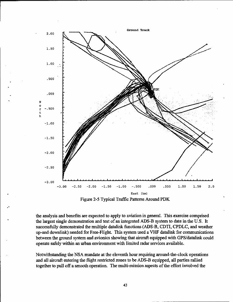
Ground Track 2.00
1.50
1.00 -
.500
.000
N 0
r -.500 t h
-1.00
-1.50
-2.00
-2.50
-3.00 -3.00 -2.50 -2.00 -1.50 -1.00 ~.500 .000 .500 1.00 1.50 2.0
East (km)
Figure 2-5 Typical Traffic Patterns Around POK
the analysis and benefits are expected to apply to aviation in general. This exercise comprised the largest single demonstration and test of an integrated ADS-B system to date in the U.S. It successfully demonstrated the multiple datalink functions (ADS-B, CDTI, CPDLC, and weather up-and downlink) needed for Free-Flight. This system used a VHF datalink for communications between the ground system and avionics showing that aircraft equipped with GPS/datalink could operate safely within an urban environment with limited radar services available.
Notwithstanding the NSA mandate at the eleventh hour requiring around-the-clock operations and all aircraft entering the flight restricted zones to be ADS-B equipped, all parties rallied together to pull off a smooth operation. The multi-mission aspects of the effort involved the
43

close cooperation of security officials, law enforcement authorities, air traffic control, cargo operators and the associated logistics and support personnel. ·
The ground situation displays at the Traffic Advisory Center were manned continuously by air traffic controllers beginning the week prior to opening ceremonies and concluding two days after the close of the games. Since the primary situation displays were initially designed with input from the ~ ~affic control specialists, the equipment was easy to operate and comprehend. ADSB was the primary means of tracking aircraft below the coverage of the Dobbins radar, which was remoted to a DBRJTE display located above the Harris console. Data-tags on the ADS-B traffic display, similar to tags on actual radar displays, aided the controllers in identifying individual aircraft.
Another mission ofHeli-STAR was that of providing cargo-hauling operations ohime critical goods. This operation required a similar means of tracking and communications to manage aircraft assets. Cargo operations were managed from the POC in a successful manner, allowing helicopters to carry out their route specific operations in an expeditious manner.
From an overall systems operation perspective, the airborne and ground equipment performed to the satisfaction of the AGATE designers and users operating without major maintenance during the project period. The only notable downtime was attributed to a telephone cable that carried data from the network control station at the POC to the display processor at the TAC was accidentally dug up by a construction crew. The reliability of the equipment was very high for a prototype system. To handle unforeseen maintenance with ground equipment or airborne installations, technical representatives from the manufacturers or SAIC/GNSS were available, either on-site or on-call, 24 hours daily.
The experience gained by researchers provided the ability to study how ADS-B technology would perform in meeting surveillance needs. Also, the capability of ADS-B to support air-to-air CDTl was of special interest. This capability is seen as an important step towards a Free-Flight operational environment (Flight 2000) and a near-term enhancement to VFR advisory services.
One of the parameters of key interest was the timeliness of aircraft position updates. Aircraft position update rates were initially set to be similar to that of an airport surveillance radar, about every five seconds. However, when multiple targets were tracked, update rates increased from the nominal five-seconds to approximately thirteen seconds as measured at the data collection node at the POC. The update rate, as seen at the TAC, was further degraded on occasions when problems occurred with the modem link between the POC and the TAC.
The update rate also increased during transmission of weather datalink messages and the occasional need to make configuration changes to the ground-based repeater network. The adaptive nature of the transmission scheme in the communication system design allowed the timing of each aircraft's transmission to occur on a more-or-less random basis in order to reduce simultaneous transmissions, hence causing further delays because aircraft had to rebroadcast their position. Certain R&D helicopters had their transmission rate specifically set to provide one-per-second updates to accommodate the special needs of the noise gathering operation.
44

Observations made at the ground operating consoles located at the TAC and the POC revealed that most of the discrepancies in aircraft position being lost as reported by the ATC specialists (at the TAC) or by operators (at the POC) revolved around the reduced ability of the portable units to maintain track compared to the permanent aircraft installations. The algorithms designed into the ground display required receipt of a valid position update within a thirty second period or the color of the _i~on would change from white to red, indicating an unreliable position report. Thus, controllers had indications that the target was no longer being actively n:acked by the ADS-B system.
There are a number of reasons that could have caused the update rates to sometimes fall short of the required 5 seconds. These include:
• loss of GPS signal in the aircraft (GPS antenna located in the aircraft interior blocking signals from some satellites on portable units),
• loss of VHF line-of-sight with a ground repeater (signal blockage due to terrain or buildings, or aircraft structure on portable units),
• high datalink utilization caused by: - high aircraft activity, - datalink network reconfiguration messages sent from the ARNA V control node, - weather message uplink from the POC, and
• loss of modem connection between the control node at the POC and the ATC specialists displays at the TAC.
The data collection system developed for Operation Heli-STAR allowed the overall update rate for the datalink network to be measured. However, the operational nature of the Heli-ST AR project did not provide an opportunity to instrument the network in a manner so as to isolate and identify specific reasons for update rate degradation.
Most Heli-STAR aircraft having the full CNS/A equipment (35 aircraft) had GPS and datalink antennas permanently installed on the outside of the aircraft in near optimum positions. Since the portable ADS-B boxes were mandated at a late date, time did not permit optimum mounting of the antennas on the exterior (48 aircraft). As a result, most of the portable installations had the GPS antenna placed on the glare screen or taped in a window which greatly reduced visibility of the satellites. GPS requires a minimum of 3 satellites in view to render position. With only 12 satellites visible in the hemisphere, any installation having a limited view of the sky would tend to yield a low probability of calculating aircraft position for transmission to the ground. Likewise, the datalink antenna was often sub-optimally installed, typically affixed to a side window, reducing the probability of reliably interacting with the primary ground receiver or repeater sites. This was especially noticeable when an aircraft was flying in areas outside of the triangular layout of the ground repeaters. The combined result of internally mounted antennas was a reduced probability of receiving a valid update position within the time window needed to keep the target active on the situation display.
45

Working distances for the ADS-B function turned out to be quite good. Coverage included the entire greater Atlanta area with reliable tracking to the surface of all the designated landing zones, aircraft antenna installation notwithstanding. Tracking is theoretically determined to be line of sight from the aircraft to one of the ground repeater/receiver locations.
Aircraft capabilities were enhanced if they were equipped with an optional MFD, which permitted vi_~wing of traffic via the CDTI and displayed uplinked weather information. Of the 35 permanently installed systems only 25 included the MFD option. The portable ADS-B boxes were capable of connecting to a MFD (or laptop computer) but no operaior-s took advantage of that option.
As with the ground situation displays, position updates for the CDTI function were variable in timeliness of information. The display orientation when the aircraft were making turns was also a factor in acquiring targets. This was due in part to the MFD having the capability of displaying a number of background options such as waypoints, airports and ground obstructions. With fewer options selected, the MFD updated reasonably well for displaying traffic. It is believed that this problem can be corrected through a number of options that include:
• increasing the processor capability, • reducing the number of objects that are displayed on the MFD, and/or • improving the display processing algorithm.
One of the immediate research benefits of the Heli-STAR operation will be to furnish AGATE, the FAA, and other interested parties with hard data on which to base designs for future systems that lead to Free-Flight operations that are interoperable and low cost for general aviation and air carrier aircraft. This will translate into general aviation aircraft that are easier to fly and better able to cooperate with current systems designed for air carrier operations.
46

.•
3.0 AIR TRAFFIC MANAGEMENT AND SECURITY
3.1 INTRODUCTION
The air traffic management (ATM) and security element of Operation Heli-ST AR experienced major growth, in scope and responsibility, as the project evolved. Initially, the air traffic requirements centered around support of the R&D aspect ofHeli-STAR. As originally conceived, there. were to be approximately 40 to 45 aircraft equipped with full capability CNS/ A systems. The air traffic requirement during this early phase of the project_was to provide support to these CNS/A-equipped aircraft so that meaningful R&D data could be obtained. These requirements included: 1) developing a low altitude route structure for the project aircraft; 2) establishing a traffic management center adequate to handle the project aircraft; and 3) providing sufficient control specialists to handle the 40 to 45 project aircraft during Heli-ST AR operations.
During the planning phase of the project (1994 and 1995), Heli-STAR staff met monthly with the Olympic Aviation Security Subcommittee. The purpose of this coordination was to make sure that there was a mutual understanding of each other's requirements between Olympic Security and Operation Heli-STAR. This coordination resulted in a letter from the subcommittee authorizing Heli-ST AR operations during the Olympics.
Another result of this coordination was a realization by Olympic officials that the Heli-STAR concept could be very useful to their security operations. If security aircraft were equipped with CNS/ A, then personnel at a command center would be able to observe where their air assets were located, thereby greatly assisting management of their operations. In addition, Olympic security had a requirement to issue clearances to aircraft operating in the TFR airspace above the Olympic Ring and venues. Much of this traffic would be operating below radar coverage in the Atlanta area
Safety requirements were a primary concern of both the FAA and Olympic Security. The requirements for safety, security, and R&D objectives ofHeli-STAR were carefully considered by both organizations. Through discussions among the Olympic Aviation Security Subcommittee, the FAA Southern Region, and Operation Heli-ST AR, it was agreed that the TAC would authorize entry into the TFRs to aircraft and pilots that had been pre-approved by Olympic Security. Thus, the Heli-ST AR air traffic management requirement grew significantly as a result of the addition of Olympic Security requirements. These requirements led to the HeliST AR air control specialists being collocated with Olympic Security personnel at Dobbins ARB, northwest of Atlanta, and sufficient controller staffing to handle 24-hour daily operations during the Olympics (July 13 through August 4).
Another increase in security requirements occurred just three weeks prior to the beginning of the Olympics when a NSA directive was issued by the White House requiring all aircraft operating in the Olympic TFRs to be equipped with CNS/A capability. This requirement further emphasized the importance of the ADS-B role in managing all air traffic involved in Olympic support operations.
47

3.2 TAC OPERATIONS
The TAC, staffed by volunteer FAA air traffic control specialists, was collocated at Dobbins ARB (MGE) in Marietta, Georgia with Olympic Security, FAA Security, U.S. Customs and GEMA. The TAC was a combined operational and R&D support center. The original R&D support service quickly expanded to meet extensive aviation security needs. The TAC continued its R&D support service while simultaneously meeting the demanding operational requirements deemed nece~sary to support the 1996 Olympic Games. Tiie original mission eventually grew to include all commercial, public safety, security, and Olympic transport heii:copters operating in the Atlanta area. These aircraft operated under VFR in uncontrolled airspace beneath the floor of the Class B and within controlled Class D airspace in the Atlanta area.
Further, the TAC authorized entry to all security-cleared aircraft into the TFRs surrounding the Olympic venue sites: Olympic Village and Olympic Ring in downtown Atlanta, Wolf Creek Skeet Range Southwest of Ben Hill, Stone Mountain Park at Stone Mountain, Atlanta Beach in Jonesboro, and the International Horse Park in Covington. At the request of the GSP, the lead security agency for the 1996 Olympic Games, TFRs were established to provide an additional level of security by controlling access to airspace surrounding the venues.
In order to be cleared by security and gain access to any TFR, pilots were required to submit an application with the GSP delineating certain specifics about their need to fly in the TFR, consent to an FAA and criminal background examination, and attend training provided by the FAA Southern Region FSDO.
Enhanced VFR services were provided to aircraft using the CNS/ A, OPS-based surveillance system. The primary component of the GPS-based system was ADS-B. ADS-B combined the use of GPS navigation with a digital datalink. ADS-B provided controllers with the capability to track aircraft position, speed, and altitude in a non-radar environment. Further, for those aircraft equipped with a MFD, datalink offered an additional means of communicating with aircraft ( other than by standard VHF and ultra high frequency (UHF) voice frequencies) by use of canned or free-text messages. Initially, service was to be provid~d for approximately 16 hours-a-day, Monday through Friday, with reduced hours on the weekends when it was anticipated that cargo traffic would be light.
However, Olympic security requested the TAC be operational 24 hours-a-day in order to provide continuous air traffic support for security aircraft. It also was determined the TAC would be the "clearing house" for all aircraft requesting entrance into any of the metropolitan Atlanta area Olympic TFRs. In order to accomplish this, it was necessary for the TAC to establish a letter of agreement with the Atlanta ATCT.
The agreement provided the policy and authority for the TAC to provide traffic advisories to VFR aircraft operating in certain airspace which otherwise was within the confines of Atlanta Tower airspace. The agreement also addressed the operation of"participating" Heli-STAR helicopters on one specific route within Atlanta Class B Airspace. "Participating" Heli-ST AR
48

.•
aircraft were those aircraft possessing CNS/ A and using specific transponder beacon codes assigned by ATC. .• .
The procedures were applicable only to VFR aircraft in the following areas:
• at or below 2,000 feet MSL in the designated Olympic TFRs except 2,500 feet MSL at the Covingt(?l_l and Olympic Ring TFRs, and
• at or below 1,500 feet MSL on published helicopter routes as depicted-on the Atlanta Helicopter Route Chart (see figure 1-2), excluding Atlanta Class B Airspace, all Class D Surface Areas and within a 4-NM radius of all temporary tower locations.
The TAC was directed by the LOA to establish and maintain a discrete phone line between the TAC and the Atlanta Terminal Radar Control (TRACON) facility. Further, the TAC was authorized to use beacon codes subset 1401-1477. Conflict alert, mode-C intruder, and terrain warning features were inhibited on the codes. Use of the codes was restricted to within 35 NM of ATL.
TAC personnel, in concert with the FSDO, provided training to all pilots cleared by Olympic Security to operate within Olympic TFRs on the procedures to be used while operating within this airspace. All pilots had to acknowledge, in writing, that they received and understood the procedures for operating within the TFRs.
Excluding the route defined as Wolf Creek ( outside A TL' s Class B airspace) direct Shannon Mall then to NBS helipad at or below 1,500 feet MSL and then reverse for exiting, no aircraft was to enter into ATL's Class B airspace, any Class D surface area, or within a 4-NM radius of any temporary tower location without ATC clearance. The temporary towers were located at Covington Airport, Clayton County Airport-Tara Field, and Peachtree City Airport-Falcon Field.
The letter of agreement directed the TAC to exchange traffic information with all VFR aircraft that contacted them on their air-to-air frequency for advisories in the airspace previously described. Further, the TAC was to terminate traffic information in sufficient time to allow aircraft to establish communications with the appropriate ATC authority to obtain clearance to enter any Class B or D airspace or within 4 NM of any temporary tower. Prior to terminating traffic information, the TAC was required to instruct aircraft to remain outside the particular airspace and to contact the controlling facility.
The TAC was not permitted to establish VFR holding points, issue holding instructions, or issue recommended altitudes to aircraft within the confines of airspace not authorized for use by the TAC. Conversely, Atlanta Tower agreed not to provide traffic advisories in areas assigned to the TAC. However, all other services normally provided by Atlanta Tower were not changed or altered by the agreement. If an aircraft being worked by Atlanta Approach infringed upon a TFR, Atlanta Approach would: retain the aircraft on their frequency and advise the aircraft they
49

were in a prohibited area, direct the aircraft to exit the area, and advise to use caution because of numerous aircraft in the area. ·· ·
Atlanta Tower, in compliance with the LOA, was to advise the TAC when they had an IFR aircraft inbound to Covington Airport. At the time of the notification, the TAC was to keep the Covington TFR clear until Atlanta Tower advised the IFR traffic was terminated.
On occasion, -if Atlanta Tower determined the need, they retained the option to lower the altitude of the Olympic Ring TFR from 2,500 feet MSL to 2,000 feet MSL, aftercoordinating with the TAC.
Just weeks prior to the initiation of operations at the TAC and the start of the 1996 Olympic Games, the FAA was directed by the White House, on advice from the NSA, to prohibit any aircraft, excluding specifically identified security aircraft, from operating in any Olympic TFR. After much discussion between FAA and White House, the decision was eventually modified to allow specifically identified CNS/ A-equipped aircraft into the TFRs, however, to ensure the security of the TFRs and enforcement of any TFR airspace intrusion, the White House requested the United States Customs Service to provide a significant air support presence. Air support was provided in the form of Lockheed P3 tracking aircraft, Sikorsky UH-60 Blackhawk helicopters and Cessna Citation jets. Many of these aircraft were equipped with forward looking infrared (FLIR), F16 radar and video and voice recording equipment. The United States Army contributed to the security package by providing a three-dimensional radar and technicians to supplement the Customs Service tracking radar.
Because the TAC was only able to track CNS/ A-equipped aircraft, a DBRITE display operating on a feed from Dobbins ARB radar was installed. DBRITE is used by local controllers at ATC terminal facilities to monitor the movement of aircraft on the approach to landing and departure from the airport. The DBRITE was adjusted to center on the I-NM diameter "no fly" Olympic Village TFR.
Air traffic operations support was provided by 12 supervisory/management level air traffic controllers on loan from many different terminal and en route ATC facilities. Also assigned to the TAC was one contractor who facilitated the coordination of ATC and security operations. Excluding the time period between 11 :00 p.m. and 7:00 a.m., the TAC was staffed with a minimum of two controllers. While one controller provided air traffic communications, the other controller managed land-line communications and coordination with other agencies and ATC facilities. They also coordinated R&D project flight aircraft operations with the POC.
The Traffic Advisory Center communication and surveillance equipment consisted of one VHF frequency with an alternate backup frequency and one UHF frequency that was used to communicate with military aircraft when VHF was not available. The central core of the CNS/ A system was the ARNA V network control station and two Harris ATC consoles. One console was used as the primary display in managing aircraft while the second console functioned as a backup and also as a second operational display when both UHF and VHF were utilized simultaneously. The system tracked all CNS/A-equipped aircraft displaying them as icons that presented the
50
. .

aircraft's call sign, speed and altitude on a computer-generated map. Although all CNS/Aequipped aircraft were displayed at the TAC, Olympic security requested that CNS/A-equipped security aircraft not be displayed at the POC. This was deemed necessary so that security missions could not be compromised by outside entities.
FAA air traffic controllers at the TAC utilized the Harris ground station strictly in an advisory role. The TAC would notify aircraft on the Olympic TAC frequency of other traffic in the area and provide an approximate relative position of the other aircraft. These advisories greatly enhanced the safety function of the visual flight rules system by allowing the controller, in a nonradar environment, to provide traffic advisories to CNS/A-equipped aircraft flying in proximity to other similarly equipped aircraft.
Rapid inter-facility communications were provided using five direct telephone drop lines. These communication links connected the TAC with the POC at GTRI and the ATCTs located at Fulton County-Brown Field, Dobbins ARB, DeKalb-Peachtree airport and Hartsfield Atlanta airport. The drop lines assisted all facilities in coordinating traffic flow and breaches of restricted airspace. In addition to the drop lines, the TAC was equipped with three standard telephone lines and a secure telephone line with an encryption device. A pilot workstation was installed at the TAC to provide up-to-date weather information to the controllers. An air traffic IFR "flow control" airport situation display (ASD) computer position was also installed. This computer position depicted radar derived weather maps and the location of all IFR aircraft flying in the United States at any given time. This system also provided aircraft call sign, altitude, speed and time to destination in minutes. The data for this position was fed directly from the FAA Air Traffic Control System Command Center (ATCSCC) in Herndon, Virginia. In the event ofan intrusion into any Olympic TFR, the TAC would make several notifications. U.S. Customs would be the first notified so that an air response could be initiated against the intruder. The Customs representative would relay any available information from the TAC regarding the violator to the P3 tracking aircraft. Following that notification, the Customs representative would direct a Sikorsky Blackhawk, and if required, a Cessna Citation to respond. The P3 would then coordinate the response of the Customs aircraft to intercept the intruder .. These aircraft would be monitored on radar and the ADS-B displays.
FAA Flight Standards, FAA Security and Olympic Security representatives were notified next. These individuals would begin an in-depth log describing the time of intrusion, aircraft information, any communications or attempts to communicate with the intruder and any followup with Customs. If the aircraft remained within the TFR, Flight Standards would notify the Flight Standards Inspector assigned, on site, in that particular TFR. If the violating aircraft was subsequently followed to a landing, an FAA Flight Standards Inspector would be flown to the scene to conduct his investigation. Over the course of 17 days of activity in Atlanta, the TAC logged 43 TFR intrusions.
As a means to evaluate the effectiveness of the equipment utilized by the controllers and to provide a means by which modifications could be made on site, the controllers were requested to complete an evaluation of the ARNA V /Harris communications system and the general operation oftheTAC.
51

3.3 ROUTE STRUCTURE
A key element of safety and the air traffic management process was the implementation of a new, low altitude, VFR route structure. The structure was designed to maximized the use of available airspace, minimized noise impact on the community and provide sensible ingress and egress to new and existing heliports. Additionally, the route structure and it's ATC support from the TAC was accompii shed by remaining transparent as possible to the high-density Atlanta area air traffic control system. This system encompassed ATL, PDK, FTY, and Dobbins.ARB.
Prior to the development of Atlanta's first helicopter route chart, helicopters and other small aircraft, such as traffic reporting and news media aircraft, used a routing system loosely based on the interstate highway system in and around Atlanta. The pilots used a single air-to-air frequency to announce their positions to other aircraft. Access to this infonnal route was coordinated among FTY, PDK, and ATL towers.
Designers of the route chart used the infonnal route system as a starting point in the development of the chart. Routes were expanded to cover a wider geographical area and altered to accommodate all new and existing heliports, Olympic venues, and to minimize noise impact on residents. Previously, place names and other colloquial names were used to identify locations along the route structure. Many of these names were rather lengthy and cumbersome thereby requiring an unnecessary amount of frequency air time to broadcast. All routes were identified by a simple numbering system. Points along the route structure where routes intersected, were identified by VFR calling points. The calling points were designated by using names of nearby geographical locations or man-made structures.
As can be seen in figure 3-1, if a flight was to be conducted from the Six Flags Amusement Park west of Atlanta to the Olympic venue located on Stone Mountain to the east of Atlanta, the pilot would have the option of using one of two routes. The most direct route would be called as, ''N33PP, Six Flags, Route 2, Stone Mountain," or, if a longer, more circuitous route was to be taken, the routing would be requested as, "N33PP, Six Flags, Route 2, 1 and 2, Stone Mountain." This routing procedure greatly simplified communications and removed all ambiguity in notifying ATC the TAC and all other pilots in the area as to where a flight was, where it was going, and how it intended to get there, using only a matter of a few seconds of frequency air time. Helicopter route charts, such as the one designed for Atlanta, have been widely used and accepted in areas such as Washington, DC and Los Angeles, California.
Upon the completion of the first rough draft of the chart by the FAA's Cartographic Office, it was forwarded to the US Department of Commerce National Oceanic and Atmospheric Administration (NOAA), National Ocean Service (NOS) for editing, confirmation of chart symbols, locations, printing, etc., and other specifications in accordance with the Interagency Air Cartographic Committee. The draft was then delivered to Atlanta where it was reviewed by Atlanta ATC and potential system users.
52
..

Route1-Route2-Route 3-Route 4-Route5-Route6-Route 7 Route 8--Route9-
Figure 3-1 Atlanta Low-Altitude Helicopter Route Structure
This process was repeated two additional times prior to final printing and issuance of the "Olympic Edition For The 1996 Summer Olympics Helicopter Route Chart ATLANTA."
3.4 AIR TRAFFIC MANAGEMENT SIGNIFICANT FINDINGS
The Atlanta Helicopter Route Chart was designed to simplify the way aircraft moved about the Atlanta area. Numbers were assigned to each individual route, which primarily overlaid the highway system in Atlanta, and place names were used for reporting points at the intersection of each route. This system, when used properly, reduced much of the unnecessary communications between aircraft and greatly simplified radio transmissions to ATC facilities to advise position or route of flight.
53
Over the course of the 1996 Olympic Games, the TAC handled approximately 9,500 aircraft movements. During this period, 43 intrusions ofTfRs occurred, predominately within the Olympic Village, Olympic Ring, and Stone Mountain TFRs.
Although is was necessary that the FAA, Customs, Olympic Security and the TAC be collocated, the TAC should have been physically separated from the other security groups because of the noise level and activity. It was not uncommon to have upwards of30 individuals in the room at any given time. This made it very difficult for the controllers to hear pilot transmissions. Several pilots complained of"background noise" when communicating with the TAC. Occasionally, other workers in the room or visitors, not knowing that the controller was communicating with an aircraft, would speak directly with the controller. It is highly recommended that in future events, like the Olympics, where security officials might be collocated with controllers, a separate area be set aside for TAC operations with limited access and noise alleviation.
More time needed to be dedicated to testing the entire communications system prior to the start of the games. After the start of the Games, itwas determined that voice communications were, at times, very distorted or unreadable. This was corrected by placing an additional antenna at a higher location in downtown Atlanta; then, it was necessary to conduct flight tests to ensure adequate coverage.
The controllers had to have several adjustments made to the logistics of the UHF NHF :frequencies. The frequencies were split between a speaker and headset, then combined, then split again. There were several problems with this arrangement. When the primary frequency was received only by headset, no one was able to provide backup assistance to the working controller because the frequency could not be heard by anyone else. At the same time, UHF was placed on a speaker. This speaker was of very poor quality rendering many transmissions inaudible. Funds were not available for a new speaker. Although communications on UHF were infrequent, it was still necessary for an additional controller to monitor the :frequency. At one point the frequencies were combined. This did not work, because the transmissions tended to cancel each other out.
The CNS/A and ADS-B technology brought a significant enhancement to the TAC and its air traffic advisory mission. The combination of the full capability CNS/ A, the portable CNS/ A, and the DBRITE display greatly facilitated the controller's ability to monitor and report traffic at low altitude and in the vicinity of the TFRs. However, for some aircraft, ADS-B was not totally effective. On some occasions, aircraft dropped off the screen or the updates were too widely spaced in time. This problem was particularly acute with aircraft outfitted with portable CNS/ A equipment that used interior GPS and datalink antennas. As a result, for monitoring movements around the TFRs, the DBRITE was used extensively in conjunction with ADS. Signal dropout and update rates still need further assessments. In spite of these concerns, ADS-B technology was a definite beneficial addition to air. traffic management resources.
Datalink communication tests, using the Harris workstation, were conducted between the TAC and airborne aircraft with mixed results. When sending messages to specific aircraft, it was
54
..

.•
discovered that all aircraft received the message. Further, there were occasions when the TAC and individual aircraft did not receive messages addressed to them. ·
The Harris workstation was generally an effective tool for managing air traffic. However, there were a few areas where the design could be improved. There was a significant amount of clutter near the heliports, particularly if there were two or more helicopters with the ADS-B system activated. In-addition, the data tags on closely spaced aircraft would overlap and the controller continuously-had to move them manually. Some method of automatical~y offsetting data tags would be very helpful to the controller.
The displayed altitude differed from the actual altitude by as much as 200 to 300 feet. This was probably due to GPS altitude rather than barometric altitude being transmitted from the aircraft. In the future, barometric altitude should be transmitted from the aircraft to preclude this error.
The integrated services digital network (ISDN) weather system at the TAC was ineffective. A similar display at the AERC functioned somewhat better demonstrating that the technology is useful, but there were various problems at the TAC and POC that precluded it from being mor~ effective. Some of these problems were associated with late installation and set up. Also, a leased telephone line was disrupted causing the system to be out of operation for some time at the TAC. The display of real-time weather that can be uplinked to suitably equipped aircraft is a critical element in realizing the full potential of the ADS-B technology. (A separate report on the ISDN weather display system used at Heli-ST AR operations centers is available. Contact FAA AND-710 at (202) 358-4972 [voice] or (202) 358-4960 [fax] for this report.)
More time was needed to establish interagency coordination at the ASOC. It took 7 to 10 days to accomplish this effort. Agencies would appear and begin operations with little or no communication with any of the other groups already in place. Different groups had little idea as to what each other's roles were and what, if any, coordination was required.
Generally, datalink messaging between operations centers and equipped aircraft was better at the POC than at the TAC. This problem was not observed during the operational concept tests, but it became apparent during initial Heli-STAR operations. The Heli-STAR team decided that the problem, while having an adverse impact on evaluating the datalink for air traffic communications, would not seriously affect TAC operations. This was because datalink messaging was only a backup means of communication between the TAC and Heli-ST AR aircraft; VHF voice was the primary communications medium. Therefore, it was decided that trying to troubleshoot the datalink messaging problem while the TAC was operational carried a greater risk than did continuing operations at the TAC knowing that some datalink messages may not be received.
55

' .
..
4.0 HELIPORT INFRASTRUCTURE
4.1 HELIPORT PLANNING
Initial planning for the heliport network began in 1994 with the development of the Olympic Aviation Subcommittee's selection of security landing zones. These zones were, by necessity, close to the major state and interstate highways. Later that year, staff from HAI and FAA AND-710 began discussions with representatives from United Parcel Se~ice (UPS) and NationsBank about the feasibility of participating in the urban intermodal..transportation system. This interest grew to where more than a dozen parcel package shippers, couriers, and financial institutions were involved. This eventually grew to become the A VF A. This group then provided critical planning data and information that would give the heliport route system its primary commercial influence. Information and data were supplied which helped to locate optimum, low cost landing sites to handle cargo. Data requested from each of the shippers included the amount of cargo, both in pounds and cubic feet, the time of day when the cargo would be shipped, and the origin/destination of the cargo. These data were collected and analyzed by the project team to establish an initial set of heliports and preliminary flight schedules. These candidate heliport locations and the preliminary schedules were then reviewed by the A VF A. Using the list of desired locations, the project team began identifying potential physical locations for heliports.
A second round of inputs from the A VF A membership was then obtained. This time, the list of potential heliport sites was used as origin/destination locations in a daily operation scenario. In addition, the A VF A members were asked to commit their companies to a specific range of cargo volumes. This second round of data from A VF A provided confirmation of the required heliport sites. At this point, the project team began to formalize agreements with the landowners allowing the FAA to establish a heliport at the respective sites. In some cases, the landowner was interested in a permanent heliport. In other cases, the landowner was interested only in a temporary heliport for use during the period of the 1996 Olympic Games.
In total, 11 heliport locations were identified; 8 locations were stand-alone heliports and 3 locations were at existing airports. The airport sites were ATL (south), PDK (northeast), and FTY (west). The stand-alone heliports were strategically located in downtown areas and sites around the Interstate 285 perimeter highway:
• Galleria Mall (northwest perimeter), • Georgia Baptist Hospital ( downtown), • NationsBank Southside (south perimeter), • NationsBank Northeast (east perimeter), • NationsBank Mitchell Street (downtown), • Norcross (northeast, beyond the perimeter area), • Roswell (north, beyond the perimeter area), and • Wachovia Buckhead (north side of downtown).
57

Other heliports were available to security and emergency management aircraft. They were located at GEMA ( southeast of downtown), Capitol ( downtown, at the Georgia State Capitol), and Dobbins Air Reserve Base (northwest, beyond the perimeter area). Law enforcement aircraft and the FAA project aircraft, a Sikorsky S-76, were located at McCollum Airport in Kennesaw, about 25 miles northwest of Atlanta.
Each heliport site had road or freight elevator access to the local street or road system thereby giving shipp~rs access to the Heli-STAR network. Road access to the h~liport was an important element in ensuring an intermodal system concept.
4.2 HELIPORT LEASES
The FAA executed separate lease agreements with each of the heliport property owners with the exception of PDK, FTY and GEMA. Each lease was negotiated through the FAA ASO Real Estate Office in Atlanta. The lease terms and conditions varied by heliport depending on the amount of construction required, the participation level or benefit in Heli-STAR by the property owner, and whether the heliport improvements would inure to the benefit of the heliport property owner after Heli-STAR.
4.2.1 Lease Term
Lease terms ranged from 3 months to 6 months depending on property availability, amount of construction and equipment required and dismantling provisions.
4.2.2 Consideration
The government paid no monetary consideration in the form of rental. It was mutually agreed to by all parties that the rights extended to the government were in consideration of the obligations assumed by the government in its establishment, operation, and maintenance of facilities upon the leased premises.
The only exception to this was the landing site at ATL. ATL had the preferred site leased out and the lease terms did not permit the current Lessee to sublet any interests. ATL was willing to release their tenant and in-turn lease to the FAA, only if there was no loss in rental revenue.
4.2.3 Restoration
Restoration was a negotiable item with the lessors. In most cases, the FAA was not obligated to restore or rehabilitate the property upon termination of the lease. The FAA decided, in accordance with government property control guidelines, when and where any structure or equipment on leased premises were to be abandoned in place. The FAA dismantled and recovered most of the heliport lighting equipment, except at two permanent heliports (ATL and PDK) where the equipment is still in use and available for further heliport study and evaluation.
58
..

..
4.2.4 Permitted Use
The government, or designated contractors such as PHI, were allowed to use the heliports to carry out Heli-STAR activities. At some heliports the property owners authorized other operators to use the heliports, however, such use could not conflict with Heli-ST AR operations. All leases had a provision whereby the lessor was required to protect the government activity from interference.
4.2.5 Liability
Federal Government liability was limited to damages caused by negligent or wrongful act or omission by government employees in accordance with and subject to the Federal Tort Claims Act of 1948. Liability coverage by Petroleum Helicopters, Inc. covered aircraft liability and comprehensive general liability in the amount of$50 million naming the Federal Government, GTRI, SAIC, and heliport property owners as additional insured.
4.2.6 Special Terms and Conditions
This section outlined specific lessor/lessee responsibilities for heliport construction, equipment, grading, access requirements, walkways, utility hookups, trailers and other essential heliport requirements
4.3 HELIPORT CONSTRUCTION
Each heliport was equipped with the minimum lighting and landing aids as required by the FAA in Advisory Circular 150/5390-2a, "Heliport Design." This included perimeter lights, usually twelve, a lighted wind cone, a heliport identification beacon, and a VASI. During the project, 12 heliports were designed and constructed. Of these, 11 were used for cargo operations. The following pages describe the equipment and layout of each heliport.
For easy identification purposes, each heliport was given a unique three-letter location identifier. Existing airports used the identifiers assigned by the FAA (ATL - Hartsfield Atlanta, PDKDeKalb-Peachtree, and FTY-Fulton County). Site drawings were developed and an equipment package list was formed for each location. Project heliports were given project unique identifiers that were descriptive of the property owner and location.
4.3.1 Georgia Emergency Management Agency
The heliport at the GEMA complex (heliport designation-GMA) was an existing 157-foot by 260-foot asphalt landing zone used by Georgia National Guard and other law enforcement agencies. This heliport was not used for cargo operations; however, it was designated as a backup cargo heliport if needed.
The construction work done at this site include painting and marking the TLOF and the four landing areas and installation of the following equipment package:
59

1 VASI, and 1 heliport identification beacon.
4.3.2 Hartsfield Atlanta International Aimort
The heliport~t A TL was developed from existing ramp parking space and undeveloped property adjacent to th~ ramp. The equipment package for this site included:
12 perimeter lights, 10 taxi lights, 5 lineup queue lights, and I lighted wind cone.
A decision was made early in the program not to put a VASI or a heliport identification beacon at the three airport locations.
After many discussions with the airport an agreement was reached as to who would actually develop this site. This agreement stated that the airport would construct the site to meet HeliST AR specifications. The airport then proceeded to develop the site using there own construction personnel and there own lighting package which included:
12 perimeter lights, and 1 lighted wind cone.
The heliport, located on the north cargo ramp, consisted of a blacktop 52-foot by 52-foot TLOF approach area for hovering and taxi only. From the TLOF helicopters were directed to park at one of five landing pads. Each pad was approximately 50 feet by 50 feet. This heliport is one of the legacies of Operation Heli-ST AR; it remains in operation for the foreseeable future.
4.3.3 DeKalb-Peachtree Airport
The permanent heliport at PDK was designed by the airport prior to this project. An additional equipment package list was formed for this site which included:
5 lineup queue lights, and 1 lighted wind cone.
A decision was made early in the program not to put a VASI or a heliport identification beacon at the three airport locations.
Discussions with the airport concluded with the project providing to the airport the 5 lineup queue lights and the lighted wind cone which would be installed by their construction contractor. Due to the efficiency of the airport construction contractor, the lights arrived after the contractor had completed the heliport construction. Because the heliport was already completed, the lights
60
•.

were not installed. This heliport is also one of the legacies of Operation Heli-STAR. It remains in operation for the foreseeable future. ·· -
PHI helicopters parked and operated from a grassy area adjacent to the heliport. This area was provided by the airport administration under the management of Universal Air Service. Landing zone crew facilities and the cargo staging area were located adjacent to the PHI area. The only constructio~ ~t this site was associated with providing utilities to the cargo operations trailer.
4.3.4 Fulton County Airport
The heliport at FTY was undeveloped prior to this project. Airport management requested that no equipment or heliport construction take place due to neighborhood sensitivities about airport development and growth. A grassy area on the airport operated by the Anny National Guard was used for cargo operations.
The only construction at this site was associated with providing electrical power and phone to the cargo operations trailer.
4.3.5 NationsBank Mitchell Street Rooftop
The heliport on the MIT rooftop was a decommissioned, existing heliport on top of a 10-story building. The heliport is constructed of a 51-foot by 81-foot concrete pad.
NationsBank provided an area on the bank's seventh floor for landing zone crews, equipment, and cargo staging. The construction work done at this site include installation of the following equipment package:
1 lighted wind cone, 1 heliport identification beacon, and 1 VASI.
Since the heliport could be used for operations after Heli-STAR, NationsBank agreed to paint the appropriate markings on the heliport. NationsBank also proceeded to develop the site further by building an elevator which ran from the seventh floor to the roof using their own construction contractor. The elevator was critical for expeditious movement of cargo to street level access of ground transportation.
The engineering associated with the structural evaluation of this site was quite extensive. Due to the age of the building, structural drawings of the roof framing and columns were not available. This resulted in a structural investigation which included coring the roof framing to determine concrete weight and magnetic resonance imaging to determine the location and quantity of steel reinforcement present. Once this information was obtained, structural analysis was performed to determine if the rooftop heliport could support the Bell 412 helicopter. Structural analysis determined that the roof was strong enough for the Bell 412 and BO-105 helicopters, at maximum gross weight, to land and take off.
61

4.3.6 NationsBank Northeast Rooftop
The heliport on the NBE rooftop was a decommissioned existing heliport on top of a 5-story building. The heliport is constructed of 63-foot by 62-foot raised concrete pad.
NationsBa.nk-.provided an area on the bank's fifth floor for landing zone crews, equipment, and cargo staging. The construction work done at this site include installation of the following equipment package: · ·
1 lighted wind cone, 1 heliport identification beacon, and 1 VASI.
Since the heliport could be used for operations after Heli-STAR, NationsBank agreed to paint the appropriate markings on the rooftop heliport. NationsBank also repaired the wooden walkway from the building to the heliport using their own maintenance personnel.
Like the MIT heliport, a determination had to be made on the amount·of weight the heliport could support, particularly the heavier Bell 412. Fortunately, structural drawings of the roof framing and columns were available for the analysis so core samples and magnetic resonance imaging were not necessary. Based on drawings, the analysis determined that the rooftop heliport would not support the Bell 412 helicopter and would only support the BO-105 ifit landed on certain areas of the pad. The pad was painted to indicate where the BO-105 could land. ·
4.3.7 North Fulton Hospital
The heliport at RAF is located on the top level of a 4-level parking deck. North Fulton hospital provided utilities and indoor space for landing zone crews and equipment. The construction work done at this site include painting and marking the TLOF, removal of a concrete lamp post pedestal located in the center of the TLOF, and installation of the following equipment package:
12 perimeter lights, 1 lighted wind cone, I heliport identification beacon, and I VASI.
The structural evaluation of this site was performed by the architectural firm which designed the parking deck. The engineer specified where the TLOF was to be located to have minimal impact on the structure. Both the Bell 412 and BO-105 could land at this heliport.
62
·-

. •
4.3.8 Georgia Baptist Hospital
The heliport at GBH is located at the existing emergency medical service heliport.
Georgia Baptist provided utilities and indoor space for landing zone crews and equipment. The construction work done at this site included the construction of a temporary wooden walkway from the heliport pad to the adjacent packing lot. The walkway was required so that cargo movement did not interfere with hospital pedestrians and EMS operations. Other work included the painting.of landing skid marks to locate where the cargo helicopters were to land on the pad, and the installation a heliport identification beacon.
4.3.9 Buckhead Wachovia Bank
The heliport at BUC was on an unused lot adjacent to the bank's operations center. The lot had a decayed asphalt parking area which was cleaned up and used as the temporary heliport.
Utilities and a trailer were provided by Wachovia Bank. The construction work done at this site included the removal of brush and dead trees, sealing the asphalt, painting and marking the TLOF and installation of the following equipment:
12 perimeter lights, 5 lineup queue lights, 1 lighted wind cone, 1 heliport identification beacon, and 1 VASI.
This site did present some additional security requirements. The perimeter lights and the VASI originally located at this site were donated by an Italian Company, Officine Panerai S.p.A. After installation was complete, the VASI was stolen and a second VASI had to be installed. Following this incident, Wachovia Bank constructed a fence around the site and provided a 24-hour armed guard for security. The heliport identification beacon at this site was on loan from Flash Technologies, Brentwood, 1N, for the duration of the project .
4.3.10 Norcross
The heliport at the Atlanta Journal and Constitution (AJC) newspaper company in Norcross consisted of a 52-foot by 52-foot concrete section of parking lot that is used by AJC delivery trucks.
AJC provided utilities and cut down trees adjacent to the parking lot. Construction work at this site included painting and marking the TLOF and installation of the following equipment:
63

12 perimeter lights, 5 lineup queue lights, 1 lighted wind cone, 1 heliport identification beacon, and 1 VASI.
4.3.11 NatioRsBank Southside
4.3.11.1 Heliport Development
The heliport at NBS was located on the front lawn of their operations facility. NationsBank provided a trailer and utilities for cargo operations. Construction work included the assembly of a temporary 24-foot by 24-foot landing pad (4-foot by 4-foot by 12-foot sections of treated lumber bolted together), construction of a wooden side walk from the cargo operations trailer to the wooden pad, painting and marking the TLOF and the installation of the following equipment:
12 perimeter lights, 5 lineup queue lights, 1 lighted wind cone, 1 heliport identification beacon, and 1 VASI.
4.3 .11.2 Prototype Lighting System
Heli-STAR provided a unique opportunity to demonstrate a prototype heliport lighting system developed by SAIC and the University of Tennessee Space Institute (UTSI) under contract to FAA AND-710. Flight tests conducted at UTSI showed that the new technology lighting systems had great potential to meet the requirements for IFR approaches to heliports. These lights were tested in a runway environment and in a downtown environment simulating an urban or suburban heliport. The color and characteristics of these lights were so unique to the well lighted city environment that they were easily identified in the midst of a variety of traditional city lights. These unique characteristics also improved the ease with which the pilot maintained visual contact with the heliport environment (simulated during these tests) and significantly increased the amount of information provided to the pilot as compared to conventional incandescent heliport lights.
These tests were so promising that a recommendation was made by UTSI to continue to evaluate these lights in an operational city environment. The original test plan called for simulation of these lights prior to actual flight tests. However, testing revealed that simulation would not be able to correctly capture the characteristics that make these lights unique, and would therefore be limited to evaluations and refinements of the geometry of the proposed lighting systems.
Heli-STAR provided an opportunity to obtain a side-by-side comparison of these new lights with current FAA-specified lights. Heli-STAR allowed pilots to compare the new technology lighting
64
·-

. _;
..
systems to standard incandescent lights arranged in configurations recommended by the Heliport Design Guide2
• :· . -
Three manufacturers assisted in the evaluation by providing lights for evaluation. The prototype heliport lighting system utilized a 20-foot "light pipe" from Automatic Power of Houston, Texas, cold cathode lights from LiteBeams of Burbank, California, and electroluminescent light panels from Byrne Industries of Acworth, Georgia. The light pipe is a hollow tube with a reflective coating on th~ inside and a filter on the outside. A light is mounted on one end and the light is reflected along the length of the 'tube, emitting a unifonn light along its fength. The light pipe provides a unique line oflight that is easily identified in a densely lighted urban environment and it utilizes only one light source. The light pipe was mounted vertically, as shown in figure 4-1~ to provide acquisition, line-up, and hover cues.
The cold cathode lights also provide a light that is very different from the incandescent, "point source" lights commonly found in urban environments and used in aviation lighting. The cold cathode lights use a neon filament that tends to disperse the light instead of a hot burning metal filament that burns an after-image onto the retina of the eye. The cold cathode lights leave no after-image even after looking directly at the lights. The cold cathode lights were laid out in a pattern that replaced traditional lead-in lights with an extended line-up installed beyond the landing site. Electroluminescent light panels were used to outline the perimeter of the landing pad. Electroluminescent light panels also provide light without leaving an after-image on the retina.
The design goals of the prototype lighting system were to provide specific cues to a pilot, rather than merely flooding the landing area with light. The cold cathode lights were selected for several reasons.
• The cold cathode lights do not leave an after-image.
• One intensity setting can be selected that can be seen from miles away, and yet will not blind the pilot near the pad.
• The lights illuminate the surrounding ground, providing the pilot with "texture" cues required by the pilot to sense movement of the helicopter.
The configuration of the cold cathode lighting was selected for the following reasons:
• The extended line-up lights provide cues that remain in the pilot's field of view throughout the entire approach, including the hover and landing. Conventional approach lighting is located prior to the threshold and is overflown and out of sight on short final, hover, and landing.
• The wing bars or extensions to the left and right of the pad provide the pilot with a peripheral cue to aid in centering the aircraft over the landing spot. The wing bars also aid the pilot in
65

Figure 4-1 Prototype Heliport Lighting System Used to Support Heli-ST AR
detecting a rate of climb or settling while in a hover. Line-up cues are also provided by the 90-degree angle to the extended lineup lights.
• The number of lights and circular pattern was designed to provide sufficient surface lighting and an easily recognizable pattern that should aid the pilot in determining and controlling closure rate.
The color of the cold cathode lights was selected by UTSI to maximize the ability of the eye to detect the light. The blue-green color is at a frequency between the best frequency for the rod and cone receptors in the eye. It is visible, therefore, by both the rods and cones and is coincidentally a color that is almost unique to an urban environment.
The final component of the prototype system is the light pipe. The 20-foot light pipe emits a uniform line of light that is recognizable from long distances. The light is also unique from the myriad point-source incandescent lights in an urban environment. The light pipes are being used by the Coast Guard to provide obstruction identification and channel line-up information to maritime pilots. In this prototype, the light pipe provides an easily identifiable line of light to aid in acquisition and identification of the heliport and its vertical orientation, in conjunction with the extended line-up lights, provides a very strong line-up cue. This cue is a natural, or intuitive cue. It requires no training for the pilot to be able to determine the aircraft's position relative to the desired approach course. This is illustrated in figure 4-2.
66
•.

• • -- • ---- • -- • -Approach from Approach on Approach from Left of Centerline Centerline Right of Centerline
Figure 4-2 Intuitive Line-Up Cues Using the Light Pipe and Cold Cathode Lights
The promise of evaluating the prototype lighting system by large numbers of commercial pilots was not realized, however. Due to the physical constraints of the heliports used during Heli-ST AR, the heliport located at NationsBank South was selected for the prototype. Due to the long summer days and a limited night schedule, night traffic was limited at all heliports. When the amount of cargo to be moved by air did not meet original estimates, the schedule was reevaluated and the night flights to the NationsBank South location were eliminated. Security flights in the early morning, a very few night cargo flights, and a few dedicated evaluation flights were the only events that used the prototype lighting system. Pilot first impressions were all favorable, with the easily identifiable lights mentioned most. Video and still photography was obtained and the system was removed and shipped to Washington, D. C. for further evaluation.
4.3.12 Galleria
The heliport at GAL was located on property that had been cleared for new roadway development. Galleria performed the grading and leveling of land as well as seeding and laying gravel for temporary parking. Construction included the building of a temporary 24-foot by 24-foot wooden landing pad (4-foot by 4-foot by 12-foot sections of treated lumber bolted together), construction of a wooden walkway from the cargo operations trailer to the wooden pad, painting and marking the TLOF and the installation of the following equipment:
12 perimeter lights, 5 lineup queue lights, 1 lighted wind cone, 1 heliport identification beacon, and 1 VASI.
67

4.4 GPS APPROACH PROCEDURE DEVELOPMENT FOR HELI-STAR OPERATIONS
In order to demonstrate the use of GPS approaches in an urban, uncontrolled environment, the FAA utilized the resources present during the operations and created non-precision visual approach procedures to the landing zones being used by Heli-ST AR cargo aircraft.
Satellite Te~l!nology Implementation, LLC., (STI) was placed under contract to the FAA through SAIC to develop approach procedures to the landing zones, or to a point-in-space, to provide an orderly, disciplined flow of helicopter traffic. Where possible, these approach procedures were developed to Terminal Instrument Procedure Standards (TERPS). The remaining procedures were developed based upon safe operations. All were used only in VFR operations.
STI began the procedure development process by combining database information, such as, heliport GPS latitude and longitude coordinates, area (landing zone) elevation, and obstacles within a 2- to 5-NM mile radius along with the distance, true bearing, and magnetic bearing from the center of the landing zone. During the surveys of the landing sites the preferred arrival and departure paths were determined, along with inclinometer and compass bearings to obstacles, potential operational hazards, and noise sensitive areas. Once this information was retrieved the procedure development began.
The procedure to each of the landing zones was considered separately. The locations of the landing zones in different locations throughout the Atlanta area offered many different types of obstacle environments. The case-by-case approach to each of the landing zones allowed for the factors of obstacles, desired approach and departure paths, and noise sensitive areas to be taken into account. In.some cases, obstacles did not allow the procedure to terminate at the helipad. These procedures ended at a point-in-space, within 2 nautical miles of the landing zone. NationsBank - Mitchell Street and Georgia Baptist Hospital are those landing zones that were not accommodating to an approach procedure. Each of these sites used the same approach procedure to a point-in-space from the West, South, or East. An approach from the north was not authorized due to obstacles and TFR restrictions.
The waypoints of the approach procedures, whenever possible, coincided with an intersection or a reporting point on the helicopter low-altitude route chart. Each approach procedure started at 1500 feet MSL, the established flight altitude for Heli-ST AR cargo flight operations, then stepped down to an intermediate altitude which varied depending on obstacles in the area. This intermediate altitude allowed for a steady visual descent to the landing zone of intended landing.
The approach procedures were established for use by the Bell 412 cargo aircraft being used to ship cargo during Heli-STAR operations. The aircraft were equipped with a Garmin GPS-165 approved to fly non-precision approaches (FAA Technical Standard Order C-129-Al). The approach procedures were to be utilized by these aircraft to remain on established routes during their approach to a landing zone. This would keep the aircraft from penetrating noise sensitive locations in the vicinity of the landing zones. The 12 approach procedures are shown in Appendix A in the heliport directory.
68
•.

..
4.5 HELIPORT DIRECTORY
A heliport directory was created for pilot use during Heli-STAR operations. Each aircraft was given a directory which included important heliport information. This information included latitude/longitude location, heliport dimensions, area street descriptions, aerial photo, communication frequencies, emergency information, and if created, a VFR GPS assisted approach de~ription. This directory can be found in Appendix A.
4.6 HELIPORT DEVELOPMENT SIGNIFICANT FINDINGS
Planning for the Heli-STAR heliport network was based on the requirements of the Olympic Aviation Subcommittee and the A VF A. Security requirements included proximity to the Olympic venues and access to the major state and interstate highways. AVFA's requirements were based on data provided by the A VF A membership regarding the amount of cargo, both in pounds and cubic feet, the time of day when the cargo would be shipped, and the origin/destination of the cargo. These data were collected and analyzed by the project team to establish an initial set of heliports and preliminary flight schedules. These candidate heliport locations were then reviewed by the Olympic Aviation Subcommittee and the A VF A. Using the list of desired locations, the project team identified potential physical locations for heliports. This process was very effective in planning and developing heliport sites.
Project aircraft used five existing airports. These airports were ATL, POK, FTY, MGE, and RYY. Heliport development was accomplished at two of these airports. At ATL and POK, the managers at each airport agreed to establish heliports to meet Heli-STAR standards. The HeliST AR project provided lineup queue lights for both airports, taxi lights for ATL, and a lighted wind cone for POK. The heliports at ATL and PDK are legacies of Operation Heli-STAR. They currently are operational and will continue to support the Atlanta vertical flight community for the foreseeable future.
Project cargo aircraft used eight heliports-three were existing heliports and five were new heliports. Only one was an existing operational heliport (GBH). Two others were existing, decommissioned heliports (MIT and NBE). Minor enhancements made at GBH included a heliport beacon, heliport marking, and a wooden pedestrian walkway. The NBE and MIT rooftop heliports required only minor enhancements for heliport operations. These included installation of a VASI, a lighted wind cone and a heliport identification beacon. However, MIT required a major modification to permit cargo to be moved from street level to the rooftop--the installation of an outside elevator.
Five new heliports were developed by Heli-STAR project personnel at GAL, NBS, NOR, RAF, and BUC. At NOR and BUC, street-level hard-surface pads were used for the heliport surface ( concrete at NOR and asphalt at BUC). At RAF, the top deck of a four-level parking structure was used as the helipad. At NBS and GAL, wooden pads were constructed from 4-inch by 4-foot by 12-foot sections of pressure-treated lumber bolted together. Each of the new heliports had perimeter lights, a lighted wind cone, a heliport identification beacon and a VASI installed. In addition, lineup queue lights were installed at NOR, GAL, NBS, and BUC.
69

An existing heliport at GEMA was available as a backup for cargo operations, if needed. This heliport was a large concrete pad capable of parking· several aircraft. GEMA personnel refurbished and marked the pad. AV ASI and a heliport identification beacon were added to enhance heliport operations.
Each heliport site had road or freight elevator access to the local street or road system thereby giving shippe!s access to the Heli-STAR network. Road access to the heliport was an important element in ensuring an intermodal system concept.
The longest lead item in heliport development was the leasing process. The principal reason leases took so long was that the entire process was unique and different from anything that had ever been done. The project team had to conceive an acceptable process by which documentation could be developed outlining government use of property without indemnification.
Because many of the Heli-STAR heliports were temporary (in operation less than 30 days) the approval process was relatively simple compared to the establishment of a permanent heliport. Development of permanent heliport sites would have required significantly more work and effort due to zoning and environmental issues. The network of heliports fell under six different county or city jurisdictions. Zoning regulations for each jurisdiction ranged from no additional requirements for heliports to application fees and lengthy public hearing processes. The full heliport establishment process can take one to two years or longer to complete.
Due to a number of factors, the OPS approach procedures developed for Operation Heli-STAR were not widely used by the project cargo aircraft. First, on-time cargo operations were considered a higher priority Heli-ST AR objective than were the approach procedure evaluations. The compressed time schedule required the cargo aircraft to fly point-to-point between heliports which did not allow for extensive use of structured approach procedures. Second, only the two Bell 412 helicopters had OPS receivers that were suitable for instrument approach procedures. To use the approach procedures with the Eurocopter BO-I 05 aircraft, the flight crew had to load the GPS approach waypoints into the OPS receiver manually. Therefore, use of the approach procedures created a higher workload for the BO-I 05 flight crews.
The heliport directory (Appendix A) was a very useful tool in familiarizing flight crews with the Heli-STAR landing zones. It was used extensively in both training and flight operations. Each Heli-ST AR cargo aircraft was provided with a heliport directory which was available during all flight operations. ·
The heliport development process used during Operation Heli-STAR provides guidelines for future vertical flight infrastructure planning. The key element of the entire process was the coordination with users of the system at the local level. The A VF A is a prototype for the coalition of interest that must be cultivated before infrastructure development is undertaken. It is evident from the commitment by local entities, like banks and municipal governments, the local community was dedicated to the use of the demonstration system. The A VF A participants believed that the heliport system was designed to serve their needs.
70
•.

5.0 FLIGHT OPERATIONS
5.1 SAFETY PLAN
Safety was deemed to be the highest priority objective for Operation Heli-ST AR. Every participant was given a safety briefing. They were instructed that safety was everyone's concern. If anyone observed an unsafe situation or a potential safety problem, they were empowered and required to st~p in and stop operations and notify the project officer of~e situation.
The safety plan was written by the FAA Project Safety Officer and SAIC. The objective of the plan was to reduce to an absolute minimum possible, all risks associated with the tasks, plans, or procedures necessary to accomplish the mission of Operation Heli-ST AR. To ensure compliance, all participants were given a safety briefing prior to any activity associated with Heli-ST AR operations. The briefing included discussions on the following topics:
• general safety, • mission requirements, • helicopter operations, • environmental hazards and protection, • helipad operations, and • hazardous material considerations.
Throughout Operation Heli-ST AR the project safety officer was actively involved in safety oversight and observation. He participated in each day's landing zone safety survey and monitored ongoing activity from both the TAC and POC. The safety officer was on call via cell phone and pager during times he was not at the Heli-ST AR operations centers.
The information provided in the safety plan, when used in conjunction with organizational standard operating procedures, provided sound and prudent measures and recommendations for conducting safe and efficient operations. The complete safety plan can be found in Appendix B.
5.2 OPERATIONAL TESTS
The flight operations activity began in August 1995 with a demonstration of the ARNAV system in Atlanta. The Harris Corporation conducted an interface test of the planned datalink systems in Melbourne, FL during mid-October. This test verified the compatibility of the Harris workstation with the data formats provided by ARNA V, ARINC, and Massachusetts Institute of Technology Lincoln Labs. GTRI was on hand to witness the tests and gather information regarding the collection of data for the R&D elements. These tests were followed by two Operational Concept Tests (OCTs) in Atlanta.
OCT Phase 1 was held in mid-November 1995 in Atlanta. Originally, the test plan called for the use of up to three aircraft and one automobile, all equipped with CNS/ A equipment. The project team used the automobile to verify the signal reception of the ARNAV network at ground level.
71

The aircraft were to fly prescribed routes to determine whether the CNS/ A signal from each aircraft could be received at the POC, TAC, and GEMA. Due to installation and aircraft certification issues, only one aircraft, belonging to the GSP, was available to support the CNS/A test portion of OCT Phase 1.
OCT Phase 2 was held in early February in Atlanta. This test evaluated simulated cargo operations, air ambulance operations, security operations, air traffic surveillance procedures, noise and flight operations data collection, and CDTI procedures.
5.2.1 OCT Phase 1
During the period from November 7-18, 1995, team members of Operation Heli-STAR conducted OCT Phase 1 in and around the Atlanta area. Members from the NASA AGATE ACE were present to support the flight tests. The NASA ACE members supplied the CNS/A equipment, as well as, two types of ground stations (ARNA V Systems and Harris Corporation) to handle display and collection of airborne data.
Based on ground contour maps of the Atlanta area, four sites were chosen for repeater locations. These sites were: A TL tower (south), PDK airport (northeast), Georgia Department of Transportation (central) and GTRI (northwest). After all ground sites were installed, an operation systems test was conducted. A rental car was equipped with a CNS/ A datalink, and was used for RF site evaluation throughout the greater Atlanta metropolitan area. This CNS/ A unit was configured to send out a position report every four seconds as it traveled through the highways, streets and alleys of Atlanta. By examination of the source ID and the repeater ID stored in the network control terminal, ARNA V personnel could determine the surveillance coverage at ground level. This automobile was used throughout the operation as a mobile monitor of all datalink activities.
The flight test was conducted under VFR and consisted of maneuvers at various ranges and altitudes in the urban environment. A GSP UH-I helicopter flew the entire Heli-ST AR route structure. The helicopter was tracked continuously on both the ARNA V and Harris displays for almost two hours with only brief outages. These outages were analyzed by Heli-STAR engineers for cause and correction. Most outages were traced to signal blockages from terrain or tall buildings that were between the helicopter and the ground repeater sites.
Both pre-stored ("canned") and free-format messages were exchanged between the test aircraft and the ARNA V Network Control Station. Post flight analysis indicated that there was no significant delay observed in transmission of these messages, and that all messages (13 uplink and 16 downlink) were received at both the aircraft and all ground stations.
An analysis was conducted of the CNS/ A transmitted data. The CNS/ A unit in the aircraft was set up to transmit its GPS-derived position every four seconds. Technicians determined the number of valid position reports by taking the total flight time in minutes, divided by 15 (15 reports per minute), and compared this number with the total ADS-B position reports recorded at the ARNA V network control station. The majority of lost position reports showed a gap of only
72
·-

..
one or two lost positions, meaning that 96 percent of the time position reports were received within eight seconds or less. The worst case was a maximum interval between positions reports of 32 seconds during maneuvering on low approach at the GAL landing site. Anecdotal information supplied by personnel on the flight indicated that the position reports were lost due to the low level of flight with proximity to buildings and terrain, tight maneuvering at low altitudes, and the antenna placement on the tail boom. Figure 5-1 presents an operational flight test from N~'":ember 16, 1995.
The distribution of intervals between position reports was as follows:
• number of reports greater than 16 seconds = 8 • number of reports greater than 12 seconds = 17 • number of reports greater than 8 seconds= 49 • number of reports greater than 5 seconds = 150
( 4 missed positions) (3 missed positions) (2 missed positions) (1 missed position)
Figure 5-1 Operation Flight Test, November 16, 1995
0.63% 1.34% 3.86%
11.81%
The objectives and goals of OCT Phase 1 were judged to have been met. The test successfully demonstrated the ARNA V CNS/ A equipment, the ARNA V network control equipment, and the Harris workstation. Two-way messaging was also successfully demonstrated, and all data were recorded and stored for post-flight analysis.
73

5.2.2 OCT Phase 2
During the period from January 29 to February 9, 1996, members of the Operation Heli-STAR team conducted OCT Phase 2 in and around the Atlanta area. OCT Phase 2 testing successfully demonstrated CNS/ A equipment and the Harris Ground Operations System working together with airborne and ground elements of the ARNA V system. The ground-based equipment was located at the POC at GTRI and the TAC at Dobbins ARB. The tracking test involved multiple aircraft including a Bell UH-I owned by the GSP, a Sikorsky S-76 own€?d by the FAA, and a Bell 412 owned by Erlanger Medical Center in Chattanooga, Tennessee. All aircraft were equipped with the full ARNA V CNS/ A system and were flown to test the functional capabilities of all elements of the ADS-B system.
OCT Phase 2 verified the operation of the ARNA V network in tracking multiple aircraft throughout the Atlanta area. Again, digital messaging was successfully demonstrated. However, several items were uncovered that needed to be fixed before the system was declared operational and flight operations could begin.
One of the problems involved the update rate of the position reports coming from the three test aircraft. The basic update rate from the Erlanger aircraft was four seconds while the update rate from the GSP and FAA aircraft was eight seconds. An example of the update rates from the three test aircraft is shown in figure 5-2. ARNA V engineers were tasked with addressing this issue. The problem was traced to software settings on the ARNA V equipment.
Update Rates • Composite OCT Phase 2 Test - Three Aircraft
100%1:::7:::I~-r:T:r.=:PF::::I::::+=:;::~ri• I I I
80%
l ~ 0 60% c ~ .. -; 40%
i 'S E ::, <J 20%
I I I I I
I I I I I I I I I I I I I I I I I
.__ .. __ ., __ UH•l --~- -~--•--~----- ◄-• I I I I I I I I I I I I I I I I I I I I I I I I I I I I I I
I I I I I I I I I I I I I I I I I I I I
1 I t I I I I I I I I I I I I I I I I I
~--~--:--~-- --:,---:--1- --:--~--½--~--:--~-- S-76 --¼--~--:--~-• I I I I I I I I I I I I I I I I I I I I I I I I I I I I I I I I I I I I I I I I I I I I I I I I I I I I I I I I I I I I I I I I I I I I I I 1 I I I I I I I I I I I I I I I I I I I I I I I I I I I I I I I I I I I I I I I I I I I ·t I I I I I I I I J I ~--r--~-,- T--~-~--, r--~-,--T·-~-~--,-·r--r-,--T--r-,--,-• I I I I I I I I I I I I I I I I I I I I I I I I 1 I I I I I I I I I I I I I I I I I I I I I I I I t I I t I I I I I I I I I I I I I I I I I I I I I I I I I I I I I I I I I I I t I I I I I I I I I I I I I I I I I I f I I I I I I t I I I I I I I I I I I I I I I I
◄--►--~- - ♦--►- ◄-- -►--►-~--·--►-◄--◄--►--►- ◄--·--►- ◄-- ◄-• I I I I I I I I I I I I I I I I I I I I I I I I I I I I I I I I I I I I I I I I I I I I I I I I I I I I I I I I I I I I I I I I I I I I I I I I I I t I I I I I I I I I I I I I I I I I I I I I I I I I I I I I I I I I I I I I 0% ..................... ~..._~1---4--+--+--+--+--+-+-l--l~--+--+--+--+-'
8 9 1 11 1 13 14 1 16 1 18 19 20 > 0 Time Interval Between Reports (Sec)
0 1
Figure 5-2 Update Rates for Te~t Aircraft During OCT Phase 2
74
•.

..
A second problem was the position update rate of the FAA S-76 in the southern portion of the coverage area. The GSP aircraft and the FAA aircraft flew in-trail throughout the route structure. In the southern part of the route structure, generally south of ATL, regular position updates were received from the GSP aircraft but position updates from the FAA aircraft were sporadic. The FAA was tasked with thoroughly checking the CNS/ A installation. Subsequently the wiring was traced, fittings were tightened, and the wiring was checked for continuity. This apparently improved th_e_ signal reception.
A third problem was the refresh rate of the MFD in CDTI mode was determined to be inefficient, especially after significant aircraft maneuvers. As two aircraft approached each other on stabilized opposite headings the MFD would accurately display the position of the oncoming aircraft and the background map information. However, after the aircraft made a significant heading change, 180 degrees in the case of the OCT Phase 2 test, the MFD would take several seconds to "catch up" with the aircraft heading change. ARNA V engineers were tasked to see if this refresh rate problem could be improved before Heli-STAR flight operations began. The FAA test director determined that, even if not corrected, this problem would not likely adversely affect flight operations. The CDTI mode was not to be used for aircraft separation; it was only an aid to locating other equipped aircraft. As such, it was only an assist to the "see and be seen" rule for visual separation. Also, during flight operations, most aircraft would be on stabilized headings or would likely encounter only minor heading changes except in areas near the heliports. Further, pilots and flight observers would be given training on how and when to use the CDTI mode. With these stipulations, the test director determined that the use of the CDTI function could be used during Operation Heli-STAR. Additional comments regarding the certification and use of the MFD in CDTI mode are contained in section 1.10-Major Heli-ST AR Issues and in section 2.4 - CNS/ A Equipment Certification.
5.3 HELi-STAR OPERATIONS
The operational missions associated with Operation Heli-STAR fall roughly into three categories: Heli-ST AR cargo, Olympic support, and public safety. The Heli-ST AR cargo mission was a major program objective and a thorough discussion of this mission is presented in section 6.0 - Heli-ST AR Cargo System. The Olympic support mission consisted of transporting celebrities and Olympic officials, television coverage support, and news gathering . For these missions, the CNS/A technology was primarily an enabling technology. A NSA directive required all aircraft operating in the TFRs to have functioning CNS/ A equipment installed. Therefore Olympic support aircraft performed their normal support functions with three exceptions. First, they had to coordinate their movements with the ASOC 24-hours prior to the mission; second, they had to turn on the CNS/ A equipment and ensure its operation prior to the mission; and third, they had to obtain clearance from the TAC for operations in the TFRs. The routes flown by the Olympic support aircraft were point-to-point with origin and destination determined by the specific mission. The Heli-ST AR public safety mission was also a major program objective and it is described in subsequent paragraphs of this section.
The initial planning requirement to meet the anticipated needs ofHeli-STAR was to equip up to · 50 helicopters with the full CNS/ A equipment. Ultimately, as a result of the NSA directive, 83
75

aircraft were equipped with CNS/A capability. Full CNS/A units were installed on 35 aircraft; portable CNS/ A units ( air to ground transmissions only) were installed on-48 aircraft. Procedurally, all aircraft desiring entry into a TFR would establish voice contact with the TAC for aircraft identification and ADS-B monitoring.
5.4 SECURITY REQUIREMENTS
From the ons~t of Olympic planning, the security elements of ACOG pr'?ssed for a flight restricted area encompassing the entire city of Atlanta and all Olympic venues. FAA ASO recognized this would place restrictions on much airspace heretofore designated unrestricted, therefore denying many pilots the right to enter those areas. A compromise was reached whereby airspace would be temporarily restricted over the Olympic village and the active game venues. TFRs were charted, and disseminated by special NOTAM. Mandatory air crew training was required prior to operations therein. Two sessions of training were established for pilots -one oriented towards operations permitted within the TFRs, conducted by FAA ASO; and a second, on operation of the CNS/ A equipment and procedures, which was conducted by Operation Heli-STAR personnel.
Several weeks before the opening ceremonies,.a NSA directive was issued that required all aircraft desiring to fly in any of the Olympic TFRs to be equipped with CNS/A avionics. The Heli-STAR team was called on to provide these additional avionics, compatible with the nowdeployed ADS-B system. Federal funds were made available and 60 additional CNS/A units were built by ARNAV Systems, Inc., under a letter of national exigency. These units were designed to be portable including self-contained batteries and window-mount antennas, capable of being carried onboard different aircraft. The additional units enhanced the research aspects of the exercise by providing the opportunity to track a greater number of aircraft than otherwise would have been possible.
Aircraft installations continued up to and during the games as needs continued to be identified. Installations consisted of either permanently installed systems with outside mounted antennas, as originally planned, or aircraft outfitt~d with one of the portable units typically operating with GPS and datalink antennas placed in the windows. Differential GPS was not used as it was determined that the GPS SPS would meet all tracking accuracy requirements for Operation HeliSTAR.
Three airships were also equipped with CNS/ A. One airship, which was operated by the Atlanta Police Department, was usually operating near the Olympic Village. The CNS/A unit on this aircraft was often used as an airborne repeater which greatly extended the range that participating aircraft could be tracked. This airship was the primary airborne law enforcement command and control aircraft.
5.5 PUBLIC SAFETY OPERATIONS
The 1996 Summer Olympic Games were described as the largest peacetime event in history. From a security perspective, the 1996 Olympic Games were a huge public safety/law
76
..

..
enforcement operation. To provide maximum protection to the public, the Governor of Georgia created the State Olympic Law Enforcement Command (SOLEC) as the public safety coordinating organization for law enforcement and emergency management. The use of aviation assets from both the public and private sector was a critical element in meeting public safety and security requirements during the Olympics.
Early in the planning efforts for Operation Heli-ST AR, coordination meetings were held between representatives ofHeli-STAR and the state agencies involved in public safety. Both groups quickly recognized that state-of-the-art GPS and datalink technology could-greatly enhance the public safety/law enforcement mission. Out of these meetings came cooperative agreements between the state agencies and the public/private partners that comprised Operation Heli-ST AR.
To satisfy their portion of these agreements, the State of Georgia developed a concept and project known as Regional Disaster Emergency Management System (RDEMS) to coordinate all aviation assets in an emergency response effort. GEMA was the state agency in charge of developing and implementing RDEMS. RDEMS established and operated the AERC in the Georgia State Operations Center (GSOC) located in downtown Atlanta. The state aviation assets that received CNS/A technology were from GEMA, GSP, Georgia Army National Guard, South Carolina National Guard, Indiana National Guard, Olympic aviation support, U.S. Customs, U.S. Department of Defense, and the Georgia Wing of the Civil Air Patrol.
5.6 PUBLIC SAFETY ROLE OF THE OPERATIONS CENTERS
In order to manage the various components ofHeli-STAR, including the command, control, coordination, and mission tasking for Olympic aviation security, four separate operations centers were established, each with a different function but with some overlapping capabilities. These were: the ASOC, and the AERC, the TAC, and the POC. Each of these operations centers has been discussed to some extent in earlier paragraphs, but they are discussed here in the context of how they fit together to support the entire Heli-ST AR program.
5.6.1 Aviation Security Operations Center (ASOC)
The Georgia Olympic Security Support Group established the Aviation Security Subcommittee to plan and coordinate all of the aviation requirements that would impact the games. The subcommittee recommended that a law enforcement aviation security response function should be developed and operated from Dobbins ARB. SOLEC established the ASOC as the primary direction and control entity for law enforcement response and mission tasking responsible for Olympic venue support. Thus the ASOC was the central focal point for all Olympic airborne law enforcement mission tasking, command, and control.
5.6.2 Aviation Emergency Response Center (AERC)
The AERC's mission was two-fold: first and foremost it was designed to be the primary backup to the ASOC with full capability to continue those missions in the event of a problem at the ASOC; and second, it was tasked with air security coverage for high risk targets outside Olympic
77

venue areas. In addition, the AERC was fully capable of responding to other emergency response missions. This was extremely beneficial since the AERC was collocated with the SOLEC Control Center. As a member of the Aviation Security Subcommittee, GEMA developed the aviation and ground response system that would cover all the Olympic venues as well as be fully capable of responding to needs throughout the state. A state disaster emergency response capability located in the GSOC would then utilize emergency medical air ambulance services, Heli-ST AR cargo aircraft, Department of Defense aircraft, Civil Air Patrol aircraft, and law enforcement aircraft if the need arose. The AERC would coordinate usage requirements with the ASOC and utilize resources that would not deter from the overall public safety requirements. Specifically for Olympic security, primary mission responsibility was assigned to the ASOC, and the AERC became the.primary backup system in case of failure. This was designed to be a redundant system. The AERC split its operations establishing a coordinating element at the ASOC to integrate security mission tasking and any other emergency response requirement relating to emergency management.
5.6.3 Traffic Advisory Center {TAC)
FAA ASO has statutory responsibility for ATC in the Southeastern United States. This meant that the FAA had to-be an integral part of managing all aircraft movements including public safety aircraft. The TAC provided this function in locations near the Olympic venues. The F AA's normal operations supported all other air traffic control functions throughout the Atlanta area.
In order to enhance air security around the Olympic venues, the Aviation Security Subcommittee, which was the lead aviation security organization for the 1996 Olympic Games, requested the FAA to create TFR zones around all venues. Six of these venues would be of significant importance to the TAC: Olympic Village, Olympic Ring, Wolf Creek, Atlanta Beach, Stone Mountain, and Covington. In order to gain access to any TFR, pilots were required to file an application with the GSP delineating certain specifics about their need to fly in the TFR, consent to an FAA and criminal background examination, and attend training provided by the FAA ASO FSDO.
Early plans envisioned the TAC being located at the AERC. However, a joint decision was made to collocate the TAC at the ASOC thereby supporting the requirement of an element from the AERC to be in the primary security center. The redundant system at the AERC would thus be capable of supporting and continuing the public safety mission in the event of a problem at the ASOC. The overall project was designed to be transparent to the existing FAA air traffic system. Additional details regarding TAC operations are described in section 3.0-Air Traffic Management and Security.
5.6.4 Proiect Operations Center (POC)
The original concept for a project operations center was to provide a central management center that would support R&D control, data collection, commercial operational dispatch, and air traffic management. One of the early urban transportation evaluation objectives was to determine the
78
..
...
..
feasibility of providing air traffic management support in an urban, regional transportation management center (TMC). These centers are being developed and estabiished in urban areas across the nation to manage congested ground transportation. It seemed logical to enhance this TMC with air traffic managers for rotary-wing and small aircraft transportation systems in the future. However, because of Olympic security concerns, Operation Heli-STAR was managed from multiple operations centers. Still, the TAC essentially performed its mission outside of traditional F: M facilities. This in essence substantiated the TMC concept and established credibility that in the future, local urban air traffic management, using s~itable low altitude ADS-B technology, could operate from a central TMC facility at relatively-low cost without losing effectiveness.
The POC was the center for the data collection activity and all R&D efforts. Data were recorded from the ARNAV network regarding the position reports sent by each of the CNS/A-equipped aircraft. These data were saved on a personal computer and archived each night for post-flight analysis. The cargo data were likewise downloaded via modern from each of the landing zones each day and archived for later analysis. These data were developed and processed using the cargo tracking software provided by Genisys. Data in the form of questionnaires filled out by project pilots, observers, and landing zone captains were collected and recorded on personnel computers for later analysis. In addition, the FAA project officer kept a detailed log of all significant events that occurred on his/her watch.
The POC was the center for cargo scheduling activity. Shipping requirements from the shippers were received on a daily basis (or more often if necessary). Project personnel analyzed the requirements from the shippers and developed schedules for the next-day cargo flights. The FAA project officer, in coordination with the helicopter operator, prepared a daily flight schedule reflecting these cargo requirements as well as security and research and development flights. This schedule was shared with the TAC, the ASOC, and passed to the cargo operations manager at PHI's operations site located at PDK airport.
5.7 RDEMS OPERATIONS
Through RD EMS, the state aviation assets were fully integrated into Operation Heli-ST AR. State aircraft participated in both OCT Phase I and Phase 2 as well as the Olympic operations . RDEMS successfully integrated the state requirements into the overall plan and significantly extended the overall goals and scope of Operation Heli-ST AR.
5. 7 .1 Airspace Management
The TAC's role in the public safety mission was as an advisory center. This worked quite well. With few modifications, the system could be taken to the next level of implementation for public safety management and have many practical applications for the future. For utilization of state assets and other emergency response resources, the AERC concept was designed to have a multistate agency constituency so each agency could provide a cohesive, coordinated response of air and ground assets without affecting any statutory role of the FAA. The Olympic project period
79

proved an FAA air traffic management function could work within the ASOC and provide the required services upon demand. This permitted the:state's emergency response system to be seamlessly integrated into the NAS.
5.7.2 Emergency Response Support
Emergency !~sponses from aviation assets were from all levels of government and the industry. This coverage extended beyond the Atlanta area reaching to Athens, Columbus and Savannah, Georgia. Full tasking capability to any of the support elements took an average of five minutes using the established process. Launch of the aircraft took another five minutes from time of notification. The mission tasking was based on the development of geographical sectors 'with OPS coordinates and positive ground reference points. This helped to avoid any confusion as to target identification and which aircraft was assigned the mission. The OPS datalink information was recorded by the POC located at GTRI for post-mission analysis.
FAA ASO needed to establish access to emergency response aircraft in the event there was a need. To accomplish this task, the AERC was established as the initial call point Procedurally, the operations center at FAA ASO would contact the AERC with the requirement. Then AERC would initiate the appropriate response .in support of FAA AS O's requirement. The National Transportation Safety Board (NTSB) also used the AERC as the initial emergency response activation agency. NTSB provided names and locations of personnel to be picked up by helicopter. NTSB personnel were provided with proper credentials so air crews would be able to identify them upon pick up.
5.7.3 Law Enforcement Integration
As directed by the AERC requirements, emergency aviation response was designed to be transparent to the law enforcement operation. This was extremely successful because mission tasks were incorporated into current routine missions. Additionally, sector identification assisted in mission tasking.
5.7.4 Multi-Agency Adaptability
The AERC was able to coordinate and demonstrate multi-agency coordination and control. This included private industry as well as public agencies. As an example, the local utility companies were actively involved with the utilization ofRDEMS. Their participation demonstrated the applicability of the system as it pertained to the private sector and their security concerns. This demonstration was highly successful.
5.7.5 RDEMS Resources
Georgia state resources were extremely limited. Personnel from the various agencies had direct missions and responsibilities to their respective agencies. This posed a potential problem because the expertise needed to carry out the program was already committed to other Olympic
80
..

..
support functions. Therefore, support personnel were scarce. However, the incorporation of Civil Air Patrol personnel assets and support personnel from the private sector proved to be an extremely valuable asset to the accomplish the RDEMS mission.
5.7.6 RDEMS Results
In summary,-the success ofRDEMS exceeded all expectations. The program logged more than 3,000 flight.hours and over 2,500 person hours during the Olympic period. The execution of the program during the 1996 Summer Olympic Games established a model for-future aviation utilization in disaster management. This is a significant achievement for the State of Georgia, GEMA, the aviation industry, and the public. It is highly recommended that the RDEMS concept using comparable low altitude GPS technology be further evaluated for national and global applications.
5.8 IN-FLIGHT OBSERVERS
5.8.1 Overview
The position of the in-flight observer was twofold. One was to ease concerns over an extra set of eyes in the cockpit, and the second was to satisfy concerns, by some FAA Flight Standards authorities, that the pilot not be able to see and operate the MFD. There were two types of aircraft used in the cargo operations, five BO-105's and two Bell 412's. In the Bell 412, PHI typically uses a two-person crew. However, because PHI uses a single pilot in the BO-105, the two-person crew requirement was achieved by using Heli-ST AR in-flight observers. The pilots' workload was high with radio calls to Class B or Class D airspace controllers or the Olympic TAC and monitoring the automatic terminal information service (ATIS) and automated weather observing system (A WOS) for pertinent weather information. The VFR operation required "eyes out" at all times looking for other aircraft and obstacles in the area. The observer also assisted the pilot by handling manifests and cargo loading/unloading and determining weight and balance adjustments. The observer shared the workload and allowed pilots to do what they do best, fly the aircraft safely and efficiently.
A team of permanent and temporary observers comprised the additional crew needed to fulfill project and schedule requirements. The qualifications of the in-flight observer were derived with safety and experience in mind. To acquire traffic, the observers used both the CNS/A equipment and visual contact of other traffic. Each observer was a certificated pilot with either a fixed- or rotary-wing aircraft rating, attended an observer training class, and had been cleared by ACOG security to fly into the TFRs. The observer staff consisted of five permanent and several temporary observers. The experience of the five permanent observers was:
• two United States Army helicopter pilots/GIRi graduate students, • Heli-ST AR flight test engineer/airplane pilot, • GTRI aerospace engineering graduate student/airplane pilot, and • airplane certified flight instructor.
81

The temporary observers consisted of FAA and NASA engineers, an FAA inspector, and helicopter industry participants.
5.8.2 Use of the Multi-Function Display
The MFD \\'.'~ used for variousfunctionsthroughout the cargo operations including traffic advisories, non-voice communications with the POC via datalink messaging, and weather information. The unit provided an excellent sense of area navigation and situational awareness. The MFD was installed on the BO-I 05 on a pedestal in place of the controls of the copilot. In many instances, sun glare caused "wash-out" of certain colors displayed on the MFD. This could potentially be prevented with a larger glare shield and a different display color scheme.
Initially, the observers and pilots were not adequately trained in the use of the MFD. The correct initial set-up of the display is essential to the subsequent use in the cockpit. For example, the operator must decide whether or not to have MFD options such as, CDT! on, Track/Ground Speed/Altitude on, and so forth. This was not addressed adequately during the training and caused misinterpretation of system functions during the first cargo missions. In regards to operating the MFD,·the·learning curve was found to be significant during the first few flights. Subsequently, the learning time was shortened by having experienced observers brief new observers in the use of the MFD.
The CDTI function was used extensively as an aid in visually acquiring other equipped traffic. The capability to display other traffic was indispensable as an adjunct to navigation and the "see and avoid" rules regarding aircraft and obstacles. The range scales available on the MFD allowed other traffic to be spotted at a known distance and bearing. The 5-NM scale was frequently used in areas of Class B and Class D airspace around the Atlanta area. While operating in or near controlled airspace (A TL, MGE, PDK, and FTY), the selectable scaling often allowed visual contact of equipped traffic before traffic advisories were received from the control tower. In areas were there was no traffic advisory service available, the CDTI function proved to be essential in identifying equipped traffic in the area. For example, an aggressive cargo routing schedule sometimes caused three to four aircraft to be between FTY and NBS. With aircraft on the ground at FTY and NBS and additional aircraft en route to each of these sites, it was essential to know when and in what direction each aircraft was moving to avoid conflicts. The CDTI function also allowed observers to electronically acquire traffic outside of visual range. This permitted the observer and the pilot to begin scanning the sky at a known distance and direction to aid in acquiring visual contact of the aircraft.
Observers also used the system's messaging capability to exchange messages with the POC in reference to schedule changes and ad hoc package pick up or delivery. This was most prevalent on routes between ATL, the downtown area, and NBS. For example, after departing from ATL a message was received that the POC had a flight plan change for the route. The message was acknowledged by the observer. Another message was received from the POC to proceed to MIT to pick up a parcel destined for NBS. The message was acknowledged, and the aircraft proceeded to MIT. The observer then sent a message to the POC that the package was on board
82
..

..
and the pilot proceeded to complete the route to NBS. On another occasion the message capability was used to notify the pilot of changing weather conditions. While the aircraft was en route to NBS from FTY, the TAC advised, via VHF radio, of heavy rain at NBS. The TAC also advised the aircraft that an earlier aircraft aborted the flight to NBS due to weather. Following the notice from the TAC, a message from the POC was received on the MFD stating the landing zone captain at that site had called to notify the rains had stopped. The flight then proceeded to NBS to deliy_er the cargo. The messaging capability thus s_aved the aircraft from being needlessly diverted.
These scenarios could have been achieved using other means of communications while the aircraft was on the ground waiting for instruction or for weather to clear. Howe".'er, holding the aircraft on the ground would have delayed the schedule and caused the heliport to be occupied while another aircraft may have been arriving from another route. The point to be made is that in an operational setting, maximum efficiency can be achieved only if all elements of the system can communicate rapidly and effectively with each other. The air crew, the ground crew, and the command center all need to have effective means of communication. The messaging capability of the datalink is an effective means of providing a portion of this communications service.
Observations of the MFD showed that the slow initialization process and the slow position updates were not position or altitude related, but occurred randomly throughout normal aircraft operations. The MFD required an excess of "head down" time for interpretation and use. This was most prevalent while using the messaging functions of the system. The letter by letter and scrolling actions are very cumbersome for the composition of messages and should incorporate more "canned" or pre-composed messages. The pre-composed messages should be related to the mission of the user.
Observers also used the MFD to receive NEXRAD information from the POC. This function had limited use because only a 75-NM scale was available. However, this scale factor did give an overview of the entire Atlanta area and provided some idea of areas to avoid due to weather. The weather information was verified by voice communication with the TAC.
5.8.3 Observer Duties in Cargo Operations
The duties of the observer during cargo operations began with the aircraft pre-flight at PDK. The observer verified that the proper bar-code card was inserted in the vinyl envelope on the side door of the aircraft. The landing zone crew used this bar code to identify the helicopter and to scan for cargo tracking. Upon landing, the observer displayed a flight card to the LZ captain showing him which cargo route the aircraft was flying. The LZ captain then handed to the observer a manifest for each bag or box that was loaded on the aircraft. Each manifest was then filed in a route folder according to the package's destination. A manifest summary accompanied cargo the LZ personnel loaded on the aircraft. The weight of the cargo was taken from the summary and relayed to the pilot for weight and balance calculations. Upon landing at the delivery site with cargo on board, the observer gave the LZ personnel the appropriate manifest for unloading. The observer relayed the weight of the unloaded cargo to the pilot for weight and
83

balance calculations. In some cases, when large amounts of cargo were being loaded and unloaded, observers assisted in performing the weight and balance calculations.
5.9 SIGNIFICANT FINDINGS-HEU-STAR OPERATIONS
There were no accidents or incidents. The safety plan was an effective training and operational tool to manage safety throughout all phases of Operation Heli-ST AR.·· Safety was the highest priority test objective. Every participant was given a safety briefing. If anyone observed an unsafe situation or a potential safety problem, they were empowered ancfrequired to step in and stop operations and notify the project officer of the situation.
The two operational tests, OCT Phase I and Phase 2, were very useful in identifying and correcting technical and operational issues affecting Operation Heli-STAR. However, in future events, it is strongly recommended that dedicated project test aircraft be available throughout the testing period to allow the test director to identify and correct all problems in a thorough manner. For example, installation problems on the F AA's S-76 aircraft precluded it from being an effective test aircraft during both OCT Phase I and Phase 2. This severely reduced the amount of data available to the test team for verifying the design and operation of the ADS-B network.
In all, 83 aircraft were equipped with CNS/A equipment: 35 were outfitted with full CNS/A capability with a two-way datalink capability and 48 were fitted with portable CNS/ A systems with a one-way datalink. As expected, the full capability systems performed much better than did the portable systems. The portable systems·suffered from antenna placement problems for both GPS and the datalink. In any operational ADS-B system, permanently mounted external antennas will be a requirement for both the GPS and datalink elements of ADS-B.
The use of four operational centers to support public safety, air traffic management, cargo operations, and data collection worked quite well. Some of these centers had overlapping functions for reliability and back-up in the event of emergencies. In order for key operational functions to be located at different centers, it is imperative that roles and responsibilities for each center be clearly identified, and it is necessary to have adequate and reliable communications between the various centers. This was facilitated with the use of dedicated "droplines" between the POC and the TAC. .
There was no direct VHF voice communications between the aircraft and the cargo operations center at the POC. This is a vital communication link in commercial operations. Voice communications are important to modifying, diverting, or canceling flights and to providing critical information between ground and air and vice versa. Future projects should consider voice communications a requirement for effective operations.
The public safety mission, known as RD EMS, was an integral part of Operation Heli-ST AR. RDEMS provided the management of all aviation public safety assets throughout the period of the 1996 Olympic Games. RDEMS also provided the integration of assets from various public safety agencies in the event of an emergency response activation. In summary, the success of
. RDEMS exceeded all expectations. The program logged more than 3,000 flight hours and over
84
•,

..
2,500 person hours during the Olympic period. RDEMS established a model for future aviation utilization in disaster management. ·· ·
The position of the in-flight observer was created to meet project requirements of a two-person crew in each of the cargo aircraft. The observers flew in the BO-I 05 aircraft and assisted the pilot in many ways including operating the MFD, looking for traffic, and assisting with cargo operations. They were an important element in providing a safe and effective cargo operations during Operat10n Heli-STAR. However, the use of a two-person crew ~-~e BO-105 aircraft for this project should not be construed as implying a requirement for future.urban operations or for the use of advanced technology equipment.
The observers were the primary users of the MFDs. In using this display, the observers noted the following points:
• Initially, the observers and pilots were not adequately trained in the use of the MFD. The observers found the various functions of the MFD confusing. This was solved by providing additional on-site briefings by experienced personnel.
• In many instances, sun glare caused "wash-out" of certain colors on the MFD. This may be prevented in the future with a larger glare shield and a different display color scheme.
• The CDTI function was used to assist in visually acquiring other equipped traffic. The capability to display other traffic was indispensable as an adjunct to navigation and greatly assisted the "see and avoid" task.
• Observers used the system's messaging capability to send and receive messages from the POC in reference to schedule changes and impromptu package pick up. This was most prevalent on routes between ATL, the downtown area, and NBS. This direct communication channel between the aircraft and the POC proved to be very useful on several occasions.
• The MFD required an excess of "head down" time for interpretation and use. This was most prevalent while using the messaging functions. The letter by letter and scrolling actions are very cumbersome for message composition. The MFD design should incorporate more mission-related, pre-composed messages.
• Observers also used the MFD to receive NEXRAD information from the POC. This function had limited use with the 75-NM scale available for Operation Heli-STAR. This scale did give an overview of the entire Atlanta metropolitan area which provided some information on areas to avoid. The weather information was verified by voice communication with the TAC.
85

6.0 HELi-ST AR CARGO SYSTEM
Early in the developing stages of the Heli-STAR project, industry and government leadership agreed that the project would have to meet certain objectives before it was moved forward. Industry saw no advantage to investing the time, money and energy into the project unless there was an economic justification significant enough to warrant continued support. The initial target market was _t}_i~ movement of large numbers of people from the outlying areas into the downtown area of Atlanta. Early projections by state, local and Olympic officials ~~icated that more than two million. people per day would be arriving in the Atlanta area to view. the 1996 Olympic Games. Hotel space was reported to be sold out to a range of 150 miles from Atlanta. The projected traffic influx was forecasted by some to be unmanageable.
It was at the first HAI Olympic Support Committee meeting held in Roswell, Georgia, that a group of major Atlanta businesses approached the project leadership with concerns regarding their ability to meet projected customer demand during the 1996 Olympics and expressed a sincere desire to explore transportation alternatives. This initial contact with local freight shippers, banks and other corporate individuals identified a viable customer for the team to serve with the core activity being to deliver high priority mail, parcels, bank paper, and other material by helicopter. Although the goal to move large numbers of Olympic attendees as a component of the project was pursued aggressively, the team was unable to successfully create the economic motive to attract industry participation on a large scale.
Establishing a prime customer requirement for the transportation evaluation was a major milestone for the project. The shipping and banking community represented nationally recognized corporations and significant contributors to Atlanta's Olympic efforts. The services they provided were critical to the economic and political stability of the community and their requirements were uniquely suited to the mission and goals of the Heli-STAR project.
Under the auspices of the HAI Olympic Support Committee, the local business community was organized; this organization later became the Atlanta Vertical Flight Association, a unit that brought strong competitors together to work for a common benefit. It was this unique partnership that became the foundation for the successful cargo demonstration conducted during the 1996 Olympics. The strategy represented by the A VF A, that of competitors working together for a common benefit, is considered key to future programs.
6.1 CARGO PARTICIPANTS
The A VF A represented the companies requiring cargo movement ("shippers") which participated in Heli-ST AR. A VF A was organized two years prior to the 1996 Olympics with two principal goals: 1) determine solutions to anticipated ground transportation problems during the 1996 Olympics, and 2) help the FAA and HAI evaluate real-world impacts from a user-designed infrastructure to move cargo by helicopters. A VF A became an informal entity without officers, bylaws or dues; however, it was a subcommittee of HAI. A VFA participants were asked to fulfill three requirements, 1) provide a sample of their normal cargo loads to be transported on a scheduled basis during the 1996 Olympics, 2) share in the cargo flight costs, and 3) provide
87

necessary, and in some cases proprietary information, for economic and industry analysis after ~~~ ~ -
6.2 SHIPPER TYPE
Each shipper within A VF A fell into a particular category differentiated by the nature of their business:
• The long distance couriers (LDCs) consisted of Federal Express, Urute.d Parcel Service, DHL Worldwide Express, United States Postal Service, and Airborne Express. The primary cargo designated by LDC shippers for Heli-STAR was their time sensitive overnight packages with origins and destinations outside Atlanta. Although the United States Postal Service was also a participant in Operation Heli-STAR, they shipped their cargo on a separately contracted helicopter due to their unique routing and scheduling requirements and the fact that their late entry precluded participation in the detailed A VF A cost and schedule plan.
• The short distance couriers {SDCs) consisted of Air Courier Dispatch, MLQ, Executive Courier, and Courier Communications. The primary cargo designated by SDC shippers was customer "on demand" cargo with origins and destinations within the metro Atlanta area.
• A bank courier (BNK) category was established consisting ofNationsBank, Wachovia, and Courier Dispatch. The primary cargo designated by BNKs for Heli-ST AR was branch proof work, cash letters and inter-company mail with origins and destinations within the metro Atlanta area.
• The corporate category consisted only of AJC. The primary cargo was newspapers.
A VF A provided a good mix of "time sensitive" cargo involving companies that could exploit the utility and economic viability of helicopters. With the exception of the Atlanta Journal & Constitution, each of the A VF A participants were direct competitors with at least one other A VF A participant. This is an important market factor because it demonstrated the willingness and ability of competitive companies to share common vertical lift vehicles and ground infrastructure components. For a future, commercially driven ADS-B infrastructure to be economically viable, this type of')oint effort" will be necessary. It was also representative of the "teamwork" concept at work throughout the project.
6.3 CARGO PLANNING
6.3.1 Early Planning Activities
Two surveys were conducted of the A VF A participants to determine their cargo requirements and to determine the number of helicopters and heliports necessary to accommodate the shippers. The first survey, conducted in early 1995, concentrated on determining cargo types, dimensions, weights, and handling characteristics. Participants were asked to respond to questions
88

concerning delivery and pick up frequencies and to list cargo characteristics for cargo leaving and entering downtown Atlanta. An Atlanta area map with numbered grids (figure 6-1) was included in the survey requesting shippers to specify by grid number the areas of Atlanta necessary for their cargo origins and destinations. The information submitted by each participant is considered proprietary and remains confidential.
Cargo plann4tg was a challenge for the A VF A participants throughout the entire planning process. During the first survey, 18 months prior to the 1996 Olympics, the Atlanta business community was only starting to address the fact that there may be problems operating their businesses during the 1996 Olympics. Few, if any, companies had decided on the level of business activity they planned on maintaining. These uncertainties, compounded by uncertainties about road closures, road restrictions, and security requirements made planning for each shipper an arduous task. SDCs had to estimate their customer's activity levels based on historical information. The bank couriers were uncertain of the Atlanta Federal Reserve Board policies and procedures and had to develop contingency plans for multiple delivery locations,
Figure 6-1 First Cargo Planning Grid Map
schedules and procedures. Because of the uncertainties, participants were not constrained on distances, times, or capacities. Participants identified their cargo requirements by specific areas of Atlanta, days of the week and approximate times. This information was then used to establish preliminary flight cost estimates, helicopter capacity requirements, heliport location requirements, and flight schedule development alternatives.
In early May 1995, seventeen months prior to the 1996 Olympics, a second, more detailed, survey was sent to the participants. Each shipper was asked to complete a matrix identifying departure times, departure points, destinations, alternate destinations, maximum pounds, maximum cubic feet, minimum pounds and minimum cubic feet as well as the days they planned
89

to ship. A list of twelve potential heliport locations was given to the participants for planning departure and arrival points. Attached to this survey was a map (figure 6_-2) showing areas where heliport sites were being considered, based on the input from the first survey, and locations of existing, probable use, heliports. The survey also requested participant input to cargo pricing alternatives (section 6.11). As was the case with the first survey, participants found the detailed planning process difficult due to the uncertainties regarding roads, security, and business activity levels.
In early June 1995, participants were briefed on the results of the second_survey, given preliminary flight schedules and were presented with the results of the cargo "accommodation" analysis. The cargo accommodation analysis determined which cargo loads could be accommodated under the·preliminary schedule given the helicopter capacities available. Based on the preliminary schedule and the cargo that could be accommodated under the schedule, the participants were asked once again to review cargo requirements. After authorized adjustments to cargo loads and schedule times the participants were asked to make a written commitment to ship a specified number of minimum pound~_ based on the rate of $.25 per pound. Through the
McCoUum ~~l Abpon RAF 1M'
0
Fulton Co Abpon FIT 0
;''1'0 .. '&ii:rmliicii, DEK .
------------+---+
Figure 6-2 Second Cargo Planning Grid Map
schedule accommodation process and reevaluation of the participants requirements, two cargo categories were determined:
• planned maximum (pounds and cubic feet), and • committed minimum (pounds and cubic feet).
Planned maximum cargo was used to determine and contract for the optimal number and type of helicopters that it would take to accommodate the maximum pound and/or cubic feet requested by the shippers. The committed minimum cargo level, at $.25 per pound, assured sufficient revenue from the shippers to pay for their proportion of flight time costs. Table 6-1 summarizes
90
•.

by shipper category the planned and committed cargo loads. Each shipper signed a Cost Sharing Agreement specifying their committed minimum pounds at $.25 per pound. If; for whatever reason, the shipper did not ship their committed minimum pounds, the shipper would still be required to pay an amount equal to the committed minimum pounds times $.25. If a shipper shipped more than the committed minimum pounds then that shipper would pay an amount equal to that shipper's total pounds shipped times the adjusted per pound rate. The adjusted per pound rate would~ determined at the end of the project comput~d by totaling all the flight costs divided by the total pounds shipped by all shippers.
The Planned and Committed Cargo loads (table 6-1) were used as the foundation for planning cargo operations. However, during the 1996 Olympics, shippers actual cargo loads varied from day-to- day which required that there be flexibility in cargo operations. At the same time, there had to be controls in place so that cargo loads would not exceed helicopter weight or volume capacities, so that schedules would be maintained, and so that flight costs would remain within budget. To maintain these controls and to coordinate, monitor and optimize shipping activities, a team of Heli-ST AR cargo planners worked nearly around to clock throughout the 1996 Olympics.
Table 6-1 Planned and Committed Cargo (does not include U.S.Postal Service)
Courier Category Planned Planned Committed Committed Maximum Maximum Minimum Minimum
Pounds Cubic Feet Pounds Cubic Feet Short Distance Couriers 178,347 29,273 40,756 7,386 Long Distance Couriers 111,265 13,996 88,320 9,921 Bank Couriers 237,473 30,033 113,118 23,041 Corporate 42,840 2,057 35,220 2,057 Total 569,925 75,359 277,414 42,405
6.3.2 The "16-Hour" Schedule
Each day between 3 p.m. and 4 p.m. (no later than 16 hours prior to the start of the next day's flights), each shipper was required to transmit to the POC, via Internet, a matrix indicating their next day's anticipated cargo loads. The matrix identified cargo weight and volume, origination/destination heliports and the flight number assigned to the cargo load. This became known as the "16 hour" schedule. During this process, all the next day's cargo loads would be run through the simulation model to identify capacity problems, heliport conflicts and schedule conflicts. Due to the dynamics of day"."to-day cargo, route and schedule changes, and the peculiarities of "round robin" routes, simulation models were extremely useful for forecasting capacity problems as well as predicting heliport conflicts. For example, if a shipper requested new or additional cargo from PDK to ATL (ATL being 3 stops after PDK) there may be sufficient helicopter capacity from PDK to the first stop NOR, however at NOR there may be a scheduled pick-up load that, with the new load from PDK, would create an over capacity
91

situation. Likewise, if a shipper canceled a cargo load, additional space would become available. To maximize the helicopter's utilization (load factor) the other shippers would be notified of available capacity. Through simulation models, planners were able to quickly identify capacity problems throughout the "round robin" route, thus allowing the planners time to adjust schedules and provide the flexibility shipper's required.
Upon compl~tion of the 16 hour schedule, between 7 p.m. to 8 p.m., the shippers received a confirmation from the POC cargo planners, as to which loads could or could not be accommodated. - ·
6.4 CARGO WEIGHT VERSUS VOLUME
Throughout the planning process A VF A participants were accustomed to thinking in terms of weight, not volume. Both cargo surveys asked for maximum and minimum pounds as well as cubic feet, however, since the participants were seldom, if ever, concerned about volume requirements or limitations, they had difficulty defining their volume requirements. During one A VF A meeting the participants were asked to estimate the volume capacity of a six cubic foot bag shown to them. Participants responded with estimates ranging from 8 cubic feet to 20 cubic feet. To insure a more accurate estimate of planned cargo volume, GTRI measured sample bags from each participant. Bags sizes ranged from 6 cubic feet to IO cubic feet.
Based on the cargo loads submitted from the first and second surveys, volume capacity would have been exceeded on many routes. After the second survey, cargo loads were reduced on routes that potentially exceeded volume capacity. Once the planned loads were reduced to fit both volume and weight capacities (based on five BO-105s and two Bell 412s), the overall planned load factor was 60 percent as to total volume capacity, 30 percent as to total weight capacity.
Measuring the actual volume shipped was difficult due to the lack of a reliable measuring process. Tag fill-in information concerning volume was required for each bag however, confusion between the participants and landing zone personnel and the subjective nature of measuring actual volume made the information unreliable.
Table 6-2 shows the cargo density characteristics from the four category of participants. The weight and volume data is based on the surveys received from the participants for planning. Insufficient actual cargo volume data, however, precluded the ability to verify these weight to volume ratios. Based on causal observations of some of the flights, the average ratios listed below may be 10 percent to 20 percent higher than actual weight to volume ratios due to the compressibility of the cargo. The weight to volume ratio is a very important factor of revenue capacity for helicopters assuming pricing is based on weight. It will also determine if the type of cargo will "cube out" ( exceed volume capacity) a particular helicopter when compared to the helicopter's weight to volume cargo capacity ratio.
92
. .

. •
Table 6-2 Cargo Densio/ Characteristics
Average Average Average Weight Category Cargo Description Bag Size Weight/Bag to Volume Ratio
Corporate newspapers ' 1.2 cu ft. 35 lb. 30 :1 Short Distance same day letters, 3 cu ft. 30 lb. 10: 1 Courier _:. packages, documents,
small boxes ....
Long Distance overnight packages, 7 cu ft. 65 lb:- 9: 1 Courier letters, small boxes
Banks canceled checks, inter- 7 cu ft. 50 lb. 7: 1 company mail
1 newspapers were bundled with approximately 30 to 40 newspapers per bundle.
6.5 CARGO TIME SENSITIVITY
During the planning process each participant was asked to describe the time sensitive nature of their cargo. Interestingly, each shipper felt their category of cargo was more time sensitive than the other categories of cargo. The following describes the time sensitive nature of each cargo category:
• Newspaper delivery is time sensitive because of the limited life of news and because of the requirement to be the first out with the news. Once a news story breaks, the various media, newspaper, radio and television, compete to get the news out. With electronic media's capability to get out news within minutes, demand for information quickly declines.
• "On demand" courier service is time sensitive by the nature of the business. Their product is providing quick, reliable, on time delivery service. The price their customers pay is based on guaranteed speed of delivery. If a delivery is late, the customer is either refunded the price or pays a reduced price .
• Long distance couriers have an elaborate system of schedules involving multiple vehicles and locations. To get the package delivered by the mid morning guaranteed time, schedules must be met. Failure to meet schedules means lost revenue, lost customers and additional recovery costs.
• Banks put canceled checks through multiple processes involving ground courier pick up and delivery to processing centers, other banks, airports, Federal Reserve, and clearing houses. Processing centers and clearing houses have deadlines dictated by processing capabilities and staffing requirements. Correspondent banks have strict deadlines for issuing credit on presented checks. Flight schedules must be maintained for delivering checks to out of town banks and Federal Reserve locations. The Federal Reserve has tiered pricing schedules based
93

on peak and off peak times of the day. If any of the deadlines are missed additional processing costs are incurred and revenue is losi: -
On the first survey, five time sensitivity categories were established and assigned by the participants to each cargo load. Based on the survey, under normal circumstances, approximately 90 percent of the cargo needed to arrive at the destination within 5 minutes of the scheduled ti~e, 8 percent within 15 minutes .of the scheduled time, and 2 percent within 30 minutes.
6.6 CARGO RESULTS
Figure 6-3 captures the results of the 13 days of cargo operations. Of the 277,414 committed minimum pounds, approximately 60,000 pounds were actually shipped.
■ Planned Maximum EiJ Committed Mininum □ 16 HourScheduled EIActual
60000 -,----,----,---,----,,---,---,---~--,---r--..---r--=a=;==--;==,-a====,
50000 +a---+---+---+-----<-------------+---t---+----+----+-11--------';' 40000 +a----i--+---+.--t-.----H---,.f--+a--+--+--+a---,ca---Ha--tllf--+a---l J:I C.
& 30000 . c--
ii CJ 20000 ~ - . ---tll'il----ta!ij--/----+---tlti.il-
10000 +a_i.'11---f---f--+EI 1--/.a! •. jl l .: L J · L -,,. L ·.:, 1:-.-. .:. L, :-0 '!11Lil lJhtil, :i...li-._Jllm_l.lll:1:Jll,lll~ffl!,,.lilJ hil,!J.JI••~''""'· WJlt;:i__J_IY..a. .I ) ,:,, , .B.
It)
~ ...
~ ~ ; if ii
.s: (I') ... Date
Figure 6-3 Planned Versus Actual Cargo Loads
A survey of participants was conducted after the 1996 Olympics about the Heli-ST AR project. Shippers were asked to state the reasons, in order of significance, that participants did not ship their committed minimum cargo pounds. Participants responded with the following comments, in order of significance:
• traffic on the roads during the 1996 Olympics was extremely light. On many roads, lighter than normal,
• more convenient to use existing ground transportation modes ... required more work to process cargo for helicopters,
• the system proved to be unreliable due to flight cancellations and PresidentialNice Presidential visits,
• schedule changes, and • cargo demand from customers was down.
94
•.

Table 6-3 shows the flight completion rate for each day and the reason for non completion. The Presidential visit on the first day had an enormous detrimental impact on.subsequent cargo operations. The TFR established for the President's protection shut down critical downtown heliports as well as heliports that were adjacent to the Presidential motorcade. Heli-ST AR cargo planners were not given adequate advance notice of the Presidential TFR impact therefore could not alert the shippers in time to reroute en route cargo. As a result some cargo was flown to incorrect heliports and shippers had to pick up cargo at inconvenient heliports. Cargo planners also advised the shippers that subsequent Presidential visits could be expected. At most, two to three hours of advance notice would be given to the shippers however tlus.amount of time was inadequate for shippers and planners to develop substitute scehudules.
In earlier planning sessions with the Olympic security personnel, it was agreed that Heli-ST AR aircraft would be permitted to operate in and out of the published TFRs. This permission was granted because the airborne avionics and ADS-B monitoring system allowed tighter control of Heli-STAR aircraft. Unfortunately, restrictions in the Presidential TFRs were treated differently from restrictions in the published TFRs. The Secret Service denied access to the airspace wherever the President and Vice President were located. Since the main Olympic venues were downtown, all the main landing zones were shut down for as much as six hours during peak cargo operating times.
Although the Secret Service representative at the TAC was willing to consider an exception for Heli-ST AR cargo aircraft to operate in the Special TFR upon request by the FAA, senior managers at FAA headquarters did not make this request.
Maintenance items that affected the schedule consisted of overheated battery indicators, fuel boost pump light, transmission chip light, and engine caution light. The "battery overheat" indications came from external heating of the batteries while the aircraft was on the helipad delivering or picking up cargo. Under normal conditions, th~ nickel-cadmium batteries used have sensors built in to notify the pilot of extreme temperatures that will damage electrical equipment. During Heli-ST AR operations, these indications were created by external heat from the exhaust, which in turn, triggered the overheat indications. These indications caused no to little delay in cargo operations. Future operations, similar to the schedules ofHeli-STAR should use the lead acid batteries to eliminate false overheat indications. A "transmission chip light" illuminated on the first day of operations taking an aircraft out of service, which was quickly replaced with another aircraft from the fleet. Metal fragments were found on the transmission chip which initiated a transmission change out overnight with the aircraft ready for operations the next day. All other items were promptly given attention from the PHI maintenance crews as the messages were received at the PHI operations center located at PDK airport. Having on-site maintenance support was a necessity for Heli-STAR for any repairs or service, especially the major repairs which were completed overnight with the loss of minimal or zero flight time.
Maintenance events were planned for and accommodated with a backup aircraft. In the event a cargo aircraft had to be taken off-line for any reason, a back up aircraft was ready to take its place. The determination as to when the back up aircraft was launched was made through
95

Table 6-3 Flight Completion Percentages
Scheduled Actual Percent Date Flights Flights Completed Reason(s) for Non-Completion
7/19/96 220 69 31% • Presidential visit
7/20/96 - 9 9 100% . -~-- -
7/22/96 198 164 83% • Maintenance .. - -
• Reduced cargo demand 7/23/96 193 170 88% • GBH heliport shut down for EMS
operations
• Maintenance 7/24/96 171 165 96% • Maintenance
7/25/96 123 111 90% • Weather
• Presidential visit 7/26/96 115 92 80% • Weather
7/27/96 10 9 90% • Reduced cargo demand
7/29/96 101 89 88% • Flight restriction into downtown
• Reduced cargo demand 7/30/96 107 104 97% • Maintenance
7/31/96 63 59 94% • Reduced cargo demand
8/1/96 63 60 95% • Weather
8/2/96 63 48 76% • Weather
• Reduced cargo demand
Total 1,436 1,149 80%
• negotiations between the FAA project officer at the POC, the cargo system contractor, and PHI - the cargo services supplier.
Some of the weather-related cancellations could have been flown under PHI's normal operational specifications for VFR operations. However, VFR minimums established for Heli-ST AR by the FAA (800-foot ceiling and 2-mile visibility) required the helicopters to remain grounded until the weather conditions exceeded project minimums. The total flight completion rate was 80 percent. If the Presidential and Vice Presidential visits are excluded, 88 percent of the scheduled flights were completed. If aircraft were allowed to fly under their normal operating restrictions
96

(500-foot ceiling and I-mile visibility), an even larger completion rate would have been achieved. ·· ·
Figure 6-4 shows the departure and arrival on time performance for cargo flights during Heli-ST AR. The schedule required an average of seven minutes between landing and takeoff for cargo loading and unloading. In most cases, seven minutes was more than adequate to unload and load the .cargo and allowed the helicopters to get back on schedule if they were running behind. Deiays in arrivals were due to ATC routing delays, weather and schedule conflicts. Overall, 89 percent of all flights departed within five minutes of scheduied.departure time, and 77 percent of all flights arrived within five minutes of scheduled arrival time.
Arrival/Departure On-Time Performance
100%-,--.----,----:::===~-.....-----,.-----.--..--~--.--~-, : Departures :
90%
80%
i;- 70% G>
~ 60%
~ a!._ 50%
i 40% "3 E 8 30%
20%
10%
I I •---~, I I
-·------►-----~------•------►- -----►-----~------·------►- --~---• I I I I I I 1 I I I I I I I I I I I I I I I 1 I I I I I I I I I I I I I I
--t -- --- ... -~- ---- - ~ - -----~ - - ----:- - ---- .a - - - .- -- - - -t- - - - - -:-- - - - --:- - -I I I I I I I I I I I I I I I I I I I I I I I I I I I I
__ J -----r----· ----- .------r----- ·-----t------r ·- -- ------¼------~----·---:: •:::: :Amvals::: : : I : : : : : '-....---': : : --y••····r-- -,------y------r-----,----•-y-••-··r··•·-,------y-••···~-----,---' I I I I I I I I I I I I I I I I I I I I I I I I I I I I I I I I I I I I t I I I I I t
--•---- -►-----~------•------►-----~------•------►-----~------•------►-----~---• I I I I I I I I I I t I I I I I I I I I I I I I I I I I I I I I I I I I I I I I I I I I I I I
--~- •-••L•••••J•••••-~•••---~•••••J•-•••-~•-••••L•-•••J------~---•••~•-•--~•-• I I I I I I I I I I I I I I I I I I I I I I I I
I I I I I I I I I I I I I I I I I I I I I I I
-- :------r----•:------f------: -----: ·-----! ·-----: -----:------t------: ----·:---, I I I I I I I I I I I I I I I I I I I I I I I I I I I I I I I I I I I I I I I I I I I I I I I ··T·--·•·r-----,------T-··••-r·----,------T--·-••r••-•·,•-•--•y••••-•r•••••,••-• I I • t I I I I I I I t I I I I I I I I I I I I I I I I I I I I I t I I • I I I I I I I I
-- ♦ ------►-----1------•------~-----1------ ♦ ------~-----1------ ♦ ------~-----1---I • I I I I I I I I I I I I I t I I I I I I I I I I I t I I I I I I I I
0% I : I I I I I I t I I I
On lime < 1 ~ ~ 4 5 ~ t A ~ fo > '10 Delay (Minutes)
Figure 6-4 Departure/ Arrival On Time Performance
Figure 6-5 shows the cargo departures and arrivals by heliport. ATL had the majority of cargo because of their dedicated flights for UPS, United States Postal Service (USPS), and AJC. Norcross was the second largest cargo heliport because the AJC, and UPS dedicated flights to Hartsfield Atlanta originated from Norcross. Of the downtown heliports, MIT handled the most cargo because of its accessibility to the downtown businesses. This was an expected result as it has been long understood that a critical element in an urban intermodal transportation system is a central business district heliport.
97

■cargo Departures
mcargo Arrivals
16000-...--.....-----.---,,--,----.------,-----,.-----,--=:;:;;::===~ 14000 12000
} __ 10000
~ 8000 e 6000 iJ 4000
2000 0
...I 0 ~ ::>
al ~ ...I J: I- w en a::: :!.::: LL
~ ID ~ ID ID 0 C ~ LL (!) z z z Q.
Landing Zane
Figure 6-5 Cargo Volume by Heliport
The information presented in table 6-4 shows the average time between the time of drop off by the shipper at the heliport and the time the shipper picks up the cargo at the destination heliport. The second column is the average time between the time the cargo was loaded on the helicopter and subsequently unloaded at the destination heliport. These times are skewed for the following reasons. First, in some instances, shippers dropping of cargo well in advance of the scheduled departure time and picking up the cargo well after the helicopter was unloaded. Second, a significant amount of cargo stopped at several heliports before arriving at the destination heliport.
Table 6-4 Average Times between Load/Unload and Drop Off/Pick Up (hours:minutes)
Type Average Time between Average Time between Shipper Shipper Drop Off and Pick Up Cargo Loading and Unloading
BNK 1:46 0:56 CRP 1:20 0:43 LDC 0:38 0:30 SDC 0:40 0:19
6.7 ROUTE DEVELOPMENT AND SCHEDULING
6. 7. I Route Planning
The route and schedule planning process evolved as the A VF A participants submitted their cargo requirements. Initially, planners tried to schedule specific times and routes based on each shippers' requirements. However, because there was a wide range of time and heliport
98
..

..
requirements it became evident that the most workable method was to fly repetitive "round robin" routes with set departure and arrival times. With this method, eacli heliport was serviced on a frequency to accommodate cargo requirei:nents while still considering load factors for each of the helicopters.
The preliminary schedule was based on the goal of getting all cargo to its destination within thirty minutes of takeoff. Additionally, since most of the cargo was destined for downtown or originated do~town, more frequent landings at a downtown heliport had to be incorporated into the schedule. A round robin, multi-stop type route was developed to accomplish these objectives. Each "round robin" route, starting and ending at PDK, serviced most or all of the heliports and incorporated two flight segments that would land at a downtown heliport(s) twice during the 2 hour and 10 minute "round robin" flight time. The route had the general appearance of a figure eight pattern. A second helicopter would depart approximately IO to 20 minutes after the first helicopter following the same route/heliport sequence. Additionally two helicopters leaving within IO minutes of each other would fly the opposite or counter route/heliport sequence. Thus, at the start of each morning, four helicopters would be airborne within 30 minutes. When each helicopter completed a route and returned to PDK they were refueled, loaded and unloaded of any cargo and departed again on the next scheduled route. Scheduled time between completing the route and starting the next route ranged from 15 to 45 minutes with the average being 26 minutes. To prevent helicopters from landing or departing simultaneously at the same heliport or having helicopters in a holding pattern waiting to land, the schedule times were adjusted based on a scheduling simulation model developed by GTRI. (See Section 6.10). With this "round robin" method each heliport was serviced on a frequency to accommodate cargo requirements while still considering load factors for the helicopter.
Initially, the schedule ofrecurring routes covered a time period from 7:00 a.m. until 10:45 p.m. for a total of 30 hours of flying time per day. While this was a vigorous schedule to be performed by the helicopter crews, it was necessary to: 1) accommodate the planned cargo loads, 2) to assess the viability of such a schedule given the constraints of fueling, maintenance, crew duty times and crew flight times, and 3) measure performance capabilities of helicopter crews under an accelerated operational tempo.
The recurring schedule of routes and times did not meet the requirements for some of the participants, particularly those participants with large cargo loads or inflexible departure or arrival times. To accommodate these needs, participants were given the option to schedule their own "dedicated flights." Three of the participants scheduled dedicated flights for early morning flights from NOR to ATL, ATL to downtown, FTY to downtown, and ATL to PDK. There was one late night dedicated flight from NOR to FTY to ATL. Shippers using dedicated flights paid by flight time rates instead of pounds shipped.
6.7.2 Scheduling Results
Although Heli-ST AR cargo planners tried to account for adequate crew rest and refueling between scheduled-route start times, the initial schedule proved to be too ambitious. After the first day of cargo operations, the operator determined that a 30-minute delay between routes for
99

each aircraft was needed to allow crew rest and to support refueling. This provided additional crew workload relief, but adversely impacted the shlppers' schedule for cargo delivery and pick up. A series of live cargo test flights, paid for by the shippers, was made prior to the commencement of operations. However, the crew rest and refueling problems were not identified at that time, probably due to a test aircraft being diverted due to a priority mission.
As a result ~( the change in schedule, shippers had to adj~ shipping requirements by changing times or routes assigned to their cargo. In some cases, shippers elected not to use the helicopters and carried their cargo by ground transportation modes. Also with the chaBge in schedule, total scheduled recurring flight time per day was reduced from 30 hours to about 28 hours. Because there was very little time for shippers to make the internal adjustments, such as notifying dispatchers and drivers, the new schedule created confusion with the some of the shippers. This resulted in missed pick up and delivery times. This incident demonstrated that under such a volatile schedule environment, communication between dispatchers, drivers and helicopter operations is necessary and changes made as early as possible. As with any initial operational evaluation, these unforeseen elements are unfortunate but prove invaluable to determining future requirements.
As demand for helicopters declined ( see section 6.13 for the reasons participants elected not ship cargo) scheduled routes and flights were adjusted and/or eliminated. After eleven days of flying with various routes and some flights being eliminated each day, the entire schedule was cut significantly to support the lighter load demands. More flight time was available, however it was deemed imprudent to fly empty aircraft simply to prove that a targeted number of flight hours could be flown, since the higher demand was met in the earlier schedules.
6.8 BAR CODE SCANNING FOR CARGO TRACKING
The cargo shipped during Heli-STAR was tracked using a system called Receive Sentry®, which is a product of Genisys Operations, Inc. Receive Sentry® utilizes bar-code and laser scanning technology to track cargo from an initial point to a final destination through any number of intermediate stops.
The scanned information from each landing zone was transferred to the POC via modem several times a day and loaded into Receive Sentry®. Receive Sentry® collected information from four scanning processes as shown in Table 6-5.
Several reports were generated from Receive Sentry® to aid in the analysis of the data. Some of the reports used included:
• activity by profile report - showed the weight shipped by each courier, • activity by destination report - showed how much weight was handled at each landing zone, • work flow report - identified incomplete data runs revealed length of time from when the
work was received by a courier to when it was dispatched to the destination courier,
100
..

..
Table 6-5 Cargo Scanning D~ta Collection Process~s
First Scan Second Scan Third Scan Fourth Scan Receipt of Cargo Load Cargo on Unload Cargo Tender Cargo to from Shipper Helicopter from Helicopter Shipper
Time/date Time/date Time/date Time/date Informatidn Shipper name Helicopter ID Landing zone Landing zone Obtained Scanner operator Landing zone Tag ID .... Tag ID from Each Tag ID Tag ID Scanner operator- Shipper name Scan Cargo weight Scanner operator Scanner operator
Landing zone
• daily summary report - used as a quick reference of the total number of items and the total weight shipped by each courier on a specified day, and
• activity log - a summary of the entire tracking of a piece of cargo from when and where it is received to when and where it was dispatched.
The database generated from Receive Sentry® was also downloaded to an Oracle® database and to various spreadsheet applications for specialized reports and analysis.
6.9 CARGO LOADING AND UNLOADING
In assessing then need for the work force required for the Heli-STAR cargo operation a requirement for trained aviation personnel was essential for a safe and efficient operation. Through the support from a U.S.Marine Reserve Unit, Marine Air Group 42, 13 qualified helicopter crew chiefs and mechanics were hired to fill the position ofLZ captain. These individuals were completely trained in the safe operation of a landing zone as well as being experts in helicopter procedures. The loader position was fielded with college students from the many universities throughout the state of Georgia.
Training of the heliport work force involved two phases. A formal training package was presented to everyone who would come in contact with the cargo operation. Basic helicopter indoctrination, landing zone procedures, 800 MHz radio procedures, portable data terminal procedures, and computer/modem operation were included during the instructional period. Prior to the actual operation, two practice periods utilizing helicopters and landing zone equipment allowed the LZ captains to evaluate their individual heliport characteristics and constraints and provide them a glimpse into the future operation.
6.10 CARGO SIMULATION
Cargo planners used simulation models for normal cargo scheduling events and for abnormal events such as heliport closures due to weather. For normal operations, the simulation helped the
101

planners to evaluate proposed route/schedules to deliver cargo with respect to the following .- . areas:
• Late cargo delivery due to conflicts, refueling or loader workload • Loader workload at each heliport during busy periods • Helicopter conflicts at non-airport heliports • Helicopter capacity problems • Unused ~cl under-utilized flights
The second focus of the simulation was to provide impacts from the potential of heliport closures. As the helicopters operate in visual flight rule conditions, weather changes could temporarily close a particular heliport. The planners wanted to know what cargo would be left "orphaned" (i.e., never picked up) at the closed heliport. They also wanted to know how late the "orphaned" cargo at the overfly destination would be if a heliport were closed and then reopened, and the loaders of the overfly destination sent the cargo with the next helicopter having spare capacity flying to the previously closed heliport.
Based on object-oriented simulation (OOSIM) the Heli-ST AR simulation model used a discrete event simulation architecture employing an event calendar that maintained a time-oriented list of events and a clock to track simulated time. As the event-oriented simulation is written in. C++, the event calendar, the clock, the events, and all of the simulated entities (e.g., ATC, helicopters, heliports, loaders, and shippers) were modeled as objects having attributes and methods that manipulate the attributes. Simulated objects could schedule events (i.e., add events with associated execution times) to the event calendar's list of events. The event calendar then processed the events at the appropriate time. On the simulation platform, a Silicon Graphics Challenger 10000, an entire simulated day executed in about four seconds.
6.11 CARGO PRICING
The concept ofHeli-STAR partnership required contributions from each participant. The HeliST AR team needed a real-world cargo scenario to determine economic and operational requirements should any future capability be established in urban centers. The A VF A could be risking cargo they carry for their customers by using an "experimental" transportation system. However, the A VF A also felt that the potential for loss or damage of their cargo was offset by the anticipated time savings the system would provide. In several discussions with the A VF A members ~d the FAA team leaders, the A VF A decided that a 10 percent cost contribution for cargo would balance the risks with the willingness to contribute to the attainment of project goals and outcomes. This cost was approximately two to three times the cost of fixed-wing transportation (e.g., a Cessna Caravan) flying between cities (via general aviation and hub airports). There is no significant economic basis for this cost. It was an agreed level of cost sharing that the A VF A was willing to contribute to the Heli-ST AR effort.
The FAA stipulated that A VF A participants would then pay 10 percent of flight costs invoiced by PHI. There was initial difficulty in determining an equitable method of allocating the
102
..
..
AVFA's 10 percent share among the participants. The initial pricing idea that was suggested to the participants was a cost per pound per mile allocation. Below are a few of the responses:
• "My customers are used to a cost per mile or cost per stop." (Short Distance Courier) • "We currently charge our customers based on mileage and weight; therefore, I believe this
method would be easiest for us to work with." (Short Distance Courier) • "Good l~ic. Needs to be what they understand." • "Per pound basis." (Long Distance Courier) • "Seems best to be pounds and miles flown." (Long Distance Courier)--• "Needs to be priced dollars per pound using a dimensional factor." (Long Distance Courier)
One particular concern shared by many of the participants was: if a per mile factor was included in the pricing formula, would they have to pay for the mileage that is traveled if their cargo was flown to several other heliports before their intended heliport?
Based on their responses and concerns the most equitable allocation of flight cost was determined to be based on a per pound shipped, with a guarantee to pay for their respective committed minimum pounds. Based on the planned minimum pounds and the estimated flight hours to carry the cargo, the participants were told to budget at a rate of$.25 per pound (10 percent of the total cost). If actual pounds exceeded the minimum pounds, their cost per pound would be lower or, if flight costs varied, the actual per pound rate would be adjusted accordingly. The actual cost per pound charged to the participants came to $.22 due to the reduced flight time to.avoid excessively low load factors.
6.12 COST ANALYSIS
Heli-ST AR offered the unique opportunity to study and analyze a working ADS-B system applied to a helicopter transportation system that included an infrastructure of heliports, routes, control centers, and support personnel. Heli-ST AR also offered the opportunity to study and analyze the economic viability to users of such a system. Unlike many vertical flight infrastructure studies, very few assumptions or estimates were required. Each element of this analysis is based on actual costs and flight data, and direct feedback from users. The 1996 Olympics created an environment that may have skewed elements such as planning and development costs, property values, demand for helicopter services, and infrastructure monitoring control requirements as well as the observed low density of downtown traffic. Also, due to the temporary short-term nature ofHeli-STAR and due to extraordinary security requirements, many costs would not be associated with a permanent infrastructure and operation. This analysis will attempt to identify the Olympic, short-term anomalies.
6.12.1 Infrastructure Costs
The total cost to plan develop, equip, test, operate and decommission the Heli-ST AR infrastructure was covered by FAA and the private sector team members. FAA costs encompass costs incurred directly by the FAA including costs by contractors and subcontractors. These
103

costs included approximately $1. 7 million for the design, development, and manufacture of airborne avionics, ground stations, and air traffic workstations. Industry costs encompass noncontractual costs incurred by participating companies. These costs would-be included as industry cost share, in-kind contributions. Specific costs for each element of the infrastructure are shown in Appendix C. A summary of the infrastructure costs is presented in table 6-6.
Table 6-6 Summary of Ground Infrastructure Costs
Ground-· FAA/ Component Contractors AGATE Industry
POC $12;900 $25,000 $50,000 TAC $21,700 $25,000 GEMA $12,700 Airports $11,400 $11,400 Heliports $254,868 $121,477
Total $289,468 $61,400 $195,577 Note: Blank cells indicate zero or unquantified values.
6.12.2 Property Lease Value
Other Government Total
$87,900 $46,700 $12,700 $22,800
$376,345
$546,445
A very significant in-kind contribution by industry was that of property for heliports (nonairport). The FAA entered into four to five month no-cost lease agreements with each of the property owners. They were willing to enter no-cost leases because each owner perceived, to various degrees, some benefit from having the heliport on their property. The values, listed in table 6-7, are estimates based on property values, type and location of heliport, owner's
Table 6-7 Estimated Heliport Lease Values During Heli-STAR
Heliport Property Owner Type Heliport (area description) Lease Value
Mitchell Street NationsBank of Downtown rooftop (prime Olympic $10,000 (MIT) Georgia commercial area) NationsBank NationsBank of Ground (commercial area) $4,500 Southside (NBS) Georgia NationsBank NationsBank of Rooftop (commercial area) $6,000 Northeast (NBE) Georgia Georgia Baptist Georgia Baptists Downtown EMS ground heliport $5,000 Hospital (GBH) Hospital (prime commercial area) Norcross (NOR) Atlanta Journal & Parking lot surface (industrial area) $2,300
Constitution Galleria (GAL) Childress Klein Ground (prime commercial area) $6,000
Properties Buckhead (BUC) Wachovia Bank Ground (prime commercial $5,000
area) Roswell (RAF) North Fulton Regional Hospital parking deck ( commercial $5,000
Hospital area)
Total $43,800
104
..
•.

..
perceived importance of the heliport, market conditions during the 1996 Olympics, and infrastructure supporting the heliport, i.e., rooftop heliports. -
6.12.3 ADS-B Airborne Costs
ADS-B airborne equipment costs are presented in table 6-8.
Table 6-8 ADS-B Airborne Equipment Costs
User Qty Equipment Cost Installation Cost Total Cost
Law Enforcement 13 $189,605 $62,010 $251,615 Cargo 10 $145,850 $47,700 $193,550 Commercial 12 $175,020 $57,240 $232,260
Total 35 $510,475 $166,950 $677,425
6.12.4 Personnel Costs
This was the hardest of all the cost categories to capture and analyze. There were numerous organizations involved and the project covered a period of over three years. The costs, shown in table 6-9, reflect the majority of known direct costs. This study has captured the majority of the direct costs associated with Heli-Star, however because of the extensive involvement by so many organizations, not all costs can be identified. The unidentified costs are primarily labor costs associated with planning, development and operations among participants. Because of cost and operational expenses, it was determined that a requirement to track participant's individual labor costs associated with Heli-ST AR was impractical. Significant industry and private sector services were thus provided that could not be estimated.
6.12.5 Costs Unique to Heli-ST AR
Heli-STAR, to a large degree, can be useful for costing future ADS-B based urban vertical flight infrastructures. To do this, Heli-ST AR unique costs must first be identified and analyzed as to the relevance to future infrastructl,Jres then adjusted as necessary. Next, costs for a permanent system not incurred during Heli-STAR, such as real estate costs, must be identified then added to future ADS-B infrastructures. Costs totally unique to Heli-STAR and not pertinent for future ADS-B infrastructures include:
• governmental, contractual, and regulatory costs necessary to conduct Heli-ST AR as a research project,
• data collection and analysis, • acoustic tests and analysis, • heliport dismantling, and • post Heli-ST AR analysis and documentation.
Heli-ST AR costs that can be identified as pertinent for future ADS-B infrastructures include:
105

Table 6-9 Personnel Costs - Based}:m Percentage of To~ Time
SAIC and Estimated GTRIHours Cost
Research, Planning & Development Heliports 2,741
- ADS-B Airborne 1,373 ADS-B Ground 165
Cargo Operations 3,871" Acoustic 102
Community Relations 574 Program Management 2,284
Total 11,110 $436,429
Installation & Construction Heliports 2,804
ADS-B Airborne 2,799 ADS-B Ground 530
Cargo Operations 2,696 Acoustic 1,115
Community Relations 792 Project Managment 1,355
Total 12,217 $561,548
Operations Heliports 895
ADS-B Airborne 1,234 ADS-B Ground 326
Cargo Operations 8,043 Acoustic 2,804
Community Relations 505 Project Managment 864
Total 14,671 $508,110 .. Decommission, Analysis & Documentation
Heliports 1,475 ADS-B Airborne 2,712
ADS-B Ground 500 Cargo 3,655
Acoustic 1,341 Community Relations 558
ProjectManagment 1,163 Total 11,405 $503,400
Total 49,277 $2,009,486
106

• heliport construction, • heliport equipment, • ADS-B ground equipment, • ADS-B airborne equipment, • ADS-B operating costs, • commUI)l_ty relations, and • aviation equipment certification.
Table 6-10 compares Heli-STAR costs with potential future ADS-B infrastructure costs.
Additional costs that would need to be included in future ADS-B infrastructures:
• property purchase or lease costs, • legal and zoning costs, and • additional ADS-B ground equipment (i.e., repeaters).
6.13 CARGO OPERATIONS SIGNIFICANT FINDINGS
The anticipated need for cargo operations during the 1996 Summer Olympics was the anticipated ground transportation congestion and restrictions throughout metro Atlanta. Businesses and law enforcement officials predicted highway gridlock throughout the downtown and surrounding communities. Amazingly what actually occurred was 17 days of extremely light traffic with unrestricted use of the highway systems. Even after the first two or three days of light traffic conditions, shippers still believed the highways would become a problem and continued to plan significant cargo loads for the helicopters. Ultimately however, with highways being unrestricted (and for other reasons discussed later) shippers primarily used familiar ground transportation methods instead of transporting by helicopter. As a result, each area of study had a materially different statistical outcome from what was anticipated and impacted, both negatively and positively, the ability to access each of the cargo and economic components. Heli-ST AR cargo operations confirmed one known principal regarding the use of helicopters for hauling cargo in an urban environment, that is, shipping cargo by helicopter, under normal conditions, is significantly more expensive than shipping cargo via ground transportation modes used by shippers today. This project was not intended to refute or confirm that principal. One of the primary goals for Heli-ST AR cargo operations was to determine what conditions and requirements make vertical flight cost competitive with existing transportation modes. This goal was accomplished. Heli-ST AR provided insight into infrastructure benefits and limitations, helicopter and crew scheduling, helicopter capabilities and limitations, and most important, the demands and requirements of the various types of shippers. A survey and interview with each of the shippers after the 1996 Olympics provided valuable information on the benefits, problems, concerns and ideas for future helicopter and infrastructure use.
From the shippers standpoint, Heli-ST AR ground infrastructure was considered "adequate" to "good." Their initial concern was heliport location in relation to their customers and/or
107

Table 6-10 Heli-STAR Versus Future ADS-B Infrastructure Costs
Cost Item Heli-ST AR Application Future ADS-B Applications
Heliport Heli-ST AR heliports were designed for Permanent heliports will likely Construction temporary use, therefore only site drawings require public hearings and
were necessary. Construction was limited environmental assessments. - to wood platforms and walkways, Depending on the heliport, full -
temporary above ground wiring, and engineering drawings may be temporary building and utilities. (See required. -Construction costs will appendix C, table C-5, Heliport Costs) depend on location, heliport
complexity, and the size of the heliport. ....
Heliport Heli-STAR heliports were well equipped Similar to Heli-ST AR costs. Equipment with lighting to accommodate day and
night operations. The lighting would also be satisfactory for non-precision landings. (See appendix C, table C-5, Heliport Costs)
ADS-B Heli-STAR used ADS-B ground equipment Equipment costs will be similar to Ground at the POC, TAC and GEMA. ADS-B Heli-ST AR but should be adjusted Equipment equipment provided 50 to 80 statute miles depending on the number of
of tracking capability. monitoring ·locations and required distances for tracking.
ADS-B Heli-STAR equipped aircraft with both Installation costs will decline as Airborne fixed and mobile Geolink transceivers CNS/ A equipment certification Equipment units. Fixed installations were performed at issues are resolved.
several local authorized avionics shops and by helicopter operators. The average fixed installation cost was about $4,400.
Personnel Heli-STAR labor costs were high because With each new ADS-B Costs of the number of participating infrastructure there will be new
organizations, many contractual provisions challenges. Heli-ST AR identified necessary for a joint government/industry many problems that are being project, and because of the innovative and addressed or have been resolved first-time ADS-B infrastructure making future ADS-B development and operation. infrastructures less costly. By
necessity, the R&D nature and high security requirements drove personnel costs higher than would have been required for conventional system operation.
108

..
operations, and ground vehicle accessibility to the heliports. Based on the cargo data from HeliSTAR, the heliports located at NationsBank, UPS and AJC, had the highest use largely due to location. NationsBank and AJC heliports were on the grounds of their operational facilities, UPS had their primary distribution facility within 2,000 feet of the ATL heliport. Shippers considered the following "transition" costs, with regard to helicopter use and location:
• driving time to and from a heliport, • cost of ground support systems (manpower & vehicles) necessary to deliver and pick up
cargo from heliports, • additional packaging and processing, • potential for errors in manifest processing and invoicing, • potential for losing cargo, • potential for cargo damage, • legal concerns about releasing and control of cargo to a third party, • potential heliport closure or helicopter delay due to maintenance or weather, and • cargo insurance coverage.
The type of recurring or "round robin" flight schedule used offset the speed/time advantage helicopters offer in a direct flight mode. Instead of flying cargo directly to the destination heliport, the cargo would often stop at 1, 2, or 3 heliports before its final destination. Cargo data reveals that the "average" number of stops for each cargo item was 1.56 stops or about twentyfive minutes of added time. This added time is costly for shippers, both in customer service and actual cash flow. However, in a highly congested urban complex, this type of schedule may actually move cargo more efficiently, since this congestion may justify the additional delas as still better than lower cost ground systems.
Dedicated flights between heliports that were on the property of, or adjacent to, the shipper, were the most efficient and highest volume flights. Dedicated flights allowed the shipper to schedule direct flights to destination heliports, thus avoiding costly time delays for interim stops. These flights also minimized most of the "transition" costs mentioned above. Thus, if a shipper (or consortium of shippers) were to develop a system of heliports at company sites, "portal-toportal" flights could be established .
One of the objectives in schedule development was to maximize the use of the helicopters during each 24-hour period. Also, duririg the planning process, shippers were submitting cargo loads that would require flights from 5 a.m. to 11 p.m. Schedules were therefore developed that accommodated the shippers and maximized helicopter usage. While the flight schedules that were developed met the demand and use requirements, crew scheduling and crew limitations often conflicted with these objectives. Duty and flight times, comfort breaks, and cockpit workload required flight time reductions and schedule adjustments due to safety and regulatory requirements.
109

Three very interesting findings were brought to light by Heli-STAR cargo operations. The first was the helicopter volume limitations for Heli-ST AR type cargo. During the planning stages the shippers responded to surveys indicating the amount of cargo they needed to ship. It was evident that the helicopters used by Heli-ST AR could hold the weights requested but, in many cases, not the volume requested. Early cargo surveys indicated the average load weight factors would be 30 percent, but more than 60 percent for volume. The volume component of cargo presented difficulties ~~r_ cargo pricing due to the difficulty in measm:mg cargo. It also presented problems for planning cargo loads. While shippers submitted estimated cargo volumes, many were significantly incorrect and, depending on the type of cargo, the bags could be compressed allowing for more than planned.
The second finding was "cargo density." Heli-STARprovided the opportunity to analyze the "time sensitive" cargo shippers sent or planned to send by helicopter. The cargo was relatively light in weight but in order to justify helicopter costs, large volumes _of time sensitive would need to be shipped. This cargo density aspect continues to be analyzed and modeled by GTRI to determine an economically viable combination of helicopter capacities and operating costs to meet the demands of today's shippers.
Finally, the third finding is that a safe and reliable system can be developed to tackle the challenges facing helicopter operators and their potential customers. The development of effective, affordable surveillance and navigation technology will help reduce costs by improving response and planning to minimize costly time delays. Specifically, the Heli-STAR project was to evaluate the benefits, if any, that a safe and effective infrastructure provides helicopter operators in attempting to conduct cargo operations.
llO
..

..
7.0 COMMUNITY INVOLVEMENT
7.1 INTRODUCTION
In recent years, the continuing development of the democratic tradition of citizen activism in the United States has been amplified by the environmental movement. This has resulted in increasing d6!llands by the public for involvement in making public sector decisions that directly affect them.- In concert with this, the FAA is required by law and regulations (National Environmental Protection Act (NEPA), Administrative Procedure Act, Title 14 Code of Federal Regulations, Part 150 Studies) to provide opportunities for community involvement. In fact, the FAA, as well as other government entities, now step beyond the role of arbitrating among competing interests and become actively engaged with internal and external stake holders to reach alternative solutions and share obligations. FAA AND-710 regarded such community involvement in the Heli-STAR program as an essential element in its development. The community involvement effort was led by CommuniQuest of Manhattan Beach, California under subcontract to SAIC.
7.2 THE ROLE OF COMMUNITY INVOLVEMENT
To be effective and ultimately successful in today's environment, organizations, programs and projects require outreach beyond traditional public relations or community relations. The technical work involved in developing a community project is often jeopardized in later stages if sufficient input from those who will be affected has not been requested early-on. It is the role of community involvement to provide mechanisms to ensure that interested segments of the public are aware of a project that potentially impacts them and that they have sufficient opportunities to provide input, as well as learn how they may benefit from the prospective transportation capability.
Community involvement work is more than traditional "public relations." Public relations can mean being involved in the community, but does not necessarily involve the community in the decision-making processes of a project on issues that directly affect the public. It is this critical step, giving the community part ownership in a project or organization, which defines community involvement.
7.3 COMMUNITY INVOLVEMENT FOR THE HELi-STAR PROJECT
The initial FAA team member assigned to work in the early planning stages (1993 - 1994) was a native of Atlanta He had a good understanding of the geography, political, and social issues and an excellent knowledge of the area's history and business perspective. This greatly facilitated the FAA and other team member's planning and issue identification process. This benefit points out the significance of having local awareness and community insight as a critical element in developing a responsive community response system.
The F AA's preliminary plan for community involvement included extensive outreach to include meetings and presentations in many of the local communities in and around Atlanta. However,
111

as Heli-ST AR planning for both the technical work and the community involvement work progressed, it became evident that such an extensive outreach process was not required. As a temporary project, extensive community acceptance was not necessary since any local impacts would be eliminated after the three-week period. However, it was recognized that community involvement, particularly the community response system was a critical component of the overall effort. This was known from earlier work by the FAA with the rotorcraft industry in heliport planning an~ development.
There were .two primary elements of the community outreach for the Heli.,ST AR project. The first was the Steering Committee, comprised of Atlanta area airport managers, representatives from local cities, Atlanta Regional Commission (ARC), ACOG, Aviation Security Committee, and local FAA facility representatives. The second element of the outreach was the community response system. These two aspects were dependent on each other. The Steering Committee provided the coordination and information to their constituents regarding the Heli-ST AR project, as well as a means of informing the community of the response line phone number. Throughout the three weeks the phone system was operating, the Heli-ST AR outreach staff coordinated with the Steering Committee and every call from a member's local area was discussed with them.
Each call was received at the Heli-ST AR community response phone line in the POC. The community response phone line was working 24 hours every day. One person was designated as the contact person and when not in the office, checked the answering machine every couple of hours, seven days a week. Specific information was taken from each caller and each received a response within a few hours. Once the basic information was obtained, the incident was investigated. When the investigation was complete, the individual received a call back with information. Follow-up calls several days later were also made.
The community response phone line received calls regarding all helicopter activity in the Atlanta area, not just Heli-ST AR. Callers obtained the response number from area airports, the FAA, or their local city hall. A list of known helicopters in the area was developed to include the color and design of the aircraft's paint scheme, and if possible the registration or ''N" number to be able to more readily identify an aircraft when someone called the response line. A map with the latest noise sensitive areas and noise inquiries was developed and updated daily. In addition, the FAA project officer at the POC advised the community response office of any unusual helicopter or heliport activity. This provided advance notice of possible calls from local residents.
7.3.1 Objectives
First, the objective was to provide information to local communities so that local residents or officials were not surprised by either the Heli-ST AR project or by increased helicopter activity. In addition, mechanisms needed to be in place to address impacts and concerns regarding the project itself or any specific operations.
The second community involvement objective was to establish guidelines and a model for such future projects. When public officials in other regions asked, "how did you interface with communities and residents?" or "how did you prepare to handle negative community reactions?"
112
..

..
it would be important to be able to discuss several specific methods, such as the role of the Steering Committee, the FAA, and other participants. ·
7.3.2 Goals
The goals of the community involvement team were to:
. -.
• provide a coordinated effort between the key community involvemei:i~. team members during the six-month planning period to ensure that each of the Heli-ST AR partners was advised of meetings, project changes, and community concerns;
• ensure that the community involvement team was involved in strategy discussions prior to making decisions that may have affected the message given to local communities and the media;
• provide a forum for public agencies to input information to the Heli-ST AR team and receive feedback from their communities and constituents; and
• develop mechanisms to effectively address any issue, concern, or complaint received from a public official or resident prior to, or during, the 1996 Olympic Games regarding Heli-STAR.
7.3.3 Community Involvement Plan Methodology Development
The methodology used to develop the community involvement plan was based on the following steps:
• conduct research and reconnaissance, • . develop an operating structure, • develop community interface guidelines, • conduct briefings regarding Heli-ST AR community involvement/media training for team, • develop a Steering Committee, • obtain local demographic information, • conduct community awareness meetings, • develop a community response system, • implement Steering Committee and a community response system, • meet with local officials and staffs, • hold meetings and presentations as needed and requested, and • implement public relations outreach through FAA ASO.
113

7.3.4 Community Involvement Plan Implementation
The community involvement plan was developed and implemented from May 1995 through a follow-up phase after the conclusion of the 1996 Olympic Games, ending in January 1997. This process is broken down into four phases.
The first p~e initiated the project and was a forerunner to developing the final community involvement plan. During this phase, extensive outreach was conductel,with local organizations and individuals to determine key stake holders-those persons and interest groups most likely to be impacted by the Heli-ST AR project in the greater Atlanta region. From this research a database was developed for use throughout the plan. This database would continually be updated as the project developed. Demographics regarding local communities in the vicinity of each proposed heliport site, route, and local airport were obtained and discussed in the input sessions. In the meetings with local cities, airports and interested organizations, the proposed structure of Heli-STAR was discussed for input and feedback. Various elements of the project and specifically the community involvement plan were discussed and input received.
The first phase culminated in the formation of a Steering Committee. In addition, communication protocols were established to facilitate coordination among agencies as well as members of the Steering Committee. The final product of Phase One was the community involvement plan. It outlined the team effort and provided guidance for the project during the next 15 months. In performing this initial research meetings were held with:
• City of Atlanta, • Atlanta Regional Commission, • City of Roswell, • PDK, • FTY, • WXIA TV pilot/reporter, • ATL, • GEMA,and • FAA Southern Region.
Furthermore, meetings and research regarding local community concerns resulted in identification and preliminary analysis of issues that could have required mitigation as part of the Heli-ST AR project development. The following issues were considered as being of most concern:
• how to implement the project at airports and heliport sites with existing noise issues, • how to handle the multitude of aircraft not related to the Heli-ST AR project that could have
an adverse impact on the perception ofHeli-STAR, • how to overcome the misconception that helicopters are only used by the affluent and
celebrities and would provide no benefit to most local residents,
114
..

..
• how to ensure that helicopter routes are noise sensitive, • how to reduce the impact of military and security helicopters flying missions off established
helicopter routes, and • how to communicate to local communities that Heli-ST AR is specifically related to the
Olympics, but also will provide security, law enforcement, and emergency response services for everyone.
Based on experience with other local communities, additional issues we!~. anticipated as possible concerns with regard to helicopter use. These potential concerns can be categorized into the following areas:
• low flight altitude, particularly in the vicinity of the airport or heliport site, • noisy aircraft, • invasion of privacy (intrusion) issues, • frequent overflights, • late night/early morning flights, • safety, • lack of local community control over operations, and • lack of ownership in the process.
In order that the technical members of the Heli-STAR team could be prepared to work with local communities and individuals, the following questions were developed as examples of common ones asked by local residents and public officials at public meetings regarding helicopter activity.
• When, where, who is flying? • How many operations will be over my house, my city (flight frequency - cumulative effect)? • How many operations will be on a specific route; in, out of, a specific heliport? • What will be the time of day of operations? • What kind of aircraft will be used? • Who can we complain to? • What will happen ifl complain? • What is meant by '1emporary?" • What altitudes are they (will they be) flying? • How will noise be measured? • What controls (power) do we have? • How can we control helicopters? • What are the impacts and how will they be reduced (mitigated)? • How can we identify helicopters? • Who approved this (project)? • Who is involved? • Why weren't we involved? • Who is making money off the project? • Helicopters don't have a good safety record - do they? • Who controls helicopters in the sky, and how (ATC issues)? • How do helicopters stay separated from other aircraft?
115

Phase two occurred between February and June, 1996. This was the major planning and preparation phase that culminated in the project impiementation just before the 1996 Olympic Games began. By the end of this phase all aspects of the community involvement program were operating and responding to the Steering Committee as well as to other local requests for meetings and presentations. Information received during this phase was carefully evaluated and, where appropriate, incorporated into the project. Publicity regarding the project and community outreach eff~s was initiated near the end of this phase. The community involvement team worked closely with the technical team during this phase to address potential concerns early-on and to meet the local needs for information or modification of project plans-.
The active phase of the Heli-STAR community involvement was between July and August 1996. In addition to addressing issues and concerns immediately prior to the 1996 Olympic Games as well as during them, the community response system was a focal point for the community involvement team. This system was to provide valuable information to the whole team in terms of where, when, and to what extent there were concerns regarding any aspect of the project.
The final phase, phase four, began just after the 1996 Olympic Games in August and continued until June 1997. It was designed as a follow-up and documentation period. Following the 1996 Olympic Games, the community involvement team continued to obtain input from the Steering Committee and other interested parties. Each Steering Committee member provided feedback to the community involvement team at the completion of the project. During this phase, evaluation of the measurement criteria from the community response system was conducted and analyzed. Coordination of this data was accomplished with the Steering Committee as well as other interested or affected parties. Phase four culminated with documentation of the community involvement program.
7.3.5 Community Response Organization and Implementation
As part of the community outreach, all segments of the Heli-STAR project team were educated to the necessity and objectives of the community involvement effort. Team members were continually briefed on community involvement plans and any new developments. Careful coordination was orchestrated among the various elements-the technical team, local FAA representatives, and community involvement representatives. In addition, all of the participants in the Heli-STAR project, including all pilots as part of the pilot and operator training sessions, received community involvement training.
The community response system was developed to manage any community issues or concerns that could have arisen due to the Heli-STAR project. Documenting these calls and the follow-up was the primary focus of the data collection effort.
The community response phone line was operational 24 hours every day between July 11 and August 2, 1996. The answering machine was checked every couple of hours, seven days a week. Each call received a response within a few hours. Specific information was needed from each caller. Many callers were upset and frustrated and required careful listening and skillful responses. Once the basic information was obtained, the concern that the call described was
116
..

..
investigated. When the investigation was complete, the individual received a return call with any information discovered in the research. Additional Jollow-up calls were _sometimes necessary. The following steps describe the operation procedures that were used in the community response office for calls relating to aircraft concerns. ·
• A call was recorded on the comment form. • The inq1:1try and any concerns were discussed with the appropriate individual associated with
Heli-STAR (helicopter operator, FAA, POC, etc.). • Through the discussions with the POC and appropriate agencies, the-_community response
team would determine the aircraft involved and an explanation for the incident. • Based on the information received through the investigation of the incident, the community
response staff then called the individual back with the information. • The follow-up form was then filled out to track any additional feedback or follow-up that
might be required either with the caller or the Heli-ST AR network. • The call log was also filled out to keep track of each call to the system. • A pin was added to the "noise sensitive map" for any call regarding a noise complaint. • The staff would call the Heli-STAR network member, if appropriate, to alert them to the fact
that an inquiry had come from their area and to provide information on what response had been given to the caller.
• Copies of each comment form and follow-up form were made and distributed to the project team as well as the appropriate member of the Steering Committee.
• A status report was kept each day to record additional information regarding other information or situations existing as ~ of the community response system.
• Every individual who called the system received a call back within two days to check on the situation and to see if the concern had been addressed.
• Coordination also took place with the GTRI acoustics staff regarding noise data collection and inquiries.
• The community response staff also visited local airports and Steering Committee network to talk with the staff, pilots, and FAA personnel regarding local issues. In addition, staff noted aircraft paint schemes and "N" numbers to be able to more easily identify aircraft when receiving an inquiry from the community.
If anyone with a concern called other phones located in the POC, the caller would be referred to the community response phone number. If the call received at other phones in the POC was of high priority, a phone number would be obtained and passed to the community response manager. The community response phone line received calls regarding all helicopter activity in the Atlanta area, not just Heli-ST AR. Callers obtained the number from area airports, the FAA or their local city hall. Media inquiries were directed to FAA Southern Region. Any calls from a public official were referred to FAA Headquarters personnel and the community involvement team was also notified.
As part of the community outreach effort, the community involvement team coordinated noise related calls with the acoustics staff at GTRI. The acknowledgment of this dual track by the project management team greatly enhanced the community outreach effort. Noise measurement
117

alone does not address community concerns. It can validate that there are noise issues and attempt to measure the magnitude of the noise levels. However, this is oniy one aspect of the noise issue. Without the community outreach and the response system, residents and community leaders often become frustrated with the noise measurement analysis. On the one hand, verifying there is a noise concern is valuable, but it also is a sensitive issue. The caller wants something done about the noise, not a verification that it exists.
Use of the n~ise data also requires careful consideration. Ji.st because noise measurements indicate that aircraft are not producing significant noise levels do~s not ~dicate that the resident does not have valid concerns. Hiding behind noise data will only further alienate or frustrate local citizens and public officials. Therefore, it is with careful study and through a combined team effort that effective outreach and resolution to noise issues can be accomplished. Also, collecting and analyzing noise data will contribute to the helicopter manufacturing industry's understanding of how to minimize noise attributes of the aircraft.
7.4 DATA COLLECTION FINDINGS
7.4.1 Individual Calls
The total number of calls into the community response system was 48. Of those, nine were from Steering Committee members coordinating information as well as inquiries regarding the project. The remaining 39 calls were from 25 individuals (i.e., 14 calls were from individuals who had called more than once). Noise was the primary reason people called the response line. Other concerns included safety, low-flying helicopters, orbiting helicopters and helicopters off the recommended flight tracks. A total of eight people called the comm.unity response phone line two or more times. All repeat calls were due to the same reason as their first call. Five out of eight of these callers called a total of two times. Of the balance of repeat callers, one called three times, one four times and one five times.
All calls into the community response phone line regarding helicopter activity were received between July 11 and August 2, 1996. Almost half of all incoming calls were prior to the actual beginning of the 1996 Olympic Games. This was largely due to law enforcement and security training preparation and familiarization flights prior to the games. More calls were received on Wednesday July 31, 1996 than any other day with a total of six calls. Calls on this day were made by residents south of PDK because of Federal Bureau oflnvestigation (FBI) activity in the area for more than 12 hours as part of the investigation into the bombing in Centennial Olympic Park the previous Saturday morning. These residents were concerned with the continuous hovering of helicopters over their houses. The second busiest days were Friday,.July 12, and Sunday, July 14, with three new callers each day.
Several calls were in regard to incidents that happened on an earlier date. Five of the calls were made one day after the incident. Two calls came in two days after the actual incident. Some of these late calls were due to the time of the incident being in the evening or late night, so the individual did not call until the next day. One assumption for calls not received on the same day as the incident is that people had more important things to do at the time of the incident and
I 18
..

..
waited to call the response phone line. Another assumption is that some people did not call the community response phone line until the situation worsened or until they ·spoke to other residents in the area and found that they shared similar frustrations about the aircraft activity.
Only one call related specifically to Heli-STAR operations. It was from a gentleman who lived near a heliport and the brightness of the heliport lights disturbed him at night. Based on coordinatio1:1:through the Heli-STAR response system, project staff were able to shut off the lights each night after the final helicopter operation.
7.4.2 Reason for Calling
Callers into the community response phone line voiced concern in nine different areas. Several callers were concerned with more than one reason, therefore the total reasons for calling is greater than the amount of calls into the response system. Of the 25 individuals who called the phone line, a total of 40 reasons were given. ''Noise" was the primary concern, mentioned in 20 different calls representing 50 percent of total reasons into the response line. "Safety," "low flying," and "frequent overflight" were all mentioned three times, each representing eight percent of all reasons into the response system. "Off flight track" and "interested/curious" were mentioned twice each, representing five percent of the total reasons. Both "early/late flight" and "heliport lights" were mentioned once by callers, each representing three percent of all reasons.
Many callers who gave more than one reason for their call expressed "noise" as a concern. Since this was a temporary event, it is believed that fewer calls regarding noise would have been received had the community been forewarned of the expected helicopter activity. No calls into the community response phone line during the Olympics were in regard to Heli-STAR aircraft. All calls received were regarding media and public security aircraft.
7.4.3 Response Network
Seventeen organizations in the Atlanta area were targeted as likely to receive calls regarding helicopter activity (calling network). Of the 25 individual callers, 18 (72 percent) were classified as coming from PDK. This was because most of the Olympic fleet of helicopters were based at this airport and therefore most of the Olympic activity was into and out of PDK. In addition, citizens in the PDK area are sophisticated community activists and are regular callers to the noise abatement office at the airport. Two calls were referred from FAA ASO and one each from FTY, A TL, A VF A, and NationsBank South. One caller did not indicate how he obtained the Heli-ST AR response line phone number.
For future projects that include aircraft activity similar to Heli-STAR, it would be helpful to increase the network series to ensure that most, if not all calls regarding aircraft activity, are referred to the community response phone line. Distributing handouts or business cards with community response phone line information to all possible networks would also be helpful in the future.
119

7.4.4 Total Calls Per Day of Week
More calls came in on Wednesdays than any other day, with a total of seven calls throughout the Olympics. This was probably due to the calls made by residents south of POK from intensive law enforcement activity as a result of the bombing in Centennial Park the previous Saturday morning. The second busiest day for calls was Friday, with a total of five calls. All five of these calls were about helicopter noise. A total of three calls came into the response line on both Thursdays aid Sundays. Tuesday was the least busy day for receiving calls, with only one call throughout the Olympics. -- ·
Although a few more calls were received during the week as opposed to the weekends, several callers showed more frustration and less tolerance of helicopter activity on Friday evening, Saturday and Sunday-especially Sunday morning. Based on conversations with callers, people seemed more tolerant of helicopter activity in their community on the weekdays and less tolerant on the weekends. A total of 10 incidents occurred on weekdays and 15 on weekends. In this case, a weekday is considered to be Monday through Friday before 5:00 p.m. A weekend is anytime after 5:00 p.m. on Friday, and Saturday and Sunday in their entirety. Breaking this down further, a total of two incidents were recorded on Mondays, none on Tuesdays, two on Wednesdays, three on Thursdays, four on Fridays, nine on Saturdays and five on Sundays.
7.4.5 Time of Incident
Of the 25 callers, 17 specified an exact time of the incident that concerned them. In some cases, the time was the only occurrence of the noticed activity. In others, time indicated is when the caller began noticing activity that continued for a longer duration. Most calls (14) were about incidents that happened during the daytime (before 5:00 p.m.). The other three callers stated times between 9:30 p.m. and 11: 15 p.m. On days with more than one call, most incident times were relatively close together.
Approximately one third of the callers could not pinpoint an exact time for the incident. Instead, they used words to describe the time of the incident such as "continuous," "all day," etc. Many people did not call the hotline immediately, but waited for several occasions of increased helicopter activity to occur. Also, some residents stated that they finally called because they realized that they were not the only people in their neighborhood bothered by the activity. When they discovered that no one else had complained, many decided to take it upon themselves to call on behalf of their neighbors. Many callers to the phone line appeared less upset once they were informed that a particular helicopter activity in their area was due to security or law enforcement.
7.5 COMMUNITY INVOLVEMENT SIGNIFICANT FINDINGS
The Heli-ST AR community response system proved very effective in addressing inquiries. A major success for the outreach was the positive community involvement benefits derived by having someone available to take calls, investigate incidents and, where feasible or necessary, facilitate making operational changes. It is highly recommended that a similar system be
120
..

implemented for other future events like the Olympics where a large number of low flying aircraft will be involved. ·· -
A key element included the coordination with airports and towers and TAC to identify and resolve inquiries. Because of the ready response and follow-up, callers were satisfied and in fact complimentary. When residents become frustrated with helicopter activity, they talk about all the helicopt~s over their homes. In the past, it has been difficult to distinguish whose helicopters they were. The ADS-B tracking system provides an important tool in demonstrating to local communities who is actually flying over their homes as well as the-opportunity to follow-up with the operator to determine the purpose of the mission.
Noise was the primary reason people called the response line. Other concerns included safety, low-flying helicopters, orbiting helicopters and helicopters off the recommended flight tracks.
The FAA and industry need to disseminate noise abatement information to pilots, especially law enforcement and security operations prior to and during any special event. Greater education efforts need to be made, particularly with public service agencies regarding "fly neighborly." While most people understand that a public aircraft's mission often requires lower altitudes or flights over neighborhoods, this type of flight can cause significant negative attitudes and perceptions to the general public if pilots are unaware of the negative potential. These negative public perceptions were extremely damaging in Los Angeles following the 1984 Olympic games.
The interface and coordination between the community involvement team and the acoustics team enhanced both aspects of the project. Noise data without action to respond or resolve potential impacts through a community outreach effort is ineffective. At the same time, noise measurements and data analysis can greatly assist the community effort, if used effectively. In addition, a noise measurement program suggests to the public that the project team is concerned with the noise issues and is serious about minimizing its impact.
The results of this project have established the importance of community outreach in any project with possible community and environmental impacts.
The coordination and communication among the various elements involved in the project proved an essential element in the community outreach effort. The involvement of local airport managers, FAA representatives, and community leaders was valuable as the project and process unfolded. Their input regarding technical aspects and local community impacts provided significant guidance throughout the project.
Use of the community response system was an essential element of the project. Even though the number of telephone calls to the operations center was not large, it was evident that overall aviation activity during the Olympics generated considerable concern within local communities. It is impossible to determine whether or not any of the people calling the response line would have elevated their concerns to a higher, more political level. However, several individuals did threaten to do so during their initial call. One individual, who called the FAA Southern Region Administrator's office indicated that ifhe did not get action, he was going to call the media.
121

Another one, in his initial call, talked about "shooting them out of the sky." In both cases, the callers seemed satisfied after talking with the Heli-STAR community responseteam. (Note: no helicopters or other low flying aircraft were fired upon.)
It would have been useful to have a law enforcement liaison to assist in coordinating with the numerous law enforcement and security agencies, who may not have been educated as to the reasons to use "fly neighborly" techniques whenever possible. Although the urgency and nature oflaw enforcement missions sometimes precludes pilots from flying higher or along noise abatement routes, increased awareness using a community response system may prove invaluable.
As a result of discussions with callers several days after their initial call, it is also evident that an important element of the response line is a timely return call. Individuals seemed surprised and pleased when the initial call was followed up several days later to check on the situation. This personal and continuing attention is an important element in any community response system. These callers are more "active" than other equally concerned neighbors. These are the people most likely to share their positive experiences and help improve community perception.
It is important to have an individual or staff who are experienced in dealing with frustrated residents and familiar with aircraft operations. Communication and facilitation skills are important. To be successful, it is not enough to have a phone line, or even to have it staffed. Some callers are often very hostile and frustrated. If the person taking the call is not trained in how to deal with hostile calls, the phone line can be more damaging than not doing anything. The person handling the calls also needs to be knowledgeable about helicopters, their mission, and operations in the local area. Being able to communicate clearly and diplomatically to a citizen about the circumstances relating to the mission is important.
It is important to include the community response team in technical aspects of the project and the planning effort from the beginning. This greatly assists the response team in being more effective in responding to inquiries, and provides improved coordination and communication with the various elements when researching an inquiry.
122

8.0 ACOUSTIC ANALYSES
8.1 INTRODUCTION
Project Heli-STAR during the 1996 Atlanta Olympic Games provided a unique opportunity to investigate helicopter noise. Unique features of this project were the varying flight activity levels prior to, during and after the 1996 Olympic Games and the ADS-B system used to track the helicopte~. To take advantage of the opportunity, a number of tasks were carried out for the acoustics study. First, the effect of increased helicopter activity on measured DNL near PDK was investigated. Second, a community survey was undertaken in the neighborhoods surrounding PDK prior to and during the Olympics to access community response to the increased noise levels. Finally, the acoustic measurement equipment was used in concert with the ADS-B tracking capabilities to produce detailed contour measurements of a helicopter performing various approaches and takeoffs.
8.2 TASK DESCRIPTIONS AND SAMPLE DATA
8.2.1 PDK Airport Contour Measurements
All DNL contour studies and community surveys were done iri the vicinity of PDK northeast of Atlanta. This location was chosen because of mixed fixed-wing and rotary-wing operations and because of the greatly increased helicopter traffic expected during the Olympic period. Prior to the 1996 Olympic Games, PDK supported some helicopter activity in the form of news and traffic helicopters. During the 1996 Olympic Games, PDK was the staging area for all the broadcast media helicopters, a fleet of helicopters for use by games officials, and the package transport helicopters used in the FAA Heli-ST AR demonstration project. There was also an increase in traffic oflarger fixed-wing aircraft due to the games. Traffic of smaller, generalaviation aircraft reduced during the games due to more stringent regulations for flight slot reservations. PDK was also the staging site for media blimp activity during the games.
The area to the west of the helipad is a residential neighborhood and there ;s a MART A light rail · station to the north. The predominant land use is light industrial/commercial up to Peachtree Industrial Boulevard, north of which are residential neighborhoods and a public park. To minimize noise exposure to the residential areas, the prescribed approach and departure path from the heliport was northwest over the MARTA station and then southwest to follow the Peachtree Industrial Boulevard/MARTA rail alignment.
Over fifty noise measurement locations were selected in the area around the helipad. Since the project concentration was on helicopter noise, the measurement locations were concentrated around the northwest comer of the airport where the majority of helicopter activities occur. The measurement locations were select.ed to be in publicly accessible areas, normally public easements near roads, open fields, public parks, and lightly utilized parking lots. These locations were used for short-term measurements before, during, and after the Olympics. Additionally, DNLs were monitored for a longer duration at three locations, two near the helipad, and one in a residential neighborhood north of the helipad. More detailed information about the locations can
123

be found in Volume II entitled "Operation Heli-ST AR - Impact of Increased Helicopter Activity on Noise Levels in the Vicinity of a General Aviation Airport during the_i996 Olympics."
8.2.2 Sample Results from POK Noise Study ·
The three long-term monitored locations were at Flightway Drive,just north of the helipad, Hardee A vell¥e, just west of the helipad, and Keswick Drive, located in a neighborhood approximately 0.7 miles north of the helipad. A plot of the variation ofDNL values calculated from equivalent sound pressure level (Leq ) values measured at the three ihove-described locations is shown in figure 8-1. The labeled dates on the axis are Sundays, spaced three weeks apart. The Olympic period is marked on the figure from the opening ceremonies on 19 July 1996 to the closing ceremonies on 5 August 1996. The pre-Olympic values ofDNL range from 62 to 71 dbA (A-weighted decibels\ This variation in noise amplitude tended to follow the day of the week, weekdays were higher that weekends. Both the Flightway Drive location and the Hardee A venue location exhibited similar trends. The Hardee location was slightly closer to the helipad, but the Flightway location was more directly in line with the flight path and so exhibited higher levels.
85
0 Flightway Dr. □ Hardee Ave.
80 - 0 Keswick Dr. 0
0 0
75 0 ,...oi,oo o 0
()
oD B □
...I
ts 70
65
60
oO D D 'a 0 0
<:9 ~ .... "'CJ 0 L.J oo O ~ «>
(Q) <:9 ◊ 0~ ~ 0 0
o:90 8 0 0o la, . ~ 53 ,g 0 0 □ rO ~qf ,..._ no V
□ Do ~
0 0 ()() o'n 0 ~ ◊ □ D 9, □ ~
0
, Olympics I
55 ., I
5/19/1996 6/9/1996 6/30/1996 7/21/1996 8/11/1996 9/1/1996 9/22/1996
date
Figure 8-1 Variation ofDNL at Long-Term Monitored Locations
A quick rise in DNL began prior to the games as additional helicopters for the media, ACOG, and the Heli-STAR program arrived and began their preliminary operations. This rise in noise began on 15 July 1996, the Monday before the opening ceremonies. As a result of this increased level of helicopter activity, the DNL values calculated rose to levels between 75 and 78 dbA.
3 Sound level weighted to account for the response of the human ear.
124
..

..
There is much less scatter in this data as compared to the pre-Olympic period and no appreciable drop in level during the weekends. Just prior to the:·beginning of the Olympics, noise monitoring began at the Keswick location finding a DNL of63.7 dbA on 12 July 1996. During the games, levels at this location remained in the 63 to 64 dbA range.
During the second week of the Olympics, the DNLs fell. The road traffic situation was not as bad as pred~~ted resulting in a reduction in flights in the second week. In the weeks following the games, the DNLs fell into pre-Olympic ranges at the helipad monito~~g locations at Flightway Drive and Hardee Ave. The same pattern of higher weekday levels and lower weekend levels was again apparent. The neighborhood location at Keswick Drive, however, showed increasing values of DNL into September. This was found to be due to insect noise· during the nighttime hours. This noise had first been seen in the data from the Keswick Drive location prior to the Olympics, and it increased in the following months. The effect of moving the helipad location to the northwest prior to the Olympics seems to have had very little effect on the measured DNL near the helipad.
A large number of sites were monitored short-term prior to the Olympics, during the Olympics, and after the Olympics to construct DNL contours around the PDK helipad. Activity levels of helicopters and other transportation vehicles were recorded at each monitored location to use in interpreting DNL measurements. Figure 8-2 is a contour plot of the measured DNL during the Olympics superimposed on a map of the area. Figure 8-3 shows the activity levels plotted as shaded symbols on top of the 65 DNL contour. Both the symbol size and shading are indicative of the activity level.
8.2.3 PDK Community Survey
This study examined the relationship between increased noise and the annoyance levels in the surrounding community. 1bree neighborhoods with a combined total of 353 homes were selected to participate in this study in order to accomplish the following objectives:
• Determine if residents detect increased noise when a helipad is added to a pre-existing general aviation airport.
• Determine if residents are more annoyed because of increased noise when a helipad is added to a pre-existing general aviation airport.
• Test the usefulness of the Schultz Curve in areas of high helicopter traffic. • Compare annoyance from helicopter noise to annoyance from other sources.
Twenty-one sound level meters were used in the neighborhoods to determine DNLs. The homes were then grouped by DNLs prior to the 1996 Olympic Games; DNLs ranged from 54 dbA to 63 dbA. Letters were sent to all the residents to introduce the interviewers and ask for cooperation with the survey. Prior to the 1996 Olympic Games (July 12-14), under normal air traffic conditions, 70 residents were surveyed on their attitudes towards their neighborhood in general, the noise level in their neighborhood, and their annoyance with specific noise sources. During
125

4000
3000
g }2000 G) J: 0 € 1000 0 z 8 C
! 0
iN T. (/'}
~ 0
,<
r ,::;
=
3000
Figure 8-2 DNL Contours Around the PDK Helipad During the Olympics.
the period of increased helicopter traffic at the 1996 Olympic Games in Atlanta (July 28 - August 2), the DNLs were calculated again at the same sites as during the Pre-Olympic period, this time ranging from 61 dbA to 72 dbA. Sixty of the same people who were interviewed prior to the Olympic Games were interviewed a second time. Seventy-two additional residents were interviewed. The second survey contained the same questions as prior to the 1996 Olympic
126
..

__ Number of obse~ed helicopters
300
4000
3000
2000
1000
0
-1000
-2000
-4000 -3000 -2000 -1000 0 1000 2000 3000
Distance East of Helipad (ft)
Figure 8-3 Helicopter Activity Levels Shown with the 65 DNL Contour During the Olympics.
Games. It tested for change in attitudes with increased noise, as well as further investigated residents' attitudes towards specific noise sources, particularly helicopters. The survey results were compiled into a database and analyzed using commercially available statistical software. Analyses including chi-square, analysis of variance, and regression analyses were run.
8.2.4 Real Time Contour Measurements
The Heli-STAR demonstration project provided the opportunity to make detailed noise measurements of the FAA's S-76 helicopter. A massive amount of data was acquired using this aircraft at a helipad constructed in support of the project and using the ARNAV ADS-B with embedded OPS to track the aircraft during the testing. The helipad site used was located behind
127

an AJC printing plant northeast of Atlanta. The site had various terrain features, including hills, fields and buildings. The purpose of these measurements was to be able to do the following:
• Measure real-time contours of the aircraft at a large number of ground locations during flyover.
• Study the effects of varying approach parameters (approach speed, approach angle, weight) on the noise signature.
• Study th; effects of various terrain features on measured noise. These features include natural features such as hills and man-made features such as buildings~ -
• Record as much data as possible for more detailed studies at a later date.
A test plan consisting of five noise measurement site configurations and eighteen approaches for each configuration was carried out. The expectation is that data from the five noise measurement configurations can be integrated to form detailed moving noise footprint maps of this particular helicopter. To this end, one microphone was kept at the same location for all test configurations to allow for minor variations in flight altitudes. All raw data from these tests is currently archived and some preliminary data analysis was accomplished. Real-time noise contours of the helicopter operation were constructed from the data of one run, during one landing operation. The repeatability at the common location has been examined for a limited number of runs. Much additional work remains to integrate the multiple configurations into a common footprint.
The buildings and hills on the site allowed for the examination of terrain features on the noise levels. One microphone configuration haq measurement locations on the roof of the building at the base of the building and a corresponding location on the other side of the approach path. Figure 8-4 shows a comparison oflocations to the left (Ll50-200) and right (Rl50-200) of the helipad on the ground and one on the roof above Ll50-200. The helipad was bounded on the right and behind by sloping hills approximately IO to 12 feet high. Behind the helipad was a railroad track in a valley created by the hill behind the helipad and another, larger hill on the other side of the track. The RIS0-200 location was near the bottom of this far hill in the valley. Figure 8-4 also shows the time of pad flyover, touchdown and takeoff labeled on the plot. The edges of the plot show higher ambient noise at the roof location due to mechanical ventilation equipment on the roof. The flyover peak is at nearly the same value for all locations, but slightly higher for the RI 50-200 location because the flyover was to the right side of the pad. The minimum occurred after the flyover peak when the helicopter was turning to line up on the approach. The Rl50-200 location has a lower noise level due to shielding by the hill between it and the helicopter. As the helicopter neared the pad the traces converged as all locations became in direct view of the helicopter. With all locations equally exposed, the levels are again very close to each other. As the helicopter landed, the hill behind the helipad shielded the RlS0-200 location, which can be seen in the steep drop off in the noise level before touchdown. The roof location was near the edge closest to the helicopter and had direct exposure to the noise of the helicopter on the ground. Noise measured at the L 150-200 location was attenuated by truck trailers in the parking lot. On takeoff, the traces again converged as all locations had direct lineof-sight to the helicopter.
128
..

< ID :!:!..
I r:r ., ...,
100
90
80
70
60
50
40 33900
f I •
I
I Flyover
33950
I Touchdown
34000
-- R150-200 (operi slope) • • • • • • · · · L 150-200 (next to building) - - - Roof above L 150-200
I Takeoff
34050 34100
time (sec past midnight EDT)
Figure 8-4 Comparison of Noise Traces from Locations around the AJC Helipad
Preliminary results suggest noise reductions could be achieved by designing helipads so that terrain features can be used to mask the noise, whether it be earthen hills or erected walls. Noise levels shielded locations will be the same for portions of the flight where they are directly exposed, but will be reduced when the helicopter is on the ground.
8.3 ACOUSTIC ANALYSIS SIGNIFICANT FINDINGS
The PDK study led to some conclusions about helicopter noise and its relationship to DNL and other environmental effects on DNL.
Increasing helicopter activity led to higher measured DNL.
• Comparison of DNL values measured prior to the Olympics and during the Olympics showed the greatest increases near the helipad, while values in neighborhoods near the airport showed much smaller increases. The three sites monitored long-term also exhibited this pattern. The two sites near the helipad showed marked increases in the DNL during the high activity of the Olympics, while a neighborhood site, not directly in the helicopter flight path, showed very little increase during the Olympics.
129

Other forms of transportation influenced the meas~7d DNL.
• The Chamblee MARTA station, located north of the helipad, had increases in both rail and ground transportation activity during the Olympics contributing to the DNL increases around its location. The eastern portion of the measurement region bordered on the approach for runway 20 and the DNL in this region was dominated by fixed-wing aircraft noise.
- - . Insect noise can have a strong influence on DNL in quiet areas.
• In quiet neighborhoods, it was discovered that a constant insect noise throughout the night was contributing to a substantial increase in DNLs. The long-term monitored Keswick Drive location showed this in having increasing DNL values after the Olympics due to increasing insect noise.
The analysis of the community survey results produced the following general conclusions:
• The residents did notice a significant change in the noise environment in their neighborhood during the period of increased helicopter activity. Fifty-eight percent of those surveyed attributed this noise increase to helicopter traffic, 21. l percent of those surveyed attributed this noise increase to air traffic, and 11.6 percent of those surveyed attributed this noise increase to both helicopters and air traffic.
• The community's annoyance level did not increase with the increased noise levels during the 1996 Olympic Games. There was no significant increase in the number of people who replied "yes" when asked "Does the level of noise in your neighborhood bother you?" even though some residents experienced increases in DNL by as much as 10 dbA, with the average increase being 5.52 dbA. Also, there was no significant increase in the number of people highly annoyed by either helicopters or airplanes even though these were the noise sources most often cited for the increase in noise.
• The survey results were also compared to the Schultz curve. The 1978 Schultz curve is a well-accepted predictor of noise annoyance based upon a comparison between percent highly annoyed and DNL. Because there was no significant difference in annoyance between the pre-Olympic period, and during the Olympic period the results were combined to cover
. DNLs from 55 dbA to 72 dbA. The DNLs for which less than ten residents were interviewed were not used. The percentage of people highly annoyed with fixed-wing aircraft noise and overall noise correlates well with the Schultz curve, while the percentage of people highly annoyed with helicopters does not. This suggests that DNL may not be the best indicator or metric for annoyance with helicopter noise.
• A comparison of the average level of annoyance with helicopter and airplane noise showed that the annoyance associated with helicopter noise was significantly greater. The average level of annoyance with helicopter noise both prior to the Olympics and during the Olympics was rated as being just above "slightly annoyed." Helicopter noise had the greatest
130

.. ,
relationship with overall annoyance level. Helicopter noise bothered 48 percent of those interviewed prior to the 1996 Olympic Games and 50 percent ofthos_e interviewed during the 1996 Olympic Games. Because a large percentage of residents were annoyed with helicopter noise, changes should be managed with caution.
Further studies need to be conducted on the specific characteristics of helicopter noise to account for the differ-ence in residents' attitudes towards helicopter noise in comparison to other noise sources. Residents expressed higher annoyance with helicopters, but this annoyance rating had a relatively low relationship with DNL. Future research also needs to concentrate on developing a better metric of annoyance caused by helicopter noise than the current noise metric, DNL.
The initial use of ADS-B tracking data in conjunction with acoustic measurements shows promise in linking noise events to flight patterns and ground tracks and thus helping in the planning of approach and flight routes to minimize community disturbance .
131

..•
9.0 FUTURE IMPLICATIONS
Operation Heli-ST AR was more than just a technology demonstration. If anything, this project is a harbinger of a new way to develop the airspace for the next century. The airspace of the future will be driven by a growing demand for services and the impact from new technology. Both of these will expand the use of the NAS to include non-traditional customers. Where the current NAS.has been designed and developed primarily for the air carriers, the twenty-first century NAS will be greatly influenced by General Aviation and new transportation systems built around small, safe and affordable aircraft. Vertical flight technology will permit access to new and ever growing markets from introduction of the civilian tiltrotor and more affordable and quieter helicopters. The infrastructure needed to support these aircraft and new markets will be low altitude, satellite-based, community friendly, and integrated with the existing ground transportation systems. Operation Heli-STAR demonstrated and explored all of these concepts successfully. It is no mere coincidence that Operation Heli-STAR and the industry announcement of the first viable commercial tiltrotor occurred in the same year-1996. The former addressed the needs of helicopters for urban infrastructure where the latter represents the aircraft that will move this vital industry to the next level of services and economic benefits to the nation. Future trends in aviation may well point to 1996 and Operation Heli-ST AR in Atlanta as their genesis.
9.1 SIGNIFICANT ELEMENTS
There are three major elements of Operation Heli-ST AR that will most likely impact future developments:
• process, • affordable technology, and • complete navigation and surveillance services.
The first element, process, is the way that the challenges and issues were addressed. The second, affordable technology, covers the basic premise that unless technology is readily available and used by the pilots and operators, it will not influence the design and development of the next century's airspace infrastructure. The third element, providing low altitude surveillance and navigation services, addresses one of the most limiting factors to general aviation expansion, especially the rotorcraft industry, and for rotorcraft not being a major factor in the design and use of the current system.
9. I. I Process
Organizational development and the process by which Operation Heli-ST AR was created reflected the fact that no single entity alone could create the infrastructure, procedures and work with the various government agencies and local communities. Technical knowledge, like economic factors, was spread across a broad spectrum of public and private institutions. One unique organizational driver was the dominant role that ACOG played in the operational concept
133

and final acceptance of the project in Atlanta. Even though ACOG was unique from its Olympic point of view, it does point out the importance of having an influential, powerful focal point. Without the recommendations of the ACOG's Aviation Security Sub-Committee which supported the concept ofHeli-STAR's ADS-B surveillance technology and user-based air traffic surveillance services, the project might not have had the opportunity to proceed from the concept phase. The role of an ACOG-type focal point naturally falls in the private sector. There was only one pr~~tical solution to achieving the goals and objectives of Operation Heli-STAR. The project had to be a joint public and private enterprise. Thus, practical constraints drove the project to adopting a revolutionary arrangement that not only proved extremely beneficial to all involved, but also created synergy for expeditiously moving the project past unforeseen obstacles. A public/private partnership that actively involves local communities and business interests may well be the surest foundation from which low altitude infrastructure systems will be established. It is now apparent that failure to mobilize local involvement and support for heliport development in the past was a major factor between achieving success or failure in developing urban area infrastructures for vertical flight aircraft. Another key element in considering organizational development process is the natural resistance to change that large bureaucratic agencies, like the FAA, have to innovation. Patience and persistence is the answer to gaining access to key decision makers at the FAA in order to get support for opportunities such as Heli-ST AR. Senior FAA management routinely canceled funding from its budget to support a proposed Heli-ST AR project between 1992 and 1994. Finally in March 1995, after an industry meeting with the FAA Administrator, David Hinson, and with the enthusiastic support of the recently appointed Associate Administrator of Research and Acquisition, Dr. George Donohue, funding was provided to the project. Even then, bureaucratic delays prevented the funding from being available to the Heli-STAR team until less than six months before the Opening Ceremonies. Even with the commitment of the Administrator, the complex resource allocation process and confusing budgeting procedures preclude the FAA from taking timely advantage of innovative opportunities such as Heli-ST AR. The primary impetus must come from outside if full commitment is to be achieved within the agency. This is an important consideration for future implications and prospective Heli-ST AR applications. Private and public partnerships will help to speed up support and responsiveness by the FAA. Public and private partnerships also bring innovative leadership and technical expertise on emerging technology that is not readily available from within the FAA.
9.1.2 Affordable Technology
One of the key contributing factors to wide spread aviation interest in and subsequent praise for Operation Heli-ST AR was the team's commitment to using affordable technology. Representing the more than 80 percent of the flying public that use the National Airspace, the General Aviation and Vertical Flight Program Office was well aware of the track record for FAA • mandated avionics equipment. Essentially, past edicts from the FAA firmly supported the goal of "safety at any cost" principle. While the equipment that permits routine positive air control and safety at high altitudes is as expensive as it is safe, users of lower altitudes and IFR procedures often had to choose between buying this equipment to fly safely within the NAS or flying outside the NAS safety net because of the prohibitive cost of certified equipment. With the FAA's primary focus on making air carrier operations the safest possible means of travel, low
134
..

..
cost users of the aviation industry often fell out of past solutions when avionics· and ground support equipment were being considered. The General Aviation and Veitical·Program Office was established in 1994 in part by the FAA to help address this problem. Operation Heli-ST AR used affordability as a critical criteria in selecting the airborne avionics and ground stations. This has been one of the major successes of the project with many in the General Aviation and helicopter community amazed at how safe this relatively inexpensive communication, navigation and surveillance equipment was. The element of affordability needs to be considered as a key criteria whei determining the type and functions of equipment on any future Heli-ST AR project. Affordability includes both the cost to the user as well as the cost to the -FAA to support and maintain services to the low altitude users. If the safety and effectiveness of affordable avionics can be proven successful in future Heli-STAR type projects, the major air carriers will also seek these relatively inexpensive types of equipment. This will help drive the FAA to jmplementing procedures and certification guidelines to make this equipment readily available. Also, with massive buys of this equipment by air carriers, the unit costs would naturally continue to drop, prompting even more general aviation pilots to purchase and use them. This will increase the effectiveness and services the FAA can provide to users of the expanded positive control airspace which also enhances safety for all.
9.1.3 Expanding the Coverage of Communication, Navigation and Surveillance Systems
As early as 1989 (the Extremely Low Visibility, IFR Rotorcraft Approaches (ELVIRA) Project), the Rotorcraft Technology Branch of the FAA (forerunner of the General Aviation and Vertical Flight Program Office) identified as the single most limiting element to expanding the life saving capabilities of helicopters was the lack of effective low altitude surveillance systems. This will be even more critical for the next generation of helicopters and vertical flight aircraft, such as the Sikorsky S-92, European Helicopter's EH-101 and civil tiltrotor, the Bell-Boeing BB-609. Without adequate surveillance coverage below 2,000 feet above the ground and continued coverage to the surface, truly safe urban air transportation systems will be not be available. The availability of low altitude surveillance systems will permit the implementation of all-weather .emergency medical services with airborne ambulances in the form of helicopters and tiltrotors. This is equally important to the implementation of future free flight systems which will finally permit the majority of general aviation pilots to enjoy the safety and benefits of the NAS currently limited to air carriers, corporate and the military users .
9.2 FUTURE CONSIDERATIONS SIGNIFICANT FINDINGS
While any future Heli-ST AR type project will no doubt have numerous unique technical, fiscal and organizational challenges that must be overcome, the three major elements that should be a constant factor in each case will be the use of partnerships between the government and private sectors, affordable technologies and expanding the effectiveness of communication, navigation and surveillance equipment. The successes that Operation Heli-ST AR achieved were in no small part realized through an effective integration of the above three elements. Finally, the process featuring partnerships along with the affordable technology focus and its application to expand low altitude communication, navigation and surveillance services should be seriously considered as the model for modernizing and establishing a full service NAS in the 21st century. The
135

proposed HA-LASKA Project (currently known as Flight 2000), establishing regional emergency medical systems, and the development of a civil tilt:rotor infrastructure are ideal candidates for taking Operation Heli-STAR to the next level._
136
,.

.,.
14CFR AaAI AC ACE ACARS ACOG ADLP ADS-B AERC AGATE AGL AJC AND-710 ARB ARC ARINC ASD ASO ASOC ASTS ATC ATCSCC ATCT ATIS ATL ATM AVFA AWOS BNK BUC CDTI CFR CIDS CNS CNS/A CPDLC CRS DAR dbA DBRITE DEC DER DNL
ACRONYMS
Title 14, Code of Federal Regulations Albert and Associates, Lafayette, Louisiana Advisory Circular Atlanta Communication Experiment
- Aeronautical Communicc1:tion and Reporting System Atlanta Committee for the Olympic Garnes Airborne Datalink Processor Automatic Dependent Surveillance - Broadc~t Aviation Emergency Response Center Advanced General Aviation Transportation Experiment (NASA Program) Above Ground Level Atlanta Journal and Constitution Newspaper Company FAA General Aviation and Vertical Flight Program Office Air Reserve Base Atlanta Regional Commission Aeronautical Radio, Incorporated Aircraft Situation Display FAA Southern Regional Office, Atlanta, Georgia Aviation Security Operations Center Atlanta Short-Haul Transportation System Air Traffic Control Air Traffic Control System Command Center Air Traffic Control Tower Automatic Terminal Information Service The William B. Hartsfield Atlanta International Airport Air Traffic Management Atlanta Vertical Flight Association ( affiliate of HAI) Automated Weather Observing System Bank Courier Wachovia Bank - Buckhead Helipad Cockpit Display of Traffic Information Code of Federal Regulations Controller Information Display System Communication, Navigation and Surveillance Communication, Navigation and Surveillance/ Airborne Controller/Pilot Datalink Communications Community Response System Designated Airworthiness Representative A-weighted Sound Pressure Level (measured in decibels) Digital Bright Radar Indicator Tower Equipment Digital Equipment Corporation Designated Engineering Representative Day-Night Levels (of noise)
137

DOS DOT ELVIRA EPiREP FAA FBI FUR FSDO FSIB FTY GA GAL GBH GEMA GMA GNSS GPS GSOC GSP GTRI HAI Heli-STAR ID IFR ISDN LDC Leq
LLC LOA LRU LZ m MARTA MFD MGE MHz MIT MSL N(number) NAS NASA NBE NBS NEPA NEXRAD
Disk Operating System Department of Transportation Extremely Low Visibility, IFR Rotorcraft Approaches Automated Electronic Pilot Report transmission Federal Aviation Administration Federal Bureau of Investigation
- Forward Looking Infrared Flight Standards District Office Flight Standards Information Bulletin Fulton County Airport-Brown Field Georgia Galleria Mall Helipad Georgia Baptist Hospital Helipad Georgia Emergency Management Agency Georgia Emergency Management Agency Helipad Global Navigation and Surveillance Services, Ponte Verde Beach, Florida Global Positioning System Georgia State Operati~ns Center Georgia State Patrol Georgia Technical Research Institute Helicopter Association International Helicopter Short-Haul Transportation Aviation Research Program Identification Instrument Flight Rules Integrated Services Digital Network Long Distance Couriers Equivalent Sound Pressure Level Limited Liability Company Letter Of Agreement Line Replaceable Unit Landing Zone Meters Metropolitan Atlanta Rapid Transit Authority Multi-Function Display Dobbins Air Reserve Base Megahertz Radio Frequency NationsBank.Mitchell Street Helipad Mean Sea Level Aircraft Registration Number (United States Registry) National Airspace System National Aeronautics and Space Administration NationsBank Northeast Helipad NationsBank Southside Helipad National Environmental Protection Agency Next Generation Weather Radar
138
•-·

..
NEXWOS NM NOAA NOR NOS NOTAM NSA NTSB NYACO OCT OOSIM PC POK PHI PMA POC R&D RAF RDBMS RDEMS RF RG-8 RYY S-76 SAIC soc SOLEC SPS SSR STC STI TAC TCAS TERPS TFR TLOF TMC TRACON TSO UH-1 UH-60 UHF UPS USPS UTSI
Next Generation Weather Observing System Nautical Mile ·· Nation Oceanic and Atmospheric Administration Atlanta Journal and Constitution Helipad, Norcross, Georgia National Ocean Service Notice To Airmen
- National Security Agency National Transportation Safety Board New York Aircraft Certification Office Operational Concept Test Object-Oriented Simulation Personal Computer DeKalb-Peachtree Airport Petroleum Helicopters, Incorporated, Lafayette, Louisiana Parts Manufacture Approval Project Operations Center Research and Development North Fulton County Helipad, Roswell, Georgia Relational Database Management System Regional Disaster Emergency Management System Radio Frequency Coaxial Cable Designation Cobb County-McCollum Field Airport, Marietta, Georgia Sikorsky Model S-76 Helicopter Science Applications International Corporation Short Distance Carrier State Olympic Law Enforcement Command Standard Positioning Service of GPS Secondary Surveillance Radar Supplemental Type Certificate Satellite Technology Implementation, LLC, Manassas, VA Traffic Advisory Center Traffic Alert and Collision Avoidance System Terminal Instrument Procedure Standards Temporary Flight Restricted Airspace Touchdown and Lift-Off Surface Transportation Management Center Terminal Radar Control Facility Technical Standard Order Bell Model UH- I Helicopter Sikorsky Model UH-60 Helicopter
. Ultra High Frequency United Parcel Service United States Postal Service University of Tennessee Space Institute
139

VASI Visual Approach Slope Indicator VFR Visual Flight Rules VHF Very High Frequency
..
140

REFERENCES
I. Bragdon, Schrage, Stancil, et al; Vertical Flight Support for the 1996 Olympics: Issues and Planning Requirements for an Intermodal Transportation System; prepared for Federal Aviation Administration, Vertical Flight Program Office (AND-710) under Grant No. 92-G-0019; prepared by Georgia Institute of Technology, Georgia Tech Research Institute, Atlanta, Georgia.30332; January 1994. ·
2. Anonymous; Advisory Circular 150/5390-2A, Heliport Design: Federal Aviation Administration, 800 Independence Avenue, SW, Washington, DC 20591; January 20, 1994.
141


APPENDIX A
HELIPORT DIRECTORY
..
143

..

..
HELICOPTER SHORT-BAUL TRANSPORTATION AND AVIATION RESEARCH PROGRAM REJJPAD DIRECTORY
1. Atlanta Hartsfield Intl' Airport - North Ramp (ATL) · 2. Atlanta Journal Constitution - Norcross (NOR) 3. De.Kalb-Peachtree Airport (PDK) 4. Fulton County- Charlie Brown Airport (FTY) S. Galleria Mall (GAL) 6. Georgia Baptist Hospital (GBH) 7. Georgia Emergency Mgmt. Agency (GMA) 8. Nations Bank Mitchell St (MIT) 9. Nations Bank SouthSide (NBS) 10. Nations Bank Northeast (NBE)* _ 11. North Fulton County Hospital (RAF) 12. Wachovia Bank - Buckhead (BUC) 13. Point-In-Space Approaches
(CAP-E, CAP-W, CAP-S)
*No OPS noise abatement procedure for this site .
145

..
146

..
HELICOPTER SHORT-HAUL TRANSPORTATION AND AVIATION RESEARCH PROGRAM . HELIPAD DIRECTORY
INGRESS/EGRESS ROUTE: HELIPAO NAME: GENERAL LOCATION: From Rt. 3 to Central Atlanta Hartsfield Intl' ATL Hartsfield ~tersection, Await ATC Airport - North Ramp International Airport/ Instructions Helipad (ATL) Ratheon Ramp From Rt. 8 to Sullivan Intersection. Await ATC N 3339.076' Instructions W 84 25.135'
LANDING SITE INFORMATION COMMUNICATIONS ATL FIT PDK
ATIS: Al 19.6S/D125.5S 110.175 128.4 Field Elevation: 990 ft MSL Dimensions: Helipad Area Type Surface: Concrete Lighted: Yes
Tower:119.5*/381.6 IJ8.5*1257.8 120.9*/228.3
Wmdsock location: Airport mid-field Obstructions: None
Ground: 121.9 121.71348.6 121.6 UNICOM: 122.95 122.95 122.95 ASTS F .: + 128.525/272. 750 +
EMSCOMMUNJCATIONS: ATL-Approach: 121.0N/119.8S VHF: 155.340 Dobbins Tower: 120. 75/397.2 ATIS: 271.6 MED Channel: Dobbins "Games Contror: l 20.30 J,,,-,,..------------------'"""."'----I REMARKS: 1.)Remain North of Taxiway Alpha at FSS Macon: 122.2, 122.45,122.6, 255.4 an times on North Ingress. Remain South of RYY Tower: 125.9 RYY AWOS: 128.125 Runway Until ATC Instructions on South Ingress. Helicopter Position Frequency: 123. 025 2.) VFR GPS noise abatement approach available * A11S will carry l11structionsfor Special OPS for this heli ad. Use CBN Point in S ce oach
Atlanta Hartsfield North Ramp (ATL)
147 ' '
I

148
LEGEND Scale: 1" = 0.3 nm
Minimum Safe Altitude=2200' msl .- Approach Segment ._ Visual Segment ._ · Missed Approach Segment
I . . .l. ...
·-

..
HELICOPTER SHORT-HAUL TRANSPORTATION AND AVIATION RESEARCH PROGRAM HELIPAD DIRECTORY
INGRESS/EGRESS ROUTE: HELJPAD NAME: GENERAL LOCATION: TRANSITION FROM: ff:elicopter Route 6 and Jimmy Carter Blvd.
Atlanta Journal Const. (NOR)
Norcross, directly North of 1-85 over commercial area
(060/240 degrees) N 33 SS.157' W 8413.687'
LANDING SITE INFORMATION COMMUNICATIONS Field Elevation: 1010 ft MSL A 1L nT PDK Dimensions: TI..OF 52' x 52' ATIS: Al19.65/Di25.5S 120.175 128.4 Type Surface: Concrete Tower:119.5*/381.6 118.5*1257.8 120.9*/228.i Lighted: Yes; Perimeter. VASI, Beacon 146' SEofTLOF Ground: 121.9 121. 71348.6 121.6 Windsock location: ss~ due East ofTI.,OF UNICOM: 122.95 122.95 122.95 -Obstructions: None ASTS F .: + 128.525/272. 750 + EMS COMMUNICATIONS: Dobbins Tower: 120.75/397.2 ATIS: 271.6 VHF: 155.340 Dobbins "Games Control"': 120.30 MED Channel: FSS Macon: 122.2, 122.45,122.6, 255.4 .,__ _____________ --t
REMARKS: 1.) VFR OPS noise abatement RYY Tower: 125.9 RYY A WOS: 128.125 approach available for this helipad.' Use NOR Helicopter Position Frequency: 123.025
roach. * A11Swill carry I11stn1ctions vr S cial OPS
Atlanta Journal Constitution - Norcross (NOR)
:149 2

\ .... \
LEGEND Scale: l 11 = 0.6 nm
'-..........._ Minimum Safe A/titude=22DO ms/ ~"'- _-_ .- Approach Segment
-, · ·-: +c Visual Segment · :· ,-~-- · \ +c Missed Appr°._ach ~egmerit
~ ~--.-.
4~2
.i.,_ _____ _.,,..-..,1111u;th oru& Hills
150
_;.f
..

HELICOPTER SHORT-HAUL TRANSPORTATION AND AVIATION RESEARCH PROGRAM HELIPAD DIRECTORY
INGRESS/EGRESS ROUTE: A TC Designated Approach Path; normally to the East at. the direction of the tower
HELIPAD NAME:
DeKalb-Peachtree Airport (PDK) N 33 53.057' W84 l8.377'
GENERAL LOCATION: Approach end of RWY 16
UNICATIONS Field Elevation: 998 ft MSL A TL FTY PDK Dimensions: Helipad Area ATIS: Al 19.65/D125.55 120.175 128.4 Type Surface: Concrete Tower:119.5*/381.6 118.5*/257.8 120.~/228.3. Lighted: Yes Ground: 121.9 121.71348.6 121.6 Windsock: Comer ofbuilding near to TLOF UNICOM: 122.95 122.95 122.95 . Obstmctions: None ASTS F .: + 128.525/272.750 + EMS COMMUNICATIONS: Dobbins Tower: 120.75/397.2 ATIS: 271.6 VHF: 1S5.340 Dobbins ""Games Control": 120.30 MED Channel: FSS Macon: 122.2, 122.45, 122.6, 255.4 .,_ _____________ --I
REMARKS: 1.) VFRGPSrioiseabatement RYYTower: 125.9 RYY AWOS: 128.125 approach available for this helipad. Use PDK Helicopter Position Frequency: 123.025 a roach. • AT/Swill c Instructions or S cial OPS
DeKalb-Peachtree Airport (PDK)
151 3

152
\ \ (_

i-------------------------------
HELICOPTER SHORT-HAUL TRANSPORTATION AND AVIATION RESEARCH PROGRAM HELIPAD DIRECTORY
INGRESS/EGRESS ROUTE: HELIPAD NAME: GENERAL LOCATION: TRANSITION FROM: Helicopter Route 1 or 2 at direction of Control Tower
Fulton County - Charlie Brown Airport(~
N 33 46.750' W8431.280'
Approach end of RWY 32 with Parking on the adjacent ramps
LANDING SITE INFORMATION CO. Field Elevation: 841 ft MSL ATL FTY PDK Dimensions: Helipad Area ATIS: A119.65/D12S.SS 120.175 128.4 Type Surface: Concrete Tower:119.S*/381.6 118.5*/257.8 120.9*/228.3· Lighted: Yes Ground: 121.9 121.71348.6 121.6 Wmdsock location: Airport mid-field UNICOM: 122.95 122.95 122.95 _ Obstructions: None ASTS F .: + 128.525/272.750 + EMS COMMUNICATIONS: Dobbins Tower: 120.75/397.2 ADS: 271.6 VHF: 155.340 Dobbins "Games Control": 120.30 MED Channel: FSS Macon: 122.2, 122.45~122.6, 255.4 ------------------1 REMARKS: 1.) VFR GPS noise abatement RYY Tower: 125.9 RYY AWOS: 128.125 approach available for this helipad. Use FI'Y Helicopter Position Frequency: 123 .025 Approach. 2.) Remain South of crossing Runway 8- * ATIS will carry Instructions for Special OPS 26 at all times.
Fulton County - Charlie Brown Airport (FTY)
153 4

154

HELICOPTER SHORT-HAUL TRANSPORTATION AND AVIATION RESEARCH PROGRAM HELIPAD DIRECTORY
INGRESS/EGRESS ROUTE: TRANSITION FROM: Helicopter Route 1 and Route 3 intersection
d
HELIPAD NAME:
Galleria (GAL) N 33 53.193' W 8427.548'
GENERAL LOCATION: Intersection of 1-285 & 1-75
LANDING SITE INFORMATION COMMUNICATIONS Field Elevation: 1040ftMSL ATL FFY · PDK Dimensions: n..OF 52' X 52' ATIS: Al 19.65/D12S.SS 120.175 128.4 Type Surface: Wood Pad, Turfi'Compacted dirt area Tower:119.5*/381.6 118.5*/257.8 120.9*/228.3 Lighted: Yes: VASI. Perimeter. Beacon Sl' Worn.OF Ground: 121.9 121. 7/348.6 121.6 Windsock location: S7' S ofTLOF UNICOM: 122.95 122.95 122.95 Obstructions: Trees. Buildin Powerlines to S, SW ASTS Fr .: + 128.525/272.750 +-EMS COMMUNICATIONS: Dobbins Tower: 120.75/397.2 ATIS: 271.6 VHF: ISS.340 Dobbins ~Games Contrort: 120.30 MED Channel: FSS Macon: 122.2, 122.45,122.6~ 255.4
...,_ ______________ .... REMARKS: 1.) VFR OPS noise abatement RYY Tower: 125.9 RYY AWOS: 128.125 approach available for this helipad. Use GAL Helicopter Position Frequency: 123.025 a roach • AT/Swill a h1stn1ctio11s for S cial OPS
Galleria Mall (GAL)
155 5

HEJ,JCOPTER SHORT-BAUL TRANSPO.KTATJU.N A.ND AV.IATJU~ ~J!.A.K~ll r.KUbaAM
BEl,IPAD DIRECTORY
THIS PAGE INTENTIONALLY LEFf BLANK
.. -
156

..
HELICOPTER SHORT-HAUL TRANSPORTATION AND AVIATION RESEARCH PROGRAM HELIPAD DIRECTORY
INGRESS/EGRESS ROUTE: HELIPAD NAME: GENERAL LOCATION: TRANSITION FROM Helicopter Route 3 and Freedom Pkwy.
Georgia Baptist Hospital (GBH)
EAST SIDE OF DOWNTOWN ATLANTA
(360/180 degrees) N 3345.7S6' W84 22.432'
LANDING SITE INFORMATION COMMUNICATIONS Field Elevation: 1025 ft MSL ATL FTY PDK Dimensions: TLOF 60., x 60' ATIS: Al 19.65/Dl25.SS 120.175 128.4 Type Surface: Concrete Tower: 119.5*/381.6 J 18.5*1257.8 120.9*/228.3 Lighted: Yes, Perimeter, Beacon on East building Ground: 121.9 121.7/348.6 121.6 Windsock location: Rooftop ofEast building UNICOM: 122.9S 122.95 122.95 Obstructions: Tel hone les, ho ital buildin ASTS F .: + 128.525/272.750 + EMS COMMUNICATIONS: Dobbins Tower: 120.75/397.2 ATIS: 271.6 VHF: 155.340 Dobbins "Games Control": 120.30 MED Channel: FSS Macon: 122.2, 122.45~122.6, 255.4
......, _____________ ___ REMARKS: 1.) VFR OPS noise abatement RYY Tower: 125.9 RYY AWOS: 128.125 approach available for this helipad~ Use CAP·E, Helicopter Position Frequency: l43.025 C4.P...S, or CAP•W oint-in .. s ace a roach * A11Swill c /11stn1ctio11s 'Or S cial OPS
Georgia Baptist Hospital (GBH)
157 6

..
158

··•
HELICOPTER SHORT-HAUL TRANSPORTATION AND AVIATION RESEARCH PROGRAM HELIPAD DIRECTORY
INGRESS/EGRESS ROUTE: HELIPAD NAME: GENERAL LOCATION: TRANSITION FROM: Helicopter Route 2 and Moreland Ave. Follow Moreland South
GEMA(GMA) N 33 43.266' W 84 21.420'
Collocated with Georgia National Guard and State Police Bqts .. half-way between All.. and Downtown.
150/330 d~OAC,
COMMUNICATIONS Field Elevation: 990 ft MSL ATL FrY PDK Dimensions: TLOF 86' x 183' ATIS: All9.65/Dl2S.55 120.175 128.4 Type Surface: Asphalt Tower:119.5*/381.6 118.5*1257.8 120.9*/228.3. Lighted: Yes; VASI, Pt:rimeter, Beacon 1so· NW of pad ctr. Ground: 121.9 121.7/348.6 121.6 Wmdsock location: 180? NW of pad center UNICOM: 122.95 /22.95 122.9S . Obstructions: None ASTS : + 128.525/272. 750 + EMS COMMUNICATIONS: Dobbins Tower: 120.75/397.2 ATIS: 271.6 VHF: 1S5.340 Dobbins "Games Contror: 120.30 f·
~D Channel: FSS Macon: 122.2, 122.45,122.6, 255.4 ------------------1 REMARKS: 1.) VFRGPS noise abatement RYYTower: 125.9 RYY AWOS: 128.125 approach available for this helipad. Use GMA Helicopter Position Frequency: 123. 025 a roach * A TIS will carry Instructions or S cial OPS
GEMA(GMA)
159 7
BEIJCOPTER SHORT-BAUL TRANSPORTATION AND A VIA11ON RESEARCH PROGRAM ffEJ.JP4.DDIRECl'ORY
-. - .
THIS PAGE INTENTIONALLY LEFT BLANK
160
..•

..
HELICOPTER SHORT-HAUL TRANSPORTATION AND AVIATION RESEARCH PROGRAM . HELIPAD DIRECTORY
INGRESS/EGRESS ROUTE: HELIPAD NAME: GENERAL LOCATION: TRANSITION FROM: Helicopter Route 2 and Proceed North to pad (100-320/ 230 degrees)
NationsBank,Mitchell St (MIT)
DOWNTOWN, Mitchell St., located by the Federal Building and CNN Center. N 33 4S.114'
W 84 23.714'
LANDING SITE INFORMATION COMMUNICATIONS Field Elevation: 1200 ft MSL ATL Fl'Y PDK . Dimensions: TLOF so~x 54' ATIS: All9.6S/D125.5S J20.17S 128.4 Type Surface: Rooftop, Concrete Tower:119.5*/381.6 118.5*/257.8 120.9*/228.3 Lighted: Yes, VASI, Perimeter, Beacon NE of ctr. Ground: 121.9 J 21. 7/348. 6 121.6 Windsock location: NE of pad center UNICOM: 122.95 122.9S 122.95 .
Obstructions: Tall Buildings ,oo~ a.gt, 2500 to 110" ASTSFreo.: + 128.525/272. 750 • School: 240 ° at 1/2 mile Dobbins Tower: 120.75/397.2 ATIS: 271.6
EMS COMMUNICATIONS: Dobbins "Games Contror: 120.30 VHF: 155.340 FSS Macon: 122.2, 122.45~122.6, 255.4 MED Channel: RYYTower: 125.9 RYY AWOS: 128.125
REMARKS: I.) VFR GPS noise abatement Helicopter Position Frequency: 123 .025 approach available for this helipad; Use CAP-W, * A 11S will carry I11structions for Special OPS CAP-E, or CAP-S noint-in-soace aooroach
NationsBank, Mitchell Street (MIT)
161 8

..
162
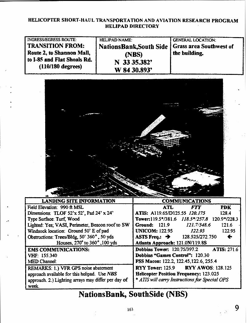
HELICOPTER SHORT-HAUL TRANSPORTATION AND AVIATION RESEARCH PROGRAM HELIPAD DIRECTORY
INGRESS/EGRESS ROUTE: HELJPAD NAME: GENERAL LOCATION: TRANSITION FROM: NationsBank,Soutb Side Grass area Southwest of Route 2, to Shannon Mall, (NBS) the bul1ding. to 1-85 and Flat Shoals Rd. N 33 35.382'
(110/180 degrees) W 8430.893'
LANDING SITE INFORMATION COMMUNICATIONS Field Elevation: 990 ft MSL ATL FTY PDK Dimensions: TLOF 52'x 52', Pad 24, x 24' ATIS: Al 19.65/0125.55 120.175 128.4 Type Surface: Turt: Wood Tower:l 19.5*/381.6 118.5*1257.8 120.9*/228.3 Lighted: Yes; VASI, Perimeter, Beacon roof to SW Ground: 121.9 121.71348.6 121.6 Windsock location: Ground SO' E of pad UNICOM: 122.95 122.95 122.95 Obstructions: Trees/Bldg, 50' 360 ° , 50 yds ASTS Freq.: ~ 128.525/272. 750 +
Houses~ 270° to 360° ,100 ds Atlanta A roach: 121.0N/119.8S EMS COMMUNICATIONS: Dobbins Tower: 120.75/397.2 ATIS: 271.6 VHF: 155.340 Dobbins "Games Control": 120.30 MEO Channel: FSS Macon: 122.2, 122.45,122.6, 2S5.4 --------------------t REMARKS: 1.) VFR GPS noise abatement RYY Tower: 125.9 RYY AWOS: 128.125 approach available for this helipad. Use NBS Bdicopter Position Frequency: 123.025 approach. 2.) Lighting arrays may differ per day of * ATIS will carry l11structio11s for Special OPS week.
NationsBank, SouthSide (NBS)
163 9

199S DcLonnc
164
Mag12.00
Sat Jul 0611:371996 Scale 1:62,500 (at center)
2KM
- State Route
_:;-1
d
- Interstate/limited Al:tf!JfJS
c= US Hviwav
-+--+- Railroad
-
..

..
HELICOPTER SHORT-HAUL TRANSPORTATION AND AVIATION RESEARCH PROGRAM HELIPAD DIRECTORY
INGRESS/EGRESS ROUTE: HELJPAD NAME: GENERAL LOCATION: TRANSITION FROM: NationsBank, Northeast Rooftop at end of building Helicopter Route 1 and RR (NBE) Tracks and La Vista Dr. N 33 50.577'
(110/200 degrees) W 8414.472'
LANDING SITE INFORMATION COMMUNICATIONS Field Elevation: 1160 ft MSL ATL FrY PDK Dimensions: TI..OF 52' x 52' ATIS: Al 19.65/012S.SS 120.175 128.4 Type Surface: Rooftop/Concrete Tower:119.S*/381.6 118.5*/257.8 120.9*/228.3 Lighted: Yes; VASI, Perimeter. Beacon 130' E of pad Ground: 121.9 121. 7/348.6 121.6 Windsock location: Elevated unit E of pad center UNICOM: 122.95 122.95 122.95 Obstructions: Tower 663' ag1 280 ° at 1/2 nu1e ASTSFreq.: + 128.52S/272. 750 +
Homes 180° at 1/4 nule EMS COMMUNICATIONS: Dobbins Tower: 120.75/397.2 ATIS: 271.6 VHF: 155.340 Dobbins "Games Contror: 120.30 MED Channel: FSS Macon: 122.2, 122.45:,122.6, 255.4 REMARKS: 1.) Rooftop pad unable to RYY Tower: 125.9 RYY AWOS: 128.125 accomodate B4l2 aircraft. 2.) B0-105 pilots land Helicopter Position Frequency: 123 .025 at designated spot on pad at all times. 3.) No GPS * ATIS will carry /11structions for Special OPS annroach available for this site
NationsBank, Northeast (NBE)
165 10
l

..
166

HELICOPTER SHORT-HAUL TRANSPORTATION AND AVIATION RESEARCH PROGRAM HELIPAD DIRECTORY
INGRESS/EGRESS ROUTE: HELIPAD NAME: GENERAL LOCATION: TRANSITION FROM: N. Fulton Co. Hospital
(RAF) 3 miles West of GA 400 (Rt.4) on Parking Garage next to Hospital
N 34 03.587' W8419.4S4'
LANDING SITE INFORMATION Field Elevation: 990 ft MSL Dimensions: TLOF 52' x 52' Type Surface: Parking Garage/Concrete Lighted: Yes; VASI, Perimeter, Beacon on util. build N of pad center
ATL FT¥ PDK ATIS: Al 19.6S/D125.SS 120.175 128.4 Tower:119.5*/381.6 118.5*1257.8 120.9*/228.3 Ground: 121.9 121.7/348.6 121.6 ·
Windsock location: Comer of garage UNICOM: 122.95 122.95 122.95 Obstructions: Ho · buildin 0901) close ~- ASTS : + 128.525/272.750 + EMS COMMUNICATIONS: Dobbins Tower: 120.75/397.2 ATIS: 271.6 VHF: 15S.340 Debbins "Games Control": 120.30
t,.;ME;.;.;;;;;.;D;..· .;;.Cbannel_,_~:----~--------1 FSS Macon: 122.2, 122.45,122.6, 255.4 REMARKS: l.)VFRGPSnoiseabatement RYYTower: 125.9 RYY AWOS: 128.125 approach available for this helipad. Use RAF Helicopter Position Frequency: 123.025 a roach. • A11S will c, Instructions r · cial OPS
N. Fulton Co. Hospital (RAF)
167 11

..
168

HELICOPTER SHORT-HAUL TRANSPORTATION AND A VIA TlON RESEARCH PROGRAM HELIPAD DIRECTORY
INGRESS/EGRESS ROUTE: TRANSITION FROM: Helicopter Rt 4 or Rt 6 to Piedmont Dr.
(090/270 degrees)
HELIPAD NAME:
Wachovia Bank -Buckhead (BUC)
N 33 49.10' W 84 22.10'
GENERAL LOCATION: City ofBuckhead, West of GA 400 and North ofl-85
LANDING SITE INFORMATION COMMUNICATIO S Field Elevation: 990 ft MSL An. FTY PDK Dimensions: TI..OF 52~x 52' ADS: Al 19.65/Dl25.S5 120.175 128.4 TypeSumce: Asphalt Tower:119.S*/381.6 118.5*1257.8 120.~/228.3 Llghtcd:Yes. VASI,Paimeter.Beacon 146'Nofpad Ground: 121.9 121.71348.6 121.6 Wmdsocklocation: 73' N ofpad UNICOM: 122.95 122.95 122.9S Obstructions: See remarks below 1 ASTS F .: + 128.525/272. 750 + EMS COMMONICA TIONS: Dobbins Tower: 120. 75/397.2 ATIS: 271.6 VHF: lSS.340 Dobbins "Games Control": 120.30 MED Channel: FSS Macon: 122.2, 122.45,122.6, 255.4 --------------------t REMARKS: 1.)Powerlines 10\ 150°at500yds RYYTower: 125.9 RYY AWOS: 128.125 Buildingsfl'rees, ss·, 360° at 100 yds, Tower 534• agl, Helicopter Position Frequency: 123.025 045 ° at 112 nu1e, Office Building 360° at 500 yds. * A11S will carry Instructions for Special OPS 2.) VFR GPS noise abatement approach available for this heli ad. Use BUC a roach.
Wachovia Bank - Buckhead (BUC)
169 12

170

171
LEGEND Scale: l 11 = 0.8 nm
Minimum Safe Altitude=2200'msl +- Approach Segment +c Visual Segment +c Missed Approach Segment

w·
/
f~-.
\ . -~--.,.~ A\,.~ 17
\II ii
~f East Point I. l 1
1•m l&:1:iinm, -~--- •• (L--~--- ·-- •···•-··-----•·- - . ··-
..
€
172

APPENDIXB
HELi-STAR SAFETY PLAN

SYSTEM SAFETY OPERATIONAL PLAN
HELICOPTER SHORT-HAUL TRANSPORTATION AVIATION RESEARCH PROGRAM
1996 OLYMPICS
General Aviation And Vertical Flight Program Office Federal Aviation Administration
By Dean M. Resch
Aviation Safety Manager and
William T. Sampson III SAIC

TABLE OF CONTENTS
1.0 Introduction ............................................................................................. Page 1
- - . .
2.0 Structure and Organization ····················································-·-~:··············Page I
3.0 Responsibilities ....................................................................................... Page 2 3.1 Director, General Aviation Vertical Flight Program Office ............. Page 2 3 .2 Aviation Safety Manager ................................................................. Page 2 3 .3 Participating Pilots ........................................................................... Page 2
4.0 Program Elements ................................................................................... Page 3 4.1 Distribution of Information .............................................................. Page 3
4.1.1 Critical .................................................................................... Page 3 4.1.2 Non-Critical ............................................................................ Page 3
4.2 Safety Notification System ............................................................... Page 3 4.3 Safety Inspection and Evaluations ................................................... Page 4 4.4 Accident, Incident and Hazard Reporting Responsibility ................ Page 4 4.5 Mandatory Helicopter Short-Haul Transportation Aviation Research Program Reports ...................................................................................... Page 4
4.5.1 National Transportation Safety Board .................................... Page 4 4.5.2 Federal Aviation Administration ............................................ Page 5
4.6 Non-Mandatory Reports ................................................................... Page 6 4.6.1 Aviation Safety Reporting System ......................................... Page 6
5.0 Post Incident Response Plan ................................................................... Page 6 5.1 Responsibilities ................................................................................ Page 6
5 .1.1 Project Manager ...................................................................... Page 6 5.1.2 Aviation Safety Officer ........................................................... Page 6 5.1.3 Participants ............................................................................. Page 7
5.2 Notification Procedures .................................................................... Page 7 5.2.1 Heliport ................................................................................... Page 7 5.2.2 Traffic Advisory Center .......................................................... Page 7 5 .2.3 Project Operations Center ....................................................... Page 8 5.2.4 Aviation Safety Officer ........................................................... Page 8
5 .3 General Information ......................................................................... Page 8 5.3.1 Training .................................................................................. Page 8 5.3.2 Plan Exercise .......................................................................... Page 8
5.4 Priorities ........................................................................................... Page 9

6.0 Preservation of Evidence and Site Security ............................................ Page 9 6.1 General Operations ........................ .-: ................................ -: ....... : ...... Page 10
6.1.1 Control of Aircraft Accident Scenes ....................................... Page 10
7.0 News Media ............................................................................................ Page 10
8.0 ~~d Analysis ............................................... ~······································Page 10
9.0 .Risk Assessment .................................................................... ~.~; ............ Page 11
10.0 Foreign Object Damage ....................................................................... Page 11
11.0 Weather Considerations ........................................................................ Page 11 11.1 Summer Flight Hazards .................................................................. Page 11 11.2 Height Density Altitudes ................................................................ Page 11 11.3 Thunderstorms ................................................................................ Page 11 11.4 Tornadoes ....................................................................................... Page 12
12.0 Other Considerations ............................................................................ Page 12 12.1 Wire Hazards .................................................................................. Page 12 12.2 Insect Hazards ................................................................................ Page 12 12.3 Bird Hazards ................................................................................... Page 12
13.0 Training Requirements .......................................................................... Page 13
APPENDIX
HELI-STAR Safety Certification Form ......................................................... Page 14 HELI-STAR Incident/Safety Report Form .................................................... Page 15
HELI-STAR Incident Notification List ·······················································:·Page 16 HELi-STAR Medical Support .................................................................... Page 17
"·

1.0 INTRODUCTION
The goal of this safety plan is to reduce to an absolute minimum possible, all risks associated with the tasks, plans or procedures necessary to accomplish the goal or mission. These risks are evaluated by the Aviation Safety Manager and project staff to ensure they offer minimal exposure to all HELi-ST AR project and project sup1>9rt personnel.
All HELi-ST AR participants are stakeholders in the project, therefore, all participants should be clear on the following safety directive:
All participants of the HELi-STAR have the authority to stop any and all operations during testing ifan unsafe condition is developing or anytime safety is being compromised.
To ensure compliance with the goals of the safety plan, all participants will receive a safety briefing prior to any activity associated with Heli-Star operations. This briefing will include, but not be limited to:
• General Safety • Mission Requirements • Helicopter Operations • Environmental Hazards and Protection • Helipad Operations • Haz.ardous Material considerations
Information provided in this safety plan, when used in conjunction with organizational standard operating procedures, provides sound and prudent measures and recommendations for conducting safe and efficient operations. If these measures and recommendations are followed, risks will be exposed, identified and acted upon in accordance with government and industry accepted risk management procedures.
2.0 STRUCTURE AND ORGANIZATION
The responsibility for developing the System Safety Plan and providing guidance and advise on it's implementation is assigned to the General Aviation and Vertical Flight Program Office (GAVFPO) Aviation Safety Manager. That responsibility includes authority to publish and implement the program and to advise the Director, GA VFPO of any additional requirements. Responsibility for implementing the plan rests with all HELi-STAR aviation participants.
The GA VFPO Aviation Safety Manager reports to the Director, GA VFPO, and serves all HELi-ST AR aviation participants in a staff capacity.
179

3.0 RESPONSIBILITIES
3.1 DIRECTOR, GAVFPO
The Director is responsible for supervising, coordinating, implementing, and directing safe flight operations for all aviation participants of the HELi-STAR. The_ pirector will ensure to the maximum extent p<;>ssible, that all flights are conducted in a professional manner to guarantee that safe opera~tng practices are observed by all participants using the HELi-ST AR infrastructure system.
3.2 AVIATION SAFETY MANAGER
The Aviation Safety Manager reports directly to the Director, GA VFPO in all matters pertaining to aviation safety and compliance with the HELi-STAR requirements and will:
• Develop an on-going safety management program • Conduct research of appropriate regulations, temporary flight
restrictions (SF AR), studies, summaries, and periodicals for modem trends in safety management and accident prevention
• Advise the Director of all current activities • Conduct advance surveys and evaluations to insure conformity to all
policies, procedures, and directives as applicable to the HELi-STAR • Assist authorities in conducting accident/incident investigations as
directed • Maintain liaison with counterparts in government and industry on
safety matters • Review all procedures for proper content and practices • Fulfill other duties assigned by the Director, GAVFPO
3.3 PARTICIPATING PILOTS
Pilots will be familiar with the requirements of the Special Federal Aviation Regulation (SF AR), company procedures-to include refueling and passenger safety briefings, and all appropriate Federal Aviation Regulations (FAR). All pilots also are responsible for:
• Being alert for safety hazards at all times • Reporting all haz.ards to appropriate authorities • Maintaining objectivity in the reporting of suspect practices
concerning operations, fueling, maintenance, dispatch or any other matter impacting aviation safety
• Assisting in the surveillance of Foreign Object Damage (FOO) and minimizing FOO effects
180
..

4.0 PROGRAM ELEMENTS
4.1 DISTRIBUTION OF INFORMATION
The distribution of safety information within the HELi-ST AR infrastructure, cate~rized into two types--critical and non-critica.1:--will be distributed in the following manner:
4.1.1 CRITICAL
All aircraft operators participating in HELi-STAR will maintain a reading file devoted to HELi-STAR. The critical file will contain only information deemed to be critical in nature. It will be mandatory for all participants to read and verify (by signature) that they have read the latest critical information.
4.1.2 NON-CRITICAL
All other information that is advisory in nature, or nice-to-know, will be posted in a non-critical reading file or posted on a safety bulletin board.
4.2 SAFETY NOTIFICATION SYSTEM
The safety reporting system allows for the immediate dissemination of safety related issues to all participants. Participants will report safety related matters to the Project Operations Center (POC) or the Aviation Safety Manager. All pertinent information will then be disseminated to all HELi-STAR participants. The following are examples of safety hazards that should be reported:
• Improper storage of hazardous materials • Foreign obstacle debris • Inoperative or inadequate heliport lighting • Heliport obstructions • Unsafe maintenance procedures • Mission deviations • Unauthorized personnel on premises • Unsafe loading or off-loading of cargo • Unsafe or improper fueling of aircraft
181

4.3 SAFETY INSPECTIONS AND EVALUATIONS
The Aviation Safety Manager will, with appropriate representatives, inspect and evaluate any or all phases of the HELi-STAR infrastructure supported by HELiST AR participants. The objectives of these inspections/evaluations are:
- • Eliminate costly and potentially hazardous situations • Assure compliance with Federal Aviation Regulation_5i. • Assure compliance with HELi-STAR procedures • Identify any potentially hazardous situation from developing • Correct any safety hazard
The Safety Manager will brief the Director on all hazardous findings and recommend appropriate actions to eliminate the hazard.
4.4 ACCIDENT, INCIDENT AND HAZARD REPORTING RESPONSIBILITY
It is the responsibility of all HELi-ST AR participants to notify the Safety Manager or his representative of anything that could negatively affect the safety of participating personnel and equipment. This active participation affords the HELi-STAR team the opportunity to not only correct deficiencies, but to continually refine and enhance its safety program overall.
4.5 MANDATORY HELi-STAR REPORTS
Mandatory reports required by the Federal Aviation Administration and National Transportation Safety Board (NTSB) will apply during the HELi-STAR demonstration . The criteria for those reports are as follows:
4.5.1 NATIONAL TRANSPORTATION SAFETY BOARD
The National Transportation Safety Board will be notified immediately when an ·aircraft accident or any of the following occurs:
• Flight control malfunction or failure • Inability of any required flight personnel to perform normal flight
duties as a result of injury or illness • Turbine engine rotor failures, excluding compressor blades and turbine
buckets • In-flight fire • Aircraft collision in-flight • Aircraft overdue and believed to have been involved in an accident
182
...

..
4.5.2 FEDERAL AVIATION ADMINISTRATION
In addition to the reports required by the NTSB, the FAA investigates certain incidents related to aircraft. In some cases, these reports duplicate those required by the NTSB. These include:
- • Flight control malfunction or failure _ • Inability of any required flight personnel to perform }!9rmal flight as a
result of injury or illness • Turbine engine rotor failures, excluding compressor blades and turbine
buckets • In-flight fire and/or lightning strike • Aircraft collision in flight with less than substantial damage resulting
in minor or no injuries • Pilot deviations from FAR Par 91 or 99 • Near mid-air collision • Rapid decompression requiring emergency action • Unwanted asymmetrical thrust reversal • Emergencies, including: aircraft equipment malfunction that require
special handling resulting in delays or resequencing • Loss of life, serious injury, substantial aircraft damage, or incidents
involving equipment attached to the aircraft during ground operations without the intention to fly
• Hazardous material incident (reference CFR Part 171.15) • Any aircraft touching down short of a runway's paved surface • Aircraft known to have struck an obstacle on the landing approach • Multi-engine aircraft running off the end or side of a runway's paved
surface or obviously losing directional control during take-off or landing
• Aircraft taking off or landing on a taxiway without clearance • Any air carrier landing at the wrong airport or on a non-airport area • Aircraft landings at an airport/heliport where the weather is less than
prescribed on applicable approach plates • Emergency evacuation - report use or operation (including
malfunction) of all emergency equipment on the aircraft • FAA aircraft incidents • In-flight total electrical failures for multi-engine aircraft, in-flight total
electrical failure for single-engine aircraft while under Instrument Flight Rules (IFR)
• Damage inflicted by one aircraft to another aircraft ( either or both of which may be parked or moving) as a result of contact with a propeller, jet blast, or rotor wash
• Parachuting fatalities and other occurrences involving safety hazards
183

• Miscellaneous - any incident not covered by any of the above that may result in damage to property, aircraft or injury to personnel
4.6 NON-MANDATORY REPORT
4.6.1 Aviation Safety Reporting System
Within the United States, the Federal Aviation Administration h~ instituted a voluntary safety reporting program designed to encourage the reporting and identification of deficiencies with the National Airspace System (NAS). The program is funded by the FAA and administered by the National Aeronautics and Space Administration (NASA) and is called the Aviation Safety Reporting System (ASRS).
NASA provides administration and data processing, assuring anonymity of the reports. The program is described in detail in FAA Advisory Circular AC 00-46C. FAR Part 91.25 of 14 CFR states that the Administrator of the FAA will not use reports submitted to the National Aeronautics and Space Administration under the Aviation Safety Reporting Program ( or any information derived from the reports) in any enforcement action exceptthat information concerning accidents or criminal offenses that are wholly excluded from the program.
5.0 POST INCIDENT RESPONSE PLAN
The post incident response plan establishes the procedures, guidelines and standards for reporting any incident or accident that may occur involving participating HELi-STAR aircraft. This plan is applicable to all participants of the HELi-STAR program and addresses all activities occurring during operational concept test periods and the actual demonstration period during the summer Olympic Games.
5.1 RESPONSIBILITIES
5.1.l Project Manager
The project manager has overall responsibility for the management of aviation resources and the implementation of an effective Post Incident Response Plan.
5.1.2 Aviation Safety Officer
The Safety Officer is responsible for the safety of aviation operations under his control. Within this responsibility is the practical requirement to provide safe working conditions, preventing injuries to participants, and protecting property from damage. Further, in the event of an incident, the Safety Officer is
184
..

..
responsible for ensuring that all notifications as indicated on the Incident Notification List have been completed ·· -
5 .1.3 All Participants
All participants have the responsibility to report all aircraft accidents, incidents, aviat{on hazards, and any deficiency that may hav~ a negative impact on safety. Any participant becoming aware of any such accident or aircraftjncidents, or other aviation-related mishap, shall utilize the Incident Notification List shown below.
5.2 NOTIFICATION PROCEDURES
5.2.1 Heliport
For all emergencies, heliport personnel should first notify local fire/rescue and police as shown on the Incident Notification List. The following information should be provided:
• Name of caller • Location of incident • The type of incident - i.e., aircraft accident, fire, personal
injury, hazardous material spill, crime in progress • Number, and if possible, severity of injuries • The telephone number where the caller may be reached
After notifying fire and police, immediately contact the Traffic Advisory Center (TAC) providing the same information. Once this has been done, recontact the TAC:
• Upon the arrival of police and fire assistance on the scene • With any updates that you feel are necessary, i.e., incident is
stable or has become more unstable, i.e., additional injuries, fire spreading
5.2.2 Traffic Advisory Center
Once receiving information that an accident or incident has occurred, the TAC shall immediately notify the following personnel:
• Police and fire to confirm that they have been notified, that the information received from the scene is correct and provide any additional information as needed to include any updates
• Project Operations Center (POC) providing a full description on what has occurred
185

• Atlanta Committee for ~e Olympic Games (A~OG) security (located at the TAC)
5.2.3 Project Operations Center
After receiving notification of the occurrence of an incident or accident, the POC sho~d, without delay, notify the following:
• . Safety Officer • Project Manager • PHI
5.2.4 Aviation Safety Officer
once notified, the Aviation Safety Officer is responsible for notifying the · following:
• FAA Southern Region • Operations Center • Duty Officer
• FAA Headquarters ( courtesy call) • AND-610 • AND-600 • AND-I • NTSB as required
5.3 GENERAL INFORMATION
5.3.1 Training
All HELI-STAR participants will receive documented training on the use of the Post Incident Response Plan.
5 .3 .2 Plan Exercise
Prior to the commencement of the demonstration period during the Olympic Games, this plan will be tested and then evaluated by the Project Manager and the Safety Officer.
186
,,

..
5.4 PRIORITIES
The order of priority of any accident or incident will be:
• The preservation of human life • The removal of injured personnel to a treatment facility
- • Secure the accident site . • Preservation of aircraft, equipment and property fro~. ~y potential or
further damage • Mandatory reporting
6.0 PRESERVATION OF EVIDENCE AND SITE SECURITY
The FAA and/or the NTSB will respond to the accident as appropriate. However, the response will not be immediate due to notification time and travel distance. Before the Investigator arrives at the scene and takes charge, it is incumbent to those first arriving at the scene to understand the requirement to secure the scene and preserve evidence in compliance with the law.
Toe following is taken from NTSB Rules and Regulations, section 830. l 0:
"The operator of an aircraft is responsible for preserving, to the extent possible, the aircraft wreckage, cargo and mail aboard the aircraft and all records, including tapes of the flight recorders and voice recorders, pertaining to the operation and maintenance of the aircraft and to the airmen involved in an accident or incident for which notification must be given until the Board takes custody thereof or a release is granted pursuant to Section 813 .17."
Prior to the time the Board or its authorized representative take custody of the aircraft wreckage, mail and cargo may be distributed or moved only to the extent necessary:
• To remove persons injured or trapped • To protect the wreckage from further damage or • To protect the public from injury
Where it is necessary to disturb or move aircraft wreckage, mail or cargo, sketches, descriptive notes, and photographs shall be made, if possible, of the accident locale including the original position and condition of the wreckage and any significant impact marks .
•
The operator of an aircraft involved in an accident or incident defined in this Part shall retain all records and reports, including internal documents and memoranda
187

dealing with the accident or incident, until a~thorized by the Boar~ to the contrary.
6.1 GENERAL OPERATIONS
6.1.1 Control of Aircraft Accident Scenes
In the event of an aircraft accident, the following is a limited guide of considerations to control the scene of an aircraft accident. Remember, it is only a guide and not meant to override any existing plan or procedure:
• Command Post • Planned Assistance (Mutual Aid Agencies) • Unplanned Assistance (General Public) • Site Access for Equipment and Personnel • Landing Sites • Triage and Medical Transportation Sites • Evacuation Routes • Assembly Points for Passengers/Crewmembers • Traffic Control • Press Relations • Hazardous Materials
7.0 NEWS MEDIA
Information releases concerning any activity of the HELi-STAR will be handled only by the Director, GA VFPO, or his designated representative. All accident or incident inquiries will be forwarded to the Southern Region Public Affairs Office, without exception.
8.0 HAZARD ANALYSIS
Procedures will be implemented to analyze, identify and control hazards in aviation systems , facilities and operations. Emphasis will be placed on early detection versus post-accident techniques.
All available resources will be applied against "worst first" hazards. In ranking priorities, potential consequences must be considered. These are:
• Degree of injury • Occupational illness • Damage • Legal and statutory implications • Adverse media reaction
188
•
..

..
9.0 RISK ASSESSMENT
Risk assessment is the subject analysis of physical hazards and operational proc~ures to arrive at a go/no go decision. The assessment supports an informed decision and is the responsibility of the operator. The pilot re~~ final authority for a go/ no go decision when the safe operation of the aircraft is-at-risk.
10.0 FOREIGN OBJECT DAMAGE (FOD)
FOD is damage, or malfunction, of an aircraft system in an aircraft caused by an object that is alien to an area or system or is ingested or lodged in a mechanism of an aircraft. FOD may cause material damage or it may cause equipment to be disabled, unsafe or less efficient.
I 1.0 WEATHER CONSIDERATIONS
I I. I Summer Flight Hazards
Flights during the summer months may expect to encounter high density altitude and thunderstorm activity in some areas. Potential hazards resulting from high density altitude includes sluggish flight control reaction, reduced power available. Associated hazards include roll clouds, high winds, heavy rain, haze and turbulence.
11.2 High Density Altitudes
High density altitude is best compensated for by proper preflight planning by computing power required to hover, take-off and land at the highest elevation and temperature expected during the flight. When power available does not equal or exceed power required, gross weight must be adjusted to allow the necessary margin of safety. Density altitude will also effect autorotative characteristics and therefore must be considered for emergency operations.
11.3 Thunderstorms
Thunderstorms or cumulonimbus, are probably the greatest hazard to flight presented by weather phenomena. Helicopters are very vulnerable to the effects of severe weather associated with thunderstorms and may receive damage, even when securely tied down, from hail, high winds, lightning strikes, or heavy rain accompanying the severe weather. Thunderstorms may occur along frontal systems. Night thunderstorms may result from air instability occurring when cool air masses move over heated terrain. Independent thunderstorms may break off
189

from a line of thunderstorms at any time and move independently. Thunderstorms may be either slow or fast moving or could be stationary and should be avoided at all costs. Severe turbulence and winds in excess of one hundred and fifty miles per hour have been recorded inside thunderstorm cells. There is a tremendous amount of potential energy contained within a thunderstorm and aircraft should remain at a maximum safe distance at all times.
11.4 Tornadoes
Another hazard associated with severe thunderstorms is the potential for tornado activity. A tornado, twister, waterspout or funnel cloud is a high velocity anticyclonic wind (in the Northern Hemisphere) which may extend vertically to the ground or lie horizontally aloft, in close proximity to the ground. A tornado may occur any time of the year but is often seen in the spring and fall during thunderstorm activity. The best way to avoid damage from a tornado is to stay well clear. Remember that a TORNADO WATCH means that the conditions are right for tornado to develop and a TORNADO WARNING means that one has been sighted.
12.0 OTHER CONSIDERATIONS
12.1 Wire Hazards
Wires suspended across valleys, mountain top to mountain top, or ridgeline to ridgeline are extremely difficult to see and pose an extreme hazard to aircraft operations. Wires are responsible for many crewmember fatalities. They should always be marked on a hazards map and crew should never fly into unfamiliar valley terrain, or in lowered visibility or without knowing the exact location of suspended wires.
12.2 Insect Hazard
In certain parts of the country, an adverse situation can be created by the rotor blades passing through swarms of insects. The insects can build up on the leading edge of the blade much like the build-up during icing, causing the blades to lose lift.
12.3 Bird Hazard
Bird activity can always pose problems for flight operations. Whether singularly or in flocks, birds can do extreme damage to an aircraft and/or engines. Notice to Airmen (NOT AMS) and pilot reports are warnings that all pilots should include in flight planning and decision making.
190
,,

•
..
13.0 TRAINING REQUIREMENTS
All HELi-STAR participants will si~ a "HELi-STAR Safety Certification Form," sample on Page 16, to acknowledge that they have received and understood briefing procedures and requirements as related to safety and HELiST AR operations. Personnel will receive training in the following appropriate areas:
• Flight operations within the SF AR • Cargo loading • Fuel Operations • Communications, Navigation and Surveillance (CNS) • Data Link operations • Security • Air Traffic Control procedures
191

HELi-ST AR Safety Certification Form
In compliance with the goal and objectives of the HELi-STAR safety plan, I have received formal training and understand the requirements and procedures related to safety in the areas of:
General Safety Mission Requirements
Helicopter Operations and Procedures Heliport Operations and Procedures
Environmental Hazards and Protection
I further understand that as part of HELi-STAR, I have the authority to stop any and all operations at any time if an unsafe condition is developing or safety is being compromised.
Signed: _________ _
Print Name: _______ _
Date: __________ _
Course Attened:
Signed: _________ _
HELi-STAR Safety Officer
Date: __________ _
----------Instructor: ------------
192
•
..

·•·
...
HELi-STAR INCIDENT/SAFETY REPORT
1.) NAME OF CALLER: ___________________ _
2.) DATE OF CALL: _________ 3.) TIME OF CALL: _____ _
4.) SITE OF INCIDENT/SAFETY ISSUE: ( )GAL ( ) MIT ( ) GBH ( ) ( )RAF ( ) NBS ( ) BUC ( )
GMA. ( ) PDK ( )
NOR () ATL_ ... ( )
NBE FTY
( )F:ST ( ) CAP ( ) OTHER'--_______ .......__ __ _
5.) WAS AN AffiCRAFT INVOLVED? ( ) YES ( ) NO
6.) IF ANSWER TO 5.) ABOVE IS YES, FILL IN BELOW; IF NO, SKIP TO 7.)
AffiCRAFT NUMBER: N _______ AmCRAFT TYPE: ______ _
PILOT IN COMMAND: _______ ~AIRCRAFT OWNER: _____ _
7.) DESCRIPTION OF INCIDENT/SAFETY ISSUE: ___________ _
8.) WAS ANYONE INJURED AS A RESULT OF THE INCIDENT/SAFETY ISSUE? ( ) NO ( ) YES, Describe Injuries ___________ ---,-____ _
9.) DID THE INCIDENT/SAFETY ISSUE INTERFERE WITH NORMAL HELi-STAR OPERATIONS?( ) NO( ) YES, Describe changes ___________ _
10.) WERE ANY HAZARDOUS MATERIALS INVOLVED? ( ) NO ( ) YES, Describe materials ________________________ _
~'~111!1i~:~~!~iJJYEl~~ii>lliffl/i'ifti1!~f~J!t~ffl@l&~i~,:1~,~~i{~~1:1~~~¥~ Name of Watch Officer: ____________________ __. Actions taken: _______________________ --1
Date Copy of Report was given to Safety Officer:
193

Helicopter Short-Haul Transportation Aviation Research Program (HELi-STAR)
INCIDENT NOTIFICATION LIST
HELIPORT
1. Police/Fire/Rescue 911
2. TAC 770-590-0857/1362
TRAFFIC ADVISORY CENTER
1. Police/Fire/Rescue 911 or Local Authority Confirm scene information (see individual site sheets)
2. POC 770-528-3262
3. ASOC Manager (ACOG Security) 770-919-9929
PROJECT OPERATIONS CENTER
1. Project Manager 770-528-7874 Pager 1-800-SKYPAGE (378-8130)
2. Safety Officer 770-528-7874
3. Petroleum Helicopters, Inc.
SAFETY OFFICER
1. FAA Southern Region
Pager l-800-467-3700(603-3022)
Atlanta 770-454-8900 PHI offices 800-235-2452
Operations Center Duty Officer 404-305-5180 (24 hours)
2. FAA Headquarters (courtesy calls)
AND-610 202-267-8759 AND-600 202-267-3320 AND-1 202-267-3555
3. NTSB (as required) =20=2=--------
194
,.
.. ,

•
•·
MEDICAL SUPPORT
Dr. Miles Brett, M.D., AME 2520 Windy Hill Rd. Suite 301 Marietta, GA 770-952-1032
Dr. Michael W. Shaffer, D.D.S. 3662 Club Drive, N.W. Suite 105 Lawrenceville, GA 770-279-7987
195

•

•
•
The following is a breakdown of the ground infrastr.ucture components:
Table C-1 Project Operations Center
FAA/ Ground Infrastructure Qty Contractors 1 Qty AGATE Qty Industry2
. : Computers 1 $2,000 1 $25,000 15 $12,800-' Geonet Repeaters 1 $5,000 -·· 1 $5,000
Geonet-Transceivers 1 $5,000 -
Antennas 1 $700 1 $700 Land Lines 1 $200
UHF Antenna 1 $200 NEXWOS 1 $20,000
800 MHz Phones 15 $3,500'' Site Space
GTRI Atrium ·.
$6,300" Office Equipment $1,500
Total $12,900 $25,000 ~
Includes SAIC, GTRI, ARNA V, and subcontractors. 2 Includes A VF A, GTRI (non contractual), and other participating companies. 3 Heliports & POC computers provided by Georgia Tech and Wachovia Bank. 4 800 MHz phones used for communicating between POC and heliports were donated by Executive Courier. 5 2,800 sq. ft. of atrium, office, and conference room space.
Table C-2 Traffic Advisory Center
FAA/ Ground Infrastructure Qty Contractors Qty AGATE Qty Industry
Computers I $25,000 I Land Line 2 $700
Radar I $16,000 Geonet Repeater 1 $5,000
Site Space
Total $5,000 $2,000
Note: Blank cells indicate zero or unquantified values.
199

Table C-3 Georgia Emergen'?..y Management Agen~y
Ground FAA/ Other Infrastructure Qty Contractor Qty AGATE Qty Industry Qty Gov't
Computers I $2,000 Geonet Repeater I $5,000
Antennas I $700 Geonet Transceiver I $5,000
..
Site Space - - -•
Total $12,700
Table C-4 Airports
FAA/ Ground Infrastructure Qty Contractors Qty AGATE Qty Industry
PDKAirport Geonet Repeater I $5,000 $5,000
Antennas 1 $700 $700 Location cost
ATL Airport .. :.
Geonet Repeater I $5,000 $5,000 Antennas I $700 $700
Location cost
Total $11,000 $11,000
Note: Blank cells indicate zero or unquantified values.
•
·-
200

'\
..
·-
Table C-5 Heliport Costs (shaded area represents __ industry cost share or_in-kind contribution)
Heliport Heliport Eng- Con- Lighting LZ Support Decom-Name Cost ineering struction Equipment Equipment mission
AIL $37,9671 $9,903 $9,613 $2,491
BUC $7,152 $8,649 $3,941 $1,608 1>:;' . ._ '::,,:;:::: .. · .. ·.
$260() ['\)$1~;~~p . .. -.:// ;,:/ii•::-;:.· ·,::- . . • .. --:• :,.;- ,·,.. . . , :;-: ,:;;; .. ·:, ; .•:._.
FTY $6,188 · -$1,031 $384
GAL $5,971 $10,982 $4,226 $1,081 $1,783 :/: ... ·:• •:: . ... ,.
. :)$i~9J,f/'. '':(': :,'-: /\ . .
!:,:_,·•,.-;:::-c:,•-·:, . .-·.•· .·. :,:,:•·• ...... ": ... <> .. ,.:: •'· ~- i:::'.:::::··:.;;.:'=.,:,~<= '." .... •,· ···,,
GBH $4,035 $4,548 $1,205 $675
GEMA $6,018 $5,464 $2,305 r,,. ·T. .. •:
·-.·-.,.·: )} : :··•.; ':, :?';::'i:: .· ,\( . .. ··•··: .. , ·•:·;: ··•: ··•
.·::· :. :::::- : .. ·. ,. .·. :, .... ,.:: ::· .:::: .,.·'· • .. ·,'••·.-: .'· .. , •:• .. \: ·,: .... MIT $19,906"' $2,734 $3,257 $1,865
";,_,'.'!':\ ·,· .... ·•· , .... >: ... $59'12 . .. ~---
..... :·\ !:'( .·. $70,760 ; >.·· :::.)i:: .::. ,1·,·.·: .. ./• .' . >· : . · ... , ..... ..,:.:_:',.
NBE $8,929 $2,134 $3,257 $1,865 )' ::> . ':( l $6;713. ..... .. $51$ . .:. ;>:-. .. :;-. . :.: .: •:_· :-.·, . ; . .. ·: ··. (
NBS $6,676 $13,387 $4,226 $1,608 > ........... _ .•... / .. - ...
.·$9~800''''' .•,, ... :.> $575 1· /, ::,· ::· .,·
::•, .·.· .· ': . I .. :- . · .. ;::,:: .. :,·,·· . .
NOR $8,079 $7,023 $4,226 $1,031 $1,608 .. $tsoo .
• •• r::·: $~Qo••· .
: ·. ·.·. ·: .. . ... \ . . •: :, ..· .
PDK $418"' $1,237 $1,031 $384
RAF $8,113 $7,129 $3,941 . '.: .. $1,200 .; .·•·. ·.: :.: '• ... . .._·.·· .::··· ,·_ .,_-:,- ... ··:,,.
'Pry()f~~-•'
... -$2,051 .:- . . ..
> ·,:: ·:, .•·
·• ,. ·.
,. . , ... ·••
~N. Metro·.· . , .
$1,176 ,: , .. ·., .. . ....
.... . , ... .. · .. :'."_.·:· . 1·• .•
Other costs Cargo carts $1,459 Utilities $714 Permits $1,411 Spares
FAA $37,967 $91,388 $73,074 $34,312 $6,347 $11,780 Indµstfy ~-:. . _::. . $33,867 :, : . . :. ::-:::«. $87·610 .·· ..... ·'· ... ,· . . .. ·.> :: Total $37,967 $91,388 $106,941 $34,312 $93,957 $11,780 • . .. Paid to City of Atlanta for 3 month use ofhehport. Includes fac1bt1es rental of$25,107 and land rental rate of $0.375 per square feet.
2 Includes $10,084 for rooftop heliport structural analysis. 3 POK constructed a pennanent heliport using FAA AIP funds. Therefore, engineering costs were minimal.
Note: Blank cells indicate zero or unquantified values.
201

Table C-6 Summary of Gro~d Infrastructure Cost~
Ground FAA! Other Component Contractors AGATE Industry Government Total
POC $12,900 $25,000 $50,000 $87,900 TAC $21,700 $25,000 $46,700 GEMA:. $12,700 $12,700 Airports $11,400 $11,400 -··· $22,800 Heliports $254;868 $121,477 . -- $376,345 (·
Total $289,468 $61,400 $195,577 $546,445
Note: Blank cells indicate zero or unquantified values.
r
·-..
202