Huawei DBS3900 Commissioning Procedure Huawei DBS3900 Commissioning Procedure
Upload
khangminh22Category
view
0download
0
उत्तरी क्षेत्र के लिए सचंािन प्रक्रिया
(भारतीय लिद्यतु लिड सलंिता (IEGC) के लिलनयम सखं्या 5.1 (f) के अनपुािन के तहत)
Operating Procedure
For
Northern Region
[In compliance with Regulation 5.1 (f) of Indian Electricity Grid Code]
July 2020
Rev 0
उत्तरी क्षेत्रीय भार प्रेषण केन्द्र
Northern Regional Load Despatch Centre 18-A, Shaheed Jeet Singh Sansanwal Marg,
Katwaria Sarai, New Delhi-110016 Ph: 011-26536832

THIS PAGE IS LEFT BLANK
INTENTIONALLY
Table of Contents 1. GENERAL ............................................................................................................................................... 4
1.1 INTRODUCTION ............................................................................................................................ 4 1.2 OBJECTIVE ................................................................................................................................... 4 1.3 SCOPE .......................................................................................................................................... 4 1.4 STRUCTURE OF OPERATING PROCEDURE ...................................................................................... 4 1.5 OPERATING MANPOWER .............................................................................................................. 6 1.6 MANAGEMENT OF OPERATING PROCEDURE ................................................................................. 6
2. NEW ELEMENT CONNECTIVITY TO GRID ................................................................................................ 7
2.1 INTRODUCTION ............................................................................................................................ 7 2.2 USER OF NRLDC ......................................................................................................................... 7 2.3 APPLICATION FOR REGISTRATION AS REGIONAL ENTITY ............................................................... 7 2.4 SWITCHING OF NEW TRANSMISSION ELEMENT & ISSUANCE OF CERTIFICATE ............................... 9
3. PLANNED OUTAGE COORDINATION .................................................................................................... 10
3.1 OVERVIEW ................................................................................................................................. 10 3.2 PLANNED OUTAGE COORDINATION PROCESS .............................................................................. 10
4. SWITCHING COORDINATION ............................................................................................................... 12
4.1 OVERVIEW ................................................................................................................................. 12 4.2 SWITCHING OF SYSTEM ELEMENTS FOR THE FIRST TIME ............................................................. 12 4.3 SWITCHING OF IMPORTANT ELEMENTS ...................................................................................... 12 4.4 OTHER PRECAUTIONS TO BE TAKEN DURING SWITCHING............................................................ 13
5. FREQUENCY CONTROL ......................................................................................................................... 15
5.1 OVERVIEW ................................................................................................................................. 15 5.2 PRIMARY RESPONSE .................................................................................................................. 15 5.3 SECONDARY CONTROL .............................................................................................................. 16 5.4 SUPPLEMENTARY CONTROL ....................................................................................................... 17 5.5 TERTIARY RESPONSE ................................................................................................................. 18 5.6 STAGGERING OF TIMING OF LOAD CONNECTION/DISCONNECTION ............................................. 18 5.7 PREVENTIVE MEASURES DURING HIGH FREQUENCY CONDITIONS .............................................. 19 5.8 PREVENTIVE MEASURES DURING LOW FREQUENCY CONDITIONS ............................................... 19 5.9 NORMAL, ALERT & EMERGENCY MESSAGES ISSUED BY NRLDC ............................................... 20 5.10 DEFENCE PLAN FOR FREQUENCY CONTROL ............................................................................... 20
6. VOLTAGE CONTROL ............................................................................................................................. 21
6.1 OVERVIEW ................................................................................................................................. 21 6.2 VAR INTERCHANGE BY DRAWEE UTILITY ................................................................................. 21 6.3 SHUNT CAPACITOR BANK SWITCHING ....................................................................................... 21 6.4 STATIC VAR COMPENSATOR (SVC) & STATCOMS OPERATION ............................................... 21 6.5 SWITCHING OF BUS REACTOR AND SWITCHABLE LINE REACTORS ............................................. 22 6.6 VAR GENERATION/ABSORPTION BY GENERATING UNITS .......................................................... 22 6.7 CHANGING TRANSFORMER TAP POSITION .................................................................................. 22 6.8 LOAD MANAGEMENT FOR CONTROLLING THE LOW VOLTAGE ................................................... 22 6.9 HVDC FILTER BANK SWITCHING............................................................................................... 23 6.10 SWITCHING-OFF OF THE LINES IN CASE OF HIGH VOLTAGE........................................................ 23 6.11 ACTION PLAN FOR VOLTAGE CONTROL ..................................................................................... 23 6.12 DEFENCE PLAN FOR VOLTAGE CONTROL ................................................................................... 24
7. CONGESTION MANAGEMENT AND ALLEVIATION ................................................................................ 25
7.1 GENERAL ................................................................................................................................... 25 7.2 PERMISSIBLE EQUIPMENT LOADING ........................................................................................... 25 7.3 ASSESSMENT OF TRANSFER CAPABILITY .................................................................................... 25 7.4 MAJOR CORRIDOR/FLOW GATES IN NORTHERN REGION ............................................................ 26 7.5 MONITORING OF CONGESTION ................................................................................................... 26 7.6 GENERATION RESCHEDULING .................................................................................................... 26
NRLDC: Operating Procedure for Northern Region-July-2020 Page 2 of 71
7.7 CURTAILMENT OF SCHEDULED TRANSACTIONS.......................................................................... 26 7.8 PROCEDURE FOR RELIEVING CONGESTION ................................................................................. 27
8. DEMAND MANAGEMENT .................................................................................................................... 28
8.1 OVERVIEW ................................................................................................................................. 28 8.2 DEMAND ESTIMATION ............................................................................................................... 28 8.3 DEMAND CONTROL .................................................................................................................... 29 8.4 HANDLING SUDDEN REDUCTION IN DEMAND ............................................................................. 30 8.5 LOAD CRASH DURING THUNDERSTORM ..................................................................................... 30
9. SCHEDULING AND DESPATCH .............................................................................................................. 31
9.1 OVERVIEW ................................................................................................................................. 31 9.2 JURISDICTION OF NRLDC .......................................................................................................... 31 9.3 SCHEDULING OF LONG TERM AND MEDIUM-TERM CONTRACTS ................................................. 31 9.4 SCHEDULING OF HYDRO STATIONS ............................................................................................ 35 9.5 SCHEDULING IN CASE OF RESERVE SHUTDOWN (RSD)............................................................... 35 9.6 SCHEDULING OF SHORT-TERM CONTRACTS ............................................................................... 37 9.7 TIME LINE FOR INFORMATION EXCHANGE FOR SCHEDULING ..................................................... 37 9.8 TRANSMISSION LOSSES .............................................................................................................. 38 9.9 PEAKING .................................................................................................................................... 38 9.10 RAMP RATE ............................................................................................................................... 39 9.11 CURTAILMENT ........................................................................................................................... 39 9.12 REVISION OF SCHEDULES REQUESTED BY REGIONAL ENTITIES .................................................. 39 9.13 REVISION IN SCHEDULE INITIATED BY NRLDC .......................................................................... 42 9.14 MODERATION OF SCHEDULE BY NRLDC ................................................................................... 42 9.15 STANDING INSTRUCTION BY SLDC TO NRLDC ......................................................................... 43 9.16 RESERVOIR FILLING/DEPLETION FOR STORAGE TYPE HYDRO STATIONS .................................... 43 9.17 IMPLEMENTED SCHEDULE ISSUED BY NRLDC ........................................................................... 44 9.18 ALLOCATION OF UN-REQUISITIONED SURPLUS .......................................................................... 44 9.19 SECURITY CONSTRAINED ECONOMIC DISPATCH (SCED) ........................................................... 44 9.20 SCHEDULING OF COLLECTIVE TRANSACTION THROUGH REAL TIME MARKET (RTM) ................. 46 9.21 SCHEDULING OF SOLAR & WIND GENERATION .......................................................................... 46 9.22 SCHEDULE PREPARATION TIMELINES AND INFORMATION DISSEMINATION: - ............................... 47
10. ANCILLARY SERVICES OPERATIONS ..................................................................................................... 49
10.1 INTRODUCTION .......................................................................................................................... 49 10.2 SCOPE ........................................................................................................................................ 49 10.3 ROLE OF NODAL AGENCY .......................................................................................................... 49 10.4 ROLE OF RRAS PROVIDERS ....................................................................................................... 49 10.5 ROLE OF REGIONAL POWER COMMITTEES (RPCS) ..................................................................... 50 10.6 ROLE OF STATE LOAD DESPATCH CENTRES (SLDCS) ................................................................ 50 10.7 TRIGGERING CRITERIA OF RRAS ............................................................................................... 50 10.8 SCHEDULING OF RRAS .............................................................................................................. 51 10.9 WITHDRAWAL OF RRAS ............................................................................................................ 51 10.10 ENERGY ACCOUNTING ............................................................................................................... 52 10.11 RRAS SETTLEMENT ................................................................................................................... 52 10.12 FRAS (FAST RESPONSE ANCILLARY SERVICES) FROM ISGS HYDRO STATIONS ......................... 52 10.13 5-MINUTES SCHEDULING, METERING, ACCOUNTING AND SETTLEMENT ..................................... 53
11. SETTLEMENT SYSTEM .......................................................................................................................... 54
11.1 OVERVIEW ................................................................................................................................. 54 11.2 SETTLEMENT PERIOD ................................................................................................................. 54 11.3 INTERFACING METERING AND CONTROL AREA BOUNDARY ....................................................... 54 11.4 TIME CORRECTION & METER CALIBRATION .............................................................................. 54 11.5 DATA PROCESSING .................................................................................................................... 54

NRLDC: Operating Procedure for Northern Region-July-2020 Page 3 of 71
11.6 ENERGY ACCOUNTING ............................................................................................................... 55 11.7 FORWARDING ENERGY DATA FROM NRLDC TO NRPC SECRETARIAT ....................................... 55 11.8 ADDITIONAL DATA TO BE FORWARDED TO NRPC SECRETARIAT ................................................ 55
12. DEFENCE MECHANISMS FOR THE SYSTEM ........................................................................................... 56
12.1 GENERAL ................................................................................................................................... 56 12.2 UNIT PROTECTION SYSTEM ........................................................................................................ 56 12.3 FLAT FREQUENCY AND RATE OF CHANGE OF FREQUENCY RELAY LOAD SHEDDING SCHEME ..... 56 12.4 UNDER VOLTAGE LOAD SHEDDING SCHEME (UVLS) ................................................................ 57 12.5 SYSTEM PROTECTION SCHEME (SPS) ......................................................................................... 58 12.6 ISLANDING SCHEME ................................................................................................................... 58
13. GRID INCIDENT, GRID DISTURBANCE AND REVIVAL ............................................................................ 59
13.1 GENERAL ................................................................................................................................... 59 13.2 DEFINITION OF GRID INCIDENT AND GRID DISTURBANCE........................................................... 59 13.3 DECLARATION OF GRID DISTURBANCE ...................................................................................... 59 13.4 CATEGORISATION OF GRID DISTURBANCES................................................................................ 60 13.5 DEFERMENT OF PLANNED OUTAGE DURING GRID DISTURBANCE ............................................... 60 13.6 RESCHEDULING DURING GRID DISTURBANCE ............................................................................ 61 13.7 SYSTEM REVIVAL ...................................................................................................................... 61 13.8 DECLARATION OF SYSTEM NORMALISATION POST GRID DISTURBANCE ..................................... 62 13.9 INTER-REGIONAL SUPPORT ........................................................................................................ 62
14. EVENT INFORMATION AND REPORTING .............................................................................................. 63
14.1 OVERVIEW ................................................................................................................................. 63 14.2 EVENT INFORMATION ................................................................................................................ 63 14.3 REPORTING SYSTEM .................................................................................................................. 63
15. DATA ACQUISITION AND COMMUNICATION SYSTEM ......................................................................... 66
15.1 OVERVIEW ................................................................................................................................. 66 15.2 RECORDING INSTRUMENTS AND COMMUNICATION FACILITIES .................................................. 66 15.3 WIDE AREA MEASUREMENT SYSTEMS IN NR ............................................................................. 66 15.4 CYBER SECURITY....................................................................................................................... 67
LIST OF ANNEXURES..................................................................................................................................... 69
REFERENCES ................................................................................................................................................. 71
NRLDC: Operating Procedure for Northern Region-July-2020 Page 4 of 71
CHAPTER – 1
1. GENERAL
1.1 Introduction
The Northern Regional power system covers geographical areas in UT of Jammu and Kashmir, UT
of Ladakh, Punjab, Himachal Pradesh, Uttarakhand, Rajasthan, UT Chandigarh, Delhi, Haryana and
Uttar Pradesh. It comprises of 97 (Ninety-Seven) Regional Entities viz. 62 (Sixty-two) Generating
stations, 18 (Eighteen) Buyers/Drawee Utilities and 15 (Fifteen) Inter-State Transmission Licensees
including two SPPD as on 30th April 2020.
Regulation 5.1(f) of the Central Electricity Regulatory Commission (Indian Electricity Grid Code)
Regulations, 2010, stipulates that a set of detailed internal operating procedure for each regional
grid shall be developed and maintained by respective Regional Load Despatch Centres, in
consultation with the regional constituents. In compliance with the above regulations, this document
viz. “Operating Procedures for Northern Region” has been prepared by the Northern Regional Load
Despatch Centre in consultation with the regional constituents of the Northern Region.
1.2 Objective
The objective of this procedure is to compile various provisions in the statute and regulations for
the guidance to the staff of the NRLDC, SLDCs and Regional Entities in the Northern Region.
1.3 Scope
The “Operating Procedures for Northern Region” applies to the power system in Northern Region.
These procedures are to be read in conjunction with the Central Electricity Regulatory Commission
(Indian Electricity Grid Code) Regulations, 2010, Central Electricity Regulatory Commission
(Indian Electricity Grid Code) (First Amendment) Regulations, 2012 to Central Electricity
Regulatory Commission (Indian Electricity Grid Code) (Fifth Amendment) Regulations, 2017. The
Operating Procedures are without prejudice to the NRLDC’ s power to give directions and exercise
supervision and control as stated under Sections 28 and 29 of the Electricity Act, 2003.
This document would come in force with immediate effect. It supersedes the Operating Procedures
issued earlier by NRLDC in July 2019.
1.4 Structure of Operating Procedure
The Operating Procedures for Northern Region consists of the following chapters.
1.4.1. Chapter-1: General
This chapter describes the objective, scope and structure of the Operating Procedures for Northern
Region.
NRLDC: Operating Procedure for Northern Region-July-2020 Page 5 of 71
1.4.2. Chapter-2: New Element Connectivity to Grid
This chapter details the procedure to be followed for charging of new element connectivity to ISTS.
1.4.3. Chapter-3: Planned Outage Coordination
This chapter enumerate the procedure for coordination of planned outage
1.4.4. Chapter-4: Switching Coordination
This chapter describes the protocol to be followed while coordinating switching operation in the
Regional grid.
1.4.5. Chapter-5: Frequency Control
This chapter elaborates the procedures for frequency control to ensure compliance to security
standards prescribed in the CEA (Grid Standards) Regulations, 2010 and CERC (Indian Electricity
Grid Code) (Fifth Amendment) Regulations, 2017. It also covers the frequency linked despatch
guidelines.
1.4.6. Chapter-6: Voltage Control
This chapter explains the procedures for voltage control to ensure compliance to security standards
prescribed in the CEA (Grid Standards) Regulation, 2010 and CERC (Indian Electricity Grid Code)
(Fifth Amendment) Regulations, 2017.
1.4.7. Chapter-7: Congestion Management and Alleviation
This chapter elaborates on the congestion management philosophy and procedure in line with the
CERC (Measures to relieve congestion in real time operation) Regulations, 2009, Detailed
Procedure for relieving congestion in real time operation as approved by CERC vide its order dated
26.03.2013.
1.4.8. Chapter-8: Demand Management
The demand estimation & control is under the purview of the State Load Despatch Centres
(SLDCs). This chapter describes the SLDC’s interface with NRLDC with respect to demand
estimation and control.
1.4.9. Chapter-9: Scheduling and Despatch
This chapter details the procedures for day-ahead and same day scheduling as implemented in
Northern Region
1.4.10. Chapter-10: Ancillary Services Operations
This chapter elucidates on the ancillary services and throws light on the procedure for registration,
operations of the RRAS with the scope and roles of different agencies. FRAS and its framework
have also been introduced as per recent CERC order.
1.4.11. Chapter-11: Energy Settlement System
This chapter gives a broad outline of the settlement system, which is an important post-despatch
activity. This activity can commence immediately after special energy meters have been
commissioned at the different substations.
1.4.12. Chapter-12: Defence Mechanism for the System
This chapter elaborates on the various defence mechanisms adopted for Security and reliability of
the Northern Region.

NRLDC: Operating Procedure for Northern Region-July-2020 Page 6 of 71
1.4.13. Chapter-13: Grid Incident, Grid Disturbances and Revival
This chapter describes the criteria for categorizing grid events as specified in the Central Electricity
Authority (Grid Standards), Regulations, 2010. The general precautions to be observed and steps
taken during restoration are also included in this chapter.
1.4.14. Chapter-14: Event Information & Reports
Timely and accurate reporting of events and exchange of information plays an extremely vital role
in an integrated system. The protocol to be followed in such cases is indicated in this chapter.
1.4.15. Chapter-15: Data Acquisition and Communication System
This chapter briefly explains the system for data acquisition and communication system. This
chapter also dwells on the Procedures on matters related with cyber security.
This document does not cover the procedure to be followed in case power supply is to be regulated
to any utility on account of non-payment of dues. The same would be implemented by NRLDC in
line with the regulations and orders issued by CERC from time to time.
The details indicated in this document may not be exhaustive. They are intended to serve only as a
guideline for efficient system operation. In particular, these procedures do not cover the tools
required for efficient and effective system operation and analysis viz. Communication Systems,
Supervisory Control & Data Acquisition Systems (SCADA), Energy Management Systems (EMS),
and other recording and control equipment. It is expected that these requirements would be
provided by all concerned to enable efficient system operation.
1.5 Operating Manpower
The control rooms of all SLDCs, power plants, grid substations as well as any other control centres
of regional constituents shall be manned round the clock by qualified and adequately trained
manpower who would remain vigilant and cooperative at all the times so as to maintain the system
safety and security and operate it in the most optimum manner.
1.6 Management of Operating Procedure
The Operating Procedure shall be maintained by NRLDC and would be reviewed annually or
earlier in case significant changes taking place in the system warrant a review. Comments and
suggestions on the document may be sent to the following address:
Chief General Manager (SO)
Northern Regional Load Despatch Centre
18-A, Shaheed Jeet Singh Sansanwal Marg
Katwaria Sarai
New Delhi-110016
e-mail: [email protected]
*****
NRLDC: Operating Procedure for Northern Region-July-2020 Page 7 of 71
CHAPTER-2
2. NEW ELEMENT CONNECTIVITY TO GRID
2.1 Introduction
A new transmission/Generating element before connecting to Grid would follow the procedure as
per different regulations of CERC. If a transmission element or Generator comes in the jurisdiction
of RLDC as per CERC guideline, that agency has to first register itself in respective RLDC. First
time switching of new element of any agency or Transmission Licensees intending to commission
any transmission element, which is a part of inter-state transmission system, would be co-ordinated
as per procedure laid down by NLDC in line with regulations & Grid code.
2.2 User of NRLDC
A list of registered users shall be available on the website of NRLDC. The list of entities whose
scheduling shall be coordinated by the NRLDC is given in Annex I.
2.3 Application for registration as regional entity
In compliance to regulation 24 of the Central Electricity Regulatory Commission (Fees and Charges
of Regional Load Despatch Centre and other related matters) Regulations 2009, as amended from
time to time, all users located in the Northern region whose scheduling, metering and energy
accounting is to be coordinated by Northern Regional Load Despatch Centre (NRLDC) shall
register themselves with the NRLDC by filing application in the format prescribed as Annex II. In
case of renewable generator, the checklist along with format for registration (for renewable plant
commissioned before and after Aug’19 ) is available at NRLDC website at https://nrldc.in/formats-
for-registrations/ . The application shall be submitted at least three months prior to the proposed
interconnection date.
2.3.1. Data to be submitted for registration
The applicant shall furnish following details along with the application for registration.
Grant of connectivity, Long term Access/Medium term Open Access by the CTU/STU
Connection Agreement signed by the applicant with CTU/STU along with Dynamic data of
Generator, Exciter, Stabiliser, Governor etc. and in case of renewable generator, dynamic
data of Solar/Wind plant as applicable.
Geographical map indicating the point of connection with ISTS/STS including latitude &
longitude detail.
Power Purchase Agreement signed by the applicant with the long-term beneficiaries
Address, contact number, email ID of a Nodal officer
When NRLDC is convinced of its jurisdiction over the applicant (in light of various provisions in
IEGC & other Regulations) the applicant shall submit additional technical details as mandated by
NRLDC: Operating Procedure for Northern Region-July-2020 Page 8 of 71
various regulations. This may inter alia include the details mentioned in the check list enclosed as
Annex III.
It shall be the responsibility of the regional entity to comply with all the statutory obligations.
Entities registered with NRLDC shall coordinate with the CTU/STU, NRLDC/SLDC for ensuring
the availability of interface metering as well as data and speech communication with
NRLDC/SLDC control centre. The entity shall submit a testing and commissioning schedule and
cooperate with NRLDC in interconnection with the ISTS. The regional entity shall furnish any
other technical detail requested by NRLDC as and when requested for.
2.3.2. Facilitating Testing & Commissioning of New Regional Entity Generators
With regards to facilitating of testing and commissioning of new generating units the Regulation 8
(7) of the CERC (Grant of connectivity, Long-term access and medium-term Open Access in inter-
State Transmission and related matter) regulation, 2009 as amended time to time provides as under.
“(7) Notwithstanding anything contained in Clause (6) of this Regulation and any provision with
regard to sale of infirm power in the Power Purchase Agreement, a unit of a generating station
including a captive generating plant which has been granted connectivity to the inter-State
Transmission System in accordance with these regulations shall be allowed to inter-change infirm
power with the grid during the commissioning period, including testing and full load testing before
the COD, after obtaining prior permission of the concerned Regional Load Despatch Centre for the
periods mentioned as under:-
(a) Drawal of start-up power shall not exceed 15 months prior to the expected date of first
synchronisation and 6 months after the date of first synchronization till the date of COD.
(b) Injection of infirm power shall not exceed six months from the date of first synchronization.
Start-up power shall not be used by the generating station for the construction activities.
.
.
.
… Provided further that the concerned Regional Load Despatch Centre while granting such
permission shall keep the grid security in view……………………………………………”
Detailed procedure of CERC for availing startup power during commissioning period is available
on http://www.cercind.gov.in/2014/regulation/sor_99.pdf.
In line with the above regulation of the Hon’ble Commission & in view of system reliability a
systematic procedure has been devised by NLDC (vide its letter dated 10.02.2014) to facilitate
testing & commissioning of generators into the grid so as to avoid a skewed dispatch scenario that
may arise in short term time horizon due to simultaneous injection of infirm power from multiple
number of large capacity generators.
The summary of the procedure is given under.
i. The new regional entity generator shall furnish the information/documents to NRLDC
well in advance (at least 10 days prior to the date of first-time synchronization).
ii. The generator shall intimate NRLDC about its testing programme / plan for infirm
injection into the grid well in advance (preferably 10-days ahead of the proposed date of
infirm injection).
iii. Testing of generating unit will be allowed by NRLDC keeping in view the grid security.
iv. A code shall be taken by the generating station from NRLDC control room before
injection by the generating unit before it starts infirm injection into the grid.
NRLDC: Operating Procedure for Northern Region-July-2020 Page 9 of 71
v. Generating stations with more than one unit may be asked by NRLDC to back down in
existing units to facilitate infirm injection from the new unit under testing.
Moreover, after successful testing, certificate/Outcome of, following shall be shared by respective
generating station to NRLDC/NRPC:
a. Governor response
b. PSS tuning
c. Black start capability
d. Dynamic data of generator, exciter, stabilizer, governor etc.
2.4 Switching of New Transmission Element & Issuance of Certificate
In line with Regulation 6 (1) of the Central Electricity Authority (Grid Standards) Regulations
2010, no entity shall introduce an element in the ISTS of Northern Grid without the concurrence of
NRLDC in the form of an operation code. In case a new power system element in Northern
Regional grid is likely to be connected with the Inter-State Transmission System or is to be
energized for the first time, from the ISTS, the applicant User/STU/CTU/licensee would follow the
‘The trial Procedure for interconnection of a new transmission element belonging to any
transmission licensee and issue of certificate of successful trial operation by Regional Load
Despatch Centres (RLDCs)’. This procedure has been formulated by POSOCO in line with Grid
code and various CERC & CEA Regulations. The procedure is available on the NRLDC’s website
and enclosed as Annex IV. In addition, an advisory has been issued by NRLDC as per discussion in
OCC/TCC meeting for standardisation of DR/EL nomenclature enclosed in Annex-IV(A).
*****
NRLDC: Operating Procedure for Northern Region-July-2020 Page 10 of 71
CHAPTER-3
3. PLANNED OUTAGE COORDINATION
3.1 Overview
All electrical equipment may be required to be taken out of service for routine or emergency
maintenance to prevent damage and failure. Outage of power system elements may also be required
to facilitate network augmentation related activities. Since outages in the system have an effect on
the network adequacy and security, they need to be planned and coordinated carefully. Planning of
outage is to be done in line with regulation 5.7.4 of the IEGC. This chapter elaborates the procedure
for availing outage of important elements in the system.
3.2 Planned outage coordination process
Requisitions for planned shutdown shall be routed through NRPC as given in Regulation 5.7.4 of
IEGC. A procedure for transmission element outage planning was proposed in 106th OCC meeting
in Dec 2014 and the same has been approved in 30th TCC and 34th NRPC meeting dated 19-20th
Mar 2015. The procedure is available on NRPC website (MoM of 30th TCC & 34th NRPC meeting)
and is enclosed in Annex V. The annual outage plan for Northern Region shall be finalized by
NRPC Secretariat in consultation with NLDC and NRLDC. The same shall be uploaded by NRPC
on its website. The above outage plan shall be reviewed by NRPC Secretariat on quarterly and
monthly basis in coordination with all stakeholders.
Shutdown requisitions approved by NRPC/OCC shall be forwarded to NRLDC at least 3 days prior
to the date on which the shutdown is to be availed. If any deviation is required, the same shall be
with prior permission of NRLDC. Requisitions for shutdown timing shall be planned properly and
works shall be completed within approved shutdown timings.
3.2.1. Re-scheduling of Approved Outage Plan
In the event of any requirement to re-schedule any planned shutdown or to avail an emergency /
unforeseen shutdown not anticipated earlier, the concerned entity shall forward a request to
NRLDC indicating the nature of emergency or the reason for deferment. NRLDC would approve
such unforeseen outages / re-scheduling of an already planned outage based on the exigency of the
case vis-à-vis system conditions. In case, any spill over to the next month occurs on account of the
deferment, the same would have to be brought to the notice of the Operation Co-ordination
Committee (OCC) by the concerned entity.
On daily basis, NRLDC would review the outage schedule for the next two days and in case of any
contingency or conditions described in regulation 5.7.4 (f & g) of the IEGC, defer any planned
outage as deemed fit clearly stating the reasons thereof. NRLDC/NLDC may defer the requested
planned outage in case of
Grid disturbance, System isolation, Partial blackout in a state
Any other event in the system that may have an adverse impact on the system security by
the proposed outage
NRLDC: Operating Procedure for Northern Region-July-2020 Page 11 of 71
The revised dates in such cases would be finalised in consultation with the concerned utilities.
Deviations from planned outages /shutdown shall also be compiled on monthly basis along with
reason for deviations.
3.2.2. Final approval from NRLDC
In line with the regulation 5.7.4 (i) of IEGC, each user, CTU and STU in Northern Region shall
obtain the final approval in the form of an ‘Operation code’ for an important grid element of NR
from NRLDC prior to availing an outage. Telemetry/data at NRLDC of element undergoing
shutdown would be ensured by the respective agencies while requesting for operation code from
NRLDC. All preparatory works for maintenance must be done well in advance before availing the
code so as to avoid any idling time. Such requests shall be forwarded to the NRLDC control room
sufficiently in advance so as to provide adequate time for carrying out the adjustments in the
network/despatch (if required) for facilitating the outage.
Similarly, an ‘Operation code’ would have to be obtained from NRLDC before reviving the
element after shut down. Telemetry availability & reliability must be ensured by the respective
agencies while requesting of operation code for revival of element after shutdown.
3.2.3. Safety Measures and Switching Operations during Outage
The operation code issued by NRLDC for opening / revival of the transmission element signifies
such approval only from the system point of view notwithstanding anything contained in respect of
safety measures and other switching operations to be carried out locally. The related line /
substation personnel would be responsible for ensuring all safety precautions to be followed while
opening / closing of any element to avoid any threat to operating personnel and equipment.
3.2.4. Timely Return of Shutdown
During the period of shutdown, the User/STU/CTU/licensee shall keep NRLDC apprised regarding
the status of work and the likely time of return of the shutdown. All efforts shall be made by the
constituents for timely return of shutdowns and delays if any shall immediately be reported to
NRLDC along with the reasons and likely time of return of shut down.
Where it is foreseen that return of Permit To Work (PTW) could be delayed due to physical
distance involved in case of a transmission line, mobile phones shall be used for communication
with the substation to minimise the outage period. It shall be the responsibility of utility requesting
the shutdown to ascertain that all work has been completed within the stipulated time and the
transmission element can be safely taken back into service.
3.2.5. Maintenance Work on Opportunity Basis
Any maintenance work on opportunity basis proposed to be carried out by related agencies during
the period of shutdown already approved by NRLDC would need the approval of NRLDC. The
same if approved would also be intimated by NRLDC to the agency, which initially applied for the
planned shutdown. On a monthly basis, a list of all shutdowns that have been taken on opportunity
basis shall be compiled. The delay or extension in returning the shutdown attributable to such
opportunity shutdown shall also be indicated separately.
*****
NRLDC: Operating Procedure for Northern Region-July-2020 Page 12 of 71
CHAPTER-4
4. SWITCHING COORDINATION
4.1 Overview
Coordination of switching operations in the grid is important for ensuring safety of personnel and
equipment as well as for ensuring adequacy and security of the grid. Before any operation of
important elements of the Northern Regional Grid is carried out on a User/STU system, the Users,
SLDC, STU, CTU, licensee shall inform NRLDC.
4.2 Switching of System Elements for the first time
Switching of new element would be carried out as explained in paragraph 2.4 of chapter 2.
4.3 Switching of Important Elements
In line with regulation 5.2 (a, b, c), of the IEGC no part of the Northern Regional grid shall be
deliberately isolated from the rest of the National/Regional grid except under an emergency and
conditions in which such isolation would prevent a total grid collapse and/or would enable early
restoration of power supply; or safety of human life; or when serious damage to a costly equipment
is imminent and such isolation would prevent it; or when such isolation is specifically instructed by
NRLDC. However, the same shall be informed to NRLDC at the earliest.
Important elements of the regional grid, which have a bearing on the network security, is compiled
and issued by NRLDC as a separate document [IEGC 5.2 (c)]. The document is available on
NRLDC website at following https://nrldc.in/download/nr-important-grid-elements-may-2020/?wpdmdl=8138
Latest switching diagram of all generating stations, 400KV, and important 230 KV / 220 KV / 132
KV substations along with the details of FSCs /Reactors / ICT Tap position etc., shall be kept at
concerned control centres i.e. SLDCs, NRLDC and NRPC Secretariat to enable the system
operation, outages, system restoration and operational analysis in a coordinated manner. A copy of
the State level / Regional level grid maps and single line diagrams shall also be maintained at these
places. In case of any changes / updating in any such diagrams, the same shall be communicated to
NRLDC & NRPC by the concerned on immediate basis.
The regional entities, users, STU, CTU, licensee shall obtain ‘Operation code’ from NRLDC before
carrying out any switching operation on any of the important elements of the Northern Regional
grid. Shut down of any 400 kV & above bus at substation needs approval of NRLDC.
In respect of double main and transfer switching scheme at 400 kV substations, NRLDC shall be
informed whenever the 400 kV transfer breaker at any substation is utilized for switching any
line/ICT. In a 400 kV & above substation/power station switchyard having breaker and a half
switching scheme, outage within the substation (say main or tie circuit breaker) not affecting power
flow on any line/ICT may be availed by the constituents/agencies after intimating to NRLDC.
However, while availing such shutdowns or carrying out switching operations it must be ensured
that at least two Dias are complete even after such outage from the view point of network
reliability. Any outage not fulfilling the above conditions needs the approval of NRLDC.
NRLDC: Operating Procedure for Northern Region-July-2020 Page 13 of 71
In line with the recommendations of the NRPC Protection Sub-committee vide ‘Summary Record
of Discussion of the 13th protection sub-committee meeting’ held on 28th January 2011, whenever
any protection system such as Bus Bar protection, LBB protection, Auto reclose etc. at generating
station or grid substation is required to be taken out of service for any maintenance work, an
operational code shall be taken from SLDC/NRLDC.
Emergency switching if any have to be carried out and immediately informed to NRLDC within a
reasonable time, say ten- minutes. Likewise, tripping of any of important elements of NR Grid
should also be informed to NRLDC within a reasonable time indicating the likely time of
restoration. Before charging, all necessary precaution shall be taken care by substation and in
coordination with other end substation.
4.4 Other Precautions to be taken during Switching
In addition to the above, it is necessary that special attention be paid to maintaining the reliability of
the system. The following areas need careful implementation by the concerned constituents /
stations:
(i) The utility shall inform the switching layout of switchyard e.g. One and half breaker
scheme, Single/Double main bus transfer scheme etc. along with the current status of transmission
elements.
(ii) In case of a two-bus system at any substation it must be ensured that the segregation of
feeders on the different buses is uniform. This would help in minimizing the number of elements
lost in case of a bus fault. This is assuming the availability of bus-bar protection at such
substation(s).
(iii) In 400 kV & above substations having a breaker and a half scheme, it must be ensured that
the two buses at such substation remain connected at least by two parallel paths so that any line /
bus fault does not result in inadvertent multiple outages. In case any element, say a line or an ICT
or a bus reactor, is expected to remain out for a period say beyond two hours at such substation, the
main & tie breakers of such elements should be closed after opening the line side isolator. This
should be done after taking all suitable precautions to avert inadvertent tripping. This of course
assumes that no maintenance is planned on such breakers / isolators.
(iv) In case when circuit breaker controlling the line is under lockout it is not advisable to
interrupt the charging current through an isolator the following practice to be adopted in such cases
(Refer Annex VI):
a) De-energise the bus connecting the line with lockout CB and then open the isolator.
b) If due to some reason it is not possible to open the isolator in above mentioned way, then
open the isolator so that no charging current is interrupted through the isolator and the
charging current is diverted to other parallel path. Such switching sequence could be
possible in case of breaker and half scheme or Double breaker Scheme, which is as follows:
c) Open the line from remote end first with direct trip (DT) disabled. With this now line
remains charged from the end where CB has problem.
NRLDC: Operating Procedure for Northern Region-July-2020 Page 14 of 71
d) In case of breaker and half scheme open the isolator so that charging current is diverted to
the parallel path and after that open the CB of parallel path.
e) In case of double breaker scheme open the isolator of the lockout breaker diverting the
charging current to other CB and then open the other CB.
f) In case of double main and transfer scheme open the isolator of lockout breaker so as to
divert the charging current through transfer bus coupler and then open the line through TBC
circuit breaker.
It is also recommended that while vacating a bus in such cases, the operators need to check the
switching arrangement for individual feeders so as to avoid unintended loss of any feeder.
(v) The substation operators must ensure the above condition even when any lightly loaded line
is opened to control overvoltage. Such opening of lines is generally superimposed over other line
outages on account of faults created by adverse weather conditions resulting in reduced security of
the system.
(vi) Single pole auto-reclose facility on all 400kV & above lines of NR and 220kv lines listed in
Important grid element of NR should always be in service. NRLDC’s approval would be required
for taking this facility out of service. Likewise, in case any transfer breaker at any 400 kV
substations having two main and transfer bus scheme is engaged, the same would be informed to
NRLDC.
(vii) All precautions should be taken to avoid switching on to fault particularly in case of
Interconnecting Transformers. In order to avoid fault current through costly equipment generally
the line shall be charged from the far end, wherever possible.
(viii) In case of 400 kV & above lines tripping on Ph-Ph fault, lines (both end tripping) should not
charge without patrolling and offline fault locator by the owner/Maintenance team. After
confirmation from both end utilities in consultation with RLDC lines to be taken in-service.
(ix) A transmission line shall preferably be charged from the grid substation. Dead line charging
by a generator shall normally be avoided except during system restoration, black start, or in case
where both ends of the transmission line are terminating at a generating station.
(x) During test charging of transmission line for the first time, all safety precautions shall be
taken and the transmission utility owning/operating the line shall satisfy the substation utility at
either ends with regards to statutory/safety clearances. During test charging if the line does not hold
even after two attempts, thorough checking of protection settings and line patrolling shall be carried
out.
(xi) Operation code issued by NRLDC for switching shall become invalid if the switching is not
completed within half an hour of issuance of code. In case the switching operation is not completed
within half an hour of the issuance of operation code from NRLDC, and if there is a probability of
further delay same code could be revalidated by NRLDC within that half an hour. The utility
obtaining code at one end shall intimate the other end utility.
*****
NRLDC: Operating Procedure for Northern Region-July-2020 Page 15 of 71
CHAPTER- 5
5. FREQUENCY CONTROL
5.1 Overview
The nominal frequency of operation in Indian grid is 50.0 Hz. All the regional entities would make
all possible efforts to ensure that the grid frequency is maintained within the band 49.90-50.05
specified in Indian Electricity Grid Code.
The regional entities shall regulate their generation and/or consumers’ load so as to maintain their
actual interchange with the grid close to the schedule. Sudden change in generating unit output by
more than one hundred (100) MW unless, under an emergency condition or, to prevent an imminent
damage to the equipment, shall be avoided. Sudden variation in load by more than 100 MW by any
regional entity without prior intimation to and consent of NRLDC shall also be avoided.
5.2 Primary Response
All regional entities shall ensure that the generating units synchronised with the grid provide
primary response in line with sections 5.2 (f), 5.2 (g), and 5.2 (h) of IEGC. The status of
implementation of FGMO/RGMO is being monitored by NRPC through OCC meetings. As per
IEGC, all Coal/lignite based thermal generating units of 200 MW and above, Open Cycle Gas
Turbine/Combined Cycle generating stations having gas turbines of capacity more than 50 MW
each and all hydro units of 25 MW and above which are synchronized with the Grid irrespective of
their ownership shall have their governors in operation at all time in accordance with the provision
provided in para of IEGC 5.2 (f).
As per IEGC 5.2 f (ii) (a) “…………For any fall in grid frequency, generation from the unit should
increase as per generator droop upto a maximum of 5% of the generation subject to ceiling limit of
105% of the MCR of the unit having regard to machine capability”.
As per IEGC fifth amendment,5.2 (h) "For the purpose of ensuring primary response,
RLDCs/SLDCs shall not schedule the generating station or unit (s) thereof beyond ex-bus
generation corresponding to 100% of the Installed capacity of the generating station or unit (s)
thereof. The Generating station shall not resort to Valve Wide Open (VWO) operation of units
whether running on full load or part load, and shall ensure that there is margin available for
providing Governor action as primary response.
In case of gas/liquid fuel based units, suitable adjustment in Installed Capacity should be made by
RLDCs/SLDCs for scheduling in due consideration of prevailing ambient conditions of temperature
and pressure vis-à-vis site ambient conditions on which installed capacity of the generating station
or unit (s) thereof have been specified:
Provided that scheduling of hydro stations shall not be reduced during high inflow period in order
to avoid spillage.
NRLDC: Operating Procedure for Northern Region-July-2020 Page 16 of 71
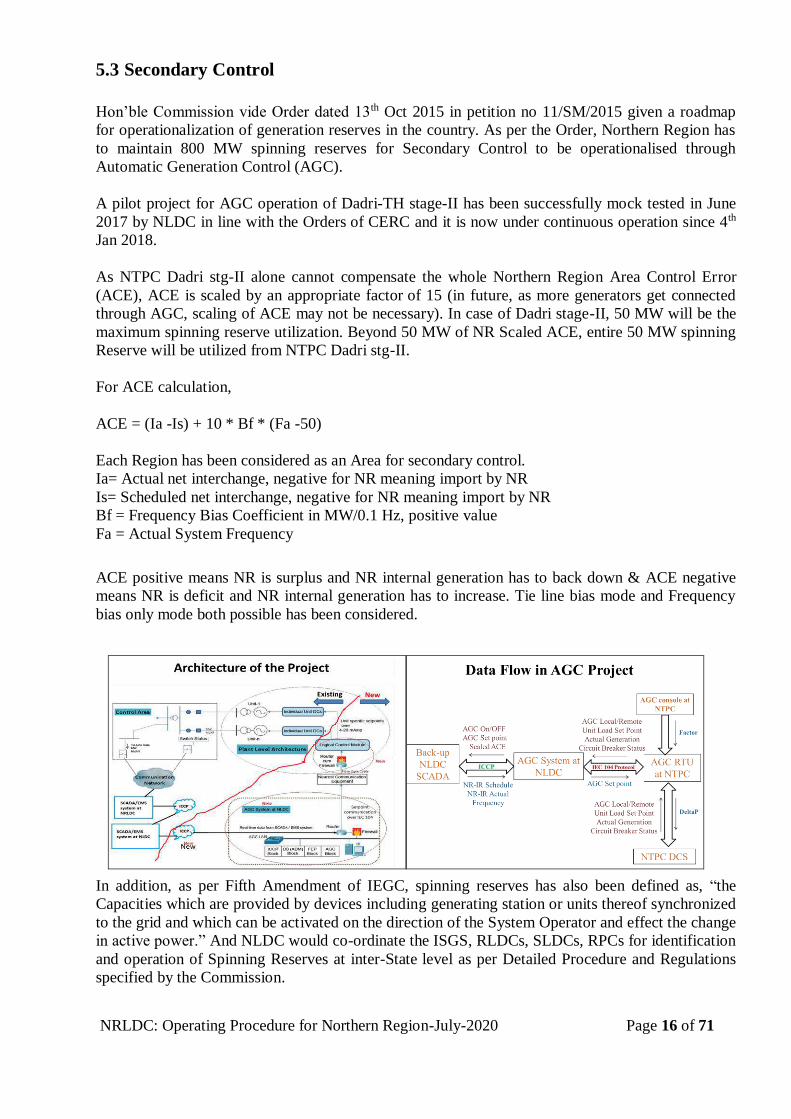
5.3 Secondary Control
Hon’ble Commission vide Order dated 13th Oct 2015 in petition no 11/SM/2015 given a roadmap
for operationalization of generation reserves in the country. As per the Order, Northern Region has
to maintain 800 MW spinning reserves for Secondary Control to be operationalised through
Automatic Generation Control (AGC).
A pilot project for AGC operation of Dadri-TH stage-II has been successfully mock tested in June
2017 by NLDC in line with the Orders of CERC and it is now under continuous operation since 4th
Jan 2018.
As NTPC Dadri stg-II alone cannot compensate the whole Northern Region Area Control Error
(ACE), ACE is scaled by an appropriate factor of 15 (in future, as more generators get connected
through AGC, scaling of ACE may not be necessary). In case of Dadri stage-II, 50 MW will be the
maximum spinning reserve utilization. Beyond 50 MW of NR Scaled ACE, entire 50 MW spinning
Reserve will be utilized from NTPC Dadri stg-II.
For ACE calculation,
ACE = (Ia -Is) + 10 * Bf * (Fa -50)
Each Region has been considered as an Area for secondary control.
Ia= Actual net interchange, negative for NR meaning import by NR
Is= Scheduled net interchange, negative for NR meaning import by NR
Bf = Frequency Bias Coefficient in MW/0.1 Hz, positive value
Fa = Actual System Frequency
ACE positive means NR is surplus and NR internal generation has to back down & ACE negative
means NR is deficit and NR internal generation has to increase. Tie line bias mode and Frequency
bias only mode both possible has been considered.
In addition, as per Fifth Amendment of IEGC, spinning reserves has also been defined as, “the
Capacities which are provided by devices including generating station or units thereof synchronized
to the grid and which can be activated on the direction of the System Operator and effect the change
in active power.” And NLDC would co-ordinate the ISGS, RLDCs, SLDCs, RPCs for identification
and operation of Spinning Reserves at inter-State level as per Detailed Procedure and Regulations
specified by the Commission.
NRLDC: Operating Procedure for Northern Region-July-2020 Page 17 of 71
These spinning reserves would be used for secondary/supplementary responses as per the procedure
notified by the Hon’ble commission.
Vide Order 319/RC/2018 dated 28th August 2019, Hon’ble Central Electricity Regulatory
Commission (CERC), in the matter of Automatic Generation Control (AGC) implementation in
India, has issued the direction that all thermal ISGS stations with installed capacity of 200 MW &
above and all hydro stations having capacity exceeding 25 MW excluding the Run-of-River Hydro
Projects irrespective of size of the generating station and whose tariff is determined or adopted by
CERC, to install equipment at the unit control rooms for transferring the required data for AGC as
per the requirement to be notified by the National Load Despatch Centre (NLDC).
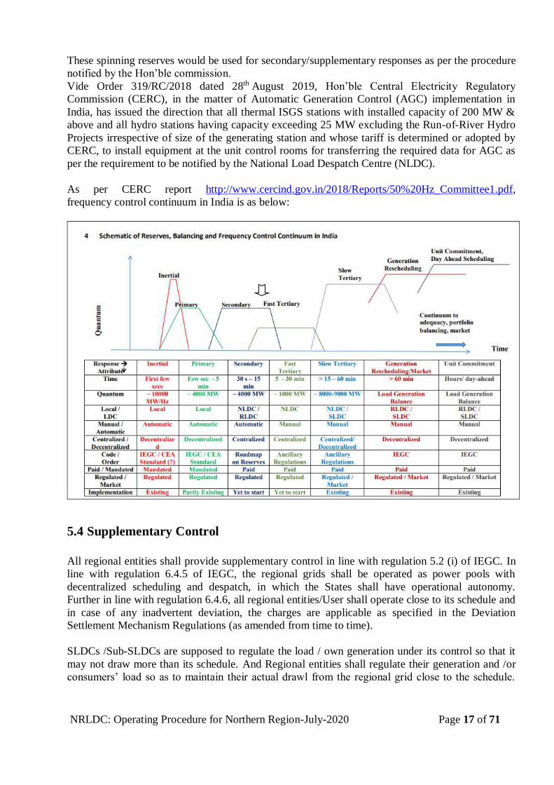
As per CERC report http://www.cercind.gov.in/2018/Reports/50%20Hz_Committee1.pdf,
frequency control continuum in India is as below:
5.4 Supplementary Control
All regional entities shall provide supplementary control in line with regulation 5.2 (i) of IEGC. In
line with regulation 6.4.5 of IEGC, the regional grids shall be operated as power pools with
decentralized scheduling and despatch, in which the States shall have operational autonomy.
Further in line with regulation 6.4.6, all regional entities/User shall operate close to its schedule and
in case of any inadvertent deviation, the charges are applicable as specified in the Deviation
Settlement Mechanism Regulations (as amended from time to time).
SLDCs /Sub-SLDCs are supposed to regulate the load / own generation under its control so that it
may not draw more than its schedule. And Regional entities shall regulate their generation and /or
consumers’ load so as to maintain their actual drawl from the regional grid close to the schedule.
NRLDC: Operating Procedure for Northern Region-July-2020 Page 18 of 71
Any inadvertent deviation shall be treated as per Deviation Settlement Mechanism Regulations. (as
amended time to time)
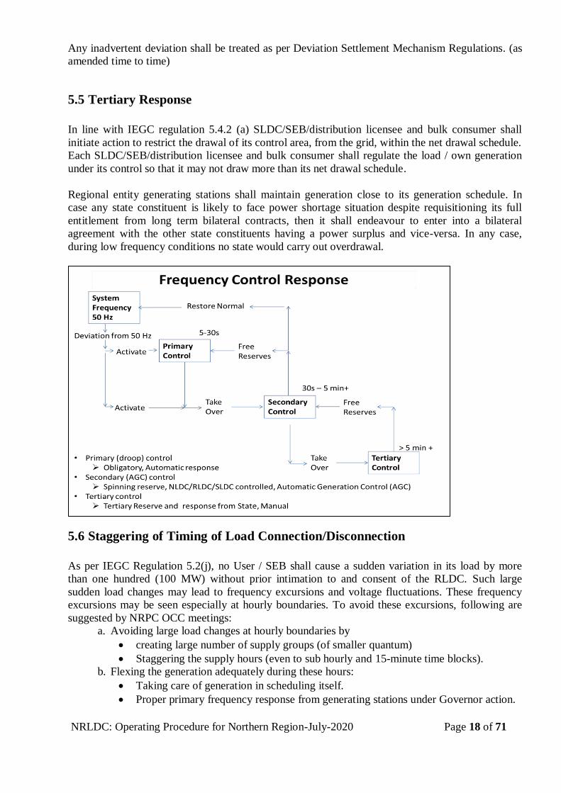
5.5 Tertiary Response
In line with IEGC regulation 5.4.2 (a) SLDC/SEB/distribution licensee and bulk consumer shall
initiate action to restrict the drawal of its control area, from the grid, within the net drawal schedule.
Each SLDC/SEB/distribution licensee and bulk consumer shall regulate the load / own generation
under its control so that it may not draw more than its net drawal schedule.
Regional entity generating stations shall maintain generation close to its generation schedule. In
case any state constituent is likely to face power shortage situation despite requisitioning its full
entitlement from long term bilateral contracts, then it shall endeavour to enter into a bilateral
agreement with the other state constituents having a power surplus and vice-versa. In any case,
during low frequency conditions no state would carry out overdrawal.
5.6 Staggering of Timing of Load Connection/Disconnection
As per IEGC Regulation 5.2(j), no User / SEB shall cause a sudden variation in its load by more
than one hundred (100 MW) without prior intimation to and consent of the RLDC. Such large
sudden load changes may lead to frequency excursions and voltage fluctuations. These frequency
excursions may be seen especially at hourly boundaries. To avoid these excursions, following are
suggested by NRPC OCC meetings:
a. Avoiding large load changes at hourly boundaries by
creating large number of supply groups (of smaller quantum)
Staggering the supply hours (even to sub hourly and 15-minute time blocks).
b. Flexing the generation adequately during these hours:
Taking care of generation in scheduling itself.
Proper primary frequency response from generating stations under Governor action.
NRLDC: Operating Procedure for Northern Region-July-2020 Page 19 of 71
5.7 Preventive Measures during High Frequency Conditions
In case the frequency is high (above 50.05 Hz) and is in increasing trend then the following actions
may be taken in order of priority provided that actual generations/drawls are maintained close to the
schedule.
1. Lifting of planned load shedding, curtailments, if any
2. Generation reduction at hydro stations having storage capability
3. Generation backing down in coal fired thermal stations & Gas station to 55% in case of ISGS
and other regional entities as per CERC IEGC regulations.
4. Generation backing down in coal fired thermal stations & Gas station (within state control area
(in case it is under drawing) as per merit order based on variable charges
5. Downward revision of requisitions from ISGS as per merit order on request of beneficiaries
6. Reduction in generation in nuclear stations to the extent possible
In case of hydro generation linked with irrigation requirements, the actual backing down or closing
down of units shall be subject to limitations on such account.
While the grid frequency is higher than 50.05 Hz, the MW generation at no generating station
(irrespective of type and ownership) shall be increased. The generation reduction would be as per
various provision of IEGC 6.3 (B) and CERC procedure for taking the units under reserve shut
down and the methodology for identifying the generating stations or units thereof to be backed
down upto the technical minimum in specific Grid conditions such as low system demand,
Regulation of Power Supply and incidence of high renewables etc., based on merit order stacking
and procedure is available at http://www.cercind.gov.in/2017/regulation/SOR132.pdf.
Similarly, no generating unit shall be synchronised with the grid while the grid frequency is above
50.05 Hz. or higher, except with the specific concurrence of NRLDC and in case of nuclear units,
which may have to be re-synchronised to prevent poisoning out of the reactor.
In line with regulation 5.2 (u), NRLDC shall make all efforts to evacuate the available solar and
wind power and treat as a must run station. However, NRLDC may instruct the solar/wind
generator (in case it is a regional entity) to back down generation on consideration of grid security
or safety of any equipment or personnel is endangered and solar/wind generator shall comply with
the same.
High frequency conditions in the grid are generally accompanied by high voltage. Requisite
measures to control over voltage may also have to be taken. The chapter on voltage control may be
referred for this.
5.8 Preventive Measures during Low Frequency Conditions
There are detailed provisions in the IEGC with regard to demand control. All efforts must be made
to avoid situation of low frequency. The chapter on demand estimation and control may be referred
for this purpose. However, in case the frequency is low (below 49.9 Hz) and is in decreasing trend
then the following actions may be taken provided that actual generations/drawls are maintained
close to the schedule:
1. Increase in generation wherever margins are available keeping margin for Primary response.
2. Upward revision in requisition in ISGS (to the extent un-dispatched) on request of beneficiaries.
NRLDC: Operating Procedure for Northern Region-July-2020 Page 20 of 71
3. Increase in generation by coal/gas fired stations within State control area (if it is over drawing) as
per merit order based on variable charges.
4. Demand management as per ADMS by State control areas in line with CERC order.
5. Demand regulation by NRLDC by switching radial feeders (List of feeders as given by
respective utility is enclosed in Annex VII).
6. Low frequency conditions are generally associated with low voltage. Requisite measures to
control low voltage may also have to be taken. The chapter on voltage control may be referred
for this.
5.9 Normal, Alert & Emergency Messages Issued by NRLDC
NRLDC shall issue Normal, Alert and Emergency messages on Frequency, Voltage & Loading
violation based on values appearing in SCADA. In addition, zero crossing violation & deviation
from schedule violation message would also be issued by NRLDC from time to time based on the
SCADA data. The logic & format for issuance of Normal, Alert & Emergency messages is enclosed
as Annex VIII & Annex IX
5.10 Defence Plan for Frequency Control
The details may be referred in Chapter on Defence Plan.
*****
NRLDC: Operating Procedure for Northern Region-July-2020 Page 21 of 71
CHAPTER- 6
6. VOLTAGE CONTROL
6.1 Overview
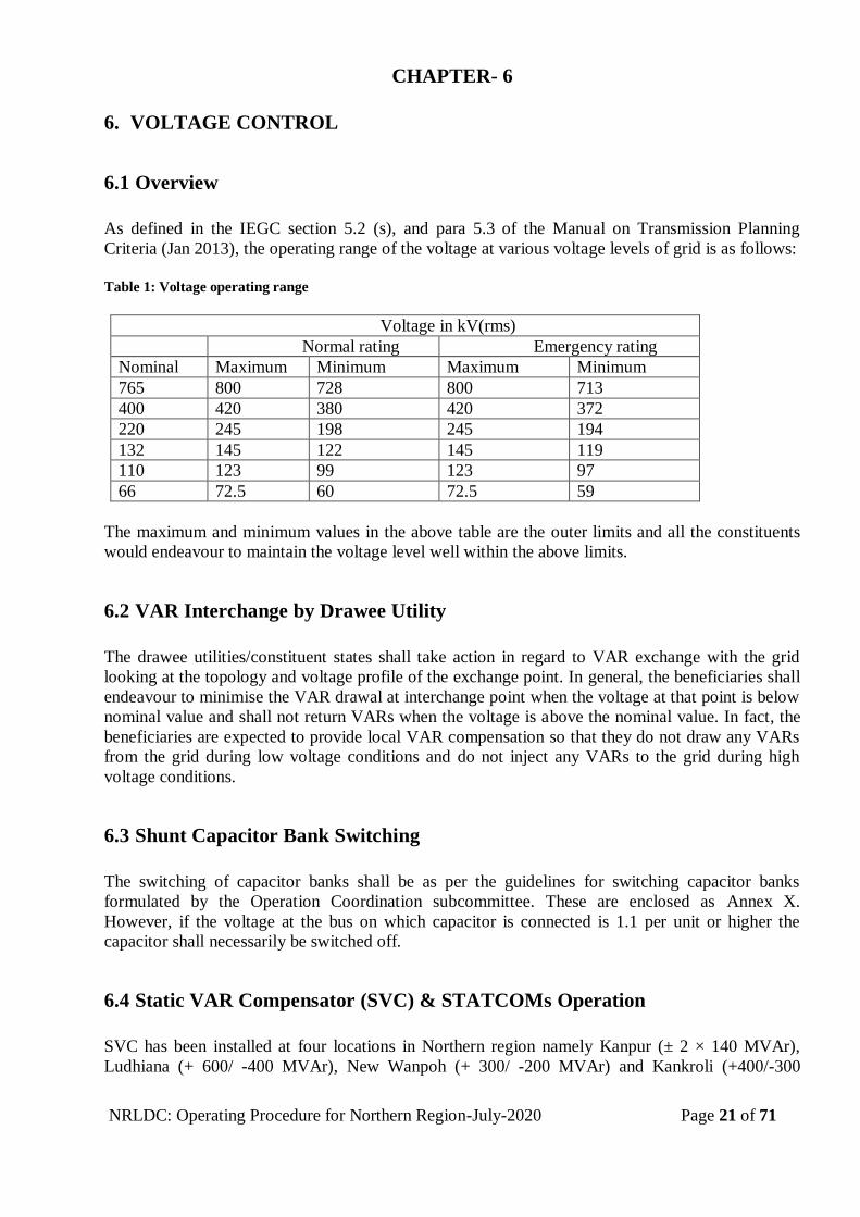
As defined in the IEGC section 5.2 (s), and para 5.3 of the Manual on Transmission Planning
Criteria (Jan 2013), the operating range of the voltage at various voltage levels of grid is as follows:
Table 1: Voltage operating range
Voltage in kV(rms)
Normal rating Emergency rating
Nominal Maximum Minimum Maximum Minimum
765 800 728 800 713
400 420 380 420 372
220 245 198 245 194
132 145 122 145 119
110 123 99 123 97
66 72.5 60 72.5 59
The maximum and minimum values in the above table are the outer limits and all the constituents
would endeavour to maintain the voltage level well within the above limits.
6.2 VAR Interchange by Drawee Utility
The drawee utilities/constituent states shall take action in regard to VAR exchange with the grid
looking at the topology and voltage profile of the exchange point. In general, the beneficiaries shall
endeavour to minimise the VAR drawal at interchange point when the voltage at that point is below
nominal value and shall not return VARs when the voltage is above the nominal value. In fact, the
beneficiaries are expected to provide local VAR compensation so that they do not draw any VARs
from the grid during low voltage conditions and do not inject any VARs to the grid during high
voltage conditions.
6.3 Shunt Capacitor Bank Switching
The switching of capacitor banks shall be as per the guidelines for switching capacitor banks
formulated by the Operation Coordination subcommittee. These are enclosed as Annex X.
However, if the voltage at the bus on which capacitor is connected is 1.1 per unit or higher the
capacitor shall necessarily be switched off.
6.4 Static VAR Compensator (SVC) & STATCOMs Operation
SVC has been installed at four locations in Northern region namely Kanpur (± 2 × 140 MVAr),
Ludhiana (+ 600/ -400 MVAr), New Wanpoh (+ 300/ -200 MVAr) and Kankroli (+400/-300
NRLDC: Operating Procedure for Northern Region-July-2020 Page 22 of 71
MVAr). Static VAR compensator (SVC) is generally featured with fixed susceptence mode and
automatic mode. In automatic mode, voltage control and reactive control mode is there. SVC shall
normally be operated in susceptence/reactive control mode. In this mode, value of Vmax, Vmin and
Q is pre-set, and output of SVC remains constant to Q (pre-set MVAr) till the voltage remain in
prescribed limit (within Vmax & Vmin). Output of SVC changes as voltages reaches beyond the
defined limits. The setting for SVC voltage reference shall be +/- 5% of 400 kV and shall be
selected in consultation with NRLDC. If required, the SVC shall be operated in voltage control
mode or VAR control mode in consultation with NRLDC. Operating mode & features of above
SVC can be referred from Reactive Power Management document of NRLDC.
STATCOM has been installed in Northern region at 400kV Nalagarh (±200 MVAr) & 400kV
Lucknow ((±300 MVAr). A brief presentation/write up on STATCOM is enclosed in Annex-X(A)
6.5 Switching of Bus Reactor and Switchable Line Reactors
Bus reactors at 400 kV shall be taken into service whenever bus voltage start rising above 405kV
and they shall be taken out of service when voltage fall below 395kV. NRLDC shall issue operating
code for switching in or out of service of Bus reactor and switchable line reactor as per the Grid
conditions. All the utilities must ensure healthy condition and availability of reactors especially
during high voltage conditions
6.6 VAR Generation/Absorption by Generating Units
In order to improve the overall voltage profile, the generators shall run in a manner so as to have
counter balancing action corresponding to low / high Grid voltage and to bring it towards the
nominal value. In order to achieve the same, all generators shall generate reactive power during low
voltage conditions and absorb reactive power during high voltage conditions as per the capability
limits of the respective generating units [IEGC 6.6.6]. Capability curve of generating station as
submitted by them can be referred from Reactive Power Management document of NRLDC.
The On-Load Tap Changers (OLTCs) or Off load tap changers on the generator transformer would
also be used to take care of seasonal variations in the voltage profile.
6.7 Changing Transformer Tap Position
The transformer taps positions on different Inter-connecting transformers forming important
elements of Regional Grid shall be changed as per requirements in order to improve the grid
voltage. NRLDC shall coordinate and advise the settings of different tap positions and any change
in their positions shall be carried out only after consultation with NRLDC [IEGC 6.6.5].
6.8 Load Management for Controlling the Low Voltage
All the state constituents shall identify the radial feeders in their areas which have significant
reactive drawal and which can be disconnected (manually or through Under Voltage relay) in order
to improve the voltage conditions in the event of voltage dropping to low levels. The details of all
such feeders shall be kept handy in the respective control rooms and standing instruction would
NRLDC: Operating Procedure for Northern Region-July-2020 Page 23 of 71
remain with the operating personnel to obtain the requisite relief in the hour of crisis by
disconnecting such feeders.
In case the state constituents do not take the requisite measures and the voltage drops down to
critically low levels (say 380kV and below at 400kV bus), then NRLDC may resort to regulatory
measures by opening of lines including those, feeding radial loads in the areas of defaulting
constituents [IEGC 6.6.3]. While taking such action, NRLDC would duly consider that the same
does not result in affecting ISGS generation.
6.9 HVDC Filter Bank Switching
During conditions of high voltage in the grid, the switchable filter banks installed at the HVDC
terminal stations shall be switched off wherever feasible in consultation with the operators at the
terminal substations. Reactive power documents of NR may be referred for HVDC filter bank
switching as per Mono/Bi-polar pole, Power order, RVO etc.
6.10 Switching-Off of the Lines in Case of High Voltage
In the event of persistent high voltage conditions when all other reactive control measures as
mentioned earlier have been exhausted, selected lines shall be opened for voltage control measures.
The opening of lines and reviving them back in such an event would be carried out as per the
instructions issued by NRLDC in real time and as per the standing instructions issued from time to
time. While taking such action, reliability of system shall also be considered.
6.11 Action Plan for Voltage Control
The following specific action at Grid Substations / Generating Stations shall be taken in the event of
voltage going high / low.
In the event of high voltage (e.g., 400kV bus voltages going above 410kV), the following specific
steps would be taken by the respective grid substations / generating station at their own, unless
specifically mentioned by NRLDC otherwise;
The bus reactors be switched in (After taking code from NRLDC)
The manually switchable capacitor banks be taken out
The switchable line/ tertiary reactors be taken in (After taking code from NRLDC)
Operate synchronous condensers for VAR absorption
Operate hydro generators / gas turbines as synchronous condenser for VAR absorption
wherever possible
Opening of the lightly loaded lines in consultation with NRLDC, keeping in view the
security of the balance network.
In the event of low voltage, (e.g. 400kV bus voltages going down below 390kV), the following
specific steps would be taken by the respective grid substations / generating station at their own,
unless specifically mentioned by NRLDC otherwise;
The bus reactors be switched out (After taking code from NRLDC)
The capacitor banks be switched in
NRLDC: Operating Procedure for Northern Region-July-2020 Page 24 of 71
The switchable line / tertiary reactors be taken out (After taking code from NRLDC)
Operate synchronous condensers for VAR generation
Operate hydro generators / gas turbines as synchronous condenser for VAR generation,
wherever possible
Closing of lines which were opened to control high voltage, in consultation with
NRLDC
6.12 Defence Plan for Voltage Control
The details may be referred in Chapter on ‘Defence Mechanism’ for Northern Region.
******
NRLDC: Operating Procedure for Northern Region-July-2020 Page 25 of 71
CHAPTER- 7
7. CONGESTION MANAGEMENT AND ALLEVIATION
7.1 General
The system planner generally designs a power system, which complies with the various
transmission security standards and associated criteria mentioned in section 3.5 of the IEGC.
Operating the system securely, within its design and limitations, is a fundamental requirement if
security of power supply is to be maintained. This chapter describes the actions required on the part
of the system operator to keep the network secured at all times against contingencies.
7.2 Permissible Equipment Loading
As per the CEA Manual on Transmission Planning Criteria, Jan 2013 all the system parameters line
voltages, loadings, frequency shall be within permissible normal limits even under N-1 or single
contingency. The loading limit for a transmission line shall be its thermal loading limit. The loading
limit for an inter-connecting transformer (ICT) shall be its name plate rating. Under N-1-1
conditions some equipment may be loaded up to their emergency limits. To bring the system
parameters back within their normal limits, load re-scheduling of generation may have to be applied
either manually or through automatic system protection schemes (SPS). Such measures shall be
applied within one and a half hour (1 ½) after the disturbance. The emergency thermal ratings
represent equipment limits that can be tolerated for a relatively short time which may be one hour
or two hours. The maximum permissible thermal line loading of different types of line
configurations, employing various types of conductors are enclosed as Annex XI .
Each system operator at SLDC / substations would endeavour to keep the line/ ICT loadings within
operating limits (Reliable under N-1 & N-1-1 contingency /As per CEA Planning criteria Jan 2013)
and inform NRLDC in case of overloading of any element. Special emphasis would be paid by each
system operator in identifying credible system contingencies & continuously evaluating the system
under his control against these contingencies.
In line with regulation 6.4.12 of IEGC, NRLDC may direct the SLDC/ISGS/other regional entities
to increase/decrease their drawal/generation in case of contingencies e.g. overloading of
lines/transformers, abnormal voltages, threat to system security. Such directions shall immediately
be acted upon.
7.3 Assessment of Transfer Capability
As per the ‘Revised Congestion Management Procedure in Real-Time System Operation’ approved
by the CERC, State Load Despatch Centre (SLDC) shall assess the Total Transfer Capability
(TTC), Transmission Reliability Margin (TRM) and Available Transfer Capability (ATC) on its
inter-State transmission corridor considering the meshed intra State corridors for exchange (import/
export) of power with inter-State Transmission System (ISTS). These figures along with the data
considered for assessment of TTC would be forwarded to the respective RLDC for assessment of
TTC at the regional level. The details of anticipated transmission constraints in the intra State
system shall also be indicated separately.
NRLDC: Operating Procedure for Northern Region-July-2020 Page 26 of 71
Assessment of Total Transfer Capability (TTC), Transmission Reliability Margin (TRM) and
Available Transfer Capability (ATC) for import and export of power within Northern region as
required for reliable system operation and for facilitating non-discriminatory open access in
transmission shall be carried out by NRLDC in coordination with National Load Despatch Centre
and other RLDCs. The ‘Detailed Procedure for Relieving Congestion in Real Time Operation’ as
approved by the CERC vide order dated 22.04.2013 may be referred for further details.
The assessed TTC, TRM and ATC shall be posted on NRLDC/NLDC website in the formats as
enclosed in Annex XII. NLDC letter on implementation regarding assessment & declaration of
ATC/TTC, Real time congestion monitoring & curtailment of transaction in real time is enclosed in
Annex XIII . A note on assessment of Total Transfer Capability (TTC) /Available Transfer
Capability (ATC) with special reference to the West to North inter-regional corridor is enclosed in
Annex XIV.
7.4 Major Corridor/Flow Gates in Northern Region
List of lines in the major corridors/flow gates in Northern region have been enclosed as Annex XV.
It is advised to monitor the loading of major corridors of NR and inter-regional boundaries.
7.5 Monitoring of Congestion
Real time data for monitoring Congestion shall be displayed on the NRLDC & NLDC website in
the formats as enclosed in Annex XVI.
7.6 Generation Rescheduling
NRLDC may revise the interchange schedule as allowed by IEGC regulation 6.4.12, 6.5.5, and
6.5.16. Further details may be seen in the chapter on scheduling.
7.7 Curtailment of Scheduled Transactions
The transactions already scheduled may be curtailed by NRLDC in the event of transmission
constraints; congestion in the grid, or in the interest of grid security. In line with regulations 6.4.12,
6.5.28, 6.5.30 and 6.5.31 of IEGC the transactions shall generally be curtailed in the following
sequence:
a. Deviation from Schedule
b. Short term bilateral transactions
c. Short term collective transactions
d. Medium term transactions
e. Long-term transactions
Amongst the customers of a particular category, curtailment shall be carried out on pro rata basis.
NRLDC would curtail a transaction at the periphery of the Regional entities. SLDC (s) shall further
incorporate the inter-se curtailment of intra State entities to implement the curtailment. However,
doing such pro-rata available relief in system shall also be taken care.
NRLDC: Operating Procedure for Northern Region-July-2020 Page 27 of 71
7.8 Procedure for Relieving Congestion
Congestion Management shall be as per the detailed procedure for relieving congestion in real time
operation as approved by CERC vide its order dated 22.04.2013. It is important to note that the
congestion charge could be applied both upstream and downstream of the congested corridor
irrespective of the frequency. Whenever actual flow on inter/ intra-regional link/ corridor exceeds
Available Transfer Capability and security criteria are violated for continuously two time blocks,
the National Load Despatch Centre may issue a warning notice. In case SLDC observes congestion
within the Intra State grid it shall take appropriate action and inform the respective RLDC which in
turn shall inform the NLDC. The notice for congestion shall be communicated to all the Regional
entities telephonically or through fax/ voice message/ e-mail and through postings on website and
making the same available on the common screen at NLDC/ RLDCs/ SLDCs. The various formats
may be referred in the detailed procedure for relieving congestion in real time operation under
regulation 4 (2) of the Central Electricity Regulatory Commission (Measures to relieve congestion
in real time operation) Regulations, 2009. These formats are also enclosed as Annex XVII.
*****
NRLDC: Operating Procedure for Northern Region-July-2020 Page 28 of 71
CHAPTER – 8
8. DEMAND MANAGEMENT
8.1 Overview
Demand management plays a very important role in system operation. Long-term demand
estimation (five years and beyond) is an important input for generation planning. In the medium
term, say one year, it constitutes an important input for outage planning of generating units and
transmission lines. In the short term, say within one week, it is an important input for generation
scheduling. Variation in demand in real time operation from the estimated values could either be
absorbed by the grid or affect it adversely. Even if the estimates are accurate, the generation could
vary from scheduled values adversely affecting the grid. Demand control then plays an important
role in arresting these adverse effects on the grid.
Demand estimation and control is essentially the responsibility of SLDCs. NRLDC would give
instructions to SLDCs on demand control whenever the same has a bearing on the security of the
regional grid & such instructions would have to be complied forthwith by all SLDCs.
8.2 Demand Estimation
The SLDCs would forecast active and reactive demand (MW peak, MW off-peak & energy in
MWh/MVArh) on an annual, quarterly, monthly, weekly and ultimately on daily basis, which
would be used in the day-ahead scheduling. The formats for reporting demand forecasts are
enclosed as Annex XVIII . As per IEGC & Ancillary services procedure, each state has to submit
the load forecast on daily basis. At present, states are uploading their day ahead load forecast on
NRLDC server in the above format. Though each SLDC is expected to maintain a historical
database for the purpose and be equipped with the state-of-the-art tools such as Energy
Management System (EMS) for demand forecasting. Ideally, the forecasts should be on hourly
basis (8760, 720 & 168 values respectively in the annual, monthly and weekly forecasts) rather than
mentioning only the peak MW and energy requirements for the period. It is also desirable to have
substation wise demand (Nodal MW / MVAr) forecasts. POSOCO and IMD has developed a
dedicated website of each region for monitoring of different weather parameter at various nodes of
each state. Link of the website is available on NRLDC site as:
http://amssdelhi.gov.in/NRLDC/main/MAIN.html. All the states are advised to use weather
information for real-time weather monitoring for finer load forecasting and balancing of load
generation portfolio.
(i) In line with the IEGC regulation 5.3 (c), the SLDC shall plan demand management measures
based on the demand estimate and the estimated availability from different sources and shall
ensure that the same is implemented by the SEB/distribution licensees.
(ii) The annual, quarterly, monthly and daily demand forecasts would be used in the outage plan
prepared by NRPC Secretariat in consultation with all the constituents. In line with IEGC
regulation 5.3 (f) and 5.3 (h), the demand forecasts by the SLDC shall be provided to NRLDC
and NRPC for operational planning and computation of total transfer capability.
NRLDC: Operating Procedure for Northern Region-July-2020 Page 29 of 71
(iii) Attention would also be paid by SLDCs in demand forecasting for special days such as
important festivals and National Holidays having different crests and troughs in the daily load-
curve as compared to normal days.
(iv) It is also important that, the reactive power requirements are forecasted right from substation
level by each SLDC. The reactive power planning exercise and programme for installation of
reactive compensation equipment should take care of these requirements also.
(v) Demand/Load Ramp forecasting is also essential especially during winter season when peak
load ramp is very steep. In case of high ramp, generation has to pick in commensurate with
increasing load to balance the load-generation to avoid any frequency deviations during this
period.
8.3 Demand Control
All the states/drawing utilities has to maintain adequate reserves as per CERC order in petition No.
11/SM/2015 on ‘Roadmap to operationalise Reserves in the country”. However, if reserves are not
to that significant level to match the demand gap, demand management can be planned by
respective agencies. The need for demand control would arise on account of the following
conditions:
Variations in demand from the estimated or forecasted values, which cannot be absorbed by the
grid.
Unforeseen generation / transmission outages resulting in reduced power availability.
Network congestion (voltage levels beyond normal operating limits, violation of TTC, network
element load beyond operating limit etc.)
Heavy reactive power demand causing low voltages.
Commercial reasons.
In the interest of system security due to any other contingency in Northern or neighbouring
regions.
Demand management measures shall be taken by SLDCs/SEB/distribution licensee/User/bulk
consumer in line with the regulation 5.4 of IEGC. Further sub-regulation 6 of Regulation 6.4 of
Principal Regulations mandates that
“6. The system of each regional entity shall be treated and operated as a notional control area. The
algebraic summation of scheduled drawal from ISGS and from contracts through long–term access,
medium-term and short–term open access arrangements shall provide the drawl schedule of each
regional entity, and this shall be determined in advance on day-ahead basis. The regional entities
shall regulate their generation and/or consumers’ load so as to maintain their actual drawal from the
regional grid close to the above schedule. Maximum inadvertent deviation allowed during a time
block shall not exceed the limits specified in the Deviation Settlement Mechanism Regulations.
Such deviations should not cause system parameters to deteriorate beyond permissible limits and
shall not lead to unacceptable line loading...”
In order to maintain schedule or to avert any deviation, all beneficiaries must contract for adequate
power. The utilities must ensure long term contract or short-term contract arrangements for meeting
their energy requirement. The generators / sellers and the beneficiaries/ the buyers should use
avenues like bilateral trading or the trading platforms of power exchanges by availing open access
for meeting short term, medium term or long-term arrangements or agreements.

NRLDC: Operating Procedure for Northern Region-July-2020 Page 30 of 71
NRLDC may give instructions for demand disconnection under normal and/or contingent
conditions. Demand control would have to be exercised under these conditions by the
SLDCs/SEB/distribution licensee/User/bulk consumer, which could be done by either of the
following methods or a combination thereof:
Manual demand disconnection.
Shutting off or reconnecting bulk power consumers having a special tariff structure
linked to number of interruptions in the day.
PC based system for rotational load shedding with facilities for central programming and
uploading of the disconnection schedule for the day from the SLDC / Sub-LDC to the
substations.
The interruptible loads shall be arranged in four groups of loads,
for scheduled power cuts/load shedding,
loads for unscheduled load shedding,
Loads to be shed through under frequency relays/ rate of change of frequency relays
(df/dt): As per CERC order, mapping of UFR & df/dt on SCADA has to be carried out
by each state control area.
Loads to be shed under any System Protection Scheme identified at NRPC level.
These loads shall be grouped in such a manner that there is no over lapping between different
groups of loads. During the demand control by manual disconnection of loads by staggering in
different groups, the roster changeover from one group to another shall be carried out in a gradual
and scientific manner so as to avoid excursions in the system parameters. Each SLDC would also
identify feeders drawing heavy quantum of reactive power and disconnect the same under low
voltage conditions. The necessary metering arrangements for identifying such feeders would be
provided by the SLDCs.
8.4 Handling Sudden Reduction in Demand
During the event of sudden load throw off in the system suitable measures to control High
frequency & High Voltage may be taken as elaborated in Section 5.7, Section 5.10 and section 6.11
of this document. In the event of sudden load reduction, generating backing down to 55% and more
can be done in line with various provision of IEGC 6.3 (B). State control areas shall also reduce its
generation as per the various prevailing regulation in view of Grid security & safety.
8.5 Load Crash during Thunderstorm
Load crash is a common phenomenon during summer on thunderstorm and as per the various
discussions held in regular OCC/TCC meetings, action plan agreed to combat such situation is as:
Monitoring of weather and plan to sensitize the affected station/nodes.
Plan load generation accordingly.
Avoiding manual opening of feeder.
As per MoM of Monsoon preparedness meeting held by JS dated 23rd June 2016, each state
has to provide list of 11kV feeder that can remain connected on such eventualities.
As per CEA/MoP guideline, maintaining at least 2 nos’ of ERS by each state control area.
*****
NRLDC: Operating Procedure for Northern Region-July-2020 Page 31 of 71
CHAPTER-9
9. SCHEDULING AND DESPATCH
9.1 Overview
As per section 28(3)(a), the Electricity Act 2003, the RLDCs shall be responsible for optimum
scheduling and despatch of electricity within the region, in accordance with the contracts entered
into with the licensees or generating companies operating in the region. The system of each regional
entity shall be operated as a notional control area and the regional grids shall be operated as power
pools with decentralized scheduling and despatch [IEGC-6.4.5 and 6.4.6].
The approval for connectivity, long term Access, Medium term Open Access and Short-term Open
Access (Bilateral as well as Collective) shall be in line with the appropriate Regulations and
procedures approved by CERC. This chapter illustrates the procedure for scheduling the approved
contracts and the treatment to be accorded for special situations.
9.2 Jurisdiction of NRLDC
The jurisdiction of NRLDC for scheduling and energy settlement is governed by regulation 6.4.2,
6.4.3, 6.4.4 of the IEGC. A list of registered users shall be available on the website of NRLDC. The
list of Entities whose scheduling shall be coordinated by the NRLDC is given as Annex-I.
The generation schedule for the stations under Bhakra Beas Management Board (BBMB) would be
co-ordinated and finalised by BBMB considering the peak hours declared by NRLDC and the
requirements of the beneficiary states viz. Punjab, Haryana, Rajasthan and Himachal Pradesh
subjected to irrigation and hydrology constraints. The schedules so finalised for each BBMB station
would be communicated to NRLDC. However, as per CERC order in Petition No. 251/GT/2013,
BBMB has started the scheduling of power from its generating unit’s/transmission assets under
ABT w.e.f 1.6.2016.
NRLDC shall be the Nodal Agency for processing of applications for Short Term Open Access
where the drawal point lies within the control area of one of the regional entities of Northern
Region.
9.3 Scheduling of Long Term and Medium-Term Contracts
In line with Regulation 42 of CERC (Terms and Conditions of Tariff) Regulations 2019-24,
NRLDC shall consider the shares / allocations of each beneficiary in the total capacity of Central
sector generating stations as determined by the Central Government, for the purpose of scheduling.
The shares shall be applied in percentages of installed capacity and shall normally remain constant
during a month. Based on the decision of the Central Government the changes in allocation shall be
communicated by the Member-Secretary, Regional Power Committee in advance, except in case of
an emergency calling for an urgent change in allocations out of unallocated capacity. The total
capacity share of a beneficiary would be sum of its capacity share plus allocation out of the
NRLDC: Operating Procedure for Northern Region-July-2020 Page 32 of 71
unallocated portion. In the absence of any specific allocation of unallocated power by the Central
Government, the unallocated power shall be added to the allocated shares in the same proportion as
the allocated shares.
Regional entities those have LTA/MTOA and long-term contracts though share allocation among
beneficiaries is either not fixed or not in terms of percentage (%), the beneficiaries would inform
the NRLDC regarding their quantum from that respective regional entity based on mutual
agreement between the Generator & the beneficiary.
The Regional Entities in Northern region shall keep NRLDC informed about the details of their
long-term contracts for the purpose of scheduling. The algebraic summation of scheduled drawal
from ISGS and from contracts through a long term, medium term and short-term open access
arrangements shall provide the drawal schedule of each regional entity, and this shall be determined
in advance on day-ahead basis.
9.3.1. Margin for Primary Response while Scheduling of Regional Entities Generator
In line with IEGC regulation fifth amendment 2017, para 5.2 (h), “For the purpose of ensuring
primary response, RLDCs/SLDCs shall not schedule the generating station or unit (s) thereof
beyond ex-bus generation corresponding to 100% of the Installed capacity of the generating station
or unit (s) thereof. The generating station shall not resort to Valve Wide Open (VWO) operation of
units whether running on full load or part load, and shall ensure that there is margin available for
providing Governor action as primary response.……… In case of gas/liquid fuel-based units,
suitable adjustment in Installed Capacity should be made by RLDCs/SLDCs for scheduling in due
consideration of prevailing ambient conditions of temperature and pressure vis-à-vis site ambient
conditions on which installed capacity of the generating station or unit (s) thereof have been
specified.
Provided that scheduling of hydro stations shall not be reduced during high inflow period in order
to avoid spillage.
The procedure to implement amended para 5.2 (h) and in spirit of SoR w.e.f 1st June 2018, NRLDC
communication dated 8th May 2018 to all regional entities is enclosed in Annex XIX. The
scheduling would be carried out as follows:
RLDCs will ensure that the schedule of the generating stations doesn’t exceed the 100% of
installed capacity less normative auxiliary consumption or the DC by generator whichever is
low.
The generator would indicate the reasons for giving DC higher than normative viz. lower
ambient temperature, lower auxiliary consumption, inherent overload capability, overflowing
hydro etc.
Primary response would be closely observed for different events in the system and failure to
provide the same despite declaring a DC higher than normative would be recorded and
periodically reported.
In case of overflowing hydro and higher than normative DC, the actual MWh generated during
the day would be closely observed to ensure that there is no gaming. The generator would also
forward the water spillage data on daily basis to RLDC for the previous day.
NRLDC: Operating Procedure for Northern Region-July-2020 Page 33 of 71
The generator would also ensure that the gap between the DC and normative DC (in case
former is higher) is not utilized for generating under Deviation Settlement Mechanism (DSM)
on continuous basis but only used for providing primary response.
In case any unit is under reserve shutdown, the DC for the unit under RSD would not exceed
the normative DC since the overload capability would not be really be available to the system.
As per SoR (13.2.8) of IEGC 5th amendment, in addition to 5.2 (h),………… However, for the
purpose of calculation of PAF, DC declared by the generator is not to be reduced. This would
ensure proper incentive for the generator for keeping units in readiness for providing much
needed grid support in case of frequency excursion
9.3.2 Procedure for scheduling of LTA/MTOA transaction
For creation of a new LTA/MTOA transaction in WBES portal, the Applicant or Buyer or Seller
shall submit following documents to RLDC/RLDCs (In case of Inter regional LTA) before 1
clear day of the start of LTA/MTOA:
1. LTA intimation & operationalization letter from CTU.
2. PPA of the transaction.
3. Cod letter of Generating plant. In case any Discom/State (Where any particular generating
station is not there), CoD letter is not required.
After receipt of above documents, buyer RLDC shall create a new LTA/MTOA with unique
transaction number in buyer RLDC WBES and also allocate a designated entity who has rights
of submission of mutually consented requisition submission for that transaction.
Same transaction number and credentials of new LTA/MTOA as assigned by buyer RLDC shall
be replicated at Seller RLDC WBES also.
Designated Entity for requisition submission in RLDC WBES:
Applicant of any LTA/MTOA transaction will be considered as the designated entity.
RLDC shall allocate one designated entity for each LTA/MTOA transactions.
The designated entity has the right for the submission of mutually consented requisition for
the assigned LTA/MTOA in WBES of RLDC, in which the entity is registered or
geographically located.
In the case of any transaction does not have any applicant, then the designated authority
rights shall be given to any utility among seller, buyer, trader of that tractions as mutually
agreed among themselves. All the utilities also need to submit no objection or their consent
to RLDC regarding same.
In case the applicant willingly surrenders its right to other agency among seller, buyer,
trader of that tractions, then authorization letter from applicant along with consent of other
agency assigned as designated entity need to be submitted to RLDC.
For inter-regional LTA/MTOA the designated entity of that transaction shall submit mutually
agreed requisition at one single RLDC WBES for scheduling and same shall be reflected at
buyer, seller entity and inter regional boundary schedule after incorporation of applicable
transmission loss as per the regulation.
NRLDC: Operating Procedure for Northern Region-July-2020 Page 34 of 71
9.3.2.1 Day ahead LTA/MTOA schedule submission
Designated entity of any LTA/MTOA transaction shall enter the availability of LTA/MTOA in
RLDC WBES for the ‘D’ day by 10:00 Hrs of the ‘D-1’ day.
Designated entity of any LTA/MTOA transaction shall enter the mutually agreed requisition
quantum in RLDC WBES for the ‘D’ day by 15:00 Hrs of the ‘D-1’ day.
NRLDC would incorporate the requisition and release the schedule for next day by 18:00 hrs.
Designated entity can submit revised mutually agreed requisition for any LTA/MTOA
transaction by 22:45 hrs of previous day to NRLDC.
MW requisition submitted by the designated authority shall be mutually agreed between buyer
and seller and necessary documents related to the mutually consented quantum submitted at
RLDC WBES shall be kept with designated utility.
9.3.2.2 Real time LTA/MTOA schedule revision
During same day, designated authority of any LTA/MTOA transaction can revise the requisition on
account of unit tripping or partial outage of unit at seller end or under requisition by the buyer or may be
for other reason.
MW requisition submitted by the designated authority shall be mutually agreed between buyer and seller
and necessary documents related to the mutually consented quantum submitted at RLDC WBES shall be
kept with designated utility.
Any revision in schedule made in odd time blocks shall become effective from 7th time block and any
revision in schedule made in even time blocks shall become effective from 8th time block, counting the
time block in which the request for revision has been received by the RLDCs to be the first one.
Timeline of submission of revised schedule in Real time will be as per IEGC 2020 and subsequent
amendments in IEGC, 2010.
9.3.3 Scheduling of LTA and MTOA (REMC):
REMC: REMC (Renewable Energy Management Centre) project was introduced for
management of RE generation. Under this project, 3 RLDC REMC, 7 State (RE rich) REMC, 1
National REMC will manage the total RE generation of India. REMC of 3 RLDC & Few states
already under operational & rest of the REMCs will be under operational very soon.
REMC Scheduling software will take care the scheduling of the RE generators.
RE generators LTA/MTOA intra/inter-regional transactions shall be created under NRLDC
REMC scheduling module as per their connectivity.
REMC LTA/MTOA transactions requisition for the same day or day ahead shall be submitted in
NRLDC REMC scheduling portal by the RE generator.
Schedule data of REMC LTA/MTOA shall be transferred to RLDC scheduling portal (WBES)
from REMC scheduling portal at the time of creation of any schedule revision in RLDC WBES.
NRLDC: Operating Procedure for Northern Region-July-2020 Page 35 of 71
RE generators of any REMC LTA/MTOA transactions cannot change any LTA/MTOA
requisition in RLDC WBES.
Curtailment of any REMC LTA/MTOA transactions as per real time requirement shall be done
in RLDC WBES portal which will be transferred to REMC scheduling portal subsequently.
Any revision in schedule made in odd time blocks shall become effective from 7th time block
and any revision in schedule made in even time blocks shall become effective from 8th time
block, counting the time block in which the request for revision has been received by the
RLDCs to be the first one. – If generator participates in RTM.
If generator doesn’t participate in RTM, then schedule revision will be allowed from 4th time
block onwards, counting the time block in which the request for revision has been received by
the RLDCs to be the first one.
9.4 Scheduling of Hydro Stations
Scheduling of Hydro station having percentage share allocation shall be done as per various
provisions in IEGC 6.5 and CERC Tariff regulation.
9.5 Scheduling in Case of Reserve Shutdown (RSD)
In line with IEGC fourth and fifth amendment, procedure of scheduling in case of RSD has been
communicated vide NRLDC letter dated 15th May 2017 enclosed in Annex XX. This detailed
procedure has been approved by CERC and available on http:
www.cercind.gov.in/2017/regulation/SOR132.pdf.
If the grid conditions do not demand for providing technical minimum to a generating station,
RLDC shall issue R-1 schedule based on the requisitions received. Under such situation, the
generating station shall have the option to go for RSD with intimation to RLDC latest by 2100
hrs of D-1. D is the scheduling date.
Before taking unit(s) under RSD, the generating station shall revise the On-Bar DC (with due
consideration to ramp up/down capability), Off Bar DC, DC and Ramp UP/Ramp Down rate.
The generator shall ensure that the Off-Bar DC is not more than the MCR less Normative
Auxiliary Consumption of the machines under RSD. The beneficiaries shall continue to bear the
capacity charge corresponding to Total DC.
When the machine is going under RSD:
In case the total requisitioned power can be supplied through other units in the same
generating station on bar, the generator shall be scheduled according to the requisitions
received.
In case total requisitioned power cannot be supplied through other units in the same
generating station on bar, the requisition from the beneficiaries shall be reduced in the ratio
of requisitioned power.
NRLDC: Operating Procedure for Northern Region-July-2020 Page 36 of 71
In the special case of a generating station where the only running machine is going under
RSD, the beneficiaries who have requisitioned power will not get any power from that
generating station. In such cases, the beneficiaries may make arrangement from alternative
sources.
No maintenance activities on unit under RSD shall be undertaken by the generating station so
that the RSD unit is always readily available for revival/synchronization. If a generating station
requires maintenance on any machine under RSD, then the same shall be done in due
consultation with RLDC. The DC shall be reduced appropriately.
When injection schedule of a CGS/ISGS falls below technical minimum due to imposition of
regulation of power supply by the generating company or transmission licensee under the
Central Electricity Regulatory Commission (Regulation of Power Supply) Regulations, 2010
and/or as per directions under the Commission order dated 2.9.2015 in Petition
No.142/MP/2012, the generator may endeavour to sell the surplus power through STOA or
Power Exchange(s) before opting for RSD.
During the day of operation, in case the system condition does not require, RLDC shall direct
the generating station to take any unit or the generating station under RSD. In such a scenario,
RLDC shall display the station likely to go under RSD on its website. In case, the schedule is
still less than the technical minimum and generating station decides to take a unit(s) under RSD,
it shall inform the same to concerned RLDC.
9.5.1. Methodology for revival of generating station or unit(s) from RSD
Once a unit is taken out under RSD, the generating station shall notify the period for which the
unit will remain under RSD and the unit can be recalled any time after 8 hours. In case of
system requirements, the generating unit can be revived before 8 hrs as well. The time to start a
machine under different conditions such as HOT, WARM and COLD shall be as per the
declaration given by the generating station under the Detailed Procedure for Ancillary Services
Operations (Format AS-1 and AS-3 of the said Procedure).
One or more beneficiaries of the generating station as well as the generating station may decide
for revival of unit(s) under RSD with commitment for technical minimum schedule with
minimum run time of 8 hrs for Coal based generating stations and 3 hrs for Gas based
generating stations post revival. In such situations, the generating station shall revise the On Bar
and Off Bar DC (with due consideration to ramp up/down capability).
RLDC may also advise the generating stations to revive unit(s) under RSD for better system
operation (IEGC 6.5.20). In such cases, RLDC shall ensure technical minimum schedule as per
above mentioned procedure in clause 8.4.
In case the machine is not revived as per the revival time declared by the generating station
under different types of start, the machine shall be treated under outage for the duration starting
from the likely revival time and the actual revival time. RLDC shall ensure that intimation is
sent to the generating station sufficiently in advance keeping in view its start-up time.
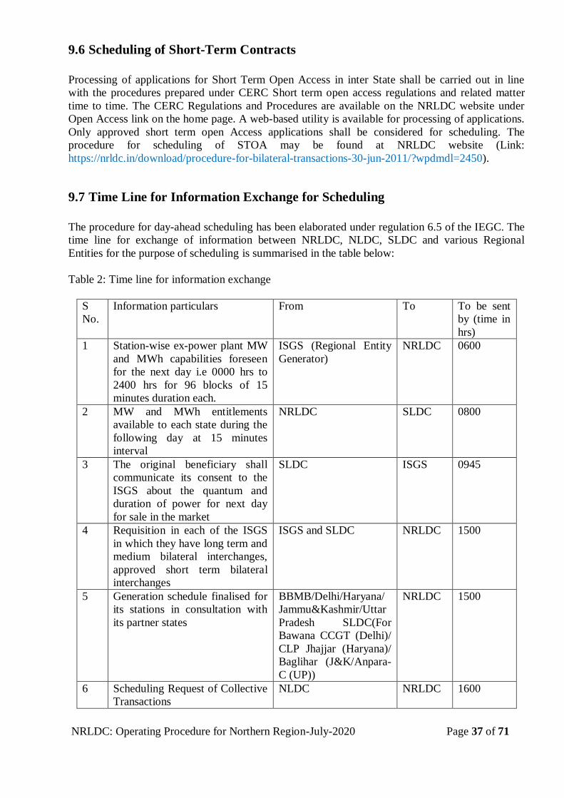
NRLDC: Operating Procedure for Northern Region-July-2020 Page 37 of 71
9.6 Scheduling of Short-Term Contracts
Processing of applications for Short Term Open Access in inter State shall be carried out in line
with the procedures prepared under CERC Short term open access regulations and related matter
time to time. The CERC Regulations and Procedures are available on the NRLDC website under
Open Access link on the home page. A web-based utility is available for processing of applications.
Only approved short term open Access applications shall be considered for scheduling. The
procedure for scheduling of STOA may be found at NRLDC website (Link:
https://nrldc.in/download/procedure-for-bilateral-transactions-30-jun-2011/?wpdmdl=2450).
9.7 Time Line for Information Exchange for Scheduling
The procedure for day-ahead scheduling has been elaborated under regulation 6.5 of the IEGC. The
time line for exchange of information between NRLDC, NLDC, SLDC and various Regional
Entities for the purpose of scheduling is summarised in the table below:
Table 2: Time line for information exchange
S
No.
Information particulars From To To be sent
by (time in
hrs)
1 Station-wise ex-power plant MW
and MWh capabilities foreseen
for the next day i.e 0000 hrs to
2400 hrs for 96 blocks of 15
minutes duration each.
ISGS (Regional Entity
Generator)
NRLDC 0600
2 MW and MWh entitlements
available to each state during the
following day at 15 minutes
interval
NRLDC SLDC 0800
3 The original beneficiary shall
communicate its consent to the
ISGS about the quantum and
duration of power for next day
for sale in the market
SLDC ISGS 0945
4 Requisition in each of the ISGS
in which they have long term and
medium bilateral interchanges,
approved short term bilateral
interchanges
ISGS and SLDC NRLDC 1500
5 Generation schedule finalised for
its stations in consultation with
its partner states
BBMB/Delhi/Haryana/
Jammu&Kashmir/Uttar
Pradesh SLDC(For
Bawana CCGT (Delhi)/
CLP Jhajjar (Haryana)/
Baglihar (J&K/Anpara-
C (UP))
NRLDC 1500
6 Scheduling Request of Collective
Transactions
NLDC NRLDC 1600
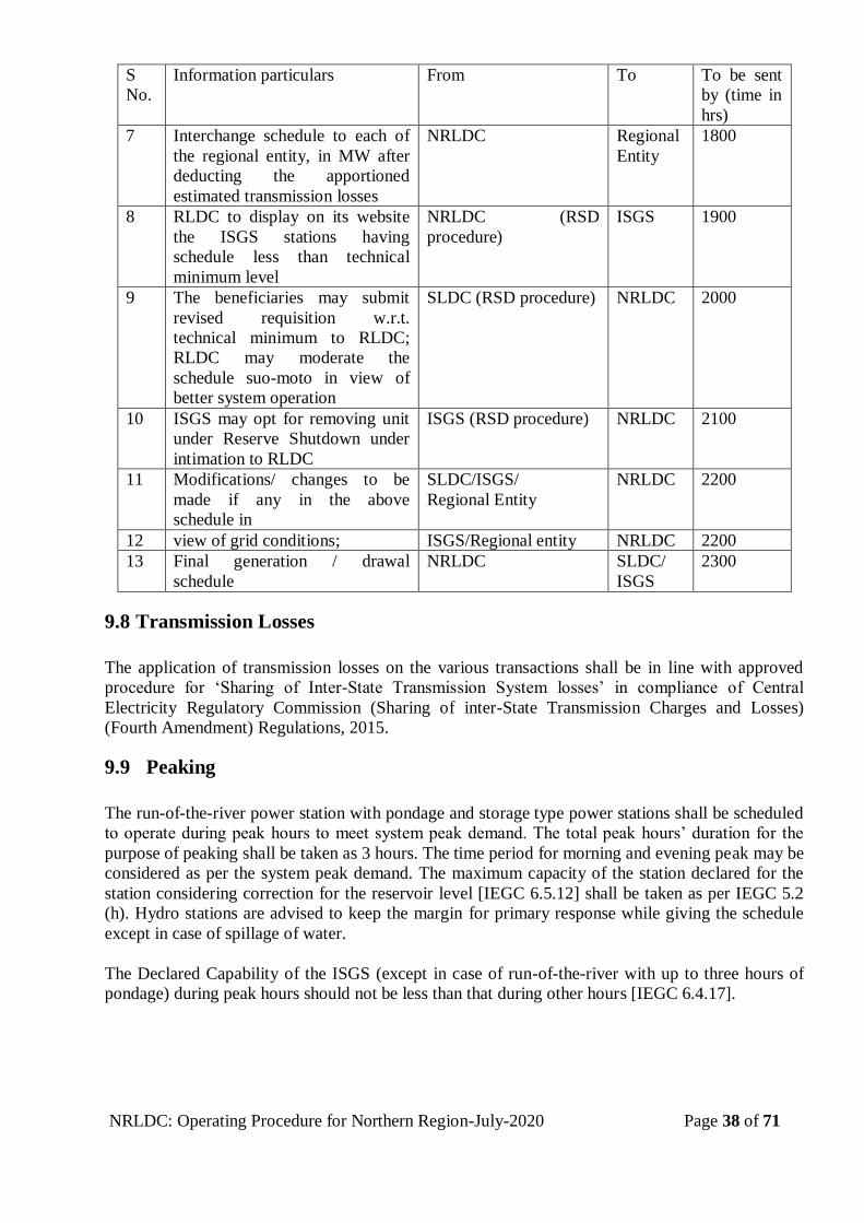
NRLDC: Operating Procedure for Northern Region-July-2020 Page 38 of 71
S
No.
Information particulars From To To be sent
by (time in
hrs)
7 Interchange schedule to each of
the regional entity, in MW after
deducting the apportioned
estimated transmission losses
NRLDC Regional
Entity
1800
8 RLDC to display on its website
the ISGS stations having
schedule less than technical
minimum level
NRLDC (RSD
procedure)
ISGS 1900
9 The beneficiaries may submit
revised requisition w.r.t.
technical minimum to RLDC;
RLDC may moderate the
schedule suo-moto in view of
better system operation
SLDC (RSD procedure) NRLDC 2000
10 ISGS may opt for removing unit
under Reserve Shutdown under
intimation to RLDC
ISGS (RSD procedure) NRLDC 2100
11 Modifications/ changes to be
made if any in the above
schedule in
SLDC/ISGS/
Regional Entity
NRLDC 2200
12 view of grid conditions; ISGS/Regional entity NRLDC 2200
13 Final generation / drawal
schedule
NRLDC SLDC/
ISGS
2300
9.8 Transmission Losses
The application of transmission losses on the various transactions shall be in line with approved
procedure for ‘Sharing of Inter-State Transmission System losses’ in compliance of Central
Electricity Regulatory Commission (Sharing of inter-State Transmission Charges and Losses)
(Fourth Amendment) Regulations, 2015.
9.9 Peaking
The run-of-the-river power station with pondage and storage type power stations shall be scheduled
to operate during peak hours to meet system peak demand. The total peak hours’ duration for the
purpose of peaking shall be taken as 3 hours. The time period for morning and evening peak may be
considered as per the system peak demand. The maximum capacity of the station declared for the
station considering correction for the reservoir level [IEGC 6.5.12] shall be taken as per IEGC 5.2
(h). Hydro stations are advised to keep the margin for primary response while giving the schedule
except in case of spillage of water.
The Declared Capability of the ISGS (except in case of run-of-the-river with up to three hours of
pondage) during peak hours should not be less than that during other hours [IEGC 6.4.17].
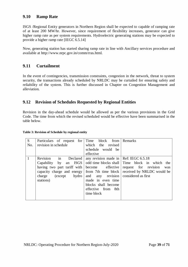
NRLDC: Operating Procedure for Northern Region-July-2020 Page 39 of 71
9.10 Ramp Rate
ISGS /Regional Entity generators in Northern Region shall be expected to capable of ramping rate
of at least 200 MW/hr. However, since requirement of flexibility increases, generator can give
higher ramp rate as per system requirements. Hydroelectric generating stations may be expected to
provide a higher ramp rate [IEGC 6.5.14]
Now, generating station has started sharing ramp rate in line with Ancillary services procedure and
available at http://www.nrpc.gov.in/comm/rras.html.
9.11 Curtailment
In the event of contingencies, transmission constraints, congestion in the network, threat to system
security, the transactions already scheduled by NRLDC may be curtailed for ensuring safety and
reliability of the system. This is further discussed in Chapter on Congestion Management and
alleviation.
9.12 Revision of Schedules Requested by Regional Entities
Revision in the day-ahead schedule would be allowed as per the various provisions in the Grid
Code. The time from which the revised scheduled would be effective have been summarised in the
table below.
Table 3: Revision of Schedule by regional entity
S
No.
Particulars of request for
revision in schedule
Time block from
which the revised
schedule would be
effective
Remarks
1 Revision in Declared
Capability by an ISGS
having two part tariff with
capacity charge and energy
charge (except hydro
stations)
any revision made in
odd time blocks shall
become effective
from 7th time block
and any revision
made in even time
blocks shall become
effective from 8th
time block
Ref: IEGC 6.5.18
Time block in which the
request for revision was
received by NRLDC would be
considered as first
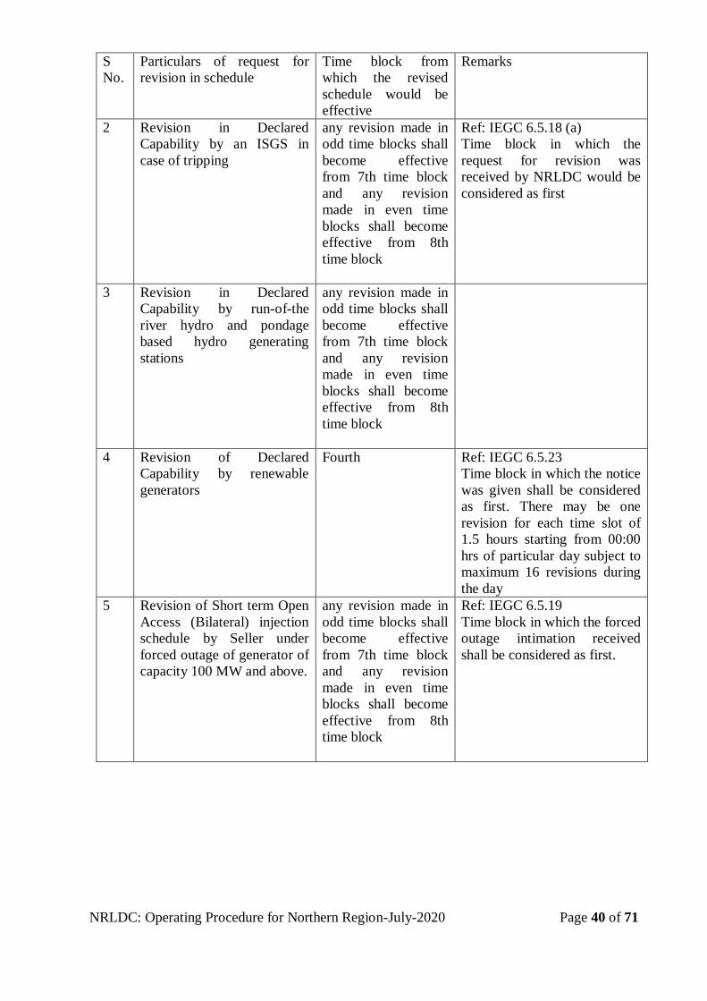
NRLDC: Operating Procedure for Northern Region-July-2020 Page 40 of 71
S
No.
Particulars of request for
revision in schedule
Time block from
which the revised
schedule would be
effective
Remarks
2 Revision in Declared
Capability by an ISGS in
case of tripping
any revision made in
odd time blocks shall
become effective
from 7th time block
and any revision
made in even time
blocks shall become
effective from 8th
time block
Ref: IEGC 6.5.18 (a)
Time block in which the
request for revision was
received by NRLDC would be
considered as first
3 Revision in Declared
Capability by run-of-the
river hydro and pondage
based hydro generating
stations
any revision made in
odd time blocks shall
become effective
from 7th time block
and any revision
made in even time
blocks shall become
effective from 8th
time block
4 Revision of Declared
Capability by renewable
generators
Fourth Ref: IEGC 6.5.23
Time block in which the notice
was given shall be considered
as first. There may be one
revision for each time slot of
1.5 hours starting from 00:00
hrs of particular day subject to
maximum 16 revisions during
the day
5 Revision of Short term Open
Access (Bilateral) injection
schedule by Seller under
forced outage of generator of
capacity 100 MW and above.
any revision made in
odd time blocks shall
become effective
from 7th time block
and any revision
made in even time
blocks shall become
effective from 8th
time block
Ref: IEGC 6.5.19
Time block in which the forced
outage intimation received
shall be considered as first.
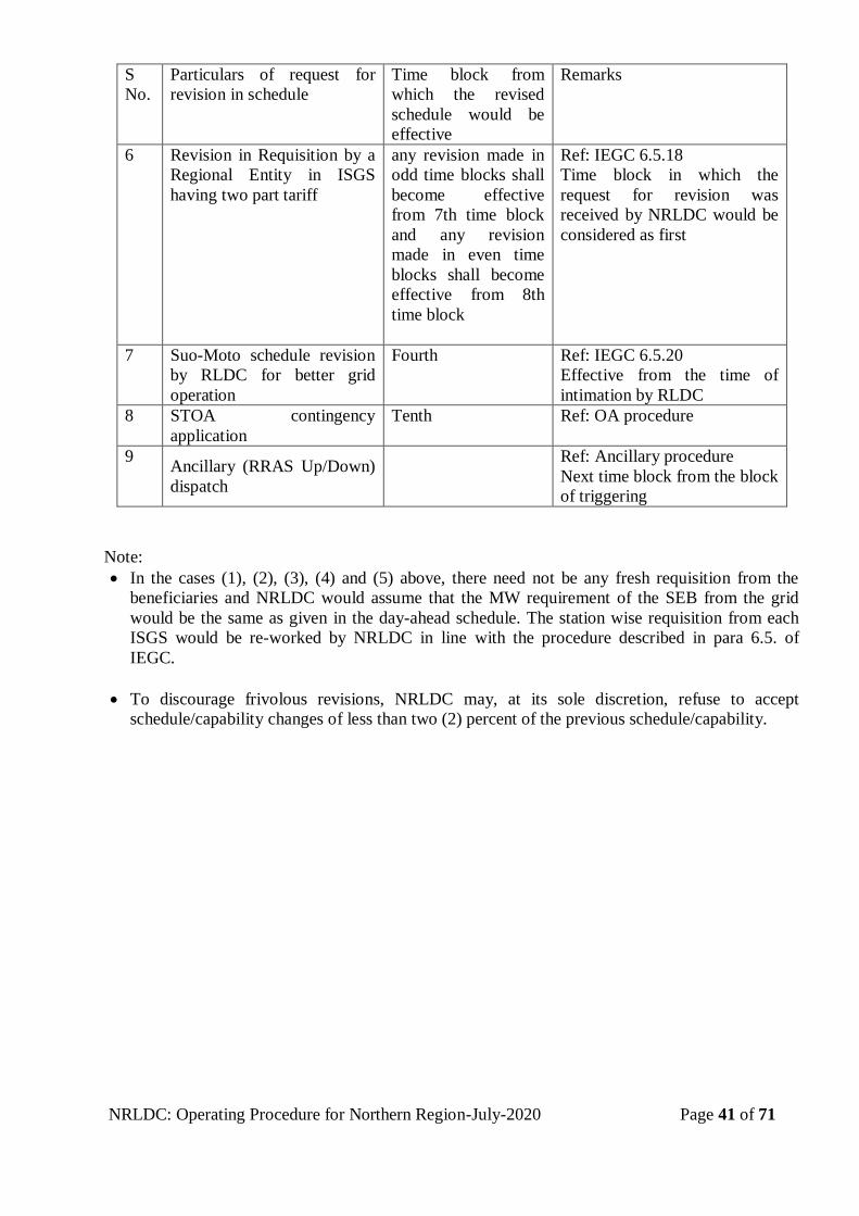
NRLDC: Operating Procedure for Northern Region-July-2020 Page 41 of 71
S
No.
Particulars of request for
revision in schedule
Time block from
which the revised
schedule would be
effective
Remarks
6 Revision in Requisition by a
Regional Entity in ISGS
having two part tariff
any revision made in
odd time blocks shall
become effective
from 7th time block
and any revision
made in even time
blocks shall become
effective from 8th
time block
Ref: IEGC 6.5.18
Time block in which the
request for revision was
received by NRLDC would be
considered as first
7 Suo-Moto schedule revision
by RLDC for better grid
operation
Fourth Ref: IEGC 6.5.20
Effective from the time of
intimation by RLDC
8 STOA contingency
application
Tenth Ref: OA procedure
9 Ancillary (RRAS Up/Down)
dispatch
Ref: Ancillary procedure
Next time block from the block
of triggering
Note:
In the cases (1), (2), (3), (4) and (5) above, there need not be any fresh requisition from the
beneficiaries and NRLDC would assume that the MW requirement of the SEB from the grid
would be the same as given in the day-ahead schedule. The station wise requisition from each
ISGS would be re-worked by NRLDC in line with the procedure described in para 6.5. of
IEGC.
To discourage frivolous revisions, NRLDC may, at its sole discretion, refuse to accept
schedule/capability changes of less than two (2) percent of the previous schedule/capability.
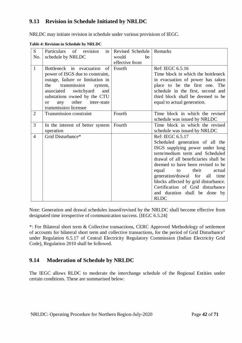
NRLDC: Operating Procedure for Northern Region-July-2020 Page 42 of 71
9.13 Revision in Schedule Initiated by NRLDC
NRLDC may initiate revision in schedule under various provisions of IEGC.
Table 4: Revision in Schedule by NRLDC
Note: Generation and drawal schedules issued/revised by the NRLDC shall become effective from
designated time irrespective of communication success. [IEGC 6.5.24]
*: For Bilateral short term & Collective transactions, CERC Approved Methodology of settlement
of accounts for bilateral short term and collective transactions, for the period of Grid Disturbance"
under Regulation 6.5.17 of Central Electricity Regulatory Commission (Indian Electricity Grid
Code), Regulation 2010 shall be followed.
9.14 Moderation of Schedule by NRLDC
The IEGC allows RLDC to moderate the interchange schedule of the Regional Entities under
certain conditions. These are summarised below:
S
No.
Particulars of revision in
schedule by NRLDC
Revised Schedule
would be
effective from
Remarks
1 Bottleneck in evacuation of
power of ISGS due to constraint,
outage, failure or limitation in
the transmission system,
associated switchyard and
substations owned by the CTU
or any other inter-state
transmission licensee
Fourth Ref: IEGC 6.5.16
Time block in which the bottleneck
in evacuation of power has taken
place to be the first one. The
schedule in the first, second and
third block shall be deemed to be
equal to actual generation.
2 Transmission constraint Fourth Time block in which the revised
schedule was issued by NRLDC
3 In the interest of better system
operation
Fourth Time block in which the revised
schedule was issued by NRLDC
4 Grid Disturbance* Ref: IEGC 6.5.17
Scheduled generation of all the
ISGS supplying power under long
term/medium term and Scheduled
drawal of all beneficiaries shall be
deemed to have been revised to be
equal to their actual
generation/drawal for all time
blocks affected by grid disturbance.
Certification of Grid disturbance
and duration shall be done by
RLDC
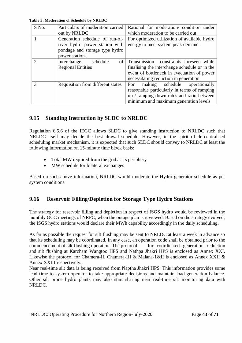
NRLDC: Operating Procedure for Northern Region-July-2020 Page 43 of 71
Table 5: Moderation of Schedule by NRLDC
9.15 Standing Instruction by SLDC to NRLDC
Regulation 6.5.6 of the IEGC allows SLDC to give standing instruction to NRLDC such that
NRLDC itself may decide the best drawal schedule. However, in the spirit of de-centralised
scheduling market mechanism, it is expected that such SLDC should convey to NRLDC at least the
following information on 15-minute time block basis:
Total MW required from the grid at its periphery
MW schedule for bilateral exchanges
Based on such above information, NRLDC would moderate the Hydro generator schedule as per
system conditions.
9.16 Reservoir Filling/Depletion for Storage Type Hydro Stations
The strategy for reservoir filling and depletion in respect of ISGS hydro would be reviewed in the
monthly OCC meetings of NRPC, when the outage plan is reviewed. Based on the strategy evolved,
the ISGS hydro stations would declare their MWh capability accordingly in the daily scheduling.
As far as possible the request for silt flushing may be sent to NRLDC at least a week in advance so
that its scheduling may be coordinated. In any case, an operation code shall be obtained prior to the
commencement of silt flushing operation. The protocol for coordinated generation reduction
and silt flushing at Karcham Wangtoo HPS and Nathpa Jhakri HPS is enclosed as Annex XXI.
Likewise the protocol for Chamera-II, Chamera-III & Malana-1&II is enclosed as Annex XXII &
Annex XXIII respectively.
Near real-time silt data is being received from Naptha Jhakri HPS. This information provides some
lead time to system operator to take appropriate decisions and maintain load generation balance.
Other silt prone hydro plants may also start sharing near real-time silt monitoring data with
NRLDC.
S No. Particulars of moderation carried
out by NRLDC
Rational for moderation/ condition under
which moderation to be carried out
1 Generation schedule of run-of-
river hydro power station with
pondage and storage type hydro
power stations
For optimized utilization of available hydro
energy to meet system peak demand
2 Interchange schedule of
Regional Entities
Transmission constraints foreseen while
finalising the interchange schedule or in the
event of bottleneck in evacuation of power
necessitating reduction in generation
3 Requisition from different states For making schedule operationally
reasonable particularly in terms of ramping
up / ramping down rates and ratio between
minimum and maximum generation levels
NRLDC: Operating Procedure for Northern Region-July-2020 Page 44 of 71
9.17 Implemented Schedule Issued by NRLDC
On completion of the operating day i.e. after 2400 hrs, the final schedule as implemented shall be
issued by NRLDC after incorporating all before the fact changes during the day of operation.
Various steps involved in the scheduling and the final schedule issued by NRLDC shall be open to
all the constituents for any checking/verification for a period of 5 days. In case any
mistake/omission is detected, NRLDC shall forthwith make a complete check and rectify the same
[IEGC 6.5.33].
9.18 Allocation of Un-Requisitioned Surplus
Scheduling of URS in CGS stations shall be coordinated in line with the CERC order in petition no
310/MP/2014 dated 05/10/2015, IEGC 5th amendment (dated 12.04.2017) and CERC order in 16/SM/2015
dated 17.10.2017. Extract of the dated 17/10/2017 against Petition No. 16/SM/2015 depicted as below
“Where both the generating station and its beneficiaries (surrendering and requesting
beneficiaries) give their standing consents in writing to RLDC that the decision of the concerned
RLDC will be binding on them with regard to scheduling and dispatch of URS power, the
concerned RLDC shall schedule such URS power to the requesting beneficiaries in relative
proportion to the quantum requested by them. In other cases, RLDCs shall schedule URS power on
the basis of the consents submitted by the generating stations in terms of the order dated
5.10.2015.”
Accordingly, Scheduling Procedure followed at NRLDC is as follows:
Beneficiaries shall submit their URS requisition MW quantum in NRLDC WBES.
Auto URS approval script of NRLDC WBES which run in each block shall approve the
URS requisition quantum as per the margin available at Generator and margin available
in inter regional corridor.
At the time schedule creation, the URS allocated amount shall be scheduled to the
respective beneficiary and generator as per the margin available and ramp up/down limit
in Generator and also subject to margin available in inter-regional corridor.
In case exigencies during real time operation, if required NRLDC Suo moto can allocate
URS to over drawing beneficiary.
9.19 Security Constrained Economic Dispatch (SCED)
Hon’ble commission in petition 02/SM/2019 dated 31st Jan 2019 directed POSOCO to implement
Pilot on Security Constrained Economic Dispatch (SCED) for ISGS pan India. It covers
optimisation model for all the thermal Inter State Generating Stations (ISGS) that are regional
entities and whose tariff is determined or adopted by the Commission for their full capacity without
violating grid security and honouring the existing scheduling practices prescribed in the Indian
Electricity Grid Code on trial basis for six months.
In compliance to CERC order’s directions, pilot on SCED for ISGS pan India has been
operationalized from 1300 Hrs on 01st April, 2019. Detailed Procedure of POSOCO for SCED
NRLDC: Operating Procedure for Northern Region-July-2020 Page 45 of 71
comprising the guidelines regarding operational aspects of SCED including scheduling, dispatch,
accounting, settlement and any residual matter etc. is available at https://posoco.in/wp-
content/uploads/2019/04/Letter_to_Generators_SCED_18April2019_As_Sent.pdf
Scheduling & Despatch of ISGS under SCED
a. The existing schedule & despatch procedure in accordance with IEGC (Part 6 - Scheduling
and Despatch Code) would continue for all entities.
b. NLDC would prepare the SCED schedules based on the following data:
(i) Normative On bar declared capability
(ii) Injection schedule (latest revision)
(iii)Ramp Rates (as declared in RRAS)
(iv) Variable Charges (as declared in RRAS)
(v) Technical Minimum (as per IEGC provisions)
(vi) Inter-Regional Transfer Margins
c. The SCED software program would consider only the units on bar and unit commitment is not
envisaged. Further, SCED would run after all schedule revisions as per the allowable time
lines have been incorporated by the RLDCs and RRAS despatched by NLDC.
d. RLDCs would incorporate the SCED schedule in the respective SCED Generator’s schedule
and provide a net injection schedule.
e. SCED schedules would be treated as deemed delivered. There would be no retrospective
changes in the SCED schedules except in situations as mentioned in Para 7.7 and 7.8 of SCED
procedure.
f. The schedules of the states/beneficiaries would not be changed under SCED and the
beneficiaries would continue to be scheduled based on their requisitions from different power
plants as per the existing practices.
g. A virtual SCED entity, VSCED-[Region] would be created in the scheduling process of the
RLDCs which shall act as a counter-party to the SCED schedules for the SCED generators.
For example, in the Northern Region, VSCED-NR shall be created. The virtual SCED entity,
by its very nature, is not a physical entity bounded by meters and hence, shall not form a part
of the Regional DSM Pool.
h. Applicable injection and withdrawal loss will be applied to SCED schedules as per the
existing scheduling practice.
i. The URS available due to Regulation of Power Supply provisions as per the CERC
Regulations would also be used for SCED procedure similar to RRAS.
j. The SCED Generator whose scheduling has been restricted due to transmission constraints
shall be excluded from the SCED optimization process to begin with. However, later these
stations can also be considered in the SCED optimization algorithm with revised constraints
(maximum/minimum generation limits) for despatch. The concerned RLDC shall inform
NLDC about such generators.
k. Energy Accounting & Settlement:
NRLDC: Operating Procedure for Northern Region-July-2020 Page 46 of 71
a. NLDC would prepare a consolidated all India statement, daily/weekly/monthly indicating
the schedules on account of SCED.
b.NLDC would maintain and operate a separate bank account in the name of “National Pool
Account (SCED)” for payments to/receipts from the SCED Generators. The details of the
bank account would be displayed on the NLDC website.
9.20 Scheduling of Collective transaction through Real Time Market (RTM)
Scheduling of collective transaction through Real time market was introduced w.e.f. 1st June, 2020.
Necessary revision to accommodate RTM was done in Indian Electricity Grid Code (IEGC), 2010
(6th Amendment), Short Term Open Access Regulation 2008 (6th Amendment) and Power market
Regulation 2010 (2nd Amendment).
Scheduling procedure of collective transaction through Real Time Market is prepared by NLDC
and available at : https://posoco.in/wp-content/uploads/2020/05/Procedure-for-Scheduling-of-
Collective-Transactions-through-RTM.pdf
All the utilities participate in RTM shall submit their sell/buy bid in power exchange portal for half
an hour as per the time line provided in amended IEGC and STOA regulation. Subsequently Power
exchanges provide all utilities cleared RTM MW quantum for each half an hour period to NLDC
and NLDC shall forward these RTM data to RLDC for implementation in utilities schedule.
Necessary change in time line for submission of DC, requisition, change in LTA/MTOA
transactions etc for the utilities as per IEGC 6th amendment has been implemented in ERLDC
WBES w.e.f. 1st June, 2020.
9.21 Scheduling of Solar & Wind Generation
Scheduling for renewable energy sources would be as per CERC procedure on Forecasting,
Scheduling and Imbalance Handling for Renewable Energy generating station including power
parks based on wind and solar at inter-state level. The procedure is enclosed in Annex-XXIV.
Forecasting of the renewable energy generation at ISTS shall be done by the RLDC and the forecast
will be available on the NRLDC website. Similarly, forecast of renewable generation at intra-state
level shall be done by respective state control area i.e. SLDCs. The generation forecast shall be
done on the basis of the weather data provided by IMD or on the basis of other methods used by the
Forecasting Agency whose service may be availed by NLDC/RLDC.
RE generators shall provide the forecast to the concerned RLDC which may be based on their own
forecast or RLDCs forecast as per the format mentioned as ‘Annex-II’ in the CERC procedure.
RE Generators may prepare their schedule based on the forecast done by RLDC or their own
forecast. Any commercial impact on account of deviation from schedule based on the forecast
chosen by the wind and solar generator shall be borne by the respective generator.
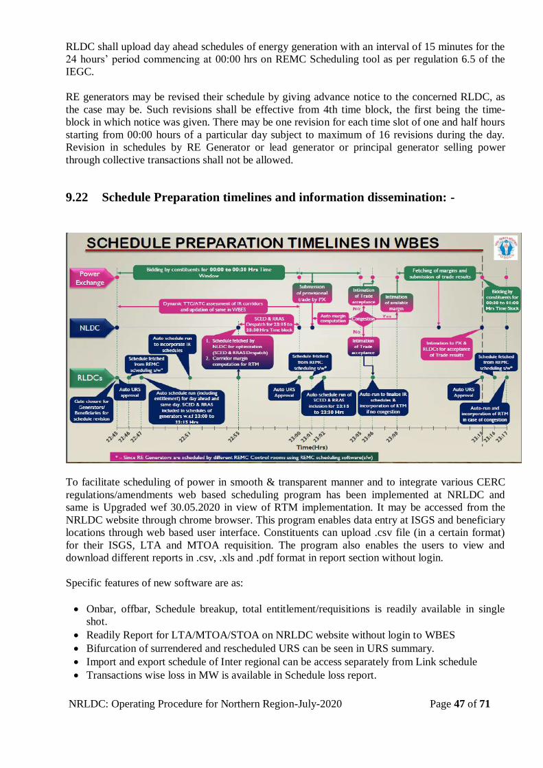
NRLDC: Operating Procedure for Northern Region-July-2020 Page 47 of 71
RLDC shall upload day ahead schedules of energy generation with an interval of 15 minutes for the
24 hours’ period commencing at 00:00 hrs on REMC Scheduling tool as per regulation 6.5 of the
IEGC.
RE generators may be revised their schedule by giving advance notice to the concerned RLDC, as
the case may be. Such revisions shall be effective from 4th time block, the first being the time-
block in which notice was given. There may be one revision for each time slot of one and half hours
starting from 00:00 hours of a particular day subject to maximum of 16 revisions during the day.
Revision in schedules by RE Generator or lead generator or principal generator selling power
through collective transactions shall not be allowed.
9.22 Schedule Preparation timelines and information dissemination: -
To facilitate scheduling of power in smooth & transparent manner and to integrate various CERC
regulations/amendments web based scheduling program has been implemented at NRLDC and
same is Upgraded wef 30.05.2020 in view of RTM implementation. It may be accessed from the
NRLDC website through chrome browser. This program enables data entry at ISGS and beneficiary
locations through web based user interface. Constituents can upload .csv file (in a certain format)
for their ISGS, LTA and MTOA requisition. The program also enables the users to view and
download different reports in .csv, .xls and .pdf format in report section without login.
Specific features of new software are as:
Onbar, offbar, Schedule breakup, total entitlement/requisitions is readily available in single
shot.
Readily Report for LTA/MTOA/STOA on NRLDC website without login to WBES
Bifurcation of surrendered and rescheduled URS can be seen in URS summary.
Import and export schedule of Inter regional can be access separately from Link schedule
Transactions wise loss in MW is available in Schedule loss report.

NRLDC: Operating Procedure for Northern Region-July-2020 Page 48 of 71
Less requisition of MTOA/LTA can be tracked from MTOA/LTA less requisition link.
Beneficiary of Northern region may requisition their own share from inter-regional plants
directly through NRLDC WBES login and vice versa and the same is reflected to concerned
RLDC’s WBES.
All RLDCs interregional ISGS schedule transactions are synchronized in real time.
Change in any schedule w.r.t any previous schedule can be extract by login to WBES
Audit trail on every page to track activity on WBES.
Separate LOGIN / PASSWORD has been provided to the concerned utilities. Login name as
allotted by NRLDC will remain same. However, password may be changed by concerned utility.
Any suggestion / feedback on the new software for further improvement may please be sent through
e-mail ([email protected]).
*****
NRLDC: Operating Procedure for Northern Region-July-2020 Page 49 of 71
CHAPTER-10
10. ANCILLARY SERVICES OPERATIONS
10.1 Introduction
The Procedure of Ancillary Services Operations is issued in compliance to Regulation 14 of the
Central Electricity Regulatory Commission (Ancillary Services Operations) Regulations 2015. The
objective of Ancillary Services Regulations is to help in restoring the frequency level to the
nominal level and to relieve the congestion in the transmission network.
All Generating Stations which are Regional Entities and whose tariff for the full capacity is
determined or adopted by the Central Electricity Regulatory Commission (CERC) shall provide the
Reserves Regulation Ancillary Services (hereinafter to be referred as “RRAS”) and shall abide by
this Procedure.
10.2 Scope
The Procedure shall be applicable to the Regional Entities involved in the transactions facilitated
through Short-Term Open Access (STOA) or Medium-Term Open Access (MTOA) or Long-Term
Access (LTA) in inter- State transmission of electricity. The Procedure shall also apply to the
SLDCs, RLDCs, NLDC and RPCs.
The Procedure shall not apply to the Regional Entity Generating Stations whose tariff for the full
capacity is not determined by the CERC.
10.3 Role of Nodal Agency
The National Load Despatch Centre (NLDC), as the Nodal Agency, shall be responsible for
implementation of Ancillary Services at inter-state level through the Regional Load Despatch
Centre (RLDCs).
The responsibilities of the nodal agency are as:
Forecasting All India Demand on day ahead basis
Preparing merit order stack of all RRAS Providers based on the variable cost of generation
Dispatch of RRAS based on the merit order considering inter-regional and intra-regional
congestion and monitoring power system parameters
Instructions for regulation up/down to RRAS providers through respective RLDC.
Considering hydro stations for dispatch under Ancillary Services in case of exigencies.
As per IECG Fifth Amendment, para 5.2 (h) …Valve wide open (VWO) margin shall not be used
by RLDC to schedule Ancillary Services.”
10.4 Role of RRAS Providers
The RRAS provider shall provide the details of the plant and generation as per the format AS1,
attached at Annex XXV and the necessary details for communication as per the format AS2,
attached at Annex XXVI.
NRLDC: Operating Procedure for Northern Region-July-2020 Page 50 of 71
The RRAS provider shall follow the instructions of nodal agency for Regulation Up and Regulation
Down and shall ensure the continuity of RRAS during the dispatch.
10.5 Role of Regional Power Committees (RPCs)
Based on the data provided by the RRAS providers, RPCs shall publish the details on their websites
as per the format AS3 (attached at Annex XXVII) on monthly basis. The RPCs shall use the details
of fixed charge, variable charge and any other statutory charges applicable on the RRAS Providers
for preparation of Energy/Deviation Accounts of the RRAS providers. Any post-facto revision in
rates/charges by RRAS providers shall not be permitted.
10.6 Role of State Load Despatch Centres (SLDCs)
SLDC shall prepare the block wise daily demand forecast as per the format AS4 (attached at Annex
XXVIII) on day-ahead basis. In case there is any revision in the forecast subsequently, this should
be communicated by the SLDC to the concerned RLDC.
10.7 Triggering Criteria of RRAS
The first merit order stack as described above shall be prepared after issuance of revision ‘0’
schedule issued by RLDCs. The RRAS for Regulation Up and Regulation Down may be
triggered on account of any of the following events:
Extreme weather conditions and/or special days such as, festivals that may lead to any
changes in the demand patterns, depletion in the network by way of tripping of network
elements (e.g., during fog), etc.
Generating unit or transmission line outages; In case of likelihood or occurrence of
violation of n-1 criteria for any of the transmission corridors or violation of ATC of any
flow gate or curtailment of LTA / MTOA / STOA (Collective and Bilateral) due to forced
outage of any element
In case of unforeseen changes in load pattern
If the frequency remains below the lower limit of operational frequency band continuously
for a period of 5 minutes or more, nodal agency shall issue an instruction for Regulation Up.
If the frequency remains above the upper limit of operational frequency band continuously
for a period of 5 minutes or more, nodal agency shall issue an instruction for Regulation
Down.
Intimation of any abnormal event such as outage of hydro generating units due to silt,
outage of thermal generating units due to coal/gas supply shortage/blockade, nuclear unit
outage due to fuel / reactor related issues, outage of Ultra Mega Solar Power
Parks/wind generation due to sudden weather changes and any other force majeure
conditions etc.
Loop flows leading to congestion
Recall by the original beneficiary
If the voltage at important nodes is beyond the operating range as per IEGC or N-1 criteria
is not satisfied or loading on one more lines in a corridor is beyond the limit specified in
CEA Manual on Transmission Planning Criteria.
NRLDC: Operating Procedure for Northern Region-July-2020 Page 51 of 71
Nodal agency may issue the instruction for RRAS dispatch based on the anticipated system
conditions.
Up Regulation: The merit order stack from lowest to highest variable cost prepared by the Nodal
Agency shall be used for “Up Regulation” RRAS. There are two cases for regulation:
Case-1: Dispatch from already running units.
Case-2: Dispatch from the units under reserve shutdown. In this case, a minimum duration
of 24 hours of dispatch shall be given to coal based and a minimum duration of 3 hours’
dispatch shall be given to Gas/RLNG/Liquid fuel based RRAS providers.
Down Regulation: The stack prepared from the highest to the lowest variable cost shall be
used for Down Regulation. The Down Regulation requirement may arise due to system conditions.
In case of congestion, the nodal agency shall also consider the other methods of alleviating
congestion while dispatching.
The format AS5 for issuing a message to RRAS provider for triggering of RRAS is attached
at Annex XXIX.
10.8 Scheduling of RRAS
A virtual regional entity called as ‘Virtual Ancillary Entity (VAE)’ shall be created for
scheduling. For Regulation Up, power shall be scheduled from the RRAS provider to VAE
by nodal agency/concerned RLDC and for Regulation Down, power shall be scheduled from
VAE to RRAS provider. The schedule will be effective earliest from the time block starting
15 minutes after issue of the dispatch instruction by the Nodal Agency or from the time
block decided by the nodal agency considering anticipated system conditions.
The injection and withdrawal losses shall be accounted in the schedule of the respective
VAE. Further, the schedules of the RRAS Providers shall be considered as revised by the
quantum scheduled by the Nodal Agency under RRAS. And any deviation from the schedule
shall be treated in accordance with CERC DSM Regulation, 2014.
In case of Downward DC revision due to unit tripping or line tripping/congestion in power
evacuation form RRAS generator, the RRAS power will be curtailed first, followed by
STOA, MTOA and LTA transactions
Once the URS power from a RRAS provider has been scheduled under RRAS, then,
this can be recalled only by the original beneficiary.
Sustained failure to provide the RRAS (barring unit tripping) by RRAS Provider(s) shall be
brought to the notice of the CERC.
10.9 Withdrawal of RRAS
The Nodal Agency, shall issue instructions to the RRAS provider, through the concerned RLDC, to
withdraw RRAS once the circumstances requiring deployment of RRAS no longer exist. The
necessary revision in the schedule of the RRAS provider shall be carried out by the concerned
RLDC. A message as per the format AS6, attached at Annex XXX may also be sent by the Nodal
Agency/RLDC to the concerned RRAS provider. In case Un-despatched power is requisitioned
back by the original beneficiary, the quantum dispatched under RRAS shall be reduced by the
NRLDC: Operating Procedure for Northern Region-July-2020 Page 52 of 71
quantum of recall by the original beneficiary. This quantum would be scheduled to the original
beneficiary from fourth time-block counting the time-block in which requisition has been received
as the first block. The RRAS schedule of the RRAS provider and the beneficiary would be revised
accordingly.
10.10 Energy Accounting
Energy Accounting shall be done by the respective RPC on weekly basis along with Deviation
Settlement Account based on interface meters’ data and schedule data.
10.11 RRAS Settlement
The concerned RPC, using block wise schedules given by concerned RLDC on weekly basis, shall
compute and furnish payment details along with the DSM Account under separate account head of
RRAS.
The payment to the generator under RRAS would be on the basis of the quantum scheduled under
Ancillary Services and the RRAS Settlement Account (Format-AS7, attached at Annex XXXI)
prepared by the concerned RPC. No separate bills shall be raised for this purpose. The payments
related to the Ancillary Services shall be settled from the concerned RLDC’S DSM Pool Account
before transfer of any residual amount to the PSDF.
10.12 FRAS (Fast Response Ancillary Services) from ISGS Hydro Stations
As per CERC order of 07/SM/2018 dated 16th July 2018, the Commission is of the view that the
flexibility and fast response provided by storage and pondage hydro could be harnessed under a
framework of Fast Response Ancillary Services for providing frequency regulation service. CERC
endorsed POSOCO to implement pilot project for FRAS covering all Central sector hydro
generating stations within six month of issue of CERC order and share the experience gained within
six month of completion of Pilot project of FRAS.
CERC advised following for framework of FRAS:
1. All constraints and commitments declared by the hydro stations shall be honoured.
2. Total energy delivered over the day shall be maintained as declared by the hydro station
3. Triggering of FRAS shall be based on the balance energy available in the hydro station
4. Schedules of the beneficiaries shall not be disturbed in the despatch of FRAS
5. Payment for FRAS shall be based on „mileage‟ basis.The mileage during the day shall be
computed as follows:
a. Net energy Enet = Eup - Edown(in MWh) (should be zero over the day)
b. Mileage Em = | Eupt |+ | Edownt| (in MWh)

NRLDC: Operating Procedure for Northern Region-July-2020 Page 53 of 71
6. No additional fixed charge or variable charges shall pay for providing FRAS support. The total
energy despatched for hydro under FRAS shall be made zero and no energy charges shall be
payable to the hydro stations.
7. The RPCs shall issue weekly FRAS accounts along with the RRAS accounts based on the data
provided to them by the RLDCs/NLDC. Incentive shall be paid from the DSM Pool on mileage
basis @10 paise per kWh both for „up‟ and „down‟ regulation provided by the hydro station.
8. All Central sector hydro generators are directed to cooperate and assist POSOCO in
successfully conducting the pilot project. The Central sector hydro stations shall follow the
FRAS instructions issued by NLDC and the performance would be monitored by
RLDCs/NLDC.
10.13 5-Minutes Scheduling, Metering, Accounting and Settlement
Hon’ble commission vide its order in 07/SM/2018 dated 16th Jul 2018 directed POSOCO to
implement the pilot project of 5 min scheduling, Metering, Accounting and settlement covering
hydro stations in NR, ER and NER as well as thermal stations with AGC installations in all five
regions. The above pilot project is to gain experience which would help in formulation/refinements
of Technical specifications and Software Requirement Specifications (SRS) for Metering Software
at RLDCs and Accounting Software at RPCs for 5-minute metering.
Concept of 5 min scheduling has been discussed and recommended by FoR technical committee
subgroup in view of large scale of RE penetration.
10.13.1. Advantage of 5 Min Scheduling, Metering, Accounting and Settlement:
1. As accuracy of RE forecasts is significantly higher the closer, they get to dispatch. Short time
scheduling will lower the ancillary service requirements, thus lower overall costs to consumers
as the need for ancillary resources decreases
2. Reduction in the requirement of reserve,
3. Low value of bringing flexibility
4. Reduction in variability
5. Robust price discovery closer to real time
6. Shorter duration scheduling would be necessary for fast response technologies like battery
storage, demand response, etc
7. Helped in reducing regulation requirements to below 1% of peak daily load in many ISO/RTOs
*****
NRLDC: Operating Procedure for Northern Region-July-2020 Page 54 of 71
CHAPTER -11
11. SETTLEMENT SYSTEM
11.1 Overview
The settlement system involves metering, data collection and processing, energy accounting and
raising of bills by the different constituents. This chapter indicates the roles and responsibilities of
the different constituents in making the settlement system operative.
11.2 Settlement Period
For the purpose of scheduling and settlement the entire day shall be divided into 96 time blocks of
15 minutes’ duration each.
11.3 Interfacing Metering and Control Area Boundary
The placement of Interface meter in Northern region shall be in line with the CEA (Installation and
Operation of Meters), regulations, 2006 and amendment thereof. The regional entities may
coordinate with CTU and NRLDC for installation of Interface meter [IEGC 6.4.21].
The control area boundary shall be determined by the placement of Interface meter. The location of
Interface meter shall not be altered without prior consent of NRLDC.
The concerned entities may coordinate with NRLDC and the CTU in case of a need for change in
control area boundary due to change in the network topology due to LILO, augmentation in the
network etc.
11.4 Time Correction & Meter Calibration
The concerned entities in whose premises Interface meters are installed shall take suitable measures
for time correction and energy meter calibration.
11.5 Data Processing
All concerned entities in Northern Region (in whose premises the Interface meters are installed)
shall take weekly meter readings and transmit them to NRLDC by Tuesday noon. The SLDCs in
Northern region must ensure that the meter data from all installations within their control area are
transmitted to NRLDC within the above schedule [IEGC 6.4.21].
Whenever there is a change in the location of Interface meter or there is a change in the CT/PT
ratios, the concerned entities shall promptly inform NRLDC. The concerned entities shall
coordinate with NRLDC in case of any problems in data collection and its transmission to
NRLDC: Operating Procedure for Northern Region-July-2020 Page 55 of 71
NRLDC.NRLDC would carry out data validation and in case of any problem, request any sub-
station to send the data again. Each substation is advised to maintain necessary back up of data.
11.6 Energy Accounting
Based on above energy meter readings, the computation of the net injection/drawal of each regional
entity shall be carried out in line with clause 6.4.22 of IEGC. All computations carried out by
NRLDC shall be open to all constituents for checking / verification for a period of 15 days and
mistakes/ omissions detected, if any, would be rectified.
11.7 Forwarding Energy Data from NRLDC to NRPC Secretariat
Following data shall be forwarded from NRLDC to the NRPC Secretariat on a weekly basis by each
Thursday noon for the seven-day period ending on the previous Sunday mid-night in line with
regulation 6.4.22 of IEGC
This processed meter data is:
Implemented schedules
Reactive energy transactions between one Regional Entity to another and from one
regional Entity to the ISTS points
Period of Transmission Constraint
Period of Congestion
Period of Grid Disturbance
Exception Report
11.8 Additional Data to be forwarded to NRPC Secretariat
Following data shall also be forwarded from NRLDC to the NRPC Secretariat on a weekly/monthly
basis.
Data required for billing of transmission charges
Availability certification of transmission lines
*****
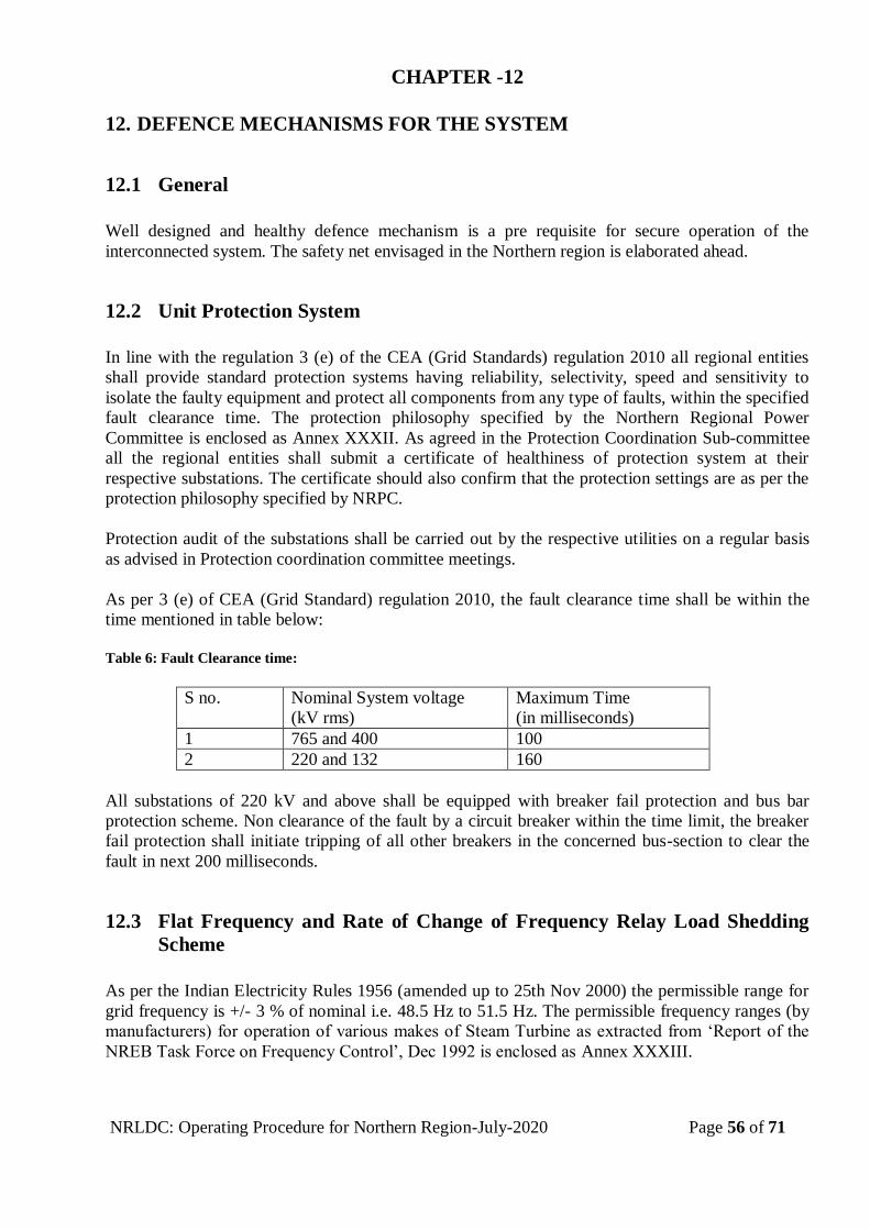
NRLDC: Operating Procedure for Northern Region-July-2020 Page 56 of 71
CHAPTER -12
12. DEFENCE MECHANISMS FOR THE SYSTEM
12.1 General
Well designed and healthy defence mechanism is a pre requisite for secure operation of the
interconnected system. The safety net envisaged in the Northern region is elaborated ahead.
12.2 Unit Protection System
In line with the regulation 3 (e) of the CEA (Grid Standards) regulation 2010 all regional entities
shall provide standard protection systems having reliability, selectivity, speed and sensitivity to
isolate the faulty equipment and protect all components from any type of faults, within the specified
fault clearance time. The protection philosophy specified by the Northern Regional Power
Committee is enclosed as Annex XXXII. As agreed in the Protection Coordination Sub-committee
all the regional entities shall submit a certificate of healthiness of protection system at their
respective substations. The certificate should also confirm that the protection settings are as per the
protection philosophy specified by NRPC.
Protection audit of the substations shall be carried out by the respective utilities on a regular basis
as advised in Protection coordination committee meetings.
As per 3 (e) of CEA (Grid Standard) regulation 2010, the fault clearance time shall be within the
time mentioned in table below:
Table 6: Fault Clearance time:
S no. Nominal System voltage
(kV rms)
Maximum Time
(in milliseconds)
1 765 and 400 100
2 220 and 132 160
All substations of 220 kV and above shall be equipped with breaker fail protection and bus bar
protection scheme. Non clearance of the fault by a circuit breaker within the time limit, the breaker
fail protection shall initiate tripping of all other breakers in the concerned bus-section to clear the
fault in next 200 milliseconds.
12.3 Flat Frequency and Rate of Change of Frequency Relay Load Shedding
Scheme
As per the Indian Electricity Rules 1956 (amended up to 25th Nov 2000) the permissible range for
grid frequency is +/- 3 % of nominal i.e. 48.5 Hz to 51.5 Hz. The permissible frequency ranges (by
manufacturers) for operation of various makes of Steam Turbine as extracted from ‘Report of the
NREB Task Force on Frequency Control’, Dec 1992 is enclosed as Annex XXXIII.
NRLDC: Operating Procedure for Northern Region-July-2020 Page 57 of 71
Under-frequency and rate of change of frequency (UFR & df/dt) are envisaged to take care of
sudden contingencies arising out of outage of generation stations or separation of inter-regional
lines. UFRs setting are for steady state operation of the grid at considerably low frequency and df/dt
settings are for fast change in frequency due to large generation outage. The settings of UFRs as
decided in NRPC are 49.2Hz, 49.0 Hz and 48.8 Hz & 48.6 Hz with the State wise load relief
enclosed in Annex XXXIV.
Three stages of df/dt settings have been envisaged.
Stage –1 of df/dt setting is to protect the All India grid from loss of generation of a large
power station.
Stage – 2 of df/dt is to protect the split grid from loss of generation of a large power station
in regional grid.
Stage – 3 of df/dt is to protect the individual regional grid/ state grid from loss of generation
in the event of isolation. The setting and quantum of relief through df/dt relay as decided in
NRPC is enclosed in Annex XXXV.
In line with regulation 5.4.2 (e) of IEGC, the interruptible loads in a control area shall be arranged
in four groups of load,
for scheduled power cuts/load shedding,
loads for unscheduled load shedding,
loads to be shed through under frequency relays/(df/dt) relays and
Loads to be shed under any System Protection Scheme identified at the RPC level.
These loads shall be grouped in a manner, that there is no overlapping between different groups of
loads. This would ensure that the automatic relief through these relays would be available to the
system under all conditions.
As per CERC order, SCADA mapping of UFR and df/dt has to carry out by each state control area
and accordingly all the state has started mapping in an agreed format in OCC.
In addition, NRLDC shall keep a comparative record of the expected load relief and actual load
relief from UFR, df/dt, UVLS relays and SPS. The same would also be placed by NRLDC in the
monthly meetings of the Operation Co-ordination Sub-Committee (OCC) of NRPC.
12.4 Under Voltage Load Shedding Scheme (UVLS)
To insulate the Regional Grid from the exigencies due to low voltage problem, Under Voltage Load
Shedding Scheme has been implemented as per the decision of 3rd NRPC meeting held on
10.11.2006 at Mussoorie.
Uttar Pradesh has installed UVRs at 9 places with total load relief of ~ 1065 MW.
Punjab has 3 nos of UVRs with a load relief of 186 MW at Moga, Malerkotla and
Bahadurgarh (Bhateri) s/stn.
Delhi has two UVR installed at 400 kV Bamnauli & Bawana. Details of UP, Punjab & Delhi
is enclosed in Annex-XXXVI.
NRLDC: Operating Procedure for Northern Region-July-2020 Page 58 of 71
Uttarakhand has one UVR installed at Rishikesh set with 190 kV. Planned relief is 30-60
MW.
Rajasthan has three UVR installed at 132kV Mandan, 132kV K.G.Bas & 220kV Neemrana
set at 90% of normal voltage with time delay of 30 second. Planned relief is 15 MW, 22
MW and 30 MW respectively.
12.5 System Protection Scheme (SPS)
Outage of a large capacity link between two distant nodes in a synchronously interconnected system
may result into excessive loading on parallel AC lines, severe drop in voltage profile, power
oscillations and finally leading to a major blackout or brown out in the system, in case
instantaneous corrective actions are not in place. On the other hand, similar outage in an
asynchronously connected system may result into load – generation imbalance on either side of the
link. In view of the above few System Protection Schemes have been implemented in Northern
region. These involve predefined generation backing down as well as load shedding under selected
contingencies. The SPS schemes have been described in detail in Annex XXXVII.
12.6 Islanding Scheme
In order to isolate the healthy subsystems following a large-scale disturbance, few generating
stations/Users and State Utilities have implemented islanding schemes. Such schemes are in
operation in Nuclear power Stations of NAPS, RAPS-A and RAPS-B. Details are enclosed as
Annex XXXVIII. The load for these nuclear generating stations are under review and revised load
would be implemented as and when finalised.
Islanding schemes of Delhi, Punjab, Jammu & Kashmir and Uttar Pradesh have also been
formulated. As envisaged and under review, Delhi islanding schemes is enclosed in Annex XXXIX
A & B; however it is yet to be commissioned.
Users/utilities intending to implement any islanding schemes for their station may do so in
consultation with NRLDC and NRPC secretariat.
*****

NRLDC: Operating Procedure for Northern Region-July-2020 Page 59 of 71
CHAPTER -13
13. GRID INCIDENT, GRID DISTURBANCE AND REVIVAL
13.1 General
This chapter is in compliance with the regulation 6.5.22 of the IEGC that mandates the RLDC to
formulate the procedure for meeting contingencies both in long run and the short run. It describes
the guidelines for classification of grid events into different categories, for the purpose of analysis
and reporting. The milestone to be reached so as to consider the system as normal is also indicated.
The general precautions to be observed, while restoring a disturbed system are also covered in this
chapter. The detailed sequence to be followed for restoration would be as per the ‘System
Restoration Procedures for Northern Region’ brought out by NRLDC.
13.2 Definition of Grid Incident and Grid Disturbance
The Grid Incident and Grid Disturbance as defined in the CEA (Grid Standards) Regulation 2010 is
as under-
“A Grid Incident means tripping of one or more power system elements of the grid like a generator,
transmission line, transformer, shunt reactor, series capacitor and Static VAR Compensator, which
requires re-scheduling of generation or load, without total loss of supply at a substation or loss of
integrity of the grid at 220 kV and above (132 kV in the case of North-Eastern Region).”- [CEA
Regulation 2 (j)]
“A Grid Disturbance means tripping of one or more power system elements of the grid like a
generator, transmission line, transformer, shunt reactor, series capacitor and Static VAR
Compensator, resulting total failure of supply at a sub-station or loss of integrity of the grid, at
the level of transmission system at 220 kV and above (132 kV in the case of North-Eastern
Region).”- [CEA Regulation 2 (i)]
In the event of a grid incident/disturbance, utmost priority is to be accorded to early restoration /
revival of the system. It is possible that during such a situation the system may have to be operated
with reduced security standards for the voltage and frequency as necessary in order to achieve the
fastest possible recovery of the grid [IEGC 5.8 (e)].
13.3 Declaration of Grid Disturbance
Declaration of Grid disturbance shall be done by the concerned RLDC at the earliest (IEGC
6.5.17.). A notice to this effect shall be posted at its website by the RLDC of the region in which the
disturbance occurred. Issue of the notice at RLDC website shall be considered as declaration of the
Grid disturbance by RLDCs. All regional entity shall take note of the disturbance and take
appropriate action at their end.
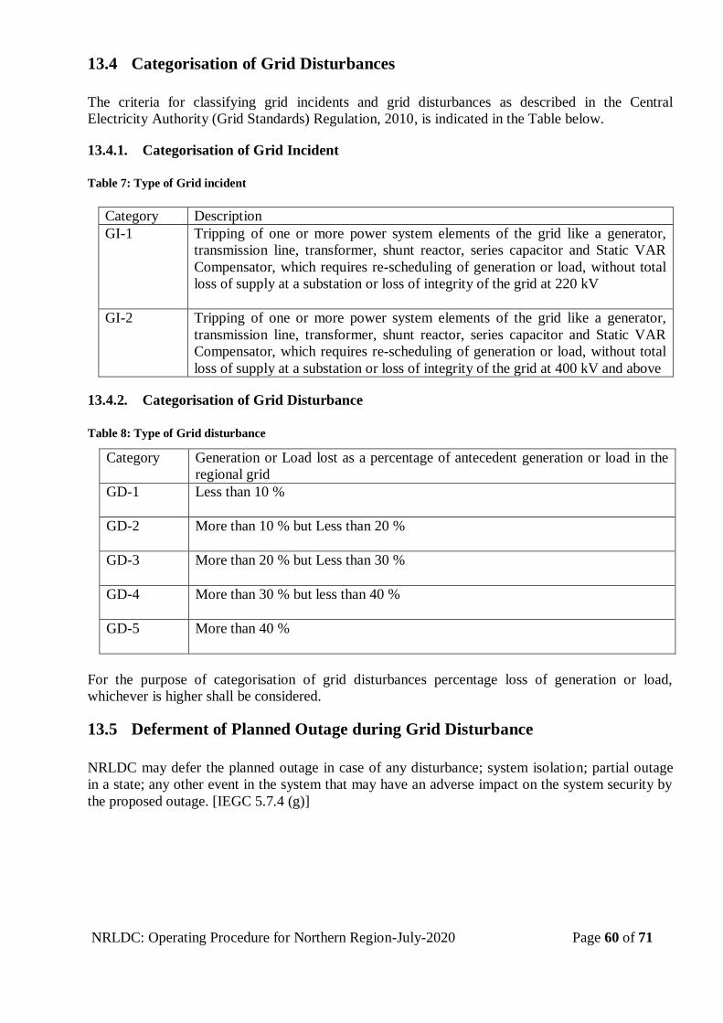
NRLDC: Operating Procedure for Northern Region-July-2020 Page 60 of 71
13.4 Categorisation of Grid Disturbances
The criteria for classifying grid incidents and grid disturbances as described in the Central
Electricity Authority (Grid Standards) Regulation, 2010, is indicated in the Table below.
13.4.1. Categorisation of Grid Incident
Table 7: Type of Grid incident
Category Description
GI-1 Tripping of one or more power system elements of the grid like a generator,
transmission line, transformer, shunt reactor, series capacitor and Static VAR
Compensator, which requires re-scheduling of generation or load, without total
loss of supply at a substation or loss of integrity of the grid at 220 kV
GI-2 Tripping of one or more power system elements of the grid like a generator,
transmission line, transformer, shunt reactor, series capacitor and Static VAR
Compensator, which requires re-scheduling of generation or load, without total
loss of supply at a substation or loss of integrity of the grid at 400 kV and above
13.4.2. Categorisation of Grid Disturbance
Table 8: Type of Grid disturbance
For the purpose of categorisation of grid disturbances percentage loss of generation or load,
whichever is higher shall be considered.
13.5 Deferment of Planned Outage during Grid Disturbance
NRLDC may defer the planned outage in case of any disturbance; system isolation; partial outage
in a state; any other event in the system that may have an adverse impact on the system security by
the proposed outage. [IEGC 5.7.4 (g)]
Category Generation or Load lost as a percentage of antecedent generation or load in the
regional grid
GD-1 Less than 10 %
GD-2 More than 10 % but Less than 20 %
GD-3 More than 20 % but Less than 30 %
GD-4 More than 30 % but less than 40 %
GD-5 More than 40 %
NRLDC: Operating Procedure for Northern Region-July-2020 Page 61 of 71
13.6 Rescheduling During Grid Disturbance
In case of any grid disturbance, scheduled generation of all the ISGS and scheduled drawal of all
the beneficiaries shall be deemed to have been revised to their actual generation/drawal for the time
blocks affected by the grid disturbance. Grid disturbance and its duration shall be notified by
NRLDC for this purpose. [IEGC 6.5.17]
13.7 System Revival
The recovery of the system shall be carried out as mentioned in the companion document ‘System
Restoration Procedures for Northern Region’ prepared by NRLDC in consultation with NLDC, all
Users, STU, SLDC, CTU and RPC Secretariat, shall be reviewed/ updated annually.
The general guidelines and precautions to be followed during system revival are indicated below:
(i) While building up the system, it would be ensured that the voltage at the charging end remains
within limits. A small amount of essential load should be connected at each substation before
extending the network. However, the ultimate objective viz. building up of the network should
not be lost sight of, while connecting the loads.
(ii) Security of the network being built up would be strengthened at the earliest by closing the
parallel lines available in the restoration path while system parameters to be maintained.
(iii) Priority would be accorded for extending supplies to railway traction and installations where
safety is of paramount importance such as nuclear power stations.
(iv) All switching instructions for a particular system have to emanate from a single agency viz.
SLDC/CPCC as the case may be. For synchronisation of two systems, NRLDC would be the
co-ordinating agency. Wherever a communication problem is foreseen, proper standing
instructions would be issued to the substation engineers for implementation.
(v) During revival of the system, only authorised personnel would be present in control rooms of
substations / power stations / SLDCs / NRLDC so as to expedite restoration of the system.
(vi) In line with Section 5.8 (e) of IEGC, all communication channels required for restoration
process shall be used for operational communication only, till grid normalcy is restored.
(vii) All generating units would be on free governor operation and the excitation controlled to
maintain proper voltage profile.
(viii) Synchronising facility should be available at major grid substations so as to have maximum
flexibility in choosing the point of synchronisation.
(ix) Scheduled generation of ISGS and scheduled drawal of the beneficiaries shall be deemed to
have been revised to their actual generation/drawal accordingly for the time blocks affected
during system revival or mock black start exercise
NRLDC: Operating Procedure for Northern Region-July-2020 Page 62 of 71
13.8 Declaration of System Normalisation Post Grid Disturbance
After a Grid Disturbance of category GD-1, GD-2, GD-3, GD-4, ‘the system would be deemed to
have been normalised if all subsystems have been synchronised and 80% of the total loss of
generation/load, during the incident, has been revived.
After a Grid Disturbance of category- GD-5, the system would be deemed to have been normalised
if, all subsystems have been synchronised; Power has been extended to each affected grid
substation; At least one unit at the affected power station has been synchronised (subject to a
maximum of three hours of receipt of start-up power).
NRLDC shall inform the regional entities, users, STU/CTU/Licensees, SLDCs in this regard.
13.9 Inter-Regional Support
In case of disturbance or any other contingency in the Northern Region or any other neighbouring
region, NRLDC shall permit exchange of such power with the neighbouring region on deviation
basis, needed to meet the essential load, start-up-power, railway traction and other such emergent
requirements for the duration of such contingencies.
*****
NRLDC: Operating Procedure for Northern Region-July-2020 Page 63 of 71
CHAPTER-14
14. EVENT INFORMATION AND REPORTING
14.1 Overview
Timely and accurate reporting and exchange of information plays a very important role in system
operation. Since the Northern Regional Grid has a large number of Users/regional entities/
constituents with wide spread boundaries, the manner in which the information flow would take
place becomes very important. This is particularly important during a grid incident/disturbance or a
crisis situation. Timely and accurate information flow under such conditions would greatly reduce
an element of uncertainty and help people in making an informed decision. In case system
restoration is likely to get delayed, it is important that the general public is also well informed to
avoid any unrest. Such instances could result in a major credibility crisis for the Electricity Supply
Industry (ESI) and has to be avoided at all cost. This chapter describes the information to be
exchanged between the constituents and NRLDC and its periodicity.
14.2 Event Information
Any tripping of an element falling under the list of “Important elements of Regional Grid”, whether
manual or automatic, shall be intimated by the control centre of the constituent to NRLDC in a
reasonable time say within ten (10) minutes of the occurrence of the event [IEGC 5.2 (d)]. Along
with the tripping intimation, the reason for tripping (to the extent determined) and the likely time of
restoration shall also be intimated. Such intimation can be on telephone or fax or e-mail.
Any operation planned to be carried out by a constituent which may have an impact on the regional
grid, or on any of the “Important Element of Northern Regional Grid”, shall be reported by the
User, STU, CTU, licensee to NRLDC in advance.
Any operations planned to be carried out on the instructions of NRLDC which may have an impact
on the system of a constituent / constituents shall be reported by NRLDC to all such constituents in
advance.
Any prolonged outage of power system elements of any user/STU/CTU, which is causing or likely
to cause danger to the grid or sub-optimal operation of the grid, shall be reported by NRLDC to
NRPC.
The intimation and the exact time of revival of an element falling under the category of “Important
Elements of Northern Regional Grid” whether revived after a tripping or after a prolonged outage
shall be intimated to NRLDC immediately.
14.3 Reporting System
The details of the Event Reports and the Periodic Reports to be prepared and issued by Constituents
/ NRLDC are as follows:
NRLDC: Operating Procedure for Northern Region-July-2020 Page 64 of 71
14.3.1. Event Report (SLDC/ Constituent/ User / regional Entity/ STU/CTU/inter-state
transmission licensee to NRLDC).
In the event of tripping of any element falling under the category of “Important Elements of
Northern Regional Grid” the “EVENT REPORT” shall be sent by the concerned constituent to
NRLDC within a period of four (4) hours of the occurrence of the event in the form Annex XL
detailed under regulation 5.9.6 of IEGC. Such report shall follow the telephonic / flash reporting
the constituent would do in a reasonable time, say within ten (10) minutes of the occurrence of the
event.
14.3.2. Grid Incident/Disturbance Report (SLDC/Constituent / User/ STU/ CTU/ inter-
state transmission licensee to NRLDC):
In the event of a grid Incident/disturbance the constituent/User/STU/CTU/licensee whose areas /
stations get affected in the Incident/disturbance shall submit a report to NRLDC at the earliest.
Along with the report clear copies of Disturbance Recorder (DR), Sequential Event Recorder (SER)
and Data Acquisition System (DAS) outputs, relay flag indications, restoration sequence, tripping
analysis and remedial measures would be sent so as to reach NRLDC within 24 hours of the
incident/disturbance [IEGC 5.2 (r)].
Further in line with the CERC (Standards of Performance for inter-state transmission licensees)
Regulations 2012, every month the inter-state transmission licensees shall furnish the data
pertaining to each tripping so as to enable computation of dependability index, security index, and
reliability index for the inter-state transmission licensee. The relevant schedule from the aforesaid
CERC regulations is enclosed as Annex XLI
14.3.3. Grid Incident/Disturbance Report (NRLDC to NLDC/ SLDC/Constituents/ User/
STU/ CTU/ inter-state transmission licensee):
In the event of a grid incident/disturbance NRLDC shall issue a brief preliminary report in
prescribed format (Enclosed as Annex XLII), indicating the affected area or system, extent of
outage and likely cause of initiation. The preliminary report for a grid disturbance would be issued
within twenty-four hours of the occurrence of the disturbance. This would be followed by a detailed
report in the following manner.
(i) Grid Disturbance Category –GD-5: Flash report followed by a detailed report within ten
(10) working days.
(ii) Grid Disturbance Category- GD-1, GD-2, GD-3 and GD-4: Flash report followed by a
detailed report within a period of seven (7) working days.
(iii)Grid Incident (GI-1 and GI-2): Flash report followed by a detailed report within a period of
four (4) working days.
The number of days mentioned above for issuing of detailed report by NRLDC is indicative only
and would depend upon timely furnishing of information / data by the concerned constituents in
line with section 13.3.2 above.
14.3.4. Automatic load shedding through SPS/ Under Frequency/(df/dt)/ Under Voltage
Relay Operations (Constituents to NRLDC and NRLDC to NRPC/CERC)
In line with the regulation 5.2 (n), 5.2 (o) 5.2 (t) of the IEGC, automatic load shedding (including
inter tripping and run back) would be initiated as result of operation of SPS/UFR / (df/dt)/UVLS
relays. In order to check and ascertain their operation as per approved plans, the details of all such
NRLDC: Operating Procedure for Northern Region-July-2020 Page 65 of 71
tripping in their areas shall be intimated by each User/SLDC to NRLDC, whenever they occur or
whenever required. NRLDC shall keep a comparative record of expected load relief and actual load
relief obtained in real time system operation (UFR and df/dt) as per IEGC regulation 5.2 (n). A
monthly report on expected load relief vis-a-vis actual load relief shall be sent to the NRPC and the
CERC.
14.3.5. Frequency Response Characteristics (FRC)
The frequency response of the State control area/Region shall be computed in line with CERC
approved “Procedure for Assessment of FRC in petition No. 49/MP/2012 (order dated 3rd May
2013. Templates are enclosed as Annex XLIII.
14.3.6. Daily Report
In line with IEGC regulation 5.5.1 (b) a daily report covering the performance of the regional grid
shall be prepared by NRLDC based on the inputs received from SLDCs/Users and shall be put on
its website.
14.3.7. Weekly Report (NRLDC to Constituents)
A weekly report shall be issued by NRLDC to all constituents of the region covering the
performance of the regional grid during the previous week, in line with regulation 5.5.1 (c)of IEGC.
Such report shall be issued within two (2) working days of the completion of the week. Such
weekly report shall be available on the website of the NLDC for at least 12 weeks.
14.3.8. Quarterly Report (Constituent to NRLDC and NRLDC to constituents)
A quarterly report shall be issued by NRLDC to all the constituents elaborating the power supply
position during the last quarter, quality of supply, the system constraints and other relevant
information in line with regulation 5.5.2 and regulation 3.4 (b) (v) of IEGC. Such report shall be
issued within two (2) weeks of the completion of the quarter.
As per 5.8 (b) of the IEGC mock trial of the procedures for different sub-system shall be carried out
by the Users/CTU/STU at least once every six months under intimation to the RLDC. Diesel
Generator sets for black start would be tested on weekly basis and test report shall be sent to RLDC
on quarterly basis.
RLDCs shall maintain a proper record of all the mock trials conducted and forward it to NLDC as a
part of quarterly report of disaster management.
A feedback on the operational issues shall be forwarded by NRLDC to NLDC on a quarterly basis
in line with the NLDC circular dated 04th February 2013. The format is enclosed as Annex XLIV.
14.3.9. Exceptional Reporting (constituents to NRLDC)
The above reporting schedules are to be strictly followed. However, in case of any contingency
such as an industrial unrest, natural calamity in any part of the region etc., there could be additional
reporting requirements not covered in the above schedule. NRLDC would inform all constituents of
any such exceptional requirement and the constituents would extend the necessary co-operation in
this regard.
*****
NRLDC: Operating Procedure for Northern Region-July-2020 Page 66 of 71
CHAPTER-15
15. DATA ACQUISITION AND COMMUNICATION SYSTEM
15.1 Overview
In line with regulation 4.6.2 and 5.2 (q) of the IEGC each User, STU, RLDC, NLDC and CTU shall
provide and maintain adequate and reliable communication facility internally and with other
Users/STUs/RLDC/SLDC to ensure exchange of data/information necessary to maintain reliability
and security of the grid. Wherever possible, redundancy and alternate path shall be maintained for
communication along important routes, e.g. SLDC to RLDC to NLDC.
CERC vide its order dated 26.09.2012 in petition 168/MP/2011 with IA No. 39/2012 has directed as
under:
“Under the grid code, it is the responsibility of all users, STUs and CTU to provide systems to
telemeter power system parameters in line with interface requirements to telemeter power system
parameters in line with interface requirements and other guidelines made available by RLDC and
associated communication system to facilitate data flow upto appropriate data collection point on
CTUs system. In view of the critical importance of telemetry and associated communication system
for ensuring reliability in operation of the grid and optimum utilization of the transmission system,
there is an imperative need for all users to establish the telemetry and associated communication
system in time bound manner so that the power system operation may be most reliable and
optimum. Moreover, in view of the requirement of communication system for generating station
and sub-station, the planning should be done in advance by the generating company and
transmission licensee to ensure that necessary system is in place before commissioning of
generating station or substation to take care of the communication requirements even at the time of
injection of infirm power by a generating station and sub-station during testing.”
15.2 Recording Instruments and Communication Facilities
The recording instruments such as Data Acquisition System, Disturbance Recorder, Event Logger,
Fault Locator, Time Synchronisation Equipment, and any other such equipment in each generating
station / substation / control centre / SLDCs shall be kept in good working condition in order to
record the events and their sequences. All such places shall have a common time reference so that
any event can be coordinated with respect to different locations having common time base.
Each regional constituent shall provide adequate and reliable communication facility with NRLDC
as well as internally and with other constituents in order to ensure exchange of data / information
necessary to maintain reliability and security of the grid.
15.3 Wide Area Measurement Systems in NR
For better monitoring of the system in real time, Phasor Measurement Units (PMUs) have been
installed by NRLDC at various locations in Northern Region under NR PMU/PDC interim pilot
project. Report covering experiences of pilot project of PMU is available at NRLDC website.
At present, large nos. of PMUs have been installed in Northern region under URTDSM scheme.
These help power system operators continuously analyse all the features of large power network in

NRLDC: Operating Procedure for Northern Region-July-2020 Page 67 of 71
real time. Various application to use large PMU data is also available at NRLDC control centre. A
brief detail of URTDSM is enclosed in XLV.
15.4 Cyber Security
15.4.1. Overview
In line with regulation 4.6.5 of IEGC, all utilities shall have in place, a cyber-security framework to
identify the critical cyber assets and protect them so as to support reliable operation of the grid.
Cyber security is important to protect sensitive and critical data. Compliance to Cyber security
standards is essential to protect against identity theft and malware threats.
15.4.2. Recommended practices
Recommended practices for ensuring cyber security are listed below:
Physical Security
– Computer Locks
– BIOS (Basic Input Output System) Security
– Account & Password Management
– Only authorized personnel should have access to the computers
– Enforce appropriate/Strong passwords
– Appropriate permissions to access folders /files
Data Backup and Restoration – Periodical backup individual and organisation’s data
– Test restoring data from backup media
– Keep backups offsite
– Keep onsite back up in a secure, fire proof area
Operating Systems – Check the operating systems we use on our workstations and servers updated
with current security "patches" and service packs
Application Software – Check our common applications (e.g. databases, accounts package)
configured for security
Confidentiality of Sensitive Data – Protect sensitive data under our control
Disaster Recovery – Prepare disaster recovery plan & test it regularly
Network and server security – Adopt safe computing policies and procedures
– Providing information about computer security to our staff

NRLDC: Operating Procedure for Northern Region-July-2020 Page 68 of 71
Hardware failure – Keep contact list /resource person in case of hardware failure
– Check whether the contract for service support is good enough to withstand a
serious hardware failure
Hosted services – Keep our website account secure/password protected
– Check whether the website is backed up by the host provider
*****
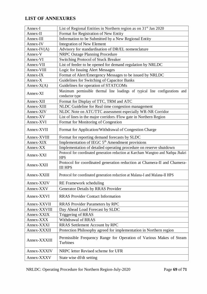
NRLDC: Operating Procedure for Northern Region-July-2020 Page 69 of 71
LIST OF ANNEXURES
Annex-I List of Regional Entities in Northern region as on 31st Jan 2020
Annex-II Format for Registration of New Entity
Annex-III Information to be Submitted by a New Regional Entity
Annex-IV Integration of New Element
Annex-IV(A) Advisory for standardisation of DR/EL nomenclature
Annex-V NRPC Outage Planning Procedure
Annex-VI Switching Protocol of Stuck Breaker
Annex-VII List of feeder to be opened for demand regulation by NRLDC
Annex-VIII Logic for Issuing Alert Messages
Annex-IX Format of Alert/Emergency Messages to be issued by NRLDC
Annex-X Guidelines for Switching of Capacitor Banks
Annex-X(A) Guidelines for operation of STATCOMs
Annex-XI Maximum permissible thermal line loadings of typical line configurations and
conductor type
Annex-XII Format for Display of TTC, TRM and ATC
Annex-XIII NLDC Guideline for Real time congestion management
Annex-XIV NLDC Note on ATC/TTC assessment especially WR-NR Corridor
Annex-XV List of lines in the major corridors /Flow gate in Northern Region
Annex-XVI Format for Monitoring of Congestion
Annex-XVII Format for Application/Withdrawal of Congestion Charge
Annex-XVIII Format for reporting demand forecasts by SLDC
Annex-XIX Implementation of IEGC 5th Amendment provisions
Annex-XX Implementation of detailed operating procedure on reserve shutdown
Annex-XXI Protocol for coordinated generation reduction at Karcham Wangtoo and Nathpa Jhakri
HPS
Annex-XXII Protocol for coordinated generation reduction at Chamera-II and Chamera-
III HPS
Annex-XXIII Protocol for coordinated generation reduction at Malana-I and Malana-II HPS
Annex-XXIV RE Framework scheduling
Annex-XXV Generator Details by RRAS Provider
Annex-XXVI RRAS Provider Contact Information
Annex-XXVII RRAS Provider Parameters by RPC
Annex-XXVIII Day Ahead Load Forecast by SLDC
Annex-XXIX Triggering of RRAS
Annex-XXX Withdrawal of RRAS
Annex-XXXI RRAS Settlement Account by RPC
Annex-XXXII Protection Philosophy agreed for implementation in Northern region
Annex-XXXIII Permissible Frequency Range for Operation of Various Makes of Steam
Turbines
Annex-XXXIV NRPC letter Revised scheme for UFR
Annex-XXXV State wise df/dt setting

NRLDC: Operating Procedure for Northern Region-July-2020 Page 70 of 71
Annex-XXXVI Under Voltage Relay Settings and Load Relief
Annex-XXXVII System Protection Scheme in Operation in Northern Region
Annex-XXXVIII Islanding Scheme in Northern Region
Annex-
XXXIXA Delhi Islanding Schemes
Annex-XXXIXB Kashmir Valley Islanding scheme
Annex-XL Form of written reports as per IEGC
Annex-XLI
Format for data to be submitted by inter-state transmission licensees to
POSOCO in line with CERC (Standards of Performance of inter-state
transmission licensees) Regulations, 2012
Annex-XLII Format of Preliminary report
Annex-XLIII Format for Frequency Response Characteristics computation
Annex-XLIV Format for feedback on operational issues to be submitted quarterly to
NLDC
Annex-XLV Brief on URTDSM scheme
NRLDC: Operating Procedure for Northern Region-July-2020 Page 71 of 71
REFERENCES
Government of India legislation and policy
o Electricity Act, 2003
o National Electricity Policy, 2005
o Tariff Policy, 2006
Central Electricity Authority Regulations/Criteria
o Manual on Transmission Network Planning Criteria, January 2013
o Grid Standards, Regulations, 2010
o Installation and Operation of Meters, Regulations, 2010
o Connectivity to the Grid, Regulations, 2007 (amended time to time)
o Technical Standards for Construction of Electric Plants and Electric Lines, 2010
Central Electricity Regulatory Commission Regulations
o Open Access in inter-State Transmission (Third Amendment) Regulations, 2015.
o Terms and Conditions of Tariff, 2014-19
o Fees and Charges of Regional Load Despatch Centre and other related matters,
Regulations, 2015.
o Revised Procedure to ‘Measures to relieve congestion in real-time operation’s 2013
o Grant of Connectivity, Long-term Access and Medium-term Open Access in inter-
State Transmission and related matters) (Fifth Amendment Regulations, 2015
o Indian Electricity Grid Code, 2010, IEGC (Fifth Amendment), 2017
o Deviation settlement Mechanism, (Third Amendment), 2014
o Power market, 2010
o Standards of Performance of inter State transmission licensees, 2012
o CERC procedure for Renewable Energy, 2017
o CERC procedure for reserve shutdown, 2017
o CERC procedure for approval of start-up power of generating units under
commissioning, 2015
Central Transmission Utility Procedures
o Procedure for making application for Grant of Connectivity in ISTS, 2010
National Load Despatch Centre Procedures
o Procedure for Scheduling of Bilateral Transaction, June 2009
o Procedure for computation of PoC rate, June 2011
o Procedure for obtaining data by Implementing Agency for determination of PoC
Charges and Losses, June 2011
o Procedure for sharing of ISTS losses: June2011
o Procedure for Assessment of Frequency Response Characteristics (FRC), 2013
o Detailed Procedure for relieving Congestion in real-time operation, 2013
Central Board of Irrigation and Power Manual
o Manual on Reliable Fault Clearance and Back up Protection of EHV and UHV
transmission Networks, Publication No. 296, September 2005
o Manual on Protection of Generators, Generator Transformers, and 220 kV and 400
kV Networks, Publication No. 274, November 1999

ANNEXURES
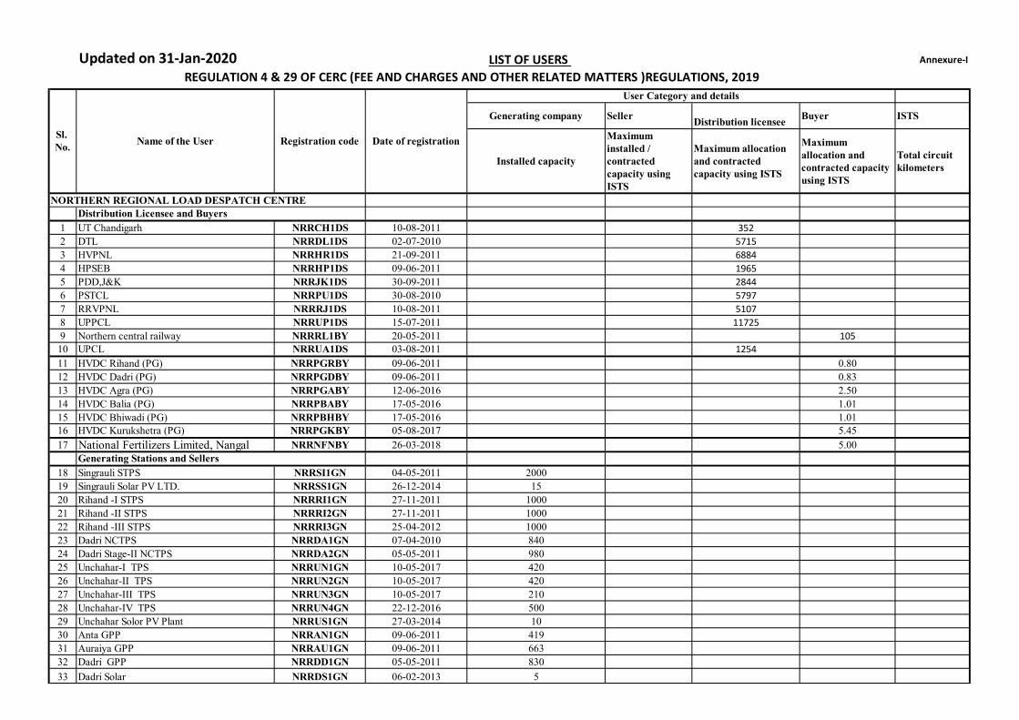
Updated on 31-Jan-2020 Annexure-I
Generating company SellerDistribution licensee
Buyer ISTS
Installed capacity
Maximum installed / contracted capacity using ISTS
Maximum allocation and contracted capacity using ISTS
Maximum allocation and contracted capacity using ISTS
Total circuit kilometers
1 UT Chandigarh NRRCH1DS 10-08-2011 352
2 DTL NRRDL1DS 02-07-2010 5715
3 HVPNL NRRHR1DS 21-09-2011 6884
4 HPSEB NRRHP1DS 09-06-2011 1965
5 PDD,J&K NRRJK1DS 30-09-2011 2844
6 PSTCL NRRPU1DS 30-08-2010 5797
7 RRVPNL NRRRJ1DS 10-08-2011 5107
8 UPPCL NRRUP1DS 15-07-2011 11725
9 Northern central railway NRRRL1BY 20-05-2011 105
10 UPCL NRRUA1DS 03-08-2011 1254
11 HVDC Rihand (PG) NRRPGRBY 09-06-2011 0.80
12 HVDC Dadri (PG) NRRPGDBY 09-06-2011 0.83
13 HVDC Agra (PG) NRRPGABY 12-06-2016 2.50
14 HVDC Balia (PG) NRRPBABY 17-05-2016 1.01
15 HVDC Bhiwadi (PG) NRRPBHBY 17-05-2016 1.0116 HVDC Kurukshetra (PG) NRRPGKBY 05-08-2017 5.45
17 National Fertilizers Limited, Nangal NRRNFNBY 26-03-2018 5.00
18 Singrauli STPS NRRSI1GN 04-05-2011 2000
19 Singrauli Solar PV LTD. NRRSS1GN 26-12-2014 15
20 Rihand -I STPS NRRRI1GN 27-11-2011 1000
21 Rihand -II STPS NRRRI2GN 27-11-2011 1000
22 Rihand -III STPS NRRRI3GN 25-04-2012 1000
23 Dadri NCTPS NRRDA1GN 07-04-2010 840
24 Dadri Stage-II NCTPS NRRDA2GN 05-05-2011 980
25 Unchahar-I TPS NRRUN1GN 10-05-2017 420
26 Unchahar-II TPS NRRUN2GN 10-05-2017 420
27 Unchahar-III TPS NRRUN3GN 10-05-2017 210
28 Unchahar-IV TPS NRRUN4GN 22-12-2016 500
29 Unchahar Solor PV Plant NRRUS1GN 27-03-2014 10
30 Anta GPP NRRAN1GN 09-06-2011 419
31 Auraiya GPP NRRAU1GN 09-06-2011 663
32 Dadri GPP NRRDD1GN 05-05-2011 830
33 Dadri Solar NRRDS1GN 06-02-2013 5
LIST OF USERS
Registration code
User Category and details
Generating Stations and Sellers
REGULATION 4 & 29 OF CERC (FEE AND CHARGES AND OTHER RELATED MATTERS )REGULATIONS, 2019
Date of registration
Distribution Licensee and Buyers
Sl. No.
Name of the User
NORTHERN REGIONAL LOAD DESPATCH CENTRE
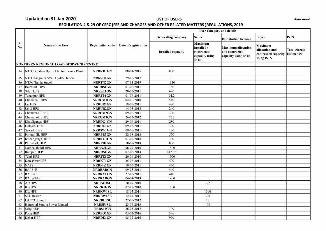
Updated on 31-Jan-2020 Annexure-I
Generating company SellerDistribution licensee
Buyer ISTS
Installed capacity
Maximum installed / contracted capacity using ISTS
Maximum allocation and contracted capacity using ISTS
Maximum allocation and contracted capacity using ISTS
Total circuit kilometers
LIST OF USERS
Registration code
User Category and details
REGULATION 4 & 29 OF CERC (FEE AND CHARGES AND OTHER RELATED MATTERS )REGULATIONS, 2019
Date of registrationSl. No.
Name of the User
NORTHERN REGIONAL LOAD DESPATCH CENTRE
34 NTPC Koldam Hydro Electric Power Plant NRRKD1GN 08-04-2015 800
35 NTPC Singrauli Small Hydro Station NRRSH1GN 29-08-2017 8
36 NTPC Tanda Stagell NRRTN2GN 07-11-2019 1320
37 Bairasiul HPS NRRBS1GN 01-06-2011 180
38 Salal HPS NRRSL1GN 20-05-2011 690
39 Tanakpur HPS NRRTP1GN 01-06-2011 94.2
40 Chamera-1 HPS NRRCM1GN 04-06-2010 540
41 Uri HPS NRRUR1GN 18-05-2011 480
42 Uri-2 HPS NRRUR2GN 14-03-2013 240
43 Chamera-II HPS NRRCM2GN 09-06-2011 300
44 Chamera-III HPS NRRCM3GN 26-03-2012 231
45 Dhauliganga HPS NRRDG1GN 29-06-2011 280
46 Dulhasti HPS NRRDU1GN 09-05-2011 390
47 Sewa-II HPS NRRSW1GN 09-05-2011 120
48 Parbati-III, HEP NRRPB3GN 22-08-2013 520
49 Kishanganga, HEP NRRKG1GN 01-03-2018 33050 Parbati-II, HEP NRRPB2GN 18-09-2018 800
51 Nathpa-Jhakri HPS NRRNJ1GN 06-07-2010 150052 Rampur HEP NRRRS1GN 07-02-2014 412.02
53 Tehri HPS NRRTE1GN 20-04-2010 100054 Koteshwer HPS NRRKT1GN 25-06-2011 400
55 NAPS NRRNA1GN 10-05-2011 440
56 RAPS -B NRRRABGN 09-05-2011 440
57 RAPS-C NRRRACGN 27-05-2011 44057 RAPS-7&8 NRRRADGN 04-04-2019 1400
58 AD HPS NRRAD1SL 10-09-2010 192
59 IGSTPS NRRIG1GN 02-12-2010 1500
60 KWHPS NRRKW1SL 18-05-2011 1000
61 SCL Bewar NRRBW1SL 12-04-2011 300
62 LANCO Bhudil NRRBL1SL 22-05-2012 70
63 Himachal Sorang Power Limted NRRSP1SL 23-09-2013 100
64 Sainj HEP NRRSJ1GN 26-05-2017 100
65 Pong HEP NRRPO1GN 05-02-2016 396
66 Dehar HEP NRRDE1GN 05-02-2016 990

Updated on 31-Jan-2020 Annexure-I
Generating company SellerDistribution licensee
Buyer ISTS
Installed capacity
Maximum installed / contracted capacity using ISTS
Maximum allocation and contracted capacity using ISTS
Maximum allocation and contracted capacity using ISTS
Total circuit kilometers
LIST OF USERS
Registration code
User Category and details
REGULATION 4 & 29 OF CERC (FEE AND CHARGES AND OTHER RELATED MATTERS )REGULATIONS, 2019
Date of registrationSl. No.
Name of the User
NORTHERN REGIONAL LOAD DESPATCH CENTRE
67 Bhakra Complex NRRBC1GN 05-02-2016 1515
68Saurya Urja Company of Rajasthan Ltd (SPPD 500MW)
NRRSU1GN 15-04-2019
69SB ENERGY FOUR PRIVATE LIMTED, Bhadla,
NRRSB1GN 26-04-2019 200
70
Adani Renewable Energy Park Rajasthan
Limited (SPPD 250MW)NRRAR1GN 15-04-2019
71RENEW SOLAR POWER Pvt. Ltd. Bhadla, (SPD)
NRRRB1GN 22-04-2019 50
72
AZURE POWER INDIA Pvt. Ltd., Bhadla
(SPD)NRRAB1GN 23-04-2019 200
73 Mahoba Solar (UP) Pvt Ltd., Rawra NRRMB1GN 31-07-2019 250
74 Azure Power Thirty Four Pvt. Ltd. Bhadla NRRAZ2GN 29-08-2019 130
75 Tata Power Renewable Energy Ltd. ChhayanNRRTC1GN 21-08-2019 150
76 Acme Chittorgarh Solar Energy Pvt Ltd. NRRAC1GN 03-10-2019 250
77 Clean Solar Power (Bhadla) Pvt Ltd. NRRCB1GN 03-10-2019 300
78
Renew SOLAR POWER Pvt. Ltd. Bikaner, (SPD) NRRRB2GN 22-10-2019 250
79 Powergrid NRTS-I&II NRRPG1TL 09-06-2011 50747
80 POWERLINK NRRPL1TL 07-04-2010 1224
81 JAYPEE Power Grid NRRJP1TL 16-05-2011 449
82 Adani Power Limited NRRAP1TL 23-09-2013 2528
83 Aravali Power Company Private Limited NRRAR1TL 02-04-2014 131
84Parbati Koldam Transmission Company LTD. NRRPK1TL 11-02-2014 458
85 NRSS XXIX Transmission Limited NRRN29TL 05-06-2015 854
86 RAPP Transmission Company Limited NRRRA1TL 29-09-2015 202
87 Patran Transmission company Limited NRRPT1TL 07-05-2016 0
88Power Transmission corporation of Uttarakhand Ltd.
NRRUT1TL 29-09-2016 28
89 NRSS XXXI (B) Transmission Limited NRR31BTL 23-11-2016 578
90Powergrid Unchahar Transmission Limited NRRPU1TL 31-03-2017 107
Inter-State Transmission Licensees
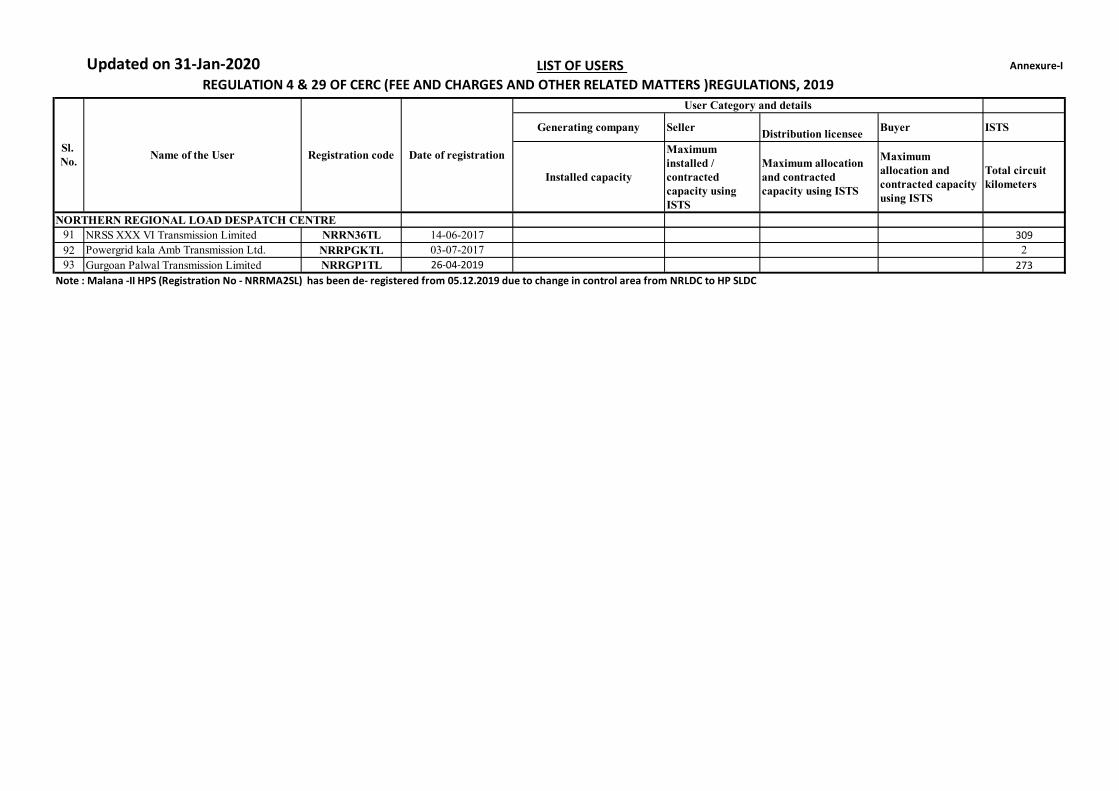
Updated on 31-Jan-2020 Annexure-I
Generating company SellerDistribution licensee
Buyer ISTS
Installed capacity
Maximum installed / contracted capacity using ISTS
Maximum allocation and contracted capacity using ISTS
Maximum allocation and contracted capacity using ISTS
Total circuit kilometers
LIST OF USERS
Registration code
User Category and details
REGULATION 4 & 29 OF CERC (FEE AND CHARGES AND OTHER RELATED MATTERS )REGULATIONS, 2019
Date of registrationSl. No.
Name of the User
NORTHERN REGIONAL LOAD DESPATCH CENTRE
91 NRSS XXX VI Transmission Limited NRRN36TL 14-06-2017 309
92 Powergrid kala Amb Transmission Ltd. NRRPGKTL 03-07-2017 2
93 Gurgoan Palwal Transmission Limited NRRGP1TL 26-04-2019 273
Note : Malana -II HPS (Registration No - NRRMA2SL) has been de- registered from 05.12.2019 due to change in control area from NRLDC to HP SLDC
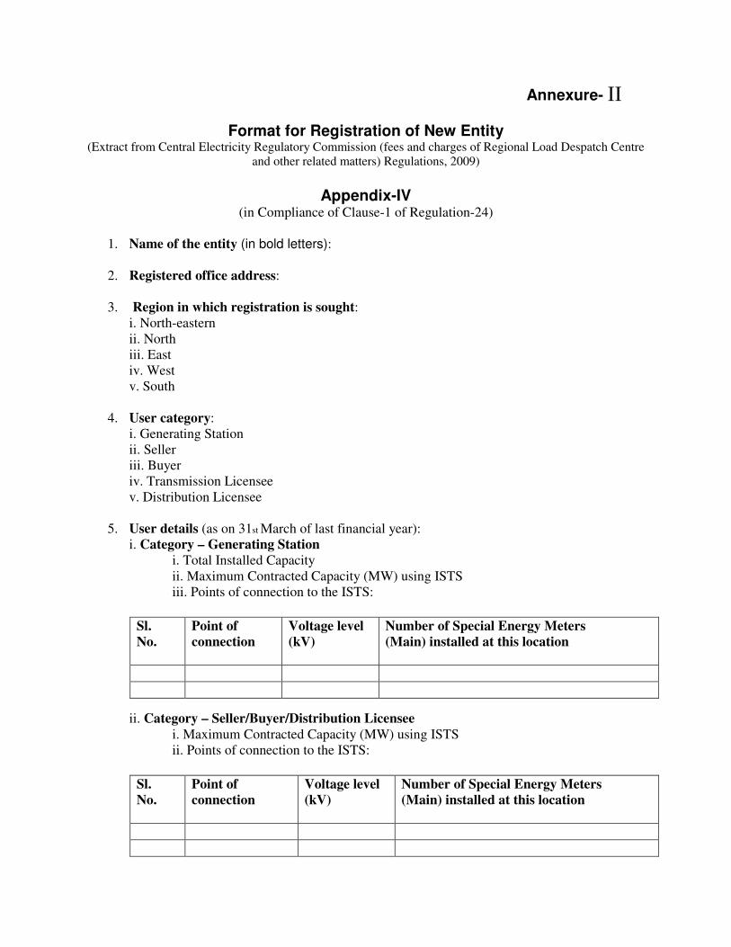
Annexure-
Format for Registration of New Entity (Extract from Central Electricity Regulatory Commission (fees and charges of Regional Load Despatch Centre
and other related matters) Regulations, 2009)
Appendix-IV
(in Compliance of Clause-1 of Regulation-24)
1. Name of the entity (in bold letters):
2. Registered office address:
3. Region in which registration is sought:
i. North-eastern
ii. North
iii. East
iv. West
v. South
4. User category:
i. Generating Station
ii. Seller
iii. Buyer
iv. Transmission Licensee
v. Distribution Licensee
5. User details (as on 31st March of last financial year):
i. Category – Generating Station
i. Total Installed Capacity
ii. Maximum Contracted Capacity (MW) using ISTS
iii. Points of connection to the ISTS:
ii. Category – Seller/Buyer/Distribution Licensee
i. Maximum Contracted Capacity (MW) using ISTS
ii. Points of connection to the ISTS:
Sl.
No.
Point of
connection
Voltage level
(kV)
Number of Special Energy Meters
(Main) installed at this location
Sl.
No.
Point of
connection
Voltage level
(kV)
Number of Special Energy Meters
(Main) installed at this location
II
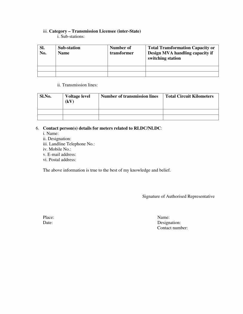
iii. Category – Transmission Licensee (inter-State)
i. Sub-stations:
ii. Transmission lines:
6. Contact person(s) details for meters related to RLDC/NLDC:
i. Name:
ii. Designation:
iii. Landline Telephone No.:
iv. Mobile No.:
v. E-mail address:
vi. Postal address:
The above information is true to the best of my knowledge and belief.
Signature of Authorised Representative
Place: Name:
Date: Designation:
Contact number:
Sl.
No.
Sub-station
Name
Number of
transformer
Total Transformation Capacity or
Design MVA handling capacity if
switching station
Sl.No.
Voltage level
(kV)
Number of transmission lines
Total Circuit Kilometers
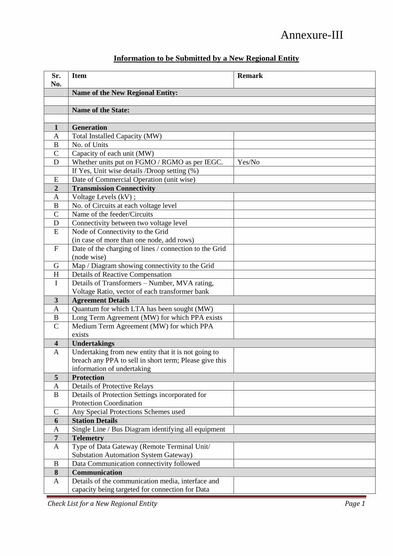
Check List for a New Regional Entity Page 1
Annexure-XI (B)
Information to be Submitted by a New Regional Entity
Sr.
No.
Item Remark
Name of the New Regional Entity:
Name of the State:
1 Generation
A Total Installed Capacity (MW)
B No. of Units
C Capacity of each unit (MW)
D Whether units put on FGMO / RGMO as per IEGC. Yes/No
If Yes, Unit wise details /Droop setting (%)
E Date of Commercial Operation (unit wise)
2 Transmission Connectivity
A Voltage Levels (kV) ;
B No. of Circuits at each voltage level
C Name of the feeder/Circuits
D Connectivity between two voltage level
E Node of Connectivity to the Grid
(in case of more than one node, add rows)
F Date of the charging of lines / connection to the Grid
(node wise)
G Map / Diagram showing connectivity to the Grid
H Details of Reactive Compensation
I Details of Transformers – Number, MVA rating,
Voltage Ratio, vector of each transformer bank
3 Agreement Details
A Quantum for which LTA has been sought (MW)
B Long Term Agreement (MW) for which PPA exists
C Medium Term Agreement (MW) for which PPA
exists
4 Undertakings
A Undertaking from new entity that it is not going to
breach any PPA to sell in short term; Please give this
information of undertaking
5 Protection
A Details of Protective Relays
B Details of Protection Settings incorporated for
Protection Coordination
C Any Special Protections Schemes used
6 Station Details
A Single Line / Bus Diagram identifying all equipment
7 Telemetry
A Type of Data Gateway (Remote Terminal Unit/
Substation Automation System Gateway)
B Data Communication connectivity followed
8 Communication
A Details of the communication media, interface and
capacity being targeted for connection for Data
Annexure-III
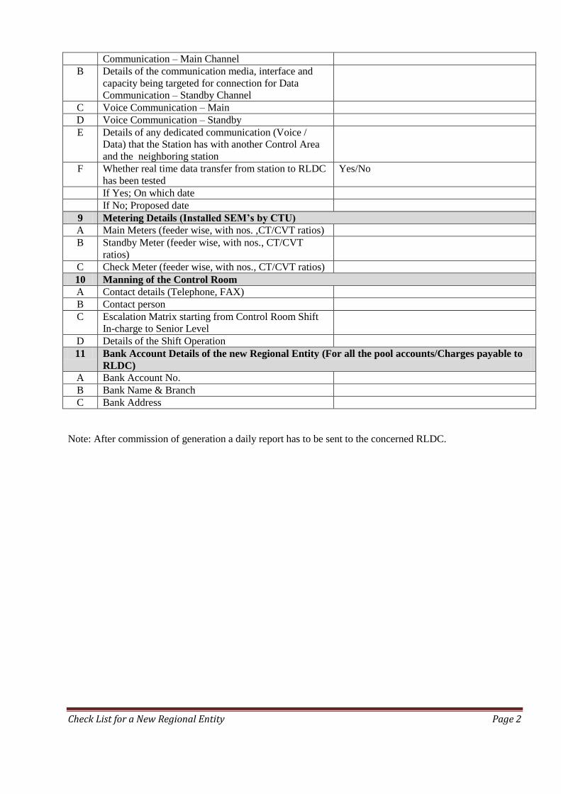
Check List for a New Regional Entity Page 2
Communication – Main Channel
B Details of the communication media, interface and
capacity being targeted for connection for Data
Communication – Standby Channel
C Voice Communication – Main
D Voice Communication – Standby
E Details of any dedicated communication (Voice /
Data) that the Station has with another Control Area
and the neighboring station
F Whether real time data transfer from station to RLDC
has been tested
Yes/No
If Yes; On which date
If No; Proposed date
9 Metering Details (Installed SEM’s by CTU)
A Main Meters (feeder wise, with nos. ,CT/CVT ratios)
B Standby Meter (feeder wise, with nos., CT/CVT
ratios)
C Check Meter (feeder wise, with nos., CT/CVT ratios)
10 Manning of the Control Room
A Contact details (Telephone, FAX)
B Contact person
C Escalation Matrix starting from Control Room Shift
In-charge to Senior Level
D Details of the Shift Operation
11 Bank Account Details of the new Regional Entity (For all the pool accounts/Charges payable to
RLDC)
A Bank Account No.
B Bank Name & Branch
C Bank Address
Note: After commission of generation a daily report has to be sent to the concerned RLDC.
Power System Operation Corporation Ltd.
(A Government of India Enterprise)
Procedure for First Time
Charging/Energization (FTC) and Integration of New or Modified Power System Element
[As per CERC (Terms and Conditions of Tariff) Regulations, 2019
(dated 07.03.2019)]
Document Name: NLDC/FTC
Document Creation Date: 24th May 2020
Version History Sr. No Description of Change Date of Change Revision No.
1 Initial Document 24th May 2020 0.0
Annexure - IV
Table of Contents Contents Page No
Introduction 1
Definitions and Interpretation 4
Section 1: Procedure for obtaining first time charging/clearance from RLDC & commencement of Grid Access for drawal of start-up power for conventional generating plants (Thermal, Gas & Hydro),Bulk Consumers or Load Serving Entities and Combined (Load & Captive) generation complex
6-180
Section 2: Procedure for Integration of Solar, Wind or Hybrid Power Plant/Wind or Solar Power Parks, WPD/SPD/HPD those are regional entities
181-239
Section3: Procedure for integration of a new or modified HVDC transmission elements and issue of certificate of successful trial operation by National Load Despatch Centre (NLDC)/ Regional Load Despatch Centres (RLDCs)
240-269
Section4: Procedure for integration of a STATCOM/SVC and issue of certificate of successful trial operation by Regional Load Despatch Centres (RLDCs)
270-283
Section5: Procedure for integration of a new or modified power system elements and issue of certificate of successful trial operation by National Load Despatch Centre (NLDC)/ Regional Load Despatch Centres (RLDCs)
284-310
INTRODUCTION This First time Charging(FTC) procedure is applicable to all the generating station those are regional entities (as defined in IEGC) as well as all the Power system elements belongs to 400kV level and above irrespective of ownership, 220 kV lines emanating from ISGS /ISTS substations, Inter Regional/ Inter-state/Transnational transmission lines irrespective of voltage level/ownership, HVDC links/poles irrespective of ownership, FACTS devices (TCSC/FSC/STATCOM/SVC) , Station Transformers (STs) connected at generating station those are regional entities.
Indian Electricity Grid Code provides for formulation of operating procedure by NLDC/RLDCs. The same is quoted below:
“A set of detailed operating procedures for the National grid shall be developed and maintained by the NLDC in consultation with the RLDCs, for guidance of the staff of the NLDC and it shall be consistent with IEGC to enable compliance with the requirement of this IEGC.
A set of detailed operating procedures for each regional grid shall be developed and maintained by the respective RLDC in consultation with the regional entities for guidance of the staff of RLDC. and shall be consistent with IEGC to enable compliance with the requirement of this IEGC.”
In accordance with the above provisions and as a part of NLDC/RLDC operating procedure, the first time charging procedure for energization and integration of new or modified power system element has been prepared. This procedure specifies the requirements to be fulfilled by the connectivity grantees prior to obtaining the permission of the RLDC/NLDC. This procedure specifies operational and study requirements for integration of new or modified power system elements with the grid.
For integrating the new or modified power system elements in the grid, the following are prerequisite before First time charging of Power system elements.
a) Power purchase Agreements(PPA), connectivity details and agreements b) Statutory clearances as per CEA or as per respective State government
authorities which ever applicable c) PTCC clearance Certificate d) Compliances of various regulation/standards of CERC and CEA e) Ensure to correct and appropriate settings of protection as per RPC
1
approved protection philosophy f) Provides Real time SCADA data and telemetry at NLDC/RLDCs g) Installation of meters as per provisions of CEA regulations h) Dedicated Voice/Data communication from generating /substation in
redundant and alternate path. i) Static and dynamic modelling data for system studies j) Compliances of relevant clauses of IEGC and operating procedures of
RLDCs k) Compliance to any other regulations and standards specified from time to
time
Based on the requirements, First Time Charging (FTC) procedure is prepared by NLDC/RLDCs to follow uniformly in all region and is divided into five sections as follows:
Section 1:- Provides the details of requirement for Integration of conventional generating plants (Thermal, Gas & Hydro), Bulk Consumers or Load Serving Entities and Combined (Load & Captive) generation complex
Section 2:- Provides the details of requirement for Integration of Solar, Wind or Hybrid Power Plant/Wind or Solar Power Parks, WPD/SPD/HPD those are regional entities
Section 3:- Describes the details of requirement for integration of a new or modified HVDC transmission elements and issue of certificate of successful trial operation by National Load Despatch Centre (NLDC)/ Regional Load Despatch Centres (RLDCs)
Section 4:- Provides the details of requirement for Procedure for integration of a STATCOM/SVC and issue of certificate of successful trial operation by Regional Load Despatch Centres (RLDCs)
Section 5:- Provides the details of requirement for integration of a new or modified power system elements and issue of certificate of successful trial operation by National Load Despatch Centre (NLDC)/ Regional Load Despatch Centres (RLDCs).
For integrating new or modified power system elements in the grid , all concerned shall have to submit the Annexures (A1-A6), (B1-B5) and (C1-C4) as per the time line mentioned in Section 5 of this document in addition to the requirement described in the respective Sections. Jurisdiction of NLDC/RLDCs for issuing charging code and trial certificate is as follows:
a) First time Charging code, subsequent testing codes will be issued as follows:
2
NLDC- Power system elements belongs to 765kV level, Inter Regional transmission lines irrespective of voltage level/ownership, inter regional HVDC transmission element, Intra-Regional ISTS HVDC transmission element and all transnational lines.
RLDC- Power system elements belongs to 400kV level irrespective of ownership, 220 kV lines emanating from ISGS /ISTS substations, Inter-state transmission lines irrespective of voltage level/ownership, Intra-State Non ISTS HVDC transmission element, FACTS devices(TCSC/FSC/STATCOM/SVC) , Station Transformers (STs) at generating station those are regional entities.; Generating station, Bulk Consumers or Load Serving Entities and Combined (Load & Captive) generation complex those are regional entities.
b) Trial Certificate will be issued as follows:
NLDC- Inter Regional transmission lines designated as ISTS irrespective of voltage level, inter regional HVDC links/Poles irrespective of ownership and all transnational lines.
RLDC- Transmission lines designated as ISTS irrespective of voltage level/ownership, Intra Regional HVDC links/poles connected as designated ISTS network, FACTS devices (TCSC/FSC/STATCOM/SVC) associated with designated ISTS; Generating station, Bulk Consumers or Load Serving Entities and Combined (Load & Captive) generation complex those are regional entities.
For Issuance of Trial operation certificate by NLDC/RLDC the following shall be ensured by all concerned
a. Compliance all the documents / sharing of data & information stated in respective Sections
b. Completion of trial operation as per CERC regulation/ procedure. c. Submitting the Annexure (C1-C4) as per FTC procedure.
SLDCs may follow a similar procedure for intra state elements too. This will help in bringing uniformity throughout the country for smooth operation of power system and in the interest of grid security This procedure supersedes all other FTC procedures issued earlier by NLDC/RLDCs.
3
Definitions and Interpretation (As defined in the Indian Electricity Grid Code)
1.1. In this procedure, unless the context otherwise requires, a. "Act" means the Electricity Act, 2003 (36 of 2003) and subsequent amendments
thereof;
b. "actual drawal" in a time-block means electricity drawn by a buyer, as the case may be, measured by the interface meters;
c. "actual injection" in a time-block means electricity generated or supplied by the
seller, as the case may be, measured by the Interface meters;
d. "beneficiary" means a person who has a share in an Inter-State Generating Station;
e. "Commission" means the Central Electricity Regulatory Commission referred to in sub-section (1) of section 76 of the Act;
f. "Deviation" in a time-block for a seller means its total actual injection minus its total
scheduled generation and for a buyer means its total actual drawal minus its total scheduled drawal;
g. “Disturbance Recorder (DR)” means a device provided to record the behaviour of the
pre-selected digital and analog values of the system parameters during an Event; h. “Event Logging Facilities” means a device provided to record the chronological
sequence of operations, of the relays and other equipment; i. "Grid Code" means the Grid Code specified by the Commission under clause (h) of
sub-section (1) of Section 79 of the Act; j. “Inter-State GeneratingSt ation (ISGS)” means a Central generating station or other
generating station, in which two or more states have Shares;
k. "interface meters" means interface meters as defined by the Central Electricity Authority under the Central Electricity Authority (Installation and Operation of Meters) Regulations, 2006, as amended from time to time;
l. “Inter State Transmission System (ISTS)” means
i) Any system for the conveyance of electricity by means of a main transmission line from the territory of one State to another State
ii) The conveyance of electricity across the territory of an intervening State as well as conveyance within the State which is incidental to such inter-state transmission of energy
iii) The transmission of electricity within the territory of State on a system built, owned, operated, maintained or controlled by CTU;
m. “Licensee” means a person who has been granted a license under Section 14 of the
Act; n. "Load Despatch Centre" means National Load Despatch Centre, Regional Load
4
Despatch Centre or State Load Despatch Centre, as the case may be, responsible for coordinating scheduling in accordance with the provisions of Grid Code;
o. "regional entity" means a person whose metering and energy accounting is done at
the regional level;
p. "Scheduled generation" at any time or for a time block or any period means schedule of generation in MW or MWh ex-bus given by the concerned Load Despatch Centre;
q. “Transmission License” means a License granted under Section 14 of the Act to transmit electricity;"time-block" means a time block of 15 minutes each for which special energy meters record values of specified electrical parameters with first time block starting at 00.00 hrs;
5
Section 1
Procedure for obtaining first time charging/clearance from RLDC & commencement of Grid Access for drawal of start-up power for conventional generating plants (Thermal, Gas & Hydro),Bulk Consumers or Load Serving Entities and Combined (Load & Captive) generation complex
6
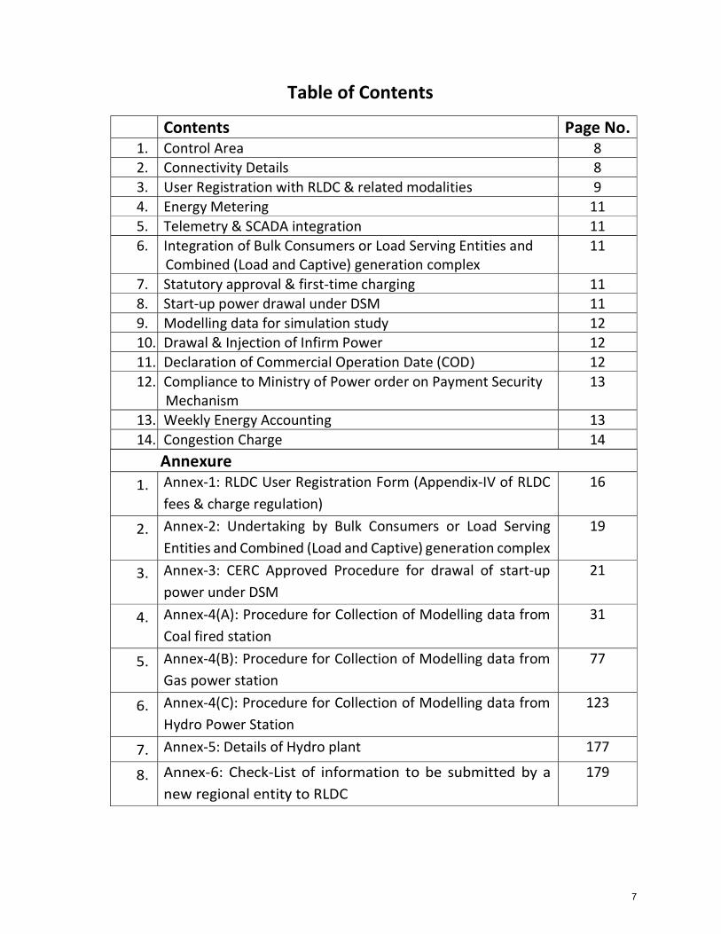
Table of Contents
Annexure 1. Annex-1: RLDC User Registration Form (Appendix-IV of RLDC
fees & charge regulation)16
2. Annex-2: Undertaking by Bulk Consumers or Load ServingEntities and Combined (Load and Captive) generation complex
19
3. Annex-3: CERC Approved Procedure for drawal of start-uppower under DSM
21
4. Annex-4(A): Procedure for Collection of Modelling data fromCoal fired station
31
5. Annex-4(B): Procedure for Collection of Modelling data fromGas power station
77
6. Annex-4(C): Procedure for Collection of Modelling data fromHydro Power Station
123
7. Annex-5: Details of Hydro plant 177
8. Annex-6: Check-List of information to be submitted by a new regional entity to RLDC
179
Contents Page No. 1. Control Area 8 2. Connectivity Details 8 3. User Registration with RLDC & related modalities 9 4. Energy Metering 11 5. Telemetry & SCADA integration 11 6. Integration of Bulk Consumers or Load Serving Entities and
Combined (Load and Captive) generation complex11
7. Statutory approval & first-time charging 11 8. Start-up power drawal under DSM 11 9. Modelling data for simulation study 12 10. Drawal & Injection of Infirm Power 12 11. Declaration of Commercial Operation Date (COD) 12 12. Compliance to Ministry of Power order on Payment Security
Mechanism13
13. Weekly Energy Accounting 13 14. Congestion Charge 14
7
Procedure for obtaining first time charging/clearance from RLDC & commencement of Grid Access for drawal of start-up power for conventional generating plants (Thermal, Gas & Hydro), Bulk Consumers or Load Serving Entities and Combined (Load and Captive) generation complex References:
1. CERC (Indian Electricity Grid Code Regulations) 2010 & subsequent amendments 2. CERC Approved Procedure for Drawl of Start-up power dated 12.08.2014 3. CERC (Deviation Settlement Mechanism) Regulation 2014 & amendments thereof 4. CERC (Fees and Charges of Regional Load Despatch Centre) Regulation 2019 5. CERC (Grand of Connectivity, Long Term Access and Medium Term Open Access in
Inter State Transmission) Regulation 2009 and amendments thereof 6. CEA (Installation of Operation of Meters) Regulation 2006 and any Amendments
thereof. 7. CEA (Technical standard for Connectivity to the Grid) Regulation, 2007& amendments 8. CEA(Measures relating to safety & electric supply) Regulations-2015 & amendments
1. Documents Submission to RLDC
The following documents shall be submitted by conventional generating plants (Thermal, Gas & Hydro), Bulk Consumers / Load Serving entitles (having min load of 100 MW and connected to ISTS) and Combined (load + captive generation( having an exportable capacity of 250MW into ISTS grid)) complex to respective RLDC before commencement of any startup activities of any Unit: 1. Control Area: Control Area jurisdiction of Generating station, Bulk Consumers or Load Serving Entities and Combined (Load & Captive) generation complex shall be in accordance with clause 6.4.2 of Chapter- 6 of IEGC-2010.
2. Connectivity Details: As per clause 4.1 of Indian Electricity Grid Code (IEGC) -2010, Central Transmission Utility (CTU) , State Transmission Utility (STU) and Users connected to, or seeking connection to Inter State Transmission System (ISTS) shall comply with the following: i. Central Electricity Authority (Technical Standards for connectivity to the Grid)
Regulations, 2007 which specifies the minimum technical and design criteria ii. Central Electricity Regulatory Commission (Grant of Connectivity, Long-term
Access and Medium-term Open Access in inter-state Transmission and related matters) Regulations,2009 and subsequent amendments thereof.
iii. CERC Approved Procedure for grant of connectivity to Inter State transmission system vide order dated 31.12.2009. A copy of the Connection agreement
8
(CON-6) shall be submitted to RLDC along with formats CON-3, CON-4, CON-5 as provided in the CERC approved Procedure.
iv. Similarly, any information on Long Term Access, Medium Term Open Access availed from CTU shall be submitted to RLDC along with copy of LTA/MTOA agreements, etc.
v. Copy of signed power purchase agreement as applicable to be submitted to the respective RLDC.
vi. As per clause 6.3 of the CERC Approved procedure dated 31.12.2009, the generating stations including captive generating station shall submit the likely date of synchronization, likely quantum and period of injection of infirm power before being put into commercial operation to the RLDC concerned at least one month in advance.
3. User Registration with RLDC & related modalities:
Generating Station, Bulk Consumers or Load Serving Entities and Combined (Load & Captive) generation complex is required to register as a ‘User ’ of RLDC for commencement of Grid Access as per Regulation-4(1) of CERC (Fees and Charges of Regional Load Despatch Centre & other related matters) Regulations-2019 which is applicable for the control period 1.4.2019 to 31.3.2024. Relevant clauses are quoted below. Quote:
“4. Registration : (1) The users shall register with the respective Regional Load Despatch Centre for commencement of Grid Access for availing system operation services of RLDC or NLDC as under:
a) All generating stations, distribution licensees and inter-State transmission licensees intending to avail the Grid Access shall register themselves with concerned Regional Load Despatch Centre responsible for scheduling, metering, energy accounting and switching operations, not less than 30 days prior to intended date of commencement of grid access, by filing an application in the format prescribed as Appendix-IV to these regulations:
Provided that when a unit is added to a generating station or an element is added to a transmission system, the generating company or transmission licensee, as the case may be, shall send an intimation to the concerned RLDC(s) for updating its records;
(2) The Regional Load Despatch Centre and the National Load Despatch Centre, as the case may be, after scrutinizing applications for registration and on being satisfied with correctness of the information furnished in the application shall register the applicant and send a written intimat’’ion to an applicant.
(3) The generating companies, distribution licensees, inter-State transmission licensees, power exchanges, traders, sellers and buyers shall pay the registration fees as specified in these Regulations.
9
(4) Regional Load Despatch Centres and National Load Despatch Centre shall maintain a list of registered users, licensees and Power Exchanges on their website along with their date of registration.”
Unquote:
The user registration form (Appendix-IV of the above regulation) is enclosed at Annex-1.
(i) Registration Fee: As per Regulation 29(2) Chapter-8 of the CERC (Fees and Charges of Regional Load Despatch Centre & other related matters) Regulations-2019, generating station is required to pay the applicable one time Registration fee for getting registered with Regional Load Despatch Centre (RLDC). The Relevant section of the above regulation [29(2)] is quoted below.
Quote:
“2) The generating companies shall pay registration fee as under:
a) For generating station upto 10 MW installed capacity: Rs 0.50 Lakh ;
b) Generating stations having installed capacity of not less than 10 MW and upto 100 MW:
Rs 1.0 Lakh ;
c) Generating stations having installed capacity of not less than 100 MW and up to 2000 MW: Rs 5.0 Lakh ;
d) Generating stations having capacity of 2000 MW and above: Rs 10.0 Lakh, and
Provided that the entire capacity of the generating station or stage thereof whose scheduling, metering and energy accounting is done separately shall be considered for the purpose of registration fee at the time of the initial registration;
Provided further that the generating companies shall intimate RLDC concerned about the additional capacity commissioned in case of generating station or stage thereof.”
Unquote:
The bank details for payment of ‘one time registration fee’ will be provided by RLDC.
(ii) Monthly Billing of RLDC Fees & Charges: As per Regulation 34 of Chapter 10 of CERC (RLDC Fees & Charges) Regulations 2019, RLDC will raise monthly ‘RLDC fees and charge bills’ to generating station. Accordingly, generating station shall make the monthly payments through RTGS to the bank account of RLDC.
10
4. Energy Metering: As per clause 6.4.21 of IEGC-2010, CTU, POWERGRID shall install special energy meters (SEMs) on all the inter connection between the regional entities and other identified points. Accordingly, RLDC shall work out the requirement of SEMs in line CEA (Installation & Operation of Meters)-Regulation-2006 & subsequent amendments after receipt of the Single Line switching Diagram of generating station indicating proposed path for drawal of start-up power. Subsequent to intimation from RLDC on the requirement of SEMs. Generating station shall coordinate with Regional HQ, POWERGRID, for procurement of the SEMs along with Data Collecting Device (DCD).
5. Telemetry & SCADA integration: As per clause 4.6.2 of IEGC-2010, All Users, STUs and CTU shall provide Systems to telemeter power system parameter such as flow, voltage and status of switches/ transformer taps etc. in line with interface requirements and other guideline made available by RLDC. The associated communication system to facilitate data flow up to appropriate data collection point on CTU’s system, shall also be established by concerned User, as specified by CTU in the connection agreement.
6. Integration of Bulk Consumers or Load Serving Entities and Combined (Load and Captive) generation complex:
System security to be ensured during the integration of Bulk Consumers or Load Serving Entities and Combined (Load and Captive) generation complex. Additional requirement to be fulfilled by Bulk Consumers or Load Serving Entities and Combined (Load and Captive) generation complex, other than the information mentioned in this procedure. Notarized Undertaking to be submitted to the owner of the of above-mentioned entities as per Annex-2.
7. Statutory approval & first-time charging
Statutory approval for energization from the Central Electricity Authority; Govt. of India in line with the CEA(Measures relating to safety & electric supply) Regulations-2015 & amendments) is to be submitted to RLDC before energization of any Electrical Installation at your end. First time charging of any new or modified power system element is carried out as per the procedure for integration of a new or modified power system elements. Charging will be allowed only after submission of the information mentioned in Procedure for integration of a new or modified power system elements & after obtaining necessary approval from respective RLDC.
8. Start-up power drawal under DSM: As per the Hon’ble CERC Notification dated 12th Aug 2014 on 4th Amendment to CERC(Grant of Connectivity, Long-term Access(LTA) and Medium-term Open Access (MTOA) in inter-state
11
transmission and related matters) Regulations, 2014 and the CERC Approved Procedure for availing start-up power from the grid by generating stations under commissioning phase through deviation settlement mechanism (DSM), Generating station has to follow the enclosed procedure at Annex-3, before commencement of any activity. All the documents to be submitted as mentioned in the enclosed procedure at Annex-3 including the duly filled “Application form seeking start up power” which is a part of the procedure.
9. Modelling data for simulation study: Modelling data for simulation study for the Thermal, Gas and Hydro generating station to be submitted as per Annex-4(A),Annex-4(B) and Anne4(C) respectively. For the Bulk Consumers / Load Serving entitles and Combined (load +captive Generation) complex, Mathematical model (if any) shared with CTU for carrying out interconnection study to be shared with respective RLDC. Hydro plants reservoir details such as FRL, MDDL, monthly design energy/10 daily energy, rated cumecs and rated head, energy content of reservoir and water content details to be provided as per Annex-5. Further a check list of items/information has to be submitted by any new regional entity generator as per the format enclosed at Annex-6.
10. Drawal & Injection of Infirm Power
As per clause Regulation 8(7) of the CERC(Grant of Connectivity, LTA and MTOA in ISTS and related matters)Regulations-2009, and amendments thereof, any generating station, including captive generating plant which has been granted connectivity to the grid shall be allowed to undertake testing including full load testing by injecting infirm power into the grid before being put into commercial operation, even before availing any type of open access, after obtaining permission of the concerned RLDC, which shall keep the grid security in view while granting such permission and the power injected into the grid as a result of this testing. It shall be charged at the rate specified in CERC (Deviation Settlement Mechanism & related matters)-Regulations-2014 as amended from time to time.
a) During the period of drawal / injection of infirm power, RLDC Control Room should be intimated in advance, the scheduled pattern of quantum of drawl / infirm injection and tripping and synchronization of the unit.
b) For any switching operation necessary codes have to be exchanged with RLDC control room
11. Declaration of Commercial Operation Date (COD)
CoD declaration of units of generating station shall be in line with 6.3A of the Grid Code (IEGC) 4th amendment regulations. Accordingly, after completion of the trial run, details to be
12
forwarded to RLDC along with the CoD declaration letter. Relevant clauses/definitions are given under for ready reference.
i. IEGC 6.3A.1: “Date of Commercial Operation (CoD)(Thermal Generating Unit)-In case of a unit of thermal Central Generating Stations or inter-State Generating Station shall mean the date declared by the generating company after demonstrating the unit capacity corresponding to its Maximum Continuous Rating (MCR) or the Installed Capacity (IC) or Name Plate Rating on designated fuel through a successful trial run and after getting clearance from the respective RLDC or SLDC, as the case may be, and in case of the generating station as a whole, the date of commercial operation of the last unit of the generating station”.
ii. IEGC 6.3A.2: “Date of Commercial Operation (CoD)(Hydro Generating Unit)-In case of a unit of hydro generating station including pumped storage hydro generating station shall mean the date declared by the generating company after demonstrating peaking capability corresponding to the Installed Capacity of the generating station through a successful trial run, and after getting clearance from the respective RLDC or SLDC, as the case may be, and in relation to the generating station as a whole, the date of commercial operation of the last generating unit of the generating station.
iii. IEGC 6.3A.3: Trial Run in relation to a thermal Central Generating Station or inter-State Generating Station or a unit thereof shall mean the successful running of the generating station or unit thereof at maximum continuous rating or installed capacity for continuous period of 72 hours in case of unit of a thermal generating station or unit thereof and 12 hours in case of a unit of a hydro generating station or unit thereof.
iv. The Generating company shall issue a certificate in compliance to clause 6.3A.1.(iii) or clause 6.3A.2.(iii) of IEGC (whichever applicable), signed by CMD/CEO/MD of the company with a copy to Member Secretary of the concerned Regional Power Committee (RPC) and Head of Concerned Regional Load Despatch Centre.
v. The generating company shall submit approval of Board of Directors to the certificates as required under IEGC clause 6.3A.1.(iii) or clause 6.3A.2.(iii)(whichever applicable) within a period of 3 months of the COD of its unit.
vi. Trial Certificate of conventional generating plants (Thermal, Gas & Hydro) will be issued by respective RLDC.
12. Compliance to Ministry of Power order on Payment Security Mechanism – Generating station shall comply with the orders of Ministry of Power pertaining to Payment Security Mechanism. As per the orders generating station shall provide status of LC opened by its beneficiaries to RLDC. Further, the daily status shall be provided on web link https://psa.posoco.in/. Appropriate login credentials for providing status of availability of Payment security will be provided after registration with RLDC.
13. Weekly Energy Accounting: As per CERC (Deviation Settlement Mechanism and related matters) Regulations (as amended) generating station shall become the RLDC DSM pool member after
13
commencement of commissioning activities of its first generating unit. RPC Secretariat, would release weekly bills for DSM through their respective web site. Transfer of DSM receivable/payable amount for beneficiaries without any additional charges is through Regional DSM Pool Account. The Regional DSM Pool account fund is operated by RLDC. The weekly DSM payment to be made by generating station (if any) after commencement of the commissioning activities of its 1st unit, shall be credited to the account.
Generating station has to furnish the requisite details about their bank account where DSM charges receivable (if any) by generating station shall be made from the Regional DSM pool account fund.
Weekly meter data collection and sending the same to RLDC is the responsibility of the utility in whose premises the SEMs are installed. Since commercial accounting is carried out on weekly basis, generating station shall collect the data on every Monday and the same shall be transmitted to RLDC by every Monday through e-mail to the respective RLDC’s e-mail addresses.
14. Congestion Charge:
Congestion charges has been defined in cl. 2 (d) of the CERC (Measures to relieve congestion in real time operation” Regulation-2009 (and amendments thereof) as under: Quote “Congestion charge” means the supplementary charge kicked in on one or more Regional entities in one or more Regions for transmission of power from one Region to another Region or from one State to another State within the a Region when deviations from the schedule cause the net drawal of power in the inter-regional or intra-regional transmission links to go beyond the Total Transfer Capability limit. Unquote RPC Secretariat, would release statement for the purpose of payment of congestion charge through their web site as and when congestion charge would be imposed. RLDC has made necessary arrangement with bank for implementation of RTGS system for quick transfer of congestion charges for beneficiaries without any additional charges. The congestion charge payment, to be made by generating station (if any), after synchronization of its 1st unit with Regional grid, shall be credited to the RLDC congestion charge account. Generating station has to furnish the requisite details about their bank account, where congestion charge receivable (if any) by generating station is to be made from the RLDC Congestion Charge (pool) account. Generating station has to Nominate representatives (with contact number and e-mail details) for co-ordination of daily scheduling and weekly data transmission to RLDC.
Enclosures. Annex-1: RLDC User Registration Form (Appendix-IV of RLDC fees & charge regulation) Annex-2: Undertaking by Bulk Consumers or Load Serving Entities and Combined (Load and Captive) generation complex
14
Annex-3: CERC Approved Procedure for drawal of start-up power under DSM Annex-4(A): Procedure for Collection of Modelling data from Coal fired station Annex-4(B): Procedure for Collection of Modelling data from Gas power station Annex-4(C): Procedure for Collection of Modelling data from Hydro Power Station Annex-5: Details of Hydro plant Annex-6: Check-List of information to be submitted by a new regional entity to RLDC
Other than the documents mentioned above the formats for first time charging of power system elements (Format A1-A6, B1-B5 and C1-C4) to be submitted to RLDC.
15

Annex-1
Appendix-IV
[in Compliance of Regulation-4 of CERC (RLDC Fees & Charges) Regulations 2015]
1. Name of the entity (in bold letters):
2. Registered office address:
3. Region in which registration is sought:
i. North-eastern
ii. North
iii. East
iv. West
v. South
4. User category:
i. Generating Station
ii. Seller
iii. Buyer
iv. Transmission Licensee
v. Distribution Licensee
5. User details (as on 31st March of last financial year):
i. Category – Generating Station
i. Total Installed Capacity
ii. Maximum Contracted Capacity (MW) using ISTS
iii. Points of connection to the ISTS:
Sl.No. Point of connection Voltage level (kV) Number of Special Energy
Meters
(Main) installed at this location
ii. Category – Seller/Buyer/Distribution Licensee
i. Maximum Contracted Capacity (MW) using ISTS
16
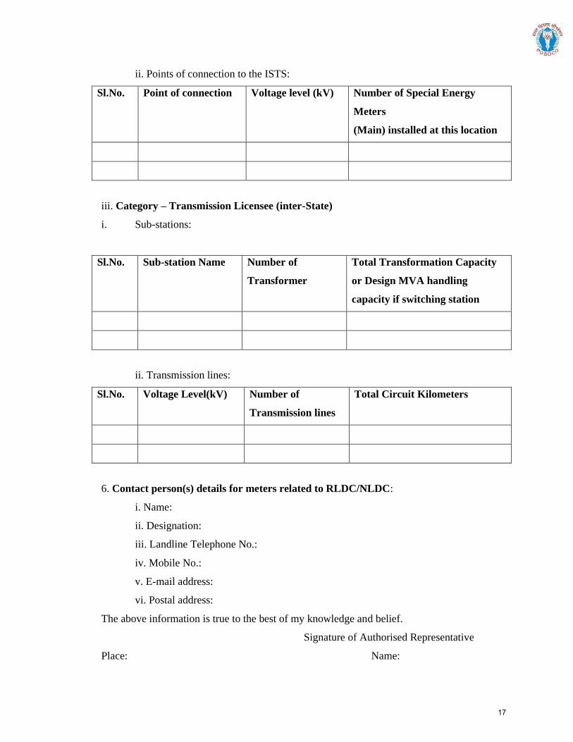
ii. Points of connection to the ISTS:
Sl.No. Point of connection Voltage level (kV) Number of Special Energy
Meters
(Main) installed at this location
iii. Category – Transmission Licensee (inter-State)
i. Sub-stations:
Sl.No. Sub-station Name Number of
Transformer
Total Transformation Capacity
or Design MVA handling
capacity if switching station
ii. Transmission lines:
Sl.No. Voltage Level(kV) Number of
Transmission lines
Total Circuit Kilometers
6. Contact person(s) details for meters related to RLDC/NLDC:
i. Name:
ii. Designation:
iii. Landline Telephone No.:
iv. Mobile No.:
v. E-mail address:
vi. Postal address:
The above information is true to the best of my knowledge and belief.
Signature of Authorised Representative
Place: Name:
17

Date: Designation:
Contact number:
18
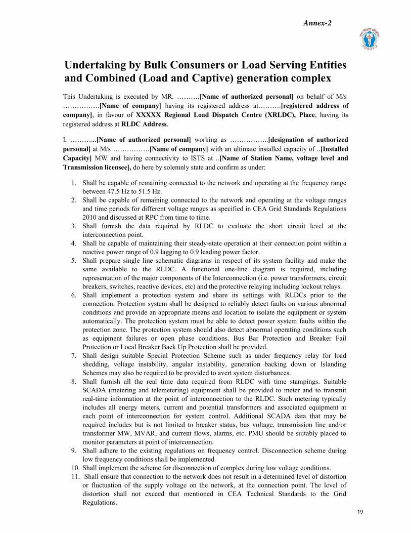
Undertaking by Bulk Consumers or Load Serving Entities and Combined (Load and Captive) generation complex
This Undertaking is executed by MR. ……….[Name of authorized personal] on behalf of M/s …………….[Name of company] having its registered address at……….[registered address of company], in favour of XXXXX Regional Load Dispatch Centre (XRLDC), Place, having its registered address at RLDC Address.
I, ………...[Name of authorized personal] working as ……………..[designation of authorized personal] at M/s …………….[Name of company] with an ultimate installed capacity of ..[Installed Capacity] MW and having connectivity to ISTS at ..[Name of Station Name, voltage level and Transmission licensee], do here by solemnly state and confirm as under:
1. Shall be capable of remaining connected to the network and operating at the frequency rangebetween 47.5 Hz to 51.5 Hz.
2. Shall be capable of remaining connected to the network and operating at the voltage rangesand time periods for different voltage ranges as specified in CEA Grid Standards Regulations2010 and discussed at RPC from time to time.
3. Shall furnish the data required by RLDC to evaluate the short circuit level at theinterconnection point.
4. Shall be capable of maintaining their steady-state operation at their connection point within areactive power range of 0.9 lagging to 0.9 leading power factor.
5. Shall prepare single line schematic diagrams in respect of its system facility and make thesame available to the RLDC. A functional one-line diagram is required, includingrepresentation of the major components of the Interconnection (i.e. power transformers, circuitbreakers, switches, reactive devices, etc) and the protective relaying including lockout relays.
6. Shall implement a protection system and share its settings with RLDCs prior to theconnection. Protection system shall be designed to reliably detect faults on various abnormalconditions and provide an appropriate means and location to isolate the equipment or systemautomatically. The protection system must be able to detect power system faults within theprotection zone. The protection system should also detect abnormal operating conditions suchas equipment failures or open phase conditions. Bus Bar Protection and Breaker FailProtection or Local Breaker Back Up Protection shall be provided.
7. Shall design suitable Special Protection Scheme such as under frequency relay for loadshedding, voltage instability, angular instability, generation backing down or IslandingSchemes may also be required to be provided to avert system disturbances.
8. Shall furnish all the real time data required from RLDC with time stampings. SuitableSCADA (metering and telemetering) equipment shall be provided to meter and to transmitreal-time information at the point of interconnection to the RLDC. Such metering typicallyincludes all energy meters, current and potential transformers and associated equipment ateach point of interconnection for system control. Additional SCADA data that may berequired includes but is not limited to breaker status, bus voltage, transmission line and/ortransformer MW, MVAR, and current flows, alarms, etc. PMU should be suitably placed tomonitor parameters at point of interconnection.
9. Shall adhere to the existing regulations on frequency control. Disconnection scheme duringlow frequency conditions shall be implemented.
10. Shall implement the scheme for disconnection of complex during low voltage conditions.11. Shall ensure that connection to the network does not result in a determined level of distortion
or fluctuation of the supply voltage on the network, at the connection point. The level ofdistortion shall not exceed that mentioned in CEA Technical Standards to the GridRegulations.
Annex-2
19
12. Shall submit the simulation modelling data to RLDC in the format required. Also carry out simulations and furnish the results whether interconnection is safe and reliable or not.
Place: Signature:
Date: Name of the authorized personal: Designation of the authorized person:
210
20
No. L-1/(93)/2009-CERC Dated: 12th August, 2014
To, Shri S.K. Sonee Chief Executive Officer Power System Operation Corporation Limited, B-9, First Floor, Qutab Institutional Area, Katwaria Sarai, New Delhi-110 016
Sub: Approval of the procedure for drawal of startup power
Dear Sir,
I am directed to refer to your letter nos. POSCO/CERC dated 14.11.2013 and 13.3.2014 and to say that the Commission has approved the Procedure for drawal of startup power for new generating stations, 2014 as per the Annexure attached to this letter. It is requested that wide publicity to the Procedure be given by POSOCO for the information of all concerned.
Thanking you, Yours faithfully
sd/- (Shubha Sarma)
Secretary
Annex-3
21
Procedure for availing Start up power from the Grid by the Generating Stations
under commissioning phase through Deviation Settlement Mechanism
This procedure is called Procedure for drawal of Start-up Power for new
Generating Stations, 2014.
This procedure describes the methodology to be followed by the
upcoming Generating Stations seeking to avail start-up power during
commissioning period.
This procedure is applicable to Generating stations without an existing
Unit under Commercial operation. Where one unit has been
commissioned and if the startup power is required by subsequent unit(s),
the same may be availed from the existing units of the same plant under
Commercial operation. In such case, the existing units shall factor the
requirement of startup power by the new upcoming units before
contracting/scheduling the entire sent out capability under STOA so that
there will not be any under injection by the existing unit(s).
However, in case power from the unit(s) of the generating station already
commissioned is fully allocated or committed under Medium Term Open
Access (MTOA)/Long Term Access (LTA), subsequent unit(s) shall be
allowed to draw Start-up power under this procedure.
1. Scope :
This Procedure shall be followed by all Regional Load Despatch Centres
(RLDCs), Regional Power Committees (RPCs) and Generating stations
including Inter-state Generating Stations (ISGS) under Seller category.
2. Definitions:
(a) Construction Power: Power required for carrying out
construction/erection works of plant and equipment of a new
Generating Station including services such as desalination of sea
water, etc.
(b) Start-Up Power: Power required for running the Auxiliary equipment for
commissioning activities of a new Generating Station.
22

(c) Auxiliary power: Power required to keep the auxiliaries like Motor Driven
Boiler Feed Pump (MDBFP), Induced Draft (ID) Fan, Forced Draft (FD) Fan,
Cooling Water (CW) pumps, etc, running after tripping of a generating
unit during its trial operation.
3. General :
The Generating station may avail Start-up power under Deviation Settlement
Mechanism from Inter-State Transmission System.
4. Pre-conditions for availing Start-up power under Deviation Settlement
Mechanism:
The Generating Station intending to avail Start-up power shall fulfil the
following conditions:
(1) It has a valid Connectivity granted by CTU as per CERC (Grant of
Connectivity, Long-term Access and Medium-term Open Access and
related matters) Regulations, 2009 (hereinafter referred to as
Connectivity Regulations)
(2) It has signed Connection Agreement as per Con-6 of the
Connectivity Regulations
(3) It has established Connectivity with the ISTS
(4) It has commissioned all the switchyard equipments including Bus /
Line reactor if any as per the grant of Connectivity (Con-3).
(5) It has established Data and Voice communication with the
concerned RLDC as per clause 4.6.2 of IEGC
(6) It has put in place necessary system protection in place as specified
by concerned Regional Power Committee (RPC).
(7) It shall coordinate Generation Transformer (GT) / Station Transformer
(ST) tap positions as per the direction of concerned Regional Load
Despatch Centre (RLDC).
5. Procedure for applying for Start-up power:
5.1 The Generating Station shall submit a request for availing Start-up
power to the concerned RLDC at least one month prior to the expected date
of availing Start-up power i.e 16 months before the expected date of first
synchronisation of the unit.
5.2 While requesting for start-up power, the Generating Station shall
furnish the following details to the concerned RLDC:
23
(1) A copy of Connectivity approval granted by CTU along with the
details of arrangement for drawing start up power ,
(2) Connection Agreement signed with CTU and other ISTS licensees
as the case may be
(3) Single line diagram of the Generating Station
(4) Inspection report of the Electrical Inspectorate of Central Electricity
Authority (CEA).
(5) Details of electrical scheme for drawal of construction power
clearly establishing the isolation between the schemes for
construction power and start up power.
(6) Details of electrical scheme for drawal of start-up power by various
phases of the Generating station.
(7) Unit details like Unit size, MCR, Auxiliaries & their rating etc.
(8) Schedule of activities and their requirement of power in terms of
quantity and period etc.
5.3 The Generating Station shall submit an undertaking that :
(1) Drawal of power is only for the purpose of start-up power and not
for the construction activity. The onus of proving that the drawal of
power is for startup of Auxiliaries, testing and commissioning
activities and not for Construction power shall lie with the
generating station alone.
(2) There is no violation of any of the agreements made with the
Distribution Licensee or any other agency.
(3) The Generating Station shall indemnify, defend and save the
SLDCs/RLDCs harmless from any and all damages, losses, claims
and actions including those relating to injury or death of any
person or damage to property, demands, suits, recoveries, costs
and expenses, court costs, attorney fees, and all other obligations
by or to third parties, arising out of or resulting from this drawal.
(4) The Generating Station shall abide by IEGC and all prevailing
Regulations and the directions of RLDC from time to time.
(5) The Generating Station shall reschedule the start up activities as
directed by RLDC due to reasons such as staggering the
simultaneous drawal of Start-up power by other Generating
Stations.
(6) The Generating Station shall pay the charges for Deviation within
due date and comply with Deviation Settlement Regulations, 2014
24
as amended from time to time or subsequent re-enactment
thereof.
(7) The Generating Station shall send the Special Energy Meter (SEM)
data to RLDC as per the provisions of IEGC for energy accounting.
(8) The Generating Station shall pay all incidental charges such as
Transmission charges, RLDC Fee & Charges, etc., as applicable,
within the due date.
(9) The Generator shall open a Revolving and Irrevocable Letter of
Credit issued by a Scheduled Bank equivalent to 2 months
transmission charges prior to drawal of Start-up power.
5.4 The Generator shall update the following information during the
period of availing the Start-up Power and likely date of first synchronisation
of the unit and subsequent program for injection of infirm power :
(1) The quantum of power to be availed on a weekly basis.
(2) The schedule is to be updated on a weekly basis, considering the
deviations in the tentative schedule.
(3) Monthly Energy data of Construction power availed from the local
licensee for the past 6 months period and monthly readings for the
period subsequent to availing start-up power.
(4) Monthly details of start-up activities carried out during the month.
The Generating Station shall also indicate whether all activities are as
per commissioning schedule or not.
6. Procedure to be followed by RLDC during the period of availing
Startup power :
6.1 The concerned RLDC shall convey the period, quantum and
duration of the Start-up power with a copy to RPC and SLDC, if
required.
6.2 RLDC may permit drawal of Start-up power for one or more units at
a time within a generating station keeping grid security in view.
6.3 RLDC will issue suitable directions to the Generating Station on Real
time basis for limiting / stopping the drawal of start-up power in case
of Network constraint on grounds of threat to system security or
frequency or Voltage falling below the limits specified in IEGC. Such
direction shall be complied by the Generating Station promptly.
25
6.4 The generator is entitled to draw the start-up power under Deviation
Settlement Mechanism, up to the maximum period of 21 months
(Fifteen months prior to expected date of synchronization and six
months after synchronization) from the date of commencement of
drawal of start-up power from the grid. In case startup power is
required beyond the specified period, the generator shall
approach C.E.R.C at least two months in advance of the date up to
which permission has been granted.
6.5 RLDC may direct the Generating Station to install under-
frequency/under voltage relays to operate below a threshold value
with suitable dead bands.
6.6 If simultaneous drawal of start-up power by more than one
generating station is likely to cause system constraints, RLDC may
stagger such drawal among various generators to relieve the
constraint.
26
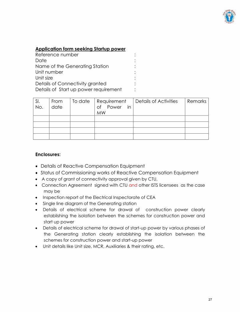
Application form seeking Startup power
Reference number :
Date :
Name of the Generating Station :
Unit number :
Unit size :
Details of Connectivity granted :
Details of Start up power requirement :
Sl.
No.
From
date
To date Requirement
of Power in
MW
Details of Activities Remarks
Enclosures:
Details of Reactive Compensation Equipment
Status of Commissioning works of Reactive Compensation Equipment
A copy of grant of connectivity approval given by CTU,
Connection Agreement signed with CTU and other ISTS licensees as the case
may be
Inspection report of the Electrical Inspectorate of CEA
Single line diagram of the Generating station
Details of electrical scheme for drawal of construction power clearly
establishing the isolation between the schemes for construction power and
start up power
Details of electrical scheme for drawal of start-up power by various phases of
the Generating station clearly establishing the isolation between the
schemes for construction power and start-up power
Unit details like Unit size, MCR, Auxiliaries & their rating, etc.
27
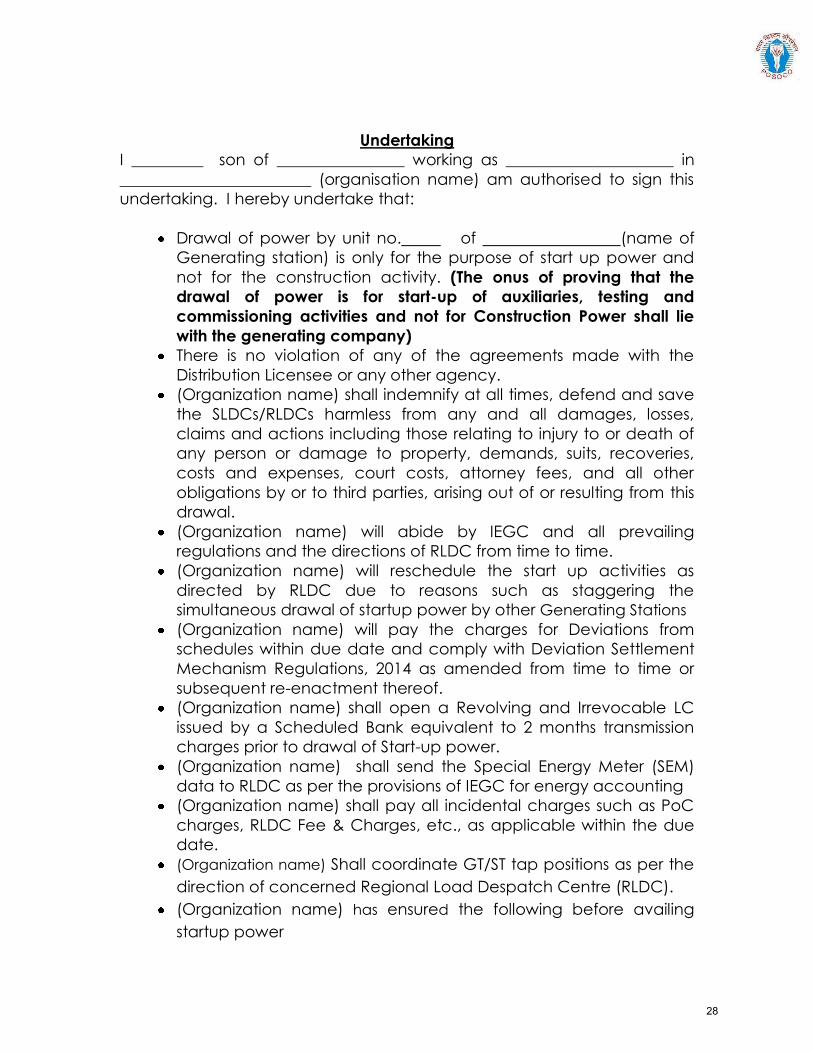
Undertaking
I _________ son of ________________ working as _____________________ in
________________________ (organisation name) am authorised to sign this
undertaking. I hereby undertake that:
Drawal of power by unit no. of (name of
Generating station) is only for the purpose of start up power and
not for the construction activity. (The onus of proving that the
drawal of power is for start-up of auxiliaries, testing and
commissioning activities and not for Construction Power shall lie
with the generating company)
There is no violation of any of the agreements made with the
Distribution Licensee or any other agency.
(Organization name) shall indemnify at all times, defend and save
the SLDCs/RLDCs harmless from any and all damages, losses,
claims and actions including those relating to injury to or death of
any person or damage to property, demands, suits, recoveries,
costs and expenses, court costs, attorney fees, and all other
obligations by or to third parties, arising out of or resulting from this
drawal.
(Organization name) will abide by IEGC and all prevailing
regulations and the directions of RLDC from time to time.
(Organization name) will reschedule the start up activities as
directed by RLDC due to reasons such as staggering the
simultaneous drawal of startup power by other Generating Stations
(Organization name) will pay the charges for Deviations from
schedules within due date and comply with Deviation Settlement
Mechanism Regulations, 2014 as amended from time to time or
subsequent re-enactment thereof.
(Organization name) shall open a Revolving and Irrevocable LC
issued by a Scheduled Bank equivalent to 2 months transmission
charges prior to drawal of Start-up power.
(Organization name) shall send the Special Energy Meter (SEM)
data to RLDC as per the provisions of IEGC for energy accounting
(Organization name) shall pay all incidental charges such as PoC
charges, RLDC Fee & Charges, etc., as applicable within the due
date.
(Organization name) Shall coordinate GT/ST tap positions as per the
direction of concerned Regional Load Despatch Centre (RLDC).
(Organization name) has ensured the following before availing
startup power
28
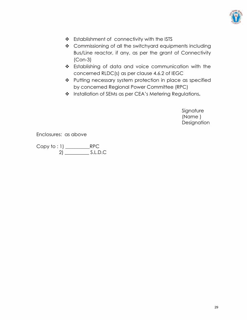
Establishment of connectivity with the ISTS
Commissioning of all the switchyard equipments including
Bus/Line reactor, if any, as per the grant of Connectivity
(Con-3)
Establishing of data and voice communication with the
concerned RLDC(s) as per clause 4.6.2 of IEGC
Putting necessary system protection in place as specified
by concerned Regional Power Committee (RPC)
Installation of SEMs as per CEA’s Metering Regulations.
Signature
(Name )
Designation
Enclosures: as above
Copy to : 1) __________RPC
2) __________ S.L.D.C
29
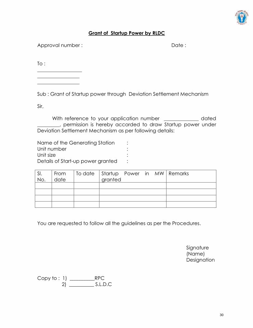
Grant of Startup Power by RLDC
Approval number : Date :
To :
__________________
_________________
_________________
Sub : Grant of Startup power through Deviation Settlement Mechanism
Sir,
With reference to your application number ______________ dated
_________, permission is hereby accorded to draw Startup power under
Deviation Settlement Mechanism as per following details:
Name of the Generating Station :
Unit number :
Unit size :
Details of Start-up power granted :
Sl.
No.
From
date
To date Startup Power in MW
granted
Remarks
You are requested to follow all the guidelines as per the Procedures.
Signature
(Name)
Designation
Copy to : 1) __________RPC
2) __________ S.L.D.C
30
Guideline for furnishing information for modelling Coal fired generation in Indian Grid
1.0 Introduction:
The purpose of this document is to act as a guideline for exchange of information for accurate modelling of coal fired thermal generation in India. Availability of fit-for-purpose steady state and dynamics models of coal fired thermal stations will enable secure operation of Indian power grid and enable identification of potential weak points in the grid so as to take appropriate remedial actions.
1.1 Applicability:
The guideline shall be applicable to all coal fired thermal generation in India that can have an impact on operation of the power grid of India, irrespective of connection at Intra-STS or ISTS (Inter-state Transmission System).
This document presents the desired information for collection of data for modelling of coal fired thermal generation in PSS/E software, a software suite being used pan-India at CEA, CTU, SLDCs, RLDCs, and NLDC for modelling of India’s power grid. A systematic set of data and basic criteria for furnishing data are presented.
1.2 Need for a fit-for-purpose model:
There is a cost involved in developing and validating dynamic models of power system equipment. But there are much higher benefits for the power system if this leads to a functional, fit-for-purpose model, and arrangements that allow that model to be maintained over time.
A functional fit-for-purpose dynamic model will:
• Facilitate significant power system efficiencies by allowing power system operations toconfidently identify the secure operating envelope and thereby manage security effectively
• Allow assessment of impact on grid elements due to connection of new elements (networkelements, generators, or loads) for necessary corrective actions
• Permit power system assets to be run with margins determined on the basis of securityassessments
• Facilitate the tuning of control systems, such as power system stabilizers, voltage- andfrequency-based special control schemes etc.
• Improve accuracy of online security tools, particularly for unusual operating conditions, which inturn is likely to result in higher reliability of supply to power system users.
The power system model would enable steady state and electromechanical transient simulation studies that deliver reasonably accurate outcomes.
Annex-4(A)
31
1.3 Regulation:
CEA Connectivity Standard 6.4.d :
The requester and user shall cooperate with RPC and Appropriate Load Despatch Centre in respect of the matters listed below, but not limited to
furnish data as required by Appropriate Transmission Utility or Transmission Licensee, Appropriate Load Despatch Centre, Appropriate Regional Power Committee and any committee constituted by the Authority or appropriate Government for system studies or for facilitating analysis of tripping or disturbance in power system;
Here Requester and User Includes a generating company, captive generating plant, energy storage system, transmission licensee (other than Central Transmission Utility and State Transmission Utility), distribution licensee, solar park developer, wind park developer, wind-solar photovoltaic hybrid system, or bulk consumer (2019 Amendment)
IEGC 4.1 :
CTU, STU and Users connected to, or seeking connection to ISTS shall comply with Central Electricity Authority (Technical Standards for connectivity to the Grid) Regulations, 2007 which specifies the minimum technical and design criteria and Central Electricity Regulatory Commission (Grant of Connectivity, Long-term Access and Medium-term Open Access in inter-state Transmission and related matters) Regulations,2009.
2.0 Coal fired thermal generation technologies:
Coal fired power plants typically burn coal to heat a boiler that produces high-temperature, high-pressure steam that is passed through the turbine to produce mechanical energy (IEEE Power and Energy Society, 2013).
Coal fired power plants constitute 54.70% of India’s installed generation capacity as on 31.12.2018, and supply around 75% of energy as on 21.02.2019. The Indian Power Sector initially comprised of sub-100MW steam-driven generators in the 1970’s, until the first 200 MW generating unit was introduced in 1977. This became almost the standard size and most generating units added during the next two decades were of 200/210 MW.
The first 500 MW unit was subsequently commissioned in 1984 and a number of 500 MW units have been commissioned since then. These 200/210 and 500 MW units form the backbone of Indian Power Sector. Meanwhile, 250 MW units have also evolved by upgrading the turbine design of existing 210 MW generating units. In last decade, super-critical plants have been commissioned of magnitude 600/660 MW and 800 MW size.
The majority of commercially available coal fired thermal generators use one of the three technologies depending upon the stream pressure within the boiler as listed below:
Annex-3(A)
32
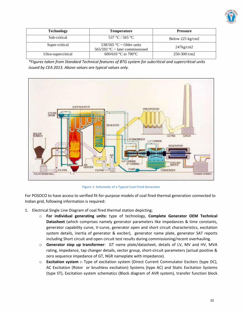
Technology Temperature Pressure Sub-critical 537 °C / 565 °C Below 225 kg/cm2
Super-critical 538/565 °C ~ Older units 565/593 °C ~ later commissioned 247kg/cm2
Ultra-supercritical 600/610 °C to 700°C 250-300 /cm2
*Figures taken from Standard Technical features of BTG system for subcritical and supercritical units issued by CEA 2013. Above values are typical values only.
Figure 1: Schematic of a Typical Coal Fired Generator
For POSOCO to have access to verified fit-for-purpose models of coal fired thermal generation connected to Indian grid, following information is required:
1. Electrical Single Line Diagram of coal fired thermal station depicting; o For individual generating units: type of technology, Complete Generator OEM Technical
Datasheet (which comprises namely generator parameters like impedances & time constants, generator capability curve, V-curve, generator open and short circuit characteristics, excitation system details, inertia of generator & exciter), generator name plate, generator SAT reports including Short circuit and open circuit test results during commissioning/recent overhauling.
o Generator step up transformer: GT name plate/datasheet, details of LV, MV and HV, MVA rating, impedance, tap changer details, vector group, short-circuit parameters (actual positive & zero sequence impedance of GT, NGR nameplate with impedance).
o Excitation system :- Type of excitation system (Direct Current Commutator Exciters (type DC), AC Excitation (Rotor or brushless excitation) Systems (type AC) and Static Excitation Systems (type ST), Excitation system schematics (Block diagram of AVR system), transfer function block
33
diagram of Excitation system, excitation transformer nameplate, saturation curves of the exciter (Ia versus If curve), IEEE standard model of excitation system, IEEE standard model and its parameter of subsystems such as Power system stabilizer (PSS), Under Excitation Limiter (UEL), Over Excitation Limiter (OEL), Voltage per Hz Limiter(V/Hz) control etc. and details thereof, factory acceptance test reports (FAT). Excitation system actual settings to be provided. AVR test report (excitation step response test).
o Power System Stabilizer (PSS): Transfer function block diagram of PSS, IEEE Standard Model, Actual PSS software settings, PSS commissioning report and Recent PSS tuning report.
o Turbine-Governor system : Type of turbine (Tandem/Cross compound), model of turbine and boiler (including details of boiler controls, technology, valves, valve characteristics), model of speed governor and turbine load (if applicable) control system (including details of technology, valves, valves characteristics) , mode of operation and control, ramp rates, turbine inertia, IEEE standard model of turbine governor system and its transfer function Block diagram and its parameters, details of control mode (boiler-follow, turbine-follow, or coordinated control), commissioning report of turbine-governor system or recent governor testing report.
2. Generic models of individual components (generator, exciter (including OEL, UEL), turbine-governor and PSS of coal fired thermal plants (refer sections 3.2 to section 3.5)
o Model should be suitable for an integration time step between 1ms and 20ms, and suitable for operation up-to 100 s
o Simulation results depicting validation of generic models against user-defined models (for P, Q, V, I) and against actual measurement (after commissioning) to be provided.
3. Encrypted user defined model (UDM) in a format suitable for latest PSSE release PSS/E (*.dll files) for electromechanical transient simulation for components coal fired thermal generators (in case non-availability of validated generic model)
o User guide for Encrypted models to be provided including instructions on how the model should be set-up
o Corresponding transfer function block diagrams to be provided o Simulation results depicting validation of User-Defined models against actual measurement to
be provided o The use of black-box type representation is not preferred.
34
Annexure: Formats for submission of modelling data for coal fired thermal generation
Version History:
Version no. Release Date Prepared by* Checked/Issued by* Changes
*Mention Designation and Contact Details
Details submitted:
Details pending:
35
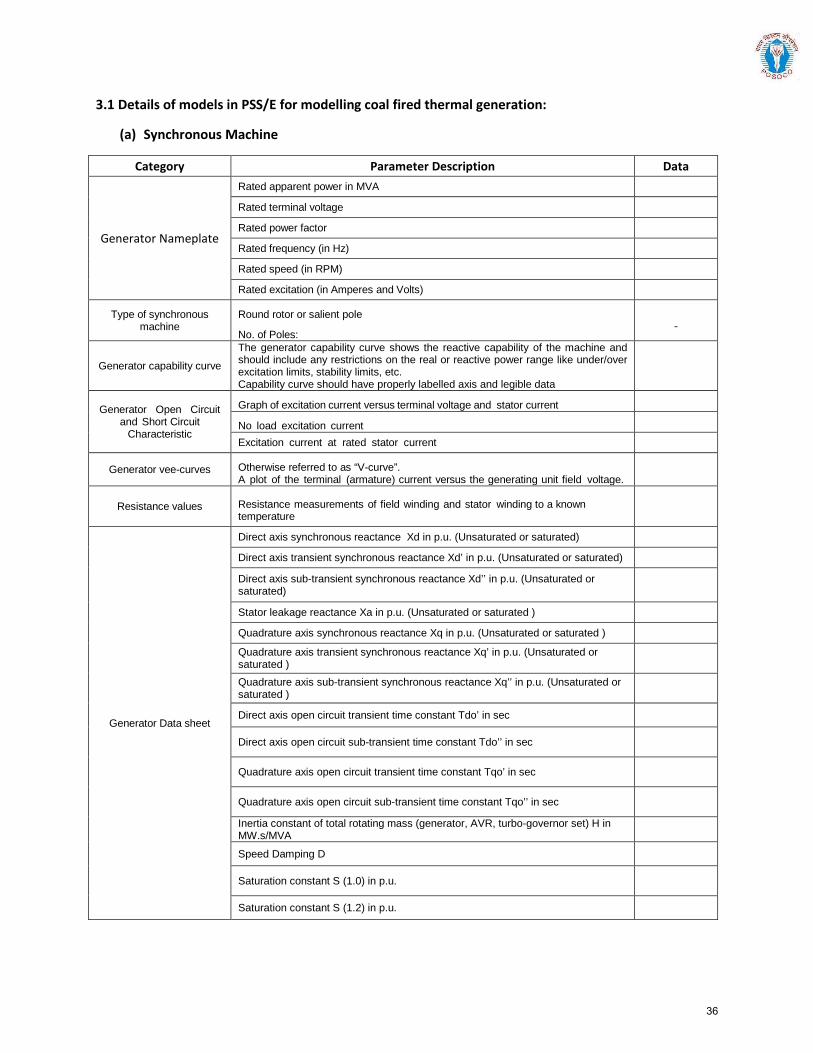
3.1 Details of models in PSS/E for modelling coal fired thermal generation:
(a) Synchronous Machine
Category Parameter Description Data
Generator Nameplate
Rated apparent power in MVA Rated terminal voltage Rated power factor Rated frequency (in Hz) Rated speed (in RPM) Rated excitation (in Amperes and Volts)
Type of synchronous machine
Round rotor or salient pole
No. of Poles:
Generator capability curve The generator capability curve shows the reactive capability of the machine and should include any restrictions on the real or reactive power range like under/over excitation limits, stability limits, etc. Capability curve should have properly labelled axis and legible data
Generator Open Circuit and Short Circuit
Characteristic
Graph of excitation current versus terminal voltage and stator current
No load excitation current Excitation current at rated stator current
Generator vee-curves Otherwise referred to as “V-curve”. A plot of the terminal (armature) current versus the generating unit field voltage.
Resistance values Resistance measurements of field winding and stator winding to a known temperature
Generator Data sheet
Direct axis synchronous reactance Xd in p.u. (Unsaturated or saturated) Direct axis transient synchronous reactance Xd’ in p.u. (Unsaturated or saturated) Direct axis sub-transient synchronous reactance Xd’’ in p.u. (Unsaturated or saturated)
Stator leakage reactance Xa in p.u. (Unsaturated or saturated ) Quadrature axis synchronous reactance Xq in p.u. (Unsaturated or saturated ) Quadrature axis transient synchronous reactance Xq’ in p.u. (Unsaturated or saturated )
Quadrature axis sub-transient synchronous reactance Xq’’ in p.u. (Unsaturated or saturated )
Direct axis open circuit transient time constant Tdo’ in sec
Direct axis open circuit sub-transient time constant Tdo’’ in sec
Quadrature axis open circuit transient time constant Tqo’ in sec
Quadrature axis open circuit sub-transient time constant Tqo’’ in sec Inertia constant of total rotating mass (generator, AVR, turbo-governor set) H in MW.s/MVA
Speed Damping D
Saturation constant S (1.0) in p.u.
Saturation constant S (1.2) in p.u.
36
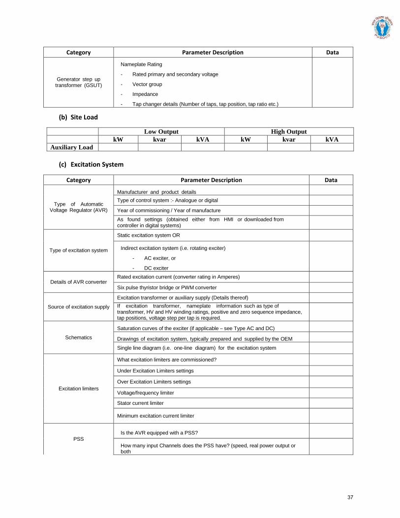
Category Parameter Description Data
Generator step up transformer (GSUT)
Nameplate Rating
- Rated primary and secondary voltage
- Vector group
- Impedance
- Tap changer details (Number of taps, tap position, tap ratio etc.)
(b) Site Load
Low Output High Output kW kvar kVA kW kvar kVA
Auxiliary Load
(c) Excitation System
Category Parameter Description Data
Type of Automatic Voltage Regulator (AVR)
Manufacturer and product details
Type of control system :- Analogue or digital
Year of commissioning / Year of manufacture
As found settings (obtained either from HMI or downloaded from controller in digital systems)
Type of excitation system
Static excitation system OR
Indirect excitation system (i.e. rotating exciter)
- AC exciter, or
- DC exciter
Details of AVR converterRated excitation current (converter rating in Amperes)
Six pulse thyristor bridge or PWM converter
Source of excitation supply
Excitation transformer or auxiliary supply (Details thereof)
If excitation transformer, nameplate information such as type of transformer, HV and HV winding ratings, positive and zero sequence impedance, tap positions, voltage step per tap is required.
Schematics
Saturation curves of the exciter (if applicable – see Type AC and DC)
Drawings of excitation system, typically prepared and supplied by the OEM
Single line diagram (i.e. one-line diagram) for the excitation system
Excitation limiters
What excitation limiters are commissioned?
Under Excitation Limiters settings
Over Excitation Limiters settings
Voltage/frequency limiter
Stator current limiter
Minimum excitation current limiter
PSS
Is the AVR equipped with a PSS?
How many input Channels does the PSS have? (speed, real power output or both
37
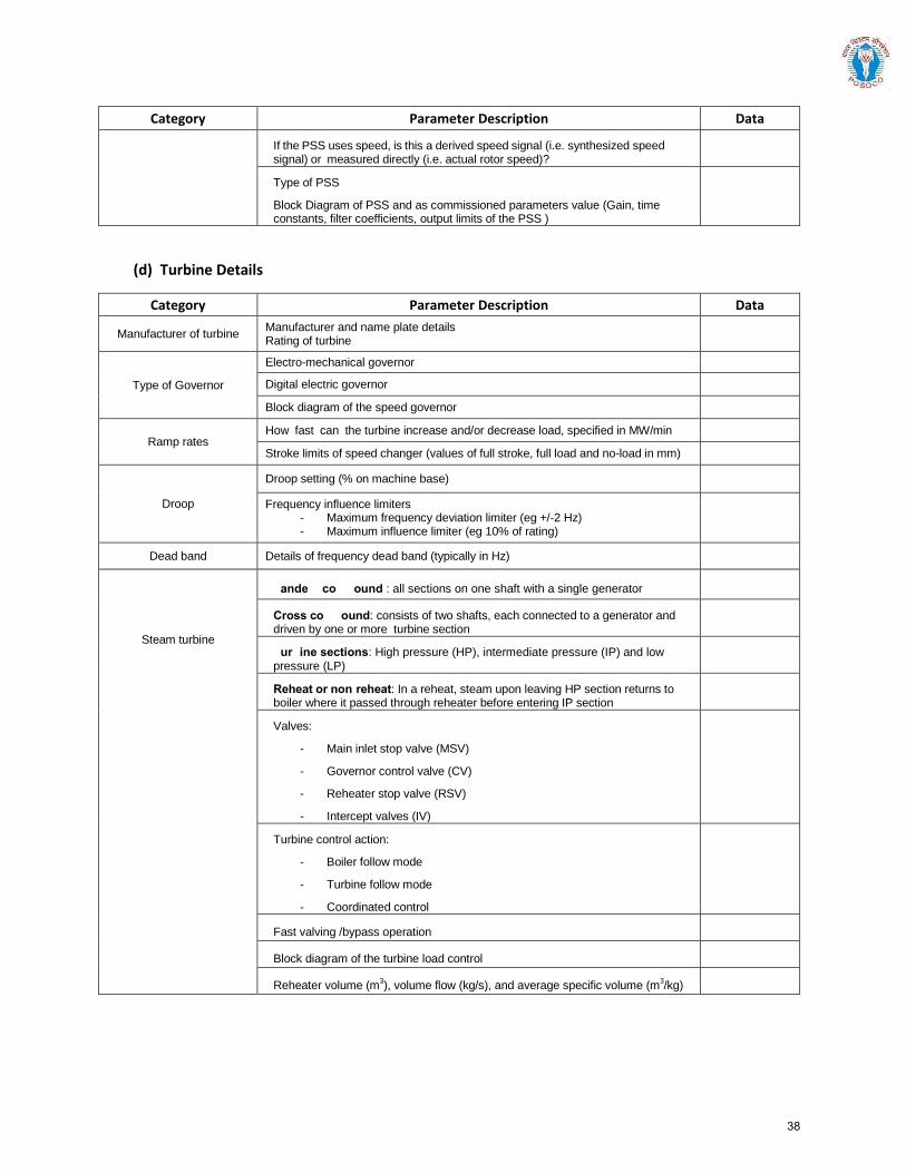
Category Parameter Description Data
If the PSS uses speed, is this a derived speed signal (i.e. synthesized speed signal) or measured directly (i.e. actual rotor speed)?
Type of PSS
Block Diagram of PSS and as commissioned parameters value (Gain, time constants, filter coefficients, output limits of the PSS )
(d) Turbine Details
Category Parameter Description Data
Manufacturer of turbine Manufacturer and name plate details Rating of turbine
Type of Governor Electro-mechanical governor Digital electric governor Block diagram of the speed governor
Ramp rates How fast can the turbine increase and/or decrease load, specified in MW/min Stroke limits of speed changer (values of full stroke, full load and no-load in mm)
Droop
Droop setting (% on machine base)
Frequency influence limiters - Maximum frequency deviation limiter (eg +/-2 Hz) - Maximum influence limiter (eg 10% of rating)
Dead band Details of frequency dead band (typically in Hz)
Steam turbine
Tandem compound : all sections on one shaft with a single generator
Cross compound: consists of two shafts, each connected to a generator and driven by one or more turbine section
Turbine sections: High pressure (HP), intermediate pressure (IP) and low pressure (LP)
Reheat or non-reheat: In a reheat, steam upon leaving HP section returns to boiler where it passed through reheater before entering IP section
Valves:
- Main inlet stop valve (MSV)
- Governor control valve (CV)
- Reheater stop valve (RSV)
- Intercept valves (IV)
Turbine control action:
- Boiler follow mode
- Turbine follow mode
- Coordinated control
Fast valving /bypass operation
Block diagram of the turbine load control
Reheater volume (m3), volume flow (kg/s), and average specific volume (m
3/kg)
38
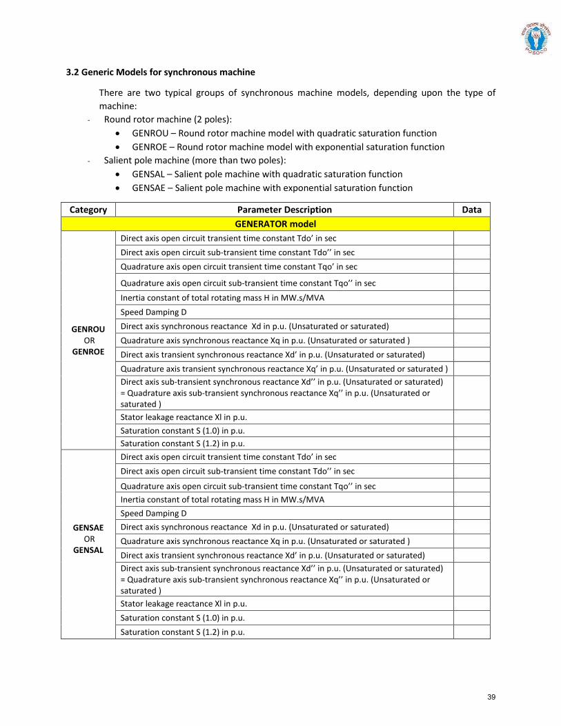
3.2 Generic Models for synchronous machine
There are two typical groups of synchronous machine models, depending upon the type of machine:
- Round rotor machine (2 poles): • GENROU – Round rotor machine model with quadratic saturation function• GENROE – Round rotor machine model with exponential saturation function
- Salient pole machine (more than two poles): • GENSAL – Salient pole machine with quadratic saturation function• GENSAE – Salient pole machine with exponential saturation function
Category Parameter Description Data GENERATOR model
GENROU OR
GENROE
Direct axis open circuit transient time constant Tdo’ in sec Direct axis open circuit sub-transient time constant Tdo’’ in sec Quadrature axis open circuit transient time constant Tqo’ in sec
Quadrature axis open circuit sub-transient time constant Tqo’’ in sec
Inertia constant of total rotating mass H in MW.s/MVA Speed Damping D Direct axis synchronous reactance Xd in p.u. (Unsaturated or saturated) Quadrature axis synchronous reactance Xq in p.u. (Unsaturated or saturated ) Direct axis transient synchronous reactance Xd’ in p.u. (Unsaturated or saturated) Quadrature axis transient synchronous reactance Xq’ in p.u. (Unsaturated or saturated ) Direct axis sub-transient synchronous reactance Xd’’ in p.u. (Unsaturated or saturated) = Quadrature axis sub-transient synchronous reactance Xq’’ in p.u. (Unsaturated or saturated ) Stator leakage reactance Xl in p.u. Saturation constant S (1.0) in p.u. Saturation constant S (1.2) in p.u.
GENSAE OR
GENSAL
Direct axis open circuit transient time constant Tdo’ in sec Direct axis open circuit sub-transient time constant Tdo’’ in sec
Quadrature axis open circuit sub-transient time constant Tqo’’ in sec Inertia constant of total rotating mass H in MW.s/MVA Speed Damping D Direct axis synchronous reactance Xd in p.u. (Unsaturated or saturated) Quadrature axis synchronous reactance Xq in p.u. (Unsaturated or saturated ) Direct axis transient synchronous reactance Xd’ in p.u. (Unsaturated or saturated) Direct axis sub-transient synchronous reactance Xd’’ in p.u. (Unsaturated or saturated) = Quadrature axis sub-transient synchronous reactance Xq’’ in p.u. (Unsaturated or saturated ) Stator leakage reactance Xl in p.u. Saturation constant S (1.0) in p.u. Saturation constant S (1.2) in p.u.
39
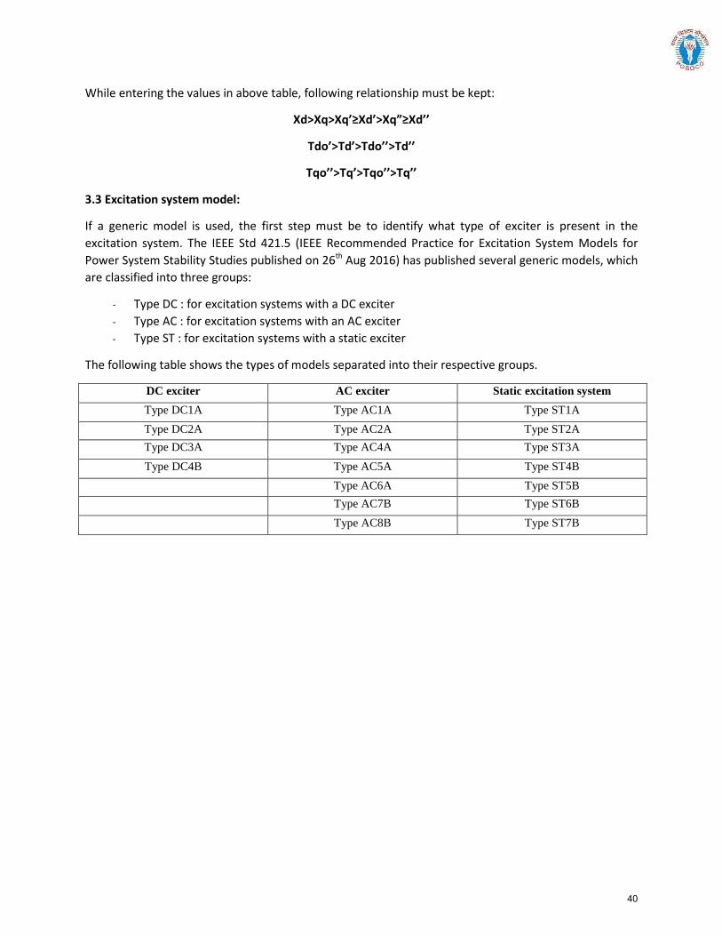
While entering the values in above table, following relationship must be kept:
Xd>Xq>Xq’≥Xd’>Xq”≥Xd’’
Tdo’>Td’>Tdo’’>Td’’
Tqo’’>Tq’>Tqo’’>Tq’’
3.3 Excitation system model:
If a generic model is used, the first step must be to identify what type of exciter is present in the excitation system. The IEEE Std 421.5 (IEEE Recommended Practice for Excitation System Models for Power System Stability Studies published on 26th Aug 2016) has published several generic models, which are classified into three groups:
- Type DC : for excitation systems with a DC exciter - Type AC : for excitation systems with an AC exciter - Type ST : for excitation systems with a static exciter
The following table shows the types of models separated into their respective groups.
DC exciter AC exciter Static excitation system Type DC1A Type AC1A Type ST1A Type DC2A Type AC2A Type ST2A Type DC3A Type AC4A Type ST3A Type DC4B Type AC5A Type ST4B
Type AC6A Type ST5B Type AC7B Type ST6B Type AC8B Type ST7B
40
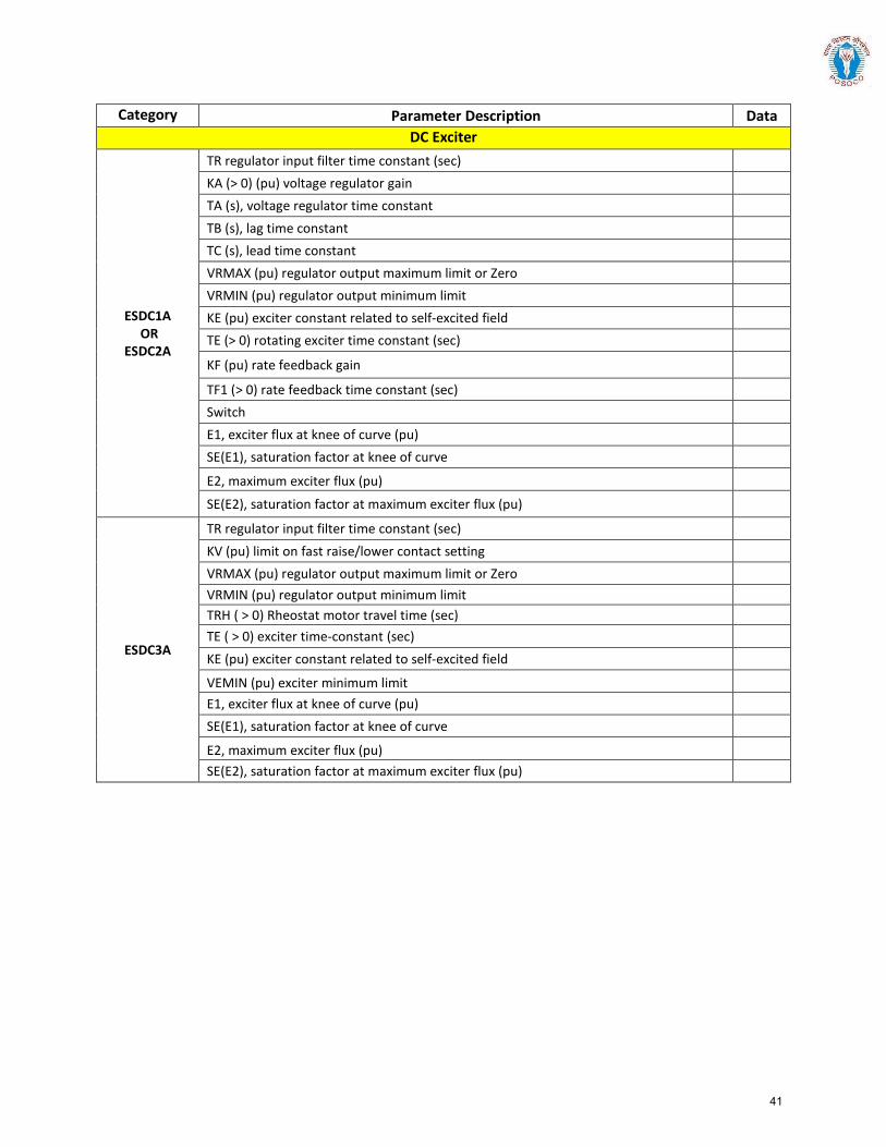
Category Parameter Description Data DC Exciter
ESDC1A OR
ESDC2A
TR regulator input filter time constant (sec) KA (> 0) (pu) voltage regulator gain TA (s), voltage regulator time constant TB (s), lag time constant TC (s), lead time constant VRMAX (pu) regulator output maximum limit or Zero VRMIN (pu) regulator output minimum limit KE (pu) exciter constant related to self-excited field TE (> 0) rotating exciter time constant (sec)
KF (pu) rate feedback gain
TF1 (> 0) rate feedback time constant (sec) Switch E1, exciter flux at knee of curve (pu) SE(E1), saturation factor at knee of curve
E2, maximum exciter flux (pu)
SE(E2), saturation factor at maximum exciter flux (pu)
ESDC3A
TR regulator input filter time constant (sec) KV (pu) limit on fast raise/lower contact setting VRMAX (pu) regulator output maximum limit or Zero VRMIN (pu) regulator output minimum limit TRH ( > 0) Rheostat motor travel time (sec) TE ( > 0) exciter time-constant (sec) KE (pu) exciter constant related to self-excited field
VEMIN (pu) exciter minimum limit E1, exciter flux at knee of curve (pu) SE(E1), saturation factor at knee of curve
E2, maximum exciter flux (pu) SE(E2), saturation factor at maximum exciter flux (pu)
41
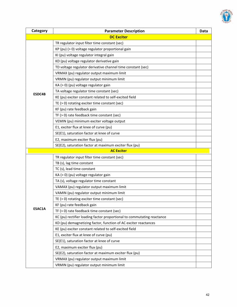
Category Parameter Description Data DC Exciter
ESDC4B
TR regulator input filter time constant (sec) KP (pu) (> 0) voltage regulator proportional gain KI (pu) voltage regulator integral gain KD (pu) voltage regulator derivative gain TD voltage regulator derivative channel time constant (sec) VRMAX (pu) regulator output maximum limit VRMIN (pu) regulator output minimum limit KA (> 0) (pu) voltage regulator gain TA voltage regulator time constant (sec) KE (pu) exciter constant related to self-excited field TE (> 0) rotating exciter time constant (sec) KF (pu) rate feedback gain TF (> 0) rate feedback time constant (sec) VEMIN (pu) minimum exciter voltage output E1, exciter flux at knee of curve (pu) SE(E1), saturation factor at knee of curve
E2, maximum exciter flux (pu) SE(E2), saturation factor at maximum exciter flux (pu)
AC Exciter
ESAC1A
TR regulator input filter time constant (sec) TB (s), lag time constant TC (s), lead time constant KA (> 0) (pu) voltage regulator gain TA (s), voltage regulator time constant VAMAX (pu) regulator output maximum limit VAMIN (pu) regulator output minimum limit TE (> 0) rotating exciter time constant (sec) KF (pu) rate feedback gain TF (> 0) rate feedback time constant (sec) KC (pu) rectifier loading factor proportional to commutating reactance KD (pu) demagnetizing factor, function of AC exciter reactances KE (pu) exciter constant related to self-excited field E1, exciter flux at knee of curve (pu) SE(E1), saturation factor at knee of curve
E2, maximum exciter flux (pu) SE(E2), saturation factor at maximum exciter flux (pu) VRMAX (pu) regulator output maximum limit VRMIN (pu) regulator output minimum limit
42
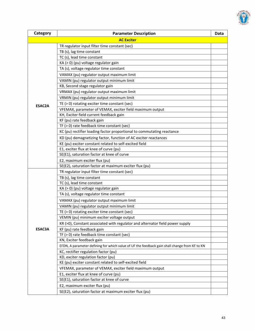
Category Parameter Description Data AC Exciter
ESAC2A
TR regulator input filter time constant (sec) TB (s), lag time constant TC (s), lead time constant KA (> 0) (pu) voltage regulator gain TA (s), voltage regulator time constant VAMAX (pu) regulator output maximum limit VAMIN (pu) regulator output minimum limit KB, Second stage regulator gain VRMAX (pu) regulator output maximum limit VRMIN (pu) regulator output minimum limit TE (> 0) rotating exciter time constant (sec) VFEMAX, parameter of VEMAX, exciter field maximum output KH, Exciter field current feedback gain KF (pu) rate feedback gain TF (> 0) rate feedback time constant (sec) KC (pu) rectifier loading factor proportional to commutating reactance KD (pu) demagnetizing factor, function of AC exciter reactances KE (pu) exciter constant related to self-excited field E1, exciter flux at knee of curve (pu) SE(E1), saturation factor at knee of curve E2, maximum exciter flux (pu) SE(E2), saturation factor at maximum exciter flux (pu)
ESAC3A
TR regulator input filter time constant (sec) TB (s), lag time constant TC (s), lead time constant KA (> 0) (pu) voltage regulator gain TA (s), voltage regulator time constant VAMAX (pu) regulator output maximum limit VAMIN (pu) regulator output minimum limit TE (> 0) rotating exciter time constant (sec) VEMIN (pu) minimum exciter voltage output KR (>0), Constant associated with regulator and alternator field power supply KF (pu) rate feedback gain TF (> 0) rate feedback time constant (sec) KN, Exciter feedback gain EFDN, A parameter defining for which value of UF the feedback gain shall change from KF to KN KC, rectifier regulation factor (pu) KD, exciter regulation factor (pu) KE (pu) exciter constant related to self-excited field VFEMAX, parameter of VEMAX, exciter field maximum output E1, exciter flux at knee of curve (pu) SE(E1), saturation factor at knee of curve E2, maximum exciter flux (pu) SE(E2), saturation factor at maximum exciter flux (pu)
43
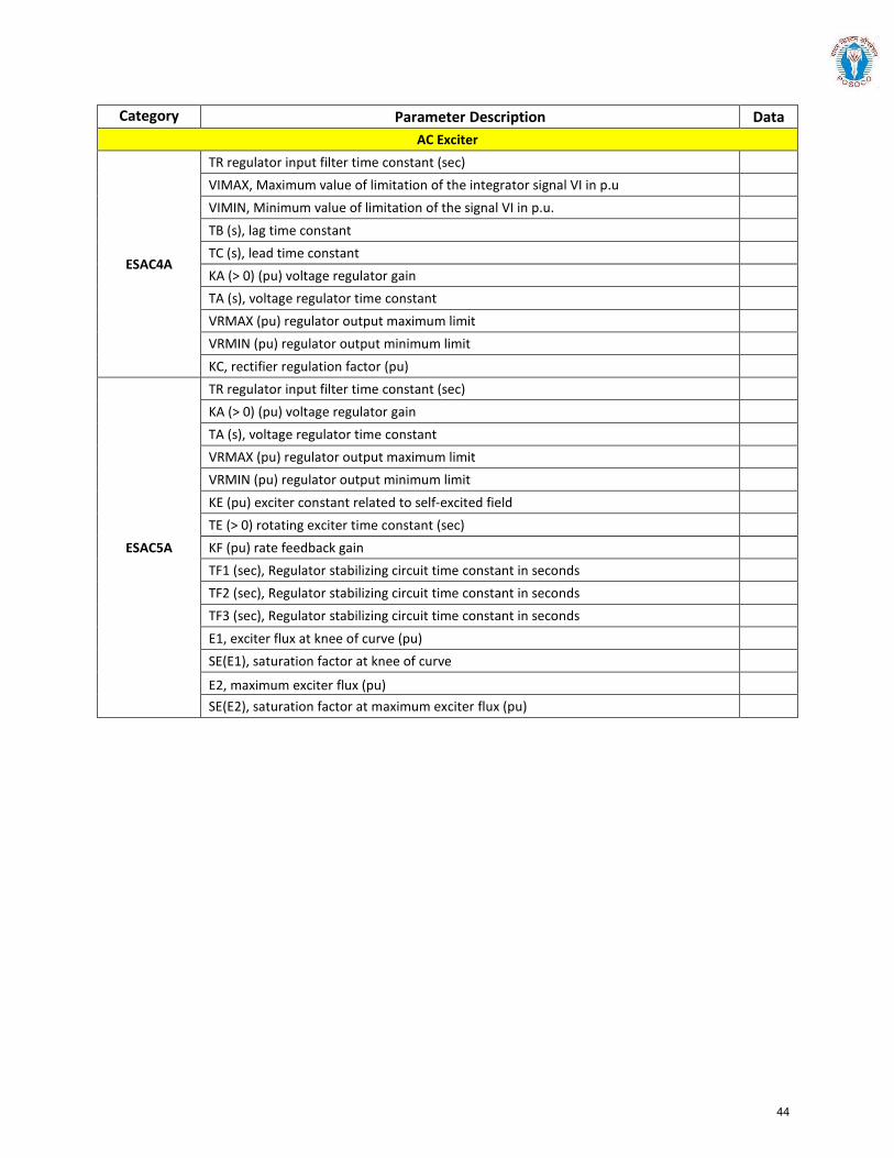
Category Parameter Description Data AC Exciter
ESAC4A
TR regulator input filter time constant (sec) VIMAX, Maximum value of limitation of the integrator signal VI in p.u VIMIN, Minimum value of limitation of the signal VI in p.u. TB (s), lag time constant TC (s), lead time constant KA (> 0) (pu) voltage regulator gain TA (s), voltage regulator time constant VRMAX (pu) regulator output maximum limit VRMIN (pu) regulator output minimum limit KC, rectifier regulation factor (pu)
ESAC5A
TR regulator input filter time constant (sec) KA (> 0) (pu) voltage regulator gain TA (s), voltage regulator time constant VRMAX (pu) regulator output maximum limit VRMIN (pu) regulator output minimum limit KE (pu) exciter constant related to self-excited field TE (> 0) rotating exciter time constant (sec) KF (pu) rate feedback gain TF1 (sec), Regulator stabilizing circuit time constant in seconds TF2 (sec), Regulator stabilizing circuit time constant in seconds TF3 (sec), Regulator stabilizing circuit time constant in seconds E1, exciter flux at knee of curve (pu) SE(E1), saturation factor at knee of curve
E2, maximum exciter flux (pu) SE(E2), saturation factor at maximum exciter flux (pu)
44
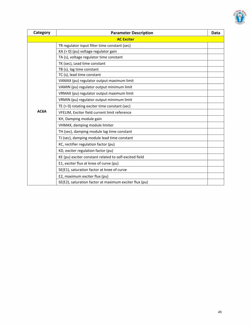
Category Parameter Description Data AC Exciter
AC6A
TR regulator input filter time constant (sec) KA (> 0) (pu) voltage regulator gain TA (s), voltage regulator time constant TK (sec), Lead time constant TB (s), lag time constant TC (s), lead time constant VAMAX (pu) regulator output maximum limit VAMIN (pu) regulator output minimum limit VRMAX (pu) regulator output maximum limit VRMIN (pu) regulator output minimum limit TE (> 0) rotating exciter time constant (sec) VFELIM, Exciter field current limit reference KH, Damping module gain VHMAX, damping module limiter TH (sec), damping module lag time constant TJ (sec), damping module lead time constant KC, rectifier regulation factor (pu) KD, exciter regulation factor (pu) KE (pu) exciter constant related to self-excited field E1, exciter flux at knee of curve (pu) SE(E1), saturation factor at knee of curve
E2, maximum exciter flux (pu) SE(E2), saturation factor at maximum exciter flux (pu)
45
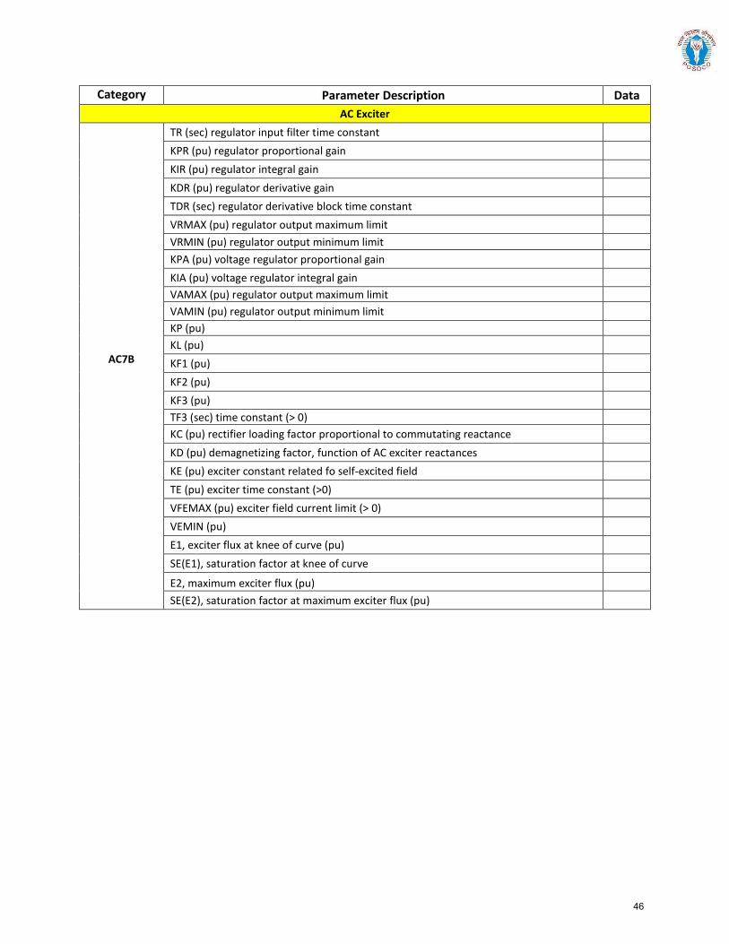
Category Parameter Description Data AC Exciter
AC7B
TR (sec) regulator input filter time constant KPR (pu) regulator proportional gain KIR (pu) regulator integral gain KDR (pu) regulator derivative gain TDR (sec) regulator derivative block time constant VRMAX (pu) regulator output maximum limit VRMIN (pu) regulator output minimum limit KPA (pu) voltage regulator proportional gain KIA (pu) voltage regulator integral gain VAMAX (pu) regulator output maximum limit VAMIN (pu) regulator output minimum limit KP (pu) KL (pu) KF1 (pu) KF2 (pu) KF3 (pu) TF3 (sec) time constant (> 0) KC (pu) rectifier loading factor proportional to commutating reactance KD (pu) demagnetizing factor, function of AC exciter reactances KE (pu) exciter constant related fo self-excited field TE (pu) exciter time constant (>0) VFEMAX (pu) exciter field current limit (> 0) VEMIN (pu) E1, exciter flux at knee of curve (pu) SE(E1), saturation factor at knee of curve
E2, maximum exciter flux (pu) SE(E2), saturation factor at maximum exciter flux (pu)
46
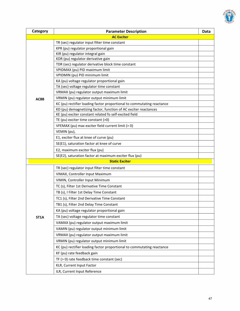
Category Parameter Description Data AC Exciter
AC8B
TR (sec) regulator input filter time constant KPR (pu) regulator proportional gain KIR (pu) regulator integral gain KDR (pu) regulator derivative gain TDR (sec) regulator derivative block time constant VPIDMAX (pu) PID maximum limit VPIDMIN (pu) PID minimum limit KA (pu) voltage regulator proportional gain TA (sec) voltage regulator time constant VRMAX (pu) regulator output maximum limit VRMIN (pu) regulator output minimum limit KC (pu) rectifier loading factor proportional to commutating reactance KD (pu) demagnetizing factor, function of AC exciter reactances KE (pu) exciter constant related fo self-excited field TE (pu) exciter time constant (>0) VFEMAX (pu) max exciter field current limit (> 0) VEMIN (pu), E1, exciter flux at knee of curve (pu) SE(E1), saturation factor at knee of curve
E2, maximum exciter flux (pu) SE(E2), saturation factor at maximum exciter flux (pu)
Static Exciter
ST1A
TR (sec) regulator input filter time constant VIMAX, Controller Input Maximum VIMIN, Controller Input Minimum TC (s), Filter 1st Derivative Time Constant TB (s), l Filter 1st Delay Time Constant TC1 (s), Filter 2nd Derivative Time Constant TB1 (s), Filter 2nd Delay Time Constant KA (pu) voltage regulator proportional gain TA (sec) voltage regulator time constant VAMAX (pu) regulator output maximum limit VAMIN (pu) regulator output minimum limit VRMAX (pu) regulator output maximum limit VRMIN (pu) regulator output minimum limit KC (pu) rectifier loading factor proportional to commutating reactance KF (pu) rate feedback gain TF (> 0) rate feedback time constant (sec) KLR, Current Input Factor ILR, Current Input Reference
47

Category Parameter Description Data Static Exciter
ST2A
TR (sec) regulator input filter time constant KA (pu) voltage regulator proportional gain TA (sec) voltage regulator time constant VRMAX (pu) regulator output maximum limit VRMIN (pu) regulator output minimum limit KE (pu) exciter constant related fo self-excited field TE (pu) exciter time constant (>0) KF (pu) rate feedback gain TF (> 0) rate feedback time constant (sec) KP (pu) voltage regulator proportional gain KI (pu) voltage regulator integral gain KC (pu) rectifier loading factor proportional to commutating reactance EFDMAX
ST3A
TR (sec) regulator input filter time constant VIMAX, Maximum value of limitation of the signal VI in p.u. VIMIN, Minimum value of limitation of the signal VI in p.u. KM, Forward gain constant of the inner loop field regulator TC (s), lag time constant TB (s), lead time constant KA (pu) voltage regulator proportional gain TA (sec) voltage regulator time constant VRMAX (pu) regulator output maximum limit VRMIN (pu) regulator output minimum limit KG, Feedback gain constant of the inner loop field regulator KP (pu) voltage regulator proportional gain KI (pu) voltage regulator integral gain VBMAX, Maximum value of limitation of the signal VB in p.u. KC (pu) rectifier loading factor proportional to commutating reactance XL, Reactance associated with potential source VGMAX, Maximum value of limitation of the signal VG in p.u ƟP (degrees) TM (sec), Forward time constant of the inner loop field regulator VMMAX, Maximum value of limitation of the signal VM in p.u VMMIN, Minimum value of limitation of the signal VM in p.u.
48
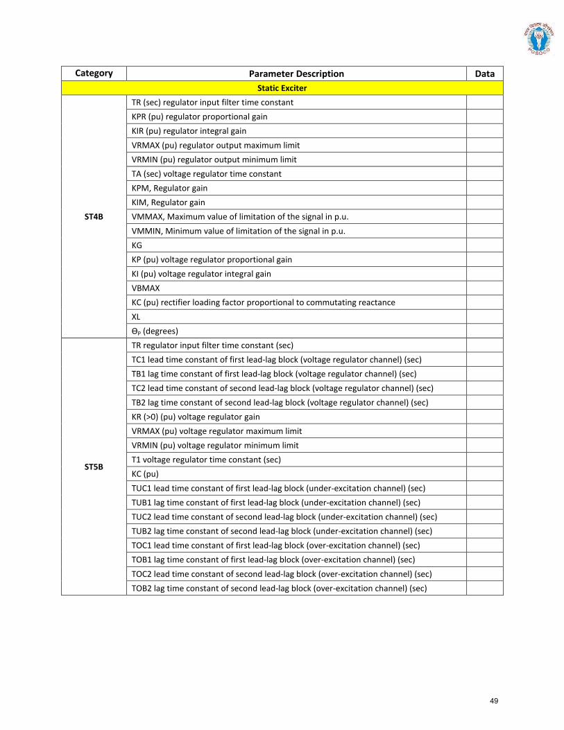
Category Parameter Description Data Static Exciter
ST4B
TR (sec) regulator input filter time constant KPR (pu) regulator proportional gain KIR (pu) regulator integral gain VRMAX (pu) regulator output maximum limit VRMIN (pu) regulator output minimum limit TA (sec) voltage regulator time constant KPM, Regulator gain KIM, Regulator gain VMMAX, Maximum value of limitation of the signal in p.u. VMMIN, Minimum value of limitation of the signal in p.u. KG KP (pu) voltage regulator proportional gain KI (pu) voltage regulator integral gain VBMAX KC (pu) rectifier loading factor proportional to commutating reactance XL ƟP (degrees)
ST5B
TR regulator input filter time constant (sec) TC1 lead time constant of first lead-lag block (voltage regulator channel) (sec) TB1 lag time constant of first lead-lag block (voltage regulator channel) (sec) TC2 lead time constant of second lead-lag block (voltage regulator channel) (sec) TB2 lag time constant of second lead-lag block (voltage regulator channel) (sec) KR (>0) (pu) voltage regulator gain VRMAX (pu) voltage regulator maximum limit VRMIN (pu) voltage regulator minimum limit T1 voltage regulator time constant (sec) KC (pu) TUC1 lead time constant of first lead-lag block (under-excitation channel) (sec) TUB1 lag time constant of first lead-lag block (under-excitation channel) (sec) TUC2 lead time constant of second lead-lag block (under-excitation channel) (sec) TUB2 lag time constant of second lead-lag block (under-excitation channel) (sec) TOC1 lead time constant of first lead-lag block (over-excitation channel) (sec) TOB1 lag time constant of first lead-lag block (over-excitation channel) (sec) TOC2 lead time constant of second lead-lag block (over-excitation channel) (sec) TOB2 lag time constant of second lead-lag block (over-excitation channel) (sec)
49
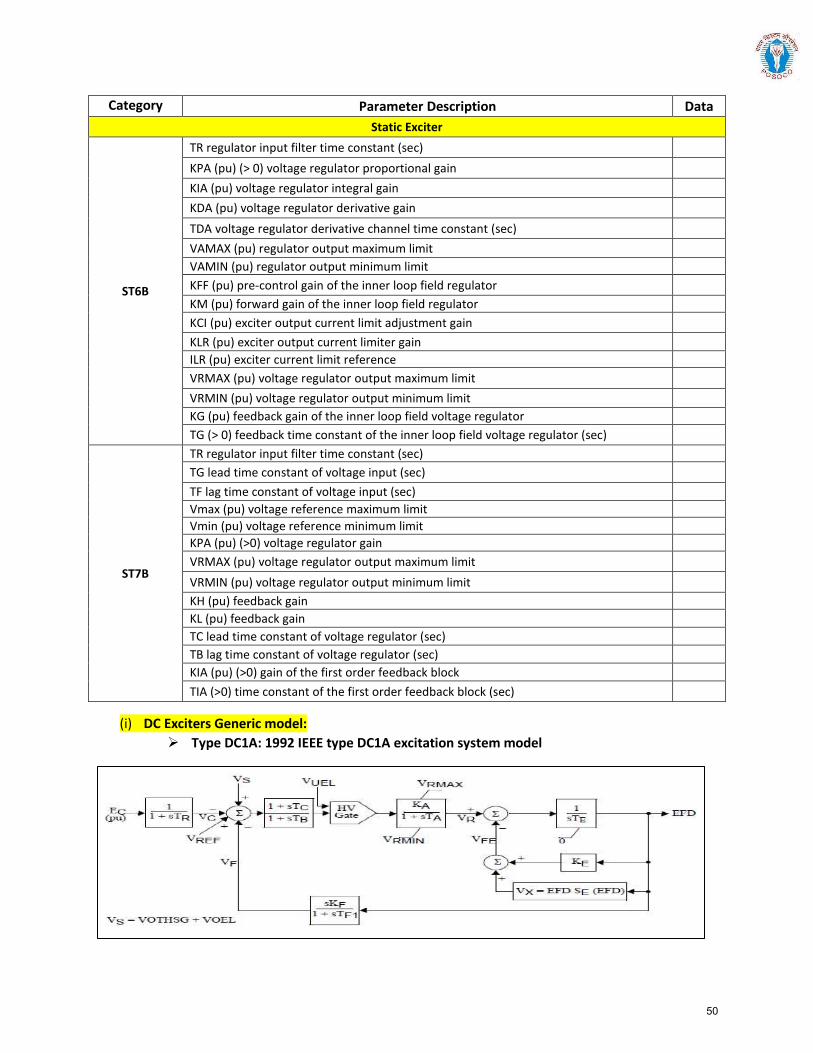
Category Parameter Description Data Static Exciter
ST6B
TR regulator input filter time constant (sec) KPA (pu) (> 0) voltage regulator proportional gain KIA (pu) voltage regulator integral gain KDA (pu) voltage regulator derivative gain TDA voltage regulator derivative channel time constant (sec) VAMAX (pu) regulator output maximum limit VAMIN (pu) regulator output minimum limit KFF (pu) pre-control gain of the inner loop field regulator KM (pu) forward gain of the inner loop field regulator KCI (pu) exciter output current limit adjustment gain KLR (pu) exciter output current limiter gain ILR (pu) exciter current limit reference VRMAX (pu) voltage regulator output maximum limit VRMIN (pu) voltage regulator output minimum limit KG (pu) feedback gain of the inner loop field voltage regulator TG (> 0) feedback time constant of the inner loop field voltage regulator (sec)
ST7B
TR regulator input filter time constant (sec) TG lead time constant of voltage input (sec) TF lag time constant of voltage input (sec) Vmax (pu) voltage reference maximum limit Vmin (pu) voltage reference minimum limit KPA (pu) (>0) voltage regulator gain VRMAX (pu) voltage regulator output maximum limit VRMIN (pu) voltage regulator output minimum limit KH (pu) feedback gain KL (pu) feedback gain TC lead time constant of voltage regulator (sec) TB lag time constant of voltage regulator (sec) KIA (pu) (>0) gain of the first order feedback block TIA (>0) time constant of the first order feedback block (sec)
(i) DC Exciters Generic model: Type DC1A: 1992 IEEE type DC1A excitation system model
50
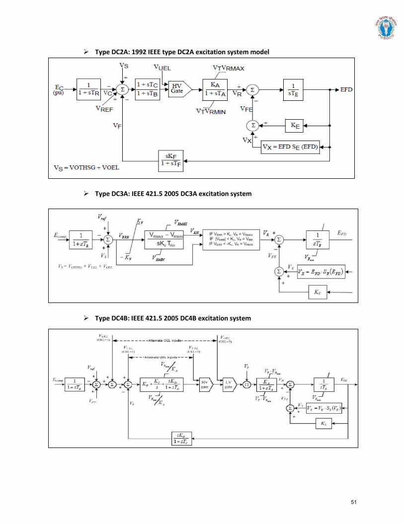
Type DC2A: 1992 IEEE type DC2A excitation system model
Type DC3A: IEEE 421.5 2005 DC3A excitation system
Type DC4B: IEEE 421.5 2005 DC4B excitation system
51

(ii) AC Exciters Generic Models:
Type AC1A: 1992 IEEE type AC1A excitation system model
Type AC2A: 1992 IEEE type AC2A excitation system model
52
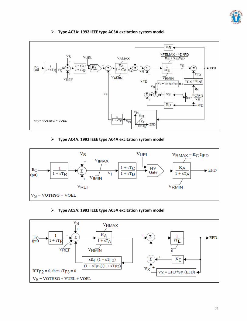
Type AC3A: 1992 IEEE type AC3A excitation system model
Type AC4A: 1992 IEEE type AC4A excitation system model
Type AC5A: 1992 IEEE type AC5A excitation system model
53
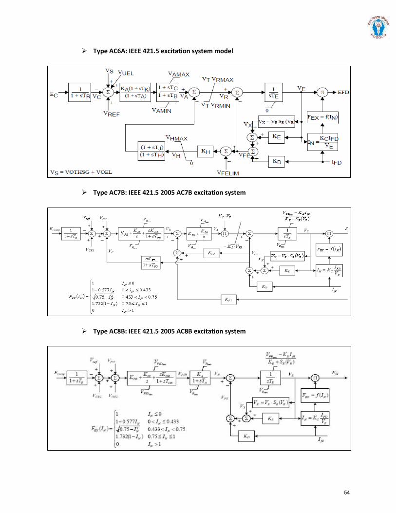
Type AC6A: IEEE 421.5 excitation system model
Type AC7B: IEEE 421.5 2005 AC7B excitation system
Type AC8B: IEEE 421.5 2005 AC8B excitation system
54

(iii) Commonly Used Static Exciters Generic Models block diagrams:
Type ST1A: 1992 IEEE type ST1A excitation system model
Type ST2A: 1992 IEEE type ST2A excitation system model
55
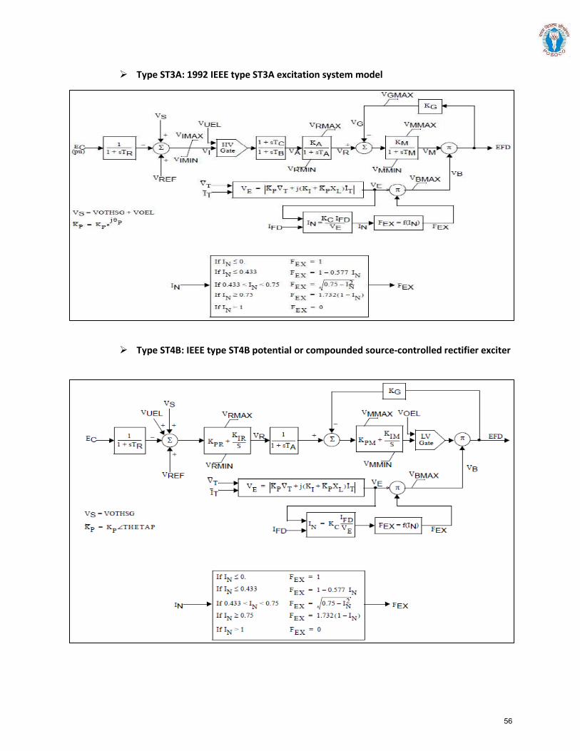
Type ST3A: 1992 IEEE type ST3A excitation system model
Type ST4B: IEEE type ST4B potential or compounded source-controlled rectifier exciter
56
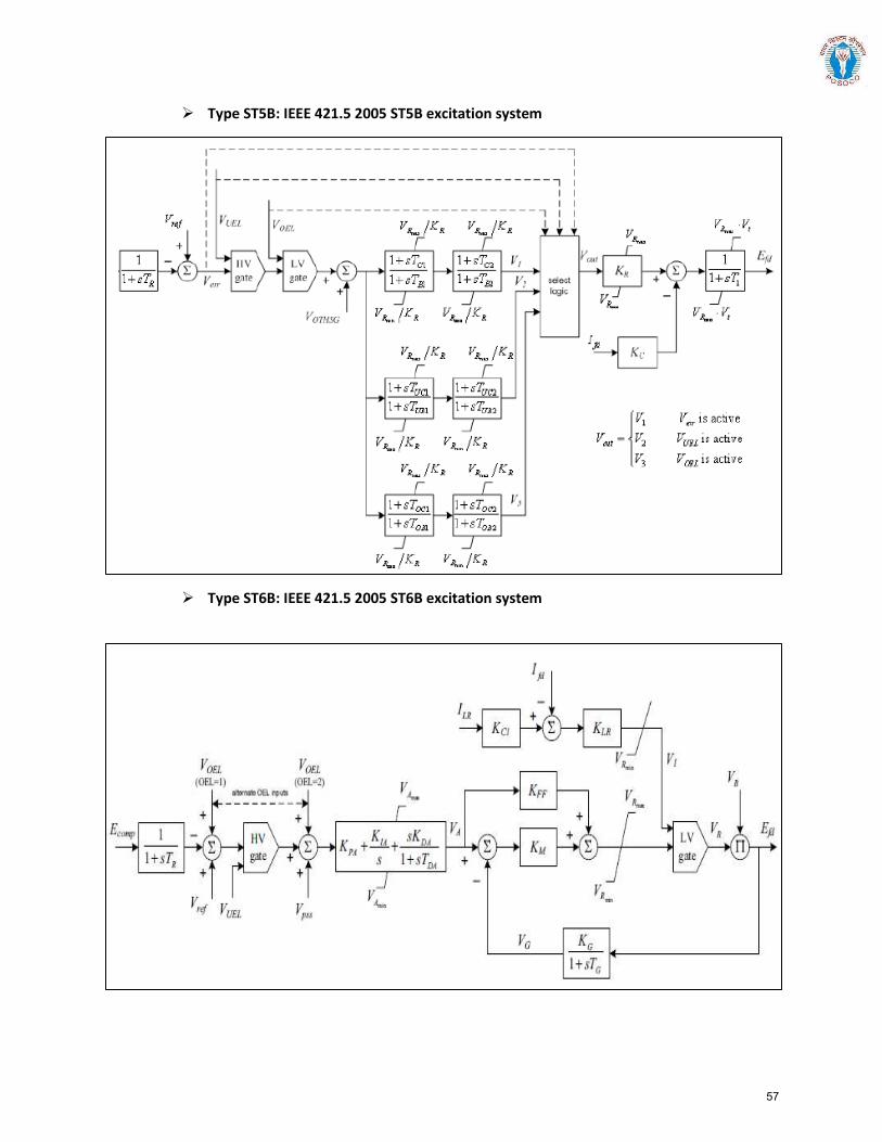
Type ST5B: IEEE 421.5 2005 ST5B excitation system
Type ST6B: IEEE 421.5 2005 ST6B excitation system
57
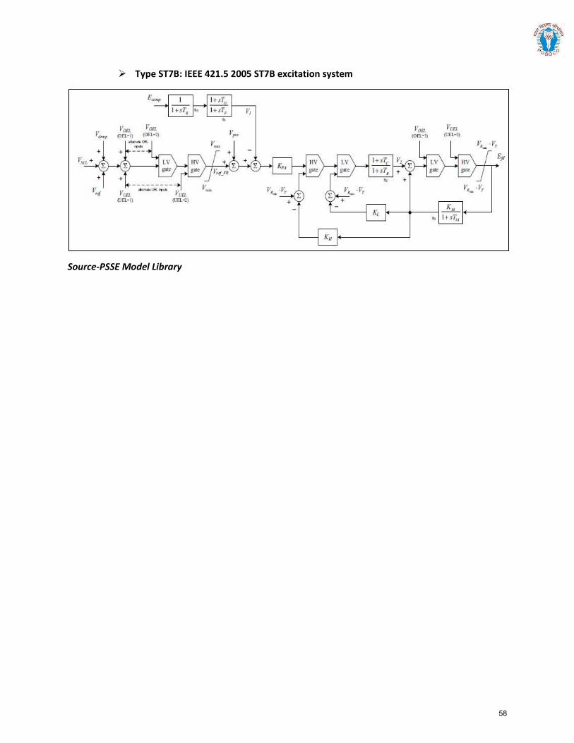
Type ST7B: IEEE 421.5 2005 ST7B excitation system
Source-PSSE Model Library
58
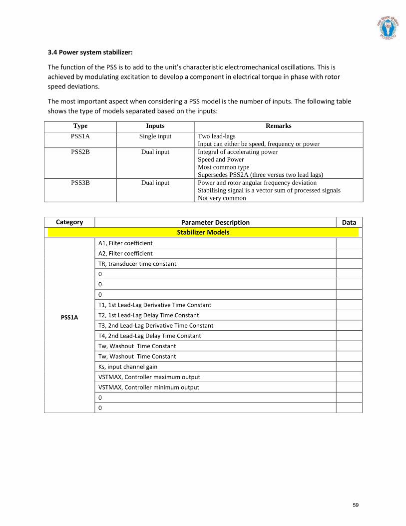
3.4 Power system stabilizer:
The function of the PSS is to add to the unit’s characteristic electromechanical oscillations. This is achieved by modulating excitation to develop a component in electrical torque in phase with rotor speed deviations.
The most important aspect when considering a PSS model is the number of inputs. The following table shows the type of models separated based on the inputs:
Type Inputs Remarks PSS1A Single input Two lead-lags
Input can either be speed, frequency or power PSS2B Dual input Integral of accelerating power
Speed and Power Most common type Supersedes PSS2A (three versus two lead lags)
PSS3B Dual input Power and rotor angular frequency deviation Stabilising signal is a vector sum of processed signals Not very common
Category Parameter Description Data Stabilizer Models
PSS1A
A1, Filter coefficient A2, Filter coefficient TR, transducer time constant 0 0 0 T1, 1st Lead-Lag Derivative Time Constant T2, 1st Lead-Lag Delay Time Constant T3, 2nd Lead-Lag Derivative Time Constant T4, 2nd Lead-Lag Delay Time Constant Tw, Washout Time Constant Tw, Washout Time Constant Ks, input channel gain VSTMAX, Controller maximum output VSTMAX, Controller minimum output 0 0
59
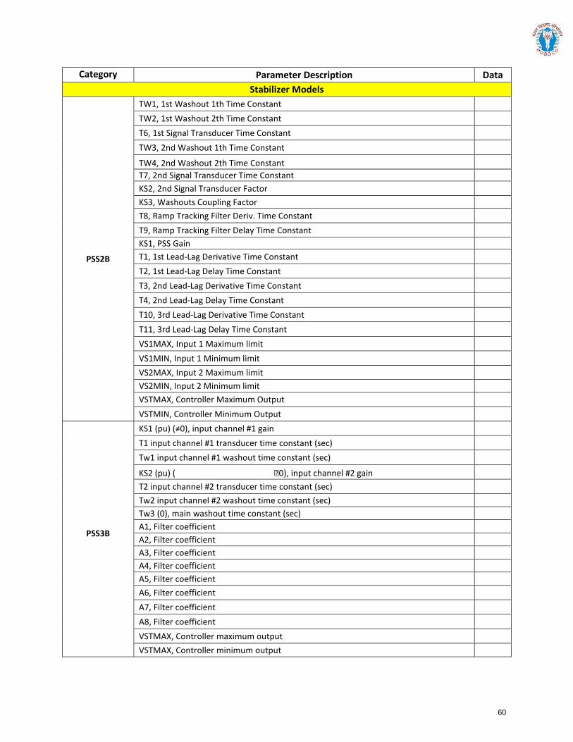
Category Parameter Description Data Stabilizer Models
PSS2B
TW1, 1st Washout 1th Time Constant TW2, 1st Washout 2th Time Constant T6, 1st Signal Transducer Time Constant TW3, 2nd Washout 1th Time Constant
TW4, 2nd Washout 2th Time Constant T7, 2nd Signal Transducer Time Constant KS2, 2nd Signal Transducer Factor KS3, Washouts Coupling Factor T8, Ramp Tracking Filter Deriv. Time Constant T9, Ramp Tracking Filter Delay Time Constant KS1, PSS Gain T1, 1st Lead-Lag Derivative Time Constant T2, 1st Lead-Lag Delay Time Constant T3, 2nd Lead-Lag Derivative Time Constant T4, 2nd Lead-Lag Delay Time Constant T10, 3rd Lead-Lag Derivative Time Constant T11, 3rd Lead-Lag Delay Time Constant VS1MAX, Input 1 Maximum limit VS1MIN, Input 1 Minimum limit VS2MAX, Input 2 Maximum limit VS2MIN, Input 2 Minimum limit VSTMAX, Controller Maximum Output VSTMIN, Controller Minimum Output
PSS3B
KS1 (pu) (≠0), input channel #1 gain T1 input channel #1 transducer time constant (sec) Tw1 input channel #1 washout time constant (sec)
KS2 (pu) ( 0), input channel #2 gain T2 input channel #2 transducer time constant (sec) Tw2 input channel #2 washout time constant (sec) Tw3 (0), main washout time constant (sec) A1, Filter coefficient A2, Filter coefficient A3, Filter coefficient A4, Filter coefficient A5, Filter coefficient A6, Filter coefficient A7, Filter coefficient A8, Filter coefficient VSTMAX, Controller maximum output VSTMAX, Controller minimum output
60
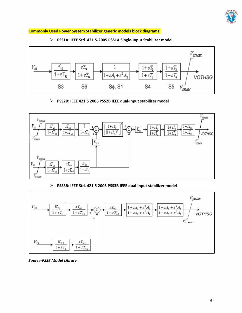
Commonly Used Power System Stabilizer generic models block diagrams:
PSS1A: IEEE Std. 421.5-2005 PSS1A Single-Input Stabilizer model
PSS2B: IEEE 421.5 2005 PSS2B IEEE dual-input stabilizer model
PSS3B: IEEE Std. 421.5 2005 PSS3B IEEE dual-input stabilizer model
Source-PSSE Model Library
61
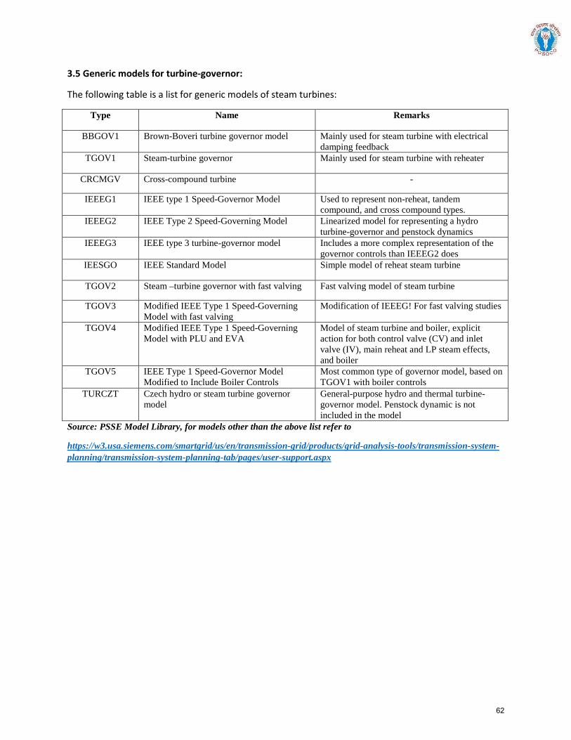
3.5 Generic models for turbine-governor:
The following table is a list for generic models of steam turbines:
Type Name Remarks
BBGOV1 Brown-Boveri turbine governor model Mainly used for steam turbine with electrical damping feedback
TGOV1 Steam-turbine governor Mainly used for steam turbine with reheater
CRCMGV Cross-compound turbine -
IEEEG1 IEEE type 1 Speed-Governor Model Used to represent non-reheat, tandem compound, and cross compound types.
IEEEG2 IEEE Type 2 Speed-Governing Model Linearized model for representing a hydro turbine-governor and penstock dynamics
IEEEG3 IEEE type 3 turbine-governor model Includes a more complex representation of the governor controls than IEEEG2 does
IEESGO IEEE Standard Model Simple model of reheat steam turbine
TGOV2 Steam –turbine governor with fast valving Fast valving model of steam turbine
TGOV3 Modified IEEE Type 1 Speed-Governing Model with fast valving
Modification of IEEEG! For fast valving studies
TGOV4 Modified IEEE Type 1 Speed-Governing Model with PLU and EVA
Model of steam turbine and boiler, explicit action for both control valve (CV) and inlet valve (IV), main reheat and LP steam effects, and boiler
TGOV5 IEEE Type 1 Speed-Governor Model Modified to Include Boiler Controls
Most common type of governor model, based on TGOV1 with boiler controls
TURCZT Czech hydro or steam turbine governor model
General-purpose hydro and thermal turbine-governor model. Penstock dynamic is not included in the model
Source: PSSE Model Library, for models other than the above list refer to
https://w3.usa.siemens.com/smartgrid/us/en/transmission-grid/products/grid-analysis-tools/transmission-system-planning/transmission-system-planning-tab/pages/user-support.aspx
62
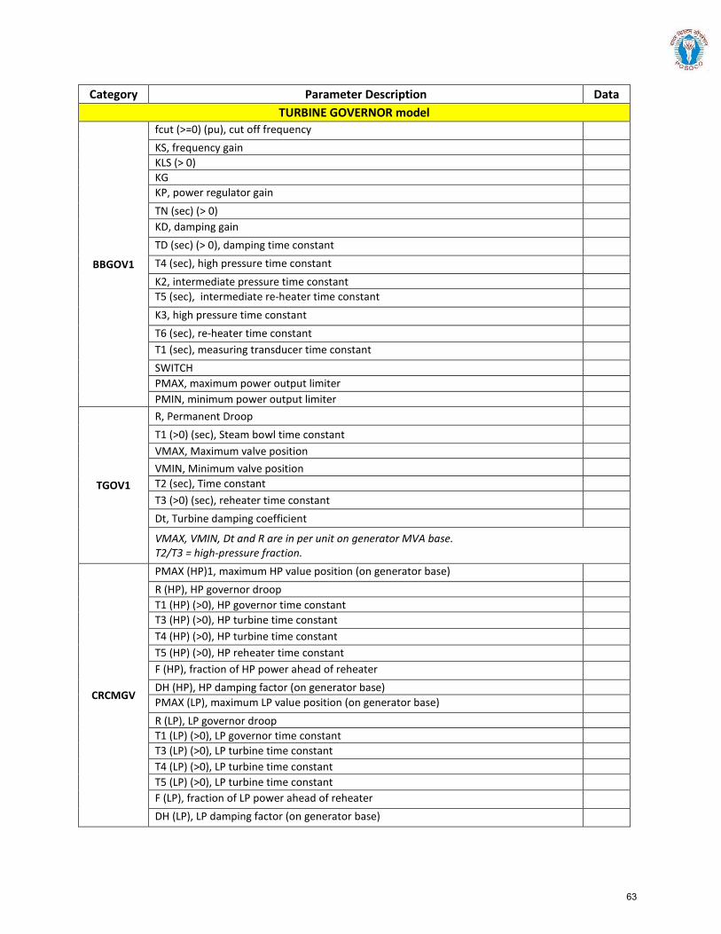
Category Parameter Description Data TURBINE GOVERNOR model
BBGOV1
fcut (>=0) (pu), cut off frequency KS, frequency gain KLS (> 0) KG KP, power regulator gain TN (sec) (> 0) KD, damping gain TD (sec) (> 0), damping time constant T4 (sec), high pressure time constant K2, intermediate pressure time constant T5 (sec), intermediate re-heater time constant K3, high pressure time constant T6 (sec), re-heater time constant T1 (sec), measuring transducer time constant SWITCH PMAX, maximum power output limiter PMIN, minimum power output limiter
TGOV1
R, Permanent Droop T1 (>0) (sec), Steam bowl time constant VMAX, Maximum valve position VMIN, Minimum valve position T2 (sec), Time constant T3 (>0) (sec), reheater time constant Dt, Turbine damping coefficient
VMAX, VMIN, Dt and R are in per unit on generator MVA base. T2/T3 = high-pressure fraction.
CRCMGV
PMAX (HP)1, maximum HP value position (on generator base) R (HP), HP governor droop T1 (HP) (>0), HP governor time constant T3 (HP) (>0), HP turbine time constant T4 (HP) (>0), HP turbine time constant T5 (HP) (>0), HP reheater time constant F (HP), fraction of HP power ahead of reheater DH (HP), HP damping factor (on generator base) PMAX (LP), maximum LP value position (on generator base) R (LP), LP governor droop T1 (LP) (>0), LP governor time constant T3 (LP) (>0), LP turbine time constant T4 (LP) (>0), LP turbine time constant T5 (LP) (>0), LP turbine time constant F (LP), fraction of LP power ahead of reheater DH (LP), LP damping factor (on generator base)
63
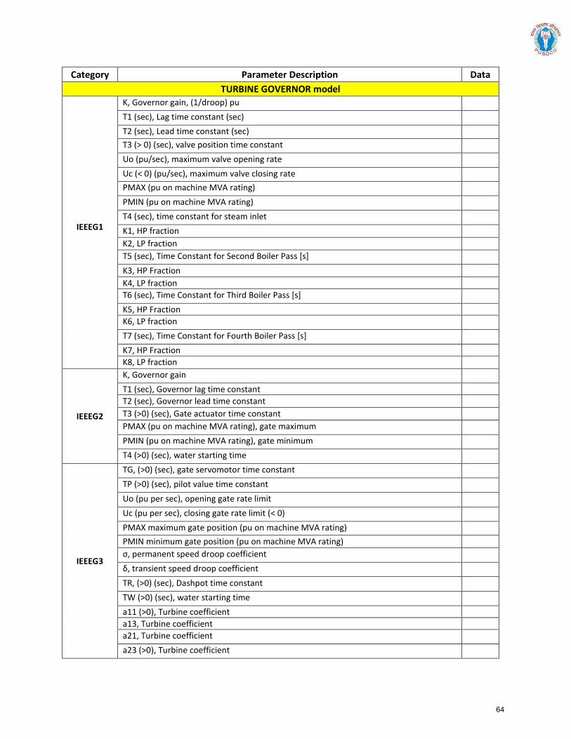
Category Parameter Description Data TURBINE GOVERNOR model
IEEEG1
K, Governor gain, (1/droop) pu T1 (sec), Lag time constant (sec) T2 (sec), Lead time constant (sec) T3 (> 0) (sec), valve position time constant Uo (pu/sec), maximum valve opening rate Uc (< 0) (pu/sec), maximum valve closing rate PMAX (pu on machine MVA rating) PMIN (pu on machine MVA rating) T4 (sec), time constant for steam inlet K1, HP fraction K2, LP fraction T5 (sec), Time Constant for Second Boiler Pass [s] K3, HP Fraction K4, LP fraction T6 (sec), Time Constant for Third Boiler Pass [s] K5, HP Fraction K6, LP fraction T7 (sec), Time Constant for Fourth Boiler Pass [s] K7, HP Fraction K8, LP fraction
IEEEG2
K, Governor gain T1 (sec), Governor lag time constant T2 (sec), Governor lead time constant T3 (>0) (sec), Gate actuator time constant PMAX (pu on machine MVA rating), gate maximum PMIN (pu on machine MVA rating), gate minimum T4 (>0) (sec), water starting time
IEEEG3
TG, (>0) (sec), gate servomotor time constant TP (>0) (sec), pilot value time constant Uo (pu per sec), opening gate rate limit Uc (pu per sec), closing gate rate limit (< 0) PMAX maximum gate position (pu on machine MVA rating) PMIN minimum gate position (pu on machine MVA rating) σ, permanent speed droop coefficient δ, transient speed droop coefficient TR, (>0) (sec), Dashpot time constant TW (>0) (sec), water starting time a11 (>0), Turbine coefficient a13, Turbine coefficient a21, Turbine coefficient a23 (>0), Turbine coefficient
64
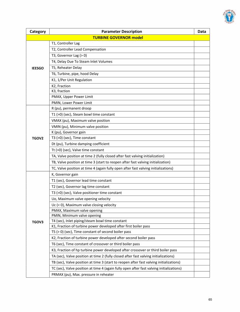
Category Parameter Description Data TURBINE GOVERNOR model
T1, Controller Lag T2, Controller Lead Compensation T3, Governor Lag (> 0) T4, Delay Due To Steam Inlet Volumes
IEESGO T5, Reheater Delay T6, Turbine, pipe, hood Delay K1, 1/Per Unit Regulation K2, Fraction K3, fraction PMAX, Upper Power Limit PMIN, Lower Power Limit
TGOV2
R (pu), permanent droop T1 (>0) (sec), Steam bowl time constant VMAX (pu), Maximum valve position VMIN (pu), Minimum valve position K (pu), Governor gain T3 (>0) (sec), Time constant Dt (pu), Turbine damping coefficient Tt (>0) (sec), Valve time constant TA, Valve position at time 2 (fully closed after fast valving initialization) TB, Valve position at time 3 (start to reopen after fast valving initialization) TC, Valve position at time 4 (again fully open after fast valving initializations)
TGOV3
K, Governor gain T1 (sec), Governor lead time constant T2 (sec), Governor lag time constant T3 (>0) (sec), Valve positioner time constant Uo, Maximum valve opening velocity Uc (< 0), Maximum valve closing velocity PMAX, Maximum valve opening PMIN, Minimum valve opening T4 (sec), Inlet piping/steam bowl time constant K1, Fraction of turbine power developed after first boiler pass T5 (> 0) (sec), Time constant of second boiler pass K2, Fraction of turbine power developed after second boiler pass T6 (sec), Time constant of crossover or third boiler pass K3, Fraction of hp turbine power developed after crossover or third boiler pass TA (sec), Valve position at time 2 (fully closed after fast valving initializations) TB (sec), Valve position at time 3 (start to reopen after fast valving initializations) TC (sec), Valve position at time 4 (again fully open after fast valving initializations) PRMAX (pu), Max. pressure in reheater
65
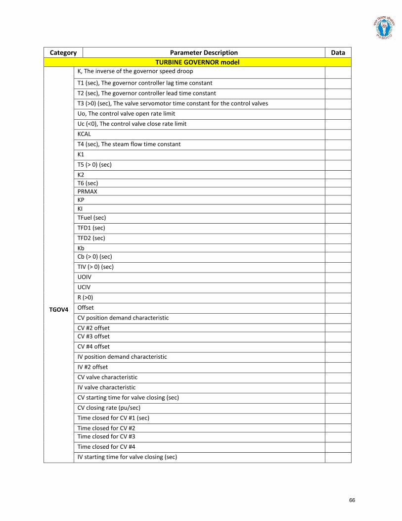
Category Parameter Description Data TURBINE GOVERNOR model
TGOV4
K, The inverse of the governor speed droop T1 (sec), The governor controller lag time constant T2 (sec), The governor controller lead time constant T3 (>0) (sec), The valve servomotor time constant for the control valves Uo, The control valve open rate limit Uc (<0), The control valve close rate limit KCAL T4 (sec), The steam flow time constant K1 T5 (> 0) (sec) K2 T6 (sec) PRMAX KP KI TFuel (sec) TFD1 (sec) TFD2 (sec) Kb Cb (> 0) (sec) TIV (> 0) (sec) UOIV UCIV R (>0) Offset CV position demand characteristic CV #2 offset CV #3 offset CV #4 offset IV position demand characteristic IV #2 offset CV valve characteristic IV valve characteristic CV starting time for valve closing (sec) CV closing rate (pu/sec) Time closed for CV #1 (sec) Time closed for CV #2 Time closed for CV #3 Time closed for CV #4 IV starting time for valve closing (sec)
66
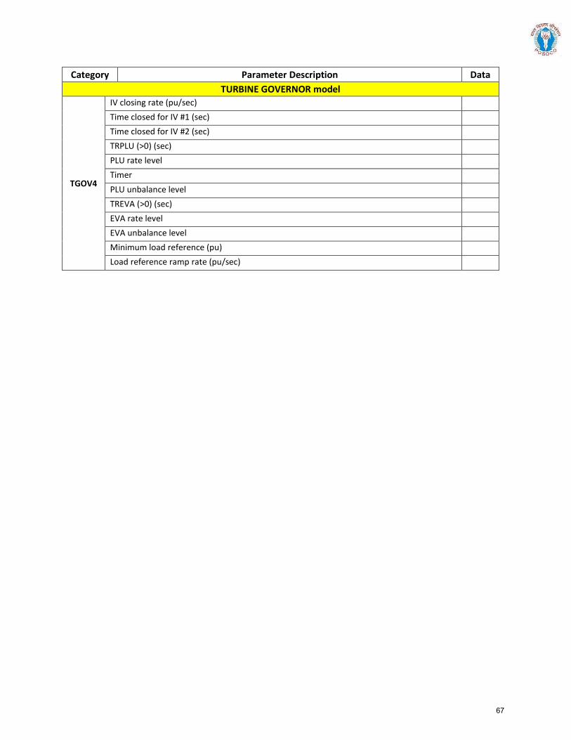
Category Parameter Description Data TURBINE GOVERNOR model
TGOV4
IV closing rate (pu/sec) Time closed for IV #1 (sec) Time closed for IV #2 (sec) TRPLU (>0) (sec) PLU rate level Timer PLU unbalance level TREVA (>0) (sec) EVA rate level EVA unbalance level Minimum load reference (pu) Load reference ramp rate (pu/sec)
67
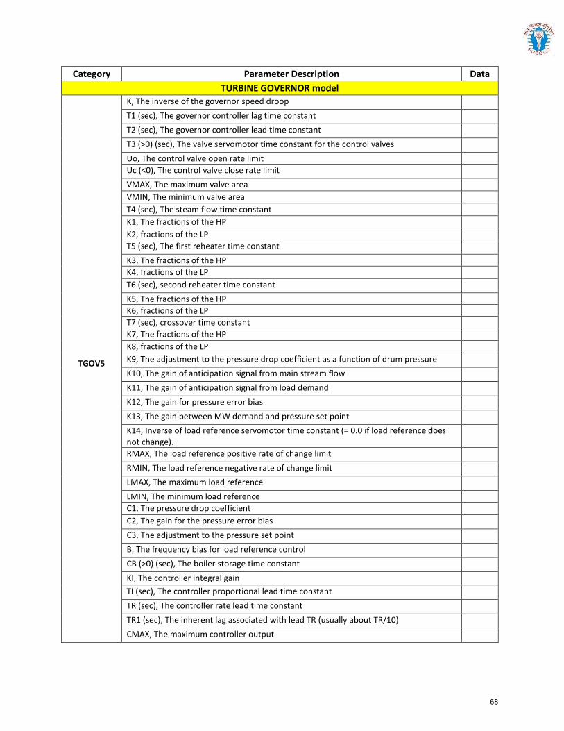
Category Parameter Description Data TURBINE GOVERNOR model
TGOV5
K, The inverse of the governor speed droop T1 (sec), The governor controller lag time constant T2 (sec), The governor controller lead time constant T3 (>0) (sec), The valve servomotor time constant for the control valves Uo, The control valve open rate limit Uc (<0), The control valve close rate limit VMAX, The maximum valve area VMIN, The minimum valve area T4 (sec), The steam flow time constant K1, The fractions of the HP K2, fractions of the LP T5 (sec), The first reheater time constant K3, The fractions of the HP K4, fractions of the LP T6 (sec), second reheater time constant K5, The fractions of the HP K6, fractions of the LP T7 (sec), crossover time constant K7, The fractions of the HP K8, fractions of the LP K9, The adjustment to the pressure drop coefficient as a function of drum pressure K10, The gain of anticipation signal from main stream flow K11, The gain of anticipation signal from load demand K12, The gain for pressure error bias K13, The gain between MW demand and pressure set point K14, Inverse of load reference servomotor time constant (= 0.0 if load reference does not change).
RMAX, The load reference positive rate of change limit RMIN, The load reference negative rate of change limit LMAX, The maximum load reference LMIN, The minimum load reference C1, The pressure drop coefficient C2, The gain for the pressure error bias C3, The adjustment to the pressure set point B, The frequency bias for load reference control CB (>0) (sec), The boiler storage time constant KI, The controller integral gain TI (sec), The controller proportional lead time constant TR (sec), The controller rate lead time constant TR1 (sec), The inherent lag associated with lead TR (usually about TR/10) CMAX, The maximum controller output
68
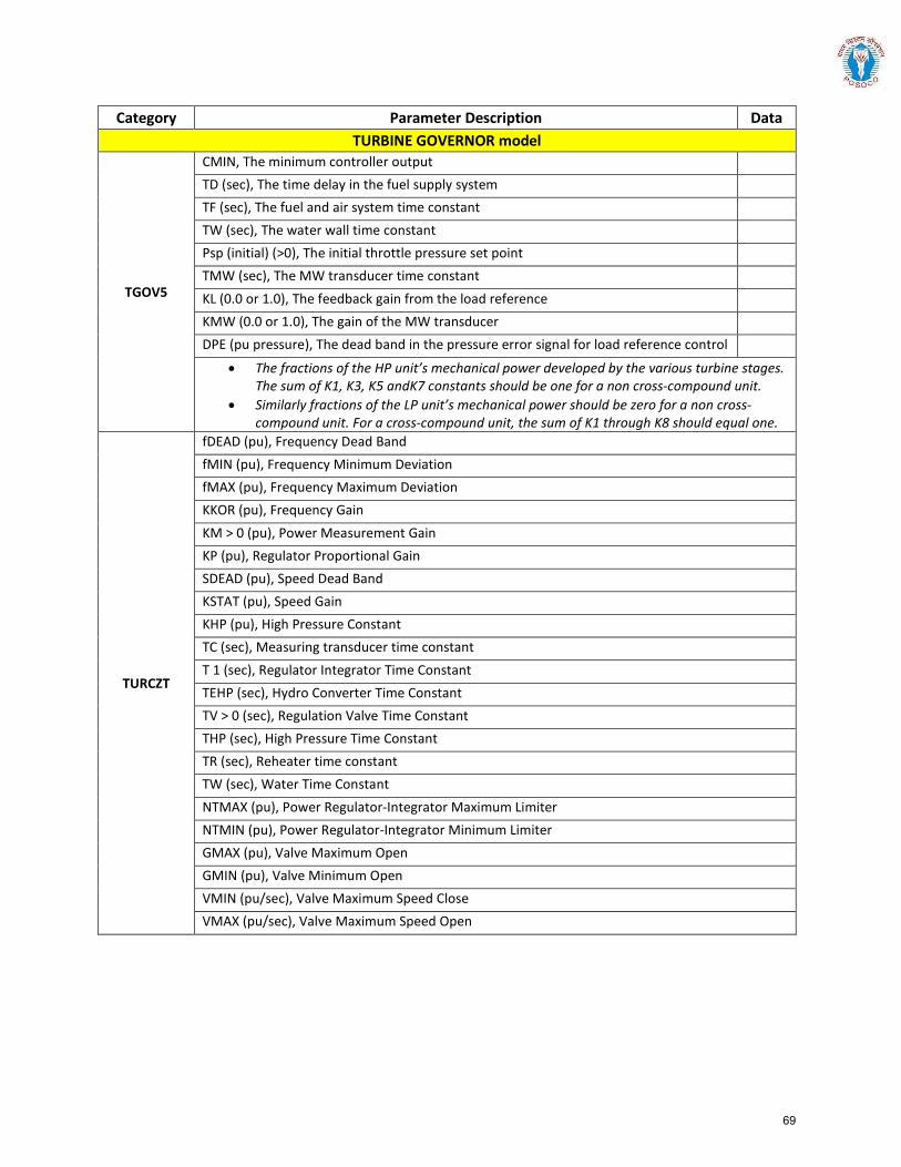
Category Parameter Description Data TURBINE GOVERNOR model
TGOV5
CMIN, The minimum controller output TD (sec), The time delay in the fuel supply system TF (sec), The fuel and air system time constant TW (sec), The water wall time constant Psp (initial) (>0), The initial throttle pressure set point TMW (sec), The MW transducer time constant KL (0.0 or 1.0), The feedback gain from the load reference KMW (0.0 or 1.0), The gain of the MW transducer DPE (pu pressure), The dead band in the pressure error signal for load reference control
• The fractions of the HP unit’s mechanical power developed by the various turbine stages.The sum of K1, K3, K5 andK7 constants should be one for a non cross-compound unit.
• Similarly fractions of the LP unit’s mechanical power should be zero for a non cross-compound unit. For a cross-compound unit, the sum of K1 through K8 should equal one.
TURCZT
fDEAD (pu), Frequency Dead Band fMIN (pu), Frequency Minimum Deviation fMAX (pu), Frequency Maximum Deviation KKOR (pu), Frequency Gain KM > 0 (pu), Power Measurement Gain KP (pu), Regulator Proportional Gain SDEAD (pu), Speed Dead Band KSTAT (pu), Speed Gain KHP (pu), High Pressure Constant TC (sec), Measuring transducer time constant T 1 (sec), Regulator Integrator Time Constant TEHP (sec), Hydro Converter Time Constant TV > 0 (sec), Regulation Valve Time Constant THP (sec), High Pressure Time Constant TR (sec), Reheater time constant TW (sec), Water Time Constant NTMAX (pu), Power Regulator-Integrator Maximum Limiter NTMIN (pu), Power Regulator-Integrator Minimum Limiter GMAX (pu), Valve Maximum Open GMIN (pu), Valve Minimum Open VMIN (pu/sec), Valve Maximum Speed Close VMAX (pu/sec), Valve Maximum Speed Open
69
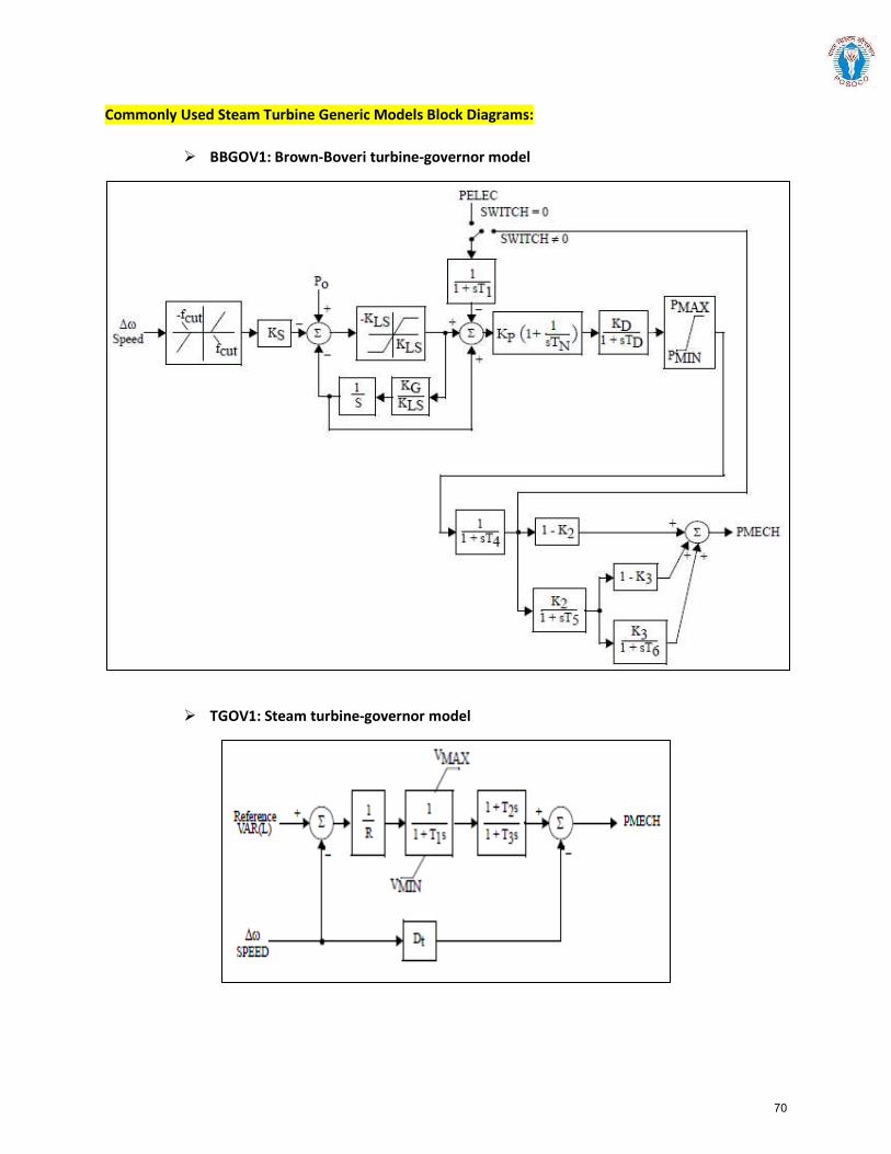
Commonly Used Steam Turbine Generic Models Block Diagrams:
BBGOV1: Brown-Boveri turbine-governor model
TGOV1: Steam turbine-governor model
70
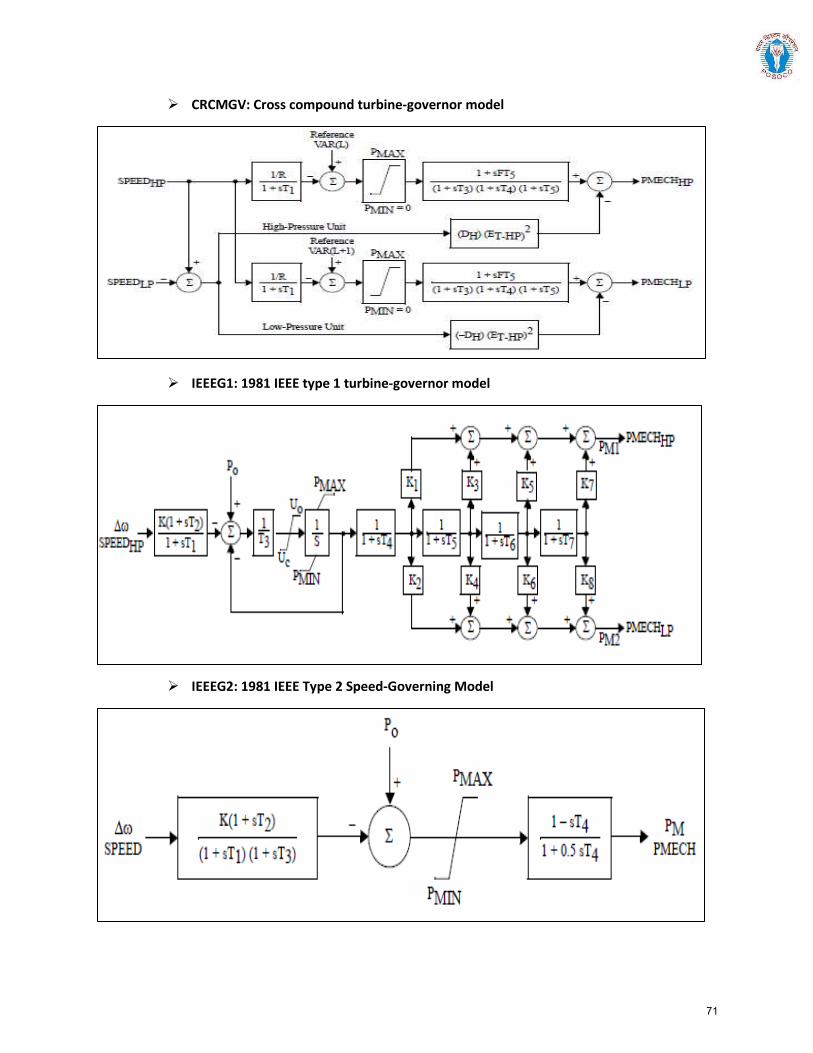
CRCMGV: Cross compound turbine-governor model
IEEEG1: 1981 IEEE type 1 turbine-governor model
IEEEG2: 1981 IEEE Type 2 Speed-Governing Model
71
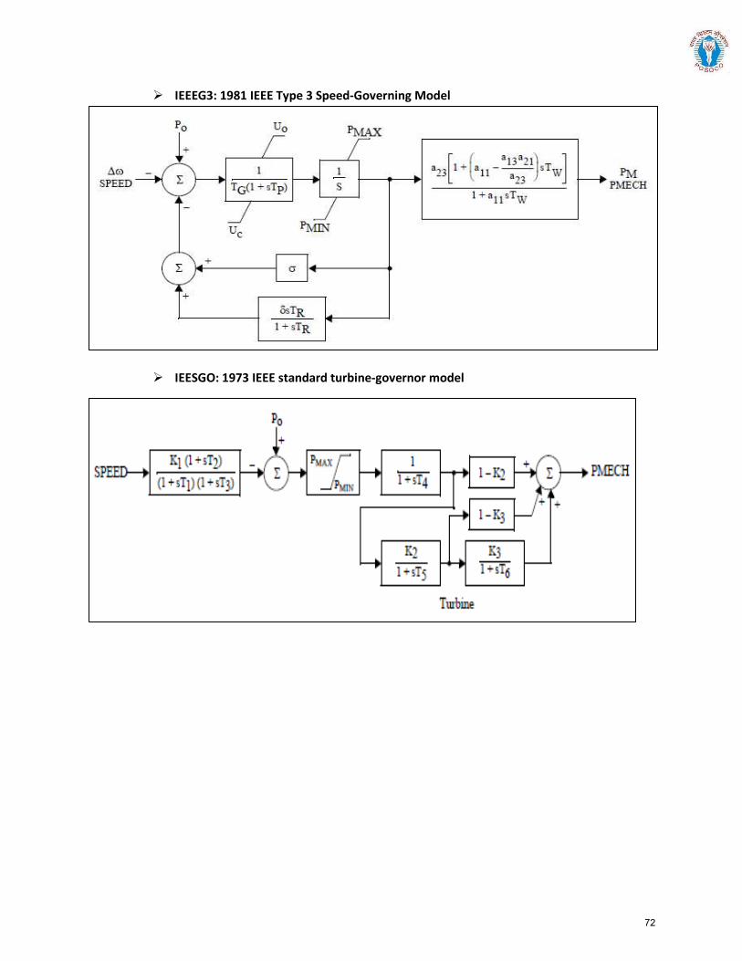
IEEEG3: 1981 IEEE Type 3 Speed-Governing Model
IEESGO: 1973 IEEE standard turbine-governor model
72
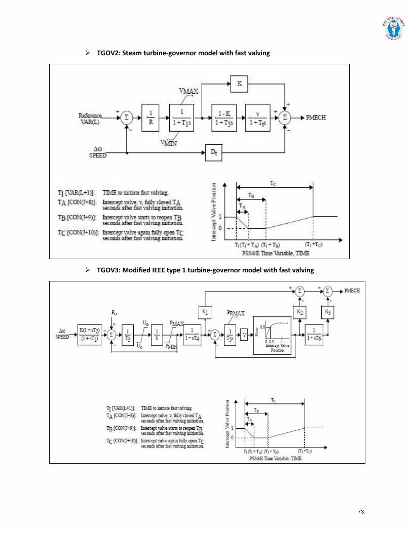
TGOV2: Steam turbine-governor model with fast valving
TGOV3: Modified IEEE type 1 turbine-governor model with fast valving
73
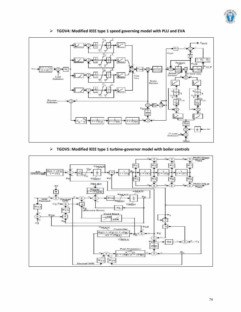
TGOV4: Modified IEEE type 1 speed governing model with PLU and EVA
TGOV5: Modified IEEE type 1 turbine-governor model with boiler controls
74
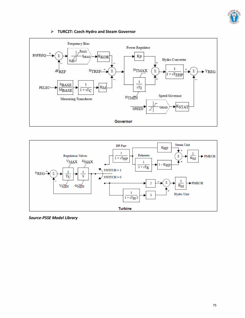
TURCZT: Czech Hydro and Steam Governor
Source-PSSE Model Library
75
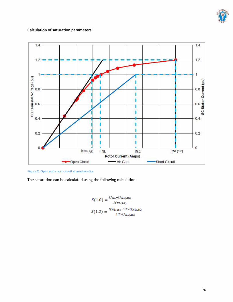
Calculation of saturation parameters:
Figure 2: Open and short circuit characteristics
The saturation can be calculated using the following calculation:
76
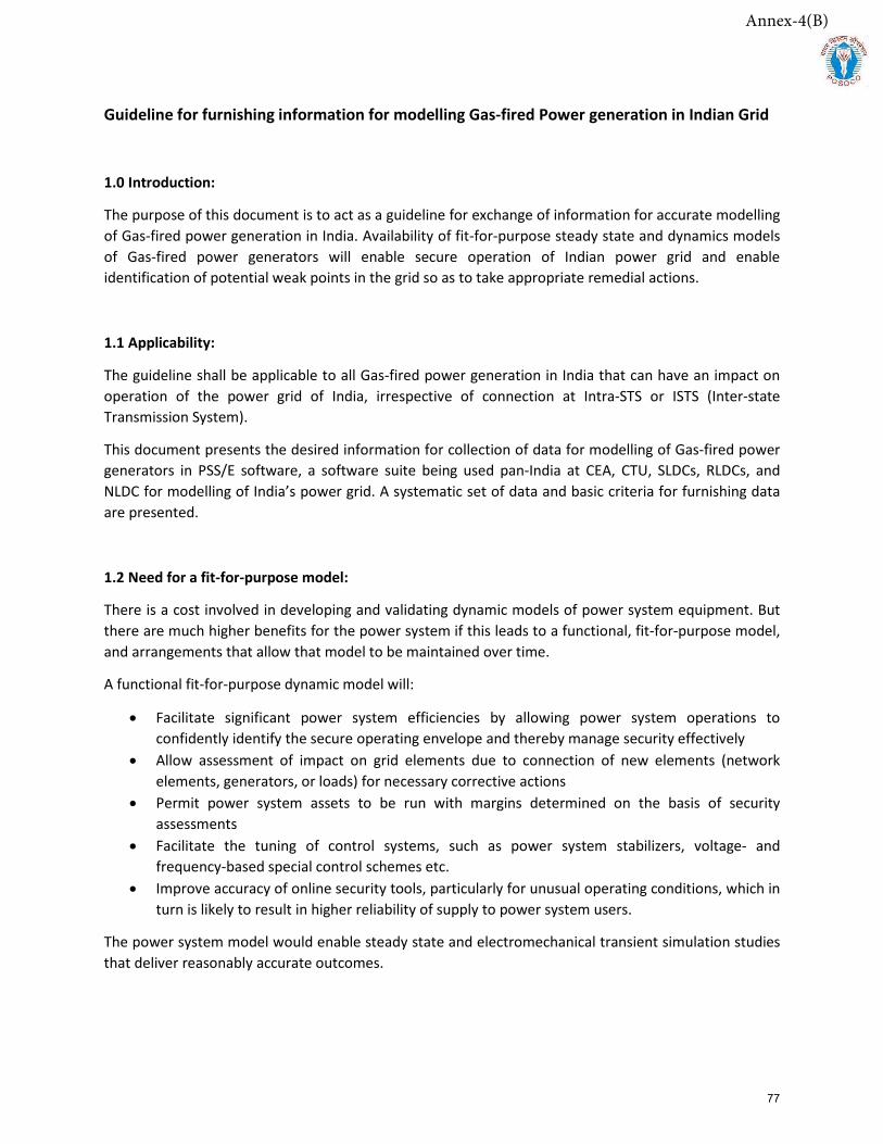
Guideline for furnishing information for modelling Gas-fired Power generation in Indian Grid
1.0 Introduction:
The purpose of this document is to act as a guideline for exchange of information for accurate modelling of Gas-fired power generation in India. Availability of fit-for-purpose steady state and dynamics models of Gas-fired power generators will enable secure operation of Indian power grid and enable identification of potential weak points in the grid so as to take appropriate remedial actions.
1.1 Applicability:
The guideline shall be applicable to all Gas-fired power generation in India that can have an impact on operation of the power grid of India, irrespective of connection at Intra-STS or ISTS (Inter-state Transmission System).
This document presents the desired information for collection of data for modelling of Gas-fired power generators in PSS/E software, a software suite being used pan-India at CEA, CTU, SLDCs, RLDCs, and NLDC for modelling of India’s power grid. A systematic set of data and basic criteria for furnishing data are presented.
1.2 Need for a fit-for-purpose model:
There is a cost involved in developing and validating dynamic models of power system equipment. But there are much higher benefits for the power system if this leads to a functional, fit-for-purpose model, and arrangements that allow that model to be maintained over time.
A functional fit-for-purpose dynamic model will:
• Facilitate significant power system efficiencies by allowing power system operations toconfidently identify the secure operating envelope and thereby manage security effectively
• Allow assessment of impact on grid elements due to connection of new elements (networkelements, generators, or loads) for necessary corrective actions
• Permit power system assets to be run with margins determined on the basis of securityassessments
• Facilitate the tuning of control systems, such as power system stabilizers, voltage- andfrequency-based special control schemes etc.
• Improve accuracy of online security tools, particularly for unusual operating conditions, which inturn is likely to result in higher reliability of supply to power system users.
The power system model would enable steady state and electromechanical transient simulation studies that deliver reasonably accurate outcomes.
Annex-4(B)
77
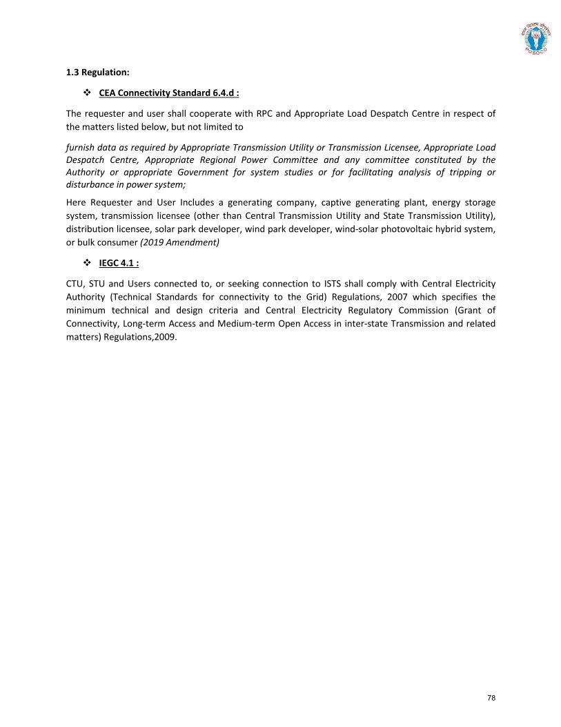
1.3 Regulation:
CEA Connectivity Standard 6.4.d :
The requester and user shall cooperate with RPC and Appropriate Load Despatch Centre in respect of the matters listed below, but not limited to
furnish data as required by Appropriate Transmission Utility or Transmission Licensee, Appropriate Load Despatch Centre, Appropriate Regional Power Committee and any committee constituted by the Authority or appropriate Government for system studies or for facilitating analysis of tripping or disturbance in power system;
Here Requester and User Includes a generating company, captive generating plant, energy storage system, transmission licensee (other than Central Transmission Utility and State Transmission Utility), distribution licensee, solar park developer, wind park developer, wind-solar photovoltaic hybrid system, or bulk consumer (2019 Amendment)
IEGC 4.1 :
CTU, STU and Users connected to, or seeking connection to ISTS shall comply with Central Electricity Authority (Technical Standards for connectivity to the Grid) Regulations, 2007 which specifies the minimum technical and design criteria and Central Electricity Regulatory Commission (Grant of Connectivity, Long-term Access and Medium-term Open Access in inter-state Transmission and related matters) Regulations,2009.
78
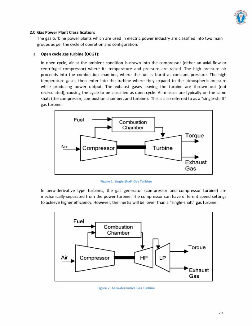
2.0 Gas Power Plant Classification: The gas turbine power plants which are used in electric power industry are classified into two main groups as per the cycle of operation and configuration:
a. Open cycle gas turbine (OCGT):
In open cycle, air at the ambient condition is drawn into the compressor (either an axial-flow orcentrifugal compressor) where its temperature and pressure are raised. The high pressure airproceeds into the combustion chamber, where the fuel is burnt at constant pressure. The hightemperature gases then enter into the turbine where they expand to the atmospheric pressurewhile producing power output. The exhaust gases leaving the turbine are thrown out (notrecirculated), causing the cycle to be classified as open cycle. All masses are typically on the sameshaft (the compressor, combustion chamber, and turbine). This is also referred to as a “single-shaft”gas turbine.
Figure 1: Single Shaft Gas Turbine
In aero-derivative type turbines, the gas generator (compressor and compressor turbine) are mechanically separated from the power turbine. The compressor can have different speed settings to achieve higher efficiency. However, the inertia will be lower than a “single-shaft” gas turbine.
Figure 2: Aero-derivative Gas Turbine
79
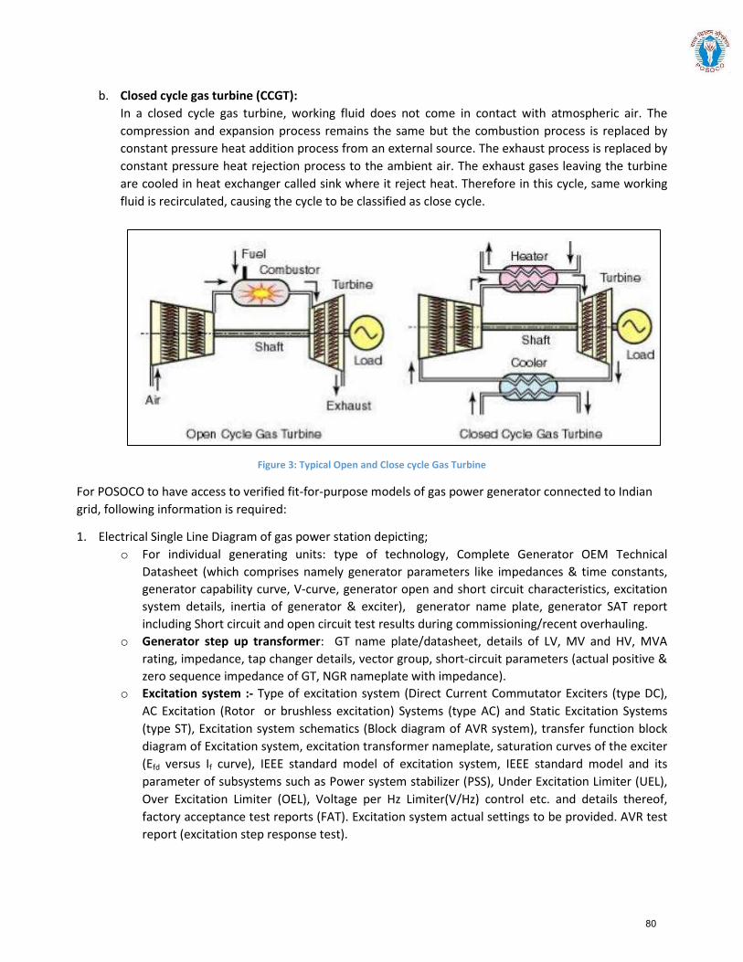
b. Closed cycle gas turbine (CCGT): In a closed cycle gas turbine, working fluid does not come in contact with atmospheric air. The compression and expansion process remains the same but the combustion process is replaced by constant pressure heat addition process from an external source. The exhaust process is replaced by constant pressure heat rejection process to the ambient air. The exhaust gases leaving the turbine are cooled in heat exchanger called sink where it reject heat. Therefore in this cycle, same working fluid is recirculated, causing the cycle to be classified as close cycle.
Figure 3: Typical Open and Close cycle Gas Turbine
For POSOCO to have access to verified fit-for-purpose models of gas power generator connected to Indian grid, following information is required:
1. Electrical Single Line Diagram of gas power station depicting; o For individual generating units: type of technology, Complete Generator OEM Technical
Datasheet (which comprises namely generator parameters like impedances & time constants, generator capability curve, V-curve, generator open and short circuit characteristics, excitation system details, inertia of generator & exciter), generator name plate, generator SAT report including Short circuit and open circuit test results during commissioning/recent overhauling.
o Generator step up transformer: GT name plate/datasheet, details of LV, MV and HV, MVA rating, impedance, tap changer details, vector group, short-circuit parameters (actual positive & zero sequence impedance of GT, NGR nameplate with impedance).
o Excitation system :- Type of excitation system (Direct Current Commutator Exciters (type DC), AC Excitation (Rotor or brushless excitation) Systems (type AC) and Static Excitation Systems (type ST), Excitation system schematics (Block diagram of AVR system), transfer function block diagram of Excitation system, excitation transformer nameplate, saturation curves of the exciter (Efd versus If curve), IEEE standard model of excitation system, IEEE standard model and its parameter of subsystems such as Power system stabilizer (PSS), Under Excitation Limiter (UEL), Over Excitation Limiter (OEL), Voltage per Hz Limiter(V/Hz) control etc. and details thereof, factory acceptance test reports (FAT). Excitation system actual settings to be provided. AVR test report (excitation step response test).
80
o Power System Stabilizer (PSS): Transfer function block diagram of PSS, IEEE Standard Model,Actual PSS software settings, PSS commissioning report and recent PSS tuning report.
o Turbine-Governor system :- Type of prime mover (open cycle, aero-derivative gas turbine orclose cycle), droop and dead-band setting, characteristic of active power versus fuel valveposition (or fuel stroke reference), size of steam turbine (ST), frequency control of ST, time lagand relationship of GT and ST, model of governor control system (including details oftechnology, valves, valves characteristics) , inlet guide vane (IGV) characteristic, ramp rates,base load/frequency control, details of heat recovery generator-HRSG (Block diagram, GT outputvs heat relationship, Drum time constant, Pressure loss due to friction in boiler tubes), , turbineinertia, IEEE standard model of turbine governor system and its transfer function Block diagramand its parameters, details of control mode (boiler-follow, turbine-follow, or coordinatedcontrol), commissioning report of turbine-governor system or recent governor testing report.
2. Generic models of individual components (generator, exciter, turbine-governor and PSS of gas powergenerator (refer sections 3.2 to section 3.5)
o Model should be suitable for an integration time step between 1ms and 20ms, and suitable foroperation up-to 100 s
o Simulation results depicting validation of generic models against user-defined models (for P, Q,V, I) and against actual measurement (after commissioning) to be provided.
3. Encrypted user defined model (UDM) in a format suitable for latest PSSE release PSS/E (*.dll files) forelectromechanical transient simulation for components of gas power generators (in case non-availabilityof validated generic model)
o User guide for Encrypted models to be provided including instructions on how the model shouldbe set-up
o Corresponding transfer function block diagrams to be providedo Simulation results depicting validation of User-Defined models against actual measurement to
be providedo The use of black-box type representation is not preferred
81
Annexure: Formats for submission of modelling data for Gas-fired power generation
Version History:
Version no. Release Date Prepared by* Checked/Issued by* Changes
*Mention Designation and Contact Details
Details submitted:
Details pending:
82
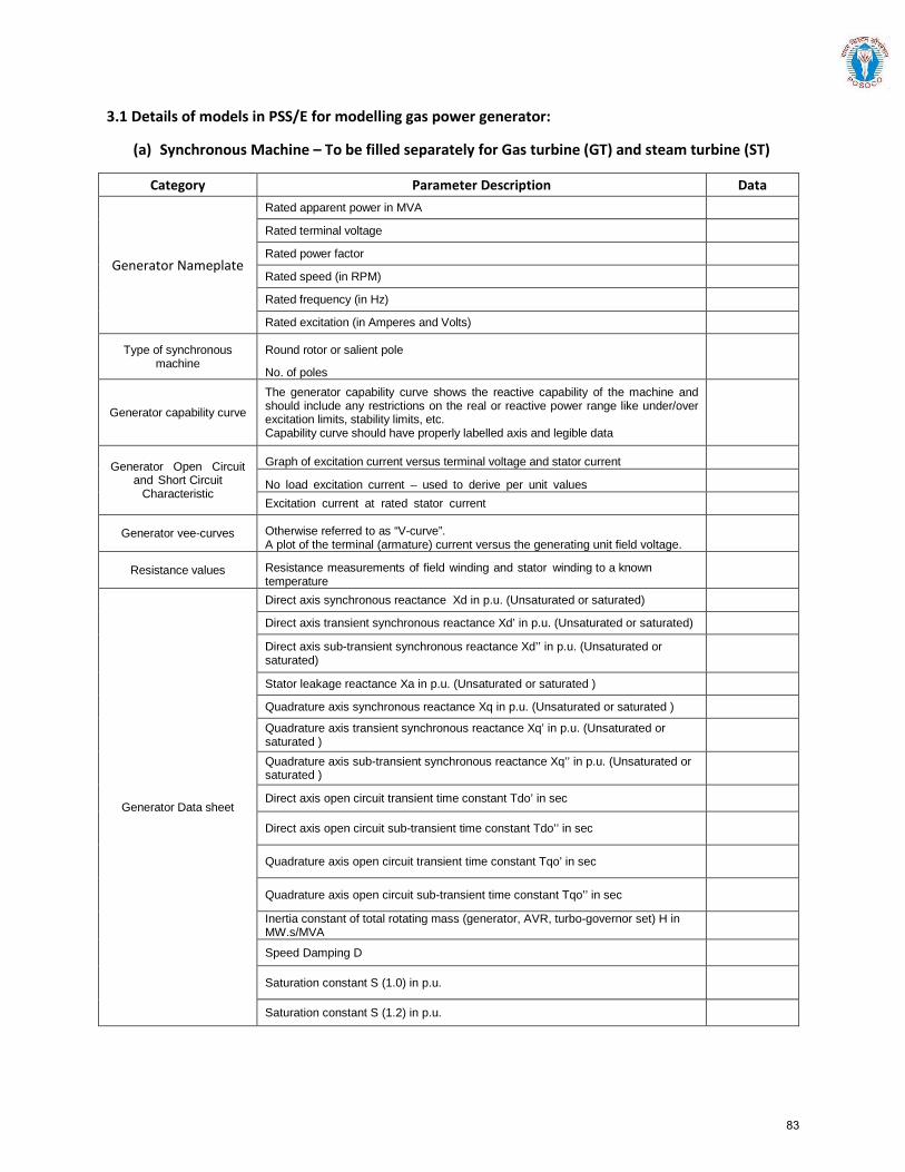
3.1 Details of models in PSS/E for modelling gas power generator:
(a) Synchronous Machine – To be filled separately for Gas turbine (GT) and steam turbine (ST)
Category Parameter Description Data
Generator Nameplate
Rated apparent power in MVA Rated terminal voltage Rated power factor Rated speed (in RPM) Rated frequency (in Hz) Rated excitation (in Amperes and Volts)
Type of synchronous machine
Round rotor or salient pole
No. of poles
Generator capability curve The generator capability curve shows the reactive capability of the machine and should include any restrictions on the real or reactive power range like under/over excitation limits, stability limits, etc. Capability curve should have properly labelled axis and legible data
Generator Open Circuit and Short Circuit
Characteristic
Graph of excitation current versus terminal voltage and stator current
No load excitation current – used to derive per unit values Excitation current at rated stator current
Generator vee-curves Otherwise referred to as “V-curve”. A plot of the terminal (armature) current versus the generating unit field voltage.
Resistance values Resistance measurements of field winding and stator winding to a known temperature
Generator Data sheet
Direct axis synchronous reactance Xd in p.u. (Unsaturated or saturated) Direct axis transient synchronous reactance Xd’ in p.u. (Unsaturated or saturated) Direct axis sub-transient synchronous reactance Xd’’ in p.u. (Unsaturated or saturated)
Stator leakage reactance Xa in p.u. (Unsaturated or saturated ) Quadrature axis synchronous reactance Xq in p.u. (Unsaturated or saturated ) Quadrature axis transient synchronous reactance Xq’ in p.u. (Unsaturated or saturated )
Quadrature axis sub-transient synchronous reactance Xq’’ in p.u. (Unsaturated or saturated )
Direct axis open circuit transient time constant Tdo’ in sec
Direct axis open circuit sub-transient time constant Tdo’’ in sec
Quadrature axis open circuit transient time constant Tqo’ in sec
Quadrature axis open circuit sub-transient time constant Tqo’’ in sec Inertia constant of total rotating mass (generator, AVR, turbo-governor set) H in MW.s/MVA
Speed Damping D
Saturation constant S (1.0) in p.u.
Saturation constant S (1.2) in p.u.
83
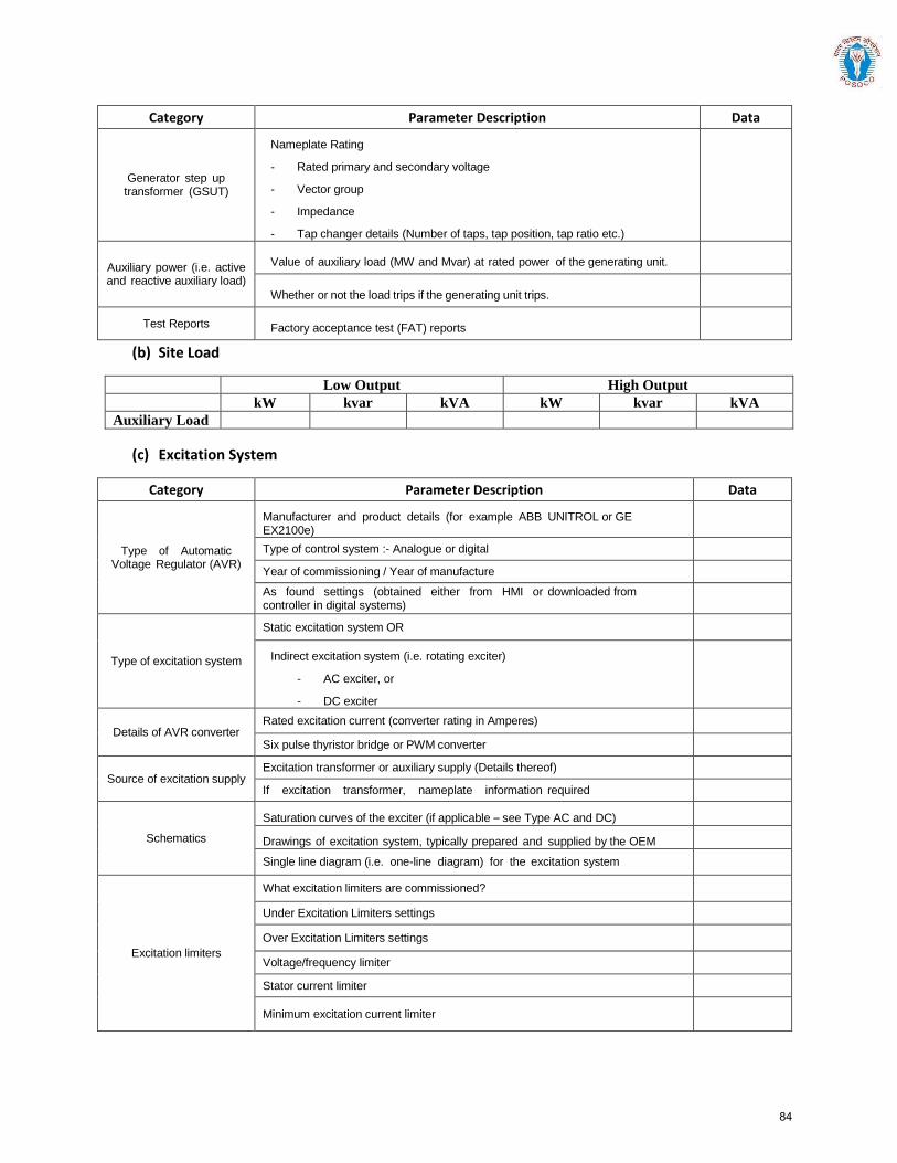
Category Parameter Description Data
Generator step up transformer (GSUT)
Nameplate Rating
- Rated primary and secondary voltage
- Vector group
- Impedance
- Tap changer details (Number of taps, tap position, tap ratio etc.)
Auxiliary power (i.e. active and reactive auxiliary load)
Value of auxiliary load (MW and Mvar) at rated power of the generating unit.
Whether or not the load trips if the generating unit trips.
Test Reports Factory acceptance test (FAT) reports
(b) Site Load
Low Output High Output kW kvar kVA kW kvar kVA Auxiliary Load
(c) Excitation System
Category Parameter Description Data
Type of Automatic Voltage Regulator (AVR)
Manufacturer and product details (for example ABB UNITROL or GE EX2100e)
Type of control system :- Analogue or digital Year of commissioning / Year of manufacture As found settings (obtained either from HMI or downloaded from controller in digital systems)
Type of excitation system
Static excitation system OR
Indirect excitation system (i.e. rotating exciter)
- AC exciter, or
- DC exciter
Details of AVR converter Rated excitation current (converter rating in Amperes) Six pulse thyristor bridge or PWM converter
Source of excitation supply Excitation transformer or auxiliary supply (Details thereof) If excitation transformer, nameplate information required
Schematics
Saturation curves of the exciter (if applicable – see Type AC and DC)
Drawings of excitation system, typically prepared and supplied by the OEM
Single line diagram (i.e. one-line diagram) for the excitation system
Excitation limiters
What excitation limiters are commissioned?
Under Excitation Limiters settings
Over Excitation Limiters settings
Voltage/frequency limiter Stator current limiter
Minimum excitation current limiter
84
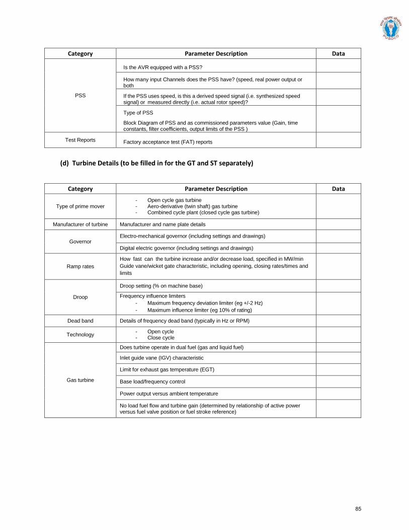
Category Parameter Description Data
PSS
Is the AVR equipped with a PSS?
How many input Channels does the PSS have? (speed, real power output or both
If the PSS uses speed, is this a derived speed signal (i.e. synthesized speed signal) or measured directly (i.e. actual rotor speed)?
Type of PSS
Block Diagram of PSS and as commissioned parameters value (Gain, time constants, filter coefficients, output limits of the PSS )
Test Reports Factory acceptance test (FAT) reports
(d) Turbine Details (to be filled in for the GT and ST separately)
Category Parameter Description Data
Type of prime mover - Open cycle gas turbine - Aero-derivative (twin shaft) gas turbine - Combined cycle plant (closed cycle gas turbine)
Manufacturer of turbine Manufacturer and name plate details
Governor Electro-mechanical governor (including settings and drawings)
Digital electric governor (including settings and drawings)
Ramp rates How fast can the turbine increase and/or decrease load, specified in MW/min
Guide vane/wicket gate characteristic, including opening, closing rates/times and
limits
Droop
Droop setting (% on machine base) Frequency influence limiters
- Maximum frequency deviation limiter (eg +/-2 Hz)
- Maximum influence limiter (eg 10% of rating)
Dead band Details of frequency dead band (typically in Hz or RPM)
Technology - Open cycle - Close cycle
Gas turbine
Does turbine operate in dual fuel (gas and liquid fuel) Inlet guide vane (IGV) characteristic
Limit for exhaust gas temperature (EGT)
Base load/frequency control
Power output versus ambient temperature
No load fuel flow and turbine gain (determined by relationship of active power versus fuel valve position or fuel stroke reference)
85
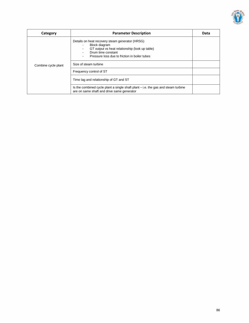
Category Parameter Description Data
Combine cycle plant
Details on heat recovery steam generator (HRSG) - Block diagram - GT output vs heat relationship (look up table) - Drum time constant - Pressure loss due to friction in boiler tubes
Size of steam turbine
Frequency control of ST
Time lag and relationship of GT and ST
Is the combined cycle plant a single shaft plant – i.e. the gas and steam turbine
are on same shaft and drive same generator
86
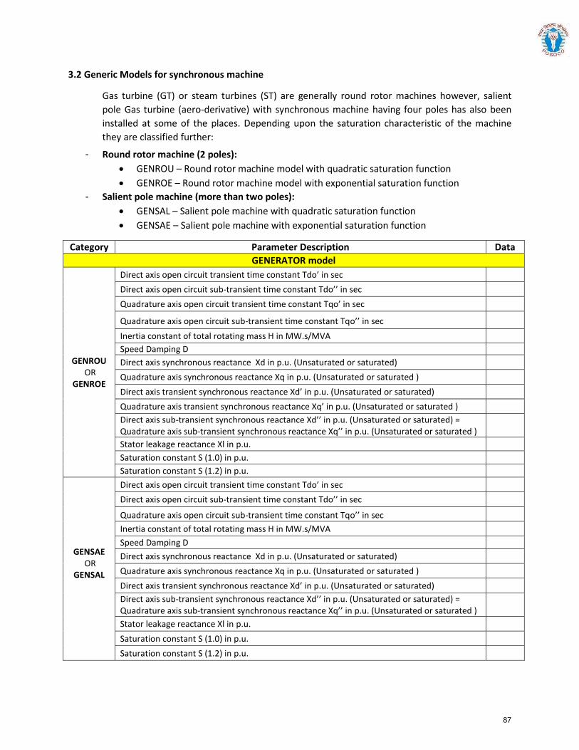
3.2 Generic Models for synchronous machine
Gas turbine (GT) or steam turbines (ST) are generally round rotor machines however, salient pole Gas turbine (aero-derivative) with synchronous machine having four poles has also been installed at some of the places. Depending upon the saturation characteristic of the machine they are classified further:
- Round rotor machine (2 poles): • GENROU – Round rotor machine model with quadratic saturation function• GENROE – Round rotor machine model with exponential saturation function
- Salient pole machine (more than two poles): • GENSAL – Salient pole machine with quadratic saturation function• GENSAE – Salient pole machine with exponential saturation function
Category Parameter Description Data GENERATOR model
GENROU OR
GENROE
Direct axis open circuit transient time constant Tdo’ in sec Direct axis open circuit sub-transient time constant Tdo’’ in sec Quadrature axis open circuit transient time constant Tqo’ in sec
Quadrature axis open circuit sub-transient time constant Tqo’’ in sec Inertia constant of total rotating mass H in MW.s/MVA Speed Damping D Direct axis synchronous reactance Xd in p.u. (Unsaturated or saturated) Quadrature axis synchronous reactance Xq in p.u. (Unsaturated or saturated ) Direct axis transient synchronous reactance Xd’ in p.u. (Unsaturated or saturated) Quadrature axis transient synchronous reactance Xq’ in p.u. (Unsaturated or saturated ) Direct axis sub-transient synchronous reactance Xd’’ in p.u. (Unsaturated or saturated) = Quadrature axis sub-transient synchronous reactance Xq’’ in p.u. (Unsaturated or saturated ) Stator leakage reactance Xl in p.u. Saturation constant S (1.0) in p.u. Saturation constant S (1.2) in p.u.
GENSAE OR
GENSAL
Direct axis open circuit transient time constant Tdo’ in sec Direct axis open circuit sub-transient time constant Tdo’’ in sec
Quadrature axis open circuit sub-transient time constant Tqo’’ in sec Inertia constant of total rotating mass H in MW.s/MVA Speed Damping D Direct axis synchronous reactance Xd in p.u. (Unsaturated or saturated) Quadrature axis synchronous reactance Xq in p.u. (Unsaturated or saturated ) Direct axis transient synchronous reactance Xd’ in p.u. (Unsaturated or saturated) Direct axis sub-transient synchronous reactance Xd’’ in p.u. (Unsaturated or saturated) = Quadrature axis sub-transient synchronous reactance Xq’’ in p.u. (Unsaturated or saturated ) Stator leakage reactance Xl in p.u. Saturation constant S (1.0) in p.u. Saturation constant S (1.2) in p.u.
87
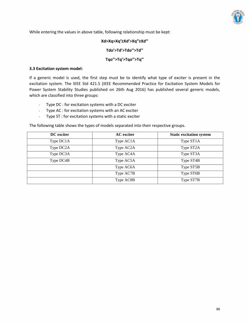
While entering the values in above table, following relationship must be kept:
Xd>Xq>Xq’≥Xd’>Xq”≥Xd’’
Tdo’>Td’>Tdo’’>Td’’
Tqo’’>Tq’>Tqo’’>Tq’’
3.3 Excitation system model:
If a generic model is used, the first step must be to identify what type of exciter is present in the excitation system. The IEEE Std 421.5 (IEEE Recommended Practice for Excitation System Models for Power System Stability Studies published on 26th Aug 2016) has published several generic models, which are classified into three groups:
- Type DC : for excitation systems with a DC exciter - Type AC : for excitation systems with an AC exciter - Type ST : for excitation systems with a static exciter
The following table shows the types of models separated into their respective groups.
DC exciter AC exciter Static excitation system Type DC1A Type AC1A Type ST1A Type DC2A Type AC2A Type ST2A Type DC3A Type AC4A Type ST3A Type DC4B Type AC5A Type ST4B
Type AC6A Type ST5B Type AC7B Type ST6B Type AC8B Type ST7B
88
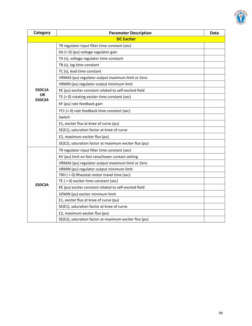
Category Parameter Description Data DC Exciter
ESDC1A OR
ESDC2A
TR regulator input filter time constant (sec) KA (> 0) (pu) voltage regulator gain TA (s), voltage regulator time constant TB (s), lag time constant TC (s), lead time constant VRMAX (pu) regulator output maximum limit or Zero VRMIN (pu) regulator output minimum limit KE (pu) exciter constant related to self-excited field TE (> 0) rotating exciter time constant (sec)
KF (pu) rate feedback gain
TF1 (> 0) rate feedback time constant (sec) Switch E1, exciter flux at knee of curve (pu) SE(E1), saturation factor at knee of curve
E2, maximum exciter flux (pu)
SE(E2), saturation factor at maximum exciter flux (pu)
ESDC3A
TR regulator input filter time constant (sec) KV (pu) limit on fast raise/lower contact setting VRMAX (pu) regulator output maximum limit or Zero VRMIN (pu) regulator output minimum limit TRH ( > 0) Rheostat motor travel time (sec) TE ( > 0) exciter time-constant (sec) KE (pu) exciter constant related to self-excited field
VEMIN (pu) exciter minimum limit E1, exciter flux at knee of curve (pu) SE(E1), saturation factor at knee of curve
E2, maximum exciter flux (pu) SE(E2), saturation factor at maximum exciter flux (pu)
89
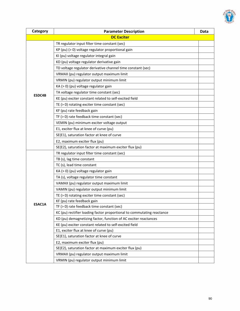
Category Parameter Description Data DC Exciter
ESDC4B
TR regulator input filter time constant (sec) KP (pu) (> 0) voltage regulator proportional gain KI (pu) voltage regulator integral gain KD (pu) voltage regulator derivative gain TD voltage regulator derivative channel time constant (sec) VRMAX (pu) regulator output maximum limit VRMIN (pu) regulator output minimum limit KA (> 0) (pu) voltage regulator gain TA voltage regulator time constant (sec) KE (pu) exciter constant related to self-excited field TE (> 0) rotating exciter time constant (sec) KF (pu) rate feedback gain TF (> 0) rate feedback time constant (sec) VEMIN (pu) minimum exciter voltage output E1, exciter flux at knee of curve (pu) SE(E1), saturation factor at knee of curve
E2, maximum exciter flux (pu) SE(E2), saturation factor at maximum exciter flux (pu)
ESAC1A
TR regulator input filter time constant (sec) TB (s), lag time constant TC (s), lead time constant KA (> 0) (pu) voltage regulator gain TA (s), voltage regulator time constant VAMAX (pu) regulator output maximum limit VAMIN (pu) regulator output minimum limit TE (> 0) rotating exciter time constant (sec) KF (pu) rate feedback gain TF (> 0) rate feedback time constant (sec) KC (pu) rectifier loading factor proportional to commutating reactance KD (pu) demagnetizing factor, function of AC exciter reactances KE (pu) exciter constant related to self-excited field E1, exciter flux at knee of curve (pu) SE(E1), saturation factor at knee of curve
E2, maximum exciter flux (pu) SE(E2), saturation factor at maximum exciter flux (pu) VRMAX (pu) regulator output maximum limit VRMIN (pu) regulator output minimum limit
90
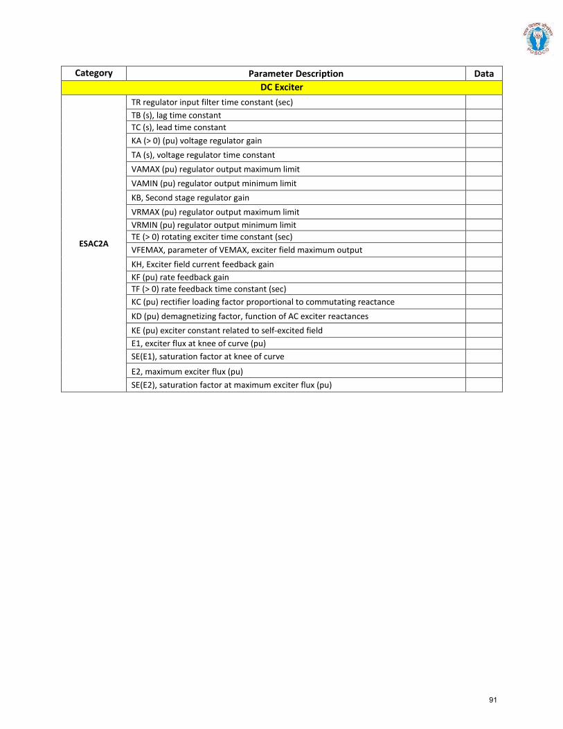
Category Parameter Description Data DC Exciter
ESAC2A
TR regulator input filter time constant (sec) TB (s), lag time constant TC (s), lead time constant KA (> 0) (pu) voltage regulator gain TA (s), voltage regulator time constant VAMAX (pu) regulator output maximum limit VAMIN (pu) regulator output minimum limit KB, Second stage regulator gain VRMAX (pu) regulator output maximum limit VRMIN (pu) regulator output minimum limit TE (> 0) rotating exciter time constant (sec) VFEMAX, parameter of VEMAX, exciter field maximum output KH, Exciter field current feedback gain KF (pu) rate feedback gain TF (> 0) rate feedback time constant (sec) KC (pu) rectifier loading factor proportional to commutating reactance KD (pu) demagnetizing factor, function of AC exciter reactances KE (pu) exciter constant related to self-excited field E1, exciter flux at knee of curve (pu) SE(E1), saturation factor at knee of curve
E2, maximum exciter flux (pu) SE(E2), saturation factor at maximum exciter flux (pu)
91
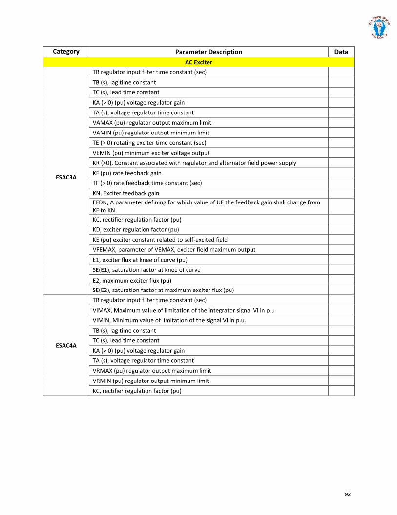
Category Parameter Description Data AC Exciter
ESAC3A
TR regulator input filter time constant (sec) TB (s), lag time constant TC (s), lead time constant KA (> 0) (pu) voltage regulator gain TA (s), voltage regulator time constant VAMAX (pu) regulator output maximum limit VAMIN (pu) regulator output minimum limit TE (> 0) rotating exciter time constant (sec) VEMIN (pu) minimum exciter voltage output KR (>0), Constant associated with regulator and alternator field power supply KF (pu) rate feedback gain TF (> 0) rate feedback time constant (sec) KN, Exciter feedback gain EFDN, A parameter defining for which value of UF the feedback gain shall change from KF to KN KC, rectifier regulation factor (pu) KD, exciter regulation factor (pu) KE (pu) exciter constant related to self-excited field VFEMAX, parameter of VEMAX, exciter field maximum output E1, exciter flux at knee of curve (pu) SE(E1), saturation factor at knee of curve
E2, maximum exciter flux (pu) SE(E2), saturation factor at maximum exciter flux (pu)
ESAC4A
TR regulator input filter time constant (sec) VIMAX, Maximum value of limitation of the integrator signal VI in p.u VIMIN, Minimum value of limitation of the signal VI in p.u. TB (s), lag time constant TC (s), lead time constant KA (> 0) (pu) voltage regulator gain TA (s), voltage regulator time constant VRMAX (pu) regulator output maximum limit VRMIN (pu) regulator output minimum limit KC, rectifier regulation factor (pu)
92
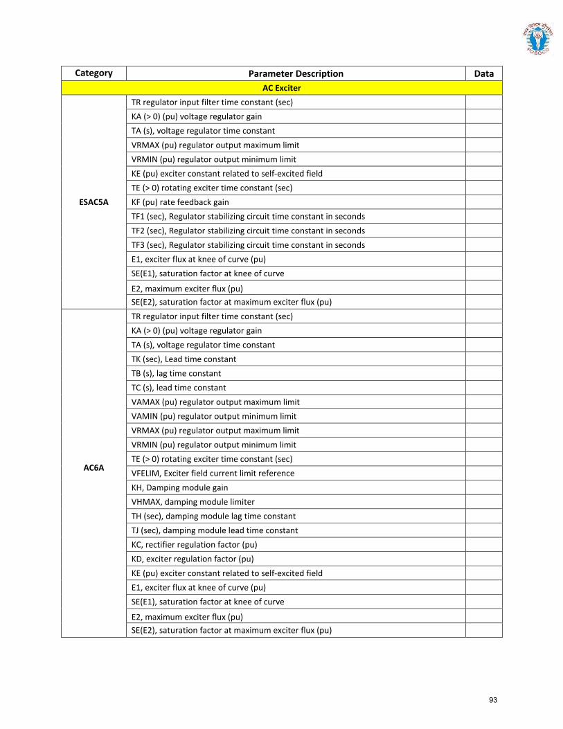
Category Parameter Description Data AC Exciter
ESAC5A
TR regulator input filter time constant (sec) KA (> 0) (pu) voltage regulator gain TA (s), voltage regulator time constant VRMAX (pu) regulator output maximum limit VRMIN (pu) regulator output minimum limit KE (pu) exciter constant related to self-excited field TE (> 0) rotating exciter time constant (sec) KF (pu) rate feedback gain TF1 (sec), Regulator stabilizing circuit time constant in seconds TF2 (sec), Regulator stabilizing circuit time constant in seconds TF3 (sec), Regulator stabilizing circuit time constant in seconds E1, exciter flux at knee of curve (pu) SE(E1), saturation factor at knee of curve
E2, maximum exciter flux (pu) SE(E2), saturation factor at maximum exciter flux (pu)
AC6A
TR regulator input filter time constant (sec) KA (> 0) (pu) voltage regulator gain TA (s), voltage regulator time constant TK (sec), Lead time constant TB (s), lag time constant TC (s), lead time constant VAMAX (pu) regulator output maximum limit VAMIN (pu) regulator output minimum limit VRMAX (pu) regulator output maximum limit VRMIN (pu) regulator output minimum limit TE (> 0) rotating exciter time constant (sec) VFELIM, Exciter field current limit reference KH, Damping module gain VHMAX, damping module limiter TH (sec), damping module lag time constant TJ (sec), damping module lead time constant KC, rectifier regulation factor (pu) KD, exciter regulation factor (pu) KE (pu) exciter constant related to self-excited field E1, exciter flux at knee of curve (pu) SE(E1), saturation factor at knee of curve
E2, maximum exciter flux (pu) SE(E2), saturation factor at maximum exciter flux (pu)
93
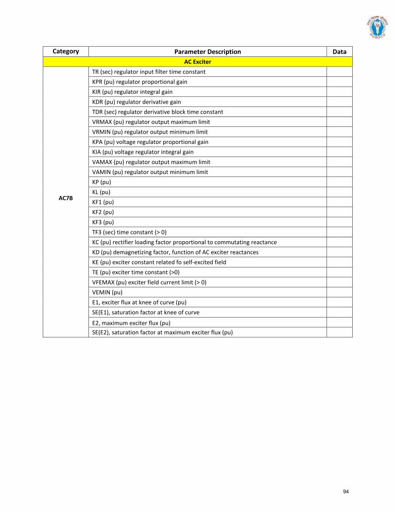
Category Parameter Description Data AC Exciter
AC7B
TR (sec) regulator input filter time constant KPR (pu) regulator proportional gain KIR (pu) regulator integral gain KDR (pu) regulator derivative gain TDR (sec) regulator derivative block time constant VRMAX (pu) regulator output maximum limit VRMIN (pu) regulator output minimum limit KPA (pu) voltage regulator proportional gain KIA (pu) voltage regulator integral gain VAMAX (pu) regulator output maximum limit VAMIN (pu) regulator output minimum limit KP (pu) KL (pu) KF1 (pu) KF2 (pu) KF3 (pu) TF3 (sec) time constant (> 0) KC (pu) rectifier loading factor proportional to commutating reactance KD (pu) demagnetizing factor, function of AC exciter reactances KE (pu) exciter constant related fo self-excited field TE (pu) exciter time constant (>0) VFEMAX (pu) exciter field current limit (> 0) VEMIN (pu) E1, exciter flux at knee of curve (pu) SE(E1), saturation factor at knee of curve
E2, maximum exciter flux (pu) SE(E2), saturation factor at maximum exciter flux (pu)
94
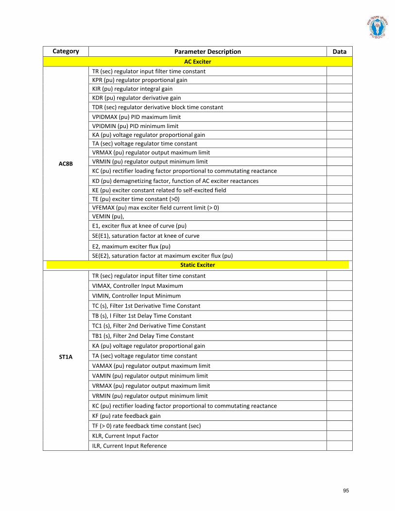
Category Parameter Description Data AC Exciter
AC8B
TR (sec) regulator input filter time constant KPR (pu) regulator proportional gain KIR (pu) regulator integral gain KDR (pu) regulator derivative gain TDR (sec) regulator derivative block time constant VPIDMAX (pu) PID maximum limit VPIDMIN (pu) PID minimum limit KA (pu) voltage regulator proportional gain TA (sec) voltage regulator time constant VRMAX (pu) regulator output maximum limit VRMIN (pu) regulator output minimum limit KC (pu) rectifier loading factor proportional to commutating reactance KD (pu) demagnetizing factor, function of AC exciter reactances KE (pu) exciter constant related fo self-excited field TE (pu) exciter time constant (>0) VFEMAX (pu) max exciter field current limit (> 0) VEMIN (pu), E1, exciter flux at knee of curve (pu) SE(E1), saturation factor at knee of curve
E2, maximum exciter flux (pu) SE(E2), saturation factor at maximum exciter flux (pu)
Static Exciter
ST1A
TR (sec) regulator input filter time constant VIMAX, Controller Input Maximum VIMIN, Controller Input Minimum TC (s), Filter 1st Derivative Time Constant TB (s), l Filter 1st Delay Time Constant TC1 (s), Filter 2nd Derivative Time Constant TB1 (s), Filter 2nd Delay Time Constant KA (pu) voltage regulator proportional gain TA (sec) voltage regulator time constant VAMAX (pu) regulator output maximum limit VAMIN (pu) regulator output minimum limit VRMAX (pu) regulator output maximum limit VRMIN (pu) regulator output minimum limit KC (pu) rectifier loading factor proportional to commutating reactance KF (pu) rate feedback gain TF (> 0) rate feedback time constant (sec) KLR, Current Input Factor ILR, Current Input Reference
95
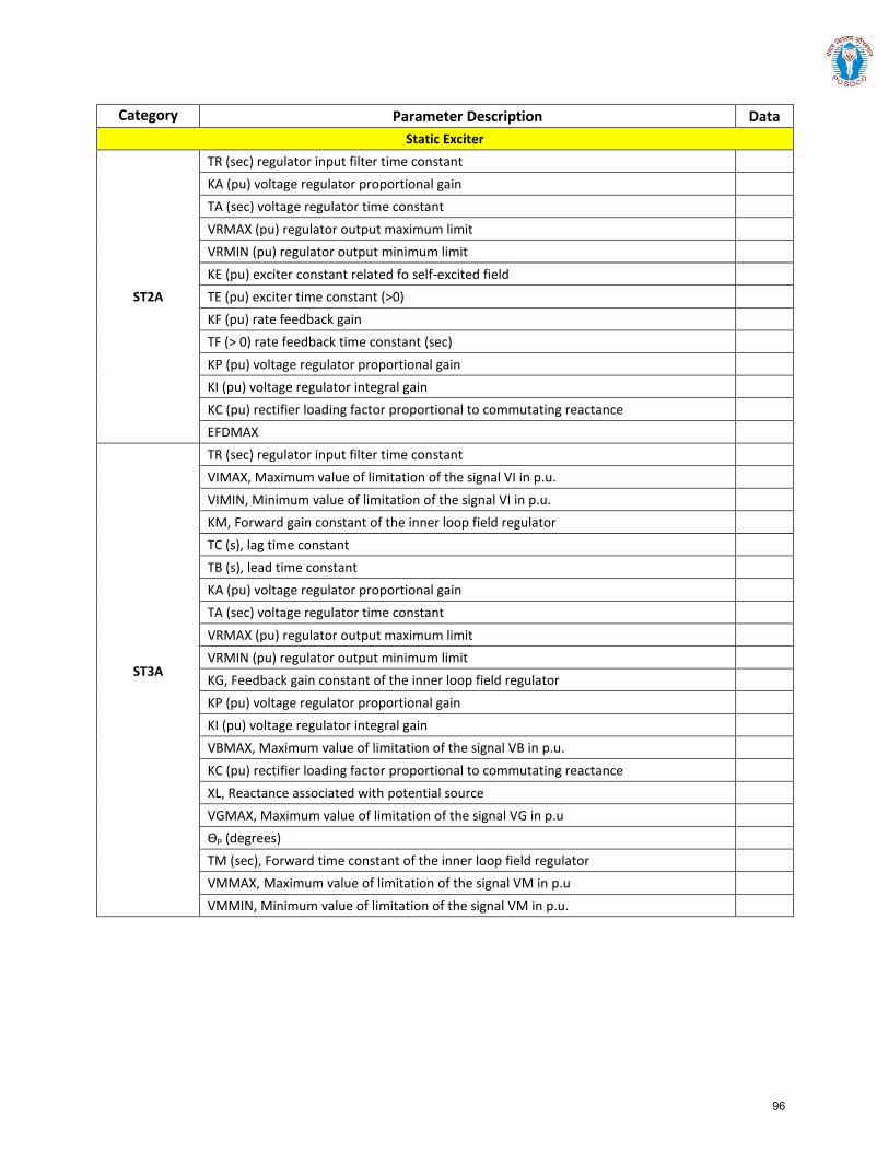
Category Parameter Description Data Static Exciter
ST2A
TR (sec) regulator input filter time constant KA (pu) voltage regulator proportional gain TA (sec) voltage regulator time constant VRMAX (pu) regulator output maximum limit VRMIN (pu) regulator output minimum limit KE (pu) exciter constant related fo self-excited field TE (pu) exciter time constant (>0) KF (pu) rate feedback gain TF (> 0) rate feedback time constant (sec) KP (pu) voltage regulator proportional gain KI (pu) voltage regulator integral gain KC (pu) rectifier loading factor proportional to commutating reactance EFDMAX
ST3A
TR (sec) regulator input filter time constant VIMAX, Maximum value of limitation of the signal VI in p.u. VIMIN, Minimum value of limitation of the signal VI in p.u. KM, Forward gain constant of the inner loop field regulator TC (s), lag time constant TB (s), lead time constant KA (pu) voltage regulator proportional gain TA (sec) voltage regulator time constant VRMAX (pu) regulator output maximum limit VRMIN (pu) regulator output minimum limit KG, Feedback gain constant of the inner loop field regulator KP (pu) voltage regulator proportional gain KI (pu) voltage regulator integral gain VBMAX, Maximum value of limitation of the signal VB in p.u. KC (pu) rectifier loading factor proportional to commutating reactance XL, Reactance associated with potential source VGMAX, Maximum value of limitation of the signal VG in p.u ƟP (degrees) TM (sec), Forward time constant of the inner loop field regulator VMMAX, Maximum value of limitation of the signal VM in p.u VMMIN, Minimum value of limitation of the signal VM in p.u.
96

Category Parameter Description Data Static Exciter
ST4B
TR (sec) regulator input filter time constant KPR (pu) regulator proportional gain KIR (pu) regulator integral gain VRMAX (pu) regulator output maximum limit VRMIN (pu) regulator output minimum limit TA (sec) voltage regulator time constant KPM, Regulator gain KIM, Regulator gain VMMAX, Maximum value of limitation of the signal in p.u. VMMIN, Minimum value of limitation of the signal in p.u. KG KP (pu) voltage regulator proportional gain KI (pu) voltage regulator integral gain VBMAX KC (pu) rectifier loading factor proportional to commutating reactance XL ƟP (degrees)
ST5B
TR regulator input filter time constant (sec) TC1 lead time constant of first lead-lag block (voltage regulator channel) (sec) TB1 lag time constant of first lead-lag block (voltage regulator channel) (sec) TC2 lead time constant of second lead-lag block (voltage regulator channel) (sec) TB2 lag time constant of second lead-lag block (voltage regulator channel) (sec) KR (>0) (pu) voltage regulator gain VRMAX (pu) voltage regulator maximum limit VRMIN (pu) voltage regulator minimum limit T1 voltage regulator time constant (sec) KC (pu) TUC1 lead time constant of first lead-lag block (under-excitation channel) (sec) TUB1 lag time constant of first lead-lag block (under-excitation channel) (sec) TUC2 lead time constant of second lead-lag block (under-excitation channel) (sec) TUB2 lag time constant of second lead-lag block (under-excitation channel) (sec) TOC1 lead time constant of first lead-lag block (over-excitation channel) (sec) TOB1 lag time constant of first lead-lag block (over-excitation channel) (sec) TOC2 lead time constant of second lead-lag block (over-excitation channel) (sec) TOB2 lag time constant of second lead-lag block (over-excitation channel) (sec)
97
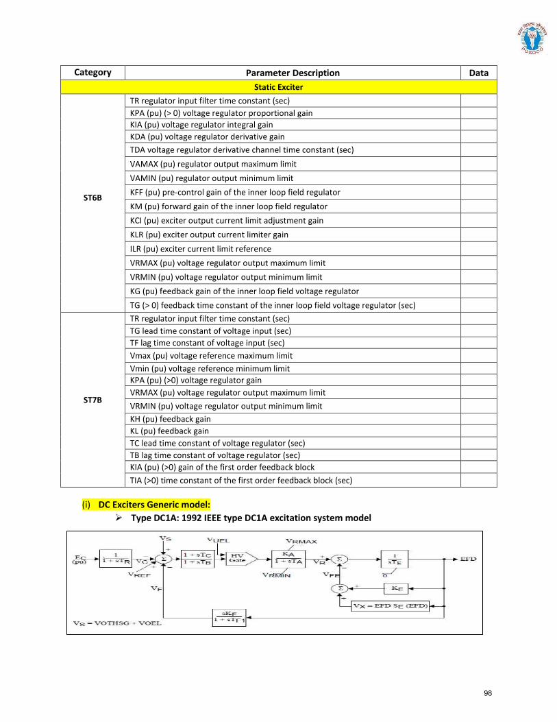
Category Parameter Description Data Static Exciter
ST6B
TR regulator input filter time constant (sec) KPA (pu) (> 0) voltage regulator proportional gain KIA (pu) voltage regulator integral gain KDA (pu) voltage regulator derivative gain TDA voltage regulator derivative channel time constant (sec) VAMAX (pu) regulator output maximum limit VAMIN (pu) regulator output minimum limit KFF (pu) pre-control gain of the inner loop field regulator KM (pu) forward gain of the inner loop field regulator KCI (pu) exciter output current limit adjustment gain KLR (pu) exciter output current limiter gain ILR (pu) exciter current limit reference VRMAX (pu) voltage regulator output maximum limit VRMIN (pu) voltage regulator output minimum limit KG (pu) feedback gain of the inner loop field voltage regulator TG (> 0) feedback time constant of the inner loop field voltage regulator (sec)
ST7B
TR regulator input filter time constant (sec) TG lead time constant of voltage input (sec) TF lag time constant of voltage input (sec) Vmax (pu) voltage reference maximum limit Vmin (pu) voltage reference minimum limit KPA (pu) (>0) voltage regulator gain VRMAX (pu) voltage regulator output maximum limit VRMIN (pu) voltage regulator output minimum limit KH (pu) feedback gain KL (pu) feedback gain TC lead time constant of voltage regulator (sec) TB lag time constant of voltage regulator (sec) KIA (pu) (>0) gain of the first order feedback block TIA (>0) time constant of the first order feedback block (sec)
(i) DC Exciters Generic model: Type DC1A: 1992 IEEE type DC1A excitation system model
98
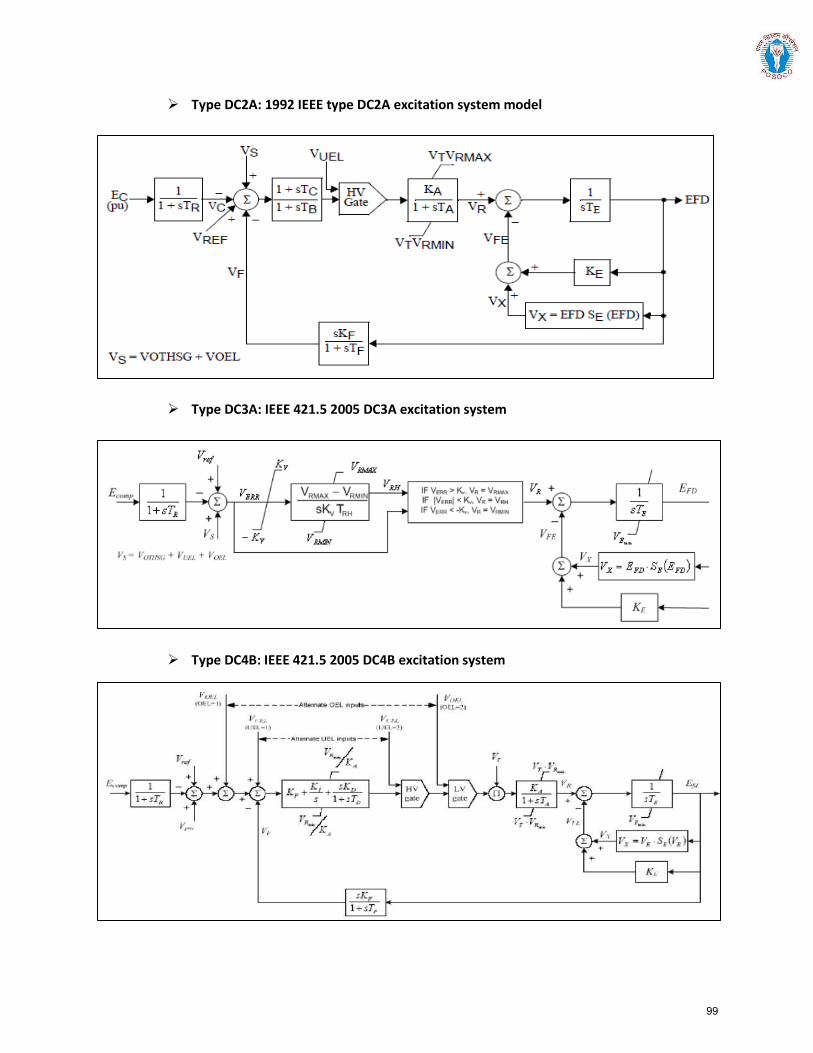
Type DC2A: 1992 IEEE type DC2A excitation system model
Type DC3A: IEEE 421.5 2005 DC3A excitation system
Type DC4B: IEEE 421.5 2005 DC4B excitation system
99
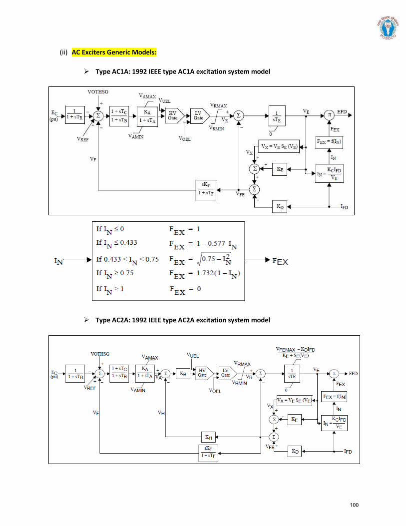
(ii) AC Exciters Generic Models:
Type AC1A: 1992 IEEE type AC1A excitation system model
Type AC2A: 1992 IEEE type AC2A excitation system model
100
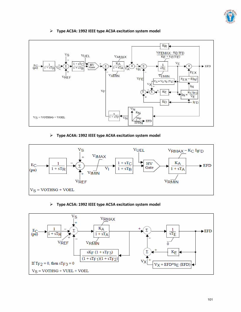
Type AC3A: 1992 IEEE type AC3A excitation system model
Type AC4A: 1992 IEEE type AC4A excitation system model
Type AC5A: 1992 IEEE type AC5A excitation system model
101

Type AC6A: IEEE 421.5 excitation system model
Type AC7B: IEEE 421.5 2005 AC7B excitation system
Type AC8B: IEEE 421.5 2005 AC8B excitation system
102
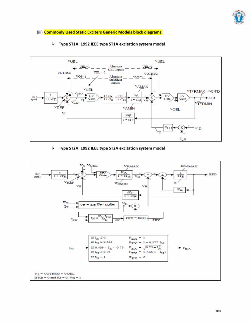
(iii) Commonly Used Static Exciters Generic Models block diagrams:
Type ST1A: 1992 IEEE type ST1A excitation system model
Type ST2A: 1992 IEEE type ST2A excitation system model
103

Type ST3A: 1992 IEEE type ST3A excitation system model
Type ST4B: IEEE type ST4B potential or compounded source-controlled rectifier exciter
104
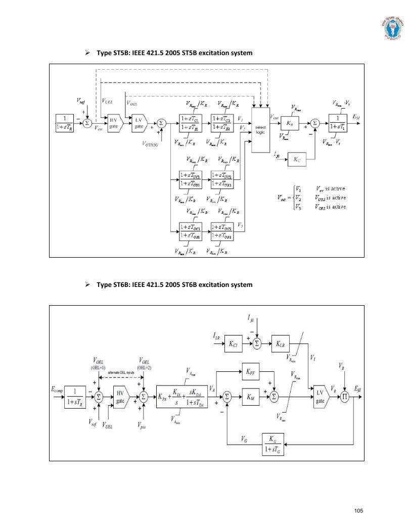
Type ST5B: IEEE 421.5 2005 ST5B excitation system
Type ST6B: IEEE 421.5 2005 ST6B excitation system
105
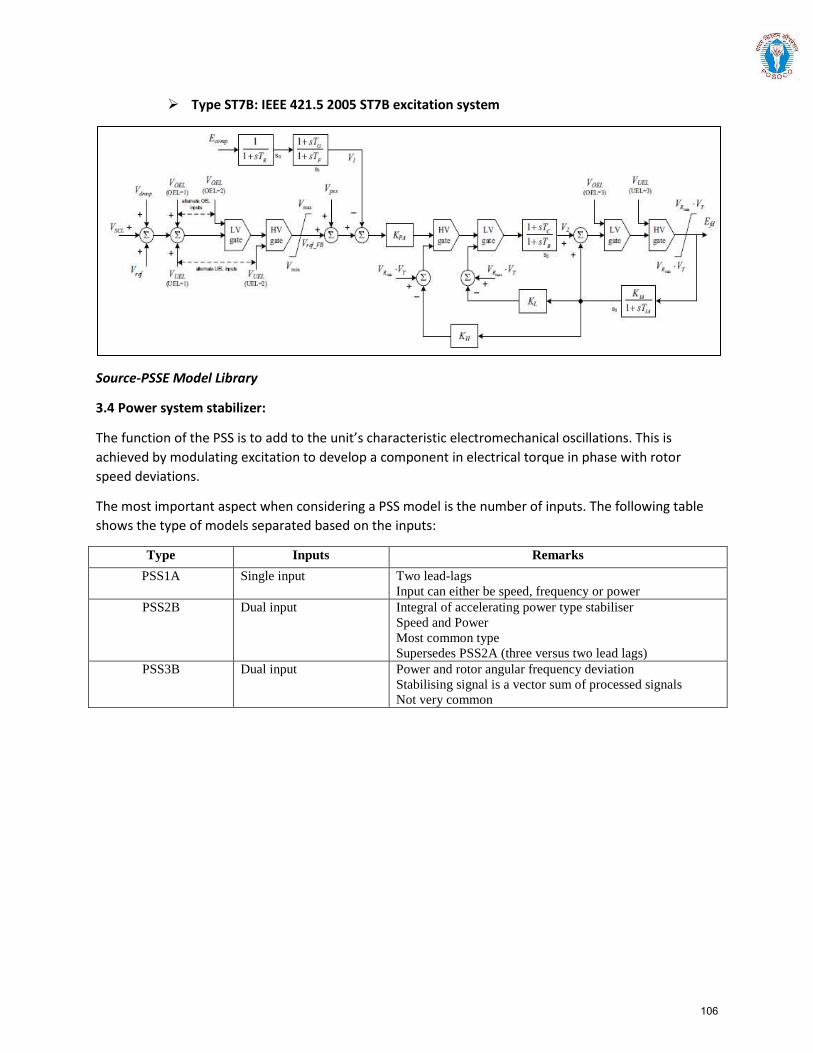
Type ST7B: IEEE 421.5 2005 ST7B excitation system
Source-PSSE Model Library
3.4 Power system stabilizer:
The function of the PSS is to add to the unit’s characteristic electromechanical oscillations. This is achieved by modulating excitation to develop a component in electrical torque in phase with rotor speed deviations.
The most important aspect when considering a PSS model is the number of inputs. The following table shows the type of models separated based on the inputs:
Type Inputs Remarks PSS1A Single input Two lead-lags
Input can either be speed, frequency or power PSS2B Dual input Integral of accelerating power type stabiliser
Speed and Power Most common type Supersedes PSS2A (three versus two lead lags)
PSS3B Dual input Power and rotor angular frequency deviation Stabilising signal is a vector sum of processed signals Not very common
106
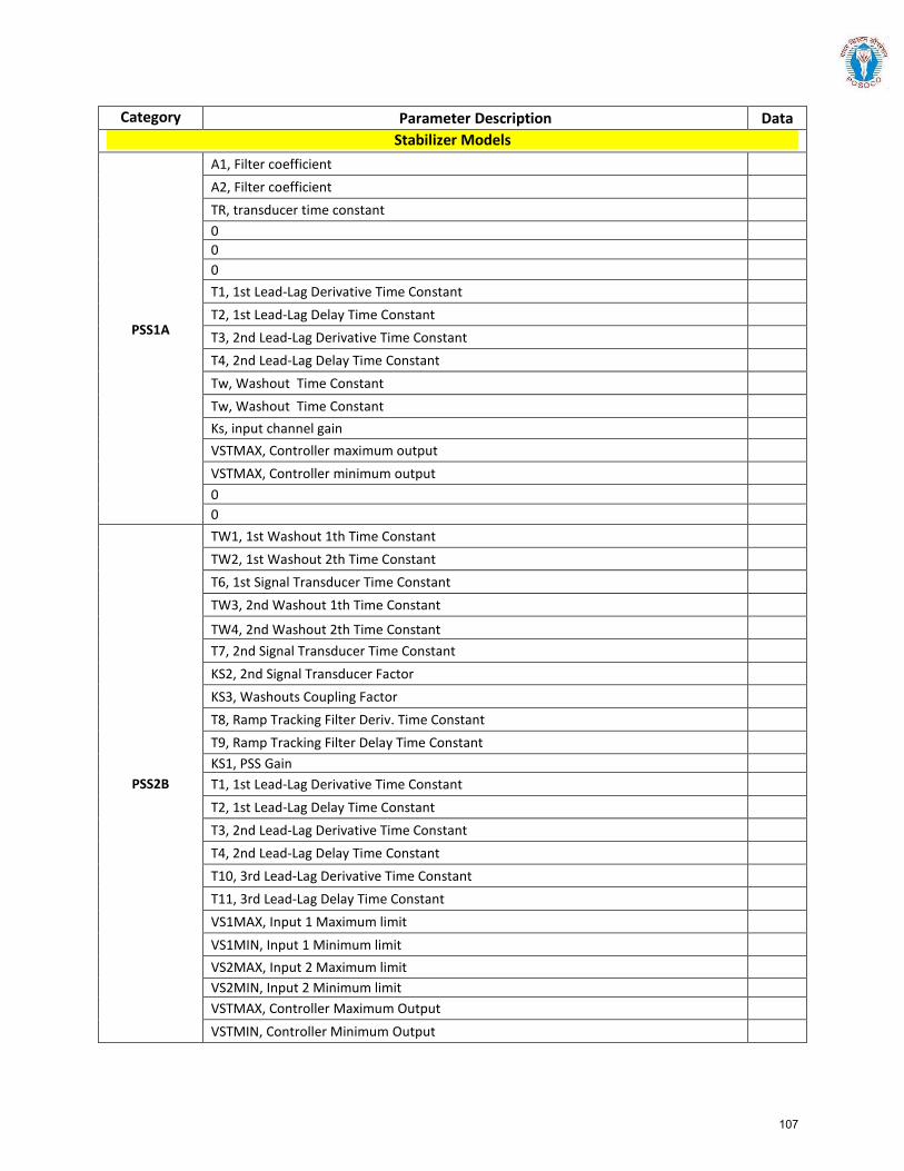
Category Parameter Description Data Stabilizer Models
PSS1A
A1, Filter coefficient A2, Filter coefficient TR, transducer time constant 0 0 0 T1, 1st Lead-Lag Derivative Time Constant T2, 1st Lead-Lag Delay Time Constant T3, 2nd Lead-Lag Derivative Time Constant T4, 2nd Lead-Lag Delay Time Constant Tw, Washout Time Constant Tw, Washout Time Constant Ks, input channel gain VSTMAX, Controller maximum output VSTMAX, Controller minimum output 0 0
PSS2B
TW1, 1st Washout 1th Time Constant TW2, 1st Washout 2th Time Constant T6, 1st Signal Transducer Time Constant TW3, 2nd Washout 1th Time Constant
TW4, 2nd Washout 2th Time Constant T7, 2nd Signal Transducer Time Constant KS2, 2nd Signal Transducer Factor KS3, Washouts Coupling Factor T8, Ramp Tracking Filter Deriv. Time Constant T9, Ramp Tracking Filter Delay Time Constant KS1, PSS Gain T1, 1st Lead-Lag Derivative Time Constant T2, 1st Lead-Lag Delay Time Constant T3, 2nd Lead-Lag Derivative Time Constant T4, 2nd Lead-Lag Delay Time Constant T10, 3rd Lead-Lag Derivative Time Constant T11, 3rd Lead-Lag Delay Time Constant VS1MAX, Input 1 Maximum limit VS1MIN, Input 1 Minimum limit VS2MAX, Input 2 Maximum limit VS2MIN, Input 2 Minimum limit VSTMAX, Controller Maximum Output VSTMIN, Controller Minimum Output
107
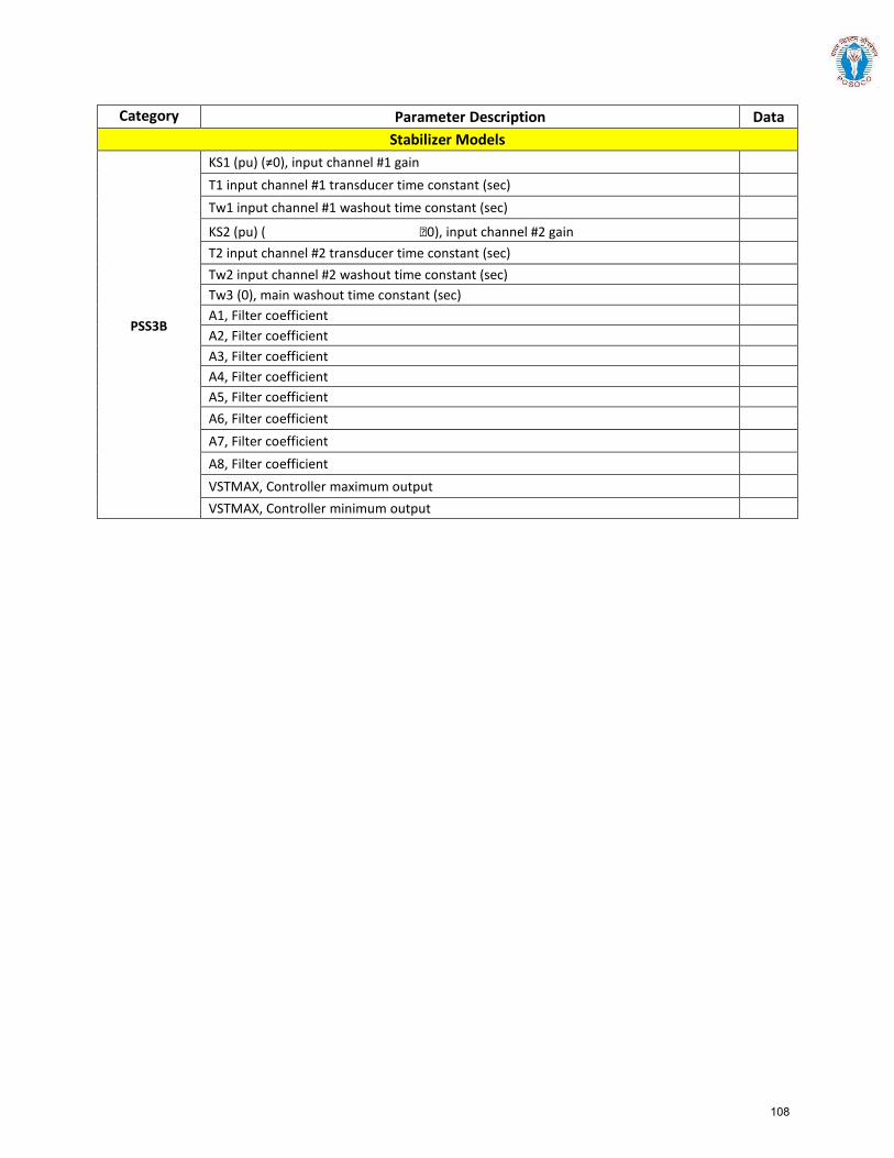
Category Parameter Description Data Stabilizer Models
PSS3B
KS1 (pu) (≠0), input channel #1 gain T1 input channel #1 transducer time constant (sec) Tw1 input channel #1 washout time constant (sec)
KS2 (pu) ( 0), input channel #2 gain T2 input channel #2 transducer time constant (sec) Tw2 input channel #2 washout time constant (sec) Tw3 (0), main washout time constant (sec) A1, Filter coefficient A2, Filter coefficient A3, Filter coefficient A4, Filter coefficient A5, Filter coefficient A6, Filter coefficient A7, Filter coefficient A8, Filter coefficient VSTMAX, Controller maximum output VSTMAX, Controller minimum output
108
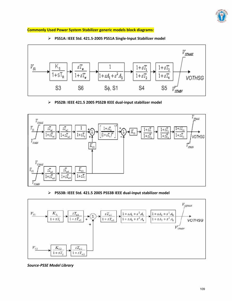
Commonly Used Power System Stabilizer generic models block diagrams:
PSS1A: IEEE Std. 421.5-2005 PSS1A Single-Input Stabilizer model
PSS2B: IEEE 421.5 2005 PSS2B IEEE dual-input stabilizer model
PSS3B: IEEE Std. 421.5 2005 PSS3B IEEE dual-input stabilizer model
Source-PSSE Model Library
109
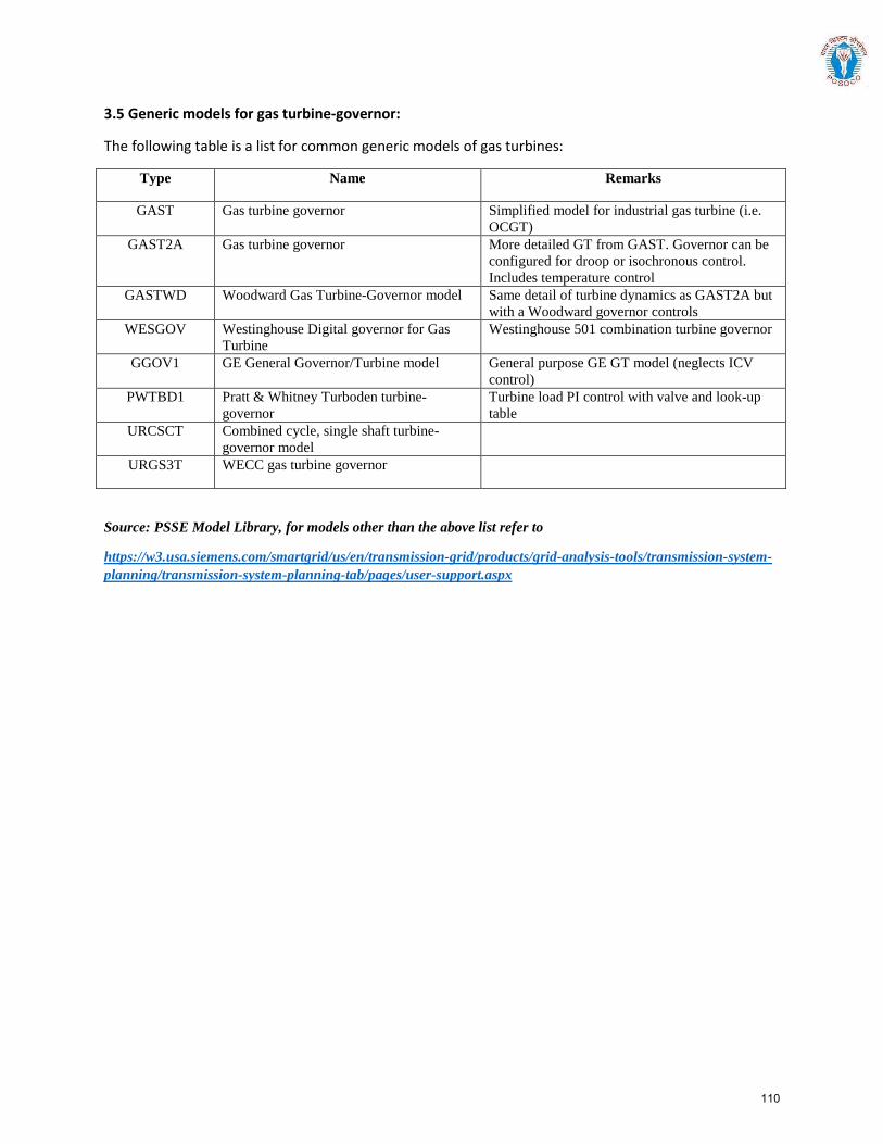
3.5 Generic models for gas turbine-governor:
The following table is a list for common generic models of gas turbines:
Type Name Remarks
GAST Gas turbine governor Simplified model for industrial gas turbine (i.e. OCGT)
GAST2A Gas turbine governor More detailed GT from GAST. Governor can be configured for droop or isochronous control. Includes temperature control
GASTWD Woodward Gas Turbine-Governor model Same detail of turbine dynamics as GAST2A but with a Woodward governor controls
WESGOV Westinghouse Digital governor for Gas Turbine
Westinghouse 501 combination turbine governor
GGOV1 GE General Governor/Turbine model General purpose GE GT model (neglects ICV control)
PWTBD1 Pratt & Whitney Turboden turbine-governor
Turbine load PI control with valve and look-up table
URCSCT Combined cycle, single shaft turbine-governor model
URGS3T WECC gas turbine governor
Source: PSSE Model Library, for models other than the above list refer to
https://w3.usa.siemens.com/smartgrid/us/en/transmission-grid/products/grid-analysis-tools/transmission-system-planning/transmission-system-planning-tab/pages/user-support.aspx
110
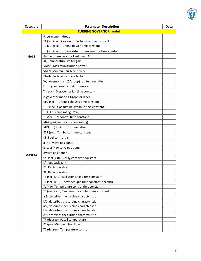
Category Parameter Description Data TURBINE GOVERNOR model
GAST
R, permanent droop T1 (>0) (sec), Governor mechanism time constant T2 (>0) (sec), Turbine power time constant
T3 (>0) (sec), Turbine exhaust temperature time constant
Ambient temperature load limit, AT KT, Temperature limiter gain VMAX, Maximum turbine power VMIN, Minimum turbine power Dturb, Turbine damping factor
GAST2A
W, governor gain (1/droop) (on turbine rating) X (sec) governor lead time constant Y (sec) (> 0) governor lag time constant
Z, governor mode:1 Droop or 0 ISO ETD (sec), Turbine exhausts time constant TCD (sec), Gas turbine dynamic time constant TRATE turbine rating (MW) T (sec), Fuel control time constant MAX (pu) limit (on turbine rating) MIN (pu) limit (on turbine rating) ECR (sec), Combustor time constant K3, Fuel control gain a (> 0) valve positioner b (sec) (> 0) valve positioner c valve positioner Ƭf (sec) (> 0), Fuel system time constant Kf, feedback gain K5, Radiation shield K4, Radiation shield T3 (sec) (> 0), Radiation shield time constant T4 (sec) (> 0), Thermocouple time constant, seconds Ƭt (> 0), Temperature control time constant T5 (sec) (> 0), Temperature control time constant af1, describes the turbine characteristic bf1, describes the turbine characteristic af2, describes the turbine characteristic bf2, describes the turbine characteristic cf2, describes the turbine characteristic TR (degree), Rated temperature K6 (pu), Minimum fuel flow TC (degree), Temperature control
111
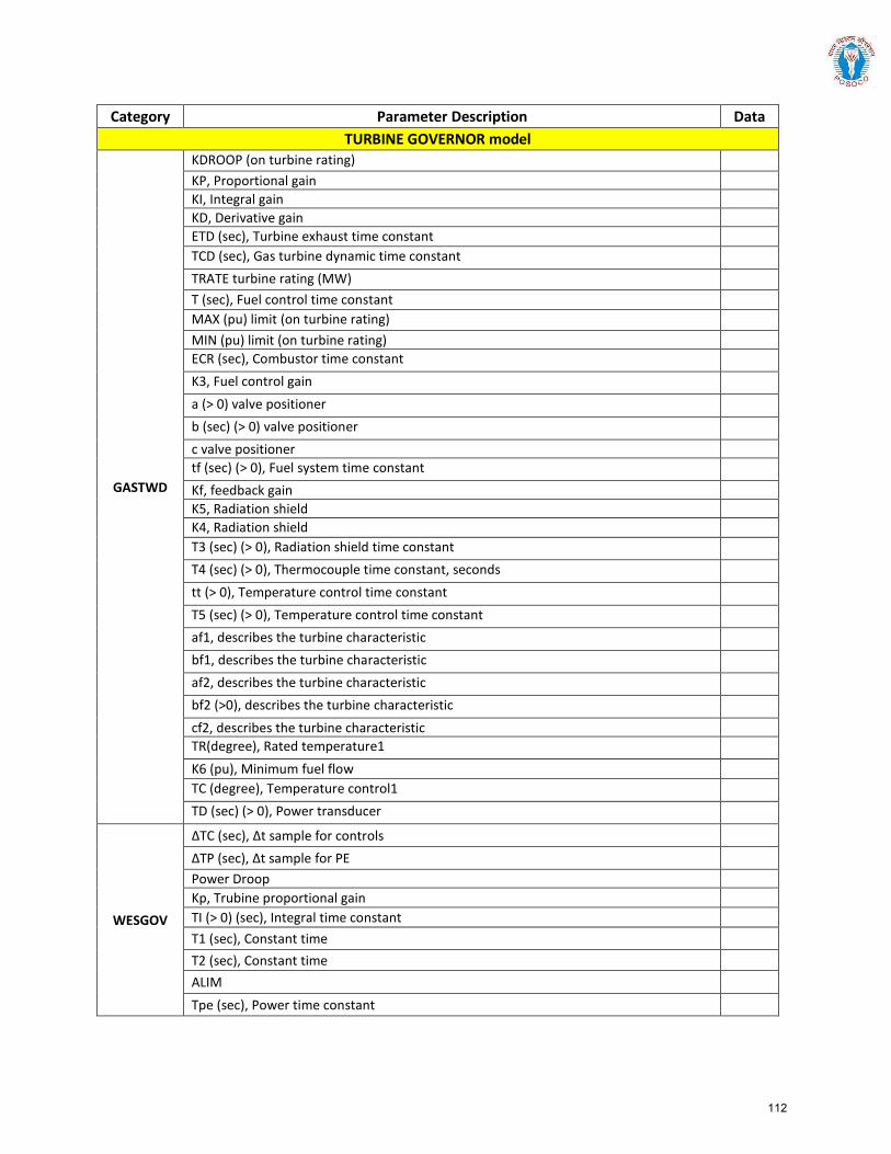
Category Parameter Description Data TURBINE GOVERNOR model
GASTWD
KDROOP (on turbine rating) KP, Proportional gain KI, Integral gain KD, Derivative gain ETD (sec), Turbine exhaust time constant TCD (sec), Gas turbine dynamic time constant TRATE turbine rating (MW) T (sec), Fuel control time constant MAX (pu) limit (on turbine rating) MIN (pu) limit (on turbine rating) ECR (sec), Combustor time constant K3, Fuel control gain a (> 0) valve positioner b (sec) (> 0) valve positioner c valve positioner tf (sec) (> 0), Fuel system time constant Kf, feedback gain K5, Radiation shield K4, Radiation shield T3 (sec) (> 0), Radiation shield time constant T4 (sec) (> 0), Thermocouple time constant, seconds tt (> 0), Temperature control time constant T5 (sec) (> 0), Temperature control time constant af1, describes the turbine characteristic bf1, describes the turbine characteristic af2, describes the turbine characteristic bf2 (>0), describes the turbine characteristic cf2, describes the turbine characteristic TR(degree), Rated temperature1 K6 (pu), Minimum fuel flow TC (degree), Temperature control1 TD (sec) (> 0), Power transducer
WESGOV
ΔTC (sec), Δt sample for controls ΔTP (sec), Δt sample for PE Power Droop Kp, Trubine proportional gain TI (> 0) (sec), Integral time constant T1 (sec), Constant time T2 (sec), Constant time ALIM Tpe (sec), Power time constant
112
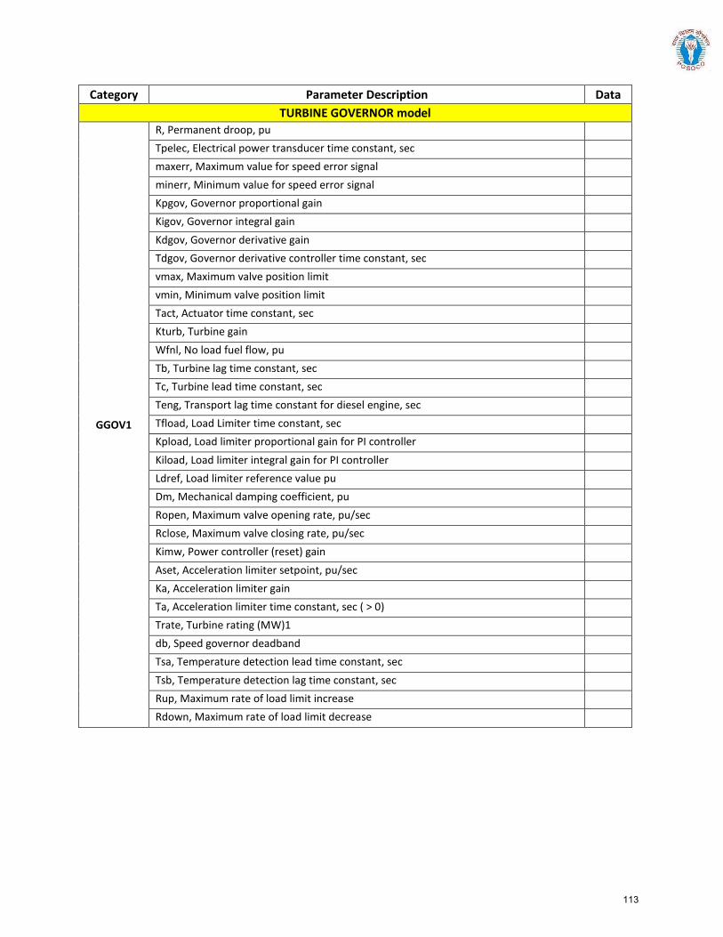
Category Parameter Description Data TURBINE GOVERNOR model
GGOV1
R, Permanent droop, pu Tpelec, Electrical power transducer time constant, sec maxerr, Maximum value for speed error signal minerr, Minimum value for speed error signal Kpgov, Governor proportional gain Kigov, Governor integral gain Kdgov, Governor derivative gain Tdgov, Governor derivative controller time constant, sec vmax, Maximum valve position limit vmin, Minimum valve position limit Tact, Actuator time constant, sec Kturb, Turbine gain Wfnl, No load fuel flow, pu Tb, Turbine lag time constant, sec Tc, Turbine lead time constant, sec Teng, Transport lag time constant for diesel engine, sec Tfload, Load Limiter time constant, sec Kpload, Load limiter proportional gain for PI controller Kiload, Load limiter integral gain for PI controller Ldref, Load limiter reference value pu Dm, Mechanical damping coefficient, pu Ropen, Maximum valve opening rate, pu/sec Rclose, Maximum valve closing rate, pu/sec Kimw, Power controller (reset) gain Aset, Acceleration limiter setpoint, pu/sec Ka, Acceleration limiter gain Ta, Acceleration limiter time constant, sec ( > 0) Trate, Turbine rating (MW)1 db, Speed governor deadband Tsa, Temperature detection lead time constant, sec Tsb, Temperature detection lag time constant, sec Rup, Maximum rate of load limit increase Rdown, Maximum rate of load limit decrease
113
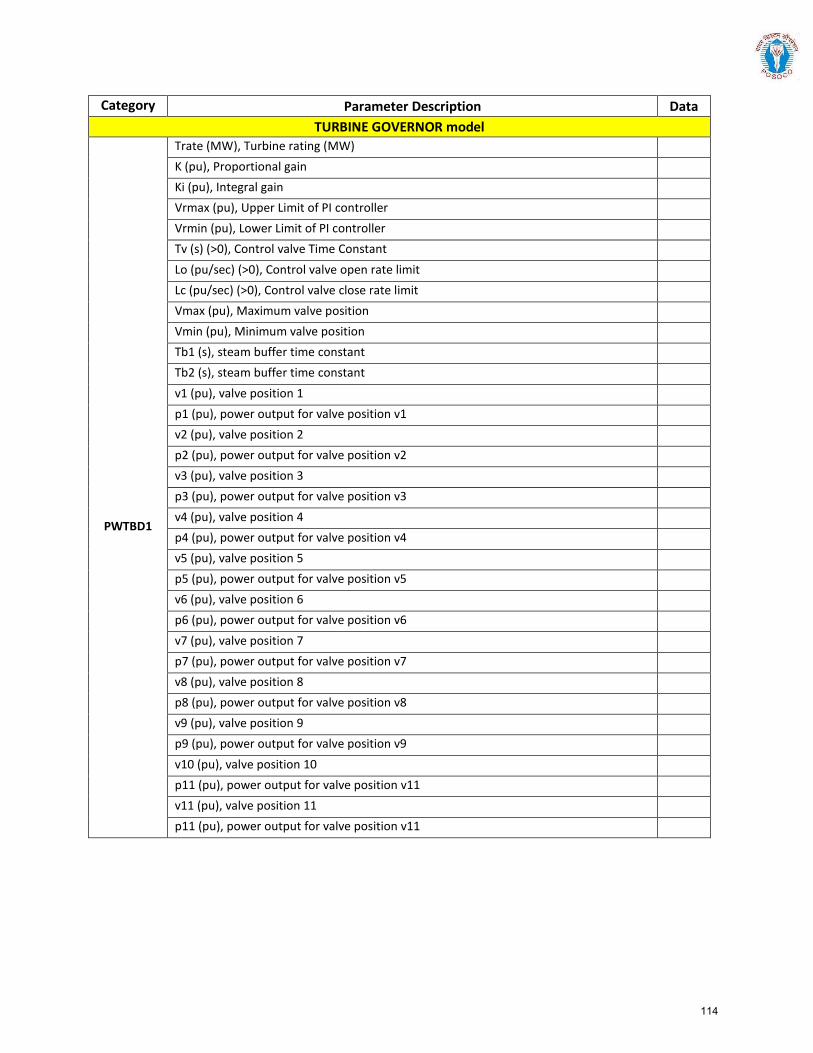
Category Parameter Description Data TURBINE GOVERNOR model
PWTBD1
Trate (MW), Turbine rating (MW) K (pu), Proportional gain Ki (pu), Integral gain Vrmax (pu), Upper Limit of PI controller Vrmin (pu), Lower Limit of PI controller Tv (s) (>0), Control valve Time Constant Lo (pu/sec) (>0), Control valve open rate limit Lc (pu/sec) (>0), Control valve close rate limit Vmax (pu), Maximum valve position Vmin (pu), Minimum valve position Tb1 (s), steam buffer time constant Tb2 (s), steam buffer time constant v1 (pu), valve position 1 p1 (pu), power output for valve position v1 v2 (pu), valve position 2 p2 (pu), power output for valve position v2 v3 (pu), valve position 3 p3 (pu), power output for valve position v3 v4 (pu), valve position 4 p4 (pu), power output for valve position v4 v5 (pu), valve position 5 p5 (pu), power output for valve position v5 v6 (pu), valve position 6 p6 (pu), power output for valve position v6 v7 (pu), valve position 7 p7 (pu), power output for valve position v7 v8 (pu), valve position 8 p8 (pu), power output for valve position v8 v9 (pu), valve position 9 p9 (pu), power output for valve position v9 v10 (pu), valve position 10 p11 (pu), power output for valve position v11 v11 (pu), valve position 11 p11 (pu), power output for valve position v11
114

Category Parameter Description Data TURBINE GOVERNOR model
URCSCT
W, governor gain (1/droop) (on turbine rating) X (sec) governor lead time constant Y (sec) (> 0) governor lag time constant Z, governor mode:1 Droop or 0 ISO ETD (sec), Turbine exhausts time constant TCD (sec), Gas turbine dynamic time constant TRATE turbine rating (MW) T (sec), Fuel control time constant MAX (pu) limit (on turbine rating) MIN (pu) limit (on turbine rating) ECR (sec), Combustor time constant K3, Fuel control gain a (> 0) valve positioner b (sec) (> 0) valve positioner c valve positioner Ƭf (sec) (> 0), Fuel system time constant Kf, feedback gain K5, Radiation shield K4, Radiation shield T3 (sec) (> 0), Radiation shield time constant T4 (sec) (> 0), Thermocouple time constant, seconds Ƭt (> 0), Temperature control time constant T5 (sec) (> 0), Temperature control time constant af1, describes the turbine characteristic bf1, describes the turbine characteristic af2, describes the turbine characteristic bf2, describes the turbine characteristic cf2, describes the turbine characteristic TR (degree), Rated temperature K6 (pu), Minimum fuel flow TC (degree), Temperature control K, Governor gain, (1/droop) pu T1 (sec), Lag time constant (sec) T2 (sec), Lead time constant (sec) T3 (> 0) (sec), valve position time constant Uo (pu/sec), maximum valve opening rate Uc (< 0) (pu/sec), maximum valve closing rate PMAX (pu on machine MVA rating) PMIN (pu on machine MVA rating)
115
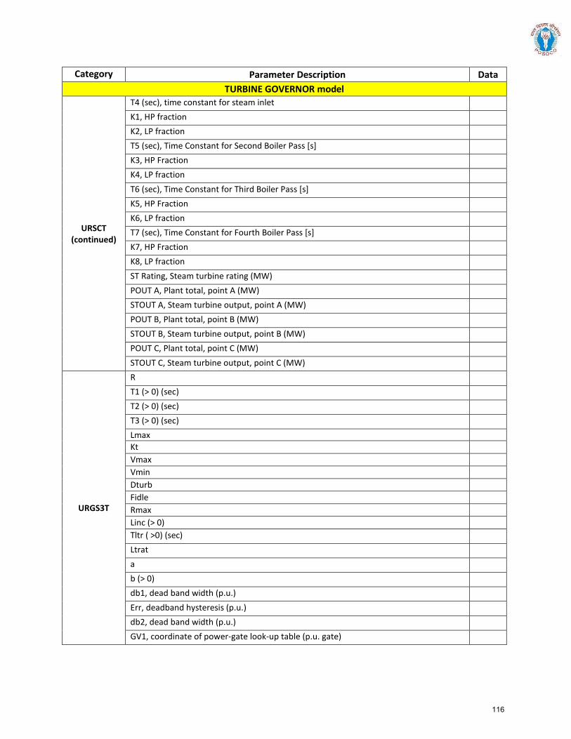
Category Parameter Description Data TURBINE GOVERNOR model
URSCT (continued)
T4 (sec), time constant for steam inlet K1, HP fraction K2, LP fraction T5 (sec), Time Constant for Second Boiler Pass [s] K3, HP Fraction K4, LP fraction T6 (sec), Time Constant for Third Boiler Pass [s] K5, HP Fraction K6, LP fraction T7 (sec), Time Constant for Fourth Boiler Pass [s] K7, HP Fraction K8, LP fraction ST Rating, Steam turbine rating (MW) POUT A, Plant total, point A (MW) STOUT A, Steam turbine output, point A (MW) POUT B, Plant total, point B (MW) STOUT B, Steam turbine output, point B (MW) POUT C, Plant total, point C (MW) STOUT C, Steam turbine output, point C (MW)
URGS3T
R T1 (> 0) (sec) T2 (> 0) (sec) T3 (> 0) (sec) Lmax Kt Vmax Vmin Dturb Fidle Rmax Linc (> 0) Tltr ( >0) (sec) Ltrat a b (> 0) db1, dead band width (p.u.) Err, deadband hysteresis (p.u.) db2, dead band width (p.u.) GV1, coordinate of power-gate look-up table (p.u. gate)
116
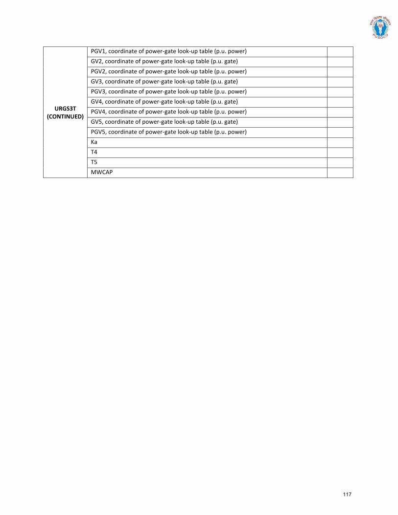
URGS3T (CONTINUED)
PGV1, coordinate of power-gate look-up table (p.u. power) GV2, coordinate of power-gate look-up table (p.u. gate) PGV2, coordinate of power-gate look-up table (p.u. power) GV3, coordinate of power-gate look-up table (p.u. gate) PGV3, coordinate of power-gate look-up table (p.u. power) GV4, coordinate of power-gate look-up table (p.u. gate) PGV4, coordinate of power-gate look-up table (p.u. power) GV5, coordinate of power-gate look-up table (p.u. gate) PGV5, coordinate of power-gate look-up table (p.u. power) Ka T4 T5 MWCAP
117
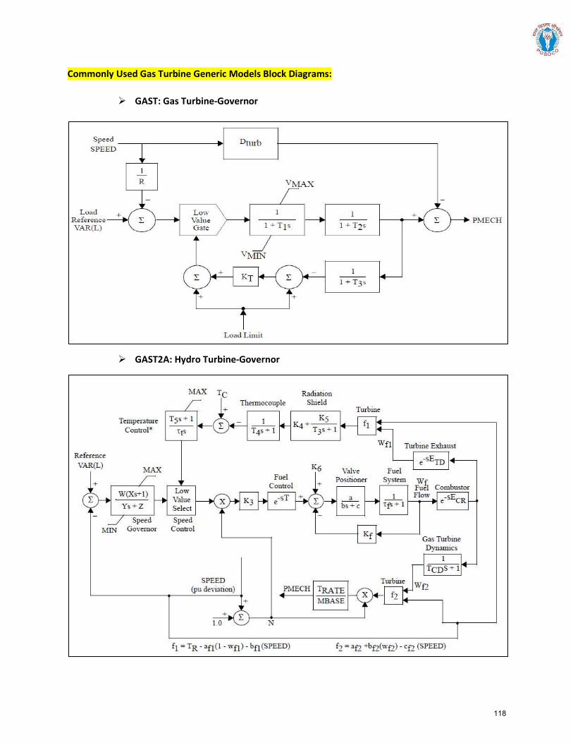
Commonly Used Gas Turbine Generic Models Block Diagrams:
GAST: Gas Turbine-Governor
GAST2A: Hydro Turbine-Governor
118
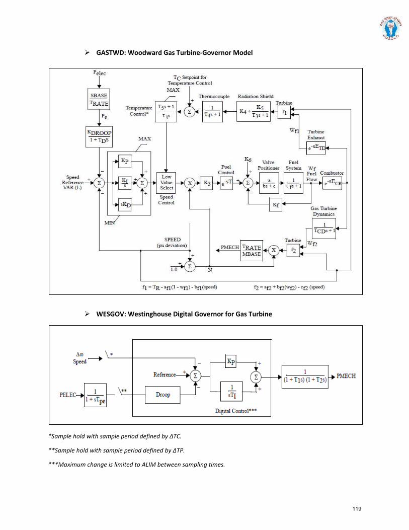
GASTWD: Woodward Gas Turbine-Governor Model
WESGOV: Westinghouse Digital Governor for Gas Turbine
*Sample hold with sample period defined by ΔTC.
**Sample hold with sample period defined by ΔTP.
***Maximum change is limited to ALIM between sampling times.
119
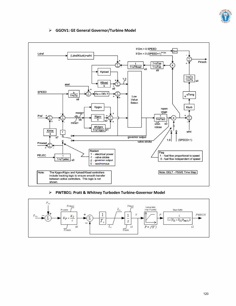
GGOV1: GE General Governor/Turbine Model
PWTBD1: Pratt & Whitney Turboden Turbine-Governor Model
120
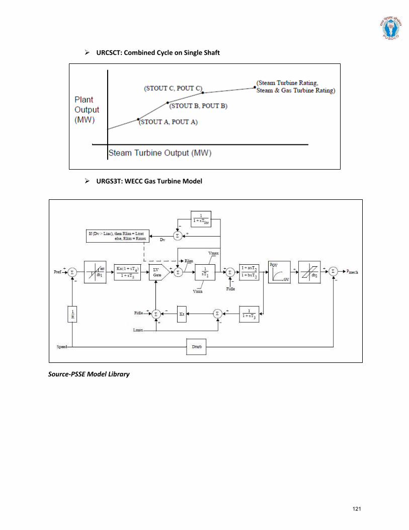
URCSCT: Combined Cycle on Single Shaft
URGS3T: WECC Gas Turbine Model
Source-PSSE Model Library
121
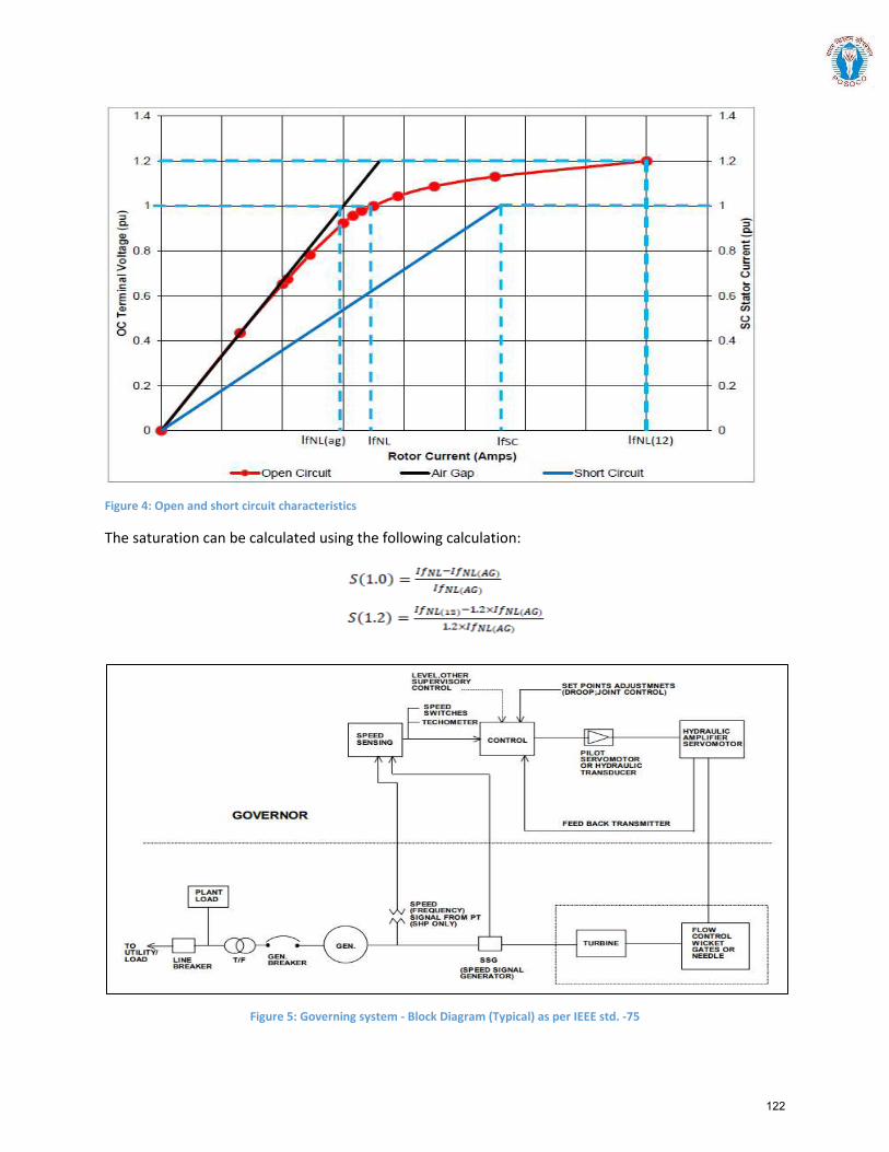
Figure 4: Open and short circuit characteristics
The saturation can be calculated using the following calculation:
Figure 5: Governing system - Block Diagram (Typical) as per IEEE std. -75
122
Guideline for exchange of data for modelling Hydro Power generation
Power System Operation Corporation Limited
Procedure for furnishing information for modelling Hydro Power Generation in Indian Grid
1.0 Introduction:
The purpose of this document is to act as a guideline for exchange of information for accurate modelling
of hydro power generation in India. Availability of fit-for-purpose steady state and dynamics models of
hydro power generation will enable secure operation of Indian power grid and enable identification of
potential weak points in the grid so as to take appropriate remedial actions.
1.1 Applicability:
The guideline shall be applicable to all hydro power generation in India that can have an impact on
operation of the power grid of India, irrespective of connection at Intra-STS or ISTS (Inter-state
Transmission System).
This document presents the desired information for collection of data for modelling of hydro power
generation in PSS/E software, a software suite being used pan-India at CEA, CTU, SLDCs, RLDCs, and
NLDC for modelling of India’s power grid. A systematic set of data and basic criteria for furnishing data
are presented.
1.2 Need for a fit-for-purpose model:
There is a cost involved in developing and validating dynamic models of power system equipment. But
there are much higher benefits for the power system if this leads to a functional, fit-for-purpose model,
and arrangements that allow that model to be maintained over time.
A functional fit-for-purpose dynamic model will:
Facilitate significant power system efficiencies by allowing power system operations to
confidently identify the secure operating envelope and thereby manage security effectively
Allow assessment of impact on grid elements due to connection of new elements (network
elements, generators, or loads) for necessary corrective actions
Permit power system assets to be run with margins determined on the basis of security
assessments
Facilitate the tuning of control systems, such as power system stabilizers, voltage- and
frequency-based special control schemes etc.
Improve accuracy of online security tools, particularly for unusual operating conditions, which in
turn is likely to result in higher reliability of supply to power system users.
The power system model would enable steady state and electromechanical transient simulation studies
that deliver reasonably accurate outcomes.
Annex-4(C)
123
Guideline for exchange of data for modelling Hydro Power generation
Power System Operation Corporation Limited
1.3 Regulation:
CEA Connectivity Standard 6.4.d :
The requester and user shall cooperate with RPC and Appropriate Load Despatch Centre in respect of
the matters listed below, but not limited to
furnish data as required by Appropriate Transmission Utility or Transmission Licensee, Appropriate Load Despatch Centre, Appropriate Regional Power Committee and any committee constituted by the Authority or appropriate Government for system studies or for facilitating analysis of tripping or disturbance in power system;
Here Requester and User Includes a generating company, captive generating plant, energy storage
system, transmission licensee (other than Central Transmission Utility and State Transmission Utility),
distribution licensee, solar park developer, wind park developer, wind-solar photovoltaic hybrid system,
or bulk consumer (2019 Amendment)
IEGC 4.1 :
CTU, STU and Users connected to, or seeking connection to ISTS shall comply with Central Electricity
Authority (Technical Standards for connectivity to the Grid) Regulations, 2007 which specifies the
minimum technical and design criteria and Central Electricity Regulatory Commission (Grant of
Connectivity, Long-term Access and Medium-term Open Access in inter-state Transmission and related
matters) Regulations,2009.
124
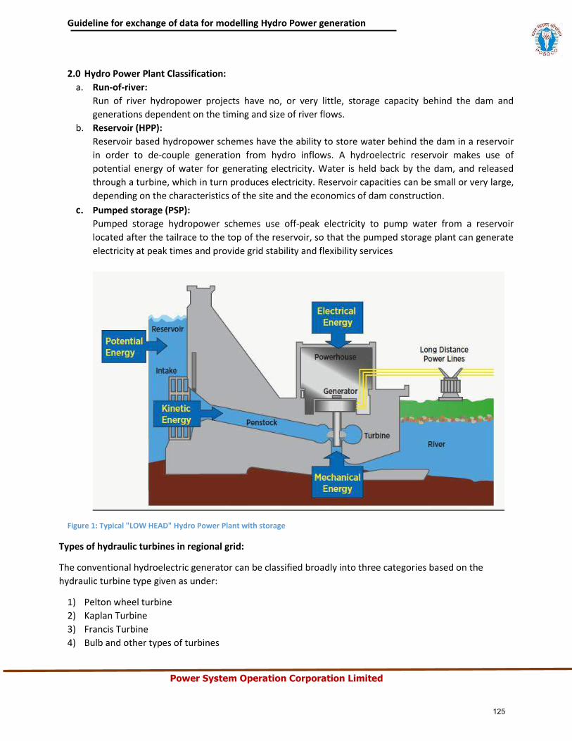
Guideline for exchange of data for modelling Hydro Power generation
Power System Operation Corporation Limited
2.0 Hydro Power Plant Classification:
a. Run-of-river:
Run of river hydropower projects have no, or very little, storage capacity behind the dam and
generations dependent on the timing and size of river flows.
b. Reservoir (HPP):
Reservoir based hydropower schemes have the ability to store water behind the dam in a reservoir
in order to de-couple generation from hydro inflows. A hydroelectric reservoir makes use of
potential energy of water for generating electricity. Water is held back by the dam, and released
through a turbine, which in turn produces electricity. Reservoir capacities can be small or very large,
depending on the characteristics of the site and the economics of dam construction.
c. Pumped storage (PSP):
Pumped storage hydropower schemes use off-peak electricity to pump water from a reservoir
located after the tailrace to the top of the reservoir, so that the pumped storage plant can generate
electricity at peak times and provide grid stability and flexibility services
Figure 1: Typical "LOW HEAD" Hydro Power Plant with storage
Types of hydraulic turbines in regional grid:
The conventional hydroelectric generator can be classified broadly into three categories based on the
hydraulic turbine type given as under:
1) Pelton wheel turbine
2) Kaplan Turbine
3) Francis Turbine
4) Bulb and other types of turbines
125
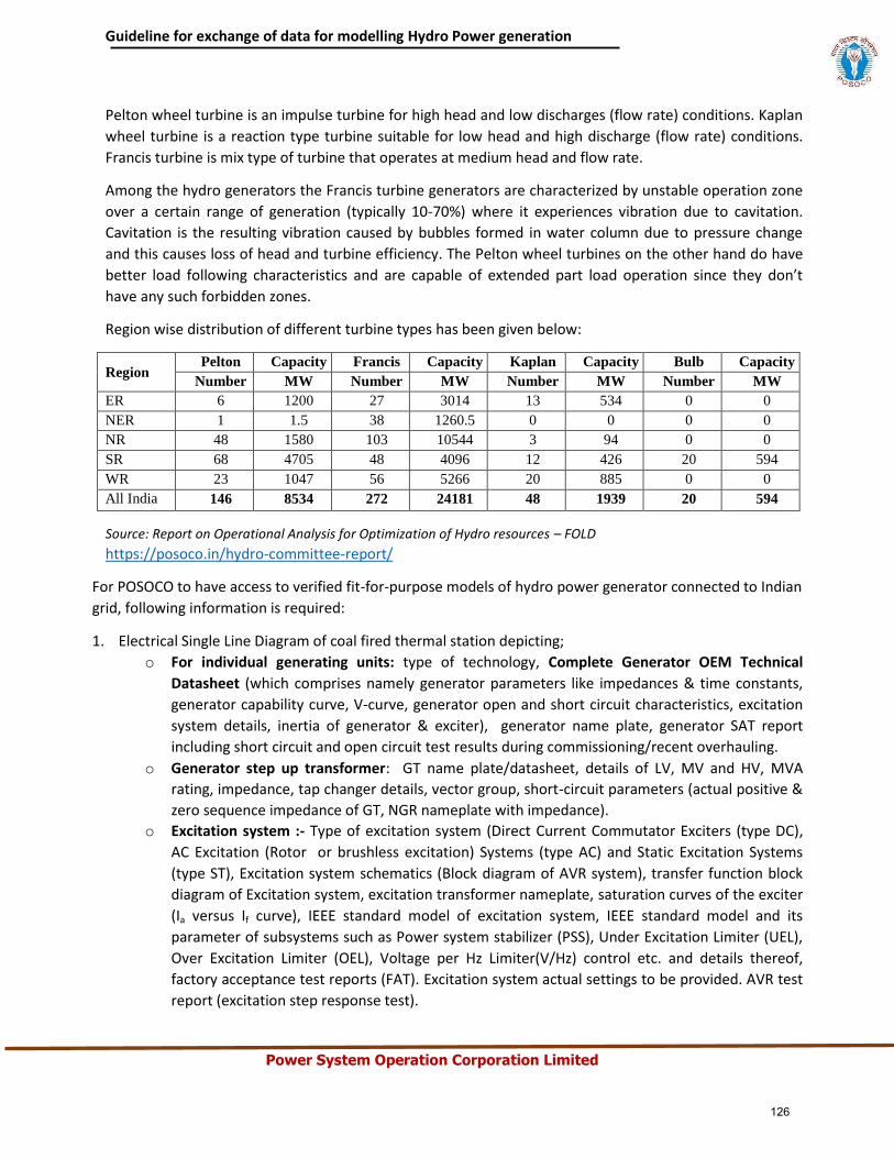
Guideline for exchange of data for modelling Hydro Power generation
Power System Operation Corporation Limited
Pelton wheel turbine is an impulse turbine for high head and low discharges (flow rate) conditions. Kaplan
wheel turbine is a reaction type turbine suitable for low head and high discharge (flow rate) conditions.
Francis turbine is mix type of turbine that operates at medium head and flow rate.
Among the hydro generators the Francis turbine generators are characterized by unstable operation zone
over a certain range of generation (typically 10-70%) where it experiences vibration due to cavitation.
Cavitation is the resulting vibration caused by bubbles formed in water column due to pressure change
and this causes loss of head and turbine efficiency. The Pelton wheel turbines on the other hand do have
better load following characteristics and are capable of extended part load operation since they don’t
have any such forbidden zones.
Region wise distribution of different turbine types has been given below:
Region Pelton Capacity Francis Capacity Kaplan Capacity Bulb Capacity
Number MW Number MW Number MW Number MW
ER 6 1200 27 3014 13 534 0 0
NER 1 1.5 38 1260.5 0 0 0 0
NR 48 1580 103 10544 3 94 0 0
SR 68 4705 48 4096 12 426 20 594
WR 23 1047 56 5266 20 885 0 0
All India 146 8534 272 24181 48 1939 20 594
Source: Report on Operational Analysis for Optimization of Hydro resources – FOLD
https://posoco.in/hydro-committee-report/
For POSOCO to have access to verified fit-for-purpose models of hydro power generator connected to Indian
grid, following information is required:
1. Electrical Single Line Diagram of coal fired thermal station depicting;
o For individual generating units: type of technology, Complete Generator OEM Technical
Datasheet (which comprises namely generator parameters like impedances & time constants,
generator capability curve, V-curve, generator open and short circuit characteristics, excitation
system details, inertia of generator & exciter), generator name plate, generator SAT report
including short circuit and open circuit test results during commissioning/recent overhauling.
o Generator step up transformer: GT name plate/datasheet, details of LV, MV and HV, MVA
rating, impedance, tap changer details, vector group, short-circuit parameters (actual positive &
zero sequence impedance of GT, NGR nameplate with impedance).
o Excitation system :- Type of excitation system (Direct Current Commutator Exciters (type DC),
AC Excitation (Rotor or brushless excitation) Systems (type AC) and Static Excitation Systems
(type ST), Excitation system schematics (Block diagram of AVR system), transfer function block
diagram of Excitation system, excitation transformer nameplate, saturation curves of the exciter
(Ia versus If curve), IEEE standard model of excitation system, IEEE standard model and its
parameter of subsystems such as Power system stabilizer (PSS), Under Excitation Limiter (UEL),
Over Excitation Limiter (OEL), Voltage per Hz Limiter(V/Hz) control etc. and details thereof,
factory acceptance test reports (FAT). Excitation system actual settings to be provided. AVR test
report (excitation step response test).
126
Guideline for exchange of data for modelling Hydro Power generation
Power System Operation Corporation Limited
o Power System Stabilizer (PSS): Transfer function block diagram of PSS, IEEE Standard Model,
Actual PSS software settings, PSS commissioning report and Recent PSS tuning report.
o Turbine-Governor system :- Type of prime mover (hydro-electric or pumped storage), type of
hydro turbine (impulse or reaction turbine) and details of head, model of turbine (including
details of technology, valves, valve characteristics), model of governor control system (including
details of technology, valves, valves characteristics) , penstock details (length, area, diameter,
thickness, elastic or non-elastic, no of penstock supplied through common tunnel and flow of
water through turbine) , mode of operation (hydro, pump storage or synchronous condenser)
and control, surge tank details (height, diameter and restricted inlet orifice), pump characteristic
(Active power Vs head) ramp rates, losses in case of synchronous condenser operation
(Mechanical loss and copper loss as a function of MVAr output), Block diagram of turbine-
governor system, IEEE standard model of turbine governor system and its transfer function
diagram and its parameters, Turbine inertia, commissioning report of turbine-governor system
or recent governor testing report.
2. Generic models of individual components (generator, exciter, turbine-governor and PSS of hydro power
generator (refer sections 3.2 to section 3.5)
o Model should be suitable for an integration time step between 1ms and 20ms, and suitable for
operation up-to 100 s
o Simulation results depicting validation of generic models against user-defined models (for P, Q,
V, I) and against actual measurement (after commissioning) to be provided.
3. Encrypted user defined model (UDM) in a format suitable for latest PSSE release PSS/E (*.dll files) for
electromechanical transient simulation for components of hydro power generators (in case non-
availability of validated generic model)
o User guide for Encrypted models to be provided including instructions on how the model should
be set-up
o Corresponding transfer function block diagrams to be provided
o Simulation results depicting validation of User-Defined models against actual measurement to
be provided
o The use of black-box type representation is not preferred
127
Guideline for exchange of data for modelling Hydro Power generation
Power System Operation Corporation Limited
Annexure: Formats for submission of modelling data for hydro power generator
Version History:
Version no. Release Date Prepared by* Checked/Issued by* Changes
*Mention Designation and Contact Details
Details submitted:
Details pending:
128
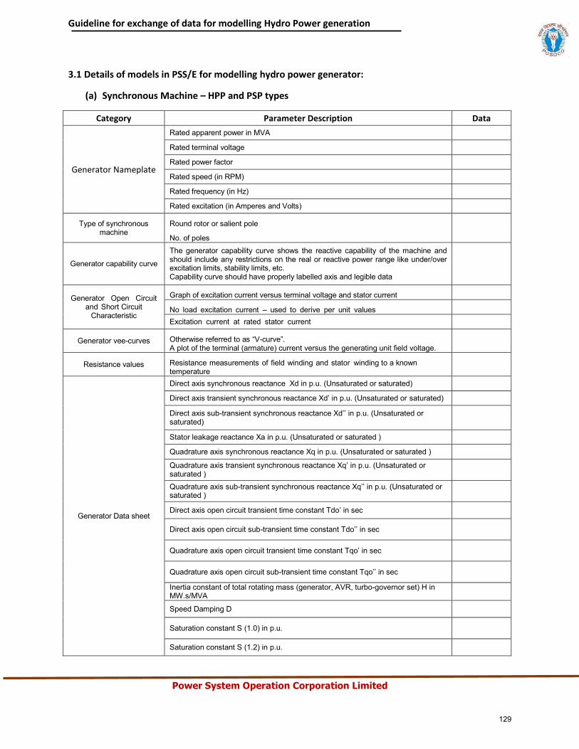
Guideline for exchange of data for modelling Hydro Power generation
Power System Operation Corporation Limited
3.1 Details of models in PSS/E for modelling hydro power generator:
(a) Synchronous Machine – HPP and PSP types
Category Parameter Description Data
Generator Nameplate
Rated apparent power in MVA
Rated terminal voltage
Rated power factor
Rated speed (in RPM)
Rated frequency (in Hz)
Rated excitation (in Amperes and Volts)
Type of synchronous machine
Round rotor or salient pole
No. of poles
Generator capability curve
The generator capability curve shows the reactive capability of the machine and should include any restrictions on the real or reactive power range like under/over excitation limits, stability limits, etc. Capability curve should have properly labelled axis and legible data
Generator Open Circuit and Short Circuit
Characteristic
Graph of excitation current versus terminal voltage and stator current
No load excitation current – used to derive per unit values Excitation current at rated stator current
Generator vee-curves Otherwise referred to as “V-curve”. A plot of the terminal (armature) current versus the generating unit field voltage.
Resistance values Resistance measurements of field winding and stator winding to a known temperature
Generator Data sheet
Direct axis synchronous reactance Xd in p.u. (Unsaturated or saturated)
Direct axis transient synchronous reactance Xd’ in p.u. (Unsaturated or saturated)
Direct axis sub-transient synchronous reactance Xd’’ in p.u. (Unsaturated or saturated)
Stator leakage reactance Xa in p.u. (Unsaturated or saturated )
Quadrature axis synchronous reactance Xq in p.u. (Unsaturated or saturated )
Quadrature axis transient synchronous reactance Xq’ in p.u. (Unsaturated or saturated ) Quadrature axis sub-transient synchronous reactance Xq’’ in p.u. (Unsaturated or saturated )
Direct axis open circuit transient time constant Tdo’ in sec
Direct axis open circuit sub-transient time constant Tdo’’ in sec
Quadrature axis open circuit transient time constant Tqo’ in sec
Quadrature axis open circuit sub-transient time constant Tqo’’ in sec
Inertia constant of total rotating mass (generator, AVR, turbo-governor set) H in MW.s/MVA
Speed Damping D
Saturation constant S (1.0) in p.u.
Saturation constant S (1.2) in p.u.
129
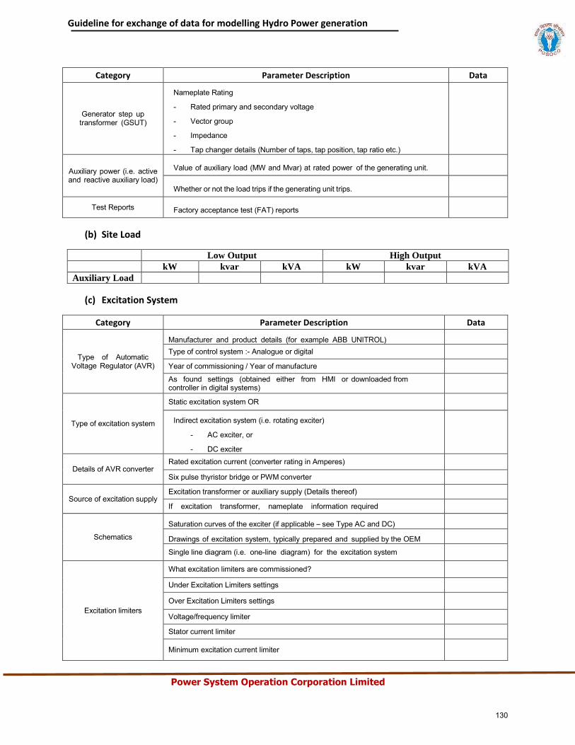
Guideline for exchange of data for modelling Hydro Power generation
Power System Operation Corporation Limited
Category Parameter Description Data
Generator step up transformer (GSUT)
Nameplate Rating
- Rated primary and secondary voltage
- Vector group
- Impedance
- Tap changer details (Number of taps, tap position, tap ratio etc.)
Auxiliary power (i.e. active and reactive auxiliary load)
Value of auxiliary load (MW and Mvar) at rated power of the generating unit.
Whether or not the load trips if the generating unit trips.
Test Reports Factory acceptance test (FAT) reports
(b) Site Load
Low Output High Output
kW kvar kVA kW kvar kVA
Auxiliary Load
(c) Excitation System
Category Parameter Description Data
Type of Automatic Voltage Regulator (AVR)
Manufacturer and product details (for example ABB UNITROL) Type of control system :- Analogue or digital
Year of commissioning / Year of manufacture
As found settings (obtained either from HMI or downloaded from controller in digital systems)
Type of excitation system
Static excitation system OR
Indirect excitation system (i.e. rotating exciter)
- AC exciter, or
- DC exciter
Details of AVR converter Rated excitation current (converter rating in Amperes)
Six pulse thyristor bridge or PWM converter
Source of excitation supply Excitation transformer or auxiliary supply (Details thereof)
If excitation transformer, nameplate information required
Schematics
Saturation curves of the exciter (if applicable – see Type AC and DC)
Drawings of excitation system, typically prepared and supplied by the OEM
Single line diagram (i.e. one-line diagram) for the excitation system
Excitation limiters
What excitation limiters are commissioned?
Under Excitation Limiters settings
Over Excitation Limiters settings
Voltage/frequency limiter
Stator current limiter
Minimum excitation current limiter
130
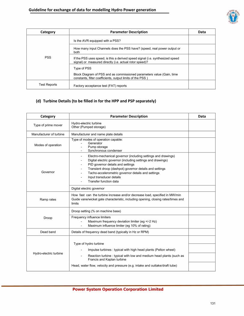
Guideline for exchange of data for modelling Hydro Power generation
Power System Operation Corporation Limited
Category Parameter Description Data
PSS
Is the AVR equipped with a PSS?
How many input Channels does the PSS have? (speed, real power output or both
If the PSS uses speed, is this a derived speed signal (i.e. synthesized speed signal) or measured directly (i.e. actual rotor speed)?
Type of PSS
Block Diagram of PSS and as commissioned parameters value (Gain, time constants, filter coefficients, output limits of the PSS )
Test Reports Factory acceptance test (FAT) reports
(d) Turbine Details (to be filled in for the HPP and PSP separately)
Category Parameter Description Data
Type of prime mover Hydro-electric turbine Other (Pumped storage)
Manufacturer of turbine Manufacturer and name plate details
Modes of operation
Type of modes of operation capable: - Generator - Pump storage - Synchronous condenser
Governor
- Electro-mechanical governor (including settings and drawings) - Digital electric governor (including settings and drawings) - PID governor details and settings - Transient droop (dashpot) governor details and settings - Tacho-accelerometric governor details and settings - Input transducer details - Transfer function data
Digital electric governor
Ramp rates How fast can the turbine increase and/or decrease load, specified in MW/min Guide vane/wicket gate characteristic, including opening, closing rates/times and limits
Droop
Droop setting (% on machine base)
Frequency influence limiters - Maximum frequency deviation limiter (eg +/-2 Hz) - Maximum influence limiter (eg 10% of rating)
Dead band Details of frequency dead band (typically in Hz or RPM)
Hydro-electric turbine
Type of hydro turbine
- Impulse turbines : typical with high head plants (Pelton wheel)
- Reaction turbine : typical with low and medium head plants (such as Francis and Kaplan turbine
Head, water flow, velocity and pressure (e.g. intake and outtake/draft tube)
131
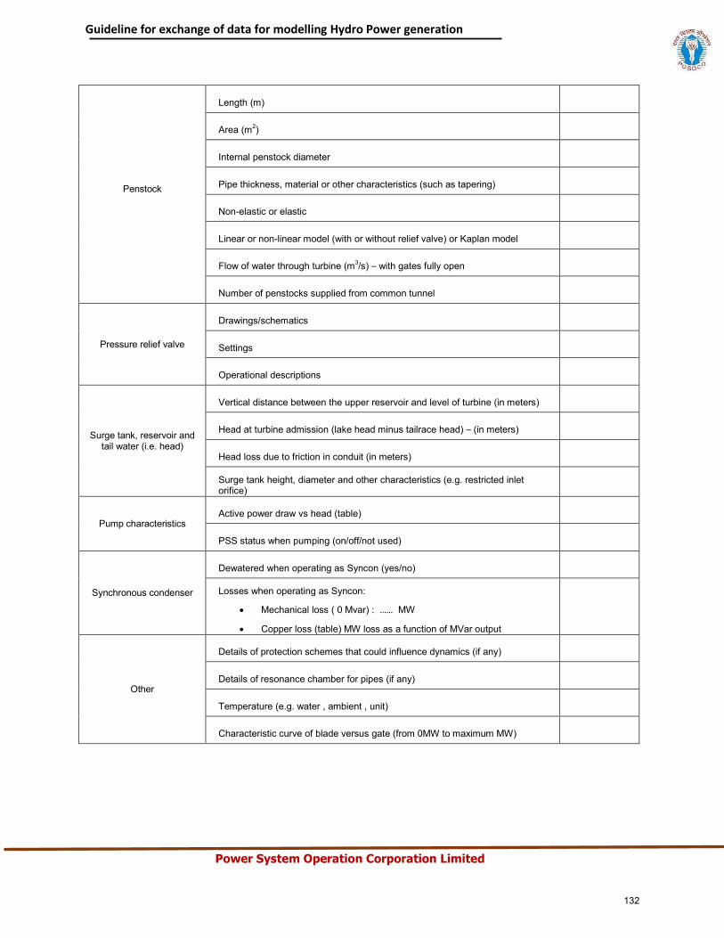
Guideline for exchange of data for modelling Hydro Power generation
Power System Operation Corporation Limited
Penstock
Length (m)
Area (m2)
Internal penstock diameter
Pipe thickness, material or other characteristics (such as tapering)
Non-elastic or elastic
Linear or non-linear model (with or without relief valve) or Kaplan model
Flow of water through turbine (m3/s) – with gates fully open
Number of penstocks supplied from common tunnel
Pressure relief valve
Drawings/schematics
Settings
Operational descriptions
Surge tank, reservoir and tail water (i.e. head)
Vertical distance between the upper reservoir and level of turbine (in meters)
Head at turbine admission (lake head minus tailrace head) – (in meters)
Head loss due to friction in conduit (in meters)
Surge tank height, diameter and other characteristics (e.g. restricted inlet orifice)
Pump characteristics Active power draw vs head (table)
PSS status when pumping (on/off/not used)
Synchronous condenser
Dewatered when operating as Syncon (yes/no)
Losses when operating as Syncon:
Mechanical loss ( 0 Mvar) : …… MW
Copper loss (table) MW loss as a function of MVar output
Other
Details of protection schemes that could influence dynamics (if any)
Details of resonance chamber for pipes (if any)
Temperature (e.g. water , ambient , unit)
Characteristic curve of blade versus gate (from 0MW to maximum MW)
132
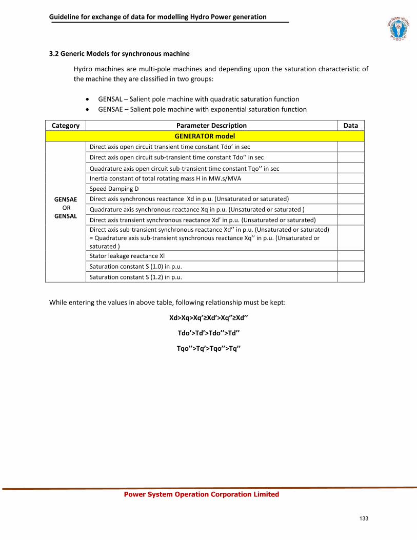
Guideline for exchange of data for modelling Hydro Power generation
Power System Operation Corporation Limited
3.2 Generic Models for synchronous machine
Hydro machines are multi-pole machines and depending upon the saturation characteristic of
the machine they are classified in two groups:
GENSAL – Salient pole machine with quadratic saturation function
GENSAE – Salient pole machine with exponential saturation function
Category Parameter Description Data
GENERATOR model
GENSAE OR
GENSAL
Direct axis open circuit transient time constant Tdo’ in sec
Direct axis open circuit sub-transient time constant Tdo’’ in sec
Quadrature axis open circuit sub-transient time constant Tqo’’ in sec
Inertia constant of total rotating mass H in MW.s/MVA
Speed Damping D
Direct axis synchronous reactance Xd in p.u. (Unsaturated or saturated)
Quadrature axis synchronous reactance Xq in p.u. (Unsaturated or saturated )
Direct axis transient synchronous reactance Xd’ in p.u. (Unsaturated or saturated)
Direct axis sub-transient synchronous reactance Xd’’ in p.u. (Unsaturated or saturated) = Quadrature axis sub-transient synchronous reactance Xq’’ in p.u. (Unsaturated or saturated )
Stator leakage reactance Xl
Saturation constant S (1.0) in p.u.
Saturation constant S (1.2) in p.u.
While entering the values in above table, following relationship must be kept:
Xd>Xq>Xq’≥Xd’>Xq”≥Xd’’
Tdo’>Td’>Tdo’’>Td’’
Tqo’’>Tq’>Tqo’’>Tq’’
133
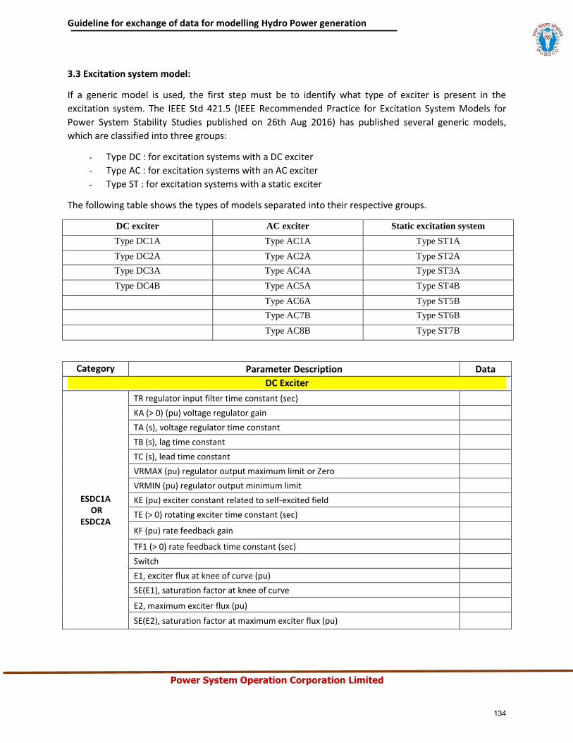
Guideline for exchange of data for modelling Hydro Power generation
Power System Operation Corporation Limited
3.3 Excitation system model:
If a generic model is used, the first step must be to identify what type of exciter is present in the
excitation system. The IEEE Std 421.5 (IEEE Recommended Practice for Excitation System Models for
Power System Stability Studies published on 26th Aug 2016) has published several generic models,
which are classified into three groups:
- Type DC : for excitation systems with a DC exciter
- Type AC : for excitation systems with an AC exciter
- Type ST : for excitation systems with a static exciter
The following table shows the types of models separated into their respective groups.
DC exciter AC exciter Static excitation system
Type DC1A Type AC1A Type ST1A
Type DC2A Type AC2A Type ST2A
Type DC3A Type AC4A Type ST3A
Type DC4B Type AC5A Type ST4B
Type AC6A Type ST5B
Type AC7B Type ST6B
Type AC8B Type ST7B
Category Parameter Description Data
DC Exciter
ESDC1A OR
ESDC2A
TR regulator input filter time constant (sec)
KA (> 0) (pu) voltage regulator gain
TA (s), voltage regulator time constant
TB (s), lag time constant
TC (s), lead time constant
VRMAX (pu) regulator output maximum limit or Zero
VRMIN (pu) regulator output minimum limit
KE (pu) exciter constant related to self-excited field
TE (> 0) rotating exciter time constant (sec)
KF (pu) rate feedback gain
TF1 (> 0) rate feedback time constant (sec)
Switch
E1, exciter flux at knee of curve (pu)
SE(E1), saturation factor at knee of curve
E2, maximum exciter flux (pu)
SE(E2), saturation factor at maximum exciter flux (pu)
134
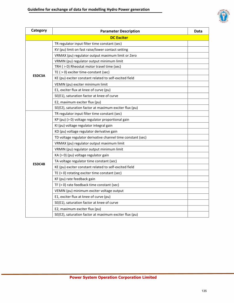
Guideline for exchange of data for modelling Hydro Power generation
Power System Operation Corporation Limited
Category Parameter Description Data
DC Exciter
ESDC3A
TR regulator input filter time constant (sec)
KV (pu) limit on fast raise/lower contact setting
VRMAX (pu) regulator output maximum limit or Zero
VRMIN (pu) regulator output minimum limit
TRH ( > 0) Rheostat motor travel time (sec)
TE ( > 0) exciter time-constant (sec)
KE (pu) exciter constant related to self-excited field
VEMIN (pu) exciter minimum limit
E1, exciter flux at knee of curve (pu)
SE(E1), saturation factor at knee of curve
E2, maximum exciter flux (pu)
SE(E2), saturation factor at maximum exciter flux (pu)
ESDC4B
TR regulator input filter time constant (sec)
KP (pu) (> 0) voltage regulator proportional gain
KI (pu) voltage regulator integral gain
KD (pu) voltage regulator derivative gain
TD voltage regulator derivative channel time constant (sec)
VRMAX (pu) regulator output maximum limit
VRMIN (pu) regulator output minimum limit
KA (> 0) (pu) voltage regulator gain
TA voltage regulator time constant (sec)
KE (pu) exciter constant related to self-excited field
TE (> 0) rotating exciter time constant (sec)
KF (pu) rate feedback gain
TF (> 0) rate feedback time constant (sec)
VEMIN (pu) minimum exciter voltage output
E1, exciter flux at knee of curve (pu)
SE(E1), saturation factor at knee of curve
E2, maximum exciter flux (pu)
SE(E2), saturation factor at maximum exciter flux (pu)
135
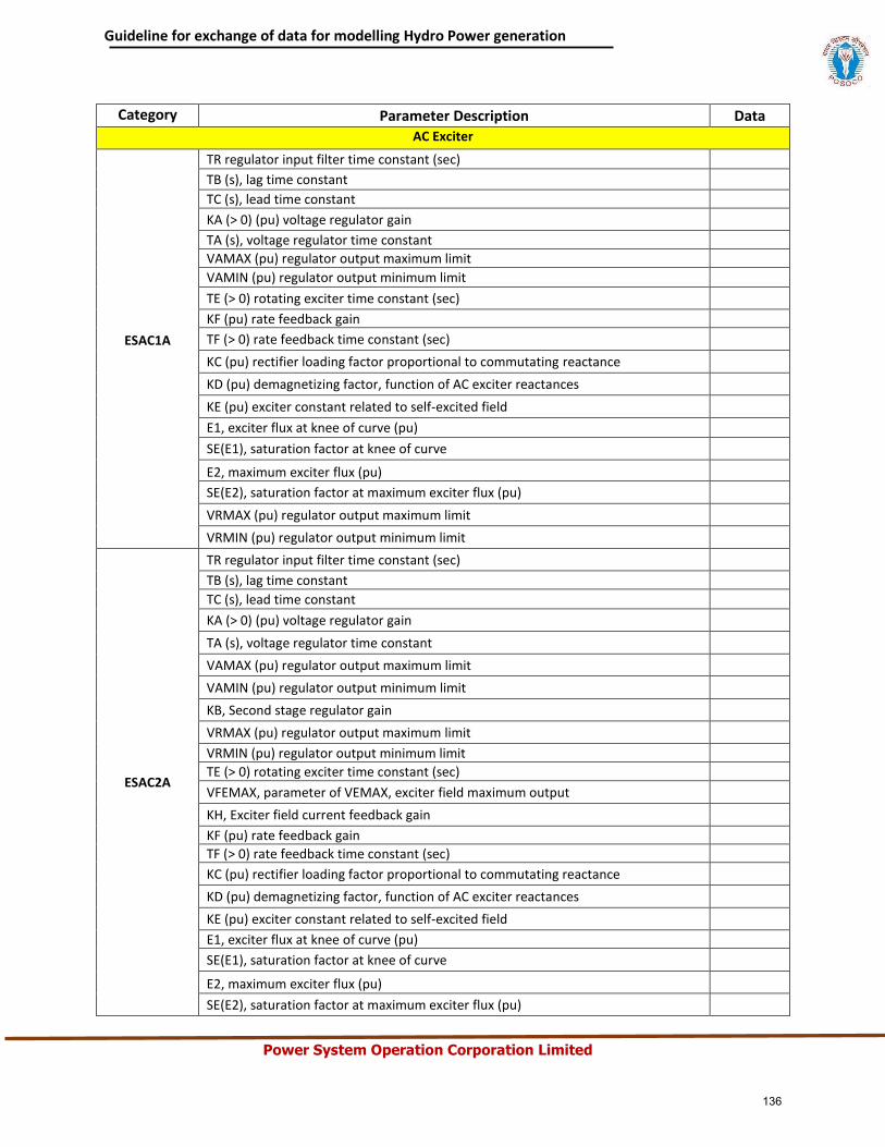
Guideline for exchange of data for modelling Hydro Power generation
Power System Operation Corporation Limited
Category Parameter Description Data
AC Exciter
ESAC1A
TR regulator input filter time constant (sec)
TB (s), lag time constant
TC (s), lead time constant
KA (> 0) (pu) voltage regulator gain
TA (s), voltage regulator time constant
VAMAX (pu) regulator output maximum limit
VAMIN (pu) regulator output minimum limit
TE (> 0) rotating exciter time constant (sec)
KF (pu) rate feedback gain
TF (> 0) rate feedback time constant (sec)
KC (pu) rectifier loading factor proportional to commutating reactance
KD (pu) demagnetizing factor, function of AC exciter reactances
KE (pu) exciter constant related to self-excited field
E1, exciter flux at knee of curve (pu)
SE(E1), saturation factor at knee of curve
E2, maximum exciter flux (pu)
SE(E2), saturation factor at maximum exciter flux (pu)
VRMAX (pu) regulator output maximum limit
VRMIN (pu) regulator output minimum limit
ESAC2A
TR regulator input filter time constant (sec)
TB (s), lag time constant
TC (s), lead time constant
KA (> 0) (pu) voltage regulator gain
TA (s), voltage regulator time constant
VAMAX (pu) regulator output maximum limit
VAMIN (pu) regulator output minimum limit
KB, Second stage regulator gain
VRMAX (pu) regulator output maximum limit
VRMIN (pu) regulator output minimum limit
TE (> 0) rotating exciter time constant (sec)
VFEMAX, parameter of VEMAX, exciter field maximum output
KH, Exciter field current feedback gain
KF (pu) rate feedback gain
TF (> 0) rate feedback time constant (sec)
KC (pu) rectifier loading factor proportional to commutating reactance
KD (pu) demagnetizing factor, function of AC exciter reactances
KE (pu) exciter constant related to self-excited field
E1, exciter flux at knee of curve (pu)
SE(E1), saturation factor at knee of curve
E2, maximum exciter flux (pu)
SE(E2), saturation factor at maximum exciter flux (pu)
136
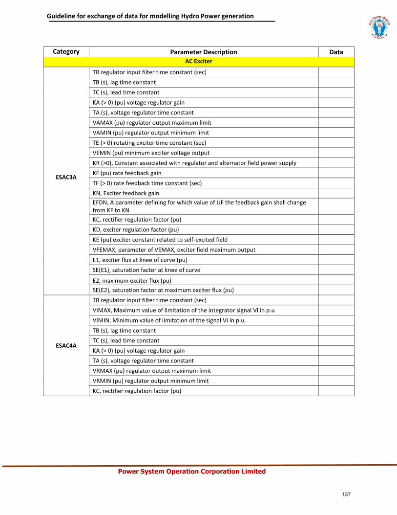
Guideline for exchange of data for modelling Hydro Power generation
Power System Operation Corporation Limited
Category Parameter Description Data
AC Exciter
ESAC3A
TR regulator input filter time constant (sec)
TB (s), lag time constant
TC (s), lead time constant
KA (> 0) (pu) voltage regulator gain
TA (s), voltage regulator time constant
VAMAX (pu) regulator output maximum limit
VAMIN (pu) regulator output minimum limit
TE (> 0) rotating exciter time constant (sec)
VEMIN (pu) minimum exciter voltage output
KR (>0), Constant associated with regulator and alternator field power supply
KF (pu) rate feedback gain
TF (> 0) rate feedback time constant (sec)
KN, Exciter feedback gain
EFDN, A parameter defining for which value of UF the feedback gain shall change from KF to KN
KC, rectifier regulation factor (pu)
KD, exciter regulation factor (pu)
KE (pu) exciter constant related to self-excited field
VFEMAX, parameter of VEMAX, exciter field maximum output
E1, exciter flux at knee of curve (pu)
SE(E1), saturation factor at knee of curve
E2, maximum exciter flux (pu)
SE(E2), saturation factor at maximum exciter flux (pu)
ESAC4A
TR regulator input filter time constant (sec)
VIMAX, Maximum value of limitation of the integrator signal VI in p.u
VIMIN, Minimum value of limitation of the signal VI in p.u.
TB (s), lag time constant
TC (s), lead time constant
KA (> 0) (pu) voltage regulator gain
TA (s), voltage regulator time constant
VRMAX (pu) regulator output maximum limit
VRMIN (pu) regulator output minimum limit
KC, rectifier regulation factor (pu)
137
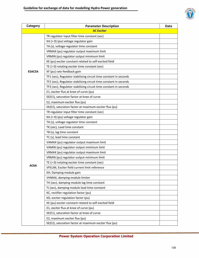
Guideline for exchange of data for modelling Hydro Power generation
Power System Operation Corporation Limited
Category Parameter Description Data
AC Exciter
ESAC5A
TR regulator input filter time constant (sec)
KA (> 0) (pu) voltage regulator gain
TA (s), voltage regulator time constant
VRMAX (pu) regulator output maximum limit
VRMIN (pu) regulator output minimum limit
KE (pu) exciter constant related to self-excited field
TE (> 0) rotating exciter time constant (sec)
KF (pu) rate feedback gain
TF1 (sec), Regulator stabilizing circuit time constant in seconds
TF2 (sec), Regulator stabilizing circuit time constant in seconds
TF3 (sec), Regulator stabilizing circuit time constant in seconds
E1, exciter flux at knee of curve (pu)
SE(E1), saturation factor at knee of curve
E2, maximum exciter flux (pu)
SE(E2), saturation factor at maximum exciter flux (pu)
AC6A
TR regulator input filter time constant (sec)
KA (> 0) (pu) voltage regulator gain
TA (s), voltage regulator time constant
TK (sec), Lead time constant
TB (s), lag time constant
TC (s), lead time constant
VAMAX (pu) regulator output maximum limit
VAMIN (pu) regulator output minimum limit
VRMAX (pu) regulator output maximum limit
VRMIN (pu) regulator output minimum limit
TE (> 0) rotating exciter time constant (sec)
VFELIM, Exciter field current limit reference
KH, Damping module gain
VHMAX, damping module limiter
TH (sec), damping module lag time constant
TJ (sec), damping module lead time constant
KC, rectifier regulation factor (pu)
KD, exciter regulation factor (pu)
KE (pu) exciter constant related to self-excited field
E1, exciter flux at knee of curve (pu)
SE(E1), saturation factor at knee of curve
E2, maximum exciter flux (pu)
SE(E2), saturation factor at maximum exciter flux (pu)
138
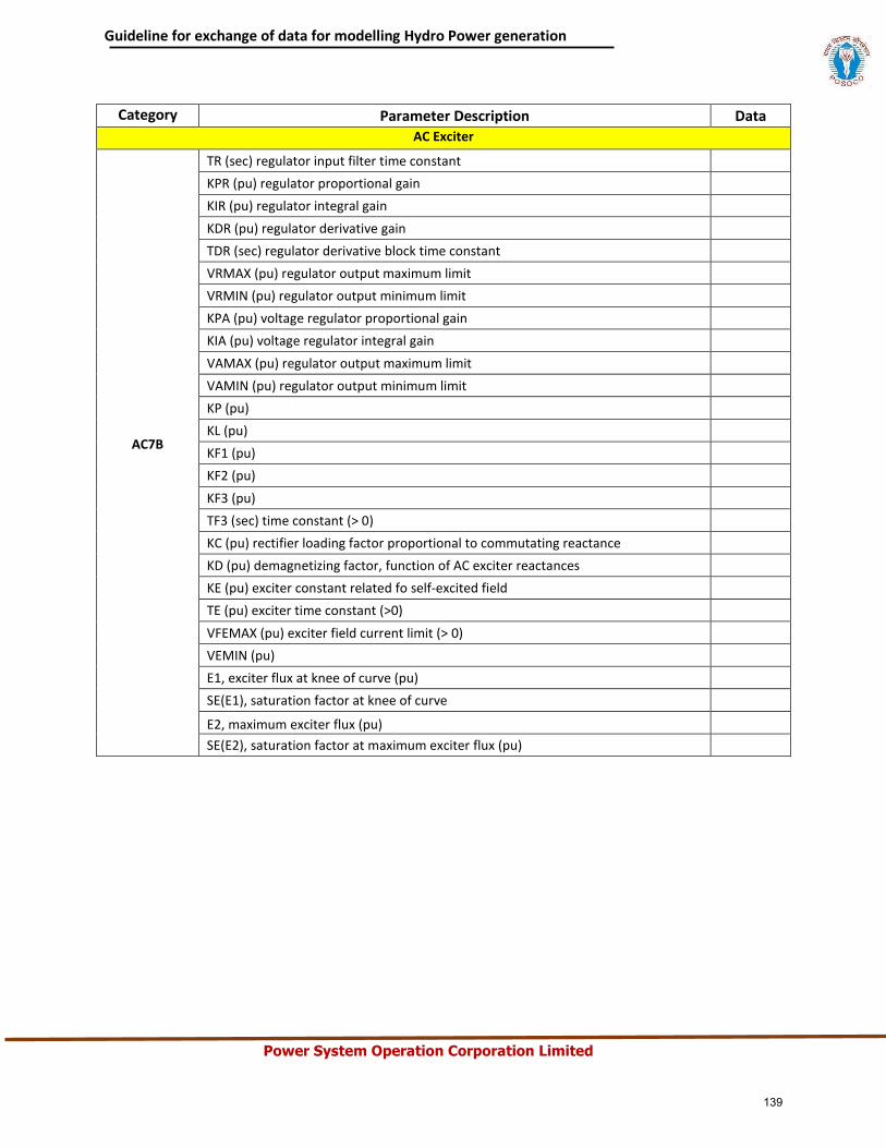
Guideline for exchange of data for modelling Hydro Power generation
Power System Operation Corporation Limited
Category Parameter Description Data
AC Exciter
AC7B
TR (sec) regulator input filter time constant
KPR (pu) regulator proportional gain
KIR (pu) regulator integral gain
KDR (pu) regulator derivative gain
TDR (sec) regulator derivative block time constant
VRMAX (pu) regulator output maximum limit
VRMIN (pu) regulator output minimum limit
KPA (pu) voltage regulator proportional gain
KIA (pu) voltage regulator integral gain
VAMAX (pu) regulator output maximum limit
VAMIN (pu) regulator output minimum limit
KP (pu)
KL (pu)
KF1 (pu)
KF2 (pu)
KF3 (pu)
TF3 (sec) time constant (> 0)
KC (pu) rectifier loading factor proportional to commutating reactance
KD (pu) demagnetizing factor, function of AC exciter reactances
KE (pu) exciter constant related fo self-excited field
TE (pu) exciter time constant (>0)
VFEMAX (pu) exciter field current limit (> 0)
VEMIN (pu)
E1, exciter flux at knee of curve (pu)
SE(E1), saturation factor at knee of curve
E2, maximum exciter flux (pu)
SE(E2), saturation factor at maximum exciter flux (pu)
139
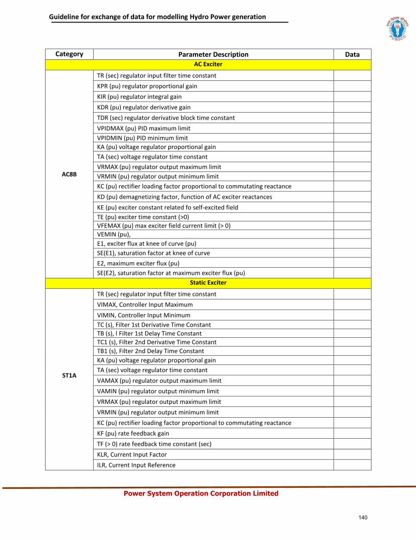
Guideline for exchange of data for modelling Hydro Power generation
Power System Operation Corporation Limited
Category Parameter Description Data
AC Exciter
AC8B
TR (sec) regulator input filter time constant
KPR (pu) regulator proportional gain
KIR (pu) regulator integral gain
KDR (pu) regulator derivative gain
TDR (sec) regulator derivative block time constant
VPIDMAX (pu) PID maximum limit
VPIDMIN (pu) PID minimum limit
KA (pu) voltage regulator proportional gain
TA (sec) voltage regulator time constant
VRMAX (pu) regulator output maximum limit
VRMIN (pu) regulator output minimum limit
KC (pu) rectifier loading factor proportional to commutating reactance
KD (pu) demagnetizing factor, function of AC exciter reactances
KE (pu) exciter constant related fo self-excited field
TE (pu) exciter time constant (>0)
VFEMAX (pu) max exciter field current limit (> 0)
VEMIN (pu),
E1, exciter flux at knee of curve (pu)
SE(E1), saturation factor at knee of curve
E2, maximum exciter flux (pu)
SE(E2), saturation factor at maximum exciter flux (pu)
Static Exciter
ST1A
TR (sec) regulator input filter time constant
VIMAX, Controller Input Maximum
VIMIN, Controller Input Minimum
TC (s), Filter 1st Derivative Time Constant
TB (s), l Filter 1st Delay Time Constant
TC1 (s), Filter 2nd Derivative Time Constant
TB1 (s), Filter 2nd Delay Time Constant
KA (pu) voltage regulator proportional gain
TA (sec) voltage regulator time constant
VAMAX (pu) regulator output maximum limit
VAMIN (pu) regulator output minimum limit
VRMAX (pu) regulator output maximum limit
VRMIN (pu) regulator output minimum limit
KC (pu) rectifier loading factor proportional to commutating reactance
KF (pu) rate feedback gain
TF (> 0) rate feedback time constant (sec)
KLR, Current Input Factor
ILR, Current Input Reference
140
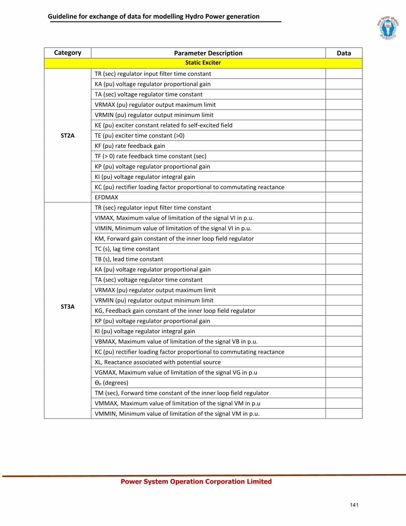
Guideline for exchange of data for modelling Hydro Power generation
Power System Operation Corporation Limited
Category Parameter Description Data
Static Exciter
ST2A
TR (sec) regulator input filter time constant
KA (pu) voltage regulator proportional gain
TA (sec) voltage regulator time constant
VRMAX (pu) regulator output maximum limit
VRMIN (pu) regulator output minimum limit
KE (pu) exciter constant related fo self-excited field
TE (pu) exciter time constant (>0)
KF (pu) rate feedback gain
TF (> 0) rate feedback time constant (sec)
KP (pu) voltage regulator proportional gain
KI (pu) voltage regulator integral gain
KC (pu) rectifier loading factor proportional to commutating reactance
EFDMAX
ST3A
TR (sec) regulator input filter time constant
VIMAX, Maximum value of limitation of the signal VI in p.u.
VIMIN, Minimum value of limitation of the signal VI in p.u.
KM, Forward gain constant of the inner loop field regulator
TC (s), lag time constant
TB (s), lead time constant
KA (pu) voltage regulator proportional gain
TA (sec) voltage regulator time constant
VRMAX (pu) regulator output maximum limit
VRMIN (pu) regulator output minimum limit
KG, Feedback gain constant of the inner loop field regulator
KP (pu) voltage regulator proportional gain
KI (pu) voltage regulator integral gain
VBMAX, Maximum value of limitation of the signal VB in p.u.
KC (pu) rectifier loading factor proportional to commutating reactance
XL, Reactance associated with potential source
VGMAX, Maximum value of limitation of the signal VG in p.u
ƟP (degrees)
TM (sec), Forward time constant of the inner loop field regulator
VMMAX, Maximum value of limitation of the signal VM in p.u
VMMIN, Minimum value of limitation of the signal VM in p.u.
141
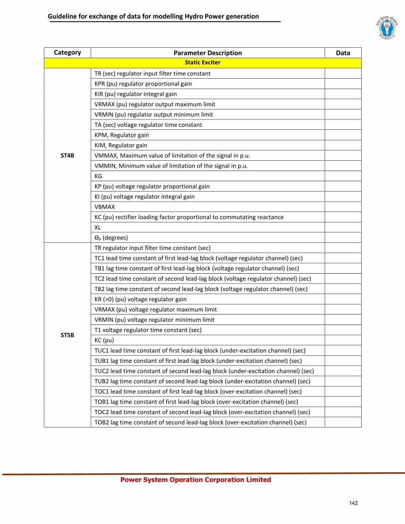
Guideline for exchange of data for modelling Hydro Power generation
Power System Operation Corporation Limited
Category Parameter Description Data
Static Exciter
ST4B
TR (sec) regulator input filter time constant
KPR (pu) regulator proportional gain
KIR (pu) regulator integral gain
VRMAX (pu) regulator output maximum limit
VRMIN (pu) regulator output minimum limit
TA (sec) voltage regulator time constant
KPM, Regulator gain
KIM, Regulator gain
VMMAX, Maximum value of limitation of the signal in p.u.
VMMIN, Minimum value of limitation of the signal in p.u.
KG
KP (pu) voltage regulator proportional gain
KI (pu) voltage regulator integral gain
VBMAX
KC (pu) rectifier loading factor proportional to commutating reactance
XL
ƟP (degrees)
ST5B
TR regulator input filter time constant (sec)
TC1 lead time constant of first lead-lag block (voltage regulator channel) (sec)
TB1 lag time constant of first lead-lag block (voltage regulator channel) (sec)
TC2 lead time constant of second lead-lag block (voltage regulator channel) (sec)
TB2 lag time constant of second lead-lag block (voltage regulator channel) (sec)
KR (>0) (pu) voltage regulator gain
VRMAX (pu) voltage regulator maximum limit
VRMIN (pu) voltage regulator minimum limit
T1 voltage regulator time constant (sec)
KC (pu)
TUC1 lead time constant of first lead-lag block (under-excitation channel) (sec)
TUB1 lag time constant of first lead-lag block (under-excitation channel) (sec)
TUC2 lead time constant of second lead-lag block (under-excitation channel) (sec)
TUB2 lag time constant of second lead-lag block (under-excitation channel) (sec)
TOC1 lead time constant of first lead-lag block (over-excitation channel) (sec)
TOB1 lag time constant of first lead-lag block (over-excitation channel) (sec)
TOC2 lead time constant of second lead-lag block (over-excitation channel) (sec)
TOB2 lag time constant of second lead-lag block (over-excitation channel) (sec)
142
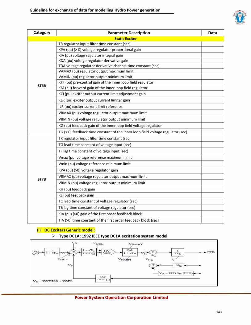
Guideline for exchange of data for modelling Hydro Power generation
Power System Operation Corporation Limited
Category Parameter Description Data
Static Exciter
ST6B
TR regulator input filter time constant (sec)
KPA (pu) (> 0) voltage regulator proportional gain
KIA (pu) voltage regulator integral gain
KDA (pu) voltage regulator derivative gain
TDA voltage regulator derivative channel time constant (sec)
VAMAX (pu) regulator output maximum limit
VAMIN (pu) regulator output minimum limit
KFF (pu) pre-control gain of the inner loop field regulator
KM (pu) forward gain of the inner loop field regulator
KCI (pu) exciter output current limit adjustment gain
KLR (pu) exciter output current limiter gain
ILR (pu) exciter current limit reference
VRMAX (pu) voltage regulator output maximum limit
VRMIN (pu) voltage regulator output minimum limit
KG (pu) feedback gain of the inner loop field voltage regulator
TG (> 0) feedback time constant of the inner loop field voltage regulator (sec)
ST7B
TR regulator input filter time constant (sec)
TG lead time constant of voltage input (sec)
TF lag time constant of voltage input (sec)
Vmax (pu) voltage reference maximum limit
Vmin (pu) voltage reference minimum limit
KPA (pu) (>0) voltage regulator gain
VRMAX (pu) voltage regulator output maximum limit
VRMIN (pu) voltage regulator output minimum limit
KH (pu) feedback gain
KL (pu) feedback gain
TC lead time constant of voltage regulator (sec)
TB lag time constant of voltage regulator (sec)
KIA (pu) (>0) gain of the first order feedback block
TIA (>0) time constant of the first order feedback block (sec)
(i) DC Exciters Generic model:
Type DC1A: 1992 IEEE type DC1A excitation system model
143
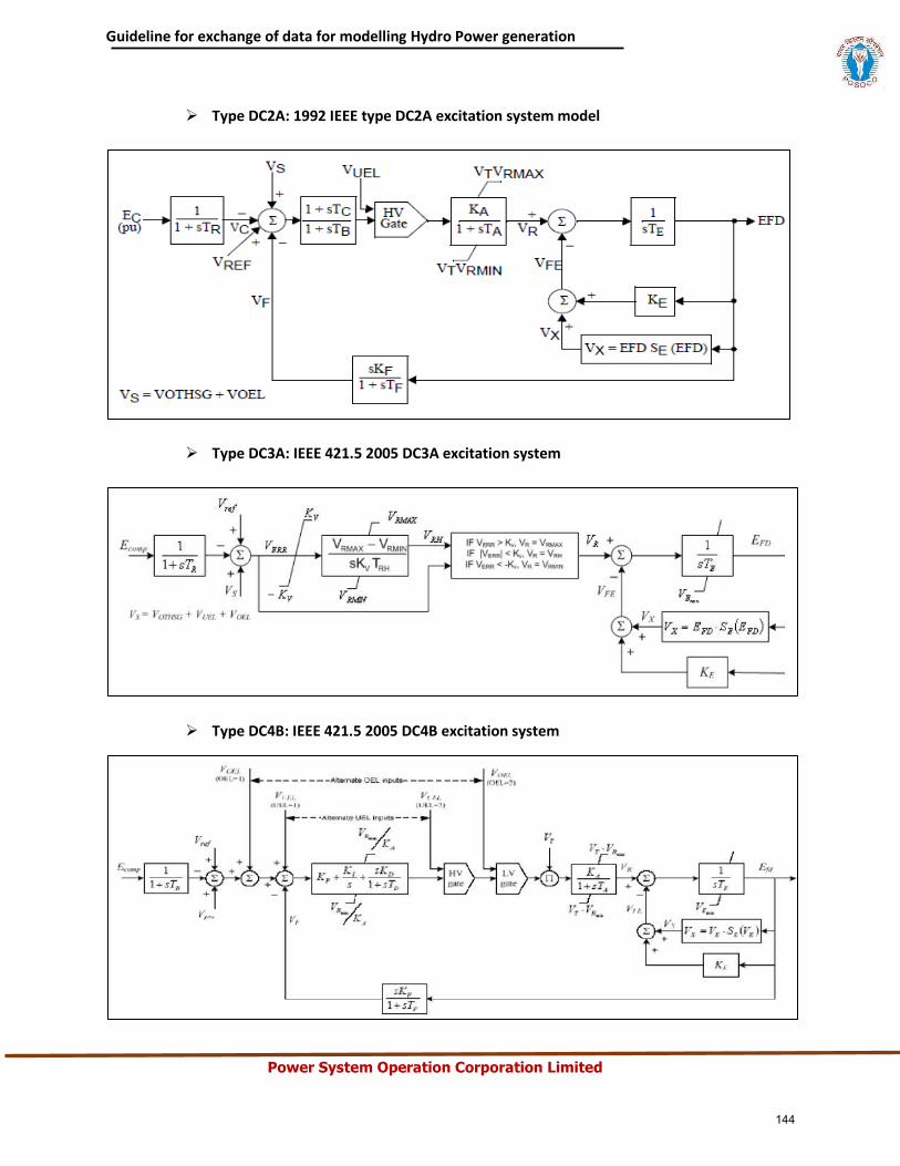
Guideline for exchange of data for modelling Hydro Power generation
Power System Operation Corporation Limited
Type DC2A: 1992 IEEE type DC2A excitation system model
Type DC3A: IEEE 421.5 2005 DC3A excitation system
Type DC4B: IEEE 421.5 2005 DC4B excitation system
144
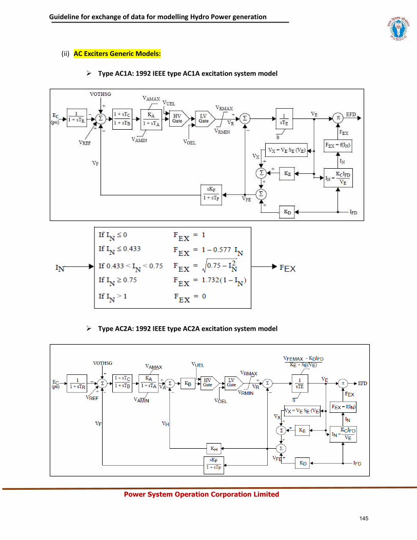
Guideline for exchange of data for modelling Hydro Power generation
Power System Operation Corporation Limited
(ii) AC Exciters Generic Models:
Type AC1A: 1992 IEEE type AC1A excitation system model
Type AC2A: 1992 IEEE type AC2A excitation system model
145
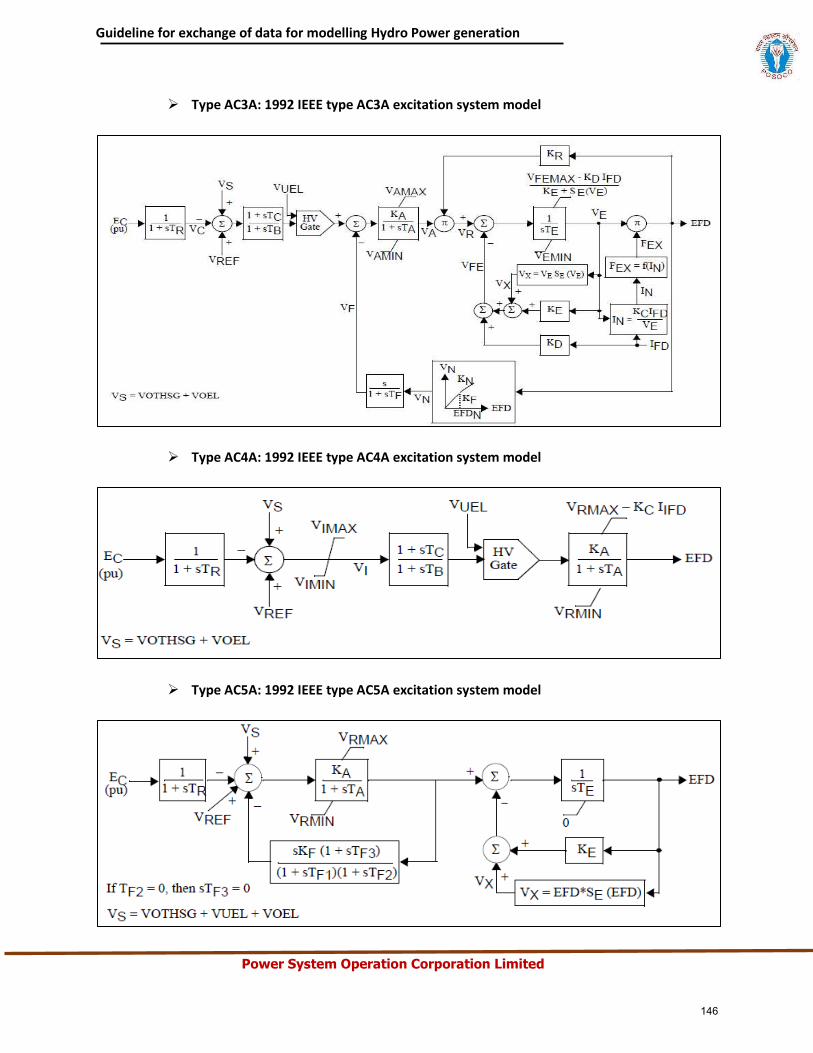
Guideline for exchange of data for modelling Hydro Power generation
Power System Operation Corporation Limited
Type AC3A: 1992 IEEE type AC3A excitation system model
Type AC4A: 1992 IEEE type AC4A excitation system model
Type AC5A: 1992 IEEE type AC5A excitation system model
146
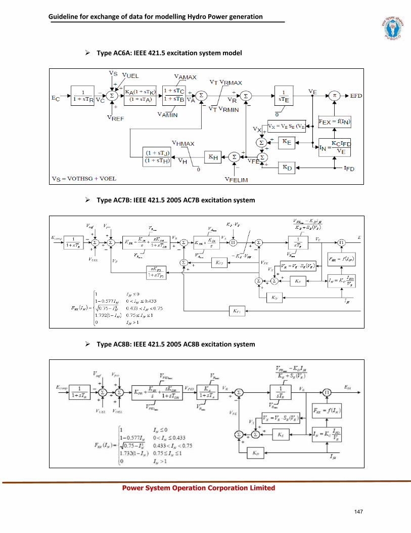
Guideline for exchange of data for modelling Hydro Power generation
Power System Operation Corporation Limited
Type AC6A: IEEE 421.5 excitation system model
Type AC7B: IEEE 421.5 2005 AC7B excitation system
Type AC8B: IEEE 421.5 2005 AC8B excitation system
147
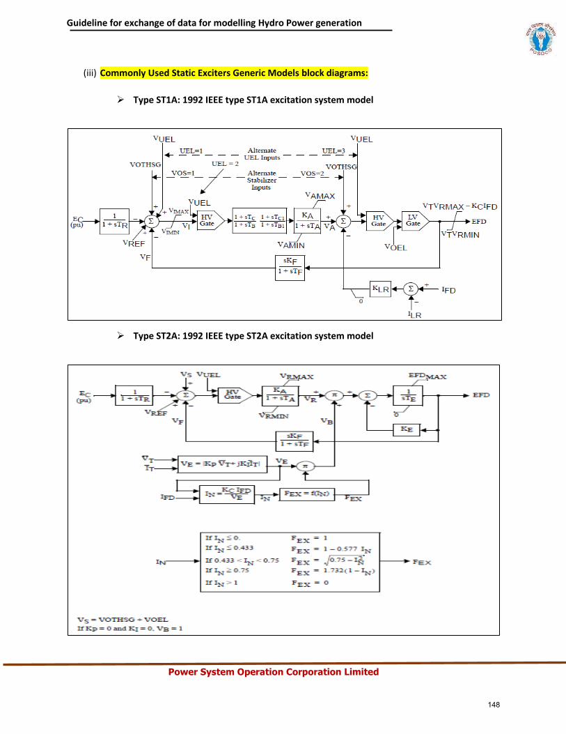
Guideline for exchange of data for modelling Hydro Power generation
Power System Operation Corporation Limited
(iii) Commonly Used Static Exciters Generic Models block diagrams:
Type ST1A: 1992 IEEE type ST1A excitation system model
Type ST2A: 1992 IEEE type ST2A excitation system model
148
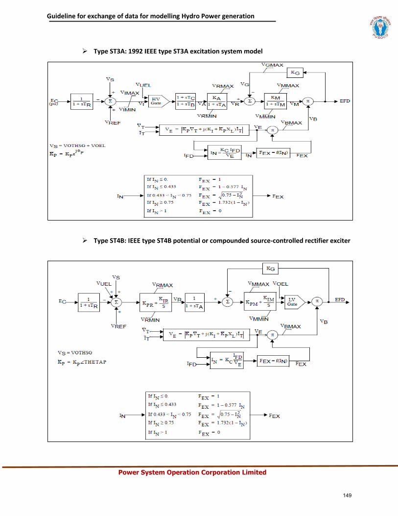
Guideline for exchange of data for modelling Hydro Power generation
Power System Operation Corporation Limited
Type ST3A: 1992 IEEE type ST3A excitation system model
Type ST4B: IEEE type ST4B potential or compounded source-controlled rectifier exciter
149
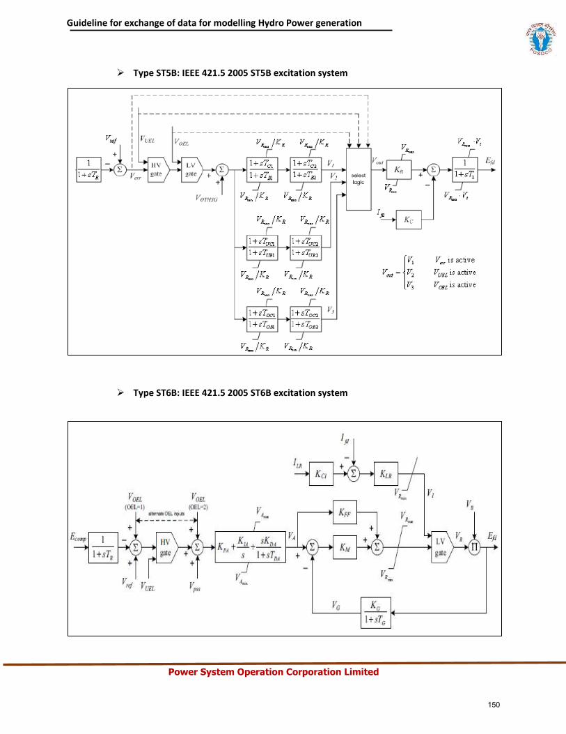
Guideline for exchange of data for modelling Hydro Power generation
Power System Operation Corporation Limited
Type ST5B: IEEE 421.5 2005 ST5B excitation system
Type ST6B: IEEE 421.5 2005 ST6B excitation system
150
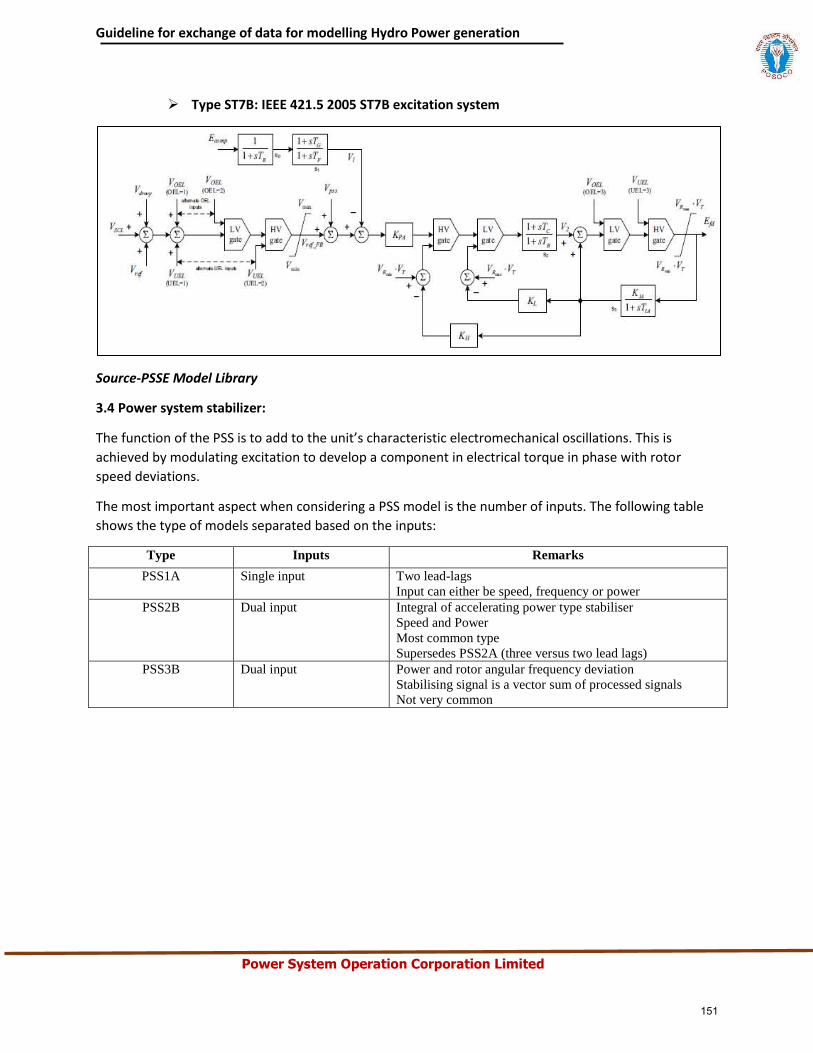
Guideline for exchange of data for modelling Hydro Power generation
Power System Operation Corporation Limited
Type ST7B: IEEE 421.5 2005 ST7B excitation system
Source-PSSE Model Library
3.4 Power system stabilizer:
The function of the PSS is to add to the unit’s characteristic electromechanical oscillations. This is
achieved by modulating excitation to develop a component in electrical torque in phase with rotor
speed deviations.
The most important aspect when considering a PSS model is the number of inputs. The following table
shows the type of models separated based on the inputs:
Type Inputs Remarks
PSS1A Single input Two lead-lags
Input can either be speed, frequency or power
PSS2B Dual input Integral of accelerating power type stabiliser
Speed and Power
Most common type
Supersedes PSS2A (three versus two lead lags)
PSS3B Dual input Power and rotor angular frequency deviation
Stabilising signal is a vector sum of processed signals
Not very common
151
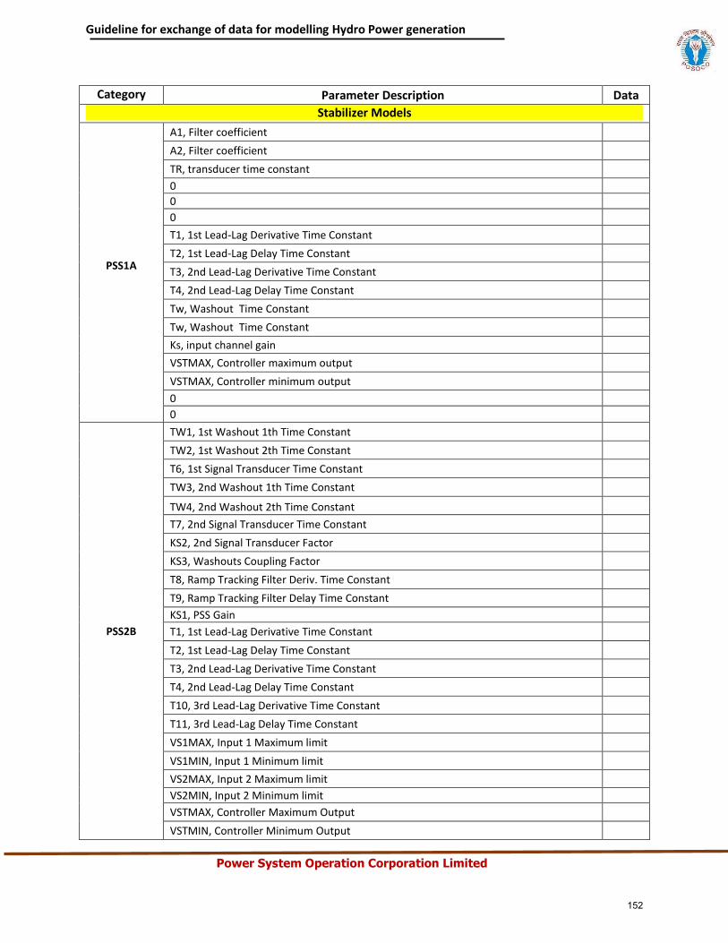
Guideline for exchange of data for modelling Hydro Power generation
Power System Operation Corporation Limited
Category Parameter Description Data
Stabilizer Models
PSS1A
A1, Filter coefficient
A2, Filter coefficient
TR, transducer time constant
0
0
0
T1, 1st Lead-Lag Derivative Time Constant
T2, 1st Lead-Lag Delay Time Constant
T3, 2nd Lead-Lag Derivative Time Constant
T4, 2nd Lead-Lag Delay Time Constant
Tw, Washout Time Constant
Tw, Washout Time Constant
Ks, input channel gain
VSTMAX, Controller maximum output
VSTMAX, Controller minimum output
0
0
PSS2B
TW1, 1st Washout 1th Time Constant
TW2, 1st Washout 2th Time Constant
T6, 1st Signal Transducer Time Constant
TW3, 2nd Washout 1th Time Constant
TW4, 2nd Washout 2th Time Constant
T7, 2nd Signal Transducer Time Constant
KS2, 2nd Signal Transducer Factor
KS3, Washouts Coupling Factor
T8, Ramp Tracking Filter Deriv. Time Constant
T9, Ramp Tracking Filter Delay Time Constant
KS1, PSS Gain
T1, 1st Lead-Lag Derivative Time Constant
T2, 1st Lead-Lag Delay Time Constant
T3, 2nd Lead-Lag Derivative Time Constant
T4, 2nd Lead-Lag Delay Time Constant
T10, 3rd Lead-Lag Derivative Time Constant
T11, 3rd Lead-Lag Delay Time Constant
VS1MAX, Input 1 Maximum limit
VS1MIN, Input 1 Minimum limit
VS2MAX, Input 2 Maximum limit
VS2MIN, Input 2 Minimum limit
VSTMAX, Controller Maximum Output
VSTMIN, Controller Minimum Output
152
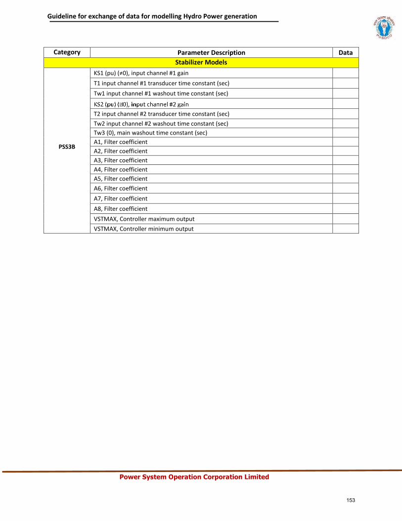
Guideline for exchange of data for modelling Hydro Power generation
Power System Operation Corporation Limited
Category Parameter Description Data
Stabilizer Models
PSS3B
KS1 (pu) (≠0), input channel #1 gain
T1 input channel #1 transducer time constant (sec)
Tw1 input channel #1 washout time constant (sec)
T2 input channel #2 transducer time constant (sec)
Tw2 input channel #2 washout time constant (sec)
Tw3 (0), main washout time constant (sec)
A1, Filter coefficient
A2, Filter coefficient
A3, Filter coefficient
A4, Filter coefficient
A5, Filter coefficient
A6, Filter coefficient
A7, Filter coefficient
A8, Filter coefficient
VSTMAX, Controller maximum output
VSTMAX, Controller minimum output
153
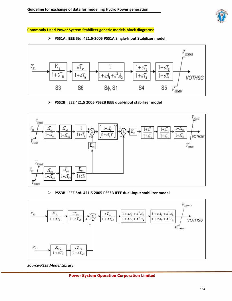
Guideline for exchange of data for modelling Hydro Power generation
Power System Operation Corporation Limited
Commonly Used Power System Stabilizer generic models block diagrams:
PSS1A: IEEE Std. 421.5-2005 PSS1A Single-Input Stabilizer model
PSS2B: IEEE 421.5 2005 PSS2B IEEE dual-input stabilizer model
PSS3B: IEEE Std. 421.5 2005 PSS3B IEEE dual-input stabilizer model
Source-PSSE Model Library
154
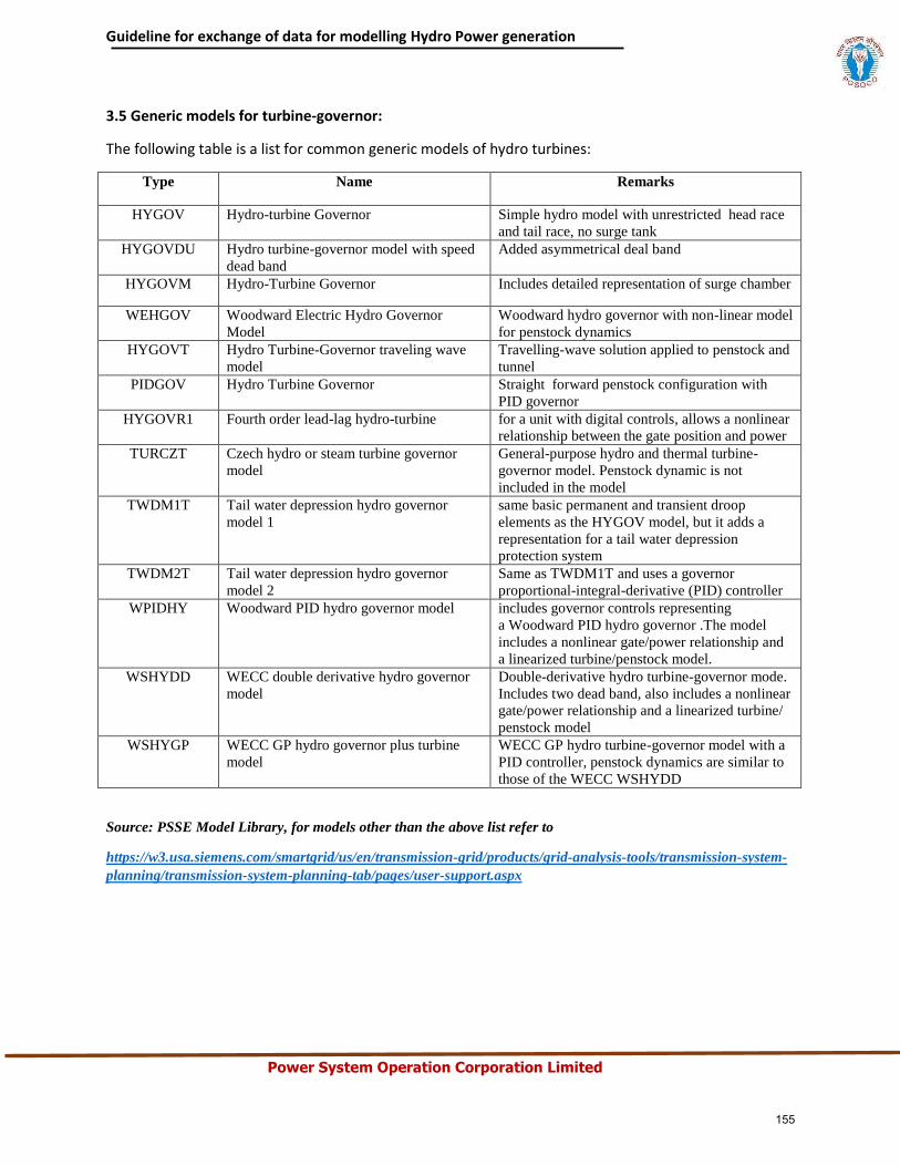
Guideline for exchange of data for modelling Hydro Power generation
Power System Operation Corporation Limited
3.5 Generic models for turbine-governor:
The following table is a list for common generic models of hydro turbines:
Type Name Remarks
HYGOV Hydro-turbine Governor Simple hydro model with unrestricted head race
and tail race, no surge tank
HYGOVDU Hydro turbine-governor model with speed
dead band
Added asymmetrical deal band
HYGOVM Hydro-Turbine Governor Includes detailed representation of surge chamber
WEHGOV Woodward Electric Hydro Governor
Model
Woodward hydro governor with non-linear model
for penstock dynamics
HYGOVT Hydro Turbine-Governor traveling wave
model
Travelling-wave solution applied to penstock and
tunnel
PIDGOV Hydro Turbine Governor Straight forward penstock configuration with
PID governor
HYGOVR1 Fourth order lead-lag hydro-turbine for a unit with digital controls, allows a nonlinear
relationship between the gate position and power
TURCZT Czech hydro or steam turbine governor
model
General-purpose hydro and thermal turbine-
governor model. Penstock dynamic is not
included in the model
TWDM1T Tail water depression hydro governor
model 1
same basic permanent and transient droop
elements as the HYGOV model, but it adds a
representation for a tail water depression
protection system
TWDM2T Tail water depression hydro governor
model 2
Same as TWDM1T and uses a governor
proportional-integral-derivative (PID) controller
WPIDHY Woodward PID hydro governor model includes governor controls representing
a Woodward PID hydro governor .The model
includes a nonlinear gate/power relationship and
a linearized turbine/penstock model.
WSHYDD WECC double derivative hydro governor
model
Double-derivative hydro turbine-governor mode.
Includes two dead band, also includes a nonlinear
gate/power relationship and a linearized turbine/
penstock model
WSHYGP WECC GP hydro governor plus turbine
model
WECC GP hydro turbine-governor model with a
PID controller, penstock dynamics are similar to
those of the WECC WSHYDD
Source: PSSE Model Library, for models other than the above list refer to
https://w3.usa.siemens.com/smartgrid/us/en/transmission-grid/products/grid-analysis-tools/transmission-system-
planning/transmission-system-planning-tab/pages/user-support.aspx
155
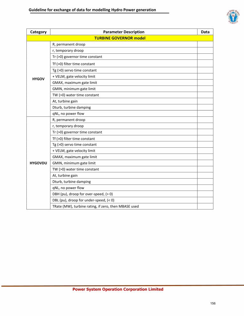
Guideline for exchange of data for modelling Hydro Power generation
Power System Operation Corporation Limited
Category Parameter Description Data
TURBINE GOVERNOR model
HYGOV
R, permanent droop
r, temporary droop
Tr (>0) governor time constant
Tf (>0) filter time constant
Tg (>0) servo time constant
+ VELM, gate velocity limit
GMAX, maximum gate limit
GMIN, minimum gate limit
TW (>0) water time constant
At, turbine gain
Dturb, turbine damping
qNL, no power flow
HYGOVDU
R, permanent droop
r, temporary droop
Tr (>0) governor time constant
Tf (>0) filter time constant
Tg (>0) servo time constant
+ VELM, gate velocity limit
GMAX, maximum gate limit
GMIN, minimum gate limit
TW (>0) water time constant
At, turbine gain
Dturb, turbine damping
qNL, no power flow
DBH (pu), droop for over-speed, (> 0)
DBL (pu), droop for under-speed, (< 0)
TRate (MW), turbine rating, if zero, then MBASE used
156
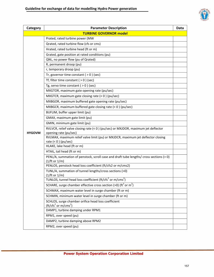
Guideline for exchange of data for modelling Hydro Power generation
Power System Operation Corporation Limited
Category Parameter Description Data
TURBINE GOVERNOR model
HYGOVM
Prated, rated turbine power (MW
Qrated, rated turbine flow (cfs or cms)
Hrated, rated turbine head (ft or m)
Grated, gate position at rated conditions (pu)
QNL, no power flow (pu of Qrated)
R, permanent droop (pu)
r, temporary droop (pu)
Tr, governor time constant ( > 0 ) (sec)
Tf, filter time constant ( > 0 ) (sec)
Tg, servo time constant ( > 0 ) (sec)
MXGTOR, maximum gate opening rate (pu/sec)
MXGTCR, maximum gate closing rate (< 0 ) (pu/sec)
MXBGOR, maximum buffered gate opening rate (pu/sec)
MXBGCR, maximum buffered gate closing rate (< 0 ) (pu/sec)
BUFLIM, buffer upper limit (pu)
GMAX, maximum gate limit (pu)
GMIN, minimum gate limit (pu)
RVLVCR, relief valve closing rate (< 0 ) (pu/sec) or MXJDOR, maximum jet deflector opening rate (pu/sec)
RVLMAX, maximum relief valve limit (pu) or MXJDCR, maximum jet deflector closing rate (< 0 ) (pu/sec)
HLAKE, lake head (ft or m)
HTAIL, tail head (ft or m)
PENL/A, summation of penstock, scroll case and draft tube lengths/ cross sections (> 0) (1/ft or 1/m)
PENLOS, penstock head loss coefficient (ft/cfs2 or m/cms2)
TUNL/A, summation of tunnel lengths/cross sections (>0) (1/ft or 1/m)
TUNLOS, tunnel head loss coefficient (ft/cfs2 or m/cms
2)
SCHARE, surge chamber effective cross section (>0) (ft2
or m2)
SCHMAX, maximum water level in surge chamber (ft or m)
SCHMIN, minimum water level in surge chamber (ft or m)
SCHLOS, surge chamber orifice head loss coefficient (ft/cfs
2 or m/cms
2)
DAMP1, turbine damping under RPM1
RPM1, over speed (pu)
DAMP2, turbine damping above RPM2
RPM2, over speed (pu)
157
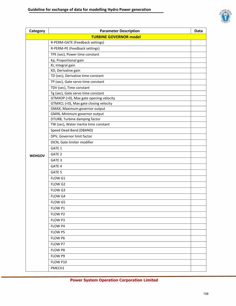
Guideline for exchange of data for modelling Hydro Power generation
Power System Operation Corporation Limited
Category Parameter Description Data
TURBINE GOVERNOR model
WEHGOV
R-PERM-GATE (Feedback settings)
R-PERM-PE (Feedback settings)
TPE (sec), Power time constant
Kp, Proportional gain
KI, Integral gain
KD, Derivative gain
TD (sec), Derivative time constant
TP (sec), Gate servo time constant
TDV (sec), Time constant
Tg (sec), Gate servo time constant
GTMXOP (>0), Max gate opening velocity
GTMXCL (<0), Max gate closing velocity
GMAX, Maximum governor output
GMIN, Minimum governor output
DTURB, Turbine damping factor
TW (sec), Water inertia time constant
Speed Dead Band (DBAND)
DPV, Governor limit factor
DICN, Gate limiter modifier
GATE 1
GATE 2
GATE 3
GATE 4
GATE 5
FLOW G1
FLOW G2
FLOW G3
FLOW G4
FLOW G5
FLOW P1
FLOW P2
FLOW P3
FLOW P4
FLOW P5
FLOW P6
FLOW P7
FLOW P8
FLOW P9
FLOW P10
PMECH1
158
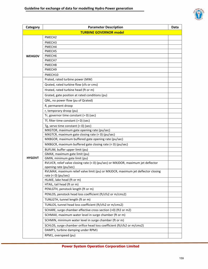
Guideline for exchange of data for modelling Hydro Power generation
Power System Operation Corporation Limited
Category Parameter Description Data
TURBINE GOVERNOR model
WEHGOV
PMECH2
PMECH3
PMECH4
PMECH5
PMECH6
PMECH7
PMECH8
PMECH9
PMECH10
HYGOVT
Prated, rated turbine power (MW)
Qrated, rated turbine flow (cfs or cms)
Hrated, rated turbine head (ft or m)
Grated, gate position at rated conditions (pu)
QNL, no power flow (pu of Qrated)
R, permanent droop
r, temporary droop (pu)
Tr, governor time constant (> 0) (sec)
Tf, filter time constant (> 0) (sec)
Tg, servo time constant (> 0) (sec)
MXGTOR, maximum gate opening rate (pu/sec)
MXGTCR, maximum gate closing rate (< 0) (pu/sec)
MXBGOR, maximum buffered gate opening rate (pu/sec)
MXBGCR, maximum buffered gate closing rate (< 0) (pu/sec)
BUFLIM, buffer upper limit (pu)
GMAX, maximum gate limit (pu)
GMIN, minimum gate limit (pu)
RVLVCR, relief valve closing rate (< 0) (pu/sec) or MXJDOR, maximum jet deflector opening rate (pu/sec)
RVLMAX, maximum relief valve limit (pu) or MXJDCR, maximum jet deflector closing rate (< 0) (pu/sec)
HLAKE, lake head (ft or m)
HTAIL, tail head (ft or m)
PENLGTH, penstock length (ft or m)
PENLOS, penstock head loss coefficient (ft/cfs2 or m/cms2)
TUNLGTH, tunnel length (ft or m)
TUNLOS, tunnel head loss coefficient (ft/cfs2 or m/cms2)
SCHARE, surge chamber effective cross section (>0) (ft2 or m2)
SCHMAX, maximum water level in surge chamber (ft or m)
SCHMIN, minimum water level in surge chamber (ft or m)
SCHLOS, surge chamber orifice head loss coefficient (ft/cfs2 or m/cms2)
DAMP1, turbine damping under RPM1
RPM1, overspeed (pu)
159
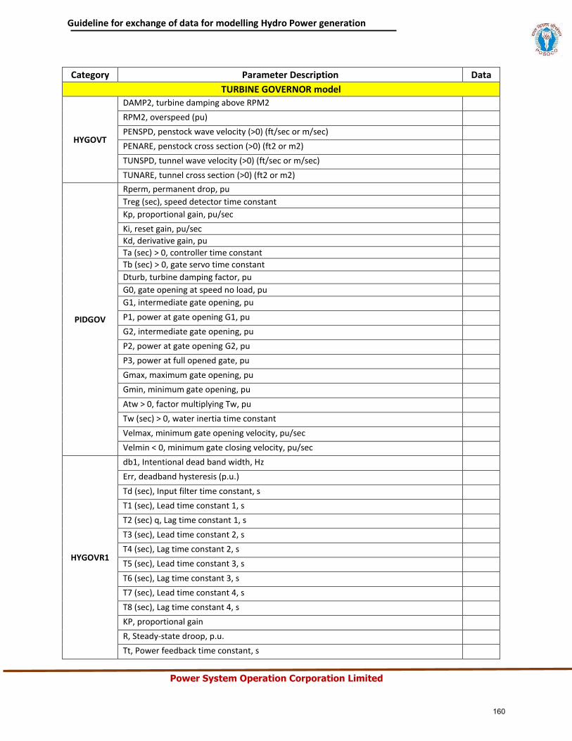
Guideline for exchange of data for modelling Hydro Power generation
Power System Operation Corporation Limited
Category Parameter Description Data
TURBINE GOVERNOR model
HYGOVT
DAMP2, turbine damping above RPM2
RPM2, overspeed (pu)
PENSPD, penstock wave velocity (>0) (ft/sec or m/sec)
PENARE, penstock cross section (>0) (ft2 or m2)
TUNSPD, tunnel wave velocity (>0) (ft/sec or m/sec)
TUNARE, tunnel cross section (>0) (ft2 or m2)
PIDGOV
Rperm, permanent drop, pu
Treg (sec), speed detector time constant
Kp, proportional gain, pu/sec
Ki, reset gain, pu/sec
Kd, derivative gain, pu
Ta (sec) > 0, controller time constant
Tb (sec) > 0, gate servo time constant
Dturb, turbine damping factor, pu
G0, gate opening at speed no load, pu
G1, intermediate gate opening, pu
P1, power at gate opening G1, pu
G2, intermediate gate opening, pu
P2, power at gate opening G2, pu
P3, power at full opened gate, pu
Gmax, maximum gate opening, pu
Gmin, minimum gate opening, pu
Atw > 0, factor multiplying Tw, pu
Tw (sec) > 0, water inertia time constant
Velmax, minimum gate opening velocity, pu/sec
Velmin < 0, minimum gate closing velocity, pu/sec
HYGOVR1
db1, Intentional dead band width, Hz
Err, deadband hysteresis (p.u.)
Td (sec), Input filter time constant, s
T1 (sec), Lead time constant 1, s
T2 (sec) q, Lag time constant 1, s
T3 (sec), Lead time constant 2, s
T4 (sec), Lag time constant 2, s
T5 (sec), Lead time constant 3, s
T6 (sec), Lag time constant 3, s
T7 (sec), Lead time constant 4, s
T8 (sec), Lag time constant 4, s
KP, proportional gain
R, Steady-state droop, p.u.
Tt, Power feedback time constant, s
160
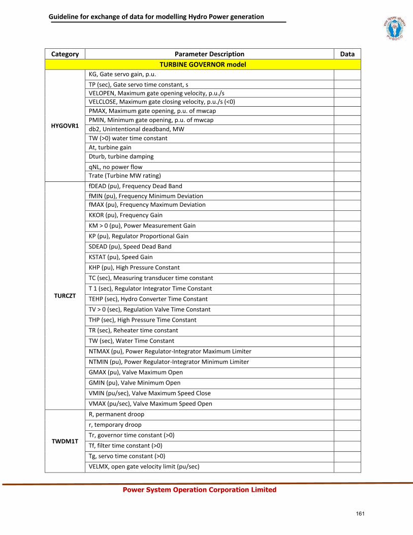
Guideline for exchange of data for modelling Hydro Power generation
Power System Operation Corporation Limited
Category Parameter Description Data
TURBINE GOVERNOR model
HYGOVR1
KG, Gate servo gain, p.u.
TP (sec), Gate servo time constant, s
VELOPEN, Maximum gate opening velocity, p.u./s
VELCLOSE, Maximum gate closing velocity, p.u./s (<0)
PMAX, Maximum gate opening, p.u. of mwcap
PMIN, Minimum gate opening, p.u. of mwcap
db2, Unintentional deadband, MW
TW (>0) water time constant
At, turbine gain
Dturb, turbine damping
qNL, no power flow
Trate (Turbine MW rating)
TURCZT
fDEAD (pu), Frequency Dead Band
fMIN (pu), Frequency Minimum Deviation
fMAX (pu), Frequency Maximum Deviation
KKOR (pu), Frequency Gain
KM > 0 (pu), Power Measurement Gain
KP (pu), Regulator Proportional Gain
SDEAD (pu), Speed Dead Band
KSTAT (pu), Speed Gain
KHP (pu), High Pressure Constant
TC (sec), Measuring transducer time constant
T 1 (sec), Regulator Integrator Time Constant
TEHP (sec), Hydro Converter Time Constant
TV > 0 (sec), Regulation Valve Time Constant
THP (sec), High Pressure Time Constant
TR (sec), Reheater time constant
TW (sec), Water Time Constant
NTMAX (pu), Power Regulator-Integrator Maximum Limiter
NTMIN (pu), Power Regulator-Integrator Minimum Limiter
GMAX (pu), Valve Maximum Open
GMIN (pu), Valve Minimum Open
VMIN (pu/sec), Valve Maximum Speed Close
VMAX (pu/sec), Valve Maximum Speed Open
TWDM1T
R, permanent droop
r, temporary droop
Tr, governor time constant (>0)
Tf, filter time constant (>0)
Tg, servo time constant (>0)
VELMX, open gate velocity limit (pu/sec)
161
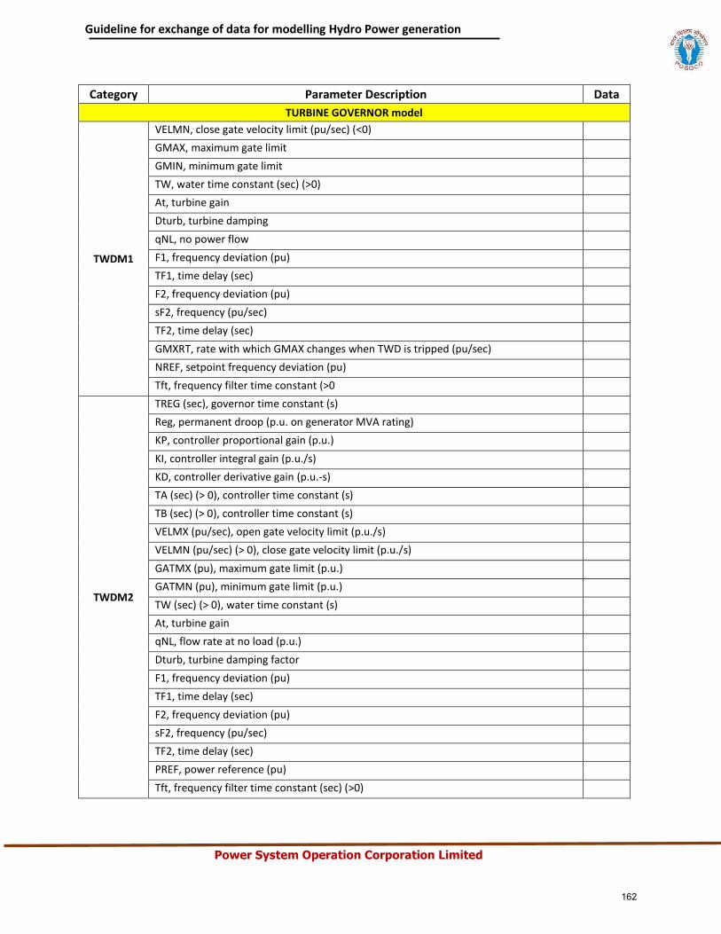
Guideline for exchange of data for modelling Hydro Power generation
Power System Operation Corporation Limited
Category Parameter Description Data
TURBINE GOVERNOR model
TWDM1
VELMN, close gate velocity limit (pu/sec) (<0)
GMAX, maximum gate limit
GMIN, minimum gate limit
TW, water time constant (sec) (>0)
At, turbine gain
Dturb, turbine damping
qNL, no power flow
F1, frequency deviation (pu)
TF1, time delay (sec)
F2, frequency deviation (pu)
sF2, frequency (pu/sec)
TF2, time delay (sec)
GMXRT, rate with which GMAX changes when TWD is tripped (pu/sec)
NREF, setpoint frequency deviation (pu)
Tft, frequency filter time constant (>0
TWDM2
TREG (sec), governor time constant (s)
Reg, permanent droop (p.u. on generator MVA rating)
KP, controller proportional gain (p.u.)
KI, controller integral gain (p.u./s)
KD, controller derivative gain (p.u.-s)
TA (sec) (> 0), controller time constant (s)
TB (sec) (> 0), controller time constant (s)
VELMX (pu/sec), open gate velocity limit (p.u./s)
VELMN (pu/sec) (> 0), close gate velocity limit (p.u./s)
GATMX (pu), maximum gate limit (p.u.)
GATMN (pu), minimum gate limit (p.u.)
TW (sec) (> 0), water time constant (s)
At, turbine gain
qNL, flow rate at no load (p.u.)
Dturb, turbine damping factor
F1, frequency deviation (pu)
TF1, time delay (sec)
F2, frequency deviation (pu)
sF2, frequency (pu/sec)
TF2, time delay (sec)
PREF, power reference (pu)
Tft, frequency filter time constant (sec) (>0)
162
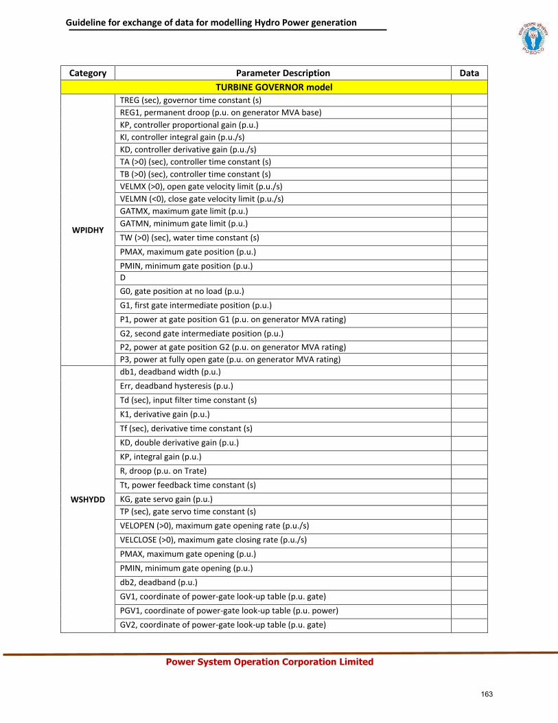
Guideline for exchange of data for modelling Hydro Power generation
Power System Operation Corporation Limited
Category Parameter Description Data
TURBINE GOVERNOR model
WPIDHY
TREG (sec), governor time constant (s)
REG1, permanent droop (p.u. on generator MVA base)
KP, controller proportional gain (p.u.)
KI, controller integral gain (p.u./s)
KD, controller derivative gain (p.u./s)
TA (>0) (sec), controller time constant (s)
TB (>0) (sec), controller time constant (s)
VELMX (>0), open gate velocity limit (p.u./s)
VELMN (<0), close gate velocity limit (p.u./s)
GATMX, maximum gate limit (p.u.)
GATMN, minimum gate limit (p.u.)
TW (>0) (sec), water time constant (s)
PMAX, maximum gate position (p.u.)
PMIN, minimum gate position (p.u.)
D
G0, gate position at no load (p.u.)
G1, first gate intermediate position (p.u.)
P1, power at gate position G1 (p.u. on generator MVA rating)
G2, second gate intermediate position (p.u.)
P2, power at gate position G2 (p.u. on generator MVA rating)
P3, power at fully open gate (p.u. on generator MVA rating)
WSHYDD
db1, deadband width (p.u.)
Err, deadband hysteresis (p.u.)
Td (sec), input filter time constant (s)
K1, derivative gain (p.u.)
Tf (sec), derivative time constant (s)
KD, double derivative gain (p.u.)
KP, integral gain (p.u.)
R, droop (p.u. on Trate)
Tt, power feedback time constant (s)
KG, gate servo gain (p.u.)
TP (sec), gate servo time constant (s)
VELOPEN (>0), maximum gate opening rate (p.u./s)
VELCLOSE (>0), maximum gate closing rate (p.u./s)
PMAX, maximum gate opening (p.u.)
PMIN, minimum gate opening (p.u.)
db2, deadband (p.u.)
GV1, coordinate of power-gate look-up table (p.u. gate)
PGV1, coordinate of power-gate look-up table (p.u. power)
GV2, coordinate of power-gate look-up table (p.u. gate)
163
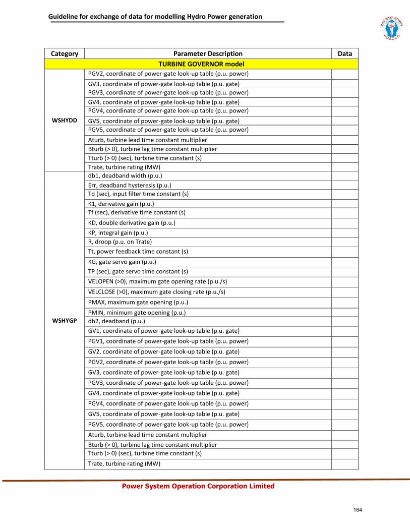
Guideline for exchange of data for modelling Hydro Power generation
Power System Operation Corporation Limited
Category Parameter Description Data
TURBINE GOVERNOR model
WSHYDD
PGV2, coordinate of power-gate look-up table (p.u. power)
GV3, coordinate of power-gate look-up table (p.u. gate)
PGV3, coordinate of power-gate look-up table (p.u. power)
GV4, coordinate of power-gate look-up table (p.u. gate)
PGV4, coordinate of power-gate look-up table (p.u. power)
GV5, coordinate of power-gate look-up table (p.u. gate)
PGV5, coordinate of power-gate look-up table (p.u. power)
Aturb, turbine lead time constant multiplier
Bturb (> 0), turbine lag time constant multiplier
Tturb (> 0) (sec), turbine time constant (s)
Trate, turbine rating (MW)
WSHYGP
db1, deadband width (p.u.)
Err, deadband hysteresis (p.u.)
Td (sec), input filter time constant (s)
K1, derivative gain (p.u.)
Tf (sec), derivative time constant (s)
KD, double derivative gain (p.u.)
KP, integral gain (p.u.)
R, droop (p.u. on Trate)
Tt, power feedback time constant (s)
KG, gate servo gain (p.u.)
TP (sec), gate servo time constant (s)
VELOPEN (>0), maximum gate opening rate (p.u./s)
VELCLOSE (>0), maximum gate closing rate (p.u./s)
PMAX, maximum gate opening (p.u.)
PMIN, minimum gate opening (p.u.)
db2, deadband (p.u.)
GV1, coordinate of power-gate look-up table (p.u. gate)
PGV1, coordinate of power-gate look-up table (p.u. power)
GV2, coordinate of power-gate look-up table (p.u. gate)
PGV2, coordinate of power-gate look-up table (p.u. power)
GV3, coordinate of power-gate look-up table (p.u. gate)
PGV3, coordinate of power-gate look-up table (p.u. power)
GV4, coordinate of power-gate look-up table (p.u. gate)
PGV4, coordinate of power-gate look-up table (p.u. power)
GV5, coordinate of power-gate look-up table (p.u. gate)
PGV5, coordinate of power-gate look-up table (p.u. power)
Aturb, turbine lead time constant multiplier
Bturb (> 0), turbine lag time constant multiplier
Tturb (> 0) (sec), turbine time constant (s)
Trate, turbine rating (MW)
164
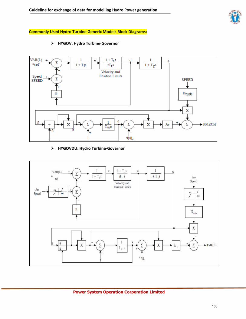
Guideline for exchange of data for modelling Hydro Power generation
Power System Operation Corporation Limited
Commonly Used Hydro Turbine Generic Models Block Diagrams:
HYGOV: Hydro Turbine-Governor
HYGOVDU: Hydro Turbine-Governor
165
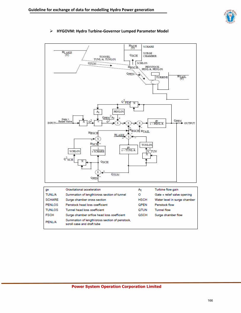
Guideline for exchange of data for modelling Hydro Power generation
Power System Operation Corporation Limited
HYGOVM: Hydro Turbine-Governor Lumped Parameter Model
166
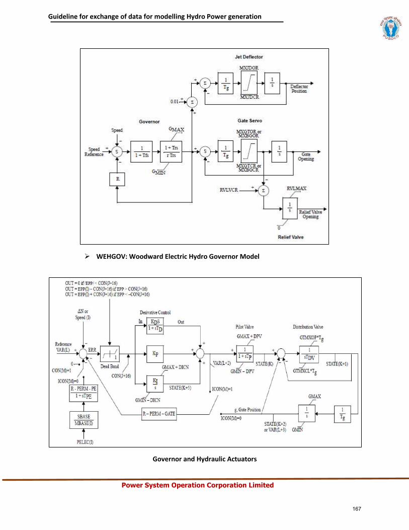
Guideline for exchange of data for modelling Hydro Power generation
Power System Operation Corporation Limited
WEHGOV: Woodward Electric Hydro Governor Model
Governor and Hydraulic Actuators
167
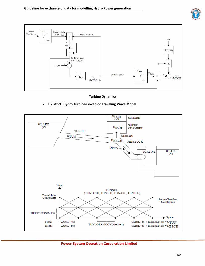
Guideline for exchange of data for modelling Hydro Power generation
Power System Operation Corporation Limited
Turbine Dynamics
HYGOVT: Hydro Turbine-Governor Traveling Wave Model
168
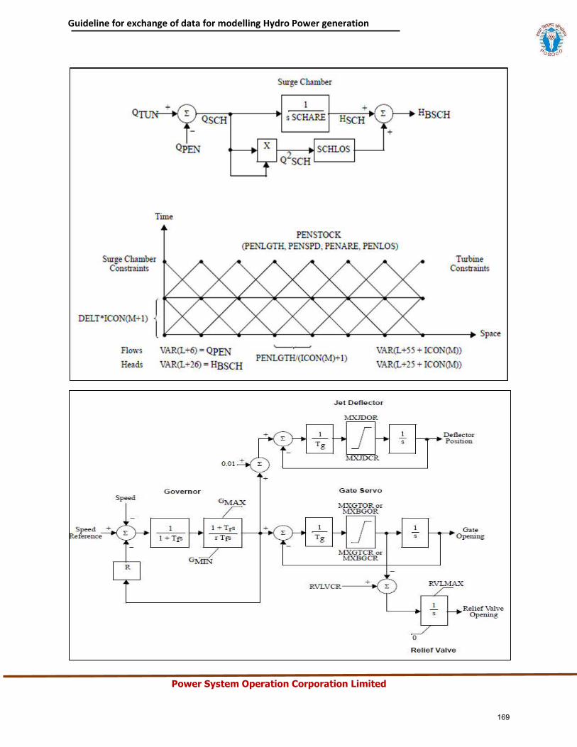
Guideline for exchange of data for modelling Hydro Power generation
Power System Operation Corporation Limited
169
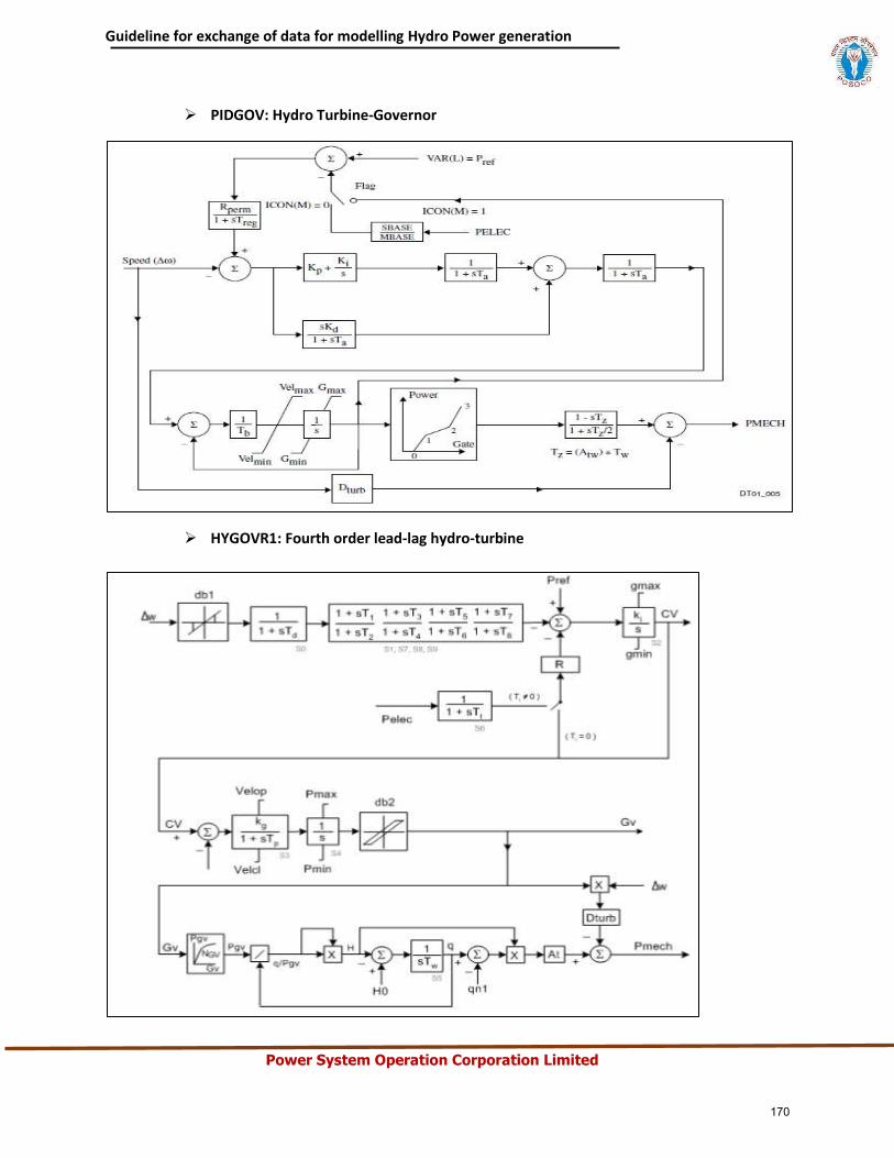
Guideline for exchange of data for modelling Hydro Power generation
Power System Operation Corporation Limited
PIDGOV: Hydro Turbine-Governor
HYGOVR1: Fourth order lead-lag hydro-turbine
170
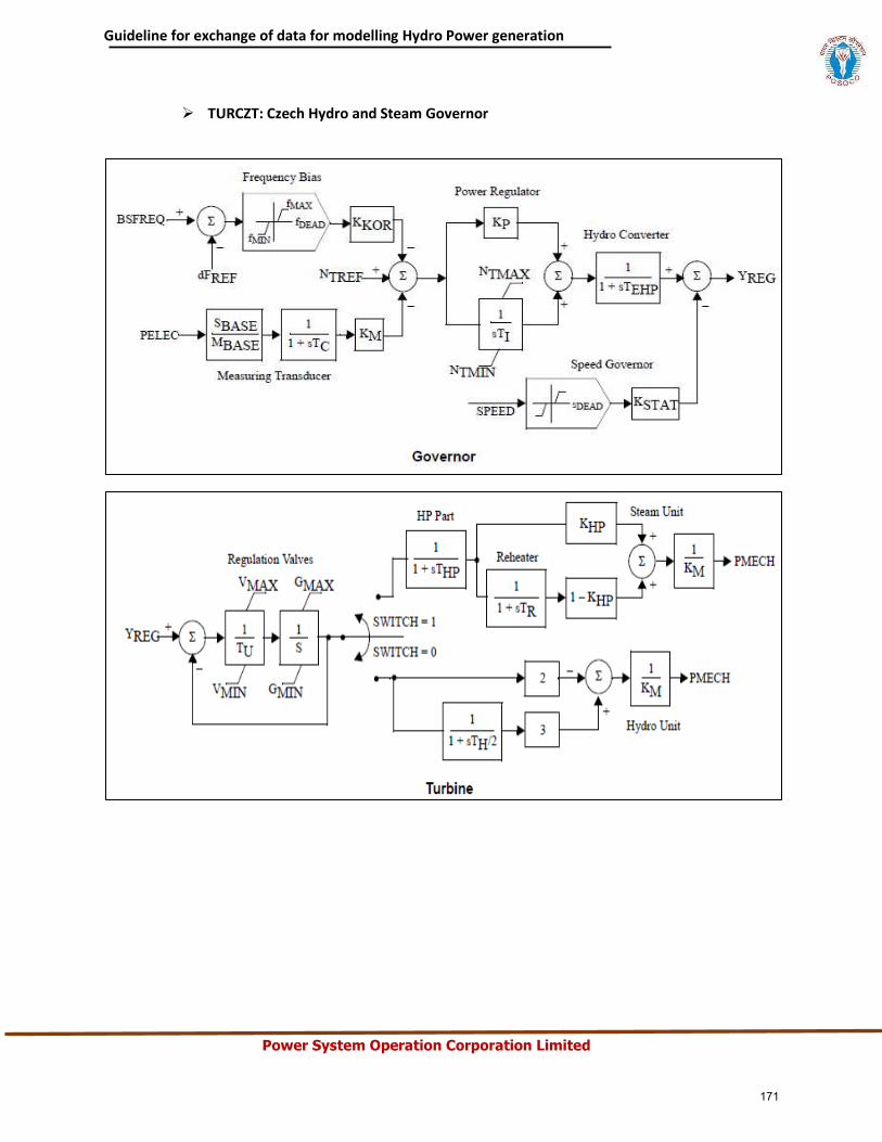
Guideline for exchange of data for modelling Hydro Power generation
Power System Operation Corporation Limited
TURCZT: Czech Hydro and Steam Governor
171
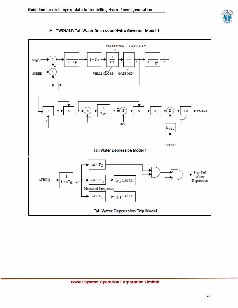
Guideline for exchange of data for modelling Hydro Power generation
Power System Operation Corporation Limited
TWDM1T: Tail Water Depression Hydro Governor Model 1
172
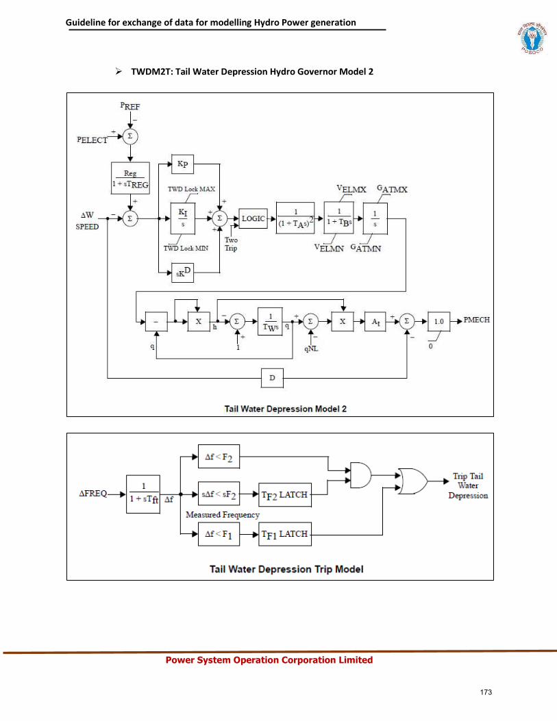
Guideline for exchange of data for modelling Hydro Power generation
Power System Operation Corporation Limited
TWDM2T: Tail Water Depression Hydro Governor Model 2
173
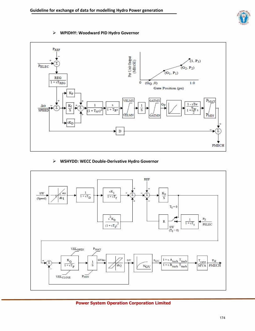
Guideline for exchange of data for modelling Hydro Power generation
Power System Operation Corporation Limited
WPIDHY: Woodward PID Hydro Governor
WSHYDD: WECC Double-Derivative Hydro Governor
174
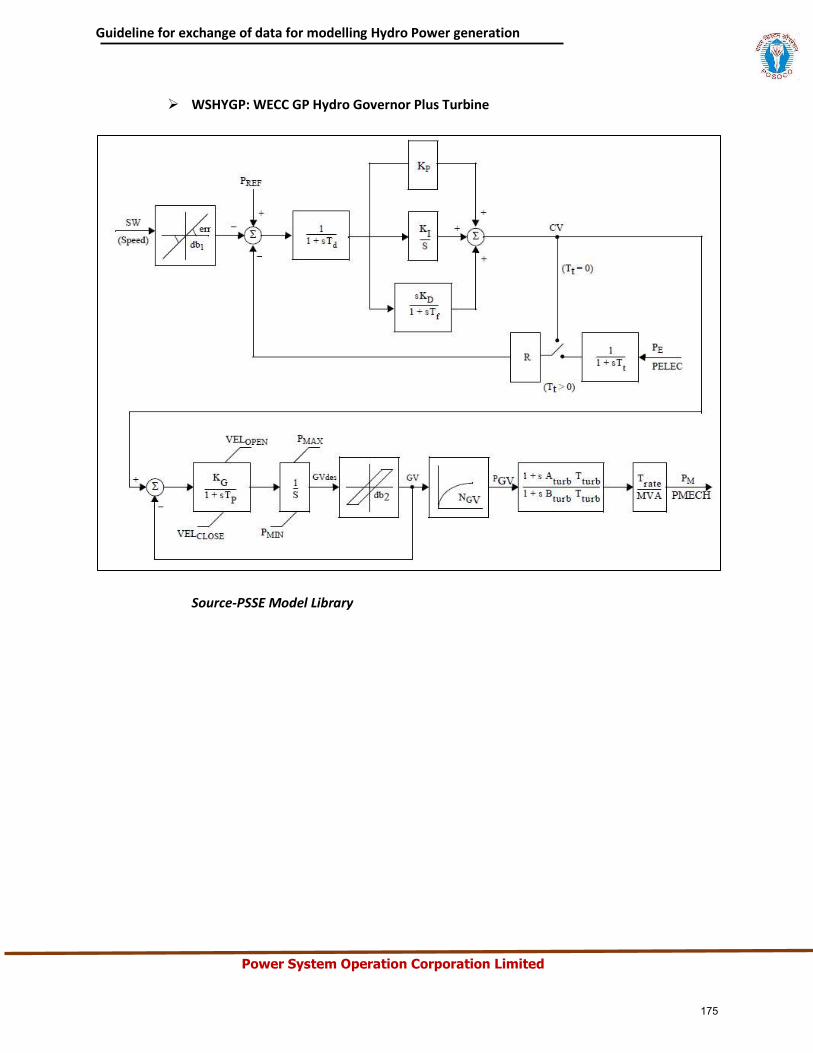
Guideline for exchange of data for modelling Hydro Power generation
Power System Operation Corporation Limited
WSHYGP: WECC GP Hydro Governor Plus Turbine
Source-PSSE Model Library
175
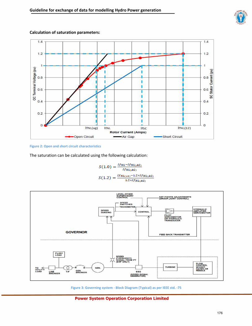
Guideline for exchange of data for modelling Hydro Power generation
Power System Operation Corporation Limited
Calculation of saturation parameters:
Figure 2: Open and short circuit characteristics
The saturation can be calculated using the following calculation:
Figure 3: Governing system - Block Diagram (Typical) as per IEEE std. -75
176

Hydro Plant Details
Project/Plant details
1 Company/SLDC name:
2 Owner of the power station:
3 Project name and location: 4 Contact Number & Name of the Nodal person : Mr./ Ms. 5 Total Installed Capacity(MW): (e.g.2x100MW): 6 Turbine type: Francis /Kaplan / Pelton/Bulb/Any other 7 Intake River & Diversion dam: 8 Hydro station type - ROR/ ROR with poundage/Storage type:
Reservoir details 1 Power station- Underground/Surface : 2 Energy content at FRL and Target energy for financial year : 3 Monthly design energy/10 daily energy:
4 Water usage (other than electricity production)- Irrigation/Flood control/ Bilateral treaty/ hydrology :
5 Which are the riparian States?
6 Is the Station part of the tandem hydro system? If yes then what are the constraints in operating the station?
7 Which is next hydro station (with pondage /reservoir) on the upstream and downstream side?
8 What is the accounting period for total water inflows and releases from the station? 9 Monthly pattern of release of water( over the day too)
10 What are the tools for forecasting the inflow silt etc. how much early (from the generation time) inflow forecasting is available?
Beneficiaries of Plant 11 Who owns the Station and Who operates the Hydro Electric Station? 12 Which are the entities having entitlement on the power generated from the Station?
Control/Direction
13 Which agency assesses the water inflows for the river basin on which the hydro station is built?
14 Which are the sectors/ entities that are entitled for water usage from the reservoir?
15 Who decides the allocation of water available for different usage such as drinking water, irrigation, industrial use, tourism, power generation?
16 Is the Station operation governed under some water sharing treaty? 17 In case the hydro station has multiple beneficiaries- Who coordinate the scheduling?
18 Who manages the water releases? Who decides the quantum of water available for power generation?
19 Where is the offtake for water for irrigation/drinking water- From the upstream from the reservoir or downstream of the tail race? What is the operating domain for the plant operator with respect to the water releases?
20 What is the philosophy for despatching the station - (managing peak demand / load following / ramping / deviation control / other)
21 How is the station compensated for the energy generated? Is the tariff multi-part or single part?
Annex-5
177
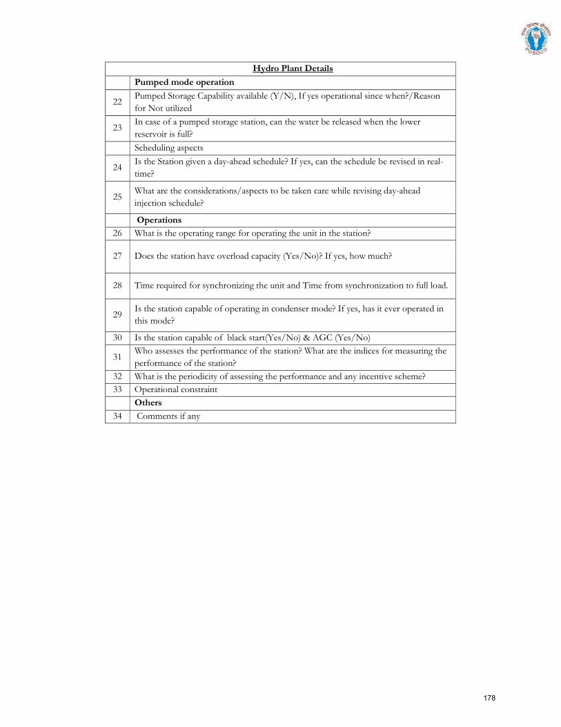
Hydro Plant Details
Pumped mode operation
22 Pumped Storage Capability available (Y/N), If yes operational since when?/Reason for Not utilized
23 In case of a pumped storage station, can the water be released when the lower reservoir is full?
Scheduling aspects
24 Is the Station given a day-ahead schedule? If yes, can the schedule be revised in real-time?
25 What are the considerations/aspects to be taken care while revising day-ahead injection schedule?
Operations 26 What is the operating range for operating the unit in the station?
27 Does the station have overload capacity (Yes/No)? If yes, how much?
28 Time required for synchronizing the unit and Time from synchronization to full load.
29 Is the station capable of operating in condenser mode? If yes, has it ever operated in this mode?
30 Is the station capable of black start(Yes/No) & AGC (Yes/No)
31 Who assesses the performance of the station? What are the indices for measuring the performance of the station?
32 What is the periodicity of assessing the performance and any incentive scheme? 33 Operational constraint
Others 34 Comments if any
178
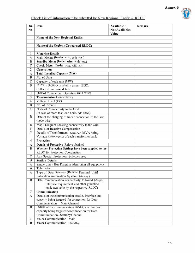
Check List of information to be submitted by New Regional Entity to RLDC
Sr. No.
Item Available I Not Available / Value
Remark
Name of the New Regional Entity:
Name of the Region / Concerned RLDC:
I Metering Details A Main Meters (feeder wise, with nos.) B Standby Meter (feeder wise, with nos.) C Check Meter (feeder wise. with nos.) 2 Generation A Total Installed Capacity (MW) B No. of Units C Capacity of each unit (MW) D FGM() / RGMO capability as per IEGC.
Collected unit wise details I [)ate of Commercial Operation (unit wise) 3 Transmission Connectivity A Voltage Level (kV) B No. of Circuits C Node of Connectivity to the Grid
(in case of more than one node, add rows) I) Date of the charging of lines / connection to the Grid
(node wise)Ii Map / Diagram showing connectivity to the Grid F Details of Reactive Compensation (3 Details of Transformers — Number. MVA rating.
Voltage Ratio, vector of each transformer bank 4 Protection A Details of Protective Relays obtained B Whether Protection Settings have been supplied to the
RLDC for Protection Coordination C Any Special Protections Schemes used 5 Station Details A Single Line / Bus Diagram identi1iing all equipment 6 Telemetry A Type of Data Gateway (Remote Terminal Unit!
Substation Automation System Gateway) B Data Communication connectivity followed (As per
interface requirement and other guideline made available by the respective RLDC)
7 Communication A Details of the communication media, interface and
capacity being targeted for connection for Data Communication Main Channel
B [)etails of the communication media, interface and capacity being targeted for connection for Data Communication — Standby Channel
C Voice Communication — Main D Voice Communication — Standby
Annex-6
179
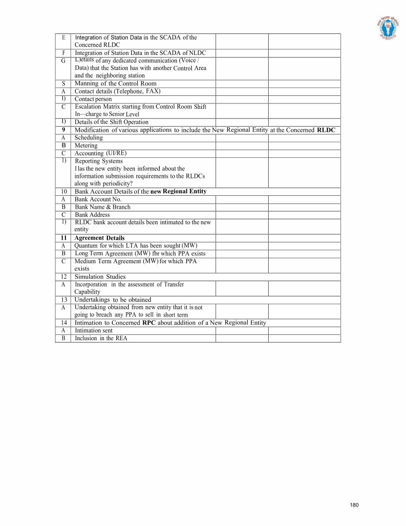
E Integration of Station Data in the SCADA of the Concerned RLDC
F Integration of Station Data in the SCADA of NLDC G L)etails of any dedicated communication (Voice /
Data) that the Station has with another Control Area and the neighboring station
S Manning of the Control Room A Contact details (Telephone, FAX) I) Contact personC Escalation Matrix starting from Control Room Shift
In—charge to Senior Level I) Details of the Shift Operation9 Modification of various applications to include the New Regional Entity at the Concerned RLDC A Scheduling B Metering C Accounting (UI/RE) 1) Reporting Systems
I las the new entity been informed about theinformation submission requirements to the RLDCsalong with periodicity?
10 Bank Account Details of the new Regional Entity A Bank Account No. B Bank Name & Branch C Bank Address 1) RLDC bank account details been intimated to the new
entity11 Agreement Details A Quantum for which LTA has been sought (MW) B Long Term Agreement (MW) fbr which PPA exists C Medium Term Agreement (MW) for which PPA
exists 12 Simulation Studies A Incorporation in the assessment of Transfer
Capability 13 Undertakings to be obtained A Undertaking obtained from new entity that it is not
going to breach any PPA to sell in short term 14 Intimation to Concerned RPC about addition of a New Regional Entity A Intimation sent B Inclusion in the REA
180
Section 2
Procedure for Integration of Solar, Wind or Hybrid Power Plant/Wind or Solar Power Parks,
WPD/SPD/HPD those are regional entities
181
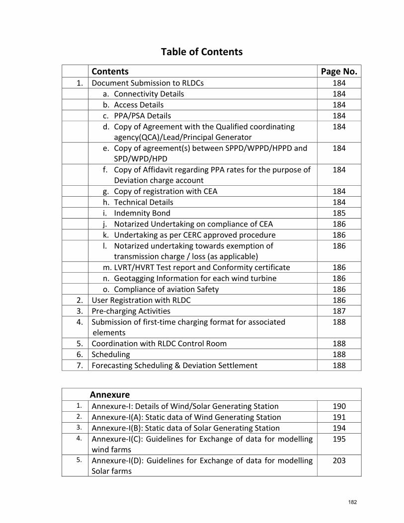
Table of Contents
Annexure 1. Annexure-I: Details of Wind/Solar Generating Station 190 2. Annexure-I(A): Static data of Wind Generating Station 191 3. Annexure-I(B): Static data of Solar Generating Station 194 4. Annexure-I(C): Guidelines for Exchange of data for modelling
wind farms195
5. Annexure-I(D): Guidelines for Exchange of data for modelling Solar farms
203
Contents Page No. 1. Document Submission to RLDCs 184
a. Connectivity Details 184 b. Access Details 184 c. PPA/PSA Details 184 d. Copy of Agreement with the Qualified coordinating
agency(QCA)/Lead/Principal Generator184
e. Copy of agreement(s) between SPPD/WPPD/HPPD andSPD/WPD/HPD
184
f. Copy of Affidavit regarding PPA rates for the purpose ofDeviation charge account
184
g. Copy of registration with CEA 184 h. Technical Details 184 i. Indemnity Bond 185 j. Notarized Undertaking on compliance of CEA 186 k. Undertaking as per CERC approved procedure 186 l. Notarized undertaking towards exemption of
transmission charge / loss (as applicable)186
m. LVRT/HVRT Test report and Conformity certificate 186 n. Geotagging Information for each wind turbine 186 o. Compliance of aviation Safety 186
2. User Registration with RLDC 186 3. Pre-charging Activities 187 4. Submission of first-time charging format for associated
elements188
5. Coordination with RLDC Control Room 188 6. Scheduling 188 7. Forecasting Scheduling & Deviation Settlement 188
182
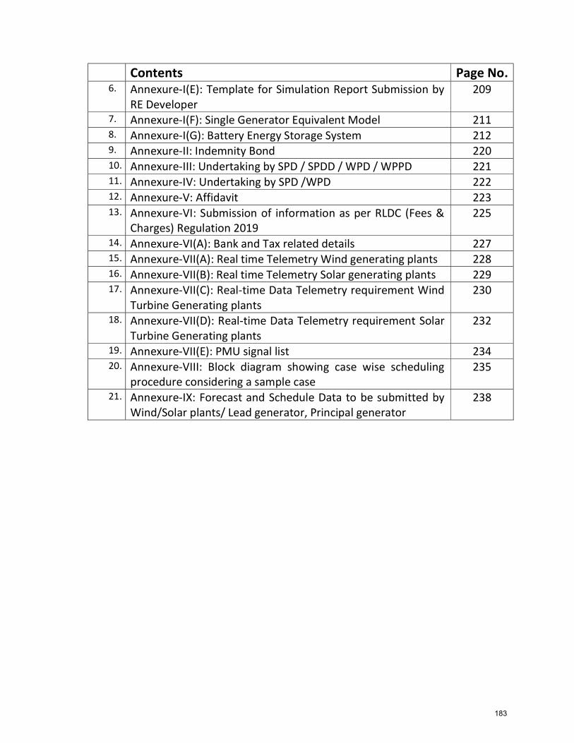
Contents Page No. 6. Annexure-I(E): Template for Simulation Report Submission by
RE Developer 209
7. Annexure-I(F): Single Generator Equivalent Model 211 8. Annexure-I(G): Battery Energy Storage System 212 9. Annexure-II: Indemnity Bond 220 10. Annexure-III: Undertaking by SPD / SPDD / WPD / WPPD 221 11. Annexure-IV: Undertaking by SPD /WPD 222 12. Annexure-V: Affidavit 223 13. Annexure-VI: Submission of information as per RLDC (Fees &
Charges) Regulation 2019 225
14. Annexure-VI(A): Bank and Tax related details 227 15. Annexure-VII(A): Real time Telemetry Wind generating plants 228 16. Annexure-VII(B): Real time Telemetry Solar generating plants 229 17. Annexure-VII(C): Real-time Data Telemetry requirement Wind
Turbine Generating plants 230
18. Annexure-VII(D): Real-time Data Telemetry requirement Solar Turbine Generating plants
232
19. Annexure-VII(E): PMU signal list 234 20. Annexure-VIII: Block diagram showing case wise scheduling
procedure considering a sample case 235
21. Annexure-IX: Forecast and Schedule Data to be submitted by Wind/Solar plants/ Lead generator, Principal generator
238
183
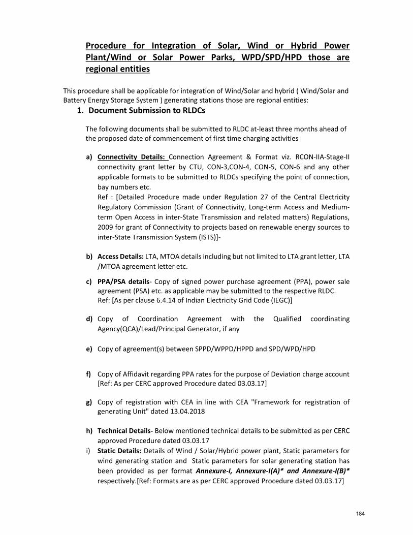
Procedure for Integration of Solar, Wind or Hybrid Power Plant/Wind or Solar Power Parks, WPD/SPD/HPD those are regional entities
This procedure shall be applicable for integration of Wind/Solar and hybrid ( Wind/Solar and Battery Energy Storage System ) generating stations those are regional entities:
1. Document Submission to RLDCs
The following documents shall be submitted to RLDC at-least three months ahead of the proposed date of commencement of first time charging activities a) Connectivity Details: Connection Agreement & Format viz. RCON-IIA-Stage-II
connectivity grant letter by CTU, CON-3,CON-4, CON-5, CON-6 and any other applicable formats to be submitted to RLDCs specifying the point of connection, bay numbers etc. Ref : [Detailed Procedure made under Regulation 27 of the Central Electricity Regulatory Commission (Grant of Connectivity, Long-term Access and Medium-term Open Access in inter-State Transmission and related matters) Regulations, 2009 for grant of Connectivity to projects based on renewable energy sources to inter-State Transmission System (ISTS)]-
b) Access Details: LTA, MTOA details including but not limited to LTA grant letter, LTA
/MTOA agreement letter etc.
c) PPA/PSA details- Copy of signed power purchase agreement (PPA), power sale agreement (PSA) etc. as applicable may be submitted to the respective RLDC.
Ref: [As per clause 6.4.14 of Indian Electricity Grid Code (IEGC)]
d) Copy of Coordination Agreement with the Qualified coordinating Agency(QCA)/Lead/Principal Generator, if any
e) Copy of agreement(s) between SPPD/WPPD/HPPD and SPD/WPD/HPD
f) Copy of Affidavit regarding PPA rates for the purpose of Deviation charge account [Ref: As per CERC approved Procedure dated 03.03.17]
g) Copy of registration with CEA in line with CEA "Framework for registration of generating Unit" dated 13.04.2018
h) Technical Details- Below mentioned technical details to be submitted as per CERC approved Procedure dated 03.03.17
i) Static Details: Details of Wind / Solar/Hybrid power plant, Static parameters for wind generating station and Static parameters for solar generating station has been provided as per format Annexure-I, Annexure-I(A)* and Annexure-I(B)* respectively.[Ref: Formats are as per CERC approved Procedure dated 03.03.17]
184
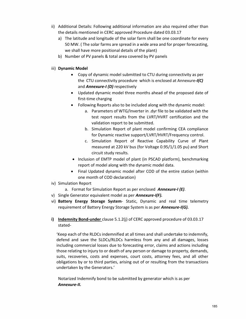
ii) Additional Details: Following additional information are also required other than the details mentioned in CERC approved Procedure dated 03.03.17 a) The latitude and longitude of the solar farm shall be one coordinate for every
50 MW. ( The solar farms are spread in a wide area and for proper forecasting, we shall have more positional details of the plant)
b) Number of PV panels & total area covered by PV panels
iii) Dynamic Model Copy of dynamic model submitted to CTU during connectivity as per
the CTU connectivity procedure which is enclosed at Annexure-I(C) and Annexure-I (D) respectively
Updated dynamic model three months ahead of the proposed date of first-time charging
Following Reports also to be included along with the dynamic model: a. Parameters of WTG/Inverter in .dyr file to be validated with the
test report results from the LVRT/HVRT certification and the validation report to be submitted.
b. Simulation Report of plant model confirming CEA compliance for Dynamic reactive support/LVRT/HVRT/Frequency control.
c. Simulation Report of Reactive Capability Curve of Plant measured at 220 kV bus (for Voltage 0.95/1/1.05 pu) and Short circuit study results.
Inclusion of EMTP model of plant (in PSCAD platform), benchmarking report of model along with the dynamic model data.
Final Updated dynamic model after COD of the entire station (within one month of COD declaration)
iv) Simulation Report a. Format for Simulation Report as per enclosed Annexure-I (E).
v) Single Generator equivalent model as per Annexure-I(F). vi) Battery Energy Storage System- Static, Dynamic and real time telemetry
requirement of Battery Energy Storage System is as per Annexure-I(G).
i) Indemnity Bond-under clause 5.1.2(j) of CERC approved procedure of 03.03.17 stated-
‘Keep each of the RLDCs indemnified at all times and shall undertake to indemnify, defend and save the SLDCs/RLDCs harmless from any and all damages, losses including commercial losses due to forecasting error, claims and actions including those relating to injury to or death of any person or damage to property, demands, suits, recoveries, costs and expenses, court costs, attorney fees, and all other obligations by or to third parties, arising out of or resulting from the transactions undertaken by the Generators.’ Notarized Indemnify bond to be submitted by generator which is as per Annexure-II.
185
j) Notarized Undertaking on compliance of CEA- As per Central Electricity Authority (Technical Standards for Connectivity to the Grid )(Amendment) Regulations, 2019, undertaking for harmonics, periodic measurement of other power quality parameters such as voltage sag, swell, flicker, disruptions, LVRT and HVRT compliance etc. to be submitted by RE generators. Ref: Central Electricity Authority (Technical Standards for Connectivity to the Grid) (Amendment) Regulations, 2019
k) Undertaking as per CERC approved procedure: RE Generator or Lead Generator or Principal Generator shall submit undertaking as per CERC approved procedure of 03.03.17. Format for undertaking is as Annexure-III
l) Notarized undertaking towards exemption of transmission charge/loss (as
applicable): As per Hon’ble CERC Notification (dated 14.12.2017) on 5th amendment to Sharing of Inter State Transmission Charges and Losses Regulation, 2017, certain wind/solar power generating stations are exempted from sharing the inter-state transmission charges and losses. Notarized undertaking to be submitted, if applicable. Format for undertaking is as per Annexure-IV
m) LVRT/HVRT Test report and Conformity certificate: LVRT/HVRT Statement of
Compliance/Conformity certificate and test report from an “accredited agency” as specified by MNRE, GoI. Accreditation certification from the agency can also be asked for verification if required. Undertaking for LVRT/HVRT compliance to be submitted. Format for undertaking is as per Annexure-V
n) Geotagging Information for each wind turbine: NIWE, Chennai developed geo-tagged database /online registry of wind turbines installed across the country. As per office memorandum of MNRE, all wind turbines in a project should be geo-tagged before Commercial Operation Date (COD). Copy of same to be submitted to RLDCs.
o) Compliance of aviation safety norms: Undertaking to be given by WPD for all the
WTGs for the compliance of aviation safety norms.
2. User Registration with RLDC As per Clause 7.2 of CERC approved Procedure dtd 03.03.17 "The SPPD / WPPD shall be responsible for registering the Solar Power Park with the respective RLDC/SLDC as applicable as a User and shall submit Appendix-IV of CERC (Fees and Charges of Regional Load Despatch Centres and related matters) Regulations, 2019 before getting connected at the Connection point with the ISTS for the first time." The SPPD/WPPD shall be registered under category "Generator" and therefore one-time registration fee shall be based on total installed capacity of SPPD/WPPD. As per Clause 14..2 of CERC approved Procedure dtd 03.03.17:”RE Generators or lead generator or principal generator shall pay RLDC fees and charges as per Hon’ble CERC
186
Regulation “Fees and charges of Regional Load Despatch Centre and other related matters”, Regulation 2015 and further amendment thereof after getting registered with respective RLDCs as a User of RLDC.”
a) Submission of information in Appendix-IV of CERC “Fees and charges of Regional Load Despatch Centre and other related matters”, Regulation 2019 as Annexure-VI
b) Bank Details for Payment of Registration fee to RLDC as Annexure-VI(A)
Bank account details to be submitted along with PAN and GSTN details.
3. Pre-charging Activities The following prerequisite must be ensured by the requester (WPD/SPD) prior to seeking code for first time charging of any new or modified power system elements:
a) Installation of Interface Meters (through CTU) – As per CEA (Installation & Operation of Meters)-Regulation-2006 & amendments, Entity has to coordinate CTU for SEMs along with data collecting devices (DCD). Generating station is responsible for submission of weekly energy meter data and time drift correction to the respective RLDCs.
b) Statutory Approval- In line with the CEA( Measures relating to safety & electric supply) Regulation-2015 (as amended), a copy of charging approval obtained from the Central Electricity Authority, Govt. of India is to be submitted to RLDCs before energisation of any electrical installation. [Ref.: CEA - Measures relating to Safety & Electric supply Regulations-2010 (clause. 43)]
c) SCADA Integration for transfer of real time data to RLDCs i) Entity has to provide real time data for wind and solar plants for all
parameters mentioned in Annexure- VII(A) and VII(B) to the Respective RLDCs @ resolution of 10 sec (Ref: - Detailed parameters as per CERC Approved Procedure of 03.03.2017]
ii) Telemetered weather parameters like Ambient Temperature (0C), Relative Humidity (%), Wind Speed, and Wind Direction etc. to be provided to respective RLDC. Segregation of telemetered points is as per Annexure-VII(C) and VII(D).
iii) PMU Installation (Signal list as per Annexure-VII(E))
d) Details of approval of scheme/Minutes of Meeting such as standing committee etc.
e) Necessary protection coordination with all adjacent substation. Confirmation to be given regarding installation of DR/EL at Solar and Wind generating stations.
f) Redundant channel upto main control centre with automatic failover. Redundancy should work for all of the following failures: - Single Communication link failure - Single Gateway failure
187
- Single Master station polling server failure g) Dedicated Voice communication from Solar/Wind Generating Plant to control
centre (RLDC) using VOIP communication is mandatory before charging of station.
h) Following Details to be shared- a) Details of PMU (make and version) b) Details of gateway/RTU – Make and version c) Details of the Multiplexor owned by RE station
4. Submission of first time charging format for associated elements- First time charging of any power system element associated with Wind/Solar plants is carried out as per the Procedure for integration of a new or modified power system elements. First time charging of any element in generating station will be allowed only after submission of the information mentioned in Procedure for integration of a new or modified power system elements. & after obtaining necessary approval from RLDC.
5. Coordination with RLDC Control Room: Any switching operation viz. charging of EHV line or first charging of WTGs/ solar inverters shall be done after availing permission (in the form of an instruction code) from the RLDC control room. Similarly, the charging date and time must be intimated to RLDC control room within 10 (ten) minutes of the first charging of the said element.
6. Scheduling: Scheduling of power from the generating station or unit thereof shall
commence from 0000 hrs after declaration of COD subject to visibility of the WTGs/Solar inverters through telemetry at the RLDC SCADA system.
Example: Suppose a Wind/Solar plant having installed capacity of 250 MW has declared COD for 250 MW. However, if on the proposed day of scheduling, status data & analog data for WTG/Solar inverters corresponding to only 50 MW capacity is visible at RLDC through SCADA system, RLDC shall consider only 50 MW for scheduling(Annexure-VIII);
7. Forecasting Scheduling & Deviation Settlement: Power plants shall comply with the provision of CERC Regulations (IEGC-03rd amendment & DSM 2nd amendment regulation 2015) and CERC approved procedure dated 03.03.2017 for facilitation of forecasting, Scheduling & Deviation Settlement in respect of its power plants.
Note: Further amendment in the procedure can be done in line with IEGC/other CERC & CEA regulations/directive from time to time.
Enclosures. Annexure-I: Details of Wind/Solar Generating Station Annexure-I(A): Static data of Wind Generating Station Annexure-I(B): Static data of Solar Generating Station Annexure-I(C): Guidelines for Exchange of data for modelling wind farms
188
Annexure-I(D): Guidelines for Exchange of data for modelling Solar farms Annexure-I(E): Template for Simulation Report Submission by RE Developer Annexure-I(F): Single Generator Equivalent Model Annexure-I(G): Battery Energy Storage System Annexure-II: Indemnity Bond Annexure-III: Undertaking by SPD / SPDD / WPD / WPPD Annexure-IV: Undertaking by SPD /WPD Annexure-V: Affidavit Annexure-VI: Submission of information as per RLDC (Fees & Charges) Regulation 2019 Annexure-VI(A): Bank and Tax related details Annexure-VII(A): Real time Telemetry Wind generating plants Annexure-VII(B): Real time Telemetry Solar generating plants Annexure-VII(C): Real-time Data Telemetry requirement Wind Turbine Generating plants Annexure-VII(D): Real-time Data Telemetry requirement Solar Turbine Generating plants Annexure-VII(E): PMU signal list Annexure-VIII: Block diagram showing case wise scheduling procedure considering a sample case Annexure-IX: Forecast and Schedule Data to be submitted by Wind/Solar plants/ Lead generator, Principal generator
Other than the documents mentioned above the formats for first time charging of transmission elements (Format A1-A6, B1-B5 and C1-C4) to be submitted to concerned RLDC.
189
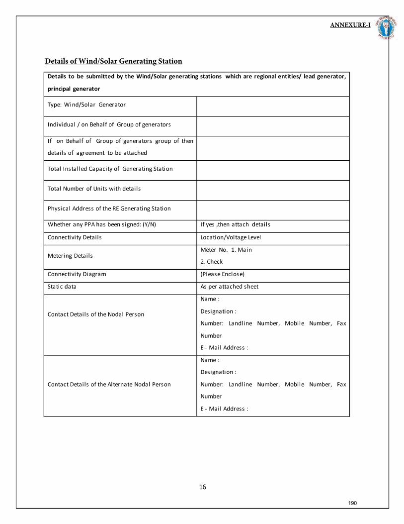
ANNEXURE-I
Details of Wind/Solar Generating Station
190
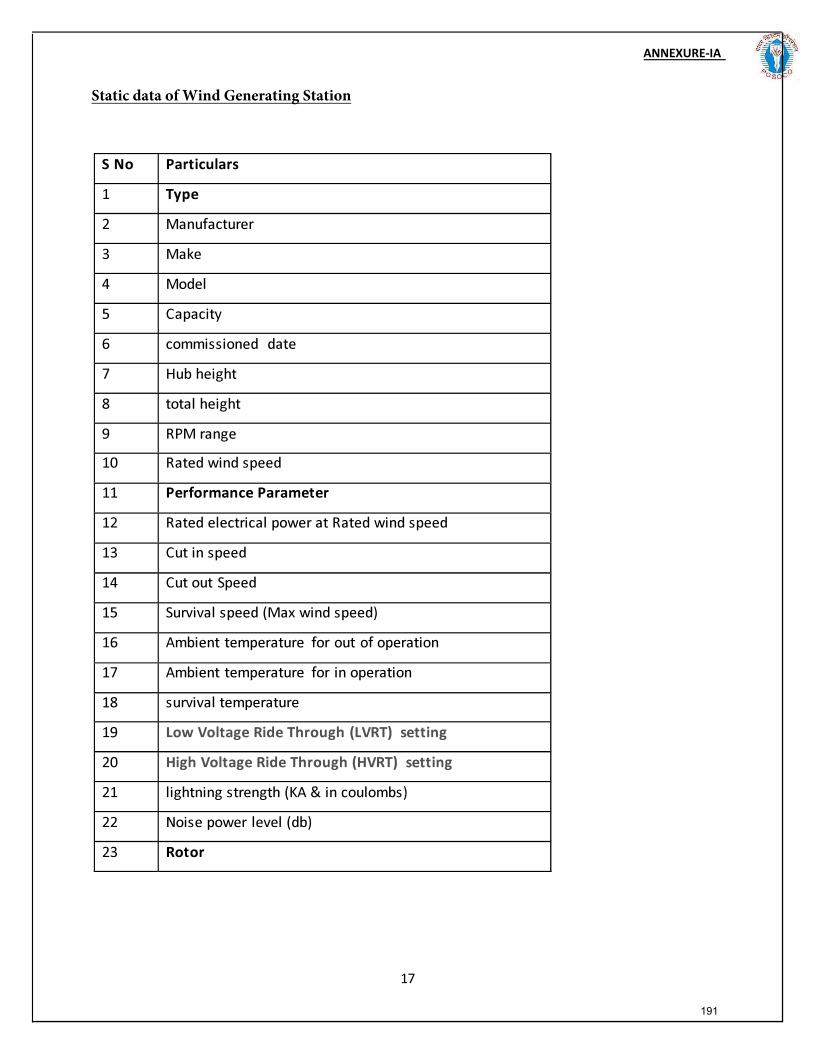
ANNEXURE-IA)
Static data of Wind Generating Station
191
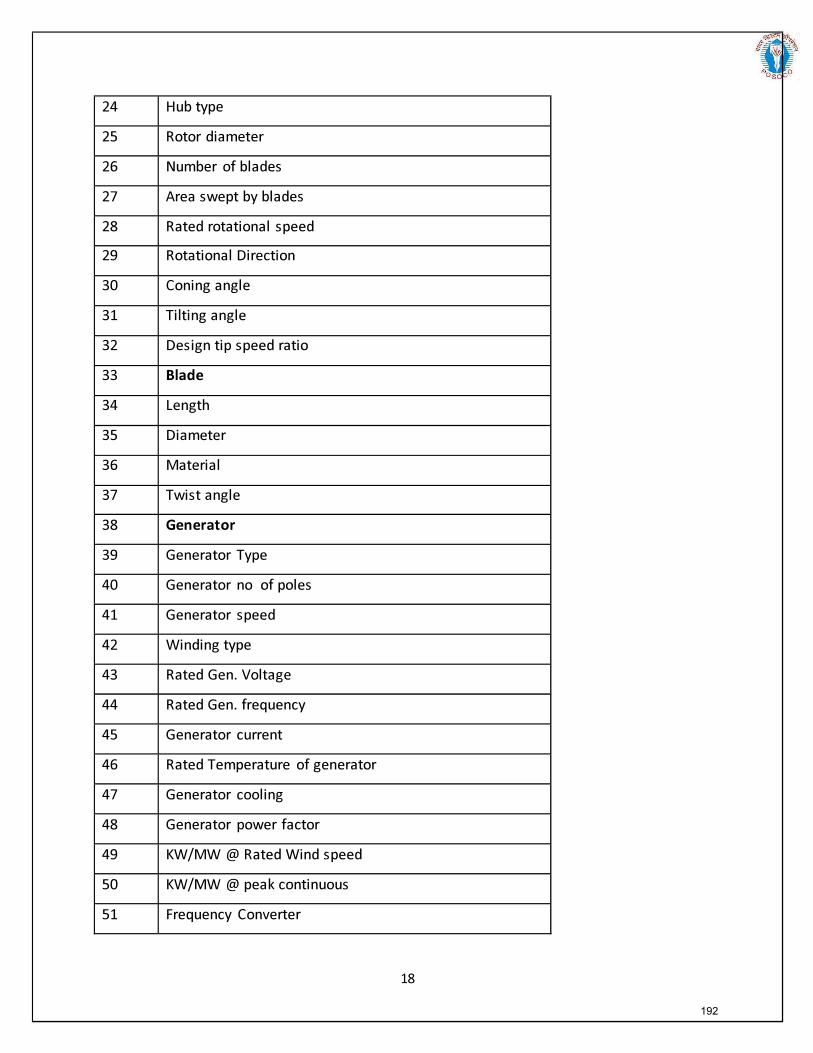
192
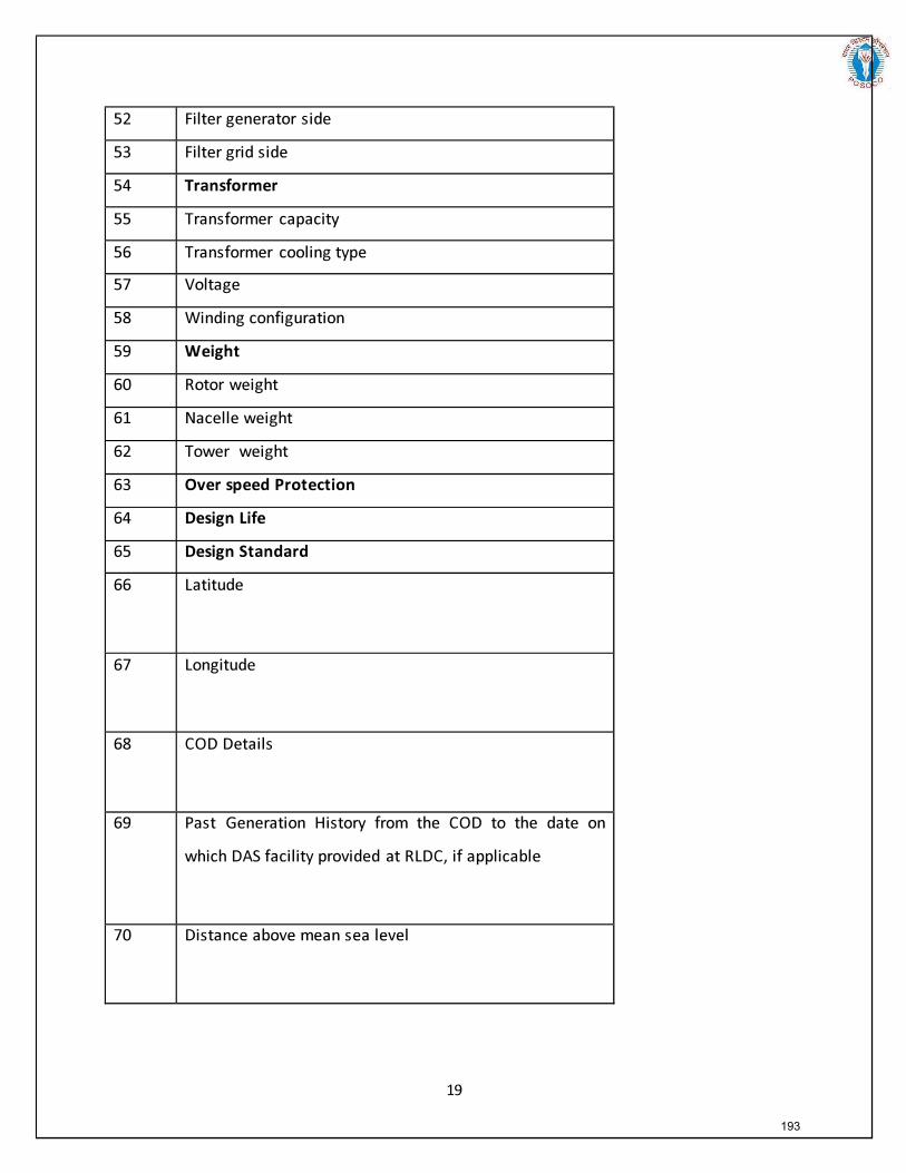
193
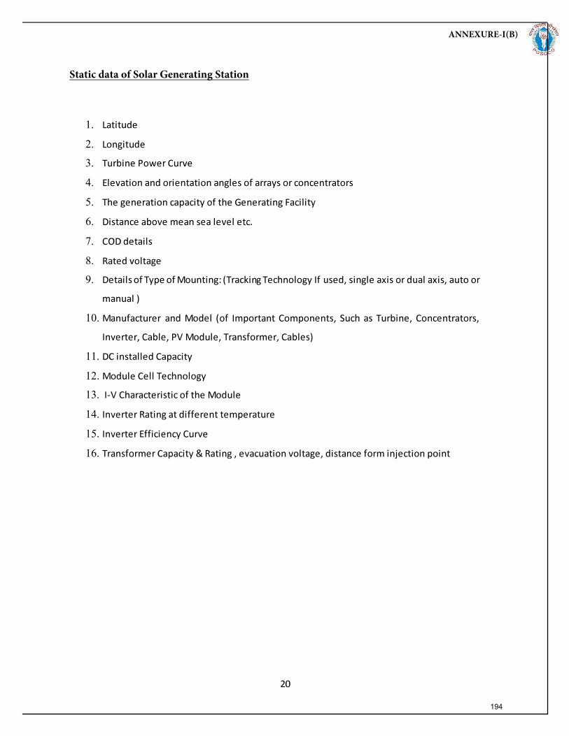
1.
2.
3.
4.
5.
6.
7.
8.
9.
10.
11.
12.
13.
14.
15.
16.
ANNEXURE-I(B)
Static data of Solar Generating Station
194
Power System Operation Corporation Limited
ANNEXURE-I(C)
195
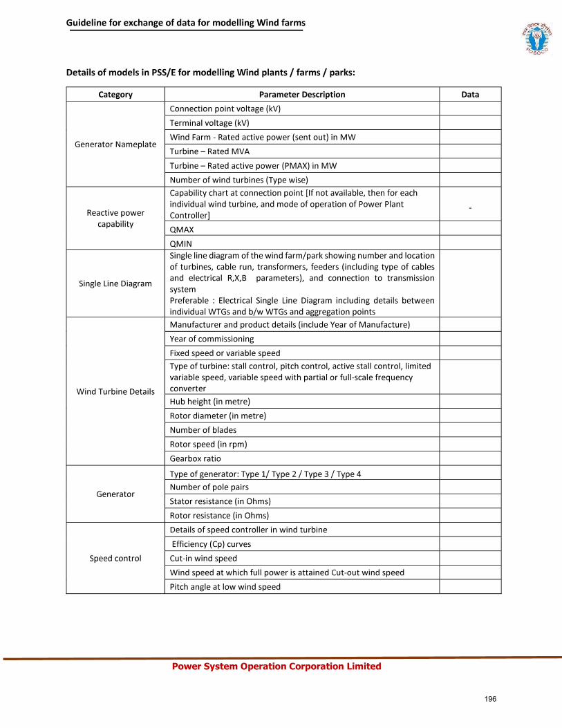
Power System Operation Corporation Limited
196
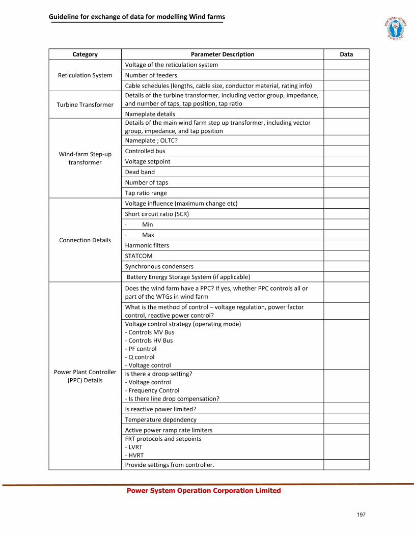
Power System Operation Corporation Limited
197
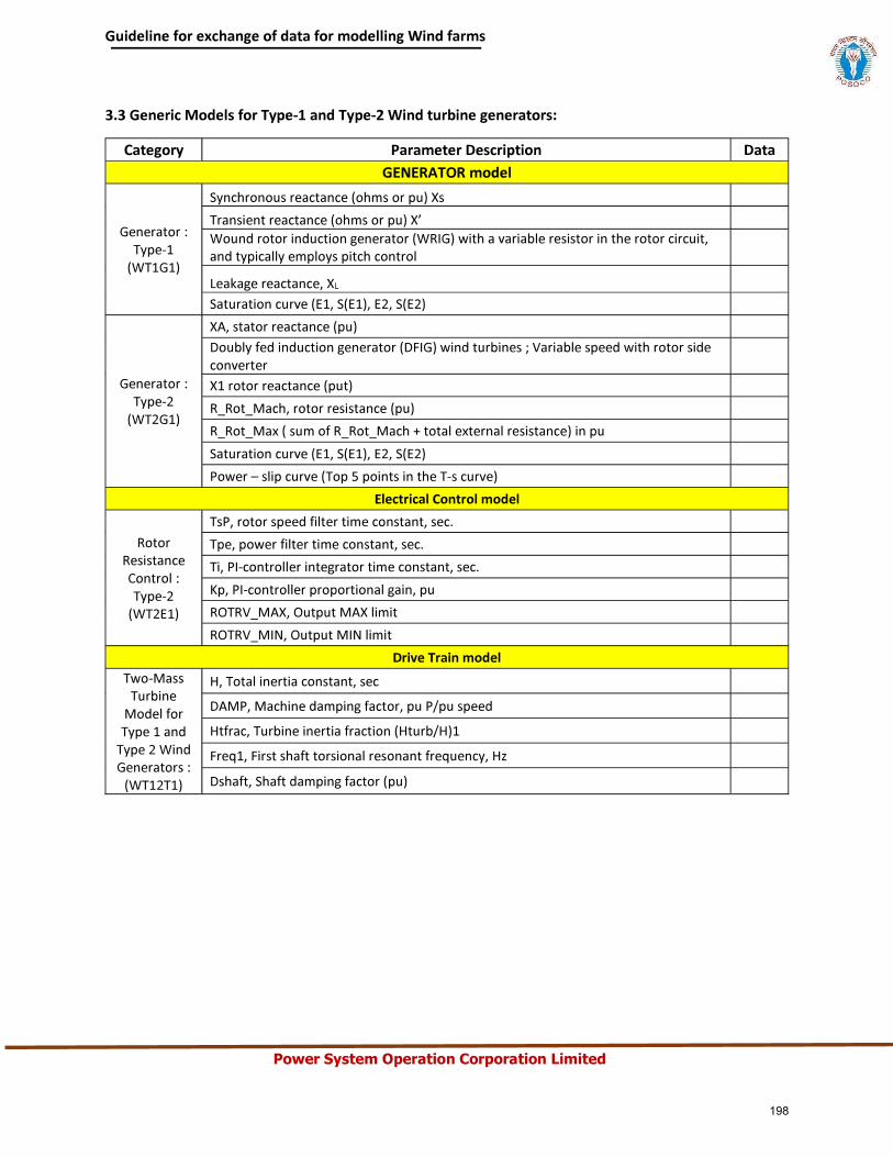
Power System Operation Corporation Limited
198
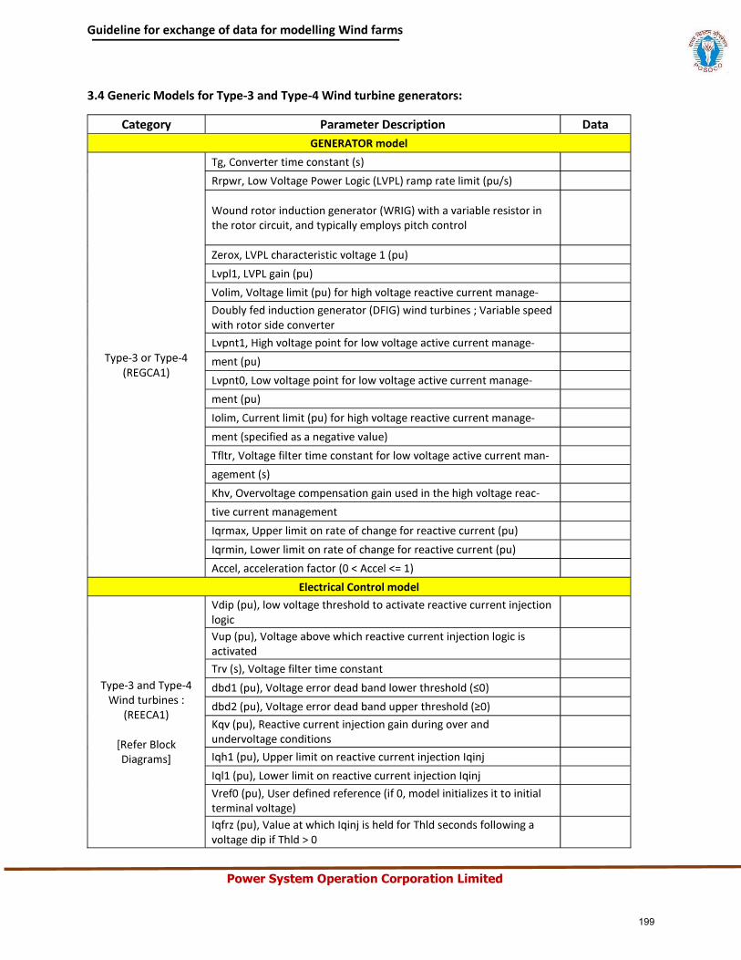
Power System Operation Corporation Limited
199
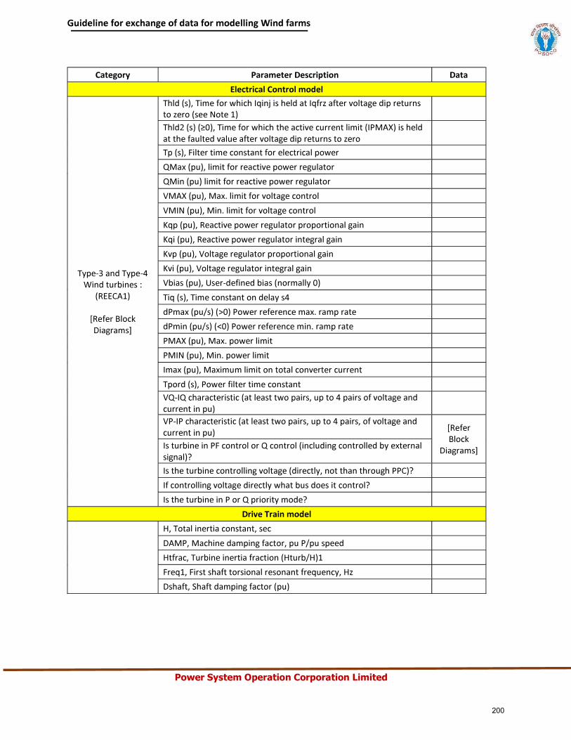
Power System Operation Corporation Limited
200
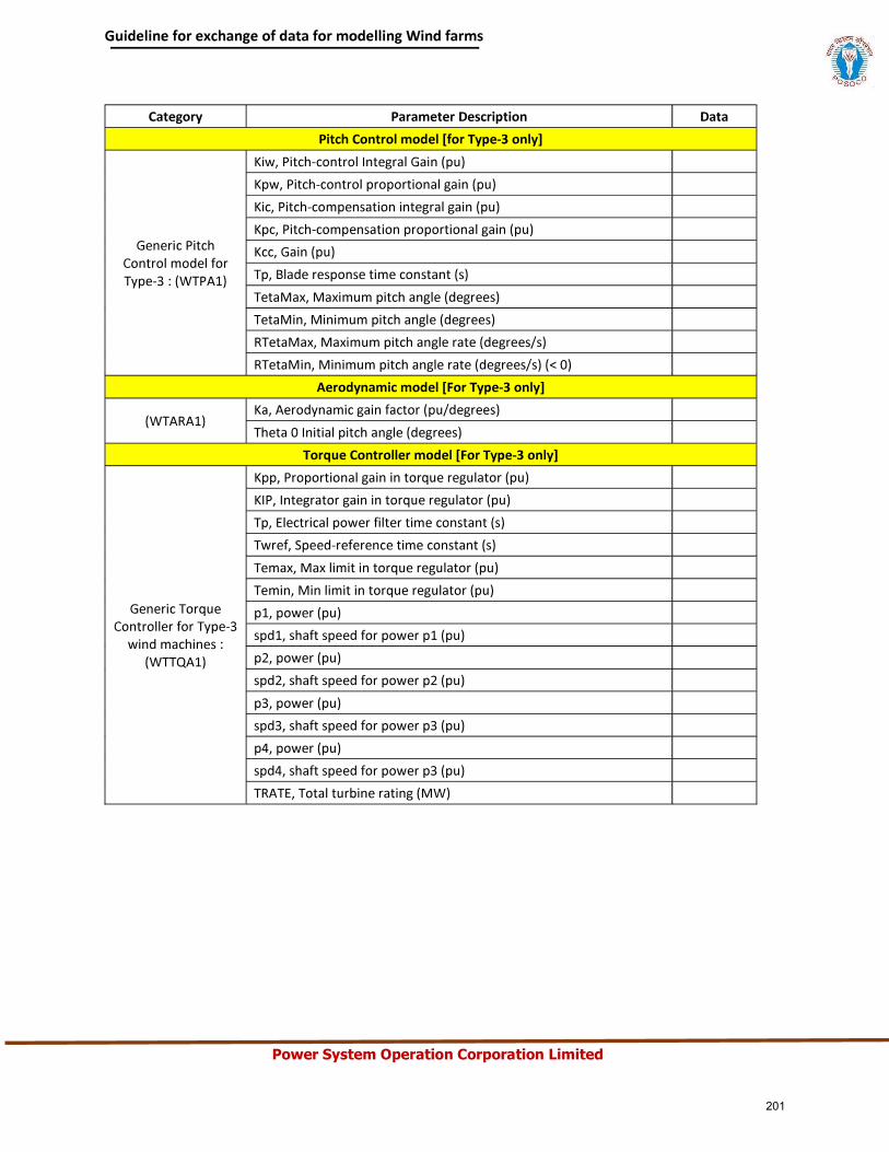
Power System Operation Corporation Limited
201
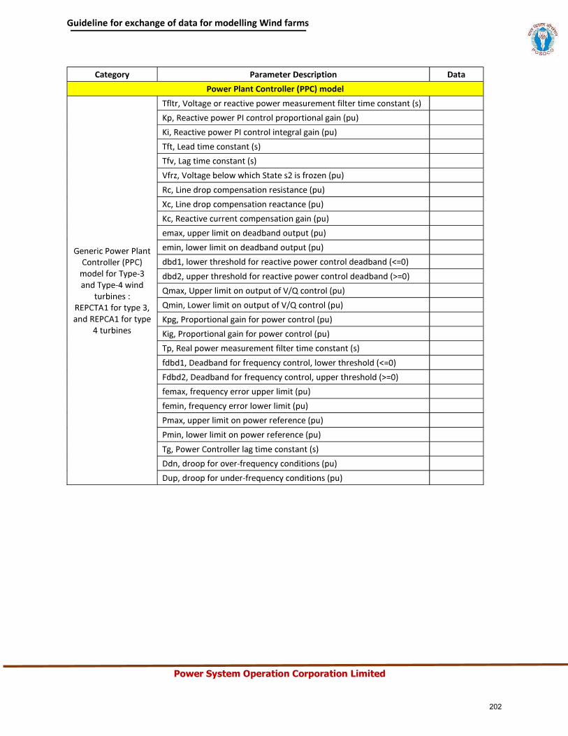
Power System Operation Corporation Limited
202
Power System Operation Corporation Limited
ANNEXURE-I(D)
203
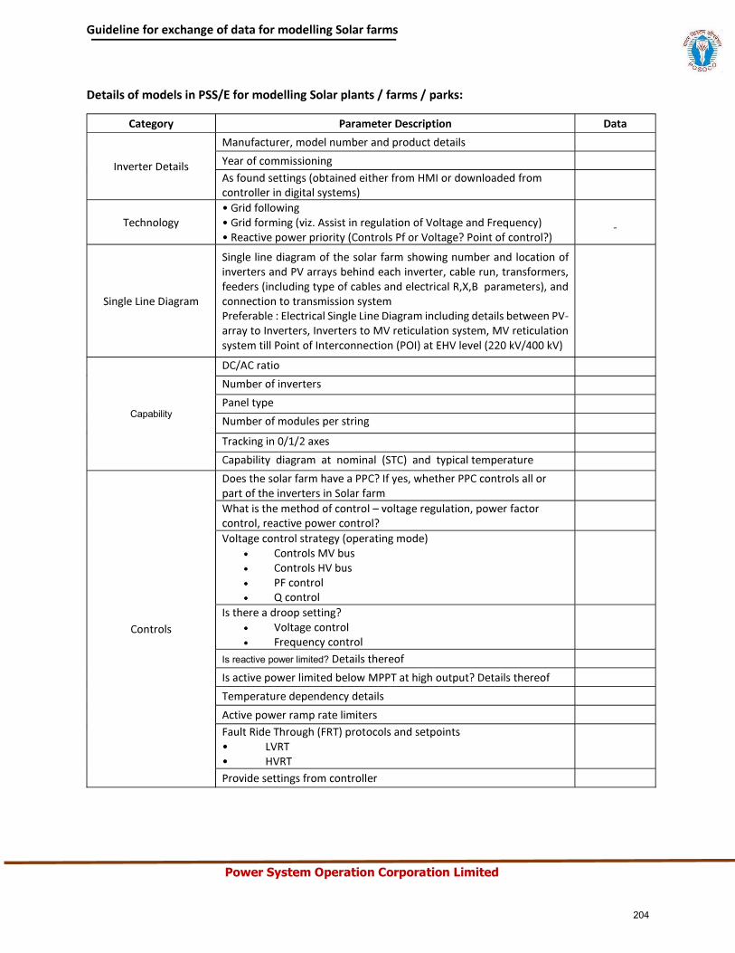
Power System Operation Corporation Limited
Capability
Is reactive power limited?
204
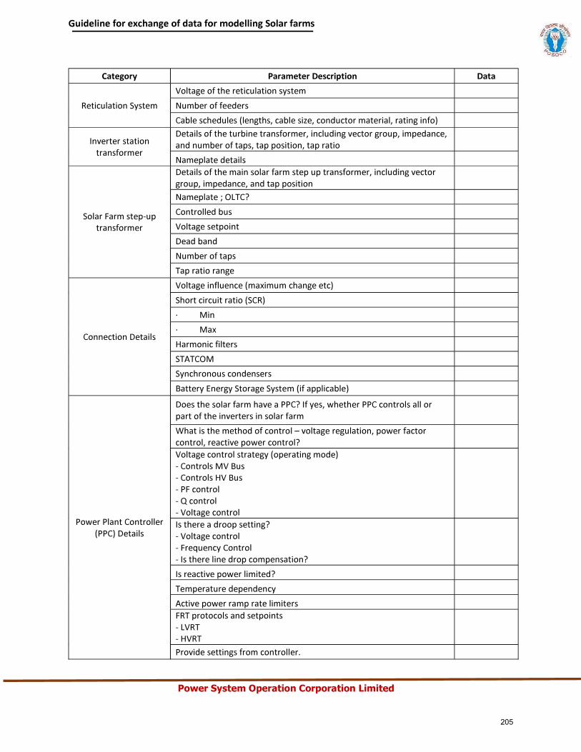
Power System Operation Corporation Limited
205
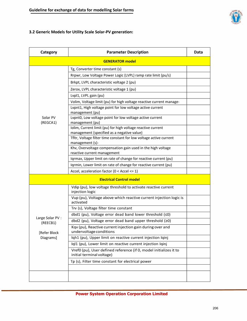
Power System Operation Corporation Limited
206
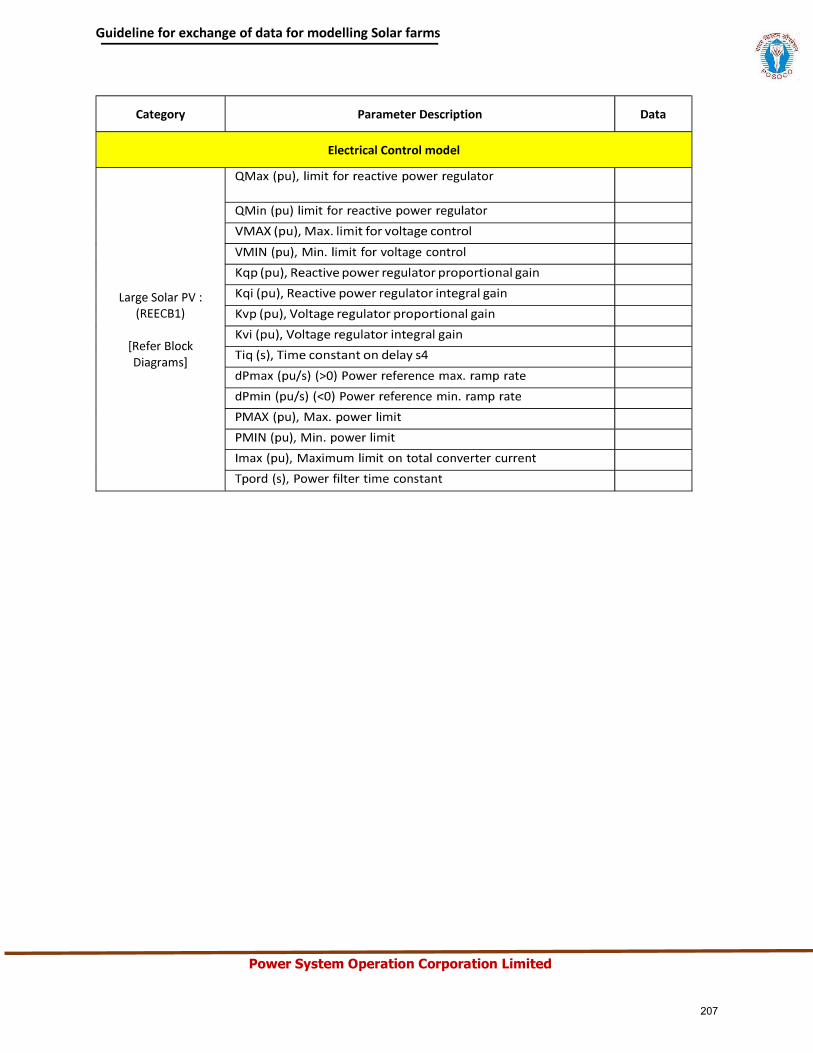
Power System Operation Corporation Limited
207
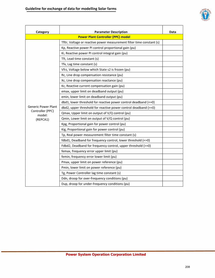
Power System Operation Corporation Limited
208
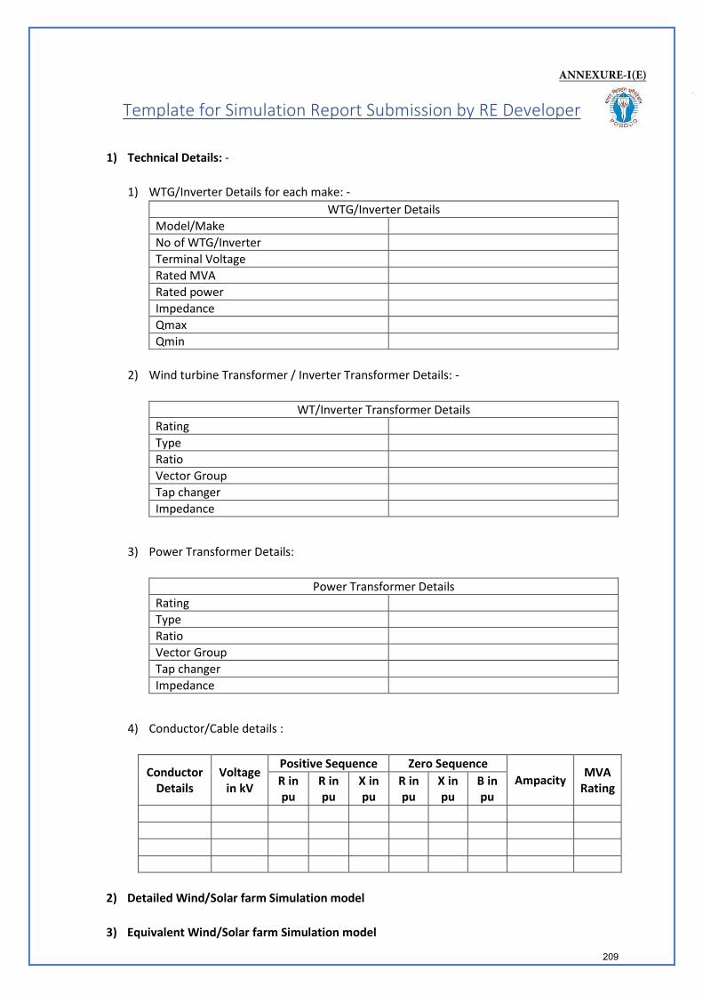
Template for Simulation Report Submission by RE Developer
1) Technical Details: -
1) WTG/Inverter Details for each make: -WTG/Inverter Details
Model/Make No of WTG/Inverter Terminal Voltage Rated MVA Rated power Impedance Qmax Qmin
2) Wind turbine Transformer / Inverter Transformer Details: -
WT/Inverter Transformer Details Rating Type Ratio Vector Group Tap changer Impedance
3) Power Transformer Details:
Power Transformer Details Rating Type Ratio Vector Group Tap changer Impedance
4) Conductor/Cable details :
Conductor Details
Voltage in kV
Positive Sequence Zero Sequence Ampacity MVA
Rating R in pu
R in pu
X in pu
R in pu
X in pu
B in pu
2) Detailed Wind/Solar farm Simulation model
3) Equivalent Wind/Solar farm Simulation model
ANNEXURE-I(E)
209
4) Simulation results showing the comparison of detailed plant model and Equivalent modelof the Wind/Solar farm
5) PQ Capability Curve plot of WTG/ Inverter for each make in the plant.
6) PQ Reactive Capability Curve plot of Wind/Solar Farm at PCC (i.e. at 220kV)- Derived from detailed plant model steady state case for PCC voltages (0.95 pu, 1 pu,
1.05 pu). - Study report to be attached as Annexure
7) Short circuit study results for 3 phase/ single phase fault at PCC.- Derived from detailed plant model steady state case.- Voltage Factor – 1.1- Study report to be attached as Annexure.
8) Simulation results of benchmarking report (if available)-Benchmarking report includes validation of WTG/ Inverter Simulated model against actualmeasurement results from the test report of Statement of Compliance/ConformityCertificate for LVRT/HVRT.This validates the following parameters of Wind machine/ Inverter model submitted in thePSSE .dyr file
• REGCA1 - Renewable Energy Generator/Converter Model• REECA1 - Generic Renewable Electrical Control Model• WTDTA1 - Generic Drive Train Model for Type 3 and Type 4 Wind Machines• WTPTA1 - Generic Pitch Control Model for Type 3 Wind Generator• WTARA1 - Generic Aerodynamic Model for Type 3 wind machine• WTTQA1 - Generic Torque controller for Type 3 wind machine
9) Simulation results of the submitted PSSE model.LVRT Test• Case-1: 3-ph impedance fault at 220 kV POC for 3 sec (220 kV grid voltage is <0.85pu during fault)• Case-2: 3-ph impedance fault at 220 kV POC for 300 msec (220 kV grid voltage is 0.15pu during fault)HVRT Test (as applicable)• Case-1: Rise in 220 kV grid voltage is up to 1.2 pu for 2 sec• Case-2: Rise in 220 kV grid voltage is up to 1.2 pu for 200 msecsOperating Frequency Range [Frequency control flag(Fflag) set 0 in PPC model] • Case -1: Rated Active Power Generation between 49.5 – 50.5 Hz.• Case -2: Stable power output between 47.5 – 52 Hz.Voltage Response Test • Case-1: Step increase in Voltage at POC from 1 pu to 1.05 pu• Case-2: Step decrease in Voltage at POC from 1 pu to 0.95 puFrequency Response Test ( as applicable) • Case-1: Increase in grid frequency up to 50.5 Hz• Case-2: Decrease in grid frequency up to 49.5 Hz.
10) List of protection and its settings for WTG/solar inverter
210
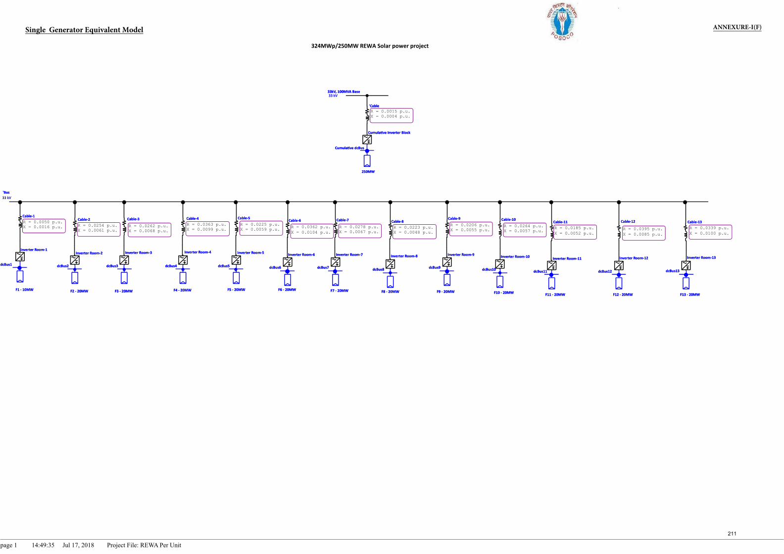
R = 0.0015 p.u.X = 0.0004 p.u.
R = 0.0339 p.u.X = 0.0100 p.u.
R = 0.0395 p.u.X = 0.0085 p.u.
R = 0.0185 p.u.X = 0.0052 p.u.
R = 0.0264 p.u.X = 0.0057 p.u.
R = 0.0206 p.u.X = 0.0055 p.u.R = 0.0223 p.u.
X = 0.0048 p.u.R = 0.0278 p.u.X = 0.0067 p.u.
R = 0.0362 p.u.X = 0.0104 p.u.
R = 0.0225 p.u.X = 0.0059 p.u.
R = 0.0363 p.u.X = 0.0099 p.u.R = 0.0262 p.u.
X = 0.0068 p.u.R = 0.0254 p.u.X = 0.0061 p.u.
R = 0.0050 p.u.X = 0.0016 p.u.
Cumula ve Inverter Block
250MW
'Cable
Inverter Room1
Cable1 Cable4
Inverter Room4
Cable3
Inverter Room3
Cable2
Inverter Room2Inverter Room12 Inverter Room13Inverter Room11
F11 20MW
Inverter Room10Inverter Room9Inverter Room8Inverter Room7Inverter Room6Inverter Room5
F1 10MWF12 20MW F13 20MWF10 20MWF9 20MWF8 20MWF7 20MWF6 20MWF5 20MWF4 20MWF3 20MWF2 20MW
Cable12 Cable13Cable11Cable10Cable9Cable8Cable7Cable6Cable5
dcBus7 dcBus8 dcBus9
'Bus33 kV
dcBus10 dcBus11 dcBus12 dcBus13dcBus4dcBus2 dcBus3
Cumula ve dcBus
dcBus5 dcBus6dcBus1
33kV, 100MVA Base33 kV
Inverter Room2Inverter Room1
dcBus2
F2 20MWF1 10MW
Cable2 Cable3Cable1
Inverter Room3
dcBus1
33 kV'Bus
Cable6
dcBus3
F3 20MW F4 20MW
dcBus4 dcBus7
Inverter Room6
33 kV
Cumula ve dcBus
33kV, 100MVA Base
dcBus5
Inverter Room5
Cable5
dcBus6
F5 20MW F6 20MW
'Cable
Cumula ve Inverter Block
250MW
Inverter Room4
Cable4 Cable10
Inverter Room10
dcBus12
Inverter Room12
F12 20MW
dcBus13
F13 20MW
Inverter Room13
F8 20MW F9 20MW
dcBus11
Inverter Room11
F11 20MW
Cable11
F7 20MW
Inverter Room7
dcBus10
F10 20MW
Cable13Cable12Cable9
Inverter Room9
dcBus9
Inverter Room8
dcBus8
Cable7 Cable8
page 1 14:49:35 Jul 17, 2018 Project File: REWA Per Unit
ANNEXURE-I(F)Single Generator Equivalent Model
211
324MWp/250MW REWA Solar power project
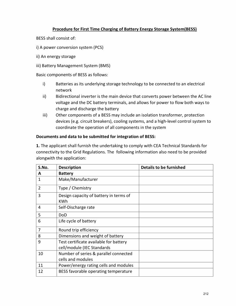
Procedure for First Time Charging of Battery Energy Storage System(BESS)
BESS shall consist of:
i) A power conversion system (PCS)
ii) An energy storage
iii) Battery Management System (BMS)
Basic components of BESS as follows:
i) Batteries as its underlying storage technology to be connected to an electricalnetwork
ii) Bidirectional inverter is the main device that converts power between the AC linevoltage and the DC battery terminals, and allows for power to flow both ways tocharge and discharge the battery
iii) Other components of a BESS may include an isolation transformer, protectiondevices (e.g. circuit breakers), cooling systems, and a high-level control system tocoordinate the operation of all components in the system
Documents and data to be submitted for integration of BESS:
1. The applicant shall furnish the undertaking to comply with CEA Technical Standards forconnectivity to the Grid Regulations. The following information also need to be provided alongwith the application:
S.No. Description Details to be furnished A Battery 1 Make/Manufacturer
2 Type / Chemistry
3 Design capacity of battery in terms of KWh
4 Self-Discharge rate
5 DoD 6 Life cycle of battery
7 Round trip efficiency 8 Dimensions and weight of battery 9 Test certificate available for battery
cell/module (IEC Standards 10 Number of series & parallel connected
cells and modules 11 Power/energy rating cells and modules 12 BESS favorable operating temperature
212
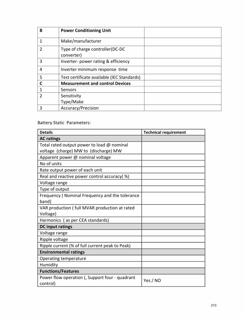
B Power Conditioning Unit
1 Make/manufacturer
2 Type of charge controller(DC-DC converter)
3 Inverter- power rating & efficiency
4 Inverter minimum response time
5 Test certificate available (IEC Standards) C Measurement and control Devices 1 Sensors 2 Sensitivity
Type/Make
3 Accuracy/Precision
Battery Static Parameters:
Details Technical requirement AC ratings Total rated output power to load @ nominal voltage (charge) MW to (discharge) MW
Apparent power @ nominal voltage No of units Rate output power of each unit Real and reactive power control accuracy( %) Voltage range Type of output Frequency ( Nominal Frequency and the tolerance band)
VAR production ( full MVAR production at rated Voltage)
Harmonics ( as per CEA standards) DC input ratings Voltage range Ripple voltage Ripple current (% of full current peak to Peak) Environmental ratings Operating temperature Humidity Functions/Features Power flow operation (, Support four - quadrant control)
Yes / NO
213
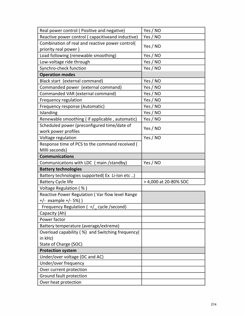
Real power control ( Positive and negative) Yes / NO Reactive power control ( capacitiveand inductive) Yes / NO Combination of real and reactive power control( priority real power )
Yes / NO
Load following (renewable smoothing) Yes / NO Low-voltage ride through Yes / NO Synchro-check function Yes / NO Operation modes Black start (external command) Yes / NO Commanded power (external command) Yes / NO Commanded VAR (external command) Yes / NO Frequency regulation Yes / NO Frequency response (Automatic) Yes / NO Islanding Yes / NO Renewable smoothing ( if applicable , automatic) Yes / NO Scheduled power (preconfigured time/date of work power profiles
Yes / NO
Voltage regulation Yes / NO Response time of PCS to the command received ( Milli seconds)
Communications Communications with LDC ( main /standby) Yes / NO Battery technologies Battery technologies supported( Ex Li-Ion etc ..) Battery Cycle life > 4,000 at 20-80% SOC Voltage Regulation ( % ) Reactive Power Regulation ( Var flow level Range +/- example +/- 5%) )
Frequency Regulation ( +/_ cycle /second) Capacity (Ah) Power factor Battery temperature (average/extreme) Overload capability ( %) and Switching frequency( in kHz)
State of Charge (SOC) Protection system Under/over voltage (DC and AC) Under/over frequency Over current protection Ground fault protection Over heat protection
214
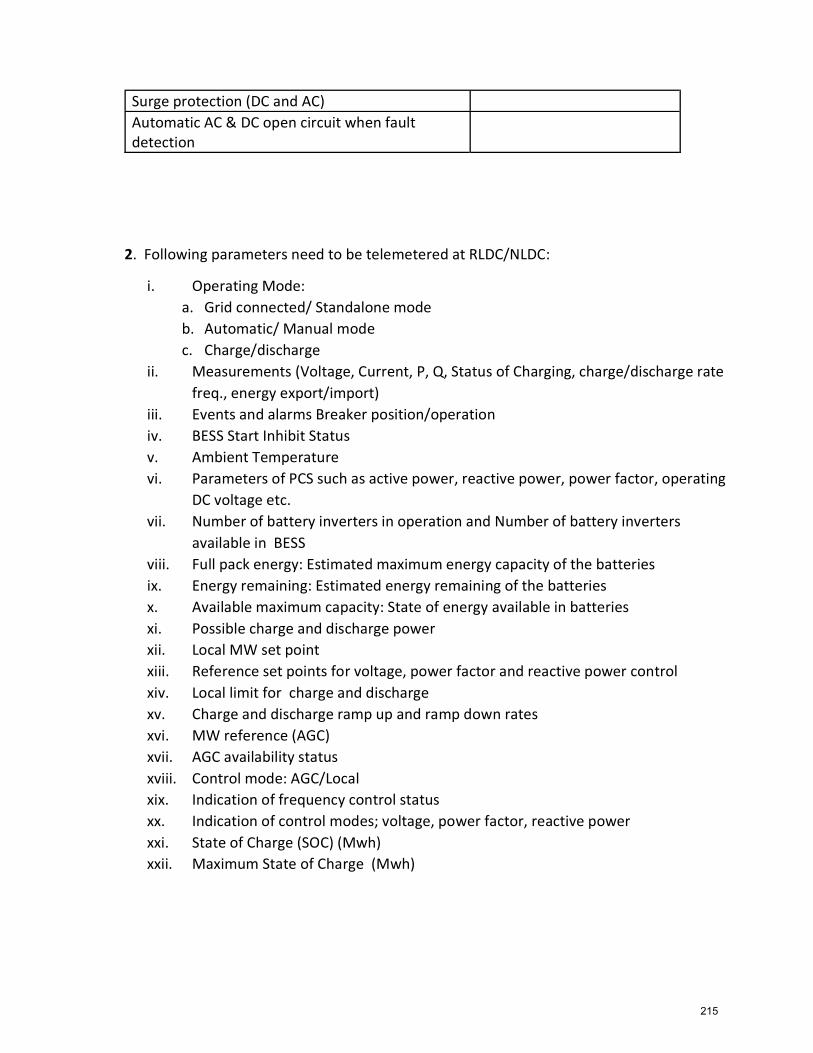
Surge protection (DC and AC) Automatic AC & DC open circuit when fault detection
2. Following parameters need to be telemetered at RLDC/NLDC:
i. Operating Mode: a. Grid connected/ Standalone mode b. Automatic/ Manual mode c. Charge/discharge
ii. Measurements (Voltage, Current, P, Q, Status of Charging, charge/discharge rate freq., energy export/import)
iii. Events and alarms Breaker position/operation iv. BESS Start Inhibit Status v. Ambient Temperature vi. Parameters of PCS such as active power, reactive power, power factor, operating
DC voltage etc. vii. Number of battery inverters in operation and Number of battery inverters
available in BESS viii. Full pack energy: Estimated maximum energy capacity of the batteries ix. Energy remaining: Estimated energy remaining of the batteries x. Available maximum capacity: State of energy available in batteries xi. Possible charge and discharge power xii. Local MW set point xiii. Reference set points for voltage, power factor and reactive power control xiv. Local limit for charge and discharge xv. Charge and discharge ramp up and ramp down rates xvi. MW reference (AGC) xvii. AGC availability status xviii. Control mode: AGC/Local xix. Indication of frequency control status xx. Indication of control modes; voltage, power factor, reactive power xxi. State of Charge (SOC) (Mwh) xxii. Maximum State of Charge (Mwh)
215
3. Test Certificates:
The applicant shall furnish the following test certificates prior to trial run:
i. Verification of sensors, metering and alarms ii. Verification of all control functions including automatic, local and remote control iii. Verification of the performance criteria iv. Demonstration of all the intended applications v. Demonstration of grid interface protection & control system vi. Verification of power quality parameters
4. Grid-tied energy storage units are predominately DC in nature. To utilize the energy storage capability on the AC electric grid, the energy from batteries must be converted to a standard AC level and regulated through a converter, generally known as the Power Conversion System (PCS). The PCS serves as the interface between the DC battery system and the AC system, providing bi-directional conversion from DC to AC (for discharging batteries) and AC to DC (for charging batteries). The PCS may consist of one or more parallel units. The PCS shall be bi-directional converter that can be operated in inverting mode for battery discharging and rectifying mode for battery charging. Power Conversion System Operation conditions:
i. The AC power transformed efficiently from the DC power of the battery arrays shall be bi-directionally transferred to or from the distribution line without causing harmonics higher than the CEA regulation.
ii. The PCS shall contain a remote synchronization feature, as well as the standard synchronization used when starting the PCS online. The remote synchronization feature allows the PCS to synchronize its voltage and frequency to any other remote AC bus or generator.
iii. Black start capability
iv. The PCS shall have the ability to perform four-quadrant control.
v. The PCS shall be able to perform load following (for PV smoothing) Voltage shall be maintained at +/- 5% nominal under normal operating conditions and +/- 10% under emergency conditions.
vi. The PCS shall have the synchro-check function to allow parallel operation with the grid, diesel and PV generators.
vii. PCS shall be able to operate in the following four modes of operation: a. Active and reactive power control: In this mode of operation, PCS controls the output
active and reactive powers supplied to the grid following their reference values which may be set locally or remotely.
216
b. Voltage and frequency control: In this mode of operation, PCS controls its own voltage and frequency, enabling it to create an islanded grid. Voltage and frequency control is possible when the PCS is in the voltage source operating mode.
c. Virtual synchronous generator: This mode of operation makes the PCS work as a voltage source converter. Under this mode, the BESS shall be able to provide its own voltage and frequency to an islanded grid, or to work in parallel with the utility grid in the grid-connected mode.
d. Voltage and frequency droop for parallel operation: The voltage droop allows reactive power sharing when the BESS is in an islanded mode or paralleled with other voltage sources. The frequency droop allows active power sharing when the BESS is in an islanded mode or paralleled with other voltage sources.
5. A sample connectivity of the BESS connected with the system is given below. BESS system is shown to be inter-connected with grid at secondary terminal of distribution transformer i.e. three-phase four-wire, 433 Volts (L-L) at point of common coupling (PCC).
217
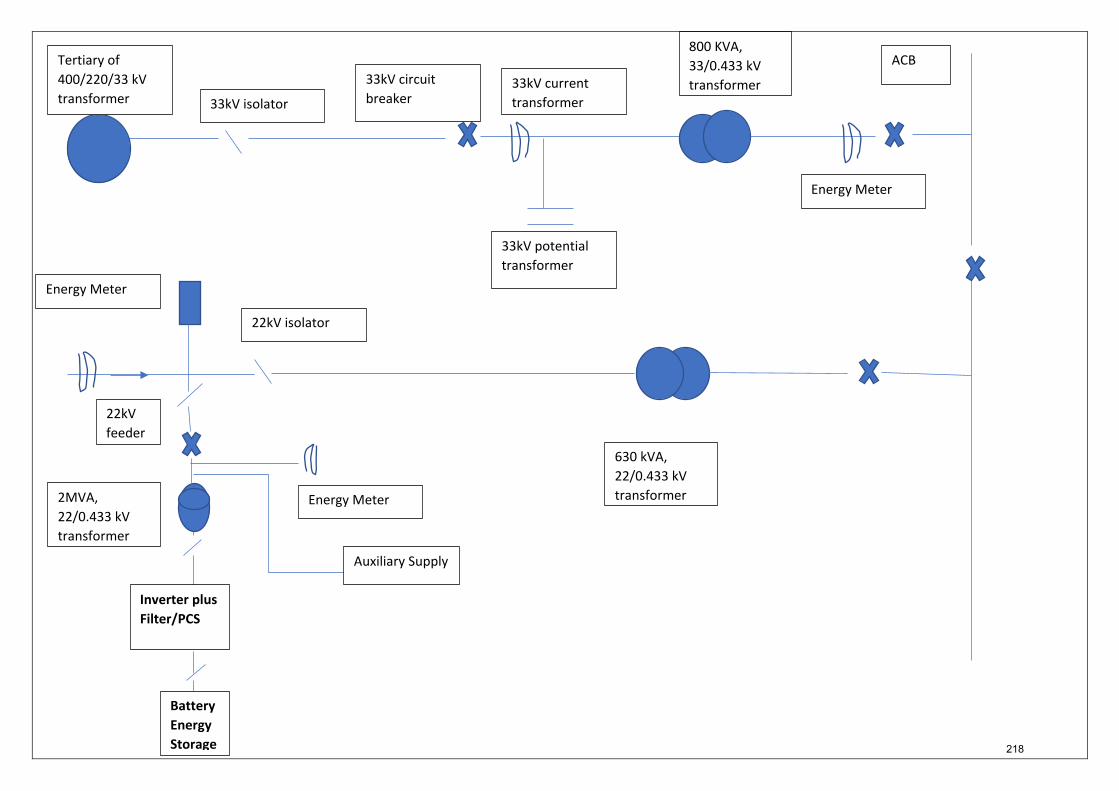
Battery Energy Storage
Inverter plus Filter/PCS
Tertiary of 400/220/33 kV transformer 33kV isolator
33kV circuit breaker
33kV current transformer
33kV potential transformer
800 KVA, 33/0.433 kV transformer
ACB
Energy Meter
22kV isolator
2MVA, 22/0.433 kV transformer
630 kVA, 22/0.433 kV transformer
Energy Meter
Energy Meter
Auxiliary Supply
22kV feeder
218
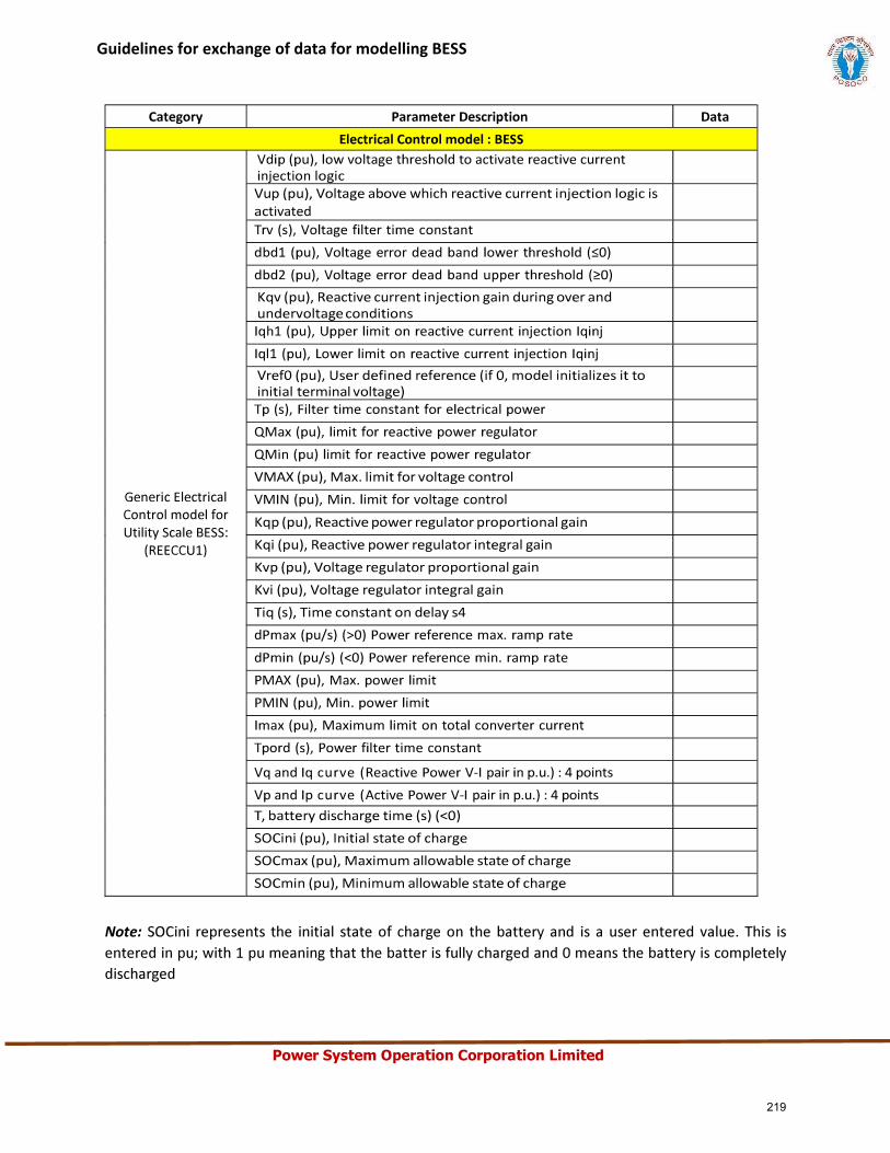
Power System Operation Corporation Limited
Guidelines for exchange of data for modelling BESS
219
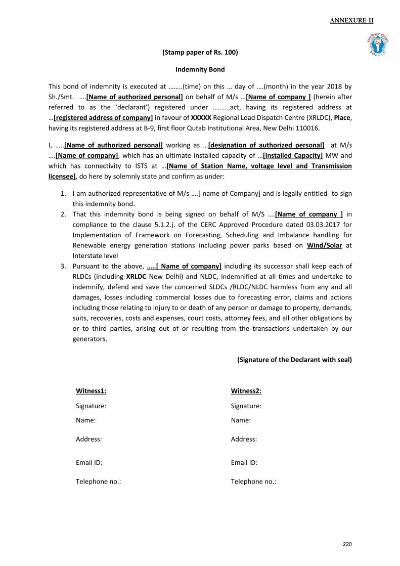
(Stamp paper of Rs. 100)
Indemnity Bond
This bond of indemnity is executed at ……..(time) on this … day of ….(month) in the year 2018 by
Sh./Smt. ….[Name of authorized personal] on behalf of M/s …[Name of company ] (herein after
referred to as the ‘declarant’) registered under ……….act, having its registered address at
…[registered address of company] in favour of XXXXX Regional Load Dispatch Centre (XRLDC), Place,
having its registered address at B-9, first floor Qutab Institutional Area, New Delhi 110016.
I, …..[Name of authorized personal] working as …[designation of authorized personal] at M/s
….[Name of company], which has an ultimate installed capacity of …[Installed Capacity] MW and
which has connectivity to ISTS at …[Name of Station Name, voltage level and Transmission
licensee], do here by solemnly state and confirm as under:
1. I am authorized representative of M/s ….[ name of Company] and is legally entitled to sign
this indemnity bond.
2. That this indemnity bond is being signed on behalf of M/S ….[Name of company ] in
compliance to the clause 5.1.2.j. of the CERC Approved Procedure dated 03.03.2017 for
Implementation of Framework on Forecasting, Scheduling and Imbalance handling for
Renewable energy generation stations including power parks based on Wind/Solar at
Interstate level
3. Pursuant to the above, …..[ Name of company] including its successor shall keep each of
RLDCs (including XRLDC New Delhi) and NLDC, indemnified at all times and undertake to
indemnify, defend and save the concerned SLDCs /RLDC/NLDC harmless from any and all
damages, losses including commercial losses due to forecasting error, claims and actions
including those relating to injury to or death of any person or damage to property, demands,
suits, recoveries, costs and expenses, court costs, attorney fees, and all other obligations by
or to third parties, arising out of or resulting from the transactions undertaken by our
generators.
(Signature of the Declarant with seal)
Witness1: Witness2:
Signature: Signature:
Name: Name:
Address: Address:
Email ID: Email ID:
Telephone no.: Telephone no.:
ANNEXURE-II
220
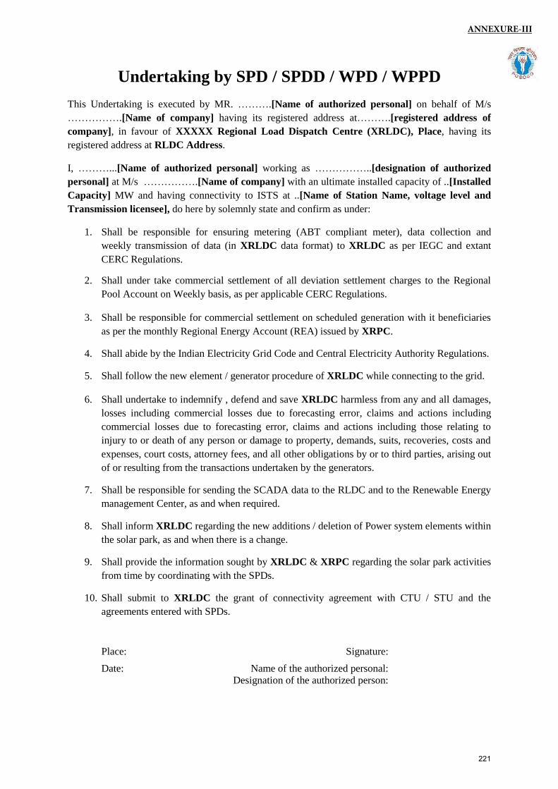
Undertaking by SPD / SPDD / WPD / WPPD
This Undertaking is executed by MR. ……….[Name of authorized personal] on behalf of M/s
…………….[Name of company] having its registered address at……….[registered address of
company], in favour of XXXXX Regional Load Dispatch Centre (XRLDC), Place, having its
registered address at RLDC Address.
I, ………...[Name of authorized personal] working as ……………..[designation of authorized
personal] at M/s …………….[Name of company] with an ultimate installed capacity of ..[Installed
Capacity] MW and having connectivity to ISTS at ..[Name of Station Name, voltage level and
Transmission licensee], do here by solemnly state and confirm as under:
1. Shall be responsible for ensuring metering (ABT compliant meter), data collection and
weekly transmission of data (in XRLDC data format) to XRLDC as per IEGC and extant
CERC Regulations.
2. Shall under take commercial settlement of all deviation settlement charges to the Regional
Pool Account on Weekly basis, as per applicable CERC Regulations.
3. Shall be responsible for commercial settlement on scheduled generation with it beneficiaries
as per the monthly Regional Energy Account (REA) issued by XRPC.
4. Shall abide by the Indian Electricity Grid Code and Central Electricity Authority Regulations.
5. Shall follow the new element / generator procedure of XRLDC while connecting to the grid.
6. Shall undertake to indemnify , defend and save XRLDC harmless from any and all damages,
losses including commercial losses due to forecasting error, claims and actions including
commercial losses due to forecasting error, claims and actions including those relating to
injury to or death of any person or damage to property, demands, suits, recoveries, costs and
expenses, court costs, attorney fees, and all other obligations by or to third parties, arising out
of or resulting from the transactions undertaken by the generators.
7. Shall be responsible for sending the SCADA data to the RLDC and to the Renewable Energy
management Center, as and when required.
8. Shall inform XRLDC regarding the new additions / deletion of Power system elements within
the solar park, as and when there is a change.
9. Shall provide the information sought by XRLDC & XRPC regarding the solar park activities
from time by coordinating with the SPDs.
10. Shall submit to XRLDC the grant of connectivity agreement with CTU / STU and the
agreements entered with SPDs.
Place: Signature:
Date: Name of the authorized personal:
Designation of the authorized person:
ANNEXURE-III
221
(Stamp paper of Rs. 100)
----------------------------------------------------------------------------------------------------------------
Undertaking by SPD/WPD
This undertaking is executed by ……………………………on behalf of M/s………………, having its registered address at …………………………, in favour of ……………….. Regional Load Despatch Centre having its registered address at …………………… ………………………………………………………………………………….
I ………………………… authorized signatory of M/s…………………… with an ultimate installed capacity of …….. MW and having connectivity to ISTS at…………………………………, do here by solemnly state and confirm as under:
Our solar project falls under Central Electricity Regulatory Commission (Sharing of Inter-State Transmission Charges and Losses) (Sixth Amendment), Regulations, 2019 which states that “No transmission charges and losses for the use of ISTS network will be payable for the generation based on solar and wind power resources for a period of 25 years from the date of commercial operation” under following conditions:
1. Such generation capacity has been awarded through competitive biddingprocess in accordance with the guidelines issued by the Central Government.[Supporting document attached as annex-1]
2. Such generation capacity has been declared under commercial operationbetween 13.02.2018 till 31.03.2022. [Supporting document attached as annex-2]
3. Power Purchase Agreement(s) have been executed for sale of such generationcapacity to all entities including Distribution Companies for compliance of theirrenewable purchase obligations. [Supporting document attached as annex-3]
Place : Signature Date :
Name: Designation:
Annexure-IV
222
(To be notarized on a Rs 100 non-judicial stamp paper)
Affidavit
I ________, Son/Daughter/Wife of _____________, aged about _______ years, residing at __________ do hereby solemnly affirm and sincerely state as follows:
1. That I am the ________(Designation) of the _______ (Company Name). I have beenauthorized by the ___________(company name) vide Board Resolution / Power ofAttorney / Authorization Letter dated ……………..to sign this affidavit on behalf of thecompany.
2. The ___ MW Wind power plant _________(Plant Name) situated at Village:______, Taluka: ______, District _____ has been awarded via competitive biddingconducted by ________ vide Letter of Intent _________ dated _______.
3. The above Wind Power Plant is scheduled to be commissioned by……………………(dd.mm.yyyy) (ref. PPA dated ……………).
4. The date of Commercial operation (COD) will be intimated by___________________(Name of WPD/SPD) to WRLDC, Mumbai prior tocommencement of scheduling of power.
5. I state that ___________(WPD/SPD Name) undertakes to ensure compliance to followingregulations and guidelines as amended from time to time:
a. Central Electricity Authority (Technical Standards for Connectivity to the Grid)Regulations, 2007 and any subsequent amendments thereof including but not limited tothe norms for Low Voltage Ride Through (LVRT) and High Voltage Ride ThroughCapabilities (HVRT) as specified under standard B2 of the CEA (Technical Standardsfor Connectivity (Amendment) Regulations 2019.
ANNEXURE-V
223
b. Central Electricity Regulatory Commission (CERC) (Grant of Connectivity, Long-TermAccess in Inter-State Transmission and related matters) regulation, 2009 andsubsequent amendments thereof.
6. I undertake to submit the test report and Statement of Compliance (SoC)/ ConformityStatement (CS) as stipulated in MNRE guidelines demonstrating the compliance ofapplicable CEA Technical standards for Connectivity to the Grid (as amended from time totime) including LVRT/HVRT.
DEPONENT
Verification: -
Verified at _______________, this the ______ day of __________ 20__, that the
contents in the above affidavit is true and correct to the best of knowledge and belief. No part of this affidavit is wrong and nothing material has been concealed therefrom.
DEPONENT
Solemnly Affirmed at ……………….
On this…………day of…… ..20___
And signed his/her name in my presence Deponent signed before me.
224
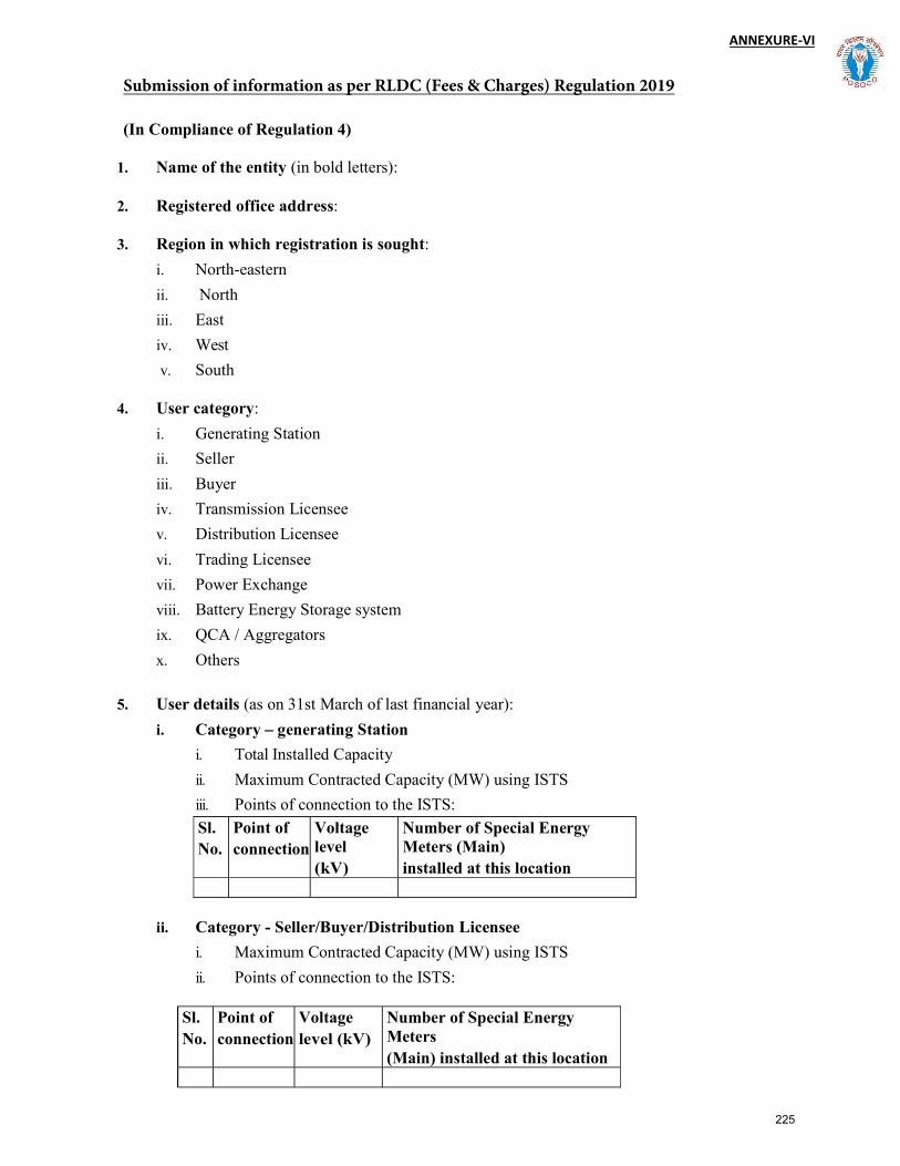
ANNEXURE-VI
(In Compliance of Regulation 4)
1. Name of the entity (in bold letters):
2. Registered office address:
3. Region in which registration is sought:
i. North-eastern
ii. North
iii. East
iv. West
v. South
4. User category:
i. Generating Station
ii. Seller
iii. Buyer
iv. Transmission Licensee
v. Distribution Licensee
vi. Trading Licensee
vii. Power Exchange
viii. Battery Energy Storage system
ix. QCA / Aggregators
x. Others
5. User details (as on 31st March of last financial year):
i. Category generating Station
i. Total Installed Capacity
ii. Maximum Contracted Capacity (MW) using ISTS
iii. Points of connection to the ISTS:
Sl. No.
Point of connection
Voltage level (kV)
Number of Special Energy Meters (Main) installed at this location
ii. Category - Seller/Buyer/Distribution Licensee
i. Maximum Contracted Capacity (MW) using ISTS
ii. Points of connection to the ISTS:
Sl. No.
Point of connection
Voltage level (kV)
Number of Special Energy Meters (Main) installed at this location
Submission of information as per RLDC (Fees & Charges) Regulation 2019
225
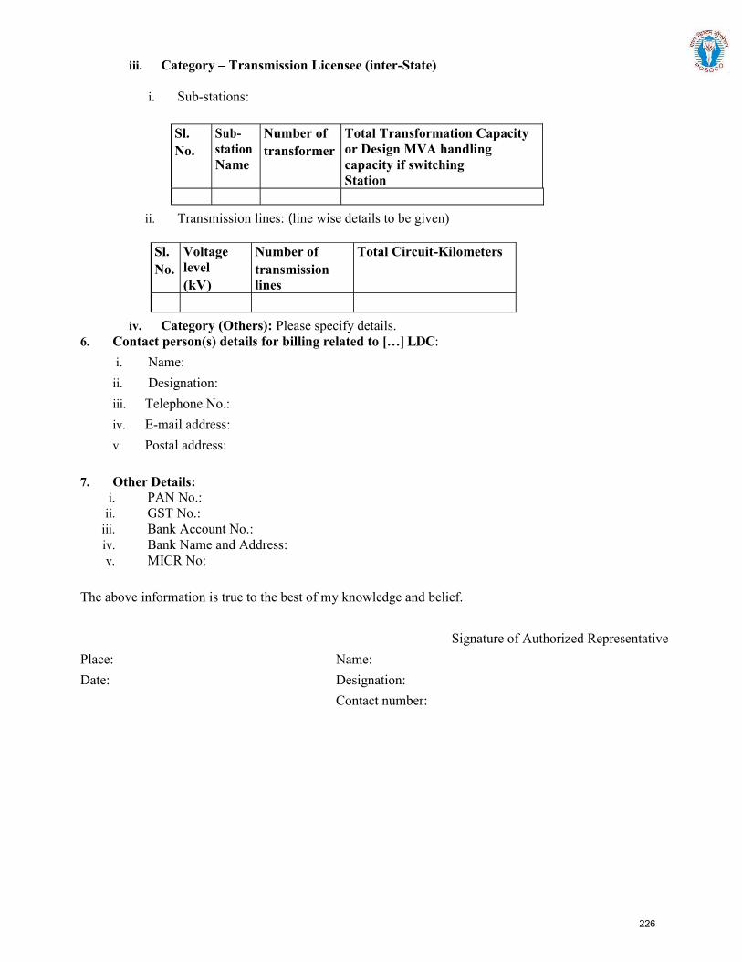
iii. Category Transmission Licensee (inter-State)
i. Sub-stations:
Sl. No.
Sub-station Name
Number of transformer
Total Transformation Capacity or Design MVA handling capacity if switching Station
ii. Transmission lines: line wise details to be given)
Sl. No.
Voltage level (kV)
Number of transmission lines
Total Circuit-Kilometers
iv. Category (Others): Please specify details.6. Contact person(s) details for billing related to :
i. Name:
ii. Designation:
iii. Telephone No.:
iv. E-mail address:
v. Postal address:
7. Other Details:i. PAN No.:
ii. GST No.:iii. Bank Account No.:iv. Bank Name and Address:v. MICR No:
The above information is true to the best of my knowledge and belief.
Signature of Authorized Representative
Place: Name:
Date: Designation:
Contact number:
226
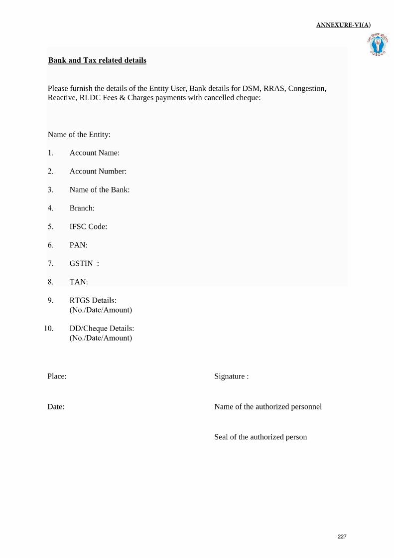
Bank and Tax related details
Please furnish the details of the Entity User, Bank details for DSM, RRAS, Congestion,
Reactive, RLDC Fees & Charges payments with cancelled cheque:
Name of the Entity:
1. Account Name:
2. Account Number:
3. Name of the Bank:
4. Branch:
5. IFSC Code:
6. PAN:
7. GSTIN :
8. TAN:
9. RTGS Details:(No./Date/Amount)
10. DD/Cheque Details:(No./Date/Amount)
Place: Signature :
Date: Name of the authorized personnel
Seal of the authorized person
ANNEXURE-VI(A)
227
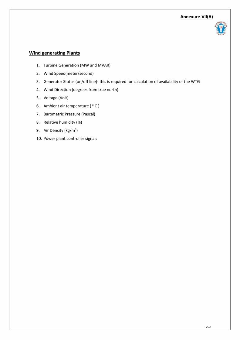
Annexure-VII(A)
Wind generating Plants
1. Turbine Generation (MW and MVAR)
2. Wind Speed(meter/second)
3. Generator Status (on/off line)- this is required for calculation of availability of the WTG
4. Wind Direction (degrees from true north)
5. Voltage (Volt)
6. Ambient air temperature ( o C )
7. Barometric Pressure (Pascal)
8. Relative humidity (%)
9. Air Density (kg/m3)
10. Power plant controller signals
228
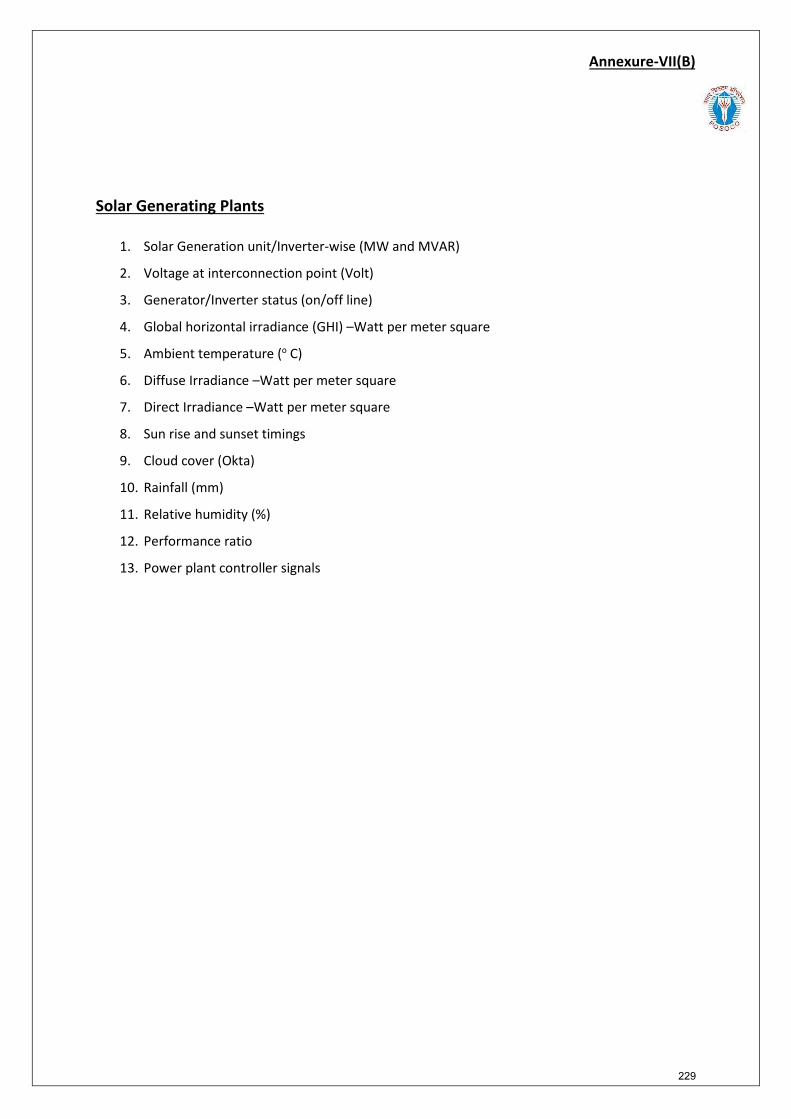
Annexure-VII(B)
Solar Generating Plants
1. Solar Generation unit/Inverter-wise (MW and MVAR)
2. Voltage at interconnection point (Volt)
3. Generator/Inverter status (on/off line)
4. Global horizontal irradiance (GHI) –Watt per meter square
5. Ambient temperature (o C)
6. Diffuse Irradiance –Watt per meter square
7. Direct Irradiance –Watt per meter square
8. Sun rise and sunset timings
9. Cloud cover (Okta)
10. Rainfall (mm)
11. Relative humidity (%)
12. Performance ratio
13. Power plant controller signals
229
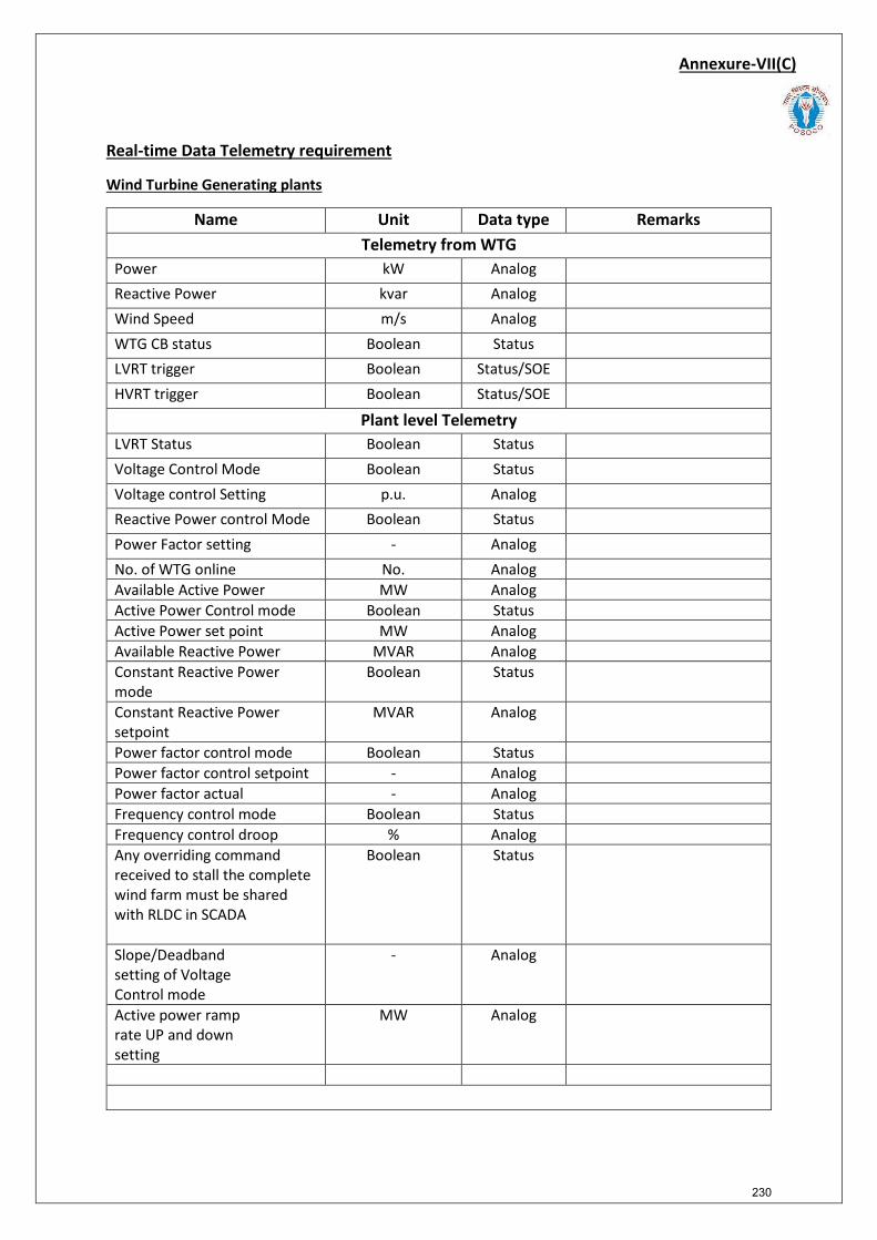
Annexure-VII(C)
Real-time Data Telemetry requirement
Wind Turbine Generating plants
Name Unit Data type Remarks Telemetry from WTG
Power kW Analog Reactive Power kvar Analog Wind Speed m/s Analog WTG CB status Boolean Status LVRT trigger Boolean Status/SOE HVRT trigger Boolean Status/SOE
Plant level Telemetry LVRT Status Boolean Status Voltage Control Mode Boolean Status Voltage control Setting p.u. Analog Reactive Power control Mode Boolean Status Power Factor setting - Analog No. of WTG online No. Analog Available Active Power MW Analog Active Power Control mode Boolean Status Active Power set point MW Analog Available Reactive Power MVAR Analog Constant Reactive Power mode
Boolean Status
Constant Reactive Power setpoint
MVAR Analog
Power factor control mode Boolean Status Power factor control setpoint - Analog Power factor actual - Analog Frequency control mode Boolean Status Frequency control droop % Analog Any overriding command received to stall the complete wind farm must be shared with RLDC in SCADA
Boolean Status
Slope/Deadband setting of Voltage Control mode
- Analog
Active power ramp rate UP and down setting
MW Analog
230
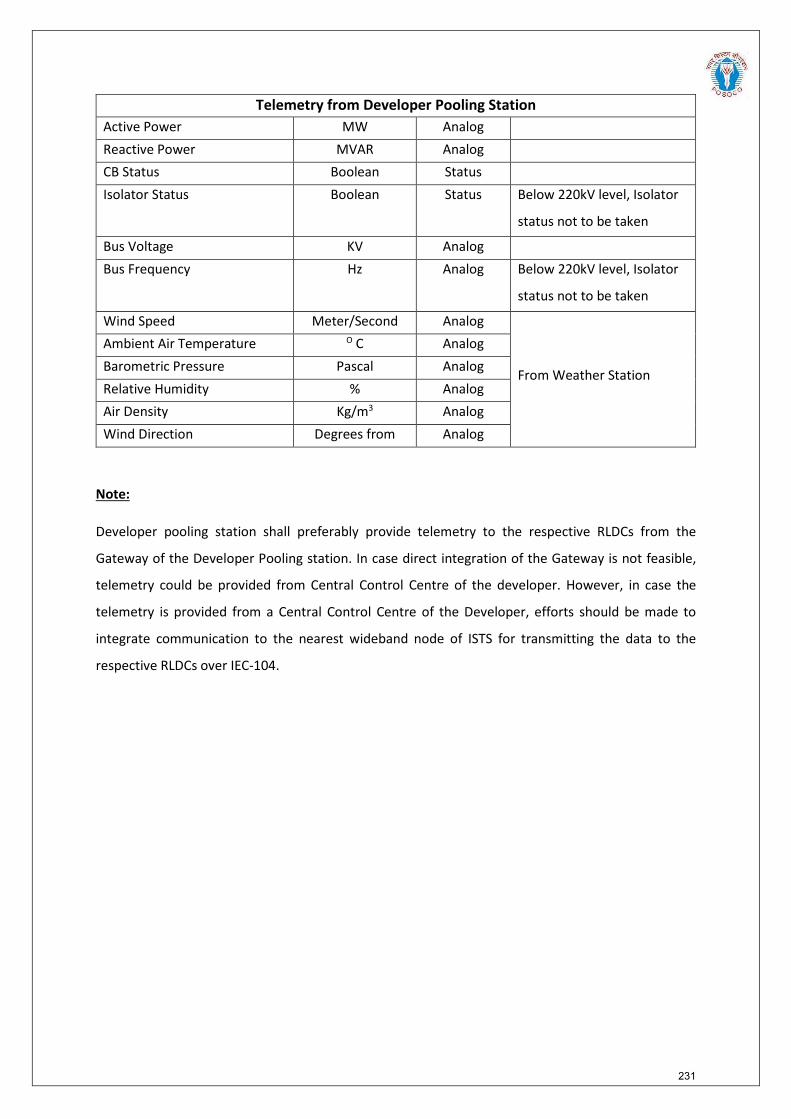
Telemetry from Developer Pooling Station Active Power MW Analog Reactive Power MVAR Analog CB Status Boolean Status Isolator Status Boolean Status Below 220kV level, Isolator
status not to be taken
Bus Voltage KV Analog Bus Frequency Hz Analog Below 220kV level, Isolator
status not to be taken
Wind Speed Meter/Second Analog
From Weather Station
Ambient Air Temperature O C Analog Barometric Pressure Pascal Analog Relative Humidity % Analog Air Density Kg/m3 Analog Wind Direction Degrees from Analog
Note:
Developer pooling station shall preferably provide telemetry to the respective RLDCs from the
Gateway of the Developer Pooling station. In case direct integration of the Gateway is not feasible,
telemetry could be provided from Central Control Centre of the developer. However, in case the
telemetry is provided from a Central Control Centre of the Developer, efforts should be made to
integrate communication to the nearest wideband node of ISTS for transmitting the data to the
respective RLDCs over IEC-104.
231
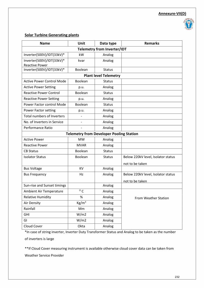
Annexure-VII(D)
Solar Turbine Generating plants
Name Unit Data type Remarks Telemetry from Inverter/IDT
Inverter(500V)/IDT(33kV)* kW Analog Inverter(500V)/IDT(33kV)*Reactive Power
kvar Analog
Inverter(500V)/IDT(33kV)* Boolean Status
Plant level Telemetry Active Power Control Mode Boolean Status Active Power Setting p.u. Analog Reactive Power Control Boolean Status Reactive Power Setting p.u. Analog Power Factor control Mode Boolean Status Power Factor setting p.u. Analog Total numbers of Inverters - Analog No. of Inverters in Service - Analog Performance Ratio - Analog
Telemetry from Developer Pooling Station Active Power MW Analog Reactive Power MVAR Analog CB Status Boolean Status Isolator Status Boolean Status Below 220kV level, Isolator status
not to be taken Bus Voltage KV Analog Bus Frequency Hz Analog Below 220kV level, Isolator status
not to be taken Sun-rise and Sunset timings Analog Ambient Air Temperature O C Analog
From Weather Station Relative Humidity % Analog Air Density Kg/m3 Analog Rainfall Mm Analog GHI W/m2 Analog GI W/m2 Analog Cloud Cover Okta Analog *In case of string inverter, Inverter Duty Transformer Status and Analog to be taken as the number
of inverters is large
**If Cloud Cover measuring instrument is available otherwise cloud cover data can be taken from
Weather Service Provider
232

NOTE:
Developer pooling station shall preferably provide telemetry to the respective RLDCs from the
Gateway of the Developer Pooling Station. In case direct integration of Gateway is not feasible,
telemetry could be provided from Central Control Centre of the Developer. However, in case the
telemetry is provided from a Central Control Centre of the Developer, efforts should be made to
integrate communication to the nearest wideband node of ISTS for transmitting the data to the
respective RLDCs over IEC-104.
233
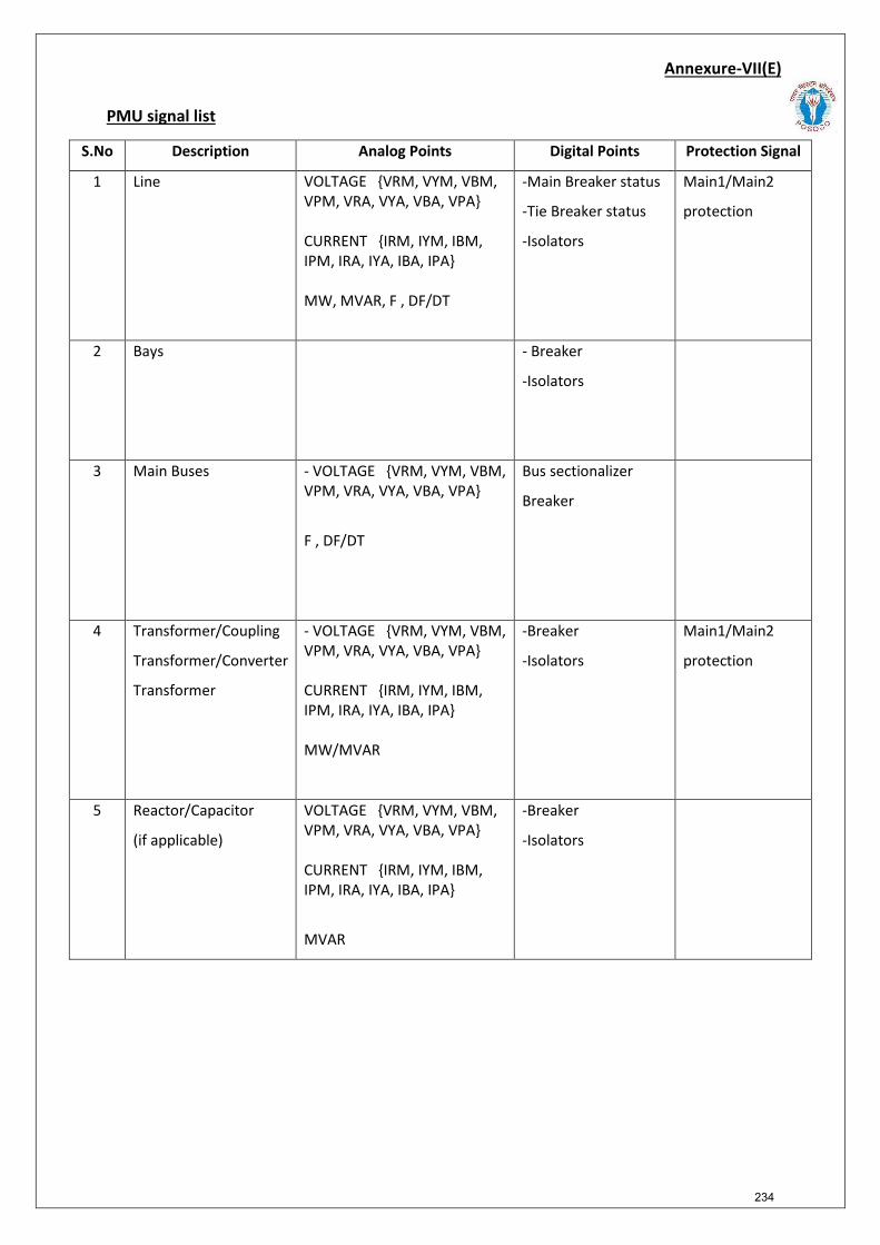
PMU signal list
Annexure-VII(E)
S.No Description Analog Points Digital Points Protection Signal
1 Line VOLTAGE {VRM, VYM, VBM, VPM, VRA, VYA, VBA, VPA}
CURRENT {IRM, IYM, IBM, IPM, IRA, IYA, IBA, IPA}
MW, MVAR, F , DF/DT
-Main Breaker status
-Tie Breaker status
-Isolators
Main1/Main2
protection
2 Bays - Breaker
-Isolators
3 Main Buses - VOLTAGE {VRM, VYM, VBM,VPM, VRA, VYA, VBA, VPA}
F , DF/DT
Bus sectionalizer
Breaker
4 Transformer/Coupling
Transformer/Converter
Transformer
- VOLTAGE {VRM, VYM, VBM,VPM, VRA, VYA, VBA, VPA}
CURRENT {IRM, IYM, IBM, IPM, IRA, IYA, IBA, IPA}
MW/MVAR
-Breaker
-Isolators
Main1/Main2
protection
5 Reactor/Capacitor
(if applicable)
VOLTAGE {VRM, VYM, VBM, VPM, VRA, VYA, VBA, VPA}
CURRENT {IRM, IYM, IBM, IPM, IRA, IYA, IBA, IPA}
MVAR
-Breaker
-Isolators
234
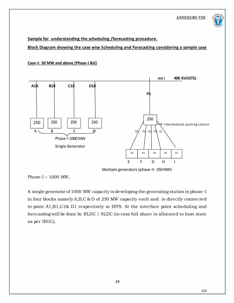
ANNEXURE-VIII
235
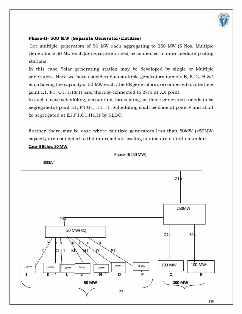
236
237
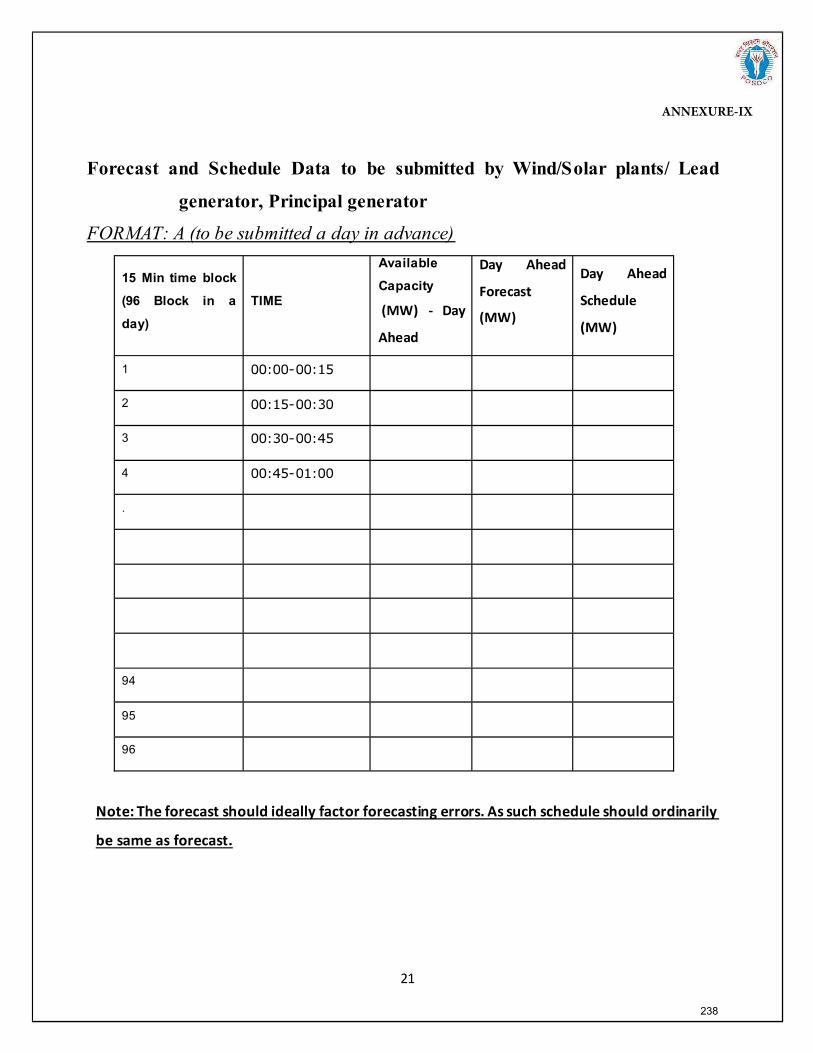
Forecast and Schedule Data to be submitted by Wind/Solar plants/ Lead
generator, Principal generator
FORMAT: A (to be submitted a day in advance)
15 Min time block
(96 Block in a
day)
TIME
Available
Capacity
1
2
3
4
.
94
95
96
ANNEXURE-IX
238
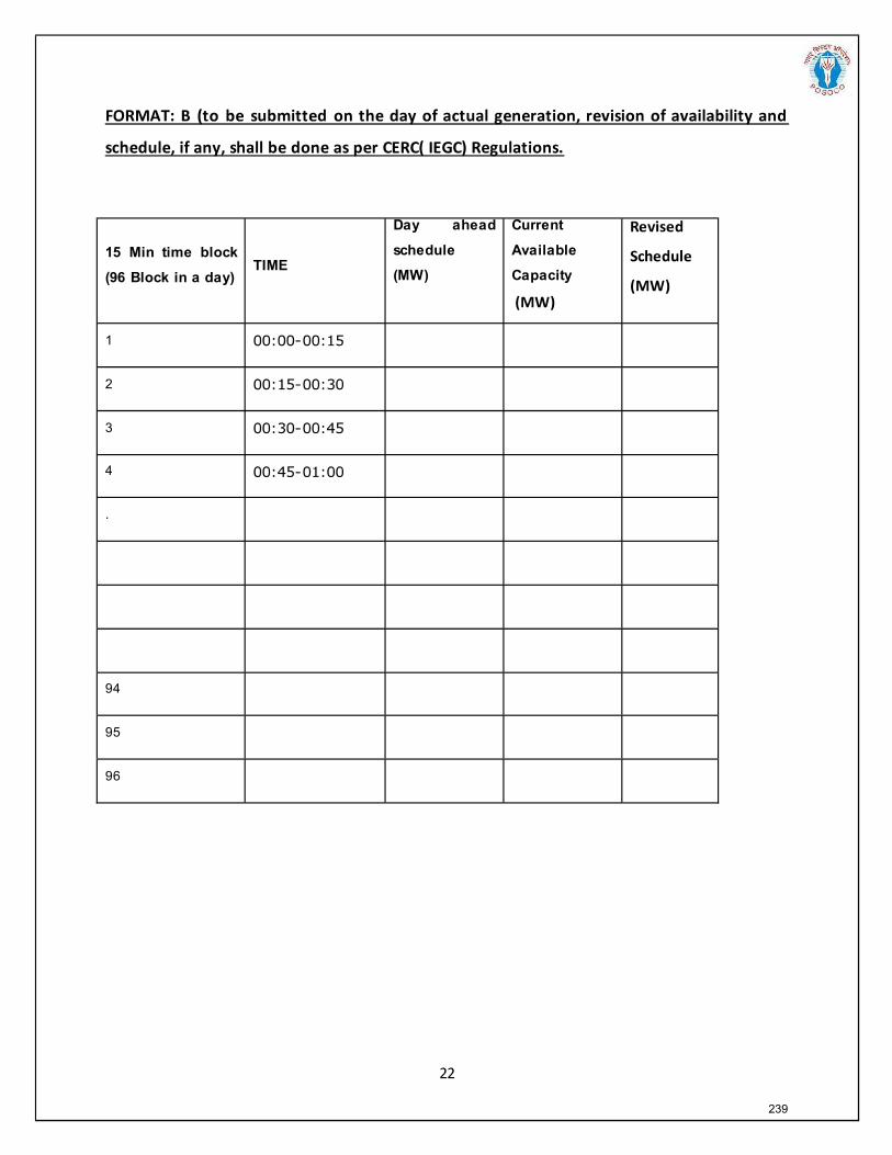
15 Min time block
(96 Block in a day) TIME
Day ahead
schedule
(MW)
Current
Available
Capacity
1
2
3
4
.
94
95
96
239
Section 3:
Procedure for integration of a new or modified HVDC
transmission elements and issue of certificate of successful trial operation by National Load
Despatch Centre (NLDC)/ Regional Load Despatch Centres (RLDCs)
240
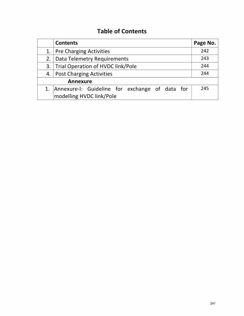
Table of Contents
Contents Page No. 1. Pre Charging Activities 242
2. Data Telemetry Requirements 243
3. Trial Operation of HVDC link/Pole 244
4. Post Charging Activities 244
Annexure 1. Annexure-I: Guideline for exchange of data for
modelling HVDC link/Pole 245
241
Procedure for integration of a new or modified HVDC transmission elements and issue of certificate of successful trial operation by National Load Despatch Centre (NLDC)/ Regional Load Despatch Centres (RLDCs)
1. Pre Charging ActivitiesThe procedure is applicable for the first time charging of HVDC transmission elements along with all filters and sub-filter banks. All the timelines & formats mentioned in this procedure shall be provided by transmission licensee/owner to concerned RLDC. Approval of first time charging of HVDC transmission elements shall be provided by NLDC/RLDC in line with these guidelines and the procedure for facilitating first time charging of new or modified power system elements. Following modelling and operational information shall be provided by the owners of HVDC station before commencement of any testing of HVDC transmission elements:
a) Name plate detailsb) Main Circuit Parameter Design report(Forward and Reverse Direction)c) Minimum power in different Configurationd) Active and reactive power controle) Frequency Controller study reportf) Emergency Power control study reportg) Power Order Compensation study reporth) Network Data Summaryi) HVDC Operation & Control Strategyj) Protection Philosophyk) Modes of operationl) Filter Arrangement with rating and minimum filter requirementm) AC filter Protectionn) Protection Settingo) Power Oscillation Damping (POD) Status along with the document on tuning.p) Auxiliary model (Frequency Controller Model, POD controller Model, Voltage
controller model)q) Dynamic parameters file *.dyrr) PSCAD models) Steady state and dynamic modelling details as per the guidelines for exchange of data
from modelling HVDC as per Annexure-I(A)t) Load flow and stability reportu) Dynamic Performance Study reportv) Sub synchronous resonance study reportw) Fundamental Frequency Temporary over voltages (FFTOV) study reportx) Dynamic Multi HVDC interaction reporty) Any other information as required by RLDC
Owners of the HVDC station shall submit a detailed proposal for testing at least 10 days in advance along with intimation of first time charging (Format A). Proposed testing schedule of HVDC transmission elements shall be duly approved by concerned Regional Power committees(RPCs)
242
The auxiliary consumption of HVDC station is generally drawn from the tertiary of the 400/220/33 kV transformer at the substation. The meter reading of this transformer would include the auxiliary consumption of HVDC station as well. Therefore, a No Objection Certificate (NOC) from the local DISCOM and SLDC would also be provided by the owner of the HVDC station. 2. Data Telemetry Requirements a. Following SCADA points shall be made available to the NLDC/RLDC control room: Analog Signal
I. AC Power Flow for converter transformer II. Tap position of converter transformer
III. DC Voltage IV. DC Power Flow V. DC Current
VI. Individual and cumulative Filter MVAR VII. Firing Angle-Alpha
VIII. Extinction angle- Gamma, etc. IX. Power order, set point X. Compensation settings if applicable
Digital Signal
I. Individual Filter Status II. HVDC Mode (Metallic return / Ground return)
III. Isolator/CB Status of DC Switchyard IV. RPC Status V. Run back Status
VI. POD Status VII. SSDC Status
VIII. SOE with Time Stamping IX. DMR 1 status X. DMR2 status
XI. MRTB status XII. GRTB status
XIII. SoE for HVDC autorestart
Protection Signal
I. DC line Fault Protection II. ESOF (emergency Switch Off) and HVDC Pole Block protection
III. POD Status (operated or not
Other than the SCADA data, PMU data shall also be provided.
243
3. Trial Operation of HVDC link/Pole a) The trial operation of HVDC link/Pole shall start only after getting all the documents
and modelling data and telemetry of the points as defined above are available at NLDC/RLDC.
b) Date and time of commencement of trial run operation shall be intimated in advance but not less than twenty four hours to NLDC and concerned RLDCs.
c) The trial operation for the purpose of HVDC link/Pole shall be continuous operation for 24 hrs.
d) During the trial operation minimum load operation, ramp rate, Overload capability and Black start capability in case of Voltage source convertor (VSC) HVDC station, reversal of power shall be demonstrated as desired by NLDC/RLDCs.
4. Post Charging Activities a. Successful Trial Operation completion certificate for inter-regional HVDC link/Pole shall be issued by NLDC in accordance with procedure for first time charging of power system elements. b. Successful Trial Operation completion certificate for Intra-Regional HVDC link/pole connected as designated ISTS network shall be issued by concerned RLDC in accordance with procedure for first time charging of power system elements. c. Following data shall be provided by the owner of HVDC station after successful trial operation for issuance of trial operation completion certificate: i. Converter transformer meter reading for the period of trial operation from both end ii. SCADA readings/plot of active and reactive power flow from both the end during the trial operation iii. Event log indicating Opening/closing of breakers vi. Output of Disturbance Recorder for the period of trial operation vii. Any other data as required by RLDC to ascertain effective operation of HVDC link/Pole
Enclosures. Annexure-I: Guideline for exchange of data for modelling HVDC link/Pole Other than the documents mentioned above the formats for first time charging of transmission elements (Format A1-A6, B1-B5 and C1-C4) to be submitted to concerned RLDC.
244

Guideline for furnishing information for Modelling HVDC links in Indian Grid
1.0 Introduction:
The purpose of this document is to act as a guideline for exchange of information for accurate modelling of high voltage direct current (HVDC) links in India. HVDCs have played a pivotal role in integration and formation of the Indian national grid, and still continue to enable bulk power transfer across regions. HVDCs enable additional flexibility in power system operations, aiding in control of active power flows and voltages. Availability of fit-for-purpose steady state and dynamics models of HVDC installations are necessary to undertake simulation studies for secure operation of Indian power grid.
1.1 Applicability:
The guideline shall be applicable to all HVDC installations in India, irrespective of the technologies used.
This document presents the desired information for collection of data for modelling of HVDC installations in PSS/E software, a software suite being used pan-India at CEA, CTU, SLDCs, RLDCs, and NLDC for modelling of India’s power grid. A systematic set of data and basic criteria for furnishing data are presented.
1.2 Need for a fit-for-purpose model:
There is a cost involved in developing and validating dynamic models of power system equipment. But there are much higher benefits for the power system if this leads to a functional, fit-for-purpose model, and arrangements that allow that model to be maintained over time.
A functional fit-for-purpose dynamic model will:
• Facilitate significant power system efficiencies by allowing power system operations toconfidently identify the secure operating envelope and thereby manage security effectively
• Allow assessment of impact on grid elements due to connection of new elements (networkelements, generators, or loads) for necessary corrective actions
• Permit power system assets to be run with margins determined on the basis of securityassessments
• Facilitate the tuning of control systems, such as power oscillation dampers, frequencycontrollers, etc.
• Improve accuracy of online security tools, particularly for unusual operating conditions, which inturn is likely to result in higher reliability of supply to power system users.
The power system model would enable steady state and electromechanical transient simulation studies that deliver reasonably accurate outcomes.
Annexure-I
245
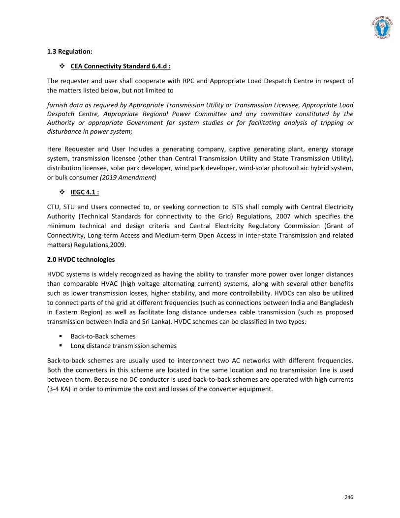
1.3 Regulation:
CEA Connectivity Standard 6.4.d :
The requester and user shall cooperate with RPC and Appropriate Load Despatch Centre in respect of the matters listed below, but not limited to
furnish data as required by Appropriate Transmission Utility or Transmission Licensee, Appropriate Load Despatch Centre, Appropriate Regional Power Committee and any committee constituted by the Authority or appropriate Government for system studies or for facilitating analysis of tripping or disturbance in power system;
Here Requester and User Includes a generating company, captive generating plant, energy storage system, transmission licensee (other than Central Transmission Utility and State Transmission Utility), distribution licensee, solar park developer, wind park developer, wind-solar photovoltaic hybrid system, or bulk consumer (2019 Amendment)
IEGC 4.1 :
CTU, STU and Users connected to, or seeking connection to ISTS shall comply with Central Electricity Authority (Technical Standards for connectivity to the Grid) Regulations, 2007 which specifies the minimum technical and design criteria and Central Electricity Regulatory Commission (Grant of Connectivity, Long-term Access and Medium-term Open Access in inter-state Transmission and related matters) Regulations,2009.
2.0 HVDC technologies
HVDC systems is widely recognized as having the ability to transfer more power over longer distances than comparable HVAC (high voltage alternating current) systems, along with several other benefits such as lower transmission losses, higher stability, and more controllability. HVDCs can also be utilized to connect parts of the grid at different frequencies (such as connections between India and Bangladesh in Eastern Region) as well as facilitate long distance undersea cable transmission (such as proposed transmission between India and Sri Lanka). HVDC schemes can be classified in two types:
Back-to-Back schemes Long distance transmission schemes
Back-to-back schemes are usually used to interconnect two AC networks with different frequencies. Both the converters in this scheme are located in the same location and no transmission line is used between them. Because no DC conductor is used back-to-back schemes are operated with high currents (3-4 KA) in order to minimize the cost and losses of the converter equipment.
246
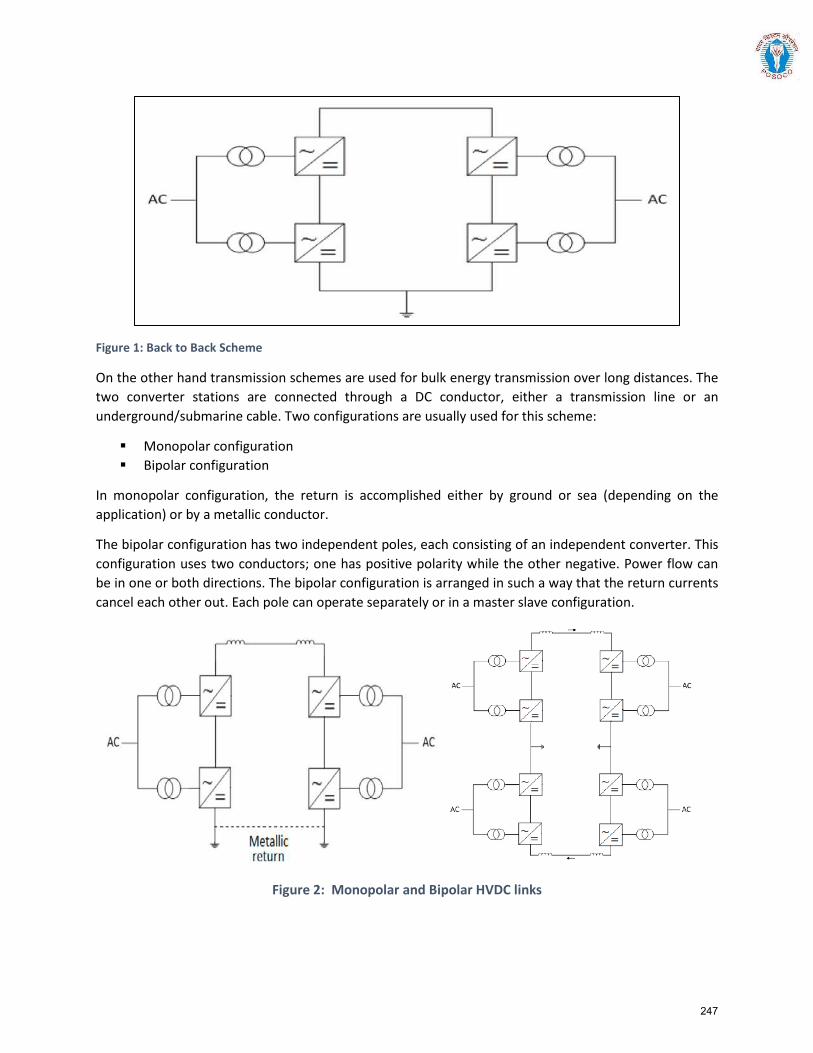
Figure 1: Back to Back Scheme
On the other hand transmission schemes are used for bulk energy transmission over long distances. The two converter stations are connected through a DC conductor, either a transmission line or an underground/submarine cable. Two configurations are usually used for this scheme:
Monopolar configuration Bipolar configuration
In monopolar configuration, the return is accomplished either by ground or sea (depending on the application) or by a metallic conductor.
The bipolar configuration has two independent poles, each consisting of an independent converter. This configuration uses two conductors; one has positive polarity while the other negative. Power flow can be in one or both directions. The bipolar configuration is arranged in such a way that the return currents cancel each other out. Each pole can operate separately or in a master slave configuration.
Figure 2: Monopolar and Bipolar HVDC links
247
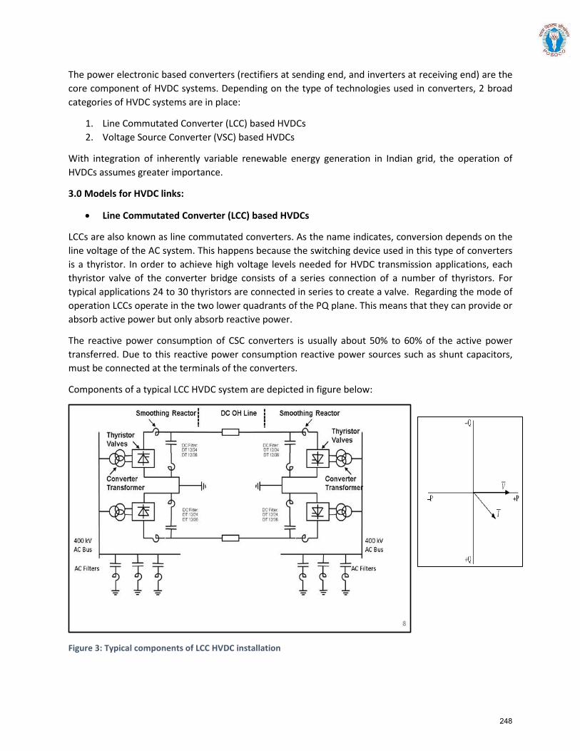
The power electronic based converters (rectifiers at sending end, and inverters at receiving end) are the core component of HVDC systems. Depending on the type of technologies used in converters, 2 broad categories of HVDC systems are in place:
1. Line Commutated Converter (LCC) based HVDCs2. Voltage Source Converter (VSC) based HVDCs
With integration of inherently variable renewable energy generation in Indian grid, the operation of HVDCs assumes greater importance.
3.0 Models for HVDC links:
• Line Commutated Converter (LCC) based HVDCs
LCCs are also known as line commutated converters. As the name indicates, conversion depends on the line voltage of the AC system. This happens because the switching device used in this type of converters is a thyristor. In order to achieve high voltage levels needed for HVDC transmission applications, each thyristor valve of the converter bridge consists of a series connection of a number of thyristors. For typical applications 24 to 30 thyristors are connected in series to create a valve. Regarding the mode of operation LCCs operate in the two lower quadrants of the PQ plane. This means that they can provide or absorb active power but only absorb reactive power.
The reactive power consumption of CSC converters is usually about 50% to 60% of the active power transferred. Due to this reactive power consumption reactive power sources such as shunt capacitors, must be connected at the terminals of the converters.
Components of a typical LCC HVDC system are depicted in figure below:
Figure 3: Typical components of LCC HVDC installation
248
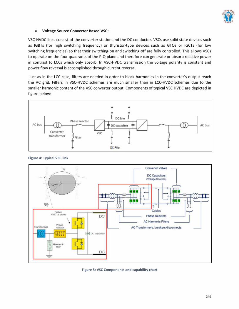
• Voltage Source Converter Based VSC:
VSC-HVDC links consist of the converter station and the DC conductor. VSCs use solid state devices such as IGBTs (for high switching frequency) or thyristor-type devices such as GTOs or IGCTs (for low switching frequencies) so that their switching-on and switching-off are fully controlled. This allows VSCs to operate on the four quadrants of the P-Q plane and therefore can generate or absorb reactive power in contrast to LCCs which only absorb. In VSC-HVDC transmission the voltage polarity is constant and power flow reversal is accomplished through current reversal.
Just as in the LCC case, filters are needed in order to block harmonics in the converter’s output reach the AC grid. Filters in VSC-HVDC schemes are much smaller than in LCC-HVDC schemes due to the smaller harmonic content of the VSC converter output. Components of typical VSC HVDC are depicted in figure below:
Figure 4: Typical VSC link
Figure 5: VSC Components and capability chart
249
Within PSSE the transformer impedance data is only required to be separated if a three winding converter transformer is used and there is reactive power equipment connected to its tertiary winding. In this case, the star-point to secondary data must be entered into the HVDC model however the primary to star-point and star-point to tertiary impedances must be represented explicitly as AC branches within the load-flow case (with appropriate equivalencing if there are multiple transformers in parallel). Otherwise, the primary to secondary converter transformer impedances should be calculated and directly entered into the DC line data with no additional AC components. Please refer to the PSSE manual (PAG Volume 1, Section 6.4.7.5).
250
Formats for submission of modelling data for HVDC Links
Version History:
Version no. Release Date Prepared by* Checked/Issued by* Changes
*Mention Designation and Contact Details
Details submitted:
Details pending:
251
Depending on the nature of technology and usage of components at site (‘As built’), the requirements for steady state and dynamic modelling evolves.
For POSOCO to get access to steady state and transient simulation models of HVDC links in India grid, the following information is required.
1. Load-flow data for the HVDC station: rated DC voltage, rated DC current, rated power, linelength, converter type (LCC or VSC)
2. Electrical Single Line Diagram (SLD) of as built HVDC station depicting:o AC infeed with filter bankso Converter transformerso DC system with filters and other equipment
3. Generic models of HVDC link and auxiliaries. Refer Table-2 for details.4. Encrypted user defined model (UDM) in a format suitable for latest release PSS/E (*.dll files) for
electromechanical transient simulation for HVDC station (in case non-availability of validatedgeneric model)
o User guide for Encrypted models to be provided including instructions on how themodel should be set-up. It should contain all relevant technical information, includingblock diagrams, list of state variables and values / descriptions of all model parameters.
o Corresponding transfer function block diagrams to be providedo Simulation results depicting validation of User-Defined models against actual
measurement (for P, Q, V, I) to be providedo The use of black-box type representation is not preferred.o Models should be suitable for an integration time step between 1ms and 10ms, and
suitable for operation up-to and in excess of 100s.
Apart from this, salient aspects of the physical operation may also be provided, like details of inter-pole compensation, inter-station compensation, metallic return operation, other special cases etc.
252
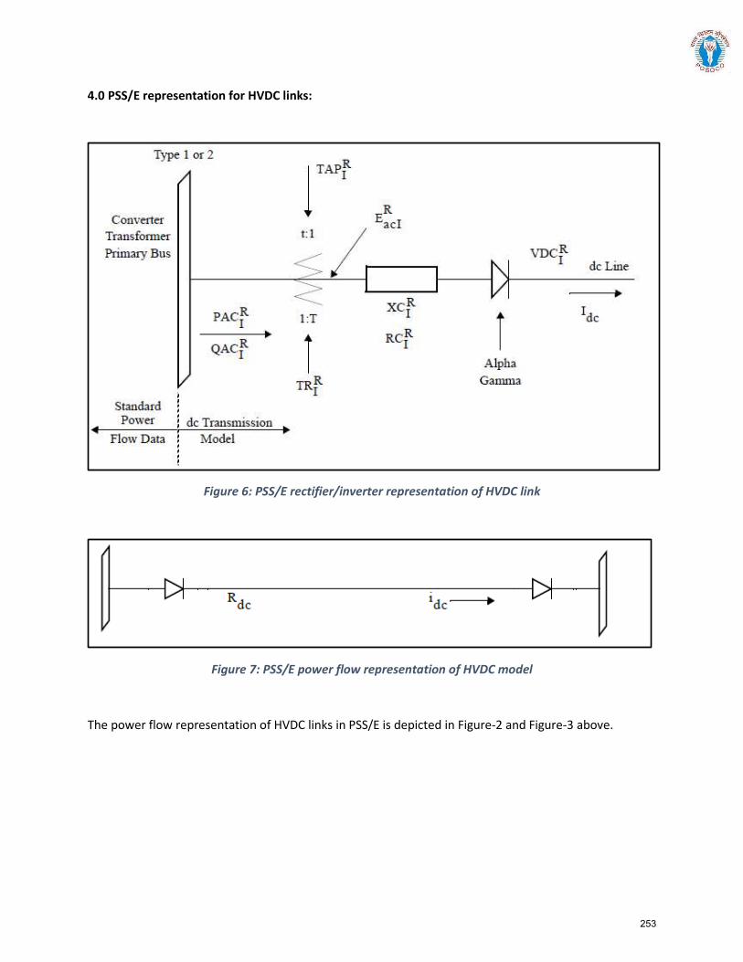
4.0 PSS/E representation for HVDC links:
Figure 6: PSS/E rectifier/inverter representation of HVDC link
Figure 7: PSS/E power flow representation of HVDC model
The power flow representation of HVDC links in PSS/E is depicted in Figure-2 and Figure-3 above.
253
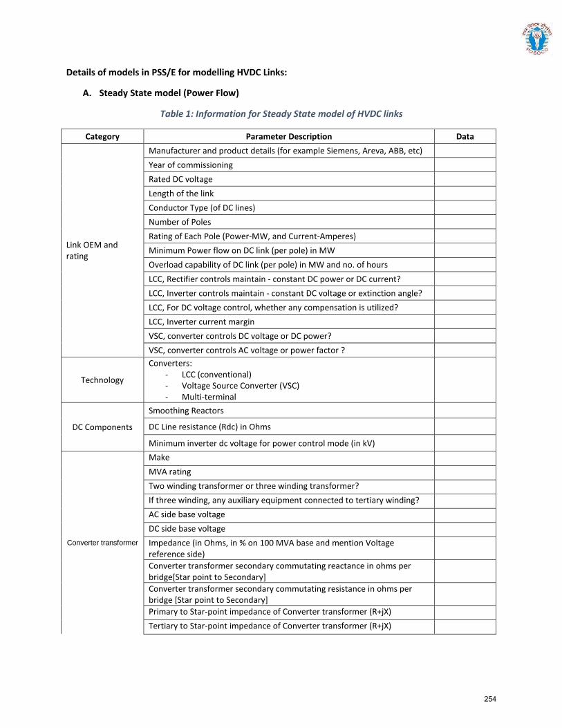
Details of models in PSS/E for modelling HVDC Links:
A. Steady State model (Power Flow)
Table 1: Information for Steady State model of HVDC links
Category Parameter Description Data
Link OEM and rating
Manufacturer and product details (for example Siemens, Areva, ABB, etc) Year of commissioning Rated DC voltage Length of the link Conductor Type (of DC lines) Number of Poles Rating of Each Pole (Power-MW, and Current-Amperes) Minimum Power flow on DC link (per pole) in MW Overload capability of DC link (per pole) in MW and no. of hours LCC, Rectifier controls maintain - constant DC power or DC current? LCC, Inverter controls maintain - constant DC voltage or extinction angle? LCC, For DC voltage control, whether any compensation is utilized? LCC, Inverter current margin VSC, converter controls DC voltage or DC power? VSC, converter controls AC voltage or power factor ?
Technology
Converters: - LCC (conventional) - Voltage Source Converter (VSC) - Multi-terminal
DC Components
Smoothing Reactors
DC Line resistance (Rdc) in Ohms
Minimum inverter dc voltage for power control mode (in kV)
Converter transformer
Make MVA rating Two winding transformer or three winding transformer? If three winding, any auxiliary equipment connected to tertiary winding? AC side base voltage DC side base voltage Impedance (in Ohms, in % on 100 MVA base and mention Voltage reference side)
Converter transformer secondary commutating reactance in ohms per bridge[Star point to Secondary]
Converter transformer secondary commutating resistance in ohms per bridge [Star point to Secondary]
Primary to Star-point impedance of Converter transformer (R+jX) Tertiary to Star-point impedance of Converter transformer (R+jX)
254
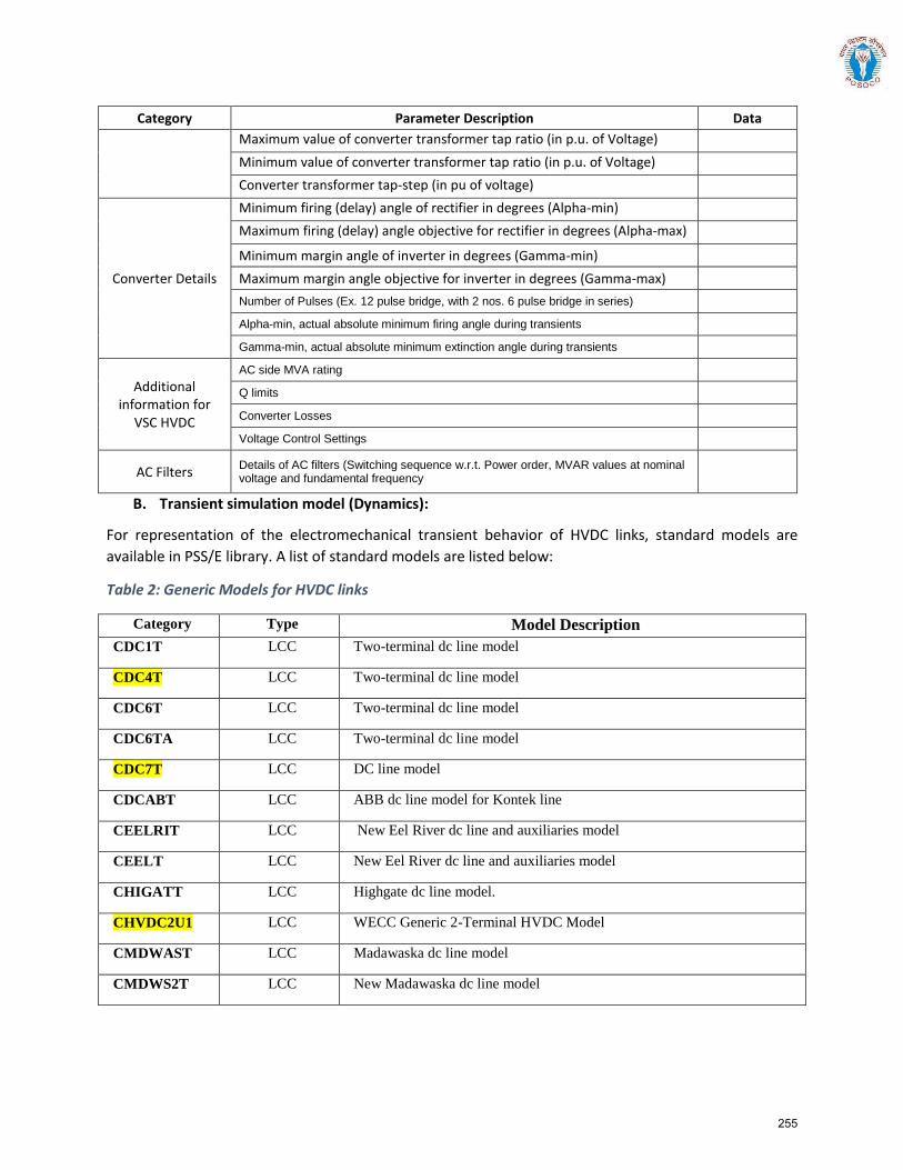
Category Parameter Description Data Maximum value of converter transformer tap ratio (in p.u. of Voltage) Minimum value of converter transformer tap ratio (in p.u. of Voltage) Converter transformer tap-step (in pu of voltage)
Converter Details
Minimum firing (delay) angle of rectifier in degrees (Alpha-min) Maximum firing (delay) angle objective for rectifier in degrees (Alpha-max) Minimum margin angle of inverter in degrees (Gamma-min) Maximum margin angle objective for inverter in degrees (Gamma-max) Number of Pulses (Ex. 12 pulse bridge, with 2 nos. 6 pulse bridge in series) Alpha-min, actual absolute minimum firing angle during transients Gamma-min, actual absolute minimum extinction angle during transients
Additional information for
VSC HVDC
AC side MVA rating Q limits Converter Losses Voltage Control Settings
AC Filters Details of AC filters (Switching sequence w.r.t. Power order, MVAR values at nominal voltage and fundamental frequency
B. Transient simulation model (Dynamics):
For representation of the electromechanical transient behavior of HVDC links, standard models are available in PSS/E library. A list of standard models are listed below:
Table 2: Generic Models for HVDC links
Category Type Model Description CDC1T LCC Two-terminal dc line model
CDC4T LCC Two-terminal dc line model
CDC6T LCC Two-terminal dc line model
CDC6TA LCC Two-terminal dc line model
CDC7T LCC DC line model
CDCABT LCC ABB dc line model for Kontek line
CEELRIT LCC New Eel River dc line and auxiliaries model
CEELT LCC New Eel River dc line and auxiliaries model
CHIGATT LCC Highgate dc line model.
CHVDC2U1 LCC WECC Generic 2-Terminal HVDC Model
CMDWAST LCC Madawaska dc line model
CMDWS2T LCC New Madawaska dc line model
255
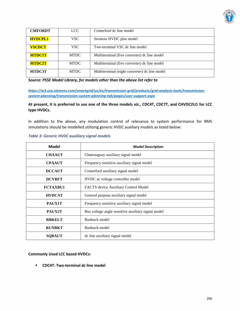
CMFORDT LCC Comerford dc line model
HVDCPL1 VSC Siemens HVDC plus model
VSCDCT VSC Two-terminal VSC dc line model
MTDC1T MTDC Multiterminal (five converter) dc line model
MTDC2T MTDC Multiterminal (five converter) dc line model
MTDC3T MTDC Multiterminal (eight converter) dc line model
Source: PSSE Model Library, for models other than the above list refer to https://w3.usa.siemens.com/smartgrid/us/en/transmission-grid/products/grid-analysis-tools/transmission-system-planning/transmission-system-planning-tab/pages/user-support.aspx
At present, it is preferred to use one of the three models viz., CDC4T, CDC7T, and CHVDC2U1 for LCC type HVDCs. In addition to the above, any modulation control of relevance to system performance for RMS simulations should be modelled utilizing generic HVDC auxiliary models as listed below:
Table 3: Generic HVDC auxiliary signal models
Model Model Description
CHAAUT Chateauguay auxiliary signal model
CPAAUT Frequency sensitive auxiliary signal model
DCCAUT Comerford auxiliary signal model
DCVRFT HVDC ac voltage controller model
FCTAXBU1 FACTS device Auxiliary Control Model
HVDCAT General purpose auxiliary signal model
PAUX1T Frequency sensitive auxiliary signal model
PAUX2T Bus voltage angle sensitive auxiliary signal model
RBKELT Runback model
RUNBKT Runback model
SQBAUT dc line auxiliary signal model
Commonly Used LCC based HVDCs:
CDC4T: Two-terminal dc line model
256
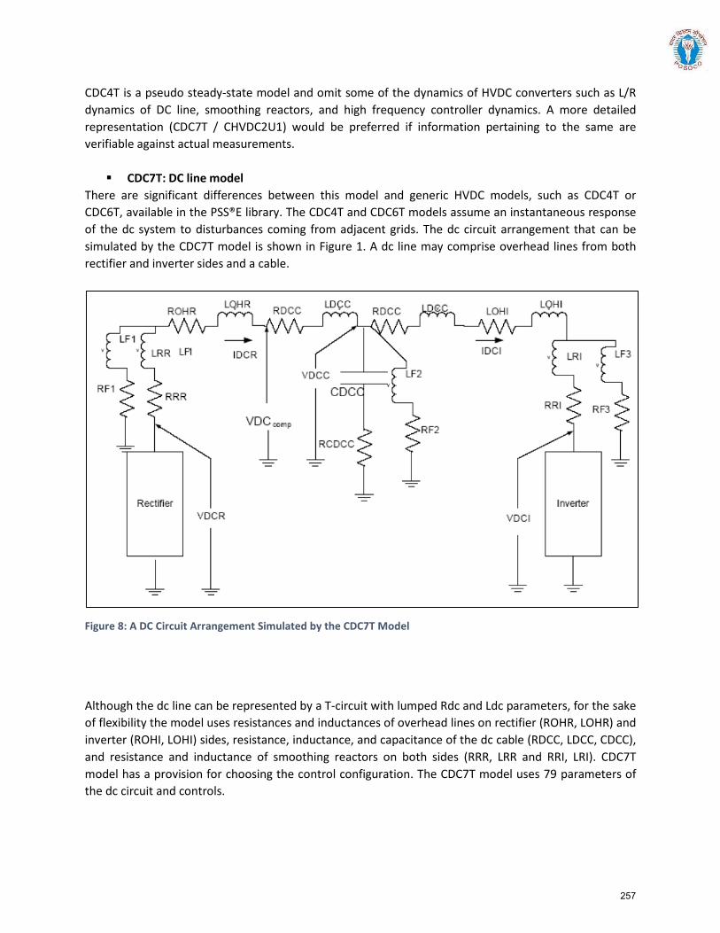
CDC4T is a pseudo steady-state model and omit some of the dynamics of HVDC converters such as L/R dynamics of DC line, smoothing reactors, and high frequency controller dynamics. A more detailed representation (CDC7T / CHVDC2U1) would be preferred if information pertaining to the same are verifiable against actual measurements.
CDC7T: DC line model There are significant differences between this model and generic HVDC models, such as CDC4T or CDC6T, available in the PSS®E library. The CDC4T and CDC6T models assume an instantaneous response of the dc system to disturbances coming from adjacent grids. The dc circuit arrangement that can be simulated by the CDC7T model is shown in Figure 1. A dc line may comprise overhead lines from both rectifier and inverter sides and a cable.
Figure 8: A DC Circuit Arrangement Simulated by the CDC7T Model
Although the dc line can be represented by a T-circuit with lumped Rdc and Ldc parameters, for the sake of flexibility the model uses resistances and inductances of overhead lines on rectifier (ROHR, LOHR) and inverter (ROHI, LOHI) sides, resistance, inductance, and capacitance of the dc cable (RDCC, LDCC, CDCC), and resistance and inductance of smoothing reactors on both sides (RRR, LRR and RRI, LRI). CDC7T model has a provision for choosing the control configuration. The CDC7T model uses 79 parameters of the dc circuit and controls.
257
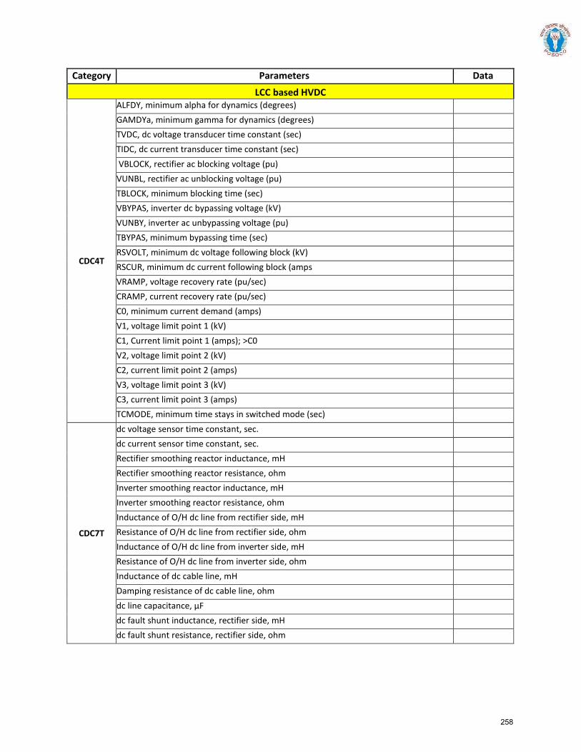
Category Parameters Data
LCC based HVDC
CDC4T
ALFDY, minimum alpha for dynamics (degrees) GAMDYa, minimum gamma for dynamics (degrees) TVDC, dc voltage transducer time constant (sec) TIDC, dc current transducer time constant (sec) VBLOCK, rectifier ac blocking voltage (pu) VUNBL, rectifier ac unblocking voltage (pu) TBLOCK, minimum blocking time (sec) VBYPAS, inverter dc bypassing voltage (kV) VUNBY, inverter ac unbypassing voltage (pu) TBYPAS, minimum bypassing time (sec) RSVOLT, minimum dc voltage following block (kV) RSCUR, minimum dc current following block (amps VRAMP, voltage recovery rate (pu/sec) CRAMP, current recovery rate (pu/sec) C0, minimum current demand (amps) V1, voltage limit point 1 (kV) C1, Current limit point 1 (amps); >C0 V2, voltage limit point 2 (kV) C2, current limit point 2 (amps) V3, voltage limit point 3 (kV) C3, current limit point 3 (amps) TCMODE, minimum time stays in switched mode (sec)
CDC7T
dc voltage sensor time constant, sec. dc current sensor time constant, sec. Rectifier smoothing reactor inductance, mH Rectifier smoothing reactor resistance, ohm Inverter smoothing reactor inductance, mH Inverter smoothing reactor resistance, ohm Inductance of O/H dc line from rectifier side, mH Resistance of O/H dc line from rectifier side, ohm Inductance of O/H dc line from inverter side, mH Resistance of O/H dc line from inverter side, ohm Inductance of dc cable line, mH Damping resistance of dc cable line, ohm dc line capacitance, µF dc fault shunt inductance, rectifier side, mH dc fault shunt resistance, rectifier side, ohm
258
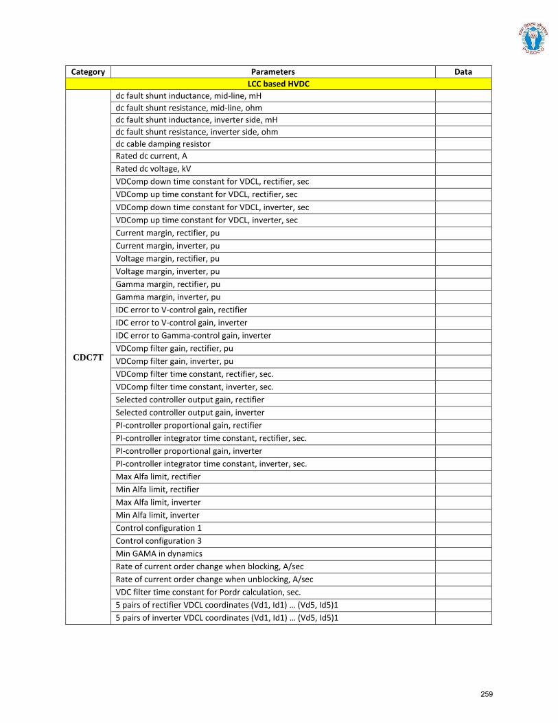
Category Parameters Data LCC based HVDC
CDC7T
dc fault shunt inductance, mid-line, mH dc fault shunt resistance, mid-line, ohm dc fault shunt inductance, inverter side, mH dc fault shunt resistance, inverter side, ohm dc cable damping resistor Rated dc current, A Rated dc voltage, kV VDComp down time constant for VDCL, rectifier, sec VDComp up time constant for VDCL, rectifier, sec VDComp down time constant for VDCL, inverter, sec VDComp up time constant for VDCL, inverter, sec Current margin, rectifier, pu Current margin, inverter, pu Voltage margin, rectifier, pu Voltage margin, inverter, pu Gamma margin, rectifier, pu Gamma margin, inverter, pu IDC error to V-control gain, rectifier IDC error to V-control gain, inverter IDC error to Gamma-control gain, inverter VDComp filter gain, rectifier, pu VDComp filter gain, inverter, pu VDComp filter time constant, rectifier, sec. VDComp filter time constant, inverter, sec. Selected controller output gain, rectifier Selected controller output gain, inverter PI-controller proportional gain, rectifier PI-controller integrator time constant, rectifier, sec. PI-controller proportional gain, inverter PI-controller integrator time constant, inverter, sec. Max Alfa limit, rectifier Min Alfa limit, rectifier Max Alfa limit, inverter Min Alfa limit, inverter Control configuration 1 Control configuration 3 Min GAMA in dynamics Rate of current order change when blocking, A/sec Rate of current order change when unblocking, A/sec VDC filter time constant for Pordr calculation, sec. 5 pairs of rectifier VDCL coordinates (Vd1, Id1) … (Vd5, Id5)1 5 pairs of inverter VDCL coordinates (Vd1, Id1) … (Vd5, Id5)1
259
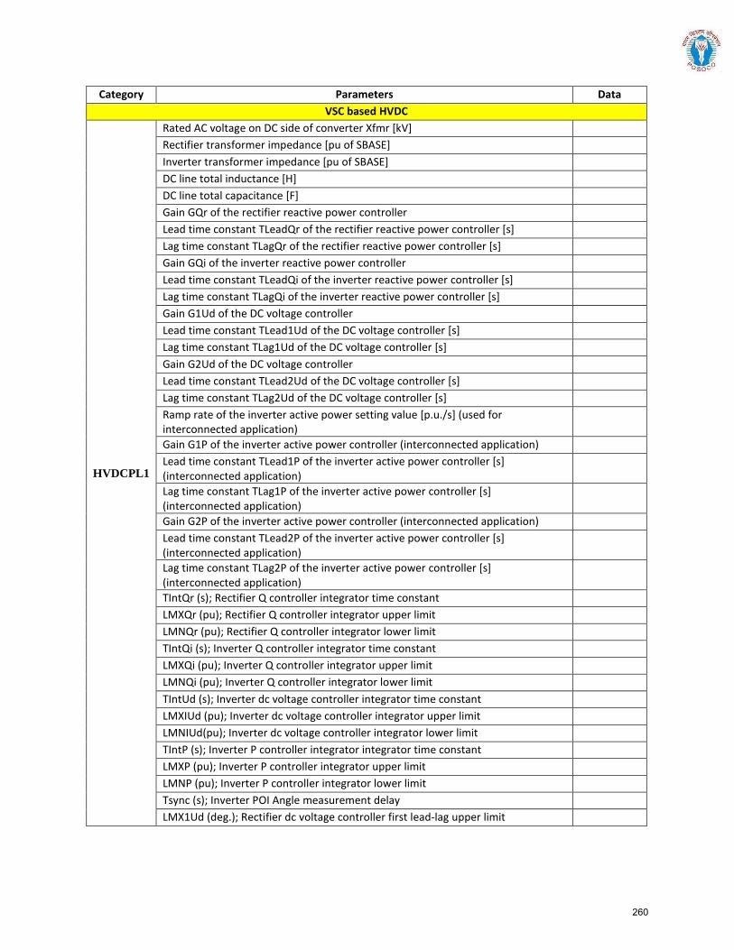
Category Parameters Data VSC based HVDC
HVDCPL1
Rated AC voltage on DC side of converter Xfmr [kV] Rectifier transformer impedance [pu of SBASE] Inverter transformer impedance [pu of SBASE] DC line total inductance [H] DC line total capacitance [F] Gain GQr of the rectifier reactive power controller Lead time constant TLeadQr of the rectifier reactive power controller [s] Lag time constant TLagQr of the rectifier reactive power controller [s] Gain GQi of the inverter reactive power controller Lead time constant TLeadQi of the inverter reactive power controller [s] Lag time constant TLagQi of the inverter reactive power controller [s] Gain G1Ud of the DC voltage controller Lead time constant TLead1Ud of the DC voltage controller [s] Lag time constant TLag1Ud of the DC voltage controller [s] Gain G2Ud of the DC voltage controller Lead time constant TLead2Ud of the DC voltage controller [s] Lag time constant TLag2Ud of the DC voltage controller [s] Ramp rate of the inverter active power setting value [p.u./s] (used for interconnected application)
Gain G1P of the inverter active power controller (interconnected application) Lead time constant TLead1P of the inverter active power controller [s] (interconnected application)
Lag time constant TLag1P of the inverter active power controller [s] (interconnected application)
Gain G2P of the inverter active power controller (interconnected application) Lead time constant TLead2P of the inverter active power controller [s] (interconnected application)
Lag time constant TLag2P of the inverter active power controller [s] (interconnected application)
TIntQr (s); Rectifier Q controller integrator time constant LMXQr (pu); Rectifier Q controller integrator upper limit LMNQr (pu); Rectifier Q controller integrator lower limit TIntQi (s); Inverter Q controller integrator time constant LMXQi (pu); Inverter Q controller integrator upper limit LMNQi (pu); Inverter Q controller integrator lower limit TIntUd (s); Inverter dc voltage controller integrator time constant LMXIUd (pu); Inverter dc voltage controller integrator upper limit LMNIUd(pu); Inverter dc voltage controller integrator lower limit TIntP (s); Inverter P controller integrator integrator time constant LMXP (pu); Inverter P controller integrator upper limit LMNP (pu); Inverter P controller integrator lower limit Tsync (s); Inverter POI Angle measurement delay LMX1Ud (deg.); Rectifier dc voltage controller first lead-lag upper limit
260
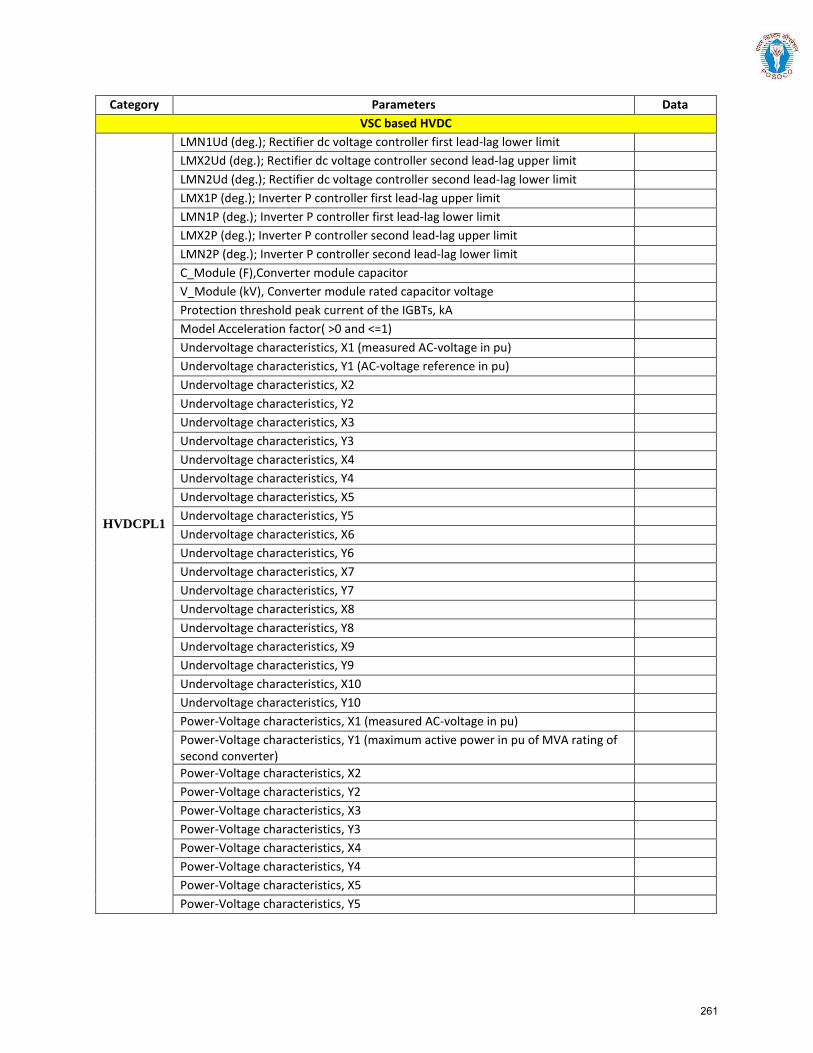
Category Parameters Data VSC based HVDC
HVDCPL1
LMN1Ud (deg.); Rectifier dc voltage controller first lead-lag lower limit LMX2Ud (deg.); Rectifier dc voltage controller second lead-lag upper limit LMN2Ud (deg.); Rectifier dc voltage controller second lead-lag lower limit LMX1P (deg.); Inverter P controller first lead-lag upper limit LMN1P (deg.); Inverter P controller first lead-lag lower limit LMX2P (deg.); Inverter P controller second lead-lag upper limit LMN2P (deg.); Inverter P controller second lead-lag lower limit C_Module (F),Converter module capacitor V_Module (kV), Converter module rated capacitor voltage Protection threshold peak current of the IGBTs, kA Model Acceleration factor( >0 and <=1) Undervoltage characteristics, X1 (measured AC-voltage in pu) Undervoltage characteristics, Y1 (AC-voltage reference in pu) Undervoltage characteristics, X2 Undervoltage characteristics, Y2 Undervoltage characteristics, X3 Undervoltage characteristics, Y3 Undervoltage characteristics, X4 Undervoltage characteristics, Y4 Undervoltage characteristics, X5 Undervoltage characteristics, Y5 Undervoltage characteristics, X6 Undervoltage characteristics, Y6 Undervoltage characteristics, X7 Undervoltage characteristics, Y7 Undervoltage characteristics, X8 Undervoltage characteristics, Y8 Undervoltage characteristics, X9 Undervoltage characteristics, Y9 Undervoltage characteristics, X10 Undervoltage characteristics, Y10 Power-Voltage characteristics, X1 (measured AC-voltage in pu) Power-Voltage characteristics, Y1 (maximum active power in pu of MVA rating of second converter)
Power-Voltage characteristics, X2 Power-Voltage characteristics, Y2 Power-Voltage characteristics, X3 Power-Voltage characteristics, Y3 Power-Voltage characteristics, X4 Power-Voltage characteristics, Y4 Power-Voltage characteristics, X5 Power-Voltage characteristics, Y5
261
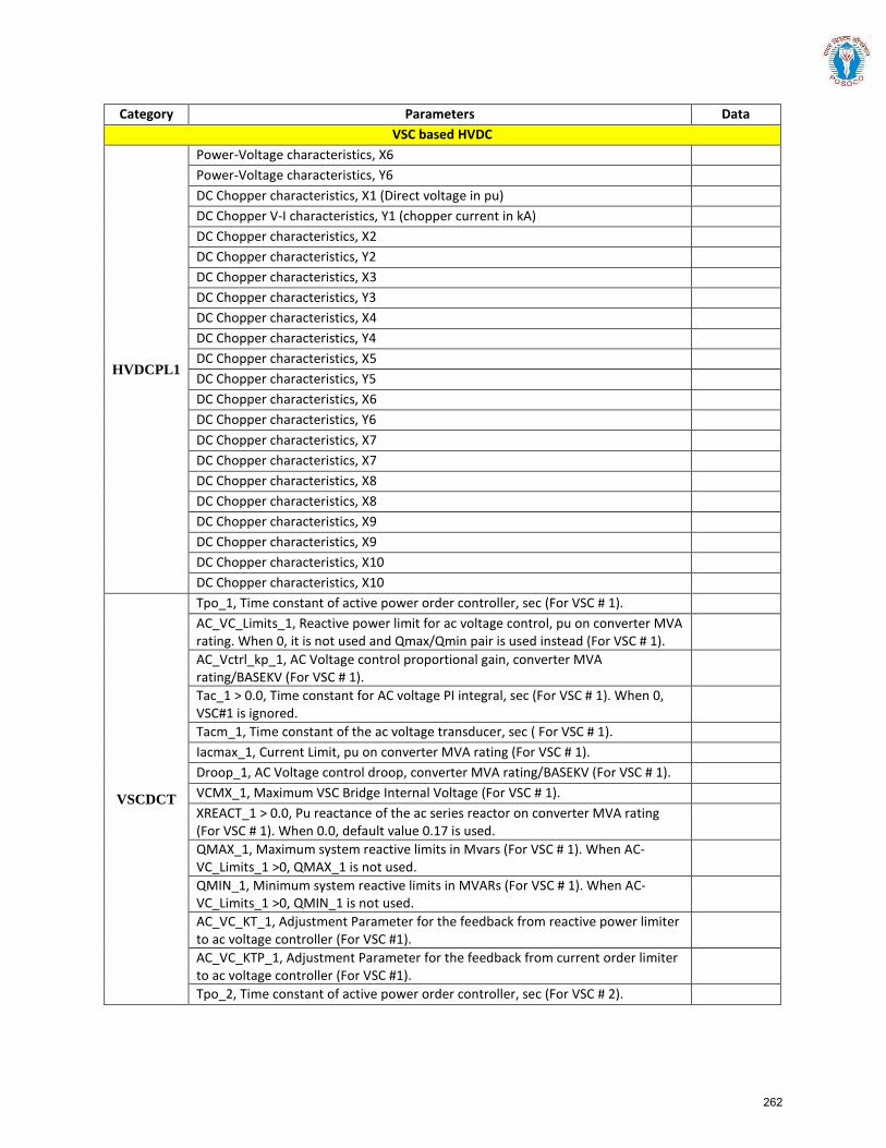
Category Parameters Data VSC based HVDC
HVDCPL1
Power-Voltage characteristics, X6 Power-Voltage characteristics, Y6 DC Chopper characteristics, X1 (Direct voltage in pu) DC Chopper V-I characteristics, Y1 (chopper current in kA) DC Chopper characteristics, X2 DC Chopper characteristics, Y2 DC Chopper characteristics, X3 DC Chopper characteristics, Y3 DC Chopper characteristics, X4 DC Chopper characteristics, Y4 DC Chopper characteristics, X5 DC Chopper characteristics, Y5 DC Chopper characteristics, X6 DC Chopper characteristics, Y6 DC Chopper characteristics, X7 DC Chopper characteristics, X7 DC Chopper characteristics, X8 DC Chopper characteristics, X8 DC Chopper characteristics, X9 DC Chopper characteristics, X9 DC Chopper characteristics, X10 DC Chopper characteristics, X10
VSCDCT
Tpo_1, Time constant of active power order controller, sec (For VSC # 1). AC_VC_Limits_1, Reactive power limit for ac voltage control, pu on converter MVA rating. When 0, it is not used and Qmax/Qmin pair is used instead (For VSC # 1).
AC_Vctrl_kp_1, AC Voltage control proportional gain, converter MVA rating/BASEKV (For VSC # 1).
Tac_1 > 0.0, Time constant for AC voltage PI integral, sec (For VSC # 1). When 0, VSC#1 is ignored.
Tacm_1, Time constant of the ac voltage transducer, sec ( For VSC # 1). Iacmax_1, Current Limit, pu on converter MVA rating (For VSC # 1). Droop_1, AC Voltage control droop, converter MVA rating/BASEKV (For VSC # 1). VCMX_1, Maximum VSC Bridge Internal Voltage (For VSC # 1). XREACT_1 > 0.0, Pu reactance of the ac series reactor on converter MVA rating (For VSC # 1). When 0.0, default value 0.17 is used.
QMAX_1, Maximum system reactive limits in Mvars (For VSC # 1). When AC-VC_Limits_1 >0, QMAX_1 is not used.
QMIN_1, Minimum system reactive limits in MVARs (For VSC # 1). When AC-VC_Limits_1 >0, QMIN_1 is not used.
AC_VC_KT_1, Adjustment Parameter for the feedback from reactive power limiter to ac voltage controller (For VSC #1).
AC_VC_KTP_1, Adjustment Parameter for the feedback from current order limiter to ac voltage controller (For VSC #1).
Tpo_2, Time constant of active power order controller, sec (For VSC # 2).
262
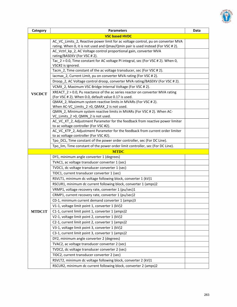
Category Parameters Data VSC based HVDC
VSCDCT
AC_VC_Limits_2, Reactive power limit for ac voltage control, pu on converter MVA rating. When 0, it is not used and Qmax/Qmin pair is used instead (For VSC # 2).
AC_Vctrl_kp_2, AC Voltage control proportional gain, converter MVA rating/BASEKV (For VSC # 2).
Tac_2 > 0.0, Time constant for AC voltage PI integral, sec (For VSC # 2). When 0, VSC#2 is ignored.
Tacm_2, Time constant of the ac voltage transducer, sec (For VSC # 2). Iacmax_2, Current Limit, pu on converter MVA rating (For VSC # 2). Droop_2, AC Voltage control droop, converter MVA rating/BASEKV (For VSC # 2). VCMX_2, Maximum VSC Bridge Internal Voltage (For VSC # 2). XREACT_2 > 0.0, Pu reactance of the ac series reactor on converter MVA rating (For VSC # 2). When 0.0, default value 0.17 is used.
QMAX_2, Maximum system reactive limits in MVARs (For VSC # 2). When AC-VC_Limits_2 >0, QMAX_2 is not used.
QMIN_2, Minimum system reactive limits in MVARs (For VSC # 2). When AC-VC_Limits_2 >0, QMIN_2 is not used.
AC_VC_KT_2, Adjustment Parameter for the feedback from reactive power limiter to ac voltage controller (For VSC #2).
AC_VC_KTP_2, Adjustment Parameter for the feedback from current order limiter to ac voltage controller (For VSC #2).
Tpo_DCL, Time constant of the power order controller, sec (For DC Line). Tpo_lim, Time constant of the power order limit controller, sec (For DC Line).
MTDC
MTDC1T
DY1, minimum angle converter 1 (degrees) TVAC1, ac voltage transducer converter 1 (sec) TVDC1, dc voltage transducer converter 1 (sec) TIDC1, current transducer converter 1 (sec) RSVLT1, minimum dc voltage following block, converter 1 (kV)1 RSCUR1, minimum dc current following block, converter 1 (amps)2 VRMP1, voltage recovery rate, converter 1 (pu/sec)1 CRMP1, current recovery rate, converter 1 (pu/sec)2 C0-1, minimum current demand converter 1 (amps)3 V1-1, voltage limit point 1, converter 1 (kV)2 C1-1, current limit point 1, converter 1 (amps)2 V2-1, voltage limit point 2, converter 1 (kV)2 C2-1, current limit point 2, converter 1 (amps)2 V3-1, voltage limit point 3, converter 1 (kV)2 C3-1, current limit point 3, converter 1 (amps)2 DY2, minimum angle converter 2 (degrees) TVAC2, ac voltage transducer converter 2 (sec) TVDC2, dc voltage transducer converter 2 (sec) TIDC2, current transducer converter 2 (sec) RSVLT2, minimum dc voltage following block, converter 2 (kV)1 RSCUR2, minimum dc current following block, converter 2 (amps)2
263
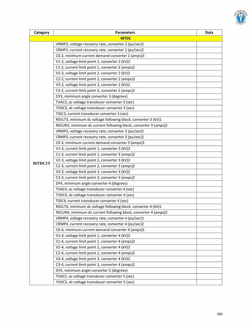
Category Parameters Data MTDC
MTDC1T
VRMP2, voltage recovery rate, converter 2 (pu/sec)1 CRMP2, current recovery rate, converter 2 (pu/sec)2 C0-2, minimum current demand converter 2 (amps)3 V1-2, voltage limit point 1, converter 2 (kV)2 C1-2, current limit point 1, converter 2 (amps)2 V2-2, voltage limit point 2, converter 2 (kV)2 C2-2, current limit point 2, converter 2 (amps)2 V3-2, voltage limit point 3, converter 2 (kV)2 C3-2, current limit point 3, converter 2 (amps)2 DY3, minimum angle converter 3 (degrees) TVAC3, ac voltage transducer converter 3 (sec) TVDC3, dc voltage transducer converter 3 (sec) TIDC3, current transducer converter 3 (sec) RSVLT3, minimum dc voltage following block, converter 3 (kV)1 RSCUR3, minimum dc current following block, converter 3 (amps)2 VRMP3, voltage recovery rate, converter 3 (pu/sec)1 CRMP3, current recovery rate, converter 3 (pu/sec)2 C0-3, minimum current demand converter 3 (amps)3 V1-3, current limit point 1, converter 3 (kV)2 C1-3, current limit point 1, converter 3 (amps)2 V2-3, voltage limit point 2, converter 3 (kV)2 C2-3, current limit point 2, converter 3 (amps)2 V3-3, voltage limit point 3, converter 3 (kV)2 C3-3, current limit point 3, converter 3 (amps)2 DY4, minimum angle converter 4 (degrees) TVAC4, ac voltage transducer converter 4 (sec) TVDC4, dc voltage transducer converter 4 (sec) TIDC4, current transducer converter 4 (sec) RSVLT4, minimum dc voltage following block, converter 4 (kV)1 RSCUR4, minimum dc current following block, converter 4 (amps)2 VRMP4, voltage recovery rate, converter 4 (pu/sec)1 CRMP4, current recovery rate, converter 4 (pu/sec)2 C0-4, minimum current demand converter 4 (amps)3 V1-4, voltage limit point 1, converter 4 (kV)2 C1-4, current limit point 1, converter 4 (amps)2 V2-4, voltage limit point 2, converter 4 (kV)2 C2-4, current limit point 2, converter 4 (amps)2 V3-4, voltage limit point 3, converter 4 (kV)2 C3-4, current limit point 3, converter 4 (amps)2 DY5, minimum angle converter 5 (degrees) TVAC5, ac voltage transducer converter 5 (sec) TVDC5, dc voltage transducer converter 5 (sec)
264

Category Parameters Data MTDC
MTDC1T
TIDC5, current transducer converter 5 (sec) RSVLT5, minimum dc voltage following block, converter 5 (kV)1 RSCUR5, minimum dc current following block, converter 5 (amps)2 VRMP5, Voltage recovery rate, converter 5 (pu/sec)1 CRMP5, current recovery rate, converter 5 (pu/sec)2 C0-5, minimum current demand converter 5 (amps)3 V1-5, voltage limit point 1, converter 5 (kV)2 C1-5, current limit point 1, converter 5 (amps)2 V2-5, voltage limit point 2, converter 5 (kV)2 C2-5, current limit point 2, converter 5 (amps)2 V3-5, voltage limit point 3, converter 5 (kV)2 C3-5, current limit point 3, converter 5 (amps)2 TCMODE (sec)
MTDC2T
DY1, minimum angle converter 1 (degrees) TVAC1, ac voltage transducer converter 1 (sec) TVDC1, dc voltage transducer converter 1 (sec) TIDC1, current transducer converter 1 (sec) RSVLT1, minimum dc voltage following block, converter 1 (kV)1 RSCUR1, minimum dc current following block, converter 1 (amps) VRMP1, voltage recovery rate, converter 1 (pu/sec)1 CRMP1, current recover rate, converter 1 (pu/sec) C0-1, minimum current demand converter 1 (amps) V1-1, minimum current demand converter 1 C1-1, minimum current demand converter 1 (amps) V2-1, minimum current demand converter 1 C2-1, minimum current demand converter 1 (amps) V3-1, minimum current demand converter 1 C3-1, minimum current demand converter 1 (amps) DY2, minimum angle converter 2 (degrees) TVAC2, ac voltage transducer converter 2 (sec) TVDC2, dc voltage transducer converter 2 (sec) TIDC2, current transducer converter 2 (sec) RSVLT2, minimum dc voltage following block, converter 2 (kV)1 RSCUR2, minimum dc current following block, converter 2 (amps) VRMP2, voltage recovery rate, converter 2 (pu/sec)1 CRMP2, current recover rate, converter 2 (pu/sec) C0-2, minimum current demand converter 2 (amps) V1-2, minimum current demand converter 2 C1-2, minimum current demand converter 2 (amps) V2-2, minimum current demand converter 2 C2-2, minimum current demand converter 2 (amps) V3-2, minimum current demand converter 2
265
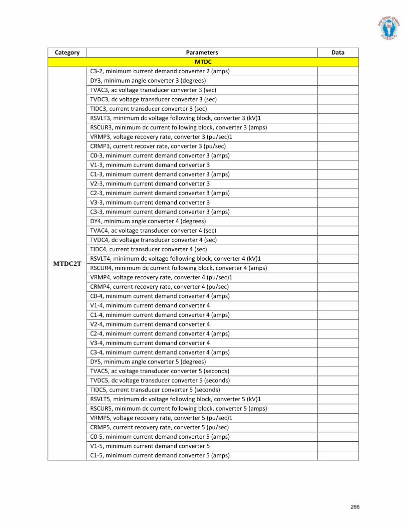
Category Parameters Data MTDC
MTDC2T
C3-2, minimum current demand converter 2 (amps) DY3, minimum angle converter 3 (degrees) TVAC3, ac voltage transducer converter 3 (sec) TVDC3, dc voltage transducer converter 3 (sec) TIDC3, current transducer converter 3 (sec) RSVLT3, minimum dc voltage following block, converter 3 (kV)1 RSCUR3, minimum dc current following block, converter 3 (amps) VRMP3, voltage recovery rate, converter 3 (pu/sec)1 CRMP3, current recover rate, converter 3 (pu/sec) C0-3, minimum current demand converter 3 (amps) V1-3, minimum current demand converter 3 C1-3, minimum current demand converter 3 (amps) V2-3, minimum current demand converter 3 C2-3, minimum current demand converter 3 (amps) V3-3, minimum current demand converter 3 C3-3, minimum current demand converter 3 (amps) DY4, minimum angle converter 4 (degrees) TVAC4, ac voltage transducer converter 4 (sec) TVDC4, dc voltage transducer converter 4 (sec) TIDC4, current transducer converter 4 (sec) RSVLT4, minimum dc voltage following block, converter 4 (kV)1 RSCUR4, minimum dc current following block, converter 4 (amps) VRMP4, voltage recovery rate, converter 4 (pu/sec)1 CRMP4, current recovery rate, converter 4 (pu/sec) C0-4, minimum current demand converter 4 (amps) V1-4, minimum current demand converter 4 C1-4, minimum current demand converter 4 (amps) V2-4, minimum current demand converter 4 C2-4, minimum current demand converter 4 (amps) V3-4, minimum current demand converter 4 C3-4, minimum current demand converter 4 (amps) DY5, minimum angle converter 5 (degrees) TVAC5, ac voltage transducer converter 5 (seconds) TVDC5, dc voltage transducer converter 5 (seconds) TIDC5, current transducer converter 5 (seconds) RSVLT5, minimum dc voltage following block, converter 5 (kV)1 RSCUR5, minimum dc current following block, converter 5 (amps) VRMP5, voltage recovery rate, converter 5 (pu/sec)1 CRMP5, current recovery rate, converter 5 (pu/sec) C0-5, minimum current demand converter 5 (amps) V1-5, minimum current demand converter 5 C1-5, minimum current demand converter 5 (amps)
266
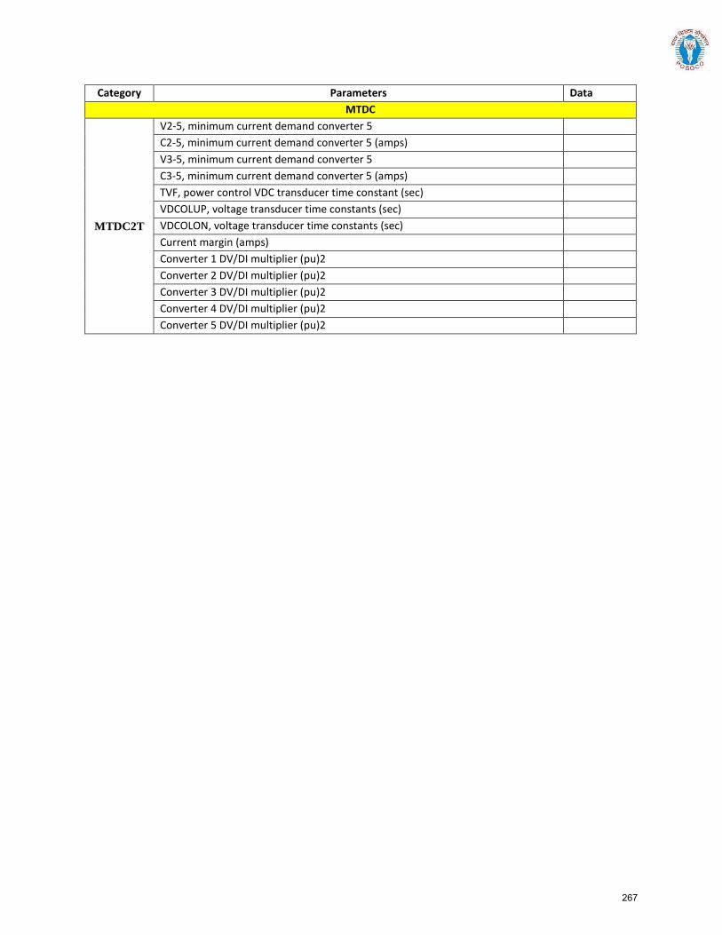
Category Parameters Data MTDC
MTDC2T
V2-5, minimum current demand converter 5 C2-5, minimum current demand converter 5 (amps) V3-5, minimum current demand converter 5 C3-5, minimum current demand converter 5 (amps) TVF, power control VDC transducer time constant (sec) VDCOLUP, voltage transducer time constants (sec) VDCOLON, voltage transducer time constants (sec) Current margin (amps) Converter 1 DV/DI multiplier (pu)2 Converter 2 DV/DI multiplier (pu)2 Converter 3 DV/DI multiplier (pu)2 Converter 4 DV/DI multiplier (pu)2 Converter 5 DV/DI multiplier (pu)2
267
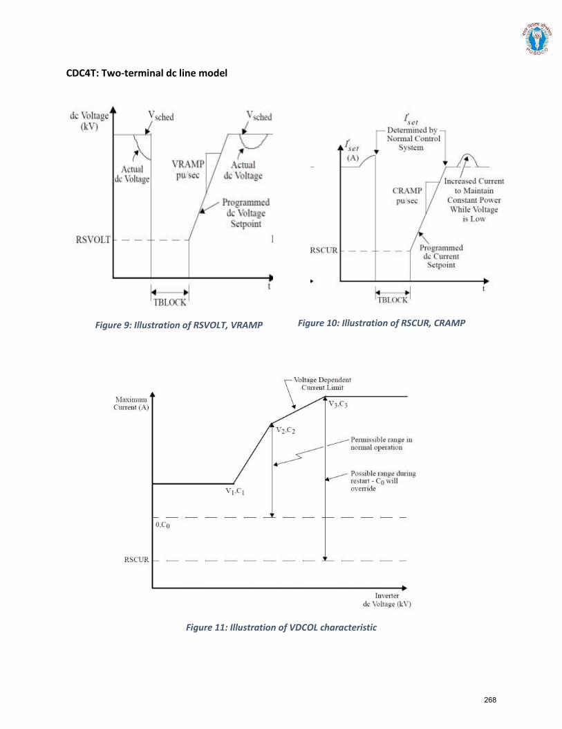
CDC4T: Two-terminal dc line model
Figure 9: Illustration of RSVOLT, VRAMP Figure 10: Illustration of RSCUR, CRAMP
Figure 11: Illustration of VDCOL characteristic
268
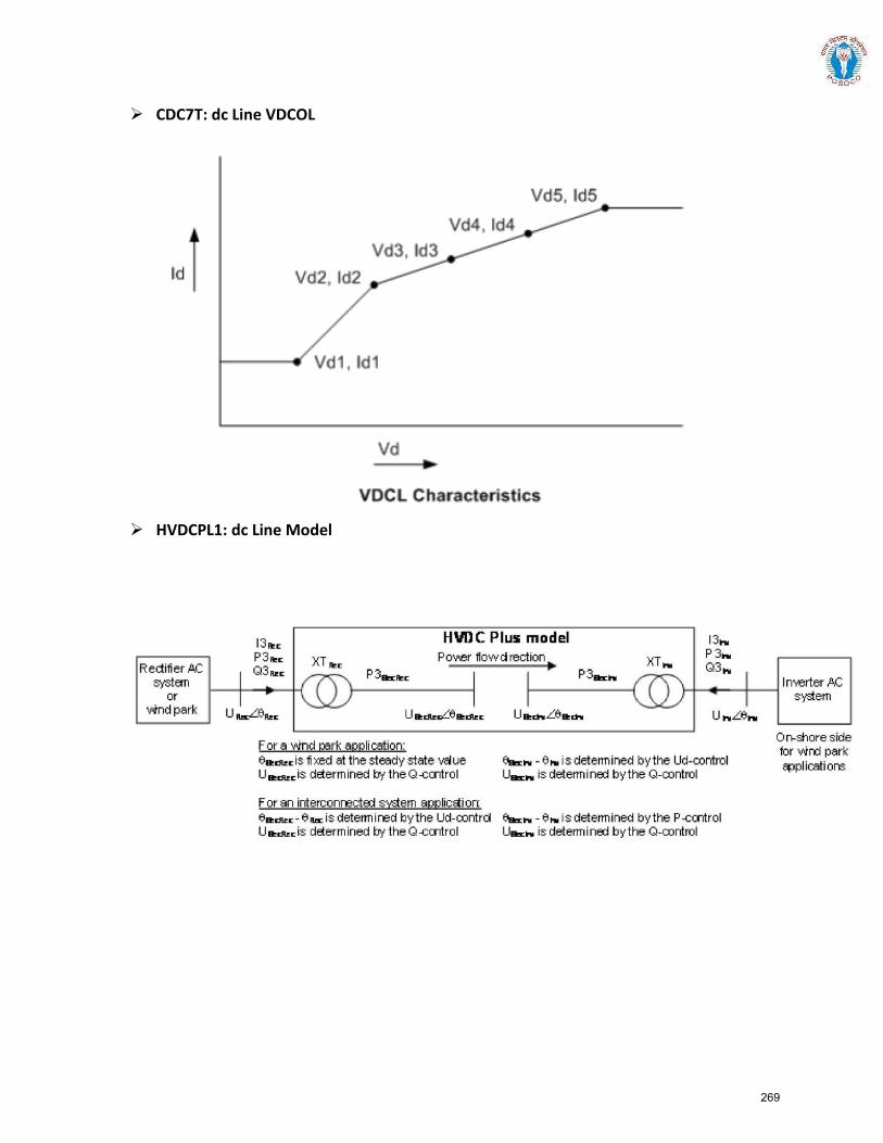
CDC7T: dc Line VDCOL
HVDCPL1: dc Line Model
269
Section 4:
Procedure for interconnection of a STATCOM/SVC and issue of certificate
of successful trial operation by Regional Load Despatch Centres (RLDCs)
270
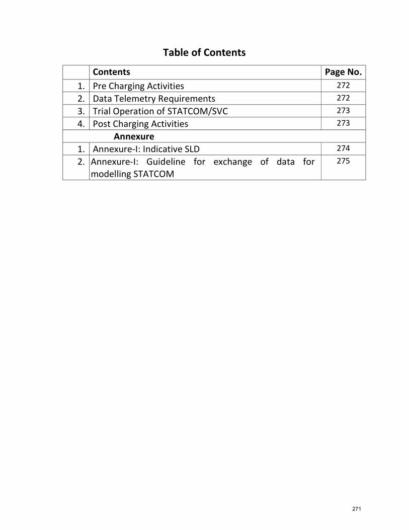
Table of Contents
Contents Page No. 1. Pre Charging Activities 272
2. Data Telemetry Requirements 272
3. Trial Operation of STATCOM/SVC 273
4. Post Charging Activities 273
Annexure 1. Annexure-I: Indicative SLD 274
2. Annexure-I: Guideline for exchange of data for modelling STATCOM
275
271
Procedure for interconnection of a STATCOM/SVC and issue of certificate of successful trial operation by Regional Load Despatch Centres (RLDCs)1. Pre Charging Activities
a. The procedure in place for first time charging of transmission elements shall
be followed for STATCOM as well and all the timelines & formats mentioned in
that procedure shall be applicable to STATCOM as well.
b. Approval of first time charging of STATCOM shall be provided by respective
RLDC in line with these guidelines and the procedure for facilitating first time
charging of new transmission elements already in place.
c. Following information shall be provided by the owners of STATCOM before
first time charging of STATCOM
Number of Blocks and rating of each blockii.
Detailed Single Line Diagram of STATCOMiii.
V/I Characteristicsiv.
Coupling Transfer HV /LV ratingv.
Coupling Transformer Rating / Impedancevi.
MSR and MSC design parametersvii.
Different Operating Modesviii.
IEEE Standard Dynamic Modelix.
Whether POD is enabled and tuned. If No, then reasons for the same.x.
Any other information as required by RLDC
d. Owners of the STATCOM shall submit a detailed proposal for testing at least
10 days in advance along with intimation of first time charging (Format A).
e. The auxiliary consumption of STATCOM is generally drawn from the tertiary of
the 400/220/33 kV transformer at the substation. The meter reading of this
transformer would include the auxiliary consumption of STATCOM as well.
Therefore, a No Objection Certificate (NOC) from the local DISCOM and SLDC
would also be provided by the owner of the STATCOM.
f. Special Energy Meter shall be installed by CTU at the coupling transformer as
well in consultation with concerned RLDC. The dummy meter readings shall be
sent to respective RLDC along with B type formats.
2. Data Telemetry Requirements
a. Following SCADA points shall be made available to the NLDC/RLDC control
room
i. Qstat : Reactive power exchange with STATCOM
ii. QMSR & QMSC : Reactive power exchange with Mechanically switched
Reactor and Mechanically Switched capacitor
iii. VHV & VMV : Voltage of high voltage bus and Medium Voltage bus where
STATCOM is connected
iv. QTra : Reactive power through the coupling transformer
i. Modelling data from STATCOM stations(Annexure-II(B))
xi.
272
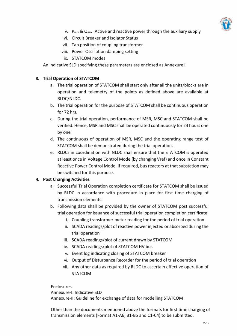
v. Paux & Qaux : Active and reactive power through the auxiliary supply
vi. Circuit Breaker and Isolator Status
vii. Tap position of coupling transformer
viii. Power Oscillation damping setting
ix. STATCOM modes
An indicative SLD specifying these parameters are enclosed as Annexure I.
3. Trial Operation of STATCOM
a. The trial operation of STATCOM shall start only after all the units/blocks are in
operation and telemetry of the points as defined above are available at
RLDC/NLDC.
b. The trial operation for the purpose of STATCOM shall be continuous operation
for 72 hrs.
c. During the trial operation, performance of MSR, MSC and STATCOM shall be
verified. Hence, MSR and MSC shall be operated continuously for 24 hours one
by one
d. The continuous of operation of MSR, MSC and the operating range test of
STATCOM shall be demonstrated during the trial operation.
e. RLDCs in coordination with NLDC shall ensure that the STATCOM is operated
at least once in Voltage Control Mode (by changing Vref) and once in Constant
Reactive Power Control Mode. If required, bus reactors at that substation may
be switched for this purpose.
4. Post Charging Activities
a. Successful Trial Operation completion certificate for STATCOM shall be issued
by RLDC in accordance with procedure in place for first time charging of
transmission elements.
b. Following data shall be provided by the owner of STATCOM post successful
trial operation for issuance of successful trial operation completion certificate:
i. Coupling transformer meter reading for the period of trial operation
ii. SCADA readings/plot of reactive power injected or absorbed during the
trial operation
iii. SCADA readings/plot of current drawn by STATCOM
iv. SCADA readings/plot of STATCOM HV bus
v. Event log indicating closing of STATCOM breaker
vi. Output of Disturbance Recorder for the period of trial operation
vii. Any other data as required by RLDC to ascertain effective operation of
STATCOM
Enclosures. Annexure-I: Indicative SLD Annexure-II: Guideline for exchange of data for modelling STATCOM
Other than the documents mentioned above the formats for first time charging of transmission elements (Format A1-A6, B1-B5 and C1-C4) to be submitted.
273
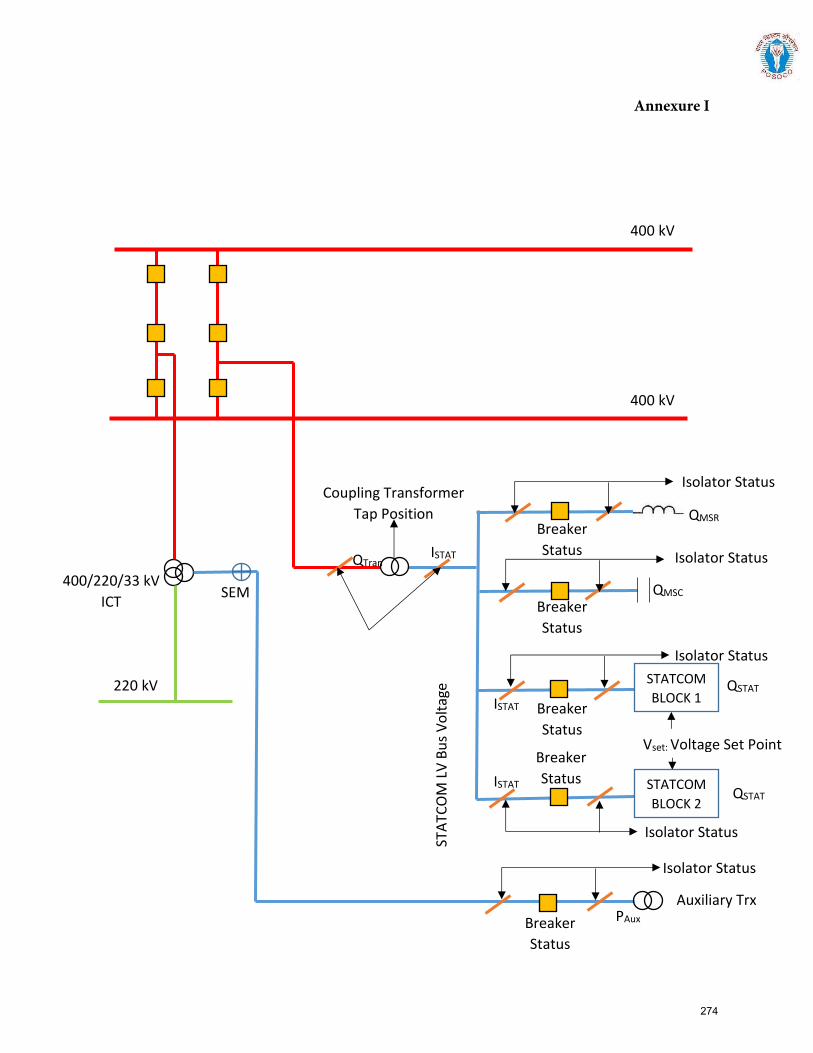
Annexure I
STATCOM
BLOCK 1
STATCOM
BLOCK 2
QTran
Isolator Status
Breaker
Status
Breaker
Status
Breaker
Status
QMSC
QMSR
QSTAT
QSTAT
Coupling Transformer
Tap Position
STA
TCO
M L
V B
us
Vo
ltag
e
Vset: Voltage Set Point
Isolator Status
Isolator Status
Isolator Status
ISTAT
ISTAT
ISTAT
Isolator Status
Auxiliary Trx PAux
Breaker
Status
Breaker
Status
400 kV
400 kV
220 kV
400/220/33 kV
ICT SEM
274
Guideline for furnishing information for Modelling Static Synchronous Compensator (STATCOM) in Indian Grid
1.0 Introduction:
The purpose of this document is to act as a guideline for exchange of information for accurate modelling of Static Synchronous Compensator (STATCOM) in India. STATCOMs are relatively recent technological additions into the Indian grid and their number is expected to increase further in the future. STATCOMs deliver reactive power to counter voltage deviations from the nominal, supporting the stability of the grid. STATCOMs are typically voltage source converter (VSC) devices. Availability of fit-for-purpose steady state and dynamics models of STATCOM installations are necessary to undertake simulation studies for secure operation of the Indian power grid.
1.1 Applicability:
The guideline shall be applicable to all STATCOM installations in India, irrespective of the technologies used.
This document presents the desired information for collection of data for modelling of STATCOM installations in PSS/E software, a software suite being used pan-India at CEA, CTU, SLDCs, RLDCs, and NLDC for modelling of India’s power grid. A systematic set of data and basic criteria for furnishing data are presented.
1.2 Need for a fit-for-purpose model:
There is a cost involved in developing and validating dynamic models of power system equipment. But there are much higher benefits for the power system if this leads to a functional, fit-for-purpose model, and arrangements that allow that model to be maintained over time.
A functional fit-for-purpose dynamic model will:
• Facilitate significant power system efficiencies by allowing power system operations toconfidently identify the secure operating envelope and thereby manage security effectively
• Allow assessment of impact on grid elements due to connection of new elements (networkelements, generators, or loads) for necessary corrective actions
• Permit power system assets to be run with margins determined on the basis of securityassessments
• Facilitate the tuning of control systems, such as power oscillation dampers, frequencycontrollers, etc.
• Improve accuracy of online security tools, particularly for unusual operating conditions, which inturn is likely to result in higher reliability of supply to power system users.
The power system model would enable steady state and electromechanical transient simulation studies that deliver reasonably accurate outcomes.
Annexure-II
275
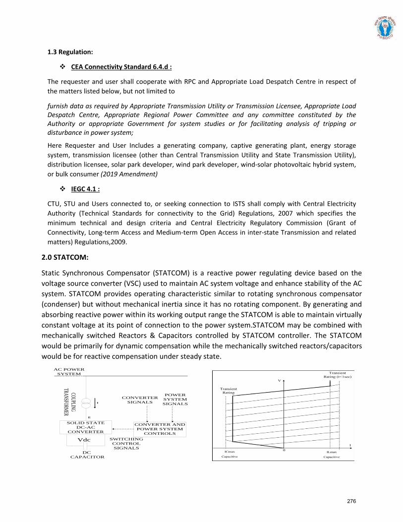
1.3 Regulation:
CEA Connectivity Standard 6.4.d :
The requester and user shall cooperate with RPC and Appropriate Load Despatch Centre in respect of the matters listed below, but not limited to
furnish data as required by Appropriate Transmission Utility or Transmission Licensee, Appropriate Load Despatch Centre, Appropriate Regional Power Committee and any committee constituted by the Authority or appropriate Government for system studies or for facilitating analysis of tripping or disturbance in power system;
Here Requester and User Includes a generating company, captive generating plant, energy storage system, transmission licensee (other than Central Transmission Utility and State Transmission Utility), distribution licensee, solar park developer, wind park developer, wind-solar photovoltaic hybrid system, or bulk consumer (2019 Amendment)
IEGC 4.1 :
CTU, STU and Users connected to, or seeking connection to ISTS shall comply with Central Electricity Authority (Technical Standards for connectivity to the Grid) Regulations, 2007 which specifies the minimum technical and design criteria and Central Electricity Regulatory Commission (Grant of Connectivity, Long-term Access and Medium-term Open Access in inter-state Transmission and related matters) Regulations,2009.
2.0 STATCOM:
Static Synchronous Compensator (STATCOM) is a reactive power regulating device based on the voltage source converter (VSC) used to maintain AC system voltage and enhance stability of the AC system. STATCOM provides operating characteristic similar to rotating synchronous compensator (condenser) but without mechanical inertia since it has no rotating component. By generating and absorbing reactive power within its working output range the STATCOM is able to maintain virtually constant voltage at its point of connection to the power system.STATCOM may be combined with mechanically switched Reactors & Capacitors controlled by STATCOM controller. The STATCOM would be primarily for dynamic compensation while the mechanically switched reactors/capacitors would be for reactive compensation under steady state.
SOLID STATE DC-AC
CONVERTER
CONVERTER AND POWER SYSTEM
CONTROLS
CONVERTER SIGNALS
CONVERTER SIGNALS
POWER SYSTEM SIGNALS
POWER SYSTEM SIGNALS
SWITCHING CONTROL SIGNALS
SWITCHING CONTROL SIGNALS
DC CAPACITOR
DC CAPACITOR
COUPLING TRANSFORMER
COUPLING TRANSFORMER
VdcVdc
EE
II
AC POWER SYSTEM
AC POWER SYSTEM
276

Version History:
Version no. Release Date Prepared by* Checked/Issued by* Changes
*Mention Designation and Contact Details
Details submitted:
Details pending:
277
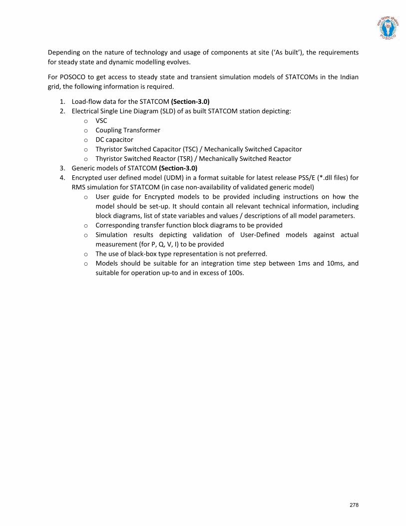
Depending on the nature of technology and usage of components at site (‘As built’), the requirements for steady state and dynamic modelling evolves.
For POSOCO to get access to steady state and transient simulation models of STATCOMs in the Indian grid, the following information is required.
1. Load-flow data for the STATCOM (Section-3.0)2. Electrical Single Line Diagram (SLD) of as built STATCOM station depicting:
o VSCo Coupling Transformero DC capacitoro Thyristor Switched Capacitor (TSC) / Mechanically Switched Capacitoro Thyristor Switched Reactor (TSR) / Mechanically Switched Reactor
3. Generic models of STATCOM (Section-3.0)4. Encrypted user defined model (UDM) in a format suitable for latest release PSS/E (*.dll files) for
RMS simulation for STATCOM (in case non-availability of validated generic model)o User guide for Encrypted models to be provided including instructions on how the
model should be set-up. It should contain all relevant technical information, includingblock diagrams, list of state variables and values / descriptions of all model parameters.
o Corresponding transfer function block diagrams to be providedo Simulation results depicting validation of User-Defined models against actual
measurement (for P, Q, V, I) to be providedo The use of black-box type representation is not preferred.o Models should be suitable for an integration time step between 1ms and 10ms, and
suitable for operation up-to and in excess of 100s.
278
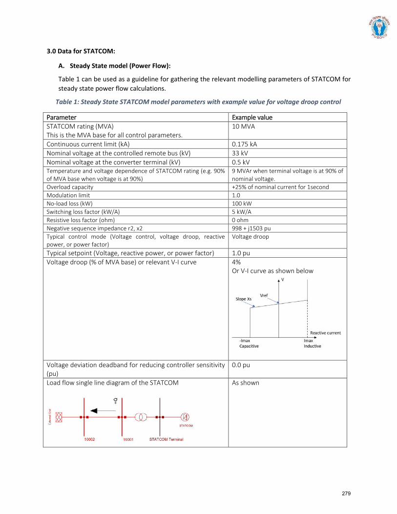
3.0 Data for STATCOM:
A. Steady State model (Power Flow):
Table 1 can be used as a guideline for gathering the relevant modelling parameters of STATCOM for steady state power flow calculations.
Table 1: Steady State STATCOM model parameters with example value for voltage droop control
Parameter Example value STATCOM rating (MVA) This is the MVA base for all control parameters.
10 MVA
Continuous current limit (kA) 0.175 kA Nominal voltage at the controlled remote bus (kV) 33 kV Nominal voltage at the converter terminal (kV) 0.5 kV Temperature and voltage dependence of STATCOM rating (e.g. 90% of MVA base when voltage is at 90%)
9 MVAr when terminal voltage is at 90% of nominal voltage.
Overload capacity +25% of nominal current for 1second Modulation limit 1.0 No-load loss (kW) 100 kW Switching loss factor (kW/A) 5 kW/A Resistive loss factor (ohm) 0 ohm Negative sequence impedance r2, x2 998 + j1503 pu Typical control mode (Voltage control, voltage droop, reactive power, or power factor)
Voltage droop
Typical setpoint (Voltage, reactive power, or power factor) 1.0 pu Voltage droop (% of MVA base) or relevant V-I curve 4%
Or V-I curve as shown below
Voltage deviation deadband for reducing controller sensitivity (pu)
0.0 pu
Load flow single line diagram of the STATCOM As shown
279
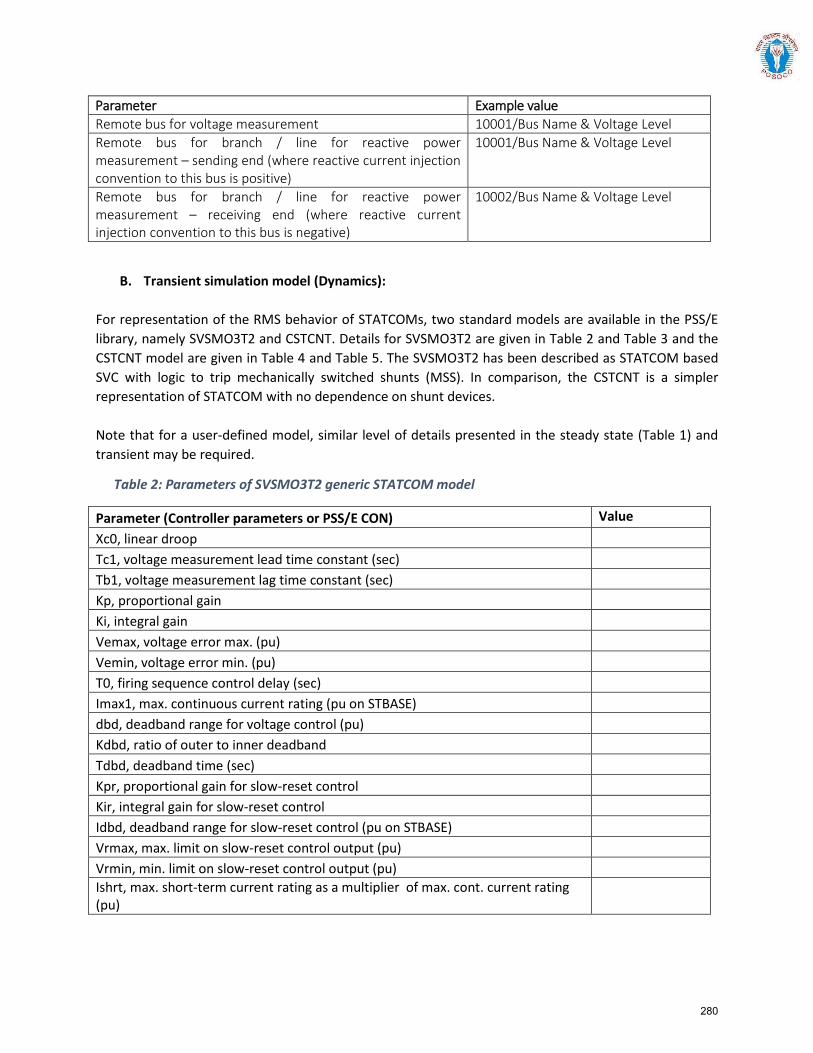
Parameter Example value Remote bus for voltage measurement 10001/Bus Name & Voltage Level Remote bus for branch / line for reactive power measurement – sending end (where reactive current injection convention to this bus is positive)
10001/Bus Name & Voltage Level
Remote bus for branch / line for reactive power measurement – receiving end (where reactive current injection convention to this bus is negative)
10002/Bus Name & Voltage Level
B. Transient simulation model (Dynamics):
For representation of the RMS behavior of STATCOMs, two standard models are available in the PSS/E library, namely SVSMO3T2 and CSTCNT. Details for SVSMO3T2 are given in Table 2 and Table 3 and the CSTCNT model are given in Table 4 and Table 5. The SVSMO3T2 has been described as STATCOM based SVC with logic to trip mechanically switched shunts (MSS). In comparison, the CSTCNT is a simpler representation of STATCOM with no dependence on shunt devices.
Note that for a user-defined model, similar level of details presented in the steady state (Table 1) and transient may be required.
Table 2: Parameters of SVSMO3T2 generic STATCOM model
Parameter (Controller parameters or PSS/E CON) Value Xc0, linear droop Tc1, voltage measurement lead time constant (sec) Tb1, voltage measurement lag time constant (sec) Kp, proportional gain Ki, integral gain Vemax, voltage error max. (pu) Vemin, voltage error min. (pu) T0, firing sequence control delay (sec) Imax1, max. continuous current rating (pu on STBASE) dbd, deadband range for voltage control (pu) Kdbd, ratio of outer to inner deadband Tdbd, deadband time (sec) Kpr, proportional gain for slow-reset control Kir, integral gain for slow-reset control Idbd, deadband range for slow-reset control (pu on STBASE) Vrmax, max. limit on slow-reset control output (pu) Vrmin, min. limit on slow-reset control output (pu) Ishrt, max. short-term current rating as a multiplier of max. cont. current rating (pu)
280
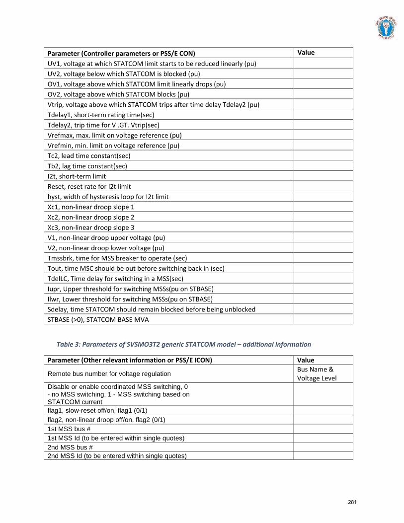
Parameter (Controller parameters or PSS/E CON) Value UV1, voltage at which STATCOM limit starts to be reduced linearly (pu) UV2, voltage below which STATCOM is blocked (pu) OV1, voltage above which STATCOM limit linearly drops (pu) OV2, voltage above which STATCOM blocks (pu) Vtrip, voltage above which STATCOM trips after time delay Tdelay2 (pu) Tdelay1, short-term rating time(sec) Tdelay2, trip time for V .GT. Vtrip(sec) Vrefmax, max. limit on voltage reference (pu) Vrefmin, min. limit on voltage reference (pu) Tc2, lead time constant(sec) Tb2, lag time constant(sec) I2t, short-term limit Reset, reset rate for I2t limit hyst, width of hysteresis loop for I2t limit Xc1, non-linear droop slope 1 Xc2, non-linear droop slope 2 Xc3, non-linear droop slope 3 V1, non-linear droop upper voltage (pu) V2, non-linear droop lower voltage (pu) Tmssbrk, time for MSS breaker to operate (sec) Tout, time MSC should be out before switching back in (sec) TdelLC, Time delay for switching in a MSS(sec) Iupr, Upper threshold for switching MSSs(pu on STBASE) Ilwr, Lower threshold for switching MSSs(pu on STBASE) Sdelay, time STATCOM should remain blocked before being unblocked STBASE (>0), STATCOM BASE MVA
Table 3: Parameters of SVSMO3T2 generic STATCOM model – additional information
Parameter (Other relevant information or PSS/E ICON) Value
Remote bus number for voltage regulation Bus Name & Voltage Level
Disable or enable coordinated MSS switching, 0 - no MSS switching, 1 - MSS switching based on STATCOM current
flag1, slow-reset off/on, flag1 (0/1)
flag2, non-linear droop off/on, flag2 (0/1)
1st MSS bus #
1st MSS Id (to be entered within single quotes)
2nd MSS bus #
2nd MSS Id (to be entered within single quotes)
281
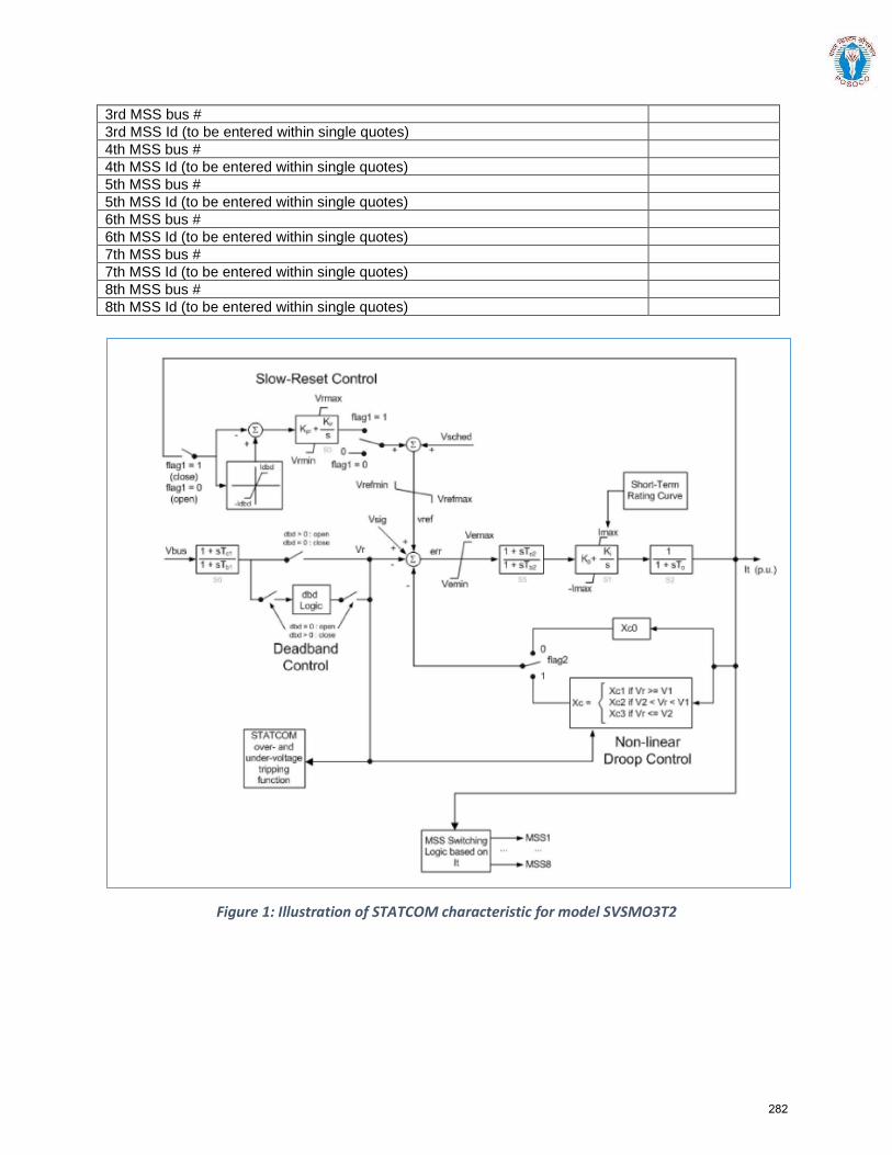
3rd MSS bus # 3rd MSS Id (to be entered within single quotes) 4th MSS bus # 4th MSS Id (to be entered within single quotes) 5th MSS bus # 5th MSS Id (to be entered within single quotes) 6th MSS bus # 6th MSS Id (to be entered within single quotes) 7th MSS bus # 7th MSS Id (to be entered within single quotes) 8th MSS bus # 8th MSS Id (to be entered within single quotes)
Figure 1: Illustration of STATCOM characteristic for model SVSMO3T2
282
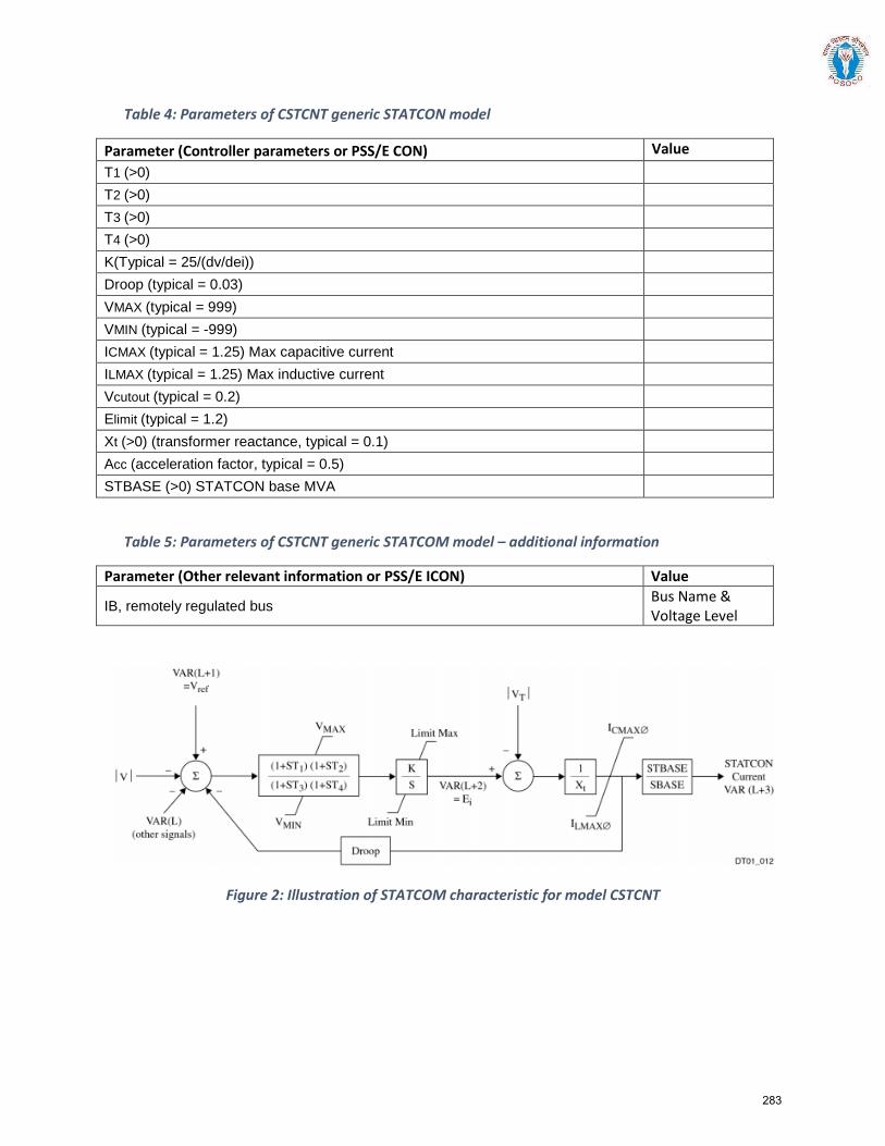
Table 4: Parameters of CSTCNT generic STATCON model
Parameter (Controller parameters or PSS/E CON) Value T1 (>0)
T2 (>0)
T3 (>0)
T4 (>0)
K(Typical = 25/(dv/dei))
Droop (typical = 0.03)
VMAX (typical = 999)
VMIN (typical = -999)
ICMAX (typical = 1.25) Max capacitive current
ILMAX (typical = 1.25) Max inductive current
Vcutout (typical = 0.2)
Elimit (typical = 1.2)
Xt (>0) (transformer reactance, typical = 0.1)
Acc (acceleration factor, typical = 0.5)
STBASE (>0) STATCON base MVA
Table 5: Parameters of CSTCNT generic STATCOM model – additional information
Parameter (Other relevant information or PSS/E ICON) Value
IB, remotely regulated bus Bus Name & Voltage Level
Figure 2: Illustration of STATCOM characteristic for model CSTCNT
283
Section5:
Procedure for integration of a new or modified power system elements and issue of
certificate of successful trial operation by National Load Despatch Centre (NLDC)/ Regional Load Despatch Centres (RLDCs)
284
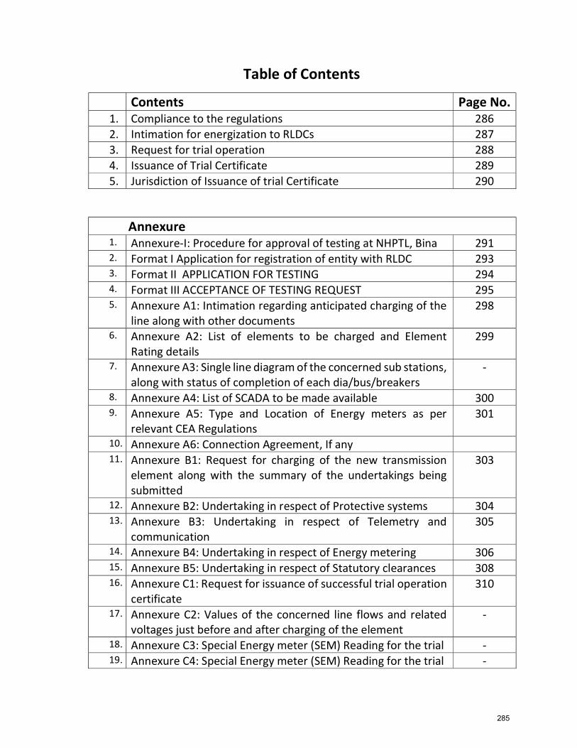
Table of Contents
Annexure 1. Annexure-I: Procedure for approval of testing at NHPTL, Bina 291 2. Format I Application for registration of entity with RLDC 293 3. Format II APPLICATION FOR TESTING 294 4. Format III ACCEPTANCE OF TESTING REQUEST 295 5. Annexure A1: Intimation regarding anticipated charging of the
line along with other documents 298
6. Annexure A2: List of elements to be charged and Element Rating details
299
7. Annexure A3: Single line diagram of the concerned sub stations, along with status of completion of each dia/bus/breakers
-
8. Annexure A4: List of SCADA to be made available 300 9. Annexure A5: Type and Location of Energy meters as per
relevant CEA Regulations 301
10. Annexure A6: Connection Agreement, If any 11. Annexure B1: Request for charging of the new transmission
element along with the summary of the undertakings being submitted
303
12. Annexure B2: Undertaking in respect of Protective systems 304 13. Annexure B3: Undertaking in respect of Telemetry and
communication 305
14. Annexure B4: Undertaking in respect of Energy metering 306 15. Annexure B5: Undertaking in respect of Statutory clearances 308 16. Annexure C1: Request for issuance of successful trial operation
certificate 310
17. Annexure C2: Values of the concerned line flows and related voltages just before and after charging of the element
-
18. Annexure C3: Special Energy meter (SEM) Reading for the trial - 19. Annexure C4: Special Energy meter (SEM) Reading for the trial -
Contents Page No. 1. Compliance to the regulations 286 2. Intimation for energization to RLDCs 287 3. Request for trial operation 288 4. Issuance of Trial Certificate 289 5. Jurisdiction of Issuance of trial Certificate 290
285
`Procedure for integration of a new power system elements and issue of certificate of successful trial operation by National Load Despatch Centre (NLDC)/ Regional Load Despatch Centres (RLDCs)
This procedure is applicable for following power system elements: Inter-Regional/Inter-State transmission lines irrespective of voltage
level/ownership HVDC transmission elements irrespective of ownership Transnational lines/elements 400kV level and above transmission lines/ICT/Bus Reactor/Line Reactor/FACTS
devices (TCSC /FSC /STATCOM /SVC)/Bus/Bay/Series Capacitor/SeriesReactor/Generating Transformer/any other elements irrespective ofownership
220 kV level transmission lines/ICT/Bus Reactor/Line Reactor/FACTS devices(TCSC /FSC / STATCOM /SVC)/ Bus/ Bay/ Series Capacitor/ Series Reactor/Generating Transformer/any other elements emanating from ISGS / ISTSsubstations
Station Transformers (STs) at generating station those are regional entities. Generating station those are regional entities. Bulk Consumers or Load Serving Entities those are regional entities. Combined (Load & Captive) generation complex those are regional entities. Short Circuit Testing of power transformers at National High Power Test
Laboratory Pvt. Ltd.(NHPTL)
Indian Electricity Grid Code provides for formulation of operating procedure by NLDC/RLDCs. The same is quoted below:
“A set of detailed operating procedures for the National grid shall be developed and maintained by the NLDC in consultation with the RLDCs, for guidance of the staff of the NLDC and it shall be consistent with IEGC to enable compliance with the requirement of this IEGC.
A set of detailed operating procedures for each regional grid shall be developed and maintained by the respective RLDC in consultation with the regional entities for guidance of the staff of RLDC. and shall be consistent with IEGC to enable compliance with the requirement of this IEGC.”
In accordance with the above provisions and as a part of NLDC/RLDC operating procedure, procedure for energization of a new or modified power system elements belonging to any transmission licensee has been formulated to enable NLDC/RLDC for secure and reliable integration of new elements. This procedure specifies requirements for integration with the grid such as protection, telemetry and communication systems, metering, statutory clearances and modelling data requirements for system studies.
The details of the same are as follows: 286
1. Compliance to the regulations: All the transmission licensee shall be complied to the regulation & their amendments mentioned below-
i) Central Electricity Authority (Technical Standards for Connectivity to the Grid Regulations, 2007
ii) Central Electricity Authority (Technical Standards for Construction of Electrical Plants and Electric Lines) Regulations, 2010
iii) Central Electricity Authority (Measures Relating to Safety & Electric Supply) Regulations,2010
iv) Central Electricity Regulatory Commission (Communication System for Inter-State Transmission of Electricity) Regulations,2017
v) Central Electricity Authority (Installation and Operation of Meters) Regulations, 2006
vi) Central Electricity Regulatory Commission (Grant of Connectivity, Long-term Access and Medium-term Open Access in Inter-State Transmission and related matters) Regulations,2009
vii) Central Electricity Regulatory Commission (Fees and Charges for Regional Load Despatch Centres) Regulations, 2019
viii) Any other regulations and standards specified from time to time
2. Intimation for energization to RLDCs-All the Transmission Licensees including deemed transmission licensees or cross-border entity(Indian side) intending to energize a new or modified any power system elements, which is part of inter-state transmission system, shall intimate the concerned RLDC the details as per the formats given below, at least (10) days prior to the anticipated date of first test charging.
a. Annexure A1: Intimation regarding anticipated charging of the power
system elements along with the list of the desired documents being submitted.
b. Annexure A2 : List of elements to be charged with their Rating
c. Annexure A3 : Single line diagram of the concerned sub stations, along
with status of completion of each dia/bus/breakers clearly indicating which elements are proposed to be charged.
d. Annexure A4 : List of SCADA points to be made available (as per
standard requirement, RLDC would need all MW and MVAr data, voltage and frequency of all the buses, all the breaker and isolator positions, OLTC tap positions, Main-1/Main-2 protection operated signals, DC side SCADA data in case of HVDC station, data for SVC/STATCOM as per RLDCS/NLDC requirement)
e. Annexure A5 : Location of Energy meters as per relevant CEA regulations 287
f. Annexure A6: Connection Agreement, wherever applicable along with all annexures.
Other than the documents mentioned above following documents needs to be submitted to RLDCs-
CTU charging instructions to be provided which shall clearly mentioned about the assumption made in the studies for ex. Whether it is anti-theft charging or complete line is going to be charged, status of parallel line etc.
Details of approval of the transmission scheme from the Standing Committee / CTU and approval for changes in the approved scheme, if any.
Availability of line reactors with the switchable or non-switchable status as per approved scheme.
CEA approval for energization as per Central Electricity Authority (Measures Relating to Safety & Electric Supply) Regulations,2010
PTCC clearance certificate Technical parameters of the power system element required for network
modeling shall be made available by CTU/STU In case of HVDC transmission elements all desired modelling data, operational
documents and telemetered data to be provided as per the procedure of integration of HVDC transmission elements.
In case of STATCOM/SVC all technical details to be provided as per procedure of STATCOM/SVC.
Short Circuit Testing of power transformers at National High Power Test Laboratory Pvt. Ltd.(NHPTL) is allowed as per the CERC approved procedure of testing enclosed as Annexure-I
Status of PMU installation
3. Within 3 days of submission of above information by the Transmission Licensee, concerned RLDC shall acknowledge the receipt of the same, as per Format II, and seek clarifications, if any. The transmission licensee shall submit the desired information/documents to the concerned RLDC within next three days.
4. Request for trial operation-The request for charging of new or modified power system element and towards start of the trial operation as per Format III shall be submitted by the Transmission Licensee to the concerned RLDC, at least three (3) days prior to the date of first-time charging. There could be a separate schedule for test charging and the final schedule for trial operation, which may be m e n t i o n e d in t h e Format-I itself. The Transmission Licensee shall also submit the following documents in this regard:
a. Annexure B1: Request for charging of the new or modified power
system elements along with the summary of the undertakings being submitted as per Format III
b. Annexure B2: Undertaking in respect of Protective systems as per
Format III A
288
c. Annexure B3: Undertaking in respect of Telemetry and communication as per Format III B
d. Annexure B4: Undertaking in respect of Energy metering as per Format III
C
e. Annexure B5: Undertaking in respect of Statutory clearances a s p e r Format III D
5. On satisfying itself with the submitted information as stated above under Para 3,
the RLDC would issue a provisional approval for charging to the Transmission Licensee as per Format IV within two days of receipt of above documents. On the designated day, the transmission licensee shall charge the transmission line and do trial operation as per the timeline mentioned in Format III, after obtaining the real time code from RLDC. All attempts would be made by the real time operating personnel at the concerned RLDC to facilitate charging and commissioning of the new or modified power system elements at the earliest, subject to availability of real time data and favorable system conditions. Charging of any new elements will not be allowed after 18:00 hrs.
6. Issuance of Trial Certificate- Clause (5) of Regulation 6.3A of Indian Electricity Grid Code provides for certification of successful trial operation of new transmission assets by RLDC. The same is quoted below:
“Trial run and Trial operation in relation to a transmission system or an element thereof shall mean successful charging of the transmission system or an element thereof for 24 hours at continuous flow of power, and communication signal from the sending end to the receiving end and with requisite metering system, telemetry and protection system in service enclosing certificate to that effect from concerned Regional Load Despatch Centre.”
After successful trial operation, following documents shall be submitted by the Transmission Licensee to concerned RLDC :
a. Annexure C1: Request for issuance of successful trial operation
certificate as per Format V b. Annexure C2: Values of the concerned line flows and related
voltages as per local SCADA just before and after cha rging of the element.
c. Annexure C3: Special Energy meter (SEM) Reading corresponding to the trial run
d. Annexure C4: Output of Disturbance Recorders / Event Loggers including the graph and event list.
7. Within three (3) working days of submission of the information mentioned above, 289
N L D C / RLDC concerned shall issue the certificate for successful completion of trial run of the transmission lines as per Format VI subject to the correctness of information provided by the transmission licensee. If any clarification is required from transmission licensee then trial certificate will be issued after resolving all the issues.
8. Jurisdiction of Issuance of trial Certificate is as follows: NLDC- Inter Regional transmission lines designated as ISTS irrespective of voltage level, inter regional HVDC link/Pole irrespective of ownership and all transnational lines. RLDC- Transmission lines designated as ISTS irrespective of voltage level/ownership, Intra Regional HVDC link/pole connected as designated ISTS network, FACTS devices (TCSC/FSC/STATCOM/SVC) associated with designated ISTS;
x-----x-----x
290
Order in Pet No.9/MP/2016 Page 34
Annexure-I
Procedure for approval of testing at NHPTL, Bina
1. NHPTL shall register with WRLDC as its user before commencement of short circuit tests by
filing an application in the Format I enclosed and payment of one time registration fee of
INR ten lakh only in line with the provisions of the CERC (RLDC Fees and Charges)
Regulations, 2015.
2. NHPTL shall apply to WRLDC at least seven (7) days in advance for approval of testing of
any High Voltage Transformer (HVTR) test equipment in Format II enclosed. Only one
application for the specified rating of the transformer for the desired period of testing time of
maximum one day shall be submitted by NHPTL. Non-refundable Application Fees of Rs
5000/- only per application/testing would be payable by NHPTL to WRLDC. In case there
is requirement of short circuit current for multiple times on the same equipment, then the
same shall be clearly mentioned in the application format including any shots for calibration
which shall be indicated separately.
3. WRLDC shall give its approval within three (3) days of receipt of the application in Format
III enclosed considering the grid conditions, anticipated fault levels and/or any other event
in the vicinity of the test laboratory with a copy to NLDC and MP SLDC. In case of any
anticipated grid condition which requires deferment of the proposed testing, WRLDC shall
intimate the revised date and time for testing for which no additional fee is required to be
paid.
4. NHPTL shall give at least one day notice to revise the date of testing. In such case no
additional application fee would be applicable. In case NHPTL is not able to conduct the
test on the approved day and time window due to reasons not attributable to POSOCO, a
fresh application shall be submitted by NHPTL at least 3 days in advance. Application fee as
mentioned in S no 2 above would be applicable.
5. On the day of testing, POWERGRID (on the request from NHPTL) shall seek real time
code from WRLDC for switching ON the 400/765 kV NHPTL feeder from Bina (PG)
substation depending upon the feeder requirements for conducting test on a particular
rating of transformer. NHPTL would then seek code from WRLDC just before applying
short circuit to the test equipment only once for a maximum duration of 250 milliseconds
with tolerance of + 10% as per IEC 60076-5. The real time code shall be issued by
WRLDC, in consultation with NLDC and MP SLDC, considering the real time grid
conditions and availability of real time data and PMU data which shall be valid for a
maximum of 4 hours. NHPTL shall attempt to complete all shots of short circuit testing
during this 4 hour window only. In case NHPTL is not able to complete the same with 4
hours, a fresh code shall be taken after indicating the reason for delay.
291
Order in Pet No.9/MP/2016 Page 35
6. In case real time conditions do not permit testing or real time data / PMU data is not
available due to any reason, WRLDC may defer the testing to some other time or date. In
such scenario, no new application or application fees are required.
7. After the test is over, POWERGRID (on the request from NHPTL) shall seek real time code
from WRLDC for switching OFF the 400 /765kV NHPTL feeder from Bina (PG).
POWERGRID Bina would also forward the energy meter data for the NHPTL feeders every
week by 1200 hours on Monday.
8. Within 24 hrs of testing of any HVTR test equipment, NHPTL shall submit output of
Disturbance Recorder and Event Logger (EL) to WRLDC.
9. Based upon the operational experience, any modification may be incorporated in the
procedure for better operation and coordination in the testing, after mutual consultation.
X- x x
292
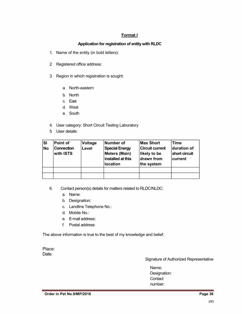
Order in Pet No.9/MP/2016 Page 36
Format I
Application for registration of entity with RLDC
1. Name of the entity (in bold letters):
2. Registered office address:
3. Region in which registration is sought:
a. North-eastern
b. North c. East d. West e. South
4. User category: Short Circuit Testing Laboratory
5. User details:
SI No
Point of Connection with ISTS
Voltage Level
Number of Special Energy Meters (Main) installed at this location
Max Short Circuit current likely to be drawn from the system
Time duration of short circuit current
6. Contact person(s) details for matters related to RLDC/NLDC: a. Name: b. Designation: c. Landline Telephone No.: d. Mobile No.: e. E-mail address: f. Postal address:
The above information is true to the best of my knowledge and belief.
Place: Date:
Signature of Authorized Representative
Name; Designation: Contact number:
293
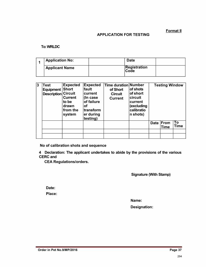
Order in Pet No.9/MP/2016 Page 37
Format II
APPLICATION FOR TESTING
To: WRLDC
1 Application No: Date
Applicant Name Registration Code
3 Test Equipment Description
Expected Short Circuit Current to be drawn from the system
Expected fault current (In case of failure of transformer during testing)
Time duration of Short Circuit
Current
Number of shots of short circuit current (excluding calibration shots)
Testing Window
Date From Time
To Time
No of calibration shots and sequence
4 Declaration: The applicant undertakes to abide by the provisions of the various CERC and
CEA Regulations/orders.
Signature (With Stamp)
Date:
Place:
Name:
Designation:
294
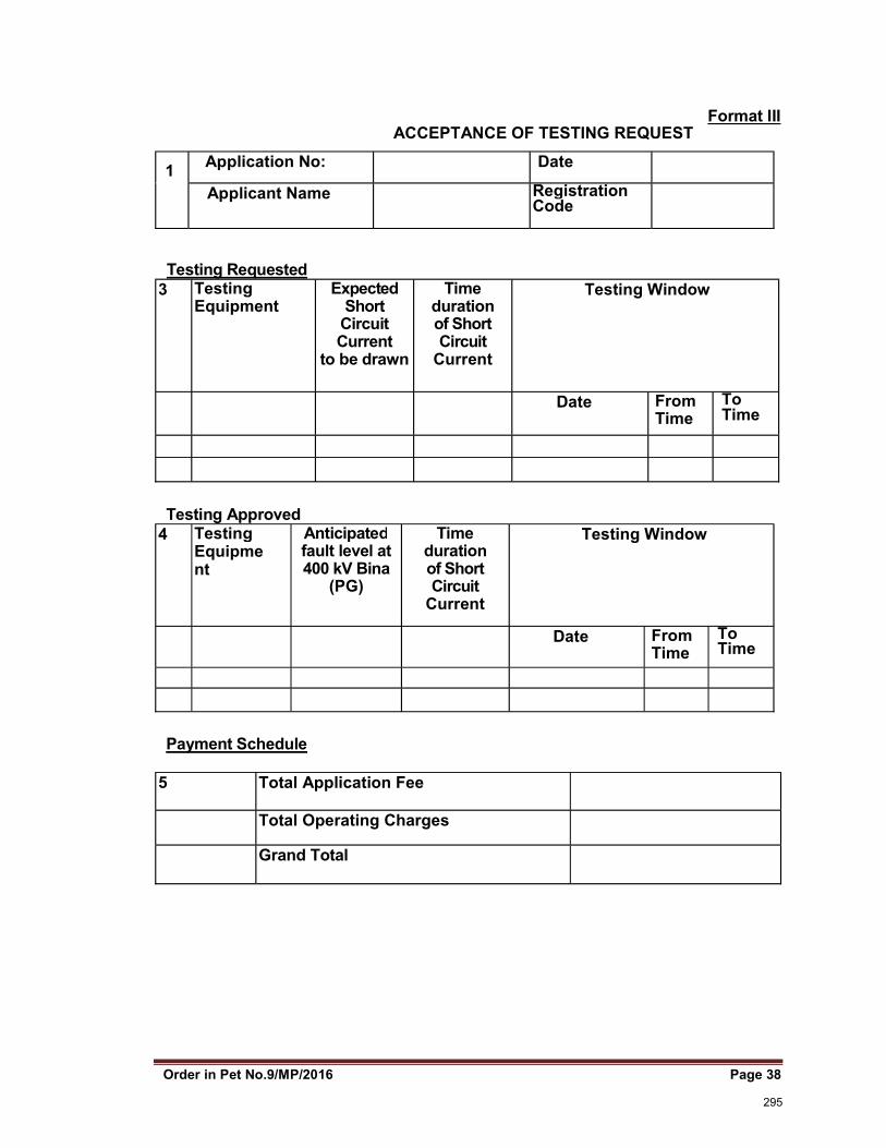
Order in Pet No.9/MP/2016 Page 38
Format III ACCEPTANCE OF TESTING REQUEST
1 Application No: Date
Applicant Name Registration Code
Testing Requested 3 Testing
Equipment Expected
Short Circuit Current
to be drawn
Time duration of Short Circuit
Current
Testing Window
Date From Time
To Time
Testing Approved 4 Testing
Equipment
Anticipated fault level at 400 kV Bina
(PG)
Time duration of Short Circuit
Current
Testing Window
Date From Time
To Time
Payment Schedule
5 Total Application Fee
Total Operating Charges
Grand Total
295
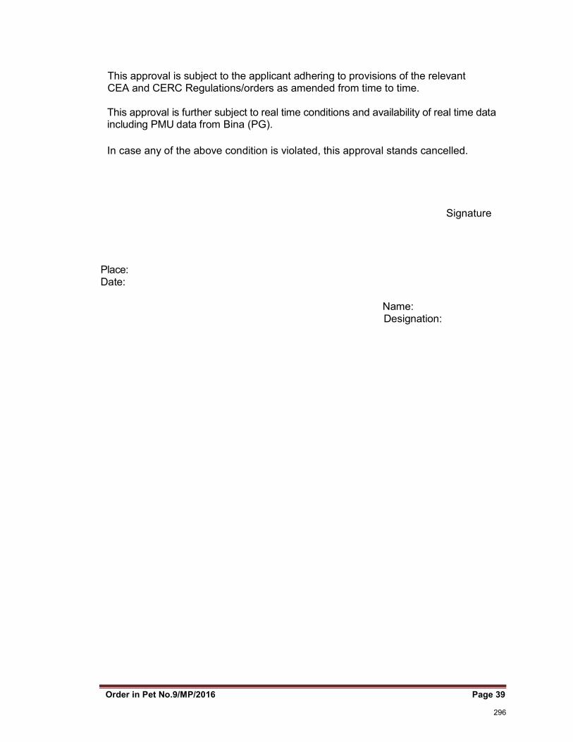
Order in Pet No.9/MP/2016 Page 39
This approval is subject to the applicant adhering to provisions of the relevant CEA and CERC Regulations/orders as amended from time to time.
This approval is further subject to real time conditions and availability of real time data including PMU data from Bina (PG).
In case any of the above condition is violated, this approval stands cancelled.
Signature
Place: Date:
Name: Designation:
296
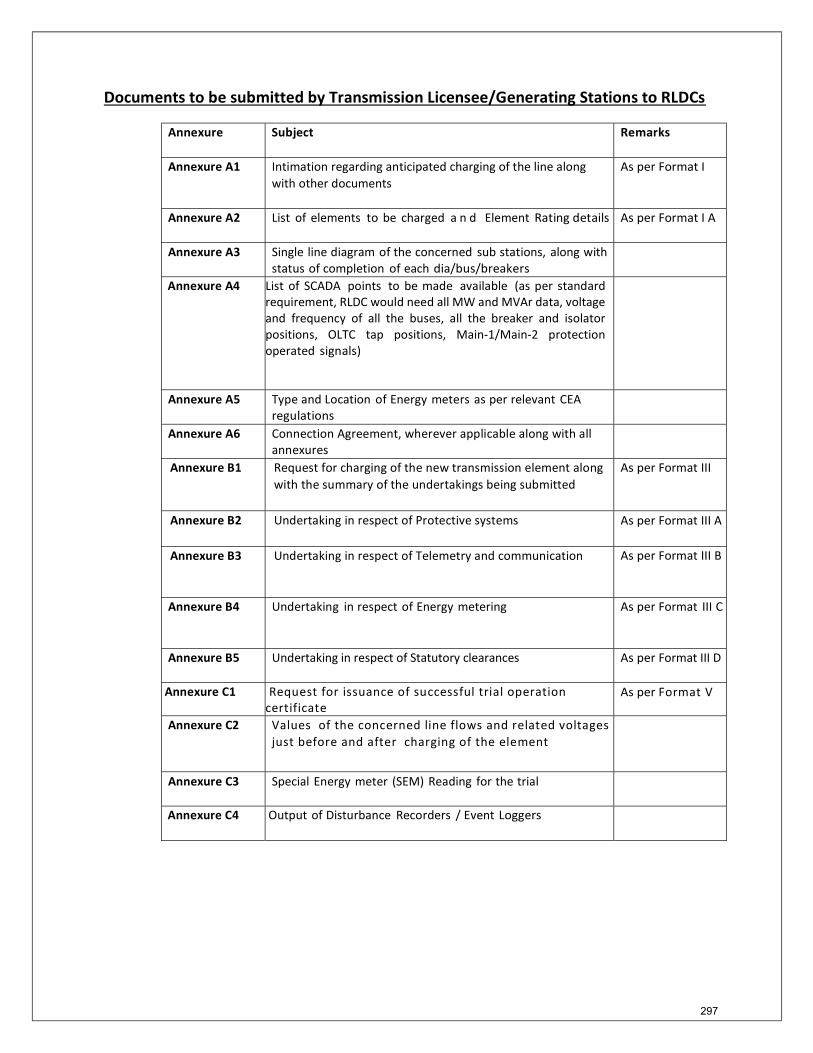
Documents to be submitted by Transmission Licensee/Generating Stations to RLDCs
Annexure Subject Remarks
Annexure A1 Intimation regarding anticipated charging of the line along with other documents
As per Format I
Annexure A2 List of elements to be charged a n d Element Rating details As per Format I A
Annexure A3 Single line diagram of the concerned sub stations, along with status of completion of each dia/bus/breakers
Annexure A4 List of SCADA points to be made available (as per standard requirement, RLDC would need all MW and MVAr data, voltage and frequency of all the buses, all the breaker and isolator positions, OLTC tap positions, Main-1/Main-2 protection operated signals)
Annexure A5 Type and Location of Energy meters as per relevant CEA regulations
Annexure A6 Connection Agreement, wherever applicable along with all annexures
Annexure B1 Request for charging of the new transmission element along with the summary of the undertakings being submitted
As per Format III
Annexure B2 Undertaking in respect of Protective systems
As per Format III A
Annexure B3 Undertaking in respect of Telemetry and communication As per Format III B
Annexure B4 Undertaking in respect of Energy metering As per Format III C
Annexure B5 Undertaking in respect of Statutory clearances As per Format III D
Annexure C1 Request for issuance of successful trial operation certificate
As per Format V
Annexure C2 Values of the concerned line flows and related voltages just before and after charging of the element
Annexure C3 Special Energy meter (SEM) Reading for the trial
Annexure C4 Output of Disturbance Recorders / Event Loggers
297
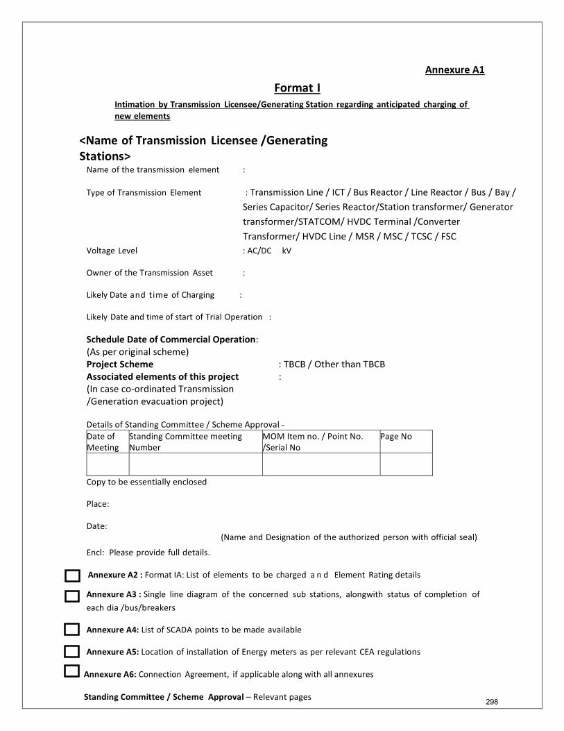
Annexure A1 Format I
Intimation by Transmission Licensee/Generating Station regarding anticipated charging of new elements
<Name of Transmission Licensee /Generating Stations>
Name of the transmission element :
Type of Transmission Element : Transmission Line / ICT / Bus Reactor / Line Reactor / Bus / Bay / Series Capacitor/ Series Reactor/Station transformer/ Generator transformer/STATCOM/ HVDC Terminal /Converter Transformer/ HVDC Line / MSR / MSC / TCSC / FSC
Voltage Level : AC/DC kV
Owner of the Transmission Asset :
Likely Date and time of Charging :
Likely Date and time of start of Trial Operation :
Schedule Date of Commercial Operation: (As per original scheme) Project Scheme : TBCB / Other than TBCB Associated elements of this project : (In case co-ordinated Transmission /Generation evacuation project) Details of Standing Committee / Scheme Approval - Date of Meeting
Standing Committee meeting Number
MOM Item no. / Point No. /Serial No
Page No
Copy to be essentially enclosed
Place:
Date:
Encl: Please provide full details.
(Name and Designation of the authorized person with official seal)
Annexure A2 : Format IA: List of elements to be charged a n d Element Rating details
Annexure A3 : Single line diagram of the concerned sub stations, alongwith status of completion of each dia /bus/breakers
Annexure A4: List of SCADA points to be made available
Annexure A5: Location of installation of Energy meters as per relevant CEA regulations
Annexure A6: Connection Agreement, if applicable along with all annexures
Standing Committee / Scheme Approval – Relevant pages
298
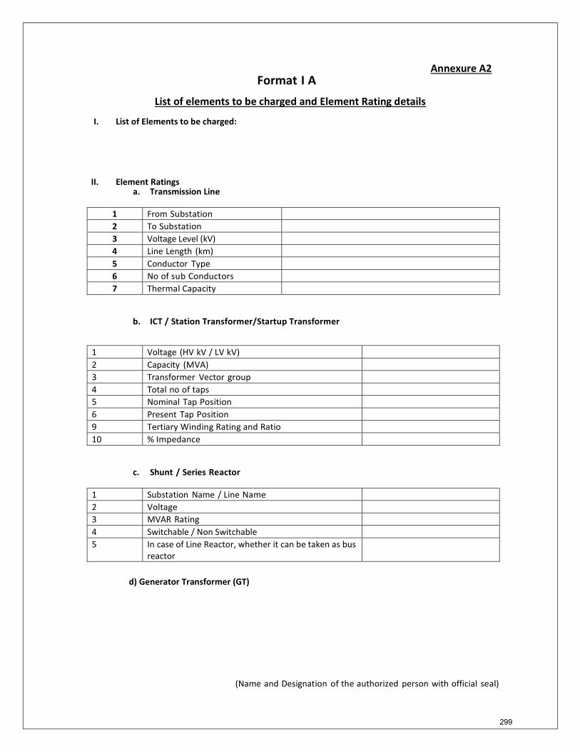
Annexure A2 Format I A
List of elements to be charged and Element Rating details
I. List of Elements to be charged:
II. Element Ratings a. Transmission Line
1 From Substation 2 To Substation 3 Voltage Level (kV) 4 Line Length (km) 5 Conductor Type 6 No of sub Conductors 7 Thermal Capacity
b. ICT / Station Transformer/Startup Transformer
1 Voltage (HV kV / LV kV) 2 Capacity (MVA) 3 Transformer Vector group 4 Total no of taps 5 Nominal Tap Position 6 Present Tap Position 9 Tertiary Winding Rating and Ratio 10 % Impedance
c. Shunt / Series Reactor
1 Substation Name / Line Name 2 Voltage 3 MVAR Rating 4 Switchable / Non Switchable 5 In case of Line Reactor, whether it can be taken as bus
reactor
d) Generator Transformer (GT)
(Name and Designation of the authorized person with official seal) 299
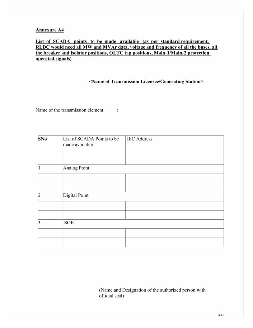
Annexure A4 List of SCADA points to be made available (as per standard requirement, RLDC would need all MW and MVAr data, voltage and frequency of all the buses, all the breaker and isolator positions, OLTC tap positions, Main‐1/Main‐2 protection operated signals) <Name of Transmission Licensee/Generating Station> Name of the transmission element : SNo List of SCADA Points to be
made available IEC Address
1 Analog Point
2 Digital Point
3 SOE
(Name and Designation of the authorized person with official seal)
300
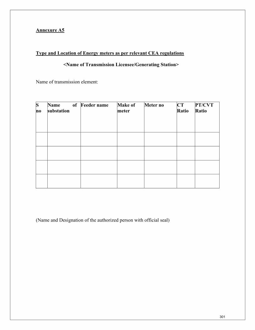
Annexure A5 Type and Location of Energy meters as per relevant CEA regulations <Name of Transmission Licensee/Generating Station> Name of transmission element: S no
Name of substation
Feeder name Make of meter
Meter no CT Ratio
PT/CVT Ratio
(Name and Designation of the authorized person with official seal) 301
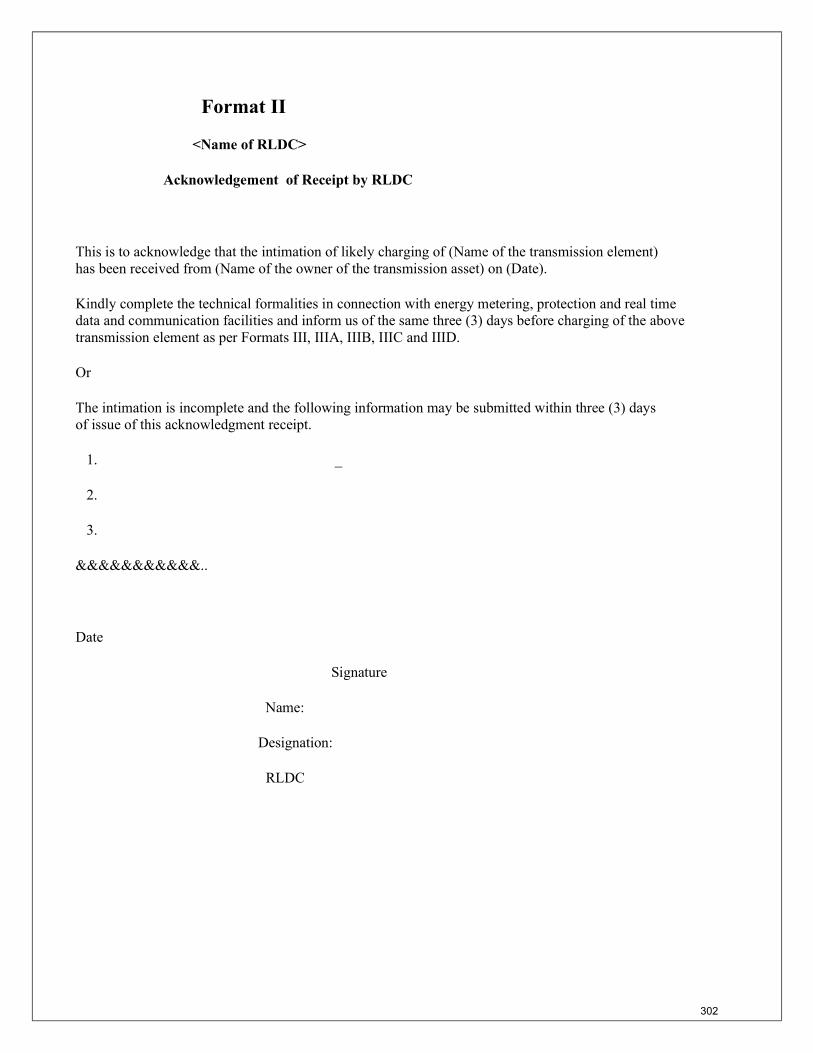
Format II <Name of RLDC> Acknowledgement of Receipt by RLDC This is to acknowledge that the intimation of likely charging of (Name of the transmission element) has been received from (Name of the owner of the transmission asset) on (Date). Kindly complete the technical formalities in connection with energy metering, protection and real time data and communication facilities and inform us of the same three (3) days before charging of the above transmission element as per Formats III, IIIA, IIIB, IIIC and IIID. Or The intimation is incomplete and the following information may be submitted within three (3) days of issue of this acknowledgment receipt. 1. _ 2. 3. &&&&&&&&&&&.. Date Signature Name: Designation: RLDC
302
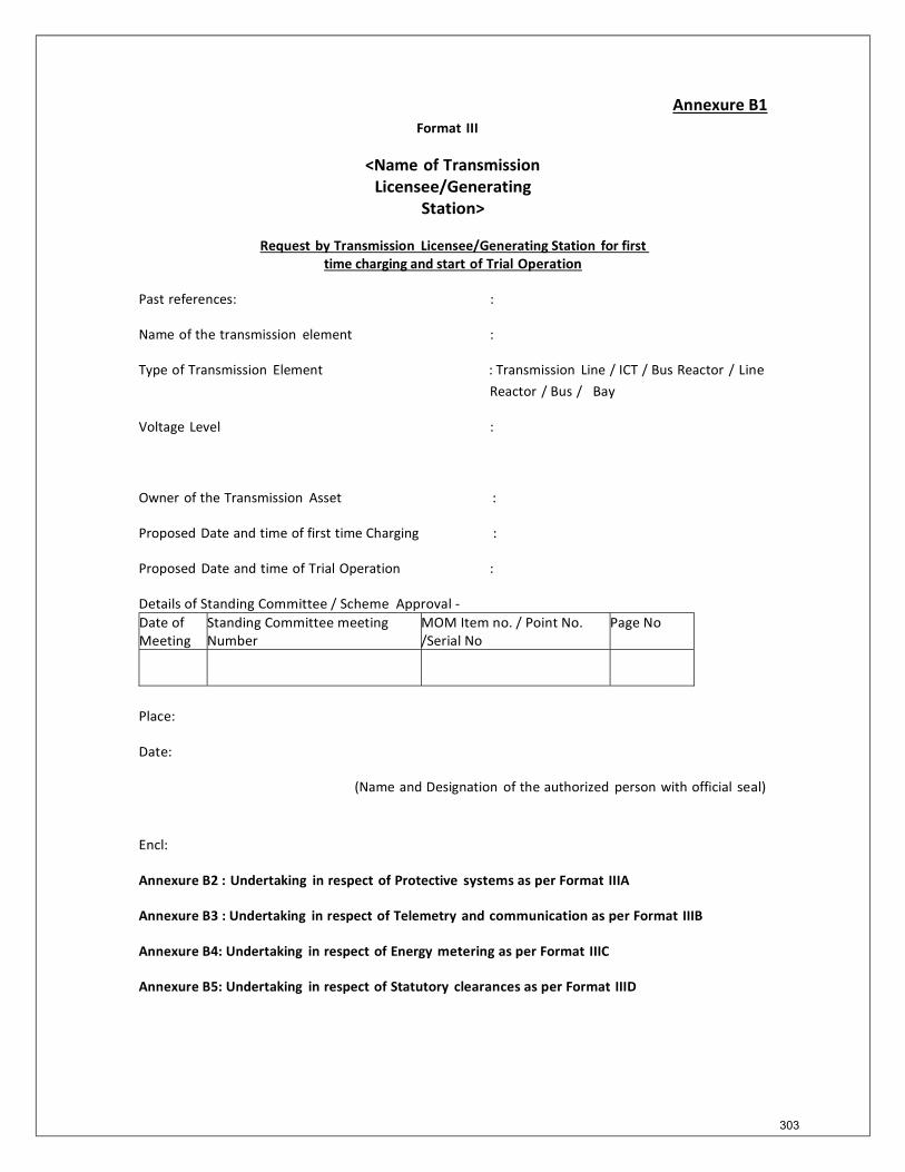
Annexure B1 Format III
<Name of Transmission
Licensee/Generating Station>
Request by Transmission Licensee/Generating Station for first
time charging and start of Trial Operation
Past references: :
Name of the transmission element :
Type of Transmission Element : Transmission Line / ICT / Bus Reactor / Line Reactor / Bus / Bay
Voltage Level :
Owner of the Transmission Asset :
Proposed Date and time of first time Charging :
Proposed Date and time of Trial Operation :
Details of Standing Committee / Scheme Approval - Date of Meeting
Standing Committee meeting Number
MOM Item no. / Point No. /Serial No
Page No
Place:
Date:
(Name and Designation of the authorized person with official seal)
Encl:
Annexure B2 : Undertaking in respect of Protective systems as per Format IIIA
Annexure B3 : Undertaking in respect of Telemetry and communication as per Format IIIB
Annexure B4: Undertaking in respect of Energy metering as per Format IIIC
Annexure B5: Undertaking in respect of Statutory clearances as per Format IIID
303
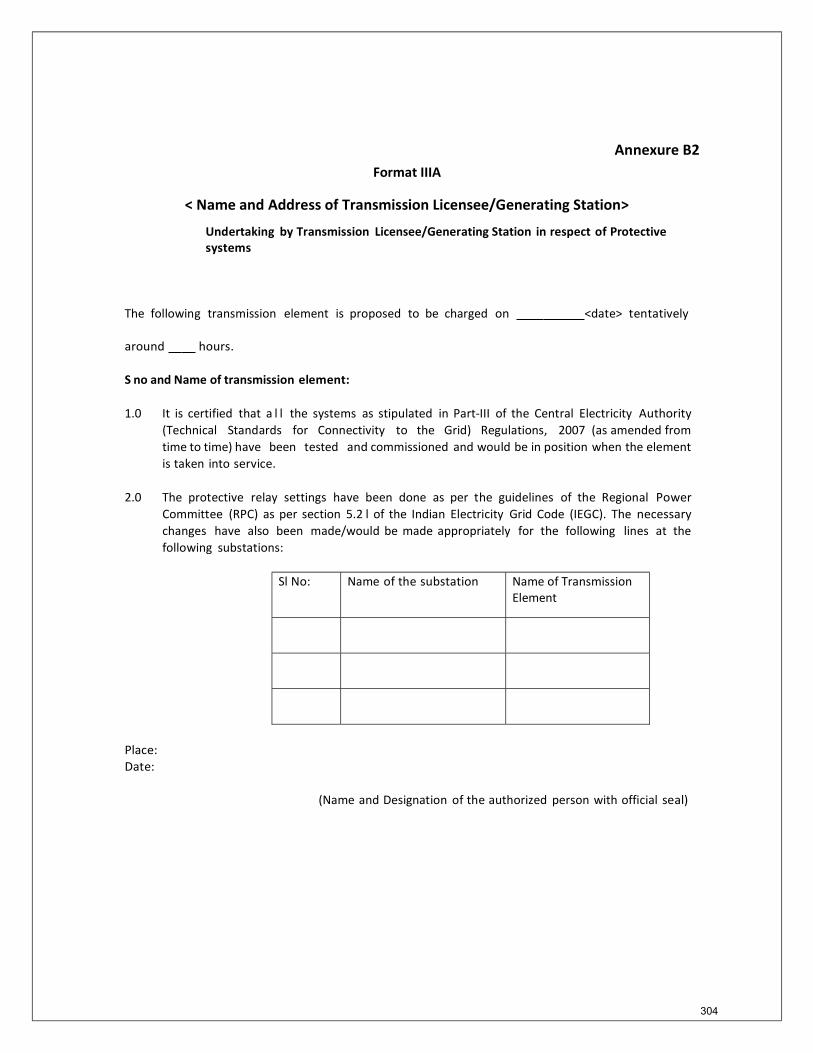
Annexure B2
Format IIIA
< Name and Address of Transmission Licensee/Generating Station>
Undertaking by Transmission Licensee/Generating Station in respect of Protective systems
The following transmission element is proposed to be charged on <date> tentatively
around hours.
S no and Name of transmission element:
1.0 It is certified that a l l the systems as stipulated in Part-III of the Central Electricity Authority (Technical Standards for Connectivity to the Grid) Regulations, 2007 (as amended from time to time) have been tested and commissioned and would be in position when the element is taken into service.
2.0 The protective relay settings have been done as per the guidelines of the Regional Power
Committee (RPC) as per section 5.2 l of the Indian Electricity Grid Code (IEGC). The necessary changes have also been made/would be made appropriately for the following lines at the following substations:
Sl No: Name of the substation Name of Transmission
Element
Place: Date:
(Name and Designation of the authorized person with official seal)
304
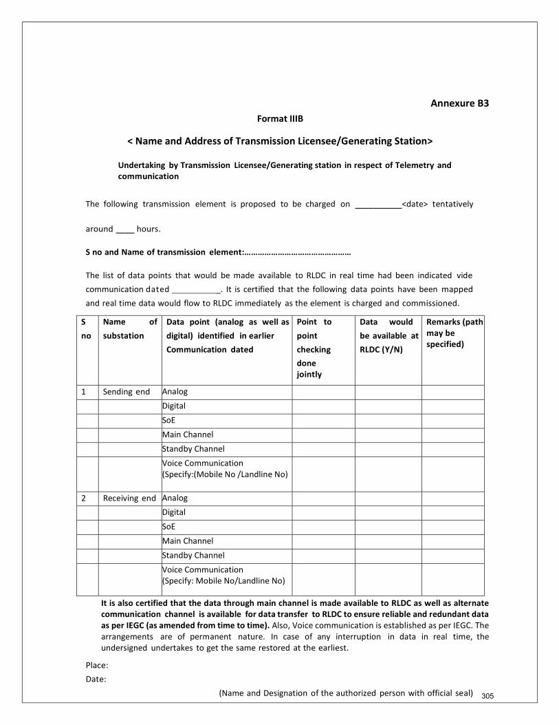
Annexure B3
Format IIIB
< Name and Address of Transmission Licensee/Generating Station>
Undertaking by Transmission Licensee/Generating station in respect of Telemetry and communication
The following transmission element is proposed to be charged on <date> tentatively
around hours.
S no and Name of transmission element:…………………………………………
The list of data points that would be made available to RLDC in real time had been indicated vide communication dated _. It is certified that the following data points have been mapped
and real time data would flow to RLDC immediately as the element is charged and commissioned.
S no
Name of
substation Data point (analog as well as digital) identified in earlier Communication dated
Point to
point checking done jointly with
Data would be available at RLDC (Y/N)
Remarks (path may be specified)
1 Sending end Analog Digital SoE Main Channel Standby Channel Voice Communication
(Specify:(Mobile No /Landline No)
2 Receiving end Analog Digital SoE Main Channel Standby Channel Voice Communication
(Specify: Mobile No/Landline No)
It is also certified that the data through main channel is made available to RLDC as well as alternate communication channel is available for data transfer to RLDC to ensure reliable and redundant data as per IEGC (as amended from time to time). Also, Voice communication is established as per IEGC. The arrangements are of permanent nature. In case of any interruption in data in real time, the undersigned undertakes to get the same restored at the earliest.
Place: Date:
(Name and Designation of the authorized person with official seal) 305
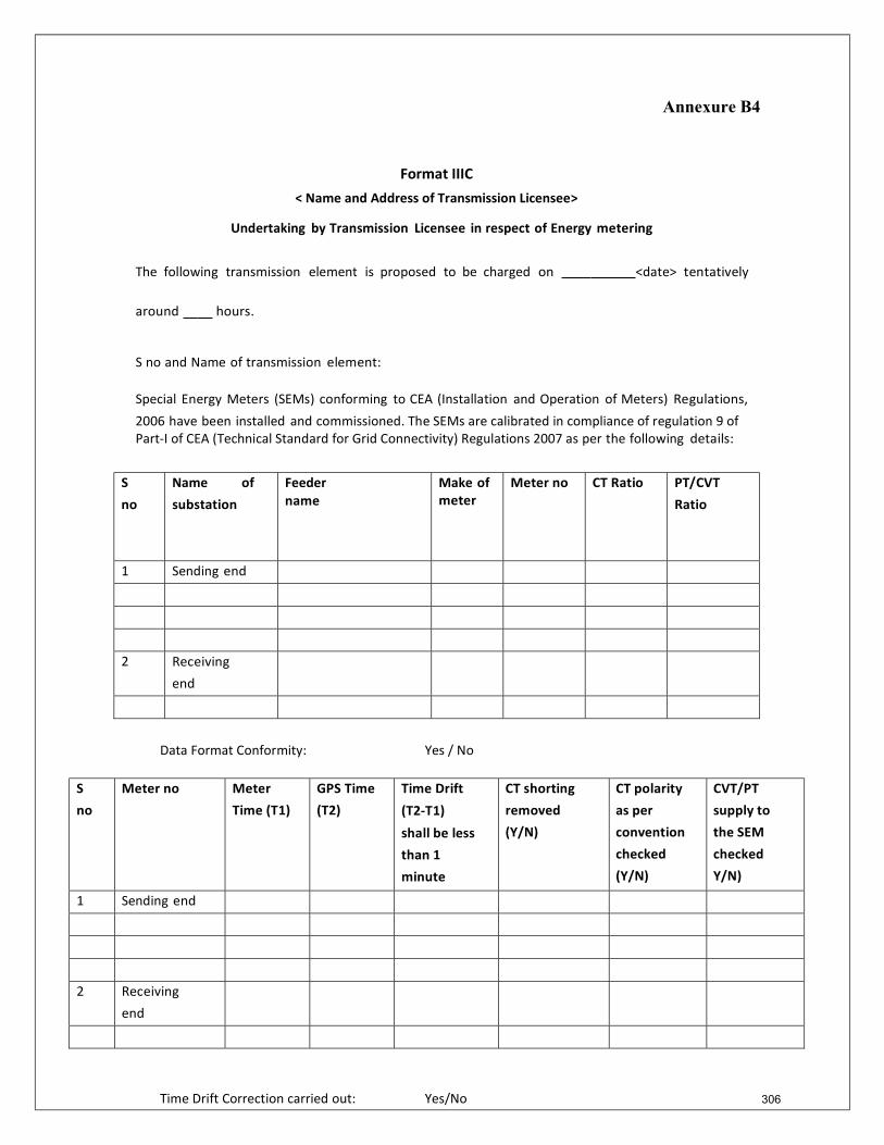
Annexure B4
Format IIIC
< Name and Address of Transmission Licensee>
Undertaking by Transmission Licensee in respect of Energy metering
The following transmission element is proposed to be charged on <date> tentatively
around hours.
S no and Name of transmission element:
Special Energy Meters (SEMs) conforming to CEA (Installation and Operation of Meters) Regulations,
2006 have been installed and commissioned. The SEMs are calibrated in compliance of regulation 9 of Part-I of CEA (Technical Standard for Grid Connectivity) Regulations 2007 as per the following details:
S no
Name of substation
Feeder name
Make of meter
Meter no CT Ratio PT/CVT Ratio
1 Sending end
2 Receiving end
Data Format Conformity: Yes / No
S no
Meter no Meter Time (T1)
GPS Time (T2)
Time Drift
(T2-T1)
shall be less than 1 minute
CT shorting removed (Y/N)
CT polarity as per convention checked (Y/N)
CVT/PT supply to the SEM checked Y/N)
1 Sending end
2 Receiving end
Time Drift Correction carried out: Yes/No 306

Annexure B4
The data from the above meters would be forwarded on weekly basis to the RLDC as per section 6.4.21 of the Indian Electricity Grid Code (IEGC) (as amended from time to time) and also as and when requested by the RLDC.
(RLDC to indicate the email ids where the data has to be forwarded).
Place:
Date:
(Name and Designation of the authorized person with official seal)
307
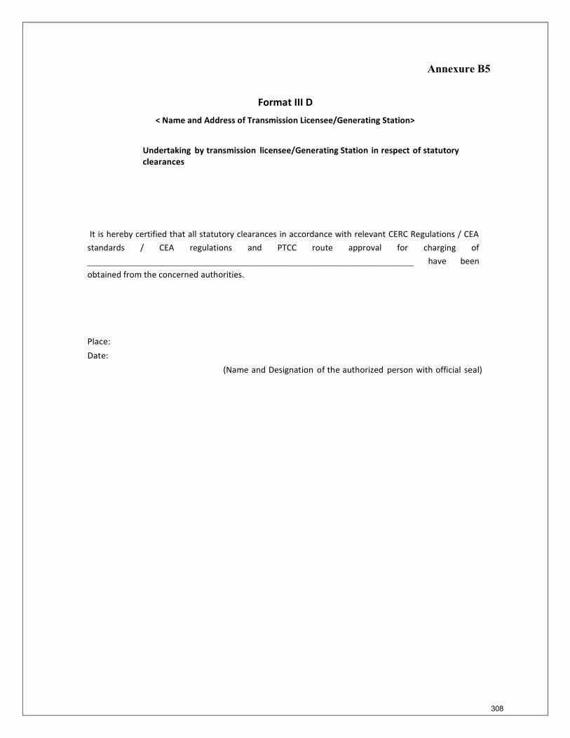
Annexure B5
Format III D
< Name and Address of Transmission Licensee/Generating Station>
Undertaking by transmission licensee/Generating Station in respect of statutory clearances
It is hereby certified that all statutory clearances in accordance with relevant CERC Regulations / CEA standards / CEA regulations and PTCC route approval for charging of ______________________________________________________________________ have been obtained from the concerned authorities.
Place: Date:
(Name and Designation of the authorized person with official seal)
308
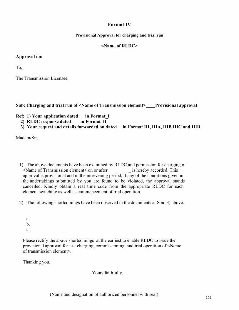
Format IV
Provisional Approval for charging and trial run
<Name of RLDC> Approval no: To, The Transmission Licensee, Sub: Charging and trial run of <Name of Transmission element>____Provisional approval Ref: 1) Your application dated in Format_I 2) RLDC response dated in Format_II 3) Your request and details forwarded on dated in Format III, IIIA, IIIB IIIC and IIID Madam/Sir, 1) The above documents have been examined by RLDC and permission for charging of <Name of Transmission element> on or after _ is hereby accorded. This approval is provisional and in the intervening period, if any of the conditions given in the undertakings submitted by you are found to be violated, the approval stands cancelled. Kindly obtain a real time code from the appropriate RLDC for each element switching as well as commencement of trial operation. 2) The following shortcomings have been observed in the documents at S no 3) above. a. b. c. Please rectify the above shortcomings at the earliest to enable RLDC to issue the provisional approval for test charging, commissioning and trial operation of <Name of transmission element>. Thanking you, Yours faithfully, (Name and designation of authorized personnel with seal)
309
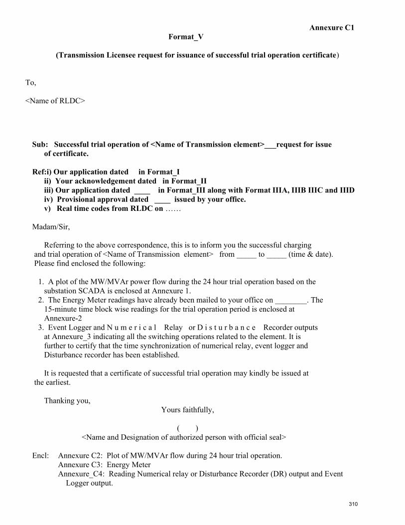
Annexure C1 Format_V
(Transmission Licensee request for issuance of successful trial operation certificate) To, <Name of RLDC>
Sub: Successful trial operation of <Name of Transmission element>___request for issue of certificate. Ref:i) Our application dated in Format_I ii) Your acknowledgement dated in Format_II iii) Our application dated ____ in Format_III along with Format IIIA, IIIB IIIC and IIID iv) Provisional approval dated ____ issued by your office. v) Real time codes from RLDC on …… Madam/Sir, Referring to the above correspondence, this is to inform you the successful charging and trial operation of <Name of Transmission element> from _____ to _____ (time & date). Please find enclosed the following: 1. A plot of the MW/MVAr power flow during the 24 hour trial operation based on the substation SCADA is enclosed at Annexure 1. 2. The Energy Meter readings have already been mailed to your office on ________. The 15-minute time block wise readings for the trial operation period is enclosed at Annexure-2 3. Event Logger and N u m e r i c a l Relay or D i s t u r b a n c e Recorder outputs at Annexure_3 indicating all the switching operations related to the element. It is further to certify that the time synchronization of numerical relay, event logger and Disturbance recorder has been established. It is requested that a certificate of successful trial operation may kindly be issued at the earliest. Thanking you, Yours faithfully, ( ) <Name and Designation of authorized person with official seal> Encl: Annexure C2: Plot of MW/MVAr flow during 24 hour trial operation. Annexure C3: Energy Meter Annexure_C4: Reading Numerical relay or Disturbance Recorder (DR) output and Event Logger output.
310
77th
PCC Minutes
Annexure-IV(A)
ITEM NO. C.7: Disturbance monitoring equipment (DME) standardization
The power system is routinely subjected to faults or disturbances which can range from transient
faults on transmission lines to system-wide disturbances involving multiple control areas, states
and even countries. Investigation of each incident is critical in optimizing the performance of
protection systems with the goal of preventing future incidents from becoming wide-area
disturbances. The tools required to perform post-incident analyses include DME which can
capture pre-event, event, and post-event conditions with a high degree of accuracy.
Recorders can be classified into two categories:
• FR (Fault Recorder) • Sequence of events Recorder (SER)
For FR (Fault Recorder) following points may be standardized:
a. Deployment b. Record Length c. Triggers d. Sampling Rates
For Sequence of events Recorder following points may be standardized:
a. SER Capability b. Point Assignments c. Use of RTUs for SER
Common issues:
a. Data format b. Power Supply c. Monitoring
Reference documents for this:
1. NERC Standard PRC-002-2 Disturbance Monitoring and Reporting Requirements 2. NPCC Regional Reliability Reference Directory # 11 Disturbance Monitoring Equipment
Criteria
In 74th PCC, all the constituents were advised to submit their comments/observations relating to the
draft standard.
PCC also decided similar kind of standard would be prepared for Transformer Protection and
Busbar Protection.
In 75th PCC, PRDC presented the draft standard for Transformer Protection and Busbar
Protection. In 76th PCC, all the members were advised to submit their comments to ERLDC and ERPC at the earliest.
Members may update.
Deliberation in the meeting
The updated draft standard is attached at Annexure-C7. PCC advised all the constituents to

77th
PCC Minutes
submit their comments to ERLDC and ERPC by next PCC

Triggering criteria for DR : Any Start
ERPC Proposed Guide Lines
Internal protection trip signals, external trigger
input, analog triggering (any phase current
exceeding 1.5 pu of CT secondary current or
any phase voltage below 0.8pu,
neutral/residual overcurrent greater than
0.25pu of CT secondary current).
DR time window : minimum 3 seconds. minimum 2 seconds.
Pre-fault time window (S): 0.5 -
Post fault time window (S): 2.5 0.3
Minimum sampling frequency: 1000 Hz 64 Samples Per Cycle
Analog signals as per priority
A. Mandatory signals:
1. Three phase voltage 1. Three phase-to-neutral voltages
2. Neutral voltage 2. Three phase currents and neutral currents.
3. Three phase current 3. Neutral Currents
4. Neutral current 4. Frequency
B. Optional signals:
1. Mutual current 1. Polarizing currents and voltages, if used.
2. Check Sync 2. Real and reactive power
The Minimum parameters to be monitored in
the Fault record shall be specified by the
Digital signals as per priority
A. Mandatory signals:
B. Optional signals:
3. Open Delta
1. Any Start
2. Any trip
3. Z1, Z2, Z3, Z4 pick up
4. Over current and Earth fault pick up
5. Over voltage stage I & II pick up
6. DT send & reverse
7. Carrier send & Receive
8. Main three phase CB open signal
9. Tie three phase CB open signal (where applicable)
10. Power Swing
11. SOTF/TOR
12. LBB
13. A/R L/O
14. Main-1/2 operated
15. Bus Bar trip
16. VT failure
17. Distance Forward & Reverse
18. T1, T2, T3, T4
19. Broken conductor
20. 86A & 86B
21. A/R 1P In Prog
22. A/R Fail
23. STUB/TEED (where applicable)
1. Any External input
2. Any Binary Input
respective RPC.
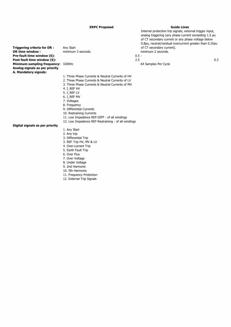
Triggering criteria for DR : Any Start
ERPC Proposed Guide Lines
Internal protection trip signals, external trigger input,
analog triggering (any phase current exceeding 1.5 pu
of CT secondary current or any phase voltage below
0.8pu, neutral/residual overcurrent greater than 0.25pu
of CT secondary current).
DR time window : minimum 3 seconds. minimum 2 seconds.
Pre-fault time window (S): 0.5 -
Post fault time window (S): 2.5 0.3
Minimum sampling frequency: 3200Hz 64 Samples Per Cycle
Analog signals as per priority
A. Mandatory signals:
Digital signals as per priority
1. Three Phase Currents & Neutral Currents of HV
2. Three Phase Currents & Neutral Currents of LV
3. Three Phase Currents & Neutral Currents of MV
4. I_REF HV
5. I_REF LV
6. I_REF MV
7. Voltages
8. Frequency
9. Differential Currents
10. Restraining Currents
11. Low Impedence REF-DIFF - of all windings
12. Low Impedence REF-Restraining - of all windings
1. Any Start
2. Any trip
3. Differential Trip
3. REF Trip HV, MV & LV
4. Over-current Trip
5. Earth Fault Trip
6. Over Flux
7. Over Voltage
8. Under Voltage
9. 2nd Harmonic
10. 5th Harmonic
11. Frequency Protection
12. External Trip Signals
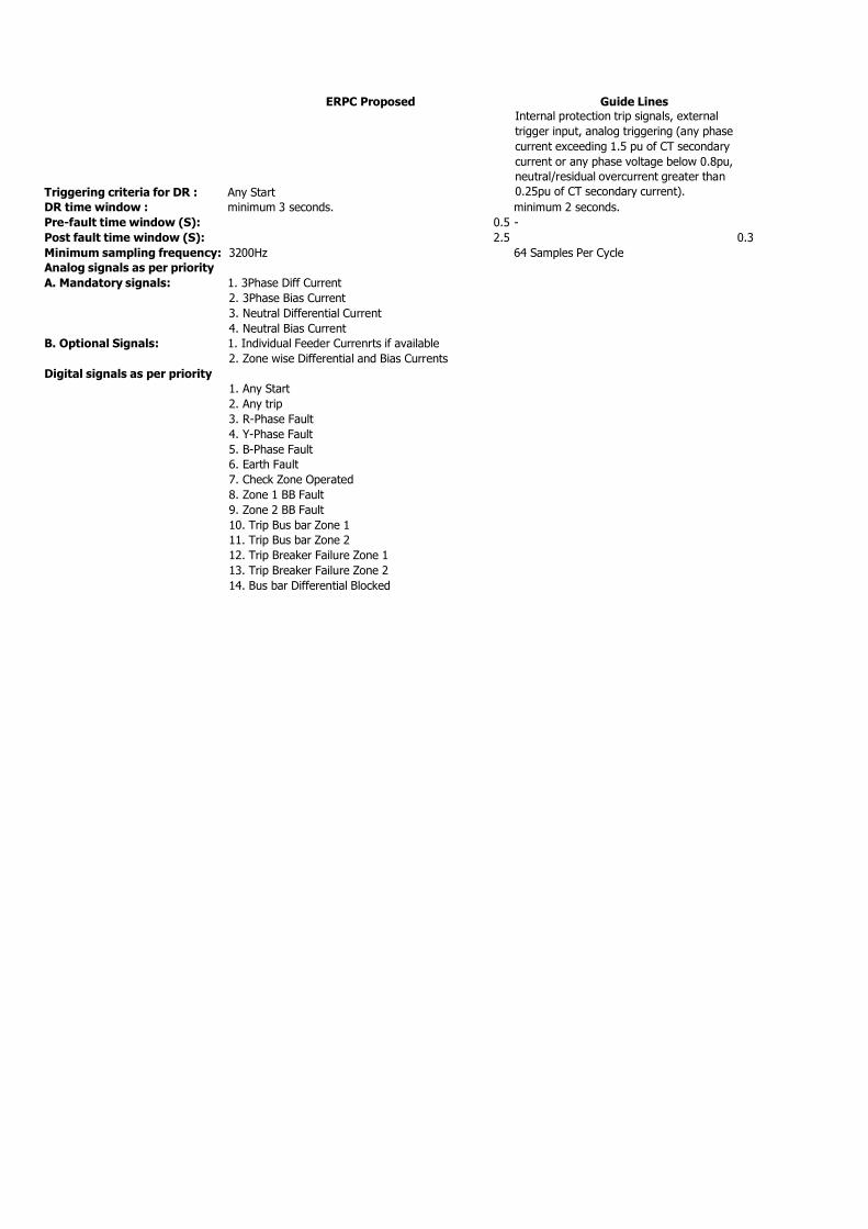
Triggering criteria for DR : Any Start
ERPC Proposed Guide Lines
Internal protection trip signals, external
trigger input, analog triggering (any phase
current exceeding 1.5 pu of CT secondary
current or any phase voltage below 0.8pu,
neutral/residual overcurrent greater than
0.25pu of CT secondary current).
DR time window : minimum 3 seconds. minimum 2 seconds.
Pre-fault time window (S): 0.5 -
Post fault time window (S): 2.5 0.3
Minimum sampling frequency: 3200Hz 64 Samples Per Cycle
Analog signals as per priority
A. Mandatory signals: 1. 3Phase Diff Current
2. 3Phase Bias Current
3. Neutral Differential Current
4. Neutral Bias Current
B. Optional Signals: 1. Individual Feeder Currenrts if available
2. Zone wise Differential and Bias Currents
Digital signals as per priority 1. Any Start
2. Any trip
3. R-Phase Fault
4. Y-Phase Fault
5. B-Phase Fault
6. Earth Fault
7. Check Zone Operated
8. Zone 1 BB Fault
9. Zone 2 BB Fault
10. Trip Bus bar Zone 1
11. Trip Bus bar Zone 2
12. Trip Breaker Failure Zone 1
13. Trip Breaker Failure Zone 2
14. Bus bar Differential Blocked
Approved in 30th
TCC & 34th
NRPC Meetings (19th
and 20th
March, 2015)
Annexure-V
Procedure for Transmission
Elements Outage Planning
in Northern Region
March 2015
The procedure aims to streamline the process of transmission outage coordination between SLDCs, NRLDCs, NLDC, NRPC and Indenting Agencies
52
Approved in 30th
TCC & 34th
NRPC Meetings (19th
and 20th
March, 2015)
Procedure for Transmission Elements Outage Planning in Northern Region
1. Introduction
Reliable operation of the All India grid is important from the view point of
Quality Of Service (QoS) to the customers and other stakeholders. Proper co-
ordination of transmission outages in the system is one of the key aspects to
ensuring reliability. Outages in the transmission network could either be on
account of planned maintenance activities or construction related activities or
any emergency conditions arising in the field. Proper coordination of
transmission element outage is important mainly due to the following factors: i. Reliability of operation of the All India grid ii. Certainty to the electricity markets.
iii. Proper crew resource mobilization at the work sites to ensure that
outage time is minimized. iv. Proper coordination of works by different entities to ensure that
outage time is optimised.
Outage Coordination has been one of the important functions of Regional
Power Committees (RPCs), Regional Load Despatch Centres (RLDCs) and
National Load Despatch Centre (NLDC) and is the first stage of operational
planning. As per Indian Electricity Grid Code (IEGC), the responsibility to
undertake planning of outage of transmission system has been assigned to
RPCs. The outages of the inter-state transmission lines and intra state elements
which are important for the region are being coordinated by RLDCs. In the
cases where the outages may have an impact across two or more regions,
coordination is in consultation with NLDC. The relevant clauses of IEGC in this
regard are quoted below: “2.4.2 The following functions which go to facilitate the stability and
smooth operation of the systems are identified for the RPC: ………… (e) To undertake planning of outage of transmission system on annual
/ monthly basis.” “2.3 Role of RLDC
2.3.1.1The Regional Load Despatch Centre shall be the apex body to ensure
integrated operation of the power system in the concerned region”
“2.2 Role of NLDC
…….. (f) Coordination with Regional Power Committees for regional outage
schedule in the national perspective to ensure optimal utilization of power
resources.”
2. Objective 53
Approved in 30th
TCC & 34th
NRPC Meetings (19th
and 20th
March, 2015)
At present, planned outages are being discussed in respective Operation
Coordination Committee (OCC) meeting of RPCs and availed based on the
actual grid conditions and/or any changes requested by transmission system
owner or transmission element outage indenting agency. The approval of
planned as well as emergency outages in the transmission network level in real
time is being coordinated by RLDCs and NLDC based on system conditions.
The procedure aims to streamline the process of outage coordination between
SLDCs, RLDCs, NLDC, RPCs, owners of transmission assets and transmission
element outage Indenting Agencies. As outage planning is an important part of
operational planning, multi-layered checks would help in ensuring reliability of
the power system. These checks need to be at the following levels:
• Due diligence between the agencies involved in the transmission asset
maintenance through bilateral discussion.
• Studies, if required, prior to approval of outages sought Operation Co-
ordination sub-Committee of RPCs
• Off-line simulations and planning at RLDCs/NLDC level
• Real time check at RLDCs/NLDC level 3. Scope
The procedure is applicable to NRPC, NRLDC, NLDC, SLDCs, STUs, load serving entities and Indenting Agency. It would be applicable once the
annual outage plan is finalized by 31st
December of each year for the next
financial year by the NRPC as per the IEGC. 4. Definitions
4.1. Approving Load Despatch Centre: The Load Despatch Centre
responsible for approving any transmission outage shall be called
Approving Load Despatch Centre. 4.2. Consenting Load Despatch Centre: The agency whose consent is
required by Approving Load Despatch Centre for approving any outage
shall be called Consenting Load Despatch Centre. 4.3. Indenting Agency: The agency which gives the requisition for outage of
any transmission element shall be called Indenting Agency. Any of the
following may request for outage of any transmission elements:
(a) CTU
54
Approved in 30th
TCC & 34th
NRPC Meetings (19th
and 20th
March, 2015)
(b) STUs
(c) Transmission Licensees
(d) Generating Companies
(e) Distribution company 4.4 NLDC oversight transmission assets: All inter-national transmission lines
and inter-regional transmission lines together with all 765 kV AC lines,
HVDC lines and other lines which significantly influence power flow on
inter-regional transmission lines shall be treated as NLDC oversight
transmission asset. List of such lines is enclosed at Annex- I. NLDC shall
review and update the list of such assets relevant to Northern Region in
consultation with OCC and upload the same on its website. 4.5 NRLDC oversight transmission assets: All transmission assets under
following categories shall be treated as NRLDC oversight transmission
assets.
(i) Category A: Transmission elements at 400 kV and above.
(ii) Category B: Transmission elements at 132 kV and above level
emanating from ISGS.
(iii) Category C: Transmission elements at 132 kV and above which are
inter-regional in nature.
(iv) Category D : Transmission elements at 132 kV level with one end in
a State while other end in another State.
List of such lines is enclosed at Annex-II. NRLDC shall review and update
the list of such assets in consultation with OCC and upload the same on
its website.
4.6 Words and expressions used in this procedure and not defined herein but
defined in the Electricity Act, 2003 (Act) or Indian Electricity Grid Code
(IEGC) shall have the meaning assigned to them under the Act or IEGC.
5. Procedure for discussing transmission outages in OCC meeting.
55
Approved in 30th
TCC & 34th
NRPC Meetings (19th
and 20th
March, 2015)
5.1. Indenting Agency shall submit the proposed shutdown for NLDC
oversight transmission assets for the next calendar month latest by 5th
day of the current month to NRPC Secretariat as per Format IA /
Format IB. The Intending Agency shall also inform the same to NLDC
and other relevant RPC Secretariats. 5.2. Indenting Agency shall submit the proposed shutdown for NRLDC
oversight transmission assets for the next calendar month latest by 8th
day of the current month to NRPC Secretariat as per Format IA /
Format IB. 5.3. The indenting agency shall carry out an internal screening of its outage
plan centrally to avoid multiple outages in the same corridor
simultaneously. Bilateral discussion between the agencies involved
may also be done to minimize outage duration before submitting the
outage plan to NRPC Secretariat. 5.4. NRPC Secretariat shall compile all the received proposals for NLDC
oversight transmission assets and NRLDC oversight transmission assets
separately and put up the same on its website by 5th
day of the month
and 12th
day of the month respectively. 5.5. If required, system studies will be carried out to facilitate discussions in
the OCC meeting. 5.6. The requests for transmission outages shall be considered by OCC
keeping in view compliance to n-1 criteria for the relevant corridor.
Based on decisions taken by the OCC, a list of approved transmission outages with the precautions to be taken shall be prepared. NRPC
would endavour to schedule all their OCC meetings between 10th
to
20th
day of the month. 5.7. NRPC Secretariat shall upload the list of approved transmission
outages on NRPC website within 3 working days of the OCC meeting. 5.8. Any shutdown proposal which requires approval of another RPC shall
be considered approved only if it is approved by the OCC of NRPC as
well as that of other RPC. 56
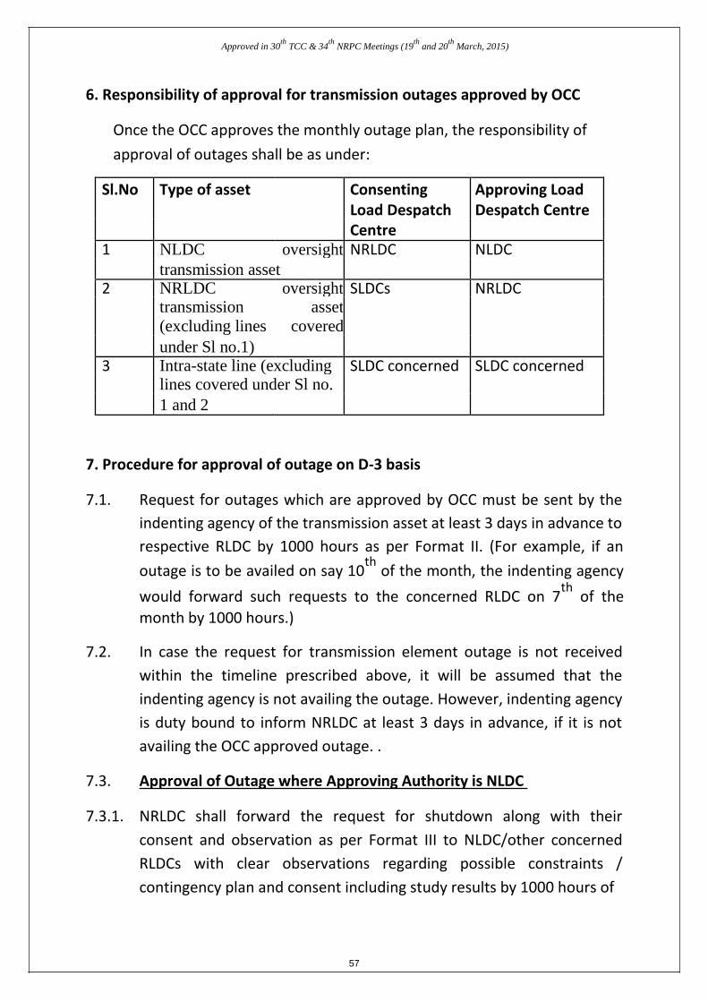
Approved in 30th
TCC & 34th
NRPC Meetings (19th
and 20th
March, 2015)
6. Responsibility of approval for transmission outages approved by OCC
Once the OCC approves the monthly outage plan, the responsibility of
approval of outages shall be as under:
Sl.No Type of asset Consenting Approving Load
Load Despatch Despatch Centre
Centre
1 NLDC oversight NRLDC NLDC
transmission asset
2 NRLDC oversight SLDCs NRLDC
transmission asset
(excluding lines covered
under Sl no.1)
3 Intra-state line (excluding SLDC concerned SLDC concerned
lines covered under Sl no.
1 and 2
7. Procedure for approval of outage on D-3 basis
7.1. Request for outages which are approved by OCC must be sent by the
indenting agency of the transmission asset at least 3 days in advance to respective RLDC by 1000 hours as per Format II. (For example, if an
outage is to be availed on say 10th
of the month, the indenting agency
would forward such requests to the concerned RLDC on 7th
of the
month by 1000 hours.) 7.2. In case the request for transmission element outage is not received
within the timeline prescribed above, it will be assumed that the
indenting agency is not availing the outage. However, indenting agency
is duty bound to inform NRLDC at least 3 days in advance, if it is not
availing the OCC approved outage. . 7.3. Approval of Outage where Approving Authority is NLDC
7.3.1. NRLDC shall forward the request for shutdown along with their
consent and observation as per Format III to NLDC/other concerned
RLDCs with clear observations regarding possible constraints /
contingency plan and consent including study results by 1000 hours of
57
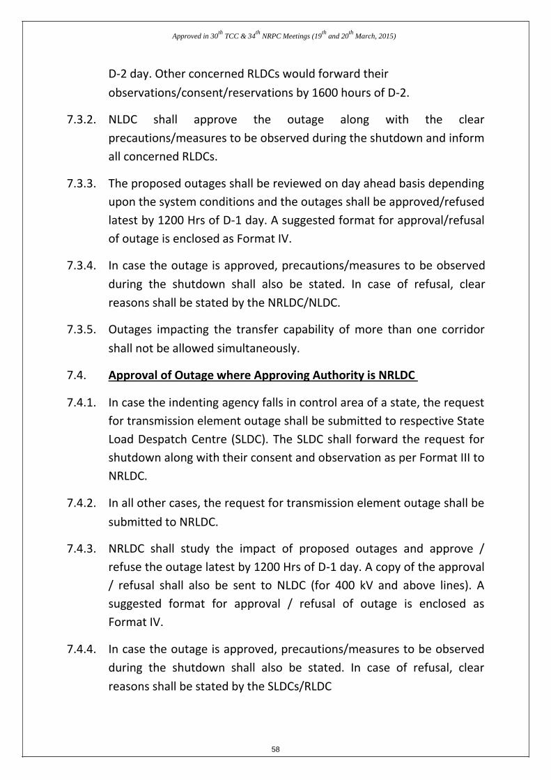
Approved in 30th
TCC & 34th
NRPC Meetings (19th
and 20th
March, 2015)
D-2 day. Other concerned RLDCs would forward their
observations/consent/reservations by 1600 hours of D-2.
7.3.2. NLDC shall approve the outage along with the clear
precautions/measures to be observed during the shutdown and inform
all concerned RLDCs. 7.3.3. The proposed outages shall be reviewed on day ahead basis depending
upon the system conditions and the outages shall be approved/refused
latest by 1200 Hrs of D-1 day. A suggested format for approval/refusal
of outage is enclosed as Format IV. 7.3.4. In case the outage is approved, precautions/measures to be observed
during the shutdown shall also be stated. In case of refusal, clear
reasons shall be stated by the NRLDC/NLDC. 7.3.5. Outages impacting the transfer capability of more than one corridor
shall not be allowed simultaneously.
7.4. Approval of Outage where Approving Authority is NRLDC
7.4.1. In case the indenting agency falls in control area of a state, the request
for transmission element outage shall be submitted to respective State
Load Despatch Centre (SLDC). The SLDC shall forward the request for
shutdown along with their consent and observation as per Format III to
NRLDC. 7.4.2. In all other cases, the request for transmission element outage shall be
submitted to NRLDC. 7.4.3. NRLDC shall study the impact of proposed outages and approve /
refuse the outage latest by 1200 Hrs of D-1 day. A copy of the approval
/ refusal shall also be sent to NLDC (for 400 kV and above lines). A
suggested format for approval / refusal of outage is enclosed as
Format IV. 7.4.4. In case the outage is approved, precautions/measures to be observed
during the shutdown shall also be stated. In case of refusal, clear
reasons shall be stated by the SLDCs/RLDC 58
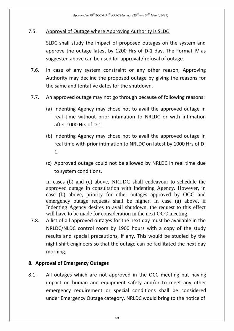
Approved in 30th
TCC & 34th
NRPC Meetings (19th
and 20th
March, 2015)
7.5. Approval of Outage where Approving Authority is SLDC
SLDC shall study the impact of proposed outages on the system and
approve the outage latest by 1200 Hrs of D-1 day. The Format IV as
suggested above can be used for approval / refusal of outage.
7.6. In case of any system constraint or any other reason, Approving
Authority may decline the proposed outage by giving the reasons for
the same and tentative dates for the shutdown.
7.7. An approved outage may not go through because of following reasons:
(a) Indenting Agency may chose not to avail the approved outage in
real time without prior intimation to NRLDC or with intimation
after 1000 Hrs of D-1.
(b) Indenting Agency may chose not to avail the approved outage in
real time with prior intimation to NRLDC on latest by 1000 Hrs of D-
1.
(c) Approved outage could not be allowed by NRLDC in real time due
to system conditions.
In cases (b) and (c) above, NRLDC shall endeavour to schedule the
approved outage in consultation with Indenting Agency. However, in
case (b) above, priority for other outages approved by OCC and
emergency outage requests shall be higher. In case (a) above, if
Indenting Agency desires to avail shutdown, the request to this effect
will have to be made for consideration in the next OCC meeting. 7.8. A list of all approved outages for the next day must be available in the
NRLDC/NLDC control room by 1900 hours with a copy of the study
results and special precautions, if any. This would be studied by the
night shift engineers so that the outage can be facilitated the next day
morning. 8. Approval of Emergency Outages
8.1. All outages which are not approved in the OCC meeting but having
impact on human and equipment safety and/or to meet any other
emergency requirement or special conditions shall be considered
under Emergency Outage category. NRLDC would bring to the notice of
59
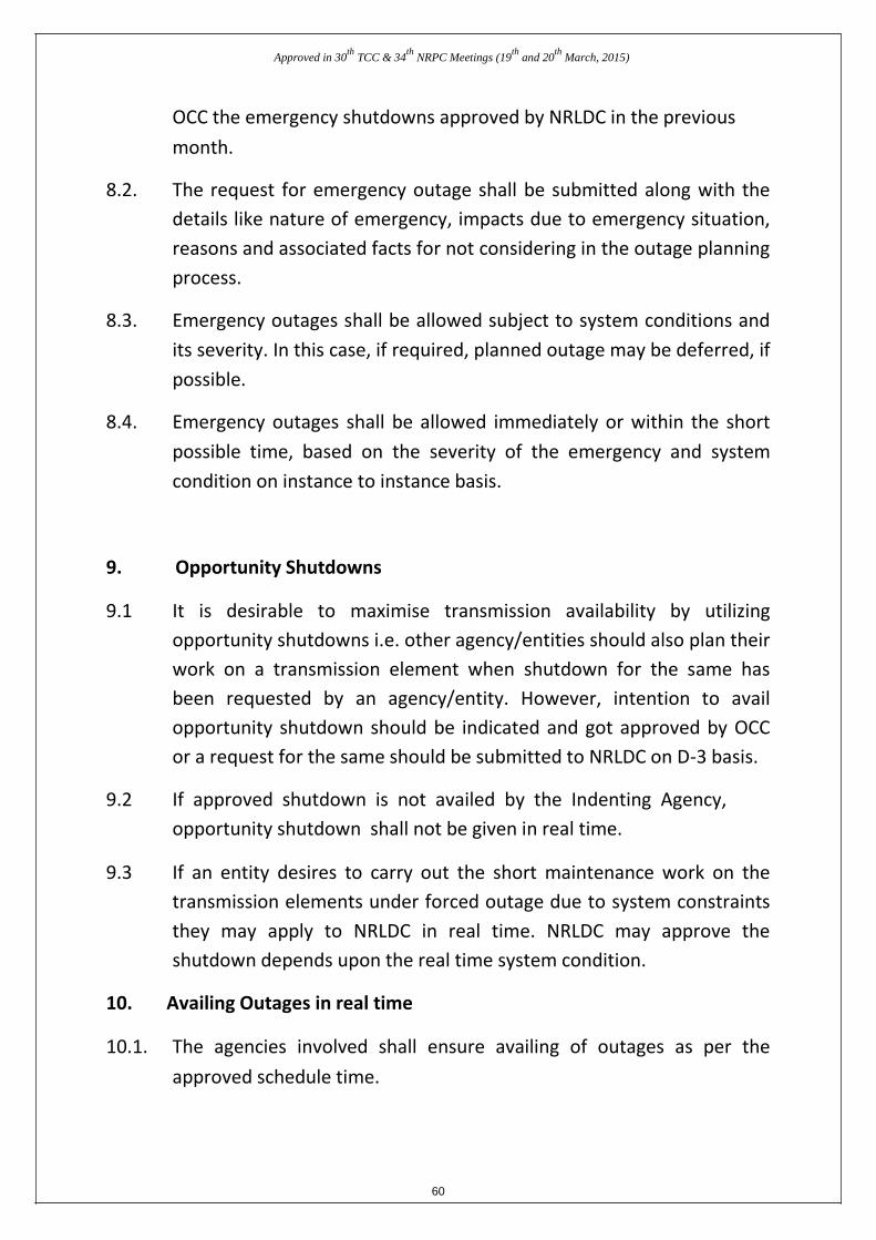
Approved in 30th
TCC & 34th
NRPC Meetings (19th
and 20th
March, 2015)
OCC the emergency shutdowns approved by NRLDC in the previous
month.
8.2. The request for emergency outage shall be submitted along with the
details like nature of emergency, impacts due to emergency situation,
reasons and associated facts for not considering in the outage planning
process. 8.3. Emergency outages shall be allowed subject to system conditions and
its severity. In this case, if required, planned outage may be deferred, if
possible. 8.4. Emergency outages shall be allowed immediately or within the short
possible time, based on the severity of the emergency and system
condition on instance to instance basis.
9. Opportunity Shutdowns
9.1 It is desirable to maximise transmission availability by utilizing
opportunity shutdowns i.e. other agency/entities should also plan their
work on a transmission element when shutdown for the same has
been requested by an agency/entity. However, intention to avail
opportunity shutdown should be indicated and got approved by OCC
or a request for the same should be submitted to NRLDC on D-3 basis. 9.2 If approved shutdown is not availed by the Indenting Agency,
opportunity shutdown shall not be given in real time.
9.3 If an entity desires to carry out the short maintenance work on the
transmission elements under forced outage due to system constraints
they may apply to NRLDC in real time. NRLDC may approve the
shutdown depends upon the real time system condition.
10. Availing Outages in real time
10.1. The agencies involved shall ensure availing of outages as per the
approved schedule time. 60
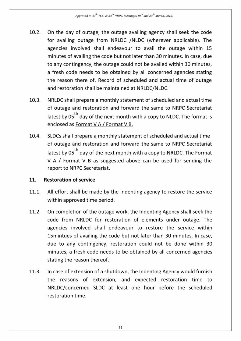
Approved in 30th
TCC & 34th
NRPC Meetings (19th
and 20th
March, 2015)
10.2. On the day of outage, the outage availing agency shall seek the code
for availing outage from NRLDC /NLDC (wherever applicable). The
agencies involved shall endeavour to avail the outage within 15
minutes of availing the code but not later than 30 minutes. In case, due
to any contingency, the outage could not be availed within 30 minutes,
a fresh code needs to be obtained by all concerned agencies stating
the reason there of. Record of scheduled and actual time of outage
and restoration shall be maintained at NRLDC/NLDC. 10.3. NRLDC shall prepare a monthly statement of scheduled and actual time
of outage and restoration and forward the same to NRPC Secretariat
latest by 05th
day of the next month with a copy to NLDC. The format is
enclosed as Format V A / Format V B. 10.4. SLDCs shall prepare a monthly statement of scheduled and actual time
of outage and restoration and forward the same to NRPC Secretariat
latest by 05th
day of the next month with a copy to NRLDC. The Format
V A / Format V B as suggested above can be used for sending the
report to NRPC Secretariat.
11. Restoration of service 11.1. All effort shall be made by the Indenting agency to restore the service
within approved time period. 11.2. On completion of the outage work, the Indenting Agency shall seek the
code from NRLDC for restoration of elements under outage. The
agencies involved shall endeavour to restore the service within
15mintues of availing the code but not later than 30 minutes. In case,
due to any contingency, restoration could not be done within 30
minutes, a fresh code needs to be obtained by all concerned agencies
stating the reason thereof. 11.3. In case of extension of a shutdown, the Indenting Agency would furnish
the reasons of extension, and expected restoration time to
NRLDC/concerned SLDC at least one hour before the scheduled
restoration time. 61
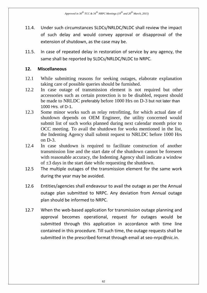
Approved in 30th
TCC & 34th
NRPC Meetings (19th
and 20th
March, 2015)
11.4. Under such circumstances SLDCs/NRLDC/NLDC shall review the impact
of such delay and would convey approval or disapproval of the
extension of shutdown, as the case may be. 11.5. In case of repeated delay in restoration of service by any agency, the
same shall be reported by SLDCs/NRLDC/NLDC to NRPC.
12. Miscellaneous 12.1 While submitting reasons for seeking outages, elaborate explanation
taking care of possible queries should be furnished. 12.2 In case outage of transmission element is not required but other
accessories such as certain protection is to be disabled, request should
be made to NRLDC preferably before 1000 Hrs on D-3 but not later than 1000 Hrs. of D-1.
12.3 Some minor works such as relay retrofitting, for which actual date of
shutdown depends on OEM Engineer, the utility concerned would
submit list of such works planned during next calendar month prior to
OCC meeting. To avail the shutdown for works mentioned in the list,
the Indenting Agency shall submit request to NRLDC before 1000 Hrs
on D-3. 12.4 In case shutdown is required to facilitate construction of another
transmission line and the start date of the shutdown cannot be foreseen
with reasonable accuracy, the Indenting Agency shall indicate a window
of ±3 days in the start date while requesting the shutdown.
12.5 The multiple outages of the transmission element for the same work
during the year may be avoided. 12.6 Entities/agencies shall endeavour to avail the outage as per the Annual
outage plan submitted to NRPC. Any deviation from Annual outage
plan should be informed to NRPC. 12.7 When the web-based application for transmission outage planning and
approval becomes operational, request for outages would be
submitted through this application in accordance with time line
contained in this procedure. Till such time, the outage requests shall be
submitted in the prescribed format through email at [email protected]. 62
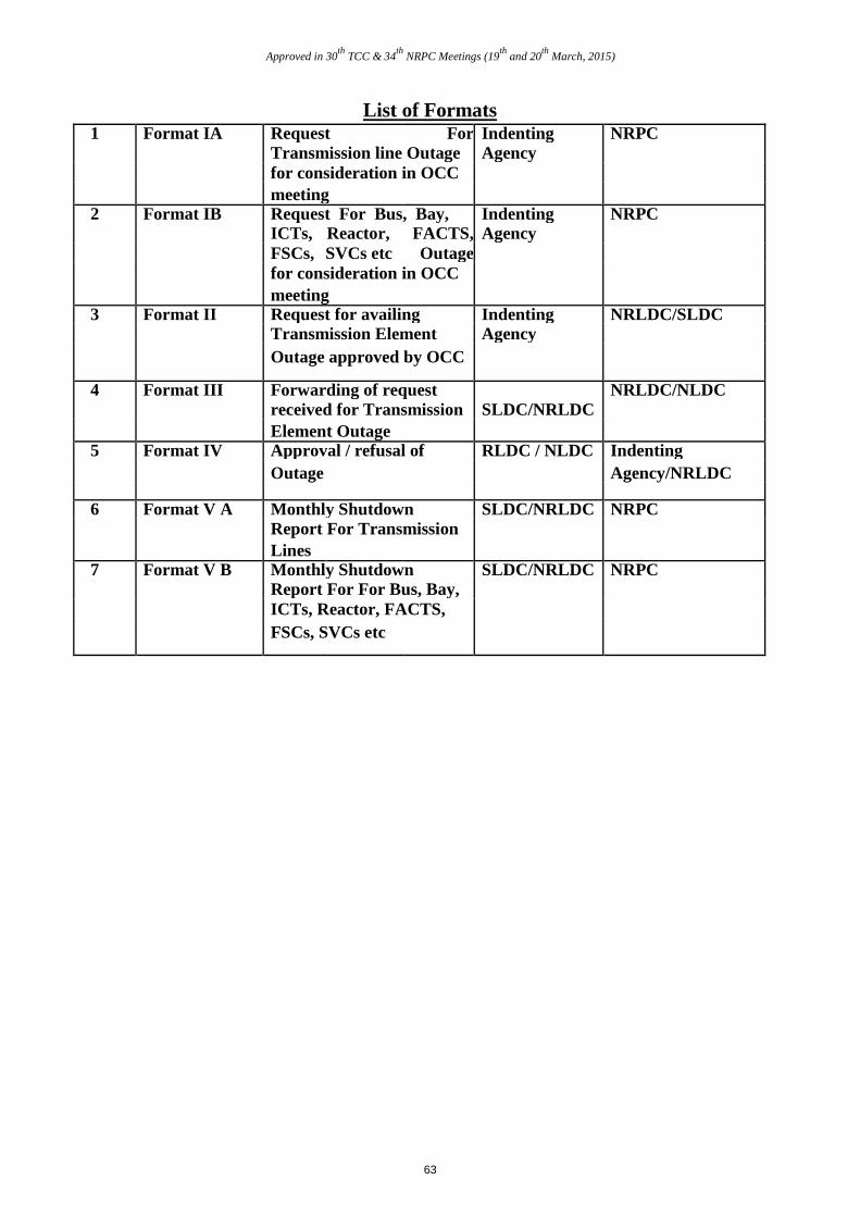
Approved in 30th
TCC & 34th
NRPC Meetings (19th
and 20th
March, 2015)
List of Formats 1 Format IA Request For Indenting NRPC
Transmission line Outage Agency
for consideration in OCC
meeting 2 Format IB Request For Bus, Bay, Indenting NRPC
ICTs, Reactor, FACTS, Agency
FSCs, SVCs etc Outage
for consideration in OCC
meeting 3 Format II Request for availing Indenting NRLDC/SLDC
Transmission Element Agency
Outage approved by OCC
4 Format III Forwarding of request NRLDC/NLDC received for Transmission SLDC/NRLDC
Element Outage 5 Format IV Approval / refusal of RLDC / NLDC Indenting
Outage Agency/NRLDC
6 Format V A Monthly Shutdown SLDC/NRLDC NRPC Report For Transmission
Lines 7 Format V B Monthly Shutdown SLDC/NRLDC NRPC
Report For For Bus, Bay,
ICTs, Reactor, FACTS,
FSCs, SVCs etc
63
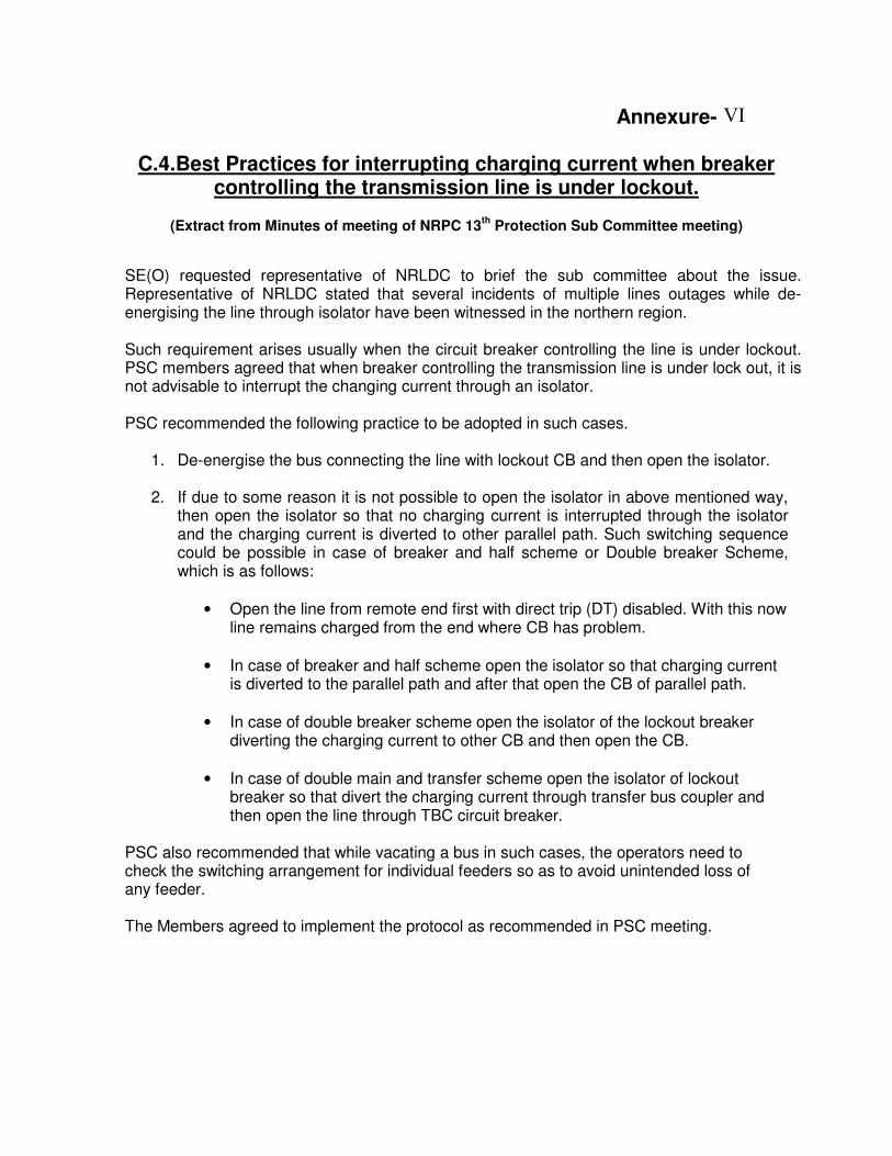
Annexure-
C.4.Best Practices for interrupting charging current when breaker controlling the transmission line is under lockout.
(Extract from Minutes of meeting of NRPC 13
th Protection Sub Committee meeting)
SE(O) requested representative of NRLDC to brief the sub committee about the issue. Representative of NRLDC stated that several incidents of multiple lines outages while de-energising the line through isolator have been witnessed in the northern region. Such requirement arises usually when the circuit breaker controlling the line is under lockout. PSC members agreed that when breaker controlling the transmission line is under lock out, it is not advisable to interrupt the changing current through an isolator. PSC recommended the following practice to be adopted in such cases.
1. De-energise the bus connecting the line with lockout CB and then open the isolator.
2. If due to some reason it is not possible to open the isolator in above mentioned way, then open the isolator so that no charging current is interrupted through the isolator and the charging current is diverted to other parallel path. Such switching sequence could be possible in case of breaker and half scheme or Double breaker Scheme, which is as follows:
• Open the line from remote end first with direct trip (DT) disabled. With this now line remains charged from the end where CB has problem.
• In case of breaker and half scheme open the isolator so that charging current is diverted to the parallel path and after that open the CB of parallel path.
• In case of double breaker scheme open the isolator of the lockout breaker diverting the charging current to other CB and then open the CB.
• In case of double main and transfer scheme open the isolator of lockout breaker so that divert the charging current through transfer bus coupler and then open the line through TBC circuit breaker.
PSC also recommended that while vacating a bus in such cases, the operators need to check the switching arrangement for individual feeders so as to avoid unintended loss of any feeder. The Members agreed to implement the protocol as recommended in PSC meeting.
VI
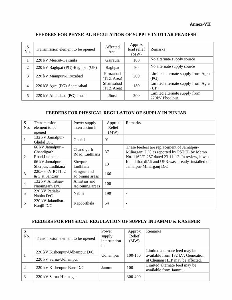
Annex-VII
FEEDERS FOR PHYSICAL REGULATION OF SUPPLY IN UTTAR PRADESH
S
No. Transmission element to be opened
Affected
Area
Approx
load relief
(MW)
Remarks
1 220 kV Meerut-Gajraula Gajraula 100 No alternate supply source
2 220 kV Baghpat (PG)-Baghpat (UP) Baghpat 80 No alternate supply source
3 220 kV Mainpuri-Firozabad Firozabad
(TTZ Area) 200
Limited alternate supply from Agra
(PG)
4 220 kV Agra (PG)-Shamsabad Shamsabad
(TTZ Area) 180
Limited alternate supply from Agra
(UP)
5 220 kV Allahabad (PG)-Jhusi Jhusi 200 Limited alternate supply from
220kV Phoolpur.
FEEDERS FOR PHYSICAL REGULATION OF SUPPLY IN PUNJAB
S
No.
Transmission
element to be
opened
Power supply
interruption in
Approx
Relief
(MW)
Remarks
1 132 kV Jamalpur-
Ghulal D/C Ghulal 91 -
2
66 kV Jamalpur –
Chandigarh
Road,Ludhiana
Chandigarh
Road, Ludhiana 37
These feeders are replacement of Jamalpur-
Miliarganj D/C as reported by PSTCL by Memo
No. 1162/T-257 dated 23-11-12. In review, it was
found that df/dt and UFR was already installed on
Jamalpur-Miliarganj D/C 66 kV Jamalpur-
Sherpur, Ludhiana
Sherpur,
Ludhiana 13
3 220/66 kV ICT1, 2
& 3 at Sangrur
Sangrur and
adjoining areas 166 -
4 132 kV Amritsar-
Naraingarh D/C
Amritsar and
Adjoining areas 100 -
5 220 kV Patiala-
Nabha D/C Nabha 190 -
6 220 kV Jalandhar-
Kanjli D/C Kapoorthala 64 -
FEEDERS FOR PHYSICAL REGULATION OF SUPPLY IN JAMMU & KASHMIR
S
No. Transmission element to be opened
Power
supply
interruption
in
Approx
Relief
(MW)
Remarks
1 220 kV Kishenpur-Udhampur D/C
Udhampur 100-150
Limited alternate feed may be
available from 132 kV. Generation
at Chenani HEP may be affected. 220 kV Sarna-Udhampur
2 220 kV Kishenpur-Barn D/C Jammu 100 Limited alternate feed may be
available from Jammu
3 220 kV Sarna-Hiranagar 300-400
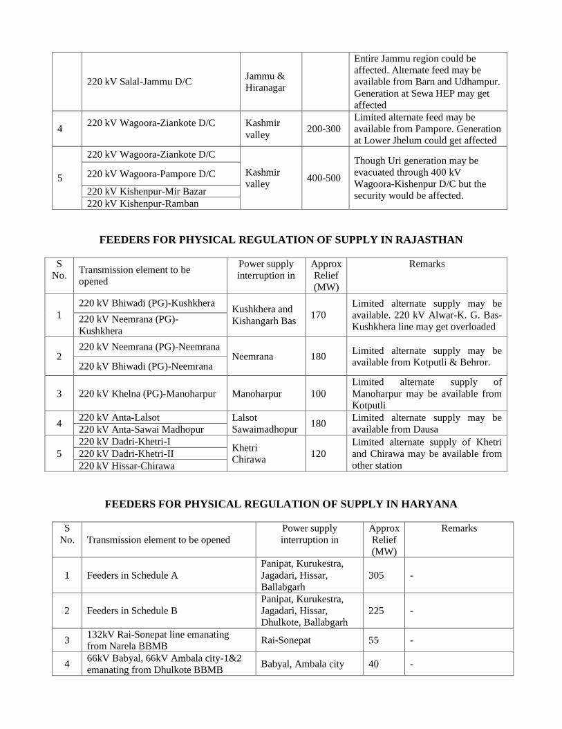
220 kV Salal-Jammu D/C Jammu &
Hiranagar
Entire Jammu region could be
affected. Alternate feed may be
available from Barn and Udhampur.
Generation at Sewa HEP may get
affected
4 220 kV Wagoora-Ziankote D/C
Kashmir
valley 200-300
Limited alternate feed may be
available from Pampore. Generation
at Lower Jhelum could get affected
5
220 kV Wagoora-Ziankote D/C
Kashmir
valley 400-500
Though Uri generation may be
evacuated through 400 kV
Wagoora-Kishenpur D/C but the
security would be affected.
220 kV Wagoora-Pampore D/C
220 kV Kishenpur-Mir Bazar
220 kV Kishenpur-Ramban
FEEDERS FOR PHYSICAL REGULATION OF SUPPLY IN RAJASTHAN
S
No. Transmission element to be
opened
Power supply
interruption in
Approx
Relief
(MW)
Remarks
1
220 kV Bhiwadi (PG)-Kushkhera Kushkhera and
Kishangarh Bas 170
Limited alternate supply may be
available. 220 kV Alwar-K. G. Bas-
Kushkhera line may get overloaded 220 kV Neemrana (PG)-
Kushkhera
2 220 kV Neemrana (PG)-Neemrana
Neemrana 180 Limited alternate supply may be
available from Kotputli & Behror. 220 kV Bhiwadi (PG)-Neemrana
3 220 kV Khelna (PG)-Manoharpur Manoharpur 100
Limited alternate supply of
Manoharpur may be available from
Kotputli
4 220 kV Anta-Lalsot Lalsot
Sawaimadhopur 180
Limited alternate supply may be
available from Dausa 220 kV Anta-Sawai Madhopur
5
220 kV Dadri-Khetri-I Khetri
Chirawa 120
Limited alternate supply of Khetri
and Chirawa may be available from
other station
220 kV Dadri-Khetri-II
220 kV Hissar-Chirawa
FEEDERS FOR PHYSICAL REGULATION OF SUPPLY IN HARYANA
S
No. Transmission element to be opened
Power supply
interruption in
Approx
Relief
(MW)
Remarks
1 Feeders in Schedule A
Panipat, Kurukestra,
Jagadari, Hissar,
Ballabgarh
305 -
2 Feeders in Schedule B
Panipat, Kurukestra,
Jagadari, Hissar,
Dhulkote, Ballabgarh
225 -
3 132kV Rai-Sonepat line emanating
from Narela BBMB Rai-Sonepat 55 -
4 66kV Babyal, 66kV Ambala city-1&2
emanating from Dhulkote BBMB Babyal, Ambala city 40 -
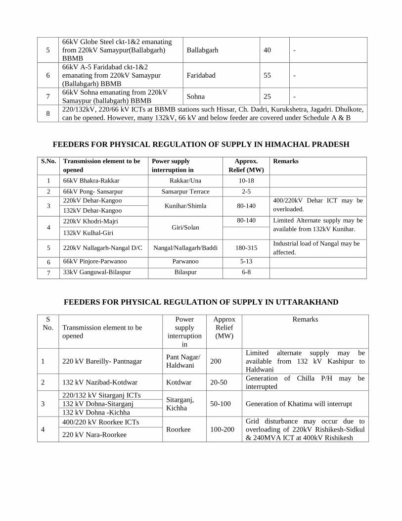
5
66kV Globe Steel ckt-1&2 emanating
from 220kV Samaypur(Ballabgarh)
BBMB
Ballabgarh 40 -
6
66kV A-5 Faridabad ckt-1&2
emanating from 220kV Samaypur
(Ballabgarh) BBMB
Faridabad 55 -
7 66kV Sohna emanating from 220kV
Samaypur (ballabgarh) BBMB Sohna 25 -
8 220/132kV, 220/66 kV ICTs at BBMB stations such Hissar, Ch. Dadri, Kurukshetra, Jagadri. Dhulkote,
can be opened. However, many 132kV, 66 kV and below feeder are covered under Schedule A & B
FEEDERS FOR PHYSICAL REGULATION OF SUPPLY IN HIMACHAL PRADESH
S.No. Transmission element to be
opened
Power supply
interruption in
Approx.
Relief (MW)
Remarks
1 66kV Bhakra-Rakkar Rakkar/Una 10-18
2 66kV Pong- Sansarpur Sansarpur Terrace 2-5
3 220kV Dehar-Kangoo
Kunihar/Shimla 80-140 400/220kV Dehar ICT may be
overloaded. 132kV Dehar-Kangoo
4 220kV Khodri-Majri
Giri/Solan 80-140 Limited Alternate supply may be
available from 132kV Kunihar. 132kV Kulhal-Giri
5 220kV Nallagarh-Nangal D/C Nangal/Nallagarh/Baddi 180-315 Industrial load of Nangal may be
affected.
6 66kV Pinjore-Parwanoo Parwanoo 5-13
7 33kV Ganguwal-Bilaspur Bilaspur 6-8
FEEDERS FOR PHYSICAL REGULATION OF SUPPLY IN UTTARAKHAND
S
No. Transmission element to be
opened
Power
supply
interruption
in
Approx
Relief
(MW)
Remarks
1 220 kV Bareilly- Pantnagar Pant Nagar/
Haldwani 200
Limited alternate supply may be
available from 132 kV Kashipur to
Haldwani
2 132 kV Nazibad-Kotdwar Kotdwar 20-50 Generation of Chilla P/H may be
interrupted
3
220/132 kV Sitarganj ICTs Sitarganj,
Kichha 50-100 Generation of Khatima will interrupt 132 kV Dohna-Sitarganj
132 kV Dohna -Kichha
4 400/220 kV Roorkee ICTs
Roorkee 100-200
Grid disturbance may occur due to
overloading of 220kV Rishikesh-Sidkul
& 240MVA ICT at 400kV Rishikesh 220 kV Nara-Roorkee
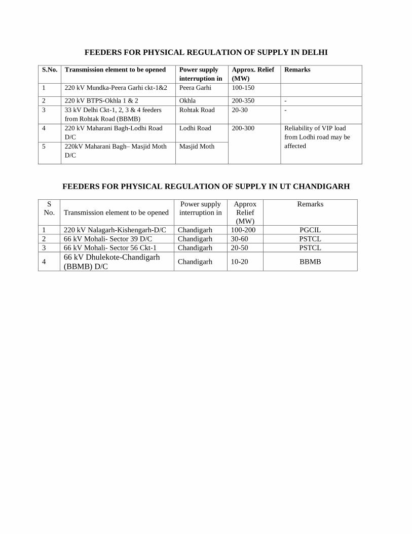
FEEDERS FOR PHYSICAL REGULATION OF SUPPLY IN DELHI
S.No. Transmission element to be opened Power supply
interruption in
Approx. Relief
(MW)
Remarks
1 220 kV Mundka-Peera Garhi ckt-1&2 Peera Garhi 100-150
2 220 kV BTPS-Okhla 1 & 2 Okhla 200-350 -
3 33 kV Delhi Ckt-1, 2, 3 & 4 feeders
from Rohtak Road (BBMB)
Rohtak Road 20-30 -
4 220 kV Maharani Bagh-Lodhi Road
D/C
Lodhi Road 200-300
Reliability of VIP load
from Lodhi road may be
affected
5 220kV Maharani Bagh– Masjid Moth
D/C
Masjid Moth
FEEDERS FOR PHYSICAL REGULATION OF SUPPLY IN UT CHANDIGARH
S
No. Transmission element to be opened
Power supply
interruption in
Approx
Relief
(MW)
Remarks
1 220 kV Nalagarh-Kishengarh-D/C Chandigarh 100-200 PGCIL
2 66 kV Mohali- Sector 39 D/C Chandigarh 30-60 PSTCL
3 66 kV Mohali- Sector 56 Ckt-1 Chandigarh 20-50 PSTCL
4 66 kV Dhulekote-Chandigarh
(BBMB) D/C Chandigarh 10-20 BBMB
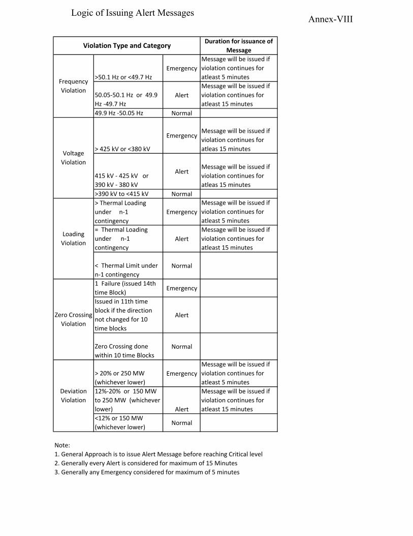
>50.1 Hz or <49.7 HzEmergency
Message will be issued if violation continues for atleast 5 minutes
50.05-50.1 Hz or 49.9 Hz -49.7 Hz
AlertMessage will be issued if violation continues for atleast 15 minutes
49.9 Hz -50.05 Hz Normal
> 425 kV or <380 kV
EmergencyMessage will be issued if violation continues for atleas 15 minutes
415 kV - 425 kV or 390 kV - 380 kV
AlertMessage will be issued if violation continues for atleas 15 minutes
>390 kV to <415 kV Normal> Thermal Loading under n-1 contingency
EmergencyMessage will be issued if violation continues for atleast 5 minutes
= Thermal Loading under n-1 contingency
AlertMessage will be issued if violation continues for atleast 15 minutes
< Thermal Limit under n-1 contingency
Normal
1 Failure (issued 14th time Block) Emergency
Issued in 11th time block if the direction not changed for 10 time blocks
Alert
Zero Crossing done within 10 time Blocks
Normal
> 20% or 250 MW (whichever lower)
EmergencyMessage will be issued if violation continues for atleast 5 minutes
12%-20% or 150 MW to 250 MW (whichever lower) Alert
Message will be issued if violation continues for atleast 15 minutes
<12% or 150 MW (whichever lower) Normal
Note:1. General Approach is to issue Alert Message before reaching Critical level2. Generally every Alert is considered for maximum of 15 Minutes3. Generally any Emergency considered for maximum of 5 minutes
Deviation Violation
Violation Type and Category Duration for issuance of Message
Frequency Violation
Voltage Violation
Loading Violation
Zero Crossing Violation
Annex-VIIILogic of Issuing Alert Messages
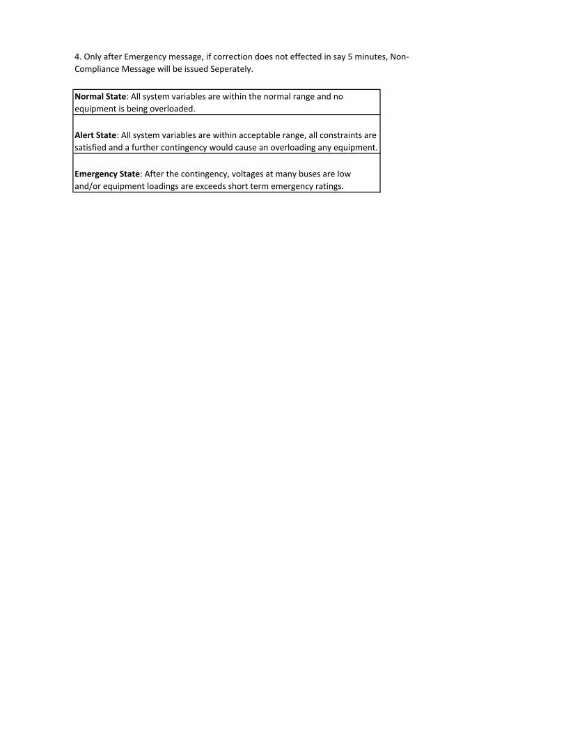
Normal State: All system variables are within the normal range and no equipment is being overloaded.
Alert State: All system variables are within acceptable range, all constraints are satisfied and a further contingency would cause an overloading any equipment.
Emergency State: After the contingency, voltages at many buses are low and/or equipment loadings are exceeds short term emergency ratings.
4. Only after Emergency message, if correction does not effected in say 5 minutes, Non-Compliance Message will be issued Seperately.
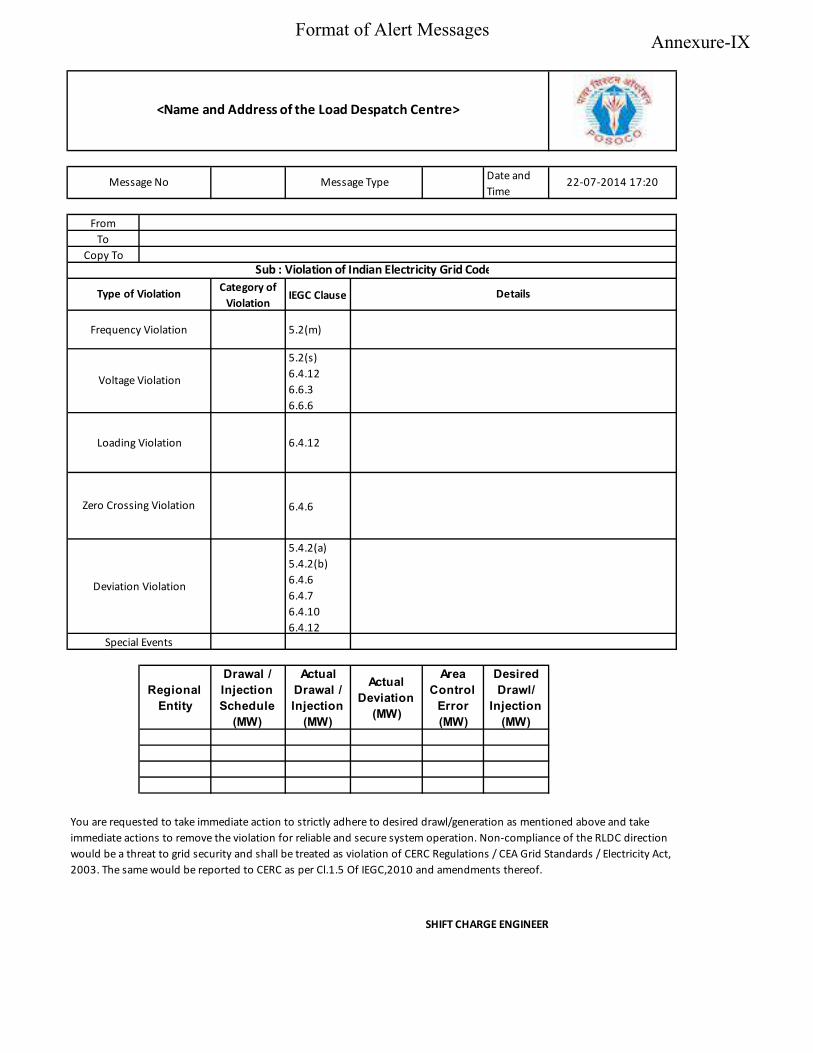
Date and Time
FromTo
Copy To
Category of Violation
IEGC Clause
5.2(m)
5.2(s) 6.4.12 6.6.3 6.6.6
6.4.12
6.4.6
5.4.2(a) 5.4.2(b) 6.4.6 6.4.7 6.4.10 6.4.12
Regional
Entity
Drawal /
Injection
Schedule
(MW)
Actual
Drawal /
Injection
(MW)
Actual
Deviation
(MW)
Area
Control
Error
(MW)
Desired
Drawl/
Injection
(MW)
SHIFT CHARGE ENGINEER
You are requested to take immediate action to strictly adhere to desired drawl/generation as mentioned above and take immediate actions to remove the violation for reliable and secure system operation. Non-compliance of the RLDC direction would be a threat to grid security and shall be treated as violation of CERC Regulations / CEA Grid Standards / Electricity Act, 2003. The same would be reported to CERC as per Cl.1.5 Of IEGC,2010 and amendments thereof.
DetailsType of Violation
Special Events
Zero Crossing Violation
Frequency Violation
Voltage Violation
Loading Violation
Deviation Violation
Sub : Violation of Indian Electricity Grid Code
<Name and Address of the Load Despatch Centre>
Message No Message Type 22-07-2014 17:20
Annexure-IXFormat of Alert Messages
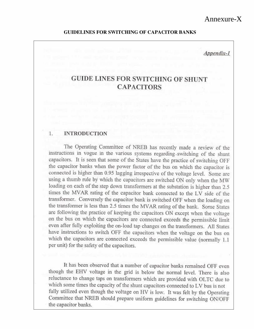
GUIDELINES FOR SWITCHING OF CAPACITOR BANKS
Annexure-X
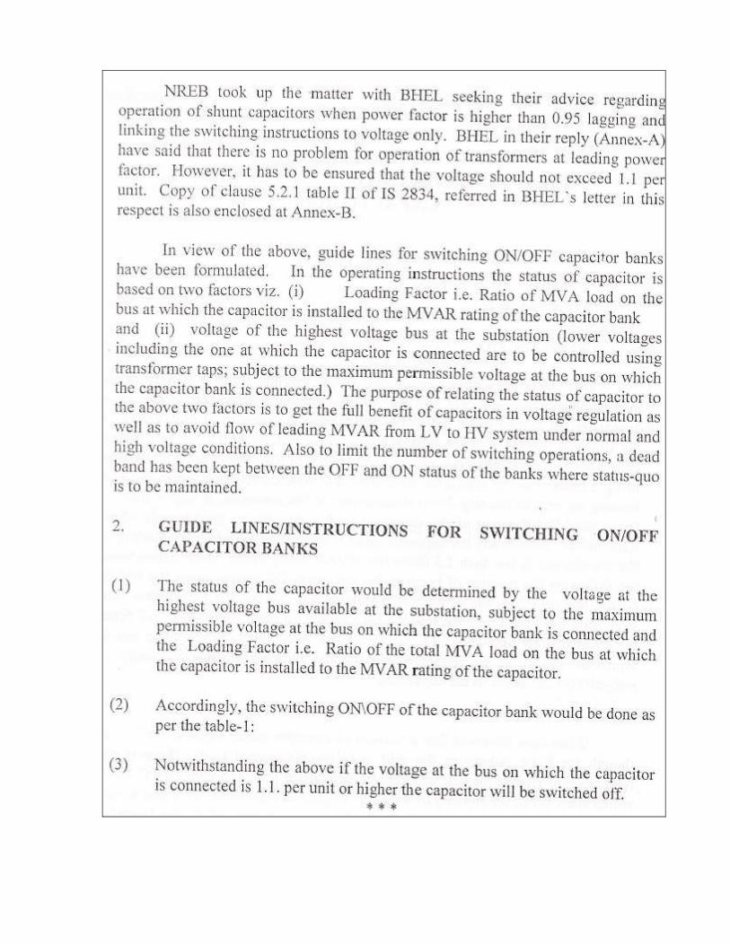
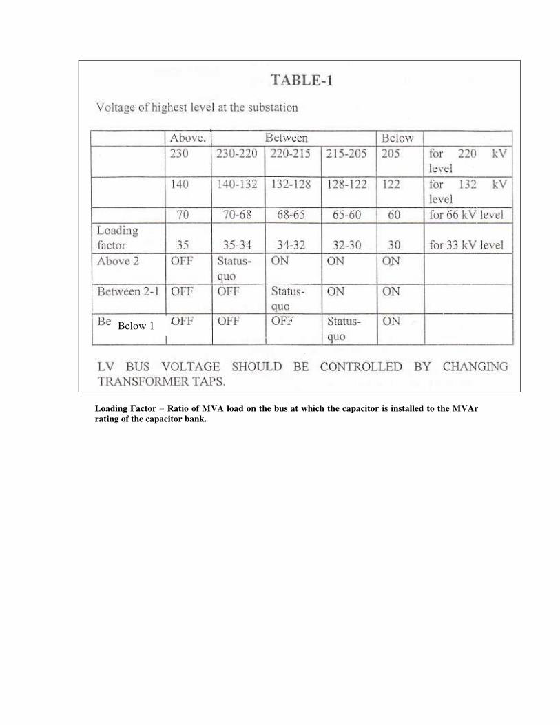
Loading Factor = Ratio of MVA load on the bus at which the capacitor is installed to the MVAr
rating of the capacitor bank.
Below 1
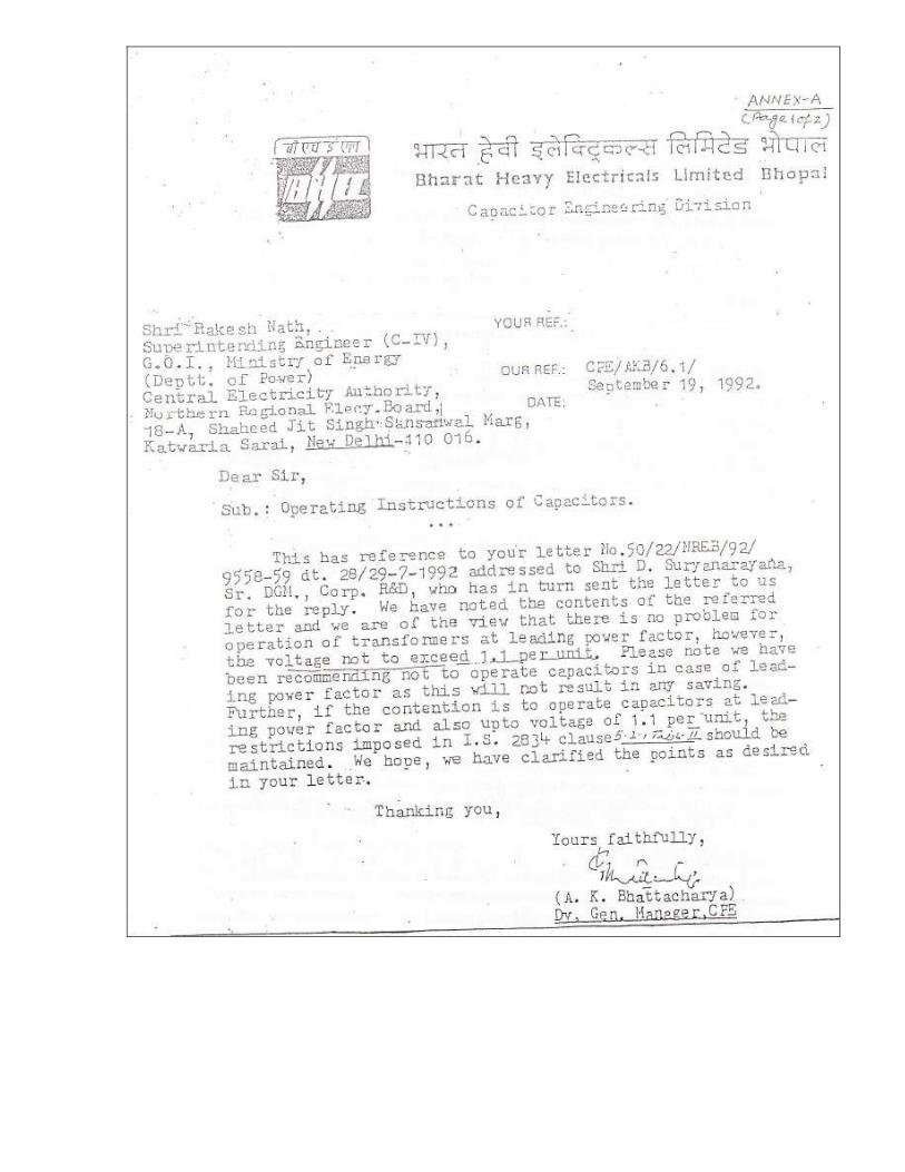
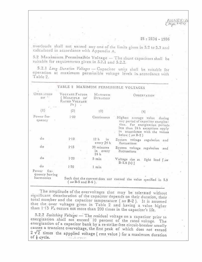
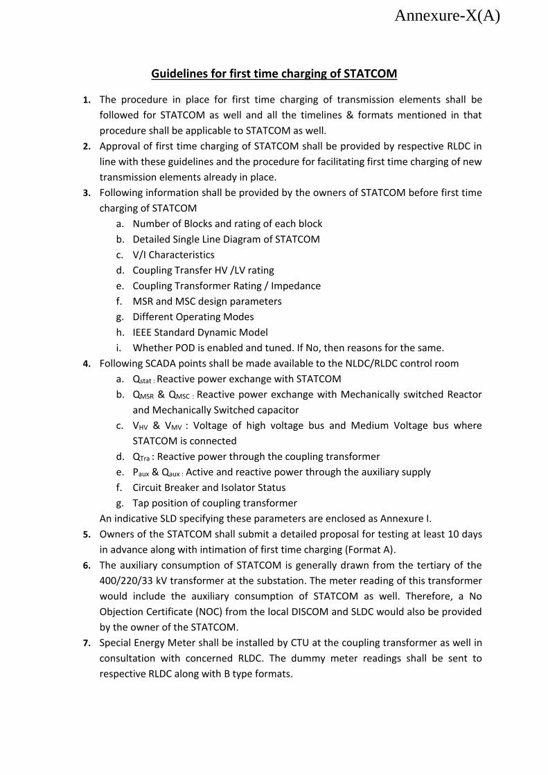
Guidelines for first time charging of STATCOM
1. The procedure in place for first time charging of transmission elements shall be
followed for STATCOM as well and all the timelines & formats mentioned in that
procedure shall be applicable to STATCOM as well.
2. Approval of first time charging of STATCOM shall be provided by respective RLDC in
line with these guidelines and the procedure for facilitating first time charging of new
transmission elements already in place.
3. Following information shall be provided by the owners of STATCOM before first time
charging of STATCOM
a. Number of Blocks and rating of each block
b. Detailed Single Line Diagram of STATCOM
c. V/I Characteristics
d. Coupling Transfer HV /LV rating
e. Coupling Transformer Rating / Impedance
f. MSR and MSC design parameters
g. Different Operating Modes
h. IEEE Standard Dynamic Model
i. Whether POD is enabled and tuned. If No, then reasons for the same.
4. Following SCADA points shall be made available to the NLDC/RLDC control room
a. Qstat : Reactive power exchange with STATCOM
b. QMSR & QMSC : Reactive power exchange with Mechanically switched Reactor
and Mechanically Switched capacitor
c. VHV & VMV : Voltage of high voltage bus and Medium Voltage bus where
STATCOM is connected
d. QTra : Reactive power through the coupling transformer
e. Paux & Qaux : Active and reactive power through the auxiliary supply
f. Circuit Breaker and Isolator Status
g. Tap position of coupling transformer
An indicative SLD specifying these parameters are enclosed as Annexure I.
5. Owners of the STATCOM shall submit a detailed proposal for testing at least 10 days
in advance along with intimation of first time charging (Format A).
6. The auxiliary consumption of STATCOM is generally drawn from the tertiary of the
400/220/33 kV transformer at the substation. The meter reading of this transformer
would include the auxiliary consumption of STATCOM as well. Therefore, a No
Objection Certificate (NOC) from the local DISCOM and SLDC would also be provided
by the owner of the STATCOM.
7. Special Energy Meter shall be installed by CTU at the coupling transformer as well in
consultation with concerned RLDC. The dummy meter readings shall be sent to
respective RLDC along with B type formats.
Annexure-X(A)
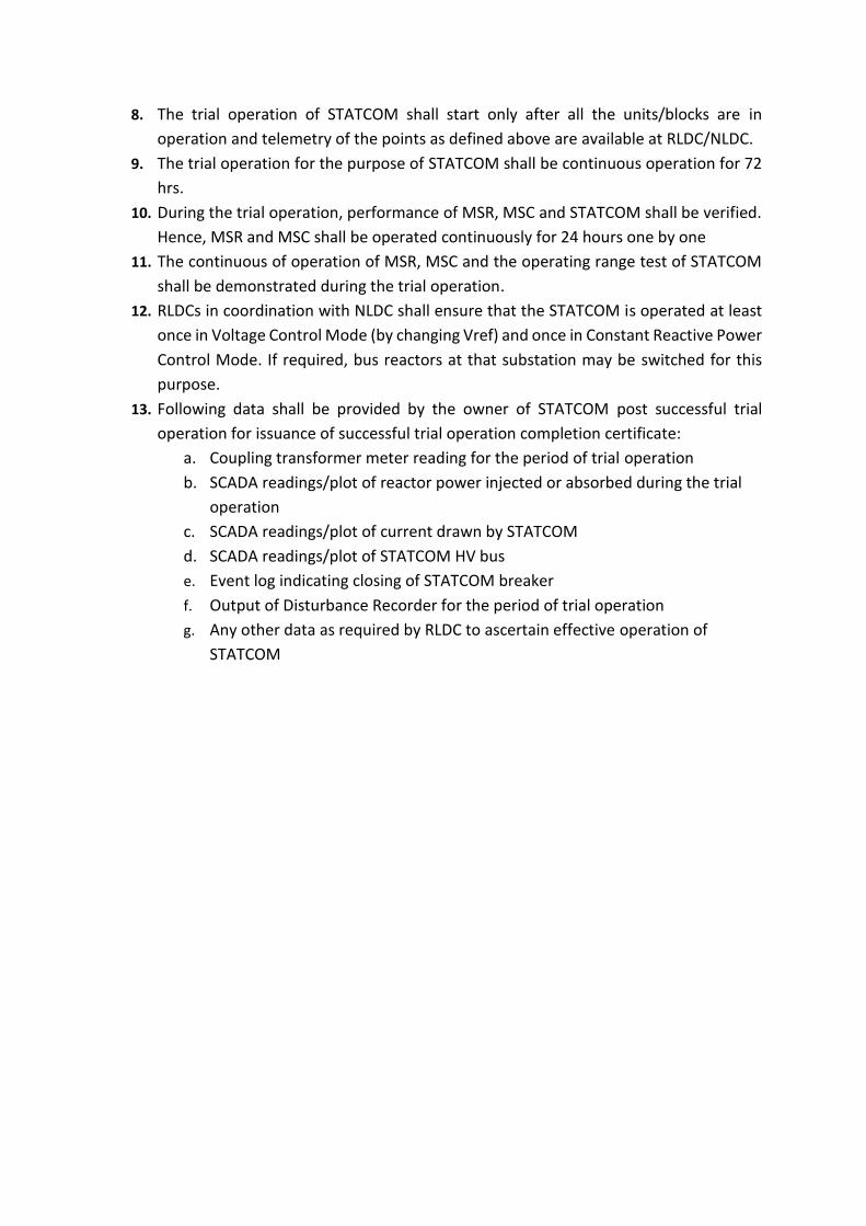
8. The trial operation of STATCOM shall start only after all the units/blocks are in
operation and telemetry of the points as defined above are available at RLDC/NLDC.
9. The trial operation for the purpose of STATCOM shall be continuous operation for 72
hrs.
10. During the trial operation, performance of MSR, MSC and STATCOM shall be verified.
Hence, MSR and MSC shall be operated continuously for 24 hours one by one
11. The continuous of operation of MSR, MSC and the operating range test of STATCOM
shall be demonstrated during the trial operation.
12. RLDCs in coordination with NLDC shall ensure that the STATCOM is operated at least
once in Voltage Control Mode (by changing Vref) and once in Constant Reactive Power
Control Mode. If required, bus reactors at that substation may be switched for this
purpose.
13. Following data shall be provided by the owner of STATCOM post successful trial
operation for issuance of successful trial operation completion certificate:
a. Coupling transformer meter reading for the period of trial operation
b. SCADA readings/plot of reactor power injected or absorbed during the trial
operation
c. SCADA readings/plot of current drawn by STATCOM
d. SCADA readings/plot of STATCOM HV bus
e. Event log indicating closing of STATCOM breaker
f. Output of Disturbance Recorder for the period of trial operation
g. Any other data as required by RLDC to ascertain effective operation of
STATCOM
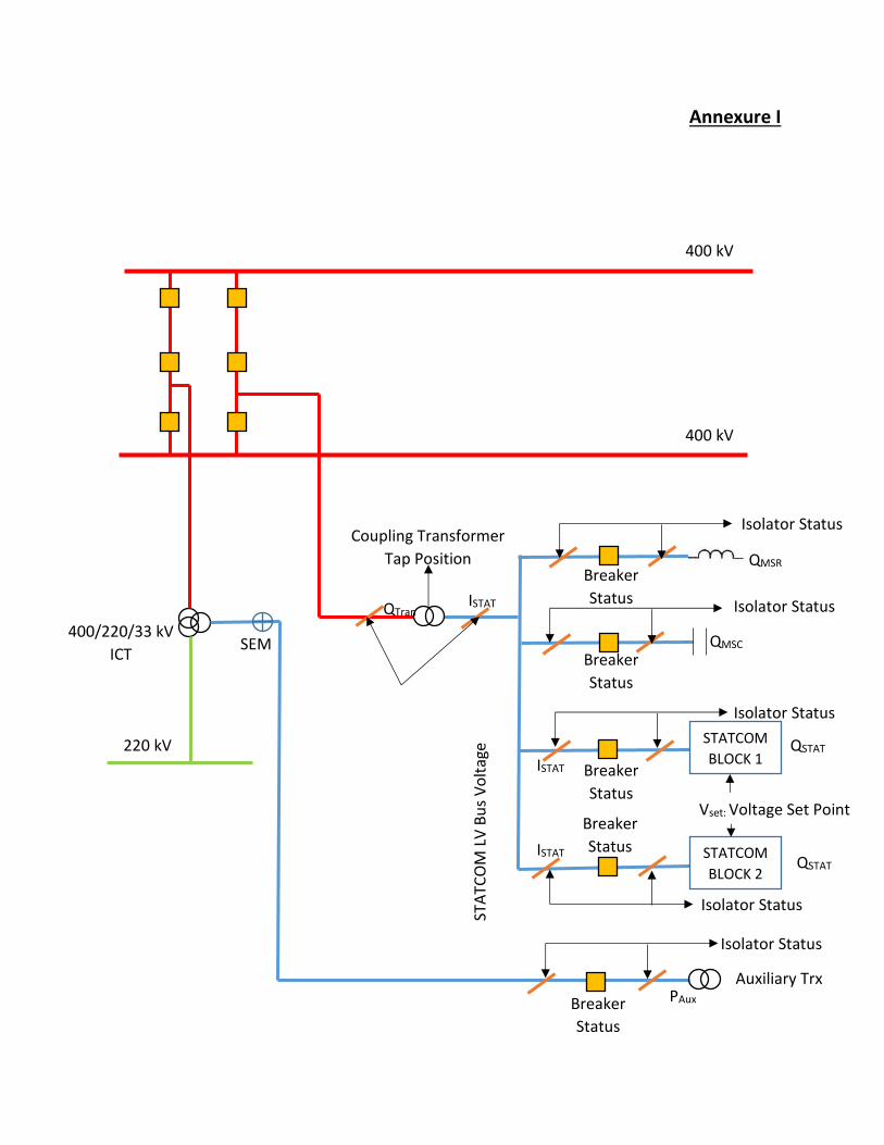
Annexure I
STATCOM
BLOCK 1
STATCOM
BLOCK 2
QTran
Isolator Status
Breaker
Status
Breaker
Status
Breaker
Status
QMSC
QMSR
QSTAT
QSTAT
Coupling Transformer
Tap Position
STA
TCO
M L
V B
us
Vo
ltag
e
Vset: Voltage Set Point
Isolator Status
Isolator Status
Isolator Status
ISTAT
ISTAT
ISTAT
Isolator Status
Auxiliary Trx PAux
Breaker
Status
Breaker
Status
400 kV
400 kV
220 kV
400/220/33 kV
ICT SEM
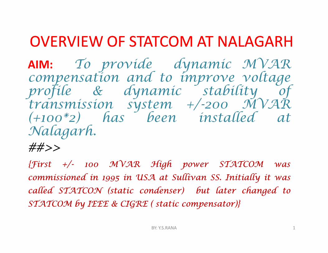
OVERVIEW OF STATCOM AT NALAGARHOVERVIEW OF STATCOM AT NALAGARHAIM: To provide dynamic MVARcompensation and to improve voltageprofile & dynamic stability oftransmission system +/-200 MVAR(+100*2) has been installed atNalagarh.##>>##>>{First{First +/+/-- 100100 MVARMVAR HighHigh powerpower STATCOMSTATCOM waswas
commissionedcommissioned inin 19951995 inin USAUSA atat SullivanSullivan SSSS.. InitiallyInitially itit waswas
calledcalled STATCONSTATCON (static(static condenser)condenser) butbut laterlater changedchanged toto
STATCOMSTATCOM byby IEEEIEEE && CIGRECIGRE (( staticstatic compensator)}compensator)}
BY: Y.S.RANA 1
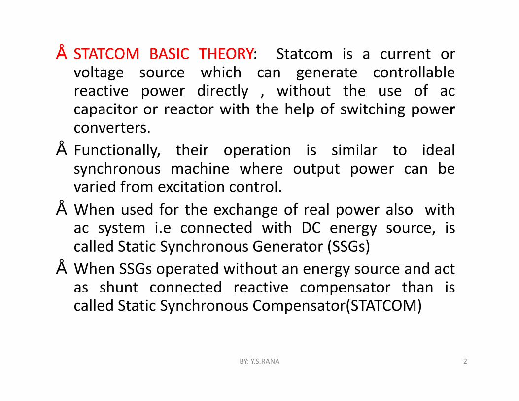
•• STATCOMSTATCOM BASICBASIC THEORYTHEORY:: Statcom is a current orvoltage source which can generate controllablereactive power directly , without the use of accapacitor or reactor with the help of switching powerconverters.
• Functionally, their operation is similar to idealsynchronous machine where output power can bevaried from excitation control.
• When used for the exchange of real power also withac system i.e connected with DC energy source, iscalled Static Synchronous Generator (SSGs)
• When SSGs operated without an energy source and actas shunt connected reactive compensator than iscalled Static Synchronous Compensator(STATCOM)
BY: Y.S.RANA 2
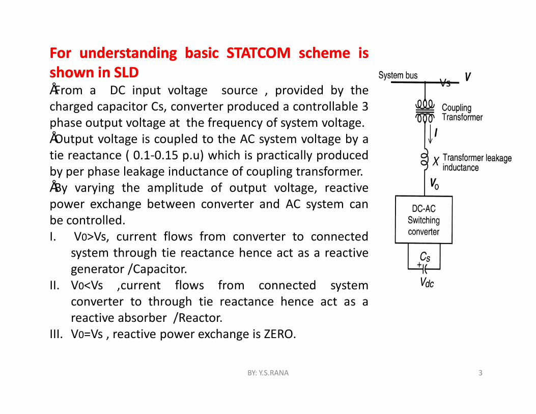
ForFor understandingunderstanding basicbasic STATCOMSTATCOM schemescheme isisshownshown inin SLDSLD•From a DC input voltage source , provided by thecharged capacitor Cs, converter produced a controllable 3phase output voltage at the frequency of system voltage.•Output voltage is coupled to the AC system voltage by atie reactance ( 0.1-0.15 p.u) which is practically producedby per phase leakage inductance of coupling transformer.•By varying the amplitude of output voltage, reactivepower exchange between converter and AC system canbe controlled.I. V0>Vs, current flows from converter to connected
system through tie reactance hence act as a reactivegenerator /Capacitor.
II. V0<Vs ,current flows from connected systemconverter to through tie reactance hence act as areactive absorber /Reactor.
III. V0=Vs , reactive power exchange is ZERO.
Vs
BY: Y.S.RANA 3

SLD OF STATCOM AT NALAGARH SLD OF STATCOM AT NALAGARH
BY: Y.S.RANA 4
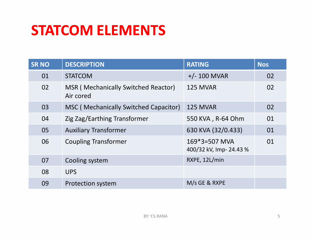
STATCOM ELEMENTSSTATCOM ELEMENTS
SR NO DESCRIPTION RATING Nos
01 STATCOM +/- 100 MVAR 02
02 MSR ( Mechanically Switched Reactor)Air cored
125 MVAR 02
03 MSC ( Mechanically Switched Capacitor) 125 MVAR 02
04 Zig Zag/Earthing Transformer 550 KVA , R-64 Ohm 01
05 Auxiliary Transformer 630 KVA (32/0.433) 01
06 Coupling Transformer 169*3=507 MVA400/32 kV, Imp- 24.43 %
01
07 Cooling system RXPE, 12L/min
08 UPS
09 Protection system M/s GE & RXPE
BY: Y.S.RANA 5
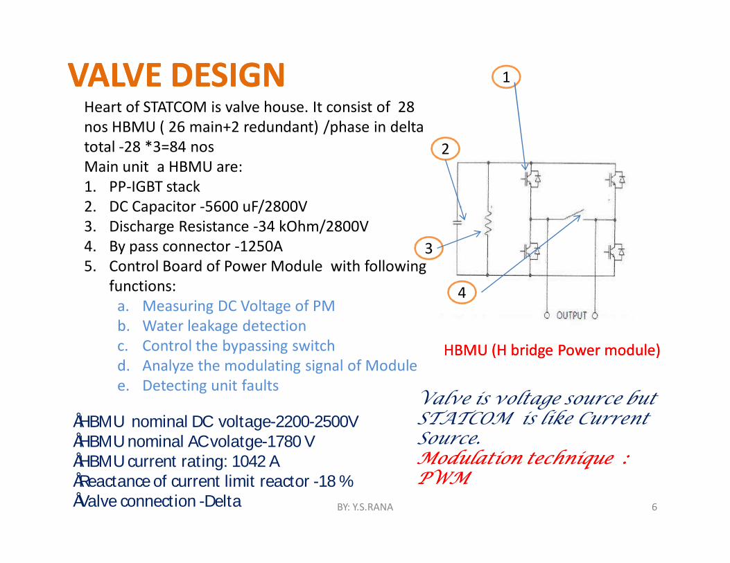
VALVE DESIGNVALVE DESIGNHeart of STATCOM is valve house. It consist of 28 nos HBMU ( 26 main+2 redundant) /phase in delta total -28 *3=84 nosMain unit a HBMU are:1. PP-IGBT stack2. DC Capacitor -5600 uF/2800V3. Discharge Resistance -34 kOhm/2800V4. By pass connector -1250A5. Control Board of Power Module with following
functions:a. Measuring DC Voltage of PMb. Water leakage detectionc. Control the bypassing switchd. Analyze the modulating signal of Modulee. Detecting unit faults
HBMU (H bridge Power module)HBMU (H bridge Power module)
1
2
3
4
Valve is voltage source but STATCOM is like Current Source. Modulation technique : Modulation technique : PWMPWM
•HBMU nominal DC voltage-2200-2500V•HBMU nominal AC volatge-1780 V•HBMU current rating: 1042 A•Reactance of current limit reactor -18 % •Valve connection -Delta BY: Y.S.RANA 6
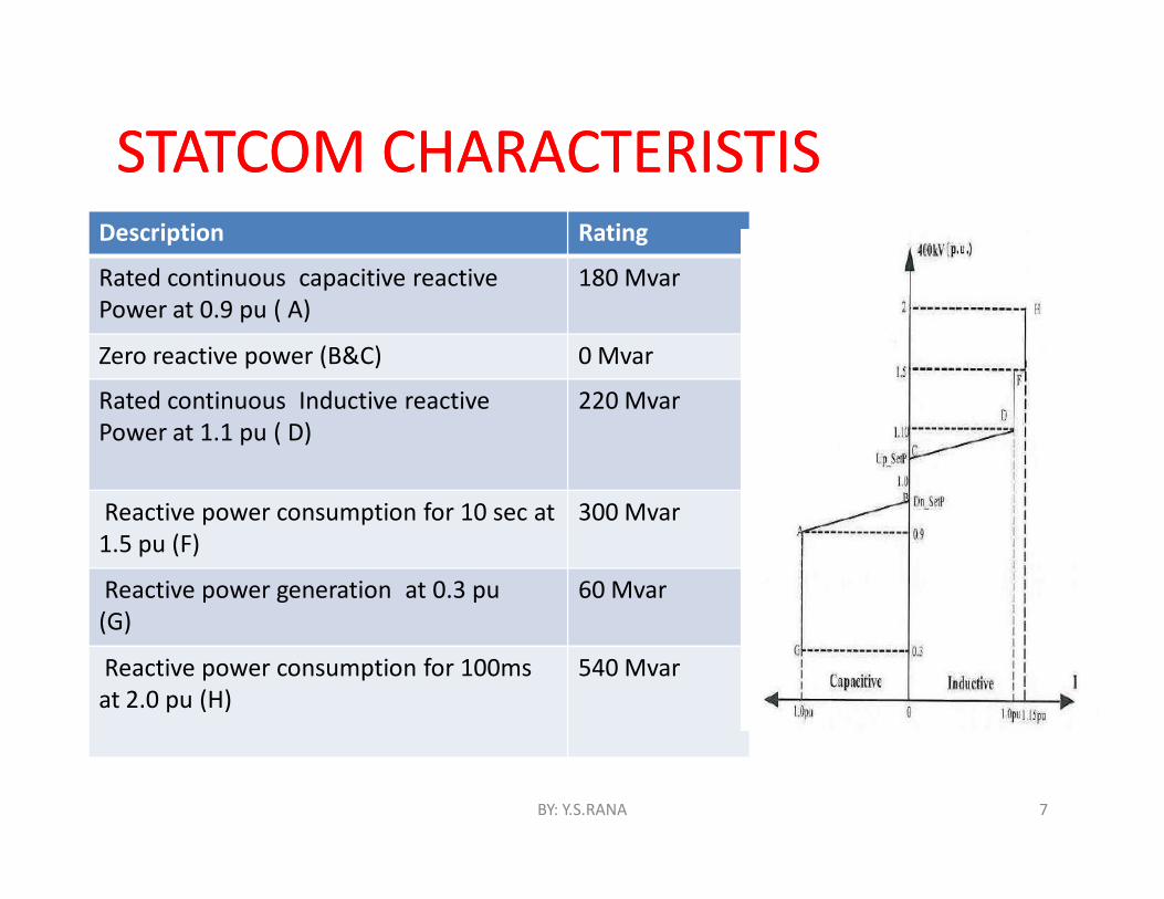
STATCOM CHARACTERISTISSTATCOM CHARACTERISTISDescription Rating
Rated continuous capacitive reactive Power at 0.9 pu ( A)
180 Mvar
Zero reactive power (B&C) 0 Mvar
Rated continuous Inductive reactive Power at 1.1 pu ( D)
220 Mvar
Reactive power consumption for 10 sec at 1.5 pu (F)
300 Mvar
Reactive power generation at 0.3 pu(G)
60 Mvar
Reactive power consumption for 100ms at 2.0 pu (H)
540 Mvar
BY: Y.S.RANA 7
CONTROL STRATEGIES CONTROL STRATEGIES STATCOM control provide following functions:STATCOM control provide following functions:1. Positive sequence & Negative sequence control .2. Constant reactive power control.3. Damping of sub synchronous oscillation ( SSO) and Power
Oscillations.4. Gain optimizer .5. Over voltage logic6. Under voltage logic7. External device co-operation control.
BY: Y.S.RANA 8
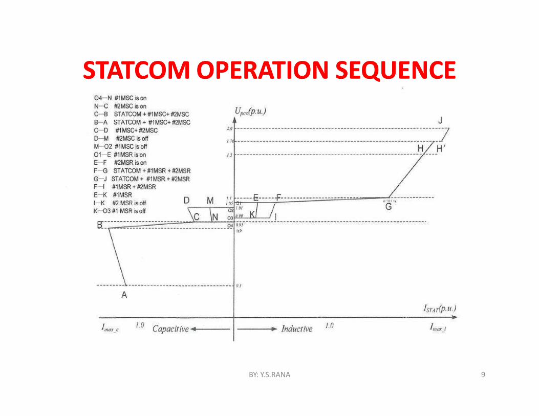
STATCOM OPERATION SEQUENCESTATCOM OPERATION SEQUENCE
BY: Y.S.RANA 9
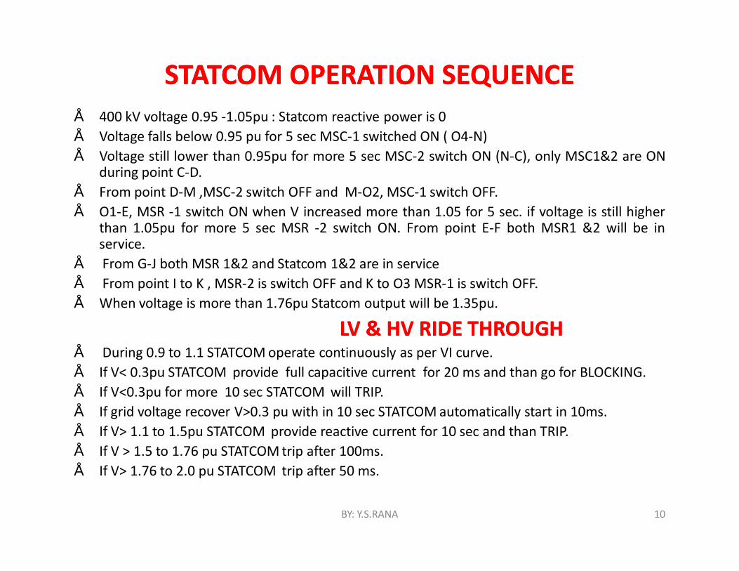
STATCOM OPERATION SEQUENCESTATCOM OPERATION SEQUENCE• 400 kV voltage 0.95 -1.05pu : Statcom reactive power is 0• Voltage falls below 0.95 pu for 5 sec MSC-1 switched ON ( O4-N)• Voltage still lower than 0.95pu for more 5 sec MSC-2 switch ON (N-C), only MSC1&2 are ON
during point C-D.• From point D-M ,MSC-2 switch OFF and M-O2, MSC-1 switch OFF.• O1-E, MSR -1 switch ON when V increased more than 1.05 for 5 sec. if voltage is still higher
than 1.05pu for more 5 sec MSR -2 switch ON. From point E-F both MSR1 &2 will be inservice.
• From G-J both MSR 1&2 and Statcom 1&2 are in service• From point I to K , MSR-2 is switch OFF and K to O3 MSR-1 is switch OFF.• When voltage is more than 1.76pu Statcom output will be 1.35pu.
LVLV && HVHV RIDERIDE THROUGHTHROUGH• During 0.9 to 1.1 STATCOM operate continuously as per VI curve.• If V< 0.3pu STATCOM provide full capacitive current for 20 ms and than go for BLOCKING.• If V<0.3pu for more 10 sec STATCOM will TRIP.• If grid voltage recover V>0.3 pu with in 10 sec STATCOM automatically start in 10ms.• If V> 1.1 to 1.5pu STATCOM provide reactive current for 10 sec and than TRIP.• If V > 1.5 to 1.76 pu STATCOM trip after 100ms.• If V> 1.76 to 2.0 pu STATCOM trip after 50 ms.
BY: Y.S.RANA 10
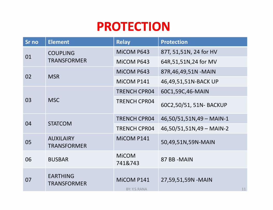
PROTECTION PROTECTION Sr no Element Relay Protection
01 COUPLINGTRANSFORMER
MiCOM P643 87T, 51,51N, 24 for HV
MiCOM P643 64R,51,51N,24 for MV
02 MSRMiCOM P643 87R,46,49,51N -MAIN
MiCOM P141 46,49,51,51N-BACK UP
03 MSC TRENCH CPR04 60C1,59C,46-MAIN
TRENCH CPR04 60C2,50/51, 51N- BACKUP
04 STATCOMTRENCH CPR04 46,50/51,51N,49 – MAIN-1
TRENCH CPR04 46,50/51,51N,49 – MAIN-2
05 AUXILAIRY TRANSFORMER
MiCOM P141 50,49,51N,59N-MAIN
06 BUSBAR MiCOM741&743 87 BB -MAIN
07 EARTHING TRANSFORMER MiCOM P141 27,59,51,59N -MAIN
BY: Y.S.RANA 11
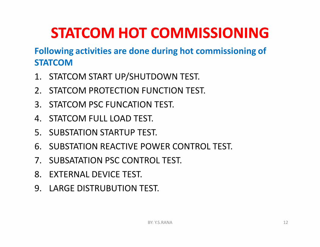
STATCOM HOT COMMISSIONING STATCOM HOT COMMISSIONING Following activities are done during hot commissioning of STATCOM1. STATCOM START UP/SHUTDOWN TEST.2. STATCOM PROTECTION FUNCTION TEST.3. STATCOM PSC FUNCATION TEST.4. STATCOM FULL LOAD TEST.5. SUBSTATION STARTUP TEST.6. SUBSTATION REACTIVE POWER CONTROL TEST.7. SUBSATATION PSC CONTROL TEST.8. EXTERNAL DEVICE TEST.9. LARGE DISTRUBUTION TEST.
BY: Y.S.RANA 12
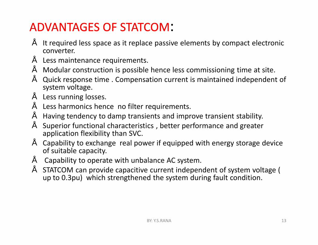
ADVANTAGES OF STATCOMADVANTAGES OF STATCOM:• It required less space as it replace passive elements by compact electronic
converter. • Less maintenance requirements.• Modular construction is possible hence less commissioning time at site.• Quick response time . Compensation current is maintained independent of
system voltage.• Less running losses. • Less harmonics hence no filter requirements.• Having tendency to damp transients and improve transient stability.• Superior functional characteristics , better performance and greater
application flexibility than SVC.• Capability to exchange real power if equipped with energy storage device
of suitable capacity.• Capability to operate with unbalance AC system.• STATCOM can provide capacitive current independent of system voltage (
up to 0.3pu) which strengthened the system during fault condition.
BY: Y.S.RANA 13
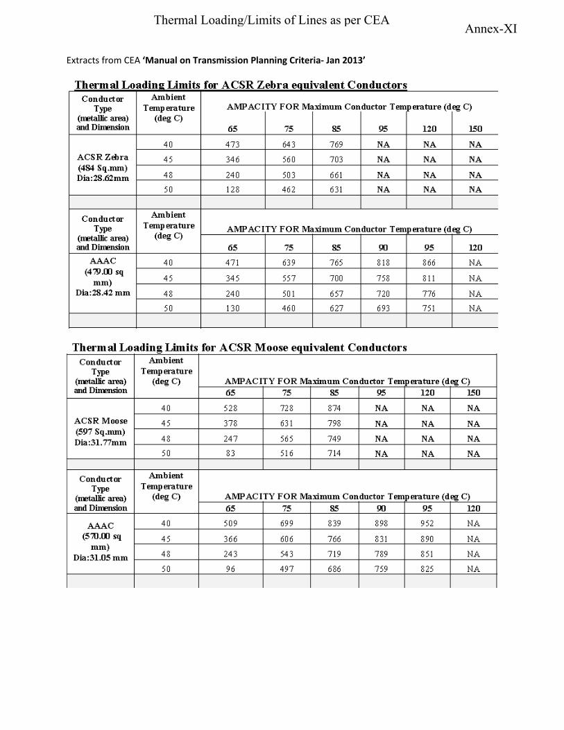
Extracts from CEA ‘Manual on Transmission Planning Criteria- Jan 2013’
Annex-XIThermal Loading/Limits of Lines as per CEA
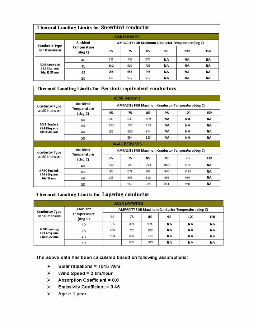
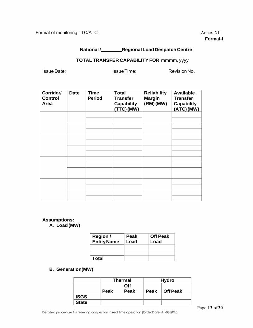
Detailed procedure for relieving congestion in real time operation (Order Date:-11-06-2010)
Format of monitoring TTC/ATC Annex-XII Format-I
National / Regional Load Despatch Centre
TOTAL TRANSFER CAPABILITY FOR mmmm, yyyy
Issue Date: Issue Time: Revision No.
Corridor/ Control
Area
Date Time Period
Total
Transfer
Capability
(TTC) (MW)
Reliability Margin
(RM) (MW)
Available
Transfer
Capability
(ATC) (MW)
Assumptions: A. Load (MW)
Region / Entity Name
Peak Load
Off Peak Load
Total
B. Generation(MW)
Thermal Hydro Off
Peak Peak Peak
Off Peak
ISGS State
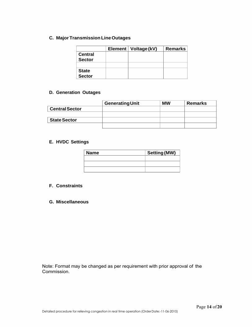
Detailed procedure for relieving congestion in real time operation (Order Date:-11-06-2010)
C. Major Transmission Line Outages
Element Voltage (kV) Remarks Central Sector
State
Sector
D. Generation Outages
Generating Unit MW Remarks Central Sector
State Sector
E. HVDC Settings
Name Setting (MW)
F. Constraints
G. Miscellaneous
Note: Format may be changed as per requirement with prior approval of the Commission.
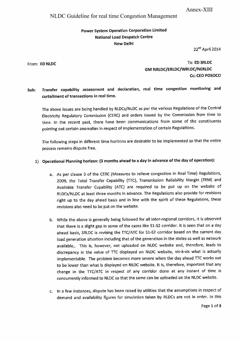
Annex-XIIINLDC Guideline for real time Congestion Management
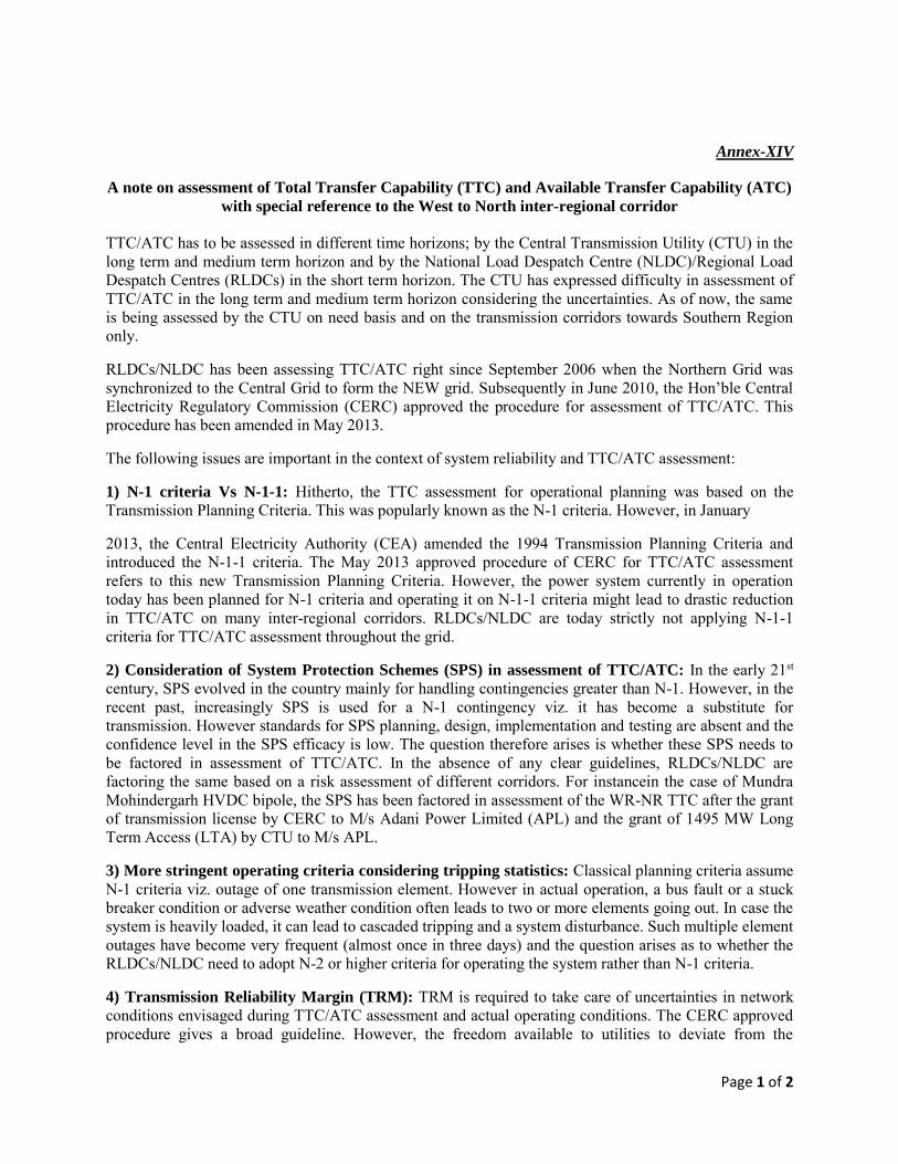
Page 1 of 2
Annex-XIV
A note on assessment of Total Transfer Capability (TTC) and Available Transfer Capability (ATC)
with special reference to the West to North inter-regional corridor
TTC/ATC has to be assessed in different time horizons; by the Central Transmission Utility (CTU) in the long term and medium term horizon and by the National Load Despatch Centre (NLDC)/Regional Load Despatch Centres (RLDCs) in the short term horizon. The CTU has expressed difficulty in assessment of TTC/ATC in the long term and medium term horizon considering the uncertainties. As of now, the same is being assessed by the CTU on need basis and on the transmission corridors towards Southern Region only.
RLDCs/NLDC has been assessing TTC/ATC right since September 2006 when the Northern Grid was synchronized to the Central Grid to form the NEW grid. Subsequently in June 2010, the Hon’ble Central
Electricity Regulatory Commission (CERC) approved the procedure for assessment of TTC/ATC. This procedure has been amended in May 2013.
The following issues are important in the context of system reliability and TTC/ATC assessment:
1) N-1 criteria Vs N-1-1: Hitherto, the TTC assessment for operational planning was based on the Transmission Planning Criteria. This was popularly known as the N-1 criteria. However, in January
2013, the Central Electricity Authority (CEA) amended the 1994 Transmission Planning Criteria and introduced the N-1-1 criteria. The May 2013 approved procedure of CERC for TTC/ATC assessment refers to this new Transmission Planning Criteria. However, the power system currently in operation today has been planned for N-1 criteria and operating it on N-1-1 criteria might lead to drastic reduction in TTC/ATC on many inter-regional corridors. RLDCs/NLDC are today strictly not applying N-1-1 criteria for TTC/ATC assessment throughout the grid.
2) Consideration of System Protection Schemes (SPS) in assessment of TTC/ATC: In the early 21st century, SPS evolved in the country mainly for handling contingencies greater than N-1. However, in the recent past, increasingly SPS is used for a N-1 contingency viz. it has become a substitute for transmission. However standards for SPS planning, design, implementation and testing are absent and the confidence level in the SPS efficacy is low. The question therefore arises is whether these SPS needs to be factored in assessment of TTC/ATC. In the absence of any clear guidelines, RLDCs/NLDC are factoring the same based on a risk assessment of different corridors. For instancein the case of Mundra Mohindergarh HVDC bipole, the SPS has been factored in assessment of the WR-NR TTC after the grant of transmission license by CERC to M/s Adani Power Limited (APL) and the grant of 1495 MW Long Term Access (LTA) by CTU to M/s APL.
3) More stringent operating criteria considering tripping statistics: Classical planning criteria assume N-1 criteria viz. outage of one transmission element. However in actual operation, a bus fault or a stuck breaker condition or adverse weather condition often leads to two or more elements going out. In case the system is heavily loaded, it can lead to cascaded tripping and a system disturbance. Such multiple element outages have become very frequent (almost once in three days) and the question arises as to whether the RLDCs/NLDC need to adopt N-2 or higher criteria for operating the system rather than N-1 criteria.
4) Transmission Reliability Margin (TRM): TRM is required to take care of uncertainties in network conditions envisaged during TTC/ATC assessment and actual operating conditions. The CERC approved procedure gives a broad guideline. However, the freedom available to utilities to deviate from the
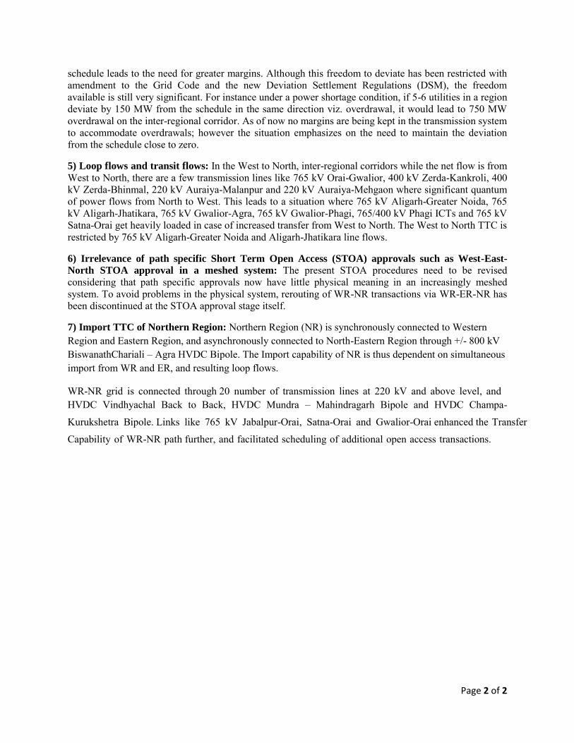
Page 2 of 2
schedule leads to the need for greater margins. Although this freedom to deviate has been restricted with amendment to the Grid Code and the new Deviation Settlement Regulations (DSM), the freedom available is still very significant. For instance under a power shortage condition, if 5-6 utilities in a region deviate by 150 MW from the schedule in the same direction viz. overdrawal, it would lead to 750 MW overdrawal on the inter-regional corridor. As of now no margins are being kept in the transmission system to accommodate overdrawals; however the situation emphasizes on the need to maintain the deviation from the schedule close to zero.
5) Loop flows and transit flows: In the West to North, inter-regional corridors while the net flow is from West to North, there are a few transmission lines like 765 kV Orai-Gwalior, 400 kV Zerda-Kankroli, 400 kV Zerda-Bhinmal, 220 kV Auraiya-Malanpur and 220 kV Auraiya-Mehgaon where significant quantum of power flows from North to West. This leads to a situation where 765 kV Aligarh-Greater Noida, 765 kV Aligarh-Jhatikara, 765 kV Gwalior-Agra, 765 kV Gwalior-Phagi, 765/400 kV Phagi ICTs and 765 kV Satna-Orai get heavily loaded in case of increased transfer from West to North. The West to North TTC is restricted by 765 kV Aligarh-Greater Noida and Aligarh-Jhatikara line flows.
6) Irrelevance of path specific Short Term Open Access (STOA) approvals such as West-East-
North STOA approval in a meshed system: The present STOA procedures need to be revised
considering that path specific approvals now have little physical meaning in an increasingly meshed system. To avoid problems in the physical system, rerouting of WR-NR transactions via WR-ER-NR has been discontinued at the STOA approval stage itself.
7) Import TTC of Northern Region: Northern Region (NR) is synchronously connected to Western Region and Eastern Region, and asynchronously connected to North-Eastern Region through +/- 800 kV BiswanathChariali – Agra HVDC Bipole. The Import capability of NR is thus dependent on simultaneous import from WR and ER, and resulting loop flows.
WR-NR grid is connected through 20 number of transmission lines at 220 kV and above level, and HVDC Vindhyachal Back to Back, HVDC Mundra – Mahindragarh Bipole and HVDC Champa-
Kurukshetra Bipole. Links like 765 kV Jabalpur-Orai, Satna-Orai and Gwalior-Orai enhanced the Transfer
Capability of WR-NR path further, and facilitated scheduling of additional open access transactions.
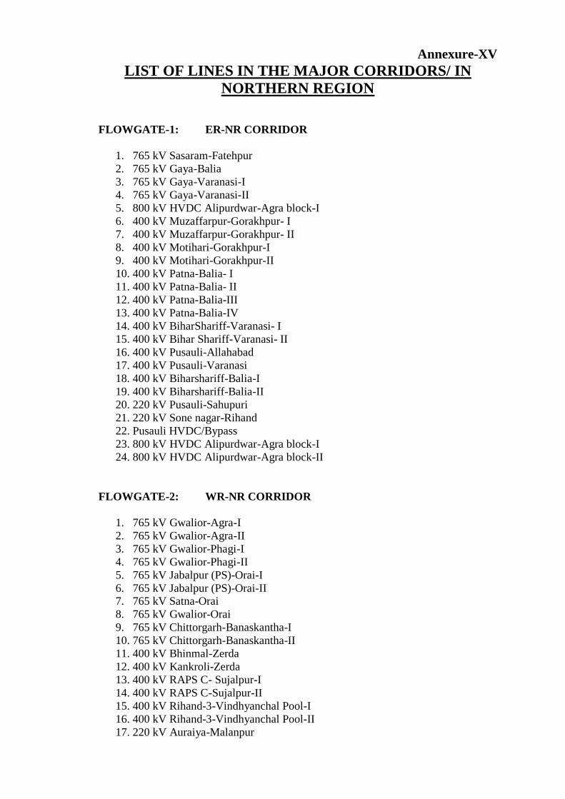
Annexure-XV
LIST OF LINES IN THE MAJOR CORRIDORS/ IN
NORTHERN REGION
FLOWGATE-1: ER-NR CORRIDOR
1. 765 kV Sasaram-Fatehpur
2. 765 kV Gaya-Balia
3. 765 kV Gaya-Varanasi-I
4. 765 kV Gaya-Varanasi-II
5. 800 kV HVDC Alipurdwar-Agra block-I
6. 400 kV Muzaffarpur-Gorakhpur- I
7. 400 kV Muzaffarpur-Gorakhpur- II
8. 400 kV Motihari-Gorakhpur-I
9. 400 kV Motihari-Gorakhpur-II
10. 400 kV Patna-Balia- I
11. 400 kV Patna-Balia- II
12. 400 kV Patna-Balia-III
13. 400 kV Patna-Balia-IV
14. 400 kV BiharShariff-Varanasi- I
15. 400 kV Bihar Shariff-Varanasi- II
16. 400 kV Pusauli-Allahabad
17. 400 kV Pusauli-Varanasi
18. 400 kV Biharshariff-Balia-I
19. 400 kV Biharshariff-Balia-II
20. 220 kV Pusauli-Sahupuri
21. 220 kV Sone nagar-Rihand
22. Pusauli HVDC/Bypass
23. 800 kV HVDC Alipurdwar-Agra block-I
24. 800 kV HVDC Alipurdwar-Agra block-II
FLOWGATE-2: WR-NR CORRIDOR
1. 765 kV Gwalior-Agra-I
2. 765 kV Gwalior-Agra-II
3. 765 kV Gwalior-Phagi-I
4. 765 kV Gwalior-Phagi-II
5. 765 kV Jabalpur (PS)-Orai-I
6. 765 kV Jabalpur (PS)-Orai-II 7. 765 kV Satna-Orai
8. 765 kV Gwalior-Orai
9. 765 kV Chittorgarh-Banaskantha-I
10. 765 kV Chittorgarh-Banaskantha-II
11. 400 kV Bhinmal-Zerda
12. 400 kV Kankroli-Zerda
13. 400 kV RAPS C- Sujalpur-I
14. 400 kV RAPS C-Sujalpur-II
15. 400 kV Rihand-3-Vindhyanchal Pool-I
16. 400 kV Rihand-3-Vindhyanchal Pool-II
17. 220 kV Auraiya-Malanpur
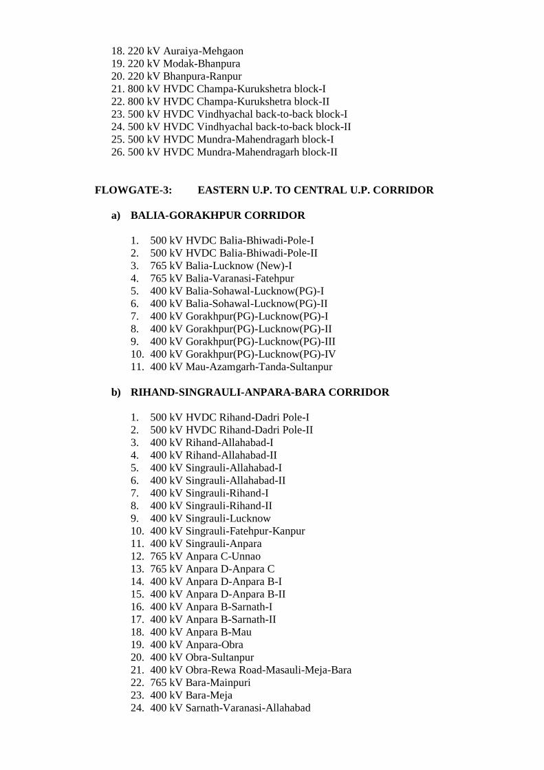
18. 220 kV Auraiya-Mehgaon
19. 220 kV Modak-Bhanpura
20. 220 kV Bhanpura-Ranpur
21. 800 kV HVDC Champa-Kurukshetra block-I
22. 800 kV HVDC Champa-Kurukshetra block-II
23. 500 kV HVDC Vindhyachal back-to-back block-I
24. 500 kV HVDC Vindhyachal back-to-back block-II
25. 500 kV HVDC Mundra-Mahendragarh block-I
26. 500 kV HVDC Mundra-Mahendragarh block-II
FLOWGATE-3: EASTERN U.P. TO CENTRAL U.P. CORRIDOR
a) BALIA-GORAKHPUR CORRIDOR
1. 500 kV HVDC Balia-Bhiwadi-Pole-I
2. 500 kV HVDC Balia-Bhiwadi-Pole-II
3. 765 kV Balia-Lucknow (New)-I
4. 765 kV Balia-Varanasi-Fatehpur
5. 400 kV Balia-Sohawal-Lucknow(PG)-I
6. 400 kV Balia-Sohawal-Lucknow(PG)-II
7. 400 kV Gorakhpur(PG)-Lucknow(PG)-I
8. 400 kV Gorakhpur(PG)-Lucknow(PG)-II
9. 400 kV Gorakhpur(PG)-Lucknow(PG)-III
10. 400 kV Gorakhpur(PG)-Lucknow(PG)-IV
11. 400 kV Mau-Azamgarh-Tanda-Sultanpur
b) RIHAND-SINGRAULI-ANPARA-BARA CORRIDOR
1. 500 kV HVDC Rihand-Dadri Pole-I
2. 500 kV HVDC Rihand-Dadri Pole-II
3. 400 kV Rihand-Allahabad-I
4. 400 kV Rihand-Allahabad-II
5. 400 kV Singrauli-Allahabad-I
6. 400 kV Singrauli-Allahabad-II
7. 400 kV Singrauli-Rihand-I
8. 400 kV Singrauli-Rihand-II
9. 400 kV Singrauli-Lucknow
10. 400 kV Singrauli-Fatehpur-Kanpur
11. 400 kV Singrauli-Anpara
12. 765 kV Anpara C-Unnao
13. 765 kV Anpara D-Anpara C
14. 400 kV Anpara D-Anpara B-I
15. 400 kV Anpara D-Anpara B-II
16. 400 kV Anpara B-Sarnath-I
17. 400 kV Anpara B-Sarnath-II
18. 400 kV Anpara B-Mau
19. 400 kV Anpara-Obra
20. 400 kV Obra-Sultanpur
21. 400 kV Obra-Rewa Road-Masauli-Meja-Bara
22. 765 kV Bara-Mainpuri
23. 400 kV Bara-Meja
24. 400 kV Sarnath-Varanasi-Allahabad
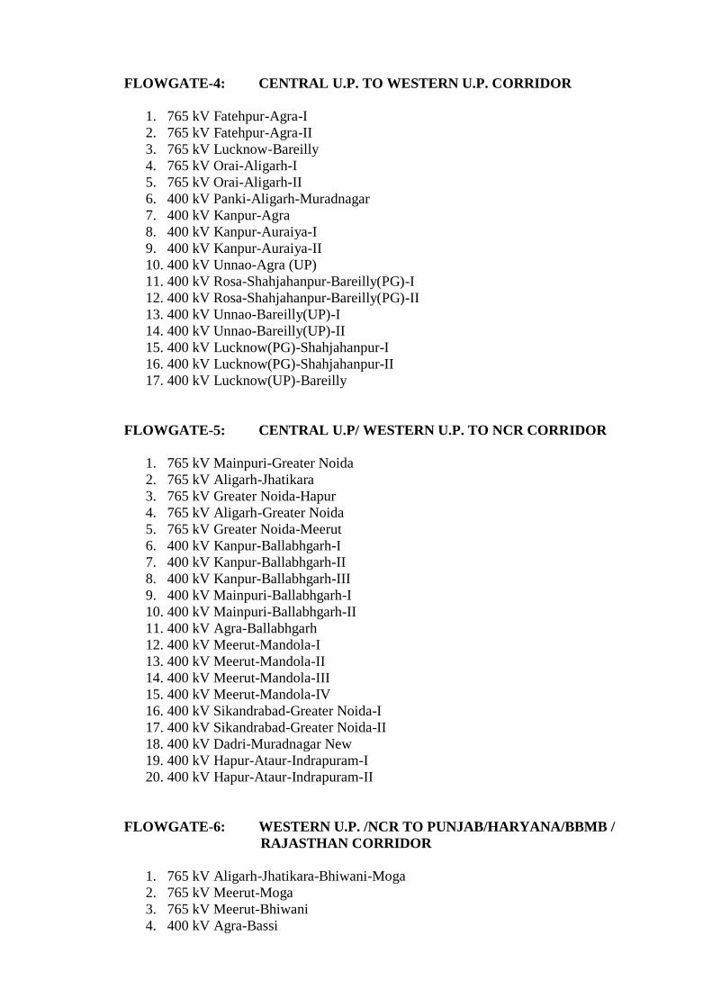
FLOWGATE-4: CENTRAL U.P. TO WESTERN U.P. CORRIDOR
1. 765 kV Fatehpur-Agra-I
2. 765 kV Fatehpur-Agra-II
3. 765 kV Lucknow-Bareilly
4. 765 kV Orai-Aligarh-I
5. 765 kV Orai-Aligarh-II
6. 400 kV Panki-Aligarh-Muradnagar
7. 400 kV Kanpur-Agra
8. 400 kV Kanpur-Auraiya-I
9. 400 kV Kanpur-Auraiya-II
10. 400 kV Unnao-Agra (UP)
11. 400 kV Rosa-Shahjahanpur-Bareilly(PG)-I
12. 400 kV Rosa-Shahjahanpur-Bareilly(PG)-II
13. 400 kV Unnao-Bareilly(UP)-I
14. 400 kV Unnao-Bareilly(UP)-II
15. 400 kV Lucknow(PG)-Shahjahanpur-I
16. 400 kV Lucknow(PG)-Shahjahanpur-II
17. 400 kV Lucknow(UP)-Bareilly
FLOWGATE-5: CENTRAL U.P/ WESTERN U.P. TO NCR CORRIDOR
1. 765 kV Mainpuri-Greater Noida
2. 765 kV Aligarh-Jhatikara
3. 765 kV Greater Noida-Hapur
4. 765 kV Aligarh-Greater Noida
5. 765 kV Greater Noida-Meerut
6. 400 kV Kanpur-Ballabhgarh-I
7. 400 kV Kanpur-Ballabhgarh-II
8. 400 kV Kanpur-Ballabhgarh-III
9. 400 kV Mainpuri-Ballabhgarh-I
10. 400 kV Mainpuri-Ballabhgarh-II
11. 400 kV Agra-Ballabhgarh
12. 400 kV Meerut-Mandola-I
13. 400 kV Meerut-Mandola-II
14. 400 kV Meerut-Mandola-III
15. 400 kV Meerut-Mandola-IV
16. 400 kV Sikandrabad-Greater Noida-I
17. 400 kV Sikandrabad-Greater Noida-II
18. 400 kV Dadri-Muradnagar New
19. 400 kV Hapur-Ataur-Indrapuram-I
20. 400 kV Hapur-Ataur-Indrapuram-II
FLOWGATE-6: WESTERN U.P. /NCR TO PUNJAB/HARYANA/BBMB /
RAJASTHAN CORRIDOR
1. 765 kV Aligarh-Jhatikara-Bhiwani-Moga
2. 765 kV Meerut-Moga
3. 765 kV Meerut-Bhiwani
4. 400 kV Agra-Bassi
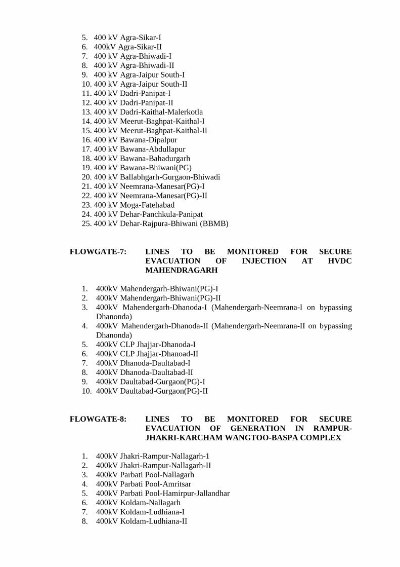
5. 400 kV Agra-Sikar-I
6. 400kV Agra-Sikar-II
7. 400 kV Agra-Bhiwadi-I
8. 400 kV Agra-Bhiwadi-II
9. 400 kV Agra-Jaipur South-I
10. 400 kV Agra-Jaipur South-II
11. 400 kV Dadri-Panipat-I
12. 400 kV Dadri-Panipat-II
13. 400 kV Dadri-Kaithal-Malerkotla
14. 400 kV Meerut-Baghpat-Kaithal-I
15. 400 kV Meerut-Baghpat-Kaithal-II
16. 400 kV Bawana-Dipalpur
17. 400 kV Bawana-Abdullapur
18. 400 kV Bawana-Bahadurgarh
19. 400 kV Bawana-Bhiwani(PG)
20. 400 kV Ballabhgarh-Gurgaon-Bhiwadi
21. 400 kV Neemrana-Manesar(PG)-I
22. 400 kV Neemrana-Manesar(PG)-II
23. 400 kV Moga-Fatehabad
24. 400 kV Dehar-Panchkula-Panipat
25. 400 kV Dehar-Rajpura-Bhiwani (BBMB)
FLOWGATE-7: LINES TO BE MONITORED FOR SECURE
EVACUATION OF INJECTION AT HVDC
MAHENDRAGARH
1. 400kV Mahendergarh-Bhiwani(PG)-I
2. 400kV Mahendergarh-Bhiwani(PG)-II
3. 400kV Mahendergarh-Dhanoda-I (Mahendergarh-Neemrana-I on bypassing
Dhanonda)
4. 400kV Mahendergarh-Dhanoda-II (Mahendergarh-Neemrana-II on bypassing
Dhanonda)
5. 400kV CLP Jhajjar-Dhanoda-I
6. 400kV CLP Jhajjar-Dhanoad-II
7. 400kV Dhanoda-Daultabad-I
8. 400kV Dhanoda-Daultabad-II
9. 400kV Daultabad-Gurgaon(PG)-I
10. 400kV Daultabad-Gurgaon(PG)-II
FLOWGATE-8: LINES TO BE MONITORED FOR SECURE
EVACUATION OF GENERATION IN RAMPUR-
JHAKRI-KARCHAM WANGTOO-BASPA COMPLEX
1. 400kV Jhakri-Rampur-Nallagarh-1
2. 400kV Jhakri-Rampur-Nallagarh-II
3. 400kV Parbati Pool-Nallagarh
4. 400kV Parbati Pool-Amritsar
5. 400kV Parbati Pool-Hamirpur-Jallandhar
6. 400kV Koldam-Nallagarh
7. 400kV Koldam-Ludhiana-I
8. 400kV Koldam-Ludhiana-II
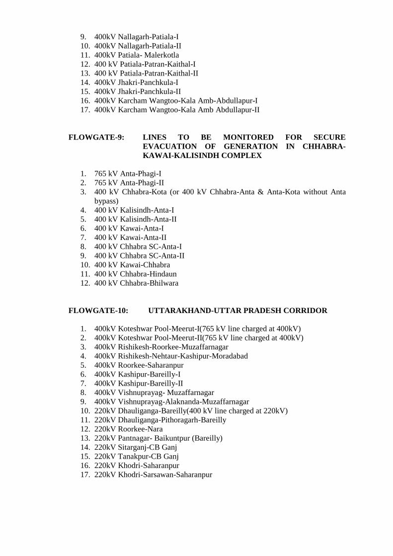
9. 400kV Nallagarh-Patiala-I
10. 400kV Nallagarh-Patiala-II
11. 400kV Patiala- Malerkotla
12. 400 kV Patiala-Patran-Kaithal-I
13. 400 kV Patiala-Patran-Kaithal-II
14. 400kV Jhakri-Panchkula-I
15. 400kV Jhakri-Panchkula-II
16. 400kV Karcham Wangtoo-Kala Amb-Abdullapur-I
17. 400kV Karcham Wangtoo-Kala Amb Abdullapur-II
FLOWGATE-9: LINES TO BE MONITORED FOR SECURE
EVACUATION OF GENERATION IN CHHABRA-
KAWAI-KALISINDH COMPLEX
1. 765 kV Anta-Phagi-I
2. 765 kV Anta-Phagi-II
3. 400 kV Chhabra-Kota (or 400 kV Chhabra-Anta & Anta-Kota without Anta
bypass)
4. 400 kV Kalisindh-Anta-I
5. 400 kV Kalisindh-Anta-II
6. 400 kV Kawai-Anta-I
7. 400 kV Kawai-Anta-II
8. 400 kV Chhabra SC-Anta-I
9. 400 kV Chhabra SC-Anta-II
10. 400 kV Kawai-Chhabra
11. 400 kV Chhabra-Hindaun
12. 400 kV Chhabra-Bhilwara
FLOWGATE-10: UTTARAKHAND-UTTAR PRADESH CORRIDOR
1. 400kV Koteshwar Pool-Meerut-I(765 kV line charged at 400kV)
2. 400kV Koteshwar Pool-Meerut-II(765 kV line charged at 400kV)
3. 400kV Rishikesh-Roorkee-Muzaffarnagar
4. 400kV Rishikesh-Nehtaur-Kashipur-Moradabad
5. 400kV Roorkee-Saharanpur
6. 400kV Kashipur-Bareilly-I
7. 400kV Kashipur-Bareilly-II
8. 400kV Vishnuprayag- Muzaffarnagar
9. 400kV Vishnuprayag-Alaknanda-Muzaffarnagar
10. 220kV Dhauliganga-Bareilly(400 kV line charged at 220kV)
11. 220kV Dhauliganga-Pithoragarh-Bareilly
12. 220kV Roorkee-Nara
13. 220kV Pantnagar- Baikuntpur (Bareilly)
14. 220kV Sitarganj-CB Ganj
15. 220kV Tanakpur-CB Ganj
16. 220kV Khodri-Saharanpur
17. 220kV Khodri-Sarsawan-Saharanpur
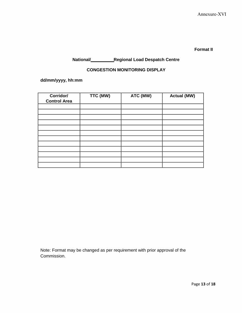
Format II
National/ Regional Load Despatch Centre
CONGESTION MONITORING DISPLAY
dd/mm/yyyy, hh:mm
Corridor/ TTC (MW) ATC (MW) Actual (MW) Control Area
Note: Format may be changed as per requirement with prior approval of the
Commission.
Page 13 of 18
Annexure-XVI
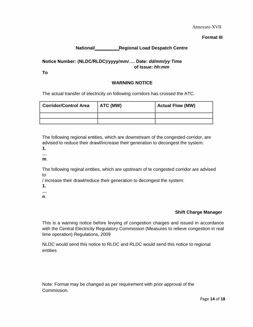
Annexure-XVII Format III
National/ Regional Load Despatch Centre
Notice Number: (NLDC/RLDC)/yyyy/mm/…. Date: dd/mm/yy Time
of Issue: hh:mm To
WARNING NOTICE
The actual transfer of electricity on following corridors has crossed the ATC.
Corridor/Control Area ATC (MW) Actual Flow (MW)
The following regional entities, which are downstream of the congested corridor, are
advised to reduce their drawl/increase their generation to decongest the system: 1. … m.
The following reginal entities, which are upstream of te congested corridor are advised
to / increase their drawl/reduce their generation to decongest the system: 1. … n.
Shift Charge Manager This is a warning notice before levying of congestion charges and issued in accordance
with the Central Electricity Regulatory Commission (Measures to relieve congestion in real
time operation) Regulations, 2009 NLDC would send this notice to RLDC and RLDC would send this notice to regional
entities Note: Format may be changed as per requirement with prior approval of the
Commission.
Page 14 of 18
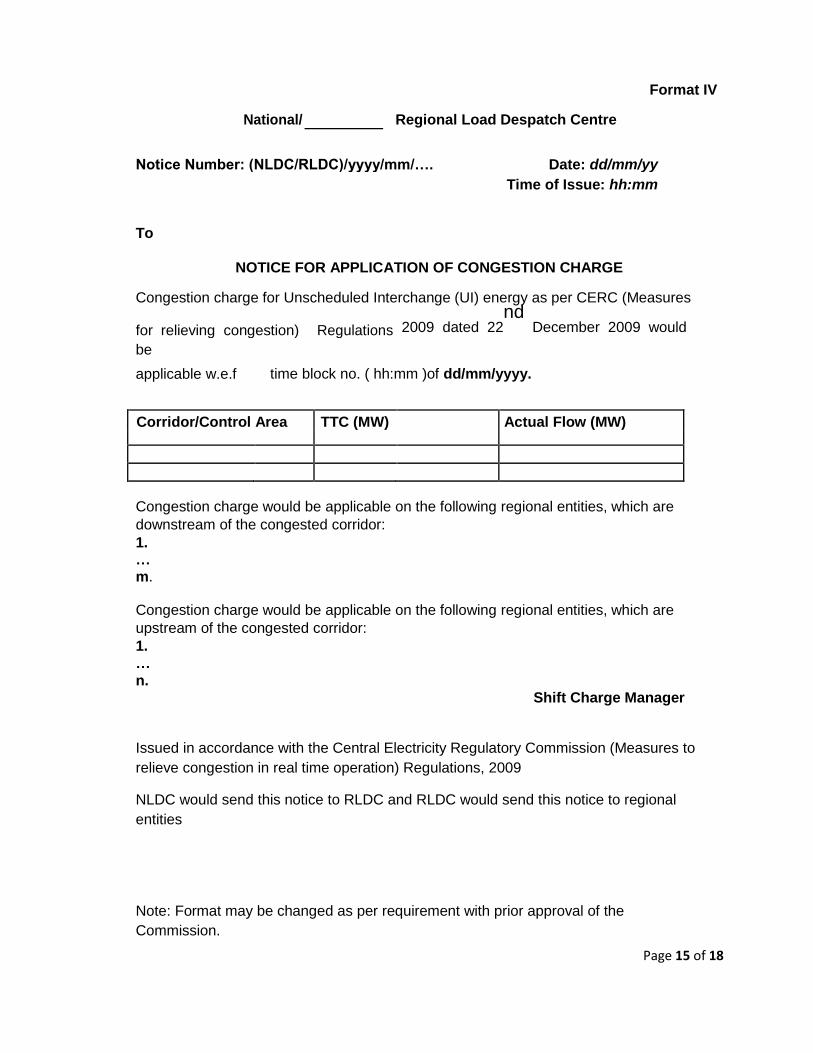
Format IV
National/ Regional Load Despatch Centre
Notice Number: (NLDC/RLDC)/yyyy/mm/…. Date: dd/mm/yy Time of Issue: hh:mm
To
NOTICE FOR APPLICATION OF CONGESTION CHARGE
Congestion charge for Unscheduled Interchange (UI) energy as per CERC (Measures
for relieving congestion) Regulations 2009 dated 22nd
December 2009 would
be
applicable w.e.f time block no. ( hh:mm )of dd/mm/yyyy.
Corridor/Control Area TTC (MW) Actual Flow (MW)
Congestion charge would be applicable on the following regional entities, which are
downstream of the congested corridor: 1. … m.
Congestion charge would be applicable on the following regional entities, which are
upstream of the congested corridor: 1. … n.
Shift Charge Manager Issued in accordance with the Central Electricity Regulatory Commission (Measures to
relieve congestion in real time operation) Regulations, 2009 NLDC would send this notice to RLDC and RLDC would send this notice to regional
entities Note: Format may be changed as per requirement with prior approval of the
Commission. Page 15 of 18
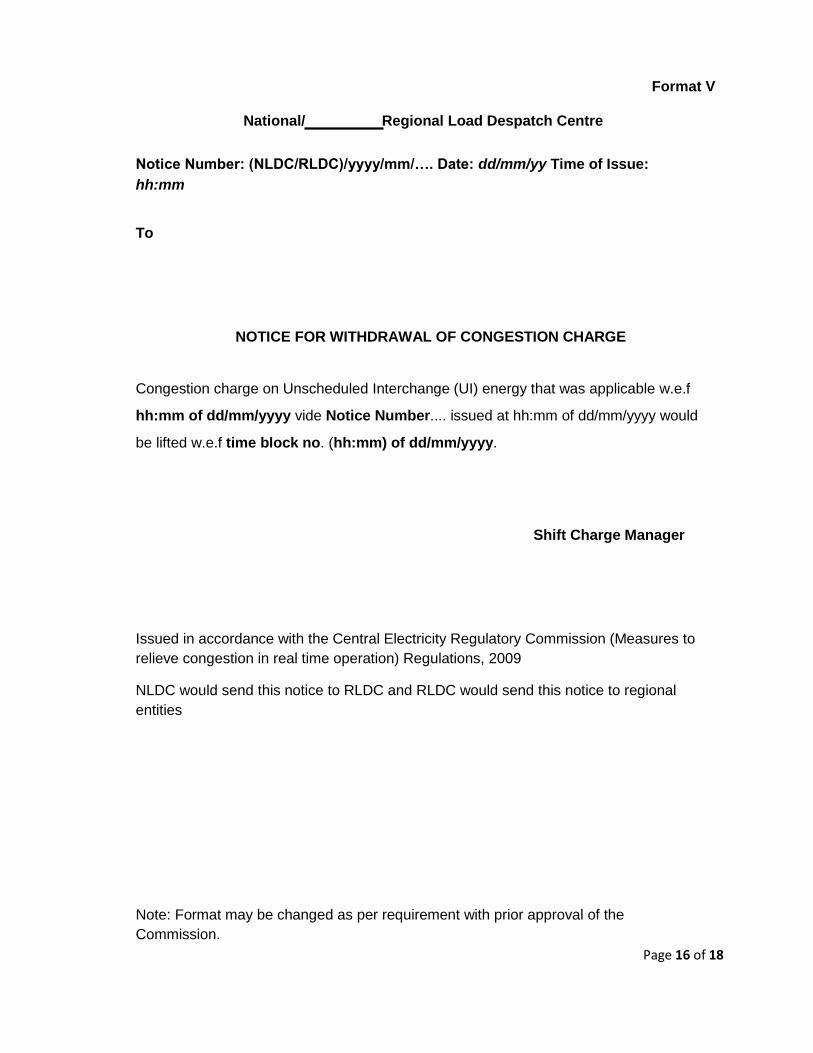
Format V
National/ Regional Load Despatch Centre Notice Number: (NLDC/RLDC)/yyyy/mm/…. Date: dd/mm/yy Time of Issue:
hh:mm To
NOTICE FOR WITHDRAWAL OF CONGESTION CHARGE Congestion charge on Unscheduled Interchange (UI) energy that was applicable w.e.f hh:mm of dd/mm/yyyy vide Notice Number.... issued at hh:mm of dd/mm/yyyy would be lifted w.e.f time block no. (hh:mm) of dd/mm/yyyy.
Shift Charge Manager Issued in accordance with the Central Electricity Regulatory Commission (Measures to
relieve congestion in real time operation) Regulations, 2009 NLDC would send this notice to RLDC and RLDC would send this notice to regional
entities Note: Format may be changed as per requirement with prior approval of the
Commission. Page 16 of 18
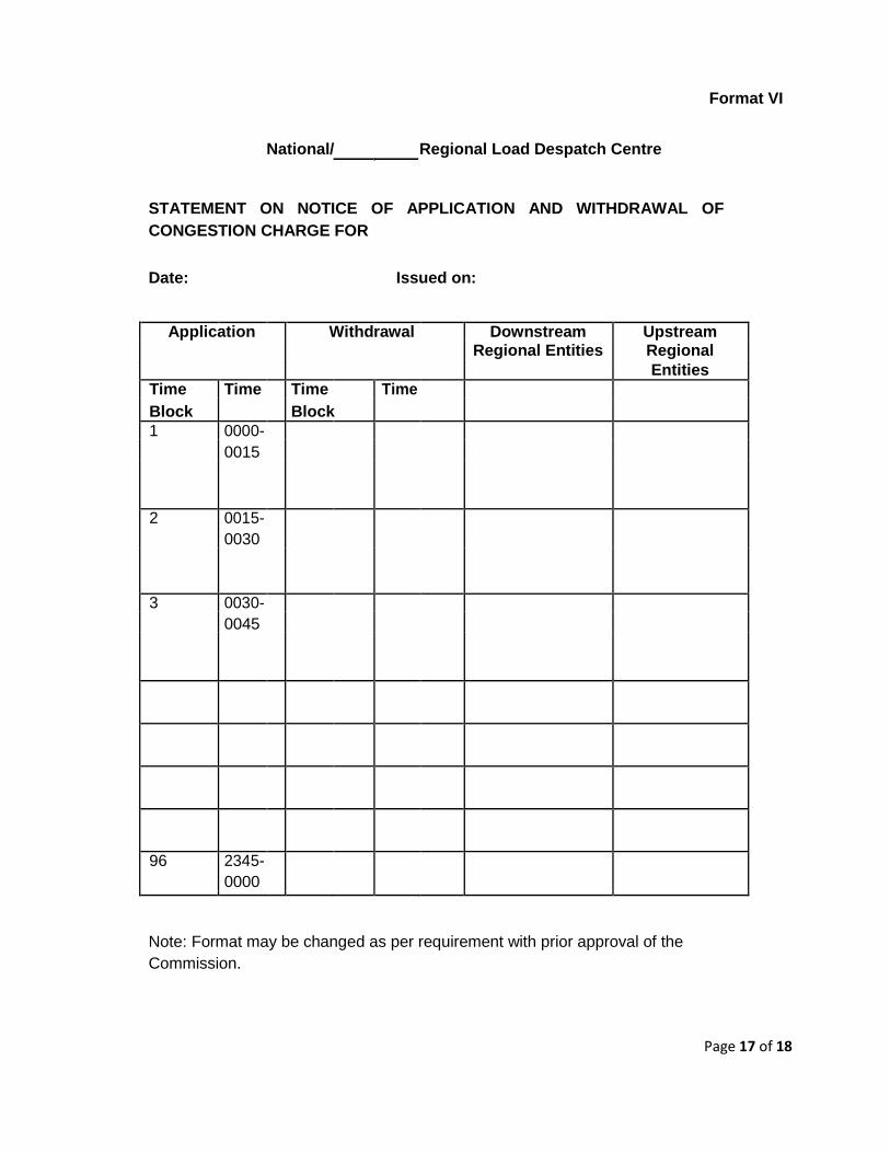
Format VI
National/ Regional Load Despatch Centre
STATEMENT ON NOTICE OF APPLICATION AND WITHDRAWAL OF
CONGESTION CHARGE FOR
Date: Issued on:
Application Withdrawal Downstream Upstream
Regional Entities Regional
Entities
Time Time Time Time
Block Block
1 0000-
0015
2 0015-
0030
3 0030-
0045
96 2345-
0000
Note: Format may be changed as per requirement with prior approval of the
Commission.
Page 17 of 18
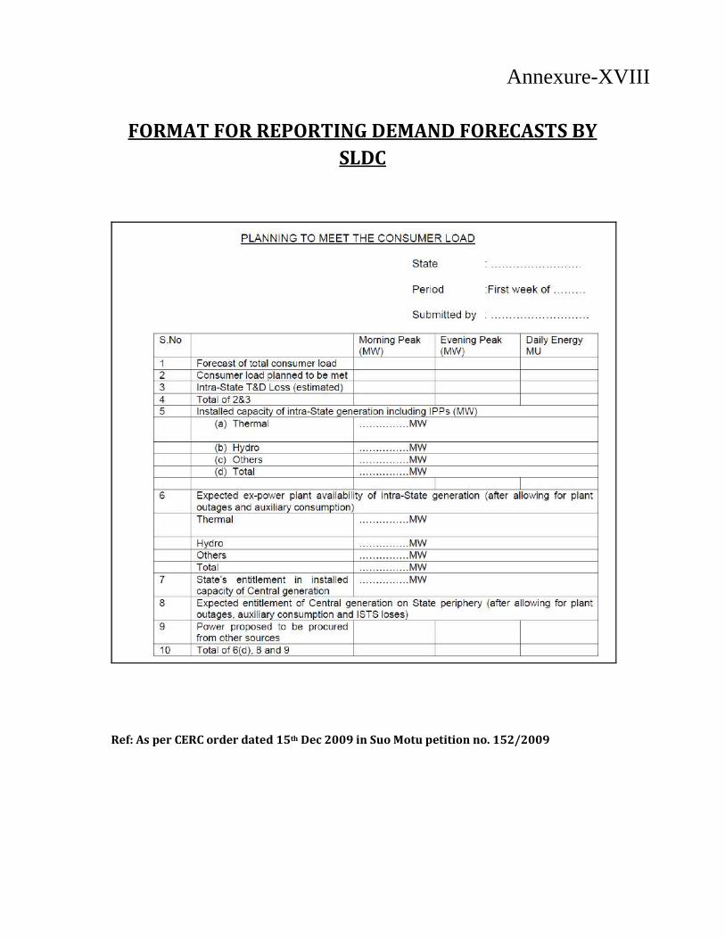
FORMAT FOR REPORTING DEMAND FORECASTS BY
SLDC
Ref: As per CERC order dated 15th Dec 2009 in Suo Motu petition no. 152/2009
Annexure-XVIII
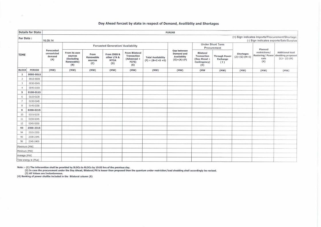
Day Ahead forcast by state in respect of Demand, Availiblity and Shortages
Details for State PUNJAB
For Date : (+) Sign indicates Imports/Procurement/Shortage; 16.09.14 (-) Sign indicates exports/Sale/Surplus
TIME
Forecasted unresricted
demand (A)
Forcasted Generation/ Availability
Gap between Demand and Availablity
(G)=(A)-(F)
Under Short Term Procurement
Shortages (3)=(G)-(H+I)
Planned
Rostering/ Power cuts (K)
Additional load shedding proposed
(L) ,- (3)-(K)
From its own sources
(Excluding Renewable)
(B)
From Renewable
sources (C)
From ISGS & other LTA &
MTOA (D)
Transaction (Advanced +
FCFS) (E)
Total Availability (F) = (B+C+D +E)
From Bilateral Bilateral Transaction
(Day Ahead + Contingency)
(H)
Through Power Exchange
( I )
BLOCK PERIOD (MW) (MW) (MW) (MW) (MW) (MW) (MW) (MW (MW) (MW) (MW) (MW)
1 0000-0015
2 0015-0030
3 0030-0045
4 0045-0100
5 0100-0115
6 0115-0130
7 0130-0145
8 0145-0200
9 0200-0215
10 0215-0230
11 0230-0245
12 0245-0300
93 2300-2315
94 2315-2330
95 2330-2345
96 2345-2400
Maximum (MW)
Minimum (MW)
Average (MW)
Total energy in (Mus)
Note :- (1) The inforamtion shall be provided by SLDCs to RLDCs by 19:00 hrs of the previous day. (2) In case the procurement under the Day Ahead, Bilateral/PX is lesser than proposed then the quantum under restriction/load shedding shall accordingly be revised. (3) All Values are Instantaneous.
(4) Banking of power shallbe included in the Bilateral column (E)
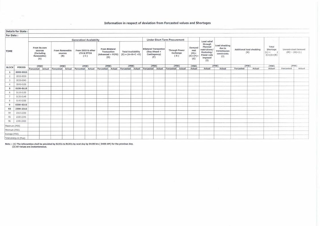
Information in respect of deviation from Forcasted values and Shortages
Details for State :
For Date :
TIME
Generation/ Availabirty Under Short Term Procurement Load relief
through Planned
restrictions/ Rostering/ Power cuts
imposed
(I)
Load shedding due to
transmission constraints
0)
Additional load shedding (K)
Total Shortage
(L) = ( I)+(3)+(K)
Unrestricted Demand
(M) = (H)+(L)
From its own sources
(Excluding
Renewable) (A)
From Renewable sources
(B)
From ISGS & other LTA & MTOA
( C )
From Bilateral Transaction
(Advanced + FCFS) (D)
Total Availability (E) = (A+B+C +D)
Bilateral Transaction (Day Ahead + Contingency)
(F)
Through Power Exchange
( G )
Demand met (H)=
(E)+(F)+ (G)
BLOCK PERIOD (MW) (MW) (MW) (MW) (MW) (MW) (MW) (MW) (MW) (MW) (MW) (MW)
Forcasted Actual Forcasted Actual Forcasted Actual Forcasted Actual Forcasted Actual Forcasted Actual Forcasted Actual Actual Actual Actual Forcasted Actual Actual Forcasted Actual
1 0000-0015
2 0015-0030
3 0030-0045
4 0045-0100
5 0100-0115
6 0115-0130
7 0130-0145
8 0145-0200
9 0200-0215
93 2300-2315
94 2315-2330
95 2330-2345
96 2345-2400
Maximum (MW)
Minimum (MW)
Average (MW)
Total energy in (Mus)
Note :- (1) The inforamtion shall be provided by SLDCs to RLDCs by next day by 04:00 hrs ( 0400 AM) for the previous day. (2) All Values are Instantaneous.
Annex-XIX
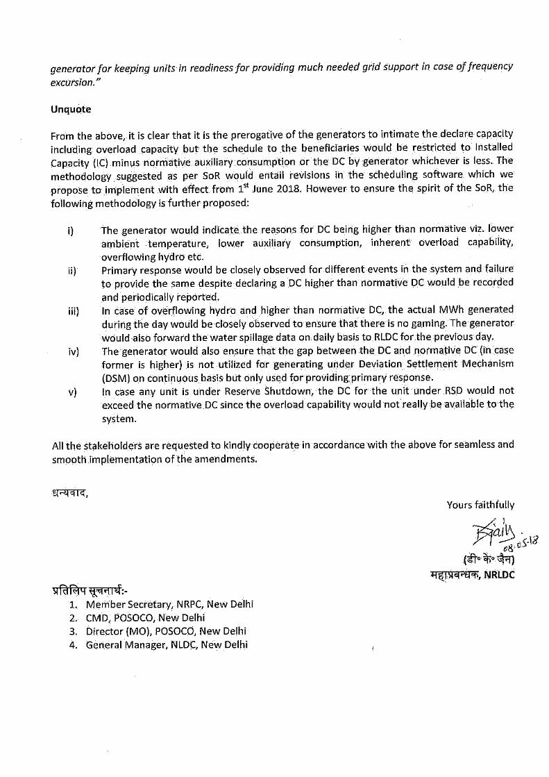
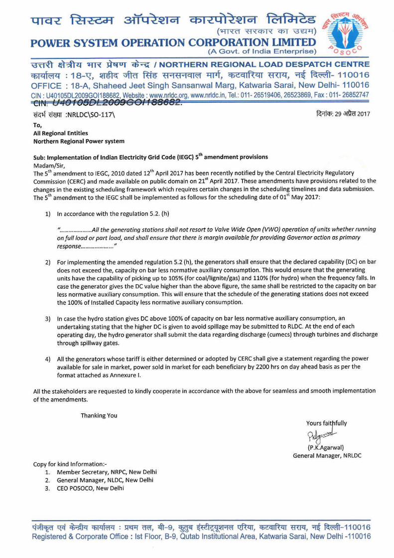
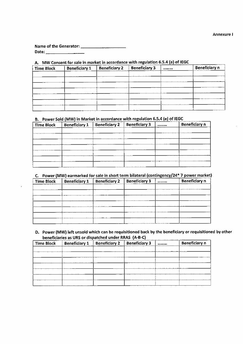
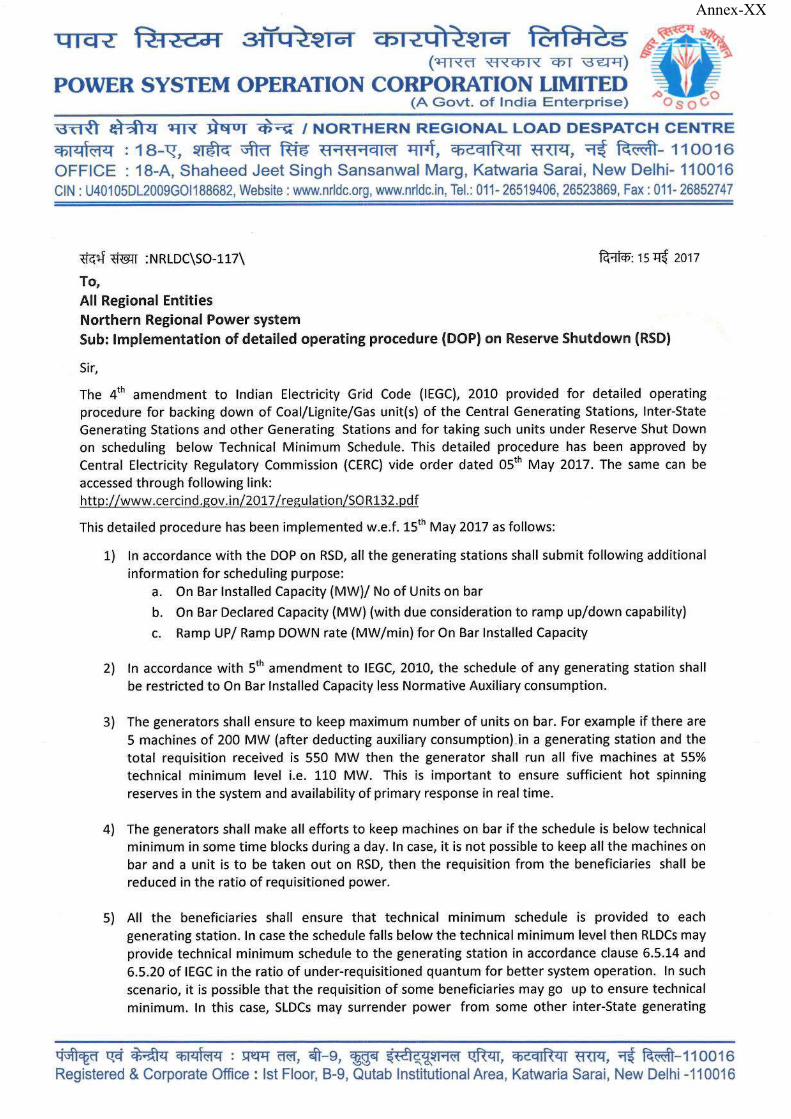
Annex-XX
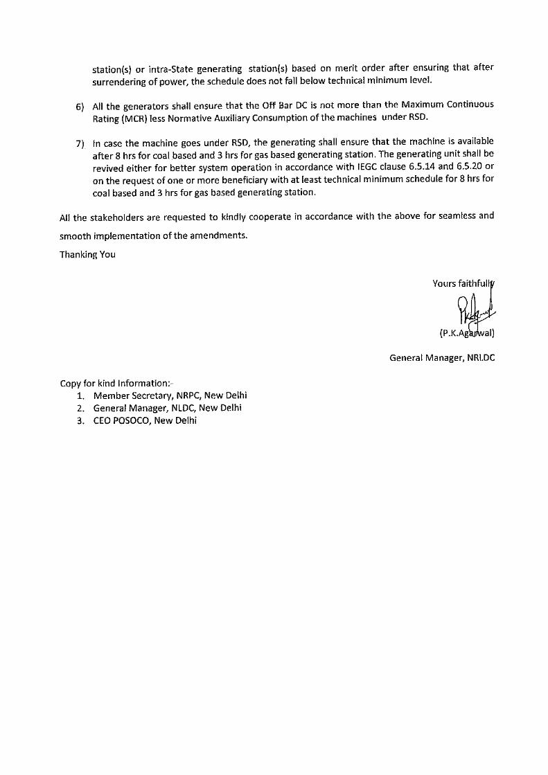
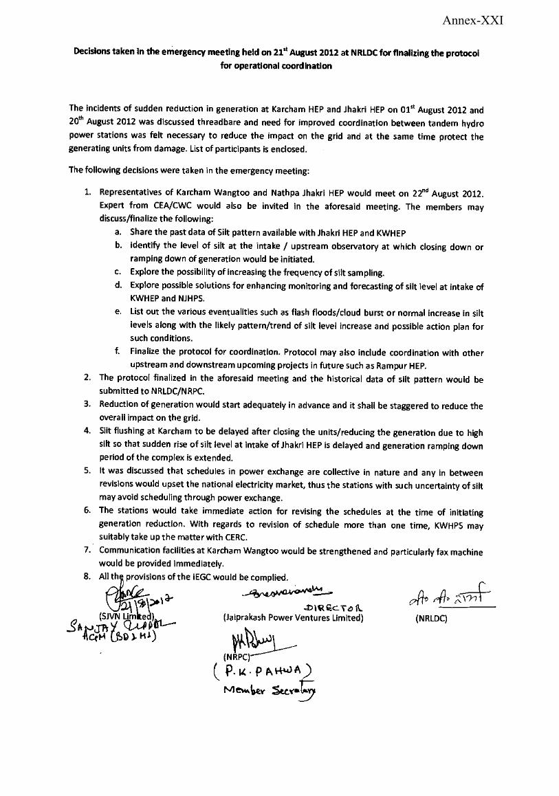
Annex-XXI
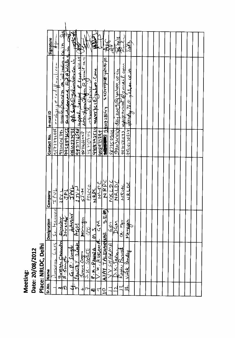
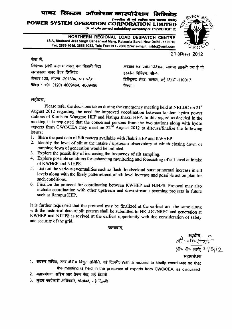
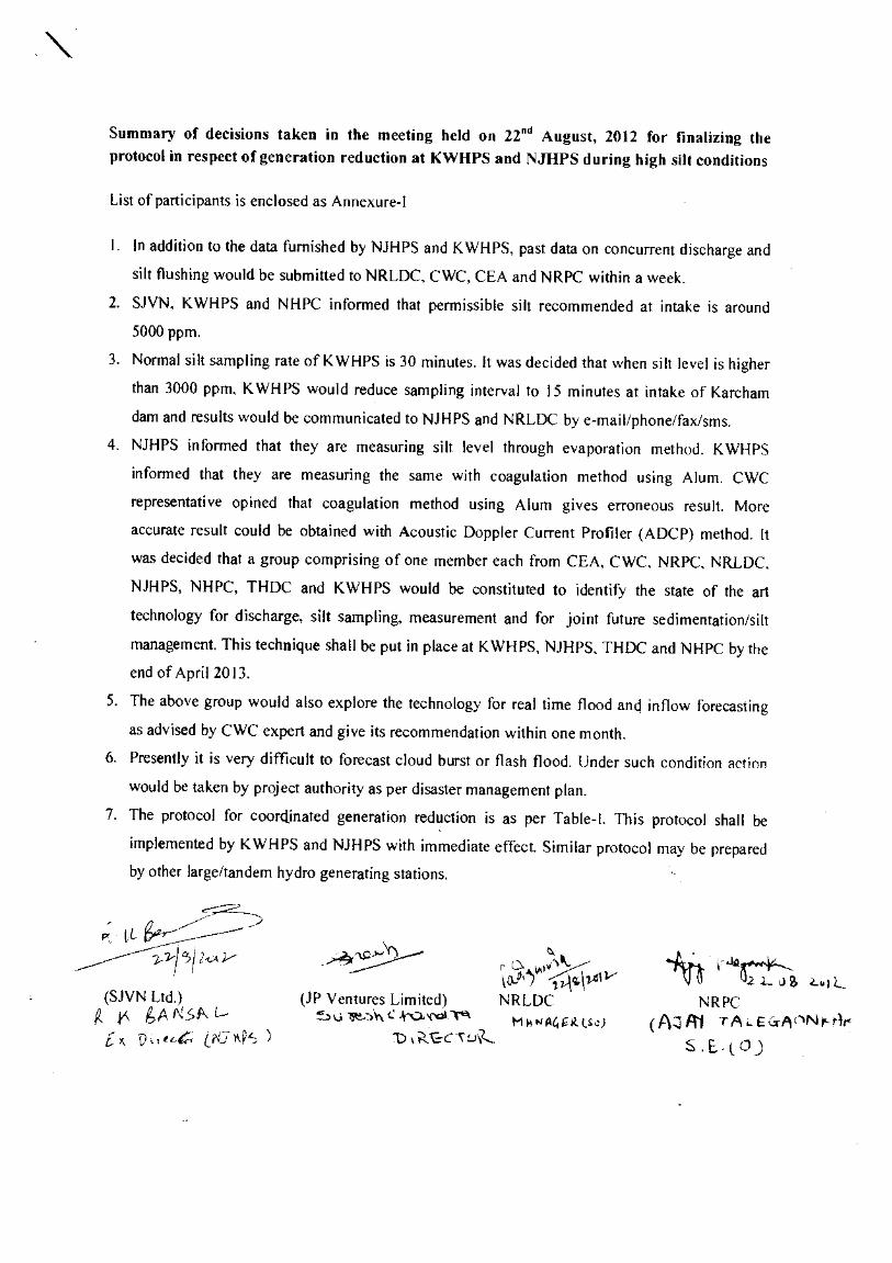
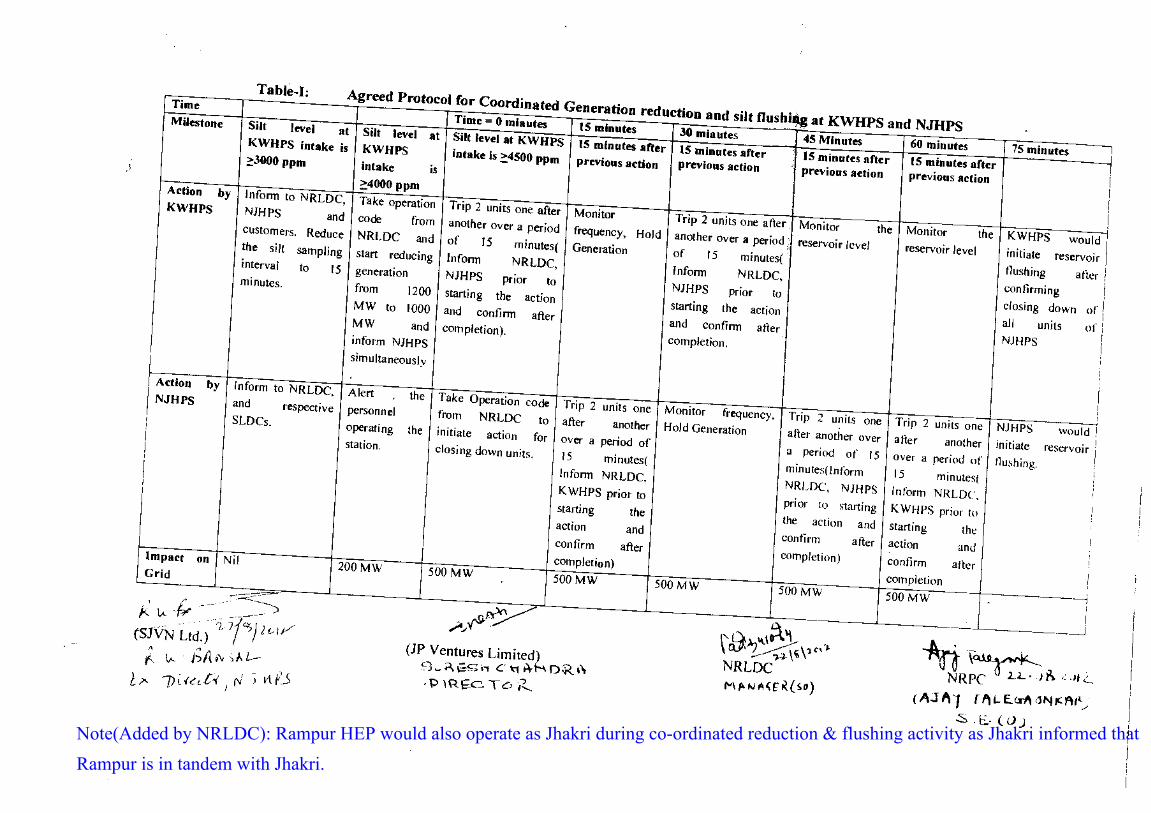
Note(Added by NRLDC): Rampur HEP would also operate as Jhakri during co-ordinated reduction & flushing activity as Jhakri informed that Rampur is in tandem with Jhakri.
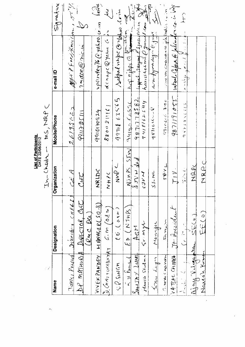
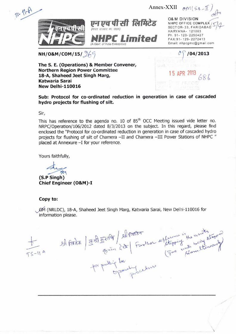
Annex-XXII
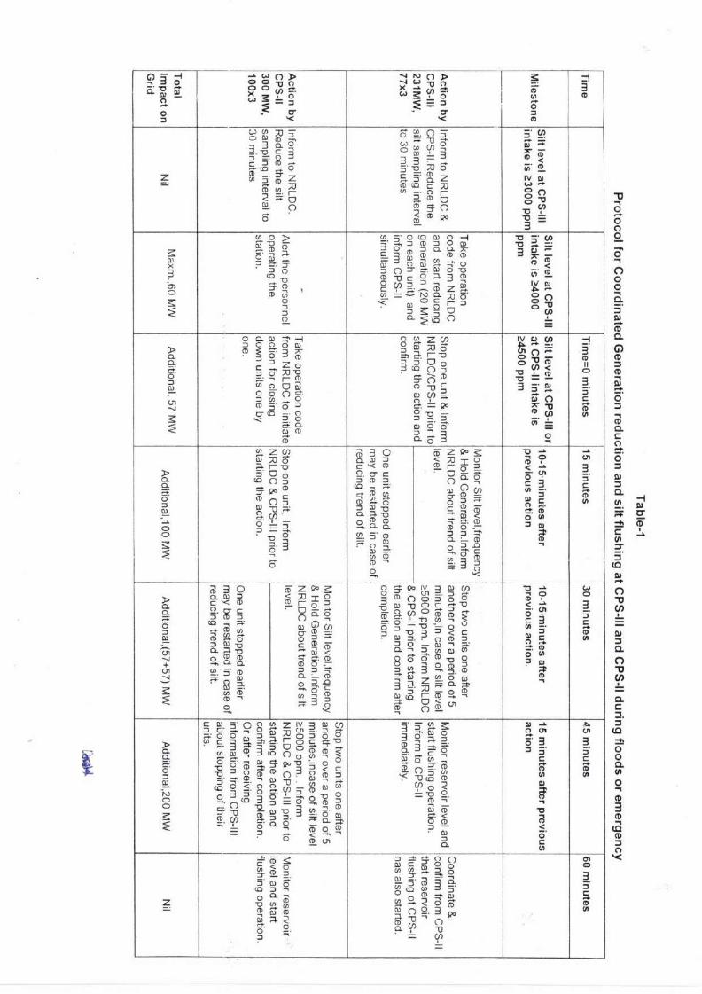
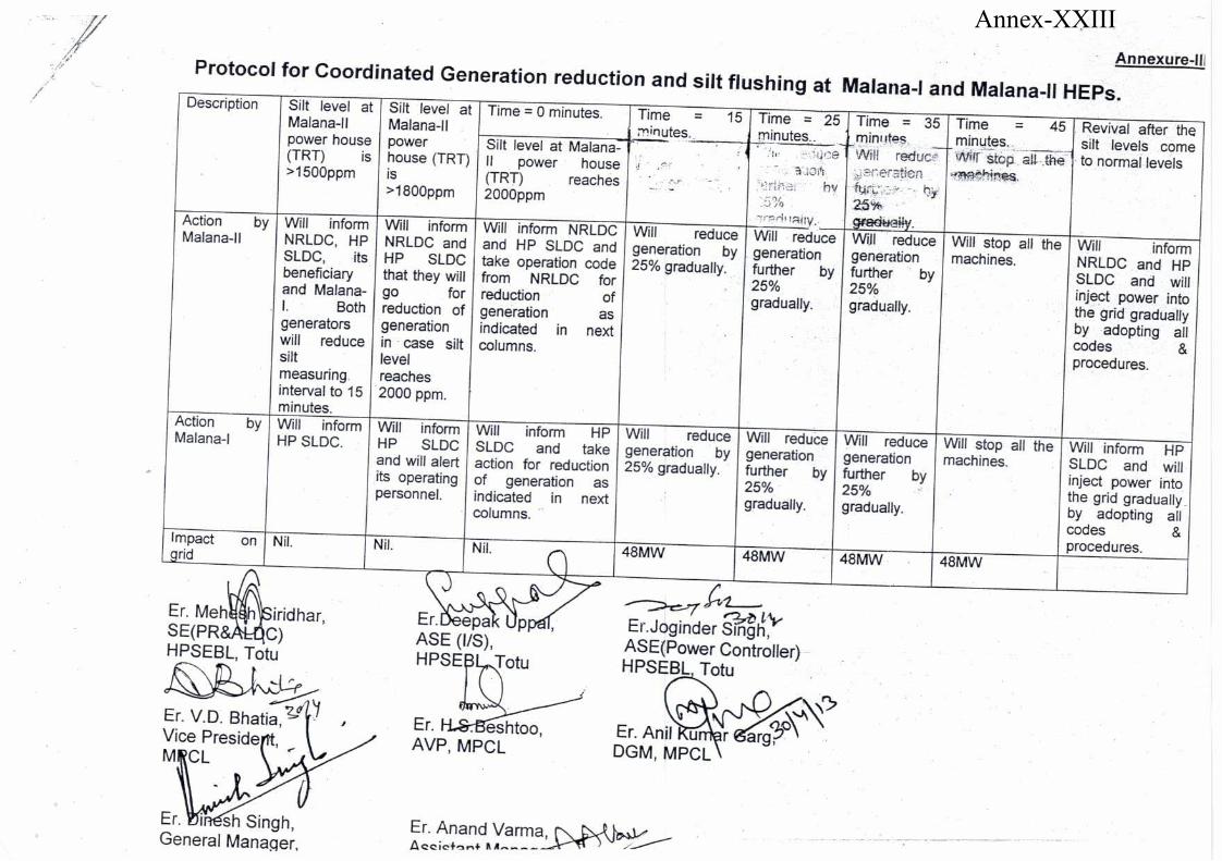
Annex-XXIII
1
Annex-XXIV
2
PROCEDURE FOR IMPLEMENTATION OF THE FRAMEWORK
ON
FORECASTING, SCHEDULING AND IMBALANCE HANDLING FOR
RENEWABLE ENERGY (RE) GENERATING STATIONS
INCLUDING POWER PARKS BASED ON WIND AND SOLAR
AT
INTER-STATE LEVEL
1. Preamble :
This Procedure is issued in compliance of Regulation 6.5 (23) of the Central
Electricity Regulatory Commission (Indian Electricity Grid Code) Regulations,
2010 and amendments thereof and Central Electricity Regulatory Commission
(Grant of Connectivity, Long-term Access and Medium-term Open Access in
inter-State Transmission and related matters) Regulations, 2010 and
amendments thereof herein after called the „Procedure for implementation of
the framework on Forecasting, Scheduling and Imbalance Handling for
Renewable Energy (RE) Generating Stations including Power Parks based on
wind and solar at Inter-State level‟.
2. Scope:
This Procedure shall be followed by National Load Despatch Centre (NLDC), all
Regional Load Despatch Centres (RLDCs), Regional Power Committees (RPCs),
and State Load Despatch Centres (SLDCs), regional entity Wind / solar
generating stations including power parks, Principal Generators, Lead
Generator.
This procedure shall be implemented with effect from the date of its notification
by the Commission.
3. Definitions:
3
3.1 Lead Generator : The lead Generator shall be as termed in the CERC
(Grant of Connectivity, Long-term Access and Medium-term Open
Access in inter-State Transmission and related matters) ( Amendment)
Regulations, 2010 as follows:
One of the generating stations using renewable sources of energy,
individually having less than 50 MW installed capacity, but
collectively having an aggregate installed capacity of 50 MW and
above, and acting on behalf of all these generating stations, and
seeking connection from CTU at a single connection point at the
pooling sub-station under CTU or connecting at pooling substation
within the Solar or Wind power park, termed as the Lead
generator. Lead Generator shall formalize a written
agreement/arrangement among all the associated generators to
undertake all operational and commercial responsibilities for the
renewable energy generating station(s) in following the provisions
of the Indian Electricity Grid Code and all other regulations of the
Commission, such as grid security, scheduling and dispatch,
collection and payment/adjustment of Transmission charges,
deviation charges, congestion and other charges etc.
3.2 Principal Generator: The Principal Generator, shall be as recognized in
the CERC (Grant of Connectivity, Long-term Access and Medium-term
Open Access in inter-State Transmission and related matters) (Third
Amendment) Regulations, 2013, as follows:
The existing generating station which agrees to act as the
"Principal Generator" on behalf of the renewable energy generating
station(s) which is seeking connectivity through the electrical
system of the existing generating station and formalizes a written
agreement/arrangement among them to undertake all operational
4
and commercial responsibilities for the renewable energy
generating station(s) in following the provisions of the Indian
Electricity Grid Code and all other regulations of the Commission,
such as grid security, scheduling and dispatch, collection and
payment/adjustment of Transmission charges, deviation charges,
congestion and other charges etc., and submit a copy of the
agreement to the CTU, along with the application for connectivity,
with copy to the respective RLDC in whose control area it is
located.
3.3 RE Generator means (i) the Wind or Solar generators who are regional
entities and (ii) Solar generators with installed capacity of more than 50
MW within a Solar Power Park (iii) Renewable energy projects based on
wind or solar resources having capacity of 500 MW and above
3.4 Connection Point: A point at which Solar park, Renewable energy
generating stations which are regional entities are connected to Inter-
State/ Intra-State system
3.5 Absolute Error shall mean the absolute value of the error in the
actual generation of wind or solar generators which are regional
entities with reference to the scheduled generation and the 'Available
Capacity' (AvC), as calculated using the following formula for each 15
minute time block:
Error (%) = 100 X [Actual Generation– Scheduled Generation]/
(AvC)
'Available Capacity (AvC)' for wind or solar generators which are
regional entities is the cumulative capacity rating of the wind
turbines or solar inverters that are capable of generating power in
a given time-block.
5
4. Applicability:
This procedure shall be applicable to:
a. All RE Generators, which are regional entities as defined in Grid Code ,
are covered under the ambit of this procedure.
b. RE Generators connected to ISTS and having aggregate generation
capacity of 50 MW and above.
c. Any renewable energy generating station of 5 MW capacity and above
but less than 50 MW capacity developed by a generating company in its
existing generating station in accordance with the CERC (Grant of
Connectivity, Long-term Access and Medium-term Open Access in
inter-State Transmission and related matters) (Third Amendment)
Regulations 2013, and connected to the existing connection point with
inter-State Transmission System through the electrical system of the
generating station.
d. Lead Generator
e. Principal Generator
f. Solar Power Park Developer
g. Wind Power Park Developer
5. Role of different entities
5.1 RE Generator
5.1.1. RE Generator or Lead Generator or Principal Generator or Solar
Power Park Developer or Wind Power Park Developer shall submit one
6
time details to concerned RLDC as per Annexure-I. Further, if there is
any change in the information furnished, then the updated
information shall be shared with the concerned RLDC not later than 7
working days of the change.
5.1.2 RE Generator or Lead Generator or Principal Generator shall
undertake the following activities.
a. Provide available capacity, Day ahead forecast (based on their
own forecast or on the forecast done by RLDC) and Schedule as
per Annexure-II through web based application maintained by
RLDCs.
b. Provide real time availability (at turbine/inverter level) and
generation data (at pooling station level) as per Annexure-III
c. Provide Monthly data transfer (as per Annexure – IV):
o For wind plants, at the turbine level- average wind speed,
average power generation at 15-min time block level
o For solar plants, for all inverters* >=1 MW- average solar
irradiation, average power generation at 15-min time block
level
* if a solar plant uses only smaller string inverters, then data may be provided at the plant level
d. Be Responsible for metering and data collection, transmission
and co-ordination with RLDC, SLDC RPC, CTU and other
agencies as per IEGC and extant CERC Regulations.
e. Undertake commercial settlement of all deviation-settlement
charges as per applicable CERC Regulations
7
f. Submit a copy of the agreement to concerned RLDC wherein it is
mentioned that RE Generator or Lead Generator or Principal
Generator shall undertake all operational and commercial
responsibilities on behalf of generating stations as per the
prevalent CERC Regulations. Further, RE Generator or Lead
Generator or Principal Generator shall also submit the
application for connectivity which was submitted to CTU to the
respective RLDC in whose control area it is located.
g. Use Automatic meter reading technologies for transfer, analysis
and processing of interface meter data.
h. Perform commercial settlement beyond the connection point (De-
pooling arrangement) and technical coordination amongst the
generators within the pooling station and upto the connection
point as the case may be.
i. Shall furnish the PPA rates on notarized affidavit for the purpose
of Deviation charge account preparation to respective RPC
supported by copy of the PPA.
j. Keep each of the RLDCs indemnified at all times and shall
undertake to indemnify, defend and save the SLDCs/RLDCs
harmless from any and all damages, losses including commercial
losses due to forecasting error, claims and actions including
those relating to injury to or death of any person or damage to
property, demands, suits, recoveries, costs and expenses, court
costs, attorney fees, and all other obligations by or to third
parties, arising out of or resulting from the transactions
undertaken by the Generators.

8
5.2 RLDC
5.2.1 The concerned RLDC shall be responsible for scheduling,
communication, coordination with RE Generators or Lead
Generator or Principal Generator. Forecasting of the renewable
energy generation shall be done by the RLDCs and the forecast will
be available on the website of the concerned RLDC. The generation
forecast shall be done on the basis of the weather data provided by
IMD or on the basis of other methods used by the Forecasting
Agency whose service may be availed by NLDC/RLDC. However, the
forecast by the concerned RLDC shall be with the objective of
ensuring secure grid operation.
5.2.2 The concerned RLDC will be responsible for processing the interface
meter data and computing the net injections by each RE Generator
or Lead Generator or Principal Generator or Solar Power Park or
Wind Power Park as specified in Annexure- V.
5.2.3 RLDC may, appoint additional manpower for carrying out the
additional responsibility assigned in these Procedures, if required.
6 Forecasting
6.1 Regional forecasting shall be done by the concerned RLDC to
facilitate secure grid operation. The concerned RLDC may engage a
forecasting agency to undertake forecasting for RE
Generators/solar parks /wind parks which are regional entities.
6.2 RE generator shall provide the forecast to the concerned RLDC
which may be based on their own forecast or RLDC‟s forecast as
per Annexure-II. In case a generator is utilizing service of RLDC for
9
its forecasting, necessary fees shall be paid by generator to RLDC
as approved by CERC.
6.3 The concerned RLDC shall consolidate and forecast based on
various parameters as mentioned in the enclosed Annexures and
weather data obtained from IMD or from any other forecast service
provider (which could be different from that provided by generator)
6.4 RE Generators or Lead Generator or Principal Generator may
prepare their schedule based on the forecast done by RLDC or their
own forecast. Any commercial impact on account of deviation from
schedule based on the forecast chosen by the wind and solar
generator shall be borne by the respective generator.
7 Connectivity
7.1 The application for connectivity shall be made in accordance with
the provisions of the Central Electricity Regulatory Commission
(Grant of Connectivity, Long-term Access and Medium-term
Open Access in inter-State Transmission and related matters)
Regulations, 2009 as amended from time to time.
7.2 The Solar Power Park Developer (SPPD) or Wind Power Park
Developer (WPPD) shall apply for Connectivity on behalf of
Generators within the park. The SPPD / WPPD shall be
responsible for registering the Solar Power Park with the respective
RLDC/ SLDC as applicable as a User and shall submit Appendix-
IV of CERC (Fees and Charges of Regional Load Despatch Centres
and related matters) Regulations, 2015 before getting connected at
the Connection point with the ISTS for the first time. SPPD /WPPD
shall be responsible for complying with all the provisions of CEA
10
standards for Grid Connectivity and other relevant CERC or CEA
regulations. The SPPD /WPPD shall act as the nodal and
accountable entity at the connection point. SPPD / WPPD shall be
responsible for sending the SCADA data to the RLDC and to the
Renewable Energy Management Centre (REMC).
7.3 In a solar /wind power park, Lead Generator shall undertake all
operational and commercial responsibilities for the solar energy
generating station(s) for less than 50 MW aggregating to 50MW and
above in following the provisions of the Indian Electricity Grid
Code and all other regulations of the Commission, such as grid
security, scheduling and dispatch, collection and
payment/adjustment of Transmission charges, DSM charges,
congestion and other charges etc., and submit a copy of the
agreement and authorization documents to the respective RLDC in
whose control area it is located
The RE generators, lead generator, principal generator, SPPD,
WPPD shall keep each of the RLDCs indemnified at all times and
shall undertake to indemnify, defend and save the SLDCs/RLDCs
harmless from any and all damages, losses, claims and actions
including those relating to injury to or death of any person or
damage to property, demands, suits, recoveries, costs and
expenses, court costs, attorney fees, and all other obligations by or
to third parties, arising out of or resulting from the transactions
undertaken by the Generators in the Solar power Park.
7.4 The commercial settlement within the solar park /wind park and
between generators shall be as detailed in Annexure-IV
11
7.5 All the technical coordination amongst the generators, within the
solar /Wind Park and upto the connection point shall be done by
the Lead generator or Principal generator or the RLDC as the case
maybe.
8 Scheduling and Despatch
8.1 Following alternatives exist for Scheduling and Despatch for Generators
within Solar / Wind Power parks due to multiple generation developers
within the Park injecting at various points with in the park and
ultimately injecting at interface with ISTS,
Case-1: The concerned RLDC shall be responsible for the scheduling,
communication, coordination with RE Generators of 50 MW and above
and connected to Inter State Transmission System (ISTS).
Case-2: Lead generator or Principal generator shall be responsible for
the coordination and communication with RLDC, SLDC, RPC and
other agencies for scheduling of RE Generators individually having less
than 50 MW, but collectively having an aggregate installed capacity of
50 MW and above and connected within the solar park.
8.2 A representative sketch showing the scheduling of RE generator power
for both cases is attached as Annexure-IV.
8.3 RE generator or lead generator or principal generator, as the case may
be, shall provide the schedule to the concerned RLDC, which may be
based on their own forecast or RLDC‟s forecast as per Annexure-II.
8.4 RE Generators or lead generator or principal generator shall be
responsible for coordinating with RLDC. It shall undertake various
12
activities associated with scheduling, commercial settlement,
communication, data consolidation and management and coordination
etc.
8.5 RLDC shall upload day ahead schedules of energy generation with an
interval of 15 minutes for the 24 hours period commencing at 00:00
hrs. on the website of the concerned RLDC as per regulation 6.5 of the
IEGC.
8.6 The schedule by RE generators or lead generator or principal generator
may be revised by giving advance notice to the concerned RLDC, as the
case may be. Such revisions shall be effective from 4th time block, the
first being the time-block in which notice was given. There may be one
revision for each time slot of one and half hours starting from 00:00
hours of a particular day subject to maximum of 16 revisions during
the day.
8.7 Revision in schedules by RE Generator or lead generator or principal
generator selling power through collective transactions shall not be
allowed.
8.8 The scheduling jurisdiction (as provided in Regulation 6.4 of IEGC
2010), metering, energy accounting and deviation charges would be as
per relevant CERC Regulations, as amended from time to time.
8.9 In the event of contingencies, transmission constraints, congestion in
the network, threat to system security, the transactions of RE
Generators already scheduled by RLDC may be curtailed as per
provisions of IEGC for ensuring secure and reliable system operation.
13
9 Metering
9.1 Interface Energy Meters at interstate level shall be installed by the
Central Transmission Utility as per CEA Metering Regulations, 2006 and
amendments thereof.
9.2 Interface Energy Meters at intra state level shall be installed by the State
Transmission Utility / SPPD /WPPD as per CEA Metering Regulations,
2006 and amendments thereof.
9.3 Interface Energy Meters with unique serial numbers and as per standard
specification, would have to be placed in accordance with CEA
Metering Regulations to facilitate boundary metering, accounting and
settlement for RE Generators. Automated meter reading (AMR) system
shall be used for communicating interface meter data at RLDCs. Internal
Clock of the interface meter shall be time synchronized with GPS.
9.4 RE Generator or lead generator or principal generator shall provide data
telemetry at the turbine/inverter level to the concerned RLDC and shall
ensure the correctness of the real-time data and undertake the corrective
actions, if required. Frequency of real-time data updation to be shared
with concerned RLDC shall be 10 second or less as per prevailing
practice followed by RLDCs. Further, turbine/inverter outage plan shall
also be forwarded to the concerned RLDC. The suggested data telemetry
requirement for RE Generators is enclosed at Annexure-III. Further,
NLDC/RLDCs shall publish the requisite list of information in due course
of time.
10 Role of RPC: Energy Accounting of Wind or Solar generating
Stations
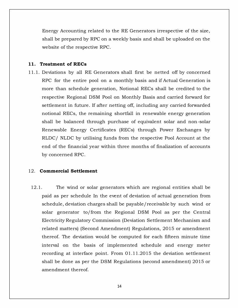
14
Energy Accounting related to the RE Generators irrespective of the size,
shall be prepared by RPC on a weekly basis and shall be uploaded on the
website of the respective RPC.
11. Treatment of RECs
11.1. Deviations by all RE Generators shall first be netted off by concerned
RPC for the entire pool on a monthly basis and if Actual Generation is
more than schedule generation, Notional RECs shall be credited to the
respective Regional DSM Pool on Monthly Basis and carried forward for
settlement in future. If after netting off, including any carried forwarded
notional RECs, the remaining shortfall in renewable energy generation
shall be balanced through purchase of equivalent solar and non-solar
Renewable Energy Certificates (RECs) through Power Exchanges by
RLDC/ NLDC by utilising funds from the respective Pool Account at the
end of the financial year within three months of finalization of accounts
by concerned RPC.
12. Commercial Settlement
12.1. The wind or solar generators which are regional entities shall be
paid as per schedule In the event of deviation of actual generation from
schedule, deviation charges shall be payable/receivable by such wind or
solar generator to/from the Regional DSM Pool as per the Central
Electricity Regulatory Commission (Deviation Settlement Mechanism and
related matters) (Second Amendment) Regulations, 2015 or amendment
thereof. The deviation would be computed for each fifteen minute time
interval on the basis of implemented schedule and energy meter
recording at interface point. From 01.11.2015 the deviation settlement
shall be done as per the DSM Regulations (second amendment) 2015 or
amendment thereof.
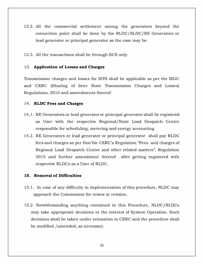
15
12.2. All the commercial settlement among the generators beyond the
connection point shall be done by the RLDC/SLDC/RE Generators or
lead generator or principal generator as the case may be.
12.3. All the transactions shall be through ECS only.
13. Application of Losses and Charges
Transmission charges and losses for ISTS shall be applicable as per the IEGC
and CERC (Sharing of Inter State Transmission Charges and Losses)
Regulations, 2010 and amendments thereof.
14. RLDC Fees and Charges
14.1. RE Generators or lead generator or principal generator shall be registered
as User with the respective Regional/State Load Despatch Centre
responsible for scheduling, metering and energy accounting.
14.2. RE Generators or lead generator or principal generator shall pay RLDC
fees and charges as per Hon‟ble CERC‟s Regulation “Fees and charges of
Regional Load Despatch Centre and other related matters”, Regulation
2015 and further amendment thereof after getting registered with
respective RLDCs as a User of RLDC.
15. Removal of Difficulties
15.1. In case of any difficulty in implementation of this procedure, NLDC may
approach the Commission for review or revision.
15.2. Notwithstanding anything contained in this Procedure, NLDC/RLDCs
may take appropriate decisions in the interest of System Operation. Such
decisions shall be taken under intimation to CERC and the procedure shall
be modified /amended, as necessary.
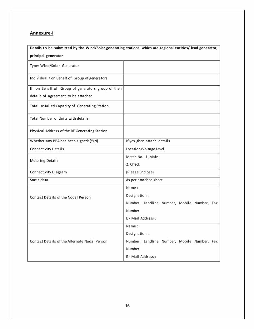
16
Annexure-I
Details to be submitted by the Wind/Solar generating stations which are regional entities/ lead generator,
principal generator
Type: Wind/Solar Generator
Individual / on Behalf of Group of generators
If on Behalf of Group of generators group of then
details of agreement to be attached
Total Installed Capacity of Generating Station
Total Number of Units with details
Physical Address of the RE Generating Station
Whether any PPA has been signed: (Y/N) If yes ,then attach details
Connectivity Details Location/Voltage Level
Metering Details Meter No. 1. Main
2. Check
Connectivity Diagram (Please Enclose)
Static data As per attached sheet
Contact Details of the Nodal Person
Name :
Designation :
Number: Landline Number, Mobile Number, Fax
Number
E - Mail Address :
Contact Details of the Alternate Nodal Person
Name :
Designation :
Number: Landline Number, Mobile Number, Fax
Number
E - Mail Address :
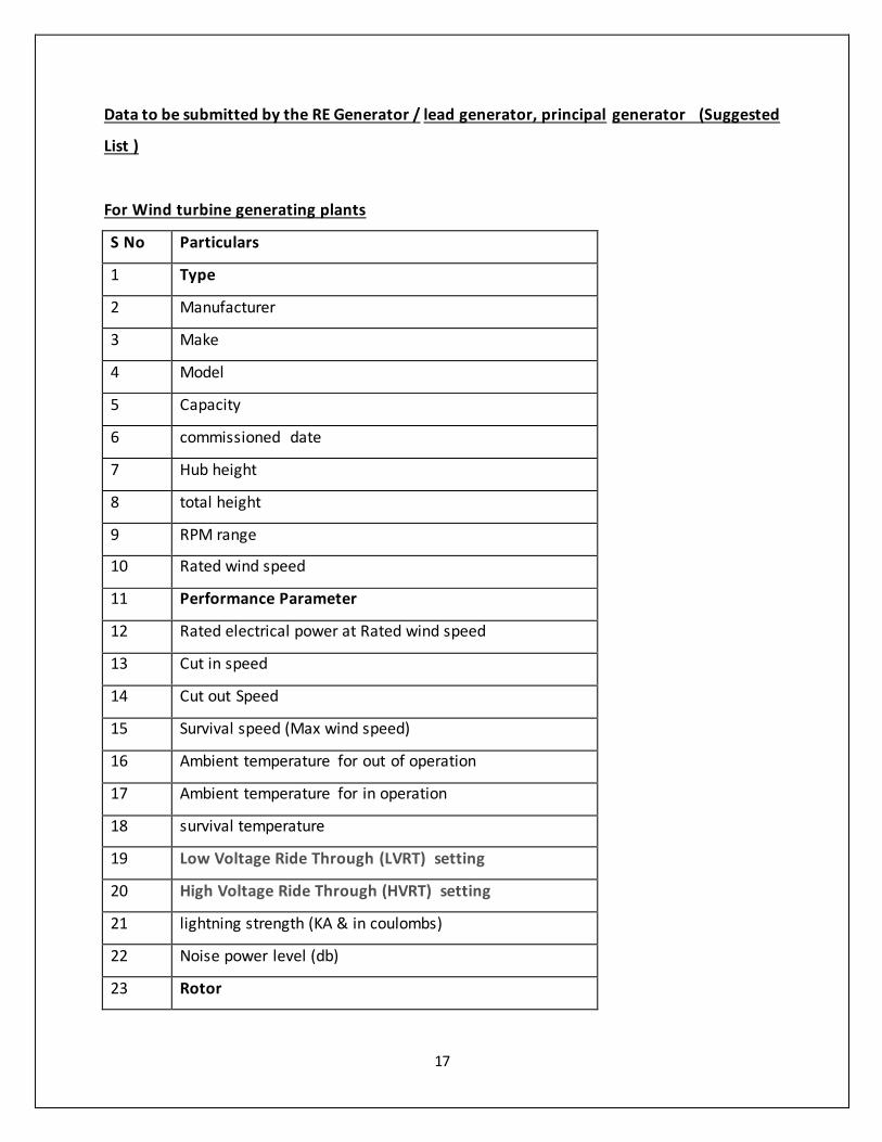
17
Data to be submitted by the RE Generator / lead generator, principal generator (Suggested
List )
For Wind turbine generating plants
S No Particulars
1 Type
2 Manufacturer
3 Make
4 Model
5 Capacity
6 commissioned date
7 Hub height
8 total height
9 RPM range
10 Rated wind speed
11 Performance Parameter
12 Rated electrical power at Rated wind speed
13 Cut in speed
14 Cut out Speed
15 Survival speed (Max wind speed)
16 Ambient temperature for out of operation
17 Ambient temperature for in operation
18 survival temperature
19 Low Voltage Ride Through (LVRT) setting
20 High Voltage Ride Through (HVRT) setting
21 lightning strength (KA & in coulombs)
22 Noise power level (db)
23 Rotor
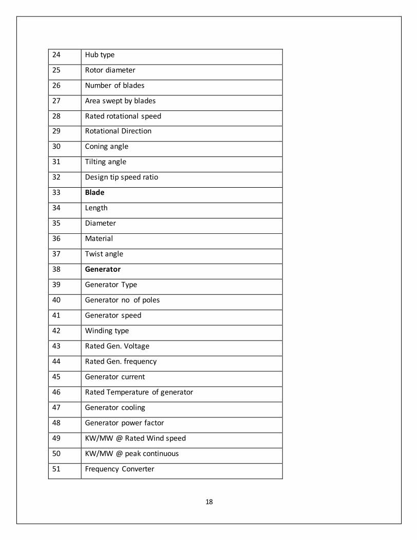
18
24 Hub type
25 Rotor diameter
26 Number of blades
27 Area swept by blades
28 Rated rotational speed
29 Rotational Direction
30 Coning angle
31 Tilting angle
32 Design tip speed ratio
33 Blade
34 Length
35 Diameter
36 Material
37 Twist angle
38 Generator
39 Generator Type
40 Generator no of poles
41 Generator speed
42 Winding type
43 Rated Gen. Voltage
44 Rated Gen. frequency
45 Generator current
46 Rated Temperature of generator
47 Generator cooling
48 Generator power factor
49 KW/MW @ Rated Wind speed
50 KW/MW @ peak continuous
51 Frequency Converter
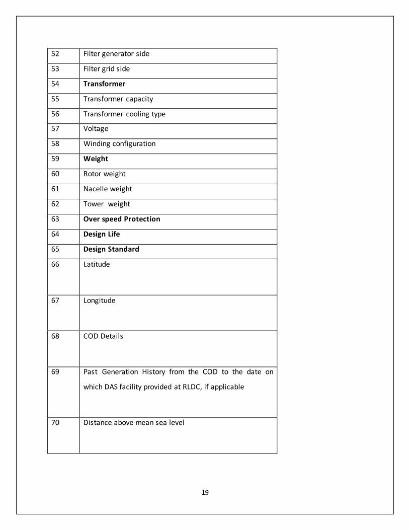
19
52 Filter generator side
53 Filter grid side
54 Transformer
55 Transformer capacity
56 Transformer cooling type
57 Voltage
58 Winding configuration
59 Weight
60 Rotor weight
61 Nacelle weight
62 Tower weight
63 Over speed Protection
64 Design Life
65 Design Standard
66 Latitude
67 Longitude
68 COD Details
69 Past Generation History from the COD to the date on
which DAS facility provided at RLDC, if applicable
70 Distance above mean sea level

20
For Solar generating Plants
Static data points:
1. Latitude
2. Longitude
3. Turbine Power Curve
4. Elevation and orientation angles of arrays or concentrators
5. The generation capacity of the Generating Facility
6. Distance above mean sea level etc.
7. COD details
8. Rated voltage
9. Details of Type of Mounting: (Tracking Technology If used, single axis or dual axis, auto or
manual )
10. Manufacturer and Model (of Important Components, Such as Turbine, Concentrators,
Inverter, Cable, PV Module, Transformer, Cables)
11. DC installed Capacity
12. Module Cell Technology
13. I-V Characteristic of the Module
14. Inverter Rating at different temperature
15. Inverter Efficiency Curve
16. Transformer Capacity & Rating , evacuation voltage, distance form injection point
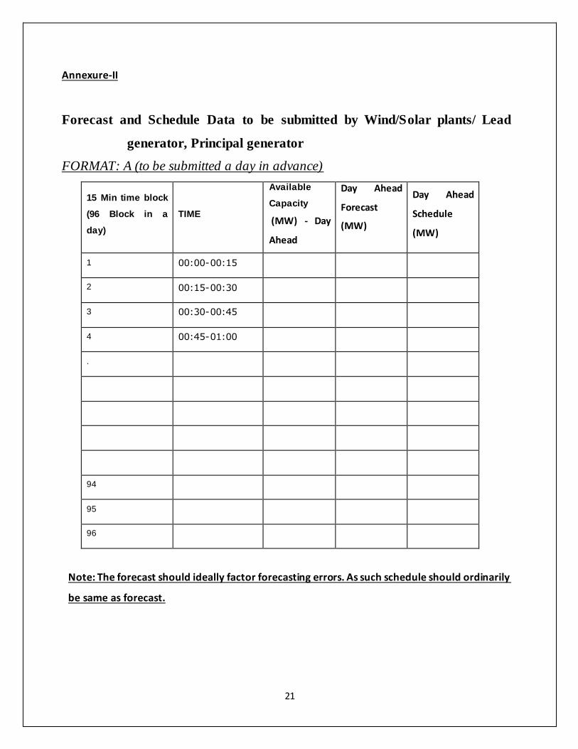
21
Annexure-II
Forecast and Schedule Data to be submitted by Wind/Solar plants/ Lead
generator, Principal generator
FORMAT: A (to be submitted a day in advance)
15 Min time block
(96 Block in a
day)
TIME
Available
Capacity
(MW) - Day
Ahead
Day Ahead
Forecast
(MW)
Day Ahead
Schedule
(MW)
1 00:00-00:15
2 00:15-00:30
3 00:30-00:45
4 00:45-01:00
.
94
95
96
Note: The forecast should ideally factor forecasting errors. As such schedule should ordinarily
be same as forecast.
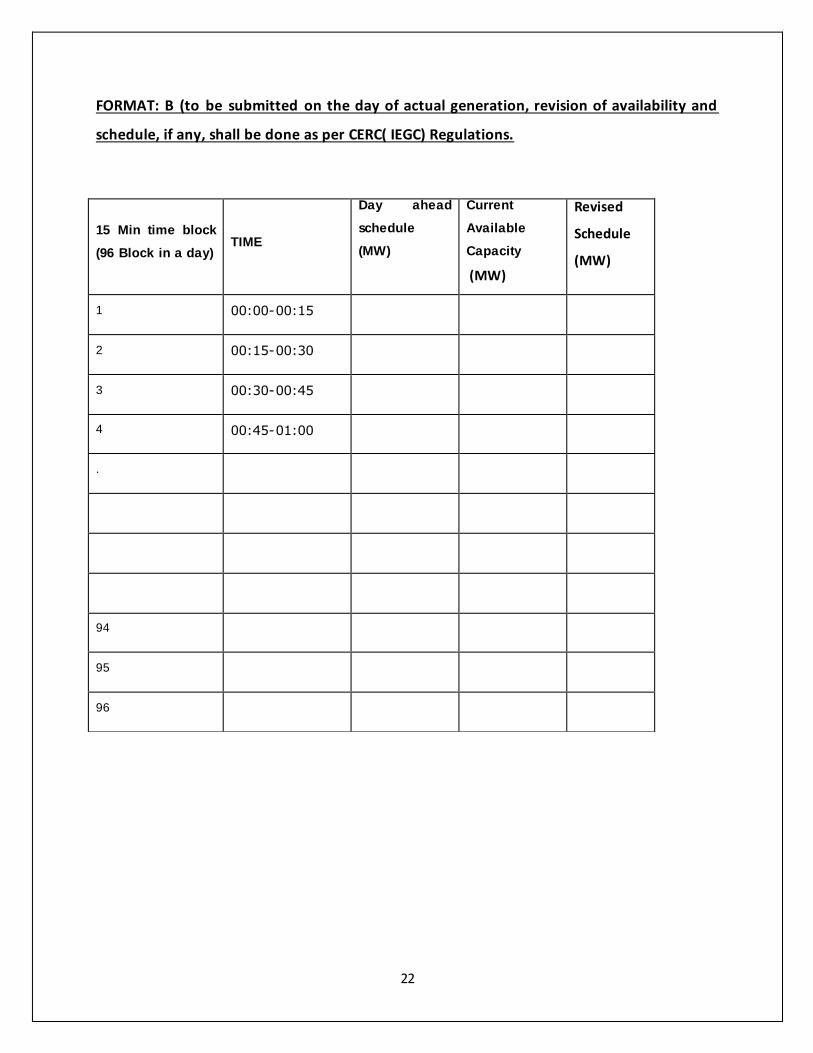
22
FORMAT: B (to be submitted on the day of actual generation, revision of availability and
schedule, if any, shall be done as per CERC( IEGC) Regulations.
15 Min time block
(96 Block in a day) TIME
Day ahead
schedule
(MW)
Current
Available
Capacity
(MW)
Revised
Schedule
(MW)
1 00:00-00:15
2 00:15-00:30
3 00:30-00:45
4 00:45-01:00
.
94
95
96
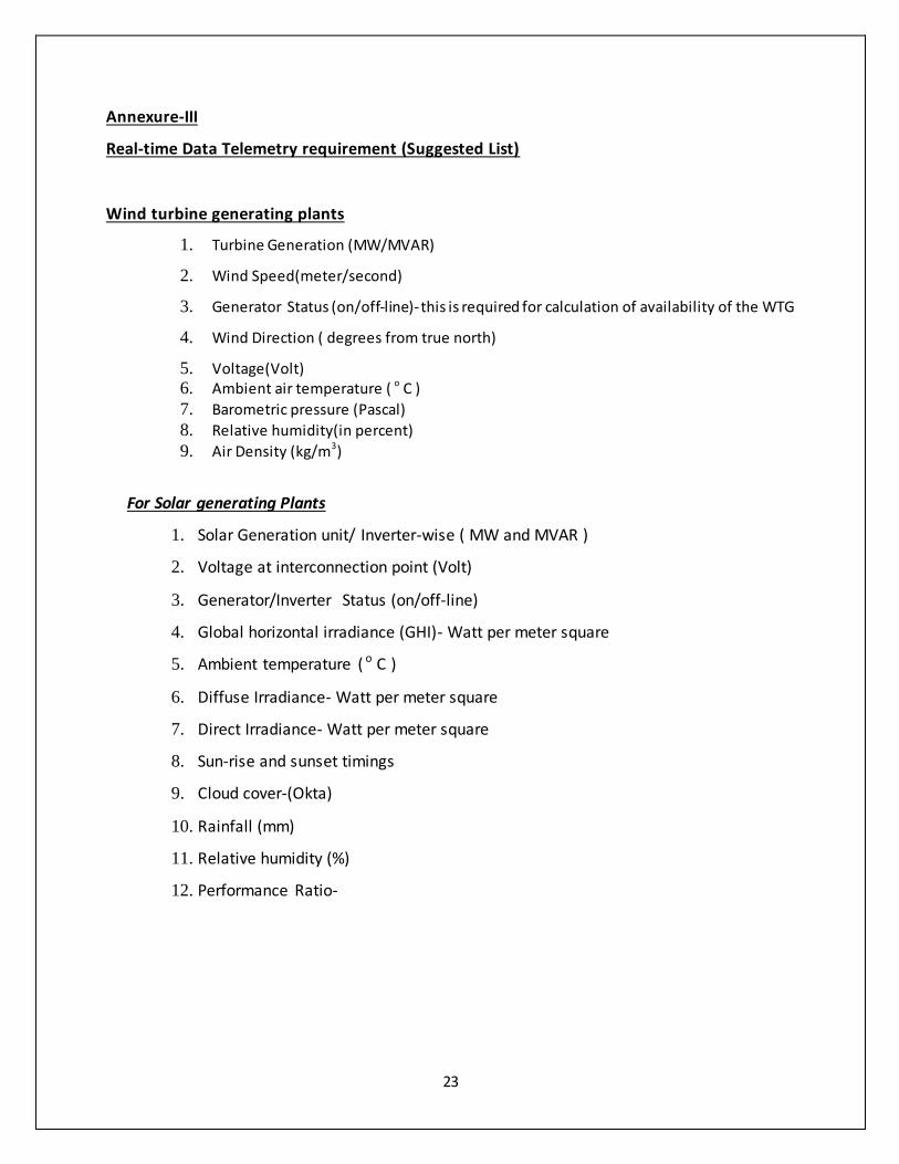
23
Annexure-III
Real-time Data Telemetry requirement (Suggested List)
Wind turbine generating plants
1. Turbine Generation (MW/MVAR)
2. Wind Speed(meter/second)
3. Generator Status (on/off-line)- this is required for calculation of availability of the WTG
4. Wind Direction ( degrees from true north)
5. Voltage(Volt) 6. Ambient air temperature ( o C )
7. Barometric pressure (Pascal)
8. Relative humidity(in percent)
9. Air Density (kg/m3)
For Solar generating Plants
1. Solar Generation unit/ Inverter-wise ( MW and MVAR )
2. Voltage at interconnection point (Volt)
3. Generator/Inverter Status (on/off-line)
4. Global horizontal irradiance (GHI)- Watt per meter square
5. Ambient temperature ( o C )
6. Diffuse Irradiance- Watt per meter square
7. Direct Irradiance- Watt per meter square
8. Sun-rise and sunset timings
9. Cloud cover-(Okta)
10. Rainfall (mm)
11. Relative humidity (%)
12. Performance Ratio-
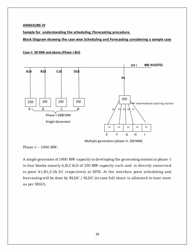
24
ANNEXURE-IV
Sample for understanding the scheduling /forecasting procedure.
Block Diagram showing the case wise Scheduling and Forecasting considering a sample case
Case-I: 50 MW and above (Phase-I &II)
(XX ) 400 KV(ISTS)
A1X B1X C1X D1X
Px
Intermediate pool ing s tation
A B C D E1 F1 G1 H1 I1
Phase-I 1000 MW
Single Generator
E F G H I
Multiple generators (phase-II- 250 MW)
Phase-I – 1000 MW,
A single generator of 1000 MW capacity is developing the generating station in phase-1
in four blocks namely A,B,C & D of 250 MW capacity each and is directly connected
to point A1,B1,C1& D1 respectively at ISTS. At the interface point scheduling and
forecasting will be done by RLDC / SLDC (in case full share is allocated to host state
as per IEGC).
250
250 250 250
50 50 50 50 50
250
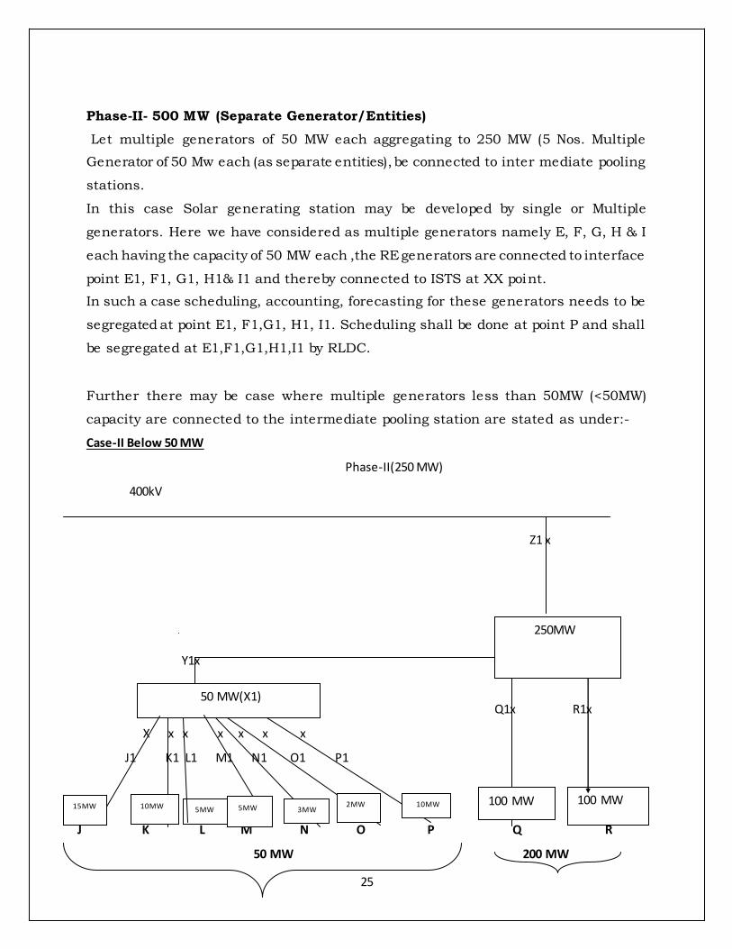
25
Phase-II- 500 MW (Separate Generator/Entities)
Let multiple generators of 50 MW each aggregating to 250 MW (5 Nos. Multiple
Generator of 50 Mw each (as separate entities), be connected to inter mediate pooling
stations.
In this case Solar generating station may be developed by single or Multiple
generators. Here we have considered as multiple generators namely E, F, G, H & I
each having the capacity of 50 MW each ,the RE generators are connected to interface
point E1, F1, G1, H1& I1 and thereby connected to ISTS at XX point.
In such a case scheduling, accounting, forecasting for these generators needs to be
segregated at point E1, F1,G1, H1, I1. Scheduling shall be done at point P and shall
be segregated at E1,F1,G1,H1,I1 by RLDC.
Further there may be case where multiple generators less than 50MW (<50MW)
capacity are connected to the intermediate pooling station are stated as under:-
Case-II Below 50 MW
Phase-II(250 MW)
400kV
Z1 x
Y1x
Q1x R1x
X x x x x x x
J1 K1 L1 M1 N1 O1 P1
X1
J K L M N O P Q R
50 MW 200 MW
50 MW(X1)
10MW 2MW 3MW 5MW 5MW 10MW 15MW 100 MW 100 MW
250MW
26
For remaining 250 MW of Phase-II, let us consider, multiple generators of 7 Nos
(J,K,L,M,N,O&P ) each having capacity less than 50 MW but collectively having an
aggregate installed capacity of 50 MW or more . Further Generators Q & R each of
100 MW are connected at Q1 & R1. All these generators are connected to ISTS at point
Z1.
Scheduling and forecasting for the generators J,K,L,M,N,O& P shall be done at Point
Z1, but need to segregated at Point J1, K1,L1, M1, N1,O1& P1 and for generators Q &
R needs to be segregated at Q1 and R1. In this case, RLDC shall schedule at point Z1
and segregate at Y1,Q1& R1 . The lead generator shall provide aggregated schedule to
RLDC at Y1. Further the lead generator shall do segregation of schedules and other
operational & commercial activities for generators J,K,L,M,N,O,P at points J1, K1,L1,
M1, N1,O1& P1.
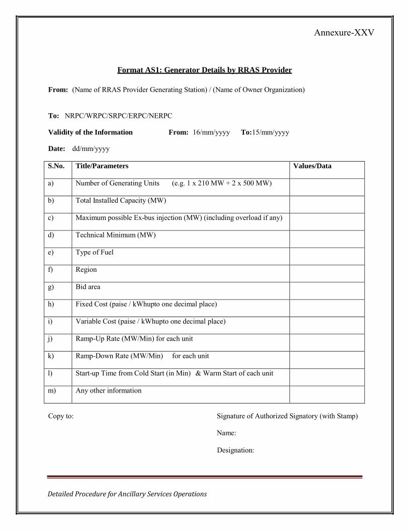
Detailed Procedure for Ancillary Services Operations
Format AS1: Generator Details by RRAS Provider
From: (Name of RRAS Provider Generating Station) / (Name of Owner Organization)
To: NRPC/WRPC/SRPC/ERPC/NERPC
Validity of the Information From: 16/mm/yyyy To:15/mm/yyyy
Date: dd/mm/yyyy
S.No. Title/Parameters Values/Data
a) Number of Generating Units (e.g. 1 x 210 MW + 2 x 500 MW)
b) Total Installed Capacity (MW)
c) Maximum possible Ex-bus injection (MW) (including overload if any)
d) Technical Minimum (MW)
e) Type of Fuel
f) Region
g) Bid area
h) Fixed Cost (paise / kWhupto one decimal place)
i) Variable Cost (paise / kWhupto one decimal place)
j) Ramp-Up Rate (MW/Min) for each unit
k) Ramp-Down Rate (MW/Min) for each unit
l) Start-up Time from Cold Start (in Min) & Warm Start of each unit
m) Any other information
Copy to: Signature of Authorized Signatory (with Stamp)
Name:
Designation:
Annexure-XXV
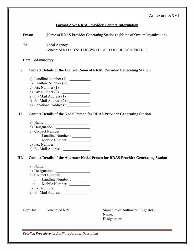
Format AS2: RRAS Provider Contact Information
Detailed Procedure for Ancillary Services Operations
From: (Name of RRAS Provider Generating Station) / (Name of Owner Organization)
To: Nodal Agency Concerned RLDC (NRLDC/WRLDC/SRLDC/ERLDC/NERLDC)
Date: dd/mm/yyyy
I. Contact Details of the Control Room of RRAS Provider Generating Station
a) Landline Number (1) : b) Landline Number (2) : c) Fax Number (1) : d) Fax Number (2) : e) E - Mail Address (1) : f) E - Mail Address (2) : g) Locational Address :
II. Contact Details of the Nodal Person for RRAS Provider Generating Station
a) Name : b) Designation : c) Contact Number
i. Landline Number : ii. Mobile Number :
d) Fax Number : e) E - Mail Address :
III. Contact Details of the Alternate Nodal Person for RRAS Provider Generating Station
a) Name : b) Designation : c) Contact Number
i. Landline Number : ii. Mobile Number :
d) Fax Number : e) E - Mail Address :
Copy to: Concerned RPC Signature of Authorized Signatory Name: Designation:
Annexure-XXVI
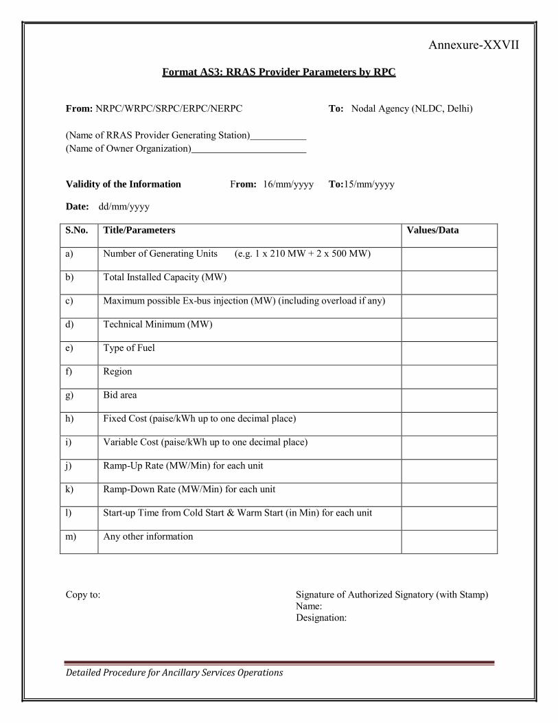
Format AS3: RRAS Provider Parameters by RPC
Detailed Procedure for Ancillary Services Operations
From: NRPC/WRPC/SRPC/ERPC/NERPC To: Nodal Agency (NLDC, Delhi)
(Name of RRAS Provider Generating Station) (Name of Owner Organization)
Validity of the Information From: 16/mm/yyyy To:15/mm/yyyy
Date: dd/mm/yyyy
S.No. Title/Parameters Values/Data
a) Number of Generating Units (e.g. 1 x 210 MW + 2 x 500 MW)
b) Total Installed Capacity (MW)
c) Maximum possible Ex-bus injection (MW) (including overload if any)
d) Technical Minimum (MW)
e) Type of Fuel
f) Region
g) Bid area
h) Fixed Cost (paise/kWh up to one decimal place)
i) Variable Cost (paise/kWh up to one decimal place)
j) Ramp-Up Rate (MW/Min) for each unit
k) Ramp-Down Rate (MW/Min) for each unit
l) Start-up Time from Cold Start & Warm Start (in Min) for each unit
m) Any other information
Copy to: Signature of Authorized Signatory (with Stamp) Name: Designation:
Annexure-XXVII
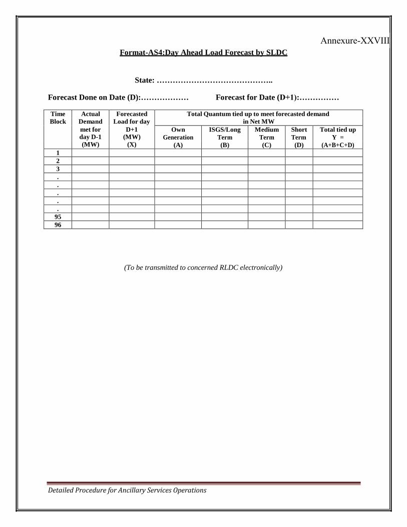
Detailed Procedure for Ancillary Services Operations
Format-AS4:Day Ahead Load Forecast by SLDC
State: ……………………………………..
Forecast Done on Date (D):……………… Forecast for Date (D+1):……………
Time Actual Forecasted Total Quantum tied up to meet forecasted demand Block Demand Load for day in Net MW
met for D+1 Own Generation
(A)
ISGS/Long Term
(B)
Medium Term
(C)
Short Term
(D)
Total tied up Y =
(A+B+C+D) day D-1 (MW) (MW) (X)
1 2 3 . . . . .
95 96
(To be transmitted to concerned RLDC electronically)
Annexure-XXVIII
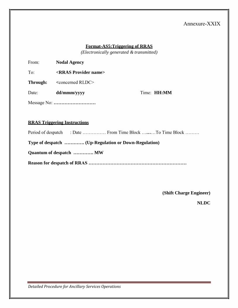
Detailed Procedure for Ancillary Services Operations
Format-AS5:Triggering of RRAS
(Electronically generated & transmitted) From: Nodal Agency
To: <RRAS Provider name>
Through: <concerned RLDC>
Date: dd/mmm/yyyy Time: HH:MM Message No: ………………………
RRAS Triggering Instructions
Period of despatch : Date …………… From Time Block ………To Time Block ……… Type of despatch …………. (Up-Regulation or Down-Regulation)
Quantum of despatch …………. MW
Reason for despatch of RRAS ………………………………………………………
(Shift Charge Engineer)
NLDC
Annexure-XXIX
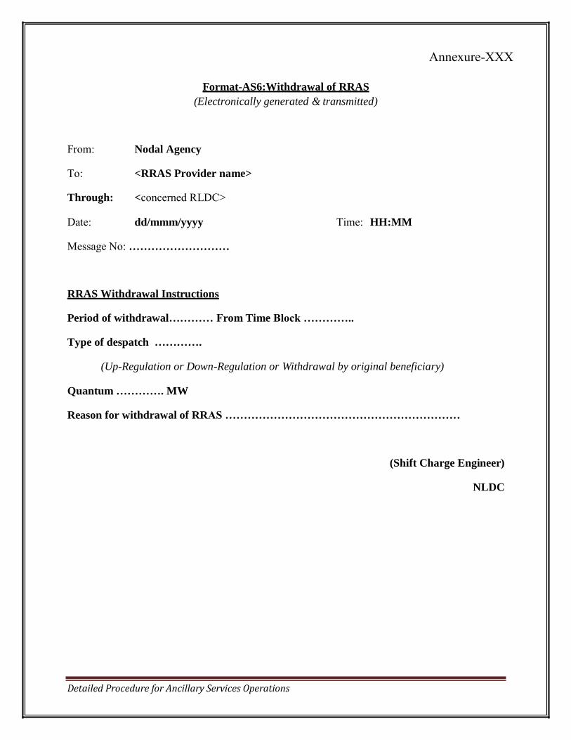
Detailed Procedure for Ancillary Services Operations
Format-AS6:Withdrawal of RRAS (Electronically generated & transmitted)
From: Nodal Agency To: <RRAS Provider name>
Through: <concerned RLDC>
Date: dd/mmm/yyyy Time: HH:MM Message No: ………………………
RRAS Withdrawal Instructions
Period of withdrawal………… From Time Block …………..
Type of despatch ………….
(Up-Regulation or Down-Regulation or Withdrawal by original beneficiary) Quantum …………. MW
Reason for withdrawal of RRAS ………………………………………………………
(Shift Charge Engineer)
NLDC
Annexure-XXX
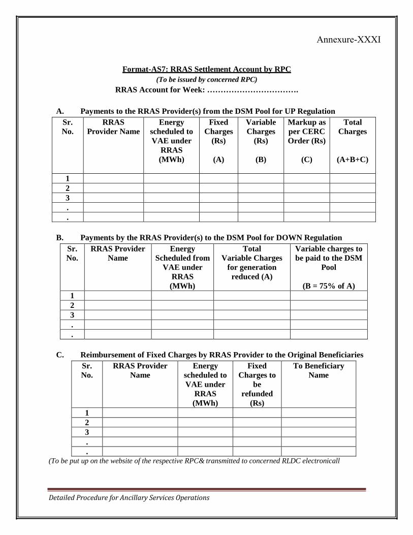
Detailed Procedure for Ancillary Services Operations
Format-AS7: RRAS Settlement Account by RPC (To be issued by concerned RPC)
RRAS Account for Week: …………………………….
A. Payments to the RRAS Provider(s) from the DSM Pool for UP Regulation
Sr. No.
RRAS Provider Name
Energy scheduled to
VAE under
RRAS
(MWh)
Fixed Charges
(Rs)
(A)
Variable Charges
(Rs)
(B)
Markup as per CERC
Order (Rs)
(C)
Total Charges
(A+B+C)
1
2
3
.
.
B. Payments by the RRAS Provider(s) to the DSM Pool for DOWN Regulation
Sr. No.
RRAS Provider Name
Energy Scheduled from
VAE under
RRAS (MWh)
Total Variable Charges
for generation
reduced (A)
Variable charges to be paid to the DSM
Pool
(B = 75% of A) 1
2
3
.
.
C. Reimbursement of Fixed Charges by RRAS Provider to the Original Beneficiaries
Sr. No.
RRAS Provider Name
Energy scheduled to
VAE under
RRAS
(MWh)
Fixed Charges to
be
refunded
(Rs)
To Beneficiary Name
1
2
3
.
.
(To be put up on the website of the respective RPC& transmitted to concerned RLDC electronicall
Annexure-XXXI
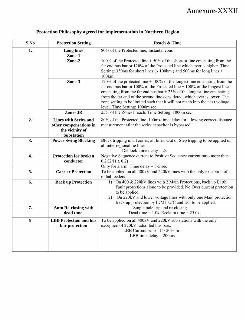
Protection Philosophy agreed for implementation in Northern Region
S.No Protection Setting Reach & Time
1. Long lines Zone-1
80% of the Protected line, Instantaneous
Zone-2 100% of the Protected line + 50% of the shortest line emanating from the far end bus bar or 120% of the Protected line which ever is higher. Time Setting: 350ms for short lines (≤ 100km ) and 500ms for long lines > 100km.
Zone-3 120% of the protected line + 100% of the longest line emanating from the far end bus bar or 100% of the Protected line + 100% of the longest line emanating from the far end bus bar + 25% of the longest line emanating from the far end of the second line considered, which ever is lower. The zone setting to be limited such that it will not reach into the next voltage level. Time Setting: 1000m sec.
Zone- 3R 25% of the Zone-1 reach. Time Setting: 1000m sec
2. Lines with Series and other compensations in
the vicinity of Substation
80% of the Protected line. 100ms-time delay for allowing correct distance measurement after the series capacitor is bypassed.
3. Power Swing Blocking Block tripping in all zones, all lines. Out of Step tripping to be applied on all inter regional tie lines Deblock time delay = 2s
4. Protection for broken conductor
Negative Sequence current to Positive Sequence current ratio more than 0.2(I2/I1 ≥ 0.2) Only for alarm: Time delay = 3-5 sec
5. Carrier Protection To be applied on all 400kV and 220kV lines with the only exception of radial feeders.
6. Back up Protection 1) On 400 & 220kV lines with 2 Main Protections, back up Earth Fault protections alone to be provided. No Over current protection to be applied.
2) On 220kV and lower voltage lines with only one Main protection Back up protection by IDMT O/C and E/F to be applied.
7. Auto Re-closing with dead time.
Single pole trip and re-closing Dead time = 1.0s. Reclaim time = 25.0s
8 LBB Protection and bus bar protection
To be applied on all 400kV and 220kV sub stations with the only exception of 220kV radial fed bus bars. LBB Current sensor I > 20% In LBB time delay = 200ms
Annexure-XXXII
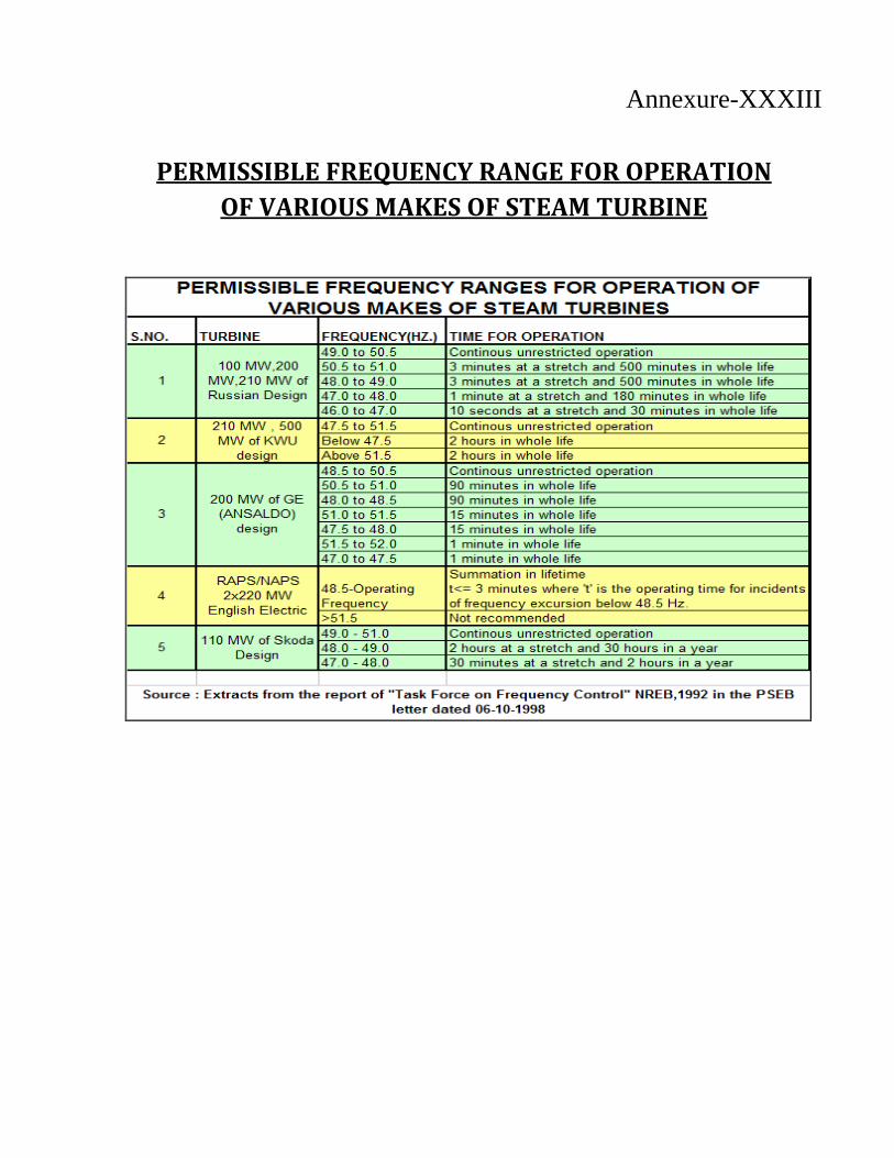
PERMISSIBLE FREQUENCY RANGE FOR OPERATION
OF VARIOUS MAKES OF STEAM TURBINE
Annexure-XXXIII
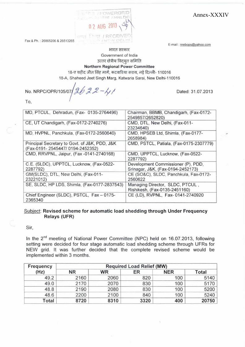
Annex-XXXIV
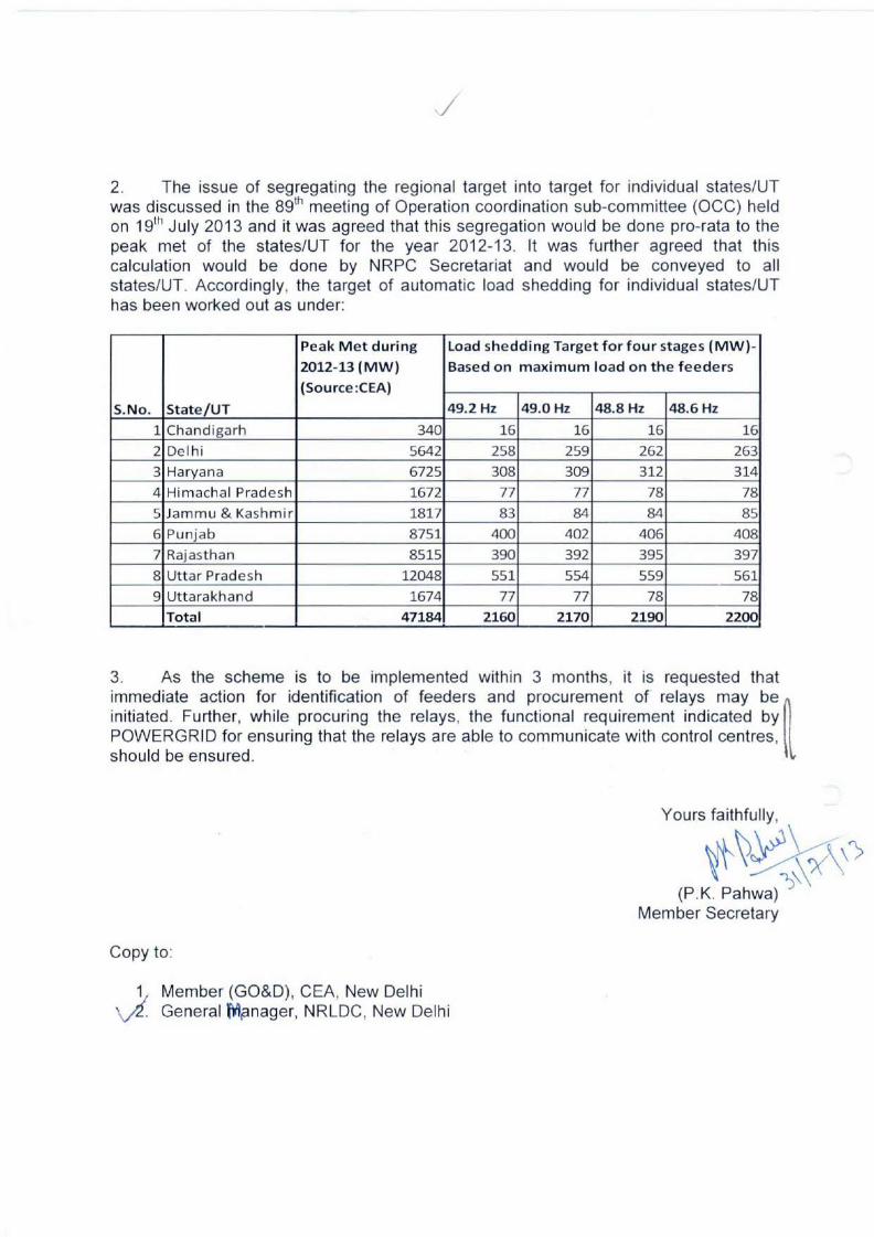
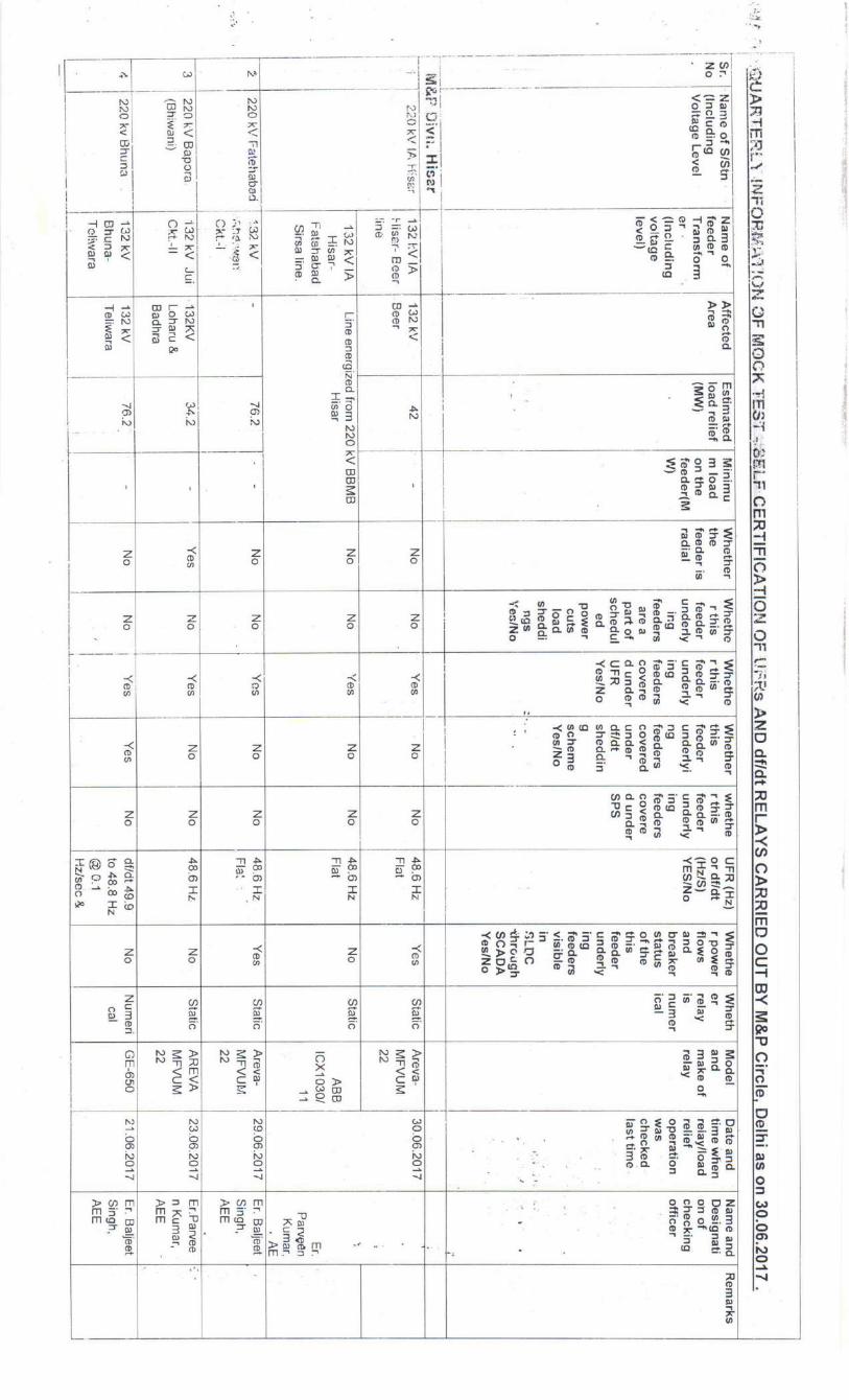
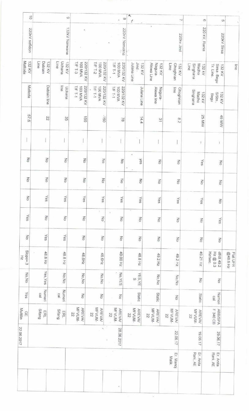
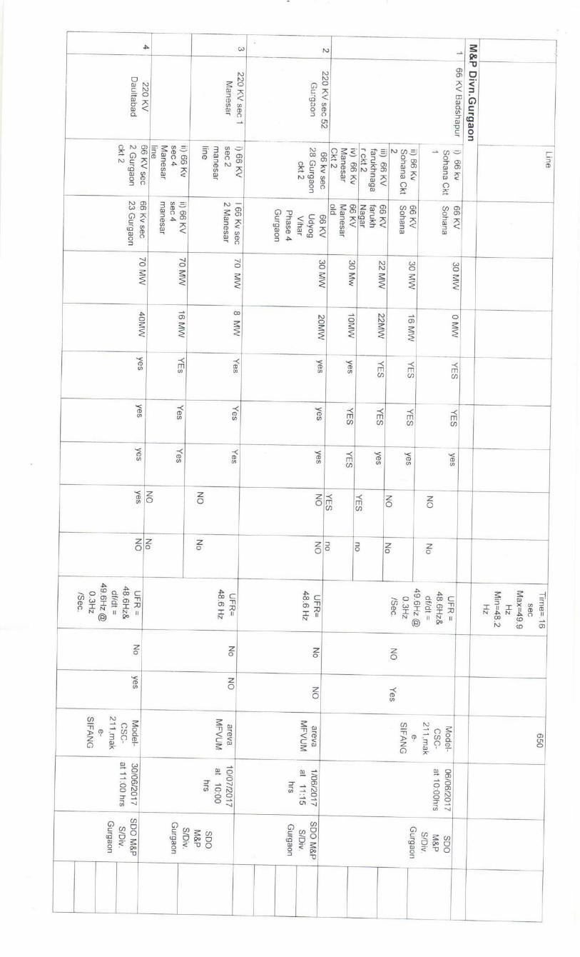
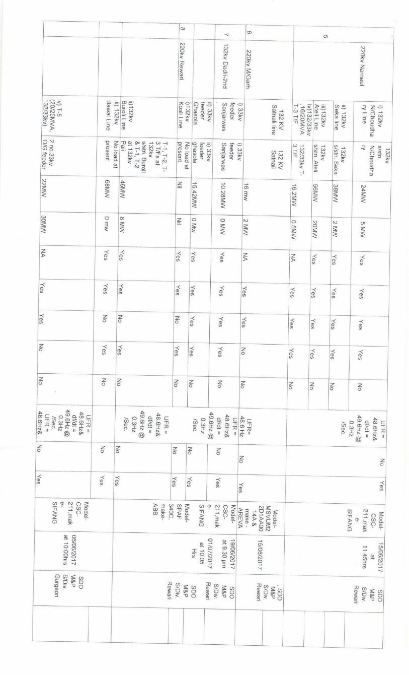
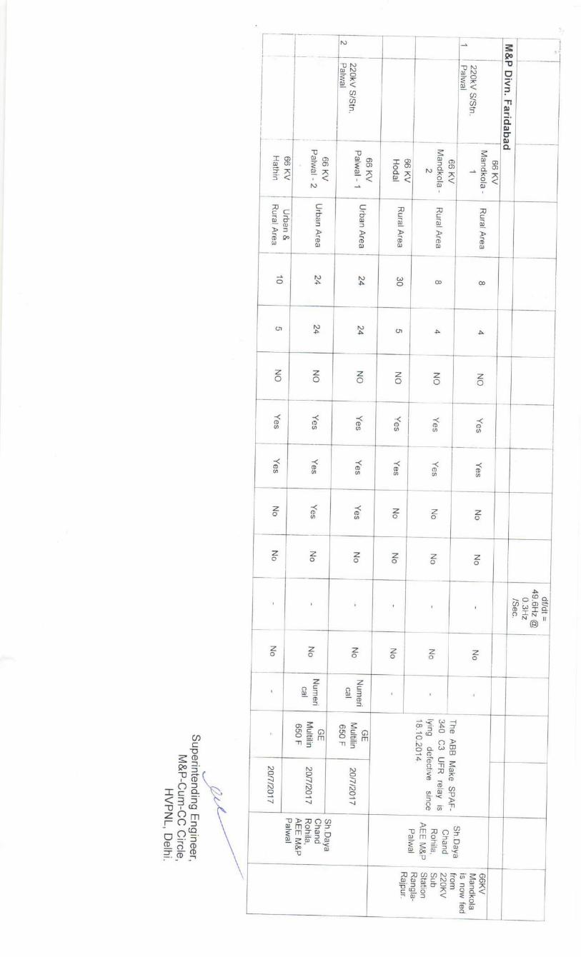
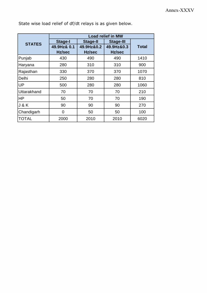
Stage-I Stage-II Stage-III
49.9Hz& 0.1
Hz/sec
49.9Hz&0.2
Hz/sec
49.9Hz&0.3
Hz/sec
Punjab 430 490 490 1410
Haryana 280 310 310 900
Rajasthan 330 370 370 1070
Delhi 250 280 280 810
UP 500 280 280 1060
Uttarakhand 70 70 70 210
HP 50 70 70 190
J & K 90 90 90 270
Chandigarh 0 50 50 100
TOTAL 2000 2010 2010 6020
State wise load relief of df/dt relays is as given below.
STATES
Load relief in MW
Total
Annex-XXXV
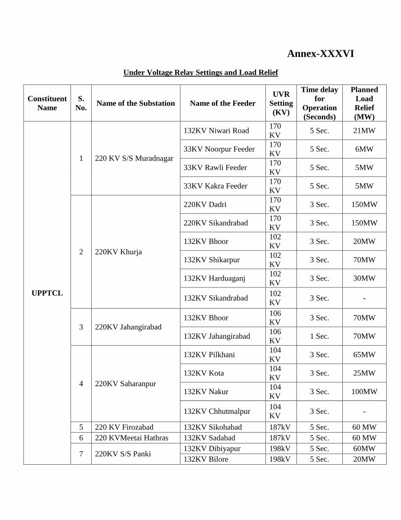
Annex-XXXVI
Under Voltage Relay Settings and Load Relief
Constituent
Name
S.
No. Name of the Substation Name of the Feeder
UVR
Setting
(KV)
Time delay
for
Operation
(Seconds)
Planned
Load
Relief
(MW)
UPPTCL
1 220 KV S/S Muradnagar
132KV Niwari Road 170
KV 5 Sec. 21MW
33KV Noorpur Feeder 170
KV 5 Sec. 6MW
33KV Rawli Feeder 170
KV 5 Sec. 5MW
33KV Kakra Feeder 170
KV 5 Sec. 5MW
2 220KV Khurja
220KV Dadri 170
KV 3 Sec. 150MW
220KV Sikandrabad 170
KV 3 Sec. 150MW
132KV Bhoor 102
KV 3 Sec. 20MW
132KV Shikarpur 102
KV 3 Sec. 70MW
132KV Harduaganj 102
KV 3 Sec. 30MW
132KV Sikandrabad 102
KV 3 Sec. -
3 220KV Jahangirabad
132KV Bhoor 106
KV 3 Sec. 70MW
132KV Jahangirabad 106
KV 1 Sec. 70MW
4 220KV Saharanpur
132KV Pilkhani 104
KV 3 Sec. 65MW
132KV Kota 104
KV 3 Sec. 25MW
132KV Nakur 104
KV 3 Sec. 100MW
132KV Chhutmalpur 104
KV 3 Sec. -
5 220 KV Firozabad 132KV Sikohabad 187kV 5 Sec. 60 MW
6 220 KVMeetai Hathras 132KV Sadabad 187kV 5 Sec. 60 MW
7 220KV S/S Panki 132KV Dibiyapur 198kV 5 Sec. 60MW
132KV Bilore 198kV 5 Sec. 20MW
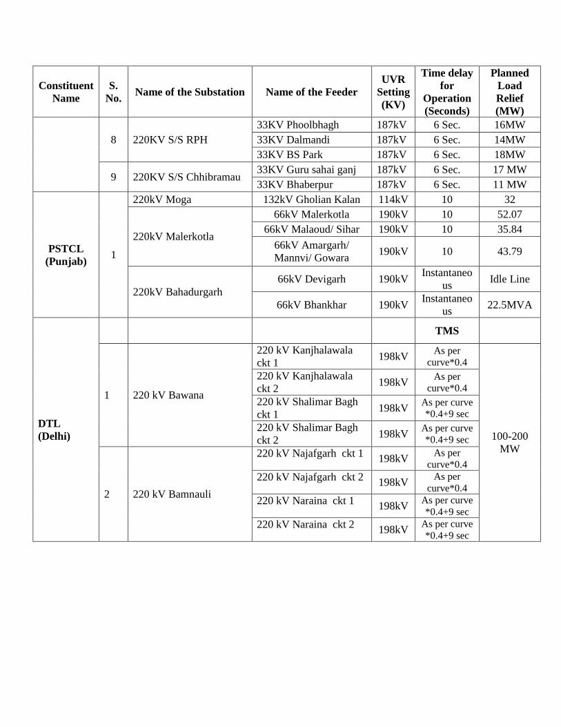
Constituent
Name
S.
No. Name of the Substation Name of the Feeder
UVR
Setting
(KV)
Time delay
for
Operation
(Seconds)
Planned
Load
Relief
(MW)
8 220KV S/S RPH
33KV Phoolbhagh 187kV 6 Sec. 16MW
33KV Dalmandi 187kV 6 Sec. 14MW
33KV BS Park 187kV 6 Sec. 18MW
9 220KV S/S Chhibramau 33KV Guru sahai ganj 187kV 6 Sec. 17 MW
33KV Bhaberpur 187kV 6 Sec. 11 MW
PSTCL
(Punjab) 1
220kV Moga 132kV Gholian Kalan 114kV 10 32
220kV Malerkotla
66kV Malerkotla 190kV 10 52.07
66kV Malaoud/ Sihar 190kV 10 35.84
66kV Amargarh/
Mannvi/ Gowara 190kV 10 43.79
220kV Bahadurgarh
66kV Devigarh 190kV Instantaneo
us Idle Line
66kV Bhankhar 190kV Instantaneo
us 22.5MVA
DTL
(Delhi)
TMS
1 220 kV Bawana
220 kV Kanjhalawala
ckt 1 198kV
As per
curve*0.4
100-200
MW
220 kV Kanjhalawala
ckt 2 198kV
As per
curve*0.4
220 kV Shalimar Bagh
ckt 1 198kV
As per curve
*0.4+9 sec
220 kV Shalimar Bagh
ckt 2 198kV
As per curve
*0.4+9 sec
2 220 kV Bamnauli
220 kV Najafgarh ckt 1 198kV
As per
curve*0.4
220 kV Najafgarh ckt 2 198kV
As per
curve*0.4
220 kV Naraina ckt 1 198kV
As per curve
*0.4+9 sec
220 kV Naraina ckt 2 198kV
As per curve
*0.4+9 sec
POSOCO-NRLDC SYSTEM PROTECTION SCHEMES IN NR |1
Annexure-XXXVII
Preface to the First Edition
The first edition of document SPS (System Protection Scheme) in Northern Region is
before you. Information contained in this booklet has been found to be very useful in various
stages of system operation.
We are sure that this updated document SPS (System Protection Scheme) in
Northern Region would be helpful for the operating personnel at different load dispatch
centres in system monitoring and control.
All efforts have been made to make this book error free and up to date. However, in view of
the fast changing network conditions, it is possible that some of the changes could have not
been incorporated as per actual. Any feedback from the users of the book is solicited, as it
will help us to improve the overall quality, style and presentation of the document in future.
S. S. Barpanda Executive Director
July 2019

POSOCO-NRLDC SYSTEM PROTECTION SCHEMES IN NR |2
POSOCO-NRLDC SYSTEM PROTECTION SCHEMES IN NR |3
INDEX
1. Introduction
2. System Protection Schemes
3. Need for SPS
4. SPS in Northern Region Power System
5. Northern Regional Grid SPS Operation
Monitoring Format
6. Roles and Responsibility regarding SPS

POSOCO-NRLDC SYSTEM PROTECTION SCHEMES IN NR |4
This page intentionally left blank
POSOCO-NRLDC SYSTEM PROTECTION SCHEMES IN NR |5
1. Introduction
The complexities in Indian electric power system operation are increasing day by
day. The size of the grid has expanded manifold and is on a high growth phase.
The need of System Protection Schemes (SPS) is spelt due to long haulage of
power. Due to heavy flow of power through these corridors, any outage usually
results in congestion in this part of the network.
This result into reduction in transfer capability across this corridor; subsequently
disturbance in a large area of the grid resulting into loss of load and generation.
SPS- System Protection scheme is a system protection scheme in addition to the
normal protection system to take care of some special contingencies like tripping of
important corridor/flow gates etc. to avoid the voltage collapse, cascade tripping,
load generation mismatch and finally blackouts in the system.
2. System Protection Schemes
System Protection Schemes are used during rare contingencies, when focus for the
protection is on the power system supply capability rather than on specific
equipment and when the consequences of an operating condition are outside the
capability of conventional protection. SPS consists of three main parts i.e., the input
which is the level of physical magnitudes and status of circuits breakers, decision
making system which initiate some actions based on inputs and output which may
be generator tripping/ back down or load tripping.
SPS are tailor made schemes & are required to operate infrequently. The Control
actions taken are predetermined & can be armed or disarmed depending upon
system conditions. It can comprise of a large number of coordinated actions, in a
cascaded manner.
For large interconnected system the non-operation of unit (like differential protection
etc) / non-unit (Like distance protection or over-current protection etc.) or backup
protections may lead wide spread disturbances. Also there is heavy rush of power
flow on inter-regional or important intra-regional corridors. Tripping of these tie lines
may overload other lines in the corridor which may result in cascading. This
necessitates the implementation of SPS as safety net for the grid.
POSOCO-NRLDC SYSTEM PROTECTION SCHEMES IN NR |6
3. Need for SPS
As per Indian Electricity Grid Code(IEGC), interstate transmission system (ISTS)
shall be capable of withstanding and be secured against the certain outages without
necessitating load shedding or rescheduling of generation during steady state
operation. These include outage of a 132 kV D/C line or Outage of a 220 kV D/C
line or Outage of a 400 kV S/C line or Outage of a single ICT or Outage of one pole
of HVDC bipole or Outage of 765 kV S/C line.
The aforesaid contingencies would be superimposed over a planned outage of
another 220 kV D/C line or 400 kV S/C line in another corridor and not emanating
from the same sub-station. ISTS shall be capable of withstanding the loss of most
severe single system infeed without loss of stability. It has also been stated that any
one of the aforesaid events shall not cause loss of supply, abnormal frequency on
sustained basis, unacceptable high or low voltage, system instability, unacceptable
overloading of ISTS elements.
As per the IEGC or transmission planning criteria, the system is not designed for 400
kV double circuit line or outage of HVDC bipole. In practice it has been observed that
there are some contingencies happening in the system resulting in outage of multiple
elements for which system is not designed.
Disturbances like loss of load, loss of generation or loss of transmission line in large
grid may cause wide variations in frequency, voltage & load angles. Originating
causes of grid failure may be due to equipment failure (including those of protective
systems), human error and cascade tripping or large scale disturbances due to
weather and/or natural calamities.
Disturbances cause discomfort to the people as well as results into huge economic
loss. Therefore, in addition to conventional unit protection system few System
Protection Schemes (SPS) are also desirable for safe and reliable operation of the
power system.
The main objective of SPS is to preserve the integrity of the electric system by using
automatic measures that are simple, reliable and safe for the system as a whole and
to provide the most extensive coverage against all possible extreme credible
contingencies.
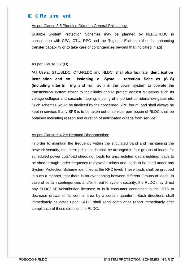
POSOCO-NRLDC SYSTEM PROTECTION SCHEMES IN NR |7
3.1 IEGC Requirement
As per Clause 3.5 Planning Criterion General Philosophy:
Suitable System Protection Schemes may be planned by NLDC/RLDC in
consultation with CEA, CTU, RPC and the Regional Entities, either for enhancing
transfer capability or to take care of contingencies beyond that indicated in a(i)
As per Clause 5.2 (O)
“All Users, STU/SLDC, CTU/RLDC and NLDC, shall also facilitate identification,
installation and commissioning of System Protection Schemes (SPS)
(including inter-tripping and run-back) in the power system to operate the
transmission system closer to their limits and to protect against situations such as
voltage collapse and cascade tripping, tripping of important corridors/flow-gates etc.
Such schemes would be finalized by the concerned RPC forum, and shall always be
kept in service. If any SPS is to be taken out of service, permission of RLDC shall be
obtained indicating reason and duration of anticipated outage from service”
As per Clause 5.4.2.e Demand Disconnection:
In order to maintain the frequency within the stipulated band and maintaining the
network security, the interruptible loads shall be arranged in four groups of loads, for
scheduled power cuts/load shedding, loads for unscheduled load shedding, loads to
be shed through under frequency relays/df/dt relays and loads to be shed under any
System Protection Scheme identified at the RPC level. These loads shall be grouped
in such a manner, that there is no overlapping between different Groups of loads. In
case of certain contingencies and/or threat to system security, the RLDC may direct
any SLDC/ SEB/distribution licensee or bulk consumer connected to the ISTS to
decrease drawal of its control area by a certain quantum. Such directions shall
immediately be acted upon. SLDC shall send compliance report immediately after
compliance of these directions to RLDC.

POSOCO-NRLDC SYSTEM PROTECTION SCHEMES IN NR |8
3.2 CEA Manual on Transmission Planning Criteria
As per CL. 4.3 of Planning Criteria
After suffering single contingency (N-1), grid is still vulnerable to experience second
contingency, though less probable (‘N-1-1’), wherein some of the equipment's may
be loaded up to their emergency limits.
To bring the system parameters back within their normal limits, load shedding/re-
scheduling of generation may have to be applied either manually or through
automatic system protection schemes (SPS).
Such measures shall generally be applied within one and a half hour (1½) after the
disturbance.
POSOCO-NRLDC SYSTEM PROTECTION SCHEMES IN NR |9
4. SPS IN NORTHERN
REGION
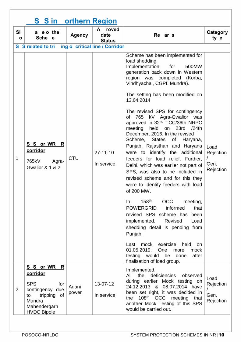
POSOCO-NRLDC SYSTEM PROTECTION SCHEMES IN NR |10
4. SPS in Northern Region
Sl. No
Name of the Scheme
Agency Approved
date & Status
Remarks Category
type
SPS related to tripping of critical line / Corridor
1
SPS for WR-NR
corridor
765kV Agra-
Gwalior & 1 & 2
CTU 27-11-10 In service
Scheme has been implemented for load shedding. Implementation for 500MW generation back down in Western region was completed (Korba, Vindhyachal, CGPL Mundra). The setting has been modified on 13.04.2014 The revised SPS for contingency of 765 kV Agra-Gwalior was approved in 32nd TCC/36th NRPC meeting held on 23rd /24th December, 2016. In the revised Scheme, States of Haryana,
Punjab, Rajasthan and Haryana
were to identify the additional
feeders for load relief. Further,
Delhi, which was earlier not part of
SPS, was also to be included in
revised scheme and for this they
were to identify feeders with load
of 200 MW.
In 158th OCC meeting,
POWERGRID informed that
revised SPS scheme has been
implemented. Revised Load
shedding detail is pending from
Punjab.
Last mock exercise held on 01.05.2019. One more mock testing would be done after finalisation of load group.
Load Rejection / Gen. Rejection
2
SPS for WR-NR
corridor
SPS for contingency due to tripping of Mundra-Mahendergarh HVDC Bipole
Adani power
13-07-12 In service
Implemented. All the deficiencies observed during earlier Mock testing on 24.12.2013 & 08.07.2014 have been set right, it was decided in the 108th OCC meeting that another Mock Testing of this SPS would be carried out.
Load Rejection / Gen. Rejection
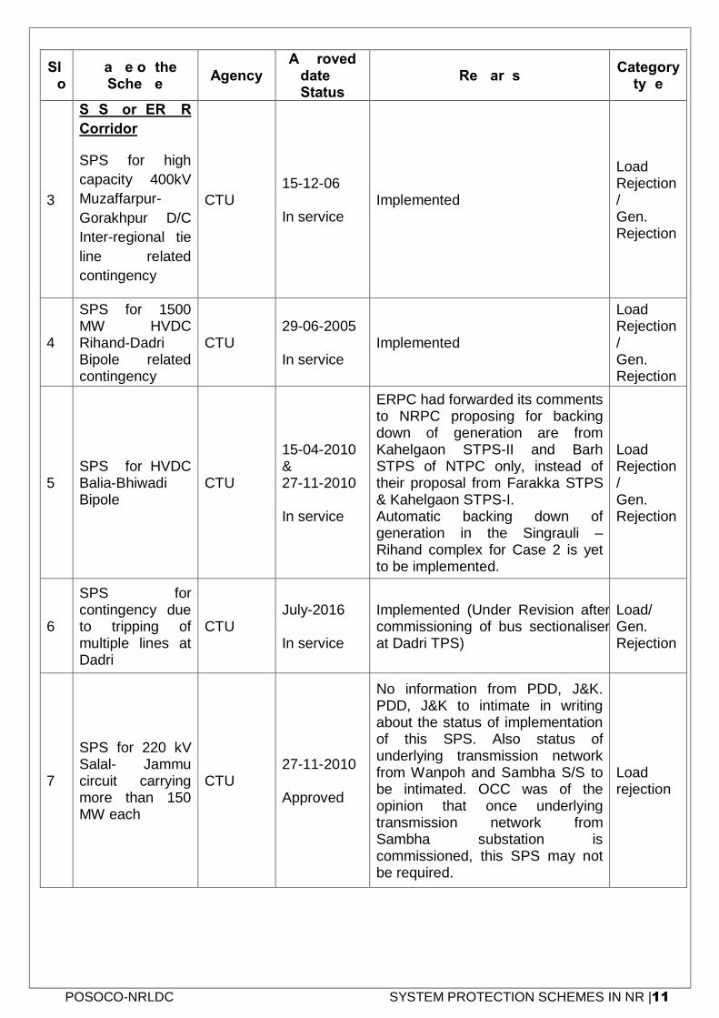
POSOCO-NRLDC SYSTEM PROTECTION SCHEMES IN NR |11
Sl. No
Name of the Scheme
Agency Approved
date & Status
Remarks Category
type
3
SPS for ER-NR
Corridor
SPS for high
capacity 400kV
Muzaffarpur-
Gorakhpur D/C
Inter-regional tie
line related
contingency
CTU 15-12-06 In service
Implemented
Load Rejection / Gen. Rejection
4
SPS for 1500 MW HVDC Rihand-Dadri Bipole related contingency
CTU 29-06-2005 In service
Implemented
Load Rejection / Gen. Rejection
5 SPS for HVDC Balia-Bhiwadi Bipole
CTU
15-04-2010 & 27-11-2010 In service
ERPC had forwarded its comments to NRPC proposing for backing down of generation are from Kahelgaon STPS-II and Barh STPS of NTPC only, instead of their proposal from Farakka STPS & Kahelgaon STPS-I. Automatic backing down of generation in the Singrauli – Rihand complex for Case 2 is yet to be implemented.
Load Rejection / Gen. Rejection
6
SPS for contingency due to tripping of multiple lines at Dadri
CTU July-2016 In service
Implemented (Under Revision after commissioning of bus sectionaliser at Dadri TPS)
Load/ Gen. Rejection
7
SPS for 220 kV Salal- Jammu circuit carrying more than 150 MW each
CTU 27-11-2010 Approved
No information from PDD, J&K. PDD, J&K to intimate in writing about the status of implementation of this SPS. Also status of underlying transmission network from Wanpoh and Sambha S/S to be intimated. OCC was of the opinion that once underlying transmission network from Sambha substation is commissioned, this SPS may not be required.
Load rejection

POSOCO-NRLDC SYSTEM PROTECTION SCHEMES IN NR |12
Sl. No
Name of the Scheme
Agency Approved
date & Status
Remarks Category
type
8 SPS Proposed for Kashmir Valley
CTU/ PDD
13-01-2013 Approved (But Yet to be discussed in RPC meeting)
A committee formed and approved. Implementation is pending from J&K
Load rejection
SPS related to Safe evacuation of Generation
9
SPS for reliable evacuation of power from NJPS, Rampur, Baspa H.E.P and Karcham Wangtoo
Karcham/Rampur/ Jhakri
04-02-2011 In service
Revised SPS considering Rampur HEP (approved in 28th TCC & 31st NRPC meeting) has been implemented on 12.03.2015.
Gen. Rejection
10
SPS for Reliable Evacuation of Ropar Generation
Ropar TPS
27-11-2010 In service
SPS installed and commissioned on 29.05.2013. SPS is hard wired.
Gen. Rejection
11
SPS for Reliable Evacuation of Rosa Generation
UPPTCL
31-03-2015 (Revised SPS) In service
Revised SPS for four units with connectivity at 220kV & 400 kV level has been implemented on 10th June 2016
Gen. Rejection
12
SPS for contingency due to tripping of evacuating lines from Narora Atomic Power Station
UPPTCL 11-05-2012 Approved
SPS has been commissioned at all locations between 15.01.15 & 17.01.15
Gen. Rejection
13
SPS for evacuation of Kawai/ Chhabra TPS
RRVPNL In Service
Revised SPS (after charging of 400kV Kawai-Anta D/C line) Implemented. In 139th OCC meeting, representative of Rajasthan informed that all efforts are being made to implement the automatic load shedding (to control the load generation
Gen. Rejection
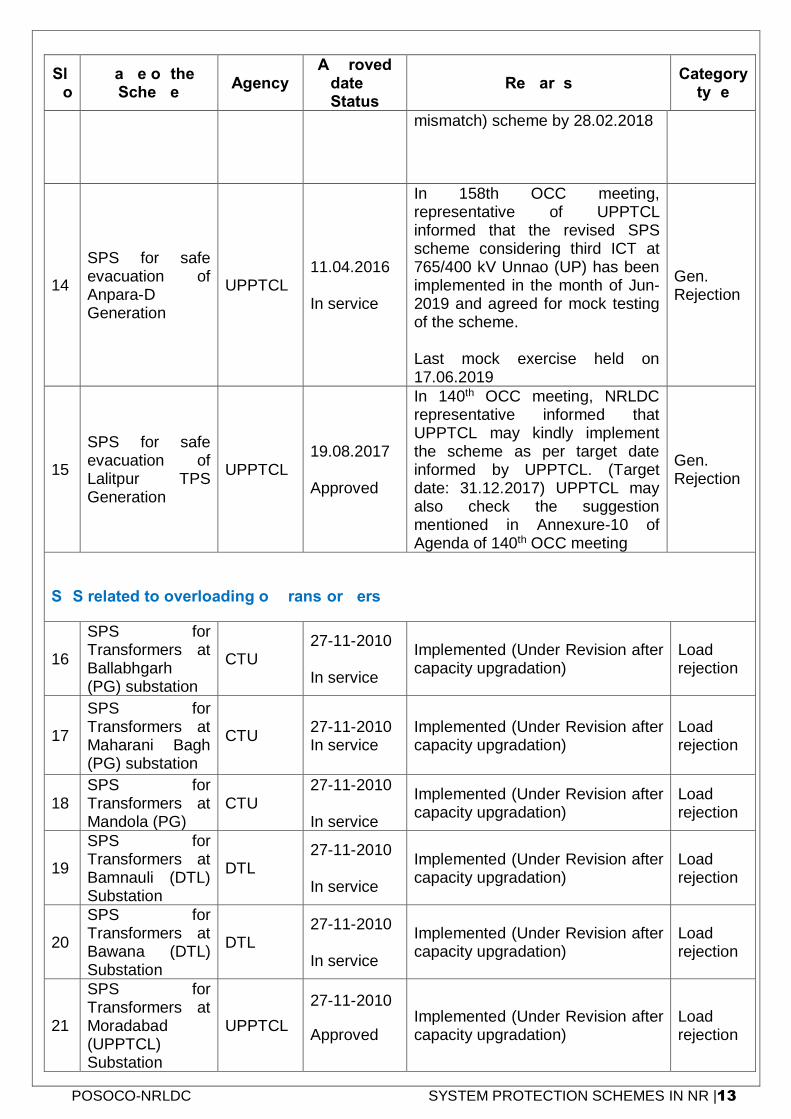
POSOCO-NRLDC SYSTEM PROTECTION SCHEMES IN NR |13
Sl. No
Name of the Scheme
Agency Approved
date & Status
Remarks Category
type
mismatch) scheme by 28.02.2018
14
SPS for safe evacuation of Anpara-D Generation
UPPTCL 11.04.2016 In service
In 158th OCC meeting, representative of UPPTCL informed that the revised SPS scheme considering third ICT at 765/400 kV Unnao (UP) has been implemented in the month of Jun-2019 and agreed for mock testing of the scheme. Last mock exercise held on 17.06.2019
Gen. Rejection
15
SPS for safe evacuation of Lalitpur TPS Generation
UPPTCL 19.08.2017 Approved
In 140th OCC meeting, NRLDC representative informed that UPPTCL may kindly implement the scheme as per target date informed by UPPTCL. (Target date: 31.12.2017) UPPTCL may also check the suggestion mentioned in Annexure-10 of Agenda of 140th OCC meeting
Gen. Rejection
SPS related to overloading of Transformers
16
SPS for Transformers at Ballabhgarh (PG) substation
CTU 27-11-2010 In service
Implemented (Under Revision after capacity upgradation)
Load rejection
17
SPS for Transformers at Maharani Bagh (PG) substation
CTU 27-11-2010 In service
Implemented (Under Revision after capacity upgradation)
Load rejection
18 SPS for Transformers at Mandola (PG)
CTU 27-11-2010 In service
Implemented (Under Revision after capacity upgradation)
Load rejection
19
SPS for Transformers at Bamnauli (DTL) Substation
DTL 27-11-2010 In service
Implemented (Under Revision after capacity upgradation)
Load rejection
20
SPS for Transformers at Bawana (DTL) Substation
DTL 27-11-2010 In service
Implemented (Under Revision after capacity upgradation)
Load rejection
21
SPS for Transformers at Moradabad (UPPTCL) Substation
UPPTCL
27-11-2010
Approved Implemented (Under Revision after capacity upgradation)
Load rejection
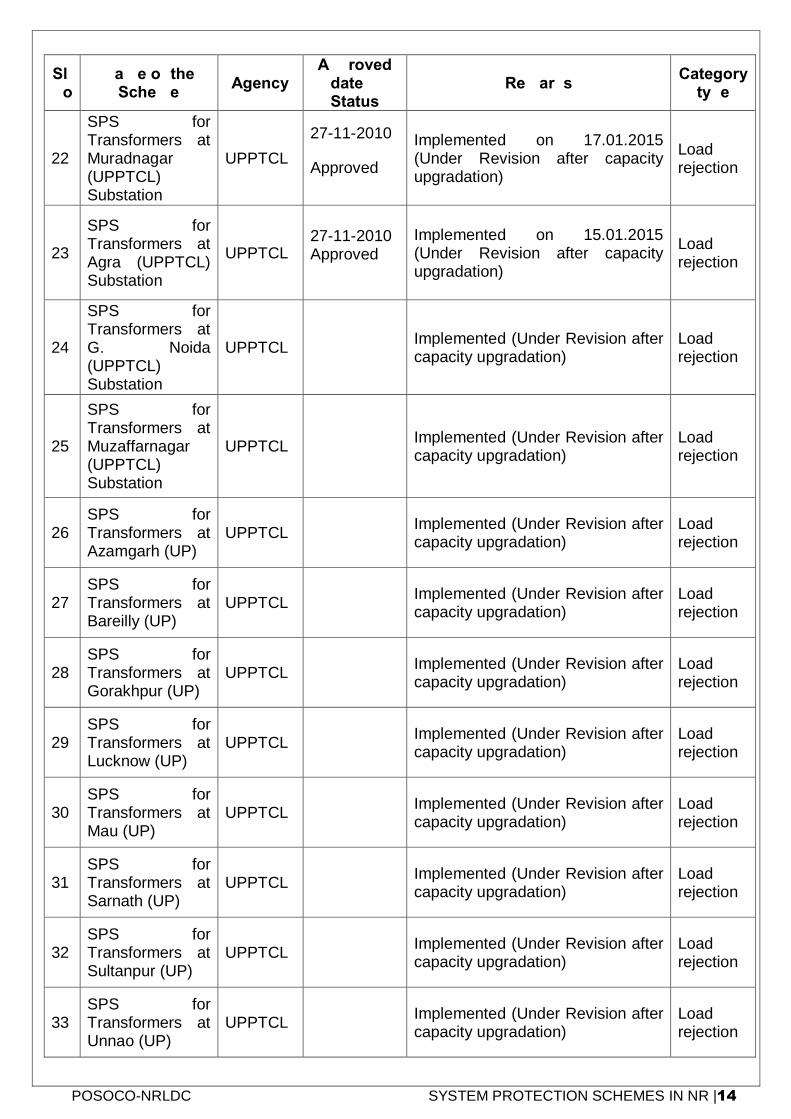
POSOCO-NRLDC SYSTEM PROTECTION SCHEMES IN NR |14
Sl. No
Name of the Scheme
Agency Approved
date & Status
Remarks Category
type
22
SPS for Transformers at Muradnagar (UPPTCL) Substation
UPPTCL
27-11-2010
Approved
Implemented on 17.01.2015 (Under Revision after capacity upgradation)
Load rejection
23
SPS for Transformers at Agra (UPPTCL) Substation
UPPTCL 27-11-2010 Approved
Implemented on 15.01.2015 (Under Revision after capacity upgradation)
Load rejection
24
SPS for Transformers at G. Noida (UPPTCL) Substation
UPPTCL Implemented (Under Revision after
capacity upgradation) Load rejection
25
SPS for Transformers at Muzaffarnagar (UPPTCL) Substation
UPPTCL Implemented (Under Revision after capacity upgradation)
Load rejection
26 SPS for Transformers at Azamgarh (UP)
UPPTCL Implemented (Under Revision after capacity upgradation)
Load rejection
27 SPS for Transformers at Bareilly (UP)
UPPTCL Implemented (Under Revision after capacity upgradation)
Load rejection
28 SPS for Transformers at Gorakhpur (UP)
UPPTCL Implemented (Under Revision after capacity upgradation)
Load rejection
29 SPS for Transformers at Lucknow (UP)
UPPTCL Implemented (Under Revision after capacity upgradation)
Load rejection
30 SPS for Transformers at Mau (UP)
UPPTCL Implemented (Under Revision after capacity upgradation)
Load rejection
31 SPS for Transformers at Sarnath (UP)
UPPTCL Implemented (Under Revision after capacity upgradation)
Load rejection
32 SPS for Transformers at Sultanpur (UP)
UPPTCL Implemented (Under Revision after capacity upgradation)
Load rejection
33 SPS for Transformers at Unnao (UP)
UPPTCL Implemented (Under Revision after capacity upgradation)
Load rejection

POSOCO-NRLDC SYSTEM PROTECTION SCHEMES IN NR |15
INDEX
Ref No. Name of the Scheme Implementing Agency
Status Pg. No.
SPS related to tripping of critical line / Corridor
SPS/NR/LINE/01
SPS for WR-NR corridor
765kV Agra-Gwalior & 1 & 2 CTU In service 18
SPS/NR/LINE/02
SPS for WR-NR corridor
SPS for contingency due to tripping of Mundra-Mahendergarh HVDC Bipole
Adani power In service 20
SPS/NR/LINE/03
SPS for ER-NR Corridor
SPS for high capacity 400kV
Muzaffarpur-Gorakhpur D/C Inter-
regional tie line related
contingency
CTU In service 22
SPS/NR/LINE/04 SPS for 1500 MW HVDC Rihand-Dadri Bipole related contingency
CTU In service 23
SPS/NR/LINE/05 SPS for HVDC Balia-Bhiwadi Bipole CTU In service 24
SPS/NR/LINE/06 SPS for contingency due to tripping of multiple lines at Dadri
CTU In service
(under revision)
25
SPS/NR/LINE/07 SPS for 220 kV Salal- Jammu circuit carrying more than 150 MW each
CTU Approved 27
SPS/NR/LINE/08 SPS Proposed for Kashmir Valley CTU/ PDD
Approved (Yet to be
discussed in RPC
meeting)
28
SPS related to Safe evacuation of Generation
SPS/NR/GEN/01 SPS for reliable evacuation of power from NJPS, Rampur, Baspa and Karcham Wangtoo HEP
Karcham/ Jhakri
In service 30
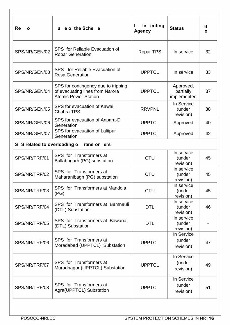
POSOCO-NRLDC SYSTEM PROTECTION SCHEMES IN NR |16
Ref No. Name of the Scheme Implementing Agency
Status Pg. No.
SPS/NR/GEN/02 SPS for Reliable Evacuation of Ropar Generation
Ropar TPS In service 32
SPS/NR/GEN/03 SPS for Reliable Evacuation of Rosa Generation
UPPTCL In service 33
SPS/NR/GEN/04 SPS for contingency due to tripping of evacuating lines from Narora Atomic Power Station
UPPTCL Approved, partially
implemented 37
SPS/NR/GEN/05 SPS for evacuation of Kawai, Chabra TPS
RRVPNL In Service
(under revision)
38
SPS/NR/GEN/06 SPS for evacuation of Anpara-D Generation
UPPTCL Approved 40
SPS/NR/GEN/07 SPS for evacuation of Lalitpur Generation
UPPTCL Approved 42
SPS related to overloading of Transformers
SPS/NR/TRF/01 SPS for Transformers at Ballabhgarh (PG) substation
CTU In service
(under revision)
45
SPS/NR/TRF/02 SPS for Transformers at Maharanibagh (PG) substation
CTU In service
(under revision)
45
SPS/NR/TRF/03 SPS for Transformers at Mandola (PG)
CTU In service
(under revision)
45
SPS/NR/TRF/04 SPS for Transformers at Bamnauli (DTL) Substation
DTL In service
(under revision)
46
SPS/NR/TRF/05 SPS for Transformers at Bawana (DTL) Substation
DTL In service
(under revision)
-
SPS/NR/TRF/06 SPS for Transformers at Moradabad (UPPTCL) Substation
UPPTCL
In Service
(under
revision) 47
SPS/NR/TRF/07 SPS for Transformers at Muradnagar (UPPTCL) Substation
UPPTCL
In Service
(under
revision) 49
SPS/NR/TRF/08 SPS for Transformers at Agra(UPPTCL) Substation
UPPTCL
In Service
(under
revision) 51
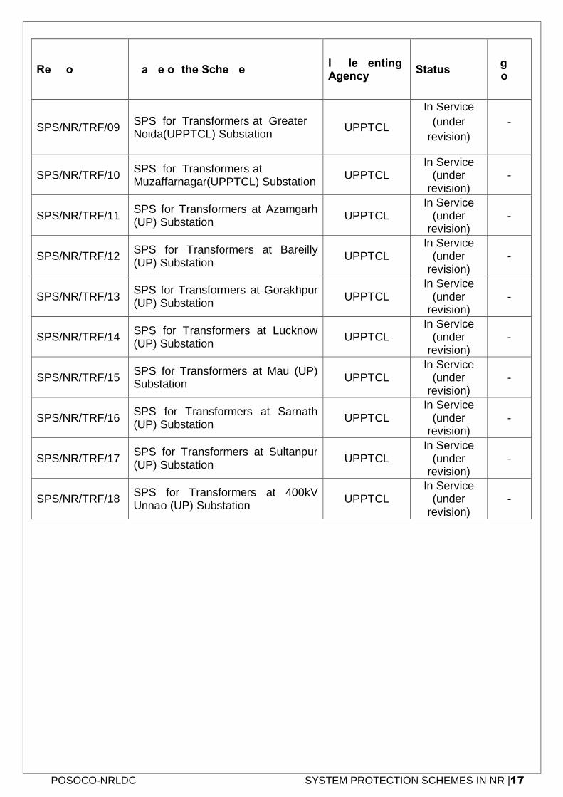
POSOCO-NRLDC SYSTEM PROTECTION SCHEMES IN NR |17
Ref No. Name of the Scheme Implementing Agency
Status Pg. No.
SPS/NR/TRF/09 SPS for Transformers at Greater Noida(UPPTCL) Substation
UPPTCL
In Service
(under
revision)
-
SPS/NR/TRF/10 SPS for Transformers at Muzaffarnagar(UPPTCL) Substation
UPPTCL In Service
(under revision)
-
SPS/NR/TRF/11 SPS for Transformers at Azamgarh (UP) Substation
UPPTCL In Service
(under revision)
-
SPS/NR/TRF/12 SPS for Transformers at Bareilly (UP) Substation
UPPTCL In Service
(under revision)
-
SPS/NR/TRF/13 SPS for Transformers at Gorakhpur (UP) Substation
UPPTCL In Service
(under revision)
-
SPS/NR/TRF/14 SPS for Transformers at Lucknow (UP) Substation
UPPTCL In Service
(under revision)
-
SPS/NR/TRF/15 SPS for Transformers at Mau (UP) Substation
UPPTCL In Service
(under revision)
-
SPS/NR/TRF/16 SPS for Transformers at Sarnath (UP) Substation
UPPTCL In Service
(under revision)
-
SPS/NR/TRF/17 SPS for Transformers at Sultanpur (UP) Substation
UPPTCL In Service
(under revision)
-
SPS/NR/TRF/18 SPS for Transformers at 400kV Unnao (UP) Substation
UPPTCL In Service
(under revision)
-
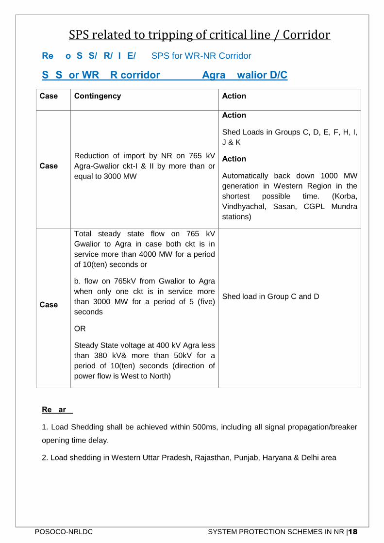
POSOCO-NRLDC SYSTEM PROTECTION SCHEMES IN NR |18
SPS related to tripping of critical line / Corridor
Ref No: SPS/NR/LINE/01: SPS for WR-NR Corridor
SPS for WR-NR corridor - 765kV Agra-Gwalior D/C
Case Contingency Action
Case-1
Reduction of import by NR on 765 kV
Agra-Gwalior ckt-I & II by more than or
equal to 3000 MW
Action-1
Shed Loads in Groups C, D, E, F, H, I,
J & K
Action-2
Automatically back down 1000 MW
generation in Western Region in the
shortest possible time. (Korba,
Vindhyachal, Sasan, CGPL Mundra
stations)
Case-2
Total steady state flow on 765 kV
Gwalior to Agra in case both ckt is in
service more than 4000 MW for a period
of 10(ten) seconds or
b. flow on 765kV from Gwalior to Agra
when only one ckt is in service more
than 3000 MW for a period of 5 (five)
seconds
OR
Steady State voltage at 400 kV Agra less
than 380 kV& more than 50kV for a
period of 10(ten) seconds (direction of
power flow is West to North)
Shed load in Group C and D
Remark:
1. Load Shedding shall be achieved within 500ms, including all signal propagation/breaker
opening time delay.
2. Load shedding in Western Uttar Pradesh, Rajasthan, Punjab, Haryana & Delhi area
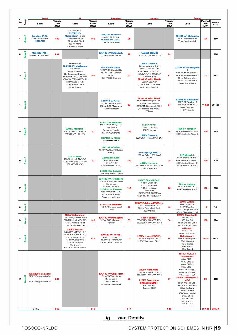
POSOCO-NRLDC SYSTEM PROTECTION SCHEMES IN NR |19
Fig 1 Load Details
Load
Planned
Load
(MW)
Load
Planned
Load
(MW)
Load
Planned
Load
(MW)
Load
Planned
Load
(MW)
Load
Planned
Load
(MW)
Group
Total
1
Gro
up
-A Mandola (PG)-
220 kV Narela D/C
NSD-70D
150
Feeders from
220/132 kV
Muradnagar old S/S
132 kV Niwai Road
132 kV Modi Steel
132 kV Morta
2*63 MVA X-Mer
100
220/132 kV Alwar-
132 kV GSS Pinan
400/220 kV Merta -
132 kV GSS Roon
25
220/66 kV Malerkotla
66 kV Malerkotla ckt
66 kV Naudhrani ckt
35 310
2
Gro
up
-B
Mandola (PG) -
220 kV Gopalpur D/C200
220/132 kV Ratangarh -
132 kV Sardar Sahar25
Panipat (BBMB)
100 MVA, 220/33 kV ICT50 275
3
Gro
up
-C
Feeders from
220/132 kV Modipuram
Sub-station.
132 KV Sardhana,
Kankankhera, Kapsad,
Kankankhera-2, 132/33kV
40MVA+ 63MVA ICT-2&3
33 kV Ladies Park,
33 kV Pallavpuram,
33 kV Siwaya
100
400/220 kV Merta -
132 kV GSS Merta City
132 kV GSS Lamba+
Gotan
132 kV GSS Kuchera
60
220kV Dhanoda-
220kV Lula Ahir Ckt-1
220kV Lula Ahir Ckt-2
(Load Relief: 220/132kV,
100MVA T/F + 220/33kV,
100MVA T/F)
220kV Charkhi Dadri-
220kV Lula Ahir
(Load Relief: 3*100MVA
220/132kV Rewari)
91
220/66 kV Gobindgarh-
1
66 kV Chourwala ckt-1,
66 kV Chourwala ckt-2,
66 kV Talwara ckt-1,
66 kV Talwara ckt-2
66 kV Focal Point
71 322
4
Gro
up
-D
220/132 kV Alwar-
132 kV GSS Bansoor
132 kV GSS Malakheda
132 kV Ramgarh
60
220kV Charkhi Dadri-
220kV Mohindergarh Ckt-1
(Radial load- 49MW)
220kV Mohindergarh Ckt-2
(Radial load of Narnaul-
38MW)
87
220/66 kV Laltokalan-
66kV Gill Road ckt-1
66kV Gill Road ckt-2
66kV Ferozpur
66 kV Sarinh
114.25 261.25
5
Gro
up
-E 220 kV Mainpuri -
2 x 132/33 kV , 63 MVA
T/F (20 MW -60 MW)
50
220/132kV Bhilwara-
132 kV GSS Gangapur,
132 kV GSS
Devgarh+Kareda,
132 kV GSS Danta
220/132 kV Merta-
(Spare DTPC)
105
132kV PTPS-
132kV Chandauli
132kV Munak
220kV Dhanoda-
220/132 kV 100 MVA X-Mer
88
220 kV Jamsher-
66 kV Nakodar Road-1
66 kV Nakodar Road-2
100 343
6
Gro
up
-F
220 kV Nara-
132/33 kV , 40 MVA T/F
132/33 kV, 2*63 MVA T/F
(32 MW -52 MW)
50
220/132 kV Alwar
132 kV GSS Alwar (Local
Load)
220/132kV Kota-
Kota local load
(40/50MVA TF)
132 kV Nanta(Talera)
220/132 kV Beawar-
132 kV GSS Ber Jaitaran
100
Samaypur (BBMB) -
220 kV Palwal D/C (MW)
(35MW)
220kV Narwana-
2*100MVA 220/132kV T/F at
220 kV Narwana
55
220 Mohali-1-
66 kV Mohali Phase-7
66 kV Mohali Phase-8B
66 kV Mohali Sector-71
66 kV Mohali Phase-1
100 305
7
Gro
up
-G
220/132 kV Ratangarh -
132 KV Ratangarh Inter-
Connector
132 kV Fatehpur
220/132 kV Beawar-
132 kV GSS Masuda,
132 KV GSS Asind,
Beawar Local Load
100
132kV Charkhi Dadri
132kV Dadri city,
132kV Matenhail,
132kV Kalanaur,
132kV Bahu
132/33kV T/F 20/25MVA
132/133V T/F 16/20 MVA
75
220 kV Ablowal-
66 kV Rakhra-I & II,
66 kV Rakhra-III & IV100 275
8
Gro
up
-H 220/132kV Bhilwara-
132 KV Bhilwara Local
Load
12
220kV Fatehabad(PGCIL)-
220kV Fatehabad Ckt-1
220kV Fatehabad Ckt-2
220kV Sirsa
45
220kV Ajitwal-
66 kV Galib ckt
66 kV Doudhar
66 kV Chogawan ckt-1
66 kV Chogawan ckt-2
15 72
9
Gro
up
-I
220kV Saharanpur-
220/132kV, 40MVA T/F-1
220/132kV, 40MVA T/F-
132kV Ambala Road
132 kV Gagalheri ckt
100
220/132 kV Ratangarh -
132kV GSS Momasar+
Patlisar
35
132kV Safidon-
220/132kV, 100MVA T/F-1
220/132kV, 100MVA T/F-2
50
220kV Dhandari-2-
66/11kV T-2
66/11kV T-4
66kV Sherpur Ckt-1
66kV Sherpur Ckt-2
109 294
10
Gro
up
-J
220kV Nanuta-
132/33kV, 63MVA T/F-1
132/33kV, 63MVA T/F-2
132kV Deoband ckt
132 kV Gangoh ckt
132 kV Rampur-
Maniharan
132 kV Shamli-Shyamla
155
220/132 kV Debari-
132kV GSS Mavli
132kV GSS Bhatewar
132 kV Debari local load
90
220kV Hissar(PGCIL)-
220kV Sangwan Ckt-1
220kV Sangwan Ckt-2
45
Ablowal -
66kV Barn
66kV passiana-1
Bahadurgarh-
66kV Bahadurgarh-1
66kV Ghanour
66kV Patiala
66kV Barn-1
66kV Barn-2
153.1 443.1
11
Gro
up
-K
400/220kV Bamnauli-
220kV Pappankala Ckt-
1
220kV Pappankala Ckt-
2
200
220/132 kV Chittorgarh-
132 kV GSS Ajolia ka
khera+Bassi
132 kV Senthi
Chittorgarh local load
65
220kV Nunamajra-
220/132kV, 100MVA T/F-1
220/132kV, 100MVA T/F-2
220kV Prem Nagar
Bhiwani (BBMB)-
Bapora Ckt-1
Bapora Ckt-2
57
220 kV Mohali-1
(Sector-80)
66kV CHD-1
66kV CHD-2
66kV CHD-3
66kV CHD-4
66kV Incoming-1
66kV Incoming-2
66kV Incoming-3
220kV Gobindgarh-2
MGG
66kV Khanna Ckt-1
66kV Khanna Ckt-2
66kV Badinpur
66kV Central
66kV Grain Market
66kV Bhari
66/11kV T-2
66/11kV T-4
66/11kV T-6
90 412
550 555 677 643 887.35 3312.4TOTAL
S.
No
. Gro
up
Delhi UP Rajasthan Haryana Punjab
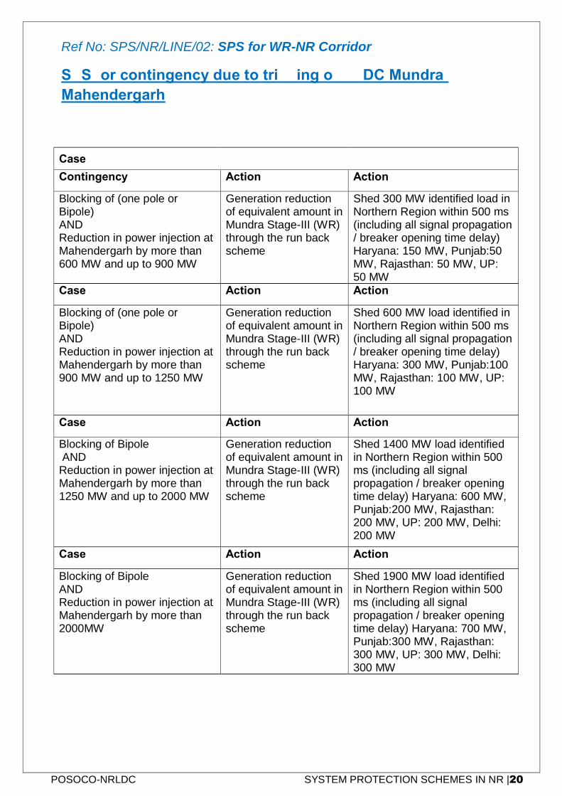
POSOCO-NRLDC SYSTEM PROTECTION SCHEMES IN NR |20
Ref No: SPS/NR/LINE/02: SPS for WR-NR Corridor
SPS for contingency due to tripping of HVDC Mundra-
Mahendergarh
Case-1
Contingency Action-1 Action-2
Blocking of (one pole or Bipole) AND Reduction in power injection at Mahendergarh by more than 600 MW and up to 900 MW
Generation reduction of equivalent amount in Mundra Stage-III (WR) through the run back scheme
Shed 300 MW identified load in Northern Region within 500 ms (including all signal propagation / breaker opening time delay) Haryana: 150 MW, Punjab:50 MW, Rajasthan: 50 MW, UP: 50 MW
Case-2 Action-1 Action-2
Blocking of (one pole or Bipole) AND Reduction in power injection at Mahendergarh by more than 900 MW and up to 1250 MW
Generation reduction of equivalent amount in Mundra Stage-III (WR) through the run back scheme
Shed 600 MW load identified in Northern Region within 500 ms (including all signal propagation / breaker opening time delay) Haryana: 300 MW, Punjab:100 MW, Rajasthan: 100 MW, UP: 100 MW
Case-3 Action-1 Action-2
Blocking of Bipole AND Reduction in power injection at Mahendergarh by more than 1250 MW and up to 2000 MW
Generation reduction of equivalent amount in Mundra Stage-III (WR) through the run back scheme
Shed 1400 MW load identified in Northern Region within 500 ms (including all signal propagation / breaker opening time delay) Haryana: 600 MW, Punjab:200 MW, Rajasthan: 200 MW, UP: 200 MW, Delhi: 200 MW
Case-4 Action-1 Action-2
Blocking of Bipole AND Reduction in power injection at Mahendergarh by more than 2000MW
Generation reduction of equivalent amount in Mundra Stage-III (WR) through the run back scheme
Shed 1900 MW load identified in Northern Region within 500 ms (including all signal propagation / breaker opening time delay) Haryana: 700 MW, Punjab:300 MW, Rajasthan: 300 MW, UP: 300 MW, Delhi: 300 MW
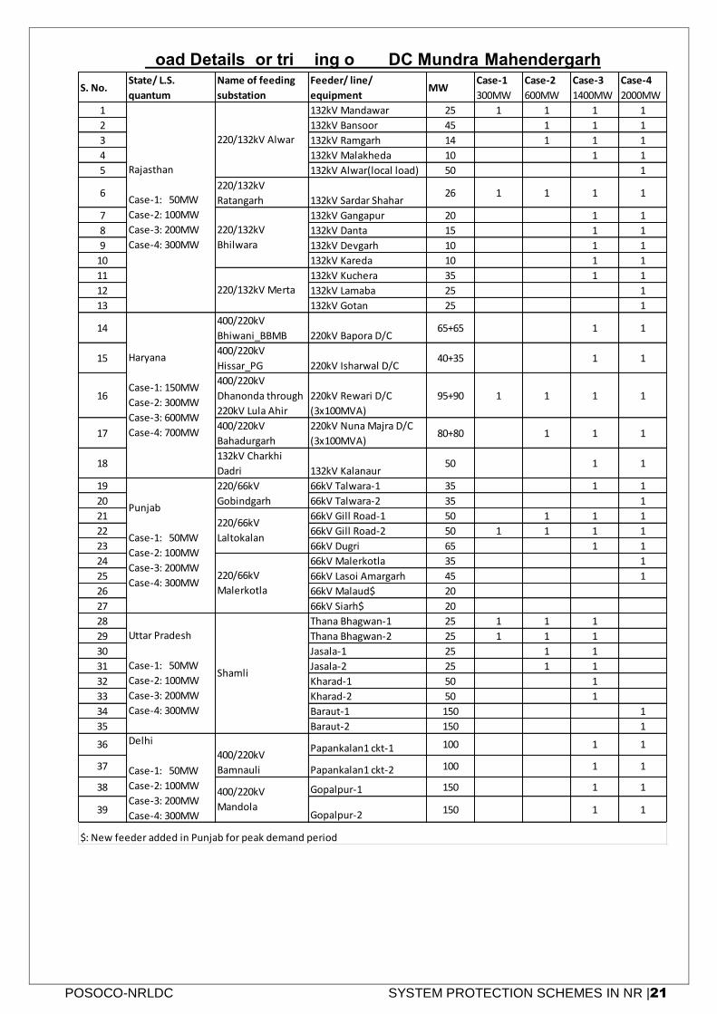
POSOCO-NRLDC SYSTEM PROTECTION SCHEMES IN NR |21
Load Details for tripping of HVDC Mundra-Mahendergarh
S. No.State/ L.S.
quantum
Name of feeding
substation
Feeder/ line/
equipmentMW
Case-1
300MW
Case-2
600MW
Case-3
1400MW
Case-4
2000MW
1 132kV Mandawar 25 1 1 1 1
2 132kV Bansoor 45 1 1 1
3 132kV Ramgarh 14 1 1 1
4 132kV Malakheda 10 1 1
5 132kV Alwar(local load) 50 1
6220/132kV
Ratangarh 132kV Sardar Shahar26 1 1 1 1
7 132kV Gangapur 20 1 1
8 132kV Danta 15 1 1
9 132kV Devgarh 10 1 1
10 132kV Kareda 10 1 1
11 132kV Kuchera 35 1 1
12 132kV Lamaba 25 1
13 132kV Gotan 25 1
14400/220kV
Bhiwani_BBMB 220kV Bapora D/C65+65 1 1
15400/220kV
Hissar_PG 220kV Isharwal D/C40+35 1 1
16
400/220kV
Dhanonda through
220kV Lula Ahir
220kV Rewari D/C
(3x100MVA)
95+90 1 1 1 1
17400/220kV
Bahadurgarh
220kV Nuna Majra D/C
(3x100MVA)80+80 1 1 1
18132kV Charkhi
Dadri 132kV Kalanaur50 1 1
19 66kV Talwara-1 35 1 1
20 66kV Talwara-2 35 1
21 66kV Gill Road-1 50 1 1 1
22 66kV Gill Road-2 50 1 1 1 1
23 66kV Dugri 65 1 1
24 66kV Malerkotla 35 1
25 66kV Lasoi Amargarh 45 1
26 66kV Malaud$ 20
27 66kV Siarh$ 20
28 Thana Bhagwan-1 25 1 1 1
29 Thana Bhagwan-2 25 1 1 1
30 Jasala-1 25 1 1
31 Jasala-2 25 1 1
32 Kharad-1 50 1
33 Kharad-2 50 1
34 Baraut-1 150 1
35 Baraut-2 150 1
36 Papankalan1 ckt-1 100 1 1
37 Papankalan1 ckt-2 100 1 1
38 Gopalpur-1 150 1 1
39 Gopalpur-2 150 1 1
400/220kV
Bamnauli
400/220kV
Mandola
Rajasthan
Case-1: 50MW
Case-2: 100MW
Case-3: 200MW
Case-4: 300MW
Haryana
Case-1: 150MW
Case-2: 300MW
Case-3: 600MW
Case-4: 700MW
Punjab
Case-1: 50MW
Case-2: 100MW
Case-3: 200MW
Case-4: 300MW
Uttar Pradesh
Case-1: 50MW
Case-2: 100MW
Case-3: 200MW
Case-4: 300MW
Delhi
Case-1: 50MW
Case-2: 100MW
Case-3: 200MW
Case-4: 300MW
220/132kV Alwar
220/132kV
Bhilwara
220/132kV Merta
220/66kV
Gobindgarh
220/66kV
Laltokalan
220/66kV
Malerkotla
Shamli
$: New feeder added in Punjab for peak demand period
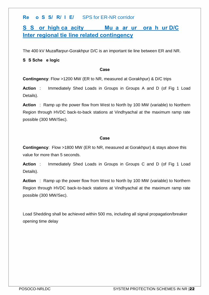
POSOCO-NRLDC SYSTEM PROTECTION SCHEMES IN NR |22
Ref No: SPS/NR/LINE/03: SPS for ER-NR corridor
SPS for high capacity 400 kV Muzaffarpur-Gorakhpur D/C
Inter-regional tie-line related contingency
The 400 kV Muzaffarpur-Gorakhpur D/C is an important tie line between ER and NR.
SPS Scheme logic:
Case-1
Contingency: Flow >1200 MW (ER to NR, measured at Gorakhpur) & D/C trips
Action-1: Immediately Shed Loads in Groups in Groups A and D (of Fig 1 Load
Details).
Action 2: Ramp up the power flow from West to North by 100 MW (variable) to Northern
Region through HVDC back-to-back stations at Vindhyachal at the maximum ramp rate
possible (300 MW/Sec).
Case-2
Contingency: Flow >1800 MW (ER to NR, measured at Gorakhpur) & stays above this
value for more than 5 seconds.
Action-1: Immediately Shed Loads in Groups in Groups C and D (of Fig 1 Load
Details).
Action 2: Ramp up the power flow from West to North by 100 MW (variable) to Northern
Region through HVDC back-to-back stations at Vindhyachal at the maximum ramp rate
possible (300 MW/Sec).
Load Shedding shall be achieved within 500 ms, including all signal propagation/breaker
opening time delay
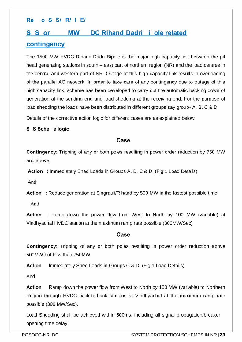
POSOCO-NRLDC SYSTEM PROTECTION SCHEMES IN NR |23
Ref No: SPS/NR/LINE/04
SPS for 1500 MW HVDC Rihand-Dadri bipole related
contingency
The 1500 MW HVDC Rihand-Dadri Bipole is the major high capacity link between the pit
head generating stations in south – east part of northern region (NR) and the load centres in
the central and western part of NR. Outage of this high capacity link results in overloading
of the parallel AC network. In order to take care of any contingency due to outage of this
high capacity link, scheme has been developed to carry out the automatic backing down of
generation at the sending end and load shedding at the receiving end. For the purpose of
load shedding the loads have been distributed in different groups say group- A, B, C & D.
Details of the corrective action logic for different cases are as explained below.
SPS Scheme logic:
Case-1
Contingency: Tripping of any or both poles resulting in power order reduction by 750 MW
and above.
Action 1: Immediately Shed Loads in Groups A, B, C & D. (Fig 1 Load Details)
And
Action 2: Reduce generation at Singrauli/Rihand by 500 MW in the fastest possible time
And
Action 3: Ramp down the power flow from West to North by 100 MW (variable) at
Vindhyachal HVDC station at the maximum ramp rate possible (300MW/Sec)
Case-2
Contingency: Tripping of any or both poles resulting in power order reduction above
500MW but less than 750MW
Action 1: Immediately Shed Loads in Groups C & D. (Fig 1 Load Details)
And
Action 2: Ramp down the power flow from West to North by 100 MW (variable) to Northern
Region through HVDC back-to-back stations at Vindhyachal at the maximum ramp rate
possible (300 MW/Sec).
Load Shedding shall be achieved within 500ms, including all signal propagation/breaker
opening time delay
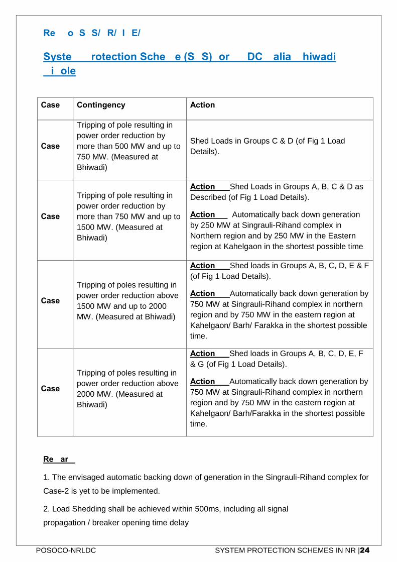
POSOCO-NRLDC SYSTEM PROTECTION SCHEMES IN NR |24
Ref No: SPS/NR/LINE/05
System Protection Scheme (SPS) for HVDC Balia-Bhiwadi
Bipole
Case Contingency Action
Case-1
Tripping of pole resulting in
power order reduction by
more than 500 MW and up to
750 MW. (Measured at
Bhiwadi)
Shed Loads in Groups C & D (of Fig 1 Load
Details).
Case-2
Tripping of pole resulting in
power order reduction by
more than 750 MW and up to
1500 MW. (Measured at
Bhiwadi)
Action-1:- Shed Loads in Groups A, B, C & D as
Described (of Fig 1 Load Details).
Action-2:- Automatically back down generation
by 250 MW at Singrauli-Rihand complex in
Northern region and by 250 MW in the Eastern
region at Kahelgaon in the shortest possible time
Case-3
Tripping of poles resulting in
power order reduction above
1500 MW and up to 2000
MW. (Measured at Bhiwadi)
Action-1:- Shed loads in Groups A, B, C, D, E & F
(of Fig 1 Load Details).
Action-2:- Automatically back down generation by
750 MW at Singrauli-Rihand complex in northern
region and by 750 MW in the eastern region at
Kahelgaon/ Barh/ Farakka in the shortest possible
time.
Case-4
Tripping of poles resulting in
power order reduction above
2000 MW. (Measured at
Bhiwadi)
Action 1:- Shed loads in Groups A, B, C, D, E, F
& G (of Fig 1 Load Details).
Action 2:- Automatically back down generation by
750 MW at Singrauli-Rihand complex in northern
region and by 750 MW in the eastern region at
Kahelgaon/ Barh/Farakka in the shortest possible
time.
Remark:
1. The envisaged automatic backing down of generation in the Singrauli-Rihand complex for
Case-2 is yet to be implemented.
2. Load Shedding shall be achieved within 500ms, including all signal
propagation / breaker opening time delay
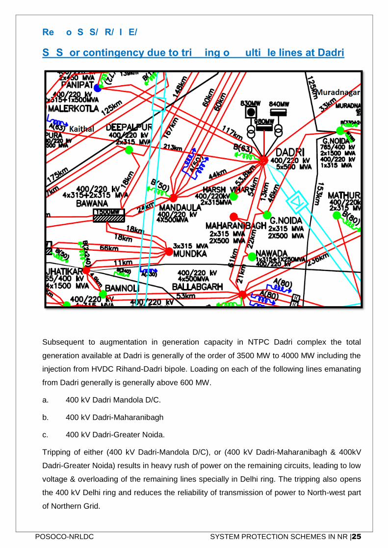
POSOCO-NRLDC SYSTEM PROTECTION SCHEMES IN NR |25
Ref No: SPS/NR/LINE/06
SPS for contingency due to tripping of multiple lines at Dadri
Subsequent to augmentation in generation capacity in NTPC Dadri complex the total
generation available at Dadri is generally of the order of 3500 MW to 4000 MW including the
injection from HVDC Rihand-Dadri bipole. Loading on each of the following lines emanating
from Dadri generally is generally above 600 MW.
a. 400 kV Dadri Mandola D/C.
b. 400 kV Dadri-Maharanibagh
c. 400 kV Dadri-Greater Noida.
Tripping of either (400 kV Dadri-Mandola D/C), or (400 kV Dadri-Maharanibagh & 400kV
Dadri-Greater Noida) results in heavy rush of power on the remaining circuits, leading to low
voltage & overloading of the remaining lines specially in Delhi ring. The tripping also opens
the 400 kV Delhi ring and reduces the reliability of transmission of power to North-west part
of Northern Grid.

POSOCO-NRLDC SYSTEM PROTECTION SCHEMES IN NR |26
SPS Scheme logic:
Contingency: Tripping of either (400 kV Dadri-Mandola D/C), or (400 kV Dadri-
Maharanibagh and 400 kV Dadri-Greater Noida), while each sets of circuits carrying more
than 1500MW either towards Mandola or towards Ballabhgarh.
Action 1: Shed Loads at 400 kV Mandola (200 MW) and 400 kV Greater Noida (200
MW). (Load Shedding shall be achieved within 500ms, including all signal
propagation/breaker opening time delay.)
And
Action 2: Automatically back down generation at Dadri by 400 MW (200MW at Stage-1
and 200MW at Stage-2) in the shortest possible time.
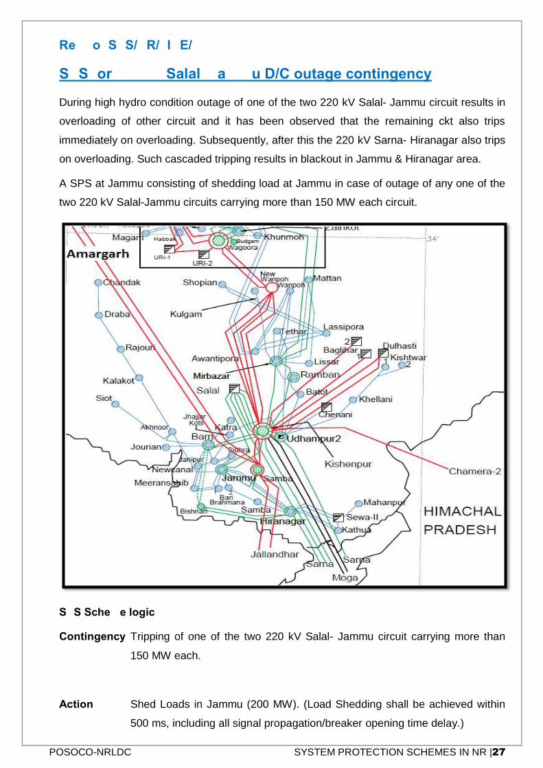
POSOCO-NRLDC SYSTEM PROTECTION SCHEMES IN NR |27
Ref No: SPS/NR/LINE/07
SPS for 220 kV Salal- Jammu D/C outage contingency
During high hydro condition outage of one of the two 220 kV Salal- Jammu circuit results in
overloading of other circuit and it has been observed that the remaining ckt also trips
immediately on overloading. Subsequently, after this the 220 kV Sarna- Hiranagar also trips
on overloading. Such cascaded tripping results in blackout in Jammu & Hiranagar area.
A SPS at Jammu consisting of shedding load at Jammu in case of outage of any one of the
two 220 kV Salal-Jammu circuits carrying more than 150 MW each circuit.
SPS Scheme logic:
Contingency: Tripping of one of the two 220 kV Salal- Jammu circuit carrying more than
150 MW each.
Action 1: Shed Loads in Jammu (200 MW). (Load Shedding shall be achieved within
500 ms, including all signal propagation/breaker opening time delay.)
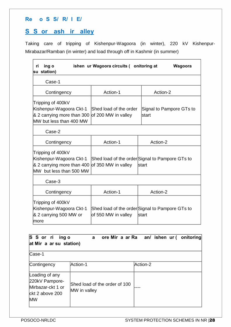
POSOCO-NRLDC SYSTEM PROTECTION SCHEMES IN NR |28
Ref No: SPS/NR/LINE/08
SPS for Kashmir Valley
Taking care of tripping of Kishenpur-Wagoora (in winter), 220 kV Kishenpur-
Mirabazar/Ramban (in winter) and load through off in Kashmir (in summer)
Tripping of 400kV Kishenpur-Wagoora circuits (monitoring at 400 kV Wagoora
substation)
Case-1
Contingency Action-1 Action-2
Tripping of 400kV
Kishenpur-Wagoora Ckt-1
& 2 carrying more than 300
MW but less than 400 MW
Shed load of the order
of 200 MW in valley
Signal to Pampore GTs to
start
Case-2
Contingency Action-1 Action-2
Tripping of 400kV
Kishenpur-Wagoora Ckt-1
& 2 carrying more than 400
MW but less than 500 MW
Shed load of the order
of 350 MW in valley
Signal to Pampore GTs to
start
Case-3
Contingency Action-1 Action-2
Tripping of 400kV
Kishenpur-Wagoora Ckt-1
& 2 carrying 500 MW or
more
Shed load of the order
of 550 MW in valley
Signal to Pampore GTs to
start
SPS for Tripping of 220 kV Pampore-Mirbazar-Ramban/Kishenpur (monitoring
at Mirbazar substation)
Case-1
Contingency Action-1 Action-2
Loading of any
220kV Pampore-
Mirbazar-ckt 1 or
ckt 2 above 200
MW
Shed load of the order of 100
MW in valley ----
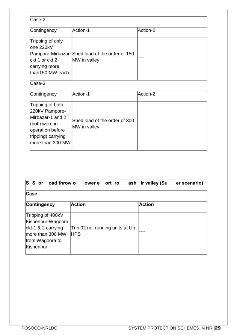
POSOCO-NRLDC SYSTEM PROTECTION SCHEMES IN NR |29
Case-2
Contingency Action-1 Action-2
Tripping of only
one 220kV
Pampore-Mirbazar-
ckt 1 or ckt 2
carrying more
than150 MW each
Shed load of the order of 150
MW in valley ----
Case-3
Contingency Action-1 Action-2
Tripping of both
220kV Pampore-
Mirbazar-1 and 2
(both were in
operation before
tripping) carrying
more than 300 MW
Shed load of the order of 300
MW in valley ----
SPS for Load throw off, power export from Kashmir valley (Summer scenario)
Case-1
Contingency Action-1 Action-2
Tripping of 400kV
Kishenpur-Wagoora
ckt-1 & 2 carrying
more than 300 MW
from Wagoora to
Kishenpur
Trip 02 no. running units at Uri
HPS ----
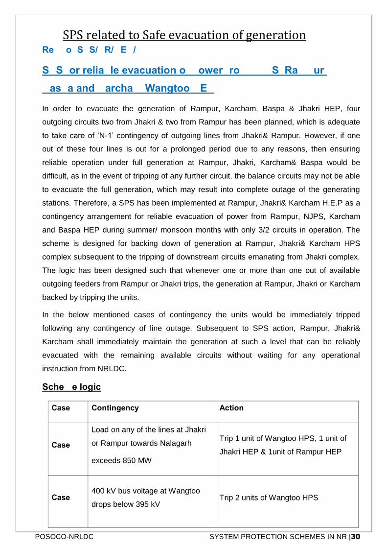
POSOCO-NRLDC SYSTEM PROTECTION SCHEMES IN NR |30
SPS related to Safe evacuation of generation Ref No: SPS/NR/GEN/01
SPS for reliable evacuation of power from NJPS, Rampur,
Baspa and Karcham Wangtoo HEP
In order to evacuate the generation of Rampur, Karcham, Baspa & Jhakri HEP, four
outgoing circuits two from Jhakri & two from Rampur has been planned, which is adequate
to take care of ‘N-1’ contingency of outgoing lines from Jhakri& Rampur. However, if one
out of these four lines is out for a prolonged period due to any reasons, then ensuring
reliable operation under full generation at Rampur, Jhakri, Karcham& Baspa would be
difficult, as in the event of tripping of any further circuit, the balance circuits may not be able
to evacuate the full generation, which may result into complete outage of the generating
stations. Therefore, a SPS has been implemented at Rampur, Jhakri& Karcham H.E.P as a
contingency arrangement for reliable evacuation of power from Rampur, NJPS, Karcham
and Baspa HEP during summer/ monsoon months with only 3/2 circuits in operation. The
scheme is designed for backing down of generation at Rampur, Jhakri& Karcham HPS
complex subsequent to the tripping of downstream circuits emanating from Jhakri complex.
The logic has been designed such that whenever one or more than one out of available
outgoing feeders from Rampur or Jhakri trips, the generation at Rampur, Jhakri or Karcham
backed by tripping the units.
In the below mentioned cases of contingency the units would be immediately tripped
following any contingency of line outage. Subsequent to SPS action, Rampur, Jhakri&
Karcham shall immediately maintain the generation at such a level that can be reliably
evacuated with the remaining available circuits without waiting for any operational
instruction from NRLDC.
Scheme logic
Case Contingency Action
Case-1
Load on any of the lines at Jhakri
or Rampur towards Nalagarh
exceeds 850 MW
Trip 1 unit of Wangtoo HPS, 1 unit of
Jhakri HEP & 1unit of Rampur HEP
Case-2
400 kV bus voltage at Wangtoo
drops below 395 kV Trip 2 units of Wangtoo HPS
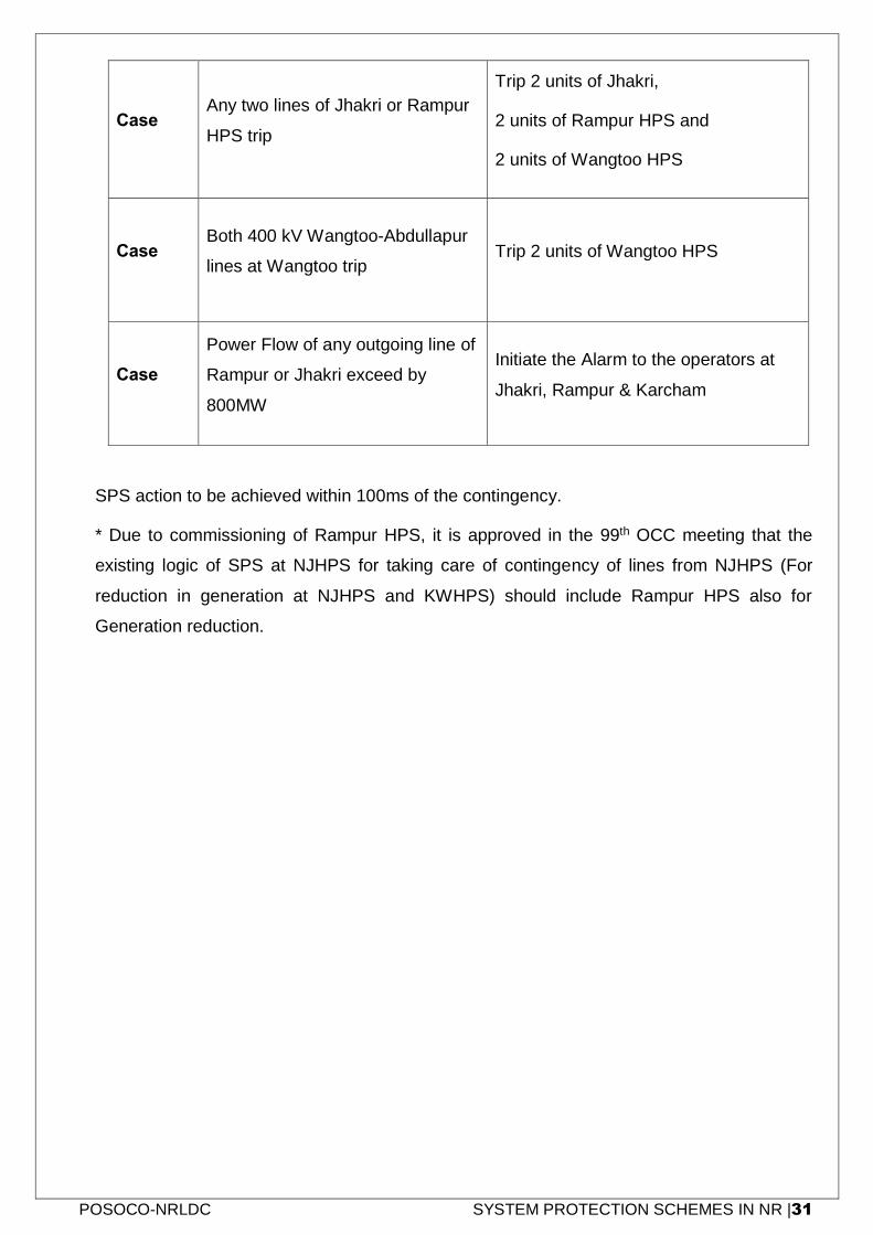
POSOCO-NRLDC SYSTEM PROTECTION SCHEMES IN NR |31
Case-3
Any two lines of Jhakri or Rampur
HPS trip
Trip 2 units of Jhakri,
2 units of Rampur HPS and
2 units of Wangtoo HPS
Case-4
Both 400 kV Wangtoo-Abdullapur
lines at Wangtoo trip Trip 2 units of Wangtoo HPS
Case-5
Power Flow of any outgoing line of
Rampur or Jhakri exceed by
800MW
Initiate the Alarm to the operators at
Jhakri, Rampur & Karcham
SPS action to be achieved within 100ms of the contingency.
* Due to commissioning of Rampur HPS, it is approved in the 99th OCC meeting that the
existing logic of SPS at NJHPS for taking care of contingency of lines from NJHPS (For
reduction in generation at NJHPS and KWHPS) should include Rampur HPS also for
Generation reduction.
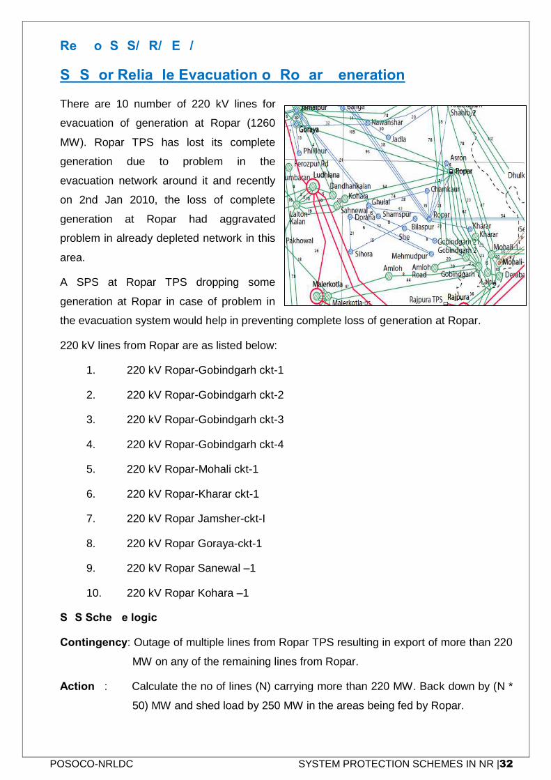
POSOCO-NRLDC SYSTEM PROTECTION SCHEMES IN NR |32
Ref No: SPS/NR/GEN/02
SPS for Reliable Evacuation of Ropar Generation
There are 10 number of 220 kV lines for
evacuation of generation at Ropar (1260
MW). Ropar TPS has lost its complete
generation due to problem in the
evacuation network around it and recently
on 2nd Jan 2010, the loss of complete
generation at Ropar had aggravated
problem in already depleted network in this
area.
A SPS at Ropar TPS dropping some
generation at Ropar in case of problem in
the evacuation system would help in preventing complete loss of generation at Ropar.
220 kV lines from Ropar are as listed below:
1. 220 kV Ropar-Gobindgarh ckt-1
2. 220 kV Ropar-Gobindgarh ckt-2
3. 220 kV Ropar-Gobindgarh ckt-3
4. 220 kV Ropar-Gobindgarh ckt-4
5. 220 kV Ropar-Mohali ckt-1
6. 220 kV Ropar-Kharar ckt-1
7. 220 kV Ropar Jamsher-ckt-I
8. 220 kV Ropar Goraya-ckt-1
9. 220 kV Ropar Sanewal –1
10. 220 kV Ropar Kohara –1
SPS Scheme logic:
Contingency: Outage of multiple lines from Ropar TPS resulting in export of more than 220
MW on any of the remaining lines from Ropar.
Action 1: Calculate the no of lines (N) carrying more than 220 MW. Back down by (N *
50) MW and shed load by 250 MW in the areas being fed by Ropar.
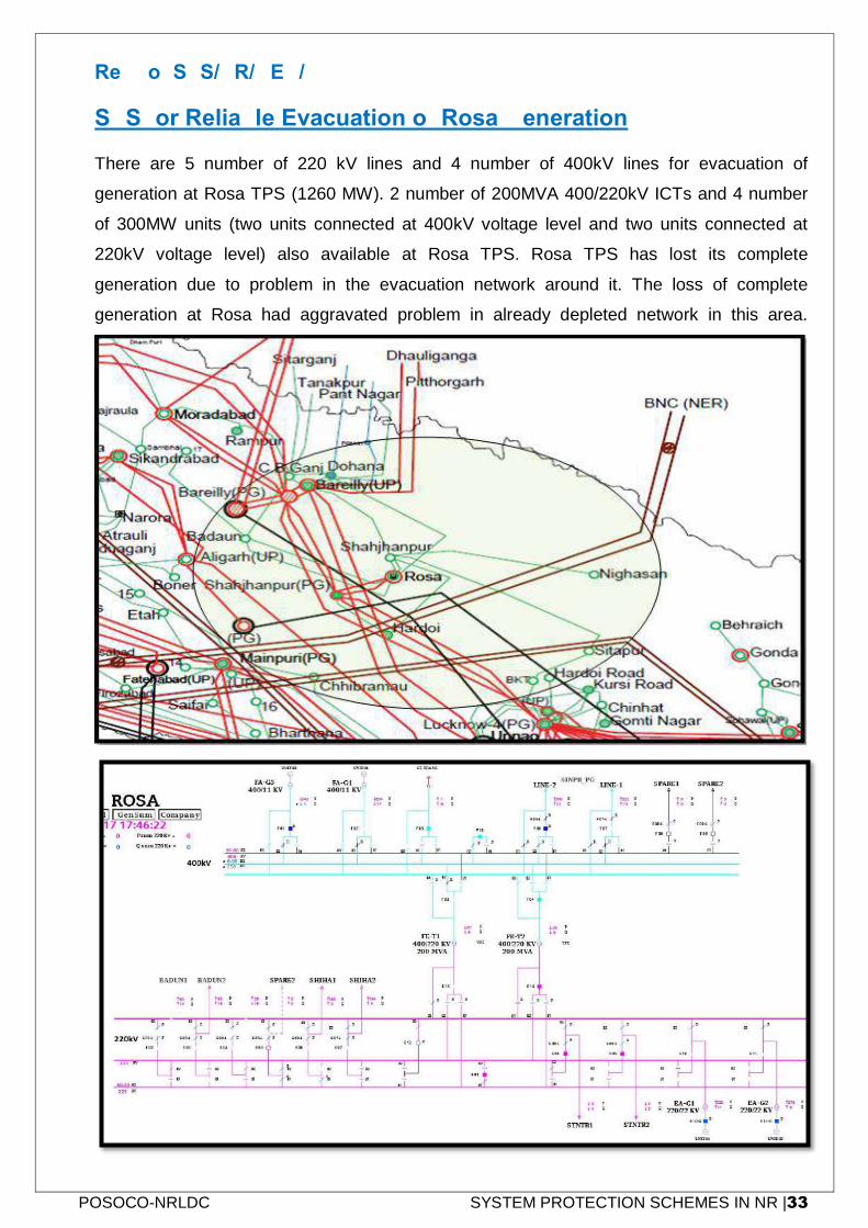
POSOCO-NRLDC SYSTEM PROTECTION SCHEMES IN NR |33
Ref No: SPS/NR/GEN/03
SPS for Reliable Evacuation of Rosa Generation
There are 5 number of 220 kV lines and 4 number of 400kV lines for evacuation of
generation at Rosa TPS (1260 MW). 2 number of 200MVA 400/220kV ICTs and 4 number
of 300MW units (two units connected at 400kV voltage level and two units connected at
220kV voltage level) also available at Rosa TPS. Rosa TPS has lost its complete
generation due to problem in the evacuation network around it. The loss of complete
generation at Rosa had aggravated problem in already depleted network in this area.
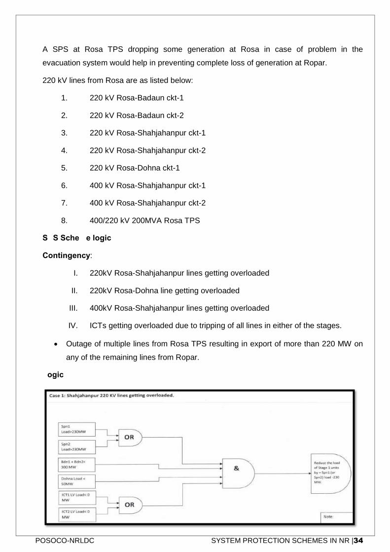
POSOCO-NRLDC SYSTEM PROTECTION SCHEMES IN NR |34
A SPS at Rosa TPS dropping some generation at Rosa in case of problem in the
evacuation system would help in preventing complete loss of generation at Ropar.
220 kV lines from Rosa are as listed below:
1. 220 kV Rosa-Badaun ckt-1
2. 220 kV Rosa-Badaun ckt-2
3. 220 kV Rosa-Shahjahanpur ckt-1
4. 220 kV Rosa-Shahjahanpur ckt-2
5. 220 kV Rosa-Dohna ckt-1
6. 400 kV Rosa-Shahjahanpur ckt-1
7. 400 kV Rosa-Shahjahanpur ckt-2
8. 400/220 kV 200MVA Rosa TPS
SPS Scheme logic:
Contingency:
I. 220kV Rosa-Shahjahanpur lines getting overloaded
II. 220kV Rosa-Dohna line getting overloaded
III. 400kV Rosa-Shahjahanpur lines getting overloaded
IV. ICTs getting overloaded due to tripping of all lines in either of the stages.
Outage of multiple lines from Rosa TPS resulting in export of more than 220 MW on
any of the remaining lines from Ropar.
Logic:
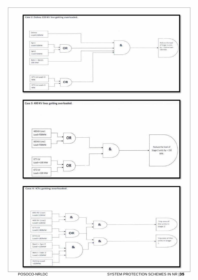
POSOCO-NRLDC SYSTEM PROTECTION SCHEMES IN NR |35
POSOCO-NRLDC SYSTEM PROTECTION SCHEMES IN NR |36
Action 1:
I. Reduce the load of stage-1 units: 220kV Rosa-Shahjahanpur ckt-1 (or ckt-2) -
230MW.
II. Reduce the load of stage-1 units: 220kV Rosa-Dohna ckt -230MW.
III. Reduce the load of stage-2 units: 150MW
IV. Trip one unit either at stage-1 or at stage-2 depends on over loading of ICTs
from 400kV side or 220kV side
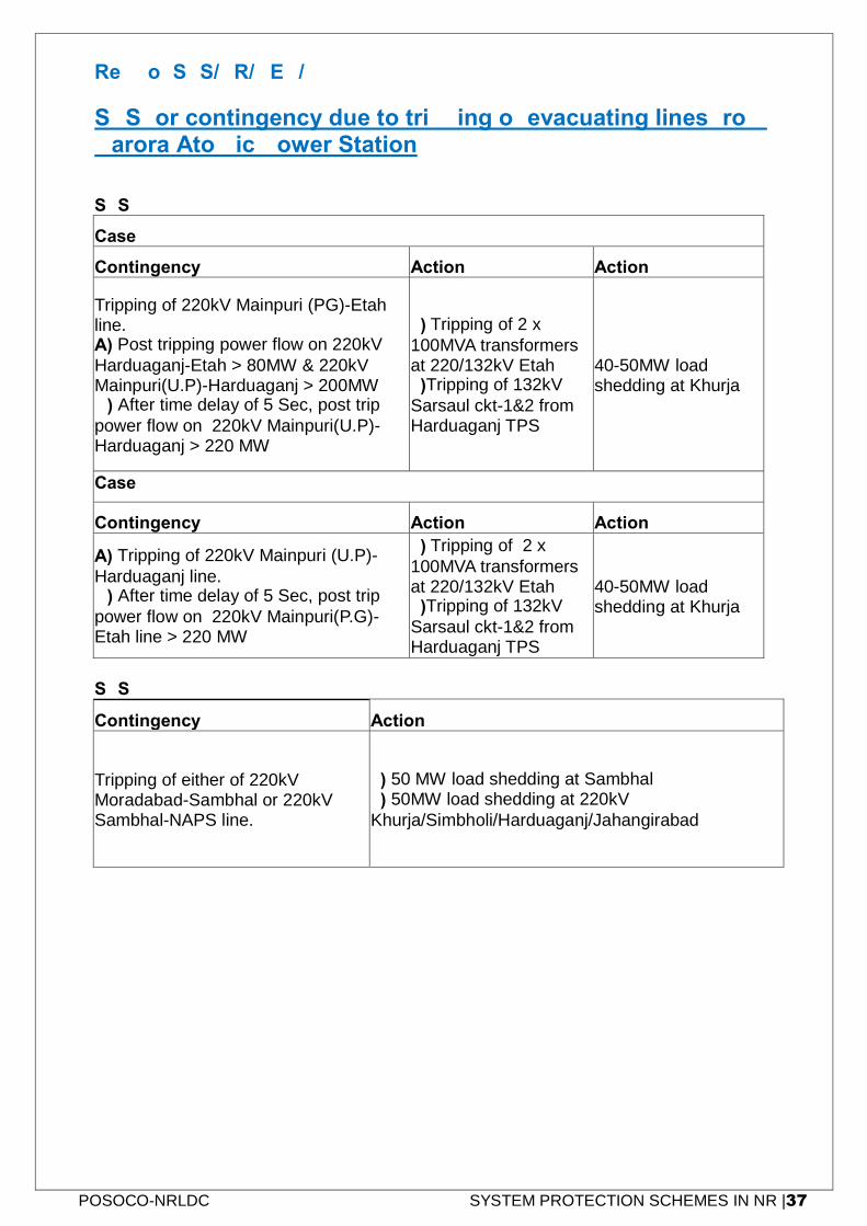
POSOCO-NRLDC SYSTEM PROTECTION SCHEMES IN NR |37
Ref No: SPS/NR/GEN/04
SPS for contingency due to tripping of evacuating lines from Narora Atomic Power Station
SPS 1
Case-1
Contingency Action - 1 Action-2
Tripping of 220kV Mainpuri (PG)-Etah line. A) Post tripping power flow on 220kV
Harduaganj-Etah > 80MW & 220kV Mainpuri(U.P)-Harduaganj > 200MW B) After time delay of 5 Sec, post trip
power flow on 220kV Mainpuri(U.P)-Harduaganj > 220 MW
1) Tripping of 2 x
100MVA transformers at 220/132kV Etah 2)Tripping of 132kV
Sarsaul ckt-1&2 from Harduaganj TPS
40-50MW load shedding at Khurja
Case-2
Contingency Action - 1 Action-2
A) Tripping of 220kV Mainpuri (U.P)-
Harduaganj line. B) After time delay of 5 Sec, post trip
power flow on 220kV Mainpuri(P.G)-Etah line > 220 MW
1) Tripping of 2 x
100MVA transformers at 220/132kV Etah 2)Tripping of 132kV
Sarsaul ckt-1&2 from Harduaganj TPS
40-50MW load shedding at Khurja
SPS 2
Contingency Action
Tripping of either of 220kV Moradabad-Sambhal or 220kV Sambhal-NAPS line.
1) 50 MW load shedding at Sambhal
2) 50MW load shedding at 220kV
Khurja/Simbholi/Harduaganj/Jahangirabad
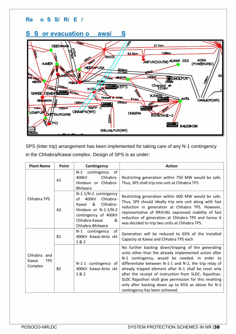
POSOCO-NRLDC SYSTEM PROTECTION SCHEMES IN NR |38
Ref No: SPS/NR/GEN/05
SPS for evacuation of Kawai TPS
SPS (Inter trip) arrangement has been implemented for taking care of any N-1 contingency
in the Chhabra/Kawai complex. Design of SPS is as under:
Plant Name Point Contingency Action
Chhabra TPS
A1
N-1 contingency of 400kV Chhabra-Hindaun or Chhabra-Bhilwara
Restricting generation within 750 MW would be safe. Thus, SPS shall trip one unit at Chhabra TPS
A2
N-1-1/N-2 contingency of 400kV Chhabra-Kawai & Chhabra-Hindaun or N-1-1/N-2 contingency of 400kV Chhabra-Kawai & Chhabra-Bhilwara
Restricting generation within 600 MW would be safe. Thus, SPS should ideally trip one unit along with fast reduction in generation at Chhabra TPS. However, representative of RRVUNL expressed inability of fast reduction of generation at Chhabra TPS and hence it was decided to trip two units at Chhabra TPS.
Chhabra and Kawai TPS Complex
B1 N-1 contingency of 400kV Kawai-Anta ckt 1 & 2
Generation will be reduced to 65% of the Installed Capacity at Kawai and Chhabra TPS each
B2 N-1-1 contingency of 400kV Kawai-Anta ckt 1 & 2
No further backing down/tripping of the generating units other than the already implemented action after N-1 contingency, would be needed. In order to differentiate between N-1-1 and N-2, the trip relay of already tripped element after N-1 shall be reset only after the receipt of instruction from SLDC, Rajasthan. SLDC Rajasthan shall give permission for this resetting only after backing down up to 65% as above for N-1 contingency has been achieved.
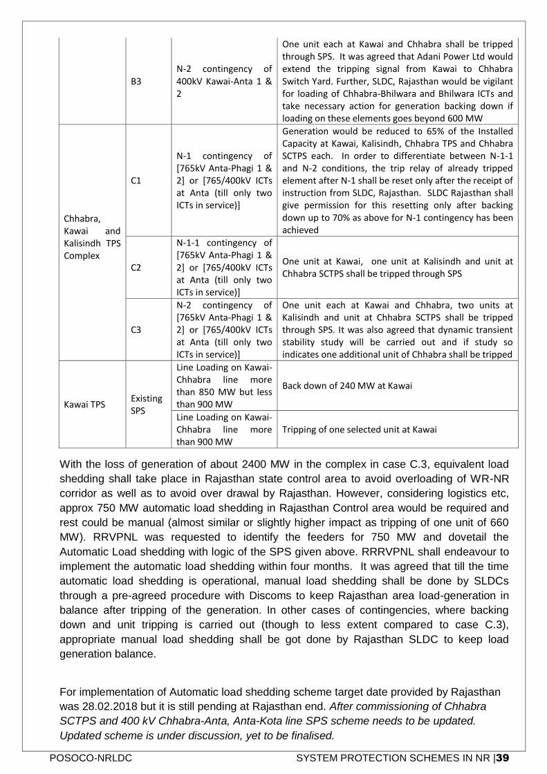
POSOCO-NRLDC SYSTEM PROTECTION SCHEMES IN NR |39
B3 N-2 contingency of 400kV Kawai-Anta 1 & 2
One unit each at Kawai and Chhabra shall be tripped through SPS. It was agreed that Adani Power Ltd would extend the tripping signal from Kawai to Chhabra Switch Yard. Further, SLDC, Rajasthan would be vigilant for loading of Chhabra-Bhilwara and Bhilwara ICTs and take necessary action for generation backing down if loading on these elements goes beyond 600 MW
Chhabra, Kawai and Kalisindh TPS Complex
C1
N-1 contingency of [765kV Anta-Phagi 1 & 2] or [765/400kV ICTs at Anta (till only two ICTs in service)]
Generation would be reduced to 65% of the Installed Capacity at Kawai, Kalisindh, Chhabra TPS and Chhabra SCTPS each. In order to differentiate between N-1-1 and N-2 conditions, the trip relay of already tripped element after N-1 shall be reset only after the receipt of instruction from SLDC, Rajasthan. SLDC Rajasthan shall give permission for this resetting only after backing down up to 70% as above for N-1 contingency has been achieved
C2
N-1-1 contingency of [765kV Anta-Phagi 1 & 2] or [765/400kV ICTs at Anta (till only two ICTs in service)]
One unit at Kawai, one unit at Kalisindh and unit at Chhabra SCTPS shall be tripped through SPS
C3
N-2 contingency of [765kV Anta-Phagi 1 & 2] or [765/400kV ICTs at Anta (till only two ICTs in service)]
One unit each at Kawai and Chhabra, two units at Kalisindh and unit at Chhabra SCTPS shall be tripped through SPS. It was also agreed that dynamic transient stability study will be carried out and if study so indicates one additional unit of Chhabra shall be tripped
Kawai TPS Existing SPS
Line Loading on Kawai-Chhabra line more than 850 MW but less than 900 MW
Back down of 240 MW at Kawai
Line Loading on Kawai-Chhabra line more than 900 MW
Tripping of one selected unit at Kawai
With the loss of generation of about 2400 MW in the complex in case C.3, equivalent load
shedding shall take place in Rajasthan state control area to avoid overloading of WR-NR
corridor as well as to avoid over drawal by Rajasthan. However, considering logistics etc,
approx 750 MW automatic load shedding in Rajasthan Control area would be required and
rest could be manual (almost similar or slightly higher impact as tripping of one unit of 660
MW). RRVPNL was requested to identify the feeders for 750 MW and dovetail the
Automatic Load shedding with logic of the SPS given above. RRRVPNL shall endeavour to
implement the automatic load shedding within four months. It was agreed that till the time
automatic load shedding is operational, manual load shedding shall be done by SLDCs
through a pre-agreed procedure with Discoms to keep Rajasthan area load-generation in
balance after tripping of the generation. In other cases of contingencies, where backing
down and unit tripping is carried out (though to less extent compared to case C.3),
appropriate manual load shedding shall be got done by Rajasthan SLDC to keep load
generation balance.
For implementation of Automatic load shedding scheme target date provided by Rajasthan
was 28.02.2018 but it is still pending at Rajasthan end. After commissioning of Chhabra
SCTPS and 400 kV Chhabra-Anta, Anta-Kota line SPS scheme needs to be updated.
Updated scheme is under discussion, yet to be finalised.
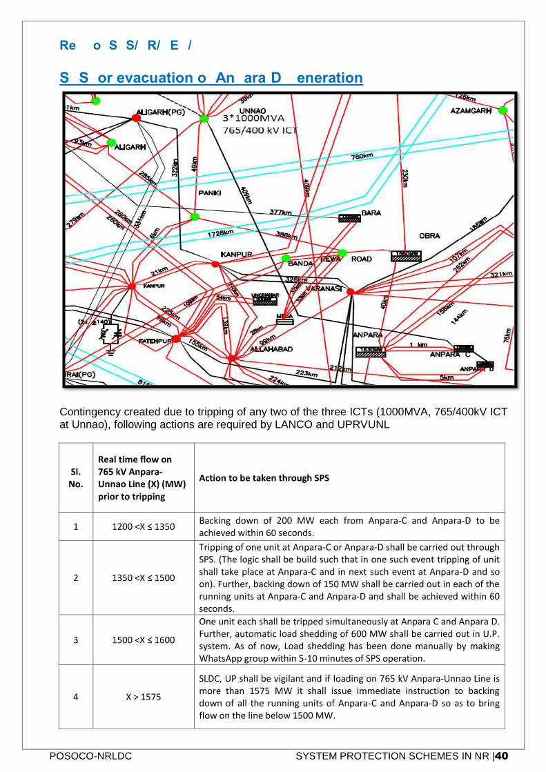
POSOCO-NRLDC SYSTEM PROTECTION SCHEMES IN NR |40
Ref No: SPS/NR/GEN/06
SPS for evacuation of Anpara-D Generation
Contingency created due to tripping of any two of the three ICTs (1000MVA, 765/400kV ICT at Unnao), following actions are required by LANCO and UPRVUNL
Sl. No.
Real time flow on 765 kV Anpara-Unnao Line (X) (MW) prior to tripping
Action to be taken through SPS
1 1200 <X ≤ 1350 Backing down of 200 MW each from Anpara-C and Anpara-D to be achieved within 60 seconds.
2 1350 <X ≤ 1500
Tripping of one unit at Anpara-C or Anpara-D shall be carried out through SPS. (The logic shall be build such that in one such event tripping of unit shall take place at Anpara-C and in next such event at Anpara-D and so on). Further, backing down of 150 MW shall be carried out in each of the running units at Anpara-C and Anpara-D and shall be achieved within 60 seconds.
3 1500 <X ≤ 1600
One unit each shall be tripped simultaneously at Anpara C and Anpara D. Further, automatic load shedding of 600 MW shall be carried out in U.P. system. As of now, Load shedding has been done manually by making WhatsApp group within 5-10 minutes of SPS operation.
4 X > 1575
SLDC, UP shall be vigilant and if loading on 765 kV Anpara-Unnao Line is more than 1575 MW it shall issue immediate instruction to backing down of all the running units of Anpara-C and Anpara-D so as to bring flow on the line below 1500 MW.
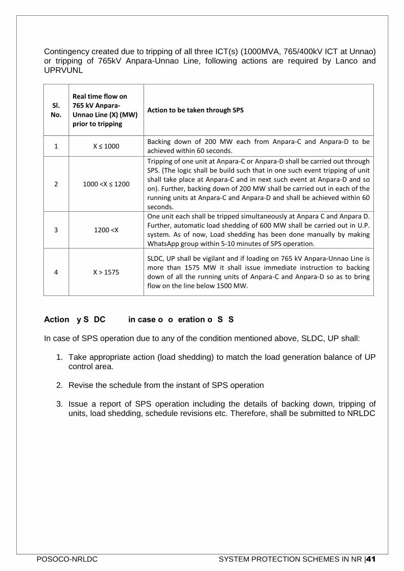
POSOCO-NRLDC SYSTEM PROTECTION SCHEMES IN NR |41
Contingency created due to tripping of all three ICT(s) (1000MVA, 765/400kV ICT at Unnao) or tripping of 765kV Anpara-Unnao Line, following actions are required by Lanco and UPRVUNL
Sl. No.
Real time flow on 765 kV Anpara-Unnao Line (X) (MW) prior to tripping
Action to be taken through SPS
1 X ≤ 1000 Backing down of 200 MW each from Anpara-C and Anpara-D to be achieved within 60 seconds.
2 1000 <X ≤ 1200
Tripping of one unit at Anpara-C or Anpara-D shall be carried out through SPS. (The logic shall be build such that in one such event tripping of unit shall take place at Anpara-C and in next such event at Anpara-D and so on). Further, backing down of 200 MW shall be carried out in each of the running units at Anpara-C and Anpara-D and shall be achieved within 60 seconds.
3 1200 <X
One unit each shall be tripped simultaneously at Anpara C and Anpara D. Further, automatic load shedding of 600 MW shall be carried out in U.P. system. As of now, Load shedding has been done manually by making WhatsApp group within 5-10 minutes of SPS operation.
4 X > 1575
SLDC, UP shall be vigilant and if loading on 765 kV Anpara-Unnao Line is more than 1575 MW it shall issue immediate instruction to backing down of all the running units of Anpara-C and Anpara-D so as to bring flow on the line below 1500 MW.
Action by SLDC, U.P. in case of operation of SPS In case of SPS operation due to any of the condition mentioned above, SLDC, UP shall:
1. Take appropriate action (load shedding) to match the load generation balance of UP control area.
2. Revise the schedule from the instant of SPS operation
3. Issue a report of SPS operation including the details of backing down, tripping of units, load shedding, schedule revisions etc. Therefore, shall be submitted to NRLDC
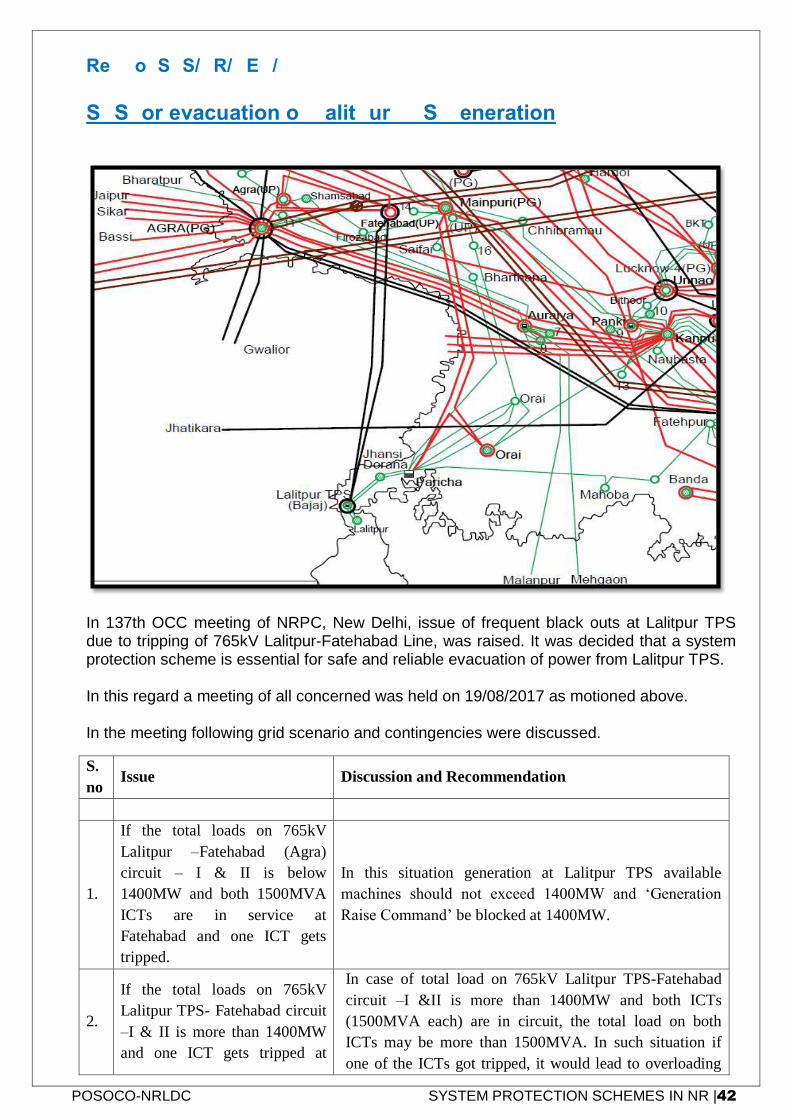
POSOCO-NRLDC SYSTEM PROTECTION SCHEMES IN NR |42
Ref No: SPS/NR/GEN/07
SPS for evacuation of Lalitpur TPS Generation
In 137th OCC meeting of NRPC, New Delhi, issue of frequent black outs at Lalitpur TPS due to tripping of 765kV Lalitpur-Fatehabad Line, was raised. It was decided that a system protection scheme is essential for safe and reliable evacuation of power from Lalitpur TPS. In this regard a meeting of all concerned was held on 19/08/2017 as motioned above. In the meeting following grid scenario and contingencies were discussed.
S.
no Issue Discussion and Recommendation
1.
If the total loads on 765kV
Lalitpur –Fatehabad (Agra)
circuit – I & II is below
1400MW and both 1500MVA
ICTs are in service at
Fatehabad and one ICT gets
tripped.
In this situation generation at Lalitpur TPS available
machines should not exceed 1400MW and ‘Generation
Raise Command’ be blocked at 1400MW.
2.
If the total loads on 765kV
Lalitpur TPS- Fatehabad circuit
–I & II is more than 1400MW
and one ICT gets tripped at
In case of total load on 765kV Lalitpur TPS-Fatehabad
circuit –I &II is more than 1400MW and both ICTs
(1500MVA each) are in circuit, the total load on both
ICTs may be more than 1500MVA. In such situation if
one of the ICTs got tripped, it would lead to overloading
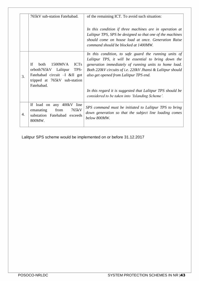
POSOCO-NRLDC SYSTEM PROTECTION SCHEMES IN NR |43
765kV sub-station Fatehabad. of the remaining ICT. To avoid such situation:
In this condition if three machines are in operation at
Lalitpur TPS, SPS be designed so that one of the machines
should come on house load at once. Generation Raise
command should be blocked at 1400MW.
3.
If both 1500MVA ICTs
orboth765kV Lalitpur TPS-
Fatehabad circuit –I &II got
tripped at 765kV sub-station
Fatehabad.
In this condition, to safe guard the running units of
Lalitpur TPS, it will be essential to bring down the
generation immediately of running units to home load.
Both 220kV circuits of i.e. 220kV Jhansi & Lalitpur should
also get opened from Lalitpur TPS end.
In this regard it is suggested that Lalitpur TPS should be
considered to be taken into ‘Islanding Scheme’.
4.
If load on any 400kV line
emanating from 765kV
substation Fatehabad exceeds
800MW.
SPS command must be initiated to Lalitpur TPS to bring
down generation so that the subject line loading comes
below 800MW.
Lalitpur SPS scheme would be implemented on or before 31.12.2017
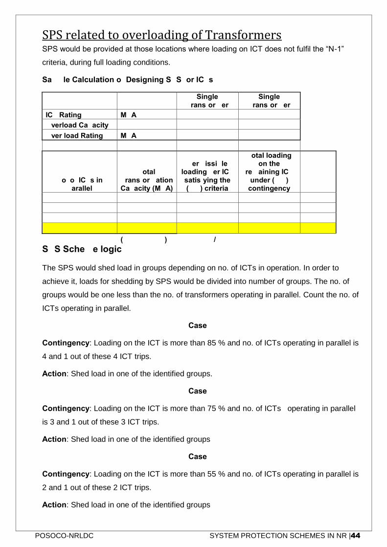
POSOCO-NRLDC SYSTEM PROTECTION SCHEMES IN NR |44
SPS related to overloading of Transformers
SPS would be provided at those locations where loading on ICT does not fulfil the “N-1”
criteria, during full loading conditions.
Sample Calculation of Designing SPS for ICTs
Single
Transformer Single
Transformer
ICT Rating MVA 315 240
Overload Capacity % 10 10
Over load Rating MVA 347 264
No. of ICTs in Parallel
Total Transformation Capacity (MVA)
Permissible loading per ICT satisfying the (N-1) criteria
Total loading on the
remaining ICT under (N-1)
contingency
2 630 174 347 55.08%
3 945 231 694 73.44%
4 1260 260 1041 82.62%
3 795 176 528 55.87%
(2*240+1*315) 264*2/3
SPS Scheme logic:
The SPS would shed load in groups depending on no. of ICTs in operation. In order to
achieve it, loads for shedding by SPS would be divided into number of groups. The no. of
groups would be one less than the no. of transformers operating in parallel. Count the no. of
ICTs operating in parallel.
Case-1
Contingency: Loading on the ICT is more than 85 % and no. of ICTs operating in parallel is
4 and 1 out of these 4 ICT trips.
Action: Shed load in one of the identified groups.
Case-2
Contingency: Loading on the ICT is more than 75 % and no. of ICTs operating in parallel
is 3 and 1 out of these 3 ICT trips.
Action: Shed load in one of the identified groups
Case-3
Contingency: Loading on the ICT is more than 55 % and no. of ICTs operating in parallel is
2 and 1 out of these 2 ICT trips.
Action: Shed load in one of the identified groups
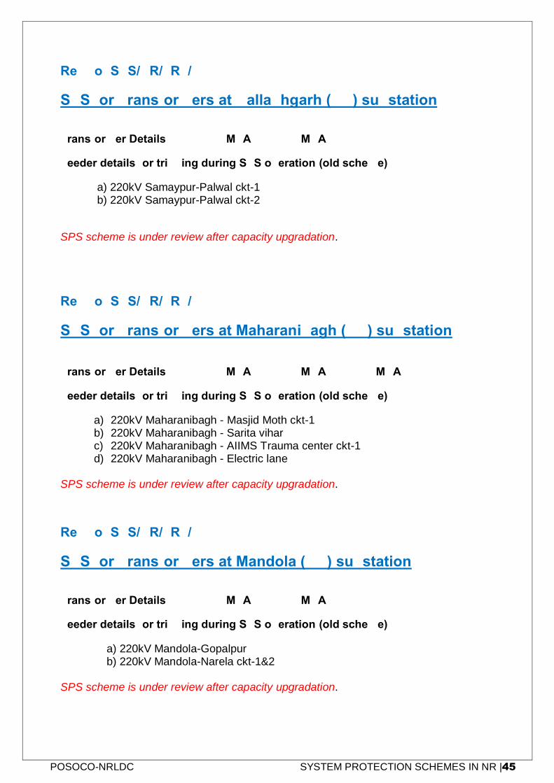
POSOCO-NRLDC SYSTEM PROTECTION SCHEMES IN NR |45
Ref No: SPS/NR/TRF/01
SPS for Transformers at Ballabhgarh (PG) substation
Transformer Details: - 4 x 500 MVA = 2000 MVA
Feeder details for tripping during SPS operation (old scheme)
a) 220kV Samaypur-Palwal ckt-1 b) 220kV Samaypur-Palwal ckt-2
SPS scheme is under review after capacity upgradation.
Ref No: SPS/NR/TRF/02
SPS for Transformers at Maharanibagh (PG) substation
Transformer Details: - 2 x 315 MVA+ 2 x 500 MVA = 1630 MVA
Feeder details for tripping during SPS operation (old scheme)
a) 220kV Maharanibagh - Masjid Moth ckt-1 b) 220kV Maharanibagh - Sarita vihar c) 220kV Maharanibagh - AIIMS Trauma center ckt-1 d) 220kV Maharanibagh - Electric lane
SPS scheme is under review after capacity upgradation.
Ref No: SPS/NR/TRF/03
SPS for Transformers at Mandola (PG) substation
Transformer Details: - 4 x 500 MVA = 2000 MVA
Feeder details for tripping during SPS operation (old scheme)
a) 220kV Mandola-Gopalpur b) 220kV Mandola-Narela ckt-1&2
SPS scheme is under review after capacity upgradation.
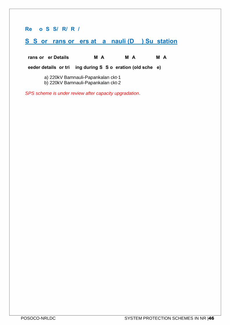
POSOCO-NRLDC SYSTEM PROTECTION SCHEMES IN NR |46
Ref No: SPS/NR/TRF/04
SPS for Transformers at Bamnauli (DTL) Substation
Transformer Details: - 2 x 315 MVA+ 2 x 500 MVA = 1630 MVA
Feeder details for tripping during SPS operation (old scheme)
a) 220kV Bamnauli-Papankalan ckt-1 b) 220kV Bamnauli-Papankalan ckt-2
SPS scheme is under review after capacity upgradation.
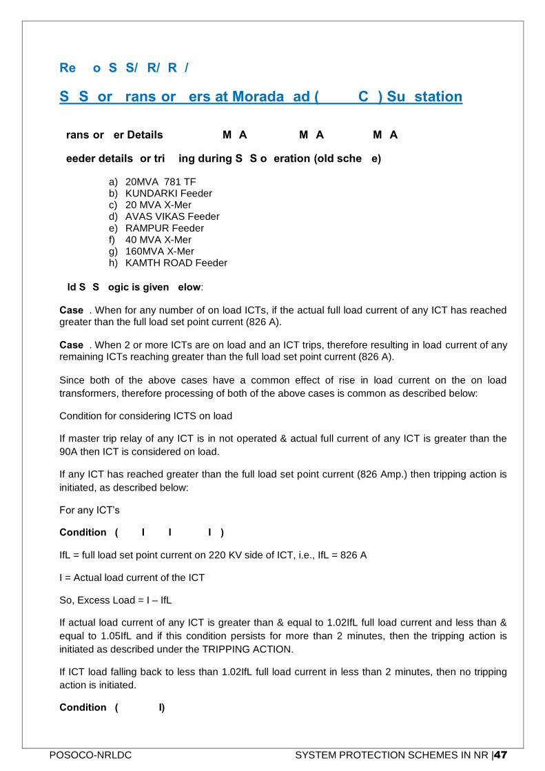
POSOCO-NRLDC SYSTEM PROTECTION SCHEMES IN NR |47
Ref No: SPS/NR/TRF/06
SPS for Transformers at Moradabad (UPPTCL) Substation
Transformer Details: - 2 x 500 MVA + 1 x 240 MVA = 1240 MVA
Feeder details for tripping during SPS operation (old scheme)
a) 20MVA 781 TF b) KUNDARKI Feeder c) 20 MVA X-Mer d) AVAS VIKAS Feeder e) RAMPUR Feeder f) 40 MVA X-Mer g) 160MVA X-Mer h) KAMTH ROAD Feeder
Old SPS Logic is given below: Case1. When for any number of on load ICTs, if the actual full load current of any ICT has reached greater than the full load set point current (826 A). Case2. When 2 or more ICTs are on load and an ICT trips, therefore resulting in load current of any remaining ICTs reaching greater than the full load set point current (826 A).
Since both of the above cases have a common effect of rise in load current on the on load
transformers, therefore processing of both of the above cases is common as described below:
Condition for considering ICTS on load
If master trip relay of any ICT is in not operated & actual full current of any ICT is greater than the
90A then ICT is considered on load.
If any ICT has reached greater than the full load set point current (826 Amp.) then tripping action is
initiated, as described below:
For any ICT’s
Condition1 (1.02*IfL<= I <= 1.05IfL)
IfL = full load set point current on 220 KV side of ICT, i.e., IfL = 826 A
I = Actual load current of the ICT
So, Excess Load = I – IfL
If actual load current of any ICT is greater than & equal to 1.02IfL full load current and less than &
equal to 1.05IfL and if this condition persists for more than 2 minutes, then the tripping action is
initiated as described under the TRIPPING ACTION.
If ICT load falling back to less than 1.02IfL full load current in less than 2 minutes, then no tripping
action is initiated.
Condition2 (1.05fL > I)
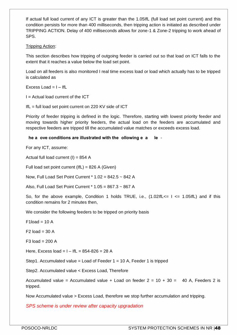
POSOCO-NRLDC SYSTEM PROTECTION SCHEMES IN NR |48
If actual full load current of any ICT is greater than the 1.05IfL (full load set point current) and this
condition persists for more than 400 milliseconds, then tripping action is initiated as described under
TRIPPING ACTION. Delay of 400 milliseconds allows for zone-1 & Zone-2 tripping to work ahead of
SPS.
Tripping Action:
This section describes how tripping of outgoing feeder is carried out so that load on ICT falls to the
extent that it reaches a value below the load set point.
Load on all feeders is also monitored I real time excess load or load which actually has to be tripped
is calculated as
Excess Load = I – IfL
I = Actual load current of the ICT
IfL = full load set point current on 220 KV side of ICT
Priority of feeder tripping is defined in the logic. Therefore, starting with lowest priority feeder and
moving towards higher priority feeders, the actual load on the feeders are accumulated and
respective feeders are tripped till the accumulated value matches or exceeds excess load.
The above conditions are illustrated with the following example: -
For any ICT, assume:
Actual full load current (I) = 854 A
Full load set point current (IfL) = 826 A (Given)
Now, Full Load Set Point Current * 1.02 = 842.5 ~ 842 A
Also, Full Load Set Point Current * 1.05 = 867.3 ~ 867 A
So, for the above example, Condition 1 holds TRUE, i.e., (1.02IfL<= I <= 1.05IfL) and if this
condition remains for 2 minutes then,
We consider the following feeders to be tripped on priority basis
F1load = 10 A
F2 load = 30 A
F3 load = 200 A
Here, Excess load = I – IfL = 854-826 = 28 A
Step1. Accumulated value = Load of Feeder 1 = 10 A, Feeder 1 is tripped
Step2. Accumulated value < Excess Load, Therefore
Accumulated value = Accumulated value + Load on feeder 2 = 10 + 30 = 40 A, Feeders 2 is
tripped.
Now Accumulated value > Excess Load, therefore we stop further accumulation and tripping.
SPS scheme is under review after capacity upgradation
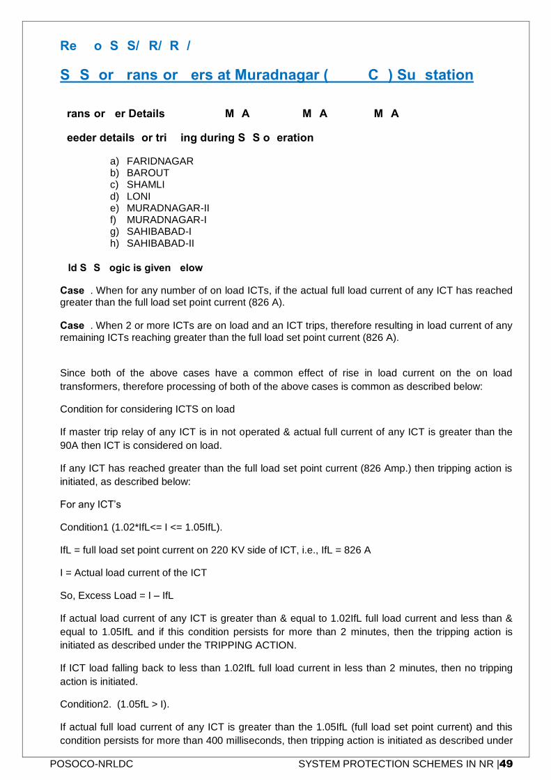
POSOCO-NRLDC SYSTEM PROTECTION SCHEMES IN NR |49
Ref No: SPS/NR/TRF/07
SPS for Transformers at Muradnagar (UPPTCL) Substation
Transformer Details: - 2 x 315 MVA + 1 x 500 MVA = 1130 MVA
Feeder details for tripping during SPS operation
a) FARIDNAGAR b) BAROUT c) SHAMLI d) LONI e) MURADNAGAR-II f) MURADNAGAR-I g) SAHIBABAD-I h) SAHIBABAD-II
Old SPS Logic is given below
Case1. When for any number of on load ICTs, if the actual full load current of any ICT has reached greater than the full load set point current (826 A). Case2. When 2 or more ICTs are on load and an ICT trips, therefore resulting in load current of any
remaining ICTs reaching greater than the full load set point current (826 A).
Since both of the above cases have a common effect of rise in load current on the on load
transformers, therefore processing of both of the above cases is common as described below:
Condition for considering ICTS on load
If master trip relay of any ICT is in not operated & actual full current of any ICT is greater than the
90A then ICT is considered on load.
If any ICT has reached greater than the full load set point current (826 Amp.) then tripping action is
initiated, as described below:
For any ICT’s
Condition1 (1.02*IfL<= I <= 1.05IfL).
IfL = full load set point current on 220 KV side of ICT, i.e., IfL = 826 A
I = Actual load current of the ICT
So, Excess Load = I – IfL
If actual load current of any ICT is greater than & equal to 1.02IfL full load current and less than &
equal to 1.05IfL and if this condition persists for more than 2 minutes, then the tripping action is
initiated as described under the TRIPPING ACTION.
If ICT load falling back to less than 1.02IfL full load current in less than 2 minutes, then no tripping
action is initiated.
Condition2. (1.05fL > I).
If actual full load current of any ICT is greater than the 1.05IfL (full load set point current) and this
condition persists for more than 400 milliseconds, then tripping action is initiated as described under
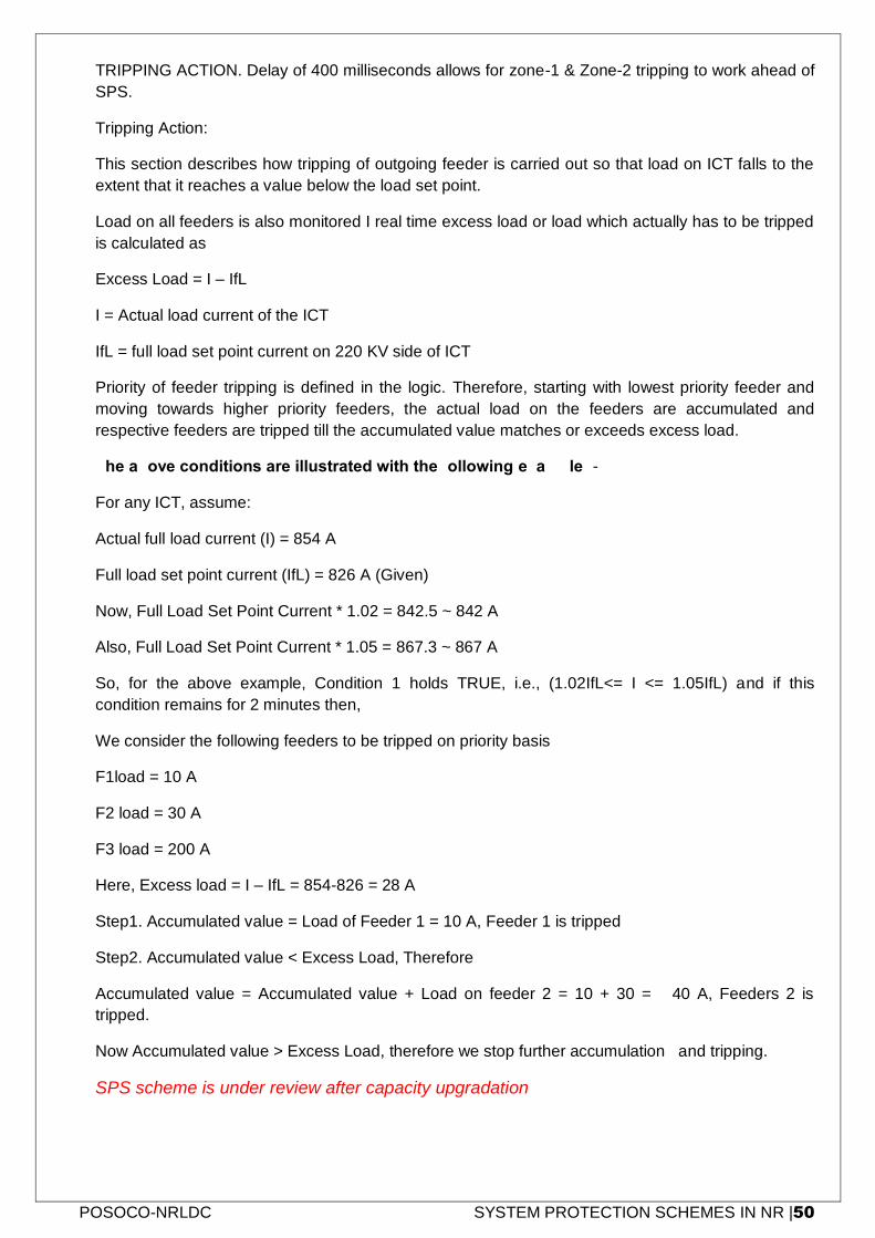
POSOCO-NRLDC SYSTEM PROTECTION SCHEMES IN NR |50
TRIPPING ACTION. Delay of 400 milliseconds allows for zone-1 & Zone-2 tripping to work ahead of
SPS.
Tripping Action:
This section describes how tripping of outgoing feeder is carried out so that load on ICT falls to the
extent that it reaches a value below the load set point.
Load on all feeders is also monitored I real time excess load or load which actually has to be tripped
is calculated as
Excess Load = I – IfL
I = Actual load current of the ICT
IfL = full load set point current on 220 KV side of ICT
Priority of feeder tripping is defined in the logic. Therefore, starting with lowest priority feeder and
moving towards higher priority feeders, the actual load on the feeders are accumulated and
respective feeders are tripped till the accumulated value matches or exceeds excess load.
The above conditions are illustrated with the following example: -
For any ICT, assume:
Actual full load current (I) = 854 A
Full load set point current (IfL) = 826 A (Given)
Now, Full Load Set Point Current * 1.02 = 842.5 ~ 842 A
Also, Full Load Set Point Current * 1.05 = 867.3 ~ 867 A
So, for the above example, Condition 1 holds TRUE, i.e., (1.02IfL<= I <= 1.05IfL) and if this
condition remains for 2 minutes then,
We consider the following feeders to be tripped on priority basis
F1load = 10 A
F2 load = 30 A
F3 load = 200 A
Here, Excess load = I – IfL = 854-826 = 28 A
Step1. Accumulated value = Load of Feeder 1 = 10 A, Feeder 1 is tripped
Step2. Accumulated value < Excess Load, Therefore
Accumulated value = Accumulated value + Load on feeder 2 = 10 + 30 = 40 A, Feeders 2 is
tripped.
Now Accumulated value > Excess Load, therefore we stop further accumulation and tripping.
SPS scheme is under review after capacity upgradation
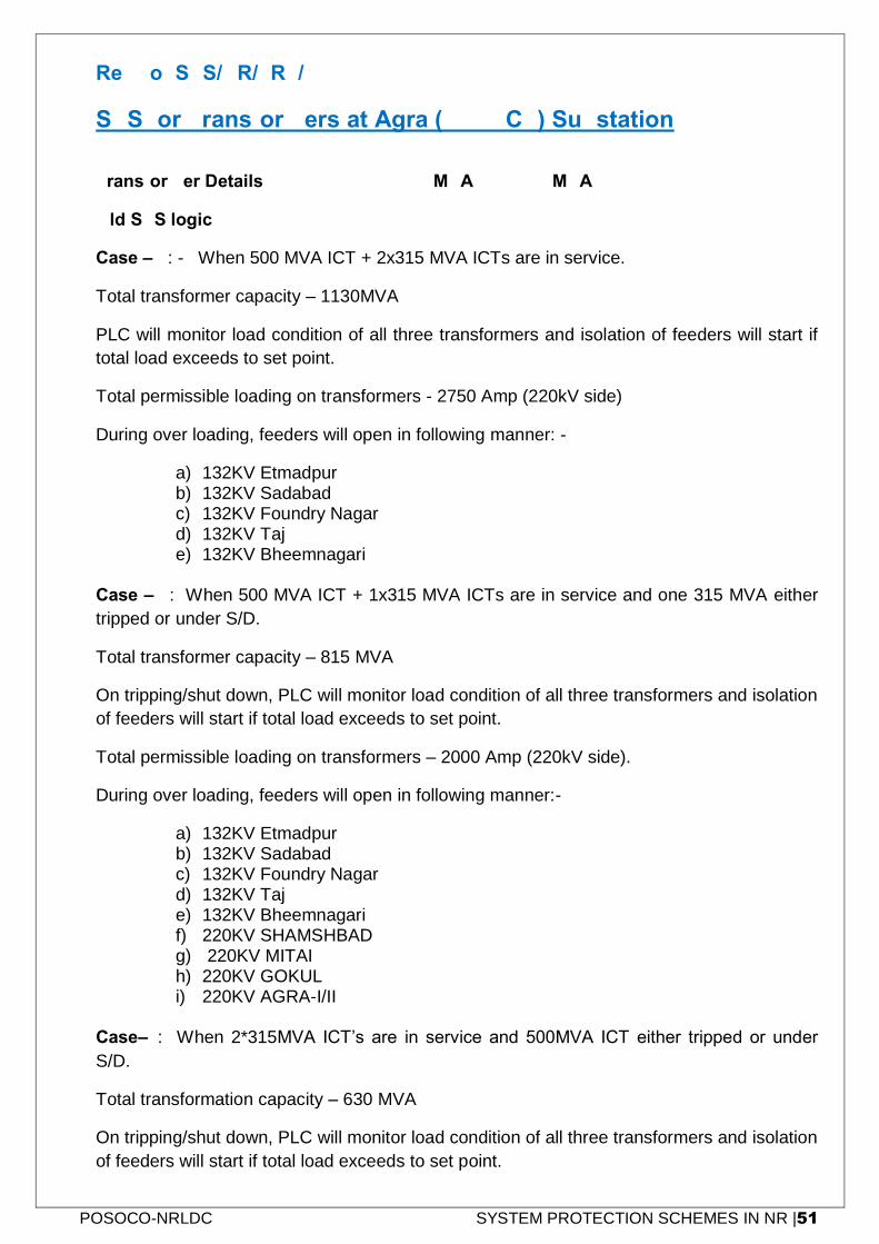
POSOCO-NRLDC SYSTEM PROTECTION SCHEMES IN NR |51
Ref No: SPS/NR/TRF/08
SPS for Transformers at Agra (UPPTCL) Substation
Transformer Details: - 2 x 500 + 1 x 315 MVA = 1315 MVA
Old SPS logic-
Case – 1: - When 500 MVA ICT + 2x315 MVA ICTs are in service.
Total transformer capacity – 1130MVA
PLC will monitor load condition of all three transformers and isolation of feeders will start if
total load exceeds to set point.
Total permissible loading on transformers - 2750 Amp (220kV side)
During over loading, feeders will open in following manner: -
a) 132KV Etmadpur b) 132KV Sadabad c) 132KV Foundry Nagar d) 132KV Taj e) 132KV Bheemnagari
Case – 2: When 500 MVA ICT + 1x315 MVA ICTs are in service and one 315 MVA either
tripped or under S/D.
Total transformer capacity – 815 MVA
On tripping/shut down, PLC will monitor load condition of all three transformers and isolation
of feeders will start if total load exceeds to set point.
Total permissible loading on transformers – 2000 Amp (220kV side).
During over loading, feeders will open in following manner:-
a) 132KV Etmadpur b) 132KV Sadabad c) 132KV Foundry Nagar d) 132KV Taj e) 132KV Bheemnagari f) 220KV SHAMSHBAD g) 220KV MITAI h) 220KV GOKUL i) 220KV AGRA-I/II
Case–3: When 2*315MVA ICT’s are in service and 500MVA ICT either tripped or under
S/D.
Total transformation capacity – 630 MVA
On tripping/shut down, PLC will monitor load condition of all three transformers and isolation
of feeders will start if total load exceeds to set point.
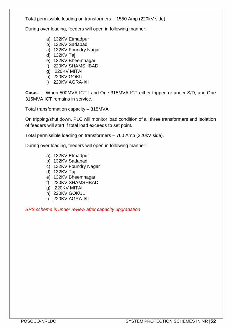
POSOCO-NRLDC SYSTEM PROTECTION SCHEMES IN NR |52
Total permissible loading on transformers – 1550 Amp (220kV side)
During over loading, feeders will open in following manner:-
a) 132KV Etmadpur b) 132KV Sadabad c) 132KV Foundry Nagar d) 132KV Taj e) 132KV Bheemnagari f) 220KV SHAMSHBAD g) 220KV MITAI h) 220KV GOKUL i) 220KV AGRA-I/II
Case–4: When 500MVA ICT-I and One 315MVA ICT either tripped or under S/D, and One
315MVA ICT remains in service.
Total transformation capacity – 315MVA
On tripping/shut down, PLC will monitor load condition of all three transformers and isolation
of feeders will start if total load exceeds to set point.
Total permissible loading on transformers – 760 Amp (220kV side).
During over loading, feeders will open in following manner:-
a) 132KV Etmadpur b) 132KV Sadabad c) 132KV Foundry Nagar d) 132KV Taj e) 132KV Bheemnagari f) 220KV SHAMSHBAD g) 220KV MITAI h) 220KV GOKUL i) 220KV AGRA-I/II
SPS scheme is under review after capacity upgradation
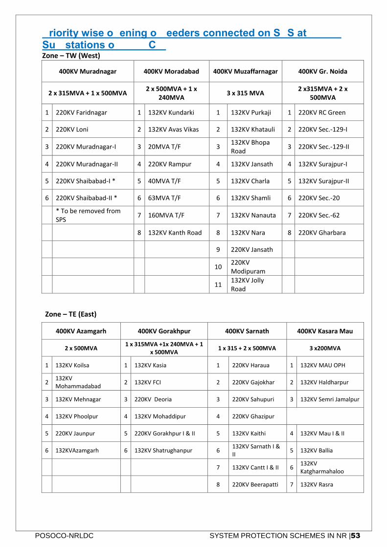
POSOCO-NRLDC SYSTEM PROTECTION SCHEMES IN NR |53
Priority wise opening of feeders connected on SPS at 400KV Sub-stations of UPPTCL: Zone – TW (West)
400KV Muradnagar 400KV Moradabad 400KV Muzaffarnagar 400KV Gr. Noida
2 x 315MVA + 1 x 500MVA 2 x 500MVA + 1 x
240MVA 3 x 315 MVA
2 x315MVA + 2 x 500MVA
1 220KV Faridnagar 1 132KV Kundarki 1 132KV Purkaji 1 220KV RC Green
2 220KV Loni 2 132KV Avas Vikas 2 132KV Khatauli 2 220KV Sec.-129-I
3 220KV Muradnagar-I 3 20MVA T/F 3 132KV Bhopa Road
3 220KV Sec.-129-II
4 220KV Muradnagar-II 4 220KV Rampur 4 132KV Jansath 4 132KV Surajpur-I
5 220KV Shaibabad-I * 5 40MVA T/F 5 132KV Charla 5 132KV Surajpur-II
6 220KV Shaibabad-II * 6 63MVA T/F 6 132KV Shamli 6 220KV Sec.-20
* To be removed from SPS
7 160MVA T/F 7 132KV Nanauta 7 220KV Sec.-62
8 132KV Kanth Road 8 132KV Nara 8 220KV Gharbara
9 220KV Jansath
10 220KV Modipuram
11 132KV Jolly Road
Zone – TE (East) 400KV Azamgarh 400KV Gorakhpur 400KV Sarnath 400KV Kasara Mau
2 x 500MVA 1 x 315MVA +1x 240MVA + 1
x 500MVA 1 x 315 + 2 x 500MVA 3 x200MVA
1 132KV Koilsa 1 132KV Kasia 1 220KV Haraua 1 132KV MAU OPH
2 132KV Mohammadabad
2 132KV FCI 2 220KV Gajokhar 2 132KV Haldharpur
3 132KV Mehnagar 3 220KV Deoria 3 220KV Sahupuri 3 132KV Semri Jamalpur
4 132KV Phoolpur 4 132KV Mohaddipur 4 220KV Ghazipur
5 220KV Jaunpur 5 220KV Gorakhpur I & II 5 132KV Kaithi 4 132KV Mau I & II
6 132KVAzamgarh 6 132KV Shatrughanpur 6 132KV Sarnath I & II
5 132KV Ballia
7 132KV Cantt I & II 6 132KV Katgharmahaloo
8 220KV Beerapatti 7 132KV Rasra
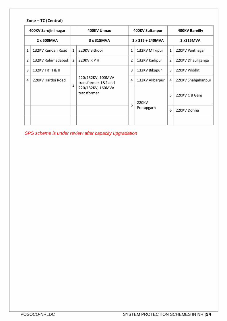
POSOCO-NRLDC SYSTEM PROTECTION SCHEMES IN NR |54
Zone – TC (Central) 400KV Sarojini nagar 400KV Unnao 400KV Sultanpur 400KV Bareilly
2 x 500MVA 3 x 315MVA 2 x 315 + 240MVA 3 x315MVA
1 132KV Kundan Road 1 220KV Bithoor 1 132KV Milkipur 1 220KV Pantnagar
2 132KV Rahimadabad 2 220KV R P H 2 132KV Kadipur 2 220KV Dhauliganga
3 132KV TRT I & II
3
220/132KV, 100MVA transformer-1&2 and 220/132KV, 160MVA transformer
3 132KV Bikapur 3 220KV Pilibhit
4 220KV Hardoi Road 4 132KV Akbarpur 4 220KV Shahjahanpur
5 220KV Pratapgarh
5 220KV C B Ganj
6 220KV Dohna
SPS scheme is under review after capacity upgradation
POSOCO-NRLDC SYSTEM PROTECTION SCHEMES IN NR |55
5. Northern Regional Grid SPS Operation Monitoring Format
SPS are deployed to preserve the integrity of the electric system. SPS consists of three main parts:
1. The input which is the level of physical magnitudes & status of circuits breakers,
2. Decision making system which initiate some actions based on inputs &
3. Output which may be generator tripping/ back down or load tripping.
Based on the level of physical magnitudes & status of circuits breakers system operators / load
dispatch engineers can find out whether the condition for enabling the operation of SPS protection
occurred or not. Once it is certified that condition for operation of SPS have prevailed, then SPS
should initiate control as per the prevailing condition.
In order to assess the performance of SPS, information regarding initiation of control as well as
execution of control both are required. As the components of SPS are widely spread over a large
geographical area under the ownership of different agencies, following three formats have been
designed in which the concerned agencies would supply information.
1. SPS Monitoring Format- 1
This is the format for collecting information from the agency having the SPS logic controller.
Information in this format would ascertain whether SPS has operated and generated the
control action or not.
2. SPS monitoring Format- 2
This is the format for collecting information from agencies executing the control action in
the form of load shedding.
3. SPS Monitoring Format -3
This is the format for collecting information from agencies executing the control action in
the form of generation backing down.
Depending on the prevailing condition during the contingency enabling SPS operation, control
action would be generated which may be either load shedding only or both load shedding and
generation backing down.
In order to assess the performance of SPS operation it is desired that for all the SPS operation
information is collected in all the above three formats. Information in the above formats would be
forwarded to NRLDC whenever any SPS related action is reported irrespective of whether it was
desirable or not.
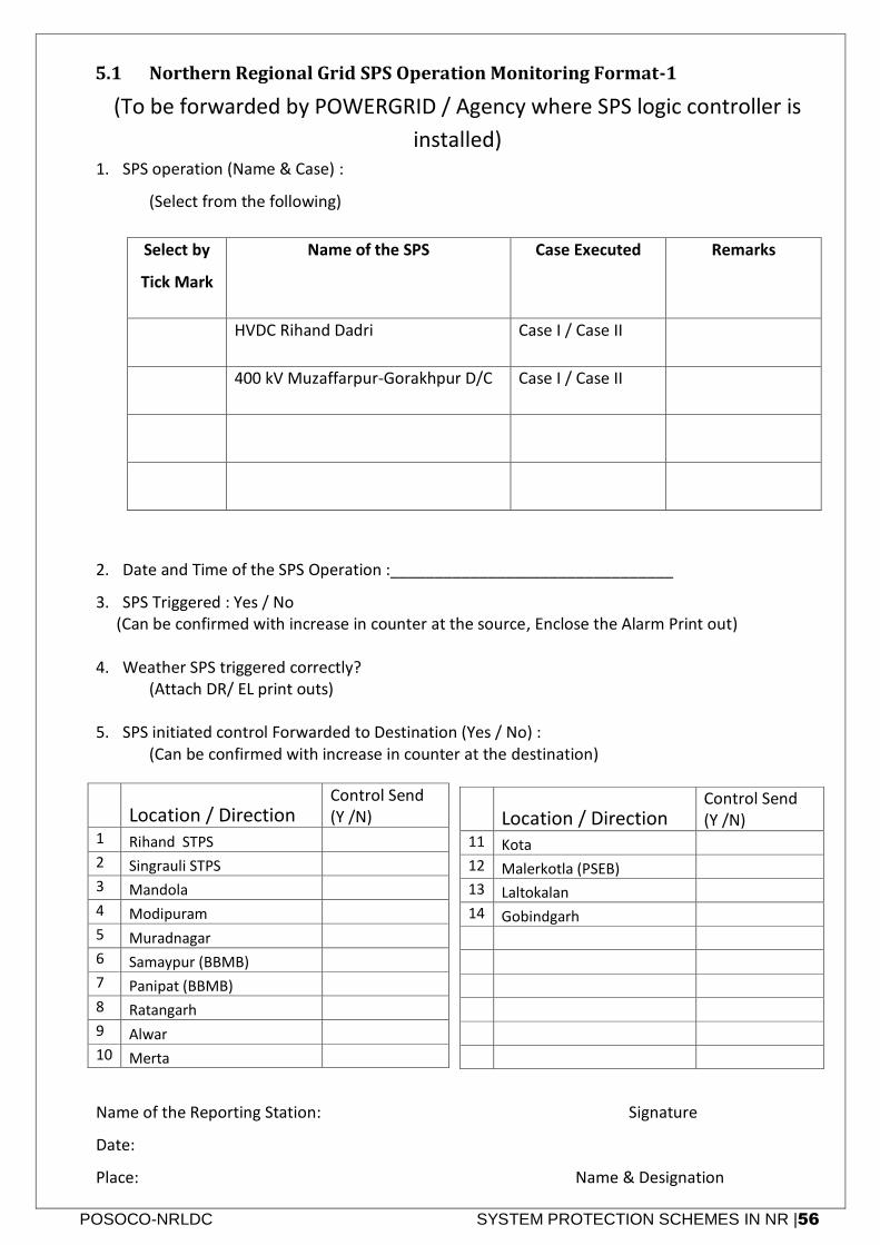
POSOCO-NRLDC SYSTEM PROTECTION SCHEMES IN NR |56
5.1 Northern Regional Grid SPS Operation Monitoring Format-1
(To be forwarded by POWERGRID / Agency where SPS logic controller is
installed) 1. SPS operation (Name & Case) :
(Select from the following)
Select by
Tick Mark
Name of the SPS Case Executed Remarks
HVDC Rihand Dadri Case I / Case II
400 kV Muzaffarpur-Gorakhpur D/C Case I / Case II
2. Date and Time of the SPS Operation :________________________________
3. SPS Triggered : Yes / No (Can be confirmed with increase in counter at the source, Enclose the Alarm Print out) 4. Weather SPS triggered correctly? (Attach DR/ EL print outs) 5. SPS initiated control Forwarded to Destination (Yes / No) : (Can be confirmed with increase in counter at the destination)
Name of the Reporting Station: Signature
Date:
Place: Name & Designation
Location / Direction
Control Send (Y /N)
1 Rihand STPS
2 Singrauli STPS
3 Mandola
4 Modipuram
5 Muradnagar
6 Samaypur (BBMB)
7 Panipat (BBMB)
8 Ratangarh
9 Alwar
10 Merta
Location / Direction
Control Send (Y /N)
11 Kota
12 Malerkotla (PSEB)
13 Laltokalan
14 Gobindgarh
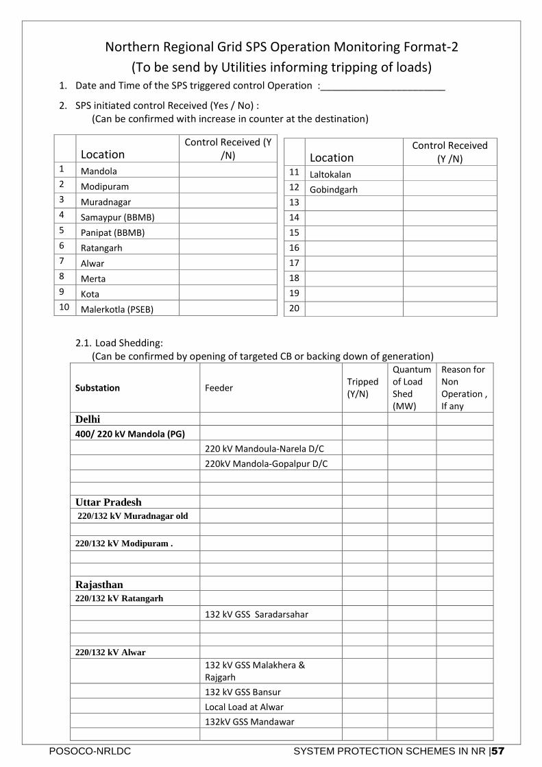
POSOCO-NRLDC SYSTEM PROTECTION SCHEMES IN NR |57
Northern Regional Grid SPS Operation Monitoring Format-2
(To be send by Utilities informing tripping of loads) 1. Date and Time of the SPS triggered control Operation :_______________________
2. SPS initiated control Received (Yes / No) : (Can be confirmed with increase in counter at the destination)
2.1. Load Shedding: (Can be confirmed by opening of targeted CB or backing down of generation)
Substation Feeder Tripped (Y/N)
Quantum of Load Shed (MW)
Reason for Non Operation , If any
Delhi
400/ 220 kV Mandola (PG)
220 kV Mandoula-Narela D/C
220kV Mandola-Gopalpur D/C
Uttar Pradesh
220/132 kV Muradnagar old
220/132 kV Modipuram .
Rajasthan
220/132 kV Ratangarh
132 kV GSS Saradarsahar
220/132 kV Alwar
132 kV GSS Malakhera & Rajgarh
132 kV GSS Bansur
Local Load at Alwar
132kV GSS Mandawar
Location
Control Received (Y /N)
1 Mandola
2 Modipuram
3 Muradnagar
4 Samaypur (BBMB)
5 Panipat (BBMB)
6 Ratangarh
7 Alwar
8 Merta
9 Kota
10 Malerkotla (PSEB)
Location
Control Received (Y /N)
11 Laltokalan
12 Gobindgarh
13
14
15
16
17
18
19
20
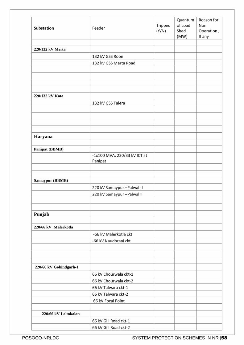
POSOCO-NRLDC SYSTEM PROTECTION SCHEMES IN NR |58
Substation Feeder Tripped (Y/N)
Quantum of Load Shed (MW)
Reason for Non Operation , If any
220/132 kV Merta
132 kV GSS Roon
132 kV GSS Merta Road
220/132 kV Kota
132 kV GSS Talera
Haryana
Panipat (BBMB)
-1x100 MVA, 220/33 kV ICT at Panipat
Samaypur (BBMB)
220 kV Samaypur –Palwal -I
220 kV Samaypur –Palwal II
Punjab
220/66 kV Malerkotla
-66 kV Malerkotla ckt
-66 kV Naudhrani ckt
220/66 kV Gobindgarh-1
66 kV Chourwala ckt-1
66 kV Chourwala ckt-2
66 kV Talwara ckt-1
66 kV Talwara ckt-2
66 kV Focal Point
220/66 kV Laltokalan
66 kV Gill Road ckt-1
66 kV Gill Road ckt-2
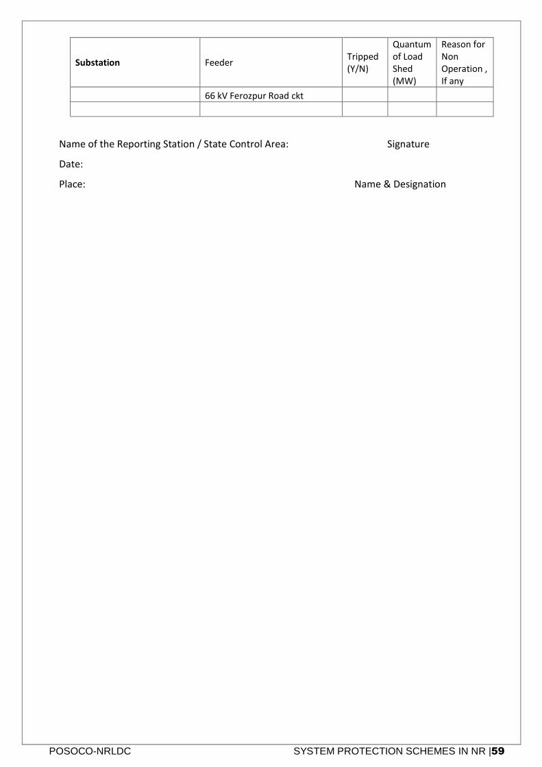
POSOCO-NRLDC SYSTEM PROTECTION SCHEMES IN NR |59
Substation Feeder Tripped (Y/N)
Quantum of Load Shed (MW)
Reason for Non Operation , If any
66 kV Ferozpur Road ckt
Name of the Reporting Station / State Control Area: Signature
Date:
Place: Name & Designation
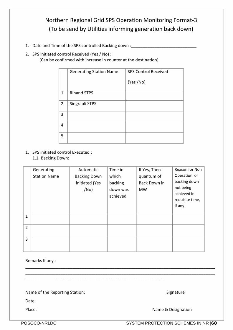
POSOCO-NRLDC SYSTEM PROTECTION SCHEMES IN NR |60
Northern Regional Grid SPS Operation Monitoring Format-3
(To be send by Utilities informing generation back down)
1. Date and Time of the SPS controlled Backing down :____________________________
2. SPS initiated control Received (Yes / No) : (Can be confirmed with increase in counter at the destination)
Generating Station Name SPS Control Received
(Yes /No)
1 Rihand STPS
2 Singrauli STPS
3
4
5
1. SPS initiated control Executed :
1.1. Backing Down:
Generating
Station Name
Automatic
Backing Down
initiated (Yes
/No)
Time in
which
backing
down was
achieved
If Yes, Then
quantum of
Back Down in
MW
Reason for Non
Operation or
backing down
not being
achieved in
requisite time,
If any
1
2
3
Remarks If any : _____________________________________________________________________________________________________________________________________________________________________________________________________________________________
Name of the Reporting Station: Signature
Date:
Place: Name & Designation
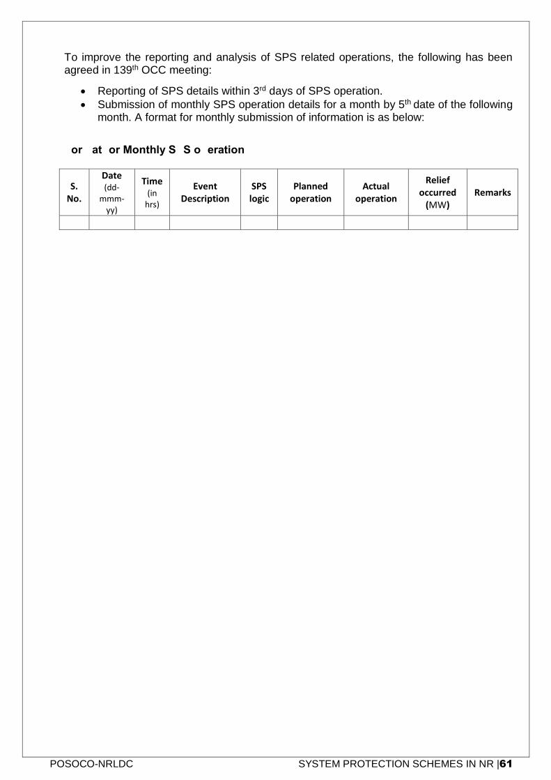
POSOCO-NRLDC SYSTEM PROTECTION SCHEMES IN NR |61
To improve the reporting and analysis of SPS related operations, the following has been agreed in 139th OCC meeting:
Reporting of SPS details within 3rd days of SPS operation.
Submission of monthly SPS operation details for a month by 5th date of the following month. A format for monthly submission of information is as below:
Format for Monthly SPS operation:
S. No.
Date (dd-
mmm-yy)
Time (in
hrs)
Event Description
SPS logic
Planned operation
Actual operation
Relief occurred
(MW) Remarks
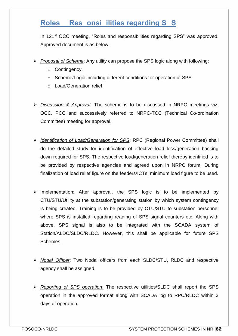
POSOCO-NRLDC SYSTEM PROTECTION SCHEMES IN NR |62
6. Roles & Responsibilities regarding SPS
In 121st OCC meeting, “Roles and responsibilities regarding SPS” was approved.
Approved document is as below:
Proposal of Scheme: Any utility can propose the SPS logic along with following:
o Contingency.
o Scheme/Logic including different conditions for operation of SPS
o Load/Generation relief.
Discussion & Approval: The scheme is to be discussed in NRPC meetings viz.
OCC, PCC and successively referred to NRPC-TCC (Technical Co-ordination
Committee) meeting for approval.
Identification of Load/Generation for SPS: RPC (Regional Power Committee) shall
do the detailed study for identification of effective load loss/generation backing
down required for SPS. The respective load/generation relief thereby identified is to
be provided by respective agencies and agreed upon in NRPC forum. During
finalization of load relief figure on the feeders/ICTs, minimum load figure to be used.
Implementation: After approval, the SPS logic is to be implemented by
CTU/STU/Utility at the substation/generating station by which system contingency
is being created. Training is to be provided by CTU/STU to substation personnel
where SPS is installed regarding reading of SPS signal counters etc. Along with
above, SPS signal is also to be integrated with the SCADA system of
Station/ALDC/SLDC/RLDC. However, this shall be applicable for future SPS
Schemes.
Nodal Officer: Two Nodal officers from each SLDC/STU, RLDC and respective
agency shall be assigned.
Reporting of SPS operation: The respective utilities/SLDC shall report the SPS
operation in the approved format along with SCADA log to RPC/RLDC within 3
days of operation.
POSOCO-NRLDC SYSTEM PROTECTION SCHEMES IN NR |63
Maintenance of SPS: Maintenance of the SPS shall be done by the implementing
agency. However reliability of auxiliary power supply needs to be ensured by station
authority where SPS is installed. Safety of DTPC (SPS equipment) and proper
maintenance of ambience shall also be the responsibility of concerned station in
charge.
Revision in SPS: SPS may be revised based on change in the network or
operational scenario / other than expected response in case of actual operation.
Mock testing of the SPS: Mock testing of SPS shall be done within 6months
Annexure NRLDC
System Restoration Procedure for Northern Region-2019
271
Annexure-IX
Islanding Schemes in Northern Region
I. NAPS islanding scheme

Annexure NRLDC
System Restoration Procedure for Northern Region-2019
272
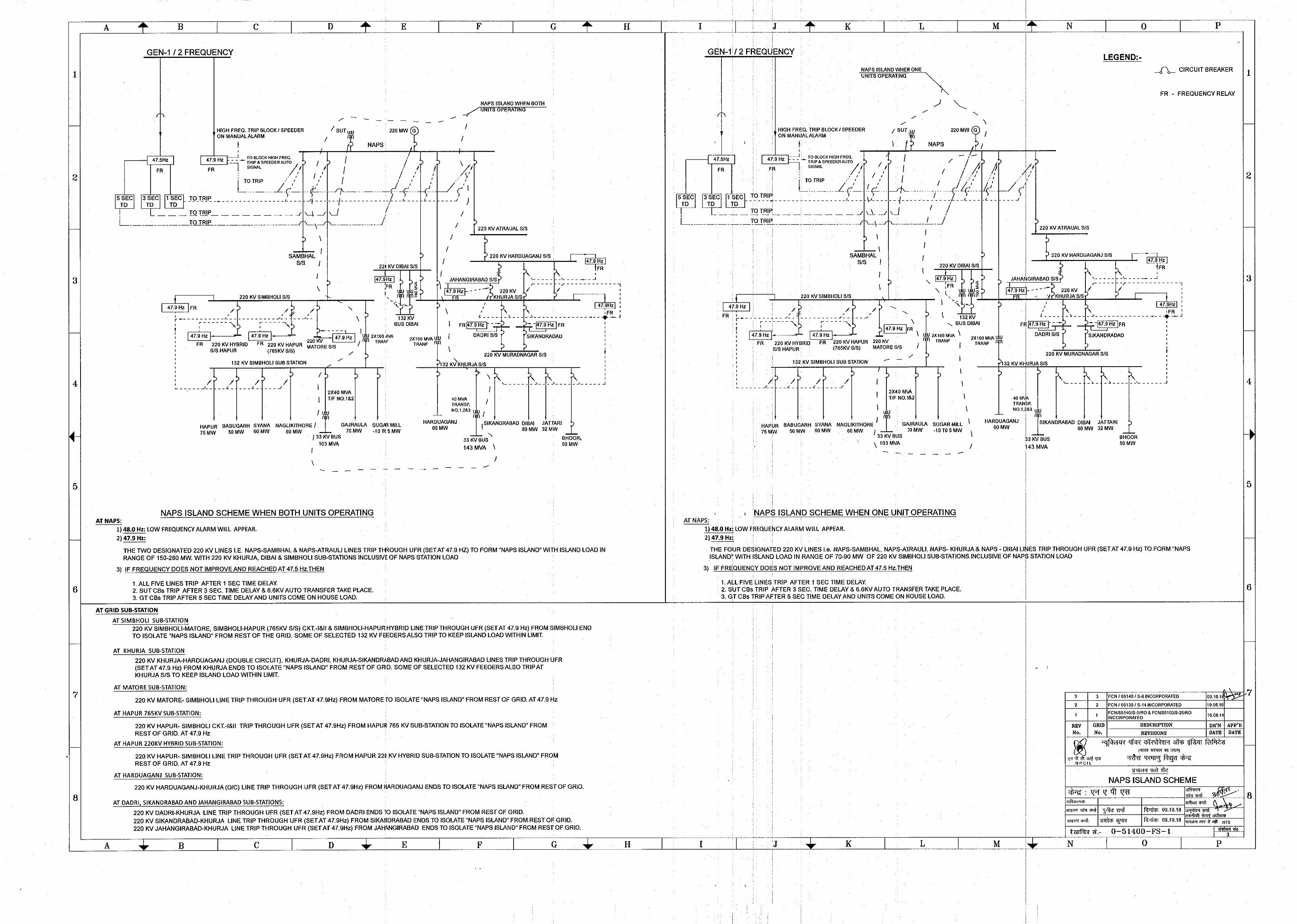

Annexure NRLDC
System Restoration Procedure for Northern Region-2019
274
Annexure NRLDC
System Restoration Procedure for Northern Region-2019
275
II. RAPS-A/B islanding scheme (Scheme is under finalization)

Annexure NRLDC
System Restoration Procedure for Northern Region-2019
276
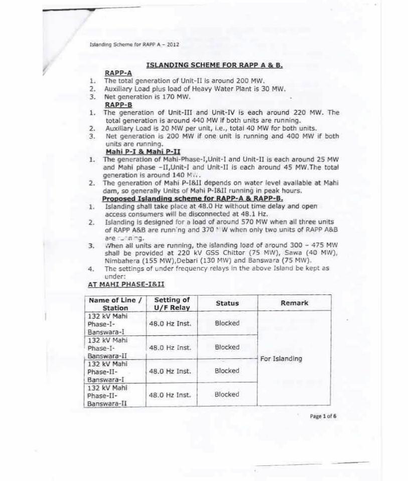
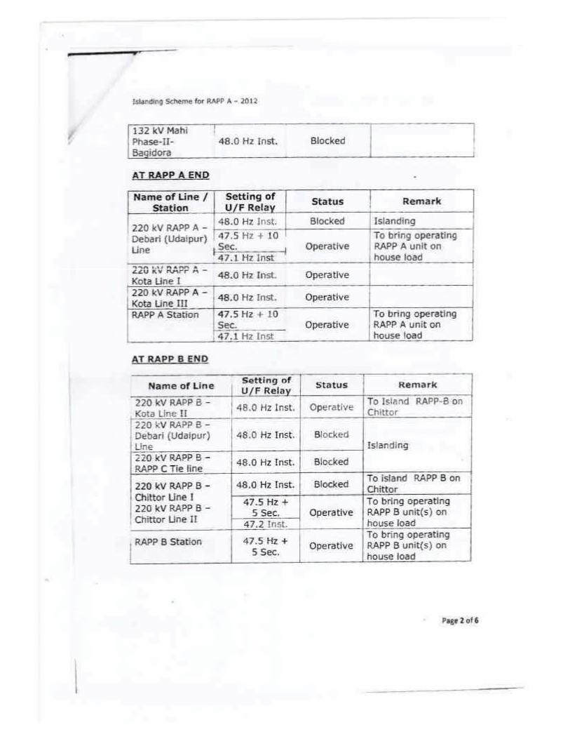
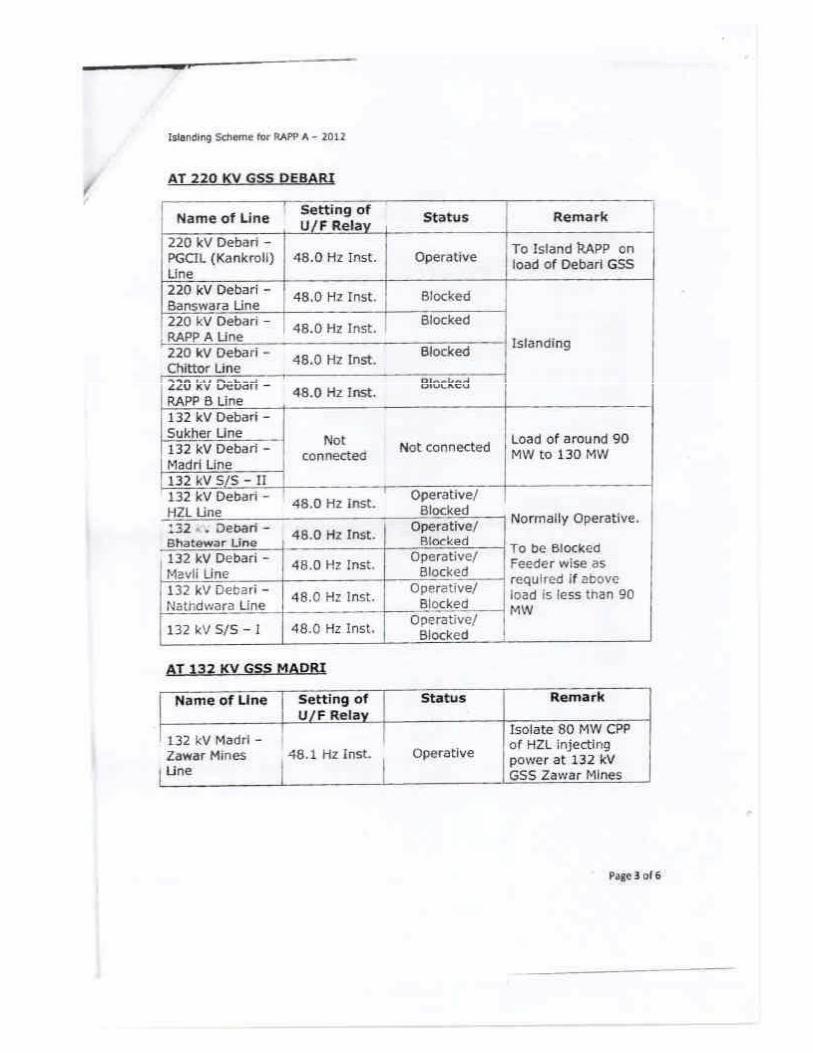
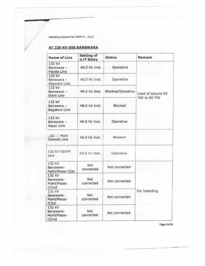
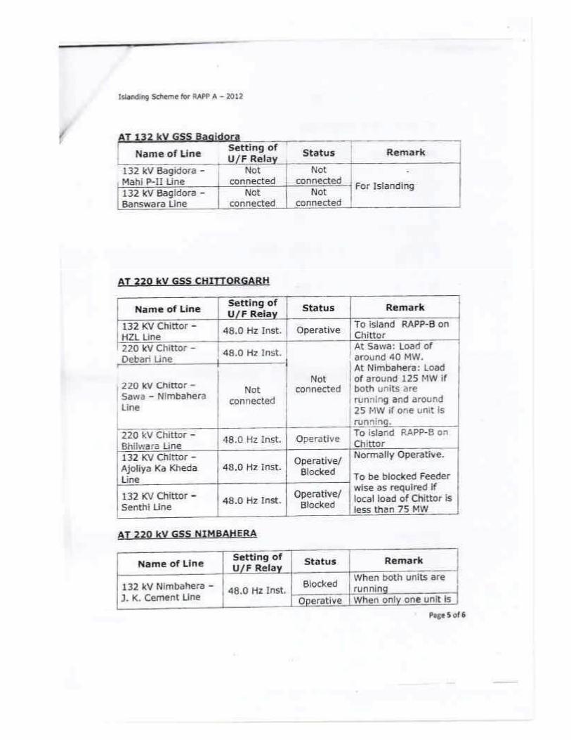
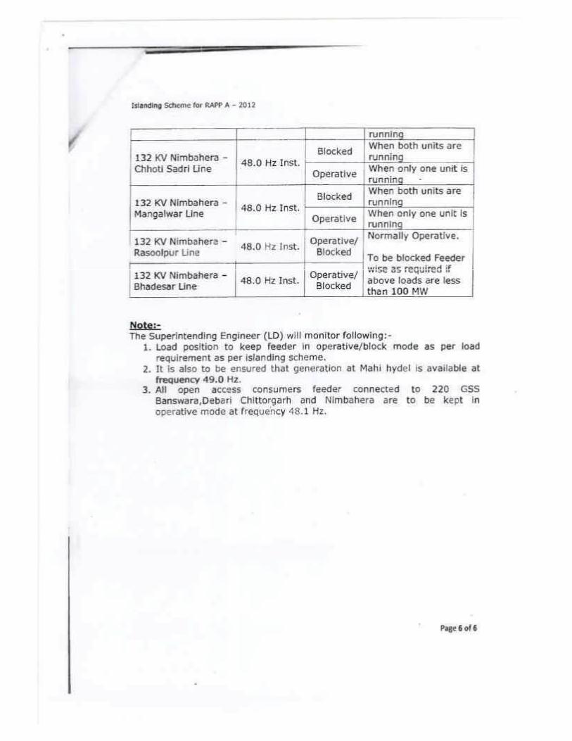
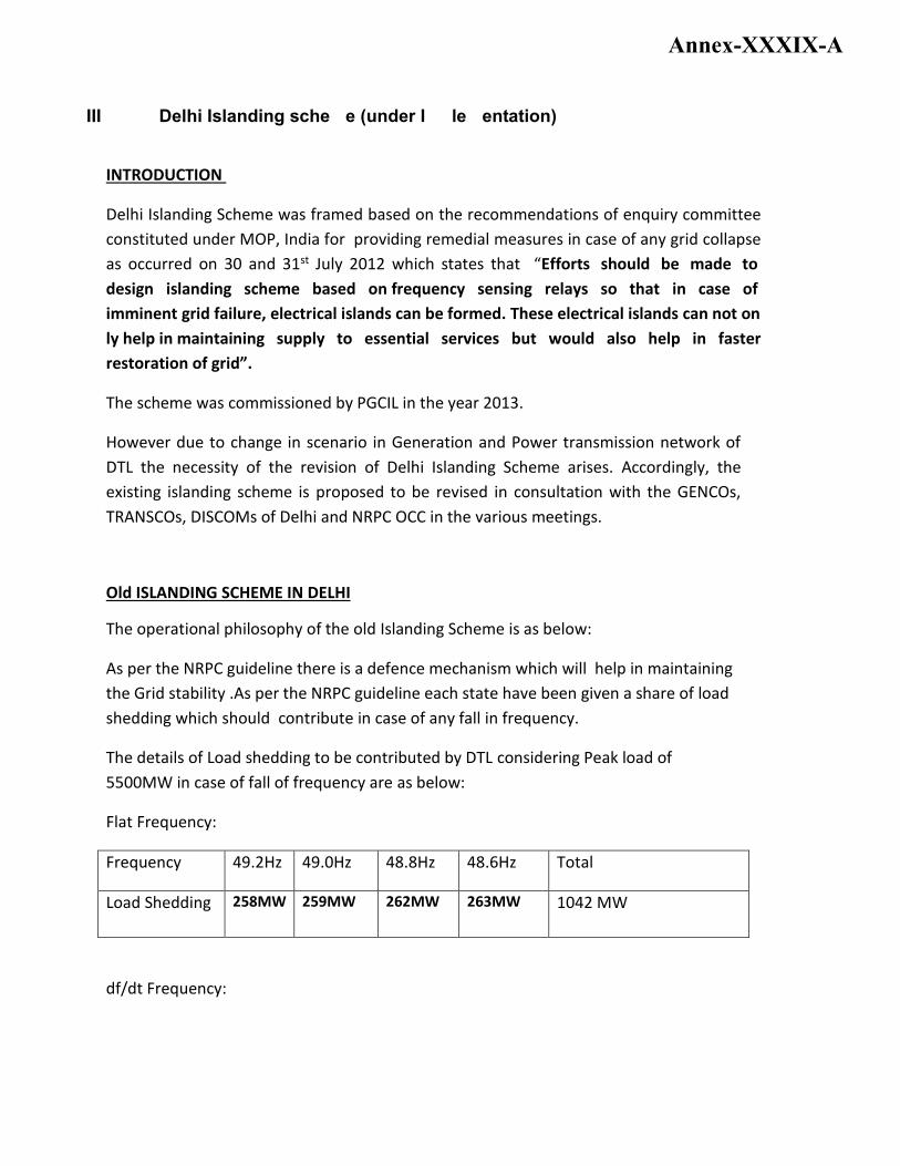
III. Delhi Islanding scheme (under Implementation)
INTRODUCTION
Delhi Islanding Scheme was framed based on the recommendations of enquiry committee
constituted under MOP, India for providing remedial measures in case of any grid collapse
as occurred on 30 and 31st July 2012 which states that “Efforts should be made to
design islanding scheme based on frequency sensing relays so that in case of
imminent grid failure, electrical islands can be formed. These electrical islands can not on
ly help in maintaining supply to essential services but would also help in faster
restoration of grid”.
The scheme was commissioned by PGCIL in the year 2013.
However due to change in scenario in Generation and Power transmission network of
DTL the necessity of the revision of Delhi Islanding Scheme arises. Accordingly, the
existing islanding scheme is proposed to be revised in consultation with the GENCOs,
TRANSCOs, DISCOMs of Delhi and NRPC OCC in the various meetings.
Old ISLANDING SCHEME IN DELHI
The operational philosophy of the old Islanding Scheme is as below:
As per the NRPC guideline there is a defence mechanism which will help in maintaining
the Grid stability .As per the NRPC guideline each state have been given a share of load
shedding which should contribute in case of any fall in frequency.
The details of Load shedding to be contributed by DTL considering Peak load of
5500MW in case of fall of frequency are as below:
Flat Frequency:
Frequency 49.2Hz 49.0Hz 48.8Hz 48.6Hz Total
Load Shedding 258MW 259MW 262MW 263MW 1042 MW
df/dt Frequency:
Annex-XXXIX-A
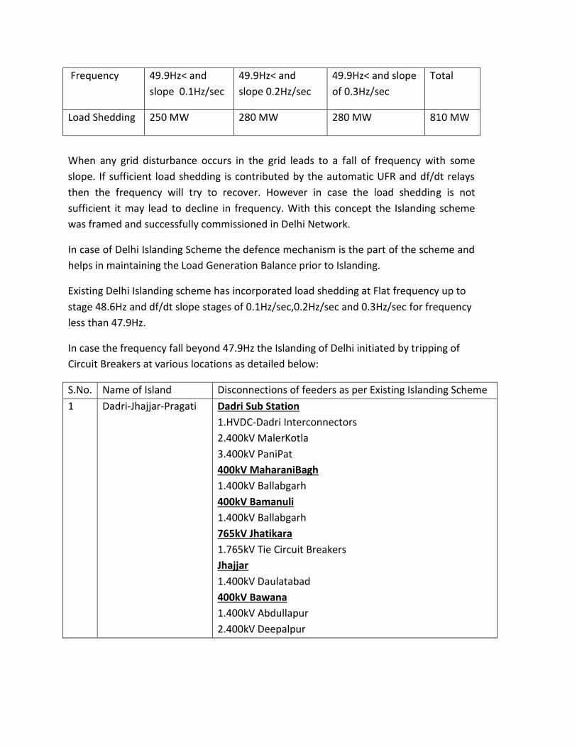
Frequency 49.9Hz< and
slope 0.1Hz/sec
49.9Hz< and
slope 0.2Hz/sec
49.9Hz< and slope
of 0.3Hz/sec
Total
Load Shedding 250 MW 280 MW 280 MW 810 MW
When any grid disturbance occurs in the grid leads to a fall of frequency with some
slope. If sufficient load shedding is contributed by the automatic UFR and df/dt relays
then the frequency will try to recover. However in case the load shedding is not
sufficient it may lead to decline in frequency. With this concept the Islanding scheme
was framed and successfully commissioned in Delhi Network.
In case of Delhi Islanding Scheme the defence mechanism is the part of the scheme and
helps in maintaining the Load Generation Balance prior to Islanding.
Existing Delhi Islanding scheme has incorporated load shedding at Flat frequency up to
stage 48.6Hz and df/dt slope stages of 0.1Hz/sec,0.2Hz/sec and 0.3Hz/sec for frequency
less than 47.9Hz.
In case the frequency fall beyond 47.9Hz the Islanding of Delhi initiated by tripping of
Circuit Breakers at various locations as detailed below:
S.No. Name of Island Disconnections of feeders as per Existing Islanding Scheme
1 Dadri-Jhajjar-Pragati Dadri Sub Station
1.HVDC-Dadri Interconnectors
2.400kV MalerKotla
3.400kV PaniPat
400kV MaharaniBagh
1.400kV Ballabgarh
400kV Bamanuli
1.400kV Ballabgarh
765kV Jhatikara
1.765kV Tie Circuit Breakers
Jhajjar
1.400kV Daulatabad
400kV Bawana
1.400kV Abdullapur
2.400kV Deepalpur
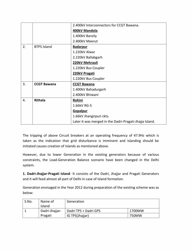
2.400kV Interconnectors for CCGT Bawana.
400kV Mandola
1.400kV Bareily
2.400kV Meerut
2. BTPS Island Badarpur
1.220kV Alwar
2.220kV Ballabgarh
220kV Mehrauli
1.220kV Bus Coupler
220kV Pragati
1.220kV Bus Coupler
3. CCGT Bawana CCGT Bawana
1.400kV Bahadurgarh
2.400kV Bhiwani
4. Rithala Rohini
1.66kV RG-5
Gopalpur
1.66kV Jhangirpuri ckts.
Later it was merged in the Dadri-Pragati-Jhajja Island.
The tripping of above Circuit breakers at an operating frequency of 47.9Hz which is
taken as the indication that grid disturbance is imminent and islanding should be
initiated causes creation of Islands as mentioned above.
However, due to lower Generation in the existing generators because of various
constraints, the Load-Generation Balance scenario have been changed in the Delhi
system.
1. Dadri-Jhajjar-Pragati Island- It consists of the Dadri, Jhajjar and Pragati Generators
and it will feed almost all part of Delhi in case of Island formation.
Generation envisaged in the Year 2012 during preparation of the existing scheme was as
below:
S.No. Name of Island
Generation
1 Dadri-Jhajjar-Pragati
Dadri TPS + Dadri GPS 1700MW
IG TPS(Jhajjar) 750MW
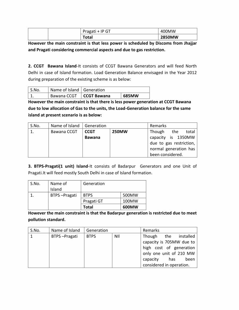
Pragati + IP GT 400MW
Total 2850MW
However the main constraint is that less power is scheduled by Discoms from Jhajjar
and Pragati considering commercial aspects and due to gas restriction.
2. CCGT Bawana Island-It consists of CCGT Bawana Generators and will feed North
Delhi in case of Island formation. Load Generation Balance envisaged in the Year 2012
during preparation of the existing scheme is as below:
S.No. Name of Island Generation
1. Bawana CCGT CCGT Bawana 685MW
However the main constraint is that there is less power generation at CCGT Bawana
due to low allocation of Gas to the units, the Load-Generation balance for the same
island at present scenario is as below:
S.No. Name of Island Generation Remarks
1. Bawana CCGT CCGT Bawana
250MW Though the total capacity is 1350MW due to gas restriction, normal generation has been considered.
3. BTPS-Pragati(1 unit) Island-It consists of Badarpur Generators and one Unit of
Pragati.It will feed mostly South Delhi in case of Island formation.
S.No. Name of Island
Generation
1. BTPS –Pragati BTPS 500MW
Pragati GT 100MW
Total 600MW
However the main constraint is that the Badarpur generation is restricted due to meet
pollution standard.
S.No. Name of Island Generation Remarks
1 BTPS –Pragati BTPS NIl Though the installed capacity is 705MW due to high cost of generation only one unit of 210 MW capacity has been considered in operation.
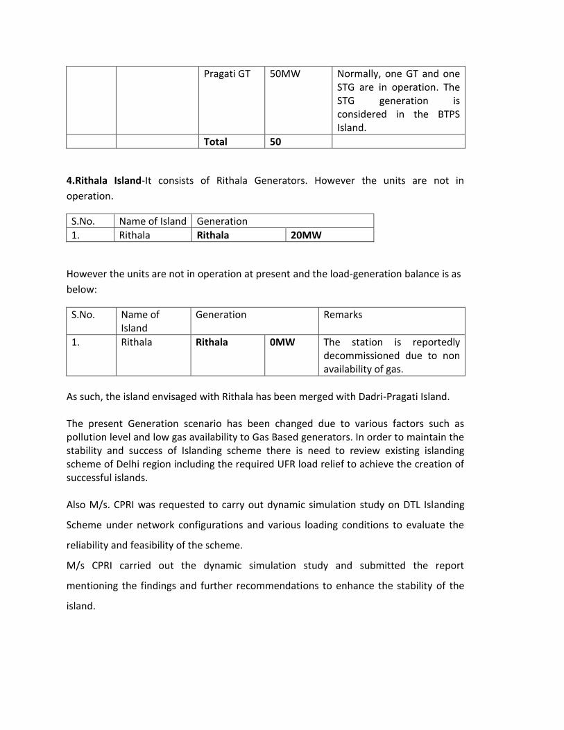
Pragati GT 50MW Normally, one GT and one STG are in operation. The STG generation is considered in the BTPS Island.
Total 50
4.Rithala Island-It consists of Rithala Generators. However the units are not in
operation.
S.No. Name of Island Generation
1. Rithala Rithala 20MW
However the units are not in operation at present and the load-generation balance is as
below:
S.No. Name of Island
Generation Remarks
1. Rithala Rithala 0MW The station is reportedly decommissioned due to non availability of gas.
As such, the island envisaged with Rithala has been merged with Dadri-Pragati Island. The present Generation scenario has been changed due to various factors such as pollution level and low gas availability to Gas Based generators. In order to maintain the stability and success of Islanding scheme there is need to review existing islanding scheme of Delhi region including the required UFR load relief to achieve the creation of successful islands. Also M/s. CPRI was requested to carry out dynamic simulation study on DTL Islanding
Scheme under network configurations and various loading conditions to evaluate the
reliability and feasibility of the scheme.
M/s CPRI carried out the dynamic simulation study and submitted the report
mentioning the findings and further recommendations to enhance the stability of the
island.
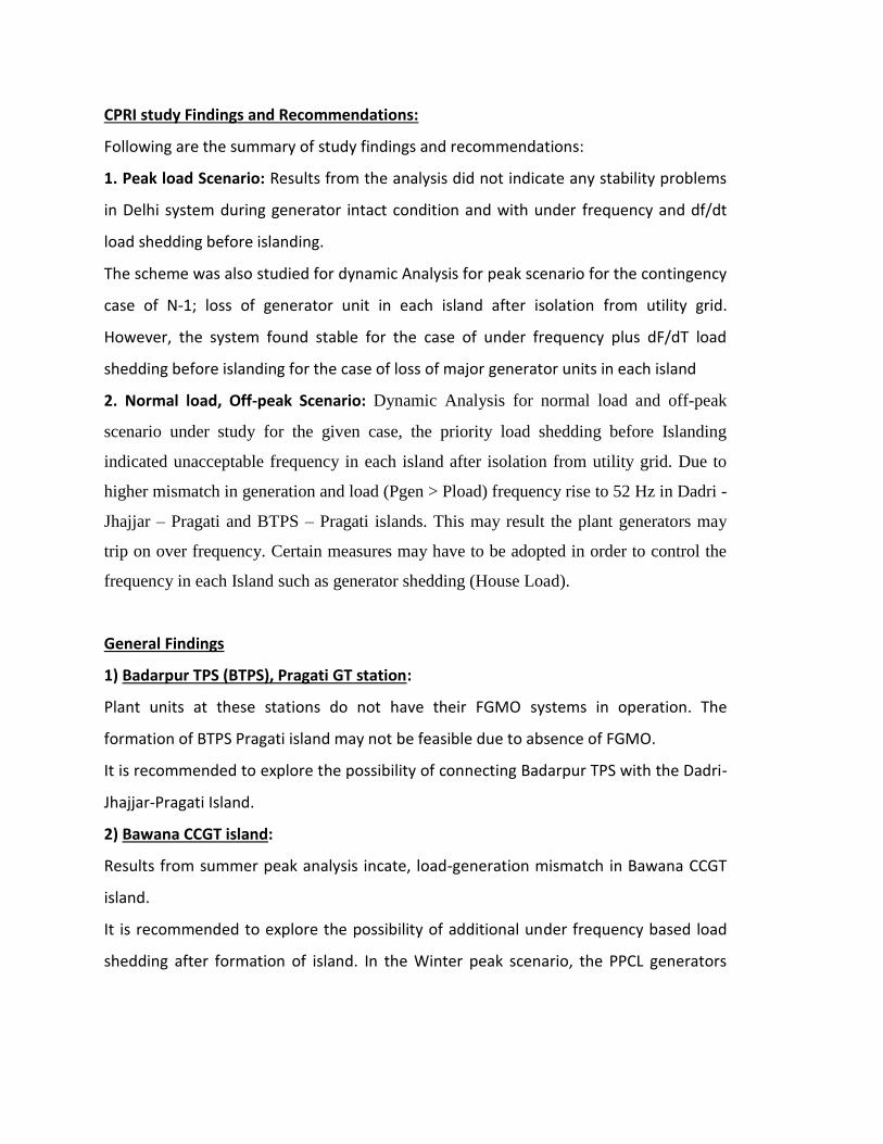
CPRI study Findings and Recommendations:
Following are the summary of study findings and recommendations:
1. Peak load Scenario: Results from the analysis did not indicate any stability problems
in Delhi system during generator intact condition and with under frequency and df/dt
load shedding before islanding.
The scheme was also studied for dynamic Analysis for peak scenario for the contingency
case of N-1; loss of generator unit in each island after isolation from utility grid.
However, the system found stable for the case of under frequency plus dF/dT load
shedding before islanding for the case of loss of major generator units in each island
2. Normal load, Off-peak Scenario: Dynamic Analysis for normal load and off-peak
scenario under study for the given case, the priority load shedding before Islanding
indicated unacceptable frequency in each island after isolation from utility grid. Due to
higher mismatch in generation and load (Pgen > Pload) frequency rise to 52 Hz in Dadri -
Jhajjar – Pragati and BTPS – Pragati islands. This may result the plant generators may
trip on over frequency. Certain measures may have to be adopted in order to control the
frequency in each Island such as generator shedding (House Load).
General Findings
1) Badarpur TPS (BTPS), Pragati GT station:
Plant units at these stations do not have their FGMO systems in operation. The
formation of BTPS Pragati island may not be feasible due to absence of FGMO.
It is recommended to explore the possibility of connecting Badarpur TPS with the Dadri-
Jhajjar-Pragati Island.
2) Bawana CCGT island:
Results from summer peak analysis incate, load-generation mismatch in Bawana CCGT
island.
It is recommended to explore the possibility of additional under frequency based load
shedding after formation of island. In the Winter peak scenario, the PPCL generators
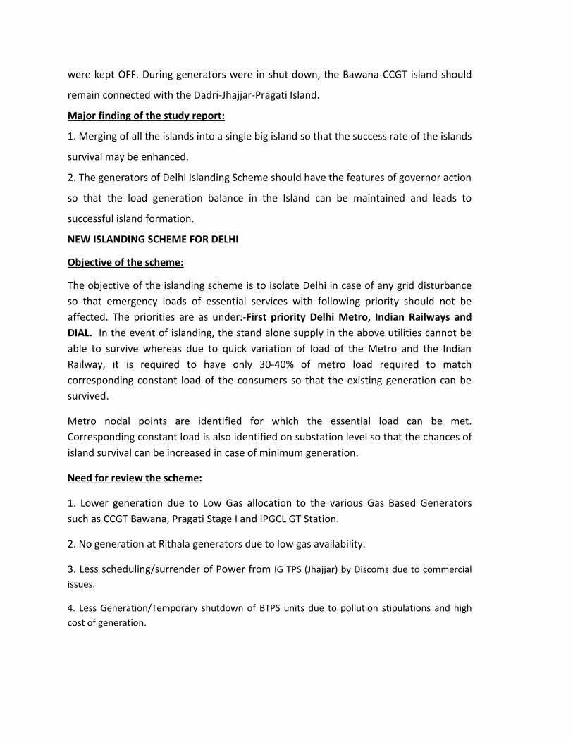
were kept OFF. During generators were in shut down, the Bawana-CCGT island should
remain connected with the Dadri-Jhajjar-Pragati Island.
Major finding of the study report:
1. Merging of all the islands into a single big island so that the success rate of the islands
survival may be enhanced.
2. The generators of Delhi Islanding Scheme should have the features of governor action
so that the load generation balance in the Island can be maintained and leads to
successful island formation.
NEW ISLANDING SCHEME FOR DELHI
Objective of the scheme:
The objective of the islanding scheme is to isolate Delhi in case of any grid disturbance
so that emergency loads of essential services with following priority should not be
affected. The priorities are as under:-First priority Delhi Metro, Indian Railways and
DIAL. In the event of islanding, the stand alone supply in the above utilities cannot be
able to survive whereas due to quick variation of load of the Metro and the Indian
Railway, it is required to have only 30-40% of metro load required to match
corresponding constant load of the consumers so that the existing generation can be
survived.
Metro nodal points are identified for which the essential load can be met.
Corresponding constant load is also identified on substation level so that the chances of
island survival can be increased in case of minimum generation.
Need for review the scheme:
1. Lower generation due to Low Gas allocation to the various Gas Based Generators
such as CCGT Bawana, Pragati Stage I and IPGCL GT Station.
2. No generation at Rithala generators due to low gas availability.
3. Less scheduling/surrender of Power from IG TPS (Jhajjar) by Discoms due to commercial
issues.
4. Less Generation/Temporary shutdown of BTPS units due to pollution stipulations and high
cost of generation.
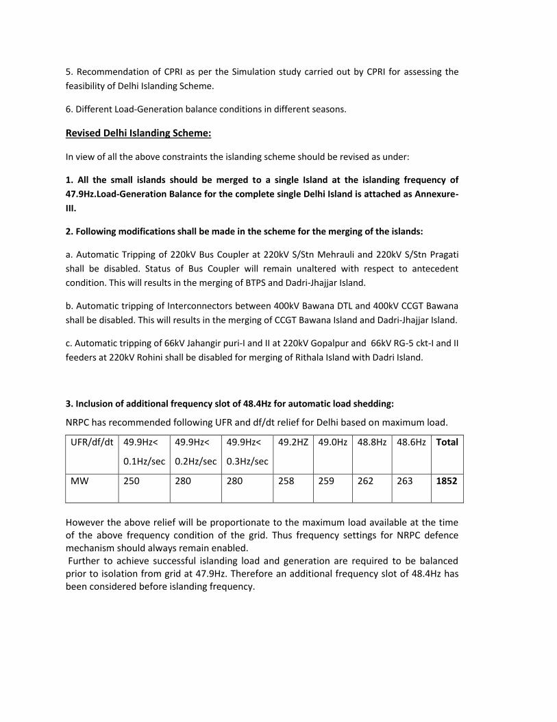
5. Recommendation of CPRI as per the Simulation study carried out by CPRI for assessing the
feasibility of Delhi Islanding Scheme.
6. Different Load-Generation balance conditions in different seasons.
Revised Delhi Islanding Scheme:
In view of all the above constraints the islanding scheme should be revised as under:
1. All the small islands should be merged to a single Island at the islanding frequency of
47.9Hz.Load-Generation Balance for the complete single Delhi Island is attached as Annexure-
III.
2. Following modifications shall be made in the scheme for the merging of the islands:
a. Automatic Tripping of 220kV Bus Coupler at 220kV S/Stn Mehrauli and 220kV S/Stn Pragati
shall be disabled. Status of Bus Coupler will remain unaltered with respect to antecedent
condition. This will results in the merging of BTPS and Dadri-Jhajjar Island.
b. Automatic tripping of Interconnectors between 400kV Bawana DTL and 400kV CCGT Bawana
shall be disabled. This will results in the merging of CCGT Bawana Island and Dadri-Jhajjar Island.
c. Automatic tripping of 66kV Jahangir puri-I and II at 220kV Gopalpur and 66kV RG-5 ckt-I and II
feeders at 220kV Rohini shall be disabled for merging of Rithala Island with Dadri Island.
3. Inclusion of additional frequency slot of 48.4Hz for automatic load shedding:
NRPC has recommended following UFR and df/dt relief for Delhi based on maximum load.
UFR/df/dt 49.9Hz<
0.1Hz/sec
49.9Hz<
0.2Hz/sec
49.9Hz<
0.3Hz/sec
49.2HZ 49.0Hz 48.8Hz 48.6Hz Total
MW 250 280 280 258 259 262 263 1852
However the above relief will be proportionate to the maximum load available at the time of the above frequency condition of the grid. Thus frequency settings for NRPC defence mechanism should always remain enabled. Further to achieve successful islanding load and generation are required to be balanced prior to isolation from grid at 47.9Hz. Therefore an additional frequency slot of 48.4Hz has been considered before islanding frequency.
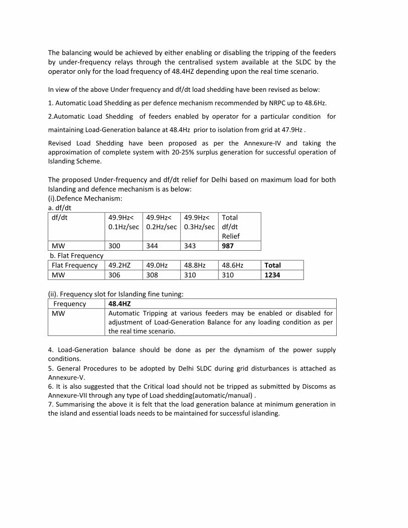
The balancing would be achieved by either enabling or disabling the tripping of the feeders by under-frequency relays through the centralised system available at the SLDC by the operator only for the load frequency of 48.4HZ depending upon the real time scenario. In view of the above Under frequency and df/dt load shedding have been revised as below:
1. Automatic Load Shedding as per defence mechanism recommended by NRPC up to 48.6Hz.
2.Automatic Load Shedding of feeders enabled by operator for a particular condition for
maintaining Load-Generation balance at 48.4Hz prior to isolation from grid at 47.9Hz .
Revised Load Shedding have been proposed as per the Annexure-IV and taking the approximation of complete system with 20-25% surplus generation for successful operation of Islanding Scheme. The proposed Under-frequency and df/dt relief for Delhi based on maximum load for both Islanding and defence mechanism is as below: (i).Defence Mechanism: a. df/dt
df/dt 49.9Hz< 0.1Hz/sec
49.9Hz< 0.2Hz/sec
49.9Hz< 0.3Hz/sec
Total df/dt Relief
MW 300 344 343 987
b. Flat Frequency
Flat Frequency 49.2HZ 49.0Hz 48.8Hz 48.6Hz Total
MW 306 308 310 310 1234
(ii). Frequency slot for Islanding fine tuning:
Frequency 48.4HZ
MW Automatic Tripping at various feeders may be enabled or disabled for adjustment of Load-Generation Balance for any loading condition as per the real time scenario.
4. Load-Generation balance should be done as per the dynamism of the power supply conditions.
5. General Procedures to be adopted by Delhi SLDC during grid disturbances is attached as Annexure-V. 6. It is also suggested that the Critical load should not be tripped as submitted by Discoms as Annexure-VII through any type of Load shedding(automatic/manual) . 7. Summarising the above it is felt that the load generation balance at minimum generation in the island and essential loads needs to be maintained for successful islanding.
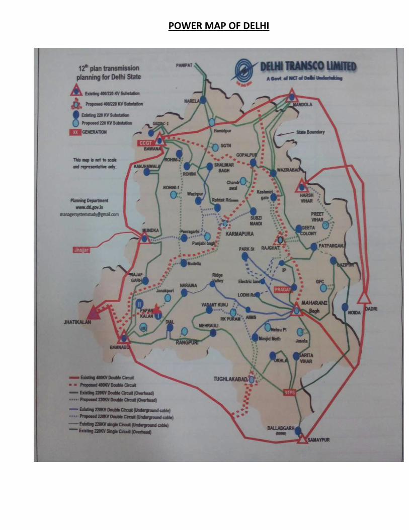
POWER MAP OF DELHI
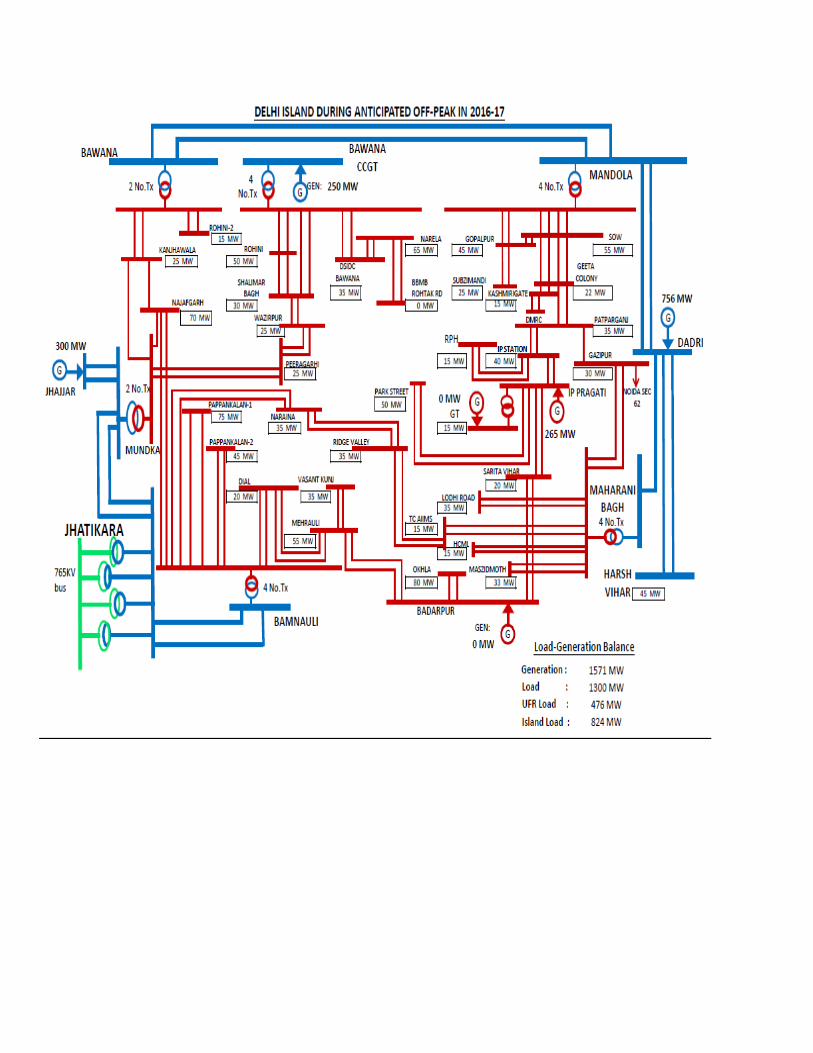
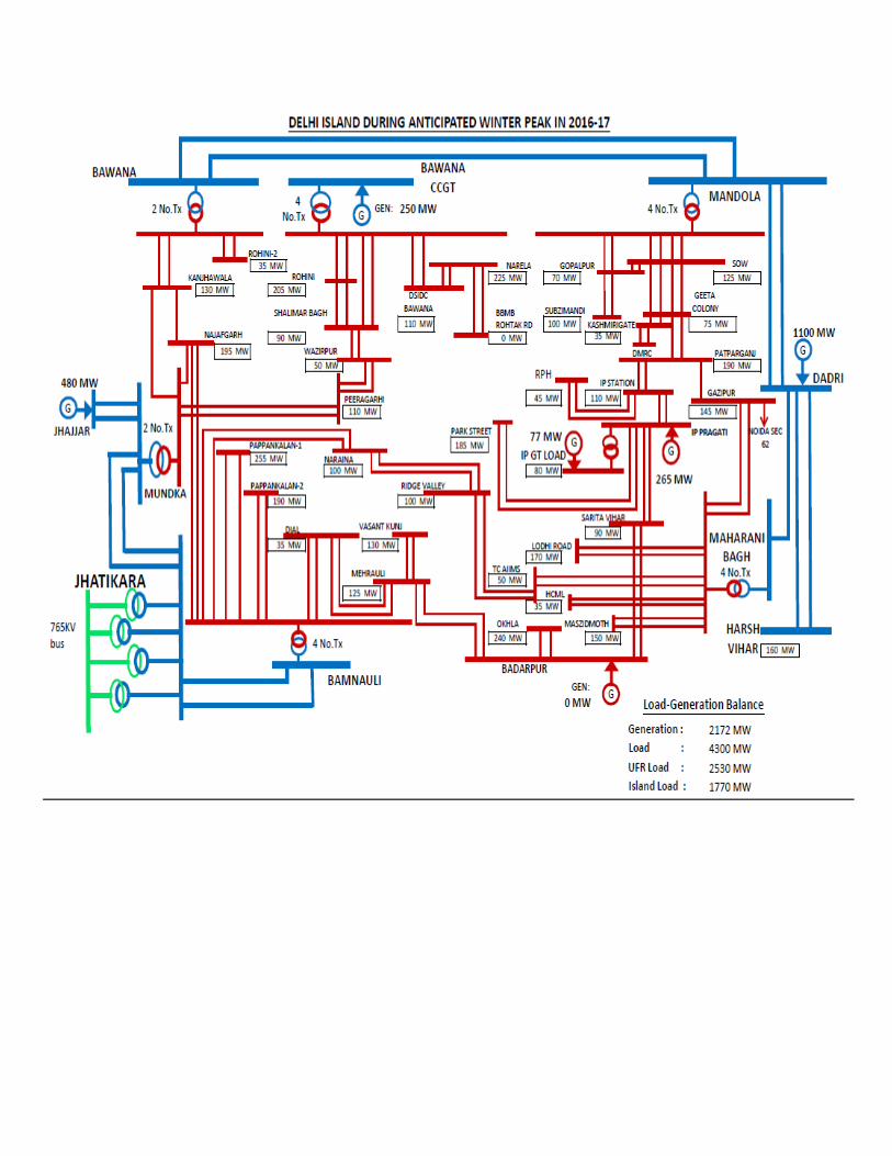
Annexure NRLDC
System Restoration Procedure for Northern Region-2018
309
IV. Scheme for revival and operation of Kashmir valley in island after its collapse (proposed)
1. After collapse of Valley power system, the Uri-I HEP shall
immediately black-start one of its unit and in coordination with
Wagoora (PG), PDD, J&K (SLDC Bemina, personnel at
Pampore & Zainakote) shall extend power supply to Pampore
through one circuit of 400 kV Uri-Wagoora, One 400/220 kV ICT
and one 220 kV Wagoora-Pampore line.
2. NRLDC shall be informed of the development and process shall
be continued unless otherwise advised by NRLDC.
3. SLDC bemina shall closely coordinate with PDD substations,
PDC generating stations, POWERGRID Wagoora and NHPC for
revival and its operation by maintaining system frequency,
voltages and line loadings in the area.
4. Load shall be put by PDD J&K at Pampore in small steps on 5-
10 MW and in close coordination with Wagoora (PG) and Uri-I
HEP.
5. After putting the load of 10-20 MW, the power supply shall be
extended to the Pampore GT station and one GT shall be
synchronized.
6. Load to be increased in close coordination with Uri HEP,
Wagoora (PG) and Pampore GT station.
7. Supply shall be extended to Uri –II HEP and one unit at Uri-II
HEP shall be synchronized.
8. Supply shall be extended to Zainakote through one circuit of 220
kV Wagoora-Zainakote.
9. Load by PDD shall be increased in small steps of 10 MW in
coordination with Uri-1 HEP.
10. Uri-II –Wagoora line shall be taken in service.
11. Other units at Uri –I, Uri –II, Pampore GT shall be taken in
service and load increased in the valley in close coordination
with generators.
12. Supply shall be extended from zainakote to Pattan through 132
kV Zainakote –pattan and after putting small load at pattan,
supply shall be extended to Lower Jhelum HEP. Units at LJHEP
shall be synchronised and more load shall be put in small steps.
13. SLDC bemina would continue to monitor the frequency and
voltage profile in island and would advise the concerned
generator and substation to increase/decrease load/generation
in small steps.
14. Generating units in the island shall be kept under free governor
mode of operation.
Annex-XXXIX-B
Annexure NRLDC
System Restoration Procedure for Northern Region-2018
310
15. Supply shall be extended to Upper Sindh HEP through 132 kV
Pampore-Chasma shahi-Habak links and units at Upper Sindh
HEP shall be synchronized.
16. Keeping in view the voltage at different stations, the additional
lines shall be taken into service to improve the reliability of the
system.
17. Additional unit shall be synchronized at all the generating
stations and load shall be put in gradually. Load shall be kept
slightly lower than the generation so that frequency remains
above 50 Hz. Also units shall have margins to pickup generation
under FGMO in case of some sudden load increase or tripping
of a unit. Thus loads shall be limited to 80% of the generation
availability or to take care of tripping of highest capacity unit in
operation (say 80-90 MW on Uri HEP –I).
18. Senior officers from PDD, PDC shall be available in control
rooms to supervise the restoration and operation of the valley
island.
19. In case of difficulty in extending the supply to different
generating stations Lower Jhelum or Upper Sindh, these
generating stations shall self start and the different island within
valley shall be synchronized with each other at a station having
synchronizing facility and under close coordination.
20. The generation precautions as given in the “System Restoration
Procedure of Northern Region” shall be followed.
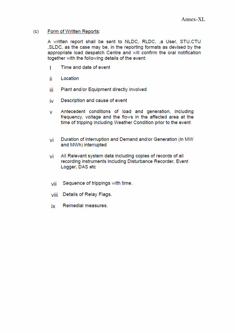
Annex-XL
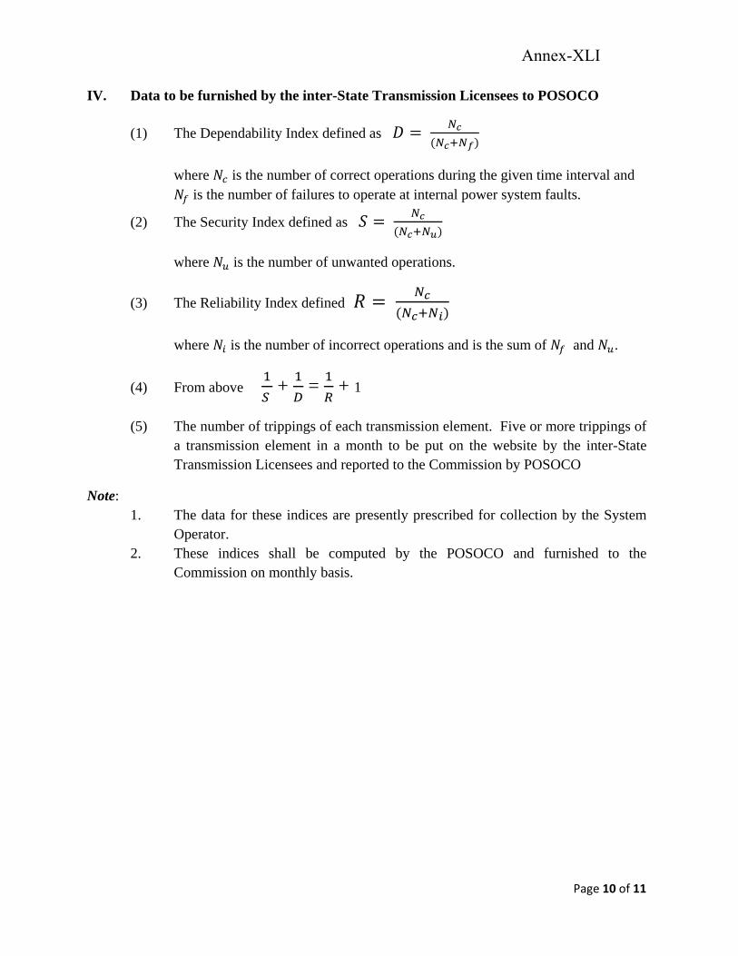
Page 10 of 11
IV. Data to be furnished by the inter-State Transmission Licensees to POSOCO
(1) The Dependability Index defined as
where is the number of correct operations during the given time interval and is the number of failures to operate at internal power system faults.
(2) The Security Index defined as
where is the number of unwanted operations.
(3) The Reliability Index defined
where is the number of incorrect operations and is the sum of and .
(4) From above + = + 1
(5) The number of trippings of each transmission element. Five or more trippings of a transmission element in a month to be put on the website by the inter-State Transmission Licensees and reported to the Commission by POSOCO
Note: 1. The data for these indices are presently prescribed for collection by the System
Operator. 2. These indices shall be computed by the POSOCO and furnished to the
Commission on monthly basis.
Annex-XLI
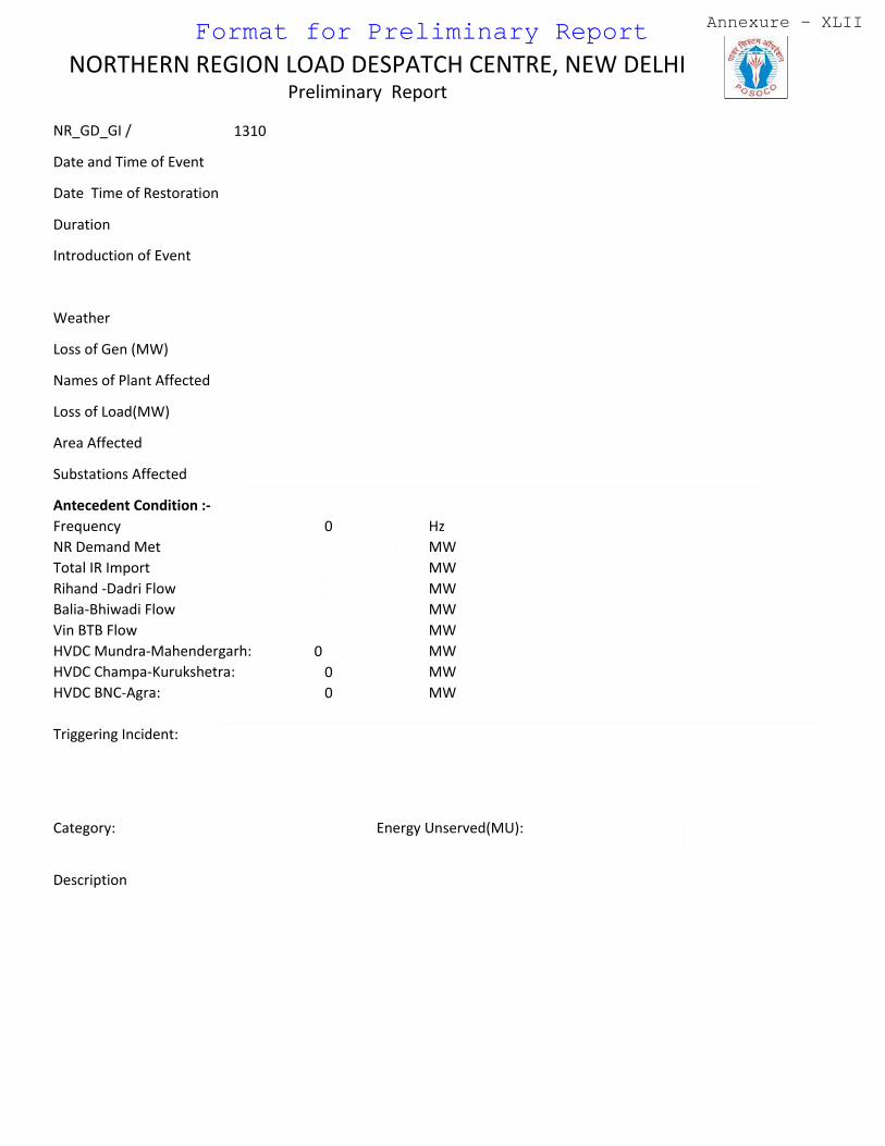
Date and Time of Event
Introduction of Event
Weather
Loss of Gen (MW)
Names of Plant Affected
Loss of Load(MW)
Area Affected
Substations Affected
Frequency 0
NR Demand Met
Total IR Import
Rihand ‐Dadri Flow
Balia‐Bhiwadi Flow
Vin BTB Flow
Description
Triggering Incident:
Hz
MW
MW
MW
MW
MW
Antecedent Condition :‐
Date Time of Restoration
NR_GD_GI / 1310
Category:
NORTHERN REGION LOAD DESPATCH CENTRE, NEW DELHI Preliminary Report
Energy Unserved(MU):
Duration
HVDC Mundra‐Mahendergarh: 0 MW
HVDC Champa‐Kurukshetra: 0 MW
HVDC BNC‐Agra: 0 MW
Format for Preliminary Report Annexure - XLII
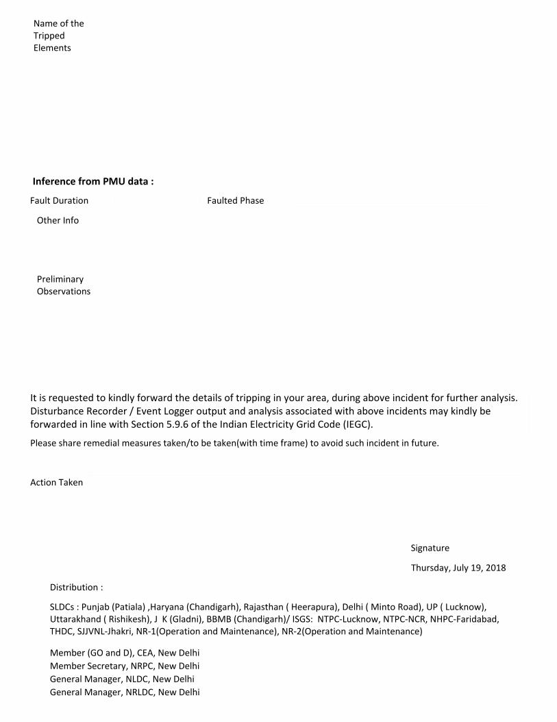
It is requested to kindly forward the details of tripping in your area, during above incident for further analysis. Disturbance Recorder / Event Logger output and analysis associated with above incidents may kindly be forwarded in line with Section 5.9.6 of the Indian Electricity Grid Code (IEGC).
Signature
Please share remedial measures taken/to be taken(with time frame) to avoid such incident in future.
Thursday, July 19, 2018
Distribution :
SLDCs : Punjab (Patiala) ,Haryana (Chandigarh), Rajasthan ( Heerapura), Delhi ( Minto Road), UP ( Lucknow), Uttarakhand ( Rishikesh), J K (Gladni), BBMB (Chandigarh)/ ISGS: NTPC‐Lucknow, NTPC‐NCR, NHPC‐Faridabad, THDC, SJJVNL‐Jhakri, NR‐1(Operation and Maintenance), NR‐2(Operation and Maintenance)
Member (GO and D), CEA, New Delhi
Member Secretary, NRPC, New Delhi
General Manager, NLDC, New Delhi
General Manager, NRLDC, New Delhi
Action Taken
Name of the Tripped Elements
Inference from PMU data :
Fault Duration Faulted Phase
Other Info
Preliminary Observations
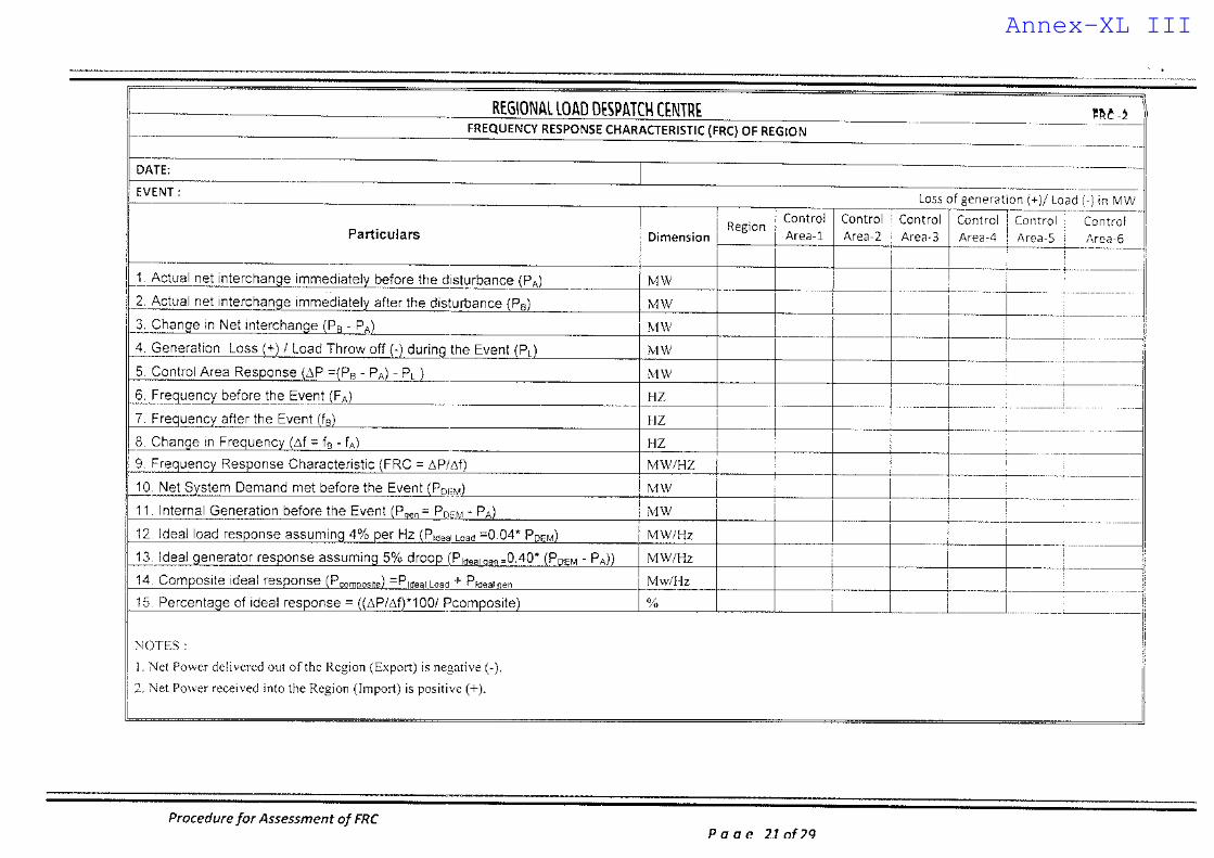
Annex-XL III
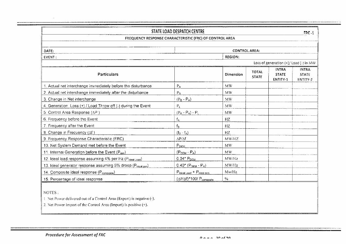
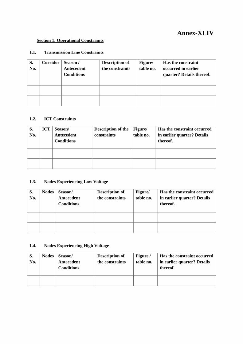
Annex-XLIV Section 1: Operational Constraints
1.1. Transmission Line Constraints
S. No.
Corridor Season / Antecedent Conditions
Description of the constraints
Figure/ table no.
Has the constraint occurred in earlier quarter? Details thereof.
1.2. ICT Constraints
S. No.
ICT Season/ Antecedent Conditions
Description of the constraints
Figure/ table no.
Has the constraint occurred in earlier quarter? Details thereof.
1.3. Nodes Experiencing Low Voltage
S. No.
Nodes Season/ Antecedent Conditions
Description of the constraints
Figure/ table no.
Has the constraint occurred in earlier quarter? Details thereof.
1.4. Nodes Experiencing High Voltage
S. No.
Nodes Season/ Antecedent Conditions
Description of the constraints
Figure / table no.
Has the constraint occurred in earlier quarter? Details thereof.
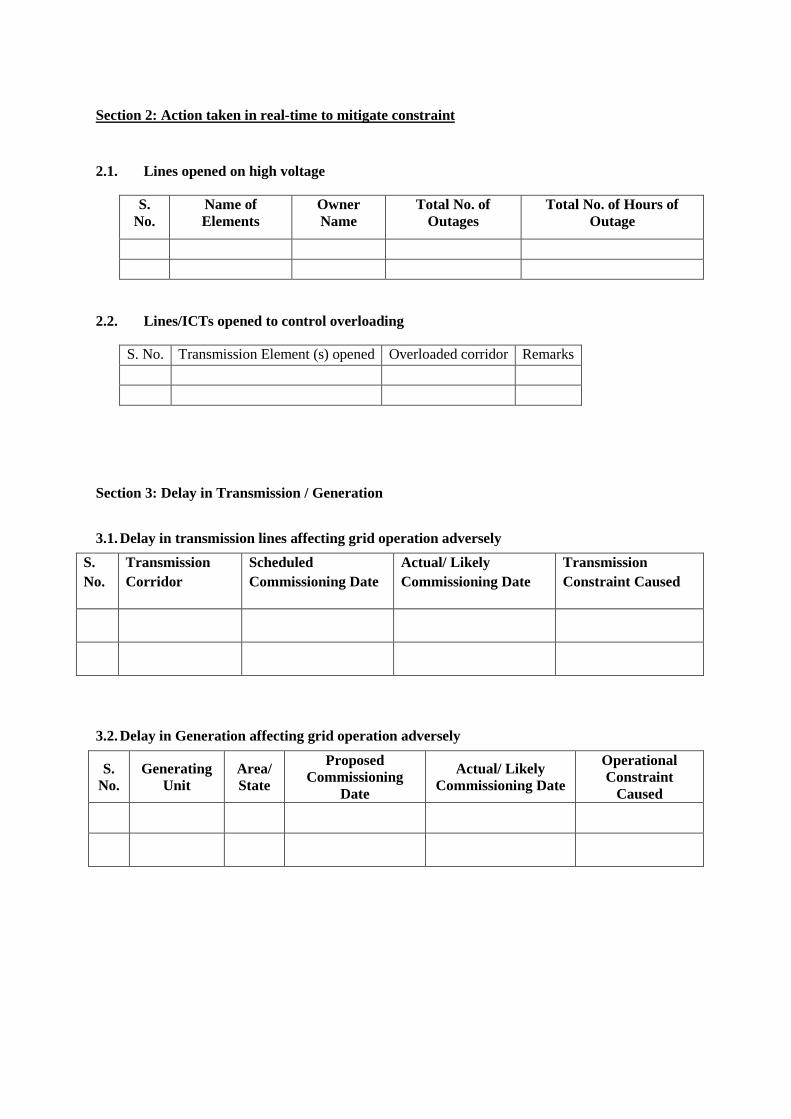
Section 2: Action taken in real-time to mitigate constraint
2.1. Lines opened on high voltage
S. No.
Name of Elements
Owner Name
Total No. of Outages
Total No. of Hours of Outage
2.2. Lines/ICTs opened to control overloading
S. No. Transmission Element (s) opened Overloaded corridor Remarks
Section 3: Delay in Transmission / Generation
3.1. Delay in transmission lines affecting grid operation adversely S. No.
Transmission Corridor
Scheduled Commissioning Date
Actual/ Likely Commissioning Date
Transmission Constraint Caused
3.2. Delay in Generation affecting grid operation adversely
S. No.
Generating Unit
Area/ State
Proposed Commissioning
Date
Actual/ Likely Commissioning Date
Operational Constraint
Caused
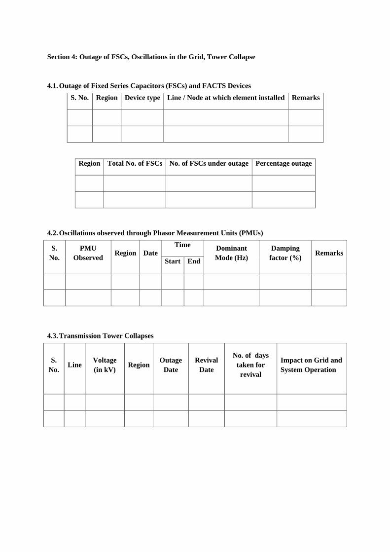
Section 4: Outage of FSCs, Oscillations in the Grid, Tower Collapse
4.1. Outage of Fixed Series Capacitors (FSCs) and FACTS Devices S. No. Region Device type Line / Node at which element installed Remarks
Region Total No. of FSCs No. of FSCs under outage Percentage outage
4.2. Oscillations observed through Phasor Measurement Units (PMUs)
S. No.
PMU Observed Region Date
Time Dominant Mode (Hz)
Damping factor (%) Remarks
Start End
4.3. Transmission Tower Collapses
S. No.
Line Voltage (in kV)
Region Outage Date
Revival Date
No. of days taken for revival
Impact on Grid and System Operation
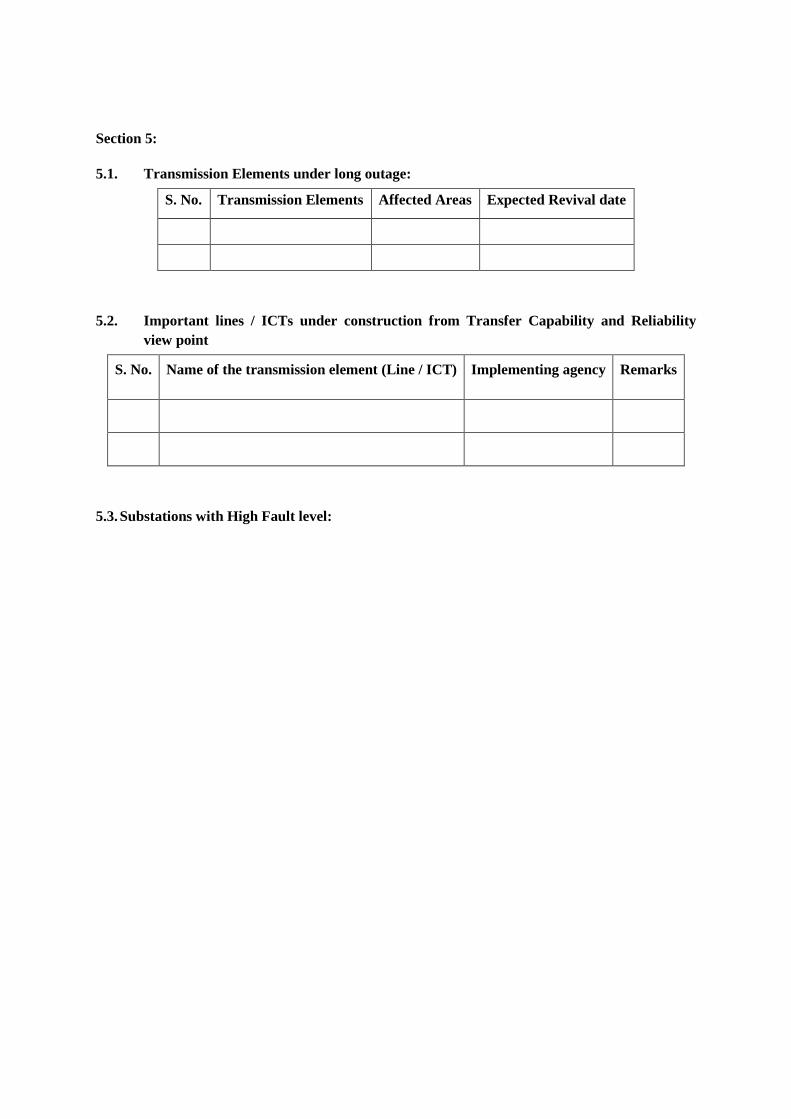
Section 5:
5.1. Transmission Elements under long outage:
S. No. Transmission Elements Affected Areas Expected Revival date
5.2. Important lines / ICTs under construction from Transfer Capability and Reliability view point
S. No. Name of the transmission element (Line / ICT) Implementing agency Remarks
5.3. Substations with High Fault level:
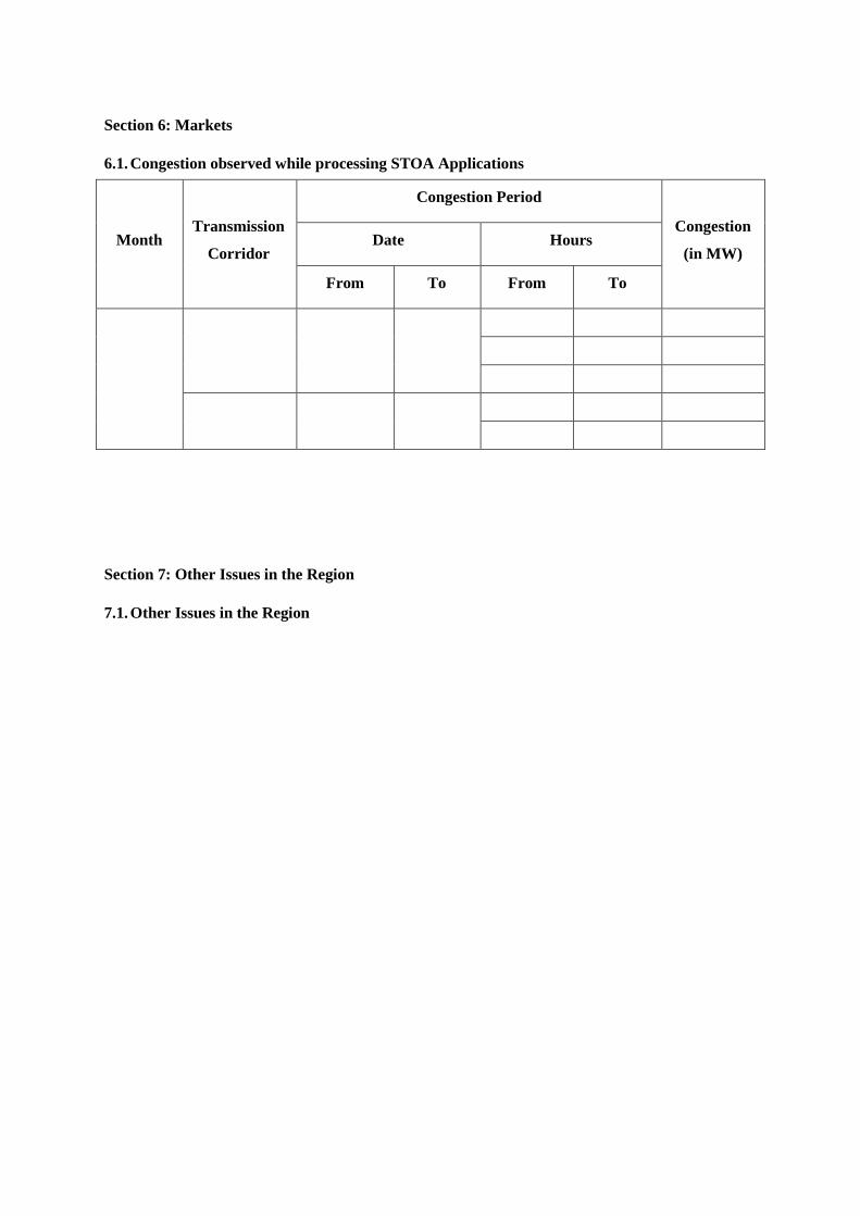
Section 6: Markets
6.1. Congestion observed while processing STOA Applications
Month Transmission
Corridor
Congestion Period
Congestion
(in MW) Date Hours
From To From To
Section 7: Other Issues in the Region
7.1. Other Issues in the Region
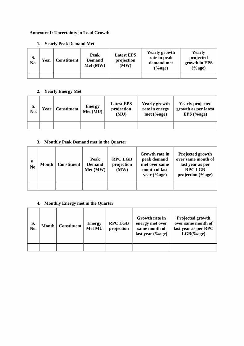
Annexure I: Uncertainty in Load Growth
1. Yearly Peak Demand Met
S. No. Year Constituent
Peak Demand
Met (MW)
Latest EPS projection
(MW)
Yearly growth rate in peak demand met
(%age)
Yearly projected
growth in EPS (%age)
2. Yearly Energy Met
S. No. Year Constituent Energy
Met (MU)
Latest EPS projection
(MU)
Yearly growth rate in energy met (%age)
Yearly projected growth as per latest
EPS (%age)
3. Monthly Peak Demand met in the Quarter
S. No Month Constituent
Peak Demand
Met (MW)
RPC LGB projection
(MW)
Growth rate in peak demand met over same month of last year (%age)
Projected growth over same month of
last year as per RPC LGB
projection (%age)
4. Monthly Energy met in the Quarter
S. No. Month Constituent Energy
Met MU RPC LGB projection
Growth rate in energy met over same month of
last year (%age)
Projected growth over same month of last year as per RPC
LGB(%age)
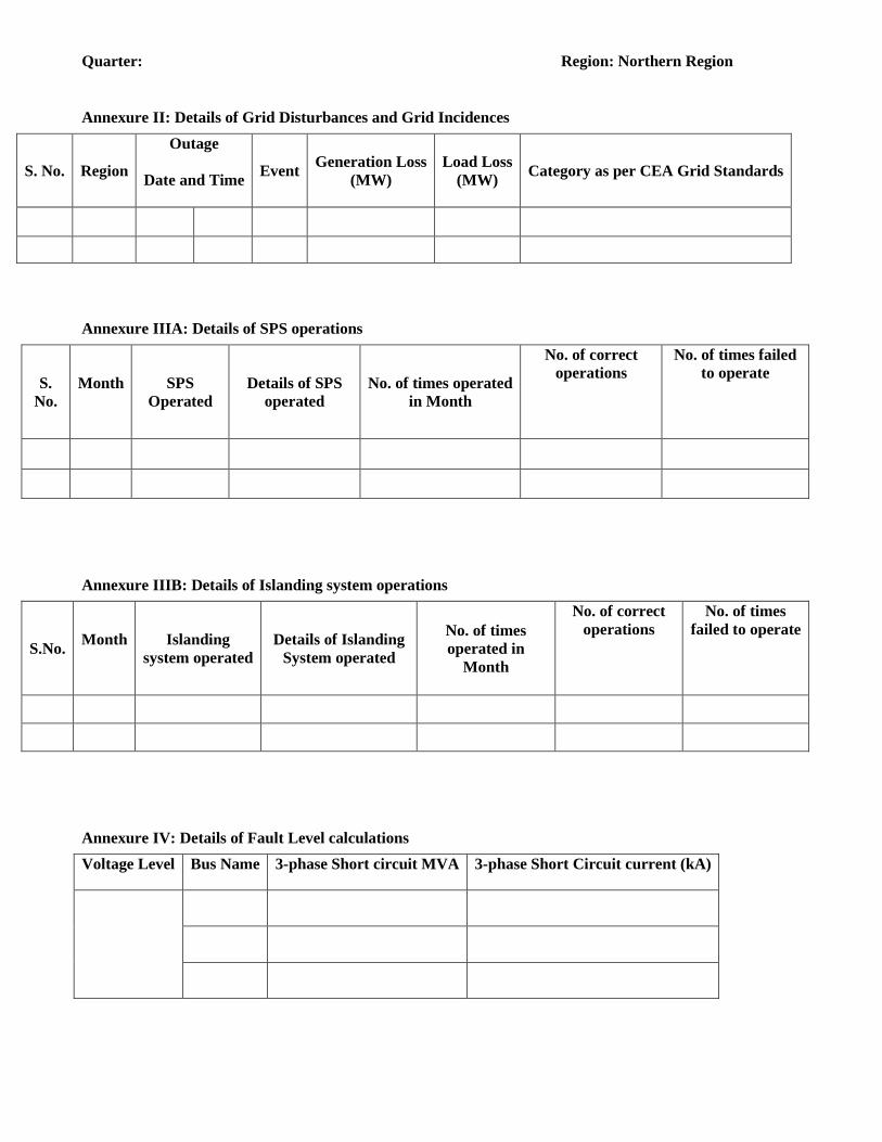
Quarter: Region: Northern Region
Annexure II: Details of Grid Disturbances and Grid Incidences
S. No. Region
Outage
Date and Time
Event Generation Loss (MW)
Load Loss (MW) Category as per CEA Grid Standards
Annexure IIIA: Details of SPS operations
S. No.
Month
SPS Operated
Details of SPS operated
No. of times operated in Month
No. of correct operations
No. of times failed to operate
Annexure IIIB: Details of Islanding system operations
S.No. Month
Islanding system operated
Details of Islanding System operated
No. of times operated in
Month
No. of correct operations
No. of times failed to operate
Annexure IV: Details of Fault Level calculations Voltage Level Bus Name 3-phase Short circuit MVA 3-phase Short Circuit current (kA)

Quarter: Region: Northern Region
AnnexureV.A: Graphs indicating Transmission Line Constraints
AnnexureV.B: Graphs indicating ICT Constraints
Annexure V.C: Graphs Indicating Nodes Experiencing Low Voltage
AnnexureV.D: Graphs Indicating Nodes Experiencing High Voltage
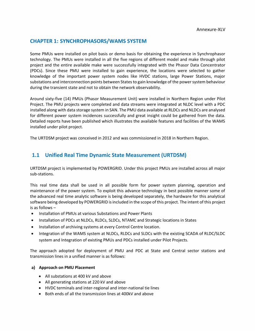
Annexure-XLV
CHAPTER 1: SYNCHROPHASORS/WAMS SYSTEM
Some PMUs were installed on pilot basis or demo basis for obtaining the experience in Synchrophasor technology. The PMUs were installed in all the five regions of different model and make through pilot project and the entire available make were successfully integrated with the Phasor Data Concentrator (PDCs). Since these PMU were installed to gain experience, the locations were selected to gather knowledge of the important power system nodes like HVDC stations, large Power Stations, major substations and interconnection points between States to gain knowledge of the power system behaviour during the transient state and not to obtain the network observability. Around sixty-five (14) PMUs (Phasor Measurement Unit) were installed in Northern Region under Pilot Project. The PMU projects were completed and data streams were integrated at NLDC level with a PDC installed along with data storage system in SAN. The PMU data available at RLDCs and NLDCs are analysed for different power system incidences successfully and great insight could be gathered from the data. Detailed reports have been published which illustrates the available features and facilities of the WAMS installed under pilot project. The URTDSM project was conceived in 2012 and was commissioned in 2018 in Northern Region.
1.1 Unified Real Time Dynamic State Measurement (URTDSM) URTDSM project is implemented by POWERGRID. Under this project PMUs are installed across all major sub-stations. This real time data shall be used in all possible form for power system planning, operation and maintenance of the power system. To exploit this advance technology in best possible manner some of the advanced real time analytic software is being developed separately, the hardware for this analytical software being developed by POWERGRID is included in the scope of this project. The intent of this project is as follows –
Installation of PMUs at various Substations and Power Plants
Installation of PDCs at NLDCs, RLDCs, SLDCs, NTAMC and Strategic locations in States
Installation of archiving systems at every Control Centre location.
Integration of the WAMS system at NLDCs, RLDCs and SLDCs with the existing SCADA of RLDC/SLDC
system and Integration of existing PMUs and PDCs installed under Pilot Projects.
The approach adopted for deployment of PMU and PDC at State and Central sector stations and transmission lines in a unified manner is as follows: a) Approach on PMU Placement
All substations at 400 kV and above
All generating stations at 220 kV and above
HVDC terminals and inter-regional and inter-national tie lines
Both ends of all the transmission lines at 400kV and above
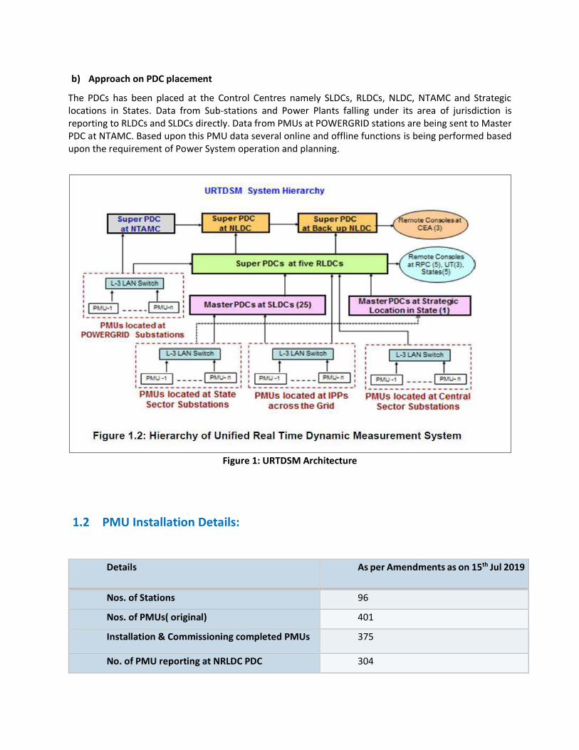
b) Approach on PDC placement
The PDCs has been placed at the Control Centres namely SLDCs, RLDCs, NLDC, NTAMC and Strategic locations in States. Data from Sub-stations and Power Plants falling under its area of jurisdiction is reporting to RLDCs and SLDCs directly. Data from PMUs at POWERGRID stations are being sent to Master PDC at NTAMC. Based upon this PMU data several online and offline functions is being performed based upon the requirement of Power System operation and planning.
Figure 1: URTDSM Architecture
1.2 PMU Installation Details:
Details As per Amendments as on 15th Jul 2019
Nos. of Stations 96
Nos. of PMUs( original) 401
Installation & Commissioning completed PMUs 375
No. of PMU reporting at NRLDC PDC 304
1.3 Various tools given under the project is given below:
Analytical Application System Overview
o The Oscillatory Stability Management (OSM) module provides foremost analysis and visualization tools for monitoring the dynamics of the power system through a study of its oscillatory modes.
o The system can have several oscillatory modes. Each mode has a frequency and a damping ratio.
o Oscillatory modes can be seen in frequency, angle difference, and power measurements. Frequency is representative of generator speeds, and is used to extract the mode phase. Power and angle difference are representative of the flow between two locations.
e-terravision (Geo-spatial Display)
o e-terravision viewer is a plug-in to APF, and provides a real time geographic system overview. The default formats for the geographic maps is Open Street Maps.
o The de-cluttering mechanism used in e-terravision allows items to be removed or added to a display at a specified zoom factor.
o Information that will be shown within e-terravision geographic display includes positive sequence voltage magnitude and angle, positive sequence current magnitude and angle5, angle differences, MW and MVAR line and interface flows, frequency, df/dt, oscillatory modes (i.e. oscillation mode frequency, percentage damping ratio, and mode shape)
o For visual alarming purposes, violation callouts denoting alert and alarm states will be shown at the appropriate location on voltage and current magnitudes, angle differences, MW and MVAR flows, frequency, df/dt, and oscillation detection, and will persist until the values return back to a normal state.
Alarm Management System
o The e-terrahabitat / e-terrascada based Alarm Management subsystem is configured in Enabled/Standby configuration in each of the URTDSM control centres.
o The subsystem provides one-line views and alarming methodology. The PDC and OMS subsystems provide the source of real time data and events.
o The Alarm Management subsystem is based on e-terrahabitat, e-terraplatform and e-terrabrowser product technology on the Red Hat Linux Operating System Platform.
Historian Overview
o The Historian subsystem provides the integrated historical storage capabilities of the URTDSM WAMS Solution comprising of Historian Server and hardware Storage solution with data interface between PDC and OSM servers.
• Receives and stores live Synchrophasor data • Captures All raw IEEE C37.118 data in real time from the PDC
o Receives and stores live OMS analytical results o Receives and stores raw domain (threshold) events o Engineering UIs for data visualisation
Time Series Derivation Framework (TDF) Engineering User Interface
The TDF (Time Derivation Framework) is the user interface of the Historian Application. TDF Engineering User Interface provides tools to create displays allowing users to:
• Create and manage user defined calculations. • Visualize and chart historical data. • Define, view and export historical data reports. • Specify and store customized dashboards (also called perspectives) to serve a particular
purpose
TDF Engineering User Interface is designed to be component-based (as opposed to display based) Component-based displays means that the content of one display is made up of different components called widgets where each widget can, for instance, list the different calculations, display calculated data for a specific time period (example: one day) or scope (example: frequencies for all 400 kV substations).
Phasor Data Analytics Tools:
Several Data Analytics Tools are under development, which will use the Phasor Measurement Units (PMUs) data and will be installed on control centres. The Data Analytics Tools under development by IIT Bombay, Mumbai are as follows –
I. Line Parameter Estimation: It is used for estimates line parameters using PMU data II. Vulnerability analysis on distance relay characteristics: Use PMU measurements to identify
relays that are vulnerable to insecure tripping. III. Linear State Estimator: PMU measurements having the same time-stamp are used to
estimate the state of the power system at the instant defined by the time-stamp IV. Supervised Zone-3 blocking: It is used to supervise operation of Zone-3 relay V. CT/CVT parameter validation: Used to identify gross error in instrument transformer VI. Control schemes for improving system security
Among the above applications, Vulnerability analysis on distance relay characteristics, Linear State Estimator, Line parameter estimation, CT/CVT calibration & Supervised Zone-3 blocking have been installed at NRLDC and are under observation.
Copyright © 2022 FDOKUMEN